
Turbo Pro
WG23.430.000-P
DE Originalbetriebsanleitung für
Einbau-Gegenstromanlage
EN Translation of original operation manual for
Submerged counter swim unit
FR Traduction du instruction d'utilisation originale pour
Installation de nage à contre-courant Encastrée
NL Vertaling van de oorspronkelijke gebruikershandleiding voor
Inbouw tegenstroominstallatie
IT Traduzione del manuale d'istruzioni originali per
Gruppo di controcorrente da incasso
ES Traducción de las instrucciones para el manejo originales para
Dispositivo contra corriente para montaje empotrado

Inhaltsverzeichnis
DE Originalbetriebsanleitung
EN Translation of original operation manual
FR Traduction du instruction d'utilisation originale
NL Vertaling van de oorspronkelijke gebruikershandleiding
IT Traduzione del manuale d'istruzioni originali
ES Traducción de las instrucciones para el manejo originales

DE Originalbetriebsanleitung
Einbau-Gegenstromanlage
Turbo Pro
WG23.430.000-P

2 DE 04|2023
BADU® ist eine Marke der
SPECK Pumpen Verkaufsgesellschaft GmbH
Hauptstraße 3
91233 Neunkirchen am Sand, Germany
Telefon 09123 949-0
Telefax 09123 949-260
info@speck-pumps.com
www.speck-pumps.com
Alle Rechte vorbehalten.
Inhalte dürfen ohne schriftliche Zustimmung von SPECK Pumpen
Verkaufsgesellschaft GmbH weder verbreitet, vervielfältigt, bearbeitet
noch an Dritte weitergegeben werden.
Dieses Dokument sowie alle Dokumente im Anhang unterliegen keinem
Änderungsdienst!
Technische Änderungen vorbehalten!
UKCA: Comply Express Ltd, Unit C2 Coalport House, Stafford Park 1,
Telford, TF3 3BD, UK

04|2023 DE 3
Inhaltsverzeichnis
1 Zu diesem Dokument ..................................................................... 6
1.1 Umgang mit dieser Anleitung...................................................... 6
1.2 Zielgruppe ................................................................................... 6
1.3 Mitgeltende Dokumente .............................................................. 6
1.3.1 Symbole und Darstellungsmittel ............................................. 6
2 Sicherheit ........................................................................................ 8
2.1 Bestimmungsgemäße Verwendung ........................................... 8
2.1.1 Mögliche Fehlanwendungen ................................................... 8
2.2 Personalqualifikation ................................................................... 8
2.2.1 Herzschrittmacher ................................................................... 9
2.3 Sicherheitsvorschriften ............................................................... 9
2.4 Schutzeinrichtungen ................................................................... 9
2.5 Bauliche Veränderungen und Ersatzteile ................................. 10
2.6 Schilder ..................................................................................... 10
2.7 Restrisiken ................................................................................ 10
2.7.1 Herabfallende Teile ............................................................... 10
2.7.2 Rotierende Teile.................................................................... 10
2.7.3 Elektrische Energie ............................................................... 10
2.7.4 Heiße Oberflächen ................................................................ 11
2.7.5 Ansauggefahr........................................................................ 11
2.7.6 Körperfangstellen .................................................................. 11
2.7.7 Magnetkräfte ......................................................................... 11
2.7.8 Magnetisches Feld ................................................................ 11
2.7.9 Verletzungsgefahr an der Einströmdüse .............................. 12
2.7.10 Ertrinkungsgefahr ............................................................. 12
2.8 Störungen ................................................................................. 12
2.9 Vermeidung von Sachschäden ................................................. 12
2.9.1 Undichtigkeit am Einbaugehäuse ......................................... 12
2.9.2 Wasseraustritt über Beckenrand .......................................... 12
2.9.3 Trockenlauf ........................................................................... 13
2.9.4 Überhitzen ............................................................................. 13
2.9.5 Blockieren des Antriebes ...................................................... 13
2.9.6 Falsche Drehrichtung der Turbine ........................................ 13
2.9.7 Frostgefahr ............................................................................ 13

4 DE 04|2023
2.9.8 Wassertemperatur................................................................. 13
2.9.9 Sichere Nutzung des Produktes ........................................... 14
2.9.10 Verschmutzung der Anlage ............................................... 14
3 Beschreibung ................................................................................ 15
3.1 Komponenten ............................................................................ 15
3.2 Funktion .................................................................................... 15
4 Transport und Zwischenlagerung ............................................... 16
4.1 Transport ................................................................................... 16
4.2 Verpackung ............................................................................... 16
4.3 Lagerung ................................................................................... 16
4.4 Rücksendung ............................................................................ 16
5 Installation ..................................................................................... 17
5.1 Einbauort (Fachpersonal) ......................................................... 17
5.1.1 Einbaustelle ........................................................................... 17
5.1.2 Bodenablauf muss vorhanden sein ...................................... 17
5.1.3 Be- und Entlüftung ................................................................ 18
5.1.4 Körper- und Luftschallübertragung ....................................... 18
5.1.5 Platzreserve .......................................................................... 18
5.1.6 Befestigungselemente .......................................................... 18
5.1.7 Schwimmbecken mit Überlaufrinne ...................................... 18
5.1.8 Montagehinweise Frequenzumrichter ................................... 18
5.2 Aufstellung (Fachpersonal) ....................................................... 20
5.2.1 Einbauhinweis Betonbecken ................................................. 20
5.2.2 Einbauhinweis Edelstahl-/Folienbecken ............................... 25
5.2.3 Kabelschutzschlauch ............................................................ 27
5.2.4 Anlagenschacht..................................................................... 27
5.2.5 Elektrische Steuerung ........................................................... 27
5.3 Fertigmontage (Fachpersonal).................................................. 27
5.3.1 Montage Piezotaster ............................................................. 28
5.3.2 Montage Düseneinheit .......................................................... 29
5.3.3 Montage Abdeckblende ........................................................ 30
5.3.4 Montage Edelstahlblende ..................................................... 30
5.3.5 Montage Antriebseinheit ....................................................... 30
5.3.6 Montage Motoreinheit ........................................................... 31
5.3.7 Nutzungsmöglichkeit der Anschlussstutzen (Rückwand) ..... 31

04|2023 DE 5
5.3.8 Einbaubeispiel....................................................................... 32
5.4 Elektrischer Anschluss (Fachpersonal) .................................... 32
5.4.1 Elektrischer Anschluss der Gegenstromanlage .................... 33
5.4.2 Anschlussschema ................................................................. 35
5.4.3 Vorbereitung Steuerkabel ..................................................... 35
5.4.4 Schaltplan Steuerkabel ......................................................... 36
5.4.5 Vorbereitung Motorkabel ...................................................... 37
5.4.6 Schaltplan 3~ 400 V 50 Hz ................................................... 40
5.4.7 Schaltplan Platine on/off ....................................................... 40
5.4.8 Schaltkasten-Anschlüsse ...................................................... 41
5.4.9 Displayanzeigen am Frequenzumrichter .............................. 41
5.4.10 Segmentanzeige, grüne und orangene LED, Sicherung .. 42
5.4.11 Einstellungen DIP-Schalter ............................................... 43
5.5 Demontage ............................................................................... 43
6 Inbetriebnahme/Außerbetriebnahme .......................................... 44
6.1 Inbetriebnahme ......................................................................... 44
6.1.1 Anlage einschalten ............................................................... 44
6.2 Betrieb ....................................................................................... 44
6.2.1 Ein-/Ausschalten ................................................................... 44
6.2.2 Mengenregulierung ............................................................... 45
6.2.3 Kugeldüse ............................................................................. 46
6.3 Außerbetriebnahme .................................................................. 46
6.3.1 Überwinterung....................................................................... 46
7 Störungen ...................................................................................... 47
7.1 Übersicht ................................................................................... 47
8 Wartung/Instandhaltung .............................................................. 49
8.1 Gewährleistung ......................................................................... 49
8.1.1 Sicherheitsrelevante Ersatzteile ........................................... 49
8.2 Serviceadressen ....................................................................... 49
9 Entsorgung ................................................................................... 50
10 Technische Daten ......................................................................... 51
10.1 Maßzeichnung .......................................................................... 51
10.2 Explosionszeichnung ................................................................ 52
11 Index .............................................................................................. 53

Zu diesem Dokument
6 DE 04|2023
1 Zu diesem Dokument
1.1 Umgang mit dieser Anleitung
Diese Anleitung ist Teil der Pumpe/Anlage. Die Pumpe/Anlage
wurde nach den anerkannten Regeln der Technik hergestellt und
geprüft. Dennoch können bei unsachgemäßer Verwendung, bei
unzureichender Wartung oder unzulässigen Eingriffen Gefahren
für Leib und Leben sowie materielle Schäden entstehen.
Anleitung vor Gebrauch aufmerksam lesen.
Anleitung während der Lebensdauer des Produktes
aufbewahren.
Anleitung dem Bedien- und Wartungspersonal jederzeit
zugänglich machen.
Anleitung an jeden nachfolgenden Besitzer oder Benutzer
des Produktes weitergeben.
1.2 Zielgruppe
Diese Anleitung richtet sich sowohl an Fachpersonal als auch an
den Endverbraucher. Eine Kennzeichnung für Fachpersonal
(Fachpersonal) ist dem jeweiligen Kapitel zu entnehmen. Die
Angabe bezieht sich auf das gesamte Kapitel. Alle anderen
Kapitel sind allgemeingültig.
1.3 Mitgeltende Dokumente
• Packliste
• Technische Unterlagen Frequenzumformer
1.3.1 Symbole und Darstellungsmittel
In dieser Anleitung werden Warnhinweise verwendet, um Sie vor
Personenschäden zu warnen.
Warnhinweise immer lesen und beachten.
GEFAHR
Gefahren für Personen.
Nichtbeachtung führt zu Tod oder schweren Verletzungen.
WARNUNG
Gefahren für Personen.
Nichtbeachtung kann zu Tod oder schweren Verletzungen führen.

Zu diesem Dokument
04|2023 DE 7
VORSICHT
Gefahren für Personen.
Nichtbeachtung kann zu leichten bis mäßigen Verletzungen
führen.
HINWEIS
Hinweise zur Vermeidung von Sachschäden, zum Verständnis
oder zum Optimieren der Arbeitsabläufe.
Um die korrekte Bedienung zu verdeutlichen, sind wichtige
Informationen und technische Hinweise besonders
hervorgehoben.
Symbol
Bedeutung
Einschrittige Handlungsaufforderung.
1.
2.
Mehrschrittige Handlungsaufforderung.
Reihenfolge der Schritte beachten.

Sicherheit
8 DE 04|2023
2 Sicherheit
2.1 Bestimmungsgemäße Verwendung
Zum Einbau in Schwimmbecken als Attraktion, zur Fitness, als
Wellenbad, zum Schwimmen ohne Wende.
Zur bestimmungsgemäßen Verwendung gehört die Beachtung
folgender Informationen:
• Diese Anleitung
Die Pumpe/Anlage darf nur innerhalb der Einsatzgrenzen
betrieben werden, die in dieser Anleitung festgelegt sind. Eine
Verwendung im Wasser mit einem Salzgehalt von mehr als
0,66 g/l muss mit dem Hersteller/Lieferanten abgesprochen
werden.
Eine gewerbliche Nutzung des Gerätes ist möglich.
Eine andere oder darüber hinausgehende Verwendung ist nicht
bestimmungsgemäß und muss zuvor mit dem Hersteller/
Lieferanten abgesprochen werden.
2.1.1 Mögliche Fehlanwendungen
• Unzureichende Befestigung und Abdichtung der Anlage.
• Öffnen und Instandhalten der Pumpe/Anlage durch nicht
qualifiziertes Personal.
• Zu langer Betrieb im oberen Drehzahlbereich.
2.2 Personalqualifikation
Dieses Gerät kann von Kindern ab 8 Jahren und darüber sowie
von Personen mit verringerten physischen, sensorischen oder
mentalen Fähigkeiten oder Mangel an Erfahrung und Wissen
benutzt werden, wenn sie beaufsichtigt oder bezüglich des
sicheren Gebrauchs des Gerätes unterwiesen wurden und die
daraus resultierenden Gefahren verstehen. Kinder dürfen nicht
mit dem Gerät spielen. Reinigung und Benutzerwartung dürfen
nicht von Kindern ohne Beaufsichtigung durchgeführt werden.
Sicherstellen, dass folgende Arbeiten nur von geschultem
Fachpersonal mit den genannten Personalqualifikationen
durchgeführt werden:
• Arbeiten an der Mechanik, zum Beispiel Wechsel der
Kugellager oder der Gleitringdichtung: qualifizierter
Mechaniker.
• Arbeiten an der elektrischen Anlage: Elektrofachkraft.

Sicherheit
04|2023 DE 9
Sicherstellen, dass folgende Voraussetzungen erfüllt sind:
• Das Personal, das die entsprechende Qualifikation noch
nicht aufweisen kann, erhält die erforderliche Schulung,
bevor es mit anlagentypischen Aufgaben betraut wird.
• Die Zuständigkeiten des Personals, zum Beispiel für
Arbeiten am Produkt, an der elektrischen Ausrüstung oder
den hydraulischen Einrichtungen, sind entsprechend
seiner Qualifikation und Arbeitsplatzbeschreibung
festgelegt.
• Das Personal hat diese Anleitung gelesen und die
erforderlichen Arbeitsschritte verstanden.
2.2.1 Herzschrittmacher
Magnete können die Funktion von Herzschrittmachern und
implantierten Defibrillatoren stören und aussetzen lassen.
– Der Herzschrittmacher kann durch das Magnetfeld in den
„Standardprogramm-Modus“ wechseln und dadurch Herz-
Kreislauf-Probleme verursachen.
– Der Defibrillator kann unter Umständen nicht mehr
funktionieren oder gefährliche Stromschläge abgeben.
Betroffene Personen dürfen Magnetpumpen nicht aufstellen,
warten und bedienen.
2.3 Sicherheitsvorschriften
Für die Einhaltung aller relevanten gesetzlichen Vorschriften und
Richtlinien ist der Betreiber der Anlage verantwortlich.
Bei Verwendung der Pumpe/Anlage folgende Vorschriften
beachten:
• Diese Anleitung
• Warn- und Hinweisschilder am Produkt
• Mitgeltende Dokumente
• Bestehende nationale Vorschriften zur Unfallverhütung
• Interne Arbeits-, Betriebs- und Sicherheitsvorschriften des
Betreibers
2.4 Schutzeinrichtungen
Das Hineingreifen in bewegliche Teile, zum Beispiel Kupplung
und/oder Lüfterrad, kann schwere Verletzungen verursachen.
Pumpe/Anlage nur mit Berührungsschutz betreiben.

Sicherheit
10 DE 04|2023
2.5 Bauliche Veränderungen und Ersatzteile
Umbau oder bauliche Veränderungen können die
Betriebssicherheit beeinträchtigen.
Pumpe/Anlage nur in Absprache mit dem Hersteller
umbauen oder verändern.
Nur Originalersatzteile oder -zubehör verwenden, das vom
Hersteller autorisiert ist.
2.6 Schilder
Alle Schilder auf der gesamten Pumpe/Anlage in lesbarem
Zustand halten.
2.7 Restrisiken
2.7.1 Herabfallende Teile
Nur geeignete und technisch einwandfreie Hebezeuge und
Lastaufnahmemittel verwenden.
Nicht unter schwebenden Lasten aufhalten.
2.7.2 Rotierende Teile
Scher- und Quetschgefahr besteht aufgrund von offenliegenden
rotierenden Teilen.
Alle Arbeiten nur bei Stillstand der Pumpe/Anlage
durchführen.
Vor Arbeiten die Pumpe/Anlage gegen Wiedereinschalten
sichern.
Unmittelbar nach Abschluss der Arbeiten alle
Schutzeinrichtungen wieder anbringen beziehungsweise in
Funktion setzen.
2.7.3 Elektrische Energie
Bei Arbeiten an der elektrischen Anlage besteht durch die feuchte
Umgebung erhöhte Stromschlaggefahr.
Ebenso kann eine nicht ordnungsgemäß durchgeführte
Installation der elektrischen Schutzleiter zum Stromschlag führen,
zum Beispiel durch Oxidation oder Kabelbruch.
VDE- und EVU-Vorschriften des
Energieversorgungsunternehmens beachten.
Schwimmbecken und deren Schutzbereiche gemäß
DIN VDE 0100-702 errichten.
Vor Arbeiten an der elektrischen Anlage folgende
Maßnahmen ergreifen:
• Anlage von der Spannungsversorgung trennen.
• Warnschild anbringen: „Nicht einschalten! An der Anlage
wird gearbeitet."

Sicherheit
04|2023 DE 11
• Spannungsfreiheit prüfen.
Elektrische Anlage regelmäßig auf ordnungsgemäßen
Zustand prüfen.
2.7.4 Heiße Oberflächen
Der Elektromotor kann eine Temperatur von bis zu 80 °C
erreichen. Dadurch besteht Verbrennungsgefahr.
Motor im Betrieb nicht berühren.
Vor Arbeiten an der Pumpe/Anlage Motor erst abkühlen
lassen.
2.7.5 Ansauggefahr
Folgende Gefährdungen können zu Ertrinken führen:
• Falsche Ausströmrichtung/Drehrichtung. Siehe Kapitel 2.9.6
auf Seite 13.
• Ansaugen, Einsaugen oder Verklemmen des Körpers oder
Körperteilen, Bekleidung und Schmuck
• Verknoten von Haaren
Anlage nie ohne Ansaugblenden betreiben.
Eng anliegende Badebekleidung tragen.
Bei längeren Haaren Bademütze verwenden.
Ansaugöffnungen regelmäßig kontrollieren und reinigen.
2.7.6 Körperfangstellen
Sollten Öffnungen zwischen 25 mm und 110 mm aus baulichen
Gründen nicht vermieden werden können, so ist dies nur zulässig,
wenn der Installateur den Kunden auf das potenzielle Risiko
hinweist.
Betreiber der Anlage muss auf potenzielles Risiko von
Fangstellen hingewiesen werden.
2.7.7 Magnetkräfte
Verletzungsgefahr durch Magnetkräfte bei Montage/Demontage
der Motoreinheit und Antriebseinheit.
Bei Arbeiten an der Anlage auf Magnetkräfte achten.
2.7.8 Magnetisches Feld
Magnete von allen Geräten und Gegenständen fern halten,
die durch starke Magnetfelder beschädigt oder entwertet
werden können.

Sicherheit
12 DE 04|2023
2.7.9 Verletzungsgefahr an der Einströmdüse
Die Einströmdüse arbeitet mit hohem Volumenstrom. Dies kann
zu Verletzungen an den Augen oder anderen empfindlichen
Körperteilen führen.
Direkten Kontakt dieser Körperteile mit dem Wasserstrahl
aus der Einströmdüse vermeiden.
2.7.10 Ertrinkungsgefahr
Gefahr des Ertrinkens bei zu starker Strömung für Personen mit
unzureichenden Schwimmkenntnissen oder physischer
Belastbarkeit.
Anlagenleistung an den Schwimmer anpassen.
Kinder und Personen mit körperlichen oder psychischen
Einschränkungen beaufsichtigen.
2.8 Störungen
Bei Störungen Anlage sofort stilllegen und ausschalten.
Alle Störungen umgehend beseitigen lassen.
Festsitzende Antriebseinheit
Wird eine festsitzende Antriebseinheit mehrmals hintereinander
eingeschaltet, kann der Motor beschädigt werden. Folgende
Punkte beachten:
Anlage nicht mehrmals hintereinander einschalten.
Propeller von Hand durchdrehen.
Antriebseinheit reinigen.
2.9 Vermeidung von Sachschäden
2.9.1 Undichtigkeit am Einbaugehäuse
Nichteinhaltung der Aushärtezeit der ABS-Verklebungen kann zu
Undichtigkeit und Überschwemmung führen.
Aushärtezeit der ABS-Verklebungen von mindestens
zwölf Stunden einhalten.
Ausreichenden Bodenablauf vorsehen.
Anlage so installieren, dass Körper- und
Luftschallübertragung reduziert werden. Dabei die
einschlägigen Vorschriften beachten.
Bei Undichtigkeit darf die Anlage nicht betrieben werden und
muss vom Netz genommen werden.
2.9.2 Wasseraustritt über Beckenrand
Sollte Wasser über den Beckenrand austreten, kann es folgende
Ursachen haben:
• Falsche Dimensionierung des Beckens.
• Überlaufrinnen und Schwallwasserbehälter zu klein.

Sicherheit
04|2023 DE 13
2.9.3 Trockenlauf
Durch Trockenlauf können Gleitlager und Kunststoffteile innerhalb
weniger Sekunden zerstört werden.
Anlage nicht trocken laufen lassen. Das gilt auch bei der
Drehrichtungskontrolle.
Inbetriebnahme der Anlage nur, wenn das Wasserniveau
350 mm über der Anlagenmitte steht.
2.9.4 Überhitzen
Folgende Faktoren können zu einer Überhitzung der Anlage
führen:
• Wasserstand zu niedrig.
• Zu hohe Umgebungstemperatur.
• Verstopfung der Ansaugblende durch Fasern,
Kleidungsstücke, Harre, Laub, Badetuch...
Wasserstand erhöhen.
Zulässige Umgebungstemperatur von 40 °C nicht
überschreiten.
Verstopfungen vermeiden bzw. vorhandene Verstopfungen
entfernen.
2.9.5 Blockieren des Antriebes
Schmutzteilchen können die Anlage verstopfen. Dadurch kann es
zu Trockenlauf und Überhitzung kommen.
Verschmutzungen durch Fasern, Kleidungsstücke, Haare,
Laub, Badetuch, usw. vermeiden.
2.9.6 Falsche Drehrichtung der Turbine
Falsche Drehrichtung durch:
• Verdrahtung nicht nach Schaltplan (z.B. Litzenkenn-
zeichnung nicht beachtet)
• Wasser-Ausströmrichtung an der Düse nicht kontrolliert.
Die Ausströmrichtung muss zwingend mit Hilfe eines
schwimmbaren Gegenstandes durch einen Installateur
überprüft werden.
2.9.7 Frostgefahr
Es wird empfohlen, die Antriebseinheit während der Frostperiode
auszubauen und in einem trockenen Raum zu lagern.
Anlage und frostgefährdete Leitungen rechtzeitig entleeren.
2.9.8 Wassertemperatur
Das Wasser darf eine Temperatur von 35 °C nicht überschreiten.

Sicherheit
14 DE 04|2023
2.9.9 Sichere Nutzung des Produktes
Eine sichere Nutzung des Produktes ist bei folgenden Punkten
nicht mehr gewährleistet:
• Bei verstopfter Frontblende.
• Bei festsitzender Antriebseinheit.
• Bei schadhafter oder fehlender Schutzeinrichtungen, zum
Beispiel Frontblende.
• Bei fehlerhafter Elektroinstallation.
2.9.10 Verschmutzung der Anlage
Bei Arbeiten an der Anlage auf einen sauberen Arbeitsplatz
achten. Es dürfen sich keine magnetisierbaren Metallpartikel in
der Nähe der Magnetkupplung befinden.

Beschreibung
04|2023 DE 15
3 Beschreibung
3.1 Komponenten
Abb. 1
1
Einbaugehäuse
2/3
Antriebseinheit
4
Düseneinheit
5
Blende
20
Motor
33
Propellerrad
42
Kugeldüse
46
Schrauben
47
Einstellhilfe
55
Frontblende
64
Piezotaster
66
Fernbedienung
3.2 Funktion
Die Anlage (1) ist für den Einbau in ein Betonbecken und in einem
stabilen Stahl- oder Kunststoffbecken mit einer glatten Wand im
Montagebereich vorgesehen.
Der Antrieb erfolgt über einen Motor (20), dessen Leistung in
verschiedenen Stufen über den Frequenzumformer einstellbar ist.
Das Ein- und Ausschalten und die Regelung erfolgt über
Piezotaster (64) in der Frontblende (55) und ist zusätzlich über
eine Fernbedienung (66) einstellbar.
Die Kraft wird über eine magnetgekuppelte Antriebseinheit (2/3)
auf das Propellerrad (33) übertragen.
Das Wasser wird an den Gittern der Blende (5) über die
Düseneinheit (4) zum Propellerrad (33) angesaugt und mit einem
kraftvollen Volumenstrom zurück ins Becken befördert.
Die Strömungsrichtung lässt sich durch eine Kugeldüse (42) unter
Verwendung der Einstellhilfe (47) schwenkbar um 5° in alle
Richtungen einstellen. Der somit erzeugte kraftvolle
Volumenstrom ermöglicht dem Schwimmer ein auf ihn persönlich
eingestelltes Schwimmerlebnis.
3 4 33 42
47 1
20
64 5
46
46
47
55
66
2
WG23.400.001-P

Transport und Zwischenlagerung
16 DE 04|2023
4 Transport und Zwischenlagerung
4.1 Transport
Lieferzustand kontrollieren:
• Verpackung auf Transportschäden prüfen.
• Schaden feststellen, mit Bildern dokumentieren und an
den Händler wenden.
4.2 Verpackung
Die zum Teil vormontierte Anlage aus der Verpackung
entnehmen. Die jeweiligen vormontierten Teile durch lösen der
Schneidschrauben abbauen und an einem trockenen Ort lagern.
4.3 Lagerung
HINWEIS
Korrosion durch Lagerung in feuchter Luft bei wechselnden
Temper
aturen!
Kondenswasser kann Wicklungen und Metallteile angreifen
.
Antriebseinheit in trockener Umgebung bei möglichst
konstanter Temperatur zwischenlagern.
HINWEIS
Beschädigung oder Verlust von Einzelteilen!
Originalverpackung erst vor dem Einbau öffnen
beziehungsweise Einzelteile bis zum Einbau in der
Originalverpackung aufbewahren.
4.4 Rücksendung
Antriebseinheit vollständig entleeren.
Antriebseinheit reinigen.
Antriebseinheit in Karton verpacken und an den Fachbetrieb
beziehungsweise Hersteller senden.

Installation
04|2023 DE 17
5 Installation
5.1 Einbauort (Fachpersonal)
5.1.1 Einbaustelle
• Der Einbau der Anlage erfolgt im Normalfall an der
Schmalseite des Beckens mit einer empfohlenen
Mindestbeckengröße von 3,5 x 6 m.
• Ein Einbau in ein Rund- oder Ovalbecken ist nicht möglich.
• Durch den Volumenstrom der Anlage kann eine Zirkulation
im Becken entstehen. Dadurch kann es zu einer
Überschneidung von Volumenstrom und Rückströmung
kommen, die sich durch einen scheinbaren Strömungsabriss
bemerkbar macht. Dies kommt vor allem dann zum
Vorschein, wenn besondere Poolformen oder beispielsweiße
Treppen verbaut sind. Generell ist dies bisher nur sehr selten
aufgetreten und stellt keinen Mangel da. Ein Verstellen der
Düse ist hier meist schon die einfachste Abhilfe, um die
Strömung im Becken günstiger zu beeinflussen.
Abb. 2
5.1.2 Bodenablauf muss vorhanden sein
Größe des Bodenablaufs nach folgenden Kriterien
bemessen:
• Größe des Schwimmbeckens.
• Umwälzvolumenstrom.
WG23.432.022-P

Installation
18 DE 04|2023
5.1.3 Be- und Entlüftung
Für ausreichende Be- und Entlüftung sorgen. Be- und
Entlüftung müssen folgende Bedingungen sicherstellen:
• Vermeidung von Kondenswasser.
• Mindestabstand Motor zur Wand: mind. 300 mm.
• Kühlung des Motors und anderer Anlagenteile, zum
Beispiel der Schaltschränke und Steuergeräte.
• Begrenzung der Umgebungstemperatur auf maximal
40 °C.
5.1.4 Körper- und Luftschallübertragung
Vorschriften für baulichen Schallschutz beachten, zum
Beispiel DIN 4109.
Anlage so aufstellen, dass die Körper- und
Luftschallübertragungen reduziert werden.
Schwingungsabsorbierende Materialien, wie z.B.
Dämmmatte, verwenden.
• Die Angabe nach Luftschallemission erfolgen nach
EN ISO 20361.
5.1.5 Platzreserve
Platzreserve so bemessen, dass Motor- und Antriebseinheit von
der Gehäuserückseite ausgebaut werden können.
5.1.6 Befestigungselemente
Anlagenteile mit Schrauben befestigen.
5.1.7 Schwimmbecken mit Überlaufrinne
Bei der Planung des Schwimmbeckens mit Überlaufrinne ist
auf ausreichende Dimensionierung der Überlaufrinne, der
Verrohrung und des Schwallwasserbehälters zu achten.
5.1.8 Montagehinweise Frequenzumrichter
HINWEIS
Der Frequenzumformer soll nur von einer Elektrofachkraft
installiert werden.
Vollständige Informationen zu dem Frequenzumrichter sind
der beigelegten Originalbetriebsanleitung zu entnehmen.
Der Umrichter darf nur senkrecht installiert werden.
Die Installation muss auf einer geeigneten, ebenen und
schwer entflammbaren Oberfläche erfolgen.
Niemals brennbare Materialien in der Nähe des Umrichters
lagern.
Der Montageort sollte frei von Schwingungen sein.

Installation
04|2023 DE 19
Den Umrichter niemals in Bereichen mit übermäßiger
Feuchtigkeit, in der Luft befindlichen aggressiven
Chemikalien oder potenziell gefährlichen Staubpartikeln
montieren.
Den Umrichter nicht in der Nähe von Wärmequellen mit
hoher Abstrahlung montieren.
Vor direkter Sonneneinstrahlung schützen. Ggfs. einen
Sonnenschutz installieren.
Der Montageort muss frei von Frostgefahr sein.
Der Luftfluss durch den Umrichter darf nicht eingeschränkt
werden. Die Wärme des Umrichters muss auf natürliche
Weise abgeleitet werden.
Bei großen Schwankungen des Umgebungsdruckes und der
Temperatur muss in die Durchführungsplatte ein geeignetes
Druckausgleichsventil installiert werden.
Sollte ein EMV-Filter im Schaltkasten verwendet werden, ist
die Schraube im Frequenzumformer kundenseitig zu
entfernen.
HINWEIS
Wenn der Umrichter länger als 2 Jahre gelagert wurde, müssen
vor erneutem Betrieb die Zwischenkreiskondensatoren neu
reformiert werden. Hierzu die Hersteller-Dokumentation beachten.

Installation
20 DE 04|2023
5.2 Aufstellung (Fachpersonal)
5.2.1 Einbauhinweis Betonbecken
Betonbecken mit Folie
Abb. 3
Betonbecken gefliest
Abb. 4
Folie
Epoxid-Quarzsand-
gemisch
Beton
Einbaugehäuse
Dichtung
Abdeckblende
Frontblende
Ansaugblende
WG23.430.034-1-P
Fliesen
Epoxid-Quarzsand-
gemisch
Beton
Einbaugehäuse
Dichtung
Abdeckblende
Frontblende
Ansaugblende
WG23.430.035-1-P
Verbundabdichtung

Installation
04|2023 DE 21
Beckenausschnitt für Betonbecken/Schalung
Abb. 5
100
354
90
270
1300
100
1433
ca.500 Kontroll, - Ausschnitt für Stützlatten
bzw. für nachträglichen Einbau!
Stützlatte (2x) Länge 325 +/-1mm
ø7
150
WG23.430.033-1-P

Installation
22 DE 04|2023
Einbau an Schalung des Betonbeckens
Abb. 6
240
350
Schneidschraube 6 x 40 (36x) (51)
Moosgummidichtung 8 x 8 (11)
Dicht-Rundschnur (16)
Schalung
Schalung
Bei Einbau auf Ausrichtung "OBEN / UP /HAUT" achten!
Stützlatte (2x) (17)
*) Beilagscheibe 6,4 x 18
DIN 9021 A4 (36x)
Betonverdichter (Betonrüttler)Beim Auffüllen mit Beton, in Gehäusenähe an
allen Seiten, mit Verdichter dichtrütteln!
WG23.430.032-1-P
Einlage für Ring aus Epoxidharz/
Quarzsandgemisch 30 x 30 mm
*) Wird nur zur Befestigung an der Schalung verwendet

Installation
04|2023 DE 23
Montage des Einbaugehäuses in ein Beton- und gefliestes
Becken
HINWEIS
Für die Abdichtung zur Betonwand wird empfohlen, einen
umlaufenden Ring aus Epoxidharz/Quarzsand an der
beckenseitigen Außenwand des Gehäuses (1) zu erstellen.
Siehe
"
Abb. 8" auf Seite 24
Vor dem Einbau an der Schalung am Gehäuse eine
betonbeständige Einlage 30 x 30 mm anbringen.
1. Einbautiefe: Mitte des Einbaugehäuses (1) soll 35 cm
unterhalb des Wasserspiegels angebracht werden.
2. Befestigungsbohrungen gemäß Bohrbild auf der Schalung
anbringen.
3. Stützlatten (17) zwischen die beiden Überlappungen der
Gehäuseinnenseite klemmen.
4. Moosgummidichtung (11) ohne Zug entlang der Nut am
Gehäuse (1) von Hand eindrücken. Mit einem Tropfen
Sekundenkleber bodenseitig fixieren.
5. Die Dicht-Rundschnur (16) in die Gehäusenut einlegen.
6. Einbaugehäuse (1) mit der Kennzeichnung „OBEN/UP/
HAUT“ ausrichten und mit den Schneidschrauben (51) an der
Schalung befestigen.
• Der Rechteckausschnitt in der Schalung ist optional. Dieser
dient der Kontrolle beziehungsweise dem richtigen Sitz oder
auch nachträglichem Einbau der Stützlatten.
Beim Betonieren darauf achten, dass der Beton von unten
nach oben aufgefüllt und mehrfach an allen Seiten mit einem
Verdichter dichtgerüttelt und armiert wird.
7. Nach Aushärtung des Betons ist die Einlage sauber zu
entfernen und mit einem Epoxidharz/Quarzsand-gemisch
bündig mit der Frontseite auszuspachteln.
8. Die Ansaugblende von der Beckeninnenseite aus mit 36
Schneidschrauben (51) mit dem Gehäuse (1) mit einem
Drehmoment von 6 Nm verschrauben.
HINWEIS
Aushärtezeit für Beton beachten!
Die Abdichtung sollte gemäß Schwimmbadnorm DIN 18535
als Verbundabdichtung erfolgen.

Installation
24 DE 04|2023
Einbauschema für den Einbau in ein Betonbecken mit
Folienauskleidung (a)
Abb. 7
HINWEIS
Hinweis für Betonbecken mit Folie
Die Folie (a) wird durch die Blende (5) an das
Einbaugehäuse (1) mit montierter Moosgummidichtung (11)
gepresst.
Bei Poolbecken mit Folie wird empfohlen, den
Rechteckausschnitt umlaufend zu verkleinern, um den
Abstand zur Lochung zu vergrößern.
Die überstehende Folie kann an die Innenseite des
Gehäuses geklebt werden.
Einbauschema für den Einbau in ein gefliestes Betonbecken
Abb. 8
HINWEIS
Hinweis für geflieste Betonbecken
Nach der Aushärtung des Betons kann um die Blende mit
einem Abstand von ca. 1 cm gefliest werden.
Die Abdichtung hat gemäß Schwimmbadnorm DIN 18535 als
Verbundabdichtung zu erfolgen.
a
1
11
5
51
WG23.430.036-P
1
11 5
51
WG23.430.037-P

Installation
04|2023 DE 25
5.2.2 Einbauhinweis Edelstahl-/Folienbecken
Folienbecken
Abb. 9
Edelstahl-/Kunststoffbecken
Abb. 10
Beckenwand
Einbaugehäuse
DichtungAnsaugblende
Frontblende
Abdeckblende
WG23.430.039-1-P
Folie
Beckenwand
Einbaugehäuse
DichtungAnsaugblende
Frontblende
Abdeckblende
WG23.430.040-1-P

Installation
26 DE 04|2023
Beckenausschnitt für Edelstahl-/Folienbecken
Abb. 11
Montage des Einbaugehäuses in ein Edelstahl- oder
Kunststoffbecken (b)
1. Einbautiefe: Mitte des Einbaugehäuses (1) soll 35 cm
unterhalb des Wasserspiegels angebracht werden.
2. Befestigungsbohrungen und Ausschnitt gemäß Bohrbild an
der Beckenwand anbringen.
HINWEIS
Bei Poolbecken mit Folie wird empfohlen, den Rechteckausschnitt
umlaufend zu
verkleinern, um den Abstand zur Lochung zu
vergrößer
n. Die überstehende Folie kann an die Innenseite des
Gehäuses geklebt werden.
3. Stützlatten (17) zwischen die beiden Überlappungen der
Gehäuseinnenseite klemmen.
4. Moosgummidichtung (11) ohne Zug entlang der Nut am
Gehäuse (1) von Hand eindrücken. Mit einem Tropfen
Sekundenkleber bodenseitig fixieren.
5. Das Einbaugehäuse (1) mit der Kennzeichnung „OBEN/UP/
HAUT“ an den Bohrungen an der Außenwand ausrichten.
6. Die Ansaugblende (5) von der Innenseite des Beckens mit 36
Schneidschrauben (51) zusammen mit dem Gehäuse (1) an
der Pool-Wand mit einem Drehmoment von 6 Nm
verschrauben.
1433
354
337
1416
100 100
90
270
1300
40
Gehäuseseitig - Glatte Dichtfläche umlaufend
ca. 40 mm erforderlich!
WG23.430.038-P

Installation
04|2023 DE 27
Einbauschema für den Einbau in ein Folien-/Stahl- oder
Kunststoffbecken
Abb. 12
5.2.3 Kabelschutzschlauch
1. Anschlussstutzen (d, (Abb. 16)) am Kunststoffgehäuse (1)
und die Anschlussbuchse vom Kabelschutzschlauch (12) mit
PVC-U/ABS-Reiniger entfetten.
2. Beide Seiten mit PVC-U/ABS-Kleber bestreichen und
anschließend zusammenstecken beziehungsweise
verkleben.
5.2.4 Anlagenschacht
Die Unterbringung der Anlage hat in einem Schacht, der am
Beckenrand angrenzt, zu erfolgen. Im Aufstellungsraum müssen
eine einwandfreie Be- und Entlüftung und ein ausreichender
Bodenablauf vorhanden sein. Eine Befestigungsmöglichkeit für
den Frequenzumformer und den Schaltschrank sowie den
Kabelschutzschlauch (möglichst oberhalb Wasserniveau) muss
gegeben sein. Im Schacht muss ein Anschluss für einen
Potentialausgleich vorhanden sein. Siehe Kapitel 0 auf Seite 32.
Für den Ein- und Ausbau von Motor und Antriebseinheit muss
ausreichend Platz vorhanden sein.
5.2.5 Elektrische Steuerung
Der Schaltkasten für die Gegenstromanlage ist in einem
trockenen Raum unterzubringen. Das Anschließen von Anlage
und Zuleitungen ist nach beiliegendem Schaltplan vorzunehmen.
Die einschlägigen Vorschriften (VDE) sind zu berücksichtigen.
Der Fi muss zwingend Typ „B“ sein.
Inbetriebnahme nur mit geschlossenem Schaltkasten und
geschlossenem Frequenzumrichter!
Beigelegte Kabel sind zu verwenden. Details zu den Kabeln sind
in einem gesonderten Übersichtsschema in Kapitel 5.4.
5.3 Fertigmontage (Fachpersonal)
111 b551
WG23.430.041-P

Installation
28 DE 04|2023
WARNUNG
Verletzungsgefahr durch Ansaugen/Ansaugwirkung durch nicht
montierte Blendenteile!
Alle Blendenteile unbedingt montieren.
Für Schäden, die auf Zuwiderhandlung oder fehlerhafte Montage
zurückzuführen sind, erlöschen
sämtliche Garantie- und
Schadensersatzansprüche!
5.3.1 Montage Piezotaster
1. Die drei Kabel durch die zylindrische Führung der Ansaug-
blende (5) und dem Einbaugehäuse (1) hindurchführen.
2. Piezotaster (64) mit jeweils zwei montierten O-Ringen (65)
bis zum Anschlag einpressen. Ggfs. O-Ring für eine leichtere
Montage einfetten.
3. Sechskantmutter der Kabelverschraubung festziehen.
Abb. 13
Piezotaster
10m (3x) (64)
O-Ring (65)
Kabelschutzschlauch (12)
WG23.430.042-1-P

Installation
04|2023 DE 29
5.3.2 Montage Düseneinheit
1. Düseneinheit (4) mit ihren 3 Befestigungsdomen in die
zylindrische Vertiefung der Gehäusezentrierung/Flansch-
zentrierung einsetzen.
2. Die drei Schneidschrauben (6x40 (46)) mit einem
Drehmoment von 6 Nm befestigen.
Abb. 14
HINWEIS
Bei einer Poolwanddicke ab 3,5 mm bis max. 27 mm sind
entsprechende Adapter (
45
) zwischen Gehäuse und Düseneinheit
(
4) einzubauen.
Die Adapterhöhe ist so zu wählen, dass im montierten Zustand
der Rundblende (
52) kein Spalt größer 8 mm zur maximal
geschwenkten Kugeldüse (42) vorhanden ist.
Über einer Wanddicke von 7 mm sind nachfolgende Bestellsätze
zu verwenden:
Wanddicke (mm) Adapter Typ
Schrauben-
länge (mm)
Bestellset
0 bis 3,5
-
40
-
Über 3,5 bis 7
Scheibe 3,5
40
-
Über 7 bis 11,5
Scheibe 7
50
1
Über 11,5 bis 14
C
50
1
Über 14 bis 17,5
D
50
1
Über 17,5 bis 21
E
60
2
Über 21 bis 24
F
60
2
Über 24 bis 27
G
60
2
WG23.430.045-P
1
446
5
45

Installation
30 DE 04|2023
5.3.3 Montage Abdeckblende
1. Die Abdeckblende (52) mit der Kennzeichnung „Oben“ in die
Ansaugblende (5) einklipsen.
5.3.4 Montage Edelstahlblende
1. Zwei Fixierschrauben (6 x 22) von der Ansaugblende (5)
entfernen.
2. Edelstahlblende (55) an der Ansaugblende (5) ausrichten.
3. Die 12 Schneidschrauben 6 x 22 (56) mit einem Drehmoment
von 6 Nm befestigen.
Abb. 15
5.3.5 Montage Antriebseinheit
1. O-Ring (36) auf die Propellereinheit (3) aufziehen.
2. Propellereinheit (3) mit den Orientierungszapfen in Stellung
6 Uhr auf die Gehäusezentrierung/Flanschzentrierung mittig
einsetzen.
3. 10 Innensechskant-Schneidschrauben (7x48 (37)) mit einem
Drehmoment von 8 Nm festziehen.
Fixschraube oben und unten
entfernen
WG23.430.046-1-P
5
52 55

Installation
04|2023 DE 31
5.3.6 Montage Motoreinheit
1. Motoreinheit kpl. (2) so auf die Zentrierung des Dichtungs-
gehäuses (31) aufsetzen, dass der Motorstecker oben ist.
2. Mit den 6 Innensechskant-Schneidschrauben (7 x 48 (29))
mit einem Drehmoment von 9 Nm festziehen.
VORSICHT
Verletzungsgefahr durch Magnetkräfte.
Bei Montage/Demontage der Motoreinheit darauf achten!
Abb. 16
5.3.7 Nutzungsmöglichkeit der Anschlussstutzen (Rückwand)
Der Anschlussstutzen (c) kann verwendet werden für:
• aktive Überwinterung
• Zirkulation, Vermeidung von stehendem Wasser im
Einbaugehäuse
• Entleerung
1
36
3
37
29
2
WG23.430.044-P
c
d

Installation
32 DE 04|2023
5.3.8 Einbaubeispiel
Abb. 17
5.4 Elektrischer Anschluss (Fachpersonal)
WARNUNG
Lebensgefahr durch falschen elektrischen Anschluss!
Der PTC im Motor ist so wie vorgesehen, mit dem
Frequenzumformer einzubinden!
Er darf nicht überbrückt oder anderweitig manipuliert werden.
Dies gilt auch bei Inbetriebnahme oder Reparatur-
Situationen.
Für die Einbindung weiterer Sicherheitsschalter im Stopp-
Kreis des Frequenzumformers (FU-Trip) ist der Hersteller zu
kontaktieren.
WARNUNG
Stromschlaggefahr durch Restladung der Kondensatoren des
Frequenzumrichters
!
Nach dem Abschalten und einer Wartezeit von 10 Minuten
darf an den Klemmen des Laststromkreises gearbeitet
werden.
39,7
24 ca. 80
2,9
Be- und Entlüftung
35
Ausreichend dimensionierter Ablauf erforderlich
Schachtbreite mind. 150 cm
Schaltanlage im trockenen
Raum montieren.
Kabelschutzschlauch möglichst
über den Wasserspiegel führen
und befestigen.
Be- und Entlüftung zur
Vermeidung von Kondenswasser.
Maße in cm
Erdungsband
WG23.430.000-3-P

Installation
04|2023 DE 33
WARNUNG
Stromschlaggefahr durch unsachgemäßen Anschluss!
Elektrische Anschlüsse und Verbindungen müssen immer
von autorisiertem Fachpersonal vorgenommen werden.
VDE- und EVU-Vorschriften des
Energieversorgungsunternehmens beachten.
Anlage für Schwimmbecken und deren Schutzbereiche
gemäß DIN VDE 0100-702 installieren.
WARNUNG
Stromschlaggefahr durch Spannung am Gehäuse!
Bei Pumpen mit Drehstrommotor ohne Motorschutz
muss ein
korrekt eingestellter Motorschutzschalter installiert werden.
Dabei die Werte auf dem Typenschild beachten.
Trennvorrichtung zur Unterbrechung der
Spannungsversorgung mit einer Kontaktöffnung von
mindestens 3 mm pro Pol installieren.
Stromkreis mit einer Fehlerstromschutzeinrichtung,
allstromsensitiv Typ B, Nennfehlerstrom IFN ≤ 30 mA,
schützen.
Nur geeignete Leitungstypen entsprechend den regionalen
Vorschriften verwenden.
Mindestquerschnitt der elektrischen Leitungen der
Motorleistung und der Leitungslänge anpassen.
Leitungen nicht knicken oder quetschen.
Wenn sich gefährliche Situationen ergeben können, Not-Aus-
Schalter gemäß DIN EN 809 vorsehen. Entsprechend dieser
Norm muss dies der Errichter/Betreiber entscheiden.
Die mitgelieferten Kabel sind nicht für die Verlegung im
Erdreich zugelassen. Es wird das Leerrohr FFKuS-EM-F 25
beziehungsweise für eine einfachere Durchziehmöglichkeit
FFKuS-EM-F 32 empfohlen. Diese sind auch für den
Verguss in Beton verwendbar.
5.4.1 Elektrischer Anschluss der Gegenstromanlage
Die Schaltung ist teilweise anschlussfertig verdrahtet. Die
noch fehlenden Anschlüsse müssen kundenseitig erstellt
werden.
Der Frequenzumrichter darf nur an den vorhandenen
Bohrungen montiert werden.

Installation
34 DE 04|2023
Bauseitiger Anschluss:
• Fehlerstromschutzeinrichtung IFN ≤ 30 mA, allstromsensitiv
Typ B
• Die Absicherung und Leitungsverlegung hat gemäß den
einschlägigen Normen und den örtlichen Gegebenheiten
(Leitungslänge, Umgebungstemperatur, Verlegeart usw.) zu
erfolgen. Diese sind unter anderem DIN VDE 0100 Teil 400
und DIN VDE 0100 Teil 500. Der Nennstrom der Pumpe ist
dabei ebenfalls zu beachten.
• Als Sicherungsautomaten empfehlen wir einen Typ mit einer
Auslösecharakteristik für höhere Anlaufströme (Motoren,
Pumpen) zu verwenden.
HINWEIS
Kabel müssen so angeordnet werden, dass die
elektromagnetische Störbeeinflussung minimiert und die
Anforderungen an die Trennung von stromführender Verkabelung
und Steuerleitung eingehalten werden.
• Kurzschlussschaltfähigkeit ICW ≤ 6 kA
• Not-Aus-Schalter, allpoligschaltend, mit 0- und 1-
Kennzeichnung
• Kabel Stromversorgungs-Verteiler (Hausanschluss) zum
Schaltkasten: H07RN-F, 5G 2,5 (Querschnitt ist abhängig
von Verlegeart)
• Kabel Schaltkasten zum Frequenzumrichter (Ein-/Ausschal-
tung): H07RN-F, 4G 2,5 (Querschnitt ist abhängig von
Verlegeart)
Für den Potentialausgleich muss ein zusätzlicher
Schutzpotentialausgleich am Motor vorgesehen sein, der mit
dem Erdungsband verbunden ist.
Weitere Informationen sind den Anschlussplänen zu entnehmen.
Oben genannte Teile sind nicht im Lieferumfang enthalten und
müssen bei Installation der Anlage bauseits beigestellt werden.

Installation
04|2023 DE 35
5.4.2 Anschlussschema
Die nachfolgende Grafik zeigt eine Übersicht, wie der
Gesamtanschluss verdrahtet werden soll. Die bauseitige
Verdrahtung von Motorkabel und Steuerkabel ist in separaten
Kapiteln erleutert.
Abb. 18
5.4.3 Vorbereitung Steuerkabel
1. Steuerkabel ggf. auf die entsprechende Länge kürzen
(bauseitiges Ende).
2. Das graue Steuerkabel ca. 15 cm abmanteln.
3. Schirm vorsichtig abtrennen.
4. Aderendhülsen auf die Adern montieren.
5. Nach Schaltplan verdrahten.
Motor
Motorkabel 10 m
*)
(orange)
Anschluss vorkonfektioniert
bauseitiger Anschluss
Frequenz-
umrichter
Steuerkabel 10-polig
Anschluss vorkonfektioniert
Schaltkasten
H07RN-F, 4G
(kundenseitig)400 V
Piezo-Taster
Hausversorgung
H07RN-F, 5G
(kundenseitig)
400 V
bauseitiger Anschluss
WG27.50.156-1-P
Verlängerung der Piezotaster nur bei Antriebssätzen länger 10 m
*) optional 25 m oder 45 m

Installation
36 DE 04|2023
5.4.4 Schaltplan Steuerkabel
Abb. 19
* PTC vom Motorkabel (braun bzw. schwarz (BR1)/
weiß (BR2)
wird auf Klemme 4+5 des FU‘s angeschlossen
vorkonfektionierte Seite
(Kupferband werkssetig
aufgebracht)
PTC*

Installation
04|2023 DE 37
5.4.5 Vorbereitung Motorkabel
WARNUNG
Stromschlaggefahr durch Arbeiten am Motor!
Vor Beginn der Installation sicherstellen, dass der Motor
spannungsfrei ist und die Kabel von der Stromquelle getrennt
sind.
Kabel niemals verbinden oder trennen, solange der
Stromkreis geschlossen ist.
Das Motorkabel muss nach folgenden Schritten vorbereitet
werden:
1. Kabel ggf. kürzen (bauseitiges Ende).
2. Die Kappe und die Kunststoff-Einlage der EMV-
Verschraubung sind auf das Kabel zu stecken. Die Nasen
am Kunststoff-Bauteil müssen Richtung Kabelende zeigen.
3. Das Kabelende muss auf eine Länge von 14 cm
abgemantelt werden. Zum Abziehen des Mantels muss
dieser der Länge nach vorsichtig eingeschnitten werden.
4. Den Schirm um die Adern öffnen und nach hinten
umklappen. Den Schirm auf eine Länge von 2 cm
abschneiden.
5. Die transparente Kunststoff-Ummantelung der Adern ist zu
entfernen.
6. Auf die 2 cm Schirm muss das beigelegte Kupferband
rundherum aufgeklebt werden, so dass kein Schirm mehr
sichtbar ist.
14 cm
2 cm

Installation
38 DE 04|2023
7. Die 3 schwarzen Adern (U, V, W) auf 6 cm kürzen. Die
Erdungs-Ader (gelb/grün) auf 8 cm kürzen.
8. Die beiden dünnen Adern von Folie, Ummantelung, Alufolie
und Schirm befreien. Die Länge bleibt bei 14 cm.
9. Die Adern U, V, W sind jeweils mit einer Aderendhülse
(blau) zu bestücken. Der Erdungsanschluss bekommt den
Ringkabel-Schuh. Die dünnen Adern (braun bzw. schwarz
(BR1)/weiß (BR2)) bekommen rote Aderendhülsen. Der
Ringkabelschuh ist im Lieferumfang enthalten.
10. Kabelzugsicherungsseil abschneiden.
11. Der restliche Teil der EMV-Verschraubung muss in die
Durchführungsplatte am Frequenzumformer eingeschraubt
werden. Die Krallen der beigestellten Gegenmutter zur
Durchführungsplatte richten. Die Durchführungsplatte nicht
entfernen.
12. Die Adern U, V, W sind in den Stecker einzuführen. Dabei
die Bezeichnung beachten. Die Steckkontakte sind ggf. erst
zu öffnen.
13. Das Erdungskabel mit dem Ringkabelschuh ist mit einer
Schraube im FU zu befestigen. Die Schraube muss vorab
gelöst werden.
14. Die Adern für den PTC (braun bzw. schwarz (BR1)/weiß
(BR2)) sind nach Schaltplan zu verdrahten. Siehe "Abb. 19"
auf Seite 36
Hinweis: Am bauseitigen Kabel muss die Erdung auch einen
Ringkabelschuh haben.

Installation
04|2023 DE 39
15. Nach abgeschlossener Verdrahtung ist die EMV-
Verschraubung zu schließen und festzuziehen. Darauf
achten, dass die Nasen am Kunststoff-Bauteil in die Nuten
greifen. Erst dann ist die Position des Kunststoff-Bauteils
formschlüssig verbunden.
• Transportkappe und O-Ring vom Motorstecker entfernen.
• Der Motorstecker ist drehbar.
• Die Verbindung zwischen Kabel und Motor erfolgt über einen
Bajonettverschluss.
Durch verschiedene Kabel-Chargen kann am Motorkabel das
Kabelende folgende Beschriftung oder Farbe besitzen.
Charge 1
Charge 2
Charge 3
grün/gelb
grün/gelb
grün/gelb
U L1 1
V
L2
2
W L3 3
braun schwarz schwarz
weiß
weiß
weiß
!

Installation
40 DE 04|2023
5.4.6 Schaltplan 3~ 400 V 50 Hz
Abb. 20
5.4.7 Schaltplan Platine on/off
Abb. 21
WG27.50.153-1-P
Bauseitiger Ans chluss
<=
<=
Pumpe
Drehrichtung rechts
Pumpe mit 3,0 kW wird bei 400V 3 N AC 50 Hz im betrieben
(Auslieferungszustand)
Pumpe mit 4,0 kW wird bei 400V 3 N AC 50 Hz im betrieben
(Auslieferungszustand)
Sicherung
NOT-AU S-Schalter
allpoligschaltend
Fehlerstrom-
schutzeinrichtung
IFN ≤ 30 mA
A1 A2
Platine
on/off
Platine
+/- 10 V
M
3~
Netz: 3~/N/PE AC 400/230V~ 50Hz / IP54
Icw <= 6 kA - Kurzschlussschaltfestigkeit
Absicherung bauseits nach DIN VDE 0100-702
Überstromschutzorgan erforderlich!
FU
Netzfilter
X1 N
L2 P
E
X1 N
L2 P
E
X7
L N
X7
L N
X1 L1
L2
L3
L1 L2 L3
1 3
5
Q1
97 95
9698
F2
246
T1 T2 T3
L1 L2 L3
L1‘ L2‘ L3‘
X1 U
V
WP
E
L1 L2 L3
U V W
1 3 57
2 4 68
1 3 5N
246N
L1 L2 L3 NPE
X10
S2 Funkempfänger Pumpe EINS1 Piezotaster Pumpe EIN
X5X8
1 2 3
+ + +
-- - S 1
X2
RK AK N
Pumpe
Platine
on/off
A1
F2
95
96
A2
A1
Q1
Anschlusskabel PIEZO Taster
Pumpe EIN S1
Funkempfänger
Pumpe EIN S2
3412 5 6
Rot
Grün
Blau
Schwarz
Gelb
Weiß
Weiß
Weiß
Rot
Rot
Violett
Violett
WG27.50.154-1-P

Installation
04|2023 DE 41
5.4.8 Schaltkasten-Anschlüsse
Abb. 22
5.4.9 Displayanzeigen am Frequenzumrichter
Die Standard-Einstellung am Display ist die Ausgangsfrequenz.
Durch Drücken der mittleren Taste in der oberen Reihe kann die
Anzeige auf Drehzahl, Motorstromstärke und Motorleistung
umgestellt werden.
Mit den Pfeiltasten „auf“ und „ab“ kann die Drehzahl manuell
eingestellt werden.
Alle anderen Tasten sind mit einem Code gesperrt. Die
Betätigung des Frequenzumrichters erfolgt entweder über die
Piezo-Taster an der Anlage oder an der Fernbedienung.
Zuleitung 400 V-Hausversorgung und
400 V-Leitung zum FU
Piezo-Taster
Steuerkabel zum FU
WG27.50.175-1-P

Installation
42 DE 04|2023
5.4.10 Segmentanzeige, grüne und orangene LED, Sicherung
Abb. 23
*RUN* blinkt, wenn der Mikroprozessor arbeitet.
*S1* leuchtet bei Tastendruck auf Pumpentaster.
*P* leuchtet, die Pumpe sollte jetzt arbeiten und der Schütz der
Pumpe sollte angezogen sein.
*P* blinkt, die Pumpe sollte im Zeitmodus eingeschaltet sein und
arbeiten und der Schütz der Pumpe sollte angezogen sein.
*S2* leuchtet bei Tastendruck auf LED-Lichttaster.
*L* leuchtet, das LED-Licht sollte jetzt leuchten.
*L* blinkt, das LED-Licht sollte im Zeitmodus leuchten.
Fehlermeldungen
*FL* leuchtet, wenn ein Kurzschluss bei der Verkabelung zum
LED-Scheinwerfer anliegt.
*FL* blinkt, wenn eine Unterbrechung der Verkabelung zum LED-
Scheinwerfer vorliegt.
Anmerkung: Die Fehleranzeigen *FL* erfolgen nur, wenn der
Zustand „LED-Licht eingeschaltet“ vorliegt. Auch im Normalfall,
also ohne Fehler des Beleuchtungsstromkreises, kann dieses
Segment auf Grund des Einschaltstromstoßes des LED-
Beleuchtungsmoduls kurz aufleuchten!
*FV* leuchtet bei Überlast der Spannung für den Mikroprozessor.
Grüne und orangene LED auf der Platine
*grüne LED* leuchtet, wenn Spannungsversorgung der Platine
vorhanden [Volt].
*orangene LED* leuchtet, wenn Motorschutz ausgelöst hat
(Überstrom).
Einstellungen des Motoschutzes überprüfen.
FV
S1 P
FL
S2
RUN
L
WG27.50.110-P

Installation
04|2023 DE 43
Sicherung auf der Platine
Sicherung ist auswechselbar: 3,15 A T
Auswechseln der Sicherung nur nötig, wenn die grüne LED [V]
nicht leuchten sollte.
5.4.11 Einstellungen DIP-Schalter
Abb. 24
5.5 Demontage
Die Demontage der Anlage erfolgt in umgekehrter Reihenfolge
der bereits jeweils beschriebenen Einheiten.
DIP-Schalter an der Platine +/-
... 30 min
... 45 min
... 15 min
... manuell
Boostlaufzeit: 15 min
Sperrzeit: 5 min
Boostlaufzeit: 15 min
Sperrzeit: -
Boostlaufzeit: 30 min
Sperrzeit: 15 min
Boostlaufzeit: 30 min
Sperrzeit: -
DIP-Schalter an der Platine ON/OFF
WG27.50.176-1-P
Die Anlage schaltet automatisch ab nach ...
up
down
1
2
3
4
5
6
7
8
1
2
3
4
5
6
7
8
DIP-Schalter 3 - 8 ohne Funktion

Inbetriebnahme/Außerbetriebnahme
44 DE 04|2023
6 Inbetriebnahme/Außerbetriebnahme
6.1 Inbetriebnahme
HINWEIS
Beschädigung des Antriebs (Gleitlager) durch Trockenlauf und
Überhitzung!
Sicherstellen, dass die Anlage stets 350 mm von der
Anlagenmitte aus unter Wasser betrieben wird.
Nach längerer Stillstandszeit muss die Antriebseinheit im
ausgeschalteten und spannungsfreien Zustand auf
Leichtgängigkeit geprüft werden.
6.1.1 Anlage einschalten
WARNUNG
Ansauggefahr bei falscher Drehrichtung! Wasserströmung muss
sich von der mittigen Ausstromdüse (
42) in Richtung Beckenmitte
bewegen!
Es darf sich keine Person unmittelbar vor der Ausstromdüse
im Wasser aufhalten!
Bei falscher Drehrichtung sofort die Anlage ausschalten und
Anschlüsse des Motors bzw. des orangenen Kabels
(Litzenkennzeichnung prüfen) nach Schaltplanvorgabe
prüfen bzw. richtig anschließen.
Das Einschalten des Motors über den vorgeschalteten
Frequenzumrichter (61) kann direkt an der Bedienblende (55) an
den Piezo-Tastern (64) im Becken oder durch die Fernbedienung
(66) erfolgen.
6.2 Betrieb
6.2.1 Ein-/Ausschalten
Die Anlage kann über die Fernbedienung (66) oder durch
Drücken des in der Blende eingebauten mittleren Piezo-Tasters
(64) ein- und ausgeschaltet werden.
Der Taster leuchtet hierbei im ausgeschalteten Zustand „blau“
und im eingeschalteten Zustand „rot“.
Beim Einschalten läuft die Turbine mit einer Verzögerung von ca.
3 Sekunden an.
Es stellt sich hierbei ein mittlerer Volumenstrom bei einer
Umdrehung von 1200 min-1 ein (Grundeinstellung).

Inbetriebnahme/Außerbetriebnahme
04|2023 DE 45
6.2.2 Mengenregulierung
WARNUNG
Gefahr von gesundheitlichen Schäden!
Ausreichend Abstand zu der Strömungsdüse (Kugeldüse
(42)) halten.
Die Mengenregulierung kann durch Drücken des in der Blende
(55) eingebauten oberen bzw. unteren Piezo-Tasters (64) oder
durch die Fernbedienung (66) erfolgen.
Blende
Pfeil nach oben
Erhöhung des Volumenstroms
Pfeil nach unten
Reduzierung des Volumenstroms
Fernbedienung
+ Erhöhung des Volumenstroms
- Reduzierung des Volumenstroms
Die Anlage kann gestuft über einen Drehzahlbereich von
750 min-1 bis 1650 min-1 geregelt werden. Die einzelnen
Leistungsstufen werden optisch an den Tastern zusätzlich durch
verschiedene Farbwechsel angezeigt.
Gelb blinkend
1650 min-1
Gelb
1500 min-1
Violett
1350 min-1
Grün
1200 min-1
Blau
Anlage aus
Rot
Anlage ein
Grün
1200 min-1
Türkis
1050 min-1
Blau
900 min-1
Blau blinkend
750 min-1
In der Boost-Stellung (max. Volumenstrom; Drehzahl 1650 min-1)
stellt sich die Mengenregulierung automatisch nach einer
Betriebszeit von 15 Minuten wieder eine Stufe zurück
(Sicherheitseinstellung, danach Sperrzeit).

Inbetriebnahme/Außerbetriebnahme
46 DE 04|2023
6.2.3 Kugeldüse
Die Ausrichtung der Düse (42) kann mit Hilfe des im Lieferumfang
enthaltenen Rohres Ø25 eingestellt werden. Die Kugeldüse (42)
ist individuell richtungsverstellbar. Im Normalfall ist die Düse
waagerecht zu stellen.
Bei Schwergängigkeit lässt sich die Düse (42) durch Lockern der
drei Kreuzschlitz-Schneidschrauben (46) mit Hilfe eines
geeigneten Schraubendrehers lösen und verstellen. Der
Kreuzschlitzschraubendreher ist dabei durch die jeweilige
Führungslochung an der Edelstahlblende (3x) anzusetzen und bis
zur Schraube durchzustecken.
6.3 Außerbetriebnahme
1. Anlage ausschalten und vom Stromnetz trennen.
2. Wasserspiegel des Schwimmbeckens bis auf Unterkante der
Blende absenken.
6.3.1 Überwinterung
Für Gegenstromanlagen im Freien, die während des Winters
durch Frost gefährdet sein können.
Aktive Überwinterung:
Durch Anschluss einer Filterpumpe am Stutzen (c) kann durch
Umwälzen des Wassers eine Eisbildung vermieden werden.
Passive Überwinterung:
1. Wasserstand mindestens bis Unterkante der Blende
absenken.
2. Komplette Antriebseinheit (inkl. Motor) nach lösen der 10
Schneidschrauben (37) herausziehen und in einem
trockenen Raum lagern.
3. Empfehlenswert ist auch die Abnahme der Edelstahlblende
(55) um sie vor Verunreinigungen während der Wintermonate
zu schützen.

Störungen
04|2023 DE 47
7 Störungen
HINWEIS
Die magnetgekuppelte Antriebseinheit ist gleitgelagert. Durch
Trockenlauf der Gleitlager entsteht
Wärme. Die Gleitlager werden
dadurch beschädigt.
Sicherstellen, dass die Pumpe/Anlage immer mit
Fördermedium gefüllt ist. Dies gilt auch bei der
Drehrichtungskontrolle.
7.1 Übersicht
Störung: Motor läuft nicht an
Mögliche Ursache
Abhilfe
Fehlerschutzeinrichtung hat
ausgelöst.
Schutzschalter wieder
einschalten.
Durch Elektrofachkraft
prüfen lassen.
Frequenzumrichter ist nicht
richtig angeschlossen.
Steckverbindung richtig
anstecken
(Bajonettverschluss).
Störung: Piezo-Taster leuchtet nicht
Mögliche Ursache
Abhilfe
Leitung falsch verdrahtet. Prüfen und korrekt
einstellen.
Taster defekt.
Prüfen und evtl.
auswechseln.
Störung: Funksender funktioniert nicht
Mögliche Ursache
Abhilfe
Batterie falsch eingelegt oder
leer.
Batterie-Polung richtig
einlegen.
Batterie austauschen.
Sender zu lange im Wasser
untergetaucht.
Batterien entfernen und
Sender bei max. 40 °C
trocknen.
Ggfs. Batterien erneuern.

Störungen
48 DE 04|2023
Störung: Sicherung in der Hausverteilung löst aus
Mögliche Ursache
Abhilfe
Falsche oder flinke Sicherung
eingebaut.
Anschlüsse prüfen.
Sicherung 16 A träge
verwenden.
Störung: Motor wird durch Wicklungsschutzkontakt außer Betrieb
gesetzt
Mögliche Ursache
Abhilfe
Keine oder mangelhafte
Belüftung im Einbauschacht.
Motor ca. 30 Minuten
abkühlen lassen.
Zu hohe
Umgebungstemperatur.
Belüftung verbessern mit
Zu- und Abluft
(Kaminwirkung).
Zu lange Betriebszeit bei max.
Drehzahl.
Betriebszeit anpassen.
Störung: Falsche Förderrichtung der Turbine
Mögliche Ursache
Abhilfe
Verdrahtung nicht nach
Schaltplan.
Durch Elektrofachkraft
prüfen lassen.
Störung: Auskuppeln der Magnetkupplung
Mögliche Ursache
Abhilfe
Schaden an Magneteinheit
oder Gleitlager.
Kundendienst
kontaktieren.
Laufrad blockiert.
Innenteile reinigen.
Störung: Fehler am Frequenzumformer
Mögliche Ursache
Abhilfe
Betriebsanleitung vom Hersteller beachten.

Wartung/Instandhaltung
04|2023 DE 49
8 Wartung/Instandhaltung
HINWEIS
Vor Instandhaltungsarbeiten Anlage vom Netz trennen.
Wann?
Was?
Regelmäßig
Ansaugöffnungen und Propeller
von Fremdkörpern befreien.
Propellerrad durchdrehen (bei
längerem Stillstand).
Verschraubungen nachziehen.
Nach Beendigung der Instandhaltungsarbeiten alle
erforderlichen Maßnahmen für die Inbetriebnahme ergreifen.
Siehe Kapitel 6.1 auf Seite 44.
Aufgrund von verschiedenen Wasserinhaltsstoffen müssen die
Teile aus Edelstahl von Zeit zu Zeit gereinigt werden, um
möglichen Korrosionsschäden vorzubeugen.
8.1 Gewährleistung
Die Gewährleistung erstreckt sich auf die gelieferten Geräte mit
allen Teilen. Ausgenommen sind jedoch natürliche
Abnutzung/Verschleiß (DIN 3151/DIN-EN 13306) aller drehenden
beziehungsweise dynamisch beanspruchter Bauteile,
einschließlich spannungsbelasteter Elektronik-Komponenten.
Die Nichtbeachtung der Sicherheitshinweise kann zum Verlust
jeglicher Schadensersatzansprüche führen.
8.1.1 Sicherheitsrelevante Ersatzteile
• Ansaugblenden
• Düsengehäuse
8.2 Serviceadressen
Serviceadressen und Adressen von Kundendiensten sind auf der
Internetseite www.speck-pumps.com zu finden.

Entsorgung
50 DE 04|2023
9 Entsorgung
Die Pumpe/Anlage beziehungsweise die Einzelteile müssen
nach Lebensdauerende fachgerecht entsorgt werden. Eine
Entsorgung im Hausmüll ist nicht zulässig!
Verpackungsmaterial, unter Beachtung der örtlichen
Vorschriften, im Hausmüll entsorgen.

Technische Daten
04|2023 DE 51
10 Technische Daten
Förderstrom [m³/h]
150-350
Leistungsaufnahme P1 [kW] 1~
3,60
Leistungsabgabe P2 [kW] 3~
3,00
Anzahl der Düsen Ø 172 mm
1
Ausströmgeschwindigkeit [m/s]
1,80-4,10
Düse allseitig schwenkbar [Grad]
± 5
Nettogewicht [kg]
51,50
10.1 Maßzeichnung
Abb. 25
Abb. 26
350
1476
397
A
A
(397)
240
29
~ 700
WG23.430.000-2-P
188
28,5 200
257
WG23.430.043-P

Technische Daten
52 DE 04|2023
10.2 Explosionszeichnung
Abb. 27
56
55
52
51
64
65
5
47
46
4
45
11
17
1
13
12
14
15
61
666
229 37 336 22 20 21 24 25 26 27
28
2
31 33 34 35
32 41 42 43 44
4
3
WG23.430.001-P
16
63
62

Index
04|2023 DE 53
11 Index
A
Aufstellung 20
Außerbetriebnahme 44
B
Bestimmungsgemäße
Verwendung 8
Betrieb 44
E
Elektrischer Anschluss 32
Entsorgung 50
Ersatzteile 10
F
Fachpersonal 17, 20, 32
Frost 13
G
Gewährleistung 49
I
Inbetriebnahme 44
Installation 17
L
Lagerung 16
S
Störungen 12, 47
Übersicht 47
T
Transport 16


EN Translation of original operation manual
Submerged counter swim unit
Turbo Pro
WG23.430.000-P

2 EN 04|2023
BADU® is a trademark of
SPECK Pumpen Verkaufsgesellschaft GmbH
Hauptstraße 3
91233 Neunkirchen am Sand, Germany
Phone +49 9123 949-0
Fax +49 9123 949-260
info@speck-pumps.com
www.speck-pumps.com
All rights reserved.
Contents may not be distributed, duplicated, edited or transferred to
third parties without the written permission of SPECK Pumpen
Verkaufsgesellschaft GmbH.
This document and all attached documents are not subject to update
service!
Subject to technical modifications!
UKCA: Comply Express Ltd, Unit C2 Coalport House, Stafford Park 1,
Telford, TF3 3BD, UK

04|2023 EN 3
Table of contents
1 About this document...................................................................... 6
1.1 Using this manual ....................................................................... 6
1.2 Target group ............................................................................... 6
1.3 Other applicable documents ....................................................... 6
1.3.1 Symbols and means of representation ................................... 6
2 Safety ............................................................................................... 8
2.1 Intended use ............................................................................... 8
2.1.1 Possible misuse ...................................................................... 8
2.2 Personnel qualification ................................................................ 8
2.2.1 Cardiac pacemakers ............................................................... 9
2.3 Safety regulations ....................................................................... 9
2.4 Protective equipment .................................................................. 9
2.5 Structural modifications and spare parts .................................... 9
2.6 Signs ........................................................................................... 9
2.7 Residual risk ............................................................................. 10
2.7.1 Falling parts .......................................................................... 10
2.7.2 Rotating parts........................................................................ 10
2.7.3 Electrical energy ................................................................... 10
2.7.4 Hot surfaces .......................................................................... 10
2.7.5 Suction danger ...................................................................... 11
2.7.6 Body traps ............................................................................. 11
2.7.7 Magnetic forces..................................................................... 11
2.7.8 Magnetic Field....................................................................... 11
2.7.9 Risk of injury at the inflow nozzle.......................................... 11
2.7.10 Danger of drowning .......................................................... 11
2.8 Faults ........................................................................................ 12
2.8.1 Seized drive unit ................................................................... 12
2.9 Preventing material damage ..................................................... 12
2.9.1 Leakage at the installation housing ...................................... 12
2.9.2 Water splashes over the edge of the pool ............................ 12
2.9.3 Dry running ........................................................................... 12
2.9.4 Overheating .......................................................................... 12
2.9.5 Blockage of the drive ............................................................ 13
2.9.6 Wrong rotation direction of the turbines ................................ 13

4 EN 04|2023
2.9.7 Risk of frost ........................................................................... 13
2.9.8 Water temperature ................................................................ 13
2.9.9 Safe use of the product ......................................................... 13
2.9.10 Contamination of the unit .................................................. 13
3 Description .................................................................................... 14
3.1 Components .............................................................................. 14
3.2 Function .................................................................................... 14
4 Transport and intermediate storage ........................................... 15
4.1 Transport ................................................................................... 15
4.2 Packing ..................................................................................... 15
4.3 Storage ...................................................................................... 15
4.4 Return ....................................................................................... 15
5 Installation ..................................................................................... 16
5.1 Installation site (Qualified specialist) ......................................... 16
5.1.1 Installation point .................................................................... 16
5.1.2 There must be ground drainage ............................................ 16
5.1.3 Ventilation and aeration ........................................................ 17
5.1.4 Structure-borne and airborne noise transmission ................. 17
5.1.5 Space requirements .............................................................. 17
5.1.6 Fastening elements ............................................................... 17
5.1.7 Swimming pool with overflow gutter...................................... 17
5.1.8 Frequency converter installation instructions ........................ 17
5.2 Installation (Qualified specialist) ............................................... 19
5.2.1 Installation tip concrete pool ................................................. 19
5.2.2 Installation note stainless steel/foil pool ................................ 24
5.2.3 Cable protective tube ............................................................ 26
5.2.4 System shaft ......................................................................... 26
5.2.5 Electrical control .................................................................... 26
5.3 Final assembly (Qualified specialist) ........................................ 27
5.3.1 Installing the piezo buttons ................................................... 27
5.3.2 Installing the nozzle unit ........................................................ 28
5.3.3 Fitting the cover panel ........................................................... 28
5.3.4 Installing the stainless steel panel ........................................ 29
5.3.5 Installing the drive unit .......................................................... 29
5.3.6 Installing the motor unit ......................................................... 29

04|2023 EN 5
5.3.7 Possibilities for using the connection nozzle (rear wall) ....... 30
5.3.8 Installation example .............................................................. 30
5.4 Electrical connection (Qualified specialist) ............................... 31
5.4.1 Electrical connection of the countercurrent system .............. 32
5.4.2 Connection diagram .............................................................. 33
5.4.3 Preparation of the control cable ............................................ 33
5.4.4 Control cable wiring diagram ................................................ 34
5.4.5 Preparation of the motor cable ............................................. 35
5.4.6 Wiring diagram 3-phase 400 V 50 Hz ................................... 38
5.4.7 On/off board circuit diagram ................................................. 38
5.4.8 Terminal box connections ..................................................... 39
5.4.9 Displays on the frequency converter .................................... 39
5.4.10 Segment display, green and orange LED, fuse ................ 40
5.4.11 DIP switch settings ........................................................... 41
5.5 Dismantling ............................................................................... 41
6 Commissioning/Decommissioning ............................................ 42
6.1 Commissioning ......................................................................... 42
6.1.1 Switching on the system ....................................................... 42
6.2 Operation .................................................................................. 42
6.2.1 Switching on/off..................................................................... 42
6.2.2 Volume regulation ................................................................. 43
6.2.3 Ball nozzle ............................................................................. 44
6.3 Shutting down ........................................................................... 44
6.3.1 Wintering over ....................................................................... 44
7 Faults ............................................................................................. 45
7.1 Overview ................................................................................... 45
8 Maintenance .................................................................................. 47
8.1 Warranty ................................................................................... 47
8.1.1 Safety-relevant spare parts ................................................... 47
8.2 Service addresses .................................................................... 47
9 Disposal ......................................................................................... 48
10 Technical Data .............................................................................. 49
10.1 Dimensional drawing ................................................................ 49
10.2 Exploded drawing ..................................................................... 50
11 Index .............................................................................................. 51

About this document
6 EN 04|2023
1 About this document
1.1 Using this manual
This manual is a component of the pump/unit. The pump/unit was
manufactured and tested according to the generally accepted
rules of technology. However, if the pump/unit is used incorrectly,
not serviced enough or tampered with, danger to life and limb or
material damage could result.
Read the manual carefully before use.
Keep the manual during the service life of the product.
Provide access to the manual for operating and service
personnel at all times.
Pass the manual on to any future owners or operators of the
product.
1.2 Target group
This manual is aimed both at qualified specialists and the end
customer. Descriptions aimed only at qualified specialists are
indicated accordingly (qualified specialist). This indication applies
to the whole point. All other points are universally valid.
1.3 Other applicable documents
• Packing list
• Technical documents frequency converter
1.3.1 Symbols and means of representation
Warnings are used in this manual to warn you of personal injury.
Always read and observe warnings.
DANGER
Danger for people.
Non-observance results in death or serious injury.
WARNING
Danger for people.
Non-observance can result in death or serious injury.
CAUTION
Danger for people.
Non-observance can result in light to moderate injury.

About this document
04|2023 EN 7
NOTICE
Notes to prevent material damage, for better understanding or to
optimise the workflow.
Important information and technical notes are specially marked to
explain correct operation.
Symbol
Meaning
Instructions for a one-step action.
1.
2.
Directions for a multi-step action.
Observe the order of the steps.

Safety
8 EN 04|2023
2 Safety
2.1 Intended use
For installation in swimming pools as an attraction, for fitness, as
a wave pool, for swimming without turning.
Observing the following information is vital for intended use:
• This manual
The pump/unit may only be operated within the application limits,
as specified in this manual. Use in water with a salt content
exceeding 0.66 g/l must be authorised by the manufacturer/
supplier.
The device can be used commercially.
Any other use or use exceeding this is not an intended use and
must first be authorised by the manufacturer/supplier.
2.1.1 Possible misuse
• Insufficient fastening and sealing of the system.
• Opening and servicing of the pump/unit by unqualified
personnel.
• Operation for too long in the upper speed range.
2.2 Personnel qualification
This unit can be used by children aged 8 and over as well as by
persons with limited physical, sensory or mental capacity or by
people with a lack of experience or knowledge, provided that they
are supervised or have been instructed in the safe use of the unit
and understand the resulting dangers. Children may not play with
the unit. Cleaning and user maintenance may not be carried out
by children without supervision.
Ensure that the following work is only performed by trained
professionals with the following qualifications:
• For mechanical work, for example replacing ball bearings
or mechanical seals: qualified mechanics.
• For work on the electric system: electricians.
Ensure that the following requirements are fulfilled:
• Personnel who do not yet have the appropriate
qualifications must receive the required training before
being allowed to work on the system.
• The personnels' responsibilities, for example working on
the product, electric equipment or hydraulic systems, are
set based on their qualifications and the job description.

Safety
04|2023 EN 9
• The personnel have read this manual and understand the
necessary working steps.
2.2.1 Cardiac pacemakers
Magnets can interfere with and stop cardiac pacemakers and
implanted defibrillators.
– The magnetic field can cause cardiac pacemakers to switch
to standard mode and therefore cause cardiovascular
problems.
– The defibrillator can potentially stop functioning or cause
dangerous electric shocks.
Those affected may not set up, maintain or operate magnetic
pumps.
2.3 Safety regulations
The operator of the system is responsible for the adherence to all
relevant statutory regulations and guidelines.
Observe the following regulations when using the pump/unit:
• This manual
• Warning and information signs on the product
• Other applicable documents
• The valid national regulations for accident prevention
• The internal occupational, operational and safety
regulations of the operator
2.4 Protective equipment
Reaching into moving parts, e.g. coupling and/or impeller fan, can
cause serious injury.
Never operate the pump/unit without protective covers.
2.5 Structural modifications and spare parts
Alterations or modifications can affect operational safety.
Never modify or alter the pump/unit without the
manufacturer's permission.
Only use original spare parts and accessories authorised by
the manufacturer.
2.6 Signs
Ensure that all the signs on the complete pump/unit remain
legible.

Safety
10 EN 04|2023
2.7 Residual risk
2.7.1 Falling parts
Only use hoisting and load-bearing equipment which is
suitable and technically sound.
Do not stand under suspended loads.
2.7.2 Rotating parts
There is a risk of shearing and crushing due to exposed rotating
parts.
Only perform servicing when the pump/unit is not in
operation.
Prior to servicing, ensure the pump/unit cannot be switched
back on.
Immediately after finishing servicing, reattach or reactivate all
protective equipment.
2.7.3 Electrical energy
There is an increased risk of electric shock when working on the
electrical system due to the humid environment.
Electrical protective earth conductors which were not installed
correctly can also result in electric shocks, for example due to
oxidation or cable breakage.
Observe VDE and utility company regulations.
Build swimming pools and their protection according to
DIN VDE 0100-702.
Before working on the electrical system, take the following
measures:
• Disconnect system from the power supply.
• Attach a warning sign: “Do not switch on! The system is
being worked on.”
• Ensure that the system is free of voltage.
Check the electrical system regularly to ensure it is in proper
working condition.
2.7.4 Hot surfaces
The electric motor can reach temperatures of up to 80 °C. There
is a risk of being burned.
Do not touch the motor during operation.
Allow the pump/unit to cool down before servicing it.

Safety
04|2023 EN 11
2.7.5 Suction danger
The following dangers can lead to drowing:
• Wrong outflow direction/rotation direction. See point 2.9.6 on
page 13.
• Sucking towards, sucking in or jamming of the body or body
parts, clothing and jewellery
• Knotting of the hair
Never operate the system without suction guards.
Do not wear loose swimwear.
Use a bathing cap if you have longer hair.
Check and clean the suction openings regularly.
2.7.6 Body traps
If openings between 25 mm and 110 mm are unavoidable for
constructional reasons, this is only permissible when the installer
warns the customer of the potential risk.
The owner of the system must alert users to the potential risk
of body traps.
2.7.7 Magnetic forces
Risk of injury from magnetic forces when assembling/dismantling
the motor unit and drive unit.
Pay attention to magnetic forces when working on the unit.
2.7.8 Magnetic Field
Avoid contact between magnets and all devices and objects
which could be damaged or obliterated due to strong
magnetic fields.
2.7.9 Risk of injury at the inflow nozzle
The inflow nozzle operates with a high volume flow rate. This can
cause injuries to the eyes or other sensitive parts of the body.
Avoid direct contact of these parts of the body with the water
jet from the inflow nozzle.
2.7.10 Danger of drowning
Danger of drowning due to strong current for persons of limited
swimming ability and physical strength.
Adapt the system power to the swimmer.
Children and persons with physical and mental disabilities
must be supervised.

Safety
12 EN 04|2023
2.8 Faults
In case of a fault, immediately switch the pump off and
remove it from operation.
Have all faults repaired immediately.
2.8.1 Seized drive unit
Switching on a seized drive unit several times in succession can
damage the motor. Observe the following points:
Do not switch the unit on repeatedly.
Turn the propeller by hand.
Clean the drive unit.
Pos: 43 /Techni sch e Dokum entati on Spec k Pump en/Be trieb sanlei tung /Sich erhei t/Verm eid ung von Sac hsc häde n/Vermei dung von Sac hsch äden @ 0\mod_1427787266105_370.docx @ 26782 @ 2 @ 1
2.9 Preventing material damage
2.9.1 Leakage at the installation housing
Non-observance of the curing time of the ABS bonding can result
in leaks and flooding
Observe the curing time of at least 12 hours for the ABS
bonding
Provide sufficient ground drainage
Install the unit in a manner which reduces structure-borne
and airborne noise transmission. When doing so, observe
relevant regulations.
In the event of leakage, the system may not be operated and
must be disconnected from the mains.
2.9.2 Water splashes over the edge of the pool
Water splashing over the edge of the pool can have the following
reasons:
• Wrong dimensioning of the pool.
• Overflow gutters and splash-water tank too small.
2.9.3 Dry running
Slide bearings and plastic parts can be destroyed within a few
seconds when running dry.
Do not allow the unit to run dry. This also applies to checking
the rotation direction.
Only start the system when the water level is 350 mm above
the system centre.
2.9.4 Overheating
The following factors can lead to overheating of the system:
• Water level too low.
• Ambient temperature which is too high.
• Motor overload switch set incorrectly.

Safety
04|2023 EN 13
• Blockage of the suction guard by fibres, items of clothing,
hairs, leaves, bathing towel etc.
Raise the water level.
Do not exceed the permitted ambient temperature of 40 °C.
Avoid blockages and/or clear existing blockages.
2.9.5 Blockage of the drive
Particles of dirt can block the system. This leads to dry running
and overheating.
Avoid blockages by fibres, items of clothing, hairs, leaves,
bathing towel, etc.
2.9.6 Wrong rotation direction of the turbines
Wrong rotation direction due to:
• Wiring not according to the circuit diagram (e.g. wire labelling
not observed)
• Water outflow direction at the nozzle not checked.
The installer must check the outflow direction with a
swimming object.
2.9.7 Risk of frost
It is recommended to remove the drive unit during the frost period
and store it in a dry room.
Drain the unit and pipes at risk of freezing in plenty of time.
2.9.8 Water temperature
The water temperature must not exceed 35 °C.
2.9.9 Safe use of the product
Safe use of the product is no longer guaranteed in the following
instances:
• When the front panel is blocked.
• When the drive unit is seized.
• When protective devices, e.g. front panel, are damaged or
missing.
• When the electrical installation is defective.
2.9.10 Contamination of the unit
Pay attention to clean work stations when working on the unit. No
magnetisable metallic particles may be kept in the vicinity of the
magnetic coupling.

Description
14 EN 04|2023
3 Description
3.1 Components
Fig. 1
1
Installation housing
2/3
Drive unit
4
Suction nozzle unit
5
Panel
20
Motor
33
Propeller wheel
42
Ball nozzle
46
Screws
47
Adjustment aid
55
Front panel
64
Piezo button
66
Remote control unit
3.2 Function
The system (1) is designed for installation in a concrete pool and
in a sturdy steel or plastic pool with a smooth wall in the assembly
area.
It is driven by a motor (20), the power of which can be adjusted in
different stages by a frequency converter.
It is switched on and off and controlled by piezo buttons (64) in
the front panel (55) and can also be adjusted by a remote control
unit (66).
The power is transmitted by a magnet-coupled drive unit (2/3) to
the propeller wheel (33).
The water is sucked in at the panel gratings (5) through the
suction nozzle unit (4) to the propeller wheel (33) and fed back
into the pool with a powerful volume flow.
The flow direction can be set by swivelling a ball nozzle (42) 5° in
all directions using the adjustment aid (47). The powerful volume
flow thus created gives the swimmer a personally adapted
swimming experience.
3 4 33 42
47 1
20
64 5
46
46
47
55
66
2
WG23.400.001-P

Transport and intermediate storage
04|2023 EN 15
4 Transport and intermediate storage
4.1 Transport
Check the delivery conditions:
• Check the packaging for transport damage.
• Determine damages, document them with photographs
and contact the distributor.
4.2 Packing
Remove the partly pre-assembled system from the packing.
Remove the respective pre-assembled parts by undoing the
tapping screws and store in a safe place.
4.3 Storage
NOTICE
Corrosion is possible due to storage in humid conditions with
fluctuating temperatures
!
Condensation can corrode windings and metal parts.
Store the drive unit in a dry place at constant temperature if
possible.
NOTICE
Damage or loss of individual parts!
Do not open the original packaging until installation or keep
individual parts in the original packaging until installation.
4.4 Return
Empty the drive unit completely.
Clean the drive unit.
Pack the drive unit in a cardboard box and send it to the
dealer or manufacturer.

Installation
16 EN 04|2023
5 Installation
5.1 Installation site (Qualified specialist)
5.1.1 Installation point
• The system is normally installed at the narrow side of the
pool with a recommended minimum pool size of 3.5 x 6 m.
• It cannot be installed in a round or oval pool.
• The volume flow in the system can lead to circulation in the
pool. This can cause an overlap of the volume flow and the
return flow which becomes noticeable in the form of an
apparent stall in the flow. This happens, above all, when
special pool shapes or, for example, steps are installed.
Generally, this has only happened very rarely so far and
does not constitute a defect. Adjusting the nozzle is usually
the simplest remedy here to favourably influence the flow in
the pool.
Fig. 2
5.1.2 There must be ground drainage
Calculate the size of the ground drain according to the
following criteria:
• Size of the swimming pool.
• Circulation flow rate.
WG23.432.022-P

Installation
04|2023 EN 17
5.1.3 Ventilation and aeration
Ensure sufficient ventilation and aeration. The ventilation and
aeration must ensure the following conditions:
• Prevention of condensation.
• Minimum distance from motor to the wall: min. 300 mm.
• Cooling of the motor and other system components, for
example switch cabinets and control units.
• Limitation of the ambient temperature to maximum 40 °C.
5.1.4 Structure-borne and airborne noise transmission
Observe the regulations for constructional noise protection,
for example DIN 4109.
Install the system so that the structure-borne noise and
airborne noise are reduced. Use vibration-absorbing
materials such as blanket insulators for example.
• The airborne noise emission is specified according to
EN ISO 20361.
5.1.5 Space requirements
Leave enough space to be able to remove the motor and drive
unit from the rear of the housing.
5.1.6 Fastening elements
Fasten the system parts with screws.
5.1.7 Swimming pool with overflow gutter
Pay attention to adequate dimensioning of the overflow
gutter, piping and splash-water tank when planning the
swimming pool.
5.1.8 Frequency converter installation instructions
NOTICE
The frequency converter should only be installed by a qualified
electrician.
See the enclosed original operating instructions for full
information about the frequency converter.
The converter may only be installed vertically.
It must be installed on a suitable level and flame-retardant
surface.
Never store inflammable materials in the vicinity of the
converter.
The installation site should be vibration-free.

Installation
18 EN 04|2023
Never install the converter in areas with excessive moisture,
aggressive chemicals or potentially dangerous dust particles
in the air.
Do not install the converter in the vicinity of heat sources with
high radiation.
Protect against direct sunlight. Install sun protection if
necessary.
The installation site must be free from risk of frost.
The air flow through the converter may not be obstructed.
The heat from the converter must dissipate naturally.
A suitable pressure compensation valve must be installed in
the feed-through plate in case of heavy fluctuations in the
ambient pressure and temperature.
If an EMC filter is to be used in the switch box, the customer
must remove the screw from the frequency converter.
NOTICE
If the converter has been in storage for longer than 2 years, the
intermediate circuit capacitors must be freshly reformed before it
is put back into operation.
See the manufacturer’s documentation
for this.

Installation
04|2023 EN 19
5.2 Installation (Qualified specialist)
5.2.1 Installation tip concrete pool
Concrete pool with foil
Fig. 3
Tiled concrete pool
Fig. 4
Foil
Epoxy resin-quartz sand
mixture
Concrete
Main housing
Seal
Cover panel
Front panel
Suction guard
WG23.430.034-2-P
Tiles
Epoxy resin-quartz sand mixture
Concrete
Main housing
Seal
Cover panel
Front panel
Suction guard
WG23.430.035-2-P
Composite seal

Installation
20 EN 04|2023
Pool cutout for concrete pools/formwork
Fig. 5
100
354
90
270
1300
100
1433
ca.500 Inspection cut-out for support slats (87)
Support slat (2x) length 325 +/- 1mm (81)
ø7
150
WG23.430.033-2-P

Installation
04|2023 EN 21
Installation of formwork for concrete pools
Fig. 6
240
350
Tapping screw 6 x 40 (36x) (51)
Foam rubber seal 8 x 8 (11)
Sealing round cord (16)
Formwork
Formwork
Pay attention to alignment "OBEN/UP/HAUT" when installing!
Support slat (2x) (17)
*) Washer 6,4 x 18
DIN 9021 A4 (36x)
Concrete compressor (concrete vibrator)When filling up with concrete, vibrate tight with
a compressor near to the housing on all sides!
WG23.430.032-2-P
Inlay for ring of epoxy resin/
quartz sand mixture 30 x 30 mm
*) Is only used for fastening to the casing.

Installation
22 EN 04|2023
Installation of the housing in a concrete and tiled pool
NOTICE
It is recommended to lay a surrounding ring of epoxy resin/quartz
sand at the pool
-side outside wall of the housing (1) as a seal to
the concrete wall.
See "Fig. 8" on page 23
Mount a concrete-resistant inlay 30 x 30 mm on the casing
on the housing prior to installation.
1. Installation depth: The centre of the installation housing (1)
should be mounted 35 cm below the water level.
2. Drill fastening holes into the casing according to the drilling
template.
3. Clamp support slats (17) between the two overlaps of the
inside of the housing.
4. Press in the foam rubber seal (11) without tension along the
groove on the housing (1) by hand. Fix with a drop of instant
glue on the floor side.
5. Place the sealing beading (16) in the groove.
6. Align the installation housing (1) according to the label
“OBEN/UP/ HAUT” and fix to the casing with the tapping
screws (51).
• The rectangular cut-out in the casing is optional. This serves
for inspection or correct seating or also later installation of
the support slats.
When concreting, make sure that the concrete is filled up
from the bottom to the top and is vibrated tight and reinforced
several times on all sides.
7. After the concrete has hardened, the inlay must be removed
and a seal applied flush with the front side with an epoxy
resin/quartz sand mixture.
8. Screw the suction guard to the housing (1) from the inside of
the pool with 36 self-tapping screws (51) with a torque of
6 Nm.
NOTICE
Observe the hardening time for concrete!
Sealing should be applied as a composite seal in accordance
with the swimming pool standard DIN 18535.

Installation
04|2023 EN 23
Installation diagram for installation in a concrete pool with
foil cladding (a)
Fig. 7
NOTICE
for concrete pool with foil
The foil (a) is pressed against the
installation housing (1) with
mounted foam rubber seal (11) by the panel (5).
For pools with a foil, it is recommended to reduce the
rectangular cut-
out all round to increase the distance from the
holes.
The overhanging foil can be stuck to the inside of the
housing.
Installation diagram for installation in a tiled concrete pool
Fig. 8
NOTICE
Note for tiled concrete pool
After the concrete has hardened, tiles can be mounted
around the panel at a distance of approx. 1 cm.
Sealing must be applied as a composite seal in accordance
with the swimming pool standard DIN 18535.
a
1
11
5
51
WG23.430.036-P
1
11 5
51
WG23.430.037-P

Installation
24 EN 04|2023
5.2.2 Installation note stainless steel/foil pool
Foil pool
Fig. 9
Stainless steel/plastic pool
Fig. 10
Pool wall
Main housing
SealSuction guard
Front panel
Cover panel
WG23.430.039-2-P
Foil
Pool wall
Main housing
SealSuction guard
Front panel
Cover panel
WG23.430.040-2-P

Installation
04|2023 EN 25
Pool cut-out for stainless steel/foil pools
Fig. 11
Installation of the housing in a stainless steel or plastic pool
(b)
1. Installation depth: The centre of the installation housing (1)
should be mounted 35 cm below the water level.
2. Drill fastening holes and make cut-out in the pool wall
according to the drilling template.
NOTICE
For pools with a foil, it is recommended to reduce the rectangular
cut
-out all round to increase the distance from the holes. The
overhanging foil can be stuck to the inside of the housing.
3. Clamp support slats (17) between the two overlaps of the
inside of the housing.
4. Press in the foam rubber seal (11) without tension along the
groove on the housing (1) by hand. Fix with a drop of instant
glue on the floor side.
5. Align the installation housing (1) according to the label
“OBEN/UP/ HAUT” to the drilled holes in the outer wall.
6. Screw the suction guard (5) to the housing (1) on the pool
wall from the inside of the pool with 36 tapping screws (51)
with a torque of 6 Nm.
1433
354
337
1416
100 100
90
270
1300
40
Housing side - smooth sealing surface all-round
approx. 40 mm required!
WG23.430.038-2-P

Installation
26 EN 04|2023
Installation diagram for installation in a foil/steel or plastic
pool
Fig. 12
5.2.3 Cable protective tube
1. Remove grease from the connection nozzle (d, (Fig. 16)) on
the plastic housing (1) and the connection socket of the cable
protection tube (12) with PVC-U/ABS cleaner.
2. Coat both sides with PVC-U/ABS adhesive and then plug or
stick together.
5.2.4 System shaft
The system must be installed in a shaft which borders the edge of
the pool. The installation space must have perfect ventilation and
sufficient ground drainage. There must be a possibility for
fastening the frequency converter and the switch cabinet as well
as the cable protection tube (above water level if possible). There
must be a potential equalisation connection in the shaft. See point
5.3.8 on page 30.
There must be sufficient room for installation and removal of the
motor and drive unit.
5.2.5 Electrical control
The terminal box for the countercurrent system must be
accommodated in a dry room. The supply cables and system
must be connected according to the enclosed circuit diagram. The
pertinent regulations (VDE) must be observed. The Fi must be
type “B”.
Start operation only with the terminal box and frequency converter
closed!
Use the cables included. Details of the cables are shown in a
separate overview diagram in chapter 5.4.
111 b551
WG23.430.041-P

Installation
04|2023 EN 27
5.3 Final assembly (Qualified specialist)
WARNING
Risk of injury from sucking in/suction effect when the panel parts
are not installe
d!
All panel parts must be mounted.
All warranty and damage compensation rights will be voided for
damages due to noncompliance or incorrect installation.
5.3.1 Installing the piezo buttons
1. Feed the three cables through the cylindrical guide of the
suction guard (5) and the installation housing (1).
2. Press in the piezo buttons (64) with two mounted O-rings
(65) each up to the stop. Where necessary, lubricate the O-
ring to facilitate fitting.
3. Tighten the hexagon nut of the cable gland.
Fig. 13
Piezo button
10m (3x) (64)
O-ring (65)
Cable protective tube (12)
WG23.430.042-2-P

Installation
28 EN 04|2023
5.3.2 Installing the nozzle unit
1. Insert the nozzle unit (4) with its 3 fastening domes into the
cylindrical depression of the housing centring/flange centring.
2. Tighten the three tapping screws (6x40 (46)) with a torque of
6 Nm.
Fig. 14
NOTICE
Appropriate adapters (45) must be installed between the housing
and the nozzle unit (
4) for a pool wall
thickness from 3.5 mm up to
max. 27 mm.
The adapter height must be chosen so that the round panel (
52)
has no gap bigger than 8 mm from the maximally swivelled ball
nozzle (42) in the installed state.
The following order kits must be used above a wall thickness of
7 mm:
Wall thickness
(mm)
Adapter type
Screw length
(mm)
Order kit
0 to 3.5
-
40
-
above 3.5 to 7
Washer 3.5
40
-
above 7 to 11.5
Washer 7
50
1
above 11.5 to 14
C
50
1
above 14 to 17.5
D
50
1
above 17.5 to 21
E
60
2
above 21 to 24
F
60
2
above 24 to 27
G
60
2
5.3.3 Fitting the cover panel
1. Clip the cover panel (52) labelled “Top” into the suction guard
(5).
WG23.430.045-P
1
446
5
45

Installation
04|2023 EN 29
5.3.4 Installing the stainless steel panel
1. Remove two fastening screws (6 x 22) from the suction guard
(5).
2. Align the stainless steel panel (55) on the suction guard (5).
3. Tighten the 12 tapping screws 6 x 22 (56) with a torque of 6
Nm.
Fig. 15
5.3.5 Installing the drive unit
1. Pull the O-ring (36) onto the propeller unit (3).
2. Insert the propeller unit (3) centrally with the orientation pin in
6 o’clock position on the housing centring/flange centring.
3. Tighten 10 hexagon socket head tapping screws (7x48 (37))
with a torque of 8 Nm.
5.3.6 Installing the motor unit
1. Place the motor unit cpl. (2) on the centring of the seal
housing (31) so that the motor plug is on the top.
2. Fix by tightening the 6 hexagon socket head tapping screws
(7 x 48 (29)) with a torque of 9 Nm.
CAUTION
Risk of injury due to magnetic forces.
Pay attention to this when installing/removing the motor unit!
Remove the fastening screws
at the top and bottom
WG23.430.046-2-P
5
52 55

Installation
30 EN 04|2023
Fig. 16
5.3.7 Possibilities for using the connection nozzle (rear wall)
The connection nozzle (c) can be used for:
• active overwintering
• circulation, avoidance of accumulation of water in the
installation housing
• emptying
5.3.8 Installation example
Fig. 17
1
36
3
37
29
2
WG23.430.044-P
c
d
39,7
24 ca. 80
2,9
Aeration and ventilation
35
Sufficiently dimensioned drain reqiured
Recom. shaft width min. 150 cm
Mount switchgear in dry
room level.
Lay and fasten cable protective
tube above the water level if
possible.
Aeration and ventilation to avoid
condensation.
Dimensions in cm
Earthing strap
WG23.430.000-3-2-P

Installation
04|2023 EN 31
5.4 Electrical connection (Qualified specialist)
WARNING
Mortal danger due to incorrect electrical connection!
The PTC in the motor must be connected to the frequency
converter as intended!
It must not be bridged or manipulated in any other way.
This applies equally in commissioning or repair situations.
The manufacturer must be contacted for integration of other
safety switches in the stop circuit of the frequency converter
(FC-Trip).
WARNING
Risk of electric shock from residual charge of the frequency
converter capacitors!
Work may be carried out on the load current circuit after
switching off and waiting 10 minutes.
WARNING
Risk of electric shock due to incorrect connections!
Electrical connections must always be carried out by
authorised specialists.
Observe VDE and utility company regulations.
Install system for swimming pools and their protection areas
in accordance with DIN VDE 0100-702.
WARNING
Risk of electric shock due to voltage on the housing!
An overload switch
which is set correctly must be installed for
pumps with three-phase motors without motor protection. In
doing so, observe the values on the motor name plate.
Install a disconnecting device with at least a 3 mm contact
gap per pole to interrupt the power supply.
Protect the circuit with a fault current circuit breaker, all
current-sensitive type B, rated error current IFN ≤ 30 mA.
Only use suitable pipe types according to regional
regulations.

Installation
32 EN 04|2023
Adjust minimum diameter of the electrical pipes to
accommodate the motor output and pipe length.
Do not bend or squash the pipes.
If hazardous situations can occur, provide an emergency off
switch according to DIN EN 809. The builder/operator must
make a decision according to this standard.
The included cables are not approved for laying in the
ground. The conduit FFKuS-EM-F 25 or, for easier pull-
through possibility, FFKuS-EM-F 32 is recommended. These
should also be used for casting in concrete.
5.4.1 Electrical connection of the countercurrent system
The circuit is partially wired ready for connection. The
connections that are still missing must be made by the
customer.
The frequency converter may only be mounted at the
available bore holes.
On-site connection:
• Fault current circuit breaker IFN ≤ 30 mA, all current-sensitive
type B
• Lines must be protected and laid in accordance with the
pertinent standards and local conditions (line length, ambient
temperature, type of laying, etc.). These are DIN VDE 0100
Part 400 and DIN VDE 0100 Part 500 i.a. The rated flow of
the pump must also be observed.
• We recommend the use of an automatic circuit breaker with a
tripping characteristic for higher starting currents (motors,
pumps).
NOTICE
Cables should be arranged so that electromagnetic interference is
minimised and
requirements for separation from energised wiring
and the control line are observed.
• Shot-circuit switching capability ICW ≤ 6 kA
• Emergency stop switch, all-pole-switching, with 0 and 1
labelling
• Cable power supply distributor (house connection) to the
terminal box: H07RN-F, 5G 2.5 (the cross-section depends
on the type of laying)
• Cable terminal box to frequency converter (on/off switch):
H07RN-F, 4G 2.5 (the cross-section depends on the type of
laying)

Installation
04|2023 EN 33
An additional protection potential equalisation, connected to
the earth strap, must be provided on the motor for potential
equalisation.
See the wiring diagrams for additional information. The parts
named above are not part of the scope of supply and must be
provided by the customer when installing the system.
5.4.2 Connection diagram
The diagram below shows an overview of how all the connections
are to be wired. The on-site wiring of the motor cable and control
cable is explained in separate chapters.
Fig. 18
5.4.3 Preparation of the control cable
1. Shorten the control cable to the appropriate length (customer
end).
2. Strip the grey control cable approx. 15 cm.
3. Carefully separate the shield.
4. Fit the wire end ferrules to the wires.
5. Wire according to the circuit diagram.
Motor
Motor cable 10 m
*)
(orange)
Pre-assembled connection
connection by customer
Frequency
converter
Control cable 10-pole
Pre-assembled connection
Terminal box
H07RN-F, 4G
(provided by customer)400 V
Piezo button
House supply
H07RN-F, 5G
(provided by customer)
400 V
connection by customer
WG27.50.156-2-P Extension of the piezo buttons only for drive sets longer than 10 m.
*) optionally 25 m or 45 m

Installation
34 EN 04|2023
5.4.4 Control cable wiring diagram
Fig. 19
Board
Speed UP Speed Down S3 Piezo button UP Piezo button DOWN S5 radio receiver UP/DOWN
Red
Green
Blue
Black
Yellow
White
Red
Green
Blue
Black
Yellow
White
White
White
Red
Red
Red
Violet
Violet
Radio receiver
pump ON S5
Connecting cable PIEZO button
pump ON S4
Connecting cable PIEZO button
pump ON S3
Potential-free contact
for evaluating the
frequency converter (OK)
(contact the manufacturer if necessary)
WG27.50.155-2-P
Grey
White
Brown
Black
Violet
Blue
Pink
Yellow
Green
Red
Grey
Brown
Black
Blue/vi olet
Pink
Yellow
Green
Red
Control cable Turbo Pro to FC 10 wires
Control terminal FC
White
* PTC of the motor cable
(brown or black (BR1)/white (BR2)
is connected to terminal 4 + 5 of the FC.
pre-assembled side
(copper band applied
at the factory)
PTC*

Installation
04|2023 EN 35
5.4.5 Preparation of the motor cable
WARNING
Electric shock when working on the motor!
Make sure that the motor is voltage-free and that the cables
are disconnected from the power source before beginning
installation.
Never connect or disconnect cables as long as the circuit is
closed.
The motor cable must be prepared by the following steps:
1. Shorten the cable if necessary (customer end).
2. Plug the cap and the plastic inlay of the EMC gland onto
the cable. The lugs on the plastic part must face towards
the end of the cable.
3. The end of the cable must be stripped over a length of 14
cm. To strip the sheath, it must be slit carefully lengthwise.
4. Open the shield around the wires and fold back. Cut off the
shield to a length of 2 cm.
5. Remove the transparent plastic sheath of the wires.
6. The enclosed copper band must be stuck all round the 2
cm shield so that none of the shield is visible any more.
14 cm
2 cm

Installation
36 EN 04|2023
7. Shorten the 3 black wires (U, V, W) to 6 cm. Shorten the
earth wire (yellow/green) to 8 cm.
8. Remove film, sheath, aluminium foil and shield from the two
thin wires. The length is left at 14 cm.
9. Fit a wire end ferrule (blue) to the end of each wire U, V, W.
Fit a ring cable shoe to the earth wire. Fit red wire end
ferrules to the thin wires (brown or black (BR1)/white
(BR2)). The ring cable shoe is included in the scope of
supply.
10. Cut off the cable strain relief.
11. The rest of the EMC gland must be screwed into the feed-
through plate on the frequency converter. Align the claws of
the enclosed lock nut to the feed-through plate. Do not
remove the feed-through plate.
12. The wires U, V, W must be inserted into the plug. Observe
the labelling. The plug contacts must be opened first if
necessary.
13. Fasten the earthing cable with the ring cable shoe in the FC
with a screw. The screw must be loosened first.
14. The wires for the PTC (brown or black (BR1)/white (BR2))
must be connected according to the circuit diagram. See
"Fig. 19" on page 34
Note: The earthing cable on the customer side must also have a
ring cable shoe.

Installation
04|2023 EN 37
15. The EMC screw-type gland must be closed and tightened
after completing the wiring. Make sure that the lugs on the
plastic part grip into the groove. Only then is the position of
the plastic part interlocked.
• Remove the transport cap and O-ring from the motor plug.
• The motor plug rotates.
• The cable and motor are connected by a bayonet catch.
Different cable batches can mean that the end of the motor cable
has the following label or colour.
Batch 1
Batch 2
Batch 3
green/yellow
green/yellow
green/yellow
U L1 1
V
L2
2
W L3 3
brown black black
white
white
white
!

Installation
38 EN 04|2023
5.4.6 Wiring diagram 3-phase 400 V 50 Hz
Fig. 20
5.4.7 On/off board circuit diagram
Fig. 21
WG27.50.153-2-P
Connection by customer
<=
<=
Pump
Direction of rotation clockwise
Pump with 3.0 kW is operated at 400 V 3 N AC 50 Hz in the
(state of delivery)
Pump with 4.0 kW is operated at 400 V 3 N AC 50 Hz in the
(state of delivery)
Fus e
EMERGENGY-OFF s witch
all-pole disconnection
Residual current
device
IFN ≤ 30 mA
A1 A2
Board
on/off
Board
+/- 10 V
M
3~
Power: 3~/N/PE AC 400/230V~ 50Hz / IP54
Icw <= 6 kA - Short circuit breaking capacity
Fusing at customer to DIN VDE 0100-702
Overcurrent mains fitting necessary!
FU
Network filter
X1
N
L2 P
E
X1
N
L2 P
E
X7
L N
X7
L N
X1
L1
L2
L3
L1 L2 L3
1 3
5
Q1
97 95
9698
F2
246
T1 T2 T3
L1 L2 L3
L1‘ L2‘ L3‘
X1
U
V
WP
E
L1 L2 L3
U V W
1 3 57
2 4 68
1 3 5N
24 6 N
L1 L2 L3 NPE
X10
S2 Radio receiver pump ONS1 Piezo button pump ON
X5X8
12 3
+ + +
-- - S 1
X2
RK AK N
Pump
Board
on/off
A1
F2
95
96
A2
A1
Q1
Connecting cable Piezo button
pump ON S1
Radio receiver
pump ON S2
3412 5 6
red
green
blue
black
yellow
white
white
white
red
red
violet
violet
WG27.50.154-2-P

Installation
04|2023 EN 39
5.4.8 Terminal box connections
Fig. 22
5.4.9 Displays on the frequency converter
The standard setting on the display is the output frequency. By
pressing the middle button on the top row, the display can be
switched to speed, motor current strength and motor power.
The speed can be set manually with the “up” and “down” arrow
keys.
All other keys are locked by a code. The frequency converter is
operated either by the piezo buttons on the system or on the
remote control unit.
Supply cable 400 V house supply and
400 V cable to the FC
Piezo button
Control cable to the FC
WG27.50.175-2-P

Installation
40 EN 04|2023
5.4.10 Segment display, green and orange LED, fuse
Fig. 23
*RUN* flashes when the microprocessor is working.
*S1* lights up when one of the pump’s buttons is pressed.
*P* lights up, the pump should now work and the pump’s
protection should be on.
*P* flashes, the pump should be turned on in time mode and the
pump’s protection should be on.
*S2* lights up when the LED light button is pressed.
*L* lights up, the LED light should now be on.
*L* flashes, the LED light should now be on in time mode.
Error message
*FL* lights up if there is a short circuit in the cable to the LED
floodlight.
*FL* flashes if there is a disruption in the cable to the LED
floodlight.
Note: The error message *FL* only occurs if the condition “LED
light turned on” is met. Normally, without there being an error in
the lighting circuit, this segment can light up briefly due to the
inrush current in the LED lighting module!
*FV* lights up if the voltage in the microprocessor overloads.
Green and orange LEDs on the circuit board
*green LED* lights up: Power supply present in the circuit board
[Volt].
*orange LED* lights up: Motor protection has triggered (over
current).
Check the motor protection settings.
Circuit board fuse
Replaceable fuse: 3.15 A T
The fuse only needs replacing if the green LED [V] is not lit up.
FV
S1 P
FL
S2
RUN
L
WG27.50.110-P

Installation
04|2023 EN 41
5.4.11 DIP switch settings
Fig. 24
5.5 Dismantling
The system is dismantled in reverse order of the previously
described respective units.
DIP switch on the +/- board
... 30 min
... 45 min
... 15 min
... manual
Boost runtime: 15 min
Off-time: 5 min
Boost runtime: 15 min
Off-time: -
Boost runtime: 30 min
Off-time: 15 min
Boost runtime: 30 min
Off-time: -
DIP switch on the ON/OFF board
WG27.50.176-2-P
The system switches off automatically after ...
up
down
1
2
3
4
5
6
7
8
1
2
3
4
5
6
7
8
DIP switches 3 - 8 without function

Commissioning/Decommissioning
42 EN 04|2023
6 Commissioning/Decommissioning
6.1 Commissioning
NOTICE
Damage to the drive (sliding bearing) due to dry running and
overheating!
Make sure that the system is always operated 350 mm from
the system centre under water.
After longer periods at standstill, the drive unit must be checked
for smooth action in the off and voltage-free state.
6.1.1 Switching on the system
WARNING
Danger of sucking in with wrong rotation direction! The water
current must move from the middle outflow nozzle (
42) towards
the centre of the pool!
No persons may be directly in front of the outflow nozzle!
In case of incorrect rotation direction, switch off the system
immediately and check the connections of the motor or the
orange cable (check wire labelling) according to the circuit
diagram specifications and connect correctly.
The motor can be switched on by the preceding frequency
converter (61) directly on the operating panel (55) at the piezo
buttons (64) in the pool or with the remote control unit (66).
6.2 Operation
6.2.1 Switching on/off
The system can be switched on and off with the remote control
unit (66) or by pressing the middle piezo button (64) installed in
the panel.
The button lights “blue” in the off state and “red” in the on state.
The turbine starts up with a delay of approx. 3 seconds when
switching on.
A medium volume flow of 1200 rpm is set here (basic setting).

Commissioning/Decommissioning
04|2023 EN 43
6.2.2 Volume regulation
WARNING
Risk of damage to health!
Keep a safe distance from the current nozzle (ball nozzle
(42)).
The volume can be regulated by pressing the upper and lower
piezo buttons (64) installed in the panel (55) or by the remote
control unit (66).
Panel
Arrow up
Increase volume flow
Arrow down
Reduce volume flow
Remote control
+
Increase volume flow
-
Reduce volume flow
The system can be controlled over a speed range from 750 rpm to
1650 rpm. The individual power stages are additionally indicated
visually by changing colours on the buttons.
yellow flashing
1650 rpm
yellow
1500 rpm
violet
1350 rpm
green
1200 rpm
blue
System off
red
System on
green
1200 rpm
turquoise
1050 rpm
blue
900 rpm
blue flashing
750 rpm
In the boost position (max. volume flow; speed 1650 rpm) the
volume regulation automatically switches back one stage after
15 minutes operating time (safety setting, then off-time).

Commissioning/Decommissioning
44 EN 04|2023
6.2.3 Ball nozzle
The nozzle (42) alignment can be set using the pipe Ø25 included
in the scope of supply. The direction of the ball nozzle is
individually adjustable. The nozzle (42) must usually be set
horizontally.
If it is stiff, the nozzle (42) can be loosened and adjusted by
undoing the three Phillips tapping screws (46) with a suitable
screwdriver. Insert the Phillips screwdriver through the respective
guide hole on the stainless steel panel (3x) and push through to
the screw.
6.3 Shutting down
1. Switch off the system and disconnect from the mains.
2. Lower the water level in the swimming pool to the lower edge
of the panel.
6.3.1 Wintering over
For outdoor countercurrent systems which could be endangered
by frost during the winter.
Active overwintering:
Formation of ice can be prevented by circulating the water by
connecting a filter pump to the nozzle (c).
Passive overwintering:
1. Lower the water level at least to the lower edge of the panel.
2. Pull out the complete drive unit (including the motor) after
loosening the 10 tapping screws (37) and store in a dry room.
3. It is also recommended to remove the stainless steel panel
(55) to protect it from getting dirty during the winter months.

Faults
04|2023 EN 45
7 Faults
NOTICE
The magnet-coupled drive unit is mounted on slide bearings.
When the plain bearing is run dry it creates warmth and both the
plain bearing and pump parts are damaged
.
Ensure that the pump/unit is always filled with the pump
media. This also applies to checking the rotation direction.
7.1 Overview
Problem: Motor does not start
Possible cause
Solution
Error protection device has
tripped.
Switch the circuit breaker
back on.
Have it checked by an
electrician.
Frequency converter not
connected correctly.
Plug the connection
correctly (bayonet catch).
Problem: Piezo button does not light
Possible cause
Solution
Cable wired incorrectly. Check and set correctly.
Sensor defective. Check and replace if
necessary.
Problem: Radio transmitter does not work
Possible cause
Solution
Battery inserted incorrectly or
dead.
Insert battery the right way
round.
Replace battery.
Transmitter immersed in water
for too long.
Remove batteries and dry
the transmitter at max.
40 °C.
Replace batteries if
necessary.
Problem: Fuse in the house distributor trips
Possible cause
Solution
Wrong or fast fuse installed.
Check connections.
Use 16 A slow-blow fuse.

Faults
46 EN 04|2023
Problem: Motor deactivated by winding protective contact
Possible cause
Solution
No or poor venting in the
installation shaft.
Let the motor cool down
for about 30 minutes.
Too high ambient temperature Improve ventilation with
supply and exhaust air
(chimney effect).
Too long in operation at max.
speed.
Adapt operating time.
Problem: Wrong rotation direction of the turbine
Possible cause
Solution
Wiring not according to circuit
diagram.
Have it checked by an
electrician.
Problem: Magnetic coupling is disengaged
Possible cause
Solution
Damage to the magnet unit or
plain bearing.
Contact customer
services.
Impeller is blocked.
Clean interior parts.
Problem: Error in the frequency converter
Possible cause
Solution
Observe the manufacturer’s operating instructions.

Maintenance
04|2023 EN 47
8 Maintenance
NOTICE
Disconnect the system from the mains before carrying out
maintenance work.
When?
What?
Regularly Clear foreign bodies from
suction openings and propeller.
Turn the propeller wheel (after
longer standstill)
Re-tighten screw connections.
After completing all maintenance work, perform all necessary
measures for start-up. See point 6.1 on page 42.
Due to the various water components the parts made of stainless
steel have to be cleaned periodically to avoid possible corrosive
damage.
8.1 Warranty
The warranty includes the devices delivered and all components.
However natural wear and tear (DIN 3151/DIN-EN 13306) on all
turning and dynamically loaded components, including electronic
components under tension, is not covered under the warranty.
Failure to comply with the safety instructions may void the
warranty.
8.1.1 Safety-relevant spare parts
• Suction guards
• Nozzle housing
8.2 Service addresses
Service addresses can be found on our website
www.speck-pumps.com.

Disposal
48 EN 04|2023
9 Disposal
At the end of its service life, the pump/unit or individual
components must be disposed of correctly. Disposal in the
household waste is not permitted!
Dispose of the packaging materials in the household waste in
accordance with the local regulations.

Technical Data
04|2023 EN 49
10 Technical Data
Volume flow rate [m³/h]
150-350
Power consumption P1 [kW] 1~
3.60
Power output P2 [kW] 3~
3.00
Number of nozzles Ø 172 mm
1
Outflow speed [m/s]
1.80-4.10
Nozzle swivellable to all sides [degrees]
± 5
Net weight [kg]
51.50
10.1 Dimensional drawing
Fig. 25
Fig. 26
350
1476
397
A
A
(397)
24029
~ 700
WG23.430.000-2-P
188
28,5 200
257
WG23.430.043-P

Technical Data
50 EN 04|2023
10.2 Exploded drawing
Fig. 27
56
55
52
51
64
65
5
47
46
4
45
11
17
1
13
12
14
15
61
666
229 37 336 22 20 21 24 25 26 27
28
2
31 33 34 35
32 41 42 43 44
4
3
WG23.430.001-P
16
63
62

Index
04|2023 EN 51
11 Index
C
Commissioning 42
D
Decommissioning 42
Defects
Overview 45
Disposal 48
E
Electrical connection 31
F
Faults 12, 45
Frost 13
I
Installation 16, 19
Intended use 8
M
Maintenance 47
O
Operation 42
Q
Qualified specialist 16, 19, 31
S
Spare parts 9
Storage 15
T
Transport 15
W
Warranty 47


FR Traduction des instructions d'utilisation originale
Installation de nage à contre-courant encastrée
Turbo Pro
WG23.430.000-P

2 FR 04|2023
BADU® est une marque de
SPECK Pumpen Verkaufsgesellschaft GmbH
Hauptstraße 3
91233 Neunkirchen am Sand, Allemagne
Téléphone +49 9123 949-0
Fax +49 9123 949-260
info@speck-pumps.com
www.speck-pumps.com
Tous droits réservés.
Le contenu ne doit pas être distribué, copié, modifié ou encore cédé à
un tiers sans l'accord écrit de la société SPECK Pumpen
Verkaufsgesellschaft GmbH.
Ce document ainsi que tous les documents en annexe ne sont
aucunement soumis à une obligation de mise à jour!
Sous réserves de modifications techniques !
UKCA: Comply Express Ltd, Unit C2 Coalport House, Stafford Park 1,
Telford, TF3 3BD, UK

04|2023 FR 3
Sommaire
1 A propos de ce document ............................................................. 6
1.1 Utilisation de ce manuel .............................................................. 6
1.2 Groupe ciblé ............................................................................... 6
1.3 Documents annexes ................................................................... 6
1.3.1 Symboles et représentations graphiques ............................... 6
2 Sécurité ........................................................................................... 8
2.1 Utilisation conforme aux dispositions ......................................... 8
2.1.1 Erreurs de manipulation possibles ......................................... 8
2.2 Qualification du personnel .......................................................... 8
2.2.1 Stimulateurs cardiaques (pacemakers) .................................. 9
2.3 Consignes de sécurité ................................................................ 9
2.4 Équipements de protection ....................................................... 10
2.5 Changements de la structure et pièces détachées .................. 10
2.6 Plaques signalétiques ............................................................... 10
2.7 Risques résiduels ..................................................................... 10
2.7.1 Chute de pièces .................................................................... 10
2.7.2 Pièces rotatives..................................................................... 10
2.7.3 Énergie électrique ................................................................. 10
2.7.4 Surfaces chaudes ................................................................. 11
2.7.5 Risque d'aspiration ............................................................... 11
2.7.6 Zones de happement du corps ............................................. 11
2.7.7 Forces magnétiques ............................................................. 11
2.7.8 Champ magnétique .............................................................. 12
2.7.9 Danger de blessures au niveau de la buse d’admission ...... 12
2.7.10 Danger de noyade ................................................................ 12
2.8 Pannes ...................................................................................... 12
2.8.1 Unité d’entraînement grippée ............................................... 12
2.9 Prévention des dégâts matériels .............................................. 12
2.9.1 Défaut d’étanchéité sur le boîtier de montage ...................... 12
2.9.2 Débordement d’eau au-dessus du bord du bassin ............... 13
2.9.3 Fonctionnement sans eau .................................................... 13
2.9.4 Surchauffe ............................................................................. 13
2.9.5 Blocage de l’entraînement .................................................... 13
2.9.6 Sens de rotation incorrect de la turbine ................................ 13
2.9.7 Danger de gel ....................................................................... 14
2.9.8 Température de l’eau ............................................................ 14
2.9.9 Utilisation du produit en toute sécurité ................................. 14

4 FR 04|2023
2.9.10 Encrassement de l’installation .............................................. 14
3 Description .................................................................................... 15
3.1 Composants .............................................................................. 15
3.2 Fonction .................................................................................... 15
4 Transport et stockage intermédiaire .......................................... 16
4.1 Transport ................................................................................... 16
4.2 Emballage ................................................................................. 16
4.3 Stockage ................................................................................... 16
4.4 Retour ....................................................................................... 16
5 Installation ..................................................................................... 17
5.1 Lieu de montage (Personnel qualifié) ....................................... 17
5.1.1 Emplacement de montage .................................................... 17
5.1.2 La mise en place d'une bonde d'évacuation de l'eau est
obligatoire .............................................................................. 17
5.1.3 Aération et ventilation ........................................................... 18
5.1.4 Transmission du bruit dans les solides et du bruit aérien ..... 18
5.1.5 Espace libre .......................................................................... 18
5.1.6 Éléments de fixation .............................................................. 18
5.1.7 Bassin avec goulotte de débordement ................................. 18
5.1.8 Remarques à propos du montage du convertisseur de
fréquence .............................................................................. 18
5.2 Mise en place (Personnel qualifié) ............................................ 20
5.2.1 Mise en place piscine structure béton .................................. 20
5.2.2 Remarque à propos du montage de bassins en acier
inoxydable / revêtus d’un film plastique ................................ 25
5.2.3 Gaine de protection des câbles ............................................ 27
5.2.4 Compartiment de l’installation ............................................... 27
5.2.5 Commande électrique ........................................................... 27
5.3 Montage final (Personnel qualifié) ............................................ 28
5.3.1 Montage de boutons-poussoirs piézo ................................... 28
5.3.2 Montage de l’unité de la buse ............................................... 29
5.3.3 Montage du cache de recouvrement .................................... 30
5.3.4 Montage du cache en acier inoxydable ................................ 30
5.3.5 Montage de l’unité d’entraînement........................................ 30
5.3.6 Montage de l’unité du moteur ............................................... 31
5.3.7 Possibilité d’utilisation de la tubulure de raccordement
(paroi arrière) ........................................................................ 31
5.3.8 Exemple d‘installation ........................................................... 32
5.4 Branchement électrique (Personnel qualifié) ............................ 32

04|2023 FR 5
5.4.1 Branchement électrique de l’installation à contrecourant ..... 34
5.4.2 Schéma de raccordement ..................................................... 35
5.4.3 Préparation des câbles de commande ................................. 35
5.4.4 Schéma de connexions des câbles de commande .............. 36
5.4.5 Préparation du câble du moteur ........................................... 37
5.4.6 Schéma de câblage 3~ 400 V 50 Hz .................................... 40
5.4.7 Schéma de connexions de la platine marche-arrêt .............. 40
5.4.8 Raccords du coffret de commande ....................................... 41
5.4.9 Affichages sur l’écran du convertisseur de fréquence .......... 41
5.4.10 Affichage à segment, LED verte et orange, Fusible ............. 42
5.4.11 Réglages des interrupteurs DIP............................................ 43
5.5 Démontage ............................................................................... 43
6 Mise en service/Mise hors service.............................................. 44
6.1 Mise en service ......................................................................... 44
6.1.1 Mise en marche de l’installation............................................ 44
6.2 Fonctionnement ........................................................................ 44
6.2.1 Mise en marche / à l’arrêt ..................................................... 44
6.2.2 Régulation du débit ............................................................... 45
6.2.3 Buse sphérique ..................................................................... 46
6.3 Mise hors service ...................................................................... 46
6.3.1 Hivernage .............................................................................. 46
7 Pannes ........................................................................................... 47
7.1 Aperçu ....................................................................................... 47
8 Entretien/Maintenance ................................................................. 49
8.1 Garantie .................................................................................... 49
8.1.1 Pièces de rechange de sécurité ........................................... 49
8.2 Adresses de service ................................................................. 49
9 Elimination .................................................................................... 50
10 Données techniques .................................................................... 51
10.1 Plan coté ................................................................................... 51
10.2 Vue éclatée ............................................................................... 52
11 Index .............................................................................................. 53

A propos de ce document
6 FR 04|2023
1 A propos de ce document
1.1 Utilisation de ce manuel
Ce mode d'emploi est inclus dans le colis de la
pompe/l'équipement. La pompe/l’équipement a été fabriquée et
contrôlée selon les règles techniques reconnues. Malgré cela, en
cas d'utilisation inappropriée, de maintenance insuffisante ou
d'interventions non autorisées, des risques de blessure et de mort
ainsi que de dommages matériels peuvent se présenter.
Lire attentivement le mode d'emploi avant utilisation.
Conserver le mode d'emploi pendant la durée de vie du
produit.
Le mode d'emploi doit être à tout moment accessible pour les
opérateurs et le personnel de maintenance.
Transmettre le mode d'emploi à tout propriétaire ou
utilisateur futur.
1.2 Groupe ciblé
Ces instructions s’adressent aussi bien au personnel qualifié
qu’au consommateur final. Vous trouverez l'identification
concernant le personnel qualifié (personnel qualifié) dans le
chapitre correspondant. Les informations se rapportent à
l'ensemble du chapitre. Tous les autres chapitres sont généraux.
1.3 Documents annexes
• Composition du colis
• Documentation technique du convertisseur de fréquence
1.3.1 Symboles et représentations graphiques
Des indications d'avertissement sont utilisées dans ce manuel afin
de vous éviter tout dommage corporel.
Prière de toujours lire et de respecter ces indications
d'avertissement.
DANGER
Dangers pour les personnes.
Le non-respect peut entraîner la mort ou des blessures graves.
AVERTISSEMENT
Dangers pour les personnes.
Le non
-respect de ces consignes peut entraîner la mort ou des
blessures graves.

A propos de ce document
04|2023 FR 7
ATTENTION
Dangers pour les personnes.
Le non
-respect peut conduire à des blessures légères voire
graves.
AVIS
Recommandations pour éviter les dégâts matériels, améliorer la
compréhension ou optimiser le déroulement des opérations.
Pour une utilisation correcte du filtre, des informations
importantes ainsi que des conseils techniques sont présentés de
façon spécifique.
Symbole
Signification
Intervention ne nécessitant qu'une seule étape.
1.
2.
Intervention en plusieurs étapes.
Respecter l'ordre des étapes.

Sécurité
8 FR 04|2023
2 Sécurité
2.1 Utilisation conforme aux dispositions
Pour le montage dans les bassins comme attraction, pour
l’entraînement, comme piscine à vagues artificielles, pour nager
sans faire demi-tour.
Une utilisation correcte implique la prise en compte de toutes les
informations suivantes :
• Du présent mode d'emploi
La pompe/l’installation peut uniquement être exploitée dans les
limites d'utilisation définies dans ce mode d'emploi. En cas
d’utilisation de l’installation dans une eau avec une concentration
en sel supérieure à 0,66 g/l, il faut consulter le fabricant ou le
fournisseur.
Une utilisation commerciale de l’appareil est possible.
Une utilisation autre ou une utilisation divergente n'est pas
conforme aux dispositions et doit faire l'objet d'une concertation
préalable avec le fabricant/fournisseur.
2.1.1 Erreurs de manipulation possibles
• Fixation et étanchement insuffisants de l’installation.
• Ouverture et maintenance de la pompe/l'installation par une
personne non qualifiée.
• Fonctionnement prolongée dans la plage de vitesse de
rotation supérieure.
2.2 Qualification du personnel
Cet appareil peut être utilisé par des enfants dès l’âge de 8 ans
et par des personnes avec des capacités physiques, sensorielles
ou intellectuelles limitées, ou ayant une expérience ou une
connaissance insuffisante du produit, si elles se trouvent sous
surveillance ou ont été initiées à une utilisation sûre de l'appareil
et si elles comprennent les dangers qui en résultent. Les enfants
ne doivent pas jouer avec l'appareil. Le nettoyage et la
maintenance à par l’utilisateur ne doivent pas être effectués par
des enfants laissés sans surveillance.
S'assurer que tous les travaux suivants sont uniquement
exécutés par du personnel formé avec les qualifications
suivantes :
• Pour les travaux sur la partie mécanique, comme le
changement des roulements à bille ou de la garniture
mécanique : mécanicien qualifié.

Sécurité
04|2023 FR 9
• Pour les travaux sur le système électrique : électricien
qualifié.
Assurez-vous que les conditions préalables suivantes sont
remplies:
• Le personnel qui n’a pas encore acquis la qualification
requise reçoit la formation nécessaire avant d'effectuer
des travaux sur ce type de système.
• La compétence du personnel, par exemple pour les
travaux réalisés sur les produits, sur l'équipement
électrique ou sur les installations hydrauliques, sont
déterminées par sa qualification ainsi que la définition de
son poste de travail.
• Le personnel a lu ces instructions d´utilisation et assimilé
les étapes de travail nécessaires.
2.2.1 Stimulateurs cardiaques (pacemakers)
Les aimants peuvent provoquer des perturbations et des arrêts de
fonctionnement des stimulateurs cardiaques et des défibrillateurs
cardiaques implantables.
– Soumis au champ magnétique, un stimulateur cardiaque
risque de passer en mode asynchrone et de provoquer alors
des problèmes cardio-vasculaires.
– Dans certains cas, le défibrillateur risque de ne plus
fonctionner ou d’envoyer des décharges électriques
dangereuses.
Les personnes concernées ne doivent pas installer,
entretenir ou utiliser les pompes à entraînement magnétique.
2.3 Consignes de sécurité
L'exploitant du système est responsable du respect de tous les
règlements et directives légales applicables.
Lors de l'utilisation de la pompe/l'équipement, respecter les
prescriptions suivantes:
• Le présent mode d'emploi
• Les panneaux avertisseurs et consignes de sécurité sur la
pompe
• Les documents annexes
• Les règlementations nationales en vigueur concernant la
prévention des accidents
• Les règlements internes de l´exploitant en matière de
travail, d'exploitation et de sécurité

Sécurité
10 FR 04|2023
2.4 Équipements de protection
Une intervention sur des pièces mobiles tels que l'accouplement
et/ou la roue du ventilateur, peut provoquer des blessures graves.
La pompe/l'installation doivent être utilisées uniquement avec
un système de protection contre les contacts accidentels.
2.5 Changements de la structure et pièces détachées
Les transformations ou modifications peuvent compromettre la
sécurité de l’installation.
Transformer ou modifier la pompe/l'équipement uniquement
après avoir consulté le fabricant.
Utiliser uniquement des pièces détachées ou accessoires
d'origine autorisés par le fabricant.
2.6 Plaques signalétiques
Maintenir toutes les plaques signalétiques sur l'ensemble de
la pompe/l'équipement propres et lisibles.
2.7 Risques résiduels
2.7.1 Chute de pièces
N'utiliser que des appareils et engins de levage appropriés et
techniquement irréprochables.
Il est déconseillé de stationner sous des charges
suspendues.
2.7.2 Pièces rotatives
Un risque de pincement et de coupure existe avec les pièces
rotatives apparentes.
Tous les travaux doivent être effectués lorsque la
pompe/l'installation est à l'arrêt.
S'assurer que la pompe/l'installation ne redémarrera pas
avant toute intervention.
Remettre directement tous les dispositifs de sécurité en
place ou en service en fin d’intervention.
2.7.3 Énergie électrique
Un environnement humide entraîne un risque élevé
d´électrocution lors de la réalisation de travaux sur une installation
électrique.
Une mauvaise installation à la terre peut également entraîner une
électrocution, p. ex. par oxydation ou rupture de câble.
Respecter les directives VDE et EVU de l'entreprise
d'exploitation et de distribution d'énergie.
Construire la piscine avec un champ de protection
conformément à la norme DIN VDE 0100-702.

Sécurité
04|2023 FR 11
Avant d'effectuer des travaux sur l'installation électrique,
prendre les mesures suivantes:
• Couper l'alimentation électrique de l'installation.
• Apposer un panneau d’avertissement: „Interdit de mettre
en marche ! Travaux en cours."
• Contrôler l'absence de tension.
Contrôler régulièrement la conformité de l'installation
électrique.
2.7.4 Surfaces chaudes
Le moteur électrique peut avoir une température pouvant
atteindre 80 °C. Des risques de brûlure sont possibles.
Ne pas toucher le moteur lorsqu'il est en service.
Laisser refroidir le moteur avant de réaliser tous travaux sur
la pompe/l'installation.
R
2.7.5 Risque d'aspiration
Les dangers suivants peuvent se présenter:
• Sens d’écoulement ou sens de rotation incorrect. Voir
chapitre 2.9.6, page 13.
• Aspiration, attraction ou coincement du corps ou de parties
du corps, de vêtements, bijoux
• Emmêlement des cheveux
Ne jamais utiliser l’installation sans caches d’aspiration.
Porter des vêtements de bain ajustés.
En cas de cheveux longs, porter un bonnet de bain.
Contrôler et nettoyer régulièrement les buses d'aspiration.
2.7.6 Zones de happement du corps
S’il devait s’avérer impossible d’éviter la présence d’orifices de
25 mm à 110 mm pour des raisons liées à la construction, cela
est uniquement autorisé à condition que l’installateur attire
l’attention du client sur les risques potentiels.
Il incombe d’attirer l’attention de l’exploitant de l’installation
sur les risques potentiels liés aux zones de happement.
2.7.7 Forces magnétiques
Danger de blessures émanant des forces magnétiques pendant le
montage / démontage du groupe moteur et de l’unité
d’entraînement.
Être attentif aux forces magnétiques pendant les travaux sur
l’installation.

Sécurité
12 FR 04|2023
2.7.8 Champ magnétique
Maintenez éloigné des aimants tout appareil ou objet
risquant d’être endommagé ou démagnétisé en présence de
champs magnétiques puissants.
Pos: 38 /T ech nis ch e Do kum enta tio n Sp eck Pum pe n/Be tri ebsa nlei tu ng/Si ch erh eit/R est ris ik en/V erlet zu ngs gef ahr an der E ins tröm düs e - B ADU JET Tur bo Pr o @ 1 6\mod_1580803415651_371.docx @ 322816 @ 3 @ 1
2.7.9 Danger de blessures au niveau de la buse d’admission
La buse d’admission fonctionne avec un débit volumétrique élevé.
Cela peut provoquer des lésions oculaires ou des blessures au
niveau d’autres parties du corps sensibles.
Éviter tout contact de ces parties du corps avec le jet d’eau
qui s’échappe de la buse d’admission.
2.7.10 Danger de noyade
Danger de noyade si le courant est trop fort pour les personnes
avec des aptitudes en natation ou une condition physique
insuffisantes.
Adapter la puissance de l’installation au nageur.
Surveiller les enfants et les personnes dont les capacités
physiques ou mentales sont restreintes.
2.8 Pannes
En cas de pannes, couper et débrancher immédiatement
l'installation.
Remédier immédiatement à tout dysfonctionnement.
2.8.1 Unité d’entraînement grippée
Des tentatives d’enclenchement répétées d’une unité
d’entraînement grippée peuvent endommager le moteur. Veuillez
respecter les points suivants :
Ne pas démarrer l'installation plusieurs fois de suite.
Tourner l’hélice à la main.
Nettoyer l’unité d’entraînement.
2.9 Prévention des dégâts matériels
2.9.1 Défaut d’étanchéité sur le boîtier de montage
Le non-respect du temps de durcissement des pièces en ABS
peut conduire à des fuites et des inondations.
Respecter un temps de durcissement des pièces en ABS
d'au moins 12 h.
Prévoir un écoulement au sol d´un diamètre suffisamment
grand.
Monter l'installation de façon à réduire la transmission des
sons sur le corps humain et la transmission des sons
aériens. Ce faisant, respecter les prescriptions en vigueur.

Sécurité
04|2023 FR 13
En cas de fuite, il est interdit de poursuivre l’utilisation de
l’installation. Cette dernière doit alors être déconnectée du
réseau électrique.
2.9.2 Débordement d’eau au-dessus du bord du bassin
En cas de débordement d’eau au-dessus du bord du bassin, cela
peut résulter des causes suivantes :
• Dimensionnement incorrect du bassin.
• Goulottes de débordement et réservoirs pour les projections
d’eau trop petits.
2.9.3 Fonctionnement sans eau
Un fonctionnement à sec peut détruire les paliers lisses et les
pièces en plastique en l’espace de quelques secondes.
Ne jamais faire tourner l’installation à sec. Cela vaut
également pour le contrôle du sens de rotation.
Mise en service de l’installation uniquement lorsque le niveau
de l’eau se situe 350 mm au-dessus du centre de
l’installation.
2.9.4 Surchauffe
Les facteurs suivants peuvent provoquer une surchauffe de
l’installation :
• Niveau d’eau trop bas.
• Température ambiante trop élevée.
• Colmatage du cache d’aspiration par des fibres, vêtements,
cheveux, feuilles mortes, drap de bain...
Augmenter le niveau d’eau.
Ne pas dépasser la température ambiante autorisée de
40 °C.
Éviter les colmatages et éliminer d’éventuels colmatages.
2.9.5 Blocage de l’entraînement
Les particules d’impuretés peuvent boucher l’installation. Cela
peut provoquer un fonctionnement à sec et une surchauffe.
Éviter toute contamination par des fibres, vêtements,
cheveux, feuilles mortes, drap de bain, etc.
2.9.6 Sens de rotation incorrect de la turbine
Sens de rotation incorrect en cas de :
• Câblage non conforme au schéma de connexions (par ex.
non-respect du marquage sur les tresses)
• Absence de contrôle du sens d’écoulement de l’eau sur la
buse.

Sécurité
14 FR 04|2023
Le sens d’écoulement doit impérativement être contrôlé
par un installateur à l’aide d’un objet flottant.
Pos: 53 /T ech nis ch e Do kum entation Speck Pumpen/Betriebsanleitung/Sicherheit/Vermeidung von Sachschäden/Frostgefahr - BAD U J ET Tur bo Pro @ 16\m od_1580806960345_371.docx @ 322904 @ 3 @ 1
2.9.7 Danger de gel
Pendant la période de gel, il est recommandé de démonter l’unité
d’entraînement et de la stocker dans un local sec.
Vidanger à temps l‘installation et les tuyauteries exposées au
gel.
2.9.8 Température de l’eau
L’eau ne doit pas dépasser une température de 35 °C.
2.9.9 Utilisation du produit en toute sécurité
L'utilisation du produit en toute sécurité n’est plus garantie lorsque
les points suivants ne sont pas remplis :
• Lorsque le cache frontal est bouché.
• Lorsque l’unité d’entraînement est grippée.
• Lorsque les dispositifs de protection sont endommagés ou
manquants, par exemple cache frontal.
• En cas d’installation électrique incorrecte.
2.9.10 Encrassement de l’installation
Pendant les travaux sur l’installation, veiller à la propreté du poste
de travail. Aucune particule métallique magnétisable ne doit se
trouver à proximité du couplage magnétique.

Description
04|2023 FR 15
3 Description
3.1 Composants
Fig. 1
1
Boîtier de montage
2/3
Unité d’entraînement
4
Unité de la buse
5
Cache
20
Moteur
33
Roue de l’hélice
42
Buse sphérique
46
Vis
47
Outil de réglage
55
Cache frontal
64
Bouton-poussoir piézo
66
Télécommande
3.2 Fonction
L’installation (1) est prévue pour le montage dans un bassin en
béton ou dans un bassin en acier ou plastique robuste avec une
paroi lisse dans la zone de montage.
L’entraînement est réalisé par un moteur (20), dont la puissance
est réglable à différents niveaux au moyen du convertisseur de
fréquence.
La mise en marche et à l’arrêt et la régulation s’effectuent par le
biais de boutons-poussoirs piézo (64) sur le cache frontal (55) et
sont également possibles à partir d’une télécommande (66).
La force est transmise sur la roue de l’hélice (33) par une unité
d’entraînement à accouplement électromagnétique (2/3).
L’eau est aspirée au niveau des grilles du cache (5) par l’unité de
la buse (4) vers la roue de l’hélice (33) puis réinjectée dans le
bassin avec un débit volumétrique puissant.
Le sens d’écoulement se règle au moyen d’une buse sphérique
(42) à l’aide de l’outil de réglage (47) et est orientable de 5° dans
toutes les directions. Le débit volumétrique puissant généré
permet au nageur de profiter d’une expérience de natation
adaptée à ses besoins personnels.
3 4 33 42
47 1
20
64 5
46
46
47
55
66
2
WG23.400.001-P

Transport et stockage intermédiaire
16 FR 04|2023
4 Transport et stockage intermédiaire
4.1 Transport
Contrôler la livraison:
• Vérifier si l'emballage n’a pas subi de dommages liés au
transport.
• Localiser le dommage, le documenter avec des photos et
contacter le revendeur.
4.2 Emballage
Retirer l’installation partiellement prémontée de l’emballage.
Démonter les pièces prémontées en desserrant les vis
autotaraudeuses puis les stocker à un emplacement sec.
4.3 Stockage
AVIS
Corrosion due à un stockage dans un environnement humide et
sujet aux variations de
température !
La condensation peut endommager le bobinage et les pièces
métalliques
.
Stocker l’unité d’entraînement de manière intermédiaire dans
un environnement sec à une température si possible
constante.
AVIS
Détérioration ou perte de pièces détachées !
Ouvrir l'emballage d´origine peu de temps avant le montage
et conserver les pièces détachées dans l'emballage d'origine
jusqu'au montage.
4.4 Retour
Complètement vider l’unité d’entraînement.
Nettoyer l’unité d’entraînement.
Emballer l’unité d’entraînement dans un carton puis l’envoyer
à l’entreprise spécialisée ou au fabricant.

Installation
04|2023 FR 17
5 Installation
5.1 Lieu de montage (Personnel qualifié)
5.1.1 Emplacement de montage
• En temps normal, le montage de l’installation s’effectue sur le
côté le plus court du bassin avec une taille minimale
recommandée pour le bassin de 3,5 x 6 m.
• Un montage dans un bassin rond ou ovale n’est pas
possible.
• Le débit volumétrique de l’installation peut provoquer une
circulation dans le bassin. Cela peut engendrer un
chevauchement du débit volumétrique et du reflux, qui se
traduit par une interruption apparente du courant. Ce
phénomène se produit surtout en cas d’installation de
piscines à géométrie spéciale ou d’escaliers par exemple.
Jusqu’à présent, cela ne s’est produit que très rarement et ne
constitue pas un défaut. Un réglage de la buse permet
généralement de remédier facilement à ce problème et
d’améliorer le courant dans le bassin.
Fig. 2
La mi s
5.1.2 La mise en place d'une bonde d'évacuation de l'eau est
obligatoire
Determiner le diamètre de la bonde d'evacuation selon les
critères suivants:
• Taille de la piscine.
• Débit de circulation de l'eau.
WG23.432.022-P

Installation
18 FR 04|2023
5.1.3 Aération et ventilation
Prévoir une aération et une ventilation suffisante. Veillez à ce
que l'aération et la ventilation respectent les conditions
suivantes:
• Prévention de la formation d'eaux de condensation.
• Distance minimale entre le moteur et le mur :
min. 300 mm.
• Refroidissement du moteur et d’autres pièces de
l’installation, comme les armoires électriques et appareils
de commande par exemple.
• Limitation de la température ambiante à 40 °C maximum.
5.1.4 Transmission du bruit dans les solides et du bruit aérien
Observer les prescriptions pour l’isolation acoustique des
constructions, par exemple DIN 4109.
Monter l’installation en veillant à réduire les transmissions du
bruit dans les solides et du bruit aérien. Employer des
matériaux qui absorbent les vibrations, par ex. un tapis
isolant.
• Le bruit aérien émis est indiqué selon la norme
EN ISO 20361.
5.1.5 Espace libre
Prévoir suffisamment d’espace libre pour pouvoir démonter le
groupe moteur et l’unité d’entraînement au dos du boîtier.
5.1.6 Éléments de fixation
Fixer les pièces de l’installation avec des vis.
5.1.7 Bassin avec goulotte de débordement
Pendant la planification du bassin avec goulotte de
débordement, veiller à un dimensionnement suffisant de la
goulotte de débordement, de la tuyauterie et du réservoir
pour les projections d’eau.
5.1.8 Remarques à propos du montage du convertisseur de
fréquence
AVIS
L’installation du convertisseur de fréquence est strictement
réservée à un électricien qualifié.
Des informations détaillées à propos du convertisseur de
fréquence sont disponibles dans les instructions de service
d’origine fournies.
L’installation du convertisseur est uniquement autorisée à la
verticale.

Installation
04|2023 FR 19
L’installation doit être réalisée sur une surface plane et
difficilement inflammable appropriée.
Ne jamais stocker de matériaux combustibles à proximité du
convertisseur.
L’emplacement de montage devrait être exempt de
vibrations.
Ne jamais monter le convertisseur dans des zones
extrêmement humides ou où l’air contient des produits
chimiques agressifs ou des particules de poussière
potentiellement dangereuses.
Ne pas monter le convertisseur à proximité de sources de
chaleur à rayonnement intense.
Protéger contre le rayonnement solaire direct. Le cas
échéant, installer une protection solaire.
L’emplacement de montage ne doit pas être exposé à un
risque de gel.
Le flux d’air à travers le convertisseur ne doit pas être
restreint. La chaleur du convertisseur doit pouvoir se dissiper
de manière naturelle.
En présence de fortes variations de la pression ambiante et
de la température, une vanne de compensation de pression
appropriée doit être installée dans la plaque de passage.
En cas d’utilisation d’un filtre CEM dans le coffret de
commande, il incombe au client de retirer la vis du
convertisseur de fréquence.
AVIS
En cas de stockage du convertisseur pendant une durée
supérieure à 2
ans, les condensateurs du circuit intermédiaire
doivent être remplacés avant toute nouvelle utilisation. À cet effet,
observer la documentation du fabricant.

Installation
20 FR 04|2023
5.2 Mise en place (Personnel qualifié)
5.2.1 Mise en place piscine structure béton
Piscine structure béton avec membrane PVC
Fig. 3
Piscine structure béton carrelé
z
Fig. 4
Membrane PVC
Mélange de résine époxy
et de sable silicieux
Béton
Pièce à sceller
Joint d‘etanchéité
Cache de recouvrement
Cache frontal
Cache d’aspiration
WG23.430.034-3-P
Carrelage
Mélange de résine époxy
et de sable silicieux
Béton
Pièce à sceller
Joint d‘etanchéité
Cache de recouvrement
Cache frontal
Cache d’aspiration
WG23.430.035-3-P
Étanchéité composite

Installation
04|2023 FR 21
Orifice pour bassins en béton/coffrage
Fig. 5
100
354
90
270
1300
100
1433
ca.500 Découpe de contrôle, pour lattes de
soutien
Latte de soutien (2 pc.) longueur 325 +/- 1 mm
ø7
150
WG23.430.033-3-P

Installation
22 FR 04|2023
Montage sur le coffrage d'une piscine à structure béton
Fig. 6
240
350
Vis auto taraudeuse
6 x 40 (36x) (51)
Joint en caoutchouc cellulaire
8 x 8 (11)
Cordon d‘etanchéité
rond (16)
Coffrage
Coffrage
Pendant le montage, respecter le marquage « OBEN / UP / HAUT » !
Latte de soutien (2x) (17)
*) Rondelle plate 6,4 x 18
DIN 9021 A4 (36x)
Compresseur pour béton (vibrateur à béton)Pendant le remplissage avec le béton, égaliser
de manière étanche de tous les côtés avec un
compresseur !
WG23.430.032-3-P
Couche intermédiaire pour anneau
en mélange de résine époxy et de
sable silicieux 30 x 30 mm
*) Est uniquement employé pour la fixation au coffrage.

Installation
04|2023 FR 23
Montage du boîtier de montage dans un bassin en béton ou
carrelé
AVIS
Pour l’étanchement par rapport au mur en béton, il est
recommandé de créer un anneau en résine époxy
/ sable silicieux
sur tout le pourtour de la paroi extérieure cô
té bassin du boîtier
(1).
Voir "Fig. 8", page 24
Avant le montage, appliquer une couche intermédiaire
résistante au béton 30 x 30 mm sur le coffrage sur le boîtier.
1. Profondeur de montage : le centre du boîtier de montage (1)
doit être monté 35 cm au-dessous de la surface de l’eau.
2. Percer les trous de fixation conformément au gabarit sur le
coffrage.
3. Coincer les lattes de soutien (17) entre les deux
chevauchements de la face intérieure du boîtier.
4. Enfoncer à la main le joint en caoutchouc cellulaire (11) sans
traction le long de la rainure sur le boîtier (1). Fixer au sol
avec une goutte de colle à prise rapide.
5. Insérer le joint torique d’étanchéité (16) dans la rainure du
boîtier.
6. Orienter le boîtier de montage (1) en respectant le marquage
« OBEN / UP / HAUT » puis le fixer avec les vis
autotaraudeuses (51) au coffrage.
• La découpe rectangulaire dans le coffrage est facultative.
Celle-ci sert au contrôle, au positionnement correct ou
encore au montage ultérieur des lattes de soutien.
Pendant les travaux de bétonnage, veiller à remplir le béton
de bas en haut et à l’égaliser et à l’armer plusieurs fois de
manière étanche de tous les côtés avec un compresseur.
7. Après le durcissement du béton, retirer proprement la couche
intermédiaire puis boucher les trous avec un mélange de
résine époxy / sable silicieux à fleur de la face avant.
8. Visser le cache d’aspiration par la face intérieure du bassin à
l’aide de 36 vis autotaraudeuses (51) avec le boîtier (1) avec
un couple de 6 Nm.
AVIS
Observer le temps de durcissement pour le béton !
L’étanchement devrait être effectué conformément à la
norme pour piscines DIN 18535 sous forme d’étanchéité
composite.

Installation
24 FR 04|2023
Pos: 76.1 9. 1 /Tec h nisch e D ok ument ati on S p eck P ump en/ Betr iebs anl eit ung/ Ins tall ati on/ Aufs tel lung /G ege nstr oma nl age/ tur bo pr o/Ei n bausc hem a f ür d en E inb au i n ei n Beto nbeck e n mit Fol ien aus klei dung (a) @ 17\mod_1585634155489_371.docx @ 330546 @ @ 1
Schéma de montage pour le montage dans un bassin en
béton revêtu d’un film plastique (a)
Fig. 7
AVIS
Remarque pour bassins en béton revêtu d’un film plastique
Le film plastique (a) est pressé par le cache (5) contre le
boîtier de montage (1) avec joint en caoutchouc cellulaire
(11) monté.
Pour les bassins de piscine revêtus d’un film plastique, il est
recommandé de réduire la taille de la découpe rectangulaire
sur tout le pourtour afin d’agrandir la distance par rapport à la
perforation.
Le film plastique qui dépasse peut être collé sur la face
intérieure du boîtier.
Schéma de montage pour un bassin en béton carrelé
Fig. 8
AVIS
Remarques pour bassins en béton carrelés
Après le durcissement du béton, le carrelage peut être posé
autour du cache avec une distance d’env. 1 cm.
L’étanchement doit être effectué conformément à la norme
pour piscines DIN 18535 sous forme d’étanchéité composite.
a
1
11
5
51
WG23.430.036-P
1
11 5
51
WG23.430.037-P

Installation
04|2023 FR 25
5.2.2 Remarque à propos du montage de bassins en acier
inoxydable / revêtus d’un film plastique
Piscine à membrane PVC
Fig. 9
Bassins en acier inoxydable / en plastique
Fig. 10
Paroi de la piscine
Pièce à sceller
Joints d‘étanchéité
Cache d’aspiration
Cache frontal
Cache de
recouvrement
WG23.430.039-3-P
Membrane PVC
Paroi de la piscine
Pièce à sceller
Joint d‘étanchéitéCache d’aspiration
Cache frontal
Cache de recouvrement
WG23.430.040-3-P

Installation
26 FR 04|2023
Découpe du bassin pour bassins en acier inoxydable /
revêtus d’un film plastique
Fig. 11
Montage du boîtier de montage dans un bassins en acier
inoxydable ou en plastique (b)
1. Profondeur de montage : le centre du boîtier de montage (1)
doit être monté 35 cm au-dessous de la surface de l’eau.
2. Percer les trous de fixation et la découpe conformément au
gabarit sur la paroi du coffrage.
AVIS
Pour les bassins de piscine revêtus d’un film plastique, il est
recommandé de réduire la taille de la découpe rectangulaire sur
tout le pourtour afin d’agrandir la distance par rapport à la
perforation. Le film plastique qui
dépasse peut être collé sur la
face intérieure du boîtier.
3. Coincer les lattes de soutien (17) entre les deux
chevauchements de la face intérieure du boîtier.
4. Enfoncer à la main le joint en caoutchouc cellulaire (11) sans
traction le long de la rainure sur le boîtier (1). Fixer au sol
avec une goutte de colle à prise rapide.
5. Orienter le boîtier de montage (1) en respectant le marquage
« OBEN / UP / HAUT » au niveau du perçages sur la paroi
extérieure.
6. Visser le cache d’aspiration (5) par la face intérieure du
bassin à l’aide de 36 vis autotaraudeuses (51) avec le boîtier
(1) sur la paroi de la piscine avec un couple de 6 Nm.
1433
354
337
1416
100 100
90
270
1300
40
Côté boîtier, une surface d’étanchéité lisse d’env. 40 mm
est requise sur tout le pourtour !
WG23.430.038-3-P

Installation
04|2023 FR 27
Schéma de montage pour le montage dans un bassin revêtu
d’un film plastique / en acier ou en plastique
Fig. 12
5.2.3 Gaine de protection des câbles
1. Dégraisser la tubulure de raccordement (d, (Fig. 16)) sur le
boîtier en plastique (1) et la douille de raccordement de la
gaine de protection des câbles (12) avec un nettoyant pour
PVC-U / ABS.
2. Appliquer de la colle pour PVC-U / ABS sur les deux côtés
puis assembler ou coller ensemble.
5.2.4 Compartiment de l’installation
L’installation doit être montée dans un compartiment attenant au
bord du bassin. Une aération et une ventilation irréprochables
ainsi qu’un siphon de sol aux dimensions appropriées doivent être
disponibles dans le local d’installation. Prévoir une possibilité de
fixation pour le convertisseur de fréquence et l’armoire de
distribution ainsi qu’une gaine de protection pour les câbles (si
possible au-dessus du niveau de l’eau). Un raccordement pour
une compensation de potentiel doit être disponible dans le
compartiment. Voir chapitre 0, page 32.
Un espace suffisant doit être disponible pour le montage et le
démontage du moteur et de l’unité d’entraînement.
5.2.5 Commande électrique
Le coffret de commande pour l’installation à contrecourant doit
être installé dans un local sec. Les câbles d’alimentation et
l’installation doivent être raccordés conformément au schéma de
connexions joint. Observer les prescriptions applicables (VDE).
L’interrupteur différentiel doit impérativement être du type « B ».
Mise en service uniquement avec coffret de commande fermé et
convertisseur de fréquence fermé !
Employer les câbles fournis. Des détails à propos des câbles sont
fournis dans un plan d’ensemble distinct dans le chapitre 5.4.
111 b551
WG23.430.041-P

Installation
28 FR 04|2023
5.3 Montage final (Personnel qualifié)
AVERTISSEMENT
Danger de blessures en cas d’aspiration / effet d’aspiration en
l’absence de montage des pièces du cache
!
Impérativement monter toutes les pièces du cache.
En cas de dommages résultant d’un non
-respect des instructions
ou d’un montage incorrect, la garantie expire et toute prétention à
indemnité sera déchue !
5.3.1 Montage de boutons-poussoirs piézo
1. Faire passer les trois câbles à travers le guidage cylindrique
du cache d’aspiration (5) et du boîtier de montage (1).
2. Enfoncer à fond le bouton piézoélectrique (64) avec
respectivement deux joints toriques montés (65). Le cas
échéant, graisser le joint torique pour faciliter le montage.
3. Serrer à fond l’écrou hexagonal du passe-câble à vis.
Fig. 13
Bouton-poussoir piézo
10m (3x) (64)
Joint torique (65)
Gaine de protection des
câbles (12)
WG23.430.042-3-P

Installation
04|2023 FR 29
5.3.2 Montage de l’unité de la buse
1. Installer l’unité de la buse (4) avec ses 3 dômes de fixation
dans l’évidement cylindrique du centrage du boîtier / de la
bride.
2. Serrer les trois vis autotaraudeuses (6x40 (46)) avec un
couple de 6 Nm.
Fig. 14
AVIS
Si l’épaisseur de la paroi de la piscine est comprise entre 3,5 mm
et max. 27
mm, installer des adaptateurs appropriés (45) entre le
boîtier et l’unité de la buse (
4).
Choisir la hauteur de l’adaptateur en veillant à ce qu’aucune fente
de plus de 8
mm ne subsiste après le montage du cache circulaire
(52) lorsque la buse sphérique (42) est inclinée au maximum.
Les kits de commande suivants doivent être employés à partir
d’une épaisseur de paroi de 7 mm :
Épaisseur de paroi
(mm)
Type
d’adaptateur
Longueur
des vis
(mm)
Kit de
commande
0 à 3,5
-
40
-
Plus de 3,5 à 7
Disque 3,5
40
-
Plus de 7 à 11,5
Disque 7
50
1
Plus de 11,5 à 14
C
50
1
Plus de 14 à 17,5
D
50
1
Plus de 17,5 à 21
E
60
2
Plus de 21 à 24
F
60
2
Plus de 24 à 27
G
60
2
WG23.430.045-P
1
446
5
45

Installation
30 FR 04|2023
5.3.3 Montage du cache de recouvrement
1. Clipser le cache de recouvrement (52) avec le marquage
« Haut » dans le cache d’aspiration (5).
5.3.4 Montage du cache en acier inoxydable
1. Retirer deux vis de fixation (6 x 22) du cache d’aspiration (5).
2. Aligner le cache en acier inoxydable (55) par rapport au
cache d’aspiration (5).
3. Fixer les 12 vis autotaraudeuses 6 x 22 (56) avec un couple
de 6 Nm.
Fig. 15
5.3.5 Montage de l’unité d’entraînement
1. Enfiler le joint torique (36) sur l’unité de l’hélice (3).
2. Installer l’unité de l’hélice (3) avec les goupilles d’orientation
en position 6 h sur le centrage du boîtier / de la bride.
3. Serrer à fond 10 vis autotaraudeuses à six pans creux (7x48
(37)) avec un couple de 8 Nm.
Retirer la vis fixe du haut et du bas
WG23.430.046-3-P
5
52 55

Installation
04|2023 FR 31
5.3.6 Montage de l’unité du moteur
1. Installer le groupe moteur complet (2) sur le centrage du
boîtier d’étanchéité (31) en veillant à ce que la fiche du
moteur se trouve en haut.
2. Serrer à fond 6 vis autotaraudeuses à six pans creux (7 x 48
(29)) avec un couple de 9 Nm.
ATTENTION
Danger de blessures émanant des forces magnétiques.
Être attentif à ce point pendant le montage / démontage du
groupe moteur !
Fig. 16
5.3.7 Possibilité d’utilisation de la tubulure de raccordement (paroi
arrière)
La tubulure de raccordement (c) peut être employée pour :
• l’hivernage actif
• la circulation, la prévention de la stagnation d’eau dans le
boîtier de montage
• le vidage
1
36
3
37
29
2
WG23.430.044-P
c
d

Installation
32 FR 04|2023
5.3.8 Exemple d‘installation
Fig. 17
5.4 Branchement électrique (Personnel qualifié)
AVERTISSEMENT
Danger de mort en cas de branchement électrique incorrect !
La résistance CPT dans le moteur doit être intégrée de la
manière prévue au convertisseur de fréquence !
Il est interdit de la ponter ou de la manipuler d’une manière
quelconque.
Cela vaut également pendant la mise en service et les
réparations.
Pour l’intégration d’autres contacteurs de sécurité au circuit
d’arrêt du convertisseur de fréquence (TRIP CF), contacter le
fabricant.
AVERTISSEMENT
Danger d’électrocution en raison de la charge résiduelle des
condensateurs du convertisseur de fréquence
!
Après la déconnexion et un temps d’attente de 10 minutes,
les trava
ux sont autorisés sur les bornes du circuit du courant
de charge.
39,7
24 ca. 80
2,9
Aération et dèsaération
35
Un écoulement suffisamment dimensionné est nécessaire
Largeur min. de la fosse 150 cm
Monter l‘installation de commu-
tation au sec.
Poser et fixer la gaine de protection
des câbles si possible au-dessus
de la surface de l’eau.
Aération et désaération afin d‘evi-
ter l‘eau de condensation.
Bande de mise
à la terre
WG23.430.000-3-3-P
Cotes en cm

Installation
04|2023 FR 33
AVERTISSEMENT
Risque d’électrocution dû à un mauvais branchement !
Les raccordements et connexions électriques doivent
toujours être réalisés par du personnel qualifié agréé.
Respecter les directives VDE et EVU du fournisseur et du
distributeur d’énergie.
Monter l’installation pour bassin de natation et autres zones
de protection selon DIN VDE 0100-702.
AVERTISSEMENT
Risque de décharge électrique due à la tension sur le corps de
pompe
!
Pour les pompes équipées d' un moteur triphasé sans
disjoncteur magnéto thermique dans le bobinage
, installer un
dispositif de protection de moteur réglé de manière correcte.
Respecter pour cela les indications su
r la plaque signalétique
apposée sur le produit.
Installer un dispositif de coupure de l'alimentation électrique
avec une ouverture minimum de contact de 3 mm par pôle.
Protéger le circuit électrique avec un disjoncteur différentiel,
sensible à tous les courants type B, courant différentiel
résiduel nominal IFN ≤ 30 mA.
N'utiliser que des câbles adaptés conformément aux
directives locales.
Adapter la section minimale des câbles électriques de la
puissance du moteur et la longueur des câbles.
Ne pas plier et ne pas écraser les câbles.
En cas de situations dangereuses, prévoir l’installation d’un
interrupteur d'arrêt d'urgence conformément à la norme
DIN EN 809. Le constructeur/l'exploitant doit se décider
conformément à cette norme.
Les câbles fournis ne sont pas homologués pour une pose
dans le sol. Le tuyau vide FFKuS-EM-F 25 ou, pour un
passage plus facile, FFKuS-EM-F 32 est recommandé.
Ceux-ci conviendraient également à un scellement dans le
béton.

Installation
34 FR 04|2023
5.4.1 Branchement électrique de l’installation à contrecourant
Le circuit est partiellement câblé et prêt au raccordement.
Les raccords encore manquants doivent être réalisés par le
client.
Le convertisseur de fréquence doit uniquement être monté
au niveau des perçages existants.
Raccordement à la charge du client :
• Disjoncteur différentiel IFN ≤ 30 mA, sensible à tous les
courants type B
• La protection par fusibles et la pose des conduites sont à
réaliser conformément aux normes en vigueur et aux
conditions locales (longueur des câbles, température
ambiante, type de pose, etc.). Il s’agit notamment des
normes DIN VDE 0100, partie 400, et DIN VDE 0100, partie
500. Le courant nominal de la pompe doit également être
pris en compte.
• Nous recommandons d’utiliser un type de coupe-circuit
automatique possédant une caractéristique de
déclenchement pour des courants de démarrage plus élevés
(moteurs, pompes).
NOTICE
Les câbles doivent être disposés de manière à minimiser
l’influence des perturbations électromagnétiques et à respecter
les exigences concernant la séparation du câblage sous tension
et du câble de commande.
• Capacité de commutation en cas de court-circuit ICW ≤ 6 kA
• Bouton d’arrêt d’urgence, commutation sur tous les pôles,
avec marquages 0 et 1
• Câbles du distributeur d’alimentation électrique
(branchement domestique) vers le coffret de commande :
H07RN-F, 5G 2,5 (la section varie en fonction du type de
pose)
• Câbles du coffret de commande vers le convertisseur de
fréquence (mise en marche / arrêt) : H07RN-F, 4G 2,5 (la
section varie en fonction du type de pose)
Pour la compensation de potentiel, prévoir une compensation
de potentiel de protection supplémentaire sur le moteur, qui
est reliée au ruban de mise à la terre.
De plus amples informations sont disponibles sur les schémas de
raccordement. Les pièces susmentionnées ne sont pas comprises

Installation
04|2023 FR 35
dans l’étendue de livraison et doivent être fournies par le client
lors de l’installation.
5.4.2 Schéma de raccordement
Le graphique suivant contient une vue d’ensemble du câblage du
branchement complet. Le câblage à la charge du client du câble
du moteur et des câbles de commande est expliqué dans
différents chapitres.
v
Fig. 18
5.4.3 Préparation des câbles de commande
1. Le cas échéant, raccourcir les câbles de commande à la
longueur requise (extrémité côté client).
2. Dénuder les câbles de commande sur env. 15 cm.
3. Sectionner le blindage avec précaution.
4. Monter les cosses de fil sur les fils.
5. Procéder au câblage conformément au schéma de
connexions.
Moteur
Câble du moteur 10 m
*)
(orange)
Raccord préconfectionné
branchement à effectuer sur site
Convertisseur
de fréquence
Câble de commande à 10 pôles
Raccord préconfectionné
Coffret de
commande
H07RN-F, 4G
(côté client)400 V
Bouton-poussoir piézo
Alimentation domestique
H07RN-F, 5G
(côté client)
400 V
branchement à effectuer sur site
WG27.50.156-3-P
Prolongation du bouton piézoélectrique uniquement avec les groupes d’entraînement de plus de 10 m de long.
*) en option, 25 m ou 45 m

Installation
36 FR 04|2023
5.4.4 Schéma de connexions des câbles de commande
Va
Fig. 19
Rouge
Bleu
Bleu
Bleu
Bleu/vi olet
Violet
Violet
Blanc
Blanc
Blanc
Blanc
Violet
Vert
Vert
Vert
Vert
Jaune
Jaune
Jaune
Jaune
Noir
Noir
Noir
Noir
Blanc
Blanc
Brun
Brun
Gris
Rose
Gris
Rose
Câble de commande Turbo Pro pour CF 10 fils
Borne de commande CF
Vitesse de
rotation UP
Vitesse de
rotation DOWN S3 Bouton-poussoir piézo UP Bouton-poussoir piézo DOWN S5 Récepteur radio UP/DOWN
WG27.50.155-3-P
Contact sans potentiel pour l
’évaluation du convertisseur
de fréquence (OK)
(si nécessaire, contacter le fabricant)
Câble de raccor dement
boutons-poussoi rs piézo
pompe MARCHE S3
Câble de raccor dement
boutons-poussoi rs piézo
pompe MARCHE S4
Rouge
Rouge
Rouge
Rouge
Rouge
Récepteur radio
pompe MARCHE S5
* Le CPT du câble du moteur
brun ou noir (BR1) / blanc (BR2)
est raccordé aux bornes 4 + 5 du
convertisseur de fréquence.
extrémité préconfectionnée
(bande de cuivre appliquée
en usine)
PTC*

Installation
04|2023 FR 37
5.4.5 Préparation du câble du moteur
AVERTISSEMENT
Danger d’électrocution pendant les travaux sur le moteur !
Avant le début de l’installation, s’assurer que le moteur et
hors tension et que les câbles sont débranchés de la source
de courant.
Ne jamais brancher ou débrancher le câble tant que le circuit
électrique est fermé.
Le câble du moteur doit être préparé en observant la procédure
suivante :
1. Le cas échéant, raccourcir le câble (extrémité côté client).
2. Le capuchon et l’insert en plastique du raccord vissé CEM
doivent être emboîtés sur le câble. Les ergots sur la pièce
en plastique doivent pointer vers l’extrémité du câble.
3. L’extrémité du câble doit être dénudée sur une longueur de
14 cm. Pour retirer la gaine, celle-ci doit être incisée avec
précaution dans le sens de la longueur.
4. Ouvrir le blindage autour des fils et le rabattre vers l’arrière.
Découper le blindage sur une longueur de 2 cm.
5. Retirer la gaine en plastique transparent des fils.
6. Coller le ruban en cuivre fourni tout autour sur les 2 cm du
blindage de manière à ce que le blindage ne soit plus du
tout visible.
14 cm
2 cm

Installation
38 FR 04|2023
7. Raccourcir les 3 fils noirs (U, V, W) à 6 cm. Raccourcir le fil
de mise à la terre (jaune / vert) à 8 cm.
8. Retirer le film plastique, la gaine, le film d’aluminium et le
blindage des deux fils fins. La longueur reste à 14 cm.
9. Équiper les fils U, V, W avec respectivement une cosse de
fil (bleue). Le raccord de mise à la terre doit être muni de la
cosse de câble en anneau. Les deux fils fins (brun ou noir
(BR1) / blanc (BR2)) doivent être munis des cosses de fil
rouges. La cosse de câble en anneau est comprise dans
l’étendue de livraison.
10. Découper la corde de protection contre la traction du câble.
11. La partie restante du raccord vissé CEM doit être vissés
dans la plaque de passage sur le convertisseur de
fréquence. Orienter les griffes des contrécrous fournis vers
la plaque de passage. Ne pas retirer la plaque de passage.
12. Insérer les fils U, V, W dans les fiches. Respecter alors la
désignation. Le cas échéant, les contacts à fiche doivent
d’abord être ouverts.
13. Le câble de mise à la terre avec la cosse de câble en
anneau est à fixer avec une vis dans le convertisseur de
fréquence. La vis doit préalablement être desserrée.
14. Les fils pour la résistance CPT (brun ou noir (BR1) / blanc
(BR2)) doivent être câblés conformément au schéma de
connexions. Voir "Fig. 19", page 36
Avis : sur le câble à fournir par le client, la mise à la terre doit
également comporter une cosse de câble en anneau.

Installation
04|2023 FR 39
15. Après la fin du câblage, fermer puis serrer à fond le raccord
vissé CEM. Veiller à ce que les ergots sur la pièce en
plastique s’enclenchent dans les rainures. La pièce en
plastique n’est auparavant pas fermement fixée.
• Retirer le capuchon de transport et le joint torique de la fiche
du moteur.
• La fiche du moteur peut être tournée.
• La liaison entre le câble et le moteur s’effectue à l’aide d’une
fermeture à baïonnette.
En raison des différents lots de câbles, l’extrémité du câble
moteur peut porter l’inscription ou la couleur suivante.
Lot 1
Lot 2
Lot 3
vert/jaune
vert/jaune
vert/jaune
U L1 1
V
L2
2
W L3 3
brun noir noir
blanc
blanc
blanc
!

Installation
40 FR 04|2023
5.4.6 Schéma de câblage 3~ 400 V 50 Hz
Fig. 20
5.4.7 Schéma de connexions de la platine marche-arrêt
Fig. 21
WG27.50.153-3-P
Branchement à effectuer sur site
<=
<=
Pompe
Sens de rotation à droite
La pompe à 3,0 kW est exploitée avec une tension
400 V 3 N AC 50 Hzen (état à la livraison)
La pompe à 4,0 kW est exploitée avec une tension
400 V 3 N AC 50 Hz en (état à la livraison)
Fusible
ommutateur D‘ARRET
D‘URGENCE
Coupure sur tous les pôles
Unité de contrôle de
courante de défaut
IFN ≤ 30 mA
A1 A2
Platine
on/off
Platine
+/- 10 V
M
3~
Réseau: 3~/N/PE AC 400/230V~ 50Hz / IP54
Icw <= 6 kA - pouvoir de coupure ultime
Protection par fusibles sur le site conf. à DIN VDE 0100-702
Organe du réseau à surintensité de courant requis!
FU
Filtre réseau
X1
N
L2 P
E
X1
N
L2 P
E
X7
L N
X7
L N
X1
L1
L2
L3
L1 L2 L3
1 3
5
Q1
97 95
9698
F2
246
T1 T2 T3
L1 L2 L3
L1‘ L2‘ L3‘
X1
U
V
WP
E
L1 L2 L3
U V W
1 3 57
2 4 68
1 3 5N
246N
L1 L2 L3 NPE
X10
S2 Récepteur radio pompe MARCHE
S1 boutons-poussoirs piézo
pompe MARCHE
X5X8
1 2 3
+ + +
-- - S 1
X2
RK AK N
Pompe
Platine
marche/arrêt
A1
F2
95
96
A2
A1
Q1
Câble de raccordement boutons-
poussoirs piézo
pompe MARCHE S1
Récepteur radio
pompe MARCHE S2
3412 5 6
Rouge
Vert
Bleu
Noir
Jaune
Blanc
Blanc
Blanc
Rouge
Rouge
Violet
Violet
WG27.50.154-3-P

Installation
04|2023 FR 41
5.4.8 Raccords du coffret de commande
Fig. 22
5.4.9 Affichages sur l’écran du convertisseur de fréquence
Le réglage par défaut sur l’écran est la fréquence de sortie. Une
pression sur la touche centrale dans la rangée supérieure permet
de basculer l’affichage entre la vitesse, l’intensité du courant du
moteur et la puissance du moteur.
Les touches fléchées « haut » et « bas » permettent un réglage
manuel de la vitesse de rotation.
Toutes les autres touches sont verrouillées au moyen d’un code.
L’actionnement du convertisseur de fréquences s’effectue soit à
partir des boutons-poussoirs piézo sur l’installation soit sur la
télécommande.
Câble d’alimentation pour l’alimentation
domestique 400 V et câble 400 V vers CF
Bouton-poussoir piézo
Câble de commande vers CF
WG27.50.175-3-P

Installation
42 FR 04|2023
5.4.10 Affichage à segment, LED verte et orange, Fusible
Fig. 23
*RUN* clignote, quand le microprocesseur fonctionne.
*S1* s’allume en appuyant sur la touche des pompes.
*P* s’allume. La pompe doit à present fonctionner et la protection
de la ppompe doit être active.
*P* clignote. La pompe doit être active en mode heure et
fonctionner. Le contacteur de la pompe doit être bloqué.
*S2* s’allume en appuyant sur la touche des éclairages LED.
*L* s’allume lorsque l’éclairage LED doit à présent s’allumer.
*L* clignote, lorsque l’éclairage LED doit s’allumer `à présent en
mode heure.
Messages d‘erreurs
*FL* s’allume en cas de court-circuit au niveau du câblage des
éclairages LED.
*FL* clignote en cas de rupture du câblage des éclairages LED.
Remarques! Les messages d’erreurs *FL* n’apparaissent
qu’avec “L’éclairage LED est allumé”. En règle générale et sans
erreur des circuits d’éclairage, ce segment peut s’allumer
brièvement avec un courant d’appel du module de l’éclairage
LED.
*FV* s’allume en cas de surcharge de tension du
microprocesseur.
LED orange et verte sur l’écran.
La *LED verte* s’allume: L’écran est alimenté (Volt).
La *LED orange* s’allume: La protection du moteur s’est
déclenchée (surcharge électrique).
Contrôler les paramètres de la protection du moteur.
FV
S1 P
FL
S2
RUN
L
WG27.50.110-P

Installation
04|2023 FR 43
Fusible sur l‘écran
Le fusible est échangeable: 3,15 A T
L’échange du fusible est seulement nécessaire, si la LED verte
(V) ne devait pas s’allumer.
5.4.11 Réglages des interrupteurs DIP
Fig. 24
5.5 Démontage
Le démontage de l’installation s’effectue en procédant dans
l’ordre inverse des unités et groupes respectivement décrits plus
haut.
Interrupteurs DIP sur la platine +/-
... 30 min
... 45 min
... 15 min
... manuel
Durée de fonctionnement Boost: 15 min
Temps de blocage: 5 min
Durée de fonctionnement Boost: 15 min
Temps de blocage: -
Durée de fonctionnement Boost: 30 min
Temps de blocage: 15 min
Durée de fonctionnement Boost: 30 min
Temps de blocage: -
Interrupteurs DIP sur la platine MARCHE-ARRÊT
WG27.50.176-3-P
L’installation s’arrête automatiquement après ... up
down
1
2
3
4
5
6
7
8
1
2
3
4
5
6
7
8
Interrupteurs DIP 3 à 8 sans
fonction

Mise en service/Mise hors service
44 FR 04|2023
6 Mise en service/Mise hors service
6.1 Mise en service
AVIS
Détérioration de l’entraînement (paliers lisses) en cas de
fonctionnement à sec ou de
surchauffe !
S’assurer que l’installation est toujours exploitée 350 mm à
partir du centre de l’installation au-dessous de l’eau.
Après une immobilisation prolongée, la souplesse de l’unité
d’entraînement doit être contrôlée à l’état déconnecté et hors
tension.
6.1.1 Mise en marche de l’installation
AVERTISSEMENT
Danger d’aspiration en cas de sens de rotation incorrect ! Le
courant d’eau doit se déplacer à partir de la buse d’écoulement
centrale (
42) en direction du centre du bassin !
Personne ne doit se tenir dans l’eau directement devant la
buse d’écoulement !
En cas de sens de rotation incorrect, immédiatement éteindre
l’installation puis contrôler les raccords du moteur ou du
câble orange (contrôler le marquage des tresses)
conformément au schéma de connexions et corriger le
raccordement le cas échéant.
La mise en marche du moteur à partir du convertisseur de
fréquence (61) monté en amont s’effectue directement à partir du
cache de commande (55) à l’aide des boutons-poussoirs piézo
(64) dans le bassin ou à l’aide de la télécommande (66).
6.2 Fonctionnement
6.2.1 Mise en marche / à l’arrêt
L’installation peut être mise en marche ou arrêtée à partir de la
télécommande (66) ou en appuyant sur le bouton-poussoir piézo
(64) central sur le cache.
À l’état déconnecté, le bouton-poussoir est allumé en « bleu » et,
à l’état enclenché, en « rouge ».
Lors de la mise en marche, la turbine démarre avec une
temporisation d’env. 3 secondes.
Un débit volumétrique moyen avec une vitesse de 1 200 tr/min est
alors atteint (réglage de base).

Mise en service/Mise hors service
04|2023 FR 45
6.2.2 Régulation du débit
AVERTISSEMENT
Danger de troubles de la santé !
Observer une distance suffisante par rapport à la buse
d’écoulement (buse sphérique (42)).
La régulation du débit peut être effectuée à partir du bouton-
poussoir piézo (64) du haut ou du bas sur le cache (55) ou à partir
de la télécommande (66).
Cache
Flèche vers le haut
Augmentation du débit volumétrique
Flèche vers le bas
Réduction du débit volumétrique
Télécommande
+
Augmentation du débit volumétrique
-
Réduction du débit volumétrique
L’installation peut être régulée par niveaux sur une plage de
vitesse de rotation comprise entre 750 min-1 et 1 650 min-1. Les
différents niveaux de puissance sont indiqués en plus
visuellement sur les boutons-poussoirs par différentes couleurs.
Jaune clignotant
1 650 min-1
Jaune
1 500 min-1
Violet
1 350 min-1
Vert
1 200 min-1
Bleu
Installation Arrêt
Rouge
Installation Marche
Vert
1 200 min-1
Turquoise
1 050 min-1
Bleu
900 min-1
Bleu clignotant
750 min-1
En position Boost (débit volumétrique max. ; vitesse de rotation
1 650 tr/min), la régulation du débit bascule automatiquement au
niveau inférieur après une durée de service de 15 minutes
(réglage de sécurité, ensuite temps de blocage).

Mise en service/Mise hors service
46 FR 04|2023
6.2.3 Buse sphérique
L’orientation de la buse (42) peut être réglée à l’aide du tuyau
Ø25 compris dans l’étendue de livraison. Le sens de la buse (42)
sphérique peut être réglé individuellement. En temps normal, la
buse doit être positionnée à l’horizontale.
En cas de grippage, la buse (42) peut être desserrée et ajustée
en desserrant les vis autotaraudeuses à tête cruciforme (46) à
l’aide d’un tournevis approprié. Le tournevis cruciforme doit alors
être appliqué à travers la perforation de guidage respective sur le
cache en acier inoxydable (au nombre de 3) puis enfoncé jusqu’à
la vis respective.
6.3 Mise hors service
1. Déconnecter l’installation puis la débrancher du réseau
électrique.
2. Réduire le niveau d’eau du bassin jusqu’au bord inférieur du
cache.
6.3.1 Hivernage
Pour les installations à contrecourant en plein air, qui sont
exposées à un risque de gel en hiver.
Hivernage actif :
Le raccordement d’une pompe filtrante sur la tubulure (c) permet
d’éviter une formation de glace grâce au brassage de l’eau.
Hivernage passif :
1. Réduire le niveau d’eau au moins jusqu’au bord inférieur du
cache.
2. Retirer l’unité d’entraînement complète (y compris moteur)
après avoir desserré les 10 vis autotaraudeuses (37) puis la
stocker dans un local sec.
3. Il est également recommandé de retirer le cache en acier
inoxydable (55) afin de le protéger contre les impuretés
pendant les mois d’hiver.

Pannes
04|2023 FR 47
7 Pannes
AVIS
L’unité d’entraînement à accouplement électromagnétique est
montée sur paliers lisses.
Le fonctionnement sans eau des paliers
lisses entraîne une production de chaleur. Les paliers lisses et
pièces de la pompe
seront endommagés.
S'assurer que la pompe/l'installation est toujours remplie du
liquide à pomper. Cette recommandation s’applique
également au contrôle du sens de rotation.
7.1 Aperçu
Pannes : le moteur ne démarre pas
Causes possibles
Solutions
Le dispositif de protection
différentielle s’est déclenché.
Réenclencher le
disjoncteur de protection.
Faire contrôler par un
électricien qualifié.
Raccordement incorrect du
convertisseur de fréquence.
Correctement brancher la
fiche de raccordement
(fermeture à baïonnette).
Pannes : le bouton-poussoir piézo ne s’allume pas
Causes possibles
Solutions
Câblage incorrect de la ligne.
Contrôler et corriger le
réglage.
Bouton-poussoir défectueux. Contrôler et remplacer le
cas échéant.
Pannes : l’émetteur radio ne fonctionne pas
Causes possibles
Solutions
Insertion incorrecte de la pile
ou pile vide.
Inverser la polarité de la
pile.
Remplacer la pile.
Immersion prolongée de
l’émetteur dans l’eau.
Retirer la pile puis sécher
l’émetteur à une tempé-
rature max. de 40 °C.
Le cas échéant, remplacer
les piles.

Pannes
48 FR 04|2023
Pannes : le fusible saute dans le coffret de fusibles de la maison
Causes possibles
Solutions
Usible incorrect ou fusible à
action instantanée installé.
Contrôler les
raccordements.
Employez un fusible 16 A
à action retardée.
Pannes : mise hors service du moteur par contact de protection
de l’enroulement
Causes possibles
Solutions
Aucune aération ou aération
insuffisante dans le
compartiment de montage.
Laisser refroidir le moteur
pendant env. 30 minutes.
Température ambiante trop
élevée.
Améliorer l’aération avec
une prise d’air et une
évacuation d’air (effet de
cheminée).
Temps de fonctionnement trop
long à vitesse de rotation max.
Adapter la durée de
service.
Pannes : sens de refoulement incorrect de la turbine
Causes possibles
Solutions
Câblage non conforme au
schéma de connexions.
Faire contrôler par un
électricien qualifié.
Pannes: Découplage du accouplement magnétique
Causes possibles
Solutions
Unité magnétique ou palier
lisse endommagé.
Prendre contact avec le
service après-vente.
Roue bloquée.
Nettoyer les parties
intérieures.
Pannes : erreur sur le convertisseur de fréquence
Causes possibles
Solutions
Observer les instructions de service du fabricant.

Entretien/Maintenance
04|2023 FR 49
8 Entretien/Maintenance
AVIS
Avant les travaux d’entretien, débrancher l’installation du secteur.
Quand?
Quoi?
Régulièrement
Éliminer les corps étrangers des
orifices d’aspiration et de
l’hélice.
Tourner la roue de l’hélice (en
cas d’immobilisation prolongée).
Resserrer les raccords vissés.
Après l'achèvement des travaux de maintenance, prendre
toutes les mesures nécessaires pour la mise en service. Voir
chapitre 6.1, page 44.
En raison des différentes substances présentes dans l'eau, les
pièce en acier inoxydable doivent être nettoyées de temps en
temps pour éviter les dommages possibles dus à la corrosion.
8.1 Garantie
En sont cependant exclues toutes les pièces rotatives ou celles
soumises à des contraintes dynamiques, subissant une
usure/dégradation naturelle (DIN 3151/DIN-EN 13306) y compris
les composants électroniques sous tension.
Le non-respect des consignes de sécurité peut entraîner la
privation de tout recours en dommages et intérêts.
8.1.1 Pièces de rechange de sécurité
• Caches d’aspiration
• Boîtiers de buses
8.2 Adresses de service
Les adresses pour l'entretien et le service après-vente se trouvent
sur le site Internet : www.speck-pumps.com

Elimination
50 FR 04|2023
9 Elimination
La pompe/l'installation et les composants doivent être
éliminés dans les règles de l'art à la fin de leur durée de vie.
Une élimination avec les déchets ménagers normaux est
interdite !
Jeter le matériel d'emballage avec les déchets ménagers
normaux dans le respect des prescriptions locales.

Données techniques
04|2023 FR 51
10 Données techniques
Débit de refoulement [m³/h]
150-350
Puissance absorbée P1 [kW] 1~
3,60
Puissance utile P2 [kW] 3~
3,00
Nombre de buses Ø 172 mm
1
Vitesse d’écoulement [m/s]
1,80-4,10
Buse orientable dans toutes les directions [degrés]
± 5
Poids net [kg]
51,50
10.1 Plan coté
Fig. 25
Fig. 26
350
1476
397
A
A
(397)
24029
~ 700
WG23.430.000-2-P
188
28,5 200
257
WG23.430.043-P

Données techniques
52 FR 04|2023
10.2 Vue éclatée
Fig. 27
56
55
52
51
64
65
5
47
46
4
45
11
17
1
13
12
14
15
61
666
229 37 336 22 20 21 24 25 26 27
28
2
31 33 34 35
32 41 42 43 44
4
3
WG23.430.001-P
16
63
62

Index
04|2023 FR 53
11 Index
A
Anomalies
Aperçu 47
B
Branchement électrique 32
E
Elimination 50
Entretien 49
F
Fonctionnement 44
G
Garantie 49
Gel 14
I
Installation 17
M
Maintenance 49
Mise en place 20
Mise en service 44
Mise hors service 44
P
Pannes 12, 47
Personnel qualifié 17, 20, 32
Pièces détachées 10
S
Stockage 16
T
Transport 16
U
Utilisation conforme aux
dispositions 8


NL Vertaling van de oorspronkelijke
gebruikershandleiding
Inbouw tegenstroominstallatie
Turbo Pro
WG23.430.000-P

2 NL 04|2023
BADU® is een merk van
SPECK Pumpen Verkaufsgesellschaft GmbH
Hauptstraße 3
91233 Neunkirchen am Sand, Germany
Telefoon +49 9123 949-0
Telefax +49 9123 949-260
info@speck-pumps.com
www.speck-pumps.com
Alle rechten voorbehouden.
De inhoud mag, zonder schriftelijke toestemming, van SPECK Pumpen
Verkaufsgesellschaft GmbH niet verspreid, vermenigvuldigd, bewerkt of
aan derden gegeven worden.
Dit document en ook alle documenten in de appendix kunnen
veranderen!
Technische veranderingen voorbehouden!
UKCA: Comply Express Ltd, Unit C2 Coalport House, Stafford Park 1,
Telford, TF3 3BD, UK

04|2023 NL 3
Inhoudsopgave
1 Over dit document .......................................................................... 6
1.1 Omgang met deze handleiding ................................................... 6
1.2 Doelgroep ................................................................................... 6
1.3 Overige relevante documenten................................................... 6
1.3.1 Symbolen en speciale opmaak ............................................... 6
2 Veiligheid ......................................................................................... 8
2.1 Gebruik volgens bestemming ..................................................... 8
2.1.1 Mogelijk onjuist gebruik .......................................................... 8
2.2 Kwalificaties van het personeel .................................................. 8
2.2.1 Pacemaker .............................................................................. 9
2.3 Veiligheidsvoorschriften .............................................................. 9
2.4 Veiligheidsvoorzieningen ............................................................ 9
2.5 Constructieve wijzigingen en reserveonderdelen ..................... 10
2.6 Afbeeldingen ............................................................................. 10
2.7 Overige risico's ......................................................................... 10
2.7.1 Vallende delen ...................................................................... 10
2.7.2 Draaiende delen ................................................................... 10
2.7.3 Elektrische energie ............................................................... 10
2.7.4 Hete oppervlakken ................................................................ 11
2.7.5 Aanzuiggevaar ...................................................................... 11
2.7.6 Punten met intrekkingsgevaar voor het lichaam ................... 11
2.7.7 Magneetkrachten .................................................................. 11
2.7.8 Magnetisch veld .................................................................... 11
2.7.9 Letselgevaar bij de instroomnozzle ...................................... 12
2.7.10 Verdrinkingsgevaar ........................................................... 12
2.8 Storingen................................................................................... 12
2.8.1 Vastzittende aandrijfeenheid ................................................ 12
2.9 Voorkomen van materiële schade ............................................ 12
2.9.1 Lekkage bij inbouwhuis ......................................................... 12
2.9.2 Wateruitstroom via bassinrand ............................................. 12
2.9.3 Drooglopen ........................................................................... 13
2.9.4 Oververhitting........................................................................ 13
2.9.5 Blokkering van de aandrijving ............................................... 13
2.9.6 Verkeerde draairichting van de turbine ................................. 13

4 NL 04|2023
2.9.7 Bevriezingsgevaar ................................................................ 13
2.9.8 Watertemperatuur ................................................................. 13
2.9.9 Veilig gebruik van het product ............................................... 14
2.9.10 Vervuiling van de installatie .............................................. 14
3 Beschrijving .................................................................................. 15
3.1 Componenten ........................................................................... 15
3.2 Werking ..................................................................................... 15
4 Transport en tijdelijke opslag ...................................................... 16
4.1 Transport ................................................................................... 16
4.2 Verpakking ................................................................................ 16
4.3 Opslag ....................................................................................... 16
4.4 Retourzending ........................................................................... 16
5 Installatie ....................................................................................... 17
5.1 Inbouwlocatie (Vakpersoneel)................................................... 17
5.1.1 Inbouwlocatie ........................................................................ 17
5.1.2 Bodemafvoer moet aanwezig zijn ......................................... 17
5.1.3 Be- en ontluchting ................................................................. 18
5.1.4 Emissie van contact- en omgevingsgeluid ............................ 18
5.1.5 Reserveruimte ....................................................................... 18
5.1.6 Bevestigingselementen ......................................................... 18
5.1.7 Zwembassin met overloopgoot ............................................. 18
5.1.8 Montage-instructies frequentieomvormer ............................. 18
5.2 Plaatsing (Vakpersoneel) .......................................................... 20
5.2.1 Plaatsing betonnen zwembad ............................................... 20
5.2.2 Inbouwinstructie RVS-/foliebassins ...................................... 25
5.2.3 Kabelbeschermslang ............................................................ 27
5.2.4 Installatieschacht................................................................... 27
5.2.5 Elektrische besturing ............................................................. 27
5.3 Eindmontage (Vakpersoneel) ................................................... 28
5.3.1 Montage van de piëzoknoppen ............................................. 28
5.3.2 Montage nozzle-eenheid ....................................................... 29
5.3.3 Montage afdekplaat .............................................................. 30
5.3.4 Montage RVS-afdekking ....................................................... 30
5.3.5 Montage aandrijfeenheid ...................................................... 30
5.3.6 Montage motoreenheid ......................................................... 31

04|2023 NL 5
5.3.7 Gebruiksmogelijkheden van het aansluitstuk (achterwand) . 31
5.3.8 Montagevoorbeeld ................................................................ 32
5.4 Elektrische aansluiting (Vakpersoneel) .................................... 32
5.4.1 Elektrische aansluiting van tegenstroominstallatie ............... 34
5.4.2 Aansluitschema..................................................................... 35
5.4.3 Voorbereiding stuurkabel ...................................................... 35
5.4.4 Elektrisch schema stuurkabel ............................................... 36
5.4.5 Voorbereiding motorkabel ..................................................... 37
5.4.6 Schakelschema 3~ 400 V 50 Hz .......................................... 40
5.4.7 Elektrisch schema print aan/uit ............................................. 40
5.4.8 Schakelkastaansluitingen ..................................................... 41
5.4.9 Displayweergaven bij frequentieomvormer .......................... 41
5.4.10 Segment indicator, groen en oranje LED, zekering .......... 42
5.4.11 Instellingen DIP-schakelaar .............................................. 43
5.5 Demontage ............................................................................... 43
6 Inbedrijfstelling/Buitenbedrijfstelling ......................................... 44
6.1 Inbedrijfstelling .......................................................................... 44
6.1.1 Installatie inschakelen ........................................................... 44
6.2 Gebruik ..................................................................................... 44
6.2.1 In-/uitschakelen ..................................................................... 44
6.2.2 Hoeveelheidsregeling ........................................................... 45
6.2.3 Kogelnozzle .......................................................................... 46
6.3 Buitenbedrijfstelling ................................................................... 46
6.3.1 Overwintering ........................................................................ 46
7 Storingen ....................................................................................... 47
7.1 Overzicht ................................................................................... 47
8 Onderhoud .................................................................................... 49
8.1 Garantie .................................................................................... 49
8.1.1 Veiligheidsrelevante reserveonderdelen .............................. 49
8.2 Serviceadressen ....................................................................... 49
9 Verwijdering .................................................................................. 50
10 Technische gegevens .................................................................. 51
10.1 Maatschets................................................................................ 51
10.2 Explosietekening ....................................................................... 52
11 Index .............................................................................................. 53

Over dit document
6 NL 04|2023
1 Over dit document
1.1 Omgang met deze handleiding
Deze handleiding is onderdeel van de pomp/installatie. De
pomp/installatie is volgens de erkende stand der techniek
gebouwd en gecontroleerd. Desondanks kan er bij ondeskundig
gebruik, bij onvoldoende onderhoud en bij ongeoorloofde
ingrepen gevaar voor lijf en leden evenals materiële schade
ontstaan.
Lees de handleiding voor gebruik zorgvuldig door.
Bewaar de handleiding gedurende de levensduur van het
product.
Zorg dat de handleiding te allen tijde beschikbaar is voor het
bedienings- en onderhoudspersoneel.
Geef de handleiding door aan elke volgende eigenaar of
gebruiker.
1.2 Doelgroep
Deze handleiding is gericht tot zowel vakpersoneel als
eindgebruikers. Een kenmerk voor vakpersoneel (vakpersoneel)
vindt u in het overeenkomstige hoofdstuk. De informatie heeft
betrekking op het volledige hoofdstuk. Alle andere hoofdstukken
zijn algemeen geldig.
1.3 Overige relevante documenten
• Pakbon
• Technische gegevens frequentieomvormer
1.3.1 Symbolen en speciale opmaak
In deze handleiding worden waarschuwingen gebruikt om u te
waarschuwen voor persoonlijk letsel.
Lees alle waarschuwingen en neem deze in acht.
GEVAAR
Gevaar voor personen.
Niet-naleving leidt tot de dood of ernstig letsel.
WAARSCHUWING
Gevaar voor personen.
Niet-naleving kan leiden tot de dood of ernstig letsel.

Over dit document
04|2023 NL 7
VOORZICHTIG
Gevaar voor personen.
Niet-naleving kan leiden tot licht of matig letsel.
LET OP
Aanwijzingen ter voorkoming van materiële schade, ter nadere
toelichting of ter optimalisatie van handelingen.
Om de correcte bediening te verduidelijken zijn belangrijke
informatie en technische aanwijzingen speciaal opgemaakt.
Symbool
Betekenis
Uit te voeren handeling bestaande uit één stap.
1.
2.
Handelingsinstructie bestaande uit meerdere
stappen.
Neem de volgorde van de stappen in acht.

Veiligheid
8 NL 04|2023
2 Veiligheid
2.1 Gebruik volgens bestemming
Voor het inbouwen in zwembaden als attractie, voor fitness, als
golfslagbad, voor het eindeloos zwemmen.
Tot het bedoelde gebruik behoort ook het in acht nemen van
onderstaande informatie:
• Deze handleiding
De pomp/installatie mag uitsluitend worden gebruikt binnen de
toepassingsgrenzen, die in deze handleiding zijn vastgelegd.
Gebruik in water met een zoutgehalte van meer dan 0,66 g/l moet
met de fabrikant/leverancier overeengekomen worden.
Commercieel gebruik van het apparaat is mogelijk.
Elk ander of afwijkend gebruik is niet conform het bedoelde
gebruik en moet vooraf met de fabrikant/leverancier worden
afgestemd.
2.1.1 Mogelijk onjuist gebruik
• Onvoldoende bevestiging en afdichting van de installatie.
• Openen en onderhoud van de pomp/installatie door niet
gekwalificeerd personeel.
• Te lang gebruik binnen bovenste toerentalbereik.
2.2 Kwalificaties van het personeel
Dit apparaat mag door kinderen vanaf 8 jaar en ouder en door
personen met beperkte fysieke, sensorische of mentale
vaardigheden of met een gebrek aan kennis en ervaring gebruikt
worden, zolang zij onder toezicht staan of geïnstrueerd zijn in het
veilige gebruik van het apparaat en de daaraan verbonden
gevaren begrijpen. Kinderen mogen niet met het apparaat
spelen. Reiniging en gebruikersonderhoud mogen niet zonder
toezicht door kinderen uitgevoerd worden.
Zorg dat onderstaande werkzaamheden uitsluitend worden
uitgevoerd door voldoende opgeleid personeel met de
vermelde kwalificaties:
• Werkzaamheden aan de mechanische delen, bijvoorbeeld
het vervangen van de kogellagers of van de mechanical
seal: gekwalificeerde monteur.
• Werkzaamheden aan de elektrische installatie: elektricien.

Veiligheid
04|2023 NL 9
Zorg dat aan onderstaande voorwaarden is voldaan:
• Personeel dat de betreffende kwalificaties nog niet kan
aantonen, is passend geïnstrueerd voordat het werk-
zaamheden aan de installatie uitvoert.
• De verantwoordelijkheden van het personeel, bijvoorbeeld
voor werkzaamheden aan het product, aan de elektrische
uitrusting of de hydraulische voorzieningen, zijn in over-
eenstemming met hun kwalificaties en functieomschrijving
vastgelegd.
• Het personeel heeft deze handleiding gelezen en de uit te
voeren handelingen begrepen.
2.2.1 Pacemaker
Magneten kunnen de werking van pacemakers en
geïmplanteerde defibrillatoren verstoren en uitschakelen.
– De pacemaker kan door het magneetveld in de
"standaardprogrammamodus" wisselen en daardoor
circulatieproblemen veroorzaken.
– De defibrillator kan onder omstandigheden niet meer werken
of gevaarlijke stroomschokken geven.
Desbetreffende personen mogen magneetpompen niet
installeren, onderhouden en bedienen.
2.3 Veiligheidsvoorschriften
De gebruiker van de installatie is verantwoordelijk voor het
naleven van alle relevante wettelijke voorschriften en richtlijnen.
Neem bij gebruik van de pomp/installatie onderstaande
voorschriften in acht:
• Deze handleiding
• Waarschuwingen en aanwijzingen op het product
• Overige relevante documenten
• De geldende nationale voorschriften ter voorkoming van
ongevallen
• Interne werk-, gebruiks- en veiligheidsvoorschriften van
de gebruiker
2.4 Veiligheidsvoorzieningen
Het grijpen in bewegende delen, bijvoorbeeld de koppeling en/of
ventilator, kan ernstig letsel veroorzaken.
Gebruik de pomp/installatie uitsluitend met de waaierkap.

Veiligheid
10 NL 04|2023
2.5 Constructieve wijzigingen en reserveonderdelen
Wijzigingen aan de installatie kunnen de bedrijfszekerheid nadelig
beïnvloeden.
Wijzig de pomp/installatie uitsluitend in overleg met de
fabrikant.
Gebruik uitsluitend originele reserveonderdelen en
accessoires, die door de fabrikant zijn vrijgegeven.
2.6 Afbeeldingen
Houd alle afbeeldingen op de complete pomp/installatie in
leesbare toestand.
2.7 Overige risico's
2.7.1 Vallende delen
Gebruik uitsluitend passende en in technisch goede staat
verkerende hijs- en hefmiddelen.
Ga niet onder hangende last staan.
2.7.2 Draaiende delen
Openliggende draaiende delen leveren gevaar op voor
snijwonden en beknelling.
Voer alle werkzaamheden uitsluitend uit bij stilstand van de
pomp/installatie.
Beveilig de pomp/installatie voor aanvang van de werkzaam-
heden tegen opnieuw inschakelen.
Breng direct na voltooiing van de werkzaamheden alle veilig-
heidsvoorzieningen weer aan respectievelijk stel deze weer
in werking.
2.7.3 Elektrische energie
Bij werkzaamheden aan de elektrische installatie bestaat als
gevolg van de vochtige omgeving verhoogd gevaar voor een
elektrische schok.
Ook een niet correct geïnstalleerde elektrische beschermings-
geleider kan leiden tot een elektrische schok, bijvoorbeeld bij
roest of een kabelbreuk.
Neem de VDE- en EVU-voorschriften van het energiebedrijf
in acht.
Installeer zwembaden en beschermingszones conform
DIN VDE 0100-702.
Neem voor aanvang van werkzaamheden aan de elektrische
installatie onderstaande maatregelen:
• Scheid de installatie van de netspanning.

Veiligheid
04|2023 NL 11
• Breng een waarschuwing aan: „Niet inschakelen! Aan
deze installatie wordt gewerkt."
• Controleer of de installatie spanningsloos is.
Controleer periodiek de goede staat van de elektrische
installatie.
Pos: 31 /T ech nis ch e Do kum enta tio n Sp eck Pum pe n/Be tri ebsa nlei tu ng/Si ch erh eit/R est ris ik en/H eiß e Ob erfl äch e M otor 80 °C @ 16\mod_1578900814240_372.docx @ 317973 @ 3 @ 1
2.7.4 Hete oppervlakken
De elektromotor kan een temperatuur bereiken van maximaal
80 °C. Daardoor bestaat gevaar voor verbranding.
Raak de motor tijdens bedrijf niet aan.
Laat voor aanvang van werkzaamheden aan de
pomp/installatie de motor eerst afkoelen.
2.7.5 Aanzuiggevaar
Onderstaande gevaren kunnen optreden:
• Verkeerde uitstroomrichting/draairichting. Zie hoofdstuk 2.9.6
op bladzijde 13.
• Aanzuigen, opzuigen of beknellen van het lichaam of
lichaamsdelen, kleding of sierraden
• Intrekken van haren
Installatie nooit zonder aanzuigafdekkingen gebruiken.
Draag aansluitende zwemkleding.
Gebruik bij lang haar een badmuts.
Controleer en reinig periodiek de aanzuigopeningen.
2.7.6 Punten met intrekkingsgevaar voor het lichaam
Mochten openingen tussen 25 mm en 110 mm door bouwkundige
omstandigheden niet kunnen worden vermeden, is dit alleen
toegestaan als de installateur de klant wijst op het potentiële
risico.
De exploitant van de installatie moet worden gewezen op het
potentiële risico van punten met intrekkingsgevaar.
2.7.7 Magneetkrachten
Letselgevaar door magneetkrachten bij montage/demontage van
de motoreenheid en aandrijfeenheid.
Bij werkzaamheden aan de installatie rekening houden met
de magneetkrachten.
2.7.8 Magnetisch veld
Magneten van alle apparaten en voorwerpen uit de buurt
houden, die door krachtige magneetvelden beschadigd of
qua werking verminderd kunnen worden.

Veiligheid
12 NL 04|2023
2.7.9 Letselgevaar bij de instroomnozzle
De instroomnozzle werkt met een hoge volumestroom. Dit kan tot
letsel aan de ogen of andere gevoelige lichaamsdelen leiden.
Direct contact van deze lichaamsdelen met de waterstraal uit
de instroomnozzle vermijden.
2.7.10 Verdrinkingsgevaar
Gevaar voor verdrinking bij een te sterke stroming bij personen
met onvoldoende zwemvaardigheden of fysieke belastbaarheid.
Installatiecapaciteit aanpassen aan de zwemmer.
Kinderen en personen met een lichamelijke of psychische
bewerking altijd onder toezicht stellen.
2.8 Storingen
Leg bij storingen de installatie direct stil en schakel deze uit.
Laat alle storingen onmiddellijk verhelpen.
2.8.1 Vastzittende aandrijfeenheid
Wordt een vastzittende aandrijfeenheid meerdere keren na elkaar
ingeschakeld, kan de motor worden beschadigd. Neem
onderstaande punten in acht:
Schakel de installatie nooit meerdere keren na elkaar in.
Turbinewiel met de hand doordraaien.
Aandrijfeenheid reinigen.
2.9 Voorkomen van materiële schade
2.9.1 Lekkage bij inbouwhuis
Het niet in acht nemen van de uithardingstijd van ABS-
lijmverbindingen kan leiden tot lekkages en overstromingen.
Houd voor ABS-lijmverbindingen een uithardingstijd aan van
ten minste 12 uur.
Zorg voor een bodemafvoer.
Installeer de installatie zo, dat trillingen en geluidsgolven zo
min mogelijk worden doorgegeven. Neem de betreffende
voorschriften in acht.
Bij lekkages mag de installatie niet worden gebruikt en moet
van het net worden gescheiden.
2.9.2 Wateruitstroom via bassinrand
Mocht water wegstromen over de bassinrand, kan dit de volgende
oorzaak hebben:
• Verkeerde dimensionering van het bassin.
• Overloopgoot en zwelwatertank te klein.

Veiligheid
04|2023 NL 13
2.9.3 Drooglopen
Door drooglopen kunnen glijlagers en inwendige
kunststofonderdelen binnen enkele seconden worden vernield.
Installatie niet laten drooglopen. Dat geldt ook tijdens
controle van de draairichting.
Inbedrijfstelling van de installatie alleen als het waterniveau
350 mm boven het installatiemidden staat.
2.9.4 Oververhitting
De volgende factoren kunnen tot een oververhitting van de
installatie leiden:
• Waterpeil te laag.
• Te hoge omgevingstemperatuur.
• Verstopping van de aanzuignozzle door vezels,
kledingstukken, haren, bladeren, handdoek...
Waterpeil verhogen.
Zorg dat de toegestane omgevingstemperatuur van 40 °C
niet wordt overschreden.
Verstoppingen vermijden, resp. aanwezige verstoppingen
verwijderen.
2.9.5 Blokkering van de aandrijving
Vuildeeltjes kunnen de installatie verstoppen. Hierdoor kan
drooglopen en oververhitting ontstaan.
Vervuilingen door vezels, kledingstukken, haren, bladeren,
handdoek, etc. vermijden.
2.9.6 Verkeerde draairichting van de turbine
Verkeerde draairichting door:
• Bedrading niet volgens elektrisch schema (bijv. geen
rekening gehouden met de adermarkeringen)
• Wateruitstroomrichting bij de nozzle niet gecontroleerd.
De uitstroomrichting moet altijd met een drijvend voorwerp
worden gecontroleerd door de installateur.
2.9.7 Bevriezingsgevaar
Het wordt aanbevolen de aandrijfeenheid tijdens de vorstperiode
uit te bouwen en op te slaan in een droge ruimte.
Maak de installatie en leidingen die kunnen bevriezen tijdig
leeg.
2.9.8 Watertemperatuur
Het water mag een temperatuur van 35 °C niet overschrijden.

Veiligheid
14 NL 04|2023
2.9.9 Veilig gebruik van het product
Een veilig gebruik van het product is in onderstaande gevallen
niet langer gewaarborgd:
• Bij verstopte frontplaat.
• Bij vastzittende aandrijfeenheid.
• Bij een beschadigde of ontbrekende beschermingsinrichting,
bijvoorbeeld frontplaat.
• Bij gebrekkige elektrische installatie.
2.9.10 Vervuiling van de installatie
Bij werkzaamheden aan de installatie zorgen voor een schone
werkplek. Er mogen geen magnetische metalen deeltjes in de
buurt van de magneetkoppeling aanwezig zijn.

Beschrijving
04|2023 NL 15
3 Beschrijving
3.1 Componenten
Afb. 1
1
Inbouwhuis
2/3
Aandrijfeenheid
4
Nozzle-eenheid
5
Plaat
20
Motor
33
Turbinewiel
42
Kogelnozzle
46
Schroeven
47
Instelhulp
55
Frontplaat
64
Piëzoknoppen
66
Afstandsbediening
3.2 Werking
De installatie (1) is bedoeld voor inbouw in betonnen bassins en
in een stabiel bassin van staal of kunststof, met een gladde wand
op de montagelocatie.
De aandrijving gebeurt met een motor (20) waarvan het vermogen
in verschillende niveaus instelbaar is via een frequentieomvormer.
Het in- en uitschakelen van de regeling gebeurt via piëzoknoppen
(64) in de frontplaat (55) en kan eveneens via een
afstandsbediening (66) worden uitgevoerd.
De kracht wordt via een magneetgekoppelde aandrijfeenheid (2/3)
overgedragen naar het turbinewiel (33).
Het water wordt bij de roosters van de afdekking (5) via een
nozzle-eenheid (4) naar het turbinewiel (33) gezogen en met een
krachtige volumestroom teruggepompt in het bassin.
De stromingsrichting kan 5° in alle richtingen worden ingesteld
met een kogelnozzle (42) met de instelhulp (47). De zo geleverde
krachtige volumestroom maakt een voor de zwemmer een
persoonlijk ingestelde zwembelevenis mogelijk.
3 4 33 42
47 1
20
64 5
46
46
47
55
66
2
WG23.400.001-P

Transport en tijdelijke opslag
16 NL 04|2023
4 Transport en tijdelijke opslag
4.1 Transport
Controleer de levering:
• Controleer de verpakking op transportschade.
• Schade vaststellen, foto's maken en contact met de
dealer opnemen.
4.2 Verpakking
De deels voorgemonteerde installatie uit de verpakking halen. De
betreffende voorgemonteerde onderdelen door het losdraaien van
de zelftappende schroeven demonteren en op een droge locatie
opslaan.
4.3 Opslag
LET OP
Corrosie door opslag in een vochtige omgeving bij wisselende
temperaturen
!
Condens kan inwerken op de wikkelingen en metalen delen
.
Aandrijfeenheid in een tussenopslag met een droge
omgeving bij een zo constant mogelijke temperatuur opslaan.
LET OP
Beschadiging of verlies van losse delen!
Open de originele verpakking pas bij het inbouwen resp.
bewaar losse delen in de originele verpakking tot het
inbouwen.
4.4 Retourzending
Aandrijfeenheid volledig leegmaken.
Aandrijfeenheid reinigen.
Aandrijfeenheid inpakken in een doos en terugsturen naar de
vakhandel, resp. de fabrikant.

Installatie
04|2023 NL 17
5 Installatie
5.1 Inbouwlocatie (Vakpersoneel)
5.1.1 Inbouwlocatie
• Het inbouwen van de installatie gebeurt doorgaans aan de
smalle zijde van het bassin met een minimale grootte van
3,5 x 6 m.
• Het inbouwen in ronde of ovale bassins is niet mogelijk.
• Door het debiet van de installatie kan een circulatie in het
bassin ontstaan. Hierdoor kan een overlap ontstaan tussen
debiet en terugstroming, die opvalt door een schijnbare
onderbreking van de stroming. Dit is vooral zichtbaar, als
bijzondere zwembadvormen of trappen zijn ingebouwd. Over
het algemeen is dit zeer zelden voorgekomen en is dit geen
gebrek. Het verstellen van de nozzle is hierbij meestal de
meest eenvoudige remedie, voor een gunstigere stroming in
het bassin.
Afb. 2
5.1.2 Bodemafvoer moet aanwezig zijn
Bepaal de afmetingen van de bodemafvoer naar
onderstaande criteria:
• Afmetingen van het zwembad.
• Circulatiesnelheid.
WG23.432.022-P

Installatie
18 NL 04|2023
5.1.3 Be- en ontluchting
Zorg voor voldoende be- en ontluchting. Be- en ontluchting
moeten aan onderstaande voorwaarden voldoen:
• Voorkomen van condens.
• Minimale afstand motor tot wand: min. 300 mm.
• Koeling van de motor en andere installatiedelen,
bijvoorbeeld schakelkasten en besturingen.
• Begrenzing van de omgevingstemperatuur op maximaal
40 °C.
5.1.4 Emissie van contact- en omgevingsgeluid
Voorschriften boor bouwkundige geluiddemping opvolgen,
bijvoorbeeld DIN 4109.
Installatie zo opstellen dat contact- en omgevingsgeluid
worden gereduceerd. Trillingabsorberende materialen, bijv.
isolatiedekens, gebruiken.
• De vermelding van luchtgeluidemissie gebeurt conform
EN ISO 20361.
5.1.5 Reserveruimte
Reserveruimte zo dimensioneren, dat de motor- en
aandrijfeenheid vanaf de achterzijde van de behuizing kan
worden uitgebouwd.
5.1.6 Bevestigingselementen
Installatieonderdelen bevestigen met schroeven.
5.1.7 Zwembassin met overloopgoot
Bij het ontwerp van het zwembassin met overloopgoot, moet
worden gezorgd voor voldoende dimensionering van de
overloopgoot, het pijpleidingwerk en de zwelwatertank.
5.1.8 Montage-instructies frequentieomvormer
LET OP
De frequentieomvormer mag alleen door een elektromonteur
worden geïnstalleerd.
De volledige informatie over de frequentieomvormer kunt u
vinden in de originele gebruikshandleiding.
De omvormer mag alleen verticaal worden geïnstalleerd.
Het installeren moet op een geschikte vlakke en moeilijk
ontvlambaar oppervlak gebeuren.
Nooit brandbare materialen opslaan in de buurt van de
omvormer.
De montagelocatie moet vrij zijn van trillingen.

Installatie
04|2023 NL 19
De omvormer nooit in zones met overmatige vochtigheid, in
de lucht aanwezige agressieve chemicaliën of potentieel
gevaarlijke stofdeeltjes monteren.
De omvormer niet in de buurt van warmtebronnen met een
hoge uitstraling monteren.
Beschermen tegen direct zonlicht. Indien nodig zonnewering
installeren.
De montagelocatie moet vorstvrij zijn.
De luchtstroming door de omvormer mag niet worden
belemmerd. De warmte van de omvormer moet op natuurlijke
wijze worden afgevoerd.
Bij grote schommelingen in de druk en temperatuur in de
omgeving, moet in de doorvoerplaat een geschikte
drukcompensatieklep worden geïnstalleerd.
Mocht een EMC-filter in de schakelkast worden gebruikt,
moet de schroef van de frequentieomvormer bij de klant
worden verwijderd.
LET OP
Is de omvormer meer dan 2 jaar opgeslagen geweest, moet vóór
het weer in bedrijf nemen de tussenkringcondensator opnieuw
worden geformeerd.
Zie hiervoor de documentatie van de
fabrikant.

Installatie
20 NL 04|2023
5.2 Plaatsing (Vakpersoneel)
5.2.1 Plaatsing betonnen zwembad
Betonnen zwembad met folie
Afb. 3
Betonnen zwembad betegeld
Afb. 4
Folie
Epoxyhars-
kwartszandmengsel
Beton
Inbouwhuis
Afdichting
Afdekplaat
Frontplaat
Aanzuigplaat
WG23.430.034-4-P
Tegels
Epoxyhars-kwartszandmengsel
Beton
Inbouwhuis
Afdichting
Afdekplaat
Frontplaat
Aanzuigplaat
WG23.430.035-4-P
Waterdichte afdichting

Installatie
04|2023 NL 21
Uitsnedetekening zwembad voor betonnen baden/bekisting
Afb. 5
100
354
90
270
1300
100
1433
ca.500 Controle-, uitsnede voor steunlatten
Steunlat (2x) lengte 325 +/- 1 mm
ø7
150
WG23.430.033-4-P

Installatie
22 NL 04|2023
Montage aan de bekisting voor betonnen zwembaden
Afb. 6
240
350
Zelftapper 6 x 40 (36x) (51)
Schuimrubberafdichting 8 x 8 (11)
Afdichtkoord (16)
Bekisting
Bekisting
Bij de inbouw letten op de richting "OBEN/UP/HAUT"!
Steunlat (2x) (17)
*) Vulring 6,4 x 18
DIN 9021 A4 (36x)
Betonverdichter (trilnaald)Bij het vullen met beton, in de buurt van het huis
aan alle kanten, met verdichter doortrillen!
WG23.430.032-4-P
Inleg voor ring van expoxyhars-/
kwartszandmengsel 30 x 30 mm
*) Wordt gebruikt voor bevestiging op de bekisting.

Installatie
04|2023 NL 23
Montage van het inbouwhuis in een betonnen of betegeld
bassin
LET OP
Voor de afdichting t.o.v. de betonwand wordt geadviseerd een
rondom lopende ring van expoyhars/kwartszand op de
buitenwand aan de bassinzijde van het huis (1) te maken.
Zie
"
Afb. 8" op bladzijde 24
Voor het inbouwen van de bekisting bij het huis een
betonbestendige inleg 30 x 30 mm aanbrengen.
1. Inbouwdiepte: Het midden van het inbouwhuis (1) moet
35 cm onder de waterspiegel worden aangebracht.
2. Bevestigingsboringen volgens boorpatroon op de bekisting
aanbrengen.
3. Steunlatten (17) tussen de beide overlappingen van de
binnenzijde van het huis klemmen.
4. Schuimrubberafdichting (11) zonder trekbelasting met de
hand rondom in de groef van het huis (1) drukken. Met een
druppel secondelijm aan de bodemzijde fixeren.
5. Het afdichtingssnoer (16) in de groef van het huis leggen.
6. Inbouwhuis (1) met de markering "OBEN/UP/ HAUT"
(BOVEN) uitlijnen en met de zelftappende schroeven (51) op
de bekisting bevestigen.
• De rechthoekige uitsnede in de bekisting is optioneel. Deze
dient ter controle, resp. correcte bevestiging of voor het
naderhand inbouwen van de steunlatten.
Bij het betonstorten zorgen dat de beton van onder naar
boven wordt gevuld en meerdere keren aan alle zijden wordt
verdicht met een trilnaald en wordt voorzien van pantsering.
7. Na het uitharden van de beton, moet de inleg zonder resten
worden verwijderd en met een
epoxyhars/kwartszandmengsel vlak met de voorzijde worden
afgesmeerd.
8. De aanzuigplaat vanaf de binnenzijde van het bassin met 36
zelftappende schroeven (51) samen met het huis (1)
vastschroeven met een aanhaalmoment van 6 Nm.
LET OP
Rekening houden met de uithardingstijd voor beton!
De afdichting moet volgens zwembadnorm DIN 18535 als
waterdichte afdichting worden uitgevoerd.

Installatie
24 NL 04|2023
Inbouwschema voor het inbouwen in een betonnen bassin
met foliebekleding (a)
Afb. 7
LET OP
Aanwijzing voor betonnen bassin met folie
De folie (a) wordt door de plaat (5) tegen de inbouwbehuizing
(1) met gemonteerde schuimrubberafdichting (11) gedrukt.
Bij poolbassins met folie wordt aanbevolen de rechthoekige
uitsnede rondom te verkleinen, om de afstand tot het
gatenpatroon te vergroten.
De overlappende folie kan tegen de binnenzijde van het huis
worden gelijmd.
Inbouwschema voor het inbouwen in een betonnen bassin
met betegeling
Afb. 8
LET OP
Aanwijzing voor betonnen bassins
Na het uitharden van de beton kan op een afstand van ca.
1 cm van de afdekking worden betegeld.
De afdichting moet volgens zwembadnorm DIN 18535 als
waterdichte afdichting worden uitgevoerd.
a
1
11
5
51
WG23.430.036-P
1
11 5
51
WG23.430.037-P

Installatie
04|2023 NL 25
5.2.2 Inbouwinstructie RVS-/foliebassins
Foliezwembad
Afb. 9
RVS-/kunststofbassin
Afb. 10
Zwembadwand
Inbouwhuis
AfdichtingAanzuigplaat
Frontplaat
Afdekplaat
WG23.430.039-4-P
Folie
Aanzuigplaat
Frontplaat
Afdekplaat
WG23.430.040-4-P
Zwembadwand
Inbouwhuis
Afdichting

Installatie
26 NL 04|2023
Bassinuitsnede voor RVS-/kunststofbassins
Afb. 11
Montage van het inbouwhuis in een RVS-/kunststofbassin (b)
1. Inbouwdiepte: Het midden van het inbouwhuis (1) moet
35 cm onder de waterspiegel worden aangebracht.
2. Bevestigingsboringen en uitsnede volgens boorpatroon
aanbrengen in de bassinwand.
LET OP
Bij poolbassins met folie wordt aanbevolen de rechthoekige
uitsnede rondom te verkleinen, om de afstand tot het
gatenpatroon te vergroten. De overlappende folie kan tegen de
binnenzijde van het huis worden gelijmd.
3. Steunlatten (17) tussen de beide overlappingen van de
binnenzijde van het huis klemmen.
4. Schuimrubberafdichting (11) zonder trekbelasting met de
hand rondom in de groef van het huis (1) drukken. Met een
druppel secondelijm aan de bodemzijde fixeren.
5. Het inbouwhuis (1) met de markering "OBEN/UP/ HAUT"
(BOVEN) uitlijnen met de boringen in de buitenwand.
6. De aanzuigplaat (5) vanaf de binnenzijde van het bassin met
36 zelftappende schroeven (51) samen met het huis (1)
vastschroeven op de poolwand met een aanhaalmoment van
6 Nm.
1433
354
337
1416
100 100
90
270
1300
40
Huiszijde - glad afdichtvlak rondom ca. 40 mm
noodzakelijk!
WG23.430.038-4-P

Installatie
04|2023 NL 27
Inbouwschema voor het inbouwen in een bassin van folie,
staal of kunststof
Afb. 12
5.2.3 Kabelbeschermslang
1. Aansluitstuk (d, (Afb. 16)) bij kunststofhuis (1) en de
aansluitbus van de kabelbeschermslang (12) met PVC-
U/ABS-reiniger ontvetten.
2. Beide zijden insmeren met PVC-U/ABS-lijm en daarna in
elkaar steken, resp. verlijmen.
5.2.4 Installatieschacht
De installatie moet worden ondergebracht in een schacht die
grenst aan de bassinrand. De opstelruimte moet zijn voorzien van
goede ventilatie en een voldoende bodemafvoer. Er moet een
bevestigingsmogelijkheid zijn voor de frequentieomvormer en de
schakelkast, evenals de kabelbeschermslang (indien mogelijk
boven de waterspiegel). In de schacht moet een aansluiting voor
potentiaalvereffening aanwezig zijn. Zie hoofdstuk 0 op bladzijde
32.
Voor het inbouwen en uitbouwen van motor en aandrijfeenheid
moet voldoende ruimte aanwezig zijn.
5.2.5 Elektrische besturing
De schakelkast voor de tegenstroominstallatie moet worden
ondergebracht in een droge ruimte. Het aansluiten van
voedingsleidingen en installatie moet gebeuren volgens het
meegeleverde schakelschema. De van toepassing zijnde
voorschriften (VDE) moeten worden opgevolgd. De
aardlekschakelaar moet van het type "B" zijn.
Inbedrijfstelling alleen met gesloten schakelkast en gesloten
freqentieomvormer!
De meegeleverde kabels moeten worden gebruikt. Details m.b.t.
de kabels zijn opgenomen in een apart overzichtsschema in
hoofdstuk 5.4.
111 b551
WG23.430.041-P

Installatie
28 NL 04|2023
5.3 Eindmontage (Vakpersoneel)
WAARSCHUWING
Letselgevaar door aanzuigen/aanzuigwerking door niet-
gemonteerde afdekkingsonderdelen!
Alle afdekkingsonderdelen altijd monteren.
Bij schade die kan worden herleid tot gebrekkige of foutieve
montage, vervalt elke aanspraak op garantie en
schadeloosstelling!
5.3.1 Montage van de piëzoknoppen
1. De drie kabels door de cilindrische geleiding van de
aanzuigplaat (5) en het inbouwhuis (1) leiden.
2. Piëzo-toets (64) met twee gemonteerde O-ringen (65) tot de
aanslag inpersen. Indien nodig. O-ring voor eenvoudige
montage invetten.
3. Zeskantmoer van de kabelwartel vastdraaien.
Afb. 13
Piëzoknop
10m (3x) (64)
O-ring (65)
Kabelbeschermslang (12)
WG23.430.042-4-P

Installatie
04|2023 NL 29
5.3.2 Montage nozzle-eenheid
1. Nozzle-eenheid (4) met de 3 bevestigingsdoorns in de
cilindrische verdieping van de huiscentrering/flenscentrering
plaatsen.
2. De drie zelftappende schroeven (6x40 (46)) met een
aanhaalmoment van 6 Nm bevestigen.
Afb. 14
LET OP
Bij een poolwanddikte vanaf 3,5 mm tot max. 27 mm moeten de
betreffende adapters (
45) tussen de behuizing en de nozzle-
eenheid (
4) worden ingebouwd.
De adapterhoogte moet zo
worden gekozen dat in gemonteerde
toestand van de ronde afdekking (
52
) geen spleet aanwezig is die
groter is dan 8 mm t.o.v. de maximaal gezwenkte kogelnozzle
(42).
Boven een wanddikte van 7 mm moeten de volgende bestelsets
worden gebruikt:
Wanddikte (mm)
Adapter-
type
Schroef-
lengte (mm)
Bestelset
0 tot 3,5
-
40
-
Groter dan 3,5 tot 7
Ring 3,5
40
-
Groter dan 7 tot 11,5
Ring 7
50
1
Groter dan 11,5 tot 14
C
50
1
Groter dan 14 tot 17,5
D
50
1
Groter dan 17,5 tot 21
E
60
2
Groter dan 21 tot 24
F
60
2
Groter dan 24 tot 27
G
60
2
WG23.430.045-P
1
446
5
45

Installatie
30 NL 04|2023
5.3.3 Montage afdekplaat
1. De afdekplaat (52) met de markering "Boven" in de
aanzuigplaat (5) vastklikken.
5.3.4 Montage RVS-afdekking
1. Twee fixeerschroeven (6 x 22) van de aanzuigplaat (5)
verwijderen.
2. Lijn de rvs plaat (55) met de aanzuigplaat (5).
3. De 12 zelftappende schroeven 6 x 22 (56) met een
aanhaalmoment van 6 Nm bevestigen.
Afb. 15
5.3.5 Montage aandrijfeenheid
1. O-ring (36) op de schroefeenheid (3) trekken.
2. Schroefeenheid (3) met oriëntatienok in de stand 6 uur
gecentreerd op de huiscentrering/flenscentrering plaatsen.
3. 10 zelftappende inbusschroeven (7x48 (37)) met een
aanhaalmoment van 8 Nm aanhalen.
Bevestigingsschroef boven
en onder verwijderen
WG23.430.046-4-P
5
52 55

Installatie
04|2023 NL 31
5.3.6 Montage motoreenheid
1. Motoreenheid cpl. (2) zo op de centrering van het afdichthuis
(31) plaatsen dat de motorstekker aan de bovenzijde ligt.
2. De 6 zelftappende inbusschroeven (7 x 48 (29)) met een
aanhaalmoment van 9 Nm aanhalen.
VOORZICHTIG
Letselgevaar door magneetkrachten.
Houd hier bij de montage/demontage van de motoreenheid
rekening mee!
Afb. 16
5.3.7 Gebruiksmogelijkheden van het aansluitstuk (achterwand)
Het aansluitstuk (c) kan worden gebruikt voor:
• Actieve overwintering
• Circulatie, voorkomen van stilstaand water in de
inbouwbehuizing
• Leegmaken
1
36
3
37
29
2
WG23.430.044-P
c
d

Installatie
32 NL 04|2023
5.3.8 Montagevoorbeeld
Afb. 17
5.4 Elektrische aansluiting (Vakpersoneel)
WAARSCHUWING
Levensgevaar door verkeerde elektrische aansluiting!
De PTC in de motor moet zoals bedoeld worden gekoppeld
aan de frequentieomvormer!
Deze mag niet worden overbrugd of op andere wijze worden
gemanipuleerd.
Dit geldt ook bij de inbedrijfstelling of bij reparaties.
Voor de koppeling van andere veiligheidsschakelaars in het
stopcircuit van de frequentieomvormer (FO-trip), contact
opnemen met de fabrikant.
WAARSCHUWING
Gevaar voor een elektrische schok door restlading van de
condensatoren van de frequentieomvormer!
Na het uitschakelen en een wachttijd van 10 minuten, mag
pas aan de klemmen van het laststroomcircuit worden
gewerkt.
39,7
24 ca. 80
2,9
Be- en ontluchting
35
Voldoende gedimensioneerde afvoer vereist
Schachtbreedte min. 150 cm
Schakelinstallatie in een droge
ruimte monteren.
Kabelbeschermslang indien
mogelijk tot boven waterspiegel
leiden en bevestigen.
Be- en ontluchting ter voorko-
ming van condens.
Aardstrip
WG23.430.000-3-4-P
Afmetingen in cm

Installatie
04|2023 NL 33
WAARSCHUWING
Gevaar voor een elektrische schok door ondeskundige
aansluiting!
Elektrische aansluitingen en verbindingen moeten altijd door
geautoriseerd personeel worden uitgevoerd.
Neem de VDE- en EVU-voorschriften van het energiebedrijf
in acht.
Installatie voor zwembassin en de beschermde zonde
volgens DIN VDE 0100-702 installeren.
WAARSCHUWING
Gevaar voor een elektrische schok door spanning op het huis!
Bij pompen met een draaistroommotor zonder motor-
beveiliging moet een correct ingestelde motorbeveiligings-
schakelaar geïnstalleerd worden. Neem daarbij de waarden
op het typeplaatje in acht.
Installeer een scheidingsvoorziening voor de netspanning
met een contactopening van ten minste 3 mm per contact.
Stroomcircuit beveiligen met een aardlekschakelaar, gevoelig
voor alle stromen type B, nominale aardlekstroom
IFN ≤ 30 mA.
Gebruik uitsluitend passende kabelsoorten overeenkomstig
de lokale voorschriften.
Minimale doorsnede van de elektrische leidingen van het
motorvermogen en de lengte van de leidingen aanpassen.
Leidingen niet knikken of platdrukken.
Voorzie in een NOODSTOP-schakelaar conform DIN EN 809
wanneer zich gevaarlijke situaties kunnen voordoen.
Conform deze norm is de installateur/gebruiker voor deze
beslissing verantwoordelijk.
De meegeleverde kabels mogen niet in de grond worden
gelegd. Een mantelbuis FFKuS-EM-F 25, resp. voor een
betere doortrekmogelijkheid FFKuS-EM-F 32, wordt
geadviseerd. Deze mogen ook voor het storten in beton
worden gebruikt.

Installatie
34 NL 04|2023
5.4.1 Elektrische aansluiting van tegenstroominstallatie
De schakeling is deels aansluitklaar bedraad. De nog
ontbrekende aansluitingen moeten worden gemonteerd door
de klant.
De frequentieomvormer mag alleen worden gemonteerd via
de aanwezige boringen.
Gebouwaansluiting:
• Aardlekschakelaar IFN ≤ 30 mA, gevoelig voor alle stromen
type B
• De beveiliging en de kabelligging moet worden uitgevoerd in
overeenstemming met de relevante normen en de
plaatselijke omstandigheden (kabellengte,
omgevingstemperatuur, manier van leggen enz.). Dit zijn
onder andere DIN VDE 0100 deel 400 en DIN VDE 0100
deel 500. De nominale stroom van de pomp moet daarbij
eveneens in acht worden genomen.
• Als zekeringautomaten adviseren wij een type met een
activeringskarakteristiek voor hogere aanloopstromen
(motoren, pompen) te gebruiken.
NOTICE
De kabels moeten zo worden gelegd, dat de elektromagnetische
stoorsignalen worden geminimaliseerd en wordt voldaan aan de
scheiding van stroomvoerende bekabeling en besturingsleidingen.
• Kortsluitbestendigheid ICW ≤ 6 kA
• Noodstopschakelaar, op alle polen schakelend, met 0- en
1-markering
• Kabel meterkast (huisaansluiting) naar schakelkast:
H07RN-F, 5G 2,5 (doorsnede is afhankelijk van
verleggingstype)
• Kabel schakelkast naar frequentieomvormer (in-/
uitschakeling): H07RN-F, 4G 2,5 (doorsnede is afhankelijk
van verleggingstype)
Er moet een extra aardleider aanwezig zijn bij de motor, die
is verbonden met de aardrail, die zorgt voor
potentiaalvereffening.
Meer informatie kunt u vinden in de aansluitschema's.
Bovengenoemde onderdelen behoren niet tot de leveringsomvang
en moeten bij de installatie op locatie ter beschikking worden
gesteld.

Installatie
04|2023 NL 35
5.4.2 Aansluitschema
De volgende afbeelding geeft een overzicht voor het bedraden
van de totale aansluiting. De bedrading van motorkabels en
stuurkabels wordt uitgelegd in aparte hoofdstukken.
Afb. 18
5.4.3 Voorbereiding stuurkabel
1. Stuurkabel indien nodig afkorten tot de betreffende lengte
(einde in gebouw).
2. De grijze stuurkabel ca. 15 cm strippen.
3. Afscherming voorzichtig losmaken.
4. Adereindhulzen op de aders monteren.
5. Volgens elektrisch schema bedraden.
Motor
Motorkabel 10 m
*)
(oranje)
Aansluiting voorgeproduceerd
Vaste aansluiting
Frequentie-
omvormer
Stuurkabel 10-polig
Aansluiting voorgeproduceerd
Schakelkast
H07RN-F, 4G
(Door de klant)400 V
Piëzoknop
Huisnet
H07RN-F, 5G
(Door de klant)
400 V
Vaste aansluiting
WG27.50.156-4-P
Verlenging van de piëzo-toetsen alleen bij aandrijfsets langer dan 10 m.
*) optioneel 25 m of 45 m

Installatie
36 NL 04|2023
5.4.4 Elektrisch schema stuurkabel
Afb. 19
Groen
Groen
Groen
Geel
Geel
Geel
Geel
Zwart
Zwart
Zwart
Blauw
Blauw
Blauw
Blauw/paars
Paars
Paars
Wit
Wit
Wit
Wit
Rood
Groen
Zwart
Bruin
Wit
Bruin
Wit
Paars
Grijs
Roze
Grijs
Roze
is oli eren
PTC*
Print
Toerental
OMHOOG
Toerental
OMLAAG S3 Piëzoknop OMHOOG Piëzoknop OMLAAG
S5 Draadloze ontvanger
OMHOOG/OMLAAG
OMHOOG OMLAAG
Potentiaalvrij contact
voor analyse van de
frequentieomvormer (OK)
(indien nodig contact opnemen
met fabrikant)
WG27.50.155-4-P
Aansluitkabel PIEZO-knop
pomp AAN S3
Aansluitkabel PIEZO-knop
pomp AAN S4
Draadloze ontvanger
pomp AAN S5
Stuurkabel Turbo Pro naar FO 10-aderig
Stuurklem FO
Rood
Rood
Rood
Rood
Rood
* PTC van motorkabel (bruin, r e sp . zwart (BR1)/
wit (BR2)) wordt op
kl e m 4 + 5 van de FO aangesloten.
voorgeproduceerde zijde
(koperband in de fabriek
aangebracht)

Installatie
04|2023 NL 37
5.4.5 Voorbereiding motorkabel
WAARSCHUWING
Gevaar voor een elektrische schok door werkzaamheden aan de
motor!
Voor aanvang van het installeren zorgen dat de motor
spanningsvrij is en de kabel is gescheiden van de
stroombron.
Kabels nooit verbinden of scheiden, zolang het stroomcircuit
is gesloten.
De motorkabel moet worden voorbereid op basis van de volgende
stappen:
1. Kabel indien nodig afkorten (einde in gebouw).
2. De kap en de kunststofinleg van de EMC-wartel moeten op
de kabel worden gestoken. De nokken bij het
kunststofonderdeel moeten richting kabeleinde wijzen.
3. Het kabeluiteinde moet worden gestript over een lengte van
14 cm. Voor het aftrekken van de mantel moet deze
voorzichtig worden ingesneden over de betreffende lengte.
4. De afscherming rond de aders openen en naar achter
omklappen. De afscherming over een lengte van 2 cm
afsnijden.
5. De transparante kunststofommanteling van de aders moet
worden verwijderd.
6. Over de 2 cm afscherming moet rondom de meegeleverde
koperband worden gelijmd, zodat de afscherming niet meer
zichtbaar is.
14 cm
2 cm

Installatie
38 NL 04|2023
7. De 3 zwarte aders (U, V, W) afkorten op 6 cm. De aardader
(geel/groen) afkorten op 8 cm.
8. De beide dunnen aders van folie, ommanteling,
aluminiumfolie en afscherming bevrijden. De lengte blijft
14 cm.
9. De aders U, V, W moeten elk worden voorzien van een
adereindhuls (blauw). De aardaansluiting krijgt een
ringkabelschoen. De dunne aders (bruin, resp. zwart
(BR1)/wit (BR2)) krijgen een rode adereindhuls. De
ringkabelschoen wordt meegeleverd.
10. Kabelontlastingssnoer afsnijden.
11. De overige onderdelen van de EMC-wartel moet in de
doorvoerplaat bij de frequentieomvormer worden
ingeschroefd. De bekken van de meegeleverde contramoet
uitlijnen met de doorvoerplaat. De doorvoerplaat niet
verwijderen.
12. De aders U, V, W invoeren in de stekker. Hierbij rekening
houden met de aanduidingen. De stekkercontacten moeten
indien nodig eerst worden geopend.
13. De aardkabel met de ringkabelschoen moet met een
schroef worden bevestigd in de FO. De schroef moet eerst
worden losgedraaid.
14. De aders voor de PTC (bruin, resp. zwart (BR1)/wit (BR2))
moeten volgens het elektrisch schema worden bedraad. Zie
"Afb. 19" op bladzijde 36.
Aanwijzing: Ook bij de kabel in het gebouw moet de aarde
worden voorzien van een ringkabelschoen.

Installatie
04|2023 NL 39
15. Na het afronden van de bedrading, moet de EMC-wartel
worden gesloten en vastgedraaid. Zorg dat de nokken bij
het kunststofonderdeel in de groeven grijpen. Dan pas is de
positie van het kunststofonderdeel vormsluitend verbonden.
• Transportkap en O-ring van de motorstekker verwijderen.
• De motorstekker is draaibaar.
• De bedrading tussen kabel en motor gebeurt via een
bajonetsluiting.
Door verschillende kabel-charges, kan het kabeluiteinde van de
motorkabel de volgende beschrifting of kleur hebben.
Charge 1
Charge 2
Charge 3
Groen/geel Groen/geel Groen/geel
U
L1
1
V L2 2
W
L3
3
Bruin
Zwart
Zwart
Wit Wit Wit
!

Installatie
40 NL 04|2023
5.4.6 Schakelschema 3~ 400 V 50 Hz
Afb. 20
5.4.7 Elektrisch schema print aan/uit
Afb. 21
WG27.50.153-4-P
Vaste aansluiting
<=
<=
Pomp
Draairichting rechts
Pomp met 3,0 kW wordt bij 400 V 3 N AC 50 Hz binnen gebruikt
(toestand bij levering)
Pomp met 4,0 kW wordt bij 400 V 3 N AC 50 Hz binnen gebruikt
(toestand bij levering)
Zekering
NOODSTOP-schakelaar
meerpolig schakelend
Aardlekschakelaar
IFN ≤ 30 mA
A1 A2
Print
aan/uit
Print
+/- 10 V
M
3~
Lichtnet: 3~/N/PE AC 400/230V~ 50Hz / IP54
Icw <= 6 kA - Schakelmogelijkheid na kortsluiting
Installatiezekering conform DIN VDE 0100-702
Overstroomorgaan vereist!
FU
Netfilter
X1
N
L2 P
E
X1
N
L2 P
E
X7
L N
X7
L N
X1
L1
L2
L3
L1 L2 L3
1 3
5
Q1
97 95
9698
F2
246
T1 T2 T3
L1 L2 L3
L1‘ L2‘ L3‘
X1
U
V
WP
E
L1 L2 L3
U V W
1 3 57
2 4 68
1 3 5N
24 6 N
L1 L2 L3 NPE
X10
S2 Draadloze ontvanger pomp AANS1 PIEZO-knop pomp AAN
X5X8
12 3
+ + +
-- - S 1
X2
RK AK N
Pomp
Print
aan/uit
A1
F2
95
96
A2
A1
Q1
Aansluitkabel PIEZO-knop
pomp AAN S1
Draadloze ontvanger
pomp AAN S2
3412 5 6
rood
groen
Blauw
zwart
geel
wit
wit
wit
rood
rood
paars
paars
WG27.50.154-4-P

Installatie
04|2023 NL 41
5.4.8 Schakelkastaansluitingen
Afb. 22
5.4.9 Displayweergaven bij frequentieomvormer
De standaardinstelling op het display is de uitgangsfrequentie.
Door het drukken op de middelste toets op de bovenste regel, kan
de weergave worden omgeschakeld naar toerental,
motorstroomsterkte en motorvermogen.
Met de pijltoetsen "Omhoog" en "Omlaag" kan het toerental
handmatig worden ingesteld.
Alle andere toetsen zijn geblokkeerd met een code. De bediening
van de frequentieomvormer gebeurt via de piëzo-knoppen bij de
installatie of via de afstandsbediening.
Voedingsleiding 400 V huisnet en
400 V leiding naar FO
Piëzoknop
Stuurkabel naar FO
WG27.50.175-4-P

Installatie
42 NL 04|2023
5.4.10 Segment indicator, groen en oranje LED, zekering
Afb. 23
*RUN* knippert wanneer de microprocessor werkt.
*S1* brandt wanneer de drukknop wordt ingedrukt.
*P* brandt, de pomp moet nu werken en de bescherming van de
pomp moet worden ingeschakeld.
*P* knippert, de pomp moet in de tijdmodus zijn ingeschakeld en
werken en de bescherming van de pomp moet ingeschakeld zijn.
*S2* brandt wanneer de drukknop van de LED-lamp wordt
ingedrukt.
*L* brandt, de LED-lamp moet nu branden.
*L* knippert, de LED-lamp moet in de tijdmodus branden.
Foutmeldingen
*FL* brandt als er kortsluiting aanwezig is in de bedrading van de
LED lamp.
*FL* knippert als er een onderbreking van de bedrading is van de
LED lamp.
Opmerking: de foutmelding *FL* verschijnt alleen wanneer er
„LED lamp aan“ staat. Dit segment kan ook in het normale geval
kort oplichten, d.w.z. zonder storing in het lichtcircuit, door de
stroomstoot van het inschakelen van de LED-verlichtingsmodule!
*FV* brandt bij overbelasting van de spanning voor de
microprocessor.
Groen en oranje LED op het display
*groene LED* brandt: voeding van de display beschikbaar [Volt].
*oranje LED* brandt: motorbescherming is uitgeschakeld
(overstroom).
Instellingen van de motorbescherming controleren.
FV
S1 P
FL
S2
RUN
L
WG27.50.110-P

Installatie
04|2023 NL 43
Zekering op het display
zekering is verwisselbaar: 3,15 A T
Het uitwisselen van de zekering is alleen nodig wanneer de
groene LED [V] niet branden moet.
5.4.11 Instellingen DIP-schakelaar
Afb. 24
5.5 Demontage
De demontage van de installatie gebeurt in omgekeerde volgorde
van de al beschreven eenheden.
DIP-schakelaar met de +/- printplaat
... 30 min
... 45 min
... 15 min
... handmatig
Boostlooptijd: 15 min
Spertijd: 5 min
Boostlooptijd: 15 min
Spertijd: -
Boostlooptijd: 30 min
Spertijd: 15 min
Boostlooptijd: 30 min
Spertijd: -
DIP-schakelaar bij ON/OFF printplaat
WG27.50.176-4-P
De installatie schakelt uit na ...
up
down
1
2
3
4
5
6
7
8
1
2
3
4
5
6
7
8
DIP-schakelaar 3 - 8 geen functie

Inbedrijfstelling/Buitenbedrijfstelling
44 NL 04|2023
6 Inbedrijfstelling/Buitenbedrijfstelling
6.1 Inbedrijfstelling
LET OP
Beschadiging van de aandrijving (glijlagers) door drooglopen en
oververhitting!
Zorg dat de installatie altijd 35
0 mm vanaf het midden van de
installatie onder water wordt bediend.
Na langere stilstand moet de aandrijfeenheid in uitgeschakelde en
spanningsvrije toestand op licht lopen worden gecontroleerd.
6.1.1 Installatie inschakelen
WAARSCHUWING
Aanzuiggevaar bij verkeerde draairichting! De waterstroming moet
vanuit de middelste uitstroomnozzle (
42) in de richting van het
bassinmidden bewegen
!
Er mag geen persoon in het water zijn direct voor de
uitstroomnozzle!
Bij een verkeerde draairichting de installatie onmiddellijk
uitschakelen en de aansluitingen van de motor, resp. de
oranje kabel (adermarkering controleren) volgens het
elektrisch schema controleren, resp. correct aansluiten.
Het inschakelen van de motor via de voorgeschakelde
frequentieomvormer (61) kan direct op het bedieningsdeel in de
afdekking (55) via de piëzo-knoppen (64) in het bassin of via de
afstandsbediening (66) gebeuren.
6.2 Gebruik
6.2.1 In-/uitschakelen
De installatie kan via de afstandsbediening (66) of door het
drukken op de in de afdekking ingebouwde middelste piëzo-
knoppen (64) worden in- en uitgeschakeld.
De knop brandt bij ingeschakelde toestand "Blauw" en in
uitgeschakelde toestand "Rood".
Bij het inschakelen start de turbine met een vertraging van ca.
3 seconden op.
Hierbij ontstaat een middelmatige volumestroom bij een toerental
van 1200 omwentelingen/min (basisinstelling).

Inbedrijfstelling/Buitenbedrijfstelling
04|2023 NL 45
6.2.2 Hoeveelheidsregeling
WAARSCHUWING
Gevaar voor schade aan de gezondheid!
Houd voldoende afstand van de stromingsnozzle
(kogelnozzle (42)).
De hoeveelheidsregeling kan door het drukken op de in de
afdekking (55) ingebouwde bovenste en onderste piëzo-knoppen
(64) of via de afstandsbediening (66) plaatsvinden.
Plaat
Pijl omhoog
Verhoging van de volumestroom
Pijl omlaag
Reducering van de volumestroom
Afstandsbediening
+ Verhoging van de volumestroom
- Reducering van de volumestroom
De installatie kan getrapt via een toerentalbereik van
750 min-1 tot 1650 min-1 worden geregeld. De individuele
vermogensniveaus worden tevens visueel weergegeven bij de
knoppen door verschillende kleurwisselingen.
Geel knipperend
1650 min-1
Geel
1500 min-1
Violet
1350 min-1
Groen
1200 min-1
Blauw
Installatie uit
Rood
Installatie aan
Groen
1200 min-1
Turquoise
1050 min-1
Blauw
900 min-1
Blauw knipperend
750 min-1
In de boost-stand (max. volumestroom, toerental 1650 min-1)
schakelt de hoeveelheidsregeling automatisch na een bedrijfstijd
van 15 minuten weer één niveau lager (veiligheidsinstelling,
daarna spertijd).

Inbedrijfstelling/Buitenbedrijfstelling
46 NL 04|2023
6.2.3 Kogelnozzle
De richting van de nozzle (42) kan met de meegeleverde pijp
Ø 25 worden ingesteld. De richting van de kogelnozzle (42) is
individueel instelbaar. Doorgaans moet de nozzle horizontaal
worden ingesteld.
Bij zwaar lopen kan de nozzle (42) ook door het iets losdraaien
van de drie zelftappende kruiskopschroeven (46) met een
geschikte schroevendraaier worden losgemaakt en versteld. De
kruiskopschroevendraaier moet hierbij door de betreffende
geleidingsboringen bij de RVS-afdekking (3x) tot de schroef
worden ingestoken.
6.3 Buitenbedrijfstelling
1. De installatie uitschakelen en van het stroomnet scheiden.
2. Waterspiegel van het zwembassin tot de onderkant van de
afdekking laten zakken.
6.3.1 Overwintering
Voor tegenstroominstallaties in de buitenlucht, die tijdens de
winter door vorst in gevaar kunnen komen.
Actieve overwintering:
Door het aansluiten van een filterpomp op het aansluitstuk (c) kan
door circulatie van het water ijsvorming worden vermeden.
Passieve overwintering:
1. Waterpeil minimaal tot de onderkant van de afdekking laten
zakken.
2. Complete aandrijfeenheid (incl. motor) na het losdraaien van
de 10 zelftappende schroeven (37) uittrekken en in een
droge ruimte opslaan.
3. Het wordt aanbevolen ook de RVS-afdekking (55) te
verwijderen, om deze te beschermen tegen vervuilingen
tijdens de wintermaanden.

Storingen
04|2023 NL 47
7 Storingen
LET OP
De magneetgekoppelde aandrijfeenheid heeft een glijlagering.
Door het drooglopen van de glijlager ontstaat warmte. De glijlager
en pompdelen raken daardoor beschadigd
.
Zorg ervoor dat de pomp/de installatie altijd gevuld is met het
medium. Dat geldt ook tijdens controle van de draairichting.
7.1 Overzicht
Storing: Motor start niet op
Mogelijke oorzaak
Oplossing
Aardlekschakelaar is
geactiveerd.
Beveiligingsschakelaar
weer inschakelen.
Door elektromonteur laten
controleren.
Frequentieomvormer niet
correct aangesloten.
Stekkerverbindingen
correct aansluiten
(bajonetsluiting)
Storing: Piëzo-knop brandt niet
Mogelijke oorzaak
Oplossing
Leiding verkeerd bedraad.
Controleren en correct
instellen.
Knop defect. Controleren en indien
nodig vervangen.
Storing: Draadloze zender werkt niet.
Mogelijke oorzaak
Oplossing
Batterij verkeerd geplaatst of
leeg.
Batterij met de polen op
de juiste plaats inleggen.
Batterij vervangen.
Zender te lang
ondergedompeld in water.
Batterijen vervangen en
zender bij max. 40 °C
drogen.
Indien nodig. batterijen
vervangen.

Storingen
48 NL 04|2023
Storing: Zekering in meterkast spreekt aan
Mogelijke oorzaak
Oplossing
Verkeerde of te snelle zekering
ingebouwd.
Aansluitingen controleren.
Zekering 16 A traag
gebruiken.
Storing: Motor wordt uitgeschakeld door
wikkelingsbeveiligingsschakelaar
Mogelijke oorzaak
Oplossing
Geen op gebrekkige ventilatie
in inbouwschacht.
Motor ca. 30 minuten
laten afkoelen.
Te hoge
omgevingstemperatuur.
Ventilatie verbeteren met
luchttoevoer en
luchtafvoer
(schoorsteenwerking).
De lang gebruik bij max.
toerental.
Gebruiksduur aanpassen.
Storing: Verkeerde pomprichting van de turbine
Mogelijke oorzaak
Oplossing
Bedrading niet volgens
elektrisch schema.
Door elektromonteur laten
controleren.
Storing: Loskoppelen van de magneetkoppeling
Mogelijke oorzaak
Oplossing
Schade aan de magneete-
enheid of het glijlager.
Contact opnemen met de
klantenservice.
Waaier blokkeert.
Binnenste delen reinigen.
Storing: Storing in frequentieomvormer
Mogelijke oorzaak
Oplossing
Gebruikshandleiding van de motorfabrikant opvolgen.

Onderhoud
04|2023 NL 49
8 Onderhoud
LET OP
Vóór reparatiewerkzaamheden de installatie van het net scheiden.
Wanneer?
Wat?
Regelmatig
Aanzuigopeningen en schroef
bevrijden van vreemde
voorwerpen.
De turbinewielas doordraaien
(bij langdurige stilstand)
De schroefverbindingen
natrekken.
Na beëindiging van de onderhoudswerkzaamheden alle
vereiste maatregelen voor de inbedrijfstelling uitvoeren. Zie
hoofdstuk 6.1 op bladzijde 44.
Vanwege diverse waterbestanddelen moeten deze delen van
roestvrijstaal van tijd tot tijd worden gereinigd om mogelijke
corrosieschade te voorkomen.
8.1 Garantie
De garantie omvat alle geleverde apparaten en onderdelen.
Uitgezonderd is echter natuurlijke slijtage (DIN 3151/
DIN-EN 13306) van alle draaiende resp. dynamisch belaste
onderdelen, inclusief onder spanning staande elektronische
componenten.
Het niet naleven van de veiligheidsaanwijzingen kan leiden tot
verlies van elke aanspraak op schadevergoeding.
8.1.1 Veiligheidsrelevante reserveonderdelen
• Aanzuigafdekkingen
• Nozzlehuis
8.2 Serviceadressen
Serviceadressen en adressen van klantendiensten vindt u op de
internetpagina www.speck-pumps.com.

Verwijdering
50 NL 04|2023
9 Verwijdering
De pomp/installatie resp. losse onderdelen moeten aan het
einde van hun levensduur correct worden afgevoerd. Afvoer
met het normale huisvuil is niet toegestaan!
Voer verpakkingsmateriaal af met het huisvuil, met
inachtneming van de lokale voorschriften.

Technische gegevens
04|2023 NL 51
10 Technische gegevens
Pompopbrengst [m³/h]
150-350
Opgenomen vermogen P1 [kW] 1~
3,60
Afgegeven vermogen P2 [kW] 3~
3,00
Aantal nozzles Ø 172 mm
1
Uitstroomsnelheid [m/s]
1,80-4,10
Nozzles aan alle kanten zwenkbaar [graden]
± 5
Netto gewicht [kg]
51,50
10.1 Maatschets
Afb. 25
Afb. 26
350
1476
397
A
A
(397)
24029
~ 700
WG23.430.000-2-P
188
28,5 200
257
WG23.430.043-P

Technische gegevens
52 NL 04|2023
10.2 Explosietekening
Afb. 27
56
55
52
51
64
65
5
47
46
4
45
11
17
1
13
12
14
15
61
666
229 37 336 22 20 21 24 25 26 27
28
2
31 33 34 35
32 41 42 43 44
4
3
WG23.430.001-P
16
63
62

Index
04|2023 NL 53
11 Index
B
Bevriezing 13
Buitenbedrijfstelling 44
E
Elektrische aansluiting 32
G
Garantie 49
Gebruik 44
Gebruik volgens bestemming 8
I
Inbedrijfstelling 44
Installatie 17
O
Onderhoud 49
Opslag 16
P
Plaatsing 20
R
Reserveonderdelen 10
S
Storingen 12, 47
Overzicht 47
T
Transport 16
V
Vakpersoneel 17, 20, 32
Verwijdering 50


IT Traduzione del manuale d'istruzioni originali
Gruppo di controcorrente da incasso
Turbo Pro
WG23.430.000-P

2 IT 04|2023
BADU® e' un marchio
SPECK Pumpen Verkaufsgesellschaft GmbH
Hauptstraße 3
91233 Neunkirchen am Sand, Germany
Telefono +49 9123 949-0
Fax +49 9123 949-260
info@speck-pumps.com
www.speck-pumps.com
Tutti i diritti riservati.
I contenuti non potranno essere diffusi, riprodotti, modificati né ceduti a
terzi senza il consenso scritto di SPECK Pumpen Verkaufsgesellschaft
GmbH.
Questo documento e tutti i documenti contenuti nell'allegato non sono
soggetti ad alcuna revisione!
Ci riserviamo variazioni tecniche!
UKCA: Comply Express Ltd, Unit C2 Coalport House, Stafford Park 1,
Telford, TF3 3BD, UK

04|2023 IT 3
Indice
1 Informazioni sul presente documento ......................................... 6
1.1 Utilizzo delle presenti istruzioni .................................................. 6
1.2 Destinatari ................................................................................... 6
1.3 Altra documentazione valida....................................................... 6
1.3.1 Simboli e mezzi illustrativi ....................................................... 6
2 Sicurezza ......................................................................................... 8
2.1 Uso conforme ............................................................................. 8
2.1.1 Possibili usi errati .................................................................... 8
2.2 Qualifica del personale ............................................................... 8
2.2.1 Pacemaker .............................................................................. 9
2.3 Disposizioni di sicurezza ............................................................. 9
2.4 Dispositivi di protezione .............................................................. 9
2.5 Modifiche strutturali e parti di ricambio ..................................... 10
2.6 Segnali - etichette ..................................................................... 10
2.7 Rischi residui ............................................................................ 10
2.7.1 Caduta di componenti ........................................................... 10
2.7.2 Parti rotanti ............................................................................ 10
2.7.3 Energia elettrica .................................................................... 10
2.7.4 Superfici ad alta temperatura ................................................ 11
2.7.5 Pericolo di aspirazione .......................................................... 11
2.7.6 Trappole per oggetti .............................................................. 11
2.7.7 Forze magnetiche ................................................................. 11
2.7.8 Campo magnetico ................................................................. 11
2.7.9 Pericolo di lesioni in prossimità dell’ugello di afflusso .......... 12
2.7.10 Pericolo di annegamento ...................................................... 12
2.8 Guasti ........................................................................................ 12
2.8.1 Unità di azionamento bloccata.............................................. 12
2.9 Evitare danni materiali .............................................................. 12
2.9.1 Difetto di tenuta nel corpo da murare ................................... 12
2.9.2 Fuoriuscita di acqua oltre il bordo della vasca ...................... 13
2.9.3 Funzionamento a secco ........................................................ 13
2.9.4 Surriscaldamento .................................................................. 13
2.9.5 Bloccaggio dell’azionamento ................................................ 13
2.9.6 Senso di rotazione non corretto della turbina ....................... 13
2.9.7 Pericolo di gelo ..................................................................... 14
2.9.8 Temperatura dell’acqua ........................................................ 14
2.9.9 Utilizzo sicuro del prodotto .................................................... 14

4 IT 04|2023
2.9.10 Impianto sporco..................................................................... 14
3 Descrizione .................................................................................... 15
3.1 Componenti ............................................................................... 15
3.2 Funzione ................................................................................... 15
4 Trasporto ed immagazzinamento temporaneo .......................... 17
4.1 Trasporto ................................................................................... 17
4.2 Imballaggio ................................................................................ 17
4.3 Immagazzinamento ................................................................... 17
4.4 Spedizione di ritorno ................................................................. 17
5 Installazione .................................................................................. 18
5.1 Luogo di montaggio (Personale specializzato) ......................... 18
5.1.1 Posizione di montaggio ......................................................... 18
5.1.2 Scarico di fondo deve essere presente ................................ 18
5.1.3 Ventilazione e scarico/sfiato dell'aria .................................... 19
5.1.4 Trasmissione del rumore indotto dalla struttura e del
rumore aereo ......................................................................... 19
5.1.5 Spazio di riserva.................................................................... 19
5.1.6 Elementi di fissaggio ............................................................. 19
5.1.7 Piscina con canale di troppopieno ........................................ 19
5.1.8 Indicazioni di montaggio convertitore di frequenza ............... 19
5.2 Installazione (Personale specializzato) ..................................... 21
5.2.1 Installazione vasca di cemento armato ................................. 21
5.2.2 Nota di installazione per vasche con rivestimento in
acciaio inox/vasche prefabbricate con liner impermeabile ... 27
5.2.3 Guaina di protezione ............................................................. 29
5.2.4 Pozzo dell’impianto ............................................................... 29
5.2.5 Comando elettrico ................................................................. 29
5.3 Finitura (Personale specializzato) ............................................. 30
5.3.1 Montaggio del pulsante piezoelettrico .................................. 30
5.3.2 Montaggio Unità di ugelli ....................................................... 31
5.3.3 Montaggio del pannello di copertura ..................................... 32
5.3.4 Montaggio copertura in acciaio inox ..................................... 32
5.3.5 Montaggio unità di azionamento ........................................... 32
5.3.6 Montaggio Unità motore ........................................................ 33
5.3.7 Possibilità di utilizzare i bocchettoni di raccordo (parete
posteriore) ............................................................................. 33
5.3.8 Esempio di installazione ....................................................... 34
5.4 Collegamento elettrico (Personale specializzato) ..................... 34

04|2023 IT 5
5.4.1 Allacciamento elettrico dell’impianto di nuoto
controcorrente ................................................................................... 35
5.4.2 Schema dei collegamenti ...................................................... 37
5.4.3 Preparazione cavo di controllo ............................................. 37
5.4.4 Schema elettrico cavo di controllo ........................................ 38
5.4.5 Preparazione cavo motore .................................................... 39
5.4.6 Schema elettrico 3 ~ 400 V, 50 Hz ....................................... 42
5.4.7 Schema elettrico Scheda ON/OFF ....................................... 42
5.4.8 Collegamenti quadro elettrico ............................................... 43
5.4.9 Indicazioni sul display del convertitore di frequenza ............ 43
5.4.10 Visualizzazione a segmenti, LED verde e arancione,
salvavita ................................................................................ 44
5.4.11 Impostazioni dell’interruttore DIP .......................................... 45
5.5 Smontaggio ............................................................................... 45
6 Messa in servizio/Messa fuori servizio ...................................... 46
6.1 Messa in funzione ..................................................................... 46
6.1.1 Accensione dell’impianto ...................................................... 46
6.2 Funzionamento ......................................................................... 46
6.2.1 Accensione/spegnimento ...................................................... 46
6.2.2 Regolazione della portata ..................................................... 47
6.2.3 Ugello a sfera ........................................................................ 48
6.3 Messa fuori servizio .................................................................. 48
6.3.1 Invernaggio ........................................................................... 48
7 Guasti ............................................................................................ 49
7.1 Panoramica ............................................................................... 49
8 Manutenzione/controllo ............................................................... 51
8.1 Garanzia ................................................................................... 51
8.1.1 Ricambi rilevanti sotto l'aspetto della sicurezza ................... 51
8.2 Indirizzi assistenza .................................................................... 51
9 Smaltimento .................................................................................. 52
10 Dati tecnici .................................................................................... 53
10.1 Disegno quotato ........................................................................ 53
10.2 Disegno esploso ....................................................................... 54
11 Indice ............................................................................................. 55

Informazioni sul presente documento
6 IT 04|2023
1 Informazioni sul presente documento
1.1 Utilizzo delle presenti istruzioni
Queste istruzioni sono parte pompa/impianto. Pompa/impianto è
stato prodotto e controllato secondo le regole tecniche
riconosciute ed approvate. Il suo utilizzo non conforme, la sua
manutenzione insufficiente o interventi non consentiti su di esso
possono tuttavia comportare pericoli anche letali o danni materiali.
Leggere attentamente le presenti istruzioni prima dell'uso.
Conservare le istruzioni per tutta la durata del prodotto.
Rendere le istruzioni costantemente accessibili al personale
di servizio e di manutenzione.
Consegnare le istruzioni ad ogni proprietario o utilizzatore
futuro.
1.2 Destinatari
Queste istruzioni sono destinate sia a personale specializzato
come pure all'utente finale. Un contrassegno per il personale
specializzato (personale specializzato) è riportato nel rispettivo
capitolo. L'indicazione si riferisce al capitolo completo. Tutti gli altri
capitoli sono validi generalmente.
1.3 Altra documentazione valida
• Elenco dei colli
• Documentazione tecnica Convertitore di frequenza
1.3.1 Simboli e mezzi illustrativi
Nelle presenti istruzioni si fa uso di avvertenze per evitare lesioni
alle persone.
Leggere ed osservare le avvertenze in qualsiasi caso.
PERICOLO
Pericolo per le persone.
La mancata osservanza causa la morte o gravi lesioni.
AVVERTENZA
Pericolo per le persone.
La mancata osservanza può causare la morte o gravi lesioni.
ATTENZIONE
Pericolo per le persone.
La mancata
osservanza può causare lesioni lievi o di media
gravità.

Informazioni sul presente documento
04|2023 IT 7
AVVISO
Avvertenze per evitare danni materiali, per migliorare la
comprensione o per ottimizzare i processi di lavoro.
Per illustrare e chiarire l'uso corretto, informazioni importanti ed
avvertenze tecniche sono evidenziate in modo particolare.
Simbolo
Significato
Singola azione da compiere.
1.
2.
Istruzioni per una serie di azioni da compiere.
Rispettare l'ordine delle azioni.

Sicurezza
8 IT 04|2023
2 Sicurezza
2.1 Uso conforme
Per il montaggio in una piscina come attrazione, per fitness, come
piscina con onde, per nuotare senza virata.
Dell'uso conforme fa parte anche il rispetto delle seguenti
informazioni:
• Il presente manuale
La pompa/impianto deve funzionare solo entro i limiti di impiego
indicate nel presente manuale d'istruzioni. Un impiego di acqua
con concentrazione salina maggiore a 0,66 g/l deve essere
concordato con il produttore/fornitore.
L'apparecchio può essere utilizzato in ambito professionale.
Qualsiasi altro impiego diverso da quello previsto è considerato
non conforme e deve essere chiarito con il costruttore/il fornitore
prima della messa in servizio.
2.1.1 Possibili usi errati
• Fissaggio e tenuta insufficiente dell’impianto.
• Apertura e riparazione della pompa/impianto da parte di
personale non qualificato.
• Funzionamento troppo lungo nell’intervallo di regime
superiore.
2.2 Qualifica del personale
Questo apparecchio può essere utilizzato da bambini a partire
dagli 8 anni di età e da persone con ridotte capacità fisiche,
sensoriali o psichiche, insufficiente esperienza o inadeguate
conoscenze purché sorvegliate da una persona responsabile
della loro sicurezza o abbiano ricevuto istruzioni sull'uso sicuro
dell'apparecchio ed abbiano compreso i pericoli che ne possono
derivare. I bambini non devono giocare con l'apparecchio. La
pulizia e la manutenzione a cura dell'utente non devono essere
effettuate da bambini se non sorvegliati da una persona
responsabile.
Assicurarsi che i seguenti lavori siano effettuati solo da
personale adeguatamente formato, con le seguenti qualifiche
tecniche:
• Lavori sul sistema meccanico, ad esempio cambio
cuscinetti oppure cambio tenuta meccanica: meccanico
qualificato.
• Lavori sull'impianto elettrico: elettricista qualificato.

Sicurezza
04|2023 IT 9
Assicurare che siano soddisfatte le seguenti condizioni:
• Il personale non ancora in possesso della qualifica
necessaria viene debitamente addestrato prima di essere
incaricato di svolgere compiti tipici dell'impianto.
• Le competenze del personale, ad esempio per i lavori sul
prodotto, sull'equipaggiamento elettrico o sui dispositivi
idraulici, sono definite in funzione della qualifica e della
descrizione del posto di lavoro.
• Il personale ha letto le presenti istruzioni ed ha compreso
le diverse fasi di lavoro necessarie.
2.2.1 Pacemaker
I magneti possono interferire con il funzionamento di pacemaker e
defibrillatori impiantati, provocandone l'arresto.
– Il pacemaker può essere commutato dal campo magnetico
sulla "modalità programma standard" e causare così
problemi al sistema cardiovascolare.
– In determinate circostanze il defibrillatore non è in grado di
funzionare oppure può rilasciare scariche elettriche
pericolose.
Le persone interessate non devono installare, riparare né
azionare le pompe magnetiche.
2.3 Disposizioni di sicurezza
Dell'osservanza delle disposizioni di legge e delle direttive in
materia è responsabile il gestore dell'impianto.
Per l'utilizzo pompa/impianto osservare le seguenti
disposizioni:
• Il presente manuale
• Cartelli di pericolo e di avvertimento sul prodotto
• Altra documentazione valida
• Disposizioni nazionali sulla prevenzione degli infortuni
• Disposizioni di lavoro, di esercizio e di sicurezza interne
del gestore
2.4 Dispositivi di protezione
L'intervento su componenti in movimento, come ad esempio
giunto e/o ventola, può provocare lesioni gravi.
Far funzionare la pompa/impianto solo con protezione contro
i contatti accidentali.

Sicurezza
10 IT 04|2023
2.5 Modifiche strutturali e parti di ricambio
Trasformazioni o modifiche possono influenzare negativamente la
sicurezza operativa.
Trasformare o modificare pompa/impianto solo dopo aver
contattato il costruttore.
Utilizzare solo parti di ricambio originali o accessori originali
approvati dal costruttore.
2.6 Segnali - etichette
Tutti i segnali e le etichette presenti sull'intero pompa/
impianto devono essere mantenute chiaramente leggibili.
2.7 Rischi residui
2.7.1 Caduta di componenti
Utilizzare esclusivamente apparecchi di sollevamento e
mezzi d'imbragatura idonei e in perfette condizioni tecniche.
Non sostare sotto i carichi sospesi.
2.7.2 Parti rotanti
Pericolo di taglio e di schiacciamento dovuto alle parti rotanti
scoperte.
Svolgere qualsiasi lavoro solo se la pompa/impianto è
spenta.
Prima di svolgere un lavoro proteggere la pompa/impianto
dalla riaccensione.
Immediatamente dopo l'ultimazione dei lavori rimontare
rispettivamente rimettere in funzione tutti i dispositivi di
protezione.
2.7.3 Energia elettrica
Durante i lavori sull'impianto elettrico, il pericolo di folgorazione
aumenta a causa dell'ambiente umido.
Anche un'installazione dei conduttori di protezione non eseguita
correttamente può causare folgorazione elettrica, ad esempio per
ossidazione o rottura dei cavi.
Osservare le disposizioni VDE e dell'azienda elettrica locale.
Piscina e le loro aree di sicurezza devono essere
conformemente a DIN VDE 0100-702.
Prima di svolgere lavori sull'impianto elettrico adottare le
seguenti misure:
• Staccare l'impianto dall'alimentazione elettrica.
• Applicare un cartello di avviso: „ Non accendere! Si sta
lavorando sull'impianto."
• Verificare l'assenza della tensione.

Sicurezza
04|2023 IT 11
Controllare regolarmente lo stato corretto dell'impianto
elettrico.
Pos: 31 /Techni sch e Dokum entati on Spec k Pump en/Be trieb sanlei tung /Sich erhei t/Rest risik en/H eiße Ob erfl äche Mot or 80 °C @ 16 \mod_15789008 1424 0_373. docx @ 31797 4 @ 3 @ 1
2.7.4 Superfici ad alta temperatura
Il motore elettrico può raggiungere temperature fino a 80 °C. Ne
deriva il pericolo di ustioni.
Non toccare il motore in funzione.
Far raffreddare il motore prima di svolgere lavori sulla
pompa/impianto.
2.7.5 Pericolo di aspirazione
Possono presentarsi i seguenti rischi:
• Direzione di deflusso/senso di rotazione errati. Vedere
capitolo 2.9.6 a pagina 13.
• Aspirazione o incastramento del corpo o di arti, di indumenti,
di monili e gioielli
• Dei capelli
Non far funzionare mai l’impianto senza le mascherine/
coperture di aspirazione.
Indossare indumenti attillati.
Raccogliere i capelli lunghi sotto una cuffia.
Controllare e pulire regolarmente le aperture di aspirazione.
2.7.6 Trappole per oggetti
Se per motivi strutturali non è possibile evitare aperture tra 25 mm
e 110 mm, ciò è consentito solo se l'installatore informa il cliente
del potenziale rischio.
L’utilizzatore dell'impianto deve essere informato del
potenziale rischio di intrappolamento.
2.7.7 Forze magnetiche
Pericolo di lesioni dovuto a forze magnetiche durante il
montaggio/smontaggio dell'unità motore e dell'unità di
azionamento.
Tener conto delle forze magnetiche durante l’esecuzione di
lavori dell’impianto.
2.7.8 Campo magnetico
Tenere lontani i magneti da tutti gli apparecchi e gli oggetti
che possono essere danneggiati o annullati da forti campi
magnetici.

Sicurezza
12 IT 04|2023
2.7.9 Pericolo di lesioni in prossimità dell’ugello di afflusso
L’ugello di afflusso funziona con elevata portata volumetrica. Ciò
può provocare lesioni agli occhi o altre parti sensibili del corpo.
Evitare il contatto diretto di queste parti del corpo con il getto
di acqua dell’ugello di afflusso.
2.7.10 Pericolo di annegamento
Pericolo di annegamento in caso di correnti troppo forti per
persone con capacità di nuoto o forza fisica insufficienti.
Adattare la potenza dell’impianto al nuotatore.
Supervisione dei bambini e delle persone con disabilità
fisiche o mentali.
2.8 Guasti
In caso di guasti arrestare e spegnere immediatamente
l'impianto.
Far eliminare subito tutti i guasti.
2.8.1 Unità di azionamento bloccata
Se un’unità di azionamento bloccata viene inserita più volte in
successione, è possibile danneggiare il motore. Attenersi alle
seguenti regole:
Non tentare di accendere la impianto più volte di seguito.
Ruotare manualmente l’elica.
Pulire l’unità di azionamento.
2.9 Evitare danni materiali
2.9.1 Difetto di tenuta nel corpo da murare
La mancata osservanza dei tempi di indurimento degli incollaggi
di ABS può causare perdite ed allagamenti.
Osservare un tempo di indurimento degli incollaggi di ABS di
almeno 12 h.
Predisporre un sufficiente scarico di fondo.
Installare la impianto in modo da ridurre la trasmissione di
vibrazioni sonore intrinseche e propagantesi attraverso l'aria
ed osservando la normativa in materia.
Se l’impianto presenta un difetto di tenuta, non può essere
fatto funzionare e va scollegato dalla rete.

Sicurezza
04|2023 IT 13
2.9.2 Fuoriuscita di acqua oltre il bordo della vasca
Se l'acqua fuoriesce oltre il bordo della vasca, ciò può essere
dovuto alle seguenti cause:
• Dimensionamento non corretto della vasca.
• Canali di troppopieno e serbatoio per getti d’acqua troppo
piccolo.
2.9.3 Funzionamento a secco
Un funzionamento a secco può distruggere i cuscinetti a
strisciamento entro pochi secondi.
Non permettere il funzionamento a secco dell’impianto. Ciò
vale anche per il controllo del verso di rotazione.
La messa in funzione dell’impianto è consentita soltanto
quando il livello dell’acqua si trova a 350 mm sopra il centro
dell’impianto.
2.9.4 Surriscaldamento
I seguenti fattori possono provocare il surriscaldamento
dell’impianto:
• Livello dell’acqua troppo basso.
• Temperatura ambiente eccessiva.
• Intasamento della mascherina/copertura di aspirazione
dovuto a fibre, indumenti, capelli, fogliame, asciugamani da
bagno...
Aumentare il livello dell’acqua.
Non superare la temperatura ambiente ammissibile di 40 °C.
Evitare intasamenti o eliminare intasamenti presenti.
2.9.5 Bloccaggio dell’azionamento
Particelle di sporco possono intasare l’impianto. Questo può
portare al funzionamento a secco e al surriscaldamento.
Evitare sporcizia dovuta a fibre, indumenti, capelli, fogliame,
asciugamani da bagno, ecc.
2.9.6 Senso di rotazione non corretto della turbina
Senso di rotazione non corretto perché:
• il cablaggio non è conforme allo schema elettrico (ad es. non
è stata osservata la marcatura dei cavetti)
• la direzione di deflusso dell'acqua dell'ugello non è stata
controllata.
È tassativo far controllare la direzione di deflusso da un
installatore utilizzando un oggetto galleggiante.

Sicurezza
14 IT 04|2023
2.9.7 Pericolo di gelo
Si raccomanda di smontare l’unità di azionamento durante il
periodo di gelo e di depositarla in un locale asciutto.
Svuotare tempestivamente l'impianto ed i tubi a rischio di
gelo.
2.9.8 Temperatura dell’acqua
La temperatura dell’acqua non deve superare 35 °C.
2.9.9 Utilizzo sicuro del prodotto
L'utilizzo sicuro del prodotto non è più garantito nelle seguenti
condizioni:
• Se la copertura frontale è intasata.
• Se l’unità di azionamento è bloccata.
• Se i dispositivi di protezione mancano o se sono difettosi, ad
es. copertura frontale.
• Se l’installazione elettrica è difettosa.
2.9.10 Impianto sporco
Assicurarsi che il posto di lavoro sia pulito quando si eseguono
lavori nell’impianto. In prossimità del giunto magnetico non
devono trovarsi particelle di metallo magnetizzabili.

Descrizione
04|2023 IT 15
3 Descrizione
3.1 Componenti
Fig. 1
1
Corpo da murare
2/3
Unità di azionamento
4
Unità di ugelli
5
Copertura
20
Motore
33
Girante dell’elica
42
Ugello a sfera
46
Viti
47
Ausilio di regolazione
55
Copertura frontale
64
Pulsante piezoelettrico
66
Telecomando
3.2 Funzione
L’impianto (1) è progettato per l'installazione in una vasca in
calcestruzzo e in una vasca stabile in acciaio o plastica con una
parete liscia nell'area di montaggio.
L’azionamento avviene attraverso un motore (20) la cui potenza
può essere regolata in vari stadi tramite il convertitore di
frequenza.
Le operazioni di accensione e spegnimento così come la
regolazione avvengono con i pulsanti piezoelettrici (64) nella
copertura frontale (55). La regolazione può avvenire anche
mediante telecomando (66).
La forza viene trasmessa alla girante dell’elica (33) attraverso
un’unità di azionamento (2/3) accoppiata magneticamente.
L'acqua viene aspirata in prossimità delle griglie della copertura
(5) attraverso l'unità di ugelli (4) alla girante dell'elica (33) e viene
3 4 33 42
47 1
20
64 5
46
46
47
55
66
2
WG23.400.001-P

Descrizione
16 IT 04|2023
trasportata indietro nella vasca con una potente portata
volumetrica.
La direzione del flusso può essere regolata con un ugello a sfera
(42) utilizzando l’ausilio di regolazione (47), che può essere
ruotato di 5° in tutte le direzioni. Il potente flusso volumetrico
generato in questo modo permette al nuotatore di godere di
un'esperienza di nuoto tutta sua.

Trasporto ed immagazzinamento temporaneo
04|2023 IT 17
4 Trasporto ed immagazzinamento temporaneo
4.1 Trasporto
Controllare le condizione alla consegna:
• Controllare se l'imballaggio presenta danni di trasporto.
• Determinare il danno, documentarlo fotograficamente e
inviare al rivenditore.
4.2 Imballaggio
Rimuovere l’impianto parzialmente premontato dall’imballaggio.
Smontare le rispettive parti premontate allentando le viti
autofilettanti e conservarle in un luogo asciutto.
4.3 Immagazzinamento
AVVISO
Corrosione a causa dell'immagazzinamento in aria umida e
soggetta a sbalzi termici
!
L'acqua di condensa può attaccare gli avvolgimenti e le parti
metalliche
.
Conservare provvisoriamente l'unità di azionamento in un
ambiente asciutto mantenendo la temperatura il più possibile
costante.
AVVISO
Danni o perdita di singole parti!
Aprire l´imballo originale solo immediatamente prima del
montaggio rispettivamente conservare le singole parti
nell´imballo originale fino al loro montaggio.
4.4 Spedizione di ritorno
Svuotare completamente l'unità di azionamento.
Pulire l’unità di azionamento.
Imballare l’unità di azionamento in cartoni e inviarla a
un’azienda specializzata ovvero al produttore.

Installazione
18 IT 04|2023
5 Installazione
5.1 Luogo di montaggio (Personale specializzato)
5.1.1 Posizione di montaggio
• L’impianto viene installato normalmente sul lato stretto della
vasca con una dimensione minima consigliata di 3,5 x 6 m.
• Non è possibile il montaggio in una vasca rotonda od ovale.
• La portata volumetrica dell'impianto può causare una
circolazione nella vasca. In questo modo è possibile una
sovrapposizione di portata volumetrica e ricircolazione che si
nota con un apparente stallo. Ciò diventa particolarmente
evidente in installazioni di piscine aventi una determinata
forma o, ad esempio, se sono installate scale per piscina. In
linea di massima, ciò si verifica solo molto raramente e non
rappresenta un difetto. Spesso, per rimediare in modo
semplice a questo problema e per influenzare più
favorevolmente il flusso nella vasca, è sufficiente regolare
l'ugello.
Fig. 2
5.1.2 Scarico di fondo deve essere presente
Dimensionare lo scarico di fondo secondo i seguenti criteri:
• Grandezza della piscina.
• Portata volumetrica dell'acqua in ricircolo.
WG23.432.022-P

Installazione
04|2023 IT 19
5.1.3 Ventilazione e scarico/sfiato dell'aria
Assicurare una ventilazione ed uno scarico dell'aria
sufficienti. La ventilazione e lo scarico dell'aria devono
soddisfare le seguenti condizioni:
• Evitare acqua di condensa.
• Distanza minima tra motore e parete: 300 mm min.
• Raffreddamento del motore e di altri parti dell'impianto, ad
esempio quadri elettrici e centraline di comando.
• Limitazione della temperatura ambientale a massimo
40 °C.
5.1.4 Trasmissione del rumore indotto dalla struttura e del rumore
aereo
Osservare le norme per la protezione contro i rumori, ad es.
DIN 4109.
Installare l’impianto in modo che vengano ridotte le
trasmissioni del rumore indotto dalla struttura e del rumore
aereo. Utilizzare materiali antivibranti, come ad es. stuoie
isolanti.
• Le specifiche relative all'emissione di rumore aereo
rispondono ai requisiti della norma EN ISO 20361.
5.1.5 Spazio di riserva
Dimensionare lo spazio di riserva in modo che l’unità motore e di
azionamento possa essere rimossa dalla parte posteriore
dell'alloggiamento.
5.1.6 Elementi di fissaggio
Fissare le parti dell’impianto con viti.
5.1.7 Piscina con canale di troppopieno
Durante la progettazione di una piscina con sfioratore,
assicurarsi che i canali di troppopieno, le tubazioni e il
serbatoio di getti d’acqua abbiano dimensioni sufficienti.
5.1.8 Indicazioni di montaggio convertitore di frequenza
AVVISO
Il convertitore di frequenza può essere installato soltanto da un
elettrotecnico specializzato.
Per informazioni complete sul convertitore di frequenza
consultare le istruzioni per l’uso originali allegate.
Il convertitore può essere installato soltanto in verticale.
L’installazione deve essere eseguita su una superficie piana
e difficilmente infiammabile.

Installazione
20 IT 04|2023
Non conservare mai materiali combustibili vicino al
convertitore.
Il luogo di montaggio dovrebbe essere privo di vibrazioni.
Non montare mai il convertitore in aree con eccessiva
umidità, sostanze chimiche aggressive o particelle di polvere
potenzialmente pericolose nell'aria.
Non montare il convertitore in prossimità di fonti di calore ad
alta radiazione.
Proteggere da radiazioni solari dirette. Se necessario,
installare una protezione solare.
Il luogo di montaggio deve essere privo del pericolo di gelo.
Non deve essere limitato il flusso di aria attraverso il
convertitore. Il calore prodotto dal convertitore deve essere
dissipato in modo naturale.
In caso di forti oscillazioni della pressione ambiente e della
temperatura, è necessario installare una valvola di
compensazione della pressione adeguata nella piastra
passante.
Se nel quadro elettrico viene utilizzato un filtro EMC, il cliente
deve provvedere a rimuovere la vite del convertitore di
frequenza.
AVVISO
Se il convertitore è stato tenuto a magazzino per più di 2 anni, i
condensatori del circuito intermedio devono essere riformati prima
della rimessa in funzione.
A questo scopo osservare la
documentazione del produttore.

Installazione
04|2023 IT 21
5.2 Installazione (Personale specializzato)
5.2.1 Installazione vasca di cemento armato
Vasca di cemento armato con liner impermeabile
Fig. 3
Vasca di cemento armato piastrellata
Fig. 4
Liner
Miscela di resina epossidica
e sabbia di quarzo
Cemento armato
Corpo da murare
Guarnizione
Copertura di protezione
Copertura frontale
Mascherina/copertura di aspirazione
WG23.430.034-5-P
Piastrelle
Miscela di resina epossidica
e sabbia di quarzo
Cemento armato
Copra da murare
Guarnizione
Copertura di protezione
Copertura frontale
Mascherina/copertura di aspirazione
WG23.430.035-5-P
Impermeabilizzante composito

Installazione
22 IT 04|2023
Apertura per vasche di cemento armato/cassaforma
Fig. 5
100
354
90
270
1300
100
1433
ca.500 Controllo, ritaglio per listelli di supporto
Listello di supporto (2x) lunghezza 325 +/- 1mm
ø7
150
WG23.430.033-5-P

Installazione
04|2023 IT 23
Montaggio su cassaforma per vasca di cemento armato
Fig. 6
240
350
Vite autofilettante 6 x 40 (36x) (51)
Guarnizione in gomma spugna
8 x 8 (11)
Guarnizines a sezione
circolare (16)
Cassaforma
Cassaforma
Durante il montaggio prestare attenzione all’allineamento "OBEN / UP /HAUT"!
Listello di supporto (2x) (17)
*) Rondella 6,4 x 18
DIN 9021 A4 (36x)
Costipatore per calcestruzzo
(vibratore per calcestruzzo)
Durante il riempimento di calcestruzzo compattare
per bene con il costipatore su tutti i lati in
prossimità all'alloggiamento!
WG23.430.032-5-P
Inserto per anello composto da una
miscela di resina epossidica e sabbia
di quarzo 30 x 30 mm
*) Viene utilizzato solo per il fissaggio all'armatura.

Installazione
24 IT 04|2023
Montaggio del corpo da murare in una vasca in calcestruzzo
piastrellata
AVVISO
Per l'impermeabilizzazione della parete in calcestruzzo, si
consiglia di creare un anello circonferenziale di resina
epossidica/sabbia di quarzo sulla parete esterna
dell’alloggiamento (1) sul lato della vasca.
Vedere "Fig. 8" a
pagina
26.
Prima dell'installazione sulla cassaforma, applicare alla
cassaforma un inserto resistente al calcestruzzo,
30 x 30 mm.
1. Profondità di montaggio: Il centro del corpo da murare (1)
deve trovarsi a 35 cm sotto il livello dell'acqua.
2. Praticare i fori di fissaggio sulla cassaforma conformemente
allo schema di foratura.
3. Bloccare i listelli di supporto (17) tra le due sovrapposizioni
del lato interno dell’alloggiamento.
4. Premere manualmente la guarnizione in gomma spugna (11)
senza esercitare trazione lungo la scanalatura
dell'alloggiamento (1). Fissare con una goccia di colla
istantanea sul lato inferiore.
5. Inserire la guarnizione a sezione circolare (16) nella
scanalatura dell’alloggiamento.
6. Allineare il corpo da murare (1) con la marcatura “OBEN/UP/
HAUT” (IN ALTO) e fissare sulla cassaforma con le viti
autofilettanti (51).
• Il ritaglio rettangolare nella cassaforma è opzionale. Questo
serve al controllo ossia all’accoppiamento corretto o anche al
montaggio dei listelli di supporto in un secondo tempo.
Durante il getto del calcestruzzo, assicurarsi che il
calcestruzzo sia riempito dal basso verso l'alto e che sia
vibrato e rinforzato più volte su tutti i lati con un costipatore.
7. Dopo l'indurimento del calcestruzzo, l'inserto deve essere
rimosso in modo pulito e riempito di una miscela di resina
epossidica/sabbia di quarzo a filo con il lato frontale.
8. Avvitare la mascherina/copertura di aspirazione
all'alloggiamento (1) dall'interno della vasca con 36 viti
autofilettanti (51) applicando una coppia di 6 Nm.

Installazione
04|2023 IT 25
AVVISO
Osservare il tempo d'indurimento per calcestruzzo!
L'impermeabilizzazione dovrebbe essere eseguita
conformemente alla norma per piscine DIN 18535 come
impermeabilizzazione composita.
Pos: 76.1 9. 1 /Tec h nisch e D ok ument ati on S p eck P ump en/ Betr iebs anl eit ung/ Ins tall ati on/ Aufs tel lung /G ege nstr oma nl age/ tur bo pr o/Ei n bausc hem a f ür d en E inb au i n ei n Beto nbeck e n mit Fol ien aus klei du ng (a) @ 17\mod_1585634155489_373.docx @ 330548 @ @ 1
Schema per il montaggio in una vasca in calcestruzzo con
liner (a)
Fig. 7
AVVISO
Avviso riguardante le vasche in calcestruzzo con liner
La pellicola (a) viene premuta attraverso il coperchio (5)
sull'alloggiamento di installazione (1) con la guarnizione in
gommapiuma (11) installata.
Nel caso di vasche prefabbricate con liner, si raccomanda di
ridurre il ritaglio rettangolare tutt'intorno per aumentare la
distanza dalla perforazione.
Il liner sporgente può essere incollato all'interno
dell'alloggiamento.
a
1
11
5
51
WG23.430.036-P

Installazione
26 IT 04|2023
Schema per il montaggio in una vasca in calcestruzzo
Fig. 8
AVVISO
Avviso per vasche in calcestruzzo piastrellate
Dopo l’indurimento del calcestruzzo è possibile procedere
alla piastrellatura attorno alla copertura ad una distanza di
circa 1 cm.
L'impermeabilizzazione deve essere eseguita
conformemente alla norma per piscine DIN 18535 come
impermeabilizzazione composita.
1
11 5
51
WG23.430.037-P

Installazione
04|2023 IT 27
5.2.2 Nota di installazione per vasche con rivestimento in acciaio
inox/vasche prefabbricate con liner impermeabile
Vasca prefabbricata con liner impermeabile
Fig. 9
Vasca in acciaio inox/plastica
Fig. 10
Parete della vasca
Corpo da murare
GuarnizioniMascherina/copertura di aspirazione
Copertura frontale
Copertura di
protezione
WG23.430.039-5-P
Liner
Parete della vasca
Corpo da murare
GuarnizioniMascherina/copertura di aspirazione
Copertura frontale
Copertura di protezione
WG23.430.040-5-P

Installazione
28 IT 04|2023
Ritaglio per vasche con rivestimento in acciaio inox/vasche
prefabbricate con liner impermeabile
Fig. 11
Montaggio del corpo da murare in una vasca in acciaio inox o
in plastica (b)
1. Profondità di montaggio: Il centro del corpo da murare (1)
deve trovarsi a 35 cm sotto il livello dell'acqua.
2. Praticare i fori di fissaggio e il ritaglio sulla parete della vasca
secondo lo schema di foratura.
AVVISO
Nel caso di vasche prefabbricate con liner, si raccomanda di
ridurre il ritaglio rettangolare tutt'intorno per aumentare la distanza
dalla perforazione.
Il liner sporgente può essere incollato
all'interno dell'alloggiamento.
3. Bloccare i listelli di supporto (17) tra le due sovrapposizioni
del lato interno dell’alloggiamento.
4. Premere manualmente la guarnizione in gomma spugna (11)
senza esercitare trazione lungo la scanalatura
dell'alloggiamento (1). Fissare con una goccia di colla
istantanea sul lato inferiore.
5. Allineare il corpo da murare (1) con la marcatura "OBEN/UP/
HAUT" (IN ALTO) ai fori della parete esterna.
6. Avvitare la mascherina/copertura di aspirazione (5)
dall'interno della vasca con 36 viti autofilettanti (51) insieme
all’alloggiamento (1) alla parete della piscina applicando una
coppia di 6 Nm.
1433
354
337
1416
100 100
90
270
1300
40
Lato alloggiamento - è necessaria una superficie
di tenuta liscia circonferenziale di ca. 40 mm!
WG23.430.038-5-P

Installazione
04|2023 IT 29
Schema per il montaggio in una vasca con liner/in acciaio o
plastica
Fig. 12
5.2.3 Guaina di protezione
1. Sgrassare il bocchettone di raccordo (d, (Fig. 16))
dell’alloggiamento in plastica (1) e la presa di collegamento
della guaina di protezione cavi (12) con un detergente PVC-
U/ABS.
2. Applicare un adesivo PVC-U/ABS su entrambi i lati e poi
unirli o incollarli.
5.2.4 Pozzo dell’impianto
L'impianto deve essere alloggiato in un pozzo adiacente al bordo
della vasca. Nello spazio di installazione è necessario assicurare
una ventilazione ed uno scarico dell'aria regolari e predisporre un
sufficiente scarico nel pavimento. È necessario prevedere una
possibilità di fissaggio per il convertitore di frequenza e il quadro
elettrico nonché la guaina di protezione cavi (se possibile al di
sopra del livello dell'acqua). Il pozzo deve essere dotato di un
collegamento per la compensazione del potenziale. Vedere
capitolo 0 a pagina 34.
Deve essere disponibile uno spazio sufficiente per le operazioni di
montaggio e smontaggio del motore e dell'unità di azionamento.
5.2.5 Comando elettrico
Il quadro elettrico per l’impianto di nuoto controcorrente deve
essere collocato in un locale asciutto. Il collegamento dei cavi di
alimentazione e dell'impianto deve essere eseguito secondo lo
schema elettrico allegato. Devono essere rispettate le norme
pertinenti in materia (VDE). È indispensabile che Fi sia di tipo "b".
Messa in funzione soltanto con il quadro elettrico chiuso e il
convertitore di frequenza chiuso!
Utilizzare i cavi in dotazione. I dettagli relativi ai cavi sono riportati
in una presentazione schematica separata nel capitolo 5.4.
111 b551
WG23.430.041-P

Installazione
30 IT 04|2023
5.3 Finitura (Personale specializzato)
AVVERTENZA
Pericolo di lesioni dovuto all'aspirazione/effetto aspirante di parti
non montate della copertura!
È indispensabile montare tutte le parti della copertura.
Per i danni causati da una violazione o da un'installazione
difettosa, decadono tutti i diritti a garanzia e al risarcimento
dei
danni!
5.3.1 Montaggio del pulsante piezoelettrico
1. Passare i tre cavi attraverso la guida cilindrica della
mascherina/copertura di aspirazione (5) e il corpo da
murare (1).
2. Premere il pulsante piezoelettrico (64) fino all'arresto con due
O-ring montati (65) ciascuno. Se necessario, lubrificare l'O-
ring per facilitare il montaggio.
3. Serrare il dado esagonale del passacavi a vite.
Fig. 13
Pulsante piezoelettrico
10m (3x) (64)
O-ring (65)
Guaina di protezione
cavi (12)
WG23.430.042-5-P

Installazione
04|2023 IT 31
5.3.2 Montaggio Unità di ugelli
1. Inserire l’unità di ugelli (4) con i suoi 3 elementi cilindrici di
fissaggio nell’incavo cilindrico del centraggio
dell’alloggiamento/della flangia.
2. Fissare le tre viti autofilettanti (6x40 (46)) con una coppia di
6 Nm.
Fig. 14
AVVISO
Per uno spessore della parete della piscina da 3,5 mm a max.
27 mm, si devono installare appositi adattatori (
45) tra
l’alloggiamento e l'unità di ugelli (
4).
Scegliere l’altezza degli adattatori in
modo che, quando la
copertura rotonda (
52) è montata, non ci sia una distanza
superiore a 8 mm dall'ugello a sfera ruotato al massimo (42).
Utilizzare i seguenti set di ordinazione per pareti con spessore
superiore a 7 mm:
Spessore parete
(mm)
Tipo
adattatore
Lunghezza
vite (mm)
Set di
ordinazione
0 ... 3,5
-
40
-
Oltre 3,5 a 7
Rondella 3,5
40
-
Oltre 7 a 11,5
Rondella 7
50
1
Oltre 11,5 a 14
C
50
1
Oltre 14 a 17,5
D
50
1
Oltre 17,5 a 21
E
60
2
Oltre 21 a 24
F
60
2
Oltre 24 a 27
G
60
2
WG23.430.045-P
1
446
5
45

Installazione
32 IT 04|2023
5.3.3 Montaggio del pannello di copertura
1. Chiudere a incastro la copertura di protezione (52) con la
scritta "In alto" nella mascherina/copertura di aspirazione (5).
5.3.4 Montaggio copertura in acciaio inox
1. Rimuovere due viti di fissaggio (6 x 22) dalla
mascherina/copertura di aspirazione (5).
2. Allineare la copertura in acciaio inox (55) alla mascherina/
copertura di aspirazione (5).
3. Fissare le 12 viti autofilettanti 6 x 22 (56) con una coppia di
6 Nm.
Fig. 15
5.3.5 Montaggio unità di azionamento
1. Inserire l'O-ring (36) sull'elica (3).
2. Inserire il gruppo elica (3) al centro, con il perno di
orientamento in posizione ore 6 sul centraggio
dell'alloggiamento/centraggio della flangia.
3. Serrare 10 viti autofilettanti a esagono cavo (7x48 (37)) con
una coppia di 8 Nm.
Rimuovere la vite di fissaggio
in alto e in basso
WG23.430.046-5-P
5
52 55

Installazione
04|2023 IT 33
5.3.6 Montaggio Unità motore
1. Posizionare l’unità motore cpl. (2) sul centraggio
dell’alloggiamento della guarnizione (31) in modo che la
spina del motore si trovi nella parte superiore.
2. Serrare con le 6 viti autofilettanti a esagono cavo (7 x 48
(29)) applicando una coppia di 9 Nm.
ATTENZIONE
Pericolo di lesioni dovuto a forze magnetiche.
Si deve tener conto di ciò durante le operazioni di
montaggio/smontaggio!
Fig. 16
5.3.7 Possibilità di utilizzare i bocchettoni di raccordo (parete
posteriore)
Il bocchettone di raccordo (c) può essere utilizzato per:
• invernaggio attivo
• circolazione, evitare l'acqua stagnante nel corpo da murare
• svuotamento
1
36
3
37
29
2
WG23.430.044-P
c
d

Installazione
34 IT 04|2023
5.3.8 Esempio di installazione
Fig. 17
5.4 Collegamento elettrico (Personale specializzato)
AVVERTENZA
Pericolo di morte a causa di un collegamento elettrico errato!
Il PTC nel motore deve essere integrato nel convertitore di
frequenza conformemente a quanto previsto!
Il medesimo non può essere bypassato o manipolato in altro
modo.
Ciò vale anche durante la messa in funzione o per
l’esecuzione di lavori di riparazione.
Contattare il produttore per l’integrazione di ulteriori
interruttori di sicurezza nel circuito di arresto del convertitore
di frequenza (trip CF).
AVVERTENZA
Pericolo di folgorazione dovuto alla carica residua dei
condensatori del convertitore di frequenza!
Dopo lo spegnimento e un tempo di attesa di 10 minuti si può
intervenire sui morsetti del circuito di carico.
39,7
24 ca. 80
2,9
Ventilatzione e scarico dell‘aria
35
È necessario uno scarico di dimensioni sufficienti
Larghezza de potezzo min. 150 cm
Montare il comando in ambiente
asciutto.
Se possibile, guidare e fissare
la guaina di protezione cavi al
di sopra del livello dell'acqua.
Ventilazione e scarico dell‘aria per
evitare acqua di condensa.
Fascia di messa
a terra
WG23.430.000-3-5-P
Quote in cm

Installazione
04|2023 IT 35
AVVERTENZA
Pericolo di folgorazione a causa di un collegamento improprio!
Gli allacciamenti e i collegamenti elettrici devono essere
eseguiti da personale specializzato e autorizzato.
Osservare le disposizioni VDE e dell'azienda elettrica locale.
Installare l’impianto per piscine e le relative aree protette a
norma DIN VDE 0100-702.
AVVERTENZA
Pericolo di folgorazione causato da corpo sotto tensione!
Per le pompe con motore trifase senza protezione del
motore, è necessario installare una protezione - salvamotore
impostati correttamente.
Prestare attenzione ai valori riportati
sulla targhetta.
Installare un dispositivo di separazione per l'interruzione
dell'alimentazione elettrica con un'apertura minima di
contatto di 3 mm per ciascun polo.
Proteggere il circuito elettrico con un interruttore
differenziale, sensibile alla corrente universale, di tipo B,
corrente residua nominale IFN ≤ 30 mA.
Utilizzare solo cavi di tipo adatto secondo le disposizioni
regionali.
Adeguare la sezione minima dei cavi elettrici alla potenza del
motore e alla lunghezza dei cavi.
Non piegare i cavi o schiacciare.
Se possono presentarsi situazioni pericolose, predisporre un
interruttore di arresto di emergenza secondo DIN EN 809.
Secondo questa norma la decisione deve essere presa dal
costruttore/gestore.
I cavi forniti in dotazione non sono approvati per la posa
interrata. Si raccomanda l’uso del tubo vuoto FFKuS-EM-F
25 oppure, per la possibilità di passaggio più semplice,
FFKuS-EM-F 32. Questi tubi sono utilizzabili anche per il
getto in calcestruzzo.
5.4.1 Allacciamento elettrico dell’impianto di nuoto controcorrente
Il circuito è parzialmente dotato del cablaggio necessario per
la connessione. I collegamenti mancanti devono essere
forniti dal cliente.

Installazione
36 IT 04|2023
Il convertitore di frequenza può essere montato solo sui fori
previsti.
Connessione a cura del cliente:
• Interruttore differenziale IFN ≤ 30 mA, sensibile alla corrente
universale, tipo B
• La protezione e la posa dei cavi devono essere effettuate in
conformità con le norme applicabili e le condizioni sul posto
(lunghezza cavi, temperatura ambiente, tipo di posa, ecc.). Si
tratta, tra le altre, delle norme DIN VDE 0100 parte 400 e
DIN VDE 0100 parte 500. Osservare anche la corrente
nominale della pompa.
• Si consiglia di utilizzare un tipo di interruttore automatico con
caratteristica di intervento per correnti di avviamento elevate
(motori, pompe).
NOTICE
I cavi devono essere posati in modo tale da ridurre al minimo le
interferenze elettromagnetiche e da soddisfare i requisiti posti alla
separazione tra le linee sotto tensione e la linea di controllo.
• Capacità di comando in corto circuito ICW ≤ 6 kA
• Interruttore di emergenza, onnipolare, con contrassegni 0 e 1
• Distributore di alimentazione via cavo (allacciamento
domestico) verso il quadro elettrico: H07RN-F, 5G 2,5 (la
sezione dipende dal tipo di posa in opera)
• Cavo quadro elettrico verso il convertitore di frequenza
(accensione/spegnimento): H07RN-F, 4G 2,5 (la sezione
dipende dal tipo di posa in opera)
Sul motore, che è collegato alla fascia di messa a terra, deve
essere previsto un ulteriore collegamento equipotenziale di
protezione per la compensazione del potenziale.
Ulteriori informazioni devono essere rilevate dagli schemi dei
morsetti. I componenti su indicati non rientrano nel volume di
fornitura e devono essere messi a disposizione in sede di
montaggio.

Installazione
04|2023 IT 37
5.4.2 Schema dei collegamenti
Il grafico seguente mostra una panoramica relativa al cablaggio
dell’intero collegamento. Il cablaggio in campo dei cavi di controllo
e del cavo del motore è illustrato in capitoli separati.
Fig. 18
5.4.3 Preparazione cavo di controllo
1. Se necessario, accorciare il cavo di controllo alla lunghezza
richiesta (in sede di montaggio).
2. Spelare di ca. 15 cm il cavo di controllo grigio.
3. Staccare con cautela lo schermo.
4. Montare i capicorda sui fili.
5. Procedere al cablaggio attenendosi alle indicazioni riportate
nello schema elettrico.
Motore
Cavo motore 10 m
*)
(arancione)
Collegamento, preassemblato
Collegamento in sede di montaggio
Convertitore
di frequenza
Cavo di controllo, 10 poli
Collegamento, preassemblato
Quadro
elettrico
H07RN-F, 4G
(a cura del cliente)400 V
Pulsante piezoelettrico
Collegamenti elettrici domestici
H07RN-F, 5G
(a cura del cliente)
400 V
Collegamento in sede di montaggio
WG27.50.156-5-P
Estensione del pulsante piezoelettrico solo per set di trasmissione più lunghi di 10 m
*) a scelta 25 m oppure 45 m

Installazione
38 IT 04|2023
5.4.4 Schema elettrico cavo di controllo
Fig. 19
Scheda
Numero di giri UP
Numero di giri
DOWN
S3 Pulsante
piezoelettrico UP
Pulsante
piezoelettrico DOWN S5 Radioricevitore UP/DOWN
Contatti a potenziale zero
per la valutazione del convertitore
di frequenza (OK)
(se necessario, interpellare il produttore.)
Cavo di collegam ento pulsante
PIEZOelettri co Pompa ON S4
Cavo di collegam ento pulsante
PIEZOelettri co Pompa ON S4
Radioricevitore
Pompa ON S5
Cavo di collegamento Turbo Pro verso CF 10 fili
Morsetto di controllo CF
Grigio
Grigio
Rosa
Rosa
Marr one
Marr one
Violetto
Violetto
Blu/violetto
Violetto
Verde
Verde
Verde
Verde
Giallo
Giallo
Giallo
Giallo
Rosso
Rosso
Rosso
Rosso
Rosso
Rosso
Nero
Nero
Nero
Nero
Blu
Blu
Blu
Blanco
Blanco
Blanco
Blanco
Blanco
Blanco
WG27.50.155-5-P
* PIl PTC del cavo motore (marrone o nero (BR1)/
bianco (BR2)) viene
collegato ai morsetti 4 + 5 dell'inverter.
lato completo di terminali
(nastro di rame applicato
da parte del costruttore)
PTC*

Installazione
04|2023 IT 39
5.4.5 Preparazione cavo motore
AVVERTENZA
Pericolo di folgorazione dovuto a lavori eseguiti sul motore!
Prima di avviare l'installazione, assicurarsi che il motore sia
privo di tensione e che i cavi siano scollegati dalla fonte di
corrente.
Non collegare o scollegare mai i cavi quando il circuito
elettrico è chiuso.
Per la preparazione del cavo motore attenersi ai seguenti passi:
1. Se necessario, accorciare i cavi (in sede di montaggio).
2. Il cappuccio e l'inserto in plastica del pressacavo EMC
devono essere montati sul cavo. Le alette del componente
in plastica devono essere rivolte verso l'estremità del cavo.
3. Spelare di ca. 14 cm l’estremità del cavo. Per staccare la
guaina, essa deve essere tagliata con cautela procedendo
in senso longitudinale.
4. Aprire lo schermo attorno dei fili e ripiegarlo all’indietro.
Tagliare lo schermo a una lunghezza di 2 cm.
5. Togliere la guaina in plastica trasparente dei fili.
6. Il nastro di rame allegato deve essere incollato tutto intorno
allo schermo, lungo 2 cm, in modo che non sia più visibile
nessuna parte dello schermo.
14 cm
2 cm

Installazione
40 IT 04|2023
7. Accorciare i 3 fili neri (U, V, W) a 6 cm. Accorciare il filo di
messa a terra (giallo/verde) a 8 cm.
8. Rimuovere la pellicola, la guaina, il foglio di alluminio e lo
schermo da entrambi i fili sottili. La lunghezza rimane a
14 cm.
9. Applicare rispettare un capocorda (blu) sui fili U, V, W. Il filo
di messa a terra riceve il capocorda ad anello. I fili sottili
(marrone o nero (BR1)/bianco (BR2)) ricevono i capicorda
rossi. Il capocorda ad anello rientra nel volume di fornitura.
10. Tagliare la fune di sicurezza per la tensione del cavo.
11. La parte rimanente del pressacavo EMC deve essere
avvitata nella piastra passante del convertitore di
frequenza. Allineare le graffe del controdado, fornite in
dotazione, con la piastra passante. Non rimuovere la
piastra passante.
12. Inserire i fili U, V, W nella spina. Durante questa operazione
osservare la denominazione. Se necessario, aprire
dapprima i contatti a spina.
13. Fissare il cavo di messa a terra con il capocorda ad anello
con la vite nel CF. Prima bisogna allentare la vite.
14. Cablare i fili per il PTC (marrone o nero (BR1)/bianco
(BR2)) in base allo schema elettrico. Vedere "Fig. 19" a
pagina 38.
Avviso: Anche il filo di messa a terra del cavo del cliente deve
avere un capocorda ad anello.

Installazione
04|2023 IT 41
15. Una volta terminata l’operazione di cablaggio, chiudere e
serrare il pressacavo EMC. Assicurarsi che le alette del
componente in plastica si innestino nelle scanalature. Solo
a questo punto la posizione del componente in plastica
risulta accoppiata geometricamente.
• Rimuovere il cappuccio di trasporto e l'O-ring dal connettore
del motore.
• Il connettore del motore è girevole.
• L’accoppiamento tra cavo e motore avviene attraverso una
chiusura a baionetta.
Poiché si hanno diversi lotti di cavi, l'estremità del cavo del motore
può avere la seguente etichettatura o colore.
Lotto 1
Lotto 2
Lotto 3
verde/giallo verde/giallo verde/giallo
U
L1
1
V L2 2
W
L3
3
marrone
nero
nero
bianco bianco bianco
!

Installazione
42 IT 04|2023
5.4.6 Schema elettrico 3 ~ 400 V, 50 Hz
Fig. 20
5.4.7 Schema elettrico Scheda ON/OFF
Fig. 21
Collegamento in sede di montaggio
Rete: 3~/N/PE AC 400/230 V ~ 50 H z // IP 54
Icw <= 6 kA - Capacità di comando in corto circuito
Protenzione in sede di montaggio secondo DIN VDE 0100-702
È necessario un orango di protezione da sovracorrente!
Capacità di comande
in corto circuito
IFN ≤ 30 mA
Sicurezza
Interruttore ARRESTO
DI EMERGENZA
onnipolare
WG27.50.153-5-P
<=
<=
Pompa
Verso di rotazione orario
La pompa con 3,0 kW viene fatta funzionare a
400 V 3 N AC 50 Hz in (stato alla consegna)
La pompa con 4,0 kW viene fatta funzionare a
400 V 3 N AC 50 Hz in (stato alla consegna)
A1 A2
Scheda
on/off
Scheda
+/- 10 V
M
3~
FU
Filtro di rete
X1
N
L2 P
E
X1
N
L2 P
E
X7
L N
X7
L N
X1
L1
L2
L3
L1 L2 L3
1 3
5
Q1
97 95
9698
F2
246
T1 T2 T3
L1 L2 L3
L1‘ L2‘ L3‘
X1
U
V
WP
E
L1 L2 L3
U V W
1 3 57
2 4 68
1 3 5N
246N
L1 L2 L3 NPE
X10
S2 Radioricevitore Pompa ONS1 Pulsante piezoelettrico Pompa ON
X5
X8
1 2 3
+ + +
-- - S1
X2
RK AK N
Pompa
Scheda
on/off
A1
F2
95
96
A2
A1
Q1
Cavo di collegamento pulsante
PIEZOelettrico Pomp ON S1
Radioricevitore
Pompa ON S2
3412 5 6
Rosso
Verde
Blu
Nero
Gialio
Blanco
Blanco
Blanco
Rosso
Rosso
Violetto
Violetto
WG27.50.154-5-P

Installazione
04|2023 IT 43
5.4.8 Collegamenti quadro elettrico
Fig. 22
5.4.9 Indicazioni sul display del convertitore di frequenza
L'impostazione standard nel display è la frequenza di uscita. Se si
preme il tasto centrale nella riga superiore, è possibile commutare
la visualizzazione sul numero di giri, sull'intensità di corrente del
motore e sulla potenza del motore.
Con i tasti freccia "su" e "giù" il numero di giri può essere regolato
manualmente.
Tutti gli altri tasti sono bloccati con un codice. L’azionamento del
convertitore di frequenza avviene tramite il pulsante piezoelettrico
dell’impianto o del telecomando.
Cavo per l’alimentazione domestica 400V
e cavo 400 V verso il CF
Pulsante piezoelettrico
Cavo di controllo verso il CF
WG27.50.175-5-P

Installazione
44 IT 04|2023
5.4.10 Visualizzazione a segmenti, LED verde e arancione, salvavita
Fig. 23
*RUN* lampeggia se il microprocessore lavora.
*S1* si illumina premendo il pulsante della pompa.
*P* si illumina, la pompa dovrebbe ora lavorare e il relè della
pompa dovrebbe essere azionato.
*P* lampeggia, la pompa dovrebbe essere attivata in modalità
temporale e lavorare e il relè della pompa dovrebbe essere
azionato.
*S2* si illumina premendo il pulsante luminoso LED.
*L* si illumina, la luce LED dovrebbe illuminare ora.
*L* lampeggia, la luce LED dovrebbe ora illuminarsi in modalità
temporale.
Segnalazioni di errori
*FL* si illumina se il cortocircuito nel cablaggio è adiacente al faro
LED.
*FL* lampeggia se sussiste un’interruzione del cablaggio al faro
LED.
Nota: le segnalazioni di errori *FL* avvengono solo se sussiste la
condizione „luce LED attivata”. Anche in caso normale, per cui
senza errore del circuito elettrico di illuminazione, questo
segmento può accendersi brevemente in base all’impulso di
corrente di avvio della modalità di illuminazione LED!
*FV* si illumina in caso di sovraccarico di tensione per il
microprocessore.
LED verde e arancione sulla scheda
Il *LED verde* si illumina: presente alimentazione elettrica della
scheda (Volt).
Il *LED arancione* si illumina: il salvamotore è scattato
(sovratensione).
Controllare le regolazioni del salvamotore.
FV
S1 P
FL
S2
RUN
L
WG27.50.110-P

Installazione
04|2023 IT 45
Salvavita sulla scheda
Il salvavita è rimovibile: 3,15 A T
La rimozione del salvavita necessaria solo se il LED verde (V)
non è illuminato.
5.4.11 Impostazioni dell’interruttore DIP
Fig. 24
5.5 Smontaggio
Lo smontaggio dell’impianto avviene in sequenza inversa delle
unità già descritte.
Interruttore DIP sulla scheda +/-
... 30 min
... 45 min
... 15 min
... manuale
Tempo di boost: 15 min
Tempo di blocco: 5 min
Tempo di boost: 15 min
Tempo di blocco: -
Tempo di boost: 30 min
Tempo di blocco: 15 min
Tempo di boost: 30 min
Tempo di blocco: -
Interruttore DIP sulla scheda ON/OFF
WG27.50.176-5-P
L'impianto si spegne automaticamente dopo ...
up
down
1
2
3
4
5
6
7
8
1
2
3
4
5
6
7
8
Interruttori DIP 3 - 8 senza
funzione

Messa in servizio/Messa fuori servizio
46 IT 04|2023
6 Messa in servizio/Messa fuori servizio
6.1 Messa in funzione
AVVISO
Danneggiamento dell’azionamento (cuscinetti a strisciamento) in
seguito al funzionamento a secco e al surriscaldamento!
Assicurarsi che l’impianto venga sempre fatto funzionare
sott'acqua a 350 mm dal centro dell’impianto.
Dopo periodi prolungati di inattività l'unità di azionamento deve
essere controllata per verificarne il funzionamento regolare in
stato spento e diseccitato.
6.1.1 Accensione dell’impianto
AVVERTENZA
Pericolo di aspirazione se il senso di rotazione non è corretto! Il
flusso di acqua deve spostarsi dall'ugello centrale di
uscita (42)
verso il centro della vasca!
Nessuno deve trattenersi in acqua direttamente davanti
all'ugello di uscita!
Se il senso di rotazione non è corretto, spegnere
immediatamente l’impianto e controllare i collegamento del
motore o del cavo arancione (controllare la marcatura dei
cavetti) in base allo schema elettrico ovvero collegarli
correttamente.
L’accensione del motore attraverso il convertitore di frequenza
(61) montato a monte può avvenire direttamente sul pannello di
comando (55) con i pulsanti piezoelettrici (64) nella vasca o
tramite telecomando (66).
6.2 Funzionamento
6.2.1 Accensione/spegnimento
L’impianto può essere acceso e spento tramite il telecomando
(66) o premendo il pulsante piezoelettrico (64) centrale integrato
nella copertura.
Il tasto si illumina di "blu" quando è spento e di "rosso" quando è
acceso.
All’accensione la turbina si avvia con un ritardo di ca. 3 secondi.
Viene impostata una portata volumetrica media a 1200 giri min-1
(impostazione di base).

Messa in servizio/Messa fuori servizio
04|2023 IT 47
6.2.2 Regolazione della portata
AVVERTENZA
Pericolo di danni alla salute!
Mantenere una distanza sufficiente davanti all'ugello di flusso
(ugello a sfera (42)).
La portata può essere regolata premendo il pulsante
piezoelettrico (64) superiore o inferiore integrato nella copertura
(55) o servendosi del telecomando (66).
Copertura
Freccia su
Aumento della portata volumetrica
Freccia giù
Riduzione della portata volumetrica
Telecomando
+ Aumento della portata volumetrica
- Riduzione della portata volumetrica
L’impianto può essere controllato a passi su un intervallo di
regime da 750 min-1 a 1650 min-1. I singoli stadi di potenza sono
indicati anche otticamente sui pulsanti con diversi cambi di colore.
Giallo lampeggiante
1650 min-1
Giallo
1500 min-1
Violetto
1350 min-1
Verde
1200 min-1
Blu
Impianto OFF
Rosso
Impianto ON
Verde
1200 min-1
Turchese
1050 min-1
Blu
900 min-1
Blu lampeggiante
750 min-1
Nella posizione di boost (portata volumetrica max.; numero di giri
1650 min-1) la regolazione della portata viene impostata
automaticamente a un livello inferiore dopo un tempo di
funzionamento di 15 minuti (impostazione di sicurezza, poi tempo
di blocco).

Messa in servizio/Messa fuori servizio
48 IT 04|2023
6.2.3 Ugello a sfera
L’allineamento dell’ugello (42) può essere regolato con l’ausilio
del tubo Ø25 fornito in dotazione. La direzione dell’ugello (42) a
sfera può essere regolata individualmente. In linea di massima,
l’ugello deve essere posizionato in orizzontale.
In caso di resistenza, l'ugello (42) può essere allentato e regolato
svitando le tre viti autofilettanti con intaglio a croce (46)
utilizzando allo scopo un cacciavite adatto. Il cacciavite con punta
a croce deve essere puntato, attraverso il rispettivo foro di guida,
sulla copertura in acciaio inox (3x) e inserito fino alla vite.
6.3 Messa fuori servizio
1. Spegnere l’impianto e staccarlo dalla rete elettrica.
2. Abbassare il livello dell'acqua della piscina fino al bordo
inferiore del pannello.
6.3.1 Invernaggio
Per impianti di nuoto controcorrente all’aperto che potrebbero
essere messi in pericolo dal gelo durante l'inverno.
Invernaggio attivo:
Se si collega una pompa di filtraggio al bocchettone di raccordo
(c), è possibile evitare la formazione di ghiaccio facendo circolare
l'acqua.
Invernaggio passivo:
1. Abbassare il livello dell’acqua almeno fino al bordo inferiore
del pannello.
2. Estrarre l'unità di azionamento completa (motore incluso)
dopo aver allentato le 10 viti autofilettanti (37) e conservarla
in un locale asciutto.
3. Si raccomanda inoltre di rimuovere la copertura in acciaio
inox (55) per proteggerla dallo sporco durante i mesi
invernali.

Guasti
04|2023 IT 49
7 Guasti
AVVISO
L’unità di azionamento accoppiata magneticamente è montata su
cuscinetti a strisciamento.
Questi cuscinetti, a funzionamento a
secco, producono calore. Per questo motivo i cuscinetti e le parti
pompa si possono danneggiare
.
Accertarsi che la pompa/impianto sia sempre riempita di
fluido. Ciò vale anche per il controllo del verso di rotazione.
7.1 Panoramica
Guasto: Il motore non si avvia
Possibile causa
Rimedio
È scattato l’interruttore
differenziale.
Reinserire l’interruttore
automatico.
Far controllare da un
elettrotecnico
specializzato.
Convertitore di frequenza non
collegato in modo corretto.
Collegare correttamente il
collegamento a spina
(chiusura a baionetta)
Guasto: Il pulsante piezoelettrico non si illumina
Possibile causa
Rimedio
Cavo non cablato
correttamente.
Controllare e regolare
correttamente.
Tasto difettoso. Controllare e sostituire, se
necessario.
Guasto: Radiotrasmettitore non funziona
Possibile cause
Rimedio
Batteria inserita in modo errato
o scarica.
Inserire la batteria
osservando la polarità
corretta.
Sostituire la batteria.
Trasmettitore immerso in
acqua troppo a lungo.
Rimuovere le batterie e
asciugare il trasmettitore a
max. 40 °C.
Se necessario, sostituire
le batterie.

Guasti
50 IT 04|2023
Guasto: Fusibile della distribuzione domestica scattato
Possibile causa
Rimedio
È installato un fusibile errato o
un fusibile rapido.
Controllare i collegamenti.
Utilizzare un fusibile ad
azione ritardata 16 A.
Guasto: Il motore viene spento mediante il contatto di terra
dell'avvolgimento
Possibile causa
Rimedio
Mancanza di ventilazione o
ventilazione insufficiente nel
pozzo di montaggio.
Lasciar raffreddare il
motore per circa 30
minuti.
Temperatura ambiente troppo
alta.
Migliorare la ventilazione
con l'aria di alimentazione
e di scarico (effetto
camino).
Tempo di funzionamento
eccessivo con numero di giri
max.
Adattare il tempo di
funzionamento.
Guasto: Direzione di trasporto non corretta della turbina
Possibile causa
Rimedio
Cablaggio non conforme allo
schema elettrico.
Far controllare da un
elettrotecnico
specializzato.
Guasto: Disaccoppiamento del giunto magnetico
Possibile causa
Rimedio
Danni all'unità magnete o ai
cuscinetti a strisciamento.
Contattare il servizio di
assistenza clienti.
Girante bloccata.
Pulire le parti interne.
Guasto: Errore nel convertitore di frequenza
Possibile causa
Rimedio
Osservare le istruzioni per l’uso del produttore.

Manutenzione/controllo
04|2023 IT 51
8 Manutenzione/controllo
AVVISO
Prima di procedere a lavori di manutenzione, scollegare l’impianto
dalla rete.
Quando?
Cosa?
Regolarmente Eliminare corpi estranei dalle
aperture di aspirazione e
dall’elica.
Ruotare la girante dell’elica (in
caso di un fermo prolungato)
Serrare ulteriormente i raccordi
a vite.
Una volta portati a termine i lavori di manutenzione,
effettuare tutte le attività previste per la messa in funzione.
Vedere capitolo 6.1 a pagina 46.
A causa delle diverse sostanze disciolte nell'acqua, le parti in
acciaio inox devono essere pulite di tanto in tanto per prevenire
possibili danni da corrosione.
8.1 Garanzia
La garanzia è estesa ai dispositivi forniti con tutti i componenti. Si
esclude tuttavia la naturale usura/il deterioramento
(DIN 3151/DIN-EN 13306) di tutti i componenti rotanti, compresi i
componenti elettronici sottoposti a tensione.
La mancata osservanza delle norme di sicurezza può portare alla
perdita di qualsiasi diritto di risarcimento dei danni.
8.1.1 Ricambi rilevanti sotto l'aspetto della sicurezza
• Mascherine/coperture di aspirazione
• Alloggiamento degli ugelli
8.2 Indirizzi assistenza
Gli indirizzi assistenza e gli indirizzi dei servizi di assistenza clienti
sono elencati sul sito Internet www.speck-pumps.com.

Smaltimento
52 IT 04|2023
9 Smaltimento
Al termine della loro durata utile, la pompa/l'impianto o i suoi
singoli componenti devono essere smaltiti correttamente. Lo
smaltimento insieme ai rifiuti domestici non è consentito!
Smaltire il materiale di imballaggio insieme ai rifiuti domestici
attenendosi alle normative locali.

Dati tecnici
04|2023 IT 53
10 Dati tecnici
Portata [m³/h]
150-350
Potenza assorbita P1 [kW] 1~
3,60
Potenza erogata P2 [kW] 3~
3,00
Numero di ugelli Ø 172 mm
1
Velocità di uscita [m/s]
1,80-4,10
Angolo di rotazione dell’ugello in ogni direzione
[gradi]
± 5
Peso netto [kg]
51,50
10.1 Disegno quotato
Fig. 25
Fig. 26
350
1476
397
A
A
(397)
24029
~ 700
WG23.430.000-2-P
188
28,5 200
257
WG23.430.043-P

Dati tecnici
54 IT 04|2023
10.2 Disegno esploso
Fig. 27
56
55
52
51
64
65
5
47
46
4
45
11
17
1
13
12
14
15
61
666
229 37 336 22 20 21 24 25 26 27
28
2
31 33 34 35
32 41 42 43 44
4
3
WG23.430.001-P
16
63
62

Indice
04|2023 IT 55
11 Indice
C
Collegamento elettrico 35
Controllo 52
F
Funzionamento 47
G
Garanzia 52
Gelo 15
Guasti 13, 50
Panoramica 50
I
Immagazzinamento 18
Installazione 19, 22
M
Manutenzione 52
Messa fuori servizio 47
Messa in servizio 47
P
Parti di ricambio 11
Personale specializzato 19, 22,
35
S
Smaltimento 53
T
Trasporto 18
U
Uso conforme 8


ES Traducción de las instrucciones originales para el
manejo
Dispositivo contra corriente para montaje empotrado
Turbo Pro
WG23.430.000-P

2 ES 04|2023
BADU® es una marca de
SPECK Pumpen Verkaufsgesellschaft GmbH
Hauptstraße 3
91233 Neunkirchen am Sand, Germany
Teléfono +49 9123 949-0
Fax +49 9123 949-260
info@speck-pumps.com
www.speck-pumps.com
Todos los derechos reservados.
Los contenidos sin la autorización escrita de SPECK Pumpen
Verkaufsgesellschaft GmbH ni difundirse, reproducirse, editarse ni
pasarse a terceros.
Este documento así como todos los documentos contenidos en el
anexo no han de sufrir modificaciones!
Tampoco modificaciones técnicas!
UKCA: Comply Express Ltd, Unit C2 Coalport House, Stafford Park 1,
Telford, TF3 3BD, UK

04|2023 ES 3
Índice de contenidos
1 Acerca de este documento ............................................................ 6
1.1 Uso de estas instrucciones ......................................................... 6
1.2 Grupo destinatario ...................................................................... 6
1.3 Documentos convalidados .......................................................... 6
1.3.1 Símbolos y medios de representación ................................... 6
2 Seguridad ........................................................................................ 8
2.1 Utilización según prescripción .................................................... 8
2.1.1 Posible mal uso....................................................................... 8
2.2 Cualificación del personal ........................................................... 8
2.2.1 Marcapasos ............................................................................ 9
2.3 Prescripciones de seguridad ...................................................... 9
2.4 Dispositivos de protección .......................................................... 9
2.5 Modificaciones estructurales y piezas de recambio ................. 10
2.6 Rótulos ...................................................................................... 10
2.7 Resto de riesgos ....................................................................... 10
2.7.1 Desprendimiento de piezas .................................................. 10
2.7.2 Componentes giratorios ........................................................ 10
2.7.3 Energía eléctrica ................................................................... 10
2.7.4 Superficies calientes ............................................................. 11
2.7.5 Peligro por aspiración ........................................................... 11
2.7.6 Puntos de atrapamiento corporales ...................................... 11
2.7.7 Fuerzas magnéticas ............................................................. 11
2.7.8 Campo magnético ................................................................. 11
2.7.9 Peligro de lesiones en la tobera de admisión ....................... 12
2.7.10 Peligro de ahogo ............................................................... 12
2.8 Averías ...................................................................................... 12
2.8.1 Unidad de accionamiento fija ................................................ 12
2.9 Prevención de daños materiales .............................................. 12
2.9.1 Falta de estanqueidad en la carcasa de montaje ................. 12
2.9.2 Salida de agua por encima del borde de la piscina .............. 13
2.9.3 Funcionamiento en seco ....................................................... 13
2.9.4 Sobrecalentamiento .............................................................. 13
2.9.5 Bloqueo del accionamiento ................................................... 13
2.9.6 Sentido de giro incorrecto de la turbina ................................ 13
2.9.7 Peligro de heladas ................................................................ 13

4 ES 04|2023
2.9.8 La temperatura del agua ....................................................... 14
2.9.9 Utilización segura del producto ............................................. 14
2.9.10 Suciedad de la instalación ................................................ 14
3 Descripción ................................................................................... 15
3.1 Componentes ............................................................................ 15
3.2 Funcionamiento ........................................................................ 15
4 Transporte y almacenamiento intermedio ................................. 17
4.1 Transporte ................................................................................. 17
4.2 Embalaje ................................................................................... 17
4.3 Almacenamiento ....................................................................... 17
4.4 Devolución ................................................................................ 17
5 Instalación ..................................................................................... 18
5.1 Lugar de instalación (Personal técnico) .................................... 18
5.1.1 Lugar de montaje .................................................................. 18
5.1.2 Drenaje de fondo debe estar disponible ............................... 18
5.1.3 Ventilación y purga de aire ................................................... 19
5.1.4 Transmisión de sonidos aéreos y estructurales ................... 19
5.1.5 Reserva de espacio .............................................................. 19
5.1.6 Elementos de fijación ............................................................ 19
5.1.7 Piscina con rebosadero ........................................................ 19
5.1.8 Instrucciones de montaje del convertidor de frecuencia....... 19
5.2 Instalación (Personal técnico) ................................................... 21
5.2.1 Instalación piscinas de hormigón .......................................... 21
5.2.2 Indicación de montaje para piscinas de acero
inoxidable/lámina .................................................................. 26
5.2.3 Manguera protectora para cables ......................................... 28
5.2.4 Foso de la instalación ........................................................... 28
5.2.5 Control eléctrico .................................................................... 28
5.3 Montaje acabado (Personal técnico) ........................................ 29
5.3.1 Montaje de la pulsador piezoeléctrico .................................. 29
5.3.2 Montaje de la unidad de boquilla .......................................... 30
5.3.3 Montaje cubierta protectora .................................................. 31
5.3.4 Montaje de la placa de acero inoxidable .............................. 31
5.3.5 Montaje de la unidad de accionamiento ............................... 31
5.3.6 Montaje de la unidad de motor ............................................. 32
5.3.7 Opción de uso de los empalmes (pared trasera) .................. 32

04|2023 ES 5
5.3.8 Ejemplo de instalación .......................................................... 33
5.4 Conexión eléctrica (Personal técnico) ...................................... 33
5.4.1 Conexión eléctrica del sistema de contracorriente ............... 34
5.4.2 Esquema de conexiones ...................................................... 36
5.4.3 Preparación de los cables de mando ................................... 36
5.4.4 Esquema de contactos de los cables de mando .................. 37
5.4.5 Preparación de los cables del motor .................................... 38
5.4.6 Esquema de conexiones 3 ~ 400 V 50 Hz ........................... 41
5.4.7 Esquema de contactos placa de circuito impreso on/off ...... 41
5.4.8 Conexiones de la caja de conexiones .................................. 42
5.4.9 Indicaciones de pantalla en el convertidor de frecuencia ..... 42
5.4.10 Visualización por segmentos, LED verde y naranja,
fusible ................................................................................ 43
5.4.11 Ajustes del conmutador DIP ............................................. 44
5.5 Desmontaje ............................................................................... 44
6 Puesta en servicio/Puesta fuera de servicio ............................. 45
6.1 Puesta en servicio .................................................................... 45
6.1.1 Conexión de la instalación .................................................... 45
6.2 Funcionamiento ........................................................................ 45
6.2.1 Conexión/desconexión ......................................................... 45
6.2.2 Regulación de cantidades .................................................... 46
6.2.3 Boquilla de bola .................................................................... 47
6.3 Puesta fuera de servicio ........................................................... 47
6.3.1 Almacenamiento invernal ..................................................... 47
7 Averías ........................................................................................... 48
7.1 Resumen................................................................................... 48
8 Mantenimiento .............................................................................. 50
8.1 Garantía .................................................................................... 50
8.1.1 Piezas de recambio relevantes para la seguridad................ 50
8.2 Direcciones del servicio de asistencia ...................................... 50
9 Eliminación de desechos ............................................................ 51
10 Datos técnicos .............................................................................. 52
10.1 Dibujo acotado .......................................................................... 52
10.2 Dibujo de despiece ................................................................... 53
11 Índice ............................................................................................. 54

Acerca de este documento
6 ES 04|2023
1 Acerca de este documento
1.1 Uso de estas instrucciones
Estas instrucciones forman parte de la bomba/unidad. La
bomba/unidad fue fabricada y comprobada de acuerdo con las
normas tecnológicas aceptadas. Sin embargo, el uso indebido, el
mantenimiento insuficiente o intervenciones inadecuadas pueden
causar riesgos para la vida y la integridad física personal o daños
a la propiedad.
Leer las instrucciones cuidadosamente antes de usar.
Conservar las instrucciones durante la vida útil del producto.
Permitir al personal operario y de mantenimiento el acceso a
las instrucciones en todo momento.
Entregar las instrucciones a cualquier propietario o usuario
posterior.
1.2 Grupo destinatario
Este manual está dirigido tanto a personal técnico como al
consumidor final. La identificación para el personal técnico
(personal técnico) puede consultarse en el correspondiente
capítulo. La indicación se refiere a todo el capítulo. Todo el resto
de los capítulos son válidos en general.
1.3 Documentos convalidados
• Lista de contenido
• Documentación técnica del convertidor de frecuencia
1.3.1 Símbolos y medios de representación
En estas instrucciones se emplean avisos de advertencia, para
advertirle ante daños personales.
Leer y tener siempre en cuenta los avisos de advertencia.
PELIGRO
Riesgos para personas.
El incumplimiento puede provocar la muerte o lesiones graves.
ADVERTENCIA
Riesgos para personas.
La no observancia puede causar la muerte o lesiones graves.
ATENCIÓN
Riesgos para personas.
La no observancia puede causar lesiones leves o moderadas.

Acerca de este documento
04|2023 ES 7
AVISO
Indicaciones para la prevención de daños materiales, para la
comprensión o para la optimización de los procesos del trabajo.
A fin de obtener un correcto manejo, las informaciones y las
indicaciones técnicas importantes están especialmente
realizadas.
Símbolo
Significado
Petición de acción de un solo paso.
1.
2.
Dirección de acción multi-paso.
Tener en cuenta el orden de los pasos.

Seguridad
8 ES 04|2023
2 Seguridad
2.1 Utilización según prescripción
Para el montaje en piscinas como atracción, para fitness, como
piscina de olas o para nadar sin giros.
Para la utilización según prescripción se deberá tener en cuenta
la siguiente información:
• Estas instrucciones
La bomba/unidad sólo puede utilizarse dentro de los límites de
aplicación que se definen en estas instrucciones. Consulte al
fabricante/el proveedor si intenta usar el NCC con una salididad
de agua de más de 0,66 g/l.
El equipo puede destinarse a uso comercial.
Cualquier otra utilización que exceda lo anterior no es según
prescripción, y debe ser acordada previamente con el
fabricante/proveedor.
2.1.1 Posible mal uso
• Fijación insuficiente y obturación de la instalación.
• Apertura y mantenimiento de la bomba/unidad por personal
no cualificado.
• Para un funcionamiento prolongado en el rango de velocidad
superior.
2.2 Cualificación del personal
Este equipo puede ser utilizado por niños menores de 8 años y
adultos con capacidades físicas, sensoriales o mentales
reducidas, o con falta de experiencia y conocimiento si son
supervisadas o instruidas acerca del uso seguro del equipo y que
entienden los riesgos resultantes. Los niños no deben jugar con
la bomba. La limpieza y el mantenimiento a cargo del usuario
no deberán realizarla los niños sin supervisión.
Asegurarse que todos los trabajos se llevan a cabo sólo por
personal especializado con las siguientes cualificaciones
profesionales:
• Trabajos en la mecánica, por. ej. cambio del cojinete de
bolas o del sello mecánico: mecánico cualificado.
• Trabajos en la instalación eléctrica: electricista
cualificado.

Seguridad
04|2023 ES 9
Asegurarse de que se cumplen los siguientes requisitos:
• El personal que no esté todavía en condiciones de
acreditar la cualificación necesaria, deberá recibir la
capacitación necesaria antes de ser encargado de las
tareas típicas del dispositivo.
• Las responsabilidades del personal, p.ej. para trabajos en
el producto, en el equipamiento eléctrico o los dispositivos
hidráulicos se determinan en función de su cualificación y
la descripción del puesto de trabajo.
• El personal ha leído estas instrucciones y entendido los
pasos de trabajo necesarios.
2.2.1 Marcapasos
Los imanes pueden interferir en el funcionamiento y provocar
fallos en los marcapasos y los desfibriladores implantados.
– El campo magnético puede provocar que el marcapasos
active el «modo de programa estándar», lo que podría
provocar problemas en el ciclo cardíaco.
– En determinadas circunstancias, el desfibrilador podría dejar
de funcionar o emitir descargas eléctricas peligrosas.
Las personas que utilicen estos dispositivos no deben
instalar, mantener ni manejar bombas magnéticas.
2.3 Prescripciones de seguridad
El usuario del dispositivo es responsable del cumplimiento de
todas las leyes y prescripciones pertinentes.
Al utilizar el bomba/unidad debe cumplir las prescripciones
siguientes:
• Estas instrucciones
• Letreros de indicación y advertencia en el producto
• Documentos convalidados
• Prescripciones nacionales existentes para la prevención
de accidentes
• Prescripciones internas de trabajo, servicio y seguridad
del fabricante
2.4 Dispositivos de protección
Poner las manos en las partes movibles, p.ej. en un acoplamiento
y/o ventilador, puede causar graves daños.
Operar la bomba/unidad sólo con protección contra
contactos.

Seguridad
10 ES 04|2023
2.5 Modificaciones estructurales y piezas de recambio
Las reformas o modificaciones pueden afectar a la seguridad
operacional.
Reformar o modificar el bomba/unidad sólo de mútuo
acuerdo con el fabricante.
Utilizar sólo piezas de recambio originales y accesorios
autorizados por el fabricante.
2.6 Rótulos
Mantener en estado legible todos los rótulos pertenecientes
a toda la bomba/unidad.
2.7 Resto de riesgos
2.7.1 Desprendimiento de piezas
Utilizar sólo dispositivos de elevación y de montaje
adecuados y técnicamente apropiados.
No se coloque debajo de cargas suspendidas.
2.7.2 Componentes giratorios
Peligro de enganche y aplastamiento debido a componentes
giratorios abiertos.
Realizar todos los trabajos sólo cuando la bomba/dispositivo
está parada.
Antes de realizar trabajos en la bomba/dispositivo asegurarla
contra reconexión.
Inmediatamente después de finalizados los trabajos, colocar
de nuevo o poner en funcionamiento todos los dispositivos
de protección.
2.7.3 Energía eléctrica
Al trabajar en la instalación eléctrica existe gran peligro de
descarga de corriente debido al entorno húmedo.
Del mismo modo, una instalación mal realizada de los
conductores protectores puede causar una descarga de corriente,
p.ej. oxidación o rotura de cable.
Tener en cuenta las prescripciones de la empresa de
suministro de energía.
Instalación de piscinas y sus zonas restringidas según norma
DIN VDE 0100-702.
Antes de trabajar en la instalación eléctrica, tomar las
siguientes medidas:
• Aislar el dispositivo de la alimentación eléctrica.
• Colocar letrero de advertencia: ¡No conectar! Se está
trabajando en el dispositivo."

Seguridad
04|2023 ES 11
• Comprobar la ausencia de tensión.
Comprobar con regularidad el buen estado de la instalación
eléctrica.
Pos: 31 /T ech nis ch e Do kum enta tio n Sp eck Pum pe n/Be tri ebsa nlei tu ng/Si ch erh eit/R est ris ik en/H eiß e Ob erfl äche M otor 80 °C @ 16\mod_1578900814240_374.docx @ 317975 @ 3 @ 1
2.7.4 Superficies calientes
El motor eléctrico puede alcanzar una temperatura de hasta
80 °C. Existe peligro de quemadura.
No tocar el motor durante el funcionamiento.
Antes de realizar trabajos en la bomba/unidad dejar primero
enfriar el motor.
2.7.5 Peligro por aspiración
Peligros que pueden surgir:
• Sentido de flujo/sentido de giro incorrectos. Ver capítulo
2.9.6, página 13.
• Aspiración, absorción o atascamiento del cuerpo o partes del
cuerpo, ropa, joyas
• Cabellos anudados
Nunca opere la instalación sin placas de aspiración.
Utilizar ropa de baño ceñida.
Para pelo más largo, usar gorro de baño.
Controlar y limpiar con regularidad los agujeros de
aspiración.
2.7.6 Puntos de atrapamiento corporales
En caso de que por motivos constructivos no puedan evitarse
orificios entre 25 mm y 110 mm, solo se permitirá si el instalador
advierte al cliente del posible riesgo.
El explotador de la instalación debe advertir del posible
riesgo de puntos de atrapamiento.
2.7.7 Fuerzas magnéticas
Peligro de lesiones debido a las fuerzas magnéticas durante el
montaje/desmontaje de la unidad de motor y la unidad de
accionamiento.
Siempre que se trabaje en la instalación, se debe tener
mucho cuidado con las fuerzas magnéticas.
2.7.8 Campo magnético
Los imanes se deben mantener alejados de cualquier
aparato u objeto que pueda resultar dañado o destruido por
los campos magnéticos intensos.

Seguridad
12 ES 04|2023
2.7.9 Peligro de lesiones en la tobera de admisión
La tobera de admisión funciona con un flujo volumétrico elevado.
Esto puede provocar lesiones en la vista u otras partes del cuerpo
sensibles.
Evite el contacto directo de estas partes del cuerpo con el
chorro de agua de la tobera de admisión.
2.7.10 Peligro de ahogo
Peligro de ahogo en caso de un caudal demasiado intenso en
personas con conocimientos insuficientes en natación o
capacidad física inadecuada.
Adapte la potencia de la instalación al nadador.
Vigile a los niños y a las personas con limitaciones físicas o
psíquicas.
2.8 Averías
En caso de averías cerrar y apagar inmediatamente el
dispositivo.
Disponer la reparación inmediata de todas las averías.
2.8.1 Unidad de accionamiento fija
Si una unidad de accionamiento fija se conecta varias veces
consecutivamente, puede dañarse el motor. Tener en cuenta los
siguientes puntos:
No encender la unidad varias veces seguidas.
Gire la hélice con la mano.
Limpie la unidad de accionamiento.
2.9 Prevención de daños materiales
2.9.1 Falta de estanqueidad en la carcasa de montaje
El no cumplimiento del tiempo de endurecimiento de los
pegamentos ABS puede dar lugar a inestanqueidad e
inundaciones.
Atenerse al tiempo de endurecimiento de por lo menos 12
horas de los pegamentos ABS.
Prever suficiente drenaje de fondo.
Instalar la unidad de manera que la transmisión de sonido
del cuerpo y del aire es menor. Tener en cuenta las medidas
pertinentes.
En caso de falta de estanqueidad no debe operarse la
instalación y debe desconectarse de la red.

Seguridad
04|2023 ES 13
2.9.2 Salida de agua por encima del borde de la piscina
En caso de que sobresalga agua por encima del borde de la
piscina, puede deberse a las siguientes causas:
• dimensionado incorrecto de la piscina,
• rebosadero y depósito de compensación muy pequeños.
2.9.3 Funcionamiento en seco
Debido a la marcha en seco pueden destruirse rodamientos
deslizantes y piezas de plástico en pocos segundos.
No deje que la instalación marche en seco. Esto rige también
para el control del sentido de giro.
Ponga en servicio la instalación solo si el nivel de agua se
halla 350 mm sobre el centro de la instalación.
2.9.4 Sobrecalentamiento
Los siguientes factores pueden provocar un sobrecalentamiento
de la instalación:
• Nivel de agua muy bajo.
• Temperatura ambiente muy alta.
• Atasco de la placa de aspiración debido a fibras, piezas de
ropa, pelos, hojas, toalla de baño...
Aumente el nivel de agua.
No sobrepasar la temperatura ambiente admitida de 40 °C.
Evite atascos o solucione los atascos existentes.
2.9.5 Bloqueo del accionamiento
Las partículas de suciedad pueden atascar la instalación. Esto
puede provocar un marcha en vacío y un sobrecalentamiento.
Evite la suciedad a causa de fibras, piezas de ropa, pelos,
hojas, toalla de baño, etc.
2.9.6 Sentido de giro incorrecto de la turbina
Sentido de giro incorrecto debido a:
• cableado no según el esquema de contactos (p. ej.
identificación de hilos trenzados no observada)
• sentido de flujo del agua en la boquilla no controlado.
El sentido de flujo debe comprobarse imprescindiblemen-
te mediante un objeto flotante por parte de un instalador.
2.9.7 Peligro de heladas
Durante el periodo de heladas, se recomienda desmontar la
unidad de accionamiento y guardarla en un lugar seco.
Drenar con antelación la unidad y las tuberías expuestas a
las heladas.

Seguridad
14 ES 04|2023
2.9.8 La temperatura del agua
El agua no debe superar una temperatura de 35 °C.
2.9.9 Utilización segura del producto
La utilización segura del producto ya no está garantizada con los
siguientes puntos:
• En caso de que la placa frontal esté atascada.
• Con la unidad de accionamiento fija.
• En caso de dispositivos de protección dañados o ausentes,
p. ej. placa frontal.
• En caso de que la instalación eléctrica sea defectuosa.
2.9.10 Suciedad de la instalación
Todos los trabajos en la instalación deben realizarse en un lugar
limpio. No debe haber partículas metálicas magnetizables en las
proximidades del acoplamiento magnético.

Descripción
04|2023 ES 15
3 Descripción
3.1 Componentes
Fig. 1
1
Carcasa de montaje
empotrado
2/3
Unidad de
accionamiento
4
Unidad de boquillas
5
Placa
20
Motor
33
Rueda de la hélice
42
Boquilla de bola
46
Tornillos
47
Ayuda de ajuste
55
Placa frontal
64
Pulsador piezoeléctrico
66
Manejo remoto
3.2 Funcionamiento
La instalación (1) se ha previsto para el montaje en una piscina
de hormigón y una piscina de acero o plástico estable con una
pared lisa en el área de montaje.
El accionamiento se realiza mediante un motor (20), cuya
potencia puede ajustarse en distintos niveles mediante el
convertidor de frecuencia.
La conexión y la desconexión así como la regulación se realizan
mediante un pulsador piezoeléctrico (64) en la placa frontal (55) y
también puede ajustarse mediante un manejo remoto (66).
La fuerza se transfiere mediante una unidad de accionamiento
con acoplamiento magnético (2/3) sobre la rueda de la hélice
(33).
3 4 33 42
47 1
20
64 5
46
46
47
55
66
2
WG23.400.001-P

Descripción
16 ES 04|2023
El agua se aspira en las rejillas de la placa (5) mediante la unidad
de boquillas (4) hacia la rueda de la hélice (33) y se transporta
con un potente flujo volumétrico de nuevo a la piscina.
El sentido de flujo puede ajustarse mediante una boquilla de bola
(42) utilizando la ayuda de ajuste (47) de forma oscilante 5° en
todas las direcciones. El potente flujo volumétrico logrado de este
modo permite al nadador una experiencia de natación ajustada
de forma personalizada.

Transporte y almacenamiento intermedio
04|2023 ES 17
4 Transporte y almacenamiento intermedio
4.1 Transporte
Comprobar el estado de suministro:
• Comprobar si el embalaje presenta daños de transporte.
• Determinar el daño, documentar con imágenes y
contactar al vendedor.
4.2 Embalaje
Saque del embalaje la instalación premontada parcialmente.
Desmonte las piezas premontadas respectivamente soltando los
tornillos cortantes y guárdelas en un lugar seco.
4.3 Almacenamiento
AVISO
¡Corrosión mediante almacenamiento en aire húmedo a
diferentes temperaturas
!
El agua condensada puede corroer los bobinados y las partes de
metal
.
Almacene temporalmente la unidad de accionamiento en un
lugar seco a una temperatura lo más constante posible.
AVISO
¡Desperfecto o pérdida de piezas sueltas!
Abrir primero el embalaje original antes del montaje, o
guardar las piezas sueltas en el embalaje original hasta el
montaje.
4.4 Devolución
Vacíe completamente la unidad de accionamiento.
Limpie la unidad de accionamiento.
Embale la unidad de accionamiento en una caja de cartón y
envíela a la empresa especializada o al fabricante.

Instalación
18 ES 04|2023
5 Instalación
5.1 Lugar de instalación (Personal técnico)
5.1.1 Lugar de montaje
• El montaje de la instalación se realiza normalmente en el
lado estrecho de la piscina con un tamaño de piscina mínimo
recomendado de 3,5 x 6 m.
• El montaje en una piscina redonda u ovalada no es posible.
• Mediante el flujo volumétrico de la instalación puede
generarse una circulación en la piscina. Esto puede llevar a
un solapamiento del flujo volumétrico y del flujo de retroceso,
que se nota por un aparente estancamiento. Esto resulta
especialmente evidente cuando se instalan formas
especiales de piscina o, por ejemplo, escaleras. Por lo
general, hasta ahora solo ha ocurrido en contadas ocasiones
y no constituye un defecto. En la mayoría de los casos, la
solución más sencilla es ajustar la boquilla para influir
favorablemente en el caudal de la piscina.
Fig. 2
5.1.2 Drenaje de fondo debe estar disponible
Dimensionar el tamaño del drenaje de fondo según
siguientes criterios:
• Tamaño de la piscina.
• Caudal volumétrico.
WG23.432.022-P

Instalación
04|2023 ES 19
5.1.3 Ventilación y purga de aire
Asegurarse de suficiente ventilación y purga de aire. La
ventilación y la purga de aire deben asegurar las siguientes
condiciones:
• Prevención de agua condensada.
• Distancia mínima del motor a la pared: mín. 300 mm.
• Refrigeración del motor y otros componentes del
dispositivo, por. ej. armarios de distribución y equipos de
mando.
• Limitación de la temperatura ambiente en máximo 40 °C.
5.1.4 Transmisión de sonidos aéreos y estructurales
Observe las disposiciones para el aislamiento acústico
constructivo, p. ej. DIN 4109.
Coloque la instalación de modo que se reduzcan las
transmisiones de sonidos aéreos y estructurales. Utilice
materiales absorbentes de oscilaciones, p. ej. esteras
aislantes.
• La emisión de ruido aéreo se especifica de acuerdo con la
norma EN ISO 20361.
5.1.5 Reserva de espacio
Mida la reserva de espacio de forma que la unidad de motor y de
accionamiento pueda desmontarse de la parte trasera de la
carcasa.
5.1.6 Elementos de fijación
Fije las piezas de la instalación con tornillos.
5.1.7 Piscina con rebosadero
Al diseñar la piscina con rebosadero debe procurarse un
dimensionado suficiente del rebosadero, las tuberías y el
depósito de compensación.
5.1.8 Instrucciones de montaje del convertidor de frecuencia
AVISO
El convertidor de frecuencia solo debe instalarlo un técnico
electricista.
Encontrará información completa sobre el convertidor de
frecuencia en las instrucciones de servicio originales
adjuntas.
El convertidor solo debe instalarse en posición vertical.
La instalación debe realizarse sobre una superficie adecuada
lisa e ignífuga.
Nunca utilice materiales combustibles cerca del convertidor.

Instalación
20 ES 04|2023
El lugar de montaje deberá estar libre de vibraciones.
Nunca monte el convertidor en áreas con humedad excesiva,
con sustancias químicas agresivas en el aire o partículas de
polvo potencialmente peligrosas.
No monte el convertidor cerca de fuentes de calor con una
elevada radiación.
Protéjalo de la radiación solar directa. Dado el caso, instale
una protección solar.
El lugar de montaje debe estar protegido de las heladas.
El flujo de aire a través del convertidor no debe verse
limitado. El calor del convertidor debe derivarse de forma
natural.
En caso de grandes oscilaciones de la presión ambiente y de
la temperatura deberá instalarse una válvula de
compensación de presión adecuada en la placa de paso.
En caso de que se utilice un filtro CEM en la caja de
conexiones, el cliente deberá retirar el tornillo del convertidor
de frecuencia.
AVISO
Si el convertidor se ha almacenado durante más de 2 años, antes
de volver a ponerlo en funcionamiento deberán volver a
reformarse los condensadores del circuito intermedio.
Para ello
observe la documentación del fabricante.

Instalación
04|2023 ES 21
5.2 Instalación (Personal técnico)
5.2.1 Instalación piscinas de hormigón
Piscinas de hormigón con liner
Fig. 3
Piscinas de hormigón con azulejos
Fig. 4
Liner
Mezcla de resina epoxi-arena
de cuarzo
Hormigón
Carcasa para
montaje empotrado
Junta
Cubierta protectora
Placa frontal
Placa de aspiración
WG23.430.034-6-P
Azulejo
Mezcla de resina epoxi-arena de cuarzo
Hormigón
Carcasa para
montaje empotrado
Junta
Cubierta protectora
Placa frontal
Placa de aspiración
WG23.430.035-6-P
Impermeabilización compuesta

Instalación
22 ES 04|2023
Orificio para hormigón/encofrado de la piscina
Fig. 5
100
354
90
270
1300
100
1433
ca.500 Control, sección para listones de apoyo
Listón de apoyo (2x) longitud 325 +/- 1 mm
ø7
150
WG23.430.033-6-P

Instalación
04|2023 ES 23
Montaje en encofrado para piscinas de hormigón
Fig. 6
240
350
Tornillo con rosca cortante
6 x 40 (36x) (51)
Junta de caucho celular 8 x 8 (11)
Cuerda redonda
obturante (16)
Encofrado
Encofrado
¡Al realizar el montaje debe prestarse atención a la alineación "OBEN / UP /HAUT"
Listón de apoyo (2x) (17)
*) Arandela 6,4 x 18
DIN 9021 A4 (36x)
Compactador de hormigón
(vibrador de hormigón)¡Al llenar con hormigón, cerca de la carcasa en
todos los lados, agitar bien con el compactador!
WG23.430.032-6-P
Inserción para anillo de mezcla de
resina epoxi/arena de cuarzo
30 x 30 mm
*) Sólo se usa para la fijación al encofrado.

Instalación
24 ES 04|2023
Montaje de la carcasa empotrada en una piscina de hormigón
y alicatada
AVISO
Para la estanqueidad con la pared de hormigón recomendamos
crear un anillo perimetral de resina epoxi/arena de cuarzo en la
pared exterior del lado de la piscina de la carcasa (1).
Ver "Fig.
8
", página 25.
Antes del montaje en el encofrado de la carcasa, coloque un
suplemento resistente al hormigón de 30 x 30 mm.
1. Profundidad de montaje: el centro de la carcasa empotrada
(1) debe colocarse 35 cm debajo del nivel del agua.
2. Realice los orificios de fijación y colóquelos según la plantilla
de perforación en el encofrado.
3. Emborne los listones de apoyo (17) entre los dos
solapamientos del lado interior de la carcasa.
4. Presione manualmente la junta de caucho celular (11) sin
tracción a lo largo de la ranura en la carcasa (1). Fíjela en el
lado del suelo con una gota de adhesivo instantáneo.
5. Coloque el cordón redondo obturador (16) en la ranura de la
carcasa.
6. Alinee la carcasa empotrada (1) con la identificación «OBEN/
UP/ HAUT» (ARRIBA) y fíjela con los tornillos cortantes (51)
en el encofrado.
• El corte rectangular en el encofrado es opcional. Este sirve
para el control y/o el asiento correcto o también el montaje
posterior de los listones de apoyo.
Al realizar el hormigonado procure que el hormigón se llene
de abajo hacia arriba y se agite y arme varias veces en todos
los lados con un compactador.
7. Tras el endurecimiento del hormigón debe retirarse de forma
limpia el suplemento y enmasillarse con una mezcla de
resina epoxi/arena de cuarzo al ras con la parte frontal.
8. Atornille la placa de aspiración desde el lado interior de la
piscina con 36 tornillos cortantes (51) con la carcasa (1) con
un par de 6 Nm.
AVISO
¡Observe el tiempo de endurecimiento del hormigón!
La estanqueidad debería realizarse según la norma para
piscinas DIN 18535 como impermeabilización.

Instalación
04|2023 ES 25
Esquema de montaje para el montaje en una piscina de
hormigón con revestimiento de lámina (a)
Fig. 7
AVISO
Nota para piscinas de hormigón con lámina
La lámina (a) es prensada a través de la placa (5) sobre la
carcasa empotrada (1) con junta de caucho celular (11)
montada.
En piscinas con lámina se recomienda reducir
perimetralmente el corte rectangular para aumentar la
distancia a la perforación.
La lámina que sobresale puede adherirse en el lado interior
de la carcasa.
Esquema de montaje para el montaje en una piscina de
hormigón alicatada
Fig. 8
AVISO
Nota para piscinas de hormigón alicatadas
Tras el endurecimiento del hormigón puede alicatarse
alrededor de la placa a una distancia de aprox. 1 cm.
La estanqueidad debe realizarse según la norma para
piscinas DIN 18535 como impermeabilización.
a
1
11
5
51
WG23.430.036-P
1
11 5
51
WG23.430.037-P

Instalación
26 ES 04|2023
5.2.2 Indicación de montaje para piscinas de acero
inoxidable/lámina
Piscinas liner
Fig. 9
Piscina de acero inoxidable/plástico
Fig. 10
Pared de la piscina
Carcasa para
montaje empotrado
JuntaPlaca de aspiración
Placa frontal
Cubierta protectora
WG23.430.039-6-P
Liner
Pared de la piscina
Carcasa para
montaje empotrado
Juntas
Placa de aspiración
Placa frontal
Cubierta protectora
WG23.430.040-6-P

Instalación
04|2023 ES 27
Recorte de piscina para piscinas de acero inoxidable/lámina
Fig. 11
Montaje de la carcasa empotrada en una piscina de acero
inoxidable o plástico (b)
1. Profundidad de montaje: el centro de la carcasa empotrada
(1) debe colocarse 35 cm debajo del nivel del agua.
2. Realice los orificios de fijación y el recorte según la plantilla
de perforación en la pared de la piscina.
AVISO
En piscinas con lámina se recomienda reducir perimetralmente el
corte rectangular para aumentar la distancia a la perforación. La
lámina que sobresale puede adherirse en el lado interior de la
carcasa.
3. Emborne los listones de apoyo (17) entre los dos
solapamientos del lado interior de la carcasa.
4. Presione manualmente la junta de caucho celular (11) sin
tracción a lo largo de la ranura en la carcasa (1). Fíjela en el
lado del suelo con una gota de adhesivo instantáneo.
5. Alinee la carcasa empotrada (1) con la identificación «OBEN/
UP/ HAUT» (ARRIBA) en los orificios de la pared exterior.
6. Atornille la placa de aspiración (5) desde el lado interior de la
piscina con 36 tornillos cortantes (51) junto con la carcasa
(1) en la pared de la piscina con un par de 6 Nm.
1433
354
337
1416
100 100
90
270
1300
40
Lado de la carcasa - ¡es necesaria una superficie
de obturación lisa perimetral de aprox. 40 mm!
WG23.430.038-6-P

Instalación
28 ES 04|2023
Esquema de montaje para el montaje en una piscina de
lámina/acero o plástico
Fig. 12
5.2.3 Manguera protectora para cables
1. Engrase el empalme (d, (Fig. 16)) en la carcasa de plástico
(1) y el conector hembra de conexión de la manguera
protectora para cables (12) con limpiador PVC-U/ABS.
2. Aplique una capa de adhesivo PVC-U/ABS en ambos lados
y, a continuación, únalos y/o péguelos.
5.2.4 Foso de la instalación
La colocación de la instalación debe realizarse en un foso que
limita con el borde de la piscina. En el espacio de montaje debe
haber una ventilación y aireación correctas y un sumidero
suficiente. Debe disponerse de una opción de fijación para el
convertidor de frecuencia y el armario de control, así como para
la manguera protectora para cables (a ser posible por encima del
nivel del agua). En el foso debe disponerse de una conexión para
una conexión equipotencial. Ver capítulo 0, página 33.
Para el montaje y el desmontaje del motor y de la unidad de
accionamiento debe haber espacio suficiente.
5.2.5 Control eléctrico
La caja de conexiones para el sistema de contracorriente debe
colocarse en un espacio seco. La conexión de las líneas de
alimentación y de la instalación debe realizarse según el
esquema de contactos adjunto. Deben observarse las
disposiciones pertinentes (VDE). El filtrado debe ser
imprescindiblemente del tipo «B».
¡Puesta en servicio solo con la caja de conexiones cerrada y el
convertidor de frecuencia cerrado!
Deben utilizarse los cables suministrados. Encontrará más
información sobre los cables en un esquema sinóptico especial
en el capítulo 5.4.
111 b551
WG23.430.041-P

Instalación
04|2023 ES 29
5.3 Montaje acabado (Personal técnico)
ADVERTENCIA
¡Peligro de lesiones debidas a aspiración/efecto de aspiración a
causa de piezas de la placa no montadas!
Monte imprescindiblemente todas las piezas de la placa.
¡En caso de daños que se deban a infracciones o un montaje
incorrecto, se extinguirán todos los derechos de garantía y
compensación por daños!
5.3.1 Montaje de la pulsador piezoeléctrico
1. Haga pasar los tres cables a través de la guía cilíndrica de la
placa de aspiración (5) y la carcasa empotrada (1).
2. Sujete a presión los palpadores piezoeléctricos (64) con las
dos juntas tóricas montadas (65) hasta el tope
respectivamente. Dado el caso, engrase la junta tórica para
un montaje más fácil.
3. Apriete las tuercas hexagonales del racor para cables.
Fig. 13
Botón piezoeléctrico
10m (3x) (64)
Junta tórica (65)
Manguera protectora para
cables (12)
WG23.430.042-6-P

Instalación
30 ES 04|2023
5.3.2 Montaje de la unidad de boquilla
1. Inserte la unidad de boquilla (4) con sus 3 cabezales de
fijación en la cavidad cilíndrica del centraje de la
carcasa/centraje de la brida.
2. Apriete los tres tornillos cortantes (6x40 (46)) con un par de
6 Nm.
Fig. 14
AVISO
Con un grosor de la pared de la piscina a partir de 3,5 mm hasta
máx. 27 mm deben montarse los correspondientes adaptadores
(
45) entre la carcasa y la unidad de boquilla (4).
La altura del adaptador debe
elegirse de modo que en estado
montado la placa redonda (
52
) no presente ningún espacio mayor
de 8 mm respecto a la boquilla de bola girada máxima (42).
Con un grosor de pared superior a 7 mm deben utilizarse los
siguientes juegos de pedido:
Grosor de pared
(mm)
Tipo de
adaptador
Longitud de
tornillo (mm)
Juego de
pedido
0 a 3,5
-
40
-
De 3,5 a 7
Disco 3,5
40
-
De 7 a 11,5
Disco 7
50
1
De 11,5 a 14
C
50
1
De 14 a 17,5
D
50
1
De 17,5 a 21
E
60
2
De 21 a 24
F
60
2
De 24 a 27
G
60
2
WG23.430.045-P
1
446
5
45

Instalación
04|2023 ES 31
5.3.3 Montaje cubierta protectora
1. Encaje a presión la cubierta protectora (52) con la
identificación «Arriba» en la placa de aspiración (5).
5.3.4 Montaje de la placa de acero inoxidable
1. Retire los dos tornillos de fijación (6 x 22) de la placa de
aspiración (5).
2. Alinee la placa de acero inoxidable (55) en la placa de
aspiración (5).
3. Fije los 12 tornillos cortantes 6 x 22 (56) con un par de 6 Nm.
Fig. 15
5.3.5 Montaje de la unidad de accionamiento
1. Colocar la junta tórica (36) en la unidad de hélice (3).
2. Coloque la unidad de hélice (3) con las espigas de
orientación centrada en la posición de las 6 horas en el
centraje de la carcasa/centraje de la brida.
3. Apriete 10 tornillos cortantes de hexágono interior (7x48
(37)) con un par de 8 Nm.
Retire el tornillo de fijación
superior e inferior
WG23.430.046-6-P
5
52 55

Instalación
32 ES 04|2023
5.3.6 Montaje de la unidad de motor
1. Coloque la unidad de motor compl. (2) en el centraje de la
carcasa de sellado (31) de modo que el conector del motor
se halle arriba.
2. Apriete los 6 tornillos cortantes de hexágono interior (7 x 48
(29)) con un par de 9 Nm.
ATENCIÓN
Peligro de sufrir lesiones debido a las fuerzas magnéticas.
¡Preste atención a ello durante el montaje/desmontaje de la
unidad de motor!
Fig. 16
5.3.7 Opción de uso de los empalmes (pared trasera)
El empalme (c) puede utilizarse para:
• almacenamiento invernal activo
• circulación, evitación de agua estancada en la carcasa
empotrada
• vaciado
1
36
3
37
29
2
WG23.430.044-P
c
d

Instalación
04|2023 ES 33
5.3.8 Ejemplo de instalación
Fig. 17
5.4 Conexión eléctrica (Personal técnico)
ADVERTENCIA
¡Peligro de lesiones a causa de una conexión eléctrica incorrecta!
¡El PTC en el motor se ha previsto para integrarlo en el
convertidor de frecuencia!
No debe puentearse ni manipularse de otro modo.
Esto también se aplica durante la puesta en servicio o
situaciones de reparación.
Para la integración de otros interruptores de seguridad en el
circuito de parada del
convertidor de frecuencia (disparo CF)
debe contactarse con el fabricante.
ADVERTENCIA
¡Peligro de descarga eléctrica debido a la carga residual de los
condensadores del convertidor de frecuencia!
Tras la desconexión y un tiempo de espera de 10 minutos,
ya puede trabajarse en los bornes del circuito eléctrico de
carga.
39,7
24 ca. 80
2,9
Ventilación y purga de aire
35
Se requiere desarollo suficientemente dimensionado
Ancho de pozoz min. 150 cm
Montar la instalación de mando
en un lugar seco.
Guíe y fije la manguera protectora
para cables a ser posible sobre
el nivel de agua.
Ventilación y purga de aire para la
prevención de agua condensada.
Banda de toma
de tierra
WG23.430.000-3-6-P
Medidas en cm

Instalación
34 ES 04|2023
ADVERTENCIA
¡Peligro de descarga de corriente por conexión inadecuada!
Las conexiones eléctricas y las uniones siempre deben ser
realizadas por personal técnico autorizado.
Tener en cuenta los reglamentos VDE y EVU de las
compañías eléctricas distribuidoras.
Monte una instalación para piscina y sus áreas de protección
según DIN VDE 0100-702.
ADVERTENCIA
¡Peligro de descarga de corriente mediante tensión en la carcasa!
Para bombas con motor trifásico sin la protección del motor,
consulte la hoja de datos de la bomba, se ha de instalar una
conexión de protección del motor correcta. Tener en cuenta
los valores que aparecen en la placa.
Instalar dispositivo de desconexión para interrumpir el
suministro de energía con mín. 3 mm de apertura de
contacto por terminal.
Proteja el circuito eléctrico con un dispositivo de protección
de corriente diferencial-residual, apto para corriente universal
de tipo B, corriente residual nominal IFN ≤ 30 mA.
Utilizar únicamente cables adecuados que satisfacen las
prescripciones regionales.
Ajuste sección mínima de los cables eléctricos de la potencia
del motor y de la longitud del cable.
No doble o aplaste.
Si pueden surgir situaciones peligrosas, prever interruptor
parada de emergencia según DIN EN 809. El instalador/
usuario debe decidir conforme a esta norma.
Los cables suministrados no son admisibles para el tendido
en el suelo. Recomendamos el tubo vacío FFKuS-EM-F 25
y/o para una opción de paso más sencilla el FFKuS-EM-F
32. Estos también podrían utilizarse para el moldeo en
hormigón.
5.4.1 Conexión eléctrica del sistema de contracorriente
La conexión está parcialmente cableada lista para la
conexión. Las conexiones que todavía faltan debe crearlas el
cliente.

Instalación
04|2023 ES 35
El convertidor de frecuencia solo debe montarse en los
orificios disponibles.
Conexión por parte del cliente:
• Dispositivo de protección de corriente diferencial-residual IFN
≤ 30 mA, apto para corriente universal de tipo B
• La protección por fusible y el tendido de los cables deben
realizarse de acuerdo con las normas pertinentes y las
condiciones locales (longitud del cable, temperatura
ambiente, tipo de tendido, etc.). Entre otras, estas son
DIN VDE 0100 parte 400 y DIN VDE 0100 parte 500. En este
caso, también debe observarse la corriente nominal de la
bomba.
• Como disyuntores de circuito recomendamos utilizar un tipo
con una característica de disparo para corrientes de
arranque más altas (motores, bombas).
NOTICE
Los cables deben disponerse de forma que se minimicen las
interferencias
electromagnéticas y se cumplan los requisitos de
separación entre el cableado que conduce corriente y el cable de
control.
• Capacidad de conmutación de cortocircuito ICW ≤ 6 kA
• Interruptor de parada de emergencia, con conexión en todos
los polos, con identificación 0 y 1
• Cable del distribuidor de suministro eléctrico (conexión
doméstica) a la caja de conexiones: H07RN-F, 5G 2,5 (la
sección depende del tipo de tendido)
• Cable de la caja de conexiones al convertidor de frecuencia
(conexión/desconexión): H07RN-F, 4G 2,5 (la sección
depende del tipo de tendido)
Debe preverse una conexión equipotencial de protección
adicional en el motor, que esté unida con la banda de tierra,
para la conexión equipotencial.
Pueden consultar más información en los esquemas de
conexiones. Las piezas indicadas arriba no se incluyen en el
volumen de suministro y debe pedirlas el cliente al montar la
instalación.

Instalación
36 ES 04|2023
5.4.2 Esquema de conexiones
El siguiente gráfico muestra un sinóptico de cómo debe cablearse
el conjunto de la conexión. El cableado a cargo del cliente del
cable del motor y del cable de mando se explica en capítulos
separados.
Fig. 18
5.4.3 Preparación de los cables de mando
1. Dado el caso, acorte el cable de mando a la longitud
correspondiente (extremo a cargo del cliente).
2. Aísle el cable de mando gris aprox. 15 cm.
3. Separe el blindaje con cuidado.
4. Monte las punteras en los conductores.
5. Cablee según el esquema de contactos.
Motor
Cable del motor de 10 m
*)
(naranja)
Conexión preconfeccionada
Conexión por las obras
Convertidor
de
frecuencia
Cable de mando de 10 polos
Conexión preconfeccionada
Caja de
conexiones
H07RN-F, 4G
(por parte del cliente)400 V
Botón piezoeléctrico
Abastecimiento doméstico
H07RN-F, 5G
(por parte del cliente)
400 V
Conexión por las obras
WG27.50.156-6-P
Prolongación del palpador piezoeléctrico sólo para kits de accionamiento de más de 10 m.
*) Opcional 25 m o 45 m

Instalación
04|2023 ES 37
5.4.4 Esquema de contactos de los cables de mando
Fig. 19
Velocidad UP Velocidad DOWN S3 Botón piezoeléctrico UP Botón piezoeléctrico DOWN S5 Radiorreceptor UP/DOWN
WG27.50.155-6-P
Contacto libre de potencial para
evaluar el convertidor de
frecuencia (OK)
en caso necesario póngase en
contacto con el fabricante)
Cable de conexión
PIEZO pulsador bom ba ON S3
Cable de conexión
PIEZO pulsador bom ba ON S4
Radiorreceptor
bomba ON S5
Cable de mando Turbo Pro para CF 10 conductores
Borne de mando CF
Gris
Gris
Rosa
Rosa
Marrón
Marrón
Verde
Verde
Verde
Verde
Amarillo
Amarillo
Amarillo
Amarillo
Rojo
Rojo
Rojo
Rojo
Rojo
Rojo
Negro
Negro
Negro
Negro
Morado
Morado
Azul/morado
Morado
Azul
Azul
Azul
Blanco
Blanco
Blanco
Blanco
Blanco
Blanco
Placa de circuito impreso
* El PTC del cable del motor
(marrón o negro (BR1)/blanco (BR2)) se
conecta al borne 4 + 5 del convertidor
de frecuencia.
lado preconfeccionado
(banda de cobre
colocada de serie)
PTC*

Instalación
38 ES 04|2023
5.4.5 Preparación de los cables del motor
ADVERTENCIA
¡Peligro de descarga eléctrica al trabajar en el motor!
Antes de empezar la instalación asegúrese de que el motor
esté libre de tensión y que los cables estén aislados de la
fuente de corriente.
Nunca una ni separe los cables mientras el circuito eléctrico
está cerrado.
El cable del motor debe prepararse según los siguientes pasos:
1. En caso necesario, acorte el cable (extremo a cargo del
cliente).
2. La caperuza y el suplemento de plástico del racor CEM
deben insertarse en el cable. La pestaña del componente
de plástico debe mirar en dirección al extremo del cable.
3. El extremo del cable debe pelarse a una longitud de 14 cm.
Para retirar el revestimiento, este debe cortarse con
cuidado según la longitud.
4. Abra el blindaje y los conductores y pliéguelos hacia
dentro. Corte el blindaje a una longitud de 2 cm.
5. Debe retirarse el recubrimiento de plástico transparente de
los conductores.
6. En el blindaje de 2 cm debe adherirse alrededor la banda
de cobre suministrada de modo que el blindaje no se vea.
14 cm
2 cm

Instalación
04|2023 ES 39
7. Recorte los 3 conductores negros (U, V, W) a 6 cm.
Recorte los conductores de puesta a tierra (amarillo/verde)
a 8 cm.
8. Libere los dos conductores delgados de la lámina, del
recubrimiento, de la lámina de aluminio y del blindaje. La
longitud se mantiene a 14 cm.
9. Los conductores U, V, W deben equiparse con una puntera
(azul) respectivamente. La conexión de puesta a tierra
pasa al terminal de cable circular. Los conductores
delgados (marrón o negro (BR1)/blanco (BR2)) se dotan
con punteras rojas. El terminal de cable circular está
incluido en el volumen de suministro.
10. Corte la cuerda de seguridad de tracción del cable.
11. La parte restante del racor CEM debe atornillarse en la
placa de paso en el convertidor de frecuencia. Alinee las
garras de las contratuercas suministradas con la placa de
paso. No retire la placa de paso.
12. Los conductores U, V, W deben introducirse en el conector.
Al hacerlo, preste atención a la denominación. Dado el
caso, primero deben abrirse los contactos enchufables.
13. El cable de puesta a tierra debe fijarse con el terminal de
cable circular con un tornillo en el convertidor de
frecuencia. Primero debe soltarse el tornillo.
14. Los conductores para el PTC (marrón o negro
(BR1)/blanco (BR2)) deben cablearse según el esquema
de contactos. Ver "Fig. 19", página 37.
Nota: En el cable a cargo del cliente la puesta a tierra también
debe poseer un terminal de cable circular.

Instalación
40 ES 04|2023
15. Una vez ha finalizado el cableado, debe cerrarse y
apretarse el racor CEM. Procure que las pestañas del
componente de plástico encajen en las ranuras. Solo
entonces podrá unirse con conexión positiva la posición del
componente de plástico.
• Retire la caperuza de transporte y la junta tórica del conector
del motor.
• El conector del motor es giratorio.
• La conexión entre el cable y el motor se realiza mediante un
cierre de bayoneta.
Debido a los distintos lotes de cables, en el cable del motor el
extremo de cable puede tener la siguiente rotulación o color.
Lote 1
Lote 2
Lote 3
verde/amarillo verde/amarillo verde/amarillo
U
L1
1
V L2 2
W
L3
3
marrón
negro
negro
blanco blanco blanco
!

Instalación
04|2023 ES 41
5.4.6 Esquema de conexiones 3 ~ 400 V 50 Hz
Fig. 20
5.4.7 Esquema de contactos placa de circuito impreso on/off
Fig. 21
Conexión por las obras
Red: 3~/N/PE AC 400/230 V ~ 50 Hz // IP 54
Icw <= 6 kA - Capacidad de conmutación de cortocircuito
Puesta de fusible por las obras según DIN VDE 0100-702
¡Se requiere red de sobrecorriente!
Conmutador
IFN ≤ 30 mA
Fusible
Interruptor PARADA DE
EMERGENCIA
Conmutación omnipolar
WG27.50.153-6-P
<=
<=
Bomba
Sentido de giro a la derecha
La bomba con 3,0 kW se acciona a 400 V 3 N AC 50 H z en
(estado de siministro)
La bomba con 4,0 kW se acciona a 400 V 3 N AC 50 H z en
(estado de siministro)
A1 A2
Placa de
circuito impreso
on/off
Placa de
circuito impreso
+/- 10 V
M
3~
FU
Filtro de red
X1
N
L2 P
E
X1
N
L2 P
E
X7
LN
X7
L N
X1
L1
L2
L3
L1 L2 L3
1 3
5
Q1
97 95
9698
F2
246
T1 T2 T3
L1 L2 L3
L1‘ L2‘ L3‘
X1
U
V
WP
E
L1 L2 L3
U V W
1 3 57
2 4 68
1 3 5N
24 6 N
L1 L2 L3 NPE
X10
S2 Radiorreceptor bomba ONS1 PIEZO pulsador bomba ON
X5X8
1 2 3
+ + +
-- - S 1
X2
RK AK N
Bomba
Placa de circuito impreso
on/off
A1
F2
95
96
A2
A1
Q1
Cable de conexión PIEZO
pulsador bomba ON S1
Radiorreceptor
bomba ON S2
3412 5 6
Rojo
Verde
Azul
Negro
Amarillo
Blanco
Blanco
Blanco
Rojo
Rojo
Violett
Violett
WG27.50.154-6-P

Instalación
42 ES 04|2023
5.4.8 Conexiones de la caja de conexiones
Fig. 22
5.4.9 Indicaciones de pantalla en el convertidor de frecuencia
El ajuste estándar en la pantalla es la frecuencia de salida. Al
pulsar la tecla central de la barra superior, la pantalla puede
cambiarse a velocidad, intensidad de corriente del motor y
potencia del motor.
Con las teclas de flecha «arriba» y «abajo» puede ajustarse
manualmente la velocidad.
Todo el resto de teclas están bloqueadas con un código. El
accionamiento del convertidor de frecuencia se realiza mediante
el pulsador piezoeléctrico en la instalación o en el manejo remoto.
Línea de alimentación abastecimiento
doméstico de 400 V y cable de 400 V
para el CF
Botón piezoeléctrico
Cable de mando para CF
WG27.50.175-6-P

Instalación
04|2023 ES 43
5.4.10 Visualización por segmentos, LED verde y naranja, fusible
Fig. 23
*RUN* parpadea cuando el microprocesador está en
funcionamiento.
*S1* se enciende cuando se presiona el pulsador.
*P* la bomba debe estar funcionando y el contactor de la bomba
debe estar activado.
*P* parpadea, la bomba debe estar encendida en el modo de
tiempo y el contactor de la bomba debe estar activado.
*S2* se ilumina al pulsar el botón en el botón de luz LED.
*L* la luz LED debe encenderse.
*L* parpadea, la luz LED debería encenderse en el modo de
tiempo.
Mensajes de error
*FL* se ilumina cuando hay un cortocircuito en el cableado del
foco LED.
*FL* parpadea cuando hay una interrupción del cableado al foco
LED.
Nota: Las pantallas de error * FL * sólo se producen cuando se
enciende el estado "Luz LED encendida". Este segment también
puede iluminarse brevemente en el caso normal, es decir, sin un
fallo en el circuito de iluminación, debido al impulse de corriente
de arranque del módulo de iluminación LED!
*FV* se ilumina cuando el voltaje del microprocesador está
sobrecargado.
Verde y naranja LED en la pletina
*LED verde* iluminado: Fuente de alimentación de la tarjeta
disponible.
El *LED naranja* está encendido: la protección del motor se ha
disparado (sobreintensidad).
Compruebe los ajustes de la protección del motor.
FV
S1 P
FL
S2
RUN
L
WG27.50.110-P

Instalación
44 ES 04|2023
Seguridad en la pletina
El fusible es intercambiable: 3,15 A T
Reemplace el fusible sólo si el LED verde [V] no está encendido.
5.4.11 Ajustes del conmutador DIP
Fig. 24
5.5 Desmontaje
El desmontaje de la instalación se realiza en la secuencia inversa
de las unidades ya descritas.
Conmutador DIP en la placa de circuito impreso +/-
... 30 min
... 45 min
... 15 min
... manual
Tiempo de arranque: 15 min
Tiempo de bloqueo: 5 min
Tiempo de arranque: 15 min
Tiempo de bloqueo: -
Tiempo de arranque: 30 min
Tiempo de bloqueo: 15 min
Tiempo de arranque: 30 min
Tiempo de bloqueo: -
Conmutador DIP en la placa de circuito impreso ON/OFF
WG27.50.176-6-P
La instalación se desconecta automáticamente tras ...
up
down
1
2
3
4
5
6
7
8
1
2
3
4
5
6
7
8
Conmutadores DIP 3-8 sin función

Puesta en servicio/Puesta fuera de servicio
04|2023 ES 45
6 Puesta en servicio/Puesta fuera de servicio
6.1 Puesta en servicio
AVISO
¡Daños en el accionamiento (rodamientos deslizantes) a causa de
marcha en seco y sobrecale
ntamiento!
Asegúrese de que la instalación siempre se accione 35
0 mm
desde el centro de la instalación bajo agua.
Tras un tiempo de parada prolongado, debe comprobarse la
suavidad de marcha de la unidad de accionamiento en estado
desconectado y libre de tensión.
6.1.1 Conexión de la instalación
ADVERTENCIA
¡Peligro de aspiración en caso de sentido de giro incorrecto! ¡El
flujo de agua debe moverse desde la boquilla de flujo central (
42)
en dirección al centro de la piscina!
¡No debe haber ninguna persona justo delante de la boquilla
de flujo en el agua!
En caso de sentido de giro incorrecto desconecte la
instalación inmediatamente y compruebe y/o conecte
correctamente las conexiones del motor y/o el cable naranja
(comprobar la identificación de hilos trenzados) según las
especificaciones del esquema de conexiones.
La conexión del motor mediante el convertidor de frecuencia
preconectado (61) puede realizarse directamente en la placa de
mando (55) de los pulsadores piezoeléctricos (64) en la piscina o
mediante el manejo remoto (66).
6.2 Funcionamiento
6.2.1 Conexión/desconexión
La instalación puede conectarse y desconectarse mediante el
manejo remoto (66) o accionando el pulsador piezoeléctrico (64)
central integrado en la placa.
El pulsador se enciende en este caso en estado desconectado
«azul» y en estado conectado «rojo».
Al realizar la conexión, la turbina arranca con un retardo de aprox.
3 segundos.
De este modo, se ajusta un flujo volumétrico medio a 1200 rpm
(posición inicial).

Puesta en servicio/Puesta fuera de servicio
46 ES 04|2023
6.2.2 Regulación de cantidades
ADVERTENCIA
¡Peligro de daños para la salud!
Mantenga una distancia suficiente a la boquilla de flujo
(boquilla de bola (42)).
La regulación de cantidades puede realizarse presionando el
pulsador piezoeléctrico (64) superior o inferior incorporado en la
placa (55) o mediante el manejo remoto (66).
Placa
Flecha hacia arriba
Aumento del flujo volumétrico
Flecha hacia abajo
Reducción del flujo volumétrico
Manejo remoto
+ Aumento del flujo volumétrico
- Reducción del flujo volumétrico
La instalación puede regularse escalonadamente mediante un
rango de velocidad de 750 rpm hasta 1650 rpm. Los distintos
niveles de potencia se muestran visualmente en los pulsadores
adicionalmente mediante un cambio de color distinto.
Amarillo intermitente
1650 rpm
Amarillo
1500 rpm
Violeta
1350 rpm
Verde
1200 rpm
Azul
Instalación off
Rojo
Instalación on
Verde
1200 rpm
Turquesa
1050 rpm
Azul
900 rpm
Azul intermitente
750 rpm
En la posición de arranque (flujo volumétrico máx.; velocidad
1650 rpm) la regulación de cantidades se ajusta automáticamente
un nivel hacia atrás tras un tiempo de servicio de 15 minutos
(ajuste de seguridad y después tiempo de bloqueo).

Puesta en servicio/Puesta fuera de servicio
04|2023 ES 47
6.2.3 Boquilla de bola
La alineación de la boquilla (42) puede ajustarse mediante el tubo
Ø25 incluido en el volumen de suministro. La boquilla (42) de bola
puede ajustarse individualmente en cuanto al sentido. Por lo
general, la boquilla debe colocarse en posición horizontal.
En caso de dificultad de movimiento, la boquilla (42) puede
soltarse y reajustarse soltando los tres tornillos cortantes de
ranura en cruz (46) mediante un destornillador adecuado. Para
ello, el destornillador de estrella debe colocarse a través del
respectivo orificio guía en la placa de acero inoxidable (3x) e
insertarse hasta llegar al tornillo.
6.3 Puesta fuera de servicio
1. Desconecte la instalación y aíslela de la red eléctrica.
2. Baje el nivel de agua de la piscina hasta el borde inferior de
la placa.
6.3.1 Almacenamiento invernal
Para sistemas de contracorriente al aire libre que pueden correr
peligro en invierno a causa de heladas.
Almacenamiento invernal activo:
Mediante la conexión de una bomba de filtro en la boquilla (c)
puede evitarse la formación de hielo debido a la circulación de
agua.
Almacenamiento invernal pasivo:
1. Baje el nivel de agua como mínimo hasta el borde inferior de
la placa.
2. Extraiga la unidad de accionamiento completa (incl. el motor)
tras soltar los 10 tornillos cortantes (37) y almacénela en un
lugar seco.
3. También es recomendable retirar la placa de acero
inoxidable (55) para protegerla de suciedad durante los
meses de invierno.

Averías
48 ES 04|2023
7 Averías
AVISO
La unidad de accionamiento con acoplamiento magnético está
apoyada con cojinetes.
El funcionamiento en seco de la bomba
genera el calentamiento de los cojinetes. Los cojinetes y las
piezas de la bomba pueden resultar dañadas
.
Asegurar que la bomba/instalación está siempre llena de
fluido. Esto rige también para el control del sentido de giro.
7.1 Resumen
Avería: kvartsihiekkasekoitusta
Posibles causas
Solución
El dispositivo de protección
contra fallo se ha disparado.
Vuelva a conectar el
interruptor de protección.
Encargue su revisión a un
técnico electricista.
Convertidor de frecuencia mal
conectado.
Conecte correctamente la
conexión enchufable
(cierre de bayoneta)
Avería: El pulsador piezoeléctrico no se enciende
Posibles causas
Solución
Cable mal cableado. Compruébelo y ajústelo
correctamente.
Pulsador defectuoso.
Compruébelo y, en caso
necesario, cámbielo.
Avería: El emisor inalámbrico no funciona
Posibles causas
Solución
Batería mal insertada o vacía.
Coloque correctamente la
polaridad de la batería.
Cambie la batería.
Emisor sumergido en agua
demasiado tiempo.
Retire las baterías y
seque el emisor a como
máximo 40 °C.
Dado el caso, cambie las
baterías.

Averías
04|2023 ES 49
Avería: El fusible en la distribución doméstica se dispara
Posibles causas
Solución
Fusible montado incorrecto o
rápido.
Compruebe las
conexiones.
Utilice un fusible de 16 A
lento.
Avería: El motor se pone fuera de servicio mediante un contacto
protector del bobinado
Posibles causas
Solución
Ventilación inexistente o
defectuosa en el foso de
montaje.
Deje enfriar el motor
aprox. 30 minutos.
Temperatura ambiente
demasiado elevada.
Mejore la ventilación con
aire de entrada y salida
(efecto chimenea).
Tiempo de funcionamiento
demasiado largo a velocidad
máx.
Adapte el tiempo de
funcionamiento.
Avería: Sentido de transporte incorrecto de la turbina
Posibles causas
Solución
Cableado no según el
esquema de contactos.
Encargue su revisión a un
técnico electricista.
Avería: Desacoplamiento del acoplamiento magnético
Posibles causas
Solución
Daños en la unidad magnética
o en el rodamiento deslizante.
Póngase en contacto con
el servicio de atención al
cliente.
Rodete bloqueado. Limpie las piezas
interiores.
Avería: Fallo en el convertidor de frecuencia
Posibles causas
Solución
Observe las instrucciones de servicio del fabricante.

Mantenimiento
50 ES 04|2023
8 Mantenimiento
AVISO
Antes de realizar trabajos de conservación, aísle la instalación de
la red.
¿Cuándo?
¿Qué?
Regularmente Limpie los cuerpos extraños de
los orificios de aspiración y de la
hélice.
Gire la rueda de la hélice (con
parada más larga)
Apriete las uniones atornilladas.
Después de terminar los trabajos de mantenimiento, hacer
todos los arreglos necesarios para la puesta en marcha. Ver
capítulo 6.1, página 45.
Debido a las distintas sustancias contenidas en el agua, de vez
en cuando es necesario limpiar las piezas de acero inoxidable
para evitar posibles daños por corrosión.
8.1 Garantía
La garantía cubre los equipos suministrados con todas las partes.
Con excepción del deterioro/desgaste natural
(DIN 3151/DIN EN 13306) de todos los componentes rotativos o
dinámicamente cargados, incluidos los componentes electrónicos
con carga de tensión.
La no observancia de las indicaciones de seguridad puede llevar
a la pérdida de cualquier reclamo por daños y perjuicios.
8.1.1 Piezas de recambio relevantes para la seguridad
• Placas de aspiración
• Carcasa de las boquillas
8.2 Direcciones del servicio de asistencia
Encontrará las direcciones del servicio de asistencia y las
direcciones de los servicios de atención al cliente en la página
web www.speck-pumps.com.

Eliminación de desechos
04|2023 ES 51
9 Eliminación de desechos
La bomba/unidad o las piezas sueltas deben ser eliminadas
conforme a las normas al final de la vida útil. ¡La evacuación
con la basura doméstica no está permitido!
Desechar el material de embalaje, en cumplimiento de las
prescripciones locales, con la basura doméstica.

Datos técnicos
52 ES 04|2023
10 Datos técnicos
Caudal [m³/h]
150-350
Absorción de potencia P1 [kW] 1~
3,60
Potencia generada P2 [kW] 3~
3,00
Cantidad de boquillas Ø 172 mm
1
Velocidad de descarga [m/s]
1,80-4,10
Boquilla que puede girar en todos los sentidos
[grados]
± 5
Peso neto [kg]
51,50
10.1 Dibujo acotado
Fig. 25
Fig. 26
350
1476
397
A
A
(397)
24029
~ 700
WG23.430.000-2-P
188
28,5 200
257
WG23.430.043-P

Datos técnicos
04|2023 ES 53
10.2 Dibujo de despiece
Fig. 27
56
55
52
51
64
65
5
47
46
4
45
11
17
1
13
12
14
15
61
6
66
229 37 336 22 20 21 24 25 26 27
28
2
31 33 34 35
32 41 42 43 44
4
3
WG23.430.001-P
16
63
62

Índice
54 ES 04|2023
11 Índice
A
Almacenamiento 17
Averías 12, 48
Resumen 48
C
Conexión eléctrica 33
E
Eliminación de desechos 51
F
Funcionamiento 45
G
Garantía 50
H
Heladas 13
I
Instalación 18, 21
M
Mantenimiento 50
P
Personal técnico 18, 21, 33
Piezas de recambio 10
Puesta en servicio 45
Puesta fuera de servicio 45
T
Transporte 17
U
Utilización según prescripción 8

Índice
04|2023 55
UKCA Declaration of Conformity
Herewith we declare that the pump unit
BADU JET Turbo Pro
Applied standard in particular:
BS EN 13451-1:2016:
Swimming pool equipment - Part 1
BS EN 13451-3:2016:
Swimming pool equipment - Part 3
BS EN 60335-1:2012 + A11:2014 + A13:2017 + A1:2019 + A2:2019 + A14:2019:
Household and similar electrical appliances
BS EN 60335-2-41:2003 +A1:2004+A2:2010:
Household and similar electrical appliances: Pumps
BS EN 62233:2008 BS EN 50178 BS IEC 61800-5-1
BS IEC 61800-3 BS EN 61000-3-2 BS EN 61000-3-12
BS EN 61000-6-1 BS EN 61000-6-2 BS EN 61000-6-3
BS EN 61000-6-4
UKCA Authorised Representative
Comply Express Ltd
Unit C2 Coalport House
Stafford Park 1
Telford, TF3 3BD
UK
i.V. Sebastian Watolla Armin Herger
Technical director Managing Director
91233 Neunkirchen am Sand,
06.04.2023
SPECK Pumpen Verkaufsgesellschaft GmbH
Hauptstraße 3, 91233 Neunkirchen am Sand,
Germany

Índice
04|2023 VG 766.2320.057 K' RE/SPN 56
EG-Konformitätserklärung
EC declaration of conformity | Déclaration CE de conformité | EG-verklaring van overeenstemming |
Dichiarazione CE di conformità | Declaración de conformidad
Hiermit erklären wir, dass das Pumpenaggregat/Maschine
Hereby we declare that the pump unit | Par la présente, nous déclarons que l’agrégat moteur-pompe |
Hiermee verklaren wij, dat het pompaggregat | Con la presente si dichiara, che la il gruppo pompa/la
macchina | Por la presente declaramos que la unidad de bomba
Baureihe
Series | Série | Serie | Serie | Serie
BADU JET Turbo Pro
folgenden einschlägigen Bestimmungen entspricht:
is in accordance with the following standards: | correspond aux dispositions pertinentes suivantes: | in de
door ons geleverde uitvoering voldoet aan de eisen van de in het vervolg genoemde bepalingen: | è
conforme alle sequenti disposizioni pertinenti: | cumple las siguientes disposiciones pertinentes:
EG-Maschinenrichtlinie 2006/42/EG
EC-Machine directive 2006/42/EC | CE-Directives européennes 2006/42/CE | EG-Machinerichtlijn
2006/42/EG | CE-Direttiva Macchine 2006/42/CE | directiva europea de maquinaria 2006/42/CE
EMV-Richtlinie 2014/30/EU
EMC-Machine directive 2014/30/EU | Directives CE sur la compatibilité électromagnétique 2014/30/UE |
Richtlijn 2014/30/EU | Direttiva di compatibilità elettromagnetica 2014/30/EU | directiva 2014/30/UE
EG-Richtlinie 2012/19/EG (WEEE)
Directive 2012/19/EC (WEEE) | Directive CE 2012/19 (DEEE) | EG-Richtlijn 2012/19/EG (WEEE) |
Direttiva 2012/19/CE (WEEE) | CE-Directiva 2012/19/EG (tratamiento de residuos de componentes de
aparatos elétricos y eléctricos y electrónicos en desuso)
EG-Richtlinie 2011/65/EG (RoHS)
Directive 2011/65/EC (RoHS) | Directive CE 2011/65 (RoHS) | EG-Richtlijn 2011/65/EG (RoHS) | Direttiva
2011/65/CE (RoHS) | CE-Directiva 2011/65/EG (limitación de utilización de determinados productos
peligrosos en aparatos elétricos y eléctricos y electrónicos)
Angewendete harmonisierte Normen, insbesondere
According to the provisions of the harmonized standard for pumps in particular | Normes hermonisées
appliquées, notamment | Gebruikte geharmoniseerde normen, in het bijzonder | Norme armonizzate
applicate in particolare | Normas armonizadas aplicadas, especialmente
EN 13451-1:2016 EN 13451-3:2016 EN 60335-1:2012/A1:2014
EN 60335-2-41:2003/A2:2010 EN 62233:2008
EN 50178 IEC 61800-5-1 IEC 61800-3
EN 61000-3-2 EN 61000-3-12 EN 61000-6-1
EN 61000-6-2 EN 61000-6-3 EN 61000-6-4
i.V. Sebastian Watolla Armin Herger
Techn. Leiter | Technical director | Geschäftsführer | Managing Director |
Directeur technique | Technisch directeur | Gérant | Bedrijfsleider |
Direttotore tecnico | Director técnico Amministratore | Gerente
91233 Neunkirchen am Sand, 06.04.2023
SPECK Pumpen Verkaufsgesellschaft GmbH
Hauptstraße 3, 91233
Neunkirchen am Sand, Germany
-
 1
1
-
 2
2
-
 3
3
-
 4
4
-
 5
5
-
 6
6
-
 7
7
-
 8
8
-
 9
9
-
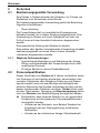 10
10
-
 11
11
-
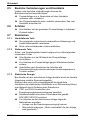 12
12
-
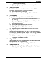 13
13
-
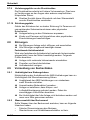 14
14
-
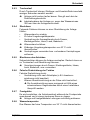 15
15
-
 16
16
-
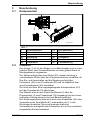 17
17
-
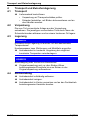 18
18
-
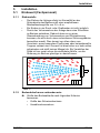 19
19
-
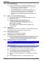 20
20
-
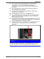 21
21
-
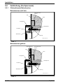 22
22
-
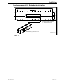 23
23
-
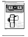 24
24
-
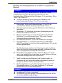 25
25
-
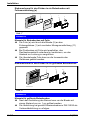 26
26
-
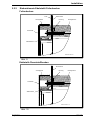 27
27
-
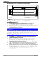 28
28
-
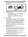 29
29
-
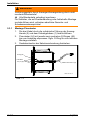 30
30
-
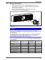 31
31
-
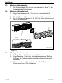 32
32
-
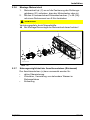 33
33
-
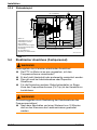 34
34
-
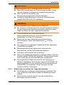 35
35
-
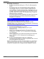 36
36
-
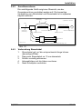 37
37
-
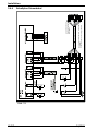 38
38
-
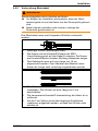 39
39
-
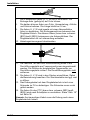 40
40
-
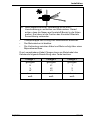 41
41
-
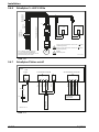 42
42
-
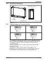 43
43
-
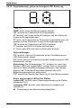 44
44
-
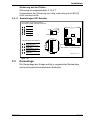 45
45
-
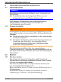 46
46
-
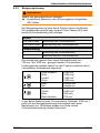 47
47
-
 48
48
-
 49
49
-
 50
50
-
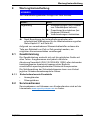 51
51
-
 52
52
-
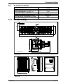 53
53
-
 54
54
-
 55
55
-
 56
56
-
 57
57
-
 58
58
-
 59
59
-
 60
60
-
 61
61
-
 62
62
-
 63
63
-
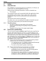 64
64
-
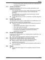 65
65
-
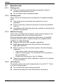 66
66
-
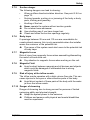 67
67
-
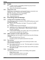 68
68
-
 69
69
-
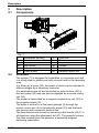 70
70
-
 71
71
-
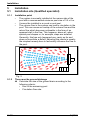 72
72
-
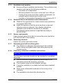 73
73
-
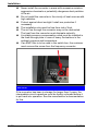 74
74
-
 75
75
-
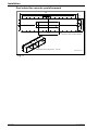 76
76
-
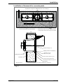 77
77
-
 78
78
-
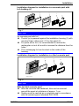 79
79
-
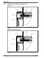 80
80
-
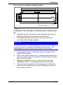 81
81
-
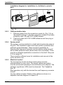 82
82
-
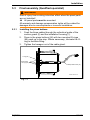 83
83
-
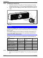 84
84
-
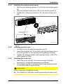 85
85
-
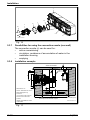 86
86
-
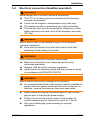 87
87
-
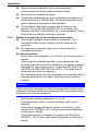 88
88
-
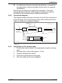 89
89
-
 90
90
-
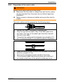 91
91
-
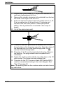 92
92
-
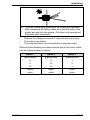 93
93
-
 94
94
-
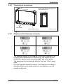 95
95
-
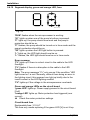 96
96
-
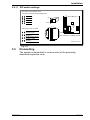 97
97
-
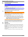 98
98
-
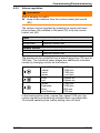 99
99
-
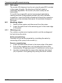 100
100
-
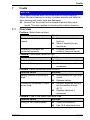 101
101
-
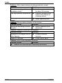 102
102
-
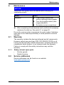 103
103
-
 104
104
-
 105
105
-
 106
106
-
 107
107
-
 108
108
-
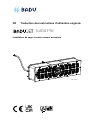 109
109
-
 110
110
-
 111
111
-
 112
112
-
 113
113
-
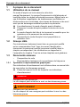 114
114
-
 115
115
-
 116
116
-
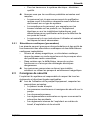 117
117
-
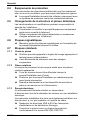 118
118
-
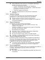 119
119
-
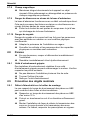 120
120
-
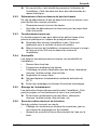 121
121
-
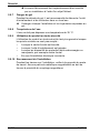 122
122
-
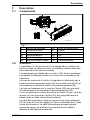 123
123
-
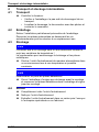 124
124
-
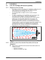 125
125
-
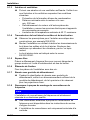 126
126
-
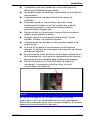 127
127
-
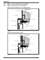 128
128
-
 129
129
-
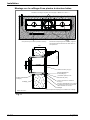 130
130
-
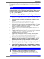 131
131
-
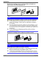 132
132
-
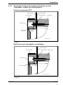 133
133
-
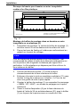 134
134
-
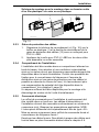 135
135
-
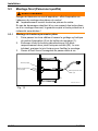 136
136
-
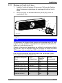 137
137
-
 138
138
-
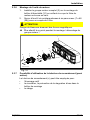 139
139
-
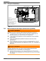 140
140
-
 141
141
-
 142
142
-
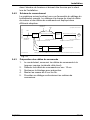 143
143
-
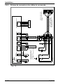 144
144
-
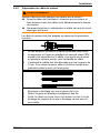 145
145
-
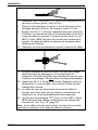 146
146
-
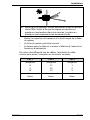 147
147
-
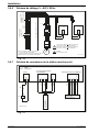 148
148
-
 149
149
-
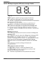 150
150
-
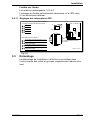 151
151
-
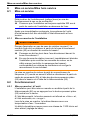 152
152
-
 153
153
-
 154
154
-
 155
155
-
 156
156
-
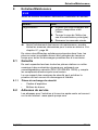 157
157
-
 158
158
-
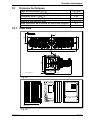 159
159
-
 160
160
-
 161
161
-
 162
162
-
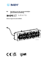 163
163
-
 164
164
-
 165
165
-
 166
166
-
 167
167
-
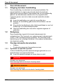 168
168
-
 169
169
-
 170
170
-
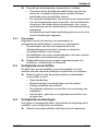 171
171
-
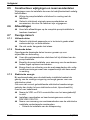 172
172
-
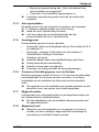 173
173
-
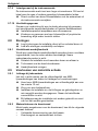 174
174
-
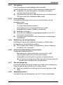 175
175
-
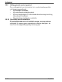 176
176
-
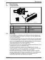 177
177
-
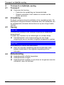 178
178
-
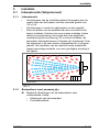 179
179
-
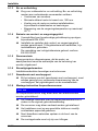 180
180
-
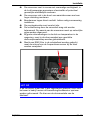 181
181
-
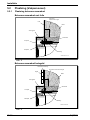 182
182
-
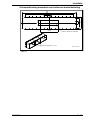 183
183
-
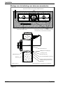 184
184
-
 185
185
-
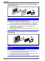 186
186
-
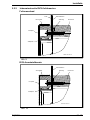 187
187
-
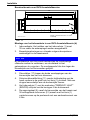 188
188
-
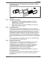 189
189
-
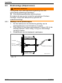 190
190
-
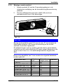 191
191
-
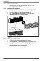 192
192
-
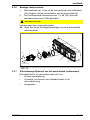 193
193
-
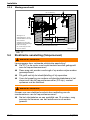 194
194
-
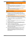 195
195
-
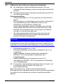 196
196
-
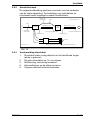 197
197
-
 198
198
-
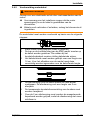 199
199
-
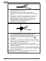 200
200
-
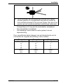 201
201
-
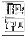 202
202
-
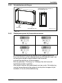 203
203
-
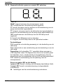 204
204
-
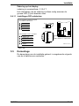 205
205
-
 206
206
-
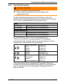 207
207
-
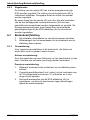 208
208
-
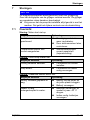 209
209
-
 210
210
-
 211
211
-
 212
212
-
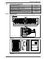 213
213
-
 214
214
-
 215
215
-
 216
216
-
 217
217
-
 218
218
-
 219
219
-
 220
220
-
 221
221
-
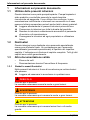 222
222
-
 223
223
-
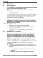 224
224
-
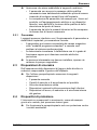 225
225
-
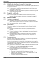 226
226
-
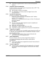 227
227
-
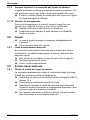 228
228
-
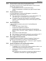 229
229
-
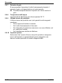 230
230
-
 231
231
-
 232
232
-
 233
233
-
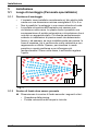 234
234
-
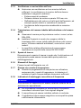 235
235
-
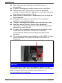 236
236
-
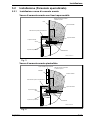 237
237
-
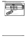 238
238
-
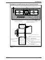 239
239
-
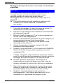 240
240
-
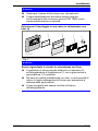 241
241
-
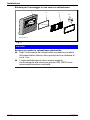 242
242
-
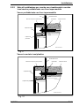 243
243
-
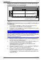 244
244
-
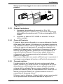 245
245
-
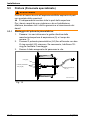 246
246
-
 247
247
-
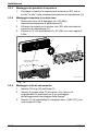 248
248
-
 249
249
-
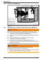 250
250
-
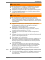 251
251
-
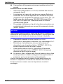 252
252
-
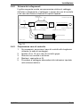 253
253
-
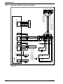 254
254
-
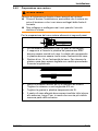 255
255
-
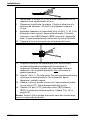 256
256
-
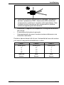 257
257
-
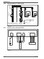 258
258
-
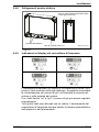 259
259
-
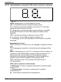 260
260
-
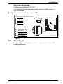 261
261
-
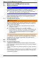 262
262
-
 263
263
-
 264
264
-
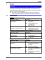 265
265
-
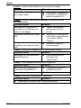 266
266
-
 267
267
-
 268
268
-
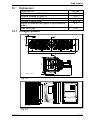 269
269
-
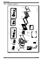 270
270
-
 271
271
-
 272
272
-
 273
273
-
 274
274
-
 275
275
-
 276
276
-
 277
277
-
 278
278
-
 279
279
-
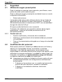 280
280
-
 281
281
-
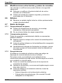 282
282
-
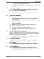 283
283
-
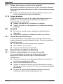 284
284
-
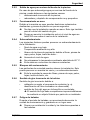 285
285
-
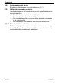 286
286
-
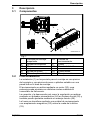 287
287
-
 288
288
-
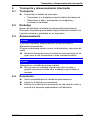 289
289
-
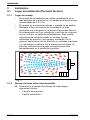 290
290
-
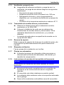 291
291
-
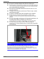 292
292
-
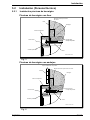 293
293
-
 294
294
-
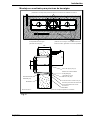 295
295
-
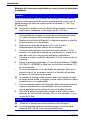 296
296
-
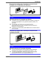 297
297
-
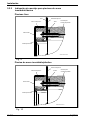 298
298
-
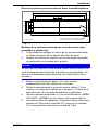 299
299
-
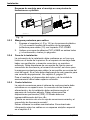 300
300
-
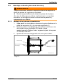 301
301
-
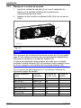 302
302
-
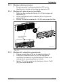 303
303
-
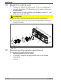 304
304
-
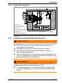 305
305
-
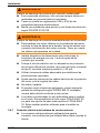 306
306
-
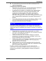 307
307
-
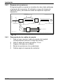 308
308
-
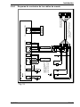 309
309
-
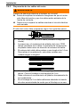 310
310
-
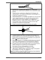 311
311
-
 312
312
-
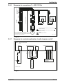 313
313
-
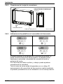 314
314
-
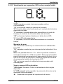 315
315
-
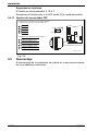 316
316
-
 317
317
-
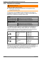 318
318
-
 319
319
-
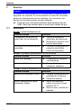 320
320
-
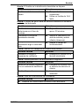 321
321
-
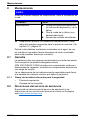 322
322
-
 323
323
-
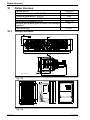 324
324
-
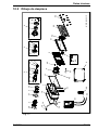 325
325
-
 326
326
-
 327
327
-
 328
328


BADU JET Turbo Pro assembly kit design 2 Handleiding
- Type
- Handleiding
- Deze handleiding is ook geschikt voor
in andere talen
- English: BADU JET Turbo Pro assembly kit design 2 Operating instructions
- italiano: BADU JET Turbo Pro assembly kit design 2 Istruzioni per l'uso
- français: BADU JET Turbo Pro assembly kit design 2 Mode d'emploi
- español: BADU JET Turbo Pro assembly kit design 2 Instrucciones de operación
- Deutsch: BADU JET Turbo Pro assembly kit design 2 Bedienungsanleitung
Gerelateerde papieren
-
 BADU JET Turbo Pro assembly kit design 2 Handleiding
-
 Speck pumpen JET Primavera Final assembly kit 400 V Handleiding
-
 BADU JET Vogue Deluxe Final assembly kit 230 V Handleiding
-
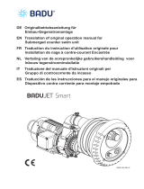 BADU JET Smart Final assembly kit 400 V Handleiding
-
 Speck pumpen Stainless steel hand rail for JET smart, 25 x 250 mm Handleiding
-
 BADU Resort 110-PM Handleiding
-
BADU Gamma 7 Handleiding
-
 BADU Resort 40-AK Handleiding
-
 BADU Delta-MK 8 Handleiding
-
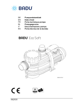 BADU Eco Soft Handleiding


