STIEBEL ELTRON DCE 11-13 Operation Instruction
- Type
- Operation Instruction

BEDIENUNG UND INSTALLATION
OPERATION AND INSTALLATION
UTILISATION ET INSTALLATION
BEDIENING EN INSTALLATIE
OBSLUHA A INSTALACE
OBSŁUGA I INSTALACJA
ЭКСПЛУАТАЦИЯ И МОНТАЖ
Elektronisch geregelter Kompakt Durchlauferhitzer | Electronically controlled
instantaneous water heater | Chauffe-eau instantané compact à régulation
électronique | Elektronisch geregelde compacte doorstromer | Elektronicky
regulovaný kompaktní průtokový ohřívač | Elektronicznie regulowany, kompaktowy
przepływowy ogrzewacz wody | Малогабаритный проточный нагреватель с электронным
» DCE 11/13
» DCE 11/13 H
» DCE 11/13 RC
1
+
-
2
°C
40
50
60
30
20
°C
40
50
60
30
20

2 |DCE 11/13| DCE 11/13 RC| DCE 11/13 H www.stiebel-eltron.com
INHALT | BESONDERE HINWEISE
BESONDERE HINWEISE
BEDIENUNG
1. Allgemeine Hinweise ����������������������������������������3
1.1 Sicherheitshinweise ��������������������������������������������� 3
1.2 Andere Markierungen in dieser Dokumentation ���������� 3
1.3 Maßeinheiten ����������������������������������������������������� 3
2. Sicherheit �����������������������������������������������������3
2.1 Bestimmungsgemäße Verwendung ������������������������� 3
2.2 Allgemeine Sicherheitshinweise ������������������������������ 3
2.3 Prüfzeichen ������������������������������������������������������� 4
3. Gerätebeschreibung �����������������������������������������4
4. Einstellungen �������������������������������������������������4
4.1 DCE11/13 | DCE11/13H �������������������������������������� 4
4.2 DCE11/13RC ����������������������������������������������������� 4
4.3 Verbrühschutz/ Temperaturbegrenzung ������������������� 5
4.4 Nach Unterbrechung der Wasserversorgung �������������� 5
5. Reinigung, Pflege und Wartung ����������������������������5
6. Problembehebung �������������������������������������������6
INSTALLATION
7. Sicherheit �����������������������������������������������������7
7.1 Allgemeine Sicherheitshinweise ������������������������������ 7
7.2 Vorschriften, Normen und Bestimmungen ����������������� 7
8. Gerätebeschreibung �����������������������������������������7
8.1 Lieferumfang ����������������������������������������������������� 7
8.2 Zubehör ������������������������������������������������������������ 7
9. Vorbereitungen ����������������������������������������������� 7
9.1 Montageort ������������������������������������������������������� 8
9.2 Mindestabstände ������������������������������������������������ 8
10. Montage �������������������������������������������������������9
10.1 Standardmontage������������������������������������������������ 9
11. Inbetriebnahme �������������������������������������������� 10
11.1 Erstinbetriebnahme �������������������������������������������� 10
11.2 Übergabe des Gerätes ����������������������������������������� 10
11.3 Wiederinbetriebnahme ���������������������������������������� 10
12. Außerbetriebnahme ��������������������������������������� 10
13. Montage-Alternativen ������������������������������������� 10
13.1 Wählbare Anschlussleistung ���������������������������������10
13.2 Verbrühschutz/ Temperaturbegrenzung ������������������11
13.3 Umbau Elektroanschluss unten ������������������������������ 11
14. Störungsbehebung ����������������������������������������� 11
15. Wartung ����������������������������������������������������� 13
16. Technische Daten ������������������������������������������� 14
16.1 Maße und Anschlüsse ����������������������������������������� 14
16.2 Elektroschaltplan ����������������������������������������������� 14
16.3 Einsatzbereiche / Umrechnungstabelle �������������������� 14
16.4 Druckverluste ���������������������������������������������������� 15
16.5 Störfallbedingungen ������������������������������������������� 15
16.6 Landesspezifische Zulassungen und Zeugnisse ���������� 15
16.7 Angaben zum Energieverbrauch ���������������������������� 15
16.8 Datentabelle ����������������������������������������������������� 15
BESONDERE HINWEISE
- Das Gerät kann von Kindern ab 3 Jahren sowie
von Personen mit verringerten physischen, sen-
sorischen oder mentalen Fähigkeiten oder Man-
gel an Erfahrung und Wissen benutzt werden,
wenn sie beaufsichtigt werden oder bezüglich
des sicheren Gebrauchs des Gerätes unterwiesen
wurden und die daraus resultierenden Gefahren
verstanden haben. Kinder dürfen nicht mit dem
Gerät spielen. Reinigung und Benutzer-Wartung
dürfen nicht von Kindern ohne Beaufsichtigung
durchgeführt werden.
- Die Armatur kann während des Betriebs eine
Temperatur von über 60 °C annehmen. Bei
Auslauftemperaturen größer 43 °C besteht
Verbrühungsgefahr.
- Das Gerät muss über eine Trennstrecke von min-
destens 3 mm allpolig vom Netzanschluss ge-
trennt werden können.
- Das Netzanschlusskabel darf bei Beschädigung
oder Austausch nur durch einen vom Hersteller
berechtigten Fachhandwerker mit dem originalen
Ersatzteil ersetzt werden.
- Befestigen Sie das Gerät wie in Kapitel „Installati-
on/ Montage“ beschrieben.
- Beachten Sie den maximalen zulässigen Druck
(siehe Kapitel „Installation/ Technische Daten/
Datentabelle“).
- Entleeren Sie das Gerät wie in Kapitel „Installati-
on / Wartung / Gerät entleeren“ beschrieben.
KUNDENDIENST UND GARANTIE
UMWELT UND RECYCLING
MONTAGESCHABLONE IM MITTELTEIL DIESER ANLEITTUNG

BEDIENUNG
Allgemeine Hinweise
DEUTSCH
www.stiebel-eltron.com DCE 11/13| DCE 11/13 RC| DCE 11/13 H | 3
BEDIENUNG
1. Allgemeine Hinweise
Das Kapitel „Bedienung“ richtet sich an den Gerätebenutzer und
den Fachhandwerker.
Das Kapitel „Installation“ richtet sich an den Fachhandwerker.
Hinweis
Lesen Sie diese Anleitung vor dem Gebrauch sorgfältig
durch und bewahren Sie sie auf.
Geben Sie die Anleitung ggf. an einen nachfolgenden
Benutzer weiter.
1.1 Sicherheitshinweise
1.1.1 Aufbau von Sicherheitshinweisen
SIGNALWORT Art der Gefahr
Hier stehen mögliche Folgen bei Nichtbeachtung des
Sicherheitshinweises.
Hier stehen Maßnahmen zur Abwehr der Gefahr.
1.1.2 Symbole, Art der Gefahr
Symbol Art der Gefahr
Verletzung
Stromschlag
Verbrennung
(Verbrennung, Verbrühung)
1.1.3 Signalworte
SIGNALWORT Bedeutung
GEFAHR Hinweise, deren Nichtbeachtung schwere Verletzungen
oder Tod zur Folge haben.
WARNUNG Hinweise, deren Nichtbeachtung schwere Verletzungen
oder Tod zur Folge haben kann.
VORSICHT Hinweise, deren Nichtbeachtung zu mittelschweren oder
leichten Verletzungen führen kann.
1.2 Andere Markierungen in dieser Dokumentation
Hinweis
Hinweise werden durch horizontale Linien ober- und un-
terhalb des Textes begrenzt. Allgemeine Hinweise wer-
den mit dem nebenstehenden Symbol gekennzeichnet.
Lesen Sie die Hinweistexte sorgfältig durch.
Symbol
Sachschaden
(Geräte-, Folgen-, Umweltschaden)
Geräteentsorgung
Dieses Symbol zeigt Ihnen, dass Sie etwas tun müssen.
Die erforderlichen Handlungen werden Schritt für Schritt
beschrieben.
1.3 Maßeinheiten
Hinweis
Wenn nicht anders angegeben, ist die verwendete Maß-
einheit Millimeter.
2. Sicherheit
2.1 Bestimmungsgemäße Verwendung
Das Gerät ist für den Einsatz im häuslichen Umfeld vorgesehen.
Es kann von nicht eingewiesenen Personen sicher bedient wer-
den. In nicht häuslicher Umgebung, z.B. im Kleingewerbe, kann
das Gerät ebenfalls verwendet werden, sofern die Benutzung in
gleicher Weise erfolgt.
Das Gerät dient zur Erwärmung von Trinkwasser oder zur Nacher-
wärmung von vorgewärmtem Wasser. Das Gerät ist für eine Kü-
chenspüle oder ein Handwaschbecken bestimmt.
Eine andere oder darüber hinausgehende Benutzung gilt als nicht
bestimmungsgemäß. Zum bestimmungsgemäßen Gebrauch ge-
hört auch das Beachten dieser Anleitung sowie der Anleitungen
für eingesetztes Zubehör.
2.2 Allgemeine Sicherheitshinweise
WARNUNG Verbrennung
Die Armatur kann während des Betriebs eine Temperatur
von über 60°C annehmen.
Bei Auslauftemperaturen größer 43°C besteht Ver-
brühungsgefahr.
!
WARNUNG Verletzung
Das Gerät kann von Kindern ab 3 Jahren sowie von Per-
sonen mit verringerten physischen, sensorischen oder
mentalen Fähigkeiten oder Mangel an Erfahrung und
Wissen benutzt werden, wenn sie beaufsichtigt werden
oder bezüglich des sicheren Gebrauchs des Gerätes un-
terwiesen wurden und die daraus resultierenden Gefah-
ren verstanden haben. Kinder dürfen nicht mit dem Gerät
spielen. Reinigung und Benutzer-Wartung dürfen nicht
von Kindern ohne Beaufsichtigung durchgeführt werden.
WARNUNG Stromschlag
Ein beschädigtes Anschlusskabel darf nur der Fachhand-
werker austauschen. Dadurch vermeiden Sie eine mög-
liche Gefährdung.
!
Sachschaden
Schützen Sie das Gerät und die Armatur vor Frost.
!
!

BEDIENUNG
Gerätebeschreibung
4 |DCE 11/13| DCE 11/13 RC| DCE 11/13 H www.stiebel-eltron.com
2.3 Prüfzeichen
Siehe Typenschild am Gerät.
Landesspezifische Zulassungen und Zeugnisse: Deutschland
Für die Geräte ist aufgrund der Landesbauordnungen ein allge-
meines bauaufsichtliches Prüfzeugnis zum Nachweis der Ver-
wendbarkeit hinsichtlich des Geräuschverhaltens erteilt.
DIN 4109
P-IX 16726/I
3. Gerätebeschreibung
Der elektronisch geregelte Kompakt-Durchlauferhitzer hält die
Auslauftemperatur unabhängig von der Zulauftemperatur bis zur
Leistungsgrenze konstant.
Das Gerät erwärmt das Wasser direkt an der Entnahmestelle, so-
bald Sie das Warmwasserventil an der Armatur öffnen. Durch
kurze Leitungswege entstehen geringe Energie- und Wasserver-
luste.
Einschaltmenge siehe Kapitel „Installation/ Technische Daten/
Datentabelle“.
Die Warmwasserleistung hängt von der Kaltwassertemperatur,
der Heizleistung, der Durchflussmenge und der eingestellten
Wunschtemperatur ab.
Warmwasser-Temperatur
Die Warmwasser-Auslauftemperatur können Sie stufenlos ein-
stellen.
Heizsystem
Das Blankdraht-Heizsystem ist für kalkarme und kalkhaltige Wäs-
ser geeignet. Das Heizsystem ist gegen Verkalkung weitgehend
unempfindlich. Das Heizsystem sorgt für eine schnelle und effizi-
ente Bereitstellung von Warmwasser.
Hinweis
Das Gerät ist mit einer Lufterkennung ausgestattet, die
eine Beschädigung des Heizsystems weitgehend verhin-
dert. Gelangt während des Betriebes Luft in das Gerät,
schaltet die Heizleistung automatisch für eine Minute aus
und das Heizsystem ist geschützt.
4. Einstellungen
4.1 DCE11/13 | DCE11/13H
Bedienung
°C
40
50
60
30
20
D0000039989
1
1 Temperatur-Einstellknopf, Temperatureinstellung
20°C- 60°C
4.2 DCE11/13RC
Mit der Funk-Fernbedienung können Sie die Temperatureinstel-
lung per Funk ändern. Die eingestellte Temperatur erscheint auf
dem Display der Funk-Fernbedienung.
Die mitgelieferte Funk-Fernbedienung ist beim Empfängermodul
angemeldet. Nur eine angemeldete Funk-Fernbedienung kann die
Einstellungen am Gerät ändern.
Die Reichweite der Funkstrecke reduziert sich durch Hindernisse
zwischen dem Gerät und der Funk-Fernbedienung.
Sie können die Funk-Fernbedienung mit der zum Lieferumfang
gehörenden Wandhalterung an einem beliebigen Ort montieren.
Bedienung
1
+
-
2
D0000039990
2
1
3
1 Display
2 Temperatureinstellung 20°C - 60°C in 0,5°C- Schritten mit
den Tasten „+“ und „-“
3 Speichertasten „1“ und „2“
Die Funk-Fernbedienung befindet sich im Normalfall im stromspa-
renden Modus, dabei ist das Display ausgeschaltet. Durch Drücken
einer beliebigen Taste aktivieren Sie die Funk-Fernbedienung, die
Temperaturanzeige erscheint. Der Laufbalken im Display signali-
siert die Datenübertragung zum Gerät.
Wenn innerhalb von 10Sekunden keine Betätigung einer Taste
erfolgt, schaltet die Funk-Fernbedienung automatisch wieder in
den stromsparenden Modus.

BEDIENUNG
Reinigung, Pege und Wartung
DEUTSCH
www.stiebel-eltron.com DCE 11/13| DCE 11/13 RC| DCE 11/13 H | 5
Die gewählte Temperatur wird auch im Stromsparmodus beibe-
halten.
Speichertastenbelegung
Wählen Sie eine Wunschtemperatur.
Drücken Sie 2Sekunden die Speichertaste „1“ oder „2“. Zur
Bestätigung blinkt die Temperaturanzeige 1x.
Sie können das Heizsystem des Gerätes ausschalten (Dis-
play-Anzeige OFF). Drücken Sie zum Ausschalten die Taste
„-“ 1x, ausgehend von der Einstellung 20°C.
Batteriewechsel
1
+
-
2
D0000047484
1
1 Symbol Batteriewechsel
Wenn das Batteriesymbol aufleuchtet, wechseln Sie die Batterie
der Funk-Fernbedienung. Ein Batteriewechsel kann auch not-
wendig werden, wenn die Temperatureinstellungen nicht beim
Gerät ankommen und/oder die Reichweite der Funkstrecke sich
verkleinert.
!
Sachschaden
Entfernen Sie die verbrauchte Batterie.
Für Schäden durch eine ausgelaufene Batterie haften wir
nicht.
Öffnen Sie das Gehäuse der Funk-Fernbedienung, indem Sie
die 4 Schrauben an der Unterseite der Funk-Fernbedienung
lösen.
Wechseln Sie die Batterie, Bauform CR2032, aus. Der Einsatz
von NiCd-Akkus ist nicht zulässig. Achten Sie auf die korrekte
Polung der Batterie (+ oben).
Drücken Sie das Gehäuse wieder zusammen und schrauben
die 4 Schrauben wieder ein. Bei der Montage des Gehäuses
dürfen Sie die umlaufende Dichtung nicht beschädigen.
Während des Batteriewechsels bleiben die gespeicherten Werte
für die Tasten „1 „und „2“ erhalten.
Batterie entsorgen
Batterien dürfen Sie nicht im Hausmüll entsorgen. Alt-
batterien enthalten Schadstoffe, die der Umwelt und
Gesundheit schaden. Verbrauchte Batterien müssen Sie
beim Handel oder einer Sammelstelle für Sonderstoffe
abgeben.
4.3 Verbrühschutz/ Temperaturbegrenzung
Bei der Aktivierung des Verbrühschutzes können Sie die Warm-
wasser-Temperatur nur von 20°C bis 43°C einstellen.
Höhere Temperatureinstellungen werden nicht ausgeführt.
Verwenden Sie den Verbrühschutz z.B. in Kindergärten, Kranken-
häusern, Seniorenheimen usw.
Hinweis
Der Fachhandwerker darf Ihnen den Verbrühschutz im
Gerät aktivieren (siehe Kapitel „Installation/ Montage-Al-
ternativen/ Verbrühschutz/ Temperaturbegrenzer“).
4.4 Nach Unterbrechung der Wasserversorgung
Siehe Kapitel „Installation/ Inbetriebnahme/ Wiederinbetrieb-
nahme“.
5. Reinigung, Pflege und Wartung
Verwenden Sie keine scheuernden oder anlösenden Reini-
gungsmittel. Zur Pflege und Reinigung des Gerätes genügt
ein feuchtes Tuch.
Kontrollieren Sie regelmäßig die Armaturen. Kalk an den
Armaturausläufen können Sie mit handelsüblichen Entkal-
kungsmitteln entfernen.
Lassen Sie die elektrische Sicherheit am Gerät regelmäßig
von einem Fachhandwerker prüfen.

BEDIENUNG
Problembehebung
6 |DCE 11/13| DCE 11/13 RC| DCE 11/13 H www.stiebel-eltron.com
6. Problembehebung
Problem Ursache Behebung
Das Gerät schaltet trotz
voll geöffnetem Warm-
wasserventil nicht ein.
Am Gerät liegt keine
Spannung an.
Prüfen Sie die Sicherung
in der Hausinstallation.
Die Durchflussmenge ist
zu gering. Der Strahl-
regler in der Armatur
ist verkalkt oder ver-
schmutzt.
Reinigen und / oder ent-
kalken Sie den Strahlreg-
ler oder erneuern Sie den
Spezial-Strahlregler.
Die Wasserversorgung ist
unterbrochen.
Entlüften Sie das Gerät
und die Kaltwasser-Zu-
laufleitung (siehe Kapitel
„Installation/Inbetrieb-
nahme/ Wiederinbe-
triebnahme“).
Die Wunschtemperatur
wird nicht erreicht.
Der interne Verbrüh-
schutz ist aktiviert.
Lassen Sie den Verbrüh-
schutz vom Fachhand-
werker deaktivieren.
Das Gerät heizt nicht
mehr, die Kaltwas-
ser-Zulauftemperatur ist
>55°C.
Verringern Sie die Kalt-
wasser-Zulauftempe-
ratur.
„Con“ erscheint gele-
gentlich auf dem Display.
Die Funk-Fernbedienung
befindet sich außerhalb
der Reichweite.
Verringern Sie den
Abstand von Funk-Fern-
bedienung zum Gerät.
Senden Sie erneut den
Temperaturwunsch.
„Con“ erscheint häufig
auf dem Display.
Batterie ist am Ende der
Kapazität.
Wechseln Sie die Batterie
(siehe Kapitel „Bedie-
nung / Gerätebeschrei-
bung / Batteriewechsel“).
Können Sie die Ursache nicht beheben, rufen Sie den Fachhand-
werker. Zur besseren und schnelleren Hilfe teilen Sie ihm die
Nummer vom Typenschild mit (000000-0000-000000).
Nr.: 000000-0000-000000
D0000040351

DEUTSCH
www.stiebel-eltron.com DCE 11/13| DCE 11/13 RC| DCE 11/13 H | 7
INSTALLATION
Sicherheit
INSTALLATION
7. Sicherheit
Die Installation, Inbetriebnahme sowie Wartung und Reparatur
des Gerätes darf nur von einem Fachhandwerker durchgeführt
werden.
7.1 Allgemeine Sicherheitshinweise
Wir gewährleisten eine einwandfreie Funktion und Betriebssicher-
heit nur, wenn das für das Gerät bestimmte Original-Zubehör und
die originalen Ersatzteile verwendet werden.
!
Sachschaden
Beachten Sie die max. zulässige Zulauftemperatur (siehe
Kapitel „Installation/ Technischen Daten/ Datentabelle“).
Bei höheren Temperaturen kann das Gerät beschädigt
werden. Mit einer Zentral-Thermostatarmatur (siehe
Kapitel „Installation/ Gerätebeschreibung/ Zubehör“)
können Sie die Zulauftemperatur begrenzen.
7.2 Vorschriften, Normen und Bestimmungen
Hinweis
Beachten Sie alle nationalen und regionalen Vorschriften
und Bestimmungen.
Der spezifische elektrische Widerstand des Wassers darf nicht
kleiner sein als auf dem Typenschild angegeben. Bei einem Was-
ser-Verbundnetz müssen Sie den niedrigsten elektrischen Wider-
stand des Wassers berücksichtigen (siehe Kapitel „Installation/
Technischen Daten/ Datentabelle“). Den spezifischen elektrischen
Widerstand oder die elektrische Leitfähigkeit des Wassers erfah-
ren Sie bei Ihrem Wasserversorgungs-Unternehmen.
8. Gerätebeschreibung
8.1 Lieferumfang
Mit dem Gerät werden geliefert:
- Stopfen für Kabeldurchführung
- Montageschablone, im Mittelteil dieser Anleitung
- Anschlussschlauch 3/8, 500mm lang, mit Dichtungen*
- T-Stück 3/8*
* nur bei DCE 11/13 und DCE 11/13 RC für den Anschluss als druck-
festes Gerät
8.2 Zubehör
Lastabwurfrelais
Eine Vorrangschaltung kann mit einem elektronischen Lastabwurf-
relais ermöglicht werden, z.B. um einen zweiten Durchlauferhit-
zer vom Stromnetz zu trennen.
Der Ansprechstrom des Lastabwurfrelais muss ≤2A sein. Der
Anschluss erfolgt an der mittleren Klemme „L“.
Drucklose Armaturen
- WEN-Sensor-Armatur für den Waschtisch
- MEK Einhebel-Mischarmatur
- WKM Zweigriff-Mischarmatur
Druckfeste Armatur
- WEH-Sensor-Armatur für den Waschtisch
- MEKD-Einhebel-Mischarmatur für Übertisch
ZTA 3/4 – Zentral Thermostatarmatur
Die Thermostatarmatur ist für die zentrale Vormischung, z.B. zum
Betrieb des Durchlauferhitzers mit einer Solaranlage.
9. Vorbereitungen
Spülen Sie die Wasserleitung gut durch.
Wasserinstallation
Ein Sicherheitsventil ist nicht notwendig.
Armaturen
Verwenden Sie geeignete Armaturen (siehe Kapitel „Installa-
tion/ Gerätebeschreibung/ Zubehör“).

8 |DCE 11/13| DCE 11/13 RC| DCE 11/13 H www.stiebel-eltron.com
INSTALLATION
Vorbereitungen
9.1 Montageort
Montieren Sie das Gerät immer senkrecht, in einem frostfreien
Raum und in der Nähe der Entnahmestelle.
9.1.1 Untertischmontage Spüle DCE11/13 | DCE11/13RC
Drucklos, mit druckloser Armatur
850
550-600
≈ 600
≥ 70
D0000039998
Druckfest, mit druckfester Armatur
850
520 - 570
≈ 600
≥ 70
D0000039997
9.1.2 Untertischmontage Waschtisch DCE11/13 | DCE11/13RC
Drucklos, mit druckloser Armatur
850
520-570
≈ 600
≥ 70
D0000040000
Druckfest, mit druckfester Armatur
850
520 - 570
≈ 600
≥ 70
D0000039999
9.1.3 Übertischmontage Waschtisch DCE11/13H
Drucklos, mit druckloser Armatur
Druckfest, mit druckfester Armatur
850
200-300
D0000050407
9.2 Mindestabstände
≥20≥20
≥50
≥50
D0000060938
Halten Sie die Mindestabstände ein, um einen störungsfreien
Betrieb des Gerätes zu gewährleisten und Wartungsarbeiten
am Gerät zu ermöglichen.

DEUTSCH
www.stiebel-eltron.com DCE 11/13| DCE 11/13 RC| DCE 11/13 H | 9
INSTALLATION
Montage
10. Montage
Standardmontage
- Elektroanschluss im oberen Bereich des Gerätes
Weitere Anschlussmöglichkeit siehe Kapitel „Installation/
Montage-Alternativen“.
- Wählbare Anschlussleistung
- Verbrühschutz/ Temperaturbegrenzung
- Elektroanschluss im unteren Bereich des Gerätes
10.1 Standardmontage
Montage des Gerätes
Hinweis
Montieren Sie das Gerät an einer Wand.
Die Wand muss ausreichend tragfähig sein.
D0000039991
Entriegeln Sie den Schnappverschluss mit einem
Schraubendreher.
Nehmen Sie die Gerätekappe nach vorn ab.
5,5 - 6,5
1
2
D0000039992
1 obere Befestigungsschraube
2 unteren Befestigungsschrauben
Zeichnen Sie die 3 Bohrlöcher mit der beiliegenden Monta-
geschablone (im Mittelteil dieser Anleitung) an.
Bohren Sie die Löcher. Verwenden Sie geeignete Dübel und
Rundkopf- oder Zylinderkopfschrauben mit 8mm Schrau-
benkopf-Durchmesser. Die Schrauben und Dübel gehören
nicht zum Lieferumfang.
Schrauben Sie die obere Schraube bis auf das angegebene
Maß ein.
Hängen Sie das Gerät auf die Schraube. Ziehen Sie das Gerät
nach unten.
Richten Sie das Gerät horizontal aus. Drehen Sie die unteren
2Schrauben ein.
Wasseranschluss
!
Sachschaden
Das Sieb muss für die Funktion des Gerätes im Kaltwasser
Zulauf des Gerätes eingebaut sein.
Montage der Armatur
Montieren Sie die Armatur. Beachten Sie dabei auch die Be-
dienungs- und Installationsanleitung der Armatur.
!
Sachschaden
Beim Montieren aller Anschlüsse müssen Sie am
Gerät mit passenden Schlüssel gegenhalten.
Hinweis
Nur beim druckfesten Anschluss DCE11/13 | DCE11/13RC:
Montieren Sie den mitgelieferten Anschlussschlauch
3/8 und das T-Stück 3/8.
Elektroanschluss herstellen
WARNUNG Stromschlag
Führen Sie alle elektrischen Anschluss- und Installati-
onsarbeiten nach Vorschrift aus.
WARNUNG Stromschlag
Achten Sie darauf, dass das Gerät an den Schutzleiter
angeschlossen ist.
Das Gerät muss über eine Trennstrecke von mindestens
3mm allpolig vom Netzanschluss getrennt werden kön-
nen.
WARNUNG Stromschlag
Die Geräte sind im Anlieferungszustand mit einem An-
schlusskabel ausgestattet.
Ein Anschluss an eine festverlegte elektrische Leitung ist
möglich, wenn die elektrische Leitung mindestens den
Querschnitt des serienmäßigen Abschlusskabels auf-
weist. Maximal ist ein Leitungsquerschnitt von 4x6mm²
möglich.
!
Sachschaden
Beachten Sie das Typenschild. Die angegebene Spannung
muss mit der Netzspannung übereinstimmen.
Schließen Sie das Anschlusskabel entsprechend des Elektro-
anschlussplanes an (siehe Kapitel „Installation/Technische
Daten/ Elektroschaltplan“). Die Anschlussleistung ist 2-stufig
wählbar. Die hohe Leistung ist voreingestellt. Wählen Sie
eine andere Leistung siehe Kapitel „Installation/ Monta-
ge-Alternativen/ Wählbare Anschlussleistung“.

10 |DCE 11/13| DCE 11/13 RC| DCE 11/13 H www.stiebel-eltron.com
INSTALLATION
Inbetriebnahme
11. Inbetriebnahme
11.1 Erstinbetriebnahme
1.
2.
4.
3.
5.
6.
≥ 60 s
°C
40
50
60
30
20
°C
40
50
60
30
20
DCE 11/13
DCE 11/13 H
DCE 11/13
DCE 11/13 H
D0000039994
Befüllen Sie das Gerät über die Armatur, bis das Leitungs-
netz und das Gerät luftfrei sind. Öffnen Sie mehrfach das
Entnahmeventil.
Aktivieren Sie den elektronischen Sicherheitsschalter (AE3).
Der elektronische Sicherheitsschalter ist bei der Anlieferung
ausgelöst.
Nur beim DCE11/13 | DCE11/13H: Stecken Sie den Stecker
des Temperatureinstellers auf die Elektronik „T-soll“. Beach-
ten Sie die Ausrichtung der Litzen.
Montieren Sie die Gerätekappe, indem Sie die Gerätekappe
aufsetzen und andrücken, bis die beiden Rasthaken hörbar
oben und unten einrasten. Kontrollieren Sie das Einrasten
der Rasthaken.
Schalten Sie die elektrische Netzspannung ein.
Nur beim DCE11/13 | DCE11/13H: Drehen Sie den Tempera-
tur-Einstellknopf zum linken und zum rechten Anschlag.
Führen Sie eine Dichtheitskontrolle durch.
Kreuzen Sie die gewählte Anschlussleistung und die
Nennspannung auf dem Typenschild an. Verwenden Sie dafür
einen Kugelschreiber.
Prüfen Sie die Arbeitsweise des Gerätes.
11.2 Übergabe des Gerätes
Erklären Sie dem Benutzer die Funktion des Gerätes. Machen
Sie ihn mit dem Gebrauch des Gerätes vertraut.
Weisen Sie den Benutzer auf mögliche Gefahren hin, speziell
die Verbrühungsgefahr.
Übergeben Sie diese Anleitung.
11.3 Wiederinbetriebnahme
!
Sachschaden
Nach Unterbrechung der Wasserversorgung müssen Sie
das Gerät mit folgenden Schritten wieder in Betrieb neh-
men. Sie vermeiden dadurch die Zerstörung des Blank-
draht-Heizsystems.
Schalten Sie das Gerät spannungsfrei, indem Sie die Siche-
rungen ausschalten.
Öffnen Sie die Armatur eine Minute lang, bis das Gerät und
die vorgeschaltete Kaltwasser-Zulaufleitung luftfrei sind.
Schalten Sie die elektrische Netzspannung wieder ein.
Siehe Kapitel „Installation/ Inbetriebnahme“.
12. Außerbetriebnahme
Trennen Sie das Gerät mit der Sicherung in der Hausinstalla-
tion von der Netzspannung.
Entleeren Sie das Gerät (siehe Kapitel „Installation/
Wartung“).
13. Montage-Alternativen
13.1 Wählbare Anschlussleistung
13kW
11kW
D0000039993
Stecken Sie den Codierstecker entsprechend der gewählten
Anschlussleistung auf.

DEUTSCH
www.stiebel-eltron.com DCE 11/13| DCE 11/13 RC| DCE 11/13 H | 11
INSTALLATION
Störungsbehebung
13.2 Verbrühschutz/ Temperaturbegrenzung
WARNUNG Verbrennung
Bei Betrieb mit vorgewärmtem Wasser kann der einge-
stellte Verbrühschutz unwirksam sein.
In diesem Fall begrenzen Sie die Temperatur an der
vorgeschalteten Zentral-Thermostatarmatur (siehe
Kapitel „Installation/ Gerätebeschreibung/ Zube-
hör“.
DCE11/13 | DCE11/13H
Die Aktivierung des Verbrühschutzes „max. 43°C“ erfolgt durch
Versetzen des Steckers an der Elektronikplatine in der Geräte-
kappe.
60 °C
43 °C
D0000039995
1 2
1 ohne Verbrühschutz
2 mit Verbrühschutz 43°C
Nehmen Sie die eingesteckte Elektronikplatine aus der
Bedieneinheit der Gerätekappe. Achten Sie dabei auf die
Schnapphaken.
Versetzen Sie den Stecker in Position „43°C“.
Bauen Sie die Elektronikplatine wieder ein, die Schnapp-
haken müssen einrasten. Achten Sie auf die Knopf- und
Achsposition.
DCE11/13RC
Die Aktivierung des Verbrühschutzes „max. 43°C“ erfolgt durch
Verschieben des DIP-Schalters im Gerät.
60°C
43°C
D0000043533
1
2
4 3
1 DIP-Schalter für Verbrühschutz
2 ohne Verbrühschutz = 60°C
3 mit Verbrühschutz = max. 43°C
4 Grüne LED-Anzeige Dauerlicht bei aktiviertem Verbrühschutz
13.3 Umbau Elektroanschluss unten
D0000043440
21 3 4 6
25 3 41
7
1 Anschlusskabel
2 Kabeltülle
3 Zugentlastung
4 Netzanschlussklemme
5 Markierung für Öffnung vom Anschlusskabel
6 Stopfen
7 Litzenführung
Demontieren Sie die Zugentlastung und das Anschlusskabel
mit der Kabeltülle.
Verschließen Sie die obere Öffnung in der Geräterückwand
mit dem beiliegenden (geschlossenen) Stopfen. Die Schutzart
IP25 (strahlwassergeschützt) ist nur mit dem sachgemäß
montierten Stopfen gewährleistet.
Versetzen Sie die Netzanschlussklemme im Gerät von oben
nach unten. Achten Sie darauf, dass die Netzanschluss-
klemme einrastet.
Verlegen Sie die Schaltlitzen unter die Litzenführung.
Drücken Sie für das Anschlusskabel eine Öffnung in die Ge-
räterückwand. Drücken Sie mit einem geeigneten Werkzeug
den Kunststoff an der kreisförmigen Markierung von der
Innenseite der Rückwand nach außen heraus. Benutzen Sie
ggf. eine Feile.
!
Sachschaden
Tauschen Sie eine beschädigte Geräterückwand aus.
Montieren Sie das Anschlusskabel mit der Kabeltülle in die
Geräterückwand.
Schließen Sie das Anschlusskabel an die Netzanschluss-
klemme an (siehe Kapitel „Installation/ Technische Daten/
Elektroschaltplan“).
Montieren Sie die Zugentlastung.
14. Störungsbehebung
WARNUNG Stromschlag
Zur Prüfung des Gerätes muss die elektrische Spannung
am Gerät anliegen.

12 |DCE 11/13| DCE 11/13 RC| DCE 11/13 H www.stiebel-eltron.com
INSTALLATION
Störungsbehebung
Anzeigemöglichkeiten LED-Diagnoseampel
13kW
11kW
D0000043418
Anzeigemöglichkeiten der Diagnoseampel (LED)
rot leuchtet bei Störung
gelb leuchtet bei Heizbetrieb
grün blinkt: Gerät am Netzanschluss
Störungsbeseitigung
Diagnoseampel Störung Ursache Behebung
keine LED leuchtet Kein warmes Wasser.
Die Sicherung in der Hausinstallation hat aus-
gelöst.
Prüfen Sie die Sicherung in der Hausinstallation.
Die Elektronik ist defekt. Tauschen Sie das Gerät aus.
grüne LED blinkt
Das Gerät schaltet nicht ein. Der Duschkopf / die Strahlregler sind verkalkt. Entkalken ggf. erneuern Sie den Duschkopf/ die
Strahlregler.
Der Warmwasserdurchfluss ist zu ge-
ring.
Das Sieb im Gerät ist verschmutzt. Reinigen Sie das Sieb.
Kein warmes Wasser bei Durchfluss
größer dem Einschaltdurchfluss.
Die Durchflusserkennung DFE ist defekt. Tauschen Sie das Gerät aus.
grüne LED blinkt,
gelbe LED blitzt
Die Solltemperatur wird nicht erreicht.
Das Gerät ist an der Leistungsgrenze.
Reduzieren Sie den Durchfluss. Bauen Sie den
Durchflussmengen-Begrenzer ein. Kontrollieren
Sie den Durchflussmengen-Begrenzer.
(nicht in allen Fällen) Die Solltemperatur wird nicht erreicht. Eine Phase fehlt. Prüfen Sie die Sicherung in der Hausinstallation.
grüne LED blinkt,
gelbe LED-Dauerlicht
Die Solltemperatur wird nicht erreicht.
Der Sollwertgeber oder das Verbindungskabel
ist defekt. Das Verbindungskabel ist nicht auf-
gesteckt.
Stecken Sie das Verbindungskabel auf, ggf. tau-
schen Sie den Sollwertgeber aus.
Der Verbrühschutz ist aktiviert. Deaktivieren Sie den Verbrühschutz.
Kein warmes Wasser bei Durchfluss
größer dem Einschaltdurchfluss.
Das Heizsystem ist defekt. Messen Sie den Widerstand des Heizsystems,
ggf. tauschen Sie das Gerät aus.
Die Elektronik ist defekt. Tauschen Sie das Gerät aus.
Solltemperatur wird nicht erreicht. Der Auslauffühler ist defekt. Prüfen Sie die Verbindung, ggf. tauschen Sie
den Auslauffühler aus.
grüne LED blinkt, rote
LED blitzt
Kein warmes Wasser. Das Gerät ist verkalkt. Tauschen Sie das Gerät aus.
Das Gerät reagiert nicht auf die
Funk-Fernbedienung, „Con“ erscheint
auf dem Display der Funk-Fernbedie-
nung.
Die Funk-Fernbedienung ist nicht angemeldet.
Melden Sie die Funk-Fernbedienung an (siehe
Kapitel „Installation/ Störungsbehebung/
Funk-Fernbedienung anmelden/abmelden“.
Das Verbindungskabel der Funk-Fernbedienung
ist nicht aufgesteckt.
Stecken Sie das Verbindungskabel auf (siehe Ka-
pitel „Installation/ Störungsbeseitigung“).
grüne LED blinkt, rote
LED-Dauerlicht
Kein warmes Wasser.
Der Sicherheitsschalter hat ausgeschaltet.
Beseitigen Sie die Fehlerursache.
Schützen Sie das Heizsystem vor Überhitzung,
indem Sie ein dem Gerät nachgeschaltetes Ent-
nahmeventil eine Minute öffnen. Dadurch wird
das Heizsystem abgekühlt. Aktivieren Sie den
Sicherheitsschalter, indem Sie den Knopf am Si-
cherheitsschalter eindrücken (siehe auch Kapitel
„Installation/ Inbetriebnahme“).
Fehler in der elektronischen Sicherheitseinrich-
tung.
Tauschen Sie das Gerät aus.
Der Einlaufsensor oder das Verbindungskabel
ist defekt.
Prüfen Sie die Verbindung, ggf. tauschen Sie
den Einlaufsensor aus.
Der Auslaufsensor oder das Verbindungskabel
hat einen Kurzschluss.
Prüfen Sie die Verbindung, ggf. tauschen Sie
den Auslaufsensor aus.
Die Elektronik ist defekt. Tauschen Sie das Gerät aus.
Wunschtemperatur > 55°C wird nicht
erreicht.
Die Kaltwasser-Zulauftemperatur ist höher als
55°C.
Verringern Sie die Kaltwasser-Zulauftemperatur
zum Gerät.
Die Heizung schaltet ab. Die Lufterkennung sensiert Luft im Wasser. Die
Heizleistung schaltet kurzzeitig ab.
Das Gerät geht nach einer Minute wieder in
Betrieb.

DEUTSCH
www.stiebel-eltron.com DCE 11/13| DCE 11/13 RC| DCE 11/13 H | 13
INSTALLATION
Wartung
Funk-Fernbedienung vom DCE11/13RC anmelden/abmelden
D0000048647
1
2
1 Taster zum Anmelden und Abmelden
2 Gelbe LED-Anzeige bei aktivierter Funk-Fernbedienung
Zum Starten der Anmeldung der Funk-Fernbedienung
drücken Sie kurz auf den Taster. Die gelbe LED beginnt zu
blinken. Drücken Sie jetzt auf die Taste „1“ der Funk-Fernbe-
dienung. Ein kurzes Blinken der LED signalisiert Ihnen die er-
folgreiche Anmeldung. Anschließend erlischt die gelbe LED.
Zur Abmeldung der Funk-Fernbedienung drücken Sie die
Taste 5Sekunden lang. Ein kurzes Blinken der LED signali-
siert Ihnen die erfolgreiche Abmeldung. Anschließend er-
lischt die gelbe LED.
Steckposition der Funk-Fernbedienung vom DCE11/13RC
D0000046810
15. Wartung
WARNUNG Stromschlag
Trennen Sie bei allen Arbeiten das Gerät allpolig vom
Netzanschluss.
Gerät entleeren
WARNUNG Verbrennung
Beim Entleeren kann heißes Wasser austreten.
Für Wartungsarbeiten oder bei Gefahr von Frost entleeren Sie
das Gerät wie folgt:
Schließen Sie das Absperrventil in der Kaltwasser Zuleitung.
Öffnen Sie das Entnahmeventil.
Lösen Sie die Wasseranschlüsse vom Gerät.
Demontieren Sie das Gerät.
Entleeren Sie das Gerät über die Wasseranschlüsse (Rest-
wasser bleibt im Gerät).
Lagerung des Gerätes
Lagern Sie ein demontiertes Gerät frostfrei, da sich Restwas-
ser im Gerät befindet, das Gefrieren und Schäden verursa-
chen kann.
Sieb / Durchflussmengen-Begrenzer reinigen oder ersetzen
D0000040081
1
2
DCE11/13
DCE11/13RC
D0000050374
2
1
DCE11/13H
1 Sieb
2 Durchflussmengen-Begrenzer

14 |DCE 11/13| DCE 11/13 RC| DCE 11/13 H www.stiebel-eltron.com
INSTALLATION
Technische Daten
16. Technische Daten
16.1 Maße und Anschlüsse
DCE11/13 | DCE11/13RC
293
188
85
99
35
19
b02
b03
c01
c06
193
291
140
D0000039746
DCE 11/13 DCE 11/13 RC
b02 Durchführung elektr.
Leitungen I
b03 Durchführung elektr.
Leitungen II
c01 Kaltwasser Zulauf Außengewinde G 3/8 A G 3/8 A
c06 Warmwasser Auslauf Außengewinde G 3/8 A G 3/8 A
DCE11/13H
293
85
99
35
19
b02
b03
100
140
c01
c06
193
40
188
D0000050396
DCE 11/13 H
b02 Durchführung elektr. Leitungen I
b03 Durchführung elektr. Leitungen II
c01 Kaltwasser Zulauf Außengewinde G 1/2 A
c06 Warmwasser Auslauf Außengewinde G 1/2 A
16.2 Elektroschaltplan
3/PE ~ 380-415V
D0000040233
3
4
1
2
1 Sicherheitstemperaturbegrenzer
2 elektronischer Sicherheitsschalter
3 Elektronik
4 Heizsystem
!
Sachschaden
Beim Festanschluss schließen Sie das Anschluss-
kabel gemäß der Klemmenbezeichnung der Buch-
senklemme an.
16.3 Einsatzbereiche / Umrechnungstabelle
Spezifischer elektrischer Widerstand und spezifische elektrische
Leitfähigkeit (siehe Kapitel „Installation/ Technische Daten/ Da-
tentabelle“).
Normangabe bei
15°C
20°C
25°C
Spez. Wi-
derstand
ρ ≥
Spez. Leitfä-
higkeit σ ≤
Spez. Wi-
derstand
ρ ≥
Spez. Leitfä-
higkeit σ ≤
Spez. Wi-
derstand
ρ ≥
Spez. Leitfä-
higkeit σ ≤
Ωcm mS/m μS/cm Ωcm mS/m μS/cm Ωcm mS/m μS/cm
900 111 1111 800 125 1250 735 136 1361
1100 91 909 970 103 1031 895 112 1117
Auslauftemperatur ca. 60°C für die Küchenspüle und beim Einsatz
einer Thermostatarmatur
Auslaufmenge
Gerät kW 11 13,5
Kaltwasser Zulauftemperatur
6°C l/min 2,9 3,6
10°C l/min 3,2 3,9
14°C l/min 3,4 4,2

DEUTSCH
www.stiebel-eltron.com DCE 11/13| DCE 11/13 RC| DCE 11/13 H | 15
INSTALLATION
Technische Daten
Nutztemperatur ca. 38°C für Handwäsche etc.
Mischwassermenge
Gerät kW 11 13,5
Kaltwasser Zulauftemperatur
6°C l/min 5,0 6,1
10°C l/min 5,7 6,9
14°C l/min 6,6 8,1
Tabellenwerte sind auf eine Nennspannung von 400 V bezogen.
Die Mischwassermenge und Auslaufmenge ist abhängig vom vor-
handenen Versorgungsdruck und der anliegenden Spannung.
16.4 Druckverluste
Armaturen
Druckverlust bei Durchflussmenge 10l/min
Einhandmischer, ca. MPa 0,04 - 0,08
Thermostatarmatur, ca. MPa 0,03 - 0,05
Handbrause, ca. MPa 0,03 - 0,15
Rohrnetz-Dimensionierungen
Zur Berechnung der Rohrnetz-Dimensionierungen ist für das Gerät
ein Druckverlust von 0,1MPa zu berücksichtigen.
16.5 Störfallbedingungen
Im Störfall können in der Installation kurzfristig Belastungen von
maximal 80 °C bei einem Druck von 1,0 MPa auftreten.
16.6 Landesspezifische Zulassungen und Zeugnisse
Prüfzeichen sind auf dem Typenschild ersichtlich.
16.7 Angaben zum Energieverbrauch
Die Produktdaten entsprechen den EU-Verordnungen zur Richtli-
nie für umweltgerechte Gestaltung energieverbrauchsrelevanter
Produkte (ErP).
DCE 11/13 DCE 11/13 RC DCE 11/13 H
230770 230771 232792
Hersteller STIEBEL ELTRON STIEBEL ELTRON STIEBEL ELTRON
Lastprofil XS XS XS
Energieeffizienzklasse A A A
Jährlicher Stromverbrauch kWh 465 465 465
Energetischer Wirkungsgrad % 40 40 40
Temperatureinstellung ab Werk °C 60 60 60
Schallleistungspegel dB(A) 15 15 15
Besondere Hinweise zur Effizienzmessung Angaben bei Pmax. Angaben bei Pmax. Angaben bei Pmax.
16.8 Datentabelle
DCE 11/13 DCE 11/13 compact RC DCE 11/13 H
230770 230771 232792
Elektrische Daten
Nennspannung V 380 400 415 380 400 415 380 400 415
Nennleistung kW 10/12,1 11/13,5 11,8/14,5 10/12,1 11/13,5 16,8/20,2 10/12,1 11/13,5 11,8/14,5
Nennstrom A 15,4/18,5 16,2/19,5 16,8/20,2 15,4/18,5 16,2/19,5 16,4/20,1 15,4/18,5 16,2/19,5 16,8/20,2
Absicherung A 16/20 16/20 16/20 16/20 16/20 16/20 16/20 16/20 16/20
Phasen 3/PE 3/PE 3/PE
Frequenz Hz 50/60 50/60 50/- 50/60 50/60 50/- 50/60 50/60 50/-
Spezifischer Widerstand ρ
15
≥ (bei ϑkalt ≤25°C) Ω cm 900 900 900 900 900 900 900 900 900
Spezifische Leitfähigkeit σ
15
≤ (bei ϑkalt ≤25°C) μS/cm 1111 1111 1111 1111 1111 1111 1111 1111 1111
Spezifischer Widerstand ρ
15
≥ (bei ϑkalt ≤55°C) Ω cm 1100 1100 1100 1100 1100 1100 1100 1100 1100
Spezifische Leitfähigkeit σ
15
≤ (bei ϑkalt ≤55°C) μS/cm 909 909 909 909 909 909 909 909 909
Max. Netzimpedanz bei 50Hz Ω 0,28 0,26 0,24 0,28 0,26 0,24 0,28 0,26 0,24
Elektronik Stand by W < 2 < 2 < 2
Anschlüsse
Wasseranschluss G 3/8 A G 3/8 A G 1/2 A
Einsatzgrenzen
Max. zulässiger Druck MPa 1 1 1
Max. Zulauftemperatur für Nacherwärmung °C 55 55 55

16 |DCE 11/13| DCE 11/13 RC| DCE 11/13 H www.stiebel-eltron.com
INSTALLATION
Technische Daten
DCE 11/13 DCE 11/13 compact RC DCE 11/13 H
Werte
Max. zulässige Zulauftemperatur °C 70 70 70
Ein l/min >2,5 >2,5 >2,5
Volumenstrom für Druckverlust l/min 4 4 4
Druckverlust bei Volumenstrom MPa 0,06 0,06 0,07
Druckverlust bei Volumenstrom ohne Durchflussmen-
gen-Begrenzer
MPa 0,015 0,015 0,025
Volumenstrom-Begrenzung bei l/min 4 4 4
Warmwasserdarbietung l/min 3,7/4,5 3,7/4,5 3,7/4,5
Δϑ bei Darbietung K 43 43 43
Hydraulische Daten
Nenninhalt l 0,2 0,2 0,2
Ausführungen
Montageart Untertisch X X
Montageart Übertisch X
Anschlussleistung wählbar X X X
Temperatureinstellung °C 20-60 20-60 20-60
Schutzklasse 1 1 1
Isolierblock Kunststoff Kunststoff Kunststoff
Heizsystem Wärmeerzeuger Blankdraht Blankdraht Blankdraht
Kappe und Rückwand Kunststoff Kunststoff Kunststoff
Schutzart (IP) IP24 IP24 IP24
Farbe weiß weiß weiß
Dimensionen
Höhe mm 293 293 293
Breite mm 188 188 188
Tiefe mm 99 85 99
Gewichte
Gewicht kg 2,5 2,5 2,5
Mini-FFB
Einsatzgrenzen
Temperatureinstellbereich °C 20-60
Funkfrequenz EU MHz 868,3
Frequenzband MHz 863,000 - 863,600
Funkreichweite Gebäude ca. m 25
Ausführungen
Schutzart (IP) IPX7
Batterietyp CR2032-3V
Dimensionen
Höhe mm 132
Breite mm 65
Tiefe mm 18,5
Gewichte
Gewicht kg 0,12
Hinweis
Die Funkreichweite ist abhängig von den baulichen Ge-
gebenheiten. Eine Funktion durch eine Geschossdecke
kann nicht immer garantiert werden.

DEUTSCH
www.stiebel-eltron.com DCE 11/13| DCE 11/13 RC| DCE 11/13 H | 17
KUNDENDIENST UND GARANTIE
Erreichbarkeit
Sollte einmal eine Störung an einem unserer Produkte auftre-
ten, stehen wir Ihnen natürlich mit Rat und Tat zur Seite.
Rufen Sie uns an:
05531 702-111
oder schreiben Sie uns:
Stiebel Eltron GmbH & Co. KG
- Kundendienst -
Fürstenberger Straße 77, 37603 Holzminden
E-Mail: kundendienst@stiebel-eltron.de
Fax: 05531 702-95890
Weitere Anschriften sind auf der letzten Seite aufgeführt.
Unseren Kundendienst erreichen Sie telefonisch rund um die
Uhr, auch an Samstagen und Sonntagen sowie an Feiertagen.
Kundendiensteinsätze erfolgen während unserer Geschäftszei-
ten (von 7.15 bis 18.00 Uhr, freitags bis 17.00 Uhr). Als Sonder-
service bieten wir Kundendiensteinsätze bis 21.30 Uhr. Für die-
sen Sonderservice sowie Kundendiensteinsätze an Wochenen-
den und Feiertagen werden höhere Preise berechnet.
Garantiebedingungen
Diese Garantiebedingungen regeln zusätzliche Garantieleistun-
gen von uns gegenüber dem Endkunden. Sie treten neben die
gesetzlichen Gewährleistungsansprüche des Kunden. Die ge-
setzlichen Gewährleistungsansprüche gegenüber den sonsti-
gen Vertragspartnern sind nicht berührt.
Diese Garantiebedingungen gelten nur für solche Geräte, die
vom Endkunden in der Bundesrepublik Deutschland als Neuge-
räte erworben werden. Ein Garantievertrag kommt nicht zu-
stande, soweit der Endkunde ein gebrauchtes Gerät oder ein
neues Gerät seinerseits von einem anderen Endkunden erwirbt.
Inhalt und Umfang der Garantie
Die Garantieleistung wird erbracht, wenn an unseren Geräten
ein Herstellungs- und/oder Materialfehler innerhalb der Garan-
tiedauer auftritt. Die Garantie umfasst jedoch keine Leistungen
für solche Geräte, an denen Fehler, Schäden oder Mängel auf-
grund von Verkalkung, chemischer oder elektrochemischer
Einwirkung, fehlerhafter Aufstellung bzw. Installation sowie
unsachgemäßer Einregulierung, Bedienung oder unsachgemä-
ßer Inanspruchnahme bzw. Verwendung auftreten. Ebenso
ausgeschlossen sind Leistungen aufgrund mangelhafter oder
unterlassener Wartung, Witterungseinflüssen oder sonstigen
Naturerscheinungen.
Die Garantie erlischt, wenn am Gerät Reparaturen, Eingriffe oder
Abänderungen durch nicht von uns autorisierte Personen vor-
genommen wurden.
Die Garantieleistung umfasst die sorgfältige Prüfung des Gerä-
tes, wobei zunächst ermittelt wird, ob ein Garantieanspruch
besteht. Im Garantiefall entscheiden allein wir, auf welche Art
der Fehler behoben wird. Es steht uns frei, eine Reparatur des
Gerätes ausführen zu lassen oder selbst auszuführen. Etwaige
ausgewechselte Teile werden unser Eigentum.
Für die Dauer und Reichweite der Garantie übernehmen wir
sämtliche Material- und Montagekosten.
Soweit der Kunde wegen des Garantiefalles aufgrund gesetzli-
cher Gewährleistungsansprüche gegen andere Vertragspartner
Leistungen erhalten hat, entfällt eine Leistungspflicht von uns.
Soweit eine Garantieleistung erbracht wird, übernehmen wir
keine Haftung für die Beschädigung eines Gerätes durch Dieb-
stahl, Feuer, Aufruhr oder ähnliche Ursachen.
Über die vorstehend zugesagten Garantieleistungen hinausge-
hend kann der Endkunde nach dieser Garantie keine Ansprüche
wegen mittelbarer Schäden oder Folgeschäden, die durch das
Gerät verursacht werden, insbesondere auf Ersatz außerhalb des
Gerätes entstandener Schäden, geltend machen. Gesetzliche
Ansprüche des Kunden uns gegenüber oder gegenüber Dritten
bleiben unberührt.
Garantiedauer
Für im privaten Haushalt eingesetzte Geräte beträgt die Garan-
tiedauer 24 Monate; im Übrigen (zum Beispiel bei einem Einsatz
der Geräte in Gewerbe-, Handwerks- oder Industriebetrieben)
beträgt die Garantiedauer 12 Monate.
Die Garantiedauer beginnt für jedes Gerät mit der Übergabe des
Gerätes an den Kunden, der das Gerät zum ersten Mal einsetzt.
Garantieleistungen führen nicht zu einer Verlängerung der
Garantiedauer. Durch die erbrachte Garantieleistung wird keine
neue Garantiedauer in Gang gesetzt. Dies gilt für alle erbrachten
Garantieleistungen, insbesondere für etwaig eingebaute Ersatz-
teile oder für die Ersatzlieferung eines neuen Gerätes.
Inanspruchnahme der Garantie
Garantieansprüche sind vor Ablauf der Garantiedauer, innerhalb
von zwei Wochen, nachdem der Mangel erkannt wurde, bei uns
anzumelden. Dabei müssen Angaben zum Fehler, zum Gerät
und zum Zeitpunkt der Feststellung gemacht werden. Als Ga-
rantienachweis ist die Rechnung oder ein sonstiger datierter
Kaufnachweis beizufügen. Fehlen die vorgenannten Angaben
oder Unterlagen, besteht kein Garantieanspruch.
Garantie für in Deutschland erworbene, jedoch außer-
halb Deutschlands eingesetzte Geräte
Wir sind nicht verpflichtet, Garantieleistungen außerhalb der
Bundesrepublik Deutschland zu erbringen. Bei Störungen eines
im Ausland eingesetzten Gerätes ist dieses gegebenenfalls auf
Gefahr und Kosten des Kunden an den Kundendienst in
Deutschland zu senden. Die Rücksendung erfolgt ebenfalls auf
Gefahr und Kosten des Kunden. Etwaige gesetzliche Ansprüche
des Kunden uns gegenüber oder gegenüber Dritten bleiben
auch in diesem Fall unberührt.
Außerhalb Deutschlands erworbene Geräte
Für außerhalb Deutschlands erworbene Geräte gilt diese Garan-
tie nicht. Es gelten die jeweiligen gesetzlichen Vorschriften und
gegebenenfalls die Lieferbedingungen der Ländergesellschaft
bzw. des Importeurs.
KUNDENDIENST UND GARANTIE

18 |DCE 11/13| DCE 11/13 RC| DCE 11/13 H www.stiebel-eltron.com
UMWELT UND RECYCLING
Entsorgung von Transport- und
Verkaufsverpackungsmaterial
Damit Ihr Gerät unbeschädigt bei Ihnen ankommt, haben wir
es sorgfältig verpackt. Bitte helfen Sie, die Umwelt zu schützen,
und entsorgen Sie das Verpackungsmaterial des Gerätes sach-
gerecht. Wir beteiligen uns gemeinsam mit dem Großhandel
und dem Fachhandwerk/ Fachhandel in Deutschland an einem
wirksamen Rücknahme- und Entsorgungskonzept für die um-
weltschonende Aufarbeitung der Verpackungen.
Überlassen Sie die Transportverpackung dem Fachhandwerker
beziehungsweise dem Fachhandel.
Entsorgen Sie Verkaufsverpackungen über eines der Dualen
Systeme in Deutschland.
Entsorgung von Altgeräten in Deutschland
Geräteentsorgung
Die mit diesem Symbol gekennzeichneten Geräte dür-
fen nicht mit dem Hausmüll entsorgt werden.
Als Hersteller sorgen wir im Rahmen der Produktverantwor-
tung für eine umweltgerechte Behandlung und Verwertung
der Altgeräte. Weitere Informationen zur Sammlung und Ent-
sorgung erhalten Sie über Ihre Kommune oder Ihren Fach-
handwerker/ Fachhändler.
Bereits bei der Entwicklung neuer Geräte achten wir auf eine
hohe Recyclingfähigkeit der Materialien.
Über das Rücknahmesystem werden hohe Recyclingquoten
der Materialien erreicht, um Deponien und die Umwelt zu ent-
lasten. Damit leisten wir gemeinsam einen wichtigen Beitrag
zum Umweltschutz.
Entsorgung außerhalb Deutschlands
Entsorgen Sie dieses Gerät fach- und sachgerecht nach den
örtlich geltenden Vorschriften und Gesetzen.
UMWELT UND RECYCLING
MONTAGESCHABLONE IM MITTELTEIL DIESER ANLEITTUNG

DEUTSCH
www.stiebel-eltron.com DCE 11/13| DCE 11/13 RC| DCE 11/13 H | 19
NOTIZEN
MONTAGESCHABLONE IM MITTELTEIL DIESER ANLEITTUNG

20 |DCE 11/13| DCE 11/13 RC| DCE 11/13 H www.stiebel-eltron.com
CONTENTS | SPECIAL INFORMATION
SPECIAL INFORMATION
OPERATION
1. General information ��������������������������������������� 21
1.1 Safety instructions ����������������������������������������������21
1.2 Other symbols in this documentation ���������������������� 21
1.3 Units of measurement ����������������������������������������� 21
2. Safety �������������������������������������������������������� 21
2.1 Intended use ����������������������������������������������������� 21
2.2 General safety instructions ����������������������������������� 21
2.3 Test symbols �����������������������������������������������������22
3. Appliance description ������������������������������������� 22
4. Settings ����������������������������������������������������� 22
4.1 DCE11/13 | DCE11/13H ������������������������������������� 22
4.2 DCE 11/13 RC ���������������������������������������������������� 22
4.3 Anti-scalding protection/ temperature limit ������������� 23
4.4 Following an interruption of the water supply ����������� 23
5. Cleaning, care and maintenance ������������������������� 23
6. Troubleshooting �������������������������������������������� 23
INSTALLATION
7. Safety �������������������������������������������������������� 24
7.1 General safety instructions ����������������������������������� 24
7.2 Instructions, standards and regulations ������������������� 24
8. Appliance description ������������������������������������� 24
8.1 Standard delivery �����������������������������������������������24
8.2 Accessories ������������������������������������������������������� 24
9. Preparations ������������������������������������������������ 24
9.1 Installation site �������������������������������������������������� 24
9.2 Minimum clearances ������������������������������������������� 25
10. Installation �������������������������������������������������� 26
10.1 Standard installation ������������������������������������������� 26
11. Commissioning ��������������������������������������������� 27
11.1 Initial start-up ��������������������������������������������������� 27
11.2 Appliance handover �������������������������������������������� 27
11.3 Recommissioning ����������������������������������������������� 27
12. Shutdown ��������������������������������������������������� 27
13. Installation options ���������������������������������������� 27
13.1 Adjustable connected load������������������������������������ 27
13.2 Anti-scalding protection/ temperature limit ������������� 28
13.3 Conversion for power connection from below ������������ 28
14. Troubleshooting �������������������������������������������� 28
15. Maintenance ������������������������������������������������ 30
16. Specification ������������������������������������������������ 31
16.1 Dimensions and connections ��������������������������������� 31
16.2 Wiring diagram ������������������������������������������������� 31
16.3 Application areas / conversion table ����������������������� 31
16.4 Pressure drop ��������������������������������������������������� 32
16.5 Fault conditions �������������������������������������������������32
16.6 Country-specific approvals and certifications ������������� 32
16.7 Details on energy consumption ������������������������������ 32
16.8 Data table �������������������������������������������������������� 33
SPECIAL INFORMATION
- The appliance may be used by children aged 3
and older and persons with reduced physical,
sensory or mental capabilities or a lack of ex-
perience and know-how, provided that they are
supervised or they have been instructed on how
to use the appliance safely and have understood
the resulting risks. Children must never play with
the appliance. Children must never clean the ap-
pliance or perform user maintenance unless they
are supervised.
- During operation, the tap can reach temperatures
in excess of 60 °C. There is a risk of scalding at
outlet temperatures in excess of 43°C.
- Ensure the appliance can be separated from the
power supply by an isolator that disconnects all
poles with at least 3 mm contact separation.
- The power cable may only be replaced (for exam-
ple if damaged) by a qualified contractor author-
ised by the manufacturer, using an original spare
part.
- Secure the appliance as described in chapter "In-
stallation/ Installation".
- Observe the maximum permissible pressure (see
chapter "Installation/ Specification/ Data table").
- Drain the appliance as described in chapter "In-
stallation/ Maintenance/ Draining the appliance".
GUARANTEE
ENVIRONMENT AND RECYCLING
INSTALLATION TEMPLATE (IN THE MIDDLE OF THESE INSTRUC-
TIONS)

OPERATION
General information
ENGLISH
www.stiebel-eltron.com DCE 11/13| DCE 11/13 RC| DCE 11/13 H | 21
OPERATION
1. General information
The chapter "Operation" is intended for appliance users and qual-
ified contractors.
The chapter "Installation" is intended for qualified contractors.
Note
Read these instructions carefully before using the appli-
ance and retain them for future reference.
Pass on the instructions to a new user if required.
1.1 Safety instructions
1.1.1 Structure of safety instructions
KEYWORD Type of risk
Here, possible consequences are listed that may result
from failure to observe the safety instructions.
Steps to prevent the risk are listed.
1.1.2 Symbols, type of risk
Symbol Type of risk
Injury
Electrocution
Burns
(burns, scalding)
1.1.3 Keywords
KEYWORD Meaning
DANGER Failure to observe this information will result in serious
injury or death.
WARNING Failure to observe this information may result in serious
injury or death.
CAUTION Failure to observe this information may result in non-seri-
ous or minor injury.
1.2 Other symbols in this documentation
Note
Notes are bordered by horizontal lines above and below
the text. General information is identified by the adjacent
symbol.
Read these texts carefully.
Symbol
Material losses
(appliance damage, consequential losses and environmen-
tal pollution)
Appliance disposal
This symbol indicates that you have to do something. The ac-
tion you need to take is described step by step.
1.3 Units of measurement
Note
Unless specified otherwise, all dimensions are given in
mm.
2. Safety
2.1 Intended use
This appliance is intended for domestic use. It can be used safely
by untrained persons. The appliance can also be used in a non-do-
mestic environment, e.g. in a small business, as long as it is used
in the same way.
This appliance is suitable for heating domestic hot water or for
reheating preheated water. The appliance is designed for one
kitchen sink or one washbasin.
Any other use beyond that described shall be deemed inappropri-
ate. Observation of these instructions and of instructions for any
accessories used is also part of the correct use of this appliance.
2.2 General safety instructions
WARNING Burns
During operation, the tap can reach temperatures in ex-
cess of 60 °C.
There is a risk of scalding at outlet temperatures in ex-
cess of 43°C.
!
WARNING Injury
The appliance may be used by children aged 3 and older
and persons with reduced physical, sensory or mental
capabilities or a lack of experience and know-how, pro-
vided that they are supervised or they have been in-
structed on how to use the appliance safely and have
understood the resulting risks. Children must never play
with the appliance. Children must never clean the ap-
pliance or perform user maintenance unless they are
supervised.
WARNING Electrocution
A damaged power cable may only be replaced by a qual-
ified contractor. This is to avoid putting yourself at risk.
!
Material losses
Protect the appliance and tap against frost.
!
!

OPERATION
Appliance description
22 |DCE 11/13| DCE 11/13 RC| DCE 11/13 H www.stiebel-eltron.com
2.3 Test symbols
See type plate on the appliance.
3. Appliance description
The electronically controlled compact instantaneous water heater
maintains a constant outlet temperature up to its output limit,
irrespective of the inlet temperature.
The appliance warms the water directly at the draw-off point, as
soon as you turn on the hot water tap. The short pipe runs ensure
that energy and water losses are minimal.
For the start flow rate, see "Installation/ Specification/ Data
table".
The DHW output depends on the cold water temperature, the
heating output, the flow rate and the set temperature required.
DHW temperature
The DHW outlet temperature can be variably adjusted.
Heating system
The bare wire heating system is suitable for hard and soft water
areas. This heating system has a low susceptibility to scale build-
up. The heating system ensures quick and efficient DHW provision.
Note
The appliance is equipped with an air detector that large-
ly prevents damage to the heating system. If, during op-
eration, air is drawn into the appliance, the heater shuts
down automatically for one minute, thereby protecting
the heating system.
4. Settings
4.1 DCE11/13 | DCE11/13H
Operation
°C
40
50
60
30
20
D0000039989
1
1 Temperature selector: Temperature setting range
20°C– 60°C
4.2 DCE 11/13 RC
With the wireless remote control, the temperature setting can
be adjusted by wireless control. The selected temperature is dis-
played on the remote control.
The wireless remote control provided is registered to the receiver
module. Only a registered remote control can alter the settings
on the appliance.
The wireless range is reduced by obstacles between the appliance
and the remote control.
You can mount the wireless remote control anywhere using the
wall mounting bracket supplied in the standard delivery.
Operation
1
+
-
2
D0000039990
2
1
3
1 Display
2 Temperature selection 20°C – 60°C in 0.5°C steps, using the
+ and - buttons
3 Memory keys 1 and 2
The wireless remote control is normally in power save mode,
which means the display is switched off. Pressing any key activates
the wireless remote control, the temperature display appears. The
progress bar indicates that data is being transmitted to the device.
If no key is pressed within 10seconds the wireless remote control
automatically switches back to power save mode.
The selected temperature is also maintained in power save mode.
Saving temperature to memory keys
Select the required temperature.
Press memory key 1 or 2 for 2seconds. The temperature dis-
play flashes once to confirm.
The heater of the appliance can be switched off (display
message OFF). To switch the heater off, select the minimum
temperature (20°C), then press the "-" button once.
Battery change
1
+
-
2
D0000047484
1
1 Battery change symbol
When the battery symbol illuminates, change the battery of the
wireless remote control. A change of battery may also become

OPERATION
Cleaning, care and maintenance
ENGLISH
www.stiebel-eltron.com DCE 11/13| DCE 11/13 RC| DCE 11/13 H | 23
necessary when the temperature settings are not received by the
device and/or the transmission range decreases.
!
Material losses
Remove the old battery.
Any damage caused by a leaking battery is excluded from
the warranty.
Open the casing of the wireless remote control by unscrew-
ing the 4 screws on the underside of the device.
Replace with a CR2032-type battery. Never use rechargeable
NiCd batteries. Ensure correct polarity of the new battery (+
at the top).
Put the casing back together and re-insert the 4 screws.
When reassembling the casing, do not damage the sealing
gasket.
The stored values for keys 1 and 2 are retained during the battery
change.
Battery disposal
Never dispose of batteries with domestic waste. Spent
batteries contain hazardous substances that are detri-
mental to the environment and human health. Dispose
of batteries through your dealer or via a central recycling
point for special waste.
4.3 Anti-scalding protection/ temperature limit
When activating the anti-scalding protection the DHW temperature
can only be set to between 20°C and 43°C.
Higher temperature settings are not implemented.
Use the anti-scalding protection in locations such as child nurs-
eries, hospitals, care homes etc.
Note
The qualified contractor can activate the anti-scalding
protection in your appliance (see chapter "Installation/
Installation options/ Anti-scalding protection/ Temper-
ature limiter").
4.4 Following an interruption of the water supply
See chapter "Installation/ Commissioning/ Restarting".
5. Cleaning, care and maintenance
Never use abrasive or corrosive cleaning agents. A damp
cloth is sufficient for cleaning the appliance.
Check the taps regularly. Limescale deposits at the tap out-
lets can be removed using commercially available descaling
agents.
Have the electrical safety of the appliance regularly checked
by an electrician.
6. Troubleshooting
Problem Cause Remedy
The appliance will not
start despite the DHW
valve being fully open.
No power at the appli-
ance.
Check the fuse/MCB in
your fuse box/distribu-
tion panel.
The flow rate is too low.
The aerator in the tap is
scaled up or dirty.
Clean and/or descale the
aerator or replace the
special aerator.
The water supply has
been interrupted.
Vent the appliance and
the cold water inlet line
(see chapter "Installa-
tion/ Commissioning/
Restarting").
The required tempera-
ture is not being reached.
Internal anti-scalding
protection is activated.
Ask a qualified contrac-
tor to deactivate the an-
ti-scalding protection.
The appliance is no
longer heating the water,
the cold water inlet tem-
perature >55°C.
Reduce the cold water
inlet temperature.
“Con” occasionally ap-
pears on the display.
The wireless remote con-
trol is outside its range.
Reduce the distance
between the wireless
remote control and the
appliance. Resend the
temperature request.
“Con” frequently appears
on the display.
The battery is at the end
of its capacity.
Change the battery (see
chapter "Operation/
Appliance description/
Battery change").
If you cannot remedy the fault, notify your contractor. To facilitate
and speed up your request, provide the number from the type
plate (000000-0000-000000).
Nr.: 000000-0000-000000
D0000040351

24 |DCE 11/13| DCE 11/13 RC| DCE 11/13 H www.stiebel-eltron.com
INSTALLATION
Safety
INSTALLATION
7. Safety
Only a qualified contractor should carry out installation, commis-
sioning, maintenance and repair of the appliance.
7.1 General safety instructions
We guarantee the trouble-free function and operational reliabil-
ity only if original accessories and spare parts intended for the
appliance are used.
!
Material losses
Observe the maximum permissible inlet temperature (see
chapter "Installation/ Specification/ Data table"). Higher
temperatures may damage the appliance. You can limit
the inlet temperature by means of a central thermostatic
valve (see chapter "Installation/ Appliance description/
Accessories").
7.2 Instructions, standards and regulations
Note
Observe all applicable national and regional regulations
and instructions.
The specific electrical resistance of the water must not fall below
that stated on the type plate. In a linked water network, factor in
the lowest electrical resistance of the water (see chapter "Installa-
tion/ Specification/ Data table"). Your water supply utility will ad-
vise you of the specific electrical water resistance or conductivity.
8. Appliance description
8.1 Standard delivery
The following are delivered with the appliance:
- Plug for cable entry
- Installation template in the centre part of these instructions
- Connection hose 3/8, 500mm long, with gaskets*
- Tee 3/8*
* for connection as pressure-tested appliances DCE11/13 and
DCE11/13RC
8.2 Accessories
Load shedding relay
Priority control can be set up using an electronic load-shedding
relay, in order to separate a second instantaneous water heater
from the mains power supply for example.
The responding current on the load shedding relay must be ≤2A.
It is connected to the central L terminal.
Non-pressurised taps
- WEN sensor tap for washbasins
- MEK mono lever mixer tap
- WKM twin-lever mixer tap
Pressure-tested tap
- WEH sensor tap for washbasins
- MEKD mono lever mixer tap for oversink installation
ZTA 3/4 – Central thermostatic valve
The thermostatic valve is for central premixing, for example when
operating the instantaneous water heater with a solar thermal
system.
9. Preparations
Flush the water line thoroughly.
Water installation
No safety valve is required.
Taps
Use suitable taps (see chapter "Installation/ Appliance de-
scription/ Accessories").
9.1 Installation site
Always install the appliance vertically in a room free from the risk
of frost and near the draw-off point.
9.1.1 DCE11/13 | DCE11/13RC undersink installation for sink
Non-pressurised, with non-pressurised tap
850
550-600
≈ 600
≥ 70
D0000039998

ENGLISH
www.stiebel-eltron.com DCE 11/13| DCE 11/13 RC| DCE 11/13 H | 25
INSTALLATION
Preparations
Pressure-tested, with pressure-tested tap
850
520 - 570
≈ 600
≥ 70
D0000039997
9.1.2 DCE11/13 | DCE11/13RC undersink installation for
washbasin
Non-pressurised, with non-pressurised tap
850
520-570
≈ 600
≥ 70
D0000040000
Pressure-tested, with pressure-tested tap
850
520 - 570
≈ 600
≥ 70
D0000039999
9.1.3 DCE11/13H oversink installation for washbasin
Non-pressurised with non-pressurised tap
Pressure-tested with pressure-tested tap
850
200-300
D0000050407
9.2 Minimum clearances
≥20≥20
≥50
≥50
D0000060938
Maintain the minimum clearances to ensure trouble-free op-
eration of the appliance and facilitate maintenance work.

26 |DCE 11/13| DCE 11/13 RC| DCE 11/13 H www.stiebel-eltron.com
INSTALLATION
Installation
10. Installation
Standard installation
- Electrical connection in upper part of appliance
For further installation options, see chapter "Installation/
Installation options":
- Adjustable connected load
- Anti-scalding protection/ temperature limit
- Electrical connection in the lower section of the appliance
10.1 Standard installation
Appliance installation
Note
Mount the appliance on a wall.
The wall must have a sufficient load-bearing capacity.
D0000039991
Undo the snap fastener using a screwdriver.
Remove the appliance front cover by pulling it forwards.
5,5 - 6,5
1
2
D0000039992
1 Upper fixing screw
2 Lower fixing screw
Mark out the 3 holes to be drilled using the installation tem-
plate (see centre section of these instructions).
Drill the holes. Use suitable rawl plugs and round head or
cylinder head screws with 8mm screw head diameter. The
screws and rawl plugs are not part of the standard delivery.
Insert the upper screw to the depth indicated.
Hook the appliance onto the screw. Pull the appliance
downwards.
Tick the selected connected load and voltage on the type
plate.
Align the appliance horizontally. Then insert the lower 2
screws.
Water connection
!
Material losses
For the appliance to function correctly, the strainer must
be built into the cold water inlet.
Tap installation
Install the tap. For this, also observe the tap operating and
installation instructions.
!
Material losses
When making the connections, counter the torque
on the appliance using an appropriate spanner.
Note
Only in the case of pressure-tested connections
DCE11/13| DCE11/13RC:
Fit the 3/8 connection hose and the 3/8 tee provided.
Making the electrical connection
WARNING Electrocution
Carry out all electrical connection and installation work
in accordance with relevant regulations.
WARNING Electrocution
Ensure that the appliance is earthed.
Ensure the appliance can be separated from the power
supply by an isolator that disconnects all poles with at
least 3mm contact separation.
WARNING Electrocution
The appliances are delivered equipped with a power
cable.
Connection to a permanent power supply is possible,
provided the cross-section of the fixed cable is at least
equal to that of the standard power cable for the ap-
pliance. The maximum permissible cross-section is
4x6mm².
!
Material losses
Observe the type plate. The specified voltage must match
the mains voltage.
Connect the power cable in accordance with the electrical
connection diagram (see chapter "Installation/ Specifica-
tion/ Wiring diagram"). There is a choice between 2 con-
nected loads. The high load is preset. If selecting a different
output, see chapter "Installation/Installation options/ Ad-
justable connected load".

ENGLISH
www.stiebel-eltron.com DCE 11/13| DCE 11/13 RC| DCE 11/13 H | 27
INSTALLATION
Commissioning
11. Commissioning
11.1 Initial start-up
1.
2.
4.
3.
5.
6.
≥ 60 s
°C
40
50
60
30
20
°C
40
50
60
30
20
DCE 11/13
DCE 11/13 H
DCE 11/13
DCE 11/13 H
D0000039994
Fill the appliance by running the tap until the pipework and
appliance are free of air. Open the draw-off valve several
times.
Activate the electronic safety switch (AE3). On delivery, the
electronic safety switch is in the tripped position.
Only for the DCE11/13 | DCE11/13H: Insert the temperature
selector plug into the "set temperature" PCB. Note the align-
ment of the wires.
Fit the appliance cover by positioning it and pressing against
it until the locking hooks at the top and bottom click into
place. Check that the locking hooks have clicked into place.
Switch the mains electrical power ON.
Only for the DCE11/13 | DCE11/13H: Turn the temperature
selector to its left-hand and right-hand end-stop.
Carry out a tightness check.
Tick the selected connected load and rated voltage on the
type plate. Use a ballpoint pen to do this.
Check the function of the appliance.
11.2 Appliance handover
Explain the functions of the appliance to the user. Show the
user how to operate the appliance.
Make the user aware of potential dangers, especially the risk
of scalding.
Hand over these instructions.
11.3 Recommissioning
!
Material losses
Following an interruption to the water supply, recommis-
sion the appliance by carrying out the following steps.
This will prevent destruction of the bare wire heating
system.
Disconnect the appliance from the power supply by removing
the fuses/tripping the MCBs.
Open the tap for one minute until the appliance and its up-
stream cold water inlet line are free of air.
Switch the mains electrical power back ON again.
See chapter "Installation/ Commissioning".
12. Shutdown
Disconnect the appliance from the mains at the MCB/fuse in
the fuse box.
Drain the appliance (see chapter "Installation/
Maintenance").
13. Installation options
13.1 Adjustable connected load
13kW
11kW
D0000039993
Plug in the coding card in accordance with the selected con-
nected load.

28 |DCE 11/13| DCE 11/13 RC| DCE 11/13 H www.stiebel-eltron.com
INSTALLATION
Troubleshooting
13.2 Anti-scalding protection/ temperature limit
WARNING Burns
When operating with preheated water, the set anti-scald-
ing protection may be ineffective.
In this case, restrict the temperature at the upstream
central thermostatic valve (see chapter "Installation/
Appliance description/ Accessories").
DCE11/13 | DCE11/13H
The anti-scalding protection "max. 43°C" is activated by reposi-
tioning the plug on the circuit board in the appliance cap.
60 °C
43 °C
D0000039995
1 2
1 Without anti-scalding protection
2 With anti-scalding protection 43°C
Remove the electronic PCB from the programming unit of the
appliance cover. Be careful with the snap-on hooks.
Move the plug to the "43°C" position.
Refit the electronic PCB, ensuring the snap-on hooks click
into place. Observe the positions of the push-button and
shaft.
DCE 11/13 RC
The anti-scalding protection "max. 43°C" is activated by changing
the setting of the DIP switch in the appliance.
60°C
43°C
D0000043533
1
2
4 3
1 DIP switch for anti-scalding protection
2 Without anti-scalding protection = 60°C
3 With anti-scalding protection = max. 43°C
4 Green LED indicator: Permanently illuminated when an-
ti-scalding protection is active
13.3 Conversion for power connection from below
D0000043440
21 3 4 6
25 3 41
7
1 Power cable
2 Cable grommet
3 Strain relief
4 Mains terminal
5 Marker for power cable aperture
6 Plug
7 Wire guides
Remove the strain relief fitting and the power cable with the
cable grommet.
Seal the top opening in the back panel using the enclosed
(sealed) plug. Protection rating IP25 (hoseproof) can only be
guaranteed with a correctly fitted plug.
Reposition the mains terminal in the appliance from the top
to the bottom. Ensure that the mains terminal clicks into
place.
Route the control wires under the wire guide.
Provide an aperture for the power cable at the back of the
appliance. For this, use a suitable tool to apply pressure
along the circular plastic knock-out marking on the appliance
back panel, pushing from the inside out. If necessary, use a
file.
!
Material losses
If the appliance back panel is damaged, replace it.
Fit the power cable with the cable grommet to the appliance
back panel.
Connect the power cable to the mains terminal (see chapter
"Installation/ Specification/ Wiring diagram").
Fit the strain relief.
14. Troubleshooting
WARNING Electrocution
In order to test the appliance it must be connected to the
power supply.

ENGLISH
www.stiebel-eltron.com DCE 11/13| DCE 11/13 RC| DCE 11/13 H | 29
INSTALLATION
Troubleshooting
Troubleshooting
Diagnostic traffic
light
Fault Cause Remedy
No LED illuminates No hot water.
The fuse/MCB in the fuse box has blown/re-
sponded.
Check the fuse/MCB in your fuse box/distribution
panel.
The PCB is faulty. Replace the appliance.
Green LED flashing
The appliance does not start. The shower head / aerators are scaled up. Descale or if necessary replace the shower
head/ aerators.
The DHW flow rate is too low. The strainer in the appliance is dirty. Clean the strainer.
No warm water when flow rate is higher
than starting flow rate.
Flow sensor DFE is faulty. Replace the appliance.
Flashing green LED,
flashing yellow LED
The set temperature is not achieved. The appliance is at its output limit. Reduce the flow rate. Install the flow limiter.
Check the flow limiter.
(not in all cases) The set temperature is not achieved. One phase down. Check the fuse/MCB in your fuse box/distribution
panel.
Green LED flashing,
yellow LED perma-
nently on
The set temperature is not achieved.
The set value transducer or the connecting cable
is faulty. The connecting cable is not plugged in.
Plug in the connecting cable; replace the set
value transducer if required.
Anti-scalding protection is activated. Deactivate the anti-scalding protection.
No warm water when flow rate is higher
than starting flow rate.
The heating system is faulty. Check the resistance of the heating system and
replace the appliance if required.
The PCB is faulty. Replace the appliance.
Set temperature is not achieved. The outlet detector is faulty. Check the connection and replace the outlet de-
tector if required.
Green LED flashing,
red LED flashing fast
No hot water. The appliance is scaled up. Replace the appliance.
The appliance does not respond to the
wireless remote control; "Con" appears
on the display of the wireless remote
control.
The wireless remote control is not registered.
Register the wireless remote control (see
chapter „Installation / Troubleshooting / Re-
gistering / deregistering the wireless remote
control“.
The connecting cable of the wireless remote
control is not plugged in.
Plug in the connecting cable (see chapter "In-
stallation / Troubleshooting").
Green LED flashing,
red LED permanently
on
No hot water.
The safety switch has tripped.
Remove the cause of the fault.
Protect the heating system against overheating
by opening a draw-off valve downstream of the
appliance for one minute. This cools down the
heating system. Activate the safety switch by
pressing the pushbutton on the safety switch
(see also chapter "Installation/ Commission-
ing").
Fault in the electronic safety equipment. Replace the appliance.
The inlet sensor or the connecting cable is
faulty.
Check the connection and replace the inlet sen-
sor if required.
There is a short circuit in the outlet sensor or the
connecting cable.
Check the connection and replace the outlet sen-
sor if required.
The PCB is faulty. Replace the appliance.
Required temperature > 55 °C is not
reached.
The cold water inlet temperature exceeds 55°C. Reduce the cold water inlet temperature to the
appliance.
The heater switches off. The air detector senses air in the water. Heating
output cuts out temporarily.
The appliance restarts after one minute.
Indication options for LED diagnostic traffic light
13kW
11kW
D0000043418
Indication options for diagnostic traffic light (LED)
Red Illuminates in the event of a fault
Yellow Illuminates during heating operation
Green Flashing: Appliance is supplied with
mains power

30 |DCE 11/13| DCE 11/13 RC| DCE 11/13 H www.stiebel-eltron.com
INSTALLATION
Maintenance
Registering/ deregistering the wireless remote control at the
DCE11/13RC
D0000048647
1
2
1 Button for registering and deregistering
2 Yellow LED illuminates when wireless remote control is
activated
To start registration of the wireless remote control briefly
press the button. The yellow LED starts to flash. Now press
key "1" on the wireless remote control. A brief flashing of the
LED indicates that registration was successful. The yellow LED
then extinguishes.
To deregister the wireless remote control press the key for
5seconds. A brief flashing of the LED indicates that deregis-
tration was successful. The yellow LED then extinguishes.
Plug-in position of the wireless remote control for
DCE11/13RC
D0000046810
15. Maintenance
WARNING Electrocution
Before any work on the appliance, disconnect it omnip-
olar from the power supply.
Draining the appliance
WARNING Burns
Hot water may escape during draining.
For maintenance work or when there is a risk of frost, drain the
appliance as follows:
Close the shut-off valve in the cold water inlet pipe.
Open the draw-off valve.
Undo the water connections on the appliance.
Remove the appliance.
Drain the appliance via the water connections (residual water
will remain in the appliance).
Appliance storage
Store the dismantled appliance in a room free from the risk
of frost, as water residues remaining inside the appliance can
freeze and cause damage.
Cleaning or replacing the strainer/flow limiter
D0000040081
1
2
DCE 11/13
DCE 11/13 RC
D0000050374
2
1
DCE 11/13 H
1 Strainer
2 Flow limiter

ENGLISH
www.stiebel-eltron.com DCE 11/13| DCE 11/13 RC| DCE 11/13 H | 31
INSTALLATION
Specication
16. Specification
16.1 Dimensions and connections
DCE11/13 | DCE11/13RC
293
188
85
99
35
19
b02
b03
c01
c06
193
291
140
D0000039746
DCE 11/13 DCE 11/13 RC
b02 Entry for cables I
b03 Entry for cables II
c01 Cold water inlet Male thread G 3/8 A G 3/8 A
c06 DHW outlet Male thread G 3/8 A G 3/8 A
DCE 11/13 H
293
85
99
35
19
b02
b03
100
140
c01
c06
193
40
188
D0000050396
DCE 11/13 H
b02 Entry for cables I
b03 Entry for cables II
c01 Cold water inlet Male thread G 1/2 A
c06 DHW outlet Male thread G 1/2 A
16.2 Wiring diagram
3/PE ~ 380-415 V
D0000040233
3
4
1
2
1 High limit safety cut-out
2 Electronic safety switch
3 PCB
4 Heating system
!
Material losses
In the case of a permanent power supply, connect
the power cable according to the designations on
the socket terminals.
16.3 Application areas / conversion table
Specific electrical resistance and specific electrical conductivity
(see chapter "Installation/ Specification/ Data table").
Standard specification at
15°C
20°C
25°C
Spec. re-
sistance
ρ ≥
Spec. conduc-
tivity σ ≤
Spec. re-
sistance
ρ ≥
Spec. conduc-
tivity σ ≤
Spec. re-
sistance
ρ ≥
Spec. conduc-
tivity σ ≤
Ωcm mS/m μS/cm Ωcm mS/m μS/cm Ωcm mS/m μS/cm
900 111 1111 800 125 1250 735 136 1361
1100 91 909 970 103 1031 895 112 1117
Outlet temperature approx. 60°C for the kitchen sink and when
using a thermostatic valve
Outlet volume
Appliance kW 11 13.5
Cold water inlet temperature
6°C l/min 2.9 3.6
10°C l/min 3.2 3.9
14°C l/min 3.4 4.2

32 |DCE 11/13| DCE 11/13 RC| DCE 11/13 H www.stiebel-eltron.com
INSTALLATION
Specication
Ideal temperature of approx. 38°C for hand-washing etc.
Amount of mixed water
Appliance kW 11 13.5
Cold water inlet temperature
6°C l/min 5.0 6.1
10°C l/min 5.7 6.9
14°C l/min 6.6 8.1
Values in the table are relative to a rated voltage of 400 V. The
mixed water volume and outlet volume are subject to the available
supply pressure and the available mains voltage.
16.4 Pressure drop
Taps
Pressure drop at flow rate 10l/min
Mono lever mixer tap, ap-
prox.
MPa 0.04 - 0.08
Thermostatic valve, approx. MPa 0.03 - 0.05
Hand shower, approx. MPa 0.03 - 0.15
Sizing the pipework
When calculating the size of the pipework, a pressure drop for the
appliance of 0.1MPa should be taken into account.
16.5 Fault conditions
In the event of a fault, loads up to a maximum of 80 °C at a pres-
sure of 1.0MPa can occur temporarily in the installation.
16.6 Country-specific approvals and certifications
Test symbols can be seen on the type plate.
16.7 Details on energy consumption
The product data complies with EU regulations relating to the
Directive on the ecological design of energy related products (ErP).
DCE 11/13 DCE 11/13 RC DCE 11/13 H
230770 230771 232792
Manufacturer STIEBEL ELTRON STIEBEL ELTRON STIEBEL ELTRON
Load profile XS XS XS
Energy efficiency class A A A
Annual power consumption kWh 465 465 465
Energy conversion efficiency % 40 40 40
Default temperature setting °C 60 60 60
Sound power level dB(A) 15 15 15
Special information on measuring efficiency Data at Pmax. Data at Pmax. Data at Pmax.

ENGLISH
www.stiebel-eltron.com DCE 11/13| DCE 11/13 RC| DCE 11/13 H | 33
INSTALLATION
Specication
16.8 Data table
DCE 11/13 DCE 11/13 compact RC DCE 11/13 H
230770 230771 232792
Electrical details
Rated voltage V 380 400 415 380 400 415 380 400 415
Rated output kW 10/12,1 11/13,5 11,8/14,5 10/12,1 11/13,5 16,8/20,2 10/12,1 11/13,5 11,8/14,5
Rated current A 15,4/18,5 16,2/19,5 16,8/20,2 15,4/18,5 16,2/19,5 16,4/20,1 15,4/18,5 16,2/19,5 16,8/20,2
MCB/fuse rating A 16/20 16/20 16/20 16/20 16/20 16/20 16/20 16/20 16/20
Phases 3/PE 3/PE 3/PE
Frequency Hz 50/60 50/60 50/- 50/60 50/60 50/- 50/60 50/60 50/-
Specific resistance ρ
15
≥ (at ϑcold ≤25°C) Ω cm 900 900 900 900 900 900 900 900 900
Specific resistance σ
15
≤ (at ϑcold ≤25°C) μS/cm 1111 1111 1111 1111 1111 1111 1111 1111 1111
Specific resistance ρ
15
≥ (at ϑcold ≤55°C) Ω cm 1100 1100 1100 1100 1100 1100 1100 1100 1100
Specific conductivity σ
15
≤ (at ϑcold ≤55°C) μS/cm 909 909 909 909 909 909 909 909 909
Max. mains impedance at 50Hz Ω 0,28 0,26 0,24 0,28 0,26 0,24 0,28 0,26 0,24
Electronic standby W < 2 < 2 < 2
Connections
Water connection G 3/8 A G 3/8 A G 1/2 A
Application limits
Max. permissible pressure MPa 1 1 1
Max. inlet temperature for reheating °C 55 55 55
Values
Max. permissible inlet temperature °C 70 70 70
ON l/min >2,5 >2,5 >2,5
Flow rate for pressure drop l/min 4 4 4
Pressure drop at flow rate MPa 0,06 0,06 0,07
Pressure drop at flow rate without flow limiter MPa 0,015 0,015 0,025
Flow rate limit at l/min 4 4 4
DHW delivery l/min 3,7/4,5 3,7/4,5 3,7/4,5
Δϑ at DHW delivery K 43 43 43
Hydraulic data
Rated capacity l 0,2 0,2 0,2
Versions
Undersink installation X X
Oversink installation X
Connected load options X X X
Temperature adjustment °C 20-60 20-60 20-60
Protection class 1 1 1
Insulation block Plastic Plastic Plastic
Heating system heat generator Bare wire Bare wire Bare wire
Cap and back panel Plastic Plastic Plastic
IP-Rating IP24 IP24 IP24
Colour white white white
Dimensions
Height mm 293 293 293
Width mm 188 188 188
Depth mm 99 85 99
Weights
Weight kg 2,5 2,5 2,5

34 |DCE 11/13| DCE 11/13 RC| DCE 11/13 H www.stiebel-eltron.com
INSTALLATION | GUARANTEE | ENVIRONMENT AND RECYCLING
GUARANTEE
ENVIRONMENT AND RECYCLING
Mini wireless remote control
Application limits
Temperature setting range °C 20-60
Wireless frequency EU MHz 868.3
Frequency band MHz 863.000 - 863.600
Wireless range inside the building
approx.
m 25
Versions
IP rating IPX7
Battery type CR2032-3V
Dimensions
Height mm 132
Width mm 65
Depth mm 18.5
Weights
Weight kg 0.12
Note
The wireless range is dependent on the building char-
acteristics. Function through a separating ceiling cannot
always be guaranteed.
Guarantee
The guarantee conditions of our German companies do not
apply to appliances acquired outside of Germany. In countries
where our subsidiaries sell our products a guarantee can only
be issued by those subsidiaries. Such guarantee is only grant
-
ed if the subsidiary has issued its own terms of guarantee. No
other guarantee will be granted.
We shall not provide any guarantee for appliances acquired in
countries where we have no subsidiary to sell our products.
This will not aect warranties issued by any importers.
Environment and recycling
We would ask you to help protect the environment.
After use,
dispose of the various materials in accordance with national
regulations.
INSTALLATION TEMPLATE (IN THE MIDDLE OF THESE INSTRUCTIONS)

FRANÇAIS
www.stiebel-eltron.com DCE 11/13| DCE 11/13 RC| DCE 11/13 H | 35
TABLE DES MATIÈRES | REMARQUES PARTICULIÈRES
REMARQUES PARTICULIÈRES
UTILISATION
1. Remarques générales ������������������������������������� 36
1.1 Consignes de sécurité ������������������������������������������ 36
1.2 Autres symboles utilisés dans cette documentation ����� 36
1.3 Unités de mesure ����������������������������������������������� 36
2. Sécurité ����������������������������������������������������� 36
2.1 Utilisation conforme ������������������������������������������� 36
2.2 Consignes de sécurité générales ���������������������������� 36
2.3 Label de conformité �������������������������������������������� 37
3. Description de l’appareil ���������������������������������� 37
4. Réglages ���������������������������������������������������� 37
4.1 DCE11/13 | DCE11/13H ������������������������������������� 37
4.2 DCE 11/13 RC ���������������������������������������������������� 37
4.3 Protection anti-ébouillantement/ limitation de
température �����������������������������������������������������38
4.4 Après coupure d’eau ������������������������������������������� 38
5. Nettoyage, entretien et maintenance �������������������� 38
6. Aide au dépannage ���������������������������������������� 39
INSTALLATION
7. Sécurité ����������������������������������������������������� 40
7.1 Consignes de sécurité générales ����������������������������40
7.2 Réglementations, normes et directives ��������������������40
8. Description de l’appareil ���������������������������������� 40
8.1 Fournitures�������������������������������������������������������40
8.2 Accessoires ������������������������������������������������������� 40
9. Travaux préparatoires ������������������������������������� 40
9.1 Lieu d’implantation���������������������������������������������40
9.2 Distances minimales ������������������������������������������� 41
10. Montage ����������������������������������������������������� 42
10.1 Pose standard ��������������������������������������������������� 42
11. Mise en service ��������������������������������������������� 43
11.1 Première mise en service ������������������������������������� 43
11.2 Remise de l’appareil au client ��������������������������������43
11.3 Remise en service ���������������������������������������������� 43
12. Mise hors service ������������������������������������������ 43
13. Variantes de montage ������������������������������������� 43
13.1 Puissance de raccordement multiple �����������������������43
13.2 Protection anti-ébouillantement/ limitation de
température �����������������������������������������������������44
13.3 Raccordement électrique par le dessous ������������������44
14. Aide au dépannage ���������������������������������������� 44
15. Maintenance ������������������������������������������������ 46
16. Données techniques ��������������������������������������� 47
16.1 Cotes et raccordements ���������������������������������������� 47
16.2 Schéma électrique ���������������������������������������������� 47
16.3 Domaines d’utilisation/ Tableau de conversion ���������� 47
16.4 Pertes de charge ������������������������������������������������ 48
16.5 Conditions en cas de panne ����������������������������������48
16.6 Homologations et certificats spécifiques au pays ��������48
REMARQUES
PARTICULIÈRES
- L’appareil peut être utilisé par des enfants dès
l’âge de 3 ans ainsi que par des personnes aux
facultés physiques, sensorielles ou mentales
réduites ou par des personnes sans expérience
sous surveillance ou après formation à l’utilisa-
tion en toute sécurité de l’appareil si les dangers
potentiels ont été compris. Ne laissez pas les en-
fants jouer avec l’appareil. Ni le nettoyage ni la
maintenance relevant de l’utilisateur ne doivent
être effectués par des enfants sans surveillance.
- Pendant le fonctionnement, la température de la
robinetterie peut dépasser 60°C. Danger de brû-
lures à des températures de sortie supérieures à
43°C.
- L’appareil doit pouvoir être déconnecté du secteur
par un dispositif de coupure omnipolaire ayant
une ouverture minimale des contacts de 3 mm.
- En cas de détérioration ou de changement du
câble d’alimentation, celui-ci doit uniquement
être remplacé par une pièce de rechange d’ori-
gine, par un installateur habilité par le fabricant.
- Fixez l’appareil comme indiqué au chapitre «Ins-
tallation/ Montage».
- Tenez compte de la pression admissible maxi-
male (voir chapitre «Installation/ Données tech-
niques/ Tableau de données»).
- Vidangez l’appareil comme indiqué au cha-
pitre «Installation/ Maintenance/ Vidange de
l’appareil».
16.7 Indications relatives à la consommation énergétique ���48
16.8 Tableau de données �������������������������������������������� 49
GARANTIE
ENVIRONNEMENT ET RECYCLAGE
GABARIT DE MONTAGE (EN PAGE CENTRALE DE CETTE NOTICE)

UTILISATION
Remarques générales
36 |DCE 11/13| DCE 11/13 RC| DCE 11/13 H www.stiebel-eltron.com
UTILISATION
1. Remarques générales
Le chapitre «Utilisation» s’adresse aux utilisateurs de l’appareil
et aux installateurs.
Le chapitre «Installation» s’adresse aux installateurs.
Remarque
Lisez attentivement cette notice avant utilisation et
conservez-la soigneusement.
Le cas échéant, veuillez remettre cette notice au nouvel
utilisateur.
1.1 Consignes de sécurité
1.1.1 Structure des consignes de sécurité
MENTION D’AVERTISSEMENT Nature du danger
Sont indiqués ici les risques éventuellement encourus
en cas de non-respect de la consigne de sécurité.
Sont indiquées ici les mesures permettant de
pallier le danger.
1.1.2 Symboles, nature du danger
Symbole Nature du danger
Blessure
Électrocution
Brûlure
(brûlure, ébouillantement)
1.1.3 Mentions d’avertissement
MENTION
D’AVERTISSE-
MENT
Signification
DANGER Caractérise des remarques dont le non-respect entraîne de
graves lésions, voire la mort.
AVERTISSEMENT Caractérise des remarques dont le non-respect peut entraî-
ner de graves lésions, voire la mort.
ATTENTION Caractérise des remarques dont le non-respect peut entraî-
ner des lésions légères ou moyennement graves.
1.2 Autres symboles utilisés dans cette
documentation
Remarque
Les remarques sont délimitées par des lignes horizontales
au-dessus et en dessous du texte. Le symbole ci-contre
caractérise des remarques générales.
Lisez attentivement les remarques.
Symbole
Dommages matériels
(endommagement de l’appareil, dommages consécutifs,
pollution de l’environnement)
Recyclage de l’appareil
Ce symbole signale une action à entreprendre. Les actions
nécessaires sont décrites étape par étape.
1.3 Unités de mesure
Remarque
Sauf indication contraire, l’unité de mesure utilisée est
le millimètre.
2. Sécurité
2.1 Utilisation conforme
L’appareil est destiné à une utilisation domestique. Il peut être
utilisé sans risques par des personnes qui ne disposent pas de
connaissances techniques particulières. L’appareil peut également
être utilisé dans un environnement non domestique, par exemple
dans de petites entreprises, à condition que son utilisation soit
du même ordre.
L’appareil sert au chauffage de l’eau sanitaire ou au chauffage
d’appoint de l’eau préchauffée. Il convient pour un évier de cuisine
ou un lavabo.
Tout autre emploi est considéré comme non conforme. Une utili-
sation conforme de l’appareil implique le respect de cette notice
et de celles relatives aux accessoires utilisés.
2.2 Consignes de sécurité générales
AVERTISSEMENT Brûlure
Pendant le fonctionnement, la température de la robi-
netterie peut dépasser 60°C.
Danger de brûlures à des températures de sortie supé-
rieures à 43°C.
!
AVERTISSEMENT Blessure
L’appareil peut être utilisé par des enfants dès l’âge de 3
ans ainsi que par des personnes aux facultés physiques,
sensorielles ou mentales réduites ou par des personnes
sans expérience sous surveillance ou après formation à
l’utilisation en toute sécurité de l’appareil si les dangers
potentiels ont été compris. Ne laissez pas les enfants
jouer avec l’appareil. Ni le nettoyage ni la maintenance
relevant de l’utilisateur ne doivent être effectués par des
enfants sans surveillance.
AVERTISSEMENT Électrocution
Seul un installateur professionnel est habilité à rem-
placer un câble d’alimentation endommagé. Ceci vous
permet d’éviter tout danger potentiel.
!
Dommages matériels
Protégez l’appareil et la robinetterie du gel.
!
!

UTILISATION
Description de l’appareil
FRANÇAIS
www.stiebel-eltron.com DCE 11/13| DCE 11/13 RC| DCE 11/13 H | 37
2.3 Label de conformité
Voir la plaque signalétique sur l’appareil.
3. Description de l’appareil
Ce chauffe-eau instantané compact à régulation électronique
maintient une température de sortie constante dans les limites
de sa puissance nominale, quelle que soit la température d’ar-
rivée d’eau.
L’appareil chauffe l’eau directement au niveau du point de sou-
tirage dès que vous ouvrez le robinet d’eau chaude. Grâce aux
faibles longueurs des conduites, les pertes d’énergie et d’eau sont
réduites.
Pour le débit d’enclenchement, voir le chapitre «Installation/
Données techniques/ Tableau de données».
La capacité en eau chaude sanitaire dépend de la température de
l’eau froide, de la puissance de chauffage, du débit et du réglage
de la température souhaitée.
Température ECS
Il est possible de régler la température de sortie de l’ECS en conti-
nu.
Système de chauffe
Le système de chauffe à fil nu convient à l’eau calcaire et non
calcaire. Le système de chauffe est largement résistant au tartre. Il
garantit une mise à disposition rapide et efficace de l’eau chaude.
Remarque
L’appareil est équipé d’un détecteur d’air qui prévient en
grande partie l’endommagement du système de chauffe.
Si de l’air pénètre dans l’appareil, la chauffe s’arrête au-
tomatiquement pendant une minute pour protéger le
système de chauffe.
4. Réglages
4.1 DCE11/13 | DCE11/13H
Utilisation
°C
40
50
60
30
20
D0000039989
1
1 Bouton de réglage de température, réglage de la tempéra-
ture de 20°C à 60°C
4.2 DCE 11/13 RC
La commande radio vous permet de modifier le réglage de la
température à distance. La température réglée s’affiche sur l’écran
de la commande radio.
La commande radio fournie est connectée au module récepteur.
Seule une commande radio connectée permet de modifier les
réglages sur l’appareil.
La portée de la liaison radio diminue en présence d’obstacles entre
l’appareil et la commande.
Vous pouvez installer la commande radio où vous le souhaitez à
l’aide du support mural fourni.
Utilisation
1
+
-
2
D0000039990
2
1
3
1 Écran
2 Réglage de la température de 20°C à 60°C à 0,5°Cprès avec
les touches «+» et «-»
3 Touches mémoire «1» et «2»
En temps normal, la commande radio est en mode économie
d’énergie, l’écran est éteint. Dès que l’on appuie sur une touche
quelconque, elle passe en mode actif et la température s’affiche.
La barre d’avancement de l’écran signale la transmission des don-
nées à l’appareil.
Si aucune touche n’est actionnée dans les 10 secondes, la com-
mande radio repasse automatiquement en mode économie
d’énergie.
La température choisie reste maintenue lorsque la commande est
en mode économie d’énergie.
Utilisation des touches mémoire
Choisissez une température.
Appuyez pendant 2secondes sur la touche mémoire «1» ou
«2». Pour signaler la confirmation, l’affichage de tempéra-
ture clignote une fois.
Vous pouvez désactiver le système de chauffe de l’appareil
(l’écran affiche OFF). Pour la désactivation, appuyez une fois
sur la touche «-» en partant du réglage 20°C.

UTILISATION
Nettoyage, entretien et maintenance
38 |DCE 11/13| DCE 11/13 RC| DCE 11/13 H www.stiebel-eltron.com
Remplacement de la pile
1
+
-
2
D0000047484
1
1 Icône signalant le remplacement de la pile
Lorsque l’icône de la pile s’allume, celle-ci doit être remplacée.
Le remplacement de la pile devient également nécessaire lorsque
les réglages de température ne parviennent plus à l’appareil et/
ou lorsque la portée de la transmission radio diminue.
!
Dommages matériels
Retirez la pile usagée.
Nous déclinons toute responsabilité pour des dommages
liés à un écoulement de la pile.
Ouvrez le boîtier de la commande radio en dévissant les 4vis
de la face inférieure.
Remplacez la pile, type CR2032. L’utilisation de piles NiCd
n’est pas autorisée. Assurez-vous de la polarité correcte de
la pile (+ en haut).
Refermez le boîtier et resserrez les 4vis. Lors de la fermeture
du boîtier, veillez à ne pas endommager le joint d’étanchéité.
Lors du remplacement de la pile, les valeurs mémorisées pour les
touches «1» et «2» sont conservées.
Recyclage de la pile
Les piles ne doivent pas être éliminées avec les déchets
ménagers. Les piles usagées contiennent des substances
nocives pour l’environnement et la santé. Elles doivent
être confiées à un commerçant ou à un point de collecte
spécialisé.
4.3 Protection anti-ébouillantement/ limitation de
température
Lorsque la protection anti-ébouillantement est activée, vous ne
pouvez régler la température de l’eau chaude sanitaire qu’entre
20 et 43°C.
Un réglage à des températures supérieures ne sera pas appliqué.
Utilisez la protection anti-ébouillantement, par exemple dans les
crèches, les hôpitaux, les maisons de retraite etc.
Remarque
L’installateur est autorisé à activer la protection an-
ti-ébouillantement de l’appareil (voir chapitre «Instal-
lation/ Variantes de montage/ Protection anti-ébouil-
lantement/ Limiteur de température»).
4.4 Après coupure d’eau
Voir chapitre «Installation/ Mise en service/ Remise en service».
5. Nettoyage, entretien et
maintenance
N’utilisez ni produit de nettoyage abrasif ni solvant. Un
chiffon humide suffit pour le nettoyage et l’entretien de
l’appareil.
Contrôlez régulièrement la robinetterie. Vous pouvez élimi-
ner le tartre au niveau des becs de robinetterie avec les pro-
duits de détartrage du commerce.
Faites contrôler régulièrement la sécurité électrique de l’ap-
pareil par un installateur.

UTILISATION
Aide au dépannage
FRANÇAIS
www.stiebel-eltron.com DCE 11/13| DCE 11/13 RC| DCE 11/13 H | 39
6. Aide au dépannage
Problème Cause Remède
L’appareil ne démarre
pas, bien que le robinet
d’eau chaude soit entiè-
rement ouvert.
L’appareil n’est pas sous
tension.
Contrôlez le fusible dans
votre armoire électrique.
Le débit est trop faible.
Le régulateur de jet de la
robinetterie est entartré
ou encrassé.
Procédez au nettoyage
et/ou au détartrage du
régulateur de jet, ou bien
remplacez-le par un mo-
dèle spécial.
L’alimentation en eau est
coupée.
Purgez l’appareil et la
conduite d’arrivée d’eau
froide (voir chapitre
«Installation/ Mise en
service/ Remise en ser-
vice»).
La température souhaitée
n’est pas atteinte.
La protection an-
ti-ébouillantement in-
terne est activée.
Demandez à l’installateur
de désactiver la protec-
tion anti-ébouillante-
ment.
L’appareil ne chauffe
plus, la température
d’arrivée d’eau froide est
supérieure à 55°C.
Réduisez la température
d’admission d’eau froide.
«Con» s’affiche parfois
à l’écran.
La commande radio et
hors de portée.
Réduisez la distance
entre la commande radio
et l’appareil. Procédez à
une nouvelle transmis-
sion de la température
souhaitée.
«Con» s’affiche souvent
à l’écran.
La pile est hors d’usage.
Remplacez la pile (voir
chapitre «Utilisation/
Sécurité/ Remplacement
de la pile»).
Appelez un installateur si vous ne réussissez pas à éliminer la
cause du problème. Pour obtenir un soutien efficace et rapide,
communiquez-lui le numéro indiqué sur la plaque signalétique
(000000-0000-000000).
Nr.: 000000-0000-000000
D0000040351

40 |DCE 11/13| DCE 11/13 RC| DCE 11/13 H www.stiebel-eltron.com
INSTALLATION
Sécurité
INSTALLATION
7. Sécurité
L’installation, la mise en service, la maintenance et les répara-
tions de cet équipement ne doivent être effectuées que par un
installateur qualifié.
7.1 Consignes de sécurité générales
Nous ne garantissons le bon fonctionnement et la sécurité de
l’appareil que si des accessoires et pièces de rechange d’origine
sont utilisés.
!
Dommages matériels
Tenez compte de la température d’arrivée d’eau maxi-
male admissible (voir chapitre «Installation/ Données
techniques/ Tableau de données»). L’appareil peut subir
des détériorations en cas de températures trop élevées.
Une robinetterie thermostatique centralisée (voir chapitre
«Installation/ Description de l’appareil/ Accessoires»)
vous permet de limiter la température d’arrivée d’eau.
7.2 Réglementations, normes et directives
Remarque
Respectez la législation et les réglementations nationales
et locales en vigueur.
La résistance électrique spécifique de l’eau ne doit pas être infé-
rieure à celle indiquée sur la plaque signalétique. Pour un réseau
interconnecté, vous devez prendre en compte la résistance élec-
trique la plus faible de l’eau (voir chapitre «Installation/ Données
techniques/ Tableau de données»). Votre société de distribution
d’eau est en mesure de délivrer les informations relatives à la
résistance électrique spécifique ou à la conductivité électrique
de l’eau.
8. Description de l’appareil
8.1 Fournitures
Sont fournis avec l’appareil:
- Bouchon pour passe-câble
- Gabarit de montage en partie centrale de cette notice
- Flexible de raccordement 3/8, 500mm de longueur, avec
joints d’étanchéité*
- Raccord en T 3/8*
* pour le raccordement en tant qu’appareil sous pression
DCE11/13 ou DCE11/13RC
8.2 Accessoires
Relais de délestage
Un circuit de priorité peut être réalisé avec un relais de délestage
électronique, par exemple pour isoler un deuxième chauffe-eau
instantané du secteur.
L’intensité de commande du relais de délestage doit être ≤2A. Le
raccordement est réalisé sur la borne centrale «L».
Robinetteries à écoulement libre
- Robinetterie à capteur WEN pour lavabo
- Mitigeur monocommande MEK
- Mélangeur mural WKM
Robinetterie sous pression
- Robinetterie à capteur WEH pour lavabo
- Mitigeur monocommande pour montage sur évier MEKD
Mitigeur thermostatique centralisé ZTA 3/4
Le mitigeur thermostatique est conçu pour un pré-mélange cen-
tralisé, par exemple pour l’exploitation du chauffe-eau instantané
avec une installation solaire.
9. Travaux préparatoires
Rincez soigneusement la conduite d’eau.
Installation hydraulique
Aucune soupape de sécurité n’est nécessaire.
Robinetterie
Utilisez une robinetterie appropriée (voir chapitre «Installa-
tion/ Description de l’appareil/ Accessoires»).
9.1 Lieu d’implantation
Montez toujours l’appareil verticalement, dans un local à l’abri du
gel et à proximité du point de soutirage.
9.1.1 Montage sous évier - Armoire-évier DCE11/13 |
DCE11/13RC
Écoulement libre, avec robinetterie à écoulement libre
850
550-600
≈ 600
≥ 70
D0000039998

FRANÇAIS
www.stiebel-eltron.com DCE 11/13| DCE 11/13 RC| DCE 11/13 H | 41
INSTALLATION
Travaux préparatoires
Sous pression, avec robinetterie sous pression
850
520 - 570
≈ 600
≥ 70
D0000039997
9.1.2 Montage sous évier - Lavabo DCE11/13 | DCE11/13RC
Écoulement libre, avec robinetterie à écoulement libre
850
520-570
≈ 600
≥ 70
D0000040000
Sous pression, avec robinetterie sous pression
850
520 - 570
≈ 600
≥ 70
D0000039999
9.1.3 Montage sur évier - Lavabo DCE11/13H
Écoulement libre, avec robinetterie à écoulement libre
Sous pression, avec robinetterie sous pression
850
200-300
D0000050407
9.2 Distances minimales
≥20≥20
≥50
≥50
D0000060938
Respectez les distances minimales de sorte à assurer un
fonctionnement sans incident et de faciliter les travaux de
maintenance.

42 |DCE 11/13| DCE 11/13 RC| DCE 11/13 H www.stiebel-eltron.com
INSTALLATION
Montage
10. Montage
Pose standard
- Raccordement électrique dans la partie supérieure de
l’appareil
Pour les autres possibilités de raccordement, voir le chapitre
«Installation/ Variantes de montage».
- Puissance de raccordement multiple
- Protection anti-ébouillantement/ limitation de température
- Raccordement électrique dans la partie inférieure de
l’appareil
10.1 Pose standard
Pose de l’appareil
Remarque
Posez l’appareil sur un mur.
Le mur doit être suffisamment porteur pour supporter
la charge.
D0000039991
Déverrouillez le bouchon à déclic à l’aide d’un tournevis.
Retirez le capot vers l’avant.
5,5 - 6,5
1
2
D0000039992
1 Vis de fixation supérieure
2 Vis de fixation inférieures
Tracez les 3trous de fixation à l’aide du gabarit de montage
fourni (en partie centrale de la présente notice).
Percez les trous. Utilisez des chevilles adaptées ainsi que des
vis à tête ronde ou cylindrique d’un diamètre de 8mm. Les
vis et chevilles ne sont pas fournies.
Serrez la vis supérieure jusqu’à la cote sous tête indiquée.
Suspendez l’appareil sur la vis. Tirez l’appareil vers le bas.
Alignez l’appareil horizontalement. Posez les 2vis
inférieures.
Raccordement hydraulique
!
Dommages matériels
Pour un bon fonctionnement de l’appareil, le filtre doit
être posé sur l’arrivée d’eau froide.
Pose de la robinetterie
Posez la robinetterie. Tenez compte des instructions d’utilisa-
tion et d’installation de la robinetterie.
!
Dommages matériels
Pour le montage de tous les raccords, l’appareil doit
être maintenu à l’aide de clés adéquates.
Remarque
Pour le raccordement sous pression des appareils
DCE11/13 | DCE11/13RC uniquement:
Installez le flexible de raccordement 3/8 et le raccord
en T 3/8 fournis.
Réalisation du raccordement électrique
AVERTISSEMENT Électrocution
Exécutez tous les travaux de raccordement et d’installa-
tion électriques selon les prescriptions.
AVERTISSEMENT Électrocution
Veillez à ce que l’appareil soit raccordé au conducteur
de mise à la terre liaison équipotentielle).
L’appareil doit pouvoir être déconnecté du secteur par un
dispositif de coupure omnipolaire ayant une ouverture
minimale des contacts de 3mm.
AVERTISSEMENT Électrocution
Les appareils sont équipés d’origine d’un cordon d’ali-
mentation.
Il est possible de brancher l’appareil sur une ligne élec-
trique fixe à condition que celle-ci présente des conduc-
teurs d’une section au moins égale à celle du cordon
de série. Ces conducteurs doivent avoir une section de
4x6mm² au maximum.
!
Dommages matériels
Respectez les indications de la plaque signalétique. La
tension indiquée doit correspondre à la tension du sec-
teur.
Raccordez le câble d’alimentation conformément au schéma
électrique (voir chapitre «Installation/ Données techniques/
Schéma électrique»). Vous pouvez choisir entre 2 puissances
de raccordement. L’appareil est préréglé sur la puissance
élevée. Pour sélectionner une autre puissance, voir le cha-
pitre «Installation/ Variantes de montage/ Puissance de
raccordement multiple».

FRANÇAIS
www.stiebel-eltron.com DCE 11/13| DCE 11/13 RC| DCE 11/13 H | 43
INSTALLATION
Mise en service
11. Mise en service
11.1 Première mise en service
1.
2.
4.
3.
5.
6.
≥ 60 s
°C
40
50
60
30
20
°C
40
50
60
30
20
DCE 11/13
DCE 11/13 H
DCE 11/13
DCE 11/13 H
D0000039994
Remplissez l’appareil via la robinetterie jusqu’à ce que le
réseau et l’appareil soient vides d’air. Ouvrez plusieurs fois le
robinet de soutirage.
Activez l’interrupteur de sécurité électronique (AE3). L’inter-
rupteur de sécurité électronique est fourni désactivé.
Uniquement pour les appareils DCE11/13 | DCE11/13H:
Branchez la fiche du régulateur de température sur le sys-
tème électronique «T consigne». Veillez à l’alignement des
fils.
Mettez le capot en place et poussez-le jusqu’à ce que les
deux crochets d’arrêt en haut et en bas s’encliquettent de
manière audible. Vérifiez que les crochets sont correctement
encliquetés.
Mettez sous tension secteur.
Uniquement pour les appareils DCE11/13 | DCE11/13H:
Tournez le bouton de réglage de température jusqu’en butée
à gauche et à droite.
Effectuez un contrôle d’étanchéité.
Modifiez la plaque signalétique.
Cochez la puissance de raccordement choisie et la tension
nominale sur la plaque signalétique. à l’aide d’un stylo à
bille.
Contrôlez le fonctionnement de l’appareil.
11.2 Remise de l’appareil au client
Expliquez les différentes fonctions de l’appareil à l’utilisateur.
Familiarisez-le avec le fonctionnement de l’appareil.
Indiquez à l’utilisateur les risques encourus, notamment le
danger de brûlures.
Remettez-lui cette notice.
11.3 Remise en service
!
Dommages matériels
Après une interruption de l’alimentation en eau, l’appa-
reil doit être remis en service comme suit. Vous évitez
ainsi d’endommager le système de chauffe à fil nu.
Mettez l’appareil hors tension en coupant le fusible ou le
disjoncteur.
Ouvrez la robinetterie pendant une minute jusqu’à ce que
l’appareil et la conduite d’arrivée d’eau froide en amont
soient purgés.
Rétablissez la tension secteur.
Voir chapitre «Installation/ Mise en service ».
12. Mise hors service
Coupez l’appareil de la tension secteur à l’aide du disjoncteur
de l’installation domestique.
Vidangez l’appareil (voir chapitre «Installation/
Maintenance»).
13. Variantes de montage
13.1 Puissance de raccordement multiple
13kW
11kW
D0000039993
Enfichez le pont de codage selon la puissance de raccorde-
ment choisie.

44 |DCE 11/13| DCE 11/13 RC| DCE 11/13 H www.stiebel-eltron.com
INSTALLATION
Aide au dépannage
13.2 Protection anti-ébouillantement/ limitation de
température
AVERTISSEMENT Brûlure
En cas d’utilisation avec de l’eau préchauffée, la protec-
tion anti-ébouillantement peut être inopérante.
Dans ce cas, limitez la température au niveau de la
robinetterie thermostatique centralisée installée en
amont (voir chapitre «Installation/ Description de
l’appareil/ Accessoires».
DCE11/13 | DCE11/13H
L’activation de la protection anti-ébouillantement «43°C maxi»
s’effectue en déplaçant la fiche de la platine électronique située
dans le capot de l’appareil.
60 °C
43 °C
D0000039995
1 2
1 sans protection anti-ébouillantement
2 avec protection anti-ébouillantement à 43°C
Retirez la carte électronique de l’unité de commande du
capot. Tenez compte des crochets d’encliquetage.
Placez la fiche en position «43°C».
Remontez la carte électronique; les crochets doivent s’encli-
queter. Tenez compte de la position des boutons et de l’axe.
DCE 11/13 RC
L’activation de la protection anti-ébouillantement «43°C maxi»
s’effectue en inversant l’interrupteur DIP situé dans l’appareil.
60°C
43°C
D0000043533
1
2
4 3
1 Interrupteur DIP de protection anti-ébouillantement
2 sans protection anti-ébouillantement = 60°C
3 avec protection anti-ébouillantement = 43°C maxi
4 DEL verte fixe lorsque la protection anti-ébouillantement est
activée
13.3 Raccordement électrique par le dessous
D0000043440
21 3 4 6
25 3 41
7
1 Câble de raccordement
2 Passe-câble
3 Dispositif anti-traction
4 Bornier de raccordement au secteur
5 Marquage pour l’ouverture de passage du câble de
raccordement
6 Bouchon
7 Guide-faisceau
Déposez le dispositif anti-traction et le câble de raccorde-
ment avec le passe-câble.
Obturez l’ouverture de passage du câble en haut de la plaque
arrière de l’appareil avec le bouchon fourni. Le degré de
protection IP25 (protégé contre les projections d’eau) n’est
garanti que si le bouchon est monté dans les règles de l’art.
Déplacez le bornier de raccordement secteur de haut en bas
dans l’appareil. Veillez à ce que le bornier de raccordement
secteur s’enclenche correctement.
Passez le faisceau sous le guide.
Pratiquez une ouverture dans la paroi arrière de l’appareil
pour le câble de raccordement. Avec un outil adapté, ap-
puyez de l’intérieur vers l’extérieur sur le plastique de la
paroi arrière marquée d’une forme circulaire. Utilisez éven-
tuellement une lime.
!
Dommages matériels
Remplacez la plaque arrière de l’appareil si elle est
endommagée.
Posez le câble de raccordement avec le passe-câble à travers
l’ouverture de la paroi arrière.
Branchez le câble d’alimentation sur le bornier de raccor-
dement secteur (voir chapitre «Installation/ Données tech-
niques/ Schéma électrique»).
Installez le dispositif anti-arrachement.
14. Aide au dépannage
AVERTISSEMENT Électrocution
Pour pouvoir être contrôlé, l’appareil doit être sous ten-
sion.

FRANÇAIS
www.stiebel-eltron.com DCE 11/13| DCE 11/13 RC| DCE 11/13 H | 45
INSTALLATION
Aide au dépannage
Possibilités d’affichage des DEL de diagnostic
13kW
11kW
D0000043418
Possibilités d’affichage des voyants de diagnostic (DEL)
rouge allumé en cas de défaut
jaune allumé en mode chauffage
vert clignotant: appareil raccordé au secteur
Que faire si....
Voyants de dia-
gnostic
Panne Cause Remède
Aucune DEL n’est
allumée
Pas d’eau chaude sanitaire.
Le disjoncteur de l’installation domestique s’est
déclenché.
Contrôlez le fusible (le disjoncteur) dans votre
armoire électrique.
Le système électronique est défectueux. Remplacez l’appareil.
DEL verte clignotante
L’appareil ne s’allume pas. La pomme de douche ou le régulateur de jet
sont entartrés.
Procédez au détartrage ou remplacez la pomme
de douche/ le régulateur de jet.
Le débit d’eau chaude est trop faible. Le filtre de l’appareil est encrassé. Nettoyez le filtre.
Absence d’eau chaude alors que le débit
est supérieur au débit d’activation.
Le dispositif de détection de débit DFE est dé-
fectueux.
Remplacez l’appareil.
La LED verte clignote,
la LED jaune flashe
Impossible d’atteindre la température
de consigne.
L’appareil a atteint la limite de puissance. Réduisez le débit. Installez le limiteur de débit.
Vérifiez le limiteur de débit.
(pas dans tous les cas) Impossible d’atteindre la température
de consigne.
Il manque une phase. Contrôlez le fusible (le disjoncteur) dans votre
armoire électrique.
LED verte clignotante,
LED jaune fixe
Impossible d’atteindre la température
de consigne.
Le générateur de valeur de consigne ou le câble
de raccordement est défectueux. Le câble de
raccordement n’est pas branché.
Branchez le câble de raccordement ou, le cas
échéant, remplacez le générateur de valeur de
consigne.
La protection anti-ébouillantement est activée. Désactivez la protection anti-ébouillantement.
Absence d’eau chaude alors que le débit
est supérieur au débit d’activation.
Le système de chauffe est défectueux. Mesurez la résistance du système de chauffe et,
le cas échéant, remplacez l’appareil.
Le système électronique est défectueux. Remplacez l’appareil.
Impossible d’atteindre la température
de consigne.
La sonde de départ est défectueuse. Vérifiez le raccordement et, le cas échéant, rem-
placez la sonde de départ.
La DEL verte clignote,
la DEL rouge flashe
Pas d’eau chaude sanitaire. L’appareil est entartré. Remplacez l’appareil.
L’appareil ne réagit pas à la commande
radio le message «Con» s’affiche à
l’écran de la commande.
La commande radio n’est pas connectée.
Connectez la commande radio (voir chapitre «
Installation / Aide au dépannage / Connexion /
déconnexion de la commande radio ».
Le câble de raccordement de la commande radio
n’est pas branché.
Branchez le câble de raccordement (voir cha-
pitre «Installation/ Aide au dépannage»).
DEL verte clignotante,
DEL rouge fixe
Pas d’eau chaude sanitaire.
L’interrupteur de sécurité s’est désactivé.
Éliminez la cause du défaut.
Protégez le système de chauffe contre la
surchauffe en laissant ouvert un robinet de
soutirage en aval de l’appareil pendant une
minute. Le système de chauffe refroidit. Activez
l’interrupteur de sécurité en enfonçant le bouton
de celui-ci (voir chapitre «Installation/ Mise en
service»).
Dysfonctionnement du dispositif de sécurité
électronique.
Remplacez l’appareil.
Le capteur d’arrivée ou le câble de raccordement
est défectueux.
Vérifiez le raccordement et, le cas échéant, rem-
placez le capteur d’arrivée.
Le capteur d’arrivée ou le câble de raccordement
présente un court-circuit.
Vérifiez le raccordement et, le cas échéant, rem-
placez le capteur d’arrivée.
Le système électronique est défectueux. Remplacez l’appareil.
La température souhaitée > 55°C n’est
pas atteinte.
La température d’arrivée d’eau froide est supéri-
eure à 55°C.
Diminuez la température d’arrivée de l’eau
froide à l’appareil.
Le chauffage s’arrête.
La détection d’air détecte de l’air dans l’eau. La
puissance de chauffe se désactive temporaire-
ment.
Après une minute, l’appareil se remet en
marche.

46 |DCE 11/13| DCE 11/13 RC| DCE 11/13 H www.stiebel-eltron.com
INSTALLATION
Maintenance
Connexion/ déconnexion de la commande radio du
DCE11/13RC
D0000048647
1
2
1 Touche de connexion et de déconnexion
2 DEL jaune d’affichage de l’activation de la commande radio
Pour démarrer la procédure de connexion de la commande
radio, appuyez brièvement sur la touche. La DEL jaune se
met à clignoter. Appuyez maintenant sur la touche «1» de
la commande radio. Un bref clignotement de la DEL vous
signale que la connexion s’est effectuée avec succès. Ensuite,
la DEL jaune s’éteint.
Pour déconnecter la commande radio, appuyez pendant 5
secondes sur la touche. Un bref clignotement de la DEL vous
signale que la déconnexion s’est effectuée avec succès. En-
suite, la DEL jaune s’éteint.
Branchement de la commande radio du DCE11/13RC
D0000046810
15. Maintenance
AVERTISSEMENT Électrocution
Déconnectez l’appareil du secteur sur tous les pôles
avant toute intervention.
Vidange de l’appareil
AVERTISSEMENT Brûlure
L’eau vidangée peut être très chaude.
Lors des travaux de maintenance ou s’il y a risque de gel, vidanger
l’appareil de la manière suivante:
Fermez le robinet d’arrêt de l’arrivée d’eau froide.
Ouvrez le robinet de soutirage.
Desserrez les raccords hydrauliques de l’appareil.
Déposez l’appareil.
Vidangez l’appareil au moyen des raccords hydrauliques (eau
résiduelle présente dans l’appareil).
Stockage de l’appareil
Veillez à protéger du gel un appareil démonté, car celui-ci
contient encore de l’eau qui pourrait geler et provoquer des
dommages.
Nettoyez ou remplacez le filtre/ limiteur de débit
D0000040081
1
2
DCE 11/13
DCE 11/13 RC
D0000050374
2
1
DCE11/13H
1 Filtre
2 Limiteur de débit

FRANÇAIS
www.stiebel-eltron.com DCE 11/13| DCE 11/13 RC| DCE 11/13 H | 47
INSTALLATION
Données techniques
16. Données techniques
16.1 Cotes et raccordements
DCE11/13 | DCE11/13RC
293
188
85
99
35
19
b02
b03
c01
c06
193
291
140
D0000039746
DCE 11/13 DCE 11/13 RC
b02 Passage des câbles
électriquesI
b03 Passage des câbles
électriquesII
c01 Arrivée eau froide Filetage mâle G 3/8 A G 3/8 A
c06 Sortie eau chaude Filetage mâle G 3/8 A G 3/8 A
DCE11/13H
293
85
99
35
19
b02
b03
100
140
c01
c06
193
40
188
D0000050396
DCE 11/13 H
b02 Passage des câbles électriquesI
b03 Passage des câbles électriquesII
c01 Arrivée eau froide Filetage mâle G 1/2 A
c06 Sortie eau chaude Filetage mâle G 1/2 A
16.2 Schéma électrique
3/PE ~ 380 à 415V
D0000040233
3
4
1
2
1 Limiteur de sécurité
2 Interrupteur de sécurité électronique
3 Électronique
4 Système de chauffe
!
Dommages matériels
Dans le cas d’une alimentation électrique par ins-
tallation fixe, branchez le câble d’alimentation selon
l’affectation des bornes indiquée sur le schéma.
16.3 Domaines d’utilisation/ Tableau de conversion
Résistance électrique spécifique et conductivité électrique spéci-
fique (voir chapitre «Installation/ Données techniques/ Tableau
des données»).
Indication normée à
15°C
20°C
25°C
Résis-
tance
spéc. ρ ≥
Résistance
Conductivité
σ ≤
Résis-
tance
spéc. ρ ≥
Résistance
Conductivité
σ ≤
Résis-
tance
spéc. ρ ≥
Résistance
Conductivité
σ ≤
Ωcm mS/m μS/cm Ωcm mS/m μS/cm Ωcm mS/m μS/cm
900 111 1111 800 125 1250 735 136 1361
1100 91 909 970 103 1031 895 112 1117
Température de sortie env. 60°C pour l’évier de cuisine et avec
une robinetterie thermostatique
Débit de sortie
Appareil kW 11 13,5
Température d’arrivée d’eau froide
6°C l/min 2,9 3,6
10°C l/min 3,2 3,9
14°C l/min 3,4 4,2

48 |DCE 11/13| DCE 11/13 RC| DCE 11/13 H www.stiebel-eltron.com
INSTALLATION
Données techniques
Température d’utilisation env. 38°C pour se laver les mains, etc.
Quantité d’ECS mélangée
Appareil kW 11 13,5
Température d’arrivée d’eau froide
6°C l/min 5,0 6,1
10°C l/min 5,7 6,9
14°C l/min 6,6 8,1
Les valeurs indiquées dans les tableaux se rapportent à une ten-
sion nominale de 400V. La quantité d’eau mélangée et le débit
de sortie dépendent de la pression d’alimentation existante et de
la tension appliquée.
16.4 Pertes de charge
Robinetterie
Perte de pression à un débit de 10l/min
Mitigeur monocommande,
env.
MPa 0,04 - 0,08
Robinetterie thermostatique,
env.
MPa 0,03 - 0,05
Douchette à main, env. MPa 0,03 - 0,15
Dimensionnement des conduites
Il doit être tenu compte d’une chute de pression de 0,1MPa pour
le dimensionnement des conduites.
16.5 Conditions en cas de panne
En cas de panne, des températures de 80 °C maximum sous pres-
sion de 1,0MPa peuvent survenir brièvement dans l’installation.
16.6 Homologations et certificats spécifiques au
pays
Les labels de conformité sont indiqués sur la plaque signalétique.
16.7 Indications relatives à la consommation
énergétique
Les caractéristiques produit correspondent aux prescriptions de
la directive UE sur l’éco-conception applicable aux produits liés
à l’énergie (ErP).
DCE 11/13 DCE 11/13 RC DCE 11/13 H
230770 230771 232792
Constructeur STIEBEL ELTRON STIEBEL ELTRON STIEBEL ELTRON
Profil de charge XS XS XS
Classe d’efficacité énergétique A A A
Consommation annuelle d’électricité kWh 465 465 465
Rendement énergétique % 40 40 40
Réglage d’usine de la température °C 60 60 60
Niveau de puissance acoustique dB(A) 15 15 15
Consignes spéciales pour mesurer le taux d’efficacité Indications pour Pmax. Indications pour Pmax. Indications pour Pmax.

FRANÇAIS
www.stiebel-eltron.com DCE 11/13| DCE 11/13 RC| DCE 11/13 H | 49
INSTALLATION
Données techniques
16.8 Tableau de données
DCE 11/13 DCE 11/13 compact RC DCE 11/13 H
230770 230771 232792
Données électriques
Tension nominale V 380 400 415 380 400 415 380 400 415
Puissance nominale kW 10/12,1 11/13,5 11,8/14,5 10/12,1 11/13,5 16,8/20,2 10/12,1 11/13,5 11,8/14,5
Intensité nominale A 15,4/18,5 16,2/19,5 16,8/20,2 15,4/18,5 16,2/19,5 16,4/20,1 15,4/18,5 16,2/19,5 16,8/20,2
Protection A 16/20 16/20 16/20 16/20 16/20 16/20 16/20 16/20 16/20
Phases 3/PE 3/PE 3/PE
Fréquence Hz 50/60 50/60 50/- 50/60 50/60 50/- 50/60 50/60 50/-
Résistance spécifique ρ15 ≥ (pour ϑfroid ≤25°C) Ω cm 900 900 900 900 900 900 900 900 900
Conductivité spécifiqueσ
15
≤ (pour ϑfroid ≤25°C) μS/cm 1111 1111 1111 1111 1111 1111 1111 1111 1111
Résistance spécifique ρ
15
≥ (pour ϑfroid ≤55°C) Ω cm 1100 1100 1100 1100 1100 1100 1100 1100 1100
Conductivité spécifique σ
15
≤ (pour ϑfroid ≤55°C) μS/cm 909 909 909 909 909 909 909 909 909
Impédance de réseau maximale à 50Hz Ω 0,28 0,26 0,24 0,28 0,26 0,24 0,28 0,26 0,24
Electronique stand-by W < 2 < 2 < 2
Raccordements
Raccord hydraulique G 3/8 A G 3/8 A G 1/2 A
Limites d‘utilisation
Pression maxi. admissible MPa 1 1 1
Température maximale d‘entrée d‘eau à réchauffer °C 55 55 55
Valeurs
Température d‘arrivée max. admissible °C 70 70 70
Marche l/min >2,5 >2,5 >2,5
Débit volumétrique pour pertes de pression l/min 4 4 4
Pertes de charge avec débit volumétrique MPa 0,06 0,06 0,07
La chute de pression à débit sans limiteur de débit MPa 0,015 0,015 0,025
Limitation du débit à l/min 4 4 4
Production d‘eau chaude l/min 3,7/4,5 3,7/4,5 3,7/4,5
Δϑ pour production d‘eau chaude K 43 43 43
Données hydrauliques
Capacité nominale l 0,2 0,2 0,2
Fabrication
Type de montage sous évier X X
Type de montage sur évier X
Puissance raccordée au choix X X X
Réglage de la température °C 20-60 20-60 20-60
Classe de protection 1 1 1
Bloc isolant plastique plastique plastique
Générateur de chaleur système de chauffe fil nu fil nu fil nu
Cache et panneau arrière plastique plastique plastique
Indice de protection (IP) IP24 IP24 IP24
Couleur blanc blanc blanc
Dimensions
Hauteur mm 293 293 293
Largeur mm 188 188 188
Profondeur mm 99 85 99
Poids
Poids kg 2,5 2,5 2,5
Mini-FFB
Limites d’utilisation
Plage de réglage de température °C 20-60
Fréquence radio EU MHz 868,3
Bande de fréquences MHz 863,000 - 863,600
Portée en intérieur env. m 25
Versions
Indice de protection (IP) IPX7
Type de batterie CR2032-3V
Dimensions
Hauteur mm 132
Largeur mm 65
Profondeur mm 18,5
Poids
Poids kg 0,12
Remarque
La portée dépend du contexte architectural. Le fonction-
nement au travers d’un plafond ne peut pas toujours être
garanti.

50 |DCE 11/13| DCE 11/13 RC| DCE 11/13 H www.stiebel-eltron.com
GARANTIE | ENVIRONNEMENT ET RECYCLAGE
GARANTIE
ENVIRONNEMENT ET RECYCLAGE
GARANTIE
ENVIRONNEMENT ET RECYCLAGE
Garantie
Les conditions de garantie de nos
sociétés allemandes ne
s’appliquent pas aux appareils achetés hors d’Allemagne.
Au
contraire, c’est la liale chargée de la distribution de nos pro
-
duits dans le pays qui est seule habilitée à accorder une garan
-
tie.
Une telle garantie ne pourra cependant être accordée que
si la liale a publié ses propres conditions de garantie.
Il ne sera
accordé aucune garantie par ailleurs.
Nous n’accordons aucune garantie pour les appareils achetés
dans des pays où aucune liale de notre société ne distribue
nos produits.
D’éventuelles garanties accordées par l’importa-
teur restent inchangées.
Environnement et recyclage
Merci de contribuer à la préservation de notre environnement.
Après usage, procédez à l’élimination des matériaux conformé
-
ment à la réglementation nationale.
GABARIT DE MONTAGE (EN PAGE CENTRALE DE CETTE NO-
TICE)

NEDERLANDS
www.stiebel-eltron.com DCE 11/13| DCE 11/13 RC| DCE 11/13 H | 51
INHOUD | BZONDERE INFO
BIJZONDERE INFO
BEDIENING
1. Algemene aanwijzingen ����������������������������������� 52
1.1 Veiligheidsaanwijzingen �������������������������������������� 52
1.2 Andere aandachtspunten in deze documentatie ���������52
1.3 Maateenheden �������������������������������������������������� 52
2. Veiligheid ��������������������������������������������������� 52
2.1 Voorgeschreven gebruik ��������������������������������������52
2.2 Algemene veiligheidsaanwijzingen �������������������������52
2.3 Keurmerk ��������������������������������������������������������� 53
3. Toestelbeschrijving ���������������������������������������� 53
4. Instellingen ������������������������������������������������� 53
4.1 DCE11/13 | DCE11/13H ������������������������������������� 53
4.2 DCE 11/13 RC ���������������������������������������������������� 53
4.3 Verbrandingsbeveiliging / temperatuurbegrenzing �����54
4.4 Na onderbreking van de watertoevoer ���������������������54
5. Reiniging, verzorging en onderhoud ��������������������� 54
6. Problemen verhelpen �������������������������������������� 55
INSTALLATIE
7. Veiligheid ��������������������������������������������������� 56
7.1 Algemene veiligheidsaanwijzingen ������������������������� 56
7.2 Voorschriften, normen en bepalingen����������������������56
8. Toestelbeschrijving ���������������������������������������� 56
8.1 Inhoud van het pakket �����������������������������������������56
8.2 Toebehoren ������������������������������������������������������56
9. Voorbereidingen ������������������������������������������� 56
9.1 Montageplaats �������������������������������������������������� 56
9.2 Minimumafstanden ��������������������������������������������57
10. Montage ����������������������������������������������������� 58
10.1 Standaardmontage ��������������������������������������������� 58
11. Ingebruikname ��������������������������������������������� 59
11.1 Eerste ingebruikname ����������������������������������������� 59
11.2 Overdracht van het toestel ������������������������������������ 59
11.3 Opnieuw in gebruik nemen ����������������������������������� 59
12. Buitendienststelling ��������������������������������������� 59
13. Alternatieven voor montage ������������������������������ 59
13.1 Instelbaar aansluitvermogen ��������������������������������� 59
13.2 Verbrandingsbeveiliging / temperatuurbegrenzing �����60
13.3 Ombouw elektrische aansluiting onderaan ���������������60
14. Storingen verhelpen ��������������������������������������� 60
15. Onderhoud �������������������������������������������������� 62
16. Technische gegevens��������������������������������������� 63
16.1 Afmetingen en aansluitingen���������������������������������63
16.2 Elektriciteitsschema �������������������������������������������� 63
16.3 Toepassingsgebieden / omrekeningstabel ���������������� 63
16.4 Drukverliezen ����������������������������������������������������64
16.5 Storingen ���������������������������������������������������������64
16.6 Plaatselijke vergunningen en certificaten �����������������64
16.7 Gegevens over het energieverbruik �������������������������64
16.8 Gegevenstabel ��������������������������������������������������� 65
BZONDERE INFO
- Het toestel kan door kinderen vanaf 3 jaar, als-
mede door personen met verminderde fysieke,
sensorische of geestelijke vermogens of met een
gebrek aan ervaring en kennis gebruikt worden,
wanneer er toezicht op hen gehouden wordt, of
wanneer ze met betrekking tot het veilige gebruik
van het toestel geïnstrueerd zijn en de gevaren
die daaruit ontstaan, begrepen hebben. Kinde-
ren mogen niet met het toestel spelen. Kinderen
mogen zonder toezicht geen reiniging of gebrui-
kersonderhoud uitvoeren.
- De temperatuur van de kraan kan bij gebruik
hoger worden dan 60°C. Bij uitlooptempera-
turen van meer dan 43°C bestaat gevaar voor
brandwonden.
- Het toestel moet op alle polen losgekoppeld kun-
nen worden op een afstand van minstens 3 mm
van de aansluiting van het net.
- De netaansluitkabel mag bij beschadiging of
vervanging alleen worden vervangen door een
origineel onderdeel en door een installateur die
daartoe door de fabrikant gemachtigd is.
- Monteer het toestel zoals beschreven in het
hoofdstuk "Installatie/ Montage".
- Neem de maximaal toegelaten druk in acht (zie
hoofdstuk "Installatie/ Technische gegevens/
Gegevenstabel").
- Maak het toestel leeg zoals beschreven in het
hoofdstuk "Installatie/onderhoud/het toestel
leegmaken".
GARANTIE
MILIEU EN RECYCLAGE
MONTAGESJABLOON (IN HET MIDDEN VAN DEZE HANDLEIDING)

BEDIENING
Algemene aanwzingen
52 |DCE 11/13| DCE 11/13 RC| DCE 11/13 H www.stiebel-eltron.com
BEDIENING
1. Algemene aanwijzingen
Het hoofdstuk "Bediening" is bedoeld voor de gebruiker van het
toestel en voor de vakman.
Het hoofdstuk "Installatie" is bestemd voor de vakman.
Info
Lees deze handleiding voor gebruik zorgvuldig door en
bewaar hem op een veilige plaats.
Overhandig de handleiding in voorkomende gevallen aan
een volgende gebruiker.
1.1 Veiligheidsaanwijzingen
1.1.1 Structuur veiligheidsaanwijzingen
TREFWOORD Soort gevaar
Hier staan mogelijke gevolgen wanneer de veilig-
heidsaanwijzing wordt genegeerd.
Hier staan maatregelen om het gevaar af te wen-
den.
1.1.2 Symbolen, soort gevaar
Symbool Soort gevaar
Letsel
Elektrische schok
Verbranding
(verbranding, verschroeiing)
1.1.3 Trefwoorden
TREFWOORD Betekenis
GEVAAR Aanwijzingen die leiden tot zwaar letsel of overlijden alsze
niet in acht worden genomen.
WAARSCHUWING Aanwijzingen die kunnen leiden tot zwaar letsel of overlij-
den als ze niet in acht worden genomen.
VOORZICHTIG Aanwijzingen die kunnen leiden tot middelmatig zwaar of
licht letsel als ze niet in acht worden genomen.
1.2 Andere aandachtspunten in deze documentatie
Info
Aanwijzingen worden boven en onder de tekst begrensd
door horizontale lijnen. Algemene aanwijzingen worden
aangeduid met het symbool dat hiernaast staat.
Lees de aanwijzingsteksten grondig door.
Symbool
Materiële schade
(toestel-, gevolg-, milieuschade)
Het toestel afdanken
Dit symbool geeft aan dat u iets moet doen. De vereiste han-
delingen worden stapsgewijs beschreven.
1.3 Maateenheden
Info
Tenzij anders wordt vermeld, worden maten in millime-
ters aangegeven.
2. Veiligheid
2.1 Voorgeschreven gebruik
Het toestel is bestemd voor gebruik in een huishoudelijke omge-
ving. Het kan veilig bediend worden door personen die daarover
niet geïnstrueerd zijn. Het toestel kan eveneens buiten een huis-
houden gebruikt worden, bijv. in kleine bedrijf, voor zover het op
dezelfde wijze gebruikt wordt.
Het toestel is geschikt voor de opwarming van tapwater of voor
de bijverwarming van water dat voorverwarmd is. Het toestel is
bedoeld voor een spoelbak in de keuken of een wastafel.
Elk ander gebruik geldt niet als gebruik conform de voorschrif-
ten. Het gebruik conform de voorschriften impliceert ook dat deze
handleiding in acht wordt genomen, net als de handleidingen voor
het gebruikte toebehoren.
2.2 Algemene veiligheidsaanwijzingen
WAARSCHUWING verbranding
De temperatuur van de kraan kan bij gebruik hoger wor-
den dan 60°C.
Bij uitlooptemperaturen van meer dan 43°C bestaat ge-
vaar voor brandwonden.
!
WAARSCHUWING letsel
Het toestel kan door kinderen vanaf 3 jaar, alsmede
door personen met verminderde fysieke, sensorische of
geestelijke vermogens of met een gebrek aan ervaring
en kennis gebruikt worden, wanneer er toezicht op hen
gehouden wordt, of wanneer ze met betrekking tot het
veilige gebruik van het toestel geïnstrueerd zijn en de
gevaren die daaruit ontstaan, begrepen hebben. Kinde-
ren mogen niet met het toestel spelen. Kinderen mogen
zonder toezicht geen reiniging of gebruikersonderhoud
uitvoeren.
WAARSCHUWING elektrische schok
Een beschadigde aansluitkabel mag alleen door een vak-
man worden vervangen. Daardoor voorkomt u mogelijk
gevaar.
!
Materiële schade
Bescherm het toestel en de kraan tegen vorst.
!
!

BEDIENING
Toestelbeschrving
NEDERLANDS
www.stiebel-eltron.com DCE 11/13| DCE 11/13 RC| DCE 11/13 H | 53
2.3 Keurmerk
Zie het typeplaatje op het toestel.
3. Toestelbeschrijving
De elektronisch geregelde minidoorstromer houdt de uitlooptem-
peratuur tot aan de vermogensgrens constant, onafhankelijk van
de aanvoertemperatuur.
Het toestel verwarmt het water direct aan het tappunt zodra u het
warmwaterventiel in de kraan opent. Door het korte leidingtraject
ontstaan slechts geringe energie- en waterverliezen.
Zie voor de tapdrempel het hoofdstuk "Installatie/ Technische
gegevens/ Gegevenstabel".
Het warmwatervermogen is afhankelijk van de koudwatertempe-
ratuur, het verwarmingsvermogen, het doorstroomvolume en de
ingestelde gewenste temperatuur.
Warmwatertemperatuur
U kunt de uitlooptemperatuur van het warme water traploos in-
stellen.
Verwarmingssysteem
Het blankdraadelement is geschikt voor kalkarm en kalkhoudend
water. Het verwarmingssysteem is in hoge mate ongevoelig voor
verkalking. Het verwarmingssysteem zorgt snel en efficiënt voor
warm water.
Info
Het toestel is uitgerust met een luchtherkenning, die
beschadiging van het verwarmingssysteem grotendeels
voorkomt. Als er tijdens de werking lucht in het toestel
komt, schakelt het verwarmingsvermogen automatisch
gedurende één minuut uit en wordt het verwarmings-
systeem beschermd.
4. Instellingen
4.1 DCE11/13 | DCE11/13H
Bediening
°C
40
50
60
30
20
D0000039989
1
1 Temperatuur-instelknop, Temperatuurinstelling 20°C - 60°C
4.2 DCE 11/13 RC
Met de draadloze afstandsbediening kunt u de temperatuurin-
stelling via radiosignalen wijzigen. De ingestelde temperatuur
verschijnt op het display van de draadloze afstandsbediening.
De meegeleverde draadloze afstandsbediening is aangemeld bij
de ontvangermodule. Enkel een aangemelde draadloze afstands-
bediening kan de instellingen op het toestel wijzigen.
Het radiobereik wordt kleiner door hindernissen tussen het toestel
en de draadloze afstandsbediening.
U kunt de draadloze afstandsbediening met de meegeleverde
wandhouder op om het even welke plek monteren.
Bediening
1
+
-
2
D0000039990
2
1
3
1 Display
2 Temperatuurinstelling 20°C - 60°C in stappen van 0,5°C-
met de toetsen "+" en "-"
3 Geheugentoetsen "1" en "2"
De draadloze afstandsbediening staat standaard in de energie-
modus. Het display is uitgeschakeld. Door op een van de toetsen
te drukken, activeert u de draadloze afstandsbediening. De tem-
peratuur verschijnt op het display. Het balkje op het display geeft
aan wanneer er gegevens naar het toestel worden verzonden.
Indien u niet binnen de 10 seconden op een toets drukt, wordt
de draadloze afstandsbediening automatisch weer in de energie-
modus geschakeld.
De gekozen temperatuur blijft ook in de energiemodus gelden.
Programmering van geheugentoetsen
Kies een gewenste temperatuur.
Druk gedurende 2 seconden op geheugentoets "1" of "2". Ter
bevestiging knippert de temperatuurweergave 1x.
U kunt het verwarmingssysteem van het toestel uitschakelen
(display-indicatie OFF). Druk om uit te schakelen 1x op de
toets "-", uitgaande van de instelling 20°C.

BEDIENING
Reiniging, verzorging en onderhoud
54 |DCE 11/13| DCE 11/13 RC| DCE 11/13 H www.stiebel-eltron.com
De batterij vervangen
1
+
-
2
D0000047484
1
1 Symbool "batterij vervangen"
Wanneer het batterijsymbool begint te branden, moet u de batterij
van de draadloze afstandsbediening vervangen. Ook wanneer de
ingegeven temperatuurinstellingen niet door het toestel worden
overgenomen en/of wanneer het bereik kleiner wordt, kan het
noodzakelijk zijn om de batterij te vervangen.
!
Materiële schade
Verwijder de verbruikte batterij.
We zijn niet aansprakelijk voor schade door een lekkende
batterij.
Open de behuizing van de draadloze afstandsbediening door
de 4 schroeven aan de onderzijde van de draadloze afstands-
bediening los te draaien.
Verwissel de batterij, type CR2032. NiCd-accu's mogen niet
gebruikt worden. Let op de juiste polarisatie van de batterij
(+ boven).
Druk de behuizing weer samen en draai de 4 schroeven weer
vast. Zorg ervoor dat u tijdens de montage van de behuizing
de dichting rondom niet beschadigt.
Tijdens het vervangen van de batterij blijven de opgeslagen waar-
den voor de toetsen "1" en "2" behouden.
Batterij wegdoen
Batterijen mogen niet met het huishoudelijk afval wor-
den meegegeven. Oude batterijen bevatten schadelijke
stoffen die een gevaar inhouden voor het milieu en de
gezondheid. Verbruikte batterijen dient u in te leveren
bij de verkoper of bij een speciaal daartoe bestemd ver-
zamelpunt.
4.3 Verbrandingsbeveiliging /
temperatuurbegrenzing
Wanneer u de verbrandingsbeveiliging activeert, kan de tempe-
ratuur van warm water alleen worden ingesteld tussen 20°C en
43°C.
Stelt u een hogere temperatuur in, dan wordt dit commando niet
uitgevoerd.
Gebruik de verbrandingsbeveiliging bijv. in kleuterscholen, zie-
kenhuizen, rusthuizen, enz.
Info
De installateur mag de verbrandingsbeveiliging in het
toestel voor u activeren (zie hoofdstuk "Installatie/ Al-
ternatieven voor montage/ Verbrandingsbeveiliging/
Temperatuurbegrenzing").
4.4 Na onderbreking van de watertoevoer
Zie hoofdstuk "Installatie/ Ingebruikname/ Opnieuw in gebruik
nemen".
5. Reiniging, verzorging en onderhoud
Gebruik geen schurende reinigingsmiddelen of reinigings-
middelen met oplosmiddelen. Een vochtige doek volstaat om
het toestel te onderhouden en te reinigen.
Controleer de kranen regelmatig. Verwijder kalk
op de kraanuitlopen met in de handel verkrijgbare
ontkalkingsmiddelen.
Laat de elektrische veiligheid van het toestel regelmatig con-
troleren door een installateur.

BEDIENING
Problemen verhelpen
NEDERLANDS
www.stiebel-eltron.com DCE 11/13| DCE 11/13 RC| DCE 11/13 H | 55
6. Problemen verhelpen
Probleem Oorzaak Oplossing
Het toestel schakelt niet
in, hoewel de warmwa-
terkraan volledig open
staat.
Het toestel heeft geen
spanning.
Controleer de zekering
van de huisinstallatie.
Het doorstroomvolume
is te laag. De straalrege-
laar in de kraan is vuil of
verkalkt.
Reinig en/of ontkalk de
straalregelaar of vervang
de speciale straalrege-
laar.
De watervoorziening is
onderbroken.
Ontlucht het toestel en de
aanvoerleiding voor koud
water (zie hoofdstuk "In-
stallatie/ Ingebruikna-
me/ Opnieuw in gebruik
nemen").
De gewenste tempera-
tuur wordt niet bereikt.
De interne verbrandings-
beveiliging is ingescha-
keld.
Laat de verbrandingsbe-
veiliging door de instal-
lateur deactiveren.
Het toestel verwarmt niet
meer, de inlooptempe-
ratuur van koud water
bedraagt >55°C.
Verlaag de koudwater-
toevoertemperatuur.
“Con” verschijnt af en toe
op het display.
De radioafstandsbedie-
ning bevindt zich buiten
het bereik.
Houd de draadloze af-
standsbediening dichter
bij het toestel. Stuur met
de afstandsbediening
opnieuw de gewenste
temperatuur naar het
toestel.
“Con” verschijnt regel-
matig op het display.
De batterij is zo goed als
leeg.
Vervang de batterij (zie
hoofdstuk "Bediening/
Veiligheid/ Batterijver-
vangen").
Waarschuw de installateur als u de oorzaak zelf niet kunt verhel-
pen. Houd het nummer op het typeplaatje (000000-0000-000000)
bij de hand voor een betere en snellere afhandeling.
Nr.: 000000-0000-000000
D0000040351

56 |DCE 11/13| DCE 11/13 RC| DCE 11/13 H www.stiebel-eltron.com
INSTALLATIE
Veiligheid
INSTALLATIE
7. Veiligheid
Installatie, ingebruikname, onderhoud en reparatie van het toestel
mogen alleen door een gekwalificeerde installateur uitgevoerd
worden.
7.1 Algemene veiligheidsaanwijzingen
Wij garanderen de goede werking en de bedrijfszekerheid uitslui-
tend bij gebruik van originele onderdelen en vervangingsonder-
delen voor het toestel.
!
Materiële schade
Neem de maximaal toegelaten toevoertemperatuur in
acht (zie hoofdstuk "Installatie/ Technische gegevens/
Gegevenstabel"). Bij hogere temperaturen kan het toestel
beschadigd raken. Met een centrale thermostaatkraan
(zie hoofdstuk "Installatie/ Toestelbeschrijving/ Acces-
soires") kunt u de aanvoertemperatuur begrenzen.
7.2 Voorschriften, normen en bepalingen
Info
Neem alle nationale en regionale voorschriften en be-
palingen in acht.
De specifieke elektrische weerstand van het water mag niet lager
zijn dan de waarde die aangegeven is op het typeplaatje. Bij een
water-koppelnet moet rekening worden gehouden met de laagste
elektrische weerstand van het water (zie het hoofdstuk "Installa-
tie/ Technischegegevens/ Gegevenstabel"). De specifieke elek-
trische weerstand of het elektrisch geleidend vermogen van het
water kunt u opvragen bij uw watermaatschappij.
8. Toestelbeschrijving
8.1 Inhoud van het pakket
Bij het toestel wordt het volgende geleverd:
- Stop voor kabeldoorvoer
- Montagesjabloon, in het middendeel van deze handleiding
- Aansluitslang 3/8, 500mm lang, met dichtingen*
- T-stuk 3/8*
* voor de aansluiting als drukvast toestel DCE11/13 en DCE11/13RC
8.2 Toebehoren
Lastafwerprelais
Een voorrangsschakeling is mogelijk met een elektronisch lastaf-
werprelais, bijv. om een tweede doorstromer los te koppelen van
het stroomnet.
De activeringsstroom van het lastafwerprelais moet ≤2A bedra-
gen. De aansluiting gebeurt op de middelste klem "L".
Drukloze kranen
- WEN-sensorkraan voor de wastafel
- MEK eengreepsmengkraan
- WKM tweegreepsmengkraan
Drukvaste kraan
- WEH-sensorkraan voor de wastafel
- MEKD eengreepsmengkraan voor bovenbouw
ZTA 3/4 - centrale thermostaatkraan
De thermostaatkraan dient voor de centrale voormenging, bijvoor-
beeld bij werking van een doorstromer met een zonne-installatie.
9. Voorbereidingen
Spoel de waterleiding grondig door.
Waterinstallatie
Een veiligheidsklep is niet noodzakelijk.
Kranen
Gebruik geschikte kranen (zie hoofdstuk "Installatie/ Toestel-
beschrijving/ Accessoires").
9.1 Montageplaats
Monteer het toestel altijd verticaal, in een vorstvrije ruimte en in
de buurt van het tappunt.
9.1.1 Onderbouw aanrecht DCE11/13 | DCE11/13RC
Drukloos, met drukloze kraan
850
550-600
≈ 600
≥ 70
D0000039998

NEDERLANDS
www.stiebel-eltron.com DCE 11/13| DCE 11/13 RC| DCE 11/13 H | 57
INSTALLATIE
Voorbereidingen
Drukvast, met drukvaste kraan
850
520 - 570
≈ 600
≥ 70
D0000039997
9.1.2 Onderbouw wastafel DCE11/13 | DCE11/13RC
Drukloos, met drukloze kraan
850
520-570
≈ 600
≥ 70
D0000040000
Drukvast, met drukvaste kraan
850
520 - 570
≈ 600
≥ 70
D0000039999
9.1.3 Bovenbouw wastafel DCE11/13H
Drukloos, met drukloze kraan
Drukvast, met drukvaste kraan
850
200-300
D0000050407
9.2 Minimumafstanden
≥20≥20
≥50
≥50
D0000060938
Houd de minimale afstanden aan om een storingsvrije
werking van het toestel te waarborgen en onderhoudswerk-
zaamheden aan het toestel mogelijk te maken.

58 |DCE 11/13| DCE 11/13 RC| DCE 11/13 H www.stiebel-eltron.com
INSTALLATIE
Montage
10. Montage
Standaardmontage
- Elektro-aansluiting in het bovenste gedeelte van het toestel
Zie voor meer aansluitmogelijkheden het hoofdstuk
"Installatie/ Alternatieven voor montage".
- Instelbaar aansluitvermogen
- Verbrandingsbeveiliging / temperatuurbegrenzing
- Elektro-aansluiting in het onderste gedeelte van het toestel
10.1 Standaardmontage
Montage van het toestel
Info
Monteer het toestel tegen een muur.
De muur moet voldoende draagvermogen hebben.
D0000039991
Ontgrendel de knipsluiting met een schroevendraaier.
Neem de toestelkap er naar voren af.
5,5 - 6,5
1
2
D0000039992
1 bovenste bevestigingsschroef
2 onderste bevestigingsschroeven
Teken de 3 boorgaten af met de meegeleverde montagesjab-
loon (zie middendeel van deze handleiding).
Boor de gaten. Gebruik geschikte pluggen en schroeven met
bolkop- of cilinderkopbouten met een schroefkopdiameter
van 8 mm. De schroeven en pluggen zijn niet meegeleverd.
Draai de bovenste schroef aan tot het aangeduide punt.
Hang het toestel aan de schroef. Trek het toestel omlaag.
Lijn het toestel horizontaal uit. Draai de onderste 2 schroeven
erin.
Aansluiting voor het water
!
Materiële schade
De zeef moet voor de goede werking van het toestel wor-
den ingebouwd in de koudwatertoevoer van het toestel.
Montage van de kraan
Monteer de kraan. Volg de instructies in de bedienings- en
installatiehandleiding van de kraan.
!
Materiële schade
Bij het vastzetten van de aansluitingen dient u met
een passende sleutel tegendruk te geven aan de
zijde van het toestel.
Info
Alleen bij een drukvaste aansluiting DCE 11/13 |
DCE11/13RC:
Monteer de meegeleverde aansluitslang 3/8 en het
T-stuk 3/8.
Elektriciteit aansluiten
WAARSCHUWING elektrische schok
Voer alle werkzaamheden voor de aansluiting en instal-
latie van de elektriciteit uit conform de voorschriften.
WAARSCHUWING elektrische schok
Zorg ervoor dat het toestel op de aardleiding is aange-
sloten.
Het toestel moet op alle polen losgekoppeld kunnen
worden op een afstand van minstens 3mm van de aan-
sluiting van het net.
WAARSCHUWING elektrische schok
De toestellen worden geleverd met aansluitkabel.
Een aansluiting op een vaste elektrische leiding is mo-
gelijk als die minstens dezelfde diameter heeft als de
standaardaansluitkabel. De maximale kabeldoorsnede
bedraagt 4x6mm².
!
Materiële schade
Houd rekening met de gegevens op het typeplaatje.
De aangegeven spanning moet overeenkomen met de
netspanning.
Sluit de aansluitkabel conform het Elektriciteitsschema aan
(zie het hoofdstuk "Installatie/ Technische gegevens/ Elek-
triciteitsschema"). Het aansluitvermogen kan in 2 trappen
worden ingesteld. Het hoge vermogen is vooraf ingesteld.
Selecteer een ander vermogen zie hoofdstuk "Installatie/ Al-
ternatieven voor montage/ Selecteerbaar aansluitvermogen".

MONTAGESCHABLONE | INSTALLATION TEMPLATE | GABARIT DE MONTAGE | MONTAGESJAB-
LOON | MONTÁŽNÍ ŠABLONA | SZABLON MONTAŻOWY | ШАБЛОН ДЛЯ МОНТАЖА

19340
291
140
MONTAGESCHABLONE | INSTALLATION TEMPLATE | GABARIT DE MONTAGE | MONTAGESJABLOON | MONTÁŽNÍ ŠABLONA |
SZABLON MONTAŻOWY | ШАБЛОН ДЛЯ МОНТАЖА

D0000052008
DCE 11/13
DCE 11/13 RC
DCE 11/13 H
19340
291
140


NEDERLANDS
www.stiebel-eltron.com DCE 11/13| DCE 11/13 RC| DCE 11/13 H | 59
INSTALLATIE
Ingebruikname
11. Ingebruikname
11.1 Eerste ingebruikname
1.
2.
4.
3.
5.
6.
≥ 60 s
°C
40
50
60
30
20
°C
40
50
60
30
20
DCE 11/13
DCE 11/13 H
DCE 11/13
DCE 11/13 H
D0000039994
Vul het toestel via de kraan tot het leidingnet en het toestel
luchtvrij zijn. Open de aftapkraan meerdere keren.
Activeer de elektronische veiligheidsschakelaar (AE3).
De elektronische veiligheidsschakelaar is bij levering
geactiveerd.
Alleen bij DCE11/13 | DCE11/13H: Steek de stekker van de
temperatuurinsteller op "T-soll" van de elektronica. Houd re-
kening met de uitlijning van de draden.
Monteer de bovenkap door die te plaatsen en erop te duwen
totdat de twee haken bovenaan en onderaan hoorbaar vast-
klikken. Controleer of de haken ook echt vastgeklikt zijn.
Schakel de elektrische netspanning in.
Alleen bij DCE11/13 | DCE11/13H: Draai de temperatuurin-
stelknop naar de linker en rechter aanslag.
Voer een dichtheidscontrole uit.
Markeer het geselecteerde aansluitvermogen en de nominale
spanning op het typeplaatje. Doe dat met een balpen.
Controleer de werking van het toestel.
11.2 Overdracht van het toestel
Leg aan de gebruiker uit hoe het toestel werkt. Instrueer
hem over het gebruik van het toestel.
Wijs de gebruiker op mogelijke gevaren, met name het ge-
vaar van brandwonden.
Overhandig hem deze handleiding.
11.3 Opnieuw in gebruik nemen
!
Materiële schade
Neem het toestel met de volgende stappen weer in ge-
bruik als de watervoorziening onderbroken is geweest.
Op die manier vermijdt u dat het blankdraadelement be-
schadigd raakt.
Schakel het toestel spanningsvrij door de zekeringen uit te
schakelen.
Open de kraan gedurende een minuut tot het toestel en de
voorgeschakelde toevoerleiding voor koud water vrij zijn van
lucht.
Schakel de elektrische netspanning weer in.
Zie hoofdstuk "Installatie/ Ingebruikname".
12. Buitendienststelling
Verbreek de verbinding tussen het toestel en de netspanning
met de zekering in de huisinstallatie.
Maak het toestel leeg (zie het hoofdstuk "Installatie/
Onderhoud").
13. Alternatieven voor montage
13.1 Instelbaar aansluitvermogen
13kW
11kW
D0000039993
Steek de codeerstekker overeenkomstig het gekozen aan-
sluitvermogen op de brug.

60 |DCE 11/13| DCE 11/13 RC| DCE 11/13 H www.stiebel-eltron.com
INSTALLATIE
Storingen verhelpen
13.2 Verbrandingsbeveiliging /
temperatuurbegrenzing
WAARSCHUWING verbranding
In de modus met voorverwarmd water werkt de ingestel-
de verbrandingsbeveiliging mogelijk niet.
Beperk dan de temperatuur op de voorgeschakelde,
centrale thermostaatkraan (zie hoofdstuk "Installa-
tie/ Toestelbeschrijving/ Accessoires").
DCE11/13 | DCE11/13H
Om de verbrandingsbeveiliging "max.43°C" te activeren, moet u
de stekker op de elektronicaprintplaat in de bovenkap verplaatsen.
60 °C
43 °C
D0000039995
1 2
1 zonder verbrandingsbeveiliging
2 met verbrandingsbeveiliging 43°C
Haal de ingestoken print uit de bedieningseenheid van de
bovenkap. Houd daarbij rekening met de klikhaken.
Verplaats de stekker naar de positie "43°C".
Zet de print terug, controleer of de klikhaken vastklikken. Let
op de knop- en aspositie.
DCE 11/13 RC
Om de verbrandingsbeveiliging "max.43°C" te activeren, moet u
de DIP-schakelaar in het toestel verschuiven.
60°C
43°C
D0000043533
1
2
4 3
1 DIP-schakelaar voor verbrandingsbeveiliging
2 zonder verbrandingsbeveiliging = 60°C
3 met verbrandingsbeveiliging = max. 43°C
4 Groene led brandt permanent indien verbrandingsbeveiliging
is geactiveerd
13.3 Ombouw elektrische aansluiting onderaan
D0000043440
21 3 4 6
25 3 41
7
1 Aansluitkabel
2 Kabeltulle
3 Trekontlasting
4 Netaansluitklem
5 Markering voor opening van aansluitkabel
6 Stop
7 Draadgeleiding
Demonteer de trekbelemmering en de aansluitkabel met de
kabeltulle.
Sluit de bovenste opening in de achterwand van het toestel af
met de meegeleverde (gesloten) stop. De beschermingsgraad
IP25 (spuitwaterdicht) is alleen gewaarborgd met vakkundig
gemonteerde stop.
Verplaats de netaansluitklem in het toestel van boven naar
onder. Let erop dat klem van de netaansluiting vastklikt.
Leg de schakeldraden onder de draadgeleiding.
Duw een opening in de achterwand van het toestel voor de
aansluitkabel. Duw met een gepast werktuig de kunststof
aan de cirkelvormige markering op de achterwand van bin-
nen naar buiten uit. Gebruik eventueel een vijl.
!
Materiële schade
Als de achterwand van het toestel beschadigd is,
dan moet deze worden vervangen.
Monteer de aansluitkabel met de kabeltulle in de achterwand
van het toestel.
Sluit de aansluitkabel aan op de klem van de netaanslui-
ting (zie hoofdstuk "Installatie/ Technische gegevens/
Elektriciteitsschema").
Monteer de trekontlasting.
14. Storingen verhelpen
WAARSCHUWING elektrische schok
Om het toestel te controleren moet het toestel stroom
krijgen.

NEDERLANDS
www.stiebel-eltron.com DCE 11/13| DCE 11/13 RC| DCE 11/13 H | 61
INSTALLATIE
Storingen verhelpen
Indicatiemogelijkheden led-diagnoselampje
13kW
11kW
D0000043418
Indicatiemogelijkheden diagnoselampje (led)
rood brandt bij storing
geel brandt tijdens de verwarmingsfunctie
groen knippert: toestel met netaansluiting
storingen verhelpen
diagnoselampje storing Oorzaak Oplossing
er brandt geen enkele
led
Er is geen warm water.
De zekering van de huisinstallatie is geactiveerd. Controleer de zekering van de huisinstallatie.
De elektronica is defect. Vervang het toestel.
sroene led knippert
Het toestel schakelt niet in. De douchekop/ straalregelaars zijn verkalkt. Ontkalk of vervang eventueel de douchekop/
straalregelaars.
Het warmwaterdebiet is te laag. De zeef in het toestel is vuil. Reinig de zeef.
Geen warm water wanneer het debiet
groter is dan het inschakeldebiet.
De doorstroomhoeveelheidsmeter DFE is defect. Vervang het toestel.
Groene LED knippert,
gele LED flitst
De nominale temperatuur wordt niet
bereikt.
Het toestel heeft de grens van zijn vermogen
bereikt.
Reduceer het debiet. Plaats de doorstroomvo-
lumebegrenzer. Controleer de doorstroomvo-
lumebegrenzer.
(niet altijd) De nominale temperatuur wordt niet
bereikt.
Er ontbreekt een fase. Controleer de zekering van de huisinstallatie.
Groene LED knippert,
gele LED brandt per-
manent
De nominale temperatuur wordt niet
bereikt.
Ofwel de sensor voor de gevraagde waarde
ofwel de verbindingskabel is defect. De verbin-
dingskabel is niet ingestoken.
Stuit de verbindingskabel aan; vervang evt. de
sensor voor de gevraagde waarde.
De verbrandingsbeveiliging is ingeschakeld. Schakel de verbrandingsbeveiliging uit.
Geen warm water wanneer het debiet
groter is dan het inschakeldebiet.
Het verwarmingssysteem is defect. Meet de weerstand van het verwarmingssys-
teem en vervang zo nodig het toestel.
De elektronica is defect. Vervang het toestel.
De nominale temperatuur wordt niet
bereikt.
De uitloopsensor is defect. Controleer de verbinding, vervang eventueel de
uitloopsensor.
groene led knippert,
rode led flitst
Er is geen warm water. Er heeft zich kalk afgezet in het toestel. Vervang het toestel.
Het toestel reageert niet op de radio-
afstandsbediening, er verschijnt "Con"
op het display van de radioafstandsbe-
diening.
De radioafstandsbediening is niet aangemeld.
Meld de draadloze afstandsbediening aan (zie
hoofdstuk „Installatie / Probleemoplossing /
Draadloze afstandsbediening aanmelden / af-
melden“).
De verbindingskabel van de radioafstandsbedie-
ning is niet gemonteerd.
Bevestig de verbindingskabels (zie hoofdstuk
"Installatie/ Probleemoplossing").
Groene LED knippert,
rode LED brandt per-
manent
Er is geen warm water.
De veiligheidsschakelaar is uitgeschakeld.
Verhelp de oorzaak van de storing.
Bescherm het verwarmingssysteem tegen over-
verhitting door een na het toestel geschakelde
aftapkraan gedurende één minuut open te zet-
ten. Daarvoor wordt het verwarmingssysteem
afgekoeld. Schakel de veiligheidsschakelaar in
door de knop op de veiligheidsschakelaar in te
drukken (zie ook hoofdstuk "Installatie/ Inge-
bruikname").
Fout in de elektronische veiligheidsvoorziening. Vervang het toestel.
De inloopsensor of de verbindingskabel is de-
fect.
Controleer de verbinding, vervang eventueel de
inloopsensor.
De uitloopsensor of de verbindingskabel heeft
kortsluiting.
Controleer de verbinding, vervang eventueel de
uitloopsensor.
De elektronica is defect. Vervang het toestel.
Gewenste temperatuur >55°C wordt
niet bereikt.
De koudwatertoevoertemperatuur is hoger dan
55°C.
Verlaag de koudwatertoevoertemperatuur naar
het toestel.
De verwarming schakelt uit.
De luchtherkenning detecteert lucht in het
water. Het verwarmingsvermogen schakelt kort-
stondig uit.
Na één minuut gaat het toestel weer in werking.

62 |DCE 11/13| DCE 11/13 RC| DCE 11/13 H www.stiebel-eltron.com
INSTALLATIE
Onderhoud
Draadloze afstandsbediening van DCE11/13RC aanmelden/
afmelden
D0000048647
1
2
1 Toets voor aan- en afmelden
2 Gele led brandt indien de draadloze afstandsbediening is
geactiveerd
Om de aanmelding van de draadloze afstandsbediening te
starten, drukt u even kort op de toets. De gele led begint
nu te knipperen. Druk nu op de toets "1" op de draadloze
afstandsbediening. Wanneer de led kort knippert, is de aan-
melding gelukt. Vervolgens gaat de gele led weer uit.
Om de draadloze afstandsbediening af te melden, drukt u de
toets 5 seconden in. Wanneer de led kort knippert, is de af-
melding gelukt. Vervolgens gaat de gele led weer uit.
Stekkerpositie van de draadloze afstandsbediening van
DCE11/13RC
D0000046810
15. Onderhoud
WAARSCHUWING elektrische schok
Scheid alle polen van het toestel van het elektriciteitsnet
voor aanvang van alle werkzaamheden.
Het toestel aftappen
WAARSCHUWING verbranding
Tijdens het aftappen kan er heet water uit het toestel
lopen.
Voor onderhoudswerkzaamheden of bij gevaar voor vorstschade
maakt uhet toestel als volgt leeg:
Sluit de afsluitklep in de toevoerleiding van het koude water.
Open het aftapventiel.
Maak de wateraansluitingen van het toestel los.
Demonteer het toestel.
Maak het toestel leeg via de wateraansluitingen (er blijft
restwater achter in het toestel).
Opslag van het toestel
Een gedemonteerd toestel moet vorstvrij bewaard worden,
want er zit restwater in het toestel dat kan bevriezen en
daardoor schade kan veroorzaken.
Reinig of vervang de zeef/ doorstroomvolumebegrenzer
D0000040081
1
2
DCE 11/13
DCE 11/13 RC
D0000050374
2
1
DCE11/13H
1 Zeef
2 Doorstroomvolumebegrenzer

NEDERLANDS
www.stiebel-eltron.com DCE 11/13| DCE 11/13 RC| DCE 11/13 H | 63
INSTALLATIE
Technische gegevens
16. Technische gegevens
16.1 Afmetingen en aansluitingen
DCE11/13 | DCE11/13RC
293
188
85
99
35
19
b02
b03
c01
c06
193
291
140
D0000039746
DCE 11/13 DCE 11/13 RC
b02 Doorvoer elektr.
kabelsI
b03 Doorvoer elektr.
kabelsII
c01 Koudwatertoevoer Buitendraad G 3/8 A G 3/8 A
c06 Warmwateruitloop Buitendraad G 3/8 A G 3/8 A
DCE11/13H
293
85
99
35
19
b02
b03
100
140
c01
c06
193
40
188
D0000050396
DCE11/13H
b02 Doorvoer elektr.kabelsI
b03 Doorvoer elektr.kabelsII
c01 Koudwatertoevoer Buitendraad G 1/2 A
c06 Warmwateruitloop Buitendraad G 1/2 A
16.2 Elektriciteitsschema
3/PE ~ 380-415 V
D0000040233
3
4
1
2
1 Veiligheidstemperatuurbegrenzer
2 Elektronische veiligheidsschakelaar
3 Elektronica
4 Verwarmingssysteem
!
Materiële schade
Bij een vaste aansluiting sluit u de aansluitkabel aan
conform de beschrijving bij de klemmen.
16.3 Toepassingsgebieden / omrekeningstabel
Voor de specifieke elektrische weerstand en de specifieke elektri-
sche geleidbaarheid, (zie het hoofdstuk "Installatie/ Technische
gegevens/ Gegevenstabel").
Genormeerde waarde
bij 15°C
20°C
25°C
Spec.
weer-
stand ρ ≥
Spec. Geleid-
baarheid σ ≤
Spec.
weer-
stand ρ ≥
Spec. Geleid-
baarheid σ ≤
Spec.
weer-
stand ρ ≥
Spec. Geleid-
baarheid σ ≤
Ωcm mS/m μS/cm Ωcm mS/m μS/cm Ωcm mS/m μS/cm
900 111 1111 800 125 1250 735 136 1361
1100 91 909 970 103 1031 895 112 1117
Uitlooptemperatuur ca. 60°C voor de spoelbak in de keuken en
bij gebruik van een thermostaatkraan
Uitloopvolume
Toestel kW 11 13,5
Toevoertemperatuur van koud water
6°C l/min 2,9 3,6
10°C l/min 3,2 3,9
14°C l/min 3,4 4,2

64 |DCE 11/13| DCE 11/13 RC| DCE 11/13 H www.stiebel-eltron.com
INSTALLATIE
Technische gegevens
Gebruikstemperatuur ca. 38°C om met de hand te wassen, enz.
Mengwatervolume
Toestel kW 11 13,5
Toevoertemperatuur van koud water
6°C l/min 5,0 6,1
10°C l/min 5,7 6,9
14°C l/min 6,6 8,1
De waarden in de tabel zijn gebaseerd op een nominale spanning
van 400 V. Het mengwatervolume en uitloopvolume zijn afhanke-
lijk van de beschikbare toevoerdruk en van de effectief aanwezige
spanning.
16.4 Drukverliezen
Kranen
Drukverlies bij doorstroomvolume 10l/min
Eengreepsmengkraan, ca. MPa 0,04 - 0,08
Thermostaatkraan, ca. MPa 0,03 - 0,05
Handdouche, ca. MPa 0,03 - 0,15
Dimensionering van het buisnet
Voor de berekening van de afmetingen van het buisnet wordt voor
het toestel rekening gehouden met een drukverlies van 0,1 MPa.
16.5 Storingen
In geval van storing kunnen in de installatie kortstondige belas-
tingen van maximaal 80 °C bij een druk van 1,0 MPa optreden.
16.6 Plaatselijke vergunningen en certificaten
Keurmerken zijn vermeld op het typeplaatje.
16.7 Gegevens over het energieverbruik
De productgegevens voldoen aan de EU-verordeningen betreffen-
de de richtlijn voor milieuvriendelijke vormgeving van energiege-
relateerde producten (ErP).
DCE 11/13 DCE 11/13 RC DCE11/13H
230770 230771 232792
Fabrikant STIEBEL ELTRON STIEBEL ELTRON STIEBEL ELTRON
Belastingsprofiel XS XS XS
Energierendementsklasse A A A
Jaarlijks stroomverbruik kWh 465 465 465
Energetisch rendement % 40 40 40
Door de fabriek ingestelde temperatuurwaarde °C 60 60 60
Geluidsniveau dB(A) 15 15 15
Bijzondere info voor rendementsmeting Gegevens bij Pmax. Gegevens bij Pmax. Gegevens bij Pmax.

NEDERLANDS
www.stiebel-eltron.com DCE 11/13| DCE 11/13 RC| DCE 11/13 H | 65
INSTALLATIE
Technische gegevens
16.8 Gegevenstabel
DCE 11/13 DCE 11/13 compact RC DCE 11/13 H
230770 230771 232792
Elektrische gegevens
Nominale spanning V 380 400 415 380 400 415 380 400 415
Nominaal vermogen kW 10/12,1 11/13,5 11,8/14,5 10/12,1 11/13,5 16,8/20,2 10/12,1 11/13,5 11,8/14,5
Nominale stroom A 15,4/18,5 16,2/19,5 16,8/20,2 15,4/18,5 16,2/19,5 16,4/20,1 15,4/18,5 16,2/19,5 16,8/20,2
Zekering A 16/20 16/20 16/20 16/20 16/20 16/20 16/20 16/20 16/20
Fasen 3/PE 3/PE 3/PE
Frequentie Hz 50/60 50/60 50/- 50/60 50/60 50/- 50/60 50/60 50/-
Specifieke weerstand ρ
15
≥ (bij ϑkoud ≤25°C) Ω cm 900 900 900 900 900 900 900 900 900
Specifieke geleidbaarheid σ
15
≤ (bij ϑkoud ≤25°C) μS/cm 1111 1111 1111 1111 1111 1111 1111 1111 1111
Specifieke weerstand ρ
15
≥ (bij ϑkoud ≤55°C) Ω cm 1100 1100 1100 1100 1100 1100 1100 1100 1100
Specifieke geleidbaarheidσ
15
≤ (bij ϑkoud ≤55 °C) μS/cm 909 909 909 909 909 909 909 909 909
Max. netimpedantie bij 50Hz Ω 0,28 0,26 0,24 0,28 0,26 0,24 0,28 0,26 0,24
Elektronica stand-by W < 2 < 2 < 2
Aansluitingen
Wateraansluiting G 3/8 A G 3/8 A G 1/2 A
Werkingsgebied
Max. toegelaten druk MPa 1 1 1
Max. aanvoertemperatuur voor bijverwarming °C 55 55 55
Waarden
Max. toegelaten toevoertemperatuur °C 70 70 70
Aan l/min >2,5 >2,5 >2,5
Debiet voor drukverlies l/min 4 4 4
Drukverlies bij volumestroom MPa 0,06 0,06 0,07
Drukverlies bij volumestroom zonder Debietbegrenzer MPa 0,015 0,015 0,025
Debietbegrenzing bij l/min 4 4 4
Warmwateraanbieding l/min 3,7/4,5 3,7/4,5 3,7/4,5
Δϑ bij aanbieding K 43 43 43
Hydraulische gegevens
Nominale inhoud l 0,2 0,2 0,2
Uitvoeringen
Type montage onder het aftappunt X X
Type montage boven het aftappunt X
Aansluitvermogen selecteerbaar X X X
Temperatuurinstelling °C 20-60 20-60 20-60
Beschermingsklasse 1 1 1
Isolatieblok Kunststof Kunststof Kunststof
Verwarmingssysteem warmtegenerator Blanke draad Blanke draad Blanke draad
Kap en achterwand Kunststof Kunststof Kunststof
Beschermingsgraad (IP) IP24 IP24 IP24
Kleur wit wit wit
Afmetingen
Hoogte mm 293 293 293
Breedte mm 188 188 188
Diepte mm 99 85 99
Gewichten
Gewicht kg 2,5 2,5 2,5
Mini-FFB
Werkingsgebied
Temperatuurinstelbereik °C 20-60
Radiofrequentie EU MHz 868,3
Frequentieband MHz 863,000 - 863,600
Radioreikwijdte gebouw ca. m 25
Uitvoeringen
Beschermingsgraad (IP) IPX7
Batterijtype CR2032-3V
Afmetingen
Hoogte mm 132
Breedte mm 65
Diepte mm 18,5
Gewichten
Gewicht kg 0,12
Info
Het draadloze bereik is afhankelijk van de bouwtechni-
sche omstandigheden. Werking doorheen een verdie-
pingsvloer kan niet altijd worden gewaarborgd.

66 |DCE 11/13| DCE 11/13 RC| DCE 11/13 H www.stiebel-eltron.com
GARANTIE | MILIEU EN RECYCLING
GARANTIE
MILIEU EN RECYCLAGE
GARANTIE
MILIEU EN RECYCLAGE
Garantie
Voor toestellen die buiten Duitsland zijn gekocht, gelden de
garantievoorwaarden van onze Duitse ondernemingen niet.
Bovendien kan in landen waar één van onze dochtermaat
-
schappijen verantwoordelijk is voor de verkoop van onze
producten, alleen garantie worden verleend door deze doch
-
termaatschappij.
Een dergelijk garantie wordt alleen verstrekt,
wanneer de dochtermaatschappij eigen garantievoorwaarden
heeft gepubliceerd.
In andere situaties wordt er geen garantie
verleend.
Voor toestellen die in landen worden gekocht waar wij geen
dochtermaatschappijen hebben die onze producten verkopen,
verlenen wij geen garantie.
Een eventueel door de importeur
verzekerde garantie blijft onverminderd van kracht.
Milieu en recycling
Wij verzoeken u ons te helpen ons milieu te beschermen.
Doe
de materialen na het gebruik weg overeenkomstig de natio
-
nale voorschriften.
MONTAGESJABLOON (IN HET MIDDEN VAN DEZE HANDLEI-
DING)

ČESKY
www.stiebel-eltron.com DCE 11/13| DCE 11/13 RC| DCE 11/13 H | 67
OBSAH | ZVLÁŠTNÍ POKYNY
ZVLÁŠTNÍ POKYNY
OBSLUHA
1. Obecné pokyny ��������������������������������������������� 68
1.1 Bezpečnostní pokyny ������������������������������������������68
1.2 Jiné symboly použité vtéto dokumentaci ������������������ 68
1.3 Měrné jednotky �������������������������������������������������68
2. Bezpečnost �������������������������������������������������� 68
2.1 Správné používání ���������������������������������������������� 68
2.2 Všeobecné bezpečnostní pokyny ����������������������������68
2.3 Kontrolní symbol ������������������������������������������������ 69
3. Popis přístroje ���������������������������������������������� 69
4. Nastavení ��������������������������������������������������� 69
4.1 DCE11/13 | DCE11/13H ������������������������������������� 69
4.2 DCE 11/13 RC ���������������������������������������������������� 69
4.3 Ochrana před opařením/ omezení teploty ���������������� 70
4.4 Po přerušení přívodu vody ������������������������������������ 70
5. Čištění, péče a údržba ������������������������������������� 70
6. Odstranění problémů �������������������������������������� 70
INSTALACE
7. Bezpečnost �������������������������������������������������� 71
7.1 Všeobecné bezpečnostní pokyny ���������������������������� 71
7.2 Předpisy, normy a ustanovení ������������������������������� 71
8. Popis přístroje ���������������������������������������������� 71
8.1 Rozsah dodávky ������������������������������������������������� 71
8.2 Příslušenství ����������������������������������������������������� 71
9. Příprava ����������������������������������������������������� 71
9.1 Místo montáže ��������������������������������������������������� 71
9.2 Minimální vzdálenosti �����������������������������������������72
10. Montហ������������������������������������������������������ 73
10.1 Standardní montáž ���������������������������������������������73
11. Uvedení do provozu ���������������������������������������� 74
11.1 První uvedení do provozu ������������������������������������� 74
11.2 Předání přístroje ������������������������������������������������ 74
11.3 Opětovné uvedení do provozu�������������������������������� 74
12. Uvedení mimo provoz ������������������������������������� 74
13. Alternativy montáže ��������������������������������������� 74
13.1 Volitelný příkon ������������������������������������������������� 74
13.2 Ochrana před opařením/ omezení teploty ���������������� 75
13.3 Přestavba elektrického připojení dole ���������������������� 75
14. Odstraňování poruch �������������������������������������� 76
15. Údržba ������������������������������������������������������� 77
16. Technické údaje �������������������������������������������� 78
16.1 Rozměry a přípojky��������������������������������������������� 78
16.2 Schéma elektrického zapojení ������������������������������� 78
16.3 Oblast použití/ Převodní tabulka ���������������������������� 78
16.4 Ztráty tlaku �������������������������������������������������������79
16.5 Podmínky vpřípadě poruchy ���������������������������������79
16.6 Potvrzení a osvědčení platná vjednotlivých zemích ����� 79
16.7 Údaje ke spotřebě energie ������������������������������������ 79
16.8 Tabulka údajů ��������������������������������������������������� 80
ZVLÁŠTNÍ POKYNY
- Přístroj smí používat děti od 3let a osoby se sní-
ženými fyzickými, senzorickými nebo mentálními
schopnostmi nebo snedostatkem zkušeností a
znalostí pouze pod dozorem nebo po poučení
obezpečném používání přístroje, a poté, co po-
rozuměly nebezpečí, které zjeho používání plyne.
Nenechávejte děti, aby si spřístrojem hrály. Čiš-
tění a údržbu, kterou má provádět uživatel, nesmí
provádět děti samostatně bez dozoru.
- Armatura může za provozu dosáhnout teploty
vyšší než 60 °C. Pokud je výstupní teplota vyšší
než 43°C hrozí nebezpečí opaření.
- Přístroj musí být možné odpojit odsíťové přípojky
navšech pólech navzdálenost nejméně 3mm.
- Přívodní kabel smí při poškození nebo při výmě-
ně nahradit originálním náhradním dílem pouze
autorizovaný servis soprávněním výrobce.
- Upevněte přístroj způsobem popsaným vkapitole
„Instalace/ Montáž“.
- Dodržujte maximální přípustný tlak (viz kapitolu
„Instalace/ Technické údaje/ Tabulka stechnic-
kými údaji“).
- Vypusťte přístroj způsobem podle popisu vkapi-
tole „Instalace/ Údržba/ Vypuštění přístroje“.
ZÁRUKA
ŽIVOTNÍ PROSTŘEDÍ A RECYKLACE
MONTÁŽNÍ ŠABLONA (UPROSTŘED TOHOTO NÁVODU)

OBSLUHA
Obecné pokyny
68 |DCE 11/13| DCE 11/13 RC| DCE 11/13 H www.stiebel-eltron.com
OBSLUHA
1. Obecné pokyny
Kapitola „Obsluha“ je určena uživatelům přístroje a instalačním
technikům.
Kapitola „Instalace“ je určena instalačním technikům.
Upozornění
Dříve, než zahájíte provoz, si pozorně přečtěte tento
návod a pečlivě jej uschovejte.
Případně předejte návod dalšímu uživateli.
1.1 Bezpečnostní pokyny
1.1.1 Struktura bezpečnostních pokynů
UVOZUJÍCÍ SLOVO - Druh nebezpečí
Zde jsou uvedeny možné následky nedodržení bez-
pečnostních pokynů.
Zde jsou uvedena opatření kodvrácení nebez-
pečí.
1.1.2 Symboly, druh nebezpečí
Symbol Druh nebezpečí
Úraz
Úraz elektrickým proudem
Popálení
(popálení, opaření)
1.1.3 Uvozující slova
UVOZUJÍCÍ
SLOVO
Význam
NEBEZPEČÍ Pokyny, jejichž nedodržení má za následek vážné nebo
smrtelné úrazy.
VÝSTRAHA Pokyny, jejichž nedodržení může mít za následek vážné
nebo smrtelné úrazy.
POZOR Pokyny, jejichž nedodržení může mít za následek středně
vážné nebo lehké úrazy.
1.2 Jiné symboly použité vtéto dokumentaci
Upozornění
Pokyny jsou odděleny vodorovnými čarami nad a pod
textem. Obecné pokyny jsou označeny symbolem zob-
razeným vedle.
Texty upozornění čtěte pečlivě.
Symbol
Věcné škody
(poškození přístroje, následné škody, poškození životního
prostředí)
Likvidace přístroje
Tento symbol vás vyzývá kurčitému jednání. Potřebné úkony
jsou popsány po jednotlivých krocích.
1.3 Měrné jednotky
Upozornění
Pokud není stanoveno jinak, jsou rozměry uvedeny vmi-
limetrech.
2. Bezpečnost
2.1 Správné používání
Přístroj je určen kpoužití vdomácnostech. Mohou jej tedy bezpeč-
ně obsluhovat neškolené osoby. Lze jej používat i mimo domác-
nosti, např. v drobném průmyslu, pokud způsob použití v takových
oblastech odpovídá určení přístroje.
Přístroj slouží k ohřevu pitné vody nebo k dodatečnému ohřevu
předehřáté vody. Přístroj je určen pro kuchyňský dřez nebo umy-
vadlo k mytí rukou.
Jiné použití nebo použití nad rámec daného rozsahu je považová-
no za použití vrozporu surčením. Kpoužití vsouladu surčením
patří také dodržování tohoto návodu a návodů kpoužívanému
příslušenství.
2.2 Všeobecné bezpečnostní pokyny
VÝSTRAHA popálení
Armatura může za provozu dosáhnout teploty vyšší než
60 °C.
Pokud je výstupní teplota vyšší než 43°C hrozí nebezpečí
opaření.
!
VÝSTRAHA úraz
Přístroj smí používat děti od 3let a osoby se sníženými
fyzickými, senzorickými nebo mentálními schopnostmi
nebo snedostatkem zkušeností a znalostí pouze pod do-
zorem nebo po poučení obezpečném používání přístroje,
a poté, co porozuměly nebezpečí, které zjeho používání
plyne. Nenechávejte děti, aby si spřístrojem hrály. Čiště-
ní a údržbu, kterou má provádět uživatel, nesmí provádět
děti samostatně bez dozoru.
VÝSTRAHA elektrický proud
Poškozený přívodní kabel smí měnit jen autorizovaný
servis. Předchází se tak možnému ohrožení.
!
Věcné škody
Chraňte přístroj a armaturu před mrazem.
!
!

OBSLUHA
Popis přístroje
ČESKY
www.stiebel-eltron.com DCE 11/13| DCE 11/13 RC| DCE 11/13 H | 69
2.3 Kontrolní symbol
Viz typový štítek na přístroji.
3. Popis přístroje
Elektronicky regulovaný kompaktní průtokový ohřívač udržuje
stálou výstupní teplotu nezávisle na teplotě přítoku až na hranici
výkonu.
Přístroj ohřívá vodu přímo u odběrného místa, jakmile dojde
kotevření teplovodního ventilu na armatuře. Vzhledem ke krátkým
rozvodům vznikají malé ztráty energie a vody.
Spínací průtok (Zap.) viz kapitolu „Technické údaje/ Tabulka
údajů“.
Výkon ohřevu vody závisí na teplotě studené vody, topném výkonu,
průtokovém množství a nastavené požadované teplotě.
Teplota teplé vody
Výstupní teplotu vody můžete plynule nastavovat.
Topný systém
Topný systém s holou spirálou je určen pro vodu s nízkým nebo
běžným obsahem vápníku. Systém ohřevu je do značné míry
odolný vůči usazování vápníku. Topný systém zajišťuje rychlou a
efektivní přípravu teplé vody.
Upozornění
Přístroj je vybaven zařízením, které rozpoznává, zda je
v systému vzduch. Tím je zabráněno poškození topné-
ho systému. Pokud se za provozu dostane do přístroje
vzduch, automaticky dojde na jednu minutu k vypnutí
ohřevu a topný systém je tak chráněný.
4. Nastavení
4.1 DCE11/13 | DCE11/13H
Obsluha
°C
40
50
60
30
20
D0000039989
1
1 Nastavovací tlačítko teploty, nastavení teploty 20°C - 60°C
4.2 DCE 11/13 RC
Rádiovým dálkovým ovladačem lze nastavení teploty změnit bez-
drátově. Na displeji rádiového dálkového ovladače se zobrazí na-
stavená teplota.
Dodávaný rádiový dálkový ovladač je přihlášen na modulu při-
jímače. Nastavení přístroje může změnit jen přihlášený dálkový
ovladač.
Dosah bezdrátového spojení omezují překážky mezi přístrojem a
dálkovým ovladačem.
Rádiový dálkový ovladač je možné namontovat na libovolném
místě pomocí nástěnného držáku, který je součástí dodávky.
Obsluha
1
+
-
2
D0000039990
2
1
3
1 Displej
2 Nastavení teploty 20°C - 60°C s krokem po 0,5°Cpomocí
tlačítek „+“ a „-“
3 Tlačítka pro uložení nastavených hodnot „1“ a „2“
Rádiový dálkový ovladač je za běžných okolností vúsporném re-
žimu, přitom je displej vypnutý. Stisknutím libovolného tlačítka
rádiový dálkový ovladač aktivujete, zobrazí se ukazatel teploty.
Přebíhající pruh na displeji signalizuje přenos dat do přístroje.
Když do 10 sekund nestisknete žádné tlačítko, přepne se dálkový
ovladač automaticky zpět do energeticky úsporného režimu.
Zvolená teplota je zachována i v energeticky úsporném režimu.
Osazení tlačítek pro uložení nastavených hodnot
Zvolte požadovanou teplotu.
Stiskněte po dobu 2 sekund tlačítko pro uložení nastave-
ných hodnot „1“ nebo „2“. Jako potvrzení 1x blikne ukazatel
teploty.
Topný systém přístroje můžete vypnout (indikace na displeji
OFF). K vypnutí stiskněte 1x tlačítko „-“, když je nastavena
hodnota 20 °C.
Výměna baterie
1
+
-
2
D0000047484
1
1 Symbol výměny baterie

OBSLUHA
Čištění, péče a údržba
70 |DCE 11/13| DCE 11/13 RC| DCE 11/13 H www.stiebel-eltron.com
Když se rozsvítí symbol baterie, vyměňte baterii v dálkovém ovla-
dači. Výměna baterie může být nutná i tehdy, když se nastavení
teploty nepřenese do přístroje a/nebo se zmenší dosah bezdrá-
tového spojení.
!
Věcné škody
Vybitou baterii vyjměte.
Neručíme za škody způsobené vybitou baterii.
Otevřete kryt rádiového dálkového ovladače povolením
4šroubů na jeho spodní straně.
Vyměňte baterii - typ CR2032. Používání nikl-kadmiových
akumulátorů není přípustné. Dbejte na správnou polaritu
nové baterie (+ nahoře).
Stiskněte kryt opět dohromady a 4 šrouby opět zašroubujte.
Při montáži krytu se nesmí poškodit obvodové těsnění.
Při výměně baterie zůstanou uložené hodnoty pro tlačítka „1“ a
„2“ zachovány.
Likvidace baterie
Nevhazujte baterie do domovního odpadu. Vybité baterie
obsahují škodlivé látky, které škodí zdraví a životnímu
prostředí. Použité baterie je nutné předat obchodu nebo
sběrnému místu nebezpečného odpadu.
4.3 Ochrana před opařením/ omezení teploty
Při aktivaci ochrany před opařením můžete nastavit teplotu teplé
vody jen od 20°C do 43°C.
Nastavení vyšší teploty se neprovede.
Použijte ochranu proti opaření, např. v mateřských školách, ne-
mocnicích, domech pro seniory atd.
Upozornění
Autorizovaný servis vám smí v přístroji aktivovat ochranu
proti opaření (viz kapitolu „Instalace/ Alternativní postu-
py montáže/ Ochrana proti opaření/ Omezovač teploty“).
4.4 Po přerušení přívodu vody
Viz kapitolu „Instalace/ Uvedení do provozu/ Opětovné uvedení
do provozu“.
5. Čištění, péče a údržba
Nepoužívejte abrazivní čisticí prostředky nebo prostředky
obsahující rozpouštědla. Košetřování a údržbě přístroje stačí
vlhká textilie.
Kontrolujte pravidelně armatury. Vodní kámen na výtocích
zarmatur odstraníte běžnými prostředky kodstranění vodní-
ho kamene.
Nechejte odborníka pravidelně provést kontrolu elektrické
bezpečnosti přístroje.
6. Odstranění problémů
Problém Příčina Odstranění
I když je ventil teplé vody
zcela otevřen, přístroj se
nezapne.
Výpadek napájení pří-
stroje.
Zkontrolujte pojistky
vnitřní instalace.
Průtokové množství je
příliš nízké. Regulátor
průtoku varmatuře je za-
nesen vodním kamenem
nebo je znečištěn.
Očistěte speciální regulá-
tor průtoku a/nebo zbav-
te jej vodního kamene či
vyměňte.
Je přerušen přívod vody.
Odvzdušněte přístroj
a přívod studené vody
(viz kapitolu „Instalace/
Uvedení do provozu/
Opětovné uvedení do
provozu“).
Není dosaženo požado-
vané teploty.
Je aktivována interní
ochrana proti opatření.
O deaktivaci ochrany
proti opaření požádejte
autorizovaný servis.
Přístroj neohřívá, teplota
vstupní studené vody je
>55°C.
Není dosaženo požado-
vané teploty > 55 °C.
Na displeji se občas obje-
vuje „Con“.
Dálkový ovladač je mimo
dosah.
Snižte vzdálenost dál-
kového ovladače od
přístroje. Odešlete znovu
požadovanou teplotu.
Na displeji se často obje-
vuje „Con“.
Baterie je na konci ka-
pacity.
Vyměňte baterii (viz ka-
pitolu „Obsluha/ Bezpeč-
nost/ Výměna baterie“).
Pokud nelze příčinu odstranit, kontaktujte odborníka. Kzískání
lepší a rychlejší pomoci sdělte číslo ztypového štítku (000000-
0000-000000).
Nr.: 000000-0000-000000
D0000040351

OBSLUHA
Bezpečnost
ČESKY
www.stiebel-eltron.com DCE 11/13| DCE 11/13 RC| DCE 11/13 H | 71
INSTALACE
7. Bezpečnost
Instalaci, uvedení do provozu, údržbu a opravy přístroje smí pro-
vádět pouze odborník.
7.1 Všeobecné bezpečnostní pokyny
Řádnou funkci a spolehlivý provoz lze zaručit pouze vpřípadě
použití původního příslušenství a originálních náhradních dílů
určených pro tento přístroj.
!
Věcné škody
Dodržujte maximální přípustnou teplotu přítoku (viz ka-
pitola „Instalace/ Technické údaje/ Tabulka stechnický-
mi údaji“). Při vyšších teplotách může dojít k poškození
přístroje. Instalací centrální termostatické armatury (viz
kapitolu „Instalace/Popis přístroje/Příslušenství“) mů-
žete omezit teplotu přítoku.
7.2 Předpisy, normy a ustanovení
Upozornění
Dodržujte všechny národní a místní předpisy a ustano-
vení.
Měrný elektrický odpor vody nesmí být menší než hodnota uvede-
ná na typovém štítku. Vpřípadě propojení několika vodovodních
sítí musíte vzít vúvahu nejnižší elektrický odpor vody (viz kapitolu
„Instalace/Technické údaje/Tabulka stechnickými údaji“). Hod-
noty měrného elektrického odporu vody nebo elektrické vodivosti
vody zjistíte u vašeho dodavatele vody.
8. Popis přístroje
8.1 Rozsah dodávky
Spolu spřístrojem je dodáváno:
- Zátky pro kabelovou průchodku
- Montážní šablona (uprostřed tohoto návodu)
- Připojovací hadice 3/8, délka 500 mm, s těsněními*
- Tvarovka T 3/8*
* kpřipojení DCE11/13 a DCE11/13RC jako tlakového přístroje
8.2 Příslušenství
zátěžové relé
Prioritní spínání se může uskutečnit pomocí elektronického zá-
těžového relé, např. k odpojení druhého průtokového ohřívače
od sítě.
Aktivační proud zátěžového relé musí být ≤2A. Připojení probíhá
na střední svorce „L“.
Beztlaké armatury
- Senzorová armatura WEN pro umyvadlo
- Páková směšovací armatura MEK
- Dvoukohoutková směšovací armatura WKM
Tlaková armatura
- Senzorová armatura WEH pro umyvadlo
- Páková směšovací armatura MEKD kinstalaci nad umyvadlo
ZTA 3/4 – centrální termostatická armatura
Termostatická armatura slouží kcentrálnímu přípravnému smě-
šování, například k provozu průtokového ohřívače se solárním
systémem.
9. Příprava
Důkladně vypláchněte vodovodní vedení.
Vodovodní instalace
Pojistný ventil není nutný.
Armatury
Použijte vhodné armatury (viz kapitola „Instalace/ Popis za-
řízení/ Příslušenství“).
9.1 Místo montáže
Přístroj instalujte vždy vmístnosti chráněné proti mrazu a svisle
doblízkosti odběrného místa.
9.1.1 Montáž pod dřez DCE11/13 | DCE11/13RC
Beztlaký, s beztlakovou armaturou
850
550-600
≈ 600
≥ 70
D0000039998

72 |DCE 11/13| DCE 11/13 RC| DCE 11/13 H www.stiebel-eltron.com
INSTALACE
Příprava
Tlakový, s tlakovou armaturou
850
520 - 570
≈ 600
≥ 70
D0000039997
9.1.2 Montáž pod umyvadlo DCE11/13 | DCE11/13RC
Beztlaký, s beztlakovou armaturou
850
520-570
≈ 600
≥ 70
D0000040000
Tlakový, s tlakovou armaturou
850
520 - 570
≈ 600
≥ 70
D0000039999
9.1.3 Montáž nad umyvadlo DCE11/13H
Beztlakový, sbeztlakou armaturou
Tlakový, stlakovou armaturou
850
200-300
D0000050407
9.2 Minimální vzdálenosti
≥20≥20
≥50
≥50
D0000060938
Dodržujte minimální vzdálenosti tak, abyste zajistili bezpo-
ruchový provoz přístroje a umožnili snadné provedení jeho
údržby.

ČESKY
www.stiebel-eltron.com DCE 11/13| DCE 11/13 RC| DCE 11/13 H | 73
INSTALACE
Montáž
10. Montáž
Standardní montáž
- Elektrická přípojka v horní části přístroje
Další možnosti připojení viz kapitola „Instalace/ Alternativní
postupy montáže“.
- Volitelný příkon
- Ochrana před opařením/ omezení teploty
- Elektrická přípojka ve spodní části přístroje
10.1 Standardní montáž
Montáž přístroje
Upozornění
Namontujte přístroj nastěnu.
Stěna musí mít dostatečnou nosnost.
D0000039991
Odblokujte západku šroubovákem.
Sejměte víko přístroje směrem dopředu.
5,5 - 6,5
1
2
D0000039992
1 Horní upevňovací šroub
2 Dolní upevňovací šrouby
Vyznačte pomocí přiložené montážní šablony 3otvory kvyvr-
tání (viz střední část tohoto návodu).
Vyvrtejte otvory. Použijte vhodné hmoždinky a šrouby sku-
latou nebo válcovou hlavou oprůměru hlavy 8mm. Šrouby a
hmoždinky nejsou součástí dodávky.
Zašroubujte horní šroub až do uvedené délky.
Zavěste přístroj na šroub. Zatáhněte za přístroj směrem dolů.
Vyrovnejte přístroj dovodorovné polohy. Zašroubujte dolní
2šrouby.
Vodovodní přípojka
!
Věcné škody
Pro správnou funkci přístroje je do přítoku studené vody
nutné nainstalovat sítko.
Montáž armatury
Namontujte armaturu. Dodržujte přitom návod k obsluze a
instalaci armatury.
!
Věcné škody
Při montáži všech přípojek musíte na přístroji použít
k přidržování vhodný klíč.
Upozornění
Jen při tlakovém připojení DCE11/13 | DCE11/13RC:
Namontujte dodanou připojovací hadici 3/8 a tvarov-
ku T 3/8.
Připojení přívodu elektrické energie
VÝSTRAHA elektrický proud
Veškerá elektrická zapojení a instalace provádějte podle
předpisů.
VÝSTRAHA elektrický proud
Pamatujte, že přístroj musí být připojen kochrannému
vodiči.
Přístroj musí být možné odpojit od síťové přípojky
navšech pólech navzdálenost nejméně 3mm.
VÝSTRAHA elektrický proud
Přístroje jsou při dodání vybaveny přívodním kabelem.
Připojení k pevnému elektrickému rozvodu je možné,
pokud má elektrické vedení průřez minimálně jako stan-
dardní napájecí kabel.přístroje. Maximální možný průřez
vedení je 4x6mm².
!
Věcné škody
Dodržujte údaje uvedené na typovém štítku. Uvedené
napětí se musí shodovat se síťovým napětím.
Připojte přívodní kabel podle schématu elektrického připoje-
ní (viz kapitolu „Instalace/Technické údaje/Schéma elektric-
kého zapojení“). Příkon lze nastavit ve 2stupních. Předem je
nastaven vysoký výkon. Vyberte jiný výkon, viz kapitola „In-
stalace/ Alternativní způsoby montáže/ Volitelný příkon“.

74 |DCE 11/13| DCE 11/13 RC| DCE 11/13 H www.stiebel-eltron.com
INSTALACE
Uvedení do provozu
11. Uvedení do provozu
11.1 První uvedení do provozu
1.
2.
4.
3.
5.
6.
≥ 60 s
°C
40
50
60
30
20
°C
40
50
60
30
20
DCE 11/13
DCE 11/13 H
DCE 11/13
DCE 11/13 H
D0000039994
Naplňte přístroj přes armaturu, dokud nejsou rozvodná síť a
přístroj zbaveny vzduchu. Otevřete několikrát odběrný ventil.
Aktivujte elektronický bezpečnostní spínač (AE3). Bezpeč-
nostní spínač je při dodávce vypnutý.
Pouze DCE11/13 | DCE11/13H: Připojte konektor regulátoru
teploty k elektronickému systému „T-soll“ (T požadovaná).
Pamatujte na správné srovnání žil.
Namontujte víko přístroje jeho nasazením a přitlačením,
dokud obě háčkové pojistky nahoře a dole slyšitelně neza-
skočí. Zkontrolujte zaskočení háčkových pojistek.
Zapněte elektrické síťové napětí.
Pouze DCE11/13 | DCE11/13H: Otočte regulátor nastavení
teploty na doraz doleva a doprava.
Proveďte kontrolu těsnosti.
Zakřížkujte zvolený příkon a jmenovité napětí natypovém
štítku. K tomuto účelu použijte propisku.
Zkontrolujte funkci přístroje.
11.2 Předání přístroje
Vysvětlete uživateli funkci přístroje. Obeznamte jej s použitím
přístroje.
Upozorněte uživatele na možná rizika, především na nebez-
pečí opaření.
Předejte tento návod.
11.3 Opětovné uvedení do provozu
!
Věcné škody
Po přerušení dodávky vody musíte přístroj opětovně uvést
do provozu pomocí následujících kroků. Zabráníte tím
poškození topného systému s holou spirálou.
Odpojte přístroj od napětí vypnutím pojistek.
Otevřete armaturu na dobu jedné minuty, dokud nejsou pří-
stroj a předřazená přípojka studené vody odvzdušněné.
Zapněte znovu elektrické síťové napětí.
Viz kapitolu „Instalace/ Uvedení do provozu“.
12. Uvedení mimo provoz
Odpojte přístroj pojistkami v domovní instalaci od síťového
napětí.
Vypusťte vodu z přístroje (viz kapitolu „Instalace/ Údržba“).
13. Alternativy montáže
13.1 Volitelný příkon
13kW
11kW
D0000039993
Zasuňte kódovací konektor vsouladu se zvoleným příkonem.

ČESKY
www.stiebel-eltron.com DCE 11/13| DCE 11/13 RC| DCE 11/13 H | 75
INSTALACE
Alternativy montáže
13.2 Ochrana před opařením/ omezení teploty
VÝSTRAHA popálení
Při provozu spředehřátou vodou může být nastavená
ochrana proti opaření neúčinná.
Vtakovém případě omezte teplotu na předřazené
centrální termostatické armatuře (viz kapitolu „In-
stalace/Popis přístroje/Příslušenství“.
DCE11/13 | DCE11/13H
Aktivace ochrany proti opaření „max. 43°C“ se provádí přesaze-
ním konektoru na elektronické desce ve víku přístroje.
60 °C
43 °C
D0000039995
1 2
1 Bez ochrany proti opaření
2 S ochranou proti opaření 43°C
Vyjměte zasunutou elektronickou desku z ovládací jednotky
víka přístroje. Přitom dávejte pozor na upevňovací háky.
Přemístěte zástrčku do polohy „43°C“.
Vložte elektronickou desku zpět, upevňovací háčky musejí
zaklapnout. Dbejte přitom na polohu knoflíku a osy.
DCE 11/13 RC
Aktivace ochrany proti opaření „max. 43°C“ se provádí přepnutím
DIP přepínače v přístroji.
60°C
43°C
D0000043533
1
2
4 3
1 DIP přepínač ochrany proti opaření
2 Bez ochrany proti opaření = 60°C
3 S ochranou proti opaření = max. 43°C
4 Při aktivované ochraně proti opaření svítí trvale zelený LED
ukazatel
13.3 Přestavba elektrického připojení dole
D0000043440
21 3 4 6
25 3 41
7
1 Přívodní kabel
2 Kabelová průchodka
3 Odlehčení od tahu
4 Síťová připojovací svorka
5 Označení otvoru přívodního kabelu
6 Zátka
7 Vedení pro kabel
Demontujte pojistku proti vytržení a přívodní kabel skabelo-
vou průchodkou.
Uzavřete horní otvor v zadní stěně přístroje přiloženou (uza-
vírací) zátkou. Krytí IP25 (chráněno proti stříkající vodě) je
zaručeno pouze v případě odborně instalované zátky.
Přemístěte přívodní síťovou svorku vpřístroji shora dolů.
Dbejte na to, aby síťová připojovací svorka zaskočila.
Veďte připojovací vodiče pod vedením pro vodiče.
Vytlačte vzadní části přístroje otvor pro přívodní kabel. Vyt-
lačte plast vhodným nástrojem vkruhovém vyznačení zvnitř-
ní strany zadní stěny směrem ven. Případně použijte pilník.
!
Věcné škody
Poškozenou zadní stěnu přístroje vyměňte.
Namontujte přívodní kabel skabelovou průchodkou do zadní
strany přístroje.
Připojte přívodní kabel ksíťové svorkovnici (viz kapitolu „In-
stalace/ Technické údaje/ Schéma elektrického zapojení“).
Namontujte pojistku proti vytržení.

76 |DCE 11/13| DCE 11/13 RC| DCE 11/13 H www.stiebel-eltron.com
INSTALACE
Odstraňování poruch
14. Odstraňování poruch
VÝSTRAHA elektrický proud
Ke kontrole musí být přístroj připojen kelektrickému
napětí.
Varianty hlášení na diagnostických kontrolkách LED
13kW
11kW
D0000043418
Možnosti zobrazení informací na diagnostické liště (LED)
červená svítí při poruše
žlutá svítí při ohřívání
zelená bliká: Přístroj připojený ksíti
Odstraňování poruch a závad
Diagnostická lišta Závada Příčina Odstranění
Nesvítí žádná LED Neteče teplá voda.
Došlo kvypnutí pojistky vdomovní instalaci. Zkontrolujte pojistky vnitřní instalace.
Závada elektronického systému. Vyměňte přístroj.
Bliká zelená LED
Přístroj nezapíná. Ve sprchovací hlavici/vperlátorech se usadil
vodní kámen.
Odstraňte vodní kámen nebo vyměňte sprchova-
cí hlavici/perlátory.
Průtok vody je příliš nízký. Sítko v přístroji je znečištěné. Vyčistěte sítko.
Bez teplé vody, když průtok přesáhne
zapnutý průtok.
Snímač průtoku DFE je vadný. Vyměňte přístroj.
Bliká zelená dioda
LED, žlutá dioda LED
bliká rychle
Nelze dosáhnout požadované teploty.
Přístroj dosahuje hranici výkonu.
Zmenšete průtok. Namontujte omezovač průto-
ku. Zkontrolujte omezovač průtoku.
(ne ve všech přípa-
dech)
Nelze dosáhnout požadované teploty. Výpadek jedné fáze. Zkontrolujte pojistky vnitřní instalace.
Zelená LED bliká, žlutá
LED svítí trvale
Nelze dosáhnout požadované teploty.
Snímač požadované hodnoty nebo spojovací
kabel jsou vadné. Spojovací kabel není nasa-
zený.
Nasaďte spojovací kabel, příp. vyměňte snímač
požadované hodnoty.
Je aktivována ochrana proti opatření. Deaktivujte ochranu proti opaření.
Bez teplé vody, když průtok přesáhne
zapnutý průtok.
Topný systém je vadný. Změřte odpor topného systému, případně pří-
stroj vyměňte.
Závada elektronického systému. Vyměňte přístroj.
Není dosažena nastavená teplota. Snímač navýstupu je vadný. Ověřte spojení, v případě potřeby vyměňte vý-
stupní senzor.
Bliká zelená dioda
LED, červená dioda
LED bliká rychle
Neteče teplá voda.
Přístroj je zanesen vodním kamenem.
Vyměňte přístroj.
Přístroj nereaguje na bezdrátový dál-
kový ovladač, na displeji ovladače se
objevuje „Con“.
Dálkový ovladač není přihlášený.
Přihlaste rádiový dálkový ovladač (viz kapitolu
„Instalace / Odstraňování poruch / Přihlášení /
odhlášení dálkového ovladače“.
Spojovací kabel bezdrátového dálkového ovlada-
če není nasazený.
Nasaďte spojovací kabel (viz kapitolu „Instala-
ce/ Odstraňování poruch“).
Zelená LED bliká, čer-
vená LED svítí trvale
Neteče teplá voda.
Bezpečnostní spínač provedl vypnutí.
Odstraňte příčinu závady.
Chraňte topný systém před přehřátím otevřením
ventilu vodběrném místě za přístrojem na jednu
minutu. Tím se topný systém ochladí. Aktivujte
bezpečnostní spínač stisknutím jeho tlačítka (viz
též kapitolu „Instalace/Uvedení do provozu“).
Chyba v elektronickém bezpečnostním zařízení. Vyměňte přístroj.
Vstupní senzor nebo spojovací kabel jsou vadné. Ověřte spojení, v případě potřeby vyměňte
vstupní senzor.

ČESKY
www.stiebel-eltron.com DCE 11/13| DCE 11/13 RC| DCE 11/13 H | 77
INSTALACE
Údržba
Diagnostická lišta Závada Příčina Odstranění
Výstupní senzor nebo spojovací kabel má zkrat. Ověřte spojení, v případě potřeby vyměňte vý-
stupní senzor.
Závada elektronického systému. Vyměňte přístroj.
Není dosaženo požadované teploty
>55°C.
Teplota přiváděné studené vody je vyšší než
55°C.
Snižte teplotu studené vody, přiváděné do pří-
stroje.
Topení se vypne. Detekce vzduchu zjistila vzduch ve vodě. Topný
výkon se nakrátko vypne.
Přístroj se za minutu opět zapne.
Přihlášení/odhlášení dálkového ovladače DCE11/13RC
D0000048647
1
2
1 Tlačítko pro přihlášení a odhlášení
2 Žlutý LED ukazatel při aktivovaném dálkovém ovladači
Pro zahájení přihlášení dálkového ovladače stiskněte krátce
tlačítko. Žlutá LED začne blikat. Nyní stiskněte tlačítko „1“
dálkového ovladače. Krátké bliknutí LED signalizuje úspěšné
přihlášení. Poté žlutá LED zhasne.
Pro odhlášení dálkového ovladače podržte tlačítko stisknuté
5sekund. Krátké bliknutí LED signalizuje úspěšné odhlášení.
Poté žlutá LED zhasne.
Konektor k připojení rádiového dálkového ovladače
DCE11/13RC
D0000046810
15. Údržba
VÝSTRAHA elektrický proud
Při všech činnostech odpojte přístroj na všech pólech
od sítě.
Vypuštění přístroje
VÝSTRAHA popálení
Při vypouštění může vytékat horká voda.
Kvůli údržbovým pracím nebo při nebezpečí mrazu vypusťte pří-
stroj takto:
Uzavřete ventil napřívodu studené vody.
Otevřete odběrný ventil.
Odpojte odpřístroje vodovodní přípojky.
Demontujte přístroj.
Vypusťte obsah přístroje pomocí přípojek vody (vpřístroji
zůstává zbytková voda).
Uložení přístroje
Demontovaný přístroj skladujte tak, aby byl chráněn před
mrazem. Případné zbytky vody v přístroji mohou zmrznout a
způsobit škody.
Očištění nebo výměna sítka/ omezovače průtoku
D0000040081
1
2
DCE 11/13
DCE 11/13 RC
D0000050374
2
1
DCE11/13H
1 sítko
2 Omezovač průtoku

78 |DCE 11/13| DCE 11/13 RC| DCE 11/13 H www.stiebel-eltron.com
INSTALACE
Technické údaje
16. Technické údaje
16.1 Rozměry a přípojky
DCE11/13 | DCE11/13RC
293
188
85
99
35
19
b02
b03
c01
c06
193
291
140
D0000039746
DCE 11/13 DCE 11/13 RC
b02 Průchodka el. rozvoduI
b03 Průchodka el. vodičůII
c01 Přítok studené vody Vnější závit G 3/8 A G 3/8 A
c06 Výtok teplé vody Vnější závit G 3/8 A G 3/8 A
DCE11/13H
293
85
99
35
19
b02
b03
100
140
c01
c06
193
40
188
D0000050396
DCE 11/13 H
b02 Průchodka el. rozvoduI
b03 Průchodka el. vodičůII
c01 Přítok studené vody Vnější závit G 1/2 A
c06 Výtok teplé vody Vnější závit G 1/2 A
16.2 Schéma elektrického zapojení
3/PE ~ 380-415V
D0000040233
3
4
1
2
1 Bezpečnostní omezovač teploty
2 elektronický bezpečnostní spínač
3 Elektronika
4 Topný systém
!
Věcné škody
Při pevném připojení připojte přívodní kabel podle
označení na svorce se zdířkami.
16.3 Oblast použití/ Převodní tabulka
Měrný elektrický odpor a měrná elektrická vodivost (viz kapitolu
„Instalace/Technické údaje/Tabulka stechnickými údaji“).
Údaj podle normy
při 15°C
20°C
25 °C
Měrný
odpor
ρ ≥
Měrný Vodivost
σ ≤
Měrný
odpor
ρ ≥
Měrný Vodivost
σ ≤
Měrný
odpor
ρ ≥
Měrný Vodivost
σ ≤
≥ Ωcm mS/m μS/cm ≥ Ωcm mS/m μS/cm ≥ Ωcm mS/m μS/cm
900 111 1111 800 125 1250 735 136 1361
1100 91 909 970 103 1031 895 112 1117
Výstupní teplota vkuchyňském dřezu a při použití armatur ster-
mostatem cca60°C.
Odebírané množství
Přístroj kW 11 13,5
Teplota přiváděné studené vody
6°C l/min. 2,9 3,6
10°C l/min. 3,2 3,9
14°C l/min. 3,4 4,2

ČESKY
www.stiebel-eltron.com DCE 11/13| DCE 11/13 RC| DCE 11/13 H | 79
INSTALACE
Technické údaje
Užitná teplota cca 38°C pro ruční praní atd.
Množství smísené vody
Přístroj kW 11 13,5
Teplota přiváděné studené vody
6°C l/min. 5,0 6,1
10°C l/min. 5,7 6,9
14°C l/min. 6,6 8,1
Tabulkové hodnoty jsou vztaženy najmenovité napětí 400V. Množ-
ství smíšené vody a výstupní množství závisí nastávajícím vstup-
ním tlaku a napřipojeném napětí.
16.4 Ztráty tlaku
Armatury
Ztráty tlaku při průtokovém množství 10l/min
Páková baterie cca MPa 0,04 - 0,08
Armatura s termostatem cca MPa 0,03 - 0,05
Ruční sprcha cca MPa 0,03 - 0,15
Dimenzování potrubní sítě
Kvýpočtu dimenzování potrubní sítě je pro přístroj zapotřebí re-
spektovat tlakovou ztrátu 0,1MPa.
16.5 Podmínky vpřípadě poruchy
Vpřípadě poruchy může vinstalaci krátkodobě vzniknout zatížení
maximálně 80 °C při tlaku 1,0MPa.
16.6 Potvrzení a osvědčení platná vjednotlivých
zemích
Značky a symboly jsou uvedeny na typovém štítku.
16.7 Údaje ke spotřebě energie
Údaje o výrobku odpovídají nařízením EU ke směrnici o ekodesig-
nu výrobků v souvislosti se spotřebou energie (ErP).
DCE 11/13 DCE 11/13 RC DCE 11/13 H
230770 230771 232792
Výrobce STIEBEL ELTRON STIEBEL ELTRON STIEBEL ELTRON
Zátěžový profil XS XS XS
Třída energetické účinnosti A A A
Roční spotřeba el. energie kWh 465 465 465
Energetická účinnost % 40 40 40
Nastavení teploty od výrobce °C 60 60 60
Hladina akustického výkonu dB(A) 15 15 15
Zvláštní pokyny k měření účinnosti Údaje při Pmax. Údaje při Pmax. Údaje při Pmax.

80 |DCE 11/13| DCE 11/13 RC| DCE 11/13 H www.stiebel-eltron.com
INSTALACE
Technické údaje
16.8 Tabulka údajů
DCE 11/13 DCE 11/13 compact RC DCE 11/13 H
230770 230771 232792
Elektrotechnické údaje
Jmenovité napětí V 380 400 415 380 400 415 380 400 415
Jmenovitý výkon kW 10/12,1 11/13,5 11,8/14,5 10/12,1 11/13,5 16,8/20,2 10/12,1 11/13,5 11,8/14,5
Jmenovitý proud A 15,4/18,5 16,2/19,5 16,8/20,2 15,4/18,5 16,2/19,5 16,4/20,1 15,4/18,5 16,2/19,5 16,8/20,2
Jištění A 16/20 16/20 16/20 16/20 16/20 16/20 16/20 16/20 16/20
Fáze 3/PE 3/PE 3/PE
Frekvence Hz 50/60 50/60 50/- 50/60 50/60 50/- 50/60 50/60 50/-
Specifický odpor ρ
15
≥ (při ϕstudené ≤25°C) Ω cm 900 900 900 900 900 900 900 900 900
Specifická vodivost σ
15
≤ (při ϕstudená ≤25°C) μS/cm 1111 1111 1111 1111 1111 1111 1111 1111 1111
Specifický odpor ρ
15
≥ (při ϕstudené ≤55°C) Ω cm 1100 1100 1100 1100 1100 1100 1100 1100 1100
Měrná vodivost σ
15
≤ (při ϕstudená ≤55°C) μS/cm 909 909 909 909 909 909 909 909 909
Max. impedance sítě při 50 Hz Ω 0,28 0,26 0,24 0,28 0,26 0,24 0,28 0,26 0,24
Elektronika v pohotovostním režimu (stand by) W < 2 < 2 < 2
Přípojky
Vodovodní přípojka G 3/8 A G 3/8 A G 1/2 A
Meze použitelnosti
Max. dovolený tlak MPa 1 1 1
Max. teplota přítoku pro dodatečný ohřev °C 55 55 55
Hodnoty
Max. teplota vstupní vody °C 70 70 70
Zap l/min >2,5 >2,5 >2,5
Průtok pro ztráty tlaku l/min 4 4 4
Tlakové ztráty při objemovém proudu MPa 0,06 0,06 0,07
Ztráta tlaku při objemovém proudu bez omezovač
průtoku
MPa 0,015 0,015 0,025
Průtok - omezení při l/min 4 4 4
Zobrazení teplé vody l/min 3,7/4,5 3,7/4,5 3,7/4,5
Δϑ při zobrazení K 43 43 43
Údaje o hydraulickém systému
Jmenovitý objem l 0,2 0,2 0,2
Provedení
Způsob montáže pod umyvadlo X X
Způsob montáže nad umyvadlo X
Volitelný příkon X X X
Nastavení teploty °C 20-60 20-60 20-60
Třída ochrany 1 1 1
Izolační blok Umělá hmota Umělá hmota Umělá hmota
Topný systém zdroje tepla Holá spirála Holá spirála Holá spirála
Víko a zadní stěna Umělá hmota Umělá hmota Umělá hmota
Kryti (IP) IP24 IP24 IP24
Barva bílá bílá bílá
Rozměry
Výška mm 293 293 293
Šířka mm 188 188 188
Hloubka mm 99 85 99
Hmotnosti
Hmotnost kg 2,5 2,5 2,5

ČESKY
www.stiebel-eltron.com DCE 11/13| DCE 11/13 RC| DCE 11/13 H | 81
INSTALACE | ZÁRUKA | ŽIVOTNÍ PROSTŘEDÍ A RECYKLACE
Technické údaje
Mini-FFB
Meze použitelnosti
Rozsah nastavení teplot °C 20-60
Rádiový kmitočet EU MHz 868,3
Frekvenční pásmo MHz 863,000 - 863,600
Budovy s rádiovým dosahem cca m 25
Provedení
Krytí (IP) IPX7
Typ baterie CR2032-3V
Rozměry
Výška mm 132
Šířka mm 65
Hloubka mm 18,5
Hmotnosti
Hmotnost kg 0,12
Upozornění
Rádiový dosah závisí na stavebních poměrech. Funkci
přes strop podlaží nelze vždy zaručit.
Záruka
Pro přístroje nabyté mimo území Německa neplatí záruční
podmínky poskytované našimi rmami vNěmecku.
Vzemích,
ve kterých některá znašich dceřiných společností distribuuje
naše výrobky, poskytuje záruku jenom tato dceřiná společnost.
Takovou záruku lze poskytnout pouze tehdy, pokud dceřiná
společnost vydala vlastní záruční podmínky.
Jinak nelze záruku
poskytnout.
Na přístroje zakoupené vzemích, ve kterých nejsou naše vý
-
robky distribuovány žádnou zdceřiných společností, nepo
-
skytujeme žádnou záruku.
Případné záruky závazně přislíbené
dovozcem zůstávají proto nedotčené.
Životní prostředí a recyklace
Pomozte nám chránit naše životní prostředí.
Materiály po pou-
žití zlikvidujte v souladu s platnými národními předpisy.
ZÁRUKA
ŽIVOTNÍ PROSTŘEDÍ A RECYKLACE
MONTÁŽNÍ ŠABLONA (UPROSTŘED TOHOTO NÁVODU)

82 |DCE 11/13| DCE 11/13 RC| DCE 11/13 H www.stiebel-eltron.com
SPIS TREŚCI | WSKAZÓWKI SPECJALNE
WSKAZÓWKI SPECJALNE
OBSŁUGA
1. Wskazówki ogólne ����������������������������������������� 83
1.1 Wskazówki dotyczące bezpieczeństwa ���������������������83
1.2 Inne oznaczenia stosowane wniniejszej dokumentacji �83
1.3 Jednostki miar ��������������������������������������������������� 83
2. Bezpieczeństwo �������������������������������������������� 83
2.1 Użytkowanie zgodne z przeznaczeniem �������������������� 83
2.2 Ogólne wskazówki dotyczące bezpieczeństwa �����������83
2.3 Znak kontroli ����������������������������������������������������84
3. Opis urządzenia �������������������������������������������� 84
4. Nastawy ����������������������������������������������������� 84
4.1 DCE11/13 | DCE11/13H �������������������������������������84
4.2 DCE 11/13 RC ����������������������������������������������������84
4.3 Ochrona przed poparzeniem/ ograniczenie
temperatury������������������������������������������������������ 85
4.4 W przypadku przerwy w dopływie wody: ����������������� 85
5. Czyszczenie i konserwacja �������������������������������� 85
6. Usuwanie problemów ������������������������������������� 86
INSTALACJA
7. Bezpieczeństwo �������������������������������������������� 87
7.1 Ogólne wskazówki dotyczące bezpieczeństwa ����������� 87
7.2 Przepisy, normy i wymogi ������������������������������������87
8. Opis urządzenia �������������������������������������������� 87
8.1 Zakres dostawy �������������������������������������������������87
8.2 Wyposażenie dodatkowe �������������������������������������� 87
9. Przygotowanie ��������������������������������������������� 87
9.1 Miejsce montażu ������������������������������������������������ 87
9.2 Minimalne odległości ������������������������������������������88
10. Montaż ������������������������������������������������������ 89
10.1 Montaż standardowy������������������������������������������� 89
11. Uruchomienie ����������������������������������������������� 90
11.1 Pierwsze uruchomienie ���������������������������������������90
11.2 Przekazanie urządzenia ��������������������������������������� 90
11.3 Ponowne uruchomienie ��������������������������������������� 90
12. Wyłączenie z eksploatacji ��������������������������������� 90
13. Inne sposoby montażu ������������������������������������� 90
13.1 Wybór mocy przyłączeniowej �������������������������������� 90
13.2 Ochrona przed poparzeniem/ ograniczenie
temperatury������������������������������������������������������ 91
13.3 Przełożenie przyłącza elektrycznego wdół ��������������� 91
14. Usuwanie usterek ������������������������������������������ 92
15. Konserwacja ������������������������������������������������ 94
16. Dane techniczne �������������������������������������������� 94
16.1 Wymiary i przyłącza ������������������������������������������� 94
16.2 Schemat połączeń elektrycznych ���������������������������� 95
16.3 Zakresy stosowania/ tabela przeliczeniowa �������������� 95
16.4 Straty ciśnienia �������������������������������������������������� 95
16.5 Warunki awaryjne ���������������������������������������������� 95
16.6 Krajowe dopuszczenia icertyfikaty ������������������������� 95
WSKAZÓWKI
SPECJALNE
- Urządzenie może być obsługiwane przez dzieci w
wieku powyżej 3 lat, a także przez osoby oob-
niżonej sprawności ruchowej, sensorycznej lub
umysłowej, lub też przez osoby bez doświadcze-
nia i odpowiedniej wiedzy, jeśli obsługa odbywa
się pod nadzorem lub jeśli osoby te zostały po-
instruowane odnośnie do bezpiecznego użytko-
wania urządzenia i rozumieją wynikające ztego
zagrożenia. Urządzenie nie może być używane
przez dzieci do zabawy. Czyszczenie oraz konser-
wacja wykonywana przez użytkownika są czyn-
nościami, których dzieciom nie wolno wykonywać
bez nadzoru.
- Podczas pracy temperatura armatury może osią-
gnąć wartość powyżej 60 °C. Wprzypadku tem-
peratur na wylocie wyższych niż 43°C istnieje
niebezpieczeństwo poparzenia.
- Urządzenie musi być oddzielone od sieci elek-
trycznej za pomocą wielobiegunowego wyłączni-
ka z rozwarciem styków wynoszącym min. 3 mm.
- Czynności związane z wymianą sieciowego
przewodu przyłączeniowego, np. wrazie uszko-
dzenia, mogą być wykonywane wyłącznie przez
specjalistę posiadającego uprawnienia wydane
przez producenta, przy użyciu oryginalnej części
zamiennej.
- Zamocować urządzenie wsposób opisany wroz-
dziale „Instalacja/ Montaż”.
- Należy przestrzegać maksymalnego dopuszczal-
nego ciśnienia (patrz rozdział „Instalacja/ Dane
techniczne/ Tabela danych”).
- Opróżnić urządzenie w sposób opisany w roz-
dziale „Instalacja/ Konserwacja/ Opróżnianie
urządzenia”.
16.7 Dane dotyczące zużycia energii ������������������������������96
16.8 Tabela danych ���������������������������������������������������96
GWARANCJA
OCHRONA ŚRODOWISKA IRECYCLING
SZABLON MONTAŻOWY (W ŚRODKU TEJ INSTRUKCJI)

OBSŁUGA
Wskazówki ogólne
POLSKI
www.stiebel-eltron.com DCE 11/13| DCE 11/13 RC| DCE 11/13 H | 83
OBSŁUGA
1. Wskazówki ogólne
Rozdział „Obsługa” przeznaczony jest dla użytkownika urządzenia
ispecjalisty.
Rozdział „Instalacja” przeznaczony jest dla specjalisty.
Wskazówka
Przed przystąpieniem do obsługi urządzenia należy do-
kładnie zapoznać się zniniejszą instrukcją izachować ją
do późniejszego wykorzystania.
W przypadku przekazania produktu osobie trzeciej należy
jej również przekazać niniejszą instrukcję.
1.1 Wskazówki dotyczące bezpieczeństwa
1.1.1 Struktura wskazówek dotyczących bezpieczeństwa
HASŁO OSTRZEGAWCZE – rodzaj zagrożenia
W tym miejscu są określone potencjalne skutki nie-
przestrzegania wskazówki dotyczącej bezpieczeń-
stwa.
W tym miejscu są określone środki zapobiegają-
ce zagrożeniu.
1.1.2 Symbole irodzaje zagrożenia
Symbol Rodzaj zagrożenia
Obrażenia ciała
Porażenie prądem elektrycznym
Poparzenie
(różne rodzaje poparzeń, wtym poparzenie gorącą cieczą)
1.1.3 Hasła ostrzegawcze
HASŁO OSTRZE-
GAWCZE
Znaczenie
ZAGROŻENIE Wskazówki, których nieprzestrzeganie prowadzi do cięż-
kich obrażeń ciała lub śmierci.
OSTRZEŻENIE Wskazówki, których nieprzestrzeganie może prowadzić do
ciężkich obrażeń ciała lub śmierci.
OSTROŻNIE Wskazówki, których nieprzestrzeganie może prowadzić do
średnich lub lekkich obrażeń ciała.
1.2 Inne oznaczenia stosowane wniniejszej
dokumentacji
Wskazówka
Wskazówki są ograniczone poziomymi liniami powyżej
iponiżej tekstu. Ogólne wskazówki są oznaczone sym-
bolem umieszczonym obok.
Należy dokładnie zapoznać się ztreścią wskazówek.
Symbol
Szkody materialne
(uszkodzenie urządzenia, szkody następcze, zanieczyszcze-
nie środowiska)
Utylizacja urządzenia
Ten symbol informuje o konieczności wykonania jakiejś czyn-
ności. Wymagane czynności opisane są krok po kroku.
1.3 Jednostki miar
Wskazówka
Jeśli nie określono innych jednostek, wymiary podane
są w milimetrach.
2. Bezpieczeństwo
2.1 Użytkowanie zgodne z przeznaczeniem
Urządzenie przeznaczone jest do użytku domowego. Nieprzeszko-
lone osoby mogą bezpiecznie zniego korzystać. Urządzenie może
być użytkowane również poza domem, np. w małych przedsiębior-
stwach, pod warunkiem użytkowania zgodnego z przeznaczeniem.
Urządzenie jest przeznaczone do podgrzewania wody użytkowej
lub wstępnie podgrzanej. Urządzenie jest przeznaczone do sto-
sowania w zlewozmywaku lub umywalce.
Inne lub wykraczające poza obowiązujące ustalenia zastosowanie
traktowane jest jako niezgodne z przeznaczeniem. Do użytkowania
zgodnego z przeznaczeniem należy również przestrzeganie niniej-
szej instrukcji obsługi oraz instrukcji obsługi użytego wyposażenia
dodatkowego.
2.2 Ogólne wskazówki dotyczące bezpieczeństwa
OSTRZEŻENIE poparzenie
Podczas pracy temperatura armatury może osiągnąć
wartość powyżej 60 °C.
Wprzypadku temperatur na wylocie wyższych niż 43°C
istnieje niebezpieczeństwo poparzenia.
!
!

OBSŁUGA
Opis urządzenia
84 |DCE 11/13| DCE 11/13 RC| DCE 11/13 H www.stiebel-eltron.com
!
OSTRZEŻENIE obrażenia ciała
Urządzenie może być obsługiwane przez dzieci w wieku
powyżej 3 lat, a także przez osoby oobniżonej sprawno-
ści ruchowej, sensorycznej lub umysłowej, lub też przez
osoby bez doświadczenia i odpowiedniej wiedzy, jeśli
obsługa odbywa się pod nadzorem lub jeśli osoby te
zostały poinstruowane odnośnie do bezpiecznego użyt-
kowania urządzenia i rozumieją wynikające ztego za-
grożenia. Urządzenie nie może być używane przez dzieci
do zabawy. Czyszczenie oraz konserwacja wykonywana
przez użytkownika są czynnościami, których dzieciom
nie wolno wykonywać bez nadzoru.
OSTRZEŻENIE porażenie prądem elektrycznym
Uszkodzony przewód przyłączeniowy może wymienić
wyłącznie specjalista. W ten sposób można uniknąć
ewentualnych zagrożeń.
!
Szkody materialne
Chronić urządzenie iarmaturę przed mrozem.
2.3 Znak kontroli
Patrz tabliczka znamionowa na urządzeniu.
3. Opis urządzenia
Elektronicznie regulowany kompaktowy ogrzewacz przepływowy
utrzymuje stałą temperaturę na wylocie niezależnie od tempera-
tury na wlocie, aż do granicy mocy.
Urządzenie podgrzewa wodę bezpośrednio w punkcie poboru po
otwarciu zaworu ciepłej wody. Dzięki krótkim przewodom powsta-
ją niewielkie straty energii i wody.
Ilości włączeń patrz rozdział „Instalacja/ Dane techniczne/ Tabela
danych”.
Wydajność ciepłej wody urządzenia zależy od temperatury zimnej
wody, mocy grzewczej, natężenia przepływu wody i nastawionej
temperatury.
Temperatura ciepłej wody użytkowej
Temperaturę ciepłej wody na wylocie można płynnie regulować.
System grzejny
System grzejny z odkrytą grzałką jest przeznaczony do wody o ni-
skiej i wysokiej zawartości kamienia. System grzejny jest w dużym
stopniu odporny na powstawanie osadów wapiennych. System
grzejny zapewnia szybkie i wydajne przygotowanie ciepłej wody
użytkowej.
Wskazówka
Urządzenie jest wyposażone wfunkcję wykrywania po-
wietrza, która wznacznym stopniu zapobiega uszkodze-
niom systemu grzejnego. Jeśli podczas pracy do urzą-
dzenia przedostanie się powietrze, moc grzejna zostanie
automatycznie wyłączona na jedną minutę, celem ochro-
ny systemu grzejnego.
4. Nastawy
4.1 DCE11/13 | DCE11/13H
Obsługa
°C
40
50
60
30
20
D0000039989
1
1 Pokrętło nastaw temperatury, regulacja temperatury wza-
kresie od 20°C do 60°C
4.2 DCE 11/13 RC
Za pomocą radiowego pilota zdalnego sterowania temperaturę
można nastawiać drogą radiową. Nastawiona temperatura po-
kazywana jest na wyświetlaczu radiowego pilota zdalnego ste-
rowania.
Załączony do urządzenia radiowy pilot zdalnego sterowania jest
zarejestrowany w module odbiornika. Zmiany nastaw w urzą-
dzeniu można wykonywać tylko za pomocą zarejestrowanego
radiowego pilota zdalnego sterowania.
Zasięg sygnału radiowego może być ograniczony przez przeszkody
znajdujące się pomiędzy urządzeniem aradiowym pilotem zdal-
nego sterowania.
Radiowy pilot zdalnego sterowania można zamocować w do-
wolnym miejscu przy wykorzystaniu załączonego do urządzenia
uchwytu ściennego.
Obsługa
1
+
-
2
D0000039990
2
1
3
1 Wyświetlacz
2 Zakres nastaw temperatury: od 20°C - 60°C w odstępach co
0,5°Cza pomocą przycisków „+” i „-”
3 Przyciski pamięci „1” i „2”
Radiowy pilot zdalnego sterowania znajduje się wnormalnym
przypadku wtrybie energooszczędnym, przy czym wyświetlacz
jest wyłączony. Poprzez naciśnięcie dowolnego przycisku można
aktywować radiowy pilot zdalnego sterowania, na którym pojawia

OBSŁUGA
Czyszczenie i konserwacja
POLSKI
www.stiebel-eltron.com DCE 11/13| DCE 11/13 RC| DCE 11/13 H | 85
się wskazanie temperatury. Pasek stanu na wyświetlaczu sygna-
lizuje proces przesyłania danych do urządzenia.
Jeśli wtrakcie 10sekund żaden przycisk nie zostanie wciśnięty,
radiowy pilot zdalnego sterowania automatycznie przełączy się z
powrotem na tryb energooszczędny.
Wybrana temperatura zachowana zostanie także wtrybie ener-
gooszczędnym.
Przypisywanie nastaw temperatury do przycisków pamięci
Nastawić żądaną temperaturę.
Nacisnąć przez 2 sekundy przycisk pamięci „1” lub „2”. Po-
twierdzenie jest sygnalizowane jednym mignięciem wskaźni-
ka temperatury.
System grzejny urządzenia można teraz wyłączyć (wyświe-
tlacz zostaje wyłączony). Aby wyłączyć system, należy naci-
snąć jednokrotnie przycisk „-” (począwszy od nastawy 20°C).
Wymiana baterii
1
+
-
2
D0000047484
1
1 Symbol wymiany baterii
Jeśli symbol baterii zaświeci się, należy wymienić baterię wra-
diowym pilocie zdalnego sterowania. Wymiana baterii może być
konieczna także wtedy, gdy nastawy temperatury nie docierają
do urządzenia i/lub gdy zmniejsza się zasięg sygnału radiowego.
!
Szkody materialne
Zużytą baterię należy wyjąć z pilota.
Nie ponosimy odpowiedzialności za szkody spowodowa-
ne wyciekiem zbaterii.
Otworzyć pokrywę radiowego pilota zdalnego sterowania
poprzez odkręcenie 4 wkrętów znajdujących się na spodzie.
Wymienić baterię na nową baterię typu CR2032. Stosowanie
akumulatorów niklowo-kadmowych jest niedopuszczalne.
Zwrócić uwagę na prawidłową biegunowość nowej baterii (+
na górze).
Ponownie złożyć obudowę i przykręcić 4 wkręty. Przy skła-
daniu obudowy należy uważać, aby nie uszkodzić uszczelki
umieszczonej na jej obwodzie.
Przy wymianie baterii nastawy przypisane do przycisków „1” i „2”
zostają zachowane.
Utylizacja baterii
Baterii nie można dołączać do odpadów zgospodarstw
domowych. Zużyte baterie zawierają substancje szkodli-
we dla zdrowia iśrodowiska naturalnego. Zużyte baterie
należy przekazywać do punktów sprzedaży lub zbiórki
odpadów specjalnych.
4.3 Ochrona przed poparzeniem/ ograniczenie
temperatury
Po aktywacji ochrony przed poparzeniem temperaturę ciepłej
wody można nastawiać tylko wprzedziale od 20°C do 43°C.
Wyższe nastawy temperatury nie zostaną zrealizowane.
Stosować ochronę przed poparzeniem wprzedszkolach, szpita-
lach, domach opieki itp.
Wskazówka
Ochronę przed poparzeniem może w urządzeniu aktywo-
wać specjalista (patrz rozdział „Instalacja/ Inne sposoby
montażu/ Ochrona przed poparzeniem/ Ogranicznik
temperatury”).
4.4 W przypadku przerwy w dopływie wody:
Patrz rozdział „Instalacja/ Uruchomienie/ Ponowne uruchomie-
nie”.
5. Czyszczenie i konserwacja
Nie wolno używać szorujących ani rozpuszczających środków
czyszczących. Do konserwacji iczyszczenia urządzenia wy-
starczy wilgotna szmatka.
Należy regularnie sprawdzać stan armatury. Osad z wylotu
armatury należy usuwać przy użyciu standardowych środków
odwapniających.
W regularnych odstępach czasu zlecać specjaliście kontrolę
bezpieczeństwa elektrycznego urządzenia.

OBSŁUGA
Usuwanie problemów
86 |DCE 11/13| DCE 11/13 RC| DCE 11/13 H www.stiebel-eltron.com
6. Usuwanie problemów
Problem Przyczyna Rozwiązanie
Urządzenie nie włącza
się mimo całkowicie
otwartego zaworu ciepłej
wody.
Do urządzenia nie jest
doprowadzane napięcie.
Sprawdzić bezpiecznik
winstalacji domowej.
Wielkość przepływu jest
za mała. Regulator stru-
mienia w armaturze jest
pokryty kamieniem lub
zabrudzony.
Oczyścić i/lub odwapnić
regulator strumienia lub
specjalny regulator stru-
mienia.
Przerwa w dostawie
wody.
Odpowietrzyć urządzenie
i dopływ zimnej wody
(patrz rozdział „Instala-
cja/ Uruchomienie/ Po-
nowne uruchomienie”).
Żądana temperatura nie
jest osiągana.
Wewnętrzna ochrona
przed poparzeniem jest
aktywna.
Zlecić specjaliście wy-
łączenie ochrony przed
poparzeniem.
Urządzenie nie grzeje,
temperatura zimnej wody
na wlocie wynosi >55°C.
Żądana temperatura
>55°C nie jest osiągana.
Na wyświetlaczu od
czasu do czasu pojawia
się „Con”.
Radiowy pilot zdalnego
sterowania znajduje się
poza zasięgiem.
Zmniejszyć odległość ra-
diowego pilota zdalnego
sterowania od urządze-
nia. Ponownie przesłać
żądanie temperatury.
Na wyświetlaczu często
pojawia się „Con”.
Bateria jest prawie rozła-
dowana.
Wymienić baterię (patrz
rozdział „Obsługa/ Bez-
pieczeństwo/ Wymiana
baterii”).
Jeśli nie można usunąć przyczyny usterki, należy wezwać serwis.
Wcelu usprawnienia iprzyspieszenia pomocy należy podać numer
urządzenia ztabliczki znamionowej (000000-0000-000000).
Nr.: 000000-0000-000000
D0000040351

POLSKI
www.stiebel-eltron.com DCE 11/13| DCE 11/13 RC| DCE 11/13 H | 87
INSTALACJA
Bezpieczeństwo
INSTALACJA
7. Bezpieczeństwo
Instalacja, uruchomienie, jak również konserwacja inaprawa
urządzenia mogą być wykonane wyłącznie przez specjalistę.
7.1 Ogólne wskazówki dotyczące bezpieczeństwa
Producent zapewnia prawidłowe działanie ibezpieczeństwo eks-
ploatacji tylko wprzypadku stosowania oryginalnego wyposażenia
dodatkowego przeznaczonego do tego urządzenia oraz oryginal-
nych części zamiennych.
!
Szkody materialne
Przestrzegać maks. dopuszczalnej temperatury na wlo-
cie (patrz rozdział „Instalacja/ Dane techniczne/ Tabela
danych”). Przy wyższych temperaturach może nastąpić
uszkodzenie urządzenia. Centralna armatura termosta-
tyczna (patrz rozdział „Instalacja/ Opis urządzenia/ Wy-
posażenie dodatkowe”) pozwala ograniczyć temperaturę
na wlocie.
7.2 Przepisy, normy i wymogi
Wskazówka
Należy przestrzegać wszystkich krajowych i miejscowych
przepisów oraz wymogów.
Właściwa oporność elektryczna wody nie może być mniejsza niż
podana na tabliczce znamionowej. Wprzypadku sieci wodocią-
gowej należy uwzględnić najniższą oporność elektryczną wody
(patrz rozdział „Instalacja/ Dane techniczne/ Tabela danych”).
Informacjeo właściwej oporności elektrycznej lub właściwej
elektrycznej przewodności wody można uzyskać w miejscowym
zakładzie wodociągów.
8. Opis urządzenia
8.1 Zakres dostawy
Do urządzenia dołączone są następujące elementy:
- Zatyczka do przepustu kablowego
- Szablon montażowy w środkowej części niniejszej instrukcji
- wąż przyłączeniowy 3/8, dł. 500mm, zuszczelkami*
- Trójnik 3/8*
* do podłączenia jako urządzenie ciśnieniowe DCE 11/13
iDCE11/13RC
8.2 Wyposażenie dodatkowe
Przekaźnik priorytetu
Zastosowanie elektronicznego przekaźnika priorytetu umożliwia
przełączanie priorytetowe, np. w celu odłączenia od sieci elek-
trycznej drugiego ogrzewcza przepływowego.
Prąd zadziałania przekaźnik priorytetu musi wynosić ≤2A. Należy
go podłączyć do środkowego zacisku „L”.
Armatury bezciśnieniowe
- Armatura czujnikowa do umywalki WEN
- Jednouchwytowa armatura mieszająca MEK
- Dwuuchwytowa armatura mieszająca WKM
Armatura ciśnieniowa
- Armatura czujnikowa do umywalki WEH
- Jednouchwytowa armatura mieszająca MEKD do montażu
powyżej punktu poboru
ZTA 3/4 – centralna armatura z termostatem
Armatura z termostatem do centralnego mieszania wstępnego,
na przykład do eksploatacji przepływowego ogrzewacza wody z
instalacją solarną.
9. Przygotowanie
Dokładnie przepłukać przewód wody.
Instalacja wodna
Zawór bezpieczeństwa nie jest potrzebny.
Armatury
Stosować odpowiednie armatury (patrz rozdział „Instalacja/
Opis urządzenia/ Wyposażenie dodatkowe”).
9.1 Miejsce montażu
Urządzenie montować zawsze w pozycji pionowej, w pomiesz-
czeniu zabezpieczonym przed zamarzaniem i w pobliżu punktu
poboru.
9.1.1 Montaż poniżej punktu poboru (zlewozmywak)
DCE11/13 | DCE11/13RC
Zarmaturą bezciśnieniową
850
550-600
≈ 600
≥ 70
D0000039998

88 |DCE 11/13| DCE 11/13 RC| DCE 11/13 H www.stiebel-eltron.com
INSTALACJA
Przygotowanie
Zarmaturą ciśnieniową
850
520 - 570
≈ 600
≥ 70
D0000039997
9.1.2 Montaż poniżej punktu poboru (umywalka) DCE11/13 |
DCE11/13RC
Zarmaturą bezciśnieniową
850
520-570
≈ 600
≥ 70
D0000040000
Zarmaturą ciśnieniową
850
520 - 570
≈ 600
≥ 70
D0000039999
9.1.3 Montaż powyżej punktu poboru (umywalka)
DCE11/13H
Bezciśnieniowo, zarmaturą bezciśnieniową
Ciśnieniowo, zarmaturą ciśnieniową
850
200-300
D0000050407
9.2 Minimalne odległości
≥20≥20
≥50
≥50
D0000060938
Aby zapewnić sprawne działanie urządzenia oraz dostęp do
niego podczas prac konserwacyjnych, należy zachować okre-
ślone odstępy minimalne.

POLSKI
www.stiebel-eltron.com DCE 11/13| DCE 11/13 RC| DCE 11/13 H | 89
INSTALACJA
Montaż
10. Montaż
Montaż standardowy
- Przyłącze elektryczne w górnym obszarze urządzenia
Inne sposoby podłączenia przedstawiono w rozdziale
„Instalacja/ Inne sposoby montażu”.
- Wybór mocy przyłączeniowej
- Ochrona przed poparzeniem/ ograniczenie temperatury
- Przyłącze elektryczne w dolnej partii urządzenia
10.1 Montaż standardowy
Montaż urządzenia
Wskazówka
Zamontować urządzenie na ścianie.
Ściana musi mieć odpowiednią nośność.
D0000039991
Odblokować zatrzask za pomocą śrubokręta.
Zdjąć do przodu pokrywę urządzenia.
5,5 - 6,5
1
2
D0000039992
1 Górne śruby mocujące
2 Dolne śruby mocujące
Za pomocą załączonego szablonu montażowego (patrz śro-
dek niniejszej instrukcji) zaznaczyć 3otwory do wywiercenia.
Wywiercić otwory. Zastosować odpowiednie kołki rozporo-
we iśruby złbem kulistym lub złbem walcowym ośrednicy
łba 8mm. Śruby ikołki rozporowe nie są objęte zakresem
dostawy.
Wkręcić górne śruby na podany wymiar.
Zawiesić urządzenie na śrubie. Pociągnąć urządzenie w dół.
Ustawić urządzenie w poziomie. Wkręcić 2dolne śruby.
Przyłącze wody
!
Szkody materialne
W celu eksploatacji urządzenia na zasilaniu zimnej wody
należy zamontować sitko.
Montaż armatury
Zamontować armaturę. Należy przestrzegać przy tym in-
strukcji obsługi i instalacji armatury.
!
Szkody materialne
Podczas montażu wszystkich przyłączy należy przy-
trzymać urządzenie za pomocą klucza o odpowied-
nim rozmiarze.
Wskazówka
Tylko wprzypadku podłączenia ciśnieniowego DCE11/13
| DCE11/13RC:
Zamontować dołączony wąż przyłączeniowy 3/8 oraz
trójnik 3/8.
Wykonanie przyłącza elektrycznego
OSTRZEŻENIE porażenie prądem elektrycznym
Wszystkie elektryczne prace przyłączeniowe i instalacyj-
ne należy wykonywać zgodnie z przepisami.
OSTRZEŻENIE porażenie prądem elektrycznym
Zadbać oto, aby urządzenie zostało podłączone do prze-
wodu ochronnego.
Urządzenie musi być oddzielone od sieci elektrycznej za
pomocą wielobiegunowego wyłącznika z rozwarciem
styków wynoszącym min. 3 mm.
OSTRZEŻENIE porażenie prądem elektrycznym
Urządzenia w chwili dostarczenia są wyposażone
wprzewód przyłączeniowy.
Urządzenie można podłączyć do poprowadzonego na
stałe przewodu elektrycznego, jeśli jego pole przekroju
jest co najmniej równe polu przekroju seryjnego prze-
wodu przyłączeniowego. Maksymalne pole przekroju
przewodu może wynosić 4x6mm².
!
Szkody materialne
Zwrócić uwagę na treść tabliczki znamionowej. Podane
napięcie musi być zgodne znapięciem sieciowym.
Przewód przyłączeniowy podłączyć zgodnie ze schematem
połączeń elektrycznych (patrz rozdział „Instalacja/ Dane
techniczne/ Schemat połączeń elektrycznych”). Moc przy-
łączeniową można nastawić na jeden z2 stopni. Fabrycz-
nie nastawiona jest wyższa moc. Wybrać inną moc, patrz
rozdział „Instalacja/ Inne sposoby montażu/ Wybór mocy
przyłączeniowej”.

90 |DCE 11/13| DCE 11/13 RC| DCE 11/13 H www.stiebel-eltron.com
INSTALACJA
Uruchomienie
11. Uruchomienie
11.1 Pierwsze uruchomienie
1.
2.
4.
3.
5.
6.
≥ 60 s
°C
40
50
60
30
20
°C
40
50
60
30
20
DCE 11/13
DCE 11/13 H
DCE 11/13
DCE 11/13 H
D0000039994
Napełnić urządzenie poprzez armaturę, aby usunąć powie-
trze zprzewodów iurządzenia. W tym celu należy kilka razy
otworzyć zawór poboru wody.
Włączyć elektroniczny wyłącznik bezpieczeństwa (AE3).
Fabrycznie elektroniczny wyłącznik bezpieczeństwa jest
wyłączony.
Tylko wprzypadku DCE11/13 | DCE11/13H: Podłączyć wtycz-
kę nastawnika temperatury do gniazda elektroniki „T-soll”.
Należy zapewnić prawidłowe ustawienie skrętek.
Zamontować pokrywę urządzenia. W tym celu należy założyć
i docisnąć pokrywę urządzenia, aż do słyszalnego zabloko-
wania się dolnego i górnego haczyka blokującego. Sprawdzić
zatrzaśnięcie haczyków blokujących.
Włączyć napięcie sieciowe.
Tylko wprzypadku DCE11/13 | DCE11/13H: Obrócić pokrętło
regulacji temperatury w skrajne lewe, a następnie w skrajne
prawe położenie.
Przeprowadzić kontrolę szczelności.
Zaznaczyć wybraną moc przyłączeniową i napięcie znamio-
nowe na tabliczce znamionowej. Użyć do tego celu długopisu.
Sprawdzić sposób pracy urządzenia.
11.2 Przekazanie urządzenia
Wyjaśnić użytkownikowi funkcję urządzenia. Zapoznać go z
użytkowaniem urządzenia.
Poinformować użytkownika o potencjalnych zagrożeniach,
zwłaszcza o niebezpieczeństwie poparzenia.
Przekazać niniejszą instrukcję.
11.3 Ponowne uruchomienie
!
Szkody materialne
Po przerwie w zasilaniu wodą należy ponownie urucho-
mić urządzenie, wykonując poniższe czynności. W ten
sposób zapobiega się uszkodzeniu systemu grzejnego z
odkrytą grzałką.
Odłączyć urządzenie od zasilania, wyłączając bezpieczniki.
Otworzyć zawór spustowy i odczekać około minuty, aż
urządzenie i przewód doprowadzający zimną wodę zostaną
odpowietrzone.
Ponownie włączyć napięcie sieciowe.
Patrz rozdział „Instalacja / Uruchomienie”.
12. Wyłączenie z eksploatacji
Odłączyć urządzenie od zasilania sieciowego za pomocą bez-
piecznika w instalacji domowej.
Opróżnić urządzenie (patrz rozdział „Instalacja/
Konserwacja”).
13. Inne sposoby montażu
13.1 Wybór mocy przyłączeniowej
13kW
11kW
D0000039993
Przełożyć wtyczkę kodującą zgodnie zwybraną mocą
przyłączeniową.

POLSKI
www.stiebel-eltron.com DCE 11/13| DCE 11/13 RC| DCE 11/13 H | 91
INSTALACJA
Inne sposoby montażu
13.2 Ochrona przed poparzeniem/ ograniczenie
temperatury
OSTRZEŻENIE poparzenie
Przy zasilaniu wodą wstępnie podgrzaną nastawiona
ochrona przed poparzeniem może być nieskuteczna.
W takim przypadku temperaturę należy ograniczyć
na centralnej armaturze termostatycznej umieszczo-
nej przed urządzeniem (patrz rozdział „Instalacja/
Opis urządzenia/ Wyposażenie dodatkowe”).
DCE11/13 | DCE11/13H
Aktywacja ochrony przed poparzeniem „maks. 43°C” odbywa się
poprzez przestawienie wtyczki na płytce drukowanej wpokrywie
urządzenia.
60 °C
43 °C
D0000039995
1 2
1 Bez ochrony przed poparzeniem
2 Zochroną przed poparzeniem 43°C
Wyjąć elektroniczną płytkę drukowaną zjednostki obsługo-
wej w pokrywie urządzenia. Zwrócić przy tym uwagę na haki
przytrzymujące.
Przestawić wtyczkę w położenie „43°C”.
Zamontować zpowrotem płytkę drukowaną, zatrzaski w
pokrywie muszą się zablokować. Zwrócić uwagę na pozycję
przycisku iosi.
DCE 11/13 RC
Aktywacja ochrony przed poparzeniem „maks. 43°C” odbywa się
poprzez przesunięcie przełącznika DIP wurządzeniu.
60°C
43°C
D0000043533
1
2
4 3
1 Przełącznik DIP do ochrony przed poparzeniem
2 Bez ochrony przed poparzeniem = 60°C
3 Zochroną przed poparzeniem = maks. 43°C
4 Światło ciągłe zielonego wskaźnika LED przy aktywowanej
ochronie przed poparzeniem
13.3 Przełożenie przyłącza elektrycznego wdół
D0000043440
21 3 4 6
25 3 41
7
1 Kabel przyłączeniowy
2 Tulejka kablowa
3 Zabezpieczenie przed wyrwaniem przewodów
4 Zacisk sieciowy
5 Oznaczenie otworu na przewód przyłączeniowy
6 Zatyczka
7 Prowadnica przewodów
Wymontować zabezpieczenie przed wyrwaniem przewodu
iprzewód przyłączeniowy ztulejką przewodu.
Zamknąć górny otwór wtylnej ścianie urządzenia załączoną
(zamkniętą) zatyczką. Stopień ochrony IP25 (zabezpieczone
strugoszczelnie) jest zapewniony tylko w przypadku prawi-
dłowo zamontowanego zatyczki.
Przełożyć zacisk sieciowy wurządzeniu zgóry do dołu. Na-
leży dopilnować, aby sieciowy zacisk przyłączeniowy zatrza-
snął się.
Poprowadzić przewody pod prowadnicą.
Wycisnąć otwór na przewód przyłączeniowy wtylnej ścianie
urządzenia. Za pomocą odpowiedniego narzędzia wycisnąć
tworzywo sztuczne wmiejscu okrągłego oznaczenia od wnę-
trza ściany tylnej na zewnątrz. W razie potrzeby użyć pilnika.
!
Szkody materialne
Wymienić uszkodzoną ścianę tylną.
Zamontować przewód przyłączeniowy ztulejką przewodu
wtylnej ścianie urządzenia.
Podłączyć przewód przyłączeniowy do sieciowego zacisku
przyłączeniowego (patrz rozdział „Instalacja/ Dane technicz-
ne/ Schemat połączeń elektrycznych”).
Zamontować zabezpieczenie przed wyrwaniem przewodu.

92 |DCE 11/13| DCE 11/13 RC| DCE 11/13 H www.stiebel-eltron.com
INSTALACJA
Usuwanie usterek
14. Usuwanie usterek
OSTRZEŻENIE porażenie prądem elektrycznym
Podczas kontroli urządzenia musi być ono podłączone do
zasilania elektrycznego.
Możliwe wskazania diagnostycznego wskaźnika LED
13kW
11kW
D0000043418
Możliwe wskazania diagnostycznego wskaźnika (LED)
czerwony świeci się wrazie usterek
żółty świeci się wtrybie grzania
zielony miga: urządzenie podłączone do sieci
Usuwanie usterek
Wskaźnik diagno-
styczny
Usterka Przyczyna Rozwiązanie
Nie świeci się żadna
dioda LED
Brak ciepłej wody.
Zadziałał bezpiecznik winstalacji domowej. Sprawdzić bezpiecznik winstalacji domowej.
Elektronika uszkodzona. Wymienić urządzenie.
Zielona dioda LED
pulsuje
Urządzenie nie włącza się. Głowica natryskowa/ Regulatory strumienia
pokryte są kamieniem.
Usunąć kamień lub wymienić głowicę natrysko-
wą/ regulatory strumienia.
Przepływ ciepłej wody jest za niski. Zanieczyszczone sitko wurządzeniu. Wyczyścić sitko.
Brak ciepłej wody przy natężeniu prze-
pływu wody większym od natężenia
przepływu załączającego urządzenie.
Uszkodzone wykrywanie przepływu DFE.
Wymienić urządzenie.
Zielona dioda LED pul-
suje, żółta dioda LED
błyska
Zadana temperatura nie jest osiągana.
Urządzenie osiągnęło maksymalną moc.
Zmniejszyć strumień przepływu wody. Zamon-
tować ogranicznik przepływu. Kontrollieren Sie
den Durchflussmengen-Begrenzer.
(nie we wszystkich
przypadkach)
Zadana temperatura nie jest osiągana. Brak fazy. Sprawdzić bezpiecznik winstalacji domowej.
Zielona dioda LED
miga, żółta dioda LED
świeci się światłem
ciągłym
Zadana temperatura nie jest osiągana.
Uszkodzony nadajnik wartości zadanej lub prze-
wód połączeniowy. Przewód połączeniowy nie
jest podłączony.
Podłączyć przewód połączeniowy, w razie po-
trzeby wymienić nadajnik wartości zadanej.
Ochrona przed poparzeniem jest aktywna. Dezaktywować ochronę przed poparzeniem.
Brak ciepłej wody przy natężeniu prze-
pływu wody większym od natężenia
przepływu załączającego urządzenie.
System grzejny jest uszkodzony.
Zmierzyć rezystancję systemu grzewczego, ew.
wymienić urządzenie.
Elektronika uszkodzona. Wymienić urządzenie.
Temperatura zadana nie jest osiągana. Uszkodzony jest czujnik na wylocie. Sprawdzić połączenie, w razie potrzeby wymie-
nić czujnik na wylocie na nowy.
Zielona dioda LED pul-
suje, czerwona dioda
LED świeci się
Brak ciepłej wody.
Urządzenie jest pokryte kamieniem.
Wymienić urządzenie.
Urządzenie nie reaguje na radiowy pilot
zdalnego sterowania, na wyświetlaczu
pilota pojawia się „Con”.
Pilot zdalnego sterowania nie ma połączenia
radiowego zurządzeniem.
Należy nawiązać połączenie radiowe (patrz
rozdział „Instalacja / Usuwanie usterek / Nawią-
zywanie/ przerywanie połączenia radiowego,
pilota z urządzeniem”.
Przewód łączący radiowego pilota zdalnego ste-
rowania nie jest podłączony.
Podłączyć przewód łączący (parz rozdział „Insta-
lacja/ Usuwanie usterek”).

POLSKI
www.stiebel-eltron.com DCE 11/13| DCE 11/13 RC| DCE 11/13 H | 93
INSTALACJA
Usuwanie usterek
Wskaźnik diagno-
styczny
Usterka Przyczyna Rozwiązanie
Zielona dioda LED
miga, czerwona dioda
LED świeci się świa-
tłem ciągłym
Brak ciepłej wody.
Zadziałał wyłącznik bezpieczeństwa.
Usunąć przyczynę usterki.
Zabezpieczyć system grzejny przed przegrza-
niem, otwierając na minutę armaturę poboru
znajdującą się za urządzeniem. Powoduje to
schłodzenie systemu grzewczego. Aktywować
wyłącznik bezpieczeństwa, wciskając przycisk
na wyłączniku bezpieczeństwa (patrz również
rozdział „Instalacja/ Pierwsze uruchomienie”).
Usterka elektronicznego urządzenia zabezpie-
czającego.
Wymienić urządzenie.
Uszkodzony czujnik na wlocie lub przewód po-
łączeniowy.
Sprawdzić połączenie, w razie potrzeby wymie-
nić czujnik na wlocie na nowy.
Zwarcie w obwodzie czujnika na wylocie lub w
przewodzie połączeniowym.
Sprawdzić połączenie, w razie potrzeby wymie-
nić czujnik na wylocie na nowy.
Elektronika uszkodzona. Wymienić urządzenie.
Żądana temperatura > 55 °C nie jest
osiągana.
Temperatura zimnej wody na wlocie jest wyższa
niż 55 °C.
Zmniejszyć temperaturę zimnej wody na wlocie
do urządzenia.
Ogrzewanie wyłącza się.
System wykrywania powietrza sygnalizuje obec-
ność powietrza w wodzie. W urządzeniu zostaje
tymczasowo wyłączona moc grzejna.
Urządzenie powraca do pracy po minucie.
Nawiązywanie/ przerywanie połączenia radiowego, pilota
zurządzeniem DCE11/13RC
D0000048647
1
2
1 Przycisk do nawiązywania / przerywania połączenia
radiowego
2 Żółty wskaźnik LED przy aktywnym radiowym pilocie zdalne-
go sterowania
Aby nawiązać połączenie radiowe zpilotem, należy krótko
nacisnąć przycisk. Żółta dioda LED zaczyna migać. Nacisnąć
przycisk „1” radiowego pilota zdalnego sterowania. Krótkie
miganie diody LED sygnalizuje nawiązanie połączenia. Na-
stępnie żółta dioda LED gaśnie.
Aby przerwać połączenie pilota zurządzeniem, należy naci-
snąć iprzytrzymać przycisk przez 5sekund. Krótkie miganie
diody LED sygnalizuje pomyślne rozłączenie. Następnie żółta
dioda LED gaśnie.
Miejsce podłączenia radiowego pilota zdalnego sterowania
wDCE11/13RC
D0000046810

94 |DCE 11/13| DCE 11/13 RC| DCE 11/13 H www.stiebel-eltron.com
INSTALACJA
Konserwacja
15. Konserwacja
OSTRZEŻENIE porażenie prądem elektrycznym
Przed przystąpieniem do wszelkich prac należy odłączyć
urządzenie na wszystkich biegunach od sieci.
Opróżnianie urządzenia
OSTRZEŻENIE poparzenie
Podczas opróżniania urządzenia może wypłynąć gorąca
woda.
Przed pracami konserwacyjnymi lub wrazie zagrożenia mrozem
opróżnić urządzenie wnastępujący sposób:
Zamknąć zawór odcinający w przewodzie zasilania zimnej
wody.
Otworzyć zawór poboru wody.
Odkręcić wszystkie przyłącza wody od urządzenia.
Wymontować urządzenie.
Opróżnić urządzenie za pomocą przyłączy wody (resztki
wody pozostaną wurządzeniu).
Przechowywanie urządzenia
Zdemontowane urządzenie należy przechowywać wmiejscu
zabezpieczonym przed mrozem, ponieważ resztki wody po-
zostałe wurządzeniu mogą zamarznąć, co spowodujeuszko-
dzenie urządzenia.
Czyszczenie lub wymiana sitka/ ogranicznika przepływu
D0000040081
1
2
DCE 11/13
DCE 11/13 RC
D0000050374
2
1
DCE11/13H
1 Sitko
2 Ogranicznik przepływu
16. Dane techniczne
16.1 Wymiary i przyłącza
DCE11/13 | DCE11/13RC
293
188
85
99
35
19
b02
b03
c01
c06
193
291
140
D0000039746
DCE 11/13 DCE 11/13 RC
b02 Przepust na przewody
elektr.I
b03 Przepust na przewody
elektr.II
c01 Zimna woda zasilanie Gwint zewnętrzny G 3/8 A G 3/8 A
c06 Ciepła woda wyjście Gwint zewnętrzny G 3/8 A G 3/8 A
DCE11/13H
293
85
99
35
19
b02
b03
100
140
c01
c06
193
40
188
D0000050396
DCE 11/13 H
b02 Przepust na przewody elektr.I
b03 Przepust na przewody elektr.II
c01 Zimna woda zasilanie Gwint zewnętrzny G 1/2 A
c06 Ciepła woda wyjście Gwint zewnętrzny G 1/2 A

POLSKI
www.stiebel-eltron.com DCE 11/13| DCE 11/13 RC| DCE 11/13 H | 95
INSTALACJA
Dane techniczne
16.2 Schemat połączeń elektrycznych
3/PE ~ 380-415 V
D0000040233
3
4
1
2
1 Ogranicznik temperatury bezpieczeństwa
2 Elektroniczny wyłącznik bezpieczeństwa
3 Elektronika
4 System grzejny
!
Szkody materialne
Wprzypadku podłączenia na stałe przewód przyłą-
czeniowy należy podłączyć do zacisku tulejkowego
zgodnie zoznaczeniem zacisków.
16.3 Zakresy stosowania/ tabela przeliczeniowa
Właściwa oporność elektryczna iwłaściwa przewodność elektrycz-
na (patrz rozdział „Instalacja/ Dane techniczne/ Tabela danych”).
Wartość znamionowa
przy 15°C
20°C
25°C
Opór
właśc.
ρ ≥
Opór Przewod-
ność właściwa
σ ≤
Opór
właśc.
ρ ≥
Opór Przewod-
ność właściwa
σ ≤
Opór
właśc.
ρ ≥
Opór Przewod-
ność właściwa
σ ≤
Ωcm mS/m μS/cm Ωcm mS/m μS/cm Ωcm mS/m μS/cm
900 111 1111 800 125 1250 735 136 1361
1100 91 909 970 103 1031 895 112 1117
Temperatura na wylocie ok. 60°C dla zlewozmywaka przy zasto-
sowaniu armatury termostatycznej
Ilość wody na wylocie
Urządzenie kW 11 13,5
Temperatura na wlocie zimnej wody
6°C l/min 2,9 3,6
10°C l/min 3,2 3,9
14°C l/min 3,4 4,2
Temperatura użytkowa ok. 38°C do mycia rąk itp.
Ilość wody zmieszanej
Urządzenie kW 11 13,5
Temperatura na wlocie zimnej wody
6°C l/min 5,0 6,1
10°C l/min 5,7 6,9
14°C l/min 6,6 8,1
Wartości podane w tabeli odnoszą się do napięcia znamionowego
400V. Objętość wody zmieszanej i ilość wody na wylocie zależą
od ciśnienia zasilania inapięcia sieciowego.
16.4 Straty ciśnienia
Armatury
Strata ciśnienia przy przepływie 10l/min
Jednouchwytowa armatura miesza-
jąca, ok.
MPa 0,04 - 0,08
Armatura termostatyczna, ok. MPa 0,03 - 0,05
Natrysk ręczny, ok. MPa 0,03 - 0,15
Wymiarowanie sieci rur
Przy wymiarowaniu sieci rur zaleca się uwzględnienie dla urzą-
dzenia straty ciśnienia wynoszącej 0,1MPa.
16.5 Warunki awaryjne
Wrazie awarii winstalacji mogą chwilowo występować obciążenia
maks.80°C przy ciśnieniu1,0MPa.
16.6 Krajowe dopuszczenia icertyfikaty
Znaki jakości znajdują się na tabliczce identyfikacyjnej.

96 |DCE 11/13| DCE 11/13 RC| DCE 11/13 H www.stiebel-eltron.com
INSTALACJA
Dane techniczne
16.7 Dane dotyczące zużycia energii
Dane produktu odpowiadają rozporządzeniom UE dotyczącym
dyrektywy do ekologicznego kształtowania produktów istotnych
dla zużycia energii.
DCE 11/13 DCE 11/13 RC DCE 11/13 H
230770 230771 232792
Producent STIEBEL ELTRON STIEBEL ELTRON STIEBEL ELTRON
Profil obciążeń XS XS XS
Klasa efektywności energetycznej A A A
Roczne zużycie prądu kWh 465 465 465
Współczynnik sprawności energetycznej % 40 40 40
Fabryczne nastawy temperatury °C 60 60 60
Poziom mocy akustycznej dB(A) 15 15 15
Specjalne wskazówki dotyczące pomiaru efektywności Dane w przypadku Pmaks. Dane w przypadku Pmaks. Dane w przypadku Pmaks.
16.8 Tabela danych
DCE 11/13 DCE 11/13 compact RC DCE 11/13 H
230770 230771 232792
Dane elektryczne
Napięcie znamionowe V 380 400 415 380 400 415 380 400 415
Moc znamionowa kW 10/12,1 11/13,5 11,8/14,5 10/12,1 11/13,5 16,8/20,2 10/12,1 11/13,5 11,8/14,5
Prąd znamionowy A 15,4/18,5 16,2/19,5 16,8/20,2 15,4/18,5 16,2/19,5 16,4/20,1 15,4/18,5 16,2/19,5 16,8/20,2
Zabezpieczenie A 16/20 16/20 16/20 16/20 16/20 16/20 16/20 16/20 16/20
Fazy 3/PE 3/PE 3/PE
Częstotliwość Hz 50/60 50/60 50/- 50/60 50/60 50/- 50/60 50/60 50/-
Oporność właściwa ρ15 ≥ (przy ϑzimna ≤ 25°C) Ω cm 900 900 900 900 900 900 900 900 900
Przewodność właściwa σ
15
≤ (przy ϑzimna ≤25°C) μS/cm 1111 1111 1111 1111 1111 1111 1111 1111 1111
Oporność właściwa ρ
15
≥ (przy ϑzimna ≤55°C) Ω cm 1100 1100 1100 1100 1100 1100 1100 1100 1100
Przewodność właściwa σ
15
≤ (przy ϑzimna ≤ 55 °C) μS/cm 909 909 909 909 909 909 909 909 909
Max. Netzimpedanz bei 50Hz Ω 0,28 0,26 0,24 0,28 0,26 0,24 0,28 0,26 0,24
Tryb stand-by układu elektronicznego W < 2 < 2 < 2
Przyłącza
podłączenie wody G 3/8 A G 3/8 A G 1/2 A
Temperatury, granice stosowania
Maks. dopuszczalne ciśnienie MPa 1 1 1
Maks. temperatura na zasilaniu wody wstępnie pod-
grzanej
°C 55 55 55
Wartości
Maks. dopuszczalna temperatura dopływu °C 70 70 70
wł. l/min >2,5 >2,5 >2,5
Strumień przepływu dla straty ciśnienia l/min 4 4 4
Strata ciśnienia przy strumieniu przepływu MPa 0,06 0,06 0,07
Spadek ciśnienia przy przepływie bez ogranicznika
przepływu
MPa 0,015 0,015 0,025
Ograniczenie strumienia przepływu przy l/min 4 4 4
Dystrybucja ciepłej wody l/min 3,7/4,5 3,7/4,5 3,7/4,5
Δϑ przy dystrybucji K 43 43 43
Dane hydrauliczne
pojemność nominalna l 0,2 0,2 0,2
Wykonanie
Montaż poniżej punktu poboru X X
Montaż powyżej punktu poboru X
Moc przyłączeniowa ustawiana X X X
nastawa temperatury °C 20-60 20-60 20-60
klasa ochrony 1 1 1
Blok izolacyjny Tworzywo sztuczne Tworzywo sztuczne Tworzywo sztuczne
Wytwornica ciepła systemu grzewczego drut nieizolowany drut nieizolowany drut nieizolowany
Pokrywa i ściana tylna Tworzywo sztuczne Tworzywo sztuczne Tworzywo sztuczne
Rodzaj ochrony (IP) IP24 IP24 IP24
kolor Biały Biały Biały
GWARANCJA
OCHRONA ŚRODOWISKA IRECYCLING

POLSKI
www.stiebel-eltron.com DCE 11/13| DCE 11/13 RC| DCE 11/13 H | 97
INSTALACJA | GWARANCJA | OCHRONA ŚRODOWISKA IRECYCLING
GWARANCJA
OCHRONA ŚRODOWISKA IRECYCLING
SZABLON MONTAŻOWY (W ŚRODKU TEJ INSTRUKCJI)
DCE 11/13 DCE 11/13 compact RC DCE 11/13 H
Wymiary
Wysokość mm 293 293 293
Szerokość mm 188 188 188
Głębokość mm 99 85 99
Masy
Ciężar kg 2,5 2,5 2,5
Radiowego pilota zdalnego
sterowania
Granice stosowania
Zakres nastaw temperatury °C 20-60
Częstotliwość radiowa EU MHz 868,3
Pasmo częstotliwości MHz 863,000 - 863,600
Zakres radiowy budynku ok. m 25
Wykonania
Stopień ochrony (IP) IPX7
Typ baterii CR2032-3V
Wymiary
Wysokość mm 132
Szerokość mm 65
Głębokość mm 18,5
Masy
Masa kg 0,12
Wskazówka
Zasięg zdalnego sterowania zależy od warunków bu-
dowlanych. Nie zawsze można zagwarantować działanie
przez strop pomiędzy piętrami.
Gwarancja
Urządzeń zakupionych poza granicami Niemiec nie obejmu
-
ją warunki gwarancji naszych niemieckich spółek.
Ponadto w
krajach, w których jedna z naszych spółek córek jest dystrybu
-
torem naszych produktów, gwarancji może udzielić wyłącznie
ta spółka.
Taka gwarancja obowiązuje tylko wówczas, gdy spół-
ka-córka sformułowała własne warunki gwarancji.
W innych
przypadkach gwarancja nie jest udzielana.
Nie udzielamy gwarancji na urządzenia zakupione w krajach, w
których żadna z naszych spółek córek nie jest dystrybutorem
naszych produktów.
Ewentualne gwarancje udzielone przez
importera zachowują ważność.
Ochrona środowiska irecycling
Pomóż chronić środowisko naturalne.
Materiały po wykorzy-
staniu należy utylizować zgodnie zkrajowymi przepisami.

98 |DCE 11/13| DCE 11/13 RC| DCE 11/13 H www.stiebel-eltron.com
|
1. Общие указания ��������������������������� 99
1.1 ____________ 99
1.2 ___ 99
1.3 ________________________ 99
2. Техника безопасности ���������������������� 99
2.1 _______________ 99
2.2 _____ 99
2.3 ________________ 100
3. Описание устройства ��������������������� 100
4. Настройки ������������������������������� 100
4.1 DCE11/13 | DCE11/13H _____________________ 100
4.2 DCE 11/13 RC ______________________________ 100
4.3 /
_____________________________ 101
4.4 _____________ 101
5. Чистка, уход и техническое обслуживание �� 101
6. Поиск и устранение проблем �������������� 102
7. Техника безопасности ��������������������� 103
7.1 ____ 103
7.2 , _______ 103
8. Описание устройства ��������������������� 103
8.1 ________________________ 103
8.2 __________________________ 103
9. Подготовительные мероприятия ����������� 103
9.1 ___________________________ 104
9.2 __________________ 104
10. Монтаж ���������������������������������� 105
10.1 ______________________ 105
11. Ввод в эксплуатацию ���������������������� 106
11.1 _______________ 106
11.2 ________________________ 106
11. 3 ____________ 106
12. Вывод из эксплуатации �������������������� 106
13. Варианты монтажа ����������������������� 107
13.1 107
13.2 /
_____________________________ 107
13.3
____________________ 107
14. Поиск и устранение неисправностей ������� 108
15. Техническое обслуживание ���������������� 110
16. Технические характеристики �������������� 111
16.1 ____________________111
16.2 _______________________111
16.3 / 111
16.4 ___________________________112
16.5 __________________112
16.6 _____112
16.7 __________112
16.8 ________________________113
- 3, -
,
,
-
, -
-
. -
.
, -
,
.
- -
60°C.
43°C -
.
- -
3
.
- -
-
, -
, -
.
- ,
«/ ».
- , -
(. «-
/ /
»).
- -
«/ -
/ ».

РУССКИЙ
www.stiebel-eltron.com DCE 11/13| DCE 11/13 RC| DCE 11/13 H | 99
1.
«»
.
«» .
.
-
.
1.1
1.1.1
-
.
-
.
1.1.2 ,
(, )
1.1.3
, -
.
-
,
.
,
.
1.2
-
. -
.
.
( ,
)
. -
.
1.3
-
.
2.
2.1
.
.
, , ,
-
.
-
, .
.
-
.
-
, -
.
2.2
60°C.
43°C -
.
!
3, -
,
, -
, -
-
.
.
-
,
, .
!
!

100 |DCE 11/13| DCE 11/13 RC| DCE 11/13 H www.stiebel-eltron.com
. -
.
!
-
.
2.3
. .
3.
-
,
.
,
.
.
, ,
«/ /
».
, ,
.
.
,
.
.
.
,
-
. -
,
, -
.
4.
4.1 DCE11/13 | DCE11/13H
°C
40
50
60
30
20
D0000039989
1
1 , 20°C–60°C
4.2 DCE 11/13 RC
-
.
-
.
, -
, .
-
-
.
-
.
,
.
1
+
-
2
D0000039990
2
1
3
1
2
20°C 60°C «+» «-», -
0,5°C.
3 «1» «2»
( -
). -

,
РУССКИЙ
www.stiebel-eltron.com DCE 11/13| DCE 11/13 RC| DCE 11/13 H | 101
, .
. -
,
.
-
, 10
.
-
.
.
2 -
«1» «2». -
.
( -
OFF/ ). -
,
20°C, «-» .
1
+
-
2
D0000047484
1
1
-
. -
, -
/
.
!
.
, -
.
-
, 4
.
, CR2032.
- -
. -
(+ ).
4.
, -
.
-
«1» «2» .
-
. -
,
.
-
.
4.3 /
-
20°C
43°C
-
.
, ,
, ..
(. «-
/ / /
»).
4.4
. «/ /
».
5. ,
.
.
. -
-
.
.

102 |DCE 11/13| DCE 11/13 RC| DCE 11/13 H www.stiebel-eltron.com
6.
-
, -
.
-
.
-
.
-
. -
.
/
.
-
.
-
(. «/
/
-
»).
-
.
-
-
.
-
, -
-
.
,
>55°C.
-
.
«Con».
-
.
-
.
.
-
«Con».
-
.
-
(. «-
/
/
»).
-
, .
,
(000000-0000-000000).
Nr.: 000000-0000-000000
D0000040351

РУССКИЙ
www.stiebel-eltron.com DCE 11/13| DCE 11/13 RC| DCE 11/13 H | 103
7.
, ,
-
.
7.1
-
.
!
, -
(. «/ -
/ »).
.
(. «-
/ / »)
.
7.2 ,
.
!
, -
(. «/ /
»).
-
.
8.
8.1
:
-
-
- 3/8 500,
,*
- 3/8,*
* DCE 11/13
DCE11/13RC
8.2
(.,
) -
.
≤2A.
«L».
- WEN ,
- MEK
- WKM
- WE ,
- MEKD
ZTA 3/4 –
-
, , -
.
9.
.
.
(. «-
/ / »).

104 |DCE 11/13| DCE 11/13 RC| DCE 11/13 H www.stiebel-eltron.com
9.1
, -
, .
9.1.1 DCE11/13 |
DCE11/13RC
,
850
550-600
≈ 600
≥ 70
D0000039998
,
850
520 - 570
≈ 600
≥ 70
D0000039997
9.1.2
DCE11/13 | DCE11/13RC
,
850
520-570
≈ 600
≥ 70
D0000040000
,
850
520 - 570
≈ 600
≥ 70
D0000039999
9.1.3
DCE11/13H
,
,
850
200-300
D0000050407
9.2
≥20≥20
≥50
≥50
D0000060938
,
.

РУССКИЙ
www.stiebel-eltron.com DCE 11/13| DCE 11/13 RC| DCE 11/13 H | 105
10.
-
.
«/ ».
-
- /
-
10.1
.
-
.
D0000039991
.
.
5,5 - 6,5
1
2
D0000039992
1
2
( -
) 3 .
.
-
( 8).
.
.
.
.
. 2
.
!
.
. -
-
.
!
-
.
DCE11/13 |
DCE11/13RC.
3/8, -
, 3/8.
-
.
.
-
3 .
.
, -
-
, , -
. -
4x6².
!
.
.

106 |DCE 11/13| DCE 11/13 RC| DCE 11/13 H www.stiebel-eltron.com
-
(. «/
/ »). -
. -
. .
«/ /
».
11.
11.1
1.
2.
4.
3.
5.
6.
≥ 60 s
°C
40
50
60
30
20
°C
40
50
60
30
20
DCE 11/13
DCE 11/13 H
DCE 11/13
DCE 11/13 H
D0000039994
, ,
. -
.
-
(AE3). -
.
DCE11/13 | DCE11/13H
«T-».
.
:
,
. ,
.
.
DCE11/13 | DCE11/13H -
, .
.
-
-
.
.
.
11.2
.
.
, -
.
.
11.3
!
,
. -
-
.
, .
,
-
.
.
. «/ ».
12.
-
.
(. «/
»).

РУССКИЙ
www.stiebel-eltron.com DCE 11/13| DCE 11/13 RC| DCE 11/13 H | 107
13.
13.1
13kW
11kW
D0000039993
-
.
13.2 /
-
.
-
-
(. «/ /
»).
DCE11/13 | DCE11/13H
«. 43°C» -
, -
.
60 °C
43 °C
D0000039995
1 2
1
2 43°C
-
.
-.
43°C.
, -
.
.
DCE 11/13 RC
«. 43°C» -
DIP-.
60°C
43°C
D0000043533
1
2
4 3
1 DIP-,
2 = 60°C
3 = 43°C
4 ,
13.3
D0000043440
21 3 4 6
25 3 41
7
1
2
3
4
5
6
7
,
.
() . -
IP25 ( )
.

108 |DCE 11/13| DCE 11/13 RC| DCE 11/13 H www.stiebel-eltron.com
.
.
.
-
. -
-
, .
.
!
.
-
.
(. «/ -
/ »).
-
.
14.
.
(LED)
13kW
11kW
D0000043418
(LED)
:

РУССКИЙ
www.stiebel-eltron.com DCE 11/13| DCE 11/13 RC| DCE 11/13 H | 109
-
.
.
.
, .
.
/ -
.
, -
, /
.
. . .
-
,
.
DFE.
.
, -
-
.
.
.
. -
.
(
)
-
.
.
.
,
-
.
. -
.
,
.
. .
-
,
.
.
-
; .
, .
.
.
,
.
,
-
.
.
.
,
-
«Con».
-
.
(. «/
/ / /
».
.
(. «-
/ »).
,
.
-
.
.
-
. -
. -
,
( , . . «/
»).
-
.
.
-
.
-
,
.
.
,
.
, .
55 °C.
55 °C.
.
.
.
.
.

110 |DCE 11/13| DCE 11/13 RC| DCE 11/13 H www.stiebel-eltron.com
/
DCE11/13RC
D0000048647
1
2
1
2
-
, .
. -
«1». -
,
. .
, -
5 .
,
.
.
DCE11/13RC
D0000046810
15.
-
.
.
-
, -
:
.
.
.
.
( ).
-
,
,
.
/
D0000040081
1
2
DCE 11/13
DCE 11/13 RC
D0000050374
2
1
DCE11/13H
1
2

РУССКИЙ
www.stiebel-eltron.com DCE 11/13| DCE 11/13 RC| DCE 11/13 H | 111
16.
16.1
DCE11/13 | DCE11/13RC
293
188
85
99
35
19
b02
b03
c01
c06
193
291
140
D0000039746
DCE 11/13 DCE 11/13 RC
b02
I
b03
II
c01
G 3/8 A G 3/8 A
c06 .
G 3/8 A G 3/8 A
DCE11/13H
293
85
99
35
19
b02
b03
100
140
c01
c06
193
40
188
D0000050396
DCE 11/13 H
b02
I
b03
II
DCE 11/13 H
c01
G 1/2 A
c06 .
G 1/2 A
16.2
3/PE ~ 380-415
D0000040233
3
4
1
2
1
2
3
4
!
-
-
.
16.3 /
-
(. «/ -
/ »).
15°C
20°C
25 °C
. -
-
ρ ≥
. -
-
σ ≤
. -
-
ρ ≥
. -
-
σ ≤
. -
-
ρ ≥
. -
-
σ ≤
· mS/m S/cm · mS/m S/cm · mS/m S/cm
900 111 1111 800 125 1250 735 136 1361
1100 91 909 970 103 1031 895 112 1117
60°C
.
11 13,5
6°C / 2,9 3,6
10°C / 3,2 3,9
14°C / 3,4 4,2
.38°C.

112 |DCE 11/13| DCE 11/13 RC| DCE 11/13 H www.stiebel-eltron.com
-
11 13,5
6°C / 5,0 6,1
10°C / 5,7 6,9
14°C / 6,6 8,1
-
400.
.
16.4
10 /.
,
.
0,04 - 0,08
-
, .
0,03 - 0,05
, . 0,03 - 0,15
-
0,1.
16.5
-
–
80 °C 1,0.
16.6
-
.
16.7
,
(ErP).
DCE 11/13 DCE 11/13 RC DCE 11/13 H
230770 230771 232792
STIEBEL ELTRON STIEBEL ELTRON STIEBEL ELTRON
XS XS XS
A A A
* 465 465 465
% 40 40 40
°C 60 60 60
(A) 15 15 15
Pmax. Pmax. Pmax.

РУССКИЙ
www.stiebel-eltron.com DCE 11/13| DCE 11/13 RC| DCE 11/13 H | 113
16.8
DCE 11/13 DCE 11/13 compact RC DCE 11/13 H
230770 230771 232792
380 400 415 380 400 415 380 400 415
10/12,1 11/13,5 11,8/14,5 10/12,1 11/13, 5 16,8/20,2 10/12,1 11/13,5 11,8/14,5
A 15,4/18,5 16,2/19,5 16,8/20,2 15,4/18,5 16,2/19,5 16,4/20,1 15,4/18,5 16,2/19,5 16,8/20,2
A 16/20 16/20 16/20 16/20 16/20 16/20 16/20 16/20 16/20
3/PE 3/PE 3/PE
50/60 50/60 50/- 50/60 50/60 50/- 50/60 50/60 50/-
ρ15 ≥ ( ϕ ≤25°C)
900 900 900 900 900 900 900 900 900
σ15 ≤ ( ϕ
≤25°C)
/ 1111 1111 1111 1111 1111 1111 1111 1111 1111
ρ15≥ ( ϕ.≤55°C)
1100 1100 110 0 1100 1100 110 0 1100 110 0 1100
σ15 ≤ (
ϕ.≤55°C)
/ 909 909 909 909 909 909 909 909 909
. 50 0,28 0,26 0,24 0,28 0,26 0,24 0,28 0,26 0,24
(Stand by) W < 2 < 2 < 2
G 3/8 A G 3/8 A G 1/2 A
1 1 1
.
°C 55 55 55
. °C 70 70 70
. / >2,5 >2,5 >2,5
/ 4 4 4
0,06 0,06 0,07
[Druckverlust bei Volumenstrom ohne Durchfluss-
mengen-Begrenzer]
0,015 0,015 0,025
/ 4 4 4
/ 3,7/4,5 3,7/4,5 3,7/4,5
ϑ K 43 43 43
0,2 0,2 0,2
X X
X
X X X
°C 20-60 20-60 20-60
1 1 1
,
,
,
(IP) IP24 IP24 IP24
P
293 293 293
188 188 188
99 85 99
2,5 2,5 2,5

114 |DCE 11/13| DCE 11/13 RC| DCE 11/13 H www.stiebel-eltron.com
ГАРАНТИЯ|ЗАЩИТА ОКРУЖАЮЩЕЙ СРЕДЫ И УТИЛИЗАЦИЯ
-
°C 20-60
U MHz 868,3
MHz 863,000 - 863,600
.
m 25
(IP) IPX7
CR2032-3V
132
65
18,5
0,12
Указание
-
. -
.
Гарантия
Приборы, приобретенные за пределами Германии, не под-
падают под условия гарантии немецких компаний. К тому
же в странах, где продажу нашей продукции осуществляет
одна из наших дочерних компаний, гарантия предоставля-
ется исключительно этой дочерней компанией. Такая га-
рантия предоставляется только в случае, если дочерней
компанией изданы собственные условия гарантии. За пре-
делами этих условий никакая гарантия не предоставляется.
На приборы, приобретенные в странах, где ни одна из
наших дочерних компаний не осуществляет продажу
нашей продукции, никакие гарантии не распространяют-
ся. Это не затрагивает гарантий, которые могут предостав-
ляться импортером.
Защита окружающей среды и
утилизация
Внесите свой вклад в охрану окружающей среды. Утили-
зацию использованных материалов следует производить
в соответствии с национальными нормами.

РУССКИЙ
www.stiebel-eltron.com DCE 11/13| DCE 11/13 RC| DCE 11/13 H | 115
ДЛЯ ЗАМЕТОК

Deutschland
STIEBEL ELTRON GmbH & Co. KG
Dr.-Stiebel-Straße 33 | 37603 Holzminden
Tel. 05531 702-0 | Fax 05531 702-480
www.stiebel-eltron.de
Verkauf Tel. 05531 702-110 | Fax 05531 702-95108 | info-c[email protected]
Kundendienst Tel. 05531 702-111 | Fax 05531 702-95890 | [email protected]
Ersatzteilverkauf Tel. 05531 702-120 | Fax 05531 702-95335 | [email protected]
Irrtum und technische Änderungen vorbehalten! | Subject to errors and technical changes! | Sous réserve
d‘erreurs et de modifications techniques! | Onder voorbehoud van ver
g
issin
g
en en technische wi
j
zi
g
in
g
en! |
Salvo error o modificación técnica! | Excepto erro ou alteração técnica | Zastrzeżone zmian
y
techniczne i
ewentualne błędy | Omyly a technické změny jsou vyhrazeny! | A muszaki változtatások és tévedések
j
o
g
át
fenntartjuk! |
Отсутствие ошибок не гарантируется. Возможны технические изменения.
| Ch
y
b
y
a
technické zmeny sú vyhradené! Stand 9147
Australia
STIEBEL ELTRON Australia Pty. Ltd.
6 Prohasky Street | Port Melbourne VIC 3207
Tel. 03 9645-1833 | Fax 03 9645-4366
www.stiebel.com.au
Austria
STIEBEL ELTRON Ges.m.b.H.
Gewerbegebiet Neubau-Nord
Margaritenstraße 4 A | 4063 Hörsching
Tel. 07221 74600-0 | Fax 07221 74600-42
www.stiebel-eltron.at
Belgium
STIEBEL ELTRON bvba/sprl
't Hofveld 6 - D1 | 1702 Groot-Bijgaarden
Tel. 02 42322-22 | Fax 02 42322-12
www.stiebel-eltron.be
China
STIEBEL ELTRON (Guangzhou) Electric
Appliance Co., Ltd.
Rm 102, F1, Yingbin-Yihao Mansion, No. 1
Yingbin Road
Panyu District | 511431 Guangzhou
Tel. 020 39162209 | Fax 020 39162203
info@stiebeleltron.cn
www.stiebeleltron.cn
Czech Republic
STIEBEL ELTRON spol. s r.o.
K Hájům 946 | 155 00 Praha 5 - Stodůlky
Tel. 251116-111 | Fax 235512-122
www.stiebel-eltron.cz
Finland
STIEBEL ELTRON OY
Kapinakuja 1 | 04600 Mäntsälä
Tel. 020 720-9988
www.stiebel-eltron.fi
France
STIEBEL ELTRON SAS
7-9, rue des Selliers
B.P 85107 | 57073 Metz-Cédex 3
Tel. 0387 7438-88 | Fax 0387 7468-26
www.stiebel-eltron.fr
Hungary
STIEBEL ELTRON Kft.
Gyár u. 2 | 2040 Budaörs
Tel. 01 250-6055 | Fax 01 368-8097
www.stiebel-eltron.hu
Japan
NIHON STIEBEL Co. Ltd.
Kowa Kawasaki Nishiguchi Building 8F
66-2 Horikawa-Cho
Saiwai-Ku | 212-0013 Kawasaki
Tel. 044 540-3200 | Fax 044 540-3210
www.nihonstiebel.co.jp
Netherlands
STIEBEL ELTRON Nederland B.V.
Daviottenweg 36 | 5222 BH 's-Hertogenbosch
Tel. 073 623-0000 | Fax 073 623-1141
www.stiebel-eltron.nl
Poland
STIEBEL ELTRON Polska Sp. z O.O.
ul. Działkowa 2 | 02-234 Warszawa
Tel. 022 60920-30 | Fax 022 60920-29
www.stiebel-eltron.pl
Russia
STIEBEL ELTRON LLC RUSSIA
Urzhumskaya street 4,
building 2 | 129343 Moscow
Tel. 0495 7753889 | Fax 0495 7753887
www.stiebel-eltron.ru
Slovakia
TATRAMAT - ohrievače vody s.r.o.
Hlavná 1 | 058 01 Poprad
Tel. 052 7127-125 | Fax 052 7127-148
www.stiebel-eltron.sk
Switzerland
STIEBEL ELTRON AG
Industrie West
Gass 8 | 5242 Lupfig
Tel. 056 4640-500 | Fax 056 4640-501
www.stiebel-eltron.ch
Thailand
STIEBEL ELTRON Asia Ltd.
469 Moo 2 Tambol Klong-Jik
Amphur Bangpa-In | 13160 Ayutthaya
Tel. 035 220088 | Fax 035 221188
info@stiebeleltronasia.com
www.stiebeleltronasia.com
United Kingdom and Ireland
STIEBEL ELTRON UK Ltd.
Unit 12 Stadium Court
Stadium Road | CH62 3RP Bromborough
Tel. 0151 346-2300 | Fax 0151 334-2913
www.stiebel-eltron.co.uk
United States of America
STIEBEL ELTRON, Inc.
17 West Street | 01088 West Hatfield MA
Tel. 0413 247-3380 | Fax 0413 247-3369
www.stiebel-eltron-usa.com
A 318667-39914-9238
4<AMHCMO=biggha>
-
 1
1
-
 2
2
-
 3
3
-
 4
4
-
 5
5
-
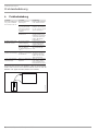 6
6
-
 7
7
-
 8
8
-
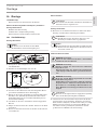 9
9
-
 10
10
-
 11
11
-
 12
12
-
 13
13
-
 14
14
-
 15
15
-
 16
16
-
 17
17
-
 18
18
-
 19
19
-
 20
20
-
 21
21
-
 22
22
-
 23
23
-
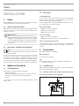 24
24
-
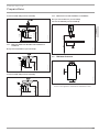 25
25
-
 26
26
-
 27
27
-
 28
28
-
 29
29
-
 30
30
-
 31
31
-
 32
32
-
 33
33
-
 34
34
-
 35
35
-
 36
36
-
 37
37
-
 38
38
-
 39
39
-
 40
40
-
 41
41
-
 42
42
-
 43
43
-
 44
44
-
 45
45
-
 46
46
-
 47
47
-
 48
48
-
 49
49
-
 50
50
-
 51
51
-
 52
52
-
 53
53
-
 54
54
-
 55
55
-
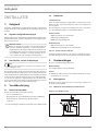 56
56
-
 57
57
-
 58
58
-
 59
59
-
 60
60
-
 61
61
-
 62
62
-
 63
63
-
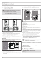 64
64
-
 65
65
-
 66
66
-
 67
67
-
 68
68
-
 69
69
-
 70
70
-
 71
71
-
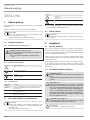 72
72
-
 73
73
-
 74
74
-
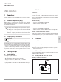 75
75
-
 76
76
-
 77
77
-
 78
78
-
 79
79
-
 80
80
-
 81
81
-
 82
82
-
 83
83
-
 84
84
-
 85
85
-
 86
86
-
 87
87
-
 88
88
-
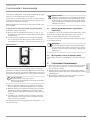 89
89
-
 90
90
-
 91
91
-
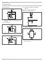 92
92
-
 93
93
-
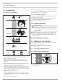 94
94
-
 95
95
-
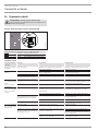 96
96
-
 97
97
-
 98
98
-
 99
99
-
 100
100
-
 101
101
-
 102
102
-
 103
103
-
 104
104
-
 105
105
-
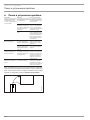 106
106
-
 107
107
-
 108
108
-
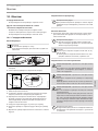 109
109
-
 110
110
-
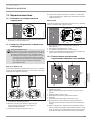 111
111
-
 112
112
-
 113
113
-
 114
114
-
 115
115
-
 116
116
-
 117
117
-
 118
118
-
 119
119
-
 120
120


STIEBEL ELTRON DCE 11-13 Operation Instruction
- Type
- Operation Instruction
in andere talen
- français: STIEBEL ELTRON DCE 11-13
- Deutsch: STIEBEL ELTRON DCE 11-13
- polski: STIEBEL ELTRON DCE 11-13
Gerelateerde papieren
-
STIEBEL ELTRON DHB-E SLi Electronic Control Instantaneous Water Heater Handleiding
-
-
STIEBEL ELTRON 236739 Operation and Installation
-
-
-
-
-
-
-