
Änderungen des Lieferumfanges
vorbehalten.
Equipment supplied is subject to
alteration.
Modifications de l’ensemble de
livraision réservées.
Ci riserviamo modifiche all’entità
della fornitura.
Ändringar av
leveransomfattningen
förbehålles.
Wijzgingen in leveringsomvang
voorbehouden.
Se reservan las modificaciones
del conjunto de suministro.
Zmeny v dodávkàch vyhrazeny.
Montageanleitung
Fitting instruction
Instructions de montage
Istruzioni di montaggio
Monteringsanvising
Montage-aanwijzing
Instrucciones de montaje
Montázní návod
Distributed by Votex GmbH Printed in Germany by Votex GmbH
Zubehör für Volkswagen
Accessories for Volkswagen
Accessoires pour Volkswagen
1
Caddy 2004 ⇒ / Caddy Maxi 2008 ⇒
1
3
4
2
5
9
10
8
6
7
11
12
A B
3
4
1
2
5
7
6
8
9
08.11.2007
Stückliste
Pos. Bezeichnung Stück
(
1 ) Trenngitter 1
(2) Unterlegscheibe 2
(3) Gegenplatte 2
(4) Schlossschraube M8 x 25 2
(5) Gewindehaken M8 2
(6) Sterngriffmutter M8 4
(7) Schlossschraube M8 x 45 2
(8) Ankerplatte 2
(9) Kunstoffkappe 4
(10) Sterngriffmutter M8 (klein) 2
(11
)Hülse 2
(12) Schutzkappe 2
Montage hinter der Rücksitzbank (A) 2K3 017 221
2K3 017 221 2K0 017 222 (nur Caddy 2004
⇒)
Montage hinter der Rücksitzbank mit optionaler Trenngitterteilung (B) 2K0 017 222
(nur Caddy 2004
⇒, nicht für Caddy Maxi 2008 ⇒)
Stückliste
Pos. Bezeichnung Stück
(
1 ) Trenngitter 1
(2) Sterngriffmutter M8 2
(3) Haltestrebe 1
(4) Schlossschraube M8 x 25 1
(5) Gegenplatte 1
(6) Unterlegscheibe 4
(7) Gummiauflage 4
(8) Untere Abstützung 1
(9) Sterngriffschraube M8 3

Distributed by Votex GmbH Printed in Germany by Votex GmbH
2
Montage hinter der Rücksitzbank (A) 2K3 017 221
Hinweis:
● Das Komplettieren des Trenngitters ist für die linke Seite beschrieben.
Das Komplettieren der rechten Seite erfolgt sinngemäß.
- Stecken Sie die Kunstoffkappen -9- auf die offenen Rohrenden
-A- des Trenngitters -1-.
- Drücken Sie die Hülse -11- in die Führung des Trenngitters -1-.
- Klappen Sie die Rücksitzbank nach vorn.
Stückliste
Pos. Bezeichnung Stück
(
1 ) Trenngitter 1
(2) Unterlegscheibe 2
(3) Gegenplatte 2
(4) Schlossschraube M8 x 25 2
(5) Gewindehaken M8 2
Stückliste
Pos. Bezeichnung Stück
(6) Sterngriffmutter M8 4
(7) Schlossschraube M8 x 45 2
(8) Ankerplatte 2
(
9) Kunstoffkappe 4
(
10 ) Sterngriffmutter M8 (klein) 2
(
11 )Hülse 2
(12) Schutzkappe 2
1
- Stellen Sie das Trenngitter -1- mit Hilfe einer zweiten Person
in den Innenraum des Fahrzeugs.
9
A
111
1
3
4
2
5
9
10
8
6
7
11
12

Distributed by Votex GmbH Printed in Germany by Votex GmbH
3
6
1
A
8 7
A
4
8
3
10
2
- Haken Sie den Gewindehaken -5- an der Gurtumlenkung ein.
- Stecken Sie den Gewindehaken -5- durch die Aufnahme am
Trenngitter.
- Drehen Sie die Sterngriffmutter -6- fest -Pfeil-.
Achtung!
Drehen Sie die Sterngriffmutter -6- nur so weit fest, bis das Trenngitter -1-
spielfrei anliegt ! Wird die Sterngriffmutter -6- zu fest gedreht, werden die
Verkleidungen oder der Gurtumlenkpunkt beschädigt.
Hinweis:
● Wird das Trenngitter ausgebaut, auch nur vorübergehend, ist der
Gewindehaken -5- ebenfalls zu entfernen!
- Klappen Sie die Verzurrösen -A- links und rechts nach oben.
- Stecken Sie die Ankerplatten -8- auf die Verzurrösen -A-.
- Befestigen Sie die Ankerplatten -8- mit den Schlossschrauben
(M8 x 45) -7- und den Sterngriffmuttern M8 -6- am
Trenngitter -1-.
- Stecken Sie die Schlossschraube (M8 x 25) -4- durch die
Gegenplatte -3-, Halteöse -A- und Ankerplatte -8-.
- Schrauben Sie die Sterngriffmutter M8 (klein) -10- mit der
Unterlegscheibe -2- auf die Schlossschraube (M8 x 25) -4-.
- Richten Sie das Trenngitter aus und ziehen Sie alle
Sterngriffmuttern fest.
- Klappen Sie die Rücksitzbank nach hinten und verriegeln Sie
die Sitzlehnen.
Hinweise:
● Sichern Sie schweres Ladegut zusätzlich mit Spanngurten!
● Das Trenngitter darf nur in Verbindung mit eingesteckten
Kopfstützen in den Rücksitz- Rückenlehnen und verriegelter
Rückenlehne genutzt werden.
● Kontrollieren Sie nach kurzer Fahrstrecke alle Verschraubungen
und ziehen sie ggf. nach.
● Kontrollieren Sie in angemessenen Abständen erneut die
Verschraubungen.
Achtung:
Der Transport von Personen hinter dem Trenngitter ist verboten!!
5
6 12

Distributed by Votex GmbH Printed in Germany by Votex GmbH
4
3
4
1
2
5
7
6
8
9
Montage hinter der Rücksitzbank mit optionaler Trenngitterteilung (B) 2K0 017 222
(nur Caddy 2004
⇒, nicht für Caddy Maxi 2008 ⇒)
Stückliste
Pos. Bezeichnung Stück
(
1 ) Trenngitter 1
(2) Sterngriffmutter M8 2
(3) Haltestrebe 1
(4) Schlossschraube M8 x 25 1
(5) Gegenplatte 1
(6) Unterlegscheibe 4
Stückliste
Pos. Bezeichnung Stück
(7) Gummiauflage 4
(8) Untere Abstützung 1
(9) Sterngriffschraube M8 3
7
8
A
7
- Montieren Sie das Trenngitter (A) (2K3 017 221 ) hinter der
Rücksitzbank.
- Drücken Sie die Gummiauflagen -7- in die untere Abstützung
-8- und die obere Abstützung -A- ein.
8
2
3
- Stecken Sie die Haltestrebe -3- auf die untere Abstützung -8-.
- Schrauben Sie die Sterngriffmutter M8 -2- ca. 25mm auf die
untere Abstützung -8-.

Distributed by Votex GmbH Printed in Germany by Votex GmbH
5
- Schrauben Sie die untere Abstützung an das Trenngitter.
- Heben Sie das Trenngitter in den Innenraum.
- Um Beschädigungen zu vermeiden und zum Ausrichten des
Trenngitters muss der Knopf -A- in Pfeilrichtung gezogen
werden.
A
- Klappen Sie die Verzurröse -A- nach oben.
- Führen Sie die Haltestrebe -3- auf die Halteöse -A-.
- Stecken Sie die Schlossschraube (M8 x 25) -4- durch die
Gegenplatte -5-, Verzurröse -A- und Haltestrebe -3-.
- Schrauben Sie die Sterngriffmutter -2- mit der
Unterlegscheibe -6- auf die Schlossschraube (M8 x 25) -4-.
A
3
5
4
6
2
6
9
- Drehen Sie die Sterngriffschraube -9- mit der
Unterlegscheibe -6- in das Trenngitter -1-.

Distributed by Votex GmbH Printed in Germany by Votex GmbH
6
A
2
8
● Durch Drehen der unteren Abstützung -8- wird der
Anpressdruck der oberen Abstützung -A- eingestellt.
- Drehen Sie die untere Abstützung -8- soweit hinein oder
heraus bis die obere Abstützung -A- an dem Dachquerträger
fest anliegt.
- Drehen Sie die Sterngriffmutter -2- gegen das Trenngitter.
- Drehen Sie alle Sterngriffschrauben und -muttern fest.
Hinweise:
● Sichern Sie schweres Ladegut zusätzlich mit Spanngurten!
● Das Trenngitter darf nur in Verbindung mit eingesteckten Kopfstützen in
den Rücksitz- Rückenlehnen und verriegelter Rückenlehne genutzt
werden.
● Kontrollieren Sie nach kurzer Fahrstrecke alle Verschraubungen und
ziehen sie ggf. nach.
● Kontrollieren Sie in angemessenen Abständen erneut die
Verschraubungen.
Achtung:
Der Transport von Personen hinter dem Trenngitter ist verboten!!

Änderungen des Lieferumfanges
vorbehalten.
Equipment supplied is subject to
alteration.
Modifications de l’ensemble de
livraision réservées.
Ci riserviamo modifiche all’entità
della fornitura.
Ändringar av
leveransomfattningen
förbehålles.
Wijzgingen in leveringsomvang
voorbehouden.
Se reservan las modificaciones
del conjunto de suministro.
Zmeny v dodávkàch vyhrazeny.
Montageanleitung
Fitting instruction
Instructions de montage
Istruzioni di montaggio
Monteringsanvising
Montage-aanwijzing
Instrucciones de montaje
Montázní návod
Distributed by Votex GmbH Printed in Germany by Votex GmbH
Zubehör für Volkswagen
Accessories for Volkswagen
Accessoires pour Volkswagen
1
Caddy 2004 ⇒ / Caddy Maxi 2008 ⇒
1
3
4
2
5
9
10
8
6
7
11
12
A B
3
4
1
2
5
7
6
8
9
List of parts
Item Designation Quantity
(
1 ) Separating grid 1
(2) Plain washer 2
(3) Counter plate 2
(4) Coach bolt M8 x 25 2
(5) Threaded hook M8 2
(6) Star grip nut M8 4
(7) Coach bolt M8 x 45 2
(8) Anchor plate 2
(9) Plastic cap 4
(10
) Star grip nut M8 (small) 2
(11
) Sleeve 2
(12) Protective cap 2
Assembly behind the rear seat (A) 2K3 017 221
2K3 017 221 2K0 017 222 (only Caddy 2004
⇒)
List of parts
Item Bezeichnung Quantity
(
1 ) Separating grid 1
(2) Star grip nut M8 2
(3) Retainer support 1
(4) Coach bolt M8 x 25 1
(5) Counter plate 1
(6) Plain washer 4
(7) Rubber support 4
(8) Lower support 1
(9) Star grip bolt M8 3
Assembly behind the rear bench seat with optional partition grille partition (B) 2K0 017 222
(only Caddy 2004
⇒, not for Caddy Maxi 2008 ⇒)

Distributed by Votex GmbH Printed in Germany by Votex GmbH
2
1
3
4
2
5
9
10
8
6
7
11
12
Assembly behind the rear seat (A) 2K3 017 221
Note:
● The assembly for the partition grille is described for the left-hand
side. Assembly of the right-hand side is similar.
- Connect plastic caps -9- to the open tube ends -A- of the
separating grid -1-.
- Push sleeve -11- into guide of partition grille -1-.
- Fold rear seat bench forwards.
List of parts
Item Designation Quantity
(
1 ) Separating grid 1
(2) Plain washer 2
(3) Counter plate 2
(4) Coach bolt M8 x 25 2
(5) Threaded hook M8 2
List of parts
Item Designation Quantity
(
6 ) Star grip nut M8 4
(7) Coach bolt M8 x 45 2
(8) Anchor plate 2
(
9) Plastic cap 4
(
10 ) Star grip nut M8 (small) 2
(
11 )Sleeve 2
(12) Protective cap 2
1
- Place the separating grid -1- in the vehicle interior with a
second person.
9
A
111

Distributed by Votex GmbH Printed in Germany by Votex GmbH
3
5
6 12
6
1
A
8 7
A
4
8
3
10
2
- Hook threaded hook -5- on seat belt relay.
- Pass the threaded hook -5- through the separating grid mounting.
- Tighten the star grip nut -6- -arrow-.
Warning!
Only tighten the star grip nut -6- until the partition grille -1- seats with no
play. If the star grip nut -6- is over tightened there is great danger that the
trim or the seat belt relay will be damaged.
Note:
● Always remove the threaded hook -5- when the partition grille is
removed, even if the partition grille is removed temporarily!
- Fold the left and right retaining eyes -A- upwards.
- Place the anchor plates -8- on the retaining eyes -A-.
- Secure the anchor plates -8- with the coach bolts (M8 x 45) -7-
and the star grip nuts M8 -6- to the separating grip -1-.
- Pass the coach bolt (M8 x 25) -4- through the counterplate
-3-, the retaining eye -A- and the anchor plate -8-.
- Fit the star grip nut M8 (small) -10- with washer -2- on the
coach bolt (M8 x 25) -4-.
- Align the separating grid and tighten all star grip nuts.t.
- Fold the rear seat backwards and lock the seat backrests.
Notes:
● Secure heavy load additionally with tensioning belts.
● The separating grid must only be used in connection with head
restraints inserted in the rear seat back of a seat and locked
back of a seat.
● Check all threaded joints after a brief drive and retighten, if
necessary.
● Check threaded joints regularly.
Warning:
It is not allowed to transport persons behind the separating grid.

Distributed by Votex GmbH Printed in Germany by Votex GmbH
4
3
4
1
2
5
7
6
8
9
List of parts
Item Designation Quantity
(
1 ) Separating grid 1
(2) Star grip nut M8 2
(3) Retainer support 1
(4) Coach bolt M8 x 25 1
(5) Counter plate 1
(6) Plain washer 4
List of parts
Item Designation Quantity
(7) Rubber support 4
(8) Lower support 1
(9) Star grip bolt M8 3
- Install the separating grid (A) (2K3 017 221 ) behind the rear
seat.
- Push rubber supports -7- in the lower support -8- and the
upper support -A- in.
7
8
A
7
8
2
3
- Fit retainer support -3- to lower support -8-.
- Fit the star grip nut M8 -2- approx. 25 mm to the lower
support -8-.
Assembly behind the rear bench seat with optional partition grille partition (B) 2K0 017 222
(only Caddy 2004
⇒, not for Caddy Maxi 2008 ⇒)

Distributed by Votex GmbH Printed in Germany by Votex GmbH
5
A
- Fit the lower support to the separating grid.
- Lift the separating grid in the interior.
- To avoid damages and to align the separating grid
the head -A- must be pulled in direction of arrow.
A
3
5
4
6
2
6
9
- Fold the retaining eye -A- upwards.
- Place the retainer support -3- on the retaining eye -A-.
- Pass the coach bolt (M8 x 25) -4- through the
counterplate -5-, the retaining eye -A- and the support -3-.
- Fit the star grip nut -2- on the coach bolt (M8 x 25) -4- with
washer -6-.
- Fit the star grip bolt -9- on the separating grid with plain
washer -6-.

Distributed by Votex GmbH Printed in Germany by Votex GmbH
6
A
2
8
● The pressure at the upper support -A- is adjusted by turning
the lower support -8-.
- Turn the lower support -8- in or out until the upper support -A-
lies tightly against the roof cross member.
- Turn the star grip nut -2- against the separating grip.
- Tighten all star grip bolts and nuts.
Notes:
● Secure heavy load additionally with tensioning belts.
● The separating grid must only be used in connection with head restraints
inserted in the rear seat back of a seat and locked back of a seat.
● Check all threaded joints after a brief drive and retighten, if necessary.
● Check threaded joints regularly.
Warning:
It is not allowed to transport persons behind the separating grid.

Änderungen des Lieferumfanges
vorbehalten.
Equipment supplied is subject to
alteration.
Modifications de l’ensemble de
livraision réservées.
Ci riserviamo modifiche all’entità
della fornitura.
Ändringar av
leveransomfattningen
förbehålles.
Wijzgingen in leveringsomvang
voorbehouden.
Se reservan las modificaciones
del conjunto de suministro.
Zmeny v dodávkàch vyhrazeny.
Montageanleitung
Fitting instructions
Instructions de montage
Istruzioni di montaggio
Monteringsanvising
Montage-aanwijzing
Instrucciones de montaje
Montázní návod
Distributed by Votex GmbH Printed in Germany by Votex GmbH
Zubehör für Volkswagen
Accessories for Volkswagen
Accessoires pour Volkswagen
1
Caddy 2004 ⇒ / Caddy Maxi 2008 ⇒
1
3
4
2
5
9
10
8
6
7
11
12
A B
3
4
1
2
5
7
6
8
9
Liste des pièces détachées
Repère Désignation Nombre
(
1 ) Grille de séparation 1
(2) Rondelle entretoise 2
(3) Plaque de renfort 2
(4) Vis de fermeture M8 x 25 2
(5) Crochet fileté M8 2
(6) Ecrou à poignée étoilée M8 4
(7) Vis de fermeture M8 x 45 2
(8) Plaque d'ancrage 2
(9) Capuchon en matière plastique 4
(10
) Ecrou à poignée étoilée M8 (petit) 2
(11
) Douille 2
(12) Capuchon de protection 2
Montage derrière la banquette arrière (A) 2K3 017 221
2K3 017 221 2K0 017 222 (uniquement Caddy 2004
⇒)
Liste des pièces détachées
Repère Désignation Nombre
(
1 ) Grille de séparation 1
(2) Ecrou à poignée étoilée M8 2
(3) Tirant de maintien 1
(4) Vis de fermeture M8 x 25 1
(5) Plaque de renfort 1
(6) Rondelle entretoise 4
(7) Embase de caoutchouc 4
(8) Appui inférieur 1
(9) Vis à poignée étoilée M8 3
Montage derrière la banquette arrière avec division du filet de séparation en option (B) 2K0 017 222
(uniquement Caddy 2004
⇒, pas pour Caddy Maxi 2008 ⇒)

Distributed by Votex GmbH Printed in Germany by Votex GmbH
2
Montage derrière la banquette arrière (A) 2K3 017 221
Remarque :
● La marche à suivre pour compléter la grille de séparation est décrite
pour le côté gauche. La marche à suivre pour compléter le côté droit
se fait comme suit.
- Enfoncez les capuchons en matière plastique -9- sur les bouts
de tube ouverts -A- de la grille de séparation -1-.
- Enfoncer la douille -11- dans le guide du filet de séparation -1-.
- Rabattre la banquette arrière vers l'avant.
Liste des pièces détachées
Repère Désignation Nombre
(
1 ) Grille de séparation 1
(2) Rondelle entretoise 2
(3) Plaque de renfort 2
(4) Vis de fermeture M8 x 25 2
(5) Crochet fileté M8 2
Liste des pièces détachées
Repère Désignation Nombre
(
6 ) Ecrou à poignée étoilée M8 4
(7) Vis de fermeture M8 x 45 2
(8) Plaque d'ancrage 2
(9) Capuchon en matière plastique 4
(
10) Ecrou à poignée étoilée M8 (petit) 2
(
11 ) Douille 2
(12) Capuchon de protection 2
- Mettez en place la grille de séparation -1- dans l'habitacle
du véhicule avec l'aide d'un deuxième mécanicien.
1
1
3
4
2
5
9
10
8
6
7
11
12
9
A
111

Distributed by Votex GmbH Printed in Germany by Votex GmbH
3
- Accrocher le crochet fileté -5- à l'enrouleur de ceinture.
- Passez le crochet fileté -5- à travers la prise située à la grille de
séparation.
- Serrez -flèche- l'écrou à poignée étoilée -6-.
Attention :
Serrer l’écrou à poignée-étoile -6- uniquement jusqu’à ce que le filet de
séparation -1- soit appliqué sans jeu ! Lorsque l’écrou à poignée-étoile
-6- est serré trop fort, cela endommage les revêtements ou le point
d’enroulement de la ceinture.
Remarque :
● Lorsque le filet de séparation est démonté, même si ce n’est que
provisoirement, le crochet fileté -5- doit être également enlevé !
- Rabattez les œillets de retenue -A- gauche et droit vers le
haut.
- Placez les plaques d'ancrage -8- sur les œillets de retenue -A-.
- Fixez les plaques d'ancrage -8- à la grille de séparation -1- à
l'aide des vis de fermeture (M8 x 45) -7- et des écrous à
poignée étoilée M8 -6-.
5
6 12
6
1
A
8 7
- Passez la vis de fermeture (M8 x 25) -4- par la plaque de
renfort -3-, l'œillet de retenue -A- et la plaque d'ancrage -8-.
- Vissez l'écrou à poignée étoilée M8 (petit) -10- muni de la
rondelle entretoise -2- sur la vis de fermeture (M8 x 25) -4-.
- Dégauchissez la grille de séparation et serrez tous les écrous
à poignée étoilée.
- Rabattez la banquette arrière vers l'arrière et verrouillez les
dossiers de siège.
A
4
8
3
10
2
Remarques :
● Freinez tout matériau transporté à poids lourd à l'aide de sangles de
serrage !
● Si vous vous servez de la grille de séparation, il faut que les appuis-
tête soient enfoncés dans les dossiers des sièges arrière et que ces
dossiers soient verrouillés.
● Au bout d'un trajet court, contrôlez tous les vissages et, si nécessaire,
resserrez-les.
● Au bout d'intervalles à durée adéquate, veuillez contrôler de nouveau
ces vissages.
Attention :
Il est strictement interdit de transporter des personnes assises derrière
la grille !!

Distributed by Votex GmbH Printed in Germany by Votex GmbH
4
Liste des pièces détachées
Repère Désignation Nombre
(
1 ) Grille de séparation 1
(2) Ecrou à poignée étoilée M8 2
(3) Tirant de maintien 1
(4) Vis de fermeture M8 x 25 1
(5) Plaque de renfort 1
(6) Rondelle entretoise 4
Liste des pièces détachées
Repère Désignation Nombre
(7) Embase de caoutchouc 4
(8) Appui inférieur 1
(9) Vis à poignée étoilée M8 3
Montage derrière la banquette arrière avec division du filet de séparation en option (B) 2K0 017 222
(uniquement Caddy 2004
⇒, pas pour Caddy Maxi 2008 ⇒)
3
4
1
2
5
7
6
8
9
7
8
A
7
- Montez la grille de séparation (A) (2K3 017 221 ) derrière la
banquette arrière.
- Enfoncez les embases de caoutchouc -7- dans les appuis
inférieur -8- et supérieur -A-.
8
2
3
- Attachez le tirant de maintien -3- à l'appui inférieur -8-.
- Vissez l'écrou à poignée étoilée M8 -2- (env. 25 mm) sur
l'appui inférieur -8-.

Distributed by Votex GmbH Printed in Germany by Votex GmbH
5
- Vissez l'appui inférieur à la grille de séparation.
- Placez la grille de séparation dans l'habitacle.
- Pour éviter tout endommagement et pour dégauchir la grille
de séparation, il faut tirer le bouton -A- dans le sens de la
flèche.
A
- Rabattez l'œillet de retenue -A- vers le haut.
- Guidez le tirant de maintien -3- sur l'œillet de retenue -A-.
- Passez la vis de fermeture (M8 x 25) -4- par la plaque de
renfort -5-, l'œillet de retenue -A- et le tirant de maintien -3-.
- Vissez l'écrou à poignée étoilée -2- muni de la rondelle
entretoise -6- sur la vis de fermeture (M8 x 25) -4-.
A
3
5
4
6
2
6
9
- Munie de la rondelle entretoise -6-, vissez la vis à poignée
étoilée -9- dans la grille de séparation -1-.

Distributed by Votex GmbH Printed in Germany by Votex GmbH
6
A
2
8
● C'est en tournant l'appui inférieur -8- que s'ajuste la pression
appliquée à l'appui supérieur -A-.
- Serrez ou desserrez l'appui inférieur -8- jusqu'à ce que l'appui
supérieur -A- s'appuie bien contre la traverse du pavillon.
- Serrez l'écrou à poignée étoilée -2- contre la grille de
séparation.
- Serrez tous les écrous et vis à poignée étoilée.
Remarques :
● Freinez tout matériau transporté à poids lourd à l'aide de sangles de
serrage !
● Si vous vous servez de la grille de séparation, il faut que les appuis-tête
soient enfoncés dans les dossiers des sièges arrière et que ces dossiers
soient verrouillés.
● Au bout d'un trajet court, contrôlez tous les vissages et, si nécessaire,
resserrez-les.
● Au bout d'intervalles à durée adéquate, veuillez contrôler de nouveau
ces vissages.
Attention :
Il est strictement interdit de transporter des personnes assises derrière la
grille !!

Änderungen des Lieferumfanges
vorbehalten.
Equipment supplied is subject to
alteration.
Modifications de l’ensemble de
livraision réservées.
Ci riserviamo modifiche all’entità
della fornitura.
Ändringar av
leveransomfattningen
förbehålles.
Wijzgingen in leveringsomvang
voorbehouden.
Se reservan las modificaciones
del conjunto de suministro.
Zmeny v dodávkàch vyhrazeny.
Montageanleitung
Fitting instruction
Instructions de montage
Istruzioni di montaggio
Monteringsanvising
Montage-aanwijzing
Instrucciones de montaje
Montázní návod
Distributed by Votex GmbH Printed in Germany by Votex GmbH
Zubehör für Volkswagen
Accessories for Volkswagen
Accessoires pour Volkswagen
1
Caddy 2004 ⇒ / Caddy Maxi 2008 ⇒
A B
3
4
1
2
5
7
6
8
9
Distinta dei pezzi
Pos. Denominazione pezzi
(
1 ) Griglia di separazione 1
(2) Rondella spessore 2
(3) Contropiastra 2
(4) Vite a testa quadra M8 x 25 2
(5) Gancio filettato M8 2
(6) Dado con manopola a crociera M8 4
(7) Vite a testa quadra M8 x 45 2
(8) Piastra di ancoraggio 2
(9) Cappuccio in plastica 4
(10) Dado con manopola a crociera M8 (piccolo) 2
(11
) Bussola 2
(12) Copertura di protezione 2
Montaggio dietro i sedili posteriori (A) 2K3 017 221
2K3 017 221 2K0 017 222 (solo Caddy 2004
⇒)
Distinta dei pezzi
Pos. Denominazione pezzi
(
1 ) Griglia di separazione 1
(2) Dado con manopola a crociera M8 2
(3) Cantonale di sostegno 1
(4) Vite a testa quadra M8 x 25 1
(5) Contropiastra 1
(6) Rondella spessore 4
(7) Supporto in gomma 4
(8) Sostegno inferiore 1
(9) Vite con manopola a crociera M8 3
1
3
4
2
5
9
10
8
6
7
11
12
Montaggio dietro il divano posteriore con suddivisione opzionale della griglia di separazione (B) 2K0 017 222
(solo Caddy 2004
⇒, non per Caddy Maxi 2008 ⇒)

Distributed by Votex GmbH Printed in Germany by Votex GmbH
2
Montaggio dietro i sedili posteriori (A) 2K3 017 221
Avvertenza:
● Il completamento della griglia di separazione è descritto per il lato
sinistro. Il completamento del lato destro avviene in modo analogo.
- Attaccare i cappucci in plastica -9- alle estremità aperte dei tubi -
A- della griglia di separazione -1-.
- Inserire la bussola -11- nella guida della griglia di separazione -1-.
- Ripiegare in avanti il divano posteriore.
Distinta dei pezzi
Pos. Denominazione pezzi
(
1 ) Griglia di separazione 1
(2) Rondella spessore 2
(3) Contropiastra 2
(4) Vite a testa quadra M8 x 25 2
(5) Gancio filettato M8 2
Distinta dei pezzi
Pos. Denominazione pezzi
(
6) Dado con manopola a crociera M8 4
(7) Vite a testa quadra M8 x 45 2
(8) Piastra di ancoraggio 2
(
9) Cappuccio in plastica 4
(
10 ) Dado con manopola a crociera M8 (piccolo) 2
(
11 ) Bussola 2
(12) Copertura di protezione 2
1
3
4
2
5
9
10
8
6
7
11
12
9
A
111
- Sistemare la griglia di separazione -1- con l'aiuto di una
seconda persona nell'abitacolo del veicolo.
1

Distributed by Votex GmbH Printed in Germany by Votex GmbH
3
- Agganciare il gancio -5- al dispositivo d'inversione cintura.
- Infilare il gancio filettato -5- attraverso il sopporto della griglia
di separazione.
- Serrare il dado con manopola a crociera -6- -freccia-.
Attenzione!
Girare il dado a manopola a crociera -6- solo di quel tanto per far
aderire la griglia di separazione -1- senza gioco! Se si avvita troppo il
dado con manopola a crociera -6- si potrebbero danneggiare i
rivestimenti o il punto di inversione cintura.
Avvertenza:
● Se si smonta la griglia di separazione - anche se solo
temporaneamente -, bisogna rimuovere anche il gancio -5-!
- Ribaltare in alto le staffe di sostegno -A- a sinistra ed a destra.
- Attaccare le piastre di ancoraggio -8- alle staffe di ritegno -A-.
- Fissare le piastre di ancoraggio -8- con le viti a testa quadra
(M8 x 45) -7- ed i dadi con manopola a crociera M8 -6- sulla
griglia di separazione -1-.
5
6 12
6
1
A
8 7
- Far passare la vite a testa quadra (M8 x 25) -4- attraverso la
contropiastra -3-, la staffa di ritegno -A- e la piastra di
ancoraggio -8-.
- Avvitare il dado con manopola a crociera M8 (piccolo) -10-
con la rondella -2- sulla vite a testa quadra (M8 x 25) -4-.
- Allineare la griglia di separazione ed avvitare tutti i dadi con
manopola a crociera.
- Ribaltare i sedili posteriori indietro e bloccare gli schienali.
Avvertenze:
● Assicurare i carichi pesanti addizionalmente con cinghie di
fissaggio!
● La griglia di separazione deve essere usata unicamente con i
poggiatesta inseriti negli schienali dei sedili posteriori e con lo
schienale bloccato.
● Dopo un breve percorso controllare tutti i collegamenti a vite ed
eventualmente riserrare le viti.
● Ricontrollare i collegamenti a vite ad intervalli regolari.
Attenzione:
E' vietato il trasporto di persone dietro la griglia di separazione!!
A
4
8
3
10
2

Distributed by Votex GmbH Printed in Germany by Votex GmbH
4
3
4
1
2
5
7
6
8
9
Distinta dei pezzi
Pos. Denominazione pezzi
(
1 ) Griglia di separazione 1
(2) Dado con manopola a crociera M8 2
(3) Cantonale di sostegno 1
(4) Vite a testa quadra M8 x 25 1
(5) Contropiastra 1
(6) Rondella spessore 4
Distinta dei pezzi
Pos. Denominazione pezzi
(7) Supporto in gomma 4
(8) Sostegno inferiore 1
(9) Vite con manopola a crociera M8 3
Montaggio dietro il divano posteriore con suddivisione opzionale della griglia di separazione (B) 2K0 017 222
(solo Caddy 2004
⇒, non per Caddy Maxi 2008 ⇒)
- Montare la griglia di separazione (A) (2K3 017 221 ) dietro i
sedili posteriori.
- Inserire i supporti in gomma -7- premendoli nel sostegno
inferiore -8- ed in quello superiore -A-.
7
8
A
7
8
2
3
- Applicare il cantonale di sostegno -3- sul sostegno inferiore
-8-.
- Avvitare il dado con manopola a crociera M8 -2- di circa 25
mm sul sostegno inferiore -8-.

Distributed by Votex GmbH Printed in Germany by Votex GmbH
5
A
- Avvitare il sostegno inferiore sulla griglia di separazione.
- Sollevare la griglia di separazione e sistemarla nell'abitacolo.
- A scanso di danneggiamenti e per allineare la griglia di
separazione, tirare il bottone -A- nella direzione indicata
dalla freccia.
A
3
5
4
6
2
- Ribaltare in alto la staffa di sostegno -A-.
- Guidare il cantonale di sostegno -3- sulla staffa di ritegno
-A-.
- Far passare la vite a testa quadra (M8 x 25) -4- attraverso la
contropiastra -5-, la staffa di ritegno -A- ed il cantonale di
sostegno -3-.
- Avvitare il dado con manopola a crociera -2- con la rondella
-6- sulla vite a testa quadra (M8 x 25) -4-.
6
9
- Avvitare la vite con manopola a crociera -9- con la
rondella -6- nella griglia di separazione -1-.

Distributed by Votex GmbH Printed in Germany by Votex GmbH
6
A
2
8
● Girando il sostegno inferiore -8- si regola la pressione di
appoggio del sostegno superiore -A-.
- Avvitare ovvero svitare il sostegno inferiore -8- finché il
sostegno superiore -A- non si appoggia saldamente sulla
traversa del tetto.
- Avvitare il dado con manopola a crociera -2- contro la griglia
di separazione.
- Serrare tutte le viti ed i dadi con manopola a crociera.
Avvertenze:
● Assicurare i carichi pesanti addizionalmente con cinghie di fissaggio!
● La griglia di separazione deve essere usata unicamente con i
poggiatesta inseriti negli schienali dei sedili posteriori e con lo schienale
bloccato.
● Dopo un breve percorso controllare tutti i collegamenti a vite ed
eventualmente riserrare le viti.
● Ricontrollare i collegamenti a vite ad intervalli regolari.
Attenzione:
E' vietato il trasporto di persone dietro la griglia di separazione!!

Änderungen des Lieferumfanges
vorbehalten.
Equipment supplied is subject to
alteration.
Modifications de l’ensemble de
livraision réservées.
Ci riserviamo modifiche all’entità
della fornitura.
Ändringar av
leveransomfattningen
förbehålles.
Wijzgingen in leveringsomvang
voorbehouden.
Se reservan las modificaciones
del conjunto de suministro.
Zmeny v dodávkàch vyhrazeny.
Montageanleitung
Fitting instruction
Instructions de montage
Istruzioni di montaggio
Monteringsanvising
Montage-aanwijzing
Instrucciones de montaje
Montázní návod
Distributed by Votex GmbH Printed in Germany by Votex GmbH
Zubehör für Volkswagen
Accessories for Volkswagen
Accessoires pour Volkswagen
1
Caddy 2004 ⇒ / Caddy Maxi 2008 ⇒
A B
3
4
1
2
5
7
6
8
9
Komponentlista
Pos Beteckning Antal
(
1 ) Lastskyddsgaller 1
(2) Bricka 2
(3) Mothåll 2
(4) Vagnsbult M8 x 25 2
(5) Hake med gängor M8 2
(6) Mutter M8 med stjärnhandtag 4
(7) Vagnsbult M8 x 45 2
(8) Fästplatta 2
(9) Plastkåpa 4
(10) Mutter M8 med stjärnhandtag (liten) 2
(11
)Hylsa 2
(12) Skyddskåpa 2
Montering bakom baksätet (A) 2K3 017 221
2K3 017 221 2K0 017 222 (Endast Caddy 2004
⇒)
Komponentlista
Pos Beteckning Antal
(
1 ) Lastskyddsgalle 1
(2) Mutter M8 med stjärnhandtag 2
(3) Fäststräva 1
(4) Vagnsbult M8 x 25 1
(5) Mothåll 1
(6) Bricka 4
(7) Gummiunderlägg 4
(8) Undre stöd 1
(9) Skruv M8 med stjärnhandtag 3
1
3
4
2
5
9
10
8
6
7
11
12
Montering bakom baksätet med optional uppdelning av lastskyddsnätet (B) 2K0 017 222
(endast Caddy 2004
⇒, inte för Caddy Maxi 2008 ⇒)

Distributed by Votex GmbH Printed in Germany by Votex GmbH
2
Montering bakom baksätet (A) 2K3 017 221
Observera:
● Kompletteringen av lastskyddsnätet är beskrivet för vänster sida.
Komplettering av höger sida sker i princip på samma vis.
- Stick på plastkåporna -9- på lastskyddsgallrets -1- öppna
rörändar -A-.
- Tryck in hylsan -11- i lastskyddsnätets -1- styrning.
- Fäll baksätet framåt.
Komponentlista
Pos Beteckning Antal
(
1 ) Lastskyddsgaller 1
(2) Bricka 2
(3) Mothåll 2
(4) Vagnsbult M8 x 25 2
(5) Hake med gängor M8 2
Komponentlista
Pos Beteckning Antal
(6) Mutter M8 med stjärnhandtag 4
(7) Vagnsbult M8 x 45 2
(8) Fästplatta 2
(9) Plastkåpa 4
(
10) Mutter M8 med stjärnhandtag (liten) 2
(
11 )Hylsa 2
(12) Skyddskåpa 2
1
3
4
2
5
9
10
8
6
7
11
12
9
A
111
1
- Ställ med hjälp av en 2:a person lastskyddsgallret -1- i bilens
kupéutrymme.

Distributed by Votex GmbH Printed in Germany by Votex GmbH
3
- Haka in haken -5- med gänga på bältesomlänkningsbeslaget.
- Stick den gängade haken -5- genom infästningen på gallret.
- Dra fast muttern -6- med stjärnhandtag -pil-.
Viktigt!
Dra endast fast muttern -6- med stjärnhandtag tills lastskyddsnätet -1-
ligger an spelfritt. Dras muttern -6- med stjärnhandtag fast för hårt
skadas klädslarna eller bältesomlänkningsbeslaget.
Observera:
● Monteras lastskyddsnätet ur, även endast tillfälligt ska även haken -5-
med gänga tas bort.
- Fäll fästöglorna -A- på vänster och höger sida uppåt.
- Stick på fästplattorna -8- på fästöglorna -A-.
- Fäst fästplattorna -8- med vagnsbultarna (M8 x 45) -7- och
M8-muttrarna med stjärnhandtag (slutna) -6- med
lastskyddsgallret -1-.
5
6 12
6
1
A
8 7
- Stick vagnsbulten (M8 x 25) -4- genom mothållet -3-,
fästöglan -A- och fästplattan -8-.
- Skruva på M8-muttern med stjärnhandtag (liten) -10- med
brickan -2- på vagnsbulten (M8 x 25) -4-.
- Rikta upp lastskyddsgallret och dra fast alla muttrar med
stjärnhandtag.
- Fäll baksätet bakåt och lås ryggstödet.
Observera:
● Säkra dessutom tung last med spännband.
● Lastskyddsgallret får endast användas tillsammans med isatta
nackskydd för ryggstödet för baksätet och låst ryggstöd.
● Kontrollera efter en kort körning alla förskruvningar och efterdra
dem om erforderligt.
● Kontrollera med regelbundna intervaller förskruvningarna på
nytt.
Viktigt:
Transport av personer bakom lastskyddsgallret är förbjuden.
A
4
8
3
10
2

Distributed by Votex GmbH Printed in Germany by Votex GmbH
4
3
4
1
2
5
7
6
8
9
Komponentlista
Pos Beteckning Antal
(
1 ) Lastskyddsgalle 1
(2) Mutter M8 med stjärnhandtag 2
(3) Fäststräva 1
(4) Vagnsbult M8 x 25 1
(5) Mothåll 1
(6) Bricka 4
Komponentlista
Pos Beteckning Antal
(7) Gummiunderlägg 4
(8) Undre stöd 1
(9) Skruv M8 med stjärnhandtag 3
Montering bakom baksätet med optional uppdelning av lastskyddsnätet (B) 2K0 017 222
(endast Caddy 2004
⇒, inte för Caddy Maxi 2008 ⇒)
- Montera lastskyddsgallret (A) (2K3 017 221 ) bakom baksätet.
- Trycken in gummimellanläggen -7- i undre stödet -8- och övre
stödet -A-.
7
8
A
7
8
2
3
- Stick på fäststrävan -3- på undre stödet -8-.
- Skruva på M8-muttern med stjärnhandtag -2- ca 25 mm på
undre stödet -8-.

Distributed by Votex GmbH Printed in Germany by Votex GmbH
5
A
- Skruva fast undre stödet på lastskyddsgallret.
- Lyft in lastskyddsgallret i kupéutrymmet.
- För att undvika skador och för uppriktning av
lastskyddsgallret måste knappen -A- dras i pilriktningen.
A
3
5
4
6
2
6
9
- Skruva in skruven med stjärnhandtag -9- med bricka -6- i
lastskyddsgallret -1-.
- Fäll fästöglan -A- uppåt.
- Skjut på fäststrävan -3- på fästöglan -A-.
- Stick vagnsbulten (M8 x 25) -4- genom mothållet -5-,
fästöglan -A- och fäststrävan -3-.
- Skruva på muttern med stjärnhandtag -2- med bricka -6- på
vagnsbulten (M8 x 25) -4-.

Distributed by Votex GmbH Printed in Germany by Votex GmbH
6
A
2
8
● Genom att vrida undre stödet -8- ställs anpressningstrycket för
övre stödet -A- in.
- Skruva in eller ut undre stödet -8- så långt tills övre stödet -A-
ligger an hårt på taktvärbalken.
- Skruva muttern med stjärnhandtag -2- till anliggning på
lastskyddsgallret.
- Skruva fast alla skruvar och muttrar med stjärnhandtag.
Observera:
● Säkra dessutom tung last med spännband.
● Lastskyddsgallret får endast användas tillsammans med isatta nackskydd
för ryggstödet för baksätet och låst ryggstöd.
● Kontrollera efter en kort körning alla förskruvningar och efterdra dem
om erforderligt.
● Kontrollera med regelbundna intervaller förskruvningarna på nytt.
Achtung:
Transport av personer bakom lastskyddsgallret är förbjuden.

Änderungen des Lieferumfanges
vorbehalten.
Equipment supplied is subject to
alteration.
Modifications de l’ensemble de
livraision réservées.
Ci riserviamo modifiche all’entità
della fornitura.
Ändringar av
leveransomfattningen
förbehålles.
Wijzgingen in leveringsomvang
voorbehouden.
Se reservan las modificaciones
del conjunto de suministro.
Zmeny v dodávkàch vyhrazeny.
Montageanleitung
Fitting instruction
Instructions de montage
Istruzioni di montaggio
Monteringsanvising
Montage-aanwijzing
Instrucciones de montaje
Montázní návod
Distributed by Votex GmbH Printed in Germany by Votex GmbH
Zubehör für Volkswagen
Accessories for Volkswagen
Accessoires pour Volkswagen
1
Caddy 2004 ⇒ / Caddy Maxi 2008 ⇒
A B
3
4
1
2
5
7
6
8
9
Stuklijst
Nr. Omschrijving Stuks
(
1 ) Scheidingsnet 1
(2) Onderlegring 2
(3) Contraplaat 2
(4) Slotbout M8 x 25 2
(5) Draadhuls M8 2
(6) Draaiknopmoer M8 4
(7) Slotbout M8 x 45 2
(8) Ankerplaat 2
(9) Kunststof kap 4
(10) Draaiknopmoer M8 (klein) 2
(11
)Huls 2
(12) Beschermkap 2
Montage achter achterbankzitting (A) 2K3 017 221
2K3 017 221 2K0 017 222 (alleen Caddy 2004
⇒)
Stuklijst
Nr. Omschrijving Stuks
(
1 ) Scheidingsnet 1
(2) Draaiknopmoer M8 2
(3) Bevestigingssteun 1
(4) Slotbout M8 x 25 1
(5) Contraplaat 1
(6) Onderlegring 4
(7) Rubber plaatje 4
(8) Onderste steun 1
(9) Draaiknopbout M8 3
1
3
4
2
5
9
10
8
6
7
11
12
Montage achter de achterbank met optionele scheidingsroostersplitsing (B) 2K0 017 222
(alleen Caddy 2004
⇒, niet voor Caddy Maxi 2008 ⇒)

Distributed by Votex GmbH Printed in Germany by Votex GmbH
2
Montage achter achterbankzitting (A) 2K3 017 221
Aanwijzing:
● Het completeren van het scheidingsrooster is voor de linkerkant
beschreven. Het completeren van de rechterkant gebeurt op
dezelfde manier.
- Kunststof kappen -9- op open pijpuiteinden -A- van
scheidingsnet -1- steken.
- Druk de huls -11- in de geleiding van het scheidingsrooster -1-.
- Achterbank naar voren klappen.
Stuklijst
Nr. Omschrijving Stuks
(
1 ) Scheidingsnet 1
(2) Onderlegring 2
(3) Contraplaat 2
(4) Slotbout M8 x 25 2
(5) Draadhuls M8 2
Stuklijst
Nr. Omschrijving Stuks
(6) Draaiknopmoer M8 4
(7) Slotbout M8 x 45 2
(8) Ankerplaat 2
(9) Kunststof kap 4
(
10) Draaiknopmoer M8 (klein) 2
(
11 )Huls 2
(12) Beschermkap 2
1
3
4
2
5
9
10
8
6
7
11
12
9
A
111
1
- Scheidingsnet -1- met hulp van een tweede persoon in het
interieur van de wagen plaatsen.

Distributed by Votex GmbH Printed in Germany by Votex GmbH
3
- Haak het holle wandanker -5- in op de gordelomkering.
- Schroefdraadhaak -5- door de steun bij het scheidingsnet steken.
- Stervormige moer -6- vastdraaien -pijl-.
Attentie:
Draai de stervormige moer -6- maar zo ver vast, tot het
scheidingsrooster -1- zonder speling aansluit ! Als de stervormige
moer -6- te stevig wordt aangedraaid, dan worden de bekledingen of het
gordelomkeerpunt beschadigd.
Aanwijzing:
● Als het scheidingsrooster gedemonteerd wordt, ook al is het maar tijdelijk,
dan moet het holle wandanker -5- eveneens worden verwijderd!
- Bevestigingsogen -A- links en rechts naar boven klappen.
- Ankerplaten -8- op bevestigingsogen -A- steken.
- Ankerplaten -8- met slotbouten (M8x45) -7- en
draaiknopmoeren M8 -6- aan scheidingsnet -1- bevestigen.
5
6 12
6
1
A
8 7
A
4
8
3
10
2
- Slotbout (M8x25) -4- door contraplaat -3-, bevestigingsoog -
A- en ankerplaat -8- steken.
- Draaiknopmoer M8 (klein) -10- met onderlegring -2- op
slotbout (M8x25) -4- schroeven.
- Scheidingsnet goed plaatsen en alle draaiknopmoeren
vastdraaien.
- Achterbankzitting naar achteren klappen en de rugleuning
vergrendelen.
Aanwijzingen:
● Zware lading extra met spanbanden vastzetten.
● Het scheidingsnet mag alleen in combinatie met ingestoken
hoofdsteunen in de achterbank-rugleuning en vergrendelde
rugleuning worden gebruikt.
● Kort na het inbouwen en een stukje gereden te hebben alle
schroefverbindingen controleren en zo nodig natrekken.
● Zo nu en dan de schroefverbindingen opnieuw controleren.
Attentie:
Het vervoer van personen achter het scheidingsnet is verboden!!

Distributed by Votex GmbH Printed in Germany by Votex GmbH
4
Stuklijst
Nr. Omschrijving Stuks
(
1 ) Scheidingsnet 1
(2) Draaiknopmoer M8 2
(3) Bevestigingssteun 1
(4) Slotbout M8 x 25 1
(5) Contraplaat 1
(6) Onderlegring 4
Stuklijst
Nr. Omschrijving Stuks
(7) Rubber plaatje 4
(8) Onderste steun 1
(9) Draaiknopbout M8 3
Montage achter de achterbank met optionele scheidingsroostersplitsing (B) 2K0 017 222
(alleen Caddy 2004
⇒, niet voor Caddy Maxi 2008 ⇒)
3
4
1
2
5
7
6
8
9
8
2
3
- Scheidingsnet (A) (2K3 017 221) achter de achterbankzitting
monteren.
- Rubber plaatje -7- in onderste steun -8- en in bovenste steun -
A- drukken.
- Bevestigingssteun -3- op onderste steun -8- steken.
- Draaiknopmoer M8 -2- ca. 25 mm op onderste steun -8-
schroeven.
7
8
A
7

Distributed by Votex GmbH Printed in Germany by Votex GmbH
5
A
- Onderste steun aan het scheidingsnet vastschroeven.
- Scheidingsnet in het interieur tillen.
- Om beschadigingen te voorkomen en om het scheidingsnet
goed te kunnen richten moet knop -A- in de pijlrichting
getrokken worden.
A
3
5
4
6
2
- Bevestigingsoog -A- naar boven klappen.
- Bevestigingssteun -3- in bevestigingsoog -A- schuiven.
- Slotbout (M8x25) -4- door contraplaat -5-,
bevestigingsoog -A- en bevestigingssteun -3- steken.
- Draaiknopmoer -2- met onderlegring -6- op
slotbout (M8x25) -4- schroeven.
6
9
- Draaiknopmoer -9- met onderlegring -6- in scheidingsnet -1-
draaien.

Distributed by Votex GmbH Printed in Germany by Votex GmbH
6
A
2
8
● Door onderste steun -8- te draaien, wordt de druk op bovenste
steun -A- afgesteld.
- Onderste steun -8- zo ver erin of eruit draaien tot bovenste
steun -A- vast tegen de dakdwarsdrager aanligt.
- Draaiknopmoer -2- tegen het scheidingsnet draaien.
- Alle draaiknopbouten en -moeren vastdraaien.
Aanwijzingen:
● Zware lading extra met spanbanden vastzetten.
● Het scheidingsnet mag alleen in combinatie met ingestoken
hoofdsteunen in de achterbank-rugleuning en vergrendelde rugleuning
worden gebruikt.
● Kort na het inbouwen en een stukje gereden te hebben alle
schroefverbindingen controleren en zo nodig natrekken.
● Zo nu en dan de schroefverbindingen opnieuw controleren.
Attentie:
Het vervoer van personen achter het scheidingsnet is verboden!!

Änderungen des Lieferumfanges
vorbehalten.
Equipment supplied is subject to
alteration.
Modifications de l’ensemble de
livraision réservées.
Ci riserviamo modifiche all’entità
della fornitura.
Ändringar av
leveransomfattningen
förbehålles.
Wijzgingen in leveringsomvang
voorbehouden.
Se reservan las modificaciones
del conjunto de suministro.
Zmeny v dodávkàch vyhrazeny.
Montageanleitung
Fitting instruction
Instructions de montage
Istruzioni di montaggio
Monteringsanvising
Montage-aanwijzing
Instrucciones de montaje
Montázní návod
Distributed by Votex GmbH Printed in Germany by Votex GmbH
Zubehör für Volkswagen
Accessories for Volkswagen
Accessoires pour Volkswagen
1
Caddy 2004 ⇒ / Caddy Maxi 2008 ⇒
A B
3
4
1
2
5
7
6
8
9
Catálogo de piezas
Pos. Denominación Unidades
(
1 ) Rejilla de separación 1
(2) Arandela 2
(3) Contraplaca 2
(4) Tornillo de cierre M8 x 25 2
(5) Gancho roscado M8 2
(6) Tuerca de empuñadura en estrella M8 4
(7) Tornillo de cierre M8 x 45 2
(8) Placa de anclaje 2
(9) Caperuza de plástico 4
(
10) Tuerca de empuñadura en estrella M8
(pequeña)
2
(
11 ) Casquillo 2
(12) Protector 2
Montaje detrás de la banqueta trasera (A) 2K3 017 221
2K3 017 221 2K0 017 222 (sólo Caddy 2004
⇒)
Catálogo de piezas
Pos. Denominación Unidades
(
1 ) Rejilla de separación 1
(2) Tuerca de empuñadura en estrella M8 2
(3) Brazo de fijación 1
(4) Tornillo de cierre M8 x 25 1
(5) Contraplaca 1
(6) Arandela 4
(7) Base de goma 4
(8) Apoyo inferior 1
(9) Tornillo de empuñadura en estrella M8 3
1
3
4
2
5
9
10
8
6
7
11
12
Montaje detrás del asiento trasero con división de rejilla de separación opcional (B) 2K0 017 222
(sólo Caddy 2004
⇒, no para Caddy Maxi 2008 ⇒)

Distributed by Votex GmbH Printed in Germany by Votex GmbH
2
Montaje detrás de la banqueta trasera (A) 2K3 017 221
Nota:
● El completado de la rejilla de separación se describe para el lado
izquierdo. El completado del lado derecho se realiza de forma
análoga.
- Encaje las caperuzas de plástico -9- en los extremos de tubo
abiertos -A- de la rejilla de separación -1-.
- Presione el casquillo -11- en la guía de la rejilla de separación -1-.
- Abatir la banqueta trasera hacia adelante.
Catálogo de piezas
Pos. Denominación Unidades
(
1 ) Rejilla de separación 1
(2) Arandela 2
(3) Contraplaca 2
(4) Tornillo de cierre M8 x 25 2
(5) Gancho roscado M8 2
Catálogo de piezas
Pos. Denominación Unidades
(6) Tuerca de empuñadura en estrella M8 4
(7) Tornillo de cierre M8 x 45 2
(8) Placa de anclaje 2
(9) Caperuza de plástico 4
(
10) Tuerca de empuñadura en estrella M8 (pequeña) 2
(
11 ) Casquillo 2
(12) Protector 2
1
3
4
2
5
9
10
8
6
7
11
12
9
A
111
1
- Coloque la rejilla de separación -1- en el habitáculo del
vehículo con ayuda de un segundo mecánico.

Distributed by Votex GmbH Printed in Germany by Votex GmbH
3
- Enganche los ganchos roscados -5- en el reenvío del cinturón.
- Pasar el gancho roscado -5- por el alojamiento en la rejilla de
separación.
- Apretar -flecha- la tuerca de empuñadura en estrella -6-.
¡Atención!
Apriete la tuerca con empuñadura estrellada -6- sólo hasta que la
rejilla de separación -1- toque sin tener juego. Si se aprieta la tuerca
con empuñadura estrellada -6- demasiado, se dañarán los
guarnecidos o el punto de reenvío del cinturón.
Nota:
● Si se desmonta la rejilla de separación, aunque sólo sea
provisionalmente, también debe retirarse el gancho roscado -5-.
- Abata hacia arriba las argollas de sujeción -A- izquierda y
derecha.
- Encaje las placas de anclaje -8- en las argollas de sujeción -A-.
- Junte las placas de anclaje -8- a la rejilla de separación -1- con
ayuda de los tornillos de cierre (M8 x 45) -7- y las tuercas de
empuñadura en estrella M8 -6-.
5
6 12
6
1
A
8 7
- Pase el tornilo de cierre (M8 x 25) -4- por la contraplaca -3-,
la argolla de sujeción -A- y la placa de anclaje -8-.
- Enrosque la tuerca de empuñadura en estrella M8 (pequeña)
-10- junto con la arandela -2- en el tornillo de cierre
(M8 x 25) -4-.
- Alinee la rejilla de separación y aprete todas las tuercas de
empuñadura en estrella.
- Abata la banqueta trasera hacia atrás y bloquee los
respaldos.
A
4
8
3
10
2
Notas:
● ¡Frene todo tipo de carga pesada también con cintas tensoras!
● Utilizar la rejilla de separación tan sólo si los apoyacabezas
están hundidos en los respaldos de los asientos traseros y si
estos respaldos están bloqueados.
● Al cabo de un recorrido corto, verifique todas las uniones
roscadas apretándolas en caso de necesidad.
● Verifique de nuevo estas uniones roscadas a intervalos
adecuados.
Atención:
¡¡Está prohibido el transporte de cualquier persona en la zona
detrás de la rejilla de separación!!

Distributed by Votex GmbH Printed in Germany by Votex GmbH
4
3
4
1
2
5
7
6
8
9
Catálogo de piezas
Pos. Denominación Unidades
(
1 ) Rejilla de separación 1
(2) Tuerca de empuñadura en estrella M8 2
(3) Brazo de fijación 1
(4) Tornillo de cierre M8 x 25 1
(5) Contraplaca 1
(6) Arandela 4
Catálogo de piezas
Pos. Denominación Unidades
(7) Base de goma 4
(8) Apoyo inferior 1
(9) Tornillo de empuñadura en estrella M8 3
Montaje detrás del asiento trasero con división de rejilla de separación opcional (B) 2K0 017 222
(sólo Caddy 2004
⇒, no para Caddy Maxi 2008 ⇒)
8
2
3
- Monte la rejilla de separación (A) (2K3 017 221 ) detrás de la
banqueta trasera.
- Hunda las bases de goma -7- en los apoyos inferior -8- y
superior -A-.
- Encajar el brazo de fijación -3- en el apoyo inferior -8-.
- Rosque la tuerca de empuñadura en estrella M8 -2-
(aprox. 25 mm) en el apoyo inferior -8-.
7
8
A
7

Distributed by Votex GmbH Printed in Germany by Votex GmbH
5
A
- Rosque el apoyo inferior a la rejilla de separación.
- Coloque la rejilla de separación en el habitáculo.
- Para evitar daños y para alinear la rejilla de separación, hay
que tirar el botón -A- en el sentido de la flecha.
A
3
5
4
6
2
- Abata hacia arriba la argolla de sujeción -A-.
- Pase el brazo de fijación -3- sobre la argolla de sujeción -A-.
- Pase el tornilo de cierre (M8 x 25) -4- por la contraplaca -5-,
la argolla de sujeción -A- y el brazo de fijación -3-.
- Enrosque la tuerca de empuñadura en estrella -2- junto con
la arandela -6- en el tornillo de cierre (M8 x 25) -4-.
6
9
- Rosque el tornillo de empuñadura en estrella -9- dispuesta
de la arandela -6- en la rejilla de separación -1-.

Distributed by Votex GmbH Printed in Germany by Votex GmbH
6
A
2
8
● La presión por aplicar en el apoyo superior -A- se ajusta
girando el apoyo inferior -8-.
- Apriete o afloje el apoyo inferior -8- hasta que el apoyo
superior -A- se apoye seguramente en la traviesa del techo.
- Rosque la tuerca de empuñadura en estrella -2- contra la
rejilla de separación.
- Apriete todos los tornillos y tuercas de empuñadura en
estrella.
Notas:
● ¡Frene todo tipo de carga pesada también con cintas tensoras!
● Utilizar la rejilla de separación tan sólo si los apoyacabezas están
hundidos en los respaldos de los asientos traseros y si estos respaldos
están bloqueados.
● Al cabo de un recorrido corto, verifique todas las uniones roscadas
apretándolas en caso de necesidad.
● Verifique de nuevo estas uniones roscadas a intervalos adecuados.
Atención:
¡¡Está prohibido el transporte de cualquier persona en la zona detrás de
la rejilla de separación!!

Änderungen des Lieferumfanges
vorbehalten.
Equipment supplied is subject to
alteration.
Modifications de l’ensemble de
livraision réservées.
Ci riserviamo modifiche all’entità
della fornitura.
Ändringar av
leveransomfattningen
förbehålles.
Wijzgingen in leveringsomvang
voorbehouden.
Se reservan las modificaciones
del conjunto de suministro.
Zmeny v dodávkàch vyhrazeny.
Montageanleitung
Fitting instruction
Instructions de montage
Istruzioni di montaggio
Monteringsanvising
Montage-aanwijzing
Instrucciones de montaje
Montázní návod
Distributed by Votex GmbH Printed in Germany by Votex GmbH
Zubehör für Volkswagen
Accessories for Volkswagen
Accessoires pour Volkswagen
1
Caddy 2004 ⇒ / Caddy Maxi 2008 ⇒
A B
3
4
1
2
5
7
6
8
9
Seznam dílů
Poz. Označení Kusů
(
1 ) Dělicí mřížka 1
(2) Podložka 2
(3) Jisticí deska 2
(4) Zámkový šroub M8 x 25 2
(5) Závitový hák M8 2
(6) Hvězdicová matice M8 4
(7) Zámkový šroub M8 x 45 2
(8) Kotvicí deska 2
(9) Plastová krytka 4
(
10) Hvězdicová matice M8 (malá) 2
(
11 ) Pouzdro 2
(12) Ochranná krytka 2
Montáž za zadním sedadlem (A) 2K3 017 221
2K3 017 221 2K0 017 222 (pouze Caddy 2004
⇒)
Seznam dílů
Poz. Označení Kusů
(
1 ) Dělicí mřížka 1
(2) Hvězdicová matice M8 2
(3) Přídržná vzpěra 1
(4) Zámkový šroub M8 x 25 1
(5) Jisticí deska 1
(6) Podložka 4
(7) Gumová podložka 4
(8) Spodní opěrka 1
(9) Hvězdicový šroub M8 3
1
3
4
2
5
9
10
8
6
7
11
12
Montáž za zadními sedačkami s dělicí mřížkou na přání (B) 2K0 017 222
(pouze Caddy 2004
⇒, ne pro Caddy Maxi 2008 ⇒)

Distributed by Votex GmbH Printed in Germany by Votex GmbH
2
Montáž za zadním sedadlem (A) 2K3 017 221
Upozornění:
● Kompletace dělicí mřížky je popsána pro levou stranu. Kompletace
pravé strany se provede analogicky.
- Nasaďte plastové krytky -9- na otevřené konce trubek -A- dělicí
mřížky -1-.
- Zamáčkněte pouzdro -11- do vodítka dělicí mřížky -1-.
- Sklopte zadní sedadlo dopředu.
Seznam dílů
Poz. Označení Kusů
(
1 ) Dělicí mřížka 1
(2) Podložka 2
(3) Jisticí deska 2
(4) Zámkový šroub M8 x 25 2
(5) Závitový hák M8 2
Seznam dílů
Poz. Označení Kusů
(6) Hvězdicová matice M8 4
(7) Zámkový šroub M8 x 45 2
(8) Kotvicí deska 2
(9) Plastová krytka 4
(
10) Hvězdicová matice M8 (malá) 2
(
11 ) Pouzdro 2
(12) Ochranná krytka 2
1
3
4
2
5
9
10
8
6
7
11
12
9
A
111
- Nasaďte dělicí mřížku -1- za pomoci druhé osoby do vnitřního
prostoru vozidla.
1

Distributed by Votex GmbH Printed in Germany by Votex GmbH
3
- Zahákněte hák se závitem -5- za úchyt bezpečnostního pásu.
- Prostrčit háček se závitem -5- úchytem na dělicí mřížce.
- Dotáhnout hvězdicovou matici -6- -šipka-.
Pozor:
Zašroubujte hvězdicovou matici -6- pouze tak daleko, až dělicí mřížka -1-
bez vůle přilehne ! Pokud zašroubujete hvězdicovou matici -6- příliš
daleko, může dojít k poškození panelů nebo úchytu bezpečnostního pásu.
Upozornění:
● Jestliže dělicí mřížku demontujete, i když jen na přechodnou dobu, je
třeba rovněž odstranit hák se závitem -5-!
- Odklopte přídržná oka -A- vlevo a vpravo směrem nahoru.
- Nasaďte kotvicí desky -8- na přídržná oka -A-.
- Upevněte kotvicí desky -8- zámkovými šrouby (M8 x 45) -7- a
hvězdicovými maticemi M8 -6- s dělicí mřížkou -1-.
5
6 12
6
1
A
8 7
- Prostrčte zámkový šroub (M8 x 25) -4- jisticí deskou -3-, přídržným
okem -A- a kotvicí deskou -8-.
- Našroubujte hvězdicovou matici M8 (malá) -10- s podložkou -2- na
zámkový šroub (M8 x 25) -4-.
- Vyrovnejte dělicí mřížku a utáhněte všechny hvězdicové matice.
- Sklopte zadní sedadlo dozadu a zajistěte opěradla.
A
4
8
3
10
2
Upozornění:
● Zajistěte těžký náklad navíc upínacími pásy!
● Dělicí mřížka se smí použít pouze společně se zasunutými
opěrkami hlavy v opěradlech zadních sedadel a se zajištěným
opěradlem.
● Zkontrolujte po ujetí krátké vzdálenosti všechny šroubové spoje a
příp. je dotáhněte.
● Kontrolujte šroubové spoje opakovaně v přiměřených
intervalech.
Pozor:
Přeprava osob za dělicí mřížkou je zakázána!!

Distributed by Votex GmbH Printed in Germany by Votex GmbH
4
3
4
1
2
5
7
6
8
9
Seznam dílů
Poz. Označení Kusů
(
1 ) Dělicí mřížka 1
(2) Hvězdicová matice M8 2
(3) Přídržná vzpěra 1
(4) Zámkový šroub M8 x 25 1
(5) Jisticí deska 1
(6) Podložka 4
Seznam dílů
Poz. Označení Kusů
(7) Gumová podložka 4
(8) Spodní opěrka 1
(9) Hvězdicový šroub M8 3
Montáž za zadními sedačkami s dělicí mřížkou na přání (B) 2K0 017 222
(pouze Caddy 2004
⇒, ne pro Caddy Maxi 2008 ⇒)
7
8
A
7
- Namontujte dělicí mřížku (A) (2K3 017 221 ) za zadní sedadlo.
- Zatlačte gumové podložky -7- ve spodní opěrce -8- a
horní opěrce -A-.
- Nasaďte přídržnou vzpěru -3- na spodní opěrku -8-.
- Našroubujte hvězdicovou matici M8 -2- cca 25 mm na spodní
opěrku -8-.
8
2
3

Distributed by Votex GmbH Printed in Germany by Votex GmbH
5
A
- Našroubujte spodní opěrku na dělicí mřížku.
- Zvedněte dělicí mřížku do vnitřního prostoru.
- Pro zamezení poškození a k vyrovnání dělicí mřížky musí být
vytaženo tlačítko -A- ve směru šipky.
- Odklopte přídržné oko -A- směrem nahoru.
- Veďte přídržnou vzpěru -3- na přídržné oko -A-.
- Prostrčte zámkový šroub (M8 x 25) -4- jisticí deskou -5-, přídržným
okem -A- a přídržnou vzpěrou -3-.
- Našroubujte hvězdicovou matici -2- s podložkou -6- na zámkový
šroub (M8 x 25) -4-.
A
3
5
4
6
2
- Našroubujte hvězdicový šroub -9- s podložkou -6- do dělicí mřížky.
6
9

Distributed by Votex GmbH Printed in Germany by Votex GmbH
6
A
2
8
● Otáčením spodní opěrky -8- se nastaví přítlak horní opěrky -A-.
- Zašroubujte nebo vyšroubujte spodní opěrku -8-, dokud horní
opěrka -A- nebude pevně přiléhat na střešní příčník.
- Otáčejte hvězdicovou maticí -2- proti dělicí mřížce.
- Utáhněte všechny hvězdicové šrouby a matice.
Upozornění:
● Zajistěte těžký náklad navíc upínacími pásy!
● Dělicí mřížka se smí použít pouze společně se zasunutými opěrkami
hlavy v opěradlech zadních sedadel a se zajištěným opěradlem.
● Zkontrolujte po ujetí krátké vzdálenosti všechny šroubové spoje a příp. je
dotáhněte.
● Kontrolujte šroubové spoje opakovaně v přiměřených intervalech.
Pozor:
Přeprava osob za dělicí mřížkou je zakázána!!

Änderungen des Lieferumfanges
vorbehalten.
Equipment supplied is subject to
alteration.
Modifications de l’ensemble de
livraision réservées.
Ci riserviamo modifiche all’entità
della fornitura.
Ändringar av
leveransomfattningen
förbehålles.
Wijzgingen in leveringsomvang
voorbehouden.
Se reservan las modificaciones
del conjunto de suministro.
Zmeny v dodávkàch vyhrazeny.
Montageanleitung
Fitting instruction
Instructions de montage
Istruzioni di montaggio
Monteringsanvising
Montage-aanwijzing
Instrucciones de montaje
Montázní návod
Distributed by Votex GmbH Printed in Germany by Votex GmbH
Zubehör für Volkswagen
Accessories for Volkswagen
Accessoires pour Volkswagen
1
ロックボルトM8x45
2K0 017 222 (Caddy 2004 のみ ⇒)
保護キャップ
リヤシートベンチ後へのオプション装備のパーティショングリル (B) 2K0 017 222 の取付け (Caddy 2004
のみ⇒ 。Caddy Maxi 2008 には該当しません⇒)
Caddy 2004 ⇒ / Caddy Maxi 2008 ⇒
アンカープレート
支え(下)
ディスタンス・ラバー
スリーブ
星型グリップ付きナットM8
ボルト付きフック M8
後部座席後方への取付 (A) 2K3 017 221
パーツ
名称
セパレーティング・グリッド
個数
押えプレート
ロックボルトM8x25
プラスチック・キャップ
星型グリップ付きナットM8(小)
A B
3
4
1
2
5
7
6
8
9
( 1 )1
(2) 2
(3) 2
(4) 2
(5) 2
(6) 4
(7) 2
(8) 2
(9) 4
(
10) 2
(
11 )2
(12) 2
2K3 017 221
( 1 )1
(2) 2
(3) 1
(4) 1
(5) 1
(6) 4
(7) 4
(8) 1
(9) 3
パーツリスト
パーツリスト
パーツ
名称
セパレーティング・グリッド
個数
ワッシャー
星型グリップ付きナットM8
固定ストラット
ロックボルトM8x25
押えプレート
ワッシャー
星型グリップ付きスクリューM8
1
3
4
2
5
9
10
8
6
7
11
12

Distributed by Votex GmbH Printed in Germany by Votex GmbH
2
ボルト付きフック M8
星型グリップ付きナットM8
注意事項:
• 左側のパーティショングリルの取付けについて説明しています。右
側の取付けは同様に行ってください。
-
セパレーティング・グリッドのパイプ「A」
にプラスチック・キャップ「9」を差し込みます。
-
スリーブ-11-をパーティショングリル-1-のパイプに挿し込みます。
-
後部座席を前に倒します。
( 1 )1
(2) 2
(3) 2
(4) 2
(5) 2
(6) 4
(7) 2
(8) 2
(9) 4
(
10) 2
(
11 )2
(12) 2
後部座席後方への取付 (A) 2K3 017 221
パーツリスト
パーツリスト
パーツ
パーツ
名称
名称
個数
個数
セパレーティング・グリッド
ワッシャー
押えプレート
ロックボルトM8x25
ロックボルトM8x45
アンカープレート
プラスチック・キャップ
星型グリップ付きナットM8(小)
1
3
4
2
5
9
10
8
6
7
11
12
9
A
111
1
-
セパレーティング・グリッドを2人で、車内に立てます。
保護キャップ
スリーブ

Distributed by Votex GmbH Printed in Germany by Votex GmbH
3
-
ホルダーリング「A」を上に持ち上げます。
-
アンカープレート「8」をホルダーリング「A」
に差し込みます。
-
アンカープレート「8」を、ロックボルト(M8x45)
「7」と星型グリップ付きナット(袋)「6」
でセパレーティング・グリッド「1」に固定します。
- フックネジ-5-をベルトデフレクションに引っ掛けます。
- ボルト付きフック「5」
をセパレーティング・グリッドの取り付け部に差し込みます。
- 星型グリップ付きナット「6」を締め付けます(矢印)。
注意!
スターグリップナット-6-を締めるときは、パーティショングリル-1-
がすき間なく接したところでやめてください!スターグリップナット-6-
を締め過ぎると、カバーやベルト方向転換部が破損することがあります。
注意事項:
一時的な場合を含め、パーティショングリルを取り外したときは、フック
ネジ-5-も取り外すようにしてください。
5
6 12
6
1
A
8 7
A
4
8
3
10
2
-
押えプレート「3」、ホルダーリング「A」、
アンカープレート「8」にロックボルト(M8x25)
「4」を通します。
-
ロックボルト(M8x25)「4」にワッシャー「2」
と星型グリップ付きナット(小)「10」を取付けます。
-
セパレーティング・グリッドの位置を調整し、星型グリッ
プ付きナットを全て締め付けます。
-
後部座席を戻し、背もたれをロックします。
注意:
• 重い荷物は、安全確保のためベルトで固定して下さい。
• セパレーティング・グリッドは、後部座席もヘッドレストを装備し、
バックレストを固定した状態でのみ使用してください。
• 短距離走行した後、ナットやスクリューが緩んでいないか確認して下
さい。
• 定期的に、ナットやスクリューが緩んでいないか確認して下さい。
危険:
セパレーティング・グリッドの後方に、
人を乗せて走行することは禁止されています。

Distributed by Votex GmbH Printed in Germany by Votex GmbH
4
リヤシートベンチ後へのオプション装備のパーティショングリル (B) 2K0 017 222 の取付け (Caddy 2004
のみ⇒ 。Caddy Maxi 2008 には該当しません⇒)
ディスタンス・ラバー
押えプレート
星型グリップ付きナットM
8
( 1 )1
(2) 2
(3) 1
(4) 1
(5) 1
(6) 4
(7) 4
(8) 1
(9) 3
セパレーティング・グリッド
パーツリスト
パーツリスト
パーツ
パーツ
名称 名称
個数
個数
固定ストラット
ロックボルトM8x2
5
ワッシャー
支え(下)
星型グリップ付きスクリューM8
3
4
1
2
5
7
6
8
9
7
8
A
7
8
2
3
-
セパレーティング・グリッド(A) (2K3 017 221 )を、
後部座席後方に取付けます。
-
ディスタンス・ラバー「7」を支え(下)「8」と支え(上)「A」に、
押し込みます。
-
固定ストラット「3」を支え(下)「8」に差し込みます。
-
星型グリップ付きナット(開)「2」を、支え(下)「8」
に約 25 mm ねじ込みます。

Distributed by Votex GmbH Printed in Germany by Votex GmbH
5
A
-
支え(下)を、セパレーティング・グリッドにネジ止めします。
-
車内のセパレーティング・グリッドを少し、持ち上げます。
-
損傷を防止するためにも、
セパレーティング・グリッドの位置を調整する際には、
ノブ「A」を矢印の方向に引いてください。
A
3
5
4
6
2
6
9
-
ホルダーリング「A」を上に持ち上げます。
-
固定ストラット「3」をホルダーリング「A」
に差し込みます。
-
押えプレート「5」、ホルダーリング「A」、
固定ストラット「3」にロックボルト(M8x25)「4」
を通します。
-
ロックボルト(M8x25)「4」にワッシャー「6」
と星型グリップ付きナット「2」を取付けます。
-
ワッシャー「6」をはめた星型グリップ付きスクリュー「9」
をセパレーティング・グリッド「1」にねじ込みます。

Distributed by Votex GmbH Printed in Germany by Votex GmbH
6
A
2
8
• 支え(下)「8」を回すことで、支え(上)「A」
にかかる圧力を調節します。
-
支え(下)「8」を左右に回して、支え(上)「A」がルーフ・ク
ロスバーからずれないよう固定します。
-
星型グリップ付きナット「2」を、
セパレーティング・グリッドに当たるまでねじ込みます。
-
全ての星型グリップ付きスクリューとナットを締め付けます。
注意:
• 重い荷物は、安全確保のためベルトで固定して下さい。
• セパレーティング・グリッドは、後部座席もヘッドレストを装備し、
バックレストを固定した状態でのみ使用してください。
• 短距離走行した後、ナットやスクリューが緩んでいないか確認して下
さい。
• 定期的に、ナットやスクリューが緩んでいないか確認して下さい。
危険:
セパレーティング・グリッドの後方に、
人を乗せて走行することは禁止されています。
Documenttranscriptie
Montageanleitung Fitting instruction Instructions de montage Istruzioni di montaggio Monteringsanvising Montage-aanwijzing Instrucciones de montaje Montázní návod Zubehör für Volkswagen Accessories for Volkswagen Accessoires pour Volkswagen 2K0 017 222 (nur Caddy 2004 ⇒) 2K3 017 221 Änderungen des Lieferumfanges vorbehalten. Equipment supplied is subject to alteration. Modifications de l’ensemble de livraision réservées. Ci riserviamo modifiche all’entità della fornitura. Ändringar av leveransomfattningen förbehålles. Wijzgingen in leveringsomvang voorbehouden. Se reservan las modificaciones del conjunto de suministro. Zmeny v dodávkàch vyhrazeny. A B Caddy 2004 ⇒ / Caddy Maxi 2008 ⇒ Montage hinter der Rücksitzbank (A) 2K3 017 221 1 2 7 3 8 Stückliste Pos. 4 9 5 10 6 11 12 Bezeichnung Stück (1) Trenngitter 1 (2) Unterlegscheibe 2 (3) Gegenplatte 2 (4) Schlossschraube M8 x 25 2 (5) Gewindehaken M8 2 (6) Sterngriffmutter M8 4 (7) Schlossschraube M8 x 45 2 (8) Ankerplatte 2 (9) Kunstoffkappe 4 (10) Sterngriffmutter M8 (klein) 2 (11 ) Hülse 2 (12) Schutzkappe 2 Montage hinter der Rücksitzbank mit optionaler Trenngitterteilung (B) 2K0 017 222 (nur Caddy 2004 ⇒, nicht für Caddy Maxi 2008 ⇒) Stückliste 1 2 6 3 7 8 4 9 5 Distributed by Votex GmbH Printed in Germany by Votex GmbH 1 Pos. Bezeichnung Stück (1) Trenngitter 1 (2) Sterngriffmutter M8 2 (3) Haltestrebe 1 (4) Schlossschraube M8 x 25 1 (5) Gegenplatte 1 (6) Unterlegscheibe 4 (7) Gummiauflage 4 (8) Untere Abstützung 1 (9) Sterngriffschraube M8 3 08.11.2007 Montage hinter der Rücksitzbank (A) 2K3 017 221 1 2 7 3 8 4 9 5 10 6 11 12 Stückliste Stückliste Pos. Bezeichnung Stück Pos. Bezeichnung (1) (2) Stück Trenngitter 1 (6) Sterngriffmutter M8 4 Unterlegscheibe 2 (7) Schlossschraube M8 x 45 2 (3) Gegenplatte 2 (8) Ankerplatte 2 (4) Schlossschraube M8 x 25 2 ( 9) Kunstoffkappe 4 (5) Gewindehaken M8 2 ( 10 ) Sterngriffmutter M8 (klein) 2 ( 11 ) Hülse 2 (12) Schutzkappe 2 Hinweis: ● Das Komplettieren des Trenngitters ist für die linke Seite beschrieben. Das Komplettieren der rechten Seite erfolgt sinngemäß. - Stecken Sie die Kunstoffkappen -9- auf die offenen Rohrenden -A- des Trenngitters -1-. - Drücken Sie die Hülse -11- in die Führung des Trenngitters -1-. - Klappen Sie die Rücksitzbank nach vorn. 9 11 A - Stellen Sie das Trenngitter -1- mit Hilfe einer zweiten Person in den Innenraum des Fahrzeugs. 1 Distributed by Votex GmbH Printed in Germany by Votex GmbH 2 1 - Haken Sie den Gewindehaken -5- an der Gurtumlenkung ein. - Stecken Sie den Gewindehaken -5- durch die Aufnahme am Trenngitter. - Drehen Sie die Sterngriffmutter -6- fest -Pfeil-. 5 6 12 Achtung! Drehen Sie die Sterngriffmutter -6- nur so weit fest, bis das Trenngitter -1spielfrei anliegt ! Wird die Sterngriffmutter -6- zu fest gedreht, werden die Verkleidungen oder der Gurtumlenkpunkt beschädigt. Hinweis: ● Wird das Trenngitter ausgebaut, auch nur vorübergehend, ist der Gewindehaken -5- ebenfalls zu entfernen! - Klappen Sie die Verzurrösen -A- links und rechts nach oben. - Stecken Sie die Ankerplatten -8- auf die Verzurrösen -A-. - Befestigen Sie die Ankerplatten -8- mit den Schlossschrauben (M8 x 45) -7- und den Sterngriffmuttern M8 -6- am Trenngitter -1-. 1 6 - Stecken Sie die Schlossschraube (M8 x 25) -4- durch die Gegenplatte -3-, Halteöse -A- und Ankerplatte -8-. - Schrauben Sie die Sterngriffmutter M8 (klein) -10- mit der Unterlegscheibe -2- auf die Schlossschraube (M8 x 25) -4-. - Richten Sie das Trenngitter aus und ziehen Sie alle Sterngriffmuttern fest. - Klappen Sie die Rücksitzbank nach hinten und verriegeln Sie die Sitzlehnen. ● Sichern Sie schweres Ladegut zusätzlich mit Spanngurten! ● Das Trenngitter darf nur in Verbindung mit eingesteckten Kopfstützen in den Rücksitz- Rückenlehnen und verriegelter Rückenlehne genutzt werden. ● Kontrollieren Sie nach kurzer Fahrstrecke alle Verschraubungen und ziehen sie ggf. nach. ● Kontrollieren Sie in angemessenen Abständen erneut die Verschraubungen. Achtung: Der Transport von Personen hinter dem Trenngitter ist verboten!! Distributed by Votex GmbH Printed in Germany by Votex GmbH 3 8 7 10 2 A Hinweise: A 8 3 4 Montage hinter der Rücksitzbank mit optionaler Trenngitterteilung (B) 2K0 017 222 (nur Caddy 2004 ⇒, nicht für Caddy Maxi 2008 ⇒) 1 2 6 3 7 8 4 9 5 Stückliste Pos. Stückliste Bezeichnung Stück Pos. Bezeichnung Stück (1) Trenngitter 1 (7) Gummiauflage 4 (2) Sterngriffmutter M8 2 (8) Untere Abstützung 1 (9) Sterngriffschraube M8 3 (3) Haltestrebe 1 (4) Schlossschraube M8 x 25 1 (5) Gegenplatte 1 (6) Unterlegscheibe 4 - Montieren Sie das Trenngitter (A) (2K3 017 221 ) hinter der Rücksitzbank. - Drücken Sie die Gummiauflagen -7- in die untere Abstützung -8- und die obere Abstützung -A- ein. 8 7 7 A - Stecken Sie die Haltestrebe -3- auf die untere Abstützung -8-. - Schrauben Sie die Sterngriffmutter M8 -2- ca. 25mm auf die untere Abstützung -8-. 2 3 8 Distributed by Votex GmbH Printed in Germany by Votex GmbH 4 - Schrauben Sie die untere Abstützung an das Trenngitter. - Heben Sie das Trenngitter in den Innenraum. - Um Beschädigungen zu vermeiden und zum Ausrichten des Trenngitters muss der Knopf -A- in Pfeilrichtung gezogen werden. A - Klappen Sie die Verzurröse -A- nach oben. - Führen Sie die Haltestrebe -3- auf die Halteöse -A-. - Stecken Sie die Schlossschraube (M8 x 25) -4- durch die Gegenplatte -5-, Verzurröse -A- und Haltestrebe -3-. - Schrauben Sie die Sterngriffmutter -2- mit der Unterlegscheibe -6- auf die Schlossschraube (M8 x 25) -4-. 3 4 5 6 2 A - Drehen Sie die Sterngriffschraube -9- mit der Unterlegscheibe -6- in das Trenngitter -1-. 9 Distributed by Votex GmbH Printed in Germany by Votex GmbH 5 6 ● Durch Drehen der unteren Abstützung -8- wird der Anpressdruck der oberen Abstützung -A- eingestellt. A - Drehen Sie die untere Abstützung -8- soweit hinein oder heraus bis die obere Abstützung -A- an dem Dachquerträger fest anliegt. - Drehen Sie die Sterngriffmutter -2- gegen das Trenngitter. - Drehen Sie alle Sterngriffschrauben und -muttern fest. 2 8 Hinweise: ● Sichern Sie schweres Ladegut zusätzlich mit Spanngurten! Das Trenngitter darf nur in Verbindung mit eingesteckten Kopfstützen in den Rücksitz- Rückenlehnen und verriegelter Rückenlehne genutzt werden. ● Kontrollieren Sie nach kurzer Fahrstrecke alle Verschraubungen und ziehen sie ggf. nach. ● Kontrollieren Sie in angemessenen Abständen erneut die Verschraubungen. Achtung: Der Transport von Personen hinter dem Trenngitter ist verboten!! ● Distributed by Votex GmbH Printed in Germany by Votex GmbH 6 Montageanleitung Fitting instruction Instructions de montage Istruzioni di montaggio Monteringsanvising Montage-aanwijzing Instrucciones de montaje Montázní návod Zubehör für Volkswagen Accessories for Volkswagen Accessoires pour Volkswagen 2K0 017 222 (only Caddy 2004 ⇒) 2K3 017 221 Änderungen des Lieferumfanges vorbehalten. Equipment supplied is subject to alteration. Modifications de l’ensemble de livraision réservées. Ci riserviamo modifiche all’entità della fornitura. Ändringar av leveransomfattningen förbehålles. Wijzgingen in leveringsomvang voorbehouden. Se reservan las modificaciones del conjunto de suministro. Zmeny v dodávkàch vyhrazeny. A B Caddy 2004 ⇒ / Caddy Maxi 2008 ⇒ Assembly behind the rear seat (A) 2K3 017 221 1 2 7 3 8 List of parts Item 4 9 5 10 6 11 12 Designation Quantity (1) Separating grid 1 (2) Plain washer 2 (3) Counter plate 2 (4) Coach bolt M8 x 25 2 (5) Threaded hook M8 2 (6) Star grip nut M8 4 (7) Coach bolt M8 x 45 2 (8) Anchor plate 2 (9) Plastic cap 4 (10 ) Star grip nut M8 (small) 2 (11 ) Sleeve 2 (12) Protective cap 2 Assembly behind the rear bench seat with optional partition grille partition (B) 2K0 017 222 (only Caddy 2004 ⇒, not for Caddy Maxi 2008 ⇒) List of parts 1 2 6 3 7 8 4 9 5 Distributed by Votex GmbH Printed in Germany by Votex GmbH 1 Item (1) Bezeichnung Quantity Separating grid 1 (2) Star grip nut M8 2 (3) Retainer support 1 (4) Coach bolt M8 x 25 1 (5) Counter plate 1 (6) Plain washer 4 (7) Rubber support 4 (8) Lower support 1 (9) Star grip bolt M8 3 Assembly behind the rear seat (A) 2K3 017 221 1 2 7 3 8 4 9 5 10 6 11 12 List of parts Item List of parts Designation Quantity Item Designation Quantity (1) Separating grid 1 (6) Star grip nut M8 4 (2) Plain washer 2 (7) Coach bolt M8 x 45 2 (3) Counter plate 2 (8) Anchor plate 2 (4) Coach bolt M8 x 25 2 ( 9) Plastic cap 4 (5) Threaded hook M8 2 ( 10 ) Star grip nut M8 (small) 2 ( 11 ) Sleeve 2 (12) Protective cap 2 Note: ● The assembly for the partition grille is described for the left-hand side. Assembly of the right-hand side is similar. - Connect plastic caps -9- to the open tube ends -A- of the separating grid -1-. - Push sleeve -11- into guide of partition grille -1-. - Fold rear seat bench forwards. 9 11 A - Place the separating grid -1- in the vehicle interior with a second person. 1 Distributed by Votex GmbH Printed in Germany by Votex GmbH 2 1 - Hook threaded hook -5- on seat belt relay. - Pass the threaded hook -5- through the separating grid mounting. - Tighten the star grip nut -6- -arrow-. 5 Warning! Only tighten the star grip nut -6- until the partition grille -1- seats with no play. If the star grip nut -6- is over tightened there is great danger that the trim or the seat belt relay will be damaged. 6 12 Note: ● Always remove the threaded hook -5- when the partition grille is removed, even if the partition grille is removed temporarily! - Fold the left and right retaining eyes -A- upwards. - Place the anchor plates -8- on the retaining eyes -A-. - Secure the anchor plates -8- with the coach bolts (M8 x 45) -7and the star grip nuts M8 -6- to the separating grip -1-. 1 6 - Pass the coach bolt (M8 x 25) -4- through the counterplate -3-, the retaining eye -A- and the anchor plate -8-. - Fit the star grip nut M8 (small) -10- with washer -2- on the coach bolt (M8 x 25) -4-. - Align the separating grid and tighten all star grip nuts.t. - Fold the rear seat backwards and lock the seat backrests. A 8 7 10 2 A Notes: ● Secure heavy load additionally with tensioning belts. ● The separating grid must only be used in connection with head restraints inserted in the rear seat back of a seat and locked back of a seat. ● Check all threaded joints after a brief drive and retighten, if necessary. ● Check threaded joints regularly. Warning: It is not allowed to transport persons behind the separating grid. Distributed by Votex GmbH Printed in Germany by Votex GmbH 3 8 3 4 Assembly behind the rear bench seat with optional partition grille partition (B) 2K0 017 222 (only Caddy 2004 ⇒, not for Caddy Maxi 2008 ⇒) 1 2 6 3 7 8 4 9 5 List of parts Item List of parts Designation Quantity Item Designation Quantity (1) Separating grid 1 (7) Rubber support 4 (2) Star grip nut M8 2 (8) Lower support 1 (9) Star grip bolt M8 3 (3) Retainer support 1 (4) Coach bolt M8 x 25 1 (5) Counter plate 1 (6) Plain washer 4 - Install the separating grid (A) (2K3 017 221 ) behind the rear seat. - Push rubber supports -7- in the lower support -8- and the upper support -A- in. 8 7 7 A - Fit retainer support -3- to lower support -8-. - Fit the star grip nut M8 -2- approx. 25 mm to the lower support -8-. 2 3 8 Distributed by Votex GmbH Printed in Germany by Votex GmbH 4 - Fit the lower support to the separating grid. - Lift the separating grid in the interior. - To avoid damages and to align the separating grid the head -A- must be pulled in direction of arrow. A - Fold the retaining eye -A- upwards. - Place the retainer support -3- on the retaining eye -A-. - Pass the coach bolt (M8 x 25) -4- through the counterplate -5-, the retaining eye -A- and the support -3-. - Fit the star grip nut -2- on the coach bolt (M8 x 25) -4- with washer -6-. 3 4 5 6 2 A - Fit the star grip bolt -9- on the separating grid with plain washer -6-. 9 Distributed by Votex GmbH Printed in Germany by Votex GmbH 5 6 ● The pressure at the upper support -A- is adjusted by turning the lower support -8-. A - Turn the lower support -8- in or out until the upper support -Alies tightly against the roof cross member. - Turn the star grip nut -2- against the separating grip. - Tighten all star grip bolts and nuts. 2 8 Notes: ● Secure heavy load additionally with tensioning belts. The separating grid must only be used in connection with head restraints inserted in the rear seat back of a seat and locked back of a seat. ● Check all threaded joints after a brief drive and retighten, if necessary. ● Check threaded joints regularly. Warning: It is not allowed to transport persons behind the separating grid. ● Distributed by Votex GmbH Printed in Germany by Votex GmbH 6 Montageanleitung Fitting instructions Instructions de montage Istruzioni di montaggio Monteringsanvising Montage-aanwijzing Instrucciones de montaje Montázní návod Zubehör für Volkswagen Accessories for Volkswagen Accessoires pour Volkswagen 2K0 017 222 (uniquement Caddy 2004 ⇒) 2K3 017 221 Änderungen des Lieferumfanges vorbehalten. Equipment supplied is subject to alteration. Modifications de l’ensemble de livraision réservées. Ci riserviamo modifiche all’entità della fornitura. Ändringar av leveransomfattningen förbehålles. Wijzgingen in leveringsomvang voorbehouden. Se reservan las modificaciones del conjunto de suministro. Zmeny v dodávkàch vyhrazeny. A B Caddy 2004 ⇒ / Caddy Maxi 2008 ⇒ Montage derrière la banquette arrière (A) 2K3 017 221 1 2 7 3 8 Liste des pièces détachées Repère 4 9 5 10 6 11 12 Désignation Nombre (1) Grille de séparation 1 (2) Rondelle entretoise 2 (3) Plaque de renfort 2 (4) Vis de fermeture M8 x 25 2 (5) Crochet fileté M8 2 (6) Ecrou à poignée étoilée M8 4 (7) Vis de fermeture M8 x 45 2 (8) Plaque d'ancrage 2 (9) Capuchon en matière plastique 4 (10 ) Ecrou à poignée étoilée M8 (petit) 2 (11 ) Douille 2 (12) Capuchon de protection 2 Montage derrière la banquette arrière avec division du filet de séparation en option (B) 2K0 017 222 (uniquement Caddy 2004 ⇒, pas pour Caddy Maxi 2008 ⇒) Liste des pièces détachées 1 2 6 3 7 8 4 9 5 Distributed by Votex GmbH Printed in Germany by Votex GmbH 1 Repère (1) Désignation Nombre Grille de séparation 1 (2) Ecrou à poignée étoilée M8 2 (3) Tirant de maintien 1 (4) Vis de fermeture M8 x 25 1 (5) Plaque de renfort 1 (6) Rondelle entretoise 4 (7) Embase de caoutchouc 4 (8) Appui inférieur 1 (9) Vis à poignée étoilée M8 3 Montage derrière la banquette arrière (A) 2K3 017 221 1 2 7 3 8 4 9 5 10 6 11 12 Liste des pièces détachées Repère Liste des pièces détachées Désignation Nombre Repère Désignation Nombre (1) Grille de séparation 1 (6) Ecrou à poignée étoilée M8 4 (2) Rondelle entretoise 2 (7) Vis de fermeture M8 x 45 2 (3) Plaque de renfort 2 (8) Plaque d'ancrage 2 (4) Vis de fermeture M8 x 25 2 (9) Capuchon en matière plastique 4 (5) Crochet fileté M8 2 ( 10) Ecrou à poignée étoilée M8 (petit) 2 ( 11 ) Douille 2 (12) Capuchon de protection 2 Remarque : ● La marche à suivre pour compléter la grille de séparation est décrite pour le côté gauche. La marche à suivre pour compléter le côté droit se fait comme suit. 9 11 A - Enfoncez les capuchons en matière plastique -9- sur les bouts de tube ouverts -A- de la grille de séparation -1-. - Enfoncer la douille -11- dans le guide du filet de séparation -1-. - Rabattre la banquette arrière vers l'avant. - Mettez en place la grille de séparation -1- dans l'habitacle du véhicule avec l'aide d'un deuxième mécanicien. 1 Distributed by Votex GmbH Printed in Germany by Votex GmbH 2 1 - Accrocher le crochet fileté -5- à l'enrouleur de ceinture. - Passez le crochet fileté -5- à travers la prise située à la grille de séparation. - Serrez -flèche- l'écrou à poignée étoilée -6-. 5 Attention : Serrer l’écrou à poignée-étoile -6- uniquement jusqu’à ce que le filet de séparation -1- soit appliqué sans jeu ! Lorsque l’écrou à poignée-étoile -6- est serré trop fort, cela endommage les revêtements ou le point d’enroulement de la ceinture. 6 12 Remarque : ● Lorsque le filet de séparation est démonté, même si ce n’est que provisoirement, le crochet fileté -5- doit être également enlevé ! - Rabattez les œillets de retenue -A- gauche et droit vers le haut. - Placez les plaques d'ancrage -8- sur les œillets de retenue -A-. - Fixez les plaques d'ancrage -8- à la grille de séparation -1- à l'aide des vis de fermeture (M8 x 45) -7- et des écrous à poignée étoilée M8 -6-. 1 6 - Passez la vis de fermeture (M8 x 25) -4- par la plaque de renfort -3-, l'œillet de retenue -A- et la plaque d'ancrage -8-. - Vissez l'écrou à poignée étoilée M8 (petit) -10- muni de la rondelle entretoise -2- sur la vis de fermeture (M8 x 25) -4-. - Dégauchissez la grille de séparation et serrez tous les écrous à poignée étoilée. - Rabattez la banquette arrière vers l'arrière et verrouillez les dossiers de siège. ● Freinez tout matériau transporté à poids lourd à l'aide de sangles de serrage ! ● Si vous vous servez de la grille de séparation, il faut que les appuistête soient enfoncés dans les dossiers des sièges arrière et que ces dossiers soient verrouillés. ● Au bout d'un trajet court, contrôlez tous les vissages et, si nécessaire, resserrez-les. ● Au bout d'intervalles à durée adéquate, veuillez contrôler de nouveau ces vissages. Attention : Il est strictement interdit de transporter des personnes assises derrière la grille !! Distributed by Votex GmbH Printed in Germany by Votex GmbH 3 8 7 10 2 A Remarques : A 8 3 4 Montage derrière la banquette arrière avec division du filet de séparation en option (B) 2K0 017 222 (uniquement Caddy 2004 ⇒, pas pour Caddy Maxi 2008 ⇒) 1 2 6 3 7 8 4 9 5 Liste des pièces détachées Liste des pièces détachées Repère Désignation Nombre Repère Désignation Nombre (1) Grille de séparation 1 (7) Embase de caoutchouc 4 (2) Ecrou à poignée étoilée M8 2 (8) Appui inférieur 1 (9) Vis à poignée étoilée M8 3 (3) Tirant de maintien 1 (4) Vis de fermeture M8 x 25 1 (5) Plaque de renfort 1 (6) Rondelle entretoise 4 - Montez la grille de séparation (A) (2K3 017 221 ) derrière la banquette arrière. - Enfoncez les embases de caoutchouc -7- dans les appuis inférieur -8- et supérieur -A-. 8 7 7 A - Attachez le tirant de maintien -3- à l'appui inférieur -8-. - Vissez l'écrou à poignée étoilée M8 -2- (env. 25 mm) sur l'appui inférieur -8-. 2 3 8 Distributed by Votex GmbH Printed in Germany by Votex GmbH 4 - Vissez l'appui inférieur à la grille de séparation. - Placez la grille de séparation dans l'habitacle. - Pour éviter tout endommagement et pour dégauchir la grille de séparation, il faut tirer le bouton -A- dans le sens de la flèche. A - Rabattez l'œillet de retenue -A- vers le haut. - Guidez le tirant de maintien -3- sur l'œillet de retenue -A-. - Passez la vis de fermeture (M8 x 25) -4- par la plaque de renfort -5-, l'œillet de retenue -A- et le tirant de maintien -3-. - Vissez l'écrou à poignée étoilée -2- muni de la rondelle entretoise -6- sur la vis de fermeture (M8 x 25) -4-. 3 4 5 6 2 A - Munie de la rondelle entretoise -6-, vissez la vis à poignée étoilée -9- dans la grille de séparation -1-. 9 Distributed by Votex GmbH Printed in Germany by Votex GmbH 5 6 ● C'est en tournant l'appui inférieur -8- que s'ajuste la pression appliquée à l'appui supérieur -A-. A - Serrez ou desserrez l'appui inférieur -8- jusqu'à ce que l'appui supérieur -A- s'appuie bien contre la traverse du pavillon. - Serrez l'écrou à poignée étoilée -2- contre la grille de séparation. - Serrez tous les écrous et vis à poignée étoilée. 2 8 Remarques : ● Freinez tout matériau transporté à poids lourd à l'aide de sangles de serrage ! ● Si vous vous servez de la grille de séparation, il faut que les appuis-tête soient enfoncés dans les dossiers des sièges arrière et que ces dossiers soient verrouillés. ● Au bout d'un trajet court, contrôlez tous les vissages et, si nécessaire, resserrez-les. ● Au bout d'intervalles à durée adéquate, veuillez contrôler de nouveau ces vissages. Attention : Il est strictement interdit de transporter des personnes assises derrière la grille !! Distributed by Votex GmbH Printed in Germany by Votex GmbH 6 Montageanleitung Fitting instruction Instructions de montage Istruzioni di montaggio Monteringsanvising Montage-aanwijzing Instrucciones de montaje Montázní návod Zubehör für Volkswagen Accessories for Volkswagen Accessoires pour Volkswagen 2K0 017 222 (solo Caddy 2004 ⇒) 2K3 017 221 Änderungen des Lieferumfanges vorbehalten. Equipment supplied is subject to alteration. Modifications de l’ensemble de livraision réservées. Ci riserviamo modifiche all’entità della fornitura. Ändringar av leveransomfattningen förbehålles. Wijzgingen in leveringsomvang voorbehouden. Se reservan las modificaciones del conjunto de suministro. Zmeny v dodávkàch vyhrazeny. A B Caddy 2004 ⇒ / Caddy Maxi 2008 ⇒ Montaggio dietro i sedili posteriori (A) 2K3 017 221 1 2 7 3 8 Distinta dei pezzi Pos. 4 9 5 10 6 11 12 Denominazione pezzi (1) Griglia di separazione 1 (2) Rondella spessore 2 (3) Contropiastra 2 (4) Vite a testa quadra M8 x 25 2 (5) Gancio filettato M8 2 (6) Dado con manopola a crociera M8 4 (7) Vite a testa quadra M8 x 45 2 (8) Piastra di ancoraggio 2 (9) Cappuccio in plastica 4 (10) Dado con manopola a crociera M8 (piccolo) 2 (11 ) Bussola 2 (12) Copertura di protezione 2 Montaggio dietro il divano posteriore con suddivisione opzionale della griglia di separazione (B) 2K0 017 222 (solo Caddy 2004 ⇒, non per Caddy Maxi 2008 ⇒) Distinta dei pezzi 1 2 6 3 7 8 4 9 5 Distributed by Votex GmbH Printed in Germany by Votex GmbH 1 Pos. Denominazione pezzi (1) Griglia di separazione 1 (2) Dado con manopola a crociera M8 2 (3) Cantonale di sostegno 1 (4) Vite a testa quadra M8 x 25 1 (5) Contropiastra 1 (6) Rondella spessore 4 (7) Supporto in gomma 4 (8) Sostegno inferiore 1 (9) Vite con manopola a crociera M8 3 Montaggio dietro i sedili posteriori (A) 2K3 017 221 1 2 7 3 8 4 9 5 10 6 11 12 Distinta dei pezzi Pos. Denominazione (1) (2) Distinta dei pezzi pezzi Pos. Denominazione pezzi Griglia di separazione 1 ( 6) Dado con manopola a crociera M8 4 Rondella spessore 2 (7) Vite a testa quadra M8 x 45 2 (3) Contropiastra 2 (8) Piastra di ancoraggio 2 (4) Vite a testa quadra M8 x 25 2 ( 9) Cappuccio in plastica 4 (5) Gancio filettato M8 2 ( 10 ) Dado con manopola a crociera M8 (piccolo) 2 ( 11 ) Bussola 2 (12) Copertura di protezione 2 Avvertenza: ● Il completamento della griglia di separazione è descritto per il lato sinistro. Il completamento del lato destro avviene in modo analogo. - Attaccare i cappucci in plastica -9- alle estremità aperte dei tubi A- della griglia di separazione -1-. - Inserire la bussola -11- nella guida della griglia di separazione -1-. - Ripiegare in avanti il divano posteriore. 9 11 A - Sistemare la griglia di separazione -1- con l'aiuto di una seconda persona nell'abitacolo del veicolo. 1 Distributed by Votex GmbH Printed in Germany by Votex GmbH 2 1 - Agganciare il gancio -5- al dispositivo d'inversione cintura. - Infilare il gancio filettato -5- attraverso il sopporto della griglia di separazione. - Serrare il dado con manopola a crociera -6- -freccia-. 5 6 12 Attenzione! Girare il dado a manopola a crociera -6- solo di quel tanto per far aderire la griglia di separazione -1- senza gioco! Se si avvita troppo il dado con manopola a crociera -6- si potrebbero danneggiare i rivestimenti o il punto di inversione cintura. Avvertenza: ● Se si smonta la griglia di separazione - anche se solo temporaneamente -, bisogna rimuovere anche il gancio -5-! - Ribaltare in alto le staffe di sostegno -A- a sinistra ed a destra. - Attaccare le piastre di ancoraggio -8- alle staffe di ritegno -A-. - Fissare le piastre di ancoraggio -8- con le viti a testa quadra (M8 x 45) -7- ed i dadi con manopola a crociera M8 -6- sulla griglia di separazione -1-. 1 6 - Far passare la vite a testa quadra (M8 x 25) -4- attraverso la contropiastra -3-, la staffa di ritegno -A- e la piastra di ancoraggio -8-. - Avvitare il dado con manopola a crociera M8 (piccolo) -10con la rondella -2- sulla vite a testa quadra (M8 x 25) -4-. - Allineare la griglia di separazione ed avvitare tutti i dadi con manopola a crociera. - Ribaltare i sedili posteriori indietro e bloccare gli schienali. ● Assicurare i carichi pesanti addizionalmente con cinghie di fissaggio! ● La griglia di separazione deve essere usata unicamente con i poggiatesta inseriti negli schienali dei sedili posteriori e con lo schienale bloccato. ● Dopo un breve percorso controllare tutti i collegamenti a vite ed eventualmente riserrare le viti. ● Ricontrollare i collegamenti a vite ad intervalli regolari. Attenzione: E' vietato il trasporto di persone dietro la griglia di separazione!! Distributed by Votex GmbH Printed in Germany by Votex GmbH 3 8 7 10 2 A Avvertenze: A 8 3 4 Montaggio dietro il divano posteriore con suddivisione opzionale della griglia di separazione (B) 2K0 017 222 (solo Caddy 2004 ⇒, non per Caddy Maxi 2008 ⇒) 1 2 6 3 7 8 4 9 5 Distinta dei pezzi Pos. Distinta dei pezzi Denominazione pezzi Pos. Denominazione pezzi (1) Griglia di separazione 1 (7) Supporto in gomma 4 (2) Dado con manopola a crociera M8 2 (8) Sostegno inferiore 1 (9) Vite con manopola a crociera M8 3 (3) Cantonale di sostegno 1 (4) Vite a testa quadra M8 x 25 1 (5) Contropiastra 1 (6) Rondella spessore 4 - Montare la griglia di separazione (A) (2K3 017 221 ) dietro i sedili posteriori. - Inserire i supporti in gomma -7- premendoli nel sostegno inferiore -8- ed in quello superiore -A-. 8 7 7 A - Applicare il cantonale di sostegno -3- sul sostegno inferiore -8-. - Avvitare il dado con manopola a crociera M8 -2- di circa 25 mm sul sostegno inferiore -8-. 2 3 8 Distributed by Votex GmbH Printed in Germany by Votex GmbH 4 - Avvitare il sostegno inferiore sulla griglia di separazione. - Sollevare la griglia di separazione e sistemarla nell'abitacolo. - A scanso di danneggiamenti e per allineare la griglia di separazione, tirare il bottone -A- nella direzione indicata dalla freccia. A - Ribaltare in alto la staffa di sostegno -A-. - Guidare il cantonale di sostegno -3- sulla staffa di ritegno -A-. - Far passare la vite a testa quadra (M8 x 25) -4- attraverso la contropiastra -5-, la staffa di ritegno -A- ed il cantonale di sostegno -3-. - Avvitare il dado con manopola a crociera -2- con la rondella -6- sulla vite a testa quadra (M8 x 25) -4-. 3 4 5 6 2 A - Avvitare la vite con manopola a crociera -9- con la rondella -6- nella griglia di separazione -1-. 9 Distributed by Votex GmbH Printed in Germany by Votex GmbH 5 6 ● Girando il sostegno inferiore -8- si regola la pressione di appoggio del sostegno superiore -A-. A - Avvitare ovvero svitare il sostegno inferiore -8- finché il sostegno superiore -A- non si appoggia saldamente sulla traversa del tetto. - Avvitare il dado con manopola a crociera -2- contro la griglia di separazione. - Serrare tutte le viti ed i dadi con manopola a crociera. 2 8 Avvertenze: ● Assicurare i carichi pesanti addizionalmente con cinghie di fissaggio! La griglia di separazione deve essere usata unicamente con i poggiatesta inseriti negli schienali dei sedili posteriori e con lo schienale bloccato. ● Dopo un breve percorso controllare tutti i collegamenti a vite ed eventualmente riserrare le viti. ● Ricontrollare i collegamenti a vite ad intervalli regolari. Attenzione: E' vietato il trasporto di persone dietro la griglia di separazione!! ● Distributed by Votex GmbH Printed in Germany by Votex GmbH 6 Montageanleitung Fitting instruction Instructions de montage Istruzioni di montaggio Monteringsanvising Montage-aanwijzing Instrucciones de montaje Montázní návod Zubehör für Volkswagen Accessories for Volkswagen Accessoires pour Volkswagen 2K0 017 222 (Endast Caddy 2004 ⇒) 2K3 017 221 Änderungen des Lieferumfanges vorbehalten. Equipment supplied is subject to alteration. Modifications de l’ensemble de livraision réservées. Ci riserviamo modifiche all’entità della fornitura. Ändringar av leveransomfattningen förbehålles. Wijzgingen in leveringsomvang voorbehouden. Se reservan las modificaciones del conjunto de suministro. Zmeny v dodávkàch vyhrazeny. A B Caddy 2004 ⇒ / Caddy Maxi 2008 ⇒ Montering bakom baksätet (A) 2K3 017 221 1 2 7 3 8 Komponentlista Pos 4 9 5 10 6 11 12 Beteckning Antal (1) Lastskyddsgaller 1 (2) Bricka 2 (3) Mothåll 2 (4) Vagnsbult M8 x 25 2 (5) Hake med gängor M8 2 (6) Mutter M8 med stjärnhandtag 4 (7) Vagnsbult M8 x 45 2 (8) Fästplatta 2 (9) Plastkåpa 4 (10) Mutter M8 med stjärnhandtag (liten) 2 (11 ) Hylsa 2 (12) Skyddskåpa 2 Montering bakom baksätet med optional uppdelning av lastskyddsnätet (B) 2K0 017 222 (endast Caddy 2004 ⇒, inte för Caddy Maxi 2008 ⇒) Komponentlista 1 2 6 3 7 8 4 9 5 Distributed by Votex GmbH Printed in Germany by Votex GmbH 1 Pos Beteckning Antal (1) Lastskyddsgalle 1 (2) Mutter M8 med stjärnhandtag 2 (3) Fäststräva 1 (4) Vagnsbult M8 x 25 1 (5) Mothåll 1 (6) Bricka 4 (7) Gummiunderlägg 4 (8) Undre stöd 1 (9) Skruv M8 med stjärnhandtag 3 Montering bakom baksätet (A) 2K3 017 221 1 2 7 3 8 4 9 5 10 6 11 12 Komponentlista Pos Beteckning (1) (2) Komponentlista Antal Pos Beteckning Antal Lastskyddsgaller 1 (6) Mutter M8 med stjärnhandtag 4 Bricka 2 (7) Vagnsbult M8 x 45 2 (3) Mothåll 2 (8) Fästplatta 2 (4) Vagnsbult M8 x 25 2 (9) Plastkåpa 4 (5) Hake med gängor M8 2 ( 10) Mutter M8 med stjärnhandtag (liten) 2 ( 11 ) Hylsa 2 (12) Skyddskåpa 2 Observera: ● Kompletteringen av lastskyddsnätet är beskrivet för vänster sida. Komplettering av höger sida sker i princip på samma vis. - Stick på plastkåporna -9- på lastskyddsgallrets -1- öppna rörändar -A-. - Tryck in hylsan -11- i lastskyddsnätets -1- styrning. - Fäll baksätet framåt. 9 11 A - Ställ med hjälp av en 2:a person lastskyddsgallret -1- i bilens kupéutrymme. 1 Distributed by Votex GmbH Printed in Germany by Votex GmbH 2 1 - Haka in haken -5- med gänga på bältesomlänkningsbeslaget. - Stick den gängade haken -5- genom infästningen på gallret. - Dra fast muttern -6- med stjärnhandtag -pil-. 5 Viktigt! Dra endast fast muttern -6- med stjärnhandtag tills lastskyddsnätet -1ligger an spelfritt. Dras muttern -6- med stjärnhandtag fast för hårt skadas klädslarna eller bältesomlänkningsbeslaget. 6 12 Observera: ● Monteras lastskyddsnätet ur, även endast tillfälligt ska även haken -5med gänga tas bort. - Fäll fästöglorna -A- på vänster och höger sida uppåt. - Stick på fästplattorna -8- på fästöglorna -A-. - Fäst fästplattorna -8- med vagnsbultarna (M8 x 45) -7- och M8-muttrarna med stjärnhandtag (slutna) -6- med lastskyddsgallret -1-. 1 6 - Stick vagnsbulten (M8 x 25) -4- genom mothållet -3-, fästöglan -A- och fästplattan -8-. - Skruva på M8-muttern med stjärnhandtag (liten) -10- med brickan -2- på vagnsbulten (M8 x 25) -4-. - Rikta upp lastskyddsgallret och dra fast alla muttrar med stjärnhandtag. - Fäll baksätet bakåt och lås ryggstödet. ● Säkra dessutom tung last med spännband. Lastskyddsgallret får endast användas tillsammans med isatta nackskydd för ryggstödet för baksätet och låst ryggstöd. ● Kontrollera efter en kort körning alla förskruvningar och efterdra dem om erforderligt. ● Kontrollera med regelbundna intervaller förskruvningarna på nytt. Viktigt: Transport av personer bakom lastskyddsgallret är förbjuden. ● Distributed by Votex GmbH Printed in Germany by Votex GmbH 3 8 7 10 2 A Observera: A 8 3 4 Montering bakom baksätet med optional uppdelning av lastskyddsnätet (B) 2K0 017 222 (endast Caddy 2004 ⇒, inte för Caddy Maxi 2008 ⇒) 1 2 6 3 7 8 4 9 5 Komponentlista Pos Komponentlista Beteckning Antal Pos Beteckning Antal (1) Lastskyddsgalle 1 (7) Gummiunderlägg 4 (2) Mutter M8 med stjärnhandtag 2 (8) Undre stöd 1 (9) Skruv M8 med stjärnhandtag 3 (3) Fäststräva 1 (4) Vagnsbult M8 x 25 1 (5) Mothåll 1 (6) Bricka 4 - Montera lastskyddsgallret (A) (2K3 017 221 ) bakom baksätet. - Trycken in gummimellanläggen -7- i undre stödet -8- och övre stödet -A-. 8 7 7 A - Stick på fäststrävan -3- på undre stödet -8-. - Skruva på M8-muttern med stjärnhandtag -2- ca 25 mm på undre stödet -8-. 2 3 8 Distributed by Votex GmbH Printed in Germany by Votex GmbH 4 - Skruva fast undre stödet på lastskyddsgallret. - Lyft in lastskyddsgallret i kupéutrymmet. - För att undvika skador och för uppriktning av lastskyddsgallret måste knappen -A- dras i pilriktningen. A - Fäll fästöglan -A- uppåt. - Skjut på fäststrävan -3- på fästöglan -A-. - Stick vagnsbulten (M8 x 25) -4- genom mothållet -5-, fästöglan -A- och fäststrävan -3-. - Skruva på muttern med stjärnhandtag -2- med bricka -6- på vagnsbulten (M8 x 25) -4-. 3 4 5 6 2 A - Skruva in skruven med stjärnhandtag -9- med bricka -6- i lastskyddsgallret -1-. 9 Distributed by Votex GmbH Printed in Germany by Votex GmbH 5 6 ● Genom att vrida undre stödet -8- ställs anpressningstrycket för övre stödet -A- in. A - Skruva in eller ut undre stödet -8- så långt tills övre stödet -Aligger an hårt på taktvärbalken. - Skruva muttern med stjärnhandtag -2- till anliggning på lastskyddsgallret. - Skruva fast alla skruvar och muttrar med stjärnhandtag. 2 8 Observera: ● Säkra dessutom tung last med spännband. Lastskyddsgallret får endast användas tillsammans med isatta nackskydd för ryggstödet för baksätet och låst ryggstöd. ● Kontrollera efter en kort körning alla förskruvningar och efterdra dem om erforderligt. ● Kontrollera med regelbundna intervaller förskruvningarna på nytt. Achtung: Transport av personer bakom lastskyddsgallret är förbjuden. ● Distributed by Votex GmbH Printed in Germany by Votex GmbH 6 Montageanleitung Fitting instruction Instructions de montage Istruzioni di montaggio Monteringsanvising Montage-aanwijzing Instrucciones de montaje Montázní návod Zubehör für Volkswagen Accessories for Volkswagen Accessoires pour Volkswagen 2K0 017 222 (alleen Caddy 2004 ⇒) 2K3 017 221 Änderungen des Lieferumfanges vorbehalten. Equipment supplied is subject to alteration. Modifications de l’ensemble de livraision réservées. Ci riserviamo modifiche all’entità della fornitura. Ändringar av leveransomfattningen förbehålles. Wijzgingen in leveringsomvang voorbehouden. Se reservan las modificaciones del conjunto de suministro. Zmeny v dodávkàch vyhrazeny. A B Caddy 2004 ⇒ / Caddy Maxi 2008 ⇒ Montage achter achterbankzitting (A) 2K3 017 221 1 2 7 3 8 Stuklijst Nr. 4 9 5 10 6 11 12 Omschrijving Stuks (1) Scheidingsnet 1 (2) Onderlegring 2 (3) Contraplaat 2 (4) Slotbout M8 x 25 2 (5) Draadhuls M8 2 (6) Draaiknopmoer M8 4 (7) Slotbout M8 x 45 2 (8) Ankerplaat 2 (9) Kunststof kap 4 (10) Draaiknopmoer M8 (klein) 2 (11 ) Huls 2 (12) Beschermkap 2 Montage achter de achterbank met optionele scheidingsroostersplitsing (B) 2K0 017 222 (alleen Caddy 2004 ⇒, niet voor Caddy Maxi 2008 ⇒) Stuklijst 1 2 6 3 7 8 4 9 5 Distributed by Votex GmbH Printed in Germany by Votex GmbH 1 Nr. Omschrijving Stuks (1) Scheidingsnet 1 (2) Draaiknopmoer M8 2 (3) Bevestigingssteun 1 (4) Slotbout M8 x 25 1 (5) Contraplaat 1 (6) Onderlegring 4 (7) Rubber plaatje 4 (8) Onderste steun 1 (9) Draaiknopbout M8 3 Montage achter achterbankzitting (A) 2K3 017 221 1 2 7 3 8 4 9 5 10 6 11 12 Stuklijst Stuklijst Nr. Omschrijving Stuks Nr. (1) (2) Omschrijving Stuks Scheidingsnet 1 (6) Draaiknopmoer M8 4 Onderlegring 2 (7) Slotbout M8 x 45 2 (3) Contraplaat 2 (8) Ankerplaat 2 (4) Slotbout M8 x 25 2 (9) Kunststof kap 4 (5) Draadhuls M8 2 ( 10) Draaiknopmoer M8 (klein) 2 ( 11 ) Huls 2 (12) Beschermkap 2 Aanwijzing: ● Het completeren van het scheidingsrooster is voor de linkerkant beschreven. Het completeren van de rechterkant gebeurt op dezelfde manier. 9 11 A - Kunststof kappen -9- op open pijpuiteinden -A- van scheidingsnet -1- steken. - Druk de huls -11- in de geleiding van het scheidingsrooster -1-. - Achterbank naar voren klappen. - Scheidingsnet -1- met hulp van een tweede persoon in het interieur van de wagen plaatsen. 1 Distributed by Votex GmbH Printed in Germany by Votex GmbH 2 1 - Haak het holle wandanker -5- in op de gordelomkering. - Schroefdraadhaak -5- door de steun bij het scheidingsnet steken. - Stervormige moer -6- vastdraaien -pijl-. 5 Attentie: Draai de stervormige moer -6- maar zo ver vast, tot het scheidingsrooster -1- zonder speling aansluit ! Als de stervormige moer -6- te stevig wordt aangedraaid, dan worden de bekledingen of het gordelomkeerpunt beschadigd. 6 12 Aanwijzing: ● Als het scheidingsrooster gedemonteerd wordt, ook al is het maar tijdelijk, dan moet het holle wandanker -5- eveneens worden verwijderd! - Bevestigingsogen -A- links en rechts naar boven klappen. - Ankerplaten -8- op bevestigingsogen -A- steken. - Ankerplaten -8- met slotbouten (M8x45) -7- en draaiknopmoeren M8 -6- aan scheidingsnet -1- bevestigen. 1 6 - Slotbout (M8x25) -4- door contraplaat -3-, bevestigingsoog A- en ankerplaat -8- steken. - Draaiknopmoer M8 (klein) -10- met onderlegring -2- op slotbout (M8x25) -4- schroeven. - Scheidingsnet goed plaatsen en alle draaiknopmoeren vastdraaien. - Achterbankzitting naar achteren klappen en de rugleuning vergrendelen. ● Zware lading extra met spanbanden vastzetten. ● Het scheidingsnet mag alleen in combinatie met ingestoken hoofdsteunen in de achterbank-rugleuning en vergrendelde rugleuning worden gebruikt. ● Kort na het inbouwen en een stukje gereden te hebben alle schroefverbindingen controleren en zo nodig natrekken. ● Zo nu en dan de schroefverbindingen opnieuw controleren. Attentie: Het vervoer van personen achter het scheidingsnet is verboden!! Distributed by Votex GmbH Printed in Germany by Votex GmbH 3 8 7 10 2 A Aanwijzingen: A 8 3 4 Montage achter de achterbank met optionele scheidingsroostersplitsing (B) 2K0 017 222 (alleen Caddy 2004 ⇒, niet voor Caddy Maxi 2008 ⇒) 1 2 6 3 7 8 4 9 5 Stuklijst Stuklijst Nr. Omschrijving Stuks Nr. Omschrijving Stuks (1) Scheidingsnet 1 (7) Rubber plaatje 4 (2) Draaiknopmoer M8 2 (8) Onderste steun 1 (9) Draaiknopbout M8 3 (3) Bevestigingssteun 1 (4) Slotbout M8 x 25 1 (5) Contraplaat 1 (6) Onderlegring 4 - Scheidingsnet (A) (2K3 017 221) achter de achterbankzitting monteren. - Rubber plaatje -7- in onderste steun -8- en in bovenste steun A- drukken. 8 7 7 A - Bevestigingssteun -3- op onderste steun -8- steken. - Draaiknopmoer M8 -2- ca. 25 mm op onderste steun -8schroeven. 2 3 8 Distributed by Votex GmbH Printed in Germany by Votex GmbH 4 - Onderste steun aan het scheidingsnet vastschroeven. - Scheidingsnet in het interieur tillen. - Om beschadigingen te voorkomen en om het scheidingsnet goed te kunnen richten moet knop -A- in de pijlrichting getrokken worden. A - Bevestigingsoog -A- naar boven klappen. - Bevestigingssteun -3- in bevestigingsoog -A- schuiven. - Slotbout (M8x25) -4- door contraplaat -5-, bevestigingsoog -A- en bevestigingssteun -3- steken. - Draaiknopmoer -2- met onderlegring -6- op slotbout (M8x25) -4- schroeven. 3 4 5 6 2 A - Draaiknopmoer -9- met onderlegring -6- in scheidingsnet -1draaien. 9 Distributed by Votex GmbH Printed in Germany by Votex GmbH 5 6 ● Door onderste steun -8- te draaien, wordt de druk op bovenste steun -A- afgesteld. A - Onderste steun -8- zo ver erin of eruit draaien tot bovenste steun -A- vast tegen de dakdwarsdrager aanligt. - Draaiknopmoer -2- tegen het scheidingsnet draaien. - Alle draaiknopbouten en -moeren vastdraaien. 2 8 Aanwijzingen: ● Zware lading extra met spanbanden vastzetten. Het scheidingsnet mag alleen in combinatie met ingestoken hoofdsteunen in de achterbank-rugleuning en vergrendelde rugleuning worden gebruikt. ● Kort na het inbouwen en een stukje gereden te hebben alle schroefverbindingen controleren en zo nodig natrekken. ● Zo nu en dan de schroefverbindingen opnieuw controleren. Attentie: Het vervoer van personen achter het scheidingsnet is verboden!! ● Distributed by Votex GmbH Printed in Germany by Votex GmbH 6 Montageanleitung Fitting instruction Instructions de montage Istruzioni di montaggio Monteringsanvising Montage-aanwijzing Instrucciones de montaje Montázní návod Zubehör für Volkswagen Accessories for Volkswagen Accessoires pour Volkswagen 2K0 017 222 (sólo Caddy 2004 ⇒) 2K3 017 221 Änderungen des Lieferumfanges vorbehalten. Equipment supplied is subject to alteration. Modifications de l’ensemble de livraision réservées. Ci riserviamo modifiche all’entità della fornitura. Ändringar av leveransomfattningen förbehålles. Wijzgingen in leveringsomvang voorbehouden. Se reservan las modificaciones del conjunto de suministro. Zmeny v dodávkàch vyhrazeny. A B Caddy 2004 ⇒ / Caddy Maxi 2008 ⇒ Montaje detrás de la banqueta trasera (A) 2K3 017 221 1 2 7 3 8 Catálogo de piezas Pos. Denominación 4 9 5 10 6 11 12 Unidades ( 1 ) Rejilla de separación 1 (2) Arandela 2 (3) Contraplaca 2 (4) Tornillo de cierre M8 x 25 2 (5) Gancho roscado M8 2 (6) Tuerca de empuñadura en estrella M8 4 (7) 2 Tornillo de cierre M8 x 45 (8) Placa de anclaje 2 (9) Caperuza de plástico 4 ( 10) Tuerca de empuñadura en estrella M8 (pequeña) 2 ( 11 ) Casquillo 2 (12) Protector 2 Montaje detrás del asiento trasero con división de rejilla de separación opcional (B) 2K0 017 222 (sólo Caddy 2004 ⇒, no para Caddy Maxi 2008 ⇒) Catálogo de piezas 2 1 3 6 7 8 4 9 5 Distributed by Votex GmbH Printed in Germany by Votex GmbH 1 Pos. Denominación Unidades ( 1 ) Rejilla de separación 1 (2) Tuerca de empuñadura en estrella M8 2 (3) Brazo de fijación 1 (4) Tornillo de cierre M8 x 25 1 (5) Contraplaca 1 (6) Arandela 4 (7) 4 Base de goma (8) Apoyo inferior 1 (9) Tornillo de empuñadura en estrella M8 3 Montaje detrás de la banqueta trasera (A) 2K3 017 221 1 2 7 3 8 4 9 5 10 6 11 12 Catálogo de piezas Pos. Denominación Catálogo de piezas Unidades Pos. Denominación Unidades (1) Rejilla de separación 1 (6) Tuerca de empuñadura en estrella M8 4 (2) Arandela 2 (7) Tornillo de cierre M8 x 45 2 (3) Contraplaca 2 (8) Placa de anclaje 2 (4) Tornillo de cierre M8 x 25 2 (9) Caperuza de plástico 4 (5) Gancho roscado M8 2 ( 10) Tuerca de empuñadura en estrella M8 (pequeña) 2 ( 11 ) Casquillo 2 (12) Protector 2 Nota: ● El completado de la rejilla de separación se describe para el lado izquierdo. El completado del lado derecho se realiza de forma análoga. 9 11 A - Encaje las caperuzas de plástico -9- en los extremos de tubo abiertos -A- de la rejilla de separación -1-. - Presione el casquillo -11- en la guía de la rejilla de separación -1-. - Abatir la banqueta trasera hacia adelante. - Coloque la rejilla de separación -1- en el habitáculo del vehículo con ayuda de un segundo mecánico. 1 Distributed by Votex GmbH Printed in Germany by Votex GmbH 2 1 - Enganche los ganchos roscados -5- en el reenvío del cinturón. - Pasar el gancho roscado -5- por el alojamiento en la rejilla de separación. - Apretar -flecha- la tuerca de empuñadura en estrella -6-. 5 6 12 ¡Atención! Apriete la tuerca con empuñadura estrellada -6- sólo hasta que la rejilla de separación -1- toque sin tener juego. Si se aprieta la tuerca con empuñadura estrellada -6- demasiado, se dañarán los guarnecidos o el punto de reenvío del cinturón. Nota: ● Si se desmonta la rejilla de separación, aunque sólo sea provisionalmente, también debe retirarse el gancho roscado -5-. - Abata hacia arriba las argollas de sujeción -A- izquierda y derecha. - Encaje las placas de anclaje -8- en las argollas de sujeción -A-. - Junte las placas de anclaje -8- a la rejilla de separación -1- con ayuda de los tornillos de cierre (M8 x 45) -7- y las tuercas de empuñadura en estrella M8 -6-. 1 6 - Pase el tornilo de cierre (M8 x 25) -4- por la contraplaca -3-, la argolla de sujeción -A- y la placa de anclaje -8-. - Enrosque la tuerca de empuñadura en estrella M8 (pequeña) -10- junto con la arandela -2- en el tornillo de cierre (M8 x 25) -4-. - Alinee la rejilla de separación y aprete todas las tuercas de empuñadura en estrella. - Abata la banqueta trasera hacia atrás y bloquee los respaldos. ● ¡Frene todo tipo de carga pesada también con cintas tensoras! ● Utilizar la rejilla de separación tan sólo si los apoyacabezas están hundidos en los respaldos de los asientos traseros y si estos respaldos están bloqueados. ● Al cabo de un recorrido corto, verifique todas las uniones roscadas apretándolas en caso de necesidad. ● Verifique de nuevo estas uniones roscadas a intervalos adecuados. Atención: ¡¡Está prohibido el transporte de cualquier persona en la zona detrás de la rejilla de separación!! Distributed by Votex GmbH Printed in Germany by Votex GmbH 3 8 7 10 2 A Notas: A 8 3 4 Montaje detrás del asiento trasero con división de rejilla de separación opcional (B) 2K0 017 222 (sólo Caddy 2004 ⇒, no para Caddy Maxi 2008 ⇒) 1 2 6 3 7 8 4 9 5 Catálogo de piezas Pos. Catálogo de piezas Denominación Unidades Pos. Denominación Unidades (1) Rejilla de separación 1 (7) Base de goma 4 (2) Tuerca de empuñadura en estrella M8 2 (8) Apoyo inferior 1 (3) Brazo de fijación 1 (9) Tornillo de empuñadura en estrella M8 3 (4) Tornillo de cierre M8 x 25 1 (5) Contraplaca 1 (6) Arandela 4 - Monte la rejilla de separación (A) (2K3 017 221 ) detrás de la banqueta trasera. - Hunda las bases de goma -7- en los apoyos inferior -8- y superior -A-. 8 7 7 A - Encajar el brazo de fijación -3- en el apoyo inferior -8-. - Rosque la tuerca de empuñadura en estrella M8 -2(aprox. 25 mm) en el apoyo inferior -8-. 2 3 8 Distributed by Votex GmbH Printed in Germany by Votex GmbH 4 - Rosque el apoyo inferior a la rejilla de separación. - Coloque la rejilla de separación en el habitáculo. - Para evitar daños y para alinear la rejilla de separación, hay que tirar el botón -A- en el sentido de la flecha. A - Abata hacia arriba la argolla de sujeción -A-. - Pase el brazo de fijación -3- sobre la argolla de sujeción -A-. - Pase el tornilo de cierre (M8 x 25) -4- por la contraplaca -5-, la argolla de sujeción -A- y el brazo de fijación -3-. - Enrosque la tuerca de empuñadura en estrella -2- junto con la arandela -6- en el tornillo de cierre (M8 x 25) -4-. 3 4 5 6 2 A - Rosque el tornillo de empuñadura en estrella -9- dispuesta de la arandela -6- en la rejilla de separación -1-. 9 Distributed by Votex GmbH Printed in Germany by Votex GmbH 5 6 ● La presión por aplicar en el apoyo superior -A- se ajusta girando el apoyo inferior -8-. A - Apriete o afloje el apoyo inferior -8- hasta que el apoyo superior -A- se apoye seguramente en la traviesa del techo. - Rosque la tuerca de empuñadura en estrella -2- contra la rejilla de separación. - Apriete todos los tornillos y tuercas de empuñadura en estrella. 2 8 Notas: ● ¡Frene todo tipo de carga pesada también con cintas tensoras! ● Utilizar la rejilla de separación tan sólo si los apoyacabezas están hundidos en los respaldos de los asientos traseros y si estos respaldos están bloqueados. ● Al cabo de un recorrido corto, verifique todas las uniones roscadas apretándolas en caso de necesidad. ● Verifique de nuevo estas uniones roscadas a intervalos adecuados. Atención: ¡¡Está prohibido el transporte de cualquier persona en la zona detrás de la rejilla de separación!! Distributed by Votex GmbH Printed in Germany by Votex GmbH 6 Montageanleitung Fitting instruction Instructions de montage Istruzioni di montaggio Monteringsanvising Montage-aanwijzing Instrucciones de montaje Montázní návod Zubehör für Volkswagen Accessories for Volkswagen Accessoires pour Volkswagen 2K0 017 222 (pouze Caddy 2004 ⇒) 2K3 017 221 Änderungen des Lieferumfanges vorbehalten. Equipment supplied is subject to alteration. Modifications de l’ensemble de livraision réservées. Ci riserviamo modifiche all’entità della fornitura. Ändringar av leveransomfattningen förbehålles. Wijzgingen in leveringsomvang voorbehouden. Se reservan las modificaciones del conjunto de suministro. Zmeny v dodávkàch vyhrazeny. A B Caddy 2004 ⇒ / Caddy Maxi 2008 ⇒ Montáž za zadním sedadlem (A) 2K3 017 221 1 2 7 3 8 Seznam dílů Poz. 4 9 5 10 6 11 12 Označení Kusů (1) Dělicí mřížka 1 (2) Podložka 2 (3) Jisticí deska 2 (4) Zámkový šroub M8 x 25 2 (5) Závitový hák M8 2 (6) Hvězdicová matice M8 4 (7) Zámkový šroub M8 x 45 2 (8) Kotvicí deska 2 (9) Plastová krytka 4 ( 10) Hvězdicová matice M8 (malá) 2 ( 11 ) Pouzdro 2 (12) Ochranná krytka 2 Montáž za zadními sedačkami s dělicí mřížkou na přání (B) 2K0 017 222 (pouze Caddy 2004 ⇒, ne pro Caddy Maxi 2008 ⇒) Seznam dílů 1 2 6 3 7 8 4 9 5 Distributed by Votex GmbH Printed in Germany by Votex GmbH 1 Poz. Označení Kusů (1) Dělicí mřížka 1 (2) Hvězdicová matice M8 2 (3) Přídržná vzpěra 1 (4) Zámkový šroub M8 x 25 1 (5) Jisticí deska 1 (6) Podložka 4 (7) Gumová podložka 4 (8) Spodní opěrka 1 (9) Hvězdicový šroub M8 3 Montáž za zadním sedadlem (A) 2K3 017 221 1 2 7 3 8 4 9 5 10 6 11 12 Seznam dílů Poz. Seznam dílů Označení Kusů Poz. Označení Kusů (1) Dělicí mřížka 1 (6) Hvězdicová matice M8 4 (2) Podložka 2 (7) Zámkový šroub M8 x 45 2 (3) Jisticí deska 2 (8) Kotvicí deska 2 (4) Zámkový šroub M8 x 25 2 (9) Plastová krytka 4 (5) Závitový hák M8 2 ( 10) Hvězdicová matice M8 (malá) 2 ( 11 ) Pouzdro 2 (12) Ochranná krytka 2 Upozornění: ● Kompletace dělicí mřížky je popsána pro levou stranu. Kompletace pravé strany se provede analogicky. - Nasaďte plastové krytky -9- na otevřené konce trubek -A- dělicí mřížky -1-. Zamáčkněte pouzdro -11- do vodítka dělicí mřížky -1-. Sklopte zadní sedadlo dopředu. 9 11 A - Nasaďte dělicí mřížku -1- za pomoci druhé osoby do vnitřního prostoru vozidla. 1 Distributed by Votex GmbH Printed in Germany by Votex GmbH 2 1 - Zahákněte hák se závitem -5- za úchyt bezpečnostního pásu. - Prostrčit háček se závitem -5- úchytem na dělicí mřížce. - Dotáhnout hvězdicovou matici -6- -šipka-. Pozor: Zašroubujte hvězdicovou matici -6- pouze tak daleko, až dělicí mřížka -1bez vůle přilehne ! Pokud zašroubujete hvězdicovou matici -6- příliš daleko, může dojít k poškození panelů nebo úchytu bezpečnostního pásu. 5 6 12 Upozornění: ● Jestliže dělicí mřížku demontujete, i když jen na přechodnou dobu, je třeba rovněž odstranit hák se závitem -5-! - - Odklopte přídržná oka -A- vlevo a vpravo směrem nahoru. Nasaďte kotvicí desky -8- na přídržná oka -A-. Upevněte kotvicí desky -8- zámkovými šrouby (M8 x 45) -7- a hvězdicovými maticemi M8 -6- s dělicí mřížkou -1-. 1 6 - - Prostrčte zámkový šroub (M8 x 25) -4- jisticí deskou -3-, přídržným okem -A- a kotvicí deskou -8-. Našroubujte hvězdicovou matici M8 (malá) -10- s podložkou -2- na zámkový šroub (M8 x 25) -4-. Vyrovnejte dělicí mřížku a utáhněte všechny hvězdicové matice. Sklopte zadní sedadlo dozadu a zajistěte opěradla. A 8 7 10 2 A Upozornění: ● Zajistěte těžký náklad navíc upínacími pásy! ● Dělicí mřížka se smí použít pouze společně se zasunutými opěrkami hlavy v opěradlech zadních sedadel a se zajištěným opěradlem. ● Zkontrolujte po ujetí krátké vzdálenosti všechny šroubové spoje a příp. je dotáhněte. ● Kontrolujte šroubové spoje opakovaně v přiměřených intervalech. Pozor: Přeprava osob za dělicí mřížkou je zakázána!! Distributed by Votex GmbH Printed in Germany by Votex GmbH 3 8 3 4 Montáž za zadními sedačkami s dělicí mřížkou na přání (B) 2K0 017 222 (pouze Caddy 2004 ⇒, ne pro Caddy Maxi 2008 ⇒) 1 2 6 3 7 8 4 9 5 Seznam dílů Poz. - Seznam dílů Označení Kusů Poz. Označení Kusů (1) Dělicí mřížka 1 (7) Gumová podložka 4 (2) Hvězdicová matice M8 2 (8) Spodní opěrka 1 (9) Hvězdicový šroub M8 3 (3) Přídržná vzpěra 1 (4) Zámkový šroub M8 x 25 1 (5) Jisticí deska 1 (6) Podložka 4 Namontujte dělicí mřížku (A) (2K3 017 221 ) za zadní sedadlo. - Zatlačte gumové podložky -7- ve spodní opěrce -8- a horní opěrce -A-. 8 7 7 A - Nasaďte přídržnou vzpěru -3- na spodní opěrku -8-. - Našroubujte hvězdicovou matici M8 -2- cca 25 mm na spodní opěrku -8-. 2 3 8 Distributed by Votex GmbH Printed in Germany by Votex GmbH 4 - Našroubujte spodní opěrku na dělicí mřížku. - Zvedněte dělicí mřížku do vnitřního prostoru. - Pro zamezení poškození a k vyrovnání dělicí mřížky musí být vytaženo tlačítko -A- ve směru šipky. A - - Odklopte přídržné oko -A- směrem nahoru. Veďte přídržnou vzpěru -3- na přídržné oko -A-. Prostrčte zámkový šroub (M8 x 25) -4- jisticí deskou -5-, přídržným okem -A- a přídržnou vzpěrou -3-. Našroubujte hvězdicovou matici -2- s podložkou -6- na zámkový šroub (M8 x 25) -4-. 3 4 5 6 2 A - Našroubujte hvězdicový šroub -9- s podložkou -6- do dělicí mřížky. 9 Distributed by Votex GmbH Printed in Germany by Votex GmbH 5 6 ● Otáčením spodní opěrky -8- se nastaví přítlak horní opěrky -A-. - Zašroubujte nebo vyšroubujte spodní opěrku -8-, dokud horní opěrka -A- nebude pevně přiléhat na střešní příčník. Otáčejte hvězdicovou maticí -2- proti dělicí mřížce. Utáhněte všechny hvězdicové šrouby a matice. - - A 2 8 Upozornění: Zajistěte těžký náklad navíc upínacími pásy! ● Dělicí mřížka se smí použít pouze společně se zasunutými opěrkami hlavy v opěradlech zadních sedadel a se zajištěným opěradlem. ● Zkontrolujte po ujetí krátké vzdálenosti všechny šroubové spoje a příp. je dotáhněte. ● Kontrolujte šroubové spoje opakovaně v přiměřených intervalech. Pozor: Přeprava osob za dělicí mřížkou je zakázána!! ● Distributed by Votex GmbH Printed in Germany by Votex GmbH 6 Montageanleitung Fitting instruction Instructions de montage Istruzioni di montaggio Monteringsanvising Montage-aanwijzing Instrucciones de montaje Montázní návod Zubehör für Volkswagen Accessories for Volkswagen Accessoires pour Volkswagen 2K3 017 221 2K0 017 222 (Caddy 2004 のみ ⇒) Änderungen des Lieferumfanges vorbehalten. Equipment supplied is subject to alteration. Modifications de l’ensemble de livraision réservées. Ci riserviamo modifiche all’entità della fornitura. Ändringar av leveransomfattningen förbehålles. Wijzgingen in leveringsomvang voorbehouden. Se reservan las modificaciones del conjunto de suministro. Zmeny v dodávkàch vyhrazeny. A B Caddy 2004 ⇒ / Caddy Maxi 2008 ⇒ 後部座席後方への取付 (A) 2K3 017 221 1 2 7 3 8 パーツリスト 名称 パーツ 4 9 5 10 11 6 12 個数 (1) セパレーティング・グリッド 1 (2) ワッシャー 2 (3) 押えプレート 2 (4) ロックボルトM8x25 2 (5) ボルト付きフック M8 2 (6) 星型グリップ付きナットM8 4 (7) ロックボルトM8x45 2 (8) アンカープレート 2 (9) プラスチック・キャップ 4 ( 10) 星型グリップ付きナットM8(小) 2 ( 11 ) スリーブ 2 (12) 保護キャップ 2 リヤシートベンチ後へのオプション装備のパーティショングリル (B) 2K0 017 222 の取付け (Caddy 2004 のみ⇒ 。Caddy Maxi 2008 には該当しません⇒) パーツリスト 2 1 6 3 7 8 4 9 5 Distributed by Votex GmbH Printed in Germany by Votex GmbH 1 パーツ 名称 個数 (1) セパレーティング・グリッド 1 (2) 星型グリップ付きナットM8 2 (3) 固定ストラット 1 (4) ロックボルト M8x25 1 (5) 押えプレート 1 (6) ワッシャー 4 (7) ディスタンス・ラバー 4 (8) 支え(下) 1 (9) 星型グリップ付きスクリューM8 3 後部座席後方への取付 (A) 2K3 017 221 1 2 7 3 8 4 9 5 10 6 11 12 パーツリスト パーツリスト 名称 パーツ 個数 名称 パーツ (1) セパレーティング・グリッド 1 (6) 星型グリップ付きナットM8 4 (2) ワッシャー 2 (7) ロックボルトM8x45 2 (3) 押えプレート 2 (8) アンカープレート 2 (4) ロックボルトM8x25 2 (9) プラスチック・キャップ 4 (5) ボルト付きフック M8 2 ( 10) 星型グリップ付きナットM8(小) 2 ( 11 ) スリーブ 2 (12) 保護キャップ 2 注意事項: • 左側のパーティショングリルの取付けについて説明しています。右 側の取付けは同様に行ってください。 - セパレーティング・グリッドのパイプ「A」 にプラスチック・キャップ「9」を差し込みます。 スリーブ-11-をパーティショングリル-1-のパイプに挿し込みます。 後部座席を前に倒します。 - セパレーティング・グリッドを2人で、車内に立てます。 - 個数 9 11 A 1 Distributed by Votex GmbH Printed in Germany by Votex GmbH 2 1 - フックネジ-5-をベルトデフレクションに引っ掛けます。 ボルト付きフック「5」 をセパレーティング・グリッドの取り付け部に差し込みます。 星型グリップ付きナット「6」を締め付けます(矢印)。 5 6 12 注意! スターグリップナット-6-を締めるときは、パーティショングリル-1がすき間なく接したところでやめてください!スターグリップナット-6を締め過ぎると、カバーやベルト方向転換部が破損することがあります。 注意事項: 一時的な場合を含め、パーティショングリルを取り外したときは、フック ネジ-5-も取り外すようにしてください。 - ホルダーリング「A」を上に持ち上げます。 アンカープレート「8」をホルダーリング「A」 に差し込みます。 アンカープレート「8」を、ロックボルト(M8x45) 「7」と星型グリップ付きナット(袋)「6」 でセパレーティング・グリッド「1」に固定します。 1 6 - - 押えプレート「3」、ホルダーリング「A」、 アンカープレート「8」にロックボルト(M8x25) 「4」を通します。 ロックボルト(M8x25)「4」にワッシャー「2」 と星型グリップ付きナット(小)「10」を取付けます。 セパレーティング・グリッドの位置を調整し、星型グリッ プ付きナットを全て締め付けます。 後部座席を戻し、背もたれをロックします。 Distributed by Votex GmbH Printed in Germany by Votex GmbH 3 8 7 10 2 A 注意: • 重い荷物は、安全確保のためベルトで固定して下さい。 • セパレーティング・グリッドは、後部座席もヘッドレストを装備し、 バックレストを固定した状態でのみ使用してください。 • 短距離走行した後、ナットやスクリューが緩んでいないか確認して下 さい。 • 定期的に、ナットやスクリューが緩んでいないか確認して下さい。 危険: セパレーティング・グリッドの後方に、 人を乗せて走行することは禁止されています。 A 8 3 4 リヤシートベンチ後へのオプション装備のパーティショングリル (B) 2K0 017 222 の取付け (Caddy 2004 のみ⇒ 。Caddy Maxi 2008 には該当しません⇒) 1 2 6 3 7 8 4 9 5 パーツリスト パーツ - 個数 パーツ 個数 名称 セパレーティング・グリッド 1 (7) ディスタンス・ラバー 4 (2) 星型グリップ付きナットM8 2 (8) 支え(下) 1 (3) 固定ストラット 1 (9) 星型グリップ付きスクリューM8 3 (4) ロックボルトM8x25 1 (5) 押えプレート 1 (6) ワッシャー 4 (1) - パーツリスト 名称 セパレーティング・グリッド(A) (2K3 017 221 )を、 後部座席後方に取付けます。 ディスタンス・ラバー「7」を支え(下)「8」と支え(上)「A」に、 押し込みます。 8 7 7 A - 固定ストラット「3」を支え(下)「8」に差し込みます。 星型グリップ付きナット(開)「2」を、支え(下)「8」 に約 25 mm ねじ込みます。 2 3 8 Distributed by Votex GmbH Printed in Germany by Votex GmbH 4 - 支え(下)を、セパレーティング・グリッドにネジ止めします。 - 車内のセパレーティング・グリッドを少し、持ち上げます。 損傷を防止するためにも、 セパレーティング・グリッドの位置を調整する際には、 ノブ「A」を矢印の方向に引いてください。 - A - - - ホルダーリング「A」を上に持ち上げます。 固定ストラット「3」をホルダーリング「A」 に差し込みます。 押えプレート「5」、ホルダーリング「A」、 固定ストラット「3」にロックボルト(M8x25)「4」 を通します。 ロックボルト(M8x25)「4」にワッシャー「6」 と星型グリップ付きナット「2」を取付けます。 3 4 5 6 2 A ワッシャー「6」をはめた星型グリップ付きスクリュー「9」 をセパレーティング・グリッド「1」にねじ込みます。 9 Distributed by Votex GmbH Printed in Germany by Votex GmbH 5 6 • 支え(下)「8」を回すことで、支え(上)「A」 にかかる圧力を調節します。 - 支え(下)「8」を左右に回して、支え(上)「A」がルーフ・ク ロスバーからずれないよう固定します。 - 星型グリップ付きナット「2」を、 セパレーティング・グリッドに当たるまでねじ込みます。 - 全ての星型グリップ付きスクリューとナットを締め付けます。 A 2 8 注意: • 重い荷物は、安全確保のためベルトで固定して下さい。 • セパレーティング・グリッドは、後部座席もヘッドレストを装備し、 バックレストを固定した状態でのみ使用してください。 • 短距離走行した後、ナットやスクリューが緩んでいないか確認して下 さい。 • 定期的に、ナットやスクリューが緩んでいないか確認して下さい。 危険: セパレーティング・グリッドの後方に、 人を乗せて走行することは禁止されています。 Distributed by Votex GmbH Printed in Germany by Votex GmbH 6-
 1
1
-
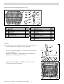 2
2
-
 3
3
-
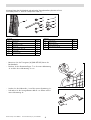 4
4
-
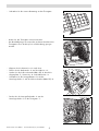 5
5
-
 6
6
-
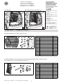 7
7
-
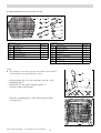 8
8
-
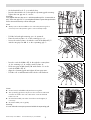 9
9
-
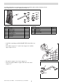 10
10
-
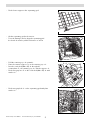 11
11
-
 12
12
-
 13
13
-
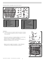 14
14
-
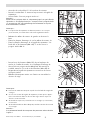 15
15
-
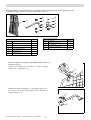 16
16
-
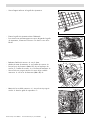 17
17
-
 18
18
-
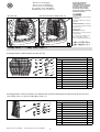 19
19
-
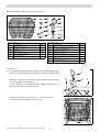 20
20
-
 21
21
-
 22
22
-
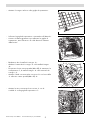 23
23
-
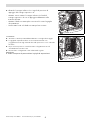 24
24
-
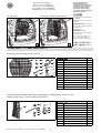 25
25
-
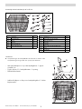 26
26
-
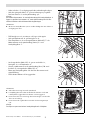 27
27
-
 28
28
-
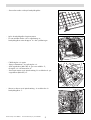 29
29
-
 30
30
-
 31
31
-
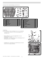 32
32
-
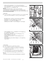 33
33
-
 34
34
-
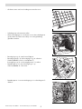 35
35
-
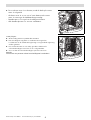 36
36
-
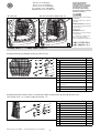 37
37
-
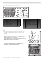 38
38
-
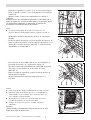 39
39
-
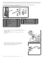 40
40
-
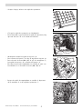 41
41
-
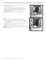 42
42
-
 43
43
-
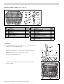 44
44
-
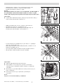 45
45
-
 46
46
-
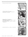 47
47
-
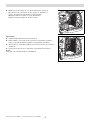 48
48
-
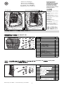 49
49
-
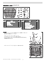 50
50
-
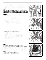 51
51
-
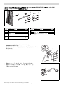 52
52
-
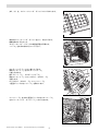 53
53
-
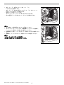 54
54


Volkswagen 2K0 017 222 Fitting Instruction
- Type
- Fitting Instruction
- Deze handleiding is ook geschikt voor
in andere talen
- English: Volkswagen 2K0 017 222
- italiano: Volkswagen 2K0 017 222
- français: Volkswagen 2K0 017 222
- español: Volkswagen 2K0 017 222
- Deutsch: Volkswagen 2K0 017 222
- čeština: Volkswagen 2K0 017 222
- 日本語: Volkswagen 2K0 017 222
- svenska: Volkswagen 2K0 017 222
Gerelateerde papieren
-
Volkswagen 3C9 017 221 Fitting Instructions Manual
-
-
-
-
-
-
