FLOTIDE SSC Series Salt Chlorinator Handleiding
- Categorie
- Accessoires voor bovengrondse zwembaden
- Type
- Handleiding

SSC SERIES
SALT CHLORINATOR
USER MANUAL
SSC25
Deutsch
English Fran aisçNederlands
MESW21090843

1.Working Principle.............................................................
3.Dimension........................................................................
4.Working condition.............................................................
5.Product specification........................................................
6.Product Features...................................................
7.Installation Guide...................................................
Installation............................................................
...............................................
......................................................
2.Product picture.................................................................
8.
9.Operation Overview
10.Control Panel
11.Timer operation (For specific model only)......................
12.Maintenance and troubleshooting..................................
3
3
6
7
8-9
9
10
4
4
4-5
5
6
CONTENT
English
2

3
Emaux Salt Chlorinator
Safe Pool Sanitizing
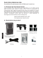
Working Principle
The chlorinator uses electrolysis to break down the salt (NaCl) in the
swimming pool to form Chlorine (Cl2). The control unit of the chlorinator can
regulate the chlorine production by altering the electric current flow through
the titanium electrode in the cell housing. Chlorine is an effective sanitizing
agent which is commonly used in swimming pools, it can inhabit the growth of
bacteria and fungi.
2NaCl+2H2O=2NaOH+H2↑+Cl2↑
Cl2+2NaOH=NaCl+NaClO+H2O
Product Features
ü
ü
ü
ü
ü
ü
Convenience and the constant delivery of pure chlorine-based sanitizer.
No more artificial chemical cleaning agent which could cause skin and eye
irritation. You just need to add natural salt in the pool.
The salt in the water is so little you do not taste or smell the salt.
The electrode is made of titanium, which is durable and resistant to
corrosion.
Easy to install and operate.
The water does not have the heavy smell of chlorine because chlorine is
not directly added to the pool.
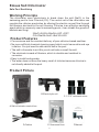
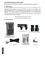
Product Picture
A.Salt chlorinator control box
B.Electrolytic cell C.1.5”/2” universal union
D.Cables E.Screw and fuse F.Manual
SSC25
English

4
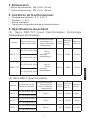
Product Dimension
!
!Electrolytic cell: 380 x 118 x 130 mm
Working Condition
!Environment Temperature: 0 degree Celsius to 50 degree Celsius
!Humdity: ≦ 85%
!Installation Area must be with good ventilation
!Keep away from other heat source
Chlorine Level Calculation
Required Chlorine Production Rate (g/hr) =
Standard Chlorine Level not less than 2mg/litre = 0.002g/litre
Example:
Pool Volume: 65m3 = 65,000litre
Turnover Rate: 4 Hour
Required Chlorine Production Rate (g/hr) = =32.5 g/hr
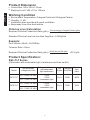
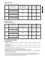
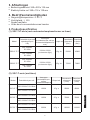
Product Specification:
SSC-TLT Series
(Chlorinator with underwater light, transformer and time switch)
Control Box: 360 x 220 x 135 mm
65,000 litre X 0.002 g/litre
4 Hours
Pool volume (litre) x Standard Chlorine (g/litre)
Turnover Rate (hr)
Salt chlorinator
voltage input/ freq
Rating (salt chlorinator
and underwater
light transformer)
220~250VAC 50/60Hz
100~120VAC 50/60Hz
220~250VAC 50/60Hz
100~120VAC 50/60Hz
100VA
+100VA
(underwater light)
100VA
+160VA
(underwater light)
15g/hr
25g/hr
Model
SSC15-TLT
SSC25-TLT
50000
75000
45000
70000
Fiberglass
Pool (Litre)
Cell
Output
Concrete
Pool
(Litre)
English

5
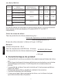
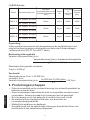
SSC-T Series
(Chlorinator with time switch)
SSC-E Series
(Basic Salt Chlorinator)
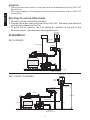
Installation Guide
Control Unit:
1. Select a convenient well-ventilated location within one meter of filter
equipment.
2. Mount the control unit vertically onto a post or wall 1.5 meters above
ground level.
(Australian Standards requires that the electric control unit shall not be
located within 3 meters of the pool water.)
3. Plug Power supply into a suitable weatherproof outlet
4. Plug pump into the power outlet of the Power Supply Unit. (applicable for
SSC-TLT Series only)
5. The Unit must be kept away from acid and other chemical storage areas.
Acid and chemical vapors will corrode the electronics inside the Unit.
6. It must also be kept away from heat sources.
SSC15-E
SSC25-E
220~250VAC 50/60Hz
100~120VAC 50/60Hz
220~250VAC 50/60Hz
100~120VAC 50/60Hz
100VA
160VA
15g/hr
25g/hr
SSC50-E
220~250VAC 50/60Hz
100~120VAC 50/60Hz
300VA 45g/hr
50000 45000
75000 70000
120000 110000
Model Salt chlorinator
voltage input/ freq
Cell
Output
Fiberglass
Pool (Litre)
Concrete
Pool(Litre)
Rating (salt chlorinator
and underwater
light transformer)
SSC15-T
SSC25-T
220~250VAC 50/60Hz
100~120VAC 50/60Hz
220~250VAC 50/60Hz
100~120VAC 50/60Hz
100VA
160VA
15g/hr
25g/hr
SSC50-T
220~250VAC 50/60Hz
100~120VAC 50/60Hz
300VA 45g/hr
50000 45000
75000 70000
120000 110000
Model Salt chlorinator
voltage input/ freq
Cell
Output
Fiberglass
Pool (Litre)
Concrete
Pool(Litre)
Rating (salt chlorinator
and underwater
light transformer)
English

Caution:
! The control unit can connect to one pump and one underwater light only (SSC-TLT
Series Only)
! The current loading of the pumped connected must not exceed 8 Amp. (SSC-TLT
Series Only)
Electrolytic cell and Electrode
1. The cell must be installed horizontally
2. Connect the water inlet and outlet to the Cell Unit. The water flow direction
must be as indicated on the Cell.
3. To avoid lost of chlorine, the Cell should be installed at the end of the
filtration system, right before the pool water return.
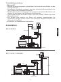
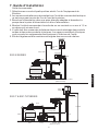
Installation
SSC-E SERIES
SSC-T & SSC-TLTSERIES
6
Waste
Filter Pump Suction
(Water from Pool)
Return to Pool
Pump
Return
Pump Cable
Cell Cable
Cell
Power
Supply
Control Box
Pool Light
Cable (if fitted)
1.5meter
Pole
Power Supply
Control Box
Pump Cable
Control Box
Cable
Cell Cable
Pump
Return
Filter Pump Suction
(Water from Pool)
Return to Pool
Cell
English

7
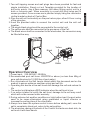
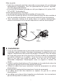
1. Two self-tapping screws and wall plugs have been provided for fast and
simple installation. Simply cut out Template provided for the location of
drill entry points. Use a 8mm masonry drill when fitting control unit to a
brick or concrete wall. When mounting to a post drill pilot holes and fit
screws provided. Once screws are in position simply hang the chlorinator
via the bracket on back of Control Box.
2. Glue the salt cell horizontally on the pool return pipe, allow 24 hour curing
of the pipe glue.
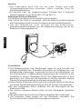
3. Used the provided cable to connect the control unit and the salt cell
together,
IThe single black plug should be connected to the control unit.
IThe yellow wire shall be connected to the gas senor of the Cell
IThe black wires shall be connected to the electrodes; the connectors may
be fitted either way.
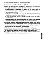
Operation Overview
1. Power input: 220-240VAC, 50/60Hz
2. Recommended pool salt lever: 4000PPM or above (no less than 40kg of
pure salt dissolved in 10,000 liter of pool water)
=Run chlorinator at the Salt Levels stated within this document and on the
product to ensure optimum sanitizer output and cell life.
=Operating this device at low salt levels will damage the cell and reduce its
life.
=The control unit displays a RED indicator when the salt level is low.
=If no action is taken to rectify the salt level, damage to the cell may result
which will not be covered under warranty.
3. During extreme hot weather conditions or high bather load, the pool water
need to be super-chlorinated using granulated or liquid chlorine or
increase the running time of the chlorinator.
4. Always turn down the system control to zero before adding salt, once the
salt is completely dissolved, return to the set position.
5. The aluminum casing at the back of the Control Unit acts as a heat sink, do
not touch it with bare hands.
Black
Yellow
Black
English

OFF
ON
ON
SYSTEM-CONTROL
MIN MAX
FUSE-250 V
F2.5 A
OPERATION
1
2
STAND-BY NO FLOW
WINTER
SWITCH
+
-
CELL
OFF
AUTO
FUSE-250 V
LIGHT
OFF
LIGHT
ON
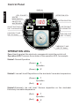
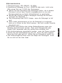
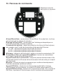
Control Panel
OPERATION LEDs
Fuse:Used to protect the electronic components inside the control unit.
Operation LED:There are three status of the operation LED, for example
Status1:Normal Operation
Status2: Low salt level/ Deposition on the electrode/ Low water temperature
Status3:Extremely low salt level/ Serious deposition on the electrode/
Extremely low water temperature
8
OPERATION LEDs
FUSE FOR SALT
CHLORINATOR
FUSE FOR LIGHT
(SSC-TLT ONLY)
TIMER
SSC-TLT ONLY)
(SSC-T AND
CELL POLARITY
WINTER
MODE SWITCH
ON/OFF FOR
WINTER MODE
LIGHT(SSC-T AND
SSC-TLT ONLY)
1
2
Operation
1
2
Operation
1
2
Operation
DISPLAY
ON/OFF BUTTON FOR
SALT CHLORINATOR
SYSTEM CONTROL
(Green)
(Green)
(Green)
(Red)
(Red)
(Red)
English

9
SALT CHLORINATOR On/Off/Auto: ON/Off Switch. In Auto mode, the
chlorinate is operated by the timer setting
Light On/Off: Switch for underwater light connected to the control unit (For
certain model)
System Control: Adjust the chlorine product of the chlorinator, for example,
for the control unit turned on for 8 hours
Set at 100% - The salt cell operated at 8 hours
Set at 50% - The salt cell operated at 4 hours
Set at 25% - The salt cell operated at 2 hours
Display: Show the percentage of the chlorine production
Winter Mode Switch and On/ Off LED: Turn on to change the chlorine
production at 85% .
Cell Polarity LED: Show the polarity of the electrodes; the polarity of the
electrode will shifted every 8 hrs of operation, so as to clean the deposition
on the electrode.
Timer: Used to set the program to turn on and off the control unit
automatically. (SSC-T AND SSC-TLT ONLY)
Stand-By LED: Turn on when chlorinate is in stand-by mode, When the
chlorinator is turn on, the standby LED will go off after 35 sec.
No Flow LED: Turn on if there is no water flow, if there is no water flow, the
pump and salt chlorinator will stop automatically.
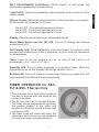
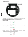
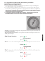
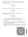
TIMER OPERATION for SSC-
TLT & SSC-T Series Only
1.Turn the outer clock face until the time of
the day is aligned with the clock at the
center of the timer
2.The 24-hour dial has 15 minutes division.
The timer can be programmed by pushing
the captive trippers to the outer ring
position for the entire period that the load
is to be turn ON.
3.The timer clock will rotate with time; the
chlorinator will be turned on automatically
if its captive tripper is pushed outward.
English

10
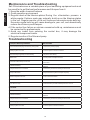
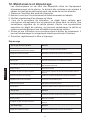
Maintenance and Troubleshooting
Troubleshooting
Salt Chlorinators are a valuable piece of pool sanitizing equipment and must
be cared for to get the best performance and life span from it.
1. Keep the water chemical balance
2. Good operation environment
3. Regular check of the titanium plates.During the chlorination process a
white powder Calcium scale may naturally build up on the titanium plates
in the cell. Regular monitor of the cell to prevent excessive scale build up.
Excessive scale build up will cause damage to your cell, and dramatically
reduce its efficiency and lifespan.
4.If the control box failure or calcium excessive build up, maintenance must
be carried out by professionals.
5. Avoid any incest from entering the control box, it may damage the
electrical component inside.
6. Regular monitor of the filter and pump
1. Low/no chlorine production How to handle
- Check the electrical plug/control box/ pump power - Connect the power properly
- Setting system is too low - Turn the system control to maximum
- Automatically stopped by the timer setting - Adjust the timer setting
- Blown fuse - Cut the power and replace the fuse
- excessive scale build up on the cell
- Switch off the salt chlorinator and clean the salt cell by professional
serviceman.
- Filter Backwashing - Once the backwash is complete, turn the filter back to normal
filtration
- The gas sensor is not connected - Connect the gas senor according to this manual
- Pump malfunction - Stop the filtration system and repair the pump
- Water temperature too low - Turn on the winter switch
- Salt lever too low - Add salt to the pool
- pH valve too high - Check the water pH valve and keep it around 7.0-7.6
2. No flow
- Pump malfunction - Stop the filtration system and repair the pump
- Filter Backwashing - Once the backwash is complete, turn the filter back to normal
filtration
- The gas sensor is not connected - Connect the gas senor according to this manual
3. No display
- Setting system is too low - Turn the system control to maximum
English

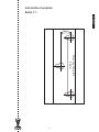
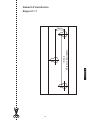
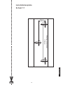
Installation template
Ratio 1:1
90mm
Mounting Template
16mm
English
11

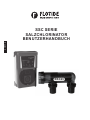
SSC SERIE
SALZCHLORINATOR
BENUTZERHANDBUCH
SSC25
Deutsch

1.Arbeitsprinzip....................................................................
3.Abmessung.......................................................................
4.Arbeitszustand.............................................
5.Produktspezifikation...............................
6.Produkteigenschaften
7.Installationsanleitung
Installation
2.Produktbild.......................................................................
.....................
...........................
.......................................................
........................................................
8. ........................................................................
9.Bedienungsüberblick.........................................................
10.Steuertafel.......................................................................
11.Timerbetrieb (nur für spezielles Modell)...........................
12.Wartung und Problemlösung............................................
3
3
6
7
8-9
9
10
4
4
4-5
5
6
INHALTSVERZEICHNIS
2
Deutsch

3
SALZCHLORINATOR
Sichere und zuverlässige Poolreinigung
1.Arbeitsprinzip
Der Chlorinatorbricht durch Elektrolysedas Salz (NaCl) auf, das dem
Swimmingpool beigegeben wurde und bildet daraus Chlor (Cl2). Die
Steuereinheit des Chlorinators kann die Chlorproduktion durch Anpassung
des Stromflusses durch die Titanelektrodedes Zellengehäuses steuern.
Natriumhypochlorid bildet sich aus Chlor. Es ist ein wirkungsvolles
Reinigungsmittel, das häufig in Swimmingpools eingesetzt wird. Es kann das
Wachstum von Bakterien und Pilzen verhindern.
2NaCl+2H2O=2NaOH+H2↑+Cl2↑
Cl2+2NaOH=NaCl+NaClO+H2O
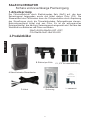
2.Produktbilder
A.Salzchlorinator-Steuerkasten
B.Elektrolyse-Zelle
C.1,5”/2” Universalverbindung
D. Kabel E. Schraube und
Sicherung F. Handbuch
SSC25
Deutsch

4
3. Abmessungen
!
!Elektrolyse-Zelle: 380 x 118 x 130 mm
4. Arbeitszustand
! Umgebungstemperatur: 0°C-50°C
! Feuchtigkeit: ≦ 85%
! Gute Belüftung
! Von anderer Wärmequelle entfernt halten
!
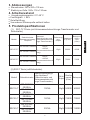
5. Produktspezifikationen
(1) SSC-TLT-Serie (mit Unterwasserbeleuchtungs-Transformator und
Zeitschalter)
Steuerkasten: 360 x 220 x 135 mm
Modell
Salzchlorinator
Spannungseingang/
Frequenz
Nennwert
(Salzchlorinator und
Unterwasserbeleucht
ungs-Transformator)
Zellenausg
ang
Output
Glasfaserp
ool (Liter)
Betonpool
(Liter)
Pool
(Liter)
SSC15-TLT
220-250VAC 50/60Hz
100VA
+100VA
(Unterwasserbeleuch
tung)
15g/h
50000
45000
100-120VAC 50/60Hz
SSC25-TLT
220-250VAC 50/60Hz
100VA
+160VA
(Unterwasserbeleuch
tung)
25g/h
75000
70000
100-120VAC 50/60Hz
(2).SSC-T Serie (mitZeitschalter)
Modell
Salzchlorinator
Spannungseingang/F
requ.Nennwert
(Salzchlorinator und
Unterwasserbeleucht
ungs-Transformator)
Zelle
Output
Glasfas
erpool
(Liter)
Betonpoo
SSC15-T
220-250VAC
50/60Hz
100VA
15g/h
50000
45000
100-120VAC
50/60Hz
SSC25-T
220-250VAC
50/60Hz
160VA
25g/h
75000
70000
100-120VAC
50/60Hz
SSC50-T
220-250VAC
50/60Hz
300VA
45g/h
120000
110000
100-120VAC
50/60Hz
Deutsch

5
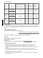
(3).SSC-E Serie
Modell
Salzchlorinator
Spannungseingang/Fre
qu.Nennwert(Salzchlori
nator
undUnterwasserbeleuch
tungs-Transformator)
Zelle
Output
Glasfaserp
ool (Liter)
Betonpool
(Liter)
Pool(Liter)
SSC15-
E
220~250VAC
50/60Hz
100VA
15g/h
50000
45000
100~120VAC
50/60Hz
SSC25-
E
220~250VAC
50/60Hz
160VA
25g/h
75000
70000
100~120VAC
50/60Hz
SSC50-
E
220~250VAC
50/60Hz
300VA
45g/h
120000
110000
100~120VAC
50/60Hz
Anmerkung:
Nur eine Pumpewird mit dem Salzchlorinator verbunden. Die aktuellen
Werte der Pumpe übersteigen nicht 8Amp (nur bei Serie SSC-TLT und SSC-T
Serie)
Chlorpegelberechnung
Erforderliche Chlorproduktionsrate (g/h)=
Standard-Chlorpegel: nicht unter 2mg/Liter = 0,002 g/Liter
Poolvolumen (Liter) x Standardchlor (g/Liter)
Umsatzrate (hr)
Beispiel:
Pool-Volumen: 65m3 = 65.000 Liter
Umsatzrate: 4 Stunden
Literg/Liter
Erforderliche Chlorproduktionsrate (g/h)=
65,000 litre X 0.002 g/litre
4 h
=32.5 g/h
6.Produkteigenschaften
√ Praktische und ständige Lieferung reinen chlorbasierten Reinigungsmittels
√ Keine künstlichen chemischen Reinigungsmittel mehr, die zu Haut- und
Augenreizungen führen können. Nur natürliches Salz muss dem Pool zugegeben
werden.
√ Es ist so wenig Salz im Wasser, dass es nicht riech- oder schmeckbar ist.
√ Die Elektrodebesteht aus Titan, einem dauerhaften Material, das korrosionsfest
ist.
√ Einfach zu installieren und zu betreiben.
√ Dem Wasser fehlt der schwere Geruch von Chlor, da Chlor dem Pool nicht direkt
zugegeben wird.
Deutsch

7.Installationsanleitung
Steuergerät
1.Wählen Sie einen geeigneten, gut belüfteten Ort innerhalb eines Meters um das
Filtergerät herum.
2.Australische Standards verlangen, dass das elektrischeSteuergerätmehr als
drei (3) Meter vom Poolwasser entfernt ist.
3.Stecken Sie die Stromversorgung in eine geeignete wasserfeste Steckdose und
stecken Sie die Pumpe in die Steckdose des Netzgeräts.
4. Steuergerät vertikal auf einem Pfosten oder einer Wand 1,5Meter über dem
Boden montieren.
5.Die Einheit muss entfernt von Säure und anderen Lagerbereichen für
Chemikalien gelagert werden. Säure- und chemische Dämpfe korrodieren die
Elektronik in dem Gerät.
6.Es ist auch von Wärmequellen fernzuhalten.
Installation
SSC-E SERIES
SSC-T & SSC-TLTSERIES
6
Waste
Filter Pump Suction
(Water from Pool)
Return to Pool
Pump
Return
Pump Cable
Cell Cable
Cell
Power
Supply
Control Box
Pool Light
Cable (if fitted)
1.5meter
Pole
Power Supply
Control Box
Pump Cable
Control Box
Cable
Cell Cable
Pump
Return
Filter Pump Suction
(Water from Pool)
Return to Pool
Cell
Deutsch

7
Vorsicht:
--Das Steuergerät kann sich mit nur einer Pumpe und einer
Unterwasserbeleuchtung verbinden. Siehe vorherige Seite für
Produktspezifikationen
--Die aktuelle Last der angeschlossenen Pumpen darf 8 Ampnicht
überschreiten(gilt nur für Serie SSC-TLT und SSC-T).
Elektrolyse-Zelle und Elektrode
1.Die Elektrolyse-Zellemuss horizontal installiert werden.
2.Um Verlust von Chlor zu vermeiden, sollte die Elektrolyse-Zelleam Ende
des Filtersystems direkt vor dem Poolwasserrücklauf installiert werden.
3.Um den Wasserein- und -auslass an die Elektrolyse-
Zelleanzuschließen,beachten Sie die Wasserflussrichtung, die an der
Elektrolyse-Zelle angegeben ist.
Black
Yellow
Black
8.Installation
1.Drei Madenschrauben und Wandstecker liegen für eine schnelle und
einfache Installation bei. Schneiden Sie einfach die Schablone aus, um
die Bohrstellen festzulegen. Verwenden Sie einen 8-mm-Steinbohrer, um
die Schraublöcher in dieBetonwand entsprechend der Positionin in der
Schablone zu bohren. Befestigen Sie die drei Madenschrauben in dem
gebohrten Loch. Wenn sich die Schrauben in Position befinden, hängen
Sie den Chlorinatoreinfach an die Klammer hinten am Gerät.
2.Kleben Sie die Elektrolyse-Zelle horizontal auf das Rücklaufrohr des Pools
und lassen Sie die Klebeverbindung am Rohr 24 Stunden lang aushärten.
3.Mit dem beiliegenden Kabel verbinden Sie das Steuergerät mit der
Elektrolyse-Zelle.
ø Der einzelne schwarze Stecker sollte mit dem Steuergerät verbunden
werden.
ø Das gelbe Kabel wird mit dem Gas-Sensor derselben Zelle verbunden.
ø Die schwarzen Kabel werden mit den Elektroden verbunden. Die
Anschlüsse können in jeder Richtung angebracht werden.
Deutsch

9.Betriebsüberblick
1. Stromversorgung: 220-240VAC, 50/60Hz
2.Empfohlener Salzpegel im Pool: 4000PPM oder mehr (nicht unter
40kg reines Salz pro 10.000 Liter Poolwasser)
▶ Lassen Sie den hlorinatorit den Salzpegeln laufen, die in diesem
Dokument und auf dem Produkt vorgegebensind um ine este
Reinigungswirkung und lgste Zellenstandzeit zu gewrleisten
▶ Betrieb des Gers mit gringen Salzpegeln beschigt die Zelleund
verringert die Standzeit
▶ Das teuergereigt eine ROTE Lampe, wenn die Salzpegel zu tief
sind
▶ Wenn nichts unternommen ird um die Salzpegel zu korrigieren,
kann es zu Schen an der Zelle kommen, der nicht vonder Garantie
abgedeckt wird
3. Bei extrem heim Wetter oder hohem Badeaufkommen muss das
Polasser superchloriniert werden. Dazu wird Chlorgranulat oder
flsiges Chlor verwendet oder die Laufzeit des hlorinator erht
4. Der alzchlorinatoruss usgeschaltet werden, wenn die Pumpe arbeitet.
5. Drehen Sie die Systemsteuerung auf null, bevor Sie Salz zugeben.
Wenn das Salz ganz gelt ist, stellen Sie die Sollposition wieder her
6. Das Aluminiumgehse hinten dient als Klkper des Steuergers. erren
Sie es nicht mit der blon Hand
Deutsch
8

10.Steuertafel
Sicherung: wird verwendet, um die elektronischen Bauteile in der
Steuereinheit zu schützen.
Bedienungs-LED:die Bedienungs-LED hat drei Statusanzeigen.
Status 1: Normaal
Status2: Geringer Salzpegel/Ablagerung auf der Elektrode/geringe
Wassertemperatur
Status3: Besonders geringer Salzpegel/starke Ablagerung auf der
Elektrode/besonders geringe Wassertemperatur
1
2
Betrieb
1
2
Betrieb
1
2
Betrieb
(Green)
(Green)
(Green)
(Red)
(Red)
(Red)
Deutsch
Siehe folgende
Beschreibung
9

10
Ein/Aus/Auto:EIN/AUS-Schalter im Auto-Modus. Der Chlorinator wird per
Timergesteuert.
Licht ein/aus:Schalter für Unterwasserbeleuchtung, verbunden mit dem
Steuergerät (für ein bestimmtes Modell)
Systemsteuerung:Einstellen des Chlorproduktsdes Chlorinators,z. B. für
das Steuergerät, das 8 Stunden lang eingeschaltet wird.
Einstellung auf 100 - Die Elektrolysezelle läuft 8 Stunden lang.
Einstellung auf 50 - Die Elektrolysezelle läuft 4 Stunden lang.
Einstellung auf 25 - Die Elektrolysezelle läuft 2 Stunden lang.
Anzeige:Zeigt die Chlorproduktion an, für höchste Leistung auf 100
stellen.Winterschalter und Ein/Aus-LED:Drehen, um Chlorproduktionauf 85
einzustellen.
Zellenpolaritäts-LED:Polarität der Elektroden einstellen;
Elektrodenpolarität wird alle 8 Betriebsstunden geändert, um Ablagerungen
an der Elektrode zu vermieden.
Timer: Wird verwendet, um das Steuergerät automatisch ein- und
auszuschalten.
Stand-by-LED:Einschalten, wenn der Chlorinator im Stand-by-Modus ist.
Wenn der Chlorinatoreingeschaltet wird, geht die Stand-by-LEDnach 35 s
aus.
LED kein Fluss:Leuchtet auf, wenn kein Wasserfluss vorhanden ist. Die
Pumpeund der Salzchlorinatorhalten automatisch an.
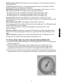
11.Timerbetrieb (nur für bestimmtes Modell)
1.Drehen Sie das äußere Uhrblatt, bis die Tageszeit der Uhr in der Mitte des
Timers entspricht.
2.Die 24-Stunden-Anzeige hat eine Unterteilung von 15 Minuten. Der
Timerkann durch Eindrücken der Auslöser auf der Außenringposition
programmiert werden, bis zu der die Last eingeschaltet werden soll.
3.Die Timeruhr dreht sich mit der Zeit, und der Chlorinatorwird automatisch
eingeschaltet, wenn der eingedrückte Auslöser nach außen gedrückt wird.
Deutsch

11
12.Wartungund Problemlösung
Salzwasserchlorinatorensind wertvolle Geräte zur Reinigung von Pools. Sie
müssen gut gepflegt werden, um einebessereLeistung und Lebensdauer
zu ermöglichen.
1.Erhalt des chemischen Gleichgewichts im Wasser
2.Gute Betriebsumgebung
3.Regelmäßig prüfen die Titaniumplatten.
4.Bei der Chlorinierung kann sich Kalzium als weißes Pulver natürlich an
den Titaniumplatten der Zelle aufbauen. Die Zelle regelmäßig prüfen, um
übermäßigen Kalkaufbau zu vermeiden. Übermäßiger Kalkaufbau
beschädigt die Zelle und verringert den Wirkungsgrad und die
Lebensdauer dramatisch.
5.Der Steuerkasten darf innen nicht nass werden. Dies würde die
elektrischen Bauteile beschädigen.
6.Filter und Pumpe regelmäßig überprüfen.
Problemlösung
1. Geringe/keine Chlorproduktion
Korrekturmaßnahme
Stromstecker/Steuerkasten/Pumpenenergie
prüfen
Stromversorgung korrekt anschließen
Systemeinstellung zu gering
Systemsteuerung auf Maximum stellen
Automatisch mit der Timer-Einstellung
eingestellt
Timer-Einstellung anpassen
Durchgebrannte Sicherung
Strom abstellen und Sicherungersetzen
Übermäßige Kalkbildung in der Zelle
Salzchlorinatorausschalten und Salzzelle
durch Fachmann reinigen lassen.
Filterrückspülung
Nach dem Rückspülen schalten Sie den Filter
wieder in normalen Filterbetrieb.
Der Gas-Sensor ist nicht angeschlossen
Schließen Sie den Gassensor laut diesem
Handbuch an.
Fehlfunktion der Pumpe
Filtersystem anhalten und Pumpe reparieren
Wassertemperatur zu gering
Salzpegel zu gering
Dem Pool Salz zugeben
pH-Wert zu hoch
pH-Wert des Wassers prüfen und auf ca. 7,0-
7,6 halten
2. Kein Durchfluss
Korrekturmaßnahme
Fehlfunktion der Pumpe
Filtersystemanhalten und Pumpe reparieren.
Filterrückspülung
Nach dem Rückspülen schalten Sie den Filter
Der Gassensor ist nicht angeschlossen
Schließen Sie den Gassensor laut diesem
3. Keine Anzeige
Korrekturmaßnahme
Systemeinstellung zu gering
Systemsteuerung auf Maximum stellen
Deutsch

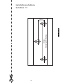
Installationsschablone
Verhältnis 1:1
90mm
Montageschablone
16mm
12
Deutsch

SÉRIE SSC
ÉLECTROLYSEUR AU SEL
MANUEL D'UTILISATION
SSC25
Fran aisç

1. Principe de fonctionnement...............................................
3. Dimensions........................................................................
4. Condition de fonctionnement.............................................
5. Spécifications du produit....................................................
6. Caractéristiques du produit.......................................
7. Guide d'installation..................................................
Installation.............................................................
.............................
..........................................
2. Illustration du produit.........................................................
8.
9. Vue d'ensemble du fonctionnement
10. Panneau de commande
11. Fonctionnement du minuteur
(modèle spécifique uniquement) .....................................
12. Maintenance et dépannage.............................................
3
3
6
7
8-9
9
10
4
4
4-5
5
6
TABLE DES MATIÈRES
2
Fran aisç

3
ÉLECTROLYSEUR AU SEL
Une méthode d'assainissement sûre et fiable pour les piscines
1. Principe de fonctionnement
L'électrolyseur utilise l'électrolyse pour décomposer le sel (NaCl) ajouté
dans la piscine pour former le chlore (Cl2). L'unité de commande de
l'électrolyseur peut réguler la production de chlore en modifiant le courant
électrique qui circule dans l'électrode en titane dans le boîtier de la cellule.
L'hypochlorite de sodium formé à partir de chlore est un agent assainissant
efficace, couramment utilisé dans les piscines. Il peut empêcher le
développement des bactéries et des champignons.
2NaCl+2H2O=2NaOH+H2↑+Cl2↑
Cl2+2NaOH=NaCl+NaClO+H2O
2. Illustration du produit
A.Boîtier de commande de
l'électrolyseur au sel
B.Cellule électrolytique C.Raccord universel
3,75/5 cm (1,5”/2”)
D.Câbles E.Vis et fusible F.Manuel
SSC25
Fran aisç

4
3. Dimensions
!
!Cellule électrolytique : 380 x 118 x 130 mm
4. Condition de fonctionnement
! Température ambiante :0 °C à 50 °C
! Humidité : ≦ 85 %
! Bonne ventilation
! À maintenir éloigné des autres sources de chaleur
5. Spécifications du produit
(1). Série SSC-TLT (avec transformateur d'éclairage
subaquatique et minuterie)
Boîtier de commande : 360 x 220 x 135 mm
Modèle
Électrolyseur au sel
tension entrée/fréqu.
Puissance nominale
(électrolyseur et
transf. d'éclairage
subaquatique)
Sortie
cellule
Bassin en
fibre de
verre (l)
Bassin en
béton (l)
SSC15-TLT
220-250 Vca 50/60 Hz
100 VA
+100 VA
(éclairage
subaquatique)
15 g/h
50 000
45 000
100-120 Vca 50/60 Hz
SSC25-TLT
220-250 Vca 50/60 Hz
100 VA
+160 VA
(éclairage
subaquatique)
25 g/h
75 000
70 000
100-120 Vca 50/60 Hz
(2). Série SSC-T (avec minuterie)
Modèle
Electrolyseur au sel
tension entrée/fréqu.
Puissance nominale
(électrolyseur et
transf. d'éclairage
subaquatique)
Sortie
cellule
Bassin en
fibre de
verre (l)
Bassin en
béton (l)
SSC15-T
220-250 Vca 50/60 Hz
100 VA
15 g/h
50 000
45 000
100-120 Vca 50/60 Hz
SSC25-T
220-250 Vca 50/60 Hz
160 VA
55/h
75 000
70 000
100-120 Vca 50/60 Hz
SSC50-T
220-250 Vca 50/60 Hz
300 VA
55/h
120 000
110 000
100-120 Vca 50/60 Hz
Fran aisç

5
(3).Série SSC-E
Remarque :
Modèle
Electrolyseur au sel
tension
entrée/fréquence
Puissance nominale
(électrolyseur et
transf. d'éclairage
Sortie
cellule
Bassin en
fibre de
verre (l)
Bassin en
béton (l)
SSC15-E
220~250 Vca 50/60 Hz
100 VA
15 g/h
50 000
45 000
100~120 Vca 50/60 Hz
SSC25-E
220~250 Vca 50/60 Hz
160 VA
25 g/h
75 000
70 000
100~120 Vca 50/60 Hz
SSC50-E
220~250 Vca 50/60 Hz
300 VA
45 g/h
120 000
110 000
100~120 Vca 50/60 Hz
Une seule pompe est raccordée à l'électrolyseur au sel. Le courant nominal
de la pompe ne doit pas dépasser 8 A (séries SSC-TLT et SSC-T
uniquement).
Calcul du niveau de chlore
Taux de production de chlore nécessaire (g/h) =
Volume de la piscine (l) x chlore standard (g/l)
taux de remplacement (h)
Niveau de chlore standard : inférieur à 2 mg/l = 0,002 g/l
Exemple :
3
Volume de la piscine : 65 m
Taux de remplacement 65 000 litres : 4 heures
Taux de production de chlore nécessaire (g/h) = 65 000X 0,002 litreg/l
4 h
= 32,5 g/h
6. Caractéristiques du produit
√ Commodité et fourniture constante d'un assainissement à base de chlore
pur.
√ Plus d'agent nettoyant chimique artificiel pouvant entraîner une irritation
dermatologique et oculaire. Il suffit d'ajouter du sel naturel dans la
piscine.
√ La quantité de sel dans l'eau est si réduite qu'il n'est pas perceptible au
goût ou à l'odeur.
√ L'électrode est en titane, durable et résistant à la corrosion.
√ Facilité d'installation et d'utilisation.
√ L'eau ne sent pas l'odeur puissante du chlore, car le chlore n'est pas
ajouté directement dans la piscine.
Fran aisç

6
Waste
Filter Pump Suction
(Water from Pool)
Return to Pool
Pump
Return
Pump Cable
Cell Cable
Cell
Power
Supply
Control Box
Pool Light
Cable (if fitted)
1.5meter
Pole
Power Supply
Control Box
Pump Cable
Control Box
Cable
Cell Cable
Pump
Return
Filter Pump Suction
(Water from Pool)
Return to Pool
Cell
7. Guide d'installation
Unité de commande
1. Sélectionnez un endroit pratique bien aéré à 1 m de l'équipement de
filtration.
2. Les normes australiennes nécessitent que l'unité de commande électrique
ne se trouve pas à moins de 3 m de l'eau de la piscine.
3. Branchez l'alimentation dans une prise étanche adaptée et branchez la
pompe dans la prise d'alimentation du bloc d'alimentation.
4. Montez l'unité de commande à la verticale sur un montant ou un mur à 1,5 m
au-dessus du niveau du sol.
5. L'unité doit être conservée à distance des zones de stockage des produits
acides et des autres produits chimiques. Les vapeurs acides et chimiques
vont corroder les composants électroniques à l'intérieur de l'unité.
6. Elle doit également être maintenue éloignée des sources de chaleur.
Fran aisç
SSC-E SERIES
SSC-T & SSC-TLTSERIES

7
Mise en garde :
--L'unité de commande peut être raccordée à une pompe et à un éclairage
subaquatique uniquement. Pour les spécifications du produit, reportez-
vous aux pages précédentes.
--Le courant de la pompe raccordée ne doit pas dépasser 8 A (séries SSC-
TLT et SSC-T uniquement).
Cellule électrolytique et électrode
1. La cellule électrolytique doit être installée à l'horizontale.
2. Pour éviter la perte de chlore, la cellule électrolytique doit être installée à
la fin du système de filtration, juste avant le retour de l'eau de la piscine.
3. Pour raccorder l'entrée et la sortie d'eau à la cellule électrolytique,
observez la direction du flux d'eau indiquée sur la cellule électrolytique.
8. Installation
1. Trois vis auto-taraudeuses et des prises murales sont fournies pour une
installation rapide et simple. Découpez simplement le gabarit fourni pour
repérer l'emplacement des points de perçage. Utilisez un foret de maçon
de 8 mm pour percer les trous des vis sur la paroi en béton en respectant
la position indiquée sur le gabarit. Fixez les trois vis auto-taraudeuses
dans le trou que vous venez de percer. Une fois les vis en place,
suspendez simplement l'électrolyseur avec un support à l'arrière de
l'unité.
2. Collez la cellule électrolytique à l'horizontale sur la conduite de retour de
la pompe et laissez durcir la colle pendant 24 heures.
3. Utilisez le câble fourni pour raccorder l'unité de commande à la cellule
électrolytique.
ø La prise noire simple doit être branchée à l'unité de commande.
ø Le câble jaune doit être branché au capteur de gaz de la cellule
électrolytique.
ø Les câbles noirs doivent être branchés aux électrodes. Les connecteurs
peuvent être posés d'un côté ou de l'autre.
Black
Yellow
Black
Fran aisç

9. Vue d'ensemble du fonctionnement
Fran aisç
8

9
Fran aisç
Reportez-vous à la
description ci-dessous
10. Panneau de commande
Allumé/Éteint/Auto : commutateur Allumé/Éteint. En mode Auto, le chlore
est actionné par le réglage du minuteur.
Éclairage allumé/éteint : commutateur de l'éclairage subaquatique sur
l'unité de commande (certains modèles)
Commande du système : réglez la production de chlore de l'électrolyseur,
par exemple, pour l'unité de commande activée pendant 8 heures
sur 100 - cellule électrolytique actionnée à 8 heures
sur 50 - cellule électrolytique actionnée à 4 heures
sur 25 - cellule électrolytique actionnée à 2 heures
Affichage : indique le chlore produit, réglé sur une sortie maximale de 100
Commutateur Hiver et voyant Allumé/Éteint : tournez ce commutateur
pour régler la production de chlore sur 85.
Voyant Polarité de la cellule LED : indique la polarité des électrodes. Elle
est décalée toutes les 8 heures de fonctionnement afin de nettoyer le dépôt
sur l'électrode.
Minuteur : permet de régler le programme pour mettre automatiquement
l'unité de commande sous/hors tension.
Voyant LED Veille : allumé lors le chlore est en mode Veille. Lorsque
l'électrolyseur est sous tension, le voyant LED Veille s'éteint après 35 s.
Voyant LED Pas de flux : allumé s'il n'y a pas de flux d'eau. S'il n'y a pas de
flux d'eau, la pompe et l'électrolyseur au sel s'arrêtent automatiquement.

10
11. Fonctionnement du minuteur (modèle
spécifique uniquement)
1. Tournez l'horloge extérieure jusqu'à ce que l'heure du jour soit alignée
avec l'horloge au centre du minuteur.
2. Le cadrant au format 24 heures est divisé par incréments de 15 minutes.
Le minuteur peut être programmé en appuyant sur les boutons captifs sur
la position de la bague extérieure pendant toute la durée pendant laquelle
la charge doit être mise sous tension.
3. L'horloge du minuteur tourne avec le temps, l'électrolyseur est activé
automatiquement si le bouton captif associé est actionné.
Fran aisç
Fusible : permet de protéger les composants électroniques à l'intérieur de
l'unité de commande.
Voyant de fonctionnement : le voyant de fonctionnement peut avoir trois
états, par exemple
État1:Normal Operation
État 2 : niveau de sel bas/dépôt sur l'électrode/température de l'eau basse
État 3 : niveau de sel très bas/ dépôt important sur l'électrode/température
de l'eau très basse
1
2
Fonctionnement
(Green)
(Green)
1
2
(Green)
(Red)
Fonctionnement
1
2
(Red)
(Red)
Fonctionnement

11
12. Maintenance et dépannage
Les électrolyseurs au sel sont des dispositifs utiles de l'équipement
d'assainissement de la piscine. Ils doivent être entretenus de manière à
obtenir les meilleures performances et une durée de service étendue.
1. Préservez l'équilibre des produits chimiques.
2. Assurez-vous que l'environnement de fonctionnement est adapté.
3. Vérifiez régulièrement les plaques en titane.
4. Lors de la procédure de chloration, un dépôt blanc calcaire peut
s'accumuler naturellement sur les plaques de titane dans la cellule. Une
surveillance régulière de la cellule permet d'éviter une accumulation
excessive du dépôt de calcaire, qui pourrait endommager la cellule et
réduire considérablement son efficacité et sa durée de service.
5. Évitez qu'une infiltration ne se produise dans le boîtier de commande. Il
pourrait endommager les composants électriques situés à l'intérieur.
6. Surveillez régulièrement le filtre et la pompe.
Dépannage
1. Pas ou peu de chlore produit
Solution
Vérifiez la prise électrique/le boîtier de
commande/l'alimentation de la pompe.
Branchez correctement l'alimentation.
Réglage du système trop bas
Mettez la commande du système au maximum.
Arrêt automatique par le réglage du minuteur
Réglez le minuteur.
Fusible grillé
Coupez l'alimentation et remplacez le fusible.
Accumulation excessive de dépôt sur la cellule
Coupez l'électrolyseur au sel et faites nettoyer la cellule
par des professionnels.
Lavage du filtre
Une fois le lavage terminé, remettez le filtre en mode
Filtration normale.
Le capteur de gaz n'est pas connecté.
Connectez le capteur de gaz selon les indications de ce
manuel.
Dysfonctionnement de la pompe
Arrêtez le système de filtration et réparez la pompe.
Température de l'eau trop basse
Activez le commutateur Hiver.
Niveau de sel trop bas
Ajoutez du sel dans la piscine.
PH trop élevé
Vérifiez le PH de l'eau et maintenez-le autour de 7.0-7.6.
2. Pas de flux
Solution
Dysfonctionnement de la pompe
Arrêtez le système de filtration et réparez la pompe.
Lavage du filtre
Une fois le lavage terminé, remettez le filtre en mode
Filtration normale.
Le capteur de gaz n'est pas connecté.
Connectez le capteur de gaz selon les indications de ce
manuel.
3. Pas d'affichage
Solution
Réglage du système trop bas
Mettez la commande du système au maximum.
Fran aisç

Gabarit d'installation
Rapport 1:1
90mm
Gabarit de montage
16mm
12
Fran aisç

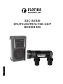
SSC-SERIE
ZOUTELEKTROLYSE-UNIT
BEDIENING
SSC25
Nederlands

1. Werking.............................................................................
3. Afmetingen........................................................................
4. Bedrijfsomstandigheden....................................................
5. Productspecificaties..........................................................
6. Producteigenschappen............................................
7. Installatiehandleiding...............................................
Installatie..............................................................
.............................................................
..................................................
2. Overzicht...........................................................................
8.
9. Bediening
10. Bedieningspaneel
11. Timer (uitsluitend voor specifiek model)..........................
12. Onderhoud en probleemwijzer........................................
3
3
6
7
8-9
9
10
4
4
4-5
5
6
INHOUD
2
Nederlands

3
ZOUTELEKTROLYSE-UNIT
Een veilige en betrouwbare manier om uw zwembad te ontsmetten
1. Werking
De chloorelektrolyse-unit gebruikt elektrolyse om het zout (NaCl) dat in het
zwembad werd gedaan om chloor (Cl2)te vormen, af te breken. De
bedieningseenheid van de chloorelektrolyse-unit regelt de chloorproductie
door de elektrische stroom door de titaniumelektrode in de celbehuizing te
wijzigen. Uit chloor gevormd natriumhypochloriet is een doeltreffend
ontsmettingsmiddel dat vaak wordt gebruikt in zwembaden en gaat de groei
van bacteriën en schimmels tegen.
2NaCl+2H2O=2NaOH+H2↑+Cl2↑
Cl2+2NaOH=NaCl+NaClO+H2O
2. Overzicht
A.Bedieningseenheid
zoutelektrolyse-unit
B.Electrolytic cell C.1.5”/2” universal union
SSC25
D. Kabels E.Screw and fuse F.Manual
Nederlands

4
3. Afmetingen
!
!Elektrolytische cel: 380 x 118 x 130 mm
4. Bedrijfsomstandigheden
!Omgevingstemperatuur:0-50 °C
!Vochtigheid: ≦ 85%
!Goede ventilatie
!Uit de buurt van warmtebronnen houden
5. Productspecificaties
(1). SSC-TLT-serie (met onderwaterlamptransformer en timer)
Bedieningseenheid: 360 x 220 x 135 mm
Model
Zoutelektrolyse-unit
spanningsinput/
freq
Vermogen
(zoutelektrolyse-unit en
onderwaterlamptransfor
mer)
Output cel
Zwembad in
glasvezel
(liter)
Zwembad
in beton
(liter)
SSC15-TLT
220-250VAC
50/60Hz
100VA+100VA
(underwater light)
15g/hr
50000
45000
100-120VAC
50/60Hz
SSC25-TLT
220-250VAC
50/60Hz
100VA+160VA
(underwater light)
25g/hr
75000
70000
100-120VAC
50/60Hz
(2). SSC-T-serie (met timer)
Model
Zoutelektrolyse-unit
Vermogen
(zoutelektrolyse-
unit en
onderwaterlamptran
Output cel
Zwembad in
glasvezel
(Litre)
Zwembad
in beton
(Litre)
SSC15-T
220-250VAC 50/60Hz
100VA
15 g/u
50000
45000
100-120VAC 50/60Hz
SSC25-T
220-250VAC 50/60Hz
160VA
25 g/u
75000
70000
100-120VAC 50/60Hz
SSC50-T
220-250VAC 50/60Hz
300VA
45 g/u
120000
110000
100-120VAC 50/60Hz
Nederlands

5
(3).SSC-E-serie
Model
Zoutelektrolyse-unit
Vermogen
(zoutelektrolyse-unit en
onderwaterlamptransfor
mer)
Output
cel
Zwembad
in
glasvezel
(liter)
Zwembad
in beton
(liter)
SSC15-E
220~250VAC 50/60Hz
100VA
15g/hr
50000
45000
100~120VAC 50/60Hz
SSC25-E
220~250VAC 50/60Hz
160VA
25g/hr
75000
70000
100~120VAC 50/60Hz
SSC50-E
220~250VAC 50/60Hz
300VA
45g/hr
120000
110000
100~120VAC 50/60Hz
Opmerking:
Indien slechts een pomp zou zijn aangesloten op de zoutelektrolyse-unit,
mag het huidige vermogen van de pomp niet meer dan 8 Amp bedragen
(uitlsuitend voor SSC-TLT en SSC-T serie)
Berekening chloorgehalte
Vereiste chloorproductie (g/u)=
zwembadvolume (liter) x standaard chloorgehalte
(g/liter) omzettijd (u)
Standaard chloorgehalte: minimaal
2 mg/l = 0,002 g/l
Voorbeeld:
Zwembadvolume: 65 m³ = 65.000 liter
omzettijd: 4 uur
Vereiste chloorproductie (g/u)= 65,000 litre X 0,002 g/litre =32,5 g/u
4 u
6. Producteigenschappen
√ Gebruiksvriendelijk en de constante levering van ontsmettingsmiddel op
basis van zuivere chloor.
√ Geen kunstmatige chemicaliën die huid- en oogirritatie zouden kunnen
veroorzaken. Gewoon normaal zout toevoegen aan het zwembad.
√ Er zit zo weinig zout in het water dat u het zout niet proeft of ruikt.
√ De elektrode is vervaardigd uit titanium, een duurzaam en
corrosiebestendig materiaal.
√ Makkelijk te installeren en bedienen.
√ Het water heeft niet de gebruikelijke chloorgeur doordat het chloor niet
rechtstreeks in het zwembad wordt gedaan.
Nederlands

7. Installatiehandleiding
Bedieningseenheid
1. Kies een handige, goed verluchte locatie op een meter van filterinstallatie
verwijderd.
2. De Australische normen vereisen dat de elektrische bedieningseenheid
niet dichter dan 3 meter van het zwembadwater mag staan.
3. Steek de stekker in een geschikt, weervast stopcontact en sluit de pomp
aan op het voedingsnet.
4. Plaats de bedieningseenheid verticaal op een paal of muurtje 1,5 meter
boven de grond.
5. Houd de unit uit de buurt van zuur en andere chemicaliën; deze
veroorzaken corrosie op de elektronica in de unit.
6. Houd de unit ook uit de buurt van warmtebronnen.
Waarschuwing:
--De bedieningseenheid kan worden aangesloten op slechts een pomp en
een onderwaterlamp (zie vorige pagina's voor productspecificaties).
--De huidige belasting van de aangesloten pomp mag niet meer dan 8 Amp.
bedragen (uitsluitend van toepassing op SSC-TLT en SSC-T series).
Elektrolytische cel en elektrode
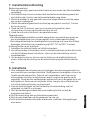
1. Installeer de elektrolytische cel altijd horizontaal.
2. Om chloorverlies te vermijden, moet u de elektrolytische cel aan het einde
van het filtratiesysteem installeren, vlak voor de retourleiding van het
zwembadwater.
3. Om de waterinvoer en -uitvoer aan te sluiten op de elektrolytische cel,
moet u letten op de richting van de waterstroming op de elektrolytische
cel.
8. Installatie
1. Drie zelftappende schroeven en muurpluggen worden meegeleverd voor
een snelle en eenvoudige installatie. Snijd gewoon de template uit voor de
locatie van de boorpunten. Gebruik een cementboor van 8 mm om de
schroefgaten te boren in de betonnen wand (volgens de positie op de
template). Draai de drie zelftappende schroeven vast in de gaten die u net
hebt geboord. Zodra ze op hun plaats zitten, hangt u de zoutelektrolyse-
unit via de haak achteraan op de eenheid.
2. Lijm de elektrolytische cel horizontaal op de retourleiding van het
zwembad, en laat 24 uur drogen.
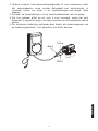
3. Sluit de bedieningseenheid aan op de elektrolytische cel met de
meegeleverde kabel,
ø Sluit de zwarte plug aan op de bedieningseenheid.
ø Sluit de gele draad aan op de gassensor van de cel.
ø Sluit de zwarte draden aan op de elektrodes, installeer de koppelingen
naar wens.
Nederlands
6

7
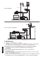
Waste
Filter Pump Suction
(Water from Pool)
Return to Pool
Pump
Return
Pump Cable
Cell Cable
Cell
Power
Supply
Control Box
Pool Light
Cable (if fitted)
1.5meter
Pole
Power Supply
Control Box
Pump Cable
Control Box
Cable
Cell Cable
Pump
Return
Filter Pump Suction
(Water from Pool)
Return to Pool
Cell
SSC-E SERIES
SSC-T & SSC-TLTSERIES
9. Bediening
1. Voeding: 220-240 VAC, 50/60 Hz
2. Aanbevolen zoutgehalte zwembad: 4000 PPM of meer (niet minder
dan 40 kg zuiver zout opgelost in 10.000 liter zwembadwater).
Respecteer het in deze handleiding en op het product vermelde
zoutgehalte om een optimale ontsmetting en levensduur te
garanderen.
Een te laag zoutgehalte beschadigt de cel en vermindert de
levensduur ervan.
Het RODE lampje op de bedieningseenheid brandt om aan te geven
dat het zoutgehalte te laag is.
Indien geen maatregelen worden getroffen om het zoutgehalte op peil
te brengen, kan de cel beschadigd raken (valt niet onder garantie!).
Nederlands

8
3.Tijdens extreem hete weersomstandigheden of veel zwemmers, moet
het zwembadwater extra worden behandeld met chloorkorrels of
vloeibaar chloor om moet u de zoutelektrolyse-unit langer laten
draaien.
4.Schakel de zoutelektrolyse uit bij onderhoudswerken aan de pomp.
5.Zet het systeem altijd op nul voor u zout toevoegt; zodra het zout
helemaal is opgelost, mag u de knop opnieuw op de ingestelde positie
zetten.
6.De aluminium behuizing achteraan doet dienst als warmteopnemer van
de bedieningseenheid: niet aanraken met blote handen.
Black
Yellow
Black
Nederlands

Raadpleeg
beschrijving
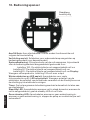
10. Bedieningspaneel
Aan/Uit/Auto: Aan-uitschakelaar. In Auto-modus functioneert de unit
volgens de timerinstelling
Verlichting aan/uit: Schakelaar voor onderwaterlamp aangesloten op
bedieningseenheid (voor bepaald model)
Systeembediening: Chloorproductie van de unit aanpassen, bijvoorbeeld
voor de bedieningseenheid aangeschakeld gedurende 8 uur
Instelling 100 - De elektrolytische cel aangeschakeld na 8 uur
Instelling 50 - De elektrolytische cel aangeschakeld na 4 uur
Instelling 25 - De elektrolytische cel aangeschakeld na 2 uur Display:
Weergave chloorproductie, Instelling 100 voor max. output
Winterschakelaar en LED aan/uit: Aanschakelen voor vaste
chloorproductie op 85. LED celpolariteit: Weergave polariteit van de
elektrodes; de polariteit van de elektrode verandert om de 8 bedrijfsuren om
de afzetting op de elektrode te reinigen.
Timer: Om het programma de bedieningseenheid automatisch te laten aan-
en uitschakelen.
Stand-By LED: Aanschakelen wanneer unit in stand-bymodus; wanneer de
unit is aangeschakeld, gaat de standby LED uit na 35 sec.
Geen stroming LED: Aanschakelen wanneer er geen waterstroming is;
wanneer er geen waterstroming is, stoppen de pomp en zoutelektrolyse-unit
automatisch.
9
Nederlands

10
11. Timer (Uitsluitend voor specifiek model)
1. Draai de buitenste klok tot het tijdstip van de dag overeenstemt met de
binnenste klok.
2. De 24-uurwijzerplaat is onderverdeeld in 15 minuten. Programmeer de
timer door de tuimelaar in de buitenste ringpositie te drukken voor de hele
periode dat de last is AAN-geschakeld.
3. De timerklok roteert met de tijd, de zoutelektrolyse wordt automatisch
aangeschakeld wanneer de tuimelschakelaar naar de buitenkant wordt
gedrukt.
Zekering: Gebruikt ter bescherming van de elektronische componenten in
de bedieningseenheid. LED: Er zijn drie LED-werkingsmodi, bijvoorbeeld
Status 1: Normale werking
Status2: Laag zoutniveau/afzetting op elektrode/watertemperatuur te laag
Status3: Extreem laag zoutniveau/zware afzetting op elektrode/
watertemperatuur veel te laag
1
2
Werking
1
2
Werking
1
2
Werking
(Green)
(Green)
(Green)
(Red)
(Red)
(Red)
Nederlands

11
12. Onderhoud en probleemwijzer
Zoutelektrolyse-units zijn een waardevol hulpmiddel om uw zwembad te
ontsmetten en verdienen een goed onderhoud om hun prestaties en
levensduur te garanderen.
1. Houd de chemicaliën in het zwembad in evenwicht. 2.Goede
bedrijfsomgeving.
3. Regelmatige controle van de titaniumplaten.
4. Tijdens het chloorvormingsproces kan zich een witte poederachtige
calciumlaag vormen op de titaniumplaten in de cel. Controleer de cel
regelmatig om overmatige aanslag te vermijden. Deze beschadigt uw cel,
en vermindert de efficiëntie e, levensduur ervan aanzienlijk.
5. Vermijd dat er vuil in de bedieningseenheid komt; dit kan de elektrische
componenten binnenin beschadigen.
6. Regelmatige controle van de filter en pomp.
Probleemwijzer
1. Lage/geen chloorproductie
Oplossing
Controleer de stroomtoevoer naar de
unit/bedieningseenheid/pomp
Stroomtoevoer correct insteken
Systeem te laag ingesteld
Draai de schakerlaar van het systeem op maximum
Automatisch gestopt door de timer
De timerinstelling aanpassen
Zekering gesprongen
Schakel de stroom uit en vervang de zekering
Overmatige aanslag op de cel
Schakel de zoutelektrolyse-unit uit en laat de zoutcel
reinigen door een professional
Reiniging filter (Backwash)
Zet de filter na reiniging opnieuw op normale filtratie
De gassensor is niet aangesloten
Sluit de gassensor aan volgens de instructies in deze
handleiding
Pomp functioneert niet
Stop het filtratiesysteem en herstel de pomp
Watertemperatuur te laag
Schakel de winterschakelaar aan
Zoutniveau te laag
Voeg zout toe aan het zwembad
Ph-klep te hoog
Controleer het ph-niveau van het water;
dit moet ongeveer 7.0-7.6 bedragen
2. Geen stroming
Oplossing
Pomp functioneert niet
Stop het filtratiesysteem en herstel de pomp
Reiniging filter (Backwash)
Zet de filter na reiniging opnieuw op normale filtratie
De gassensor is niet aangesloten
Sluit de gassensor aan volgens de instructies in deze
handleiding
3. Geen weergave
Oplossing
Systeem te laag ingesteld
Draai de schakelaar van het systeem op maximum
Nederlands

Installatietemplate
Schaal 1:1
90mm
Montagetemplate
16mm
12
Nederlands
-
 1
1
-
 2
2
-
 3
3
-
 4
4
-
 5
5
-
 6
6
-
 7
7
-
 8
8
-
 9
9
-
 10
10
-
 11
11
-
 12
12
-
 13
13
-
 14
14
-
 15
15
-
 16
16
-
 17
17
-
 18
18
-
 19
19
-
 20
20
-
 21
21
-
 22
22
-
 23
23
-
 24
24
-
 25
25
-
 26
26
-
 27
27
-
 28
28
-
 29
29
-
 30
30
-
 31
31
-
 32
32
-
 33
33
-
 34
34
-
 35
35
-
 36
36
-
 37
37
-
 38
38
-
 39
39
-
 40
40
-
 41
41
-
 42
42
-
 43
43
-
 44
44
-
 45
45
-
 46
46
-
 47
47


FLOTIDE SSC Series Salt Chlorinator Handleiding
- Categorie
- Accessoires voor bovengrondse zwembaden
- Type
- Handleiding
in andere talen
Andere documenten
-
Bestway FLOW Clear de handleiding
-
Bestway Chlorinator de handleiding
-
Zodiac WW000031 Gebruikershandleiding
-
Davey SilensorPRO SP400BT Installation And Operating Instructions Manual
-
 swim fun Easy Salt Chlorine Generator 30 m3 Handleiding
-
 Davey Water Products DES20CE de handleiding
-
-
Waterco Lacronite Eco V Pump Handleiding
-
-
 EXIT Toys 38582978 Ground Swimming Pool Handleiding


