Celexon ceiling recessed electric screen Expert 180 x 101 cm de handleiding
- Categorie
- Flat-panel plafondsteunen
- Type
- de handleiding

Bedienungsanleitung
celexon Deckeneinbauleinwand
Motor Expert | Expert XL
Vielen Dank für den Kauf dieses Produkts.
Für eine optimale Leistung und Sicherheit lesen Sie diese Anweisungen bitte sorgfältig
durch, bevor Sie dieses Produkt anschließen oder betreiben. Bitte bewahren Sie diese
Anleitung für eine spätere Verwendung auf.
Version: 32422_051
Motor Expert
Motor Expert XL

1
Diese Bedienungsanleitung dient dazu, Sie mit der Funktionsweise dieses Produktes ver-
traut zu machen. Bewahren Sie diese Anleitung daher gut auf, damit Sie jederzeit darauf
zugreifen können.
• Bitte beachten Sie vor der Montage das beiliegende Datenblatt mit weiteren Sicher-
heits- und Verwendungshinweisen.
• Beginnen Sie nicht mit der Montage, bevor Sie die komplette Bedienungsanleitung
gelesen und diese verstanden haben.
• Führen Sie die Installation mit einer weiteren Person durch um eine sichere Montage
zu gewährleisten.
• Entnehmen die das Produkt der Verpackung und entfernen alle Verpackungsmateri-
alien. Achten Sie darauf, dass sich kein Verpackungsmaterial am oder im Produkt be-
ndet Sollten Sie Verpackungsbeschädigungen feststellen, prüfen Sie zusätzlich ob
Beschädigungen am Produkt zu nden sind. Sollten Sie äußerliche Beschädigungen
an dem Gerät oder unerwartete oder unübliche Funktionsweisen feststellen, darf
das Produkt nicht weiter genutzt werden. Kontaktieren Sie umgehend den Händler,
bei dem Sie das Produkt gekauft haben oder celexon direkt (Web: www.celexon.de,
Mail: info@celexon.de) für weitere Informationen.
• Um einen störungsfreien Betrieb sicherzustellen, darf das Produkt ausschließlich in
Innenbereichen eingesetzt werden, es ist NICHT zur Nutzung im Freien geeignet.
• Die Nutzung des Geräts und Zubehörteile ist Kindern unter 16 Jahren verboten.
• Sorgen Sie dafür, dass keine Kinder mit den Geräten spielen oder sich ohne Aufsicht
in der Nähe aufhalten.
• Ein Umbauen oder Verändern des Produktes beeinträchtigt die Produktsicherheit.
• Achtung Verletzungsgefahr! Öffnen Sie das Produkt niemals eigenmächtig. Führen
Sie Reparaturen nie selbst aus!
• Verwenden Sie das Produkt nicht in der Nähe von austretendem Gas, Wasser oder in
• staubiger Umgebung.
• Behandeln Sie das Produkt sorgfältig. Es kann durch Stöße, Schläge oder Fall aus
bereits geringer Höhe beschädigt werden.
• Halten Sie das Produkt fern von Feuchtigkeit und Hitze..
• Tauchen Sie das Produkt niemals in Wasser oder andere Flüssigkeiten.
• Verwenden Sie das Produkt nur in seiner bestimmungsgemäßen Art und Weise. Eine
anderweitige Verwendung kann zu Beschädigungen am Produkt oder in dessen Um-
gebung führen.
• Ziehen Sie die Schrauben fest, aber überdrehen diese nicht. Ein zu feste Anziehen
WARNHINWEISE

2
(z.B. Durch Verwendung eines Akkuschraubendrehers) kann Schäden verursachen
und den sicheren Halt der Leinwand beeinträchtigen.
• Hängende Lasten müssen mindestens zweimal jährlich auf Festigkeit und Tragfähig-
keit geprüft werden.
• Kinder sollten nicht unbeaufsichtigt die Leinwand nutzen, bzw. darunter spielen.
• Achtung Verletzungsgefahr! Das Gerät schließt bündig und fest im eingefahrenen
Zustand – halten Sie Finger, Hände oder andere Kleinteile von der Öffnung fern.
• Alle Zuleitungen und Kabel dürfen nicht zusätzlich belastet werden und müssen so
verlegt werden, dass diese nicht beschädigt oder gequetscht werden.
• Bei Nichtbeachtung obiger Anweisungen kann es zu Personenschäden und
Beschädigungen des Produktes oder Geräten die daran angeschlossen
sind kommen. Auch kann bei fehlerhafter Installation oder Verwendung die
Garantie erlöschen.
• Wenn Sie beim Verwenden des Produktes unsicher sind, kontaktieren Sie
Fachpersonal, Ihren Händler oder celexon direkt (Web: www.celexon.de,
Mail: info@celexon.de).
• Technische Änderungen und Irrtümer vorbehalten.
Der Hersteller übernimmt keine Verantwortung für Sachschäden oder Personenschäden,
wenn die Leinwand außerhalb der empfohlenen Spezikationen verwendet wird, oder
bei unsachgemäßer Installation. Verwenden Sie diese Leinwand nicht in der Nähe von
Heizungen oder Klimaanlagen. Montieren Sie das Produkt ebenfalls nicht in direktem
Sonnenlicht oder vor einem Fenster. Aufgrund der temperaturempndlichen PVC Ober-
äche kann es zu nachhaltiger Beschädigung des Projektionstuchs kommen.
Wir empfehlen Ihnen, nach der Lieferung ca. 2 Stunden mit der Montage zu warten. So
kann sich die Leinwand akklimatisieren; besonders wenn die Leinwand von kalter in eine
warme Umgebung .oder umgekehrt gebracht wird.
Bitte vermeiden Sie jegliche Flecken auf der Tuchoberäche. Diese könnten sich mög-
licherweise nicht mehr entfernen lassen.
Die Positionen der Endpunkte sind bereits werksseitig optimal eingestellt und sollten
nicht verändert werden. Gerade bei Motor-Leinwänden sollte immer die gesamte Tuch-
länge verwendet werden, um die beste Planlage zu gewährleisten. Eine Justierung um
wenige cm der Endabschaltpunkte sollte nur von Personen mit Fachkenntnissen und
in Rücksprache mit dem Hersteller erfolgen. Eine Fehlerhafte Einstellung kann zu einer
Beschädigung der Projektionsäche führen.

3
HAFTUNGSAUSSCHLUSS
TECHNISCHE DATEN
Spannung: 220 V~240 V, 50 Hz
Verbrauch: 156 W (MAX)
0,4 W (Standby)
Die Angaben in diesem Dokument können ohne vorherige Ankündigung durch
den Hersteller geändert werden. Änderungen werden jeweils in den folgenden
Versionen dieses Handbuchs ergänzt. Irrtümer ausgeschlossen.

4
LIEFERUMFANG DECKENEINBAULEINWAND MOTOR EXPERT
Wenn Sie die Verpackung öffnen, überprüfen Sie bitte, ob ALLE unten aufgeführten
Komponenten enthalten sind. Falls ein oder mehrere Komponenten fehlen, wenden Sie
sich bitte an den Händler, bei welchem Sie das Produkt gekauft haben.
2x A
Weiße lange „L“-Prole
vorgestanzt
1x E
Montageplatte „1“ für
Leinwandgehäuse
4x I
Gewindestangen
M8x1000mm
6x M
Senkkopfschrauben
M4x10mm
1x B
C-Form Montagewinkel
1x F
Montageplatte „2“ für
Leinwandgehäuse
4x J
Bundmuttern M8
10x N
Selbstsichernde Muttern M4
2x D
Revisionsklappen
12x H
Muttern M8
4x L
Rundkopfschrauben
M4x12mm
2x C
C-Form Montagewinkel mit
Aufnahme
2x G
Deckenmontageplatten
8x K
Unterlegscheiben
Ø25x2 M8

5
ABMESSUNGEN DECKENEINBAULEINWAND MOTOR EXPERT
Vorderansicht:
Seitenansicht der Decken-
montageplatte:
Aufsicht der Deckenmontageplatte:
Alle Maße sind in mm angegeben.

6
ABMESSUNGEN DECKENEINBAULEINWAND MOTOR EXPERT
Ausschnittsmaße und Befestigungspunkte in der (Zwischen-) decke
Abmessungen der Befestigungspunkte der Deckenmontageplatten
Alle Maße sind in mm angegeben.
Modell A (mm) B (mm)
Motor Expert
(Standard inkl. 50 mm
schwarzen Rändern)
Breite Projektionsäche + 215 82
Motor Expert
(ohne schwarze Ränder)
Breite Projektionsäche + 115 82
Motor Expert Tensioned Breite Projektionsäche + 405 82
Abmessungen des Deckenausschnitts in der Zwischendecke
Modell L (mm) P (mm)
Motor Expert
(Standard inkl. 50 mm
schwarzen Rändern)
Breite Projektionsäche + 470 130
Motor Expert
(ohne schwarze Ränder)
Breite Projektionsäche + 370 130
Motor Expert Tensioned Breite Projektionsäche + 660 130

7
LIEFERUMFANG DECKENEINBAULEINWAND MOTOR EXPERT XL
Wenn Sie die Verpackung öffnen, überprüfen Sie bitte, ob ALLE unten aufgeführten
Komponenten enthalten sind. Falls ein oder mehrere Komponenten fehlen, wenden Sie
sich bitte an den Händler, bei welchem Sie das Produkt gekauft haben.
2x A
Weiße lange „L“-Prole
vorgestanzt
1x E
Montageplatte „1“ für
Leinwandgehäuse
4x I
Gewindestangen
M8x1000mm
6x M
Senkkopfschrauben
M4x10mm
1x B
C-Form Montagewinkel
1x F
Montageplatte „2“ für
Leinwandgehäuse
8x J
Bundmuttern M8
10x N
Selbstsichernde Muttern M4
2x D
Revisionsklappen
12x H
Muttern M8
4x L
Rundkopfschrauben
M4x12mm
2x C
C-Form Montagewinkel mit
Aufnahme
2x G
Deckenmontageplatten
4x K
Unterlegscheiben
Ø25x2 M8

8
ABMESSUNGEN DECKENEINBAULEINWAND MOTOR EXPERT XL
Vorderansicht:
Seitenansicht: Aufsicht der Deckenmontageplatte:

9
ABMESSUNGEN DECKENEINBAULEINWAND MOTOR EXPERT XL
Befestigungspunkte in der (Zwischen-) decke
Abmessungen der Befestigungspunkte der Deckenmontageplatten
Modell A (mm) B (mm)
Motor Expert XL
(Standard inkl. 50 mm
schwarzen Rändern)
Breite Projektionsäche + 230 82
Motor Expert XL
(ohne schwarze Ränder)
Breite Projektionsäche + 130 82
Motor Expert XL Tensioned Breite Projektionsäche + 422 82
Abmessungen des Deckenausschnitts in der Zwischendecke
Modell L (mm) P (mm)
Motor Expert XL
(Standard inkl. 50 mm
schwarzen Rändern)
Breite Projektionsäche + 485 160
Motor Expert XL
(ohne schwarze Ränder)
Breite Projektionsäche + 385 160
Motor Expert XL Tensioned Breite Projektionsäche + 677 160

10
MONTAGE EXPERT & EXPERT XL
Stellen Sie sicher, dass die Teile B und C rechtwinklig zu
Teil A montiert werden.
Achten Sie darauf, dass die Schraubverbindung zwischen N und L
so ausgeführt wird, dass die Revisionsklappe D beweglich
bleibt.
D L N
C
A
MN
B
D D
C C
B
A

11
Der Installateur muss für das Tragwerk geeignete Dübel (nicht im
Lieferumfang enthalten) für die Befestigung der Deckenmontage-
platten an der oberen Decke verwenden.
Die Gewindestangen müssen bauseitig auf die gewünschte Länge
eingekürzt werden.
Beachten Sie dafür die auf Seite 12 angegebenen Min. und Max.
Längen.
MONTAGE AN DER DECKE EXPERT & EXPERT XL
G
H
H
I
JK
Loch in die
Decke bohren
Dübel
(nicht im LU)
Schraube
(nicht im LU)

12
Um die Gewindestange l an der Deckenmontageplatte G zu befestigen, drehen
Sie eine Mutter H mindestens 20 mm auf den oberen Teil der Gewindestange.
Schrauben Sie die Gewindestangen in die Deckenmontageplatten bis zum An-
schlag ein (mindestens 10 mm!).
Ziehen Sie anschließend die Mutter fest.
Heben Sie den vormontierten Einbaurah-
men an und führen die Gewindestangen in
die Lochbohrungen des Teils C ein
Befestigen Sie den Einbaurahmen mit den
Unterlegscheiben K und Bundmuttern J.
Stellen Sie sicher, dass der untere Teil des Einbaurahmens perfekt
in Waage ist. Eine nicht nivellierte Installation des Einbaurahmens
führt zu Fehlfunktionen und Schäden an der Leinwand.
H
HG
I
K + J C

13
MONTAGE AN DEM EINBAURAHMEN EXPERT & EXPERT XL
Bevor Sie mit der Montage der Leinwand fortfahren, befesti-
gen Sie die Montageplatten E und F, wie in der Zeichnung un-
ten dargestellt.
Es ist WICHTIG, die rechte Platte auf der rechten Seite zu mon-
tieren.
Stellen Sie vor dem Befestigen der Schrauben sicher, dass die Montageplatten
E und F am äußersten Ende des Leinwandgehäuses positioniert werden.
Ziehen Sie nun ALLE Schrauben fest an und prüfen Sie, ob beide Montage-
platten fest mit dem Leinwandgehäuse verbunden sind.
E
F

14
Klappen Sie nun die beiden Revisionsklap-
pen D in die vertikale Position auf.

15
Heben Sie die Leinwand in den Einbaurah-Heben Sie die Leinwand in den Einbaurah-
men und führen Sie die Gewindestangen men und führen Sie die Gewindestangen
durch die Löcher der Montageplatten durch die Löcher der Montageplatten EE und und
FF..

16
Bestigen Sie die Monatgeplatten an den Ge-
windestangen mit den Bundmuttern J.
Stellen Sie vor dem Festziehen der Muttern sicher, dass das Gehäuse mittig
mit in dem Deckeneinbaurahmen platziert ist. Ziehen Sie nun die Bundmut-
tern fest.

17
Nun kann der elektrische Anschluss der
Leinwand durch eine Fachkraft erfolgen und
die Revisionsklappen geschlossen werden.
Damit ist die Installation abgeschlossen.

18
Hersteller: celexon Europe GmbH
Adresse: Gutenbergstraße 2, 48282 Emsdetten, DE
Produktname: celexon Deckeneinbauleinwand Motor Expert | Expert XL
Produkte, die mit dem CE-Zeichen gekennzeichnet sind, entsprechen allen An-
forderungen der entsprechenden EU-Direktiven. Die EU-Konformitätserklärung
kann unter folgender Adresse heruntergeladen werden:
www.celexon.de/zertikate
INFORMATION ZUR EU-KONFORMITÄT
Das Symbol weist auf die getrennte Rücknahme elektrischer und
elektronischer Geräte in EU-Ländern hin. Bitte werfen Sie das Gerät
nicht in den Hausmüll. Informieren Sie sich über das in Ihrem Land
gültige Rücknahmesystem und wenden Sie sich bei Fragen zum
Entsorgungsprozess an Ihre Kommune oder Ihre örtliche Wert-und
Schadstoffsammelstelle.

Operating instructions
celexon Electric ceiling recessed
projection screen Expert | Expert XL
Thank you for purchasing this product. For optimum performance and safety, please
read these instructions carefully before connecting or operating the product. Please
retain these instructions for future reference.
Version: 32422_051
Electric Expert
Electric Expert XL

1
The purpose of these operating instructions is to familiarise you with the operation of
this product. Keep the manual in a safe place so that you can refer to it at any time.
• Before installation, please refer to the data sheet for further safety and use
instructions.
• Do not start installation until you have read and understood the complete operating
instructions.
• Carry out the installation with another person to ensure safe installation.
• Remove the product from its packaging and remove all packaging material. Make
sure that there is no packaging material on or in the product. If you notice any
damage to the packaging, also check whether there is any damage to the
product. If you notice any external damage to the unit or any unexpected or unusual
functioning, do not use the product any further. Contact the retailer where you
purchased the product immediately, or celexon directly (Web: www.celexon.co.uk,
Mail: info@celexon.co.uk) for further information.
• To ensure trouble-free operation, the product may only be used indoors. it is NOT
suitable for outdoor use.
• The use of the screen and accessories is forbidden to children under 16 years of age.
• Ensure that no children play with the screen or are in the vicinity without
supervision.
• Conversion or modication of the product impairs product safety.
• Caution: Risk of injury! Never open the product without authorisation. Never carry
out repairs yourself!
• Do not use the product near leaking gas, water or in a dusty environment.
• Handle the product with care. It can be damaged by knocks, blows or falling from
even a small height.
• Keep the product away from moisture and heat.
• Never immerse the product in water or other liquids.
• Use the product only in its intended manner. Any use for any other purpose may
damage the product or its surroundings.
• Tighten the screws but do not overtighten them. Tightening too tight (e.g. by using
a cordless screwdriver) can cause damage and affect the secure hold of the screen.
• Suspended loads must be checked for strength and load-bearing capacity at least
twice a year.
WARNINGS

2
• Children should not use the screen or play under it unsupervised.
• Caution: Risk of injury! The unit closes ush and rmly, keep ngers, hands or other
small parts away from the opening.
• All supply lines and cables must not be subjected to additional loads and must be
laid in such a way that they are not damaged or crushed.
• Failure to observe the above instructions may result in personal injury and damage
to the product or equipment connected to it. Incorrect installation or use may also
invalidate the warranty.
• If you are unsure about the use of the product, please contact your
specialist personnel, your dealer or celexon directly (Web: www.celexon.co.uk, Mail:
info@celexon.co.uk).
• Technical changes and errors excepted.
The manufacturer accepts no responsibility for damage to property or personal
injury, if the screen is used outside the recommended specications, or in the event of
improper installation. Do not use this screen in the vicinity of heaters or air conditioners.
Also, do not mount the product in direct sunlight or in front of a window. Due to the
temperature-sensitive PVC surface, the projection screen fabric may be permanently
damaged.
We recommend that you wait approx. 2 hours after delivery before installing the
projection screen. This will allow the screen to acclimatise, especially if it is moved from
a cold to a warm environment or vice versa.
Please avoid any stains on the surface of the canvas. These may not be able to be
removed.
The positions of the end points are already optimally set at the factory and should not
be changed. Especially with motorised screens, the entire length of the fabric should
always be used in order to achieve the best atness. An adjustment of a few cm of the
end switch-off points should only be made by persons with specialist knowledge and in
consultation with the manufacturer. Incorrect adjustment can result in damage to the
projection surface.

3
DISCLAIMER
TECHNICAL DATA
Voltage: 220 V~240 V, 50 Hz
Consumption: 156 W (MAX)
0.4 W (standby)
The information in this document is subject to change without notice by the
manufacturer. Changes will be added to subsequent versions of this manual.
Errors excepted.

4
IN THE BOX - ELECTRIC EXPERT RECESSED CEILING SCREEN
When you open the packaging, please check that ALL the components listed below are
included. If one or more components are missing, please contact the dealer from whom
you purchased the product.
2x A
White long „L“ proles - pre-
cut
1x E
Mounting plate „1“ for
screen housing
4x I
Threaded rods
M8x1000mm
6x M
Countersunk screws
M4x10mm
1x B
C-shape mounting bracket
1x F
Mounting plate „2“ for
screen housing
4x J
Collar nuts M8
10x N
Self-locking nuts M4
2x D
Access panels
12x H
M8 nuts
4x L
Round head screws
2x C
C-shape mounting bracket
with
mounting
2x G
Ceiling mounting plates
8x K
Washers
Ø25x2 M8

5
DIMENSIONS - ELECTRIC EXPERT RECESSED CEILING SCREEN
Front view:
Side view: Top view of the ceiling mounting
plate:
All dimensions are in mm.

6
DIMENSIONS - ELECTRIC EXPERT RECESSED CEILING SCREEN
Cut-out dimensions for false ceiling and xing points
Dimensions of the mounting points of the ceiling mounting platesDimensions of the mounting points of the ceiling mounting plates
All dimensions are in mm.
Model A (mm) B (mm)
Electric Expert
(standard incl. 50 mm
black edges)
Viewing area width + 215 82
Electric Expert
(without black borders)
Viewing area width + 115 82
Electric Expert Tensioned Viewing area width + 405 82
Dimensions of the ceiling cut-out in the false ceiling
Model L (mm) P (mm)
Electric Expert
(standard incl. 50 mm black ed-
ges)
Viewing area width + 470 130
Electric Expert
(without black borders)
Viewing area width + 370 130
Electric Expert Tensioned Viewing area width + 370 130
B

7
IN THE BOX - ELECTRIC EXPERT XL RECESSED CEILING SCREEN
When you open the packaging, please check that ALL the components listed below are
included. If one or more components are missing, please contact the dealer from whom
you purchased the product
2x A
White long „L“ proles - pre-
cut
1x E
Mounting plate „1“ for
screen housing
4x I
Threaded rods
M8x1000mm
6x M
Countersunk screws
M4x10mm
1x B
C-shape mounting bracket
1x F
Mounting plate „2“ for
screen housing
8x J
Collar nuts M8
10x N
Self-locking nuts M4
2x D
Access panels
12x H
M8 nuts
4x L
Round head screws
M4x12mm
2x C
C-shape mounting bracket
with mounting
2x G
Ceiling mounting plates
4x K
Washers
Ø25x2 M8

8
DIMENSIONS - ELECTRIC EXPERT XL RECESSED CEILING SCREEN
Front view:
Side view: Top view of the ceiling mounting
plate:
All dimensions are in mm.

9
DIMENSIONS - ELECTRIC EXPERT XL RECESSED CEILING SCREEN
Dimensions of the mounting points of the ceiling mounting plates
Model A (mm) B (mm)
Electric Expert XL
(standard incl. 50 mm
black edges)
Viewing area width + 230 82
Electric Expert XL
(without black borders)
Viewing area width + 130 82
Electric Expert XL Tensioned Viewing area width + 422 82
Dimensions of the ceiling cut-out in the false ceiling
Modell L (mm) P (mm)
Electric Expert XL
(standard incl. 50 mm
black edges
Viewing area width + 485 160
Electric Expert XL
(without black borders)
Viewing area width + 385 160
Electric Expert XL Tensioned Viewing area width + 677 160
Cut-out dimensions for false ceiling and xing points
B

10
INSTALLATION INSTRUCTIONS EXPERT & EXPERT XL
Make sure that parts B and C are assembled at right angles to part
A. Make sure that the screw connection between N and L is loose
enough that the access panel D remains movable.
D
D L N
C
A
MN
B
D
C C
B
A
The installer must use suitable dowels for the supporting structure
(not included in the box) for fastening the ceiling mounting panels
to the upper ceiling.

11
The installer must use suitable dowels for the supporting structure
(not included in the box) for fastening the ceiling mounting panels
to the upper ceiling.
The threaded rods must be shortened to the desired length on
site. Observe the min. and max. lengths given on page 12.
MOUNTING ON CEILING EXPERT & EXPERT XL
G
H
H
I
JK
Drill a hole in the
ceiling
Dowel
(not in box))
Screw
(not in box)

12
To x the threaded rod l to the ceiling mounting plate G, turn nut H at least 20
mm onto the upper part of the threaded rod.
Screw the threaded rods into the ceiling mounting plates as far as they will go
(at least 10 mm!). Then tighten the nut.
Lift up the pre-assembled installation
frame and insert the threaded rods into
the holes in part C.
Secure the mounting frame with washers
K and collar nuts J.
Make sure that the lower part of the mounting frame is perfectly in
balance. An installation of the mounting frame that is not levelled
will result in malfunction and damage to the screen.
H
HG
I
K + J C

13
MOUNTING ON THE EXPERT & EXPERT XL MOUNTING FRAME
Before continuing with the installation of the screen, attach
the mounting plates E and F as shown in the drawing.
It is IMPORTANT to mount the right plate on the right side.
Before xing the screws, make sure that the mounting plates E and F are
positioned at the far end of the screen housing.
Now tighten ALL screws and check that both mounting plates are rmly
connected to the screen housing.
E
F

14
Now open the two inspection aps to the
vertical position.

15
Lift the screen into the installation frame Lift the screen into the installation frame
and guide the threaded rods through the and guide the threaded rods through the
holes in the mounting plates holes in the mounting plates E E and and FF..

16
Attach the mounting plates to the threaded
rods with the collar nuts J. Before tightening
the nuts, make sure that the enclosure is
centred in the ceiling mounting frame. Now
tighten the collar nuts.
Now the electrical connection of the screen can be made by a specialist and
the inspection aps can be closed. This completes the installation.
J

17
Now the electrical connection of the screen can
be made by a specialist and the inspection aps
can be closed.
This completes the installation.

18
Manufacturer: celexon Europe GmbH
Address: Gutenbergstraße 2, 48282 Emsdetten, DE
Product name: celexon ceiling recessed screen Electric Expert |
Expert XL
Products that are marked with the CE mark meet all requirements of the relevant
EU directives. The EU declaration of conformity can be downloaded from the
following address: www.celexon.de/zertikate
INFORMATION ON EU CONFORMITY
The symbol indicates the separate collection of electricals in EU
countries. Please do not throw the appliance into the household was-
te. Find out about the take-back system in force in your country and
if you have any questions about the disposal process, contact your
local authority or your local recycling and hazardous waste collection
centre.

19
Manufacturer: celexon Europe GmbH
Address: Gutenbergstraße 2, 48282 Emsdetten, DE
Product name: celexon ceiling recessed screen Electric Expert |
Expert XL
Products that are marked with the UKCA mark meet all requirements of the re-
levant UK directives. The UK declaration of conformity can be downloaded from
the following address: www.celexon.de/zertikate
INFORMATION ON UK CONFORMITY
The symbol indicates the separate collection of electricals in EU
countries. Please do not throw the appliance into the household was-
te. Find out about the take-back system in force in your country and
if you have any questions about the disposal process, contact your
local authority or your local recycling and hazardous waste collection
centre.

Manuel d’utilisation
Écran encastrable au plafond
celexon Motorisé Expert | Expert XL
Nous vous remercions d’avoir acheté cet article.
Pour des performances et une sécurité optimales, veuillez lire attentivement ces
instructions avant d’installer ou d’utiliser ce produit. Veuillez conserver ce manuel pour
une utilisation ultérieure.
Version: 32422_081
Motorisé Expert
Motorisé Expert XL

1
Ce mode d’emploi a pour but de vous familiariser avec le fonctionnement de ce produit.
Conservez donc soigneusement ce manuel an de pouvoir y accéder à tout moment.
• Avant de procéder au montage, veuillez consulter la che technique jointe cont-
enant d’autres consignes de sécurité et d’utilisation.
• Ne commencez pas le montage avant d’avoir lu et compris l’intégralité du mode
d’emploi.
• Effectuez l’installation avec une autre personne an de garantir un montage sûr.
• Retirez le produit de son emballage et enlevez tous les matériaux d’emballage.
Veillez à ce qu‘aucun matériau d’emballage ne se trouve sur ou dans le produit.
Si vous constatez des dommages sur l’emballage, vériez également si le produit
est endommagé. Si vous constatez des dommages extérieurs sur le produit ou un
fonctionnement inattendu ou inhabituel, l’écran ne doit plus être utilisé. Contactez
immédiatement le revendeur chez qui vous avez acheté le produit ou directement
le fabricant celexon (Web : www.celexon.fr, Mail : info@celexon.fr) pour plus d’infor-
mations.
• Pour garantir un fonctionnement sans problème, le produit doit être utilisé exclusi-
vement à l’intérieur, il n’est PAS adapté à une utilisation en extérieur.
• L’utilisation de l’appareil et de ses accessoires est interdite aux enfants de moins de
16 ans.
• Veillez à ce que les enfants ne jouent pas avec le produit et ne se trouvent pas à
proximité sans surveillance. Les personnes ne doivent pas se tenir sous le produit
(charges suspendues).
• Toute transformation ou modication du produit est interdite et porte atteinte à la
sécurité du produit !
• Attention au risque de blessure ! Ne démontez jamais le produit de votre propre
chef. N’effectuez jamais de réparations vous-même !
• Ce produit ne doit être utilisé que dans son état d’origine, non modié et non en-
dommagé.
• N’utilisez pas le produit à proximité d’appareils à gaz ou à eau ou dans un environ-
nement poussiéreux.
• Manipulez le produit avec soin. Il peut être endommagé par des chocs, des coups ou
des chutes, même de faible hauteur.
• Gardez le produit à l’abri de l’humidité et de la chaleur.
• Ne plongez jamais le produit dans l’eau ou dans d’autres liquides.
• N’utilisez le produit que de la manière pour laquelle il a été conçu. Toute autre utili-
AVERTISSEMENTS

2
sation peut entraîner des blessures corporelles, des dommages au produit ou à son
environnement.
• Lorsque vous serrez les vis, ne les serrez pas trop. Un serrage excessif (par exemple
à l’aide d’une visseuse électrique) peut entraîner des dommages et compromettre
la bonne tenue de l’écran.
• Les charges suspendues doivent être contrôlées au moins deux fois par an pour
vérier leur solidité et leur capacité de charge. Faites particulièrement attention aux
capuchons latéraux. Ceux-ci ne doivent pas être endommagés ou ssurés, sinon le
produit doit être immédiatement démonté, car la charge est entièrement supportée
par les capuchons !
• Attention au risque de blessure ! L’écran se ferme à eur du carter et fermement
en position remontée - tenez vos doigts, vos mains ou d’autres petits objets à l’écart
de l’ouverture.
• Tous les ls et câbles d’alimentation ne doivent pas être soumis à une charge sup-
plémentaire et doivent être installés de manière à ne pas être endommagés, écrasés
ou pliés.
• Le non-respect des instructions ci-dessus peut entraîner des dommages corporels
et endommager le produit ou les appareils qui y sont raccordés. La garantie peut
également être annulée en cas d’installation ou d’utilisation incorrecte.
• Si vous avez des doutes sur l’utilisation du produit, contactez le personnel spécialisé,
votre revendeur ou le fabricant celexon directement (Web : www.celexon.fr, mail :
info@celexon.fr).
• Sous réserve de modications techniques et d’erreurs.
Le fabricant décline toute responsabilité en cas de dommages matériels ou corporels
si l’écran est utilisé en dehors des spécications recommandées ou s‘il n’est pas installé
correctement. N’utilisez pas cet écran à proximité d’un chauffage ou d’un climatiseur.
N’installez pas non plus le produit à la lumière directe du soleil ou devant une fenêtre.
En raison de la surface en PVC sensible à la température, la toile de projection peut être
endommagée de manière durable.
Nous vous recommandons d’attendre environ 2 heures après la livraison avant de procé-
der au montage. Cela permet à la toile de s’acclimater ; en particulier lorsque la toile est
déplacée d’un environnement froid à un environnement chaud (ou inversement).
Veuillez éviter de faire des tâches sur la surface de la toile. Celles-ci pourraient ne plus
pouvoir être enlevées. Remontez toujours la toile après chaque utilisation.

3
AVIS DE NON-RESPONSABILITÉ
CONSEIL D’ENTRETIEN
DONNÉES TECHNIQUES
Tension : 220 V~240 V, 50 Hz
Consommation : 156 W (MAX)
0.4 W (en veille)
Les informations contenues dans ce document peuvent être modiées sans
préavis par le fabricant. Les modications seront toujours ajoutées dans les
versions suivantes de ce manuel. Toute erreur est exclue.
Ne nettoyez JAMAIS la toile avec de l’alcool ou d’autres produits de nettoyage
contenant des solvants. Utilisez uniquement un chiffon doux et propre. Une
solution savonneuse douce (max. 5%) peut éventuellement éliminer la saleté
de la surface. Évitez absolument tout contact avec des objets pointus ou
tranchants. Ceux-ci pourraient endommager durablement la toile de projection.
Pour de plus amples informations, veuillez consulter les instructions relatives
à l’écran.
Les positions des points de butée sont déjà réglées de manière optimale en usine et ne
doivent pas être modiées. Pour les écrans motorisés en particulier, il convient de tou-
jours utiliser toute la longueur de la toile an de garantir la meilleure planéité. Un réglage
de quelques centimètres des points de butée naux ne devrait être effectué que par des
personnes ayant des connaissances spécialisées et en concertation avec le fabricant. Un
mauvais réglage peut endommager l’écran de projection.

4
CONTENU DE LA LIVRAISON - MOTORISÉ EXPERT
Avant l’installation, veuillez vérier que toutes les pièces mentionnées ci-dessous sont
incluses ! S’il manque des pièces, contactez le revendeur chez qui vous avez acheté le
produit et attendez que l’installation soit complète.
2x A
Prolés blancs longs en „L”
prédécoupés
1x E
Plaque de montage „1“
pour le carter de l’écran
4x I
Tiges letées
M8x1000mm
6x M
Vis à tête fraisée
M4x10mm
1x B
Équerre de montage en
forme de C
1x F
Plaque de montage „2“
pour le carter de l’écran
4x J
Écrous à
collerette M8
10x N
Écrous
autobloquants M4
2x D
Trappes d’accès
12x H
Écrous M8
4x L
Vis à tête ronde
M4x12mm
2x C
Équerre de montage en
forme de C avec logement
2x G
Plaques de montage
au plafond
8x K
Rondelles
Ø25x2 M8

5
DIMENSIONS DE L’ÉCRAN DE PROJECTION ENCASTRÉ AU
PLAFOND MOTORISÉ EXPERT
Vue de face :
Vue de côté : Vue de la plaque de montage au
plafond :
Toutes les dimensions sont indiquées en mm.

6
DIMENSIONS DE L’ÉCRAN DE PROJECTION ENCASTRÉ AU
PLAFOND MOTORISÉ EXPERT
Dimensions de la découpe et points de xation dans le plafond (faux-plafond)
Dimensions des points de xation des plaques de montage au plafondDimensions des points de xation des plaques de montage au plafond
Toutes les dimensions sont indiquées en mm.
Modèle A (mm) B (mm)
Motorisé Expert
(standard, avec les bords
noirs de 50 mm)
Largeur de la toile de projection +
215
82
Motorisé Expert
(sans bords noirs)
Largeur de la toile de projection +
115
82
Motorisé Expert tensionné Largeur de la toile de projection +
405
82
Dimensions de la découpe dans le faux-plafond
Modèle L (mm) P (mm)
Motorisé Expert
(standard, avec les bords
noirs de 50 mm)
Largeur de la toile de projection +
470
130
Motorisé Expert
(sans bords noirs)
Largeur de la toile de projection +
370
130
Motorisé Expert tensionné Largeur de la toile de projection +
660
130
B

7
CONTENU DE LA LIVRAISON - MOTORISÉ EXPERT XL
Avant l’installation, veuillez vérier que toutes les pièces mentionnées ci-dessous sont
incluses ! S’il manque des pièces, contactez le revendeur chez qui vous avez acheté le
produit et attendez que l‘installation soit complète.
2x A
Prolés blancs longs en „L”
prédécoupés
1x E
Plaque de montage „1“
pour le carter de l’écran
4x I
Tiges letées
M8x1000mm
6x M
Vis à tête fraisée
M4x10mm
1x B
Équerre de montage en
forme de C
1x F
Plaque de montage „2“
pour le carter de l’écran
4x J
Écrous à
collerette M8
10x N
Écrous
autobloquants M4
2x D
Trappes d’accès
12x H
Écrous M8
4x L
Vis à tête ronde
M4x12mm
2x C
Équerre de montage en
forme de C avec logement
2x G
Plaques de montage
au plafond
8x K
Rondelles
Ø25x2 M8

8
DIMENSIONS DE L’ÉCRAN DE PROJECTION ENCASTRÉ AU
PLAFOND MOTORISÉ EXPERT XL
Vue de face :
Vue de côté : Vue de la plaque de montage au
plafond :
Toutes les dimensions sont indiquées en mm.

9
DIMENSIONS DE L’ÉCRAN DE PROJECTION ENCASTRÉ AU
PLAFOND MOTORISÉ EXPERT XL
Dimensions de la découpe et points de xation dans le plafond (faux-plafond)
Dimensions des points de xation des plaques de montage au plafondDimensions des points de xation des plaques de montage au plafond
Toutes les dimensions sont indiquées en mm.
Modèle A (mm) B (mm)
Motorisé Expert
(standard, avec les bords
noirs de 50 mm)
Largeur de la toile de projection +
230
82
Motorisé Expert
(sans bords noirs)
Largeur de la toile de projection +
130
82
Motorisé Expert tensionné Largeur de la toile de projection +
422
82
Dimensions de la découpe dans le faux-plafond
Modèle L (mm) P (mm)
Motorisé Expert
(standard, avec les bords
noirs de 50 mm)
Largeur de la toile de projection +
485
160
Motorisé Expert
(sans bords noirs)
Largeur de la toile de projection +
385
160
Motorisé Expert tensionné Largeur de la toile de projection +
677
160
B

10
INSTALLATION EXPERT & EXPERT XL
Veillez à ce que les pièces B et C soient montées à angle droit par
rapport à la pièce A.
Veillez à ce que l’assemblage par vis entre N et L soit réalisé de
manière à ce que la trappe d’accès D reste mobile.
D
D L N
C
A
MN
B
D
C C
B
A

11
L’installateur doit utiliser des chevilles adaptées à la structure
porteuse (non fournies) pour xer les plaques de montage sur le
plafond supérieur.
Les tiges letées doivent être raccourcies par le client à la
longueur souhaitée. Respecter pour cela les longueurs min. et
max. indiquées à la page 12.
INSTALLATION AU PLAFOND EXPERT & EXPERT XL
G
H
H
I
JK
Percer un trou
dans le plafond
Cheville (non fournie)
Vis (non fournie)

12
Pour xer la tige letée l à la plaque de montage au plafond G, vissez un écrou
H d’au moins 20 mm sur la partie supérieure de la tige letée.
Vissez les tiges letées dans les plaques de montage au plafond jusqu‘à la
butée (au moins 10 mm !). Serrez ensuite l’écrou.
Soulevez le cadre de montage prémonté
et introduisez les tiges letées dans les
trous de la pièce C.
Fixez le cadre de montage à l’aide des
rondelles K et des écrous à collerette J.
Assurez-vous que la partie inférieure du cadre de montage est
parfaitement à niveau. Une mauvaise installation du cadre de
montage entraînera des dysfonctionnements et des dommages à
l’écran.
H
HG
I
K + J C

13
MONTAGE SUR LE CADRE DE MONTAGE EXPERT & EXPERT XL
Avant de poursuivre le montage de l’écran, xez les plaques de
montage E et F comme indiqué sur le dessin ci-dessous.
Il est IMPORTANT de monter la plaque de droite sur le côté droit.
Avant de xer les vis, assurez-vous que les plaques de montage E et F sont
positionnées à l’extrémité du carter de l’écran.
Serrez maintenant fermement TOUTES les vis et vériez que les deux plaques
de montage soient bien xées au carter de l’écran.
E
F

14
Rabattez maintenant les deux trappes
d’accès en position verticale.

15
Soulevez lSoulevez l’écran dans le cadre de montage écran dans le cadre de montage
et passez les tiges letées dans les trous des et passez les tiges letées dans les trous des
plaques de montage plaques de montage EE et et FF..

16
Fixez les plaques de montage sur les tiges
letées à l’aide des écrous à collerette J.
Avant de serrer les écrous, assurez-vous que le carter est bien centré dans le
cadre de montage au plafond. Serrez ensuite les écrous à collerette.
J

17
Maintenant, le raccordement électrique de
l’écran peut être effectué par un spécialiste et
les trappes d’accès peuvent être fermées.
L’installation est ainsi terminée.

18
Fabricant : celexon Europe GmbH
Adresse : Gutenbergstraße 2, 48282 Emsdetten, DE
Nom du produit : Écran encastrable au plafond celexon Motorisé Expert |
Expert XL
Les produits portant le marquage CE sont conformes à toutes les exigences des
directives européennes correspondantes. La déclaration de conformité UE peut
être téléchargée à l’adresse suivante : www.celexon.de/zertikate
DÉCLARATION DE CONFORMITÉ À L’U.E.
Ce symbole indique que les appareils électriques et électroniques
sont repris séparément dans les pays de l’UE. Veuillez ne pas jeter
l’appareil avec les ordures ménagères. Informez-vous sur le système
de collecte en vigueur dans votre pays et adressez-vous à votre com-
mune ou à votre centre de collecte local pour toute question relative
au processus de mise à disposition.

Manual del usuario
Pantalla de proyección empotrable
Motor Expert | Expert XL
Gracias por comprar este producto.
Para un rendimiento y seguridad óptimos, lea atentamente estas instrucciones antes de
conectar o utilizar este producto. Por favor, conserve estas instrucciones para futuras
consultas.
Version: 32422_051
Motor Expert
Motor Expert XL

1
Este manual de instrucciones está destinado a familiarizarle con el funcionamiento
de este producto. Guarde este manual en un lugar seguro para poder consultarlo en
cualquier momento.
• Antes de la instalación, consulte la hoja de datos adjunta para obtener más
instrucciones de seguridad y uso.
• No comience la instalación hasta que haya leído y comprendido el manual de
instrucciones completo.
• Realice la instalación con otra persona para garantizar una instalación segura.
• Saque el producto de su embalaje y retire todos los materiales de embalaje.
Asegúrese de que no hay material de embalaje sobre o dentro del producto.
Si encuentra algún daño en el embalaje, compruebe también si el producto está
dañado. Si observa algún daño externo o en la unidad o cualquier funcionamiento
inesperado o inusual, no siga utilizando el producto. Póngase en contacto con el
distribuidor inmediatamente, o a quien compró el producto o celexon directamente
(Web: ww.celexon.es, Email: info@celexon.es) para más información.
• Para garantizar un funcionamiento sin problemas, el producto sólo puede utilizarse
en interiores. NO es adecuado para su uso en exteriores.
• El uso del aparato y de los accesorios está prohibido a los menores de 16 años.
• Asegúrese de que ningún niño juegue con el aparato o esté en sus proximidades sin
supervisión.
• Reparar o modicar el producto compromete la seguridad del mismo.
• Precaución: ¡Riesgo de lesiones! No abra nunca el producto sin autorización.
Nunca realice las reparaciones usted mismo.
• No utilice el producto cerca de fugas de gas, agua o en un entorno polvoriento.
• Manipule el producto con cuidado. Se puede dañar por golpes, o caídas
incluso desde una pequeña altura.
• Mantenga el producto alejado de la humedad y el calor.
• Nunca sumerja el producto en agua u otros líquidos.
• Utilice el producto sólo de la manera prevista. Cualquier otro uso puede causar
daños al producto o a su entorno.
• Apriete los tornillos pero no los apriete en exceso. Apretar demasiado por ejemplo
con el uso de un destornillador eléctrico puede causar daños y afectar a la sujeción
segura de la pantalla.
• La resistencia y la capacidad de carga de las cargas suspendidas deben comprobarse
al menos dos veces al año.
ADVERTENCIAS

2
• Los niños no deben utilizar la pantalla ni jugar bajo ella sin supervisión.
• Precaución: ¡Riesgo de lesiones! La unidad se cierra al ras y con rmeza en la
retracción, mantenga los dedos, las manos u otras partes pequeñas lejos de la
abertura.
• Todos los conductos y cables de alimentación no deben estar sometidos a cargas
dicionales y deben colocarse de forma que no sufran daños ni se aplasten.
• La inobservancia de las instrucciones anteriores puede provocar lesiones personales
y daños en el producto o en los equipos conectados a él.
• Una instalación o uso incorrecto también puede invalidar la garantía.
• Si no está seguro del uso del producto, póngase en contacto con su personal
especializado, su distribuidor o directamente celexon (Web: ww.celexon.es, Email:
info@celexon.es).
• Se reservan cambios o errores técnicos.
El fabricante no acepta ninguna responsabilidad por daños materiales o personales, si la
pantalla de proyección se utiliza fuera de las especicaciones recomendadas, o instalación
incorrecta. No utilice esta pantalla cerca de calentadores o acondicionadores de aire.
Además, no monte el producto bajo la luz directa del sol o frente a una ventana, ya que
la supercie de PVC sensible a la temperatura, pueden producirse daños duraderos en la
supercie de la pantalla de proyección.
Le recomendamos que espere unas 2 horas después de la entrega antes de instalar la
pantalla de proyección. De esta manera la pantalla puede aclimatarse, especialmente si
la pantalla se traslada de un lugar frío a uno cálido o viceversa.
Por favor, evite cualquier mancha en la supercie del lienzo. Es posible que no se puedan
eliminar.
Las posiciones de los puntos nales ya vienen ajustadas de fábrica de forma óptima
y no deben modicarse. Especialmente en el caso de las lonas motorizadas, se debe
utilizar siempre toda la longitud de la tela para garantizar la mejor planicidad. Un ajuste
por cm de los puntos de desconexión nal sólo debe ser realizado por personas con
conocimientos especializados y en consulta con el fabricante. Un ajuste incorrecto
puede dañar la pantalla de proyección.

3
EXENCIÓN DE RESPONSABILIDAD
DATOS TÉCNICOS
Tensión: 220 V~240 V, 50 Hz
Consumo de energía: 156 W (MAX)
0,4 W (en espera)
La información contenida en este documento está sujeta a cambios sin previo
aviso por parte del fabricante.
Los cambios se añadirán a las siguientes versiones de este manual. Se excluyen
los errores.

4
VOLUMEN DE LA ENTREGA
Cuando abra el paquete, compruebe que se incluyen TODOS los componentes enume-
rados a continuación. Si faltan uno o más componentes, por favor póngase en contacto
con el distribuidor al que compró el producto.
2x A
Perles blancos largos en
“L precortado
1x E
Placa de montaje “1“ para
carcasa de la pantalla
4x I
Varillas roscadas
M8x1000mm
6x M
Tornillos cóncavos
M4x10mm
1x B
Soporte de montaje en
forma de C
1x F
Placa de montaje “2“ para
carcasa de la pantalla
4x J
Tuercas de jación M8
10x N
Tuercas auto bloqueantes
M4
2x D
Paneles de acceso
12x H
Tuercas M8
4x L
Tornillos de cabeza redonda
M4x12mm
2x C
Soporte de montaje en
forma de C con montaje
2x G
Placas de montaje en el
techo
8x K
Arandelas
Ø25x2 M8

5
DIMENSIONES DE LA PANTALLA EMPOTRABLE EN EL TECHO
MOTOR EXPERT
Vista frontal:
Vista lateral: Vista superior de la placa de monta-
je en el techo:
Todas las dimensiones están en mm.

6
DIMENSIONES DE LA PANTALLA EMPOTRABLE MOTOR EXPERT
Dimensiones del recorte y puntos de jación en el techo (intermedio)
Dimensiones de los puntos de jación de las placas de montaje en el techoDimensiones de los puntos de jación de las placas de montaje en el techo
Todas las dimensiones están en mm.
Modelo A (mm) B (mm)
Motor Expert
(Estándar incl. 50mm bordes
negros)
Ancho supercie de
proyección + 215
82
Motor Expert
(Sin bordes negros)
Ancho supercie de
proyección + 115
82
Motor Expert tensionada Ancho supercie de
proyección + 405
82
Dimensiones del recorte del techo en el falso techo
Modelo L (mm) P (mm)
Motor Expert
(Estándar incl. 50mm bordes
negros)
Ancho supercie de
proyección + 470
130
Motor Expert
(Sin bordes negros)
Ancho supercie de
proyección + 370
130
Motor Expert tensionada Ancho supercie de
proyección + 660
130

7
SUMINISTRO DE LA PANTALLA EMPOTRABLE MOTOR EXPERT XL
Cuando abra el paquete, compruebe que se incluyen TODOS los componentes enume-
rados a continuación. Si faltan uno o más componentes, por favor póngase en contacto
con el distribuidor al que compró el producto.
1x E
Placa de montaje „1“ para
carcasa de la pantalla
4x I
Varillas roscadas
M8x1000mm
6x M
Tornillos cóncavos
M4x10mm
1x B
Soporte de montaje en
forma de C
1x F
Placa de montaje „2“ para
carcasa de la pantalla
8x J
Tuercas de cuello M8
10x N
Tuercas autobloqueantes
M4
2x D
Paneles de acceso
12x H
Tuercas M8
4x L
Tornillos de cabeza redonda
M4x12mm
2x C
Soporte de montaje en
forma de C con montaje
2x G
Placas de montaje en el
techo
4x K
Arandelas
Ø25x2 M8
2x A
Perles blancos largos en
“L precortado

8
DIMENSIONES DE LA PANTALLA EMPOTRABLE MOTOR EXPERT XL
Vista frontal:
Vista lateral: Vista superior de la placa de montaje en
el techo:

9
DIMENSIONES DE LA PANTALLA EMPOTRADA EN EL TECHO
MOTOR EXPERT XL
Dimensiones del recorte y puntos de jación en el techo (intermedio)
Dimensiones de los puntos de jación de las placas de montaje en el techo
Modelo A (mm) B (mm)
Motor Expert
(Estándar incl. 50mm bordes
negros)
Ancho supercie de
proyección + 230
82
Motor Expert
(Sin bordes negros)
Ancho supercie de
proyección + 130
82
Motor Expert tensionada Ancho supercie de
proyección + 422
82
Dimensiones del recorte del techo en el falso techo
Modelo L (mm) P (mm)
Motor Expert
(Estándar incl. 50mm bordes
negros)
Ancho supercie de
proyección + 485
160
Motor Expert
(Sin bordes negros)
Ancho supercie de
proyección + 385
160
Motor Expert tensionada Ancho supercie de
proyección + 677
160

10
MONTAJE EXPERT Y EXPERT XL
Asegúrese de que las partes B y C están montadas en ángulo recto
con la parte A.
Asegúrese de que la unión atornillada entre N y L se realice de for-
ma que la trampilla de inspección D permanezca siga siendo móvil.
D L N
C
A
MN
B
D D
C C
B
A

11
El instalador debe utilizar tacos adecuados para la estructura de
soporte (no incluidos en el suministrado) para la jación de las
placas de montaje en el techo superior.
Las varillas de rosca deben acortarse a la longitud deseada en la
obra.
Observe las longitudes mínimas y máximas indicadas en la página
12.
MONTAJE EN EL TECHO EXPERT Y EXPERT XL
G
H
H
I
JK
Perforar el
techon
Clavija
(no en LU)
Tornillo
(no en la LU)

12
Para jar la varilla roscada l a la placa de montaje del techo G, atornille una
tuerca H de al menos 20 mm en la parte superior de la varilla roscada. Atornille
las varillas roscadas en las placas de montaje del techo hasta el tope (¡al menos
10 mm!). A continuación, apriete la tuerca.
Levante el marco de instalación
premontado e introduzca las varillas
roscadas en los oricios de la parte C.
Asegure el marco de instalación con las
arandelas K y las tuercas de cuello J.
Asegúrese de que la parte inferior del marco de montaje esté
perfectamente nivelada. Una instalación del marco de montaje que
no esté nivelada provocará fallos de funcionamiento y daños en la
pantalla.
H
HG
I
K + J C

13
MONTAJE EN EL CARCASA DE MONTAJE EXPERT & EXPERT XL
Antes de proceder a la instalación de la pantalla, je las placas
de montaje E y F tal y como se muestra en el dibujo inferior.
Es IMPORTANTE montar la placa derecha en el lado derecho.
Antes de jar los tornillos, asegúrese de que las placas de montaje E y F
están colocadas en el extremo de la carcasa de la pantalla.
Ahora apriete TODOS los tornillos y compruebe que ambas placas de
montaje están rmemente unidas a la carcasa de la pantalla.
E
F

14
Abra ahora las dos trampillas de
inspección D hasta la posición vertical.

15
Levante la pantalla en el marco de montaje Levante la pantalla en el marco de montaje
e inserte las varillas roscadas a través de los e inserte las varillas roscadas a través de los
oricios de las placas de montaje oricios de las placas de montaje E E y y FF..

16
Fije las placas de montaje a las varillas
roscadas con las tuercas de cuello J.
Antes de apretar las tuercas, asegúrese de que la caja está colocada en el
centro del marco de montaje del techo. Ahora apriete las tuercas del collarín.

17
Ahora un especialista puede realizar la
conexión eléctrica de la pantalla y cerrar las
trampillas de inspección. Esto completa la
instalación.

18
Fabricante: celexon Europe GmbH
Dirección: Gutenbergstraße 2, 48282 Emsdetten, DE
Nombre del producto: Pantalla de proyección empotrable
Motor Expert | Expert XL
Los productos que llevan la marca CE cumplen todos los requisitos de las
normativas comunitarias pertinentes. La declaración de conformidad de la UE
puede descargarse en la siguiente dirección: www.celexon.de/zertikate
INFORMACIÓN SOBRE LA CONFORMIDAD DE LA UE
El símbolo indica la recogida selectiva de aparatos eléctricos y
electrónicos en los países de la UE. Por favor, no tire el aparato a la
basura doméstica. Infórmese sobre el sistema de recogida aplicable
en su país y póngase en contacto con las autoridades locales o con el
punto de recogida de residuos peligrosos y de reciclaje de su localidad
si tiene alguna duda sobre el proceso de eliminación.

Istruzioni per l’uso
Schermo da incasso a softto
celexon Motor Expert | Expert XL
Grazie per aver acquistato questo prodotto.
Per garantire prestazioni e sicurezza ottimali, leggere attentamente le presenti istruzioni
prima di collegare o utilizzare il prodotto. Conservare queste istruzioni per riferimenti
futuri.
Versione: 32422_051
Motor Expert
Motor Expert XL

1
Le presenti istruzioni per l’uso hanno lo scopo di familiarizzare l’utente con il funziona-
mento di questo prodotto. Pertanto, conservare queste istruzioni in un luogo sicuro, in
modo da potervi accedere in qualsiasi momento.
• Prima dell’installazione, consultare la scheda tecnica allegata per ulteriori istruzioni
di sicurezza e di utilizzo.
• Non iniziare il montaggio prima di aver letto e compreso le istruzioni per l’uso nella
loro interezza.
• Eseguire l’installazione con un’altra persona per garantire un’installazione sicura.
• Estrarre il prodotto dalla confezione e rimuovere tutti i materiali di imballaggio.
Assicurarsi che non vi sia materiale di imballaggio sul prodotto o al suo interno.
Se si notano danni all’imballaggio, vericare se anche il prodotto è danneggiato.
Se si notano danni esterni al dispositivo o un funzionamento imprevisto o insoli-
to, interrompere l’utilizzo del prodotto. Contattare immediatamente il rivendito-
re presso il quale è stato acquistato il prodotto o direttamente celexon (sito web:
www.celexon.it, e-mail: info@celexon.it) per ulteriori informazioni.
• Per garantire un funzionamento ottimale, il prodotto può essere utilizzato solo in
ambienti interni e NON è adatto all’uso all’esterno.
• L’uso del dispositivo e degli accessori è vietato ai bambini di età inferiore ai 16 anni.
• Assicurarsi che i bambini non giochino con i dispositivi e che non si trovino nelle
vicinanze senza supervisione.
• La conversione o la modica del prodotto ne compromette la sicurezza.
• Attenzione! Pericolo di lesioni! Non aprire mai il prodotto senza autorizzazione.
Non eseguire mai riparazioni in proprio!
• Non utilizzare il prodotto in prossimità di perdite di gas, acqua o in ambienti polve-
rosi.
• Maneggiare il prodotto con cura. Può essere danneggiato da urti, colpi o cadute
anche da un’altezza ridotta.
• Tenere il prodotto lontano da fonti di umidità e calore.
• Non immergere mai il prodotto in acqua o altri liquidi.
• Utilizzare il prodotto solo nel modo previsto. Qualsiasi altro utilizzo può causare
danni al prodotto o all’ambiente circostante.
• Serrare le viti senza ssarle eccessivamente. Un serraggio eccessivo (ad esempio
con un cacciavite a batteria) può causare danni e compromettere la tenuta del pro-
dotto.
AVVERTENZE

2
• I carichi sospesi devono essere controllati almeno due volte l’anno per vericarne la
resistenza e la capacità portante.
• I bambini non devono utilizzare lo schermo o giocare sotto di esso senza supervi-
sione.
• Attenzione! Pericolo di lesioni! Il dispositivo si chiude a lo e in modo ermetico
quando viene retratto: tenere dita, mani o altre piccole parti lontano dall’apertura.
• Tutte le linee e i cavi di alimentazione non devono essere sottoposti a carichi ag-
giuntivi e devono essere posati in modo da non essere danneggiati o schiacciati.
• La mancata osservanza di queste istruzioni può causare lesioni personali e danni al
prodotto o ai dispositivi ad esso collegati. Inoltre, un’installazione o un utilizzo non
corretti possono invalidare la garanzia.
• In caso di dubbi sull’uso del prodotto, contattare il personale quali-
cato, il rivenditore o direttamente celexon (sito web: www.celexon.it
e-mail: info@celexon.it).
• Con riserva di modiche tecniche ed errori.
Il produttore non si assume alcuna responsabilità per danni a cose o persone se lo scher-
mo viene utilizzato al di fuori delle speciche raccomandate o se viene installato in modo
non corretto. Non utilizzare questo schermo in prossimità di riscaldatori o condiziona-
tori d’aria. Inoltre, non montare il prodotto alla luce diretta del sole o davanti a una
nestra. A causa della supercie in PVC sensibile alla temperatura, la supercie dello
schermo di proiezione potrebbe subire danni permanenti.
Si consiglia di attendere circa 2 ore dalla consegna prima di procedere con il montaggio.
Ciò consente allo schermo di acclimatarsi, soprattutto quando viene portato da un am-
biente freddo a uno caldo o viceversa.
Evitare di macchiare la supercie del tessuto. Potrebbe non essere possibile rimuovere
le macchie.
Le posizioni dei punti nali sono già impostate in modo ottimale in fabbrica e non de-
vono essere modicate. Soprattutto con gli schermi motorizzati, è necessario utilizzare
sempre l’intera lunghezza del tessuto per garantire una planarità ottimale. La regolazio-
ne di pochi cm dei punti di spegnimento nali deve essere effettuata solo da persone con
conoscenze specialistiche e consultandosi con il produttore. Una regolazione errata può
causare danni allo schermo di proiezione.

3
ESCLUSIONE DI RESPONSABILITÀ
DATI TECNICI
Tensione: 220 V~240 V, 50 Hz
Consumo: 156 W (MAX)
0,4 W (standby)
Le informazioni contenute in questo documento sono soggette a modiche
senza preavviso da parte del produttore. Le modiche saranno aggiunte alle
versioni successive di questo manuale. Si escludono errori.

4
VOLUME DI FORNITURA SCHERMO DA INCASSO A SOFFITTO
MOTOR EXPERT
All’apertura della confezione, vericare che siano inclusi TUTTI i componenti elencati in
basso. Se mancano uno o più componenti, contattare il rivenditore presso il quale è stato
acquistato il prodotto.
2x A
Proli “a L” lunghi bianchi
pretagliati
1x E
Piastra di montaggio “1” per
alloggiamento dello
schermo
4x I
Aste lettate
M8x1000mm
6x M
Viti a testa svasata
M4x10mm
1x B
Staffa di montaggio a forma
di C
1x F
Piastra di montaggio “2” per
alloggiamento dello
schermo
4x J
Dadi a colletto M8
10x F
Dadi autobloccanti M4
2x D
Sportelli di ispezione
12x H
Dadi M8
4x L
Viti a testa tonda
M4x12mm
2x C
Staffa di montaggio a forma
di C con presa
2x G
Piastre di montaggio a sof-
tto
8x K
Rondelle
Ø25x2 M8

5
DIMENSIONI DELLO SCHERMO DA INCASSO A SOFFITTO MOTOR
EXPERT
Vista frontale:
Vista laterale della piastra di
montaggio a softto:
Vista della piastra di montaggio a
softto:
Tutte le dimensioni sono in mm.

6
DIMENSIONI DELLO SCHERMO DA INCASSO A SOFFITTO MOTOR
EXPERT
Dimensioni dei tagli e punti di ssaggio nel (contro)softto
Dimensioni dei punti di ssaggio delle piastre di montaggio a softto
Tutte le dimensioni sono in mm.
Modello A (mm) B (mm)
Motor Expert
(Standard con bordi neri
da 50 mm)
Ampia supercie di proiezione
+ 215
82
Motor Expert
(senza bordi neri)
Ampia supercie di proiezione
+ 115
82
Motor Expert Tensioned Ampia supercie di proiezione
+ 405
82
Dimensioni del taglio nel controsoftto
Modello L (mm) P (mm)
Motor Expert
(Standard con bordi neri
da 50 mm)
Ampia supercie di proiezione
+ 470
130
Motor Expert
(senza bordi neri)
Ampia supercie di proiezione
+ 370
130
Motor Expert Tensioned Ampia supercie di proiezione
+ 660
130

7
VOLUME DI FORNITURA SCHERMO DA INCASSO A SOFFITTO
MOTOR EXPERT XL
All’apertura della confezione, vericare che siano inclusi TUTTI i componenti elencati in
basso. Se mancano uno o più componenti, contattare il rivenditore presso il quale è stato
acquistato il prodotto.
2x A
Proli “a L” lunghi bianchi
pretagliati
1x E
Piastra di montaggio “1” per
alloggiamento dello
schermo
4x I
Aste lettate
M8x1000mm
6x M
Viti a testa svasata
M4x10mm
1x B
Staffa di montaggio a forma
di C
1x F
Piastra di montaggio “2” per
alloggiamento dello
schermo
8x J
Dadi a colletto M8
10x F
Dadi autobloccanti M4
2x D
Sportelli di ispezione
12x H
Dadi M8
4x L
Viti a testa tonda
M4x12mm
2x C
Staffa di montaggio a forma
di C con presa
2x G
Piastre di montaggio a sof-
tto
4x K
Rondelle
Ø25x2 M8

8
DIMENSIONI DELLO SCHERMO DA INCASSO A SOFFITTO MOTOR
EXPERT XL
Vista frontale:
Vista laterale: Vista della piastra di montaggio a
softto:

9
DIMENSIONI DELLO SCHERMO DA INCASSO A SOFFITTO MOTOR
EXPERT XL
Punti di ssaggio nel (contro)softto
Dimensioni dei punti di ssaggio delle piastre di montaggio a softto
Modello A (mm) B (mm)
Motor Expert XL
(Standard con bordi neri
da 50 mm)
Ampia supercie di proiezione
+ 230
82
Motor Expert XL
(senza bordi neri)
Ampia supercie di proiezione
+ 130
82
Motor Expert XL Tensioned Ampia supercie di proiezione
+ 422
82
Dimensioni del taglio nel controsoftto
Modello L (mm) P (mm)
Motor Expert XL
(Standard con bordi neri
da 50 mm)
Ampia supercie di proiezione
+ 485
160
Motor Expert XL
(senza bordi neri)
Ampia supercie di proiezione
+ 385
160
Motor Expert XL Tensioned Ampia supercie di proiezione
+ 677
160

10
MONTAGGIO DI EXPERT ED EXPERT XL
Assicurarsi che le parti B e C siano montate ad angolo retto rispet-
to alla parte A.
Assicurarsi che il collegamento a vite tra N e L avvenga in modo
tale che lo sportello di ispezione D rimanga mobile.
D L N
C
A
MN
B
D D
C C
B
A

11
Per ssare le piastre di montaggio al softto, l’installatore deve
utilizzare tasselli adatti alla struttura di supporto (non inclusi in
dotazione).
Le aste lettate devono essere accorciate in loco alla lunghezza
desiderata.
Rispettare le lunghezze minime e massime indicate a pagina 12.
MONTAGGIO AL SOFFITTO DI EXPERT ED EXPERT XL
G
H
H
I
JK
Praticare un
foro nel softto
Tassello
(non in dotazione)
Vite
(non in dotazione)

12
Per ssare l’asta lettata l alla piastra di montaggio a softto G, avvitare un
dado H ad almeno 20 mm sulla parte superiore dell’asta lettata.
Avvitare le aste lettate nelle piastre di montaggio a softto no all’arresto
(almeno 10 mm!).
Quindi serrare il dado.
Sollevare la cornice di montaggio preas-
semblata e inserire le aste lettate nei fori
della parte C.
Fissare la cornice di montaggio con le
rondelle K e i dadi a colletto J.
Assicurarsi che la parte inferiore della cornice di montaggio sia
perfettamente in piano. Un’installazione della cornice di montag-
gio non in piano provoca malfunzionamenti e danni allo schermo.
H
HG
I
K + J C

13
MONTAGGIO ALLA CORNICE DI MONTAGGIO EXPERT ED EXPERT
XL
Prima di procedere all’installazione dello schermo, ssare le
piastre di montaggio E e F come indicato nel disegno sotto-
stante.
È IMPORTANTE montare la piastra destra sul lato destro.
Prima di ssare le viti, assicurarsi che le piastre di montaggio E e F siano posi-
zionate all’estremità dell’alloggiamento dello schermo.
A questo punto, serrare TUTTE le viti e vericare che entrambe le piastre di
montaggio siano saldamente ssate all’alloggiamento dello schermo.
E
F

14
Aprire ora i due sportelli di ispezione D in
posizione verticale.

15
Sollevare lo schermo nella cornice di mon-Sollevare lo schermo nella cornice di mon-
taggio e inserire le aste lettate attraverso i taggio e inserire le aste lettate attraverso i
fori delle piastre di montaggio fori delle piastre di montaggio EE e e FF..

16
Fissare le piastre di montaggio alle aste
lettate con i dadi a colletto J.
Prima di serrare i dadi, accertarsi che l’alloggiamento sia posizionato al cen-
tro della cornice di montaggio a softto. Quindi serrare i dati a colletto.

17
A questo punto il collegamento elettrico
dello schermo può essere effettuato da uno
specialista e gli sportelli di ispezione posso-
no essere chiusi.
L’installazione sarà quindi completata.

18
Produttore: celexon Europe GmbH
Indirizzo: Gutenbergstraße 2, 48282 Emsdetten, DE
Denominazione del prodotto: Schermo da incasso a softto celexon Motor
Expert | Expert XL
I prodotti contrassegnati dal marchio CE sono conformi a tutti i requisiti delle
direttive UE in materia. La dichiarazione di conformità UE può essere scaricata
dal seguente indirizzo: www.celexon.de/zertikate
INFORMAZIONI SULLA CONFORMITÀ UE
Il simbolo indica la raccolta differenziata dei dispositivi elettrici ed
elettronici nei Paesi dell’UE. Non gettare il dispositivo nei riuti do-
mestici. Informarsi sul sistema di ritiro in vigore nel proprio Paese e
contattare l’autorità locale o il punto di raccolta dei riuti pericolosi e
di riciclaggio in caso di domande sul processo di smaltimento.

Instrukcja obsługi
Ekran projekcyjny pod zabudowę
sutową celexon Motor Expert |
Expert XL
Wersja: 32422_051
Motor Expert
Motor Expert XL
Dziękujemy za zakup tego produktu.
Aby zapewnić optymalne działanie i bezpieczeństwo, przed podłączeniem lub obsługą
tego produktu należy uważnie przeczytać niniejsze instrukcje. Prosimy o zachowanie
niniejszej instrukcji do wykorzystania w przyszłości.

1
Niniejsza instrukcja obsługi ma na celu zapoznanie użytkownika z działaniem produktu.
Niniejszą instrukcję przechowywać w bezpiecznym miejscu, aby mieć do niej dostęp w
dowolnym momencie.
• Przed podjęciem montażu należy zapoznać się z załączoną kartą danych zawierają-
cą dalsze wskazówki dotyczące bezpieczeństwa i użytkowania.
• Przed podjęciem montażu należy przeczytać ze zrozumieniem całą instrukcję ob-
sługi.
• Instalację należy wykonywać z drugą osobą, aby zapewnić bezpieczny montaż.
• Rozpakować produkt i usunąć wszystkie materiały opakowaniowe. Upewnić się, czy
w produkcie lub na nim nie ma materiałów opakowaniowych. W przypadku stwier-
dzenia uszkodzeń opakowania należy również sprawdzić, czy nie jest uszkodzony
produkt. Jeśli widoczne są zewnętrzne uszkodzenia urządzenia lub w przypadku
stwierdzenia niespodziewanego lub nietypowego sposobu działania nie wolno da-
lej używać produktu. Należy bezzwłocznie skontaktować się ze sprzedawcą, u któ-
rego nabyto produkt lub bezpośrednio z rmą celexon (Internet: www.celexon.pl,
e-mail: info@celexon.pl), aby uzyskać więcej informacji.
• Aby zapewnić bezawaryjną pracę, produkt może być używany wyłącznie w po-
mieszczeniach. Produkt NIE nadaje się do użytku na wolnym powietrzu.
• Dzieciom poniżej 16 roku życia zabrania się używania urządzenia i akcesoriów.
• Upewnić się, czy dzieci nie bawią się urządzeniami ani nie przebywają w pobliżu
bez nadzoru.
• Przebudowa lub modykowanie produktu ma negatywny wpływ na jego bezpie-
czeństwo.
• Uwaga, ryzyko obrażeń ciała! Nigdy nie otwierać produktu samodzielnie. Nigdy
nie przeprowadzać napraw samodzielnie!
• Nie używać produktu w pobliżu wyciekającego gazu, wody lub w
• zapylonym otoczeniu.
• Z produktem obchodzić się ostrożnie. Może zostać uszkodzony przez wstrząsy, ude-
rzenia lub upadek nawet z niewielkiej wysokości.
• Produkt należy chronić przed wilgocią i wysoką temperaturą.
• Nigdy nie zanurzać produktu w wodzie lub innych płynach.
• Używać produktu wyłącznie zgodnie z jego przeznaczeniem. Każde inne użycie
może prowadzić do uszkodzenia produktu lub jego otoczenia.
• Dokręcić śruby, ale ich nie przekręcić. Zbyt mocne dokręcenie
WSKAZÓWKI OSTRZEGAWCZE

2
• (np. za pomocą wkrętarki akumulatorowej) może spowodować uszkodzenie i wpły-
nąć negatywnie na bezpieczne zamocowanie ekranu projekcyjnego.
• Obciążenia podwieszane należy sprawdzać pod kątem wytrzymałości i nośności co
najmniej dwa razy w roku.
• Dzieci nie powinny korzystać z ekranu projekcyjnego bez nadzoru ani bawić się pod
nim.
• Uwaga, ryzyko obrażeń ciała! Urządzenie zamyka się równo i szczelnie po schowa-
niu – trzymać palce, dłonie lub inne drobne elementy z dala od otworu.
• Wszelkie przewody zasilające i kable nie mogą być dodatkowo obciążone i muszą
być ułożone w taki sposób, aby nie zostały uszkodzone lub zgniecione.
• Niezastosowanie się do powyższych instrukcji może spowodować obrażenia
ciała oraz uszkodzenie produktu lub podłączonych do niego urządzeń. Niewła-
ściwa instalacja lub użytkowanie może również doprowadzić do wygaśnięcia
gwarancji.
• Jeśli nie ma pewności w odniesieniu do korzystania z produk-
tu, skontaktować się z wykwalikowanym personelem, sprzedaw-
cą lub bezpośrednio z rmą celexon (Internet: www.celexon.pl,
e-mail: info@celexon.pl).
• Zastrzega się możliwość zmian technicznych i błędów.
Producent nie ponosi odpowiedzialności za szkody materialne lub obrażenia ciała, jeśli
ekran projekcyjny będzie używany niezgodnie z zalecanymi specykacjami lub jeśli jest
nieprawidłowo zainstalowany. Nie używać ekranu projekcyjnego w pobliżu grzejników
lub klimatyzatorów. Nie należy również montować produktu w miejscu narażonym na
bezpośrednie działania światła słonecznego lub przed oknem. Ze względu na wraż-
liwą na temperaturę powierzchnię PCW może dojść do trwałego uszkodzenia tkaniny
projekcyjnej.
Zalecamy odczekanie ok. 2 godzin po dostawie przed rozpoczęciem montażu. Pozwala
to na aklimatyzację ekranu projekcyjnego; zwłaszcza gdy jest on przenoszony z zimnego
do ciepłego otoczenia lub odwrotnie.
Unikać wszelkich plam na powierzchni tkaniny. Ich usunięcie może być niemożliwe.
Pozycje punktów krańcowych są optymalnie ustawione fabrycznie i nie należy ich
zmieniać. W szczególności w przypadku ekranów projekcyjnych z silnikiem należy za-
wsze używać całej długości tkaniny, aby zapewnić najlepszą pozycję płaską. Kilkucenty-
metrowa korekta punktów wyłączników krańcowych powinna być wykonywana wyłącz-
nie przez osoby posiadające specjalistyczną wiedzę i w porozumieniu z producentem.
Nieprawidłowe ustawienie może spowodować uszkodzenie powierzchni projekcyjnej.

3
WYŁĄCZENIE ODPOWIEDZIALNOŚCI
DANE TECHNICZNE
Napięcie: 220 V~240 V, 50 Hz
Zużycie: 156 W (MAKS.)
0,4 W (Standby)
Informacje zawarte w tym dokumencie mogą ulec zmianie bez uprzedniego
powiadomienia ze strony producenta. Zmiany będą dodawane do kolejnych
wersji niniejszej instrukcji. Wyklucza się pomyłki.

4
ZAKRES DOSTAWY – EKRAN PROJEKCYJNY POD ZABUDOWĘ
SUFITOWĄ MOTOR EXPERT
Po otwarciu opakowania należy sprawdzić, czy w zestawie znajdują się WSZYSTKIE wy-
mienione poniżej elementy. Jeśli brakuje jednego lub więcej elementów, skontaktować
się ze sprzedawcą, u którego nabyto produkt.
2x A
Białe, długie prole „L”
wstępnie perforowane
1x E
Płyta montażowa „1” do
obudowy ekranu projekcyj-
nego
4x I
Pręty gwintowane
M8 x 1000 mm
6x M
Śruby z łbem wpuszczanym
M4 x 10 mm
1x B
Kątownik montażowy w
kształcie C
1x F
Płyta montażowa „2” do
obudowy ekranu projekcyj-
nego
4x J
Nakrętki z kołnierzem M8
10x N
Nakrętki samozabezpiecza-
jące M4
2x D
Klapy rewizyjne
12x H
Nakrętki M8
4x L
Śruby z łbem okrągłym
M4 x 12 mm
2x C
Kątownik montażowy w
kształcie C z mocowaniem
2x G
Płyty do montażu suto-
wego
8x K
Podkładki
Ø 25x2 M8

5
WYMIARY – EKRAN PROJEKCYJNY POD ZABUDOWĘ SUFITOWĄ
MOTOR EXPERT
Widok z przodu:
widok z boku płyty
do montażu sutowego
Widok płyty do montażu sutowego
Wszystkie wymiary podano w mm.

6
Wymiary wycięcia i punkty mocowania w sucie (pośrednim)
Wymiary punktów mocowania sutowych płyt montażowych
Wszystkie wymiary podano w mm.
Model A (mm) B (mm)
Motor Expert
(standard z 50 mm
czarnych krawędzi)
Szerokość powierzchni projek-
cyjnej + 215
82
Motor Expert
(bez czarnych krawędzi)
Szerokość powierzchni projek-
cyjnej + 115
82
Motor Expert Tensioned Szerokość powierzchni projek-
cyjnej + 405
82
Wymiary wycięcia w sucie podwieszanym
Model L (mm) P (mm)
Motor Expert
(standard z 50 mm
czarnych krawędzi)
Szerokość powierzchni projek-
cyjnej + 470
130
Motor Expert
(bez czarnych krawędzi)
Szerokość powierzchni projek-
cyjnej + 370
130
Motor Expert Tensioned Szerokość powierzchni projek-
cyjnej + 660
130
WYMIARY – EKRAN PROJEKCYJNY POD ZABUDOWĘ SUFITOWĄ
MOTOR EXPERT

7
ZAKRES DOSTAWY – EKRAN PROJEKCYJNY POD ZABUDOWĘ SU-
FITOWĄ MOTOR EXPERT XL
Po otwarciu opakowania należy sprawdzić, czy w zestawie znajdują się WSZYSTKIE wy-
mienione poniżej elementy. Jeśli brakuje jednego lub więcej elementów, skontaktować
się ze sprzedawcą, u którego nabyto produkt.
2x A
Białe, długie prole „L”
wstępnie perforowane
1x E
Płyta montażowa „1” do
obudowy ekranu projekcyj-
nego
4x I
Pręty gwintowane
M8 x 1000 mm
6x M
Śruby z łbem wpuszczanym
M4 x 10 mm
1x B
Kątownik montażowy w
kształcie C
1x F
Płyta montażowa „2” do
obudowy ekranu projekcyj-
nego
8x J
Nakrętki z kołnierzem M8
10x N
Nakrętki samozabezpiecza-
jące M4
2x D
Klapy rewizyjne
12x H
Nakrętki M8
4x L
Śruby z łbem okrągłym
M4 x 12 mm
2x C
Kątownik montażowy w
kształcie C z mocowaniem
2x G
Płyty do montażu suto-
wego
4x K
Podkładki
Ø 25x2 M8

8
WYMIARY – EKRAN PROJEKCYJNY POD ZABUDOWĘ SUFITOWĄ
MOTOR EXPERT XL
Widok z przodu:
Widok z boku: Widok płyty do montażu sutowego

9
WYMIARY – EKRAN PROJEKCYJNY POD ZABUDOWĘ SUFITOWĄ
MOTOR EXPERT XL
Punkty mocowania w sucie (pośrednim)
Wymiary punktów mocowania sutowych płyt montażowych
Model A (mm) B (mm)
Motor Expert XL
(standard z 50 mm
czarnych krawędzi)
Szerokość powierzchni projek-
cyjnej + 230
82
Motor Expert XL
(bez czarnych krawędzi)
Szerokość powierzchni projek-
cyjnej + 130
82
Motor Expert XL Tensioned Szerokość powierzchni projek-
cyjnej + 422
82
Wymiary wycięcia w sucie podwieszanym
Model L (mm) P (mm)
Motor Expert XL
(standard z 50 mm
czarnych krawędzi)
Szerokość powierzchni projek-
cyjnej + 485
160
Motor Expert XL
(bez czarnych krawędzi)
Szerokość powierzchni projek-
cyjnej + 385
160
Motor Expert XL Tensioned Szerokość powierzchni projek-
cyjnej + 677
160

10
MONTAGE EXPERT & EXPERT XL
Upewnić się, że części B i C są zamontowane prostopadle do
części A.
Upewnić się, czy połączenie śrubowe między N i L
jest wykonane w taki sposób, że klapa rewizyjna D pozostaje
ruchoma.
DLN
C
A
MN
B
D D
C C
B
A

11
Instalator musi użyć kołków o odpowiednich parametrach kon-
strukcyjnych (niedołączone do zestawu), aby przymocować su-
towe płyty montażowe do górnego sutu.
Pręty gwintowane należy skrócić na miejscu do wymaganej dłu-
gości.
Proszę zwrócić uwagę na minimalne i maksymalne długości po-
dane na stronie 12 .
MONTAŻ NA SUFICIE EXPERT I EXPERT XL
G
H
H
I
JK
Wywiercić otwór
w sucie
Kołki
(niedołączone do ze-
stawu)
Śruba
(niedołączone do ze-
stawu)

12
Aby przymocować pręt gwintowany l do sutowej płyty montażowej G, nakrę-
cić nakrętkę H co najmniej 20 mm na górną część pręta gwintowanego.
Wkręcić do oporu pręty gwintowane do sutowych płyt montażowych (co naj-
mniej 10 mm!).
Następnie dokręcić nakrętkę.
Podnieść wstępnie zmontowaną ramę
montażową i włożyć pręty gwintowane w
otwory w części C
Przymocować ramę montażową za po-
mocą podkładek K i nakrętek z kołnie-
rzem J.
Upewnić się, że dolna część ramy montażowej jest idealnie wypo-
ziomowana. Nierówno zainstalowana rama montażowa spowo-
duje awarię i uszkodzenie ekranu projekcyjnego.
H
HG
I
K + J C

13
MONTAŻ NA RAMIE MONTAŻOWEJ EXPERT & EXPERT XL
Przed przystąpieniem do montażu ekranu projekcyjnego na-
leży przymocować płyty montażowe E i F, jak pokazano na po-
niższym rysunku.
WAŻNE jest zamontowanie prawej płyty po prawej stronie
Przed dokręceniem śrub należy upewnić się, czy płyty montażowe E i F znaj-
dują się na skrajnym końcu obudowy ekranu projekcyjnego.
Następnie dokręcić WSZYSTKIE śruby i sprawdzić, czy obie płyty montażowe
są dobrze przymocowane do obudowy ekranu projekcyjnego.
E
F

14
Ustawić dwie klapy rewizyjne D w pozycji
pionowej.

15
Podnieść ekran projekcyjny do ramy mon-Podnieść ekran projekcyjny do ramy mon-
tażowej i przeprowadzić pręty gwintowane tażowej i przeprowadzić pręty gwintowane
przez otwory w płytach montażowych przez otwory w płytach montażowych EE i i FF..

16
Przymocować płyty montażowe do prę-
tów gwintowanych za pomocą nakrętek z
kołnierzem J.
Przed dokręceniem nakrętek należy upewnić się, że obudowa jest umiesz-
czona centralnie w sutowej ramie montażowej. Dokręcić nakrętki z kołnie-
rzem

17
Następnie monter może wykonać podłą-
czenie elektryczne ekranu projekcyjnego i
zamknąć klapy rewizyjne.
Instalacja została tym samym ukończona.

18
Producent: celexon Europe GmbH
Adres: Gutenbergstraße 2, 48282 Emsdetten, DE
Nazwa produktu: Ekran projekcyjny pod zabudowę sutową celexon Motor
Expert | Expert XL
Produkty oznaczone znakiem CE spełniają wszelkie wymagania odpowied-
nich dyrektyw UE. Deklarację zgodności UE można pobrać pod adresem:
www.celexon.de/zertikate
INFORMACJA O ZGODNOŚCI Z PRZEPISAMI UE
Symbol oznacza, że w krajach UE urządzenia elektryczne i elektroniczne
są odbierane osobno. Prosimy nie wyrzucać urządzenia do odpadów
domowych. Należy pozyskać informacje o systemie odbioru obowią-
zującym w danym kraju i skontaktować się z władzami lokalnymi lub
lokalnym punktem recyklingu i zbiórki zanieczyszczeń, jeśli istnieją
jakiekolwiek pytania dotyczące procesu utylizacji.

Handleiding
celexon plafondinbouwscherm
Motor Expert | Expert XL
Hartelijk dank voor uw aankoop van dit product.
Voor optimale prestaties en veiligheid moet u deze aanwijzingen zorgvuldig doorlezen
voordat u dit product aansluit of gebruikt. Bewaar deze handleiding voor later gebruik.
Versie: 32422_051
Motor Expert
Motor Expert XL

1
Deze handleiding is bedoeld om u vertrouwd te maken met de werking van dit product.
Bewaar deze handleiding daarom goed, zodat u deze altijd kunt raadplegen.
• Neem voor de montage het bijgevoegde gegevensblad met verdere veiligheids- en
gebruiksaanwijzingen in acht.
• Begin niet met de montage voordat u de volledige handleiding hebt doorgelezen
en begrepen.
• Voer de installatie met een tweede persoon uit om een veilige montage te waar-
borgen.
• Haal het product uit de verpakking en verwijder alle verpakkingsmaterialen. Let
erop dat zich geen verpakkingsmateriaal aan of in het product bevindt. Mocht u
beschadigingen aan de verpakking constateren, moet u ook controleren of het pro-
duct beschadigd is. Mocht u beschadigingen aan de buitenkant van het apparaat
of een onverwachte of ongebruikelijke werking constateren, mag het product niet
verder worden gebruikt. Neem voor meer informatie onmiddellijk contact op met
de dealer waarbij u het product hebt gekocht of rechtstreeks met celexon (internet:
www.celexon.nl, e-mail: info@celexon.nl).
• Om te zorgen voor storingsvrij gebruik mag het product uitsluitend binnenshuis
worden gebruikt. Het product is NIET geschikt voor gebruik in de buitenlucht.
• Het gebruik van het apparaat en de accessoires is verboden voor kinderen jonger
dan 16 jaar.
• Zorg ervoor dat kinderen niet met het apparaat spelen of zich zonder toezicht in de
buurt van het apparaat bevinden.
• Ombouwen of veranderen van het product beïnvloedt de productveiligheid.
• Let op, letselgevaar! Open het product nooit eigenmachtig. Voer nooit zelf repa-
raties uit!
• Gebruik het product niet in de buurt van uittredend gas, water of in een stofge
omgeving.
• Behandel het product zorgvuldig. Het apparaat kan door stoten, schokken of vallen
(al vanaf geringe hoogte) beschadigd raken.
• Houd het product uit de buurt van vocht en hitte.
• Dompel het product nooit in water of andere vloeistoffen.
• Gebruik het product alleen waarvoor het bedoeld is. Afwijkend gebruik kan leiden
tot beschadigingen van het product of in de omgeving van het product.
• Draai de schroeven vast, maar draai ze niet te strak aan. Te strak aandraaien
WAARSCHUWINGEN

2
(bijv. door gebruik van een accuboormachine) kan schade veroorzaken en de veilige
houvast van het scherm beïnvloeden.
• Hangende lasten moeten minimaal twee keer per jaar op vastheid en draagvermo-
gen worden gecontroleerd.
• Kinderen mogen niet zonder toezicht het scherm gebruiken resp. eronder spelen.
• Let op, letselgevaar! Het apparaat sluit vlak en stevig in de ingeschoven toestand
- houd vingers, handen of andere kleine voorwerpen uit de buurt van de opening.
• Alle toevoerleidingen en kabels mogen niet aanvullend worden belast en moeten zo
worden gelegd dat ze niet beschadigd of geplet worden.
• Bij niet-inachtneming van bovenstaande aanwijzingen kunnen letsel en beschadi-
gingen van het product of daaraan aangesloten apparaten ontstaan. Bij foutieve
installatie of gebruik kan de garantie ook komen te vervallen.
• Als u twijfelt bij het gebruik van het product, neem dan contact op met vak-
personeel, uw dealer of rechtstreeks met celexon (internet: www.celexon.nl,
e-mail: info@celexon.nl).
• Technische wijzigingen en fouten zijn voorbehouden.
De fabrikant is niet aansprakelijk voor materiële schade of letsel als het scherm buiten
de aanbevolen specicaties wordt gebruikt of bij ondeskundige installatie. Gebruik dit
scherm niet in de buurt van verwarmingen of airco's. Monteer het product eveneens
niet in direct zonlicht of voor een raam. Vanwege het temperatuurgevoelige oppervlak
van pvc kan blijvende beschadiging van het projectiedoek ontstaan.
Wij adviseren om na levering ca. 2 uur met de montage te wachten. Zo kan het scherm
acclimatiseren; vooral als het scherm van een koude naar een warme omgeving (of om-
gekeerd) wordt gebracht.
Vermijd vlekken op het doekoppervlak. Deze kunnen mogelijk niet meer verwijderd
worden.
De posities van de eindpunten zijn al af fabriek optimaal ingesteld en mogen niet ver-
anderd worden. Juist bij motorschermen moet altijd de gehele doeklengte worden ge-
bruikt om de beste vlakke positie te waarborgen. Een afstelling van enkele cm van de
einduitschakelpunten mag alleen door personen met vakkennis en in overleg met de
fabrikant worden uitgevoerd. Een foutieve instelling kan leiden tot beschadiging van het
projectieoppervlak.

3
UITSLUITING VAN AANSPRAKELIJKHEID
TECHNISCHE GEGEVENS
Spanning: 220 V~240 V, 50 Hz
Verbruik: 156 W (MAX)
0,4 W (stand-by)
De informatie in dit document kan zonder voorafgaande kennisgeving door de
fabrikant worden gewijzigd. Wijzigingen worden telkens in de volgende versies
van dit handboek aangevuld. Fouten voorbehouden.

4
LEVERINGSOMVANG PLAFONDINBOUWSCHERM MOTOR EXPERT
Als u de verpakking opent, moet u controleren of ALLE hieronder vermelde componen-
ten aanwezig zijn. Neem contact op met de dealer waarbij u het product hebt gekocht
indien een of meerdere componenten ontbreken.
2x A
Witte lange 'L'-proelen
voorgestansd
1x E
Montageplaat '1' voor
schermbehuizing
4x I
Schroefdraadstangen
M8x1000 mm
6x M
Schroeven met verzonken
kop M4x10 mm
1x B
C-vormige montagehoek
1x F
Montageplaat '2' voor
schermbehuizing
4x J
Kraagmoeren M8
10x N
Zelfborgende moeren M4
2x D
Revisiekleppen
12x H
Moeren M8
4x L
Schroeven met ronde kop
M4x12 mm
2x C
C-vormige montagehoek
met opname
2x G
Plafondmontageplaten
8x K
Sluitringen
Ø25x2 M8

5
AFMETINGEN PLAFONDINBOUWSCHERM MOTOR EXPERT
Vooraanzicht:
Zijaanzicht van de plafondmontage-
plaat
Bovenaanzicht van de plafondmon-
tageplaat
Alle afmetingen zijn in mm aangegeven.

6
AFMETINGEN PLAFONDINBOUWSCHERM MOTOR EXPERT
Uitsparingsafmetingen en bevestigingspunten in het (tussen-)plafond
Afmetingen van de bevestigingspunten van de plafondmontageplaten
Alle afmetingen zijn in mm aangegeven.
Model A (mm) B (mm)
Motor Expert
(Standaard incl. 50 mm
zwarte randen)
Breed projectieoppervlak +
215
82
Motor Expert
(zonder zwarte randen)
Breed projectieoppervlak + 115 82
Motor Expert Tensioned Breed projectieoppervlak +
405
82
Afmetingen van de plafonduitsparing in het tussenplafond
Model L (mm) P (mm)
Motor Expert
(Standaard incl. 50 mm
zwarte randen)
Breed projectieoppervlak +
470
130
Motor Expert
(zonder zwarte randen)
Breed projectieoppervlak +
370
130
Motor Expert Tensioned Breed projectieoppervlak +
660
130

7
LEVERINGSOMVANG PLAFONDINBOUWSCHERM MOTOR EXPERT
XL
Als u de verpakking opent, moet u controleren of ALLE hieronder vermelde componen-
ten aanwezig zijn. Neem contact op met de dealer waarbij u het product hebt gekocht
indien een of meerdere componenten ontbreken.
2x A
Witte lange 'L'-proelen
voorgestansd
1x E
Montageplaat '1' voor
schermbehuizing
4x I
Schroefdraadstangen
M8x1000 mm
6x M
Schroeven met verzonken
kop M4x10 mm
1x B
C-vormige montagehoek
1x F
Montageplaat '2' voor
schermbehuizing
8x J
Kraagmoeren M8
10x N
Zelfborgende moeren M4
2x D
Revisiekleppen
12x H
Moeren M8
4x L
Schroeven met ronde kop
M4x12 mm
2x C
C-vormige montagehoek
met opname
2x G
Plafondmontageplaten
4x K
Sluitringen
Ø25x2 M8

8
AFMETINGEN PLAFONDINBOUWSCHERM MOTOR EXPERT XL
Vooraanzicht:
Zijaanzicht: Bovenaanzicht van de plafondmon-
tageplaat

9
AFMETINGEN PLAFONDINBOUWSCHERM MOTOR EXPERT XL
Bevestigingspunten in het (tussen-)plafond
Afmetingen van de bevestigingspunten van de plafondmontageplaten
Model A (mm) B (mm)
Motor Expert XL
(Standaard incl. 50 mm
zwarte randen)
Breedte projectieoppervlak +
230
82
Motor Expert XL
(zonder zwarte randen)
Breedte projectieoppervlak +
130
82
Motor Expert XL Tensioned Breedte projectieoppervlak +
422
82
Afmetingen van de plafonduitsparing in het tussenplafond
Model L (mm) P (mm)
Motor Expert XL
(Standaard incl. 50 mm
zwarte randen)
Breedte projectieoppervlak +
485
160
Motor Expert XL
(zonder zwarte randen)
Breedte projectieoppervlak +
385
160
Motor Expert XL Tensioned Breedte projectieoppervlak +
677
160

10
MONTAGE EXPERT & EXPERT XL
Zorg ervoor dat de onderdelen B en C in een rechte hoek ten op-
zichte van onderdeel A worden gemonteerd.
Let erop dat de schroefverbinding tussen N en L zo wordt uitge-
voerd, dat de revisieklep D beweegbaar blijft.
D L N
C
A
MN
B
D D
C C
B
A

11
De installateur moet voor het draagwerk geschikte pluggen (niet
meegeleverd) voor de bevestiging van de plafondmontageplaten
aan het bovenste plafond gebruiken.
De schroefdraadstangen moeten ter plekke tot de gewenste leng-
te worden ingekort.
Neem daarvoor de op pagina 12 opgegeven min. en max. lengtes
in acht.
MONTAGE AAN HET PLAFOND EXPERT & EXPERT XL
G
H
H
I
JK
Gat in het
plafond boren
Plug (niet in
leveringsomvang)
Schroef (niet in
leveringsomvang)

12
Om de schroefdraadstang l op de plafondmontageplaat G te bevestigen, draait
u een moer H ten minste 20 mm op het bovenste deel van de schroefdraad-
stang.
Schroef de schroefdraadstangen in de plafondmontageplaten tot de aanslag
in (minimaal 10 mm!).
Draai de moer vervolgens vast.
Til het voorgemonteerde inbouwframe op
en breng de schroefdraadstangen in de
boorgaten van onderdeel C
Bevestig het inbouwframe met de sluitrin-
gen K en kraagmoeren J.
Zorg ervoor dat het onderste deel van het inbouwframe volledig
waterpas staat. Een niet-genivelleerde installatie van het inbouw-
frame leidt tot storingen en schade aan het scherm.
H
HG
I
K + J C

13
MONTAGE AAN HET INBOUWFRAME EXPERT & EXPERT XL
Voordat u met de montage van het scherm doorgaat, beves-
tigt u de montageplaten E en F zoals weergegeven in de on-
derstaande tekening.
Het is BELANGRIJK om de rechterplaat aan de rechterkant te
monteren.
Zorg er voor het bevestigen van de schroeven voor dat de montageplaten E
en F aan het buitenste einde van de schermbehuizing worden gepositioneerd.
Draai nu ALLE schroeven goed aan en controleer of beide montageplaten
vast met de schermbehuizing verbonden zijn.
E
F

14
Klap nu de beide revisiekleppen D in verti-
cale positie omhoog.

15
Til het scherm in het inbouwframe en breng Til het scherm in het inbouwframe en breng
de schroefdraadstangen door de gaten van de schroefdraadstangen door de gaten van
de montageplaten de montageplaten EE en en FF..

16
Bevestig de montageplaten met de kraag-
moeren J aan de schroefdraadstangen.
Zorg er voor het vastdraaien van de moeren voor dat de behuizing midden
in het plafondinbouwframe is geplaatst. Draai nu de kraagmoeren vast.

17
Nu kan de elektrische aansluiting van het
scherm door een vakman worden uitge-
voerd en kunnen de revisiekleppen worden
gesloten.
Daarmee is de installatie afgerond.

18
Fabrikant: celexon Europe GmbH
Adres: Gutenbergstraße 2, 48282 Emsdetten, DE
Productnaam: celexon plafondinbouwscherm Motor Expert | Expert XL
Producten met de CE-markering voldoen aan alle eisen van de relevante
EU-richtlijnen. De EU-conformiteitsverklaring kan worden gedownload via het
volgende adres: www.celexon.de/zertikate
INFORMATIE OVER EU-CONFORMITEIT
Het symbool wijst op de gescheiden inzameling van elektrische en
elektronische apparaten in EU-landen. Verwijder het apparaat niet met
het huishoudelijk afval. Informeer uzelf over het in uw land geldende
inzamelingssysteem en neem bij vragen over het verwijderingsproces
contact op met uw gemeente of uw plaatselijke inzamelpunt.

Bruksanvisning
celexon motordriven takinfälld
projektorduk Expert | Expert XL
Tack för att du har köpt denna produkt.
För optimal prestanda och säkerhet, läs dessa instruktioner noggrant innan du ansluter
eller använder produkten. Spara också dessa instruktioner för framtida referens.
Version: 32422_051
Motor Expert
Motor Expert XL

1
Syftet med denna bruksanvisning är att göra dig bekant med användningen av denna
produkt. Förvara därför dessa anvisningar på ett säkert ställe, för att kunna hänvisa till
dem när som helst.
• Före installationen bör du läsa det bifogade databladet med ytterligare säkerhets-
och användningsinstruktioner.
• Börja inte med monteringen förrän du har läst och förstått hela bruksanvisningen.
• Utför installationen tillsammans med en annan person för att garantera en säker
montering.
• Ta ut produkten ur förpackningen och ta bort allt förpackningsmaterial. Kontrollera
att det inte nns något förpackningsmaterial på eller i produkten. Om du märker
att förpackningen är skadad, kontrollera också om produkten är skadad. Om du
märker någon yttre skada på enheten eller oväntad eller ovanlig funktion, fortsätt
inte att använda produkten. Kontakta omedelbart den återförsäljare som du köpte
produkten av eller celexon direkt (webb: www.celexon.se, e-post: info@celexon.se)
för ytterligare information.
• För att säkerställa en problemfri drift får produkten endast användas inomhus, den
är INTE lämplig för utomhusbruk.
• Det är förbjudet för barn under 16 år att använda prdukten och tillbehören.
• Se till att inga barn leker med produkten eller vistas i närheten av den utan överva-
kning.
• Om produkten modieras eller förändras äventyras produktsäkerheten.
• OBS! Öppna aldrig produkten utan tillstånd. Utför aldrig reparationer själv.
• Använd inte produkten i närheten av gas- eller vattenapparater eller i dammiga
miljöer.
• Hantera produkten med försiktighet. Den kan skadas av stötar, slag eller fall från en
låg höjd.
• Håll produkten borta från fukt och värme.
• Doppa aldrig produkten i vatten eller andra vätskor.
• Använd produkten endast på det sätt som den är avsedd för. All annan användning
kan leda till personskador, skador på produkten eller dess omgivning.
• Dra åt skruvarna, men inte för hårt. Om du drar åt för hårt (t.ex. med en sladdlös
skruvmejsel) kan det orsaka skador och påverka dukens säkra fäste.
• Upphängda laster måste kontrolleras minst två gånger om året med avseende på
hållfasthet och bärförmåga.
• Barn får inte använda duken eller leka under den utan uppsikt.
OBSERVERA

2
• OBS! Enheten stängs jämnt och tätt när den är indragen - håll ngrar, händer eller
andra smådelar borta från öppningen.
• Alla ledningar och kablar får inte utsättas för ytterligare belastning och måste för-
läggas på ett sådant sätt att de inte skadas eller krossas.
• Om du inte följer ovanstående instruktioner kan det leda till personskador och ska-
dor på produkten eller utrustning som är ansluten till den. Felaktig installation eller
användning kan också leda till att garantin upphör att gälla.
• Om du är osäker på hur produkten ska användas, kontakta kvalicerad personal, din
återförsäljare eller celexon direkt (webb: www.celexon.se, e-post: info@celexon.se).
• Tekniska ändringar och fel förbehålles.
Tillverkaren tar inget ansvar för skador på egendom eller personskador om duken an-
vänds utanför de rekommenderade specikationerna eller om den är felaktigt installerad.
Använd inte duken i närheten av värmare eller luftkonditioneringsapparater. Montera
inte heller produkten i direkt solljus eller framför ett fönster. På grund av den tempera-
turkänsliga PVC-ytan kan permanenta skador uppstå på projektordukens yta.
Vi rekommenderar att du väntar ca 2 timmar efter leverans innan du installerar duken.
Detta gör att duken kan acklimatisera sig, särskilt när duken yttas från en kall till en
varm miljö (eller tvärtom).
Undvik att smutsa ner tygets yta. Det kan vara svårt att få den ren igen. Dra alltid tillbaka
projektorduken efter varje användning.
Slutpunkternas positioner är redan optimalt inställda i fabriken och ska inte ändras.
Särskilt när det gäller motoriserade dukar bör man alltid använda hela tygets längd för
att få bästa möjliga planhet. Justering med några centimeter av de slutliga punkterna
får endast utföras av personer med specialistkunskaper och i samråd med tillverkaren.
Felaktig justering kan skada projektorduken.

3
ANSVARSFRISKRIVNING
TEKNISK INFORMATION
Spänning 220 V~240 V, 50 Hz
Förbrukning: 156 W (MAX)
0,4 W (Standby)
Informationen i detta dokument kan ändras av tillverkaren utan förhandsbes-
ked. Ändringar kommer att läggas till i senare versioner av denna handbok. Fel
förbehållna.

4
LEVERANSENS OMFATTNING MOTORDRIVEN TAKINFÄLLD
PROJEKTORDUK EXPERT
När du öppnar förpackningen ska du kontrollera att ALLA komponenter som anges ne-
dan nns med. Om en eller era komponenter saknas, kontakta den återförsäljare som
du köpte produkten av.
2x A
Vita långa „L“-proler
förskurna
1x E
Monteringsplatta „1“ för
skärmhölje
4x I
Gängad stång
M8x1000mm
6x M
Försänkta skruvar
M4x10mm
1x B
C-format monteringsfäste
1x F
Monteringsplatta „2“ för
skärmhölje
4x J
Kragmutter M8
10x N
Självlåsande muttrar M4
2x D
Inspektionsluckor
12x H
Mutter M8
4x L
Skruvar med runt huvud
M4x12mm
2x C
C-format monteringsfäste
med utökning
2x G
Takmonteringsplattor
8x K
Brickor
Ø25x2 M8

5
DIMENSIONER MOTORDRIVEN TAKINFÄLLD PROJEKTORDUK
EXPERT
Framifrån:
Sidovy: Ovanifrån på takmonteringsplattan:
Alla mått är angivna i mm.

6
Utskärningsmått och fästpunkter i (under)taket.
Mått på monteringspunkterna för monteringsplattorna i taket Mått på monteringspunkterna för monteringsplattorna i taket
Alla mått är angivna i mm.
Modell A (mm) B (mm)
Motor Expert
(Standard inkl. 50 mm
svarta kanter)
Bred projektionsyta + 215 82
Motor Expert
(utan svarta kanter)
Bred projektionsyta + 115 82
Motor Expert Tensioned Bred projektionsyta + 405 82
Mått på takuttaget i undertaket
Modell L (mm) P (mm)
Motor Expert
(Standard inkl. 50 mm
svarta kanter)
Bred projektionsyta + 470 130
Motor Expert
(ohne schwarze Ränder)
Bred projektionsyta + 370 130
Motor Expert Tensioned Bred projektionsyta + 660 130
DIMENSIONER MOTORDRIVEN TAKINFÄLLD PROJEKTORDUK
EXPERT

7
LEVERANSENS OMFATTNING MOTORDRIVEN TAKINFÄLLD
PROJEKTORDUK EXPERT XL
När du öppnar förpackningen ska du kontrollera att ALLA komponenter som anges ne-
dan nns med. Om en eller era komponenter saknas, kontakta den återförsäljare som
du köpte produkten av.
2x A
Vita långa „L“-proler
förskurna
1x E
Monteringsplatta „1“ för
skärmhölje
4x I
Gängad stång
M8x1000mm
6x M
Försänkta skruvar
M4x10mm
1x B
C-format monteringsfäste
1x F
Monteringsplatta „2“ för
skärmhölje
8x J
Kragmutter M8
10x N
Självlåsande muttrar M4
2x D
Inspektionsluckor
12x H
Mutter M8
4x L
Skruvar med runt huvud
M4x12mm
2x C
C-format monteringsfäste
med utökning
2x G
Takmonteringsplattor
4x K
Brickor
Ø25x2 M8

8
DIMENSIONER MOTORDRIVEN TAKINFÄLLD PROJEKTORDUK
EXPERT XL
Framifrån:
Sidovy: Ovanifrån på takmonteringsplattan:
Alla mått är angivna i mm.

9
DIMENSIONER MOTORDRIVEN TAKINFÄLLD PROJEKTORDUK
EXPERT XL
Utskärningsmått och fästpunkter i (under)taket.
Mått på monteringspunkterna för monteringsplattorna i taket
Modell A (mm) B (mm)
Motor Expert XL
(Standard inkl. 50 mm
svarta kanter)
Bred projektionsyta + 230 82
Motor Expert XL
(utan svarta kanter)
Bred projektionsyta + 130 82
Motor Expert XL Tensioned Bred projektionsyta + 42 82
Mått på takuttaget i undertaket
Modell L (mm) P (mm)
Motor Expert XL
(Standard inkl. 50 mm
svarta kanter)
Bred projektionsyta + 485 160
Motor Expert XL
(utan svarta kanter)
Bred projektionsyta + 385 160
Motor Expert XL Tensioned Bred projektionsyta + 677 160

10
MONTERING EXPERT & EXPERT XL
Se till att delarna B och C monteras i rät vinkel mot del A.
Se till att skruvförbindelsen mellan N och L görs på ett sådant sätt
att inspektionsluckan D förblir rörlig.
D L N
C
A
MN
B
D D
C C
B
A

11
Installatören måste använda pluggar som är lämpliga för stödkon-
struktionen (ingår inte i leveransen) för att fästa takmonterings-
plattorna i det övre taket.
De gängade stängerna måste kortas till önskad längd på plats.
Observera de minsta och största längderna som anges på sidan
12. Längder.
MONTERING I TAKET EXPERT & EXPERT XL
G
H
H
I
JK
Borra ett hål
i taket
Pluggar
(inte i LO)
Skruv
(inte i LO)

12
För att fästa den gängade stången l på takmonteringsplattan G, skruva fast en
mutter H minst 20 mm på den övre delen av den gängade stången.
Skruva in de gängade stängerna i takmonteringsplattorna så långt det går
(minst 10 mm!). Dra sedan åt muttern.
Se till att den nedre delen av monteringsramen är helt jämn. En
installation av monteringsramen som inte är jämn kan leda till pro-
blem och skador på duken.
H
HG
I
K + J C
Lyft upp den förmonterade monteringsra-
men och sätt in de gängade stängerna i
hålen i del C. . Fäst monteringsramen med
brickor K och muttrar J.

13
MONTERING PÅ MONTERINGSRAMEN EXPERT & EXPERT XL
Innan du fortsätter med installationen av duken ska du fästa
monteringsplattorna E och F enligt ritningen nedan.
Det är VIKTIGT att montera den högra plattan på höger sida.
Innan du sätter fast skruvarna ska du se till att monteringsplattorna E och F är
placerade längst ut på höljet.
Dra nu åt ALLA skruvar och kontrollera att båda monteringsplattorna är or-
dentligt anslutna till höljet.
E
F

14
Öppna nu de två inspektionsluckorna D till
vertikalt läge.

15
Lyft in duken i monteringsramen och styr de Lyft in duken i monteringsramen och styr de
gängade stängernan genom hålen i monte-gängade stängernan genom hålen i monte-
ringsplattorna ringsplattorna EE och och FF

16
Fäst monteringsplattorna på de gängade
stängerna med hjälp av muttrarna J.
Innan du drar åt muttrarna ska du se till att höljet är placerat centralt i takmon-
teringsramen. Dra nu åt muttrarna.

17
Nu kan den elektriska anslutningen av duken
göras av en specialist och inspektionsluckor-
na kan stängas.
Detta slutför installationen.

18
Tillverkare: celexon Europe GmbH
Adress: Gutenbergstraße 2, 48282 Emsdetten, DE
Produktnamn: celexon motordriven takinfälld Expert | Expert XL
Produkter som är CE-märkta uppfyller alla krav i de relevanta EU-direktiven.
EU-försäkran om överensstämmelse kan laddas ner från följande adress: www.
celexon.de/zertikate
INFORMATION OM EU-ÖVERENSSTÄMMELSE
Symbolen visar att elektrisk och elektronisk utrustning samlas in se-
parat i EU-länderna. Släng inte apparaten i hushållsavfallet. Ta reda på
vilket återtagningssystem som gäller i ditt land och kontakta din lo-
kala myndighet eller din lokala mottagningsplats för återvinning och
farligt avfall om du har några frågor om avfallshanteringen.
-
 1
1
-
 2
2
-
 3
3
-
 4
4
-
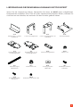 5
5
-
 6
6
-
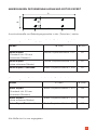 7
7
-
 8
8
-
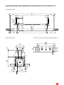 9
9
-
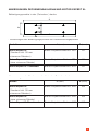 10
10
-
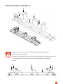 11
11
-
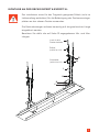 12
12
-
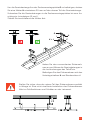 13
13
-
 14
14
-
 15
15
-
 16
16
-
 17
17
-
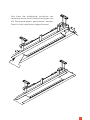 18
18
-
 19
19
-
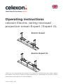 20
20
-
 21
21
-
 22
22
-
 23
23
-
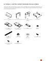 24
24
-
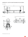 25
25
-
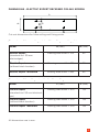 26
26
-
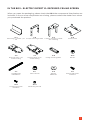 27
27
-
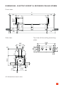 28
28
-
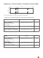 29
29
-
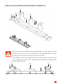 30
30
-
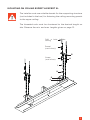 31
31
-
 32
32
-
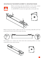 33
33
-
 34
34
-
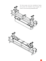 35
35
-
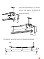 36
36
-
 37
37
-
 38
38
-
 39
39
-
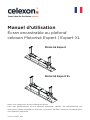 40
40
-
 41
41
-
 42
42
-
 43
43
-
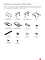 44
44
-
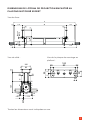 45
45
-
 46
46
-
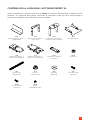 47
47
-
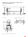 48
48
-
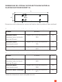 49
49
-
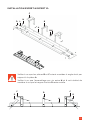 50
50
-
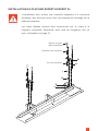 51
51
-
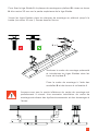 52
52
-
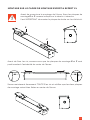 53
53
-
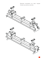 54
54
-
 55
55
-
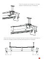 56
56
-
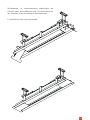 57
57
-
 58
58
-
 59
59
-
 60
60
-
 61
61
-
 62
62
-
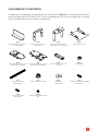 63
63
-
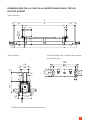 64
64
-
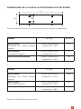 65
65
-
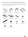 66
66
-
 67
67
-
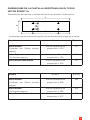 68
68
-
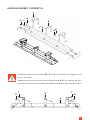 69
69
-
 70
70
-
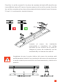 71
71
-
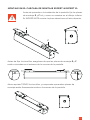 72
72
-
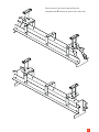 73
73
-
 74
74
-
 75
75
-
 76
76
-
 77
77
-
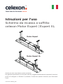 78
78
-
 79
79
-
 80
80
-
 81
81
-
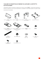 82
82
-
 83
83
-
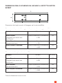 84
84
-
 85
85
-
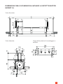 86
86
-
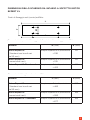 87
87
-
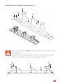 88
88
-
 89
89
-
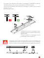 90
90
-
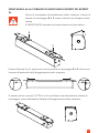 91
91
-
 92
92
-
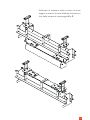 93
93
-
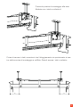 94
94
-
 95
95
-
 96
96
-
 97
97
-
 98
98
-
 99
99
-
 100
100
-
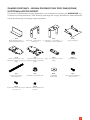 101
101
-
 102
102
-
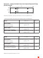 103
103
-
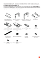 104
104
-
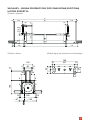 105
105
-
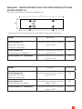 106
106
-
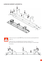 107
107
-
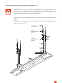 108
108
-
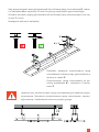 109
109
-
 110
110
-
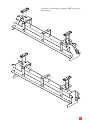 111
111
-
 112
112
-
 113
113
-
 114
114
-
 115
115
-
 116
116
-
 117
117
-
 118
118
-
 119
119
-
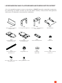 120
120
-
 121
121
-
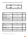 122
122
-
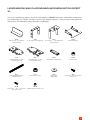 123
123
-
 124
124
-
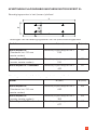 125
125
-
 126
126
-
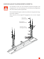 127
127
-
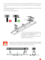 128
128
-
 129
129
-
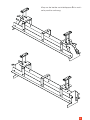 130
130
-
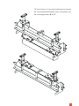 131
131
-
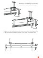 132
132
-
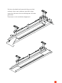 133
133
-
 134
134
-
 135
135
-
 136
136
-
 137
137
-
 138
138
-
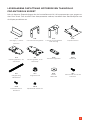 139
139
-
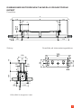 140
140
-
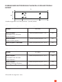 141
141
-
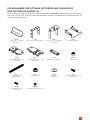 142
142
-
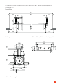 143
143
-
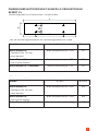 144
144
-
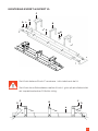 145
145
-
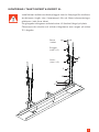 146
146
-
 147
147
-
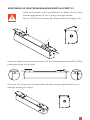 148
148
-
 149
149
-
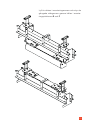 150
150
-
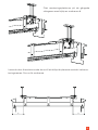 151
151
-
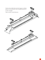 152
152
-
 153
153


Celexon ceiling recessed electric screen Expert 180 x 101 cm de handleiding
- Categorie
- Flat-panel plafondsteunen
- Type
- de handleiding
in andere talen
- italiano: Celexon ceiling recessed electric screen Expert 180 x 101 cm Manuale del proprietario
- français: Celexon ceiling recessed electric screen Expert 180 x 101 cm Le manuel du propriétaire
- español: Celexon ceiling recessed electric screen Expert 180 x 101 cm El manual del propietario
- Deutsch: Celexon ceiling recessed electric screen Expert 180 x 101 cm Bedienungsanleitung
- polski: Celexon ceiling recessed electric screen Expert 180 x 101 cm Instrukcja obsługi
Gerelateerde papieren
-
Celexon Tischleinwand Mobil Professional 81 x 61cm de handleiding
-
-
-
-
-
-
-
-
-
Andere documenten
-
Yamaha DPX-1300 de handleiding
-
Lenco LPJ-500BU de handleiding
-
-
 JBSYSTEMS LP-8140 de handleiding
-
Konig Electronic TVS-KN-FSB500 de handleiding
-
Konig Electronic TVS-KN-AVS100B Handleiding
-
-
Samsung SP-LSP7TFA Handleiding
-
Philips PPX520 Gebruikershandleiding
