
A1004849 - 664Y7100 • A
EN
FR
NL
ES
IT
DE
PL
RU
200 - 250 - 300 - 350 - 400 - 500 LP & RP
Prestige Box
INSTALLATION, OPERATION AND MAINTENANCE INSTRUCTIONS
for the Installer and the User

Addendum Nox Values: A1007428 - ADD0170
Addendum - NOx & Declaration of Conformity i.a.w. Royal Decree (BE)
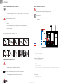
APPLICABILITY :
664Y7100 - Rev A - Prestige Box 200 - 250 - 300 - 350 - 400 - 450 - 500 LP - RP
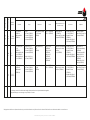
NOx (Class 6/ Classe 6 / Klass 6/ Klasse 6)*
Weighted / Pondéré/Gewogen / Gewichtet.
Prestige Box
200 - 300 - 400 LP-RP
mg/kWh
34,2
250 - 350 - 500 LP-RP
mg/kWh
39,6
* i.a.w. EN15502-1+A1:2015

Addendum Nox Values: A1007428 - ADD0170

Addendum Prestige Chimney Connections : A1005389 - ADD0070
Addendum - Prestige Chimney Connections
APPLICABILITY :
664Y6700 - Rev D - Prestige 24-32 Solo/Excellence
664Y6200 - Rev F - Prestige 42-50-75-100-120 Solo
664Y7100 - Rev A - Prestige Box 200-250-300-350-400-500 LP&RP
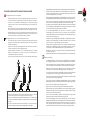
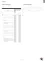
RECOMMENDATIONS FOR CHIMNEY CONNECTION
Essential recommendations for safety
• Do not install the boiler into a common flue piping with any other gas or oil
appliances. This will cause flue gas spillage or appliance malfunction.
• Verify installed combustion air and flue piping are sealed gas tight and meet all
provided instructions and applicable codes and standards.
• Failure to properly support the flue system can cause the flue system to fail,
resulting in substantial property damage, serious injury, or death.
• A byproduct of any gas/oil fired appliance is carbon monoxide. Failure to install
carbon monoxide detectors with alarms can result in serious injury, or death. Refer
to applicable local regulations.
Essential recommendations for the correct operation of the appliance
• A condensation outlet connected to the sewer must be fitted close to the boiler to
prevent the condensation products from the flue pipe from running into the boiler.
• Install a condensate neutralisation system if required by national and/or local
regulations and have it cleaned regularly.
• Only use flue system components from the same manufacturer to connect this
appliance and ensure that the pipe and connection diameters all match.
• Make sure to secure the flue piping to a solid structure.
• Exclusively use provided brackets to support the flue system.
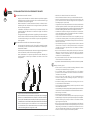
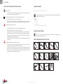
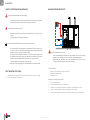
• Install the horizontal flue pipes with a slight slope of 5 cm per meter (3°), so that the
acid condensation water flows to a condensate recovery container and does not
damage the heating body.
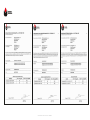
≤0,5 m
≤2,0 m
≤1,0 m
≤1,0 m
4
1
3
1
≤0,25 m
≤2,0 m
≤0,25 m
4
2
≤0,25 m
≤0,25 m
≤2,0 m
4
2
Slope = 3°
1. Each elbow and straight element will be secured at the sleeve.
2. In case the straight element before or after the first elbow is shorter than 25 cm,
secure the straight element after the elbow using a bracket.
3. In case a straight (horizontal or sloped) element is longer than 1 m, support the element in
its center using a clamp, making sure to allow free movement of the pipe.
4. Secure with a clamp every 2 meters in vertical piping/1 meter in horizontal/sloped
piping, making sure to distribute the clamps evenly on the length of piping.
• If the appliance is provided with a condensate drain assembly, make sure to install
the complete assembly on the boiler. If the assembly is incomplete, replace the entire
assembly.
• Make sure that the condensate drain assembly is filled with water before starting
up the boiler and check regularly the water level. Fill with water as necessary.
• It is mandatory to ventilate the boiler room. The high or low air vent opening
dimensions depend on the boiler power and the boiler room size. Refer to the local
regulations in force.
• If the combustion air inlet is located in an area likely to cause or contain
contamination, or if products which could contaminate the air cannot be removed,
the combustion air must be repiped and terminated at another location.
• Pool, laundry, common household, and hobby products often contain fluorine
or chlorine compounds, which can form strong acids and corrode the internal
components and flue system.
• In the case of parallel flue systems, make sure to maintain sufficient distance
(at least 40 mm) between the boiler flue piping and combustible materials, and
between the flue pipe and air inlet pipe if the latter is made of plastic material.
• Do not use screws to fasten together any flue pipe elements or any PP air inlet
elements.
• Do not bond piping elements together using glue (e.g. silicone) or foam (e.g. PUR).
General remark
• For safety reasons and to make assembly easier, it is recommended to prefer the
use of concentric flue pipes when possible.
• It is recommended to isolate the flue piping in damp rooms to prevent condensation
water from forming on the piping and drip.
• When cutting the pipes to dimension, make sure to cut squarely and deburr the
edges to prevent seals from being incorrect or damaged.
• To make piping assembly easier, exclusively use a mixture of water and soap (1%)
on the extremity of the pipe to be fit in.
• When fitting metal flue pipes, make sure to always fit the pipe into the sleeve to
the end stop.
• When fitting plastic flue pipes, make sure to allow material expansion by leaving
about 10 mm between the pipe end and the sleeve end stop.
• Make sure to install the piping without any strain.
• Make sure to install an inspection opening in the flue system.
• When connecting the flue pipes, make sure not to exceed the maximum length
recommended for the product, otherwise the system power might decrease.
• ACV-approved components will be used for the chimney connection. Failure to do
so will make any warranty claim void.
• For C63 connection type (not allowed in Belgium), make sure to use the correct
piping material according to the resistance to temperature, pressure, chemical
composition of flue, condensation and soot. A code (as explained in EN 1443),
marked on the pipe, allows to determine if the material complies with the flue
system requirements.
EN

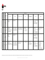
Addendum Prestige Chimney Connections : A1005389 - ADD0070
Boiler Models
Connexion type
Material /
Ø (mm)
Components *
Terminals Pipes Extensions Bends
Measurement and con-
densate recovery
Accessories Adapters
Prestige 24-32
C93
PP Flex
Ø 60
Set C93 Ø 60/100,
(537D6407)
Flexible PP Ø 60, 25 m
(537D6406)
— — —
• Connection sheath
Alu for 60/100
(537D6408)
• Connector Flex-Flex PP
Ø 60 (537D6447)
—
Prestige 24-32
C13
C33
PP - Galva
Ø 60/100
• Roof Terminal
(537D6353)
• Wall Terminal
(537D6354)
Lengths :
• 250 mm (537D6355)
• 500 mm (537D6356)
• 1000 mm (537D6357)
Sliding extension, straight
(+ 50 to 130 mm )
(537D6358)
• 15° (537D6466)
• 30° (537D6467)
• 43° - 45° (537D6359)
• 87° - 90° (537D6360)
Measuring T-piece with
inspection (537D6361)
• Weather Slate Steep
(537D6363)
• Bracket Ø 100 mm
(537D6364)
• Weather Slate Flat roof
(Ø 350 mm) (537D6362)
Adapter Ø 60/100 - 2 x
Ø 80 with measurement
points (537D6415)
Prestige 24-32
Prestige 42-50-75
C93
PP Flex
Ø 80
Set C93 Ø 80/125,
(537D6287)
Flexible PP PP Ø 80, 25 m
(537D6275)
— — —
• Connection sheath
Alu for 80/125
(537D6266)
• Connector Flex-Flex PP
Ø 80 (537D6448)
—
Prestige 24-32
Prestige 42-50-75
C13
C33
PP - Galva
Ø 80/125
• Roof Terminal
(537D6184 )
• Wall terminal kit
(537D6185)
Lengths :
• 250 mm (537D6186)
• 500 mm (537D6187)
• 1000 mm (537D6188)
• 2000 mm (537D6516)
Sliding extension , straight
(+ 50 to 130 mm )
(537D6189)
• 43° - 45° (537D6190)
• 87° - 90° (537D6191)
• Measuring Tube
( 537D6193)
• Measuring T-piece with
inspection (537D6229)
• Weather Slate Steep
(537D6182)
• Bracket Ø 125 mm
(537D6183)
• Weather salte, at roof
(Ø 390 mm) (537D6194)
• Expander SST/Alu
Ø 80/125 mm -
2 x Ø 80 mm
(537D6231)
• Expander PP/ALU,
Ø 60/100 mm - Ø
80/125 mm (537D6405)
Prestige 42-50-
75-100-120
C93
PP Flex
Ø 100
Set C93 Ø 100/150,
(537D6290)
Flexible PP Ø 100, 25 m
(537D6271)
— — —
• Connection sheath
Alu for Ø 100/150
(37D6267)
• Adapter Flex-Flex PP Ø
100 (537D6451)
—
* Designations and references (between brackets) are provided as information only. Please refer to the latest ACV brochure for more information and the correct references.
EN

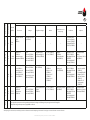
Addendum Prestige Chimney Connections : A1005389 - ADD0070
Boiler Models
Connexion type
Material /
Ø (mm)
Components *
Terminals Pipes Extensions Bends
Measurement and con-
densate recovery
Accessories Adapters
Prestige 42-50-75-
100-120
C13
C33
PP - Galva
Ø 100/150
• Roof Terminal
(537D6300)
• Wall terminal kit
(537D6301)
Lengths :
• 250 mm (537D6302)
• 500 mm (537D6303)
• 1000 mm (537D6304)
• 2000 mm (537D6517)
Sliding extension, straight
(+ 50 to 130 mm)
(537D6305)
• 43° - 45° (537D6306)
• 87° - 90° (537D6307)
• Measuring Tube
( 537D6308)
• Measuring T-piece with
inspection (537D6310)
• Weather Slate Steep
25°-45° (537D6209)
• Bracket Ø 150 mm
(537D6210)
• Weather Slate, Flat roof
(Ø 430 mm) (537D6208)
Concentric to parallel
adapter Ø 100/150 mm - 2 x
Ø 100 mm (537D6207)
Prestige 42-50-75-100-120
B23P
C53
SST
Ø 150
• Roof Terminal , ue
Ø 150
(537D6211)
• Wall terminal kit , ue,
Ø 150 (537D6212)
• Wall terminal kit, air,
Ø 100 (537D6213)
Lengths, flue, Ø 150 :
• 250 mm (537D6214)
• 500 mm (537D6215)
• 1000 mm (537D6216)
Length, air, PVC Ø 100 :
• 500 mm (537D6217)
Sliding extension, flue,
Ø 150
(537D6218)
• Flue, Ø 150, 45°
(537D6219)
• Flue, Ø 150, 90°
(537D6220)
• Air, Ø 100, 45°
(537D6221)
• Air, Ø 100, 90°
(537D6222)
Element for measurement
and recovery of conden-
sates, ue,
Ø 150 (537D6223)
• Weather Slate Steep
25°-45° (537D6209)
• Bracket Ø 150 mm
(537D6210)
• Weather Slate, Flat roof
(Ø 430 mm) (537D6208)
• Expander Ø 100 -
Ø 150 mm mandatory
(537D6293)
• Concentric to parallel
adapter Ø 100/150
mm - 2 x Ø 100 mm
(537D6207)
• Adapter Ø 80 - Ø 100
mm, air (537D6172)
Prestige 42-50-75-100-120
C13
C33
SST - SST
Ø 100/150
• Roof Terminal,
(537D6197)
• Wall terminal
(537D6198)
Lengths :
• 250 mm (537D6199)
• 500 mm (537D6200)
• 1000 mm (537D6201)
Sliding extension (280 to
395 mm)
(537D6202)
• 43° - 45° (537D6203)
• 87° - 90° (537D6204)
Element for measurement
and recovery of conden-
sates, ue, (537D6226)
• Weather Slate Steep
25°-45° (537D6209)
• Bracket Ø 150 mm
(537D6210)
• Weather Slate, Flat roof
(Ø 430 mm) (537D6208)
Concentric to parallel
adapter Ø 100/150 mm - 2 x
Ø 100 mm (537D6207)
Prestige Box
The chimney connection should be made using the chimney tubes and seals provided with the Prestige Box.
Only parallel flue pipe connection types are possible, NO concentric.
* Designations and references (between brackets) are provided as information only. Please refer to the latest ACV brochure for more information and the correct references.
EN

Addendum Prestige Chimney Connections : A1005389 - ADD0070
RECOMMANDATIONS POUR LE RACCORDEMENT CHEMINÉE
Recommandations essentielles à la sécurité
• Ne pas raccorder la chaudière à un conduit de cheminée auquel d'autres appareils
de chauffage au gaz ou au fioul sont raccordés. Cela occasionnera une fuite des gaz
de combustion ou une panne de l'appareil.
• Vérifier l'étanchéité des conduits d'évacuation des fumées et d'amenée d'air de
combustion, qu'ils sont conformes à toutes les consignes fournies et qu'ils satisfont
aux codes et normes applicables.
• Si l'installation d'évacuation des fumées n'est pas correctement soutenue, cela
pourrait engendrer des défectuosités et occasionner des dégâts et des blessures
graves ou mortelles.
• Tout appareil de chauffage qui fonctionne au gaz/fioul génère du monoxyde de
carbone. L'absence de détecteurs de monoxyde de carbone dotés d'une alarme peut
occasionner des blessures graves voire mortelles. Se reporter aux réglementations
locales applicables.
Recommandations essentielles au bon fonctionnement de l'appareil
• Une évacuation des condensats raccordée à l'égout doit être installée à proximité
de la chaudière pour éviter l'écoulement dans la chaudière des condensats qui se
forment dans la cheminée.
• Installer un système de neutralisation des condensats si exigé par les réglementations
locales et/ou nationales, et veiller à le faire nettoyer régulièrement.
• Utiliser exclusivement des composants provenant d'un même fabricant pour
raccorder l'appareil, et s'assurer que les diamètres de conduits et des raccords
correspondent.
≤0,5 m
≤2,0 m
≤1,0 m
≤1,0 m
4
1
3
1
≤0,25 m
≤2,0 m
≤0,25 m
4
2
≤0,25 m
≤0,25 m
≤2,0 m
4
2
Pente = 3°
1. Chaque coude et élément droit sera maintenu au manchon.
2. Dans le cas d'un élément droit se trouvant avant ou après le premier coude et d'une longueur
inférieure à 25 cm, maintenir l'élément droit se trouvant après le coude à l'aide d'une fixation
3. Dans le cas d'un conduit droit (horizontal ou installé en pente) d'une longueur supérieure à 1 m,
soutenir l'élément en son centre à l'aide d'un collier qui permet le libre mouvement de l'élément.
4. Placer un collier de support tous les 2 mètres dans le cas des conduits verticaux /
tous les mètres dans le cas de conduits horizontaux/en pente en veillant à répartir les
colliers de manière régulière sur la longueur de conduit.
• Veiller à fixer les conduits de cheminée à une structure solide.
• Utiliser exclusivement les fixations fournies pour soutenir l'installation cheminée.
• Installer les conduits horizontaux avec une légère pente de 5cm par mètre (3°) afin
que les écoulements acides de condensats se dirigent vers un bac récupérateur et
n'endommagent pas le corps de chauffe.
• Si l'appareil est fourni avec un dispositif d'évacuation des condensats, veiller à installer
l'ensemble complet sur la chaudière. S'il est incomplet, remplacer l'ensemble complet.
• S'assurer que le dispositif d'évacuation des condensats est rempli d'eau avant de démarrer
la chaudière et vérifier régulièrement le niveau d'eau. Le remplir d'eau si nécessaire.
• La ventilation de la chaufferie est obligatoire. Les dimensions de l'ouverture haute
ou basse dépendent de la puissance de la chaudière et du volume de la chaufferie,
ainsi que des réglementations locales applicables.
• Si l'entrée d'air de combustion est située dans une zone susceptible de provoquer
ou de contenir des éléments polluants, ou si les produits qui pourraient polluer l'air
ne peuvent être déplacés, l'air de combustion doit être prélevé à un autre endroit, à
l'aide d'un nouveau conduit.
• Les produits utilisés pour les piscines, le lavage, l'entretien et les loisirs contiennent
souvent du fluor ou du chlore. Ces derniers peuvent former des acides puissants
susceptibles de corroder les composants internes de la chaudière et l'installation
d'évacuation des fumées.
• Dans le cas d'une installation à conduits parallèles, veiller à respecter une distance
suffisante (au moins 40 mm) entre les conduits des fumées et des matériaux
combustibles, et entre les conduits des fumées et le conduit d'amenée d'air de
combustion s'il est en matériaux plastiques.
• Ne pas fixer ensemble à l'aide de vis des conduits d'évacuation des fumées, ou des
conduits d'amenée d'air de combustion en PP.
• Ne pas fixer des conduits ensemble à l'aide de colle (p. ex. au silicone) ou de mousse (p. ex. PUR).
Remarques à caractère général
• Pour des raisons de sécurité et pour faciliter l'assemblage, l'utilisation de conduits
concentriques est recommandée lorsque c'est possible.
• Il est recommandé d'isoler les conduits d'évacuation des gaz de combustion
qui traversent des locaux humides afin d'éviter la formation et l'écoulement de
condensation sur les conduites.
• Lors de la découpe des conduits, veiller à les couper perpendiculairement et
à ébavurer les bords pour éviter d'endommager les joints et s'assurer que les
raccordements sont étanches.
• Pour faciliter l'assemblage, utiliser exclusivement un mélange d'eau et de savon
(1%) sur l'extrémité du conduit à emboiter.
• Lors de l'assemblage de conduits métalliques, veiller à toujours enfoncer le conduit
à fond de butée dans le manchon.
• Lors de l'assemblage de conduits en plastique, veiller à permettre l'expansion du matériau
en laissant environ 10 mm entre l'extrémité du conduit et la butée interne du manchon.
• Faire le montage sans contrainte.
• Prévoir un regard pour inspecter la cheminée.
• Lors de l'exécution du raccordement cheminée, veiller à ne pas dépasser la longueur
maximale indiquée pour le produit, sous peine de diminuer la puissance de l'installation.
• Utiliser des éléments agréés par ACV pour effectuer le raccordement. À défaut,
l'appel en garantie sera réputé nul.
• Dans le cas d'un raccordement de type C63 (interdit en Belgique), veiller à utiliser un
matériau adéquat en termes de résistance à la température, à la pression, à la teneur
chimique des gaz de combustion, à la condensation et à la formation de suies. Un
code (voir la norme EN 1443) est indiqué sur les conduits et permet de savoir si le
matériau est conforme aux exigences d'une installation particulière.
FR

Addendum Prestige Chimney Connections : A1005389 - ADD0070
Modèles de
Chaudière
Raccordement
Matériau /
Ø (mm)
Composants *
Terminaux Conduits Conduits réglables Coudes
Mesure et récup.
condensation
Accessoires Adaptateurs
Prestige 24-32
C93
PP Flex
Ø 60
Set C93 Ø 60/100,
(537D6407)
Tube exible PP Ø 60, 25
m (537D6406)
— — —
• Fourreau de raccord-
ement pour concen-
trique (537D6408)
• Adaptateur Flex-Flex
PP Ø 60 (537D6447)
—
Prestige 24-32
C13
C33
PP - Galva
Ø 60/100
• Terminal vertical
(537D6353)
• Kit terminal horizontal
(537D6354)
Longueurs :
• 250 mm (537D6355)
• 500 mm (537D6356)
• 1000 mm (537D6357)
Conduit coulissant (+
50 à 130 mm à droite)
(537D6358)
• 15° (537D6466)
• 30° (537D6467)
• 43° - 45° (537D6359)
• 87° - 90° (537D6360)
Élément de mesure
en T avec inspection
(537D6361)
• Solin réglable
(537D6363)
• Fixation Ø 100 mm
(537D6364)
• Solin toit plat (Ø 350
mm) (537D6362)
Adaptateur Ø 60/100 - 2
x Ø 80 avec prises de
mesure (537D6415)
Prestige 24-32
Prestige 42-50-75
C93
PP Flex
Ø 80
Set C93 Ø 80/125,
(537D6287)
Tube exible PPS Ø 80, 25
m (537D6275)
— — —
• Fourreau de raccord-
ement pour concen-
trique (537D6266)
• Adaptateur Flex-Flex
PP Ø 80 (537D6448)
—
Prestige 24-32
Prestige 42-50-75
C13
C33
PP - Galva
Ø 80/125
• Terminal vertical
(537D6184 )
• Terminal horizontal
avec plaques murales
(537D6185)
Longueurs :
• 250 mm (537D6186)
• 500 mm (537D6187)
• 1000 mm (537D6188)
• 2000 mm (537D6516)
Conduit coulissant (+
50 à 130 mm à droite)
(537D6189)
• 43° - 45° (537D6190)
• 87° - 90° (537D6191)
• Tube de mesure.
( 537D6193)
• Élément de mesure
en T avec inspection
(537D6229)
• Solin réglable
(537D6182)
• Fixation Ø 125 mm
(537D6183)
• Solin toit plat (Ø 390
mm) (537D6194)
• Adaptateur inox.
Ø 80/125 mm -
2 x Ø 80 mm
(537D6231)
• Adaptateur PPS,
Ø 60/100 mm - Ø
80/125 mm (537D6405)
Prestige 42-50-
75-100-120
C93
PP Flex
Ø 100
Set C93 Ø 100/150,
(537D6290)
Tube exible PPS Ø 100,
25 m (537D6271)
— — —
• Fourreau de raccord-
ement pour concen-
trique (537D6267)
• Adaptateur Flex-Flex
PP Ø 100 (537D6451)
—
* Les descriptions et références (entre parenthèses) sont fournies à titre d’information. Veuillez vous référer au catalogue ACV le plus récent pour davantage de détails et les références exactes.
FR

Addendum Prestige Chimney Connections : A1005389 - ADD0070
Modèles de
Chaudière
Raccordement
Matériau /
Ø (mm)
Composants *
Terminaux Conduits Conduits réglables Coudes
Mesure et récup.
condensation
Accessoires Adaptateurs
Prestige 42-50-
75-100-120
C13
C33
PP - Galva
Ø 100/150
• Terminal vertical
(537D6300)
• Kit terminal horizontal
(537D6301)
Longueurs :
• 250 mm (537D6302)
• 500 mm (537D6303)
• 1000 mm (537D6304)
• 2000 mm (537D6517)
Conduit coulissant (+
50 à 130 mm à droite)
(537D6305)
• 43° - 45° (537D6306)
• 87° - 90° (537D6307)
• Tube de mesure.
( 537D6308)
• Élément de
mesure en T
avec inspection
(537D6310)
• Solin réglable 25°-45°
(537D6209)
• Fixation Ø 150 mm
(537D6210)
• Solin toit plat (Ø 430
mm) (537D6208)
Adaptateur concentrique/paral-
lèle Ø 100/150 mm - 2 x Ø 100
mm (537D6207)
Prestige 42-50-75-100-120
B23P
C53
Inox
Ø 150
• Terminal vertical,
fumées Ø 150
(537D6211)
• Kit terminal horizon-
tal, fumées, Ø 150
(537D6212)
• Kit terminal horizontal,
air, Ø 100 (537D6213)
Longueurs, fumées, Ø
150 :
• 250 mm (537D6214)
• 500 mm (537D6215)
• 1000 mm (537D6216)
Longueur, air, PVC Ø 100 :
• 500 mm (537D6217)
Longueur réglable,
fumées, Ø 150 (537D6218)
• Fumées, Ø 150, 45°
(537D6219)
• Fumées, Ø 150, 90°
(537D6220)
• Air, Ø 100, 45°
(537D6221)
• Air, Ø 100, 90°
(537D6222)
• Tube de mesure
avec récupérateur
de condensats,
fumées,
Ø 150 (537D6223)
• Solin réglable 25°-45°
(537D6209)
• Fixation Ø 150 mm
(537D6210)
• Solin toit plat (Ø 430
mm) (537D6208)
• Adaptateur Ø 100 -
Ø 150 mm obligatoire
(537D6293)
• Adaptateur concentrique/
parallèle
Ø 100/150 mm - 2 x Ø 100
mm (537D6207)
• Adaptateur Ø 80 - Ø 100
mm, air (537D6172)
Prestige 42-50-75-100-120
C13
C33
Inox - Inox
Ø 100/150
• Terminal vertical,
(537D6197)
• Terminal horizontal
(537D6198)
Longueurs :
• 250 mm (537D6199)
• 500 mm (537D6200)
• 1000 mm (537D6201)
Longueur réglable (280 à
395 mm)
(537D6202)
• 43° - 45° (537D6203)
• 87° - 90° (537D6204)
Tube de mesure
avec récupérateur
de condensats
(537D6226)
• Solin réglable 25°-45°
(537D6209)
• Fixation Ø 150 mm
(537D6210)
• Solin toit plat (Ø 430
mm) (537D6208)
Adaptateur concentrique/paral-
lèle Ø 100/150 mm - 2 x Ø 100
mm (537D6207)
Prestige Box
Effectuer le raccordement cheminée à l’aide des conduits et joints livrés avec le produit.
Les conduits d’’évacuation des fumées doivent être raccordés en parallèle, PAS en concentrique.
* Les descriptions et références (entre parenthèses) sont fournies à titre d’information. Veuillez vous référer au catalogue ACV le plus récent pour davantage de détails et les références exactes.
FR

Addendum Prestige Chimney Connections : A1005389 - ADD0070
VEILIGHEIDSVOORSCHRIFTEN VOOR DE ROOKGASAFVOER
Belangrijke instructies voor de veiligheid
• De ketel niet installeren in een gemeenschappelijke rookgasafvoer met andere gas-
of olie-apparaten. Dit zal rookgas lekkage of defect van het apparaat veroorzaken.
•
Controleer of de geïnstalleerde verbrandingslucht en rookgasafvoer gasdicht
aangesloten zijn en voldoen aan alle geldende instructies en toepasselijke codes
en normen.
• Als de rookgasafvoer niet goed wordt ondersteund, kan het rookgasafvoersysteem
defect raken, met als gevolg aanzienlijke materiële schade, ernstig letsel of de dood.
• Een bijproduct van een met gas/olie-gestookt apparaat is koolmonoxide. Als u geen
koolmonoxidemelders met alarmsignalen installeert, kan dit ernstig letsel of de
dood tot gevolg hebben. Volg de geldende lokale voorschriften
Belangrijke instructie voor een correcte werking van het toestel
• Een condensafvoer die op het riool is aangesloten, moet dicht bij de ketel worden
geplaatst om te voorkomen dat de condensatieproducten uit de rookgasafvoerbuis
in de ketel terechtkomen.
• Installeer een condensaatneutraliseringssysteem indien vereist door nationale en /
of lokale voorschriften en laat het regelmatig reinigen.
•
Gebruik uitsluitend onderdelen van het rookgasafvoersysteem van dezelfde
fabrikant om dit apparaat aan te sluiten en zorg ervoor dat de leiding en de
aansluitdiameters allemaal overeenkomen.
• Zorg ervoor dat het rookgasafvoersysteem op een solide structuur wordt bevestigd.
≤0,5 m
≤2,0 m
≤1,0 m
≤1,0 m
4
1
3
1
≤0,25 m
≤2,0 m
≤0,25 m
4
2
≤0,25 m
≤0,25 m
≤2,0 m
4
2
Helling = 3°
1. Elke bocht en recht element worden op de mof vastgezet.
2. Indien de rechte buizen voor of na de eerste bocht korter zijn dan 25 cm, dient het
tweede rechte element na de bocht vastgezet worden met een beugel.
3. Indien een recht (horizontaal of verslepend) element langer is dan 1 m, ondersteun dan
het element in het midden met behulp van een klem en zorg ervoor dat de buis vrij kan
bewegen.
4. Zet vast met een klem elk 2 meter in verticale leidingen / 1 meter in horizontale /
verslepend leidingen. Verdeel de klemmen gelijkmatig over de leidingen.
• Gebruik uitsluitend meegeleverde beugels om het rookgasafvoersysteem te ondersteunen.
• Installeer de horizontale rookkanalen met een lichte helling van 5 cm per meter (3 °),
zodat het condensatiewater naar een condensaatterugwinningscontainer stroomt
en het verwarmingslichaam niet beschadigt.
• Als het apparaat wordt geleverd met een condenswaterafvoer, zorg er dan voor dat u de
volledige assemblage op de ketel installeert. Als de set incompleet is, vervangt u de hele set.
• Zorg ervoor dat de condensafvoer is gevuld met water voordat u de ketel in gebruik
neemt en controleer regelmatig het waterniveau. Vul met water indien nodig.
• De ventilatie van de stookruimte is verplicht. De afmetingen van de bovenverluchting
of onderverluchting zijn afhankelijk van het vermogen van de ketel en het volume
van de stookruimte. Volg de geldende lokale voorschriften.
• Als de verbrandingsluchtinlaat zich bevindt in een ruimte die mogelijk
verontreinigingen veroorzaakt of bevat, of als producten die de lucht kunnen
verontreinigen niet kunnen worden verwijderd, moet de verbrandingslucht op een
andere locatie worden aangezogen.
• Zwembad, was, gemeenschappelijke huishoudelijke en hobbyproducten bevatten
vaak fluor- of chloorverbindingen, die sterke zuren kunnen vormen en de interne
componenten en het rookgasafvoersysteem kunnen aantasten.
• Zorg bij parallelle rookgasafvoersystemen voor voldoende afstand (minimaal 40
mm) tussen de rookgasleidingen van de ketel en brandbare materialen, en tussen
de rookgasafvoer en de luchtinlaatleiding als deze is gemaakt van kunststof.
• Gebruik geen schroeven om rookgasafvoerelementen of PP-luchtinlaatelementen
aan elkaar te bevestigen.
• Verbind leiding-elementen niet aan elkaar met lijm (bv. siliconen) of schuim (bv. PUR).
Algemene opmerking
• Om veiligheidsredenen en om de montage te vergemakkelijken, is het raadzaam om
waar mogelijk het gebruik van een concentrisch rookgasafvoersysteem te verkiezen.
• Het wordt aanbevolen om de rookgasafvoerleidingen in vochtige ruimtes te isoleren
om te voorkomen dat zich condensatiewater op de leidingen vormt en druppelt.
• Wanneer u de leidingen op maat snijdt, zorg dan dat u rond snijdt en de randen
ontbraamt om te voorkomen dat de afdichtingen onjuist of beschadigd zijn.
• Om het assembleren van leidingen gemakkelijker te maken, gebruikt u uitsluitend
een mengsel van water en zeep (1%) op het uiteinde van de te passen buis.
• Zorg er bij het monteren van metalen rookgasafvoerkanalen voor dat de buis altijd
in de mof tot aan de aanslag wordt geplaatst.
• Zorg er bij het monteren van kunststof rookgasafvoerbuizen voor dat de materiaal-
uitzetting ongeveer 10 mm is tussen het uiteinde van de buis en de eindaanslag van de mof.
• Zorg ervoor dat u de leidingen zonder spanning installeert.
• Zorg ervoor dat u een inspectieopening in het rookkanaalsysteem installeert.
• Bij de uitvoering van de schouwaansluiting moet u erop toezien dat het opgegeven
maximale lengte aanbevolen voor het product niet overschreden wordt, zo niet kan
het vermogen van de installatie afnemen.
• Voor de schoorsteenaansluiting, uitsluitend ACV-goedgekeurde componenten
gebruiken. Als u dit nalaat, vervalt elke aanspraak op garantie.
• Voor C63-verbindingstype (niet toegestaan in België), zorg ervoor dat u het juiste
leidingmateriaal gebruikt in overeenstemming met de weerstand tegen temperatuur,
druk, chemische samenstelling van het rookkanaal, condensatie en roet. Een code
(zoals uitgelegd in EN 1443), gemarkeerd op de buis, maakt het mogelijk om te
bepalen of het materiaal voldoet aan de vereisten van het rookgasafvoersysteem.
NL

Addendum Prestige Chimney Connections : A1005389 - ADD0070
Ketel modellen
Aansluitingen
Materiaal /
Ø (mm)
Componenten *
Doorvoeren Leidingen Regelbare leidingen Bochten
Meetelement en con-
densopvang
Toebehoren Adapters
Prestige 24-32
C93
PP Flex
Ø 60
Toebehoren Set C93 C93
Ø 60/100,
(537D6407)
25 m exibele buis PPS Ø
60, (537D6406)
— — —
• Aansluitingskoker voor
concentrische schouw
(537D6408)
• Koppelstuk Flex-Flex
PP Ø 60 (537D6447)
—
Prestige 24-32
C13
C33
PP - Galva
Ø 60/100
• Dakdoorvoer
(537D6353)
• Kit muurdoorvoer met
muurplaten en bocht
90° (537D6354)
Lengte :
• 250 mm (537D6355)
• 500 mm (537D6356)
• 1000 mm (537D6357)
Invoegbare lengte.
(verlengt een lengte + 50
tot 130 mm) (537D6358)
• 15° (537D6466)
• 30° (537D6467)
• 43° - 45° (537D6359)
• 87° - 90° (537D6360)
T-inspectiemeetelement
(537D6361)
• Regelbare losse pan
(537D6363)
• Bevestiging Ø 100 mm
(537D6364)
• Losse pan plat dak (Ø
350 mm) (537D6362)
Adapter Ø 60/100 - 2 x Ø
80 met meetopeningen
(537D6415)
Prestige 24-32
Prestige 42-50-75
C93
PP Flex
Ø 80
Toebehoren Set C93 Ø
80/125,
(537D6287)
25 m exibele buis PPS Ø
80, (537D6275)
— — —
• Aansluitingskoker voor
concentrische schouw
(537D6266)
• Koppelstuk Flex-Flex
PP Ø 80 (537D6448)
—
Prestige 24-32
Prestige 42-50-75
C13
C33
PP - Galva
Ø 80/125
• Dakdoorvoer
(537D6184 )
• Muurdoorvoer met
muurplaten (537D6185)
Lengte :
• 250 mm (537D6186)
• 500 mm (537D6187)
• 1000 mm (537D6188)
• 2000 mm (537D6516)
Invoegbare lengte(verlen-
gt een lengte + 50 tot 130
mm) (537D6189)
• 43° - 45° (537D6190)
• 87° - 90° (537D6191)
• Meetelement.
( 537D6193)
• T-inspectiemeetele-
ment (537D6229)
• Regelbare losse pan
(537D6182)
• Bevestiging Ø 125 mm
(537D6183)
• Losse pan plat dak (Ø
390 mm) (537D6194)
• Concentrisch/Parallel
Adapter inox.
Ø 80/125 mm -
2 x Ø 80 mm
(537D6231)
• Adapter PPS,
Ø 60/100 mm - Ø
80/125 mm (537D6405)
* Beschrijvingen en referenties (tussen haakjes) worden ter informatie verstrekt. Raadpleeg de nieuwste ACV-catalogus voor meer informatie en exacte referenties.
NL

Addendum Prestige Chimney Connections : A1005389 - ADD0070
Ketel modellen
Aansluitingen
Materiaal
/
Ø (mm)
Componenten *
Doorvoeren Leidingen Regelbare leidingen Bochten
Meetelement en con-
densopvang
Toebehoren Adapters
Prestige 42-50-75-
100-120
C93
PP Flex
Ø 100
Toebehoren Set C93 Ø
100/150,
(537D6290)
25 m exibele buis PPS Ø
100, (537D6271)
— — —
• Aansluitingskoker
voor concentrische
schouw (537D6267)
• Verlengstuk Flex-Flex
PP Ø 100 (537D6451)
—
Prestige 42-50-
75-100-120
C13
C33
PP - Galva
Ø 100/150
• Dakdoorvoer
(537D6300)
• Muurdoorvoer met
muurplaten(537D6301)
Lengte :
• 250 mm (537D6302)
• 500 mm (537D6303)
• 1000 mm (537D6304)
• 2000 mm (537D6517)
Invoegbare lengte (+
verlengt een lengte 50
tot 130 mm) (537D6305)
• 43° - 45° (537D6306)
• 87° - 90° (537D6307)
• Meetbuis.
( 537D6308)
• T-inspectiemeetele-
ment (537D6310)
• Regelbare losse pan
25°-45° (537D6209)
• Bevestiging Ø 150 mm
(537D6210)
• Losse pan plat dak (Ø
430 mm) (537D6208)
Concentrisch/Parallel
Adapter,
Ø 100/150 mm - 2 x Ø 100
mm (537D6207)
Prestige 42-50-75-100-120
B23P
C53
SST
Ø 150
• Dakdoorvoer, rook,
Ø 150 (537D6211)
• Muurdoorvoer, rook,
Ø 150 (537D6212)
• Muurdoorvoel, lucht,
Ø 100 (537D6213)
Lengte, rook, Ø 150 :
• 250 mm (537D6214)
• 500 mm (537D6215)
• 1000 mm (537D6216)
Lengte, lucht, PVC Ø 100 :
• 500 mm (537D6217)
Lengte regelbaar, rook,
Ø 150 (537D6218)
• Rook, Ø 150, 45°
(537D6219)
• Rook, Ø 150, 90°
(537D6220)
• Lucht, Ø 100, 45°
(537D6221)
• Lucht, Ø 100, 90°
(537D6222)
• Meetbuis met conden-
sopvang, rook,
Ø 150 (537D6223)
• Regelbare losse pan
25°-45° (537D6209)
• Bevestiging Ø 150 mm
(537D6210)
• Losse pan plat dak (Ø
430 mm) (537D6208)
• Adapter Ø 100 - Ø 150
mm,, rook, verplicht
(537D6293)
• Concentrisch/Parallel
Adapter Ø 100/150
mm - 2 x Ø 100 mm
(537D6207)
• Adapter Ø 80 - Ø
100 mm, mucht
(537D6172)
Prestige 42-50-
75-100-120
C13
C33
SST - SST
Ø 100/150
• Dakdoorvoer,
(537D6197)
• Muurdoorvoer
(537D6198)
Lengte :
• 250 mm (537D6199)
• 500 mm (537D6200)
• 1000 mm (537D6201)
Lengte regelbaar (280 tot
395 mm)
(537D6202)
• 43° - 45° (537D6203)
• 87° - 90° (537D6204)
Condensopvang en meet-
buis (537D6226)
• Regelbare losse pan
25°-45° (537D6209)
• Bevestiging Ø 150 mm
(537D6210)
• Losse pan plat dak (Ø
430 mm) (537D6208)
Concentrisch/Parallel
Adapter Ø 100/150 mm - 2
x Ø 100 mm (537D6207)
Prestige
Box
Het rookgasafvoersysteem moet worden gemaakt met behulp van de leidingen en afdichtingen die zijn meegeleverd met de Prestige Box.
Alleen parallel rookgasafvoersysteem is mogelijk, GEEN concentrisch.
* Beschrijvingen en referenties (tussen haakjes) worden ter informatie verstrekt. Raadpleeg de nieuwste ACV-catalogus voor meer informatie en exacte referenties.
NL

Addendum Prestige Chimney Connections : A1005389 - ADD0070

Addendum Prestige Chimney Connections : A1005389 - ADD0070

Prestige Box: A1004849 - 664Y7100 • A
en
2
EN
FR
NL
ES
IT
DE
PL
RU
TABLE OF CONTENTS
RECOMMENDATIONS .....................................................................................................3
Instructions for the end user .................................................................................................................................................... 3
APPLIANCE DESCRIPTION ..............................................................................................4
General..............................................................................................................................................................................................4
Boiler Control Panel .....................................................................................................................................................................4
Safety devices ................................................................................................................................................................................4
Expansion vessel ...........................................................................................................................................................................4
Plate-to-Plate Heat Exchanger ................................................................................................................................................4
Prestige Box ...................................................................................................................................................................................5
TECHNICAL CHARACTERISTICS ....................................................................................6
Dimensions and clearance ........................................................................................................................................................6
Combustion Characteristics .....................................................................................................................................................8
Electrical Characteristics of Prestige box ............................................................................................................................8
Hydraulic characteristics ..........................................................................................................................................................10
Maximum Operating Conditions ..........................................................................................................................................10
Recommendations for the Prevention of Corrosion and Scaling in Heating Systems ..................................... 11
INSTALL ATION .............................................................................................................. 12
Safety instructions for the installation ...............................................................................................................................12
Package Contents .......................................................................................................................................................................12
Moving the Prestige Box ..........................................................................................................................................................12
Tools required for the installation ........................................................................................................................................12
Opening and closing the front panel ..................................................................................................................................13
Hydraulic connections ..............................................................................................................................................................13
Gas connection ............................................................................................................................................................................ 13
Chimney connection .................................................................................................................................................................13
Electrical connection .................................................................................................................................................................13
STARTING UP ................................................................................................................. 14
Safety Instructions for Starting up .......................................................................................................................................14
Tools required for starting up ................................................................................................................................................14
Checks before starting up .......................................................................................................................................................14
Filling the heating circuit .........................................................................................................................................................14
Starting up the System .............................................................................................................................................................15
MAINTENANCE ..............................................................................................................16
Safety Instructions for Maintenance ...................................................................................................................................16
shutting down the system ......................................................................................................................................................16
Draining the heating circuit ....................................................................................................................................................16
Periodic maintenance tasks ................................................................................................................................................... 17
Blockage and error codes ........................................................................................................................................................17
DECLARATION OF CONFORMITY ............................................................................... 18

NOTE
This manual contains important information with respect to the installation, the starting up and the
maintenance of the appliance.
This manual must be provided to the user, who will read it carefully and keep it in a safe place.
We accept no liability should any damage result from the failure to comply with theinstructions
contained in this technical manual.
Essential recommendations for safety
• It is prohibited to carry out any modifications to the appliance without the
manufacturer’s prior and written agreement.
• The product must be installed by a qualified engineer, in accordance with
applicable local standards and regulations.
• The installation must comply with the instructions contained in this manual and
with the standards and regulations applicable to heating systems.
• Failure to comply with the instructions in this manual could result in personal
injury or a risk of environmental pollution.
• The manufacturer declines all liability for any damage caused as a result of
incorrect installation or in the event of the use of appliances or accessories that are
not specified by the manufacturer.
Essential recommendations for the correct operation of the appliance
• In order to ensure that the appliance operates correctly, it is essential to have it
serviced by a certified installer or maintenance contractor every year.
• In case of anomaly, please call your service engineer.
• Faulty parts may only be replaced by genuine factory parts.
General remarks
• The availability of certain models as well as their accessories may vary according to
markets.
• The manufacturer reserves the right to change the technical characteristics and
features of its products without prior notice.
• In spite of the strict quality standards that ACV applies to its appliances during
production, inspection and transport, faults may occur. Please immediately notify
your approved installer of any faults.
en
3
Prestige Box: A1004849 - 664Y7100 • A
EN
FR
NL
ES
IT
DE
PL
RU
If you smell gas:
- Immediately isolate the gas supply.
- Open windows and doors to ventilate the area.
- Do not use any electrical appliances and do not operate any switches.
- Immediately notify your gas supplier and/or your installer.
RECOMMENDATIONS
INSTRUCTIONS FOR THE END USER
Essential recommendations for safety
• Never by-pass the safety devices installed in the system.
• The Prestige Box is a heating system operating with gas and must be used according to
the manufacturer's definition and local regulations.
• Do not store any flammable or corrosive products, paint, solvents, salts, chloride
products and other detergent products near the appliance.
• This appliance is not intended for use by persons (including children) with reduced
physical, sensory or mental capabilities, or lack of experience and knowledge, unless
supervised or unless they have been given instruction concerning the use of the
appliance by a person responsible for their safety.
• Children should be supervised to ensure that they do not play with the appliance.
Essential recommendations for the correct operation of the appliance
• The Prestige Box must be connected to a heating network that is compatible with its
output.
• The heating circuit must be thoroughly rinsed with clear water before starting up the
appliance.
• The operation and maintenance of the Prestige boiler(s) installed in the Prestige
Box must be performed in accordance with the boiler's Installation, Operation and
Maintenance Instructions.
General remarks
• This manual is an integral part of the Prestige Box. It must be carefully kept by the
user and remain with the Prestige Box, even in case of a change in the owner or if the
appliance is moved to another location.
• Checking the appliance settings can only be carried out by an ACV-trained installer or
by ACV's maintenance department.

Prestige Box: A1004849 - 664Y7100 • A
en
4
EN
FR
NL
ES
IT
DE
PL
RU
APPLIANCE DESCRIPTION
GENERAL
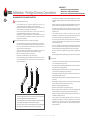
The Prestige Box is a heating system for commercial buildings. This complete heating module houses several
boilers (up to 4) and consists of a specically-designed insulated cabinet that can be located outdoors. It is
also protected against frost in cold weather conditions through the anti-frost features of the boiler(s), and the
insulation of the tubes.
The Prestige Box is comprised of a condensate neutralisation system, an expansion vessel, an electric box and
safety devices among other things. Optional items can also be added in the cabinet. The front door(s) of the
cabinet can be opened for easy access to the items located inside and for maintenance purposes.
The cabinet contains several Prestige boilers (from 2 to 4), that are hydraulically and electrically connected to one
another in a cascade conguration. Each boiler has, however, its own chimney connection. The system control
is performed by the Master boiler in the cascade through the ACVMax processor. For more information on the
cascade function of the ACVMax, refer to the Installer’s Handbook, available on www.acv.com. (ref 660Y2900,)
For more information on the Prestige Solo boilers and their technical characteristics installed in the Prestige
Box, refer to the Prestige Solo Installation, Operation and Maintenance Instructions.
List of Prestige box models :
Prestige Box 200-250-300-350-400-500 LP (with plate-to-plate heat exchanger and connections on the left)
Prestige Box 200-250-300-350-400-500 RP (with plate-to-plate heat exchanger and connections on the right)
BOILER CONTROL PANEL
For the description and general operation of the boiler control panel, refer to the Prestige Solo Installation,
Operation and Maintenance Manual and to the Installer’s Handbook (available at www.acv.com/Documen-
tation/Prestige).
In addition to the installed Prestige boiler(s), the Prestige box is provided with the following items :
SAFETY DEVICES
• Safety valve - Safety valve set at 4.0 bar.
• Manometer - Indicates the Heating circuit pressure (each boiler).
• Condensate anti-freeze system - the condensates are heated through a small electrical resistance to
prevent them from freezing in the Prestige box.
• INAIL group (optional - not provided) - It is the responsibility of the installer to take care of it, if
required.
EXPANSION VESSEL
All the Prestige Box models are equipped with an expansion vessel of the required size for the system, accord-
ing to the size and power of the Prestige boilers.
PLATE-TO-PL ATE HEAT EXCHANGER
All the Prestige Box models have a built-in plate-to-plate heat exchanger.

8
9
11
10
3
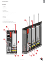
1. Electrical box
2. Expansion vessel
3. Prestige Solo boiler
4. Circulation pump
5. Boiler gas connection (valve)
6. 3-way valve (handle in vertical position : draining circuit open, handle in
horizontal position: draining circuit closed)
7. Plate-to-plate Heat exchanger
8. Main gas pipe
9. Transport slot(s)
10. Safety devices (INAIL group - optional)
11. Condensate neutralisation system
12. Seal-equipped openings (left or right) for pipe connections
13. Leak-free chimney connection and chimney tube (Ø 100mm, h: 100mm)
3
4
5
6
1
13
7
2
12
en
5
Prestige Box: A1004849 - 664Y7100 • A
EN
FR
NL
ES
IT
DE
PL
RU
APPLIANCE DESCRIPTION
PRESTIGE BOX

Prestige Box: A1004849 - 664Y7100 • A
en
6
EN
FR
NL
ES
IT
DE
PL
RU
TECHNICAL CHARACTERISTICS
Prestige Box
LP - RP
200 250 300 350 400 500
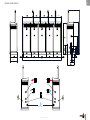
Overall length (base incl.) mm 2494 2494 3297 3297 4100 4100
Overall height (Base and chimney incl.) mm 2479.5 2479.5 2479.5 2479.5 2479.5 2479.5
Overall Width (base incl.) mm 800 800 800 800 800 800
Chimney connection mm 100 100 100 100 100 100
Min. of ue pipe mm 100 100 100 100 100 100
Heating connection [M] “ 2 2 2 1/2 2 1/2 2 1/2 2 1/2
Gas connection [M] “ 1 1/2 1 1/2 2 1/2 2 1/2 2 1/2 2 1/2
Drained weight Kg 823 833 942 957 1080 1100
DIMENSIONS AND CLEARANCE

4100
626
1717.1
1004
∅ 2’
∅ 2’
∅ 2’
∅ 2’
∅ 50 mm
∅ 1 1/2’
800
en
7
Prestige Box: A1004849 - 664Y7100 • A
EN
FR
NL
ES
IT
DE
PL
RU
TECHNICAL CHARACTERISTICS

Prestige Box: A1004849 - 664Y7100 • A
en
8
EN
FR
NL
ES
IT
DE
PL
RU
TECHNICAL CHARACTERISTICS
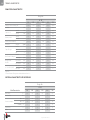
COMBUSTION CHARACTERISTICS
Prestige Box
LP - RP
200 250 300 350 400 500
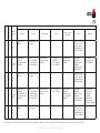
Number of boilers in the Prestige box 2 x P100 2 x P120 3 x P100 3 x P120 4 x P100 4 x P120
Input (PCI) kW 198.0 230.0 297.0 345.0 396.0 460.0
Output at 100%
(80/60°C)
kW
193.2 221.6 289.8 332.4 289.8 443.2
(50/30°C)
kW
208.4 240.0 312.6 360.0 416.8 480.0
Eciency at 100%*
(80/60°C)
%
97. 6 96.3 97.6 96.3 97. 6 96.3
(50/30°C)
%
105.3 104.3 105.3 104.3 105.3 104.3
Eciency at 30% load (EN677)*
%
2015.8 216.0 323.7 324.0 431.6 432.0
NOx (Class 5) Weighted*
mg/kWh
38 44 38 44 38 44
Temp. of ue gases
Nominal
°C
80 80 80 80 80 80
Max.
°C
110 110 110 110 110 110
Min.
°C
30 30 30 30 30 30
Mass ow rate** of ue gases
Nominal
kg/h
166.1 193.0 166.1 193.0 166.1 193.0
at min output
kg/h
21.0 21.0 21.0 21.0 21.0 21.0
Max gas ow rate
G20/G25
G20 (20 mbar)
m³/h
21.0 24.4 31.5 36.6 42.0 48.8
G25 (25 mbar)
m³/h
24.4 28 .4 36.6 42.6 48.8 56.8
CO
2
(closed front panel)*
Max. output
%CO
2
9.0 9.1 9.0 9.1 9.0 9.1
Min. output
%CO
2
9.0 9.1 9.0 9.1 9.0 9.1
* per boiler
** The mass ow rate of ue gases was calculated with an air factor of 1.3
ELECTRICAL CHARACTERISTICS OF PRESTIGE BOX
Prestige Box
LP - RP
Main Characteristics
200 250 300 350 400 500
Rated voltage V~ 230 230 230 230 230 230
Rated frequency Hz 50 50 50 50 50 50
Electrical consumption
Max W 490 540 735 810 980 1080
Min W 126 126 131 131 136 136
in Standby W 10 10 15 15 20 20
Input intensity A 16 16 16 16 16 16
IP Class X4D X4D X4D X4D X4D X4D

en
9
Prestige Box: A1004849 - 664Y7100 • A
EN
FR
NL
ES
IT
DE
PL
RU
TECHNICAL CHARACTERISTICS
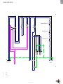
-H1
X1
X2
-T1
-X1
X1
X2
-E1
-E2
t
-T1
t
-TS
t
-P1
Regulation Thermosta
t
Safety Thermostat
Safety Pressostat
1 2 3
X2-PE
1
X2-L1
2
X2-N1
3
X2-S
4
X2-O
5
X2-L2
6
X2-N2
7
X2-N
9
X2-NS
10
X2-NS
11
X2-L1
12
X2-PE
13
1
C
230V
24V
1
COM
NC
NC
COM
NC
COM
Boilers
-Q1
3N
4N
1
2
-Q2
3N
4N
1
2
C 10
C10
-U<
D1
D2
Power Supply
X1
B.
Bk.
V.
V.
V.
V.
Y/Gr.
Y/Gr.
Y/Gr.
B.
Bk.
B.
B.
Bk.
B.
B.
B.
Bk.
B.
Bk.
Bk.
Bk.
Y/Gr.
Y/Gr.
B.
B.
Bk.
B.
Bk.
Bk.
B. Blue
Bk. Black
V. Violet
Y/Gr. Yellow/Green

Prestige Box: A1004849 - 664Y7100 • A
en
10
EN
FR
NL
ES
IT
DE
PL
RU
TECHNICAL CHARACTERISTICSTECHNICAL CHARACTERISTICS
MAXIMUM OPERATING CONDITIONS
Maximum Service Pressure *
- Primary circuit : ............................................................................................................................................ 4 bar
Maximum Operating Conditions
- Maximum temperature (primary) : .................................................................................................. 87°C
Water Quality
See "Recommendations for the Prevention of Corrosion and Scaling in Heating Systems" on following page.
HYDRAULIC CHARACTERISTICS
Prestige Box
LP - RP
200 250 300 350 400 500
Capacity (primary) L 56 56 84 84 112 112
Max. operating pressure of primary circuit bar 4 4 4 4 4 4
Min. required ow rate per boiler L/h 4,300 5,200 4,300 5,200 4,300 5,200

4. Limit the carbonate concentration in the water
- The fill water must be softened if its hardness is higher than 20° fH (11,2° dH).
- Check regularly the water hardness and enter the values in the service log.
- Water hardness table :
Water hardness °fH °dH mmolCa(HCO3)2 / l
Very soft 0 - 7 0 - 3.9 0 - 0.7
Soft 7 - 15 3.9 - 8.4 0.7 - 1.5
Fairly hard 15 - 25 8.4 - 14 1.5 - 2.5
Hard 25 - 42 14 - 23.5 2.5 - 4.2
Very hard > 42 > 23.5 > 4.2
5. Control the water parameters
- In addition to the oxygen and the water hardness, other parameters of the water must be
checked.
- Treat the water if the measured values are outside the range.
Acidity 6,6 < pH < 8,5
Conductivity < 400 μS/cm (at 25°C)
Chlorides < 125 mg/l
Iron < 0,5 mg/l
Copper < 0,1 mg/l
RECOMMENDATIONS FOR THE PREVENTION OF CORROSION AND
SCALING IN HEATING SYSTEMS
How oxygen and carbonates can affect the heating system
Oxygen and dissolved gasses in the water of the primary circuit contribute to the oxi-
dation and the corrosion of the system components that are made of ordinary steel
(radiators, ...). The resulting sludge is then deposited in the appliance exchanger.
The combination of carbonates and carbon dioxide in the water results in the formation of scale
on the hot surfaces of the installation, including those of the appliance exchanger.
These deposits in the heat exchanger reduce the water ow rate and thermally insulate the ex-
change surfaces, which is likely to damage them.
Sources of oxygen and carbonates in the heating circuit
The primary circuit is a closed circuit; the water it contains is therefore isolated from the mains
water. When maintaining the system or lling up the circuit, water renewal results in the addition
of oxygen and carbonates in the primary circuit. The larger the water volume in the system, the
larger the addition.
Hydraulic components without an oxygen barrier (PE pipes and connections) admit oxygen into
the system.
Prevention Principles
1. Clean the existing system before installing a new appliance
- Before the system is lled, it must be cleaned in accordance with standard EN14336.
Chemical cleaning agents can be used.
- If the circuit is in bad condition, or the cleaning operation was not efficient, or the volume of
water in the installation is substantial (e.g. cascade system), it is recommended to separate
the appliance from the heating circuit using a plate-to-plate exchanger or equivalent. In
that case, it is recommended to install a hydrocyclone or magnetic filter on the installation
side.
2. Limit the fill frequency
- Limit fill operations. In order to check the quantity of water that has been added into the
system, a water meter can be installed on the filling line of the primary circuit.
- Automatic filling systems are not recommended unless the fill frequency is monitored and
the scale and corrosion inhibitor remain at the correct levels.
- If your installation requires frequent water refilling, make sure your system is free of water
leaks.
- Inhibitors may be used in accordance with standard EN 14868.
3. Limit the presence of oxygen and sludge in the water
- A deaerator (on the appliance flow line) combined with a dirt separator (upstream of the
appliance) must be installed according to the manufacturer's instructions.
- ACV recommends using additives that keep the oxygen in solution in the water, such as
Fernox (www.fernox.com) and Sentinel (www.sentinel-solutions.net) products.
- The additives must be used in accordance with the instructions issued by the manufacturer
of the water treatment product.
en
11
Prestige Box: A1004849 - 664Y7100 • A
EN
FR
NL
ES
IT
DE
PL
RU
TECHNICAL CHARACTERISTICSTECHNICAL CHARACTERISTICS

TOOLS REQUIRED FOR THE INSTALLATION
GAS
pressure
(mbar)
Prestige Box: A1004849 - 664Y7100 • A
en
12
EN
FR
NL
ES
IT
DE
PL
RU
INSTALLATION
PACKAGE CONTENTS
The Prestige box is delivered assembled and packaged.
At product reception and after removal of packaging, check the package contents and that
the appliance is free of damages.
Contents
• Prestige Box
• Flue tubes
• Seals for ue tubes
• Installation, Operation and Maintenance Manual
SAFETY INSTRUCTIONS FOR THE INSTALLATION
General remark
• The connections (electrical, flue pipe, hydraulic, gas) must be carried out in accordance
with current standards and regulations in force.
Essential recommendations for the correct operation of the appliance
• Install the appliance to ensure easy access at all times.
• If works need to be performed (close to the Prestige Box), make sure to turn off the
boiler to prevent dust from entering and accumulating in the heating boiler system.
Essential recommendations for safety
• Install the Prestige box on a base made of non-combustible materials.
• Make sure that all air vents are unobstructed at all times.
• A condensation outlet connected to the sewer must be fitted to the Prestige Box to
prevent the condensation products from the flue pipe from running into the appliance(s).
• Do not store any corrosive products, paint, solvents, salts, chloride products and other
detergent products near the Prestige Box.
• The flue pipe diameter must not be smaller than that of the appliance(s) flue gas outlet
connection.
Essential recommendations for the electrical safety
• Isolate the external electrical supply (integrated electrical box) of the Prestige Box
before performing any operation on the electrical circuit.
• This appliance is not intended for use by persons (including children) with reduced
physical, sensory or mental capabilities, or lack of experience and knowledge, unless
supervised or unless they have been given instruction concerning the use of the
appliance by a person responsible for their safety.
MOVING THE PRESTIGE BOX
Make sure to use a means of transport adapted to the product size and weight and the
lifting holes in the Prestige box base.

KEY
en
13
Prestige Box: A1004849 - 664Y7100 • A
EN
FR
NL
ES
IT
DE
PL
RU
INSTALLATION
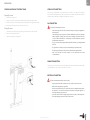
OPENING AND CLOSING THE FRONT PANEL
Opening Procedure
1. Put the key in the upper lock.
2. Turn the key to the left to unlock the panel, while maintaining the panel using the handle.
3. Pull the top of the panel towards you, then lift up the whole panel to disengage the bottom lugs.
4. Remove the whole panel and stow it vertically in a safe location.
Closing Procedure
1. Lift the whole panel vertically and engage the lugs in the bottom groove of the box frame.
2. Push the top of the panel in position.
3. Turn the key to the right to lock the panel.
HYDRAULIC CONNECTIONS
Connection holes, equipped with a seal, are provided either on the left or on the right side of the Prestige
box to make the required hydraulic/gas connections. Please refer to the Prestige Solo boiler manual for more
information and recommendations regarding the hydraulic/gas connections.
CHIMNEY CONNECTION
The chimney connection should be made using the chimney tubes and seals provided with the Prestige Box.
Only parallel ue pipe connection types are possible, NO concentric.
GAS CONNECTION
ELECTRICAL CONNECTION
Essential recommendations for safety
• Install a manual gas shut-off valve outside the Prestige box, on the gas supply tube to
the Prestige box.
• Check that the gas type and pressure from the distribution network are compatible
with the appliance settings. Refer to the table containing all relevant data in the
section “Technical characteristics” of the Prestige Solo boiler Installation, Operation
and Maintenance Instructions.
• The gas connection must comply with all applicable standards [e.g. in Belgium: NBN
D51-003].
• The gas burners are factory preset for use with natural gas [equivalent to G20].
• The natural gas to liquid gas conversion is not authorized in Prestige box boilers.
• Refer to the Prestige Solo boiler manual for more information and safety
recommendations.
Essential recommendations for the electrical safety
• Only an approved installer is authorized to carry out the electrical connections.
• Make sure that the appliance is grounded.
• Install a 2-way switch and a fuse or circuit breaker of the recommended rating outside
the appliance, so as to be able to shut power down when servicing the appliance or
before performing any operation on it.
• Isolate the external electrical supply (integrated electrical box) of the Prestige Box
before performing any operation on the electrical circuit.

SAFETY INSTRUCTIONS FOR STARTING UP
General remark
• In normal operation, the burner starts automatically as soon as the boiler
temperature drops below the preset temperature.
Essential recommendations for safety
• The components inside the control panel may only be accessed by an approved
installer.
• Set the water temperature in accordance with usage and local plumbing codes.
• Make sure that the heating circuit filling valve is closed once the starting up
process is complete.
GAS
pressure
(mbar)
Prestige Box: A1004849 - 664Y7100 • A
en
14
EN
FR
NL
ES
IT
DE
PL
RU
STARTING UP
CHECKS BEFORE STARTING UP
Essential recommendation for safety
• Check the tightness of the flue pipe connections.
Essential recommendation for the correct operation of the appliance
• Control the tightness of the hydraulic circuit connections.
TOOLS REQUIRED FOR STARTING UP
FILLING THE HEATING CIRCUIT
General Remark
• Depending on the box model selected, connections will be located on the left or on
the right.
If an external DHW tank is included in the system, make sure to put the DHW tank under
pressure before pressurizing the heating (primary) circuit.
Set-up conditions
• Boiler(s) shut-down
• External power supply isolated
• Draining circuit 3-way valve closed (in horizontal position)
Heating circuit lling procedure
1. Open the isolating valves (1).
2. Make sure that 3-way valve (3) is closed (handle in horizontal position) and the drain valve (4) is tightly
closed.
3. Open the lling valve (2).
4. Once the system is bled from air through the boiler(s) automatic air vent, bring the pressure to the static
pressure between 1.5 bar and 2 bar.
5. Close the lling valve (2).
Follow-on tasks
1. Check there are no leaks.
1
2
4
3
1
Cold water
Hot water

en
15
Prestige Box: A1004849 - 664Y7100 • A
EN
FR
NL
ES
IT
DE
PL
RU
STARTING UP
STARTING UP THE SYSTEM
Set-up conditions
• All connections made
• Electrical power supply on
• Gas supply open
• Hydraulic circuit full of water
Procedure
1. Check that there is no gas leak.
2. Push in the ON/OFF master switch ( ) of the boiler(s).
3. Refer to the Prestige Solo Installation, Operation and Maintenance manual, and to the “Cascade” Volume
of the Installer’s Handbook.
Follow-on tasks
1. Check that there are no leaks.

Prestige Box: A1004849 - 664Y7100 • A
en
16
EN
FR
NL
ES
IT
DE
PL
RU
MAINTENANCE
SHUTTING DOWN THE SYSTEM
1. Switch the boilers o using the ON/OFF master switch and isolate the external power supply.
2. Close the gas supply valve of the appliance.
SAFETY INSTRUCTIONS FOR MAINTENANCE
Essential recommendation for the electrical safety
• Isolate the external power supply of the appliance before performing any operation,
unless it is required to take measurements or perform system setup.
Essential recommendations for safety
• Water flowing out of the drain valve may be extremely hot and could cause severe
scalding.
• Check the tightness of the flue pipe connections.
Essential recommendations for the correct operation of the appliance
• It is recommended to have the appliance and the burner(s) serviced at least once a
year or every 1,500 hours. More frequent servicing may be required depending on the
appliance use. Please consult your installer for advice.
• The boiler and burner maintenance will be carried out by a qualified engineer, and
the defective parts may only be replaced by genuine factory parts. Refer to the boiler
installation, Operation and Maintenance manual for the correct procedures.
• Control the tightness of the hydraulic circuit connections.
• Make sure to replace the gaskets of the removed items before reinstalling them.
DRAINING THE HEATING CIRCUIT
1
2
3
1
Essential recommendations for safety
• If an external DHW tank is installed in the system, make sure to drain the heating
(primary) circuit or bring its pressure to 0 bar before draining the DHW tank.
• Water flowing out of the drain valve may be extremely hot and could cause severe
scalding. Keep people away from the hot water discharge.
Set-up conditions
• Boiler(s) switched o using the ON/OFF master switch
• External power supply isolated
• Gas supply closed
Heating circuit draining procedure
1. Close the isolating valves (1).
2. Connect the drain valve (2) to the sewer with a hose.
3. Open the 3-way valve (3) (in vertical position) to empty the circuit and allow air to enter.
4. Open the drain valve (2) to finish emptying the heating circuit of the boiler.
5. Close the drain valve (2) and the 3-way valve (3) once the heating circuit of the boiler is empty.

en
17
Prestige Box: A1004849 - 664Y7100 • A
EN
FR
NL
ES
IT
DE
PL
RU
MAINTENANCE
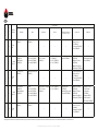
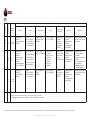
PERIODIC MAINTENANCE TASKS
Tasks
Frequency
Periodic
inspec-
tion
1 year 2 years
End-user Professional
1. Make sure that the system water pressure is at least 1 bar
when cold. Top up the system if necessary, adding small
quantities of water at a time. In case of repeated lls, call
your installer.
X X
2. Check that there is no water on the box oor. Call your in-
staller if there is.
X X
3. Check that no error code is displayed on the control panel.
Call your installer if necessary.
X X
4. Check that all gas, hydraulic and electrical connections are
correctly fastened and tight. Refer to the Installation, Oper-
ation and Maintenance manual of the boiler for more infor-
mation.
X
5. Check the ue gas exhaust: correct fastening, correct instal-
lation, no leaks or clogging.
X
6. Check the combustion parameters (CO and CO2), refer to
the manuals provided with the boiler for more information.
X
7. Check the seals around the ue-tube and replace in case of
damage.
X
8. Carry out all required maintenance and cleaning tasks, re-
pairs and replacements that might be required. Refer to the
Installation, Operation and Maintenance manual of the boil-
er for more information.
X
BLOCKAGE AND ERROR CODES
If an error code is displayed on the main control panel, refer to the “Blockage and Error Codes” section in the
Prestige Boiler Installation, Operation and Maintenance manual or in the Installer’s Handbook available at
www.acv.com/Documentation/Prestige.

Prestige Box: A1004849 - 664Y7100 • A
en
18
EN
FR
NL
ES
IT
DE
PL
RU
DECLARATION OF CONFORMITY

PRESTIGE 42-50-75-100-120 Solo : A1004849 - 664Y7100 • A
EN
FR
NL
ES
IT
DE
PL
RU
en
19

PRESTIGE 42-50-75-100-120 Solo : A1004849 - 664Y7100 • A
en
20
EN
FR
NL
ES
IT
DE
PL
RU

PRESTIGE 42-50-75-100-120 Solo : A1004849 - 664Y7100 • A
EN
FR
NL
ES
IT
DE
PL
RU
en
21

PRESTIGE 42-50-75-100-120 Solo : A1004849 - 664Y7100 • A
en
22
EN
FR
NL
ES
IT
DE
PL
RU

PRESTIGE 42-50-75-100-120 Solo : A1004849 - 664Y7100 • A
EN
FR
NL
ES
IT
DE
PL
RU
en
23

PRESTIGE 42-50-75-100-120 Solo : A1004849 - 664Y7100 • A
en
24
EN
FR
NL
ES
IT
DE
PL
RU
-
 1
1
-
 2
2
-
 3
3
-
 4
4
-
 5
5
-
 6
6
-
 7
7
-
 8
8
-
 9
9
-
 10
10
-
 11
11
-
 12
12
-
 13
13
-
 14
14
-
 15
15
-
 16
16
-
 17
17
-
 18
18
-
 19
19
-
 20
20
-
 21
21
-
 22
22
-
 23
23
-
 24
24
-
 25
25
-
 26
26
-
 27
27
-
 28
28
-
 29
29
-
 30
30
-
 31
31
-
 32
32
-
 33
33
-
 34
34
-
 35
35
-
 36
36
-
 37
37


in andere talen
- English: ACV Prestige Box : Operating instructions
- français: ACV Prestige Box : Mode d'emploi
Gerelateerde papieren
Andere documenten
-
Mark GSX 55 Technical Manual
-
elco R600 Handleiding
-
-
-
Dovre VT70.111 de handleiding
-
Dovre S203.111 de handleiding
-
-
Ubbink 0188011 Installatie gids
-
Atlantic OPTIMAPACK 3025 V de handleiding
-