
VIDEO CD CHANGER RECEIVER
OWNER’S MANUAL
VOLUME
INPUT SELECTOR
VCR• LD/TV• VCD/CD• TAPE/MD• TUNER
VCD/CD TUNER
MIC TONE MIC MIC MIXING
SOFTNORMAL MAXMIN
STANDBY/ON
PHONES
KARAOKE
PROGRAM
ECHO
ECHO
MEMORY
MUSIC
DISPLAY MEMORY AUTO/MAN’L REPEAT TIME
TIME ADJ TIMER HOUR MIN
INPUT TRIM
VIDEO CD CHANGER RECEIVER EM-203VCD
PRESET/TUNING/BAND
A/B/C/D/E
OPEN/CLOSE
DISC 1 DISC 2 DISC 3
DISC
CHANGE
VIDEO CD
Version 2.0
/
Playback Control
T L

22
●
Remote control transmitter
●
Transmisor del control remoto
●
Batteries (size AA, UM/SUM-3, R6, HP-7)
●
Pilas (tamaño AA, tipo UM/SUM-3, R6, HP-7)
●
AM loop antenna
●
Antena de cuadro AM
●
Indoor FM antenna
●
Antena interior de FM
SUPPLIED ACCESSORIES
●
After unpacking, check that the following parts are contained.
ACCESORIOS INCLUIDOS
●
Desembalar el aparato y verificar que los siguientes accesorios están en la caja.
STANDBY/ON
TIME
A
PROG
B C D
+I0
E
1
1
2
2
3
3
4
4
5
5
6
6
7
7
8
8
9 0
PRESET
INPUT
TIME INDEX
INTRO DIGEST
KARAOKE
SLEEP
VCD/CD
MUSIC
TUNER
PROGRAM
VOLUME
DISC SKIP
RETURN
PREV NEXT
SELECT
STOP
PLAY/PAUSE
LEVEL
ECHO/KEY
TEST
CENTER/REAR
/DELAY
RANDOM OPEN/ CLOSE
INDEXMODE
VCD/CD
TUNER

33
VIDEO CD CHANGER RECEIVER
VIDEO CD
Version 2.0
/
Playback Control
PRESET/TUNING/BAND
A
/
B
/
C
/
D
/
E
OPEN/CLOSE
DISC 1 DISC 2 DISC 3
DISC
CHANGE
VOLUME
INPUT SELECTOR
VCR • LD/TV • VCD/CD • TAPE/MD • TUNER
VCD/CD TUNER
MIC TONE MIC MIC MIXING
SOFTNORMAL MAXMIN
STANDBY/ON
PHONES
KARAOKE
PROGRAM
ECHO ECHO
MEMORY
MUSIC
DISPLAY MEMORY AUTO/MAN’L REPEAT TIME
TIME ADJ TIMER HOUR MIN
INPUT TRIM
MHz
PRESET
TOTAL REM
NOR TEST
PHANTOM
TIMER
SLEEP
STEREO RANDOM
TUNED MEMORY
AUTO PTY HOLD
PROGRAMMUSIC
ROCK POPS
JAZZ USER 12
KARAOKE
L R
VOCAL CUT
PRO LOGIC HALL ARENA DISCO
3 STEREO STADIUM MONO MOVIE
100 1K 10K
VCD
S F REP
PBC
PROG
VOLUME
OVER
1234
78910
13 14 15
5
11
6
12
K
Hz
3
2
4
8
7
0
A
B C
D E
F
K
L
M
J
G I
H
9
5
6
1 2 3 567 9 B04
C
A8
ED
1
N
1

44
VIDEO CD CHANGER RECEIVER
VIDEO CD
Version 2.0
/
Playback Control
PRESET/TUNING/BAND
A
/
B
/
C
/
D
/
E
OPEN/CLOSE
DISC 1 DISC 2 DISC 3
DISC
CHANGE
VOLUME
INPUT SELECTOR
VCR • LD/TV • VCD/CD • TAPE/MD • TUNER
VCD/CD TUNER
MIC TONE MIC MIC MIXING
SOFTNORMAL MAXMIN
STANDBY/ON
PHONES
KARAOKE
PROGRAM
ECHO ECHO
MEMORY
MUSIC
DISPLAY MEMORY AUTO/MAN’L REPEAT TIME
TIME ADJ TIMER HOUR MIN
INPUT TRIM
MHz
TRACK PRESET
TOTAL REM
NOR TEST
PHANTOM
TIMER
SLEEP
STEREO RANDOM
TUNED MEMORY
AUTO PTY HOLD
PROGRAMMUSIC
ROCK POPS
JAZZ USER 12
KARAOKE
L R
VOCAL CUT
PRO LOGIC HALL ARENA DISCO
3 STEREO STADIUM MONO MOVIE
100 1K 10K
VCD
S F REP
PBC
PROG
VOLUME
OVER
1234
78910
13 14 15
5
11
6
12
K
Hz
O
V
W
P Q
R S
T
F G IH
K NL OM PJ
U
2

55
STANDBY/ON
TIME
A
PROG
B C D
+I0
E
1
1
2
2
3
3
4
4
5
5
6
6
7
7
8
8
9 0
PRESET
INPUT
TIME INDEX
INTRO DIGEST
KARAOKE
SLEEP
VCD/CD
MUSIC
TUNER
PROGRAM
VOLUME
DISC SKIP
RETURN
PREV NEXT
SELECT
STOP
PLAY/PAUSE
LEVEL
ECHO/KEY
TEST
CENTER/REAR
/DELAY
RANDOM OPEN/CLOSE
INDEXMODE
VCD/CD
TUNER
2
1
3
4
0
D
E
B
A
5
7
8
9
6
C
STANDBY/ON
TIME
A
PROG
B C D
+I0
E
1
1
2
2
3
3
4
4
5
5
6
6
7
7
8
8
9 0
PRESET
INPUT
TIME INDEX
INTRO DIGEST
KARAOKE
SLEEP
VCD/CD
MUSIC
TUNER
PROGRAM
VOLUME
DISC SKIP
RETURN
PREV NEXT
SELECT
STOP
PLAY/PAUSE
LEVEL
ECHO/KEY
TEST
CENTER/REAR
/DELAY
RANDOM OPEN/CLOSE
INDEXMODE
VCD/CD
TUNER
F
G
O
H
I
KLJ
N
M
P
3
1
3
2
4
30°
30°
0.2 m – 6 m
(8” – 20’)
5
STANDBY/ON
TIME
A
PROG
B C D
+I0
E
INPUT
TIME INDEX
INTRO DIGEST
KARAOKE
SLEEP
VCD/CD
MUSIC
TUNER
PROGRAM
VOLUME
DISC SKIP
RETURN
PREV NEXT
SELECT
STOP
PLAY/PAUSE
LEVEL
ECHO/KEY
TEST
CENTER/REAR
/DELAY
RANDOM OPEN/CLOSE
INDEXMODE
R
S
Q
T

66
SPEAKERS
CENTER/REAR
VOLTAGE
SELECTOR
SPEAKERS
FRONT
AC OUTLET
MAINS
R L
CENTERREAR REAR
REAR SINGLE
CENTER :6
Ω
MIN./SPEAKER
6
Ω
MIN./SPEAKER
SEE OWNER’S MANUAL FOR CONNECTION.
SEE OWNER’S MANUAL FOR CONNECTION.
REAR
:4
Ω
MIN./SPEAKER
REAR SINGLE
:8
Ω
MIN./SPEAKER
RL
UNSWITCHED
100W MAX.
L
AUDIO SIGNAL
TAPE
/
MD LD
/
TV
AUDIO SIGNAL
VCR SUBWOOFER
R
IN OUT IN OUT
OUT
VCR MONITOR
OUT
LD
/
TV
VIDEO SIGNAL
ANTENNA
AM
FM
GND
75
Ω
UNBAL.
NORMALAUTO
50kHz
9kHz
10kHzNTSC
100kHz
FM
AM
PHANTOM
PAL
CENTER
MODE
TV
MODE
FREQUENCY
STEP
IN OUT
VIDEO SIGNAL
SUBWOOFER
OUT
OUT
SPEAKERS
CENTER/REAR
SPEAKERS
FRONT
R L
CENTERREAR REAR
REAR SINGLE
CENTER :6
Ω
MIN./SPEAKER
6
Ω
MIN./SPEAKER
SEE OWNER’S MANUAL FOR CONNECTION.
SEE OWNER’S MANUAL FOR CONNECTION.
REAR
:4
Ω
MIN./SPEAKER
REAR SINGLE
:8
Ω
MIN./SPEAKER
RL
L
R
L
R
6
Rear speakers
Altavoces traseros
Center speaker
Altavoz central
Subwoofer system
Sistema de altavoz de graves
secundarios
Front speakers
Altavoces delanteros
(General model)
(Modelo General)

77
SPEAKERS
CENTER/REAR
VOLTAGE
SELECTOR
SPEAKERS
FRONT
MAINS
R L
CENTERREAR REAR
REAR SINGLE
CENTER :6
Ω
MIN./SPEAKER
6
Ω
MIN./SPEAKER
SEE OWNER’S MANUAL FOR CONNECTION.
SEE OWNER’S MANUAL FOR CONNECTION.
REAR
:4
Ω
MIN./SPEAKER
REAR SINGLE
:8
Ω
MIN./SPEAKER
RL
L
AUDIO SIGNAL
TAPE
/
MD LD
/
TV
AUDIO SIGNAL
VCR SUBWOOFER
R
IN OUT IN OUT
OUT
VCR MONITOR
OUT
LD
/
TV
VIDEO SIGNAL
ANTENNA
AM
FM
GND
75
Ω
UNBAL.
NORMAL
AUTO
50kHz
9kHz
10kHzNTSC
100kHz
FM
AM
PHANTOM
PAL
CENTER
MODE
TV
MODE
FREQUENCY
STEP
IN OUT
VIDEO SIGNAL
SPEAKERS
CENTER/REAR
R L
CENTERREAR REAR
REAR SINGLE
CENTER :6
Ω
MIN./SPEAKER
SEE OWNER’S MANUAL FOR CONNECTION.
REAR
:4
Ω
MIN./SPEAKER
REAR SINGLE
:8
Ω
MIN./SPEAKER
AC OUTLET
UNSWITCHED
100W MAX.
L
R
NX-C70
NX-E70
7
White line
Linea blanca
White line
Linea blanca
(General model)
(Modelo General)

88
8
LD player etc.
Tocadiscos de discos láser, etc.
Monitor TV
Monitor de TV
Tape deck, MD recorder, etc.
Platina, grabador de MD, etc.
Video cassette recorder
Videograbador
SPEAKERS
CENTER/REAR
VOLTAGE
SELECTOR
SPEAKERS
FRONT
AC OUTLET
MAINS
R L
CENTERREAR REAR
REAR SINGLE
CENTER :6
Ω
MIN./SPEAKER
6
Ω
MIN./SPEAKER
SEE OWNER’S MANUAL FOR CONNECTION.
SEE OWNER’S MANUAL FOR CONNECTION.
REAR
:4
Ω
MIN./SPEAKER
REAR SINGLE
:8
Ω
MIN./SPEAKER
RL
UNSWITCHED
100W MAX.
L
AUDIO SIGNAL
TAPE
/
MD LD
/
TV
AUDIO SIGNAL
VCR SUBWOOFER
R
IN OUT IN OUT
OUT
VCR MONITOR
OUT
LD
/
TV
VIDEO SIGNAL
ANTENNA
AM
FM
GND
75
Ω
UNBAL.
NORMAL
AUTO
50kHz
9kHz
10kHzNTSC
100kHz
FM
AM
PHANTOM
PAL
CENTER
MODE
TV
MODE
FREQUENCY
STEP
IN OUT
VIDEO SIGNAL
AUDIO OUT
VIDEO OUT
AUDIO OUT
AUDIO IN
VIDEO OUT
VIDEO IN
LINE OUT
LINE IN
VIDEO IN
*
(General model)
(Modelo General)

E-1
English
ENGLISH
INTRODUCTION
CONTENTS
Page
PRECAUTIONS.............................................2-3
FEATURES.......................................................4
NAMES OF CONTROLS
AND INDICATORS ...........................................5
REMOTE CONTROL TRANSMITTER.............6
SETTING UP THE SPEAKERS ....................7-9
CONNECTIONS ........................................10-12
STARTING THE OPERATION
OF THIS UNIT ...........................................13-14
ADJUSTMENTS........................................14-17
VIDEO CD PLAYER OPERATION............18-26
PLAYBACK CONTROL OF
VIDEO CD (Ver. 2.0)..................................27-29
Page
TUNING OPERATION...............................30-32
OPERATING EXTERNAL UNITS
CONNECTED WITH THIS UNIT.....................33
USING GRAPHIC EQUALIZER................34-36
USING SOUND FIELD PROCESSOR......37-40
KARAOKE OPERATION...........................41-43
HOW TO USE THE BUILT-IN TIMER .......44-46
TROUBLESHOOTING ..............................47-48
SPECIFICATIONS ..........................................49
Thank you for purchasing this YAMAHA product. We hope it will give you many years of trouble-free enjoyment. For the best
performance, read this manual carefully. It will guide you in operating your YAMAHA product.
For basic source play, the following illustrations on top of
pages will help you to look for the section you need.
......Video CD (CD) playback ......Tuning

E-2
PRECAUTIONS: READ THIS BEFORE OPERATING YOUR UNIT
■ Do not connect audio equipment to the AC outlet on the
rear panel if the equipment requires more power than the
outlet is rated to provide.
■ Do not plug the AC power plug to the wall socket before
you finish all connections.
■ The voltage to be used must be the same as that specified
on this unit. Using this unit with a higher voltage than
specified is dangerous and may result in a fire or other
types of accidents causing damage. YAMAHA will not be
held responsible for any damage resulting from use of this
unit with a voltage other than specified.
■ The sound level at a given volume setting depends on
speaker location and other factors. Care should be taken
to avoid exposure to sudden high levels of sound, which
may occur when turning on the unit with the volume control
setting at high, and to continuous high levels of sound.
■ Sudden temperature changes and storage or operation in
an extremely humid environment may cause condensation
inside the cabinet. Condensation can cause the unit to
malfunction.
To eliminate condensation:
•
Pickup
Leave the power on with no disc in the unit until normal
playback is possible (about 1 hour).
•
Remote control
Wipe off condensation on the transmitter window with a
soft cloth before operating the unit.
■ To prevent a malfunction of this unit:
•
Do not use any non standard shaped disc (heart etc.)
available on the market, because it may damage the
unit.
•
Do not use a disc with tape, seals, or paste on it,
because damage to the unit may result.
■ To assure the finest performance, please read this manual
carefully. Keep it in a safe place for future reference.
■ Choose the installation location of this unit carefully. Avoid
placing it in direct sunlight or close to a source of heat.
Also avoid locations subject to vibration and excessive
dust, heat, cold or moisture. Keep it away from sources of
hum such as transformers and electric motors.
■ Do not operate this unit upside-down. It may overheat,
possibly causing damage.
■ Never open the cabinet. If something drops into the set,
contact your dealer.
■ For Singapore model :
The openings on the cabinet assure proper ventilation of
the unit. If these openings are obstructed, the temperature
inside the cabinet will rise rapidly. Therefore, avoid
placing objects against these openings, and install the unit
in well-ventilated condition. Be sure to allow a space of at
least 20 cm behind, 20 cm on the both sides and 30 cm
above the top panel of the unit. Otherwise it may not only
damage the unit, but also cause fire.
■ Always set the VOLUME control to minimum before
starting an audio source play: increase the volume
gradually to an appropriate level after play has started.
■ When not planning to use this unit for long periods of time
(ie., vacation, etc.), disconnect the AC power plug from the
wall outlet.
■ Grounding or polarization – Precautions should be taken
so that the grounding or polarization of the unit is not
defeated.
■ Do not use force on switches, controls or connection wires.
When moving the unit, first disconnect the power plug and
the wires connected to other equipment. Never pull the
wire itself.
■ If an external appliance (TV, radio, etc.) interferes with this
unit’s operation, move this unit away from such an
appliance.
■ Do not attempt to clean the unit with chemical solvents;
this might damage the finish. Use a clean, dry cloth.
■ Be sure to read the “TROUBLESHOOTING” section
regarding common operating errors before concluding that
the unit is faulty.
■ To prevent lightning damage, disconnect the AC power
plug and the antenna cable when there is an electrical
storm.
IMPORTANT
Please record the serial number of this unit in the space
below.
Model:
Serial No.:
The serial number is located on the rear of the unit.
Retain this Owner’s Manual in a safe place for future
reference.
WARNING
TO REDUCE THE RISK OF FIRE OR ELECTRIC SHOCK,
DO NOT EXPOSE THIS APPLIANCE TO RAIN OR
MOISTURE.

WARNING
To reduce the risk of fire or electric shock, do not expose this
unit to rain or moisture.
To avoid electrical shock, do not open the cabinet. Refer
servicing to qualified personnel only.
E-3
English
NOTE
Please check the copyright laws in your country to record
from records, compact discs, radio, etc. Recording of
copyright material may infringe copyright laws.
CAUTION FOR MOVING THIS UNIT
Before moving this unit, first remove all discs from the disc
table and close the table by pressing the OPEN/CLOSE
button. After you confirm that “NO DISC” lights up on the
display, turn this unit into the standby mode by pressing
the STANDBY/ON switch, and then disconnect the power
plug from the AC outlet.
CAUTION 1
Use of controls or adjustments or performance of
procedures other than those specified herein may result in
hazardous radiation exposure.
CAUTION 2
As the laser beam used in this unit is harmful to the eyes,
do not attempt to disassemble the cabinet. Refer servicing
to qualified personnel only.
Laser component in this product is capable of emitting
radiation exceeding the limit for Class 1.
PRECAUTIONS: READ THIS BEFORE OPERATING YOUR UNIT
This unit is classified as a CLASS 1
LASER product.
The CLASS 1 LASER PRODUCT
label is located on the rear exterior.
Laser Diode Properties
•
Material: GaAlAs
•
Wavelength: 780nm
•
Emission Duration: continuous
•
Laser Output: max. 44.6µW*
* This output is the value measured at a distance of about
200mm from the objective lens surface on the Optical
Pick-up Block.
CLASS 1 LASER PRODUCT
CAUTION FOR CARRYING THIS UNIT
Be sure not to carry or tip this unit with discs remaining in
it.
This unit is not disconnected from the AC power source
as long as it is connected to the wall outlet, even if this
unit itself is turned off. This state is called the standby
mode.
In this state, this unit is designed to consume a certain
level of power.
VOLTAGE SELECTOR (China and General models
only)
The voltage selector on the rear panel of this unit must
be set for your local main voltage BEFORE plugging
into the AC main supply.
Voltages are 110/120/220/240V AC, 50/60 Hz.
The Video CD player on this unit can play discs of the following types only.
Never attempt to load a disc other than above on this unit because it may cause a damage to this unit and/or other units
connected to this unit.
VIDEO CD
Video CDs are classified into two types, version 1.1 and 2.0. This unit can play not only discs of version 1.1, but also version
2.0 on which a Playback Control can be made.
Video CD, version 1.1: With the same operation as compact discs, you can enjoy sounds and pictures (movies).
Video CD, version 2.0: In addition to a normal play which is the same as discs of version 1.1, you can make a Playback
Control. (For details on Playback Control, refer to page 27.)
Type of disc
Video CD
CD
(including CD-G)
Mark printed
on the disc
Type of signal
recorded
Sound
+
Picture (Movie)
Sound
Sound
only
+
Still picture
Size (Dimension)
12 cm
8 cm (Single type)
12 cm
8 cm (Single type)
Maximum possible
play time
74 minutes
20 minutes
74 minutes
20 minutes
GRAPHICS

E-4
FEATURES
General
● 5-Speaker Configuration
Front L, R: 100W + 100W (6Ω) RMS Output
Power, 10% THD,
1 kHz
Center
: 32W (6Ω) RMS Output Power,
10% THD, 1 kHz
Rear: 28W (8Ω) RMS Output Power,
10% THD, 1 kHz
● Adjustable Display Brightness
● Multi-use Timer/Sleep Timer
● Automatic Turning This Unit into the
Standby Mode
● 4 External Audio/Video Component
Connecting Capability
● SUBWOOFER Output Terminal which
Passes Low Frequencies Only
● Video Output Format Selector (TV MODE)
Switch
● Remote Control Capability
Video CD Player
● 3-Disc Carousel Auto-Changer (for Playing
Back Video CDs and Compact Discs)
● PLAYXCHANGE; Disc Changing Capability
while Playing Back Another
● 20-Track Random Access Programmable
Playback
● Single Track/Entire Disc/All Disc Repeat Play
● Random-sequence Play
● Playback Control Function Available for
Video CDs, Version 2.0
● Quick Overview of a Track and a Disc with a
Touch of the DIGEST and INTRO Buttons
Tuner
● 40 Station Random Access Preset Tuning
● 40 Station Automatic Preset Tuning
Sound Field Processor Including Dolby Pro
Logic Surround Decoder
● 2 Programs for Dolby Surround Decoding
(DOLBY PRO LOGIC and DOLBY 3 STEREO)
5 Programs for Sound Field Processing
(HALL, ARENA, DISCO, STADIUM and MONO
MOVIE)
● Automatic Input Balance Control for Dolby
Pro Logic Surround
● 2 Center Channel Modes
(NORMAL/PHANTOM)
● Test Tone Generator for Easier Speaker
Balance Adjustment
Graphic Equalizer
● 3-Band Graphic Equalizer
● 3 Preset Graphic Equalizer Modes
Selectable According to the Music Source
(ROCK, POPS and JAZZ)
● 2 Equalizer Pattern Storing Capability
Karaoke-functions
● 4 Modes for Singing Karaoke
● 2 Microphone Connecting Capability
● MIC Mixing Level and MIC Tone Controls
● Echo Level and Key Level Control Capability
● Karaoke Sound Recording Capability
(Recording Your Singing Voice and Karaoke
Effects with the Music Source)
This unit employs a Dolby Pro Logic Surround decoder similar
to professional Dolby Stereo decoders used in many movie
theaters. By using the Dolby Pro Logic Surround decoder,
you can experience the dramatic realism and impact of Dolby
Surround movie theater sound in your own home. Dolby Pro
Logic employs a four-channel-five-speaker system. The Pro
Logic Surround system divides the input signal into four
levels: the left and right main channels, the center channel
(used for dialog), and the rear surround sound channels
(used for sound effects, background noise, and other ambient
noises). The center channel allows listeners seated in even
less-than-ideal positions to hear the dialog originating from
the action on the screen while experiencing good stereo
imaging.
Dolby Surround is encoded on the sound track of pre-
recorded video tapes, laser discs, and some TV/cable
broadcasts. When you play a source encoded with Dolby
Surround on this unit, the Dolby Pro Logic Surround decoder
decodes the signal and distributes the surround-sound
effects.
In addition, this unit features a built-in automatic input balance
control. This always assures you the best performance
without manual adjustment.
Manufactured under license from Dolby Laboratories
Licensing Corporation. DOLBY, the double-D symbol and
“PRO LOGIC” are trademarks of Dolby Laboratories
Licensing Corporation.
Dolby Pro Logic Surround

E-5
English
NAMES OF CONTROLS AND INDICATORS
For amplifier/tuner
(See figure 1 on page 33 at the beginning part of this
manual.)
Display
1 Preset Equalizer Mode Indicator (MUSIC)
2 Sound Field Program Indicator (PROGRAM)
3 Karaoke Mode Indicator (KARAOKE)
4 Center Channel Mode (NOR/PHANTOM) Indicator
5 TEST Indicator
6 TIMER Set Indicator
7 STEREO Indicator
8 TUNED Indicator
9 MEMORY Indicator
0 AUTO Tuning Indicator
A SLEEP Indicator
B Volume Level Meter (VOLUME)
C Graphic Equalizer Level Indicators
D Preset Number Indicator (PRESET)
E Multi Information Display
(Time, Station Frequency, Volume Level, etc.)
1 STANDBY/ON Switch
2 PROGRAM Selector Button
3 Equalizer Control Buttons
(ECHO Buttons)
(Key Level Control / Buttons)
4 MUSIC Button
5 A/B/C/D/E Button
6 PRESET/TUNING/BAND Selector Button
7 PHONES Jack
8 KARAOKE Button
9 User Program MEMORY Button
0 Remote Control Sensor
A DISPLAY Button
B Tuner MEMORY (TIME ADJUST) Button
C AUTO/MAN’L (TIMER) Button
D REPEAT (HOUR) Button
E TIME (MIN) Button
F INPUT TRIM Button
G VCD/CD INPUT SELECTOR Button
H TUNER INPUT SELECTOR Button
I INPUT SELECTOR (Down)/ (Up) Buttons
J MIC TONE (Microphone Tone) Control
K MIC (Microphone) Jacks
L MIC MIXING (Microphone Mixing) Level Control
M VOLUME Control
N Tuning (Down)/ (Up) Buttons
For Video CD player
(See figure 2 on page 44 at the beginning part of this
manual.)
Display
F RANDOM Play Indicator
G Music Calendar Indicator
H Music Calendar OVER Indicator
I Disc Indicator
J Track Number Indicator (TRACK)
K Time Display
L Play Indicator:
M VCD (Video CD) Indicator
N (S, F) REPEAT Indicator
O Program (PROG) Play Indicator
P PBC (PLAYBACK CONTROL) Indicator
O Disc Table
P DISC Selector Buttons
Q OPEN/CLOSE Button:
R DISC CHANGE Button
S Stop Button:
T Play/Pause Button: /
U Skip Buttons: /
(Search Buttons: / )
V REPEAT Button
W TIME Button

E-6
Loading the batteries for the
remote control transmitter
(See figure 4 on page 55.)
1 Remove the battery compartment cover.
(Slide the cover in the direction of the arrow.)
2 Insert 2 “AA” size batteries (UM/SUM-3, R6, HP-7 or
equivalent) into the battery compartment.
* Installing the batteries improperly may cause failure.
3 Replace the battery compartment cover.
Precautions for battery use
•
Insert the batteries according to the direction indicated in
the battery compartment.
•
Replace all batteries with new ones at the same time.
•
Remove the batteries if they are weak or the unit is not in
use for long periods.
•
Do not mix normal batteries with rechargeable batteries.
Proper use of the remote control
transmitter
(See figure 5 on page 55.)
Aim (within the range of 60° with no obstacles) the remote
control transmitter at the remote control sensor and operate
as shown.
Notes concerning use
•
Replace the batteries if control distance decreases or
operation becomes unstable.
•
Periodically clean the transmitter window on the remote
control transmitter and the sensor on the main unit with a
soft cloth.
•
Exposing the sensor on the main unit to strong light
(especially an inverter type of fluorescent lamp etc.) may
interfere with operation. In this case, reposition the main
unit to avoid direct lighting.
•
Keep the remote control transmitter away from moisture,
excessive heat, shock and vibrations.
•
The remote control transmitter’s usable range is within
0.2m (8”) and 6m (20’) away from the sensor.
Names of control buttons
(See figure 3 on page 55 at the beginning part of this
manual.)
■
Amplifier/tuner control buttons
1 Remote Control Transmitter Window
2 Preset Station Number Buttons
3 A, B, C, D, E Selector Buttons
4 TUNER Input Selector Button
5 VCD/CD Input Selector Button
6 CENTER/REAR/DELAY Selector Button
(ECHO/KEY Selector Button)
7 TEST Button
8 LEVEL Control Buttons
(Key Level Control / Buttons)
9 SLEEP Button
0 PRESET Number (Down)/ (Up) Buttons
A INPUT Selector Buttons
B MUSIC Button
C PROGRAM Button
D STANDBY/ON Switch
E VOLUME – (Down)/+ (Up) Buttons
■ Video CD player control buttons
F Track Number Input Buttons
G TIME Button
H PROGRAM Button
I Disc Play MODE Selector Button
J DISC SKIP Button
K INDEX Buttons
L Skip Buttons: /
(Search Buttons: / )
(PREV/NEXT Buttons)
M RANDOM Button
N STOP Button:
(RETURN Button)
O OPEN/CLOSE Button:
P PLAY/PAUSE Button: /
(SELECT Button)
Q TIME INDEX Buttons
R DIGEST Button
S INTRO Button
T KARAOKE Button
REMOTE CONTROL TRANSMITTER

E-7
English
SETTING UP THE SPEAKERS
This unit is designed to provide the best sound-field quality with a 5-speaker configuration: a pair of front speakers, a pair of rear
speakers and a center speaker. You can use one rear speaker only instead of using two rear speakers, and omit the center
speaker. (Refer to the “Speaker configuration” shown below.)
The front speakers are used for the main source sound plus the effect sounds. The rear speakers are used for the effect and
surround sounds, and the center speaker is for the center sounds (dialog etc.).
(1)
(2)
Front R
Center
Front L
TV set
Rear R
Rear L
Speaker configuration
(1)5-Speaker Configuration
This configuration is the most effective and recommended
one. In this configuration, the center speaker is
necessary as well as the rear speakers. If the sound field
program PRO LOGIC or 3 STEREO is selected,
conversations will be output from the center speaker and
the ambience will be excellent.
● Set the center channel mode to the “NORMAL”
position. (For details, refer to page 16.)
(2)4-Speaker Configuration
(without the center speaker)
The center speaker is not used in this configuration. If the
sound field program PRO LOGIC is selected, the
center sound will be output from the left and the right front
speakers, although the program 3 STEREO is
useless in this configuration. However, the sound effect
of other programs can be almost the same as that of the
5-speaker configuration.
● Be sure to set the center channel mode to the
“PHANTOM” position. (For details, refer to page 16.)
Note
As this unit is equipped with a monaural amplifier for the rear
channel, sounds output from the rear speakers are in
monaural. So, you may use one rear speaker only instead of
using two rear speakers.
However, the use of two rear speakers is recommended
when there are more than one listener in the listening room.
When using one rear speaker, place it right behind your
listening position.
Speaker placement
Front speakers: In normal position.
Rear speakers: Behind your listening position, facing
slightly inward. Nearly 1.8 m (approx.
six feet) up from the floor.
Center speaker: Precisely between the front speakers.
Rear L
TV set
Rear R
Front L Center Front R
Dialogue
Surround sound
Dialogue
Surround sound
Rear L
Rear R
Front L Front R
Dialogue
Surround sound
Dialogue
Surround sound
Rear L Rear R
Front L
Front R
Center

E-8
SETTING UP THE SPEAKERS
40mm
1
2
Good No good
Tapping screw
(Available at the
hardware store)
Wall/ wall
support
Only for customers who use the YAMAHA
NS-P30 speaker system (separate
purchase)
If you use the YAMAHA NS-P30 speaker system with this
unit, read the following descriptions for mounting the NS-P30.
* “NS-P30” is the package number which includes the
YAMAHA speaker systems NX-E70 and NX-C70.
NX-E70 is designed to be used as a rear effect speaker
system, and NX-C70 is designed to be used as a center
speaker system.
■ Mounting the rear speakers (NX-E70)
Mount the rear speakers on a shelf, rack or on the floor
directly, or hang them on the wall.
To mount the rear speakers on a wall
1 Attach the provided mounting bracket to the rear of the
speaker by using the provided screws.
2 Fasten screws into a firm wall or wall support as shown in
the diagram, and hang the holes of the mounting bracket
on the protruding screws.
* The holes are arranged so that the speakers can be
mounted in a side long, upright or upside-down way.
* Make sure that the screws are caught by a narrow part
of the holes securely.
Notes
●
Never attach the bracket to the speaker backwards.
●
Speaker cords should be connected to the speaker’s
terminals after the bracket is attached to the speaker to
prevent the speaker cords pressed between the speaker
and the bracket.

E-9
English
WARNING:
●
Each speaker weighs 0.8 kg (1 lbs. 12 oz.). Do not
mount them on thin plywood or soft wall surface
material, as the screws may come out of the flimsy
surface, causing the speakers to fall down and be
damaged, or result in personal injury.
●
Do not fasten the speakers to wall with nails,
adhesives, or other unsound hardware. Long-term use
and vibrations may cause them to fall down.
●
To avoid accidents resulting from tripping over loose
speaker cables, fix them to the wall.
To hang in a side long way
Hang the speakers so that each of them faces inside as
figured left.
SETTING UP THE SPEAKERS
■
Mounting the center speaker (NX-C70)
Place the speaker on top of the TV or on the floor under the
TV or inside the TV rack in a stable position.
When placing the speaker on top of the TV, to prevent the
speaker from falling down, put the provided pads at four
points on bottom of the speaker.
Notes
●
Do not place the speaker on top of the TV whose area
is smaller than the bottom area of the speaker. If
placed, the speaker may drop out causing an injury to
you.
●
Though this speaker is a magnetic shielding type,
there may be some influence on a TV picture
depending on the type of TV or the placement of the
speaker. In such a case, place the speaker apart from
the TV so that there is no influence on TV picture.

E-10
CONNECTIONS
Connecting speakers
(See figure 6 on page 66.)
Connect the front speakers to the FRONT SPEAKERS
terminals, the center speaker to the CENTER SPEAKERS
terminals and the rear speakers to the REAR SPEAKERS
terminals.
Note
Use speakers with the specified impedance shown on the
rear of this unit.
■ How to Connect:
Connect the SPEAKERS terminals to your speakers with wire
of the proper gauge, cut as short as possible. If the
connections are faulty, no sound will be heard from the
speakers. Make sure that the polarity of the speaker wires is
correct, that is the + and – markings are observed. If these
wires are reversed, the sound will be unnatural and lack bass.
Caution
Do not let the bare speaker wires touch each other as
this could damage the amplifier and/or speakers.
Note on connecting one rear speaker only
You can use one rear speaker only in place of two rear
speakers. For connecting one rear speaker, follow the
method shown below.
Red: positive (+)
Black: negative (–)
➀
Press up the tab.
➁
Insert the bare wire.
[Remove approx.
5mm (1/4”) insulation
from the speaker
wires.]
➂
Press down the tab
and secure the wire.
➀
➁
➂
Note on connecting a subwoofer (separate
purchase)
You may wish to add a subwoofer to reinforce the bass
frequencies.
Connect the SUBWOOFER OUT terminal of this unit to the
INPUT terminal of the subwoofer amplifier, and connect the
speaker terminals of the subwoofer amplifier to the
subwoofer.
With some subwoofer systems, including the Yamaha Active
Servo Processing Subwoofer System, an amplifier is
incorporated into the system.
* The SUBWOOFER OUT terminal outputs low frequencies
from the front and center channels.
(The cut-off frequency of signals output from this terminal is
200 Hz.)
■ How to connect the YAMAHA NS-P30 speaker
system (separate purchase) to this unit
(See figure 7 on page 77.)
If you connect the YAMAHA NS-P30 speaker system to this
unit, read the following descriptions.
NX-E70 (Rear speakers)
● Connect the push-type input terminals on the rear of the
speakers to the REAR SPEAKERS terminals of this unit
with the provided speaker cables.
● One side of the speaker cable has a white line and the
other side has no line. Connect the (+) terminals on both
this unit and the speakers using the side with a white line.
Connect the (–) terminals on both components using the
side with no line.
● Connect one speaker to the left (marked L) terminals of
this unit, and another speaker to the right (marked R)
terminals, making sure not to reverse the polarity (+, –). If
one speaker is connected with reversed polarity, the sound
will be unnatural and lack bass.
Procedures:
➀ Press the tab on the terminal down, as shown in the
figure.
➁ Insert the bare speaker wire end properly into the terminal
hole. [Remove approx. 5 mm (1/4”) insulation from the
speaker cable.]
➂ Remove your finger from the tab to allow it to lock snugly
on the cable’s wire end.
➃ Test the security of the connection by tugging lightly on
the cable at the terminal.
NX-C70 (Center speaker)
To connect the speaker cable from NX-C70 to the CENTER
SPEAKERS terminals of this unit, make sure to connect the
side with a white line to the (+) terminal and the side with no
line to the (–) terminal.
Never plug the AC supply lead of this unit into the AC outlet until all connections are
completed.
Rear speaker
R L
CENTERREAR REAR
REAR SINGLE

E-11
English
ANTENNA
AM
FM
GND
75
Ω
UNBAL.
ANTENNA
AM
FM
GND
75
Ω
UNBAL.
(1)
(2)
(3)
(4)
ANTENNA
AM
FM
GND
75
Ω
UNBAL.
VCR MONITOR
OUT
ANTENNA
AM
FM
GND
75
Ω
UNBAL.
NORMAL
PHANTOM
CENTER
MODE
N
OUT
E
O SIGNAL
Antenna connection
(1) Supplied FM antenna
Connect the FM antenna wire to the corresponding terminal
and direct the FM antenna wire to the direction where the
strongest signal can be received.
(2) Supplied AM loop antenna
Connect the AM loop antenna wires to the corresponding
terminals. Position the AM loop antenna for optimum
reception. Place the AM loop antenna on a shelf etc., or
install it on the rack or wall with screws (not supplied).
Notes
•
When static is still heard even after adjusting the position
of the AM loop antenna, try reversing the wire connections
(from the upper terminal to the lower one, and vice versa).
•
Do not place the AM loop antenna on the unit. It will result
in noise generation, since the unit is equipped with digital
electronics. Place the AM loop antenna away from the
unit.
(3) External FM antenna
Use an external FM antenna instead of an indoor FM
antenna if you need better reception. Consult your dealer.
(4) External AM antenna
Use an external AM antenna if you need better reception.
Consult your dealer.
Note
When using an external AM antenna, be sure to keep the
wire of the AM loop antenna connected.
CONNECTIONS
or
15 m (49 feet)
7.5 m (25 feet)
Earth rod
FREQUENCY STEP switch (China and General models
only)
Because the interstation frequency spacing differs in
different areas, set the FREQUENCY STEP switch
(located at the rear) according to the frequency spacing in
your area. Before setting this switch, disconnect the AC
supply lead of this unit from the AC outlet.

E-12
CONNECTIONS
SPEAKERS
CENTER/REAR
VOLTAGE
SELECTOR
SPEAKERS
FRONT
AC OUTLET
MAINS
R L
CENTERREAR REAR
REAR SINGLE
CENTER :6
Ω
MIN./SPEAKER
6
Ω
MIN./SPEAKER
SEE OWNER’S MANUAL FOR CONNECTION.
SEE OWNER’S MANUAL FOR CONNECTION.
REAR
:4
Ω
MIN./SPEAKER
REAR SINGLE
:8
Ω
MIN./SPEAKER
RL
UNSWITCHED
100W MAX.
L
AUDIO SIGNAL
TAPE
/
MD LD
/
TV
AUDIO SIGNAL
VCR SUBWOOFER
R
IN OUT IN OUT
OUT
VCR MONITOR
OUT
LD
/
TV
VIDEO SIGNAL
ANTENNA
AM
FM
GND
75
Ω
UNBAL.
NORMALAUTO
50kHz
9kHz
10kHzNTSC
100kHz
FM
AM
PHANTOM
PAL
CENTER
MODE
TV
MODE
FREQUENCY
STEP
IN OUT
VIDEO SIGNAL
To AC outlet
Connecting external components
(See figure 8 on page 88.)
This unit can be connected with external audio and video
components. Make connections between this unit and other
components using RCA pin plug connector cables correctly,
that is to say L (left) to L and R (right) to R. Also, refer to the
owner’s manual for each component to be connected to this
unit.
*
: AC OUTLET (UNSWITCHED)
The power cord of any audio/video unit can be connected to
this outlet.
The power to this outlet is not controlled by this unit’s
STANDBY/ON switch . This outlet will supply power to the
connected unit even if this unit is in the standby mode.
The maximum power that can be connected to this outlet is
100 watts
Setting the video output format
selector (TV MODE) switch
The Video CD player built into this unit is designed for use
with the NTSC and PAL television formats. Set this switch to
the position for the format your monitor TV employs.
PAL: Outputs signals in the PAL format no matter which
format (PAL or NTSC) the currently playing disc
employs.
Set to this position if your monitor TV employs the
PAL format.
AUTO: Outputs signals in the same format as the currently
playing disc employs.
Set to this position if your monitor TV can be
switched in between the PAL and NTSC formats
automatically.
NTSC: Outputs signals in the NTSC format no matter which
format (PAL or NTSC) the currently playing disc
employs.
Set to this position if your monitor TV employs the
NTSC format.
Note
Be sure to play back a disc which employs the same format
that your monitor TV employs, otherwise a picture will not be
played back normally.
Connecting the AC supply lead
•
After completing all connections, plug the AC supply lead
into a convenient AC outlet.
•
Unplug the AC supply lead from the AC outlet if the unit is
not to be used for a long period of time.
SPEAKERS
CENTER/REAR
VOLTAGE
SELECTOR
SPEAKERS
FRONT
AC OUTLET
MAINS
R L
CENTERREAR REAR
REAR SINGLE
CENTER :6
Ω
MIN./SPEAKER
6
Ω
MIN./SPEAKER
SEE OWNER’S MANUAL FOR CONNECTION.
SEE OWNER’S MANUAL FOR CONNECTION.
REAR
:4
Ω
MIN./SPEAKER
REAR SINGLE
:8
Ω
MIN./SPEAKER
RL
UNSWITCHED
100W MAX.
L
AUDIO SIGNAL
TAPE
/
MD LD
/
TV
AUDIO SIGNAL
VCR SUBWOOFER
R
IN OUT IN OUT
OUT
VCR MONITOR
OUT
LD
/
TV
VIDEO SIGNAL
ANTENNA
AM
FM
GND
75
Ω
UNBAL.
NORMALAUTO
50kHz
9kHz
10kHzNTSC
100kHz
FM
AM
PHANTOM
PAL
CENTER
MODE
TV
MODE
FREQUENCY
STEP
IN OUT
VIDEO SIGNAL
50kHz
9kHz
NORMAL
PHANTOM
CENTER
MODE
TV
MODE
AUTO
NTSC
PAL
(General model)
(General model)

E-13
English
STANDBY mode
While the power is on, pressing the STANDBY/ON switch
(or the STANDBY/ON switch on the remote control
transmitter) switches this unit to the standby mode. (In this
mode, the display shows only the time.) In this mode, main
voltage is still present inside the unit. If you want to switch
off this unit completely, disconnect the AC power plug from
the AC outlet.
STARTING THE OPERATION OF THIS UNIT
Turning this unit on or into the
standby mode
If the AC supply lead is connected to the AC outlet, this unit
can be turned on and turned into the standby mode by
pressing the STANDBY/ON switch on the front panel of this
unit or the STANDBY/ON switch on the remote control
transmitter.
* While this unit is on, the display shows the name of
currently selected input source or other information.
In the standby mode, the display shows only the time.
Automatic turning this unit into the standby mode
This unit will be automatically turned into the standby mode if
30 minutes pass without any operation on the control parts of
this unit after a playback of Video CD (or CD) ends.
* This function is not available unless time setting is made
on the built-in clock.
VIDEO CD CHANGER RECEIVER
VIDEO CD
Version 2.0
/
Playback Control
PRESET/TUNING/BAND
A/B/C/D/E
OPEN/CLOSE
DISC 1 DISC 2 DISC 3
DISC
CHANGE
VOLUME
INPUT SELECTOR
VCR•LD/TV•VCD/CD •TAPE/MD•TUNER
VCD/CD TUNER
MIC TONE MIC MIC MIXING
SOFTNORMAL MAXMIN
STANDBY/ON
PHONES
KARAOKE
PROGRAM
ECHO ECHO
MEMORY
MUSIC
DISPLAY MEMORY AUTO/MAN’L REPEAT TIME
TIME ADJ TIMER HOUR MIN
INPUT TRIM
STANDBY/ON
INPUT
TIME INDEX
INTRO DIGEST
KARAOKE
SLEEP
VCD/CD
MUSIC
TUNER
PROGRAM
VOLUME
DISC SKIP
RETURN
PREV NEXT
SELECT
STOP
PLAY/PAUSE
LEVEL
ECHO/KEY
TEST
CENTER/REAR
/DELAY
Volume control
Front panel operation
Rotate the VOLUME control clockwise to increase the
volume, and counterclockwise to decrease the volume.
Remote control operation
Press the VOLUME + button to increase the volume and the
VOLUME – button to decrease the volume.
* Adjusted volume level is shown by the volume level meter
and in figures on the display.
VOLUME
VOLUME
VOLUME

E-14
Setting the clock
1
While the power is on, press the DISPLAY button to
display the time. If this unit is in the standby mode, you
can proceed to the next step.
2 While holding the TIME ADJ button pressed, press the
HOUR button and set the hour.
* Press the HOUR button once to advance the time by 1
hour. Press and hold to advance continuously.
3 While holding the TIME ADJ button pressed, press the
MIN button and set the minute.
* Press the MIN button once to advance the time by 1
minute. Press and hold to advance continuously.
Singapore model uses a 24-hour display. For China and
General models, either the 24-hour display or the 12-
hour display [shown by “AM (PM) 12:00”] is selected
depending on the setting of the FREQUENCY STEP
switch on the rear panel, so you cannot select a desired
type freely.
In the event of a power failure or when the AC supply
lead is disconnected.
The time display will go out, however, the clock will function
for about 5 minutes without power supply. So you do not
have to reset the time if the AC power supply is resumed
within about 5 minutes.
When the AC power supply is resumed after more than 5
minutes pass without power supply, the time display will flash
on and off to indicate that the time must be reset.
1
2
3
Changes.
Changes.
DISPLAY
MEMORY
TIME ADJ
MEMORY REPEAT TIME
TIME ADJ
MODE PTY SEEK START
HOUR MIN
REPEAT TIME
MODE PTY SEEK START
HOUR MIN
Listening with headphones
• Be sure that your headphones have a 3.5 mm (1/8”)
diameter plug and are between 16 ohms and 50 ohms
impedance. Recommended impedance is 32 ohms.
• When headphones are connected, the speakers are
defeated automatically and you can listen to the sound to
be output from the front speakers through headphones.
Adjust the VOLUME control for desired volume.
VIDEO CD CHANGER RECEIVER
VIDEO CD
Version 2.0
/
Playback Control
PRESET/TUNING/BAND
A/B/C/D/E
OPEN/CLOSE
DISC 1 DISC 2 DISC 3
DISC
CHANGE
VOLUME
INPUT SELECTOR
VCR•LD/TV• VCD/CD•TAPE/MD•TUNER
VCD/CD TUNER
MIC TONE MIC MIC MIXING
SOFTNORMAL MAXMIN
STANDBY/ON
PHONES
KARAOKE
PROGRAM
ECHO ECHO
MEMORY
MUSIC
DISPLAY MEMORY AUTO/MAN’L REPEAT TIME
TIME ADJ TIMER HOUR MIN
INPUT TRIM
PHONES
STARTING THE OPERATION OF THIS UNIT
ADJUSTMENTS

E-15
English
Adjusting brightness of the display
If desired, you can adjust brightness of the display.
1 Press and hold the DISPLAY button for more than 2
seconds so that “DIMMER±0” appears on the display.
2 Holding the DISPLAY button pressed, turn the VOLUME
control clockwise to increase or counterclockwise to
decrease brightness.
This adjustment can be made even though this unit is in the
standby mode.
Control range
When the power is on: ±0 to –6 (Preset value: ±0)
When this unit is in the standby mode : +3 to –3 (Preset
value: ±0)
Adjusting input level of sources
respectively
You can adjust input level of sources (the built-in Video CD
player, tuner, and external units connected to this unit, for
example tape deck and video cassette recorder).
(Selectable values: 0 dB, –3 dB, –6 dB, –9 dB)
1 Select a source whose input level you will adjust by using
the INPUT SELECTOR buttons, and then play back the
source. (For source playback, refer to pages 18 to 33 ).
2 Press and hold the INPUT TRIM button for more than 2
seconds so that “TRIM” and the currently selected value
appear on the display.
3 While holding the INPUT TRIM button down, change the
value by turning the VOLUME control.
4 When you finish the adjustment, release the INPUT TRIM
button.
(The selected value is memorized by this operation.)
5 In the same way, adjust input level of other sources.
ADJUSTMENTS
DISPLAY
DISPLAY
1
2
VOLUME
INPUT TRIM
INPUT TRIM
1
2
3
INPUT SELECTOR
VCR • LD/TV • VCD/CD • TAPE/MD • TUNER
VCD/CD TUNER
VOLUME

E-16
Speaker balance adjustment
This procedure lets you adjust the sound output level balance
between the front, center, and rear speakers using the built-in
test tone generator. When this adjustment is performed, the
sound output level heard at the listening position will be the
same from each speaker. This is important for the best
performance of the built-in Dolby Pro Logic surround decoder.
The adjustment of each speaker output level should be
done at your listening position with the remote control
transmitter. Otherwise, the result may not be satisfactory.
Before operation
Set the CENTER MODE switch on the rear panel of this unit
to the position suitable for your speaker system configuration.
(Refer to page 7 for details.)
NORMAL (For 5-speaker configuration):
Select this position when you use the center speaker.
PHANTOM (For 4-speaker configuration):
Select this position when you do not use the center
speaker. The center sound will be output from the left
and right front speakers.
1 Press the STANDBY/ON switch to turn the power on.
2 Turn the VOLUME control counterclockwise to decrease
the volume to minimum.
3 Press the PROGRAM button once or more so that “
PRO LOGIC” lights up on the sound field program
indicator.
4 Press the TEST button.
* “TEST” flashes on and off on the display.
5 Press the VOLUME + (up) button to increase the volume.
You will hear a test tone (like pink noise) from the left front
speaker, then the center speaker, then the right front
speaker, and then the rear speakers, for about two seconds
each. The display changes as shown below.
* The test tone from the left rear speaker and the right rear
speaker will be heard at the same time.
(L and R)
4
2
3
1
5
3
1
2, 5
SPEAKERS
CENTER/REAR
VOLTAGE
SELECTOR
SPEAKERS
FRONT
AC OUTLET
MAINS
R L
CENTERREAR REAR
REAR SINGLE
CENTER :6
Ω
MIN./SPEAKER
6
Ω
MIN./SPEAKER
SEE OWNER’S MANUAL FOR CONNECTION.
SEE OWNER’S MANUAL FOR CONNECTION.
REAR
:4
Ω
MIN./SPEAKER
REAR SINGLE
:8
Ω
MIN./SPEAKER
RL
UNSWITCHED
100W MAX.
L
AUDIO SIGNAL
TAPE
/
MD LD
/
TV
AUDIO SIGNAL
VCR SUBWOOFER
R
IN OUT IN OUT
OUT
VCR MONITOR
OUT
LD
/
TV
VIDEO SIGNAL
ANTENNA
AM
FM
GND
75
Ω
UNBAL.
NORMALAUTO
50kHz
9kHz
10kHzNTSC
100kHz
FM
AM
PHANTOM
PAL
CENTER
MODE
TV
MODE
FREQUENCY
STEP
IN OUT
VIDEO SIGNAL
NORMAL
PHANTOM
CENTER
MODE
NORMALAUTO
50kHz
9kHz
10kHzNTSC
100kHz
FM
AM
PHANTOMPAL
CENTER
MODE
TV
MODE
FREQU
VIDEO CD CHANGER RECEIVER
VIDEO CD
Version 2.0
/
Playback Control
PRESET/TUNING/BAND
A/B/C/D/E
OPEN/CLOSE
DISC 1 DISC 2 DISC 3
DISC
CHANGE
VOLUME
INPUT SELECTOR
VCR•LD/TV• VCD/CD•TAPE/MD•TUNER
VCD/CD TUNER
MIC TONE MIC MIC MIXING
SOFTNORMAL MAXMIN
STANDBY/ON
PHONES
KARAOKE
PROGRAM
ECHO ECHO
MEMORY
MUSIC
DISPLAY MEMORY AUTO/MAN’L REPEAT TIME
TIME ADJ TIMER HOUR MIN
INPUT TRIM
STANDBY/ON
TIME
A
PROG
B C D
+I0
E
1
1
2
2
3
3
4
4
5
5
6
6
7
7
8
8
9 0
PRESET
INPUT
TIME INDEX
INTRO DIGEST
KARAOKE
SLEEP
VCD/CD
MUSIC
TUNER
PROGRAM
VOLUME
DISC SKIP
RETURN
PREV NEXT
SELECT
STOP
PLAY/PAUSE
LEVEL
ECHO/KEY
TEST
CENTER/REAR
/DELAY
RANDOM OPEN/CLOSE
INDEXMODE
VCD/CD
TUNER
ADJUSTMENTS
(General model)

E-17
English
ADJUSTMENTS
STANDBY/ON
TIME
A
PROG
B C D
+I0
E
1
1
2
2
3
3
4
4
5
5
6
6
7
7
8
8
9 0
PRESET
INPUT
TIME INDEX
INTRO DIGEST
KARAOKE
SLEEP
VCD/CD
MUSIC
TUNER
PROGRAM
VOLUME
DISC SKIP
RETURN
PREV NEXT
SELECT
STOP
PLAY/PAUSE
LEVEL
ECHO/KEY
TEST
CENTER/REAR
/DELAY
RANDOM OPEN/CLOSE
INDEXMODE
VCD/CD
TUNER
6 Adjust the sound output levels of the center speaker and
the rear speakers by using the LEVEL control buttons so
that they become almost as same as that of the front
speakers.
●
When the test tone is output from the center speaker,
pressing the LEVEL control buttons change the output
level of the center speaker.
●
When the test tone is output from the rear speakers,
pressing the LEVEL control buttons change the output
level of the rear speakers.
*
Pressing the + button raises and the – button lowers the
level.
7 If the adjustments are finished, press the TEST button to
cancel the test tone.
* “TEST” disappears from the display.
Notes
●
Once you have completed these adjustments, you can
adjust whole sound level on your audio system by using
the VOLUME control (or the VOLUME keys on the remote
control transmitter) only.
●
In step 6, if the center channel mode is in the “PHANTOM”
position, the sound output level of the center speaker
cannot be adjusted. This is because in this mode, the
center sound is automatically output from the left and right
front speakers.
NOR TEST
PROGRAMMUSIC
KARAOKE
PRO LOGIC
100 1K 10K
NOR TEST
PROGRAMMUSIC
KARAOKE
PRO LOGIC
100 1K 10K
Adjustable
Adjustable
7
6

E-18
The procedures on this section (from page 18 to 26) are
ineffective when this unit is in the Playback Control mode.
For information about the Playback Control operation of
Video CDs, version 2.0, refer to pages 27–29.
CD/Video CD playback
* If you play back a Video CD, turn on the monitor TV
connected to this unit.
1 Select the Video CD player by pressing the VCD/CD
INPUT SELECTOR button so that “VCD/CD” appears on
the display.
2 Press the OPEN/CLOSE button to open the disc table.
3 Place discs on the trays, label side up.
* Up to three discs can be loaded on the trays.
To load the third disc, rotate the disc table by pressing
the DISC CHANGE button on the front panel or the
DISC SKIP button on the remote control transmitter.
* 8 cm (3”) discs may be played without an adaptor.
4 Press the OPEN/CLOSE button to close the disc table.
* The total number of tracks and the total playing time of
the disc being selected will be displayed for several
seconds.
* The music calendar will be displayed only for the
number of tracks on the disc being selected.
* If the disc contains more than 15 tracks, the “OVER”
indicator will light up on the music calendar.
* If the selected disc is a Video CD, “VCD” lights up on
the display.
5 If necessary, change the disc play mode by pressing the
disc play MODE selector button on the remote control
transmitter watching the display.
Single disc play mode: Only a designated disc is played
back.
All disc play mode: All discs on the disc table are played
back sequentially.
VIDEO CD PLAYER OPERATION
The disc on the tray located
on the top of this indicator is
now being selected.
Music calendar
VIDEO CD CHANGER RECEIVER
VIDEO CD
Version 2.0
/
Playback Control
PRESET/TUNING/BAND
A/B/C/D/E
OPEN/CLOSE
DISC 1 DISC 2 DISC 3
DISC
CHANGE
VOLUME
INPUT SELECTOR
VCR•LD/TV• VCD/CD•TAPE/MD•TUNER
VCD/CD TUNER
MIC TONE MIC MIC MIXING
SOFTNORMAL MAXMIN
STANDBY/ON
PHONES
KARAOKE
PROGRAM
ECHO ECHO
MEMORY
MUSIC
DISPLAY MEMORY AUTO/MAN’L REPEAT TIME
TIME ADJ TIMER HOUR MIN
INPUT TRIM
STANDBY/ON
TIME
A
PROG
B C D
+I0
E
1
1
2
2
3
3
4
4
5
5
6
6
7
7
8
8
9 0
PRESET
INPUT
TIME INDEX
INTRO DIGEST
KARAOKE
SLEEP
VCD/CD
MUSIC
TUNER
PROGRAM
VOLUME
DISC SKIP
RETURN
PREV NEXT
SELECT
STOP
PLAY/PAUSE
LEVEL
ECHO/KEY
TEST
CENTER/REAR
/DELAY
RANDOM OPEN/CLOSE
INDEXMODE
VCD/CD
TUNER
TRACK
TOTAL
PROGRAM
KARAOKE
PRO LOGIC
VOLUME
1234
78910
5
11
6
12
Lights up only when the all
disc play mode is selected.
DISC selector buttons
3, 6
5
2, 4
7,
11, 22
1
STANDBY/ON
3
Total number of tracks Total playing time
2, 4
STANDBY/ON
7, 11, 22
1
3

E-19
English
VIDEO CD PLAYER OPERATION
PLAYXCHANGE
During playback, you can open the disc table by pressing the
DISC CHANGE button without interrupting playback.
However, in this case, pressing the DISC SKIP button or a
DISC selector button is invalid.
Note
You can load or replace discs on the trays when the disc
table is opening, however, never load a disc on the tray
hidden inside the unit. In doing so, the disc and the unit may
be damaged, because the tray already has a disc, which is
being played back.
6 If necessary, select another disc by pressing the DISC
SKIP button on the remote control transmitter once or
more (so that the corresponding disc tray number is
located on the top of the disc indicator).
7 Press the play/pause / button to start playback from
track 1.
* The “ ” indicator will appear and playback will begin.
As the playback of each track on the music calendar is
finished, that track number will go out.
For easier operation
Pressing the DISC selector button (1, 2 or 3) will select the
disc directly, and playback will begin from track 1
automatically
Note
If a Video CD, version 2.0 is selected, “PBC” lights up on the
display, yet the total number of tracks, the total playing time
of the disc and the music calendar will not be displayed. In
this mode, disc playback is controlled by the rule of Playback
Control. (For details of Playback Control, refer to page
27–29.)
To cancel this mode and restore the normal playback mode,
press the RETURN (
) button on the remote control
transmitter. “PBC” disappears from the display.
To call the Playback Control mode again, press and hold the
RETURN (
) button on the remote control transmitter for
more than 2 seconds.
To interrupt playback
11 Press the play/pause / button.
* The “ ” indicator will flash.
22 Press the play/pause / button to resume playback
from the same point.
To stop playback
Press the stop button.
To turn the unit into the standby mode after use
Turn this unit into the standby mode by pressing the
STANDBY/ON switch. (The indicators will go off except for
the current time display.)
Direct playback
When this unit is in the standby mode, pressing the DISC
selector (1, 2 or 3) button will turn the power on and start disc
playback automatically.
When the power is on, even if an input source other than
Video CD player is selected, pressing a DISC selector button
or closing the disc table by pushing the front edge of the disc
table gently will start playback directly.
* These ways of playback can also be used to close the disc
table. If the table is closed in these ways, playback will
begin automatically, however, the display will not show the
total number of tracks and the total playing time of the disc
to be played back.
Direct operation
When this unit is in the standby mode, pressing the following
buttons will turn the power on and perform their own
functions automatically.
On the front panel: OPEN/CLOSE, DISC (1, 2, 3),
INPUT SELECTOR (VCD/CD, TUNER)
On the remote control transmitter:
OPEN/CLOSE, VCD/CD, TUNER,
PLAY/PAUSE
Precautions
•
Subjecting the unit to shock or vibration can cause
mistracking.
•
Playing back some discs at high volume can cause
mistracking. In this case, listen at lower volume.
•
Do not pull open the disc table forcibly with your hands.
•
Do not push the disc table while it is moving.
•
If the power fails while the table is open, wait until the
power supply returns or gently push the table manually to
close it.
•
The temperature range for playing back discs is
recommended to be 5°C (41°F) – 35°C (95°F).

E-20
TIME
A
PROG
B C D
+I0
E
VCD/CD TUNER
1
1
2
2
3
3
4
4
5
5
6
6
7
7
8
8
9 0
PRESET
DISC SKIP
RETURNNEXTPREV SELECT
OPEN/CLOSE
INDEX
RANDOM
PLAY/PAUSE
STOP
MODE
VIDEO CD PLAYER OPERATION
Direct-selection playback
By using the track number input buttons on the remote
control transmitter, any track you wish to listen to can be
played back directly.
Use the track number input buttons to select the desired
track number. Playback will begin automatically.
A. For example, to choose selection 5
Press the “5” button.
B. For example, to choose selection 12
(1)Press the “+10” button.
(2)Within a few seconds, press “2” button.
C. For example, to choose selection 20
(1)Press the “+10” button.
(2)Within a few seconds, press the “+10” button again.
(3)Within a few seconds, press the “0” button.
Note
If you select a track number higher than the number of tracks
on the disc, only the last track of the disc may be played
back.
“Skip search” and “Manual search” are performed using the
same buttons.
To play back a desired track on
the disc (Skip search)
The beginning of any track can be found automatically.
1 Select a disc and begin playback.
2 Press the button to advance or button to
reverse through the disc.
Press once for each track to be advanced or reversed.
•
Press once to advance to the track following the
one now playing back.
•
Press once to return to the start of the track now
playing back.
•
Press twice to return to the track before the track
now playing back.
Notes
•
This function can also be performed while the Video CD
player is stopped. Press the play/pause / button
when your desired track number appears on the track
number display. Playback will begin from the beginning of
the track.
•
This function will be performed forward or backward from
any point on the disc. However, it will not move forward
during playback of the final track.
2
1
VIDEO CD CHANGER RECEIVER
VIDEO CD
Version 2.0
/
Playback Control
PRESET/TUNING/BAND
A/B/C/D/E
OPEN/CLOSE
DISC 1 DISC 2 DISC 3
DISC
CHANGE
VOLUME
INPUT SELECTOR
VCR•LD/TV• VCD/CD•TAPE/MD•TUNER
VCD/CD TUNER
MIC TONE MIC MIC MIXING
SOFTNORMAL MAXMIN
STANDBY/ON
PHONES
KARAOKE
PROGRAM
ECHO ECHO
MEMORY
MUSIC
DISPLAY MEMORY AUTO/MAN’L REPEAT TIME
TIME ADJ TIMER HOUR MIN
INPUT TRIM
STANDBY/ON
TIME
A
PROG
B C D
+I0
E
1
1
2
2
3
3
4
4
5
5
6
6
7
7
8
8
9 0
PRESET
INPUT
TIME INDEX
INTRO DIGEST
KARAOKE
SLEEP
VCD/CD
MUSIC
TUNER
PROGRAM
VOLUME
DISC SKIP
RETURN
PREV NEXT
SELECT
STOP
PLAY/PAUSE
LEVEL
ECHO/KEY
TEST
CENTER/REAR
/DELAY
RANDOM OPEN/CLOSE
INDEXMODE
VCD/CD
TUNER
1
2

E-21
English
VIDEO CD PLAYER OPERATION
STANDBY/ON
TIME
A
PROG
B C D
+I0
E
1
1
2
2
3
3
4
4
5
5
6
6
7
7
8
8
9 0
PRESET
INPUT
TIME INDEX
INTRO DIGEST
KARAOKE
SLEEP
VCD/CD
MUSIC
TUNER
PROGRAM
VOLUME
DISC SKIP
RETURN
PREV NEXT
SELECT
STOP
PLAY/PAUSE
LEVEL
ECHO/KEY
TEST
CENTER/REAR
/DELAY
RANDOM OPEN/CLOSE
INDEXMODE
VCD/CD
TUNER
1
2
To advance or reverse playback
rapidly (Manual search)
1 Begin playback.
2 Press and hold the button to advance playback
rapidly, and the button to reverse playback rapidly.
*
The sound can be heard (although slightly garbled)
during manual search in either direction. This is
convenient for reviewing the contents quickly.
Note
Manual search can also be performed while playback is
paused, though no sound will be heard.
Index search
If the currently selected disc includes index numbers,
playback can be started from any desired index number.
1 Select a track which has index numbers by using the track
number input buttons.
2 Pressing the INDEX or button once or more
searches for and select any index number. Play starts
from the point of selected index number.
Notes
● If you select an index number that is higher than the
highest index number of the disc, the highest index
number’s part of the disc may be played back.
● If the disc has no encoded index points, playback will
begin from the start of the selected track.
VIDEO CD CHANGER RECEIVER
VIDEO CD
Version 2.0
/
Playback Control
PRESET/TUNING/BAND
A/B/C/D/E
OPEN/CLOSE
DISC 1 DISC 2 DISC 3
DISC
CHANGE
VOLUME
INPUT SELECTOR
VCR•LD/TV• VCD/CD•TAPE/MD•TUNER
VCD/CD TUNER
MIC TONE MIC MIC MIXING
SOFTNORMAL MAXMIN
STANDBY/ON
PHONES
KARAOKE
PROGRAM
ECHO ECHO
MEMORY
MUSIC
DISPLAY MEMORY AUTO/MAN’L REPEAT TIME
TIME ADJ TIMER HOUR MIN
INPUT TRIM
STANDBY/ON
TIME
A
PROG
B C D
+I0
E
1
1
2
2
3
3
4
4
5
5
6
6
7
7
8
8
9 0
PRESET
INPUT
TIME INDEX
INTRO DIGEST
KARAOKE
SLEEP
VCD/CD
MUSIC
TUNER
PROGRAM
VOLUME
DISC SKIP
RETURN
PREV NEXT
SELECT
STOP
PLAY/PAUSE
LEVEL
ECHO/KEY
TEST
CENTER/REAR
/DELAY
RANDOM OPEN/CLOSE
INDEXMODE
VCD/CD
TUNER
2
1
2
1

E-22
VIDEO CD PLAYER OPERATION
STANDBY/ON
TIME
A
PROG
B C D
+I0
E
1
1
2
2
3
3
4
4
5
5
6
6
7
7
8
8
9 0
PRESET
INPUT
TIME INDEX
INTRO DIGEST
KARAOKE
SLEEP
VCD/CD
MUSIC
TUNER
PROGRAM
VOLUME
DISC SKIP
RETURN
PREV NEXT
SELECT
STOP
PLAY/PAUSE
LEVEL
ECHO/KEY
TEST
CENTER/REAR
/DELAY
RANDOM OPEN/CLOSE
INDEXMODE
VCD/CD
TUNER
VIDEO CD CHANGER RECEIVER
VIDEO CD
Version 2.0
/
Playback Control
PRESET/TUNING/BAND
A/B/C/D/E
OPEN/CLOSE
DISC 1 DISC 2 DISC 3
DISC
CHANGE
VOLUME
INPUT SELECTOR
VCR•LD/TV• VCD/CD•TAPE/MD•TUNER
VCD/CD TUNER
MIC TONE MIC MIC MIXING
SOFTNORMAL MAXMIN
STANDBY/ON
PHONES
KARAOKE
PROGRAM
ECHO ECHO
MEMORY
MUSIC
DISPLAY MEMORY AUTO/MAN’L REPEAT TIME
TIME ADJ TIMER HOUR MIN
INPUT TRIM
1
6
4
3
2
6
TIME
1
Display information during programming
Playback order
Music calendar Selected disc
Selected track number Total playing time
TRACK
PROGRAM
KARAOKE
PRO LOGIC
PROG
VOLU
OVER
1234
78910
13 14 15
5
11
6
12
TRACK
PROGRAM
KARAOKE
PRO LOGIC
PROG
VOLUM
OVER
1234
78910
13 14 15
5
11
6
12
Program play
You can program up to 20 tracks in any desired order.
1 Load discs and close the disc table.
2 When in the stop mode, press the PROG button to
prepare for programming.
* “PROG” and “P-01” will light up on the display, and all
track numbers on the selected disc will begin flashing.
3 If necessary, select a desired disc by pressing the DISC
SKIP button.
* Just after you change the disc, this unit reads the
contents of the newly selected disc for a few seconds.
During this internal operation, if you go on to the next
step, “WAIT” appears on the display and your
operation is canceled.
4 Use the track number input buttons to select the desired
track number.
* The selected track number and the total play time of
the programmed tracks will light up on the display, and
soon it will be replaced by the display of the next
playback order. Programmed track numbers on the
selected disc will stop flashing and light up on the
music calendar.
* Pressing the TIME button displays the total play time of
the programmed tracks for about 1 second, and then it
is replaced by the display of the next playback order.
* For example, to choose selection 12
(1)Press the “+10” button.
(2)Within 3 seconds, press the “2” button.
5 Repeat steps 3 and 4 for any other track. Up to 20 tracks
can be programmed.
6 Press the play/pause / button to start playback of
programmed tracks.
Notes
•
When this unit is in the Playback Control mode (“PBC” is
illuminated on the display) and the playback is stopped,
pressing the PROG button cancels the Playback Control
mode, and so you can make programming operations.
•
It is also possible to program a sequence of tracks while
looking at the list of tracks on the surface of the disc
before closing the disc table.
•
During playback or pause, programming is not possible.
•
If the total time of the programmed tracks becomes 100
minutes or more, the highest position of the figure will not
be displayed.
•
The total time of the programmed tracks will not be
displayed, if track number 16 or higher is programmed.
•
Skip search can be performed during playback, but only
within the range of the programmed tracks.
•
Manual search can be performed during playback to
search all tracks, including unprogrammed tracks.
•
If programs are made selecting tracks from more than one
disc, pressing the DISC CHANGE button is useless during
program play.
TIME

E-23
English
To stop program play
•
Press the stop button. The first programmed track
number will be displayed.
•
To resume playback, press the play/pause / button.
Playback will begin from the beginning of the program.
To cancel a programmed sequence
There are several methods as described below.
•
Press the stop button while the unit is stopped.
•
Open the disc table
•
Turn this unit into the standby mode.
To check program data
1. If during playing back, press the stop button.
2. Press the PROG button.
3. Each time the button is pressed, the track numbers
and sequential order of the programmed tracks can be
checked one after another. The display of the track
number can be returned (sequentially in reverse order) by
pressing the button.
To correct program data
1. Follow the procedure described in “To check program
data”.
2. Display the track number to be corrected by pressing the
or button.
3. Press a track number input button to select a track to
replace the one displayed. The previously programmed
track will be cleared from the memory and the new one
will be programmed.
4. When the correction is finished, press the PROG button
or play/pause / button once again.
VIDEO CD PLAYER OPERATION
VIDEO CD CHANGER RECEIVER
VIDEO CD
Version 2.0
/
Playback Control
PRESET/TUNING/BAND
A/B/C/D/E
OPEN/CLOSE
DISC 1 DISC 2 DISC 3
DISC
CHANGE
VOLUME
INPUT SELECTOR
VCR•LD/TV• VCD/CD•TAPE/MD•TUNER
VCD/CD TUNER
MIC TONE MIC MIC MIXING
SOFTNORMAL MAXMIN
STANDBY/ON
PHONES
KARAOKE
PROGRAM
ECHO ECHO
MEMORY
MUSIC
DISPLAY MEMORY AUTO/MAN’L REPEAT TIME
TIME ADJ TIMER HOUR MIN
INPUT TRIM
STANDBY/ON
TIME
A
PROG
B C D
+I0
E
1
1
2
2
3
3
4
4
5
5
6
6
7
7
8
8
9 0
PRESET
INPUT
TIME INDEX
INTRO DIGEST
KARAOKE
SLEEP
VCD/CD
MUSIC
TUNER
PROGRAM
VOLUME
DISC SKIP
RETURN
PREV NEXT
SELECT
STOP
PLAY/PAUSE
LEVEL
ECHO/KEY
TEST
CENTER/REAR
/DELAY
RANDOM OPEN/CLOSE
INDEXMODE
VCD/CD
TUNER
/
PROG
/
STANDBY/ON
TIME
A
PROG
B C D
+I0
E
1
1
2
2
3
3
4
4
5
5
6
6
7
7
8
8
9 0
PRESET
INPUT
TIME INDEX
INTRO DIGEST
KARAOKE
SLEEP
VCD/CD
MUSIC
TUNER
PROGRAM
DISC SKIP
RETURN
PREV NEXT
SELECT
STOP
PLAY/PAUSE
LEVEL
ECHO/KEY
TEST
CENTER/REAR
/DELAY
RANDOM OPEN/CLOSE
INDEXMODE
VCD/CD
TUNER
VIDEO CD CHANGER RECEIVER
VIDEO CD
Version 2.0
/
Playback Control
PRESET/TUNING/BAND
A/B/C/D/E
OPEN/CLOSE
DISC 1 DISC 2 DISC 3
DISC
CHANGE
VOLUME
INPUT SELECTOR
VCR•LD/TV• VCD/CD•TAPE/MD•TUNER
VCD/CD TUNER
MIC TONE MIC MIC MIXING
SOFTNORMAL MAXMIN
STANDBY/ON
PHONES
KARAOKE
PROGRAM
ECHO ECHO
MEMORY
MUSIC
DISPLAY MEMORY AUTO/MAN’L REPEAT TIME
TIME ADJ TIMER HOUR MIN
INPUT TRIM
1
1
3
2
Random play
Tracks on a selected disc or all discs on the disc table can be
played back in a random order.
1 Load discs and close the disc table.
2 If necessary, switch the disc play mode by pressing the
disc play MODE selector button.
* If the single disc play mode is selected, select a desired
disc by pressing the DISC SKIP button.
3 Press the RANDOM button to begin random play.
* The “RANDOM” indicator will light up.
To cancel the random play
Press the stop button, or press the RANDOM button
again. The “RANDOM” indicator will go out.
Notes
● This feature will not function during programming or
program play.
● The RANDOM button can work when this unit is in the
Playback Control mode and stopped. In this state, pressing
the RANDOM button cancels the Playback Control mode.

E-24
Repeat play
All discs, an entire disc, a single track or a programmed
sequence can be continuously repeated.
1 While watching the display, press the REPEAT button
once or more to select a desired repeat play mode (S
REP or F REP).
2 Press the play/pause / button.
Repeat play modes
SINGLE REPEAT (S REP)
A single track is played back repeatedly.
* This is also available in the program play mode and the
random play mode. (If the repeat play mode is switched off,
the program play mode or the random play mode will be
resumed.)
FULL REPEAT (F REP)
When the unit is in the single disc play mode:
A designated disc is played back repeatedly.
* In the random play mode, the selected disc is repeatedly
played back, but the order of tracks is different every time.
When the unit is in the all disc play mode:
All discs on the disc table are played back repeatedly.
* In the random play mode, the random play is performed
among all discs and repeated with a different order of
tracks every time.
Notes
•
In the program play mode, a sequence of programmed
tracks is played back repeatedly.
•
When this unit is in the Playback Control mode (“PBC” is
illuminated on the display), no repeat play mode can be
selected.
To cancel the repeat play
Press the REPEAT button once or more so that the (S, F)
REP indicator goes out.
VIDEO CD PLAYER OPERATION
STANDBY/ON
TIME
A
PROG
B C D
+I0
E
1
1
2
2
3
3
4
4
5
5
6
6
7
7
8
8
9 0
PRESET
INPUT
TIME INDEX
INTRO DIGEST
KARAOKE
SLEEP
VCD/CD
MUSIC
TUNER
PROGRAM
VOLUME
DISC SKIP
RETURN
PREV NEXT
SELECT
STOP
PLAY/PAUSE
LEVEL
ECHO/KEY
TEST
CENTER/REAR
/DELAY
RANDOM OPEN/CLOSE
INDEXMODE
VCD/CD
TUNER
(off) S REP
F REP
2
VIDEO CD CHANGER RECEIVER
VIDEO CD
Version 2.0
/
Playback Control
PRESET/TUNING/BAND
A/B/C/D/E
OPEN/CLOSE
DISC 1 DISC 2 DISC 3
DISC
CHANGE
VOLUME
INPUT SELECTOR
VCR•LD/TV• VCD/CD•TAPE/MD•TUNER
VCD/CD TUNER
MIC TONE MIC MIC MIXING
SOFTNORMAL MAXMIN
STANDBY/ON
PHONES
KARAOKE
PROGRAM
ECHO ECHO
MEMORY
MUSIC
DISPLAY MEMORY AUTO/MAN’L REPEAT TIME
TIME ADJ TIMER HOUR MIN
INPUT TRIM
1
2

E-25
English
Switching the time display
Each time the TIME button is pressed, the display will
change as described below.
[Example]
When the second track is being played back (Refer to the
illustration on the left.)
➀ The elapsed play time for the track now playing back will
be displayed.
* 8 seconds have passed since the beginning of the
second track.
➁ The remaining play time for the current track will be
displayed.
* 2 minutes and 58 seconds remain till the end of the
second track.
➂ The total play time of the disc will be displayed.
(If the unit is in the program play mode, the total play time
of the programmed tracks will be displayed.)
➃ The total remaining play time from the point being played
at that time will be displayed.
* 41 minutes remain till the end of the disc.
Notes
● During random play, the total remaining play time on the
disc will not be displayed.
● The remaining play time will not be displayed for track
number 16 or higher.
If a program play is performed and the programs include a
track number 16 or higher, the total play time and the total
remaining play time will not be displayed, either.
● When this unit is in the Playback Control mode (“PBC” is
illuminated on the display), the currently selected time
display mode cannot be changed to another.
VIDEO CD PLAYER OPERATION
TIME
VIDEO CD CHANGER RECEIVER
VIDEO CD
Version 2.0
/
Playback Control
PRESET/TUNING/BAND
A/B/C/D/E
OPEN/CLOSE
DISC 1 DISC 2 DISC 3
DISC
CHANGE
VOLUME
INPUT SELECTOR
VCR•LD/TV• VCD/CD•TAPE/MD•TUNER
VCD/CD TUNER
MIC TONE MIC MIC MIXING
SOFTNORMAL MAXMIN
STANDBY/ON
PHONES
KARAOKE
PROGRAM
ECHO ECHO
MEMORY
MUSIC
DISPLAY MEMORY AUTO/MAN’L REPEAT TIME
TIME ADJ TIMER HOUR MIN
INPUT TRIM
TIME
TRACK
1
TRACK
REM
2
TRACK
TOTAL
3
TRACK
TOTAL REM
4
STANDBY/ON
TIME
A
PROG
B C D
+I0
E
1
1
2
2
3
3
4
4
5
5
6
6
7
7
8
8
9 0
PRESET
INPUT
TIME INDEX
INTRO DIGEST
KARAOKE
SLEEP
VCD/CD
MUSIC
TUNER
PROGRAM
VOLUME
DISC SKIP
RETURN
PREV NEXT
SELECT
STOP
PLAY/PAUSE
LEVEL
ECHO/KEY
TEST
CENTER/REAR
/DELAY
RANDOM OPEN/CLOSE
INDEXMODE
VCD/CD
TUNER

E-26
STANDBY/ON
TIME
A
PROG
B C D
+I0
E
1
1
2
2
3
3
4
4
5
5
6
6
7
7
8
8
9 0
PRESET
INPUT
TIME INDEX
INTRO DIGEST
KARAOKE
SLEEP
VCD/CD
MUSIC
TUNER
PROGRAM
VOLUME
DISC SKIP
RETURN
PREV NEXT
SELECT
STOP
PLAY/PAUSE
LEVEL
ECHO/KEY
TEST
CENTER/REAR
/DELAY
RANDOM OPEN/CLOSE
INDEXMODE
VCD/CD
TUNER
STANDBY/ON
TIME
A
PROG
B C D
+I0
E
1
1
2
2
3
3
4
4
5
5
6
6
7
7
8
8
9 0
PRESET
INPUT
TIME INDEX
INTRO DIGEST
KARAOKE
SLEEP
VCD/CD
MUSIC
TUNER
PROGRAM
VOLUME
DISC SKIP
RETURN
PREV NEXT
SELECT
STOP
PLAY/PAUSE
LEVEL
ECHO/KEY
TEST
CENTER/REAR
/DELAY
RANDOM OPEN/CLOSE
INDEXMODE
VCD/CD
TUNER
To skip through tracks or an
entire disc forward or backward
(for Video CDs only)
Pressing the TIME INDEX or button once allows you
to skip through the track forward or backward respectively by
the time shown on the display.
Every time you press a button repeatedly, the skipping time
changes and is shown on the display. Releasing the button
makes the Video CD player skip forward or backward by the
displayed time. The skip operation varies as follows:
●
While you are playing back a disc, you can skip forward or
backward through the entire disc.
●
While you are playing back a Video CD, version 2.0 in the
Playback Control mode, you can skip forward or backward
through the selected track.
To get a quick overview of a track
or a disc (for Video CDs only)
To watch scenes of a selected track on a
Video CD
Press the DIGEST button.
To watch the beginning of all tracks on a
Video CD
Press the INTRO button.
* You can watch up to nine screens at a time on the video
monitor.
Notes
●
These buttons can work only for playing back a Video CD.
●
These buttons cannot work when playing back a Video CD,
version 2.0 in the Playback Control mode. To make these
buttons work, press and hold the stop button for more
than 2 seconds to stop this unit.
●
These DIGEST and INTRO operations repeat endlessly
until you stop playback.
●
These button cannot work in the program play and random
play modes.
●
The monitor can show up to nine screens at a time. The
number of screens varies from disc to disc. There may be
a case that the monitor can show one screen only as
shown below.
VIDEO CD PLAYER OPERATION
TIME INDEX
INTRO
DIGEST
To cancel DIGEST and INTRO operations
Press the stop button.

E-27
English
PLAYBACK CONTROL OF VIDEO CD (Ver. 2.0)
This function is available for Video CDs, version 2.0 only.
“PBC” will light up on the display when a version 2.0 disc is
used.
The Playback Control differs with each disc. This section
gives a basic explanation of Playback Control. Refer to the
instruction manual for the disc for details.
Playback Control provides you with two types of new
playback enjoyment.
Playback selection on a screen menu
You can select pictures, music and information to play back
by selecting items on a screen menu. (Similar to having a
conversation.)
Playback of high quality pictures
You can enjoy watching pictures which are four times as high
in quality as moving pictures.
A Flowchart of Playback Control (as an example)
Mode just after the
disc is selected
Playback ends.
Movie
Movie
Movie
Movie
Movie
Picture
Picture
Picture Picture
Picture
Picture
Picture
Picture
Picture
Picture
Picture
Screen
menu
Screen
menu
1
1
12
NEXT
PREV
34
2
2
3
Picture Picture
RETURN
RETURN
RETURN
RETURN RETURN
RETURN: RETURN button
NEXT: NEXT button
PREV: PREV button
1, 2, 3, 4: Track number input
buttons

E-28
PLAYBACK CONTROL OF VIDEO CD (Ver. 2.0)
Basic operation
Use the remote control transmitter for making Playback
Control operations.
Note
Disc playback in the Playback Control mode depends on the
data of the disc used. So, the following operations may not
be able to be applied to some discs.
Be sure to refer to the instruction manual for the disc.
1 Stop this unit and select a Video CD (version 2.0) by
pressing the DISC SKIP button on the remote control
transmitter .
* “PBC” lights up on the display.
2 Press the SELECT button. A screen menu appears on the
TV monitor.
* Some discs show several short movies sequentially
instead of a menu.
3 Select the number of item you want to play back by using
the track number input buttons.
* If the disc shows several short movies sequentially,
press the SELECT button when a desired picture
appears.
4 Playback starts, or another menu appears. If another
menu appears, repeat step 3.
(Some discs have more than one screen menu.)
5 If “NEXT” or “ ” appears on the screen during
playback, pressing the NEXT button will change to the
next menu.
If “PREV” or “ ” appears on the screen during
playback, pressing the PREV button will restore the
previous menu.
Notes
●
In the Playback Control mode, the TIME and REPEAT
buttons are disabled.
●
The PROG, RANDOM, DIGEST and INTRO buttons can
work when this unit is in the Playback Control mode and
stopped. In this state, pressing one of these buttons
cancels the Playback Control mode.
STANDBY/ON
TIME
A
PROG
B C D
+I0
E
1
1
2
2
3
3
4
4
5
5
6
6
7
7
8
8
9 0
PRESET
INPUT
TIME INDEX
INTRO DIGEST
KARAOKE
SLEEP
VCD/CD
MUSIC
TUNER
PROGRAM
VOLUME
DISC SKIP
RETURN
PREV NEXT
SELECT
STOP
PLAY/PAUSE
LEVEL
ECHO/KEY
TEST
CENTER/REAR
/DELAY
RANDOM OPEN/CLOSE
INDEXMODE
VCD/CD
TUNER
5
1
3
2, 3

E-29
English
PLAYBACK CONTROL OF VIDEO CD (Ver. 2.0)
To stop playback
Press and hold the RETURN button for more than 2 seconds.
To return to a previous screen mode during
playback
Press the RETURN button once.
* To return to the first screen mode, press the RETURN
button repeatedly until the first screen mode appears.
If the disc has index numbers
If the currently selected disc includes index numbers,
playback can be started from any desired index number.
1 Select a track which has index numbers by using the track
number input buttons.
2 Pressing the INDEX or button once or more
searches for and selects any index number. Play starts
from the point of selected index number.
To playback a Video CD (ver. 2.0) without
Playback Control operation
Press the RETURN button when this unit is stopped. “PBC”
disappears from the display, and this unit turns into a normal
playback mode.
To restore the Playback Control mode again, press and hold
the RETURN button for more than 2 seconds.
STANDBY/ON
TIME
A
PROG
B C D
+I0
E
1
1
2
2
3
3
4
4
5
5
6
6
7
7
8
8
9 0
PRESET
INPUT
TIME INDEX
INTRO DIGEST
KARAOKE
SLEEP
VCD/CD
MUSIC
TUNER
PROGRAM
VOLUME
DISC SKIP
RETURN
PREV NEXT
SELECT
STOP
PLAY/PAUSE
LEVEL
ECHO/KEY
TEST
CENTER/REAR
/DELAY
RANDOM OPEN/CLOSE
INDEXMODE
VCD/CD
TUNER
RETURN
2
1

E-30
Normally, if station signals are strong and there is no
interference, quick automatic-search tuning (Automatic
tuning) is possible. However, if signals of the station you
want to select are weak, you must tune to it manually
(Manual tuning).
Automatic tuning
1 Select the tuner by pressing the TUNER INPUT
SELECTOR button so that “TUNER” appears on the
display.
2 Select the reception band (FM or AM) by pressing the
PRESET/TUNING/BAND button confirming it on the
display.
* Do not select a preset tuning mode (in which
“PRESET” lights up on the display.)
3 Press the AUTO/MAN’L button so that “AUTO” lights up
on the display.
(In this mode, stations are received in stereo or monaural
automatically.)
4 Press the button to tune to a higher frequency, or
press the button to tune to a lower frequency.
(When tuned in to a station, “TUNED” will light up on the
display.)
5 If the station where tuning search stopped is not the
desired one, follow step 4 again.
* If the tuning search does not stop at the desired station,
change to the Manual tuning method as described below.
* STEREO indicator will light up when an FM stereo
broadcast with sufficient signal strength is received.
Manual tuning
11 Follow steps 1 and 2 of the Automatic tuning method.
22 Press the AUTO/MAN’L button so that “AUTO”
disappears from the display.
(In this mode, stations are received in monaural.)
33 Press and hold the button to tune to a higher
frequency, or press and hold the button to tune to a
lower frequency.
Release it just before reaching the desired frequency,
and then press it repeatedly until the desired frequency
appears.
(When tuned in to a station, “TUNED” will light up on the
display.)
Note
If you tune in to an FM station manually, it is received in
monaural automatically to increase the signal quality.
Note
Pressing the TUNER input selector button on the remote
control transmitter switches the tuner from FM to AM mode
and vice versa.
TUNING OPERATION
VIDEO CD CHANGER RECEIVER
VIDEO CD
Version 2.0
/
Playback Control
PRESET/TUNING/BAND
A/B/C/D/E
OPEN/CLOSE
DISC 1 DISC 2 DISC 3
DISC
CHANGE
VOLUME
INPUT SELECTOR
VCR•LD/TV• VCD/CD•TAPE/MD•TUNER
VCD/CD TUNER
MIC TONE MIC MIC MIXING
SOFTNORMAL MAXMIN
STANDBY/ON
PHONES
KARAOKE
PROGRAM
ECHO ECHO
MEMORY
MUSIC
DISPLAY MEMORY AUTO/MAN’L REPEAT TIME
TIME ADJ TIMER HOUR MIN
INPUT TRIM
STANDBY/ON
TIME
A
PROG
B C D
+I0
E
1
1
2
2
3
3
4
4
5
5
6
6
7
7
8
8
9 0
PRESET
INPUT
TIME INDEX
INTRO DIGEST
KARAOKE
SLEEP
VCD/CD
MUSIC
TUNER
PROGRAM
VOLUME
DISC SKIP
RETURN
PREV NEXT
SELECT
STOP
PLAY/PAUSE
LEVEL
ECHO/KEY
TEST
CENTER/REAR
/DELAY
RANDOM OPEN/CLOSE
INDEXMODE
VCD/CD
TUNER
4, 333, 22
1
1
2

E-31
English
TUNING OPERATION
Manual preset tuning
This unit can store station frequencies selected by tuning
operation. With this function, you can select any desired
station only by calling the corresponding preset station
number. Up to 40 stations (8 stations x 5 groups) can be
stored.
To store stations
(Example: To store a station to A1)
1 Tune in to a desired station.
(Refer to the previous page for tuning procedure.)
2 Press the tuner MEMORY button.
* “MEMORY” and “PRESET” will flash on the display for
about 5 seconds.
3 Select a desired group (A – E) of preset stations by
pressing the A/B/C/D/E button confirming it on the
display, before “MEMORY” goes out.
(In this case, select group A.)
4
Select a preset station number by pressing the
or
button repeatedly before “MEMORY” goes out.
(In this case, select “1”.)
5 Within about 5 seconds, press the tuner MEMORY button
again.
* In the same way, program other stations to A2, A3 ... A8.
* You can program more stations to the preset station
numbers of other groups in the same way by selecting
other groups in step 3.
To recall a preset station
11 Select a group of preset stations by pressing the
A/B/C/D/E button.
22 Select the desired preset station number by pressing the
or button repeatedly.
Notes
•
A new setting can be programmed in place of the former
one.
•
For presets the setting of the AUTO/MAN’L button is
stored along with the station frequency.
For easier operation
By using the preset station number buttons and the
A,B,C,D,E selector buttons on the remote control transmitter,
a preset station number and a group can be selected directly.
The currently displayed station
has been programmed to A1.
VIDEO CD CHANGER RECEIVER
VIDEO CD
Version 2.0
/
Playback Control
PRESET/TUNING/BAND
A/B/C/D/E
OPEN/CLOSE
DISC 1 DISC 2 DISC 3
DISC
CHANGE
VOLUME
INPUT SELECTOR
VCR•LD/TV• VCD/CD•TAPE/MD•TUNER
VCD/CD TUNER
MIC TONE MIC MIC MIXING
SOFTNORMAL MAXMIN
STANDBY/ON
PHONES
KARAOKE
PROGRAM
ECHO ECHO
MEMORY
MUSIC
DISPLAY MEMORY AUTO/MAN’L REPEAT TIME
TIME ADJ TIMER HOUR MIN
INPUT TRIM
STANDBY/ON
TIME
A
PROG
B C D
+I0
E
1
1
2
2
3
3
4
4
5
5
6
6
7
7
8
8
9 0
PRESET
INPUT
TIME INDEX
INTRO DIGEST
KARAOKE
SLEEP
VCD/CD
MUSIC
TUNER
PROGRAM
VOLUME
DISC SKIP
RETURN
PREV NEXT
SELECT
STOP
PLAY/PAUSE
LEVEL
ECHO/KEY
TEST
CENTER/REAR
/DELAY
RANDOM OPEN/CLOSE
INDEXMODE
VCD/CD
TUNER
MHz
PRESET
TAPE 1
AUTO
4, 22
2, 5
3, 11
3, 11
4, 22

E-32
Automatic preset tuning
You can make use of an automatic preset tuning function.
With this function, this unit performs automatic tuning and
stores stations with strong signals sequentially. Up to 40
stations are stored automatically in the same way as in the
manual preset tuning method on the previous page.
1 Select the tuner by pressing the TUNER INPUT
SELECTOR button so that “TUNER” appears on the
display.
2 Press and hold the tuner MEMORY button for more than
2 seconds.
* The MEMORY and AUTO indicators flash.
This unit performs automatic tuning and searches FM and
AM stations in that order. Received stations are programmed
to A1, A2 ... A8 sequentially.
When the automatic preset tuning is completed;
The display shows the frequencies of the first preset station
(stored to A1).
Check the contents and the number of preset stations by
following the procedure of the section “To recall a preset
station” on the previous page.
To recall a preset station
Simply follow the procedure of the section “To recall a preset
station” on the previous page.
Notes
•
The automatic preset tuning search will be performed
through all frequencies until 40 stations are stored. If the
number of received stations is less than 40, the search will
stop after searching all frequencies.
* Since FM stations are searched for first, there may be a
case that 40 preset stations are occupied by FM
stations only.
•
With this function, only stations with sufficient signal
strength are stored automatically. If the station you want
to program is weak in signal strength, tune in to it with the
Manual tuning method (in monaural) and program it by
following the procedure of the section “To store stations”
on the previous page.
•
You can replace a preset station with another FM or AM
station manually by simply following the procedure of the
section “To store stations” on the previous page.
VIDEO CD CHANGER RECEIVER
VIDEO CD
Version 2.0
/
Playback Control
PRESET/TUNING/BAND
A/B/C/D/E
OPEN/CLOSE
DISC 1 DISC 2 DISC 3
DISC
CHANGE
VOLUME
INPUT SELECTOR
VCR•LD/TV• VCD/CD•TAPE/MD•TUNER
VCD/CD TUNER
MIC TONE MIC MIC MIXING
SOFTNORMAL MAXMIN
STANDBY/ON
PHONES
KARAOKE
PROGRAM
ECHO ECHO
MEMORY
MUSIC
DISPLAY MEMORY AUTO/MAN’L REPEAT TIME
TIME ADJ TIMER HOUR MIN
INPUT TRIM
TUNING OPERATION
STANDBY/ON
TIME
A
PROG
B C D
+I0
E
1
1
2
2
3
3
4
4
5
5
6
6
7
7
8
8
9 0
PRESET
INPUT
TIME INDEX
INTRO DIGEST
KARAOKE
SLEEP
VCD/CD
MUSIC
TUNER
PROGRAM
VOLUME
DISC SKIP
RETURN
PREV NEXT
SELECT
STOP
PLAY/PAUSE
LEVEL
ECHO/KEY
TEST
CENTER/REAR
/DELAY
RANDOM OPEN/CLOSE
INDEXMODE
VCD/CD
TUNER
2
1
1
Memory back-up
The memory back-up circuit prevents the programmed
data from being lost even if the AC supply lead is
disconnected from the AC outlet or the power is cut due
to temporary power failure. If, however, the power is cut
for more than one week, the memory may be erased. If
so, it can be re-programmed by simply following the
preset tuning steps.

E-33
English
OPERATING EXTERNAL UNITS CONNECTED WITH THIS UNIT
To listen to or watch a source on an
external unit connected with this
unit
1
Select the position of input source (VCR, LD/TV or
TAPE/MD) you will play back by pressing the INPUT
SELECTOR or button until the corresponding
name appears on the display.
* The names of input sources correspond with the
names of terminals to connect with external units on
the rear of this unit.
2 Play back the source.
(For a video source, turn on the monitor TV.)
3 Adjust the volume to a desired level by using the
VOLUME control.
If you prefer, use the graphic equalizer and/or the sound
field processor built into this unit.
To record a source to tape
Not only a source played back on this unit, but also a source
played back on an external unit can be recorded by the tape
deck, VCR, MD recorder, etc. connected with this unit.
11 Select the source you want to record by using the INPUT
SELECTOR buttons.
22 Play back the source and then turn the VOLUME control
up to confirm the input source.
33 Begin recording on the tape deck or VCR etc. connected
with this unit.
Notes
● Only when a karaoke mode is selected and one or two
microphone(s) are connected to this unit, you can record
your vocal input from the microphone(s) along with the
source onto a tape (or MD) by using the tape deck, VCR,
etc. connected to the TAPE/MD OUT and/or VCR OUT
terminals on the rear of this unit. (Refer to page 43 for
details.)
● If the key level is changed when the built-in Video CD
player is selected as the input source, sources are
recorded with the key level changed.
VIDEO CD CHANGER RECEIVER
VIDEO CD
Version 2.0
/
Playback Control
PRESET/TUNING/BAND
A/B/C/D/E
OPEN/CLOSE
DISC 1 DISC 2 DISC 3
DISC
CHANGE
VOLUME
INPUT SELECTOR
VCR•LD/TV• VCD/CD•TAPE/MD•TUNER
VCD/CD TUNER
MIC TONE MIC MIC MIXING
SOFTNORMAL MAXMIN
STANDBY/ON
PHONES
KARAOKE
PROGRAM
ECHO ECHO
MEMORY
MUSIC
DISPLAY MEMORY AUTO/MAN’L REPEAT TIME
TIME ADJ TIMER HOUR MIN
INPUT TRIM
STANDBY/ON
TIME
A
PROG
B C D
+I0
E
1
1
2
2
3
3
4
4
5
5
6
6
7
7
8
8
9 0
PRESET
INPUT
TIME INDEX
INTRO DIGEST
KARAOKE
SLEEP
VCD/CD
MUSIC
TUNER
PROGRAM
VOLUME
DISC SKIP
RETURN
PREV NEXT
SELECT
STOP
PLAY/PAUSE
LEVEL
ECHO/KEY
TEST
CENTER/REAR
/DELAY
RANDOM OPEN/CLOSE
INDEXMODE
VCD/CD
TUNER
1, 11
1, 11
3, 22
3, 22

E-34
The built-in graphic equalizer presents you with the pleasure
of listening to music with various sound effects.
This unit provides 3 preset equalizer modes as listed right.
You can enjoy listening to music with a desired sound effect
by selecting one of these modes.
In addition, the built-in 3 band graphic equalizer allows you to
adjust the equalizer pattern to create an effect for your
desired sound taste.
Preset graphic equalizer modes (MUSIC)
USING GRAPHIC EQUALIZER
Mode
ROCK
POPS
JAZZ
USER 1
USER 2
Feature
High and low frequencies are emphasized.
This mode is suitable for reproducing
dynamic and powerful sounds of rock
music etc.
Vocals are emphasized and whole sound is
clear. This mode is suitable for pops.
High frequencies for piano, sax, etc. are
emphasized. Medium frequencies for
vocals are also emphasized moderately.
These are for storing equalizer patterns of
your own adjusting.
(Refer to page 36 for the storing method.)
VIDEO CD CHANGER RECEIVER
VIDEO CD
Version 2.0
/
Playback Control
PRESET/TUNING/BAND
A/B/C/D/E
OPEN/CLOSE
DISC 1 DISC 2 DISC 3
DISC
CHANGE
VOLUME
INPUT SELECTOR
VCR•LD/TV• VCD/CD•TAPE/MD•TUNER
VCD/CD TUNER
MIC TONE MIC MIC MIXING
SOFTNORMAL MAXMIN
STANDBY/ON
PHONES
KARAOKE
PROGRAM
ECHO ECHO
MEMORY
MUSIC
DISPLAY MEMORY AUTO/MAN’L REPEAT TIME
TIME ADJ TIMER HOUR MIN
INPUT TRIM
MUSIC
ROCK POPS
JAZZ USER 12
PRO
3 STE
100 1K 10K
STANDBY/ON
TIME
A
PROG
B C D
+I0
E
1
1
2
2
3
3
4
4
5
5
6
6
7
7
8
8
9 0
PRESET
INPUT
TIME INDEX
INTRO DIGEST
KARAOKE
SLEEP
VCD/CD
MUSIC
TUNER
PROGRAM
VOLUME
DISC SKIP
RETURN
PREV NEXT
SELECT
STOP
PLAY/PAUSE
LEVEL
ECHO/KEY
TEST
CENTER/REAR
/DELAY
RANDOM OPEN/CLOSE
INDEXMODE
VCD/CD
TUNER
2
2
Listening to the music with a
preset equalizer effect
1 Play back a source. (For source playback, refer to pages
18 to 33.)
2 Press the MUSIC button once or more so that the name
of a desired mode appears on the preset equalizer mode
indicator.
* Whenever you press the MUSIC button, the preset
mode changes and is displayed as follows.
* The equalizer pattern of the selected mode is shown on
the graphic equalizer level indicators.
* For details about “USER 1” and “USER 2”, refer to
page 36.
ROCK
POPS JAZZ
OFF
USER 1
USER 2
PROGRAMMUSIC
ROCK POPS
JAZZ USER 12
PRO LOGIC HALL ARENA DISCO
3 STEREO STADIUM MONO MOVIE
100 1K 10K

E-35
English
Adjusting the graphic equalizer
for your desired sound taste
The 3 band graphic equalizer allows you to adjust the level
for each frequency band.
* Make adjustment by monitoring the equalizer level
indicators on the display.
1 Play back a source. (For source playback, refer to pages
18 to 33.)
2 Press the equalizer control or button once or
more to select the frequency band to which you will adjust
the level.
*The selected frequency band is shown on the display.
*The scale bar of the selected frequency band on the
graphic equalizer level indicators will flash.
3 Press the equalizer control or button once or
more to adjust the level.
*If a preset graphic equalizer mode is selected, its name
goes off from the preset equalizer mode indicator
(MUSIC) by this operation.
4 In the same way, make adjustment for other frequency
bands.
Note
When a Karaoke mode is selected, the equalizer cannot be
adjusted.
Turning the equalizer to “flat” (the
state with no equalization applied)
Press the MUSIC button and the PROGRAM button on the
front panel at the same time. The equalizer pattern is turned
to “flat” and the selection of a sound field program is
canceled.
USING GRAPHIC EQUALIZER
VIDEO CD CHANGER RECEIVER
VIDEO CD
Version 2.0
/
Playback Control
PRESET/TUNING/BAND
A/B/C/D/E
OPEN/CLOSE
DISC 1 DISC 2 DISC 3
DISC
CHANGE
VOLUME
INPUT SELECTOR
VCR•LD/TV• VCD/CD•TAPE/MD•TUNER
VCD/CD TUNER
MIC TONE MIC MIC MIXING
SOFTNORMAL MAXMIN
STANDBY/ON
PHONES
KARAOKE
PROGRAM
ECHO ECHO
MEMORY
MUSIC
DISPLAY MEMORY AUTO/MAN’L REPEAT TIME
TIME ADJ TIMER HOUR MIN
INPUT TRIM
PROGRAMMUSIC
ROCK POPS
JAZZ USER 12
PRO LOGIC HALL ARENA DISCO
3 STEREO STADIUM MONO MOVIE
100 1K 10K
3
2
MUSIC
PROGRAM

E-36
Storing your own equalizer patterns
An equalizer pattern of your own adjusting can be stored as a
user preset mode. Two patterns can be stored as desired.
To store
1 Select a desired equalizer mode by pressing the MUSIC
button and adjust the equalizer as you prefer by using the
equalizer control buttons.
2 Press the user program MEMORY button.
* The MEMORY indicator and the equalizer pattern will
flash for about 5 seconds.
“USER 1” or “USER 2” appears on the display.
3 Select “USER 1” or “USER 2” to which you will store the
selected equalizer pattern by pressing the MUSIC button
once or more before the flashing indicators go off.
4 Press the user program MEMORY button before the
flashing indicators go off. With this operation, a storing is
completed.
* In the same way, store another pattern to the other user
preset number.
Notes
• A new pattern can be stored in place of the former one.
• In step 3 or 4, if the flashing indicators go off before
operation, return to step 2.
To recall a user program
11 Play back a source. (For source playback, refer to pages
18 to 33.)
22 Press the MUSIC button once or more so that the user
preset number (USER 1 or USER 2) you want to recall
lights up.
VIDEO CD CHANGER RECEIVER
VIDEO CD
Version 2.0
/
Playback Control
PRESET/TUNING/BAND
A/B/C/D/E
OPEN/CLOSE
DISC 1 DISC 2 DISC 3
DISC
CHANGE
VOLUME
INPUT SELECTOR
VCR•LD/TV• VCD/CD•TAPE/MD•TUNER
VCD/CD TUNER
MIC TONE MIC MIC MIXING
SOFTNORMAL MAXMIN
STANDBY/ON
PHONES
KARAOKE
PROGRAM
ECHO ECHO
MEMORY
MUSIC
DISPLAY MEMORY AUTO/MAN’L REPEAT TIME
TIME ADJ TIMER HOUR MIN
INPUT TRIM
PROGRAMMUSIC
ROCK POPS
JAZZ USER 12
PRO LOGIC HALL ARENA DISCO
3 STEREO STADIUM MONO MOVIE
100 1K 10K
STANDBY/ON
TIME
A
PROG
B C D
+I0
E
1
1
2
2
3
3
4
4
5
5
6
6
7
7
8
8
9 0
PRESET
INPUT
TIME INDEX
INTRO DIGEST
KARAOKE
SLEEP
VCD/CD
MUSIC
TUNER
PROGRAM
VOLUME
DISC SKIP
RETURN
PREV NEXT
SELECT
STOP
PLAY/PAUSE
LEVEL
ECHO/KEY
TEST
CENTER/REAR
/DELAY
RANDOM OPEN/CLOSE
INDEXMODE
VCD/CD
TUNER
MUSIC MEMORY
MUSIC
USING GRAPHIC EQUALIZER

E-37
English
The Sound Field Processor built into this unit presents you with the ambience of an actual concert hall etc. by adding effects as
sonic reflections or reberverations that create the sound environment of a hall etc. This unit provides preset sound field programs
shown below. You can enjoy an excellent audio sound field by selecting one of them, and adding desired adjustments.
This unit incorporates a Dolby Pro Logic Surround decoder for multi-channel sound reproduction of Dolby Surround encoded video
sources. The operation of the Dolby Pro Logic Surround decoder can be controlled by selecting a corresponding sound field
program.
USING SOUND FIELD PROCESSOR
Brief Overview of Sound Field Programs
PROGRAM
PRO LOGIC
3 STEREO
HALL
ARENA
DISCO
STADIUM
MONO MOVIE
FEATURE
This program is used for playback of sources encoded with Dolby Surround.
Sounds are reproduced as movie creaters designed by using five speakers. You can experience the
dramatic realism and impact of a movie theater.
This program is effective not only for playback of sources encoded with Dolby Surround, but also for
sources not encoded with Dolby Surround or TV programs with 2-channel stereo sound. With this
program, 2-channel stereo sound is converted into 3-channels (left front, center and right front), so the
dialogs are emphasized on the center position by the use of the center speaker. As no sound is output
from the rear speakers, this program is also effective in a simple Audio/Video system without rear
speakers.
In this program, the center will appear to be deep behind the front speakers, creating an expansive
large hall ambience. Orchestra and opera music is suited for this sound field.
This program simulates the sound environment of a big hall with long reverberation time and many
reflections of high frequencies.
This program recreates the acoustic environment of a lively disco in the heart of a very lively city. The
sound is dense and highly concentrated. It is also characterized by a high-energy, “immediate” sound.
This program gives you long delays between direct sounds and effect sounds, and extraordinarily
spacious feel of a large stadium.
This program is designed specifically to enhance mono source programs. Compared to a strictly
mono setting, the sound image created in this mode is wider and slightly forward of the speaker pair,
lending an immediacy to the overall sound. It is particularly effective when used with old mono
movies, news broadcasts and dialog.
PROGRAMMUSIC
ROCK POPS
JAZZ USER 12
PRO LOGIC HALL ARENA DISCO
3 STEREO STADIUM MONO MOVIE

E-38
Listening to the music with a
sound field effect
1 Play back a source. (For source playback, refer to pages
18 to 33.)
2 Press the PROGRAM button once or more so that the
name of a desired program lights up on the sound field
program indicator.
* Whenever you press the PROGRAM button, the
program changes and is displayed as follows.
3 If desired, adjust the delay time and the output level of
each speaker. (For details, refer to the corresponding
descriptions on pages 39 to 40.)
Notes
● When HALL, ARENA, DISCO, STADIUM or MONO
MOVIE is selected, no sound is heard from the center
speaker.
● When a monaural sound source is played with PRO
LOGIC, no sound is heard from the rear speakers.
● If you play back a source not encoded with the Dolby Pro
Logic Surround when PRO LOGIC is selected, the
source may not be played back normally.
● A sound field program and a karaoke mode cannot work
simultaneously. If you press the KARAOKE button to
select a karaoke mode, the sound field processor
becomes unavailable. (The sound field program indicator
on the display goes off.)
Reversely, if you select a sound field program by pressing
the PROGRAM button once or more, the karaoke mode
becomes unavailable.
USING SOUND FIELD PROCESSOR
VIDEO CD CHANGER RECEIVER
VIDEO CD
Version 2.0
/
Playback Control
PRESET/TUNING/BAND
A/B/C/D/E
OPEN/CLOSE
DISC 1 DISC 2 DISC 3
DISC
CHANGE
VOLUME
INPUT SELECTOR
VCR•LD/TV• VCD/CD•TAPE/MD•TUNER
VCD/CD TUNER
MIC TONE MIC MIC MIXING
SOFTNORMAL MAXMIN
STANDBY/ON
PHONES
KARAOKE
PROGRAM
ECHO ECHO
MEMORY
MUSIC
DISPLAY MEMORY AUTO/MAN’L REPEAT TIME
TIME ADJ TIMER HOUR MIN
INPUT TRIM
PROGRAMMUSIC
ROCK POPS
JAZZ USER 12
PRO LOGIC HALL ARENA DISCO
3 STEREO STADIUM MONO MOVIE
100 1K 10K
STANDBY/ON
TIME
A
PROG
B C D
+I0
E
1
1
2
2
3
3
4
4
5
5
6
6
7
7
8
8
9 0
PRESET
INPUT
TIME INDEX
INTRO DIGEST
KARAOKE
SLEEP
VCD/CD
MUSIC
TUNER
PROGRAM
VOLUME
DISC SKIP
RETURN
PREV NEXT
SELECT
STOP
PLAY/PAUSE
LEVEL
ECHO/KEY
TEST
CENTER/REAR
/DELAY
RANDOM OPEN/CLOSE
INDEXMODE
VCD/CD
TUNER
3
2
2
PRO LOGIC
3 STEREO HALL
ARENA
OFF
DISCO
STADIUM
MONO MOVIE

E-39
English
Adjusting CENTER LEVEL
If desired, you can adjust the sound output level of the center
speaker even if the output level is already set in “Speaker
balance adjustment” on pages 16 to 17.
Control range : +10 to –20
1 Press the CENTER/REAR/DELAY selector button once or
more so that “CENT” appears on the display.
2 By continuously pressing the LEVEL control + or – button,
the level value changes continuously.
Notes
● This adjustment can be made only when the sound field
program PRO LOGIC or 3 STEREO is selected.
● Once the output level is adjusted, the level value will be
the same in the PRO LOGIC and 3 STEREO
programs.
● If the center channel mode is in the “PHANTOM” position,
the sound output level of the center speaker cannot be
adjusted. This is because in this mode, the center sound
is automatically output from the left and right front
speakers.
USING SOUND FIELD PROCESSOR
STANDBY/ON
TIME
A
PROG
B C D
+I0
E
1
1
2
2
3
3
4
4
5
5
6
6
7
7
8
8
9 0
PRESET
INPUT
TIME INDEX
INTRO DIGEST
KARAOKE
SLEEP
VCD/CD
MUSIC
TUNER
PROGRAM
VOLUME
DISC SKIP
RETURN
PREV NEXT
SELECT
STOP
PLAY/PAUSE
LEVEL
ECHO/KEY
TEST
CENTER/REAR
/DELAY
RANDOM OPEN/CLOSE
INDEXMODE
VCD/CD
TUNER
Adjusting REAR LEVEL
If desired, you can adjust the sound output level of the rear
speakers even if the output level is already set in “Speaker
balance adjustment” on pages 16 to 17.
Control range : +10 to –20
1 Press the CENTER/REAR/DELAY selector button once or
more so that “REAR” appears on the display.
2 By continuously pressing the LEVEL control + or – button,
the level value changes continuously.
Notes
● This adjustment can be made when a sound field program
except 3 STEREO is selected.
● Adjustment can be made to PRO LOGIC, HALL,
ARENA, DISCO, STADIUM and MONO MOVIE
individually.
2
1

E-40
USING SOUND FIELD PROCESSOR
Adjusting DELAY TIME
You can adjust the time difference between the beginning of
the sound from the front speakers and the beginning of the
effect sound from the rear speakers.
The larger the value, the later the effect sound is generated.
This adjustment can be made to all programs (except 3
STEREO) individually.
Control range
PRO LOGIC : 15, 20, 25, 30 milliseconds
HALL, ARENA, DISCO, STADIUM,
MONO MOVIE : 15, 20, 25, 30, 40, 50 milliseconds
1 Press the CENTER/REAR/DELAY selector button once
or more so that “DEL” appears on the display.
2 By continuously pressing the LEVEL control + or – button,
the value changes continuously.
Notes
● When 3 STEREO is selected, this adjustment cannot
be made.
● Adding too much delay will cause an unnatural effect with
some sources.
● When the LEVEL control button is pressed, sound may be
momentarily interrupted.
Note
The values of the delay time, center level and rear level you
set the last time will remain memorized even when this unit is
in the standby mode.
However, if the power cord is kept disconnected for more
than one week, these values will be automatically changed
back to the original factory settings.
STANDBY/ON
TIME
A
PROG
B C D
+I0
E
1
1
2
2
3
3
4
4
5
5
6
6
7
7
8
8
9 0
PRESET
INPUT
TIME INDEX
INTRO DIGEST
KARAOKE
SLEEP
VCD/CD
MUSIC
TUNER
PROGRAM
VOLUME
DISC SKIP
RETURN
PREV NEXT
SELECT
STOP
PLAY/PAUSE
LEVEL
ECHO/KEY
TEST
CENTER/REAR
/DELAY
RANDOM OPEN/CLOSE
INDEXMODE
VCD/CD
TUNER
2
1
Adjustable

E-41
English
VIDEO CD CHANGER RECEIVER
VIDEO CD
Version 2.0
/
Playback Control
PRESET/TUNING/BAND
A/B/C/D/E
OPEN/CLOSE
DISC 1 DISC 2 DISC 3
DISC
CHANGE
VOLUME
INPUT SELECTOR
VCR•LD/TV• VCD/CD•TAPE/MD•TUNER
VCD/CD TUNER
MIC TONE MIC MIC MIXING
SOFTNORMAL MAXMIN
STANDBY/ON
PHONES
KARAOKE
PROGRAM
ECHO ECHO
MEMORY
MUSIC
DISPLAY MEMORY AUTO/MAN’L REPEAT TIME
TIME ADJ TIMER HOUR MIN
INPUT TRIM
MIC TONE MIC MIC MIXING
SOFTNORMAL MAXMIN
KARAOKE OPERATION
Singing karaoke
This unit allows you to enjoy singing karaoke by using not
only a source for karaoke use but also any normal audio
source.
1 Connect one or two microphones to the MIC jack(s) on
the front panel.
2 Select a karaoke mode (L R, L, R or VOCAL CUT) by
pressing the KARAOKE button once or more so that the
corresponding name appears on the karaoke mode
indicator.
* Whenever you press the KARAOKE button, the
karaoke mode changes and is displayed as follows.
For descriptions of the karaoke modes, see the list below.
3 Play back a source. (For source playback, refer to page
18–33.)
4 If desired, adjust the level of echo effect and key level of
the source currently played back. (For details, see the
next page.)
5 While singing, adjust the mixing level of singing voice by
turning the MIC MIXING level control.
6 If desired, adjust the tonal quality of singing voice by
turning the MIC TONE control.
* Turning the MIC TONE control clockwise makes tonal
quality softer.
To cancel the karaoke mode
Press the KARAOKE button once or more until the karaoke
mode indicator goes off, or press the PROGRAM button to
select a sound field program.
Note
The microphone(s) connected to the MIC jack(s) on the front
panel of this unit is available only when a karaoke mode is
selected.
1
Feature
Signals on the left channel and the right channel are output from the left and right speakers
respectively.
Selecting this mode is suitable for singing karaoke by using a source which contains
background music and no vocal.
Only signals on the left channel of the source are output from the left and right speakers.
When using a karaoke source which contains both background music and original vocals on
the right channel and background music only on the left channel, selecting this mode is
suitable for singing karaoke.
Only signals on the right channel of the source are output from the left and right speakers.
When using a karaoke source which contains both background music and original vocals on
the left channel and background music only on the right channel, selecting this mode is
suitable for singing karaoke.
Medium frequencies of the source sound (vocals etc.) are attenuated. Select this mode when
you sing karaoke using a normal audio source with vocals.
Note
There may be a case that vocals cannot be attenuated effectively depending on a source.
Karaoke modes (KARAOKE)
Mode
LR
(STEREO)
L
(L ONLY)
R
(R ONLY)
VOCAL CUT
For a karaoke source
(without vocals)
For a multisound
source
For a normal source
Note
When using a multisound source for Karaoke use, be sure to select the L or R mode. If the VOCAL CUT mode is selected,
depending on a source, sound may become unnatural.
STANDBY/ON
TIME
A
PROG
B C D
+I0
E
1
1
2
2
3
3
4
4
5
5
6
6
7
7
8
8
9 0
PRESET
INPUT
TIME INDEX
INTRO DIGEST
KARAOKE
SLEEP
VCD/CD
MUSIC
TUNER
PROGRAM
VOLUME
DISC SKIP
RETURN
PREV NEXT
SELECT
STOP
PLAY/PAUSE
LEVEL
ECHO/KEY
TEST
CENTER/REAR
/DELAY
RANDOM OPEN/CLOSE
INDEXMODE
VCD/CD
TUNER
4
2
5
6
2
LR L
VOCAL CUT
R
(off)

E-42
KARAOKE OPERATION
VIDEO CD CHANGER RECEIVER
VIDEO CD
Version 2.0
/
Playback Control
PRESET/TUNING/BAND
A/B/C/D/E
OPEN/CLOSE
DISC 1 DISC 2 DISC 3
DISC
CHANGE
VOLUME
INPUT SELECTOR
VCR•LD/TV• VCD/CD•TAPE/MD•TUNER
VCD/CD TUNER
MIC TONE MIC MIC MIXING
SOFTNORMAL MAXMIN
STANDBY/ON
PHONES
KARAOKE
PROGRAM
ECHO ECHO
MEMORY
MUSIC
DISPLAY MEMORY AUTO/MAN’L REPEAT TIME
TIME ADJ TIMER HOUR MIN
INPUT TRIM
STANDBY/ON
TIME
A
PROG
B C D
+I0
E
1
1
2
2
3
3
4
4
5
5
6
6
7
7
8
8
9 0
PRESET
INPUT
TIME INDEX
INTRO DIGEST
KARAOKE
SLEEP
VCD/CD
MUSIC
TUNER
PROGRAM
VOLUME
DISC SKIP
RETURN
PREV NEXT
SELECT
STOP
PLAY/PAUSE
LEVEL
ECHO/KEY
TEST
CENTER/REAR
/DELAY
RANDOM OPEN/CLOSE
INDEXMODE
VCD/CD
TUNER
Adjusting the level of echo effect
You can adjust the level of echo effect applied to the sound
input from the microphone(s).
Control range: OFF (off), MIN (minimum), MID (middle),
MAX (maximum)
On the front panel:
Press the ECHO button once or more to increase the
level.
Press the ECHO button once or more to decrease the
level.
On the remote control transmitter:
1 Press the ECHO/KEY selector button once or more so
that “ECHO” appears on the display.
2 Press the LEVEL + button to increase the level.
Press the LEVEL – button to decrease the level.
Note
This adjustment can be made only when a Karaoke mode
(L R, L, R or VOCAL CUT) is selected.
Adjusting key level of the source
currently played back
The key level adjustment can be made only when the Video
CD player is selected as the source.
Control range: –6 to 6
On the front panel:
Press the button once or more to decrease the level.
Press the button once or more to increase the level.
On the remote control transmitter:
1 Press the ECHO/KEY selector button once or more so
that “KEY” appears on the display.
2 Press the LEVEL + button to increase the level.
Press the LEVEL – button to decrease the level.
Notes
•
This adjustment can be made only when the L R, L or R
mode is selected.
•
You can change the key level even while playing back a
still picture (on a Video CD) though it is not effective until
the playback of still picture end.
To reset the key level to 50
•
Turn this unit into the standby mode.
•
Change to another input source by using the INPUT
SELECTOR buttons.
•
Turn the built-in equalizer to “flat”. (See page 35 for
details.)
•
Change the currently selected karaoke mode to another.
ECHO
ECHO
1
2

E-43
English
KARAOKE OPERATION
Recording your vocal mixed with
the source onto a tape (adding
effects of the selected karaoke
mode and other karaoke
functions)
Only when a karaoke mode is selected and one or two
microphone(s) are connected to this unit, you can record
your vocal input from the microphone(s) along with the
source onto a tape (or MD) by using the tape deck, VCR, etc.
connected to the TAPE/MD OUT and/or VCR OUT terminals
on the rear of this unit.
In addition, effects of the selected karaoke mode, and effects
of karaoke functions (MIC MIXING level, MIC TONE, ECHO
and/or key level control) can also be recorded with the vocal
and the source.
To record:
1 Select the source to be recorded by pressing the
corresponding INPUT SELECTOR button.
2 Prepare to sing Karaoke by using microphone(s).
3 If you want to record effects of karaoke functions (MIC
MIXING level, MIC TONE, ECHO and/or key level
control) together, make adjustments on them.
4 Play the source and then turn up the VOLUME control to
confirm the input source.
5 Begin recording on the tape deck (or MD recorder etc.) or
VCR connected to this unit.
6 Begin singing Karaoke.
Notes
● If “VCR” is selected as the input source, recording cannot
be made by using the VCR etc. connected to the VCR
OUT terminals on the rear of this unit.
● If “TAPE/MD” is selected as the input source, recording
cannot be made by using the tape deck etc. connected to
the TAPE/MD OUT terminals on the rear of this unit.
● With this recording method, the effect of the built-in
graphic equalizer cannot be recorded with the source
even if it is used.
VIDEO CD CHANGER RECEIVER
VIDEO CD
Version 2.0
/
Playback Control
PRESET/TUNING/BAND
A/B/C/D/E
OPEN/CLOSE
DISC 1 DISC 2 DISC 3
DISC
CHANGE
VOLUME
INPUT SELECTOR
VCR•LD/TV• VCD/CD•TAPE/MD•TUNER
VCD/CD TUNER
MIC TONE MIC MIC MIXING
SOFTNORMAL MAXMIN
STANDBY/ON
PHONES
KARAOKE
PROGRAM
ECHO ECHO
MEMORY
MUSIC
DISPLAY MEMORY AUTO/MAN’L REPEAT TIME
TIME ADJ TIMER HOUR MIN
INPUT TRIM
STANDBY/ON
TIME
A
PROG
B C D
+I0
E
1
1
2
2
3
3
4
4
5
5
6
6
7
7
8
8
9 0
PRESET
INPUT
TIME INDEX
INTRO DIGEST
KARAOKE
SLEEP
VCD/CD
MUSIC
TUNER
PROGRAM
VOLUME
DISC SKIP
RETURN
PREV NEXT
SELECT
STOP
PLAY/PAUSE
LEVEL
ECHO/KEY
TEST
CENTER/REAR
/DELAY
RANDOM OPEN/CLOSE
INDEXMODE
VCD/CD
TUNER
3
14
1
3
3
2
33
4
3

E-44
VIDEO CD CHANGER RECEIVER
VIDEO CD
Version 2.0
/
Playback Control
PRESET/TUNING/BAND
A/B/C/D/E
OPEN/CLOSE
DISC 1 DISC 2 DISC 3
DISC
CHANGE
VOLUME
INPUT SELECTOR
VCR•LD/TV• VCD/CD•TAPE/MD•TUNER
VCD/CD TUNER
MIC TONE MIC MIC MIXING
SOFTNORMAL MAXMIN
STANDBY/ON
PHONES
KARAOKE
PROGRAM
ECHO ECHO
MEMORY
MUSIC
DISPLAY MEMORY AUTO/MAN’L REPEAT TIME
TIME ADJ TIMER HOUR MIN
INPUT TRIM
HOW TO USE THE BUILT-IN TIMER
Timer play
By using the built-in timer, you can set the time when the unit
turns on and a source begins playing automatically, and the
time when the unit turns into the standby mode automatically.
1 Prepare the source to be played.
For tuner:
Tune in to the station you will listen to.
For Video CD player:
Load a disc on the disc table. If more than one disc are
loaded on the disc table, select the disc by using the
DISC selector buttons or the DISC SKIP button.
2 Press the DISPLAY button.
Whenever the DISPLAY button is pressed, the display
mode changes as follows.
On each mode, make a setting for the timer play,
following the setting procedure described below.
➀ Current time (TIMER on/off mode)
➁ Source selecting mode (TUNER, VCD/CD)
➂ ON TIME/Time setting mode
➃ OFF TIME/Time setting mode
➄ Normal display mode
Note
The display mode will be changed to the next mode
after about 8 seconds elapse in turn automatically. If the
mode is changed before the setting is completed, call the
mode again by pressing the DISPLAY button once or
more.
Setting procedure:
➀ Current time
Check to be sure that the current time is correct, and
press the TIMER button so that “TIMER” lights up on
the display.
➁ Source selecting mode
Select the source (TUNER or VCD/CD) to be played
with the INPUT SELECTOR buttons.
* If “TUNER” is selected, soon it is changed to the
frequency display mode. In this mode, you can
select the station to listen to by the timer play by
using the PRESET/TUNING/BAND selector button,
A/B/C/D/E button and / buttons.
→
→→→→
STANDBY/ON
TIME
A
PROG
B C D
+I0
E
1
1
2
2
3
3
4
4
5
5
6
6
7
7
8
8
9 0
PRESET
INPUT
TIME INDEX
INTRO DIGEST
KARAOKE
SLEEP
VCD/CD
MUSIC
TUNER
PROGRAM
VOLUME
DISC SKIP
RETURN
PREV NEXT
SELECT
STOP
PLAY/PAUSE
LEVEL
ECHO/KEY
TEST
CENTER/REAR
/DELAY
RANDOM OPEN/CLOSE
INDEXMODE
VCD/CD
TUNER
2-➀
2
2-➁
2-➁

E-45
English
➂ ON TIME/time setting mode
[“ON TIME” appears on the display, and soon it is
changed to a time setting mode.]
Set to the time when you want to begin the timer play
by using the HOUR button and the MIN button.
➃ OFF TIME/time setting mode
[“OFF TIME” appears on the display, and soon it is
changed to a time setting mode.]
If necessary, set to the time when you want to finish
the timer play (to turn this unit into the standby mode)
by using the HOUR button and the MIN button. Even
if you do not set the time, it has already been set so
that the timer play finishes after 1 hour.
Note
The TIMER button functions also in the time (ON TIME or
OFF TIME) setting mode. (However, it also turns this unit
into the standby mode.)
3 Press the TIMER button to complete the timer play
setting. (This unit turns into the standby mode.) If you will
still use this unit, press the STANDBY/ON switch to turn
on this unit.
Note
If you continue using this unit after a timer play setting is
made, the source set for the timer play will begin playing
when the time comes in place of the source played at that
time.
To cancel the timer play setting
After the timer play is finished (while the current time is
displayed), press the TIMER button so that “TIMER” goes out
from the display.
If you do not cancel the timer play setting, this unit will turn
on at the same time every day, so it can be used as an
alarm.
* Unless the AC supply lead is unplugged or there is a
power failure for more than 5 minutes, the time set on the
timer will be retained until it is reset.
How to make time setting in the ON TIME or OFF
TIME mode
For the hour:
Press the HOUR button to change the hour to a higher value.
Press and hold to change continuously.
For the minute:
Use the MIN button and operate it in the same way as you do
to change the hour.
Note
You can also change the hour (or the minute) to a lower
value by pressing the HOUR button (or the MIN button) with
the TIME ADJ button pressed and held.
HOW TO USE THE BUILT-IN TIMER
STANDBY/ON
TIME
A
PROG
B C D
+I0
E
1
1
2
2
3
3
4
4
5
5
6
6
7
7
8
8
9 0
PRESET
INPUT
TIME INDEX
INTRO DIGEST
KARAOKE
SLEEP
VCD/CD
MUSIC
TUNER
PROGRAM
VOLUME
DISC SKIP
RETURN
PREV NEXT
SELECT
STOP
PLAY/PAUSE
LEVEL
ECHO/KEY
TEST
CENTER/REAR
/DELAY
RANDOM OPEN/CLOSE
INDEXMODE
VCD/CD
TUNER
DISPLAY
STANDBY/ON
STANDBY/ON
TIMER
HOUR MIN
VIDEO CD CHANGER RECEIVER
VIDEO CD
Version 2.0
/
Playback Control
PRESET/TUNING/BAND
A/B/C/D/E
OPEN/CLOSE
DISC 1 DISC 2 DISC 3
DISC
CHANGE
VOLUME
INPUT SELECTOR
VCR•LD/TV• VCD/CD•TAPE/MD•TUNER
VCD/CD TUNER
MIC TONE MIC MIC MIXING
SOFTNORMAL MAXMIN
STANDBY/ON
PHONES
KARAOKE
PROGRAM
ECHO ECHO
MEMORY
MUSIC
DISPLAY MEMORY AUTO/MAN’L REPEAT TIME
TIME ADJ TIMER HOUR MIN
INPUT TRIM
TIME ADJ

E-46
HOW TO USE THE BUILT-IN TIMER
VIDEO CD CHANGER RECEIVER
VIDEO CD
Version 2.0
/
Playback Control
PRESET/TUNING/BAND
A/B/C/D/E
OPEN/CLOSE
DISC 1 DISC 2 DISC 3
DISC
CHANGE
VOLUME
INPUT SELECTOR
VCR•LD/TV• VCD/CD•TAPE/MD•TUNER
VCD/CD TUNER
MIC TONE MIC MIC MIXING
SOFTNORMAL MAXMIN
STANDBY/ON
PHONES
KARAOKE
PROGRAM
ECHO ECHO
MEMORY
MUSIC
DISPLAY MEMORY AUTO/MAN’L REPEAT TIME
TIME ADJ TIMER HOUR MIN
INPUT TRIM
STANDBY/ON
TIME
A
PROG
B C D
+I0
E
1
1
2
2
3
3
4
4
5
5
6
6
7
7
8
8
9 0
PRESET
INPUT
TIME INDEX
INTRO DIGEST
KARAOKE
SLEEP
VCD/CD
MUSIC
TUNER
PROGRAM
VOLUME
DISC SKIP
RETURN
PREV NEXT
SELECT
STOP
PLAY/PAUSE
LEVEL
ECHO/KEY
TEST
CENTER/REAR
/DELAY
RANDOM OPEN/CLOSE
INDEXMODE
VCD/CD
TUNER
STANDBY/ON
SLEEP
STANDBY/ON
Sleep timer operation
This unit can be turned into the standby mode automatically.
1 Play the desired sound source.
2 Press the SLEEP button. “SLEEP” appears on the display,
and soon it is replaced by “2h00m”.
3 Press the SLEEP button repeatedly until the desired sleep
time appears on the display. The display will change as
described below. [Time is displayed by the hour (h) and
the minute (m).]
* The original display mode will resume about 4 seconds
after the selection is made.
* The SLEEP indicator will light up to indicate that the
sleep timer is on.
4 The unit will turn into the standby mode automatically
when the selected sleep time passes.
To confirm the sleep time setting
Press the SLEEP button once. “SLEEP” appears on the
display, and soon it is replaced by the remaining time of the
selected sleep time.
To change the sleep time
While the SLEEP indicator is illuminated, press the SLEEP
button repeatedly until the desired time appears.
To stop the sleep timer operation
Press the STANDBY/ON switch, or press the SLEEP button
repeatedly until “OFF SLEEP” appears on the display.
(The SLEEP indicator will go out.)
Using the timer and the sleep
timer at the same time
You can make a timer play setting so that the timer operates
after this unit turns into the standby mode by the operation of
the sleep timer.
1 Prepare timer play. (See pages 44 to 45)
* After the timer play setting is made, press the
STANDBY/ON switch to turn on this unit.
2 Press the SLEEP button and set the sleep time.
When the sleep timer operation finishes, the timer begins
functioning to turn the source on at the preset time.
Note
You cannot use the timer and the sleep timer at the same
time in any way other than described here.
OFF SLEEP
(Sleep timer is off.)
2h00m 1h30m 1h00m 0h30m
↑
↑
↑
↑
↑

E-47
English
TROUBLESHOOTING
If your unit fails to operate normally, check the following points to determine whether the fault can be corrected by the simple
measures suggested. If it cannot, or if the fault is not listed in the SYMPTOM column, disconnect the power cord and contact your
authorized YAMAHA dealer or service center for help.
CAUSE
AC supply lead is not plugged in.
There is an influence of strong external
noise (lightning, excessive static
electricity, etc.) or a misoperation on this
unit while using this unit.
The protection circuit has been activated
because of short circuit etc.
The SLEEP timer has functioned.
Loose speaker connections.
Speaker connections are not secure.
One rear speaker connection is loose or
bad.
The sound output level to the rear
speakers is set to minimum.
No sound field program is selected.
The sound output level to the center
speaker is set to minimum.
The center channel mode is in PHANTOM
mode.
Incorrect sound field program selection.
No sound field program is selected.
Incorrect cord connections.
Input source selection is not proper.
Current time is not set.
The internal microcomputer has been
frozen by an external electric shock
(lightning, excessive static electricity, etc.)
or power supply with low voltage.
The component connected to the
TAPE/MD OUT or VCR OUT terminals of
this unit is turned off.
This unit is in the standby mode.
Interference from starting motor of nearby
car.
Interference from thermostat of nearby
electrical appliance.
Antenna input is too weak due to
obstructions or excessive distance from
broadcasting station.
Insufficient antenna input.
Preset memory has been erased.
Interference from source such as lightning,
fluorescent lights, electric motors or
thermostat of nearby electrical appliance.
TV or microprocessor is being used
nearby.
Radio signal is weak or antenna is not
properly connected.
SYMPTOM
The unit fails to turn on when the
STANDBY/ON switch is pressed, or
turns into the standby mode suddenly
soon after the power is turned on.
It happens that this unit does not work
normally.
The sound suddenly goes off.
No sound from one speaker
No sound from speakers.
No sound from the rear speakers.
No sound from the center speaker.
No sound (or no picture) from an
external unit connected with this unit.
Can’t set timer.
This unit will not operate properly.
The volume level cannot be increased,
or sound is distorted.
The sound is degraded when listening
with the headphones connected to the
tape deck etc. that are connected with
this unit.
Excessive static in FM broadcasts.
Noise increases during stereo
broadcasts.
Stereo broadcasts are noisy and
STEREO indicator blinks on and off.
Cannot select preset stations.
Buzzing or static during AM
broadcasts.
AM broadcast sensitivity is poor.
REMEDY
Plug in the AC supply lead.
Turn this unit into the standby mode and disconnect
the AC power cord from the AC outlet. After about 30
seconds pass, connect the power and operate this
unit again.
Turn this unit into the standby mode, and then turn
on to reset the protection circuit.
Cancel the SLEEP timer function.
Connect properly.
Secure the connections.
Connect it properly.
Raise the sound output level to the rear speakers.
Select the appropriate program.
Raise the sound output level to the center speaker.
Select NORMAL mode.
Select the appropriate program.
Connect the cords properly. If the problem persists,
the cords may be defective.
Make a proper input source selection.
Set current time.
Unplug the AC supply lead from the wall AC outlet,
and then plug in again after about one minute.
Turn the power to the component on.
Turn on the power to this unit.
Position the FM antenna as high and as far away
from nearby roads as possible. Connect using a
coaxial cable.
Check antenna connections.
Install a multi-element type FM antenna if possible.
Install an antenna appropriate for the electric field
strength of your area.
Reprogram memory presets.
Problem is difficult to eliminate but can be lessened
by grounding AM loop antenna.
Move away from TV or microprocessor.
Properly connect AM loop antenna.
Change orientation of AM loop antenna.
Install an external AM antenna.
GENERAL
TUNER

E-48
CAUSE
A nonstandardized disc is played back.
Disc is upside down.
Disc is dirty.
The input source selection is incorrect.
Disc is dirty.
Volume is set too high.
Setting of the TV MODE switch on the rear
panel is improper.
Batteries are dead.
Remote control transmitter is too far away
or is being used at incorrect angle.
Direct sunlight or lighting (of an inverter
type of fluorescent lamp etc.) is striking
the remote control sensor of the main unit.
Remote control transmitter is being used
near TV set with a remote control sensor.
SYMPTOM
A disc cannot be played back normally,
or there is a noise during playback.
Playback will not begin even if disc is
loaded.
No sound (or no picture).
Sound stops suddenly (always at the
same spot).
A picture is disturbed or unstable.
Remote control transmitter doesn’t
work.
TV functions strangely when the remote
control transmitter is used.
TROUBLESHOOTING
REMEDY
Play back another disc.
Load disc label side up.
Clean disc.
Select the Video CD player by pressing the VCD/CD
INPUT SELECTOR button.
Clean disc.
Lower volume.
Set the TV MODE switch to another proper position.
Replace batteries.
Use within 6 m and 60° radius.
Change position of the main unit.
Relocate this unit away from the TV or cover TV’s
remote control sensor.
VIDEO CD PLAYER
REMOTE CONTROL

E-49
English
SPECIFICATIONS
As a part of policy of continuous improvement, YAMAHA reserves the right to make design and specification changes for
product improvement without prior notice. The performance specification figures indicated are nominal values of production
units.
■ Amplifier section
Minimum RMS Output Power per Channel
Front L, R
6 ohms, 1 kHz, 0.9% THD ............................... 80W+80W
6 ohms, 1 kHz, 10% THD ............................ 100W+100W
Center
6 ohms, 1 kHz, 0.9% THD ........................................ 25W
6 ohms, 1 kHz, 10% THD ......................................... 32W
Rear
8 ohms, 1 kHz, 0.9% THD ........................................ 20W
8 ohms, 1 kHz, 10% THD ......................................... 28W
Input Sensitivity/Impedance
TAPE/MD, LD/TV .................................. 300 mV/47 k-ohms
VCR ....................................................... 150 mV/47 k-ohms
Headphone Output Impedance.............................. 80 ohms
Total Harmonic Distortion (1 kHz)
TAPE/MD to SP OUT (40W/6 ohms)........................ 0.09%
Signal-to-Noise Ratio (IHF-A Network)
VCR IN.........................................................................80 dB
Graphic Equalizer Characteristics
(100 Hz, 1 kHz, 10 kHz) ........................................... ±10 dB
Microphone Input sensitivity/Impedance (ECHO: OFF)
MIC...........................................................0.7 mV/55 k-ohms
■ Video section
Video Signal Level ..................................... 1 Vp-p/75 ohms
Maximum Input Level................................ 1.5 Vp-p or more
Signal-to-Noise Ratio ................................... 50 dB or more
Monitor Out Frequency Response
............................................................5 Hz to 10 MHz, –3 dB
■ Tuner section
Tuning Range
FM............................................................87.5 to 108.0 MHz
AM
[Singapore model] .................................531 to 1,611 kHz
[China and General models].................530 to 1,710 kHz
Usable Sensitivity
FM (75 ohms, 30 dB S/N Quieting, 1 kHz, 100% mod.)
...................................................................1.5 µV (14.8 dBf)
AM ........................................................................ 480 µV/m
■ Video CD player section
Type ........................................ 3 disc carousel auto-changer
Signal Readout
............... Non-contact, 3-beam semi-conductor laser pick-up
D/A Converter ....................................................... 1-bit DAC
Filter ....................................8-time oversampling digital filter
Wow and Flutter .............................Below measurable limits
■ General
Power Supply
[Singapore model].....................................AC 230V, 50 Hz
[China and General models]
..........................................AC 110/120/220/240V, 60/50 Hz
Power Consumption ....................................................120W
(In the standby mode: 9W)
AC Outlet
UNSWITCHED OUTLET....................................100W max.
Dimensions (W x H x D)...................... 435 x 171 x 383 mm
(17-1/8” x 6-3/4” x 15-1/16”)
Weight ................................................ 10.5 kg (22 lbs. 2 oz.)
Accessories................................................AM loop antenna
Indoor FM antenna
Remote control transmitter
Batteries
Specifications are subject to change without notice.

YAMAHA ELECTRONICS CORPORATION,USA6660 ORANGETHORPE AVE., BUENA PARK, CALIF.90620, U.S.A.
YAMAHA CANADA MUSIC LTD.135 MILNER AVE., SCARBOROUGH, ONTARIO M1S 3R1, CANADA
YAMAHA ELECTRONIK EUROPA G.m.b.H.SIEMENSSTR.22-34, 25462 RELLINGEN BEI HAMBURG, F.R.OF GERMANY
YAMAHA ELECTRONIQUE FRANCE S.A.RUE AMBROISE CROIZAT BP70 CROISSY-BEAUBOURG 77312 MARNE-LA-VALLEE CEDEX02, FRANCE
YAMAHA ELECTRONICS (UK) LTD.YAMAHA HOUSE, 200 RICKMANSWORTH ROAD WATFORD, HERTS WD1 7JS, ENGLAND
YAMAHA SCANDINAVIA A.B.J A WETTERGRENS GATA 1, BOX 30053, 400 43 VÄSTRA FRÖLUNDA, SWEDEN
YAMAHA MUSIC AUSTRALIA PTY,LTD.17-33 MARKET ST., SOUTH MELBOURNE, 3205 VIC., AUSTRALIA
Printed in Malaysia
Documenttranscriptie
TL VIDEO CD CHANGER RECEIVER OWNER’S MANUAL VIDEO CD CHANGER RECEIVER EM-203VCD A/B/C/D/E VIDEO CD OPEN/CLOSE PRESET/TUNING/BAND DISC CHANGE Version 2.0 / Playback Control DISC 1 DISC 2 DISC VOLUME INPUT SELECTOR VCD/CD TUNER PROGRAM 3 STANDBY/ON ECHO MUSIC ECHO VCR•LD/TV•VCD/CD•TAPE/MD•TUNER KARAOKE MEMORY PHONES MIC TONE DISPLAY MEMORY AUTO/MAN’L REPEAT TIME TIME ADJ TIMER HOUR MIN MIC MIC MIXING INPUT TRIM NORMAL SOFT MIN MAX SUPPLIED ACCESSORIES ACCESORIOS INCLUIDOS ● ● ● ● After unpacking, check that the following parts are contained. Desembalar el aparato y verificar que los siguientes accesorios están en la caja. Remote control transmitter Transmisor del control remoto ● ● VCD/CD TUNER 2 3 4 1 1 2 6 3 7 5 4 5 PRESET 8 6 7 8 9 A B C D TIME PROG MODE AM loop antenna Antena de cuadro AM 0 E +I0 INDEX DISC SKIP PREV VCD/CD TUNER NEXT RANDOM OPEN/CLOSE RETURN SELECT STOP PLAY/PAUSE INPUT CENTER/REAR TEST /DELAY MUSIC TIME INDEX ECHO/KEY LEVEL PROGRAM INTRO DIGEST STANDBY/ON SLEEP KARAOKE VOLUME ● ● ● ● Batteries (size AA, UM/SUM-3, R6, HP-7) Pilas (tamaño AA, tipo UM/SUM-3, R6, HP-7) 2 Indoor FM antenna Antena interior de FM 1 1 2 MUSIC ROCK POPS JAZZ USER 12 3 4567890A PROGRAM PRO LOGIC HALL ARENA DISCO 3 STEREO STADIUM MONO MOVIE B KARAOKE NOR TEST STEREO RANDOM 1 2 3 4 5 6 L R PHANTOM TUNED MEMORY 7 8 9 10 11 12 VOCAL CUT TIMER AUTO PTY HOLD SLEEP TOTAL REM 13 14 15 OVER PRESET 100 1K KHz VCD PBC MHz S F REP PROG 10K C 1 2 D VOLUME E 5 34 VIDEO CD CHANGER RECEIVER 6 A/B/C/D/E VIDEO CD OPEN/CLOSE PRESET/TUNING/BAND DISC CHANGE Version 2.0 / Playback Control DISC 1 DISC 2 DISC VOLUME INPUT SELECTOR VCD/CD TUNER PROGRAM 3 STANDBY/ON ECHO MUSIC ECHO VCR•LD/TV•VCD/CD•TAPE/MD•TUNER KARAOKE MEMORY PHONES MIC TONE DISPLAY MEMORY AUTO/MAN’L REPEAT TIME TIME ADJ TIMER HOUR MIN NORMAL 7 8 90 A B C D E 3 MIC MIC MIXING INPUT TRIM SOFT F G H IJ MIN K MAX L MN 2 F MUSIC ROCK POPS JAZZ USER 12 PROGRAM PRO LOGIC HALL ARENA DISCO 3 STEREO STADIUM MONO MOVIE G HI KARAOKE NOR TEST STEREO RANDOM 1 2 3 4 5 6 L R PHANTOM TUNED MEMORY 7 8 9 10 11 12 VOCAL CUT TIMER AUTO PTY HOLD SLEEP TOTAL REM 13 14 15 OVER TRACK PRESET 100 1K KHz VCD PBC MHz S F REP PROG 10K J K VOLUME LM N O P O P Q R S VIDEO CD CHANGER RECEIVER A/B/C/D/E VIDEO CD OPEN/CLOSE T PRESET/TUNING/BAND DISC CHANGE Version 2.0 / Playback Control DISC 1 DISC 2 DISC VOLUME INPUT SELECTOR VCD/CD TUNER PROGRAM 3 STANDBY/ON ECHO MUSIC ECHO VCR•LD/TV•VCD/CD•TAPE/MD•TUNER KARAOKE MEMORY PHONES MIC TONE DISPLAY MEMORY AUTO/MAN’L REPEAT TIME TIME ADJ TIMER HOUR MIN NORMAL V W 4 MIC MIC MIXING INPUT TRIM SOFT MIN MAX U 3 2 3 1 1 VCD/CD TUNER 2 3 4 5 1 2 3 5 6 7 8 6 7 8 9 0 A B C D E TIME PROG MODE 4 5 6 7 8 9 4 PRESET F G H 0 +I0 PREV VCD/CD TUNER NEXT RETURN SELECT STOP PLAY/PAUSE MUSIC 3 6 7 8 5 PRESET 6 7 8 9 B C D TIME PROG MODE 5 4 A 0 E +I0 RANDOM OPEN/CLOSE INDEX PROGRAM INTRO DISC SKIP PREV VCD/CD TUNER DIGEST D SLEEP KARAOKE A B E TIME PROG TIME INDEX ECHO/KEY LEVEL 2 A B C INPUT CENTER/REAR TEST /DELAY VCD/CD TUNER 2 3 4 1 RANDOM OPEN/CLOSE INDEX DISC SKIP 1 NEXT RETURN SELECT STOP PLAY/PAUSE O P INPUT CENTER/REAR TEST /DELAY I MUSIC TIME INDEX JK L MN ECHO/KEY INTRO PROGRAM LEVEL DIGEST STANDBY/ON STANDBY/ON SLEEP KARAOKE VOLUME VOLUME MODE C D E +I0 RANDOM OPEN/CLOSE INDEX DISC SKIP PREV VCD/CD TUNER NEXT RETURN SELECT STOP PLAY/PAUSE INPUT CENTER/REAR TEST /DELAY MUSIC TIME INDEX ECHO/KEY LEVEL PROGRAM INTRO DIGEST STANDBY/ON SLEEP KARAOKE VOLUME 4 Q R S T 5 2 0.2 m – 6 m (8” – 20’) 1 3 30° 5 30° 6 Center speaker Altavoz central Rear speakers Altavoces traseros L R SPEAKERS Front speakers CENTER/REAR REAR R CENTER Altavoces delanteros L REAR L R REAR SINGLE CENTER :6Ω MIN./SPEAKER REAR :4Ω MIN./SPEAKER REAR SINGLE :8Ω MIN./SPEAKER SEE OWNER’S MANUAL FOR CONNECTION. SPEAKERS FRONT R L 6Ω MIN./SPEAKER SEE OWNER’S MANUAL FOR CONNECTION. (General model) (Modelo General) VOLTAGE SELECTOR SPEAKERS CENTER/REAR REAR R CENTER L REAR MAINS ANTENNA REAR SINGLE CENTER :6Ω MIN./SPEAKER REAR :4Ω MIN./SPEAKER REAR SINGLE :8Ω MIN./SPEAKER SEE OWNER’S MANUAL FOR CONNECTION. AC OUTLET AM SPEAKERS FRONT R GND L AUDIO SIGNAL TAPE/MD IN OUT LD/TV VCR IN SUBWOOFER OUT FM VIDEO SIGNAL UNSWITCHED 100W MAX. L 6Ω MIN./SPEAKER LD/TV OUT VCR IN OUT MONITOR OUT TV MODE AUTO R 75Ω UNBAL. CENTER MODE NORMAL FREQUENCY STEP 100kHz 50kHz FM SEE OWNER’S MANUAL FOR CONNECTION. AUDIO SIGNAL VIDEO SIGNAL PAL PHANTOM 9kHz AM NTSC 10kHz Subwoofer system Sistema de altavoz de graves secundarios SUBWOOFER OUT OUT 6 7 NX-C70 White line Linea blanca White line Linea blanca SPEAKERS L CENTER/REAR REAR R CENTER R L REAR REAR SINGLE CENTER :6Ω MIN./SPEAKER REAR :4Ω MIN./SPEAKER REAR SINGLE :8Ω MIN./SPEAKER NX-E70 SEE OWNER’S MANUAL FOR CONNECTION. (General model) (Modelo General) VOLTAGE SELECTOR SPEAKERS CENTER/REAR REAR R CENTER L REAR MAINS ANTENNA REAR SINGLE CENTER :6Ω MIN./SPEAKER REAR :4Ω MIN./SPEAKER REAR SINGLE :8Ω MIN./SPEAKER SEE OWNER’S MANUAL FOR CONNECTION. AC OUTLET AM SPEAKERS FRONT R GND L AUDIO SIGNAL TAPE/MD IN OUT LD/TV VCR IN SUBWOOFER OUT FM VIDEO SIGNAL UNSWITCHED 100W MAX. 6Ω MIN./SPEAKER L LD/TV OUT VCR IN OUT MONITOR OUT TV MODE AUTO R 75Ω UNBAL. CENTER MODE NORMAL FREQUENCY STEP 100kHz 50kHz FM SEE OWNER’S MANUAL FOR CONNECTION. AUDIO SIGNAL 7 VIDEO SIGNAL PAL PHANTOM 9kHz AM NTSC 10kHz 8 VOLTAGE SELECTOR Monitor TV Monitor de TV VIDEO IN VIDEO OUT AUDIO OUT LD player etc. Tocadiscos de discos láser, etc. (General model) (Modelo General) SPEAKERS CENTER/REAR REAR R CENTER L REAR MAINS ANTENNA REAR SINGLE CENTER :6Ω MIN./SPEAKER REAR :4Ω MIN./SPEAKER REAR SINGLE :8Ω MIN./SPEAKER SEE OWNER’S MANUAL FOR CONNECTION. AC OUTLET AM SPEAKERS FRONT R GND L AUDIO SIGNAL TAPE/MD IN OUT LD/TV VCR IN SUBWOOFER OUT FM VIDEO SIGNAL UNSWITCHED 100W MAX. 6Ω MIN./SPEAKER L LD/TV OUT VCR IN MONITOR OUT OUT TV MODE AUTO R 75Ω UNBAL. CENTER MODE NORMAL FREQUENCY STEP 100kHz 50kHz FM Tape deck, MD recorder, etc. Platina, grabador de MD, etc. 8 VIDEO IN AUDIO IN LINE IN LINE OUT * VIDEO SIGNAL AUDIO OUT AUDIO SIGNAL VIDEO OUT PAL PHANTOM 9kHz AM NTSC 10kHz SEE OWNER’S MANUAL FOR CONNECTION. Video cassette recorder Videograbador ENGLISH Thank you for purchasing this YAMAHA product. We hope it will give you many years of trouble-free enjoyment. For the best performance, read this manual carefully. It will guide you in operating your YAMAHA product. CONTENTS Page Page PRECAUTIONS.............................................2-3 TUNING OPERATION ...............................30-32 FEATURES .......................................................4 OPERATING EXTERNAL UNITS CONNECTED WITH THIS UNIT.....................33 NAMES OF CONTROLS AND INDICATORS ...........................................5 USING GRAPHIC EQUALIZER ................34-36 REMOTE CONTROL TRANSMITTER .............6 USING SOUND FIELD PROCESSOR ......37-40 SETTING UP THE SPEAKERS ....................7-9 KARAOKE OPERATION...........................41-43 CONNECTIONS ........................................10-12 HOW TO USE THE BUILT-IN TIMER .......44-46 STARTING THE OPERATION OF THIS UNIT ...........................................13-14 TROUBLESHOOTING ..............................47-48 SPECIFICATIONS ..........................................49 ADJUSTMENTS ........................................14-17 For basic source play, the following illustrations on top of pages will help you to look for the section you need. VIDEO CD PLAYER OPERATION ............18-26 PLAYBACK CONTROL OF VIDEO CD (Ver. 2.0)..................................27-29 ......Video CD (CD) playback E-1 ......Tuning English INTRODUCTION PRECAUTIONS: READ THIS BEFORE OPERATING YOUR UNIT ■ Do not connect audio equipment to the AC outlet on the rear panel if the equipment requires more power than the outlet is rated to provide. ■ To assure the finest performance, please read this manual carefully. Keep it in a safe place for future reference. ■ Choose the installation location of this unit carefully. Avoid placing it in direct sunlight or close to a source of heat. Also avoid locations subject to vibration and excessive dust, heat, cold or moisture. Keep it away from sources of hum such as transformers and electric motors. ■ Do not plug the AC power plug to the wall socket before you finish all connections. ■ The voltage to be used must be the same as that specified on this unit. Using this unit with a higher voltage than specified is dangerous and may result in a fire or other types of accidents causing damage. YAMAHA will not be held responsible for any damage resulting from use of this unit with a voltage other than specified. ■ Do not operate this unit upside-down. It may overheat, possibly causing damage. ■ Never open the cabinet. If something drops into the set, contact your dealer. ■ The sound level at a given volume setting depends on speaker location and other factors. Care should be taken to avoid exposure to sudden high levels of sound, which may occur when turning on the unit with the volume control setting at high, and to continuous high levels of sound. ■ For Singapore model : The openings on the cabinet assure proper ventilation of the unit. If these openings are obstructed, the temperature inside the cabinet will rise rapidly. Therefore, avoid placing objects against these openings, and install the unit in well-ventilated condition. Be sure to allow a space of at least 20 cm behind, 20 cm on the both sides and 30 cm above the top panel of the unit. Otherwise it may not only damage the unit, but also cause fire. ■ Sudden temperature changes and storage or operation in an extremely humid environment may cause condensation inside the cabinet. Condensation can cause the unit to malfunction. ■ Always set the VOLUME control to minimum before starting an audio source play: increase the volume gradually to an appropriate level after play has started. To eliminate condensation: • ■ When not planning to use this unit for long periods of time (ie., vacation, etc.), disconnect the AC power plug from the wall outlet. • ■ Grounding or polarization – Precautions should be taken so that the grounding or polarization of the unit is not defeated. Pickup Leave the power on with no disc in the unit until normal playback is possible (about 1 hour). Remote control Wipe off condensation on the transmitter window with a soft cloth before operating the unit. ■ To prevent a malfunction of this unit: Do not use any non standard shaped disc (heart etc.) available on the market, because it may damage the unit. Do not use a disc with tape, seals, or paste on it, because damage to the unit may result. • ■ Do not use force on switches, controls or connection wires. When moving the unit, first disconnect the power plug and the wires connected to other equipment. Never pull the wire itself. • ■ If an external appliance (TV, radio, etc.) interferes with this unit’s operation, move this unit away from such an appliance. IMPORTANT Please record the serial number of this unit in the space below. ■ Do not attempt to clean the unit with chemical solvents; this might damage the finish. Use a clean, dry cloth. ■ Be sure to read the “TROUBLESHOOTING” section regarding common operating errors before concluding that the unit is faulty. Model: ■ To prevent lightning damage, disconnect the AC power plug and the antenna cable when there is an electrical storm. The serial number is located on the rear of the unit. Retain this Owner’s Manual in a safe place for future reference. Serial No.: WARNING TO REDUCE THE RISK OF FIRE OR ELECTRIC SHOCK, DO NOT EXPOSE THIS APPLIANCE TO RAIN OR MOISTURE. E-2 WARNING NOTE Please check the copyright laws in your country to record from records, compact discs, radio, etc. Recording of copyright material may infringe copyright laws. To reduce the risk of fire or electric shock, do not expose this unit to rain or moisture. To avoid electrical shock, do not open the cabinet. Refer servicing to qualified personnel only. CAUTION FOR CARRYING THIS UNIT Be sure not to carry or tip this unit with discs remaining in it. CAUTION 1 Use of controls or adjustments or performance of procedures other than those specified herein may result in hazardous radiation exposure. CAUTION FOR MOVING THIS UNIT Before moving this unit, first remove all discs from the disc table and close the table by pressing the OPEN/CLOSE button. After you confirm that “NO DISC” lights up on the display, turn this unit into the standby mode by pressing the STANDBY/ON switch, and then disconnect the power plug from the AC outlet. CAUTION 2 As the laser beam used in this unit is harmful to the eyes, do not attempt to disassemble the cabinet. Refer servicing to qualified personnel only. VOLTAGE SELECTOR (China and General models only) The voltage selector on the rear panel of this unit must be set for your local main voltage BEFORE plugging into the AC main supply. Voltages are 110/120/220/240V AC, 50/60 Hz. CLASS 1 LASER PRODUCT This unit is classified as a CLASS 1 LASER product. The CLASS 1 LASER PRODUCT label is located on the rear exterior. Laser component in this product is capable of emitting radiation exceeding the limit for Class 1. This unit is not disconnected from the AC power source as long as it is connected to the wall outlet, even if this unit itself is turned off. This state is called the standby mode. In this state, this unit is designed to consume a certain level of power. Laser Diode Properties Material: GaAlAs Wavelength: 780nm Emission Duration: continuous Laser Output: max. 44.6µW* * This output is the value measured at a distance of about 200mm from the objective lens surface on the Optical Pick-up Block. • • • • The Video CD player on this unit can play discs of the following types only. Type of disc Mark printed on the disc Sound + Picture (Movie) Video CD CD (including CD-G) Type of signal recorded Sound only GRAPHICS Sound + Still picture Size (Dimension) Maximum possible play time 12 cm 74 minutes 8 cm (Single type) 20 minutes 12 cm 74 minutes 8 cm (Single type) 20 minutes Never attempt to load a disc other than above on this unit because it may cause a damage to this unit and/or other units connected to this unit. VIDEO CD Video CDs are classified into two types, version 1.1 and 2.0. This unit can play not only discs of version 1.1, but also version 2.0 on which a Playback Control can be made. Video CD, version 1.1: With the same operation as compact discs, you can enjoy sounds and pictures (movies). Video CD, version 2.0: In addition to a normal play which is the same as discs of version 1.1, you can make a Playback Control. (For details on Playback Control, refer to page 27.) E-3 English PRECAUTIONS: READ THIS BEFORE OPERATING YOUR UNIT FEATURES General Tuner ● 5-Speaker Configuration ● 40 Station Random Access Preset Tuning ● 40 Station Automatic Preset Tuning Front L, R: 100W + 100W (6Ω) RMS Output Power, 10% THD,1 kHz Center: 32W (6Ω) RMS Output Power, 10% THD, 1 kHz Sound Field Processor Including Dolby Pro Logic Surround Decoder Rear: 28W (8Ω) RMS Output Power, 10% THD, 1 kHz ● 2 Programs for Dolby Surround Decoding (DOLBY PRO LOGIC and DOLBY 3 STEREO) 5 Programs for Sound Field Processing (HALL, ARENA, DISCO, STADIUM and MONO MOVIE) ● Adjustable Display Brightness ● Multi-use Timer/Sleep Timer ● Automatic Turning This Unit into the Standby Mode ● Automatic Input Balance Control for Dolby Pro Logic Surround ● 4 External Audio/Video Component Connecting Capability ● 2 Center Channel Modes (NORMAL/PHANTOM) ● SUBWOOFER Output Terminal which Passes Low Frequencies Only ● Test Tone Generator for Easier Speaker Balance Adjustment ● Video Output Format Selector (TV MODE) Switch Graphic Equalizer ● Remote Control Capability ● 3-Band Graphic Equalizer ● 3 Preset Graphic Equalizer Modes Selectable According to the Music Source (ROCK, POPS and JAZZ) Video CD Player ● 3-Disc Carousel Auto-Changer (for Playing Back Video CDs and Compact Discs) ● 2 Equalizer Pattern Storing Capability ● PLAYXCHANGE; Disc Changing Capability while Playing Back Another Karaoke-functions ● 20-Track Random Access Programmable Playback ● 4 Modes for Singing Karaoke ● Single Track/Entire Disc/All Disc Repeat Play ● 2 Microphone Connecting Capability ● Random-sequence Play ● Playback Control Function Available for Video CDs, Version 2.0 ● Quick Overview of a Track and a Disc with a Touch of the DIGEST and INTRO Buttons ● MIC Mixing Level and MIC Tone Controls ● Echo Level and Key Level Control Capability ● Karaoke Sound Recording Capability (Recording Your Singing Voice and Karaoke Effects with the Music Source) Dolby Pro Logic Surround Dolby Surround is encoded on the sound track of prerecorded video tapes, laser discs, and some TV/cable broadcasts. When you play a source encoded with Dolby Surround on this unit, the Dolby Pro Logic Surround decoder decodes the signal and distributes the surround-sound effects. In addition, this unit features a built-in automatic input balance control. This always assures you the best performance without manual adjustment. This unit employs a Dolby Pro Logic Surround decoder similar to professional Dolby Stereo decoders used in many movie theaters. By using the Dolby Pro Logic Surround decoder, you can experience the dramatic realism and impact of Dolby Surround movie theater sound in your own home. Dolby Pro Logic employs a four-channel-five-speaker system. The Pro Logic Surround system divides the input signal into four levels: the left and right main channels, the center channel (used for dialog), and the rear surround sound channels (used for sound effects, background noise, and other ambient noises). The center channel allows listeners seated in even less-than-ideal positions to hear the dialog originating from the action on the screen while experiencing good stereo imaging. Manufactured under license from Dolby Laboratories Licensing Corporation. DOLBY, the double-D symbol and “PRO LOGIC” are trademarks of Dolby Laboratories Licensing Corporation. E-4 For amplifier/tuner (See figure 1 on page 3 at the beginning part of this manual.) 1 2 3 STANDBY/ON Switch 4 5 6 7 8 9 0 A B C D E F G H I J K L M N MUSIC Button O P Q R S T U Disc Table Display 1 2 3 4 5 6 7 8 9 0 A B C D E Preset Equalizer Mode Indicator (MUSIC) Sound Field Program Indicator (PROGRAM) Karaoke Mode Indicator (KARAOKE) Center Channel Mode (NOR/PHANTOM) Indicator TEST Indicator TIMER Set Indicator STEREO Indicator TUNED Indicator MEMORY Indicator AUTO Tuning Indicator SLEEP Indicator Volume Level Meter (VOLUME) Graphic Equalizer Level Indicators Preset Number Indicator (PRESET) Multi Information Display (Time, Station Frequency, Volume Level, etc.) For Video CD player (See figure 2 on page 4 at the beginning part of this manual.) Display F G H I J K L M N O P RANDOM Play Indicator Music Calendar Indicator Music Calendar OVER Indicator Disc Indicator V W Track Number Indicator (TRACK) Time Display Play Indicator: VCD (Video CD) Indicator (S, F) REPEAT Indicator Program (PROG) Play Indicator PBC (PLAYBACK CONTROL) Indicator E-5 English NAMES OF CONTROLS AND INDICATORS PROGRAM Selector Button Equalizer Control Buttons (ECHO Buttons) (Key Level Control / Buttons) A/B/C/D/E Button PRESET/TUNING/BAND Selector Button PHONES Jack KARAOKE Button User Program MEMORY Button Remote Control Sensor DISPLAY Button Tuner MEMORY (TIME ADJUST) Button AUTO/MAN’L (TIMER) Button REPEAT (HOUR) Button TIME (MIN) Button INPUT TRIM Button VCD/CD INPUT SELECTOR Button TUNER INPUT SELECTOR Button INPUT SELECTOR (Down)/ (Up) Buttons MIC TONE (Microphone Tone) Control MIC (Microphone) Jacks MIC MIXING (Microphone Mixing) Level Control VOLUME Control Tuning (Down)/ (Up) Buttons DISC Selector Buttons OPEN/CLOSE Button: DISC CHANGE Button Stop Button: Play/Pause Button: / Skip Buttons: / (Search Buttons: / REPEAT Button TIME Button ) REMOTE CONTROL TRANSMITTER Names of control buttons (See figure 3 on page 5 at the beginning part of this manual.) ■ Amplifier/tuner control buttons ■ Video CD player control buttons 1 2 3 4 5 6 Remote Control Transmitter Window Track Number Input Buttons 7 8 F G H I J K L TEST Button 9 0 A B C D E Preset Station Number Buttons A, B, C, D, E Selector Buttons TUNER Input Selector Button VCD/CD Input Selector Button CENTER/REAR/DELAY Selector Button (ECHO/KEY Selector Button) LEVEL Control Buttons (Key Level Control / Buttons) SLEEP Button PRESET Number (Down)/ MUSIC Button PROGRAM Button STANDBY/ON Switch VOLUME – (Down)/+ (Up) Buttons PROGRAM Button Disc Play MODE Selector Button DISC SKIP Button INDEX Buttons Skip Buttons: / (Search Buttons: / (PREV/NEXT Buttons) M N RANDOM Button O P OPEN/CLOSE Button: Q R S T TIME INDEX Buttons (Up) Buttons INPUT Selector Buttons TIME Button ) STOP Button: (RETURN Button) PLAY/PAUSE Button: (SELECT Button) / DIGEST Button INTRO Button KARAOKE Button Loading the batteries for the remote control transmitter Proper use of the remote control transmitter (See figure 4 on page 5.) (See figure 5 on page 5.) 1 Remove the battery compartment cover. (Slide the cover in the direction of the arrow.) 2 Aim (within the range of 60° with no obstacles) the remote control transmitter at the remote control sensor and operate as shown. Insert 2 “AA” size batteries (UM/SUM-3, R6, HP-7 or equivalent) into the battery compartment. * Installing the batteries improperly may cause failure. 3 Notes concerning use • Replace the batteries if control distance decreases or operation becomes unstable. • Periodically clean the transmitter window on the remote control transmitter and the sensor on the main unit with a soft cloth. • Exposing the sensor on the main unit to strong light (especially an inverter type of fluorescent lamp etc.) may interfere with operation. In this case, reposition the main unit to avoid direct lighting. • Keep the remote control transmitter away from moisture, excessive heat, shock and vibrations. • The remote control transmitter’s usable range is within 0.2m (8”) and 6m (20’) away from the sensor. Replace the battery compartment cover. Precautions for battery use Insert the batteries according to the direction indicated in the battery compartment. Replace all batteries with new ones at the same time. Remove the batteries if they are weak or the unit is not in use for long periods. Do not mix normal batteries with rechargeable batteries. • • • • E-6 This unit is designed to provide the best sound-field quality with a 5-speaker configuration: a pair of front speakers, a pair of rear speakers and a center speaker. You can use one rear speaker only instead of using two rear speakers, and omit the center speaker. (Refer to the “Speaker configuration” shown below.) The front speakers are used for the main source sound plus the effect sounds. The rear speakers are used for the effect and surround sounds, and the center speaker is for the center sounds (dialog etc.). Speaker configuration (1) Front L Center (1) 5-Speaker Configuration Front R This configuration is the most effective and recommended one. In this configuration, the center speaker is necessary as well as the rear speakers. If the sound field program PRO LOGIC or 3 STEREO is selected, conversations will be output from the center speaker and the ambience will be excellent. ● Set the center channel mode to the “NORMAL” position. (For details, refer to page 16.) Dialogue Surround sound (2) 4-Speaker Configuration (without the center speaker) Rear R Rear L The center speaker is not used in this configuration. If the sound field program PRO LOGIC is selected, the center sound will be output from the left and the right front speakers, although the program 3 STEREO is useless in this configuration. However, the sound effect of other programs can be almost the same as that of the 5-speaker configuration. ● Be sure to set the center channel mode to the “PHANTOM” position. (For details, refer to page 16.) (2) Front L Front R Dialogue Note As this unit is equipped with a monaural amplifier for the rear channel, sounds output from the rear speakers are in monaural. So, you may use one rear speaker only instead of using two rear speakers. However, the use of two rear speakers is recommended when there are more than one listener in the listening room. When using one rear speaker, place it right behind your listening position. Surround sound Rear L Rear R Speaker placement Front R Center Center Front speakers: Rear speakers: Front L Center speaker: TV TV set set Rear R Rear L E-7 In normal position. Behind your listening position, facing slightly inward. Nearly 1.8 m (approx. six feet) up from the floor. Precisely between the front speakers. English SETTING UP THE SPEAKERS SETTING UP THE SPEAKERS Only for customers who use the YAMAHA NS-P30 speaker system (separate purchase) 1 If you use the YAMAHA NS-P30 speaker system with this unit, read the following descriptions for mounting the NS-P30. * “NS-P30” is the package number which includes the YAMAHA speaker systems NX-E70 and NX-C70. NX-E70 is designed to be used as a rear effect speaker system, and NX-C70 is designed to be used as a center speaker system. 2 ■ Mounting the rear speakers (NX-E70) Mount the rear speakers on a shelf, rack or on the floor directly, or hang them on the wall. Wall/ wall support To mount the rear speakers on a wall Tapping screw (Available at the hardware store) 1 Attach the provided mounting bracket to the rear of the speaker by using the provided screws. 2 Fasten screws into a firm wall or wall support as shown in the diagram, and hang the holes of the mounting bracket on the protruding screws. * The holes are arranged so that the speakers can be mounted in a side long, upright or upside-down way. * Make sure that the screws are caught by a narrow part of the holes securely. Notes Never attach the bracket to the speaker backwards. ● Speaker cords should be connected to the speaker’s terminals after the bracket is attached to the speaker to prevent the speaker cords pressed between the speaker and the bracket. ● 40mm Good No good E-8 To hang in a side long way Hang the speakers so that each of them faces inside as figured left. WARNING: ● Each speaker weighs 0.8 kg (1 lbs. 12 oz.). Do not mount them on thin plywood or soft wall surface material, as the screws may come out of the flimsy surface, causing the speakers to fall down and be damaged, or result in personal injury. ● Do not fasten the speakers to wall with nails, adhesives, or other unsound hardware. Long-term use and vibrations may cause them to fall down. ● To avoid accidents resulting from tripping over loose speaker cables, fix them to the wall. ■ Mounting the center speaker (NX-C70) Place the speaker on top of the TV or on the floor under the TV or inside the TV rack in a stable position. When placing the speaker on top of the TV, to prevent the speaker from falling down, put the provided pads at four points on bottom of the speaker. Notes ● Do not place the speaker on top of the TV whose area is smaller than the bottom area of the speaker. If placed, the speaker may drop out causing an injury to you. ● Though this speaker is a magnetic shielding type, there may be some influence on a TV picture depending on the type of TV or the placement of the speaker. In such a case, place the speaker apart from the TV so that there is no influence on TV picture. E-9 English SETTING UP THE SPEAKERS CONNECTIONS Never plug the AC supply lead of this unit into the AC outlet until all connections are completed. Connecting speakers (See figure 6 on page 6.) Note on connecting a subwoofer (separate purchase) Connect the front speakers to the FRONT SPEAKERS terminals, the center speaker to the CENTER SPEAKERS terminals and the rear speakers to the REAR SPEAKERS terminals. You may wish to add a subwoofer to reinforce the bass frequencies. Connect the SUBWOOFER OUT terminal of this unit to the INPUT terminal of the subwoofer amplifier, and connect the speaker terminals of the subwoofer amplifier to the subwoofer. With some subwoofer systems, including the Yamaha Active Servo Processing Subwoofer System, an amplifier is incorporated into the system. * The SUBWOOFER OUT terminal outputs low frequencies from the front and center channels. (The cut-off frequency of signals output from this terminal is 200 Hz.) Note Use speakers with the specified impedance shown on the rear of this unit. ■ How to Connect: Connect the SPEAKERS terminals to your speakers with wire of the proper gauge, cut as short as possible. If the connections are faulty, no sound will be heard from the speakers. Make sure that the polarity of the speaker wires is correct, that is the + and – markings are observed. If these wires are reversed, the sound will be unnatural and lack bass. ■ How to connect the YAMAHA NS-P30 speaker system (separate purchase) to this unit (See figure 7 on page 7.) Caution Do not let the bare speaker wires touch each other as this could damage the amplifier and/or speakers. If you connect the YAMAHA NS-P30 speaker system to this unit, read the following descriptions. Red: positive (+) Black: negative (–) NX-E70 (Rear speakers) ● Connect the push-type input terminals on the rear of the speakers to the REAR SPEAKERS terminals of this unit with the provided speaker cables. ● One side of the speaker cable has a white line and the other side has no line. Connect the (+) terminals on both this unit and the speakers using the side with a white line. Connect the (–) terminals on both components using the side with no line. ● Connect one speaker to the left (marked L) terminals of this unit, and another speaker to the right (marked R) terminals, making sure not to reverse the polarity (+, –). If one speaker is connected with reversed polarity, the sound will be unnatural and lack bass. ➀ Press up the tab. ➁ Insert the bare wire. ➀ ➂ ➁ [Remove approx. 5mm (1/4”) insulation from the speaker wires.] ➂ Press down the tab and secure the wire. Note on connecting one rear speaker only You can use one rear speaker only in place of two rear speakers. For connecting one rear speaker, follow the method shown below. Procedures: ➀ Press the tab on the terminal down, as shown in the figure. ➁ Insert the bare speaker wire end properly into the terminal hole. [Remove approx. 5 mm (1/4”) insulation from the speaker cable.] ➂ Remove your finger from the tab to allow it to lock snugly on the cable’s wire end. ➃ Test the security of the connection by tugging lightly on the cable at the terminal. Rear speaker REAR R CENTER L REAR NX-C70 (Center speaker) To connect the speaker cable from NX-C70 to the CENTER SPEAKERS terminals of this unit, make sure to connect the side with a white line to the (+) terminal and the side with no line to the (–) terminal. REAR SINGLE E-10 Antenna connection ANTENNA (1) (1) Supplied FM antenna AM Connect the FM antenna wire to the corresponding terminal and direct the FM antenna wire to the direction where the strongest signal can be received. GND 75Ω UNBAL. FM (2) Supplied AM loop antenna Connect the AM loop antenna wires to the corresponding terminals. Position the AM loop antenna for optimum reception. Place the AM loop antenna on a shelf etc., or install it on the rack or wall with screws (not supplied). (2) Notes • When static is still heard even after adjusting the position of the AM loop antenna, try reversing the wire connections (from the upper terminal to the lower one, and vice versa). • Do not place the AM loop antenna on the unit. It will result in noise generation, since the unit is equipped with digital electronics. Place the AM loop antenna away from the unit. ANTENNA (3) External FM antenna Use an external FM antenna instead of an indoor FM antenna if you need better reception. Consult your dealer. AM GND (4) External AM antenna FM 75Ω UNBAL. 15 m (49 feet) (3) Use an external AM antenna if you need better reception. Consult your dealer. (4) Note When using an external AM antenna, be sure to keep the wire of the AM loop antenna connected. 7.5 m (25 feet) Earth rod ANTENNA AM GND or FM 75Ω UNBAL. FREQUENCY STEP switch (China and General models only) Because the interstation frequency spacing differs in different areas, set the FREQUENCY STEP switch (located at the rear) according to the frequency spacing in your area. Before setting this switch, disconnect the AC supply lead of this unit from the AC outlet. ANTENNA AM GND 75Ω FM UNBAL. EO SIGNAL VCR N MONITOR OUT OUT CENTER MODE NORMAL PHANTOM E-11 English CONNECTIONS CONNECTIONS Connecting external components (See figure 8 on page 8.) This unit can be connected with external audio and video components. Make connections between this unit and other components using RCA pin plug connector cables correctly, that is to say L (left) to L and R (right) to R. Also, refer to the owner’s manual for each component to be connected to this unit. * : AC OUTLET (UNSWITCHED) The power cord of any audio/video unit can be connected to this outlet. The power to this outlet is not controlled by this unit’s STANDBY/ON switch . This outlet will supply power to the connected unit even if this unit is in the standby mode. The maximum power that can be connected to this outlet is 100 watts TV MODE AUTO Setting the video output format selector (TV MODE) switch CENTER MODE NORMAL 50kHz The Video CD player built into this unit is designed for use with the NTSC and PAL television formats. Set this switch to the position for the format your monitor TV employs. PAL PHANTOM 9kHz NTSC PAL: VOLTAGE SELECTOR SPEAKERS CENTER/REAR REAR R CENTER L REAR Outputs signals in the PAL format no matter which format (PAL or NTSC) the currently playing disc employs. Set to this position if your monitor TV employs the PAL format. MAINS ANTENNA REAR SINGLE CENTER :6Ω MIN./SPEAKER REAR :4Ω MIN./SPEAKER REAR SINGLE :8Ω MIN./SPEAKER SEE OWNER’S MANUAL FOR CONNECTION. AC OUTLET AUTO: Outputs signals in the same format as the currently playing disc employs. Set to this position if your monitor TV can be switched in between the PAL and NTSC formats automatically. AM SPEAKERS FRONT R GND L AUDIO SIGNAL TAPE/MD IN OUT LD/TV VCR IN SUBWOOFER OUT FM 75Ω UNBAL. VIDEO SIGNAL UNSWITCHED 100W MAX. L 6Ω MIN./SPEAKER LD/TV VCR IN OUT OUT MONITOR OUT TV MODE AUTO R CENTER MODE FREQUENCY STEP 100kHz 50kHz NORMAL FM PAL PHANTOM 9kHz AM NTSC 10kHz SEE OWNER’S MANUAL FOR CONNECTION. AUDIO SIGNAL VIDEO SIGNAL (General model) NTSC: Outputs signals in the NTSC format no matter which format (PAL or NTSC) the currently playing disc employs. Set to this position if your monitor TV employs the NTSC format. Note Be sure to play back a disc which employs the same format that your monitor TV employs, otherwise a picture will not be played back normally. (General model) VOLTAGE SELECTOR SPEAKERS CENTER/REAR REAR R CENTER L REAR MAINS ANTENNA REAR SINGLE CENTER :6Ω MIN./SPEAKER REAR :4Ω MIN./SPEAKER REAR SINGLE :8Ω MIN./SPEAKER SEE OWNER’S MANUAL FOR CONNECTION. AC OUTLET AM SPEAKERS FRONT R GND L AUDIO SIGNAL TAPE/MD IN OUT LD/TV VCR IN SUBWOOFER OUT FM VIDEO SIGNAL UNSWITCHED 100W MAX. 6Ω MIN./SPEAKER L LD/TV OUT VCR IN OUT MONITOR OUT TV MODE AUTO R 75Ω UNBAL. CENTER MODE NORMAL Connecting the AC supply lead FREQUENCY STEP 100kHz 50kHz FM SEE OWNER’S MANUAL FOR CONNECTION. AUDIO SIGNAL VIDEO SIGNAL PAL PHANTOM 9kHz AM NTSC 10kHz • • To AC outlet E-12 After completing all connections, plug the AC supply lead into a convenient AC outlet. Unplug the AC supply lead from the AC outlet if the unit is not to be used for a long period of time. Turning this unit on or into the standby mode VIDEO CD CHANGER RECEIVER A/B/C/D/E VIDEO CD OPEN/CLOSE PRESET/TUNING/BAND If the AC supply lead is connected to the AC outlet, this unit can be turned on and turned into the standby mode by pressing the STANDBY/ON switch on the front panel of this unit or the STANDBY/ON switch on the remote control transmitter. * While this unit is on, the display shows the name of currently selected input source or other information. In the standby mode, the display shows only the time. DISC CHANGE Version 2.0 / Playback Control DISC 1 DISC 2 DISC VOLUME INPUT SELECTOR VCD/CD TUNER PROGRAM 3 STANDBY/ON ECHO MUSIC ECHO VCR•LD/TV•VCD/CD•TAPE/MD•TUNER KARAOKE MEMORY PHONES MIC TONE DISPLAY MEMORY AUTO/MAN’L REPEAT TIME TIME ADJ TIMER HOUR MIN NORMAL DISC SKIP PREV VCD/CD TUNER NEXT MIC MIC MIXING INPUT TRIM RETURN SELECT STOP PLAY/PAUSE SOFT MIN MAX Automatic turning this unit into the standby mode This unit will be automatically turned into the standby mode if 30 minutes pass without any operation on the control parts of this unit after a playback of Video CD (or CD) ends. * This function is not available unless time setting is made on the built-in clock. INPUT CENTER/REAR TEST /DELAY MUSIC TIME INDEX ECHO/KEY LEVEL PROGRAM INTRO DIGEST STANDBY/ON SLEEP KARAOKE VOLUME STANDBY mode While the power is on, pressing the STANDBY/ON switch (or the STANDBY/ON switch on the remote control transmitter) switches this unit to the standby mode. (In this mode, the display shows only the time.) In this mode, main voltage is still present inside the unit. If you want to switch off this unit completely, disconnect the AC power plug from the AC outlet. Volume control Front panel operation Rotate the VOLUME control clockwise to increase the volume, and counterclockwise to decrease the volume. VOLUME VOLUME Remote control operation Press the VOLUME + button to increase the volume and the VOLUME – button to decrease the volume. * Adjusted volume level is shown by the volume level meter and in figures on the display. VOLUME E-13 English STARTING THE OPERATION OF THIS UNIT STARTING THE OPERATION OF THIS UNIT Listening with headphones • Be sure that your headphones have a 3.5 mm (1/8”) diameter plug and are between 16 ohms and 50 ohms impedance. Recommended impedance is 32 ohms. • When headphones are connected, the speakers are defeated automatically and you can listen to the sound to be output from the front speakers through headphones. Adjust the VOLUME control for desired volume. PHONES VIDEO CD CHANGER RECEIVER A/B/C/D/E VIDEO CD OPEN/CLOSE PRESET/TUNING/BAND DISC CHANGE Version 2.0 / Playback Control DISC 1 DISC 2 DISC 3 VOLUME INPUT SELECTOR VCD/CD TUNER PROGRAM STANDBY/ON ECHO MUSIC ECHO VCR•LD/TV•VCD/CD•TAPE/MD•TUNER KARAOKE MEMORY PHONES MIC TONE DISPLAY MEMORY AUTO/MAN’L REPEAT TIME TIME ADJ TIMER HOUR MIN MIC MIC MIXING INPUT TRIM NORMAL SOFT MIN MAX ADJUSTMENTS Setting the clock 1 While the power is on, press the DISPLAY button to DISPLAY 1 2 MODE display the time. If this unit is in the standby mode, you can proceed to the next step. PTY SEEK REPEAT TIME TIME ADJ HOUR MIN Changes. 3 PTY SEEK While holding the TIME ADJ button pressed, press the HOUR button and set the hour. * Press the HOUR button once to advance the time by 1 hour. Press and hold to advance continuously. 3 While holding the TIME ADJ button pressed, press the MIN button and set the minute. * Press the MIN button once to advance the time by 1 minute. Press and hold to advance continuously. START MEMORY MODE 2 START MEMORY REPEAT TIME TIME ADJ HOUR MIN Singapore model uses a 24-hour display. For China and General models, either the 24-hour display or the 12hour display [shown by “AM (PM) 12:00”] is selected depending on the setting of the FREQUENCY STEP switch on the rear panel, so you cannot select a desired type freely. Changes. In the event of a power failure or when the AC supply lead is disconnected. The time display will go out, however, the clock will function for about 5 minutes without power supply. So you do not have to reset the time if the AC power supply is resumed within about 5 minutes. When the AC power supply is resumed after more than 5 minutes pass without power supply, the time display will flash on and off to indicate that the time must be reset. E-14 Adjusting brightness of the display 1 If desired, you can adjust brightness of the display. DISPLAY 1 Press and hold the DISPLAY button for more than 2 seconds so that “DIMMER±0” appears on the display. 2 Holding the DISPLAY button pressed, turn the VOLUME control clockwise to increase or counterclockwise to decrease brightness. VOLUME 2 This adjustment can be made even though this unit is in the standby mode. DISPLAY Control range When the power is on: ±0 to –6 (Preset value: ±0) When this unit is in the standby mode : +3 to –3 (Preset value: ±0) Adjusting input level of sources respectively 1 INPUT SELECTOR VCD/CD TUNER You can adjust input level of sources (the built-in Video CD player, tuner, and external units connected to this unit, for example tape deck and video cassette recorder). (Selectable values: 0 dB, –3 dB, –6 dB, –9 dB) VCR•LD/TV•VCD/CD•TAPE/MD•TUNER 2 1 Select a source whose input level you will adjust by using the INPUT SELECTOR buttons, and then play back the source. (For source playback, refer to pages 18 to 33 ). 2 Press and hold the INPUT TRIM button for more than 2 seconds so that “TRIM” and the currently selected value appear on the display. 3 While holding the INPUT TRIM button down, change the value by turning the VOLUME control. 4 When you finish the adjustment, release the INPUT TRIM button. (The selected value is memorized by this operation.) 5 In the same way, adjust input level of other sources. INPUT TRIM 3 VOLUME INPUT TRIM E-15 English ADJUSTMENTS ADJUSTMENTS Speaker balance adjustment CENTER MODE TV MODE AUTO This procedure lets you adjust the sound output level balance between the front, center, and rear speakers using the built-in test tone generator. When this adjustment is performed, the sound output level heard at the listening position will be the same from each speaker. This is important for the best performance of the built-in Dolby Pro Logic surround decoder. The adjustment of each speaker output level should be done at your listening position with the remote control transmitter. Otherwise, the result may not be satisfactory. FREQU 100kHz 50kHz NORMAL FM PHANTOM 9kHz PAL AM NTSC 10kHz Before operation VOLTAGE SELECTOR SPEAKERS Set the CENTER MODE switch on the rear panel of this unit to the position suitable for your speaker system configuration. (Refer to page 7 for details.) CENTER/REAR REAR R CENTER L REAR MAINS ANTENNA REAR SINGLE CENTER :6Ω MIN./SPEAKER REAR :4Ω MIN./SPEAKER REAR SINGLE :8Ω MIN./SPEAKER SEE OWNER’S MANUAL FOR CONNECTION. AC OUTLET AM SPEAKERS FRONT R GND L AUDIO SIGNAL TAPE/MD IN OUT LD/TV VCR IN NORMAL (For 5-speaker configuration): Select this position when you use the center speaker. SUBWOOFER OUT FM VIDEO SIGNAL L 6Ω MIN./SPEAKER UNSWITCHED 100W MAX. LD/TV VCR IN OUT OUT MONITOR OUT TV MODE 75Ω UNBAL. CENTER MODE AUTO R NORMAL FREQUENCY STEP 100kHz 50kHz FM PAL PHANTOM 9kHz AM NTSC 10kHz SEE OWNER’S MANUAL FOR CONNECTION. AUDIO SIGNAL VIDEO SIGNAL PHANTOM (For 4-speaker configuration): Select this position when you do not use the center speaker. The center sound will be output from the left and right front speakers. (General model) 1 Press the STANDBY/ON switch to turn the power on. 2 Turn the VOLUME control counterclockwise to decrease 2, 5 3 the volume to minimum. VIDEO CD CHANGER RECEIVER A/B/C/D/E VIDEO CD OPEN/CLOSE 3 Press the PROGRAM button once or more so that “ PRESET/TUNING/BAND DISC CHANGE PRO LOGIC” lights up on the sound field program indicator. Version 2.0 / Playback Control DISC 1 DISC 2 DISC VOLUME INPUT SELECTOR VCD/CD TUNER PROGRAM 3 STANDBY/ON MUSIC ECHO 4 Press the TEST button. ECHO VCR•LD/TV•VCD/CD•TAPE/MD•TUNER KARAOKE MEMORY PHONES MIC TONE DISPLAY MEMORY AUTO/MAN’L REPEAT TIME TIME ADJ TIMER HOUR MIN MIC * “TEST” flashes on and off on the display. MIC MIXING INPUT TRIM NORMAL SOFT MIN MAX 5 Press the VOLUME + (up) button to increase the volume. 1 You will hear a test tone (like pink noise) from the left front speaker, then the center speaker, then the right front speaker, and then the rear speakers, for about two seconds each. The display changes as shown below. 1 VCD/CD TUNER 2 3 4 1 2 3 6 7 8 6 7 8 9 A B C D TIME PROG MODE 5 4 5 PRESET 0 E +I0 INDEX DISC SKIP PREV VCD/CD TUNER NEXT RANDOM OPEN/CLOSE RETURN SELECT STOP PLAY/PAUSE INPUT CENTER/REAR TEST /DELAY 4 MUSIC TIME INDEX 3 (L and R) 1 ECHO/KEY LEVEL PROGRAM INTRO DIGEST STANDBY/ON SLEEP KARAOKE * The test tone from the left rear speaker and the right rear speaker will be heard at the same time. VOLUME 2 5 E-16 6 Adjust the sound output levels of the center speaker and the rear speakers by using the LEVEL control buttons so that they become almost as same as that of the front speakers. When the test tone is output from the center speaker, pressing the LEVEL control buttons change the output level of the center speaker. ● MUSIC 1 VCD/CD TUNER 2 3 4 1 2 3 6 7 8 6 7 8 9 A B C D TIME PROG MODE 5 PRESET 0 100 E 1K 10K +I0 INDEX DISC SKIP PREV VCD/CD TUNER CENTER/REAR TEST /DELAY NEXT RANDOM OPEN/CLOSE RETURN SELECT STOP PLAY/PAUSE Adjustable MUSIC When the test tone is output from the rear speakers, pressing the LEVEL control buttons change the output level of the rear speakers. ● TIME INDEX ECHO/KEY LEVEL KARAOKE NOR TEST 5 4 INPUT 7 PROGRAM PRO LOGIC PROGRAM INTRO DIGEST STANDBY/ON SLEEP KARAOKE VOLUME 6 MUSIC 100 1K PROGRAM PRO LOGIC KARAOKE NOR TEST 10K Adjustable * Pressing the + button raises and the – button lowers the level. 7 If the adjustments are finished, press the TEST button to cancel the test tone. * “TEST” disappears from the display. Notes ● Once you have completed these adjustments, you can adjust whole sound level on your audio system by using the VOLUME control (or the VOLUME keys on the remote control transmitter) only. ● In step 6, if the center channel mode is in the “PHANTOM” position, the sound output level of the center speaker cannot be adjusted. This is because in this mode, the center sound is automatically output from the left and right front speakers. E-17 English ADJUSTMENTS VIDEO CD PLAYER OPERATION 7, 1, 2 2, 4 3 VIDEO CD CHANGER RECEIVER CD/Video CD playback A/B/C/D/E VIDEO CD OPEN/CLOSE The procedures on this section (from page 18 to 26) are ineffective when this unit is in the Playback Control mode. For information about the Playback Control operation of Video CDs, version 2.0, refer to pages 27–29. * If you play back a Video CD, turn on the monitor TV connected to this unit. PRESET/TUNING/BAND DISC CHANGE Version 2.0 / Playback Control DISC 1 DISC 2 DISC 3 1 Select the Video CD player by pressing the VCD/CD INPUT SELECTOR button so that “VCD/CD” appears on the display. 2 3 Press the OPEN/CLOSE button to open the disc table. 4 Press the OPEN/CLOSE button to close the disc table. * The total number of tracks and the total playing time of the disc being selected will be displayed for several seconds. * The music calendar will be displayed only for the number of tracks on the disc being selected. * If the disc contains more than 15 tracks, the “OVER” indicator will light up on the music calendar. * If the selected disc is a Video CD, “VCD” lights up on the display. VOLUME INPUT SELECTOR VCD/CD TUNER PROGRAM STANDBY/ON MUSIC ECHO ECHO VCR•LD/TV•VCD/CD•TAPE/MD•TUNER KARAOKE MEMORY PHONES MIC TONE DISPLAY MEMORY AUTO/MAN’L REPEAT TIME TIME ADJ TIMER HOUR MIN MIC MIC MIXING INPUT TRIM NORMAL SOFT MIN MAX 1 STANDBY/ON DISC selector buttons 3 Place discs on the trays, label side up. * Up to three discs can be loaded on the trays. To load the third disc, rotate the disc table by pressing the DISC CHANGE button on the front panel or the DISC SKIP button on the remote control transmitter. * 8 cm (3”) discs may be played without an adaptor. Music calendar PROGRAM PRO LOGIC 2, 4 The disc on the tray located on the top of this indicator is now being selected. 1 2 3 4 5 6 KARAOKE 7 8 9 10 11 12 TOTAL TRACK 5 1 VCD/CD TUNER 2 3 4 1 2 3 6 7 8 6 3, 6 1 5 PRESET 7 8 9 A B C D TIME PROG MODE VOLUME 5 4 0 E Total number of tracks +I0 INDEX DISC SKIP PREV VCD/CD TUNER NEXT RETURN SELECT STOP PLAY/PAUSE 7, 1, 2 5 INPUT CENTER/REAR TEST /DELAY MUSIC TIME INDEX ECHO/KEY LEVEL PROGRAM Total playing time RANDOM OPEN/CLOSE INTRO DIGEST If necessary, change the disc play mode by pressing the disc play MODE selector button on the remote control transmitter watching the display. STANDBY/ON SLEEP KARAOKE Single disc play mode: Only a designated disc is played back. All disc play mode: All discs on the disc table are played back sequentially. VOLUME STANDBY/ON Lights up only when the all disc play mode is selected. E-18 6 7 To interrupt playback If necessary, select another disc by pressing the DISC SKIP button on the remote control transmitter once or more (so that the corresponding disc tray number is located on the top of the disc indicator). Press the play/pause / button to start playback from track 1. * The “ ” indicator will appear and playback will begin. As the playback of each track on the music calendar is finished, that track number will go out. 1 Press the play/pause / button. * The “ ” indicator will flash. 2 Press the play/pause from the same point. / button to resume playback To stop playback Press the stop For easier operation button. To turn the unit into the standby mode after use Pressing the DISC selector button (1, 2 or 3) will select the disc directly, and playback will begin from track 1 automatically Turn this unit into the standby mode by pressing the STANDBY/ON switch. (The indicators will go off except for the current time display.) Note If a Video CD, version 2.0 is selected, “PBC” lights up on the display, yet the total number of tracks, the total playing time of the disc and the music calendar will not be displayed. In this mode, disc playback is controlled by the rule of Playback Control. (For details of Playback Control, refer to page 27–29.) To cancel this mode and restore the normal playback mode, press the RETURN ( ) button on the remote control transmitter. “PBC” disappears from the display. To call the Playback Control mode again, press and hold the RETURN ( ) button on the remote control transmitter for more than 2 seconds. Direct playback When this unit is in the standby mode, pressing the DISC selector (1, 2 or 3) button will turn the power on and start disc playback automatically. When the power is on, even if an input source other than Video CD player is selected, pressing a DISC selector button or closing the disc table by pushing the front edge of the disc table gently will start playback directly. * These ways of playback can also be used to close the disc table. If the table is closed in these ways, playback will begin automatically, however, the display will not show the total number of tracks and the total playing time of the disc to be played back. Direct operation When this unit is in the standby mode, pressing the following buttons will turn the power on and perform their own functions automatically. On the front panel: OPEN/CLOSE, DISC (1, 2, 3), INPUT SELECTOR (VCD/CD, TUNER) On the remote control transmitter: OPEN/CLOSE, VCD/CD, TUNER, PLAY/PAUSE PLAYXCHANGE Precautions • Subjecting the unit to shock or vibration can cause mistracking. • Playing back some discs at high volume can cause mistracking. In this case, listen at lower volume. • Do not pull open the disc table forcibly with your hands. • Do not push the disc table while it is moving. • If the power fails while the table is open, wait until the power supply returns or gently push the table manually to close it. • The temperature range for playing back discs is recommended to be 5°C (41°F) – 35°C (95°F). During playback, you can open the disc table by pressing the DISC CHANGE button without interrupting playback. However, in this case, pressing the DISC SKIP button or a DISC selector button is invalid. Note You can load or replace discs on the trays when the disc table is opening, however, never load a disc on the tray hidden inside the unit. In doing so, the disc and the unit may be damaged, because the tray already has a disc, which is being played back. E-19 English VIDEO CD PLAYER OPERATION VIDEO CD PLAYER OPERATION Direct-selection playback By using the track number input buttons on the remote control transmitter, any track you wish to listen to can be played back directly. Use the track number input buttons to select the desired track number. Playback will begin automatically. A. For example, to choose selection 5 Press the “5” button. 1 VCD/CD TUNER 2 3 4 1 2 3 6 7 8 6 7 8 9 B C D TIME PROG 0 E +I0 PREV C. For example, to choose selection 20 (1) Press the “+10” button. (2) Within a few seconds, press the “+10” button again. (3) Within a few seconds, press the “0” button. RANDOM OPEN/CLOSE INDEX DISC SKIP B. For example, to choose selection 12 (1) Press the “+10” button. (2) Within a few seconds, press “2” button. 5 PRESET A MODE 5 4 NEXT RETURN SELECT STOP PLAY/PAUSE Note If you select a track number higher than the number of tracks on the disc, only the last track of the disc may be played back. “Skip search” and “Manual search” are performed using the same buttons. 1 VIDEO CD CHANGER RECEIVER A/B/C/D/E VIDEO CD OPEN/CLOSE To play back a desired track on the disc (Skip search) PRESET/TUNING/BAND DISC CHANGE Version 2.0 / Playback Control DISC 1 DISC 2 DISC The beginning of any track can be found automatically. 3 VOLUME INPUT SELECTOR VCD/CD TUNER PROGRAM 1 2 STANDBY/ON ECHO MUSIC ECHO VCR•LD/TV•VCD/CD•TAPE/MD•TUNER KARAOKE MEMORY PHONES MIC TONE DISPLAY MEMORY AUTO/MAN’L REPEAT TIME TIME ADJ TIMER HOUR MIN MIC MIC MIXING INPUT TRIM NORMAL SOFT MIN MAX 2 1 VCD/CD TUNER 2 3 4 1 2 3 6 7 8 6 7 8 9 0 A B C D E TIME PROG MODE 2 DISC SKIP PREV VCD/CD TUNER NEXT Notes • This function can also be performed while the Video CD player is stopped. Press the play/pause / button when your desired track number appears on the track number display. Playback will begin from the beginning of the track. • This function will be performed forward or backward from any point on the disc. However, it will not move forward during playback of the final track. 5 PRESET RANDOM OPEN/CLOSE RETURN SELECT STOP PLAY/PAUSE 1 INPUT CENTER/REAR TEST /DELAY MUSIC TIME INDEX ECHO/KEY LEVEL PROGRAM INTRO DIGEST STANDBY/ON SLEEP Press the button to advance or button to reverse through the disc. Press once for each track to be advanced or reversed. once to advance to the track following the • Press one now playing back. once to return to the start of the track now • Press playing back. twice to return to the track before the track • Press now playing back. 5 4 +I0 INDEX Select a disc and begin playback. KARAOKE VOLUME E-20 To advance or reverse playback rapidly (Manual search) 1 VIDEO CD CHANGER RECEIVER A/B/C/D/E VIDEO CD OPEN/CLOSE 1 2 PRESET/TUNING/BAND DISC CHANGE Version 2.0 / Playback Control DISC 1 DISC 2 DISC 3 VOLUME INPUT SELECTOR VCD/CD TUNER PROGRAM STANDBY/ON ECHO MUSIC ECHO VCR•LD/TV•VCD/CD•TAPE/MD•TUNER KARAOKE MEMORY PHONES MIC TONE DISPLAY MEMORY AUTO/MAN’L REPEAT TIME TIME ADJ TIMER HOUR MIN MIC MIC MIXING INPUT TRIM NORMAL SOFT MIN VCD/CD TUNER 2 3 4 1 2 3 6 7 8 6 7 8 9 A B C D TIME PROG MODE 2 Press and hold the button to advance playback rapidly, and the button to reverse playback rapidly. * The sound can be heard (although slightly garbled) during manual search in either direction. This is convenient for reviewing the contents quickly. MAX Note Manual search can also be performed while playback is paused, though no sound will be heard. 2 1 Begin playback. 5 4 5 PRESET 0 E +I0 RANDOM OPEN/CLOSE INDEX DISC SKIP PREV VCD/CD TUNER NEXT RETURN SELECT STOP PLAY/PAUSE 1 INPUT CENTER/REAR TEST /DELAY MUSIC TIME INDEX ECHO/KEY PROGRAM LEVEL INTRO DIGEST STANDBY/ON SLEEP KARAOKE VOLUME Index search 2 If the currently selected disc includes index numbers, playback can be started from any desired index number. 1 VCD/CD TUNER 2 3 4 1 2 3 6 7 8 6 7 8 9 0 A B C D E TIME PROG MODE DISC SKIP VCD/CD 5 4 5 PRESET 1 1 Select a track which has index numbers by using the track number input buttons. 2 Pressing the INDEX or button once or more searches for and select any index number. Play starts from the point of selected index number. +I0 INDEX PREV NEXT TUNER RANDOM OPEN/CLOSE RETURN SELECT STOP PLAY/PAUSE INPUT CENTER/REAR TEST /DELAY MUSIC TIME INDEX ECHO/KEY LEVEL PROGRAM INTRO Notes If you select an index number that is higher than the highest index number of the disc, the highest index number’s part of the disc may be played back. ● If the disc has no encoded index points, playback will begin from the start of the selected track. DIGEST STANDBY/ON SLEEP ● KARAOKE VOLUME E-21 English VIDEO CD PLAYER OPERATION VIDEO CD PLAYER OPERATION Program play 6 1 You can program up to 20 tracks in any desired order. VIDEO CD CHANGER RECEIVER A/B/C/D/E VIDEO CD OPEN/CLOSE PRESET/TUNING/BAND 1 2 Load discs and close the disc table. 3 If necessary, select a desired disc by pressing the DISC SKIP button. * Just after you change the disc, this unit reads the contents of the newly selected disc for a few seconds. During this internal operation, if you go on to the next step, “WAIT” appears on the display and your operation is canceled. 4 Use the track number input buttons to select the desired track number. * The selected track number and the total play time of the programmed tracks will light up on the display, and soon it will be replaced by the display of the next playback order. Programmed track numbers on the selected disc will stop flashing and light up on the music calendar. * Pressing the TIME button displays the total play time of the programmed tracks for about 1 second, and then it is replaced by the display of the next playback order. DISC CHANGE Version 2.0 / Playback Control DISC 1 DISC 2 DISC 3 VOLUME INPUT SELECTOR VCD/CD TUNER PROGRAM STANDBY/ON MUSIC ECHO When in the stop mode, press the PROG button to prepare for programming. * “PROG” and “P-01” will light up on the display, and all track numbers on the selected disc will begin flashing. ECHO VCR•LD/TV•VCD/CD•TAPE/MD•TUNER KARAOKE MEMORY PHONES MIC TONE DISPLAY MEMORY AUTO/MAN’L REPEAT TIME TIME ADJ TIMER HOUR MIN MIC MIC MIXING INPUT TRIM NORMAL SOFT MIN MAX TIME TIME 1 VCD/CD TUNER 2 3 4 1 2 3 6 7 8 6 7 8 9 0 A B C D E TIME PROG MODE 2 DISC SKIP VCD/CD 5 4 4 5 PRESET +I0 INDEX PREV NEXT TUNER RANDOM OPEN/CLOSE RETURN SELECT STOP PLAY/PAUSE 1 6 INPUT 3 CENTER/REAR TEST /DELAY MUSIC TIME INDEX ECHO/KEY LEVEL PROGRAM INTRO DIGEST * For example, to choose selection 12 (1) Press the “+10” button. (2) Within 3 seconds, press the “2” button. STANDBY/ON SLEEP KARAOKE VOLUME Display information during programming 5 Repeat steps 3 and 4 for any other track. Up to 20 tracks can be programmed. 6 Press the play/pause programmed tracks. 1 2 3 4 5 6 KARAOKE 7 8 9 10 11 12 13 14 15 OVER TRACK PROG VOLUM Playback order Music calendar PROGRAM PRO LOGIC KARAOKE Selected disc 1 2 3 4 5 6 7 8 9 10 11 12 13 14 15 OVER TRACK PROG Selected track number button to start playback of Notes When this unit is in the Playback Control mode (“PBC” is illuminated on the display) and the playback is stopped, pressing the PROG button cancels the Playback Control mode, and so you can make programming operations. • It is also possible to program a sequence of tracks while looking at the list of tracks on the surface of the disc before closing the disc table. • During playback or pause, programming is not possible. • If the total time of the programmed tracks becomes 100 minutes or more, the highest position of the figure will not be displayed. • The total time of the programmed tracks will not be displayed, if track number 16 or higher is programmed. • Skip search can be performed during playback, but only within the range of the programmed tracks. • Manual search can be performed during playback to search all tracks, including unprogrammed tracks. • If programs are made selecting tracks from more than one disc, pressing the DISC CHANGE button is useless during program play. • PROGRAM PRO LOGIC / VOLU Total playing time E-22 To stop program play • • / VIDEO CD CHANGER RECEIVER A/B/C/D/E VIDEO CD OPEN/CLOSE Press the stop button. The first programmed track number will be displayed. To resume playback, press the play/pause / button. Playback will begin from the beginning of the program. To cancel a programmed sequence PRESET/TUNING/BAND DISC CHANGE Version 2.0 / Playback Control DISC 1 DISC 2 DISC There are several methods as described below. • Press the stop button while the unit is stopped. • Open the disc table • Turn this unit into the standby mode. VOLUME INPUT SELECTOR VCD/CD TUNER PROGRAM 3 STANDBY/ON MUSIC ECHO ECHO VCR•LD/TV•VCD/CD•TAPE/MD•TUNER KARAOKE MEMORY PHONES MIC TONE DISPLAY MEMORY AUTO/MAN’L REPEAT TIME TIME ADJ TIMER HOUR MIN MIC MIC MIXING INPUT TRIM NORMAL SOFT MIN MAX To check program data PROG 1 VCD/CD TUNER 2 3 4 1 2 3 6 7 8 6 7 8 9 A B C D TIME PROG MODE 1. If during playing back, press the stop button. 2. Press the PROG button. 3. Each time the button is pressed, the track numbers and sequential order of the programmed tracks can be checked one after another. The display of the track number can be returned (sequentially in reverse order) by pressing the button. 5 4 5 PRESET 0 E To correct program data +I0 RANDOM OPEN/CLOSE INDEX DISC SKIP PREV VCD/CD TUNER NEXT RETURN SELECT STOP PLAY/PAUSE 1. Follow the procedure described in “To check program data”. 2. Display the track number to be corrected by pressing the or button. 3. Press a track number input button to select a track to replace the one displayed. The previously programmed track will be cleared from the memory and the new one will be programmed. 4. When the correction is finished, press the PROG button or play/pause / button once again. / INPUT CENTER/REAR TEST /DELAY MUSIC TIME INDEX ECHO/KEY PROGRAM LEVEL INTRO DIGEST STANDBY/ON SLEEP KARAOKE VOLUME Random play 1 Tracks on a selected disc or all discs on the disc table can be played back in a random order. VIDEO CD CHANGER RECEIVER A/B/C/D/E VIDEO CD OPEN/CLOSE PRESET/TUNING/BAND DISC CHANGE Version 2.0 / Playback Control DISC 1 DISC 2 DISC VOLUME INPUT SELECTOR VCD/CD TUNER PROGRAM 3 STANDBY/ON ECHO MUSIC 1 2 Load discs and close the disc table. 3 Press the RANDOM button to begin random play. * The “RANDOM” indicator will light up. ECHO VCR•LD/TV•VCD/CD•TAPE/MD•TUNER KARAOKE MEMORY PHONES MIC TONE DISPLAY MEMORY AUTO/MAN’L REPEAT TIME TIME ADJ TIMER HOUR MIN MIC MIC MIXING INPUT TRIM NORMAL SOFT MIN MAX If necessary, switch the disc play mode by pressing the disc play MODE selector button. * If the single disc play mode is selected, select a desired disc by pressing the DISC SKIP button. To cancel the random play 1 VCD/CD TUNER 2 3 4 1 2 3 6 7 8 6 7 8 9 A B C D TIME PROG MODE 2 Press the stop button, or press the RANDOM button again. The “RANDOM” indicator will go out. 5 4 5 PRESET 0 3 Notes ● This feature will not function during programming or program play. ● The RANDOM button can work when this unit is in the Playback Control mode and stopped. In this state, pressing the RANDOM button cancels the Playback Control mode. E +I0 INDEX DISC SKIP PREV VCD/CD TUNER NEXT RANDOM OPEN/CLOSE RETURN SELECT STOP PLAY/PAUSE 1 INPUT CENTER/REAR TEST /DELAY MUSIC TIME INDEX ECHO/KEY LEVEL PROGRAM INTRO DIGEST STANDBY/ON SLEEP KARAOKE E-23 English VIDEO CD PLAYER OPERATION VIDEO CD PLAYER OPERATION Repeat play All discs, an entire disc, a single track or a programmed sequence can be continuously repeated. 2 VIDEO CD CHANGER RECEIVER A/B/C/D/E VIDEO CD OPEN/CLOSE DISC 1 DISC 2 DISC While watching the display, press the REPEAT button once or more to select a desired repeat play mode (S REP or F REP). 2 Press the play/pause PRESET/TUNING/BAND DISC CHANGE Version 2.0 / Playback Control 3 / button. VOLUME INPUT SELECTOR VCD/CD TUNER PROGRAM 1 STANDBY/ON ECHO MUSIC ECHO VCR•LD/TV•VCD/CD•TAPE/MD•TUNER KARAOKE Repeat play modes MEMORY PHONES MIC TONE DISPLAY MEMORY AUTO/MAN’L REPEAT TIME TIME ADJ TIMER HOUR MIN MIC MIC MIXING INPUT TRIM NORMAL SOFT MIN MAX SINGLE REPEAT (S REP) A single track is played back repeatedly. * This is also available in the program play mode and the random play mode. (If the repeat play mode is switched off, the program play mode or the random play mode will be resumed.) 1 FULL REPEAT (F REP) 1 VCD/CD TUNER 2 3 4 1 2 3 6 7 8 6 7 8 9 A B C D TIME PROG MODE When the unit is in the single disc play mode: A designated disc is played back repeatedly. * In the random play mode, the selected disc is repeatedly played back, but the order of tracks is different every time. 5 4 5 When the unit is in the all disc play mode: All discs on the disc table are played back repeatedly. * In the random play mode, the random play is performed among all discs and repeated with a different order of tracks every time. PRESET 0 E +I0 INDEX DISC SKIP PREV VCD/CD TUNER NEXT RANDOM OPEN/CLOSE RETURN SELECT STOP PLAY/PAUSE 2 INPUT CENTER/REAR TEST /DELAY MUSIC TIME INDEX Notes In the program play mode, a sequence of programmed tracks is played back repeatedly. When this unit is in the Playback Control mode (“PBC” is illuminated on the display), no repeat play mode can be selected. • • ECHO/KEY LEVEL PROGRAM INTRO DIGEST STANDBY/ON SLEEP KARAOKE VOLUME To cancel the repeat play Press the REPEAT button once or more so that the (S, F) REP indicator goes out. (off) S REP F REP E-24 Switching the time display VIDEO CD CHANGER RECEIVER A/B/C/D/E VIDEO CD OPEN/CLOSE Each time the TIME button is pressed, the display will change as described below. PRESET/TUNING/BAND DISC CHANGE Version 2.0 / Playback Control DISC 1 DISC 2 DISC 3 VOLUME INPUT SELECTOR VCD/CD TUNER PROGRAM [Example] When the second track is being played back (Refer to the illustration on the left.) STANDBY/ON MUSIC ECHO ECHO VCR•LD/TV•VCD/CD•TAPE/MD•TUNER KARAOKE MEMORY PHONES MIC TONE DISPLAY MEMORY AUTO/MAN’L REPEAT TIME TIME ADJ TIMER HOUR MIN MIC MIC MIXING INPUT TRIM NORMAL SOFT MIN MAX ➀ The elapsed play time for the track now playing back will ➁ TIME TIME 1 ➂ TRACK 1 VCD/CD TUNER 2 3 4 1 2 3 6 7 8 6 7 8 9 A B C D TIME PROG MODE 5 PRESET 0 E +I0 INDEX DISC SKIP PREV VCD/CD TUNER NEXT ➃ 5 4 RANDOM OPEN/CLOSE RETURN SELECT STOP PLAY/PAUSE 2 REM TRACK Notes ● During random play, the total remaining play time on the disc will not be displayed. ● The remaining play time will not be displayed for track number 16 or higher. If a program play is performed and the programs include a track number 16 or higher, the total play time and the total remaining play time will not be displayed, either. ● When this unit is in the Playback Control mode (“PBC” is illuminated on the display), the currently selected time display mode cannot be changed to another. INPUT CENTER/REAR TEST /DELAY MUSIC TIME INDEX ECHO/KEY LEVEL PROGRAM INTRO DIGEST STANDBY/ON SLEEP KARAOKE VOLUME be displayed. * 8 seconds have passed since the beginning of the second track. The remaining play time for the current track will be displayed. * 2 minutes and 58 seconds remain till the end of the second track. The total play time of the disc will be displayed. (If the unit is in the program play mode, the total play time of the programmed tracks will be displayed.) The total remaining play time from the point being played at that time will be displayed. * 41 minutes remain till the end of the disc. 3 TOTAL TRACK 4 TOTAL REM TRACK E-25 English VIDEO CD PLAYER OPERATION VIDEO CD PLAYER OPERATION 1 VCD/CD TUNER 2 3 4 1 2 3 6 7 8 6 7 8 9 A B C D TIME PROG MODE To skip through tracks or an entire disc forward or backward (for Video CDs only) 5 4 5 PRESET 0 E Pressing the TIME INDEX or button once allows you to skip through the track forward or backward respectively by the time shown on the display. +I0 RANDOM OPEN/CLOSE INDEX DISC SKIP PREV VCD/CD TUNER NEXT RETURN SELECT STOP PLAY/PAUSE INPUT CENTER/REAR TEST /DELAY MUSIC TIME INDEX TIME INDEX ECHO/KEY PROGRAM LEVEL INTRO Every time you press a button repeatedly, the skipping time changes and is shown on the display. Releasing the button makes the Video CD player skip forward or backward by the displayed time. The skip operation varies as follows: ● While you are playing back a disc, you can skip forward or backward through the entire disc. ● While you are playing back a Video CD, version 2.0 in the Playback Control mode, you can skip forward or backward through the selected track. DIGEST STANDBY/ON SLEEP KARAOKE VOLUME To get a quick overview of a track or a disc (for Video CDs only) To watch scenes of a selected track on a Video CD Press the DIGEST button. 1 VCD/CD TUNER 2 3 4 5 1 2 5 6 3 7 4 7 8 9 B C D TIME PROG MODE To watch the beginning of all tracks on a Video CD PRESET 8 6 A 0 E +I0 INDEX DISC SKIP PREV VCD/CD TUNER NEXT RANDOM OPEN/CLOSE RETURN SELECT STOP PLAY/PAUSE INPUT CENTER/REAR TEST /DELAY MUSIC Press the INTRO button. * You can watch up to nine screens at a time on the video monitor. INTRO TIME INDEX ECHO/KEY LEVEL PROGRAM INTRO DIGEST STANDBY/ON SLEEP KARAOKE DIGEST VOLUME Notes ● These buttons can work only for playing back a Video CD. ● These buttons cannot work when playing back a Video CD, version 2.0 in the Playback Control mode. To make these buttons work, press and hold the stop button for more than 2 seconds to stop this unit. ● These DIGEST and INTRO operations repeat endlessly until you stop playback. ● These button cannot work in the program play and random play modes. ● The monitor can show up to nine screens at a time. The number of screens varies from disc to disc. There may be a case that the monitor can show one screen only as shown below. To cancel DIGEST and INTRO operations Press the stop button. E-26 This function is available for Video CDs, version 2.0 only. “PBC” will light up on the display when a version 2.0 disc is used. The Playback Control differs with each disc. This section gives a basic explanation of Playback Control. Refer to the instruction manual for the disc for details. Playback Control provides you with two types of new playback enjoyment. Playback selection on a screen menu You can select pictures, music and information to play back by selecting items on a screen menu. (Similar to having a conversation.) Playback of high quality pictures You can enjoy watching pictures which are four times as high in quality as moving pictures. A Flowchart of Playback Control (as an example) Mode just after the disc is selected RETURN 1 Movie Screen menu RETURN 2 Picture RETURN: RETURN button NEXT: NEXT button PREV: PREV button 1, 2, 3, 4: Track number input buttons RETURN 3 RETURN Screen menu RETURN 2 1 NEXT Movie Movie Picture Picture Movie Movie Picture PREV Picture 1 2 3 4 Picture Picture Picture Picture Picture Picture Picture Picture Playback ends. E-27 English PLAYBACK CONTROL OF VIDEO CD (Ver. 2.0) PLAYBACK CONTROL OF VIDEO CD (Ver. 2.0) Basic operation Use the remote control transmitter for making Playback Control operations. 1 VCD/CD TUNER 2 3 4 1 2 3 6 7 8 6 7 8 9 A B C D TIME PROG MODE 1 Note Disc playback in the Playback Control mode depends on the data of the disc used. So, the following operations may not be able to be applied to some discs. Be sure to refer to the instruction manual for the disc. 5 4 5 PRESET 0 E 3 +I0 INDEX DISC SKIP PREV VCD/CD TUNER NEXT RANDOM OPEN/CLOSE RETURN SELECT STOP PLAY/PAUSE 2, 3 INPUT CENTER/REAR TEST /DELAY 5 MUSIC 1 Stop this unit and select a Video CD (version 2.0) by pressing the DISC SKIP button on the remote control transmitter . * “PBC” lights up on the display. 2 Press the SELECT button. A screen menu appears on the TV monitor. * Some discs show several short movies sequentially instead of a menu. 3 Select the number of item you want to play back by using the track number input buttons. * If the disc shows several short movies sequentially, press the SELECT button when a desired picture appears. 4 Playback starts, or another menu appears. If another menu appears, repeat step 3. (Some discs have more than one screen menu.) 5 If “NEXT” or “ ” appears on the screen during playback, pressing the NEXT button will change to the next menu. TIME INDEX ECHO/KEY LEVEL PROGRAM INTRO DIGEST STANDBY/ON SLEEP KARAOKE VOLUME If “PREV” or “ ” appears on the screen during playback, pressing the PREV button will restore the previous menu. Notes In the Playback Control mode, the TIME and REPEAT buttons are disabled. ● The PROG, RANDOM, DIGEST and INTRO buttons can work when this unit is in the Playback Control mode and stopped. In this state, pressing one of these buttons cancels the Playback Control mode. ● E-28 To stop playback Press and hold the RETURN button for more than 2 seconds. 1 VCD/CD TUNER 2 3 4 5 1 2 5 6 2 3 7 4 PRESET 8 6 7 8 9 0 A B C D E TIME PROG MODE To return to a previous screen mode during playback 1 Press the RETURN button once. * To return to the first screen mode, press the RETURN button repeatedly until the first screen mode appears. +I0 INDEX DISC SKIP PREV VCD/CD TUNER NEXT RANDOM OPEN/CLOSE RETURN SELECT STOP PLAY/PAUSE INPUT CENTER/REAR TEST /DELAY MUSIC TIME INDEX RETURN If the disc has index numbers ECHO/KEY LEVEL PROGRAM INTRO DIGEST If the currently selected disc includes index numbers, playback can be started from any desired index number. STANDBY/ON SLEEP KARAOKE VOLUME 1 Select a track which has index numbers by using the track number input buttons. 2 Pressing the INDEX or button once or more searches for and selects any index number. Play starts from the point of selected index number. To playback a Video CD (ver. 2.0) without Playback Control operation Press the RETURN button when this unit is stopped. “PBC” disappears from the display, and this unit turns into a normal playback mode. To restore the Playback Control mode again, press and hold the RETURN button for more than 2 seconds. E-29 English PLAYBACK CONTROL OF VIDEO CD (Ver. 2.0) TUNING OPERATION 1 Normally, if station signals are strong and there is no interference, quick automatic-search tuning (Automatic tuning) is possible. However, if signals of the station you want to select are weak, you must tune to it manually (Manual tuning). 2 Automatic tuning VIDEO CD CHANGER RECEIVER A/B/C/D/E VIDEO CD OPEN/CLOSE 1 Select the tuner by pressing the TUNER INPUT SELECTOR button so that “TUNER” appears on the display. 2 Select the reception band (FM or AM) by pressing the PRESET/TUNING/BAND button confirming it on the display. * Do not select a preset tuning mode (in which “PRESET” lights up on the display.) 3 Press the AUTO/MAN’L button so that “AUTO” lights up on the display. (In this mode, stations are received in stereo or monaural automatically.) 4 Press the button to tune to a higher frequency, or press the button to tune to a lower frequency. (When tuned in to a station, “TUNED” will light up on the display.) 5 If the station where tuning search stopped is not the desired one, follow step 4 again. * If the tuning search does not stop at the desired station, change to the Manual tuning method as described below. STEREO indicator will light up when an FM stereo broadcast with sufficient signal strength is received. PRESET/TUNING/BAND DISC CHANGE Version 2.0 / Playback Control DISC 1 DISC 2 DISC 3 VOLUME INPUT SELECTOR VCD/CD TUNER PROGRAM STANDBY/ON ECHO MUSIC ECHO VCR•LD/TV•VCD/CD•TAPE/MD•TUNER KARAOKE MEMORY PHONES MIC TONE DISPLAY MEMORY AUTO/MAN’L REPEAT TIME TIME ADJ TIMER HOUR MIN NORMAL 3, 2 1 SOFT MIC MIXING MIN MAX 4, 3 1 VCD/CD TUNER 2 3 4 1 2 3 6 7 8 6 7 8 9 0 A B C D E TIME PROG MODE MIC INPUT TRIM 5 4 5 PRESET +I0 INDEX DISC SKIP PREV VCD/CD TUNER NEXT * RANDOM OPEN/CLOSE RETURN SELECT STOP PLAY/PAUSE INPUT CENTER/REAR TEST /DELAY MUSIC Manual tuning TIME INDEX ECHO/KEY LEVEL PROGRAM INTRO DIGEST STANDBY/ON SLEEP KARAOKE VOLUME 1 2 Follow steps 1 and 2 of the Automatic tuning method. 3 Press and hold the button to tune to a higher frequency, or press and hold the button to tune to a lower frequency. Release it just before reaching the desired frequency, and then press it repeatedly until the desired frequency appears. (When tuned in to a station, “TUNED” will light up on the display.) Press the AUTO/MAN’L button so that “AUTO” disappears from the display. (In this mode, stations are received in monaural.) Note If you tune in to an FM station manually, it is received in monaural automatically to increase the signal quality. Note Pressing the TUNER input selector button on the remote control transmitter switches the tuner from FM to AM mode and vice versa. E-30 English TUNING OPERATION Manual preset tuning This unit can store station frequencies selected by tuning operation. With this function, you can select any desired station only by calling the corresponding preset station number. Up to 40 stations (8 stations x 5 groups) can be stored. 3, 1 To store stations (Example: To store a station to A1) VIDEO CD CHANGER RECEIVER A/B/C/D/E VIDEO CD OPEN/CLOSE PRESET/TUNING/BAND DISC CHANGE Version 2.0 / Playback Control DISC 1 DISC 2 DISC MUSIC ECHO VCR•LD/TV•VCD/CD•TAPE/MD•TUNER KARAOKE Tune in to a desired station. (Refer to the previous page for tuning procedure.) 2 Press the tuner MEMORY button. * “MEMORY” and “PRESET” will flash on the display for about 5 seconds. 3 Select a desired group (A – E) of preset stations by pressing the A/B/C/D/E button confirming it on the display, before “MEMORY” goes out. (In this case, select group A.) 4 Select a preset station number by pressing the button repeatedly before “MEMORY” goes out. (In this case, select “1”.) 5 Within about 5 seconds, press the tuner MEMORY button again. VOLUME INPUT SELECTOR VCD/CD TUNER PROGRAM STANDBY/ON ECHO 1 3 MEMORY PHONES MIC TONE DISPLAY MEMORY AUTO/MAN’L REPEAT TIME TIME ADJ TIMER HOUR MIN MIC MIC MIXING INPUT TRIM NORMAL SOFT MIN MAX 4, 2 2, 5 or TAPE 1 AUTO 4, 2 PRESET MHz 1 VCD/CD TUNER 2 3 4 5 1 2 5 6 3 7 4 PRESET 8 6 7 8 9 A B C D TIME PROG MODE 0 E +I0 INDEX DISC SKIP PREV VCD/CD TUNER NEXT The currently displayed station has been programmed to A1. 3, 1 RANDOM OPEN/CLOSE RETURN SELECT STOP PLAY/PAUSE * In the same way, program other stations to A2, A3 ... A8. * You can program more stations to the preset station numbers of other groups in the same way by selecting other groups in step 3. INPUT CENTER/REAR TEST /DELAY MUSIC TIME INDEX ECHO/KEY LEVEL PROGRAM INTRO DIGEST STANDBY/ON SLEEP To recall a preset station KARAOKE VOLUME 1 Select a group of preset stations by pressing the A/B/C/D/E button. 2 Select the desired preset station number by pressing the or button repeatedly. Notes A new setting can be programmed in place of the former one. For presets the setting of the AUTO/MAN’L button is stored along with the station frequency. • • For easier operation By using the preset station number buttons and the A,B,C,D,E selector buttons on the remote control transmitter, a preset station number and a group can be selected directly. E-31 TUNING OPERATION Automatic preset tuning You can make use of an automatic preset tuning function. With this function, this unit performs automatic tuning and stores stations with strong signals sequentially. Up to 40 stations are stored automatically in the same way as in the manual preset tuning method on the previous page. 1 VIDEO CD CHANGER RECEIVER A/B/C/D/E VIDEO CD OPEN/CLOSE PRESET/TUNING/BAND DISC CHANGE Version 2.0 / Playback Control DISC 1 DISC 2 DISC VOLUME INPUT SELECTOR VCD/CD TUNER PROGRAM 3 1 Select the tuner by pressing the TUNER INPUT SELECTOR button so that “TUNER” appears on the display. 2 Press and hold the tuner MEMORY button for more than 2 seconds. * The MEMORY and AUTO indicators flash. STANDBY/ON ECHO MUSIC ECHO VCR•LD/TV•VCD/CD•TAPE/MD•TUNER KARAOKE This unit performs automatic tuning and searches FM and AM stations in that order. Received stations are programmed to A1, A2 ... A8 sequentially. MEMORY PHONES MIC TONE DISPLAY MEMORY AUTO/MAN’L REPEAT TIME TIME ADJ TIMER HOUR MIN MIC MIC MIXING INPUT TRIM NORMAL SOFT MIN MAX When the automatic preset tuning is completed; 2 1 The display shows the frequencies of the first preset station (stored to A1). Check the contents and the number of preset stations by following the procedure of the section “To recall a preset station” on the previous page. To recall a preset station 1 VCD/CD TUNER 2 3 4 5 1 2 3 5 6 7 8 6 7 8 A B TIME PROG MODE 4 Simply follow the procedure of the section “To recall a preset station” on the previous page. PRESET 9 C D 0 E +I0 INDEX DISC SKIP PREV VCD/CD TUNER NEXT RANDOM OPEN/CLOSE RETURN SELECT STOP PLAY/PAUSE Notes • The automatic preset tuning search will be performed through all frequencies until 40 stations are stored. If the number of received stations is less than 40, the search will stop after searching all frequencies. * Since FM stations are searched for first, there may be a case that 40 preset stations are occupied by FM stations only. • With this function, only stations with sufficient signal strength are stored automatically. If the station you want to program is weak in signal strength, tune in to it with the Manual tuning method (in monaural) and program it by following the procedure of the section “To store stations” on the previous page. • You can replace a preset station with another FM or AM station manually by simply following the procedure of the section “To store stations” on the previous page. INPUT CENTER/REAR TEST /DELAY MUSIC TIME INDEX ECHO/KEY LEVEL PROGRAM INTRO DIGEST STANDBY/ON SLEEP KARAOKE VOLUME Memory back-up The memory back-up circuit prevents the programmed data from being lost even if the AC supply lead is disconnected from the AC outlet or the power is cut due to temporary power failure. If, however, the power is cut for more than one week, the memory may be erased. If so, it can be re-programmed by simply following the preset tuning steps. E-32 To listen to or watch a source on an external unit connected with this unit 1 Select the position of input source (VCR, LD/TV or 3, 2 VIDEO CD CHANGER RECEIVER A/B/C/D/E VIDEO CD OPEN/CLOSE TAPE/MD) you will play back by pressing the INPUT SELECTOR or button until the corresponding name appears on the display. * The names of input sources correspond with the names of terminals to connect with external units on the rear of this unit. PRESET/TUNING/BAND 2 Play back the source. (For a video source, turn on the monitor TV.) 3 Adjust the volume to a desired level by using the VOLUME control. If you prefer, use the graphic equalizer and/or the sound field processor built into this unit. DISC CHANGE Version 2.0 / Playback Control DISC 1 DISC 2 DISC VOLUME INPUT SELECTOR VCD/CD TUNER PROGRAM 3 STANDBY/ON ECHO MUSIC ECHO VCR•LD/TV•VCD/CD•TAPE/MD•TUNER KARAOKE MEMORY PHONES MIC TONE DISPLAY MEMORY AUTO/MAN’L REPEAT TIME TIME ADJ TIMER HOUR MIN MIC MIC MIXING INPUT TRIM NORMAL SOFT MIN MAX 1, 1 To record a source to tape 1 VCD/CD TUNER 2 3 4 1 2 3 6 7 8 6 7 8 9 A B C D TIME PROG MODE Not only a source played back on this unit, but also a source played back on an external unit can be recorded by the tape deck, VCR, MD recorder, etc. connected with this unit. 5 4 5 PRESET 0 INDEX DISC SKIP PREV VCD/CD TUNER NEXT Select the source you want to record by using the INPUT SELECTOR buttons. 2 Play back the source and then turn the VOLUME control up to confirm the input source. 3 Begin recording on the tape deck or VCR etc. connected with this unit. RANDOM OPEN/CLOSE RETURN SELECT STOP PLAY/PAUSE INPUT CENTER/REAR TEST /DELAY MUSIC TIME INDEX 1, 1 ECHO/KEY LEVEL 1 E +I0 PROGRAM INTRO DIGEST STANDBY/ON SLEEP KARAOKE VOLUME Notes ● Only when a karaoke mode is selected and one or two microphone(s) are connected to this unit, you can record your vocal input from the microphone(s) along with the source onto a tape (or MD) by using the tape deck, VCR, etc. connected to the TAPE/MD OUT and/or VCR OUT terminals on the rear of this unit. (Refer to page 43 for details.) 3, 2 ● If the key level is changed when the built-in Video CD player is selected as the input source, sources are recorded with the key level changed. E-33 English OPERATING EXTERNAL UNITS CONNECTED WITH THIS UNIT USING GRAPHIC EQUALIZER The built-in graphic equalizer presents you with the pleasure of listening to music with various sound effects. This unit provides 3 preset equalizer modes as listed right. You can enjoy listening to music with a desired sound effect by selecting one of these modes. In addition, the built-in 3 band graphic equalizer allows you to adjust the equalizer pattern to create an effect for your desired sound taste. MUSIC ROCK POPS JAZZ USER 12 Preset graphic equalizer modes (MUSIC) PROGRAM PRO LOGIC HALL ARENA DISCO 3 STEREO STADIUM MONO MOVIE Mode Feature ROCK High and low frequencies are emphasized. This mode is suitable for reproducing dynamic and powerful sounds of rock music etc. POPS Vocals are emphasized and whole sound is clear. This mode is suitable for pops. JAZZ High frequencies for piano, sax, etc. are emphasized. Medium frequencies for vocals are also emphasized moderately. USER 1 USER 2 100 1K These are for storing equalizer patterns of your own adjusting. (Refer to page 36 for the storing method.) 10K Listening to the music with a preset equalizer effect 2 VIDEO CD CHANGER RECEIVER A/B/C/D/E VIDEO CD OPEN/CLOSE PRESET/TUNING/BAND DISC CHANGE Version 2.0 / Playback Control 1 DISC DISC 2 DISC 3 VOLUME INPUT SELECTOR VCD/CD TUNER PROGRAM STANDBY/ON ECHO MUSIC ECHO VCR•LD/TV•VCD/CD•TAPE/MD•TUNER KARAOKE MIC TONE DISPLAY MEMORY AUTO/MAN’L REPEAT TIME TIME ADJ TIMER HOUR MIN 2 Press the MUSIC button once or more so that the name of a desired mode appears on the preset equalizer mode indicator. * Whenever you press the MUSIC button, the preset mode changes and is displayed as follows. MUSIC ROCK POPS JAZZ USER 12 MIC MIC MIXING INPUT TRIM NORMAL SOFT MIN MAX PRO 3 STE 1 VCD/CD TUNER 2 3 4 5 1 2 5 6 1K Play back a source. (For source playback, refer to pages 18 to 33.) MEMORY PHONES 100 1 10K 3 7 4 7 8 9 B C D TIME PROG DISC SKIP PREV VCD/CD TUNER NEXT E RANDOM OPEN/CLOSE RETURN SELECT STOP PLAY/PAUSE INPUT 2 CENTER/REAR TEST /DELAY MUSIC TIME INDEX ECHO/KEY LEVEL PROGRAM INTRO DIGEST STANDBY/ON SLEEP USER 1 ROCK OFF USER 2 * The equalizer pattern of the selected mode is shown on the graphic equalizer level indicators. * For details about “USER 1” and “USER 2”, refer to page 36. 0 +I0 INDEX JAZZ PRESET 8 6 A MODE POPS KARAOKE VOLUME E-34 Adjusting the graphic equalizer for your desired sound taste MUSIC PROGRAM The 3 band graphic equalizer allows you to adjust the level for each frequency band. * Make adjustment by monitoring the equalizer level indicators on the display. 3 VIDEO CD CHANGER RECEIVER A/B/C/D/E VIDEO CD OPEN/CLOSE PRESET/TUNING/BAND DISC CHANGE Version 2.0 / Playback Control DISC 1 DISC 2 DISC MUSIC ECHO VCR•LD/TV•VCD/CD•TAPE/MD•TUNER KARAOKE Play back a source. (For source playback, refer to pages 18 to 33.) 2 Press the equalizer control or button once or more to select the frequency band to which you will adjust the level. * The selected frequency band is shown on the display. * The scale bar of the selected frequency band on the graphic equalizer level indicators will flash. 3 Press the equalizer control or button once or more to adjust the level. * If a preset graphic equalizer mode is selected, its name goes off from the preset equalizer mode indicator (MUSIC) by this operation. 4 In the same way, make adjustment for other frequency bands. VOLUME INPUT SELECTOR VCD/CD TUNER PROGRAM STANDBY/ON ECHO 1 3 MEMORY PHONES MIC TONE DISPLAY MEMORY AUTO/MAN’L REPEAT TIME TIME ADJ TIMER HOUR MIN MIC MIC MIXING INPUT TRIM NORMAL SOFT MIN MAX 2 MUSIC ROCK POPS JAZZ USER 12 100 1K PROGRAM PRO LOGIC HALL ARENA DISCO 3 STEREO STADIUM MONO MOVIE 10K Note When a Karaoke mode is selected, the equalizer cannot be adjusted. Turning the equalizer to “flat” (the state with no equalization applied) Press the MUSIC button and the PROGRAM button on the front panel at the same time. The equalizer pattern is turned to “flat” and the selection of a sound field program is canceled. E-35 English USING GRAPHIC EQUALIZER USING GRAPHIC EQUALIZER Storing your own equalizer patterns MUSIC MEMORY An equalizer pattern of your own adjusting can be stored as a user preset mode. Two patterns can be stored as desired. To store VIDEO CD CHANGER RECEIVER A/B/C/D/E VIDEO CD OPEN/CLOSE PRESET/TUNING/BAND DISC CHANGE Version 2.0 / Playback Control DISC 1 DISC 2 DISC 3 1 Select a desired equalizer mode by pressing the MUSIC button and adjust the equalizer as you prefer by using the equalizer control buttons. 2 Press the user program MEMORY button. * The MEMORY indicator and the equalizer pattern will flash for about 5 seconds. “USER 1” or “USER 2” appears on the display. 3 Select “USER 1” or “USER 2” to which you will store the selected equalizer pattern by pressing the MUSIC button once or more before the flashing indicators go off. 4 Press the user program MEMORY button before the flashing indicators go off. With this operation, a storing is completed. VOLUME INPUT SELECTOR VCD/CD TUNER PROGRAM STANDBY/ON MUSIC ECHO ECHO VCR•LD/TV•VCD/CD•TAPE/MD•TUNER KARAOKE MEMORY PHONES MIC TONE DISPLAY MEMORY AUTO/MAN’L REPEAT TIME TIME ADJ TIMER HOUR MIN NORMAL MUSIC ROCK POPS JAZZ USER 12 100 1K MIC MIC MIXING INPUT TRIM SOFT MIN MAX PROGRAM PRO LOGIC HALL ARENA DISCO 3 STEREO STADIUM MONO MOVIE * In the same way, store another pattern to the other user preset number. 10K Notes A new pattern can be stored in place of the former one. In step 3 or 4, if the flashing indicators go off before operation, return to step 2. • • 1 VCD/CD TUNER 2 3 4 1 2 3 6 7 8 6 7 8 9 A B C D TIME PROG MODE 5 4 5 To recall a user program PRESET 0 E +I0 INDEX DISC SKIP PREV VCD/CD TUNER NEXT RANDOM OPEN/CLOSE RETURN SELECT STOP PLAY/PAUSE MUSIC INPUT CENTER/REAR TEST /DELAY MUSIC TIME INDEX ECHO/KEY LEVEL PROGRAM INTRO DIGEST STANDBY/ON SLEEP KARAOKE VOLUME E-36 1 Play back a source. (For source playback, refer to pages 18 to 33.) 2 Press the MUSIC button once or more so that the user preset number (USER 1 or USER 2) you want to recall lights up. The Sound Field Processor built into this unit presents you with the ambience of an actual concert hall etc. by adding effects as sonic reflections or reberverations that create the sound environment of a hall etc. This unit provides preset sound field programs shown below. You can enjoy an excellent audio sound field by selecting one of them, and adding desired adjustments. This unit incorporates a Dolby Pro Logic Surround decoder for multi-channel sound reproduction of Dolby Surround encoded video sources. The operation of the Dolby Pro Logic Surround decoder can be controlled by selecting a corresponding sound field program. MUSIC ROCK POPS JAZZ USER 12 PROGRAM PRO LOGIC HALL ARENA DISCO 3 STEREO STADIUM MONO MOVIE Brief Overview of Sound Field Programs PROGRAM PRO LOGIC 3 STEREO FEATURE This program is used for playback of sources encoded with Dolby Surround. Sounds are reproduced as movie creaters designed by using five speakers. You can experience the dramatic realism and impact of a movie theater. This program is effective not only for playback of sources encoded with Dolby Surround, but also for sources not encoded with Dolby Surround or TV programs with 2-channel stereo sound. With this program, 2-channel stereo sound is converted into 3-channels (left front, center and right front), so the dialogs are emphasized on the center position by the use of the center speaker. As no sound is output from the rear speakers, this program is also effective in a simple Audio/Video system without rear speakers. HALL In this program, the center will appear to be deep behind the front speakers, creating an expansive large hall ambience. Orchestra and opera music is suited for this sound field. ARENA This program simulates the sound environment of a big hall with long reverberation time and many reflections of high frequencies. DISCO This program recreates the acoustic environment of a lively disco in the heart of a very lively city. The sound is dense and highly concentrated. It is also characterized by a high-energy, “immediate” sound. STADIUM MONO MOVIE This program gives you long delays between direct sounds and effect sounds, and extraordinarily spacious feel of a large stadium. This program is designed specifically to enhance mono source programs. Compared to a strictly mono setting, the sound image created in this mode is wider and slightly forward of the speaker pair, lending an immediacy to the overall sound. It is particularly effective when used with old mono movies, news broadcasts and dialog. E-37 English USING SOUND FIELD PROCESSOR USING SOUND FIELD PROCESSOR Listening to the music with a sound field effect 2 VIDEO CD CHANGER RECEIVER A/B/C/D/E VIDEO CD OPEN/CLOSE PRESET/TUNING/BAND 1 Play back a source. (For source playback, refer to pages 18 to 33.) 2 Press the PROGRAM button once or more so that the name of a desired program lights up on the sound field program indicator. * Whenever you press the PROGRAM button, the program changes and is displayed as follows. DISC CHANGE Version 2.0 / Playback Control DISC 1 DISC 2 DISC VOLUME INPUT SELECTOR VCD/CD TUNER PROGRAM 3 STANDBY/ON MUSIC ECHO ECHO VCR•LD/TV•VCD/CD•TAPE/MD•TUNER KARAOKE MEMORY PHONES MIC TONE DISPLAY MEMORY AUTO/MAN’L REPEAT TIME TIME ADJ TIMER HOUR MIN MIC MIC MIXING INPUT TRIM NORMAL SOFT MIN MAX PRO LOGIC MUSIC ROCK POPS JAZZ USER 12 100 1K PROGRAM PRO LOGIC HALL ARENA DISCO 3 STEREO STADIUM MONO MOVIE HALL ARENA OFF 10K MONO MOVIE 3 1 VCD/CD TUNER 2 3 4 1 2 3 6 7 8 6 7 8 9 A B C D TIME PROG MODE 5 4 5 DISC SKIP PREV VCD/CD TUNER NEXT CENTER/REAR TEST /DELAY RETURN SELECT STOP PLAY/PAUSE MUSIC PROGRAM If desired, adjust the delay time and the output level of each speaker. (For details, refer to the corresponding descriptions on pages 39 to 40.) Notes ● When HALL, ARENA, DISCO, STADIUM or MONO MOVIE is selected, no sound is heard from the center speaker. E RANDOM OPEN/CLOSE TIME INDEX 2 ● When a monaural sound source is played with PRO LOGIC, no sound is heard from the rear speakers. ECHO/KEY LEVEL DISCO 0 +I0 INDEX STADIUM PRESET INPUT 3 3 STEREO INTRO DIGEST STANDBY/ON SLEEP KARAOKE ● If you play back a source not encoded with the Dolby Pro Logic Surround when PRO LOGIC is selected, the source may not be played back normally. VOLUME ● A sound field program and a karaoke mode cannot work simultaneously. If you press the KARAOKE button to select a karaoke mode, the sound field processor becomes unavailable. (The sound field program indicator on the display goes off.) Reversely, if you select a sound field program by pressing the PROGRAM button once or more, the karaoke mode becomes unavailable. E-38 Adjusting CENTER LEVEL If desired, you can adjust the sound output level of the center speaker even if the output level is already set in “Speaker balance adjustment” on pages 16 to 17. 1 VCD/CD TUNER 2 3 4 1 2 3 6 7 8 6 5 PRESET 7 8 9 A B C D TIME PROG MODE Control range : +10 to –20 5 4 0 E +I0 INDEX DISC SKIP PREV VCD/CD TUNER NEXT 1 Press the CENTER/REAR/DELAY selector button once or more so that “CENT” appears on the display. 2 By continuously pressing the LEVEL control + or – button, the level value changes continuously. RANDOM OPEN/CLOSE RETURN SELECT STOP PLAY/PAUSE INPUT 1 CENTER/REAR TEST /DELAY MUSIC TIME INDEX ECHO/KEY LEVEL PROGRAM INTRO DIGEST STANDBY/ON SLEEP 2 KARAOKE VOLUME Notes ● This adjustment can be made only when the sound field program PRO LOGIC or 3 STEREO is selected. ● Once the output level is adjusted, the level value will be the same in the PRO LOGIC and 3 STEREO programs. ● If the center channel mode is in the “PHANTOM” position, the sound output level of the center speaker cannot be adjusted. This is because in this mode, the center sound is automatically output from the left and right front speakers. Adjusting REAR LEVEL If desired, you can adjust the sound output level of the rear speakers even if the output level is already set in “Speaker balance adjustment” on pages 16 to 17. Control range : +10 to –20 1 Press the CENTER/REAR/DELAY selector button once or more so that “REAR” appears on the display. 2 By continuously pressing the LEVEL control + or – button, the level value changes continuously. Notes ● This adjustment can be made when a sound field program except 3 STEREO is selected. ● Adjustment can be made to PRO LOGIC, HALL, ARENA, DISCO, STADIUM and MONO MOVIE individually. E-39 English USING SOUND FIELD PROCESSOR USING SOUND FIELD PROCESSOR Adjusting DELAY TIME 1 VCD/CD TUNER 2 3 4 1 2 3 6 7 8 6 7 8 9 A B C D TIME PROG MODE You can adjust the time difference between the beginning of the sound from the front speakers and the beginning of the effect sound from the rear speakers. The larger the value, the later the effect sound is generated. This adjustment can be made to all programs (except 3 STEREO) individually. 5 4 5 PRESET 0 E +I0 INDEX DISC SKIP PREV VCD/CD TUNER NEXT Control range RANDOM OPEN/CLOSE RETURN SELECT STOP PLAY/PAUSE PRO LOGIC : 15, 20, 25, 30 milliseconds HALL, ARENA, DISCO, STADIUM, MONO MOVIE : 15, 20, 25, 30, 40, 50 milliseconds INPUT 1 CENTER/REAR TEST /DELAY MUSIC TIME INDEX ECHO/KEY LEVEL PROGRAM INTRO DIGEST STANDBY/ON SLEEP 2 KARAOKE VOLUME 1 Press the CENTER/REAR/DELAY selector button once or more so that “DEL” appears on the display. 2 By continuously pressing the LEVEL control + or – button, the value changes continuously. Adjustable Notes ● When 3 STEREO is selected, this adjustment cannot be made. ● Adding too much delay will cause an unnatural effect with some sources. ● When the LEVEL control button is pressed, sound may be momentarily interrupted. Note The values of the delay time, center level and rear level you set the last time will remain memorized even when this unit is in the standby mode. However, if the power cord is kept disconnected for more than one week, these values will be automatically changed back to the original factory settings. E-40 Singing karaoke 1 MIC TONE NORMAL MIC SOFT MIN VIDEO CD CHANGER RECEIVER MAX A/B/C/D/E VIDEO CD OPEN/CLOSE This unit allows you to enjoy singing karaoke by using not only a source for karaoke use but also any normal audio source. MIC MIXING 1 Connect one or two microphones to the MIC jack(s) on the front panel. 2 Select a karaoke mode (L R, L, R or VOCAL CUT) by pressing the KARAOKE button once or more so that the corresponding name appears on the karaoke mode indicator. * Whenever you press the KARAOKE button, the karaoke mode changes and is displayed as follows. LR L R VOCAL CUT PRESET/TUNING/BAND DISC CHANGE Version 2.0 / Playback Control DISC 1 DISC 2 DISC 3 (off) VOLUME INPUT SELECTOR VCD/CD TUNER PROGRAM STANDBY/ON MUSIC ECHO For descriptions of the karaoke modes, see the list below. ECHO VCR•LD/TV•VCD/CD•TAPE/MD•TUNER KARAOKE MEMORY PHONES MIC TONE DISPLAY MEMORY AUTO/MAN’L REPEAT TIME TIME ADJ TIMER HOUR MIN NORMAL 2 SOFT 6 1 VCD/CD TUNER 2 3 4 1 2 3 6 7 8 6 7 8 9 0 A B C D E TIME PROG MODE MIC MIC MIXING INPUT TRIM MIN MAX 5 DISC SKIP PREV VCD/CD TUNER NEXT 5 PRESET RANDOM OPEN/CLOSE RETURN SELECT STOP PLAY/PAUSE 4 MUSIC TIME INDEX ECHO/KEY LEVEL PROGRAM 4 If desired, adjust the level of echo effect and key level of the source currently played back. (For details, see the next page.) 5 While singing, adjust the mixing level of singing voice by turning the MIC MIXING level control. 6 If desired, adjust the tonal quality of singing voice by turning the MIC TONE control. * Turning the MIC TONE control clockwise makes tonal quality softer. To cancel the karaoke mode Press the KARAOKE button once or more until the karaoke mode indicator goes off, or press the PROGRAM button to select a sound field program. INPUT CENTER/REAR TEST /DELAY Play back a source. (For source playback, refer to page 18–33.) 5 4 +I0 INDEX 3 INTRO DIGEST STANDBY/ON SLEEP KARAOKE VOLUME 2 Note The microphone(s) connected to the MIC jack(s) on the front panel of this unit is available only when a karaoke mode is selected. Karaoke modes (KARAOKE) Mode Feature For a karaoke source (without vocals) LR (STEREO) Signals on the left channel and the right channel are output from the left and right speakers respectively. Selecting this mode is suitable for singing karaoke by using a source which contains background music and no vocal. For a multisound source L (L ONLY) Only signals on the left channel of the source are output from the left and right speakers. When using a karaoke source which contains both background music and original vocals on the right channel and background music only on the left channel, selecting this mode is suitable for singing karaoke. R (R ONLY) Only signals on the right channel of the source are output from the left and right speakers. When using a karaoke source which contains both background music and original vocals on the left channel and background music only on the right channel, selecting this mode is suitable for singing karaoke. VOCAL CUT Medium frequencies of the source sound (vocals etc.) are attenuated. Select this mode when you sing karaoke using a normal audio source with vocals. Note There may be a case that vocals cannot be attenuated effectively depending on a source. For a normal source Note When using a multisound source for Karaoke use, be sure to select the L or R mode. If the VOCAL CUT mode is selected, depending on a source, sound may become unnatural. E-41 English KARAOKE OPERATION KARAOKE OPERATION Adjusting the level of echo effect You can adjust the level of echo effect applied to the sound input from the microphone(s). Control range: OFF (off), MIN (minimum), MID (middle), MAX (maximum) ECHO VIDEO CD CHANGER RECEIVER A/B/C/D/E VIDEO CD OPEN/CLOSE On the front panel: Press the ECHO button once or more to increase the level. Press the ECHO button once or more to decrease the level. PRESET/TUNING/BAND DISC CHANGE Version 2.0 / Playback Control DISC 1 DISC 2 DISC 3 On the remote control transmitter: 1 Press the ECHO/KEY selector button once or more so that “ECHO” appears on the display. VOLUME INPUT SELECTOR VCD/CD TUNER PROGRAM STANDBY/ON ECHO MUSIC ECHO VCR•LD/TV•VCD/CD•TAPE/MD•TUNER KARAOKE MEMORY PHONES MIC TONE DISPLAY MEMORY AUTO/MAN’L REPEAT TIME TIME ADJ TIMER HOUR MIN MIC MIC MIXING INPUT TRIM NORMAL SOFT MIN 2 MAX Press the LEVEL + button to increase the level. Press the LEVEL – button to decrease the level. Note This adjustment can be made only when a Karaoke mode (L R, L, R or VOCAL CUT) is selected. ECHO Adjusting key level of the source currently played back The key level adjustment can be made only when the Video CD player is selected as the source. 1 VCD/CD TUNER 2 3 4 1 2 3 6 7 8 6 5 PRESET 7 8 9 A B C D TIME PROG MODE Control range: –6 to 6 5 4 On the front panel: Press the button once or more to decrease the level. Press the button once or more to increase the level. 0 E +I0 INDEX DISC SKIP PREV VCD/CD TUNER NEXT RANDOM OPEN/CLOSE RETURN SELECT STOP PLAY/PAUSE On the remote control transmitter: 1 Press the ECHO/KEY selector button once or more so that “KEY” appears on the display. INPUT 1 CENTER/REAR TEST /DELAY MUSIC TIME INDEX ECHO/KEY LEVEL PROGRAM INTRO DIGEST STANDBY/ON SLEEP 2 KARAOKE 2 VOLUME Press the LEVEL + button to increase the level. Press the LEVEL – button to decrease the level. Notes This adjustment can be made only when the L R, L or R mode is selected. You can change the key level even while playing back a still picture (on a Video CD) though it is not effective until the playback of still picture end. • • To reset the key level to 50 • Turn this unit into the standby mode. • Change to another input source by using the INPUT SELECTOR buttons. • Turn the built-in equalizer to “flat”. (See page 35 for details.) • Change the currently selected karaoke mode to another. E-42 3 3 1 4 VIDEO CD CHANGER RECEIVER A/B/C/D/E VIDEO CD OPEN/CLOSE Recording your vocal mixed with the source onto a tape (adding effects of the selected karaoke mode and other karaoke functions) Only when a karaoke mode is selected and one or two microphone(s) are connected to this unit, you can record your vocal input from the microphone(s) along with the source onto a tape (or MD) by using the tape deck, VCR, etc. connected to the TAPE/MD OUT and/or VCR OUT terminals on the rear of this unit. In addition, effects of the selected karaoke mode, and effects of karaoke functions (MIC MIXING level, MIC TONE, ECHO and/or key level control) can also be recorded with the vocal and the source. PRESET/TUNING/BAND DISC CHANGE Version 2.0 / Playback Control DISC 1 DISC 2 DISC 3 VOLUME INPUT SELECTOR VCD/CD TUNER PROGRAM STANDBY/ON ECHO MUSIC ECHO VCR•LD/TV•VCD/CD•TAPE/MD•TUNER KARAOKE MEMORY PHONES MIC TONE DISPLAY MEMORY AUTO/MAN’L REPEAT TIME TIME ADJ TIMER HOUR MIN MIC MIC MIXING INPUT TRIM NORMAL SOFT MIN MAX To record: 3 2 3 1 VCD/CD TUNER 2 3 4 1 2 3 6 7 8 6 7 8 A B TIME PROG MODE 5 4 5 9 PREV VCD/CD TUNER NEXT D 3 RETURN SELECT STOP PLAY/PAUSE MUSIC TIME INDEX 1 PROGRAM INTRO DIGEST STANDBY/ON SLEEP 4 Play the source and then turn up the VOLUME control to confirm the input source. 5 Begin recording on the tape deck (or MD recorder etc.) or VCR connected to this unit. 6 Begin singing Karaoke. If you want to record effects of karaoke functions (MIC MIXING level, MIC TONE, ECHO and/or key level control) together, make adjustments on them. Notes ● If “VCR” is selected as the input source, recording cannot be made by using the VCR etc. connected to the VCR OUT terminals on the rear of this unit. ECHO/KEY LEVEL Prepare to sing Karaoke by using microphone(s). E RANDOM OPEN/CLOSE INPUT CENTER/REAR TEST /DELAY 2 3 0 +I0 DISC SKIP Select the source to be recorded by pressing the corresponding INPUT SELECTOR button. PRESET C INDEX 1 KARAOKE 3 VOLUME ● If “TAPE/MD” is selected as the input source, recording cannot be made by using the tape deck etc. connected to the TAPE/MD OUT terminals on the rear of this unit. 4 ● With this recording method, the effect of the built-in graphic equalizer cannot be recorded with the source even if it is used. E-43 English KARAOKE OPERATION HOW TO USE THE BUILT-IN TIMER Timer play By using the built-in timer, you can set the time when the unit turns on and a source begins playing automatically, and the time when the unit turns into the standby mode automatically. 1 Prepare the source to be played. For tuner: Tune in to the station you will listen to. VIDEO CD CHANGER RECEIVER A/B/C/D/E VIDEO CD OPEN/CLOSE For Video CD player: Load a disc on the disc table. If more than one disc are loaded on the disc table, select the disc by using the DISC selector buttons or the DISC SKIP button. PRESET/TUNING/BAND DISC CHANGE Version 2.0 / Playback Control DISC 1 DISC 2 DISC 3 VOLUME INPUT SELECTOR VCD/CD TUNER PROGRAM STANDBY/ON ECHO MUSIC ECHO VCR•LD/TV•VCD/CD•TAPE/MD•TUNER KARAOKE MEMORY PHONES MIC TONE DISPLAY MEMORY AUTO/MAN’L REPEAT TIME TIME ADJ TIMER HOUR MIN NORMAL 2-➁ MIC MIXING MIN 2 MAX VCD/CD TUNER 2 3 4 1 2 3 6 7 8 → ➀ 5 PRESET 7 8 9 A B C D TIME PROG 0 E +I0 INDEX DISC SKIP PREV VCD/CD TUNER NEXT RANDOM OPEN/CLOSE RETURN SELECT STOP PLAY/PAUSE INPUT CENTER/REAR TEST /DELAY MUSIC Current time (TIMER on/off mode) ➁ Source selecting mode (TUNER, VCD/CD) ➂ ON TIME/Time setting mode ➃ OFF TIME/Time setting mode ➄ Normal display mode Note The display mode will be changed to the next mode after about 8 seconds elapse in turn automatically. If the mode is changed before the setting is completed, call the mode again by pressing the DISPLAY button once or more. 5 4 Press the DISPLAY button. Whenever the DISPLAY button is pressed, the display mode changes as follows. On each mode, make a setting for the timer play, following the setting procedure described below. → → → → 1 MODE SOFT 2-➁ 2 2-➀ 6 MIC INPUT TRIM Setting procedure: TIME INDEX ECHO/KEY LEVEL PROGRAM INTRO DIGEST STANDBY/ON SLEEP ➀ Current time Check to be sure that the current time is correct, and press the TIMER button so that “TIMER” lights up on the display. ➁ Source selecting mode Select the source (TUNER or VCD/CD) to be played with the INPUT SELECTOR buttons. * If “TUNER” is selected, soon it is changed to the frequency display mode. In this mode, you can select the station to listen to by the timer play by using the PRESET/TUNING/BAND selector button, A/B/C/D/E button and / buttons. KARAOKE VOLUME E-44 HOUR STANDBY/ON MIN VIDEO CD CHANGER RECEIVER A/B/C/D/E VIDEO CD OPEN/CLOSE PRESET/TUNING/BAND DISC CHANGE Version 2.0 / Playback Control DISC 1 DISC 2 DISC VOLUME INPUT SELECTOR VCD/CD TUNER PROGRAM MUSIC VCR•LD/TV•VCD/CD•TAPE/MD•TUNER KARAOKE MEMORY MIC TONE DISPLAY MEMORY AUTO/MAN’L REPEAT TIME TIME ADJ TIMER HOUR MIN MIC MIC MIXING INPUT TRIM NORMAL SOFT MIN MAX 3 DISPLAY TIME ADJ ➃ OFF TIME/time setting mode [“OFF TIME” appears on the display, and soon it is changed to a time setting mode.] If necessary, set to the time when you want to finish the timer play (to turn this unit into the standby mode) by using the HOUR button and the MIN button. Even if you do not set the time, it has already been set so that the timer play finishes after 1 hour. Note The TIMER button functions also in the time (ON TIME or OFF TIME) setting mode. (However, it also turns this unit into the standby mode.) ECHO PHONES ON TIME/time setting mode [“ON TIME” appears on the display, and soon it is changed to a time setting mode.] Set to the time when you want to begin the timer play by using the HOUR button and the MIN button. 3 STANDBY/ON ECHO ➂ TIMER Press the TIMER button to complete the timer play setting. (This unit turns into the standby mode.) If you will still use this unit, press the STANDBY/ON switch to turn on this unit. Note If you continue using this unit after a timer play setting is made, the source set for the timer play will begin playing when the time comes in place of the source played at that time. To cancel the timer play setting 1 VCD/CD TUNER 2 3 4 1 2 3 6 7 8 6 7 8 9 A B C D TIME PROG MODE After the timer play is finished (while the current time is displayed), press the TIMER button so that “TIMER” goes out from the display. If you do not cancel the timer play setting, this unit will turn on at the same time every day, so it can be used as an alarm. * Unless the AC supply lead is unplugged or there is a power failure for more than 5 minutes, the time set on the timer will be retained until it is reset. 5 4 5 PRESET 0 E +I0 INDEX DISC SKIP PREV VCD/CD TUNER NEXT RANDOM OPEN/CLOSE RETURN SELECT STOP PLAY/PAUSE INPUT CENTER/REAR TEST /DELAY MUSIC TIME INDEX ECHO/KEY LEVEL PROGRAM INTRO DIGEST STANDBY/ON SLEEP KARAOKE VOLUME How to make time setting in the ON TIME or OFF TIME mode STANDBY/ON For the hour: Press the HOUR button to change the hour to a higher value. Press and hold to change continuously. For the minute: Use the MIN button and operate it in the same way as you do to change the hour. Note You can also change the hour (or the minute) to a lower value by pressing the HOUR button (or the MIN button) with the TIME ADJ button pressed and held. E-45 English HOW TO USE THE BUILT-IN TIMER HOW TO USE THE BUILT-IN TIMER Sleep timer operation This unit can be turned into the standby mode automatically. VIDEO CD CHANGER RECEIVER A/B/C/D/E VIDEO CD OPEN/CLOSE PRESET/TUNING/BAND 1 2 Play the desired sound source. 3 Press the SLEEP button repeatedly until the desired sleep time appears on the display. The display will change as described below. [Time is displayed by the hour (h) and the minute (m).] DISC CHANGE Version 2.0 / Playback Control DISC 1 DISC 2 DISC 3 VOLUME INPUT SELECTOR VCD/CD TUNER PROGRAM STANDBY/ON ECHO MUSIC Press the SLEEP button. “SLEEP” appears on the display, and soon it is replaced by “2h00m”. ECHO VCR•LD/TV•VCD/CD•TAPE/MD•TUNER MEMORY AUTO/MAN’L REPEAT TIME TIME ADJ TIMER HOUR MIN MIC MIC MIXING INPUT TRIM NORMAL SOFT MIN MAX 1h30m 1h00m ↑ MIC TONE DISPLAY ↑ 2h00m ↑ MEMORY ↑ KARAOKE PHONES 0h30m ↑ OFF SLEEP (Sleep timer is off.) * The original display mode will resume about 4 seconds after the selection is made. * The SLEEP indicator will light up to indicate that the sleep timer is on. STANDBY/ON 4 The unit will turn into the standby mode automatically when the selected sleep time passes. To confirm the sleep time setting Press the SLEEP button once. “SLEEP” appears on the display, and soon it is replaced by the remaining time of the selected sleep time. To change the sleep time 1 VCD/CD TUNER 2 3 4 5 1 2 3 5 6 7 8 6 7 8 A B TIME PROG MODE 4 While the SLEEP indicator is illuminated, press the SLEEP button repeatedly until the desired time appears. PRESET 9 C D 0 E +I0 INDEX DISC SKIP PREV VCD/CD TUNER NEXT To stop the sleep timer operation RANDOM OPEN/CLOSE RETURN SELECT STOP PLAY/PAUSE Press the STANDBY/ON switch, or press the SLEEP button repeatedly until “OFF SLEEP” appears on the display. (The SLEEP indicator will go out.) INPUT CENTER/REAR TEST /DELAY MUSIC TIME INDEX ECHO/KEY LEVEL PROGRAM INTRO DIGEST STANDBY/ON SLEEP SLEEP KARAOKE VOLUME Using the timer and the sleep timer at the same time STANDBY/ON You can make a timer play setting so that the timer operates after this unit turns into the standby mode by the operation of the sleep timer. 1 Prepare timer play. (See pages 44 to 45) * After the timer play setting is made, press the STANDBY/ON switch to turn on this unit. 2 Press the SLEEP button and set the sleep time. When the sleep timer operation finishes, the timer begins functioning to turn the source on at the preset time. Note You cannot use the timer and the sleep timer at the same time in any way other than described here. E-46 TROUBLESHOOTING GENERAL SYMPTOM CAUSE AC supply lead is not plugged in. Plug in the AC supply lead. It happens that this unit does not work normally. There is an influence of strong external noise (lightning, excessive static electricity, etc.) or a misoperation on this unit while using this unit. Turn this unit into the standby mode and disconnect the AC power cord from the AC outlet. After about 30 seconds pass, connect the power and operate this unit again. The sound suddenly goes off. The protection circuit has been activated because of short circuit etc. Turn this unit into the standby mode, and then turn on to reset the protection circuit. The SLEEP timer has functioned. Cancel the SLEEP timer function. No sound from one speaker Loose speaker connections. Connect properly. No sound from speakers. Speaker connections are not secure. Secure the connections. No sound from the rear speakers. One rear speaker connection is loose or bad. Connect it properly. The sound output level to the rear speakers is set to minimum. Raise the sound output level to the rear speakers. No sound field program is selected. Select the appropriate program. The sound output level to the center speaker is set to minimum. Raise the sound output level to the center speaker. The center channel mode is in PHANTOM mode. Select NORMAL mode. Incorrect sound field program selection. No sound field program is selected. Select the appropriate program. Incorrect cord connections. Connect the cords properly. If the problem persists, the cords may be defective. Input source selection is not proper. Make a proper input source selection. Can’t set timer. This unit will not operate properly. Current time is not set. Set current time. The internal microcomputer has been frozen by an external electric shock (lightning, excessive static electricity, etc.) or power supply with low voltage. Unplug the AC supply lead from the wall AC outlet, and then plug in again after about one minute. The volume level cannot be increased, or sound is distorted. The component connected to the TAPE/MD OUT or VCR OUT terminals of this unit is turned off. Turn the power to the component on. The sound is degraded when listening with the headphones connected to the tape deck etc. that are connected with this unit. This unit is in the standby mode. Turn on the power to this unit. Excessive static in FM broadcasts. Interference from starting motor of nearby car. Position the FM antenna as high and as far away from nearby roads as possible. Connect using a coaxial cable. No sound from the center speaker. No sound (or no picture) from an external unit connected with this unit. Interference from thermostat of nearby electrical appliance. TUNER REMEDY The unit fails to turn on when the STANDBY/ON switch is pressed, or turns into the standby mode suddenly soon after the power is turned on. Noise increases during stereo broadcasts. Antenna input is too weak due to obstructions or excessive distance from broadcasting station. Check antenna connections. Stereo broadcasts are noisy and STEREO indicator blinks on and off. Insufficient antenna input. Install an antenna appropriate for the electric field strength of your area. Cannot select preset stations. Preset memory has been erased. Reprogram memory presets. Buzzing or static during AM broadcasts. Interference from source such as lightning, fluorescent lights, electric motors or thermostat of nearby electrical appliance. Problem is difficult to eliminate but can be lessened by grounding AM loop antenna. TV or microprocessor is being used nearby. Move away from TV or microprocessor. Radio signal is weak or antenna is not properly connected. Properly connect AM loop antenna. AM broadcast sensitivity is poor. Install a multi-element type FM antenna if possible. Change orientation of AM loop antenna. Install an external AM antenna. E-47 English If your unit fails to operate normally, check the following points to determine whether the fault can be corrected by the simple measures suggested. If it cannot, or if the fault is not listed in the SYMPTOM column, disconnect the power cord and contact your authorized YAMAHA dealer or service center for help. VIDEO CD PLAYER TROUBLESHOOTING SYMPTOM A disc cannot be played back normally, or there is a noise during playback. CAUSE A nonstandardized disc is played back. REMEDY Play back another disc. Playback will not begin even if disc is loaded. Disc is upside down. Load disc label side up. Disc is dirty. Clean disc. No sound (or no picture). The input source selection is incorrect. Select the Video CD player by pressing the VCD/CD INPUT SELECTOR button. Sound stops suddenly (always at the same spot). Disc is dirty. Clean disc. Volume is set too high. Setting of the TV MODE switch on the rear panel is improper. Lower volume. Set the TV MODE switch to another proper position. Batteries are dead. Replace batteries. Remote control transmitter is too far away or is being used at incorrect angle. Use within 6 m and 60° radius. Direct sunlight or lighting (of an inverter type of fluorescent lamp etc.) is striking the remote control sensor of the main unit. Remote control transmitter is being used near TV set with a remote control sensor. Change position of the main unit. REMOTE CONTROL A picture is disturbed or unstable. Remote control transmitter doesn’t work. TV functions strangely when the remote control transmitter is used. E-48 Relocate this unit away from the TV or cover TV’s remote control sensor. As a part of policy of continuous improvement, YAMAHA reserves the right to make design and specification changes for product improvement without prior notice. The performance specification figures indicated are nominal values of production units. ■ Amplifier section ■ Tuner section Minimum RMS Output Power per Channel Front L, R 6 ohms, 1 kHz, 0.9% THD ............................... 80W+80W 6 ohms, 1 kHz, 10% THD ............................ 100W+100W Center 6 ohms, 1 kHz, 0.9% THD ........................................ 25W 6 ohms, 1 kHz, 10% THD ......................................... 32W Rear 8 ohms, 1 kHz, 0.9% THD ........................................ 20W 8 ohms, 1 kHz, 10% THD ......................................... 28W Tuning Range FM............................................................87.5 to 108.0 MHz AM [Singapore model] .................................531 to 1,611 kHz [China and General models] .................530 to 1,710 kHz Usable Sensitivity FM (75 ohms, 30 dB S/N Quieting, 1 kHz, 100% mod.) ...................................................................1.5 µV (14.8 dBf) AM ........................................................................ 480 µV/m Input Sensitivity/Impedance TAPE/MD, LD/TV .................................. 300 mV/47 k-ohms VCR ....................................................... 150 mV/47 k-ohms ■ Video CD player section Type ........................................ 3 disc carousel auto-changer Headphone Output Impedance.............................. 80 ohms Total Harmonic Distortion (1 kHz) TAPE/MD to SP OUT (40W/6 ohms)........................ 0.09% Signal Readout ............... Non-contact, 3-beam semi-conductor laser pick-up Signal-to-Noise Ratio (IHF-A Network) VCR IN.........................................................................80 dB D/A Converter ....................................................... 1-bit DAC Filter ....................................8-time oversampling digital filter Graphic Equalizer Characteristics (100 Hz, 1 kHz, 10 kHz) ........................................... ±10 dB Wow and Flutter .............................Below measurable limits Microphone Input sensitivity/Impedance (ECHO: OFF) MIC...........................................................0.7 mV/55 k-ohms ■ General Power Supply [Singapore model].....................................AC 230V, 50 Hz [China and General models] ..........................................AC 110/120/220/240V, 60/50 Hz ■ Video section Video Signal Level ..................................... 1 Vp-p/75 ohms Power Consumption ....................................................120W (In the standby mode: 9W) Maximum Input Level ................................ 1.5 Vp-p or more Signal-to-Noise Ratio ................................... 50 dB or more AC Outlet UNSWITCHED OUTLET....................................100W max. Monitor Out Frequency Response ............................................................5 Hz to 10 MHz, –3 dB Dimensions (W x H x D) ...................... 435 x 171 x 383 mm (17-1/8” x 6-3/4” x 15-1/16”) Weight ................................................ 10.5 kg (22 lbs. 2 oz.) Accessories................................................AM loop antenna Indoor FM antenna Remote control transmitter Batteries Specifications are subject to change without notice. E-49 English SPECIFICATIONS YAMAHA YAMAHA YAMAHA YAMAHA YAMAHA YAMAHA YAMAHA ELECTRONICS CORPORATION, USA 6660 ORANGETHORPE AVE., BUENA PARK, CALIF. 90620, U.S.A. CANADA MUSIC LTD. 135 MILNER AVE., SCARBOROUGH, ONTARIO M1S 3R1, CANADA ELECTRONIK EUROPA G.m.b.H. SIEMENSSTR. 22-34, 25462 RELLINGEN BEI HAMBURG, F.R. OF GERMANY ELECTRONIQUE FRANCE S.A. RUE AMBROISE CROIZAT BP70 CROISSY-BEAUBOURG 77312 MARNE-LA-VALLEE CEDEX02, FRANCE ELECTRONICS (UK) LTD. YAMAHA HOUSE, 200 RICKMANSWORTH ROAD WATFORD, HERTS WD1 7JS, ENGLAND SCANDINAVIA A.B. J A WETTERGRENS GATA 1, BOX 30053, 400 43 VÄSTRA FRÖLUNDA, SWEDEN MUSIC AUSTRALIA PTY, LTD. 17-33 MARKET ST., SOUTH MELBOURNE, 3205 VIC., AUSTRALIA Printed in Malaysia-
 1
1
-
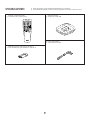 2
2
-
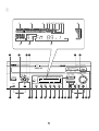 3
3
-
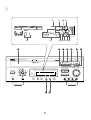 4
4
-
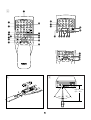 5
5
-
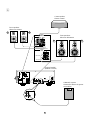 6
6
-
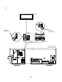 7
7
-
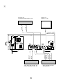 8
8
-
 9
9
-
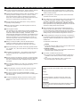 10
10
-
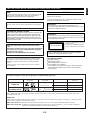 11
11
-
 12
12
-
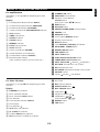 13
13
-
 14
14
-
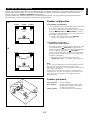 15
15
-
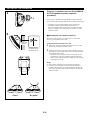 16
16
-
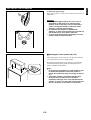 17
17
-
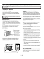 18
18
-
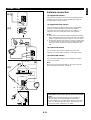 19
19
-
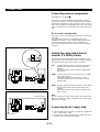 20
20
-
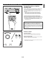 21
21
-
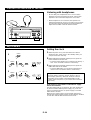 22
22
-
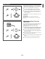 23
23
-
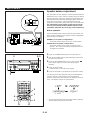 24
24
-
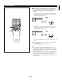 25
25
-
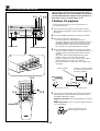 26
26
-
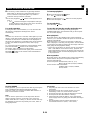 27
27
-
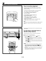 28
28
-
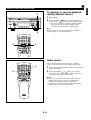 29
29
-
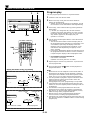 30
30
-
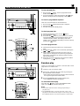 31
31
-
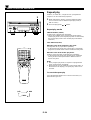 32
32
-
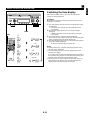 33
33
-
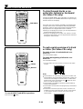 34
34
-
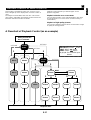 35
35
-
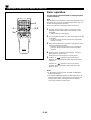 36
36
-
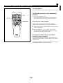 37
37
-
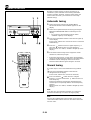 38
38
-
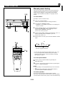 39
39
-
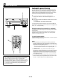 40
40
-
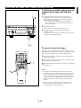 41
41
-
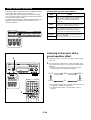 42
42
-
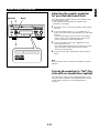 43
43
-
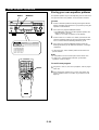 44
44
-
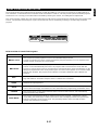 45
45
-
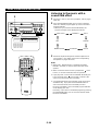 46
46
-
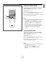 47
47
-
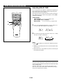 48
48
-
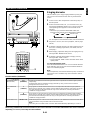 49
49
-
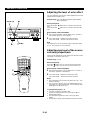 50
50
-
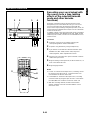 51
51
-
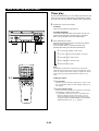 52
52
-
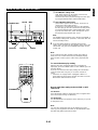 53
53
-
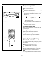 54
54
-
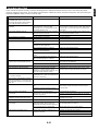 55
55
-
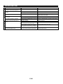 56
56
-
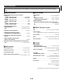 57
57
-
 58
58


in andere talen
- English: Yamaha EM-203VCD User manual
- italiano: Yamaha EM-203VCD Manuale utente
- русский: Yamaha EM-203VCD Руководство пользователя
- français: Yamaha EM-203VCD Manuel utilisateur
- español: Yamaha EM-203VCD Manual de usuario
- Deutsch: Yamaha EM-203VCD Benutzerhandbuch
- português: Yamaha EM-203VCD Manual do usuário
- dansk: Yamaha EM-203VCD Brugermanual
- suomi: Yamaha EM-203VCD Ohjekirja
- čeština: Yamaha EM-203VCD Uživatelský manuál
- svenska: Yamaha EM-203VCD Användarmanual
- Türkçe: Yamaha EM-203VCD Kullanım kılavuzu
- polski: Yamaha EM-203VCD Instrukcja obsługi
- română: Yamaha EM-203VCD Manual de utilizare