Yamaha RX-V559 de handleiding
- Categorie
- AV-ontvangers
- Type
- de handleiding
Deze handleiding is ook geschikt voor

YAMAHA ELECTRONICS CORPORATION, USA
6660 ORANGETHORPE AVE., BUENA PARK, CALIF. 90620, U.S.A.
YAMAHA CANADA MUSIC LTD.
135 MILNER AVE., SCARBOROUGH, ONTARIO M1S 3R1, CANADA
YAMAHA ELECTRONIK EUROPA G.m.b.H.
SIEMENSSTR. 22-34, 25462 RELLINGEN BEI HAMBURG, GERMANY
YAMAHA ELECTRONIQUE FRANCE S.A.
RUE AMBROISE CROIZAT BP70 CROISSY-BEAUBOURG 77312 MARNE-LA-VALLEE CEDEX02, FRANCE
YAMAHA ELECTRONICS (UK) LTD.
YAMAHA HOUSE, 200 RICKMANSWORTH ROAD WATFORD, HERTS WD18 7GQ, ENGLAND
YAMAHA SCANDINAVIA A.B.
J A WETTERGRENS GATA 1, BOX 30053, 400 43 VÄSTRA FRÖLUNDA, SWEDEN
YAMAHA MUSIC AUSTRALIA PTY, LTD.
17-33 MARKET ST., SOUTH MELBOURNE, 3205 VIC., AUSTRALIA
©
2006 All rights reserved.
RX-V559
Printed in Malaysia WG73470
RX-V559
AV Receiver
Ampli-tuner audio-vidéo
OWNER’S MANUAL
MODE D’EMPLOI
BEDIENUNGSANLEITUNG
BRUKSANVISNING
GEBRUIKSAANWIJZING
ИНСТРУКЦИЯ ПО ЭКСПЛУАТАЦИИ
G
RX-V559_G_cv.fm Page 1 Tuesday, November 22, 2005 3:43 PM

CAUTION: READ THIS BEFORE OPERATING YOUR UNIT.
1 To assure the finest performance, please read this manual
carefully. Keep it in a safe place for future reference.
2 Install this sound system in a well ventilated, cool, dry, clean
place – away from direct sunlight, heat sources, vibration,
dust, moisture, and/or cold. Allow ventilation space of at
least 30 cm on the top, 20 cm on the left and right, and 20
cm on the back of this unit.
3 Locate this unit away from other electrical appliances,
motors, or transformers to avoid humming sounds.
4 Do not expose this unit to sudden temperature changes from
cold to hot, and do not locate this unit in a environment with
high humidity (i.e. a room with a humidifier) to prevent
condensation inside this unit, which may cause an electrical
shock, fire, damage to this unit, and/or personal injury.
5 Avoid installing this unit where foreign object may fall onto
this unit and/or this unit may be exposed to liquid dripping
or splashing. On the top of this unit, do not place:
– other components, as they may cause damage and/or
discoloration on the surface of this unit.
– burning objects (i.e. candles), as they may cause fire,
damage to this unit, and/or personal injury.
– containers with liquid in them, as they may fall and
liquid may cause electrical shock to the user and/or
damage to this unit.
6 Do not cover this unit with a newspaper, tablecloth, curtain,
etc. in order not to obstruct heat radiation. If the temperature
inside this unit rises, it may cause fire, damage to this unit,
and/or personal injury.
7 Do not plug in this unit to a wall outlet until all connections
are complete.
8 Do not operate this unit upside-down. It may overheat,
possibly causing damage.
9 Do not use force on switches, knobs and/or cords.
10 When disconnecting the power cable from the wall outlet,
grasp the plug; do not pull the cord.
11 Do not clean this unit with chemical solvents; this might
damage the finish. Use a clean, dry cloth.
12 Only voltage specified on this unit must be used. Using this
unit with a higher voltage than specified is dangerous and
may cause fire, damage to this unit, and/or personal injury.
YAMAHA will not be held responsible for any damage
resulting from use of this unit with a voltage other than
specified.
13 To prevent damage by lightning, keep the power cable and
outdoor antennas disconnected from a wall outlet or this unit
during a lightning storm.
14 Do not attempt to modify or fix this unit. Contact qualified
YAMAHA service personnel when any service is needed.
The cabinet should never be opened for any reasons.
15 When not planning to use this unit for long periods of time
(i.e. vacation), disconnect the AC power plug from the wall
outlet.
16 Install this unit near the AC wall outlet where the power
cable plug can be reached easily.
17 Be sure to read the “TROUBLESHOOTING” section on
common operating errors before concluding that this unit is
faulty.
18 Before moving this unit, press MASTER ON/OFF to release
it outward to the OFF position to turn off this unit, and then
disconnect the power cable from the AC wall outlet.
19 VOLTAGE SELECTOR (Asia and General models only)
The VOLTAGE SELECTOR on the rear panel of this unit
must be set for your local main voltage BEFORE plugging
into the AC wall outlet. Voltages are:
Asia model ............................ 220/230–240 V AC, 50/60 Hz
General model ........ 110/120/220/230–240 V AC, 50/60 Hz
■ For U.K. customers
If the socket outlets in the home are not suitable for the
plug supplied with this appliance, it should be cut off and
an appropriate 3 pin plug fitted. For details, refer to the
instructions described below.
The plug severed from the mains lead must be destroyed, as a
plug with bared flexible cord is hazardous if engaged in a live
socket outlet.
■ Special Instructions for U.K. Model
CAUTION: READ THIS BEFORE OPERATING YOUR UNIT.
WARNING
TO REDUCE THE RISK OF FIRE OR ELECTRIC
SHOCK, DO NOT EXPOSE THIS UNIT TO RAIN
OR MOISTURE.
This unit is not disconnected from the AC power
source as long as it is connected to the wall outlet, even
if this unit itself is turned off. In this state, this unit is
designed to consume a very small quantity of power.
Note
IMPORTANT
THE WIRES IN MAINS LEAD ARE COLOURED IN
ACCORDANCE WITH THE FOLLOWING CODE:
Blue: NEUTRAL
Brown: LIVE
As the colours of the wires in the mains lead of this
apparatus may not correspond with the coloured
markings identifying the terminals in your plug,
proceed as follows:
The wire which is coloured BLUE must be connected
to the terminal which is marked with the letter N or
coloured BLACK. The wire which is coloured
BROWN must be connected to the terminal which is
marked with the letter L or coloured RED.
Making sure that neither core is connected to the earth
terminal of the three pin plug.

1
PREPARATIONINTRODUCTION
BASIC
OPERATION
SOUND FIELD
PROGRAMS
ADVANCED
OPERATION
ADDITIONAL
INFORMATION
English
FEATURES............................................................. 2
GETTING STARTED............................................ 3
Supplied accessories .................................................. 3
Installing batteries in the remote control ................... 3
CONTROLS AND FUNCTIONS ......................... 4
Front panel ................................................................. 4
Remote control........................................................... 6
Front panel display .................................................... 9
Rear panel ................................................................ 11
CONNECTIONS .................................................. 12
Placing speakers....................................................... 12
Connecting speakers ................................................ 13
Information on jacks and cable plugs ...................... 16
Audio and video signal flow.................................... 17
Connecting a TV...................................................... 18
Connecting a DVD player, a DVD recorder,
a VCR or an STB................................................. 19
Connecting a CD player, an MD player
or a tape deck....................................................... 21
Connecting a YAMAHA iPod universal dock ........ 22
Connecting a multi-format player
or an external decoder ......................................... 23
Connecting a game console, a video camera
or a portable audio player.................................... 23
Connecting the FM and AM antennas ..................... 24
Connecting the power cable..................................... 26
Setting the speaker impedance................................. 27
Turning on and off the power .................................. 28
BASIC SETUP ...................................................... 29
PLAYBACK.......................................................... 32
USING AUDIO FEATURES............................... 34
Using SILENT CINEMA ........................................ 34
Muting the audio output........................................... 34
Selecting the night listening mode........................... 34
Selecting the input mode ......................................... 35
Using the sleep timer ............................................... 35
Adjusting the speaker level...................................... 36
Selecting the Compressed Music
Enhancer mode .................................................... 37
Selecting the MULTI CH INPUT component......... 38
Enjoying multi-channel sources
in 2-channel stereo............................................... 39
Enjoying unprocessed input sources........................ 39
Enjoying pure hi-fi stereo sound.............................. 39
USING VIDEO FEATURES ............................... 40
Displaying the input source information ................. 40
Selecting the OSD mode.......................................... 41
Playing video sources in the background ................ 41
ENJOYING SURROUND SOUND .................... 42
Enjoying multi-channel sources in surround ........... 42
Enjoying 2-channel sources in surround.................. 43
Using Virtual CINEMA DSP .................................. 44
RECORDING........................................................45
FM/AM TUNING..................................................46
Automatic tuning ..................................................... 46
Manual tuning.......................................................... 47
Automatic preset tuning........................................... 48
Manual preset tuning ............................................... 49
Selecting preset stations........................................... 50
Exchanging preset stations ...................................... 51
RADIO DATA SYSTEM TUNING
(U.K. AND EUROPE MODELS ONLY)........53
Selecting the Radio Data System program .............. 53
Using the Radio Data System station network ........ 54
Displaying the Radio Data System information ...... 55
SOUND FIELD PROGRAMS .............................57
Selecting sound field programs ............................... 57
Sound field program descriptions............................ 58
Changing sound field parameter settings................. 60
Sound field program speaker layouts ...................... 66
SET MENU ............................................................69
Using SET MENU................................................... 71
1 SOUND MENU.................................................... 72
2 INPUT MENU...................................................... 77
3 OPTION MENU................................................... 79
ADVANCED SETUP............................................82
REMOTE CONTROL FEATURES ...................84
Controlling this unit, a TV,
or other components ............................................ 84
Setting the remote control code ............................... 86
Setting library codes ................................................ 87
Resetting all remote control codes........................... 88
USING MULTI-ZONE CONFIGURATION.....89
Connecting Zone 2................................................... 89
Controlling Zone 2................................................... 90
USING iPod® ........................................................92
Setting the remote control code ............................... 92
Controlling iPod ...................................................... 92
RESETTING THE SYSTEM...............................94
TROUBLESHOOTING .......................................95
GLOSSARY.........................................................100
Audio information ................................................. 100
Video information.................................................. 101
Sound field program information .......................... 102
SPECIFICATIONS.............................................103
CONTENTS
INTRODUCTION
PREPARATION
BASIC OPERATION
SOUND FIELD PROGRAMS
ADVANCED OPERATION
ADDITIONAL INFORMATION

FEATURES
2
Built-in 6-channel power amplifier
◆ Minimum RMS output power
(0.06% THD, 20 Hz to 20 kHz, 8 Ω)
Front: 95 W + 95 W
Center: 95 W
Surround: 95 W + 95 W
Surround back: 95 W
Sound field programs
◆ Proprietary YAMAHA technology for the creation of sound
fields
◆ Dolby Digital/Dolby Digital EX decoder
◆ DTS/DTS-ES Matrix 6.1, Discrete 6.1, DTS Neo:6, DTS 96/
24 decoder
◆ Dolby Pro Logic/Dolby Pro Logic II/Dolby Pro Logic IIx
decoder
◆ Virtual CINEMA DSP
◆ SILENT CINEMA
™
Sophisticated AM/FM tuner
◆ 40-station random and direct preset tuning
◆ Automatic preset tuning
◆ Preset station shifting capability (preset editing)
Radio Data System
(U.K. and Europe models only)
◆ Radio Data System tuning capability
iPod controlling capability
◆ DOCK terminal to connect a YAMAHA iPod universal dock
(such as YDS-10 sold separately), which supports iPod (Click
and Wheel), iPod nano, and iPod mini
Other features
◆ 192-kHz/24-bit D/A converter
◆ OSD (on-screen display) menus that allow you to optimize
this unit to suit your individual audiovisual system
◆ 6 additional input jacks for discrete multi-channel input
◆ S-video signal input/output capability
◆ Component video input/output capability
(3 COMPONENT VIDEO INs and 1 MONITOR OUT)
◆ Digital video signal conversion (composite video ↔ S-video
→ component video) capability for monitor out
◆ Optical and coaxial digital audio signal jacks
◆ Sleep timer
◆ Cinema and music night listening modes
◆ Remote control with preset remote control codes,
backlighting input selector buttons, and an iPod (stationed in a
YAMAHA iPod universal dock connected to the DOCK
terminal) controlling capability
◆ Zone 2 custom installation facility
◆ Zone switching capability between the main zone and Zone 2
using ZONE CONTROL
◆ PORTABLE mini analog input jack on the front panel for a
portable audio player
◆ Compressed Music Enhancer mode to improve the sound
quality of compression artifacts (such as the MP3 format) to
that of a high-quality stereo
• y indicates a tip for your operation.
• Some operations can be performed by using either the buttons on the front panel or the ones on the remote control. In case the button
names differ between the front panel and the remote control, the button name on the remote control is given in parentheses.
• This manual is printed prior to production. Design and specifications are subject to change in part as a result of improvements, etc. In
case of differences between the manual and product, the product has priority.
Manufactured under license from Dolby Laboratories.
“Dolby”, “Pro Logic”, and the double-D symbol are trademarks
of Dolby Laboratories.
Manufactured under license from Digital Theater Systems, Inc.
“DTS”, “DTS-ES”, “NEO:6”, and “DTS 96/24” are trademarks
of Digital Theater Systems, Inc. Copyright 1996, 2003 Digital
Theater Systems, Inc. All right reserved.
“iPod” is a trademark of Apple Computer, Inc., registered in the
U.S. and other countries.
“SILENT CINEMA” is a trademark of YAMAHA
CORPORATION.
FEATURES
Notes
iPod
®

GETTING STARTED
3
INTRODUCTION
English
Check that you received all of the following parts.
1 Take off the battery compartment cover.
2 Insert the two supplied batteries
(AA, R6, UM-3) according to the polarity
markings (+ and –) on the inside of the
battery compartment.
3 Snap the battery compartment cover back
into place.
• Change all of the batteries if you notice the following
conditions:
– the operation range of the remote control decreases.
– the TRANSMIT indicator does not flash or its light becomes
dim.
• Do not use an old battery together with a new one.
• Do not use different types of batteries (such as alkaline and
manganese batteries) together. Read the packaging carefully as
these different types of batteries may have the same shape and
color.
• If the batteries have leaked, dispose of them immediately. Avoid
touching the leaked material or letting it come into contact with
clothing, etc. Clean the battery compartment thoroughly before
installing new batteries.
• Do not throw away batteries with general house waste; dispose
of them correctly in accordance with your local regulations.
• If the remote control is without batteries for more than 2
minutes, or if exhausted batteries remain in the remote control,
the contents of the memory may be cleared. When the memory
is cleared, insert new batteries, set up the remote control code
and program any acquired functions that may have been
cleared.
GETTING STARTED
Supplied accessories
Installing batteries in the remote control
TV MUTE TV INPUT
MUTE
AMP
SOURCE
TV
MENUTITLE
SET MENU
LEVEL
DISPLAYRETURN
BAND
SRCH MODE
DAB MEMORY
A/B/C/D/E
ENTER
PRESET/CH
REC
AUDIO
DISC SKIP
STEREO
1
EFFECT
VOLUME
TV VOL TV CH
TRANSMITCODE SET
STANDBY
POWER
POWERPOWER
CD
AVTV
MULTI CH IN
SLEEP
CD-R
DVD DTV
MD
CBL
TUNER
V-AU X DVR
STANDARD
5
SPEAKERS
9
MUSIC
2
SELECT
6
ENHANCER
0
ENTERTAIN
3
EXTD SUR.
7
NIGHT
10
MOVIE
4
DIRECT ST.
8
STRAIGHT
ENT.
FREQ/TEXT EONSTARTPTY SEEKMODE
Remote control
Batteries (2)
(AA, R6, UM-3)
Indoor FM antenna
(U.S.A., Canada, China, Asia
and General models)
AM loop antenna
75-ohm/300-ohm antenna
adapter (U.K. model only)
Indoor FM antenna
(U.K., Europe, Australia
and Korea models)
1
3
2
Notes

CONTROLS AND FUNCTIONS
4
1 MASTER ON/OFF
Turns on or off this unit (see page 28).
2 MAIN ZONE ON/OFF
Turns on the main zone or sets it to the standby mode
(see page 28).
• In the standby mode, this unit consumes a small amount of
power in order to receive infrared signals from the remote
control.
• When you turn on this unit, there will be a 4 to 5-second delay
before this unit can reproduce sound.
• This button is operational only when MASTER ON/OFF is
pressed inward to the ON position.
3 Remote control sensor
Receives signals from the remote control (see page 8).
4 Front panel display
Shows information about the operational status of this unit
(see page 9).
5 A/B/C/D/E, NEXT
• Selects one of the 5 preset station groups (A to E) when
“TUNER” is selected as the input source (see page 46).
• Selects the speaker channel whose output level you
want to adjust when “TUNER” is not selected as the
input source (see page 36).
6 PRESET/TUNING l / h, LEVEL +/–
• Selects one of the 8 preset station numbers (1 to 8)
when “TUNER” is selected as the input source. The
colon (:) is displayed in the front panel display (see
page 46).
• Selects the tuning frequency when “TUNER” is
selected as the input source. The colon (:) is not
displayed in the front panel display (see page 46).
• Adjusts the level of the speaker channel selected using
NEXT when “TUNER” is not selected as the input
source (see page 36).
7 MEMORY (MAN’L/AUTO FM)
Stores a preset station in the memory. Hold down this
button for more than 3 seconds to start automatic preset
tuning (see page 48).
CONTROLS AND FUNCTIONS
Front panel
ZONE 2
ON/OFF
ZONE
CONTROL
VIDEO PORTABLEL AUDIO R
NEXTEDIT
EFFECT
MEMORY
FM/AM
PRESET/TUNING
A/B/C/D/E
PROGRAM
l PRESET/TUNING h
TUNING MODE
INPUT MODETONE CONTROLSTRAIGHT
SPEAKERSPHONES
MAIN ZONE
MASTER
SILENT CINEMA
BA
MULTI CH
INPUT
VOLUME
VIDEO AUX
INPUT
ON OFF
LEVEL
MAN'L/AUTO FM
AUTO/MAN'L
ON/OFF
3145687
IJKGFD
A
L
BC
2
EH
90
Notes

CONTROLS AND FUNCTIONS
5
INTRODUCTION
English
8 TUNING MODE (AUTO/MAN’L)
Switches between automatic tuning (the AUTO indicator
is turned on) and manual tuning (the AUTO indicator is
turned off) (see page 46).
9 ZONE 2 ON/OFF
Turns on Zone 2 or sets it to the standby mode
(see page 90).
This button is operational only when MASTER ON/OFF is
pressed inward to the ON position.
0 ZONE CONTROL
Switches the zone you want to control between the main
zone and Zone 2 (see page 90).
y
When Zone 2 is selected, the ZONE2 indicator flashes in the front
panel display for approximately 5 seconds. While the indicator is
flashing, perform the desired operation.
A VOLUME
Controls the output level of all audio channels.
y
This does not affect the AUDIO OUT (REC) level.
B PHONES (SILENT CINEMA) jack
Outputs audio signals for private listening with
headphones (see page 34).
• When you connect headphones, no signals are output at the
SUBWOOFER OUTPUT jack or the speaker terminals.
• All Dolby Digital and DTS audio signals are mixed down to the
left and right headphone channels.
C SPEAKERS A/B
Turns on or off the set of front speakers connected to the
FRONT A and/or B terminals on the rear panel each time
the corresponding button is pressed.
D PRESET/TUNING, EDIT
• Switches the function of PRESET/TUNING l / h
between selecting preset station numbers and selecting
the tuning frequency.
• Edits the assignments of preset stations (see page 51).
E STRAIGHT (EFFECT)
Turns the sound field programs off or on. When the
“STRAIGHT” mode is selected, 2-channel or multi-
channel input signals are output directly from their
respective speakers without effect processing
(see page 39).
F FM/AM
Switches the reception band between FM and AM when
“TUNER” is selected as the input source (see page 46).
G PROGRAM selector
Selects sound field programs or adjusts the bass/treble
balance in conjunction with TONE CONTROL (see
page 33).
H TONE CONTROL
Adjusts the bass/treble balance of the front left and right
speakers in conjunction with the PROGRAM selector
(see page 33).
I INPUT MODE
Selects either digital or analog input signals exclusively or
sets this unit to automatically detect the type of input
signals and select the corresponding input signals when
one component is connected via both digital and analog
connections (see page 35).
J INPUT selector
Selects the desired input source.
K MULTI CH INPUT
Selects the component connected to the MULTI CH
INPUT jacks as the input source (see page 38).
The input source connected to the MULTI CH INPUT jacks takes
priority over the source selected with the INPUT selector on the
front panel (or the input selector buttons on the remote control).
L VIDEO AUX jacks
Input audio and video signals from a portable external
source such as a game console, a video camera or a
portable audio player (see page 23).
y
To reproduce the source signals input at these jacks, select
“V-AUX” as the input source.
• The audio signals input at the PORTABLE mini jack take
priority over the ones input at the AUDIO L/R jacks.
• The audio signals input at the DOCK terminal on the rear panel
take priority over the ones input at the VIDEO AUX jacks.
Note
Notes
Note
Notes

CONTROLS AND FUNCTIONS
6
This section describes the function of each control on the
remote control used to control this unit. To operate other
components, see “REMOTE CONTROL FEATURES” on
page 84.
The operation mode of the remote control buttons in the shaded
areas below depends on the component selector switch position.
Set the component selector switch to AMP to control this unit. To
control the TUNER functions, set the component selector switch
to SOURCE and then press TUNER to select “TUNER” as the
input source.
■ Controlling this unit
Set the component selector switch to AMP to control this
unit.
1 Infrared window
Outputs infrared control signals. Aim this window at the
component you want to operate (see page 8).
2 CODE SET
Use to set up remote control codes (see page 86).
3 Input selector buttons
Select the input source you want to control.
The corresponding input selector button for the currently selected
input source lights up for approximately 5 seconds after you press
any buttons on the remote control, showing which source
component is currently being operated.
4 Sound field program selector buttons
Select sound field programs (see page 57).
– Use SELECT to play back 2-channel sources in
surround (see page 43).
– Use EXTD SUR. to switch between 5.1 and
6.1-channel playback of multi-channel sources
(see page 42).
– Use DIRECT ST. to play back 2-channel sources in hi-
fi stereo sound (see page 39).
5 SPEAKERS
Turns on or off the set of front speakers connected to the
FRONT A and/or B terminals on the rear panel. Press this
button repeatedly to toggle as follows:
6 ENHANCER
Turns on or off the Compressed Music Enhancer mode
(see page 37).
7 LEVEL
Selects the speaker channel to be adjusted and sets the
output level (see page 36).
8 Cursor buttons u / d / j / i, ENTER
Select and adjust the sound field program parameters or
the “SET MENU” parameters.
9 RETURN
Returns to the previous menu level when adjusting the
“SET MENU” parameters.
0 TRANSMIT indicator
Flashes while the remote control is sending infrared
signals.
Remote control
Note
TV MUTE TV INPUT
MUTE
AMP
SOURCE
TV
MENUTITLE
SET MENU
LEVEL
DISPLAYRETURN
BAND
SRCH MODE
DAB MEMORY
A/B/C/D/E
ENTER
PRESET/CH
REC
AUDIO
DISC SKIP
STEREO
1
EFFECT
VOLUME
TV VOL TV CH
TRANSMITCODE SET
STANDBY
POWER
POWERPOWER
CD
AVTV
MULTI CH IN
SLEEP
CD-R
DVD DTV
MD
CBL
TUNER
V-AUX DVR
STANDARD
5
SPEAKERS
9
MUSIC
2
SELECT
6
ENHANCER
0
ENTERTAIN
3
EXTD SUR.
7
NIGHT
10
MOVIE
4
DIRECT ST.
8
STRAIGHT
ENT.
FREQ/TEXT EONSTARTPTY SEEKMODE
K
0
A
B
C
D
F
E
G
H
I
J
1
2
3
4
5
6
8
9
7
L
Note
A on B on
A and B off

CONTROLS AND FUNCTIONS
7
INTRODUCTION
English
A STANDBY
Sets this unit to the standby mode (see page 28).
This button is operational only when MASTER ON/OFF on the
front panel is pressed inward to the ON position.
B POWER
Turns on this unit (see page 28).
This button is operational only when MASTER ON/OFF on the
front panel is pressed inward to the ON position.
C SLEEP
Sets the sleep timer (see page 35).
D MULTI CH IN
Selects the component connected to the MULTI CH
INPUT jacks as the input source when using an external
decoder, etc. (see page 38).
E VOLUME +/–
Increases or decreases the volume level.
F Component selector switch
Selects the operation mode of the remote control buttons
in the shaded areas.
AMP
Operates this unit.
SOURCE
Operates the component selected with an input
selector button (see page 85).
TV
Operates the TV assigned to either DTV/CBL or
(see page 84).
• To set the remote control codes for other components, see
page 86.
• When you set the remote control codes for both DTV/CBL and
(see page 86), priority is given to the one set for DTV/
CBL.
G MUTE
Mutes the audio output. Press again to restore the audio
output to the previous volume level (see page 34).
H STRAIGHT (EFFECT)
Turns the sound field programs off or on. When the
“STRAIGHT” mode is selected, 2-channel or multi-
channel input signals are output directly from their
respective speakers without effect processing
(see page 39).
I NIGHT
Turns on or off the night listening modes (see page 34).
J SET MENU
Enters “SET MENU” (see page 71).
K DISPLAY
Selects the on-screen display (OSD) mode for your video
monitor (see page 41).
L Radio Data System tuning buttons
(U.K. and Europe models only)
FREQ/TEXT
Switches the Radio Data System display between the
PS mode, PTY mode, RT mode, CT mode (if the
station offers the corresponding data services) and the
frequency display (see page 55).
PTY SEEK MODE
Sets this unit to the PTY SEEK mode (see page 53).
PTY SEEK START
Starts searching for a station once the desired program
type is selected in the PTY SEEK mode (see page 53).
EON
Selects a program type (NEWS, AFFAIRS, INFO, or
SPORT) for automatic tuning (see page 54).
Note
Note
Notes

CONTROLS AND FUNCTIONS
8
■ Controlling the TUNER functions
Set the component selector switch to SOURCE and then
press TUNER to select “TUNER” as the input source.
4 Numeric buttons
Use numbers 1 through 8 to select preset stations.
7 BAND
Switches the reception band between FM and AM
(see page 46).
8 Cursor buttons u / d / j / i
Press j / i to select a preset station group (A to E) and
u / d to select a preset station number (1 to 8)
(see page 50).
■ Using the remote control
The remote control transmits a directional infrared ray.
Be sure to aim the remote control directly at the remote
control sensor on this unit during operation.
• Do not spill water or other liquids on the remote control.
• Do not drop the remote control.
• Do not leave or store the remote control in the following types
of conditions:
– places of high humidity, such as near a bath
– places of high temperatures, such as near a heater or stove
– places of extremely low temperatures
– dusty places
Notes
ZONE 2
ON/OFF
ZONE
CONTROL
VIDEO PORTABLEL AUDIO R
NEXTEDIT
EFFECT
MEMORY
FM/AM
PRESET/TUNING
A/B/C/D/E
PROGRAM
l PRESET/TUNING h
TUNING MODE
INPUT MODETONE CONTROLSTRAIGHT
SPEAKERSPHONES
MAIN ZONE
MASTER
SILENT CINEMA
BA
MULTI CH
INPUT
VOLUME
VIDEO AUX
INPUT
ON OFF
LEVEL
MAN'L/AUTO FM
AUTO/MAN'L
ON/OFF
30 30
TV MUTE TV INPUT
MUTE
AMP
SOURCE
TV
MENUTITLE
SET MENU
LEVEL
DISPLAYRETURN
BAND
SRCH MODE
DAB MEMORY
A/B/C/D/E
ENTER
PRESET/CH
REC
AUDIO
DISC SKIP
STEREO
1
EFFECT
VOLUME
TV VOL TV CH
TRANSMITCODE SET
STANDBY
POWER
POWERPOWER
CD
AVTV
MULTI CH IN
SLEEP
CD-R
DVD DTV
MD
CBL
TUNER
V-AUX DVR
STANDARD
5
SPEAKERS
9
MUSIC
2
SELECT
6
ENHANCER
0
ENTERTAIN
3
EXTD SUR.
7
NIGHT
10
MOVIE
4
DIRECT ST.
8
STRAIGHT
ENT.
FREQ/TEXT EONSTARTPTY SEEKMODE
Approximately 6 m

CONTROLS AND FUNCTIONS
9
INTRODUCTION
English
1 Decoder indicators
The respective indicator lights up when any of the
decoders of this unit function.
2 ENHANCER indicator
Lights up when the Compressed Music Enhancer mode is
turned on (see page 37).
3 Sound field indicators
Light up to indicate the active DSP sound fields.
4 VIRTUAL indicator
Lights up when Virtual CINEMA DSP is active (see
page 44).
5 Input source indicators
The corresponding cursor lights up to show the currently
selected input source.
6 DOCK indicator
Lights up when you station your iPod in a YAMAHA iPod
universal dock (such as YDS-10 sold separately)
connected to the DOCK terminal of this unit
(see page 22).
7 SILENT CINEMA indicator
Lights up when headphones are connected and a sound
field program is selected (see page 34).
8 CINEMA DSP indicator
Lights up when you select a CINEMA DSP sound field
program (see page 58).
9 AUTO indicator
Lights up when this unit is in the automatic tuning mode
(see page 46).
0 TUNED indicator
Lights up when this unit is tuned into a station
(see page 46).
A STEREO indicator
Lights up when this unit is receiving a strong signal for an
FM stereo broadcast while the AUTO indicator is lit
(see page 46).
B MEMORY indicator
Flashes to show that a station can be stored (see page 48).
C VOLUME level indicator
Indicates the current volume level.
D PCM indicator
Lights up when this unit is reproducing PCM (Pulse Code
Modulation) digital audio signals.
E STANDARD indicator
Lights up when the “SUR. STANDARD” or “SUR.
ENHANCED” program is selected (see page 43).
Front panel display
p
DVR
p
DVD
p
CD
p
V-AUX
p
DTV/CBL
p
MD/CD-R
p
TUNER
96
24
q PL
q EX
q PL
ENHANCER
MATRIX DISCRETE
SILENT CINEMA
ZONE2 NIGHT
DOCK
STANDARD
AUTO
PSHOLD RT
EON
PTYPTY
TUNED
MUTE
VOLUME
MEMORY
SLEEP
VIRTUAL
PCM
q PL x
A B
SP
mS
ft
dB
96/24
HiFi DSP
LFE
LCR
SL SB SR
q
DIGITAL
t
dB
STEREO
CT
2
H
EI
GJK LNMPO
Q
D
F
1345768 B
0A9C
(U.K. and Europe models only)
Presence DSP sound field
Listening position
Surround left
DSP sound field
Surround right
DSP sound field
Surround back DSP sound field

CONTROLS AND FUNCTIONS
10
F SP A B indicators
Light up according to the set of front speakers selected.
G Headphones indicator
Lights up when headphones are connected (see page 34).
H ZONE2 indicator
Lights up when Zone 2 is turned on (see page 90).
I NIGHT indicator
Lights up when you select a night listening mode
(see page 34).
J HiFi DSP indicator
Lights up when you select a HiFi DSP sound field
program (see page 58).
K Multi-information display
Shows the name of the current sound field program and
other information when adjusting or changing settings.
L SLEEP indicator
Lights up while the sleep timer is on (see page 35).
M MUTE indicator
Flashes while the MUTE function is on (see page 34).
N 96/24 indicator
Lights up when a DTS 96/24 signal is input to this unit.
O Input channel indicators
Indicate the channel components of the current digital
input signal (see page 30).
P LFE indicator
Lights up when the input signal contains the LFE signal.
Q Radio Data System indicators
(U.K. and Europe models only)
Lights up when the Radio Data System data is being
received.
EON
Lights up when the EON data service is being
received.
PTY HOLD
Lights up while searching for the Radio Data System
stations in the PTY SEEK mode.

CONTROLS AND FUNCTIONS
11
INTRODUCTION
English
1 Video component jacks
See pages 18 and 19 for connection information.
2 Audio component jacks
See page 21 for connection information.
3 MULTI CH INPUT jacks
See page 23 for connection information.
4 ZONE 2 OUTPUT jacks
See page 89 for connection information.
These jacks output analog signals only.
5 SUBWOOFER OUTPUT jack
See page 13 for connection information.
6 DIGITAL OUTPUT jack
See page 21 for connection information.
7 DIGITAL INPUT jacks
See page 19 for connection information.
8 DOCK terminal
Use to connect a YAMAHA iPod universal dock (such as
YDS-10 sold separately) where your iPod can be
stationed.
See page 22 for connection information.
9 COMPONENT VIDEO jacks
See pages 18 and 19 for connection information.
0 REMOTE jacks
See page 89 for details.
A CONTROL OUT jack
This is a control expansion terminal for custom
installation.
B Antenna terminals
See page 24 for connection information.
C Speaker terminals
See page 13 for connection information.
D AC OUTLET(S)
Use to supply power to your other audiovisual
components.
See page 26 for details.
■ VOLTAGE SELECTOR
(Asia and General models only)
See page 26 for details.
Rear panel
AUDIO AUDIO OUTPUT DIGITAL INPUT
DVD DVD
COAXIAL
DTV/CBLMD/CD-RMD/CD-R
SUB
WOOFER
SUB
WOOFER
SURROUND
FRONT ZONE 2
OUT
(REC)
IN
(PLAY)
MD/
CD-R
CD
DVD
MONITOR OUT
DTV/CBL
DVD DVR
COMPONENT VIDEO
P
RPBY
FM ANT
75Ω
UNBAL.
AM
ANT
GND
TUNER SPEAKERS
DOCK
DTV/CBL
IN OUT
DVR DVD DTV/CBL
IN OUT
DVR
CENTER
DIGITAL
OUTPUT
MULTI CH INPUT
VIDEO S VIDEO
MONITOR
OUT
MONITOR
OUT
FRONT
A
B
OUTIN
REMOTE CONTROL
OUT
+12V
15mA MAX.
SURROUND
CENTER
SURROUND BACK
PRPBY
OPTICAL OPTICAL
0
87654321
AB C
D
9
Note

CONNECTIONS
12
The speaker layout below shows the standard ITU-R
*
speaker setting. You can use it to enjoy CINEMA DSP and
multi-channel audio sources.
*
ITU-R is the radio communication sector of the ITU
(International Telecommunication Union).
Front left and right speakers (FL and FR)
The front speakers are used for the main source sound plus
effect sounds. Place these speakers at an equal distance
from the ideal listening position. The distance of each
speaker from each side of the video monitor should be the
same.
Center speaker (C)
The center speaker is for the center channel sounds
(dialog, vocals, etc.). If for some reason it is not practical
to use a center speaker, you can do without it. Best results,
however, are obtained with the full system. Place the
center speaker centrally between the front speakers and as
close to the monitor as possible, such as directly over or
under it.
Surround left and right speakers (SL and SR)
The surround speakers are used for effect and surround
sounds. Place these speakers behind your listening
position, facing slightly inwards, about 1.8 m above the
floor.
Surround back speaker (SB)
The surround back speaker supplements the surround
speakers and provides more realistic front-to-back
transitions. Place this speaker directly behind the listening
position and at the same height as the surround speakers.
Subwoofer (SW)
The use of a subwoofer with a built-in amplifier, such as
the YAMAHA Active Servo Processing Subwoofer
System, is effective not only for reinforcing bass
frequencies from any or all channels, but also for hi-fi
stereo sound reproduction of the LFE (low-frequency
effect) channel included in Dolby Digital and DTS
sources. The position of the subwoofer is not so critical,
because low bass sounds are not highly directional. But it
is better to place the subwoofer near the front speakers.
Turn it slightly toward the center of the room to reduce
wall reflections.
CONNECTIONS
Placing speakers
SW
FR
FL
SB
SL
SR
C
60˚
30˚
SB
FL
FR
C
SL
SR
SR
80˚
SL
1.8 m

13
CONNECTIONS
PREPARATION
English
Be sure to connect the left channel (L), right channel (R), “+” (red) and “–” (black) properly. If the connections are faulty,
no sound will be heard from the speakers, and if the polarity of the speaker connections is incorrect, the sound will be
unnatural and lack bass.
• Before connecting the speakers, make sure that this unit is turned off (see page 28).
• Do not let the bare speaker wires touch each other or do not let them touch any metal part of this
unit. This could damage this unit and/or speakers.
• Use magnetically shielded speakers. If this type of speakers still creates the interference with the
monitor, place the speakers away from the monitor.
• If you are to use 4 or 6 ohm speakers, be sure to set “SP IMP.” to “6ΩMIN” before using this unit
(see page 27).
• A speaker cord is actually a pair of insulated cables running side by side. Cables are colored or shaped differently, perhaps with a
stripe, groove or ridge. Connect the striped (grooved, etc.) cable to the “+” (red) terminals of this unit and your speaker. Connect the
plain cable to the “–” (black) terminals.
• The low-frequency signals of other speakers set to “SML” (or “SMALL”) or to “NONE” in “SPEAKER SET” (see pages 72 and 73)
are directed to the speakers selected in “LFE/BASS OUT” (see page 73).
Connecting speakers
Notes
CAUTION
OUTPUT
SUB
WOOFER
SPEAKERS
FRONT
A
B
SURROUND
CENTER SURROUND BACK
1 2 4 57
63
Subwoofer
Center
speaker
Front speakers (A)
Surround back
speaker
LeftRight
LeftRight
Surround speakers
Front
speakers
(B)

14
CONNECTIONS
FRONT terminals
Connect one or two front speaker systems (1, 2) to these
terminals. If you use only one front speaker system,
connect it to the FRONT A or B terminal.
CENTER terminals
Connect a center speaker (3) to these terminals.
SURROUND terminals
Connect surround speakers (4, 5) to these terminals.
SURROUND BACK terminals
Connect a surround back speaker (6) to these terminals.
SUBWOOFER jack
Connect a subwoofer with a built-in amplifier (7) (such as
the YAMAHA Active Servo Processing Subwoofer
System) to this jack.
7
1
2
6
5
4
3
Speaker layout

15
CONNECTIONS
PREPARATION
English
■ Connecting the speaker cable
1 Remove approximately 10 mm of insulation
from the end of each speaker cable and then
twist the exposed wires of the cable together
to prevent short circuits.
2 Loosen the knob.
3 Insert one bare wire into the hole on the side
of each terminal.
4 Tighten the knob to secure the wire.
■ Connecting the banana plug
(except U.K., Europe and Asia models)
The banana plug is a single-pole electrical connector
widely used to terminate speaker cables.
1 Tighten the knob.
2 Insert the banana plug connector into the
end of the corresponding terminal.
10 mm
Red: positive (+)
Black: negative (–)
Red: positive (+)
Black: negative (–)
Red: positive (+)
Black: negative (–)
Banana plug

16
CONNECTIONS
You can use the digital jacks to input PCM, Dolby Digital and DTS bitstreams. When you connect components to both the COAXIAL
and OPTICAL jacks, priority is given to the signals input at the COAXIAL jack. All digital input jacks are compatible with 96-kHz
sampling digital signals.
■ Audio jacks
This unit has four types of audio jacks. Connection
depends on the availability of audio jacks on your other
components.
AUDIO jacks
For conventional analog audio signals transmitted via left
and right analog audio cables. Connect red plugs to the
right jacks and white plugs to the left jacks.
DIGITAL AUDIO COAXIAL jacks
For digital audio signals transmitted via coaxial digital
audio cables.
DIGITAL AUDIO OPTICAL jacks
For digital audio signals transmitted via optical digital
audio cables.
Pull out the cap from the optical jack before you connect the fiber
optic cable. Do not discard the cap. When you are not using the
optical jack, be sure to put the cap back in place. This cap protects
the jack from dust.
PORTABLE jack
For analog audio signals transmitted via stereo analog
audio mini cables.
■ Video jacks
This unit has three types of video jacks. Connection
depends on the availability of input jacks on your video
monitor. When “VIDEO CONV.” is set to “ON” (see
page 79), the video signals input at the VIDEO and S
VIDEO jacks are converted and output at the VIDEO, S
VIDEO and COMPONENT VIDEO jacks
interchangeably.
VIDEO jacks
For conventional composite video signals transmitted via
composite video cables.
S VIDEO jacks
For S-video signals, separated into the luminance (Y) and
chrominance (C) video signals transmitted on separate
wires of S-video cables.
COMPONENT VIDEO jacks
For component video signals, separated into the
luminance (Y) and chrominance (P
B, PR) video signals
transmitted on separate wires of component video cables.
Information on jacks and cable plugs
Note
VIDEO S VIDEO
COMPONENT VIDEO
Y PB PR
PB
Y
P
R
S
V
COAXIAL
DIGITAL AUDIO
AUDIO
PORTABLE
OPTICAL
DIGITAL AUDIO
R
L
C
O
M
R
L
Left and right
analog audio
cable plugs
Optical
digital
audio cable
plug
Coaxial
digital audio
cable plug
Composite
video cable
plug
S-video
cable plug
Component
video cable
plugs
Stereo
analog
audio
mini cable
plug
Audio jacks and cable plugs Video jacks and cable plugs
(Red)(White) (Orange) (Yellow) (Green) (Blue) (Red)
Note

17
CONNECTIONS
PREPARATION
English
■ Audio signal flow for AUDIO OUT (REC)
This unit handles digital and analog signals independently. Thus, audio signals input at the analog jacks are output only at the analog
AUDIO OUT (REC) jacks. Likewise, audio signals input at the DIGITAL INPUT (OPTICAL or COAXIAL) jacks are output only at the
DIGITAL OUTPUT jack.
■ Video signal flow for MONITOR OUT
When video signals are input at the COMPONENT VIDEO, S VIDEO and VIDEO jacks, the priority order of the input signals is as
follows where the video signals input at the COMPONENT VIDEO jacks have the top priority:
COMPONENT VIDEO > S VIDEO > VIDEO
Audio and video signal flow
Note
Note
DIGITAL AUDIO
OPTICAL
DIGITAL AUDIO
COAXIAL
PORTABLE
AUDIO
RLRL
Digital output
Output
AUDIO OUT (REC)
Input
Analog output
Digital audio
Analog audio
S VIDEO
VIDEO
COMPONENT
VIDEO
Y P
B
P
R
Y P
B
P
R
Through
Output
(MONITOR OUT)
Input
Video conversion when “VIDEO CONV.” is set to “ON” (see page 79)
Analog video

18
CONNECTIONS
Connect your TV to the VIDEO MONITOR OUT jack, the S VIDEO MONITOR OUT jack or the COMPONENT
VIDEO MONITOR OUT jacks of this unit.
Do not connect this unit or other components to the AC power supply until all connections between
components are complete.
Connecting a TV
CAUTION
MONITOR OUT
COMPONENT VIDEO
VIDEO S VIDEO
MONITOR
OUT
MONITOR
OUT
PRPBY
PRPB
V
S
Y
TV
S-video in
Component video in
Video in

19
CONNECTIONS
PREPARATION
English
Connect your DVD player, DVD recorder, VCR or STB (set-top box) using the same type of video connections as those
made for your TV (see page 18). The cable TV receiver and the satellite receiver are examples of the STB.
Do not connect this unit or other components to the AC power supply until all connections between
components are complete.
• When “VIDEO CONV.” is set to “OFF” (see page 79), be sure to make the same type of video connections as those made for your TV
(see page 18). For example, if you connected your TV to the VIDEO MONITOR OUT jack of this unit, connect your other
components to the VIDEO jacks.
• When “VIDEO CONV.” is set to “ON” (see page 79), the converted video signals are output only at the MONITOR OUT jacks. When
recording a source, you must make the same type of video connections between each component.
• To make a digital connection to a component other than the default component assigned to each DIGITAL INPUT or DIGITAL
OUTPUT jack, select the corresponding setting for “OPTICAL OUT”, “OPTICAL IN”, or “COAXIAL IN” in “I/O ASSIGNMENT”
(see page 77).
• If you connect your DVD player to both the DIGITAL INPUT (OPTICAL) and the DIGITAL INPUT (COAXIAL) jacks, priority is
given to the signals input at the DIGITAL INPUT (COAXIAL) jack.
■ Connecting a DVD player
Connecting a DVD player, a DVD recorder, a VCR or an STB
Notes
CAUTION
AUDIO DIGITAL INPUT
DVD DVD
COAXIAL
DVD
DVD
COMPONENT VIDEO
P
RPBY
DVD
VIDEO S VIDEO
OPTICAL
S
P
RPBY
V
C
LR
O
DVD player
Optical audio out
Coaxial audio out
Video out
Audio out
S-video out
Component video out

20
CONNECTIONS
■ Connecting a DVD recorder or a VCR
■ Connecting an STB
AUDIO
DVR
COMPONENT VIDEO
IN OUT
DVR
IN OUT
DVR
VIDEO S VIDEO
PRPBY
V
S
V
LR LR
PRPBY
S
DVD recorder or
VCR
Audio in
Audio out
Video in
Video out
Component video out
S-video in
S-video out
AUDIO DIGITAL INPUT
DTV/CBL
DTV/CBL
COMPONENT VIDEO
P
RPBY
DTV/CBL DTV/CBL
VIDEO S VIDEO
OPTICAL
S
P
RPBY
V
LR
O
Cable TV receiver or
satellite receiver
Optical audio out
Component video out
Video out
Audio out
S-video out

21
CONNECTIONS
PREPARATION
English
Connect your CD player, MD player or tape deck via analog and/or digital connections.
Do not connect this unit or other components to the AC power supply until all connections between
components are complete.
To make a digital connection to a component other than the default component assigned to each DIGITAL INPUT or DIGITAL
OUTPUT jack, select the corresponding setting for “OPTICAL OUT”, “OPTICAL IN”, or “COAXIAL IN” in “I/O ASSIGNMENT”
(see page 77).
Connecting a CD player, an MD player or a tape deck
Note
CAUTION
AUDIO DIGITAL INPUT
MD/CD-RMD/CD-R
OUT
(REC)
IN
(PLAY)
MD/
CD-R
CD
DIGITAL
OUTPUT
OPTICAL OPTICAL
LR
LR LR
O
O
CD player
MD recorder or
tape deck
Audio out
Audio out
Audio in
Optical audio out
Optical audio in

22
CONNECTIONS
This unit is equipped with the DOCK terminal on the rear panel that allows you to connect a YAMAHA iPod universal
dock (such as YDS-10 sold separately) where you can station your iPod and control playback of your iPod using the
supplied remote control. Connect a YAMAHA iPod universal dock (such as YDS-10 sold separately) to the DOCK
terminal on the rear panel of this unit using its dedicated cable. Once the connection is complete, station your iPod in the
YAMAHA iPod universal dock.
Do not connect this unit or other components to the AC power supply until all connections between
components are complete.
• Only iPod (Click and Wheel), iPod nano, and iPod mini are supported.
• You need a YAMAHA iPod universal dock (such as YDS-10 sold separately) and its dedicated cable compatible with the DOCK
terminal of this unit.
• Once your iPod is stationed in a YAMAHA iPod universal dock (such as YDS-10 sold separately) connected to the DOCK terminal of
this unit, this unit begins the signal transmission with your iPod.
• Once the connection between your iPod and this unit is complete, “iPod connected” appears in the front panel display and the DOCK
indicator lights up in the front panel display. If the connection between your iPod and this unit fails, a status message appears in the
front panel display. For a complete list of connection status messages, see the iPod section in “TROUBLESHOOTING” on page 99.
• Only analog audio and video signals of your iPod are input at the DOCK terminal, and the analog audio signals can be output at the
analog AUDIO OUT (REC) jacks for recording.
• Your iPod battery is automatically charged when your iPod is stationed in a YAMAHA iPod universal dock (such as YDS-10 sold
separately) connected to the DOCK terminal of this unit as long as this unit is turned on.
• Depending on the type of iPod, you may need to insert one of the iPod adapters supplied with a YAMAHA iPod universal dock (such
as YDS-10 sold separately) into the dock slot before you station your iPod.
Connecting a YAMAHA iPod universal dock
Notes
CAUTION
DOCK
YAMAHA iPod universal dock
(such as YDS-10 sold separately)
iPod

23
CONNECTIONS
PREPARATION
English
This unit is equipped with 6 additional input jacks
(FRONT L/R, CENTER, SURROUND L/R and
SUBWOOFER) for discrete multi-channel input from a
multi-format player, external decoder or sound processor.
Connect the output jacks on your multi-format player or
external decoder to the MULTI CH INPUT jacks. Be sure
to match the left and right output jacks to the left and right
input jacks for the front and surround channels.
Do not connect this unit or other components to
the AC power supply until all connections
between components are complete.
• When you select the component connected to the MULTI CH
INPUT jacks as the input source (see page 38), this unit
automatically turns off the digital sound field processor, and
you cannot select sound field programs.
• This unit does not redirect signals input at the MULTI CH
INPUT jacks to accommodate for missing speakers. We
recommend that you connect at least a 5.1-channel speaker
system before using this feature.
• When headphones are used, signals are output only from the
front left and right channels.
Use the VIDEO AUX jacks on the front panel to connect a
game console, a video camera or a portable audio player to
this unit.
Be sure to turn off the volume of this unit and
other components before making connections.
• The audio signals input at the PORTABLE mini jack take
priority over the ones input at the AUDIO L/R jacks.
• The audio signals input at the DOCK terminal takes priority
over the ones input at the VIDEO AUX jacks.
Connecting a multi-format player
or an external decoder
Notes
CAUTION
SUB
WOOFER
SURROUND
FRONT
CENTER
MULTI CH INPUT
L R L R
Multi-format player or
external decoder
Front out
Surround out
Subwoofer out
Center out
Connecting a game console, a
video camera or a portable audio
player
Notes
CAUTION
ZONE 2
ON/OFF
ZONE
CONTROL
VIDEO PORTABLEL AUDIO R
NEXTEDIT
EFFECT
MEMORY
FM/AM
PRESET/TUNING
A/B/C/D/E
PROGRAM
l PRESET/TUNING h
TUNING MODE
INPUT MODETONE CONTROLSTRAIGHT
SPEAKERSPHONES
MAIN ZONE
MASTER
SILENT CINEMA
BA
MULTI CH
INPUT
VOLUME
VIDEO AUX
INPUT
ON OFF
LEVEL
MAN'L/AUTO FM
AUTO/MAN'L
ON/OFF
V
L
R
M
VIDEO PORTABLEL AUDIO R
VIDEO AUX
Game console or
video camera
Audio out L/R
Video out
Portable audio
player
Audio out

24
CONNECTIONS
Both FM and AM indoor antennas are supplied with this
unit. In general, these antennas should provide sufficient
signal strength. Connect each antenna correctly to the
designated terminals.
• Be sure to set the tuner frequency step (Asia and General
models only) according to the frequency spacing in your area
(see page 83).
• The AM loop antenna should be placed away from this unit.
• The AM loop antenna should always be connected, even if an
outdoor AM antenna is connected to this unit.
• A properly installed outdoor antenna provides clearer reception
than an indoor one. If you experience poor reception quality,
install an outdoor antenna. Consult the nearest authorized
YAMAHA dealer or service center about outdoor antennas.
■ Connecting the AM loop antenna
1 Set up the AM loop antenna.
2 Press and hold the tab of the AM ANT
terminal.
3 Insert one of the AM loop antenna lead wires
into the AM ANT terminal.
4 Release the tab of the AM ANT terminal back
into place.
5 Repeat steps 2 through 4 to connect the
other lead wire to the GND terminal.
y
Once you have properly connected the AM loop antenna to
this unit, orient the AM loop antenna for the best reception
when you tune into AM stations (see page 46).
Connecting the FM and AM antennas
Notes
FM ANT
75Ω
UNBAL.
AM
ANT
GND
TUNER
AM loop antenna
(supplied)
Ground (GND terminal)
For maximum safety and
minimum interference,
connect the antenna
GND
terminal to a good earth
ground. A good earth ground
is a metal stake driven into
moist earth.
Indoor FM antenna
(supplied)
Outdoor AM antenna
Use a 5 to 10 m of vinyl-covered wire
extended outdoors from a window.

25
CONNECTIONS
PREPARATION
English
■ Assembling the 75-ohm/300-ohm
antenna adapter (U.K. model only)
1 Open the cover of the supplied 75-ohm/300-
ohm antenna adapter.
2 Cut the external sleeve of the 75-ohm coaxial
cable to prepare it for connection.
3 Cut the lead wire and remove it.
4 Insert the cable wire into the slot and then
clamp it with pliers.
5 Snap the cover back into place.
6 mm
8 mm
11 mm
Lead wire
Clamp
Clamp
Insert the cable wire
into the slot.

26
CONNECTIONS
Once all connections are complete, plug the power cable into the AC wall outlet.
■ VOLTAGE SELECTOR
(Asia and General models only)
The VOLTAGE SELECTOR on the rear panel of
this unit must be set for your local voltage
BEFORE plugging the power cable into the AC
wall outlet. Improper setting of the VOLTAGE
SELECTOR may cause damage to this unit and
create a potential fire hazard.
Rotate the VOLTAGE SELECTOR clockwise or
counterclockwise to the correct position using a
straight slot screwdriver.
Voltages are as follows:
Asia model ......................... 220/230–240 V AC, 50/60 Hz
General model .....110/120/220/230–240 V AC, 50/60 Hz
■ AC OUTLET(S) (SWITCHED)
U.K. and Australia models..................................... 1 outlet
Korea model............................................................... None
Other models......................................................... 2 outlets
Use these outlet(s) to supply power to any connected
components. Connect the power cable of your other
components to these outlet(s). Power to these outlet(s) is
supplied when the main zone or Zone 2 is turned on.
However, power to these outlet(s) is cut off when the main
zone and Zone 2 are turned off or when MASTER ON/
OFF on the front panel is pressed and released outward to
the OFF position. For information on the maximum power
or the total power consumption of the components that can
be connected to these outlet(s), see “SPECIFICATIONS”
on page 103.
Connecting the power cable
AC OUTLETS
To the AC wall outlet
(U.S.A. model)
CAUTION
230-
240V
VOLTAGE
SELECTOR
Voltage indication
Memory back-up
The memory back-up circuit prevents the stored data
from being lost even if this unit is in the standby mode.
However, the stored data will be lost in case the power
cable is disconnected from the AC wall outlet or if the
power supply is cut off for more than one week.

27
CONNECTIONS
PREPARATION
English
If you are to use 4 or 6 ohm speakers, set “SP
IMP.” to “6ΩMIN” as follows BEFORE using this
unit.
1 Make sure this unit is turned off.
See page 28 for details about turning on or off this
unit.
2 Press and hold STRAIGHT (EFFECT) on the
front panel and then press MASTER ON/OFF
inward to the ON position to turn on this unit.
This unit turns on, and the advanced setup menu
appears in the front panel display.
3 Rotate the PROGRAM selector on the front
panel to select “SP IMP.”.
The following display appears in the front panel
display.
4 Press STRAIGHT (EFFECT) on the front
panel repeatedly to select “6ΩMIN”.
The following display appears in the front panel
display.
5 Press MASTER ON/OFF on the front panel to
release it outward to the OFF position to save
the new setting and turn off this unit.
The setting you made is reflected next time you turn on this
unit.
Setting the speaker impedance
CAUTION
ZONE 2
ON/OFF
ZONE
CONTROL
VIDEO PORTABLEL AUDIO R
NEXTEDIT
EFFECT
MEMORY
FM/AM
PRESET/TUNING
A/B/C/D/E
PROGRAM
l
PRESET/TUNING
h
TUNING MODE
INPUT MODETONE CONTROLSTRAIGHT
SPEAKERSPHONES
MAIN ZONE
MASTER
SILENT CINEMA
BA
MULTI CH
INPUT
VOLUME
VIDEO AUX
INPUT
ON OFF
LEVEL
MAN'L/AUTO FM
AUTO/MAN'L
ON/OFF
32,4
2,5
EFFECT
STRAIGHT
MASTER
ON OFF
While holding
down
PROGRAM
SP IMP.-8 MIN
Note
EFFECT
STRAIGHT
SP IMP.-6 MIN
MASTER
ON OFF

28
CONNECTIONS
When all connections are complete, turn on this unit.
■ Turning on this unit
Press MASTER ON/OFF on the front panel inward
to the ON position to turn on this unit.
• Press MAIN ZONE ON/OFF on the front panel (or
STANDBY on the remote control) to set the main
zone to the standby mode.
• Press MAIN ZONE ON/OFF on the front panel (or
POWER on the remote control) to turn on the main
zone.
MAIN ZONE ON/OFF on the front panel as well as
POWER and STANDBY on the remote control are
operational only when MASTER ON/OFF is pressed inward
to the ON position.
■ Turning off this unit
Press MASTER ON/OFF on the front panel again
to release it outward to the OFF position to turn
off this unit.
Turning on and off the power
ZONE 2
ON/OFF
ZONE
CONTROL
VIDEO PORTABLEL AUDIO R
NEXTEDIT
EFFECT
MEMORY
FM/AM
PRESET/TUNING
A/B/C/D/E
PROGRAM
l
PRESET/TUNING
h
TUNING MODE
INPUT MODETONE CONTROLSTRAIGHT
SPEAKERSPHONES
MAIN ZONE
MASTER
SILENT CINEMA
BA
MULTI CH
INPUT
VOLUME
VIDEO AUX
INPUT
ON OFF
LEVEL
MAN'L/AUTO FM
AUTO/MAN'L
ON/OFF
AMP
SOURCE
TV
VOLUME
TV VOL TV CH
TRANSMITCODE SET
STANDBY
POWER
POWERPOWER
CD
AVTV
MULTI CH IN
SLEEP
CD-R
DVD DTV
MD
CBL
TUNER
V-AU X D VR
MASTER ON/OFF
MAIN ZONE ON/OFF
STANDBY
POWER
Note
MASTER
ON OFF
Front panel
ON/OFF
MAIN ZONE
STANDBY
Front panel Remote control
or
ON/OFF
MAIN ZONE
POWER
Front panel
or
Remote control
MASTER
ON OFF
Front panel

BASIC SETUP
29
PREPARATION
English
The “BASIC SETUP” feature is a useful way to set up your system quickly and with minimal effort.
• Make sure you disconnect your headphones from this unit.
• If you wish to configure this unit manually using more precise adjustments, use the detailed parameters in “SOUND MENU” (see
page 72).
• Altering any parameters in “BASIC SETUP” resets all parameters manually adjusted in “SOUND MENU” (see page 72).
• Initial settings are indicated in bold under each parameter.
• Press RETURN on the remote control to return to the previous menu level.
1 Set the component selector switch to AMP.
2 Press SET MENU to enter “SET MENU”.
The top “SET MENU” display appears in the OSD.
3 Press u / d to select “BASIC SETUP”.
4 Press ENTER to enter “BASIC SETUP”.
The following display appears in the OSD.
5 Press u / d to select “ROOM” and then j / i
to select the desired setting.
Select the size of the room where you have installed
your speakers. In general, the room sizes are defined
as follows:
Choices: S, M, L
[U.S.A. and Canada models]
S (small) 16 x 13ft, 200ft
2
(4.8 x 4.0m, 20m
2
)
M (medium) 20 x 16ft, 300ft
2
(6.3 x 5.0m, 30m
2
)
L (large) 26 x 19ft, 450ft
2
(7.9 x 5.8m, 45m
2
)
[Other models]
S (small) 3.6 x 2.8m, 10m
2
M (medium) 4.8 x 4.0m, 20m
2
L (large) 6.3 x 5.0m, 30m
2
BASIC SETUP
Notes
AMP
SOURCE
TV
VOLUME
TV VOL TV CH
TRANSMITCODE SET
STANDBY
POWER
POWERPOWER
CD
AVTV
MULTI CH IN
SLEEP
CD-R
DVD DTV
MD
CBL
TUNER
V-AU X D VR
MENUTITLE
SET MENU
LEVEL
DISPLAYRETURN
BAND
SRCH MODE
DAB MEMORY
A/B/C/D/E
ENTER
PRESET/CH
REC
AUDIO
STEREO
1
EFFECT
STANDARD
5
SPEAKERS
9
MUSIC
2
SELECT
6
ENHANCER
0
ENTERTAIN
3
EXTD SUR.
7
NIGHT
10
MOVIE
4
DIRECT ST.
8
STRAIGHT
ENT.
1
3-12
2,13
AMP
SOURCE
TV
MENU
SET MENU
SRCH MODE
SET MENU
.;BASICSETUP
;MANUALSETUP
.;SIGNAL INFO
[ ]/[]:Up/Down
[ENTER]:Enter
p
p
A/B/C/D/E
ENTER
PRESET/CH
;BASIC SETUP
.ROOM: S >M L
SUBWOOFER;;;;YES
SPEAKERS;;;;6spk
SETUP:>OK CANCEL
[]/[]:Up/Down
[<]/[>]:Select
p
p
A/B/C/D/E
ENTER
PRESET/CH
;BASIC SETUP
.ROOM: S >M L
SUBWOOFER;;;;YES
SPEAKERS;;;;6spk
SETUP:>OK CANCEL
[]/[]:Up/Down
[<]/[>]:Select
p
p
A/B/C/D/E
ENTER
PRESET/CH

30
BASIC SETUP
6 Press d to select “SUBWOOFER” and then
j / i to select the desired setting.
Choices: YES, NONE
• Select “YES” if you have a subwoofer in your
system.
• Select “NONE” if you do not have a subwoofer in
your system.
7 Press d to select “SPEAKERS” and then j / i
to select the number of speakers connected
to this unit.
8 Press d to select “SETUP” and then j / i to
select the desired setting.
Choices: OK, CANCEL
• Select “OK” to apply the settings you made.
• Select “CANCEL” to cancel the setup procedure
without making any changes.
y
You can also press SET MENU to cancel the setup
procedure.
9 Press ENTER to confirm your selection.
If you selected “OK” in step 8, each speaker outputs a
test tone twice in turn. “CHECK:Test Tone” appears
in the OSD for a few seconds and then “CHECK
OK?” appears in the OSD.
y
Check the speaker connections (see page 13) and adjust the
“SPEAKERS” settings back in step 7, if necessary.
Choice Display Speakers
2spk
Front L/R
3spk
Front L/R, Center
4spk
Front L/R, Surround L/R
5spk
Front L/R, Center, Surround L/R
6spk
Front L/R, Center, Surround L/R,
Surround back
A/B/C/D/E
ENTER
PRESET/CH
;BASIC SETUP
ROOM: S >M L
.SUBWOOFER;;;;YES
SPEAKERS;;;;6spk
SETUP:>OK CANCEL
[]/[]:Up/Down
[<]/[>]:Select
p
p
A/B/C/D/E
ENTER
PRESET/CH
;BASIC SETUP
ROOM: S >M L
SUBWOOFER;;;;YES
.SPEAKERS;;;;6spk
SETUP:>OK CANCEL
[]/[]:Up/Down
[<]/[>]:Select
p
p
LL C R
SL SB SR
LL C R
SL SB SR
LL CR
SL SB SR
LL C R
SL SB SR
LL C R
SL SB
SB
SR
LL C R
SL SB SR
A/B/C/D/E
ENTER
PRESET/CH
;BASIC SETUP
ROOM: S >M L
SUBWOOFER;;;;YES
SPEAKERS;;;;6spk
. SETUP:>OK CANCEL
[]/[]:Up/Down
[<]/[>]:Select
p
p
A/B/C/D/E
ENTER
PRESET/CH
;BASIC SETUP
ROOM: S >M L
SUBWOOFER;;;;YES
SPEAKERS;;;;6spk
SETUP:>OK CANCEL
.CHECK:Test Tone
[]/[]:Up/Down
[<]/[>]:Select
p
p
;BASIC SETUP
ROOM: S >M L
SUBWOOFER;;;;YES
SPEAKERS;;;;6spk
SETUP:>OK CANCEL
.CHECK OK?;;;;YES
[]/[]:Up/Down
[<]/[>]:Select
p
p

31
BASIC SETUP
PREPARATION
English
10 Press j / i to select the desired setting.
Choices: YES, NO
• Select “YES” to complete the setup procedure if
the test tone levels from each speaker were
satisfactory.
• Select “NO” to proceed to the speaker level
adjustment menu in step 12 to balance the output
level of each speaker.
11 Press ENTER to confirm your selection.
• If you selected “YES” in step 10, the setup
procedure is completed and the display returns to
the top “SET MENU” display.
• If you selected “NO” in step 10, the front speaker
level adjustment display appears in the front panel
display.
12 Press u / d to select a speaker and then j / i
to adjust the balance.
The selected speaker and the front left speaker (or the
surround left speaker) output a test tone in turn.
•Press i to increase the value.
•Press j to decrease the value.
• Select “FR” to adjust the balance between the front
left and right speakers.
• Select “C” to adjust the balance between the front
left and center speakers.
• Select “SL” to adjust the balance between the front
left and surround left speakers.
• Select “SB” to adjust the balance between the
surround left and surround back speakers.
• Select “SR” to adjust the balance between the
surround left and surround right speakers.
• Select “SWFR” to adjust the balance between the
front left speaker and the subwoofer.
13 Press SET MENU to exit from “BASIC
SETUP”.
;BASIC SETUP
ROOM: S >M L
SUBWOOFER;;;;YES
SPEAKERS;;;;6spk
SETUP:>OK CANCEL
.CHECK OK?;;;;YES
[]/[]:Up/Down
[<]/[>]:Select
p
p
A/B/C/D/E
ENTER
PRESET/CH
A/B/C/D/E
ENTER
PRESET/CH
A/B/C/D/E
ENTER
PRESET/CH
;BASIC SETUP
. FR;;;;;;;;;;
C;;;;;;;;;;
SL;;;;;;;;;;
SB;;;;;;;;;;
SR;;;;;;;;;;
SWFR;;;;;;;;;;
[]/[]:Select
[<]/[>]:Adjust
p
p
MENU
SET MENU
SRCH MODE

PLAYBACK
32
Extreme caution should be exercised when you play back CDs encoded in DTS. If you play back a CD
encoded in DTS on a DTS-incompatible CD player, you will only hear some unwanted noise that may
damage your speakers. Check whether your CD player supports CDs encoded in DTS. Also, check the
sound output level of your CD player before you play back a CD encoded in DTS.
1 Turn on the video monitor connected to this
unit.
2 Press SPEAKERS A or B on the front panel
(or set the component selector switch to
AMP and then press SPEAKERS on the
remote control repeatedly).
Each time you press SPEAKERS A or B, the
respective speakers are turned on or off.
3 Rotate the INPUT selector on the front panel
(or press one of the input selector buttons on
the remote control) to select the desired
input source.
The name of the currently selected input source
appears in the front panel display and in the OSD for
a few seconds.
If you are to select an input source connected via digital
connections, set “INPUT MODE” to “AUTO” or “DTS”
(see page 35).
4 Start playback on the selected source
component or select a broadcast station.
Refer to the operating instructions for the source
component.
See page 46 for details about tuning instructions.
PLAYBACK
CAUTION
ZONE 2
ON/OFF
ZONE
CONTROL
VIDEO PORTABLEL AUDIO R
NEXTEDIT
EFFECT
MEMORY
FM/AM
PRESET/TUNING
A/B/C/D/E
PROGRAM
l PRESET/TUNING h
TUNING MODE
INPUT MODETONE CONTROLSTRAIGHT
SPEAKERSPHONES
MAIN ZONE
MASTER
SILENT CINEMA
BA
MULTI CH
INPUT
VOLUME
VIDEO AUX
INPUT
ON OFF
LEVEL
MAN'L/AUTO FM
AUTO/MAN'L
ON/OFF
66,7 32 5
TV MUTE TV INPUT
MUTE
AMP
SOURCE
TV
VOLUME
TV VOL TV CH
TRANSMITCODE SET
STANDBY
POWER
POWERPOWER
CD
AVTV
MULTI CH IN
SLEEP
CD-R
DVD DTV
MD
CBL
TUNER
V-AU X D VR
TV MUTE TV INPUT
MUTE
MENUTITLE
SET MENU
LEVEL
DISPLAYRETURN
BAND
SRCH MODE
DAB MEMORY
A/B/C/D/E
ENTER
PRESET/CH
REC
AUDIO
DISC SKIP
STEREO
1
EFFECT
STANDARD
5
SPEAKERS
9
MUSIC
2
SELECT
6
ENHANCER
0
ENTERTAIN
3
EXTD SUR.
7
NIGHT
10
MOVIE
4
DIRECT ST.
8
STRAIGHT
ENT.
7
5
2
3
2
SPEAKERS
BA
SPEAKERS
9
AMP
SOURCE
TV
Front panel
Remote control
or
Note
CD
MULTI CH IN
SLEEP
CD-R
DVD DTV
MD
CBL
TUNER
V-AUX DVR
INPUT
Front panel Remote control
or
DVR
p
DVD CD
V-AUX DTV/CBL
MD/CD-R
TUNER
VOLUME
A
SP
dB
LR
DVD AUTO
Currently selected
input source
Currently selected
input mode
Available input sources

33
PLAYBACK
BASIC
OPERATION
English
5 Rotate VOLUME on the front panel (or press
VOLUME +/– on the remote control) to adjust
the volume to the desired output level.
6 Press TONE CONTROL on the front panel
repeatedly to select “TREBLE” or “BASS”
and then rotate the PROGRAM selector to
adjust the corresponding frequency
response level.
• Select “TREBLE” to adjust the high-frequency
response.
• Select “BASS” to adjust the low-frequency
response.
• Speaker and headphone adjustments are stored
independently.
• When “TONE BYPASS” is set to “AUTO” (see page 76),
and “BASS” and “TREBLE” are set to 0 dB, audio output
automatically bypasses the tone control circuitry of this
unit.
• If you increase or decrease the high-frequency or low-
frequency sound to an extreme level, the tonal quality of
the surround speakers may not match that of the front left
and right speakers.
• TONE CONTROL is not effective when the “DIRECT
STEREO” mode (see page 39) is selected or when the
component connected to the MULTI CH INPUT jacks is
selected as the input source (see page 38).
• To enjoy multi-channel sources in surround, see page 42
for details.
7 Rotate the PROGRAM selector on the front
panel (or press one of the sound field
program selector buttons on the remote
control repeatedly) to select the desired
sound field program.
The name of the selected sound field program appears
in the front panel display and in the OSD.
See page 58 for details about sound field programs.
• Choose a sound field program based on your listening
preference, not merely on the name of the program.
• When you select an input source, this unit automatically
selects the last sound field program used with the
corresponding input source.
• Sound field programs cannot be selected when the
component connected to the MULTI CH INPUT jacks is
selected as the input source (see page 38).
• Sampling frequencies higher than 48 kHz (except for DTS
96/24 signals) are sampled down to 48 kHz and then sound
field programs are applied.
• To display information about the currently selected input
source in the OSD, see page 40 for details.
Notes
VOLUME
VOLUME
or
Remote control
Front panel
TONE CONTROL
PROGRAM
DVR
p
DVD CD
V-AUX DTV/CBL
MD/CD-R
TUNER
VOLUME
A
SP
dB
LR
TREBLE 0dB
Notes
PROGRAM
STEREO
1
EFFECT
STANDARD
5
SPEAKERS
9
MUSIC
2
SELECT
6
ENHANCER
0
ENTERTAIN
3
EXTD SUR.
7
NIGHT
10
MOVIE
4
DIRECT ST.
8
STRAIGHT
ENT.
Front panel
or
Remote control
DVR
p
DVD CD
V-AUX DTV/CBL
MD/CD-R
TUNER
VOLUME
A
SP
dB
LR
TV Sports
Currently selected
surround field program

USING AUDIO FEATURES
34
SILENT CINEMA allows you to enjoy multi-channel
music or movie sound, including Dolby Digital and DTS
sources, through ordinary headphones. SILENT CINEMA
activates automatically whenever you connect headphones
to the PHONES jack while listening to CINEMA DSP or
HiFi DSP sound field programs (see page 58). When
activated, the SILENT CINEMA indicator lights up in the
front panel display.
• SILENT CINEMA does not activate when the component
connected to the MULTI CH INPUT jacks is selected as the
input source (see page 38).
• SILENT CINEMA is not effective when the “DIRECT
STEREO” (see page 39) or “2ch Stereo” mode (see page 39) is
selected, or when this unit is in the “STRAIGHT” mode (see
page 39).
Press MUTE on the remote control to mute the
audio output. Press MUTE again to resume the
audio output.
y
• You can also rotate VOLUME on the front panel or VOLUME
+/– on the remote control to resume the audio output.
• You can adjust the muting level by using the “MUTING TYPE”
parameter in “SOUND MENU” (see page 76).
• The MUTE indicator flashes in the front panel display when the
audio output is muted and disappears from the front panel
display when the audio output is resumed.
If you change the input source or the sound field program while
the audio output is being muted, this unit resumes the audio
output.
The night listening modes are designed to improve
listenability at lower volumes or at night. Choose either
“NIGHT:CINEMA” or “NIGHT:MUSIC” depending on
the type of material you are playing.
1 Set the component selector switch to AMP
and then press NIGHT on the remote control
repeatedly to select “NIGHT:CINEMA” or
“NIGHT:MUSIC”.
Choices: NIGHT:CINEMA, NIGHT:MUSIC, OFF
• Select “NIGHT:CINEMA” when watching films to
reduce the dynamic range of film soundtracks and
make dialog easier to hear at lower volumes.
• Select “NIGHT:MUSIC” when listening to music
sources to preserve ease-of-listening for all sounds.
• Select “OFF” if you do not want to use this feature.
y
When a night listening mode is selected, the NIGHT
indicator lights up in the front panel display.
2 Press j / i on the remote control to adjust the
effect level while “NIGHT:CINEMA” or
“NIGHT:MUSIC” is displayed in the front
panel display.
Choices: MIN, MID, MAX
• Select “MIN” for minimum compression.
• Select “MID” for standard compression.
• Select “MAX” for maximum compression.
USING AUDIO FEATURES
Using SILENT CINEMA
Notes
Muting the audio output
Note
MUTE
Selecting the night listening mode
NIGHT
10
AMP
SOURCE
TV
A/B/C/D/E
ENTER
PRESET/CH
Remote control
Effect.Lvl:MID

35
USING AUDIO FEATURES
BASIC
OPERATION
English
y
“NIGHT:CINEMA” and “NIGHT:MUSIC” adjustments are
stored independently.
• You cannot use the night listening modes in the following
cases:
– when the “DIRECT STEREO” mode (see page 39) is
selected.
– when the component connected to the MULTI CH
INPUT jacks is selected as the input source (see
page 38).
– when headphones are connected to the PHONES jack.
• The night listening modes may vary in effectiveness
depending on the input source and surround sound settings
you use.
This unit comes with a variety of input jacks. Do the
following to select the type of input signals you want to
use.
y
• We recommend setting “INPUT MODE” to “AUTO” in most
cases.
• You can adjust the default input mode of this unit by using the
“INPUT MODE” parameter in “INPUT MENU” (see page 78).
• To play DTS-encoded CDs when using a digital audio
connection, be sure to set “INPUT MODE” to “DTS”.
• DTS decoding may not be performed correctly depending on
the player even if you make a digital connection between this
unit and the player.
1 Rotate the INPUT selector on the front panel
to select the desired input source.
2 Press INPUT MODE on the front panel
repeatedly to select the desired input mode.
AUTO Automatically selects input signals in
the following order:
(1) Digital signals
(2) Analog signals
DTS Selects only digital signals encoded in
DTS. If no DTS signals are input, no
sound is output.
ANALOG Selects only analog signals. If no
analog signals are input, no sound is
output.
When “INPUT MODE” is set to “AUTO”, this unit
automatically switches to the appropriate decoder if a Dolby
Digital or DTS signal is detected.
Use this feature to automatically set this unit to the
standby mode after a certain amount of time. The sleep
timer is useful when you are going to sleep while this unit
is playing or recording a source. The sleep timer also
automatically turns off any external components
connected to AC OUTLET(S) (see page 26).
1 Press one of the input selector buttons on
the remote control to select the desired input
source.
2 Start playback on the selected source
component or select a broadcast station.
Refer to the operating instructions for the source
component.
See page 46 for details about tuning instructions.
Notes
Selecting the input mode
Notes
INPUT
INPUT MODE
DVR
p
DVD CD
V-AUX DTV/CBL
MD/CD-R
TUNER
VOLUME
A
SP
dB
LR
DVD AUTO
Currently selected
input source
Currently selected
input mode
Available input sources
Note
Using the sleep timer
CD
MULTI CH IN
SLEEP
CD-R
DVD DTV
MD
CBL
TUNER
V-AUX DVR

36
USING AUDIO FEATURES
3 Press SLEEP on the remote control
repeatedly to set the amount of time.
Each time you press SLEEP, the front panel display
changes as shown below.
The SLEEP indicator flashes while you are switching
the amount of time for the sleep timer. Once the sleep
timer is set, the SLEEP indicator lights up in the front
panel display, and the display returns to the selected
sound field program.
4 To cancel the sleep timer, press SLEEP on
the remote control repeatedly until “SLEEP
OFF” appears in the front panel display.
The SLEEP indicator turns off, and “SLEEP OFF”
disappears from the front panel display after a few
seconds.
y
The sleep timer setting can also be canceled by pressing
STANDBY on the remote control (or MAIN ZONE ON/
OFF on the front panel) to set the main zone to the standby
mode.
You can adjust the output level of each speaker while
listening to a music source. This is also possible when
playing sources input at the MULTI CH INPUT jacks.
This operation will override the level adjustments made in
“BASIC SETUP” (see page 29) and “SPEAKER LEVEL” (see
page 74).
y
This operation can also be performed using the control buttons on
the front panel. Press NEXT on the front panel repeatedly to
select the speaker channel whose output level you want to adjust
and then press LEVEL +/– on the front panel to adjust the output
level.
1 Set the component selector switch to AMP
and then press LEVEL on the remote control
repeatedly to select the speaker you want to
adjust.
• Select “FRONT L” to adjust the front left speaker
output level.
• Select “CENTER” to adjust the center speaker
output level.
• Select “FRONT R” to adjust the front right speaker
output level.
• Select “SUR. R” to adjust the surround right
speaker output level.
• Select “SUR. B” to adjust the surround back
speaker output level.
• Select “SUR. L” to adjust the surround left speaker
output level.
• Select “SWFR” to adjust the subwoofer output
level.
y
Once you press LEVEL on the remote control, you can also
select the speaker by pressing u / d.
SLEEP
SLEEP 90min
SLEEP 60minSLEEP 30minSLEEP OFF
SLEEP 120min
DVR DVD
p
CD
V-AUX DTV/CBL
MD/CD-R
TUNER
VOLUME
SLEEP
A
SP
dB
LR
SLEEP 120min
Flashes
DVR DVD
p
CD
V-AUX DTV/CBL
MD/CD-R
TUNER
VOLUME
SLEEP
A
SP
dB
LR
STRAIGHT
Lights up
SLEEP
DVR DVD
p
CD
V-AUX DTV/CBL
MD/CD-R
TUNER
VOLUME
A
SP
dB
LR
SLEEP OFF
Adjusting the speaker level
Note
TV MUTE TV INPUT
MUTE
AMP
SOURCE
TV
MENUTITLE
SET MENU
LEVEL
DISPLAYRETURN
BAND
SRCH MODE
DAB MEMORY
A/B/C/D/E
ENTER
PRESET/CH
REC
AUDIO
DISC SKIP
STEREO
1
EFFECT
VOLUME
TV VOL TV CH
STANDARD
5
SPEAKERS
9
MUSIC
2
SELECT
6
ENHANCER
0
ENTERTAIN
3
EXTD SUR.
7
NIGHT
10
MOVIE
4
DIRECT ST.
8
STRAIGHT
ENT.
2
3
1
1
AMP
SOURCE
TV
TITLE
LEVEL
BAND

37
USING AUDIO FEATURES
BASIC
OPERATION
English
2 Press j / i on the remote control to adjust the
speaker output level.
• Press i to increase the value.
• Press j to decrease the value.
Control range: –10 dB to +10 dB
3 Press ENTER on the remote control when
you have completed your adjustment.
Compression artifacts (such as the MP3 format) are
created by a lossy compression scheme where the audio is
resampled to lower the bitrate and to remove sounds that
are indistinguishable to typical human hearing. The
Compressed Music Enhancer feature of this unit enhances
your listening experience by regenerating the missing
harmonics in a compression artifact. As a result, flattened
complexity due to the loss of high-frequency fidelity as
well as lack of bass due to the loss of low-frequency bass
is compensated, providing the improved performance of
the overall sound system.
• The Compressed Music Enhancer mode is compatible with the
PCM signals (32 kHz, 44.1 kHz and 48 kHz) and the analog 2-
channel input sources.
• The Compressed Music Enhancer mode is not effective with
any of the sound field programs.
• When the Compressed Music Enhancer mode is turned on while
an incompatible input source is being played back, “Not
Available” appears in the front panel display and in the OSD.
• When the input source is changed to an incompatible input
source while the Compressed Music Enhancer mode is turned
on, the Compressed Music Enhancer mode is automatically
turned off and the incompatible input source is played back in
2-channel or 6-channel stereo.
y
The ENHANCER indicator lights up in the front panel display
when one of the Compressed Music Enhancer modes is selected.
A/B/C/D/E
ENTER
PRESET/CH
A/B/C/D/E
ENTER
PRESET/CH
Selecting the Compressed Music
Enhancer mode
Notes

38
USING AUDIO FEATURES
1 Set the component selector switch to AMP
and then press ENHANCER on the remote
control repeatedly to select the desired
Compressed Music Enhancer mode.
The following display is shown in the OSD and the
ENHANCER indicator lights up in the front panel
display.
Choices: 2ch Stereo, 6ch Stereo, Off
• Select “2ch Stereo” to play back compression
artifacts in 2-channel stereo.
• Select “6ch Stereo” to play back compression
artifacts in 6.1-channel stereo.
• Select “Off
” to turn off the Compressed Music
Enhancer mode.
When you select “Off ”, this unit returns to the previously
selected sound field program.
2 Press j / i on the remote control to select the
desired effect level.
Choices: HIGH, LOW
• Select “HIGH” for a high effect level.
• Select “LOW” for a low effect level.
Set the effect level to “HIGH” or “LOW” according to the
characteristics of a source. The high-frequency signals of
some sources may be emphasized too much. In this case, se
the effect level to “LOW”.
Use this feature to select the component connected to the
MULTI CH INPUT jacks (see page 23) as the input
source.
Press MULTI CH INPUT on the front panel (or
MULTI CH IN on the remote control) so that
“MULTI CH INPUT” appears in the front panel
display.
When “MULTI CH INPUT” is shown in the front panel display,
no other source can be played. To select another input source with
the INPUT selector on the front panel (or one of the input selector
buttons), press MULTI CH INPUT (or MULTI CH IN on the
remote control) so that “MULTI CH INPUT” disappears from the
front panel display.
Note
Note
ENHANCER
0
MUSIC ENHANCER
2ch Stereo
. LOW >HIGH
ENHANCER
AMP
SOURCE
TV
Lights up
A/B/C/D/E
ENTER
PRESET/CH
Selecting the MULTI CH INPUT
component
Note
MULTI CH
INPUT
MULTI CH IN
Front panel
Remote control
or
MULTI CH INPUT

39
USING AUDIO FEATURES
BASIC
OPERATION
English
You can mix down multi-channel sources to 2 channels
and enjoy playback in 2-channel stereo.
Set the component selector switch to AMP and
then press STEREO on the remote control
repeatedly to select “2ch Stereo”.
y
• You can use a subwoofer with this program when “LFE/BASS
OUT” is set to “SWFR” or “BOTH” (see page 73).
• You can also select the “2ch Stereo” mode by rotating the
PROGRAM selector on the front panel.
When this unit is in the “STRAIGHT” mode, 2-channel
stereo sources are output from only the front left and right
speakers. Multi-channel sources are decoded straight into
the appropriate channels without any additional effect
processing.
1 Set the component selector switch to AMP
and then press STRAIGHT on the remote
control to select “STRAIGHT”.
2 To deactivate the “STRAIGHT” mode, press
STRAIGHT on the remote control again so
that “STRAIGHT” disappears from the front
panel display.
The sound effect is turned back on.
y
You can also select the “STRAIGHT” mode by pressing
STRAIGHT (EFFECT) on the front panel.
The “DIRECT STEREO” mode allows sources to bypass
the decoders and DSP processors of this unit so that you
can enjoy pure hi-fi sound from 2-channel PCM and
analog sources.
Set the component selector switch to AMP and
then press DIRECT ST. on the remote control to
select “DIRECT STEREO”.
• To avoid unexpected noise, do not play CDs encoded in DTS
when the “DIRECT STEREO” mode is selected.
• When multi-channel signals (Dolby Digital and DTS) are input,
this unit automatically switches to the corresponding analog
input. When “DTS” is selected as the input mode (see page 35),
no sound will be output.
• No sound will be output from the subwoofer.
• “TONE CONTROL” (see page 33) and “SOUND MENU” (see
page 72) settings (except for speaker level settings) are not
effective.
• The front panel display automatically dims.
y
You can also select the “DIRECT STEREO” mode by rotating the
PROGRAM selector on the front panel.
Enjoying multi-channel sources in
2-channel stereo
Enjoying unprocessed input
sources
STEREO
1
AMP
SOURCE
TV
2ch Stereo
EFFECT
STRAIGHT
ENT.
AMP
SOURCE
TV
STRAIGHT
Enjoying pure hi-fi stereo sound
Notes
AMP
SOURCE
TV
DIRECT ST.
8
DIRECT STEREO

USING VIDEO FEATURES
40
You can display the format, sampling frequency, channel,
bit rate and flag data of the current input signal.
1 Set the component selector switch to AMP
and then press SET MENU on the remote
control.
The top “SET MENU” display appears in the OSD.
2 Press d repeatedly to select “SIGNAL INFO”
and then press ENTER.
The following information about the input source
appears in the OSD.
Signal format FORMAT
Signal format display. When this unit cannot detect a
digital signal, it automatically switches to analog
input.
Display status: Analog, Digital, Dolby D, DTS, PCM,
---
“---” appears when this unit cannot detect any signals.
Sampling frequency SAMPLING
The number of samples per second taken from a
continuous signal to make a discrete signal.
Display status: 32kHz, 44.1kHz, 48kHz, 64kHz,
88.2kHz, 96kHz, ---
“---” appears when this unit cannot detect the sampling
frequency.
Channel CHANNEL
The number of source channels in the input signal
(front/surround/LFE). For example, a multi-channel
soundtrack with 3 front channels, 2 surround
channels and LFE, is displayed as “3/2/0.1”.
“---” appears when there is no source channel available.
Bit rate BITRATE
The number of bits passing a given point per second.
“---” appears when this unit cannot detect the bit rate.
Flag FLAG
Flag data encoded in DTS, Dolby Digital, or PCM
signals that cue this unit to automatically switch
decoders.
3 Press SET MENU on the remote control again
to exit from “SET MENU”.
USING VIDEO FEATURES
Displaying the input source
information
SET MENU
.;BASICSETUP
;MANUALSETUP
.;SIGNAL INFO
[ ]/[]:Up/Down
[ENTER]:Enter
p
p
AMP
SOURCE
TV
MENU
SET MENU
SRCH MODE
;SIGNAL INFO
FORMAT PCM
SAMPLING 48kHz
CHANNEL 2/0/---
BITRATE ---
FLAG NONE
A/B/C/D/E
ENTER
PRESET/CH
A/B/C/D/E
ENTER
PRESET/CH
Note
Note
Note
Note
MENU
SET MENU
SRCH MODE

41
USING VIDEO FEATURES
BASIC
OPERATION
English
You can display the operating information of this unit on a
video monitor. If you display the “SET MENU” and sound
field program parameter settings on a video monitor, it is
much easier to see the available options and parameters
than it is to read the information in the front panel display.
1 Turn on the video monitor connected to this
unit.
2 Set the component selector switch to AMP
and then press DISPLAY on the remote
control repeatedly to toggle between the
OSD modes.
The OSD mode changes in the following order.
Full display
Fully shows the sound field program parameter
settings as well as the contents of the front panel
display.
Short display
Briefly shows the contents of the front panel display
at the bottom of the screen each time you operate this
unit.
Display off
No information is displayed except for the “SET
MENU” screen.
y
You can display a gray background in the OSD when there
is not video signal being input by setting “GRAY BACK” in
“OPTION MENU” to “AUTO” (see page 80).
• The OSD signal is not output at the DVR OUT jacks and
will not be recorded.
• You must set “VIDEO CONV.” in “OPTION MENU” to
“ON” (see page 79) to display the OSD.
• To display the OSD with the component video signals
output at the COMPONENT VIDEO MONITOR OUT
jacks, set the OSD mode to the full display mode.
• When “GRAY BACK” in “OPTION MENU” is set to
“OFF” (see page 80), the OSD may not be displayed
correctly depending on the conditions of the picture.
You can combine a video image from a video source with
sound from an audio source. For example, you can enjoy
listening to classical music while viewing beautiful
scenery from the video source on the video monitor.
Press the input selector buttons on the remote
control to select a video source and then an
audio source.
If you want to enjoy an audio source input at the MULTI CH
INPUT jacks together with a video source, first select the video
source and then press MULTI CH INPUT on the front panel (or
MULTI CH IN on the remote control) to select the component
connected to the MULTI CH INPUT jacks as the input source
(see page 38).
Selecting the OSD mode
DISPLAY
AMP
SOURCE
TV
Full display
Short display
Display off
P02 MUSIC
. Pop/Rock
DSP LEVEL;;;;0dB
P.INIT.DLY;;21ms
P.ROOM SIZE;;1.0
S.INIT.DLY;;25ms
S.ROOM SIZE;;1.0
P02 MUSIC
Pop/Rock
Full display Short display
Notes
Playing video sources in the
background
Note
CD
MULTI CH IN
SLEEP
CD-R
DVD DTV
MD
CBL
TUNER
V-AUX DVR
Audio sources
Video sources

ENJOYING SURROUND SOUND
42
If you connected a surround back speaker, use this feature
to enjoy 6.1-channel playback for multi-channel sources
using the Dolby Pro Logic IIx, Dolby Digital EX or
DTS-ES decoders.
1 Set the component selector switch to AMP
and then press EXTD SUR. on the remote
control repeatedly to switch between 5.1 and
6.1-channel playback.
2 Press j / i repeatedly to select a decoder
while “PLIIxMusic” (etc.) is displayed.
Auto AUTO
When a signal flag that can be recognized by this unit is
input, this unit selects the optimum decoder to play back
the signal in 6.1 channels.
If this unit cannot recognize the flag or no flag is present
in the input signal, it cannot automatically be played in 6.1
channels.
Decoders
You can select from the following decoders depending on
the format of the source you are playing.
Off OFF
Decoders are not used to create 6.1 channels.
• Some 6.1-channel compatible discs do not have a signal flag
that can be automatically detected by this unit. When playing
these kinds of discs in 6.1 channels, select a decoder manually
from “PLIIx Music”, “EX/ES” or “EX”.
• 6.1-channel playback is not possible even if you press EXTD
SUR. in the following cases:
– when “SUR. L/R SP” (see page 73) or “SUR. B SP” (see
page 73) is set to “NONE”.
– when the component connected to the MULTI CH INPUT
jacks is being played.
– when the source being played does not contain surround left
and right channel signals.
– when a Dolby Digital KARAOKE source is being played.
– when the “2ch Stereo” (see page 39) or “DIRECT STEREO”
(see page 39) mode is selected.
• When this unit is turned off, this setting will be reset to
“AUTO”.
• The Pro Logic IIx decoder is not available when “SUR. B SP” is
set to “NONE” (see page 73).
ENJOYING SURROUND SOUND
Enjoying multi-channel sources in
surround
EXTD SUR.
7
AMP
SOURCE
TV
A/B/C/D/E
ENTER
PRESET/CH
Decoder Functions
PLIIxMusic
Plays back Dolby Digital or DTS signals
in 6.1 channels using the Pro Logic IIx
music decoder.
EX/ES
Plays back Dolby Digital or DTS signals
in 6.1 channels using the Dolby Digital
EX or DTS-ES decoder.
EX
Plays back Dolby Digital or DTS signals
in 6.1 channels using the Dolby Digital
EX decoder.
Notes

43
ENJOYING SURROUND SOUND
BASIC
OPERATION
English
Signals input from 2-channel sources can also be played
back on multi-channels.
1 Set the component selector switch to AMP
and then press STANDARD on the remote
control repeatedly to switch between the
“SUR. STANDARD” and “SUR. ENHANCED”
programs or press MOVIE to select the
“MOVIE THEATER” program.
2 Press SELECT on the remote control
repeatedly to select the desired decoder.
You can select from the following modes depending
on the type of source you are playing and your
personal preference.
y
You can also select a decoder by pressing j / i on the remote
control while the decoder type is displayed in the front panel
display.
The Pro Logic IIx decoder is not available when “SUR. B SP” is
set to “NONE” (see page 73).
Enjoying 2-channel sources in
surround
AMP
SOURCE
TV
STANDARD
5
MOVIE
4
or
SELECT
6
SUR. STANDARD Functions
PRO LOGIC
Dolby Pro Logic processing for any
sources
PLII Movie
Dolby Pro Logic II processing for
movie sources
PLII Music
Dolby Pro Logic II processing for
music sources
PLII Game
Dolby Pro Logic II processing for
game sources
PLIIx Movie
Dolby Pro Logic IIx processing for
movie sources
PLIIx Music
Dolby Pro Logic IIx processing for
music sources
PLIIx Game
Dolby Pro Logic IIx processing for
game sources
Neo:6 Cinema
DTS processing for movie sources
Neo:6 Music
DTS processing for music sources
SUR. ENHANCED
or
MOVIE THEATER
Functions
PRO LOGIC
Dolby Pro Logic processing for any
sources
PLII Movie
Dolby Pro Logic II processing for
movie sources
PLIIx Movie
Dolby Pro Logic IIx processing for
movie sources
Neo:6 Cinema
DTS processing for movie sources
Note

44
ENJOYING SURROUND SOUND
Virtual CINEMA DSP allows you to enjoy the CINEMA
DSP programs without surround speakers. It creates
virtual speakers to reproduce the natural sound field.
If you set “SUR. L/R SP”
to “NONE” (see page 73),
Virtual CINEMA DSP activates automatically whenever
you select a CINEMA DSP sound field program (see
page 58).
Virtual CINEMA DSP will not activate even when “SUR. L/R
SP” is set to “NONE” (see page 73) in the following cases:
– when the component connected to the MULTI CH INPUT
jacks is selected as the input source (see page 38).
– when headphones are connected to the PHONES jack.
– when the “DIRECT STEREO” (see page 39) or “2ch Stereo”
mode (see page 39) is selected, or when this unit is in the
“STRAIGHT” mode (see page 39).
Using Virtual CINEMA DSP
Note

RECORDING
45
BASIC
OPERATION
English
Recording adjustments and other operations are performed from the recording components. Refer to the operating
instructions for those components.
The DTS signal is a digital bitstream. Attempting to digitally record the DTS bitstream will result in
noise being recorded. Therefore, if you want to use this unit to record sources encoded in DTS, the
following considerations and adjustments need to be made. To play DTS-encoded DVDs and CDs
(when using a digital audio connection) on your DTS-compatible player, follow its operating
instructions to make a setting so that the analog signal will be output from the player.
• When this unit is set to the standby mode, you cannot record between other components connected to this unit.
• The settings of TONE CONTROL (see page 33), VOLUME, the speaker level (see page 74) and the sound field programs (see
page 58) do not affect the recorded material.
• The source connected to the MULTI CH INPUT jacks of this unit cannot be recorded.
• S-video and composite video signals pass independently through the video circuits of this unit. Therefore, when recording or dubbing
video signals input from a video source component that provides only an S-video or a composite video signal, you can record only an
S-video or a composite video signal on your VCR.
• Digital signals input at the DIGITAL INPUT jacks are not output at the analog AUDIO OUT (REC) jacks for recording. Likewise,
analog signals input at the AUDIO IN or PORTABLE jacks are not output at the DIGITAL OUTPUT jack. Therefore, if your source
component is connected to provide only digital or analog signals, you can only record digital or analog signals.
• A given input source is not output on the same OUT (REC) channel.
• Check the copyright laws in your country to record from CDs, radio, etc. Recording of copyrighted material may infringe copyright
laws.
• The analog audio signals input at the DOCK terminal can be output at the analog AUDIO OUT (REC) jacks for recording.
y
Do a test recording before you start an actual recording.
1 Turn on all the connected components.
2 Rotate the INPUT selector on the front panel
(or press one of the input selector buttons on
the remote control) to select the source
component you want to record from.
3 Start playback on the selected source
component or select a broadcast station.
4 Start recording on the recording component.
RECORDING
Notes
If you play back a video source that uses scrambled or encoded signals to prevent it from being dubbed, the picture
itself may be disturbed due to those signals.
CAUTION
ZONE 2
ON/OFF
ZONE
CONTROL
VIDEO PORTABLEL AUDIO R
NEXTEDIT
EFFECT
MEMORY
FM/AM
PRESET/TUNING
A/B/C/D/E
PROGRAM
l
PRESET/TUNING
h
TUNING MODE
INPUT MODETONE CONTROLSTRAIGHT
SPEAKERSPHONES
MAIN ZONE
MASTER
SILENT CINEMA
BA
MULTI CH
INPUT
VOLUME
VIDEO AUX
INPUT
ON OFF
LEVEL
MAN'L/AUTO FM
AUTO/MAN'L
ON/OFF
2
AMP
SOURCE
TV
VOLUME
TV VOL TV CH
TRANSMITCODE SET
STANDBY
POWER
POWERPOWER
CD
AVTV
MULTI CH IN
SLEEP
CD-R
DVD DTV
MD
CBL
TUNER
V-AU X D VR
2
INPUT
CD
MULTI CH IN
SLEEP
CD-R
DVD DTV
MD
CBL
TUNER
V-AUX DVR
or
Front panel Remote control

FM/AM TUNING
46
There are 2 tuning methods: automatic and manual. Automatic tuning is effective when station signals are strong and
there is no interference. If the signal from the station you want to select is weak, tune into it manually. You can also use
the automatic and manual preset tuning features to store up to 40 stations (A1 to E8: 8 preset station numbers in each of
the 5 preset station groups). Furthermore, you can recall any preset stations and exchange the assignment of two preset
stations with each other.
Orient the connected FM and AM antennas for the best reception.
Automatic tuning is effective when station signals are
strong and there is no interference.
1 Rotate the INPUT selector to select “TUNER”
as the input source.
2 Press FM/AM to select the reception band.
“FM” or “AM” appears in the front panel display.
3 Press TUNING MODE (AUTO/MAN’L) so that
the AUTO indicator lights up in the front
panel display.
If a colon (:) appears in the front panel display, tuning
is not possible. Press PRESET/TUNING to turn the
colon (:) off.
4 Press PRESET/TUNING l / h once to begin
automatic tuning.
When this unit is tuned into a station, the TUNED
indicator lights up and the frequency of the received
station is shown in the front panel display.
•Press h to tune into a higher frequency.
•Press l to tune into a lower frequency.
FM/AM TUNING
Note
Automatic tuning
ZONE 2
ON/OFF
ZONE
CONTROL
VIDEO PORTABLEL AUDIO R
NEXTEDIT
EFFECT
MEMORY
FM/AM
PRESET/TUNING
A/B/C/D/E
PROGRAM
l PRESET/TUNING h
TUNING MODE
INPUT MODETONE CONTROLSTRAIGHT
SPEAKERSPHONES
MAIN ZONE
MASTER
SILENT CINEMA
BA
MULTI CH
INPUT
VOLUME
VIDEO AUX
INPUT
ON OFF
LEVEL
MAN'L/AUTO FM
AUTO/MAN'L
ON/OFF
3 312 4
INPUT
Front panel
FM/AM
or
AMFM
TUNING MODE
AUTO/MAN'L
DVR DVD CD
V-AUX DTV/CBL
MD/CD-R
p
TUNER
AUTO TUNED
VOLUME
A
SP
dB
LR
A AM 1440 kHz
Lights upNo colon (:)
EDIT
PRESET/TUNING
DVR DVD CD
V-AUX DTV/CBL
MD/CD-R
p
TUNER
AUTO TUNED
VOLUME
A
SP
dB
LR
A AM 1530 kHz
LEVEL
l PRESET/TUNING h
Lights up

47
FM/AM TUNING
BASIC
OPERATION
English
If the signal received from the station you want to select is
weak, tune into it manually.
Manually tuning into an FM station automatically switches the
tuner to monaural reception to increase the signal quality.
1 Rotate the INPUT selector to select “TUNER”
as the input source.
2 Press FM/AM to select the reception band.
“FM” or “AM” appears in the front panel display.
3 Press TUNING MODE (AUTO/MAN’L) so that
the AUTO indicator disappears from the front
panel display.
If a colon (:) appears in the front panel display, tuning
is not possible. Press PRESET/TUNING to turn the
colon (:) off.
4 Press PRESET/TUNING l / h to tune into
the desired station manually.
Hold down the button to continue searching.
Manual tuning
Note
ZONE 2
ON/OFF
ZONE
CONTROL
VIDEO PORTABLEL AUDIO R
NEXTEDIT
EFFECT
MEMORY
FM/AM
PRESET/TUNING
A/B/C/D/E
PROGRAM
l PRESET/TUNING h
TUNING MODE
INPUT MODETONE CONTROLSTRAIGHT
SPEAKERSPHONES
MAIN ZONE
MASTER
SILENT CINEMA
BA
MULTI CH
INPUT
VOLUME
VIDEO AUX
INPUT
ON OFF
LEVEL
MAN'L/AUTO FM
AUTO/MAN'L
ON/OFF
3 312 4
INPUT
Front panel
FM/AM
or
AMFM
TUNING MODE
AUTO/MAN'L
DVR DVD CD
V-AUX DTV/CBL
MD/CD-R
p
TUNER
TUNED
VOLUME
A
SP
dB
LR
A AM 1440 kHz
No colon (:)
EDIT
PRESET/TUNING
LEVEL
l PRESET/TUNING h

48
FM/AM TUNING
You can use the automatic preset tuning feature to store
FM stations with strong signals up to 40 (A1 to E8: 8
preset station numbers in each of the 5 preset station
groups) of those stations in order. You can then recall any
preset station easily by selecting the preset station number.
1 Rotate the INPUT selector to select “TUNER”
as the input source.
2 Press FM/AM to select “FM” as the reception
band.
“FM” appears in the front panel display.
3 Press and hold MEMORY (MAN’L/AUTO FM)
for more than 3 seconds.
The preset station number as well as the MEMORY
and AUTO indicators flashes. After approximately 5
seconds, automatic presetting starts from the current
frequency and proceeds toward the higher
frequencies.
When automatic preset tuning is completed, the front
panel display shows the frequency of the last preset
station.
y
You can specify the preset number from which this unit
stores FM stations and/or begins tuning toward lower
frequencies. For details, see “Automatic preset tuning
options” on page 49.
• Any stored station data existing under a preset station
number is cleared when you store a new station under the
same preset station number.
• If the number of received stations does not reach 40 (E8),
automatic preset tuning automatically stops after
searching for all the available stations.
• Only FM stations with sufficient signal strength are stored
automatically by automatic preset tuning. If the station
you want to store is weak in signal strength, tune into it
manually and store it as described in “Manual preset
tuning” on page 49.
Automatic preset tuning
ZONE 2
ON/OFF
ZONE
CONTROL
VIDEO PORTABLEL AUDIO R
NEXTEDIT
EFFECT
MEMORY
FM/AM
PRESET/TUNING
A/B/C/D/E
PROGRAM
l PRESET/TUNING h
TUNING MODE
INPUT MODETONE CONTROLSTRAIGHT
SPEAKERSPHONES
MAIN ZONE
MASTER
SILENT CINEMA
BA
MULTI CH
INPUT
VOLUME
VIDEO AUX
INPUT
ON OFF
LEVEL
MAN'L/AUTO FM
AUTO/MAN'L
ON/OFF
132
INPUT
Front panel
FM/AM
FM
Notes
DVR DVD CD
V-AUX DTV/CBL
MD/CD-R
p
TUNER
AUTO TUNED
VOLUME
MEMORY
A
SP
dB
LR
A1:FM 87.50MHz
MEMORY
MAN'L/AUTO FM
Flashes
Flash

49
FM/AM TUNING
BASIC
OPERATION
English
■ Automatic preset tuning options
You can specify the preset number from which this unit
stores FM stations and/or begins tuning toward lower
frequencies.
First carry out steps 1 through 3 in “Automatic preset tuning” on
page 48.
• Press A/B/C/D/E and then PRESET/TUNING l
/ h to select the preset station number under
which the first station will be stored.
Automatic preset tuning stops when stations have all
been stored up to E8.
• Press PRESET/TUNING so that the colon (:)
disappears from the front panel display and
then press PRESET/TUNING l to begin tuning
toward lower frequencies.
You can also store up to 40 stations (A1 to E8: 8 preset
station numbers in each of the 5 preset station groups)
manually.
1 Tune into a station automatically or manually.
See pages 46 and 47 for tuning instructions.
When this unit is tuned into a station, the front panel
display shows the frequency of the station received.
2 Press MEMORY (MAN’L/AUTO FM).
The MEMORY indicator flashes in the front panel
display for approximately 5 seconds.
3 Press A/B/C/D/E repeatedly to select a preset
station group (A to E) while the MEMORY
indicator is flashing.
The selected preset station group letter appears.
Check that the colon (:) appears in the front panel
display.
Note
NEXT
A/B/C/D/E
LEVEL
l PRESET/TUNING h
EDIT
PRESET/TUNING
l PRESET/TUNING h
LEVEL
Manual preset tuning
ZONE 2
ON/OFF
ZONE
CONTROL
VIDEO PORTABLEL AUDIO R
NEXTEDIT
EFFECT
MEMORY
FM/AM
PRESET/TUNING
A/B/C/D/E
PROGRAM
l PRESET/TUNING h
TUNING MODE
INPUT MODETONE CONTROLSTRAIGHT
SPEAKERSPHONES
MAIN ZONE
MASTER
SILENT CINEMA
BA
MULTI CH
INPUT
VOLUME
VIDEO AUX
INPUT
ON OFF
LEVEL
MAN'L/AUTO FM
AUTO/MAN'L
ON/OFF
43 2,5
DVR DVD CD
V-AUX DTV/CBL
MD/CD-R
p
TUNER
TUNED
VOLUME
A
SP
dB
LR
A AM 630 kHz
MEMORY
MAN'L/AUTO FM
MEMORY
Flashes
NEXT
A/B/C/D/E
DVR DVD CD
V-AUX DTV/CBL
MD/CD-R
p
TUNER
TUNED
VOLUME
MEMORY
A
SP
dB
LR
C :AM 630 kHz
Preset station
group
Flashes
Colon (:)

50
FM/AM TUNING
4 Press PRESET/TUNING l / h to select a
preset station number (1 to 8) while the
MEMORY indicator is flashing.
• Press h to select a higher preset station number.
• Press l to select a lower preset station number.
5 Press MEMORY (MAN’L/AUTO FM) while the
MEMORY indicator is flashing.
The station band and frequency appear in the front
panel display with the preset station group and
number you have selected. The MEMORY indicator
disappears from the front panel display.
6 Repeat steps 1 through 5 to store other
stations.
• Any stored station data existing under a preset station
number is cleared when you store a new station under the
same preset station number.
• The reception mode (stereo or monaural) is stored along
with the station frequency.
You can tune into any desired station simply by selecting
the preset station group and number under which it was
stored.
y
When performing this operation with the remote control, set the
component selector switch to SOURCE and then press TUNER
to select “TUNER” as the input source.
1 Press A/B/C/D/E on the front panel
(or A/B/C/D/E j / i on the remote control) to
select the desired preset station group
(A to E).
The preset station group letter appears in the front
panel display and changes each time you press the
button.
Notes
LEVEL
l PRESET/TUNING h
DVR DVD CD
V-AUX DTV/CBL
MD/CD-R
p
TUNER
TUNED
VOLUME
MEMORY
A
SP
dB
LR
C3:AM 630 kHz
Preset station number
Flashes
DVR DVD CD
V-AUX DTV/CBL
MD/CD-R
p
TUNER
TUNED
VOLUME
A
SP
dB
LR
C3:AM 630 kHz
The displayed station has been stored as C3.
MEMORY
MAN'L/AUTO FM
Selecting preset stations
ZONE 2
ON/OFF
ZONE
CONTROL
VIDEO PORTABLEL AUDIO R
NEXTEDIT
EFFECT
MEMORY
FM/AM
PRESET/TUNING
A/B/C/D/E
PROGRAM
l PRESET/TUNING h
TUNING MODE
INPUT MODETONE CONTROLSTRAIGHT
SPEAKERSPHONES
MAIN ZONE
MASTER
SILENT CINEMA
BA
MULTI CH
INPUT
VOLUME
VIDEO AUX
INPUT
ON OFF
LEVEL
MAN'L/AUTO FM
AUTO/MAN'L
ON/OFF
2
1
MENUTITLE
SET MENU
LEVEL
DISPLAYRETURN
BAND
SRCH MODE
DAB MEMORY
A/B/C/D/E
ENTER
PRESET/CH
REC
STEREO
1
EFFECT
STANDARD
5
SPEAKERS
9
MUSIC
2
SELECT
6
ENHANCER
0
ENTERTAIN
3
EXTD SUR.
7
NIGHT
10
MOVIE
4
DIRECT ST.
8
STRAIGHT
ENT.
2
1
NEXT
A/B/C/D/E
A/B/C/D/E
ENTER
PRESET/CH
or
Front panel Remote control

51
FM/AM TUNING
BASIC
OPERATION
English
2 Press PRESET/TUNING l / h on the front
panel (or PRESET/CH u / d on the remote
control) to select the desired preset station
number (1 to 8).
The preset station group and number appear in the
front panel display along with the station band and
frequency.
You can exchange the assignments of two preset stations
with each other. The example below describes the
procedure to exchange preset station “E1” with “A5”.
1 Select preset station “E1” using A/B/C/D/E
and PRESET/TUNING l / h.
See “Selecting preset stations” on page 50.
2 Press and hold EDIT for more than 3
seconds.
“E1” and the MEMORY indicator flash in the front
panel display.
LEVEL
l PRESET/TUNING h
DVR DVD CD
V-AUX DTV/CBL
MD/CD-R
p
TUNER
TUNED
VOLUME
A
SP
dB
LR
E1:FM 87.50MHz
A/B/C/D/E
ENTER
PRESET/CH
or
Front panel Remote control
Exchanging preset stations
ZONE 2
ON/OFF
ZONE
CONTROL
VIDEO PORTABLEL AUDIO R
NEXTEDIT
EFFECT
MEMORY
FM/AM
PRESET/TUNING
A/B/C/D/E
PROGRAM
l PRESET/TUNING h
TUNING MODE
INPUT MODETONE CONTROLSTRAIGHT
SPEAKERSPHONES
MAIN ZONE
MASTER
SILENT CINEMA
BA
MULTI CH
INPUT
VOLUME
VIDEO AUX
INPUT
ON OFF
LEVEL
MAN'L/AUTO FM
AUTO/MAN'L
ON/OFF
2,4 1,3
EDIT
PRESET/TUNING
DVR DVD CD
V-AUX DTV/CBL
MD/CD-R
p
TUNER
TUNED
VOLUME
MEMORY
A
SP
dB
LR
E1:FM 87.50MHz
Flashes
Flashes

52
FM/AM TUNING
3 Select preset station “A5” using A/B/C/D/E
and PRESET/TUNING l / h.
“A5” and the MEMORY indicator flash in the front
panel display.
See “Selecting preset stations” on page 50.
4 Press EDIT again.
“EDIT E1–A5” appears in the front panel display and
the assignments of the two preset stations are
exchanged.
DVR DVD CD
V-AUX DTV/CBL
MD/CD-R
p
TUNER
TUNED
VOLUME
MEMORY
A
SP
dB
LR
A5:FM 90.60MHz
NEXT
A/B/C/D/E
LEVEL
l PRESET/TUNING h
Flashes
Flashes
DVR DVD CD
V-AUX DTV/CBL
MD/CD-R
p
TUNER
TUNED
VOLUME
A
SP
dB
LR
EDIT E1-A5
EDIT
PRESET/TUNING

RADIO DATA SYSTEM TUNING (U.K. AND EUROPE MODELS ONLY)
53
BASIC
OPERATION
English
Radio Data System (U.K. and Europe models only) is a data transmission system used by FM stations in many countries.
The Radio Data System function is carried out among the network stations. This unit can receive various Radio Data
System data such as PS (program service), PTY (program type), RT (radio text), CT (clock time), and EON (enhanced
other networks) when receiving Radio Data System broadcasting stations.
Use this feature to select one of the 15 Radio Data System
program types and search for all the available preset
stations of the selected program type.
1 Press TUNER on the remote control to select
“TUNER” as the input source.
2 Press PTY SEEK MODE on the remote
control to set this unit to the PTY SEEK
mode.
The name of the program type or “NEWS” flashes in
the front panel display.
y
To cancel the PTY SEEK mode, press PTY SEEK MODE
on the remote control again.
3 Press PRESET/CH u / d on the remote
control to select the desired program type.
The name of the selected program type appears in the
front panel display.
RADIO DATA SYSTEM TUNING
(U.K. AND EUROPE MODELS ONLY)
Selecting the Radio Data System
program
AMP
SOURCE
TV
VOLUME
TV VOL TV CH
TRANSMITCODE SET
STANDBY
POWER
POWERPOWER
CD
AVTV
MULTI CH IN
SLEEP
CD-R
DVD DTV
MD
CBL
TUNER
V-AU X D VR
MENUTITLE
SET MENU
LEVEL
DISPLAYRETURN
BAND
SRCH MODE
DAB MEMORY
A/B/C/D/E
ENTER
PRESET/CH
REC
AUDIO
DISC SKIP
EFFECT
9010
ENT.
FREQ/TEXT
EONSTARTMODE PTY SEEK
1
2
3
4
TUNER
STARTMODE PTY SEEK
NEWS
Flashes
Program type Descriptions
NEWS
News
AFFAIRS
Current affairs
INFO
General information
SPORT
Sports
EDUCATE
Education
DRAMA
Drama
CULTURE
Culture
SCIENCE
Science
VARIED
Light entertainment
POP M
Popular music
ROCK M
Rock music
M.O.R. M
Middle-of-the-road music (easy-
listening)
LIGHT M
Light classics
CLASSICS
Serious classics
OTHER M
Other music
A/B/C/D/E
ENTER
PRESET/CH
POP M
Lights up

54
RADIO DATA SYSTEM TUNING (U.K. AND EUROPE MODELS ONLY)
4 Press PTY SEEK START on the remote
control to start searching for all the available
Radio Data System preset stations.
The name of the selected program type flashes and
the PTY HOLD indicator lights up in the front panel
display while this unit is searching for stations.
y
To stop searching for stations, press PTY SEEK START on
the remote control again.
• This unit stops searching for stations when a station
broadcasting the selected program type is found.
• If the station found is not the one you desire, press PTY
SEEK START again to resume searching for another
station broadcasting the same program type.
Use this feature to receive the EON (enhanced other
networks) data service of the Radio Data System station
network. Once you select one of the 4 Radio Data System
program types (NEWS, AFFAIRS, INFO, or SPORT), this
unit automatically searches for all the available preset
stations that are scheduled to broadcast the EON data
service of the selected program type for a certain duration
of time. When the scheduled EON data service starts, this
unit automatically switches to the local station
broadcasting the EON data service and then switches back
to the national station once the EON data service ends.
• You can use this feature only when the EON data service is
available.
• The EON indicator lights up in the front panel display only
when the EON data service is being received from a Radio Data
System station.
1 Press TUNER on the remote control to select
“TUNER” as the input source.
2 Make sure the EON indicator is lit in the front
panel display.
If the EON indicator is not lit in the front panel
display, select another Radio Data System program so
that the EON indicator lights up.
Notes
STARTMODE PTY SEEK
POP M
PTY HOLD
Flashes Lights up
Using the Radio Data System
station network
Notes
AMP
SOURCE
TV
VOLUME
TV VOL TV CH
TRANSMITCODE SET
STANDBY
POWER
POWERPOWER
CD
AVTV
MULTI CH IN
SLEEP
CD-R
DVD DTV
MD
CBL
TUNER
V-AU X D VR
MENUTITLE
SET MENU
LEVEL
DISPLAYRETURN
BAND
SRCH MODE
DAB MEMORY
A/B/C/D/E
ENTER
PRESET/CH
REC
AUDIO
DISC SKIP
EFFECT
9010
ENT.
FREQ/TEXT
EONSTARTMODE PTY SEEK
1
3
TUNER

55
RADIO DATA SYSTEM TUNING (U.K. AND EUROPE MODELS ONLY)
BASIC
OPERATION
English
3 Press EON on the remote control repeatedly
to select one of the 4 Radio Data System
program types (NEWS, AFFAIRS, INFO or
SPORT).
The name of the selected program type appears in the
front panel display.
y
To cancel the EON feature, press EON on the remote control
repeatedly until the name of the program type disappears
and “EON OFF” appears in the front panel display.
Use this feature to display the 4 types of the Radio Data
System information: PS (program service), PTY (program
type), RT (radio text) and CT (clock time). The
corresponding indicators light up in the front panel
display.
• You can select one of the Radio Data System modes only when
the corresponding Radio Data System indicator lights up in the
front panel display. It may take a while for this unit to receive
all of the Radio Data System data from the station.
• You can select only the available Radio Data System modes
being offered by the station.
• If the signals being received are not strong enough, this unit
may not be able to utilize the Radio Data System data. In
particular, the “RT” mode requires a large amount of data and
may not be available even when the other Radio Data System
modes are available.
• In case of poor reception conditions, press TUNING MODE
(AUTO/MAN’L) on the front panel so that the AUTO indicator
disappears from the front panel display.
• If the signal strength is weakened by external interference while
this unit is receiving the Radio Data System data, the reception
may be cut off unexpectedly and “...WAIT” appears in the front
panel display.
• When the “RT” mode is selected, this unit can display the
program information by a maximum of 64 alphanumeric
characters, including the umlaut symbol. Unavailable characters
are displayed with the “_” (underscore).
• If the reception is cut off when the “CT” mode is selected, “CT
WAIT” appears in the front panel display.
1 Press TUNER on the remote control to select
“TUNER” as the input source.
EON
NEWS
Lights up
Displaying the Radio Data System
information
Notes
AMP
SOURCE
TV
VOLUME
TV VOL TV CH
TRANSMITCODE SET
STANDBY
POWER
POWERPOWER
CD
AVTV
MULTI CH IN
SLEEP
CD-R
DVD DTV
MD
CBL
TUNER
V-AU X D VR
MENUTITLE
SET MENU
LEVEL
DISPLAYRETURN
BAND
SRCH MODE
DAB MEMORY
A/B/C/D/E
ENTER
PRESET/CH
REC
AUDIO
DISC SKIP
EFFECT
9010
ENT.
FREQ/TEXT
EONSTARTMODE PTY SEEK
1
2
TUNER

56
RADIO DATA SYSTEM TUNING (U.K. AND EUROPE MODELS ONLY)
2 Press FREQ/TEXT on the remote control
repeatedly to select the desired Radio Data
System display mode.
• Select “PS” to display the name of the Radio Data
System program currently being received.
• Select “PTY” to display the type of the Radio Data
System program currently being received.
• Select “RT” to display the information on the
Radio Data System program currently being
received.
• Select “CT” to display the current time.
FREQ/TEXT
CTRTPTYPS
Frequency display

SOUND FIELD PROGRAMS
57
SOUND FIELD
PROGRAMS
English
What really creates the rich, full tones of a live instrument are the multiple reflections from the walls of the room. In
addition to making the sound live, these reflections enable us to tell where the player is situated as well as the size and
shape of the room in which we are sitting.
■ Elements of a sound field
There are two distinct types of sound reflections that combine to make up the sound field in addition to the direct sound
coming straight to our ears from the player’s instrument.
Early reflections
Reflected sounds reach our ears extremely rapidly (50 ms to 100 ms after the direct sound), after reflecting from one
surface only (for example, from a wall or the ceiling). Early reflections actually add clarity to the direct sound.
Reverberations
These are caused by reflections from more than one surface (for example, from the walls, and the ceiling) so numerous
that they merge together to form a continuous sonic afterglow. They are non-directional and lessen the clarity of the direct
sound.
Direct sound, early reflections and subsequent reverberations taken together help us to determine the subjective size and
shape of the room, and it is this information that the digital sound field processor reproduces in order to create sound
fields.
If you could create the appropriate early reflections and subsequent reverberations in your listening room, you would be
able to create your own listening environment. The acoustics in your room could be changed to those of a concert hall, a
dance floor, or a room with virtually any size at all. This ability to create sound fields at will is exactly what YAMAHA
has done with the digital sound field processor.
• Choose a sound field program based on your listening preference, not merely on the name of the program.
• When you select an input source, this unit automatically selects the last sound field program used with the corresponding input source.
• Sound field programs cannot be selected when the component connected to the MULTI CH INPUT jacks is selected as the input
source (see page 38).
• Sampling frequencies higher than 48 kHz (except for DTS 96/24 signals) are sampled down to 48 kHz and then sound field programs
are applied.
■ Front panel operations
Rotate the PROGRAM selector on the front panel.
The name of the selected sound field program appears in
the front panel display and in the OSD.
■ Remote control operations
Set the component selector switch to AMP and
then press one of the sound field program
selector buttons on the remote control
repeatedly.
The name of the selected sound field program appears in
the front panel display and in the OSD.
SOUND FIELD PROGRAMS
Selecting sound field programs
Notes
ZONE 2
ON/OFF
ZONE
CONTROL
VIDEO PORTABLEL AUDIO R
NEXTEDIT
EFFECT
MEMORY
FM/AM
PRESET/TUNING
A/B/C/D/E
PROGRAM
l
PRESET/TUNING
h
TUNING MODE
INPUT MODETONE CONTROLSTRAIGHT
SPEAKERSPHONES
MAIN ZONE
MASTER
SILENT CINEMA
BA
MULTI CH
INPUT
VOLUME
VIDEO AUX
INPUT
ON OFF
LEVEL
MAN'L/AUTO FM
AUTO/MAN'L
ON/OFF
PROGRAM selector
TV MUTE TV INPUT
MUTE
AMP
SOURCE
TV
PRESET/CH
STEREO
1
EFFECT
VOLUME
TV VOL TV CH
STANDARD
5
SPEAKERS
9
MUSIC
2
SELECT
6
ENHANCER
0
ENTERTAIN
3
EXTD SUR.
7
NIGHT
10
MOVIE
4
DIRECT ST.
8
STRAIGHT
ENT.
AMP
Sound field program
selector buttons

58
SOUND FIELD PROGRAMS
This unit is equipped with a variety of precise digital decoders that allow you to enjoy multi-channel playback from
almost any stereo or multi-channel sound source. This unit is also equipped with a YAMAHA digital sound field
processing (DSP) chip containing several sound field programs which you can use to enhance your playback experience.
y
The YAMAHA CINEMA DSP modes are compatible with all Dolby Digital, DTS, and Dolby Surround sources. Set “INPUT MODE”
to “AUTO” (see page 35) to enable this unit to automatically switch to the appropriate digital decoder according to the input signal.
• The DSP sound field programs of this unit are recreations of real-world acoustic environments made from precise measurements taken
in the actual concert hall, music venue, movie theater, etc. Thus, you may notice variations in the strength of the reflections coming
from the front, back, left and right.
• Choose a sound field program based on your listening preference, not merely on the name of the program itself.
■ For movie/video sources
You can select from the following sound fields when playing movie or video sources. The sound fields marked “MULTI”
can be used with multi-channel sources, like DVD, digital TV, etc. Those marked “2-CH” can be used with 2-channel
stereo sources like TV programs, video tapes, etc.
y
Rotate the PROGRAM selector on the front panel (or set the component selector switch to AMP and then press one of the sound field
program selector buttons on the remote control) to select the desired sound field program (see page 57).
Sound field program descriptions
Notes
Remote
control
button
Sound field program Features Sources
1
STEREO
2ch Stereo
Downmixes multi-channel sources to 2 channels or plays back 2-channel
sources as they are.
MULTI
2-CH
2
MUSIC
Pop/Rock
CINEMA DSP processing. Creates an enthusiastic atmosphere where you can
feel as if you are in an actual jazz or rock concert.
3
ENTERTAINMENT
TV Sports
CINEMA DSP processing. Reproduces the sound environment of a large concert
hall using the surround sound field to enhance your experience of watching
various TV programs such as news, variety shows, music programs or sports
programs.
ENTERTAINMENT
Mono Movie
CINEMA DSP processing. Reproduces monaural video sources (such as old
movies) at the optimum reverberation level to create sound depth using only the
presence sound field.
ENTERTAINMENT
Game
CINEMA DSP processing. Adds a deep and spatial feeling to video game
sounds.

59
SOUND FIELD PROGRAMS
SOUND FIELD
PROGRAMS
English
■ For music sources
You can select from the following sound fields when playing music sources, like CD, FM/AM broadcasting, tapes, etc.
y
Rotate the PROGRAM selector on the front panel (or set the component selector switch to AMP and then press one of the sound field
program selector buttons on the remote control) to select the desired sound field program (see page 57).
4
MOVIE THEATER
Spectacle
CINEMA DSP processing. This program reproduces the extremely wide sound
field of a 70-mm movie theater in detail, making both the video and the sound
field incredibly real. This is ideal for any kind of video source encoded in Dolby
Surround, Dolby Digital or DTS, especially large-scale movie productions.
MULTI
2-CH
MOVIE THEATER
Sci-Fi
CINEMA DSP processing. This program reproduces dialog and sound effects in
the latest sound form for science fiction films, thus creating a broad and
expansive cinematic space amid silence. You can enjoy science fiction films
encoded in Dolby Surround, Dolby Digital or DTS in a virtual-space sound field
employing the most advanced techniques.
MOVIE THEATER
Adventure
CINEMA DSP processing. This program reproduces the sound design of the
newest 70-mm and multi-channel soundtrack films similar to the sound field of
the newest movie theaters, so the reverberations of the sound field itself are
restrained as much as possible.
MOVIE THEATER
General
CINEMA DSP processing. This program reproduces sounds from 70-mm and
multi-channel soundtrack films characterized by soft and extensive sound field.
5
SUR. STANDARD
Standard processing for the selected decoder.
SUR. ENHANCED
Enhanced processing for the selected decoder.
Remote
control
button
Sound field program Features Sources
Remote
control
button
Sound field program Features Sources
1
STEREO
2ch Stereo
Plays back 2-channel sources.
2-CH
STEREO
6ch Stereo
Plays back 2-channel sources from all speakers in 6.1 channels, providing a
larger sound field ideal for background music at parties, etc.
2
MUSIC
Hall in Vienna
HiFi DSP processing. The program reproduces a classic shoe-box type concert
hall with approximately 1700 seats. Pillars and ornate carvings create extremely
complex reflections which produce a very full, rich sound.
MULTI
2-CH
MUSIC
The Bttm Line
HiFi DSP processing. This program reproduces the stage front in “The Bottom
Line”, a famous New York jazz club where 300 people can be seated.
MUSIC
The Roxy Thtr
HiFi DSP processing. This program reproduces the dynamic rock music
environment of “The Roxy Theatre”, one of the hottest rock clubs in L.A.The
listener’s imaginary seat is at the center-left of the hall.
3
ENTERTAINMENT
Disco
HiFi DSP processing. This program reproduces the acoustic environment of a
lively disco in the heart of a big city to create a highly concentrated and
energetic sound.
5
SUR. STANDARD
Standard processing for the selected decoder.
SUR. ENHANCED
Enhanced processing for the selected decoder.

60
SOUND FIELD PROGRAMS
You can enjoy good quality sound with the initial factory
settings. Although you do not have to change the initial
factory settings, you can change some of the parameters to
better suit the input source or your listening room.
• Use the “PARAM. INI” feature in “OPTION MENU” to
initialize the parameters of each sound field program within a
sound field program group (see page 80).
• When you set a sound field parameter to a value other than the
initial factory settings, an asterisk mark (*) appears by the
sound field parameter name in the OSD.
• You cannot change the sound field parameter values when
“MEMORY GUARD” in “OPTION MENU” is set to “ON”
(see page 80). If you want to change the sound field parameter
values, set “MEMORY GUARD” to “OFF”.
y
• For details about the function and control range of each sound
field parameter, see page 61.
• Repeat steps 3 and 4 as necessary to change other sound field
program parameter settings.
• The available sound field parameters for some of the sound field
programs may be displayed on more than one page in the OSD.
In this case, press u / d to scroll through pages.
• If you press and hold j / i to change the sound field parameter
value, the initial factory settings are shown momentarily in the
front panel display.
1 Set the component selector switch to AMP.
2 Turn on the video monitor and then press
DISPLAY on the remote control.
The following display is shown in the OSD.
3 Press one of the sound field program
selector buttons repeatedly to select the
desired sound field program you want to
adjust.
4 Press u / d to select the desired sound field
parameter and then j / i to change the
selected sound field parameter value.
•Press i to increase the value.
•Press j to decrease the value.
Changing sound field parameter
settings
Notes
AMP
SOURCE
TV
VOLUME
TV VOL TV CH
TRANSMITCODE SET
STANDBY
POWER
POWERPOWER
CD
AVTV
MULTI CH IN
SLEEP
CD-R
DVD DTV
MD
CBL
TUNER
V-AU X D VR
TV MUTE TV INPUT
MUTE
MENUTITLE
SET MENU
LEVEL
DISPLAYRETURN
BAND
SRCH MODE
DAB MEMORY
A/B/C/D/E
ENTER
PRESET/CH
REC
AUDI O
STEREO
1
EFFECT
STANDARD
5
SPEAKERS
9
MUSIC
2
SELECT
6
ENHANCER
0
ENTERTAIN
3
EXTD SUR.
7
NIGHT
10
MOVIE
4
DIRECT ST.
8
STRAIGHT
ENT.
2
4
1
3
AMP
SOURCE
TV
DISPLAY
P02 MUSIC
. Pop/Rock
DSP LEVEL;;;;0dB
P.INIT.DLY;;21ms
P.ROOM SIZE;;1.0
S.INIT.DLY;;25ms
S.ROOM SIZE;;1.0
Sound field program category
Sound field parameters Sound field parameter
values
Cursor
STEREO
1
EFFECT
STANDARD
5
SPEAKERS
9
MUSIC
2
SELECT
6
ENHANCER
0
ENTERTAIN
3
EXTD SUR.
7
NIGHT
10
MOVIE
4
DIRECT ST.
8
STRAIGHT
ENT.
A/B/C/D/E
ENTER
PRESET/CH

61
SOUND FIELD PROGRAMS
SOUND FIELD
PROGRAMS
English
■ Sound field parameter descriptions
You can adjust the values of certain digital sound field parameters so that the sound fields are recreated accurately in your
listening room. Not all of the following parameters are found in every program.
y
To change sound field parameter settings to suit your listening environment, see page 60 for details.
Sound field parameter Features
DSP LEVEL
DSP level. Adjusts the level of all the DSP effect sounds within a narrow range. Depending on
the acoustics of your listening room, you may want to increase or decrease the DSP effect level
relative to the level of the direct sound.
Control range: –6 dB to +3 dB
INIT.DLY
P.INIT.DLY
S.INIT.DLY
SB INI.DLY
Initial delay. Presence, surround, and surround back initial delay. Changes the apparent distance
from the source sound by adjusting the delay between the direct sound and the first reflection
heard by the listener. The smaller the value, the closer the sound source seems to the listener. The
larger the value, the farther it seems. For a small room, set to a small value. For a large room, set
to a large value.
Control range: 1 to 99 ms (INIT.DLY and P.INIT.DLY)
1 to 49 ms (S.INIT.DLY and SB INI.DLY)
Source sound
Early
reflections
Time
Time
Time
Delay
Delay
Delay
Sound source
Reflection face
Level
Small value = 1 ms Large value = 99 ms
Level
Level

62
SOUND FIELD PROGRAMS
ROOM SIZE
P.ROOM SIZE
S.ROOM SIZE
SB ROOM SIZE
Room size. Presence, surround, and surround back room size. Adjusts the apparent size of the
surround sound field. The larger the value, the larger the surround sound field becomes. As the
sound is repeatedly reflected around a room, the larger the hall is, the longer the time between
the original reflected sound and the subsequent reflections. By controlling the time between the
reflected sounds, you can change the apparent size of the virtual venue. Changing this parameter
from one to two doubles the apparent length of the room.
Control range: 0.1 to 2.0
LIVENESS
S.LIVENESS
SB LIVENESS
Liveness. Surround and surround back liveness. Adjusts the reflectivity of the virtual walls in the
hall by changing the rate at which the early reflections decay. The early reflections of a sound
source decay much faster in a room with acoustically absorbent wall surfaces than in one which
has highly reflective surfaces. A room with acoustically absorbent surfaces is referred to as
“dead”, while a room with highly reflective surfaces is referred to as “live”. This parameter lets
you adjust the early reflection decay rate and thus the “liveness” of the room.
Control range: 0 to 10
Sound field parameter Features
Level
Level
Level
Time Time Time
Source sound
Early
reflections
Small value = 0.1
Large value = 2.0
Sound source
Source sound
Level
Level
Level
Dead
Live
Time
Time Time
Small reflected
sound
Large reflected
sound
Small value = 0 Large value = 10

63
SOUND FIELD PROGRAMS
SOUND FIELD
PROGRAMS
English
REV.TIME
Reverberation time. Adjusts the amount of time taken for the dense, subsequent reverberation
sound to decay by 60 dB at 1 kHz. This changes the apparent size of the acoustic environment
over an extremely wide range. Set a longer reverberation time for “dead” sources and listening
room environments, and a shorter time for “live” sources and listening room environments.
Control range: 1.0 to 5.0 s
REV.DELAY
Reverberation delay. Adjusts the time difference between the beginning of the direct sound and
the beginning of the reverberation sound. The larger the value, the later the reverberation sound
begins. A later reverberation sound makes you feel as if you are in a larger acoustic environment.
Control range: 0 to 250 ms
Sound field parameter Features
Reverberation
Reverberation
60 dB 60 dB 60 dB
Source sound
REV.TIME
REV.TIME
REV.TIME
Sound source
Short
reverberation
Long
reverberation
Small value = 1.0 s Large value = 5.0 s
Early reflections
Source sound
Level
REV. LEVEL
Time

64
SOUND FIELD PROGRAMS
REV.LEVEL
Reverberation level. Adjusts the volume of the reverberation sound. The larger the value, the
stronger the reverberation becomes.
Control range: 0 to 100%
2ch Stereo
DIRECT
2-channel stereo direct. Bypasses the decoders and DSP processors of this unit for pure hi-fi
stereo sound when playing 2-channel analog sources.
Choices: AUTO, OFF
y
• The “AUTO” setting bypasses the decoders and DSP processors only when “BASS” and
“TREBLE” are set to 0 dB (see page 33).
• When multi-channel signals (Dolby Digital and DTS) are input, they are downmixed to 2
channels and output from the front left and right speakers.
• The low-frequency signals input from the front left and right speakers are redirected to the
subwoofer in the following cases:
– “LFE/BASS OUT” is set to “BOTH” (see page 73).
– “FRONT SP” is set to “SMALL” (see page 72) and “LFE/BASS OUT” is set to “SWFR”
(see page 73).
6ch Stereo
CT LEVEL
SL LEVEL
SR LEVEL
SB LEVEL
6-channel stereo center, surround left, surround right and surround back levels. Adjusts the
volume level of each channel in the 6-channel stereo mode.
Control range: 0 to 100%
Sound field parameter Features
(dB)
60 dB
Level
Source sound
Reverberation
REV.TIME
REV.DELAY
Time

65
SOUND FIELD PROGRAMS
SOUND FIELD
PROGRAMS
English
y
The “PRO LOGIC IIx Music”, “PRO LOGIC II Music”, and “DTS Neo:6 Music” parameters can be set only when “SUR.
STANDARD” is selected. Set the component selector switch to AMP and then press STANDARD on the remote control repeatedly to
select “SUR. STANDARD” (see page 43).
PRO LOGIC IIx Music
PRO LOGIC II Music
PANORAMA
Pro Logic IIx Music and Pro Logic II Music panorama. Sends stereo signals to the surround
speakers as well as the front speakers for a wraparound effect.
Choices: OFF, ON
PRO LOGIC IIx Music
PRO LOGIC II Music
DIMENSION
Pro Logic IIx Music and Pro Logic II Music dimension. Adjusts the sound field either towards
the front or towards the rear.
Control range: –3 (towards the rear) to +3 (towards the front)
Initial setting: STD (standard)
PRO LOGIC IIx Music
PRO LOGIC II Music
CENTER WIDTH
Pro Logic IIx Music and Pro Logic II Music center width. Moves the center channel output
completely towards the center speaker or towards the front left and right speakers. A larger value
moves the center channel output towards the front left and right speakers.
Control range: 0 (center channel sound is output only from the center speaker) to
7 (center channel sound is output only from the front left and right speakers)
Initial setting: 3
DTS Neo:6 Music
C.IMAGE
DTS Neo:6 Music center image. Adjusts the front left and right channel output relative to the
center channel to make the center channel more or less dominant as necessary.
Control range: 0.0 to 1.0
Initial setting: 0.3
Sound field parameter Features

66
SOUND FIELD PROGRAMS
Sound output from each speaker depends on the type of audio signals being input. Refer to the diagrams in the table
below to understand the speaker layout for each sound field program.
Be advised that there may be no or not enough sound output from speakers depending on the type of input source being played back.
Furthermore, there may be some channels that can only be used partially when they are adjusted to specific aspects of movies, such as
special sound effects, etc.
y
Except for “2ch Stereo”, “6ch Stereo”, and “STRAIGHT”, you can select a decoder to output sound from the surround back speaker
(see page 42).
The abbreviations and symbols used in each diagram are as follows:
*
When the q EX / q PL IIx / ES indicators are turned off in the front panel display
Sound field program speaker layouts
Note
Front left speaker Surround left speaker
Center speaker Surround right speaker
Front right speaker Surround back speaker
Speaker from which sound is being output Speaker from which no sound is being output
Sound field program
2-channel audio
(monaural)
2-channel audio
(stereo)
5.1/6.1-channel audio *
STEREO
2ch Stereo
STEREO
6ch Stereo
MUSIC
Hall in Vienna
The Bttm Line
The Roxy Thtr
ENTERTAINMENT
Disco
MUSIC
Pop/Rock
ENTERTAINMENT
TV Sports
Mono Movie
Game
L
SL
C SR
R
SB
SB
L
C
R
SL SR
L
C
R
SL
SR
SB
L
C
R
SL
SR
SB
L
C
R
SL
SB
SR
L
C
R
SL
SB
SR
L
C
R
SL
SB
SR
L
C
R
SL
SB
SR
L
C
R
SL
SB
SR
L
C
R
SL
SB
SR
L
C
R
SL
SB
SR
L
C
R
SL
SB
SR
L
C
R
SL
SB
SR

67
SOUND FIELD PROGRAMS
SOUND FIELD
PROGRAMS
English
MOVIE THEATER
Spectacle
Sci-Fi
Adventure
General
SUR. STANDARD
DOLBY DIGITAL
PRO LOGIC
DTS
Pro Logic Pro Logic
SUR. STANDARD
PLII Movie
PLII Music
PLII Game
PLIIx Movie
PLIIx Music
PLIIx Game
Pro Logic II/Pro Logic IIx Pro Logic II
Pro Logic IIx
SUR. STANDARD
Neo:6 Cinema
Neo:6 Music
Cinema Cinema/Music
Music
SUR. ENHANCED
DOLBY DIGITAL
PRO LOGIC
DTS
Pro Logic Pro Logic
Sound field program
2-channel audio
(monaural)
2-channel audio
(stereo)
5.1/6.1-channel audio *
L
C
R
SL
SB
SR
L
C
R
SL
SB
SR
L
C
R
SL
SB
SR
L
C
R
SL
SB
SR
L
C
R
SL
SB
SR
L
C
R
SL
SB
SR
L
C
R
SL
SB
SR
L
C
R
SL
SB
SR
L
C
R
SL
SB
SR
L
C
R
SL
SB
SR
L
C
R
SL
SB
SR
L
C
R
SL
SB
SR
L
C
R
SL
SB
SR
L
C
R
SL
SB
SR
L
C
R
SL
SB
SR

68
SOUND FIELD PROGRAMS
SUR. ENHANCED
PLII Movie
PLIIx Movie
Pro Logic II
Pro Logic IIx
SUR. ENHANCED
Neo:6 Cinema
STRAIGHT
Monaural playback
DIRECT STEREO
Monaural playback
Sound field program
2-channel audio
(monaural)
2-channel audio
(stereo)
5.1/6.1-channel audio *
L
C
R
SL
SB
SR
L
C
R
SL
SB
SR
L
C
R
SL
SB
SR
L
C
R
SL
SB
SR
L
C
R
SL
SB
SR
L
C
R
SL
SB
SR
L
C
R
SL
SB
SR
L
C
R
SL
SB
SR
L
C
R
SL
SB
SR
L
C
R
SL
SB
SR

SET MENU
69
ADVANCED
OPERATION
English
You can use the following parameters in “SET MENU” to adjust a variety of system settings and customize the way this
unit operates. Change the initial settings (indicated in bold under each parameter) to reflect the needs of your listening
environment.
■ Basic setup BASIC SETUP
Use this feature to set up your system quickly and with minimal effort (see page 29).
■ Manual setup MANUAL SETUP
Use this feature to manually adjust speaker and system parameters.
Sound menu 1 SOUND MENU
Use this menu to manually adjust any speaker settings, alter the quality and tone of the sound output by the system or
compensate for video signal processing delays when using LCD monitors or projectors.
Input menu 2 INPUT MENU
Use this menu to manually reassign the input/output jacks, select the input mode or rename the input source.
SET MENU
Parameter Features Page
A)SPEAKER SET
Selects the size of each speaker, the speakers for low-frequency signal output, and the
crossover frequency.
72
B)SPEAKER LEVEL
Adjusts the output level of each speaker.
74
C)SP DISTANCE
Adjusts the delay time of each speaker.
75
D)CENTER GEQ
Adjusts the tonal quality of the center speaker.
75
E)LFE LEVEL
Adjusts the output level of the LFE channel for Dolby Digital or DTS signals.
75
F)DYNAMIC RANGE
Adjusts the dynamic range of Dolby Digital or DTS signals.
76
G)AUDIO SET
Adjusts the muting level, audio delay and tone bypass settings.
76
Parameter Features Page
A)I/O ASSIGNMENT
Assigns the input/output jacks of this unit according to the component to be used.
77
B)INPUT MODE
Selects the initial input mode of the source.
78
C)INPUT RENAME
Changes the name of the input source.
78
D)VOLUME TRIM
Adjusts the output volume of each jack.
79

70
SET MENU
Option menu 3 OPTION MENU
Use this menu to manually adjust the optional system parameters.
■ Signal information SIGNAL INFO
Use this feature to check audio signal information (see page 40).
Parameter Features Page
A)DISPLAY SET
Adjusts the brightness of the display and converts video signals.
79
B)MEMORY GUARD
Locks sound field program parameters and other “SET MENU” settings.
80
C)PARAM. INI
Initializes the parameters of a group of sound field programs.
80
D)MULTI ZONE SET
Specifies the location of the speakers connected to the SPEAKERS B terminals.
81

71
SET MENU
ADVANCED
OPERATION
English
Use the remote control to access and adjust each
parameter.
y
• You can change the “SET MENU” parameters while this unit is
reproducing sound.
• If you press one of the sound field program selector buttons
during the “SET MENU” operation, the “SET MENU”
operation is canceled.
• Repeat the following procedure to select and adjust each
parameter setting.
• Press RETURN to return to the previous menu level.
You cannot change some “SET MENU” parameters when
“NIGHT:CINEMA” or “NIGHT:MUSIC” is selected as the night
listening mode (see page 34).
1 Set the component selector switch to AMP
and then press SET MENU to enter “SET
MENU”.
The top “SET MENU” display appears in the OSD.
2 Press u / d to select “MANUAL SETUP”.
3 Press ENTER to enter “MANUAL SETUP”.
The “MANUAL SETUP” display appears in the
OSD.
4 Press u / d repeatedly and then press
ENTER to select and enter the desired menu.
The following displays are examples where “SOUND
MENU” is selected.
Using SET MENU
Note
TV MUTE TV INPUT
MUTE
AMP
SOURCE
TV
STEREO
VOLUME
TV VOL TV CH
CD
AVTV
MULTI CH IN
SLEEP
CD-R
DVD DTV
MD
CBL
TUNER
V-A UX DV R
MUSIC ENTERTAIN MOVIE
MENUTITLE
SET MENU
LEVEL
DISPLAYRETURN
BAND
SRCH MODE
DAB MEMORY
A/B/C/D/E
ENTER
PRESET/CH
REC
STEREO
1
EFFECT
STANDARD
5
SPEAKERS
9
MUSIC
2
SELECT
6
ENHANCER
0
ENTERTAIN
3
EXTD SUR.
7
NIGHT
10
MOVIE
4
DIRECT ST.
8
STRAIGHT
ENT.
1
2-6
1,7
MENU
SET MENU
SRCH MODE
SET MENU
.;BASICSETUP
;MANUALSETUP
.;SIGNAL INFO
[ ]/[]:Up/Down
[ENTER]:Enter
p
p
AMP
SOURCE
TV
SET MENU
;BASICSETUP
.;MANUALSETUP
.;SIGNAL INFO
[ ]/[]:Up/Down
[ENTER]:Enter
p
p
A/B/C/D/E
ENTER
PRESET/CH
;MANUAL SETUP
.1SOUNDMENU
2INPUTMENU
3OPTIONMENU
[]/[]:Up/Down
[ENTER]:Enter
p
p
A/B/C/D/E
ENTER
PRESET/CH
.A)SPEAKERSET
B)SPEAKERLEVEL
C)SPDISTANCE
D)CENTER GEQ
[]/[]:Up/Down
[ENTER]:Enter
1 SOUND
MENU 1/2
p
p
.E)LFE LEVEL
F)DYNAMIC RANGE
G)AUDIO SET
[]/[]:Up/Down
[ENTER]:Enter
1 SOUND
MENU 2/2
p
p
A/B/C/D/E
ENTER
PRESET/CH
A/B/C/D/E
ENTER
PRESET/CH

72
SET MENU
5 Press u / d repeatedly and then press
ENTER to select and enter the desired
submenu.
The following display is an example where
“SPEAKER LEVEL” is selected.
6 Press u / d to select the desired parameter
and then j / i to change the parameter
settings.
• Press i to increase the value.
• Press j to decrease the value.
7 Press SET MENU to exit from “SET MENU”.
Use this menu to manually adjust any speaker settings or
compensate for video signal processing delays when using
LCD monitors or projectors.
■ Speaker settings A)SPEAKER SET
Use this feature to manually adjust any speaker settings.
y
If you are not satisfied with the bass sounds from your speakers,
you can change these settings according to your preference.
Front speakers FRONT SP
Choices: SMALL, LARGE
• Select “SMALL” (small) if you have small front
speakers that do not reproduce low-frequency signals
effectively. The low-frequency signals of the front left
and right channels are directed to the speakers selected
in “LFE/BASS OUT” (see page 73).
• Select “LARGE” (large) if you have large front
speakers that reproduce low-frequency signals
effectively. All the front left and right channel signals
are directed to the front left and right speakers.
If “LFE/BASS OUT” is set to “FRNT” (see page 73), the LFE
signals found in Dolby Digital or DTS sources, the low-frequency
signals of the front left and right channels, and the low-frequency
signals of other speakers set to “SML” (or “SMALL”) or to
“NONE” are all directed to the front left and right speakers
regardless of the “FRONT SP” setting.
Memory back-up
The memory back-up circuit prevents the stored data
from being lost even if this unit is in the standby mode.
However, the stored data will be lost in case the power
cable is disconnected from the AC wall outlet or if the
power supply is cut off for more than one week.
.FL;;;;;;;;;;
FR;;;;;;;;;;
C;;;;;;;;;;
B)SPEAKER
LEVEL
-__________+
A/B/C/D/E
ENTER
PRESET/CH
A/B/C/D/E
ENTER
PRESET/CH
A/B/C/D/E
ENTER
PRESET/CH
A/B/C/D/E
ENTER
PRESET/CH
MENU
SET MENU
SRCH MODE
1 SOUND MENU
Note
.A)SPEAKERSET
B)SPEAKERLEVEL
C)SPDISTANCE
D)CENTER GEQ
[]/[]:Up/Down
[ENTER]:Enter
1 SOUND
MENU 1/2
p
p
.E)LFE LEVEL
F)DYNAMIC RANGE
G)AUDIO SET
[]/[]:Up/Down
[ENTER]:Enter
1 SOUND
MENU 2/2
p
p
SMALL>LARGE
FRONT SP

73
SET MENU
ADVANCED
OPERATION
English
Center speaker CENTER SP
Choices: NONE, SML, LRG
• Select “NONE” (none) if you did not connect a center
speaker. The low-frequency signals of the center
channel are directed to the speakers selected in “LFE/
BASS OUT”, and the rest of the center channel signals
are directed to the front left and right speakers.
• Select “SML” (small) if you have a small center
speaker that does not reproduce low-frequency signals
effectively. The low-frequency signals of the center
channel are directed to the speakers selected in “LFE/
BASS OUT”.
• Select “LRG” (large) if you have a large center speaker
that reproduces low-frequency signals effectively. All
the center channel signals are directed to the center
speaker.
Surround left/right speakers SUR. L/R SP
Choices: NONE, SML, LRG
• Select “NONE” (none) if you did not connect surround
speakers. This unit is set to the Virtual CINEMA DSP
mode (see page 44) and “SUR. B SP” is automatically
set to “NONE”. The low-frequency signals of the
surround left and right channels are directed to the
speakers selected in “LFE/BASS OUT”.
• Select “SML” (small) if you have small surround left
and right speakers that do not reproduce low-frequency
signals effectively. The low-frequency signals of the
surround left and right channels are directed to the
speakers selected in “LFE/BASS OUT”.
• Select “LRG” (large) if you have large surround left
and right speakers that reproduce low-frequency
signals effectively. All the surround channel signals are
directed to the surround left and right speakers.
Surround back speakers SUR. B SP
Choices: NONE, SML, LRG
• Select “NONE” (none) if you did not connect a
surround back speaker. The low-frequency signals of
the surround back channel are directed to the speakers
selected in “LFE/BASS OUT”, and the rest of the
surround back channel signals are directed to the
surround left and right speakers.
• Select “SML” (small) if you have a small surround
back speaker that does not reproduce low-frequency
signals effectively. The low-frequency signals of the
surround back channel are directed to the speakers
selected in “LFE/BASS OUT”.
• Select “LRG” (large) if you have a large surround back
speaker that reproduces low-frequency signals
effectively. All the surround back channel signals are
directed to the surround back speaker.
Bass out LFE/BASS OUT
Use this feature to select the speakers that output the LFE
(low-frequency effect) and the low-frequency signals.
Choices: SWFR, FRNT, BOTH
• Select “SWFR” (subwoofer) if you connected a
subwoofer. The LFE signals as well as the low-
frequency signals of other speakers set to “SML” (or
“SMALL”) or to “NONE” are directed to the
subwoofer.
• Select “FRNT” (front) if you did not connect a
subwoofer. The LFE signals, the low-frequency signals
of the front left and right channels, and the low-
frequency signals of other speakers set to “SML” (or
“SMALL”) or to “NONE” are all directed to the front
left and right speakers regardless of the “FRONT SP”
setting (see page 72).
• Select “BOTH” (both) if you connected a subwoofer.
The low-frequency signals of any source are output
from the subwoofer. The LFE signals as well as the
low-frequency signals of other speakers set to “SML”
(or “SMALL”) or to “NONE” are directed to the
subwoofer. The low-frequency signals of the front left
and right channels are directed to the front left and
right speakers and the subwoofer regardless of the
“FRONT SP” setting (see page 72).
NONE>SMLLRG
CENTER SP
NONE>SMLLRG
SUR. L/R SP
NONE>SML LRG
SUR. B SP
SWFRFRNT>BOTH
LFE/BASS OUT

74
SET MENU
Crossover CROSS OVER
Use this feature to select a crossover frequency of all the
speakers set to “SML” (or “SMALL”) or to “NONE” in
“SPEAKER SET” (see pages 72 and 73). All frequencies
below the selected frequency will be sent to the subwoofer
or to the speakers set to “LRG” (or “LARGE”) in
“SPEAKER SET” (see pages 72 and 73).
Choices: 40Hz, 60Hz, 80Hz, 90Hz, 100Hz, 110Hz,
120Hz, 160Hz, 200Hz
Subwoofer phase SUBWOOFER PHASE
Use this feature to switch the phase of your subwoofer if
bass sounds are lacking or unclear.
Choices: NORMAL, REVERSE
• Select “NORMAL” if you do not want to reverse the
phase of your subwoofer.
• Select “REVERSE” to reverse the phase of your
subwoofer.
■ Speaker level B)SPEAKER LEVEL
Use this feature to manually balance the speaker levels
between the front left or surround left speakers and each
speaker selected in “SPEAKER SET” (see page 72).
Control range: –10.0 to +10.0 dB
Control step: 1.0 dB
Initial setting: 0 dB
• Select “FL” to adjust the balance of the front left
speaker.
• Select “FR” to adjust the balance of the front right
speaker.
• Select “C” to adjust the balance of the center speaker.
• Select “SL” to adjust the balance of the surround left
speaker.
• Select “SR” to adjust the balance of the surround right
speaker.
• Select “SB” to adjust the balance of the surround back
speaker.
• Select “SWFR” to adjust the balance of the subwoofer.
“C”, “SL”, “SR”, “SB” and “SWFR” cannot be adjusted if
“CENTER SP” (see page 73), “SUR. L/R SP” (see page 73),
“SUR. B SP” (see page 73) and “LFE/BASS OUT” (see page 73)
are set to “NONE” respectively.
FREQ;;;80Hz
CROSS OVER
>NORMALREVERSE
02ASUBWOOFER PHASE
Note
.FL;;;;;;;;;;
FR;;;;;;;;;;
C;;;;;;;;;;
B)SPEAKER
LEVEL
-__________+

75
SET MENU
ADVANCED
OPERATION
English
■ Speaker distance C)SP DISTANCE
Use this feature to manually adjust the distance of each
speaker and the delay applied to the respective channel.
Ideally, each speaker should be the same distance from the
main listening position. However, this is not possible in
most home situations. Thus, a certain amount of delay
must be applied to the sound from each speaker so that all
sounds will arrive at the listening position at the same
time.
Unit UNIT
Choices: meters (m), feet (ft)
Initial setting:
[U.S.A. and Canada models]: feet (ft)
[Other models]: meters (m)
• Select “meters” to adjust speaker distances in meters.
• Select “feet” to adjust speaker distances in feet.
Speaker distances
Control range: 0.30 to 24.00 m (1.0 to 80.0 ft)
Control step: 0.10 m (0.5 ft)
• Select “FRONT L” to adjust the distance of the front
left speaker.
Initial setting: 3.00 m (10.0 ft)
• Select “FRONT R” to adjust the distance of the front
right speaker.
Initial setting: 3.00 m (10.0 ft)
• Select “CENTER” to adjust the distance of the center
speaker.
Initial setting: 3.00 m (10.0 ft)
• Select “SUR. L” to adjust the distance of the surround
left speaker.
Initial setting: 3.00 m (10.0 ft)
• Select “SUR. R” to adjust the distance of the surround
right speaker.
Initial setting: 3.00 m (10.0 ft)
• Select “SUR. B” to adjust the distance of the surround
back speaker.
Initial setting: 2.10 m (7.0 ft)
• Select “SWFR” to adjust the distance of the subwoofer.
Initial setting: 3.00 m (10.0 ft)
“CENTER”, “SUR.L”, “SUR.R”, “SUR.B” and “SWFR” cannot
be adjusted if “CENTER SP” (see page 73), “SUR. L/R SP” (see
page 73), “SUR. B SP” (see page 73) and “LFE/BASS OUT” (see
page 73) are set to “NONE” respectively.
■ Center graphic equalizer D)CENTER GEQ
Use this feature to adjust the built-in 5-frequency band
(100Hz, 300Hz, 1kHz, 3kHz and 10kHz) graphic
equalizer for the center channel so that the tonal quality of
the center speaker matches that of the front speakers. You
can make adjustments while listening to the currently
selected source component or a test tone.
Control range: –6 to +6 dB
Control step: 0.5 dB
Initial setting: 0 dB
Test tone TEST
Choices: OFF, ON
• Select “OFF” to stop test tones and output the currently
selected source component.
• Select “ON” to output test tones from the front left and
center speakers, and adjust the tonal quality of the
center speaker.
y
Press u / d to select a frequency band and j / i to adjust the
selected frequency band.
■ Low-frequency effect level E)LFE LEVEL
Use this feature to adjust the output level of the LFE (low-
frequency effect) channel according to the capacity of
your subwoofer or headphones. The LFE channel carries
low-frequency special effects which are only added to
certain scenes. This setting is effective only when this unit
decodes Dolby Digital or DTS signals.
Control range: –20 to 0 dB
Control step: 1 dB
Speaker SPEAKER
Adjusts the speaker LFE level.
Headphone HEADPHONE
Adjusts the headphone LFE level.
Depending on the settings of “LFE/BASS OUT” (see page 73),
some signals may not be output at the SUBWOOFER OUTPUT
jack.
Note
. UNIT;;;;;;meters
FRONTL;;;;3.00m
FRONTR;;;;3.00m
CENTER;;;;;3.00m
[]/[]:Up/Down
[<]/[>]:Adjust
C)SP
DISTANCE
p
p
Note
.TEST>OFFON
100Hz ;;;;;; 0dB
300Hz ;;;;;; 0dB
1kHz ;;;;;; 0dB
3kHz ;;;;;; 0dB
10kHz ;;;;;; 0dB
[]/[]:Up/Down
[<]/[>]:Adjust
D)CENTER GEQ
-______+
p
p
.SPEAKER;;;;;;0dB
HEADPHONE;;;;0dB
[]/[]:Up/Down
[<]/[>]:Adjust
E)LFE
LEVEL
p
p

76
SET MENU
■ Dynamic range F)DYNAMIC RANGE
Use this feature to select the amount of dynamic range
compression to be applied to your speakers or
headphones. This setting is effective only when this unit is
decoding Dolby Digital and DTS signals.
Speaker SP
Adjusts the speaker compression.
Headphone HP
Adjusts the headphone compression.
Choices: MIN, STD, MAX
• Select “MIN” (minimum) if you regularly listen at low
volume levels.
• Select “STD” (standard) for general use.
• Select “MAX” (maximum) to preserve the greatest
amount of dynamic range.
■ Audio settings G)AUDIO SET
Use this feature to adjust the overall audio settings of this
unit.
Muting type MUTING TYPE
Use this feature to adjust how much the mute function
reduces the output volume (see page 34).
Choices: FULL, –20dB
• Select “FULL” to completely mute all the audio
output.
• Select “–20dB” to reduce the current volume by 20 dB.
Audio delay AUDIO DELAY
Use this feature to delay the sound output and synchronize
it with the video image. This may be necessary when
using certain LCD monitors or projectors.
Control range: 0 to 160 ms
Control step: 1 ms
Tone bypass TONE BYPASS
Use this feature to select whether audio output bypasses
tone control circuitry when “TREBLE” and “BASS” are
set to 0 dB (see page 33).
Choices: AUTO, OFF
• Select “AUTO” if you want signals to bypass tone
control circuitry to provide the purest signal possible.
• Select “OFF” if you do not want signals to bypass tone
control circuitry.
.SP:MINSTD>MAX
HP:MINSTD>MAX
[]/[]:Up/Down
[<]/[>]:Select
F)DYNAMIC RANGE
p
p
.MUTING TYPE;FULL
AUDIO DELAY;;0ms
TONE BYPASS;AUTO
[]/[]:Up/Down
[<]/[>]:Select
G)AUDIO SET
p
p

77
SET MENU
ADVANCED
OPERATION
English
Use this menu to reassign the input/output jacks, select the
input mode or rename the input source.
■ Input/output assignment
A)I/O ASSIGNMENT
Use this feature to assign the input/output jacks according
to the component to be used if the initial settings of this
unit do not correspond to your needs. Change the
following parameters to reassign the respective jacks and
effectively connect more components.
Once the input/output jacks are reassigned, you can select
the corresponding component by using the INPUT
selector on the front panel (or the input selector buttons on
the remote control).
For COMPONENT VIDEO jacks A, B and C
CMPNT-V INPUT [A]
CMPNT-V INPUT [B]
CMPNT-V INPUT [C]
Choices: [A] DVD, DTV/CBL, V-AUX, DVR
[B] DVD, DTV/CBL, V-AUX, DVR
[C] DVD, DTV/CBL, V-AUX, DVR
For OPTICAL OUTPUT jack 1 OPTICAL OUT (1)
Choices: CD, MD/CD-R, DVD, DTV/CBL, V-AUX,
DVR
For OPTICAL INPUT jacks 2, 3 and 4
OPTICAL IN (2)
OPTICAL IN (3)
OPTICAL IN (4)
Choices: (2) CD, MD/CD-R, DVD, DTV/CBL, V-AUX,
DVR
(3) CD, MD/CD-R, DVD, DTV/CBL, V-AUX,
DVR
(4) CD, MD/CD-R, DVD, DTV/CBL, V-AUX,
DVR
For COAXIAL INPUT jack 5 COAXIAL IN (5)
Choices: (5) CD, MD/CD-R, DVD, DTV/CBL, V-AUX,
DVR
• You cannot select a specific item more than once for the same
type of jack.
• When you connect a component to both the DIGITAL INPUT
(COAXIAL) and DIGITAL INPUT (OPTICAL) jacks, priority
is given to the signals input at the DIGITAL INPUT
(COAXIAL) jack.
2 INPUT MENU
.A)I/OASSIGNMENT
B)INPUTMODE
C)INPUTRENAME
D)VOLUME TRIM
[]/[]:Up/Down
[ENTER]:Enter
2
INPUT
MENU
p
p
.[A];;;;;DVD
(DVD)
[B];;;;;DTV/CBL
(DTV/CBL)
[C];;;;; DVR
( DVR )
CMPNT-V
INPUT
.(1);;;;;MD/CD-R
(MD/CD-R )
OPTICAL
OUT
Notes
.(2);;;;;MD/CD-R
(MD/CD-R)
(3);;;;; DVD
(DVD )
(4);;;;;DTV/CBL
(DTV/CBL )
OPTICAL
IN
.(5);;;;; DVD
( DVD )
COAXIAL
IN

78
SET MENU
■ Input mode B)INPUT MODE
Use this feature to set this unit to reset “INPUT MODE”
back to “AUTO” (see page 35) regardless of the previous
setting or to recall the last input mode (“AUTO”, “DTS”,
or “ANALOG”) used for that source whenever you turn on
this unit.
Choices: AUTO, LAST
• Select “AUTO” to reset “INPUT MODE” back to
“AUTO” (see page 35) regardless of the previous
setting whenever you turn on this unit. This unit
automatically selects input signals in the following
order:
(1) Digital signals
(2) Analog signals
• Select “LAST” to set this unit to automatically recall
the last input mode (“AUTO”, “DTS”, or “ANALOG”)
used for that source whenever you turn on this unit.
■ Input rename C)INPUT RENAME
Use this feature to change the name of the input source
that appears in the OSD and in the front panel display.
1 Press one of the input selector buttons on
the remote control to select the input source
you want to change the name of.
2 Set the component selector switch to AMP
and then press j / i on the remote control to
place the “_” (underscore) under the space
or the character you want to edit.
3 Press u / d to select the character you want
to use and then press j / i to move to the
next space.
• You can use up to 8 characters for each input.
• Press d to change the character in the following order, or
press u to go in the reverse order:
A to Z, a space, 0 to 9, a space, a to z, a space, symbols (#,
*, –, +, etc.)
4 Repeat steps 1 through 3 to rename each
input source.
5 Press SET MENU on the remote control to
exit from “INPUT RENAME”.
>AUTOLAST
[<]/[>]:Select
[ENTER]:Return
B)INPUT
MODE
DVD-> DVD
[<]/[>]:Position
[]/[]:Chara.
C)INPUT
RENAME
________
p
p
CD
MULTI CH IN
SLEEP
CD-R
DVD DTV
MD
CBL
TUNER
V-AUX DVR
Notes
AMP
SOURCE
TV
A/B/C/D/E
ENTER
PRESET/CH
A/B/C/D/E
ENTER
PRESET/CH
A/B/C/D/E
ENTER
PRESET/CH
MENU
SET MENU
SRCH MODE

79
SET MENU
ADVANCED
OPERATION
English
■ Volume Trim D)VOLUME TRIM
Use this feature to adjust the level of the signal input at
each jack. This is useful if you want to balance the level of
each input source to avoid sudden changes in volume
when switching between input sources.
Choices: CD, MD/CD-R, TUNER, DVD, DTV/CBL,
V-AUX, DVR
Control range: –6.0 to +6.0 dB
Control step: 1.0 dB
Initial setting: 0.0 dB
Use this menu to adjust the optional system parameters.
■ Display settings A)DISPLAY SET
Dimmer DIMMER
Use this feature to adjust the brightness of the front panel
display.
Control range: – 4 to 0
Control step: 1
• Press j to make the front panel display dimmer.
• Press i to make the front panel display brighter.
Video conversion VIDEO CONV.
Use this feature to set whether to convert the video signals
input at the VIDEO and S VIDEO jacks.
Choices: ON, OFF
• Select “ON” to convert composite and S-video signals
interchangeably and up-convert composite and S-video
signals to component video signals.
• Select “OFF” not to convert any signals.
• The converted video signals are only output at the MONITOR
OUT jacks. When recording a video source, you must make the
same type of video connections between each component.
• When composite video or S-video signals from a VCR are
converted to component video signals, the picture quality may
suffer depending on your VCR.
• You must set “VIDEO CONV.” to “ON” to display the OSD.
• Unconventional signals input at the composite video or S-video
jacks cannot be converted or may be output abnormally. In such
cases, set “VIDEO CONV.” to “OFF”.
DVD->0.0dB
[<]/[>]:Adjust
[RETURN]:Exit
D)VOLUME TRIM
3 OPTION MENU
Notes
.A)DISPLAYSET
B)MEMORYGUARD
C)PARAM.INI
D)MULTI ZONESET
[]/[]:Up/Down
[ENTER]:Enter
3
OPTION
MENU
p
p
.DIMMER;;;;;;;;;0
VIDEOCONV.;;;ON
OSD SHIFT;;;;;;0
GRAY BACK;;;AUTO
[]/[]:Up/Down
[<]/[>]:Adjust
A)DISPLAY
SET
p
p

80
SET MENU
OSD shift OSD SHIFT
Use this feature to adjust the vertical position of the OSD.
Control range: –5 (upward) to +5 (downward)
Control step: 1
Initial setting: 0
• Press j to raise the position of the OSD.
• Press i to lower the position of the OSD.
Gray back GRAY BACK
Use this feature to display a gray background in the OSD
when there is no video signal being input.
Choices: AUTO, OFF
• Select “AUTO” to display a gray background in the
OSD when there is no video signal being input.
• Select “OFF” not to display any background in the
OSD.
• Depending on the video signals being input or the system
setting of your video monitor (NTSC or PAL), the OSD may be
displayed abnormally. In such cases, set “GRAY BACK” to
“OFF”.
• Even when “GRAY BACK” is set to “OFF”, the OSD may not
be displayed correctly depending on the conditions of the
picture.
■ Memory guard B)MEMORY GUARD
Use this feature to prevent accidental changes to DSP
program parameter values and other system settings.
Choices: OFF, ON
• Select “OFF” to turn off the “MEMORY GUARD”
feature.
• Select “ON” to protect:
– DSP program parameters
– all “SET MENU” items
– all speaker levels
When “MEMORY GUARD” is set to “ON”, you cannot select
and adjust any other “SET MENU” items.
■ Parameter initialization C)PARAM. INI
Use this feature to initialize the parameters of each sound
field program within a sound field program group. When
you initialize a sound field program group, all of the
parameter values within that group revert to their initial
factory settings.
Press the corresponding sound field program selector
buttons on the remote control to select the sound
field
program that you want to initialize.
An asterisk (*) appears to the left of the sound field
program names that have been changed from their initial
factory settings.
Choices: STEREO, MUSIC, ENTERTAINMENT,
MOVIE THEATER, STANDARD
• You cannot automatically revert to the previous parameter
settings once you initialize a sound field program group.
• You cannot separately initialize individual sound field
programs.
• You cannot initialize any sound field program groups when
“MEMORY GUARD” is set to “ON” (see page 80).
Notes
Note
>OFFON
[<]/[>]:Select
[ENTER]:Return
B)MEMORY
GUARD
Notes
STEREO
*MUSIC
ENTERTAINMENT
MOVIE THEATER
*STANDARD
Press DSP key
C)PARAM.
INI

81
SET MENU
ADVANCED
OPERATION
English
■ Zone set D)MULTI ZONE SET
Use this feature to specify the location of speakers
connected to the SPEAKERS B terminals of this unit.
Speaker B setting SP B
Use this feature to select the location of the front speakers
connected to the SPEAKERS B terminals.
Choices: FRONT, ZONE B
• Select “FRONT” to turn on or off SPEAKERS A and B
when the speakers connected to the SPEAKERS B
terminals are set in the main zone.
• Select “ZONE B” if the speakers connected to the
SPEAKERS B terminals are set in another zone. If
SPEAKERS A is turned off and SPEAKERS B is
turned on, all the speakers including the subwoofer in
the main zone are muted and this unit outputs sound at
the SPEAKERS B terminals only.
• If you connect headphones to the PHONES jack of this unit, the
sound is output from both headphones and the SPEAKERS B
terminals when “SP B” is set to “ZONE B”.
• If a DSP program is selected when “SP B” is set to “ZONE B”,
this unit automatically enters the Virtual CINEMA DSP mode
(see page 44).
Notes
.SPB;;;;;;;FRONT
[<]/[>]:Select
[ENTER]:Return
D)MULTI ZONE
SET

ADVANCED SETUP
82
This unit has additional menus that are displayed in the front panel display. The advanced setup menu offers additional
operations to adjust and customize the way this unit operates. Change the initial settings (indicated in bold under each
parameter) to reflect the needs of your listening environment.
• The settings you make are reflected next time you press MASTER ON/OFF inward to the ON position to turn on this unit (see
page 28).
• Only MASTER ON/OFF, STRAIGHT (EFFECT) and the PROGRAM selector are effective while you are using the advanced setup
menu.
• All the other operations cannot be made while you are using the advanced setup menu.
• The advanced setup menu is only available in the front panel display.
1 Press MASTER ON/OFF on the front panel to
release it outward to the OFF position to turn
off this unit.
2 Press and hold STRAIGHT (EFFECT) on the
front panel and then press MASTER ON/OFF
inward to the ON position to turn on this unit.
This unit turns on, and the advanced setup menu
appears in the front panel display.
3 Rotate the PROGRAM selector on the front
panel to select the parameter you want to
adjust.
The name of the selected parameter appears in the
front panel display.
See page 83 for a complete list of available
parameters.
4 Press STRAIGHT (EFFECT) on the front
panel repeatedly to change the selected
parameter setting.
5 Press MASTER ON/OFF on the front panel to
release it outward to the OFF position to save
the new setting and turn off this unit.
y
The settings you made are reflected next time you turn on
this unit.
ADVANCED SETUP
Notes
ZONE 2
ON/OFF
ZONE
CONTROL
VIDEO PORTABLEL AUDIO R
NEXTEDIT
EFFECT
MEMORY
FM/AM
PRESET/TUNING
A/B/C/D/E
PROGRAM
l PRESET/TUNING h
TUNING MODE
INPUT MODETONE CONTROLSTRAIGHT
SPEAKERSPHONES
MAIN ZONE
MASTER
SILENT CINEMA
BA
MULTI CH
INPUT
VOLUME
VIDEO AUX
INPUT
ON OFF
LEVEL
MAN'L/AUTO FM
AUTO/MAN'L
ON/OFF
1-2,5 2,4 3
MASTER
ON OFF
MASTER
ON OFF
EFFECT
STRAIGHT
While holding
down
PROGRAM
SP IMP.-8 MIN
Currently selected
parameter setting
Currently selected
parameter
EFFECT
STRAIGHT
MASTER
ON OFF

83
ADVANCED SETUP
ADVANCED
OPERATION
English
■ Speaker impedance SP IMP.
Use this feature to set the speaker impedance of this unit
so that it matches that of your speakers.
Choices: 8ΩMIN, 6ΩMIN
• Select “8ΩMIN” to set the speaker impedance to 8 Ω .
• Select “6ΩMIN” to set the speaker impedance to 6 Ω .
*
The Canada model cannot use two separate speaker systems
(A and B) simultaneously when “SP IMP.” is set to “8ΩMIN”.
■ Factory presets PRESET
Use this feature to reset all the parameters of this unit to
the initial factory settings (see page 94).
Choices: CANCEL, RESET
• Select “CANCEL” not to reset any parameters of this
unit.
• Select “RESET” to reset the parameters of this unit.
• This setting completely resets all the parameters of this unit
including the “SET MENU” parameters. However, the
advanced setup menu parameters will not be initialized.
• The initial factory settings are activated next time you turn on
this unit.
■ Remote control AMP ID REMOTE AMP
Use this feature to set the AMP ID of this unit for remote
control recognition (see page 87).
Choices: ID1, ID2
• Select “ID1” when the remote control AMP ID library
code is set to “00001”.
• Select “ID2” when the remote control AMP ID library
code is set to “00002”.
You need to set the corresponding remote control AMP library
code for the remote control (see page 87).
■ Remote control TUNER ID REMOTE TUN
Use this feature to set the TUNER ID of this unit for
remote control recognition (see page 87).
Choices: ID1, ID2
• Select “ID1” when the remote control TUNER ID
library code is set to “81916”.
• Select “ID2” when the remote control TUNER ID
library code is set to “81917”.
You need to set the corresponding remote control TUNER library
code for the remote control (see page 87).
■ Tuner frequency step TU
(Asia and General models only)
Use this feature to set the tuner frequency step according
to the frequency spacing in your area.
Choices: AM10/FM100, AM9/FM50
• Select “AM10/FM100” for North, Central and South
America.
• Select “AM9/FM50” for all other areas.
SP IMP. Speaker Impedance level
8ΩMIN
Front
If you use one set (A or B),
the impedance of each
speaker must be 8 Ω or
higher.
If you use two sets (A and
B), the impedance of each
speaker must be 16 Ω or
higher.
*
Center
The impedance of each
speaker must be 8 Ω or
higher.
Surround
Surround back
6ΩMIN
Front
If you use one set (A or B),
the impedance of each
speaker must be 4 Ω or
higher.
If you use two sets (A and
B), the impedance of each
speaker must be 8 Ω or
higher.
Center
The impedance of each
speaker must be 6 Ω or
higher.
Surround
Surround back
Notes
Note
Note

REMOTE CONTROL FEATURES
84
In addition to controlling this unit, the remote control can also operate other audiovisual components made by YAMAHA
and other manufacturers. To control your TV or other components, you must set the appropriate remote control code for
each input source (see page 86).
■ Controlling this unit
Set the component selector switch to AMP to control this
unit.
*1
These buttons always control this unit regardless of the
component selector switch position.
*2
These buttons control this unit only when the component
selector switch is set to AMP.
■ Controlling a TV
Set the component selector switch to TV to control your
TV. To control your TV, you must set the appropriate
remote control code for DTV/CBL or (see page 86).
When you set the remote control codes for both DTV/
CBL and , priority is given to the one set for DTV/
CBL.
*1
These buttons always control your TV regardless of the
component selector switch position.
*2
These buttons control your TV only when the component
selector switch is set to TV. For details, see the “Digital TV/
Cable TV” column on page 85.
REMOTE CONTROL FEATURES
Controlling this unit, a TV, or other components
Notes
TV MUTE TV INPUT
MUTE
AMP
SOURCE
TV
MENUTITLE
SET MENU
LEVEL
DISPLAYRETURN
BAND
SRCH MODE
DAB MEMORY
A/B/C/D/E
ENTER
PRESET/CH
REC
AUDIO
DISC SKIP
STEREO
1
EFFECT
VOLUME
TV VOL TV CH
TRANSMITCODE SET
STANDBY
POWER
POWERPOWER
CD
AVTV
MULTI CH IN
SLEEP
CD-R
DVD DTV
MD
CBL
TUNER
V-AU X D VR
STANDARD
5
SPEAKERS
9
MUSIC
2
SELECT
6
ENHANCER
0
ENTERTAIN
3
EXTD SUR.
7
NIGHT
10
MOVIE
4
DIRECT ST.
8
STRAIGHT
ENT.
FREQ/TEXT EONSTARTPTY SEEKMODE
*1
*2
Notes
Remote control Digital TV/Cable TV
TV POWER Turns on or off the power.
TV VOL +/–
Increases or decreases the volume
level.
TV CH +/– Changes the channel number.
TV MUTE Mutes the audio output.
TV INPUT Changes the input source.
TV MUTE TV INPUT
MUTE
AMP
SOURCE
TV
MENUTITLE
SET MENU
LEVEL
DISPLAYRETURN
BAND
SRCH MODE
DAB MEMORY
A/B/C/D/E
ENTER
PRESET/CH
REC
AUDIO
DISC SKIP
STEREO
1
EFFECT
VOLUME
TV VOL TV CH
TRANSMITCODE SET
STANDBY
POWER
POWERPOWER
CD
AVTV
MULTI CH IN
SLEEP
CD-R
DVD DTV
MD
CBL
TUNER
V-AU X D VR
STANDARD
5
SPEAKERS
9
MUSIC
2
SELECT
6
ENHANCER
0
ENTERTAIN
3
EXTD SUR.
7
NIGHT
10
MOVIE
4
DIRECT ST.
8
STRAIGHT
ENT.
FREQ/TEXT EONSTARTPTY SEEKMODE
*1
*2

85
REMOTE CONTROL FEATURES
ADVANCED
OPERATION
English
■ Controlling other components
Set the component selector switch to SOURCE to control
other components selected with the input selector buttons,
, , or the blank button on the right of MD/CD-R. You
must set the appropriate remote control code for each
input source (see page 86). The following table shows the
function of each control button used to control other
components assigned to each input selector button, ,
, and the blank button on the right of MD/CD-R. Be
advised that some buttons may not correctly operate the
selected component.
*1
This button is operational only when the original remote control supplied with the component has a POWER button.
*2
These buttons control your VCR or DVD recorder only when you set the appropriate remote control code for DVR (see page 86).
*3
When you use this button to record a source, press it twice repeatedly to prevent a malfunction.
*4
Press and hold to search backward or forward.
TV MUTE TV INPUT
MUTE
AMP
SOURCE
TV
STEREO
1
VOLUME
TV VOL TV CH
TRANSMITCODE SET
STANDBY
POWER
POWERPOWER
CD
AVTV
MULTI CH IN
SLEEP
CD-R
DVD DTV
MD
CBL
TUNER
V-A UX D VR
MUSIC
2
ENTERTAIN
3
MOVIE
4
UU
U
MENUTITLE
SET MENU
LEVEL
DISPLAYRETURN
BAND
SRCH MODE
DAB MEMORY
A/B/C/D/E
ENTER
PRESET/CH
REC
AUDIO
DISC SKIP
STEREO
1
EFFECT
STANDARD
5
SPEAKERS
9
MUSIC
2
SELECT
6
ENHANCER
0
ENTERTAIN
3
EXTD SUR.
7
NIGHT
10
MOVIE
4
DIRECT ST.
8
STRAIGHT
ENT.
FREQ/TEXT EONSTARTPTY SEEKMODE
2
3
4
7
9
5
6
8
1
Remote
control
DVD
player/
recorder
VCR
Digital TV/
Cable TV
LD player CD player
MD/CD
recorder
Tuner
iPod
®
1 AV POWER
Power *1 Power *1 Power *2 Power *1 Power *1 Power *1
2 1-9, 0, +10
Numeric
buttons
Numeric
buttons
Numeric
buttons
Numeric
buttons
Numeric
buttons
Numeric
buttons
Preset stations
(1-8)
3 TITLE
Title Band
4 PRESET/CH
u
Up
VCR channel
up
Up Preset up (1-8) Up
PRESET/CH
d
Down
VCR channel
down
Down
Preset down
(1-8)
Down
A/B/C/D/E j Left Left
Preset down
(A-E)
A/B/C/D/E i Right Right
Preset up
(A-E)
ENTER Enter Enter
Subsequent
menu
5 RETURN
Return Return
6 REC/
DISC SKIP
Disc skip
(player)
Rec (recorder)
*3
Rec *3 Rec *2*3 Disc skip Rec *3
p Play Play Play *2 Play Play Play Play
w
Search
backward
Search
backward
Search
backward *2
Search
backward
Search
backward
Search
backward
Search
backward *4
f Search forward Search forward
Search forward
*2
Search forward Search forward Search forward
Search forward
*4
AUDIO Audio Audio Audio *2 Sound
e Pause Pause Pause *2 Pause Pause Pause Pause
b Skip backward Skip backward
Skip backward
*2
Skip backward Skip backward Skip backward Skip backward
a Skip forward Skip forward
Skip forward
*2
Skip forward Skip forward Skip forward Skip forward
s Stop Stop Stop *2 Stop Stop Stop Stop
7 ENT.
Title/Index Enter Enter Chapter/Time Index Index
8 MENU
Menu Menu Previous menu
9 DISPLAY
Display Display Display Display Display Display Display
Notes

86
REMOTE CONTROL FEATURES
You can control your TV and other components by setting
the appropriate remote control code for each input source.
For a complete list of available remote control codes, refer
to “LIST OF REMOTE CONTROL CODES” at the end of
this manual.
The following table shows the default component in the
“Library (component category)” column and the remote
control code for each input source.
Remote Control Code Default Settings
You may not be able to operate your YAMAHA component even
if a YAMAHA remote control code is initially set as listed above.
In this case, try setting other YAMAHA remote control codes.
y
The blank button is the one on the right of MD/CD-R.
1 Press one of the input selector buttons or
/ to select the component you want to
set up.
2 Press CODE SET using a ballpoint pen or a
similar object.
The TRANSMIT indicator on the remote control
flashes twice.
3 Press the numeric buttons (0 to 9) to enter
the five-digit remote control code for the
component to be used.
The TRANSMIT indicator on the remote control
flashes twice, and the remote control code for the
selected component is set.
y
Refer to “LIST OF REMOTE CONTROL CODES” at the
end of this manual.
• If the manufacturer of your component has more than one
code, try each of them until you find the correct one.
• If you do not press any buttons within 30 seconds in step
3, the setup process is canceled. If this happens, repeat the
setup procedure.
• If you enter the code number “9980”, the remote control
code previously set for the selected component is cleared.
Setting the remote control code
Input
source
Library
(component
category)
Manufacturer
Default
code
CD CD YAMAHA 61907
MD/CD-R MD YAMAHA 70888
DVD DVD YAMAHA 40539
DTV/CBL – – –
TUNER TUNER YAMAHA 81916
V-AUX – – –
DVR DVR YAMAHA 51544
–––
–––
Blank
button
TAPE YAMAHA 70524
Note
Notes
CD
MULTI CH IN
SLEEP
CD-R
DVD DTV
MD
CBL
TUNER
V-AUX DVR
TRANSMIT
CODE SET
Flashes
STEREO
1
EFFECT
STANDARD
5
SPEAKERS
9
MUSIC
2
SELECT
6
ENHANCER
0
ENTERTAIN
3
EXTD SUR.
7
NIGHT
10
MOVIE
4
DIRECT ST.
8
STRAIGHT
ENT.
TRANSMIT
Flashes

87
REMOTE CONTROL FEATURES
ADVANCED
OPERATION
English
You can operate multiple YAMAHA receivers or
amplifiers in the same room with the supplied remote
control simultaneously. Set the appropriate library code to
select and operate the desired component with the
supplied remote control.
■ Setting remote control AMP ID library
codes
Select one of the following codes to set the remote control
AMP ID library code for the component you want to use.
1 Press CODE SET using a ballpoint pen or a
similar object.
The TRANSMIT indicator on the remote control
flashes twice.
2 Press the numeric buttons to enter the code
number “00001” or “00002”.
The TRANSMIT indicator on the remote control
flashes twice, and the AMP ID library code is
changed.
*1
The remote control setting
*2
The setting of this unit (see page 83)
• You need to set the corresponding remote control AMP ID
of this unit in the advanced setup (see page 83).
• When using multiple YAMAHA receivers/amplifiers, you
may be able to operate the other components
simultaneously with the default code setting. In this case,
set one of the alternative codes to operate this unit
separately.
■ Setting remote control TUNER ID library
codes
Select one of the following codes to set the remote control
TUNER ID library code for the component you want to
use.
1 Press TUNER to select “TUNER” as the input
source.
2 Press CODE SET using a ballpoint pen or a
similar object.
The TRANSMIT indicator on the remote control
flashes twice.
3 Press the numeric buttons to enter the code
number “81916” or “81917”.
The TRANSMIT indicator on the remote control
flashes twice, and the TUNER ID library code is
changed.
*1
The remote control setting
*2
The setting of this unit (see page 83)
• You need to set the corresponding remote control TUNER
ID of this unit in the advanced setup (see page 83).
• When using multiple YAMAHA receivers/amplifiers, you
may be able to operate the other components
simultaneously with the default code setting. In this case,
set one of the alternative codes to operate this unit
separately.
Setting library codes
AMP ID
library code
*1
Function
Remote
control AMP
ID *2
00001
(initial setting)
To operate this unit using
the default code.
ID1
(initial setting)
00002
To operate this unit using
an alternative code.
ID2
Notes
TRANSMIT
CODE SET
Flashes
STEREO
1
EFFECT
STANDARD
5
SPEAKERS
9
MUSIC
2
SELECT
6
ENHANCER
0
ENTERTAIN
3
EXTD SUR.
7
NIGHT
10
MOVIE
4
DIRECT ST.
8
STRAIGHT
ENT.
TRANSMIT
Flashes
TUNER ID
library code
*1
Function
Remote
control
TUNER ID *2
81916
(initial setting)
To operate this unit using
the default code.
ID1
(initial setting)
81917
To operate this unit using
an alternative code.
ID2
Notes
TUNER
TRANSMIT
CODE SET
Flashes
STEREO
1
EFFECT
STANDARD
5
SPEAKERS
9
MUSIC
2
SELECT
6
ENHANCER
0
ENTERTAIN
3
EXTD SUR.
7
NIGHT
10
MOVIE
4
DIRECT ST.
8
STRAIGHT
ENT.
TRANSMIT
Flashes

88
REMOTE CONTROL FEATURES
Use this feature to clear all the remote control codes
previously set and reset all of them to the initial factory
settings.
1 Press CODE SET using a ballpoint pen or a
similar object.
The TRANSMIT indicator on the remote control
flashes twice.
2 Press the numeric buttons to enter the code
number “9981”.
The TRANSMIT indicator on the remote control
flashes twice, and all the remote control codes
previously set are cleared and reset to the initial
factory settings.
y
If you do not press any buttons within 30 seconds after step
2, the clearing process is canceled. In this case, repeat the
clearing procedure.
Resetting all remote control codes
TRANSMIT
CODE SET
Flashes
STEREO
1
EFFECT
STANDARD
5
SPEAKERS
9
MUSIC
2
SELECT
6
ENHANCER
0
ENTERTAIN
3
EXTD SUR.
7
NIGHT
10
MOVIE
4
DIRECT ST.
8
STRAIGHT
ENT.
TRANSMIT
Flashes

USING MULTI-ZONE CONFIGURATION
89
ADVANCED
OPERATION
English
This unit allows you to configure a multi-zone audio system. The Zone 2 feature allows you to set this unit to reproduce
separate input sources in the main zone and the second zone (Zone 2). You can control this unit from the second zone
using the supplied remote control.
You need the following additional equipment to use the multi-zone functions of this unit:
• An infrared signal receiver in the second zone.
• An infrared signal emitter in the main zone. This emitter transmits the infrared signals from the remote control via the
infrared signal receiver in the second zone to a CD player or a DVD player, etc. in the main zone.
• An amplifier and speakers in the second zone.
y
• Since there are many possible ways to connect and use this unit in a multi-zone configuration, we recommend that you consult with
your nearest authorized YAMAHA dealer or service center about the Zone 2 connections that best meet your requirements.
• Some YAMAHA models are able to connect directly to the REMOTE jacks of this unit. If you own these products, you may not need
to use an infrared signal emitter. Up to 6 YAMAHA components can be connected as shown below.
■ Multi-zone configuration and Zone 2 connections
• When you do not use the main zone, press MAIN ZONE ON/OFF on the front panel to turn off the main zone. Adjust the volume
control on the amplifier in the second zone.
• To avoid unexpected noise, DO NOT USE the Zone 2 feature with CDs encoded in DTS.
USING MULTI-ZONE CONFIGURATION
Only analog signals are sent to the second zone. Any source you want to listen to in the second zone must be
connected to the analog AUDIO IN jacks of this unit.
Connecting Zone 2
Notes
REMOTE OUTREMOTE OUTREMOTE OUT REMOTE OUT
REMOTE INREMOTE INREMOTE IN
REMOTE IN
This unit
YAMAHA
component
YAMAHA
component
Infrared signal
receiver
REMOTE OUT
AUDIO IN
VIDEO IN
MONITOR OUT
SP OUT
REMOTE IN
ZONE 2 OUTPUT
MAIN ZONE
ZONE 2
Infrared signal emitter
DVD player
Amplifier
Remote control
Infrared signal receiver
Second zoneMain zone
This unit

90
USING MULTI-ZONE CONFIGURATION
You can select and control Zone 2 by using the control
buttons on the front panel or on the remote control. The
available operations are listed as follows:
• Selecting the input source of Zone 2
• Tuning into FM or AM when “TUNER” is selected as
the input source of Zone 2 (see page 46)
• Enjoying music stored on your iPod stationed in a
YAMAHA iPod universal dock (such as YDS-10 sold
separately) connected to the DOCK terminal of this
unit when “V-AUX” is selected as the input source
(see page 92)
y
The volume level and tonal quality of Zone 2 cannot be adjusted.
Adjust the volume control on the amplifier in Zone 2.
You must complete each step while the ZONE2 indicator is
flashing in the front panel display. Otherwise, the Zone 2 mode is
automatically canceled and this unit returns to the normal
operation mode. In this case, repeat the Zone 2 selection
procedure.
■ Controlling Zone 2 with the front panel
1 Press ZONE 2 ON/OFF to turn on Zone 2.
y
ZONE 2 ON/OFF is operational only when MASTER ON/
OFF on the front panel is pressed inward to the ON position.
Once MASTER ON/OFF on the front panel is pressed
inward to the ON position, you can also press POWER or
STANDBY on the remote control to turn on the main zone
and Zone 2 or set them to the standby mode.
2 Press ZONE CONTROL to control Zone 2.
The ZONE2 indicator flashes in the front panel
display for approximately 5 seconds.
3 Rotate the INPUT selector to select the
desired input source while the ZONE2
indicator is flashing in the front panel
display.
• Select “TUNER” as the input source to use the
TUNER features in Zone 2. For details about the
TUNER operations, see “FM/AM TUNING” on
page 46.
• Select “V-AUX” as the input source to use iPod
features in Zone 2. For details about the iPod
operations, see “USING iPod®” on page 92.
4 Press ZONE 2 ON/OFF to set Zone 2 to the
standby mode.
Controlling Zone 2
Note
ZONE 2
ON/OFF
ZONE
CONTROL
ZONE2
Flashes
INPUT
ZONE 2
ON/OFF

91
USING MULTI-ZONE CONFIGURATION
ADVANCED
OPERATION
English
■ Setting the remote control to the Zone 2
mode
The remote control is originally set to the main mode to control
the main zone. To control Zone 2 with the remote control, you
must first set the remote control to the Zone 2 mode.
1 Press CODE SET using a ballpoint pen or a
similar object.
The TRANSMIT indicator on the remote control
flashes twice.
2 Press the numeric buttons to enter the code
number “9992”.
■ Controlling Zone 2 with the remote
control
• The remote control is originally set to the main mode to control
the main zone, and the TRANSMIT indicator on the remote
control is turned off when the remote control is set to the main
mode.
• When the remote control is set to the Zone 2 mode, POWER,
STANDBY, MUTE, and the input selector buttons are set to
control Zone 2. However, the rest of the remote control buttons
remain in the main mode.
• The remote control automatically exits from the Zone 2 mode in
the following cases:
– when you do not make any operations within 10 seconds after
the remote control is set to the Zone 2 mode.
– when you press a remote control button other than POWER,
STANDBY, MUTE, and the input selector buttons.
1 Press and hold POWER or STANDBY and
then press to set the remote control to
the Zone 2 mode.
• Press POWER when the main zone is turned on.
• Press STANDBY when the main zone is turned off.
The TRANSMIT indicator on the remote control
lights up while the remote control is set to the Zone 2
mode.
2 Press POWER to turn on Zone 2.
3 Press one of the input selector buttons to
select the desired input source of Zone 2.
y
To mute the audio output of Zone 2, press MUTE on the
remote control. Press MUTE again to resume the audio
output of Zone 2.
4 Press STANDBY to set Zone 2 to the standby
mode.
Note
Notes
TRANSMIT
CODE SET
Flashes
STEREO
1
EFFECT
STANDARD
5
SPEAKERS
9
MUSIC
2
SELECT
6
ENHANCER
0
ENTERTAIN
3
EXTD SUR.
7
NIGHT
10
MOVIE
4
DIRECT ST.
8
STRAIGHT
ENT.
TRANSMIT
Flashes
TRANSMIT
POWER
Lights up
While holding
down
STANDBY
or
POWER
CD
MULTI CH IN
SLEEP
CD-R
DVD DTV
MD
CBL
TUNER
V-AUX DVR
MUTE
STANDBY

USING IPOD®
92
Once you have stationed your iPod in a YAMAHA iPod universal dock (such as YDS-10 sold separately) connected to
the DOCK terminal of this unit (see page 22), you can enjoy playback of your iPod using the supplied remote control.
You can also use the Compressed Music Enhancer mode of this unit to improve the sound quality of the compression
artifacts (such as the MP3 format) stored on your iPod (see page 37).
• Only iPod (Click and Wheel), iPod nano, and iPod mini are supported.
• Compatibility with your iPod may vary depending on the software version of your iPod.
• The controls on your iPod are not operational when you operate your iPod using the OSD of this unit.
• There are some characters that cannot be displayed in the front panel or in the OSD of this unit.
• The name of the song being played appears in the front panel display up to 14 alphanumeric characters.
y
• For a complete list of the remote control functions used to control your iPod, see the “iPod” column in “Controlling other
components” on page 85.
• For a complete list of status messages that appear in the front panel display and in the OSD, see the “iPod” section in
“TROUBLESHOOTING” on page 99.
You need to first assign the remote control code to V-AUX
on the remote control to control your iPod when “V-AUX”
is selected as the input source.
1 Press V-AUX on the remote control to select
“V-AUX” as the input source.
2 Press CODE SET on the remote control using
a ball point pen or a similar object.
The TRANSMIT indicator on the remote control
flashes twice.
3 Press the numeric buttons to enter the code
number “81981”.
The TRANSMIT indicator on the remote control
flashes twice, and the remote control code for V-AUX
is set.
Once the remote control code is assigned to V-AUX on the
remote control, you can control your iPod when “V-AUX”
is selected as the input source. The operations of your iPod
can be done with or without the aid of the OSD of this
unit.
■ Controlling iPod without using the OSD
Once “V-AUX” is selected as the input source, you can
perform the basic operations of your iPod (see page 85)
using the supplied remote control without the aid of the
OSD of this unit.
Operations can be also done with the controls on your iPod.
y
For a complete list of the remote control buttons used to control
your iPod, see the “iPod” column in “Controlling other
components” on page 85.
USING iPod
®
Notes
Setting the remote control code
V-AUX
TRANSMIT
CODE SET
Flashes
STEREO
1
EFFECT
STANDARD
5
SPEAKERS
9
MUSIC
2
SELECT
6
ENHANCER
0
ENTERTAIN
3
EXTD SUR.
7
NIGHT
10
MOVIE
4
DIRECT ST.
8
STRAIGHT
ENT.
TRANSMIT
Flashes
Controlling iPod
Note

93
USING iPod®
ADVANCED
OPERATION
English
■ Controlling iPod using the OSD
Once “V-AUX” is selected as the input source, you can
perform the advanced operations of your iPod using the
supplied remote control with the aid of the OSD of this
unit. You can also browse the songs stored on your iPod in
the OSD. Further, you can change or adjust settings for
your iPod to suit your personal preferences.
• Operations cannot be done with the controls on your iPod.
• The YAMAHA logo appears in the display window of your
iPod.
• The “Setup” parameters can be changed or adjusted only in the
OSD.
• Press ENTER on the remote control to toggle between the
“Setup” parameter settings.
• You cannot browse the photos or video clips stored on your
iPod in the OSD. Instead, you must use the controls on your
iPod to select the desired photos or video clips. For details, see
“Controlling iPod without using the OSD” on page 92.
y
• Press MENU on the remote control to move back to the
previous menu level.
• For a complete list of the remote control buttons used to control
your iPod, see the “iPod” column in “Controlling other
components” on page 85.
1 Press DISPLAY on the remote control.
The following display appears in the OSD.
2 Press u / d on the remote control to select
the desired menu and then press ENTER to
enter the selected menu.
Choices: Playlists (playlists), Artists (artists),
Albums (albums), Songs (songs),
Genres (genres), Composers (composers),
Setup (setup)
• Playlists > Songs
• Artists > Albums > Songs
• Albums > Songs
• Songs
• Genres > Artists > Albums > Songs
• Composers > Albums > Songs
• Setup > Shuffle, Repeat, Onscreen, FL Scroll
Shuffle Shuffle
Use this feature to set this unit to play songs or albums in a
random order.
Choices: Off, Songs, Albums
• Select “Off
” to deactivate this feature.
• Select “Songs” to set this unit to play songs in a
random order.
• Select “Albums” to set this unit to play albums in a
random order.
When “Shuffle” is set to a setting other than “Off ”, the
highlighted letter “S” appears in the top right corner while songs
or albums are being shuffled.
Repeat Repeat
Use this feature to set this unit to repeat one song or a
sequence of songs.
Choices: Off, One, All
• Select “Off ” to deactivate this feature.
• Select “One” to set this unit to repeat one song.
• Select “All” to set this unit to repeat a sequence of
songs.
When “Repeat” is set to a setting other than “Off ”, the
highlighted letter “R” appears in the top right corner while one
song or a sequence of songs are being repeated.
On-screen display time Onscreen
Use this feature to set the amount of time for which the
OSD is displayed after you perform a certain operation on
your iPod.
Choices: Always, 5s, 10s
• Select “Always” to display the OSD unceasingly while
you are operating your iPod.
• Select “5s” to turn off the OSD 5 seconds after you
perform a certain operation on your iPod.
• Select “10s” to turn off the OSD 10 seconds after you
perform a certain operation on your iPod.
Front panel display scroll FL Scroll
Use this feature to set whether to display the iPod
operation status in the front panel display in a continuous
manner or by 14 alphanumeric characters at once.
Choices: Cont, Once
• Select “Cont” to display the iPod operation status in
the front panel display in a continuous manner.
• Select “Once” to display the iPod operation status in
the front panel display by 14 alphanumeric characters
at once.
Notes
>
>
>
>
>
>
>
Playlists
Artists
Albums
Songs
Genres
Composers
Setup
iPod Top
DISPLAY
A/B/C/D/E
ENTER
PRESET/CH
A/B/C/D/E
ENTER
PRESET/CH
Note
Note

RESETTING THE SYSTEM
94
Use this feature to reset all the parameters of this unit to the initial factory settings.
• This procedure completely resets all the parameters of this unit including the “SET MENU” parameters. However, the advanced setup
menu parameters will not be initialized.
• The initial factory settings are activated next time you turn on this unit.
y
To cancel the initialization procedure at any time without making any changes, press MASTER ON/OFF on the front panel to release it
outward to the OFF position.
1 Press MASTER ON/OFF on the front panel to
release it outward to the OFF position to turn
off this unit.
2 Press and hold STRAIGHT (EFFECT) on the
front panel and then press MASTER ON/OFF
inward to the ON position to turn on this unit.
This unit turns on, and the advanced setup menu
appears in the front panel display.
3 Rotate the PROGRAM selector on the front
panel to select “PRESET”.
4 Press STRAIGHT (EFFECT) on the front
panel repeatedly to select “RESET”.
y
Select “CANCEL” to cancel the initialization procedure
without making any changes.
5 Press MASTER ON/OFF on the front panel to
release it outward to the OFF position to
confirm your selection and turn off this unit.
RESETTING THE SYSTEM
Notes
ZONE 2
ON/OFF
ZONE
CONTROL
VIDEO PORTABLEL AUDIO R
NEXTEDIT
EFFECT
MEMORY
FM/AM
PRESET/TUNING
A/B/C/D/E
PROGRAM
l PRESET/TUNING h
TUNING MODE
INPUT MODETONE CONTROLSTRAIGHT
SPEAKERSPHONES
MAIN ZONE
MASTER
SILENT CINEMA
BA
MULTI CH
INPUT
VOLUME
VIDEO AUX
INPUT
ON OFF
LEVEL
MAN'L/AUTO FM
AUTO/MAN'L
ON/OFF
3
1-2,5 2,4
MASTER
ON OFF
EFFECT
STRAIGHT
MASTER
ON OFF
While holding
down
PROGRAM
PRESET-CANCEL
EFFECT
STRAIGHT
PRESET-RESET
MASTER
ON OFF

TROUBLESHOOTING
95
ADDITIONAL
INFORMATION
English
Refer to the table below when this unit does not function properly. If the problem you are experiencing is not listed below
or if the instruction below does not help, turn off this unit, disconnect the power cable, and contact the nearest authorized
YAMAHA dealer or service center.
■ General
TROUBLESHOOTING
Problem Cause Remedy
See
page
This unit fails to turn
on or enters the
standby mode soon
after the power is
turned on.
The power cable is not connected or the
plug is not completely inserted.
Connect the power cable firmly.
—
The speaker impedance setting is
incorrect.
Set the speaker impedance to match your speakers.
27
The protection circuitry has been
activated.
Make sure that all speaker wire connections on this
unit and on all speakers are secure and that the wire
for each connection does not touch anything other
than its respective connection.
13
This unit has been exposed to a strong
external electric shock (such as lightning
or strong static electricity).
Set this unit to the standby mode, disconnect the
power cable, plug it back in after 30 seconds and then
use it normally.
—
No sound Incorrect input or output cable
connections.
Connect the cables properly. If the problem persists,
the cables may be defective.
18-23
“INPUT MODE” is set to “DTS” or
“ANALOG”.
Set “INPUT MODE” to “AUTO”.
35
No appropriate input source has been
selected.
Select an appropriate input source with the INPUT
selector on the front panel (or the input selector
buttons on the remote control) and MULTI CH
INPUT on the front panel (or MULTI CH IN on the
remote control).
32, 38
Speaker connections are not secure. Secure the connections.
13
The front speakers to be used have not
been selected properly.
Select the set of front speakers with SPEAKERS A or
B on the front panel or SPEAKERS on the remote
control.
32
The volume is turned down. Turn up the volume.
—
The sound is muted. Press MUTE or VOLUME +/– on the remote control
to resume audio output and then adjust the volume.
34
“INPUT MODE” is set to “ANALOG”
while playing a source encoded in DTS.
Set “INPUT MODE” to “AUTO” or “DTS”.
35
Signals this unit cannot reproduce are
being input from a source component,
such as a CD-ROM.
Play a source whose signals can be reproduced by this
unit.
—
No picture The output and input for the picture are
connected to different types of video
jacks.
Set “VIDEO CONV.” to “ON”.
79

96
TROUBLESHOOTING
Problem Cause Remedy
See
page
The sound suddenly
goes off.
The protection circuitry has been activated
because of a short circuit, etc.
Check that the speaker impedance setting is correct.
27, 83
Check that the speaker wires are not touching each
other and then turn this unit back on.
—
The sleep timer has turned off this unit. Turn on this unit, and play the source again.
—
The sound is muted. Press MUTE or VOLUME +/– on the remote control
to resume audio output.
34
Sound is heard from
the speaker on one
side only.
Incorrect cable connections. Connect the cables properly. If the problem persists,
the cables may be defective.
13
Incorrect settings in “SPEAKER
LEVEL”.
Adjust the “SPEAKER LEVEL” settings.
74
Only the center
speaker outputs
substantial sound.
When playing a monaural source with a
CINEMA DSP program, the source signal
is directed to the center channel, and the
front and surround speakers output effect
sounds.
No sound is heard
from the center
speaker.
“CENTER SP” in “SET MENU” is set to
“NONE”.
Set “CENTER SP” to “SML” or “LRG”.
73
One of the HiFi DSP programs (except for
“6ch Stereo”) has been selected.
Try another sound field program.
57
No sound is heard
from the surround
speakers.
“SUR. L/R SP” in “SET MENU” is set to
“NONE”.
Set “SUR. L/R SP” to “SML” or “LRG”.
73
This unit is in the “STRAIGHT” mode
and a monaural source is being played
back.
Press STRAIGHT (EFFECT) on the front panel so
that “STRAIGHT” disappears from the front panel
display.
39
No sound is heard
from the surround
back speaker.
“SUR. L/R SP” in “SET MENU” is set to
“NONE” and “SUR. B SP” is
automatically set to “NONE”.
Set “SUR. L/R SP” and “SUR. B SP” to “SML” or
“LRG”.
73
“SUR. B SP” in “SET MENU” is set to
“NONE”.
Set “SUR. B SP” to “SML” or “LRG”.
73
No sound is heard
from the subwoofer.
“LFE/BASS OUT” in “SET MENU” is
set to “FRNT” when a Dolby Digital or
DTS signal is being played.
Set “LFE/BASS OUT” to “SWFR” or “BOTH”.
73
“LFE/BASS OUT” in “SET MENU” is
set to “SWFR” or “FRNT” when a 2-
channel source is being played.
Set “LFE/BASS OUT” to “BOTH”.
73
The source does not contain low-
frequency signals.

97
TROUBLESHOOTING
ADDITIONAL
INFORMATION
English
Problem Cause Remedy
See
page
Dolby Digital or DTS
sources cannot be
played. (Dolby Digital
or DTS indicator in
the front panel
display does not light
up.)
The connected component is not set to
output Dolby Digital or DTS digital
signals.
Make an appropriate setting following the operating
instructions for your component.
—
“INPUT MODE” is set to “ANALOG”. Set “INPUT MODE” to “AUTO” or “DTS”.
35
A humming sound is
heard.
Incorrect cable connections. Connect the audio cables firmly. If the problem
persists, the cables may be defective.
—
The volume level
cannot be increased,
or the sound is
distorted.
The component connected to the AUDIO
OUT (REC) jacks of this unit is turned
off.
Turn on the power of the component.
—
The sound effect
cannot be recorded.
It is not possible to record the sound effect
with a recording component.
A source cannot be
recorded by a digital
recording component
connected to the
DIGITAL OUTPUT
jack.
The source component is not connected to
the DIGITAL INPUT jacks of this unit.
Connect the source component to the DIGITAL
INPUT jacks.
19, 21
Some components cannot record the
Dolby Digital or DTS sources.
A source cannot be
recorded by an
analog component
connected to the
AUDIO OUT (REC)
jacks.
The source component is not connected to
the analog AUDIO IN jacks of this unit.
Connect the source component to the analog AUDIO
IN jacks.
21
The sound field
parameters and some
other settings of this
unit cannot be
changed.
“MEMORY GUARD” in “SET MENU”
is set to “ON”.
Set “MEMORY GUARD” to “OFF”.
80
This unit does not
operate properly.
The internal microcomputer has been
frozen by an external electric shock (such
as lightning or excessive static electricity)
or by a power supply with low voltage.
Disconnect the power cable from the AC wall outlet
and then plug it in again after about 30 seconds.
—
“CHECK SP WIRES”
appears in the front
panel display.
Speaker cables are short-circuited. Make sure all speaker cables are connected correctly.
13
There is noise
interference from
digital or radio
frequency equipment.
This unit is too close to the digital or high-
frequency equipment.
Move this unit further away from such equipment.
—
The picture is
disturbed.
The video source uses scrambled or
encoded signals to prevent dubbing.
This unit suddenly
enters the standby
mode.
The internal temperature becomes too
high and the overheat protection circuitry
has been activated.
Wait about 1 hour for this unit to cool down and then
turn it back on.
—

98
TROUBLESHOOTING
■ Tuner
Problem Cause Remedy
See
page
FM
FM stereo reception is
noisy.
The characteristics of FM stereo
broadcasts may cause this problem
when the transmitter is too far away or
the antenna input is poor.
Check the antenna connections.
24
Try using a high-quality directional FM
antenna.
—
Use the manual tuning method.
47
There is distortion, and
clear reception cannot
be obtained even with a
good FM antenna.
There is multi-path interference. Adjust the antenna position to eliminate
multi-path interference.
—
The desired station
cannot be tuned into
with the automatic
tuning method.
The signal is too weak. Use a high-quality directional FM antenna.
—
Use the manual tuning method.
47
Previously preset
stations can no longer
be tuned into.
This unit has been disconnected for a
long period.
Set preset stations
48, 49
AM
The desired station
cannot be tuned into
with the automatic
tuning method.
The signal is weak or the antenna
connections are loose.
Tighten the AM loop antenna connections
and orient it for the best reception.
—
Use the manual tuning method.
47
There are continuous
crackling and hissing
noises.
Noises result from lightning,
fluorescent lamps, motors, thermostats
and other electrical equipment.
Use an outdoor antenna and a ground wire.
This will help somewhat, but it is difficult to
eliminate all noise.
—
There are buzzing and
whining noises.
A TV set is being used nearby. Move this unit away from the TV set.
—

99
TROUBLESHOOTING
ADDITIONAL
INFORMATION
English
■ Remote control
■ iPod
In case of a transmission error without a status message appearing in the front panel and in the OSD, check the connection to your iPod
(see page 22).
Problem Cause Remedy
See
page
The remote control
does not work nor
function properly.
Wrong distance or angle. The remote control functions within a maximum
range of 6 m and no more than 30 degrees off-axis
from the front panel.
8
Direct sunlight or lighting (from an
inverter type of fluorescent lamp, etc.) is
striking the remote control sensor of this
unit.
Reposition this unit.
—
The batteries are weak. Replace all batteries.
3
The remote control code is not correctly
set.
Set the remote control code correctly using “LIST OF
REMOTE CONTROL CODES” at the end of this
manual.
86
Try setting another code for the same manufacturer
using “LIST OF REMOTE CONTROL CODES” at
the end of this manual.
86
The library code of the remote control and
the remote control ID of this unit do not
match.
Match the remote control ID of this unit with the
corresponding remote control library code.
83, 87
Even if the remote control code is
correctly set, there are some models that
do not respond to the remote control.
Note
Status message Cause Remedy
See
page
Loading...
This unit is in the middle of recognizing
the connection with your iPod.
This unit is in the middle of acquiring
song lists from your iPod.
Connect error
There is a problem with the signal path
from your iPod to this unit.
Turn off this unit and reconnect the YAMAHA iPod
universal dock to the DOCK terminal of this unit.
22
Try resetting your iPod.
—
Unknown type
The iPod being used is not supported by
this unit.
Only iPod (Click and Wheel), iPod nano, and iPod
mini are supported.
—
iPod connected
Your iPod is properly stationed in a
YAMAHA iPod universal dock (such as
YDS-10 sold separately) connected to the
DOCK terminal of this unit, and the
connection between your iPod and this
unit is complete.
Disconnected
Your iPod was removed from a YAMAHA
iPod universal dock (such as YDS-10 sold
separately) connected to the DOCK
terminal of this unit.
Station your iPod back in a YAMAHA iPod universal
dock (such as YDS-10 sold separately) connected to
the DOCK terminal of this unit.
22
Unable to play
This unit cannot play back the songs
currently stored on your iPod.
Check that the songs currently stored on your iPod
are playable.
—
Store some other playable music files on your iPod.
—

GLOSSARY
100
■ Dolby Digital
Dolby Digital is a digital surround sound system that gives
you completely independent multi-channel audio. With 3
front channels (front L/R and center), and 2 surround
stereo channels, Dolby Digital provides 5 full-range audio
channels. With an additional channel especially for bass
effects, called LFE (Low Frequency Effect), the system
has a total of 5.1-channels (LFE is counted as 0.1
channel). By using 2-channel stereo for the surround
speakers, more accurate moving sound effects and
surround sound environment are possible than with Dolby
Surround. The wide dynamic range from maximum to
minimum volume reproduced by the 5 full-range channels
and the precise sound orientation generated using digital
sound processing provide listeners with unprecedented
excitement and realism. With this unit, any sound
environment from monaural up to a 5.1-channel
configuration can be freely selected for your enjoyment.
■ Dolby Digital EX
Dolby Digital EX creates 6 full-bandwidth output
channels from 5.1-channel sources. This is done using a
matrix decoder that derives 3 surround channels from the
2 in the original recording. For the best results, Dolby
Digital EX should be used with movie sound tracks
recorded with Dolby Digital Surround EX. With this
additional channel, you can experience more dynamic and
realistic moving sound especially with scenes with “fly-
over” and “fly-around” effects.
■ Dolby Pro Logic II
Dolby Pro Logic II is an improved technique used to
decode vast numbers of existing Dolby Surround sources.
This new technology enables a discrete 5-channel
playback with 2 front left and right channels, 1 center
channel, and 2 surround left and right channels instead of
only 1 surround channel for conventional Pro Logic
technology. There are three modes available: “Music
mode” for music sources, “Movie mode” for movie
sources and “Game mode” for game sources.
■ Dolby Pro Logic IIx
Dolby Pro Logic IIx is a new technology enabling discrete
multi-channel playback from 2-channel or multi-channel
sources. There are three modes available: “Music mode”
for music sources, “Movie mode” for movie sources (for
2-channel sources only) and “Game mode” for game
sources.
■ Dolby Surround
Dolby Surround uses a 4-channel analog recording system
to reproduce realistic and dynamic sound effects: 2 front
left and right channels (stereo), a center channel for dialog
(monaural), and a surround channel for special sound
effects (monaural). The surround channel reproduces
sound within a narrow frequency range. Dolby Surround is
widely used with nearly all video tapes and laser discs,
and in many TV and cable broadcasts as well. The Dolby
Pro Logic decoder built into this unit employs a digital
signal processing system that automatically stabilizes the
volume on each channel to enhance moving sound effects
and directionality.
■ DTS 96/24
DTS 96/24 offers an unprecedented level of audio quality
for multi-channel sound on DVD video, and is fully
backward-compatible with all DTS decoders. “96” refers
to a 96 kHz sampling rate compared to the typical 48 kHz
sampling rate. “24” refers to 24-bit word length. DTS 96/
24 offers sound quality transparent to the original 96/24
master, and 96/24 5.1-channel sound with full-quality full-
motion video for music programs and motion picture
soundtracks on DVD video.
■ DTS (Digital Theater Systems)
Digital Surround
DTS digital surround was developed to replace the analog
soundtracks of movies with a 6.1-channel digital sound
track, and is now rapidly gaining popularity in movie
theaters around the world. Digital Theater Systems Inc.
has developed a home theater system so that you can enjoy
the depth of sound and natural spatial representation of
DTS digital surround in your home. This system produces
practically distortion-free 6.1-channel sound (technically,
front left and right, center, surround left and right, and
LFE 0.1 (subwoofer) channels for a total of 5.1 channels).
This unit incorporates a DTS-ES decoder that enables 6.1-
channel reproduction by adding the surround back channel
to the existing 5.1-channel format.
■ ITU-R
ITU-R is the radio communication sector of the ITU
(International Telecommunication Union). ITU-R
recommends a standard speaker placement which is used
in many critical listening rooms, especially for mastering
purposes.
GLOSSARY
Audio information

101
GLOSSARY
ADDITIONAL
INFORMATION
English
■ LFE 0.1 channel
This channel reproduces low-frequency signals. The
frequency range of this channel is from 20 Hz to 120 Hz.
This channel is counted as 0.1 because it only enforces a
low-frequency range compared to the full-range
reproduced by the other 5/6 channels in Dolby Digital or
DTS 5.1/6.1-channel systems.
■ Neo:6
Neo:6 decodes the conventional 2-channel sources for 6-
channel playback by the specific decoder. It enables
playback with the full-range channels with higher
separation just like digital discrete signal playback. There
are two modes available: “Music mode” for music sources
and “Cinema mode” for movie sources.
■ PCM (Linear PCM)
Linear PCM is a signal format under which an analog
audio signal is digitized, recorded and transmitted without
using any compression. This is used as a method of
recording CDs and DVD audio. The PCM system uses a
technique for sampling the size of the analog signal per
very small unit of time. Standing for “Pulse Code
Modulation”, the analog signal is encoded as pulses and
then modulated for recording.
■ Sampling frequency and number of
quantized bits
When digitizing an analog audio signal, the number of
times the signal is sampled per second is called the
sampling frequency, while the degree of fineness when
converting the sound level into a numeric value is called
the number of quantized bits. The range of rates that can
be played back is determined based on the sampling rate,
while the dynamic range representing the sound level
difference is determined by the number of quantized bits.
In principle, the higher the sampling frequency, the wider
the range of frequencies that can be played back, and the
higher the number of quantized bits, the more finely the
sound level can be reproduced.
■ Component video signal
With the component video signal system, the video signal
is separated into the Y signal for the luminance and the PB
and P
R signals for the chrominance. Color can be
reproduced more faithfully with this system because each
of these signals is independent. The component signal is
also called the “color difference signal” because the
luminance signal is subtracted from the color signal. A
monitor with component input jacks is required in order to
output component signals.
■ Composite video signal
With the composite video signal system, the video signal
is composed of three basic elements of a video picture:
color, brightness and synchronization data. A composite
video jack on a video component transmits these three
elements combined.
■ S-video signal
With the S-video signal system, the video signal normally
transmitted using a pin cable is separated and transmitted
as the Y signal for the luminance and the C signal for the
chrominance through the S-video cable. Using the
S VIDEO jack eliminates video signal transmission loss
and allows recording and playback of even more beautiful
images.
Video information

102
GLOSSARY
■ CINEMA DSP
Since the Dolby Surround and DTS systems were
originally designed for use in movie theaters, their effect
is best felt in a theater having many speakers designed for
acoustic effects. Since home conditions, such as room
size, wall material, number of speakers, and so on, can
differ so widely, it is inevitable that there are differences in
the sound heard. Based on a wealth of actually measured
data, YAMAHA CINEMA DSP uses YAMAHA original
sound field technology to combine Dolby Pro Logic,
Dolby Digital and DTS systems to provide the audiovisual
experience of movie theater in the listening room of your
own home.
■ SILENT CINEMA
YAMAHA has developed a natural, realistic sound effect
DSP algorithm for headphones. Parameters for
headphones have been set for each sound field so that
accurate representations of all the sound field programs
can be enjoyed on headphones.
■ Virtual CINEMA DSP
YAMAHA has developed a Virtual CINEMA DSP
algorithm that allows you to enjoy DSP sound field
surround effects even without any surround speakers by
using virtual surround speakers. It is even possible to
enjoy Virtual CINEMA DSP using a minimal two-speaker
system that does not include a center speaker.
Sound field program information

SPECIFICATIONS
103
ADDITIONAL
INFORMATION
English
AUDIO SECTION
• Minimum RMS Output Power for Front, Center, Surround,
Surround back
20 Hz to 20 kHz, 0.06% THD, 8 Ω ....................................... 95 W
• Maximum Power (EIAJ)
[Asia, China, Korea and General models]
1 kHz, 10% THD, 8 Ω ..........................................................135 W
• Dynamic Power (IHF)
8/6/4/2 Ω ........................................................ 130/165/195/240 W
• Maximum Output Power [Europe model]
1 kHz, 0.7% THD, 4 Ω .........................................................145 W
• IEC Output Power [Europe and Asia models]
1 kHz, 0.06% THD, 8 Ω .......................................................105 W
• Damping Factor (IHF)
20 Hz to 20 kHz, 8 Ω................................................... 120 or more
• Frequency Response
CD terminal to Front L/R ...................... 10 Hz to 100 kHz, –3 dB
• Total Harmonic Distortion
CD, etc. to Front L/R (20 Hz to 20 kHz, 50 W, 8 Ω)
............................................................................... 0.06% or less
• Signal to Noise Ratio (IHF-A Network)
CD (250 mV) to Front L/R, Effect Off.................. 100 dB or more
• Residual Noise (IHF-A Network)
Front L/R ............................................................... 150 µV or less
• Channel Separation (1 kHz/10 kHz)
CD (5.1 kΩ terminated) to Front L/R .......... 60 dB/45 dB or more
• Tone Control (Front L/R)
BASS Boost/Cut ..................................................... ±10 dB/60 Hz
TREBLE Boost/Cut .............................................. ±10 dB/20 kHz
• Phones Output .......................................................... 150 mV/100 Ω
• Input Sensitivity/Input Impedance
CD, etc. ................................................................. 200 mV/47 kΩ
MULTI CH INPUT ............................................... 200 mV/47 kΩ
• Output Level/Output Impedance
REC OUT ............................................................. 200 mV/1.2 kΩ
SUBWOOFER ............................................................. 4 V/1.2 kΩ
ZONE 2 OUTPUT ............................................... 200 mV/1.2 kΩ
VIDEO SECTION
• Video Signal Type .......................................................... PAL/NTSC
• Signal to Noise Ratio ................................................ 50 dB or more
• Frequency Response (MONITOR OUT)
Component ............................................... 5 Hz to 60 MHz, –3 dB
FM SECTION
• Tuning Range
[U.S.A. and Canada models] ........................... 87.5 to 107.9 MHz
[Asia and General models] ........ 87.5/87.50 to 108.0/108.00 MHz
[Other models] ............................................ 87.50 to 108.00 MHz
• Usable Sensitivity (IHF)........................................ 1.0 µV (11.2 dBf)
• Signal to Noise Ratio (IHF)
Mono/Stereo .............................................................. 76 dB/70 dB
• Harmonic Distortion (1 kHz)
Mono/Stereo ................................................................ 0.2%/0.3%
• Stereo Separation (1 kHz) ....................................................... 42 dB
• Frequency Response .......................... 20 Hz to 15 kHz, +0.5, –2 dB
AM SECTION
• Tuning Range
[U.S.A. and Canada models] .............................. 530 to 1710 kHz
[Asia and General models] ................. 530/531 to 1710/1611 kHz
[Other models] ................................................... 531 to 1611 kHz
• Usable Sensitivity ............................................................. 300 µV/m
GENERAL
• Power Supply
[U.S.A. and Canada models] .............................. AC 120 V, 60 Hz
[Australia model] ............................................... AC 240 V, 50 Hz
[China model] ..................................................... AC 220 V, 50 Hz
[Korea model] .................................................... AC 220 V, 60 Hz
[U.K. and Europe models] ................................. AC 230 V, 50 Hz
[General model] .............. AC 110/120/220/230–240 V, 50/60 Hz
[Asia model] ................................... AC 220/230–240 V, 50/60 Hz
• Power Consumption
[U.S.A. and Canada models] ................................. 350 W/440 VA
[Other models] ................................................................... 360 W
• Standby Power Consumption ...................................... 0.1 W or less
•AC Outlets
[Australia model] ............................... 1 (Total 100 W maximum)
[U.S.A., Canada and China models] ... 2 (Total 100 W maximum)
[Europe, Asia and General models] ..... 2 (Total 50 W maximum)
• Dimensions (W x H x D) ................................. 435 x 171 x 393 mm
(17.1 x 6.7 x 15.5 in)
• Weight ..................................................................... 11 kg (24.3 lbs)
SPECIFICATIONS

APPENDIX-i
LIST OF REMOTE CONTROL CODES
LISTE DES CODES DE COMMANDE
LISTE DER FERNBEDIENUNGSCODES
LISTA ÖVER FJÄRRKONTROLLKODER
LIJST MET AFSTANDSBEDIENINGSCODES
СПИСОК КОДОВ ДИСТАНЦИОННОГО УПРАВЛЕНИЯ
CABLE TV RECEIVER
ABC 10003
ADB 11230, 11269
AICHI DENSHI11512
AMSTRAD 11222
AUNA 11230, 11269
AUSTAR 10276
BIRMINGHAM
CABLE COMMUNICATIONS
10276
BRITISH TELECOM
10003
CABLE & WIRELESS
11068
DX ANTENNA
11500, 11502
FASTWEB 11630
FRANCE TELECOM
10817, 11734
FREEBOX 11482
FUJITSU 11497
GENERAL INSTRUMENT
10003, 10276
GOLDEN CHANNEL
11110
HOMECHOICE11590
JERROLD 10003, 10276
MACAB 10817
MADRITEL 11230
MASPRO 11510
MOTOROLA 10276, 11106,
11483
MR ZAP 11112
MR. ZAP 11112
NEC 11496
NOKIA 11569
NOOS 10817, 11624
NTL 10003, 11060,
11068
ONO 11068
OPTUS 10276
PACE 11060, 11068,
11577
PANASONIC 10375, 11488
PHILIPS 10817
PIONEER 11021, 11500
PVP STEREO
VISUAL MATRIX
10003
SAGEM 10817, 11112,
11624
SAMSUNG 11060, 11666
SATBOX 10375
SCIENTIFIC ATLANTA
11510
SONY 11460
STARCOM 10003
SUMITOMO 11500, 11503,
11504
SUPERCABLE
10276
TELE DANMARK
11016
TELEWEST 11068
THOMSON 11110, 11734
TORX 10003
TOSHIBA 11509
TRI-VISION 11257
UNITED CABLE
10003
UPC 11582
US ELECTRONICS
10276
CABLE/PVR
COMBINATION
FRANCE TELECOM11734
FREEBOX 11482
MOTOROLA 11106
NOKIA 11569
NOOS 11624
SUPERCABLE 10276
THOMSON 11734
UPC 11582
DBS/PVR
COMBINATION
@SAT 11300
ATSAT 11300
BRITISH SKY BROADCASTING
11175
CANALSATELLITE
11339
COMAG 11412
DIGIFUSION 11645
DIRECTV 10099, 10639
DREAM MULTIMEDIA
11237
ECHOSTAR 10610
FORCE 11194
FOXTEL 11356
GBSAT 11214
HUMAX 11176, 11427,
11670, 11675
KATHREIN 11221, 11561
MAXIMUM 11334
NOKIA 11310, 11311
OPENTEL 11412
PACE 11423, 11623
PANASONIC 11320
PHILIPS 10099
REBOX 11214
SAGEM 11253, 11307,
11692
SHARP 11489
SIEMENS 11657
SKY 11175, 11848,
11850
SKYPLUS 11412
SONY 10639
STRONG 11300
THOMSON 11534, 11900
TOPFIELD 11206, 11545
TPS 11253, 11307
ZEHNDER 11075, 11412
SATELLITE RECEIVER
@SAT 11300
@SKY 11334
ABSAT 10713
ADB 10642, 11259,
11367, 11473,
11491
AIWA 11514, 11515
AKAI 10200
ALBA 10713, 11284
ALLSAT 10200, 11017,
11043
ALLSONIC 10369
ALLTECH 10713
ALLVISION 11232, 11334,
11412
AMITRONICA 10713
AMPERE 10132
AMSTRAD 10132, 10713,
10847, 10885,
11113, 11175
ANGLO 10713
ANKARO 10369, 10713,
11279
ANTSAT 11017, 11083
ARCON 11043, 11075,
11279
ARNION 11300
ASAT 10200
ASCI 10114, 11334,
11461
ASLF 10713
ASSCOM 10853
ASTON 11129
ASTRA 10713
ASTRO 10133, 10173,
10369, 10658,
11099, 11100,
11113
ATSAT 11300
ATSKY 11334
AUDIOLINE 11429
AURORA 10879
AUSTAR 10642, 10879,
11259
AXIS 10369, 11111
B@YTRONIC 11412
BENTLEY WALKER
11017
BEST 10369
BIG SAT 11457
BLACK DIAMOND
11284
BLAUPUNKT 10173
BLUE SKY 10713
BOCA 10132, 10713,
11232, 11366,
11474
BOSTON 11251
BRAINWAVE 10658
BRITISH SKY BROADCASTING
10847, 11175
BROCO 10713
BSKYB 10847, 11175
BT 11296
BUBU SAT 10713
BUSH 11284, 11471,
11672
CANAL DIGITAL
10853, 11622
CANAL+ 10853
CANALSATELLITE
10853, 11339,
11853
CENTREX 11457
CGV 11413
CHESS 10114, 10713,
11334
CITYCOM 10299, 10818,
11075, 11176,
11232
COLOMBIA 10132
COLUMBIA 10132
COMAG 10132, 11232,
11366, 11412,
11413, 11579
CONDOR 10369
CONRAD 10132, 10369
COSHIP 11457
CYRUS 10200
D-BOX 10873
DAEWOO 10713, 11111,
11296, 11743
DELTASAT 11075
DGTEC 11242
DIGENIUS 10299, 11161
DIGIALITY 11685
DIGIFUSION 11645
DIGIQUEST 11457, 11473
DIGISAT 11232
DIGISKY 11457
DIGITALL WORLD
11227
DIJAM 11296
DIRECTV 10099, 10639
DISTRATEL 10885, 11283,
11704
DMT 11075
DNT 10200
DREAM MULTIMEDIA
11237
DUNE 10369
DX ANTENNA 11530
ECHOSTAR 10167, 10610,
10713, 10853,
11200, 11323,
11409, 11467,
11473, 11477
EINHELL 10132, 10713
ELAP 10587, 10713,
11129, 11567
ELSAT 10713
ELTA 10200, 10369
EMME ESSE 10369
EMTECH 11214
ENGEL 10713, 11017,
11251
01EN_07_Code_RX-V559_G.fm Page i Wednesday, December 7, 2005 11:13 AM

APPENDIX-ii
EURIEULT 10885
EUROLINE 11251
EUROPHON 10132, 10299
EUROSKY 10114, 10132,
10262, 10299,
10369
EUROSTAR 10818, 10898
EUTELSAT 10713
FENNER 10369, 10713
FERGUSON 10711, 11291
FINLUX 10573
FLAIR MATE 10713
FMD 11457
FORCE 11194
FORTEC STAR 11017, 11083
FOXTEL 10879, 11356
FRACARRO 10125
FTEMAXIMAL10369, 10713,
11556
FUBA 10173, 10262,
10299, 10369,
10573, 11161,
11214
FUGIONKYO 10125
GALAXIS 10369, 10853,
11111, 11557
GARDINER 10818
GARNET 11075
GBSAT 11214
GECCO 11157, 11273,
11412
GENERAL SATELLITE
11176
GF 11043
GF STAR 11043
GLOBO 11251, 11626
GOD DIGITAL 10200
GOLD BOX 10292, 10853
GOLDEN INTERSTAR
11283
GOLDVISION 11017
GOODMANS 11246, 11284
GRUNDIG 10173, 10847,
10853, 10879,
11291
HAENSEL & GRETEL
10132
HANDAN 11622
HANSEATIC 11099, 11100
HAUPPAUGE 11672
HB 11214
HDT 11011
HE@D 11279
HIRSCHMANN10125, 10173,
10299, 10369,
10573, 11111,
11232, 11412
HITACHI 11250, 11284,
11518, 11523,
11525
HUMAX 11176, 11225,
11427, 11648,
11670, 11675,
11743
HUTH 10132, 11017,
11075
HYUNDAI 11011, 11075
ICAN 11367
ID DIGITAL 11176
ILLUSION SAT11557
IMPERIAL 11429
INGELEN 10114
INTERNATIONAL
10132
INTERSTAR 11017, 11214
JAEGER 11334
JVC 11507, 11531,
11532
K-SAT 10713
KAMM 10713
KAON 11300
KATELCO 11111
KATHREIN 10114, 10173,
10200, 10249,
10442, 10480,
10504, 10553,
10622, 10658,
10713, 10818,
10898, 11221,
11416, 11561,
11567
KENNEX 10125
KENWOOD 10853
KEY WEST 10132
KITON 10114
KOSCOM 11043
KOSMOS 10442
KREILING 10114, 10249,
10658, 11461
KREISELMEYER
10173
L&S ELECTRONIC
10132, 10369,
11043, 11334
LABGEAR 11296
LASAT 10132, 10173,
10299, 10369
LEMON 11461
LENCO 10369, 10713
LENOXX 11611
LG 11075, 11226
LIFESAT 10132, 10299,
10369, 10713,
11043
LIFETEC 10587
LODOS 11284
LOGIX 11017, 11075
LORENZEN 10132, 10299,
10867, 11161,
11579
LUPUS 10369
LUXOR 10573
LUXORIT 11681
M VISION 11557
MANATA 10132, 10713
MANHATTAN 11017, 11083
MARANTZ 10200
MASPRO 10173, 10713,
11520, 11530
MATSUI 10173, 11284
MAXIMUM 11075, 11334,
11685
MDS 11225
MEDIACOM 11206
MEDIASAT 10292, 10853
MEDION 10132, 10299,
10369, 10713,
11043, 11075,
11232, 11334,
11412, 11626
MEDISON 10713
MEGA 10200
MELECTRONIC
10818
METRONIC 10132, 10713,
10818, 10885,
11279, 11283,
11334, 11691,
11704
METZ 10173
MICRO 10713
MICRO ELEKTRONIC
10713
MICROMAXX 10299, 10369
MICROSTAR 11075
MICROTEC 10713
MORGAN'S 10132, 10200,
10713, 11232,
11412
MULTICHOICE10642, 10879
MYRYAD 10200
MYSAT 10713
NEC 11270, 11519
NEOTION 11334
NETGEM 11322
NETSAT 10099
NEUF TELECOM
11322
NEUF TV 11322
NEUHAUS 10713
NEULING 10132, 11232
NEUSAT 10587, 10713,
11279
NEVELING 11161
NEXTWAVE 11017
NIKKO 10200, 10713
NOKIA 10573, 10751,
10853, 10873,
11023, 11223,
11310, 11311,
11723
NORDMENDE 11611
OKANO 10442
OPENTEL 11232, 11412
OPTEX 10114, 10713,
11043, 11283
OPTUS 10879
ORBIS 11232, 11334,
11412
ORBITECH 10114, 10541,
11099, 11100
P/SAT 11232
PACE 10200, 10329,
10720, 10847,
10853, 10867,
11175, 11323,
11423, 11623,
11850
PACIFIC 11284
PACKARD BELL
11111
PALCOM 10299, 10587,
11161, 11409
PANASAT 10879
PANASONIC 10847, 11104,
11304, 11320,
11404, 11508,
11526, 11527,
11528
PANDA 10173
PANSAT 11011
PATRIOT 10132
PHILIPS 10099, 10133,
10173, 10200,
10292, 10818,
10853, 10898,
11114, 11118,
11672
PHONOTREND11017, 11200
PILOTIME 11339
PINO 11334
PIONEER 10292, 10329,
10352, 10853,
11308
PLASMATIC 10442
PMB 10713
PREISNER 10132, 10262,
11113, 11366
PREMIER 10292
PREMIERE 10292, 10873,
11429
PRIMACOM 11111
QUADRAL 10369
QUELLE 10299
RADIOLA 10200
RADIX 11113
RCA 11291
REBOX 11214
RED STAR 10369
REGAL 11251
RFT 10200, 10541
ROADSTAR 10713, 10853
ROVER 10369, 10713
S-ZWO 11207
SAB 11251
SABA 10885
SAGEM 10820, 11114,
11253, 11307,
11690, 11691,
11692, 11694
SAMSUNG 10853, 11017,
11206, 11243,
11293, 11458,
11570
SANYO 11219
SAT CONTROL11300
SAT TEAM 10713
SATEC 10713
SATELCO 10369, 11232
SATPLUS 11100
SATSTATION 11083
SCHAUB LORENZ
11214
SCHNEIDER 11206, 11251
SCHWAIGER 10132, 10504,
10587, 10885,
11075, 11083,
11111, 11334,
11412, 11457,
11474
SCS 10299
SEDEA ELECTRONIQUE
10125, 10132,
11206, 11283
SEG 10114, 10369,
11075, 11251,
11626
SEPTIMO 10885
SERINO 10610
SERVISAT 10713, 11251
SHARP 10541, 11489,
11513, 11517
SIEMENS 10173, 11657
SILVA 10299
SKANTIN 10713
SKARDIN 10587
SKR 10713
SKT 11449
SKY 10099, 10847,
11175, 11848,
11849, 11850
SKY ITALIA 11848, 11849
SKY XL 11251, 11412
SKY+ 11175
SKYMASTER 10587, 10713,
11075, 11200,
11409, 11611
SKYMAX 10200
SKYPLUS 11232, 11334,
11412
01EN_07_Code_RX-V559_G.fm Page ii Wednesday, December 7, 2005 11:13 AM

APPENDIX-iii
SKYSAT 10114, 10713
SKYVISION 11334
SL 10132, 10299
SM ELECTRONIC
10587, 10713,
11200, 11409
SMART 10132, 10299,
10713, 11113,
11157, 11232,
11273, 11413
SONY 10282, 10292,
10639, 10847,
10853, 11524,
11558
SR 10132
STARLITE 10200
STREAM 11848
STRONG 10125, 10132,
10369, 10713,
10820, 10853,
10879, 11146,
11157, 11258,
11300, 11409,
11430, 11626
SUNNY 11300
SUNNY SOUND
10369
SUNSAT 10713
SUNSTAR 10132, 10369,
10642
SYSTEC 11334
TARBS 11225
TBOSTON 11457
TEAC 11225, 11227,
11251, 11322
TECHNISAT 10114, 10200,
10262, 10541,
11099, 11100,
11322
TECHNOMATE
11283, 11610
TECHNOSONIC
11672
TECHNOTREND
11429
TECHNOWELT10132
TECHSAN 11017
TECHWOOD 10114, 11284
TEKCOMM 11017
TELE SYSTEM ELECTRONIC
11611
TELECIEL 11043
TELEKA 10262
TELESTAR 10114, 11099,
11100, 11251,
11334
TELESYSTEM 11251, 11409
TELETECH 10114
TELEVES 10132, 11214,
11300
TELEWIRE 11232
TEVEBOX 11681
TEVION 10713, 11409,
11622
THOMSON 10292, 10711,
10713, 10820,
10847, 10853,
11046, 11175,
11291, 11498,
11534, 11900
TINY 11672
TIOKO 10132
TOKAI 10200
TONNA 10587, 10713,
11611
TOPFIELD 11206, 11207,
11208, 11545,
11722
TOSHIBA 11501, 11516,
11530
TPS 10820, 11253,
11307
TRIAD 10372
TRIAX 10114, 10132,
10200, 10713,
10853, 11099,
11113, 11157,
11227, 11251,
11291, 11296
TT-MICRO 11429
TURNSAT 10713
TWINNER 10713
UEC 10879
UNIDEN 11521
UNISAT 10132, 10200
UNITED 11251
UNIVERSUM 10114, 10173,
10299, 11099,
11251
VAN HUNEN 11161
VARIOSAT 10173
VEGA 10369
VENTANA 10200
VESTEL 10114, 11251
VISIONIC 10125, 11279,
11283
VISIOSAT 10114, 10713,
11129, 11457
VTECH 10818
WISI 10173, 10299,
10372, 10406,
10638
WISPLUS 11258
WORLDSAT 10114, 11214,
11251, 11323
XRYPTON 10369
XSAT 10713, 10847,
11214, 11323
XTREME 11300
YAKUMO 11413
ZEHNDER 10114, 10369,
10504, 10818,
11075, 11232,
11251, 11334,
11412, 11413
HDTV DECORDER
PIONEER 11010
SHARP 11010
OTHER VIDEO
ACCESSORIES
ABS 11272
ALIENWARE 11272
CYBERPOWER11272
GATEWAY 11272
HAUPPAUGE 11408
HEWLETT PACKARD
11272
HOWARD COMPUTERS
11272
HP 11272
HUSH 11272
IBUYPOWER 11272
LINKSYS 11272
MEDIA CENTER PC
11272
MICROSOFT 11272
MIND 11272
NIVEUS MEDIA
11272
NORTHGATE 11272
PACKARD BELL
11272
PINNACLE SYSTEMS
11447
PIONEER 11010
RICAVISION 11272
SHARP 11010
SONY 11272, 11733
STACK 9 11272
SYSTEMAX 11272
TOSHIBA 11272
TOUCH 11272
VIEWSONIC 11272
VOODOO 11272
ZT GROUP 11272
TV
A.R. SYSTEMS20374, 20455
ACER 21339
ACURA 20009
ADL 21217
ADMIRAL 20093, 20163,
20264
ADVENT 20817
AGB 20516
AIKO 20009, 20264
AIM 20805
AIWA 21180
AKAI 20009, 20035,
20037, 20163,
20178, 20208,
20218, 20264,
20361, 20371,
20433, 20473,
20480, 20516,
20548, 20556,
20602, 20606,
20631, 20696,
20714, 20715,
20729, 20745,
20753, 21207
AKIBA 20037, 20218,
20455
AKITO 20037
AKURA 20009, 20037,
20218, 20264,
20412, 20668,
20714, 21037,
21982
ALBA 20009, 20037,
20163, 20218,
20355, 20371,
20418, 20443,
20487, 20668,
20714, 21037
ALL-TEL 20865
ALLSTAR 20037
AMPLIVISION 20370
AMSTRAD 20009, 20037,
20218, 20264,
20371, 20412,
20433, 20516,
21037
ANAM 20009, 20250
ANAM NATIONAL2
0250
ANDERSSON 21149, 21163
ANGLO 20009, 20264
ANITECH 20009, 20037
ANSONIC 20009, 20292,
20370, 20668
APEX DIGITAL20890, 21217
ARDEM 20037, 20714
ARISTONA 20037, 20556
ART 21037
ASORA 20009
ASUKA 20218, 20264
AUDIOSONIC 20009, 20037,
20109, 20218,
20264, 20370,
20374, 20486,
20714, 20715
AUDIOTON 20264, 20486
AUDIOWORLD20698
AWA 20009, 20108,
20606
AXXENT 20009
BAIRD 20208
BANG & OLUFSEN
20565
BASIC LINE 20009, 20037,
20218, 20374,
20455, 20556,
20668, 21037,
21163
BAUER 20805
BAUR 20037, 20361,
20512
BEAUMARK 20178
BEKO 20037, 20370,
20418, 20486,
20606, 20714,
20715, 20808,
21037
BELSON 20698
BEON 20037, 20418
BERTHEN 20668
BESTAR 20037, 20370,
20374
BESTAR-DAEWOO
20374
BLACK DIAMOND
20614, 20821,
21037, 21909
BLAUPUNKT 20170, 20195,
20200, 20327,
20455
BLUE SKY 20037, 20218,
20455, 20487,
20556, 20668,
20714, 20715,
20808, 21037,
21191
BLUESKY 21388
BOOTS 20009
BOXLIGHT 20736
BPL 20037, 20896
BRANDT 20109, 20335,
20560, 20625,
20714
BRINKMANN 20037, 20418,
20486, 20668
BTC 20218
BUSH 20009, 20037,
20208, 20218,
20264, 20355,
20361, 20371,
20374, 20487,
20556, 20614,
20617, 20660,
20668, 20698,
20714, 20778,
21037, 21243
BYDESIGN 21309, 21311
01EN_07_Code_RX-V559_G.fm Page iii Wednesday, December 7, 2005 11:13 AM

APPENDIX-iv
CANTON 20218
CARAD 20610, 20668,
21037
CARENA 20037, 20455
CARVER 20054, 20170
CASCADE 20009, 20037
CASIO 20037
CATHAY 20037
CCE 20037
CELEBRITY 20000
CELESTIAL 20820, 20821
CENTREX 20780
CENTRUM 21037
CENTURION 20037
CGE 20074, 20370,
20418
CHANGHONG 20821
CIMLINE 20009, 20218
CITIZEN 20060
CITY 20009
CLARIVOX 20037
CLATRONIC 20009, 20037,
20218, 20264,
20370, 20371,
20606, 20714
CLAYTON 21037
CONDOR 20009, 20037,
20264, 20370,
20411, 20418
CONIA 20754
CONRAC 20808
CONTEC 20009, 20037
CONTINENTAL EDISON
20109, 20487
COSMEL 20037
CROSLEY 20054, 20074
CROWN 20009, 20037,
20053, 20208,
20370, 20412,
20418, 20486,
20487, 20606,
20712, 20714,
20715, 21037
CS ELECTRONICS
20218
CURTIS MATHES
20054, 20060,
20093, 20145
CYBERTRON 20218
CYTRONIX 21298
D-VISION 20556
DAEWOO 20009, 20037,
20218, 20374,
20556, 20634,
20865, 20880,
21307, 21909
DAINICHI 20218
DANSAI 20009, 20035,
20037, 20208
DANSETTE 20412
DANTAX 20714, 20715
DAVIS 20736
DAYTEK 21207
DAYTON 20009, 21207
DAYTRON 20374
DE GRAAF 20208, 20548
DECCA 20037, 20516
DENKO 20264
DENON 20145, 20511
DENVER 20037, 20587,
21189
DESMET 20009, 20037
DIAMANT 20037
DIAMOND 20825
DICK SMITH ELECTRONICS
20698
DIGATRON 20037
DIGILINE 20105, 20668
DIGITAL LIFE 20780, 20872,
20891
DIGITOR 20037, 20698
DIGIX 20880
DIXI 20009, 20037
DL 20891
DMTECH 21338
DOMEOS 20668
DOMLAND 20394
DREAM VISION
21704
DSE 20698
DUAL 20037, 20352,
20394
DVX 20891
DYNATRON 20037
E-ELITE 20218
ECCO 20773
EDISON-MINERVA
20487
EIKI 20735
ELBE 20292, 20411,
20435, 20516,
20610
ELBE-SHARP 20516
ELECTROBAND
20000
ELECTROGRAPH
21755
ELEKTA 20264
ELIN 20009, 20037,
20361, 20548
ELITE 20218
ELTA 20009, 20264
EMERSON 20037, 20178,
20361, 20370,
20371, 20486,
20714, 21909
ENVISION 21365
ERRES 20037
ESC 20037
ETRON 20001, 20009
EUROFEEL 20264
EUROMAN 20037, 20264
EUROPA 20037
EUROPHON 20516
EVOLUTION 21756
EXQUISIT 20037
FENNER 20009, 20374
FERGUSON 20037, 20053,
20109, 20195,
20335, 20443,
20548, 20560,
20625, 21037
FIDELITY 20037, 20163,
20264, 20361,
20371, 20412,
20512
FINLANDIA 20163, 20208,
20346, 20548
FINLUX 20037, 20105,
20346, 20411,
20473, 20480,
20492, 20516,
20631, 20714,
20715, 20808
FIRSTLINE 20009, 20037,
20208, 20361,
20374, 20411,
20556, 20668,
20714, 20808,
21037, 21191,
21307, 21363,
21388
FISHER 20208, 20370,
20555
FLINT 20037, 20218,
20264, 20455,
20610
FORCE 21149
FORMENTI 20037
FORTRESS 20093
FRABA 20037, 20370
FRIAC 20009, 20037,
20370, 20610
FRONTECH 20009, 20163,
20264
FUJIMARO 20865
FUJITSU 20009, 20683,
20853
FUJITSU GENERAL
20009, 20683
FUJITSU SIEMENS
21298
FUNAI 20264, 20668
GALAXI 20037
GALAXIS 20037, 20370
GATEWAY 21755, 21756
GBC 20009, 20218,
20374
GE 20093, 20178,
20560, 20625,
20735
GEC 20037, 20163,
20361, 20516
GELOSO 20009, 20374
GENERAL TECHNIC
20009
GENESIS 20009
GENEXXA 20009, 20163,
20218
GERICOM 20808, 20865,
20880, 21206,
21217, 21298
GOLDFUNK 20668
GOLDSTAR 20001, 20037,
20109, 20163,
20178, 20361,
20377, 20606,
20714, 20715
GOODING 20487
GOODMANS 20009, 20035,
20037, 20218,
20264, 20335,
20360, 20371,
20374, 20480,
20487, 20516,
20556, 20560,
20634, 20668,
20714, 20808,
20880, 21037,
21163, 21909
GORENJE 20370
GPM 20218
GRADIENTE 20053, 20170
GRAETZ 20163, 20361,
20371, 20487,
20714
GRANADA 20037, 20108,
20163, 20208,
20226, 20473,
20516, 20548,
20560
GRANDIN 20009, 20037,
20163, 20374,
20455, 20610,
20668, 20714,
20715, 20865,
20880, 21037,
21191, 21374,
21388
GRUNDIG 20037, 20195,
20443, 20487,
20556, 20587,
20740, 21223
H&B 20808
HAIER 20698, 20891
HALLMARK 20178
HANIMEX 20218
HANSEATIC 20009, 20037,
20361, 20377,
20394, 20556,
20634, 20714,
20808
HANTAREX 20009, 20037,
20516, 20829,
20865, 21338
HANTOR 20037
HARMAN/KARDON
20054
HARSPER 20865
HARWA 20773, 21196,
21269
HARWOOD 20009, 20037,
20412, 20487
HAVERMY 20093
HCM 20009, 20037,
20218, 20264,
20412, 20418
HELIOS 20865
HEMA 20009
HIKONA 20218
HINARI 20009, 20037,
20218, 20264,
20355
HISAWA 20218, 20455,
20610, 20714
HISENSE 20508, 20556,
20780, 21363
HITACHI 20037, 20105,
20108, 20109,
20145, 20163,
20178, 20225,
20473, 20480,
20481, 20492,
20516, 20548,
20578, 20634,
20744, 20797,
21037, 21149,
21194, 21576
HITACHI FUJIAN
20108
HITSU 20009, 20218,
20455, 20610
HOEHER 20714, 20865
HOME ELECTRONICS
20606
HORNYPHON 20037
HUANYU 20374
HUGOSON 20890, 21217
HUMAX 21295
HYPER 20009
01EN_07_Code_RX-V559_G.fm Page iv Wednesday, December 7, 2005 11:13 AM

APPENDIX-v
HYPSON 20037, 20264,
20455, 20668,
20714, 20715,
21037
HYUNDAI 20860, 20865,
20876, 21152,
21244, 21294
IBERIA 20037
ICE 20218, 20264,
20371
ICES 20218
IIYAMA 20877, 21217
IMPERIAL 20037, 20074,
20370, 20418
INDIANA 20037
INFINITY 20054
INFOCUS 20736, 20752,
21164, 21206
INGELEN 20163, 20487,
20610, 20714
INGERSOLL 20009
INNO HIT 20009, 20516,
21163
INNOWERT 20865, 21298
INTERBUY 20037, 20264
INTERFUNK 20037, 20163,
20200, 20327,
20361, 20512
INTERNAL 20037, 21909
INTERVISION 20009, 20037,
20218, 20264,
20377, 20394,
20455, 20486,
20487
IRRADIO 20218, 20371
ISUKAI 20037, 20218,
20455
ITS 20264, 20371
ITT 20163, 20208,
20346, 20361,
20473, 20480,
20548, 20610
ITT NOKIA 20163, 20208,
20346, 20361,
20473, 20480,
20548, 20606,
20610
ITV 20037, 20264,
20374
IX 20877
JBL 20054
JCB 20000
JDV 21982
JENSEN 20817
JMB 20443, 20556,
20634
JOCEL 20712
JUBILEE 20556
JVC 20053, 20093,
20218, 20371,
20418, 20606,
20650, 20653,
20683, 20731
KAISUI 20009, 20037,
20218, 20455
KAPSCH 20163, 20361
KARCHER 20264, 20606,
20610, 20714,
20778
KATHREIN 20556
KAWA 20371
KB ARISTOCRAT
20163
KENDO 20037, 20411,
20610
KENNEDY 20435
KENNEX 21037
KIOTA 20001
KITON 20037, 20668
KNEISSEL 20037, 20292,
20374, 20411,
20435, 20556,
20610
KONKA 20037, 20218,
20371, 20418,
20587, 20641,
20714, 20754
KONTAKT 20487
KORPEL 20037
KOYODA 20009
KREISEN 20876
KYOSHU 20412, 20418
KYOTO 20163
L&S ELECTRONIC
20714, 20808
LASAT 20486
LEADER 20009
LECSON 20037
LEMAIR 20411
LENCO 20037, 20374
LEYCO 20037, 20264
LG 20037, 20178,
20442, 20556,
20698, 20714,
20715, 20829,
21146, 21148,
21191
LIESENK & TTER
20037
LIESENKOTTER
20037, 20327
LIFETEC 20037, 20218,
20374, 20668,
20714, 21037
LOCAL INDIA TV
20264, 20371,
20602
LODOS 21037
LOEWE 20037, 20136,
20292, 20512,
20516, 20633,
20790
LOGIK 20001, 20773,
20880, 21217
LOGIX 20668
LUKER 21982
LUMA 21037
LUX MAY 20009, 20037
LUXOR 20163, 20208,
20361, 20473,
20480, 20548,
20631, 21037,
21163
LXI 20054, 20156,
20178
M ELECTRONIC
20009, 20037,
20105, 20109,
20163, 20346,
20374, 20480
MADISON 20037
MAGNADYNE 20516
MAGNAFON 20516
MAGNAVOX 20054, 20780
MAGNUM 20037, 20714,
20715
MANESTH 20035, 20037,
20264
MANHATTAN 20037, 20668,
20778, 21037
MARANTZ 20037, 20054,
20412, 20556,
20704
MARK 20037, 20714,
20715
MASUDA 20009, 20218
MATSUI 20009, 20035,
20037, 20195,
20208, 20335,
20355, 20371,
20433, 20443,
20455, 20487,
20516, 20556,
20714, 21037
MATSUSHITA 20250, 20650
MAXENT 21755
MEDIATOR 20037
MEDION 20037, 20512,
20556, 20668,
20698, 20714,
20808, 20880,
21037, 21248
MEGAS 20610
MEGATRON 20145, 20178
MEI 21037
MELECTRONIC
20009, 20037,
20105, 20163,
20195, 20346,
20374, 20411,
20480, 20492,
20512, 20634,
20714
MEMOREX 20009, 20060,
20178, 20250,
21037
MERCURY 20009
METRONIC 20625
METZ 20037, 20367,
20388, 20447,
20587, 20668,
20746, 21163
MGA 20178
MICROMAXX 20037, 20668,
20808, 21037
MICROSTAR 20808
MIKOMI 21149
MINATO 20037
MINERVA 20108, 20487,
20516
MINOKA 20412
MITSUBISHI 20037, 20093,
20108, 20178,
20250, 20512,
20556, 21037
MIVAR 20292, 20516,
20609
MONACO 20009
MORGAN'S 20037
MOTOROLA 20093
MTC 20060, 20370,
20512
MTLOGIC 20714
MULTITEC 20037, 20486,
20668, 21037
MULTITECH 20009, 20037,
20264, 20486
MURPHY 20163
MUSIKLAND 20218
MYRYAD 20556
NAD 20156, 20178,
20361
NAIKO 20037, 20606,
21982
NAT 20226
NATIONAL 20226
NEC 20009, 20053,
20156, 20170,
20374, 20455,
20587, 20704,
21704
NECKERMANN
20037, 20200,
20327, 20370,
20411, 20418,
20556
NEI 20037, 20371
NEOVIA 20865, 20876,
21206, 21318,
21338, 21371,
21373, 21376,
21390
NETSAT 20037
NETTV 21755
NEUFUNK 20037, 20218,
20556, 20610,
20714
NIKKAI 20009, 20035,
20037, 20218,
20264
NIKKO 20178
NOKIA 20163, 20208,
20346, 20361,
20374, 20473,
20480, 20548,
20606, 20610,
20631
NORCENT 21365
NORDMENDE 20037, 20109,
20195, 20560,
20714
NORMEREL 20037
NOVATRONIC 20037, 20105,
20374
OCEANIC 20163, 20208,
20361, 20473,
20548
OKANO 20009, 20037,
20370
OMEGA 20264
OMNI 20891
ONIMAX 20714
ONWA 20218, 20371,
20433
OPTIMUS 20250, 20650
OPTONICA 20093
ORION 20037, 20355,
20412, 20443,
20516, 20556,
20714, 20880
ORLINE 20037, 20218
ORMOND 20668, 21037
ORSOWE 20516
OSAKI 20037, 20218,
20264, 20355,
20374, 20412,
20556
OSO 20218
OSUME 20037, 20218
OTTO VERSAND
20037, 20093,
20109, 20226,
20361, 20512,
20556
PACIFIC 20443, 20556,
20714, 21037
PALLADIUM 20037, 20370,
20411, 20418,
20714
01EN_07_Code_RX-V559_G.fm Page v Wednesday, December 7, 2005 11:13 AM

APPENDIX-vi
PALSONIC 20001, 20037,
20264, 20418,
20698, 20773
PANAMA 20037, 20264
PANASHIBA 20001
PANASONIC 20037, 20163,
20226, 20250,
20361, 20367,
20516, 20548,
20650, 20853,
21210, 21310
PANAVISION 20037, 20411
PATHE CINEMA
20163
PAUSA 20009
PENNEY 20060, 20156,
20178
PERDIO 20037, 20163
PHILCO 20037, 20054,
20074, 20145,
20370, 20418
PHILIPS 20009, 20037,
20054, 20200,
20361, 20374,
20556, 20772,
21756
PHOENIX 20037, 20486
PHONOLA 20037
PIONEER 20037, 20109,
20163, 20361,
20486, 20512,
20679, 20760
PIONIER 20486
PLANTRON 20009
PLAYSONIC 20037, 20714,
20715
POLAROID 20865
PORTLAND 20374
POWERPOINT
20037, 20487,
20698
PRANDONI-PRINCE
20361, 20516
PRIMA 20264, 20412
PRINSTON 21037
PRINZ 20361
PROFEX 20009, 20163,
20361
PROFI 20009
PROFITRONIC
20037
PROLINE 20037, 20411,
20625, 20634,
21037
PROSONIC 20037, 20668,
20714
PROTECH 20009, 20037,
20264, 20418,
20486, 20668,
21037
PROTON 20178
PROVISION 20037, 20556,
20714
PROXIMA 20735
PYE 20037, 20374,
20556
QUADRAL 20218
QUASAR 20009, 20250,
20650, 20865
QUELLE 20037, 20074,
20200, 20327,
20361, 20512,
20668, 21037
R-LINE 20037
RADIALVA 20218
RADIOLA 20037, 20556
RADIOMARELLI
20037, 20516
RADIOSHACK 20037, 20178
RADIOTONE 20009, 20037,
20264, 20412,
20668, 21037
RCA 20093, 20625,
20679
REALISTIC 20178
REDIFFUSION 20346, 20361,
20548
REFLEX 20037, 20668,
21037
RELISYS 20865, 20876,
20877, 20878,
21206, 21207,
21268, 21298
REOC 20714
REVOX 20037
REX 20163, 20264,
20411
RFT 20037, 20264
RINEX 20773
ROADSTAR 20009, 20037,
20218, 20264,
20418, 20668,
20714, 21037,
21189
ROVER 20877
ROWA 20698, 20712
ROYAL LUX 20335, 20412
SABA 20109, 20163,
20250, 20335,
20361, 20498,
20516, 20548,
20560, 20625,
20714
SAGEM 20455, 20610,
20830, 21313
SAISHO 20009, 20264,
20516
SAIVOD 20037, 20668,
20712, 21037,
21163, 21982
SAKAI 20163
SALORA 20163, 20208,
20361, 20480,
20516, 20548,
20631
SALSA 20335
SAMBERS 20516
SAMPO 21755
SAMSUNG 20009, 20037,
20060, 20163,
20178, 20208,
20264, 20370,
20482, 20556,
20587, 20618,
20644
SANSUI 20037, 20727,
20729, 20861
SANTON 20009
SANYO 20088, 20108,
20170, 20208,
20370, 20555,
20704, 20735
SBR 20037, 20556
SCEPTRE 21217
SCHAUB LORENZ
20361, 20374,
20486, 20548,
20606, 20714,
21191
SCHNEIDER 20037, 20163,
20218, 20352,
20361, 20371,
20394, 20556,
20668, 20714,
21037
SCOTCH 20178
SCOTLAND 20163
SCOTT 20178
SEARS 20054, 20156,
20178
SEAWAY 20634
SEELVER 21037
SEG 20009, 20037,
20218, 20264,
20487, 20634,
20668, 21037,
21163
SEI 20516
SEI-SINUDYNE
20037, 20516
SELECO 20163, 20264,
20346, 20371,
20411, 20435
SEMP 20156
SENCORA 20009
SENTRA 20035
SERINO 20093, 20455,
20610
SHARP 20053, 20093,
20200, 20491,
20516, 21163,
21193
SHENG CHIA 20093
SHINTOSHI 20037
SHIVAKI 20037, 20443
SIAREM 20516
SIEMENS 20037, 20195,
20200, 20327
SIERA 20556
SIESTA 20370
SILVA 20037, 20361
SILVA SCHNEIDER
20037
SILVER 20361, 20715
SILVERCREST 21037
SINGER 20009, 20335,
20433, 20435
SINOTEC 20773
SINUDYNE 20516
SKY 20037, 20880
SKYSONIC 20696
SLIDING 20865, 20880,
21318, 21374,
21388
SLX 20668
SMARAGD 20487
SOEMTRON 20865, 21298
SOLAVOX 20037, 20163,
20361, 20548
SONAWA 20218
SONIKO 20037
SONITRON 20208, 20370
SONOKO 20009, 20037
SONOLOR 20163, 20208,
20361, 20548
SONTEC 20009, 20037,
20370
SONY 20000, 20037,
20053, 20093,
20145, 20156,
20170, 20250,
20353, 21100,
21505, 21751
SOUND & VISION
20374
SOUNDESIGN 20178
SOUNDWAVE 20037, 20418,
20715
SPECTRA 20009
SSANGYONG 20009
STANDARD 20009, 20037,
20218, 20374,
21037
STARLITE 20009, 20037,
20264
STENWAY 20218
STERN 20163, 20411
STEVISON 21982
STRATO 20009, 20037,
20264
STRONG 21149, 21163
SUNKAI 20355, 20455,
20487, 20610,
20865
SUNSTAR 20009, 20037,
20264, 20371
SUNWOOD 20037
SUPERLA 20516
SUPERSCAN 20093
SUPERSONIC 21189
SUPERTECH 20009, 20037,
20218
SUPRA 20009
SUPREME 20000
SUSUMU 20218, 20335
SVA 20587, 20865,
20872
SYLVANIA 20054
SYSLINE 20037
T+A 20447
TANDBERG 20367
TANDY 20093, 20163,
20218
TARGA 21307
TASHIKO 20163
TATUNG 20037, 20516,
21756
TCM 20714, 20808
TEAC 20009, 20037,
20170, 20178,
20264, 20412,
20418, 20455,
20512, 20668,
20698, 20712,
21037, 21149,
21755, 21909
TEC 20009, 20037
TECH LINE 20037, 20668
TECHNICS 20250, 20556,
20650
TECHNISAT 20556
TECHNISSON 20714
TECHNOSONIC
20556
TECHWOOD 21163
TECNIMAGEN 20556
TEDELEX 20009, 20891
TEKNIKA 20054, 20060
TELECOR 20394
TELEFUNKEN 20037, 20074,
20109, 20335,
20346, 20486,
20498, 20560,
20625, 20714,
20896
TELEFUSION 20037
TELEGAZI 20037
TELEMAGIC 20735
01EN_07_Code_RX-V559_G.fm Page vi Wednesday, December 7, 2005 11:13 AM

APPENDIX-vii
TELESONIC 20037
TELESTAR 20037, 20556
TELESYSTEM 20876
TELETECH 20009, 20037,
20668, 21037
TELEVIEW 20037
TEMPEST 20009
TENNESSEE 20037
TENSAI 20009, 20037,
20105, 20218,
20371, 20374,
20377, 20715,
21037
TENSON 20009
TEVION 20556, 20668,
20714, 20808,
21037, 21248,
21298
TEXET 20009, 20218,
20374
THOMSON 20037, 20109,
20335, 20560,
20625
THORN 20035, 20037,
20074, 20109,
20335, 20361,
20512
TINY 21269
TINY DIGITAL 20660
TMK 20178
TOKAI 20009, 20037,
20163, 20374,
20668, 21037
TOKAIDO 21037
TOKYO 20035
TOMASHI 20218
TONGTEL 20780
TOSHIBA 20035, 20060,
20109, 20156,
20195, 20241,
20508, 20618,
20650, 20714,
20736, 21163,
21164, 21704
TRANS CONTINENS
20037, 20668,
21037
TRANS-CONTINENTS
20865, 21374
TRANSONIC 20009, 20037,
20587, 20698,
20712
TRIDENT 20516
TRISTAR 20218
TRIUMPH 20346, 20516,
20556
TVTEXT 95 20556
UHER 20037, 20374,
20418, 20480,
20486
ULTRAVOX 20037
UNIC LINE 20037, 20455
UNITED 20037, 20714,
20715, 21037
UNIVERSAL 20037
UNIVERSUM 20009, 20037,
20074, 20105,
20170, 20200,
20264, 20327,
20346, 20361,
20370, 20411,
20418, 20473,
20480, 20492,
20512, 20618,
20631, 20668,
21037, 21163
UNIVOX 20037, 20163
V2MAX 20865
V7 VIDEOSEVEN
21376, 21755
V7VIDEOSEVEN
20880
VESTEL 20037, 20556,
20668, 21037,
21163
VICTOR 20053, 20653
VIDEOCON 20508
VIDEOLOGIC 20218
VIDEOLOGIQUE
20218
VIDIKRON 20054, 20735
VIDTECH 20178
VIEWPIA 20876
VIEWSONIC 20797, 21755
VIORE 21207
VISION 20037
VIZIO 21756
VOXSON 20163, 20178,
20418
WALTHAM 20037, 20109,
20163, 20418,
20443, 20668,
21037
WARDS 20000, 20054,
20060, 20156,
20178
WATSON 20009, 20037,
20218, 20394,
20668, 21037
WAYCON 20156
WEGA 20037
WELLTECH 20714
WESTINGHOUSE
20890
WHARFEDALE
20037, 20556
WHITE WESTINGHOUSE
20037, 21909
WINDSOR 21037
WINDY SAM 20556
WORLD-OF-VISION
20865, 20877,
20880, 20890,
21298
X-VIEW 21191
XENIUS 20634
XLOGIC 20860
XORO 21196, 21217,
21243
XRYPTON 20037
YAMADA 21340
YAMAHA 20650, 20769,
20797, 21405,
21406, 21407,
21576
YAMISHI 20455
YAPSHE 20250
YOKAN 20037
YOKO 20009, 20037,
20218, 20264
ZANUSSI 20264
ZENITH 20178, 21909
PVR
ABS 31972
ALIENWARE 31972
CYBERPOWER
31972
DELL 31972
GATEWAY 31972
HEWLETT PACKARD
31972
HOWARD COMPUTERS
31972
HP 31972
HUSH 31972
IBUYPOWER 31972
JVC 31279
LINKSYS 31972
MEDIA CENTER PC
31972
MICROSOFT 31972
MIND 31972
NIVEUS MEDIA31972
NORTHGATE 31972
PANASONIC 31244, 31807,
31808, 31809
PHILIPS 31340
SONY 31636, 31972
STACK 9 31972
SYSTEMAX 31972
TAGAR SYSTEMS
31972
TOSHIBA 30828, 31008,
31972
TOUCH 31972
VIEWSONIC 31972
VOODOO 31972
ZT GROUP 31972
VCR
ABS 31972
ACCENT 30072
ADMIRAL 30048
ADVENTURA 30000
ADYSON 30072
AIKO 30278
AIWA 30000, 30032,
30037, 30307,
30348, 30352
AKAI 30041, 30106,
30240, 30315,
30348, 30352,
30642
AKIBA 30072
AKURA 30072
ALBA 30000, 30072,
30081, 30278,
30315, 30348,
30352
ALIENWARE 31972
ALLSTAR 30081
AMERICA ACTION
30278
AMSTRAD 30000, 30072,
30278
ANAM 30037, 30162,
30226, 30240
ANAM NATIONAL
30162, 30226
ANITECH 30072
ANSONIC 30000
ARISTONA 30081
ASA 30037, 30081
ASHA 30240
ASUKA 30037, 30038
AUDIOSONIC 30278
AUDIOVOX 30037, 30278
AVP 30000, 30352
AWA 30043
BAIRD 30000, 30041,
30104, 30106
BASIC LINE 30072, 30104,
30278
BEAUMARK 30240
BEKO 30104
BELL & HOWELL
30104
BESTAR 30278
BLACK DIAMOND
30642
BLACK PANTHER
30278
BLAUPUNKT 30034, 30081,
30162, 30226
BLUE SKY 30037, 30072,
30278, 30348,
30352, 30480,
30642
BONDSTEC 30072
BRANDT 30041, 30206,
30320, 30321
BRANDT ELECTRONIQUE
30041
BRINKMANN 30348
BROKSONIC 30348
BUSH 30000, 30072,
30081, 30278,
30315, 30348,
30352, 30642
CALIX 30037
CARREFOUR 30045
CARVER 30081
CASIO 30000
CATHAY 30278
CCE 30072, 30278
CGE 30000
CIMLINE 30072
CITIZEN 30037, 30278
CLATRONIC 30000, 30072
COLT 30072
COMBITECH 30352
CONDOR 30278
CRAIG 30037, 30072,
30240
CROWN 30037, 30072,
30278, 30480
CURTIS MATHES
30041, 30162
CYBERNEX 30240
CYBERPOWER31972
CYRUS 30081
DAEWOO 30045, 30278,
30352, 30637,
30642
DANSAI 30072, 30278
DANTAX 30352
DE GRAAF 30042, 30048,
30081, 30104,
30166
DECCA 30000, 30067,
30081, 30352
DEITRON 30278
DELL 31972
DENKO 30072
DENON 30042
DIAMANT 30037
01EN_07_Code_RX-V559_G.fm Page vii Wednesday, December 7, 2005 11:13 AM

APPENDIX-viii
DICK SMITH ELECTRONICS
30642
DIGITOR 30642
DSE 30642
DUAL 30000, 30041,
30081, 30278,
30348
DUMONT 30000, 30081,
30104
DYNATECH 30000
ELBE 30038, 30278
ELCATECH 30072
ELECTROHOME
30037
ELECTROPHONIC
30037
ELIN 30240
ELSAY 30072
ELTA 30072, 30278
EMEREX 30032
EMERSON 30000, 30037,
30043, 30045,
30072, 30278,
30637
ESC 30240, 30278
FERGUSON 30000, 30041,
30278, 30320,
30321
FIDELITY 30000, 30072,
30240, 30352
FINLANDIA 30000, 30037,
30042, 30043,
30048, 30081,
30104, 30106,
30166, 30226
FINLUX 30000, 30042,
30081, 30104
FIRSTLINE 30037, 30043,
30045, 30072,
30278, 30348,
30480
FISHER 30104
FLINT 30348
FRONTECH 30072
FUJI 30033
FUJITSU 30000, 30045
FUNAI 30000
GALAXIS 30278
GARRARD 30000
GATEWAY 31972
GE 30048, 30240,
30320
GEC 30081
GENERAL 30045
GENERAL TECHNIC
30348
GENEXXA 30104
GOLDHAND 30072
GOLDSTAR 30037, 30038,
30480
GOODMANS 30000, 30037,
30072, 30081,
30278, 30348,
30352, 30637,
30642
GPX 30037
GRADIENTE 30000
GRAETZ 30041, 30104,
30240
GRANADA 30000, 30037,
30042, 30048,
30081, 30104,
30226, 30240
GRANDIN 30000, 30037,
30072, 30278
GRUNDIG 30034, 30072,
30081, 30226,
30320, 30347,
30348, 30352
HANIMEX 30352
HANSEATIC 30037, 30038,
30081
HARLEY DAVIDSON
30000
HARMAN/KARDON
30038, 30081
HARWOOD 30072
HCM 30072
HEWLETT PACKARD
31972
HINARI 30041, 30072,
30240, 30278,
30352
HISAWA 30352
HISCHITO 30045
HITACHI 30000, 30037,
30041, 30042,
30081, 30166,
30240
HOEHER 30278, 30642
HORNYPHON 30081
HOWARD COMPUTERS
31972
HP 31972
HUGHES NETWORK SYSTEMS
30042
HUSH 31972
HYPSON 30000, 30037,
30072, 30278,
30480
IBUYPOWER 31972
IMPERIAL 30000
INGERSOLL 30240
INNO HIT 30072
INTERBUY 30072
INTERFUNK 30081, 30104
INTERNAL 30278, 30637
INTERNATIONAL
30037, 30278,
30642
INTERVISION 30000, 30278
IRRADIO 30072, 30081
ITT 30041, 30104,
30106, 30240
ITV 30037, 30278
JBL 30278
JENSEN 30041
JMB 30348, 30352
JOYCE 30000
JVC 30041, 30067,
30206, 31008,
31279
KAISUI 30072
KAMBROOK 30037
KARCHER 30081, 30278,
30642
KEC 30037, 30278
KENDO 30072, 30106,
30278, 30315,
30348, 30642
KENWOOD 30038, 30041,
30067
KLH 30072
KNEISSEL 30037, 30278,
30348, 30352
KODAK 30037
KORPEL 30072
KYOTO 30072
LENCO 30278
LEYCO 30072
LG 30037, 30480
LIFETEC 30348
LINKSYS 31972
LLOYD'S 30000
LOEWE 30037, 30081,
30162, 31562
LOGIK 30072, 30106,
30240
LUX MAY 30072
LUXOR 30043, 30048,
30104, 30106,
30315
LXI 30037
M ELECTRONIC
30000, 30038
MAGNASONIC30278
MAGNAVOX 30000, 30081,
30642
MAGNIN 30240
MAGNUM 30642
MANESTH 30045, 30072,
30081
MARANTZ 30038, 30081
MARK 30000, 30278
MARTA 30037
MASTEC 30642
MASTER'S 30278
MATSUI 30240, 30348,
30352
MATSUSHITA 30162, 30226
MEDIA CENTER PC
31972
MEDION 30348, 30352,
30642
MELECTRONIC
30000, 30037,
30038
MEMOREX 30000, 30037,
30048, 30104,
30162, 30240,
30307, 30348
MEMPHIS 30072
METRONIC 30081
METZ 30037, 30081,
30162, 30226,
30347, 30836,
31562
MGA 30043, 30240
MGN TECHNOLOGY
30240
MICORMAY 30348
MICROSOFT 31972
MIND 31972
MINOLTA 30042
MITSUBISHI 30043, 30048,
30067, 30081,
30480, 30642
MOTOROLA 30048
MTC 30000, 30240
MULTITEC 30037
MULTITECH 30000, 30072
MURPHY 30000
MYRYAD 30081
NAD 30104
NAIKO 30348, 30642
NATIONAL 30226
NEBULA ELECTRONICS
30033
NEC 30037, 30038,
30041, 30067,
30104, 30278
NECKERMANN
30081
NESCO 30072
NIKKAI 30072, 30278
NIKKO 30037
NIKON 30034
NIVEUS MEDIA
31972
NOBLEX 30240
NOKIA 30041, 30042,
30048, 30081,
30104, 30106,
30240, 30278,
30315
NORDMENDE 30041, 30067,
30320, 30321
NORTHGATE 31972
OCEANIC 30000, 30041,
30048, 30081,
30104, 30106
OKANO 30072, 30278,
30315, 30348
OLYMPUS 30226
ONIMAX 30642
OPTIMUS 30037, 30048,
30104, 30162
ORBIT 30072
ORION 30348, 30352
OSAKI 30000, 30037,
30072
OSUME 30072
OTTO VERSAND
30081
PACE 30352
PACIFIC 30000, 30348,
30642
PACKARD BELL
31972
PALLADIUM 30037, 30041,
30072, 30348
PALSONIC 30000, 30072,
30642
PANASONIC 30162, 30226,
30836, 31244,
31562, 31807,
31808, 31809
PATH E C I NEM A
30043
PATHE MARCONI
30041
PENNEY 30037, 30038,
30042, 30240
PENTAX 30042
PERDIO 30000
PHILCO 30038, 30072
PHILIPS 30081
PHOENIX 30278
PHONOLA 30081
PILOT 30037
PIONEER 30042, 30067,
30081, 30162
POLK AUDIO 30081
PORTLAND 30278, 30637
PRINZ 30000
PROFITRONIC
30081, 30240
PROLINE 30000, 30278,
30320, 30642
PROSONIC 30278
PROTEC 30072
PROTECH 30081
PROVISION 30278
PYE 30081
QUASAR 30162, 30278
QUELLE 30081
RADIALVA 30037, 30048
RADIOLA 30081
RADIONETTE 30037
RADIOSHACK 30000, 30037
01EN_07_Code_RX-V559_G.fm Page viii Wednesday, December 7, 2005 11:13 AM

APPENDIX-ix
RADIX 30037
RANDEX 30037
RANK ARENA 30041
RCA 30042, 30048,
30106, 30240,
30320
REALISTIC 30000, 30037,
30048, 30104
REOC 30348
REX 30041
RFT 30072
RICAVISION 31972
RICOH 30034
ROADSTAR 30037, 30072,
30081, 30240,
30278
ROYAL 30072
SABA 30041, 30206,
30278, 30320,
30321
SAISHO 30348
SALORA 30043, 30104,
30106
SAMSUNG 30045, 30240
SANKY 30048
SANSUI 30000, 30041,
30067, 30072,
30106
SANYO 30048, 30067,
30104, 30240
SAVILLE 30240, 30278,
30352
SBR 30081
SCHAUB LORENZ
30000, 30041,
30104, 30106,
30315, 30348
SCHNEIDER 30000, 30037,
30042, 30072,
30081, 30240,
30278, 30348,
30352, 30642
SCOTT 30043, 30045
SEARS 30000, 30037,
30042, 30104
SEAWAY 30278
SEG 30072, 30081,
30240, 30278,
30637, 30642
SEI 30081
SELECO 30037, 30041
SEMP 30045
SENTRA 30072
SHARP 30037, 30048
SHINTOM 30072, 30104
SHIVAKI 30037
SHOGUN 30240
SIEMENS 30037, 30081,
30104, 30320,
30347
SIERA 30081
SILVA 30037
SILVER 30278
SINGER 30045, 30072
SINUDYNE 30081, 30352
SMARAGD 30348
SONNECLAIR 30072
SONTEC 30037
SONWA 30642
SONY 30000, 30032,
30033, 30034,
30106, 31032,
31636, 31972
SOUNDWAVE 30037, 30348
SSANGYONG 30072
STACK 9 31972
STERN 30278
STS 30042
SUNKAI 30278, 30348
SUNSTAR 30000
SUNTRONIC 30000
SUNWOOD 30072
SUPRA 30037
SYLVANIA 30000, 30043,
30081
SYMPHONIC 30000
SYSTEMAX 31972
T+A 30162
TAGAR SYSTEMS
31972
TANDBERG 30278
TANDY 30000, 30104
TASHIKO 30000, 30037,
30048, 30081,
30240
TATUNG 30000, 30041,
30043, 30048,
30081, 30348,
30352
TCHIBO 30348
TCM 30348
TEAC 30000, 30037,
30041, 30278,
30307, 30637,
30642
TEC 30072
TECH LINE 30072
TECHNICS 30081, 30162,
30226
TEDELEX 30642
TEKNIKA 30000, 30037
TELEAVIA 30041
TELEFUNKEN 30041, 30206,
30278, 30320,
30321, 30642
TELERENT 30226
TELETECH 30000, 30072,
30278
TENOSAL 30072
TENSAI 30000, 30072,
30278
TEVION 30348, 30642
TEXET 30278
THOMAS 30000
THOMSON 30041, 30067,
30278, 30320,
30321
THORN 30037, 30041,
30104
TMK 30240
TOKAI 30037, 30072
TOPLINE 30348
TOSHIBA 30041, 30042,
30043, 30045,
30081, 30352,
30828, 31008,
31972
TOTEVISION 30037, 30240
TOUCH 31972
TOWADA 30072
TRADEX 30081
UHER 30240
ULTRAVOX 30278
UNITECH 30240
UNITED 30348
UNIVERSUM 30000, 30037,
30081, 30104,
30106, 30240,
30348
VECTOR 30045
VECTOR RESEARCH
30038
VICTOR 30041, 30067
VIDEO CONCEPTS
30045
VIDEO TECHNIC
30000
VIDEOMAGIC 30037
VIDEOSONIC 30240
VIEWSONIC 31972
VILLAIN 30000
VOODOO 31972
WARDS 30000, 30033,
30038, 30042,
30045, 30048,
30072, 30081,
30240
WATSON 30081, 30352,
30642
WHITE WESTINGHOUSE
30072, 30278,
30637
WORLD 30348
XR-1000 30000, 30072
YAMAHA 30038
YAMISHI 30072, 30278
YOKAN 30072
YOKO 30037, 30240
ZENITH 30000, 30033,
30034, 30637
ZT GROUP 31972
ZX 30348, 3035
DVD PLAYER
3D LAB 40539
A-TREND 40714
ACOUSTIC SOLUTIONS
40713, 40730,
41450
AEG 40770, 40788,
40790
AIRIS 40672, 41005,
41107
AIWA 40533, 40641
AKAI 40766, 40770,
40788, 40790,
40898, 41115,
41233
AKI 41005
AKURA 40898, 41140,
41170, 41233,
41367
ALBA 40539, 40672,
40695, 40713,
40730, 41140
ALCO 40790
ALIZE 41151
ALL-TEL 41451
ALLEGRO 40869
AMITECH 40770, 40850
AMOI 40852
AMPHION MEDIA WORKS
40872
AMSTRAD 40713
AMW 40872
ANSONIC 40759, 40831
APEX DIGITAL40672, 41004,
41020, 41833
ARIANET 40818
AUDIOSONIC 41265
AUDIOVOX 40790
AUVIO 40843, 41090
AVIOUS 41165
AXION 40730
BASE 41451
BASIC LINE 40713
BAZE 40898, 41165
BBK 40862
BEL CANTO DESIGN
41571
BELLAGIO 41004
BLACK DIAMOND
40713, 40766,
40833
BLUE PARADE40571
BLUE SKY 40651, 40672,
40695, 40713,
40804, 40843
BOGHE 41004
BOMAN 40898
BRAINWAVE 40770, 41115
BRANDT 40503, 40651
BROKSONIC 40695
BUSH 40516, 40672,
40695, 40713,
40730, 40831,
40833, 40879,
41128, 41165
CAMBRIDGE AUDIO
41109
CCE 40730
CELESTIAL 41020
CENTREX 40672, 41004
CENTRUM 40713, 40779,
41005
CGV 40751, 41115
CINEA 40831, 40841
CINETEC 40713
CINEVISION 40833, 40869,
41483
CLASSIC 40730
CLATRONIC 40672, 40788,
40818, 41165
CLAYTON 40713
COBY 40730, 40852,
41107, 41165
CODEX 41233
COMPACKS 41107, 41265
CONIA 40852
CONTINENTAL EDISON
40831
CRAIG 40831
CROWN 40770, 41115
CRYPTO 41228
CYBERCOM 40831
CYBERHOME 40714, 40816,
41023
CYTRON 40651
D-VISION 41115
DAENYX 40872
DAEWOO 40705, 40714,
40770, 40833,
40869, 40872
DAEWOO INTERNATIONAL
40872
DALTON 41036, 41107
DANSAI 40770, 41115
DANTAX 40539, 40713,
40723, 40790
DAYTEK 40872, 41005
DAYTON 40872
DCE 40831
DECCA 40770, 41115
DENON 40490, 40634,
41282, 41634
DENVER 40788, 40898,
41107, 41165,
41450
DESAY 40843, 41090
01EN_07_Code_RX-V559_G.fm Page ix Wednesday, December 7, 2005 11:13 AM

APPENDIX-x
DIAMOND 40651, 40768
DICK SMITH ELECTRONICS
40833, 41483
DIGATRON 41009
DIGIHOME 40713
DIGITOR 41005
DIGITREX 40672
DIK 40831
DINAMIC 40788
DISNEY 40675
DIVIDO 40705
DK DIGITAL 40831
DMTECH 41271
DRAGON 40831
DREAMX 41151
DSE 40833, 41483
DUAL 40651, 40665,
40713, 40730,
40779, 40790,
40831
DURABRAND 40713, 40831
EASY HOME 40857
ECC 40730
ECLIPSE 40723, 40751
ELFUNK 40850
ELIN 40770
ELLION 40850
ELTA 40672, 40770,
40788, 40850,
41115, 41151
ELTAX 40766
EMERSON 40591, 40675,
40705
ENTERPRISE 40591
ENZER 41228
EUROLINE 40788, 41115,
41233
FENNER 40651
FERGUSON 40651, 40898
FINLUX 40591, 40672,
40741, 40751,
40770, 41165
FIRSTLINE 40713, 40843,
40869
FISHER 40670
FUNAI 40675, 40695
FUSION 40862
GE 40522
GLOBAL SOLUTIONS
40768
GO VIDEO 40741, 40744,
40833, 40869,
41075, 41483
GOLDSTAR 40591, 40741
GOODMANS 40651, 40713,
40723, 40730,
40790, 40833,
40879, 41004,
41140
GRAETZ 40665
GRAN PRIX 40831, 40898
GRANDIN 40713, 41233
GRUNDIG 40539, 40651,
40670, 40695,
40705, 40713,
40775, 40790,
41004, 41036,
41128
GRUNKEL 40770
H & B 40818, 40841,
40850, 41233
H&B 40713, 40818,
40841, 40850,
41233
HANSEATIC 40741, 40790
HARMAN/KARDON
40702
HCM 40788
HDT 40705
HENSS 40713
HIMAX 40843
HITACHI 40573, 40664,
40713
HITEKER 40672
HOEHER 40651, 40713,
40831
HOME ELECTRONICS
40730
HOME TECH INDUSTRIES
41107, 41451
HOYO 40665
HYUNDAI 40766, 40850,
41228
INGELEN 40788
INTEGRA 40627
ISP 40695
JATON 40665
JBL 40702
JDB 40730
JDV 41367
JMB 40695
JVC 40503, 40539,
40558, 40623,
40867
KANSAI 41107
KANSAS TECHNOLOGIES
41233
KAWASAKI 40790
KENDO 40713, 40831
KENNEX 40713, 40770,
40898
KENWOOD 40490, 40534
KIIRO 40770
KINGAVON 40818
KISS 40665, 40841,
41523
KLH 40790, 41020
KOSS 40651
KXD 40857
LAWSON 40768
LENCO 40651, 40713,
40770, 41165
LEXIA 40768
LG 40591, 40741,
40790, 40801,
40869
LIFETEC 40651, 40831
LIMIT 40768
LITEON 41058
LODOS 40713
LOEWE 40511, 40539,
40741
LOGIX 40705
LUKER 41367
LUMATRON 40695, 40705,
40741, 40833,
41115
LUNATRON 40741
LUXMAN 40573
LUXOR 40713, 41004
MAGNAVOX 40503, 40539,
40675, 40713,
41140
MAGNEX 40723, 41165
MAJESTIC 41107
MANHATTAN 40705, 40713
MARANTZ 40539
MARK 40713
MARQUANT 40770
MATSUI 40651, 40672,
40695, 40713,
41004
MAXIM 40713, 40872
MBO 40730
MDS 40713
MECOTEK 40770
MEDION 40630, 40651,
40831, 40879,
41107, 41345
MEI 40790
MEMOREX 40695, 40831
METZ 40525, 40571,
40713
MICO 40723, 40751,
41223
MICROBOSS 40718
MICROMEDIA 40503, 40539
MICROMEGA 40539
MICROSOFT 40522
MICROSTAR 40831
MINAX 40713
MINERVA 40705
MINOKA 40770
MINOWA 41165
MIRROR 40879
MITSUBISHI 40713, 41521
MIZUDA 40770, 40818
MONYKA 40665
MPX 40843
MTLOGIC 41265
MUSTEK 40730
MX ONDA 40651, 40751,
41223
NAD 40741
NAIKO 40770, 41004,
41367
NEC 40785, 40869
NEOVIA 41271
NEUFUNK 40665
NEVIR 40770, 40831,
41197
NORCENT 40872, 41107,
41265
NORDMENDE 40831
NU-TEC 41228
OLIDATA 40672
ONKYO 40503, 40627,
40792
OPTIM 40843
OPTIMUS 40525
ORAVA 40818
ORBIT 40872
ORION 40695, 41006,
41128, 41233
ORITRON 40651
ORMOND 40713
P&B 40818, 41451
PACIFIC 40695, 40713,
40759, 40768,
40790, 40804,
40831
PACKARD BELL
40831
PALLADIUM 40695, 40779
PALSONIC 40672, 40852
PANASONIC 40490, 41282
PARAMOUNT PICTURES
40779
PEEKTON 40898
PHILCO 40788
PHILIPS 40503, 40539,
40675
PHILO 41345
PHONOTREND41165
PIONEER 40525, 40571,
41571
PLAYGO 41265
PLU2 40850, 41090
POLAROID 41020
POLK AUDIO 40539
PORTLAND 40770
POWERPOINT 40872
PRIMA 40766
PRIMA ELECTRONIC
40766
PRINZ 40831
PRISM 40705, 41006
PRO2 41107, 41345
PROLINE 40651, 40672,
40833, 41004
PROSCAN 40522
PROSON 40713
QWESTAR 40651
RADIONETTE 40741, 40869
RAITE 40665
RCA 40522, 40571,
40790
REC 40490, 40766
RED STAR 40759, 40763,
40770, 40788,
40898, 41107,
41345
REDSTAR 40763, 40898
REOC 40768
REVOY 40841
RIO 40869
ROADSTAR 40713, 40730,
40818, 40833,
40879, 40898,
41006
RONIN 40872
ROTEL 40558, 40623
ROWA 40516, 40872,
41004
SABA 40651
SAIVOD 40759, 40831,
41367
SALORA 40741
SAMSUNG 40490, 40573,
40744, 41075
SANSUI 40695, 40751,
40768
SANTOSH 41115
SANYO 40670, 40695,
40713, 40873
SCAN 40705, 40850
SCANMAGIC 40730
SCHAUB LORENZ
40770, 40788,
41115, 41151
SCHNEIDER 40539, 40651,
40705, 40713,
40779, 40788,
40790, 40804,
40831
SCIENTIFIC LABS
40768
SCOTT 40651, 40672,
40718, 41005,
41036, 41233
SEG 40665, 40713,
40763, 40768,
40872
SHANGHAI 40672
SHARP 40630, 40675,
40713, 41256
SHERWOOD 40741, 40770
SHINSONIC 40533
SILVA 40788, 40898
01EN_07_Code_RX-V559_G.fm Page x Wednesday, December 7, 2005 11:13 AM

APPENDIX-xi
SILVA SCHNEIDER
40831, 40898
SINGER 40751
SKANTIC 40539, 40713
SKYMASTER 40730, 40768
SKYWORTH 40766, 40898
SLIDING 41115
SM ELECTRONIC
40730, 40768
SMART 40705, 40713,
40718
SONIC BLUE 40869
SONY 40533, 40573,
40772, 40864,
41033, 41633
SOUND COLOR
41233
SOUNDMASTER
40768
STANDARD 40651, 40768,
40788, 40831,
40898
STARLOGIC 41005
STARMEDIA 40818, 41005
STEVISON 41367
STRONG 40713
SUNKAI 40770, 40850
SUNSTECH 40831
SUNWOOD 40788, 40898
SUPERVISION 40768
SVA 40672
SYLVANIA 40675
SYMPHONIC 40675
SYNN 40768
TANDBERG 40713
TATUNG 40770
TEAC 40516, 40571,
40695, 40741,
40759, 40768,
40790, 40809,
40833, 41006,
41197, 41483
TEC 40898
TECHNICS 40490
TECHNIKA 40770, 40831,
41115, 41165
TECHNISSON 41115
TECHNOSONIC
40730, 41115
TECHWOOD 40713
TEDELEX 41228
TELETECH 40713, 40768
TENSAI 40651, 40770
TEVION 40651, 40833,
40898, 41036,
41170, 41382
THETA DIGITAL
40571
THOMSON 40522
TOKAI 40665, 40788,
40790, 40898
TOM-TEC 41450
TOSHIBA 40503, 40695
TRANS-CONTINENTS
40831, 40872,
41165, 41327
TREDEX 40804, 40843
TRUVISION 40857
UMAX 41151
UNITED 40672, 40695,
40788, 41115,
41165, 41228
UNIVERSUM 40591, 40713,
40741, 40779,
40790, 40869
UPTEK 40763
UPXUS 41345
URBAN CONCEPTS
40503
VENTURER 40790
VESTEL 40713
VIETA 40705, 41265
VIEWMASTER40862
VOXSON 40730, 40831
VTREK 41228
WAITEC 41151
WELKIN 40831
WELLINGTON 40713
WELTSTAR 40713
WHARFEDALE
40751, 40790
WILSON 40831, 41233
WINDSOR 40713
WINDY SAM 40573
WOXTER 41005, 41151
XBOX 40522
XENIUS 40790
XLOGIC 40768
XMS 40770
XORO 41183
YAKUMO 41004
YAMADA 40872, 41004,
41151
YAMAHA 40490, 40539,
41282, 41543
YAMAKAWA 40665, 40872
YUKAI 40730
ZENITH 40503, 40591,
40741, 40869
ZENNOX 41265
ZOECE 41265
LD PLAYER
AIWA 40203
CARVER 40064, 40194
DENON 40059
FUNAI 40203
HARMAN/KARDON
40194
HITACHI 40395
KENWOOD 40258
MAGNAVOX 40194, 40217
MARANTZ 40064, 40194
MITSUBISHI 40059
NAD 40059
NAGSMI 40059
OPTIMUS 40059
PANASONIC 40204
PHILIPS 40064, 40194
PIONEER 40059
POLK AUDIO 40194
QUASAR 40204
REALISTIC 40203
SALORA 40064
SHARP 40001
SONY 40193, 40201
TECHNICS 40204
TELEFUNKEN 40059
THETA DIGITAL
40194
VICTOR 40245
WARDS 40059
YAMAHA 40217
DVD RECORDER
APEX DIGITAL51056
BOGHE 51221
DENON 50490
DICK SMITH ELECTRONICS
51730
DIGITREX 51056
DSE 51730
ELTAX 51321
FUNAI 50675
GATEWAY 51158
GO VIDEO 50741, 51158,
51730
H & B 51235, 51421
HITACHI 51664
JVC 51164, 51275
KREISEN 51421
LG 50741
LITEON 51158, 51416,
51440, 51456
LOEWE 50741
MAGNAVOX 50646
MEDION 51347
MICO 51221
MITSUBISHI 51403
MUSTEK 51730
NEC 51404
PANASONIC 50490, 51010,
51011
PHILIPS 50646, 51158,
51818
PIONEER 50631, 51475,
51476
RCA 50522
RELISYS 51347
SAMSUNG 50490
SENSORY SCIENCE51158
SHARP 50630, 50675,
51419, 51550,
51556
SINUDYNE 51221
SONY 51033, 51069,
51070, 51433
SYLVANIA 50675
TANGENT 51321
TEVION 51227
THOMSON 50551
TOSHIBA 51510
VICTOR 51275
XORO 51221
YAMADA 51056, 51158,
51416
YAMAHA 51544
ZENITH 50741
CD PLAYER
ADC 60018
ADCOM 60234
ADVANTAGE 60032
AIWA 60157
AKAI 60156, 60362,
60643
ALTO 60625
ANAM 60362
ARCAM 60157
ARISTON 60625
AUDIO DYNAMICS
60018
AUDIO RESEARCH
60157
AUDIOLAB 60157
AUDIOMECA 60157
AUDIOTON 60157
BUSH 60643
CAIRN 60157
CALIFORNIA AUDIO LABS
60029, 60303
CAMBRIDGE 60157, 60625
CAMBRIDGE AUDIO
60625
CARVER 60157, 60179,
60299
CCE 60643
COPLAND 60393
CYRUS 60157
DENON 60003, 60034,
60626
DKK 60000
DMX ELECTRONICS
60157
DUAL 60003
ECLIPSE 60625
EROICA 60481
FIDELITY 60625
FISHER 60179
GARRARD 60393, 60643
GEMINI 60625
GENEXXA 60032, 60426
GOLDMUND 60157
GOLDSTAR 60643
GOODMANS 60362, 60625
GRUNDIG 60157
GTX 60362
HARMAN/KARDON
60157, 60173,
60426
HCM 60625
HIRO 60625
HITACHI 60032
INTEGRA 60101
KENWOOD 60028, 60157,
60190, 60626
KRELL 60157
KYOCERA 60018
LINN 60157
LG 71208
LOEWE 60157
LUXMAN 60093
MAGNAVOX 60157
MARANTZ 60029, 60157,
60626
MATSUI 60157, 60643
MCS 60029
MEMOREX 60032
MERIDIAN 60157
MICROMEGA 60157
MIRO 60000
MISSION 60157
MITSUBISHI 60156
MTC 60625
MUSICAL FIDELITY
60393
MYRYAD 60157
NAD 60000, 60299,
60721
NAGAOKA 60018
NAIM 60157
NAKAMICHI 60147
NEC 60234
NIKKO 60362, 60625
NSM 60157
ONKYO 60101, 61327
OPTIMUS 60000, 60032,
60179, 60426
ORION 60393
PANASONIC 60029, 60303
PHILIPS 60157, 60626
PINK TRIANGLE
60625
PIONEER 60032, 60101
POLK AUDIO 60157
PROTON 60157
QED 60157
01EN_07_Code_RX-V559_G.fm Page xi Wednesday, December 7, 2005 11:13 AM

APPENDIX-xii
QUAD 60157
QUASAR 60029
RADIOLA 60157
RADIOTONE 60625
RCA 60032, 60179
REALISTIC 60179
RESTEK 60157
REVOX 60157
ROTEL 60157, 60897
SAE 60157
SAMSUNG 60524
SANSUI 60157, 60625
SANYO 60179
SEG 60625
SHARP 60034
SHERWOOD 60426
SIEMENS 60157, 60362
SIMAUDIO 60157
SONIC FRONTIERS
60157
SONY 60000
STS 60018
SUPERTECH 60625
SYNERGY 60625
TAG MCL AR E N
60157
TANDY 60032
TEAC 60362, 60393,
60625, 60643
TECHNICS 60029, 60207,
60303
TECHWOOD 60362
THORENS 60157
THULE AUDIO60157
TOSHIBA 60299, 60481
TRAXDATA 60626
UNIVERSUM 60157, 60362,
60524
WARDS 60000, 60032,
60157, 60179
YAMAHA 60036, 61907
YBA 60625
CD RECORDER
DENON 70626, 70766
HHB 70192
JVC 71294
KENWOOD 70626
LG 71208
MARANTZ 70626
NAD 71208
PHILIPS 70626
PIONEER 70192, 71087
RCA 70420
SONY 70000
TDK 71208
TEAC 70420
VICTOR 70072, 71294
YAMAHA 70888, 71292
MD RECORDER
DENON 70873
KENWOOD 70681
OPTIMUS 71063
PIONEER 71063
SHARP 70861, 71684
SONY 70490
TECHNICS 71078
YAMAHA 70490, 70888,
71909
TAPE DECK
AIWA 70029, 70197
AKAI 70189, 70283
ARCAM 70076
CARVER 70029
DENON 70076
EROICA 70189
GARRARD 70308, 70309
GRUNDIG 70029
HARMAN/KARDON
70029
INKEL 70070
JVC 70244, 70273
KENWOOD 70070, 70205
MAGNAVOX 70029
MARANTZ 70029
MITSUBISHI 70189, 70283
MYRYAD 70029
ONKYO 70135, 70282
OPTIMUS 70027, 70220
ORION 70308, 70309
PANASONIC 70229
PHILIPS 70029, 70229
PIONEER 70027, 70220
POLK AUDIO 70029
RADIOLA 70029
RCA 70027, 70220
REVOX 70029
SANSUI 70029
SHARP 70205, 70231
SONY 70170, 70243
TEAC 70283, 70289,
70308, 70309
TECHNICS 70229
THORENS 70029
VICTOR 70244, 70273
WARDS 70027, 70029
YAMAHA 70097, 70205,
70524
TUNER
ACOUSTIC SOLUTIONS
81467
AIWA 80158, 80189
AKAI 80115, 80609
ANAM 80281, 80609
ARCAM 80189
CAIRN 80189
CAMBRIDGE 80189
CAMBRIDGE AUDIO
81455, 81647
CARVER 80189
DENON 80004, 80273
DUAL 80004
GARRARD 80281
GOLDMUND 80189
GOLDSTAR 80281
GOODMANS 80609
GRADIENTE 80281
GRUNDIG 80189, 80281
HARMAN/KARDON
80110, 80189
INKEL 80027, 80066
JBL 80110
JVC 80074
KENWOOD 80027, 80645
LG 80281
LINN 80189
LOEWE 80189
MAGNAVOX 80189
MARANTZ 80189
MEMOREX 80014
MICROMEGA 80189
MUSICAL FIDELITY
80445
MYRYAD 80189
NAD 80320, 80609
NIKKO 80609
ONKYO 80103, 80119
PANASONIC 80309, 80518
PHILIPS 80189
PIONEER 80014
POLK AUDIO 80189
RADIOLA 80189
RESTEK 80189
REVOX 80140, 80189
SANSUI 80189, 80609
SHERWOOD 80066
SIEMENS 80609
SONIC 80281
SONY 80158
SOUNDWAVE 80609
TEAC 80110, 80609
TECHNICS 80309, 80518,
81135
TECHWOOD 80281, 80609
THORENS 80189
UNIVERSUM 80189, 80281,
80609
VICTOR 80074
WARDS 80014, 80158,
80189
YAMAHA 80293, 81908
(TUNER ID1) 81916
(TUNER ID2) 81917
ZENITH 80281
OTHER AUDIO
ACCESSORIES
YAMAHA (iPod) 81981
01EN_07_Code_RX-V559_G.fm Page xii Wednesday, December 7, 2005 11:13 AM

YAMAHA ELECTRONICS CORPORATION, USA
6660 ORANGETHORPE AVE., BUENA PARK, CALIF. 90620, U.S.A.
YAMAHA CANADA MUSIC LTD.
135 MILNER AVE., SCARBOROUGH, ONTARIO M1S 3R1, CANADA
YAMAHA ELECTRONIK EUROPA G.m.b.H.
SIEMENSSTR. 22-34, 25462 RELLINGEN BEI HAMBURG, GERMANY
YAMAHA ELECTRONIQUE FRANCE S.A.
RUE AMBROISE CROIZAT BP70 CROISSY-BEAUBOURG 77312 MARNE-LA-VALLEE CEDEX02, FRANCE
YAMAHA ELECTRONICS (UK) LTD.
YAMAHA HOUSE, 200 RICKMANSWORTH ROAD WATFORD, HERTS WD18 7GQ, ENGLAND
YAMAHA SCANDINAVIA A.B.
J A WETTERGRENS GATA 1, BOX 30053, 400 43 VÄSTRA FRÖLUNDA, SWEDEN
YAMAHA MUSIC AUSTRALIA PTY, LTD.
17-33 MARKET ST., SOUTH MELBOURNE, 3205 VIC., AUSTRALIA
©
2006 All rights reserved.
RX-V559
Printed in Malaysia WG73470
RX-V559
AV Receiver
Ampli-tuner audio-vidéo
OWNER’S MANUAL
MODE D’EMPLOI
BEDIENUNGSANLEITUNG
BRUKSANVISNING
GEBRUIKSAANWIJZING
ИНСТРУКЦИЯ ПО ЭКСПЛУАТАЦИИ
G
RX-V559_G_cv.fm Page 1 Tuesday, November 22, 2005 3:43 PM
-
 1
1
-
 2
2
-
 3
3
-
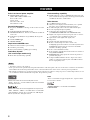 4
4
-
 5
5
-
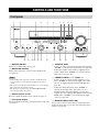 6
6
-
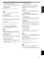 7
7
-
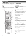 8
8
-
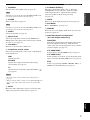 9
9
-
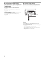 10
10
-
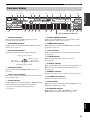 11
11
-
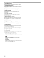 12
12
-
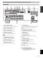 13
13
-
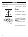 14
14
-
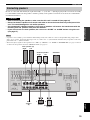 15
15
-
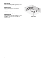 16
16
-
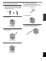 17
17
-
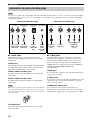 18
18
-
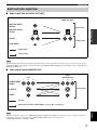 19
19
-
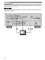 20
20
-
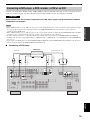 21
21
-
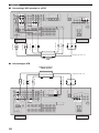 22
22
-
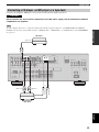 23
23
-
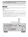 24
24
-
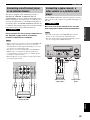 25
25
-
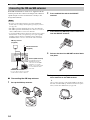 26
26
-
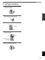 27
27
-
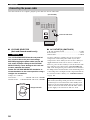 28
28
-
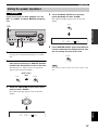 29
29
-
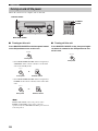 30
30
-
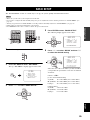 31
31
-
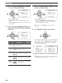 32
32
-
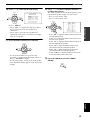 33
33
-
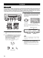 34
34
-
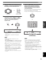 35
35
-
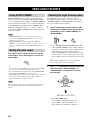 36
36
-
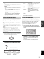 37
37
-
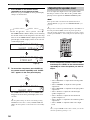 38
38
-
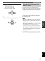 39
39
-
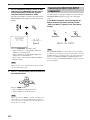 40
40
-
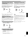 41
41
-
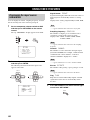 42
42
-
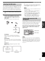 43
43
-
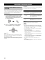 44
44
-
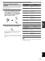 45
45
-
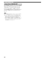 46
46
-
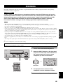 47
47
-
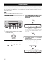 48
48
-
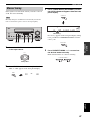 49
49
-
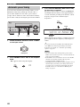 50
50
-
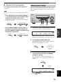 51
51
-
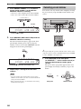 52
52
-
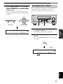 53
53
-
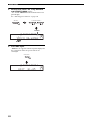 54
54
-
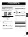 55
55
-
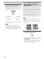 56
56
-
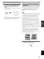 57
57
-
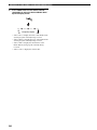 58
58
-
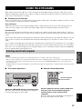 59
59
-
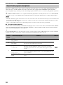 60
60
-
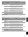 61
61
-
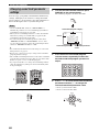 62
62
-
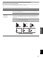 63
63
-
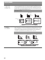 64
64
-
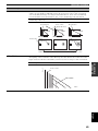 65
65
-
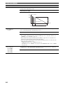 66
66
-
 67
67
-
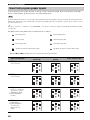 68
68
-
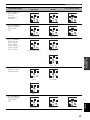 69
69
-
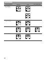 70
70
-
 71
71
-
 72
72
-
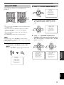 73
73
-
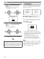 74
74
-
 75
75
-
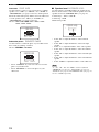 76
76
-
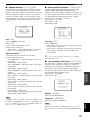 77
77
-
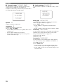 78
78
-
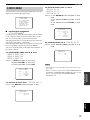 79
79
-
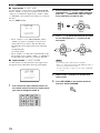 80
80
-
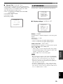 81
81
-
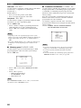 82
82
-
 83
83
-
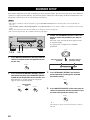 84
84
-
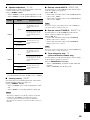 85
85
-
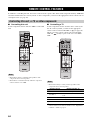 86
86
-
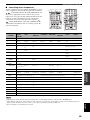 87
87
-
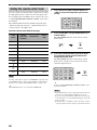 88
88
-
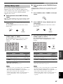 89
89
-
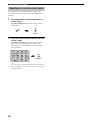 90
90
-
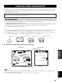 91
91
-
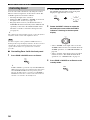 92
92
-
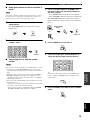 93
93
-
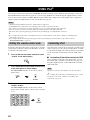 94
94
-
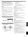 95
95
-
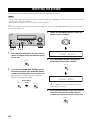 96
96
-
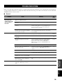 97
97
-
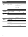 98
98
-
 99
99
-
 100
100
-
 101
101
-
 102
102
-
 103
103
-
 104
104
-
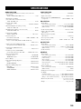 105
105
-
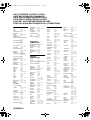 106
106
-
 107
107
-
 108
108
-
 109
109
-
 110
110
-
 111
111
-
 112
112
-
 113
113
-
 114
114
-
 115
115
-
 116
116
-
 117
117
-
 118
118


Yamaha RX-V559 de handleiding
- Categorie
- AV-ontvangers
- Type
- de handleiding
- Deze handleiding is ook geschikt voor
in andere talen
- English: Yamaha RX-V559 Owner's manual
- italiano: Yamaha RX-V559 Manuale del proprietario
- français: Yamaha RX-V559 Le manuel du propriétaire
- Deutsch: Yamaha RX-V559 Bedienungsanleitung
- dansk: Yamaha RX-V559 Brugervejledning
- svenska: Yamaha RX-V559 Bruksanvisning
- Türkçe: Yamaha RX-V559 El kitabı
- română: Yamaha RX-V559 Manualul proprietarului
Gerelateerde artikelen
-
Yamaha RXV1800BL de handleiding
-
-
-
Yamaha RX V661 - AV Receiver Handleiding
-
-
Yamaha RX-V863 de handleiding
-
-
-
-