
Synthesizer Parameter Manual
EN
EN
Introduction
This manual explains the parameters and technical terms that are used for synthesizers
incorporating the Yamaha AWM2 sound generators.
You should use this manual together with the documentation unique to the product. Read the
documentation first and use this parameter manual to learn more about parameters and terms
that relate to Yamaha synthesizers. We hope that this manual gives you a detailed and
comprehensive understanding of Yamaha synthesizers.
Information
The contents of this manual and the copyrights thereof are under exclusive ownership by
Yamaha Corporation.
The company names and product names in this manual are the trademarks or registered
trademarks of their respective companies.
Some functions and parameters in this manual may not be provided in your product.
The information in this manual is current as of October 2010.

2
Table Of Contents
1 Voice Parameters . . . . . . . . . . . . . . . . . . . . . . . . . . . . . . . . . . . . . . . 4
1-1 Basic Terms . . . . . . . . . . . . . . . . . . . . . . . . . . . . . . . . . . . . . . . . . . . . 4
1-1-1 Definitions . . . . . . . . . . . . . . . . . . . . . . . . . . . . . . . . . . . . . . . . 4
1-2 Synthesis Parameters . . . . . . . . . . . . . . . . . . . . . . . . . . . . . . . . . . . . . 5
1-2-1 Oscillator . . . . . . . . . . . . . . . . . . . . . . . . . . . . . . . . . . . . . . . . . 5
1-2-2 Pitch . . . . . . . . . . . . . . . . . . . . . . . . . . . . . . . . . . . . . . . . . . . . 8
1-2-3 Pitch EG (Pitch Envelope Generator) . . . . . . . . . . . . . . . . . . . 9
1-2-4 Filter . . . . . . . . . . . . . . . . . . . . . . . . . . . . . . . . . . . . . . . . . . . 13
1-2-5 Filter Type . . . . . . . . . . . . . . . . . . . . . . . . . . . . . . . . . . . . . . . 16
1-2-6 Filter EG (Envelope Generator) . . . . . . . . . . . . . . . . . . . . . . 22
1-2-7 Filter Scale . . . . . . . . . . . . . . . . . . . . . . . . . . . . . . . . . . . . . . 26
1-2-8 Amplitude . . . . . . . . . . . . . . . . . . . . . . . . . . . . . . . . . . . . . . . 27
1-2-9 Amplitude EG (Envelope Generator) . . . . . . . . . . . . . . . . . . 31
1-2-10 Amplitude Scale . . . . . . . . . . . . . . . . . . . . . . . . . . . . . . . . . . 33
1-2-11 LFO (Low-Frequency Oscillator) . . . . . . . . . . . . . . . . . . . . . . 34
1-3 Operational Parameters . . . . . . . . . . . . . . . . . . . . . . . . . . . . . . . . . . 41
1-3-1 General . . . . . . . . . . . . . . . . . . . . . . . . . . . . . . . . . . . . . . . . . 41
1-3-2 Play Mode . . . . . . . . . . . . . . . . . . . . . . . . . . . . . . . . . . . . . . . 41
1-3-3 Portamento . . . . . . . . . . . . . . . . . . . . . . . . . . . . . . . . . . . . . . 42
1-3-4 Micro Tuning List . . . . . . . . . . . . . . . . . . . . . . . . . . . . . . . . . 43
1-3-5 Arpeggio . . . . . . . . . . . . . . . . . . . . . . . . . . . . . . . . . . . . . . . . 44
1-3-6 Controller Set . . . . . . . . . . . . . . . . . . . . . . . . . . . . . . . . . . . . 47
1-3-7 Effect . . . . . . . . . . . . . . . . . . . . . . . . . . . . . . . . . . . . . . . . . . . 48
1-3-8 EQ (Equalizer) . . . . . . . . . . . . . . . . . . . . . . . . . . . . . . . . . . . 50
2 Effects . . . . . . . . . . . . . . . . . . . . . . . . . . . . . . . . . . . . . . . . . . . . . . . 52
2-1 Basic Terms . . . . . . . . . . . . . . . . . . . . . . . . . . . . . . . . . . . . . . . . . . . 52
2-1-1 Definisions . . . . . . . . . . . . . . . . . . . . . . . . . . . . . . . . . . . . . . 52
2-2 Effect Types . . . . . . . . . . . . . . . . . . . . . . . . . . . . . . . . . . . . . . . . . . . 52
2-2-1 Reverb . . . . . . . . . . . . . . . . . . . . . . . . . . . . . . . . . . . . . . . . . 52
2-2-2 Delay . . . . . . . . . . . . . . . . . . . . . . . . . . . . . . . . . . . . . . . . . . . 52
2-2-3 Chorus . . . . . . . . . . . . . . . . . . . . . . . . . . . . . . . . . . . . . . . . . 53
2-2-4 Flanger . . . . . . . . . . . . . . . . . . . . . . . . . . . . . . . . . . . . . . . . . 53
2-2-5 Phaser . . . . . . . . . . . . . . . . . . . . . . . . . . . . . . . . . . . . . . . . . 53
2-2-6 Tremolo & Rotary . . . . . . . . . . . . . . . . . . . . . . . . . . . . . . . . . 54
2-2-7 Distortion . . . . . . . . . . . . . . . . . . . . . . . . . . . . . . . . . . . . . . . . 54
2-2-8 Compressor . . . . . . . . . . . . . . . . . . . . . . . . . . . . . . . . . . . . . 54
2-2-9 Wah . . . . . . . . . . . . . . . . . . . . . . . . . . . . . . . . . . . . . . . . . . . 54
2-2-10 Lo-Fi . . . . . . . . . . . . . . . . . . . . . . . . . . . . . . . . . . . . . . . . . . . 55
2-2-11 Tech . . . . . . . . . . . . . . . . . . . . . . . . . . . . . . . . . . . . . . . . . . . 55
2-2-12 Vocoder . . . . . . . . . . . . . . . . . . . . . . . . . . . . . . . . . . . . . . . . 55
2-2-13 Misc . . . . . . . . . . . . . . . . . . . . . . . . . . . . . . . . . . . . . . . . . . . 55
2-3 Effect Parameters . . . . . . . . . . . . . . . . . . . . . . . . . . . . . . . . . . . . . . . 56
2-3-1 A . . . . . . . . . . . . . . . . . . . . . . . . . . . . . . . . . . . . . . . . . . . . . . 56
2-3-2 B . . . . . . . . . . . . . . . . . . . . . . . . . . . . . . . . . . . . . . . . . . . . . . 56
2-3-3 C . . . . . . . . . . . . . . . . . . . . . . . . . . . . . . . . . . . . . . . . . . . . . . 56
2-3-4 D . . . . . . . . . . . . . . . . . . . . . . . . . . . . . . . . . . . . . . . . . . . . . . 57

3
2-3-5 E . . . . . . . . . . . . . . . . . . . . . . . . . . . . . . . . . . . . . . . . . . . . . . 58
2-3-6 F . . . . . . . . . . . . . . . . . . . . . . . . . . . . . . . . . . . . . . . . . . . . . . 59
2-3-7 G . . . . . . . . . . . . . . . . . . . . . . . . . . . . . . . . . . . . . . . . . . . . . . 60
2-3-8 H . . . . . . . . . . . . . . . . . . . . . . . . . . . . . . . . . . . . . . . . . . . . . . 60
2-3-9 I . . . . . . . . . . . . . . . . . . . . . . . . . . . . . . . . . . . . . . . . . . . . . . . 60
2-3-10 L . . . . . . . . . . . . . . . . . . . . . . . . . . . . . . . . . . . . . . . . . . . . . . 61
2-3-11 M . . . . . . . . . . . . . . . . . . . . . . . . . . . . . . . . . . . . . . . . . . . . . . 62
2-3-12 N . . . . . . . . . . . . . . . . . . . . . . . . . . . . . . . . . . . . . . . . . . . . . . 63
2-3-13 O . . . . . . . . . . . . . . . . . . . . . . . . . . . . . . . . . . . . . . . . . . . . . . 63
2-3-14 P . . . . . . . . . . . . . . . . . . . . . . . . . . . . . . . . . . . . . . . . . . . . . . 63
2-3-15 R . . . . . . . . . . . . . . . . . . . . . . . . . . . . . . . . . . . . . . . . . . . . . . 64
2-3-16 S . . . . . . . . . . . . . . . . . . . . . . . . . . . . . . . . . . . . . . . . . . . . . . 64
2-3-17 T . . . . . . . . . . . . . . . . . . . . . . . . . . . . . . . . . . . . . . . . . . . . . . 65
2-3-18 V . . . . . . . . . . . . . . . . . . . . . . . . . . . . . . . . . . . . . . . . . . . . . . 65
2-3-19 W . . . . . . . . . . . . . . . . . . . . . . . . . . . . . . . . . . . . . . . . . . . . . 65
3 MIDI . . . . . . . . . . . . . . . . . . . . . . . . . . . . . . . . . . . . . . . . . . . . . . . . . 66
3-1 Overview . . . . . . . . . . . . . . . . . . . . . . . . . . . . . . . . . . . . . . . . . . . . . . 66
3-1-1 About MIDI . . . . . . . . . . . . . . . . . . . . . . . . . . . . . . . . . . . . . . 66
3-1-2 MIDI channels . . . . . . . . . . . . . . . . . . . . . . . . . . . . . . . . . . . . 66
3-1-3 MIDI ports . . . . . . . . . . . . . . . . . . . . . . . . . . . . . . . . . . . . . . . 67
3-1-4 MIDI messages . . . . . . . . . . . . . . . . . . . . . . . . . . . . . . . . . . . 67
3-2 Channel Messages . . . . . . . . . . . . . . . . . . . . . . . . . . . . . . . . . . . . . . 68
3-2-1 Note On/Off . . . . . . . . . . . . . . . . . . . . . . . . . . . . . . . . . . . . . . 68
3-2-2 Pitch Bend . . . . . . . . . . . . . . . . . . . . . . . . . . . . . . . . . . . . . . 68
3-2-3 Program Change . . . . . . . . . . . . . . . . . . . . . . . . . . . . . . . . . 68
3-2-4 Control Change . . . . . . . . . . . . . . . . . . . . . . . . . . . . . . . . . . . 68
3-2-5 Channel Mode message . . . . . . . . . . . . . . . . . . . . . . . . . . . . 71
3-2-6 Channel After Touch . . . . . . . . . . . . . . . . . . . . . . . . . . . . . . . 71
3-2-7 Polyphonic After Touch . . . . . . . . . . . . . . . . . . . . . . . . . . . . . 71
3-3 System Messages . . . . . . . . . . . . . . . . . . . . . . . . . . . . . . . . . . . . . . 72
3-3-1 System Exclusive Messages . . . . . . . . . . . . . . . . . . . . . . . . 72
3-3-2 System Common Message . . . . . . . . . . . . . . . . . . . . . . . . . . 72
3-3-3 System Realtime Messages . . . . . . . . . . . . . . . . . . . . . . . . . 72

Voice Parameters
4
1 Voice Parameters
1-1 Basic Terms
1-1-1 Definitions
Voice A Voice is a musical instrument sound that is built into an Electronic
Musical Instrument.
There are two Voice Types:
Normal Voices
Drum Voices
Normal Voice Normal Voices are mainly pitched musical instrument-type sounds.
You can play over the range of the keyboard at the standard pitch for each
key. Normal Voices consist of one or more Elements (see "Element").
Drum Voice Drum Voices are mainly percussion/drum sounds.
A Drum Voice consists of mainly percussion/drum sounds that are
assigned to individual notes on the keyboard, or a collection of assigned
percussion/drum waves. The Drum Voice is also known as a Drum Kit.
Figure 1: Individual drum sounds, different for each key.
Element An Element is the smallest unit that makes up a Normal Voice.
An Element is created by applying Voice Parameters to sound material. A
single Normal Voice can be created by combining several Elements.
Drum Key A Drum Key is the smallest unit that makes up a Drum Voice.
A Drum Key is assigned to individual notes on the Keyboard. The
percussion/Drum wave is assigned to a Drum Key.
Voice Edit A function that lets you create your own Voices.
Use Voice Edit to adjust or apply Voice Parameters to a Voice.
For Normal Voices:
Use Common Edit to edit the settings that are common to all
Elements;
Use Element Edit to edit the settings for each Element separately.
For Drum Voices:
Use Common Edit to edit the settings that are common to all keys;
Use Key Edit to edit the settings for each key separately.
GM General MIDI (GM) is a worldwide standard for Voice organization and
MIDI functions of synthesizers and tone generators.
This standard ensures that any song sounds virtually the same on any GM
device of any manufacturer. The GM Voice Bank on this synthesizer is
designed to appropriately play back GM song data. However, the sound
may not be exactly the same as played by the original tone generator.
C0 C1 C6

Voice Parameters
5
1-2 Synthesis Parameters
1-2-1 Oscillator
An Oscillator outputs the waveform that determines the basic pitch of an Element and is one
unit of the tone generator block of the Electronic Musical Instrument.
You can:
Assign the waveform (or basic sound material) to each Element of a Normal Voice or each
key of a Drum Voice;
Set the note range for the Element (Normal Voice);
Set the Velocity response (Normal Voice);
Set the XA (eXpanded Articulation) parameters.
Element Switch Switches a selected Element On or Off.
Elements for which the Element Switch is switched off will not sound.
XA Control Determines the functioning of the Expanded Articulation (XA) feature of an
Element.
The XA feature is sophisticated tone generator system that allows you to
more effectively recreate realistic sound and natural performance
techniques. It also provides other unique modes for random and alternate
sound changes as you play.
For each Element, you can set to:
Normal: The Element sounds normally each time you play the note.
Legato: When the Mono/Poly parameter is set to Mono, this Element
will be played in place of the one which is set to "Normal" of the XA
Control parameter when you play the keyboard in legato fashion
(playing the next note of a single-note line or melody before releasing
the previous note).
Key off sound: The Element will sound each time you release the
note.
Wave cycle (for multiple Elements): Each Element sounds
alternately according to its numerical order. In other words, playing
the first note will sound Element 1, the second note Element 2, and
so on.
Wave random (for multiple Elements): Each Element will sound
randomly each time you play the note.
AF 1 on: When the ASSIGNABLE FUNCTION [1] button is turned
On, the Element will sound.
AF 2 on: When the ASSIGNABLE FUNCTION [2] button is turned
On, the Element will sound.
All AF off: When both the ASSIGNABLE FUNCTION [1] and [2]
buttons are turned Off, the Element will sound.
To create the desired sound, assign the same Element Group to all
Elements that have the same XA features. See "Element Group".
Element Group Determines the group for XA Control.
The Elements of a group can be called up in sequential order or in random
order. All Elements that have the same type of XA features must have the
same group number.
This setting does not apply when the XA Control parameters of all
Elements are set to Normal.

Voice Parameters
6
Waveform Bank Specifies the Waveform Bank of an Element or Drum Key (Drum Voice).
Preset
User: This lets you create User Waveforms based on samples that
are recorded in the Sampling mode.
Waveform Category and
Number
Specifies the waveform of an Element (Normal Voice) or Drum Key (Drum
Voice).
The waveform is specified as a combination of a Waveform Category and
a Waveform Number.
Assign Mode (for Drum
Voices)
Enables or disables double playback of the same note.
Single: Double or repeated playback of the same note is not possible.
The first note will be stopped, then the next note will be sounded.
Multi: All notes are sounded simultaneously. This allows playback of
the same note when it is played multiple times in succession
(especially for tambourine and cymbal sounds that you would want to
ring out to their full decay).
In general, you can use the setting Multi. Keep in mind that the Multi
setting consumes overall polyphony and that sounds may be cut off.
Receive Note Off (for
Drum Voices)
Determines whether a Drum Key responds to the MIDI Note Off message
or not.
On: Stops the sound when you release the key (Drum Key). For
sustained, non-fading drum sounds.
Off: Continues the (fading) sound when you release the key (Drum
Key).
Alternate Group (for
Drum Voices)
Prevents playback of unnatural combinations of Drum Keys.
You should assign Drum Keys that cannot be played simultaneously on a
real Drum Kit (like open and closed hi-hats) to the same Alternate Group.
Select Off for Drum Keys that can be played simultaneously.
Key On Delay Defines the time delay between when a key is pressed and the
corresponding sound is actually played.
The higher the value, the longer the delay time.
Delay Tempo Sync Determines if the Key On Delay is synchronized to the tempo of the
Arpeggio or sequencer (Song or Pattern).
Delay Tempo Determines the timing of the Key On Delay when the Delay Tempo Sync
is set to On.
Velocity Cross Fade Determines how gradually the volume of an Element decreases in
proportion to the distance of Velocity changes outside the Velocity Limit
setting.
The higher the value, the more gradual the volume decreases.
0: No sound outside the Velocity Limit (see "Velocity Limit") is
produced.
Use this parameter to create natural-sounding Velocity cross fades, in
which different Elements change gradually depending on the strength at
which you play the keyboard.

Voice Parameters
7
Velocity Limit Determines the minimum and maximum Velocity values in which an
Element responds.
Each Element will only sound for notes played between its specified
Velocity Limits.
For example, this lets you have one Element sound when you play softly
and have a different one sound when you play strongly.
If you first specify the maximum value and then the minimum value, for
example "93 to 34," then the Velocity range covers both "1 to 34" and
"93to127."
Note Limit Determines the lowest and highest notes of the keyboard range for an
Element.
The selected Element will sound only when you play notes within this
range.
If you first specify the highest note and then the lowest note, for example
"C5 to C4", then the note range covers both "C-2 to C4" and "C5 to G8."

Voice Parameters
8
1-2-2 Pitch
The processing unit that controls the pitch of the wave output from the Oscillator on the tone
generator block of the Electronic Musical Instrument.
This unit controls the pitch of the sound (wave) output from the Oscillator. In the case of a
Normal Voice, you can detune separate Elements, apply Pitch Scaling and so on. Also, by
setting the Pitch Envelope Generator (Pitch EG), you can control how the pitch changes over
time.
Coarse Tuning Determines the pitch of each Element (Normal Voice) or each Drum Key
(Drum Voice) in semitones.
Fine Tuning Determines the pitch of each Element or each Drum Key in cents.
The term "cent" refers to one hundredth of a semitone (i.e., 100 cents = 1
semitone).
Pitch Velocity Sensitivity Determines how the pitch of the Element or Drum Key responds to
Velocity.
Positive values: The pitch rises more, the harder you play the
keyboard.
Negative values: The pitch falls more, the harder you play the
keyboard.
0: No change in pitch.
Fine Scaling Sensitivity Determines the degree to which the notes (specifically, their position or
Octave Range) affect the pitch in Fine Tuning of the selected Element,
assuming C3 as the basic pitch.
Positive values: The pitch of lower notes drops and that of higher
notes rises.
Negative values: The pitch of lower notes rises and that of higher
notes drops.
Random This lets you randomly vary the pitch of the Element for each note you play.
The higher the value, the greater the pitch variation.
0: No pitch change.
Pitch Key Follow
Sensitivity
Determines the sensitivity of the Key Follow effect (the pitch interval of
adjacent notes), assuming the pitch of the Center Key as standard.
+100% (the normal setting): Adjacent notes are pitched one semitone
apart.
0%: All notes are the same pitch specified as the Center Key.
Negative values: The settings are reversed.
This parameter is useful for creating alternate tunings, or for use with
sounds that do not need to be spaced in semitones, such as pitched drum
sounds in a Normal Voice.

Voice Parameters
9
1-2-3 Pitch EG (Pitch Envelope Generator)
This lets you control the transition in pitch from the moment the sound starts to the moment the
sound stops. You can create the Pitch EG by setting parameters as illustrated below. When
you press a key on the keyboard, the pitch of the Voice will change according to these Pitch
EG settings.
This is useful for creating automatic changes in pitch, which is effective for Synth Brass
sounds.
Figure 3: Pitch Envelope Generator
A: Key On: Pressing the key
B: Key Off: Releasing the key
Pitch Key Follow
Sensitivity Center Key
Determines the central note or pitch for Pitch Key Follow.
The note number set here is the same pitch as normal regardless of the
Pitch Key Follow setting.
Figure 2: Pitch Key Follow and Center Key
A: Lower range
B: Center Key
C: Higher range
D: Amount of pitch change
E: When Pitch Key Follow = 100
F: Large
G: Small
+
–
D
E
F
G
B
C
A
D
E
F
GH I
0
B
C
A
K
L
M
N
J

Voice Parameters
10
C: Time
D: Pitch
E: Hold Time
F: Attack Time
G: Decay 1 Time
H: Decay 2 Time
I: Release Time
J: Hold Level
K: Attack Level
L: Decay 1 Level
M: Decay 2 Level = Sustain Level
N: Release Level
Hold Time Determines the time between the moment you press a key on the
keyboard and the moment the envelope starts to rise.
Attack Time Determines the speed of attack from the initial pitch (Hold Level) to the
normal pitch of the Voice after the hold time has elapsed.
Decay 1 Time Determines how fast the envelope falls from the normal pitch (Attack
Level) of the Voice to the pitch specified as the Decay 1 Level.
Decay 2 Time Determines how fast the envelope falls from the pitch specified as the
Decay 1 Level to the pitch specified as the Decay 2 Level.
Release Time Determines how fast the envelope falls from the pitch specified as the
Decay 2 Level to the pitch specified as the Release Level when the note is
released.
Hold Level Determines the initial pitch at the moment the key is pressed.
Attack Level Determines the normal pitch of the pressed key.
Decay 1 Level Determines the level which the pitch of sound reaches from the Attack
Level after the Decay 1 time elapses.
Decay 2 Level Determines the sustain-level pitch which will be maintained while a note is
held.
Release Level Determines the final pitch reached after the note is released.
EG Depth Determines the range over which the pitch envelope changes.
0: The pitch does not change.
The farther from 0 the value is, the larger the pitch range.
Negative values: The pitch change is reversed.

Voice Parameters
11
EG Depth Velocity
Sensitivity
Determines how the pitch range of the Element responds to Velocity.
Positive values: High Velocities cause the pitch range to expand and
low Velocities cause it to contract, as shown in Figure 4.
Negative values: High Velocities cause the pitch range to contract
and low Velocities cause it to expand.
0: The pitch envelope does not change, regardless of the Velocity.
Figure 4: High Velocity, large range
Figure 5: Low Velocity, small range
EG Depth Velocity
Curve
Determines how the pitch range will be generated according to the Velocity
(strength) with which you play notes on the keyboard.
Figure 6: Pitch EG Depth Velocity Curve
A: Low
B: High
C: Low
D: High
X: Velocity
Y: Pitch Change
D
B
C
Y
A
X

Voice Parameters
12
EG Time Velocity
Sensitivity
Determines how the Pitch EG transition time (speed) responds to Velocity,
or to the strength with which the key is pressed.
Positive values: High Velocities result in a fast Pitch EG transition
speed while low Velocities result in a slow speed, as shown in Figure
7.
Negative values: High Velocities result in a slow Pitch EG transition
speed while low Velocities result in a fast speed.
0: The Pitch EG transition speed does not change, regardless of the
Velocity.
Figure 7: Playing hard (high Velocity): fast speed
Figure 8: Playing softly (low Velocity): slow speed
EG Time Velocity
Sensitivity Segment
Determines the part of the Pitch EG that is affected by the EG Time
Velocity Sensitivity.
EG Time Key Follow
Sensitivity
Determines the degree to which the notes (specifically, their position or
Octave Range) affect the pitch EG times of the selected Element.
Positive values: High notes result in a high pitch EG transition speed
while low notes result in a slow speed.
Negative values: High notes result in a slow pitch EG transition speed
while low notes result in a high speed.
0: The pitch EG transition speed does not change, regardless of the
played note.

Voice Parameters
13
1-2-4 Filter
A filter is a circuit or processor that modifies tone by blocking or passing a specific frequency
range of the sound.
Filters work by allowing portions of the signal lower or higher than a given frequency to pass,
and cutting the remainder of the signal. This given frequency is referred to as the Cutoff
Frequency. You can produce a relatively brighter or darker sound depending on how you set
the Cutoff Frequency.
By adjusting the Resonance (which boosts the level of the signal in the area of the Cutoff
Frequency), you can produce a distinctive "peaky" tone, making the sound brighter and harder.
On the tone generator block of the Electronic Musical Instrument, the sound signal output from
the Pitch unit is processed by the Filter unit.
EG Time Key Follow
Sensitivity Center
Key
Determines the central note or pitch for the EG Time Key Follow.
When the Center Key note is played, the Pitch EG behaves according to
its actual settings.
Figure 9: Pitch EG Time Key Follow and Center Key
A: Center Key
B: Slower Speed
C: Faster Speed
D: Lower range
E: Higher range
F: Positive value
G: Negative value
+63
+30
-40
B
A
DE
C
F
G
Cutoff Frequency Determines the Cutoff Frequency for the Filter, or the central frequency
around which the Filter is applied.
The tonal characteristics of the Voice and function of the Cutoff Frequency
differ depending on which Filter Type is selected (see Chapter 1-2-5 Filter
Type).

Voice Parameters
14
Cutoff Velocity
Sensitivity
Determines how the Cutoff Frequency responds to Velocity, or the strength
with which you play notes.
Positive values: The Cutoff Frequency rises the stronger you play the
keyboard.
Negative values: The Cutoff Frequency rises the softer you play the
keyboard.
0: The Cutoff Frequency does not change, regardless of the Velocity.
Resonance Resonance is used to set the amount of Resonance (harmonic emphasis)
applied to the signal at the Cutoff Frequency.
This parameter can boost the level of the signal in the area of the Cutoff
Frequency. By emphasizing the overtones in this area, this can produce a
distinctive "peaky" tone, making the sound brighter and harder.
This can be used in combination with the Cutoff Frequency parameter to
add further character to the sound.
This parameter is available when an LPF, HPF, BPF (excluding the
BPFw), or BEF is selected as a Filter Type.
Width The Width parameter is used to adjust the width of the band of signal
frequencies passed by the filter with the BPFw.
This parameter is available when a BPFw is selected as a Filter Type.
Resonance Velocity
Sensitivity
Determines the degree to which Resonance responds to Velocity, or the
strength with which you play notes.
Positive values: The higher the Velocity, the greater the Resonance.
Negative values: The lower the Velocity, the greater the Resonance.
0: No change of the Resonance value.
Gain Determines the Gain of the signal sent to the filter.
The lower the value, the lower the Gain. The tonal characteristics
generated by the filter differ depending on the value set here.
Cutoff Key Follow
Sensitivity
Determines the degree to which the notes (specifically, their position or
Octave Range) affect the Cutoff Frequency of the selected Element,
assuming C3 as the basic pitch.
Positive values: The Cutoff Frequency drops for lower notes and rises
for higher notes.
Negative values: The Cutoff Frequency rises for lower notes and
drops for higher notes.

Voice Parameters
15
Cutoff Key Follow
Center Key
This indicates the central note for Cutoff Key Follow.
Figure 10: Cutoff Key Follow and Center Key
A: Lower range
B: Center Key = C3
C: Higher range
D: Amount of Cutoff Frequency change
E: When Cutoff Key Follow Sensitivity = 100
F: Large
G: Small
Distance Determines the Distance between the two Cutoff Frequencies of the Dual
Filter Types (which consist of two identical filters in parallel), and of the
LPF12+BPF6 type.
When any other Filter Type is selected, this parameter is not available.
HPF Cutoff
Frequency
Determines the central frequency for the Key Follow parameter of the HPF.
This parameter is only available for Filter Types LPF12+HPF12 and
LPF6+HPF6.
HPF Cutoff Key
Follow Sensitivity
Determines the degree to which the notes (specifically, their position or
Octave Range) affect the Cutoff Frequency of the HPF.
Positive values: The Cutoff Frequency drops for lower notes and rises
for higher notes.
Negative values: The Cutoff Frequency rises for lower notes and
drops for higher notes.
This parameter is only available for Filter Types LPF12+HPF12 and
LPF6+HPF6.
HPF Cutoff Key
Follow Sensitivity
Center Key
This indicates the central note for HPF Key Follow Sensitivity.
+
–
D
E
F
G
B
C
A

Voice Parameters
16
1-2-5 Filter Type
LPF (Low-Pass
Filter)
This is a Filter Type that only passes signals below the Cutoff Frequency.
The sound can be brightened by raising the Cutoff Frequency of the filter.
On the other hand, the sound can be darkened by lowering the Cutoff
Frequency of the filter. You can produce a distinctive "peaky" sound by
raising the Resonance to boost the signal level in the area of the Cutoff
Frequency.
This Filter Type is most popular and useful for producing classic
synthesizer sounds.
Figure 11: Low-Pass Filter
A: Cutoff Frequency
B: Resonance
C: Frequencies that are “passed” by the filter
X: Frequency (Pitch)
Y: Level
CA
B
X
A
X
Y
Y

Voice Parameters
17
LPF24D A dynamic -24 dB/oct Low-Pass Filter with a characteristic digital sound.
Compared to the LPF24A type, this filter can produce a more pronounced
Resonance effect.
Figure 12: LPF24D
A: Resonance
B: Frequencies that are “passed” by the filter
LPF24A A digital dynamic Low-Pass Filter with characteristics similar to a 4-pole
analog synthesizer filter.
LPF18 3-pole -18 dB/oct Low-Pass Filter.
LPF18s 3-pole -18 dB/oct Low-Pass Filter.
This filter has a smoother cutoff slope than the LPF18 type.
HPF (High-Pass
Filter)
A Filter Type that only passes signals above the Cutoff Frequency.
You can use the Resonance parameter to add further character to the
sound.
Figure 13: High-Pass Filter
A: Cutoff Frequency
B: Resonance
C: Frequencies that are “passed” by the filter
X: Frequency (Pitch)
Y: Level
A
B
C
A
B
X
Y

Voice Parameters
18
HPF24D A dynamic -24 dB/oct High-Pass Filter with a characteristic digital sound.
This filter can produce a pronounced Resonance effect.
Figure 14: HPF24D
A: Resonance
HPF12 -12 dB/oct dynamic High-Pass Filter.
BPF (Band-Pass
Filter)
A Filter Type that only passes a band of signals around the Cutoff
Frequency.
Figure 15: Band-Pass Filter
A: Center Frequency
B: Cutoff Range
C: Frequencies that are “passed” by the filter
X: Frequency
Y: Level
A
Y
B
A
X
C

Voice Parameters
19
BPF12D The combination of a -12 dB/oct HPF and LPF with a characteristic digital
sound.
Figure 16: BPF12D
A: Resonance
B: Cutoff Range
C: Frequencies that are “passed” by the filter
D: -12 dB/oct
X: Frequency
Y: Level
BPF6 The combination of a -6 dB/oct HPF and LPF.
Figure 17: BPF6
A: Resonance
B: Cutoff Range
C: Frequencies that are “passed” by the filter
D: -6 dB/oct
X: Frequency
Y: Level
Y
BB
A
C
X
D
Y
BB
A
C
X
D

Voice Parameters
20
BPFw A -12 dB/oct BPF that combines HPF and LPF filters to allow wider
bandwidth settings.
Figure 18: BPFw
A: Width can be increased
B: Cutoff Range
C: Frequencies that are “passed” by the filter
X: Frequency
Y: Level
BEF (Band-Eliminate
Filter)
The Band-Eliminate Filter has an opposite effect on the sound compared
to the Band-Pass Filter.
When this Filter Type is selected, you can set the Cutoff Frequency around
which the audio signal is muted or eliminated.
Figure 19: Band-Eliminate Filter
A: Center Frequency
B: Cutoff Range
C: Frequencies that are “passed” by the filter
X: Frequency
Y: Level
BEF12 -12 dB/oct Band-Eliminate Filter.
BEF6 -6 dB/oct Band-Eliminate Filter.
Y
B
B
C
X
A
Y
B
C
X
A

Voice Parameters
21
Dual LPF Two -12 dB/oct Low-Pass Filters connected in parallel.
You can edit the distance between the two Cutoff Frequencies.
Figure 20: Dual Low-Pass Filters
A: Distance
B: Lower Cutoff Frequency is set directly on the Display
X: Frequency
Y: Level
Dual HPF Two -12 dB/oct High-Pass Filters connected in parallel.
Dual BPF Two -6 dB/oct Band-Pass Filters connected in parallel.
Dual BEF Two -6 dB/oct Band-Eliminate Filters connected in serial.
Figure 21: Dual Band-Eliminate Filters
A: Distance
B: Lower Cutoff Frequency is set directly on the Display
X: Frequency
Y: Level
LPF12+HPF12 A combination of a -12 dB/oct Low-Pass Filter and a -12 dB/oct High-Pass
Filter connected in serial.
When this Filter Type is selected, HPF Cutoff and HPF Key Follow
Sensitivity can be set.
LPF6+HPF6 A combination of a -6 dB/oct Low-Pass Filter and a -6 dB/oct High-Pass
Filter connected in serial.
When this Filter Type is selected, HPF Cutoff and HPF Key Follow
Sensitivity can be set.
Y
B
X
A
Y
B
X
A

Voice Parameters
22
1-2-6 Filter EG (Envelope Generator)
This lets you control the transition in tone from the moment the sound starts to the moment the
sound stops. You can create a custom Filter EG by setting parameters as illustrated below.
When you press a key on the keyboard, the Cutoff Frequency will change according to these
EG settings.
Figure 23: Filter Envelope Generator
A: Key On: Pressing the key
B: Key Off: Releasing the key
C: Time
D: Cutoff Frequency
E: Hold Time
F: Attack Time
G: Decay 1 Time
H: Decay 2 Time
I: Release Time
J: Hold Level
K: Attack Level
L: Decay 1 Level
LPF12+BPF6 A combination of a -12 dB/oct Low-Pass Filter and a -6 dB/oct Band-Pass
Filter connected in parallel.
You can edit the distance between the two Cutoff Frequencies.
Figure 22: LPF12+BPF6
A: Distance
B: Lower Cutoff Frequency is set directly on the Display
X: Frequency
Y: Level
Y
B
X
A
D
E
F
GH I
0
B
C
A
K
L
M
N
J

Voice Parameters
23
M: Decay 2 Level = Sustain Level
N: Release Level
Hold Time Determines the time between the moment you press a key on the
keyboard and the moment the envelope starts to rise.
Attack Time Determines the speed of attack from the initial Cutoff Frequency (at Hold
Level) to the maximum level of the Voice after the Hold Time has elapsed.
Decay 1 Time Determines how fast the envelope falls from the maximum Cutoff
Frequency (at Attack Level) to the Cutoff Frequency specified as the
Decay 1 Level.
Decay 2 Time Determines how fast the envelope falls from the Cutoff Frequency
specified as the Decay 1 Level to the Cutoff Frequency specified as the
Decay 2 Level.
Release Time Determines how fast the envelope falls from the Cutoff Frequency
specified as the Decay 2 Level to the Cutoff Frequency specified as the
Release Level when the note is released.
Hold Level Determines the initial Cutoff Frequency at the moment the key is pressed.
Attack Level Determines the maximum Cutoff Frequency which the envelope reaches
after a key is pressed.
Decay 1 Level Determines the level which the Cutoff Frequency reaches from the Attack
Level after the Decay 1 time elapses.
Decay 2 Level Determines the Cutoff Frequency which will be maintained while a note is
held.
Release Level Determines the final Cutoff Frequency reached after the note is released.
EG Depth Determines the range over which the Cutoff Frequency envelope changes.
0: The Cutoff Frequency does not change.
The farther from 0 the value is, the larger the range of the Cutoff
Frequency.
Negative values: The change of the Cutoff Frequency is reversed.

Voice Parameters
24
EG Depth Velocity
Sensitivity
Determines how the range of the Cutoff Frequency responds to Velocity.
Positive values: high Velocities cause the Filter EG range to expand
and low Velocities cause it to contract, as shown in Figure 24 and
Figure 25.
Negative values: High Velocities cause the Filter EG range to contract
and low Velocities cause it to expand.
0: The Filter EG range does not change, regardless of the Velocity.
Figure 24: Positive Sensitivity: High Velocity, large range
Figure 25: Positive Sensitivity: Low Velocity, small range
EG Depth Velocity
Sensitivity Curve
Curve that determines how the Filter EG transition range changes
according to the Velocity (strength) with which you play notes on the
keyboard.
Figure 26 shows an example in which the middle range of Velocities
(around 64) causes the Filter EG transition range not to change and the
higher/lower range of Velocities causes it to change more rapidly.
Figure 26: Filter EG Depth Velocity Curve
A: Low
B: High
C: Low
D: High
X: Velocity
Y: Filter EG Transition Range (Cutoff Frequency range)
D
B
C
Y
A
X

Voice Parameters
25
EG Time Velocity
Sensitivity
Determines how the Filter EG transition time (speed) responds to Velocity,
or the strength with which the key is pressed.
Positive values: High Velocities result in a fast Filter EG transition
speed while low Velocities result in a slow speed, as shown in Figure
27 and Figure 28.
Negative values: High Velocities result in a slow Filter EG transition
speed while low Velocities result in a fast speed.
0: The pitch transition speed does not change, regardless of the
Velocity.
Figure 27: Positive Sensitivity: Playing hard, fast speed
Figure 28: Positive Sensitivity: Playing softly, slow speed
EG Time Velocity
Sensitivity Segment
Determines the part of the Filter EG that is affected by the EG Time
Velocity Sensitivity.
EG Time Key Follow
Sensitivity
Determines the degree to which the notes (specifically, their position or
Octave Range) affect the Filter EG times of the selected Element.
Positive values: High notes result in a fast Filter EG transition speed
while low notes result in a slow speed.
Negative values: High Velocities result in a slow Filter EG transition
speed while low notes result in a fast speed.
0: The Filter EG transition speed does not change, regardless of
which note is played.

Voice Parameters
26
1-2-7 Filter Scale
This controls the Filter Cutoff Frequency according to the positions of the notes on the
keyboard. You can divide the entire keyboard by setting four Break Points, and assign different
Cutoff Frequency Offset values to these Break Points. The Cutoff Frequency changes in a
linear fashion between successive Break Points.
Table 1 and Figure 30 show an example in which the basic Cutoff Frequency value is 64 and
the various Offset values of the Break Points change that basic value accordingly.
/i
Table 1: Offsets at Break Points
EG Time Key Follow
Sensitivity Center
Key
Determines the central note or pitch for EG Time Key Follow.
When the Center Key note is played, the Filter EG behaves according to
its actual settings.
Figure 29: Filter EG Time Key Follow and Center Key
A: Center Key
B: Slower Speed
C: Faster Speed
D: Lower range
E: Higher range
F: Positive value
G: Negative value
+63
+30
-40
B
A
DE
C
F
G
Break Point 1 2 3 4
Note C#1 D#2 C3 A4
Offset -4 +10 +17 +4

Voice Parameters
27
Figure 30: Filter Scale
A: Break Point 1
B: Break Point 2
C: Break Point 3
D: Break Point 4
X: Note
Y: Cutoff Frequency
1-2-8 Amplitude
The Amplitude unit controls the output level (amplitude or volume) of the sound output from the
Filter. The signals are sent at this output level to the Effect block (see Chapter 2 Effects).
By setting the Amplitude Envelope Generator (AEG), you can control how the Amplitude
changes over time.
60
ABCD
X
74
81
68
Y
Break Point 1 - 4 Determines the four Filter Scale Break Points by specifying their respective
note numbers.
Offset 1 - 4 Determines the offset value of the Cutoff Frequency of each Filter Scale
Break Point.
Level Determines the output level of the Element or Drum Key.
Level Velocity
Sensitivity
Determines how the output level of the Element or Drum Key responds to
Velocity.
Positive values: The output level rises the harder you play the
keyboard.
Negative values: The output level rises the softer you play the
keyboard.
0: The output level does not change.

Voice Parameters
28
Level Velocity
Sensitivity Offset
Raises or lowers the level specified by the Level Velocity Sensitivity.
If the result is higher than 127, the velocity is set to 127.
Figure 31: Level Velocity Sensitivity Offset = 0
Figure 32: Level Velocity Sensitivity Offset = 64
Figure 33: Level Velocity Sensitivity Offset = 96
A: Level Velocity Sensitivity = 0
B: Level Velocity Sensitivity = 32
C: Level Velocity Sensitivity = 64
X: Velocity with which you play a note
Y: Actual resulting velocity (affecting the tone generator)
064
127
127
A
B
X
Y
C
064
127
127
A
B
X
Y
C
064
127
127
A
B
X
Y
C

Voice Parameters
29
Level Velocity
Sensitivity Curve
Determines how the actual Velocity will be generated according to the
Velocity (strength) with which you play notes on the keyboard.
Figure 34: Level Velocity Sensitivity Curve
A: Soft
B: Strong
C: Low
D: High
X: Velocity (Playing strength)
Y: Volume
Level Key Follow
Sensitivity
Determines the degree to which the notes (specifically, their position or
Octave Range) affect the Amplitude level of the selected Element,
assuming C3 as the basic pitch.
Positive values: Lower the output level for lower notes and raise it for
higher notes.
Negative values: Raise the output level for lower notes and lower it for
higher notes.
D
B
C
Y
A
X

Voice Parameters
30
Level Key Follow
Sensitivity Center
Key
This indicates that the central note for Level Key Follow Sensitivity is C3.
Figure 35:
Level Key Follow and Center Key
A: Lower range
B: Center Key = C3
C: Higher range
D: Amount of Amplitude EG level change
E: When Level Key Follow = 100
F: Large
G: Small
Pan Adjusts the stereo pan position of the sound.
This Voice Pan parameter may have little or no audible effect if Pan for a
specific element is set to the left position and Pan for another element is
set to the right position.
Alternate Pan Determines the amount by which the sound is panned alternately left and
right for each key you press.
The Pan setting is used as the Center Pan position.
Higher values increase the width of the Pan range.
Random Pan Determines the amount by which the sound of the selected Element is
panned randomly left and right for each key you press.
The Pan setting is used as the Center Pan position.
Scaling Pan Determines the degree to which the notes (specifically, their position or
Octave Range) affect the Pan position, left and right, of the selected
Element.
At note C3, the main Pan setting is used for the basic Pan position.
Positive values: Move the pan position to the left for lower notes and
to the right for higher notes.
Negative values: Move the pan position to the right for lower notes
and to the left for higher notes.
+
–
D
E
F
G
B
C
A

Voice Parameters
31
1-2-9 Amplitude EG (Envelope Generator)
This lets you control the transition in Amplitude from the moment the sound starts until the
moment the sound stops. You can create a custom Amplitude EG by setting parameters as
illustrated below. When you press a key on the keyboard, the volume will change according to
these EG settings.
Figure 36: Amplitude Envelope Generator
A: Key On: Pressing the key
B: Key Off: Releasing the key
C: Time
D: Level (volume)
E: Attack Time
F: Decay 1 Time
G: Decay 2 Time
H: Release Time
I: Initial Level
J: Attack Level
K: Decay 1 Level
L: Decay 2 Level = Sustain Level
M: Release Level
EF G H
D
AB
I
0
C
M
L
K
J
Attack Time Determines how quickly the sound reaches its maximum level after the key
is pressed.
Decay 1 Time Determines how fast the envelope falls from the Attack Level to the
Decay 1 Level.
Decay 2 Time Determines how fast the envelope falls from the Decay 1 Level to the
Decay 2 Level (sustain level).
Release Time Determines how quickly the sound decays to silence after the key is
released.
Initial Level Determines the initial level at the moment the key is pressed.
Attack Level Determines the maximum level which the envelope reaches after a key is
pressed.
Decay 1 Level Determines the level which the envelope reaches from the Attack Level
after the Decay 1 Time elapses.
Decay 2 Level Determines the level which will be maintained while a note is held.

Voice Parameters
32
Half Damper Switch Determines if the Half Damper is switched on.
When the Half Damper Switch is set to On, holding down the FC3 Foot
Controller produces a "half-pedal" effect just as on a real acoustic piano.
Half Damper Time Determines how quickly the sound decays to silence after the key is
released while holding down the Foot Controller FC3 with the Half Damper
Switch set to On.
After releasing the key, you can control the decay time of the sound via the
Foot Controller position, with the Half Damper Time of the AEG being the
maximum decay value and the Release Time of the AEG being the
minimum decay value.
When you release the pedal, the decay time after the key is released is
equivalent to the AEG Release Time. You can create a piano-like effect by
setting the Release Time to a small value and setting the Half Damper
Time to a large value.
EG Time Velocity
Sensitivity
Determines how the AEG transition time (speed) responds to Velocity, or
the strength with which the key is pressed.
Positive values: High Velocities result in a fast AEG transition speed
while low Velocities result in a slow speed, as shown in Figure 37 and
Figure 38.
Negative values: High Velocities result in a slow AEG transition speed
while low Velocities result in a fast speed.
0: The amplitude transition speed does not change, regardless of the
Velocity.
Figure 37: Positive Sensitivity: Playing hard, fast speed
Figure 38: Positive Sensitivity: Playing softly, slow speed
EG Time Velocity
Sensitivity Segment
Determines the part of the Amplitude EG that is affected by EG Time
Velocity Sensitivity.
EG Time Key Follow
Sensitivity
Determines the degree to which the notes (specifically, their position or
Octave Range) affect the Amplitude EG times of the selected Element.
Positive values: High notes result in a fast Amplitude EG transition
speed while low notes result in a slow speed.
Negative values: High notes result in a slow Amplitude EG transition
speed while low notes result in a fast speed.
0: The Amplitude EG transition speed does not change, regardless of
the played note.

Voice Parameters
33
1-2-10 Amplitude Scale
This controls the Amplitude output level according to the positions of the notes on the
keyboard. You can divide the entire keyboard by setting four Break Points, and assign different
Amplitude Offset values to these Break Points.
The Amplitude changes in a linear fashion between successive Break Points.
Table 2 and Figure 40 show an example in which the basic Amplitude (volume) value for the
selected Element is 80 and the various Offset values of the Break Points change that basic
value accordingly.
/i
Table 2: Offsets at Break Points
EG Time Key Follow
Sensitivity Center
Key
Determines the central note for EG Time Key Follow Sensitivity.
When the Center Key note is played, the AEG behaves according to its
actual settings.
Figure 39: Amplitude EG Time Key Follow and Center Key
A: Center Key
B: Slower Speed
C: Faster Speed
D: Lower range
E: Higher range
F: Positive value
G: Negative value
EG Time Key Follow
Sensitivity Release
Adjustment
Determines the sensitivity of EG Time Key Follow Sensitivity to EG
Release.
The lower the value, the lower the sensitivity.
+63: Sets the EG Time Key Follow Sensitivity to the value of Decay 1
or Decay 2.
-64: Produces no effect in the EG Time Key Follow Sensitivity.
+63
+30
-40
B
A
DE
C
F
G
Break Point 1 2 3 4
Note C1 C2 C3 C4
Offset -4 +10 +17 +4

Voice Parameters
34
Figure 40: Amplitude Scale
A: Break Point 1
B: Break Point 2
C: Break Point 3
D: Break Point 4
X: Note
Y: Amplitude
1-2-11 LFO (Low-Frequency Oscillator)
The Low-Frequency Oscillator (LFO) unit of the tone generator block generates a low-
frequency signal.
The signal from the LFO can be used to modulate the pitch, filter, and amplitude. Modulating
the pitch produces a vibrato effect, modulating the filter produces a wah effect, and modulating
the amplitude produces a tremolo effect.
You can set the Common LFO which set the basic LFO parameters common to all Elements
of the Voice. Also, you can set the Element LFO which set the LFO parameters for each
individual Element.
ABCD
76
90
97
84
X
Y
Break Point 1 - 4 Determines the four Amplitude Scale Break Points by specifying their
respective note numbers.
Offset 1 - 4 Determines the offset value of the level of each Amplitude Scale Break
Point.
LFO Wave Selects the Wave and determines how the LFO waveform modulates the
sound.
Play Mode Determines whether the LFO cycles repeatedly (loop) or only once (one
shot).
Speed Determines the speed of the LFO Wave.
The higher the value, the faster the speed.

Voice Parameters
35
Phase Determines the starting phase point for the LFO Wave when it is reset.
Figure 41: Phases of a wave
A: Phase
X: Time
Y: Level
Tempo Sync Determines whether or not the LFO speed is synchronized to the tempo of
the Arpeggio or sequencer (Song or Pattern).
Tempo Speed This parameter allows you to make detailed note value settings that
determine how the LFO pulses in sync with the Arpeggio or sequencer
.
This parameter is only available when the Tempo Sync parameter
has been set to
On.
Key On Reset Determines whether or not the LFO is reset each time a note is played.
Off: The LFO cycles freely with no key synchronization. Pressing a
key starts the LFO wave at whatever phase the LFO happens to be
at that moment.
Figure 42: Key On Reset Off
A: Key On
X: Time
A
X
Y
0
90
120
240
180 270
A
X

Voice Parameters
36
Each-on: The LFO resets with each note you play and starts a
waveform at the phase specified by the Phase parameter.
Figure 43: Key On Reset Each-on
A: Key On (first note)
B: Key On (second note)
X: Time
1st-on: The LFO resets with each note you play and starts a
waveform at the phase specified by the Phase parameter. If you play
a second note while the first is being held, the LFO continues cycling
according to the same phase as triggered by the first note--in other
words, the LFO only resets if the first note is released before the
second is played.
Figure 44: Key On Reset 1st-on
A: Key On (first note)
B: Key On (second note)
X: Time
Random Speed Determines the degree to which the LFO speed changes at random.
Higher values result in a larger degree of speed change.
0: Results in the original speed.
This parameter cannot be set when Tempo Sync is set to On.
Delay Determines the delay time between the moment you press a key on the
keyboard and the moment the LFO comes into effect.
A higher value results in a longer delay time.
AB
X
B
A
X

Voice Parameters
37
Fade-In Time Determines the amount of time for the LFO effect to fade in after the Delay
time has elapsed.
A higher value results in a slower fade-in.
0: The LFO effect will not fade in but reach the maximum level
immediately after the Delay time has elapsed.
Figure 45: Lower value: faster fade-in
Figure 46: Higher value: slower fade-in
A: Key On
B: Maximum
C: Delay
D: Fade-In
X: Time
D
B
C
A
X
D
B
C
A
X

Voice Parameters
38
Hold (Hold Time) Determines the time during which the LFO is held at its maximum level.
A higher value results in a longer Hold Time.
127: No fade-out.
Figure 47: Hold Time
A: Key On
B: Maximum
C: Hold
X: Time
B
C
A
X

Voice Parameters
39
Fade-Out Time Determines the amount of time for the LFO effect to fade out (after the Hold
Time has elapsed).
A higher value results in a slower fade-out.
Figure 48: Lower value: faster fade-out
Figure 49: Higher value: slower fade-out
A: Key On
B: Maximum
C: Hold
D: Fade-Out
X: Time
Pitch Modulation
Depth
Determines the amount (depth) by which the LFO Wave varies
(modulates) the pitch of the sound.
The higher the setting, the greater the depth of control.
Filter Modulation
Depth
Determines the amount (depth) by which the LFO Wave varies
(modulates) the Filter Cutoff Frequency.
The higher the setting, the greater the depth of control.
Amplitude
Modulation Depth
Determines the amount (depth) by which the LFO Wave varies
(modulates) the Amplitude of the sound.
The higher the setting, the greater the depth of control.
Control Destination Determines the parameters which are to be controlled (modulated) by the
LFO Wave.
The LFO Wave can control various parameters such as Amplitude
modulation depth, Pitch modulation depth, Filter modulation depth and
Resonance.
B
CD
A
X
B
C
D
A
X

Voice Parameters
40
Control Depth Determines the LFO Wave Depth.
LFO Element Switch Determines whether or not each Element is to be affected by the LFO.
Depth Offset Determines the offset values of the Control Depth parameter for the
respective Elements.
If the resultant Control Depth value is negative, it will be set to 0.
If the resultant Control Depth value is greater than 127, it will be set to 127.
LFO Phase Offset Determines the offset values of the Phase parameter for the respective
Elements.
Figure 50: Phases of a wave
A: Phase
X: Time
Y: Level
Template Selects a pre-programmed setting for creating an original LFO wave.
Slope Determines the slope or ramp characteristics of the LFO wave.
Off: Creates no slope.
Up: Creates an upward slope.
Down: Creates a downward slope.
Up&Down: Creates an upward then downward slope.
Cycle Determines the amount of steps for creating the LFO Wave.
Step Value Determines the level for each step.
A
X
Y
0
90
120
240
180 270

Voice Parameters
41
1-3 Operational Parameters
1-3-1 General
1-3-2 Play Mode
Voice Bank The Voice Bank is the memory that includes data of Normal Voices and
Drum Voices.
Category The keyword Category indicates the instrument characteristics or the type
of sound.
A Preset Voice is registered to a certain Category.
Assignable Function
1 Mode and
Assignable Function
2 Mode
Determines whether the buttons ASSIGNABLE FUNCTION [1] and
ASSIGNABLE FUNCTION [2] function as latch type or as momentary type.
Latch: Pressing the button alternates the lamp status between on
and off.
Momentary: Pressing/holding the button turns the lamp on and
releasing the button turns the lamp off.
Ribbon Controller
Mode
Determines how the Ribbon Controller responds when released.
Reset: Releasing your finger from the Ribbon Controller
automatically returns the value to the center.
Hold: Releasing your finger from the Ribbon Controller maintains the
value at the last point of contact.
MIDI Transmit
Channel
Indicates the MIDI channel over which the keyboard/controller sends MIDI
data (to an external sequencer, tone generator, or other device).
Volume Determines the output level of the Voice.
Set this parameter to adjust the balance between the current Voice and
other Voices.
Note Shift Determines the transpose setting for the amount (in semitones) by which
the pitch is raised or lowered.
Pitch Bend Range
Upper / Pitch Bend
Range Lower
Determines the maximum Pitch Bend Range in semitones.
Examples:
Setting the Upper parameter to +12 results in a maximum pitch rise of one
octave when the Pitch Bend wheel is moved upwards.
Setting the Lower parameter to -12 results in the pitch being lowered up to
a maximum of one octave (12 semitones) when the Pitch Bend wheel is
moved downwards.
Micro Tuning This function lets you change the keyboard scale from normal tuning
(equal temperament) to one of a variety of special scales.
See Section 1-3-4 Micro Tuning List.
You can determine the scale type for each Voice by simply selecting a
Tuning Number.
Micro Tuning Bank Selects the Micro Tuning Bank.
The Preset Bank and User Bank are available.
Micro Tuning
Number
Selects the Micro Tuning Number.
The Preset Bank provides several types including the most common:
Equal Temperament. See Section 1-3-4 Micro Tuning List.
Micro Tuning Root Sets the base note for each scale.
For some scales this setting may not be necessary.

Voice Parameters
42
1-3-3 Portamento
Portamento is used to create a smooth transition in pitch from one note played on the keyboard
to the next one.
Mono/Poly Selects monophonic or polyphonic.
Mono: The selected Voice is played back monophonically; only a
single note is played back simultaneously.
Poly: The selected Voice is played back polyphonically; multiple
notes or chords can be played back simultaneously.
For many instrument sounds (such as bass and synth lead), Mono allows
a more natural and smooth sounding legato performance than Poly.
Key Assign Mode Determines the playing method when the same notes are received
continuously in the same channel, and without a corresponding note off
message.
Single: If double playback of the same note is transmitted to the
internal tone generator, the first note will be stopped and then the next
note will be sounded.
Multi: When double playback of the same note is transmitted to the
internal tone generator, all the notes are sounded simultaneously.
Single is useful when two or more instances of the same note are received
nearly simultaneously, or without a corresponding note off message. To
allow playback of each instance of the same note, set this to Multi.
Portamento Switch Determines whether Portamento is applied to the current Voice or not.
Portamento Time Determines the pitch transition time or rate when Portamento is applied.
Higher values result in a longer pitch change time.
The effect of the parameter depends on the settings of Portamento Time
Mode.
Portamento Mode Determines how Portamento is applied to your keyboard performance.
Fingered: Portamento is only applied when you play legato (playing
the next note before releasing the previous one).
Fulltime: Portamento is applied to all notes.
Portamento Time
Mode
Determines how the pitch changes in time.
Rate1: Pitch changes at the specified rate.
Time1: Pitch changes in the specified time.
Rate2: Pitch changes at the specified rate within an octave.
Time2: Pitch changes in the specified time within an octave.
Portamento Legato
Slope
Adjusts the attack of the Voice for Mono legato playing.
When the parameter Mono/Poly is set to Mono, legato playing may
produce an unnatural attack depending on the waveform assigned to the
selected Voice. To solve such a problem, you can use this parameter to
adjust the attack of the Voice.
Normally, this should be set to a low value for waveforms with short attack
times, and to a high value for waveforms with long attack times.

Voice Parameters
43
1-3-4 Micro Tuning List
Equal Temperament The "compromise" tuning used for most of the last 200 years of Western
music, and found on most electronic keyboards.
Each half step is exactly 1/12 of an octave, and music can be played in any
key with equal ease. However, none of the intervals are perfectly in tune.
Pure Major This tuning is designed so that most of the intervals (especially the major
third and perfect fifth) in the major scale are pure.
This means that other intervals will be correspondingly out of tune.
You need to specify the key (C - B) you will be playing in as the Micro
Tuning Root parameter.
Pure Minor The same as Pure Major, but designed for minor scales.
You need to specify the key (C - B) you will be playing in as the Micro
Tuning Root parameter.
Werckmeist Andreas Werckmeister, a contemporary of Bach, designed this tuning so
that keyboard instruments could be played in any key.
Each key has a unique character.
You need to specify the key (C - B) you will be playing in as the Micro
Tuning Root parameter.
Kimberger Johann Philipp Kirnberger, an 18th century composer, created this
tempered scale to allow performances in any key.
You need to specify the key (C - B) you will be playing in as the Micro
Tuning Root parameter.
Vallot&Yng Francescatonio Vallotti and Thomas Young (both mid-1700s) devised this
adjustment to the Pythagorean tuning, in which the first six fifths are
lowered by the same amount.
You need to specify the key (C - B) you will be playing in as the Micro
Tuning Root parameter.
1/4 shift The normal equal-tempered scale, shifted up 50 cents.
1/4 tone Twenty-four equally-spaced notes per octave.
Play twenty-four notes to move one octave.
1/8 tone Forty-eight equally-spaced notes per octave.
Play forty-eight notes to move one octave.
Indian Usually observed in Indian music.
White keys only.
Arabic Usually observed in Arabic music.

Voice Parameters
44
1-3-5 Arpeggio
This function lets you automatically trigger musical and rhythmic phrases using the current
Voice by simply pressing a key or keys on the keyboard.
The Arpeggio sequence changes in response to the actual notes or chords you play, giving you
a wide variety of inspiring musical phrases and ideas, both in composing and performing.
Arpeggio Bank Determines the Arpeggio Bank containing the desired Arpeggio type.
Preset Bank: Selects the preset Arpeggio Type.
User Bank: Selects an Arpeggio Type you created and stored
yourself.
Arpeggio Category/
Sub Category
Determines the Arpeggio category and sub category.
The Arpeggio types are divided into several categories. The
Arpeggio categories are divided into sub categories. Because the sub
categories are listed based on the music genre, it is easy to find the sub
category appropriate for your desired music style.
Arpeggio Switch Determines whether Arpeggio is On or Off.
Arpeggio Hold Determines whether the Arpeggio continues cycling after the keys are
released.
Off: The Arpeggio plays only while you hold the keys.
On: The Arpeggio cycles automatically, even if you release your
fingers from the keys.
Sync-off: Arpeggio playback continues to run silently, even when you
release the keys. Pressing any key turns Arpeggio playback on again,
and the Arpeggio is heard from the point in the cycle where playback
is resumed.
Change Timing Determines the actual timing at which the Arpeggio type is switched when
you select another type during Arpeggio playback.
Realtime: The Arpeggio type is switched immediately.
Measure: The Arpeggio type is switched at the top of the next
measure.
Arpeggio Velocity
Limit
Determines the lowest and highest Velocity that can trigger Arpeggio
playback.
This lets you set the Velocity range with which you press the key to trigger
Arpeggio playback. You can also create separate low and high trigger
ranges for the Arpeggio playback, with a Velocity "hole" in the middle, by
specifying the maximum value first.
For example, setting a Velocity Limit of 93 - 34 lets you play the Arpeggio
from two separate Velocity ranges: soft (1 to 34) and hard (93 to 127).
Notes played at middle Velocities (35 to 92) do not play the Arpeggio.
Arpeggio Note Limit Determines the lowest and highest notes in the Arpeggio's note range.
Notes played in this range trigger the Arpeggio.
For example, setting a Note Limit of C5 - C4 lets you trigger the Arpeggio
by playing notes in the two ranges of C-2 to C4 and C5 to G8; notes played
between C4 and C5 have no effect on the Arpeggio.
Arpeggio Tempo Determines the Arpeggio Tempo.

Voice Parameters
45
Key Mode Determines how the Arpeggio plays back when playing the keyboard.
Sort: When you play specific notes (for example, the notes of a
chord), the same sequence plays, no matter what order you play the
notes.
Thru: When you play specific notes (for example, the notes of a
chord), the resulting sequence differs depending on the order of the
notes.
Direct: Note events of the Arpeggio sequence do not play; only the
notes you play on the keyboard are heard. When the Arpeggio plays
back, events such as Pan and Brightness are applied to the sound of
your keyboard performance. Use this setting when the Arpeggio
types include non-note data or when you set the Arpeggio Category
to Control.
Sort+Direct: The Arpeggio is played back according to the Sort
setting, and the notes played are also sounded.
Thru+Direct: The Arpeggio is played back according to the Thru
setting, and the notes played are also sounded.
Velocity Mode Adjusts the Velocity of the Arpeggio notes.
Original: The Arpeggio plays back at the preset Velocities included
in the Arpeggio sequence data.
Thru: The Arpeggio plays back according to the Velocity of your
playing. For example, if you press the keys strongly, the playback
volume of the Arpeggio is high.
Output Octave Shift Shifts the pitch of the Arpeggio up or down in octaves.
Unit Multiply Adjusts the Arpeggio playback time based on tempo.
By using this parameter, you can create a different Arpeggio type from the
original one.
200%: The playback time will be doubled and the tempo is halved.
100%: The normal playback time.
50%: The playback time will be halved and the tempo doubled.
Quantize Value Determines to which beats the note data in the Arpeggio will be aligned, or
determines to which beats in the Arpeggio the swing is applied.
Quantize Strength Sets the "strength" by which note events are pulled toward the nearest
quantize beats.
0%: No quantization.
50%: The note events are pulled halfway between 0% and 100%.
100%: Exact timing as set by Quantize Value.
Swing Delays notes on even-numbered beats (backbeats) to produce a swing
feel.
+1 and higher: Delay the Arpeggio notes.
-1 and lower: Advance the Arpeggio notes.
0: Exact timing as set by Quantize Value, resulting in no swing.
Judicious use of this setting lets you create swing rhythms and triplet feels,
such as shuffle and bounce.

Voice Parameters
46
Velocity Rate Determines how much the Velocity of Arpeggio playback is offset from the
original value.
100%: The original Velocities are used.
Below 100%: Reduces the Velocities of the Arpeggio notes.
Above 100%: Increases the Velocities.
If the resulting Velocity value is 0, it will be set to 1.
If the resulting Velocity value is greater than 127 it will be set to 127.
Gate Time Rate Determines how much the Gate Time (length) of the Arpeggio notes is
offset from the original value.
100%: Indicates that the original Gate Times are used.
Below 100%: Shortens the Gate Times of the Arpeggio notes.
Above 100%: Lengthens the Gate Times of the Arpeggio notes.
The Gate Time cannot be decreased beyond its normal minimum of 1; any
values outside that range will automatically be limited to the minimum.
Octave Range Specifies the maximum Arpeggio range in octaves.
Positive values: Increase the Octave Range of the Arpeggio playback
upwards.
Negative values: Increase the Octave Range of the Arpeggio
playback downwards.
Loop Determines whether the Arpeggio plays a single time or continuously,
while notes are held.
On: The Arpeggio cycles while notes are held.
Off: The Arpeggio plays only once even if notes are held.
Trigger Mode Determines how Arpeggio playback is started and stopped.
Gate: Pressing the key starts Arpeggio playback and releasing the
note stops it.
Toggle: Pressing the key starts/stops Arpeggio playback and
releasing the note does not affect Arpeggio playback.
This Mode
overrules the
Arpeggio Hold setting. In other words, even when
the
Arpeggio Hold parameter is set to On, pressing the key
start/stops Arpeggio playback
.
Normally, this parameter should be set to Gate.
Accent Velocity
Threshold
Determins the minimum Velocity that will trigger the Accent Phrase.
Some Arpeggio types include special sequence data called Accent
Phrases, which will be played back only when Velocities higher than the
specified threshold are received.
Accent Start
Quantize
Determines the start timing of the Accent Phrase when the Velocity higher
than the specified threshold in Accent Velocity Threshold is received.
Off: The Accent Phrase starts as soon as the Velocity is received.
On: The Accent Phrase starts on the beat specified for each Arpeggio
type after the Velocity is received.
Random SFX Determins whether Random SFX is active or not.
Some Arpeggio types feature the Random SFX (Sound Effect) function,
which will trigger a special sound when the note is released--for example,
the fret noise of a guitar.

Voice Parameters
47
1-3-6 Controller Set
The controllers such as knobs on the front panel can be used to change and adjust a variety
of parameters for each Voice--both in real time and simultaneously. For example, keyboard
aftertouch can be used to control vibrato and the Modulation Wheel can be used to control
tonal brightness.
The function settings for all controllers are referred to as a Controller Set, and several
Controller Sets can be created for each Voice. The controller is referred to as Source, and the
controlled function is referred to as Destination.
Random SFX
Velocity Offset
Determines the offset value by which the Random SFX notes will be
shifted from their original Velocities.
If the resulting Velocity is 0, it will be set to 1.
If the resulting Velocity is greater than 127, it will be set to 127.
Random SFX Key On
Control
Defines the way in which the Velocity of the Random SFX special sound
is determined.
On: The Random SFX special sound is played with a pre-
programmed Velocity.
Off: The Random SFX special sound is played with the Velocity
generated when the key is pressed.
Fixed SD/BD (for
Drum Voices)
Determines whether or not C1 and D1 are fixed as notes for Snare Drum
(SD) and Bass Drum (BD) in Arpeggio playback.
When this parameter is set to On, C1 will be used as the note of the Snare
Drum and D1 will be used as the note of the Bass Drum in Arpeggio
playback.
Although most Drum Kits assign the Snare Drum sound to C1 and the Bass
Drum to D1, certain Drum Kits additionally assign these sounds to other
notes and certain Arpeggio Types are created by using those different
notes. Accordingly, you may hear improper sounds depending on the
selected Arpeggio Type and Drum Kit. Setting this parameter to On may
solve such problems.
Source Determines which panel controller is to be assigned and used for the
selected Controller Set.
You can assign multiple functions to a controller.
Destination Determines the parameter that is controlled by the Source.
You can select any of the available parameters for each controller, such as
volume, pitch and LFO depth.
Depth Determines the degree to which the Source affects the Destination
parameter.
For negative values, the controller operation is reversed: maximum
controller settings produce minimum parameter changes.
Controller Set
Element Switch
Determines whether or not the selected controller affects each individual
Element of the current Voice.
This parameter is disabled when the Destination is set to a parameter that
is not related to the Voice Elements.

Voice Parameters
48
1-3-7 Effect
The Effect unit applies Effects to the output of the tone generator block and audio input block,
processing and enhancing the sound. Effects are applied in the final stages of editing, letting
you change the sound of the created Voice as desired.
The unprocessed sound is called
"dry" sound, and the processed sound is referred to as "wet."
Master Effect Master effects are applied to the final stereo output signal of the entire
sound.
System Effect System Effects are applied to the overall sound: a Voice, an entire
Performance, a Song, etc.
With System Effects, the sound of each Part is sent to the effect according
to the Effect Send Level for each Part. The processed sound (referred to
as “wet”) is sent back to the mixer, according to the Return Level, and
output—after being mixed with the unprocessed “dry” sound. This
arrangement lets you prepare an optimum balance of the effect sound and
the original sound of the Parts.
Insertion Effect Insertion Effects can be applied individually to each of specified parts
before merging signals of all parts.
It should be used for sounds for which you want to drastically change the
character. The synthesizer features some sets of Insertion Effects (one set
has A and B units).
Element Out Determines which Insertion Effect (A or B) is used to process each
individual Element of the current Normal Voice.
Set this to Thru to bypass the Insertion Effects for the specified element.
When the Insertion Effect Connection parameter is set to Vocoder, the
signal of each Element is output to the same process for the Vocoder
regardless of this setting.
Key Out Determines which Insertion Effect (A or B) is used to process each
individual Drum Key of the current Drum Voice.
Parameters can be set for each Drum Key.
When the Insertion Effect Connection parameter is set to Vocoder, the
signal from each Drum Key is output to the same process for the Vocoder
regardless of this setting.

Voice Parameters
49
Insertion Effect
Connection
Lets you set the effect routing for Insertion Effects A and B.
Parallel: Signals processed with the Insertion Effect A and B blocks
are sent to the Master Effect, Master EQ, Reverb and Chorus blocks.
Figure 51: Insertion Effect Connection Parallel
Ins A>B: Signals processed with the Insertion Effect A are sent to the
Insertion Effect B and signals processed with the Insertion Effect B
are sent to the Master Effect, Master EQ, Reverb and Chorus blocks.
Figure 52: Insertion Effect Connection Ins A>B
Ins B>A: Signals processed with the Insertion Effect B are sent to the
Insertion Effect A and signals processed with the Insertion Effect A
are sent to the Master Effect, Master EQ, Reverb and Chorus blocks.
Figure 53: Insertion Effect Connection Ins B>A
Vocoder: the Insertion Effects A and B are unified, then used as the
Vocoder. Signals processed with the Vocoder block are sent to the
Master Effect, Master EQ, Reverb and Chorus blocks.
Figure 54: Insertion Effect Connection Vocoder
V: Vocoder
Chorus The Chorus System Effect block uses various types of modulation
processing, including flanger and phaser, to enhance the sound in a
variety of ways.
Chorus Send Adjusts the Chorus send level.
The higher the value the deeper the Chorus.
Reverb The Reverb System Effect block adds a warm ambience to the sound,
simulating the complex reflections of actual performance spaces, such as
a concert hall or a small club.
Reverb Send Adjusts the reverb send level.
The higher the value the deeper the Reverb.
A
B
A
B
A
B
V

Voice Parameters
50
1-3-8 EQ (Equalizer)
Usually an equalizer (EQ) is used to correct the sound output from amplifiers or speakers to
match the special character of the room, or to change the tonal character of the sound.
The sound is divided into several frequency bands, and adjustments are made to the sound by
raising or lowering the level of each band. By adjusting the sound according to the genre
(classical music being more refined, pop music more crisp, and rock music more dynamic) you
can draw out the special characteristics of the music and make your performance more
enjoyable.
Chorus to Reverb Determines the Send level of the signal sent from the Chorus Effect to the
Reverb Effect.
The higher the value, the deeper the Reverb that is applied to the Chorus
processed signal.
Reverb Return Determines the Return level of the Reverb Effect.
Chorus Return Determines the Return level of the Chorus Effect.
Reverb Pan Determines the pan position of the Reverb effect sound.
Chorus Pan Determines the pan position of the Chorus effect sound.
2-Band EQ This Effect type is an equalizer that allows equalization of the Low and
High bands.
Boost 6, Boost 12,
Boost 18
Boosts the entire band of the selected Element by +6dB, +12dB, and
+18dB respectively.
Parametric EQ (PEQ) Use this to attenuate or boost signal levels (gain) around the Frequency.
An equalizer in which all of the parameters of equalization can be adjusted.
The adjustable parameters include:
Center Frequency
Gain (boost/cut) of the Center Frequency
Bandwidth (also called Q or Shape; see "Q")
Figure 55: PEQ
Frequency Determines the center frequency.
Frequencies around this point are attenuated/boosted by the Gain setting.
Gain Determines the level gain for the Frequency, or the amount the selected
frequency band is attenuated or boosted.
X
Y
–
+
0

Voice Parameters
51
Q A parameter that determines the EQ bandwidth, or range of frequencies,
to be attenuated/boosted.
Consequently, this parameter determines the frequency characteristic
curve.
The Q setting is only available for the Mid band, which is a Peaking type
EQ. The EQ Shape of the High and Low band is of the Shelving type.

Effects
52
2 Effects
2-1 Basic Terms
2-1-1 Definisions
2-2 Effect Types
2-2-1 Reverb
Also called "reverberation," this refers to the sound energy remaining in a room or closed space
after the original sound stops.
Similar to, yet different from echo, Reverb is the indirect, diffuse sound of reflections from the
walls and ceiling that accompany the direct sound. The characteristics of this indirect sound
depends on the size of the room or space and the materials and furnishings in the room.
2-2-2 Delay
An effect (or device) that delays an audio signal for ambient or rhythmic effects.
VCM (Virtual
Circuitry Modelling)
VCM is a technology that authentically models the elements in analog
circuitry (such as resistors and capacitors). Effect types using the VCM
technology produce the uniquely warm characteristics of vintage
processing gear.
REV-X REV-X is a Reverb algorithm developed by Yamaha. It provides a high-
density, richly reverberant sound quality, with smooth attenuation, spread
and depth that work together to enhance the original sound.
REV-X HALL Reverb emulating the acoustics of a concert hall using the REV-X
technology.
R3 HALL Reverb emulating the acoustics of a concert hall using the algorithm
derived from the Yamaha ProR3.
SPX HALL Reverb emulating the acoustics of a concert hall derived from the Yamaha
SPX1000.
REV-X ROOM Reverb emulating the acoustics of a room using REV-X technology.
R3 ROOM Reverb emulating the acoustics of a room using the algorithm derived from
the Yamaha ProR3.
SPX ROOM Reverb emulating the acoustics of a room derived from the Yamaha
SPX1000.
R3 PLATE Reverb emulating a metal plate using the algorithm derived from the
Yamaha ProR3.
SPX STAGE Reverb appropriate for a solo instrument derived from the Yamaha
SPX1000.
SPACE SIMULATOR Reverb that lets you set the space size by specifying the width, height, and
depth.
CROSS DELAY The feedback of the two delayed sounds is crossed.
TEMPO CROSS
DELAY
Tempo-synchronized Cross delay.

Effects
53
2-2-3 Chorus
Depending on the particular Chorus type and parameters, this can make a Voice sound
"larger," as if several identical instruments were playing in unison, or it can give a Voice greater
warmth and depth.
2-2-4 Flanger
This effect creates a swirling, metallic sound.
2-2-5 Phaser
Cyclically modulates the phase to add modulation to the sound.
TEMPO DELAY
MONO
Tempo-synchronized Mono delay.
TEMPO DELAY
STEREO
Tempo-synchronized Stereo delay.
CONTROL DELAY Delay with delay time that is controllable in real time.
DELAY LR Produces two delayed sounds: L and R.
DELAY LCR Produces three delayed sounds: L, R and C (center).
DELAY LR (Stereo) Produces two delayed sounds in stereo: L and R.
G CHORUS A Chorus Effect that produces a richer and more complex modulation than
normal chorus.
2 MODULATOR A Chorus Effect consisting of pitch modulation and amplitude modulation.
SPX CHORUS An effect which uses a 3-phase LFO to add modulation and spaciousness
to the sound.
SYMPHONIC A 3-phase Chorus which uses a complex LFO wave.
ENSEMBLE DETUNE Chorus effect without modulation, created by adding a slightly pitch-shifted
sound.
VCM FLANGER These effects emulate the characteristics of an analog flanger used in the
1970s, recreating a warm, high-quality flanger effect.
CLASSIC FLANGER Conventional type of flanger.
TEMPO FLANGER Tempo-synchronized flanger.
DYNAMIC FLANGER Dynamically controlled flanger.
VCM PHASER MONO This effect emulates the characteristics of analog phasers used in the
1970s, recreating a warm, high-quality phaser effect. Mono phaser with
VCM technology producing a vintage sound.
VCM PHASER
STEREO
This effect emulates the characteristics of analog phasers used in the
1970s, recreating a warm, high-quality phaser effect. Stereo phaser with
VCM technology producing a vintage sound.
TEMPO PHASER Tempo-synchronized phaser.
DYNAMIC PHASER Dynamically controlled phase shifter.

Effects
54
2-2-6 Tremolo & Rotary
The Tremolo effect cyclically modulates the volume. The Rotary Speaker effect simulates the
characteristic vibrato effect of a rotary speaker.
2-2-7 Distortion
This type can be used mainly for guitar, adding distortion with an edge to the sound.
2-2-8 Compressor
Compressor is an effect commonly used to limit and compress the dynamics (softness/
loudness) of an audio signal. When used with Gain to boost the overall level, this creates a
more powerful, more consistently high-level sound. Compression can be used to increase
sustain for electric guitar, smooth out the volume of a vocal, or bring a Drum Kit or rhythm
pattern further up-front in the mix.
2-2-9 Wah
This Effect cyclically modulates the tone brightness (Cutoff Frequency of a filter). Auto Wah
modulates the tone via LFO, Touch Wah modulates the tone via volume and Pedal Wah
modulates the tone the pedal control. These effects emulate the characteristics of analog wah
effects used in the 1970s, recreating a warm, high-quality wah-wah effect.
AUTO PAN An effect which cyclically moves the sound left/right and front/back.
TREMOLO An effect which cyclically modulates the volume.
ROTARY SPEAKER Simulation of a rotary speaker.
AMP SIMULATOR 1 Simulation of a guitar amplifier.
AMP SIMULATOR 2 Simulation of a guitar amplifier.
COMP DISTORTION Since a Compressor is included in the first stage, steady distortion can be
produced regardless of changes in input level.
COMP DISTORTION
DELAY
Compressor, Distortion and Delay are connected in series.
VCM COMPRESSOR
376
This effect emulates the characteristics of analog compressors, used as
standard effects in recording studios. It frames and thickens the sound,
and is suitable for drum and bass sounds.
CLASSIC
COMPRESSOR
Conventional compressor.
MULTI BAND COMP 3-band compressor.
VCM AUTO WAH Modulates the tone via the LFO.
VCM TOUCH WAH Modulates the tone via the Amplitude.
VCM PEDAL WAH Modulates the tone via the pedal control.
For best results, assign the Pedal Control parameter of this Effect Type to
the Foot Controller in the Controller Set display, then use the Foot
Controller to control this effect in real time.

Effects
55
2-2-10 Lo-Fi
This Effect intentionally degrades the audio quality of the input signal via several methods such
as lowering the sampling frequency.
2-2-11 Tech
This Effect changes the tonal characteristics radically by using a filter and modulation.
2-2-12 Vocoder
This effect extracts characteristics from the microphone sound and applies it to the Voice
played from the keyboard.
2-2-13 Misc
This category includes the other effect types.
LO-FI Degrades the audio quality of the input signal to get a lo-fi sound.
NOISY Adds noise to the current sound.
DIGITAL
TURNTABLE
Simulates the noise of an analog record.
RING MODULATOR An effect that modifies the pitch by applying Amplitude Modulation to the
frequency of the input.
DYNAMIC RING
MODULATOR
Dynamically controlled Ring Modulator.
DYNAMIC FILTER Dynamically controlled filter.
AUTO SYNTH Processes the input signal into a synthesizer-type sound.
ISOLATOR Controls the level of a specified frequency band of the input signal.
SLICE Slices the Amplitude EG of the Voice sound.
TECH MODULATION Adds a unique feeling of modulation similar to ring modulation.
VOCODER This creates a distinctive, "robot voice" effect which is generated when you
play the keyboard and sing or speak into the microphone at the same time.
VCM EQ 501 This effect emulates the characteristics of analog equalizers used in the
1970s, recreating a warm, high-quality equalization.
PITCH CHANGE Changes the pitch of the input signal.
EARLY REFLECTION This effect isolates only the early reflection components of the Reverb.
HARMONIC
ENHANCER
Adds new harmonics to the input signal to make the sound stand out.
TALKING
MODULATOR
Adds a vowel sound to the input signal.
DAMPER
RESONANCE
Simulates the Resonance produced when the damper pedal of a piano is
pressed.
NOISE
GATE+COMP+EQ
This effect combines Noise Gate, Compressor and 3-Band EQ, to provide
optimum processing of the microphone input, especially vocals.

Effects
56
2-3 Effect Parameters
2-3-1 A
2-3-2 B
2-3-3 C
AEG Phase Offsets the phase of the Amplitude EG.
AM Depth Determines the depth of Amplitude Modulation.
AM Inverse R Determines the phase of the Amplitude Modulation for the R channel.
AM Speed Determines the Amplitude Modulation speed.
AM Wave Selects the wave for modulating the Amplitude.
AMP Type Selects the amplifier type to be simulated.
Analog Feel Adds the characteristics of an analog flanger to the sound.
Attack Determines the amount of time that elapses between the playing of a key
and the start of the compressor effect.
Attack Offset Determines the amount of time that elapses between the playing of a key
and the start of the wah effect.
Attack Time Determines the attack time of the envelope follower.
Bit Assign Determines how Word Length is applied to the sound.
Bottom Determines the minimum value of the wah filter.
The Bottom parameter is available only when the value is less than that of
the Top parameter.
BPF1-10 Gain Determines each output gain of BPFs 1 - 10 of the Vocoder effect.
Click Density Determines the frequency at which the click sounds.
Click is the click sound of a metronome, that can be sounded during
playback or recording.
Click Level Determines the click level.
Color Determines the fixed phase modulation.
The Color parameter may not be effective depending on the values of the
Mode and Stage parameters.
Common Release Determines the amount of time that elapses between the releasing of a
note and the end of the effect.
This is a parameter of Multi Band Comp.
Compress Determines the minimum input level at which the compressor effect is
applied.
Comp Attack Determines the amount of time that elapses between the playing of a key
and the start of the compressor effect.
Comp Release Determines the amount of time that elapses between the releasing of a
note and the end of the compressor effect.
Comp Threshold Determines the minimum input level at which the compressor effect is
applied.
Comp Ratio Determines the ratio of the compressor.

Effects
57
2-3-4 D
Comp Output Level Determines the level of the signal output from the compressor effect.
Control Type This is a parameter of Control Delay.
Normal: The delay effect is always applied to the sound.
Scratch: The delay effect is not applied if both the Delay Time and
Delay Time Offset are set to 0.
Damper Control When the half-damper compatible FC3 footswitch is connected to the
SUSTAIN jack, the Damper Control parameter is controlled by the FC3
over a range of 0 - 127, allowing for partial damper effects, such as are
available on an actual grand piano.
Decay Controls how the Reverb sound decays.
Delay Level Determines the level of the delayed sound.
Delay Level C Determines the level of the delayed sound for the center channel.
Delay Mix Determines the level of the delayed mixed sound when multiple effects are
applied.
Delay Offset Determines the offset value of the delay modulation.
Delay Time Determines the delay of the sound in note value or absolute time.
Delay Time C, L, R Determines the delay time for each channel: center, left and right.
Delay Time L>R Determines the amount of time between the moment the sound is input
from the L channel and the moment the sound is output to the R channel.
Delay Time Offset R Determines the delay time for the R channel as offset.
Delay Time R>L Determines the amount of time between the moment the sound is input
from the R channel and the moment the sound is output to the L channel.
Delay Transition
Rate
Determines the speed (rate) at which the delay time is changed from the
current value to the specified new value.
Density Determines the density of the reverberations or reflections.
Depth Determines a specific value, depending on the selected Effect type.
For Space Simulator, this parameter determines the depth of the simulated
room.
For VCM Flanger, this parameter determines the Amplitude of the LFO
wave that controls the cyclic change of the delay modulation.
For Phaser Type, this parameter determines the Amplitude of the LFO
wave that controls the cyclic change of the phase modulation.
Detune Determines the amount by which pitch is detuned.
Device Selects the device for changing how to distort the sound.
Diffusion Determines the spread of the selected effect.
Direction Determines the direction of the modulation controlled by the envelope
follower.
Divide Freq High Determines the high frequency for dividing the entire sound into three
bands.
Divide Freq Low Determines the low frequency for dividing the entire sound into three
bands.
Divide Min Level Determines the minimum level of the portions extracted via the Slice effect.

Effects
58
2-3-5 E
Divide Type Determines how the sound (wave) is sliced by the note length.
Drive Determines the extent of a series of specific effects.
For the distortion, noisy or slice effects, this parameter determines the
extent to which the sound is distorted.
For one of the Miscellaneous effects, this parameter determines the extent
to which the enhancer or talking modulator is applied.
Drive Horn Determines the depth of the modulation generated via the rotation of the
horn.
Drive Rotor Determines the depth of the modulation generated via the rotation of the
rotor.
Dry Level Determines the level of the dry (unprocessed) sound.
Dry LPF Cutoff
Frequency
Determines the Cutoff Frequency of the Low-Pass Filter applied to the dry
sound.
Dry Mix Level Determines the level of the mixed (both processed and unprocessed)
sound.
Dry Send to Noise Determines the level of the dry signal sent to the noise effect.
Dry/Wet Balance Determines the balance of the dry sound and the effect sound.
Dyna Level Offset Determines the offset value added to the output of the envelope follower.
Dyna Threshold
Level
Determines the minimum level at which the envelope follower starts.
Edge Sets the curve that determines how the sound is distorted.
Emphasis Determines the change of the characteristics at high frequencies.
EQ Frequency Determines the center frequency for each band of the EQ.
EQ Gain Determines the level gain of the EQ center frequency for each band.
EQ High Frequency Determines the center frequency of the high EQ band that is attenuated/
boosted.
EQ High Gain Determines the amount of boost or attenuation applied to the high EQ
band.
EQ Low Frequency Determines the center frequency of the low EQ band that is attenuated/
boosted.
EQ Low Gain Determines the amount of boost or attenuation applied to the low EQ band.
EQ Mid Frequency Determines the center frequency of the middle EQ band that is attenuated/
boosted.
EQ Mid Gain Determines the amount of boost or attenuation applied to the middle EQ
band.
EQ Mid Width Determines the width of the middle EQ band.
EQ Width Determines the width of the EQ band.
EQ1 Frequency Determines the center frequency of the EQ1 (Low Shelving).
EQ1 Gain Determines the level gain of the EQ1 (Low Shelving) center frequency.
EQ2 Frequency Determines the center frequency of the EQ2.
EQ2 Gain Determines the level gain of the EQ2 center frequency.

Effects
59
2-3-6 F
EQ2 Q Determines the EQ2 bandwidth, or range of EQ2 frequencies.
EQ3 Frequency Determines the center frequency of the EQ3.
EQ3 Gain Determines the level gain of the EQ3 center frequency.
EQ3 Q Determines the EQ3 bandwidth, or range of EQ3 frequencies.
EQ4 Frequency Determines the center frequency of the EQ4.
EQ4 Gain Determines the level gain of the EQ4 center frequency.
EQ4 Q Determines the EQ4 bandwidth, or range of EQ4 frequencies.
EQ5(HSH) Frequency Determines the center frequency of the EQ5 (High Shelving).
EQ5(HSH) Gain Determines the level gain of the EQ5 (High Shelving) center frequency.
ER/Rev Balance Determines the level balance of the early reflection and Reverb sounds.
F/R Depth Determines the depth of the F/R (front/rear) pan.
This parameter of Auto Pan is available when Pan Direction is set to Lturn
or Rturn.
FB Hi Damp Ofst R Determines the amount of decay in high frequencies for the R channel as
offset.
FB Level Ofst R Determines the feedback level for the R channel as offset.
Feedback Determines the level of the sound signal output from the effect block and
returned to its own input.
Feedback High Damp Determines the amount of decay of the high frequencies in the feedback
sound.
Feedback Level Determines a specific value, depending on the selected Effect type.
For the Reverb and Early Reflection effects, this parameter determines the
feedback level of the initial delay.
For the delay, chorus, flanger, comp distortion delay, and Tech effects, this
parameter determines the feedback level output from the delay and
returned to the input.
For Tempo Phaser and Dynamic Phaser, this parameter determines the
feedback level output from the phaser and returned to the input.
Feedback Level 1, 2 Determines the feedback level of the delayed sound in each of the first
series and second series.
Feedback Time Determines the delay time of the feedback.
Feedback Time 1, 2,
L, R
Determines the time of the feedback delay 1, 2, L and R.
Filter Type Determines a specific value, depending on the selected setting.
For Lo-Fi, this parameter selects the tonal characteristic type.
For Dynamic Filter, this parameter determines the Filter Type.
Fine 1, 2 Fine-tunes the pitch for each of the first series and second series.
Formant Offset This Vocoder parameter adds the offset value to the Cutoff Frequency of
BPF for the Inst input.
Formant Shift This Vocoder parameter shifts the Cutoff Frequency of the BPF for Inst
input.

Effects
60
2-3-7 G
2-3-8 H
2-3-9 I
Gate Switch Determines whether or not the microphone sound is output from the HPF
while you release the keys.
Off: The microphone sound is always output.
On: The microphone sound is output only while a key is pressed.
Normally, set this parameter to On.
Gate Time Determines the gate time of the sliced portion.
Height Determines the height of the simulated room.
Hi Resonance Adjusts the Resonance of the high frequencies.
High Attack Determines the amount of time from the moment a key is pressed to the
moment the compressor is applied to the high frequencies.
High Gain Determines the output gain for the high frequencies.
High Level Determines the level of the high frequencies.
High Mute Switches the mute status of the high frequencies.
High Ratio Determines a specific value, depending on the selected Effect type.
For REV-X Hall and REV-X Room, this parameter determines the ratio of
the high frequencies.
For Multi Band Comp, this parameter determines the ratio of the
compressor for the high frequencies.
High Threshold Determines the minimum input level at which the effect is applied to the
high frequencies.
Horn Speed Fast Determines the speed of the horn when the slow/fast switch is set to Fast.
Horn Speed Slow Determines the speed of the horn when the slow/fast switch is set to Slow.
HPF Cutoff
Frequency
Determines a specific value, depending on the selected Effect type.
For Reverb type, tech type, or misc type, this parameter determines the
Cutoff Frequency of the High-Pass Filter.
For Vocoder, this parameter determines the Cutoff Frequency for the High-
Pass Filter applied to the microphone sound.
HPF Output Level Determines how much the output from High-Pass Filter is mixed with the
output from the Vocoder.
Initial Delay Determines the amount of time that elapses between the direct, original
sound and the initial reflections.
Initial Delay 1, 2 Determines the delay time until the initial reflection for each of the first
series and second series.
Initial Delay Lch, Rch Determines the amount of time that elapses between the direct, original
sound and the initial reflections (echoes) that follow it for each of R and L
channels.
Input Level Determines the input level of the signal to which the compressor is applied.
Input Mode Selects mono or stereo configuration for the input sound.

Effects
61
2-3-10 L
Input Select Selects an input channel.
Inst Input Level Determines the level of the keyboard performance sound which is to be
input to the Vocoder.
L/R Depth Determines the depth of the L/R pan effect.
L/R Diffusion Determines the spread of the sound.
Lag Determines the lag time that is additionally applied to the delayed sound
specified via a note length.
LFO Depth Determines a specific value, depending on the selected Effect type.
For SPX Chorus, Symphonic, Classic Flanger, and Ring Modulator, this
parameter determines the depth of the modulation.
For Tempo Phase, this parameter determines the frequency of the phase
modulation.
LFO Phase
Difference
Determines the L/R phase difference of the modulated wave.
LFO Phase Reset Determines how to reset the initial phase of the LFO.
LFO Speed Determines a specific value, depending on the selected Effect type.
For Chorus effects, Flanger effects, Tremolo and Ring Modulator, this
parameter determines the frequency of the modulation.
For Tempo Phaser and Tempo Franger, this parameter determines the
modulation speed via a note type.
For Auto Pan, this parameter determines the frequency of the Auto Pan.
LFO Wave Determines a specific value, depending on the selected Effect type.
For Flanger effects and Ring Modulator, this parameter selects the wave
for modulation.
For Auto Pan, this parameter determines the panning curve.
For VCM Auto Wah, this parameter selects the wave: sine or square.
Liveness Determines the decay characteristic of Early Reflection.
Low Attack Determines the amount of time from the moment a key is pressed to the
moment the compressor is applied to the low frequencies.
Low Gain Determines the output gain for the low frequencies.
Low Level Determines the output level for the low frequencies.
Low Mute Determines whether the low frequency band is off or on.
Low Ratio Determines the ratio of low frequencies.
When “REV-X Hall” or “REV-X Room” is selected, this parameter
determines the ratio of the low frequencies. When “Multi Band Comp” is
selected, this parameter determines the ratio of the compressor for the low
frequencies.
Low Threshold Determines the minimum input level at which the effect is applied to the low
frequencies.
LPF Cutoff Freqency Determines the Cutoff Frequency of the Low-Pass Filter.
LPF Resonance Determines the resonance of the low pass filter for the input sound.

Effects
62
2-3-11 M
Manual Determines a specific value, depending on the selected Effect type.
For VCM Flanger, this parameter determines the offset value of the delay
modulation.
For VCM Phaser mono and VCM Phaser stereo, this parameter
determines the offset value of the phase modulation.
Meter Changes the meter.
Mic Gate Threshold Determines the threshold level of the noise gate for the microphone sound.
If noise interferes with the Vocoder effect, set this parameter to a relatively
high value to prevent noise from producing inadvertent, unexpected
sounds.
Mic Level Determines the input level of the microphone sound.
Mic L-R Angle Determines the L/R angle of the microphone.
Mid Attack Determines the amount of time from the moment a key is pressed to the
moment the compressor is applied to the mid frequencies.
Mid Gain Determines the output gain for the mid frequencies.
Mid Level Determines the output level for the mid frequencies.
Mid Mute Switches the mute status of the mid frequencies.
Mid Ratio Determines the ratio of the compressor for the mid frequencies.
Mid Threshold Determines the minimum input level at which the effect is applied for the
mid frequencies.
Mix Determines the volume of the effect sound.
Mix Level Determines the level of the effect sound mixed with the dry sound.
Mod Depth Determines the depth of the modulation.
Mod Depth Ofst R Determines the depth of the modulation for R channel as offset.
Mod Feedback Determines the feedback level to the modulation.
Mod Gain Determines the gain of the modulation.
Mod LPF Cutoff
Frequency
Determines the Cutoff Frequency of the Low-Pass Filter applied to the
modulated sound.
Mod LPF Resonance Determines the Resonance of the Low-Pass Filter for the modulated
sound.
Mod Mix Balance Determines a specific value, depending on the selected Effect type.
For Noisy, this parameter determines the mix balance of the modulated
element.
For Tech Modulation, this parameter determines the volume of the
modulated sound.
Mod Speed Determines the modulation speed.
Mod Wave Type Selects the wave type for modulation.
Mode Determines the phaser type, or more specifically, the factor for forming the
phaser effect.
Modulation Phase Determines the L/R phase difference of the modulated wave.
Move Speed Determines how long it takes to move the sound from the current status to
the sound specified via the Vowel parameter.

Effects
63
2-3-12 N
2-3-13 O
2-3-14 P
Noise Gate Attack Determines the amount of time that elapses between the playing of a key
and the start of the Noise Gate effect.
Noise Gate Release Determines the amount of time that elapses between the releasing of a
note and the end of the Noise Gate effect.
Noise Gate
Threshold
Determines the minimum input level at which the Noise Gate effect is
applied.
Noise Input Level Determines the noise level which is to be input.
Noise Level Determines the noise level.
Noise LPF Cutoff
Frequency
Determines the Cutoff Frequency of the Low-Pass Filter applied to the
noise.
Noise LPF Q Determines the Resonance of the Low-Pass Filter applied to the noise.
Noise Mod Depth Determines the depth of the noise modulation.
Noise Mod Speed Determines the speed of the noise modulation.
Noise Tone Determines the tonal characteristics of the noise.
On/Off Switch Turns the isolator on or off.
OSC Frequency
Coarse
Determines the frequency at which the sine wave modulates the amplitude
of the input wave.
OSC Frequency Fine Fine-tunes the frequency at which the sine wave modulates the amplitude
of the input wave.
Output Determines the level of the signal output from the effect block.
Output Gain Determines the gain of the signal output from the effect block.
Output Level Determines the level of the signal output from the effect block.
Output Level 1, 2 Determines the level of the signal output from the first block and second
block, respectively.
Overdrive Determines the degree and character of the distortion effect.
Pan 1, 2 Determines the pan setting for each of the first series and second series.
Pan AEG Min Level This parameter of the Slice effect determines the minimum level of the
Amplitude EG applied to the panned sound.
Pan AEG Type This parameter of the Slice effect determines the type of the Amplitude EG
applied to the panned sound.
Pan Depth Determines the depth of the pan effect.
Pan Direction Determines the direction toward which the stereo pan position of the sound
moves.
Pan Type Determines the pan type.

Effects
64
2-3-15 R
2-3-16 S
Pedal Control When VCM Pedal Wah is selected, this parameter determines the Cutoff
Frequency of the wah filter.
For best results, assign this parameter to the Foot Controller in the
Controller Set display, then use the Foot Controller to control this
parameter.
Pedal Response Determines how the sound responds to changes in the damper control.
Phase Shift Offset Determines the offset value of the phase modulation.
Pitch 1, 2 Determines the pitch in semitones for each of the first series and second
series.
PM Depth Determines the depth of the pitch modulation.
Pre Mod HPF Cutoff
Frequency
Determines the Cutoff Frequency of the High-Pass Filter before the
modulation.
Pre-LPF Cutoff
Frequency
Determines the Cutoff Frequency of the Low-Pass Filter before the
modulation.
Pre-LPF Resonance Determines the Resonance of the Low-Pass Filter for the input sound.
Presence This parameter of the Guitar Amp effect controls high frequencies.
Ratio Determines the ratio of the compressor.
Release Determines the amount of time that elapses between the releasing of a key
and the end of the compressor effect.
Release Curve Determines the release curve of the envelope follower.
Release Time Determines the release time of the envelope follower.
Resonance Determines the Resonance of the filter.
Resonance Offset Determines the Resonance as offset.
Reverb Delay Determines the delay time from the early reflections until the
reverberations.
Reverb Time Determines the Reverb time.
Room Size Determines the size of the room in which the instrument sounds.
Rotor Speed Fast Determines the speed of the rotor when the slow/fast switch is set to Fast.
Rotor Speed Slow Determines the speed of the rotor when the slow/fast switch is set to Slow.
Rotor/Horn Balance Determines the volume balance of the horn and rotor.
Sampling Freq.
Control
Controls the sampling frequency.
Sensitivity Determines a specific value, depending on the selected Effect type.
For Dynamic Flanger, Dynamic Phaser, and the Tech effects, this
parameter determines the sensitivity of the modulation applied to the input
change.
For VCM Touch Wah effects, this parameter determines the sensitivity of
the wah filter's change applied to the input change.

Effects
65
2-3-17 T
2-3-18 V
2-3-19 W
Slow-Fast Time of
Horn
Determines how long it takes for the rotation speed of the horn to change
from the current speed (slow or fast) to the other one (fast or slow) when
the rotation speed is switched.
Slow-Fast Time of
Rotor
Determines how long it takes for the rotation speed of the rotor to change
from the current speed (slow or fast) to another one (fast or slow) when the
rotation speed is switched.
Space Type Selects the type of space simulation.
Speaker Type Selects the type of speaker simulation.
Speed Determines a specific value, depending on the selected Effect type.
For VCM Flanger, this parameter determines the frequency of the LFO
wave which controls the cyclic change of the delay modulation.
For Phaser, this parameter determines the frequency of the LFO wave
which controls the cyclic change of the phase modulation.
For VCM Auto Wah, this parameter determines the speed of the LFO.
Speed Control Switches the rotary speed.
Spread Determines the spread of the sound.
Stage Determines the step number of the phase shifter.
Threshold Determines the minimum input level at which the effect is applied.
Top Determines the maximum value of the wah filter.
The Top parameter is available only when the value is more than that of
the Bottom parameter.
Type Determines a specific value, depending on the selected Effect type.
For VCM Flanger, this parameter determines the flanger type.
For Wah effects, this parameter determines the type of the Auto Wah.
For Early Reflection, this parameter determines the type of the reflection
sound.
Vocoder Attack Determines the Attack Time of the Vocoder sound.
The higher the value, the slower the attack.
Vocoder Release Determines the ReleaseTime of the Vocoder sound.
The higher the value, the slower the decay.
Vowel Selects a vowel type.
Wall Vary Determines the wall status of the simulated room.
Higher values produce more diffuse reflections.
Width Determines the width of the simulated room.
Word Length Determines the degree of sound roughness.

MIDI
66
3MIDI
3-1 Overview
3-1-1 About MIDI
MIDI (Musical Instrument Digital Interface) is a standard that allows electronic musical
instruments to communicate with each other, by sending and receiving compatible types of
MIDI data or messages. The types of MIDI data include Note, Control Change, Program
Change and various other types.
This synthesizer can control other MIDI devices by transmitting note-related data and various
types of controller data. It can also be controlled by incoming MIDI messages which
automatically determine the tone generator mode, select MIDI channels, Voices and Effects,
change parameter values, and of course play the Voices specified for the various parts.
3-1-2 MIDI channels
MIDI performance data is assigned to one of sixteen MIDI channels. Using these channels,
1 through 16, the performance data for sixteen different instrument parts can be
simultaneously sent over one MIDI cable.
Think of the MIDI channels as TV channels. Each TV station transmits its broadcasts over a
specific channel.
Your home TV set receives many different programs simultaneously from several TV stations
and you select the appropriate channel to watch the desired program. MIDI operates on the
same basic principle.
Figure 56: MIDI Channels
A: Weather Report
B: News
The transmitting instrument sends MIDI data on a specific MIDI channel (MIDI Transmit
Channel) via a single MIDI cable to the receiving instrument. If the receiving instrument's MIDI
channel (MIDI Receive Channel) matches the Transmit Channel, the receiving instrument will
sound according to the data sent by the transmitting instrument.
A
B
B
1
2
2

MIDI
67
Figure 57: MIDI Cable
A: MIDI Transmit channel 2
B: MIDI cable
C: MIDI Receive channel 2
3-1-3 MIDI ports
The above-mentioned sixteen-channel limit can be overcome by using separate MIDI "ports,"
each supporting sixteen channels. While a single MIDI cable is equipped to handle data over
up to sixteen channels simultaneously, a USB connection is capable of handling far more,
thanks to the use of MIDI ports. Each MIDI port can handle sixteen channels, and the USB
connection allows up to eight ports, enabling you to use up to 128 channels on your computer.
3-1-4 MIDI messages
MIDI messages can be divided into two groups:
Channel messages (see section 3-2 Channel Messages) and
System messages (see section 3-3 System Messages).
The following explanations show examples of MIDI messages. For more details about MIDI
messages (for example, for editing recorded MIDI data) please refer to any of the fine MIDI
guidebooks that are commercially available.
A
C
B

MIDI
68
3-2 Channel Messages
3-2-1 Note On/Off
Messages which are generated when the keyboard is played:
Note On: Generated when a key is pressed.
Note Off: Generated when a key is released.
Each message includes a specific note number, which corresponds to the key that is pressed,
plus a Velocity value based on how hard the key is struck.
Reception note range = C -2 (0) - G8 (127), C3 = 60
Velocity range = 1 - 127 (only the Note On Velocity is received)
3-2-2 Pitch Bend
Pitch Bend messages are continuous controller messages that allow the pitch of designated
notes to be raised or lowered by a specified amount over a specified duration.
This message is a numerical representation of pitch bend wheel position.
3-2-3 Program Change
Messages that determine which Voice to select for each part. In combination with Bank Select,
you can select not only basic Voice numbers, but also variation Voice bank numbers.
3-2-4 Control Change
Control Change messages let you select a Voice bank, control volume, panning, modulation,
portamento time, brightness, and various other controller parameters, through specific Control
Change numbers. Each Control Change number corresponds to a specific parameter.
When you specify Program Change as a number in the range of 0 - 127, specify a
number that is one less than the program number listed in the Voice List. For
example, to specify program number 128, you would actually enter Program Change
127.
Bank Select MSB
(Control #0) and
Bank Select LSB
(Control #32)
Messages that select variation Voice bank numbers by combining and
sending the MSB and LSB from an external device.
The functions of MSB and LSB messages differ depending on the tone
generator mode:
MSB numbers select Voice Type (Normal Voice or Drum Voice);
LSB numbers select Voice banks.
A new bank selection will not become effective until the next Program
Change message is received.
To change the Voices (including the Voice banks), transmit Bank Select
MSB, LSB, then Program Change in this order as a set.
Modulation (Control
#1)
Messages that control vibrato depth using the Modulation Wheel.
127: Maximum vibrato.
0: Vibrato off.

MIDI
69
Portamento Time
(Control #5)
Messages that control the duration of portamento, or a continuous pitch
glide between successively played notes.
127: Maximum portamento time.
0: Minimum portamento time.
When the parameter Portamento Switch (Control #65) is set to On, the
value set here can adjust the speed of the pitch change.
Data Entry MSB
(Control #6) and Data
Entry LSB (Control
#38)
These parameters specify the value of RPN MSB and RPN LSB events.
The parameter value is determined by combining the MSB and LSB.
Main Volume
(Control #7)
Messages that control the volume of each part.
127: Maximum volume.
0: Volume off.
This provides detailed control over the level balance among the parts.
Pan (Control #10) Messages that control the stereo panning position of each part (for stereo
output).
127: Positions the sound to the far right.
0: Positions the sound to the far left.
Expression (Control
#11)
Messages that control intonation expression of each part during
performance.
This parameter produces volume variations during playback:
127: Maximum volume.
0: Volume off.
Hold1 (Control #64) Messages that control sustain on/off.
Notes playing when the pedal is pressed will be sustained.
64 - 127: Sustain on.
0 - 63: Sustain off.
When the pedal supports half-damper playing, a higher value results in
longer sustain time.
Portamento (Control
#65)
Messages that control portamento On/Off.
64 - 127: Portamento On.
0 - 63: Portamento Off.
When Mono/Poly is set to Mono and this parameter is On, you can
effectively perform legato passages by playing successive notes smoothly
with no breaks between notes (in other words, holding down one key and
not releasing it until the next is played).
The length (degree) of the portamento effect is controlled by Portamento
Time (Control #5).
Sostenuto (Control
#66)
Messages that control sostenuto On/Off.
64 - 127: Sostenuto On.
0 - 63: Sostenuto Off.
Holding specific notes and then pressing and holding the sostenuto pedal
will sustain those notes as you play subsequent notes, until the pedal is
released.

MIDI
70
/i
Harmonic Content
(Control #71)
Messages that adjust the filter Resonance set for each part.
The value set here is an offset value which will be added to or subtracted
from the Voice data.
Release Time
(Control #72)
Messages that adjust the Amplitude EG Release Time set for each part.
This is an offset that is added to or subtracted from the Voice data.
Attack Time (Control
#73)
Messages that adjust the Amplitude EG Attack Time set for each part.
This is an offset that is added to or subtracted from the Voice data.
Brightness (Control
#74)
Messages that adjust the filter Cutoff Frequency set for each part.
This is an offset that is added to or subtracted from the Voice data.
Decay Time (Control
#75)
Messages that adjust the Amplitude EG decay time set for each part.
This is an offset that is added to or subtracted from the Voice data.
Effect1 Depth
(Reverb Send Level)
(Control #91)
Messages that adjust the send level for the Reverb effect.
Effect3 Depth
(Chorus Send Level)
(Control #93)
Messages that adjust the send level for the Chorus effect.
Effect4 Depth
(Variation Send
Level) (Control #94)
Messages that adjust the send level for the Variation effect.
Data Increment
(Control #96) and
Data Decrement
(Control #97)
Messages that increase or decrease the MSB value of pitch bend
sensitivity, fine tune, or coarse tune in steps of 1.
You will need to assign one of those parameters using the RPN in the
external device in advance.
NRPN MSB (Control
#99) and NRPN LSB
(Control #98)
Used primarily as offset values for vibrato, filter, EG and other settings.
Data Entry is used to set the parameter value after specifying the
parameter using the NRPN (Non-Registered Parameter Number) MSB
and LSB. Once an NRPN is specified, the following data entry message
received on the same channel is processed as the value of that NRPN.
Prevent operational errors by transmitting an RPN Null message (7FH,
7FH) after using these messages to perform a control operation.
RPN MSB (Control
#101) and RPN LSB
(Control #100)
Used primarily as offset values for pitch bend sensitivity, tuning, and other
part settings.
First send the RPN (Registered Parameter Number) MSB and RPN LSB
to specify the parameter which is to be controlled. Then use Data
Increment/Decrement to set the value of the specified parameter.
Once the RPN has been set for a channel, subsequent data entry will be
recognized as the same RPN's value change. Therefore, after you use the
RPN, you should set a Null (7FH, 7FH) value to avoid unexpected results.
The RPN numbers that can be received, are listed in Table 3: RPN
Parameter List.
The NRPN MSB and NRPN LSB cannot be handled by the tone generator block in
some synthesizers, although it can be recorded to a Song/Pattern track.

MIDI
71
Table 3: RPN Parameter List
3-2-5 Channel Mode message
3-2-6 Channel After Touch
Messages that let you control the sounds by the pressure you apply to the keys after the initial
striking of the keys, over the entire channel.
3-2-7 Polyphonic After Touch
Messages that let you control the sounds by the pressure you apply to the keys after the initial
striking of the keys, for each individual key.
RPN Parameter
Name
Data Entry
(Range)
Function
MSB LSB MSB LSB
000 000 Pitch Bend
Sensitivity
000 - 024 - Specifies the amount of pitch bend
produced in response to pitch bend
data in semitone increments.
000 001 Fine Tune -64 - +63 - Adjusts the tuning in cent increments.
000 002 Coarse Tune -24 - +24 - Adjusts the tuning in semitone
increments.
127 127 Null - - Voids the RPN and NRPN settings so
no tone generator settings are
changed when subsequent Data Entry
messages are received.
All Sounds Off
(Control #120)
Clears all sounds currently sounding on the specified channel.
However, the status of channel messages such as Note On and Hold On
is maintained.
Reset All Controllers
(Control #121)
Resets all controllers to their initial values.
However, some controllers are not affected.
All Notes Off (Control
#123)
Clears all notes currently on for the specified channel.
However, if Hold1 or Sostenuto is on, notes will continue sounding until
these are turned off.
Omni Mode Off
(Control #124)
Performs the same operation as when an All Notes Off message is
received.
The receive channel is set to 1.
Omni Mode On
(Control #125)
Performs the same operation as when an All Notes Off message is
received.
Only the receive channel is set to Omni On.
Mono (Control #126) Performs the same operation as when an All Sound Off message is
received.
If the 3
rd
byte parameter (the parameter that determines the mono number)
is 0 - 16, the parts corresponding to those channels are set to Mono.
Poly (Control #127) Performs the same function as when an All Sounds Off message is
received.
Sets the corresponding channel to Poly Mode.

MIDI
72
3-3 System Messages
3-3-1 System Exclusive Messages
Changes internal tone generator settings such as Voice and effect settings, remote switch
control, tone generator more switching, and others via MIDI.
The Device Number of the synthesizer must match the Device Number of the external MIDI
device when transmitting/receiving bulk data, parameter changes or other System Exclusive
Messages. System Exclusive Messages control various functions of this synthesizer, including
master volume and master tuning, tone generator mode, effect type and various other
parameters. Some System Exclusive Messages are called Universal Messages (for example,
GM System On) and do not require the Device Number.
3-3-2 System Common Message
System Common messages also control the sequencer.
3-3-3 System Realtime Messages
System Common messages control the sequencer.
General MIDI (GM)
System On
When this message is received, the synthesizer will receive the MIDI
messages that are compatible with GM System Level 1, and consequently
will not receive Bank Select messages.
When the instrument receives the GM System On message, each receive
channel of parts 1 - 16 (in a Multi) will be assigned to 1 - 16.
Make sure that the interval between this message and the first note data
of the song is a quarter note or longer.
Data Format: F0 7E 7F 09 01 F7 (Hexadecimal).
MIDI Master Volume When this message is received, the Volume MSB will be effective for the
System Parameter.
Data Format: F0 7F 7F 04 01 ll mm F7 (Hexadecimal), in which:
ll (LSB) = ignored;
mm (MSB) = appropriate volume value.
Mode Change When this message is received, the mode of the synthesizer changes.
Data Format: F0 43 1n 7F 0D 0A 00 01 0m F7 (Hexadecimal), in which:
n = Device Number;
m = 0 - 6.
MIDI Time Code
Quarter Frame (F1H)
This message lets the current MIDI sequence data position generate in
absolute time (hours/minutes/seconds/frames).
Song Position
Pointer (F2H)
This message lets the start position for the MIDI sequence data specify.
Song Select (F3H) This message lets the number of the MIDI sequence data specify.
Start (FAH) This message lets the MIDI sequence data start playing back from the
beginning.
This message will be transmitted when pressing the [>] (Play) button at the
top of the Song or Pattern.
Continue (FBH) This message lets the MIDI sequence data start playing back from the
current song position.
This message will be transmitted when pressing the [>] (Play) button at the
middle of the Song or Pattern.

MIDI
73
Stop (FCH) This message causes MIDI sequence data (song) to stop playing back.
This message will be transmitted when pressing the [] (Stop) button
during playback.
Active Sensing (FEH) This is a type of MIDI message used to prevent unexpected results when
a MIDI cable is disconnected or damaged while the instrument is being
played.
Once this message has been received, if no MIDI data is subsequently
received within an interval period, the same function is performed as when
All Sounds Off, All Notes Off, and Reset All Controllers messages are
received, and the device returns to a status in which FEH is not monitored.
The interval period is approximately 300 msec.
Timing Clock (F8H) This message is transmitted with a fixed interval (24 times per 1/4 note) to
synchronize connected MIDI instruments.

U.R.G., Digital Musical Instruments Division
©2011 Yamaha Corporation
A0
Yamaha Web Site (English only)
http://www.yamahasynth.com
Yamaha Manual Library
http://www.yamaha.co.jp/manual/
Documenttranscriptie
Synthesizer Parameter Manual EN Introduction This manual explains the parameters and technical terms that are used for synthesizers incorporating the Yamaha AWM2 sound generators. You should use this manual together with the documentation unique to the product. Read the documentation first and use this parameter manual to learn more about parameters and terms that relate to Yamaha synthesizers. We hope that this manual gives you a detailed and comprehensive understanding of Yamaha synthesizers. Information The contents of this manual and the copyrights thereof are under exclusive ownership by Yamaha Corporation. The company names and product names in this manual are the trademarks or registered trademarks of their respective companies. Some functions and parameters in this manual may not be provided in your product. The information in this manual is current as of October 2010. EN Table Of Contents 1 Voice Parameters . . . . . . . . . . . . . . . . . . . . . . . . . . . . . . . . . . . . . . . 4 1-1 1-2 1-3 2 Basic Terms . . . . . . . . . . . . . . . . . . . . . . . . . . . . . . . . . . . . . . . . . . . . 4 1-1-1 Definitions . . . . . . . . . . . . . . . . . . . . . . . . . . . . . . . . . . . . . . . . 4 Synthesis Parameters . . . . . . . . . . . . . . . . . . . . . . . . . . . . . . . . . . . . . 5 1-2-1 Oscillator . . . . . . . . . . . . . . . . . . . . . . . . . . . . . . . . . . . . . . . . . 5 1-2-2 Pitch . . . . . . . . . . . . . . . . . . . . . . . . . . . . . . . . . . . . . . . . . . . . 8 1-2-3 Pitch EG (Pitch Envelope Generator) . . . . . . . . . . . . . . . . . . . 9 1-2-4 Filter . . . . . . . . . . . . . . . . . . . . . . . . . . . . . . . . . . . . . . . . . . . 13 1-2-5 Filter Type . . . . . . . . . . . . . . . . . . . . . . . . . . . . . . . . . . . . . . . 16 1-2-6 Filter EG (Envelope Generator) . . . . . . . . . . . . . . . . . . . . . . 22 1-2-7 Filter Scale . . . . . . . . . . . . . . . . . . . . . . . . . . . . . . . . . . . . . . 26 1-2-8 Amplitude . . . . . . . . . . . . . . . . . . . . . . . . . . . . . . . . . . . . . . . 27 1-2-9 Amplitude EG (Envelope Generator) . . . . . . . . . . . . . . . . . . 31 1-2-10 Amplitude Scale . . . . . . . . . . . . . . . . . . . . . . . . . . . . . . . . . . 33 1-2-11 LFO (Low-Frequency Oscillator) . . . . . . . . . . . . . . . . . . . . . . 34 Operational Parameters . . . . . . . . . . . . . . . . . . . . . . . . . . . . . . . . . . 41 1-3-1 General . . . . . . . . . . . . . . . . . . . . . . . . . . . . . . . . . . . . . . . . . 41 1-3-2 Play Mode . . . . . . . . . . . . . . . . . . . . . . . . . . . . . . . . . . . . . . . 41 1-3-3 Portamento . . . . . . . . . . . . . . . . . . . . . . . . . . . . . . . . . . . . . . 42 1-3-4 Micro Tuning List . . . . . . . . . . . . . . . . . . . . . . . . . . . . . . . . . 43 1-3-5 Arpeggio . . . . . . . . . . . . . . . . . . . . . . . . . . . . . . . . . . . . . . . . 44 1-3-6 Controller Set . . . . . . . . . . . . . . . . . . . . . . . . . . . . . . . . . . . . 47 1-3-7 Effect . . . . . . . . . . . . . . . . . . . . . . . . . . . . . . . . . . . . . . . . . . . 48 1-3-8 EQ (Equalizer) . . . . . . . . . . . . . . . . . . . . . . . . . . . . . . . . . . . 50 Effects . . . . . . . . . . . . . . . . . . . . . . . . . . . . . . . . . . . . . . . . . . . . . . . 52 2-1 2-2 2-3 Basic Terms . . . . . . . . . . . . . . . . . . . . . . . . . . . . . . . . . . . . . . . . . . . 2-1-1 Definisions . . . . . . . . . . . . . . . . . . . . . . . . . . . . . . . . . . . . . . Effect Types . . . . . . . . . . . . . . . . . . . . . . . . . . . . . . . . . . . . . . . . . . . 2-2-1 Reverb . . . . . . . . . . . . . . . . . . . . . . . . . . . . . . . . . . . . . . . . . 2-2-2 Delay . . . . . . . . . . . . . . . . . . . . . . . . . . . . . . . . . . . . . . . . . . . 2-2-3 Chorus . . . . . . . . . . . . . . . . . . . . . . . . . . . . . . . . . . . . . . . . . 2-2-4 Flanger . . . . . . . . . . . . . . . . . . . . . . . . . . . . . . . . . . . . . . . . . 2-2-5 Phaser . . . . . . . . . . . . . . . . . . . . . . . . . . . . . . . . . . . . . . . . . 2-2-6 Tremolo & Rotary . . . . . . . . . . . . . . . . . . . . . . . . . . . . . . . . . 2-2-7 Distortion . . . . . . . . . . . . . . . . . . . . . . . . . . . . . . . . . . . . . . . . 2-2-8 Compressor . . . . . . . . . . . . . . . . . . . . . . . . . . . . . . . . . . . . . 2-2-9 Wah . . . . . . . . . . . . . . . . . . . . . . . . . . . . . . . . . . . . . . . . . . . 2-2-10 Lo-Fi . . . . . . . . . . . . . . . . . . . . . . . . . . . . . . . . . . . . . . . . . . . 2-2-11 Tech . . . . . . . . . . . . . . . . . . . . . . . . . . . . . . . . . . . . . . . . . . . 2-2-12 Vocoder . . . . . . . . . . . . . . . . . . . . . . . . . . . . . . . . . . . . . . . . 2-2-13 Misc . . . . . . . . . . . . . . . . . . . . . . . . . . . . . . . . . . . . . . . . . . . Effect Parameters . . . . . . . . . . . . . . . . . . . . . . . . . . . . . . . . . . . . . . . 2-3-1 A . . . . . . . . . . . . . . . . . . . . . . . . . . . . . . . . . . . . . . . . . . . . . . 2-3-2 B . . . . . . . . . . . . . . . . . . . . . . . . . . . . . . . . . . . . . . . . . . . . . . 2-3-3 C . . . . . . . . . . . . . . . . . . . . . . . . . . . . . . . . . . . . . . . . . . . . . . 2-3-4 D . . . . . . . . . . . . . . . . . . . . . . . . . . . . . . . . . . . . . . . . . . . . . . 2 52 52 52 52 52 53 53 53 54 54 54 54 55 55 55 55 56 56 56 56 57 2-3-5 2-3-6 2-3-7 2-3-8 2-3-9 2-3-10 2-3-11 2-3-12 2-3-13 2-3-14 2-3-15 2-3-16 2-3-17 2-3-18 2-3-19 3 E .............................................. F .............................................. G .............................................. H .............................................. I ............................................... L .............................................. M .............................................. N .............................................. O .............................................. P .............................................. R .............................................. S .............................................. T .............................................. V .............................................. W ............................................. 58 59 60 60 60 61 62 63 63 63 64 64 65 65 65 MIDI . . . . . . . . . . . . . . . . . . . . . . . . . . . . . . . . . . . . . . . . . . . . . . . . . 66 3-1 3-2 3-3 Overview . . . . . . . . . . . . . . . . . . . . . . . . . . . . . . . . . . . . . . . . . . . . . . 3-1-1 About MIDI . . . . . . . . . . . . . . . . . . . . . . . . . . . . . . . . . . . . . . 3-1-2 MIDI channels . . . . . . . . . . . . . . . . . . . . . . . . . . . . . . . . . . . . 3-1-3 MIDI ports . . . . . . . . . . . . . . . . . . . . . . . . . . . . . . . . . . . . . . . 3-1-4 MIDI messages . . . . . . . . . . . . . . . . . . . . . . . . . . . . . . . . . . . Channel Messages . . . . . . . . . . . . . . . . . . . . . . . . . . . . . . . . . . . . . . 3-2-1 Note On/Off . . . . . . . . . . . . . . . . . . . . . . . . . . . . . . . . . . . . . . 3-2-2 Pitch Bend . . . . . . . . . . . . . . . . . . . . . . . . . . . . . . . . . . . . . . 3-2-3 Program Change . . . . . . . . . . . . . . . . . . . . . . . . . . . . . . . . . 3-2-4 Control Change . . . . . . . . . . . . . . . . . . . . . . . . . . . . . . . . . . . 3-2-5 Channel Mode message . . . . . . . . . . . . . . . . . . . . . . . . . . . . 3-2-6 Channel After Touch . . . . . . . . . . . . . . . . . . . . . . . . . . . . . . . 3-2-7 Polyphonic After Touch . . . . . . . . . . . . . . . . . . . . . . . . . . . . . System Messages . . . . . . . . . . . . . . . . . . . . . . . . . . . . . . . . . . . . . . 3-3-1 System Exclusive Messages . . . . . . . . . . . . . . . . . . . . . . . . 3-3-2 System Common Message . . . . . . . . . . . . . . . . . . . . . . . . . . 3-3-3 System Realtime Messages . . . . . . . . . . . . . . . . . . . . . . . . . 3 66 66 66 67 67 68 68 68 68 68 71 71 71 72 72 72 72 Voice Parameters 1 Voice Parameters 1-1 Basic Terms 1-1-1 Definitions Voice A Voice is a musical instrument sound that is built into an Electronic Musical Instrument. There are two Voice Types: Normal Voices Drum Voices Normal Voice Normal Voices are mainly pitched musical instrument-type sounds. You can play over the range of the keyboard at the standard pitch for each key. Normal Voices consist of one or more Elements (see "Element"). Drum Voice Drum Voices are mainly percussion/drum sounds. A Drum Voice consists of mainly percussion/drum sounds that are assigned to individual notes on the keyboard, or a collection of assigned percussion/drum waves. The Drum Voice is also known as a Drum Kit. C0 C1 C6 Figure 1: Individual drum sounds, different for each key. Element An Element is the smallest unit that makes up a Normal Voice. An Element is created by applying Voice Parameters to sound material. A single Normal Voice can be created by combining several Elements. Drum Key A Drum Key is the smallest unit that makes up a Drum Voice. A Drum Key is assigned to individual notes on the Keyboard. The percussion/Drum wave is assigned to a Drum Key. Voice Edit A function that lets you create your own Voices. Use Voice Edit to adjust or apply Voice Parameters to a Voice. For Normal Voices: Use Common Edit to edit the settings that are common to all Elements; Use Element Edit to edit the settings for each Element separately. For Drum Voices: Use Common Edit to edit the settings that are common to all keys; Use Key Edit to edit the settings for each key separately. GM General MIDI (GM) is a worldwide standard for Voice organization and MIDI functions of synthesizers and tone generators. This standard ensures that any song sounds virtually the same on any GM device of any manufacturer. The GM Voice Bank on this synthesizer is designed to appropriately play back GM song data. However, the sound may not be exactly the same as played by the original tone generator. 4 Voice Parameters 1-2 Synthesis Parameters 1-2-1 Oscillator An Oscillator outputs the waveform that determines the basic pitch of an Element and is one unit of the tone generator block of the Electronic Musical Instrument. You can: Assign the waveform (or basic sound material) to each Element of a Normal Voice or each key of a Drum Voice; Set the note range for the Element (Normal Voice); Set the Velocity response (Normal Voice); Set the XA (eXpanded Articulation) parameters. Element Switch Switches a selected Element On or Off. Elements for which the Element Switch is switched off will not sound. XA Control Determines the functioning of the Expanded Articulation (XA) feature of an Element. The XA feature is sophisticated tone generator system that allows you to more effectively recreate realistic sound and natural performance techniques. It also provides other unique modes for random and alternate sound changes as you play. For each Element, you can set to: Normal: The Element sounds normally each time you play the note. Legato: When the Mono/Poly parameter is set to Mono, this Element will be played in place of the one which is set to "Normal" of the XA Control parameter when you play the keyboard in legato fashion (playing the next note of a single-note line or melody before releasing the previous note). Key off sound: The Element will sound each time you release the note. Wave cycle (for multiple Elements): Each Element sounds alternately according to its numerical order. In other words, playing the first note will sound Element 1, the second note Element 2, and so on. Wave random (for multiple Elements): Each Element will sound randomly each time you play the note. AF 1 on: When the ASSIGNABLE FUNCTION [1] button is turned On, the Element will sound. AF 2 on: When the ASSIGNABLE FUNCTION [2] button is turned On, the Element will sound. All AF off: When both the ASSIGNABLE FUNCTION [1] and [2] buttons are turned Off, the Element will sound. To create the desired sound, assign the same Element Group to all Elements that have the same XA features. See "Element Group". Element Group Determines the group for XA Control. The Elements of a group can be called up in sequential order or in random order. All Elements that have the same type of XA features must have the same group number. This setting does not apply when the XA Control parameters of all Elements are set to Normal. 5 Voice Parameters Waveform Bank Specifies the Waveform Bank of an Element or Drum Key (Drum Voice). Preset User: This lets you create User Waveforms based on samples that are recorded in the Sampling mode. Waveform Category and Number Specifies the waveform of an Element (Normal Voice) or Drum Key (Drum Voice). The waveform is specified as a combination of a Waveform Category and a Waveform Number. Assign Mode (for Drum Voices) Enables or disables double playback of the same note. Single: Double or repeated playback of the same note is not possible. The first note will be stopped, then the next note will be sounded. Multi: All notes are sounded simultaneously. This allows playback of the same note when it is played multiple times in succession (especially for tambourine and cymbal sounds that you would want to ring out to their full decay). In general, you can use the setting Multi. Keep in mind that the Multi setting consumes overall polyphony and that sounds may be cut off. Receive Note Off (for Drum Voices) Determines whether a Drum Key responds to the MIDI Note Off message or not. On: Stops the sound when you release the key (Drum Key). For sustained, non-fading drum sounds. Off: Continues the (fading) sound when you release the key (Drum Key). Alternate Group (for Drum Voices) Prevents playback of unnatural combinations of Drum Keys. You should assign Drum Keys that cannot be played simultaneously on a real Drum Kit (like open and closed hi-hats) to the same Alternate Group. Select Off for Drum Keys that can be played simultaneously. Key On Delay Defines the time delay between when a key is pressed and the corresponding sound is actually played. The higher the value, the longer the delay time. Delay Tempo Sync Determines if the Key On Delay is synchronized to the tempo of the Arpeggio or sequencer (Song or Pattern). Delay Tempo Determines the timing of the Key On Delay when the Delay Tempo Sync is set to On. Velocity Cross Fade Determines how gradually the volume of an Element decreases in proportion to the distance of Velocity changes outside the Velocity Limit setting. The higher the value, the more gradual the volume decreases. 0: No sound outside the Velocity Limit (see "Velocity Limit") is produced. Use this parameter to create natural-sounding Velocity cross fades, in which different Elements change gradually depending on the strength at which you play the keyboard. 6 Voice Parameters Velocity Limit Determines the minimum and maximum Velocity values in which an Element responds. Each Element will only sound for notes played between its specified Velocity Limits. For example, this lets you have one Element sound when you play softly and have a different one sound when you play strongly. If you first specify the maximum value and then the minimum value, for example "93 to 34," then the Velocity range covers both "1 to 34" and "93 to 127." Note Limit Determines the lowest and highest notes of the keyboard range for an Element. The selected Element will sound only when you play notes within this range. If you first specify the highest note and then the lowest note, for example "C5 to C4", then the note range covers both "C-2 to C4" and "C5 to G8." 7 Voice Parameters 1-2-2 Pitch The processing unit that controls the pitch of the wave output from the Oscillator on the tone generator block of the Electronic Musical Instrument. This unit controls the pitch of the sound (wave) output from the Oscillator. In the case of a Normal Voice, you can detune separate Elements, apply Pitch Scaling and so on. Also, by setting the Pitch Envelope Generator (Pitch EG), you can control how the pitch changes over time. Coarse Tuning Determines the pitch of each Element (Normal Voice) or each Drum Key (Drum Voice) in semitones. Fine Tuning Determines the pitch of each Element or each Drum Key in cents. The term "cent" refers to one hundredth of a semitone (i.e., 100 cents = 1 semitone). Pitch Velocity Sensitivity Determines how the pitch of the Element or Drum Key responds to Velocity. Positive values: The pitch rises more, the harder you play the keyboard. Negative values: The pitch falls more, the harder you play the keyboard. 0: No change in pitch. Fine Scaling Sensitivity Determines the degree to which the notes (specifically, their position or Octave Range) affect the pitch in Fine Tuning of the selected Element, assuming C3 as the basic pitch. Positive values: The pitch of lower notes drops and that of higher notes rises. Negative values: The pitch of lower notes rises and that of higher notes drops. Random This lets you randomly vary the pitch of the Element for each note you play. The higher the value, the greater the pitch variation. 0: No pitch change. Pitch Key Follow Sensitivity Determines the sensitivity of the Key Follow effect (the pitch interval of adjacent notes), assuming the pitch of the Center Key as standard. +100% (the normal setting): Adjacent notes are pitched one semitone apart. 0%: All notes are the same pitch specified as the Center Key. Negative values: The settings are reversed. This parameter is useful for creating alternate tunings, or for use with sounds that do not need to be spaced in semitones, such as pitched drum sounds in a Normal Voice. 8 Voice Parameters Pitch Key Follow Sensitivity Center Key Determines the central note or pitch for Pitch Key Follow. The note number set here is the same pitch as normal regardless of the Pitch Key Follow setting. E D F G + – A C B Figure 2: Pitch Key Follow and Center Key A: B: C: D: E: F: G: 1-2-3 Lower range Center Key Higher range Amount of pitch change When Pitch Key Follow = 100 Large Small Pitch EG (Pitch Envelope Generator) This lets you control the transition in pitch from the moment the sound starts to the moment the sound stops. You can create the Pitch EG by setting parameters as illustrated below. When you press a key on the keyboard, the pitch of the Voice will change according to these Pitch EG settings. This is useful for creating automatic changes in pitch, which is effective for Synth Brass sounds. K D J 0 E L F G M N H I B A Figure 3: Pitch Envelope Generator A: Key On: Pressing the key B: Key Off: Releasing the key 9 C Voice Parameters C: D: E: F: G: H: I: J: K: L: M: N: Time Pitch Hold Time Attack Time Decay 1 Time Decay 2 Time Release Time Hold Level Attack Level Decay 1 Level Decay 2 Level = Sustain Level Release Level Hold Time Determines the time between the moment you press a key on the keyboard and the moment the envelope starts to rise. Attack Time Determines the speed of attack from the initial pitch (Hold Level) to the normal pitch of the Voice after the hold time has elapsed. Decay 1 Time Determines how fast the envelope falls from the normal pitch (Attack Level) of the Voice to the pitch specified as the Decay 1 Level. Decay 2 Time Determines how fast the envelope falls from the pitch specified as the Decay 1 Level to the pitch specified as the Decay 2 Level. Release Time Determines how fast the envelope falls from the pitch specified as the Decay 2 Level to the pitch specified as the Release Level when the note is released. Hold Level Determines the initial pitch at the moment the key is pressed. Attack Level Determines the normal pitch of the pressed key. Decay 1 Level Determines the level which the pitch of sound reaches from the Attack Level after the Decay 1 time elapses. Decay 2 Level Determines the sustain-level pitch which will be maintained while a note is held. Release Level Determines the final pitch reached after the note is released. EG Depth Determines the range over which the pitch envelope changes. 0: The pitch does not change. The farther from 0 the value is, the larger the pitch range. Negative values: The pitch change is reversed. 10 Voice Parameters EG Depth Velocity Sensitivity Determines how the pitch range of the Element responds to Velocity. Positive values: High Velocities cause the pitch range to expand and low Velocities cause it to contract, as shown in Figure 4. Negative values: High Velocities cause the pitch range to contract and low Velocities cause it to expand. 0: The pitch envelope does not change, regardless of the Velocity. Figure 4: High Velocity, large range Figure 5: Low Velocity, small range EG Depth Velocity Curve Determines how the pitch range will be generated according to the Velocity (strength) with which you play notes on the keyboard. D Y C A X B Figure 6: Pitch EG Depth Velocity Curve A: B: C: D: X: Y: Low High Low High Velocity Pitch Change 11 Voice Parameters EG Time Velocity Sensitivity Determines how the Pitch EG transition time (speed) responds to Velocity, or to the strength with which the key is pressed. Positive values: High Velocities result in a fast Pitch EG transition speed while low Velocities result in a slow speed, as shown in Figure 7. Negative values: High Velocities result in a slow Pitch EG transition speed while low Velocities result in a fast speed. 0: The Pitch EG transition speed does not change, regardless of the Velocity. Figure 7: Playing hard (high Velocity): fast speed Figure 8: Playing softly (low Velocity): slow speed EG Time Velocity Sensitivity Segment Determines the part of the Pitch EG that is affected by the EG Time Velocity Sensitivity. EG Time Key Follow Sensitivity Determines the degree to which the notes (specifically, their position or Octave Range) affect the pitch EG times of the selected Element. Positive values: High notes result in a high pitch EG transition speed while low notes result in a slow speed. Negative values: High notes result in a slow pitch EG transition speed while low notes result in a high speed. 0: The pitch EG transition speed does not change, regardless of the played note. 12 Voice Parameters EG Time Key Follow Sensitivity Center Key Determines the central note or pitch for the EG Time Key Follow. When the Center Key note is played, the Pitch EG behaves according to its actual settings. F C G +63 +30 D E -40 B A Figure 9: Pitch EG Time Key Follow and Center Key A: B: C: D: E: F: G: 1-2-4 Center Key Slower Speed Faster Speed Lower range Higher range Positive value Negative value Filter A filter is a circuit or processor that modifies tone by blocking or passing a specific frequency range of the sound. Filters work by allowing portions of the signal lower or higher than a given frequency to pass, and cutting the remainder of the signal. This given frequency is referred to as the Cutoff Frequency. You can produce a relatively brighter or darker sound depending on how you set the Cutoff Frequency. By adjusting the Resonance (which boosts the level of the signal in the area of the Cutoff Frequency), you can produce a distinctive "peaky" tone, making the sound brighter and harder. On the tone generator block of the Electronic Musical Instrument, the sound signal output from the Pitch unit is processed by the Filter unit. Cutoff Frequency Determines the Cutoff Frequency for the Filter, or the central frequency around which the Filter is applied. The tonal characteristics of the Voice and function of the Cutoff Frequency differ depending on which Filter Type is selected (see Chapter 1-2-5 Filter Type). 13 Voice Parameters Cutoff Velocity Sensitivity Determines how the Cutoff Frequency responds to Velocity, or the strength with which you play notes. Positive values: The Cutoff Frequency rises the stronger you play the keyboard. Negative values: The Cutoff Frequency rises the softer you play the keyboard. 0: The Cutoff Frequency does not change, regardless of the Velocity. Resonance Resonance is used to set the amount of Resonance (harmonic emphasis) applied to the signal at the Cutoff Frequency. This parameter can boost the level of the signal in the area of the Cutoff Frequency. By emphasizing the overtones in this area, this can produce a distinctive "peaky" tone, making the sound brighter and harder. This can be used in combination with the Cutoff Frequency parameter to add further character to the sound. This parameter is available when an LPF, HPF, BPF (excluding the BPFw), or BEF is selected as a Filter Type. Width The Width parameter is used to adjust the width of the band of signal frequencies passed by the filter with the BPFw. This parameter is available when a BPFw is selected as a Filter Type. Resonance Velocity Sensitivity Determines the degree to which Resonance responds to Velocity, or the strength with which you play notes. Positive values: The higher the Velocity, the greater the Resonance. Negative values: The lower the Velocity, the greater the Resonance. 0: No change of the Resonance value. Gain Determines the Gain of the signal sent to the filter. The lower the value, the lower the Gain. The tonal characteristics generated by the filter differ depending on the value set here. Cutoff Key Follow Sensitivity Determines the degree to which the notes (specifically, their position or Octave Range) affect the Cutoff Frequency of the selected Element, assuming C3 as the basic pitch. Positive values: The Cutoff Frequency drops for lower notes and rises for higher notes. Negative values: The Cutoff Frequency rises for lower notes and drops for higher notes. 14 Voice Parameters Cutoff Key Follow Center Key This indicates the central note for Cutoff Key Follow. E D F G + – A B C Figure 10: Cutoff Key Follow and Center Key A: B: C: D: E: F: G: Lower range Center Key = C3 Higher range Amount of Cutoff Frequency change When Cutoff Key Follow Sensitivity = 100 Large Small Distance Determines the Distance between the two Cutoff Frequencies of the Dual Filter Types (which consist of two identical filters in parallel), and of the LPF12+BPF6 type. When any other Filter Type is selected, this parameter is not available. HPF Cutoff Frequency Determines the central frequency for the Key Follow parameter of the HPF. This parameter is only available for Filter Types LPF12+HPF12 and LPF6+HPF6. HPF Cutoff Key Follow Sensitivity Determines the degree to which the notes (specifically, their position or Octave Range) affect the Cutoff Frequency of the HPF. Positive values: The Cutoff Frequency drops for lower notes and rises for higher notes. Negative values: The Cutoff Frequency rises for lower notes and drops for higher notes. This parameter is only available for Filter Types LPF12+HPF12 and LPF6+HPF6. HPF Cutoff Key Follow Sensitivity Center Key This indicates the central note for HPF Key Follow Sensitivity. 15 Voice Parameters 1-2-5 Filter Type LPF (Low-Pass Filter) This is a Filter Type that only passes signals below the Cutoff Frequency. The sound can be brightened by raising the Cutoff Frequency of the filter. On the other hand, the sound can be darkened by lowering the Cutoff Frequency of the filter. You can produce a distinctive "peaky" sound by raising the Resonance to boost the signal level in the area of the Cutoff Frequency. This Filter Type is most popular and useful for producing classic synthesizer sounds. Y C A Y A X B X Figure 11: Low-Pass Filter A: B: C: X: Y: Cutoff Frequency Resonance Frequencies that are “passed” by the filter Frequency (Pitch) Level 16 Voice Parameters LPF24D A dynamic -24 dB/oct Low-Pass Filter with a characteristic digital sound. Compared to the LPF24A type, this filter can produce a more pronounced Resonance effect. A B Figure 12: LPF24D A: B: Resonance Frequencies that are “passed” by the filter LPF24A A digital dynamic Low-Pass Filter with characteristics similar to a 4-pole analog synthesizer filter. LPF18 3-pole -18 dB/oct Low-Pass Filter. LPF18s 3-pole -18 dB/oct Low-Pass Filter. This filter has a smoother cutoff slope than the LPF18 type. HPF (High-Pass Filter) A Filter Type that only passes signals above the Cutoff Frequency. You can use the Resonance parameter to add further character to the sound. Y C B A Figure 13: High-Pass Filter A: B: C: X: Y: Cutoff Frequency Resonance Frequencies that are “passed” by the filter Frequency (Pitch) Level 17 X Voice Parameters HPF24D A dynamic -24 dB/oct High-Pass Filter with a characteristic digital sound. This filter can produce a pronounced Resonance effect. A Figure 14: HPF24D A: Resonance HPF12 -12 dB/oct dynamic High-Pass Filter. BPF (Band-Pass Filter) A Filter Type that only passes a band of signals around the Cutoff Frequency. Y C B A Figure 15: Band-Pass Filter A: B: C: X: Y: Center Frequency Cutoff Range Frequencies that are “passed” by the filter Frequency Level 18 X Voice Parameters BPF12D The combination of a -12 dB/oct HPF and LPF with a characteristic digital sound. Y A B B D X C Figure 16: BPF12D A: B: C: D: X: Y: BPF6 Resonance Cutoff Range Frequencies that are “passed” by the filter -12 dB/oct Frequency Level The combination of a -6 dB/oct HPF and LPF. A Y B B D C Figure 17: BPF6 A: B: C: D: X: Y: Resonance Cutoff Range Frequencies that are “passed” by the filter -6 dB/oct Frequency Level 19 X Voice Parameters BPFw A -12 dB/oct BPF that combines HPF and LPF filters to allow wider bandwidth settings. Y B B A X C Figure 18: BPFw A: B: C: X: Y: Width can be increased Cutoff Range Frequencies that are “passed” by the filter Frequency Level BEF (Band-Eliminate The Band-Eliminate Filter has an opposite effect on the sound compared Filter) to the Band-Pass Filter. When this Filter Type is selected, you can set the Cutoff Frequency around which the audio signal is muted or eliminated. Y B C A Figure 19: Band-Eliminate Filter A: B: C: X: Y: Center Frequency Cutoff Range Frequencies that are “passed” by the filter Frequency Level BEF12 -12 dB/oct Band-Eliminate Filter. BEF6 -6 dB/oct Band-Eliminate Filter. 20 X Voice Parameters Dual LPF Two -12 dB/oct Low-Pass Filters connected in parallel. You can edit the distance between the two Cutoff Frequencies. A Y X B Figure 20: Dual Low-Pass Filters A: B: X: Y: Distance Lower Cutoff Frequency is set directly on the Display Frequency Level Dual HPF Two -12 dB/oct High-Pass Filters connected in parallel. Dual BPF Two -6 dB/oct Band-Pass Filters connected in parallel. Dual BEF Two -6 dB/oct Band-Eliminate Filters connected in serial. Y A B X Figure 21: Dual Band-Eliminate Filters A: B: X: Y: Distance Lower Cutoff Frequency is set directly on the Display Frequency Level LPF12+HPF12 A combination of a -12 dB/oct Low-Pass Filter and a -12 dB/oct High-Pass Filter connected in serial. When this Filter Type is selected, HPF Cutoff and HPF Key Follow Sensitivity can be set. LPF6+HPF6 A combination of a -6 dB/oct Low-Pass Filter and a -6 dB/oct High-Pass Filter connected in serial. When this Filter Type is selected, HPF Cutoff and HPF Key Follow Sensitivity can be set. 21 Voice Parameters LPF12+BPF6 A combination of a -12 dB/oct Low-Pass Filter and a -6 dB/oct Band-Pass Filter connected in parallel. You can edit the distance between the two Cutoff Frequencies. Y A X B Figure 22: LPF12+BPF6 A: B: X: Y: 1-2-6 Distance Lower Cutoff Frequency is set directly on the Display Frequency Level Filter EG (Envelope Generator) This lets you control the transition in tone from the moment the sound starts to the moment the sound stops. You can create a custom Filter EG by setting parameters as illustrated below. When you press a key on the keyboard, the Cutoff Frequency will change according to these EG settings. K D J 0 E L F G M N H I B A Figure 23: Filter Envelope Generator A: B: C: D: E: F: G: H: I: J: K: L: Key On: Pressing the key Key Off: Releasing the key Time Cutoff Frequency Hold Time Attack Time Decay 1 Time Decay 2 Time Release Time Hold Level Attack Level Decay 1 Level 22 C Voice Parameters M: Decay 2 Level = Sustain Level N: Release Level Hold Time Determines the time between the moment you press a key on the keyboard and the moment the envelope starts to rise. Attack Time Determines the speed of attack from the initial Cutoff Frequency (at Hold Level) to the maximum level of the Voice after the Hold Time has elapsed. Decay 1 Time Determines how fast the envelope falls from the maximum Cutoff Frequency (at Attack Level) to the Cutoff Frequency specified as the Decay 1 Level. Decay 2 Time Determines how fast the envelope falls from the Cutoff Frequency specified as the Decay 1 Level to the Cutoff Frequency specified as the Decay 2 Level. Release Time Determines how fast the envelope falls from the Cutoff Frequency specified as the Decay 2 Level to the Cutoff Frequency specified as the Release Level when the note is released. Hold Level Determines the initial Cutoff Frequency at the moment the key is pressed. Attack Level Determines the maximum Cutoff Frequency which the envelope reaches after a key is pressed. Decay 1 Level Determines the level which the Cutoff Frequency reaches from the Attack Level after the Decay 1 time elapses. Decay 2 Level Determines the Cutoff Frequency which will be maintained while a note is held. Release Level Determines the final Cutoff Frequency reached after the note is released. EG Depth Determines the range over which the Cutoff Frequency envelope changes. 0: The Cutoff Frequency does not change. The farther from 0 the value is, the larger the range of the Cutoff Frequency. Negative values: The change of the Cutoff Frequency is reversed. 23 Voice Parameters EG Depth Velocity Sensitivity Determines how the range of the Cutoff Frequency responds to Velocity. Positive values: high Velocities cause the Filter EG range to expand and low Velocities cause it to contract, as shown in Figure 24 and Figure 25. Negative values: High Velocities cause the Filter EG range to contract and low Velocities cause it to expand. 0: The Filter EG range does not change, regardless of the Velocity. Figure 24: Positive Sensitivity: High Velocity, large range Figure 25: Positive Sensitivity: Low Velocity, small range EG Depth Velocity Sensitivity Curve Curve that determines how the Filter EG transition range changes according to the Velocity (strength) with which you play notes on the keyboard. Figure 26 shows an example in which the middle range of Velocities (around 64) causes the Filter EG transition range not to change and the higher/lower range of Velocities causes it to change more rapidly. D Y C A X B Figure 26: Filter EG Depth Velocity Curve A: B: C: D: X: Y: Low High Low High Velocity Filter EG Transition Range (Cutoff Frequency range) 24 Voice Parameters EG Time Velocity Sensitivity Determines how the Filter EG transition time (speed) responds to Velocity, or the strength with which the key is pressed. Positive values: High Velocities result in a fast Filter EG transition speed while low Velocities result in a slow speed, as shown in Figure 27 and Figure 28. Negative values: High Velocities result in a slow Filter EG transition speed while low Velocities result in a fast speed. 0: The pitch transition speed does not change, regardless of the Velocity. Figure 27: Positive Sensitivity: Playing hard, fast speed Figure 28: Positive Sensitivity: Playing softly, slow speed EG Time Velocity Sensitivity Segment Determines the part of the Filter EG that is affected by the EG Time Velocity Sensitivity. EG Time Key Follow Sensitivity Determines the degree to which the notes (specifically, their position or Octave Range) affect the Filter EG times of the selected Element. Positive values: High notes result in a fast Filter EG transition speed while low notes result in a slow speed. Negative values: High Velocities result in a slow Filter EG transition speed while low notes result in a fast speed. 0: The Filter EG transition speed does not change, regardless of which note is played. 25 Voice Parameters EG Time Key Follow Sensitivity Center Key Determines the central note or pitch for EG Time Key Follow. When the Center Key note is played, the Filter EG behaves according to its actual settings. F C G +63 +30 D E -40 B A Figure 29: Filter EG Time Key Follow and Center Key A: B: C: D: E: F: G: 1-2-7 Center Key Slower Speed Faster Speed Lower range Higher range Positive value Negative value Filter Scale This controls the Filter Cutoff Frequency according to the positions of the notes on the keyboard. You can divide the entire keyboard by setting four Break Points, and assign different Cutoff Frequency Offset values to these Break Points. The Cutoff Frequency changes in a linear fashion between successive Break Points. Table 1 and Figure 30 show an example in which the basic Cutoff Frequency value is 64 and the various Offset values of the Break Points change that basic value accordingly. /i Table 1: Offsets at Break Points Break Point 1 2 3 4 Note C#1 D#2 C3 A4 Offset -4 +10 +17 +4 26 Voice Parameters Y 81 74 68 60 A B C D X Figure 30: Filter Scale A: B: C: D: X: Y: 1-2-8 Break Point 1 Break Point 2 Break Point 3 Break Point 4 Note Cutoff Frequency Break Point 1 - 4 Determines the four Filter Scale Break Points by specifying their respective note numbers. Offset 1 - 4 Determines the offset value of the Cutoff Frequency of each Filter Scale Break Point. Amplitude The Amplitude unit controls the output level (amplitude or volume) of the sound output from the Filter. The signals are sent at this output level to the Effect block (see Chapter 2 Effects). By setting the Amplitude Envelope Generator (AEG), you can control how the Amplitude changes over time. Level Determines the output level of the Element or Drum Key. Level Velocity Sensitivity Determines how the output level of the Element or Drum Key responds to Velocity. Positive values: The output level rises the harder you play the keyboard. Negative values: The output level rises the softer you play the keyboard. 0: The output level does not change. 27 Voice Parameters Level Velocity Sensitivity Offset Raises or lowers the level specified by the Level Velocity Sensitivity. If the result is higher than 127, the velocity is set to 127. Y A 127 B 0 64 C 127 X Figure 31: Level Velocity Sensitivity Offset = 0 Y A 127 B C 0 64 127 X Figure 32: Level Velocity Sensitivity Offset = 64 Y 127 A B C 0 64 127 X Figure 33: Level Velocity Sensitivity Offset = 96 A: B: C: X: Y: Level Velocity Sensitivity = 0 Level Velocity Sensitivity = 32 Level Velocity Sensitivity = 64 Velocity with which you play a note Actual resulting velocity (affecting the tone generator) 28 Voice Parameters Level Velocity Sensitivity Curve Determines how the actual Velocity will be generated according to the Velocity (strength) with which you play notes on the keyboard. D Y C A X B Figure 34: Level Velocity Sensitivity Curve A: B: C: D: X: Y: Level Key Follow Sensitivity Soft Strong Low High Velocity (Playing strength) Volume Determines the degree to which the notes (specifically, their position or Octave Range) affect the Amplitude level of the selected Element, assuming C3 as the basic pitch. Positive values: Lower the output level for lower notes and raise it for higher notes. Negative values: Raise the output level for lower notes and lower it for higher notes. 29 Voice Parameters Level Key Follow Sensitivity Center Key This indicates that the central note for Level Key Follow Sensitivity is C3. E D F G + – A B C Figure 35: Level Key Follow and Center Key A: B: C: D: E: F: G: Lower range Center Key = C3 Higher range Amount of Amplitude EG level change When Level Key Follow = 100 Large Small Pan Adjusts the stereo pan position of the sound. This Voice Pan parameter may have little or no audible effect if Pan for a specific element is set to the left position and Pan for another element is set to the right position. Alternate Pan Determines the amount by which the sound is panned alternately left and right for each key you press. The Pan setting is used as the Center Pan position. Higher values increase the width of the Pan range. Random Pan Determines the amount by which the sound of the selected Element is panned randomly left and right for each key you press. The Pan setting is used as the Center Pan position. Scaling Pan Determines the degree to which the notes (specifically, their position or Octave Range) affect the Pan position, left and right, of the selected Element. At note C3, the main Pan setting is used for the basic Pan position. Positive values: Move the pan position to the left for lower notes and to the right for higher notes. Negative values: Move the pan position to the right for lower notes and to the left for higher notes. 30 Voice Parameters 1-2-9 Amplitude EG (Envelope Generator) This lets you control the transition in Amplitude from the moment the sound starts until the moment the sound stops. You can create a custom Amplitude EG by setting parameters as illustrated below. When you press a key on the keyboard, the volume will change according to these EG settings. D J K I 0 E F L M G A H C B Figure 36: Amplitude Envelope Generator A: B: C: D: E: F: G: H: I: J: K: L: M: Key On: Pressing the key Key Off: Releasing the key Time Level (volume) Attack Time Decay 1 Time Decay 2 Time Release Time Initial Level Attack Level Decay 1 Level Decay 2 Level = Sustain Level Release Level Attack Time Determines how quickly the sound reaches its maximum level after the key is pressed. Decay 1 Time Determines how fast the envelope falls from the Attack Level to the Decay 1 Level. Decay 2 Time Determines how fast the envelope falls from the Decay 1 Level to the Decay 2 Level (sustain level). Release Time Determines how quickly the sound decays to silence after the key is released. Initial Level Determines the initial level at the moment the key is pressed. Attack Level Determines the maximum level which the envelope reaches after a key is pressed. Decay 1 Level Determines the level which the envelope reaches from the Attack Level after the Decay 1 Time elapses. Decay 2 Level Determines the level which will be maintained while a note is held. 31 Voice Parameters Half Damper Switch Determines if the Half Damper is switched on. When the Half Damper Switch is set to On, holding down the FC3 Foot Controller produces a "half-pedal" effect just as on a real acoustic piano. Half Damper Time Determines how quickly the sound decays to silence after the key is released while holding down the Foot Controller FC3 with the Half Damper Switch set to On. After releasing the key, you can control the decay time of the sound via the Foot Controller position, with the Half Damper Time of the AEG being the maximum decay value and the Release Time of the AEG being the minimum decay value. When you release the pedal, the decay time after the key is released is equivalent to the AEG Release Time. You can create a piano-like effect by setting the Release Time to a small value and setting the Half Damper Time to a large value. EG Time Velocity Sensitivity Determines how the AEG transition time (speed) responds to Velocity, or the strength with which the key is pressed. Positive values: High Velocities result in a fast AEG transition speed while low Velocities result in a slow speed, as shown in Figure 37 and Figure 38. Negative values: High Velocities result in a slow AEG transition speed while low Velocities result in a fast speed. 0: The amplitude transition speed does not change, regardless of the Velocity. Figure 37: Positive Sensitivity: Playing hard, fast speed Figure 38: Positive Sensitivity: Playing softly, slow speed EG Time Velocity Sensitivity Segment Determines the part of the Amplitude EG that is affected by EG Time Velocity Sensitivity. EG Time Key Follow Sensitivity Determines the degree to which the notes (specifically, their position or Octave Range) affect the Amplitude EG times of the selected Element. Positive values: High notes result in a fast Amplitude EG transition speed while low notes result in a slow speed. Negative values: High notes result in a slow Amplitude EG transition speed while low notes result in a fast speed. 0: The Amplitude EG transition speed does not change, regardless of the played note. 32 Voice Parameters EG Time Key Follow Sensitivity Center Key Determines the central note for EG Time Key Follow Sensitivity. When the Center Key note is played, the AEG behaves according to its actual settings. F C G +63 +30 D E -40 B A Figure 39: Amplitude EG Time Key Follow and Center Key A: B: C: D: E: F: G: EG Time Key Follow Sensitivity Release Adjustment Center Key Slower Speed Faster Speed Lower range Higher range Positive value Negative value Determines the sensitivity of EG Time Key Follow Sensitivity to EG Release. The lower the value, the lower the sensitivity. +63: Sets the EG Time Key Follow Sensitivity to the value of Decay 1 or Decay 2. -64: Produces no effect in the EG Time Key Follow Sensitivity. 1-2-10 Amplitude Scale This controls the Amplitude output level according to the positions of the notes on the keyboard. You can divide the entire keyboard by setting four Break Points, and assign different Amplitude Offset values to these Break Points. The Amplitude changes in a linear fashion between successive Break Points. Table 2 and Figure 40 show an example in which the basic Amplitude (volume) value for the selected Element is 80 and the various Offset values of the Break Points change that basic value accordingly. /i Table 2: Offsets at Break Points Break Point 1 2 3 4 Note C1 C2 C3 C4 Offset -4 +10 +17 +4 33 Voice Parameters 97 Y 90 84 76 A B C D X Figure 40: Amplitude Scale A: B: C: D: X: Y: Break Point 1 Break Point 2 Break Point 3 Break Point 4 Note Amplitude Break Point 1 - 4 Determines the four Amplitude Scale Break Points by specifying their respective note numbers. Offset 1 - 4 Determines the offset value of the level of each Amplitude Scale Break Point. 1-2-11 LFO (Low-Frequency Oscillator) The Low-Frequency Oscillator (LFO) unit of the tone generator block generates a lowfrequency signal. The signal from the LFO can be used to modulate the pitch, filter, and amplitude. Modulating the pitch produces a vibrato effect, modulating the filter produces a wah effect, and modulating the amplitude produces a tremolo effect. You can set the Common LFO which set the basic LFO parameters common to all Elements of the Voice. Also, you can set the Element LFO which set the LFO parameters for each individual Element. LFO Wave Selects the Wave and determines how the LFO waveform modulates the sound. Play Mode Determines whether the LFO cycles repeatedly (loop) or only once (one shot). Speed Determines the speed of the LFO Wave. The higher the value, the faster the speed. 34 Voice Parameters Phase Determines the starting phase point for the LFO Wave when it is reset. Y X 90 0 A 180 270 240 120 Figure 41: Phases of a wave A: X: Y: Phase Time Level Tempo Sync Determines whether or not the LFO speed is synchronized to the tempo of the Arpeggio or sequencer (Song or Pattern). Tempo Speed This parameter allows you to make detailed note value settings that determine how the LFO pulses in sync with the Arpeggio or sequencer. This parameter is only available when the Tempo Sync parameter has been set to On. Key On Reset Determines whether or not the LFO is reset each time a note is played. Off: The LFO cycles freely with no key synchronization. Pressing a key starts the LFO wave at whatever phase the LFO happens to be at that moment. X A Figure 42: Key On Reset Off A: X: Key On Time 35 Voice Parameters Each-on: The LFO resets with each note you play and starts a waveform at the phase specified by the Phase parameter. X A B Figure 43: Key On Reset Each-on A: Key On (first note) B: Key On (second note) X: Time 1st-on: The LFO resets with each note you play and starts a waveform at the phase specified by the Phase parameter. If you play a second note while the first is being held, the LFO continues cycling according to the same phase as triggered by the first note--in other words, the LFO only resets if the first note is released before the second is played. X A B Figure 44: Key On Reset 1st-on A: B: X: Random Speed Key On (first note) Key On (second note) Time Determines the degree to which the LFO speed changes at random. Higher values result in a larger degree of speed change. 0: Results in the original speed. This parameter cannot be set when Tempo Sync is set to On. Delay Determines the delay time between the moment you press a key on the keyboard and the moment the LFO comes into effect. A higher value results in a longer delay time. 36 Voice Parameters Fade-In Time Determines the amount of time for the LFO effect to fade in after the Delay time has elapsed. A higher value results in a slower fade-in. 0: The LFO effect will not fade in but reach the maximum level immediately after the Delay time has elapsed. B D X C A Figure 45: Lower value: faster fade-in D B X C A Figure 46: Higher value: slower fade-in A: B: C: D: X: Key On Maximum Delay Fade-In Time 37 Voice Parameters Hold (Hold Time) Determines the time during which the LFO is held at its maximum level. A higher value results in a longer Hold Time. 127: No fade-out. C B X A Figure 47: Hold Time A: B: C: X: Key On Maximum Hold Time 38 Voice Parameters Fade-Out Time Determines the amount of time for the LFO effect to fade out (after the Hold Time has elapsed). A higher value results in a slower fade-out. C D B X A Figure 48: Lower value: faster fade-out C B D X A Figure 49: Higher value: slower fade-out A: B: C: D: X: Key On Maximum Hold Fade-Out Time Pitch Modulation Depth Determines the amount (depth) by which the LFO Wave varies (modulates) the pitch of the sound. The higher the setting, the greater the depth of control. Filter Modulation Depth Determines the amount (depth) by which the LFO Wave varies (modulates) the Filter Cutoff Frequency. The higher the setting, the greater the depth of control. Amplitude Modulation Depth Determines the amount (depth) by which the LFO Wave varies (modulates) the Amplitude of the sound. The higher the setting, the greater the depth of control. Control Destination Determines the parameters which are to be controlled (modulated) by the LFO Wave. The LFO Wave can control various parameters such as Amplitude modulation depth, Pitch modulation depth, Filter modulation depth and Resonance. 39 Voice Parameters Control Depth Determines the LFO Wave Depth. LFO Element Switch Determines whether or not each Element is to be affected by the LFO. Depth Offset Determines the offset values of the Control Depth parameter for the respective Elements. If the resultant Control Depth value is negative, it will be set to 0. If the resultant Control Depth value is greater than 127, it will be set to 127. LFO Phase Offset Determines the offset values of the Phase parameter for the respective Elements. Y X 90 0 A 180 270 240 120 Figure 50: Phases of a wave A: X: Y: Template Slope Phase Time Level Selects a pre-programmed setting for creating an original LFO wave. Determines the slope or ramp characteristics of the LFO wave. Off: Creates no slope. Up: Creates an upward slope. Down: Creates a downward slope. Up&Down: Creates an upward then downward slope. Cycle Determines the amount of steps for creating the LFO Wave. Step Value Determines the level for each step. 40 Voice Parameters 1-3 Operational Parameters 1-3-1 General Voice Bank The Voice Bank is the memory that includes data of Normal Voices and Drum Voices. Category The keyword Category indicates the instrument characteristics or the type of sound. A Preset Voice is registered to a certain Category. Assignable Function Determines whether the buttons ASSIGNABLE FUNCTION [1] and ASSIGNABLE FUNCTION [2] function as latch type or as momentary type. 1 Mode and Assignable Function Latch: Pressing the button alternates the lamp status between on 2 Mode and off. Momentary: Pressing/holding the button turns the lamp on and releasing the button turns the lamp off. 1-3-2 Ribbon Controller Mode Determines how the Ribbon Controller responds when released. Reset: Releasing your finger from the Ribbon Controller automatically returns the value to the center. Hold: Releasing your finger from the Ribbon Controller maintains the value at the last point of contact. MIDI Transmit Channel Indicates the MIDI channel over which the keyboard/controller sends MIDI data (to an external sequencer, tone generator, or other device). Play Mode Volume Determines the output level of the Voice. Set this parameter to adjust the balance between the current Voice and other Voices. Note Shift Determines the transpose setting for the amount (in semitones) by which the pitch is raised or lowered. Pitch Bend Range Upper / Pitch Bend Range Lower Determines the maximum Pitch Bend Range in semitones. Examples: Setting the Upper parameter to +12 results in a maximum pitch rise of one octave when the Pitch Bend wheel is moved upwards. Setting the Lower parameter to -12 results in the pitch being lowered up to a maximum of one octave (12 semitones) when the Pitch Bend wheel is moved downwards. Micro Tuning This function lets you change the keyboard scale from normal tuning (equal temperament) to one of a variety of special scales. See Section 1-3-4 Micro Tuning List. You can determine the scale type for each Voice by simply selecting a Tuning Number. Micro Tuning Bank Selects the Micro Tuning Bank. The Preset Bank and User Bank are available. Micro Tuning Number Selects the Micro Tuning Number. The Preset Bank provides several types including the most common: Equal Temperament. See Section 1-3-4 Micro Tuning List. Micro Tuning Root Sets the base note for each scale. For some scales this setting may not be necessary. 41 Voice Parameters Mono/Poly Selects monophonic or polyphonic. Mono: The selected Voice is played back monophonically; only a single note is played back simultaneously. Poly: The selected Voice is played back polyphonically; multiple notes or chords can be played back simultaneously. For many instrument sounds (such as bass and synth lead), Mono allows a more natural and smooth sounding legato performance than Poly. Key Assign Mode Determines the playing method when the same notes are received continuously in the same channel, and without a corresponding note off message. Single: If double playback of the same note is transmitted to the internal tone generator, the first note will be stopped and then the next note will be sounded. Multi: When double playback of the same note is transmitted to the internal tone generator, all the notes are sounded simultaneously. Single is useful when two or more instances of the same note are received nearly simultaneously, or without a corresponding note off message. To allow playback of each instance of the same note, set this to Multi. 1-3-3 Portamento Portamento is used to create a smooth transition in pitch from one note played on the keyboard to the next one. Portamento Switch Determines whether Portamento is applied to the current Voice or not. Portamento Time Determines the pitch transition time or rate when Portamento is applied. Higher values result in a longer pitch change time. The effect of the parameter depends on the settings of Portamento Time Mode. Portamento Mode Determines how Portamento is applied to your keyboard performance. Fingered: Portamento is only applied when you play legato (playing the next note before releasing the previous one). Fulltime: Portamento is applied to all notes. Portamento Time Mode Determines how the pitch changes in time. Rate1: Pitch changes at the specified rate. Time1: Pitch changes in the specified time. Rate2: Pitch changes at the specified rate within an octave. Time2: Pitch changes in the specified time within an octave. Portamento Legato Slope Adjusts the attack of the Voice for Mono legato playing. When the parameter Mono/Poly is set to Mono, legato playing may produce an unnatural attack depending on the waveform assigned to the selected Voice. To solve such a problem, you can use this parameter to adjust the attack of the Voice. Normally, this should be set to a low value for waveforms with short attack times, and to a high value for waveforms with long attack times. 42 Voice Parameters 1-3-4 Micro Tuning List Equal Temperament The "compromise" tuning used for most of the last 200 years of Western music, and found on most electronic keyboards. Each half step is exactly 1/12 of an octave, and music can be played in any key with equal ease. However, none of the intervals are perfectly in tune. Pure Major This tuning is designed so that most of the intervals (especially the major third and perfect fifth) in the major scale are pure. This means that other intervals will be correspondingly out of tune. You need to specify the key (C - B) you will be playing in as the Micro Tuning Root parameter. Pure Minor The same as Pure Major, but designed for minor scales. You need to specify the key (C - B) you will be playing in as the Micro Tuning Root parameter. Werckmeist Andreas Werckmeister, a contemporary of Bach, designed this tuning so that keyboard instruments could be played in any key. Each key has a unique character. You need to specify the key (C - B) you will be playing in as the Micro Tuning Root parameter. Kimberger Johann Philipp Kirnberger, an 18th century composer, created this tempered scale to allow performances in any key. You need to specify the key (C - B) you will be playing in as the Micro Tuning Root parameter. Vallot&Yng Francescatonio Vallotti and Thomas Young (both mid-1700s) devised this adjustment to the Pythagorean tuning, in which the first six fifths are lowered by the same amount. You need to specify the key (C - B) you will be playing in as the Micro Tuning Root parameter. 1/4 shift The normal equal-tempered scale, shifted up 50 cents. 1/4 tone Twenty-four equally-spaced notes per octave. Play twenty-four notes to move one octave. 1/8 tone Forty-eight equally-spaced notes per octave. Play forty-eight notes to move one octave. Indian Usually observed in Indian music. White keys only. Arabic Usually observed in Arabic music. 43 Voice Parameters 1-3-5 Arpeggio This function lets you automatically trigger musical and rhythmic phrases using the current Voice by simply pressing a key or keys on the keyboard. The Arpeggio sequence changes in response to the actual notes or chords you play, giving you a wide variety of inspiring musical phrases and ideas, both in composing and performing. Arpeggio Bank Determines the Arpeggio Bank containing the desired Arpeggio type. Preset Bank: Selects the preset Arpeggio Type. User Bank: Selects an Arpeggio Type you created and stored yourself. Arpeggio Category/ Sub Category Determines the Arpeggio category and sub category. The Arpeggio types are divided into several categories. The Arpeggio categories are divided into sub categories. Because the sub categories are listed based on the music genre, it is easy to find the sub category appropriate for your desired music style. Arpeggio Switch Determines whether Arpeggio is On or Off. Arpeggio Hold Determines whether the Arpeggio continues cycling after the keys are released. Off: The Arpeggio plays only while you hold the keys. On: The Arpeggio cycles automatically, even if you release your fingers from the keys. Sync-off: Arpeggio playback continues to run silently, even when you release the keys. Pressing any key turns Arpeggio playback on again, and the Arpeggio is heard from the point in the cycle where playback is resumed. Change Timing Determines the actual timing at which the Arpeggio type is switched when you select another type during Arpeggio playback. Realtime: The Arpeggio type is switched immediately. Measure: The Arpeggio type is switched at the top of the next measure. Arpeggio Velocity Limit Determines the lowest and highest Velocity that can trigger Arpeggio playback. This lets you set the Velocity range with which you press the key to trigger Arpeggio playback. You can also create separate low and high trigger ranges for the Arpeggio playback, with a Velocity "hole" in the middle, by specifying the maximum value first. For example, setting a Velocity Limit of 93 - 34 lets you play the Arpeggio from two separate Velocity ranges: soft (1 to 34) and hard (93 to 127). Notes played at middle Velocities (35 to 92) do not play the Arpeggio. Arpeggio Note Limit Determines the lowest and highest notes in the Arpeggio's note range. Notes played in this range trigger the Arpeggio. For example, setting a Note Limit of C5 - C4 lets you trigger the Arpeggio by playing notes in the two ranges of C-2 to C4 and C5 to G8; notes played between C4 and C5 have no effect on the Arpeggio. Arpeggio Tempo Determines the Arpeggio Tempo. 44 Voice Parameters Key Mode Determines how the Arpeggio plays back when playing the keyboard. Sort: When you play specific notes (for example, the notes of a chord), the same sequence plays, no matter what order you play the notes. Thru: When you play specific notes (for example, the notes of a chord), the resulting sequence differs depending on the order of the notes. Direct: Note events of the Arpeggio sequence do not play; only the notes you play on the keyboard are heard. When the Arpeggio plays back, events such as Pan and Brightness are applied to the sound of your keyboard performance. Use this setting when the Arpeggio types include non-note data or when you set the Arpeggio Category to Control. Sort+Direct: The Arpeggio is played back according to the Sort setting, and the notes played are also sounded. Thru+Direct: The Arpeggio is played back according to the Thru setting, and the notes played are also sounded. Velocity Mode Adjusts the Velocity of the Arpeggio notes. Original: The Arpeggio plays back at the preset Velocities included in the Arpeggio sequence data. Thru: The Arpeggio plays back according to the Velocity of your playing. For example, if you press the keys strongly, the playback volume of the Arpeggio is high. Output Octave Shift Shifts the pitch of the Arpeggio up or down in octaves. Unit Multiply Adjusts the Arpeggio playback time based on tempo. By using this parameter, you can create a different Arpeggio type from the original one. 200%: The playback time will be doubled and the tempo is halved. 100%: The normal playback time. 50%: The playback time will be halved and the tempo doubled. Quantize Value Determines to which beats the note data in the Arpeggio will be aligned, or determines to which beats in the Arpeggio the swing is applied. Quantize Strength Sets the "strength" by which note events are pulled toward the nearest quantize beats. 0%: No quantization. 50%: The note events are pulled halfway between 0% and 100%. 100%: Exact timing as set by Quantize Value. Swing Delays notes on even-numbered beats (backbeats) to produce a swing feel. +1 and higher: Delay the Arpeggio notes. -1 and lower: Advance the Arpeggio notes. 0: Exact timing as set by Quantize Value, resulting in no swing. Judicious use of this setting lets you create swing rhythms and triplet feels, such as shuffle and bounce. 45 Voice Parameters Velocity Rate Determines how much the Velocity of Arpeggio playback is offset from the original value. 100%: The original Velocities are used. Below 100%: Reduces the Velocities of the Arpeggio notes. Above 100%: Increases the Velocities. If the resulting Velocity value is 0, it will be set to 1. If the resulting Velocity value is greater than 127 it will be set to 127. Gate Time Rate Determines how much the Gate Time (length) of the Arpeggio notes is offset from the original value. 100%: Indicates that the original Gate Times are used. Below 100%: Shortens the Gate Times of the Arpeggio notes. Above 100%: Lengthens the Gate Times of the Arpeggio notes. The Gate Time cannot be decreased beyond its normal minimum of 1; any values outside that range will automatically be limited to the minimum. Octave Range Specifies the maximum Arpeggio range in octaves. Positive values: Increase the Octave Range of the Arpeggio playback upwards. Negative values: Increase the Octave Range of the Arpeggio playback downwards. Loop Determines whether the Arpeggio plays a single time or continuously, while notes are held. On: The Arpeggio cycles while notes are held. Off: The Arpeggio plays only once even if notes are held. Trigger Mode Determines how Arpeggio playback is started and stopped. Gate: Pressing the key starts Arpeggio playback and releasing the note stops it. Toggle: Pressing the key starts/stops Arpeggio playback and releasing the note does not affect Arpeggio playback. This Mode overrules the Arpeggio Hold setting. In other words, even when the Arpeggio Hold parameter is set to On, pressing the key start/stops Arpeggio playback. Normally, this parameter should be set to Gate. Accent Velocity Threshold Determins the minimum Velocity that will trigger the Accent Phrase. Some Arpeggio types include special sequence data called Accent Phrases, which will be played back only when Velocities higher than the specified threshold are received. Accent Start Quantize Determines the start timing of the Accent Phrase when the Velocity higher than the specified threshold in Accent Velocity Threshold is received. Off: The Accent Phrase starts as soon as the Velocity is received. On: The Accent Phrase starts on the beat specified for each Arpeggio type after the Velocity is received. Random SFX Determins whether Random SFX is active or not. Some Arpeggio types feature the Random SFX (Sound Effect) function, which will trigger a special sound when the note is released--for example, the fret noise of a guitar. 46 Voice Parameters Random SFX Velocity Offset Determines the offset value by which the Random SFX notes will be shifted from their original Velocities. If the resulting Velocity is 0, it will be set to 1. If the resulting Velocity is greater than 127, it will be set to 127. Random SFX Key On Defines the way in which the Velocity of the Random SFX special sound Control is determined. On: The Random SFX special sound is played with a preprogrammed Velocity. Off: The Random SFX special sound is played with the Velocity generated when the key is pressed. Fixed SD/BD (for Drum Voices) 1-3-6 Determines whether or not C1 and D1 are fixed as notes for Snare Drum (SD) and Bass Drum (BD) in Arpeggio playback. When this parameter is set to On, C1 will be used as the note of the Snare Drum and D1 will be used as the note of the Bass Drum in Arpeggio playback. Although most Drum Kits assign the Snare Drum sound to C1 and the Bass Drum to D1, certain Drum Kits additionally assign these sounds to other notes and certain Arpeggio Types are created by using those different notes. Accordingly, you may hear improper sounds depending on the selected Arpeggio Type and Drum Kit. Setting this parameter to On may solve such problems. Controller Set The controllers such as knobs on the front panel can be used to change and adjust a variety of parameters for each Voice--both in real time and simultaneously. For example, keyboard aftertouch can be used to control vibrato and the Modulation Wheel can be used to control tonal brightness. The function settings for all controllers are referred to as a Controller Set, and several Controller Sets can be created for each Voice. The controller is referred to as Source, and the controlled function is referred to as Destination. Source Determines which panel controller is to be assigned and used for the selected Controller Set. You can assign multiple functions to a controller. Destination Determines the parameter that is controlled by the Source. You can select any of the available parameters for each controller, such as volume, pitch and LFO depth. Depth Determines the degree to which the Source affects the Destination parameter. For negative values, the controller operation is reversed: maximum controller settings produce minimum parameter changes. Controller Set Element Switch Determines whether or not the selected controller affects each individual Element of the current Voice. This parameter is disabled when the Destination is set to a parameter that is not related to the Voice Elements. 47 Voice Parameters 1-3-7 Effect The Effect unit applies Effects to the output of the tone generator block and audio input block, processing and enhancing the sound. Effects are applied in the final stages of editing, letting you change the sound of the created Voice as desired. The unprocessed sound is called "dry" sound, and the processed sound is referred to as "wet." Master Effect Master effects are applied to the final stereo output signal of the entire sound. System Effect System Effects are applied to the overall sound: a Voice, an entire Performance, a Song, etc. With System Effects, the sound of each Part is sent to the effect according to the Effect Send Level for each Part. The processed sound (referred to as “wet”) is sent back to the mixer, according to the Return Level, and output—after being mixed with the unprocessed “dry” sound. This arrangement lets you prepare an optimum balance of the effect sound and the original sound of the Parts. Insertion Effect Insertion Effects can be applied individually to each of specified parts before merging signals of all parts. It should be used for sounds for which you want to drastically change the character. The synthesizer features some sets of Insertion Effects (one set has A and B units). Element Out Determines which Insertion Effect (A or B) is used to process each individual Element of the current Normal Voice. Set this to Thru to bypass the Insertion Effects for the specified element. When the Insertion Effect Connection parameter is set to Vocoder, the signal of each Element is output to the same process for the Vocoder regardless of this setting. Key Out Determines which Insertion Effect (A or B) is used to process each individual Drum Key of the current Drum Voice. Parameters can be set for each Drum Key. When the Insertion Effect Connection parameter is set to Vocoder, the signal from each Drum Key is output to the same process for the Vocoder regardless of this setting. 48 Voice Parameters Insertion Effect Connection Lets you set the effect routing for Insertion Effects A and B. Parallel: Signals processed with the Insertion Effect A and B blocks are sent to the Master Effect, Master EQ, Reverb and Chorus blocks. A B Figure 51: Insertion Effect Connection Parallel Ins A>B: Signals processed with the Insertion Effect A are sent to the Insertion Effect B and signals processed with the Insertion Effect B are sent to the Master Effect, Master EQ, Reverb and Chorus blocks. A B Figure 52: Insertion Effect Connection Ins A>B Ins B>A: Signals processed with the Insertion Effect B are sent to the Insertion Effect A and signals processed with the Insertion Effect A are sent to the Master Effect, Master EQ, Reverb and Chorus blocks. A B Figure 53: Insertion Effect Connection Ins B>A Vocoder: the Insertion Effects A and B are unified, then used as the Vocoder. Signals processed with the Vocoder block are sent to the Master Effect, Master EQ, Reverb and Chorus blocks. V Figure 54: Insertion Effect Connection Vocoder V: Vocoder Chorus The Chorus System Effect block uses various types of modulation processing, including flanger and phaser, to enhance the sound in a variety of ways. Chorus Send Adjusts the Chorus send level. The higher the value the deeper the Chorus. Reverb The Reverb System Effect block adds a warm ambience to the sound, simulating the complex reflections of actual performance spaces, such as a concert hall or a small club. Reverb Send Adjusts the reverb send level. The higher the value the deeper the Reverb. 49 Voice Parameters 1-3-8 Chorus to Reverb Determines the Send level of the signal sent from the Chorus Effect to the Reverb Effect. The higher the value, the deeper the Reverb that is applied to the Chorus processed signal. Reverb Return Determines the Return level of the Reverb Effect. Chorus Return Determines the Return level of the Chorus Effect. Reverb Pan Determines the pan position of the Reverb effect sound. Chorus Pan Determines the pan position of the Chorus effect sound. EQ (Equalizer) Usually an equalizer (EQ) is used to correct the sound output from amplifiers or speakers to match the special character of the room, or to change the tonal character of the sound. The sound is divided into several frequency bands, and adjustments are made to the sound by raising or lowering the level of each band. By adjusting the sound according to the genre (classical music being more refined, pop music more crisp, and rock music more dynamic) you can draw out the special characteristics of the music and make your performance more enjoyable. 2-Band EQ This Effect type is an equalizer that allows equalization of the Low and High bands. Boost 6, Boost 12, Boost 18 Boosts the entire band of the selected Element by +6dB, +12dB, and +18dB respectively. Parametric EQ (PEQ) Use this to attenuate or boost signal levels (gain) around the Frequency. An equalizer in which all of the parameters of equalization can be adjusted. The adjustable parameters include: Center Frequency Gain (boost/cut) of the Center Frequency Bandwidth (also called Q or Shape; see "Q") Y + X 0 – Figure 55: PEQ Frequency Determines the center frequency. Frequencies around this point are attenuated/boosted by the Gain setting. Gain Determines the level gain for the Frequency, or the amount the selected frequency band is attenuated or boosted. 50 Voice Parameters Q A parameter that determines the EQ bandwidth, or range of frequencies, to be attenuated/boosted. Consequently, this parameter determines the frequency characteristic curve. The Q setting is only available for the Mid band, which is a Peaking type EQ. The EQ Shape of the High and Low band is of the Shelving type. 51 Effects 2 Effects 2-1 Basic Terms 2-1-1 Definisions VCM (Virtual Circuitry Modelling) VCM is a technology that authentically models the elements in analog circuitry (such as resistors and capacitors). Effect types using the VCM technology produce the uniquely warm characteristics of vintage processing gear. REV-X REV-X is a Reverb algorithm developed by Yamaha. It provides a highdensity, richly reverberant sound quality, with smooth attenuation, spread and depth that work together to enhance the original sound. 2-2 Effect Types 2-2-1 Reverb Also called "reverberation," this refers to the sound energy remaining in a room or closed space after the original sound stops. Similar to, yet different from echo, Reverb is the indirect, diffuse sound of reflections from the walls and ceiling that accompany the direct sound. The characteristics of this indirect sound depends on the size of the room or space and the materials and furnishings in the room. 2-2-2 REV-X HALL Reverb emulating the acoustics of a concert hall using the REV-X technology. R3 HALL Reverb emulating the acoustics of a concert hall using the algorithm derived from the Yamaha ProR3. SPX HALL Reverb emulating the acoustics of a concert hall derived from the Yamaha SPX1000. REV-X ROOM Reverb emulating the acoustics of a room using REV-X technology. R3 ROOM Reverb emulating the acoustics of a room using the algorithm derived from the Yamaha ProR3. SPX ROOM Reverb emulating the acoustics of a room derived from the Yamaha SPX1000. R3 PLATE Reverb emulating a metal plate using the algorithm derived from the Yamaha ProR3. SPX STAGE Reverb appropriate for a solo instrument derived from the Yamaha SPX1000. SPACE SIMULATOR Reverb that lets you set the space size by specifying the width, height, and depth. Delay An effect (or device) that delays an audio signal for ambient or rhythmic effects. CROSS DELAY The feedback of the two delayed sounds is crossed. TEMPO CROSS DELAY Tempo-synchronized Cross delay. 52 Effects 2-2-3 TEMPO DELAY MONO Tempo-synchronized Mono delay. TEMPO DELAY STEREO Tempo-synchronized Stereo delay. CONTROL DELAY Delay with delay time that is controllable in real time. DELAY LR Produces two delayed sounds: L and R. DELAY LCR Produces three delayed sounds: L, R and C (center). DELAY LR (Stereo) Produces two delayed sounds in stereo: L and R. Chorus Depending on the particular Chorus type and parameters, this can make a Voice sound "larger," as if several identical instruments were playing in unison, or it can give a Voice greater warmth and depth. G CHORUS A Chorus Effect that produces a richer and more complex modulation than normal chorus. 2 MODULATOR A Chorus Effect consisting of pitch modulation and amplitude modulation. SPX CHORUS An effect which uses a 3-phase LFO to add modulation and spaciousness to the sound. SYMPHONIC A 3-phase Chorus which uses a complex LFO wave. ENSEMBLE DETUNE Chorus effect without modulation, created by adding a slightly pitch-shifted sound. 2-2-4 Flanger This effect creates a swirling, metallic sound. VCM FLANGER These effects emulate the characteristics of an analog flanger used in the 1970s, recreating a warm, high-quality flanger effect. CLASSIC FLANGER Conventional type of flanger. TEMPO FLANGER Tempo-synchronized flanger. DYNAMIC FLANGER Dynamically controlled flanger. 2-2-5 Phaser Cyclically modulates the phase to add modulation to the sound. VCM PHASER MONO This effect emulates the characteristics of analog phasers used in the 1970s, recreating a warm, high-quality phaser effect. Mono phaser with VCM technology producing a vintage sound. VCM PHASER STEREO This effect emulates the characteristics of analog phasers used in the 1970s, recreating a warm, high-quality phaser effect. Stereo phaser with VCM technology producing a vintage sound. TEMPO PHASER Tempo-synchronized phaser. DYNAMIC PHASER Dynamically controlled phase shifter. 53 Effects 2-2-6 Tremolo & Rotary The Tremolo effect cyclically modulates the volume. The Rotary Speaker effect simulates the characteristic vibrato effect of a rotary speaker. 2-2-7 AUTO PAN An effect which cyclically moves the sound left/right and front/back. TREMOLO An effect which cyclically modulates the volume. ROTARY SPEAKER Simulation of a rotary speaker. Distortion This type can be used mainly for guitar, adding distortion with an edge to the sound. 2-2-8 AMP SIMULATOR 1 Simulation of a guitar amplifier. AMP SIMULATOR 2 Simulation of a guitar amplifier. COMP DISTORTION Since a Compressor is included in the first stage, steady distortion can be produced regardless of changes in input level. COMP DISTORTION DELAY Compressor, Distortion and Delay are connected in series. Compressor Compressor is an effect commonly used to limit and compress the dynamics (softness/ loudness) of an audio signal. When used with Gain to boost the overall level, this creates a more powerful, more consistently high-level sound. Compression can be used to increase sustain for electric guitar, smooth out the volume of a vocal, or bring a Drum Kit or rhythm pattern further up-front in the mix. 2-2-9 VCM COMPRESSOR 376 This effect emulates the characteristics of analog compressors, used as standard effects in recording studios. It frames and thickens the sound, and is suitable for drum and bass sounds. CLASSIC COMPRESSOR Conventional compressor. MULTI BAND COMP 3-band compressor. Wah This Effect cyclically modulates the tone brightness (Cutoff Frequency of a filter). Auto Wah modulates the tone via LFO, Touch Wah modulates the tone via volume and Pedal Wah modulates the tone the pedal control. These effects emulate the characteristics of analog wah effects used in the 1970s, recreating a warm, high-quality wah-wah effect. VCM AUTO WAH Modulates the tone via the LFO. VCM TOUCH WAH Modulates the tone via the Amplitude. VCM PEDAL WAH Modulates the tone via the pedal control. For best results, assign the Pedal Control parameter of this Effect Type to the Foot Controller in the Controller Set display, then use the Foot Controller to control this effect in real time. 54 Effects 2-2-10 Lo-Fi This Effect intentionally degrades the audio quality of the input signal via several methods such as lowering the sampling frequency. LO-FI Degrades the audio quality of the input signal to get a lo-fi sound. NOISY Adds noise to the current sound. DIGITAL TURNTABLE Simulates the noise of an analog record. 2-2-11 Tech This Effect changes the tonal characteristics radically by using a filter and modulation. RING MODULATOR An effect that modifies the pitch by applying Amplitude Modulation to the frequency of the input. DYNAMIC RING MODULATOR Dynamically controlled Ring Modulator. DYNAMIC FILTER Dynamically controlled filter. AUTO SYNTH Processes the input signal into a synthesizer-type sound. ISOLATOR Controls the level of a specified frequency band of the input signal. SLICE Slices the Amplitude EG of the Voice sound. TECH MODULATION Adds a unique feeling of modulation similar to ring modulation. 2-2-12 Vocoder This effect extracts characteristics from the microphone sound and applies it to the Voice played from the keyboard. VOCODER This creates a distinctive, "robot voice" effect which is generated when you play the keyboard and sing or speak into the microphone at the same time. 2-2-13 Misc This category includes the other effect types. VCM EQ 501 This effect emulates the characteristics of analog equalizers used in the 1970s, recreating a warm, high-quality equalization. PITCH CHANGE Changes the pitch of the input signal. EARLY REFLECTION This effect isolates only the early reflection components of the Reverb. HARMONIC ENHANCER Adds new harmonics to the input signal to make the sound stand out. TALKING MODULATOR Adds a vowel sound to the input signal. DAMPER RESONANCE Simulates the Resonance produced when the damper pedal of a piano is pressed. NOISE GATE+COMP+EQ This effect combines Noise Gate, Compressor and 3-Band EQ, to provide optimum processing of the microphone input, especially vocals. 55 Effects 2-3 Effect Parameters 2-3-1 A 2-3-2 2-3-3 AEG Phase Offsets the phase of the Amplitude EG. AM Depth Determines the depth of Amplitude Modulation. AM Inverse R Determines the phase of the Amplitude Modulation for the R channel. AM Speed Determines the Amplitude Modulation speed. AM Wave Selects the wave for modulating the Amplitude. AMP Type Selects the amplifier type to be simulated. Analog Feel Adds the characteristics of an analog flanger to the sound. Attack Determines the amount of time that elapses between the playing of a key and the start of the compressor effect. Attack Offset Determines the amount of time that elapses between the playing of a key and the start of the wah effect. Attack Time Determines the attack time of the envelope follower. B Bit Assign Determines how Word Length is applied to the sound. Bottom Determines the minimum value of the wah filter. The Bottom parameter is available only when the value is less than that of the Top parameter. BPF1-10 Gain Determines each output gain of BPFs 1 - 10 of the Vocoder effect. C Click Density Determines the frequency at which the click sounds. Click is the click sound of a metronome, that can be sounded during playback or recording. Click Level Determines the click level. Color Determines the fixed phase modulation. The Color parameter may not be effective depending on the values of the Mode and Stage parameters. Common Release Determines the amount of time that elapses between the releasing of a note and the end of the effect. This is a parameter of Multi Band Comp. Compress Determines the minimum input level at which the compressor effect is applied. Comp Attack Determines the amount of time that elapses between the playing of a key and the start of the compressor effect. Comp Release Determines the amount of time that elapses between the releasing of a note and the end of the compressor effect. Comp Threshold Determines the minimum input level at which the compressor effect is applied. Comp Ratio Determines the ratio of the compressor. 56 Effects Comp Output Level Control Type Determines the level of the signal output from the compressor effect. This is a parameter of Control Delay. Normal: The delay effect is always applied to the sound. Scratch: The delay effect is not applied if both the Delay Time and Delay Time Offset are set to 0. 2-3-4 D Damper Control When the half-damper compatible FC3 footswitch is connected to the SUSTAIN jack, the Damper Control parameter is controlled by the FC3 over a range of 0 - 127, allowing for partial damper effects, such as are available on an actual grand piano. Decay Controls how the Reverb sound decays. Delay Level Determines the level of the delayed sound. Delay Level C Determines the level of the delayed sound for the center channel. Delay Mix Determines the level of the delayed mixed sound when multiple effects are applied. Delay Offset Determines the offset value of the delay modulation. Delay Time Determines the delay of the sound in note value or absolute time. Delay Time C, L, R Determines the delay time for each channel: center, left and right. Delay Time L>R Determines the amount of time between the moment the sound is input from the L channel and the moment the sound is output to the R channel. Delay Time Offset R Determines the delay time for the R channel as offset. Delay Time R>L Determines the amount of time between the moment the sound is input from the R channel and the moment the sound is output to the L channel. Delay Transition Rate Determines the speed (rate) at which the delay time is changed from the current value to the specified new value. Density Determines the density of the reverberations or reflections. Depth Determines a specific value, depending on the selected Effect type. For Space Simulator, this parameter determines the depth of the simulated room. For VCM Flanger, this parameter determines the Amplitude of the LFO wave that controls the cyclic change of the delay modulation. For Phaser Type, this parameter determines the Amplitude of the LFO wave that controls the cyclic change of the phase modulation. Detune Determines the amount by which pitch is detuned. Device Selects the device for changing how to distort the sound. Diffusion Determines the spread of the selected effect. Direction Determines the direction of the modulation controlled by the envelope follower. Divide Freq High Determines the high frequency for dividing the entire sound into three bands. Divide Freq Low Determines the low frequency for dividing the entire sound into three bands. Divide Min Level Determines the minimum level of the portions extracted via the Slice effect. 57 Effects 2-3-5 Divide Type Determines how the sound (wave) is sliced by the note length. Drive Determines the extent of a series of specific effects. For the distortion, noisy or slice effects, this parameter determines the extent to which the sound is distorted. For one of the Miscellaneous effects, this parameter determines the extent to which the enhancer or talking modulator is applied. Drive Horn Determines the depth of the modulation generated via the rotation of the horn. Drive Rotor Determines the depth of the modulation generated via the rotation of the rotor. Dry Level Determines the level of the dry (unprocessed) sound. Dry LPF Cutoff Frequency Determines the Cutoff Frequency of the Low-Pass Filter applied to the dry sound. Dry Mix Level Determines the level of the mixed (both processed and unprocessed) sound. Dry Send to Noise Determines the level of the dry signal sent to the noise effect. Dry/Wet Balance Determines the balance of the dry sound and the effect sound. Dyna Level Offset Determines the offset value added to the output of the envelope follower. Dyna Threshold Level Determines the minimum level at which the envelope follower starts. E Edge Sets the curve that determines how the sound is distorted. Emphasis Determines the change of the characteristics at high frequencies. EQ Frequency Determines the center frequency for each band of the EQ. EQ Gain Determines the level gain of the EQ center frequency for each band. EQ High Frequency Determines the center frequency of the high EQ band that is attenuated/ boosted. EQ High Gain Determines the amount of boost or attenuation applied to the high EQ band. EQ Low Frequency Determines the center frequency of the low EQ band that is attenuated/ boosted. EQ Low Gain Determines the amount of boost or attenuation applied to the low EQ band. EQ Mid Frequency Determines the center frequency of the middle EQ band that is attenuated/ boosted. EQ Mid Gain Determines the amount of boost or attenuation applied to the middle EQ band. EQ Mid Width Determines the width of the middle EQ band. EQ Width Determines the width of the EQ band. EQ1 Frequency Determines the center frequency of the EQ1 (Low Shelving). EQ1 Gain Determines the level gain of the EQ1 (Low Shelving) center frequency. EQ2 Frequency Determines the center frequency of the EQ2. EQ2 Gain Determines the level gain of the EQ2 center frequency. 58 Effects EQ2 Q Determines the EQ2 bandwidth, or range of EQ2 frequencies. EQ3 Frequency Determines the center frequency of the EQ3. EQ3 Gain Determines the level gain of the EQ3 center frequency. EQ3 Q Determines the EQ3 bandwidth, or range of EQ3 frequencies. EQ4 Frequency Determines the center frequency of the EQ4. EQ4 Gain Determines the level gain of the EQ4 center frequency. EQ4 Q Determines the EQ4 bandwidth, or range of EQ4 frequencies. EQ5(HSH) Frequency Determines the center frequency of the EQ5 (High Shelving). 2-3-6 EQ5(HSH) Gain Determines the level gain of the EQ5 (High Shelving) center frequency. ER/Rev Balance Determines the level balance of the early reflection and Reverb sounds. F F/R Depth Determines the depth of the F/R (front/rear) pan. This parameter of Auto Pan is available when Pan Direction is set to L turn or R turn. FB Hi Damp Ofst R Determines the amount of decay in high frequencies for the R channel as offset. FB Level Ofst R Determines the feedback level for the R channel as offset. Feedback Determines the level of the sound signal output from the effect block and returned to its own input. Feedback High Damp Determines the amount of decay of the high frequencies in the feedback sound. Feedback Level Determines a specific value, depending on the selected Effect type. For the Reverb and Early Reflection effects, this parameter determines the feedback level of the initial delay. For the delay, chorus, flanger, comp distortion delay, and Tech effects, this parameter determines the feedback level output from the delay and returned to the input. For Tempo Phaser and Dynamic Phaser, this parameter determines the feedback level output from the phaser and returned to the input. Feedback Level 1, 2 Determines the feedback level of the delayed sound in each of the first series and second series. Feedback Time Determines the delay time of the feedback. Feedback Time 1, 2, L, R Determines the time of the feedback delay 1, 2, L and R. Filter Type Determines a specific value, depending on the selected setting. For Lo-Fi, this parameter selects the tonal characteristic type. For Dynamic Filter, this parameter determines the Filter Type. Fine 1, 2 Fine-tunes the pitch for each of the first series and second series. Formant Offset This Vocoder parameter adds the offset value to the Cutoff Frequency of BPF for the Inst input. Formant Shift This Vocoder parameter shifts the Cutoff Frequency of the BPF for Inst input. 59 Effects 2-3-7 G Gate Switch Determines whether or not the microphone sound is output from the HPF while you release the keys. Off: The microphone sound is always output. On: The microphone sound is output only while a key is pressed. Normally, set this parameter to On. Gate Time 2-3-8 2-3-9 Determines the gate time of the sliced portion. H Height Determines the height of the simulated room. Hi Resonance Adjusts the Resonance of the high frequencies. High Attack Determines the amount of time from the moment a key is pressed to the moment the compressor is applied to the high frequencies. High Gain Determines the output gain for the high frequencies. High Level Determines the level of the high frequencies. High Mute Switches the mute status of the high frequencies. High Ratio Determines a specific value, depending on the selected Effect type. For REV-X Hall and REV-X Room, this parameter determines the ratio of the high frequencies. For Multi Band Comp, this parameter determines the ratio of the compressor for the high frequencies. High Threshold Determines the minimum input level at which the effect is applied to the high frequencies. Horn Speed Fast Determines the speed of the horn when the slow/fast switch is set to Fast. Horn Speed Slow Determines the speed of the horn when the slow/fast switch is set to Slow. HPF Cutoff Frequency Determines a specific value, depending on the selected Effect type. For Reverb type, tech type, or misc type, this parameter determines the Cutoff Frequency of the High-Pass Filter. For Vocoder, this parameter determines the Cutoff Frequency for the HighPass Filter applied to the microphone sound. HPF Output Level Determines how much the output from High-Pass Filter is mixed with the output from the Vocoder. I Initial Delay Determines the amount of time that elapses between the direct, original sound and the initial reflections. Initial Delay 1, 2 Determines the delay time until the initial reflection for each of the first series and second series. Initial Delay Lch, Rch Determines the amount of time that elapses between the direct, original sound and the initial reflections (echoes) that follow it for each of R and L channels. Input Level Determines the input level of the signal to which the compressor is applied. Input Mode Selects mono or stereo configuration for the input sound. 60 Effects Input Select Selects an input channel. Inst Input Level Determines the level of the keyboard performance sound which is to be input to the Vocoder. 2-3-10 L L/R Depth Determines the depth of the L/R pan effect. L/R Diffusion Determines the spread of the sound. Lag Determines the lag time that is additionally applied to the delayed sound specified via a note length. LFO Depth Determines a specific value, depending on the selected Effect type. For SPX Chorus, Symphonic, Classic Flanger, and Ring Modulator, this parameter determines the depth of the modulation. For Tempo Phase, this parameter determines the frequency of the phase modulation. LFO Phase Difference Determines the L/R phase difference of the modulated wave. LFO Phase Reset Determines how to reset the initial phase of the LFO. LFO Speed Determines a specific value, depending on the selected Effect type. For Chorus effects, Flanger effects, Tremolo and Ring Modulator, this parameter determines the frequency of the modulation. For Tempo Phaser and Tempo Franger, this parameter determines the modulation speed via a note type. For Auto Pan, this parameter determines the frequency of the Auto Pan. LFO Wave Determines a specific value, depending on the selected Effect type. For Flanger effects and Ring Modulator, this parameter selects the wave for modulation. For Auto Pan, this parameter determines the panning curve. For VCM Auto Wah, this parameter selects the wave: sine or square. Liveness Determines the decay characteristic of Early Reflection. Low Attack Determines the amount of time from the moment a key is pressed to the moment the compressor is applied to the low frequencies. Low Gain Determines the output gain for the low frequencies. Low Level Determines the output level for the low frequencies. Low Mute Determines whether the low frequency band is off or on. Low Ratio Determines the ratio of low frequencies. When “REV-X Hall” or “REV-X Room” is selected, this parameter determines the ratio of the low frequencies. When “Multi Band Comp” is selected, this parameter determines the ratio of the compressor for the low frequencies. Low Threshold Determines the minimum input level at which the effect is applied to the low frequencies. LPF Cutoff Freqency Determines the Cutoff Frequency of the Low-Pass Filter. LPF Resonance Determines the resonance of the low pass filter for the input sound. 61 Effects 2-3-11 M Manual Determines a specific value, depending on the selected Effect type. For VCM Flanger, this parameter determines the offset value of the delay modulation. For VCM Phaser mono and VCM Phaser stereo, this parameter determines the offset value of the phase modulation. Meter Changes the meter. Mic Gate Threshold Determines the threshold level of the noise gate for the microphone sound. If noise interferes with the Vocoder effect, set this parameter to a relatively high value to prevent noise from producing inadvertent, unexpected sounds. Mic Level Determines the input level of the microphone sound. Mic L-R Angle Determines the L/R angle of the microphone. Mid Attack Determines the amount of time from the moment a key is pressed to the moment the compressor is applied to the mid frequencies. Mid Gain Determines the output gain for the mid frequencies. Mid Level Determines the output level for the mid frequencies. Mid Mute Switches the mute status of the mid frequencies. Mid Ratio Determines the ratio of the compressor for the mid frequencies. Mid Threshold Determines the minimum input level at which the effect is applied for the mid frequencies. Mix Determines the volume of the effect sound. Mix Level Determines the level of the effect sound mixed with the dry sound. Mod Depth Determines the depth of the modulation. Mod Depth Ofst R Determines the depth of the modulation for R channel as offset. Mod Feedback Determines the feedback level to the modulation. Mod Gain Determines the gain of the modulation. Mod LPF Cutoff Frequency Determines the Cutoff Frequency of the Low-Pass Filter applied to the modulated sound. Mod LPF Resonance Determines the Resonance of the Low-Pass Filter for the modulated sound. Mod Mix Balance Determines a specific value, depending on the selected Effect type. For Noisy, this parameter determines the mix balance of the modulated element. For Tech Modulation, this parameter determines the volume of the modulated sound. Mod Speed Determines the modulation speed. Mod Wave Type Selects the wave type for modulation. Mode Determines the phaser type, or more specifically, the factor for forming the phaser effect. Modulation Phase Determines the L/R phase difference of the modulated wave. Move Speed Determines how long it takes to move the sound from the current status to the sound specified via the Vowel parameter. 62 Effects 2-3-12 N Noise Gate Attack Determines the amount of time that elapses between the playing of a key and the start of the Noise Gate effect. Noise Gate Release Determines the amount of time that elapses between the releasing of a note and the end of the Noise Gate effect. Noise Gate Threshold Determines the minimum input level at which the Noise Gate effect is applied. Noise Input Level Determines the noise level which is to be input. Noise Level Determines the noise level. Noise LPF Cutoff Frequency Determines the Cutoff Frequency of the Low-Pass Filter applied to the noise. Noise LPF Q Determines the Resonance of the Low-Pass Filter applied to the noise. Noise Mod Depth Determines the depth of the noise modulation. Noise Mod Speed Determines the speed of the noise modulation. Noise Tone Determines the tonal characteristics of the noise. 2-3-13 O On/Off Switch Turns the isolator on or off. OSC Frequency Coarse Determines the frequency at which the sine wave modulates the amplitude of the input wave. OSC Frequency Fine Fine-tunes the frequency at which the sine wave modulates the amplitude of the input wave. Output Determines the level of the signal output from the effect block. Output Gain Determines the gain of the signal output from the effect block. Output Level Determines the level of the signal output from the effect block. Output Level 1, 2 Determines the level of the signal output from the first block and second block, respectively. Overdrive Determines the degree and character of the distortion effect. 2-3-14 P Pan 1, 2 Determines the pan setting for each of the first series and second series. Pan AEG Min Level This parameter of the Slice effect determines the minimum level of the Amplitude EG applied to the panned sound. Pan AEG Type This parameter of the Slice effect determines the type of the Amplitude EG applied to the panned sound. Pan Depth Determines the depth of the pan effect. Pan Direction Determines the direction toward which the stereo pan position of the sound moves. Pan Type Determines the pan type. 63 Effects Pedal Control When VCM Pedal Wah is selected, this parameter determines the Cutoff Frequency of the wah filter. For best results, assign this parameter to the Foot Controller in the Controller Set display, then use the Foot Controller to control this parameter. Pedal Response Determines how the sound responds to changes in the damper control. Phase Shift Offset Determines the offset value of the phase modulation. Pitch 1, 2 Determines the pitch in semitones for each of the first series and second series. PM Depth Determines the depth of the pitch modulation. Pre Mod HPF Cutoff Frequency Determines the Cutoff Frequency of the High-Pass Filter before the modulation. Pre-LPF Cutoff Frequency Determines the Cutoff Frequency of the Low-Pass Filter before the modulation. Pre-LPF Resonance Determines the Resonance of the Low-Pass Filter for the input sound. Presence This parameter of the Guitar Amp effect controls high frequencies. 2-3-15 R Ratio Determines the ratio of the compressor. Release Determines the amount of time that elapses between the releasing of a key and the end of the compressor effect. Release Curve Determines the release curve of the envelope follower. Release Time Determines the release time of the envelope follower. Resonance Determines the Resonance of the filter. Resonance Offset Determines the Resonance as offset. Reverb Delay Determines the delay time from the early reflections until the reverberations. Reverb Time Determines the Reverb time. Room Size Determines the size of the room in which the instrument sounds. Rotor Speed Fast Determines the speed of the rotor when the slow/fast switch is set to Fast. Rotor Speed Slow Determines the speed of the rotor when the slow/fast switch is set to Slow. Rotor/Horn Balance Determines the volume balance of the horn and rotor. 2-3-16 S Sampling Freq. Control Controls the sampling frequency. Sensitivity Determines a specific value, depending on the selected Effect type. For Dynamic Flanger, Dynamic Phaser, and the Tech effects, this parameter determines the sensitivity of the modulation applied to the input change. For VCM Touch Wah effects, this parameter determines the sensitivity of the wah filter's change applied to the input change. 64 Effects Slow-Fast Time of Horn Determines how long it takes for the rotation speed of the horn to change from the current speed (slow or fast) to the other one (fast or slow) when the rotation speed is switched. Slow-Fast Time of Rotor Determines how long it takes for the rotation speed of the rotor to change from the current speed (slow or fast) to another one (fast or slow) when the rotation speed is switched. Space Type Selects the type of space simulation. Speaker Type Selects the type of speaker simulation. Speed Determines a specific value, depending on the selected Effect type. For VCM Flanger, this parameter determines the frequency of the LFO wave which controls the cyclic change of the delay modulation. For Phaser, this parameter determines the frequency of the LFO wave which controls the cyclic change of the phase modulation. For VCM Auto Wah, this parameter determines the speed of the LFO. Speed Control Switches the rotary speed. Spread Determines the spread of the sound. Stage Determines the step number of the phase shifter. 2-3-17 T Threshold Determines the minimum input level at which the effect is applied. Top Determines the maximum value of the wah filter. The Top parameter is available only when the value is more than that of the Bottom parameter. Type Determines a specific value, depending on the selected Effect type. For VCM Flanger, this parameter determines the flanger type. For Wah effects, this parameter determines the type of the Auto Wah. For Early Reflection, this parameter determines the type of the reflection sound. 2-3-18 V Vocoder Attack Determines the Attack Time of the Vocoder sound. The higher the value, the slower the attack. Vocoder Release Determines the ReleaseTime of the Vocoder sound. The higher the value, the slower the decay. Vowel Selects a vowel type. 2-3-19 W Wall Vary Determines the wall status of the simulated room. Higher values produce more diffuse reflections. Width Determines the width of the simulated room. Word Length Determines the degree of sound roughness. 65 MIDI 3 MIDI 3-1 Overview 3-1-1 About MIDI MIDI (Musical Instrument Digital Interface) is a standard that allows electronic musical instruments to communicate with each other, by sending and receiving compatible types of MIDI data or messages. The types of MIDI data include Note, Control Change, Program Change and various other types. This synthesizer can control other MIDI devices by transmitting note-related data and various types of controller data. It can also be controlled by incoming MIDI messages which automatically determine the tone generator mode, select MIDI channels, Voices and Effects, change parameter values, and of course play the Voices specified for the various parts. 3-1-2 MIDI channels MIDI performance data is assigned to one of sixteen MIDI channels. Using these channels, 1 through 16, the performance data for sixteen different instrument parts can be simultaneously sent over one MIDI cable. Think of the MIDI channels as TV channels. Each TV station transmits its broadcasts over a specific channel. Your home TV set receives many different programs simultaneously from several TV stations and you select the appropriate channel to watch the desired program. MIDI operates on the same basic principle. A B 1 2 B 2 Figure 56: MIDI Channels A: Weather Report B: News The transmitting instrument sends MIDI data on a specific MIDI channel (MIDI Transmit Channel) via a single MIDI cable to the receiving instrument. If the receiving instrument's MIDI channel (MIDI Receive Channel) matches the Transmit Channel, the receiving instrument will sound according to the data sent by the transmitting instrument. 66 MIDI A B C Figure 57: MIDI Cable A: MIDI Transmit channel 2 B: MIDI cable C: MIDI Receive channel 2 3-1-3 MIDI ports The above-mentioned sixteen-channel limit can be overcome by using separate MIDI "ports," each supporting sixteen channels. While a single MIDI cable is equipped to handle data over up to sixteen channels simultaneously, a USB connection is capable of handling far more, thanks to the use of MIDI ports. Each MIDI port can handle sixteen channels, and the USB connection allows up to eight ports, enabling you to use up to 128 channels on your computer. 3-1-4 MIDI messages MIDI messages can be divided into two groups: Channel messages (see section 3-2 Channel Messages) and System messages (see section 3-3 System Messages). The following explanations show examples of MIDI messages. For more details about MIDI messages (for example, for editing recorded MIDI data) please refer to any of the fine MIDI guidebooks that are commercially available. 67 MIDI 3-2 Channel Messages 3-2-1 Note On/Off Messages which are generated when the keyboard is played: Note On: Generated when a key is pressed. Note Off: Generated when a key is released. Each message includes a specific note number, which corresponds to the key that is pressed, plus a Velocity value based on how hard the key is struck. Reception note range = C -2 (0) - G8 (127), C3 = 60 Velocity range = 1 - 127 (only the Note On Velocity is received) 3-2-2 Pitch Bend Pitch Bend messages are continuous controller messages that allow the pitch of designated notes to be raised or lowered by a specified amount over a specified duration. This message is a numerical representation of pitch bend wheel position. 3-2-3 Program Change Messages that determine which Voice to select for each part. In combination with Bank Select, you can select not only basic Voice numbers, but also variation Voice bank numbers. When you specify Program Change as a number in the range of 0 - 127, specify a number that is one less than the program number listed in the Voice List. For example, to specify program number 128, you would actually enter Program Change 127. 3-2-4 Control Change Control Change messages let you select a Voice bank, control volume, panning, modulation, portamento time, brightness, and various other controller parameters, through specific Control Change numbers. Each Control Change number corresponds to a specific parameter. Bank Select MSB (Control #0) and Bank Select LSB (Control #32) Messages that select variation Voice bank numbers by combining and sending the MSB and LSB from an external device. The functions of MSB and LSB messages differ depending on the tone generator mode: MSB numbers select Voice Type (Normal Voice or Drum Voice); LSB numbers select Voice banks. A new bank selection will not become effective until the next Program Change message is received. To change the Voices (including the Voice banks), transmit Bank Select MSB, LSB, then Program Change in this order as a set. Modulation (Control #1) Messages that control vibrato depth using the Modulation Wheel. 127: Maximum vibrato. 0: Vibrato off. 68 MIDI Portamento Time (Control #5) Messages that control the duration of portamento, or a continuous pitch glide between successively played notes. 127: Maximum portamento time. 0: Minimum portamento time. When the parameter Portamento Switch (Control #65) is set to On, the value set here can adjust the speed of the pitch change. These parameters specify the value of RPN MSB and RPN LSB events. Data Entry MSB (Control #6) and Data The parameter value is determined by combining the MSB and LSB. Entry LSB (Control #38) Main Volume (Control #7) Messages that control the volume of each part. 127: Maximum volume. 0: Volume off. This provides detailed control over the level balance among the parts. Pan (Control #10) Messages that control the stereo panning position of each part (for stereo output). 127: Positions the sound to the far right. 0: Positions the sound to the far left. Expression (Control #11) Messages that control intonation expression of each part during performance. This parameter produces volume variations during playback: 127: Maximum volume. 0: Volume off. Hold1 (Control #64) Messages that control sustain on/off. Notes playing when the pedal is pressed will be sustained. 64 - 127: Sustain on. 0 - 63: Sustain off. When the pedal supports half-damper playing, a higher value results in longer sustain time. Portamento (Control #65) Messages that control portamento On/Off. 64 - 127: Portamento On. 0 - 63: Portamento Off. When Mono/Poly is set to Mono and this parameter is On, you can effectively perform legato passages by playing successive notes smoothly with no breaks between notes (in other words, holding down one key and not releasing it until the next is played). The length (degree) of the portamento effect is controlled by Portamento Time (Control #5). Sostenuto (Control #66) Messages that control sostenuto On/Off. 64 - 127: Sostenuto On. 0 - 63: Sostenuto Off. Holding specific notes and then pressing and holding the sostenuto pedal will sustain those notes as you play subsequent notes, until the pedal is released. 69 MIDI Harmonic Content (Control #71) Messages that adjust the filter Resonance set for each part. The value set here is an offset value which will be added to or subtracted from the Voice data. Release Time (Control #72) Messages that adjust the Amplitude EG Release Time set for each part. This is an offset that is added to or subtracted from the Voice data. Attack Time (Control Messages that adjust the Amplitude EG Attack Time set for each part. #73) This is an offset that is added to or subtracted from the Voice data. Brightness (Control #74) Messages that adjust the filter Cutoff Frequency set for each part. This is an offset that is added to or subtracted from the Voice data. Decay Time (Control #75) Messages that adjust the Amplitude EG decay time set for each part. This is an offset that is added to or subtracted from the Voice data. Effect1 Depth (Reverb Send Level) (Control #91) Messages that adjust the send level for the Reverb effect. Effect3 Depth (Chorus Send Level) (Control #93) Messages that adjust the send level for the Chorus effect. Effect4 Depth (Variation Send Level) (Control #94) Messages that adjust the send level for the Variation effect. Data Increment (Control #96) and Data Decrement (Control #97) Messages that increase or decrease the MSB value of pitch bend sensitivity, fine tune, or coarse tune in steps of 1. You will need to assign one of those parameters using the RPN in the external device in advance. NRPN MSB (Control #99) and NRPN LSB (Control #98) Used primarily as offset values for vibrato, filter, EG and other settings. Data Entry is used to set the parameter value after specifying the parameter using the NRPN (Non-Registered Parameter Number) MSB and LSB. Once an NRPN is specified, the following data entry message received on the same channel is processed as the value of that NRPN. Prevent operational errors by transmitting an RPN Null message (7FH, 7FH) after using these messages to perform a control operation. RPN MSB (Control #101) and RPN LSB (Control #100) Used primarily as offset values for pitch bend sensitivity, tuning, and other part settings. First send the RPN (Registered Parameter Number) MSB and RPN LSB to specify the parameter which is to be controlled. Then use Data Increment/Decrement to set the value of the specified parameter. Once the RPN has been set for a channel, subsequent data entry will be recognized as the same RPN's value change. Therefore, after you use the RPN, you should set a Null (7FH, 7FH) value to avoid unexpected results. The RPN numbers that can be received, are listed in Table 3: RPN Parameter List. The NRPN MSB and NRPN LSB cannot be handled by the tone generator block in some synthesizers, although it can be recorded to a Song/Pattern track. /i 70 MIDI Table 3: RPN Parameter List RPN 3-2-5 Parameter Name Data Entry (Range) MSB Function MSB LSB LSB 000 000 Pitch Bend Sensitivity 000 - 024 - Specifies the amount of pitch bend produced in response to pitch bend data in semitone increments. 000 001 Fine Tune -64 - +63 - Adjusts the tuning in cent increments. 000 002 Coarse Tune -24 - +24 - Adjusts the tuning in semitone increments. 127 127 Null - - Voids the RPN and NRPN settings so no tone generator settings are changed when subsequent Data Entry messages are received. Channel Mode message All Sounds Off (Control #120) Clears all sounds currently sounding on the specified channel. However, the status of channel messages such as Note On and Hold On is maintained. Reset All Controllers Resets all controllers to their initial values. (Control #121) However, some controllers are not affected. All Notes Off (Control Clears all notes currently on for the specified channel. #123) However, if Hold1 or Sostenuto is on, notes will continue sounding until these are turned off. 3-2-6 Omni Mode Off (Control #124) Performs the same operation as when an All Notes Off message is received. The receive channel is set to 1. Omni Mode On (Control #125) Performs the same operation as when an All Notes Off message is received. Only the receive channel is set to Omni On. Mono (Control #126) Performs the same operation as when an All Sound Off message is received. If the 3rd byte parameter (the parameter that determines the mono number) is 0 - 16, the parts corresponding to those channels are set to Mono. Poly (Control #127) Performs the same function as when an All Sounds Off message is received. Sets the corresponding channel to Poly Mode. Channel After Touch Messages that let you control the sounds by the pressure you apply to the keys after the initial striking of the keys, over the entire channel. 3-2-7 Polyphonic After Touch Messages that let you control the sounds by the pressure you apply to the keys after the initial striking of the keys, for each individual key. 71 MIDI 3-3 System Messages 3-3-1 System Exclusive Messages Changes internal tone generator settings such as Voice and effect settings, remote switch control, tone generator more switching, and others via MIDI. The Device Number of the synthesizer must match the Device Number of the external MIDI device when transmitting/receiving bulk data, parameter changes or other System Exclusive Messages. System Exclusive Messages control various functions of this synthesizer, including master volume and master tuning, tone generator mode, effect type and various other parameters. Some System Exclusive Messages are called Universal Messages (for example, GM System On) and do not require the Device Number. 3-3-2 General MIDI (GM) System On When this message is received, the synthesizer will receive the MIDI messages that are compatible with GM System Level 1, and consequently will not receive Bank Select messages. When the instrument receives the GM System On message, each receive channel of parts 1 - 16 (in a Multi) will be assigned to 1 - 16. Make sure that the interval between this message and the first note data of the song is a quarter note or longer. Data Format: F0 7E 7F 09 01 F7 (Hexadecimal). MIDI Master Volume When this message is received, the Volume MSB will be effective for the System Parameter. Data Format: F0 7F 7F 04 01 ll mm F7 (Hexadecimal), in which: ll (LSB) = ignored; mm (MSB) = appropriate volume value. Mode Change When this message is received, the mode of the synthesizer changes. Data Format: F0 43 1n 7F 0D 0A 00 01 0m F7 (Hexadecimal), in which: n = Device Number; m = 0 - 6. System Common Message System Common messages also control the sequencer. 3-3-3 MIDI Time Code Quarter Frame (F1H) This message lets the current MIDI sequence data position generate in absolute time (hours/minutes/seconds/frames). Song Position Pointer (F2H) This message lets the start position for the MIDI sequence data specify. Song Select (F3H) This message lets the number of the MIDI sequence data specify. System Realtime Messages System Common messages control the sequencer. Start (FAH) This message lets the MIDI sequence data start playing back from the beginning. This message will be transmitted when pressing the [>] (Play) button at the top of the Song or Pattern. Continue (FBH) This message lets the MIDI sequence data start playing back from the current song position. This message will be transmitted when pressing the [>] (Play) button at the middle of the Song or Pattern. 72 MIDI Stop (FCH) This message causes MIDI sequence data (song) to stop playing back. This message will be transmitted when pressing the [] (Stop) button during playback. Active Sensing (FEH) This is a type of MIDI message used to prevent unexpected results when a MIDI cable is disconnected or damaged while the instrument is being played. Once this message has been received, if no MIDI data is subsequently received within an interval period, the same function is performed as when All Sounds Off, All Notes Off, and Reset All Controllers messages are received, and the device returns to a status in which FEH is not monitored. The interval period is approximately 300 msec. Timing Clock (F8H) This message is transmitted with a fixed interval (24 times per 1/4 note) to synchronize connected MIDI instruments. 73 Yamaha Web Site (English only) http://www.yamahasynth.com Yamaha Manual Library http://www.yamaha.co.jp/manual/ U.R.G., Digital Musical Instruments Division ©2011 Yamaha Corporation A0-
 1
1
-
 2
2
-
 3
3
-
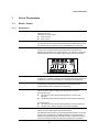 4
4
-
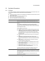 5
5
-
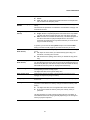 6
6
-
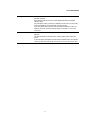 7
7
-
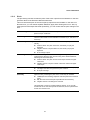 8
8
-
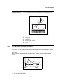 9
9
-
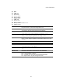 10
10
-
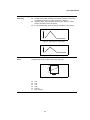 11
11
-
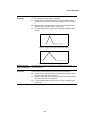 12
12
-
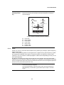 13
13
-
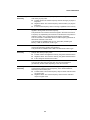 14
14
-
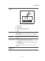 15
15
-
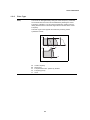 16
16
-
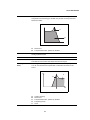 17
17
-
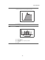 18
18
-
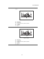 19
19
-
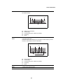 20
20
-
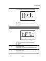 21
21
-
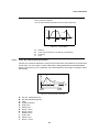 22
22
-
 23
23
-
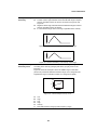 24
24
-
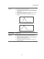 25
25
-
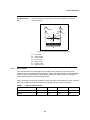 26
26
-
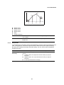 27
27
-
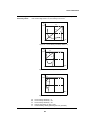 28
28
-
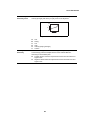 29
29
-
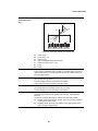 30
30
-
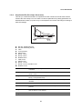 31
31
-
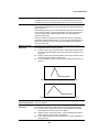 32
32
-
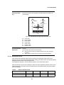 33
33
-
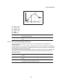 34
34
-
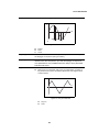 35
35
-
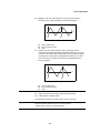 36
36
-
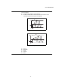 37
37
-
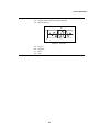 38
38
-
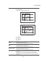 39
39
-
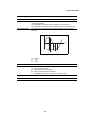 40
40
-
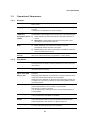 41
41
-
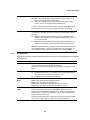 42
42
-
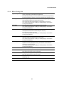 43
43
-
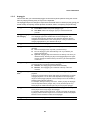 44
44
-
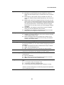 45
45
-
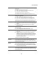 46
46
-
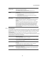 47
47
-
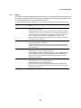 48
48
-
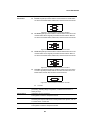 49
49
-
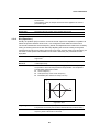 50
50
-
 51
51
-
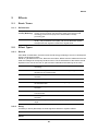 52
52
-
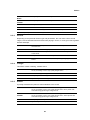 53
53
-
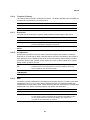 54
54
-
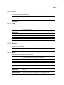 55
55
-
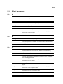 56
56
-
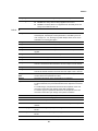 57
57
-
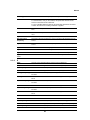 58
58
-
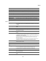 59
59
-
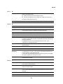 60
60
-
 61
61
-
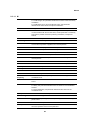 62
62
-
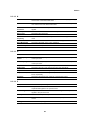 63
63
-
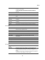 64
64
-
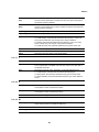 65
65
-
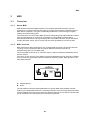 66
66
-
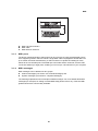 67
67
-
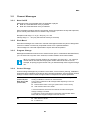 68
68
-
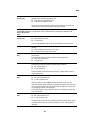 69
69
-
 70
70
-
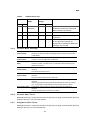 71
71
-
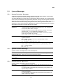 72
72
-
 73
73
-
 74
74


Yamaha CP4 Handleiding
- Categorie
- Muziek drums
- Type
- Handleiding
in andere talen
- English: Yamaha CP4 User manual
- italiano: Yamaha CP4 Manuale utente
- русский: Yamaha CP4 Руководство пользователя
- français: Yamaha CP4 Manuel utilisateur
- español: Yamaha CP4 Manual de usuario
- Deutsch: Yamaha CP4 Benutzerhandbuch
- português: Yamaha CP4 Manual do usuário
- dansk: Yamaha CP4 Brugermanual
- suomi: Yamaha CP4 Ohjekirja
- čeština: Yamaha CP4 Uživatelský manuál
- svenska: Yamaha CP4 Användarmanual
- Türkçe: Yamaha CP4 Kullanım kılavuzu
- polski: Yamaha CP4 Instrukcja obsługi
- română: Yamaha CP4 Manual de utilizare
