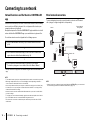
Yamaha ATS-4080 de handleiding
- Categorie
- Luidsprekersets
- Type
- de handleiding

U
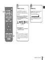
Quick Start Guide
EN
Front Surround System
English

2 En
Contents
Before using the unit ............................................................ 3
Features....................................................................................................................3
PREPARATION
Supplied items ...................................................................... 4
Part names and functions .................................................... 6
Installation ............................................................................ 9
Connections ........................................................................ 10
PLAYBACK
Operations........................................................................... 13
NETWORKS
Connecting to a network.................................................... 18
Specifications...................................................................... 22
About this Quick Start Guide
This Quick Start Guide provides basic setup to use the unit and feature of the unit.
The unit is equipped with a number of other functions not described in this document.
For more information about this product, refer to the Owner’s Manual on the Yamaha
website.
Follow one of the methods described below to view the latest Owner’s Manual.
In HTML format
• Scan the QR code found on the front cover of this document.
• Visit the following website.
https://manual.yamaha.com/av/18/ats4080/
In PDF format
• Visit the following website.
https://download.yamaha.com/
[For U.S. customers only]
Visit the following website for additional information, FAQ’s, downloads such as
“Owner’s Manual” and product updates.
http://usa.yamaha.com/support/
• In this booklet, iOS and Android mobile devices are collectively referred to as
“mobile devices”. The specific type of mobile device is noted in explanations as
needed.
• Trademarks and trade names used in this document are those of their respective
owners. See the Owner’s Manual for more information.
• This manual uses the following signal words for the important information:
– WARNING
This content indicates “risk of serious injury or death.”
– CAUTION
This content indicates “risk of injury.”
– NOTICE
Indicates points that you must observe in order to prevent product failure, damage
or malfunction and data loss, as well as to protect the environment.
– NOTE
Indicates notes on instructions, restrictions on functions, and additional
information that may be helpful.

Before using the unit En 3
Before using the unit
Introduction
This front surround system allows for the enjoyment of dynamic sound with video played on a TV.
Features
TV
Playback device
(BD/DVD player)
The unit
• Play audio from a TV or BD/DVD player in
surround sound.
• Play audio from a Bluetooth device with
excellent quality.
• Play audio over a network with superior
sound quality.
Bluetooth device
(Smartphone)
AirPlay Internet radio
Streaming service
Computer (NAS)
Wireless router

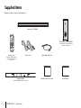
4 En PREPARATION ➤ Supplied items
PREPARATION
Supplied items
Make sure you have received all of the following items.
Center unit (ATS-CU4080)
Remote control
A CR2025 Lithium battery has
already been inserted into the
remote control.
Optical digital audio cablePower cord × 2
DRILL HERE / PERCER CIC
MOUNTING TEMPLATE / GABARIT DE FIXATION
DRILL HERE / PERCER CIC
Mounting template
Use when mounting the center unit on a wall
Quick Start Guide (this booklet)
Wireless subwoofer (NS-WSW43)
In this manual, the wireless subwoofer is
referred to as “subwoofer”.
Safety Brochure

PREPARATION ➤ Supplied items En 5
Preparing the remote control
Remove the battery’s insulating strip before attempting to use the remote control.
Operating range of the remote control
Operate the remote control within the range as shown below.
Battery’s insulating strip
Remote control sensor
Within 6 m (20 ft)
Replacing the battery in the remote control
Press and hold the release tab firmly in the direction indicated by [A], and slide the
battery holder out in the direction indicated by [B].
Battery holder
Release tab
CR2025 Lithium battery

6 En PREPARATION ➤ Part names and functions
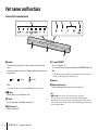
Part names and functions
Center unit (front panel/top panel)
a Indicators
The indicators on the top panel flash or glow, to show the operation and setting
status.
In this manual, indicators status, such as off, glowing, and flashing, are shown as the
illustrations below.
NOTE
• The brightness of the indicators can be changed using DIMMER on the remote control (p. 17).
b y (input)
Select an input source to be played back (p. 14).
c | (mute)
Mute the audio output. Touch | again to unmute (p. 15).
d }/{ (volume +/-)
Adjust the volume (p. 15).
e z (power)/CONNECT
Turn on or off the unit (p. 13).
Use to connect the unit to a network using the MusicCast CONTROLLER app (p. 19).
NOTE
• The unit may automatically turn off when the auto power standby function is enabled. For details, see
“Setting the auto power standby function” in the Owner’s Manual.
f Speakers
g Remote control sensors
Receive infrared signals from the remote control of the unit (p. 13).
NOTE
• b, c, d and e are touch sensors. Touch icons with your finger to control functions.
• Do not place any objects on the touch panel as doing so may result in unintended operations.
• When touch panel control is disabled, no operations can be performed using the unit’s touch panel. This
prevents accidental operation of the unit. For details, see “Enabling/disabling touch panel control (child lock
function)” in the Owner’s Manual.
g
bc d ea
f
f
: Off : Glows : Flashes

PREPARATION ➤ Part names and functions En 7
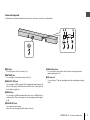
Center unit (rear panel)
The illustrations in this manual include labels next to the jacks on the bottom of the unit for easy identification.
a AC IN jack
Connect the power cord of the center unit (p. 11).
b NETWORK jack
For connecting to a network with a network cable (p. 18).
c HDMI OUT (ARC) jack
For connecting to an HDMI-compatible TV and outputting video/audio signals (p. 10).
When a TV that supports Audio Return Channel (ARC) is used, TV audio signal can
also be input through this jack.
d HDMI IN jack
For connecting to an HDMI-compatible playback device, such as a BD/DVD player, a
satellite and cable TV tuner, and a game console, and inputting video/audio signals
(p. 10).
e UPDATE ONLY jack
Use to update this unit’s firmware.
Refer to the instructions supplied with the firmware for details.
f ANALOG input jack
For connecting to an external device with a 3.5 mm stereo mini plug cable and
inputting audio signals (p. 11).
g TV input jack
For connecting to a TV with an optical digital audio cable and inputting audio signals
(p. 10).
a
b
ef g
cd

8 En PREPARATION Part names and functions
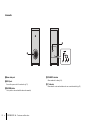
Subwoofer
a Bass reflex port
b AC IN jack
Connect the power cord of the subwoofer (p. 11).
c PAIRING button
Use to pair the center unit with the subwoofer manually.
d STANDBY indicator
Shows subwoofer’s status (p. 13).
e * indicator
Glows when the center unit and subwoofer are connected wirelessly (p. 12).
a
b
cde

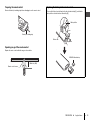
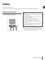
PREPARATION ➤ Installation En 9
Installation
The center unit can be installed on a TV stand, etc.
Position the subwoofer to the left or right of the center unit. Angle the subwoofer slightly toward the center of the room to prevent sound from reflecting off of walls.
Installing the center unit on a TV stand
Position the center unit with the touch panel facing up.
NOTE
• The center unit can also be mounted on a wall. Some knowledge of building construction is required for
safe installation. Please have a qualified contractor or dealer install the center unit on a wall. For details,
see “Information for qualified contractors or dealers” in the Owner’s Manual.
Touch panelRemote control sensor
NOTICE
• Do not stack the center unit and a BD player or other device directly on each other. Doing so may cause
a malfunction due to vibrations.
• Avoid touching, and never place any weight or pressure on, the subwoofer’s speaker (portion covered
with fabric). Doing so may damage the speakers.
• Do not install the subwoofer where the speaker (portion covered with fabric) is too close to a wall, or
cover the subwoofer’s bass reflex port. Doing so may reduce sound volume.
• The subwoofer can only be used in its upright position. Do not position the subwoofer on its side.
• This unit contains non-magnetic shielding speakers. Do not place magnetically sensitive items (hard disk
drive, etc.) near the unit.
• The center unit and subwoofer communicate wirelessly. Do not place objects that block or interfere with
wireless signals, such as metallic furniture or devices, between the center unit and the subwoofer as
wireless communication may be adversely affected.

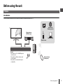
10 En PREPARATION ➤ Connections
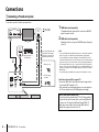
Connections
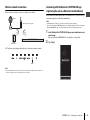
a Connecting a TV and set-top box
For the cable connection, follow the procedure below.
OPTICAL
OUTPUT
123
HDMI INPUT
HDMI
OUTPUT
12
1 HDMI cable (sold separately)
The digital audio/video signals from the set-top box or BD/DVD
player are input to this unit.
2 HDMI cable (sold separately)
Digital video from the set-top box or BD/DVD player is displayed
on the TV.
NOTE
• Use a 19-pin HDMI cable with the HDMI logo printed on it. A cable with a maximum
length of 5 m (16 ft) is recommended to prevent degradation of signal quality.
• Use of a flat HDMI cable may make installing the center unit difficult because the
cable will be bent by the bottom of the center unit when connected. Confirm the layout
and position of jacks on the center unit before choosing an appropriate HDMI cable.
• This unit supports HDCP version 2.2, a copy protection technology. For playback of
4K video, connect the unit to the HDMI input jack (one compatible with HDCP 2.2) on
an HDCP 2.2-compliant TV, and to the HDMI output jack on a HDCP 2.2-compliant
BD/DVD player.
• Use a premium high-speed HDMI cable for playback of 3D and 4K video content.
Audio Return Channel (ARC) supported TV
• Connect an HDMI cable to the audio return channel supported jack
(the jack with “ARC” indicated) on TV.
• Video and audio content from playback devices can be output from
the TV even when this unit is off (HDMI signal pass-through).
What is Audio Return Channel (ARC)?
In order for the unit to play audio from a TV, the TV must usually be
connected to the unit via an audio cable as well as an HDMI cable.
If, however, the TV supports Audio Return Channel (ARC), TV
audio signals can be input to the unit via the HDMI cable that
outputs video signals from the unit to the TV.
Cable, satellite or
network set-top box, or
BD/DVD player
TV
1. Remove the cap.
2. Check the plug’s
orientation.
: Video signals
: Audio signals
Use the optical digital audio cable
(supplied) when connecting the
center unit to a TV that does not
support Audio Return Channel.

PREPARATION ➤ Connections En 11
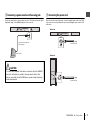
b Connecting a game console via the analog jack
Connect an external device, such as a game console or TV that does not have an optical
digital audio output, to the ANALOG input jack of the center unit.
c Connecting the power cord
Once all connections have been made, connect the supplied power cords to the AC IN
jacks on the center unit and subwoofer respectively, and plug the power cords into AC
wall outlets.
CAUTION
• If volume can be adjusted on the device connected to the unit’s ANALOG
input jack, set that device's volume to the same level as that of other
devices connected to the unit’s HDMI jacks to prevent volume from being
louder than expected.
3.5 mm stereo mini plug cable
(sold separately)
Game console
To an AC wall outlet
To an AC wall outlet
Center unit
Subwoofer

12 En PREPARATION ➤ Connections
d Turning on the unit
Press z (power) on the remote control or touch z/CONNECT on the center unit. The
unit turns on and the center unit and subwoofer are automatically connected via wireless
connection. Once the connection has been successfully established, the * indicator on
the subwoofer’s rear panel glows, and the unit is ready for playback.
NOTE
• If the * indicator on the subwoofer does not glow properly, see “No sound is coming from the subwoofer”
in the Owner’s Manual.
Glows
or
Turn on the unit

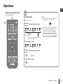
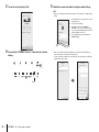
PLAYBACK ➤ Operations En 13
PLAYBACK
Operations
1
Remote control signal transmitter
Transmits infrared signals.
z (power) button
Turns on or off the unit.
Center unit
Turned on
Turned off/network standby
Subwoofer
Turned on
Turned off/network standby
NOTE
• When the unit is turned on for the first time after purchase,
the * indicator on the center unit flashes slowly.
While the * indicator is flashing, network settings from your
iOS device (an iPhone, etc.) can be applied to the unit to
connect the unit to a wireless network. For details on
settings, see “Connecting to a network using the WAC
function” in the Owner’s Manual. Press any button on the
remote control to cancel this function if it will not be used.
The * indicator does not flash if the unit’s NETWORK jack
is connected to a router using a cable (wired connection).
The indicator for the last input
source selected glows.
Indicates the surround setting, and network or
Bluetooth connection status.
Off Glows
Glows
1

14 En PLAYBACK ➤ Operations
2
3
Input buttons
Select an input source to be played back.
TV ....................TV audio or sound from a device
connected to the unit’s TV input
jack
HDMI................Sound from a device connected to
the HDMI input jack
ANALOG .........Sound from a device connected to
the ANALOG input jacks
BLUETOOTH ..Sound from a Bluetooth connected
device
NET..................Audio acquired via a network
The indicator for the selected input source glows.
(Example: when TV is selected)
NOTE
• To play sound from the device connected to the TV or to
watch video from the device, set the TV’s input source to the
playback device.
• For details on playing music files stored on a Bluetooth
device, see “Listening to music stored on a Bluetooth
®
device” in the Owner’s Manual.
• For details on playing content via a network, see the
following in the Owner’s Manual:
− “Play music with AirPlay”
− “Play music stored on a media server (computer or NAS)”
− “Listening to Internet radio”
− “Listening to streaming services”
− “Play music stored on mobile devices”
Glows
2
3D SURROUND, SURROUND and
STEREO buttons
Switch to 3D surround playback, surround
playback, and stereo (2-channel) playback.
3D SURROUND button
Switch to 3D surround playback. When 3D
surround is selected, DTS Virtual:X makes it
possible to hear sound not only from horizontal
directions, but also from varying heights.
Glows blue
SURROUND button
Switch to surround playback.
Glows white
STEREO button
Switch to stereo (2-channel) playback.
Off
NOTE
• The TV Program, Movie, Music, Sports, or Game surround
mode can be selected using the dedicated MusicCast
CONTROLLER app installed on a mobile device when the
unit is connected to a network and registered as a
MusicCast-enabled device with the app (p. 19).
3

PLAYBACK ➤ Operations En 15
4
5
SUBWOOFER (+/-) buttons
Adjust the volume of the subwoofer.
VOLUME (+/-) buttons
Adjust the volume of the unit.
| (mute) button
Mute the audio output. Press the button again to
unmute.
Volume down (–) Volume up (+)
Volume down (–) Volume up (+)
Flash (on mute)
4
CLEAR VOICE button
Enable/disable the clear voice function.
When this function is enabled, human voices such
as lines in movies and TV shows, or news and
sport commentary, are played clearly.
BASS EXTENSION button
Enable/disable the bass extension function. When
this function is enabled, you can enjoy a powerful
bass sound.
Enabled: Flash three times and turn off
Disabled: Flash once and turn off
Enabled: Flash three times and turn off
Disabled: Flash once and turn off
5

16 En PLAYBACK ➤ Operations
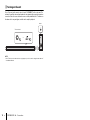
6
INFO button
Press INFO to confirm the type of audio signal being played, as well as settings for functions such as the
bass extension function.
The indicators on the unit will show the following audio information for three seconds immediately after INFO
is pressed.
a Show the type of audio signal.
HDMI glows (white): Dolby Digital
HDMI glows (red): DTS
TV glows (white): AAC
HDMI and TV off: PCM/analog input/no input
b Show whether Dolby Pro Logic II is enabled
or disabled. Dolby Pro Logic II is enabled
automatically when 2-channel stereo
signals are played in surround sound.
Glows: Enabled
Off: Disabled
c Show the bass extension function setting.
Glows: Enabled
Off: Disabled
d Show the clear voice function setting.
Glows: Enabled
Off: Disabled
e Show the network standby function setting.
Glows: Enabled
Off: Disabled
f Show the Bluetooth function setting.
Glows (blue): Enabled
Off: Disabled
abcde f
6

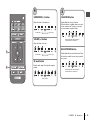
PLAYBACK ➤ Operations En 17
7
8
FAVORITE (1–3) buttons
Use the FAVORITE button to register input
sources played over a network (Internet radio
stations, music files stored on a media server, etc.)
as favorites.
Register favorites with the FAVORITE buttons
1 Play the input source to be registered.
2 Press and hold FAVORITE 1, 2, or 3 at least
three seconds.
Play favorite input sources
1 Press FAVORITE 1, 2, or 3 to which the input
source has been assigned.
NOTE
• Favorites assigned to FAVORITE 1, 2, or 3 using the remote
control will also be assigned to MusicCast CONTROLLER
app “Favorites” 1, 2, and 3. If favorite 1, 2, or 3 is changed
with either the unit or the MusicCast CONTROLLER app, the
corresponding favorite will also be automatically changed
with the other.
Flash (three times)
7
DIMMER button
Change the brightness of the indicators. Each time
DIMMER is pressed, the brightness of the
indicators changes as follows.
Dim (default setting) → Off → Bright
↑
Indicators glow brightly just after operation and
change to the specified brightness after a few
seconds.
8

18 En NETWORKS ➤ Connecting to a network
NETWORKS
Connecting to a network
Network functions and the MusicCast CONTROLLER
app
A network connection allows you to listen to Internet radio stations or music streaming
services, and to use AirPlay to play music files, or to play music files stored on your
computer (media server) via this unit.
Most playback requires the “MusicCast CONTROLLER” app for mobile devices. Install
and use the MusicCast CONTROLLER app on your mobile device to play music files.
Proceed from network connection to playback in the following sequence.
* AirPlay can be used to play music files without using the MusicCast CONTROLLER
app.
NOTE
• To use network function, the unit, your computer and mobile device must be connected to the same router.
• When using a multiple SSID router, access to the unit might be restricted depending on the SSID to
connect. Connect the unit and mobile device to the same SSID.
• Some security software installed on your computer, or network device settings (such as a firewall), may
block the unit’s access to your computer or Internet radio stations. Should this occur, change security
software and/or network device settings.
• A network connection cannot be established if the MAC address filter on your router is enabled. Check
your router’s settings.
• To configure your router’s subnet mask manually, apply the same subnet used by this unit to all devices.
• Use of a broadband connection is recommended when using Internet services.
• The unit cannot be connected to a network that requires manual setup. Connect the unit to a DHCP-
enabled router.
Wired network connections
To use a wired network connection, connect the unit to a router via an STP network
cable (category 5 or higher straight cable; sold separately).
NOTE
• If network connections or settings are changed, use the MusicCast CONTROLLER app to connect the unit
to a network and register the unit as a MusicCast-enabled device again (p. 19).
a Choose a wired network connection (p. 18) or a wireless network connection
(p. 19).
b Use the MusicCast CONTROLLER app to connect the unit to a network, and
register the unit as a MusicCast-enabled device (p. 19).
c Use the MusicCast CONTROLLER app* to play music over a network.
For details on playing music over a network, refer to the Owner’s Manual.
LAN
WAN
Internet
Computer
Network cable
Modem
Mobile device
Router
Network Attached
Storage (NAS)

NETWORKS ➤ Connecting to a network En 19
Wireless network connections
Connect the unit to a wireless router (access point) to use a network.
The * indicator on the unit glows when the unit is connected to a wireless network.
NOTE
• If the unit and the wireless router (access point) are too far apart, the unit may not connect to a wireless
router (access point). In such case, place them close to each other.
Connecting with the MusicCast CONTROLLER app
(registering the unit as a MusicCast-enabled device)
Install the MusicCast CONTROLLER app on your mobile device to connect the unit to a
network and register it as a MusicCast-enabled device.
NOTE
• Confirm that your mobile device is connected to your home router before beginning.
• This section uses MusicCast CONTROLLER app screens displayed in English on an iPhone as examples.
• MusicCast CONTROLLER app screens and menu labels are subject to change without prior notice.
1 Install the MusicCast CONTROLLER app on your mobile device, and
open the app.
Search for “MusicCast CONTROLLER” on the App Store or Google Play.
2 Tap “Setup”.
Internet
Wireless router (access point)
Modem
Mobile device
Glows

20 En NETWORKS ➤ Connecting to a network
3 Turn on the unit, and then tap “Next”.
4 Touch and hold z/CONNECT until the * indicator on the unit starts
flashing.
5 Follow the on-screen instructions to configure network settings.
NOTE
• When a screen like that below is displayed, follow the on-screen instructions to configure network
settings.
• When a screen like that at left below is displayed, select the network to which the unit will be
connected and enter the router’s password (encryption key).
The router’s password (encryption key) is often noted on the router itself. Refer to documentation
supplied with the router for details.
Flashes
1. Use the Home button on your mobile device to return
to the Home screen.
2. Select “Wi-Fi” from “Settings”.
3. Select “MusicCastSetup” from “CHOOSE A
NETWORK...”. If the on-screen instructions prompt
you to enter the MusicCastSetup password, enter the
password displayed on the screen.
4. Use the Home button to return to the MusicCast
CONTROLLER app.
Password for ABCD_1234
ABCD_1234
Password
YAS-408
ABCD_1234

NETWORKS ➤ Connecting to a network En 21
6 To register the unit as a MusicCast-enabled device, configure the
following items.
• Location name (“home”, “John’s house”, etc.)
• Name and photo of the room where the unit is installed
The location name, and the name and photo of the room where the unit is installed
can be changed later.
Network connection with the MusicCast CONTROLLER app is now complete, and the
unit has been registered as a MusicCast-enabled device.
NOTE
• If a different MusicCast-enabled device is already registered with the MusicCast CONTROLLER app, tap
~ (Settings) in the room selection screen, and then select “Add New Device” to add the unit to the app.
Tap

22 En Specifications
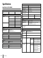
Specifications
Specifications (ATS-CU4080)
Amplifier section
Maximum rated output
power
Front L/R 50 W × 2ch
Speaker section
Front L/R Type Acoustic suspension type
(non-magnetic shielding)
Driver 4.6 cm (1-3/4”) cone × 4
Frequency response 160 Hz to 9 kHz
Impedance 4 Ω (8 Ω × 2)
Tweeter Driver 2.5 cm (1") dome × 2
Frequency response 9 kHz to 23 kHz
Impedance 4 Ω
Decoder
Supported audio signal
(HDMI/optical input)
PCM (up to 5.1ch)
Dolby Digital (up to 5.1ch)
DTS Digital Surround (up to 5.1ch)
Input jacks
HDMI 1 (HDMI IN)
Digital (Optical) 1 (TV)
Analog (3.5 mm stereo mini) 1 (ANALOG)
Output jacks
HDMI 1 (HDMI OUT (ARC))
Other jacks
USB 1 (UPDATE ONLY)
LAN 1 (NETWORK)
Bluetooth
Bluetooth version Ver 4.2
Supported profiles A2DP, AVRCP
Supported codecs Sink: SBC, AAC
Bluetooth class Bluetooth Class 2
Range (line-of-sight) Approx. 10 m (33 ft)
Supported content
protection method
SCMS-T (sink)
Radio frequency U.K. and Europe models 2402 MHz to 2480 MHz
Maximum output power
(EIRP)
U.K. and Europe models 6.5 dBm (4.5 mW)
Network
Ethernet standard 100BASE-TX/10BASE-T
Supported codecs WAV (PCM format only) /AIFF/FLAC: up to 192 kHz
ALAC: up to 96 kHz
MP3/WMA/MPEG-4 AAC: up to 48 kHz
PC client function
AirPlay supported
Internet radio
Wi-Fi
Wireless LAN
standards
IEEE 802.11 a/b/g/n/ac*
* 20 MHz channel bandwidth only
Radio frequency
band
2.4 GHz/5 GHz
Available security
method
WEP, WPA2-PSK (AES), Mixed Mode
Radio frequency U.K. and Europe
models
2.4 GHz band 2402 MHz to 2482 MHz (20 MHz)
5 GHz band 5170 MHz to 5250 MHz (20 MHz)
5250 MHz to 5330 MHz (20 MHz)
5490 MHz to 5710 MHz (20 MHz)
5735 MHz to 5835 MHz (20 MHz)
Maximum output
power (EIRP)
U.K. and Europe
models
2.4 GHz band 19.2 dBm (83.2 mW)
5 GHz band 5170 MHz to 5250 MHz (20 MHz):
21.5 dBm (141.3 mW)
5250 MHz to 5330 MHz (20 MHz):
21.8 dBm (151.4 mW)
5490 MHz to 5710 MHz (20 MHz):
24.1 dBm (257.0 mW)
5735 MHz to 5835 MHz (20 MHz):
13.5 dBm (22.4 mW)

Specifications En 23
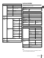
Specifications (NS-WSW43)
The specifications of the subwoofer are as follows.
NOTE
• The contents of this manual apply to the latest specifications as of the publishing date. To obtain the latest
manual, access the Yamaha website then download the manual file.
General
Power supply U.S.A. and Canada models AC 120 V, 60 Hz
Australia model AC 240 V, 50 Hz
Europe, Asia, and Russia
models
AC 110 to 240 V, 50/60 Hz
U.K. model AC 230 V, 50 Hz
Taiwan model AC 110 V, 60 Hz
China model AC 220 V, 50 Hz
Korea model AC 220 V, 60 Hz
Power
consumption
30 W
Standby power
consumption
U.S.A., Canada and Taiwan
models
HDMI control off, network
standby off
0.4 W
HDMI control off, network
standby on (Wired/Wi-Fi/
Bluetooth)
1.6/1.8/
1.7 W
HDMI control on, network
standby off
0.7 W
HDMI control on, network
standby on
2.2 W
U.K. and Europe models and
other models
HDMI control off, network
standby off
0.4 W
HDMI control off, network
standby on (Wired/Wi-Fi/
Bluetooth)
1.6/1.8/
1.7 W
HDMI control on, network
standby off
0.7 W
HDMI control on, network
standby on
2.2 W
Dimensions
(W x H x D)
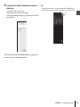
980 × 60 × 110.5 mm (38-5/8" × 2-3/8" × 4-3/8")
Weight 2.7 kg (6 lbs)
Amplifier section
Maximum rated output
power
100 W
Speaker section
Type Bass reflex type (non-magnetic shielding type)
Driver 16 cm (6-1/2") cone × 1
Frequency response 40 Hz to 160 Hz
Impedance 2 Ω
Radio frequency band 2.4 GHz
Radio frequency U.K. and Europe models 2405.35 MHz to 2477.35 MHz
Maximum output power
(EIRP)
U.K. and Europe models 9.0 dBm (8 mW)
Transmission range 10 m ([33 ft] without interference)
General
Power supply U.S.A. and Canada models AC 120 V, 60 Hz
Europe, Asia, and Russia
models
AC 110 to 240 V, 50/60 Hz
U.K. model AC 230 V, 50 Hz
Taiwan model AC 110 V, 60 Hz
Korea model AC 220 V, 60 Hz
China model AC 220 V, 50 Hz
Australia model AC 240 V, 50 Hz
Power consumption 19 W
Standby power
consumption
U.S.A., Canada and Taiwan
models
0.8 W
U.K. and Europe models and
other models
0.8 W
Dimensions (W × H × D) 180 × 417 × 405 mm (7-1/8" × 16-3/8" × 16")
Weight 9.4 kg (21 lbs)

Published 03/2020 KSOD-B0
Manual Development Group
© 2018 Yamaha Corporation
AV17-0352
Yamaha Global Site
https://www.yamaha.com/
Yamaha Downloads
https://download.yamaha.com/
10-1 Nakazawa-cho, Naka-ku, Hamamatsu, 430-8650 Japan
-
 1
1
-
 2
2
-
 3
3
-
 4
4
-
 5
5
-
 6
6
-
 7
7
-
 8
8
-
 9
9
-
 10
10
-
 11
11
-
 12
12
-
 13
13
-
 14
14
-
 15
15
-
 16
16
-
 17
17
-
 18
18
-
 19
19
-
 20
20
-
 21
21
-
 22
22
-
 23
23
-
 24
24


Yamaha ATS-4080 de handleiding
- Categorie
- Luidsprekersets
- Type
- de handleiding
in andere talen
- English: Yamaha ATS-4080 Owner's manual
- italiano: Yamaha ATS-4080 Manuale del proprietario
- français: Yamaha ATS-4080 Le manuel du propriétaire
- Deutsch: Yamaha ATS-4080 Bedienungsanleitung
Gerelateerde artikelen
-
Yamaha YMS-4080 de handleiding
-
-
-
-
Yamaha YSP-2700 de handleiding
-
-
Yamaha SRT-1500 de handleiding
-
-
Yamaha WX-051 de handleiding
-