Danfoss VLT 6000 (Legacy Product) Gebruikershandleiding
- Type
- Gebruikershandleiding

1
MN.60.G1.02 - VLT is a registered Danfoss trademark
VLT
®
6000 HVAC
■■
■■
■
IntroductionIntroduction
IntroductionIntroduction
Introduction
Variable speed drives have been used in industrial
applications for years because of their ability to
provide precise process control. They have also
become the standard method of control for heating
ventilation and air-conditioning (HVAC) systems due
to their precise control and significant energy savings.
The operational concerns for HVAC systems are quite
different from those for industrial applications. In most
HVAC installations there is a large installed base of
sensitive electronic equipment such as computers,
outstations and radios. Airports, hospitals and
research facilities will for example make much heavier
demands on the variable speed drives than the
industrial plants.
This feature note will deal with one aspect of electrical
noise generation in variable speed drives: Radio
Frequency Interference (RFI) on the AC power line.
We describe the causes and effects of such noise as
well as the considerations that are to be made in
connection with the selection and installation of a
variable speed drive.
■■
■■
■
Causes of Radio Frequency InterferenceCauses of Radio Frequency Interference
Causes of Radio Frequency InterferenceCauses of Radio Frequency Interference
Causes of Radio Frequency Interference
(RFI)(RFI)
(RFI)(RFI)
(RFI)
ee
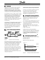
Figure 1: Schematic of Basic Drive design
Most variable speed drives operate by using a bridge
rectifier to convert the incoming AC voltage into a DC
bus voltage. The inverter bridge of the drive then
converts the DC bus voltage into the controlled
voltage and frequency that the motor requires.
For the most common types of drives in use today,
IGBTs are used to convert the DC voltage into an AC
voltage with controlled amplitude and frequency. To
perform this control most drives incorporate
sophisticated control circuitry with micro-processors
of high clock frequencies.
Both the inverter and the control circuitry generate
electrical noise at frequencies higher than 150 kHz.
If the drive is not designed carefully, this noise will
be conducted to the surroundings, causing
malfunction of other electronic equipment,
especially if it is not designed with a high level of
immunity to such high frequency noise.
■■
■■
■
Measuring Radio Frequency InterferenceMeasuring Radio Frequency Interference
Measuring Radio Frequency InterferenceMeasuring Radio Frequency Interference
Measuring Radio Frequency Interference
The levels of RFI from a drive is dependent on many
different factors. The design of the drive is most
important, since this determines how low the
distortion can get.
The measuring results for different drives may vary a
lot, so to get a real picture it is important to know
exactly how the measuring was made. Some of the
most important factors are:
Impedance between drive chassis and ground
Type of motor cable used or transfer impedance of
cable screen
Length of motor cable
Radiated emission is almost impossible to
reproduce. The reason is that even a slight change
in the measuring set-up will influence the results a
lot. Measuring made on site will always be
unreliable, since it is impossible to create a clean
environment.
■■
■■
■
Radio frequency interference limitsRadio frequency interference limits
Radio frequency interference limitsRadio frequency interference limits
Radio frequency interference limits
The most important international standard defining
RFI limits for drives is:
EN 55011/CISPR 11
EN55011 sets three different limits:
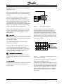
Figure 2: Average conducted emission levels
Average levels
EN 55011 2A
EN 55011 1A
EN 55011 1B
66
60
56
50
46
150 kHz
500 kHz
5 MHz
30 MHz
Emission,
screened motor cable
dB/uV
90
80
76

VLT is a registered Danfoss trademark
2
VLT
®
6000 HVAC
Of these limits only 1A and 1B have been applied as
legal requirements.
Each level contains limits to quasi peak and average
conducted emission as well as quasi peak radiated
emission.
Figure 2 shows the limit for average conducted
emission. Conducted emission is a cause for
concern. With EN 55011 demands for Quasi Peak
and Average were combined in one standard to get
more equal demands and remove the need to
determine which of the two requirements that should
apply to the equipment. The level is approximately
10dB mV lower than the quasi peak levels.
Often the quasi peak limits do not cause any major
problems in the design of the RFI filter. The average
limits, however, have caused problems to many
manufacturers.
■■
■■
■
RFI filtersRFI filters
RFI filtersRFI filters
RFI filters
RFI filters are available in many different designs. The
most economical and best functioning filter will match
the drive very carefully.
An RFI filter mainly consists of common mode
reactors and capacitors.
Whether a filter is good at filtering the frequencies
exceeding the limit of the norm will always be
dependent on the design. If the filter is not designed
for the drive, the filter components will have to be
oversized resulting in increased costs.
■■
■■
■
Installation considerationsInstallation considerations
Installation considerationsInstallation considerations
Installation considerations
When installing a drive, it is important to check the
manufacturers’ guidelines and some general rules of
thumb:
a.a.
a.a.
a.
Avoid pigtailsAvoid pigtails
Avoid pigtailsAvoid pigtails
Avoid pigtails
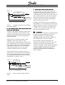
A pigtail is as shown in figure 3, where the screen-end
is twisted and connected to the PE-terminal or a
ground screw.
U
V
W
PE
Figure 3: Motor cable with pigtail
This type of ground connection increases the
transfer impedance to ground and increases the
noise levels that can be measured on the mains
cable. Figure 4 shows measured values of transfer
impedance for different lengths of cable screen and
pig-tails. As can be seen even a fairly short pig-tail
has the same transfer impedance as 150m of cable
screen above 10 MHz.
Figure 4: Comparison of transfer impedance for
cable screens and pigtails
Figure 5 below shows the impact on compliance
when a good installation (curve 1)
is changed to an installation with a pigtail of 5 cm at
the drive end, while the motor end is left untouched
(curve 2). Where the good installation complies with
EN 55011 1B, the installation with 5 cm of pig-tail
barely complies with EN 55011 1A. As indicated in
figure 4 a longer pig-tail would reduce compliance
even further.
0,01
0,1
1
10
100
1000
1 10 100 1000 10000 100000
Fre
q
uenc
y
in KHz
Screen im
p
edance 150m
Screen im
p
edance 50m
Screen im
p
edance 10m
5cm pigtail
20cm
p
i
g
tail
EMC-cable gland w/ screen grounding
Typical braided copper screen cable
1)1)
1)1)
1)
2)2)
2)2)
2)
3)3)
3)3)
3)
4)4)
4)4)
4)
5)5)
5)5)
5)
6)6)
6)6)
6)
1)1)
1)1)
1)
2)2)
2)2)
2)
3)3)
3)3)
3)
4)4)
4)4)
4)
5)5)
5)5)
5)
6)6)
6)6)
6)

3
MN.60.G1.02 - VLT is a registered Danfoss trademark
VLT
®
6000 HVAC
Figure 5: Comparison between good installation
and pigtail installation
b.b.
b.b.
b.
Use screened motor cable from the drive to theUse screened motor cable from the drive to the
Use screened motor cable from the drive to theUse screened motor cable from the drive to the
Use screened motor cable from the drive to the
motormotor
motormotor
motor
, also inside panels., also inside panels.
, also inside panels., also inside panels.
, also inside panels.
Usually the cable between the panel and the motor is
screened. Unfortunately, output contactors inside
panels are often connected with unscreened cables.
That will give problems with noise being radiated
between the cables.
Figure 6 shows a comparison between a good
installation (curve 1) and a bad one, using
unscreened motor cables inside the panel (curve 2).
In this example great care was taken to separate the
mains cable from the motor cable. It is sometimes
not possible to avoid the use of unscreened motor
cable inside the panels, but as curve 2 shows
compliance with EN 55011 1A is achievable.
Often the mains and motor cables, however, are
placed much too close and this causes transmission
of noise directly between mains and motor cables,
thus by-passing the RFI filter and losing compliance
with EN 55011, as shown in curve 3.
Figure 6: Using unscreened cables inside the
panel.
c.c.
c.c.
c.
Connect the scrConnect the scr
Connect the scrConnect the scr
Connect the scr
een at motor and VLeen at motor and VL
een at motor and VLeen at motor and VL
een at motor and VL
TT
TT
T
::
::
:
To get an effective screening of the electric and
magnetic field from the motor cable it is necessary to
connect the screen at the motor and at the VLT.
Connecting the screen only in one end will screen the
electric field but will have no effect on the magnetic
field. As the noise from the motor cable is mainly
magnetic fields the screen will be very ineffective
when connected only in one end.
Equalising currents will rarely case any problems to
the installation. As a rule of thumb the screen should
therefore always be connected in both ends. If then a
problem should occur, then it is recommended to
connect a 1 µF capacitor at the drive end, rather
than just disconnecting the screen.
■■
■■
■
ConclusionConclusion
ConclusionConclusion
Conclusion
To ensure optimum performance it is highly important
to select the right drive and filter and to do the
installation work right. A good drive with the
appropriate RFI filter cannot ensure compliance, if
the installation work is not done properly.
Many buildings incorporate equipment that is
sensitive to radio frequency interference. This is not
only the case for airports, telecommunication
facilities and hospitals. Ordinary appartment buildings
and office complexes also have a lot of sensitive
equipment installed. It is therefore especially
important to limit radio frequency interference in
HVAC installations.
Curve 2
The screen effect of the cable
is reduced due to a pig-tail grounding
EN 55011 1B
66
60
56
50
46
150 kHz
500 kHz
5 MHz
30 MHz
Average levels
EN 55011 1A
Emission,
screened motor cable
Curve 1
Grounding of screen
through cable clamp
Cable conducted noise
dB/uV
Average levels
EN 55011 1A
EN 55011 1B
66
60
56
50
46
150 kHz
500 kHz
5 MHz
30 MHz
E
m
i
ss
i
on,
screened motor cable
Cable conducted noise
dB/uV
25-35 dB
Curve 1
Screened
motor cable
all the way
15-25 dB
Curve 3
Unscreened Motor cable and
mains cable in close proximity
inside panel
Curve 2
Good distance between
unscreened motor cable
and mains cable
inside panel
-
 1
1
-
 2
2
-
 3
3


Danfoss VLT 6000 (Legacy Product) Gebruikershandleiding
- Type
- Gebruikershandleiding
in andere talen
Gerelateerde papieren
Andere documenten
-
Eurotherm EMC Gebruikershandleiding
-
Yamaha P-2201 Handleiding
-
ABB ACH580-01-088A-4 Quick Installation And Start-Up Manual
-
-
Invacare Robin Mover Handleiding
-
-
-
-
ABB ACS55-01N-02A2-2 Handleiding