GBC Ultra Ultra MP StreamPunch Handleiding
- Type
- Handleiding

StreamPunchTM Ultra/Ultra MP
GB Operation Instructions Manual
F Manuel d'instructions et d'utilisation
E Manual de instrucciones de operación
I Manuale d’istruzioni
D Bedienungsanleitung
NL Gebruiksaanwijzing
PT Manual de instruções de operação
RU Руководство по эксплуатации
CHI
操作使用手册
Part Number: 7715805
Revision number: F1
Issue Date: October 2018
All manuals and user guides at all-guides.com

StreamPunchTM Ultra/Ultra MP
English 3
Français 13
Español 23
Italiano 33
Deutsch 43
Nederlands 53
Português 63
На русском языке 73
中文 83
GB Please read these instructions carefully and keep them in a safe place for future
reference.
F Lisez attentivement le présent manuel et conservez-le en lieu sûr afin de pouvoir le
consulter en cas de besoin.
E Lea estas instrucciones cuidadosamente y manténgalas en un lugar seguro para consulta
en el futuro.
I Si prega di leggere attentamente le presenti istruzioni d'uso e di conservarle a portata di
mano per ogni ulteriore consultazione.
D Bitte lesen Sie diese Bedienungsanleitung sorgfältig durch und bewahren Sie sie als
Referenz für die Zukunft an einem sicheren Ort auf.
NL Lees deze gebruiksaanwijzing aandachtig door en bewaar deze op een veilige plaats voor
later.
PT Leia atentamente estas instruções e mantenha-as em um lugar seguro para futuras
consultas.
RU Внимательно прочтите все руководство и сохраните его на будущее.
CHI 请仔细阅读本手册,并将其保存在安全位置供日后参考。
All manuals and user guides at all-guides.com

3
GB
StreamPunchTM Ultra/Ultra MP
TABLE OF CONTENTS
1. SAFETY INSTRUCTIONS 3
Important safeguards 3
Cleaning 3
Service 4
Safety messages 4
2. INTRODUCTION 4
3. QUICK START GUIDE 5
4. USER OPERATIONS 6
1. SAFETY INSTRUCTIONS
THE SAFETY OF YOU AND OTHERS IS VERY IMPORTANT TO
GBC. IMPORTANT SAFETY MESSAGES AND INFORMATION ARE
CONTAINED IN THIS MANUAL AS WELL AS ON THE MACHINE
ITSELF. PLEASE MAKE SURE YOU CAREFULLY READ AND
UNDERSTAND ALL OF THESE BEFORE OPERATING THE
MACHINE.
THE SAFETY ALERT SYMBOL PRECEDES EACH SAFETY
MESSAGE IN THIS OPERATION INSTRUCTIONS
MANUAL. THIS SYMBOL INDICATES A POTENTIAL
PERSONAL SAFETY HAZARD THAT COULD HURT YOU
OR OTHERS.
THE FOLLOWING PICTORIAL IS FOUND ON THE STREAMPUNCH
ULTRA:
This safety symbol means that you might get
seriously hurt or killed if you open the product
and expose yourself to hazardous voltage.
NEVER remove the screwed on covers.
ALWAYS refer service requirements to
qualified service personnel.
5. USER DISPLAY 7
6. PROBLEM SOLVING 9
7. SPECIFICATIONS 9
8. DIE SET USER MANUAL 10
Important safeguards
Use the StreamPunch Ultra only for its intended purpose of
punching paper and covers according to the indicated
specifications.
Retain this Operation Instructions manual for future use.
CAUTION: THE PRINTER ON/OFF SWITCH DOES NOT
CUT OFF POWER FROM THE PUNCH.
The StreamPunch Ultra must be connected to a supply voltage
corresponding to the electrical rating of the machine operation
instructions (also listed on the serial number label).
The grounding plug is a safety feature and will only fit into the
proper grounding-type power outlet. If you are unable to insert the
plug into an outlet, contact a qualified electrician to have a suitable
outlet installed.
Do not alter the plug on the end of the cordset (if provided) of the
StreamPunch Ultra. It is provided for your safety.
Unplug the StreamPunch Ultra before moving the machine or
whenever the machine is not in use for an extended period of
time.
Do not operate the StreamPunch Ultra if the machine has a
damaged power supply cord or plug. Do not operate the machine
after any malfunction. Do not operate the machine in case of liquid
spills, or if the machine has been damaged in any other way.
Do not overload electrical outlets beyond their capacity. To do so
may result in fire or electrical shock.
Cleaning
You may clean the exterior of the StreamPunch Ultra using a soft,
damp cloth.
Do not use detergents or solvents as damage to the machine may
occur.
All manuals and user guides at all-guides.com

4
GB
StreamPunchTM Ultra/Ultra MP
Safety messages
MAIN CORDSET SELECTION
(THE FOLLOWING NOTE ONLY APPLIES ONLY TO THE UNITS
RATED 230V 50Hz, AND LOCATED IN THE EUROPEAN UNION)
CAUTION: WHEN CHOOSING A DETACHABLE LINE
CORD FOR USE WITH YOUR STREAMPUNCH ULTRA,
ALWAYS FOLLOW THE FOLLOWING PRECAUTIONS
The cordset consists of three parts: the attachment plug, the cord and
the appliance inlet. Each of these components must have European
regulatory safety approvals.
The following minimum electrical ratings for the specific cordset are
published for safety purposes.
DO NOT USE CORDSETS THAT DO NOT MEET THE FOLLOWING
MINIMUM ELECTRICAL REQUIREMENTS.
PLUG: 3 amperes, 250 volts, 50/60 Hz, Class 1, 3 conductor,
European safety approved.
CORD: Type H05VV-F3G0.75, Harmonized (< HAR >). The “< >”
symbols indicate cord approved according to appropriate European
standard (NOTE: “HAR” may be substituted for approval mark of
European safety agency that approved the cord. An example would be
“< VDE >”).
APPLIANCE CONNECTOR: 3 amperes, 250 volts, 50/60 Hz,
European safety approved, Type IEC 320. The cordset shall not
exceed 3 meters in length. A cordset with component electrical ratings
greater than the minimum specified electrical ratings may be
substituted.
FCC NOTE
(THE FOLLOWING NOTE ONLY APPLIES TO THE UNITS RATED
115V 60Hz.)
This equipment has been tested and found to comply with the limits for
a Class A digital device, pursuant to Part 15 of the FCC Rules. These
limits are designed to provide reasonable protection against harmful
interference when the equipment is operated in a commercial
environment.
This equipment generates, uses, and can radiate radio frequency
energy and, if not installed and used in accordance with the Operation
Manual, may cause harmful interference with radio communications.
Operation of this equipment in a residential area is likely to cause
harmful interference in which case the user will be required to correct
the interference at his/her own expense.
CAN ICES-3 (A)/NMB-3(A)
CAUTION: ANY MODIFICATIONS MADE TO THIS DEVICE
THAT ARE NOT APPROVED BY GBC MAY VOID THE
AUTHOIRITY GRANTED TO THE USER BY THE FCC
AND/OR INDUSTRY CANADA TO OPERATE THIS
EQUIPMENT.
Service, StreamPunch Ultra
Do not attempt to service your StreamPunch Ultra yourself. Contact an
authorized service representative for any required repairs or major
maintenance for your StreamPunch Ultra.
DO NOT REMOVE THE MACHINE’S COVER.
There are NO user-serviceable parts inside the machine in order to
avoid potential personal injury and/or damage to property or the
machine itself.
Service, Diesets
Every dieset is thoroughly oiled at the factory prior to shipping. During
normal use this oil will be exhausted and should be replaced. As part of
regular maintenance, each dieset should be oiled.
See Section 8 StreamPunch Ultra Dieset Manual for instructions on
servicing the Diesets.
2. INTRODUCTION
Thank you for purchasing the StreamPunch Ultra. It is a versatile
production system that will enable you to punch documents for a variety
of binding styles by means of a simple die change. It has also been
designed for easy operation.
The StreamPunch Ultra is an innovative solution for punching paper
and offers the following design features:
Quick-change die sets that can be interchanged without any tools.
All StreamPunch Ultra die sets include an Identification Label
providing the user with the hole pattern and name.
Convenient storage area for two extra Die Sets.
Duty Cycle and Product Positioning
The GBC StreamPunch Ultra provides a flexible, cost effective
punching solution for light to medium level punching production
environments. It is designed for production print users that typically
punch their documents at an average of 20-30% of their overall
workflow. For customers that run continuous punching for long runs of
over 4 hours, performance may vary or degrade due to a wide range of
media weights and environmental conditions that can occur.
AMPV - Nominal 600,000 average monthly print volume (A4/letter),
assuming volume is split 50/50 between punch and bypass (300,000
punch and 300,000 bypass).
Maximum Recommended Monthly Volume - The maximum
recommended monthly punch volume should NOT exceed 400,000.
Maximum Punch Duty Cycle - In addition to the aforementioned
conditions, no more than 2 sheets of 300gsm per 5 sheets of 75gsm
should be punched. The heaviest paper stocks are typically used as
only the front and back covers of the bound book application.
Operating Die Set Supplies
Dies are considered consumables and when worn, must be replaced
since sharpening is not possible.
Each die set has a 90-day warranty from the date of purchase. The
warranty is void if the die is used beyond its specifications.
Punch die life will be maximized if oiled every 100,000 punch cycles
(see Dieset Service for details)
Die sets have an expected use life of 750,000 punches using
20 lb/75 gsm paper. This is a minimum life expectation only. Die life is
NOT guaranteed due to a wide range of media weights and
environmental conditions that the dies may endure. If you are going to
be punching extended runs that exceed the die use life, it is strongly
recommended that you have sufficient numbers of the appropriate die
sets on hand to continue with minimal downtime.
All manuals and user guides at all-guides.com

5
GB
StreamPunchTM Ultra/Ultra MP
3. QUICK START GUIDE
StreamPunch Ultra must be connected to AC power to enable any
feature of the machine. Below are three modes of operation of
StreamPunch Ultra.
1. Bypass Mode:
This operation will allow paper to pass through the StreamPunch
Ultra without being punched.
This is the default mode of operation for StreamPunch Ultra.
Make sure the Punch Icon is not selected in the printer’s User
Interface.
2. Single Punch Mode:
This operation will punch the trail edge of all sheets that pass
through the StreamPunch Ultra.
Step 1: A properly configured die set must be inserted before
running punch mode. See section 4.A for details on Die set
changes and follow the labels on the die set for configuration.
Step 2: Before starting a print job select the Punch (Single
Punch) icon to enable punching.
StreamPunch Ultra will now function in Single Punch mode.
3. Double Punch Mode:
This operation will punch the two rows of holes- One in the middle
of the sheet and the other adjacent to the trail edge of all sheets
that pass through the StreamPunch Ultra.
Step 1: A properly configured die set must be inserted before
running punch mode. See section 4.A for details on Die set
changes and follow the labels on the die set for configuration.
Step 2: Before starting a print job select the Double Punch icon
to enable punching.
StreamPunch Ultra will now function in Double Punch mode.
Layout of StreamPunch Ultra LCD User Interface
4. Die Set Configuration
To configure the Die Set for the desired sheet size that is being
processed see section 8 – Die Set User Manual.
UP
DOWN
ENTER/
OK
All manuals and user guides at all-guides.com

6
GB
StreamPunchTM Ultra/Ultra MP
4. USER OPERATIONS
A. Interchanging Die Sets:
Are completed without tools and only take seconds to perform
B. Punch Chip Container:
Easy-to-access chip tray for quick chip disposal
C. Die Set Storage:
Holds up to 2 spare Die Sets
D. Punch Bypass:
Short straight-through paper path for unpunched documents
E. Punch Mode Path:
Wide radius turn can support stocks up to 300g/m2 cover
Paper flow and User Interactive sections of StreamPunch Ultra
A. Interchanging Die Sets:
Your StreamPunch Ultra offers the convenience of interchangeable die
sets, allowing you to economically punch documents for a wide variety
of binding styles. Changing the machine's die sets is both quick and
easy, as the following instructions illustrate:
Note: For advanced Die Set Configuration instructions- See Section 8
Die Set User Manual.
Removing Die Sets from the Machine: The inter-changeable die set
slot of the StreamPunch Ultra is located adjacent to the Punch Chip
container at the bottom of the punch.
Step 1: Stop the printer/copier.
Step 2: Open the StreamPunch Ultra access door panel.
Step 3: Securely grasp the die lock handle and rotate it in the
CCW direction, as indicated in the label near the die lock handle.
This releases the die from the locked position.
Step 4: Slide the die set out until it is fully removed, supporting it
with both hands.
Step 5: Properly store the removed Die Set in the Die Set storage
area. (keep away from dust, dirt, accidental falls from the edge of
counters, etc.).
Step 6: Select the desired Die Set for your new job and slide it into
the Die Set slot. Push the Die set firmly until the Die stop feature
contacts the round magnet. This is critical in ensuring the proper
position of the die set.
Step 7: Grasp the handle and rotate it in CW direction until the
latch is fully engaged, as shown indicated in the label.
WARNING: POSSIBLE PINCH POINT HAZARD. WHEN
INSTALLING DIE SETS IN YOUR STREAMPUNCH ULTRA,
ALWAYS KEEP FINGERS AND OTHER BODY PARTS OUT
OF THE MACHINE’S DIE SET SLOT AND AWAY FROM ALL
AREAS OF THE DIE SET, EXCEPT FOR THE FINGER HOLE
IN THE DIE SET. FAILURE TO FOLLOW THESE
PRECAUTIONS MAY RESULT IN INJURY.
Step 8: Close the Access Door Panel.
Step 9: Proceed with your printing and punching job.
Please note that when using a new die some oil will be present around
the punched holes on the sheet. After punching 25 to 50 sheets the die
will no longer leave oil on the sheets. It is recommended that a short
test print job be run after installing a new die or a die that has recently
been oiled.
B. Punch Chip Container:
The Punch Chip Container for your StreamPunch Ultra is located at the
front of the machine’s base. The drawer should periodically be pulled
out and emptied. The StreamPunch Ultra uses a sensor to determine
when the punch container is full. Once the punch container becomes
full the LCD display shows "Chip Tray Full" message and a message
also appear on the printers user interface screen.
All manuals and user guides at all-guides.com

7
GB
StreamPunchTM Ultra/Ultra MP
C. Paper Clearing:
When paper is jammed in the paper path of
StreamPunch Ultra the LCD display shows the
area where a sheet(s) is jammed.
Area
Description
If paper is jammed in Zone 1, lift the paper guide
plate located just inside, reach and remove the
jammed paper. To close the paper guide, raise
the handle to unlatch the mechanism and firmly
close it.
If paper is jammed in Zone 2, move the door to
the right, reach in and remove the jammed paper.
If paper is jammed in Zone 3, press the top lever
while holding the bottom lever. This will unlatch the
chute; continue to open the chute until it reached
the magnet on the right side. Reach in and remove
the paper. To return the chute to the closed
position, move it back in the opposite direction until
the latch mechanism is activated.
If paper is jammed in Zone 5, unlatch the chute,
reach in and remove any jammed paper.
If paper is jammed in Zone 6, move the door to
the left, reach in and remove the jammed paper.
Before uninstalling the die set, ensure Zone 3 and
5 are cleared of any jammed paper. If there is no
paper found in Zone 3 and 5, then uninstall the
die set to remove any jammed paper. (see
Section 4. Changing the Interchangable die sets)
5. USER DISPLAY . OPERATION CONTROLS
Located on the front of the StreamPunch Ultra is a user interactive LCD
panel that provides Messages; Settings and Information relating to the
functions of the punch unit.
LCD Panel Overview
Messages on the LCD Panel
1. Ready Bypass
StreamPunch Ultra is ready to bypass, sheets will not be punched.
2. Ready Single Punch
StreamPunch Ultra is ready to process a punch job, all sheets
through the unit will be punched.
3. Ready Double Punch
StreamPunch Ultra is ready to process a punch job, all sheets
through the unit will be punch in the middle of sheet and along trail
edge of the sheet.
4. Running Bypass
This is displayed when Bypass mode is in operation.
5. Running Single Punch
This is displayed when Single punch mode is in operation.
6. Running Double punch
This is displayed when Double punch mode is in operation.
7. Chip tray Full
When the punch container becomes full of waste paper chips, this
message will be displayed.
8. Chip tray Out
When the punch container is removed or not fully inserted into the
punch unit, this message will be displayed.
9. Check die
When the Die Set is removed or not fully inserted into the punch
unit, this message will be displayed. When this message is
displayed the punch unit will run in Bypass mode only.
10. Close Door
When the Front door is open or not completely closed this
message will be displayed.
11. Paper jam
When a sheet of paper becomes jammed within the punch unit,
this message is displayed. See the section of this manual titled
PAPER CLEARING for instructions on how to remove a jammed
sheet.
All manuals and user guides at all-guides.com

8
GB
StreamPunchTM Ultra/Ultra MP
Changing the Settings on the LCD panel
1. Backgage Depth Setting
Backgage is the distance of the punched hole(s) from the trail
edge of the sheet. This distance can be adjusted by entering the
Settings section (press Up or Down from the Home screen, and
press OK for Settings).
Pressing Up arrow will increase the Depth of Backgage, and
Pressing Down arrow will decrease the Depth of Backgage.
2. Alignment Setting
Alignment is the distance of the Top punched hole from the side
edge of the sheet (viewed from the punch output orientation). This
distance can be adjusted by entering the Settings section (press
Up or Down arrow from the Home screen, and press OK for
Settings). Pressing Up arrow will increase the Alignment position,
and Pressing Down arrow will decrease the Alignment position.
3. Clear Cover
Use this setting to adjust the Backgage depth and Alignment
setting for Clear Cover media. Adjusting this offset does not affect
the Backgage and Alignment settings of other media types.
4. Language
The LCD panel can be configured to display one of the
following languages: English; Francais; Espanol; Deutsch or
Italiano.
5. Units
The LCD panel can be configured to display units in MM or
Inches.
Displaying Information on the LCD Panel
1. Die type
This is type of die-set currently installed in the punch.
2. Die cycles
This is the total number of sheets punched with the currently
installed die-set.
3. Punch cycles
This is the total number of punched sheets the system has
processed.
4. Firmware
This displays the current level of firmware of StreamPunch
Ultra.
BACKGAGE
“-”ON THE LCD
DECREASES
BACKGAGE
DEPTH
“+”ON THE LCD
INCREASES
BACKGAGE
DEPTH
ALIGNEMENT
“+” ON THE LCD
INCREASES
ALIGNMENT
OFFSET
“-” ON THE LCD
DECREASES
ALIGNMENT
OFFSET
All manuals and user guides at all-guides.com

9
GB
StreamPunchTM Ultra/Ultra MP
6. PROBLEM SOLVING
Probable Cause
Probable Cause
No power, won’t punch
Power cord not attached to back
of machine or not properly
plugged into the wall.
Punched holes not aligned with
the edge of the paper
Follow instructions on die set
labels to properly configure the
die for a specific sheet size
When punching with paper of
270-300 gsm with grain
orientation in the direction of
paper flow, paper jams may occur
depending on the stiffness of the
media. Using a different, less
rigid, cover media may remove
the problem.
Sheet jamming repeatedly at die
set area.
Remove the die-set, inspect the
die throat to see if there is any
stuck paper chad.
Check that printed sheets do not
have excess curl. Make efforts to
reduce curl to the minimum
possible. Review the printer
manual to reduce this if present.
When punching with paper of
270-300 gsm with grain
orientation in the direction of
paper flow, paper jams may occur
depending on the stiffness of the
media. Using a different, less
rigid, cover media may remove
the problem.
Insert Chip tray message on the
LCD interface.
Make sure the Chip tray is fully
inserted.
7. SPECIFICATIONS
Speed
Up to 136 sheets per minute
Punch Sheet Size and
Edge
LEF- Long Edge Fed
SEF- Short Edge Fed
Tab Stock
US Sizes
LTR LEF
LTR SEF
LTR SEF Double Punch
Statement LEF
Legal SEF
Ledger SEF
Ledger SEF Double Punch
ISO sizes
A4 LEF
A4 SEF
A4 SEF Double Punch
A5 LEF
A3 SEF
A3 SEF Double Punch
US Sizes
LTR, with 3,4,5,8 and 10 tabs
Statement, with 3 and 5 tabs
ISO Sizes
A4, with 5 and 10 tabs
A5, with 3 and 5 tabs
Paper Stock
Clear Cover
Plain: 75gsm - 300gsm
(20# bond to 110# cover)
Coated: 120gsm - 300gsm
(32# bond to 110# cover)
7mil
Bypass mode stock and
sizes
Paper sizes and stocks same as
printer
Punch Capacity
Single Sheet
Power Supply
115V, 60Hz, Single Phase
230V, 50Hz, Single Phase
Electrical
Amps and
Frequency
115V; 3.8A; 60Hz (or)
230V; 1.9A; 50Hz
Safety Certification
cULus
Dimensions
L: 730mm; W: 445mm; H: 1000mm
L: 29"; W: 17.5"; H: 39.5"
Weight
96 kg
212 lbs
Shipping Weight
127 kg
280 lbs.
Manufactured
Assembled in Taiwan
All manuals and user guides at all-guides.com

10
GB
StreamPunchTM Ultra/Ultra MP
8. DIE SET USER MANUAL
The die sets for the StreamPunch Ultra are intended to work with
multiple paper sizes and sheet feed directions. In order to
accommodate different sheet sizes this die set must be configured to
the correct number of punching pins and the die stop must be set to
the proper position. The die label contains information on the common
paper punching sizes, for the uncommon sizes please refer to Table 1.
Glossary
LEF- Long Edge Feed- Indicates that the paper is being fed through
the machine so that the longer side of the sheet will be punched.
SEF- Short Edge Feed- Indicates that the paper is being fed through
the machine so that the shorter side of the sheet will be punched.
Statement (STMT) Paper- 8.5" X 5.5"
Legal Paper- 8.5" X 14"
Ledger Paper- 11" X 17"
Pin Numbering
Die punching pins are numbered sequentially starting from the handle
end. Figure 8.1 shows a 47 hole coil die (404757) as an example. All
square and round hole die sets follow the same pin numbering format.
Figure 8.1 Coil Die Set Pin Numbering
Figure 8.2 Pressure Bar Removal
To remove punch pins from the StreamPunch Ultra first turn the two
Quarter Turn Fasteners counter clockwise to release the pressure bar.
Remove the pressure bar and set aside.
Figure 8.3 Pressure Bar
Figure 8.3 Pin Removal
Lift up and remove the desired pins according to Table 8.1. Store pins
in the pin storage tray inside front door of machine making sure pins
cannot be dropped, damaged or lost while removed.
Figure 8.4 Replace Pressure Bar
Replace the pressure bar by lining up dowel pin holes with exposed
dowel pins. Hold pressure bar so that it is seats completely over dowel
pins and then rotate Quarter Turn Fasteners clockwise until a click is
felt to lock pressure bar in position.
Important! Make sure pressure bar is attached and both Quarter Turn
Fasteners are in the locked position prior to inserting the die set into
the machine or serious damage can occur to both the machine and die
set.
Dowel Pin
Holes
Dowel Pin Holes
Pin #1
Pin #47
Quarter Turn
Fastener
Pin Removal
Coil
Rnd/Oval
Wire
2:1
Rnd/Sq
Wire
3:1
Rnd/Sq
3 Hole
8mm
3/5/7
Hole
8mm
2/4
Hole
8mm
2/4
Hole
6.5mm
2/4
Hole
SCAN
VeloBind
11 Hole
LTR
VeloBind
12 Hole
A4
CombBind
eWire
Rnd/Sq
US Paper Sizes
Pin numbers to be removed based on paper size and orientation
Ricoh Part Number
404757
404771
404758
404768
404759
404769
404760
404762
404763
404763
404764
404765
404766
404768
404770
404772
LTR LEF
2, 47
1, 23
1, 34
NONE
3H/5H/7H
N/A
N/A
N/A
NONE
N/A
1, 21
1, 34
LTR SEF
7, 42
NONE
5, 31
N/A
N/A
N/A
N/A
N/A
N/A
N/A
NONE
N/A
STATEMENT LEF
7, 42
NONE
5, 31
N/A
N/A
N/A
N/A
N/A
N/A
N/A
NONE
5, 31
LEGAL SEF
7, 42
NONE
5, 31
N/A
N/A
N/A
N/A
N/A
N/A
N/A
NONE
5, 31
LEDGER SEF
2, 47
1, 23
1, 34
NONE
3H/5H/7H
N/A
N/A
N/A
NONE
N/A
1, 21
1, 34
9" x 12" LEF
1, 2, 47
1, 23
1, 34
NONE
3H/5H/7H
N/A
N/A
N/A
NONE
N/A
1, 21
1, 34
9" x 12" SEF
6, 7, 42, 43
3, 21
5, 31
N/A
N/A
N/A
N/A
N/A
N/A
N/A
3, 19
5, 31
12" x 18" SEF
1, 2, 47
1, 23
1, 34
NONE
3H/5H/7H
N/A
N/A
N/A
NONE
N/A
1, 21
1, 34
Coil
Rnd/Oval
Wire
2:1
Rnd/Sq
Wire
3:1
Rnd/Sq
3 Hole
8mm
3/5/7
Hole
8mm
2/4
Hole
8mm
2/4
Hole
6.5mm
2/4
Hole
SCAN
VeloBind
11 Hole
LTR
VeloBind
12 Hole
A4
CombBind
eWire
Rnd/Sq
ISO Paper Sizes
Pin numbers to be removed based on paper size and orientation
Ricoh Part Number
404757
404771
404758
404768
404759
404769
404760
404762
404763
404763
404764
404765
404766
404768
404770
404772
A4 LEF
NONE
NONE
NONE
N/A
N/A
2H/4H
2H/4H
NONE
N/A
NONE
NONE
NONE
A4 SEF
7, 41
4, 21
5, 30
N/A
N/A
1, 4
1, 4
NONE
N/A
N/A
4, 19
5, 30
A5 LEF
7, 41
4, 21
5, 30
N/A
N/A
1, 4
1, 4
NONE
N/A
N/A
4,19
5, 30
A3 SEF
NONE
NONE
NONE
N/A
N/A
2H/4H
2H/4H
NONE
N/A
NONE
NONE
NONE
SRA4 LEF
NONE
NONE
NONE
N/A
N/A
2H/4H
2H/4H
NONE
N/A
NONE
NONE
NONE
SRA4 SEF
6, 7, 41, 42
4, 21
4, 5, 30, 31
N/A
N/A
1, 4
1, 4
NONE
N/A
N/A
4, 19
4, 5, 30, 31
SRA3 SEF
NONE
NONE
NONE
N/A
N/A
2H/4H
2H/4H
NONE
N/A
NONE
NONE
NONE
*For CombBind 20H configuration pull Pin Number 1 Table 8.1 Pin Removal Guide
The above chart shows the information on which pins need to be removed to correctly punch each sheet size and configuration that the StreamPunch
Ultra can accept. For standard offering dies not found in the chart no pin adjustment is necessary.
All manuals and user guides at all-guides.com

11
GB
StreamPunchTM Ultra/Ultra MP
Pin Addition
The process for adding punch pins is the same as pin removal except
that pins are added and not removed once the pressure bar is off.
When replacing punch pins make certain that the pins are completely
seated against the pin retainer prior to reattaching the pressure bar.
Figure 8.5 Pin Addition
Die Stop Position
On some of the StreamPunch Ultra die sets there is an adjustable die
stop which is used to re-center the die set for certain sheet sizes, as
shown in Figure 8.7. For die sets without a die stop knob there is no
die stop position adjustment necessary.
For units with a die stop knob, the die stop must be set to the correct
position or the punched holes will not be centered on the sheet. The
common paper sizes are shown on the die stop handle label below the
die stop knob, for the uncommon paper sizes please refer to Table 8.2.
Position A is when the arrow on the die stop knob points down towards
the handle and lines up with the lower arrow on the die stop handle
label. Position B is when the arrow on the die stop knob points to the
side and lines up with the side arrow on the die stop handle label. (See
Figure 8.7)
To change the die stop position first remove the die from the machine
and place on a flat stable surface. While holding the die in a stable
position push down on the die stop knob until the knob is free to rotate.
Then turn the knob until the arrow on the knob lines up with the desired
arrow on the die stop handle label. Once the arrows line up, release
the die stop knob making sure that the metal die stop on the bottom
fully seats against the die plate.
Coil
Rnd/ Oval
Wire
2:1
Rnd/Sq
Wire
3:1
Rnd/Sq
CombBind
eWire
Rnd/Sq
US Paper Sizes
Die Stop Position Based On Paper Size or Orientation
Ricoh Part Number
404757
404771
404758
404768
404759
404769
404768
404770
404772
LTR LEF
B
A
A
A
A
LTR SEF
B
A
B
A
B
STATEMENT LEF
B
A
B
A
B
LEGAL SEF
B
A
B
A
B
LEDGER SEF
B
A
A
A
A
9" x 12" LEF
B
A
A
A
A
9" x 12" SEF
B
A
B
A
B
12" x 18" SEF
B
A
A
A
A
Coil
Rnd/ Oval
Wire
2:1
Rnd
Wire
3:1
Rnd
CombBind
eWire
Rnd/Sq
US Paper Sizes
Die Stop Position Based On Paper Size or Orientation
Ricoh Part Number
404757
404771
404758
404768
404759
404769
404768
404770
404772
A4 LEF
A
A
A
A*
A
A4 SEF
A
A
A
B
A
A5 LEF
A
A
A
B
A
A3 SEF
A
A
A
A*
A
SRA4 LEF
A
A
A
A*
A
SRA4 SEF
A
B
A
B
A
SRA3 SEF
A
A
A
A*
A
*For CombBind 20H Configuration set to die stop position B
Table 8.2 Die Stop Position Guide
Figure 8.7 Coil Die Stop Position
Die Set Maintenance
The StreamPunch Ultra die set must be periodically oiled and greased
to maintain proper functionality and prevent premature failure of the die
set. The die set should be oiled and inspected every 100K cycles.
Before lubricating the die, remove all visible paper dust present,
preferably using compressed air or a clean dry cloth if compressed air
is not available. If compressed air is available, use it to clean out the
area between the top and bottoms plates. Do not used a cloth to clean
this area.
To lubricate die set pins that do not have felt pads:
1. Depress the die set so that the pins protrude from the bottom
plate.
2. Apply a drop of high quality machine oil to the end of each pin.
3. Wipe clean, leaving a light coat of oil on them.
To lubricate die set pins that have felt pads:
1. Lubricate with a high quality machine oil.
2. Apply oil lightly along the length of the pad [1], but do not over
saturate.
3. Do not use spray lubricants because they tend to dry up
quickly and leave a sticky residue.
Oil from the die may blemish the first few punched sheets after oil
has been applied. Run test punched copies until clean copies can
be made.
Figure 8.8 Lubrication
Die Set Shoulder Bolts
The die set shoulder bolts must be checked and lubricated as
necessary every 200K cycles. If the grease is missing from the springs
or shoulder bolts [2] then additional grease must be applied.
1. Lubricate with a high quality Teflon-based grease.
2. Apply grease to shoulder bolts and springs [2]
3. Wipe up any excess grease.
End of Die Life
If a die set is at the end of its life it will tend to cause paper jams due to
hanging paper chips. This is a result of die plate wear and not pin
wear, which cannot be corrected. When this occurs, the die set must
be replaced with a new one. Attempting to replace or sharpen pins will
not correct the issue since the wear is in the plates and therefore is not
recommended.
CORRECT INCORRECT
CORRECT INCORRECT
Die Stop
Handle Label
Die Stop Knob
Position A
Position B
All manuals and user guides at all-guides.com

12
GB
StreamPunchTM Ultra/Ultra MP
StreamPunch Ultra Die Sets
The StreamPunch Ultra uses a variety of easily interchangeable die sets that allow you to punch documents in line for several different binding
styles. By selecting the appropriate die set, you can use your StreamPunch Ultra to punch documents in any of the following binding styles.
DuraGlide HDTM die sets are shown in bold where available.
Die Set Description
RICOH Part Number
For Plastic Comb Binding:
Die, RICOH, Comb Bind
Die, RICOH, Comb Bind, HD
404767
409059
PB Plastic Bind; Hole Size: 8mm x 2.9mm (0.313" x 0.116") (LxW); Center-to-Center Hole Spacing: 14.3mm (0.563")
For Twin Loop™ Binding:
Die, RICOH, Wire 3.1, Sq.
404769
W3 Wire; Square; 3 Holes per inch; Hole Size: 4mm x 4mm (0.156" x 0.156") (L x W); Center-to-Center Hole Spacing:
8.5mm (0.333")
Die, RICOH, Wire 2.1, Sq.
404768
W2 Wire; Rectangle; 2 Holes per inch; Hole Size: 6.4mm x 5.4mm (0.250" x 0.214")(L xW); Center-to-Center Hole Spacing:
12.7mm (0.500")
Die, RICOH, eWire, 3:1, Sq.
404770
eWire; Square; 3 Holes per inch; Hole Size: 5mm x 5mm (0.197" x 0.197") (L x W); Center-to-Center Hole Spacing:
8.5mm (0.333")
Die, RICOH, Wire, 3:1, Rnd.
404759
W3 Wire; Round; 3 Holes per inch; Hole Size: 4mm (0.158") Diameter; Center-to-Center Hole Spacing: 8.5mm (0.335")
Die, RICOH, Wire, 2:1, Rnd.
404758
W2 Wire; Round; 2 Holes per inch; Hole Size: 6.5mm (0.0.256") Diameter; Center-to-Center Hole Spacing: 12.7mm (0.5")
Die, RICOH, eWire, 3:1, Rnd.
404772
eWire; Round; 3 Holes per inch; Hole Size: 5.5mm (0.217") Diameter; Center-to-Center Hole Spacing: 8.5mm (0.333")
For Color Coil™ Binding:
Die, RICOH, Coil, Rnd.
Die, RICOH, Coil, Rnd, HD
404757
409057
C4 Coil; Round; 4 Holes per inch; Hole Size: 4.4mm (0.174") Diameter; Center-to-Center Hole Spacing: 6.3mm (0.2475")
Die, RICOH, Coil, Oval
404771
C4 Coil; Oval; 4 Holes per inch; Hole Size: 4mm x 5mm (0.158" x 0.197") (L x W); Center-to-Center Hole Spacing: 6.3mm
(0.2475")
For Velo® Bind:
Die, RICOH, Velobind®, 11 Holes, Ltr.
404765
VB Velobind®; Round; 1 Hole per inch Hole Size: 3.2mm (0.125") Diameter; Center-to-Center Hole Spacing: 25.4mm (1")
Die, RICOH, Velobind®, 12 Holes, A4.
404766
VB Velobind®; Round; 1 Hole per inch Hole Size: 3.2mm (0.126") Diameter; Center-to-Center Hole Spacing: 25.4mm (1")
For Loose Leaf Binding:
Die, RICOH, 3 Hole, 8mm
Die, RICOH, 3 Hole, 8mm, HD
404760
409058
3 Ring Binder; U.S. (Standard Loose-leaf Patterns); Hole Size: 8mm (0.316") Diameter
Die, RICOH, 3/5/7 Hole, 8mm
404761
3 Ring, 5 Ring, 7 Ring; U.S. (Standard Loose-leaf Patterns); Hole Size: 8mm (0.316") Diameter
Die, RICOH, 4 Hole, 8mm
404762
4 Ring Binder; European (Standard Loose-leaf Patterns); Hole Size: 8mm (0.315") Diameter
Die, RICOH, 4 Hole, 6.5mm
404763
4 Ring Binder; European (Standard Loose-leaf Patterns); Hole Size: 6.5mm (0.256") Diameter
Die, RICOH, 4 Hole, Scan
404764
4 Ring Binder; Scandinavian (Standard Loose-leaf Patterns); Hole Size: 6.5mm (0.256") Diameter
©2016 GBC, Lake Zurich, Illinois - All rights reserved. Graphics do not represent actual punch pattern dimensions or spacing.
* When the Plastic Comb binding die is used in the 21 hole configuration on A4 width paper (297mm), there is the potential for the outer edge of holes 1 and 21 to be torn. The theoretical
paper edge should be 1.62mm from the edge of the sheet. This event is dependent on paper type, paper width and hole alignment optimization. To avoid this issue, it is recommended to
use a 20 hole configuration instead. 20 hole comb binding supplies are commonly available from GBC and other manufacturers and are considered more optimal than the 21 hole
configuration.
121-A4
19-LTR
1 34-A432-LTR
123-A4
21-LTR
134
1 32-L 34-A4
TR
123-A4
21-LTR
1 34
147-A444-LTR
147-A444-LTR
1 11
1 12
13
17
4
1 4
1 4
All manuals and user guides at all-guides.com

13
F
StreamPunchTM Ultra/Ultra MP
TABLE DES MATIÈRES
1. CONSIGNES DE SÉCURITÉ 13
Consignes importantes 13
Nettoyage 13
Entretien 14
Messages de sécurité 14
2. INTRODUCTION 14
3. GUIDE DE DÉMARRAGE RAPIDE 15
4. OPÉRATIONS DE L'UTILISATEUR 16
1. CONSIGNES DE SÉCURITÉ
VOTRE SÉCURITÉ ET LA SÉCURITÉ DES PERSONNES QUI VOUS
ENTOURENT SONT TRÈS IMPORTANTES POUR GBC. LES
CONSIGNES ET MESSAGES DE SÉCURITÉ ESSENTIELS
DÉLIVRÉS DANS LE PRÉSENT MANUEL APPARAISSENT
ÉGALEMENT SUR LA MACHINE. VEUILLEZ LIRE ATTENTIVEMENT
CE MANUEL AVANT D’UTILISER LA MACHINE.
DANS CE MANUEL D’UTILISATION, VOUS TROUVEREZ
UN SYMBOLE D’AVERTISSEMENT EN REGARD DE
CHAQUE MESSAGE DE SÉCURITÉ. CE SYMBOLE
SIGNALE UN RISQUE POTENTIEL. VOUS POURRIEZ
VOUS BLESSER, BLESSER UN TIERS OU
ENDOMMAGER LE PRODUIT.
VOUS TROUVEREZ LES ÉTIQUETTES SUIVANTES SUR
L‘STREAMPUNCH ULTRA:
Ce symbole de sécurité signale qu'une
décharge électrique pourrait vous blesser
gravement, voire entraîner la mort si vous
ouvrez la machine. Ne retirez JAMAIS les
couvercles vissés de la machine. Faites
TOUJOURS appel pour la maintenance à un
personnel qualifié.
5. AFFICHAGE DE L'UTILISATEUR 17
6. RÉSOLUTION DES PROBLÈMES 19
7. CARACTÉRISTIQUES TECHNIQUES 19
8. MANUEL D'UTILISATION DES JEUX DE
MATRICES 20
Consignes importantes
Utilisez l’StreamPunch Ultra uniquement pour perforer le papier et
les couvertures conformément aux spécifications indiquées.
Gardez ce manuel d’utilisation à portée de main.
ATTENTION: L’INTERRUPTEUR MARCHE/ARRÊT DE
L’IMPRIMANTE NE MET PAS LA PERFORATRICE HORS
TENSION.
La tension d’alimentation de l’StreamPunch Ultra doit
correspondre aux caractéristiques électriques de la machine (elles
sont indiquées sur l’étiquette du numéro de série).
Une prise de terre est prévue par mesure de sécurité. Elle doit
être raccordée à une prise électrique prévue à cet effet. Si vous
ne parvenez pas à introduire la fiche dans la prise, faites appel à
un électricien qualifié pour qu’il installe une prise adéquate.
Ne modifiez pas la fiche située au bout du cordon d’alimentation
de l’StreamPunch Ultra (si elle est fournie). Elle a été conçue pour
votre sécurité.
Débranchez l’StreamPunch Ultra avant de déplacer la machine ou
si vous prévoyez de ne pas l’utiliser durant une longue période.
N’utilisez pas l‘StreamPunch Ultra si le cordon ou la fiche
d’alimentation de la machine est endommagé. N’utilisez pas la
machine après un quelconque dysfonctionnement. Ne mettez pas
la machine sous tension si vous avez renversé un liquide ou si
elle est endommagée de quelque façon que ce soit.
Ne surchargez pas les prises électriques. Cela pourrait provoquer
un incendie ou une décharge électrique.
Nettoyage
Vous pouvez nettoyer la surface externe de l’StreamPunch Ultra à
l’aide d’un chiffon doux et humide.
N’utilisez pas de détergent ou de solvants, car vous pourriez
endommager la machine.
All manuals and user guides at all-guides.com

14
F
StreamPunchTM Ultra/Ultra MP
Messages de sécurité
SÉLECTION DU CORDON D’ALIMENTATION SECTEUR
(LE PARAGRAPHE SUIVANT NE S’APPLIQUE QU’AUX MODÈLES
ALIMENTÉS PAR UN COURANT DE 230V 50Hz UTILISÉS DANS
L’UNION EUROPÉENNE.)
ATTENTION: LORSQUE VOUS CHOISISSEZ UN CORDON
D’ALIMENTATION AMOVIBLE POUR VOTRE
STREAMPUNCH ULTRA, RESPECTEZ TOUJOURS LES
PRÉCAUTIONS SUIVANTES.
Le cordon est constitué de trois parties: la fiche, le cordon et la
connexion à la machine. Chacun de ces composants dispose de
l’homologation européenne requise en matière de sécurité.
Les caractéristiques électriques minimales applicables au cordon sont
publiées pour des raisons de sécurité.
N’UTILISEZ PAS DE CORDONS NE RESPECTANT PAS LES
EXIGENCES ÉLECTRIQUES MINIMALES SUIVANTES.
FICHE: 3 A, 250V, 50/60Hz, Classe 1, à 3 conducteurs, homologue par
l'Union Européenne.
CORDON: Type H05VV-F3G0.75, harmonisé (< HAR >). Les symbols
«< >» indiquent que le cordon est homologué conformément à la
norme européenne appropriée (REMARQUE: «HAR» équivaut à la
marquee d’homologation de l’agence de sécurité européenne qui a
approuvé le cordon. Exemple: «< VDE >»).
CONNECTEUR DE L’APPAREIL: 3 A, 250V, 50/60Hz, homologué par
l’Union Européenne, type IEC 320. Le cordon ne doit pas excéder 3 m
de long. Vous pouvez remplacer le cordon électrique par un cable
d'alimentation présentant des caractéristiques électriques supérieures
aux minima indiqués.
NOTE FCC
(LE PARAGRAPHE SUIVANT NE S’APPLIQUE QU’AUX MODÈLES
ALIMENTÉS PAR UN COURANT DE 115V 60Hz.)
Cet équipement a été testé et il satisfait aux normes relatives aux
appareils numériques de Classe A, conformément à la Partie 15 des
règles FCC. Ces limites ont été prévues pour garantir une protection
raisonnable contre les interférences nocives lors de l’utilisation de
l’équipement dans une zone de travail.
Cet équipement génère, utilise et irradie des ondes radio. Par
conséquent, si vous ne l’installez pas ou ne l’utilisez pas conformément
au manuel d’utilisation, vous risquez de provoquer des interferences
dans les communications par radio. L’utilisation de cet équipement
dans une zone habitée risque de provoquer des interférences. Dans ce
cas, vous devrez corriger ces interférences à vos frais.
CAN ICES-3 (A)/NMB-3(A)
MISE EN GARDE: TOUTE MODIFICATION EFFECTUÉE
SUR CET APPAREIL QUI NE SERAIT PAS APPROUVÉE
PAR GBC PEUT ANNULER L'AUTORISATION
ACCORDÉE À L'UTILISATEUR PAR LA FCC ET/OU
L'INDUSTRIE AU CANADA D'UTILISER CET
ÉQUIPEMENT.
Entretien, StreamPunch Ultra
Ne tentez pas de réparer votre StreamPunch Ultra par vous-même.
Contactez un représentant agréé pour effectuer les réparations ou le
gros entretien de votre StreamPunch Ultra.
NE RETIREZ PAS LES COUVERCLES DE LA MACHINE.
AUCUNE pièce interne ne peut être remplacée par l’utilisateur. Les
risques de blessure et/ou d’endommagement de la machine sont ainsi
éliminés.
Entretien des matrices
Chaque matrice doit être soigneusement lubrifiée en usine avant d’être
livrée au client. Dans des conditions normales d’utilisation, ce lubrifiant
disparaît progressivement et doit être remplacé. Dans le cadre d'une
maintenance régulière, chaque jeu de matrices doit être lubrifié.
Voir en Section 8 le manuel d'instructions pour jeu de matrices
StreamPunch Ultra sur l'entretien des jeux de matrices.
2. INTRODUCTION
Nous tenons à vous remercier d’avoir acheté un StreamPunch Ultra.
Ce système de production polyvalent vous permettra de perforer des
documents de nombreuses manières en remplaçant tout simplement le
bloc à colonnes. Cet appareil a été conçu dans un souci de simplicité
d'utilisation.
L’StreamPunch Ultra est une solution innovante pour perforer le papier.
Il offre en outre les caractéristiques suivantes:
Les blocs à colonnes peuvent être remplacés rapidement sans
outil ni levier.
Tous les blocs à colonnes de l’StreamPunch Ultra disposent d’une
étiquette d'identification indiquant la configuration de perforation et
son nom.
Zone de stockage pratique pour deux jeux de matrices.
Cycle de service et positionnement du produit
Le GBC StreamPunch Ultra offre une solution de perforation souple et
rentable pour des environnements de production de perforations de
niveau léger à moyen. Il est conçu pour les utilisateurs d'imprimantes
qui ont généralement besoin de perforer leurs documents à une
moyenne de 20 à 30% de leur flux de travail total. Pour les clients qui
effectuent de longues perforations de plus de 4 heures, les
performances peuvent varier ou se dégrader en raison d'une large
gamme de poids et de conditions environnementales qui peuvent se
produire.
AMPV - Volume nominal moyen mensuel de 600 000 impressions
(A4/lettre), si le volume est réparti à 50/50 entre la perforation et la
dérivation (300 000 perforations et 300 000 dérivations).
Volume mensuel maximum recommandé - Le volume de
perforations mensuel maximum recommandé ne doit PAS dépasser
400 000.
Cycle de service maximum de perforations - Outre les conditions
sus-mentionnées, pas plus de 2 feuilles de 300 gsm sur 5 feuilles de 75
gsm doivent être perforées. Les stocks de papier le plus lourd sont
généralement utilisés comme pages de couverture et dernières pages
pour l'application de reliure de livres.
Fourniture de jeux de matrices de fonctionnement
Les matrices sont considérées comme des consommables et doivent être
remplacées lorsqu'elles sont usées, car il est impossible de les aiguiser.
Chaque jeu de matrices possède une garantie de 90 jours après la
date d'achat. La garantie est annulée si la matrice est utilisée en
dehors de ses spécifications.
La durée de vie des matrices de perforation peut être prolongée si elle
est lubrifiée tous les 100 000 cycles de perforation (voir Entretien des
jeux de matrices pour les détails)
Les jeux de matrices ont une durée d'utilisation prévue de 750 000
perforations avec du papier de 20 lb/75 gsm. Il s'agit uniquement d'une
prévision de durée de vie. La durée de vie des matrices n'est PAS
garantie en raison de la large gamme de poids des supports et de
conditions environnementales que les matrices peuvent supporter. Si
vous prévoyez de perforer pendant de longues durées qui dépassent la
durée de vie des matrices, il est fortement recommandé d'avoir un
nombre suffisant de jeux de matrices appropriées pour continuer avec
un minimum de temps d'arrêt.
All manuals and user guides at all-guides.com

15
F
StreamPunchTM Ultra/Ultra MP
3. GUIDE DE DÉMARRAGE RAPIDE
Le StreamPunch Ultra doit être raccordé au courant CA du secteur
pour pouvoir activer l'une des fonctions de l'appareil. Ci-dessous
sont indiqués les trois modes de fonctionnement du StreamPunch
Ultra.
1. Mode derivation:
Cette opération permet au papier de passer par l’StreamPunch Ultra
sans être perforé.
C'est le mode de fonctionnement par défaut du StreamPunch
Ultra. Assurez-vous que l'icône Punch (perforation) n'est pas
sélectionné dans l'Interface utilisateur de l'imprimante.
2. Mode perforation simple:
Cette opération permet de perforer le bord arrière de toutes les
feuilles passant par l'StreamPunch Ultra.
Étape 1: Un jeu de matrices correctement configuré doit être
introduit avant de lancer le mode perforation. Voir en section 4.A
les détails sur le changement des jeux de matrices et suivre les
étiquettes sur la configuration des jeux de matrices.
Étape 2: Avant de commencer une tâche d'impression,
sélectionnez l'icône Punch (perforation simple) pour activer la
perforation.
L'StreamPunch Ultra fonctionne désormais en mode Perforation
simple.
3. Mode Perforation double:
Cette opération permet de perforer les deux rangées de trous: une
au milieu de la feuille et l'autre adjacente au bord arrière de toutes
les feuilles qui passent dans l'StreamPunch Ultra.
Étape 1: Un jeu de matrices correctement configuré doit être
introduit avant de lancer le mode perforation. Voir en section 4.A
les détails sur le changement des jeux de matrices et suivre les
étiquettes sur la configuration des jeux de matrices.
Étape 2: Avant de commencer une tâche d'impression,
sélectionnez l'icône Double Punch (perforation double) pour
activer la perforation.
L'StreamPunch Ultra fonctionne désormais en mode Perforation
double.
Disposition de l'interface utilisateur LCD de l'StreamPunch Ultra
4. Configuration du jeu de matrices
Pour configurer le jeu de matrices au format désiré de la feuille en
cours de traitement, voir la section 8 - Manuel d'utilisation des jeux
de matrices.
HAUT
BAS
ENTRER/
OK
All manuals and user guides at all-guides.com

16
F
StreamPunchTM Ultra/Ultra MP
4. OPÉRATIONS UTILISATEUR
A. Permutation des jeux de matrices:
S'effectue sans outils et ne prend que quelques secondes
B. Récipient à confettis:
Bac à confettis facile d'accès pour l'élimination rapide des
confettis
C. Stockage des matrices:
Prévu pour stocker jusqu’à deux matrices
D. By-pass perforatrice:
Chemin papier court et direct pour les documents non perforés
E. Chemin papier en mode perforation:
Le grand rayon de la courbe permet d’utiliser des supports d’un
grammage allant jusqu’à 300g/m2.
Débit de papier et sections interactives utilisateur de l'StreamPunch Ultra
A. Permutation des jeux de matrices:
Votre StreamPunch Ultra utilise des matrices interchangeables, ce qui
vous permet de perforer, à moindres frais, les documents en fonction
de différents styles de reliure. Le remplacement des matrices de la
machine est rapide et facile. Pour ce faire, suivez les instructions
suivantes:
Remarque: Pour les instructions sur la configuration avancée des jeux
de matrices, voir la section 8 Manuel d'utilisation des jeux de matrices.
Retrait des matrices de la machine: La fente pour jeu de matrice
interchangeable du StreamPunch Ultra est située à côté du bac à
déchets de perforation au fond de la perforatrice.
Étape 1: Arrêter l'imprimante/copieur.
Étape 2: Ouvrir le panneau de la porte d'accès de l'StreamPunch
Ultra.
Étape 3: Saisir fermement la poignée de blocage de la matrice et
la tourner dans le sens anti-horaire, comme indiqué sur l'étiquette
située à côté de la poignée. Ceci permet de débloquer la matrice.
Étape 4: Faire glisser le jeu de matrices jusqu'à le retirer
entièrement, en le soutenant des deux mains.
Étape 5: Ranger soigneusement le jeu de matrices extrait dans
l'espace de rangement des jeux de matrices. (le protéger de la
poussière, des salissures, des chutes accidentelles du bord des
compteurs, etc.).
Étape 6: Choisir le jeu de matrices désiré pour votre nouvelle
tâche et le glisser dans la fente du jeu de matrices. Pousser
fermement le jeu de matrices jusqu'à ce que le dispositif d'arrêt de
la matrice soit en contact avec l'aimant rond. Ceci est primordial
pour s'assurer de la bonne position du jeu de matrices.
Étape 7: Saisir la poignée et la tourner dans le sens horaire,
jusqu'à ce que le loquet soit complètement engagé, comme illustré
sur l'étiquette.
ATTENTION: FAITES ATTENTION DE NE PAS VOUS
COINCER LES DOIGTS. LORS DE LA MISE EN PLACE DE
LA MATRICE DANS L’STREAMPUNCH ULTRA, ÉLOIGNEZ
VOS DOIGTS DE LA FENTE POUR MATRICE ET NE TENEZ
LA MATRICE QU’À L’AIDE DE L’ORIFICE PRÉVU À CET
EFFET. SOYEZ PRUDENT, CAR VOUS POURRIEZ VOUS
BLESSER.
Étape 8: Fermez la porte d’accès.
Étape 9: Poursuivez votre travail d’impression/perforation.
À noter que lorsque vous utilisez une matrice neuve, quelques traces
d’huile peuvent être présentes autour des trous de perforation de la
feuille. Après environ 25 à 50 feuilles, la matrice ne laissera plus
aucune trace d’huile sur les feuilles. Il est recommandé d’effectuer un
court test d’impression après avoir installé une matrice neuve ou
récemment lubrifiée.
B. Récipient à confettis:
Le réservoir à confettis de perforation pour l'StreamPunch Ultra est
situé à l'avant de la base de la machine. Le tiroir doit être régulièrement
retiré et vidé. L'StreamPunch Ultra utilise un capteur pour déterminer
quand le réservoir à confettis est plein. Une fois que le réservoir à
confettis est plein, l'écran LCD affiche le message «Chip Tray Full»
(Bac à confettis plein) et un message apparaît également sur l'écran de
l'interface utilisateur de l'imprimante.
All manuals and user guides at all-guides.com

17
F
StreamPunchTM Ultra/Ultra MP
C. Dégagement du papier:
Lorsque du papier est coincé dans le passage de
papier de l'StreamPunch Ultra, l'écran LCD
indique la zone où les feuilles sont coincées.
Zone
Description
Si du papier est coincé en Zone 1, soulever la
plaque de guidage du papier située à l'intérieur,
atteindre le papier coincé et le retirer. Pour fermer
le guide de papier, soulever la poignée pour
débloquer le mécanisme et le refermer
fermement.
Si du papier est coincé en Zone 2, déplacer la
porte vers la droite, atteindre le papier coincé et
le retirer.
Si du papier est coincé en Zone 3, appuyer sur le
levier du haut tout en maintenant celui du bas.
Ceci permet de déverrouiller la chute ; continuer à
ouvrir la chute jusqu'à ce qu'elle atteigne l'aimant
du côté droite. Atteindre et retirer le papier. Pour
ramener la chute en position fermée, la déplacer
dans le sens opposé jusqu'à ce que le
mécanisme de verrouillage soit active.
Si du papier est coincé en Zone 5, débloquer la
goulotte, atteindre le papier coincé et le retirer.
Si du papier est coincé en Zone 6, déplacer la
porte vers la gauche, atteindre le papier coincé et
le retirer.
Avant de retirer le jeu de matrices, s'assurer qu'il
n'existe pas de papier coincé dans les Zones 3 et
5. Si aucun papier ne se trouve en Zone 3 et 5,
déposer le jeu de matrices pour retirer tout le
papier coincé. (Voir Section 4. Changement des
jeux de matrices interchangeables).
5. AFFICHAGE DE L'UTILISATEUR . OPERATION CONTROLS
À l'avant de l'StreamPunch Ultra se trouve un panneau LCD interactif
utilisateur qui affiche des messages, des paramètres et des
informations relatives aux fonctions de la poinçonneuse.
Aperçu du panneau LCD
Messages sur le panneau LCD
1. Dérivation prêt
L'StreamPunch Ultra est prêt à passer en mode dérivation, les
feuilles ne seront pas perforées.
2. Matrice simple prêt
L'StreamPunch Ultra est prêt à effectuer une tâche de perforation,
toutes les feuilles dans l'appareil vont être perforées.
3. Perforation double prêt
L'StreamPunch Ultra est prêt à effectuer une tâche de perforation,
toutes les feuilles dans l'appareil vont être perforées en leur milieu
et le long du bord arrière.
4. Lancement Dérivation
Ceci est affiché lorsque le mode de Dérivation est activé.
5. Lancement Matrice simple
Ceci est affiché lorsque le mode de Perforation simple est activé.
6. Lancement Matrice double
Ceci est affiché lorsque le mode de Perforation double est activé.
7. Bac à confettis plein
Lorsque le réservoir à confettis se remplit de confettis de papier,
ce message s'affiche.
8. Bac à confettis sorti
Lorsque le réservoir à confettis est retiré ou mal inséré dans la
perforatrice, ce message s'affiche.
9. Vérifier la matrice
Lorsque le jeu de matrices est retiré ou mal inséré dans la
perforatrice, ce message s'affiche. Lorsque ce message s'affiche,
la perforatrice démarre en mode Dérivation uniquement.
10. Fermer la porte
Lorsque la porte avant est ouverte ou mal fermée, ce message
s'affiche.
11. Bourrage papier
Lorsqu'une feuille de papier se coince dans la perforatrice, ce
message s'affiche. Voir dans la section de ce manuel intitulée
DÉGAGEMENT PAPIER les instructions sur la façon de retirer
une feuille coincée.
All manuals and user guides at all-guides.com

18
F
StreamPunchTM Ultra/Ultra MP
Modification des paramètres sur le panneau LCD
1. Réglage de profondeur de marge
La marge est la distance entre le(s) trou(s) de perforation et le bord
arrière de la feuille. Cette distance peut être réglée en accédant à la
section Paramètres (appuyer sur «Up» (haut) ou «Down» (bas) sur
l'écran d'accueil et appuyer sur OK pour les Paramètres).
Une pression sur la flèche «Up» augmente la profondeur de la
marge et
Une pression sur la flèche «Down» diminue la profondeur de la
marge.
2. Réglage de l'alignement
L'alignement est la distance entre le trou de perforation du haut et
le bord latéral de la feuille (vue à partir du sens de sortie de la
perforation). Cette distance peut être réglée dans la section
Paramètres (appuyer sur la flèche Up (haut) ou Down (bas) sur
l'écran d'accueil et appuyer sur OK pour les Paramètres). Une
pression sur la flèche Up (haut) augmente la position de
l'alignement et une pression sur la flèche Down (bas) diminue la
position de l'alignement.
3. Effacer écartement
Utiliser ce réglage pour ajuster la profondeur de l'espace arrière et
le paramètre d'alignement pour le couvercle transparent. Le
réglage de cet écart n'affecte pas l'espace arrière et les
paramètres d'alignement d'autres types de supports.
4. Langue
Le panneau LCD peut être configuré pour afficher l'une des
langues suivantes: English; Francais; Espanol; Deutsch ou
Italiano.
5. Unités
Le panneau LCD peut être configuré pour afficher les unités
en mm ou en pouces.
Affichage des informations sur le panneau LCD
1. Type de Matrice
Il s'agit du type de jeu de matrices actuellement installé dans
la perforatrice.
2. Cycles de matrices
C'est le nombre total de feuilles perforées avec le jeu de
matrices actuellement installé.
3. Cycles de perforation
C'est le nombre total de feuilles perforées que le système a
traité.
4. Micrologiciel
Ceci affiche le niveau actuel du logiciel d'StreamPunch Ultra.
MARGE
«+» SUR LE LCD AUGMENTE
LA PROFONDEUR DE LA MARGE
«-» SUR LE LCD
DIMINUE LA
PROFONDEUR
DE LA MARGE
«+» SUR LE LCDAUGMENTE
L'ÉCART D'ALIGNEMENT
ALIGNEMENT
«-» SUR LE LCD DIMINUE
L'ÉCART D'ALIGNEMENT
All manuals and user guides at all-guides.com

19
F
StreamPunchTM Ultra/Ultra MP
6. RÉSOLUTION DES PROBLÈMES
Cause probable
Cause probable
Pas d'alimentation, pas de
perforation
Le cordon d'alimentation n'est
pas fixé à l'arrière de la machine
ou n'est pas correctement
branché à la prise murale.
Les trous perforés ne sont pas
alignés avec le bord du papier
Suivre les instructions sur les
étiquettes des jeux de matrices
pour configurer correctement la
matrice pour un format spécifique
Lors de la perforation de papier
de 270-300 gsm avec l'orientation
du grain dans le sens de
circulation du papier, des
bourrages peuvent se produire en
fonction de la rigidité du support.
L’utilisation d'un support de
couverture différent, moins rigide,
peut résoudre ce problème.
Bourrage de feuilles répété au
niveau du jeu de matrices.
Retirer le jeu de matrices,
examiner la gorge des matrices
pour rechercher d'éventuels
confettis coincés.
Vérifier que les feuilles imprimées
ne sont pas trop incurvées.
S’efforcer de réduire le plus
possible le gondolage au
minimum. Le cas échéant,
consulter le manuel de
l'imprimante pour réduire ce
problème.
Lors de la perforation de papier
de 270-300 gsm avec l'orientation
du grain dans le sens de
circulation du papier, des
bourrages peuvent se produire en
fonction de la rigidité du support.
L’utilisation d'un support de
couverture différent, moins rigide,
peut résoudre ce problème.
Insérer un message de bac à
confettis sur l'interface LCD
S'assurer que le bac à confettis
est complètement introduit.
7. CARACTÉRISTIQUES TECHNIQUES
Vitesse
Jusqu'à 136 feuilles par minute
Dimensions et bord de
la feuille perforée
LEF- Alimentation bord
long
SEF- Alimentation bord
court
Stock de onglet
Formats US
LTR LEF
LTR SEF
LTR SEF Double perforation
Statement LEF
Legal SEF
Ledger SEF
Ledger SEF Double perforation
Formats ISO
A4 LEF
A4 SEF
A4 SEF Double perforation
A5 LEF
A3 SEF
A3 SEF Double perforation
Formats US
LTR, 3,4,5,8 et 10 et onglets
Statement, avec 3 et 5 onglets
Formats ISO
A4, avec 5 et 10 onglets
A5, avec 3 et 5 onglets
Stock de papier
Couvercle transparent
Simple: 75gsm - 300gsm
(20# reliure à 110# couverture)
Couché: 120gsm - 300gsm
(32# reliure à 110# couverture)
7mil
Stock et formats en
mode Dérivation
Formats de papier et stocks identiques
à ceux de l'imprimante
Capacité de perforation
Feuille simple
Alimentation électrique
115V, 60Hz, Monophase
230V, 50Hz, Monophase
Électricité
Ampères et
Fréquence
115V; 3.8A; 60Hz (ou)
230V; 1.9A; 50Hz
Certification de sécurité
cULus
Dimensions
L: 730mm; W: 445mm; H: 1000mm
L: 29"; W: 17.5"; H: 39.5"
Poids
96 kg
212 livres
Poids d’expédition
127 kg
280 livres
Fabriqué
Assemblé à Taïwan
All manuals and user guides at all-guides.com

21
F
StreamPunchTM Ultra/Ultra MP
8. DIE SET USER MANUAL
Les jeux de matrices de l'StreamPunch Ultra peuvent travailler avec
plusieurs formats de papier et plusieurs sens d'alimentation des
feuilles. Pour accepter différents formats de feuilles, cette matrice doit
être configurée au bon nombre de poinçons de perforation et la butée
de la matrice doit être réglée à la bonne position. L'étiquette de la
matrice comporte des informations sur les dimensions classiques de
perforation du papier ; pour les dimensions inhabituelles, veuillez vous
reporter au Tableau 1.
Glossaire
LEF- Alimentation bord long - Indique que le papier passe dans la
machine de façon que le bord long de la feuille soit perforé.
SEF- Alimentation bord court - Indique que le papier passe dans la
machine de façon que le bord court de la feuille soit perforé.Statement
Format Relevé (STMT) - 8.5" X 5.5"
Format Légal - 8.5" X 14"
Format Ledger - 11" X 17"
Numérotation des poinçons
Les poinçons de perforation de la matrice sont numérotés de manière
séquentielle à partir de l'extrémité de la poignée. La Figure 8.1 montre
un exemple de matrice à bobine à 47 trous (404757). Tous les jeux de
matrices à trous carrés et ronds suivent le même format de
numérotation des poinçons.
Figure 8.1 Numérotation des poinçons du jeu de matrice à bobine
Figure 8.2 Dépose de la barre de pression
Pour retirer des poinçons de perforation de l'StreamPunch Ultra,
tourner d'abord les deux fixations quart de tour dans le sens antihoraire
pour dégager la barre de pression. Retirer la barre de pression et la
mettre de côté.
Figure 8.3 Barre de pression
Figure 8.3 Retrait des poinçons
Soulever et retirer les poinçons désirés en suivant le Tableau 8.1.
Ranger les poinçons dans le bac de rangement des poinçons à
l'intérieur de la porte avant de la machine, en veillant à ne pas heurter,
endommager ou perdre des poinçons en les retirant.
Figure 8.4 Remplacer la barre de pression
Remplacer la barre de pression en alignant les trous des poinçons de
guidage avec les poinçons de guidage apparents. Tenir la barre de
pression de façon qu'elle soit complètement posée sur les poinçons de
guidage, puis faire tourner les fixations quart de tour dans le sens
horaire jusqu'à ressentir un déclic pour verrouiller la barre de pression.
Important ! S'assurer que la barre de pression est bien fixée et que les
deux fixations quart de tour est en position verrouillée avant
d'introduire le jeu de matrices dans la machine, pour éviter de graves
dégâts sur la machine et le jeu de poinçons.
Retrait des poinçons
Bobine
Ronde/Ovale
Fil
2:1
Ronde/ Carré
Fil
3:1
Ronde/ Carré
3 Trou
8mm
3/5/7
Trou
8mm
2/4
Trou
8mm
2/4
Trou
6.5mm
2/4
Trou
numérisat
VeloBind
11 Trou
LTR
VeloBind
12 Trou
A4
CombBind
eWire
Ronde/ Carré
Format de papier US
Position des arrêts de matrice selon le format ou l'orientation du papier
Référence Ricoh
404757
404771
404758
404768
404759
404769
404760
404762
404763
404763
404764
404765
404766
404768
404770
404772
LTR LEF
2, 47
1, 23
1, 34
AUCUN
3H/5H/7H
AUCUN
AUCUN
AUCUN
AUCUN
AUCUN
1, 21
1, 34
LTR SEF
7, 42
AUCUN
5, 31
AUCUN
AUCUN
AUCUN
AUCUN
AUCUN
AUCUN
AUCUN
AUCUN
5, 31
STATEMENT LEF
7, 42
AUCUN
5, 31
AUCUN
AUCUN
AUCUN
AUCUN
AUCUN
AUCUN
AUCUN
AUCUN
5, 31
LEGAL SEF
7, 42
AUCUN
5, 31
AUCUN
AUCUN
AUCUN
AUCUN
AUCUN
AUCUN
AUCUN
AUCUN
5, 31
LEDGER SEF
2, 47
1, 23
1, 34
AUCUN
3H/5H/7H
AUCUN
AUCUN
AUCUN
AUCUN
AUCUN
1, 21
1, 34
9" x 12" LEF
1, 2, 47
1, 23
1, 34
AUCUN
3H/5H/7H
AUCUN
AUCUN
AUCUN
AUCUN
AUCUN
1, 21
1, 34
9" x 12" SEF
6, 7, 42, 43
3, 21
5, 31
AUCUN
AUCUN
AUCUN
AUCUN
AUCUN
AUCUN
AUCUN
3, 19
5, 31
12" x 18" SEF
1, 2, 47
1, 23
1, 34
AUCUN
3H/5H/7H
AUCUN
AUCUN
AUCUN
AUCUN
AUCUN
1, 21
1, 34
Bobine
Ronde/Ovale
Fil
2:1
Ronde/ Carré
Fil
3:1
Ronde/ Carré
3 Trou
8mm
3/5/7
Trou
8mm
2/4
Trou
8mm
2/4
Trou
6.5mm
2/4
Trou
numérisat
VeloBind
11 Trou
LTR
VeloBind
12 Trou
A4
CombBind
eWire
Ronde/ Carré
Format de papier US
Position des arrêts de matrice selon le format ou l'orientation du papier
Référence Ricoh
404757
404771
404758
404768
404759
404769
404760
404762
404763
404763
404764
404765
404766
404768
404770
404772
A4 LEF
AUCUN
AUCUN
AUCUN
AUCUN
AUCUN
2H/4H
2H/4H
AUCUN
AUCUN
AUCUN
AUCUN
AUCUN
A4 SEF
7, 41
4, 21
5, 30
AUCUN
AUCUN
1, 4
1, 4
AUCUN
AUCUN
AUCUN
4, 19
5, 30
A5 LEF
7, 41
4, 21
5, 30
AUCUN
AUCUN
1, 4
1, 4
AUCUN
AUCUN
AUCUN
4,19
5, 30
A3 SEF
AUCUN
AUCUN
AUCUN
AUCUN
AUCUN
2H/4H
2H/4H
AUCUN
AUCUN
AUCUN
AUCUN
AUCUN
SRA4 LEF
AUCUN
AUCUN
AUCUN
AUCUN
AUCUN
2H/4H
2H/4H
AUCUN
AUCUN
AUCUN
AUCUN
AUCUN
SRA4 SEF
6, 7, 41, 42
4, 21
4, 5, 30, 31
AUCUN
AUCUN
1, 4
1, 4
AUCUN
AUCUN
AUCUN
4, 19
4, 5, 30, 31
SRA3 SEF
AUCUN
AUCUN
AUCUN
AUCUN
AUCUN
2H/4H
2H/4H
AUCUN
AUCUN
AUCUN
AUCUN
AUCUN
*Pour une configuration CombBind 20H tirer le poinçon n° 1
Tableau 8.1 Guide de retrait des broches
Le tableau ci-dessus donne des informations sur les poinçons qui doivent être retirés pour perforer correctement chaque format de feuille et la
configuration que l'StreamPunch Ultra peut accepter. Pour les matrices standard ne figurant pas dans le tableau, aucun réglage des poinçons n'est
nécessaire.
Poinçon n° 1
Poinçon n° 47
Système de fixation
quart
Dowel Pin
Holes
Trous des
poinçons
Trous des
poinçons de
guidage
All manuals and user guides at all-guides.com

21
F
StreamPunchTM Ultra/Ultra MP
Ajout de poinçons
Le processus d'ajout de poinçons de perforation est identique à celui
du retrait, à l'exception que des poinçons sont rajoutés et ne sont pas
retirés une fois que la barre de pression est retirée. Pour remettre les
poinçons de perforation en place, s'assurer que les poinçons sont bien
installés contre le dispositif de retenue avant de refixer la barre de
pression
Figure 8.5 Ajout de poinçons
Position d'arrêt de matrice
Sur certains jeux de matrices StreamPunch Ultra se trouve une butée de
matrice réglable servant à recentrer le jeu de matrices pour certains
formats de feuilles, comme illustré sur la Figure 8.7. Pour les jeux de
matrices sans bouton d'arrêt de matrice, aucun réglage de position de la
butée de matrice n'est nécessaire.
Pour les appareils avec bouton d'arrêt de matrice, la butée de matrice doit
être réglée à la bonne position, sinon les trous de perforation ne seront pas
centrés sur la feuille. Les formats de papier communs sont illustrés sur
l'étiquette de la poignée d'arrêt de matrice, sous le bouton d'arrêt ; pour les
formats de papier inhabituels, se reporter au Tableau 8.2.
La position A est celle où la flèche sur le bouton d'arrêt de matrice est
dirigée vers le bas en direction de la poignée et alignée avec la flèche vers
le bas sur l'étiquette de la poignée d'arrêt de matrice. La position B est celle
où la flèche sur le bouton d'arrêt de matrice est dirigée vers le côté et
alignée avec la flèche de côté sur l'étiquette de la poignée d'arrêt de
matrice. (Voir Figure 8.7.)
Pour changer la position de la butée de matrice, retirer d'abord la matrice
de la machine et la placer sur une surface plane et stable. Tout en
maintenant la matrice en position stable, appuyer sur le bouton d'arrêt de
matrice jusqu'à ce qu'il tourne librement. Tourner ensuite le bouton jusqu'à
ce que la flèche sur le bouton soit alignée avec la flèche choisie sur
l'étiquette de la poignée d'arrêt de matrice. Une fois les flèches alignées,
relâcher le bouton d'arrêt de matrice en s'assurant que la butée de matrice
en métal du bas appuie bien contre la plaque de matrice.
Bobine
Ronde/Ovale
Fil
2:1
Ronde/Carré
Fil
3:1
Ronde/Carré
CombBind
eWire
Ronde/Carré
Format de papier US
Position des arrêts de matrice selon le format ou l'orientation du papier
Référence Ricoh
404757
404771
404758
404768
404759
404769
404768
404770
404772
LTR LEF
B
A
A
A
A
LTR SEF
B
A
B
A
B
STATEMENT LEF
B
A
B
A
B
LEGAL SEF
B
A
B
A
B
LEDGER SEF
B
A
A
A
A
9" x 12" LEF
B
A
A
A
A
9" x 12" SEF
B
A
B
A
B
12" x 18" SEF
B
A
A
A
A
Bobine
Ronde/Ovale
Fil
2:1
Ronde/Carré
Fil
3:1
Ronde/Carré
CombBind
eWire
Ronde/Carré
Format de papier ISO
Position des arrêts de matrice selon le format ou l'orientation du papier
Référence Ricoh
404757
404771
404758
404768
404759
404769
404768
404770
404772
A4 LEF
A
A
A
A*
A
A4 SEF
A
A
A
B
A
A5 LEF
A
A
A
B
A
A3 SEF
A
A
A
A*
A
SRA4 LEF
A
A
A
A*
A
SRA4 SEF
A
B
A
B
A
SRA3 SEF
A
A
A
A*
A
*Pour la configuration CombBind 20H, régler sur la position B d'arrêt de matrice
Tableau 8.2 Guide de position d'arrêt des matrices
Figure 8.7 Position d'arrêt des matrices à bobine
Maintenance des jeux de matrices
Le jeu de matrices StreamPunch Ultra doit être régulièrement huilé et
graissé pour maintenir le bon fonctionnement et empêcher toute panne
prématurée du jeu de matrices. Le jeu de matrices doit être lubrifié et
inspecté tous les 100K cycles. Avant de graisser la matrice, enlevez
toutes les poussières de papier présentes, de préférence en utilisant
de l’air comprimé ou un chiffon sec et propre si aucun dispositif à air
comprimé n’est disponible. Si de l’air comprimé est disponible, utilisez-
le pour nettoyer la zone entre les plaques supérieures et inférieures.
N’utilisez pas de chiffon pour nettoyer cette zone.
Pour lubrifier des poinçons de jeu de matrice sans feutres:
1. Abaisser le jeu de matrices de façon que les poinçons
dépassent de la plaque du fond.
2. Mettre une goutte d'huile pour machine de qualité supérieure à
l'extrémité de chaque poinçon.
3. Les nettoyer, en y laissant une légère couche d'huile.
Pour lubrifier des poinçons de jeu de matrice avec feutres:
1. Lubrifier avec une huile pour machine de qualité supérieure.
2. Appliquer légèrement l'huile tout le long du feutre [1], mais
sans excès.
3. Ne pas utiliser de lubrifiants à vaporiser, car ils ont tendance à
sécher rapidement et à laisser des traces collantes.
L'huile provenant de la matrice peut ternir les premières feuilles
perforées après son application. Lancer un test des copies
perforées jusqu'à obtenir des copies propres.
Figure 8.8 Lubrification
Boulons à épaulement de jeu de matrice
Les boulons à épaulement du jeu de matrices doivent être vérifiés et
lubrifiés au besoin tous les 200K cycles. S'il manque de la graisse sur
les ressorts ou les boulons à épaulement [2], de la graisse
supplémentaire doit être appliquée.
1. Lubrifier avec une graisse à base de téflon de qualité
supérieure.
2. Mettre de la graisse sur les boulons à épaulement et les
ressorts [2]
3. Essuyer toute la graisse en excès.
Fin de vie des matrices
Si un jeu de matrices arrive en fin de vie, il a tendance à provoquer des
bourrages papier en raison des confettis de papier accrochés. Ceci est
dû à l'usure de la plaque de matrice et non à l'usure des poinçons qui
ne peut pas être corrigée. Si cela se produit, le jeu de matrices doit
être remplacé par un neuf. Le fait de remplacer ou d'aiguiser les
poinçons ne permet pas de corriger ce problème, car l'usure se trouve
dans les plaques et ceci n'est donc pas recommandé.
CORRECTE INCORRECTE
CORRECTE INCORRECTE
Position B
Position A
Bouton d'arrêt
de matrice
Étiquette de poignée
d'arrêt de matrice
All manuals and user guides at all-guides.com

22
F
StreamPunchTM Ultra/Ultra MP
Jeux de matrices StreamPunch Ultra disponibles
L'StreamPunch Ultra utilise différents jeux de matrices interchangeables qui vous permettent de perforer des documents en ligne selon plusieurs styles différents de reliure.
En sélectionnant le jeu de matrices approprié, vous pouvez utiliser votre StreamPunch Ultra pour perforer des documents avec les styles de reliure suivants. Des jeux de
matrices DuraGlide HDTM sont illustrés en caractères gras le cas échéant.
Description des Jeux de matrices
Référence RICOH
Pour une reliure à anneaux plastiques:
Matrice, RICOH, Reliure combinée
Matrice, RICOH, Reliure combinée, HD
404767
409059
PB Bind en plastique; taille de l’orifice: 8mm x 2,9mm (0,313" x 0, 116") (L x l); distance entre les orifices (de centre à
Centre): 14,3 mm (0,563")
Pour une reliure Twin Loop™:
Matrice, RICOH, Fil, 3.1 Carré
404769
W3 Fil; Carré; 3 trous par pouce; taille de trou: 4mm x 4mm (0,156" x 0,156") (L x l) Espacement de trou entre centres:
8,5mm (0,333")
Matrice, RICOH, Fil, 2.1 Carré
404768
W2 Fil; Rectangulaire; 2 trous par pouce; taille de trou: 6,4mm x 5,4mm (0,250" x 0,214") (L x l) Espacement de trou entre
centres: 12,7mm (0,500")
Matrice, RICOH, eWire, Carré
404770
eWire; Fil; Rectangulaire; 3 trous par pouce; taille de trou: 5mm x 5mm (0,197" x 0,197") (L x W); Espacement de trou entre
centres: 8,5mm (0,333")
Matrice, RICOH, Fil, 3:1, Ronde
404759
W3 Fil; Ronde; 3 orifices par pouce; Taille de l’orifice: 4mm (0,158") de diamètre; Distance entre les orifices (de centre à
centre): 8,5mm (0,335")
Matrice, RICOH, Fil, 2:1, Ronde
404758
W2 Fil; Ronde; 2 orifices par pouce; Taille de l’orifice: 6.5mm (0,256") de diamètre; Distance entre les orifices (de centre à
centre): 12,7mm (0,5")
Matrice, RICOH, eWire, Ronde
404772
eWire; Ronde; 3 orifices par pouce; Taille de l’orifice: 5.5mm (0,217") de diamètre; Distance entre les orifices (de centre à
centre): 8,5mm (0,333")
Pour une reliure Color Coil™:
Matrice, RICOH, Coil, Ronde
Matrice, RICOH, Coil, Ronde, HD
404757
409057
C4 Coil; Ronde; 4 orifices par pouce; taille de l’orifice: 4,4 mm (0,174") de diamètre; distance entre les orifices (de centre à
centre): 6,3 mm (0,2475")
Matrice, RICOH, Coil, Ovale
404771
C4 Coil; Ovale; 4 orifices par pouce; taille de l’orifice: 4mm x 5mm (0,158" x 0,197") (L x l); de diamètre; distance entre les
orifices (de centre à centre): 6,3 mm (0,2475")
Pour une reliure VeloBind®:
Matrice, RICOH, Velobind®, 11 Trous, Ltr.
404765
VB VeloBind®; Ronde; 1 orifice par pouce; taille de l’orifice: 3,2 mm (0,125") de diamètre; distance entre les orifices (de centre
à centre): 25,4 mm (1")
Matrice, RICOH, Velobind®, 12 Trous, A4.
404766
VB VeloBind®; Ronde; 1 orifice par pouce; taille de l’orifice: 3,2 mm (0,126") de diamètre; distance entre les orifices (de centre
à centre): 25,4 mm (1")
Pour une reliure à feuillets mobiles:
Matrice, RICOH, 3 Trou, 8mm
Matrice, RICOH, 3 Trou, 8mm, HD
404760
409058
3 Reliure à anneaux; U.S (Modèles standard à feuilles mobiles); Taille du trou: 8 mm (0,316") de diamètre.
Matrice, RICOH, 3/5/7 Trou, 8mm
404761
3 anneaux, 5 anneaux, 7 anneaux; U.S (Modèles standard à feuilles mobiles); Taille du trou: 8 mm (0,316") de diamètre.
Matrice, RICOH, 4 Trou, 8mm
404762
4 Reliure à anneaux; Européen (modèles standard de feuillets mobiles); Taille du trou: 8mm (0,315") de diamètre
Matrice, RICOH, 4 Trou, 6.5mm
404763
4 Reliure à anneaux; Européen (modèles standard de feuillets mobiles); Taille du trou: 6,5mm (0,256") de diamètre
Matrice, RICOH, 4 Trou, numérisat
404764
4 Reliure à anneaux; Scandinavian (Modèles standard à feuilles mobiles); Taille du trou: 6,5 mm (0,256") de diamètre
©2016 GBC, Lake Zurich, Illinois - Tous droits réservés. Les modèles de perforation représentés sur les illustrations ne sont pas à l’échelle .
*Lorsque la matrice de reliure à boudin en plastique est utilisée dans la configuration à 21 trous sur du papier A4 (297 mm), il existe un risque de déchirure du bord extérieur des trous 1 et 21. Le bord théorique du papier
doit être à 1,62 mm du bord de la feuille. Ce phénomène dépend du type de papier, de sa largeur et de l'optimisation de l'alignement des trous. Pour éviter ce problème, il est recommandé d'utiliser plutôt une configuration à
20 trous. des boudins de reliure en plastique sont facilement disponibles chez GBC ou d'autres fabricants et sont considérés comme plus efficaces que la configuration à 21 trous.
121-A4
19-LTR
1 34-A432-LTR
123-A4
21-LTR
134
1 32-L 34-A4
TR
123-A4
21-LTR
1 34
147-A444-LTR
147-A444-LTR
1 11
1 12
13
17
4
1 4
1 4
All manuals and user guides at all-guides.com

23
E
StreamPunchTM Ultra/Ultra MP
ÍNDICE
1. INSTRUCCIONES DE SEGURIDAD 23
Instrucciones importantes 23
Limpieza 23
Reparación 24
Avisos de seguridad 24
2. INTRODUCCIÓN 24
3. GUÍA DE INICIO RÁPIDO 25
4. OPERACIONES DE USUARIO 26
1. INSTRUCCIONES DE SEGURIDAD
SU SEGURIDAD Y LA DE LAS PERSONAS QUE LE RODEAN SON
MUY IMPORTANTES PARA GBC. LOS MENSAJES E
INTRUCCIONES DE SEGURIDAD IMPORTANTES APARECEN EN
ESTE MANUAL Y EN LA MÁQUINA. LEA ATENTAMENTE ESTE
MANUAL ANTES DE USAR LA MÁQUINA.
EN ESTE MANUAL DE USO ENCONTRARÁ UN SÍMBOLO
DE ADVERTENCIA EN CADA MENSAJE DE SEGURIDAD.
ES TE SÍM BOL O INDICA UN RIES GO PO TE NCIAL:
PODRÍA LESIONARSE, LESIONAR A TERCEROS O
DAÑAR EL PRODUCTO.
LAS SIGUIENTES ETIQUETAS APARECEN EN EL STREAMPUNCH
ULTRA:
Este símbolo señala que una descarga
eléctrica podría lesionarle gravemente e
incluso provocarle la muerte si abre la
máquina. No retire NUNCA las placas
atornilladas sobre las tapas de la máquina.
Refiera SIEMPRE los requisitos del
servicio al servicio cualificado personal.
5. PANTALLA DE USUARIO 27
6. SOLUCIÓN DE PROBLEMAS 29
7. ESPECIFICACIONES 29
8. JUEGO DE TROQUELES 30
Instrucciones importantes
Utilice el StreamPunch Ultra únicamente para perforar el papel y
la cubierta de acuerdo con las especificaciones indicadas.
Conserve este manual de instrucciones para usos en el futuro.
PRECAUCIÓN: EL INTERRUPTOR PARA ENCENDER O
APAGAR LA IMPRESORA NO DESCONECTA LA
PERFORADORA.
La tensión de alimentación del StreamPunch Ultra debe
corresponder a las características eléctricas de la máquina (están
indicadas en la etiqueta del número de serie).
La máquina dispone de una toma de tierra para garantizar su
seguridad. Debe conectarse a un enchufe adecuado para toma de
tierra. Si no consigue conectar el enchufe a la toma, contacte a un
electricista calificado para que instale una toma adecuada.
No modifique el conector del cable de alimentación del
StreamPunch Ultra (en caso de haberlo). Se ha diseñado para
garantizar su seguridad.
Desconecte el StreamPunch Ultra si desea desplazar la máquina
o si no la va a usar durante un largo periodo
No use el StreamPunch Ultra si el cable o la toma de alimentación
de la máquina están dañados. No use la máquina en caso de
avería, derrame de algún líquido o si está dañada.
No sobrecargue la toma de alimentación. Podría provocar
unincendio o una descarga eléctrica.
Limpieza
You Puede limpiar la superficie externa del StreamPunch Ultra con
un trapo suave y húmedo.
No use detergente ni disolventes, ya que podría dañar la máquina.
All manuals and user guides at all-guides.com

24
E
StreamPunchTM Ultra/Ultra MP
Avisos de seguridad
SELECCIÓN
(LA SECCIÓN SIGUIENTE SÓLO ES VÁLIDA PARA LAS UNIDADES
230V 50Hz UTILIZADAS EN LA UNIÓN EUROPEA)
PRECAUCIÓN: A LA HORA DE SELECCIONAR UN CABLE
DE ALIMENTACIÓN AMOVIBLE PARA SU
STREAMPUNCH ULTRA, RESPETE SIEMPRE LAS
PRECAUCIONES SIGUIENTES.
El cable está compuesto por tres partes: el enchufe, el cable y la
conexión a la máquina. Cada uno de esos componentes dispone de la
homologación europea para la seguridad.
A continuación le indicamos las características eléctricas
correspondientes al cable de alimentació.
NO UTILICE CABLES QUE NO RESPETEN LAS EXIGENCIAS
ELÉCTRICAS MÍNIMAS AQUÍ MENCIONADAS.
ENCHUFE: 3 amperios, 250 voltios, 50/60 Hz, Clase 1,3 conductores,
homologado por la Unión Europea.
CABLE: Tipo H05VV-F3G0.75, armonizado (< HAR >). Los símbolos
“< >” indican que el cable ha sido homologado de acuerdo con la
norma europea correspondiente (NOTA: “HAR” equivale a la marca de
homologación de la agencia de seguridad europea que aprobó el
cable. Ejemplo: “< VDE >”).
CONEXIÓN A LA MÁQUINA: 3 amperios, 250 voltios, 50/60 Hz,
homologado por la Unión Europea, Tipo IEC 320. El cable no debe
sobrepasar 3 metros de largo. Puede sustituir el cable por uno que tenga
las características eléctricas superiores a las mínimas aquí especificadas.
Reparación, StreamPunch Ultra
No trate de reparar su StreamPunch Ultra por su cuenta. Contacte a un
representante certificado para efectuar reparaciones o el
mantenimiento de su StreamPunch Ultra.
NO RETIRE LAS TAPAS DE LA MÁQUINA.
NINGUNA pieza interna puede ser reemplazada por el usuario para así
evitar que se lesione que se lesione, que se produzcan daños en la
propiedad o en la máquina.
Servicio, juegos de troqueles
Cada juego de troqueles viene bien lubricado de la fábrica antes de
enviarse. Durante el uso regular, el lubricante se gastará y tendrá que
reemplazarse. Como parte del mantenimiento regular, debe aceitarse
cada juego de troqueles.
Véase la sección 8 del Manual de Juego de Troqueles StreamPunch
Ultra, para instrucciones adicionales sobre el servicio de los juegos de
troqueles.
2. INTRODUCCIÓN
Ante todo, le damos las gracias por adquirir un StreamPunch Ultra.
Este sistema de producción versátil le permitirá perforar documentos
de numerosas maneras y sustituir simplemente el juego de troqueles.
Este aparato ha sido concebido para ser fácil de manejar.
El StreamPunch Ultra es una solución innovadora para perforar el
papel. Ofrece las características siguientes.
Se pueden sustituir los juegos de troqueles rápidamente sin
herramientas ni palancas.
Cada juego de troqueles del StreamPunch Ultra dispone de una
etiqueta de identificación con su nombre y su patrón de
perforación.
Conveniente espacio para guardar dos juegos de troqueles extra.
Ciclo de trabajo y posicionamiento del producto
El equipo GBC StreamPunch Ultra ofrece una solución de perforación
flexible y rentable para entornos de baja y media producción. Está
diseñado para usuarios de de producción de impresiones que
generalmente perforan sus documentos a un promedio de un 20% a
30% de su flujo de trabajo general. Para clientes que realizan
perforación continua para tiradas largas de más de 4 horas, el
rendimiento puede variar o degradarse debido a una amplia gama de
gramajes de material y de condiciones ambientales que pueden ocurrir.
VIPM - Volumen de impresión promedio mensual nominal de 600 000
hojas (A4/carta), asumiendo que el volumen se divide 50/50 entre
perforación y derivación (300 000 para perforación y 300 000 en
derivación).
Volumen mensual máximo recomendado - El volumen de perforación
mensual máximo recomendado NO debe exceder 400 000 hojas.
Ciclo de trabajo máximo de perforación - Además de las
condiciones mencionadas, no deben perforarse más de 2 hojas de
300 g/m² por cada 5 hojas de papel de 75 g/m². El papel de mayor
espesor generalmente se usa solo en las tapas frontal y posterior de la
aplicación de encuadernación.
Suministro de troqueles de trabajo
Los troqueles se consideran consumibles y, cuando se desgastan,
deben reemplazarse porque no es posible afilarlos.
Cada juego de troqueles tiene una garantía de 90 días desde la fecha
de compra. La garantía no tiene validez si el troquel se utiliza más allá
de sus especificaciones.
La vida útil del troquel de perforación será máxima si se lubrica cada
100 000 ciclos de perforación (véase Servicio del juego de troqueles
para obtener más información)
Los juegos de troqueles tienen una vida útil de 750 000 golpes usando
papel de 20 lb/75 g/m². Esta es una vida útil mínima esperada
solamente. La vida útil del troquel NO está garantizada debido a una
amplia gama de gramajes de material y de condiciones ambientales
que los troqueles pueden soportar. Si usted va a realizar operaciones
extendidas de perforación que superen la vida útil del troquel, se
recomienda encarecidamente que usted cuente con un número
suficiente de juegos de troqueles disponibles para continuar trabajando
con un tiempo mínimo de inactividad.
All manuals and user guides at all-guides.com

25
E
StreamPunchTM Ultra/Ultra MP
3. GUÍA DE INICIO RÁPIDO
El equipo StreamPunch Ultra debe estar conectado a la
alimentación de CA para que funcionen todas las opciones de la
máquina. A continuación se presentan tres modos de operación del
equipo StreamPunch Ultra.
1. Modo de derivación:
Esta operación permite que el papel pase a través de la
StreamPunch Ultra sin ser perforado.
Este el modo de operación predeterminado del equipo
StreamPunch Ultra. Asegúrese de que el ícono Perforar no esté
seleccionado en la Interfaz de usuario.
2. Modo de Perforación Simple:
Esta operación perfora cerca del borde trasero de todas las hojas
que pasan a través de la StreamPunch Ultra.
Paso 1: Debe insertarse un juego de troqueles correctamente
configurado antes de ejecutar el modo de perforación. Véase la
sección 4. A para obtener más detalles sobre los cambios de
juego de troqueles y observe las etiquetas en el juego de
troqueles para la ver la configuración.
Paso 2: Antes de comenzar un trabajo de impresión, seleccione
el icono Perforar (perforación simple) para activar la perforación.
La StreamPunch Ultra funcionará ahora en el modo Perforación
Simple.
3. Modo Perforación Doble:
Esta operación perfora dos filas de orificios, una en el centro de la
hoja y la otra junto al borde trasero de todas las hojas que pasan a
través de la StreamPunch Ultra.
Paso 1: Debe insertarse un juego de troqueles correctamente
configurado antes de ejecutar el modo de perforación. Véase la
sección 4. A para obtener más detalles sobre los cambios de
juego de troqueles y observe las etiquetas en el juego de
troqueles para la ver la configuración.
Paso 2: Antes de comenzar un trabajo de impresión, seleccione
el icono Perforar Doble para activar la perforación.
La StreamPunch Ultra funcionará ahora en el modo Perforación
Doble.
Esquema de la interfaz de usuario LCD de la StreamPunch Ultra
4. Configuración del juego de troqueles
Para configurar el juego de troqueles indicado para el tamaño de
hoja deseado que se está procesando, véase la sección 8 –
Juego de troqueles.
ARRIBA
ABAJO
INTRO /
OK
All manuals and user guides at all-guides.com

26
E
StreamPunchTM Ultra/Ultra MP
4. OPERACIONES DE USUARIO
A. Intercambio del juego de troqueles:
Se realiza sin herramientas y toma algunos segundos solamente
B. Recipiente de confeti:
Recipiente de fácil acceso para una rápida eliminación del confeti
C. Almacén para juegos de troqueles:
Almacena hasta dos juegos de troqueles de repuesto
D. Carril para los documentos sin perforar (bypass):
Carril para los documentos no perforados.
E. Carril para el modo perforación:
El ángulo radial permite soportar hasta 300g/m2.
Flujo del papel y secciones Interactivas de Usuario de la StreamPunch
Ultra
A. Intercambio del juego de troqueles:
Su StreamPunch Ultra usa juegos de troqueles intercambiables que le
permiten perforar de manera económica, los documentos en function
de los diferentes estilos de encuadernación. La sustitución de los
juegos de troqueles de la máquina es rápida y fácil. Para ello, siga las
instrucciones siguientes:
Nota: Para instrucciones avanzadas sobre la configuración del juego
de troqueles, véase la sección 8.
Desinstalación del juego de troqueles de la máquina: El hueco del
juego de troquel intercambiable del equipo StreamPunch Ultra está
ubicado adyacente al recipiente de confeti en la parte inferior de la
perforadora.
Paso 1: Detenga la impresora o copiadora.
Paso 2: Abra el panel de puerta de acceso a la StreamPunch Ultra.
Paso 3: Agarre firmemente la manilla de bloqueo del troquel y
gírela en sentido derecho, como se indica en la etiqueta cerca de
la manilla. Esto libera el troquel de la posición de bloqueo.
Paso 4: Deslice el juego de troqueles hacia afuera hasta que
salga completamente, sosteniéndolo con ambas manos.
Paso 5: Guarde adecuadamente el juego de troqueles recién
desinstalado en el área de almacenamiento. (protéjalo del polvo,
suciedad o caídas accidentales desde bordes de cubiertas, etc.).
Paso 6: Seleccione el juego de troqueles deseado para su nuevo
trabajo y deslícelo hacia adentro por la ranura para troquel en la
máquina. Empuje el juego de troqueles firmemente hasta que el
mecanismo de tope del troquel haga contacto con el imán
redondo. Este paso es esencial para asegurar la posición correcta
del juego de troqueles.
Paso 7: Agarre la manilla y gírela en sentido izquierdo hasta que
el cerrojo esté completamente enganchado, como se indica en la
etiqueta.
PRECAUCIÓN: TENGA CUIDADO DE NO PILLARSE LOS
DEDOS. AL COLOCAR EL JUEGO DE TROQUELES EN EL
STREAMPUNCH ULTRA, ALEJE LOS DEDOS DE LA
RANURA PARA LA ORIFICIO PREVISTO PARA ELLO. SEA
PRUDENTE YA QUE PODRÍA LESIONARSE.
Paso 8: Cierre la puerta de acceso.
Paso 9: Proceda con su trabajo de perforación.
Tenga en cuenta que cuando utilice un nuevo juego de troqueles,
puede haber un poco de lubricante en los orificios de la perforación.
Luego de perforar de 25 a 50 hojas, el juego de troqueles dejará de
manchar las hojas con lubricante. Se recomienda hacer una prueba
pequeña de impresión después de instalar un nuevo juego de
troqueles o de lubricar un juego de troqueles recientemente.
B. Recipiente de confeti:
El recipiente de confeti para su StreamPunch Ultra está ubicado en el
frente de la base de la máquina. El recipiente debe retirarse periódica y
vaciarse periódicamente. La StreamPunch Ultra utiliza un sensor para
determinar cuándo está lleno el recipiente. Una vez que el recipiente
se llena, la pantalla LCD muestra el mensaje "Recipiente de confeti
lleno" y aparece también un mensaje en la pantalla de interfaz de
usuario de la impresora.
All manuals and user guides at all-guides.com

27
E
StreamPunchTM Ultra/Ultra MP
C. Despeje del papel:
Cuando hay papel atascado en la trayectoria del
papel de la StreamPunch Ultra, la pantalla LCD
muestra el área donde está(n) la(s) hoja(s)
atascadas.
Zone
Description
Si el papel está atascado en la Zona 1, levante la
placa guía del papel ubicada justo adentro,
alcance el papel atascado y retírelo. Para cerrar
la guía del papel, levante la manilla para
desbloquear el mecanismo y ciérrela firmemente.
Si el papel está atascado en la Zona 2, mueva la
puerta hacia la derecha, alcance el papel
atascado y retírelo.
Si el papel está atascado en la Zona 3, presione
la palanca superior mientras sostiene la palanca
inferior. Con esto se desbloquea el canal;
continúe abriendo el canal hasta que alcance el
imán en el lado derecho. Alcance el papel
atascado y retírelo. Para volver el canal a la
posición cerrada, muévalo de regreso en la
dirección opuesta hasta que el mecanismo de
traba se active.
Si el papel está atascado en la Zona 5, destrabe
el canal, alcance el papel atascado y retírelo.
Si el papel está atascado en la Zona 6, mueva la
puerta hacia la izquierda, alcance el papel
atascado y retírelo.
Antes de desinstalar el juego de troqueles,
asegúrese de que las Zonas 3 y 5 están libres de
cualquier papel atascado. Si no se encuentra
papel atascado en las Zonas 3 y 5, desinstale el
juego de troqueles para retirar cualquier papel
atascado. (Véase la Sección 4. Cambio de juego
de troqueles intercambiables).
5. PANTALLA DE USUARIO . OPERATION CONTROLS
Ubicado en la parte frontal de la StreamPunch Ultra hay un panel LCD
interactivo para el usuario que proporciona Mensajes, Ajustes e
Información relativa a las funciones de la unidad perforadora.
Descripción general del panel LCD
Mensajes en el Panel LCD
1. Derivación Lista
La StreamPunch Ultra está lista para derivación, las hojas no serán
perforadas.
2. Perforación Simple Lista
La StreamPunch Ultra está lista para realizar un trabajo de
perforación, todas las hojas que pasen por la unidad serán
perforadas.
3. Perforación Doble Lista
La StreamPunch Ultra está lista para realizar un trabajo de
perforación, todas las hojas que pasen por la unidad serán perforadas
en la mitad de la hoja y a lo largo del borde posterior de la hoja.
4. Derivación funcionando
Este mensaje se muestra cuando el modo de derivación está en
operación.
5. Perforación Simple funcionando
Este mensaje se muestra cuando el modo de perforación Simple está
en operación.
6. Perforación Doble funcionando
Este mensaje se muestra cuando el modo de perforación doble está
en operación.
7. Recipiente de confeti lleno
Este mensaje aparecerá cuando el recipiente de pedacitos de papel
se llene.
8. Recipiente de confeti afuera
Este mensaje se muestra cuando el recipiente de la perforadora se
retira o no está completamente insertado en la unidad de perforación.
9. Revisar troquel
Este mensaje se muestra cuando el troquel está afuera o no está
completamente insertado en la unidad de perforación. Cuando este
mensaje aparece, la unidad perforadora solo funcionará en el modo
de Derivación.
10. Cerrar la puerta
Este mensaje aparece cuando la puerta frontal está abierta o no está
completamente cerrada.
11. Papel atascado
Este mensaje aparece cuando hay papel atascado dentro de la
unidad perforadora. Véase la sección de este manual titulada
"DESPEJE DEL PAPEL" para obtener instrucciones sobre cómo
eliminar una hoja atascada.
All manuals and user guides at all-guides.com

28
E
StreamPunchTM Ultra/Ultra MP
Cambio de los Ajustes en el panel LCD
1. Ajuste del margen de perforación
El margen de perforación es la distancia de las perforaciones al
borde posterior de la hoja. Esta distancia puede ajustarse
entrando a la opción Ajustes, presionando Arriba o Abajo en la
pantalla Inicio, y luego presionando OK para Ajustes.
Presionando la flecha Arriba se aumenta el margen, y
Presionando la flecha Abajo se disminuye el margen.
2. Ajuste de la alineación
La alineación es la distancia desde la perforación superior al
borde de la hoja (vista desde el lado de salida de la perforación).
Esta distancia puede ajustarse en la opción Ajustes (presionar la
flecha Arriba o Abajo en la pantalla Inicio, y luego presionar OK
para Ajustes). Presionando la flecha Arriba se aumenta la
posición de Alineación, y presionando la flecha Abajo se
disminuye la posición de Alineación.
3. Tapa transparente
Use este ajuste para variar la profundidad de margen de
perforación y la alineación de perforación para material de tapa
transparente. El ajuste de este desplazamiento no afecta a los
ajustes de alineación de profundidad de margen de perforación y
de alineación de perforación de otros tipos de material.
4. Idioma
El panel LCD puede configurarse para mostrar uno de los
siguientes idiomas: Inglés, francés, español, alemán o italiano
5. Unidades
El panel LCD puede configurarse para mostrar unidades en
milímetros o en pulgadas.
Visualización de información en el panel LCD
1. Tipo de Troquel
Este es el tipo de juego de troquel instalado actualmente en la
perforadora.
2. Ciclos de troquel
Este es el número total de hojas perforadas con el juego de
troqueles actual.
3. Ciclos de perforación
Este es el número total de hojas perforadas que el sistema ha
procesado
4. Firmware
Esta información muestra la versión actual de firmware de
StreamPunch Ultra.
MARGEN DE PERFORACIÓN
“+”EN EL LCD AUMENTA
EL MARGEN
“-”EN EL LCD
DISMINUYE
EL MARGEN
ALINEACIÓN
“-”EN EL LCD DISMINUYE
LA POSICIÓN DE ALINEACIÓN
“+”EN EL LCD AUMENTA
LA POSICIÓN DE ALINEACIÓN
All manuals and user guides at all-guides.com

29
E
StreamPunchTM Ultra/Ultra MP
6. SOLUCIÓN DE PROBLEMAS
Causa probable
Causa probable
No hay alimentación, la unidad
no perfora
El cable de alimentación no está
conectado a la parte posterior de
la máquina o no está
correctamente enchufado a la
pared.
Las perforaciones no están
alineadas con el borde del
papel
Siga las instrucciones en las
etiquetas de cada juego de
troqueles para configurar
correctamente el troquel por un
tamaño determinado de hoja
Al perforación con papel de 270-
300 gsm con orientación del
grano en la dirección del flujo de
papel, pueden producirse atascos
de papel dependiendo de la
rigidez del material. El uso de un
medio de cobertura diferente,
menos rígido, puede solucionar el
problema.
Las hojas se atascan varias
veces en la zona del troquel.
Retire el juego de troqueles,
inspeccione la garganta del
troquel para ver si hay algún
papel atascado.
Comprobar que las hojas
impresas no quedan
excesivamente onduladas.
Procurar reducir las ondulaciones
al mínimo posible. Revisar el
manual de la impresora para
abordar este problema si se
presenta.
Al perforación con papel de 270-
300 gsm con orientación del
grano en la dirección del flujo de
papel, pueden producirse atascos
de papel dependiendo de la
rigidez del material. El uso de un
medio de cobertura diferente,
menos rígido, puede solucionar el
problema.
Mensaje Insertar recipiente de
confeti en la interfaz LCD.
Compruebe que el recipiente de
confeti esté completamente
insertado.
7. ESPECIFICACIONES
Velocidad
Hasta 136 hojas por minuto
Tamaño de la hoja y
borde para perforación
LEF - Alimentación por
el borde largo
SEF - Alimentación por
el borde corto
Tipo de lengüetas
Tamaños USA
LTR LEF
LTR SEF
LTR SEF Doble Perforación
Statement LEF
Legal SEF
Ledger SEF
Ledger SEF Doble Perforación
Tamaños ISO
A4 LEF
A4 SEF
A4 SEF Doble Perforación
A5 LEF
A3 SEF
A3 SEF Doble Perforación
Tamaños USA
LTR, con 3,4,5,8 y 10 lengüetas
Statement, con 3 y 5 lengüetas
Tamaños ISO
A4, con 5 and 10 lengüetas
A5, con 3 and 5 lengüetas
Tipo de papel
Tapa transparente
Normal: 75 gsm - 300 gsm
(Bond 20# a Tapa 110#)
Satinado: 120 gsm - 300 gsm
(Bond 32# a Tapa 110#)
7mil
Modo derivación papel y
tamaños
Tamaños y tipos de papel igual que
impresora
Capacidad de
perforación
Una sola hoja
Fuente de alimentación
115V, 60Hz, Una fase
230V, 50Hz, Una fase
Consumo eléctrico
Amperios y
frecuencia
115V; 3.8A; 60Hz (o)
230V; 1.9A; 50Hz
Certificación de la
seguridad
cULus
Dimensiones
Largo: 730 mm; Ancho: 445 mm;
Altura: 1000 mm
Largo: 29"; Ancho: 17,5"; Altura: 39,5"
Peso
96 kg
212 lbs
Peso de envío
127 kg
280 lbs.
Fabricación
Armado en Taiwán
All manuals and user guides at all-guides.com

30
E
StreamPunchTM Ultra/Ultra MP
8. JUEGO DE TROQUELES
Los juegos de troqueles para la StreamPunch Ultra han sido
diseñados para trabajar con varios tamaños de papel y direcciones de
alimentación de las hojas. Con el fin de dar cabida a los distintos
tamaños de hoja, este juego de troqueles debe estar configurado para
el número correcto de clavijas de perforación y el tope del troquel debe
ajustarse a la posición correcta. La etiqueta del troquel contiene
información sobre los tamaños de perforación en papel común, para
los tamaños no comunes consulte la Tabla 1.
Glosario
LEF, alimentación por el lado largo, indica que el papel se alimenta a
través de la máquina de forma tal que el lado más largo de la hoja es
el que se perfora.
SEF, alimentación por el lado corto, indica que el papel se alimenta a
través de la máquina de forma tal que el lado más corto de la hoja es
el que se perfora.
Statement (STMT) Paper- 8.5" X 5.5"
Legal Paper- 8.5" X 14"
Ledger Paper- 11" X 17"
Numeración de las clavijas
Las clavijas del troquel se enumeran secuencialmente comenzando
del extremo de la manilla. La Figura 8.1 muestra un troquel para
espiral de 47 clavijas (404757) como ejemplo. Todos los juegos de
troqueles de perforación cuadrada y redonda siguen el mismo formato
de numeración de clavijas.
Figura 8.1 Numeración de clavijas de juego de troqueles para
espiral
Figura 8.2 Extracción de la barra de presión
Para quitar las clavijas de perforación de la StreamPunch Ultra gire
primero los dos cerrojos de cuarto de vuelta hacia la izquierda para
liberar la barra de presión. Quite la barra de presión y déjela a un lado.
Figura 8.3 Barra de presión
Figura 8.3 Extracción de las clavijas
Levante y retire las clavijas deseadas de acuerdo a la Tabla 8.1.
Guarde las clavijas en la bandeja de almacenamiento de clavijas
dentro de la puerta frontal de la máquina, asegurándose de que las
clavijas no puedan caerse al piso, dañarse o extraviarse cuando se
retiran.
Figura 8.4 Reinstale la barra de presión
Reinstale la barra de presión alineando las perforaciones de la barra
con los pasadores expuestos. Sostenga la barra de presión de modo
que asiente completamente sobre los pasadores y luego gire los
cerrojos de cuarto de vuelta hacia la derecha hasta se sienta un clic
para bloquear la barra de presión en su lugar.
¡Importante! Compruebe que la barra de presión esté correctamente
asentada y que ambos cerrojos de cuarto de vuelta estén en la
posición de bloqueo antes de volver a instalar el juego de troqueles en
la máquina, no hacerlo puede causar serios daños tanto a la máquina
como al juego de troqueles.
Extracción de las clavijasl
Espir
Rednd/
Ovalado
Alambre
2:1
Rednd/Cuadr
Alambre
3:1
Rednd/Cuadr
3 Orif
8mm
3/5/7
Orif
8mm
2/4
Orif
8mm
2/4
Orif
6.5mm
2/4
Orif
escan
VeloBind
11 Orif
LTR
VeloBind
12 Orif
A4
CombBind
eWire
Rednd/Cuadr
Tamaños de papel US
Números de clavijas a extraer en base a tamaño u orientación de papel
Número de parte Ricoh
404757
404771
404758
404768
404759
404769
404760
404762
404763
404763
404764
404765
404766
404768
404770
404772
LTR LEF
2, 47
1, 23
1, 34
NINGUNO
3H/5H/7H
NINGUNO
NINGUNO
NINGUNO
NINGUNO
NINGUNO
1, 21
1,34
LTR SEF
7, 42
NINGUNO
5, 31
NINGUNO
NINGUNO
NINGUNO
NINGUNO
NINGUNO
NINGUNO
NINGUNO
NINGUNO
5,31
STATEMENT LEF
7, 42
NINGUNO
5, 31
NINGUNO
NINGUNO
NINGUNO
NINGUNO
NINGUNO
NINGUNO
NINGUNO
NINGUNO
5,31
LEGAL SEF
7, 42
NINGUNO
5, 31
NINGUNO
NINGUNO
NINGUNO
NINGUNO
NINGUNO
NINGUNO
NINGUNO
NINGUNO
5,31
LEDGER SEF
2, 47
1, 23
1, 34
NINGUNO
3H/5H/7H
NINGUNO
NINGUNO
NINGUNO
NINGUNO
NINGUNO
1, 21
1, 34
9" x 12" LEF
1, 2, 47
1, 23
1, 34
NINGUNO
3H/5H/7H
NINGUNO
NINGUNO
NINGUNO
NINGUNO
NINGUNO
1, 21
1, 34
9" x 12" SEF
6, 7, 42, 43
3, 21
5, 31
NINGUNO
NINGUNO
NINGUNO
NINGUNO
NINGUNO
NINGUNO
NINGUNO
3, 19
5, 31
12" x 18" SEF
1, 2, 47
1, 23
1, 34
NINGUNO
3H/5H/7H
NINGUNO
NINGUNO
NINGUNO
NINGUNO
NINGUNO
1, 21
1, 34
Espir
Rednd/
Ovalado
Alambre
2:1
Rednd/Cuadr
Alambre
3:1
Rednd/Cuadr
3 Orif
8mm
3/5/7
Orif
8mm
2/4
Orif
8mm
2/4
Orif
6.5mm
2/4
Orif
escan
VeloBind
11 Orif
LTR
VeloBind
12 Orif
A4
CombBind
eWire
Rednd/Cuadr
Tamaños de papel US
Números de clavijas a extraer en base a tamaño u orientación de papel
Número de parte Ricoh
404757
404771
404758
404768
404759
404769
404760
404762
404763
404763
404764
404765
404766
404768
404770
404772
A4 LEF
NINGUNO
NINGUNO
NINGUNO
NINGUNO
NINGUNO
2H/4H
2H/4H
NINGUNO
NINGUNO
NINGUNO
NINGUNO
NINGUNO
A4 SEF
7, 41
4, 21
5, 30
NINGUNO
NINGUNO
1, 4
1, 4
NINGUNO
NINGUNO
NINGUNO
4, 19
5, 30
A5 LEF
7, 41
4, 21
5, 30
NINGUNO
NINGUNO
1, 4
1, 4
NINGUNO
NINGUNO
NINGUNO
4,19
5, 30
A3 SEF
NINGUNO
NINGUNO
NINGUNO
NINGUNO
NINGUNO
2H/4H
2H/4H
NINGUNO
NINGUNO
NINGUNO
NINGUNO
NINGUNO
SRA4 LEF
NINGUNO
NINGUNO
NINGUNO
NINGUNO
NINGUNO
2H/4H
2H/4H
NINGUNO
NINGUNO
NINGUNO
NINGUNO
NINGUNO
SRA4 SEF
6, 7, 41, 42
4, 21
4, 5, 30, 31
NINGUNO
NINGUNO
1, 4
1, 4
NINGUNO
NINGUNO
NINGUNO
4, 19
4, 5, 30, 31
SRA3 SEF
NINGUNO
NINGUNO
NINGUNO
NINGUNO
NINGUNO
2H/4H
2H/4H
NINGUNO
NINGUNO
NINGUNO
NINGUNO
NINGUNO
* Para la combinación CombBind 20H tire la clavija número 1
Tabla 8.1 Guía de extracción de clavijas
La tabla anterior muestra la información sobre cuáles clavijas deben retirarse para perforar correctamente cada tamaño y configuración de hoja que la
StreamPunch Ultra puede aceptar. Para troqueles estándar que no se encuentran en la tabla no es necesario el ajuste de clavijas
Clavija #47
Clavija #1
Cerrojos de cuarto
de vuelta
Perforaciones de
pasadores
Perforaciones
de pasadores
All manuals and user guides at all-guides.com

31
E
StreamPunchTM Ultra/Ultra MP
Instalación de clavijas
El proceso de instalar clavijas de perforación es el mismo que el del
extraer las clavijas excepto que se agregan en lugar de extraerlos una
vez que se retira la barra de presión. En caso de sustitución de clavijas
de perforación, asegúrese de que las clavijas estén completamente
asentadas en el retenedor de clavija antes de volver a colocar la barra
de presión.
Figura 8.5 Instalación de clavijas
Posición de tope de troquel
En algunos de los juegos de troquel StreamPunch Ultra hay un tope de
troquel ajustable que se utiliza para volver a centrar el juego de
troqueles para ciertos tamaños de hoja, como se muestra en la Figura
6.7. Para juegos de troqueles sin perilla de tope de troquel no es
necesario el ajuste de posición del tope de troquel.
Para unidades con perilla de tope de troquel, el tope debe ajustarse en
la posición correcta o los orificios no se centrarán en la hoja. Los
tamaños de papel comunes se muestran en la etiqueta de la manilla
de tope de troquel debajo de la perilla de tope; para los tamaños de
papel no comunes, consulte la Tabla 8.2.
La posición A es cuando la flecha de la perilla de tope de troquel indica
hacia abajo hacia la manilla y se alinea con la flecha inferior en la
etiqueta de la manilla de tope de troquel. La posición B es cuando la
flecha de la perilla de tope de troquel indica hacia el lado y se alinea
con la flecha lateral en la etiqueta de la manilla de tope de troquel.
(Véase la Figura 8.7)
Para cambiar la posición del tope de troquel, retire primero el troquel
de la máquina y déjelo sobre una superficie plana y estable. Mientras
sujeta el troquel en una posición estable, empuje hacia abajo la perilla
de tope del troquel hasta que la perilla gire libremente. A continuación,
gire la perilla hasta que la flecha de la perilla se alinee con la flecha
deseada en la etiqueta de la manilla de tope de troquel. Una vez que
las flechas coincidan, suelte la perilla asegurándose de que el tope del
troquel de metal en la parte inferior se asiente completamente contra
la placa del troquel.
Espir
Rednd/
Ovalado
Alambre
2:1
Rednd/Cuadr
Alambre
3:1
Rednd/Cuadr
CombBind
eWire
Rednd/Cuadr
Tamaños de papel US
Posición de tope de troquel en base a tamaño u orientación de papel
Número de parte Ricoh
404757
404771
404758
404768
404759
404769
404768
404770
404772
LTR LEF
B
A
A
A
A
LTR SEF
B
A
B
A
B
STATEMENT LEF
B
A
B
A
B
LEGAL SEF
B
A
B
A
B
LEDGER SEF
B
A
A
A
A
9" x 12" LEF
B
A
A
A
A
9" x 12" SEF
B
A
B
A
B
12" x 18" SEF
B
A
A
A
A
Espir
Rednd/
Ovalado
Alambre
2:1
Rednd/Cuadr
Alambre
3:1
Rednd/Cuadr
CombBind
eWire
Rednd/Cuadr
Tamaños de papel ISO
Posición de tope de troquel en base a tamaño u orientación de papel
Número de parte Ricoh
404757
404771
404758
404768
404759
404769
404768
404770
404772
A4 LEF
A
A
A
A*
A
A4 SEF
A
A
A
B
A
A5 LEF
A
A
A
B
A
A3 SEF
A
A
A
A*
A
SRA4 LEF
A
A
A
A*
A
SRA4 SEF
A
B
A
B
A
SRA3 SEF
A
A
A
A*
A
* Para configuración CombBind 20H ajuste el tope de troquel a la posición B
Tabla 8.2 Guía de posición de tope de troquel
Figura 8.7 Posición de tope de troquel para espiral
Mantenimiento del juego de troqueles
El juego de troqueles de la StreamPunch Ultra debe aceitarse y
engrasarse periódicamente para mantener un correcto funcionamiento
y evitar el deterioro prematuro del juego de troqueles. El juego de
troqueles debe aceitarse e inspeccionarse cada 100 000 ciclos. Antes
de lubricar el troquel, retire todo el polvo de papel visible presente,
preferiblemente usando aire comprimido o un paño limpio y seco en
caso de no disponer de aire comprimido. Si hay aire comprimido
disponible, usar para limpiar la zona entre las placas superior e
inferior. No utilice un paño para limpiar esta zona.
Para lubricar clavijas de troquel que no tienen almohadillas de
fieltro:
1. Presione el juego de troqueles de modo que las clavijas
sobresalgan fuera de la placa inferior.
2. Aplique una gota de aceite de máquina de alta calidad en el
extremo de cada clavija.
3. Limpie con un trapo, dejando una fina capa de aceite sobre las
clavijas
Para lubricar clavijas de troquel que cuentan con almohadillas de
fieltro:
1. Lubrique con aceite de máquina de alta calidad.
2. Aplique una pequeña cantidad de aceite a lo largo del fieltro
[1], sin saturar demasiado.
3. No utilice lubricantes aerosol porque tienden a secarse rápido
y dejan un residuo pegajoso.
El aceite del troquel puede manchar las primeras hojas
perforadas después de aplicar el aceite. Perfore varias hojas de
prueba hasta que se obtengan copias limpias.
Figura 8.8 Lubricación
Pernos de hombro de juego de troqueles
Los pernos de hombro del juego de troqueles deben revisarse y
lubricarse según sea necesario cada 200 000 ciclos. Si falta grasa en
los resortes o pernos de hombro [2], debe aplicarse grasa adicional.
1. Lubrique con grasa de alta calidad a base de Teflón.
2. Aplique la grasa a los pernos de hombro y resortes [2]
3. Limpie el exceso de grasa.Lubricate with a high quality Teflon-
based grease.
Fin de vida útil de los troqueles
Si un juego de troqueles ha llegado al final de su vida útil tenderá a
causar atascos de papel debido a confeti de papel acumulado. Esto se
debe al desgaste de la placa del troquel y no al desgaste de las
clavijas, y esto no se puede corregir. Cuando esto ocurre, el juego de
troqueles debe reemplazarse con una unidad nueva. Intentar sustituir
o afilar las clavijas no corregirá el problema ya que el desgaste está en
las placas y por lo tanto no es recomendable.
CORRECTO INCORRECTO
CORRECTO INCORRECTO
Posición B
Posición A
Perilla de tope
de troquel
Etiqueta de manilla
de tope de troquel
All manuals and user guides at all-guides.com

32
E
StreamPunchTM Ultra/Ultra MP
Juegos de troqueles StreamPunch Ultra
La perforadora StreamPunch Ultra utiliza una variedad de juegos de troqueles fácilmente intercambiables que permiten perforar documentos en línea
para varios estilos de encuadernación diferentes. Mediante la selección del juego de troqueles apropiado, usted puede utilizar su StreamPunch Ultra
para perforar documentos en cualquiera de los siguientes estilos de encuadernación. Los juegos de troqueles DuraGlide HDTM se muestran en negrita
donde están disponibles.
Descripción Juegos de troqueles
Número de parte RICOH
Para una encuadernación con anillas plásticas, seleccione:
Troquel, RICOH, Peine encuadern
Troquel, RICOH, Peine encuadern, HD
404767
409059
PB Plástico Enlazar; tamaño de orificio: 8mm (0,313") (L) x 2,9mm (0,116") (l); distancia entre los orificios (de centro a
centro): 14,3mm (0,563") (de centro a centro): 14,3mm (0,563")
Para una encuadernación Twin Loop™, seleccione:
Troquel, RICOH, Alambre 3.1, Cuadr
404769
Alambre W3; cuadrado; 3 orificios por pulgada; tamaño del orificio: 4mm (0,156") (L) x 4mm (0,156") (l); distancia entre los
orificios (de centro a centro): 8,5mm (0,333")
Troquel, RICOH, Alambre 2.1, Cuadr
404768
Alambre W3; rectángulo; 2 orificios por pulgada; tamaño del orificio: 6,4mm (0,250") (L) x 5.4mm (0,214") (l); distancia entre
los orificios (de centro a centro): 12,7mm (0,500")
Troquel, RICOH, eWire, Cuadr
404770
eWire; cuadrado; 3 cuadrado; 3 orificios por pulgada; tamaño del orificio: 5mm x 5mm (0,197" x 0,197") (L x W); distancia
entre los orificios (de centro a centro): 8,5mm (0,333")
Troquel, RICOH, Alambre, 3:1, Rednd
404759
Alambre W3; redondo; Australia; 3 orificios por pulgada; tamaño del orificio: 4mm (0,158") de distancia; entre los orificios (de
centro a centro): 8,5mm (0,335")
Troquel, RICOH, Alambre, 2:1, Rednd
404758
Alambre W2; redondo; Australia; 2 orificios por pulgada; tamaño del orificio: 6,5mm (0,256") de distancia; entre los orificios
(de centro a centro): 12,7mm (0,5")
Troquel, RICOH, eWire, Rednd
404772
eWire; redondo; 3 orificios por pulgada; tamaño del orificio: 5.5mm (0,217") de distancia; entre los orificios (de centro a
centro): 8,5mm (0,335")
Para una encuadernación Color Coil™, seleccione:
Troquel, RICOH, Coil, Rednd
Troquel, RICOH, Coil, Rednd, HD
404757
409057
C4 Coil; redondo; 4 orificios por pulgada; tamaño del orificio: 4,4mm (0,174") de diámetro; distancia entre los orificios (de
centro a centro): 6,3mm (0,2475")
Troquel, RICOH, Coil, Ovalado
404771
C4 Coil; ovalado; 4 orificios por pulgada; tamaño del orificio: 4mm (0,158") (L) x 5mm (0,197") (l); distancia entre los orificios
(de centro a centro): 6,3mm (0,2475")
Para una encuadernación VeloBind®, seleccione:
Troquel, RICOH, Velobind®, 11 orificios, Ltr.
404765
VB VeloBind®; redondo; 1 orificio por pulgada; tamaño del orificio: 3,2mm (0,125") de diámetro;distancia entre los orificios
(de centro a centro): 25,4mm (1")
Troquel, RICOH, Velobind®, 12 orificios, A4.
404766
VB VeloBind®; redondo; 1 orificio por pulgada; tamaño del orificio: 3,2mm (0,126") de diámetro;distancia entre los orificios
(de centro a centro): 25,4mm (1")
Para una encuadernación con hojas móviles, seleccione:
Troquel, RICOH, 3 Orif, 8mm
Troquel, RICOH, 3 Orif, 8mm, HD
404760
409058
Binder de 3 anillas; U.S (Patrones estándar hojas sueltas); Tamaño de perforación: 8 mm (0,316") Diámetro
Troquel, RICOH, 3/5/7 Orif, 8mm
404761
3 anillas, 5 anillas, 7 anillas; U.S (Patrones estándar hojas sueltas); Tamaño de perforación: 8 mm (0,315") Diámetro
Troquel, RICOH, 4 Orif, 8mm
404762
Binder de 4 anillas; europeo (Patrones estándar hojas sueltas); Tamaño de perforación: 8 mm (0,315") Diámetro
Troquel, RICOH, 4 Orif, 6.5mm
404763
Binder de 4 anillas; europeo (Patrones estándar hojas sueltas); Tamaño de perforación: 6,5 mm (0,256") Diámetro
Troquel, RICOH, 4 Orif, escan
404764
Binder de 4 anillas; Scandinavian (Patrones estándar hojas sueltas); Tamaño de perforación: 6,5 mm (0,256") Diámetro
©2016 GBC, Lake Zurich, Illinois - Todos los derechos reservados. Los gráficos no representan las dimensiones o el espacio actuales de las perforaciones
*Cuando se utiliza el troquel de encuadernación Peine Plástico en la configuración de perforación 21 en papel de ancho A4 (297 mm), es posible que el borde exterior de las perforaciones 1 y 21 se dañe. El borde teórico del papel debe ser 1.62
mm desde el borde de la hoja. Este evento depende de la optimización del tipo de papel, del ancho del papel y de la alineación de las perforaciones. Para evitar este problema, se recomienda utilizar alternativamente una configuración de 20
perforaciones. El suministro de peines de encuadernación de 20 perforaciones puede ser provisto por GBC u otros fabricantes y se considera más óptimo que la configuración de 21 perforaciones.
121-A4
19-LTR
1 34-A432-LTR
123-A4
21-LTR
134
1 32-L 34-A4
TR
123-A4
21-LTR
1 34
147-A444-LTR
147-A444-LTR
1 11
1 12
13
17
4
1 4
1 4
All manuals and user guides at all-guides.com

33
I
StreamPunchTM Ultra/Ultra MP
Sommario
1. MESSAGGI RELATIVI ALLA SICUREZZA 33
Misure di sicurezza importanti 33
Pulizia 33
Assistenza tecnica 34
Messaggi relativi alla sicurezza 34
2. INTRODUZIONE 34
3. GUIDA RAPIDA 35
4. OPERAZIONI DELL’UTENTE 36
1. MESSAGGI RELATIVI ALLA SICUREZZA
L’UTILIZZO DELLA MACCHINA IN CONDIZIONI DI SICUREZZA È
MOLTO IMPORTANTE PER GBC. ALL’INTERNO DI QUESTO
MANUALE E SULLA MACCHINA STESSA SONO PRESENTI
IMPORTANTI MESSAGGI E INFORMAZIONI RELATIVI ALLA
SICUREZZA. ASSICURARSI DI LEGGERE ATTENTAMENTE E
COMPRENDERE TUTTA LA DOCUMENTAZIONE RELATIVA ALLA
SICUREZZA PRIMA DI UTILIZZARE LA MACCHIN.
TUTTI I MESSAGGI RELATIVI ALLA SICUREZZA
PRESENTI IN QUESTO MANUALE DELL’OPERATORE
SONO PRECEDUTI DA UN SIMBOLO DI PERICOLO. TALE
SIMBOLO INDICA UN POTENZIALE PERICOLO DI
LESIONI ALLE PERSONE O UN RISCHIO DI DANNI ALLA
MACCHINA O AGLI IMPIANTI.
SU STREAMPUNCH ULTRA SONO PRESENTI LE SEGUENTI
ETICHETTE:
Questo simbolo relativo alla sicurezza
indica un potenziale pericolo di gravi lesioni
personali o morte se si apre la macchina
esponendosi a tensioni elettriche
pericolose. Non rimuovere MAI i pannelli di
copertura fissati sulla macchina con viti.
Faccia riferimento SEMPRE i requisiti di
servizio a servizio qualificato personale.
5. DISPLAY DELL’UTENTE 37
6. SOLUZIONE DEI PROBLEMI 39
7. CARATTERISTICHE TECNICHE 39
8. MANUALE UTENTE PER LA MATRICE 40
Misure di sicurezza importanti
Utilizzare StreamPunch Ultra esclusivamente per le funzioni per
cui stato progettato, ossia per la perforazione di carta e copertine,
in base alle specifiche tecniche riportate.
Conservare questo Manuale dell’operatore per consultazioni
successive.
ATTENZIONE: L’INTERRUTTORE DI ALIMENTAZIONE
DELLA STAMPANTE NON INTERROMPE
L’ALIMENTAZIONE DELLA PERFORATRICE.
La macchina StreamPunch Ultra deve essere collegato a una
fonte di alimentazione con una tensione corrispondente alle
specifiche relative alla tensione di alimentazione presenti nelle
istruzioni operative della macchina (riportate anche sull’etichetta
del numero di serie).
Il terminale di terra fornisce un collegamento di sicurezza ed è
funzionale esclusivamente con l’apposito tipo di presa di
alimentazione con messa a terra. Se non è possibile inserire la
spina nella presa, contattare un elettricista qualificato per
l’installazione di una presa idonea.
Non modificare la spina del cavo di alimentazione (se presente) di
StreamPunch Ultra. È fornita per garantire la sicurezza
ell’operatore.
Scollegare dall’alimentazione StreamPunch Ultra se si desidera
spostare la macchina oppure quando questa non viene utilizzata
per un periodo di tempo prolungato.
Non azionare StreamPunch Ultra se il cavo o la spina di
alimentazione della macchina è danneggiato. Non azionare la
macchina se presenta malfunzionamenti, se è stato versato
liquido nella macchina o se la macchina presenta danni di
qualsiasi tipo.
Non sovraccaricare le prese di alimentazione oltre le loro
capacità. Il sovraccarico delle prese può causare incendi o rischio
di scosse elettriche.
Pulizia
Per pulire le parti esterne di StreamPunch Ultra, utilizzare un
panno morbido inumidito.
Non utilizzare detersivi o solventi: possono danneggiare la
macchina.
All manuals and user guides at all-guides.com

34
I
StreamPunchTM Ultra/Ultra MP
Messaggi relativi alla sicurezza
CARATTERISTICHE DEL CAVO DI ALIMENTAZIONE PRINCIPALE
(LA NOTA SEGUENTE SI APPLICA ESCLUSIVAMENTE ALLE UNITÀ
CON TENSIONE DI ALIMENTAZIONE DI 230V 50HZ, INSTALLATE
NELL’AMBITO DELL’UNIONE EUROPEA)
ATTENZIONE: PER LA SCELTA DI UN CAVO CON SPINA
DI COLLEGAMENTO ALLA PRESA DI ALIMENTAZIONE
DA UTILIZZARE CON STREAMPUNCH ULTRA, OSSERVARE
SEMPRE LE SEGUENTI MISURE PRECAUZIONALI
Il cavo di alimentazione ·costituito da tre parti: spina di collegamento
all’alimentazione, cavo e connettore alla macchina. Ciascuno di tali
componenti deve essere conforme alla normativa di sicurezza CEE.
Di seguito sono riportati i requisiti elettrici minimi relativi al cavo di
alimentazione specifico, a scopo di sicurezza.
NON UTILIZZARE CAVI DI ALIMENTAZIONE NON CONFORMI AI
REQUISITI ELETTRICI MINIMI RIPORTATI DI SEGUITO.
SPINA: 3 ampere, 250 volt, 50/60 Hz, classe 1, 3 conduttori, conforme
alle Norme di sicurezza CEE.
CAVO: tipo H05VV-F3G0.75, Norme armonizzate ( < HAR > ). I simboli
“< >” indicano i cavi conformi allo standard europeo specifico. (NOTA:
“HAR” può essere sostituito dal marchio di approvazione di un’agenzia
europea per la sicurezza che abbia approvato l’idoneità del cavo.
Esempio: “ < VDE > “).
CONNETTORE ALLA MACCHINA: 3 ampere, 250 volt, 50/60 Hz,
conforme alle Norme di sicurezza CEE, tipo IEC 320. La lunghezza del
cavo di alimentazione non deve essere superiore a 3 metri. È possible
utilizzare un cavo con caratteristiche elettriche superiori rispetto ai
requisiti elettrici minimi indicati.
Assistenza tecnica, StreamPunch Ultra
Non eseguire tentativi di assistenza tecnica su StreamPunch Ultra in
assenza di personale specializzato. Contattare un responsabile
dell’assistenza tecnica autorizzato per qualsiasi tipo di riparazione
necessaria o per i principali interventi di manutenzione di StreamPunch
Ultra.
NON RIMUOVERE IL PANNELLO DI COPERTURA DELLA
MACCHINA.
NESSUNO dei componenti interni alla macchina può essere riparato
dall’utente. In tal modo si evitano potenziali rischi di lesioni personali e/
o danni alla macchina o agli impianti.
Servizi, Matrici
Tutte le matrici vengono oleate in modo approfondito in fabbrica prima
della spedizione. Durante il normale utilizzo, l’olio viene consumato e
va sostituito. Nell'ambito di una regolare manutenzione, ogni matrice
deve essere lubrificata.
Vedere la Sezione 8 del Manuale per le matrici di StreamPunch Ultra
per ulteriori istruzioni sulla manutenzione delle matrici.
2. INTRODUZIONE
Grazie per aver acquistato StreamPunch Ultra. È un sistema di
produzione versatile che consente di perforare documenti secondo
schemi diversi con la semplice sostituzione delle matrici di
perforazione. È stato inoltre progettato in modo da essere facile da
utilizzare.
StreamPunch Ultra rappresenta una soluzione innovativa per la
perforazione della carta, con le seguenti caratteristiche tecniche:
Set di matrici a sostituzione rapida con bloccaggio automatico
(senza ausilio di strumenti né leve).
Tutte le matrici di perforazione StreamPunch Ultra sono dotate di
un’etichetta identificativa su cui sono riportati il tipo e lo schema di
perforazione.
Zona di stoccaggio comoda per le due ulteriori matrici.
Ciclo di lavoro e Posizionamento del prodotto
GBC StreamPunch Ultra offre una soluzione di punzonatura
conveniente e flessibile per ambienti di produzione di punzonatura da
un livello minimo a uno medio. È progettato per gli utenti di stampa di
produzione che di solito perforano i loro documenti a una media del 20-
30% del loro flusso di lavoro complessivo. Per i clienti che eseguono un
lavoro continuo di perforazioni per oltre 4 ore, le prestazioni possono
variare o degradare a causa di un'ampia gamma di grammature e
condizioni ambientali che possono verificarsi.
AMPV - Volume di stampa medio mensile di 600.000 (A4/lettera),
supponendo che il volume sia diviso 50/50 tra perforazione e bypass
(300.000 perforazione e 300.000 bypass).
Volume mensile massimo consigliato - Il volume massimo
raccomandato di perforazioni mensili NON deve superare i 400.000.
Massimo ciclo di lavoro di perforazione - In aggiunta alle condizioni
di cui sopra, non più di 2 fogli di 300gsm per 5 fogli di 75gsm devono
essere perforati. I carichi di carta più pesanti sono in genere utilizzati
solo come copertina anteriore e posteriore del libro rilegato.
Forniture di matrice operativa
Le matrici sono considerate materiali di consumo e in caso di usura
devono essere sostituite in quanto non è possibili affilarle.
Ogni matrice ha una garanzia di 90 giorni dalla data di acquisto. La
garanzia è nulla se la matrice è utilizzata non tenendo conto delle sue
caratteristiche tecniche.
La vita della matrice viene ottimizzata se viene oleata ogni 100.000 cicli
di perforazione (vedere Assistenza matrice per i dettagli)
Le matrici hanno una durata prevista di 750.000 perforazioni utilizzando
una carta di 20 lb/75 gsm. Questa è la minima aspettativa di vita. La
vita della matrice NON è garantita a causa di un'ampia gamma di
grammature e condizioni ambientali che le matrici possono sopportare.
Nel caso si debbano aumentare le perforazioni oltrepassando la durata
di uso della matrice, si raccomanda vivamente di avere un numero
sufficiente di appositi set di matrici a disposizione per continuare con
tempi di inattività minimi.
All manuals and user guides at all-guides.com

35
I
StreamPunchTM Ultra/Ultra MP
3. GUIDA RAPIDA
StreamPunch Ultra deve essere collegato alla rete elettrica per
attivare qualsiasi funzione della macchina. Qui di seguito vi sono
tre modalità operative di StreamPunch Ultra.
1. Modalità Bypass:
Questa operazione consentirà alla carta di passare attraverso
StreamPunch Ultra senza essere perforata.
Questa è la modalità predefinita di funzionamento di
StreamPunch Ultra. Assicurarsi che l'icona Punzonatura non
sia selezionata nell’interfaccia utente della stampante.
2. Modalità di perforazione singola:
Questa operazione perforerà il bordo maggiore di tutti i fogli che
passano attraverso StreamPunch Ultra.
Fase 1: Prima di avviare la modalità perforazione va inserita
una matrice correttamente configurata. Vedere la sezione 4.A
per i dettagli sulle modifiche della matrice e seguire le etichette
sulla matrice per la configurazione.
Fase 2: Prima di iniziare un processo di stampa selezionare
l'icona Punzonatura (Punzonatura singola) per abilitare la
punzonatura.
StreamPunch Ultra ora funzionerà in modalità Perforazione
singola.
3. Modalità Perforazione doppia:
Questa operazione perforerà le due file di fori: una al centro del
foglio e l’altra adiacente al bordo maggiore di tutti i fogli che
passano attraverso StreamPunch Ultra.
Fase 1: Prima di avviare la modalità perforazione va inserita
una matrice correttamente configurata. Vedere la sezione 4.A
per i dettagli sulle modifiche della matrice e seguire le etichette
sulla matrice per la configurazione.
Fase 2: Prima di iniziare un processo di stampa selezionare
l’icona Punzonatura doppia per abilitare la punzonatura.
StreamPunch Ultra ora funzionerà in modalità Perforazione
doppia.
Layout dell’interfaccia utente LCD di StreamPunch Ultra
4. Configurazione matrice
Per configurare la matrice per la dimensione desiderata del foglio
che è in fase di elaborazione vedere la sezione 8 del Manuale
utente per la matrice.
SU
GIÙ
INVIO /
OK
All manuals and user guides at all-guides.com

36
I
StreamPunchTM Ultra/Ultra MP
4. OPERAZIONI DELL’UTENTE
A. Sostituzione delle matrici:
Viene eseguita senza l’ausilio di strumenti e richiede solo alcuni
secondi.
B. Contenitore residui perforazione:
Contenitore facilmente accessibile per consentire un rapido
smaltimento dei residui della perforazione.
C. Alloggiamento per la conservazione delle matrici di
perforazione:
Contiene fino a due matrici di perforazione di riserva.
D. Bypass perforazione:
Percorso breve e diretto della carta per documenti da non
perforare.
E. Percorso in modalità perforazione:
La curva ad ampio raggio supporta carichi fino a 300g/m2.
Sezioni interattive del flusso di carta e dell’utente di StreamPunch Ultra
A. Sostituzione delle matrici:
StreamPunch Ultra dispone di utili matrici di perforazione
intercambiabili, che consentono di perforare documenti in modo
economico con molti tipi di perforazione diversi. La sostituzione delle
matrici di perforazione della macchina è un’operazione semplice e
rapida, come risulta evidente dalle seguenti istruzioni:
Nota: Per le istruzioni avanzate di configurazione della matrice vedere
la sezione 8 del Manuale utente per la matrice.
Rimuovere le matrici dalla macchina: L’alloggiamento per le matrici
intercambiabili dell’StreamPunch Ultra si trova accanto al contenitore
residui della perforazione nella parte inferiore del punzone.
Fase 1: Arrestare la stampante/copiatrice.
Fase 2: Aprire lo sportello di accesso di StreamPunch Ultra.
Fase 3: Impugnare saldamente la maniglia di bloccaggio della
matrice e ruotarla in senso orario, come indicato nell'etichetta
accanto alla maniglia di bloccaggio della matrice. Con questo
movimento, la matrice viene liberproata dalla posizione di
bloccaggio.
Fase 4: Far scorrere la matrice fino a quando non è
completamente rimossa, sostenendola con tutte e due le mani.
Fase 5: Conservare con cura la matrice di perforazione estratta
nell’apposito alloggiamento di conservazione delle matrici. (tenere
lontano da polvere e impurità, evitare di farla cadere dai bordi dei
piani di lavoro, ecc.).
Fase 6: Selezionare la matrice desiderata per la nuova
operazione di perforazione e inserirla nell’apposito alloggiamento.
Esercitare una pressione energica sulla matrice di perforazione
fino a quando la matrice non si blocca a contatto col magnete
rotondo. Questo è fondamentale per garantire la corretta
posizione della matrice.
Fase 7: Afferrare la maniglia e ruotarla in senso antiorario finché il
fermo non sia completamente inserito, come indicato
nell'etichetta.
ATTENZIONE: PERICOLO DI SCHIACCIAMENTO.
DURANTE L’INSTALLAZIONE DELLE MATRICI DI
PERFORAZIONE IN STREAMPUNCH ULTRA, TENERE
SEMPRE LE DITA E ALTRE PARTI DEL CORPO FUORI
DALL’ALLOGGIAMENTO PER LE MATRICI PRESENTE
NELLA MACCHINA E LONTANO DA TUTTE LE PARTI
DELLE MATRICI DI PERFORAZIONE, FATTA ECCEZIONE
PER L’APPOSITO FORO DI PRESA PRESENTE SULLA
MATRICE. LA MANCATA OSSERVANZA DI QUESTE
MISURE PRECAUZIONALI PUÓ ESSERE CAUSA DI
LESIONI PERSONALI.
Fase 8: Chiudere lo sportello di accesso.
Fase 9: Procedere con la stampa e la perforazione.
Quando si utilizza una nuova matrici, è possibile che sia presente
dell’olio intorno ai fori del foglio. Dopo la perforazione di 25 - 50 fogli, la
matrice non lascerà più alcuna traccia di olio. Si consiglia di effettuare
una stampa di prova dopo l’installazione o oliazione di una matrice.
B. Contenitore residui perforazione:
Il contenitore dei residui della perforazione di StreamPunch Ultra si
trova nella parte anteriore della base della macchina. Estrarre
periodicamente il cassetto e svuotarlo. StreamPunch Ultra utilizza un
sensore per determinare quando il contenitore è pieno. Quando il
contenitore è pieno, il dispaly LCD mostra il messaggio “Contenitore
residui pieno” e verrà visualizzato un messaggio anche sulla schermata
di interfaccia utente delle stampanti.
All manuals and user guides at all-guides.com

37
I
StreamPunchTM Ultra/Ultra MP
C. Rimozione della carta:
Quando la carta è inceppata nel percorso carta
della StreamPunch Ultra, il display LCD visualizza
l'area in cui si è inceppato un foglio o i fogli.
Zona
Descrizione
Se la carta si è inceppata nella zona 1, sollevare
la piastra di guida della carta presente all’interno,
quindi raggiungere e rimuovere la carta
inceppata. Per chiudere la guida della carta,
sollevare la maniglia per sbloccare il meccanismo
e chiuderlo saldamente.
Se la carta si è inceppata nella zona 2, spostare
lo sportello verso destra, quindi inserire la mano
nel collettore e rimuovere la carta inceppata..
Se la carta si è inceppata nella zona 3, premere
la leva in alto tenendo la leva inferiore. Ciò
sbloccherà il collettore; continuare ad aprire il
collettore fino a raggiungere il magnete sul lato
destro. Inserire la mano e rimuovere la carta. Per
riportare il collettore alla posizione di chiusura,
spostarlo nella direzione opposta fino
all'attivazione del meccanismo di fermo.
Se la carta si è inceppata nella zona 5, sganciare
il collettore, inserire la mano e rimuovere la carta
inceppata.
Se la carta si è inceppata nella zona 6, spostare
lo sportello verso sinistra, quindi inserire la mano
nel collettore e rimuovere la carta inceppata.
Prima di disinstallare la matrice, assicurarsi che
nelle zone 3 e 5 non sia presente della carta
inceppata. Se non vi è carta nelle zone 3 e 5,
allora disinstallare la matrice per rimuovere
eventuale carta inceppata (vedi Sezione 4.
Modifica dei set di matrici intercambiabili).
5. DISPLAY DELL’UTENTE . OPERATION CONTROLS
Sulla parte anteriore di StreamPunch Ultra vi è un pannello LCD
interattivo dell’utente che fornisce messaggi, impostazioni e
informazioni relative alle funzioni della unità di perforazione.
Descrizione del pannello LCD
Messaggi sul pannello LCD
1. Bypass pronto:
StreamPunch Ultra è pronto in modalità bypass, i fogli non
verranno perforati.
2. Perforazione singola pronta
StreamPunch Ultra è pronto per il processo di perforazione, tutti i
fogli che passeranno attraverso l’unità saranno perforati.
3. Perforazione doppia pronta
StreamPunch Ultra è pronto per il processo di perforazione, tutti i
fogli che passeranno attraverso l’unità saranno maggiore del
foglio.
4. Bypass in esecuzione:
Viene visualizzato quando la modalità Bypass è in funzione.
5. Perforazione singola in esecuzione:
Viene visualizzato quando la modalità Perforazione singola è in
funzione.
6. Perforazione doppia in esecuzione:
Viene visualizzato quando la modalità Perforazione doppia è in
funzione.
7. Contenitore residui pieno
Quando il contenitore di perforazione è pieno di residui di carta,
verrà visualizzato questo messaggio.
8. Contenitore residui fuori
Quando il contenitore di perforazione viene rimosso o non è
completamente inserito nell’unità di perforazione, verrà
visualizzato questo messaggio.
9. Controllare la matrice
Quando la matrice viene rimossa o non è completamente inserita
nell’unità di perforazione, verrà visualizzato questo messaggio.
Quando viene visualizzato questo messaggio l’unità di
perforazione funzionerà solo in modalità bypass.
10. Chiudere il portello
Quando il portello anteriore è aperto o non completamente chiuso
verrà visualizzato questo messaggio.
11. Inceppamento carta
Quando un foglio di carta si inceppa all'interno dell’unità di
perforazione, viene visualizzato questo messaggio. Vedere la
sezione di questo manuale denominata RIMOZIONE DELLA
CARTA per le istruzioni su come rimuovere un foglio inceppato.
All manuals and user guides at all-guides.com

38
I
StreamPunchTM Ultra/Ultra MP
Modifica delle impostazioni sul pannello LCD
1. Impostazione della profondità del pettine di tenuta
Il pettine di tenuta è la distanza tra i fori perforati e il bordo
maggiore della carta. Questa distanza può essere regolata
entrando nella sezione Impostazioni (premere Su o Giù dalla
schermata Home, e premere OK per le impostazioni).
Premendo Freccia Su aumenterà la profondità del pettine di
tenuta, e Premendo Freccia Giù diminuirà la profondità del pettine
di tenuta.
2. Impostazione dell’allineamento
L'allineamento è la distanza del foro superiore perforato dal bordo
laterale del foglio (visto dall’orientamento di uscita della
perforazione). Questa distanza può essere regolata entrando nella
sezione Impostazioni (premere la freccia Su o Giù dalla
schermata Home, e premere OK per le impostazioni). Premendo
la Freccia Su aumenterà la posizione dell’allineamento, e
premendo la Freccia Giù diminuirà la posizione dell’allineamento.
3. Annullare l’offset
Utilizzare questa impostazione per regolare l’impostazione
della profondità del Pettine di tenuta e dell’Allineamento per
Annullare copertina. La regolazione di questo offset non
incide sulle impostazioni del Pettine di tenuta e
dell’Allineamento di altri tipi di supporti.
4. Lingua
Il pannello LCD può essere configurato per visualizzare una
delle seguenti lingue: Inglese; Francese; Spagnolo; Tedesco
o Italiano.
5. Unità
Il pannello LCD può essere configurato per visualizzare le
unità in mm o pollici.
Visualizzazione delle informazioni sul pannello LCD
1. Tipo Matrice
Questo è il tipo di matrice attualmente installata nel punzone.
2. Cicli della matrice
Il numero totale di fogli perforati con la matrice attualmente
installata.
3. Cicli di perforazione
Il numero totale di fogli perforati che il dispositivo ha gestito.
4. Firmware
Mostra il livello attuale del firmware di StreamPunch Ultra.
“+” SULL’LCD
AUMENTA
LA PROFONDITÀ
DEL PETTINE
DI TENUTA
PETTINE DI TENUTA
“-” SULL’LCD
DIMINUISCE
LA PROFONDITÀ
DEL PETTINE
DI TENUTA
ALLINEAMENTO
“+” SULL’LCD
AUMENTA L’OFFSET
DELL’ALLINEAMENTO
“-” SULL’LCD
DIMINUISCE L’OFFSET
DELL’ALLINEAMENTO
All manuals and user guides at all-guides.com

39
I
StreamPunchTM Ultra/Ultra MP
6. SOLUZIONE DEI PROBLEMI
Causa possibile
Causa possibile
Senza alimentazione non ci
sarà alcuna perforazione
Il cavo di alimentazione non
collegato al retro della macchina o
non adeguatamente collegato al
muro.
Fori punzonati non allineati con
il bordo della carta
Seguire le istruzioni sulle
etichette della matrice per
configurare correttamente la
matrice per un formato specifico
del foglio
Nella perforazione con carta di
270-300 gsm e orientamento
della grana in direzione del flusso
della carta, in base alla rigidità del
supporto, possono verificarsi
degli inceppamenti della carta.
Utilizzare un supporto diverso,
meno rigido, per la copertina per
risolvere il problema.
Foglio inceppato ripetutamente
nella zona della matrice.
Rimuovere la matrice, ispezionare
la strozzatura della matrice per
vedere se sono rimasti bloccati dei
frammenti di carta.
Controllare che i fogli stampati non
siano eccessivamente arricciati.
Ridurre le arricciature al minimo.
Controllare il manuale della
stampante per ulteriori
informazioni.
Nella perforazione con carta di
270-300 gsm e orientamento
della grana in direzione del flusso
della carta, in base alla rigidità del
supporto, possono verificarsi
degli inceppamenti della carta.
Utilizzare un supporto diverso,
meno rigido, per la copertina per
risolvere il problema.
Inserire il messaggio Contenitore
residui sull'interfaccia LCD.
Accertarsi che il contenitore residui
sia completamente inserito.
7. SPECIFICHE TECNICHE
Velocità
Fino a 136 fogli al minuto
Dimensione e bordo del
foglio di perforazione
LEF- Alimentazione
bordo lungo
SEF- Alimentazione
bordo corto
Carichi di schede
Formati degli Stati Uniti
LTR LEF
LTR SEF
LTR SEF Perforazione doppia
Lettera LEF
Legale SEF
Ledger SEF
Ledger SEF Perforazione doppia
Formati ISO
A4 LEF
A4 SEF
A4 SEF Perforazione doppia
A5 LEF
A3 SEF
A3 SEF Perforazione doppia
Formati degli Stati Uniti
LTR, con 3,4,5,8 e 10 schede
Lettera, con 3 e 5 schede
Formati ISO
A4, con 5 e 10 schede
A5, con 3 e 5 schede
Carichi di carta
Annullare copertina
Semplice: 75g/mq - 300g/mq
(20# grassetto su 110# copertina)
Patinata: 120g/mq - 300g/mq
(32# grassetto su 110# copertina)
7 mil.
Bypassa modalità carico
e dimensioni
Dimensioni e carichi di carta uguali a
quelli per la stampante
Funzioni di perforazione
Foglio singolo
Alimentazione
115V, 60Hz, Monofase
230V, 50Hz, Monofase
Elettrico
Ampere e
Frequenza
115V; 3.8A; 60Hz (o)
230V; 1.9A; 50Hz
Certificazione di
sicurezza
cULus
Dimensioni
L: 730mm; W: 445mm; H: 1000mm
L: 29"; W: 17.5"; H: 39.5"
Peso
96 kg
212 lbs
Peso per la spedizione
127 kg
280 lbs.
Luogo di produzione
Assemblato a Taiwan
All manuals and user guides at all-guides.com

40
I
StreamPunchTM Ultra/Ultra MP
8. MANUALE UTENTE MATRICE
Le matrici di perforazione per StreamPunch Ultra sono destinate a
lavorare con diversi formati di carta e direzioni di alimentazione dei
fogli. Al fine di conformarsi ai diversi formati dei fogli questa matrice
deve essere configurata per il numero corretto di perni per la
punzonatura e la matrice deve essere impostata sulla posizione
corretta. L'etichetta della matrice contiene informazioni sui formati di
punzonatura comuni della carta, per le dimensioni non comuni si
rimanda alla Tabella 1.
Glossario
LEF- Alimentazione lato lungo: indica che la carta viene alimentata
attraverso la macchina in modo che il lato più lungo del foglio venga
perforato.
SEF- Alimentazione lato corto: indica che la carta viene alimentata
attraverso la macchina in modo che il lato più corto del foglio venga
perforato
Lettera Carta (STMT) - 8.5" X 5.5"
Legale Carta - 8.5" X 14"
Ledger Carta - 11" x 17"
Numerazione perni
Le perni di perforazione della matrice sono numerati in sequenza a
partire dalla fine dell’impugnatura. La figura 8.1 mostra una matrice a
47 fori a spirale (404757) come esempio. Tutte le matrici di
perforazione quadrate e rotonde seguono lo stesso formato di
numerazione dei perni.
Figura 8.1 Numerazione perni della matrice a spirale
Figura 8.2 Rimozione della barra di pressione
Per rimuovere i perni di perforazione da StreamPunch Ultra girare i
due elementi di fissaggi di un quarto di giro in senso antiorario per
liberare la barra di pressione. Rimuovere la barra di pressione e
tenerla da parte.
Figura 8.3 Barra di pressione
Figure 8.3 Rimozione perno
Sollevare e rimuovere i perni desiderati secondo la tabella 8.1.
Conservare i perni nel vassoio contenitore per i perni all’interno del
portello anteriore della macchina assicurandosi che i perni non possano
cadere, non vengano danneggiati o vadano persi durante la rimozione.
Figura 8.4 Sostituzione della barra di pressione
Sostituire la barra di pressione allineando i fori calibrati con i perni di
guida a vista. Tenere la barra di pressione in modo che sia posta
completamente sui perni di guida e poi ruotare gli elementi di fissaggio
di un quarto di giro fino a quando non si sente un clic per bloccare la
barra di pressione in posizione.
Importante! Assicurarsi che la barra di pressione sia fissata e che gli
elementi di fissaggio di un quarto di giro siano nella posizione di blocco
prima di inserire la matrice nella macchina o possono verificarsi danni
gravi per la macchina e per la matrice.
Rimozione perno
Spirale
Rotondo/Ovale
Filo 2:1
Rotondo/
Quadrato
Filo 3:1
Rotondo/
Quadrato
3 Fori
8mm
3/5/7
Fori
8mm
2/4
Fori
8mm
2/4
Fori
6.5mm
2/4
Fori
Scansione
VeloBind
11 Fori
LTR
VeloBind
12 Fori
A4
CombBind
eWire
Rotondo/
Quadrato
Formati carta US
I numeri dei pin da rimuovere in base alle dimensioni della carta o all’orientamento
Codice Ricoh
404757
404771
404758
404768
404759
404769
404760
404762
404763
404763
404764
404765
404766
404768
404770
404772
LTR LEF
2, 47
1, 23
1, 34
NESSUNA
3H/5H/7H
N/A
N/A
N/A
NESSUNA
N/A
1, 21
1,34
LTR SEF
7, 42
NESSUNA
5, 31
N/A
N/A
N/A
N/A
N/A
N/A
N/A
NESSUNA
5,31
STATEMENT LEF
7, 42
NESSUNA
5, 31
N/A
N/A
N/A
N/A
N/A
N/A
N/A
NESSUNA
5,31
LEGAL SEF
7, 42
NESSUNA
5, 31
N/A
N/A
N/A
N/A
N/A
N/A
N/A
NESSUNA
5,31
LEDGER SEF
2, 47
1, 23
1, 34
NESSUNA
3H/5H/7H
N/A
N/A
N/A
NESSUNA
N/A
1, 21
1, 34
9" x 12" LEF
1, 2, 47
1, 23
1, 34
NESSUNA
3H/5H/7H
N/A
N/A
N/A
NESSUNA
N/A
1, 21
1, 34
9" x 12" SEF
6, 7, 42, 43
3, 21
5, 31
N/A
N/A
N/A
N/A
N/A
N/A
N/A
3, 19
5, 31
12" x 18" SEF
1, 2, 47
1, 23
1, 34
NESSUNA
3H/5H/7H
N/A
N/A
N/A
NESSUNA
N/A
1, 21
1, 34
Spirale
Rotondo/Ovale
Filo 2:1
Rotondo/
Quadrato
Filo 3:1
Rotondo/
Quadrato
3 Fori
8mm
3/5/7
Fori
8mm
2/4
Fori
8mm
2/4
Fori
6.5mm
2/4
Fori
Scansione
VeloBind
11 Fori
LTR
VeloBind
12 Fori
A4
CombBind
eWire
Rotondo/
Quadrato
Formati carta ISO
I numeri dei pin da rimuovere in base alle dimensioni della carta o all’orientamento
Codice Ricoh
404757
404771
404758
404768
404759
404769
404760
404762
404763
404763
404764
404765
404766
404768
404770
404772
A4 LEF
NESSUNA
NESSUNA
NESSUNA
N/A
N/A
2H/4H
2H/4H
NESSUNA
N/A
NESSUNA
NESSUNA
NESSUNA
A4 SEF
7, 41
4, 21
5, 30
N/A
N/A
1, 4
1, 4
NESSUNA
N/A
N/A
4, 19
5, 30
A5 LEF
7, 41
4, 21
5, 30
N/A
N/A
1, 4
1, 4
NESSUNA
N/A
N/A
4,19
5, 30
A3 SEF
NESSUNA
NESSUNA
NESSUNA
N/A
N/A
2H/4H
2H/4H
NESSUNA
N/A
NESSUNA
NESSUNA
NESSUNA
SRA4 LEF
NESSUNA
NESSUNA
NESSUNA
N/A
N/A
2H/4H
2H/4H
NESSUNA
N/A
NESSUNA
NESSUNA
NESSUNA
SRA4 SEF
6, 7, 41, 42
4, 21
4, 5, 30, 31
N/A
N/A
1, 4
1, 4
NESSUNA
N/A
N/A
4, 19
4, 5, 30, 31
SRA3 SEF
NESSUNA
NESSUNA
NESSUNA
N/A
N/A
2H/4H
2H/4H
NESSUNA
N/A
NESSUNA
NESSUNA
NESSUNA
*Per configurazione CombBind 20H perno estratto n. 1
Tabella 8.1 Guida rimozione perno
La precedente tabella evidenzia le informazioni in base alle quali i perni devono essere rimossi per punzonare correttamente ogni formato del foglio e la
configurazione che StreamPunch Ultra può accettare. Per le matrici standard che non sono presenti nella tabella non è necessaria una regolazione del
perno.
Perno n. 1
Perno n. 47
Elementi di fissaggio di un
quarto di giro
Dowel Pin
Holes
Fori calibrati
All manuals and user guides at all-guides.com

41
I
StreamPunchTM Ultra/Ultra MP
Aggiunta perno
Le procedimento per l'aggiunta dei perni di perforazione è lo stesso di
quello della rimozione dei perni tranne che i perni vengono aggiunti e
non rimossi una volta che la barra di pressione è disattivata. In caso di
sostituzione dei perni di perforazione accertarsi che i perni siano
completamente posizionati contro il fermo del perno prima di
ricollegare la barra di pressione.
Figura 8.5 Aggiunta perno
Posizione di fermo della matrice
Su alcune matrici di perforazione di StreamPunch Ultra c’è un fermo
della matrice regolabile che viene utilizzato per centrare nuovamente la
matrice su alcune dimensioni di foglio, come mostrato nella Figura 8.7.
Per le matrici di perforazione senza manopola di arresto non è
necessaria nessuna regolazione della posizione del fermo della
matrice.
Per unità con una manopola di arresto della matrice, il fissaggio della
matrice deve essere impostato nella posizione corretta o i fori
punzonati non saranno centrati sul foglio. I formati di carta comuni
sono indicati sull’etichetta dell’impugnatura del fermo della matrice
sotto la manopola di arresto della matrice, per le dimensioni non
comuni si rimanda alla Tabella 8.2.
La posizione A si ha quando la freccia sulla manopola di arresto della
matrice punta in basso verso l’impugnatura e si allinea con la freccia in
basso sull’etichetta dell’impugnatura di arresto della matrice. La
posizione B si ha quando la freccia sulla manopola di arresto della
matrice punta di lato e si allinea con la freccia laterale sull’etichetta
dell’impugnatura di arresto della matrice. (Vedere Figura 8.7)
Per cambiare la posizione di arresto della matrice rimuovere
innanzitutto la matrice dalla macchina e posizionarla su una superficie
piana e stabile. Tenendo la matrice in posizione stabile spingere verso
il basso la manopola di arresto della matrice fino a quando la
manopola può ruotare liberamente. Poi girare la manopola fino a
quando la freccia sulla manopola si allinea con la freccia desiderata
sull’etichetta dell’impugnatura di arresto della matrice. Una volta che le
frecce sono allineate, allentare la manopola di arresto della matrice
facendo attenzione che il blocco metallico della matrice poggi nella
parte inferiore completamente contro la piastra della matrice.
Spirale
Rotondo/Ovale
Filo 2:1
Rotondo/
Quadrato
Filo 3:1
Rotondo/
Quadrato
CombBind
eWire
Rotondo/
Quadrato
Formati carta US
Posizione di fermo della matrice in base alle dimensioni della carta o all’orientamento
Codice Ricoh
404757
404771
404758
404768
404759
404769
404768
404770
404772
LTR LEF
B
A
A
A
A
LTR SEF
B
A
B
A
B
LETTERA LEF
B
A
B
A
B
LEGALE SEF
B
A
B
A
B
LEDGER SEF
B
A
A
A
A
9" x 12" LEF
B
A
A
A
A
9" x 12" SEF
B
A
B
A
B
12" x 18" SEF
B
A
A
A
A
Spirale
Rotondo/Ovale
Filo 2:1
Rotondo/
Quadrato
Filo 3:1
Rotondo/
Quadrato
CombBind
eWire
Rotondo/
Quadrato
Formati carta ISO
Posizione di fermo della matrice in base alle dimensioni della carta o all’orientamento
Codice Ricoh
404757
404771
404758
404768
404759
404769
404768
404770
404772
A4 LEF
A
A
A
A*
A
A4 SEF
A
A
A
B
A
A5 LEF
A
A
A
B
A
A3 SEF
A
A
A
A*
A
SRA4 LEF
A
A
A
A*
A
SRA4 SEF
A
B
A
B
A
SRA3 SEF
A
A
A
A*
A
* Per la configurazione del CombBind 20H impostare la posizione B di fermo della matrice
Tabella 8.2 Guida per la posizione di fermo della matrice
Figura 8.7 Posizione di fermo della matrice a spirale
Manutenzione matrice
La matrice di perforazione di StreamPunch Ultra deve essere
periodicamente oleata e lubrificata per mantenere la corretta
funzionalità ed evitare un cedimento prematuro della matrice. La
matrice di perforazione deve essere oleata e controllata ogni centomila
cicli. Prima di lubrificare la matrice, rimuovere eventuali residui visibili
di carta, preferibilmente utilizzando aria compressa oppure, se questa
non fosse disponibile, un panno pulito e asciutto. Se è disponibile l'aria
compressa, utilizzarla per pulire l'area compresa tra la piastra
superiore e quella inferiore. Non utilizzare alcun panno per pulire
questa area.
Per lubrificare i perni della matrice che non hanno feltrini:
1. Mantenere premuta la matrice di perforazione in modo che i
perni sporgano dalla piastra di base.
2. Applicare una goccia di olio per macchina di alta qualità
all’estremità di ciascun perno.
3. Pulire, lasciandovi sopra un leggero strato di olio.
Per lubrificare i perni della matrice che hanno feltrini:
1. Ingrassare con un olio per macchina di alta qualità.
2. Applicare l'olio leggermente lungo la lunghezza del feltrino [1],
ma senza esagerare.
3. Non utilizzare lubrificanti spray perché tendono ad asciugarsi in
fretta e a lasciare un residuo appiccicoso.
Alcune tracce di olio possono essere presenti sulla prima serie di
fogli perforati dopo che l’olio è stato applicato. Eseguire copie
perforate di prova fino a che non si avranno copie pulite.
Figura 8.8 Lubrificazione
Viti a perno della matrice
Le viti a perno della matrice di perforazione devono essere controllate
e ingrassata ogni duecentomila cicli. Se il grasso manca dalle molle o
dalle viti a perno [2], bisogna aggiungerne dell’altro.
1. Ingrassare con un olio per macchina di alta qualità a base di
Teflon.
2. Ingrassare le viti a perno e le molle [2].
3. Pulire il grasso in eccesso.
Fine della vita della matrice
Se una matrice è alla fine della sua vita tenderà a causare
inceppamenti dovuti a ritagli di carta sospesi. Questo è il risultato
dell’usura della piastra della matrice e non dell’usura del perno, che
non si può risolvere. Quando ciò si verifica, la matrice deve essere
sostituita con una nuova. Tentare di sostituire o affilare i perni non
risolve il problema in quanto l'usura è nelle piastre e pertanto non è
consigliabile.
CORRETTA NON CORRETTA
CORRETTA NON CORRETTA
Posizione B
Posizione A
Manopola di fermo
della matrice
Etichetta
dell’impugnatura di
arresto della matrice
All manuals and user guides at all-guides.com

41
I
StreamPunchTM Ultra/Ultra MP
StreamPunch Ultra della matrice
StreamPunch Ultra utilizza una varietà di set di matrici facilmente intercambiabili che consentono di perforare i documenti in linea con diversi stili di
rilegatura. Selezionando la corretta matrice, è possibile utilizzare StreamPunch Ultra per perforare documenti in uno dei seguenti tipi di rilegatura. Gli
stampi DuraGlide HDTM sono indicati in grassetto se disponibili.
Descrizione della matrice
Codice RICOH
Per rilegatura a pettine in plastica:
Matrice, RICOH, Comb Bind
Matrice, RICOH, Comb Bind, HD
404767
409059
Rilegatura a dorso plastico; dimensioni fori: 8mm x 2.9mm (0.313" x 0.116"); Spaziatura dei Buchi da Centro a Centro
14.3mm (0.563")
Per rilegatura Twin Loop™:
Matrice, RICOH, Filo 3,1 mq.
404769
W3 Filo; Quadrato; 3 Buchi per pollice; Dimensioni dei Buchi: 4mm x 4mm (0.156" x 0.156" (L x W) Spaziatura dei Buchi da
Centro a Centro: 8.5mm (0.333")
Matrice, RICOH, Filo 2,1 mq.
404768
W2 Filo; Rettangolare; 2 Buchi per pollice; Dimensioni dei Buchi: 6.4mm x 5.4mm (0.250" x 0.214" (L x W) Spaziatura dei
Buchi da Centro a Centro: 12.7mm (0.500")
Matrice, RICOH, eWire, mq.
404770
eWire; Quadrato; 3 Buchi per pollice; Dimensioni dei Buchi: 5mm x 5mm (0.197" x 0.197") (L x W); Spaziatura dei Buchi da
Centro a Centro: 8.5mm (0.333")
Matrice, RICOH, Filo 3,1 rotondo
404759
W3 Filo; fori circolari; 3 Buchi per pollice; Dimensioni dei Buchi: 4mm (0.158") Diametro: Spaziatura dei Buchi da Centro a
Centro: 8.5mm (0.335")
Matrice, RICOH, Filo 2,1 rotondo
404758
W2 Filo; fori circolari; 2 Buchi per pollice; Dimensioni dei Buchi: 6.5mm (0.256") Diametro: Spaziatura dei Buchi da Centro a
Centro: 12.7mm (0.5")
Matrice, RICOH, eWire, rotondo
404772
eWire; Filo circolari; 3 Buchi per pollice; Dimensioni dei Buchi: 5.5mm (0.217") Diametro: Spaziatura dei Buchi da Centro a
Centro: 8.5mm (0.335")
Per rilegatura Color Coil™:
Matrice, RICOH, Spirale rotondo
Matrice, RICOH, Spirale rotondo, HD
404757
409057
Spirali C4; 2 Buchi per pollice; Dimensioni dei Buchi: 4.4mm (0.174") Diametro; Spaziatura dei Buchi da Centro a Centro:
6.3mm (0.2475")
Matrice, RICOH, Spirale ovale
404771
Spirali C4; ovale; 4 Buchi per pollice; Dimensioni dei Buchi: 4mm x 5mm (0.158" x 0.197") (L x W); Spaziatura dei Buchi da
Centro a Centro: 6.3mm (0.2475")
Per rilegatura Velo®:
Matrice, RICOH, Velobind®, 11 fori, Ltr.
404765
Rilegatura VB Velobind®; fori circolari; 1 foro per pollice; Dimensioni dei Buchi: 3.2mm (0.125") Diametro; Spaziatura dei
Buchi da Centro a Centro: 25.4mm (1")
Matrice, RICOH, Velobind®, 12 fori, A4
404766
Rilegatura VB Velobind®; fori circolari; 1 foro per pollice; Dimensioni dei Buchi: 3.2mm (0.126") Diametro; Spaziatura dei Buchi
da Centro a Centro: 25.4mm (1")
Per rilegatura in fogli sciolti:
Matrice, RICOH, 3 Fori, 8 mm
Matrice, RICOH, 3 Fori, 8 mm, HD
404760
409058
3 Raccoglitore ad anelli; U.S. (Modelli standard fogli staccabili); Formato del fori: 8mm (0.316") Diametro
Matrice, RICOH, 3/5/7 Fori, 8 mm
404761
3 anello, 5 anello, 7 anello; U.S. (Modelli standard fogli staccabili); Formato del fori: 8mm (0.316") Diametro
Matrice, RICOH, 4 Fori, 8 mm
404762
4 Raccoglitore ad anelli; Europei (Modelli standard fogli staccabili); Formato del fori: 8mm (0.315") Diametro
Matrice, RICOH, 4 Fori, 6.5 mm
404763
4 Raccoglitore ad anelli; Europei (Modelli standard fogli staccabili); Formato del fori: 6.5mm (0.256") Diametro
Matrice, RICOH, 4 Fori, Scansione
404764
4 Raccoglitore ad anelli; Scandinavo (Modelli standard fogli staccabili); Formato del fori: 6.5mm (0.256") Diametro
©2016 GBC, Lake Zurich, Illinois - All rights reserved. Graphics do not represent actual punch pattern dimensions or spacing.
*Quando la matrice della rilegatura a spirale in plastica è utilizzata nella configurazione di 21 fori su un documento di larghezza A4 (297 millimetri), esiste la probabilità che il bordo esterno dei fori 1 e 21 sia strappato. In teoria il bordo della carta deve trovarsi a 1,62 millimetri dal bordo del foglio. Questo
dipende dal tipo di carta, dalla larghezza della carta e dall’ottimizzazione dell’allineamento dei fori. Per evitare questo problema, si consiglia di utilizzare una configurazione di 20 fori. Le forniture di rilegature a spirale con 20 fori sono comunemente disponibili presso GBC e presso altri produttori e sono
considerate migliori della configurazione a 21 fori.
121-A4
19-LTR
1 34-A432-LTR
123-A4
21-LTR
134
1 32-L 34-A4
TR
123-A4
21-LTR
1 34
147-A444-LTR
147-A444-LTR
1 11
1 12
13
17
4
1 4
1 4
All manuals and user guides at all-guides.com

43
D
StreamPunchTM Ultra/Ultra MP
INHALTSVERZEICHNIS
1. SICHERHEITSHINWEISE 43
Wichtige Sicherheitsinformationen 43
Reinigen 43
Instandsetzung 44
Sicherheitshinweise 44
2. EINFÜHRUNG 44
3. KURZANLEITUNG 45
4. BEDIENERAUFGABEN 46
1. SICHERHEITSHINWEISE
IHRE SICHERHEIT UND DIE SICHERHEIT ANDERER PERSONEN
LIEGT GBC SEHR AM HERZEN. IN DIESEM HANDBUCH SOWIE
AUF DEM GERÄT SELBST FINDEN SIE WICHTIGE
SICHERHEITSHINWEISE UND - INFORMATIONEN. LESEN SIE
BITTE DIESE HINWEISE UND INFORMATIONEN GENAU DURCH,
BEVOR SIE DAS GERÄT BEDIENEN.
JEDER SICHERHEITSHINWEIS IN DIESEM HANDBUCH
IST MIT EINEM WARNSYMBOL MARKIERT. DIESES
WARNSYMBOL BEDEUTET, DASS EINE POTENTIELLE
GEFAHR FÜR DIE SICHERHEIT VON PERSONEN
BESTEHT, DIE SIE ODER ANDERE VERLETZEN
KÖNNTE.
AUF DEM STREAMPUNCH ULTRA BEFINDEN SICH FOLGENDE
WARNHINWEISE:
Dieser sicherheitssymbol bedeutet, dass
schwere Verletzungs- oder sogar Lebensgefahr
besteht, wenn Sie das Gerät öffnen und unter
elektrischer Spannung stehende Teile
berühren. Entfernen Sie nie die angeschraubte
Abdeckungen Wenden Sie sich für
Servicearbeiten immer an qualifiziertes
Personal.
5. BEDIENERANZEIGE 47
6. FEHLERBEHEBUNG 49
7. TECHNISCHE DATEN 49
8. LOCHSTEMPEL-BENUTZERHANDBUCH 50
Wichtige Sicherheitsinformationen
Verwenden Sie den StreamPunch Ultra nur für seinen
vorgesehenen Bestimmungszweck, nämlich das Lochen von
Papier und Deckblättern gemäß den Angaben in "Technische
Daten".
Bewahren Sie dieses Benutzerhandbuch auf, damit Sie immer
wieder darin nachschlagen können.
VORSICHT: MIT DEM EIN-/AUS-SCHALTER DES
DRUCKERS WIRD DIE STROMZUFUHR ZUM LOCHER
NICHT UNTERBROCHEN.
Der StreamPunch Ultra muss an eine Stromzufuhr mit der korrekten,
im Benutzerhandbuch und auf dem Seriennummernschild
angegebenen Netzspannung angeschlossen werden.
Der Sicherheitsstecker kann nur an eine ordnungsgemäß geerdete
Steckdose angeschlossen werden. Wenn keine solche Steckdose
vorhanden ist, beauftragen Sie einen qualifizierten Elektriker, eine
geeignete Steckdose zu montieren.
Nehmen Sie keine Änderungen am Stecker des StreamPunch Ultra
Anschlusskabels (falls mitgeliefert) vor. Es dient zu Ihrer Sicherheit.
Ziehen Sie den Stecker heraus, bevor Sie den StreamPunch Ultra
verschieben oder wenn das Gerät über eine längere Zeitdauer nicht in
Betrieb ist.
Nehmen Sie den StreamPunch Ultra nicht in Betrieb, wenn das
Anschlusskabel oder der Stecker des Geräts beschädigt ist. Nach
einer Störung, wenn Flüssigkeit über das Gerät verschüttet oder das
Gerät auf irgendeine Weise beschädigt wurde, dürfen Sie es ebenfalls
nicht betreiben.
Überlasten Sie Steckdosen nicht. Wenn Sie die Kapazität einer
Steckdose überschreiten, könnte dies zu Brand oder Stromschlag
führen.
Reinigen
Die Außenseite des StreamPunch Ultra kann mit einem weichen,
feuchten Tuch abgewischt werden.
Verwenden Sie keine Reinigungs- oder Lösungsmittel, da dies zu
Schäden am Gerät führen könnte.
All manuals and user guides at all-guides.com

44
D
StreamPunchTM Ultra/Ultra MP
Sicherheitshinweise
WAHL DER ANSCHLUSSLEITUNG
(DIE NACHFOLGENDEN HINWEISE GELTEN NUR FÜR GERÄTE
INNERHALB DER EUROPÄISCHEN UNION MIT EINER
NENNSPANNUNG VON 230V 50Hz.)
VORSICHT: BITTE BEACHTEN SIE FOLGENDE
VORSICHTSMASSNAHMEN, WENN SIE EINE
ABNEHMBARE ANSCHLUSSLEITUNG FÜR IHREN
STREAMPUNCH ULTRA WÄHLEN.
Anschlussleitung besteht aus drei Teilen: Anschlussstecker, Kabel und
Gerätestecker. Jedes dieser Bestandteile muss die europäischen
Sicherheitsvorschriften erfüllen.
Zur Gewährleistung der Sicherheit werden im Folgenden die Minimalwerte
für die elektrische Nennleistung der Anschlussleitung angegeben.
VERWENDEN SIE KEINE ANSCHLUSSLEITUNGEN, WELCHE DIE
FOLGENDEN MINIMALEN ELEKTRISCHEN ANFORDERUNGEN
NICHT ERFÜLLEN.
STECKER: 3 Ampère, 250 Volt, 50/60 Hz, Klasse 1, dreipolig, erfüllt
europäische Sicherheitsnormen.
KABEL: Typ H05VV-F3G0.75, harmonisiert (<HAR>). Die Zeichen
„< >“ bedeuten, dass ein Kabel der entsprechenden europäischen
Norm entspricht. (HINWEIS: „HAR“ kann durch das Prüfzeichen der
europäischen Prüfstelle, welche das Kabel genehmigt hat, ersetzt
werden. Ein Beispiel dafür wäre „<VDE>“.)
GERÄTESTECKER: 3 Ampère, 250 Volt, 50/60 Hz, erfüllt europäische
Sicherheitsnormen, Typ IEC 320. Das Kabel darf nicht länger als 3 m
sein. Es kann auch eine Anschlussleitung verwendet werden, deren
Bestandteile eine höhere elektrische Nennleistung als die
angegebenen Minimalwerte aufweisen.
Instandsetzung, StreamPunch Ultra
Do Führen Sie keine eigenhändigen Reparaturen am StreamPunch
Ultra durch. Wenn Reparaturen oder aufwendigere Wartungsarbeiten
am StreamPunch Ultra notwendig sind, wenden Sie sich an eine
autorisierte Servicestelle.
ENTFERNEN SIE AUF KEINEN FALL DIE
GERÄTEABDECKUNG.
Es gibt keine Teile im Innern des Geräts, die vom Benutzer gewartet
werden müssten. Dadurch sollen mögliche Verletzungen und/oder eine
Beschädigung des Geräts vermieden werden. itself.
Instandsetzung, Lochstempel
Jeder Lochstempel wird vor der Auslieferung im Werk gründlich geölt.
Während des Normalbetriebs verbraucht sich dieses Öl und muss ersetzt
werden. Als Teil der regelmäßigen Wartung muss jeder Lochstempel geölt
werden.
Siehe Abschnitt 8 StreamPunch Ultra Lochstempel-Benutzerhandbuch für
Anweisungen über die Wartung der Lochstempel.
2. EINFÜHRUNG
Vielen Dank, dass Sie sich für einen StreamPunch Ultra entschieden haben.
Der StreamPunch Ultra ist ein vielseitiges Endverarbeitungssystem für Ihre
Dokumente, das Ihnen erlaubt, mit einem einfachen Stempelwechsel
Dokumente für verschiedene Bindearten zu lochen.
Das Gerät wurde speziell für eine einfache Bedienung konzipiert. Der
StreamPunch Ultra stellt eine innovative Lösung für das Lochen von
Papier dar und bietet die folgenden Konstruktionsmerkmale:
Rasch auswechselbare, selbsteinrastende Lochstempel (ohne
Werkzeuge oder Hebel).
Alle StreamPunch Ultra Lochstempel sind mit einem
Kennzeichnungsetikett versehen, auf dem Name und Lochmuster
angegeben sind.
Praktisches Staufach für zwei zusätzliche Lochstempel.
Arbeitszyklus und Produktaufstellung
Der GBC StreamPunch Ultra bietet für Unternehmen mit kleinen bis
mittleren Produktionsmengen eine flexible, kostengünstige Lösung zum
Lochen von Papier. Er wurde speziell für Anwender im Bereich
Auflagendruck konzipiert, die durchschnittlich 20 bis 30 % ihrer
Gesamtproduktion an Dokumenten lochen. Bei langen, kontinuierlichen
Produktionsläufen von mehr als 4 Stunden kann es aufgrund der
breiten Palette an verfügbaren Papiergewichten und unterschiedlichen
Umgebungsbedingungen zu Schwankungen und Einschränkungen
beim Leistungsvermögen kommen.
AMPV - Das durchschnittliche monatliche Produktionsvolumen liegt
nominell bei 600 000 Blatt (A4/Letter), unter der Annahme, dass sich
das Volumen im Verhältnis 50/50 zwischen Stanzen und Bypass
aufteilt (300 000 Blatt stanzen und 300 000 Blatt durch den Bypass).
Maximal empfohlenes monatliches Stanzvolumen - Das maximal
empfohlene monatliche Stanzvolumen sollte 400 000 Blatt NICHT
übersteigen.
Maximaler Stanzarbeitszyklus - Zusätzlich zu den zuvor erwähnten
Bedingungen, sollten je fünf (5) Blatt mit einem Gewicht von 75 g/m²
nicht mehr als zwei (2) Blätter mit einem Gewicht von 300 g/m²
gestanzt werden. Papier mit dem schwersten Flächengewicht wird
typischerweise nur für das vordere und hintere Deckblatt von
gebundenen Büchern verwendet.
Lochstempel-Betriebsmittel
Lochstempel gelten als Verbrauchsgüter und müssen ausgetauscht
werden, wenn sie verschlissen sind, da ein Schärfen nicht möglich ist.
Für jeden Lochstempelsatz wird eine 90-tägige Garantie ab dem Tag des
Kaufdatums gewährt. Die Garantie erlischt, wenn der Lochstempel über
den Rahmen seiner technischen Spezifikation hinaus verwendet wird.
Die Lebensdauer des Lochstempels kann optimiert werden, wenn er
nach jeweils 100 000 Lochzyklen geölt wird (Einzelheiten siehe
Lochstempelwartung).
Lochstempelsätze haben bei der Verwendung von Papier mit einem
Gewicht von 75 g/m² (20 lb/m²) eine zu erwartenden Nutzungsdauer von
750 000 Lochzyklen. Dies ist jedoch lediglich eine Mindestnutzungsdauer.
Die Lochstempelnutzungsdauer wird aufgrund der Vielzahl von
Mediengewichten und Umgebungsbedingungen, denen die Lochstempel
eventuell ausgesetzt sind, NICHT garantiert. Wenn Sie planen große
Auflagen zu Lochen, welche die Nutzungsdauer der Lochstempel
übersteigen, wird dringend empfohlen, dass Sie die erforderlichen
Lochstempelsätze in ausreichender Anzahl bevorraten, um die
Stillstandszeiten so gering wie möglich zu halten.
All manuals and user guides at all-guides.com

45
D
StreamPunchTM Ultra/Ultra MP
3. KURZANLEITUNG
Der StreamPunch Ultra muss an einen Wechselstromanschluss
angeschlossen sein, damit die Funktionen der Maschine genutzt
werden können. Der StreamPunch Ultra verfügt über die drei
nachfolgend aufgeführten Betriebsmodi.
1. Bypassmodus:
In diesem Betriebsmodus werden Dokumente durch den
StreamPunch Ultra geführt, ohne dass sie gelocht werden.
Dies ist der Standard-Betriebsmodus des StreamPunch Ultra.
Achten Sie darauf, dass auf der Bedieneroberfläche des
Druckers das Symbol „Lochen“ nicht angewählt ist.
2. Einzellochmodus:
In diesem Betriebsmodus wird die Hinterkante aller Blätter
gelocht, die durch den StreamPunch Ultra geführt werden.
Schritt 1: Bevor der Lochmodus ausgeführt wird, muss ein
ordnungsgemäß konfigurierter Lochstempel eingesetzt werden.
Einzelheiten zum Wechsel der Lochstempel finden Sie in
Abschnitt 4 A. Zur Konfigurierung befolgen Sie bitte die
Anweisungen auf den Aufklebern der Lochstempel.
Schritt 2: Bevor ein Druckauftrag gestartet wird, muss das
Symbol „Lochen“ (Einzellochung) angewählt werden, um den
Lochmodus zu aktivieren.
Der StreamPunch Ultra arbeitet nun im Einzellochmodus.
3. Doppellochmodus:
In diesem Betriebsmodus werden zwei Lochreihen gestanzt – eine
in der Mitte und eine weitere an der Hinterkante aller Blätter, die
durch den StreamPunch Ultra geführt werden.
Schritt 1: Bevor der Lochmodus ausgeführt wird, muss ein
ordnungsgemäß konfigurierter Lochstempel eingesetzt werden.
Einzelheiten zum Wechsel der Lochstempel finden Sie in
Abschnitt 4 A. Zur Konfigurierung befolgen Sie bitte die
Anweisungen auf den Aufklebern der Lochstempel.
Schritt 2: Bevor ein Druckauftrag gestartet wird, muss das
Symbol „Doppellochung“ angewählt werden, um den
Lochmodus zu aktivieren.
Der StreamPunch Ultra arbeitet nun im Doppellochmodus.
Anordnung der StreamPunch Ultra LCD-Bedieneroberfläche
4. Lochstempelkonfigurierung
Um den Lochstempel für die gewünschte Blattgröße, die
verarbeitet werden soll, zu konfigurieren, folgen Sie den
Anweisungen im Abschnitt 8 des Lochstempel-
Benutzerhandbuchs.
AUF
AB
ENTER/
OK
All manuals and user guides at all-guides.com

46
D
StreamPunchTM Ultra/Ultra MP
4. BEDIENERAUFGABEN
A. Auswechseln der Lochstempel:
Erfordert keine Werkzeuge und dauert nur wenige Sekunden
B. Lochabfallbehälter:
Bequem zugänglicher Abfallbehälter zur schnellen Entsorgung der
Lochabfälle
C. Aufbewahrung der Lochstempel:
Stauraum für bis zu zwei Lochstempel.
D. Bypass:
Kurzer Papierweg für Dokumente, die nicht gelocht werden sollen
E. Papierweg für Lochmodus:
Großzügiger Radius in der Wendung, akzeptiert Pappen bis
300g/m2
Papierführung und interaktive Bedienerbereiche des StreamPunch Ultra
A. Auswechseln der Lochstempel:
Ihr StreamPunch Ultra verfügt über auswechselbare Lochstempel,
damit Sie Dokumente für viele verschiedene Bindearten wirtschaftlich
lochen können. Das Auswechseln der Lochstempel ist einfach und
nimmt wenig Zeit in Anspruch, wie die nachfolgende Anleitung zeigt:
Hinweis: Weiterführende Anweisungen zur Lochstempelkonfiguration
finden Sie im Abschnitt 8 des StreamPunch Ultra Lochstempel-
Benutzerhandbuchs.
Entfernen der Lochstempel aus dem Gerät: Die Montagerinne der
auswechselbaren Lochstempel des StreamPunch Ultra befindet sich
neben dem Locherabfallbehälter im unteren Teil des Lochers.
Schritt 1: Drucker/Kopierer anhalten.
Schritt 2: Zugangstür des StreamPunch Ultra öffnen
Schritt 3: Greifen Sie sicher den Lochstempelverriegelungsgriff
und drehen Sie nach links, wie auf dem Etikett in der Nähe des
Lochstempelverriegelungsgriffs angegeben. Dadurch wird der
Lochstempel von der verriegelten Position gelöst.
Schritt 4: Den Lochstempel mit beiden Händen ganz
herausziehen.
Schritt 5: Den herausgenommenen Lochstempel im dafür
vorgesehenen Stauraum aufbewahren. (Schutz vor Staub,
versehentlichem Herunterfallen an Thekenkanten, usw.).
Schritt 6: Den gewünschten Lochstempel für den neuen
Arbeitsauftrag auswählen und in den Lochstempeleinschub
schieben. Den Lochstempel fest einschieben, bis der
Stempelanschlag am runden Magneten anliegt. Dies ist
entscheidend, um die ordnungsgemäße Ausrichtung des
Lochstempels zu gewährleisten.
Schritt 7: Den Griff greifen und nach rechts drehen bis der Riegel
voll einrastet, wie auf dem Etikett angegeben
VORSICHT: EINKLEMMGEFAHR. BEI DER MONTAGE
DÜRFEN FINGER UND ANDERE KÖRPERTEILE NICHT MIT
DER MONTAGERINNE UND ANDEREN BEREICHEN DES
LOCHSTEMPELS IN BERÜHRUNG KOMMEN, AUßER MIT
DER FINGERÖFFNUNG AM LOCHSTEMPEL. EIN NICHT-
EINHALTEN DIESER VORSICHTSMASSNAHMEN KANN ZU
VERLETZUNGEN FÜHREN.
Schritt 8: Zugangstür schließen.
Schritt 9: Fahren Sie mit Ihrem Druck- und Lochauftrag fort.
Beachten Sie, dass sich bei Verwendung eines neuen Stempels ein
wenig Öl auf dem Blatt um die gestanzten Löcher sammelt. Nach dem
Lochen von 25 bis 50 Blättern hinterlässt der Stempel kein Öl mehr auf
den Blättern. Es wird empfohlen einen kleinen Test-Druckauftrag
durchzuführen, wenn ein neuer Stempel oder ein frisch geölter Stempel
eingebaut wurde.
B. Lochabfallbehälter:
Der Lochabfallbehälter des StreamPunch Ultra befindet sich vorn im
Sockel der Maschine. Der Einschub sollte regelmäßig herausgezogen
und geleert werden. Der StreamPunch Ultra ist mit einem Sensor
ausgestattet, der erkennt, wenn der Lochabfallbehälter voll ist. Sobald
der Lochabfallbehälter voll ist, erscheint auf der LCD-Anzeige die
Meldung „LO-ABF-B. VOLL“ (Lochabfallbehälter voll). Auf der
Bedieneroberfläche des Druckers wird ebenfalls eine entsprechende
Meldung angezeigt.
All manuals and user guides at all-guides.com

47
D
StreamPunchTM Ultra/Ultra MP
C. Papierstau beseitigen:
Wenn sich in der Papierführung des StreamPunch
Ultra Papier staut, wird auf der LCD-Anzeige der
Bereich angezeigt, in dem sich Blätter angestaut
haben.
Bereich
Beschreibung
Falls sich Papier im Bereich 1 staut, heben Sie
das Papierführungsblech an, das sich direkt im
Innenteil befindet, greifen Sie hinein und
entfernen Sie das gestaute Papier. Um die
Papierführung zu schließen, heben Sie den Griff
an, um den Mechanismus zu entriegeln, und
schließen Sie die Papierführung fest.
Falls sich Papier im Bereich 2 staut, bewegen Sie
die Tür nach rechts, greifen Sie hinein und
entfernen Sie das gestaute Papier.
Falls sich Papier im Bereich 3 staut, drücken Sie
auf den oberen Hebel, indem Sie gleichzeitig den
unteren Hebel festhalten. Den so entriegelten
Kanal weiter öffnen, bis er am Magneten auf der
rechten Seite anliegt. Hineingreifen und das
Papier entfernen. Zum Schließen des Kanals,
diesen in die entgegengesetzte Richtung
bewegen, bis die Verriegelung einrastet.
Falls sich Papier im Bereich 5 staut, entriegeln
Sie die Rinne, greifen Sie hinein und entfernen
Sie das gestaute Papier.
Falls sich Papier im Bereich 6 staut, bewegen Sie
die Tür nach links, greifen Sie hinein und
entfernen Sie das gestaute Papier
Bevor Sie den Lochstempel ausbauen, stellen Sie
sicher, dass sich in den Bereichen 3 und 5 kein
Papier angestaut hat. Wenn kein Papier mehr in
den Bereichen 3 und 5 vorhanden ist, bauen Sie
den Lochstempel aus und entfernen Sie das
gestaute Papier. (siehe Abschnitt 4. Auswechseln
der Lochstempel).
5. BEDIENERANZEIGE . OPERATION CONTROLS
Auf der Vorderseite des StreamPunch Ultra befindet sich eine
interaktive LCD-Anzeige, auf der Meldungen, Einstellungen und
Informationen zur Funktion des Lochers angezeigt werden.
Übersicht LCD-Anzeige
Meldungen auf der LCD-Anzeige
1. Bypass bereit
Der Bypass des StreamPunch Ultra ist bereit, durchlaufende
Blätter werden nicht gelocht.
2. Einzellochung bereit
Der StreamPunch Ultra ist für einen Lochauftrag bereit, alle durch
das Gerät laufenden Blätter werden gelocht.
3. Doppellochung bereit
Der StreamPunch Ultra ist für einen Lochauftrag bereit, alle durch
das Gerät laufenden Blätter werden in der Mitte des Blattes und
entlang der Hinterkante gelocht.
4. Bypass in Betrieb
Wird angezeigt, wenn der Bypassmodus in Betrieb ist.
5. Einzellochung in Betrieb
Wird angezeigt, wenn der Einzellochmodus in Betrieb ist.
6. Doppellochung in Betrieb
Wird angezeigt, wenn der Doppellochmodus in Betrieb ist.
7. Lochabfallbehälter voll
Diese Meldung wird angezeigt, wenn der Lochabfallbehälter voller
Papierschnitzel ist.
8. Lochabfallbehälter fehlt
Diese Meldung wird angezeigt, wenn der Lochabfallbehälter
entnommen oder nicht ganz in den Locher eingeschoben wurde.
9. Lochstempel prüfen
Diese Meldung wird angezeigt, wenn der Lochstempel
entnommen oder nicht ganz in die Lochereinheit eingeschoben
wurde. Wenn diese Meldung angezeigt wird, kann der Locher nur
im Bypassmodus verwendet werden.
10. Tür schließen
Diese Meldung wird angezeigt, wenn die Vordertür offen oder
nicht vollständig geschlossen ist.
11. Papierstau
Diese Meldung wird angezeigt, wenn sich Papier im Locher staut.
Anweisungen zum Entfernen von gestautem Papier finden Sie im
Abschnitt „PAPIERSTAU BESEITIGEN“ dieser Bedienungsanleitung.
All manuals and user guides at all-guides.com

48
D
StreamPunchTM Ultra/Ultra MP
Ändern der Einstellungen auf der LCD-Anzeige
1. Rückmaß Tiefeneinstellung
Rückmaß ist der Abstand des/der gestanzten Lochs/Löcher von
der Blatthinterkante. Dieser Abstand kann im Abschnitt
„Einstellungen“ eingestellt werden (im Startbildschirm die Auf-
oder Ab-Pfeiltaste drücken und dann auf OK drücken, um
„Einstellungen“ aufzurufen).
Durch Drücken der Auf-Pfeiltaste nimmt das Rückmaß zu
(Abstand wird größer), und Durch Drücken der Ab-Pfeiltaste
nimmt das Rückmaß ab (Abstand wird kleiner).
2. Ausrichtungseinstellung
Ausrichtung ist der Abstand zwischen dem oberen Stanzloch und
der Seitenkante des Blattes (von der Stanzlochposition aus
gesehen). Dieser Abstand kann im Abschnitt „Einstellungen“
eingestellt werden (im Startbildschirm die Auf- oder Ab-Pfeiltaste
drücken und dann auf OK drücken, um „Einstellungen“
aufzurufen). Durch Drücken der Auf-Pfeiltaste wird die
Ausrichtungsposition angehoben, und durch Drücken der Ab-
Pfeiltaste wird die Ausrichtungsposition abgesenkt.
3. Versatz Löschen
Bitte benutzen Sie diese Einstellung, um die Einstellung für
Rückmaß und Ausrichtung bei klaren Deckblattmedien
einzustellen. Durch die Einstellung dieses Versatzes werden
die Einstellungen für Rückmaß und Ausrichtung anderer
Medientypen nicht beeinflusst.
4. Sprache
Die LCD-Anzeige kann wahlweise eine der folgenden
Sprachen anzeigen. English; Francais; Espanol; Deutsch
oder Italiano.
5. Einheiten
Die LCD-Anzeige kann Einheiten wahlweise in mm oder Zoll
anzeigen.
Anzeigen von Informationen auf der LCD-Anzeige
1. Lochstempeltyp
Dies ist der Typ des aktuell installierten Lochstempels.
2. Lochstempelzyklen
Das ist die Gesamtzahl der mit dem aktuellen Lochstempel
gelochten Blätter.
3. Lochzyklen
Das ist die Gesamtzahl der vom System gelochten Blätter.
4. Firmware
Zeigt die aktuelle Firmware-Version des StreamPunch Ultra
an.
„+“AUF DEM LCD REDUZIERT
DAS RÜCKMASS
RÜCKMASS
„-“AUF DEM LCD
REDUZIERT
DAS RÜCKMASS
„+“AUF DEM LCD HEBT
DIEAUSRICHTUNG AN
AUSRICHTUNG
„-“AUF DEM LCD SENKT
DIEAUSRICHTUNG AB
All manuals and user guides at all-guides.com

49
D
StreamPunchTM Ultra/Ultra MP
6. FEHLERBEHEBUNG
Wahrscheinliche Ursache
Wahrscheinliche Ursache
Kein Strom, locht nicht
Netzkabel auf der Rückseite der
Maschine nicht angeschlossen
oder nicht ordnungsgemäß in die
Wandsteckdose eingesteckt.
Gestanzte Löcher verlaufen
nicht entlang der Kante des
Papiers
Die Anweisungen auf den
Aufklebern der Lochstempel
befolgen, um die Lochstempel für
eine spezifische Blattgröße
ordnungsgemäß zu konfigurieren
Wenn Papier mit einer Stärke von
270-300 g/m² mit der Struktur in
Richtung des Papierlaufs
lochpfeifen wird, kann es je nach
Steifigkeit des Mediums zu
Papierstaus kommen. Dieses
Problem lässt sich
gegebenenfalls durch
Verwendung eines anderen,
weniger steifen Einbands
beheben.
Wiederholter Papierstau im
Lochstempelbereich
Den Lochstempel ausbauen und
die Lochstempelbohrung auf
anhaftende Stanzabfälle
überprüfen.
Vergewissern Sie sich, dass die
Blätter nicht gewellt sind. Glattes
Papier wird beim lochpfeifen
erfasst. Achten Sie darauf,
Welligkeit nach Möglichkeit zu
vermeiden. Gegebenenfalls
beheben Sie den Fehler gemäß
der Bedienungsanleitung des
Druckers.
Wenn Papier mit einer Stärke von
270-300 g/m² mit der Struktur in
Richtung des Papierlaufs
lochpfeifen wird, kann es je nach
Steifigkeit des Mediums zu
Papierstaus kommen. Dieses
Problem lässt sich
gegebenenfalls durch
Verwendung eines anderen,
weniger steifen Einbands
beheben.
Meldung „Lochabfallbehälter
einführen“ auf der LCD-
Anzeige.
Sicherstellen, dass der
Lochabfallbehälter vollständig
eingeführt ist.
7. TECHNISCHE DATEN
Geschwindigkeit
Bis zu 136 Blatt pro Minute
Blattgröße und
Lochkante
LEF- Quereinzug (Long
Edge Feed)
SEF- Längseinzug
(Short Edge Feed)
Registerblätter
US-Größen
LTR LEF
LTR SEF
LTR SEF Doppellochung
Statement LEF
Legal SEF
Ledger SEF
Ledger SEF Doppellochung
ISO-Größen
A4 LEF
A4 SEF
A4 SEF Doppellochung
A5 LEF
A3 SEF
A3 SEF Doppellochung
US-Größen
LTR, mit 3,4,5,8 und 10 registerkarten
Statement, mit 3 und 5 registerkarten
ISO-Größen
A4, mit 5 und 10 registerkarten
A5, mit 3 und 5 registerkarten
Papiervorrat
Klares Deckblatt
Normal: 75 g/m² - 300 g/m²
(20# Bond bis 110# Cover)
Beschichtet: 120 g/m² - 300 g/m²
(32# Bond bis 110# Cover)
7 mil
Bypassmodus für
Material und Größe
Papiergröße und -material wie beim
Drucker
Lochungskapazität
Einzelblatt
Stromversorgung
115V, 60Hz, einphasig
230V, 50Hz, einphasig
Elektrische Daten
Ampere
und
Frequenz
115V; 3.8A; 60Hz (oder)
230V; 1.9A; 50Hz
Sicherheit Zertifizierung
cULus
Abmessungen
L: 730mm; W: 445mm; H: 1000mm
L: 29"; W: 17.5"; H: 39.5"
Gewicht
96 kg
212 lbs.
Versandgewicht
127 kg
280 lbs.
Herstellung
Hergestellt in Taiwan
All manuals and user guides at all-guides.com

50
D
StreamPunchTM Ultra/Ultra MP
8. LOCHSTEMPEL-BENUTZERHANDBUCH
Die Lochstempel für den StreamPunch Ultra können mit einer Vielzahl
von Papiergrößen und unterschiedlichen Blattausrichtungen verwendet
werden. Um unterschiedliche Blattgrößen verarbeiten zu können, muss
der Lochstempel mit der richtigen Anzahl an Lochpfeifen konfiguriert
und der Lochstempelanschlag auf die korrekte Position eingestellt
werden. Auf dem Aufkleber des Lochstempels befinden sich Angaben
zu den gängigen Papierlochformaten, weniger gebräuchliche Formate
entnehmen Sie bitte Tabelle 1.
Glossar
LEF - Long Edge Feed - Quereinzug - Das Papier wird so durch die
Maschine geführt, dass die längere Kante des Blattes gelocht wird.
SEF - Short Edge Feed - Längseinzug - Das Papier wird so durch die
Maschine geführt, dass die kürzere Kante des Blattes gelocht wird.
Statement Papierformat (STMT) - 8.5" X 5.5"
Legal Papierformat - 8.5" X 14"
Ledger Papierformat - 11" X 17"
Nummerierung der Lochpfeifen
Die Lochpfeifen sind fortlaufend nummeriert, Nummer 1 liegt am
Griffende. Abbildung 8.1 zeigt als Beispiel einen 47-Loch Spiral-
Lochstempel. Die Pfeifennummerierung folgt bei allen Lochstempeln
mit quadratischen bzw. runden Löchern dem gleichen Format.
Abbildung 8.1 Nummerierung der Lochpfeifen eines Spiral-
Lochstempels
Abbildung 8.2 Druckleiste ausbauen
Um Lochpfeifen aus dem StreamPunch Ultra entfernen zu können,
müssen zunächst die beiden Bajonettverschlüsse gegen den
Uhrzeigersinn gedreht werden, um die Druckleiste zu entriegeln. Die
Druckleiste entfernen und ablegen.
Abbildung 8.3 Druckleiste
Abbildung 8.3 Lochpfeifenausbau
Anheben und die nach Tabelle 8.1 erforderlichen Lochpfeifen
entfernen. Die Lochpfeifen in der Lochpfeifenablageschale auf der
Innenseite der Vordertür der Maschine aufbewahren, sodass sie nicht
herunterfallen, beschädigt werden oder verloren gehen, solange sie
ausgebaut sind.
Abbildung 8.4 Druckleiste einbauen
Die Druckleiste einbauen, indem die Passstiftlöcher an den
freiliegenden Passstiften ausgerichtet werden. Die Druckleiste so
halten, dass sie vollständig auf den Passstiften sitzt. Dann die
Bajonettverschlüsse im Uhrzeigersinn drehen, bis sie spürbar
einrasten, um die Druckleiste in ihrer Position zu verriegeln.
Wichtig! Achten Sie darauf, dass die Druckleiste angebracht ist und
beide Bajonettverschlüsse verriegelt sind, bevor Sie den Lochstempel
in die Maschine einführen. Bei Nichtbeachtung kann es zu schweren
Schäden an Maschine und Lochstempel kommen.
Lochpfeifenausbaul
Spirale
Rund/Oval
Draht
2:1
Rund/Quadr.
Draht
3:1
Rund/Quadr.
3 Löch
8mm
3/5/7
Löch
8mm
2/4
Löch
8mm
2/4
Löch
6.5mm
2/4
Löch
SCAN
VeloBind
11 Löch
LTR
VeloBind
12 Löch
A4
CombBind
eWire
Rund/Quadr.
US-Papier formate
Nummern der je nach Papierformat und Ausrichtung zu entfernenden Lochpfeifen
Ricoh Teilenummer
404757
404771
404758
404768
404759
404769
404760
404762
404763
404763
404764
404765
404766
404768
404770
404772
LTR LEF
2, 47
1, 23
1, 34
KEINE
3H/5H/7H
N.Z.
N.Z.
N.Z.
KEINE
N.Z.
1, 21
1,34
LTR SEF
7, 42
KEINE
5, 31
N.Z.
N.Z.
N.Z.
N.Z.
N.Z.
N.Z.
N.Z.
KEINE
5,31
STATEMENT LEF
7, 42
KEINE
5, 31
N.Z.
N.Z.
N.Z.
N.Z.
N.Z.
N.Z.
N.Z.
KEINE
5,31
LEGAL SEF
7, 42
KEINE
5, 31
N.Z.
N.Z.
N.Z.
N.Z.
N.Z.
N.Z.
N.Z.
KEINE
5,31
LEDGER SEF
2, 47
1, 23
1, 34
KEINE
3H/5H/7H
N.Z.
N.Z.
N.Z.
KEINE
N.Z.
1, 21
1, 34
9" x 12" LEF
1, 2, 47
1, 23
1, 34
KEINE
3H/5H/7H
N.Z.
N.Z.
N.Z.
KEINE
N.Z.
1, 21
1, 34
9" x 12" SEF
6, 7, 42, 43
3, 21
5, 31
N.Z.
N.Z.
N.Z.
N.Z.
N.Z.
N/A
N.Z.
3, 19
5, 31
12" x 18" SEF
1, 2, 47
1, 23
1, 34
KEINE
3H/5H/7H
N.Z.
N.Z.
N.Z.
KEINE
N.Z.
1, 21
1, 34
Spirale
Rund/Oval
Draht
2:1
Rund/Quadr.
Draht
3:1
Rund/Quadr.
3 Löch
8mm
3/5/7
Löch
8mm
2/4
Löch
8mm
2/4
Löch
6.5mm
2/4
Löch
SCAN
VeloBind
11 Löch
LTR
VeloBind
12 Löch
A4
CombBind
eWire
Rund/Quadr.
ISO-Papier formate
Nummern der je nach Papierformat und Ausrichtung zu entfernenden Lochpfeifen
Ricoh Teilenummer
404757
404771
404758
404768
404759
404769
404760
404762
404763
404763
404764
404765
404766
404768
404770
404772
A4 LEF
KEINE
KEINE
KEINE
N.Z.
N.Z.
2H/4H
2H/4H
KEINE
N.Z.
KEINE
KEINE
KEINE
A4 SEF
7, 41
4, 21
5, 30
N.Z.
N.Z.
1, 4
1, 4
KEINE
N.Z.
N.Z.
4, 19
5, 30
A5 LEF
7, 41
4, 21
5, 30
N.Z.
N.Z.
1, 4
1, 4
KEINE
N.Z.
N.Z.
4,19
5, 30
A3 SEF
KEINE
KEINE
KEINE
N.Z.
N.Z.
2H/4H
2H/4H
KEINE
N.Z.
KEINE
KEINE
KEINE
SRA4 LEF
KEINE
KEINE
KEINE
N.Z.
N.Z.
2H/4H
2H/4H
KEINE
N.Z.
KEINE
KEINE
KEINE
SRA4 SEF
6, 7, 41, 42
4, 21
4, 5, 30, 31
N.Z.
N.Z.
1, 4
1, 4
KEINE
N.Z.
N.Z.
4, 19
4, 5, 30, 31
SRA3 SEF
KEINE
KEINE
KEINE
N.Z.
N.Z.
2H/4H
2H/4H
KEINE
N.Z.
KEINE
KEINE
KEINE
*Für CombBind 20H Konfiguration Lochpfeife Nummer 1 ziehen
Tabelle 8.1 Anleitung zum Lochpfeifenausbau
Die oben dargestellte Tabelle enthält Angaben zu den Lochpfeifen, die entfernt werden müssen, um die unterschiedlichen Papierformate und
Konfigurationen lochen zu können, die vom StreamPunch Ultra verarbeitet werden können. Für standardmäßig angebotene Lochstempel, die in der
Tabelle nicht aufgeführt sind, ist keine Justierung der Lochpfeifen erforderlich.
Lochpfeife #1
Lochpfeife #47
Bajonettverschluss
Passstiftlöcher
Passstiftlöcher
All manuals and user guides at all-guides.com

51
D
StreamPunchTM Ultra/Ultra MP
Lochpfeifeneinbau
Das Verfahren zum Einbau von
Lochpfeifen ist das gleiche wie das zum
Lochpfeifenausbau mit der Ausnahme,
dass Lochpfeifen hinzugefügt und nicht
entfernt werden, nachdem die Druckleiste
abgenommen wurde. Beim Einsetzen von
Lochpfeifen ist darauf zu achten, dass die
Lochpfeifen vollständig am
Lochpfeifenhalter anliegen, bevor die
Druckleiste wieder angebracht wird.
Abbildung 8.5 Lochpfeifeneinbau
Einstellen des Lochstempelanschlags
Einige StreamPunch Ultra Lochstempel sind mit einem einstellbaren
Lochstempelanschlag ausgestattet, der verwendet wird, um den
Lochstempel, wie in Abbildung 8.7 dargestellt, für bestimmte
Papierformate neu zu zentrieren. Bei Lochstempeln ohne
Stempelanschlagknopf ist keine Ausrichtung des Lochstempelanschlags
erforderlich.
Bei Sätzen mit Stempelanschlagknopf muss der Lochstempelanschlag
ordnungsgemäß ausgerichtet werden. Andernfalls sind die gestanzten
Löcher auf dem Blatt nicht zentriert. Die gängigen Papierformate sind auf
dem Aufkleber des Stempelanschlaggriffs unter dem
Stempelanschlagknopf dargestellt, weniger gebräuchliche Papierformate
entnehmen Sie bitte Tabelle 8.2.
In Position A zeigt der Pfeil auf dem Stempelanschlagknopf nach unten
Richtung Griff und verläuft bündig mit dem unteren Pfeil auf dem
Aufkleber des Stempelanschlaggriffs. In Position B zeigt der Pfeil auf
dem Stempelanschlagknopf zur Seite und verläuft bündig mit dem
seitlichen Pfeil auf dem Aufkleber des Stempelanschlaggriffs. (siehe
Abbildung 8.7)
Um die Ausrichtung des Lochstempelanschlags zu ändern, zuerst den
Lochstempel aus der Maschine entfernen und auf eine ebene Fläche
legen. Den Lochstempel in einer stabilen Stellung festhalten und den
Stempelanschlagknopf so weit nach unten drücken, bis der Knopf frei
drehbar ist. Dann den Knopf drehen, bis der Pfeil auf dem Knopf bündig
mit dem gewünschten Pfeil auf dem Aufkleber des Stempelanschlaggriffs
verläuft. Sobald die Pfeile bündig sind, den Stempelanschlagknopf
loslassen und dabei sicherstellen, dass der metallene
Lochstempelanschlag auf der Unterseite vollständig an der
Lochstempelplatte anliegt.
Spirale
Rund/Oval
Draht 2:1
Rund/Quadr.
Draht 3:1
Rund/Quadr.
CombBind
eWire
Rund/Quadr.
US-Papierformate
Lochstempelanschlag je nach Papierformat und Ausrichtung
Ricoh Teilenummer
404757
404771
404758
404768
404759
404769
404768
404770
404772
LTR LEF
B
A
A
A
A
LTR SEF
B
A
B
A
B
STATEMENT LEF
B
A
B
A
B
LEGAL SEF
B
A
B
A
B
LEDGER SEF
B
A
A
A
A
9" x 12" LEF
B
A
A
A
A
9" x 12" SEF
B
A
B
A
B
12" x 18" SEF
B
A
A
A
A
Spirale
Rund/Oval
Draht 2:1
Rund/Quadr.
Draht 3:1
Rund/Quadr.
CombBind
eWire
Rund/Quadr.
ISO-Papierformate
Lochstempelanschlag je nach Papierformat und Ausrichtung
Ricoh Teilenummer
404757
404771
404758
404768
404759
404769
404768
404770
404772
A4 LEF
A
A
A
A*
A
A4 SEF
A
A
A
B
A
A5 LEF
A
A
A
B
A
A3 SEF
A
A
A
A*
A
SRA4 LEF
A
A
A
A*
A
SRA4 SEF
A
B
A
B
A
SRA3 SEF
A
A
A
A*
A
*Für CombBind 20 H Konfiguration auf Position B stellen
Tabelle 8.2 Anleitung für Lochstempelanschlagspositionen
Abbildung 8.7 Spiral-Lochstempelanschlagsposition
Wartung der Lochstempel
Der StreamPunch Ultra Lochstempel muss regelmäßig geölt und
geschmiert werden, um seine ordnungsgemäße Funktion zu
gewährleisten und einem vorzeitigen Verschleiß des Lochstempels
vorzubeugen. Der Lochstempel sollte alle 100000 Zyklen geölt und
überprüft werden. Vor dem Ölen des Lochstempels jeglichen
Papierstaub entfernen, vorzugsweise mit Druckluft, ansonsten mit
einem trockenen, sauberen Tuch. Falls Druckluft verfügbar ist, damit
den Bereich zwischen den oberen und unteren Platten reinigen.
Diesen Bereich nicht mit einem Tuch reinigen!
Schmierung von Lochpfeifen in Lochstempeln ohne Filzkissen:
1. Den Lochstempel herunterdrücken, sodass die Lochpfeifen
durch die Bodenplatte ragen.
2. Auf jedes Lochpfeifenende einen Tropfen hochwertiges
Maschinenöl auftragen.
3. Sauber wischen, sodass die Lochpfeifen von einem leichten
Ölfilm bedeckt sind.
Schmierung von Lochpfeifen in Lochstempeln mit Filzkissen:
1. Mit einem hochwertigen Maschinenöl schmieren.
2. Öl leicht auf die gesamte Länge des Kissens [1] auftragen,
aber nicht durchtränken.
3. Keine Sprühschmiermittel verwenden, da diese gewöhnlich
schneller antrocknen und klebrige Rückstände hinterlassen.
Nachdem Öl aufgetragen wurde, kann es vorkommen, dass die
ersten gelochten Blätter mit Öl vom Lochstempel verunreinigt
werden. Daher zunächst probeweise Blätter lochen, bis saubere
Blätter ausgegeben werden.
Abbildung 8.8 Schmierung
Lochstempel-Schulterschrauben
Die Lochstempel-Schulterschrauben müssen alle 200000 Zyklen
überprüft und bei Bedarf geschmiert werden. Wenn Schmierfett auf
den Federn oder Schulterschrauben [2] fehlt, muss zusätzliches
Schmierfett aufgetragen werden.
1. Mit einem hochwertigen Schmierfett auf Teflonbasis
schmieren.
2. Schmierfett auf Schulterschrauben und Federn [2] auftragen.
3. Überschüssiges Schmierfett abwischen.
Ende der Lochstempel-Lebensdauer
IWenn ein Lochstempel das Ende seiner Lebensdauer erreicht hat,
verursacht er tendenziell häufiger Papierstaus durch anhaftende
Papierschnitzel. Dies ist auf den Verschleiß der Lochstempelplatte
zurückzuführen, nicht auf Lochpfeifenverschleiß und kann nicht
korrigiert werden. Wenn dieser Fall eintritt, muss der Lochstempel
durch einen neuen ersetzt werden. Der Versuch, Lochpfeifen zu
ersetzen oder zu schärfen, wird das Problem nicht beseitigen, da der
Verschleiß in den Platten auftritt. Daher wird davon abgeraten.
RICHTIG FALSCH
RICHTIG FALSCH
Position B
Position A
Stempelanschla
gknopf
Aufkleber des
Stempelanschlaggriffs
All manuals and user guides at all-guides.com

52
D
StreamPunchTM Ultra/Ultra MP
StreamPunch Ultra -Lochstempel
Für den StreamPunch Ultra stehen Ihnen verschiedene, einfach auswechselbare Lochstempel zur Verfügung, mit denen Sie Dokumente für
unterschiedliche Bindearten lochen können. Durch die Auswahl des entsprechenden Lochstempels, können Sie mit dem StreamPunch Ultra Dokumente
lochen, die nach einer der nachfolgend aufgeführten Bindearten gebunden werden sollen. Verfügbare DuraGlide HDTM Lochstempel sind in Fettdruck
dargestellt.
Lochstempel Beschreibung:
RICOH Teilenummer:
Für Plastikrückenbindung:
Lochstempel, RICOH, Kammbindung,
Lochstempel, RICOH, Kammbindung, HD
404767
409059
PB Plastikbindung; Lochgröße: 8mm (0.315") L x 3.2mm (0.126") B, Lochabstand von Mitte bis Mitte: 14.3mm (0.563")
Für "Twin Loop™" Bindung:
Lochstempel, RICOH, Draht 3.1 Quadr
404769
W3 Draht; Quadratisch; 3 Löcher per Inch; Lochgröße: 4mm x 4mm (0.156" x 0.156") (LxW) Mitte zu Lochmitte Abtand:
8.5mm (0.333")
Lochstempel, RICOH, Draht 3.1 Quadr
404768
W2 Draht; Rechteckig; 2 Löcher pro Zoll; Lochgröße: 6.4 mm x 5.5 mm (0.250" x 0.214")( (L x B), Lochabstand von Mitte zu
Mitte: 12.7 mm (0.5").
Lochstempel, RICOH, eWire, Quadr
404770
eWire; Quadratisch; 3 Löcher per Inch; Lochgröße: 5mm x 5mm (0.197" x 0.197") (L x W); Mitte zu Lochmitte Abtand: 8.5mm
(0.333")
Lochstempel, RICOH, Draht, 3:1, Rund
404759
W3 Draht; rund; 3 Löcher pro Zoll; Lochgröße: 4mm (0.158") Durchmesser, Lochabstand von Mitte bis Mitte:
8.5mm (0.335")
Lochstempel, RICOH, Draht, 2:1, Rund
404758
W2 Draht; rund; 2 Löcher pro Zoll; Lochgröße: 6.5mm (0.256") Durchmesser, Lochabstand von Mitte bis Mitte:
12.7mm (0.5")
Lochstempel, RICOH, eWire, Rund
404772
eWire; rund; 3 Löcher pro Zoll; Lochgröße: 5.5mm (0.217") Diameter; Durchmesser, Lochabstand von Mitte bis Mitte: 8.5mm
(0.333")
Für Color Coil™-Bindung:
Lochstempel, RICOH, Coil, Rund
Lochstempel, RICOH, Coil, Rund, HD
404757
409057
C4 Spirale; rund; 4 Löcher pro Zoll; Lochgröße: 4.5mm (0.174") Durchmesser, Lochabstand von Mitte bis Mitte:
6.3mm (0.2475")
Lochstempel, RICOH, Coil, Oval
404771
C4 Spirale; Oval; 4 Löcher pro Zoll; Lochgröße: 4mm x 5mm (0.158" x 0.197") (L x B); Lochabstand von Mitte bis Mitte:
6.3mm (0.2475")
Für Velo® Bindung:
Lochstempel, RICOH, Velobind®, 11 Löcher, Ltr.
404765
VB Velobind®; rund; 1 Loch pro Zoll; Lochgröße: 3.2mm (0.125") Durchmesser, Lochabstand von Mitte bis Mitte:
25.4mm (1")
Lochstempel, RICOH, Velobind®, 12 Löcher, A4.
404766
VB Velobind®; rund; 1 Loch pro Zoll; Lochgröße: 3.2mm (0.126") Durchmesser, Lochabstand von Mitte bis Mitte:
25.4mm (1")
Für Loseblattbindung verwenden:
Lochstempe, RICOH, 3 Löch, 8mm
Lochstempe, RICOH, 3 Löch, 8mm, HD
404760
409058
3-Ring-Bindung; US (Standard Loseblattmuster); Lochgröße: 8mm (0.316") Durchmesser
Lochstempe, RICOH, 3/5/7 Löch, 8mm
404761
3-Ring, 5-Ring, 7-Ring; US (Standard Loseblattmuster); Lochgröße: 8mm (0.316") Durchmesser
Lochstempe, RICOH, 4 Löch, 8mm
404762
4 Spiralbindung; Europäisch (Standard-Loseringmuster); Lochgröße; 8mm (0.315") Durchmesser
Lochstempe, RICOH, 4 Löch, 6.5mm
404763
4 Spiralbindung; Europäisch (Standard-Loseringmuster); Lochgröße; 6.5mm (0.256") Durchmesser
Lochstempe, RICOH, 4 Löch, Scan
404764
4 Spiralbindung; Skandinavien (Standard-Loseringmuster); Lochgröße; 6.5mm (0.256") Durchmesser
©2016 GBC, Lake Zurich, Illinois - Alle Rechte vorbehalten. Die Zeichnungen stellen nicht die tatsächlichen Lochmusterabmessungen und -abstände dar.
*Wenn der Stempel für Kunststoffkammbindung in der 21-Loch-Konfiguration für Papier im Format A4 (297 mm) verwendet wird, kann es dazu kommen, dass die Ränder der Löcher 1 und 21 ausreißen. Theoretisch sollte die Papierkante
1,62 mm von der Blattkante liegen. Dies hängt ab von Papiertyp, Papierbreite und optimaler Lochausrichtung. Um dieses Problem zu vermeiden, wird die Verwendung der 20-Loch-Konfiguration empfohlen. GBC und andere Hersteller führen
Materialien für die 20-Loch-Kammbindung in ihrem Standardsortiment. Die 20-Loch-Bindung wird im Vergleich zur 21-Loch-Konfiguration allgemein als optimaler betrachtet.
121-A4
19-LTR
1 34-A432-LTR
123-A4
21-LTR
134
1 32-L 34-A4
TR
123-A4
21-LTR
1 34
147-A444-LTR
147-A444-LTR
1 11
1 12
13
17
4
1 4
1 4
All manuals and user guides at all-guides.com

53
NL
StreamPunchTM Ultra/Ultra MP
INHOUDSOPGAVE
1. VEILIGHEIDSVOORSCHRIFTEN 53
Belangrijke veiligheidsvoorschriften 53
Schoonmaken 53
Onderhoud van de 54
Veiligheidsinformatie 54
2. INLEIDING 54
3. GIDS SNELLE START 55
4. GEBRUIKERSHANDELINGEN 56
1. VEILIGHEIDSVOORSCHRIFTEN
VOOR GBC IS UW VEILIGHEID EN DIE VAN ANDEREN VAN
ESSENTIEEL BELANG. IN DEZE GEBRUIKSAANWIJZING EN OP
HET APPARAAT TREFT U BELANGRIJKE
VEILIGHEIDSVOORSCHRIFTEN EN WAARSCHUWINGEN AAN.
LEES DEZE AANDACHTIG DOOR VOORDAT U HET APPARAAT IN
GEBRUIK NEEM.
ELKE VEILIGHEIDSWAARSCHUWING IN DEZE
GEBRUIKSAANWIJZING WORDT VOORAFGEGAAN
DOOR EEN WAARSCHUWINGSSYMBOOL. DIT SYMBOOL
DUIDT OP MOGELIJK GEVAAR VOOR LETSEL BIJ UZELF
OF DERDEN.
OP DE STREAMPUNCH ULTRA TREFT U DE VOLGENDE LABELS
AAN:
Deze symbool waarschuwing houdt in dat
u ernstig of dodelijk gewond kunt raken
door de machine te openen en uzelf bloot
te stellen aan gevaarlijke spanningen.
Verwijder NOOIT de beschermkappen.
Laat onderhoudswerkzaamheden ALTIJD
uitvoeren door bevoegd personeel.
5. GEBRUIKERSDISPLAY 57
6. PROBLEMEN OPLOSSEN 59
7. SPECIFICATIES 59
8. HANDLEIDING PONSSTEMPELS 60
Belangrijke veiligheidsvoorschriften
Gebruik de StreamPunch Ultra enkel zoals bedoeld voor het
perforeren van papier en covers die voldoen aan de opgegeven
specificaties.
Bewaar deze gebruiksaanwijzing goed, zodat u deze later nog
eens kunt raadplegen.
LET OP: MET DE AAN/UIT-SCHAKELAAR VAN DE
PRINTER SCHAKELT U NIET DE STROOM NAAR HET
PERFOREERAPPARAAT UIT.
Sluit de StreamPunch Ultra aan op een voedingsspanning die
overeenkomt met de spanning van het apparaat (staat ook
aangegeven op het label met het serienummer).
De geaarde stekker is een veiligheidsvoorziening en past alleen
op een geschikte geaarde contactdoos. Neem contact op met een
erkende installateur als u de stekker niet in de contactdoos kunt
steken en laat een geschikte contactdoos plaatsen.
Sluit geen andere stekker aan op het uiteinde van het netsnoer
(indien geleverd) van de StreamPunch Ultra. De stekker is
geleverd met het oog op uw veiligheid.
Haal de stekker van de StreamPunch Ultra uit de contactdoos
voordat u het apparaat verplaatst of wanneer u het apparaat
gedurende langere tijd niet gebruikt.
Gebruik de StreamPunch Ultra niet als het netsnoer of de stekker
van het apparaat beschadigd is. Gebruik het apparaat niet in het
geval van een storing, als er vloeistof in het apparaat is gemorst of
als het apparaat op enigerlei wijze beschadigd is.
Voorkom overbelasting van contactdozen. Overbelasting kan
brand of een elektrische schok tot gevolg hebben.
Schoonmaken
U kunt de StreamPunch Ultra aan de buitenkant schoonmaken
met een zachte, vochtige doek.
Gebruik geen schoonmaak- of oplosmiddelen want deze kunnen
het apparaat beschadigen.
All manuals and user guides at all-guides.com

54
NL
StreamPunchTM Ultra/Ultra MP
Veiligheidsinformatie
KIEZEN VAN DE NETSNOERSET
(HET ONDERSTAANDE IS ALLEEN VAN TOEPASSING OP
APPARATEN MET EEN NOMINALE SPANNING VAN 230V, 50 Hz EN
GELDT ALLEEN BINNEN DE EUROPESE UNIE.)
LET OP: HOUDT U ZICH ALTIJD AAN DE VOLGENDE
VOORZORGSMAATREGELEN ALS U EEN LOS SNOER
KIEST VOOR DE STREAMPUNCH ULTRA.
De snoerset bestaat uit drie onderdelen: de netstekker, het netsnoer en
de apparaatstekker. Elk van deze onderdelen moet voldoen aan de
Europese veiligheidsvoorschriften.
Hieronder worden om veiligheidsredenen de minimale nominale
spanningswaarden voor de snoerset vermeld.
GEBRUIK GEEN SNOERSETS DIE NIET VOLDOEN AAN DE
VOLGENDE MINIMUMEISEN.
NETSTEKKER: 3 ampère, 250 volt, 50/60Hz, geleider Klasse 1, 3,
conform Europese veiligheidsvoorschriften.
NETSNOER: Type H05VV-F3G0.75, geharmonieerd ( < HAR > ). De
tekens "< >" geven aan dat het snoer voldoet aan de
betreffendeEuropese norm. (OPMERKING: "HAR" kan worden
vervangen door het keurmerk van de Europese veiligheidsinstantie die
het snoer goedgekeurd heeft. Een voorbeeld hiervan is "< VDE >").
APPARAATSTEKKER: 3 ampère, 250 volt, 50/60 Hz, conform
Europese veiligheidsvoorschriften, type IEC 320. De snoerset mag niet
langer zijn dan 3 meter. Een snoerset waarvan een onderdeel een
nominale spanningswaarde heeft die hoger is dan de aangegeven
minimale waarde kan eveneens worden gebruikt.
Onderhoud van de StreamPunch Ultra
Voer het onderhoud van de StreamPunch Ultra niet zelf uit. Laat
reparaties of groot onderhoud van de StreamPunch Ultra uitvoeren
door een erkende servicevertegenwoordiger.
VERWIJDER DE BESCHERMKAP VAN HET APPARAAT
NIET.
Om persoonlijk letsel en/of beschadiging van het apparaat of de
omgeving te voorkomen bevat het apparaat GEEN onderdelen die u
zelf kunt vervangen.
Onderhoud van de ponsstempels
Elke ponsstempel is grondig geolied in de fabriek voor ze uitgeleverd
zijn. Bij normaal gebruik zal deze olie opraken en moet deze vernieuwd
worden. Als onderdeel van het normale onderhoud moet elke
ponsstempel geolied worden.
Zie sectie 8 StreamPunch Ultra Dieset-handleiding voor instructies voor
het onderhoud van de Diesets.
2. INLEIDING
Dank u voor uw aanschaf van de StreamPunch Ultra, een veelzijdig
productiesysteem waarmee u documenten kunt perforeren voor
verschillende inbindstijlen door eenvoudig de ponsstempel te
verwisselen. Het apparaat is erg eenvoudig te bedienen.
De StreamPunch Ultra is een innovatieve oplossing voor het perforeren
van papier en beschikt over de volgende functies:
Snel verwisselbare ponsstempels die automatisch vergrendelen
zonder gereedschap of hendels.
Alle ponsstempels van de StreamPunch Ultra zijn voorzien van
een identificatielabel waarop het gatenpatroon en de naam staan.
Handige opbergruimte voor twee extra ponssets.
Bedrijfscyclus en productpositionering
De GBC StreamPunch Ultra biedt een flexibele, kosteneffectieve
bokszak oplossing voor lichte tot medium niveau ponsen productie-
omgevingen. Het is ontworpen voor productie afdrukken gebruikers die
meestal punch hun documenten op een gemiddelde van 20 tot 30%
van hun algemene workflow. Voor klanten die continu ponsen voor
lange runs van meer dan 4 uur worden uitgevoerd, kan de prestaties
variëren of degraderen als gevolg van een breed scala van media
gewichten en milieu-omstandigheden die kunnen optreden.
GMPV - Nominaal 600,000 gemiddeld maandelijks printvolume
(A4/letter), verondersteld dat het volume opgesplitst wordt in 50/50
tussen perforatie en bypass (300,000 perforatie en 300,000 bypass).
Maximaal Aanbevolen Maandelijks Volume - Het maximaal
aanbevolen maandelijks perforatievolume mag NIET meer bedragen
dan 400,000.
Maximale Bedrijfscyclus Perforatie - Naast de voorgaande
voorwaarden geldt ook dat niet meer dan 2 vellen van 300 gr/m² per
5 vellen van 75 gr/m² geperforeerd mogen worden. De zwaarste
papiersoorten worden meestal gebruikt als alleen de voor- en
achterkaft van het gebonden boek toepassing.
Voorraad ponsstempels
De stempels worden beschouwd als verbruiksmateriaal en moeten
vervangen worden als ze versleten zijn want ze kunnen niet gescherpt
worden.
Elke ponstempel heeft een garantie van 90 dagen vanaf de datum van
aankoop. De garantie geldt niet als de stempel wordt gebruikt op een
manier die niet overeenstemt met de specificaties.
De levensduur van de stempel wordt geoptimaliseerd als deze wordt
geolied om de 100,000 perforatiecycli (Zie Onderhoud ponsstempel
voor details)
De ponsstempels hebben een verwachte levensduur van 750,000
perforaties met 20 lb / 75 gr/m² papier. Dit is slechts een minimale
levensverwachting. De levensduur van de stempel wordt NIET
gegarandeerd wegens het grote aantal verschillende mediagewichten
en de omgevingsfactoren waaraan de stempels blootgesteld worden.
Als u langere periodes dan de verwachte levensduur van de stempels
gaat perforeren, dan wordt het ten zeerste aanbevolen om voldoende
gepaste ponsstempels bij de hand te hebben om te kunnen verder
werken met een minimale downtime.
All manuals and user guides at all-guides.com

55
NL
StreamPunchTM Ultra/Ultra MP
3. GIDS SNELLE START
StreamPunch Ultra moet worden aangesloten op Netstroom zijn
aangesloten om elke functie van de machine. Hieronder zijn drie
modi van de werking van het StreamPunch Ultra.
1. Modus rechtstreekse baan:
In deze modus passeert het papier door de StreamPunch Ultra
zonder geperforeerd te worden.
Deze is de standaardmodus van de werking van voor
StreamPunch Ultra. Zorg ervoor dat de Punch Pictogram niet
wordt geselecteerd in de gebruikersinterface van de printer.
2. Modus enkelvoudig perforeren:
Deze operatie perforeert de rand van alle vellen die door de
StreamPunch Ultra passeren.
Stap 1: Er moet een goed geconfigureerde ponsstempel
geïnstalleerd zijn voor u de perforeermodus kunt gebruiken. Zie
deel 4. A voor details over het wisselen van ponsstempels en
volg de labels op de ponsstempel voor de configuratie.
Stap 2: Voordat een afdrukopdracht starten selecteer de Punch
(enkelvoudig perforeren) pictogram om ponsen mogelijk.
StreamPunch Ultra zal nu in de Single Punch modus werken.
3. Modus dubbel perforeren:
Hiermee worden twee rijen gaten geperforeerd – een in het
midden van het vel en het andere in de rand van alle vellen die
door de StreamPunch Ultra passeren.
Stap 1: Er moet een goed geconfigureerde ponsstempel in het
toestel geïnstalleerd zijn voor u de perforeermodus kunt
gebruiken. Zie deel 4.A voor details over het wisselen van
ponsstempels en volg de labels op de ponsstempel voor de
configuratie.
Stap 2: Voordat een afdrukopdracht starten selecteer het
Dubbele Perforatie pictogram om ponsen mogelijk.
StreamPunch Ultra zal nu in de Double Punch modus werken.
Lay-out van de StreamPunch Ultra lcd-gebruikersinterface
4. Configuratie stempels
Om de stempels te configureren voor het gewenste papierformaat,
zie deel 8 – Handleiding stempels.
OMHOOG
OMLAAG
ENTER/
OK
All manuals and user guides at all-guides.com

56
NL
StreamPunchTM Ultra/Ultra MP
4. . GEBRUIKERSHANDELINGEN
A. Stempels wisselen:
Gebeurt zonder gereedschap en duurt slechts enkele seconden.
B. Snipperlade:
Gemakkelijk te bereiken snipperlade om snippers snel te
verwijderen.
C. Opbergvak voor de ponsstempels:
Voor 2 reservestempels.
D. Rechtstreekse papierbaan:
Korte, rechte papierbaan voor niet-geperforeerde documenten
E. Perforatiebaan:
Brede, U-vormige doorvoer geschikt voor papiersoorten tot 300g/m2
Papierstroom en interactieve onderdelen van StreamPunch Ultra
A. Stempels wisselen:
De StreamPunch Ultra biedt u het gemak van verwisselbare
ponsstempels, waardoor u voordelig documenten kunt perforeren voor
een grote verscheidenheid aan inbindstijlen. De ponsstempels zijn snel
en eenvoudig te verwisselen, zoals de onderstaande instructies
duidelijk maken:
Opmerking: Voor geavanceerde configuratie-instructies van de
stempels, zie deel 8 Handleiding Stempels.
Ponsstempels uit de machine verwijderen: De verwisselbare
stempels van de StreamPunch Ultra is gelegen naast de snipperlade
aan de onderkant van de stempel.
Stap 1: Stop de printer/het kopieerapparaat.
Stap 2: Open het toegangspaneel van de StreamPunch Ultra.
Stap 3: Neem voorzichtig het handvat van de stempelmoer en
draai het in tegen de klok, zoals aangegeven op het label. Dit haalt
de stempel uit de gesloten positie.
Stap 4: Schuif de ponsstempel naar buiten tot hij volledig
verwijderd is, terwijl u deze met beide handen ondersteunt.
Stap 5: Correct opslaan de verwijderde ponsstempels in het
sterven instellen opslaggebied. (uit de buurt houden van stof, vuil,
opletten dat ze niet vallen, etc.).
Stap 6: Kies de gewenste ponsstempels voor uw nieuwe opdracht
en schuif deze in de gleuf van de ponsstempels. Duw de
ponsstempels stevig tot de stop van de stempel in contact komt
met de ronde magneet. Dit is van kritisch belang opdat de
ponsstempels op de correcte positie zouden zitten.
Stap 7: Neem het handvat en draai het in tegenwijzerzin tot de
grendel volledig los is, zoals aangegeven op het label.
WAARSCHUWING: MOGELIJK GEVAAR VOOR SCHERPE
PUNTEN. HOUD UW VINGERS EN ANDERE
LICHAAMSDELEN BIJ HET INSTALLEREN VAN DE
PONSSTEMPELS IN DE STREAMPUNCH ULTRA UIT DE
BUURT VAN DE STEMPELSLEUF VAN HET APPARAAT,
MET UITZONDERING VAN DE DAARVOOR BESTEMDE
OPENING IN DE PONSSTEMPEL. HET NIET IN ACHT
NEMEN VAN DEZE VOORZORGSMAATREGEL KAN
LETSEL TOT GEVOLG HEBBEN.
Stap 8: Sluit het toegangspaneel.
Stap 9: Ga verder met afdrukken en perforeren.
Wanneer een nieuwe ponsstempel in gebruik genomen wordt, kan er
wat olie achterblijven rond de perforatiegaten op het papier. Na 25 tot
50 perforaties blijft er geen olie meer achter op het papier. Wij
adviseren u een korte testopdracht uit te voeren na het installeren van
een nieuwe of pas geoliede stempel.
B. Snipperlade:
De snipperlade van uw StreamPunch Ultra zit aan de voorkant van het
toestel. De lade moet regelmatig uitgehaald en geledigd worden. De
StreamPunch Ultra heeft een sensor die aangeeft wanneer de
snipperlade vol is. Als de snipperlade vol is dan toont het LCD-scherm
“Chip Tray Full/Snipperlade vol” en er verschijnt ook een bericht op het
gebruikersinterfacescherm van de printer.
All manuals and user guides at all-guides.com

57
NL
StreamPunchTM Ultra/Ultra MP
C. Vastgelopen papier verwijderen:
Als er papier vastzit in de StreamPunch Ultra, dan
toont het lcd-scherm aan waar het papier precies
vastzit.
Zone
Beschrijving
Als het papier is vastgelopen in Zone 1, hef dan
de papiergeleidingsplaat op en verwijder het
vastgelopen papier. Om de geleidingsplaat te
sluiten, hef het handvat omhoog om het
mechanisme te ontgrendelen en stevig dich.
Als het papier is vastgelopen in Zone 2, verplaats
de deur naar de rechts, bereiken en verwijder het
vastgelopen papier.
Als er papier vastzit in Zone 3, druk dan op de
bovenste grendel terwijl u de onderste grendel
vasthoudt. Hierdoor zal de doorvoer ontgrendeld
worden; doe de doorvoer verder open tot deze de
magneet aan de rechterkant bereikt. Verwijder
het papier. Om de goot weer naar de gesloten
positie te brengen, breng ze terug naar de
tegenovergestelde positie tot het
vergrendelingsmechanisme geactiveerd wordt.
Als het papier is vastgelopen in Zone 5,
releasehandle de parachute, bereiken en
verwijder al het vastgelopen papier.
Als het papier is vastgelopen in Zone 6, verplaats
de deur naar de linkerkant, bereiken en verwijder
het vastgelopen papier.
Voor u de ponsstempels vervangt moet u
controleren of geen papier vastzit in zone 3 en 5.
Als er geen papier in zone 3 en 5 wordt
gevonden, dan kunt u de ponsstempels
demonteren om vastgelopen papier te
verwijderen. (zie Deel 4. De Ponsstempels
vervangen).
5. GEBRUIKERSDISPLAY . OPERATION CONTROLS
Vooraan op de StreamPunch Ultra is er een lcd-scherm voor de
gebruiker waarop berichten verschijnen, de instellingen en informatie
over de functies van de ponseenheid.
Overzicht LCD-scherm
Berichten op het lcd-scherm
1. Rechtstreekse papierbaan klaar
StreamPunch Ultra is klaar voor de rechtstreekse doorvoer, het
papier wordt niet geperforeerd.
2. Enkelvoudig perforeren klaar
StreamPunch Ultra is klaar voor een perforatie-opdracht, alle
vellen worden geperforeerd.
3. Dubbel perforeren klaar
StreamPunch Ultra is klaar voor een perforatie-opdracht, alle
vellen worden in het midden geperforeerd en langs de rand van
het blad.
4. Rechtstreekse papierbaan in werking
Dit bericht verschijnt als de Bypass modus in werking is.
5. Enkelvoudige perforatie in werking
Dit bericht verschijnt als de Single punch mode in werking is.
6. Dubbele perforatie in werking
Dit bericht verschijnt als de Double punch mode in werking is.
7. Snipperlade vol
Dit bericht verschijnt als de snipperlade vol zit met snippers.
8. Snipperlade uit
Dit bericht verschijnt als de snipperlade verwijderd werd of niet
volledig in het toestel werd teruggeplaatst.
9. Stempel controleren
Dit bericht verschijnt als de ponsstempels verwijderd werden of
niet volledig in het toestel werden teruggeplaatst. Als dit bericht
verschijnt dan zal het toestel enkel in Bypass modus werken.
10. Paneel sluiten
Dit bericht verschijnt als het voorpaneel open is of niet volledig
werd gesloten.
11. Papier zit vast
Dit bericht verschijnt als er een blad papier vastzit in het toestel.
Zie deel van deze handleiding met titel VASTGELOPEN PAPIER
VERWIJDEREN voor instructies over hoe u vastgelopen papier
moet verwijderen.
All manuals and user guides at all-guides.com

58
NL
StreamPunchTM Ultra/Ultra MP
De Instellingen op het lcd-scherm veranderen
1. Instelling diepte aanslag
De aanslag is de afstand van het geperforeerde gat naar de rand
van het blad. De afstand kan aangepast worden in de Instellingen
(druk Ophoog of Omlaag op het hoofdscherm, en druk OK voor
Instellingen).
Door Omhoog te drukken zal de diepte van de aanslag vergroten,
en door Omlaag te drukken zal de diepte van de aanslag
verkleinen.
2. Instelling uitlijning
De uitlijning is de afstand van het bovenste geperforeerde gat
naar de zijkant van het blad (gezien vanuit oriëntatie van uitvoer).
Deze afstand kan aangepast worden via de Instellingen (druk
Omhoog of Omlaag in het Startscherm, en druk OK voor
Instellingen). Klikken op het pijltje omhoog vergroot de uitlijning,
en klikken op het pijltje omlaag verkleint de uitlijning.
3. Duidelijk afdekking
Gebruik deze instelling om aan te passen de Backgage diepte en
instelling van de uitlijning voor media duidelijk dekken.
Aanpassing van deze verschuiving heeft geen invloed op de
instellingen voor Backgage en uitlijning van andere mediatypen.
4. Taal
Het lcd-scherm kan berichten in de volgende talen weergeven:
Engels, Frans, Spaans, Duits of Italiaans.
5. Eenheden
U kunt het lcd-scherm instellen om de eenheden in mm of inches
weer te geven.
Informatie weergeven op het lcd-scherm
1. Stempel type
Dies ist der Typ des Lochstempels aktuell installierten im Locher.
2. Stempelcycli
Dit is het totaal aantal pagina’s die werden geperforeerd met de
momenteel geïnstalleerde ponsstempel.
3. Perforeercycli
Dit is het totale aantal pagina’s dat het systeem heeft verwerkt.
4. Firmware
Dit toont het huidige niveau van firmware van StreamPunch Ultra
aan.
“+” OP LCD VERGROOT
DE DIEPTE VAN AANSLAG
AANSLAG
"-" OP LCD VERKLEINT
DE DIEPTE VAN AANSLAG
UITLIJNING
“+” OP LCD
VERGROOT UITLIJNING
“-“ OP LCD
VERKLEINT DE UITLIJNING
All manuals and user guides at all-guides.com

59
NL
StreamPunchTM Ultra/Ultra MP
6. PROBLEMEN OPLOSSEN
Probleem
Mogelijke oorzaak
Geen stroom, perforeert niet
Netsnoer niet aangesloten op
achterkant toestel of niet degelijk
in stopcontact in muur.
Geperforeerde gaten niet
uitgelijnd met rand van papier
Volg de instructies op de labels
van de stempels om de stempel
correct te configureren voor een
specifiek papierformaat.
Wanneer u 270-300 grams papier
in de looprichting stempel, dan
kan het papier vastlopen,
afhankelijk van de stijfheid van
het kaftmateriaal. Door ander,
minder stijf, materiaal voor de kaft
te gebruiken, kunt u dit probleem
oplossen.
Herhaaldelijk papier vast in
zone van de ponsstempels
Verwijder de ponsstempels,
controleer of er geen
ponssnippers vastzitten in de
stempelhouder.
Controleer of de geprinte vellen
niet overmatig zijn gekruld.
Probeer het krullen van de vellen
tot een minimum te beperken.
Raadpleeg de handleiding van de
printer als dit probleem zich
voordoet.
Wanneer u 270-300 grams papier
in de looprichting stempel, dan
kan het papier vastlopen,
afhankelijk van de stijfheid van
het kaftmateriaal. Door ander,
minder stijf, materiaal voor de kaft
te gebruiken, kunt u dit probleem
oplossen.
Bericht snipperlade plaatsen op
lcd-interface
Zorg dat de snipperlade volledig
in het toestel zit.
7. SPECIFICATIES
Snelheid
Tot 136 vellen per minuut
Papierformaat voor
perforeren en
Kant
LEF- Long Edge Fed
(staand)
SEF- Short Edge Fed
(liggend)
Tabbladen soorten
Formaten US
LTR LEF
LTR SEF
LTR SEF Double Punch
Statement LEF
Juridische SEF
Juridische SEF
Juridische SEF Double Punch
Formaten ISO
A4 LEF
A4 SEF
A4 SEF Double Punch
A5 LEF
A3 SEF
A3 SEF Double Punch
Formaten US
LTR, met 3,4,5,8 en 10 tabbladen
Statement, met 3 en 5 tabbladen
Formaten ISO
A4, met 5 en 10 tabbladen
A5, met 3 en 5 tabbladen
Papier soorten
Duidelijk afdekking
Normaal: 75gsm - 300gsm
(20# bond tot 110# cover)
Gelaagd: 120gsm - 300gsm
(32# bond tot 110# cover)
7mil
Bypassmodus soorten
en formaten
Zelfde papierformaten en soorten als
bij printer
Perforeercapaciteit
Enkel vel
Voeding
115V, 60Hz, Eenfasig
230V, 50Hz, Eenfasig
Elektrische
gegevens
Ampère en
Frequentie
115V; 3.8A; 60Hz (of)
230V; 1.9A; 50Hz
Veiligheidscertificering
cULus
Afmetingen
L: 730mm; W: 445mm; H: 1000mm
L: 29"; W: 17.5"; H: 39.5"
Gewicht
96 kg
212 lbs
Verzendgewicht
127 kg
280 lbs.
Land van herkomst
Gemaakt in Taiwan
All manuals and user guides at all-guides.com

60
NL
StreamPunchTM Ultra/Ultra MP
8. HANDLEIDING PONSSTEMPELS
De ponsstempels voor de StreamPunch Ultra kunnen voor meerdere
papierformaten en papierinvoerrichtingen gebruikt worden. Om
verschillende papierformaten aan te kunnen moet de ponsstempel
ingesteld zijn op het juiste aantal ponspennen en de stempelstop moet
op de juiste positie ingesteld zijn. Op het label van de stempel staat
informatie over de courante formaten, voor de ongewone formaten
moet u Tabel 1 raadplegen.
Verklarende woordenlijst
LEF- Long Edge Feed- geeft aan dat het papier zo in het toestel wordt
gestoken dat de lange kant van het papier wordt geperforeerd
(staand).
SEF- Short Edge Feed- geeft aan dat het papier zo in het toestel wordt
gestoken dat de kortere kant van het papier wordt geperforeerd
(liggend).
Statement Papier (STMT) - 8.5" X 5.5"
Legal Papier- 8.5" X 14"
Ledger Papier- 11" X 17"
Nummering pennen
De ponspennen van de stempels zijn opeenvolgend genummerd, te
beginnen aan de kant van het handvat. Op Figuur 8.1 ziet u een
ponsstempel met 47 gaten (404757) als voorbeeld. Alle vierkante en
ronde ponsstempels volgen dezelfde nummering.
Figuur 8.1 Nummering pennen ponsstempel
Figuur 8.2 Verwijdering drukbalk
Om ponspennen van de StreamPunch Ultra te verwijderen moet u
eerst de twee kwartdraaisluitingen in tegenwijzerzin draaien om de
drukbalk vrij te maken. Verwijder de drukbalk en leg ze aan de kant.
Figuur 8.3 Drukbalk
Figuur 8.3 Verwijdering pennen
Hef de gewenste pennen op en verwijder ze volgens Tabel 8.1.
Bewaar de pennen in de opslaglade in het deurpaneel van het toestel
en zorg dat ze niet kunnen vallen, beschadigd worden of verloren
raken tijdens de verwijdering.
Figuur 8.4 Drukbalk terugplaatsen
Plaats de drukbalk terug door de gaten van de geleidepennen op
dezelfde lijn te plaatsen met de blootgestelde geleidepennen. Houd de
drukbalk vast zodat ze volledig over de geleidepennen zit en draai dan
de kwartdraaisluitingen in wijzerzin tot u een klik voelt die de drukbalk
in de juiste positie sluit.
Belangrijk! Controleer of de drukbalk vastzit en dat beide
kwartdraaisluitingen in de gesloten positie zitten voor u de
ponsstempels in het toestel steekt want anders kan er ernstige schade
optreden aan zowel het toestel als de ponsstempels.
Verwijdering
pennen
Speol
Rond/Ovaal
Draad 2:1
Rond/Vierkant
Draad 3:1
Rond/Vierkant
3 Gat
8mm
3/5/7
Gat
8mm
2/4
Gat
8mm
2/4
Gat
6.5mm
2/4
Gat
SCAN
VeloBind
11 Gat
LTR
VeloBind
12 Gat
A4
CombBind
eWire
Rond/Vierkant
Papier formaten US
Te verwijderen pennummers gebaseerd op papierformaat of oriëntering
Ricoh Onderdeel nummer
404757
404771
404758
404768
404759
404769
404760
404762
404763
404763
404764
404765
404766
404768
404770
404772
LTR LEF
2, 47
1, 23
1, 34
GEEN
3H/5H/7H
NVT
NVT
NVT
GEEN
NVT
1, 21
1,34
LTR SEF
7, 42
GEEN
5, 31
NVT
NVT
NVT
NVT
NVT
NVT
NVT
GEEN
5,31
STATEMENT LEF
7, 42
GEEN
5, 31
NVT
NVT
NVT
NVT
NVT
NVT
NVT
GEEN
5,31
LEGAL SEF
7, 42
GEEN
5, 31
NVT
NVT
NVT
NVT
NVT
NVT
NVT
GEEN
5,31
LEDGER SEF
2, 47
1, 23
1, 34
GEEN
3H/5H/7H
NVT
NVT
NVT
GEEN
NVT
1, 21
1, 34
9" x 12" LEF
1, 2, 47
1, 23
1, 34
GEEN
3H/5H/7H
NVT
NVT
NVT
GEEN
NVT
1, 21
1, 34
9" x 12" SEF
6, 7, 42, 43
3, 21
5, 31
NVT
NVT
NVT
NVT
NVT
NVT
NVT
3, 19
5, 31
12" x 18" SEF
1, 2, 47
1, 23
1, 34
GEEN
3H/5H/7H
NVT
NVT
NVT
GEEN
NVT
1, 21
1, 34
Speol
Rond/Ovaal
Draad 2:1
Rond/Vierkant
Draad 3:1
Rond/Vierkant
3 Gat
8mm
3/5/7
Gat
8mm
2/4
Gat
8mm
2/4
Gat
6.5mm
2/4
Gat
SCAN
VeloBind
11 Gat
LTR
VeloBind
12 Gat
A4
CombBind
eWire
Rond/Vierkant
Papier formaten ISO
Te verwijderen pennummers gebaseerd op papierformaat of oriëntering
Ricoh Onderdeel nummer
404757
404771
404758
404768
404759
404769
404760
404762
404763
404763
404764
404765
404766
404768
404770
404772
A4 LEF
GEEN
GEEN
GEEN
NVT
NVT
2H/4H
2H/4H
GEEN
NVT
GEEN
GEEN
GEEN
A4 SEF
7, 41
4, 21
5, 30
NVT
NVT
1, 4
1, 4
GEEN
NVT
NVT
4, 19
5, 30
A5 LEF
7, 41
4, 21
5, 30
NVT
NVT
1, 4
1, 4
GEEN
NVT
NVT
4,19
5, 30
A3 SEF
GEEN
GEEN
GEEN
NVT
NVT
2H/4H
2H/4H
GEEN
NVT
GEEN
GEEN
GEEN
SRA4 LEF
GEEN
GEEN
GEEN
NVT
NVT
2H/4H
2H/4H
GEEN
NVT
GEEN
GEEN
GEEN
SRA4 SEF
6, 7, 41, 42
4, 21
4, 5, 30, 31
NVT
NVT
1, 4
1, 4
GEEN
NVT
NVT
4, 19
4, 5, 30, 31
SRA3 SEF
GEEN
GEEN
GEEN
NVT
NVT
2H/4H
2H/4H
GEEN
NVT
GEEN
GEEN
GEEN
* Voor CombBind 20H Configuratie Trek Pen Nummer 1
Tabel 8.1 Gids verwijdering pennen
In bovenstaande tabel staat de informatie inzake de verwijdering van pennen om elk papierformaat correct te perforeren en inzake de configuratie die
mogelijk is op de StreamPunch Ultra. Van standaardstempels die niet in de tabel staan hoeven de pennen niet aangepast te worden.
Pen #1
Pen #47
Kwartdraai-sluiting
Dowel Pin
Holes
Gaten geleidepennen
All manuals and user guides at all-guides.com

61
NL
StreamPunchTM Ultra/Ultra MP
Pennen toevoegen
Het proces om pennen toe te voegen is hetzelfde als dat om pennen te
verwijderen, behalve dat er pennen worden toegevoegd en niet
verwijderd als de drukbalk werd uitgehaald. Bij het vervangen van de
ponspennen moet u controleren of de pennen volledig tegen de
penhouder zitten voor u de drukbalk opnieuw vastmaakt.
Figuur 8.5 Pennen toevoegen
Stoppositie stempel
Op sommige van de ponsstempels van de StreamPunch Ultra is er een
aanpasbare stempelstop die wordt gebruikt om de ponsstempel
opnieuw te centreren voor bepaalde papierformaten, zoals
aangegeven in Figuur 8.7. Voor ponsstempels zonder een stopknop is
er geen aanpassing vereist van de stoppositie.
Voor toestellen met een stopknop moet de stop op de correcte plaats
worden ingesteld of de geperforeerde gaten zullen niet gecentreerd
zijn op het blad. De courante papierformaten worden weergegeven op
het label van het handvat van de stempelstop, voor de niet courante
formaten moet u tabel 8.2 raadplegen.
Positie A is als de pijl op de stempelstopknop naar beneden richting
het handvat wijst en op dezelfde lijn komt met de onderste pijl op het
label van het handvat van de stempelstop. Positie B is als de pijl op de
stempelstopknop naar de zijkant wijst en op dezelfde lijn komt met de
zijwaartse pijl op het label van het handvat van de stempelstop. (Zie
figuur 8.7).
Om de positie van de stempelstop te wijzigen moet u eerst de stempel
uit het toestel halen en deze op een vlak en stabiel oppervlak plaatsen.
Terwijl u de stempel in een stabiele positie houdt moet u op de
stempelstopknop duwen tot deze vrij kan draaien. Draai dan aan de
knop tot de pijl op de knop op dezelfde lijn komt met de gewenste pijl
op het label van het handvat van de stempelstop. Eens de pijlen op
dezelfde lijn staan laat dan de stempelknop los en zorg dat de metalen
stempelstop onderaan volledig tegen de stempelplaat komt.
Speol
Rond/Ovaal
Draad 2:1
Rond/Vierkant
Draad 3:1
Rond/Vierkant
CombBind
eWire
Rond/Vierkant
Papierformaten US
Stoppositie stempel gebaseerd op papierformaat of oriëntering
Ricoh Onderdeel nummer
404757
404771
404758
404768
404759
404769
404768
404770
404772
LTR LEF
B
A
A
A
A
LTR SEF
B
A
B
A
B
STATEMENT LEF
B
A
B
A
B
LEGAL SEF
B
A
B
A
B
LEDGER SEF
B
A
A
A
A
9" x 12" LEF
B
A
A
A
A
9" x 12" SEF
B
A
B
A
B
12" x 18" SEF
B
A
A
A
A
Speol
Rond/Ovaal
Draad 2:1
Rond/Vierkant
Draad 3:1
Rond/Vierkant
CombBind
eWire
Rond/Vierkant
ISO Papierformaten
Stoppositie stempel gebaseerd op papierformaat of oriëntering
Ricoh Onderdeel nummer
404757
404771
404758
404768
404759
404769
404768
404770
404772
A4 LEF
A
A
A
A*
A
A4 SEF
A
A
A
B
A
A5 LEF
A
A
A
B
A
A3 SEF
A
A
A
A*
A
SRA4 LEF
A
A
A
A*
A
SRA4 SEF
A
B
A
B
A
SRA3 SEF
A
A
A
A*
A
* Voor CombBind 20H Configuratie in positie B ponsstempel
Tabel 8.2 Gids stoppositie stempel
Figuur 8.7 Stoppositie Spoel stempel
Onderhoud ponsstempels
De ponsstempels van de StreamPunch Ultra moeten regelmatig
geolied en gesmeerd worden om naar behoren te blijven werken en
om voortijdige defecten van de ponsstempels te vermijden. De
ponsstempels moeten elke 100K cyclus worden geolied en
gecontroleerd. Voordat u de stans smeert, moet u alle zichtbare
papierstof verwijderen, bij voorkeur met perslucht of een schone droge
doek als er geen perslucht beschikbaar is. Als er wel perslucht
beschikbaar is, gebruik dit dan om het gebied tussen de bovenste en
onderste platen schoon te blazen. Gebruik geen doek om dit gebied
schoon te maken.
Om stempelpennen zonder vilten strip te smeren:
1. Druk de ponsstempels in zodat de pennen uit de onderste
plaat steken.
2. Breng een druppel hoogwaardige olie aan op het uiteinde van
elke pen.
3. Veeg ze schoon en laat een fijne laag olie achter op de
pennen.
Om stempelpennen met vilten strip te smeren:
1. Smeer met een hoogwaardige olie.
2. Breng olie aan over de lengte van de strip [1] maar overdrijf
niet.
3. Gebruik geen smeermiddelen in sprayvorm want deze drogen
snel op en laten een kleverig residu achter.
Het kan zijn dat er op de eerst geperforeerde vellen wat olie op het
papier te zien is. Laat enkele testkopieën lopen voor u propere
kopieën kunt maken.
Figuur 8.8 Smeren
Schroefringen ponsstempels
U moet de schroefringen van de ponsstempels elke 200K cyclus
controleren en smeren. Als er geen smeersel op de veren of
schroefringen [2] zit, dan moet u extra vet aanbrengen.
1. Smeer met een hoogwaardige Teflon olie .
2. Breng smeersel aan op de schroefringen en veren [2]
3. Veeg het overtollige smeersel weg.
Einde levensduur stempels
Als een ponsstempel op het einde van zijn levensduur is gekomen, dan
zal deze papierblokkeringen veroorzaken door de loshangende
papiersnippers. Dit is het gevolg van slijtage van de stempelplaat en
niet van slijtage van de pennen, die niet gecorrigeerd kan worden. Als
dit voorvalt dan moeten de ponsstempels vervangen worden door
nieuwe. Proberen om de pennen te vervangen of te scherpen zal dit
probleem niet oplossen aangezien de slijtage zich voordoet op de
platen, dit wordt dan ook niet aangeraden.
JUIST VERKEERD
JUIST VERKEERD
Positie B
Positie A
Knop
stempelstop
Label handvat
stempelstop
All manuals and user guides at all-guides.com

62
NL
StreamPunchTM Ultra/Ultra MP
Beschikbare ponsstempels StreamPunch Ultra
De StreamPunch Ultra maakt gebruikt van tal van gemakkelijk verwisselbare ponsstempels waarmee u documenten kunt perforeren voor verschillende
inbindstijlen. Door de geschikte ponsstempel te kiezen kunt u uw StreamPunch Ultra gebruiken om documenten te perforeren in eender welk van de
volgende inbindstijlen. De ponsstempels van DuraGlide HDTM zijn in het vet gedrukt als ze beschikbaar zijn.
Beschrijving ponsstempel
RICOH Onderdeelnummer
Voor inbinden met plastic bindruggen kiest u:
Stempel, RICOH, Comb Bind
Stempel, RICOH, Comb Bind, HD
404767
409059
PB plastic bindrug; grootte perforatiegat: 8mm x 2,9mm (0.313" x 0.116") (l x b); afstand tussen de gaten (middelpunt tot
middelpunt): 14,3mm (0.563")
Voor inbinden met TwinLoop™ kiest u:
Stempel, RICOH, Draad 3.1, Vierkant.
404769
W3 draadrug; Square; 3 gaten per inch; grootte perforatiegat: 4mm x 4mm (0,156" x 0,156") (l x b); afstand tussen de gaten
(middelpunt tot middelpunt): 8,5mm (0.333")
Stempel, RICOH, Draad 2.1, Vierkant
404768
W2 draadrug; rechthoekig; 2 gaten per inch; grootte perforatiegat: 6,4mm x5, 4mm (0.250" x 0.214") (l x b); afstand tussen de
gaten (middelpunt tot middelpunt): 12,7mm (0.500")
Stempel, RICOH, eWire, Vierkant.
404770
eWire; Square; 3 gaten per inch; grootte perforatiegat: 5mm x 5mm (0,197" x 0,197") (L x W); afstand tussen de gaten
(middelpunt tot middelpunt): 8,5mm (0.333")
Stempel, RICOH, Draad, 3:1, Rond
404759
W3 draadrug; rond; 3 gaten per inch; grootte perforatiegat: 4mm(0.158") (diameter); afstand tussen de gaten (middelpunt tot
middelpunt): 8,5mm (0,335")
Stempel, RICOH, Draad, 2:1, Rond
404758
W2 draadrug; rond; 2 gaten per inch; grootte perforatiegat: 6.5mm(0.256") (diameter); afstand tussen de gaten (middelpunt tot
middelpunt): 12,7mm (0,5")
Stempel, RICOH, eWire, Rond.
404772
eWire; rond; 3 gaten per inch; grootte perforatiegat: 5.5mm (0,217") afstand tussen de gaten (middelpunt tot middelpunt): 8,5mm
(0,333")
Voor inbinden met ColorCoil™ kiest u:
Stempel, RICOH, Spoel, Rond
Stempel, RICOH, Spoel, Rond, HD
404757
409057
C4 spiraalbindrug; rond; 4 gaten per inch; grootte perforatiegat: 4,4mm (0.174") (diameter); afstandtussen de gaten (middelpunt
tot middelpunt): 6,3mm (0.2475")
Stempel, RICOH, Spoel, Ovaal
404771
C4 spiraalbindrug; ovaal; 4 gaten per inch; grootte perforatiegat: 4mm x 5mm (0,158" x 0,197") (l x b); afstandtussen de gaten
(middelpunt tot middelpunt): 6,3mm (0,2475")
Voor inbinden met VeloBind® kiest u:
Stempel, RICOH, Velobind®, 11 Gaten, Ltr.
404765
VB VeloBind®; rond; 1 gat per inch; grootte perforatiegat: 3,2mm (0.125") (diameter); afstand tussen de gaten (middelpunt tot
middelpunt): 25,4 mm (1")
Stempel, RICOH, Velobind®, 12 Gaten, A4.
404766
VB VeloBind®; rond; 1 gat per inch; grootte perforatiegat: 3,2mm (0.126") (diameter); afstand tussen de gaten (middelpunt tot
middelpunt): 25,4 mm (1")
Voor inbinden van losse vellen kiest u:
Stempel, RICOH, 3 Gaten, 8mm
Stempel, RICOH, 3 Gaten, 8mm, HD
404760
409058
3-rings ringband; U.S. (standaardpatroon voor losse bladen); grootte perforatiegat: 8mm (0.316")(diameter)
Stempel, RICOH, 3/5/7 Gaten, 8mm
404761
3-rings, 5-rings, 7-rings; U.S. (standaardpatroon voor losse bladen); grootte perforatiegat: 8mm (0.316")(diameter)
Stempel, RICOH, 4 Gaten, 8mm
404762
4-rings ringband; Europese (standaardpatroon voor losse bladen); grootte perforatiegat: 8mm (0.315")(diameter)
Stempel, RICOH, 4 Gaten, 6.5mm
404763
4-rings ringband; Europese (standaardpatroon voor losse bladen); grootte perforatiegat: 6.5mm (0.256")(diameter)
Stempel, RICOH, 4 Gaten, Scan
404764
4-rings ringband; Scandinavische (standaardpatroon voor losse bladen); grootte perforatiegat: 6.5mm (0.256")(diameter)
©2016 GBC, Lake Zurich, Illinois - Alle rechten voorbehouden. De perforatiepatronen zijn niet op ware grootte afgebeeld.
*Dit bericht verschijnt als het inbinden met Plastic Kam sterven wordt gebruikt in 21 gat configuration op A4-papier breedte (297 mm), is er het potentieel voor de buitenste rand van gaten 1 en 21 worden gescheurd. De theoretische papier rand
moet 1,62 mm van de rand van het vel. Deze gebeurtenis is afhankelijk van papiersoort, papierbreedte en uitlijning van de gaten optimalisatie. Om dit probleem te voorkomen, wordt aanbevolen gebruik te maken van een 20 gat configuratie. 20
gat kam bindend leveringen zijn meestal verkrijgbaar bij GBC en andere fabrikanten en worden beschouwd als meer optimale dan de 21 gat configuratie.
121-A4
19-LTR
1 34-A432-LTR
123-A4
21-LTR
134
1 32-L 34-A4
TR
123-A4
21-LTR
1 34
147-A444-LTR
147-A444-LTR
1 11
1 12
13
17
4
1 4
1 4
All manuals and user guides at all-guides.com

63
PT
StreamPunchTM Ultra/Ultra MP
ÍNDICE
1. INSTRUÇÕES DE SEGURANÇA 63
Medidas de segurança importantes 63
Limpeza 63
Serviço 64
Mensagens de Segurança 64
2. INTRODUÇÃO 64
3. GUIA DE INICIAÇÃO RÁPIDA 65
4. OPERAÇÕES DO USUÁRIO 66
1. INSTRUÇÕES DE SEGURANÇA
A SUA SEGURANÇA E A DOS OUTROS É MUITO IMPORTANTE
PARA A GBC. ENCONTRAM-SE NESTE MANUAL E NA PRÓPRIA
MÁQUINA MENSAGENS E INFORMAÇÕES IMPORTANTES SOBRE
SEGURANÇA. POR FAVOR, LEIA ATENTAMENTE E ENTENDA
TUDO ISSO ANTES DE USAR A MÁQUINA.
O SÍMBOLO DE ALERTA DE SEGURAÇA PRECEDE CADA
MENSAGEM DE SEGURANÇA DESTE MANUAL DE
INSTRUÇÕES DE USO. ESTE SÍMBOLO INDICA QUE
VOCÊ CORRE SÉRIOS RISCOS DE SOFRER
FERIMENTOS PESSOAIS OU AOS OUTROS.
A FIGURA A SEGUIR APARECE NO STREAMPUNCH ULTRA:
Esta símbolo de segurança indica que
você pode correr riscos de ferimentos
sérios ou de morte ao abrir o produto e ao
expor-se à tensão perigosa. NUNCA
remova as partes rosqueadas das tampas.
Conte SEMPRE com os serviços de
pessoal qualificado quando for necessário.
5. VISUALISAÇÃO DO USUÁRIO 67
6. SOLUÇÃO DE PROBLEMAS 69
7. ESPECIFICAÇÕES 69
8. MANUAL DOS JOGOS DE MOLDES DO
USUÁRIO 70
Medidas de segurança importantes
Use o StreamPunch Ultra somente para perfurar papéis e tampas,
de acordo com as especificações indicadas.
Guarde este manual de Instruções de Usos para uso futuro.
CUIDADO: O INTERRUPTOR LIGADO/DESLIGADO DA
IMPRESSORA NÃO CORTA A ENERGIA DO
PERFURADOR.
O StreamPunch Ultra deve estar ligado à tensão de suprimento
correspondente à avaliação elétrica das instruções de uso da
máquina (também listada no rótulo de número de série).
O plugue de aterramento é uma característica de segurança que
se ajustará apenas à tomada apropriada para aterramento.
Não altere o plugue nas extremidades do conjunto de cabos do
StreamPunch Ultra (se for fornecido). Ele implica na sua
segurança.
Desligue o StreamPunch Ultra antes de locomover a máquina ou
quando esta não estiver sendo usada por um período longo de
tempo.
Não use o StreamPunch Ultra se a máquina tiver um cabo ou
plugue do suprimento de energia danificado. Não use a máquina
quando esta apresentar qualquer problema de mau
funcionamento. Não use a máquina caso ocorra derramamento
de líquidos ou se ela apresentar qualquer problema de
funcionamento.
Não exceda a capacidade das tomadas elétricas, pois isso poderá
ocasionar um incêndio ou choque elétrico.
Limpeza
Você pode limpar a parte externa do StreamPunch Ultra com um
pano úmido e macio.
Não use detergentes ou solventes para evitar danos à máquina.
All manuals and user guides at all-guides.com

64
PT
StreamPunchTM Ultra/Ultra MP
Mensagens de Segurança
SELEÇÃO DO PRINCIPAL DO CONJUNTO DE CABOS
(A OBSERVAÇÃO A SEGUIR SÓ SE APLICA ÀS UNIDADES COM
230V 50HZ, E QUE ESTÃO LOCALIZADAS NA UNIÃO EUROPÉIA)
CUIDADO: AO ESCOLHER UM CABO REMOVÍVEL PARA
SER USADO COM O SEU STREAMPUNCH ULTRA, SIGA
SEMPRE AS INSTRUÇÕES ABAIXO
O conjunto de cabos consiste de três partes: o plugue de adaptação, o
cabo e a entrada do equipamento. Cada um desses componentes
precisa estar de acordo com as normas de segurança européias.
As análises elétricas mínimas para o conjunto de cabos específico
estão disponíveis por questão de segurança.
NÃO USE OS CONJUNTOS DE CABOS QUE NÃO ATENDAM AS
NECESSIDADES ELÉTRICAS MÍNIMAS.
PLUGUE: 3 amperes, 250 volts, 50/60 Hz, Classe 1, 3 condutor,
aprovado pelas normas de segurança européias.
CABO: Tipo H05VV-F3G0.75, Harmonizado (< HAR >). Os “< >”
símbolos indicam que o cabo foi aprovado pelos padrões europeus
apropriados (OBSERVAÇÃO: “HAR” pode ser substituído pela marca
de aprovação da agência de segurança européia. Para exemplificar,
teríamos: “< VDE >“).
CONECTOR DO EQUIPAMENTO: 3 amperes, 250 volts, 50/60 Hz,
aprovado pelas normas de segurança européias, Tipo IEC 320. O cabo
não poderá ter mais de 3 metros de comprimento. Um cabo com
avaliação elétrica acima da especificada poderá ser substituído.
Serviço, StreamPunch Ultra
Não tente fazer a manutenção do seu StreamPunch Ultra por conta
própria. Contate um representante autorizado no caso de haver
necessidade de fazer quaisquer consertos ou a manutenção especial
do seu StreamPunch Ultra.
NÃO REMOVA A TAMPA DA MÁQUINA.
O usuário NÂO pode reparar as peças internas da máquina. Desta
forma, evitam-se ferimentos pessoais graves e/ou danos à propriedade
ou a própria máquina.
Serviço, Jogo de moldes
Cada jogo de moldes é totalmente lubrificado com óleo na fábrica
antes de ser embarcado. Normalmente, durante o uso do jogo, esse
óleo será exaurido e precisará ser reposto. Como parte da manutenção
regular, cada conjunto de perfuração deve ser lubrificado.
Veja o Manual StreamPunch Ultra Dieset na Seção 8 para obter
instruções sobre a manutenção dos conjuntos de perfuração.
2. INTRODUÇÃO
Obrigado por você ter adquirido o StreamPunch Ultra. Ele possui um
sistema de produção versátil. Com ele, você poderá perfurar diversos
documentos através de uma simples mudança de molde. Ele também
foi projetado para facilitar a sua utilização.
O StreamPunch Ultra é uma solução inovadora para a perfuração de
papel que oferece as seguintes características de design:
Jogos de moldes para serem mudados rapidamente e que se
engatam sem o auxílio de ferramentas ou alavancas.
Todos os jogos de moldes do StreamPunch Ultra incluem um
indicador de identificação que fornece um tipo de furo e o seu
nome ao usuário.
Área de área de armazenamento adequada para os dois
conjuntos adicionais de punção.
Ciclo de serviços e posicionamento do produto
O GBC StreamPunch Ultra oferece uma solução de perfuração flexível,
economicamente viável de iluminação para ambientes de produção de
perfuração de nível médio. Ele foi criado para os usuários de impressão
de produção que geralmente perfuram os seus documentos em uma
média de 20-30% do seu fluxo de trabalho geral. Para os clientes que
executam perfurações contínuas por mais de 4 horas, o desempenho
pode variar ou diminuir devido a uma vasta gama de pesos de suporte
de impressão e de condições ambientais que podem ocorrer.
MMIM - Média nominal máxima de impressão mensal de 600.000
(A4/carta), considerando que o volume é dividido em 50/50 entre a
perfuração e o desvio (300.000 perfurações e 300.000 desvios).
Volume mensal máximo recomendado - O volume mensal máximo
recomendado NÃO pode exceder 400.000 perfurações.
Ciclo máximo de serviços de perfuração - Além das condições
apresentadas acima, só podem ser perfuradas até 2 folhas de 300gsm
e 5 folhas de 75gsm podem ser perfuradas. Os estoques de papel
mais pesados são normalmente usados somente como capa frontal e
traseira do livro encadernado.
Operando o suprimento do conjunto de matrizes
As matrizes são consideradas itens de consumo e quando envelhecem
precisam ser substituídas, já que deixam de afiar.
Cada conjunto de matrizes tem uma garantia de 90 dias a partir da
data de compra. A garantia perderá a validade se a matriz for utilizada
da maneira recomendada.
A vida da matriz de perfuração será maximizada se ela for lubrificada a
cada ciclo de 100.000 de perfurações (veja os Serviços do Conjunto de
Matrizes para obter mais detalhes).
O conjunto de matrizes tem uma vida útil prevista de 750.000
perfurações em papel de 20 lb/75 gsm. Esta é apenas uma previsão de
vida útil mínima. A vida útil da matriz NÃO tem garantia vasta gama de
mídias de elevada gramatura e às condições ambientais a que a matriz
pode submetida. Se você pretender aumentar o número de
perfurações que excedam a vida útil da matriz, recomenda-se que
você tenha um número disponível e suficiente de conjuntos de
matrizes apropriadas para prosseguir com o tempo mínimo de
inatividade.
All manuals and user guides at all-guides.com

65
PT
StreamPunchTM Ultra/Ultra MP
3. GUIA DE INICIAÇÃO RÁPIDA
O StreamPunch Ultra deve ser ligado à rede elétrica para permitir
o uso de qualquer funcionalidade da máquina. Abaixo são
apresentados três modos de operação do StreamPunch Ultra.
1. Modo de desvio:
Esta operação permitirá que o papel passe pelo StreamPunch
Ultra sem ser perfurado.
Este é o modo padrão de operação para o StreamPunch
Ultra. Verifique se o modo predefinido não está selecionado
no ícone da Interface do Usuário na impressora.
2. Modo de perfuração única:
Esta operação perfurará o final de todas as bordas das folhas de
papel que passarem pelo StreamPunch Ultra.
Passo 1: Um conjunto de moldes apropriadamente
configurados deve ser introduzido antes que o modo perfurar
seja acionado. Consulte os detalhes na seção 4.A para se
informar sobre as mudanças do jogo de moldes e siga as
etiquetas nesses conjuntos para executar a configuração.
Passo 2: Antes de iniciar uma impressão, selecione o ícone
Perfuração (Furo Único) para possibilitar que a perfuração seja
realizada.
Agora, o StreamPunch Ultra funcionará no modo de perfuração
única.
3. Modo de perfuração dupla:
Esta operação perfurará as duas fileiras de orifícios- Uma se
encontra no centro da folha de papel e a outra se encontra no final
da borda de todas as folhas que passam pelo StreamPunch Ultra.
Passo 1: Um jogo de modelos apropriadamente configurados
deve ser introduzido antes que o modo perfurar seja acionado.
Consulte os detalhes na seção 4.A para se informar sobre as
mudanças do jogo de moldes e siga as etiquetas nesses jogos
para executar a configuração.
Passo 2: Antes de iniciar uma impressão, selecione o ícone
Perfuração Dupla para possibilitar que a perfuração seja
realizada.
Agora, o StreamPunch Ultra funcionará no modo de perfuração
dupla.
Exibição da tela LCD da interface do usuário do StreamPunch Ultra
4. Configuração do jogo de modelos
Para configurar o jogo de moldes para o tamanho desejado da
folha em andamento, consulte a seção 8 do Manual do jogo de
moldes do usuário.
PARA CIMA
PARA BAIXO
ENTER/
OK
All manuals and user guides at all-guides.com

66
PT
StreamPunchTM Ultra/Ultra MP
4. OPERAÇÕES DO USUÁRIO
A. Transferência dos jogos de moldes:
Estão concluídos (sem ferramentas) e sua execução leva
segundos.
B. Reservatório de aparas perfuradas:
Bandeja de aparas de fácil acesso para o descarte rápido das
Mesmas.
C. Armazenamento dos Jogos de Moldes:
É possível armazenar até 2 jogos de moldes para reposição.
D. Passagem secundária da perfuração:
Percurso curto e direto de papel para documentos que não
precisam ser perfurados.
E. Percurso do molde de perfuração:
A ampla rotação do raio permite suportar uma cobertura de até
300 g/m2
Fluxo de papel e seções interativas do usuário do StreamPunch Ultra
A. Transferência dos jogos de moldes:
Com a conveniência para trocar os jogos de moldes intercambiáveis,
você poderá perfurar documentos de forma econômica e com uma
variedade de estilos padronizados. É fácil e rápido para você trocar os
jogos de moldes desta máquina, como está ilustrado nas instruções a
seguir:
Nota: Consulte a Seção 8 do Manual dos jogos de moldes do usuário
para obter informações sobre as instruções de configuração avançada
do jogo de moldes.
Removendo os Jogos de Moldes da Máquina: O encaixe do
conjunto de punção permutável do StreamPunch Ultra está localizado
ao lado do recipiente de aparas na parte inferior do perfurador.
Passo 1: Pare a impressora/copiadora.
Passo 2: Abra o painel da porta de acesso do StreamPunch Ultra.
Passo 3: Segure firmemente a trava de punção e gire-a na
direção CCW, conforme indicado no rótulo próximo à alavanca da
trava do perfurador. Desta forma, a punção será liberada da
posição de bloqueio.
Passo 4: Deslize o jogo de moldes até que ele seja totalmente
removido, apoiando-o com as mãos.
Passo 5: Armazene adequadamente o jogo de perfuração que foi
removido do conjunto de perfuração na área de armazenamento.
(mantenha-o longe de poeira, sujeira e evite quedas acidentais
das bordas de bancadas, etc.).
Passo 6: Selecione o jogo de moldes desejado para a sua nova
tarefa e insira-o na abertura do conjunto de moldes. Empurre
firmemente o jogo de moldes até que o dispositivo entre em
contato com o ímã circular. Este procedimento é crucial para
assegurar que a posição do jogo de moldes seja a apropriada.
Passo 7: Segure a alavanca e gire-a no sentido CW até que a
trava esteja devidamente encaixada, conforme indicado no rótulo.
CUIDADO: PERIGO EMINENTE NO PONTO DE APERTO.
DURANTE A INSTALAÇÃO DOS SEUS JOGOS DE
MOLDES, SEMPRE MANTENHA OS DEDOS E OUTRAS
PARTES DO SEU CORPO FORA DO ALCANCE DA
ENTRADA DA MÁQUINA E DE TODAS AS OUTRAS
ÁREAS, EXCETO O ORIFÍCIO PARA O DEDO DO JOGO.
SE VOCÊ NÃO SEGUIR ESTAS MEDIDAS DE
PRECAUÇÃO, PODERÁ CORRER O RISCO DE
FERIMENTOS.
Passo 8: Feche o Painel da Porta de Acesso.
Passo 9: Continue executando o seu trabalho de impressão e
perfuração.
Por favor, observe que ao usar um modelo novo, aparecerá óleo ao
redor dos orifícios perfurados da folha. Depois de perfurar de 25 a 50
folhas, ele desaparecerá delas. Recomenda-se fazer um teste rápido
de impressão quando um novo modelo for usado ou quando um odelo
for lubrificado com óleo.
B. Recipiente de aparas perfuradas:
O recipiente de aparas perfuradas para o StreamPunch Ultra está
localizado na parte frontal da base da máquina. A gaveta deve ser
aberta periodicamente e esvaziada. O StreamPunch Ultra usa um
sensor para determiner quando o recipiente de perfuração está cheio e
o visor LCD mostra a mensagem “Bandeja de aparas cheia“. Outra
mensagem também aparecerá na tela da interface da impressora do
usuário.
All manuals and user guides at all-guides.com

67
PT
StreamPunchTM Ultra/Ultra MP
C. Limpeza de papéis:
Quando os papéis estão congestionados no
trajeto do StreamPunch Ultra, o visor LCD
mostrará a área de congestionamento de uma ou
mais folhas.
Area
Descrição
Se o papel estiver congestionado na Zona 1,
levante a placa da guia de papel localizada no
interior, alcance e retire o papel congestionado.
Para fechar a guia de papel, levante a alavanca
para destravar o mecanismo e fechá-lo com
firmeza.
Se o papel estiver congestionado na Zona 2,
mova a porta para a direita e direitaretire o papel
congestionado.
Se o papel estiver congestionado na Zona 3,
pressione a alavanca superior enquanto você
segura a alavanca inferior. Esse procedimento
fará com que o papel da abertura se solte.
Continue abrindo até atingir o ímã à direita.
Alcance o papel e remova-o. Para retornar o
cano à posição fechada, mova-o para trás e na
posição contrária até que o mecanismo de
bloqueio seja ativado.
Se o papel estiver congestionado na Zona 5,
destrave a abertura e retire o papel
congestionado.
Se o papel estiver congestionado na Zona 6,
mova a porta para a esquerda, e retire o papel
congestionado.
Antes de desinstalar o conjunto de punção,
certifique-se de que a Zona 3 e 5 estão sem
nenhum papel congestionado. Se não houver
papel nas Zonas 3 e 5, desinstale o conjunto de
punção para remover qualquer papel
congestionado. (consulte a seção 4 - Mudando os
jogos de moldes intercambiáveis).
5. VISOR DO USUÁRIO . OPERATION CONTROLS
Na parte frontal do StreamPunch Ultra encontra-se um painel interativo
LCD do usuário que mostra as mensagens, configurações e
informações relacionadas às funções da unidade de perfuração.
Visão geral do painel LCD
Mensagens no painel LCD
1. O desvio está pronto
O StreamPunch Ultra está pronto para executar o desvio, as
folhas não serão perfuradas.
2. A Perfuração única está pronta
O StreamPunch Ultra está pronto para executar uma perfuração;
todas as folhas da unidade serão perfuradas.
3. A Perfuração única está pronta
O StreamPunch Ultra está pronto para executar uma perfuração;
todas as folhas da unidade serão perfuradas no centro da folha,
ao longo da borda no final da folha.
4. Executando o desvio
Esta mensagem será mostrada quando o modo de desvio estiver
sendo executado.
5. Executando uma única perfuração
Esta mensagem será mostrada quando o modo de perfuração
única estiver sendo executado.
6. Executando uma perfuração dupla
Esta mensagem será mostrada quando o modo de perfuração
dupla estiver sendo executado.
7. A bandeja de aparas está cheia
Esta mensagem será mostrada quando o recipiente de perfuração
estiver cheio de aparas descartáveis de papel.
8. A bandeja de aparas está mal posicionada
Esta mensagem será mostrada quando o recipiente de perfuração
não estiver encaixado na posição correta ou não for introduzido
totalmente na unidade de perfuração.
9. Verificando o molde
Esta mensagem será mostrada quando o jogo de moldes não
estiver encaixado na posição correta ou não for introduzido
totalmente na unidade de perfuração. Quando aparecer esta
mensagem aparecer, a unidade de perfuração funcionará apenas
no modo de desvio.
10. Fechar a porta
Esta mensagem será mostrada quando a porta da frente estiver
aberta ou não estiver totalmente fechada.
11. Congestionamento de papel
Quando uma folha de papel ficar congestionada no interior da
unidade de perfuração, esta mensagem será exibida. Consulte a
seção neste manual intitulado LIMPEZA DE PAPEL de para obter
instruções sobre como remover uma folha congestionada.
All manuals and user guides at all-guides.com

68
PT
StreamPunchTM Ultra/Ultra MP
Mudando as configurações no painel LCD
1. Configuração da profundidade da guia de medição
A guia de medição é a distância do orifício(s) perfurado(s) da
borda no final da folha. Para ajustar esta distância, entre na seção
de Configurações (pressione a seta para Cima ou para Baixo na
tela inicial, e pressione OK para executar as Configurações).
Se você pressionar a seta para Cima, aumentará a profundidade
da guia de medição, e para Baixo, diminuirá a profundidade da
guia de medição.
2. Configuração de alinhamento
O alinhamento é a distância do orifício perfurado na parte superior
da borda lateral da folha (visualizada a partir da orientação da
perfuração resultante). Para ajustar esta distância, entre na seção
de Configurações (pressione a seta para Cima ou para Baixo na
tela inicial, e pressione OK para executar as Configurações). Se
você pressionar a seta para Cima, aumentará a posição de
alinhamento, e para Baixo, diminuirá a posição de alinhamento.
3. Limpeza off-set
Use esta configuração para ajustar a profundidade do
calibrador traseiro e a configuração de alinhamento para
limpar a tampa. O ajuste deste tipo de impressão não afeta
as configurações do calibrador traseiro e do alinhamento de
outros tipos de papel.
4. Línguas
O painel LCD pode ser configurado para uma das seguintes
línguas: inglês, francês, espanhol, alemão ou Italiano.
5. Unidades
O painel LCD pode ser configurado para mostrar as
unidades em milímetros ou polegadas.
Mostrando as informações no painel LCD
1. Tipo de Furo
Este é o tipo de conjunto de perfuração que está instalado
no momento.
2. Ciclos de moldes
Este é o número total de folhas que foram perfuradas com o
jogo de moldes que acabou de ser instalado.
3. Ciclos de perfuração
Este é o número total de folhas perfuradas que foram
executadas pelo o sistema.
4. Firmware
Mostra o nível atual de firmware do StreamPunch Ultra.
“+” NA TELA LCD AUMENTA
A PROFUNDIDADE DO
GUIA DE MEDIÇÃO
GUIA DE MEDIÇÃO
“-“ NA TELA LCDDIMINUI
A PROFUNDIDADE
DO GUIA DE MEDIÇÃO
ALINHAMENTO
“+“NA TELA LCD AUMENTA
A ESQUADRIA DO ALINHAMENTO
“-”NA TELA LCD DIMINUI
A ESQUADRIA DO ALINHAMENTO
All manuals and user guides at all-guides.com

69
PT
StreamPunchTM Ultra/Ultra MP
6. SOLUÇÃO DE PROBLEMAS
Causa Provável
Causa Provável
Se a máquina não estiver
ligada, não haverá perfuração.
O cabo de energia não está
ajustado à parte posterior da
máquina ou devidamente inserido
na parede.
Os orifícios perfurados não
estão alinhados com a borda do
papel.
Siga as instruções nas etiquetas
dos jogos de moldes para
configurar devidamente o molde
para o tamanho específico da
folha.
Ao fazer com perfuração folhas
de 270-300 gsm com orientação
granular na direção do fluxo de
papel, poderá haver
congestionamento, dependendo
da rigidez do papel. O uso de um
papel de capa diferente, menos
rígido, poderá solucionar o
problema.
Congestionamento constante
das folhas na área do jogo de
moldes.
Remova o jogo de moldes,
verifique se há resquícios de
papel presos na garganta do
molde.
Verifique se as folhas impressas
não têm excesso de ondulação.
Faça o possível para reduzir ao
máximo a ondulação. Reveja o
manual da impressora para
reduzi-la, se estiver presente.
Ao fazer com perfuração folhas
de 270-300 gsm com orientação
granular na direção do fluxo de
papel, poderá haver
congestionamento, dependendo
da rigidez do papel. O uso de um
papel de capa diferente, menos
rígido, poderá solucionar o
problema.
Insira a mensagem da bandeja
de aparas na interface LCD.
Certifique-se de que a bandeja de
aparas esteja totalmente
encaixada.
7. ESPECIFICAÇÕES
Velocidade
Até 136 folhas por minuto
Tamanho e borda da
folha para ser perfurada
LEF- alimentação com
borda longa
SEF- alimentação com
borda curta
Reserva de guia
Tamanhos nos EUA
LTR LEF
LTR SEF
LTR SEF Perfuração dupla
Carta LEF
Legal SEF
Ledger SEF
Ledger SEF Perfuração dupla
Tamanhos ISO
A4 LEF
A4 SEF
A4 SEF Perfuração dupla
A5 LEF
A3 SEF
A3 SEF Perfuração dupla
Tamanhos nos EUA
LTR, com 3,4,5,8 e 10 guias
Carta, com 3 e 5 guias
Tamanhos ISO
A4, com 5 e 10 guias
A5, com 3 e 5 guias
Reserva de papel
Limpar a tampa
Simples: 75gsm - 300gsm
(20# seguido de capa 110#)
Revestida: 120gsm - 300gsm
(32 seguido de capa 110#)
7mil
Modo de derivação do
estoque e dos tamanhos
Os tamanhos e os reservatórios de
papel são semelhantes aos da
impressora
Capacidade de
perfuração
Apenas uma folha
Suprimento de
Energia
115V, 60Hz,, Fase única
230V, 50Hz, Fase única
Elétrica
Amps e
Frequência
115V; 3.8A; 60Hz (ou)
230V; 1.9A; 50Hz
Certificação de
segurança:
cULus
Dimensões
L: 730mm; W: 445mm; H: 1000mm
L: 29"; W: 17.5”; H: 39.5"
Peso
96 kg
212 lbs
Peso de Embarque
127 kg
280 lbs.
Fabricação
Montado em Taiwan
All manuals and user guides at all-guides.com

70
PT
StreamPunchTM Ultra/Ultra MP
8. MANUAL DO JOGO DE MOLDES DO USUÁRIO
Os jogos de moldes para o StreamPunch Ultra são usados em
trabalhos com vários tamanhos de papel e de direções de alimentação
das folhas. Para acomodar tamanhos diferentes de papel, este jogo de
moldes deve ser configurado de acordo com o número correto de
pinos de perfuração e a parada do molde deve estar na posição
apropriada. A etiqueta do molde contém informações sobre os
tamanhos de perfuração para papel comum. Para outros tamanhos,
consulte a Tabela 1.
Glossário
LEF- Alimentação com borda longa – Indica que o papel está sendo
alimentado na máquina para que o lado mais longo da folha seja
perfurado.
SEF- Alimentação com borda curta- Indica que o papel está sendo
alimentado na máquina para que o lado mais curto da folha seja
perfurado.
Papel carta (STMT) - 8.5" X 5.5"
Papel legal - 8.5" X 14"
Papel ledger - 11" X 17"
Numeração dos pinos
Os pinos de perfuração do molde são numerados sequencialmente, a
partir da extremidade da alavanca. A Figura 8.1 mostra um molde
espiral com furo 47 (404757) como exemplo. Todos os jogos de
moldes quadrados ou circulares seguem o mesmo formato de
numeração dos pinos.
Figura 8.1 Numeração do pino do jogo dos moldes espirais
Figura 8.2 Remoção da barra de pressão
Para remover os pinos de perfuração do StreamPunch Ultra, gire os
dois contadores dos fixadores de um quarto de volta no sentido horário
para soltar a barra de pressão. Remova a barra de pressão e deixe-a
de lado.
Figura 8.3 Barra de pressão
Figura 8.3 Remoção do pino
Levante e remova os pinos desejados de acordo com a Tabela 8.1.
Guarde os pinos na bandeja do reservatório de pinos dentro da porta
frontal da máquina. Certifique-se de que os pinos não sejam
derrubados, danificados ou perdidos durante a sua remoção.
Figura 8.4 Substituição da barra de pressão
Para substituir a barra de pressão, alinhe o pino guia aos pinos guias
que estão expostos. Fixe a barra de pressão para que ela se acomode
totalmente sobre os pinos guias e, em seguida, gire os fixadores de
um quarto de volta no sentido horário até que se ouça um estalo e a
barra de pressão esteja na posição apropriada.
Importante! Certifique-se de que a barra de pressão esteja fixada e os
dois fixadores de um quarto de volta estejam travados, antes de
introduzir o jogo de moldes na máquina. Do contrário, a máquina e o
jogo de moldes podem ser seriamente danificados
Remoção do
pino
Espiral
Redondo/Oval
Fio
2:1
Redondo/
Quadrado
Fio
3:1
Redondo/
Quadrado
3 Orifício
8mm
3/5/7
Orifício
8mm
2/4
Orifício 8mm
2/4
Orifício
6.5mm
2/4
Orifício
Escaneadora
VeloBind
11 Orifício
LTR
VeloBind
12 Orifício
A4
CombBind
eWire
Redondo/
Quadrado
Tamanhos de papel US
Números do pinos para serem removidos com base no tamanho ou na orientação do papel
Número da peça Ricoh
404757
404771
404758
404768
404759
404769
404760
404762
404763
404763
404764
404765
404766
404768
404770
404772
LTR LEF
2, 47
1, 23
1, 34
Nenhum
3H/5H/7H
Nenhum
Nenhum
Nenhum
Nenhum
Nenhum
1, 21
1, 34
LTR SEF
7, 42
Nenhum
5, 31
Nenhum
Nenhum
Nenhum
Nenhum
Nenhum
Nenhum
Nenhum
Nenhum
Nenhum
STATEMENT LEF
7, 42
Nenhum
5, 31
Nenhum
Nenhum
Nenhum
Nenhum
Nenhum
Nenhum
Nenhum
Nenhum
5, 31
LEGAL SEF
7, 42
Nenhum
5, 31
Nenhum
Nenhum
Nenhum
Nenhum
Nenhum
Nenhum
Nenhum
Nenhum
5, 31
LEDGER SEF
2, 47
1, 23
1, 34
Nenhum
3H/5H/7H
Nenhum
Nenhum
Nenhum
Nenhum
Nenhum
1, 21
1, 34
9" x 12" LEF
1, 2, 47
1, 23
1, 34
Nenhum
3H/5H/7H
Nenhum
Nenhum
Nenhum
Nenhum
Nenhum
1, 21
1, 34
9" x 12" SEF
6, 7, 42, 43
3, 21
5, 31
Nenhum
Nenhum
Nenhum
Nenhum
Nenhum
Nenhum
Nenhum
3, 19
5, 31
12" x 18" SEF
1, 2, 47
1, 23
1, 34
Nenhum
3H/5H/7H
Nenhum
Nenhum
Nenhum
Nenhum
Nenhum
1, 21
1, 34
Espiral
Redondo/Oval
Fio
2:1
Redondo/
Quadrado
Fio
3:1
Redondo/
Quadrado
3 Orifício
8mm
3/5/7
Orifício
8mm
2/4
Orifício 8mm
2/4
Orifício
6.5mm
2/4
Orifício
Escaneadora
VeloBind
11 Orifício
LTR
VeloBind
12 Orifício
A4
CombBind
eWire
Redondo/
Quadrado
Tamanhos de papel ISO
Números do pinos para serem removidos com base no tamanho ou na orientação do papel
Número da peça Ricoh
404757
404771
404758
404768
404759
404769
404760
404762
404763
404763
404764
404765
404766
404768
404770
404772
A4 LEF
Nenhum
Nenhum
Nenhum
Nenhum
Nenhum
2H/4H
2H/4H
Nenhum
Nenhum
Nenhum
Nenhum
Nenhum
A4 SEF
7, 41
4, 21
5, 30
Nenhum
Nenhum
1, 4
1, 4
Nenhum
Nenhum
Nenhum
4, 19
5, 30
A5 LEF
7, 41
4, 21
5, 30
Nenhum
Nenhum
1, 4
1, 4
Nenhum
Nenhum
Nenhum
4,19
5, 30
A3 SEF
Nenhum
Nenhum
Nenhum
Nenhum
Nenhum
2H/4H
2H/4H
Nenhum
Nenhum
Nenhum
Nenhum
Nenhum
SRA4 LEF
Nenhum
Nenhum
Nenhum
Nenhum
Nenhum
2H/4H
2H/4H
Nenhum
Nenhum
Nenhum
Nenhum
Nenhum
SRA4 SEF
6, 7, 41, 42
4, 21
4, 5, 30, 31
Nenhum
Nenhum
1, 4
1, 4
Nenhum
Nenhum
Nenhum
4, 19
4, 5, 30, 31
SRA3 SEF
Nenhum
Nenhum
Nenhum
Nenhum
Nenhum
2H/4H
2H/4H
Nenhum
Nenhum
Nenhum
Nenhum
Nenhum
*Pour une configuration CombBind 20H tirer le poinçon n° 1
Tabela 8.1 Guia de remoção do pino
O quadro acima mostra as informações de que os pinos necessitam para serem removidos e perfurarem corretamente cada tamanho da folha e as
configurações que são aceitas pelo StreamPunch Ultra. Para os moldes padrão que não se encontram no quadro, não é necessário fazer nenhum
ajuste.
Pin #1
Pin #47
Fixador de um
quarto de volta
Dowel Pin
Holes
Orifícios do pino de guia
Dowel Pin
Holes
All manuals and user guides at all-guides.com

71
PT
StreamPunchTM Ultra/Ultra MP
Adição de pinos
O processo para adicionar os pinos de perfuração é o mesmo que o
da remoção dos pinos, exceto que os pinos são adicionados e não
removidos quando a barra de pressão estiver desativada. Ao substituir
os pinos de puxar, certifique-se de que eles estejam totalmente
acomodados no retentor de pinos antes de fixar a barra de pressão
novamente.
Figura 8.5 Adição dos pinos
Posição de parada do molde
Em alguns dos jogos de moldes do StreamPunch Ultra há um parada
ajustável do molde que é usada para centralizar novamente o molde
ajustado para determinados tamanhos da folha, como mostra a Figura
8.7. Para os jogos de moldes sem um botão de parada do molde não
há é necessário fazer nenhum ajuste na posição de parada do molde.
Para as unidades com um botão de parada do molde, a parada do
molde deve ser ajustada na posição correta ou os orifícios perfurados
não serão centralizados na folha. Os tamanhos do papel comum são
mostrados na etiqueta da alavanca da parada do molde, abaixo do
botão de parada do molde. Para outros tamanhos de papel, consulte a
Tabela 8.2.
A posição A é quando a seta do botão de parada do molde aponta
para baixo em direção à alavanca e se alinha com a seta inferior da
etiqueta da alavanca do molde. A posição B é quando a seta do botão
de parada do molde aponta para o lado e se alinha com a seta lateral
da etiqueta da alavanca do molde. (Veja a Figura 8.7)
Para mudar a posição da parada do molde, remova o molde da
máquina e coloque-o em uma superfície plana e estável. Mantenha o
molde em uma posição estável e abaixe o botão de parada do molde
até que o ele esteja livre para girar. Em seguida, gire o botão até que a
seta no botão se alinhe com a seta almejada da etiqueta da alavanca
do molde. Assim que as setas estiverem alinhadas, solte o botão de
parada do molde, certificando-se de que a parte inferior da parada do
molde de metal se acomode totalmente na placa do molde.
Espiral
Redondo/Oval
Fio 2:1
Redondo/
Quadrado
Fio 3:1
Redondo/
Quadrado
CombBind
eWire
Redondo/
Quadrado
Tamanhos de papel US
Posição de parada do molde baseada no tamanho ou na orientação do papel
Número da peça Ricoh
404757
404771
404758
404768
404759
404769
404768
404770
404772
LTR LEF
B
A
A
A
A
LTR SEF
B
A
B
A
B
CARTA LEF
B
A
B
A
B
LEGAL SEF
B
A
B
A
B
LEDGER SEF
B
A
A
A
A
9" x 12" LEF
B
A
A
A
A
9" x 12" SEF
B
A
B
A
B
12" x 18" SEF
B
A
A
A
A
Espiral
Redondo/Oval
Fio 2:1
Redondo/
Quadrado
Fio 3:1
Redondo/
Quadrado
CombBind
eWire
Redondo/
Quadrado
Tamanhos de papel ISO
Posição de parada do molde baseada no tamanho ou na orientação do papel
Número da peça Ricoh
404757
404771
404758
404768
404759
404769
404768
404770
404772
A4 LEF
A
A
A
A*
A
A4 SEF
A
A
A
B
A
A5 LEF
A
A
A
B
A
A3 SEF
A
A
A
A*
A
SRA4 LEF
A
A
A
A*
A
SRA4 SEF
A
B
A
B
A
SRA3 SEF
A
A
A
A*
A
*Para a configuração CombBind 20H, coloque o jogo de molde na posição B
Tabela 8.2 Guia da posição do jogo de moldes
Figura 8.7 Posição de parada do molde espiral
Manutenção do jogo de moldes
O jogo de moldes do StreamPunch Ultra deve ser lubrificado
periodicamente com óleo e graxa par manter o seu funcionamento
apropriado e também para evitar que haja falha prematura no jogo de
moldes. O jogo de moldes deve ser lubrificado com óleo e
inspecionado a cada ciclo de 100K. Antes de lubrificar o molde,
remova toda a poeira visível no papel, de preferência com ar
comprimido ou um pano seco e limpo, caso não haja ar comprimido
disponível. Se houver ar comprimido, use-o para limpar a área entre a
placa superior e a inferior. Não use um pano para limpar esta área.
Para lubrificar os pinos do jogo de moldes que não possuem
protetores de feltro:
1. Aperte o jogo de moldes para que os pinos se soltem da placa
na parte inferior.
2. Aplique uma gota de óleo para máquinas de boa qualidade na
ponta de cada pino.
3. Limpe, deixando uma camada fina de óleo neles.
Para lubrificar os pinos do jogo de moldes que possuem
protetores de feltro:
1. Lubrifique-os com óleo para máquinas de boa qualidade.
2. Aplique suavemente óleo em toda extensão do protetor [1],
mas não exagere.
3. Não use lubrificantes em spray porque eles tendem a secar
rapidamente e a deixar um resíduo aderente.
Depois de ser aplicado, o óleo do molde pode manchar as
primeiras folhas que foram perfuradas. Faça cópias de teste até
que elas saiam totalmente limpas.
Figura 8.8 Lubrificação
Parafusos com ressalto do jogo de moldes
Os parafusos com ressalto do jogo de moldes devem ser
inspecionados e lubrificados a cada ciclo de 200K. Se faltar graxa nas
molas ou nos parafusos com ressalto [2], mais graxa deve ser aplicada
neles.
1. Lubrifique-os com graxa teflonada de boa qualidade.
2. Aplique graxa nos parafusos com ressalto e nas molas [2]
3. Limpe completamente qualquer excesso de graxa.
Fim da vida útil do molde
Se um jogo de moldes estiver no fim da sua vida útil, ele poderá
causar congestionamentos de papel devido às aparas de papel que
estão soltas. Isso resulta do desgaste da placa do molde e não do
desgaste do pino, que não pode ser corrigido. Nesse caso, o jogo de
moldes deve ser substituído por um novo. Tentar substituir ou amolar
os pinos não corrigirá o problema, já que o desgaste se encontra nas
placas e, portanto, esse procedimento não é recomendado.
CORRETA INCORRETA
CORRETA INCORRETA
Posição B
Posição A
Botão de parada
do molde
Etiqueta da
alavanca de
parada do molde
All manuals and user guides at all-guides.com

72
PT
StreamPunchTM Ultra/Ultra MP
Jogos de moldes StreamPunch Ultra
O StreamPunch Ultra usa uma variedade de jogos de moldes facilmente intercambiáveis que permitem que você perfure documentos em série e com
estilos diferentes e pré-determinados. Se você selecionar o jogo apropriado de moldes, poderá usar o seu StreamPunch Ultra para perfurar documentos
em qualquer um dos seguintes estilos pré-determinados. Os jogo de punção DuraGlide HDTM são mostrados em negrito quando for possível.
Descrição dos jogos de moldes
Número da peça RICOH
Para o Pente de Plástico padronizado, escolha:
Molde, RICOH, Comb Bind
Molde, RICOH, Comb Bind, HD
404767
409059
PB Pente de Plástico padronizado; Tamanho do Furo: 8mm x 2.9mm (0.313" x 0.116") (CxL); Espaçamento do Furo de um
centro ao outro: 14.3 mm (0.563")
Para o padrão Twin Loop™, escolha:
Molde, RICOH, Fio 3.1 Quadrado
404769
W3 Arame; Quadrado; 3 Furos por polegada; Tamanho do Furo: 4mm x 4mm (0.156" x 0.156") (C x L); Espaçamento do
Furo de um centro ao outro: 8.5 mm (0.333")
Molde, RICOH, Fio 2.1 Quadrado
404768
W2 Arame; Retângulo; 2 Furos por polegada; Tamanho do Furo: 6.4mm x 5.4mm (0.250" x 0.214") (C x L); Espaçamento do
Furo de um centro ao outro: 12.7 mm (0.500")
Molde, RICOH, eWire, Quadrado.
404770
eWire; Quadrado; 3 Furos por polegada; Tamanho do Furo: 5mm x 5mm (0.197" x 0.197") (L x W); Espaçamento do Furo de
um centro ao outro: 8.5 mm (0.333")
Molde, RICOH, Fio, 3:1, Redondo
404759
W3 Arame; Redondo; 3 Furos por polegada; Tamanho do Furo: 4mm(0.158") Diâmetro; Espaçamento do Furo de um centro
ao outro: 8.5 mm (0.335")
Molde, RICOH, Fio, 2:1, Redondo
404758
W2 Arame; Redondo; 2 Furos por polegada; Tamanho do Furo: 6.5mm(0.256") Diâmetro; Espaçamento do Furo de um
centro ao outro: 12.7 mm (0.5")
Die, RICOH, eWire, Redondo.
404772
eWire; Redondo; 3 Furos por polegada; Tamanho do Furo: 5.5mm (0.217") Diâmetro; Espaçamento do Furo de um centro ao
outro: 8.5 mm (0.335")
Para o padrão Color Coil™, escolha:
Molde, RICOH, Espiral, Redondo
Molde, RICOH, Espiral, Redondo, HD
404757
409057
C4 Espiral; Redondo; 4 Furos por polegada; Tamanho do Furo: 4.4mm (0.174") Diâmetro; Espaçamento do Furo de um
centro ao outro: 6.3mm (0.2475")
Molde, RICOH, Espiral, Oval
404771
C4 Espiral; Oval; 4 Furos por polegada; Tamanho do Furo: 4mm x 5mm (0.158" x 0.197") (C x L); Espaçamento do Furo de
um centro ao outro: 6.3mm (0.2475")
Para o padrão Velo®, escolha:
Molde, RICOH, Velobind®, 11 Orifícios, Ltr.
404765
VB Velobind®; Redondo; 1 Furo por polegada Tamanho do Furo: 3.2mm (0.125") Diâmetro; Espaçamento do Furo de um
centro ao outro: 25.4mm (1")
Molde, RICOH, Velobind®, 12 Orifícios, A4.
404766
VB Velobind®; Redondo; 1 Furo por polegada Tamanho do Furo: 3.2mm (0.126") Diâmetro; Espaçamento do Furo de um
centro ao outro: 25.4mm (1")
Para o padrão Looseleaf, escolha:
Molde, RICOH, Orifício 3, 8mm
Molde, RICOH, Orifício 3, 8mm, HD
404760
409058
3 Ring Binder; EUA (Modelos Looseleaf Padronizados); Tamanho do Furo: 8mm (0.316") Diâmetro
Molde, RICOH, Orifício 3/5/7, 8mm
404761
3 Ring, 5 Ring, 7 Ring; EUA (Modelos Looseleaf Padronizados); Tamanho do Furo: 8mm (0.316") Diâmetro
Molde, RICOH, Orifício 4, 8mm
404762
4 Ring Binder; Europeu (Modelos Looseleaf Padronizados); Tamanho do Furo: 8mm (0.315") Diâmetro
Molde, RICOH, Orifício 4, 6.5mm
404763
4 Ring Binder; Europeu (Modelos Looseleaf Padronizados); Tamanho do Furo: 6.5mm (0.256") Diâmetro
Molde, RICOH, Orifício 4, Escaneadora
404764
4 Ring Binder; Escandinávia (Modelos Looseleaf Padronizados); Tamanho do Furo: 6.5mm (0.256") Diâmetro
©2016 GBC, Lake Zurich, Illinois - Todos os direitos reservados. Os gráficos não representam as dimensões ou os espaçamentos reais dos padrões de perfuração.
*Quando o furo de vinculação do pente de plástico for usado na configuração do orifício 21 em papel A4 (297 mm) de largura, é possível que a borda externa dos buracos 1 e 21 seja rasgada. Teoricamente, a borda da folha de papel deve ser
de 1,62 mm. Este evento depende do tipo de papel, da sua largura e da otimização do alinhamento do furo. Para evitar esse problema, é recomendável usar uma configuração de buraco 20. Os suprimentos de vinculação do pente de orifício 20
geralmente estão disponíveis na GBC e outros fabricantes e são considerados os ideais para a configuração de orifício 21.
121-A4
19-LTR
1 34-A432-LTR
123-A4
21-LTR
134
1 32-L 34-A4
TR
123-A4
21-LTR
1 34
147-A444-LTR
147-A444-LTR
1 11
1 12
13
17
4
1 4
1 4
All manuals and user guides at all-guides.com

73
RU
StreamPunchTM Ultra/Ultra MP
СОДЕРЖАНИЕ
1. ТЕХНИКА БЕЗОПАСНОСТИ 73
Меры предосторожности 73
Чистка 73
Обслуживание 74
Предупреждающие надписи 74
2. ВВЕДЕНИЕ 74
3. КРАТКОЕ РУКОВОДСТВО ПОЛЬЗОВАТЕЛЯ 75
4. ОБСЛУЖИВАНИЕ ПОЛЬЗОВАТЕЛЕМ 76
1. ТЕХНИКА БЕЗОПАСНОСТИ
МЫ В КОМПАНИИ GBC УДЕЛЯЕМ ОЧЕНЬ БОЛЬШОЕ ВНИМАНИЕ
Т ЕХНИКЕ БЕЗОПАСНОСТИ. ПРЕДУПРЕЖДАЮЩИЕ И
ИНФОРМАЦИОННЫЕ НАДПИСИ НАХОДЯТСЯ КАК В ДАННОМ
РУКОВОДСТВЕ, ТАК И НА САМОМ АППАРАТЕ ПЕРЕД РАБОТОЙ
С АППАРАТОМ ВНИМАТЕЛЬНО ИЗУЧИТЕ ВСЕ ЭТИ НАДПИСИ.
ЭТОТ ПРЕДУПРЕЖДАЮЩИЙ ЗНАК ПРЕДШЕСТВУЕТ
КАЖДОЙ ПРЕДУПРЕЖДАЮЩЕЙ НАДПИСИ В ДАННОМ
РУКОВОДСТВЕ. ЭТ ОТ ЗНАК УКАЗЫВАЕТ НА
ПОТЕНЦИАЛЬНУЮ ОПАСНОСТЬ ПОЛУЧЕНИЯ ТРАВМЫ
ВАМИ ИЛИ ОКРУЖАЮЩИМИ ВАС ЛЮДЬМИ.
НА АППАРАТЕ STREAMPUNCH ULTRA ИМЕЮТСЯ СЛЕДУЮЩИЕ
ПРЕДУПРЕЖДАЮЩИЕ ТАБЛИЧКИ:
Этот символ безопасности означает, что
вскрытие аппарата может привести к
серьезной травме или летальному
исходу из-за опасного высокого
напряжения.НИКОГДА не снимайте
привинченные крышки. Обслуживание
аппарата ВСЕГДА должно проводиться
квалифицированными сотрудниками
сервисного центра.
5. ДИСПЛЕЙ 77
6. УСТРАНЕНИЕ НЕПОЛАДОК 79
7. ХАРАКТЕРИСТИКИ 79
8. РУКОВОДСТВО ПО УСТАНОВКЕ ШТАМПОВ 80
Меры предосторожности
Используйте аппарат StreamPunch Ultra только в
предназначенных целях для перфорации бумаги в
соответствии с указанными техническими характеристиками.
Сохраните на будущее это руководство по эксплуатации.
ВНИМАНИЕ: ВЫКЛЮЧАТЕЛЬ ВКЛ/ВЫКЛ ПРИНТЕРА НЕ
ВЫКЛЮЧАЕТ ПИТАНИЕ ПЕРФОРАТОРА.
Аппарат StreamPunch Ultra должен быть подключен к сети
питания с напряжением, соответствующим расчетным
электрическим параметрам, приведенным в руководстве по
эксплуатации (и также указанным на этикетке с серийным
номером).
Вилка с заземлением используются в целях безопасности. Ее
можно вставить только в соответствующую розетку с
заземлением. Если вилку невозможно вставить в розетку,
свяжитесь с квалифицированным электриком, чтобы он
поставил подходящую розетку.
Не меняйте вилку на конце съемного силового кабеля для
StreamPunch Ultra (если входит в комплект поставки). Он
предоставляется в целях вашей безопасности.
Отключайте аппарат от сети питания перед его
перемещением. Также отключайте аппарат, если он не будет
использоваться долгое время.
Не используйте аппарат, если у него поврежден силовой
кабель или вилка. Не используйте аппарат в случае любой
неисправности. Не включайте аппарат, если на него
пролилась жидкость или он получил повреждение любым
другим способом.
Не перегружайте электрические розетки сверх
установленного предела. Это может привести к пожару или
поражению электрическим током.
Чистка
Внешнюю часть аппарата StreamPunch Ultra можно протирать
мягкой влажной тряпкой.
Не используйте моющие средства или растворители, так как
они могут повредить аппарат.
All manuals and user guides at all-guides.com

74
RU
StreamPunchTM Ultra/Ultra MP
Предупреждающие надписи
ВЫБОР СЪЕМНОГО СИЛОВОГО КАБЕЛЯ
(СЛЕДУЮЩЕЕ ЗАМЕЧАНИЕ ОТНОСИТСЯ ТОЛЬКО К
МОДЕЛЯМ,РАССЧИТАННЫМ НА СЕТЬ С НАПРЯЖЕНИЕМ 230 В
И ЧАСТОТОЙ 50 Гц; ТАКИЕ МОДЕЛИ ПОСТАВЛЯЮТСЯ В
ЕВРОПЕЙСКИЙ СОЮЗ)
ВНИМАНИЕ: ПРИ ВЫБОРЕ СЪЕМНОГО СИЛОВОГО
КАБЕЛЯ ДЛЯ АППАРАТА STREAMPUNCH ULTRA
ВСЕГДА СОБЛЮДАЙТЕ СЛЕДУЮЩИЕ М ЕРЫ
ПРЕДОСТОРОЖНОСТИ.
Съемный силовой кабель состоит из трех частей: вилка, шнур и
разъем Каждая из этих частей должна соответствовать
европейским нормативам по безопасности.
В целях безопасности съемный силовой кабель должен отвечать
следующими минимальным требованиям.
НЕ ИСПОЛЬЗУЙТЕ СИЛОВОЙ КАБЕЛЬ, НЕ ОТВЕЧАЮЩИЙ
СЛЕДУЮЩИМ МИНИМАЛЬНЫМ ТРЕБОВАНИЯМ.
ВИЛКА: 3 А, 250 В, 50/60 Гц, соответствие европейским
нормативам для проводников классов 1, 3.
ШНУР: Тип H05VV-F3G0.75, Harmonized (< HAR >). Символы “< >”
указывают на то, что шнур отвечает соответствующему
европейском стандарту (ПРИМЕЧАНИЕ: Вместо “HAR” может быть
другой приемочный знак европейского агентства по безопасности,
проверившего шнур. Например, может стоять “< VDE >”).
РАЗЪЕМ: 3 А, 250 В, 50/60 Гц, соответствие европейскому
стандарту IEC 320. Длина кабеля не должна превышать 3 м.
Можно использовать кабель, все части которого
превосходятуказанные выше требования.
Обслуживание, StreamPunch Ultra
Не пытайтесь самостоятель но обслуживать аппарат StreamPunch
Ultra. Для проведения ремонта или обслуживания аппарата
StreamPunch Ultra обратитесь в авторизованный сервисный центр.
НЕ СНИМАЙТЕ КРЫШКУ АППАРАТА.
Внутри аппарата НЕТ частей, обслуживаемых пользователем. Не
открывайте крышку аппарата во избежание возможных травм и/или
ущерба для собственности или повреждения самого аппарата.
Обслуживание, Штампы
Каждый штамп тщательно смазан маслом на фабрике перед
поставкой аппарата. В ходе обычной эксплуатации это масло
расходуется, так что штамп нуждается в повторной смазке. В ходе
регулярного техобслуживания необходимо производить смазку
каждого комплекта матриц.
Инструкции по обслуживанию комплектов матриц приведены в
Разделе 8 Руководства по комплектам матриц перфоратора
StreamPunch Ultra.
2. ВВЕДЕНИЕ
Благодарим за приобретение аппарата StreamPunch Ultra. Этот
универсальный аппарат позволяет выполнять перфорацию для
самых разных стилей переплета путем простой смены штампа.
Аппарат прост в эксплуатации.
StreamPunch Ultra – инновационное решение для перфорации со
следующими характеристиками:
Быстрая смена самозащелкивающихся штампов без
инструментов или рычажков.
На всех штампах StreamPunch Ultra стоит идентификационная
метка со схемой расположения отверстий и названием
переплета.
Удобное место хранения для двух дополнительных
комплектов матриц.
Режим работы и позиционирование продукта
Перфоратор GBC StreamPunch Ultra представляет собой гибкое и
недорогое решение при перфорировании в условиях малых и
средних тиражей. Устройство предназначено для использования в
типографиях, где как правило производится перфорирование 20-
30% документов от общего объема печатной продукции. При
проведении перфорирования длительного цикла,
продолжительность которого превышает 4 часа, рабочие качества
могут отличаться или ухудшаться по причине широкого спектра
плотности печатных материалов и возможных внешних условий.
Среднемесячный объем печати - номинальный объем 600 000
листов (A4/letter), с допущением, что весь объем распределятся в
пропорции 50/50 (300 000 листов – перфорация, и 300 000 листов
– в обход).
Максимальный рекомендуемый ежемесячный объем -
максимальный рекомендуемый ежемесячный объем перфорации
не должен превышать 400 000 листов.
Максимальная нагрузка - в дополнение к вышеупомянутым
условиям, следует перфорировать не более 2 листов плотностью
300 г/м2 на 5 листов плотностью 75 г/м2. Бумага наибольшей
плотности как правило используется только на передней и задней
сторонах обложки переплета.
Рабочие поставки штампов
Штампы считаются расходными материалами, и в случае износа
подлежат замене, так как их заточка невозможна.
На каждый штамп предоставляется 90-дневная гарантия с даты
покупки. Гарантия недействительна при использовании штампа
вне указанных характеристик.
Ресурс штампа будет максимальным, если его смазывать через
каждые 100 000 рабочих циклов (подробности см. в Руководства
по эксплуатации штампов)
Расчетный ресурс штампов составляет 750 000 операций при
использовании бумаги плотностью 75 г/м2. Это - минимальный
ожидаемый ресурс. Срок службы штампа НЕ гарантируется из-за
широкого диапазона плотности бумаги и окружающих условий.
Если Вы собираетесь использовать штамп в режимах, которые
превышают его ресурс, настоятельно рекомендуется иметь
достаточное количество соответствующих штампов под рукой,
чтобы минимизировать время простоя.
All manuals and user guides at all-guides.com

75
RU
StreamPunchTM Ultra/Ultra MP
3. КРАТКОЕ РУКОВОДСТВО ПОЛЬЗОВАТЕЛЯ
Для использования перфоратора StreamPunch Ultra в каком-
либо из режимов, устройство должно быть подключено к
источнику переменного тока. Ниже приведены три режима
работы перфоратора StreamPunch Ultra.
1. Режим обхода (Bypass):
В нем бумага пройдет через StreamPunch Ultra без операции
перфорации.
Для устройства StreamPunch Ultra данный режим
является стандартным режимом по умолчанию.
Убедитесь в том, что на пользовательском интерфейсе
принтера не выбрана пиктограмма Перфорация.
2. Режим Однорядной перфорации:
В этом режиме перфорируются отверстия вдоль внутренней
кромки всех листов, проходящих через StreamPunch Ultra .
Шаг 1: До начала работы нужно установить
соответствующий штамп. Порядок смены штампа см. в
разделе 4. Поверьте правильное положение по наклейкам
на штампе.
Шаг 2: Для включения режима, перед началом печати
выбрать пиктограмму Перфорация (Одиночная
перфорация).
Перфоратор будет работать в режиме однорядной
перфорации.
3. Режим Двурядной перфорации:
В этом режиме машина делает два ряда отверстий, – один в
середине листа, второй, – рядом с внутренней кромкой всех
листов, которые проходят через StreamPunch Ultra.
Шаг 1: До начала работы нужно установить
соответствующий штамп. Порядок смены штампа см. в
разделе 4. Поверьте правильное положение по наклейкам
на штампе.
Шаг 2: Для включения режима, перед началом печати
выбрать пиктограмму Двойная перфорация.
Перфоратор будет работать в режиме двурядной
перфорации.
Кнопки управления интерфейса пользователя StreamPunch Ultra
4. Установка штампов
Настройка штампов под нужный размер листа описана в
разделе 8 – Руководство по установке штампов.
ВВЕРХ
ВНИЗ
ВВОД /
OK
All manuals and user guides at all-guides.com

76
RU
StreamPunchTM Ultra/Ultra MP
4. ОБСЛУЖИВАНИЕ ПОЛЬЗОВАТЕЛЕМ
A. Смена штампов:
Выполняется за считанные секунды без применения
инструментов.
B. Контейнер для отходов:
Легко вынимется для быстрого удаления отходов
перфорации.
C. Хранилище штампов:
Вмещает до 2 запасных штампов.
D. Обходной путь:
Короткий прямой путь для вывода бумаги без проведения.
E. Путь режима перфорации:
Большой радиус закругления поддерживает бумагу
плотностью до 300g/m2 (обложка).
Путь движения бумаги и обслуживаемые пользователем части
перфоратора StreamPunch Ultra
A. Смена штампов:
Аппарат StreamPunch Ultra имеет набор сменных штампов, что
позволяет выполнять перфорацию документов под различные
стили переплета. Это удобно и экономично. Смена штампов
происходит быстро и легко, согласно следующими инструкциям:
Примечание: Подробные инструкции по установке штампов см.
Раздел 8 - Руководство по установке штампов.
Извлечение штампов из машины: Полка для сменных
комплектов матриц перфоратора StreamPunch Ultra расположена
рядом с контейнером отходов перфорации в нижней части
перфоратора.
Шаг 1: Остановите принтер/копир.
Шаг 2: Откройте дверцу для обслуживания на StreamPunch
Ultra.
Шаг 3: Прочно взяться за фиксирующую рукоятку матрицы и
повернуть ее против часовой стрелки, как показано на
пиктограмме рядом с фиксирующей рукояткой. Таким образом
происходит освобождение матрицы из запертого положения.
Шаг 4: Полностью выдвиньте штамп из машины, удерживая
его обеими руками.
Шаг 5: Хранение извлеченного матричного комплекта
производить надлежащим образом в месте для хранения
комплектов матриц. (не допуская попадания грязи и пыли,
случайных падений с рабочих поверхностей и т.д.).
Шаг 6: Выберите нужный штамп для следующего задания и
вставьте его в гнездо для штампа. Надавите на штамп, чтобы
ограничитель на штампе уперся в круглый магнит. Это важно
для обеспечения правильного положения штампа.
Шаг 7: Взяться за рукоятку и повернуть ее по часовой стрелке
до полного зацепления защелки, как показано на пиктограмме.
ОСТОРОЖНО: СУЩЕСТВУЕТ ОПАСНОСТЬ
ЗАЩЕМЛЕНИЯ. ПРИ УСТАНОВКЕ ШТАМПА В АППАРАТ
STREAMPUNCH ULTRA ВСЕГДА ДЕРЖИТЕ ПАЛЬЦЫ И
ПРОЧИЕ ЧАСТИ ТЕЛА ПОДАЛЬШЕ ОТ ГНЕЗДА ШТАМПА
И ВСЕХ ЧАСТЕЙ ШТАМПА, ЗА ИСКЛЮЧЕНИЕМ
ОТВЕРСТИЯ ДЛЯ ПАЛЬЦА. НЕСОБЛЮДЕНИЕ ЭТИХ МЕР
ПРЕДОСТОРОЖНОСТИ МОЖЕТ ПРИВЕСТИ К ТРАВМЕ.
Шаг 8: Закройте дверцу доступа.
Шаг 9: Включите режим перфорации и приступите к
выполнению задания на печать и перфорацию.
Обратите внимание, что при использовании нового штампа может
появляться масло на листах возле перфорации. После
перфорации 25-50 листов штамп больше не будет пачкать листы
маслом. После установки нового или недавно смазанного штампа
рекомендуется провести короткую пробную печать.
B. Контейнер для отходов:
Сборник отходов перфорации на StreamPunch Ultra расположен
спереди, в нижней части машины. Контейнер следует
периодически вынимать и освобождать. В перфораторе
StreamPunch Ultra имеется датчик заполнения контейнера для
отходов. При заполнении контейнера на ЖК-дисплее машины а
также в экране пользовательского интерфейса принтера
отображается сообщение “Контейнер заполнен“(Chip Tray Full).
All manuals and user guides at all-guides.com

77
RU
StreamPunchTM Ultra/Ultra MP
C. Удаление замятой бумаги:
При замятии бумаги в тракте StreamPunch
Ultra, на ЖК-дисплее отображается участок,
где находится замятый лист(ы).
Участок
Описание
При замятии бумаги в Зоне 1, поднять
находящуюся непосредственно внутри
пластину направляющей бумаги, достать
застрявший лист рукой. Для закрытия
направляющей бумаги, поднять рукоятку,
выведя механизм из зацепления, и плотно ее
закрыть.
При замятии бумаги в Зоне 2, отодвинуть
дверцу вправо, достать застрявший лист
рукой.
При замятии бумаги в Зоне 3, нажать на
верхний рычаг, удерживая при этом нижний
рычаг. Произойдет расцепление лотка; открыть
лоток до упора в магнит на правой стороне.
Чтобы закрыть лоток, поверните его в
противоположном направлении до
срабатывания защелки.
При замятии бумаги в Зоне 5, расцепить лоток,
достать застрявший лист рукой.
При замятии бумаги в Зоне 6, отодвинуть
дверцу влево, достать застрявший лист рукой.
Перед снятием матричного комплекта
необходимо очистить Зоны 3 и 5 от замятой
бумаги. При отсутствии бумаги в Зоне 3 и 5,
произвести снятие матричного комплекта для
удаления замятой бумаги. (см. Раздел 4.
Замена штампов).
5. ДИСПЛЕЙ . OPERATION CONTROLS
На передней панели StreamPunch Ultra расположен ЖК-дисплей,
на котором отображаются сообщения; установки и информация о
функционировании машины.
Структура меню интерфейса пользователя
Сообщения на ЖК-дисплее
1. Готов Обход
Машина не будет перфорировать проходящие через неё
листы.
2. Готов Однорядная перфорация
Машина готова к работе, все проходящие через неё листы
через будут перфорированы.
3. Готов Двурядная перфорация
Машина готова к работе, все проходящие через неё листы
будут перфорированы в середине и вдоль внутренней кромки
листа.
4. Работа Обход
Отображается при работе в режиме обхода.
5. Работа Однорядная перфорация
Отображается при работе в режиме однорядной перфорации.
6. Работа Двурядная перфорация
Отображается при работе в режиме двурядной перфорации.
7. Контейнер заполнен
Это сообщение отображается, когда контейнер для отходов
полностью заполняется.
8. Контейнер не вставлен
Это сообщение отображается, если контейнер для отходов
снят или не полностью вставлен в перфоратор.
9. Проверьте штамп
Это сообщение отображается, если штамп снят или не
полностью вставлен в гнездо для штампа. Когда
отображается это сообщение, перфоратор будет работать
только в режиме обхода.
10. Закройте дверцу
Если передняя дверца открыта или закрыта не полностью,
будет отображаться это сообщение.
11. Замята бумага
Данное сообщение выводится на дисплей при замятии бумаги
в перфораторе. Указания по извлечению застрявших листов
приведены в разделе "Устранение замятий" настоящего
руководства.
All manuals and user guides at all-guides.com

78
RU
StreamPunchTM Ultra/Ultra MP
Изменение Установок на ЖК-дисплее
1. Установки ширины отступа
Отступ – это расстояние от внутренней кромки листа до
перфорированного отверстия. Его можно изменить в разделе
Установки (для перехода к разделу Установки в Главном
экране нажмите стрелку Вверх или Вниз, затем OK).
Ширина отступа увеличивается при нажатии стрелки Вверх, и
уменьшается при нажатии стрелки Вниз.
2. Установка центровки
Под центровкой понимается расстояние от бокового края
листа до перфорированного отверстия (если смотреть с
выхода блока перфорации). Его можно изменить в разделе
Установки (для перехода к разделу Установки в Главном
экране нажмите стрелку Вверх или Вниз, затем OK).
Расстояние центровки увеличивается при нажатии стрелки
Вверх, и уменьшается при нажатии стрелки Вниз.
3. Обнулить отступ
Данная установка применяется для регулировки
горизонтального и вертикального отступов для прозрачных
обложек. Регулировка данного параметра не влияет на
величину горизонтального и вертикального отступов для
прочих видов бумаги.
4. Язык
Информация на ЖК-дисплее может отображаться на одном
из следующих языков: английский; французский; испанский;
немецкий или итальянский.
5. Единицы
Расстояние на ЖК-дисплее может отображаться в
миллиметрах или дюймах.
Отображение информации на ЖК-дисплее
1. Тип матрицы
Комплект матрицы, в данный момент установленный в
перфораторе.
2. Циклов штампа
Это общее количество листов, перфорированных
установленным в данное время штампом.
3. Циклов перфорации
Это общее количество перфорированных в машине листов.
4. Микропрограмма
Отображает текущую версию микропрограммы StreamPunch
Ultra.
КНОПКА “+”
УВЕЛИЧИВАЕТ
ОТСТУП
ОТСТУП
КНОПКА “-”
УМЕНЬШАЕТ
ОТСТУП
ЦЕНТРОВКА
КНОПКА “+” УВЕЛИЧИВАЕТ
РАССТОЯНИЕ ЦЕНТРОВКИ
КНОПКА “-” УМЕНЬШАЕТ
РАССТОЯНИЕ ЦЕНТРОВКИ
All manuals and user guides at all-guides.com

79
RU
StreamPunchTM Ultra/Ultra MP
6. УСТРАНЕНИЕ НЕПОЛАДОК
Неполадки
Возможная причина
Нет питания, машина не
перфорирует
Силовой кабель не
подсоединен к задней части
аппарата или не включен в
розетку.
Перфорированные отверстия
не выровнены по краям
бумаги
Правильно подберите и
установите штамп для
конкретного размера листа
согласно указаниям на
наклейке на штампе
При Перфорационные бумагой
с плотностью 270-300 г/м2 с
ориентацией зерна в
направлении потока бумаги
может произойти ее замятие, в
зависимости от жесткости
среды. Проблему можно
устранить путем использования
другой, менее жесткой среды
для обложки.
Бумага постоянно заминается
в зоне штампа.
Извлеките штамп, осмотрите
его на предмет налипания
обрезков бумаги.
Убедиться, что отпечатанные
листы не имеют чрезмерного
загиба. Необходимо
постараться свести загибы к
минимуму, насколько это
возможно. См. руководство по
эксплуатации принтера для
уменьшения этой проблемы,
если она существует.
При Перфорационные бумагой
с плотностью 270-300 г/м2 с
ориентацией зерна в
направлении потока бумаги
может произойти ее замятие, в
зависимости от жесткости
среды. Проблему можно
устранить путем использования
другой, менее жесткой среды
для обложки.
На ЖК-дисплее появляется
сообщение “Вставьте
контейнер для отходов”.
Проверьте, что контейнер для
отходов вставлен в машину до
упора.
7. ХАРАКТЕРИСТИКИ
Производительность
До 136 листов в минуту
Размер листа и
сторона перфорации
LEF- длинная сторона
SEF - короткая
сторона
Вкладка фондовой
Формат US
LTR LEF
LTR SEF
LTR SEF двурядная
Statement LEF
Legal SEF
Ledger SEF
Ledger SEF двурядная
Формат ISO
A4 LEF
A4 SEF
A4 SEF двурядная
A5 LEF
A3 SEF
A3 SEF двурядная
Формат US
LTR, c 3,4,5,8 и 10 вкладок
Statement, c 3 и 5 вкладок
Формат ISO
A4, c 5 и 10 вкладок
A5, c 3 и 5 вкладок
Плотность бумаги
Прозрачная крышка
Немелованная бумага: 75 – 300 г/м2
(от высокосортной 20# до плотной
110#)
Мелованная: 120 – 300 г/м2
(от высокосортной 32# до плотной
110#)
7 мил
Плотность и размер
бумаги в режиме
обхода
Формат и плотность бумаги такие же,
как для принтера
Возможности
перфорации
По одному листу
Питание
115V, 60Hz, однофазное
230V, 50Hz, однофазное
Электрическое
Частота сети
и потребляемый
ток
115V; 3.8A; 60Hz
(или)
230V; 1.9A; 50Hz
свидетельство
безопасности:
cULus
Габариты
L: 730mm; W: 445mm; H: 1000mm
L: 29"; W: 17.5"; H: 39.5"
Вес
96 кг
212 фунтов
Вес с тарой
127 кг
280 фунтов
Изготовитель
Собрано на Тайване
All manuals and user guides at all-guides.com

80
RU
StreamPunchTM Ultra/Ultra MP
8. РУКОВОДСТВО ПО УСТАНОВКЕ ШТАМПОВ
Штампы для перфоратора StreamPunch Ultra могут работать с
различными форматами и ориентацией подачи бумаги. Для
работы с различными размерами листа на штампе нужно
выставить правильное число перфорационных штифтов, а
ограничитель на штампе установить в нужное положение.
Наклейка на штампе содержит информацию о типовых размерах
бумаги. Для нестандартных размеров пожалуйста см. Таблицу 1.
Глоссарий
LEF- подача длинной стороной – бумага проходит через машину
так, что перфорируется длинная сторона листа.
LEF- подача короткой стороной – бумага проходит через машину
так, что перфорируется короткая сторона листа.
Формат Statement (STMT) - 8.5" X 5.5"
Формат Legal - 8.5" X 14"
Формат Ledger - 11" X 17"
Нумерация штифтов
Перфорационные штифты штампа пронумерованы
последовательно, начинаясь с конца, где расположена ручка. В
качестве примера на рис. 8.1 изображен штамп с 47 штифтами
(404757). Все штампы с квадратными и круглыми штифтами имеют
одинаковую нумерацию штифтов.
Рис. 8.1 Нумерация штифтов штампа
Рис. 8.2 Снятие прижимной планки
Чтобы извлечь штифт из штампа StreamPunch Ultra, сначала
поверните два четвертьоборотных фиксатора против часовой
стрелки, чтобы освободить прижимную планку. Извлеките
прижимную планку и отложите в сторону.
Рис. 8.3 Прижимная планка
Рис. 8.3 Удаление штифтов
Извлеките ненужные штифты согласно Таблице 8.1. Храните
штифты в лотке для штифтов на передней дверце машины.
Следите затем, чтобы не уронить, повредить и потерять штифты
во время извлечения.
Рис. 8.4 Установка прижимной планки
Установите на место прижимную планку, совместив установочные
отверстия для штифтов с выступающими штифтами. Надавите на
прижимную планку, чтобы штифты вошли в установочные
отверстия, и затем поверните два четвертьоборотных фиксатора
по часовой стрелке, пока не услышите щелчок.
Важно! Перед установкой штампа в машину убедитесь, что
прижимная планка надежно зафиксирована, и оба
четвертьоборотных фиксатора находятся в положении «закрыт»,
иначе возможно серьезное повреждение и машины, и штампа.
Удаление
штифтов
Круглая/
овальный
навивка
Проволока
2:1
круглые отв./
квадратные
отв.
Проволока
3:1
круглые отв./
квадратные
отв.
3 Отверстия
8mm
3/5/7
Отверстия
8mm
2/4
Отверстия
8mm
2/4
Отверстия
6.5mm
2/4
Отверстия
SCAN
VeloBind
11 Отверстия
LTR
VeloBind
12 Отверстия
A4
CombBind
eWire
круглые отв./
квадратные
отв.
Формат бумаги США
Номера извлекаемых штифтов в зависимости от формата бумаги или ориентации листа
Номер части Ricoh:
404757
404771
404758
404768
404759
404769
404760
404762
404763
404763
404764
404765
404766
404768
404770
404772
LTR LEF
2, 47
1, 23
1, 34
NONE
3H/5H/7H
N/A
N/A
N/A
NONE
N/A
1, 21
1, 34
LTR SEF
7, 42
NONE
5, 31
N/A
N/A
N/A
N/A
N/A
N/A
N/A
NONE
N/A
STATEMENT LEF
7, 42
NONE
5, 31
N/A
N/A
N/A
N/A
N/A
N/A
N/A
NONE
5, 31
LEGAL SEF
7, 42
NONE
5, 31
N/A
N/A
N/A
N/A
N/A
N/A
N/A
NONE
5, 31
LEDGER SEF
2, 47
1, 23
1, 34
NONE
3H/5H/7H
N/A
N/A
N/A
NONE
N/A
1, 21
1, 34
9" x 12" LEF
1, 2, 47
1, 23
1, 34
NONE
3H/5H/7H
N/A
N/A
N/A
NONE
N/A
1, 21
1, 34
9" x 12" SEF
6, 7, 42, 43
3, 21
5, 31
N/A
N/A
N/A
N/A
N/A
N/A
N/A
3, 19
5, 31
12" x 18" SEF
1, 2, 47
1, 23
1, 34
NONE
3H/5H/7H
N/A
N/A
N/A
NONE
N/A
1, 21
1, 34
Круглая/
овальный
навивка
Проволока
2:1
круглые отв./
квадратные
отв.
Проволока
3:1
круглые отв./
квадратные
отв.
3 Отверстия
8mm
3/5/7
Отверстия
8mm
2/4
Отверстия
8mm
2/4
Отверстия
6.5mm
2/4
Отверстия
SCAN
VeloBind
11 Отверстия
LTR
VeloBind
12 Отверстия
A4
CombBind
eWire
круглые отв./
квадратные
отв.
Формат бумаги ISO
Номера извлекаемых штифтов в зависимости от формата бумаги или ориентации листа
Номер части Ricoh:
404757
404771
404758
404768
404759
404769
404760
404762
404763
404763
404764
404765
404766
404768
404770
404772
A4 LEF
NONE
NONE
NONE
N/A
N/A
2H/4H
2H/4H
NONE
N/A
NONE
NONE
NONE
A4 SEF
7, 41
4, 21
5, 30
N/A
N/A
1, 4
1, 4
NONE
N/A
N/A
4, 19
5, 30
A5 LEF
7, 41
4, 21
5, 30
N/A
N/A
1, 4
1, 4
NONE
N/A
N/A
4,19
5, 30
A3 SEF
NONE
NONE
NONE
N/A
N/A
2H/4H
2H/4H
NONE
N/A
NONE
NONE
NONE
SRA4 LEF
NONE
NONE
NONE
N/A
N/A
2H/4H
2H/4H
NONE
N/A
NONE
NONE
NONE
SRA4 SEF
6, 7, 41, 42
4, 21
4, 5, 30, 31
N/A
N/A
1, 4
1, 4
NONE
N/A
N/A
4, 19
4, 5, 30, 31
SRA3 SEF
NONE
NONE
NONE
N/A
N/A
2H/4H
2H/4H
NONE
N/A
NONE
NONE
NONE
* Для CombBind 20H удалите штифт номер 1
Таблица 8.1 Удаление штифтов
В приведенных таблицах указано, которые штифты необходимо извлечь в зависимости от формата и ориентации листа, обрабатываемого машиной StreamPunch Ultra. Для стандартных
штампов, не указанных в таблицах, извлекать штифты не нужно.
Штифт 1
Штифт 47
Четвертьоборот
ный фиксатор
Dowel Pin
Holes
Установочные отверстия
All manuals and user guides at all-guides.com

81
RU
StreamPunchTM Ultra/Ultra MP
Добавление штифтов
Порядок действий при добавлении штифтов тот же самый, что и
при их удалении, за исключением того, что штифты не удаляются,
а добавляются. При установке штифтов перед установкой
прижимной планки убедитесь, что они плотно прижаты к
удерживающей планке.
Рис. 8.5 Добавление штифтов
Положение ограничителя на штампе
На некоторых штампах, используемых в StreamPunch Ultra, есть
регулируемый ограничитель штампа, который служит для
выравнивания штампа под определенные форматы листа, как
показано на рис. 8.7. Для штампов без ручки ограничителя никаких
регулировок положения не требуется.
Для штампов с ручкой ограничителя штампа ее нужно установить
в правильное положение, иначе перфорированные отверстия не
будут отцентрированы на листе. Типовые форматы бумаги
указаны на наклейке рядом с ручкой регулировки ограничителя
штампа. Нестандартные форматы бумаги см. в Таблице 8.2.
В положении A стрелка на ручке ограничителя штампа указывает в
сторону рукоятки и совпадает с нижней стрелкой на наклейке под
ручкой ограничителя штампа. В положении B стрелка на ручке
ограничителя штампа направлена в сторону и совпадает с
боковой стрелкой на наклейке под ручкой ограничителя штампа.
(См. рис. 8.7)
Для изменения положения ограничителя штампа сначала
извлеките штамп из машины и положите на плоскую устойчивую
поверхность. Крепко удерживая штамп в неподвижном положении,
нажмите на ручку ограничителя штампа, чтобы она свободно
поворачивалась. Затем поверните ручку, пока стрелка на ручке не
совместится с нужной стрелкой на наклейке. Когда стрелки
совместятся, отпустите ручку ограничителя штампа, и проверьте,
что металлический ограничитель в нижней части штампа плотно
прижат к основанию штампа.
Круглая/
овальный
навивка
Проволока 2:1
круглые отв./
квадратные отв.
Проволока 3:1
круглые отв./
квадратные отв.
CombBind
eWire круглые отв./
квадратные отв.
Формат бумаги США
Положение ограничителя штампа в зависимости от формата бумаги или ориентации листа
Номер части Ricoh:
404757
404771
404758
404768
404759
404769
404768
404770
404772
LTR LEF
B
A
A
A
A
LTR SEF
B
A
B
A
B
STATEMENT LEF
B
A
B
A
B
LEGAL SEF
B
A
B
A
B
LEDGER SEF
B
A
A
A
A
9" x 12" LEF
B
A
A
A
A
9" x 12" SEF
B
A
B
A
B
12" x 18" SEF
B
A
A
A
A
Круглая/
овальный
навивка
Проволока 2:1
круглые отв./
квадратные отв.
Проволока 3:1
круглые отв./
квадратные отв.
CombBind
eWire круглые отв./
квадратные отв.
Формат бумаги ISO
Положение ограничителя штампа в зависимости от формата бумаги или ориентации листа
Номер части Ricoh:
404757
404771
404758
404768
404759
404769
404768
404770
404772
A4 LEF
A
A
A
A*
A
A4 SEF
A
A
A
B
A
A5 LEF
A
A
A
B
A
A3 SEF
A
A
A
A*
A
SRA4 LEF
A
A
A
A*
A
SRA4 SEF
A
B
A
B
A
SRA3 SEF
A
A
A
A*
A
* Для переплета CombBind 20H установите ограничитель штампа в положение B
Таблица 8.2 Положения ограничителя штампа
Рис. 8.7 Положение ручки ограничителя штампа
Техническое обслуживание штампов
Штамп следует периодически смазывать для поддержания
надлежащего функционирования и предотвращения
преждевременного отказа. Штамп следует осматривать и
смазывать каждые 100 тысяч циклов работы. До нанесения смазки
на штамп необходимо устранить всю видимую бумажную пыль,
предпочтительно с использованием сжатого воздуха или чистой
сухой ткани, если использование сжатого воздуха невозможно.
Если возможно использование сжатого воздуха, необходимо с его
помощью произвести очистку пространства между верхней и
нижней пластинами. Ткань для очистки данного участка не
используется.
Смазка штифтов штампа без войлочных подушек:
1. Сжать штамп так, чтобы штифты вышли из нижней
пластины.
2. Нанести каплю высококачественного машинного масла на
конец каждого штифта.
3. Чистой тканью уберите излишки масла, оставив тонкий
слой масла.
Смазка штифтов штампа с войлочными подушками:
1. Смажьте высококачественным машинным маслом.
2. Нанесите немного масла вдоль подушки [1], но не
переувлажняйте подушку.
3. Не используйте распыляемую смазку, так как она как
правило, быстро высыхает и оставляет липкий остаток.
После смазки штамп может измазать маслом первые
несколько перфорированных листов. Поэтому следует
пропустить несколько пробных листов, пока не будут
выходить чистые перфорированные листы.
Рис. 8.8 Нанесение смазки
Болты с буртиком на штампе
Болты с буртиком на штампе следует осматривать и при
необходимости смазывать каждые 200 тыс. рабочих циклов. Если
на пружинах или болтах с буртиком [2] отсутствует смазка, их
необходимо смазать.
1. Смажьте высококачественной смазкой на основе
политетрафторэтилена.
2. Нанесите смазку на болты с буртиком и пружины [2]
3. Вытрите лишнюю смазку.
Срок службы штампа
Если штамп выработал свой ресурс, он будет приводить к
замятию бумаги в машине из-за не полностью вырезанной бумаги
в отверстиях. Это является результатом износа пластины штампа,
а не штифтов. Такой штамп не подлежит ремонту, и должен быть
заменен новым. Попытка заменить или заострить штифты не
приведет к устранению проблемы, так как ее причина заключается
в износе пластины.
ПРАВИЛЬНО НЕПРАВИЛЬНО
ПРАВИЛЬНО НЕПРАВИЛЬНО
Положение B
Положение A
Ручка
ограничителя на
штампе
Наклейка на ручке
регулировки
ограничителя штампа
All manuals and user guides at all-guides.com

82
RU
StreamPunchTM Ultra/Ultra MP
StreamPunch Ultra штампов
В аппарате StreamPunch Ultra используется набор легко сменяемых штампов, что позволяет выполнять перфорацию для ряда различных стилей
переплета. Выбирая подходящий штамп, можно выполнить перфорацию в любом стиле переплета из указанных ниже. Штампы DuraGlide HDTM
показаны жирным, где это возможно.
Описание штампов
Номер части RICOH:
Для пластиковых гребенок:
Штамп, RICOH, Comb Bind
Штамп, RICOH, Comb Bind, HD
404767
409059
Пластиковая гребенка; размер отверстий: 8mm x 2.9mm (0,313" x 0,1126") (Д x Ш); расстояние между центрами отверстий:
14,3 мм (0,563")
Для сдвоенных пружин Twin Loop™:
Штамп, RICOH, проволока 3:1 квадратные
отв.
404769
Проволока W3; квадратные отверстия; 3 отверстия на дюйм; размер отверстий: 4 mm x 4 mm (0,156" x 0,156")
(Д x Ш); расстояние между центрами отверстий: 8.5 mm (0,333")
Штамп, RICOH, проволока 2:1 квадратные
отв.
404768
Проволока W2; прямоугольные отверстия; 2 отверстия на дюйм; размер отверстий: 6,4 mm x 5,4 mm
(0,250" x 0,214") (Д x Ш); расстояние между центрами отверстий: 12,7 mm (0,500")
Штамп, RICOH, eWire, квадратные отв.
404770
eWire; квадратные отверстия; 3 отверстия на дюйм; размер отверстий: 5mm x 5mm (0,197" x 0,197")(Д x Ш); расстояние между
центрами отверстий: 8,5 mm (0,333")
Штамп, RICOH, проволока 3:1 круглые отв.
404759
Проволока W3; круглые отверстия; 3 отверстия на дюйм; размер отверстий: 4 mm (0,158") в диаметре; расстояние между
центрами отверстий: 8.5 mm (0,335")
Штамп, RICOH, проволока 3:1 круглые отв.
404758
Проволока W2; круглые отверстия; 3 отверстия на дюйм; размер отверстий: 4 mm (0,158") в диаметре; расстояние между
центрами отверстий: 8.5 mm (0,335")
Штамп, RICOH, eWire, круглые отв.
404772
eWire; Round; 3 круглые отверстия; 3 отверстия на дюйм; размер отверстий: 5.5mm (0,217") в диаметре; расстояние между
центрами отверстий: 8,5 mm (0,335")
Для цветных колец Color Coil™:
Штамп, RICOH, пружина, круглые отв.
Штамп, RICOH, пружина, круглые отв., HD
404757
409057
Кольца С4; круглые отверстия; 4 отверстия на дюйм; размер отверстий: 4,4 mm ( 0,174") в диаметре; расстояние меж ду
центрами отверстий: 6.3 mm (0,2475")
Штамп, RICOH, пружина, овальный отв.
404771
Кольца С4; овальный отверстия; 4 отверстия на дюйм; размер отверстий: 4mm x 5mm (0,158" x 0,197") (Д x Ш); расстояние
меж ду центрами отверстий: 6,3 mm (0,2475")
Для переплета Velo®:
Штамп, RICOH, Velobind®, 11 отв., Letter
404765
Velobind®; круглые отверстия; 1 отверстие на дюйм; размер отверстий: 3,2 mm ( 0,125") в диаметре; расстояние между
центрами отверстий: 25,4 mm (1")
Штамп, RICOH, Velobind®, 12 отв., A4
404766
Velobind®; круглые отверстия; 1 отверстие на дюйм; размер отверстий: 3,2 mm ( 0,126") в диаметре; расстояние между
центрами отверстий: 25,4 mm (1")
Для переплета Looseleaf:
Штамп, RICOH, 3 отв. диаметром 8 mm
Штамп, RICOH, 3 отв. диаметром 8 mm, HD
404760
409058
Скоросшиватель с 3-мя кольцами; США (стандартные папки с вкладными листами); размер отверстий: диаметр 8 мм (0,316”)
в диаметре
Штамп, RICOH, 3/5/7 отв. Диаметром 8 mm
404761
3-кольцевой, 5-кольцевой, 7-кольцевой; США (стандартные папки с вкладными листами); размер отверстий: 8 мм (0,316") в
диаметре
Штамп, RICOH, 4 отв. диаметром 8 mm
404762
4-кольцевой переплет; Европа (стандартная схема Looseleaf); размер отверстий: 8 мм (0,315") в диаметре
Штамп, RICOH, 4 отв. диаметром 6,5 mm
404763
4-кольцевой переплет; Европа (стандартная схема Looseleaf); размер отверстий: 6,5 мм (0,256") в диаметре
Штамп, RICOH, 4 отв., Scan
404764
4-кольцевой переплет; скандинавский (стандартная схема Looseleaf); размер отверстий: 6,5 мм (0,256")
в диаметре
©2016 GBC, Lake Zurich, Illinois - Все права защищены. Рисунки не отражают действительные размеры отверстий или расстояния между ними
* При использовании матрицы для переплета пластиковой гребенкой в конфигурации с 21 отверстием на бумаге формата А4 (297 мм) существует вероятность порыва наружных кромок отверстий 1 и 21. Теоретически край бумаги должен располагаться на
расстоянии 1,62 мм от кромки листа. Вероятность порыва кромок крайних отверстий зависит от типа бумаги, ее ширины и регулировки отступа отверстий. Во избежание данного затруднения рекомендуется применение конфигурации с 20 отверстиями.
Материалы для переплета с 20 отверстиями широко представлены GBC и другими производителями и считаются более оптимальными, чем конфигурация с 21 отверстием.
121-A4
19-LTR
1 34-A432-LTR
123-A4
21-LTR
134
1 32-L 34-A4
TR
123-A4
21-LTR
1 34
147-A444-LTR
147-A444-LTR
1 11
1 12
13
17
4
1 4
1 4
All manuals and user guides at all-guides.com

83
CHI
StreamPunchTM Ultra/Ultra MP
目录 0
1. 安全指南 83
重要防护装置 83
清理 83
维修 84
安全信息 84
2. 简介 84
3. 快速入门指南 85
4. 用户操作 86
1. 安全指南
对于GBC来说,您和其他人的安全至关重要。在本手册中和机器本身包
含了重要的安全信息。请确保您在操作本机器之前先仔细阅读并理解所
有这些信息。
本操作使用手册中,在每条安全消息之前都带有一个安全警告
标识。该标识指示可能对您或他人构成损坏的潜在危险情况。
在冲孔机的流上提供以下图标
该安全标志意味着,如果您打开产品并将您自
己暴露在危险电压之下,您可能遭受重伤甚至
死亡。不得拧下盖子上的螺钉。务必要求合格
的维修人员熟悉维修要求。
5. 用户显示界面 87
6. 问题解决 89
7. 规格 89
8. 模具使用说明 90
重要防护装置
根据规格,仅把 StreamPunch Ultra 于冲孔纸张和封面等指
定用途。
保留该操作使用手册供将来使用。
注意:打印机开启/关闭开关不能切断冲孔机的电源。
StreamPunch Ultra 必须连接到与机器操作手册的电气级别相
对应的电压上(也可见序列号标牌)。
接地式插头提供了安全特征,仅能装配在正确接地类型的电源插孔
上。如果您不能把插头插入插孔,请联系合格的电气技师安装适当
插孔。
不得更改 StreamPunch Ultra 电源线(如提供)末端的插头。
它用于确保您的安全。
移 动 机 器 之 前 , 或 一 旦 机 器 长 期 不 使 用 的 情 况 下 应 拔 下
StreamPunch Ultra 的电源。
如果机器的电源线或插头损坏,不得操作 StreamPunch Ultra。
出现任何故障后不得操作机器。如果出现液体溢出,或机器出现任
何其他情况的损坏,不得操作机器。
不得使电气插座的负载超出其容量。这样可导致火灾或电击。
清理
您可以使用潮湿的软布清理 StreamPunch Ultra 的外部。
不得使用清洁剂或溶剂,这些可对机器造成损坏。
All manuals and user guides at all-guides.com

84
CHI
StreamPunchTM Ultra/Ultra MP
安全信息
主要导线选择
(如下说明仅适用于额定电压为 230V 50HZ,欧洲地区使用的装置)
注意:选择您 的 STREAMPUNCH ULTRA 使用 的 可 拆 卸
电线时,务必遵守如下注意事项。
电源线包括三部分:连接插头、导线和电器插座。每个零部件必须带有
欧盟法规规定的安全标识。
出于安全目的,发布了特定电源线的如下最低电气额定值。
不得使用不符合如下最低电气要求的电源线。
插头:3 安、250 伏、50/60 Hz、1 级、3 导线,经欧盟安全认证。
电源线:H05VV-F3G0.75 型,协调式(< HAR >)。“< >” 符号表示电
源线经认证符合相关欧盟标准(备注:“HAR”可更换为该电源线的欧盟
机构认证标识。比如“< VDE >”)。
电器接头:3 安、250 伏、50/60 Hz、经欧盟安全认证,IEC 320 型。
电源线长度不得超过 3 米。可 更换为电气额定值超出最低指定额
定值的电源线。
StreamPunch Ultra 维修
不得尝试自行维修 StreamPunch Ultra。对于 StreamPunch Ultra 的任
何所需维修或主要维护,请联系经授权的维修代表。
不得取下机器的盖子
为避免潜在的人员受伤和/或财产或机器本身受损,在机器内部不存在用
户可维修的零件。
模具维修
每个模具在出厂时、运输之前都经过充分润滑。正常使用期间,机油会
耗尽,应更换机油。作为日常维护的部分工作,每个模具组都应当润
滑。
请见第 8节,StreamPunch Ultra模具组手册了解模具组维修指南。
2. 简介
感 谢 您 购买 StreamPunch Ultra。 它 是 通 用 生 产 系统,您只要简 单
地更换模具,即可采用多种装订形式对文件进行装订。它也设计用于轻
松操作。
StreamPunch Ultra 是纸张冲孔的创造性解决方案,具有如下
设计特点:
快速更换自锁型模具,不用工具或操作杆。
所有 StreamPunch Ultra 模具包含一个识别定位装置,为用户提
供孔型和名称。
两个附加模具的存储区。
负载循环和产品定位
GBC StreamPunch Ultra 可为轻中级冲孔生产环境提供灵活、性价比高
的冲孔解决方案。它专门设计用于整个工作流程中对文档冲孔占 20-30%
的印刷用户。对于连续运行冲孔长达 4小时以上的客户来说,由于介质
重量存在差异,环境条件可能发生变化,性能可能出现波动甚至下降。
AMPV -假定冲孔和旁路比例为50/50,则每月平均额定打印量为
600000
份(300000 份冲孔,300000 份旁路)
最大建议每月容量 - 最大建议每月冲孔量不应超过 400000 份。
最大冲孔负载循环 – 除了上述条件之外,在每 5张75gsm 中不得对超
出
2张300gsm 的纸张进行冲孔。最重的纸料通常仅用作精装书的前后封面。
模具组操作
模具是消耗品,不允许出现尖锐边沿,磨损时必须更换。
每个模具自采购之日起存在 90 天的担保期。如果超出规格使用模具,则
本担保无效。
如果每 100000 次冲孔循环加注润滑油,则可以最大程度延长模具的使
用寿命(请见模具使用章节了解详情)。
如果使用 20 lb/75 gsm 纸,则模具组的预期使用寿命为 750000 次冲孔。
这仅为最低寿命周期。由于模具承受的介质重量和环境条件可能出现变
化,因此不能担保模具的使用寿命。如果您在模具超出使用寿命后仍使
用该模具,则强烈建议您准备足够数量的适当模具组,以便最大程度降
低 停 工 时 间 。
All manuals and user guides at all-guides.com

85
CHI
StreamPunchTM Ultra/Ultra MP
3. 快速入门指南
StreamPunch Ultra 必须连接至交流电,才能实现机器的全部功能。
下面是 StreamPunch Ultra的三种操作模式。
1. 旁路模式
该模式下,纸张通过 StreamPunch Ultra 而不冲孔。
这是 StreamPunch Ultra 的默认操作模式。 确保在打印机的用户
界
面上未选择冲孔图标。
2. 单冲孔模式:
该模式下,StreamPunch Ultra 将所有通过机器的纸张单侧边缘
冲孔。
步骤 1:运行冲孔模式前,插入正确配置的模具。请见 4.A 节了解
模具更换详细信息,并按模具标签上的说明进行配置。
步骤 2:在开始印刷作业之前,选择冲孔(单次冲孔)图标启用冲
孔。
StreamPunch Ultra 即进入单冲孔模式。
3. 双冲孔模式:
该模式下,StreamPunch Ultra 在穿过机器的纸张上冲两行孔,
一行在纸张中间,另一行邻近纸张边缘。
步骤 1:运行冲孔模式前,需插入正确配置的模具。请见 4.A 节了
解模具更换详细信息,并按模具标签上的说明进行配置。
步骤 2:在开始印刷作业之前,选择双冲孔图标启用冲孔。
StreamPunch Ultra 即进入双冲孔模式。
StreamPunch Ultra
的
LCD
用户界面布局
4. 模具配置
根据使用纸张的尺寸来选择正确的模具配置,具体参见第 8节—模
具操作指南。
上
下
回车/确认
All manuals and user guides at all-guides.com

86
CHI
StreamPunchTM Ultra/Ultra MP
4. 用户操作
A. 模具更换:
无需工具即可完成模具的更换,且仅需要几秒钟
B. 冲孔容器:
切屑盘易于拿取,可快速处理切屑
C. 模具存储:
最多可存储 2 个备用模具。
D. 冲孔旁路:
未冲孔文档的短的直通路径
E. 冲孔模式路径:
宽半径转动可支持最大 300g/m2 封面的纸料。
StreamPunch Ultra
的纸张走向和用户交互区
A. 模具更换:
您的 StreamPunch Ultra 可以采用互换模具,这样您可以采用多种装订
形式经济地对文档进行冲孔。更换机器的模具方便快捷,如下图所示。
注:高级模具配置的操作方法,请参照第 8 节—模具操作指南。
从机器上取下模具:StreamPunch Ultra 的可更换模具组槽位于冲孔机
底
部纸屑容器的相邻位置。
步骤 1: 停止打印机/复印机运行。
步骤 2: 打开 StreamPunch Ultra 的检修门面板。.
步骤 3: 牢牢抓住模具锁定手柄,并逆时针方向转动,见模具锁手柄
附近的标签所示。这可从模具从锁定位置解锁。
步骤 4:向外滑动模具,直至其完全脱离。请注意双手操作以防掉落。
步骤 5:把取下的模具组正确存储在模具组存储区域。(远离灰尘、
尘埃,避免从柜台边沿偶然落下等)。
步骤 6:根据需要选择所需的模具,并将其滑入模具槽内。压紧模具,
直至模具接触圆形磁铁并卡住,这对确保模具的正确定位非常重要。
步骤 7:抓住手柄并顺时针转动,直到手闭锁完全结合,见标签所。
警告:冲孔点可能发生危险。当把模具安装到 StreamPunch
Ultra 内时,务必使手指和身体其他部分 远离机器的模具槽及
模具所有区域,模具的指孔除外。不遵守这些注意事项可导致
受伤。
步骤 8: 关闭检修门面板。
步骤 9: 继续打印和冲孔工作。
请注意,当使用新模具时,在纸张的冲孔四周可能出现机油。在冲孔大
约 25 到 50 页之后,纸张上不会再有模具残留的机油。
建议在安装新模具或为模具加注机油之后,进行简短的测试打印工作。
B. 冲孔容器:
StreamPunch Ultra 的冲孔容器位于机器底座的前方,请定期将其取出
并清空。StreamPunch Ultra 使用传感器判断冲孔容器是否充满。
一旦冲孔容器充满,LCD 显示屏会提示“切屑盘已满”,打印机用户界
面屏幕上也会显示一条提示信息。
All manuals and user guides at all-guides.com

87
CHI
StreamPunchTM Ultra/Ultra MP
C. 清理卡纸:
StreamPunch Ultra 出 现 卡 纸 时 , LCD 显示
屏会提示卡纸区域。
卡纸区域
处理方法描述
如果区域 1中卡纸,提升内部的纸导板,拿到并取出
卡纸。为正确关闭纸导板,提升手柄解锁装置,并牢
固固定。
如果区域 2中卡纸,中向右移动门,接触并取出
卡纸。
如果区域 3中卡纸,按下顶部杆的同时按下底部杆。
如果纸卡在向下的纸槽内,把门向右移动。
接触并取下卡住的纸。然后反向移动纸槽。
直至闭锁装置启动为止,
从而使其回到关闭位置。
如果区域 5中卡纸,解锁纸槽,接触并取出卡纸。
如果区域 6中卡纸,向左移动门,接触并取出卡纸。
安装模具组之前,确保区域 3和5不含任何卡纸。如
果在区域 3和5中未发现纸,则取下模具组,取出卡
纸(参照第 4节—更换模具)。
5. 用户显示界面 . OPERATION CONTROLS
用户交互 LCD 显示屏位于 StreamPunch Ultra 前端,可显示打孔操
作的相关提示消息、菜单设置界面以及功能信息。
LCD
控制面板概览
LCD
控制面板信息
1. 旁路模式就绪
StreamPunch Ultra 旁路模式下,不对纸张进行冲孔。
2. 单冲孔模式就绪
StreamPunch Ultra 可执行冲孔操作,对所有穿过机器的纸张进
行单孔冲孔。
3. 双冲孔模式就绪
StreamPunch Ultra 可执行冲孔操作,对所有穿过机器的纸张中
间和边缘处进行冲孔。
4. 旁路模式运行中
旁路模式运行过程中,LCD显示屏上提示此信息。
5. 单冲孔模式运行中
单冲孔模式运行过程中,LCD 显示屏上提示此信息。.
6. 双冲孔模式运行中
双冲孔模式运行过程中,LCD 显示屏上提示此信息。
7. 切屑盘已满
冲孔容器中的碎纸屑装满时,LCD显示屏上提示此信息。
8. 切屑盘取出
冲孔容器被取出或未完全插入时,LCD 显示屏上提示此信息。
9. 检查模具
模具被取出或未完全插入冲孔机时,LCD 显示屏上提示此信息。此
时冲孔机仅能执行旁路模式。
10. 关门
冲孔机前门打开或未完全关闭时,LCD 显示屏上提示此信息。
11. 卡纸
如果纸张卡在冲孔机内,则显示该消息。请见本手册中“清除卡
纸”一节了解如何取出卡住纸张。
All manuals and user guides at all-guides.com

88
CHI
StreamPunchTM Ultra/Ultra MP
在
LCD
显示屏上更改设置
1. 后标尺深度设置
后标尺用于设置冲孔与纸张边缘的距离,该距离可通过“Settings”
(设置)”进行调整(在主屏按下上下键,选择“OK(确认)”进行
设置)。
按上箭头增大后标尺深度;按下箭头减小后标尺深度。
2. 对齐设置
对齐设置的是顶部的冲孔与纸张侧面边缘(从冲孔输出方向观察)
的距离。该距离可通过“设置”界面进行调整(在主屏按下上下
键)箭头,选择“确认”进行设置)。按上箭头增大该距离,按下
箭头减小该距离。
3. 清除偏移量
使用该设置调节装裱封面介质的左侧边沿深度和上侧边沿设置。
调节该偏移量不影响其他介质类型的左侧边沿深度和上侧边沿
设置。
4. 语言
LCD 显示屏有以下语言可供选择:英语、法语、西班牙语、
德语或意大利语。
5. 单位
LCD 显示屏的显示单位可设置为毫米或英寸。
LCD
显示屏的显示信息
1. 模具类型
这是当前安装在冲孔机中的模具类型。
2. 模具周期
采用当前模具时,系统处理的冲孔纸张总数。
3. 冲孔周期
系统已处理的冲孔纸张总数。
4. 固件
显示当前 StreamPunch Ultra 固件的版本。
LCD显示屏上的“+”
表示增大后标尺深度
后标尺
LCD显示屏上的“-”
表示减小后标尺深度
对齐设置
LCD显示屏上的“+”
表示增大对齐偏移量
LCD显示屏上的“-”
表示减小对齐偏移量
All manuals and user guides at all-guides.com

89
CHI
StreamPunchTM Ultra/Ultra MP
6. 解决问题
可能原因
可能原因
无电,不能冲孔
电源线未连接到机器背面,
或未正确插入到电源插槽内。
冲孔未与纸张边缘对齐
根据纸张规格,
按模具标签上的说明正确配置模
具。
当按照纸张方向具冲头 270-
300gsm 带有纹理的纸张时,依介
质硬度不同,可能会出现卡纸。使
用其他不太坚硬的封面介质可能会
解决此问题。
在模具区域重复出现卡纸的情况
取出模具,
检查模孔处是否有纸屑。
检查并确认已印刷的纸不存在过度
卷曲的现象。装订书册时,平板纸
会钩得更加牢固。尽量将卷曲降低
到最低程度。如有该问题,查看打
印机手册进行降低
当按照纸张方向具冲头 270-
300gsm 带有纹理的纸张时,依介
质硬度不同,可能会出现卡纸。使
用其他不太坚硬的封面介质可能会
解决此问题。
LCD 界面显示“Insert Chip tray
(请插入切屑盘)”的提示信息
请确保切屑盘已完全插入。
7. 规格
速度
不超过 136页纸/分钟
冲孔纸张尺寸和
冲孔边缘
LEF- 长边进纸
SEF- 短边进纸
选项卡股票
US
尺寸
信纸 LEF
信纸 SEF
信纸 SEF 双冲孔
报表 LEF
法律文书 SEF
账簿 SEF
账簿 SEF 双冲孔
ISO
尺寸
A4 LEF
A4 SEF
A4 SEF 双冲孔
A5 LEF
A3 SEF
A3 SEF 双冲孔
US
尺寸
LTR 与 3、 4、 5、 8 和 10 选项卡
报表、与 3 和 5 选项卡
ISO
尺寸
A4 、与 5 和 10 选项卡
A5 、与 3 和 5选项卡
纸料
透明封面
普通纸: 75gsm - 300gsm
(20# 文件纸到 110# 封面)
光面纸: 120gsm - 300gsm
(32# 文件纸到 110#封面)
7mil
旁路模式纸料和尺寸
纸张尺寸和纸料与打印机相同
冲孔容量
单页
电源
115V、 60Hz、单相电
230V、 50Hz、单相电
电气特征
电流和频率
115V; 3.8A; 60Hz (或)
230V; 1.9A; 50Hz
安全认证
cULus
尺寸
长:730mm;宽:445mm;高:1000mm
长:29”;宽:17.5”;高:39.5”
重量
96 kg
212 lbs
运输重量
127 kg
280 lbs.
制造
台湾组装
All manuals and user guides at all-guides.com

90
CHI
StreamPunchTM Ultra/Ultra MP
8. 模具使用说明
StreamPunch Ultra 的模具可支持多种纸张尺寸和进纸方向。
请根据不同的纸张尺寸配置模具,使用正确数量的冲头,且止退键需设
置在正确位置。模块标签上标注的是普通纸张的冲孔尺寸,非普通纸张
尺寸请参照表 1。
术语
LEF- 长边进纸- 即纸张穿过机器时长边冲孔。
SEF- 短边进纸-即纸张穿过机器时短边冲孔。
报表纸(STMT) -8.5" X 5.5"
法律文书-8.5" X 14"
账簿纸-11" X 17"
冲头编号
模具冲头自手柄端按顺序编号。例如图 8.1 所示的是一个 47 孔线圈模具
(404757)。所有方孔和圆孔模具的冲头编号格式都相同。
图 8.1 线圈模具引脚编号
以上图表列举了针对相应纸张尺寸需要移除的冲头,并介绍了
StreamPunch Ultra 的可行性配置。表中未提及的标准模具无需调整冲
头。
图8.2 压力棒的移除
要从 StreamPunch Ultra 上移除冲头,首先请将两个四分之一圈紧固
件逆时针旋转,解开压力棒,然后将其移除并放置在旁边。
图8.3 压力棒
图8.3 冲头的移除
根据表 8.1 的说明,将相应的冲头抬起并移除。将冲头放置在机器前门
的冲头存储槽内以确保移除后冲头不会掉落、损坏或遗失。
图8.4 更换压力棒
将外置的合销对准销孔,更换压力棒。手握压力棒,保证其完全位于合
销上方,然后顺时针旋转四分之一圈紧固件,直至听到“咔擦”声,表
明压力棒被锁定。
重要提示:往机器中插入模具前,请确保已安装压力棒,且两个四分之一
圈紧固件都位于锁定位置,否则可能会对机器和模具均造成严重损坏。
冲头的移除
圆形/椭圆
线圈
线
2:1
圆形/方形
线
3:1
圆形/方形
3 孔
8mm
3/5/7
孔
8mm
2/4
孔
8mm
2/4
孔
6.5mm
2/4
孔
扫描
VeloBind
11 孔
LTR
VeloBind
12 孔
A4
梳式装订
eWire
圆形/方形
美国纸张尺寸
根据纸张尺寸或方向移除的冲头编号
Ricoh(施乐) 零件号
404757
404771
404758
404768
404759
404769
404760
404762
404763
404763
404764
404765
404766
404768
404770
404772
LTR LEF
2, 47
1, 23
1, 34
无
3H/5H/7H
无
无
无
无
无
1, 21
1, 34
LTR SEF
7, 42
无
5, 31
无
无
无
无
无
无
无
无
无
报表 LEF
7, 42
无
5, 31
无
无
无
无
无
无
无
无
5, 31
法律文书 SEF
7, 42
无
5, 31
无
无
无
无
无
无
无
无
5, 31
账簿 SEF
2, 47
1, 23
1, 34
无
3H/5H/7H
无
无
无
无
无
1, 21
1, 34
9" x 12" LEF
1, 2, 47
1, 23
1, 34
无
3H/5H/7H
无
无
无
无
无
1, 21
1, 34
9" x 12" SEF
6, 7, 42, 43
3, 21
5, 31
无
无
无
无
无
无
无
3, 19
5, 31
12" x 18" SEF
1, 2, 47
1, 23
1, 34
无
3H/5H/7H
无
无
无
无
无
1, 21
1, 34
圆形/椭圆
线圈
线
2:1
圆形/方形
线
3:1
圆形/方形
3 孔
8mm
3/5/7
孔
8mm
2/4
孔
8mm
2/4
孔
6.5mm
2/4
孔
扫描
VeloBind
11 孔
LTR
VeloBind
12 孔
A4
梳式装订
eWire
圆形/方形
ISO 纸张尺寸
根据纸张尺寸或方向移除的冲头编号
Ricoh(施乐) 零件号
404757
404771
404758
404768
404759
404769
404760
404762
404763
404763
404764
404765
404766
404768
404770
404772
A4 LEF
无
无
无
无
无
2H/4H
2H/4H
无
无
无
无
无
A4 SEF
7, 41
4, 21
5, 30
无
无
1, 4
1, 4
无
无
无
4, 19
5, 30
A5 LEF
7, 41
4, 21
5, 30
无
无
1, 4
1, 4
无
无
无
4,19
5, 30
A3 SEF
无
无
无
无
无
2H/4H
2H/4H
无
无
无
无
无
SRA4 LEF
无
无
无
无
无
2H/4H
2H/4H
无
无
无
无
无
SRA4 SEF
6, 7, 41, 42
4, 21
4, 5, 30, 31
无
无
1, 4
1, 4
无
无
无
4, 19
4, 5, 30, 31
SRA3 SEF
无
无
无
无
无
2H/4H
2H/4H
无
无
无
无
无
* CombBind 20H 配置,拉出 1号冲头
表8.1 冲头移除指南
以上图表列举了针对相应纸张尺寸需要移除的冲头,并介绍了 StreamPunch Ultra 的可行性配置。表中未提及的标准模具无需调整冲头。
冲头 #1
冲头#47
四分之一圈紧固件
Dowel Pin
Holes
销孔
All manuals and user guides at all-guides.com

91
CHI
StreamPunchTM Ultra/Ultra MP
添加冲头
添加冲头与移除冲头的步骤大致相同,唯一的不同在于移除压力棒后是
添加冲头而非将其移除。更换冲头时,请在重新连接压力棒前确保冲头
完全固定在定位器上。
图8.5 添加冲头
止退位置
某些 StreamPunch Ultra 模具上的止退位置是可调整的,针对特
定纸张尺寸可重新使模具居中,如图 8.7 所示。 无止退旋钮的模具则无
需调整止退位置。
针对有止退旋钮的模具而言,请确保止退键设置在正确的位置,否则可
能造成纸张上的冲孔不居中。模具止退键旋钮下方的止退标签介绍了普
通纸张的尺寸,非普通纸张尺寸请参照表 8.2。
位置 A为止退旋钮上的箭头向下指向手柄,并与止退手柄标签下方的箭
头对齐。位置 B为止退旋钮上的箭头指向侧面,并与止退手柄标签侧面
的箭头对齐。(参照图 8.7)
要更改止退位置,首先请从机器上将模具移除并放置在稳定的平面上。
把模具固定在稳定位置,按下止退旋钮,直至旋钮可以转动,然后旋转
旋钮,使旋钮上的箭头与模具手柄标签上所需的箭头对齐。最后,松开
止退旋钮,确保止退键底部的金属完全位于模具底座上。
圆形/椭圆
线圈
线
2:1
圆形/方形
线
3:1
圆形/方形
梳式装订
eWire
圆形/方形
美国纸张尺寸
按纸张尺寸和方向确定止退位置
Ricoh(施乐) 零件号
404757
404771
404758
404768
404759
404769
404768
404770
404772
LTR LEF
B
A
A
A
A
LTR SEF
B
A
B
A
B
报表 LEF
B
A
B
A
B
法律文书 SEF
B
A
B
A
B
账簿 SEF
B
A
A
A
A
9" x 12" LEF
B
A
A
A
A
9" x 12" SEF
B
A
B
A
B
12" x 18" SEF
B
A
A
A
A
圆形/椭圆
线圈
线
2:1
圆形/方形
线
3:1
圆形/方形
梳式装订
eWire
圆形/方形
ISO 纸张尺寸
按纸张尺寸和方向确定止退位置
Ricoh(施乐) 零件号
404757
404771
404758
404768
404759
404769
404768
404770
404772
A4 LEF
A
A
A
A*
A
A4 SEF
A
A
A
B
A
A5 LEF
A
A
A
B
A
A3 SEF
A
A
A
A*
A
SRA4 LEF
A
A
A
A*
A
SRA4 SEF
A
B
A
B
A
SRA3 SEF
A
A
A
A*
A
* CombBind 20H,请将止退位置设置为位置 B
表8.2 止退位置指南
图8.7 线圈止退位置
模具维护
请 定 期 为 StreamPunch Ultra 的模具更换机油并进行润滑,以维
护其性能和避免过早损坏。每个模具在大约 100K 次冲孔循环后应重新加
注机油并进行检查。润滑模具前,清理掉纸上所有的可见灰尘,最好用
压缩空气,没有压缩空气的情况下也可使用干净的干布。如果可以使用
压缩空气,则用其吹扫顶板和底板之间的区域。不要用抹布清理这个区
域。
润滑无毡带的模具冲头:
1. 按下模具,使冲头从底座上突起
2. 在每颗冲头底部涂上高质量的机油
3. 擦去多余的机油,只留下薄薄一层即可
为带毡带的模具冲头润滑:
1. 使用高质量的机油润滑.
2. 轻轻沿着毡带[1]涂抹机油,注意不要过度浸透。
3. 请勿使用喷雾润滑剂,因为这种润滑剂会过快地干燥并留下黏糊
的残渣。
为模具加注机油后,前几张冲孔的纸张上可能会出现机油,这是正常现
象。使用前请进行测试,直至冲孔纸张上不再出现机油。
图8.8 润滑
模具肩螺栓
每200K 次冲孔循环后,需对模具肩螺栓进行检查和润滑。若弹簧或肩
螺栓[2]上没有油脂,请及时加注润滑脂。
1. 请使用高质量的聚四氟乙烯润滑油
2. 在肩螺栓和弹簧上涂抹润滑油 [2]
3. 擦干多余的润滑油
模具寿命终结
模具寿命终结时,残留的纸屑会导致机器卡纸。这是由于底座的磨损,
而非冲头的磨损造成的,因而无法避免。此时,请更换新模具。由于损
坏发生在模底座,更换或磨尖冲头无法解决问题,因此不推荐这样做。
位置 B
位置 A
止退旋钮
止退手柄标签
All manuals and user guides at all-guides.com

92
CHI
StreamPunchTM Ultra/Ultra MP
StreamPunch Ultra 模套
StreamPunch Ultra 采用多种易于更换的模具,因此您可以针对不同的装订形式连续为文档冲孔。选择好相应的模具,便可使用 StreamPunch Ultra 为以
下所有装订形式的文档冲孔。DuraGlide HDTM 模具组请见粗体字显示。
模具组说明
RICOH(施乐) 零件号
塑料梳式装订:
模具,RICOH,梳式装订
模具,RICOH,梳式装订, HD
404767
409059
PB 塑料装订;孔尺寸: 8mm x 2.9mm (0.313" x 0.116") (LxW); 中心孔间距:14.3mm (0.563")
Twin Loop™ 装订:
模具,RICOH,线 3.1 方形
404769
W3线;方形;每英寸 3个孔;孔尺寸:4mm x 4mm (0.156" x 0.156") (L x W);中心孔间距: 8.5mm (0.333")
模具,RICOH,线 2.1 方形
404768
W2线;矩形;每英寸 2个孔;孔尺寸:6.4mm x 5.4mm (0.250" x 0.214")(L xW); 中心孔间距:12.7mm (0.500")
模具, RICOH, eWire, 方形
404770
eWire; 方形;每英寸 3个孔;孔尺寸 5mm x 5mm (0.197" x 0.197")(L x W);中心孔间距: 8.5mm (0.333")
模具,RICOH,线,3:1, 圆形
404759
W3线;圆形;每英寸 3个孔;孔尺寸: 4mm (0.158") 直径;中心孔间距:8.5mm (0.335")
模具,RICOH,线, 2:1, 圆形
404758
W2线;圆形;每英寸 2个孔;孔尺寸: 6.5mm (0.256")直径;中心孔间距:12.7mm (0.5")
模具, RICOH, eWire, Rnd.
404772
eWire;圆形;每英寸 3个孔;孔尺寸: 5.5mm (0.217") 直径;中心孔间距:8.5mm (0.335")
Color Coil™ 装订:
模具,RICOH,线圈,圆形
模具,RICOH,线圈,圆形, HD
404757
409057
C4 线圈;圆形;每英寸 4个孔;孔尺寸: 4.4mm (0.174")直径;中心孔间距:6.3mm (0.2475")
模具,RICOH,线圈,椭圆
404771
C4 线圈;椭圆;每英寸 4个孔;孔尺寸:4mm x 5mm(0.158" x 0.197")(LxW);中心孔间距:6.3mm (0.2475")
Velo® 装订:
模具,RICOH,Velobind®, 11孔, Ltr.
404765
VB Velobind®;圆形,每英寸 1个孔;孔尺寸:3.2mm (0.125") 直径;中心孔间距:25.4mm (1")
模具,RICOH,Velobind®, 12孔,A4.
404766
VB Velobind®;圆形,每英寸 1个孔;孔尺寸:3.2mm (0.126") 直径;中心孔间距:25.4mm (1")
活页装订:
模具,RICOH,3孔,8mm
模具,RICOH,3孔,8mm, HD
404760
409058
3 环活页夹; 美国(标准活页型);孔尺寸: 8mm (0.316") 直径
模具,RICOH,3/5/7孔,8mm
404761
3 环、5环、7环;美国(标准活页型);孔尺寸:8mm (0.316") 直径
模具,RICOH,4孔,8mm
404762
4 环活页夹;欧洲(标准活页型); 孔尺寸:8mm (0.315") 直径
模具,RICOH,4 孔,6.5mm
404763
4 环活页夹;欧洲(标准活页型);孔尺寸:6.5mm (0.256") 直径
模具,RICOH,4 孔,扫描
404764
4 环活页夹;斯堪的纳维亚(标准活页型); 孔尺寸: 6.5mm (0.256") 直径
©2016 GBC, Lake Zurich, Illinois - 版权所有。
图片仅供参考,不代表实际冲孔样品尺寸或间距。
* 如果 A4 宽度纸张(297mm)采用 21 孔方案,在使用塑料夹装订模具时,外侧孔 1和21 存在被撕裂的可能性。纸边沿距离纸板边沿理论值应为 1.62mm。 该事件取决于纸类型、
纸宽度和孔上边距的优化。为避免出现此问题,建议使用 20 孔方案。GBC 和其他制造商均能提供 20 孔塑料夹装订方式,认为优于 21 孔结构。
121-A4
19-LTR
1 34-A432-LTR
123-A4
21-LTR
134
1 32-L 34-A4
TR
123-A4
21-LTR
1 34
147-A444-LTR
147-A444-LTR
1 11
1 12
13
17
4
1 4
1 4
All manuals and user guides at all-guides.com
-
 1
1
-
 2
2
-
 3
3
-
 4
4
-
 5
5
-
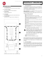 6
6
-
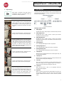 7
7
-
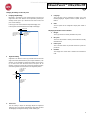 8
8
-
 9
9
-
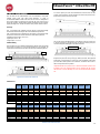 10
10
-
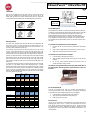 11
11
-
 12
12
-
 13
13
-
 14
14
-
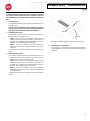 15
15
-
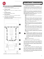 16
16
-
 17
17
-
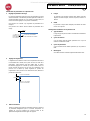 18
18
-
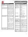 19
19
-
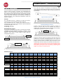 20
20
-
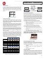 21
21
-
 22
22
-
 23
23
-
 24
24
-
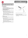 25
25
-
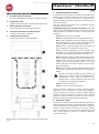 26
26
-
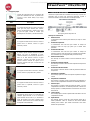 27
27
-
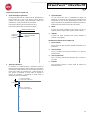 28
28
-
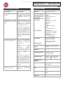 29
29
-
 30
30
-
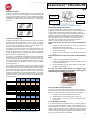 31
31
-
 32
32
-
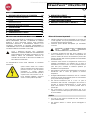 33
33
-
 34
34
-
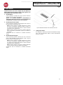 35
35
-
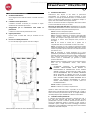 36
36
-
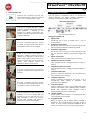 37
37
-
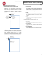 38
38
-
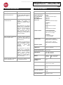 39
39
-
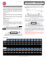 40
40
-
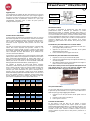 41
41
-
 42
42
-
 43
43
-
 44
44
-
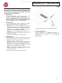 45
45
-
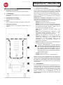 46
46
-
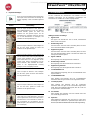 47
47
-
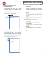 48
48
-
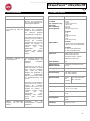 49
49
-
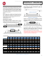 50
50
-
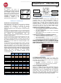 51
51
-
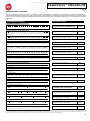 52
52
-
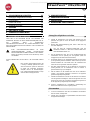 53
53
-
 54
54
-
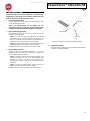 55
55
-
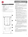 56
56
-
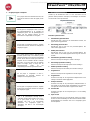 57
57
-
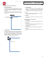 58
58
-
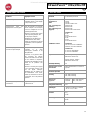 59
59
-
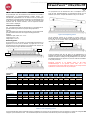 60
60
-
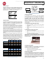 61
61
-
 62
62
-
 63
63
-
 64
64
-
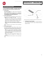 65
65
-
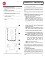 66
66
-
 67
67
-
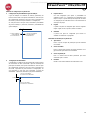 68
68
-
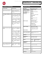 69
69
-
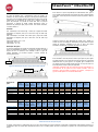 70
70
-
 71
71
-
 72
72
-
 73
73
-
 74
74
-
 75
75
-
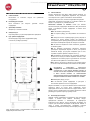 76
76
-
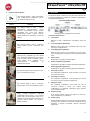 77
77
-
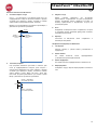 78
78
-
 79
79
-
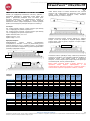 80
80
-
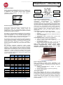 81
81
-
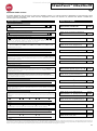 82
82
-
 83
83
-
 84
84
-
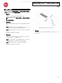 85
85
-
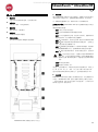 86
86
-
 87
87
-
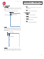 88
88
-
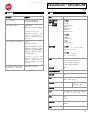 89
89
-
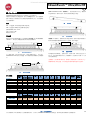 90
90
-
 91
91
-
 92
92


