
BEDIENUNG UND INSTALLATION
OPERATION AND INSTALLATION
UTILISATION ET INSTALLATION
BEDIENING EN INSTALLATIE
OBSLUHA A INSTALACE
ЭКСПЛУАТАЦИЯ И МОНТАЖ
OBSLUHA A INŠTALÁCIA
Einschraubheizkörper | Immersion heater | Cartouche chauffante à visser |
Inschroef-verwarmingselement | | Ввинчивающийся
нагревательный элемент | Skrutkovacie ohrievacie teleso
» BGC
» BGC/45
» BGC 2
» BGC 2/60

2 | BGC WWW.STIEBEL-ELTRON.COM
INHALT | BEDIENUNG
ALLGEMEINE HINWEISE
BEDIENUNG
1. Allgemeine Hinweise ����������������������������������������2
1.1 Sicherheitshinweise ��������������������������������������������� 2
1.2 Andere Markierungen in dieser Dokumentation ���������� 2
1.3 Maßeinheiten ����������������������������������������������������� 2
2. Sicherheit �����������������������������������������������������3
2.1 Bestimmungsgemäße Verwendung ������������������������� 3
2.2 Allgemeine Sicherheitshinweise ������������������������������ 3
3. Gerätebeschreibung �����������������������������������������3
4. Einstellungen �������������������������������������������������3
5. Reinigung, Pflege und Wartung ����������������������������3
6. Problembehebung �������������������������������������������3
INSTALLATION
7. Sicherheit �����������������������������������������������������4
7.1 Allgemeine Sicherheitshinweise ������������������������������ 4
7.2 Vorschriften, Normen und Bestimmungen ����������������� 4
7.3 Wasseranschluss und Sicherheitsgruppe ������������������� 4
8. Gerätebeschreibung �����������������������������������������4
8.1 Lieferumfang ����������������������������������������������������� 4
8.2 Notwendiges Zubehör ������������������������������������������ 4
9. Montage �������������������������������������������������������4
10. Inbetriebnahme ����������������������������������������������6
10.1 Übergabe des Gerätes ������������������������������������������ 6
11. Einstellungen �������������������������������������������������6
12. Störungsbehebung �������������������������������������������6
13. Wartung �������������������������������������������������������7
14. Technische Daten ��������������������������������������������� 7
14.1 Maße und Anschlüsse ������������������������������������������ 7
14.2 Elektroschaltpläne und Anschlüsse �������������������������� 7
14.3 Datentabelle ������������������������������������������������������ 8
KUNDENDIENST UND GARANTIE
UMWELT UND RECYCLING
1.1 Sicherheitshinweise
1.1.1 Aufbau von Sicherheitshinweisen
! SIGNALWORT Art der Gefahr
Hier stehen mögliche Folgen bei Nichtbeachtung des Si-
cherheitshinweises.
Hier stehen Maßnahmen zur Abwehr der Gefahr.
1.1.2 Symbole, Art der Gefahr
Symbol Art der Gefahr
Verletzung
Stromschlag
Verbrennung
(Verbrennung, Verbrühung)
1.1.3 Signalworte
SIGNALWORT Bedeutung
GEFAHR Hinweise, deren Nichtbeachtung schwere Verletzungen
oder Tod zur Folge haben.
WARNUNG Hinweise, deren Nichtbeachtung schwere Verletzungen
oder Tod zur Folge haben kann.
VORSICHT Hinweise, deren Nichtbeachtung zu mittelschweren oder
leichten Verletzungen führen kann.
1.2 Andere Markierungen in dieser Dokumentation
Hinweis
Allgemeine Hinweise werden mit dem nebenstehenden
Symbol gekennzeichnet.
Lesen Sie die Hinweistexte sorgfältig durch.
Symbol Bedeutung
Sachschaden
(Geräte-, Folge-, Umweltschaden)
Geräteentsorgung
Dieses Symbol zeigt Ihnen, dass Sie etwas tun müssen.
Die erforderlichen Handlungen werden Schritt für Schritt
beschrieben.
1.3 Maßeinheiten
Hinweis
Wenn nicht anders angegeben, sind alle Maße in Milli-
meter.
!
!
BEDIENUNG
1. Allgemeine Hinweise
Das Kapitel „Bedienung“ richtet sich an den Gerätebenutzer und
den Fachhandwerker.
Das Kapitel „Installation“ richtet sich an den Fachhandwerker.
Hinweis
Lesen Sie diese Anleitung vor dem Gebrauch sorgfältig
durch und bewahren Sie sie auf.
Geben Sie die Anleitung gegebenenfalls an einen nach-
folgenden Benutzer weiter.

BEDIENUNG
SICHERHEIT
DEUTSCH
WWW.STIEBEL-ELTRON.COM BGC | 3
2. Sicherheit
2.1 Bestimmungsgemäße Verwendung
Das Gerät ist für den Einbau in den Behälter einer geschlossenen
Heizungs- oder Trinkwasser-Erwärmungsanlage vorgesehen.
Das Gerät ist für den Einsatz im häuslichen Umfeld vorgesehen.
Es kann von nicht eingewiesenen Personen sicher bedient wer-
den. In nicht häuslicher Umgebung, z.B. im Kleingewerbe, kann
das Gerät ebenfalls verwendet werden, sofern die Benutzung in
gleicher Weise erfolgt.
Eine andere oder darüber hinausgehende Benutzung gilt als nicht
bestimmungsgemäß. Zum bestimmungsgemäßen Gebrauch ge-
hört auch das Beachten dieser Anleitung. Bei Änderungen oder
Umbauten am Gerät erlischt jegliche Gewährleistung.
Als nicht bestimmungsgemäß gilt auch der Einsatz des Gerätes
zur Erwärmung anderer Flüssigkeiten als Wasser oder auch mit
Chemikalien versetzten Wassers wie z.B. Sole.
2.2 Allgemeine Sicherheitshinweise
WARNUNG Stromschlag
Spritzen Sie nie mit Wasser oder anderen Flüssigkeiten
auf das Gerät.
WARNUNG Verbrennung
Bei Temperatur-Einstellung größer 43°C kann sofort
Wasser hoher Temperatur fließen.
! WARNUNG Verletzung
Das Gerät kann von Kindern ab 8 Jahren sowie von Per-
sonen mit verringerten physischen, sensorischen oder
mentalen Fähigkeiten oder Mangel an Erfahrung und
Wissen benutzt werden, wenn sie beaufsichtigt werden
oder bezüglich des sicheren Gebrauchs des Geräts unter-
wiesen wurden und die daraus resultierenden Gefahren
verstanden haben. Kinder dürfen nicht mit dem Gerät
spielen. Reinigung und Benutzer-Wartung dürfen nicht
von Kindern ohne Beaufsichtigung durchgeführt werden.
Hinweis
Beim Einsatz des Einschraubheizkörpers steht der Behäl-
ter unter Wasserleitungsdruck.
Während der Aufheizung tropft das Ausdehnungswasser
aus dem Sicherheitsventil. Tropft nach Beendigung der
Aufheizung Wasser, informieren Sie Ihren Fachhandwer-
ker.
3. Gerätebeschreibung
Das Gerät erwärmt elektrisch Trinkwasser. Die Tempera tur kön-
nen Sie mit dem Temperatur-Einstellknopf bestimmen. Wenn die
gewählte Temperatur erreicht ist, schaltet das Gerät ab und bei
Bedarf automatisch wieder ein.
4. Einstellungen
26�02�79�0033
Sie können die Temperatur stufenlos einstellen. Werkseitig ist die
Temperatureinstellung begrenzt und kann vom Fachhandwerker
anders eingestellt werden (siehe Kapitel „Installation/ Einstel-
lungen“).
Sie unterbrechen die Aufheizung, indem Sie den Temperatur-Ein-
stellknopf auf „kalt“ (siehe Abbildung) stellen.
5. Reinigung, Pflege und Wartung
Ist das Gerät in einer Trinkwasser-Erwärmungsanlage instal-
liert, beachten Sie Folgendes: Fast jedes Wasser scheidet bei
hohen Temperaturen Kalk aus. Der Kalk lagert sich beson-
ders am Heizkörper ab und muss von Zeit zu Zeit vom Fach-
handwerker entfernt werden.
Berücksichtigen Sie beim Einsatz des Einschraubheizkörpers
in Behältern mit Magnesium-Schutzanode den erhöhten
Anodenabtrag. Kontrollieren Sie Schutzanode und Heizkörper
erstmals nach ca. 1 Jahr.
Betätigen Sie regelmäßig das Sicherheitsventil, um einem
Festsitzen z. B. durch Kalkablagerungen vorzubeugen.
6. Problembehebung
Störung Ursache Behebung
Das Wasser wird
nicht warm.
Es liegt keine Spannung an. Prüfen Sie die Sicherungen in
der Hausinstallation.
Die Temperatur ist falsch
eingestellt.
Prüfen Sie die Temperatur-
einstellung.
Können Sie die Ursache nicht beheben, rufen Sie den Fachhand-
werker. Zur besseren und schnelleren Hilfe teilen Sie ihm die
Nummer vom Typenschild mit (Nr. 000000-0000-000000):
BGC Nr.: 000000 - 0000 - 000000
Made in Germany
26�02�79�0048

4 | BGC WWW.STIEBEL-ELTRON.COM
INSTALLATION
SICHERHEIT
INSTALLATION
7. Sicherheit
Die Installation, Inbetriebnahme sowie Wartung und Reparatur
des Gerätes darf nur von einem Fachhandwerker durchgeführt
werden.
7.1 Allgemeine Sicherheitshinweise
Wir gewährleisten eine einwandfreie Funktion und Betriebssicher-
heit nur, wenn das für das Gerät bestimmte Original-Zubehör und
die originalen Ersatzteile verwendet werden.
7.2 Vorschriften, Normen und Bestimmungen
Hinweis
Beachten Sie alle nationalen und regionalen Vorschriften
und Bestimmungen.
7.3 Wasseranschluss und Sicherheitsgruppe
Hinweis
Führen Sie alle Wasseranschluss- und Installationsarbei-
ten nach Vorschrift aus.
Der Behälter muss mit Wassereinlauf- und Wasserauslaufrohren
aus Metall versehen sein. Andere berührbare Metallteile des Be-
hälters, die mit Wasser in Berührung kommen, müssen dauerhaft
und zuverlässig mit dem Schutzleiter verbunden sein.
Der max. zulässige Druck darf nicht überschritten werden (siehe
Kapitel „Technische Daten/ Datentabelle“ und Technische Daten
des Behälters).
Installieren Sie ein baumustergeprüftes Sicherheitsventil in
der Kaltwasserzulaufleitung. Beachten Sie dabei, dass Sie in
Abhängigkeit von dem Ruhedruck evtl. zusätzlich ein Druck-
minderventil benötigen.
Dimensionieren Sie die Abflussleitung so, dass bei voll ge-
öffnetem Sicherheitsventil das Wasser ungehindert ablaufen
kann.
Montieren Sie die Abblaseleitung des Sicherheitsventils mit
einer stetigen Abwärtsneigung in einem frostfreien Raum.
Die Abblaseöffnung des Sicherheitsventils muss zur Atmo-
sphäre geöffnet bleiben.
8. Gerätebeschreibung
8.1 Lieferumfang
Mit dem Gerät werden geliefert:
- Schaltbildaufkleber
- Verlängerung, G 1½, 45mm (BGC/45 | BGC 2/60)
8.2 Notwendiges Zubehör
In Abhängigkeit vom Ruhedruck sind Sicherheitsgruppen und
Druckminderventile erhältlich. Diese baumustergeprüften Sicher-
heitsgruppen schützen das Gerät vor unzulässigen Drucküber-
schreitungen.
9. Montage
Hinweis
Der Einbau von unten ist aus Sicherheitsgründen nicht
zulässig.
26�02�09�0001
Beachten Sie die zulässigen Einbaulagen im Behälter (siehe
Abbildung).
Bauen Sie den Einschraubheizkörper nur mit parallel aus-
gerichteten Heizkörpern und Schutzrohr ein. Richten Sie die
Bauteile gegebenenfalls nach.
Achten Sie beim Einbau darauf, dass der Temperatur-Ein-
stellknopf oben ist.
Schrauben Sie das Gerät mindestens bis zur Hälfte des Ge-
windes ein. Der Einschraubheizkörper wird mit einem Dich-
tring abgedichtet.

DEUTSCH
WWW.STIEBEL-ELTRON.COM BGC | 5
INSTALLATION
MONTAGE
BGC | BGC/45
≤ 65
1
26�02�79�0044
BGC 2 | BGC 2/60
≤ 100
1
26�02�79�0075
1 Verlängerung (BGC/45 | BGC 2/60)
Falls Sie das Gerät in einem Speicher mit Wärmedämmung
montieren, verwenden Sie einen Einschraubheizkörper mit
Verlängerung. Sie können die Verlängerung auch nutzen, um
die Eintauchtiefe zu reduzieren (siehe Kapitel „Technische
Daten/ Datentabelle“). Der maximale Abstand zwischen Ein-
schraubheizkörper und Behälter (siehe Abbildung) darf nicht
überschritten werden.
Elektroanschluss herstellen
WARNUNG Stromschlag
Führen Sie alle elektrischen Anschluss- und Installati-
onsarbeiten nach Vorschrift aus.
WARNUNG Stromschlag
Der Anschluss an das Stromnetz ist nur als fester An-
schluss möglich. Das Gerät muss über eine Trenn strecke
von mindestens 3mm allpolig vom Netzanschluss ge-
trennt werden können.
! Sachschaden
Beachten Sie das Typenschild. Die angegebene Spannung
muss mit der Netzspannung übereinstimmen.
Hinweis
Achten Sie darauf, dass das Gerät an den Schutzleiter
angeschlossen ist.
Ziehen Sie den Temperatur-Einstellknopf ab.
Drehen Sie die Schrau ben heraus.
Nehmen Sie die den Schaltraumdeckel ab.
100
200
26�02�79�0049
Bereiten Sie die Anschlussleitung vor und beachten Sie
dabei, dass der Schutzleiter länger sein muss als die übrigen
Leiter.
Führen Sie die Anschlussleitung durch die Kabelführung in
den Schaltraum ein.
Schließen Sie die gewünschte Leistung entsprechend der An-
schlussbeispiele an (siehe Kapitel „Technische Daten/ Elekt-
roschaltpläne und Anschlüsse“).
Kreuzen Sie die gewählte Anschlussleistung und -span-
nung auf dem Typenschild an. Verwenden Sie dabei einen
Kugelschreiber.
Überkleben Sie gegebenenfalls das Schaltbild im Schaltraum-
deckel mit dem entsprechenden Schaltbildaufkleber.
Montage abschließen
Setzen Sie den Schaltraumdeckel wieder auf und drehen Sie
die Schrauben ein.
Stecken Sie den Temperatur-Einstellknopf auf.

6 | BGC WWW.STIEBEL-ELTRON.COM
INSTALLATION
INBETRIEBNAHME
10. Inbetriebnahme
! Sachschaden
Bei Trockengang wird der Sicherheitstemperaturbegren-
zer zerstört und die Regler-Begrenzer-Kombination muss
ausgetauscht werden.
! Sachschaden
Ist im gleichen Behälter ein Wärmeübertrager eingebaut,
müssen Sie die maximale Temperatur dieses Wärme-
übertragers begrenzen. Hierdurch verhindern Sie, dass
der Temperaturbegrenzer des Einschraubheizkörpers
anspricht.
Füllen Sie die Anlage mit Wasser.
Drehen Sie den Temperatur-Einstellknopf auf maximale
Temperatur.
Schalten Sie die Netzspannung ein.
Prüfen Sie die Arbeitsweise des Gerätes.
Prüfen Sie die Funktionsfähigkeit der Sicherheitsgruppe.
10.1 Übergabe des Gerätes
Erklären Sie dem Benutzer die Funktion des Gerätes und ma-
chen Sie ihn mit dem Gebrauch des Gerätes vertraut.
Weisen Sie den Benutzer auf mögliche Gefahren hin, speziell
die Verbrühungsgefahr.
Übergeben Sie diese Anweisung.
11. Einstellungen
Temperaturwahl-Begrenzung einstellen
Sie können die Temperaturwahl-Begrenzung unter dem Tempe-
ratur-Einstellknopf einstellen. Werkseitig ist das Gerät auf 60°C
begrenzt.
Trennen Sie das Gerät vom Netzanschluss.
Stellen Sie den Temperatur-Einstellknopf auf „kalt“.
Ziehen Sie den Temperatur-Einstellknopf ab.
60 °C
45 °C
12
26�02�79�0034
1 Begrenzungsscheibe
2 ohne Begrenzungsscheibe, maximal 80°C
Sie können die Begrenzung durch Wenden der Begrenzungs-
scheibe auf 45°C oder 60°C einstellen. Durch Entfernen der
Begrenzungsscheibe kann die maximale Temperatur einge-
stellt werden.
Stecken Sie den Temperatur-Einstellknopf wieder auf.
12. Störungsbehebung
Hinweis
Bei Temperaturen unter -15°C kann der Sicherheitstem-
peraturbegrenzer auslösen. Diesen Temperaturen kann
das Gerät schon bei der Lagerung oder beim Transport
ausgesetzt sein.
Störung Ursache Behebung
Das Wasser wird nicht
warm.
Der Sicherheitstem-
peraturbegrenzer hat
angesprochen, weil der
Regler defekt ist.
Beheben Sie die Fehler-
ursache. Tauschen Sie
die Regler-Begren-
zer-Kombination aus.
Der Sicherheitstem-
peraturbegrenzer hat
angesprochen, weil die
Temperatur -15°C unter-
schritten hat.
Drücken Sie die Rück-
stelltaste.
Der Sicherheitstem-
peraturbegrenzer hat
angesprochen, weil ein
Wärmeübertrager im
gleichen Behälter zu
hoch eingestellt ist.
Begrenzen Sie die ma-
ximale Temperatur des
Wärmeaustauschers.
Der Heizflansch ist de-
fekt.
Tauschen Sie den Heiz-
flansch aus.
Das Sicherheitsventil
tropft bei ausgeschalte-
ter Heizung.
Der Ventilsitz ist ver-
schmutzt.
Reinigen Sie den Ven-
tilsitz.
1
26�02�79�0035
1 Rück stelltaste des Sicherheitstemperaturbegrenzers

DEUTSCH
WWW.STIEBEL-ELTRON.COM BGC | 7
INSTALLATION
WARTUNG
13. Wartung
WARNUNG Stromschlag
Trennen Sie bei allen Arbeiten das Gerät allpolig vom
Netzanschluss.
Sicherheitsgruppe prüfen
Prüfen Sie die Sicherheitsgruppe regelmäßig.
Heizkörper entkalken
Entkalken Sie die Heizkörper nur nach Demon tage.
14. Technische Daten
14.1 Maße und Anschlüsse
BGC
Ø103
166 500
G 1 1/2
D0000019841
1
BGC/45
Ø103
166 500
45
G 1 1/2
G 1 1/2
455
D0000019842
1
BGC 2
Ø103
166 540
G 1 1/2
D0000019844
1
BGC 2/60
Ø103
166 540
480
60
G 1 1/2
G 1 1/2
D0000019843
1
1 Durchführung elektrische Leitung
14.2 Elektroschaltpläne und Anschlüsse
Das Gerät ist bei Werksauslieferung wie folgt geschaltet.
6 kW, 3/PE ~ 400 V
L1 L2 L3 N
STB
TR
11 21 31
12
11
22
21
32
31
12 22 32
26�02�79�0039
1
Wenn Sie eine andere Leistung wählen, beachten Sie folgende
Schaltpläne.
2 kW, 1/N/PE ~ 230 V
L1 L2 L3 N
STB
TR
11 21 31
12
11
22
21
32
31
12 22 32
26�02�79�0040
1
3 kW, 2/PE ~ 400 V
1
L1 L2 L3 N
STB
TR
11 21 31
12
11
22
21
32
31
12 22 32
26�02�79�0041
1 Heizkörper 1,9 kW

8 | BGC WWW.STIEBEL-ELTRON.COM
INSTALLATION
TECHNISCHE DATEN
4 kW, 1/N/PE ~ 230 V
1
L1 L2 L3 N
STB
TR
11 21 31
12
11
22
21
32
31
12 22 32
26�02�79�0042
5,7 kW, 1/N/PE ~ 230 V
1
L1 L2 L3 N
STB
TR
11 21 31
12
11
22
21
32
31
12 22 32
26�02�79�0043
1 Heizkörper 1,9 kW
14.3 Datentabelle
BGC BGC/45 BGC 2 BGC 2/60
003769 075115 232029 232030
Elektrische Daten
Anschlussleistung ~ 230 V kW 2-5,7 2-5,7 2-5,7 2-5,7
Anschlussleistung ~ 400 V kW 6 6 6 6
Nennspannung V230/400 230/400 230/400 230/400
Phasen 1/N/PE, 2/PE, 3/PE 1/N/PE, 2/PE, 3/PE 1/N/PE, 2/PE, 3/PE 1/N/PE, 2/PE, 3/PE
Frequenz Hz 50/60 50/60 50/60 50/60
Betriebsart Einkreis X X X X
Einsatzgrenzen
Temperatureinstellbereich °C 10-80 10-80 10-80 10-80
Max. zulässiger Druck MPa 1 1 1 1
Mindestdurchmesser Behälter mm 450 450 450 450
Mindestvolumen Behälter l50 50 50 50
Ausführungen
Schutzart (IP) IP44 IP44 IP44 IP44
Dimensionen
Eintauchtiefe mm 500 455 540 480
Gewichte
Gewicht kg 22,5 2,2 2,8

DEUTSCH
WWW.STIEBEL-ELTRON.COM BGC | 9
KUNDENDIENST UND GARANTIE
Erreichbarkeit
Sollte einmal eine Störung an einem unserer Produkte auftre-
ten, stehen wir Ihnen natürlich mit Rat und Tat zur Seite.
Rufen Sie uns an:
05531 702-111
oder schreiben Sie uns:
Stiebel Eltron GmbH & Co. KG
- Kundendienst -
Fürstenberger Straße 77, 37603 Holzminden
E-Mail: kundendienst@stiebel-eltron.de
Fax: 05531 702-95890
Weitere Anschriften sind auf der letzten Seite aufgeführt.
Unseren Kundendienst erreichen Sie telefonisch rund um die
Uhr, auch an Samstagen und Sonntagen sowie an Feiertagen.
Kundendiensteinsätze erfolgen während unserer Geschäftszei-
ten (von 7.15 bis 18.00 Uhr, freitags bis 17.00 Uhr). Als Sonder-
service bieten wir Kundendiensteinsätze bis 21.30 Uhr. Für die-
sen Sonderservice sowie Kundendiensteinsätze an Wochenen-
den und Feiertagen werden höhere Preise berechnet.
Garantiebedingungen
Diese Garantiebedingungen regeln zusätzliche Garantieleistun-
gen von uns gegenüber dem Endkunden. Sie treten neben die
gesetzlichen Gewährleistungsansprüche des Kunden. Die ge-
setzlichen Gewährleistungsansprüche gegenüber den sonsti-
gen Vertragspartnern sind nicht berührt.
Diese Garantiebedingungen gelten nur für solche Geräte, die
vom Endkunden in der Bundesrepublik Deutschland als Neuge-
räte erworben werden. Ein Garantievertrag kommt nicht zu-
stande, soweit der Endkunde ein gebrauchtes Gerät oder ein
neues Gerät seinerseits von einem anderen Endkunden erwirbt.
Inhalt und Umfang der Garantie
Die Garantieleistung wird erbracht, wenn an unseren Geräten
ein Herstellungs- und/oder Materialfehler innerhalb der Garan-
tiedauer auftritt. Die Garantie umfasst jedoch keine Leistungen
für solche Geräte, an denen Fehler, Schäden oder Mängel auf-
grund von Verkalkung, chemischer oder elektrochemischer
Einwirkung, fehlerhafter Aufstellung bzw. Installation sowie
unsachgemäßer Einregulierung, Bedienung oder unsachgemä-
ßer Inanspruchnahme bzw. Verwendung auftreten. Ebenso
ausgeschlossen sind Leistungen aufgrund mangelhafter oder
unterlassener Wartung, Witterungseinflüssen oder sonstigen
Naturerscheinungen.
Die Garantie erlischt, wenn am Gerät Reparaturen, Eingriffe oder
Abänderungen durch nicht von uns autorisierte Personen vor-
genommen wurden.
Die Garantieleistung umfasst die sorgfältige Prüfung des Gerä-
tes, wobei zunächst ermittelt wird, ob ein Garantieanspruch
besteht. Im Garantiefall entscheiden allein wir, auf welche Art
der Fehler behoben wird. Es steht uns frei, eine Reparatur des
Gerätes ausführen zu lassen oder selbst auszuführen. Etwaige
ausgewechselte Teile werden unser Eigentum.
Für die Dauer und Reichweite der Garantie übernehmen wir
sämtliche Material- und Montagekosten.
Soweit der Kunde wegen des Garantiefalles aufgrund gesetzli-
cher Gewährleistungsansprüche gegen andere Vertragspartner
Leistungen erhalten hat, entfällt eine Leistungspflicht von uns.
Soweit eine Garantieleistung erbracht wird, übernehmen wir
keine Haftung für die Beschädigung eines Gerätes durch Dieb-
stahl, Feuer, Aufruhr oder ähnliche Ursachen.
Über die vorstehend zugesagten Garantieleistungen hinausge-
hend kann der Endkunde nach dieser Garantie keine Ansprüche
wegen mittelbarer Schäden oder Folgeschäden, die durch das
Gerät verursacht werden, insbesondere auf Ersatz außerhalb des
Gerätes entstandener Schäden, geltend machen. Gesetzliche
Ansprüche des Kunden uns gegenüber oder gegenüber Dritten
bleiben unberührt.
Garantiedauer
Für im privaten Haushalt eingesetzte Geräte beträgt die Garan-
tiedauer 24 Monate; im Übrigen (zum Beispiel bei einem Einsatz
der Geräte in Gewerbe-, Handwerks- oder Industriebetrieben)
beträgt die Garantiedauer 12 Monate.
Die Garantiedauer beginnt für jedes Gerät mit der Übergabe des
Gerätes an den Kunden, der das Gerät zum ersten Mal einsetzt.
Garantieleistungen führen nicht zu einer Verlängerung der
Garantiedauer. Durch die erbrachte Garantieleistung wird keine
neue Garantiedauer in Gang gesetzt. Dies gilt für alle erbrachten
Garantieleistungen, insbesondere für etwaig eingebaute Ersatz-
teile oder für die Ersatzlieferung eines neuen Gerätes.
Inanspruchnahme der Garantie
Garantieansprüche sind vor Ablauf der Garantiedauer, innerhalb
von zwei Wochen, nachdem der Mangel erkannt wurde, bei uns
anzumelden. Dabei müssen Angaben zum Fehler, zum Gerät
und zum Zeitpunkt der Feststellung gemacht werden. Als Ga-
rantienachweis ist die Rechnung oder ein sonstiger datierter
Kaufnachweis beizufügen. Fehlen die vorgenannten Angaben
oder Unterlagen, besteht kein Garantieanspruch.
Garantie für in Deutschland erworbene, jedoch außer-
halb Deutschlands eingesetzte Geräte
Wir sind nicht verpflichtet, Garantieleistungen außerhalb der
Bundesrepublik Deutschland zu erbringen. Bei Störungen eines
im Ausland eingesetzten Gerätes ist dieses gegebenenfalls auf
Gefahr und Kosten des Kunden an den Kundendienst in
Deutschland zu senden. Die Rücksendung erfolgt ebenfalls auf
Gefahr und Kosten des Kunden. Etwaige gesetzliche Ansprüche
des Kunden uns gegenüber oder gegenüber Dritten bleiben
auch in diesem Fall unberührt.
Außerhalb Deutschlands erworbene Geräte
Für außerhalb Deutschlands erworbene Geräte gilt diese Garan-
tie nicht. Es gelten die jeweiligen gesetzlichen Vorschriften und
gegebenenfalls die Lieferbedingungen der Ländergesellschaft
bzw. des Importeurs.

10 | BGC WWW.STIEBEL-ELTRON.COM
UMWELT UND RECYCLING
Entsorgung von Transport- und
Verkaufsverpackungsmaterial
Damit Ihr Gerät unbeschädigt bei Ihnen ankommt, haben wir
es sorgfältig verpackt. Bitte helfen Sie, die Umwelt zu schützen,
und entsorgen Sie das Verpackungsmaterial des Gerätes sach-
gerecht. Wir beteiligen uns gemeinsam mit dem Großhandel
und dem Fachhandwerk/ Fachhandel in Deutschland an einem
wirksamen Rücknahme- und Entsorgungskonzept für die um-
weltschonende Aufarbeitung der Verpackungen.
Überlassen Sie die Transportverpackung dem Fachhandwerker
beziehungsweise dem Fachhandel.
Entsorgen Sie Verkaufsverpackungen über eines der Dualen
Systeme in Deutschland.
Entsorgung von Altgeräten in Deutschland
Geräteentsorgung
Die mit diesem Symbol gekennzeichneten Geräte dür-
fen nicht mit dem Hausmüll entsorgt werden.
Als Hersteller sorgen wir im Rahmen der Produktverantwor-
tung für eine umweltgerechte Behandlung und Verwertung
der Altgeräte. Weitere Informationen zur Sammlung und Ent-
sorgung erhalten Sie über Ihre Kommune oder Ihren Fach-
handwerker/ Fachhändler.
Bereits bei der Entwicklung neuer Geräte achten wir auf eine
hohe Recyclingfähigkeit der Materialien.
Über das Rücknahmesystem werden hohe Recyclingquoten
der Materialien erreicht, um Deponien und die Umwelt zu ent-
lasten. Damit leisten wir gemeinsam einen wichtigen Beitrag
zum Umweltschutz.
Entsorgung außerhalb Deutschlands
Entsorgen Sie dieses Gerät fach- und sachgerecht nach den
örtlich geltenden Vorschriften und Gesetzen.

ENGLISH
WWW.STIEBEL-ELTRON.COM BGC | 11
CONTENTS | OPERATION
GENERAL INFORMATION
OPERATION
1. General information ��������������������������������������� 11
1.1 Safety instructions ����������������������������������������������11
1.2 Other symbols in this documentation ���������������������� 11
1.3 Units of measurement ����������������������������������������� 11
2. Safety �������������������������������������������������������� 12
2.1 Intended use �����������������������������������������������������12
2.2 General safety instructions �����������������������������������12
2.3 Test symbols �����������������������������������������������������12
3. Equipment description ������������������������������������ 12
4. Settings ����������������������������������������������������� 12
5. Cleaning, care and maintenance ������������������������� 12
6. Troubleshooting �������������������������������������������� 12
INSTALLATION
7. Safety �������������������������������������������������������� 13
7.1 General safety instructions ����������������������������������� 13
7.2 Instructions, standards and regulations �������������������13
7.3 Water connection and safety assembly �������������������� 13
8. Equipment description ������������������������������������ 13
8.1 Standard delivery �����������������������������������������������13
8.2 Required accessories ������������������������������������������13
9. Mounting ���������������������������������������������������� 13
10. Commissioning ��������������������������������������������� 15
10.1 Appliance handover �������������������������������������������� 15
11. Settings ����������������������������������������������������� 15
12. Troubleshooting �������������������������������������������� 15
13. Maintenance ������������������������������������������������ 16
14. Specification ������������������������������������������������ 16
14.1 Dimensions and connections ��������������������������������� 16
14.2 Wiring diagrams and connections ��������������������������16
14.3 Data table �������������������������������������������������������� 17
GUARANTEE
ENVIRONMENT AND RECYCLING
1.1 Safety instructions
1.1.1 Structure of safety instructions
! KEYWORD Type of risk
Here, possible consequences are listed that may result
from failure to observe the safety instructions.
Steps to prevent the risk are listed.
1.1.2 Symbols, type of risk
Symbol Type of risk
Injury
Electrocution
Burns
(burns, scalding)
1.1.3 Keywords
KEYWORD Meaning
DANGER Failure to observe this information will result in serious
injury or death.
WARNING Failure to observe this information may result in serious
injury or death.
CAUTION Failure to observe this information may result in non-
serious or minor injury.
1.2 Other symbols in this documentation
Note
General information is identified by the symbol shown
on the left.
Read these texts carefully.
Symbol Meaning
Material losses
(Appliance and consequential losses, environmental pol-
lution)
Appliance disposal
This symbol indicates that you have to do something. The ac-
tion you need to take is described step by step.
1.3 Units of measurement
Note
All measurements are given in mm unless stated oth-
erwise.
!
!
OPERATION
1. General information
The chapter “Operation” is intended for appliance users and quali-
fied contractors.
The chapter “Installation” is intended for qualified contractors.
Note
Read these instructions carefully before using the appli-
ance and retain them for future reference.
Pass on the instructions to a new user if required.

OPERATION
SAFETY
12 | BGC WWW.STIEBEL-ELTRON.COM
2. Safety
2.1 Intended use
The appliance is intended for installation in cylinders in a sealed
heating or DHW heating system.
This appliance is designed for domestic use. It can be used safely
by untrained persons. The appliance can also be used in a non-
domestic environment, e.g. in a small business, as long as it is
used in the same way.
Any other use beyond that described shall be deemed inappropri-
ate. Observation of these instructions is also part of the correct
use of this appliance. Any modifications or conversions to the
appliance void all warranty rights.
It is also incorrect to use the appliance to heat liquids other than
water, or water containing chemicals such as brine.
2.2 General safety instructions
WARNUNG Electrocution
Never spray the appliance with water or other liquids
WARNUNG Burns
Bei Temperatur-Einstellung größer 43°C kann sofort
Wasser hoher Temperatur fließen.
! WARNING Injury
The appliance may be used by children aged 8 and up
and persons with reduced physical, sensory or mental
capabilities or a lack of experience provided that they
are supervised or they have been instructed on how to
use the appliance safely and have understood the result-
ing risks. Children must never play with the appliance.
Children must never clean the appliance or perform user
maintenance unless they are supervised.
Note
While the threaded immersion heater is in use, the cyl-
inder is under mains water pressure.
During the heating process, expansion water will drip
from the safety valve. If water continues to drip when
heating is completed, please inform your heating con-
tractor.
2.3 Test symbols
See type plate on the appliance.
3. Equipment description
The appliance heats DHW electrically. You can adjust the tempera-
ture using the temperature selector. Once the selected tempera-
ture has been reached, the appliance switches off and restarts
automatically when required.
4. Settings
26�02�79�0033
The temperature is infinitely adjustable. Temperature selection is
limited at the factory and can be adjusted by the heating contractor
(see chapter “Installation / Settings”).
You can interrupt the heating process by setting the temperature
selector to “cold” (see figure).
5. Cleaning, care and maintenance
If the appliance is installed in a DHW heating system, please
note that almost every type of water deposits limescale at
high temperatures. Limescale builds up on the heating ele-
ment in particular and has to be removed occasionally by the
heating contractor.
Always take the increased anode wear into consideration
when using the threaded immersion heater in cylinders with
protective magnesium anodes. Protective anodes and heat-
ing elements should be checked after approx. one year.
Regularly activate the safety valve to prevent it from becom-
ing blocked e.g. by limescale deposits.
6. Troubleshooting
Fault Cause Remedy
The water does not
heat up.
There is no power.
Check the fuse/MCB in
your fuse box/distribu-
tion panel.
The temperature is incor-
rectly adjusted.
Check the temperature
selection.
If you cannot remedy the fault, notify your heating contractor. To
facilitate and speed up your enquiry, please provide the serial
number from the type plate (no. 000000-0000-000000):
BGC Nr.: 000000 - 0000 - 000000
Made in Germany
26�02�79�0048

ENGLISH
WWW.STIEBEL-ELTRON.COM BGC | 13
INSTALLATION
SAFETY
INSTALLATION
7. Safety
Only qualified contractors should carry out installation, commis-
sioning, maintenance and repair of the appliance.
7.1 General safety instructions
We guarantee trouble-free operation and operational reliability
only if the original accessories and spare parts intended for the
appliance are used.
7.2 Instructions, standards and regulations
Note
Observe all applicable national and regional regulations
and instructions.
7.3 Water connection and safety assembly
Note
Carry out all water connection and installation work in
accordance with regulations.
The cylinder must be connected with water inlet and outlet pipes
made from metal. Other metal parts of the cylinder that can be
touched and that are in contact with water must be permanently
and reliably connected with the earth conductor.
The max. permissible pressure must not be exceeded (see chapter
“Specification/ Data table” and cylinder specification).
Install a type-tested safety valve in the cold water supply
line. For this bear in mind that, depending on the static pres-
sure, you may also need a pressure reducing valve.
Size the drain so that water can drain off unimpeded when
the safety valve is fully opened.
Fit the discharge pipe of the safety valve with a constant
downward slope and in a room free from the risk of frost.
The safety valve discharge aperture must remain open to the
atmosphere.
8. Equipment description
8.1 Standard delivery
Delivered with the appliance are:
- Extension, G 1½, 45 mm (BGC/45 | BGC 2/60)
- Wiring diagram label
8.2 Required accessories
Depending on the static pressure, safety assemblies and pressure
reducing valves are available. These type-tested safety assemblies
protect the appliance against unacceptable excess pressure.
9. Mounting
Note
Installation from below is not permissible for safety rea-
sons.
26�02�09�0001
Observe the permissible installation position in the cylinder
(see figure).
Always install the threaded immersion heater with heating
elements and a protective pipe arranged in parallel. Realign
the components where necessary.
During installation, ensure that the temperature selector is at
the top.
Screw on the appliance up to at least half of the thread. The
threaded immersion heater is sealed in by means of a seal
ring.

14 | BGC WWW.STIEBEL-ELTRON.COM
INSTALLATION
MOUNTING
BGC | BGC/45
≤ 65
1
26�02�79�0044
BGC 2 | BGC 2/60
≤ 100
1
26�02�79�0075
1 Extension (BGC/45 | BGC 2/60)
If you install the appliance in a cylinder with thermal insula-
tion, use a threaded immersion heater with extension. You
can also use the extension to reduce the immersion depth
(see chapter “Specification/ Data table”). The maximum
clearance between the threaded immersion heater and cylin-
der (see diagram) must not be exceeded.
Connecting the power supply
WARNUNG Electrocution
Carry out all electrical connection and installation work
in accordance with relevant regulations.
WARNUNG Electrocution
Make the power supply only as a permanent connection.
The appliance must be able to be separated from the
mains power supply by an isolator that disconnects all
poles with at least 3 mm contact separation.
! Geräte- und Umweltschäden
Observe the type plate. The specified voltage must match
the mains voltage.
Hinweis
Ensure that the appliance is earthed.
Pull off the temperature selector.
Undo the screws.
Remove the cap.
100
200
26�02�79�0049
Prepare the power cable, ensuring that the earth conductor
is longer than the other conductors.
Feed the power cable through the cable entry into the control
panel.
Connect the required load in accordance with the connection
examples (see chapter “Specification / Wiring diagrams and
connections”).
Tick the selected connected load and voltage on the type
plate. Please use a ballpoint pen to do this.
Affix the relevant wiring diagram label if required over the
wiring diagram in the cap.
Completing the installation process
Replace the cap and secure it with screws.
Replace the temperature selector.

ENGLISH
WWW.STIEBEL-ELTRON.COM BGC | 15
INSTALLATION
COMMISSIONING
10. Commissioning
! Material losses
Boiling dry destroys the high limit safety cut-out and the
controller-limiter combination must then be replaced.
! Material losses
If a heat exchanger is installed in the same cylinder, you
must limit the maximum temperature for this heat ex-
changer. This prevents the high limit safety cut-out of the
threaded immersion heater from responding.
Fill the system with water.
Turn the temperature selector to maximum temperature.
Switch the mains power ON.
Check the function of the appliance.
Check the function of the safety assembly.
10.1 Appliance handover
Explain the appliance function to users and familiarise them
with its operation.
Make users aware of potential dangers, especially the risk of
scalding.
Hand over these instructions.
11. Settings
Adjusting the temperature selection limitation
You can adjust the temperature selection limitation beneath the
temperature selector. At the factory, the appliance is limited to
60 °C.
Isolate the appliance from the power supply.
Set the temperature selector to “cold”.
Pull off the temperature selector.
60 °C
45 °C
12
26�02�79�0034
1 Limiter disc
2 Without limiter disc, maximum 80 °C
You can set the limit to 45 °C / 60 °C by rotating the limiter
disc. By removing the limiter disc, the maximum temperature
can be set.
Replace the temperature selector.
12. Troubleshooting
Note
The high limit safety cut-out can respond at temperatures
below –15 °C. The appliance may be subjected to these
temperatures during storage or transport.
Fault Cause Remedy
The water does not
heat up.
The high limit safety
cut-out has responded
because the controller
is faulty.
Remedy the cause of
the fault. Replace the
controller-limiter com-
bination.
The high limit safety
cut-out has responded
because the temperature
has dropped below -15 °C.
Press the reset button.
The high limit safety cut-
out has responded be-
cause a heat exchanger
in the same cylinder is
set too high.
Limit the maximum
temperature of the heat
exchanger.
The flanged immersion
heater is faulty.
Replace the flanged im-
mersion heater.
The safety valve drips
when the heating is
switched off.
The valve seat is con-
taminated.
Clean the valve seat.
1
26�02�79�0035
1 High limit safety cut-out reset button

16 | BGC WWW.STIEBEL-ELTRON.COM
INSTALLATION
MAINTENANCE
13. Maintenance
WARNUNG Electrocution
Before any work on the appliance, disconnect all poles
from the power supply.
Checking the safety assembly
Regularly check the safety assembly.
Descaling heating elements
Descale the heating elements only after they have been
removed.
14. Specification
14.1 Dimensions and connections
BGC
Ø103
166 500
G 1 1/2
D0000019841
1
BGC 2
Ø103
166 540
G 1 1/2
D0000019844
1
BGC/45
Ø103
166 500
45
G 1 1/2
G 1 1/2
455
D0000019842
1
BGC 2/60
Ø103
166 540
480
60
G 1 1/2
G 1 1/2
D0000019843
1
1 Entry electrical cables
14.2 Wiring diagrams and connections
The appliance is wired as follows at the factory.
6 kW, 3/PE ~ 400 V
L1 L2 L3 N
STB
TR
11 21 31
12
11
22
21
32
31
12 22 32
26�02�79�0039
1
If you select another load, observe the following wiring diagrams.
2 kW, 1/N/PE ~ 230 V
L1 L2 L3 N
STB
TR
11 21 31
12
11
22
21
32
31
12 22 32
26�02�79�0040
1
3 kW, 2/PE ~ 400 V
1
L1 L2 L3 N
STB
TR
11 21 31
12
11
22
21
32
31
12 22 32
26�02�79�0041
1 Heating element 1.9 kW

ENGLISH
WWW.STIEBEL-ELTRON.COM BGC | 17
4 kW, 1/N/PE ~ 230 V
1
L1 L2 L3 N
STB
TR
11 21 31
12
11
22
21
32
31
12 22 32
26�02�79�0042
5.7 kW, 1/N/PE ~ 230 V
1
L1 L2 L3 N
STB
TR
11 21 31
12
11
22
21
32
31
12 22 32
26�02�79�0043
1 Heating element 1.9 kW
14.3 Data table
BGC BGC/45 BGC 2 BGC 2/60
003769 075115 232029 232030
Electrical details
Connected load with ~ 230 V kW 2-5.7 2-5.7 2-5.7 2-5.7
Connected load with ~ 400 V kW 6 6 6 6
Rated voltage V230/400 230/400 230/400 230/400
Phases 1/N/PE, 2/PE, 3/PE 1/N/PE, 2/PE, 3/PE 1/N/PE, 2/PE, 3/PE 1/N/PE, 2/PE, 3/PE
Frequency Hz 50/60 50/60 50/60 50/60
Single circuit operating mode X X X X
Application limits
Available temperature range °C 10-80 10-80 10-80 10-80
Max. permissible pressure MPa 1 1 1 1
Minimum cylinder diameter mm 450 450 450 450
Minimum cylinder volume l50 50 50 50
Versions
IP-Rating IP44 IP44 IP44 IP44
Dimensions
Depth of insertion mm 500 455 540 480
Weights
Weight kg 2.0 2.5 2.2 2.8
INSTALLATION | GUARANTEE | ENVIRONMENT AND RECYCLING
SPECIFICATION
Guarantee
The guarantee conditions of our German companies do not
apply to appliances acquired outside of Germany. In countries
where our subsidiaries sell our products a guarantee can only
be issued by those subsidiaries. Such guarantee is only grant-
ed if the subsidiary has issued its own terms of guarantee. No
other guarantee will be granted.
We shall not provide any guarantee for appliances acquired in
countries where we have no subsidiary to sell our products.
This will not aect warranties issued by any importers.
Environment and recycling
We would ask you to help protect the environment. After use,
dispose of the various materials in accordance with national
regulations.

18 | BGC WWW.STIEBEL-ELTRON.COM
TABLE DES MATIÈRES | UTILISATION
REMARQUES GÉNÉRALES
UTILISATION
1. Remarques générales ������������������������������������� 18
1.1 Consignes de sécurité ������������������������������������������ 18
1.2 Autres symboles utilisés dans cette documentation ����� 18
1.3 Unités de mesure ����������������������������������������������� 18
2. Sécurité ����������������������������������������������������� 19
2.1 Utilisation conforme ������������������������������������������� 19
2.2 Consignes de sécurité générales ���������������������������� 19
2.3 Marque de conformité ����������������������������������������� 19
3. Description de l’appareil ���������������������������������� 19
4. Réglages ���������������������������������������������������� 19
5. Nettoyage, maintenance et entretien �������������������� 19
6. Aide au dépannage ���������������������������������������� 19
INSTALLATION
7. Sécurité ����������������������������������������������������� 20
7.1 Sécurité générale ����������������������������������������������� 20
7.2 Prescriptions, normes et directives �������������������������20
7.3 Raccordement hydraulique et groupe de sécurité ������� 20
8. Description de l’appareil ���������������������������������� 20
8.1 Fourniture ��������������������������������������������������������20
8.2 Accessoires nécessaires ��������������������������������������� 20
9. Montage ����������������������������������������������������� 20
10. Mise en service ��������������������������������������������� 21
10.1 Remise de l’appareil ������������������������������������������� 21
11. Réglages ���������������������������������������������������� 22
12. Élimination des défauts ����������������������������������� 22
13. Entretien ���������������������������������������������������� 22
14. Données techniques ��������������������������������������� 23
14.1 Cotes et raccordements ����������������������������������������23
14.2 Schémas électriques et connexions ������������������������� 23
14.3 Tableau de données �������������������������������������������� 24
GARANTIE
ENVIRONNEMENT ET RECYCLAGE
1.1 Consignes de sécurité
1.1.1 Structure des consignes de sécurité
! MENTION D’AVERTISSEMENT Nature du danger
La mention indique la nature des risques encourus en
cas de non-respect de la consigne de sécurité.
Sont indiquées ici les mesures permettant le pallier
au danger.
1.1.2 Symboles, nature du danger
Symbole Nature du danger
Risque de blessure
Électrocution
Brûlure
(brûlure, ébouillantement)
1.1.3 Mentions d’avertissement
MENTION D’AVER-
TISSEMENT
Signification
DANGER Caractérise des remarques dont le non-respect en-
traîne de graves lésions, voire la mort.
AVERTISSEMENT Caractérise des remarques dont le non-respect peut
entraîner de graves lésions, voire la mort.
ATTENTION Caractérise des remarques dont le non-respect peut
entraîner des lésions légères ou moyennement graves.
1.2 Autres symboles utilisés dans cette
documentation
Remarque
Le symbole ci-contre signale des remarques d’ordre
général.
Lisez attentivement ces remarques.
Symbole Signification
Dommages matériels
(dommages causés à l’appareil, dommages indirects et
pollution de l’environnement)
Recyclage de l’appareil
Ce symbole signale une action à entreprendre. Les actions
nécessaires sont décrites pas-à-pas.
1.3 Unités de mesure
Remarque
Sauf indication contraire, toutes les cotes sont indiquées
en millimètres.
!
!
UTILISATION
1. Remarques générales
Le chapitre «Utilisation» s’adresse aux utilisateurs de l’appareil
et aux installateurs.
Le chapitre «Installation» s’adresse aux installateurs.
Remarque
Veuillez lire attentivement cette notice avant utilisation
et conservez-la soigneusement.
Remettez cette notice au nouvel utilisateur le cas échéant.

UTILISATION
SÉCURITÉ
FRANÇAIS
WWW.STIEBEL-ELTRON.COM BGC | 19
2. Sécurité
2.1 Utilisation conforme
Cet appareil est conçu pour être monté dans le réservoir d’une
installation de chauffage ou de réchauffement de l’eau sanitaire
en circuit fermé.
L’appareil est destiné à une utilisation domestique. Il peut être
utilisé par des personnes qui ne disposent pas de connaissances
techniques particulières. L’appareil peut également être utilisé
dans un environnement non domestique, p. ex. dans des petites
entreprises, à condition que son utilisation soit identique.
Tout emploi sortant de ce cadre est considéré comme non
conforme. Fait aussi partie d’une utilisation conforme le respect
de cette notice. Toute garantie expire en cas de modifications ou
de transformations apportées à cet appareil.
L’utilisation de l’appareil pour chauffer d’autres liquides que l’eau
ou bien de l’eau additionnée de produits chimiques, comme p. ex.
de l’eau glycolée, est également considérée comme non conforme.
2.2 Consignes de sécurité générales
AVERTISSEMENT Électrocution
N'éclaboussez jamais l'appareil avec de l'eau ou d'autres
liquides.
AVERTISSEMENT Brûlure
Si la température est réglée à plus de 43 °C, de l'eau
chaude à température élevée peut s'écouler immédia-
tement .
! AVERTISSEMENT Blessure
L’appareil peut être utilisé par les enfants de 8 ans et plus
ainsi que par les personnes aux facultés physiques, sen-
sorielles ou mentales réduites ou par des personnes sans
expérience lorsqu’ils sont sous surveillance ou qu’ils ont
été formés à l’utilisation en toute sécurité de l’appareil
et qu’ils ont compris les dangers encourus. Ne laissez
pas les enfants jouer avec l’appareil. Ni le nettoyage ni
la maintenance relevant de l’utilisateur ne doivent être
effectués par des enfants sans surveillance.
Remarque.
En service, le réservoir avec la cartouche chauffante à
visser est sous pression de l'eau courante .
Pendant la montée en température, de l'eau due à l'ex-
pansion goutte de la vanne de sécurité. Si l'eau coule tou-
jours alors que le chauffage de l'eau est achevé, appelez
l'installateur.
2.3 Marque de conformité
Voir la plaque signalétique apposée sur l’appareil.
3. Description de l’appareil
Cet appareil réchauffe l’eau chaude potable électriquement. La
température se détermine à l’aide du bouton de réglage de tem-
pérature. L’appareil se coupe automatiquement dès que la tem-
pérature sélectionnée est atteinte et se remet automatiquement
en marche en cas de besoin.
4. Réglages
26�02�79�0033
Vous pouvez régler la température en continu. Le réglage de la
température est limité en usine et votre artisan professionnel peut
changer le réglage de la température (voir le chapitre Installation/
Réglages).
Vous arrêtez la chauffe de l’eau en réglant le bouton de réglage
de la température sur froid (voir la figure).
5. Nettoyage, maintenance et
entretien
Si l’appareil est installé dans une installation de réchauf-
fement de l’eau potable, il faut noter ceci : presque toutes
les eaux déposent du calcaire à des températures élevées.
Le tartre se dépose sur les corps de chauffe en particu-
lier et doit être éliminé de temps à autre par votre artisan
professionnel.
Si une cartouche chauffante à visser est mise en œuvre dans
des réservoirs à anode de protection au magnésium, il faut
prendre en compte l’usure plus élevée de l’anode. Il faudra
contrôler l’anode de protection et la cartouche au bout d’une
année environ pour la première fois.
Actionnez régulièrement la soupape de sécurité afin d’éviter
tout grippage dû aux dépôts de calcaire.
6. Aide au dépannage
Perturbation Cause
Comment y remédier
L'eau n'est pas
chaude.
Pas de tension. Contrôlez les fusibles dans la boîte
de fusibles de la maison.
La température est mal
réglée.
Contrôlez le réglage de la tempé-
rature.
Si vous ne pouvez pas remédier à la panne, appelez un spé-
cialiste. Pour qu’il puisse vous aider plus rapidement et mieux,
donnez-lui le numéro indiqué sur la plaque signalétique
(n° 000000-0000-000000) :
BGC Nr.: 000000 - 0000 - 000000
Made in Germany
26�02�79�0048

20 | BGC WWW.STIEBEL-ELTRON.COM
INSTALLATION
SÉCURITÉ
INSTALLATION
7. Sécurité
L’installation, la mise en service, la maintenance et les réparations
de cet équipement ne doivent être effectuées que par un artisan
professionnel.
7.1 Sécurité générale
Nous garantissons un bon fonctionnement et la sécurité d’exploi-
tation uniquement si les accessoires d’origine destinés à l’appareil
ainsi que les pièces de rechange d’origine sont utilisés.
7.2 Prescriptions, normes et directives
Remarque.
Prenez en compte toutes les prescriptions et les consignes
nationales et régionales.
7.3 Raccordement hydraulique et groupe de
sécurité
Remarque
Exécutez tous les travaux de raccordement et d’installa-
tion hydrauliques suivant les prescriptions.
Le ballon doit être équipé de tubes d’admission et de sortie d’eau
en métal. D’’autres parties métalliques accessibles qui entrent en
contact avec l’’eau doivent être reliées en permanence à la terre.
La pression max. admissible ne doit pas être dépassée (voir le
chapitre «Donnéestechniques/Tableau de données» et les don-
nées techniques du ballon).
Installez une soupape de sécurité arrivée eau froide testée
conforme au type de construction. Notez qu’en fonction de
la pression au repos, il sera éventuellement nécessaire de
poser un réducteur de pression supplémentaire.
La conduite d’évacuation doit être conçue de sorte que l’eau
puisse s’écouler librement lorsque la soupape de sécurité est
entièrement ouverte.
Installez la conduite de purge de la soupape de sécurité avec
une inclinaison constante vers le bas dans un local à l’abri du
gel.
L’ouverture de purge de la soupape de sécurité doit être
ouverte sur l’atmosphère.
8. Description de l’appareil
8.1 Fourniture
Equipement fourni avec l’appareil :
- Rallonge
, G 1½, 45 mm
(BGC/45 | BGC 2/60)
- Autocollant schéma de connexion
8.2 Accessoires nécessaires
Des groupes de sécurité et des réducteurs de pression peuvent
être fournis si la pression au repos le nécessite. Ces groupes de
sécurité homologués protègent l’appareil des excès de pression
non autorisés.
9. Montage
Remarque.
Le montage en bas n'est pas autorisé pour des raisons
de sécurité .
26�02�09�0001
Respectez les positions de montage admissibles dans le
réservoir (voir la figure).
N’installez la cartouche chauffante qu’avec des corps de
chauffe et un tube de protection orientés parallèlement. Si
besoin est, ajustez les modules.
Assurez-vous au montage que le bouton de réglage de la
température est en haut.
Vissez l’appareil sur au moins la moitié du filetage. La car-
touche chauffante est étanchéifiée avec un joint d’étanchéité.

FRANÇAIS
WWW.STIEBEL-ELTRON.COM BGC | 21
INSTALLATION
MISE EN SERVICE
BGC | BGC/45
≤ 65
1
26�02�79�0044
BGC 2 | BGC 2/60
≤ 100
1
26�02�79�0075
1 Rallonge (BGC/45 | BGC 2/60)
Si vous montez l’appareil dans un ballon doté d’une isola-
tion thermique, utilisez un système chauffant à visser avec
rallonge. Vous pouvez également utiliser la rallonge pour
réduire la profondeur de plongée (voir chapitre Données
techniques / Tableau de données). L’écart maximal entre le
système chauffant à visser et le ballon (voir figure) ne doit
pas être dépassé.
9.2.1 Raccordement électrique
AVERTISSEMENT Électrocution
Exécutez tous les travaux de raccordement et d'installa-
tion électriques conformément aux prescriptions.
AVERTISSEMENT Électrocution
Le raccordement au secteur ne peut être qu'une
connexion fixe. L'appareil doit pouvoir être déconnecté
du secteur par un dispositif de coupure omnipolaire
ayant une ouverture minimale des contacts de 3 mm.
! Dommages matériels
Se référer à la plaque signalétique. La tension indiquée
doit concorder avec celle du secteur.
Remarque.
Assurez-vous que l'appareil est bien raccordé au conduc-
teur de protection.
Sortez le bouton de réglage de la température.
Dévissez les vis.
Ôtez le capot.
100
200
26�02�79�0049
Préparez la ligne de raccordement électrique en respectant
le fait que le conducteur de protection doit être plus long que
les autres conducteurs.
Passez le câble de raccordement au travers du passe-câble
dans la zone de commande.
Raccordez la puissance souhaitée en fonction des exemples
de raccordement (voir le chapitre Données techniques / Sché-
mas électriques et connexions).
Marquez d’une croix la puissance et la tension de raccorde-
ment choisie sur la plaquette signalétique. Utilisez un stylo
bille.
Appliquez, si besoin est, l’autocollant du schéma de
connexion respectif dans le capot en recouvrant l’ancien.
Achèvement du montage
Replacez le capot et vissez-le.
Remettez le bouton de réglage de la température en place.
10. Mise en service
! Dommages matériels
Le limiteur de température de sécurité est détruit en cas
de marche à sec et le régulateur-limiteur de température
devra être remplacé.
! Dommages matériels
Si un échangeur de chaleur est monté dans le même
réservoir, vous devez limiter la température maximale
de cet échangeur. Vous éviterez ainsi que le limiteur de
température de la cartouche chauffante à visser ne se
déclenche.
Remplissez l’installation d’eau.
Tournez le bouton de réglage de la température sur la tem-
pérature maximale.
Branchez la tension secteur.
Contrôlez le fonctionnement de l’appareil.
Vérifiez le fonctionnement du groupe de sécurité.
10.1 Remise de l’appareil
Expliquez le fonctionnement de l’appareil à l’utilisateur puis
familiarisez-le avec l’emploi de l’appareil.
Instruisez l’utilisateur sur les risques éventuels, notamment
sur les risques de brûlure.
Remettez cette notice.

22 | BGC WWW.STIEBEL-ELTRON.COM
INSTALLATION
RÉGLAGES
11. Réglages
Réglage de la limitation de sélection de la température
Vous pouvez régler la limitation de sélection de la température
sous le bouton de réglage de la température. L’appareil est limité
à 60 °C en usine.
Débranchez l’appareil du secteur.
Mettez le bouton de réglage de la température sur « froid ».
Sortez le bouton de réglage de la température.
60 °C
45 °C
12
26�02�79�0034
1 Disque limiteur
2 Sans disque limiteur, 80 °C maximum
Vous pouvez choisir une limitation à 45 °C/ 60 °C en retour-
nant le disque limiteur. Après avoir enlevé le disque limiteur,
la température maximale peut être réglée.
Remettez le bouton de réglage de la température en place.
12. Élimination des défauts
Remarque.
Le limiteur de température de sécurité peut se déclencher
à des températures inférieures à -15 °C. L’appareil peut
être soumis à de telles températures lors de son stockage
ou de son transport.
Perturbation Cause
Comment y remédier
L'eau n'est pas chaude. Le limiteur de tempé-
rature de sécurité s'est
déclenché parce que le
régulateur est défaillant.
Remédiez à la cause du
problème. Remplacez
le combiné régulateur-
limiteur.
Le limiteur de tempé-
rature de sécurité s'est
déclenché parce que la
température est infé-
rieure à -15 °C.
Appuyez sur le bouton de
réarmement.
Le limiteur de tempé-
rature de sécurité s'est
déclenché parce que le
réglage de l'échangeur
de chaleur dans le même
réservoir est trop élevé.
Limitez la température
maximale de l'échangeur
de chaleur.
La résistance chauffante
est défectueuse.
Remplacez la résistance
chauffante.
La vanne de sécurité
goutte lorsque le chauf-
fage est en arrêt.
Le siège de la vanne est
sale.
Nettoyez le siège de la
vanne.
1
26�02�79�0035
1 Bouton de réarmement du limiteur de température de
sécurité.
13. Entretien
AVERTISSEMENT Électrocution
Coupez l'appareil sur tous les pôles du réseau pour tous
les travaux .
Contrôle du groupe de sécurité
Contrôlez le groupe de sécurité régulièrement.
Détartrage du corps de chauffe
Ne détartrez les corps de chauffe qu’après les avoir déposés.

FRANÇAIS
WWW.STIEBEL-ELTRON.COM BGC | 23
INSTALLATION
DONNÉES TECHNIQUES
14. Données techniques
14.1 Cotes et raccordements
BGC
Ø103
166 500
G 1 1/2
D0000019841
1
BGC/45
Ø103
166 500
45
G 1 1/2
G 1 1/2
455
D0000019842
1
BGC 2
Ø103
166 540
G 1 1/2
D0000019844
1
BGC 2/60
Ø103
166 540
480
60
G 1 1/2
G 1 1/2
D0000019843
1
1 Passage des câbles électriques
14.2 Schémas électriques et connexions
Au départ d’usine, l’appareil est commuté comme suit.
6 kW, 3/PE ~ 400 V
L1 L2 L3 N
STB
TR
11 21 31
12
11
22
21
32
31
12 22 32
26�02�79�0039
1
Si vous choisissez une autre puissance, tenez compte des schémas
de raccordement suivants.
2 kW, 1/N/PE ~ 230 V
L1 L2 L3 N
STB
TR
11 21 31
12
11
22
21
32
31
12 22 32
26�02�79�0040
1
3 kW, 2/PE ~ 400 V
1
L1 L2 L3 N
STB
TR
11 21 31
12
11
22
21
32
31
12 22 32
26�02�79�0041
1 Corps de chauffe 1,9 kW

24 | BGC WWW.STIEBEL-ELTRON.COM
4 kW, 1/N/PE ~ 230 V
1
L1 L2 L3 N
STB
TR
11 21 31
12
11
22
21
32
31
12 22 32
26�02�79�0042
5,7 kW, 1/N/PE ~ 230 V
1
L1 L2 L3 N
STB
TR
11 21 31
12
11
22
21
32
31
12 22 32
26�02�79�0043
1 Corps de chauffe 1,9 kW
14.3 Tableau de données
BGC BGC/45 BGC 2 BGC 2/60
003769 075115 232029 232030
Données électriques
Puissance connectée ~ 230 V kW 2-5,7 2-5,7 2-5,7 2-5,7
Puissance connectée ~ 400 V kW 6 6 6 6
Tension nominale V230/400 230/400 230/400 230/400
Phases 1/N/PE, 2/PE, 3/PE 1/N/PE, 2/PE, 3/PE 1/N/PE, 2/PE, 3/PE 1/N/PE, 2/PE, 3/PE
Fréquence Hz 50/60 50/60 50/60 50/60
Mode de fonctionnement Simple puissance X X X X
Limites d’utilisation
Plage de réglage de température °C 10-80 10-80 10-80 10-80
Pression max. admissible MPa 1 1 1 1
Diamètre minimum du ballon mm 450 450 450 450
Volume minimum du ballon l50 50 50 50
Exécutions
Degré de protection (IP) IP44 IP44 IP44 IP44
Cotes
profondeur (d’immersion) mm 500 455 540 480
Poids
Poids kg 2,0 2,5 2,2 2,8
INSTALLATION | GARANTIE | ENVIRONNEMENT ET RECYCLAGE
DONNÉES TECHNIQUES
Garantie
Les conditions de garantie de nos sociétés allemandes ne
s’appliquent pas aux appareils achetés hors d’Allemagne. Au
contraire, c’est la liale chargée de la distribution de nos pro-
duits dans le pays qui est seule habilitée à accorder une garan-
tie. Une telle garantie ne pourra cependant être accordée que
si la liale a publié ses propres conditions de garantie. Il ne sera
accordé aucune garantie par ailleurs.
Nous n’accordons aucune garantie pour les appareils achetés
dans des pays où aucune liale de notre société ne distribue
nos produits. D’éventuelles garanties accordées par l’importa-
teur restent inchangées.
Environnement et recyclage
Merci de contribuer à la préservation de notre environnement.
Après usage, procédez à l’élimination des matériaux conformé-
ment à la réglementation nationale.

WWW.STIEBEL-ELTRON.COM BGC | 25
NEDERLANDS
INHOUD|BEDIENING
BEDIENING
1. Algemene aanwijzingen ����������������������������������� 25
1.1 Veiligheidsaanwijzingen �������������������������������������� 25
1.2 Andere aandachtspunten in deze documentatie ���������25
1.3 Maateenheden �������������������������������������������������� 25
2. Veiligheid ��������������������������������������������������� 26
2.1 Voorgeschreven gebruik ��������������������������������������26
2.2 Algemene veiligheidsaanwijzingen �������������������������26
2.3 Keurmerk ��������������������������������������������������������� 26
3. Toestelomschrijving ���������������������������������������� 26
4. Instellingen ������������������������������������������������� 26
5. Reiniging, verzorging en onderhoud ��������������������� 26
6. Probleemoplossing ���������������������������������������� 26
INSTALLATIE
7. Veiligheid ��������������������������������������������������� 27
7.1 Algemene veiligheidsaanwijzingen ������������������������� 27
7.2 Voorschriften, normen en bepalingen���������������������� 27
7.3 Wateraansluiting en veiligheidsgroep ���������������������� 27
8. Toestelomschrijving ���������������������������������������� 27
8.1 Leveringstoebehoren������������������������������������������� 27
8.2 Noodzakelijk toebehoren ��������������������������������������27
9. Montage ����������������������������������������������������� 27
10. Ingebruikname ��������������������������������������������� 29
10.1 Overdracht van het toestel ������������������������������������ 29
11. Instellingen ������������������������������������������������� 29
12. Storingen verhelpen ��������������������������������������� 29
13. Onderhoud �������������������������������������������������� 30
14. Technische gegevens��������������������������������������� 30
14.1 Afmetingen en aansluitingen���������������������������������30
14.2 Elektriciteitsschakelschema en aansluitingen ������������ 30
14.3 Gegevenstabel ��������������������������������������������������� 31
GARANTIE
MILIEU EN RECYCLING
1.1 Veiligheidsaanwijzingen
1.1.1 Opbouw veiligheidsaanwijzingen
! TREFWOORD Soort gevaar
Hier staan mogelijke gevolgen, wanneer de veiligheids-
aanwijzing wordt genegeerd.
Hier staan maatregelen om het gevaar af te wen-
den.
1.1.2 Symbolen, soort gevaar
Symbool Soort gevaar
Letsel
Elektrische schok
Verbranding
(verbranding, verschroeiing)
1.1.3 Trefwoorden
TREFWOORD Betekenis
GEVAAR Aanwijzingen die leiden tot zwaar letsel of overlijden,
wanneer deze niet in acht genomen worden.
WAARSCHUWING Aanwijzingen die kunnen leiden tot zwaar letsel of overlij-
den, wanneer deze niet in acht genomen worden.
VOORZICHTIG Aanwijzingen die kunnen leiden tot middelmatig zwaar of
licht letsel, wanneer deze niet in acht genomen worden.
1.2 Andere aandachtspunten in deze documentatie
Info
Algemene aanwijzingen worden aangeduid met het sym-
bool dat hiernaast staat.
Lees de aanwijzingsteksten grondig door.
Symbool Betekenis
Materiële schade
(toestel-, gevolg-, milieuschade)
Het toestel afdanken
Dit symbool geeft aan dat u iets moet doen. De vereiste han-
delingen worden stapsgewijs beschreven.
1.3 Maateenheden
Info
Tenzij anders wordt vermeld, worden alle maten in mil-
limeter aangegeven.
!
!
BEDIENING
1. Algemene aanwijzingen
Het hoofdstuk “Bediening” is bedoeld voor de gebruiker van het
toestel en voor de installateur.
Het hoofdstuk “Installatie” is bestemd voor de installateur.
Info
Lees deze handleiding voor gebruik zorgvuldig door en
bewaar deze op een veilige plaats.
Overhandig de handleiding in voorkomende gevallen aan
een volgende gebruiker.

BEDIENING
VEILIGHEID
26 | BGC WWW.STIEBEL-ELTRON.COM
2. Veiligheid
2.1 Voorgeschreven gebruik
Het toestel is bestemd voor montage in het reservoir van een
gesloten verwarmings- of tapwaterverwarmingsinstallatie.
Het toestel is bestemd voor gebruik in een huishoudelijke omge-
ving. Het kan veilig bediend worden door personen die daarover
niet geïnstrueerd zijn. Het toestel kan eveneens in een niet huis-
houdelijke omgeving gebruikt worden, bijv. in het kleinbedrijf,
voor zover het op dezelfde wijze wordt gebruikt.
Elk ander gebruik geldt niet als gebruik conform de voorschriften.
Het voorgeschreven gebruik betekent ook de naleving van deze
handleiding. In geval van wijzigingen of aanpassingen aan het
toestel vervalt de garantie.
Als niet conform de voorschriften geldt ook het gebruik van het
toestel voor het verwarmen van andere vloeistoffen dan water of
water met chemicaliën, bijv. pekel.
2.2 Algemene veiligheidsaanwijzingen
WAARSCHUWING voor elektrische schok
Besproei het toestel nooit met water of andere andere
vloeistoffen.
WAARSCHUWING Verbranding
Bij een temperatuurinstelling die hoger is dan 43 °C, is
het mogelijk dat er onmiddellijk water met een hoge
temperatuur naar buiten stroomt.
! WAARSCHUWING voor letsel
Het toestel kan door kinderen vanaf 8 jaar, alsmede
door personen met verminderde fysieke, sensorische of
geestelijke vermogens of met een gebrek aan ervaring
en kennis worden gebruikt, wanneer er toezicht op hen
gehouden wordt, of wanneer ze met betrekking tot het
veilige gebruik van het toestel zijn geïnstrueerd en de
gevaren die daaruit ontstaan, hebben begrepen. Kinde-
ren mogen niet met het toestel spelen. Kinderen mogen
zonder toezicht geen reiniging of gebruikersonderhoud
uitvoeren.
Aanwijzing
Wanneer het inschroef-verwarmingselement wordt ge-
bruikt, staat het reservoir onder druk van de waterleiding.
Het expansiewater druppelt tijdens verwarming uit de
veiligheidsklep. Waarschuw uw vakman als er na het
verwarmen nog water nadruppelt.
2.3 Keurmerk
Zie het typeplaatje op het toestel.
3. Toestelomschrijving
Het toestel verwarmt op elektrische wijze tapwater. U kunt de
temperatuur regelen met de temperatuurinstelknop. Wanneer de
geselecteerde temperatuur is bereikt, wordt het toestel uit- en bij
behoefte automatisch weer ingeschakeld.
4. Instellingen
26�02�79�0033
Het is mogelijk de temperatuur traploos in te stellen. De tempera-
tuurinstelling werd in de fabriek begrensd en kan door de vakman
anders worden ingesteld (zie hoofdstuk “Installatie/instellingen”).
U kunt de opwarming onderbreken door de temperatuurinstel-
knop op “koud” (zie afbeelding) te zetten.
5. Reiniging, verzorging en onderhoud
Let op het volgende als in het toestel een tapwaterverwar-
mingsinstallatie is geïnstalleerd: Bijna al het water geeft kalk
af bij hoge temperaturen. De kalk hecht zich vooral aan het
verwarmingselement en deze moet periodiek door de vak-
man worden verwijderd.
Let bij gebruik van het inschroef-verwarmingselement in
reservoirs met een magnesiumveiligheidsanode op de ver-
hoogde slijtage van de anode. Controleer de veiligheidsa-
node en het verwarmingselement voor het eerst in elk geval
na circa 1 jaar.
Stel periodiek de veiligheidsklep in werking, zodat vastzitten,
bijv. door kalkafzettingen, voorkomen wordt.
6. Probleemoplossing
Storing Oorzaak Oplossing
Het water wordt niet
warm.
Er is geen spanning. Controleer de zekeringen
van de huisinstallatie.
De temperatuur is ver-
keerd ingesteld.
Controleer de tempera-
tuurinstelling.
Als u de oorzaak zelf niet kunt verhelpen, waarschuwt u de vak-
man. Om u nog sneller en beter te kunnen helpen, deelt u hem
het nummer op het typeplaatje mee (nr. 000000-0000-000000):
BGC Nr.: 000000 - 0000 - 000000
Made in Germany
26�02�79�0048

WWW.STIEBEL-ELTRON.COM BGC | 27
NEDERLANDS
INSTALLATIE
VEILIGHEID
INSTALLATIE
7. Veiligheid
Installatie, inbedrijfstelling, evenals onderhoud en reparatie van
het toestel mogen alleen door een gekwalificeerde vakman wor-
den uitgevoerd.
7.1 Algemene veiligheidsaanwijzingen
Wij waarborgen de goede werking en de bedrijfsveiligheid uit-
sluitend bij gebruik van originele accessoires en vervangingson-
derdelen voor de apparatuur.
7.2 Voorschriften, normen en bepalingen
Aanwijzing
Neem alle nationale en regionale voorschriften en be-
palingen in acht.
7.3 Wateraansluiting en veiligheidsgroep
Info
Voer alle werkzaamheden voor wateraansluiting en in-
stallatie uit conform de voorschriften.
Het reservoir moet voorzien zijn van metalen watertoevoer- en
-uitloopbuizen. Andere metalen delen van het reservoir die met
water in aanraking komen en die kunnen worden aangeraakt,
moeten permanent en betrouwbaar verbonden zijn met de aard-
leiding.
De max. toegelaten druk mag niet worden overschreden (zie
hoofdstuk “Technische gegevens/gegevenstabel” en de technische
gegevens van de boiler).
Monteer een type-gekeurde veiligheidsklep in de koudwa-
teraanvoerleiding. Let erop dat daarvoor, afhankelijk van de
statische druk, eventueel ook een reduceerafsluiter nodig is.
Dimensioneer de afvoerleiding op een wijze dat het water bij
volledig geopende veiligheidsklep ongehinderd kan worden
afgevoerd.
Monteer de afblaasleiding van de veiligheidsklep met een
constante afwaartse helling in een vorstvrije ruimte.
De afblaasopening van de veiligheidsklep moet geopend blij-
ven naar de atmosfeer.
8. Toestelomschrijving
8.1 Leveringstoebehoren
Bij het toestel wordt het volgende geleverd:
- Verlenging, G 1½, 45 mm (BGC/45 | BGC 2/60)
- Schakelschemasticker
8.2 Noodzakelijk toebehoren
Afhankelijk van de statische druk zijn veiligheidsgroepen en redu-
ceerafsluiters verkrijgbaar. Deze type-gekeurde veiligheidsgroe-
pen beschermen het toestel tegen een verboden drukoverschrij-
ding.
9. Montage
Aanwijzing
Montage van onderaf is uit veiligheidsoverwegingen niet
toegelaten.
26�02�09�0001
Let op de toegelaten inbouwposities in het reservoir (zie
afbeelding).
Bouw het inschroef-verwarmingselement enkel met parallel
afgestelde verwarmingselementen en schermpijp in. Stel de
componenten eventueel achteraf af.
Zorg er bij montage voor dat de temperatuurinstelknop aan
de bovenkant zit.
Schroef het toestel minstens tot de helft van het schroefdraad
erin. Het inschroef-verwarmingselement wordt door een tef-
lonpakking afgedicht.

28 | BGC WWW.STIEBEL-ELTRON.COM
INSTALLATIE
MONTAGE
BGC | BGC/45
≤ 65
1
26�02�79�0044
BGC 2 | BGC 2/60
≤ 100
1
26�02�79�0075
1 Verlenging (BGC/45 | BGC 2/60)
Als u het toestel monteert op een boiler met isolatie, ge-
bruikt u een inschroefverwarmingselement met een verleng-
stuk. U kunt het verlengstuk ook gebruiken om de dompel-
diepte te verkleinen (zie het hoofdstuk “Technische gegevens/
gegevenstabel”). De maximale afstand tussen het inschroef-
verwarmingselement en het reservoir (zie afbeelding) mag
niet worden overschreden.
Elektrische aansluiting realiseren
WAARSCHUWING voor elektrische schok
Voer alle werkzaamheden voor elektriciteitsaansluitin-
gen en montage uit conform de voorschriften.
WAARSCHUWING voor elektrische schok
Aansluiting op het stroomnet is enkel als vaste aanslui-
ting mogelijk. Het toestel moet op alle polen met een
afstand van minstens 3 mm van het stroomnetwerk kun-
nen worden losgekoppeld.
! Materiële schade
Neem de gegevens op het typeplaatje in acht. De aan-
gegeven spanning moet overeenkomen met de netspan-
ning.
Aanwijzing
Zorg ervoor dat het toestel is aangesloten op de aard-
leiding.
Trek de temperatuurinstelknop eraf.
Draai de schroeven eruit.
Verwijder de afdekkap.
100
200
26�02�79�0049
Prepareer de aansluitdraad en let er daarbij op dat de aard-
geleiding langer moet zijn dan de andere draden.
Leid de aansluitdraad door de kabelgeleiding de schakel-
ruimte in.
Sluit het gewenste vermogen aan in overeenstemming met
de aansluitvoorbeelden (zie hoofdstuk “Technische gegevens/
elektriciteitsschakelschema en aansluitingen”).
Markeer het geselecteerde aansluitvermogen en de geselec-
teerde spanning op het typeplaatje. Doe dat met een balpen.
Plak eventueel het schakelschema in de afdekkap met behulp
van de betreffende schakelschemasticker.
Montageprocedure afsluiten
Plaats de afdekkap opnieuw en draai de schroeven vast.
Steek de temperatuurinstelknop erop.

WWW.STIEBEL-ELTRON.COM BGC | 29
NEDERLANDS
INSTALLATIE
INGEBRUIKNAME
10. Ingebruikname
! Materiële schade
Door droge werking wordt de veiligheidstemperatuurbe-
grenzer vernield en moet de regelaar-begrenzer-combi-
natie worden vervangen.
! Materiële schade
Indien in hetzelfde reservoir een warmtewisselaar is
gemonteerd, moet de maximumtemperatuur van deze
warmtewisselaar worden begrensd. Op die manier
wordt voorkomen dat de temperatuurbegrenzer van het
inschroef-verwarmingselement wordt geactiveerd.
Vul de installatie met water.
Draai de temperatuurinstelknop naar de maximale
temperatuur.
Schakel de netspanning in.
Controleer de werkmodus van het toestel.
Controleer de goede werking van de veiligheidsmodule.
10.1 Overdracht van het toestel
Leg aan de gebruiker de werking van het toestel uit en maak
hem vertrouwd met het gebruik ervan.
Wijs de gebruiker op mogelijk gevaar, met name
verbrandingsgevaar.
Geef deze instructies mee.
11. Instellingen
Temperatuurkeuzebegrenzing instellen
U kunt de temperatuurkeuzebegrenzing via de temperatuurin-
stelknop instellen. In de fabriek is het toestel begrensd op 60 °C.
Koppel het toestel los van het elektriciteitsnet.
Zet de temperatuurinstelknop op “koud”.
Trek de temperatuurinstelknop eraf.
60 °C
45 °C
12
26�02�79�0034
1 Begrenzingsschijf
2 Zonder begrenzingsschijf, maximaal 80 °C
U kunt de begrenzing instellen op 45 °C/60 °C door Begren-
zingsschijf draaien te selecteren. Als u de begrenzingsschijf
verwijdert, kan de maximale temperatuur worden ingesteld.
Steek de temperatuurinstelknop er weer op.
12. Storingen verhelpen
Aanwijzing
Bij temperaturen onder -15 °C kan de veiligheidstempe-
ratuurbegrenzer activeren. Het toestel kan al bij opslag of
bij het transport aan deze temperaturen zijn blootgesteld.
Storing Oorzaak Oplossing
Het water wordt niet
warm.
De veiligheidstemperatuurbe-
grenzer is geactiveerd, omdat de
regelaar defect is.
Los de oorzaak van de
storing op. Vervang
de combinatie rege-
laar-begrenzer.
De veiligheidstemperatuurbe-
grenzer is geactiveerd, omdat de
temperatuur lager is dan -15 °C.
Druk op de resettoets.
De veiligheidstemperatuurbe-
grenzer is geactiveerd, omdat
de warmtewisselaar in hetzelfde
reservoir te hoog is ingesteld.
Begrens de maxi-
mumtemperatuur van
de warmtewisselaar.
De verwarmingsflens is defect. Vervang de verwar-
mingsflens.
De veiligheidsklep
druppelt na, wan-
neer de verwarming
is uitgeschakeld.
De klepzitting is vuil.
Reinig de klepzitting.
1
26�02�79�0035
1 Resettoets van de veiligheidstemperatuurbegrenzer

30 | BGC WWW.STIEBEL-ELTRON.COM
INSTALLATIE
ONDERHOUD
13. Onderhoud
WAARSCHUWING voor elektrische schok
Scheid alle polen van het toestel van het elektriciteitsnet
voor aanvang van alle werkzaamheden.
Veiligheidsmodule testen
Het is verplicht de veiligheidsmodule periodiek te testen.
Verwarmingselement ontkalken
Ontkalk het verwarmingselement enkel na demontage.
14. Technische gegevens
14.1 Afmetingen en aansluitingen
BGC
Ø103
166 500
G 1 1/2
D0000019841
1
BGC/45
Ø103
166 500
45
G 1 1/2
G 1 1/2
455
D0000019842
1
BGC 2
Ø103
166 540
G 1 1/2
D0000019844
1
BGC 2/60
Ø103
166 540
480
60
G 1 1/2
G 1 1/2
D0000019843
1
1 Doorvoer elektr.kabels
14.2 Elektriciteitsschakelschema en aansluitingen
Het toestel is bij levering af fabriek als volgt geschakeld.
6 kW, 3/PE ~ 400 V
L1 L2 L3 N
STB
TR
11 21 31
12
11
22
21
32
31
12 22 32
26�02�79�0039
1
Wanneer u een ander vermogen selecteert, let dan op de volgende
schakelschema’s.
2 kW, 1/N/PE ~ 230 V
L1 L2 L3 N
STB
TR
11 21 31
12
11
22
21
32
31
12 22 32
26�02�79�0040
1
3 kW, 2/PE ~ 400 V
1
L1 L2 L3 N
STB
TR
11 21 31
12
11
22
21
32
31
12 22 32
26�02�79�0041
1 Verwarmingselement 1,9 kW

WWW.STIEBEL-ELTRON.COM BGC | 31
NEDERLANDS
INSTALLATIE | GARANTIE | MILIEU EN RECYCLING
TECHNISCHE GEGEVENS
4 kW, 1/N/PE ~ 230 V
1
L1 L2 L3 N
STB
TR
11 21 31
12
11
22
21
32
31
12 22 32
26�02�79�0042
5,7 kW, 1/N/PE ~ 230 V
1
L1 L2 L3 N
STB
TR
11 21 31
12
11
22
21
32
31
12 22 32
26�02�79�0043
1 Verwarmingselement 1,9 kW
14.3 Gegevenstabel
BGC BGC/45 BGC 2 BGC 2/60
003769 075115 232029 232030
Elektrische gegevens
Aansluitvermogen ~ 230 V kW 2-5,7 2-5,7 2-5,7 2-5,7
Aansluitvermogen ~ 400 V kW 6 6 6 6
Nominale spanning V230/400 230/400 230/400 230/400
Fasen 1/N/PE, 2/PE, 3/PE 1/N/PE, 2/PE, 3/PE 1/N/PE, 2/PE, 3/PE 1/N/PE, 2/PE, 3/PE
Frequentie Hz 50/60 50/60 50/60 50/60
Werkwijze Eénkring X X X X
Werkingsgebied
Temperatuurinstelbereik °C 10-80 10-80 10-80 10-80
Max. toegelaten druk MPa 1 1 1 1
Minimumdiameter boiler mm 450 450 450 450
Minimuminhoud boiler l50 50 50 50
Uitvoeringen
Beschermingsgraad (IP) IP44 IP44 IP44 IP44
Afmetingen
Inbouwdiepte mm 500 455 540 480
Gewichten
Gewicht kg 2,0 2,5 2,2 2,8
Garantie
Voor toestellen die buiten Duitsland zijn gekocht, gelden de
garantievoorwaarden van onze Duitse ondernemingen niet.
Bovendien kan in landen waar één van onze dochtermaat-
schappijen verantwoordelijk is voor de verkoop van onze
producten, alleen garantie worden verleend door deze doch-
termaatschappij. Een dergelijk garantie wordt alleen verstrekt,
wanneer de dochtermaatschappij eigen garantievoorwaarden
heeft gepubliceerd. In andere situaties wordt er geen garantie
verleend.
Voor toestellen die in landen worden gekocht waar wij geen
dochtermaatschappijen hebben die onze producten verkopen,
verlenen wij geen garantie. Een eventueel door de importeur
verzekerde garantie blijft onverminderd van kracht.
Milieu en recycling
Wij verzoeken u ons te helpen ons milieu te beschermen. Doe
de materialen na het gebruik weg overeenkomstig de natio-
nale voorschriften.

32 | BGC WWW.STIEBEL-ELTRON.COM
OBSAH | OBSLUHA
OBECNÉ POKYNY
OBSLUHA
1. Obecné pokyny ��������������������������������������������� 32
1.1 Bezpečnostní pokyny ������������������������������������������ 32
1.2 Jiné symboly použité vtéto dokumentaci ������������������ 33
1.3 Měrné jednotky ������������������������������������������������� 33
2. Zabezpečení ������������������������������������������������ 33
2.1 Správné používání ���������������������������������������������� 33
2.2 Všeobecné bezpečnostní pokyny ���������������������������� 33
3. Popis přístroje ���������������������������������������������� 33
4. Nastavení ��������������������������������������������������� 33
5. Čištění, péče a údržba ������������������������������������� 34
6. Odstranění problémů �������������������������������������� 34
INSTALACE
7. Zabezpečení ������������������������������������������������ 34
7.1 Všeobecné bezpečnostní pokyny ����������������������������34
7.2 Předpisy, normy a ustanovení �������������������������������34
7.3 Vodovodní přípojka a bezpečnostní skupina �������������� 34
8. Popis přístroje ���������������������������������������������� 34
8.1 Rozsah dodávky �������������������������������������������������34
8.2 Potřebné příslušenství ����������������������������������������� 34
9. Montហ������������������������������������������������������ 35
10. Uvedení do provozu ���������������������������������������� 36
10.1 Předání přístroje ������������������������������������������������36
11. Nastavení ��������������������������������������������������� 36
12. Odstraňování poruch �������������������������������������� 36
13. Údržba ������������������������������������������������������� 36
14. Technické údaje �������������������������������������������� 37
14.1 Rozměry a přípojky��������������������������������������������� 37
14.2 Schémata elektrického zapojení a přípojky ��������������� 37
14.3 Tabulka údajů ��������������������������������������������������� 38
ZÁRUKA
ŽIVOTNÍ PROSTŘEDÍ A RECYKLACE
OBSLUHA
1. Obecné pokyny
Kapitola „Obsluha“ je určena uživatelům přístroje a instalačním
technikům.
Kapitola „Instalace“ je určena instalačním technikům.
Upozornění
Dříve, než zahájíte provoz, si pozorně přečtěte tento
návod a pečlivě jej uschovejte.
Případně předejte návod dalšímu uživateli.
1.1 Bezpečnostní pokyny
1.1.1 Struktura bezpečnostních pokynů
! UVOZUJÍCÍ SLOVO - Druh nebezpečí
Zde jsou uvedeny možné následky nedodržení bezpeč-
nostních pokynů.
Zde jsou uvedena opatření kodvrácení nebezpečí.
1.1.2 Symboly, druh nebezpečí
Symbol
Úraz
Úraz elektrickým proudem
Popálení
(popálení, opaření)
1.1.3 Uvozující slova
SLOVO
Význam
NEBEZPEČÍ Pokyny, jejichž nedodržení má za následek vážné nebo
smrtelné úrazy.
VÝSTRAHA Pokyny, jejichž nedodržení může mít za následek vážné
nebo smrtelné úrazy.
POZOR Pokyny, jejichž nedodržení může mít za následek středně
vážné nebo lehké úrazy.
!

OBSLUHA
WWW.STIEBEL-ELTRON.COM BGC | 33
ČESKY
1.2 Jiné symboly použité vtéto dokumentaci
Upozornění
Obecné pokyny jsou označeny symbolem zobrazeným
vedle.
Texty upozornění čtěte pečlivě.
Symbol Význam
Věcné škody
(poškození přístroje, následné škody, poškození životního
prostředí)
Likvidace přístroje
Tento symbol vás vyzývá kurčitému jednání. Potřebné úkony
jsou popsány po jednotlivých krocích.
1.3 Měrné jednotky
Upozornění
Pokud není uvedeno jinak, jsou všechny rozměry uvedeny
vmilimetrech.
2. Zabezpečení
2.1 Správné používání
Přístroj je určen k montáži do nádrže tlakového zařízení pro vy-
tápění a ohřev pitné vody.
Přístroj je určen kpoužití vdomácnostech. Mohou jej tedy bezpeč-
ně obsluhovat neškolené osoby. Lze jej používat i mimo domác-
nosti, např. v drobném průmyslu, pokud je provozován stejným
způsobem jako v domácnostech.
Jiné použití nebo použití nad rámec daného rozsahu je považováno
za použití vrozporu surčením. Kpoužití vsouladu súčelem patří
také dodržování tohoto návodu. Vpřípadě provedení změn nebo
přestaveb tohoto přístroje zaniká jakákoliv záruka.
Za použití vrozporu súčelem je považováno také použití přístroje
kohřívání jiných kapalin, než je voda nebo ohřívání vody spřísa-
dou chemikálií, jako je nemrznoucí směs.
2.2 Všeobecné bezpečnostní pokyny
VÝSTRAHA elektrický proud
Nikdy nestříkejte na přístroj vodu nebo jiné kapaliny.
VÝSTRAHA popálení
Při nastavení teploty vyšší než 43 °C může ihned vytékat
voda o vysoké teplotě.
! VÝSTRAHA úraz
Přístroj smí používat děti od 8let a osoby se sníženými
fyzickými, senzorickými nebo mentálními schopnostmi
nebo snedostatečnými zkušenostmi a znalostmi pouze
pod dozorem, nebo poté, co byly poučeny obezpečném
používání přístroje a jsou si vědomy nebezpečí, která
zjeho používání plynou. Nenechávejte děti, aby si spří-
strojem hrály. Čištění a uživatelskou údržbu nesmějí
provádět děti bez dozoru.
Upozornění
Při použití šroubovacího topného tělesa je nádrž pod tla-
kem ve vodovodním potrubí.
Během ohřevu z pojistného ventilu odkapává přebytečná
voda. Pokud voda kape i po ukončení ohřevu vody, infor-
mujte svého specializovaného odborníka.
3. Popis přístroje
Přístroj slouží k elektrickému ohřevu pitné vody. Teploty lze nasta-
vovat regulátorem teploty. Jakmile je dosaženo nastavené teploty,
přístroj se vypne a v případě potřeby automaticky znovu zapne.
4. Nastavení
26�02�79�0033
Teplotu je možné nastavovat plynule. Sériově je nastavení teploty
omezeno a teplota může být jinak plynule nastavena autorizova-
ným servisem (viz kapitolu „Instalace/Nastavení“).
Ohřev přerušíte otočením knoflíku nastavení teploty na „studená“
(viz obrázek).
!

OBSLUHA
34 | BGC WWW.STIEBEL-ELTRON.COM
5. Čištění, péče a údržba
Je-li přístroj instalován v zařízení k ohřevu pitné vody, dbejte
následujícího: Téměř vkaždé vodě se při vyšších teplotách
vylučuje vápník. Vápník se usazuje zvláště na topném tělese
a musí být čas od času odstraněno autorizovaným servisem.
Při použití šroubovacího topného tělesa v nádržích s ochran-
nou magnéziovou anodou zohledněte zvýšený úběr anody.
Ochrannou anodu a topné těleso zkontrolujte poprvé asi po
1 roce.
Pravidelně otáčejte hlavičkou pojistného ventilu, abyste za-
bránili jeho zablokování usazeninami vodního kamene.
6. Odstranění problémů
Voda není teplá. Došlo kvýpadku elektrického
napájení.
Zkontrolujte pojistky vnitřní
instalace.
Teplota je špatně nastavena. Zkontrolujte nastavení tep-
loty.
Pokud nelze příčinu odstranit, kontaktujte odborníka. Z důvodu
získání lepší a rychlejší pomoci si připravte číslo (č. 000000-0000-
000000), které je uvedeno na typovém štítku:
BGC Nr.: 000000 - 0000 - 000000
Made in Germany
26�02�79�0048
INSTALACE
7. Zabezpečení
Instalaci, uvedení do provozu, údržbu a opravy přístroje smí pro-
vádět pouze odborník.
7.1 Všeobecné bezpečnostní pokyny
Řádnou funkci a spolehlivý provoz lze zaručit pouze vpřípadě
použití původního příslušenství a originálních náhradních dílů
určených pro tento přístroj.
7.2 Předpisy, normy a ustanovení
Upozornění
Dodržujte všechny národní a místní předpisy a ustano-
vení.
7.3 Vodovodní přípojka a bezpečnostní skupina
Upozornění
Veškeré vodovodní přípojky a instalace provádějte podle
předpisů.
Nádrž musí být vybavena kovovým přívodním a odtokovým po-
trubím. Další kovové části nádrže, kterých se lze dotýkat a které
přichází do styku s vodou, musí být trvale a spolehlivě připojené
k ochrannému vodiči.
Max. povolený tlak nesmí být překročen (viz kapitolu „Technické
údaje/ tabulka údajů“ a Technické údaje nádrže).
Nainstalujte pojistný ventil schváleného konstrukčního vzoru
na přívodní potrubí studené vody. Nezapomeňte, že vzá-
vislosti na klidovém tlaku budete případně navíc potřebovat
také tlakový redukční ventil.
Odtok dimenzujte tak, aby v případě zcela otevřeného pojist-
ného ventilu mohla voda plynule odtékat.
Namontujte odtok pojistného ventilu s plynulým sklonem v
nezamrzající místnosti.
Vypouštěcí otvor pojistného ventilu musí zůstat směrem do
atmosféry otevřený.
8. Popis přístroje
8.1 Rozsah dodávky
Spolu spřístrojem je dodáváno:
- Nálepka schématu zapojení
- Prodloužení, G 1½, 45mm (BGC/45 | BGC 2/60)
8.2 Potřebné příslušenství
V závislosti na klidovém tlaku jsou k dostání bezpečnostní skupiny
a tlakové redukční ventily. Tyto bezpečnostní skupiny schváleného
konstrukčního vzoru chrání přístroj před nepřípustným překro-
čením tlaku.

WWW.STIEBEL-ELTRON.COM BGC | 35
ČESKY
INSTALACE
9. Montáž
Upozornění
Instalace zespodu není z bezpečnostních důvodů dovo-
lená.
26�02�09�0001
Dbejte dovolené montážní polohy v nádrži (viz obrázek).
Instalujte šroubovací topné těleso jen s paralelně vyrovnaný-
mi topnými tělesy a ochrannou trubkou. Podle potřeby kon-
strukční díly vyrovnejte.
Dbejte při instalaci na to, aby byl knoflík knastavení teploty
nahoře.
Přístroj našroubujte alespoň do poloviny závitu. Šroubovací
topné těleso je utěsněno těsnicím kroužkem.
BGC | BGC/45
≤ 65
1
26�02�79�0044
BGC 2 | BGC 2/60
≤ 100
1
26�02�79�0075
1 Prodloužení (BGC/45 | BGC 2/60)
Je-li přístroj namontován do zásobníku s tepelnou izolací,
použijte šroubovací topné těleso s prodloužením. Prodloužení
můžete také použít ke snížení hloubky ponoru (viz kapitola
„Technické údaje / Tabulka údajů“). Maximální vzdálenost
mezi šroubovacím topným tělesem a nádrží (viz obrázek)
nesmí být překročena.
Připojení přívodu elektrické energie
VÝSTRAHA elektrický proud
Veškerá elektrická zapojení a instalace provádějte podle
předpisů.
VÝSTRAHA elektrický proud
Přípojka k elektrické síti smí být provedena pouze jako
pevná přípojka. Přístroj musí být možné odpojit odsíťové
přípojky navšech pólech navzdálenost nejméně 3mm.
! Věcné škody
Dodržujte údaje uvedené na typovém štítku. Uvedené
napětí se musí shodovat se síťovým napětím.
Upozornění
Pamatujte, že přístroj musí být připojen kochrannému
vodiči.
Odejměte knoflík regulátoru teploty.
Vyšroubujte šrouby.
Sejměte kryt spínacího prostoru.
100
200
26�02�79�0049
Připravte si přívodní kabel a pamatujte na to, že ochranný
vodič musí být delší než ostatní vodiče.
Protáhněte přívodní vedení kabelovou průchodkou na spodní
straně přístroje.
Připojte požadovaný výkon podle příkladů zapojení (viz ka-
pitola „Technické údaje / Schémata elektrického zapojení a
přípojky“).
Zakřížkujte zvolený příkon a napětí natypovém štítku. Přitom
použijte propisovací tužku.
Případně přelepte schéma zapojení v krytu spínacího prosto-
ru odpovídající nálepkou schématu zapojení.
Dokončení montáže
Opět nasaďte kryt spínacího prostoru a zašroubujte šrouby.
Nasaďte tlačítko regulátoru teploty.

36 | BGC WWW.STIEBEL-ELTRON.COM
INSTALACE
10. Uvedení do provozu
! Věcné škody
Při provozu nasucho se zničí bezpečnostní omezovač tep-
loty a kombinace regulátor-omezovač se musí vyměnit.
! Věcné škody
Je-li ve stejné nádrži instalován výměník tepla, musíte
omezit maximální teplotu tohoto výměníku tepla. Zabrá-
níte tím, aby zasahoval omezovač teploty šroubovacího
topného tělesa.
Naplňte zařízení vodou.
Otočte regulátor teploty namaximální teplotu.
Zapněte napájení ze sítě.
Zkontrolujte funkci přístroje.
Zkontrolujte funkčnost bezpečnostní skupiny.
10.1 Předání přístroje
Vysvětlete uživateli funkci přístroje a seznamte ho se způso-
bem jeho užívání.
Upozorněte uživatele na možná rizika, především na nebez-
pečí opaření.
Předejte tento návod.
11. Nastavení
Nastavení mezních hodnot regulace teploty
Mezní hodnoty regulace teploty je možné nastavit knoflíkem re-
gulátoru teploty. Sériově je přístroj omezen na 60 °C.
Odpojte přístroj od síťové přípojky.
Nastavte knoflík regulátoru teploty do polohy „studená“.
Odejměte knoflík regulátoru teploty.
60 °C
45 °C
12
26�02�79�0034
1 Omezovací podložka
2 bez omezovací podložky, maximálně 80°C
Omezení můžete nastavit otočením omezovací podložky na
45°C nebo 60°C. Odstraněním omezovací podložky můžete
nastavit maximální teplotu.
Nasaďte opět knoflík regulátoru teploty.
12. Odstraňování poruch
Upozornění
Při teplotách nižších než -15°C se může bezpečnostní
omezovač teploty aktivovat. Těmto teplotám může být
přístroj vystaven již při skladování nebo při dopravě.
Voda není teplá.
Bezpečnostní omezovač
teploty se aktivoval z
důvodu závady na regu-
látoru.
Odstraňte příčinu záva-
dy. Vyměňte kombinaci
regulátoru a omezovače.
Došlo kaktivaci bez-
pečnostního omezovače
teploty, protože teplota
klesla pod -15°C.
Stiskněte tlačítko Reset.
Došlo k aktivaci bez-
pečnostního omezovače
teploty, protože výměník
tepla ve stejné nádrži je
nastaven na příliš vyso-
kou hodnotu.
Omezte maximální teplo-
tu výměníku tepla.
Vadná topná příruba. Vyměňte topnou přírubu.
Pojistný ventil kape při
vypnutém topení.
Sedlo ventilu je znečiš-
těné.
Vyčistěte sedlo ventilu.
1
26�02�79�0035
1 Tlačítko Reset bezpečnostního omezovače teploty
13. Údržba
VÝSTRAHA elektrický proud
Při všech činnostech odpojte přístroj na všech pólech
od sítě.
Kontrola bezpečnostní skupiny
Kontrolujte pravidelně bezpečnostní skupinu.
Odvápnění topného tělesa
Topné těleso odvápněte pouze po demontáži.

WWW.STIEBEL-ELTRON.COM BGC | 37
ČESKY
INSTALACE
14. Technické údaje
14.1 Rozměry a přípojky
BGC
Ø103
166 500
G 1 1/2
D0000019841
1
BGC/45
Ø103
166 500
45
G 1 1/2
G 1 1/2
455
D0000019842
1
BGC 2
Ø103
166 540
G 1 1/2
D0000019844
1
BGC 2/60
Ø103
166 540
480
60
G 1 1/2
G 1 1/2
D0000019843
1
1 Průchodka elektrických rozvodů
14.2 Schémata elektrického zapojení a přípojky
Přístroj je při dodání z výroby zapojen takto.
6kW, 3/PE ~ 400 V
L1 L2 L3 N
STB
TR
11 21 31
12
11
22
21
32
31
12 22 32
26�02�79�0039
1
Pokud si přejete vybrat jiný výkon, dbejte následujících schémat
zapojení.
2kW, 1/N/PE ~ 230V
L1 L2 L3 N
STB
TR
11 21 31
12
11
22
21
32
31
12 22 32
26�02�79�0040
1
3kW, 2/PE ~ 400 V
1
L1 L2 L3 N
STB
TR
11 21 31
12
11
22
21
32
31
12 22 32
26�02�79�0041
1 Topné těleso 1,9kW

38 | BGC WWW.STIEBEL-ELTRON.COM
INSTALACE |
4kW, 1/N/PE ~ 230V
1
L1 L2 L3 N
STB
TR
11 21 31
12
11
22
21
32
31
12 22 32
26�02�79�0042
5,7kW, 1/N/PE ~ 230V
1
L1 L2 L3 N
STB
TR
11 21 31
12
11
22
21
32
31
12 22 32
26�02�79�0043
1 Topné těleso 1,9kW
14.3 Tabulka údajů
BGC BGC/45 BGC 2 BGC 2/60
003769 075115 232029 232030
Elektrotechnické údaje
Příkon ~ 230 V kW 2-5,7 2-5,7 2-5,7 2-5,7
Příkon ~ 400V kW 6 6 6 6
Jmenovité napětí V230/400 230/400 230/400 230/400
Fáze 1/N/PE, 2/PE, 3/PE 1/N/PE, 2/PE, 3/PE 1/N/PE, 2/PE, 3/PE 1/N/PE, 2/PE, 3/PE
Frekvence Hz 50/60 50/60 50/60 50/60
Jednookruhový provozní režim X X X X
Meze použitelnosti
Rozsah nastavení teplot °C 10-80 10-80 10-80 10-80
Max. dovolený tlak MPa 1 1 1 1
Minimální průměr zásobníku mm 450 450 450 450
Minimální objem zásobníku l50 50 50 50
Provedení
Krytí (IP) IP44 IP44 IP44 IP44
Rozměry
Hloubka ponoru mm 500 455 540 480
Hmotnosti
Hmotnost kg 22,5 2,2 2,8
Záruka
Pro přístroje nabyté mimo území Německa neplatí záruční
podmínky poskytované našimi rmami vNěmecku. Vzemích,
ve kterých některá znašich dceřiných společností distribuuje
naše výrobky, poskytuje záruku jenom tato dceřiná společnost.
Takovou záruku lze poskytnout pouze tehdy, pokud dceřiná
společnost vydala vlastní záruční podmínky. Jinak nelze záruku
poskytnout.
Na přístroje zakoupené vzemích, ve kterých nejsou naše vý-
robky distribuovány žádnou zdceřiných společností, nepo-
skytujeme žádnou záruku. Případné záruky závazně přislíbené
dovozcem zůstávají proto nedotčené.
Životní prostředí a recyklace
Pomozte nám chránit naše životní prostředí. Materiály po pou-
žití zlikvidujte v souladu s platnými národními předpisy.

WWW.STIEBELELTRON.COM BGC | 39
РУССКИЙ
|
ЭКСПЛУАТАЦИЯ
1. Общие указания ����������������������������� 39
1.1 ______________ 39
1.2 _____ 40
1.3 ___________________________ 40
2. Техника безопасности �����������������������40
2.1 _________________ 40
2.2 ________ 40
2.3 ____________________ 40
3. Описание прибора ��������������������������� 40
4. Настройки ���������������������������������� 41
5. Чистка, уход и техническое обслуживание ����41
6. Устранение неисправностей ������������������ 41
МОНТАЖ
7. Техника безопасности ����������������������� 41
7.1 ________ 41
7.2 , ______________ 41
7.3
______________________ 41
8. Описание прибора ���������������������������42
8.1 ______________________________ 42
8.2 _________________ 42
9. Монтаж �������������������������������������42
10. Запуск ��������������������������������������43
10.1 ____________________________ 43
11. Настройки ����������������������������������43
12. Устранение неисправностей ������������������ 44
13. Техобслуживание ����������������������������44
14. Технические характеристики �����������������44
14.1 ________________________ 44
14.2 _____________ 45
14.3 __________________________ 46
ГАРАНТИЯ
ЗАЩИТА ОКРУЖАЮЩЕЙ СРЕДЫ И УТИЛИЗАЦИЯ
1. Общие указания
«» -
.
«» .
Указание
.
.
1.1 Указания по технике безопасности
1.1.1 Структура указаний по технике безопасности
! СИГНАЛЬНОЕ СЛОВО Вид опасности
Здесь приведены возможные последствия несо-
блюдения указания по технике безопасности.
Здесь приведены мероприятия по предотвра-
щению опасности.
1.1.2 Символы, вид опасности
(, )
1.1.3 Сигнальные слова
, -
.
,
.
,
.
!

40 | BGC WWW.STIEBELELTRON.COM
1.2 Другие обозначения в данной
документации
Указание
.
.
( ,
)
. -
.
1.3 Единицы измерения
Указание
, -
.
2. Техника безопасности
2.1 Использование по назначению
-
.
.
-
.
, , , ,
.
-
.
.
.
-
,
, ,
, .
2.2 Общие указания по технике
безопасности
ОПАСНОСТЬ поражения электрическим током
Никогда не брызгайте водой или другими жидко-
стями на прибор.
ОПАСНОСТЬ oжог
При установке температуры выше 43 °C может
сразу же пойти вода высокой температуры.
! ПРЕДУПРЕЖДЕНИЕ о травмоопасности
Детям старше 8 лет а также лицам с ограниченны-
ми физическими, сенсорными и умственными спо-
собностями, не имеющим опыта и не владеющим
информацией о приборе, разрешено использовать
прибор только под присмотром других лиц или
после соответствующего инструктажа о правилах
безопасного пользования и потенциальной опас-
ности в случае несоблюдения этих правил. Не до-
пускать шалостей детей с прибором. Дети могут
выполнять чистку прибора и те виды техническо-
го обслуживания, которые обычно производятся
пользователем, только под присмотром взрослых.
Указание
-
-
.
, , -
.
- -
, .
2.3 Знак технического контроля
. .
-
.
3. Описание прибора
-
. -
.
-
.
!

WWW.STIEBELELTRON.COM BGC | 41
РУССКИЙ
4. Настройки
26_02_79_0033
. -
,
(. « / »).
-
«» (. ).
5. Чистка, уход и техническое
обслуживание
,
:
. -
, -
.
.
1 .
-
, .
6. Устранение неисправностей
. -
.
-
-
.
.
.
-
, .
,
( 000000-0000-000000):
BGC Nr.: 000000 - 0000 - 000000
Made in Germany
26_02_79_0048
7. Техника безопасности
, ,
-
.
7.1 Общие указания по технике безопасности
-
.
7.2 Предписания, нормы и положения
Указание
-
.
7.3 Подключение воды и установка
предохранительного узла
Указание
-
.
, , -
. ,
, -
.
. (. «-
/ » «-
»).
-
.
-
.
,
-
.
-
, -
.
.

42 | BGC WWW.STIEBELELTRON.COM
8. Описание прибора
8.1 Объем поставки
:
-, G 1½, 45 (BGC/45 | BGC 2/60)
-
8.2 Необходимые принадлежности
-
.
.
9. Монтаж
Указание
-
.
26_02_09_0001
(. ).
-
-
. -
.
, -
.
.
-
().
BGC | BGC/45
≤ 65
1
26_02_79_0044
BGC 2 | BGC 2/60
≤ 100
1
26_02_79_0075
1 (BGC/45 | BGC 2/60)
-
, -
.
-
(. « /
».
-
(. ).

WWW.STIEBELELTRON.COM BGC | 43
РУССКИЙ
Подключение к источнику питания
ПРЕДУПРЕЖДЕНИЕ поражения электрическим
током
Все работы по установлению электрических со-
единений и монтажу необходимо производить в
соответствии с инструкцией.
ПРЕДУПРЕЖДЕНИЕ поражения электрическим
током
Подключение к электросети должно быть в не-
разъемном исполнении. Прибор должен расце-
пляться с сетью с помощью разделяющего участ-
ка размером не менее 3 мм на каждом полюсе.
! Материальный ущерб
.
.
Указание
-
.
.
.
.
100
200
26_02_79_0049
,
, -
.
.
(. « -
/ »).
-
. -
.
-
.
Завершение монтажа
.
.
10. Запуск
! Материальный ущерб
-
-
- .
! Материальный ущерб
,
-
. -
.
.
-
.
.
.
.
10.1 Передача прибора
.
, -
.
.
11. Настройки
Настройка ограничителя температуры
. -
60 °C.
.
«».
.
60 °C
45 °C
12
26_02_79_0034
1
2 , 80 °C
45 °C / 60 °C -
. -
.
.

44 | BGC WWW.STIEBELELTRON.COM
12. Устранение неисправностей
Указание
-15 °C -
.
.
.
-
-
.
-
. -
-
.
-
, -
-15 °C.
.
-
,
.
-
.
-
.
-
.
-
-
.
.
-
.
1
26_02_79_0035
1
13. Техобслуживание
ПРЕДУПРЕЖДЕНИЕ поражения электрическим
током
При любых работах отсоединяйте все контакты
прибора от сети.
Проверка предохранительного комплекта
.
Удаление накипи с нагревательного элемента
.
14. Технические характеристики
14.1 Размеры и соединения
BGC
Ø103
166 500
G 1 1/2
D0000019841
1
BGC/45
Ø103
166 500
45
G 1 1/2
G 1 1/2
455
D0000019842
1
BGC 2
Ø103
166 540
G 1 1/2
D0000019844
1
BGC 2/60
Ø103
166 540
480
60
G 1 1/2
G 1 1/2
D0000019843
1
1

WWW.STIEBELELTRON.COM BGC | 45
РУССКИЙ
14.2 Электрические схемы и соединения
-
.
6 кВт, 3/PE ~ 400 В
L1 L2 L3 N
STB
TR
11 21 31
12
11
22
21
32
31
12 22 32
26_02_79_0039
1
-
.
2 кВт, однофазная сеть пер. тока, ~230 В
L1 L2 L3 N
STB
TR
11 21 31
12
11
22
21
32
31
12 22 32
26_02_79_0040
1
3 кВт, 2/PE ~ 400 В
1
L1 L2 L3 N
STB
TR
11 21 31
12
11
22
21
32
31
12 22 32
26_02_79_0041
1 1,9
4 кВт, однофазная сеть пер. тока, ~230 В
1
L1 L2 L3 N
STB
TR
11 21 31
12
11
22
21
32
31
12 22 32
26_02_79_0042
5,7 кВт, однофазная сеть пер. тока, ~230 В
1
L1 L2 L3 N
STB
TR
11 21 31
12
11
22
21
32
31
12 22 32
26_02_79_0043
1 1,9

46 | BGC WWW.STIEBELELTRON.COM
| |
14.3 Таблица параметров
BGC BGC/45 BGC 2 BGC 2/60
003769 075115 232029 232030
~ 230 2-5,7 2-5,7 2-5,7 2-5,7
~ 400 6 6 6 6
230/400 230/400 230/400 230/400
.
, 2/PE, 3/PE
.
, 2/PE, 3/PE
.
, 2/PE, 3/PE
.
, 2/PE, 3/PE
50/60 50/60 50/60 50/60
X X X X
°C 10-80 10-80 10-80 10-80
1 1 1 1
450 450 450 450
50 50 50 50
(IP) IP44 IP44 IP44 IP44
500 455 540 480
2,0 2,5 2,2 2,8
Гарантия
Приборы, приобретенные за пределами Германии, не под-
падают под условия гарантии немецких компаний. К тому
же в странах, где продажу нашей продукции осуществляет
одна из наших дочерних компаний, гарантия предоставля-
ется исключительно этой дочерней компанией. Такая га-
рантия предоставляется только в случае, если дочерней
компанией изданы собственные условия гарантии. За пре-
делами этих условий никакая гарантия не предоставляется.
На приборы, приобретенные в странах, где ни одна из
наших дочерних компаний не осуществляет продажу
нашей продукции, никакие гарантии не распространяют-
ся. Это не затрагивает гарантий, которые могут предостав-
ляться импортером.
Защита окружающей среды и
утилизация
Внесите свой вклад в охрану окружающей среды. Утили-
зацию использованных материалов следует производить
в соответствии с национальными нормами.

SLOVENSKY
WWW.STIEBEL-ELTRON.COM BGC | 47
OBSAH | OBSLUHA
VŠEOBECNÉ POKYNY
OBSLUHA
1. Všeobecné pokyny ����������������������������������������� 47
1.1 Bezpečnostné pokyny ������������������������������������������ 47
1.2 Iné označenia v tejto dokumentácii ������������������������� 47
1.3 Rozmerové jednotky �������������������������������������������� 47
2. Bezpečnosť �������������������������������������������������� 48
2.1 Použitie v súlade s určením �����������������������������������48
2.2 Všeobecné bezpečnostné pokyny ���������������������������48
3. Popis zariadenia �������������������������������������������� 48
4. Nastavenia �������������������������������������������������� 48
5. Čistenie, ošetrovanie a údržba ��������������������������� 48
6. Odstraňovanie problémov ��������������������������������� 48
INŠTALÁCIA
7. Bezpečnosť �������������������������������������������������� 49
7.1 Všeobecné bezpečnostné pokyny ��������������������������� 49
7.2 Predpisy, normy a ustanovenia ������������������������������ 49
7.3 Vodovodná prípojka a bezpečnostná skupina ������������49
8. Popis zariadenia �������������������������������������������� 49
8.1 Rozsah dodávky ������������������������������������������������� 49
8.2 Potrebné príslušenstvo ����������������������������������������49
9. Montហ������������������������������������������������������ 49
10. Uvedenie do prevádzky ������������������������������������ 51
10.1 Odovzdanie zariadenia ���������������������������������������� 51
11. Nastavenia �������������������������������������������������� 51
12. Odstraňovanie porúch ������������������������������������� 51
13. Údržba ������������������������������������������������������� 52
14. Technické údaje �������������������������������������������� 52
14.1 Rozmery a prípojky ���������������������������������������������52
14.2 Elektrické schémy zapojenia a prípojky �������������������� 52
14.3 Tabuľka s údajmi ����������������������������������������������� 53
ZÁRUKA
ŽIVOTNÉ PROSTREDIE A RECYKLÁCIA
1.1 Bezpečnostné pokyny
1.1.1 Štruktúra bezpečnostných pokynov
! SIGNÁLNE SLOVO Druh nebezpečenstva
Tu sú uvedené možné následky pri nerešpektovaní bez-
pečnostných pokynov.
Tu sú uvedené opatrenia na odvrátenie nebezpečen-
stva.
1.1.2 Symboly, druh nebezpečenstva
Symbol
Poranenie
Zásah elektrickým prúdom
Popálenie
(popálenie, obarenie)
1.1.3 Signálne slová
SIGNÁLNE
SLOVO
Význam
NEBEZPEČEN-
STVO
Pokyny, ktorých nedodržiavanie má za následok ťažké
poranenia alebo smrť.
VÝSTRAHA Pokyny, ktorých nerešpektovanie môže mať za následok
ťažké poranenia alebo smrť.
POZOR Pokyny, ktorých nedodržiavanie môže viesť k stredne ťaž-
kým alebo ľahkým poraneniam.
1.2 Iné označenia v tejto dokumentácii
Upozornenie
Všeobecné pokyny sú označené vedľa uvedeným sym-
bolom.
Pozorne si prečítajte texty upozornení.
Symbol Význam
Materiálne škody
(škody na zariadení, následné škody, škody na životnom
prostredí)
Likvidácia zariadenia
Tento symbol vám signalizuje, že musíte niečo urobiť. Potreb-
né postupy sú popísané krok za krokom.
1.3 Rozmerové jednotky
Upozornenie
Ak nie je uvedené inak, všetky rozmery sú v milimetroch.
!
!
OBSLUHA
1. Všeobecné pokyny
Kapitola „Obsluha“ je určená používateľovi prístroja a odbornému
montážnikovi.
Kapitola „Inštalácia“ je určená odbornému montážnikovi.
Upozornenie
Pred použitím si dôkladne prečítajte tento návod a uscho-
vajte ho.
Tento návod prípadne odovzdajte nasledujúcemu pou-
žívateľovi.

OBSLUHA
48 | BGC WWW.STIEBEL-ELTRON.COM
2. Bezpečnosť
2.1 Použitie v súlade s určením
Prístroj je určený na montáž do nádrže uzavretého vykurovacieho
zariadenia alebo zariadenia na ohrev pitnej vody.
Zariadenie je určené na používanie vdomácom prostredí. Bezpeč-
ne ho môžu používať aj osoby, ktoré neboli opoužívaní poučené.
Zariadenie sa môže používať aj v inom ako domácom prostredí,
napr. vmalých prevádzkach, ak sa používa rovnakým spôsobom.
Iné použitie alebo použitie nad určený rámec sa pokladá za po-
užitie v rozpore s určením. K použitiu vsúlade surčením patrí aj
dodržiavanie tohto návodu. V prípade zmien alebo prestavieb na
prístroji zaniká akákoľvek záruka.
Za použitie v rozpore s určeným použitím sa považuje použitie
prístroja na ohrev iných kvapalín, ako je voda alebo vody obsa-
hujúcej chemikálie, ako napr. soľanka.
2.2 Všeobecné bezpečnostné pokyny
VÝSTRAHA Zásah elektrickým prúdom
Nikdy nestriekajte na prístroj vodu ani iné kvapaliny.
VÝSTRAHA Popálenie
Pri nastavení teploty vyššej ako 43°C môže okamžite
tiecť voda s vysokou teplotou.
! VÝSTRAHA Poranenie
Deti od 8 rokov ako aj osoby so zníženými fyzickými,
senzorickými či mentálnymi schopnosťami, alebo osoby
snedostatočnými skúsenosťami avedomosťami môžu
zariadenie používať pod dozorom, prípadne ak boli
obezpečnom používaní zariadenia poučené aporozu-
meli ztoho vyplývajúcim nebezpečenstvám. Deti sa so
zariadením nesmú hrať. Čistenie apoužívateľskú údržbu
nesmú vykonávať deti bez dozoru.
Upozornenie
Pri použití skrutkovacieho vykurovacieho telesa je nádrž
pod tlakom vodovodného potrubia.
Počas ohrevu kvapká z poistného ventilu expanzná voda.
Ak po ukončení ohrevu kvapká voda, informujte odbor-
ného montážnika.
3. Popis zariadenia
Prístroj elektricky ohrieva pitnú vodu. Teplotu môžete určiť pomo-
cou otočného regulátora teploty. Po dosiahnutí zvolenej teploty
sa prístroj vypne a v prípade potreby automaticky opäť zapne.
4. Nastavenia
26�02�79�0033
Teplotu je možné nastavovať plynule. Z výroby je nastavenie tep-
loty obmedzené a montážnik môže toto nastavenie zmeniť (pozri
kapitolu „Inštalácia/ Nastavenia“).
Ohrev prerušíte tým, že otočný regulátor teploty uvediete do po-
lohy „studený“ (pozri obrázok).
5. Čistenie, ošetrovanie a údržba
Ak je prístroj nainštalovaný v zariadení na ohrev pitnej vody,
dodržiavajte nasledovné: Takmer každá voda pri vysokých
teplotách odlučuje vápnik. Vápnik sa usadzuje najmä na vy-
kurovacom telese a montážnik ho musí občas odstrániť.
Pri použití skrutkovacieho vykurovacieho telesa berte v nádr-
žiach s ochrannou anódou z horčíka do úvahy zvýšený úber
anódy. Ochrannú anódu a vykurovacie teleso skontrolujte
prvýkrát po cca 1 roku.
Pravidelne manipulujte poistným ventilom, aby ste predišli
zadreniu zapríčinenému napr. vápenatými usadeninami.
6. Odstraňovanie problémov
Porucha
Voda sa nezo-
hrieva.
Nie je prítomné žiadne na-
pätie.
Skontrolujte poistky domovej
inštalácie.
Teplota je nesprávne nasta-
vená.
Skontrolujte nastavenie
teploty.
Ak neviete príčinu odstrániť, zavolajte odborného montážnika.
Kvôli lepšej a rýchlejšej pomoci mu uveďte číslo z typového štítku
(č. 000000-0000-000000):
BGC Nr.: 000000 - 0000 - 000000
Made in Germany
26�02�79�0048

SLOVENSKY
WWW.STIEBEL-ELTRON.COM BGC | 49
INŠTALÁCIA
INŠTALÁCIA
7. Bezpečnosť
Inštaláciu, uvedenie do prevádzky ako aj údržbu a opravu zaria-
denia smie vykonávať iba odborný montážnik.
7.1 Všeobecné bezpečnostné pokyny
Bezchybnú funkciu a prevádzkovú bezpečnosť zaručujeme len
vtedy, ak sa používa originálne príslušenstvo a originálne ná-
hradné diely, ktoré sú pre prístroj určené.
7.2 Predpisy, normy a ustanovenia
Upozornenie
Dbajte na všetky vnútroštátne a regionálne predpisy a
ustanovenia.
7.3 Vodovodná prípojka a bezpečnostná skupina
Upozornenie
Všetky práce na vodovodnej prípojke a inštalačné práce
vykonávajte podľa predpisov.
Nádrž musí byť opatrená kovovými rúrkami na vtok a výtok vody.
Iné kontaktné kovové diely, ktoré sa dostávajú do kontaktu s vodou,
musia byť trvalo a spoľahlivo spojené s ochranným vodičom.
Max. prípustný tlak sa nesmie prekračovať (pozri kapitolu „Tech-
nické údaje / Tabuľka s údajmi“ a Technické údaje nádrže).
Nainštalujte poistný ventil, ktorý má testovaný konštrukčný
vzor, do prívodného vedenia studenej vody. Dbajte pri tom na
to, že v závislosti od statického tlaku budete príp. potrebovať
dodatočný redukčný ventil.
Dimenzujte odtokové potrubie tak, aby pri úplne otvorenom
poistnom ventile mohla voda odtekať bez prekážky.
Namontujte vypúšťacie potrubie poistného ventilu s trvalým
sklonom nadol v nezamŕzajúcej miestnosti.
Vypúšťací otvor poistného ventilu musí zostať otvorený do
atmosféry.
8. Popis zariadenia
8.1 Rozsah dodávky
So zariadením sa dodáva:
- Nálepka schémy zapojenia
- Predĺženie, G 1½, 45mm (BGC/45 | BGC 2/60)
8.2 Potrebné príslušenstvo
V závislosti od statického tlaku sú k dispozícii bezpečnostné sku-
piny a redukčné ventily. Tieto bezpečnostné skupiny, ktoré majú
testovaný konštrukčný vzor, chránia prístroj pred neprípustnými
prekročeniami tlaku.
9. Montáž
Upozornenie
Montáž zospodu nie je z bezpečnostných dôvodov prí-
pustná.
26�02�09�0001
Dodržte prípustné montážne polohy v nádrži (pozri obrázok).
Skrutkovacie vykurovacie teleso montujte len s paralelne
vyrovnanými vykurovacími telesami a ochrannou rúrkou. Prí-
padne dodatočne vyrovnajte konštrukčné diely.
Pri montáži dbajte na to, aby bol otočný regulátor teploty
hore.
Zaskrutkujte prístroj najmenej do polovice závitu. Skrutkova-
cie vykurovacie teleso sa utesňuje tesniacim krúžkom.

50 | BGC WWW.STIEBEL-ELTRON.COM
INŠTALÁCIA
BGC | BGC/45
≤ 65
1
26�02�79�0044
BGC 2 | BGC 2/60
≤ 100
1
26�02�79�0075
1 Predĺženie (BGC/45 | BGC 2/60)
Ak prístroj montujete do zásobníka s tepelnou izoláciou, pou-
žite skrutkovacie vykurovacie teleso s predĺžením. Predĺženie
môžete použiť aj na redukciu hĺbky ponoru (pozri kapitolu
„Technické údaje/ Tabuľka s údajmi“). Maximálna vzdiale-
nosť medzi skrutkovacím vykurovacím telesom a nádržou
(pozri obrázok) sa nesmie prekročiť.
Vytvorenie elektrickej prípojky
VÝSTRAHA Zásah elektrickým prúdom
Všetky práce na elektrickom pripojení a elektrické inšta-
lačné práce vykonávajte podľa predpisov.
VÝSTRAHA Zásah elektrickým prúdom
Pripojenie k elektrickej sieti je možné len v podobe tr-
valej prípojky. Zariadenie sa musí dať odpojiť od siete
všetkými pólmi s minimálnou odpojovacou vzdialenosťou
3mm.
! Materiálne škody
Dbajte na typový štítok. Uvedené napätie sa musí zhodo-
vať so sieťovým napätím.
Upozornenie
Dbajte na to, aby zariadenie bolo pripojené na ochranný
vodič.
Odnímte otočný regulátor teploty.
Vyskrutkujte skrutky.
Odnímte veko spínacieho priestoru.
100
200
26�02�79�0049
Pripravte napájacie káble a dbajte pritom na to, že ochranný
vodič musí byť dlhší ako ostatné vodiče.
Prevlečte napájacie káble cez káblovú priechodku do spína-
cieho priestoru.
Podľa príkladov zapojenia pripojte želaný príkon (pozri
kapitolu „Technické údaje/Elektrické schémy zapojenia a
prípojky“).
Krížikom označte zvolený inštalovaný príkon a napätie na ty-
povom štítku. Použite pri tom guľôčkové pero.
Prípadne prelepte schému zapojenia vo veku spínacieho
priestoru príslušnou nálepkou schémy zapojenia.
Ukončenie montáže
Znova nasaďte veko spínacieho priestoru a zaskrutkujte
skrutky.
Založte otočný regulátor teploty na miesto.

SLOVENSKY
WWW.STIEBEL-ELTRON.COM BGC | 51
INŠTALÁCIA
10. Uvedenie do prevádzky
! Materiálne škody
Pri chode na sucho sa bezpečnostný obmedzovač tep-
loty zničí a kombinácia regulátor-obmedzovač sa musí
vymeniť.
! Materiálne škody
Ak je v rovnakej nádrži namontovaný výmenník tepla,
musíte obmedziť maximálnu teplotu tohto výmenníka
tepla. Tým zabránite, aby zareagoval obmedzovač teploty
skrutkovacieho vykurovacieho telesa.
Naplňte zariadenie vodou.
Nastavte otočný regulátor teploty na maximálnu teplotu.
Zapnite sieťové napájanie.
Skontrolujte činnosť zariadenia.
Skontrolujte funkčnosť bezpečnostnej skupiny.
10.1 Odovzdanie zariadenia
Vysvetlite funkciu zariadenia používateľovi a oboznámte ho s
jeho používaním.
Poučte ho o možných nebezpečenstvách, osobitne o nebez-
pečenstve obarenia.
Tento návod odovzdajte.
11. Nastavenia
Nastavenie obmedzenia voľby teploty
Obmedzenie voľby teploty môžete nastaviť pomocou otočného re-
gulátora teploty. Prístroj je z výroby obmedzený na 60°C.
Odpojte prístroj od sieťového pripojenia.
Nastavte otočný regulátor teploty na „studený“.
Odnímte otočný regulátor teploty.
60 °C
45 °C
12
26�02�79�0034
1 Obmedzovacia podložka
2 bez obmedzovacej podložky, maximálne 80°C
Obmedzenie môžete nastaviť obrátením obmedzovacej pod-
ložky na 45°C alebo 60°C. Odstránením obmedzovacej pod-
ložky je možné nastaviť maximálnu teplotu.
Znova nasaďte otočný regulátor teploty.
12. Odstraňovanie porúch
Upozornenie
Pri teplotách pod -15°C sa môže spustiť bezpečnostný
obmedzovač teploty. Týmto teplotám môže byť prístroj
vystavený už pri skladovaní alebo preprave.
Porucha
Voda sa nezohrieva.
Bezpečnostný obmedzo-
vač teploty zareagoval,
pretože je regulátor
chybný.
Odstráňte príčinu chyby.
Vymeňte kombináciu re-
gulátor-obmedzovač.
Bezpečnostný obmedzo-
vač teploty zareagoval,
pretože teplota poklesla
pod -15°C.
Stlačte nulovacie tlačidlo.
Bezpečnostný obmedzo-
vač teploty zareagoval,
lebo výmenník tepla v
rovnakej nádrži je nasta-
vený príliš vysoko.
Obmedzte maximálnu
teplotu výmenníka tepla.
Ohrievacie teleso je
chybné.
Vymeňte ohrievacie
teleso.
Poistný ventil kvapká pri
vypnutom ohreve.
Ventilové sedlo je zne-
čistené.
Očistite ventilové sedlo.
1
26�02�79�0035
1 Nulovacie tlačidlo bezpečnostného obmedzovača teploty

52 | BGC WWW.STIEBEL-ELTRON.COM
INŠTALÁCIA
13. Údržba
VÝSTRAHA Zásah elektrickým prúdom
Pri všetkých prácach odpojte všetky póly zariadenia od
sieťového pripojenia.
Kontrola bezpečnostnej skupiny
Pravidelne kontrolujte bezpečnostnú skupinu.
Odvápnenie vykurovacieho telesa
Vykurovacie teleso odvápňujte len po demontáži.
14. Technické údaje
14.1 Rozmery a prípojky
BGC
Ø103
166 500
G 1 1/2
D0000019841
1
BGC/45
Ø103
166 500
45
G 1 1/2
G 1 1/2
455
D0000019842
1
BGC 2
Ø103
166 540
G 1 1/2
D0000019844
1
BGC 2/60
Ø103
166 540
480
60
G 1 1/2
G 1 1/2
D0000019843
1
1 Priechodka elektrického vedenia
14.2 Elektrické schémy zapojenia a prípojky
Prístroj je pri dodaní z výroby zapojený nasledovne.
6kW, 3/PE ~ 400V
L1 L2 L3 N
STB
TR
11 21 31
12
11
22
21
32
31
12 22 32
26�02�79�0039
1
Keď vyberiete iný príkon, dodržte nasledujúce schémy zapojenia.
2kW, 1/N/PE ~ 230V
L1 L2 L3 N
STB
TR
11 21 31
12
11
22
21
32
31
12 22 32
26�02�79�0040
1
3kW, 2/PE ~ 400V
1
L1 L2 L3 N
STB
TR
11 21 31
12
11
22
21
32
31
12 22 32
26�02�79�0041
1 Vykurovacie teleso 1,9kW

SLOVENSKY
WWW.STIEBEL-ELTRON.COM BGC | 53
INŠTALÁCIA
4kW, 1/N/PE ~ 230V
1
L1 L2 L3 N
STB
TR
11 21 31
12
11
22
21
32
31
12 22 32
26�02�79�0042
5,7kW, 1/N/PE ~ 230V
1
L1 L2 L3 N
STB
TR
11 21 31
12
11
22
21
32
31
12 22 32
26�02�79�0043
1 Vykurovacie teleso 1,9kW
14.3 Tabuľka s údajmi
BGC BGC/45 BGC 2 BGC 2/60
003769 075115 232029 232030
Elektrické údaje
Inštalovaný príkon ~ 230 V kW 2-5,7 2-5,7 2-5,7 2-5,7
Inštalovaný príkon ~ 400V kW 6 6 6 6
Menovité napätie V230/400 230/400 230/400 230/400
Fázy 1/N/PE, 2/PE, 3/PE 1/N/PE, 2/PE, 3/PE 1/N/PE, 2/PE, 3/PE 1/N/PE, 2/PE, 3/PE
Frekvencia Hz 50/60 50/60 50/60 50/60
Prevádzkový režim jednookruhový X X X X
Hranice použitia
Rozsah nastavenia teploty °C 10-80 10-80 10-80 10-80
Max. povolený tlak MPa 1 1 1 1
Minimálny priemer nádrže mm 450 450 450 450
Minimálny objem nádrže l50 50 50 50
Vyhotovenia
Druh krytia (IP) IP44 IP44 IP44 IP44
Rozmery
Hĺbka ponoru mm 500 455 540 480
Hmotnosti
Hmotnosť kg 22,5 2,2 2,8

54 | BGC WWW.STIEBEL-ELTRON.COM
Záruka
Pre zariadenia nadobudnuté mimo Nemecka neplatia záruč-
né podmienky našich nemeckých spoločností. V krajinách, v
ktorých existuje jedna z našich dcérskych spoločností predá-
vajúcich naše výrobky, sa skôr poskytuje záruka iba od tejto
dcérskej spoločnosti. Takáto záruka je poskytnutá iba vtedy,
keď dcérska spoločnosť vydala vlastné záručné podmienky.
Nad rámec uvedeného sa záruka neposkytuje.
Na zariadenia, ktoré boli nadobudnuté v krajinách, v ktorých
naše výrobky nepredáva žiadna z našich dcérskych spoločnos-
tí, záruku neposkytujeme. Prípadné záruky prisľúbené dovoz-
com zostávajú týmto nedotknuté.
Životné prostredie a recyklácia
Pomôžte chrániť naše životné prostredie. Balenie prístroja je
nutné zlikvidovať v súlade s vnútroštátnymi predpismi a usta-
noveniami o likvidácii odpadov.

SLOVENSKY
WWW.STIEBEL-ELTRON.COM BGC | 55
POZNÁMKY

Deutschland
STIEBEL ELTRON GmbH & Co. KG
Dr.-Stiebel-Straße 33 | 37603 Holzminden
Tel. 05531 702-0 | Fax 05531 702-480
info@stiebel-eltron.de
www.stiebel-eltron.de
Verkauf Tel. 05531 702-110 | Fax 05531 702-95108 | info-center@stiebel-eltron.de
Kundendienst Tel. 05531 702-111 | Fax 05531 702-95890 | kundendienst@stiebel-eltron.de
Ersatzteilverkauf Tel. 05531 702-120 | Fax 05531 702-95335 | ersatzteile@stiebel-eltron.de
Irrtum und technische Änderungen vorbehalten! | Subject to errors and technical changes! | Sous réserve
d‘erreurs et de modifications techniques! | Onder voorbehoud van vergissingen en technische wijzigingen!|
Salvo error o modificación técnica! | Excepto erro ou alteração técnica | Zastrzeżone zmiany techniczne i
ewentualne błędy | Omyly a technické změny jsou vyhrazeny! | A muszaki változtatások és tévedések jogát
fenntartjuk! | Отсутствие ошибок не гарантируется. Возможны технические изменения. | Chyby a
technické zmeny sú vyhradené! Stand 9375
Australia
STIEBEL ELTRON Australia Pty. Ltd.
6 Prohasky Street | Port Melbourne VIC 3207
Tel. 03 9645-1833 | Fax 03 9645-4366
info@stiebel.com.au
www.stiebel.com.au
Austria
STIEBEL ELTRON Ges.m.b.H.
Gewerbegebiet Neubau-Nord
Margaritenstraße 4 A | 4063 Hörsching
Tel. 07221 74600-0 | Fax 07221 74600-42
info@stiebel-eltron.at
www.stiebel-eltron.at
Belgium
STIEBEL ELTRON bvba/sprl
't Hofveld 6 - D1 | 1702 Groot-Bijgaarden
Tel. 02 42322-22 | Fax 02 42322-12
info@stiebel-eltron.be
www.stiebel-eltron.be
China
STIEBEL ELTRON (Tianjin) Electric Appliance
Co., Ltd.
Plant C3, XEDA International Industry City
Xiqing Economic Development Area
300085 Tianjin
Tel. 022 8396 2077 | Fax 022 8396 2075
info@stiebeleltron.cn
www.stiebeleltron.cn
Czech Republic
STIEBEL ELTRON spol. s r.o.
K Hájům 946 | 155 00 Praha 5 - Stodůlky
Tel. 251116-111 | Fax 235512-122
info@stiebel-eltron.cz
www.stiebel-eltron.cz
Finland
STIEBEL ELTRON OY
Kapinakuja 1 | 04600 Mäntsälä
Tel. 020 720-9988
info@stiebel-eltron.fi
www.stiebel-eltron.fi
France
STIEBEL ELTRON SAS
7-9, rue des Selliers
B.P 85107 | 57073 Metz-Cédex 3
Tel. 0387 7438-88 | Fax 0387 7468-26
info@stiebel-eltron.fr
www.stiebel-eltron.fr
Hungary
STIEBEL ELTRON Kft.
Gyár u. 2 | 2040 Budaörs
Tel. 01 250-6055 | Fax 01 368-8097
info@stiebel-eltron.hu
www.stiebel-eltron.hu
Japan
NIHON STIEBEL Co. Ltd.
Kowa Kawasaki Nishiguchi Building 8F
66-2 Horikawa-Cho
Saiwai-Ku | 212-0013 Kawasaki
Tel. 044 540-3200 | Fax 044 540-3210
info@nihonstiebel.co.jp
www.nihonstiebel.co.jp
Netherlands
STIEBEL ELTRON Nederland B.V.
Daviottenweg 36 | 5222 BH 's-Hertogenbosch
Tel. 073 623-0000 | Fax 073 623-1141
info@stiebel-eltron.nl
www.stiebel-eltron.nl
Poland
STIEBEL ELTRON Polska Sp. z O.O.
ul. Działkowa 2 | 02-234 Warszawa
Tel. 022 60920-30 | Fax 022 60920-29
biuro@stiebel-eltron.pl
www.stiebel-eltron.pl
Russia
STIEBEL ELTRON LLC RUSSIA
Urzhumskaya street 4,
building 2 | 129343 Moscow
Tel. 0495 7753889 | Fax 0495 7753887
info@stiebel-eltron.ru
www.stiebel-eltron.ru
Slovakia
TATRAMAT - ohrievače vody s.r.o.
Hlavná 1 | 058 01 Poprad
Tel. 052 7127-125 | Fax 052 7127-148
info@stiebel-eltron.sk
www.stiebel-eltron.sk
Switzerland
STIEBEL ELTRON AG
Industrie West
Gass 8 | 5242 Lupfig
Tel. 056 4640-500 | Fax 056 4640-501
info@stiebel-eltron.ch
www.stiebel-eltron.ch
Thailand
STIEBEL ELTRON Asia Ltd.
469 Moo 2 Tambol Klong-Jik
Amphur Bangpa-In | 13160 Ayutthaya
Tel. 035 220088 | Fax 035 221188
info@stiebeleltronasia.com
www.stiebeleltronasia.com
United Kingdom and Ireland
STIEBEL ELTRON UK Ltd.
Unit 12 Stadium Court
Stadium Road | CH62 3RP Bromborough
Tel. 0151 346-2300 | Fax 0151 334-2913
info@stiebel-eltron.co.uk
www.stiebel-eltron.co.uk
United States of America
STIEBEL ELTRON, Inc.
17 West Street | 01088 West Hatfield MA
Tel. 0413 247-3380 | Fax 0413 247-3369
info@stiebel-eltron-usa.com
www.stiebel-eltron-usa.com
A 171592-41040-9428
4<AMHCMM=hbfjcg>
-
 1
1
-
 2
2
-
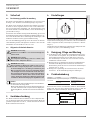 3
3
-
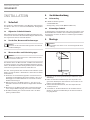 4
4
-
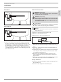 5
5
-
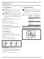 6
6
-
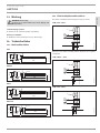 7
7
-
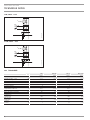 8
8
-
 9
9
-
 10
10
-
 11
11
-
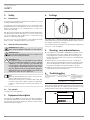 12
12
-
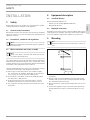 13
13
-
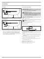 14
14
-
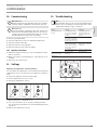 15
15
-
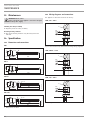 16
16
-
 17
17
-
 18
18
-
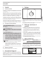 19
19
-
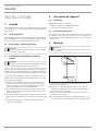 20
20
-
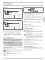 21
21
-
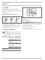 22
22
-
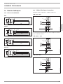 23
23
-
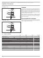 24
24
-
 25
25
-
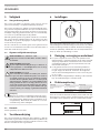 26
26
-
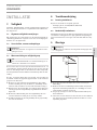 27
27
-
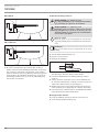 28
28
-
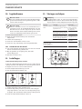 29
29
-
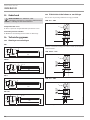 30
30
-
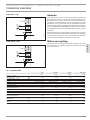 31
31
-
 32
32
-
 33
33
-
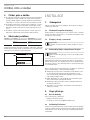 34
34
-
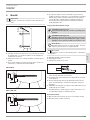 35
35
-
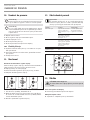 36
36
-
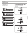 37
37
-
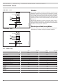 38
38
-
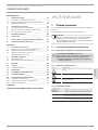 39
39
-
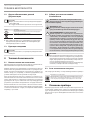 40
40
-
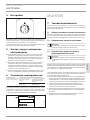 41
41
-
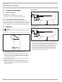 42
42
-
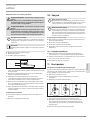 43
43
-
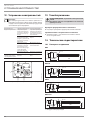 44
44
-
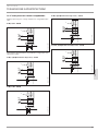 45
45
-
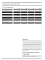 46
46
-
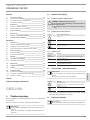 47
47
-
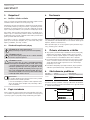 48
48
-
 49
49
-
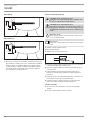 50
50
-
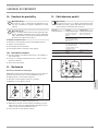 51
51
-
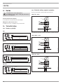 52
52
-
 53
53
-
 54
54
-
 55
55
-
 56
56


in andere talen
- français: STIEBEL ELTRON BGC 2 Manuel utilisateur
- Deutsch: STIEBEL ELTRON BGC 2 Benutzerhandbuch
- slovenčina: STIEBEL ELTRON BGC 2 Používateľská príručka
Gerelateerde papieren
-
STIEBEL ELTRON SBP 400 E Operation and Installation
-
STIEBEL ELTRON 071333 Operation and Installation
-
STIEBEL ELTRON SHW 200 S Installatie gids
-
-
-
-
-
-
-