
N° 73502_V7_25/09/2017
FR
EN
DE
ES
RU
NL
IT
02-04 / 23-28
04-07 / 23-28
08-10 / 23-28
11-13 / 23-28
14-16 / 23-28
17-19 / 23-28
20-22 / 23-28
PUSH PULL
MB 15 / MB 25

2
PUSH PULL MB15 / MB 25
IMPORTANT : AVANT LA MISE EN SERVICE DE LA MACHINE, LIRE LE CONTENU DE CE MANUEL ET LE CONSERVER,
PENDANT TOUTE LA VIE OPÉRATIONNELLE, DANS UN ENDROIT CONNU PAR LES PERSONNES INTÉRESSÉES. CETTE
MACHINE NE DOIT ÊTRE UTILISÉE QUE POUR DES OPÉRATIONS DE SOUDURE.
1 PRÉCAUTIONS DE SÉCURITÉ
La soudure peut nuire à vous-mêmes et aux autres; il est donc important de connaître les précautions de sécurité
décrites dans le manuel d’instructions du générateur.
2 DESCRIPTION GÉNÉRALE
2.1 SPÉCIFICATIONS
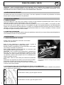
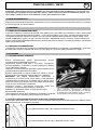
La torche PUSH-PULL a été conçue pour faciliter la soudure de ls d’aluminium particulièrement minces, mais il est
également possible de souder des ls d’acier, d’inox, de CuAl et CuSi.
La torche est fournie avec un tube contact de 0,8 mm alu (MB15) ou de 1,2 mm alu (MB25) et une gaine en téon
pour du l de 0.8 et 1mm (MB15) ou 0,8 et 1,2 mm (MB25), qui grâce à ses qualités glissantes, est particulièrement
indiqué pour l’entraînement des ls d’aluminium. Le téon a un coefcient de friction très bas, mais est peu résistant à
l’abrasion. Lorsqu’on veut souder pendant de longues périodes des ls de fer ou d’acier inoxydable, il est donc conseillé
de remplacer la gaine en téon par celle en métal.
2.2 LIMITES D’UTILISATION
La torche ne doit pas être utilisée au-delà des limites de spécication (200A 15%) aux risques d’importantes dégradations.
Le cas échéant, la torche ne sera pas garantie.
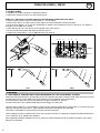
3 INSTALLATION
3.1 MISE EN ŒUVRE SUR LE POSTE
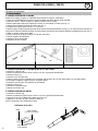
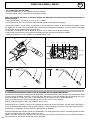
Extraire le tube en métal situé à l’intérieur de la xation
centralisée du générateur.
Relier la torche PUSH-PULL au générateur, monter le guide l
dévidoir sur la gaine en téon en saillie de la torche.
Bloquer la xation centralisée de la torche PUSH-PULL en la vissant
sur la xation centralisée du générateur.
Relier le câble sortant de la torche PUSH-PULL au connecteur situé
sur le panneau avant du poste à souder.
Important : Pour la soudure des ls d’aluminium, notamment les
ls de Ø 0,6 ou 0,8 mm, il est extrêmement important de régler
l’embrayage à la valeur minimale de pression, alors que pour tous
les autres ls il suft de faire quelques tours sur l’embrayage pour
obtenir la pression correcte.
Tube contact : utiliser un tube contact pour l’aluminium au diamètre
du l.
Sélectionner le programme de soudure qui convient au l à utiliser.
Pour faciliter l’insertion du l dans le bloc moteur du dévidoir,
préférer une coupure nette et garder le l bien droit, en positionnant
la torche la plus droite possible.
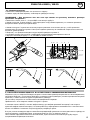
3.1.2 Préparation du groupe d’entraînement du l de la torche PUSH-PULL
Utiliser le galet d’entraînement du l avec la gorge correspondante au diamètre de l à utiliser. Le diamètre est représenté
par une rainure sur le pan du galet.
MB15
(A) côté rainure 0.6mm / (B) côté opposé 0.8-1mm
MB25
(A) côté rainure 0.8-1mm / (B) côté opposé 1.2mm
FR
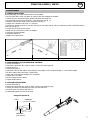
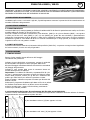
Lors de l’utilisation de gaine rouge ou bleu (soudage
aluminium), il est conseillé d’utiliser l’accessoire 91151. Ce
guide gaine inox améliore le centrage de la gaine et facilite
le débit du l.

3
PUSH PULL MB15 / MB 25
FR
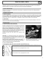
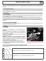
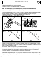
3.1.3 Chargement du l
• Desserrer la vis imperdable (A) et la tirer vers l’extérieur.
• Extraire le capot B de façon à avoir la vue sur le groupe d’entraînement.
REM. Pour les ls de 1mm ou si lors du chargement du l de diamètre inférieur, il y a des bourrages :
• Desserrer la buse gaz (D) et le tube contact
(C + C1 pour MB25)
.
• Appuyer sur le levier (E) de façon à soulever le palier appuie-l, pour éviter que le l rencontre des obstacles lors de
sa première insertion.
• Appuyer sur la gâchette (F) de la torche ou sur le bouton avance l du poste pour faire avancer le l jusqu’à la sortie
de la torche. Il est préférable de le faire avancer à vitesse réduite une fois le l arrivé au niveau des galets.
• Vérier que le l est positionné à l’intérieur de la gorge du galet d’entraînement du l (G).
• Remettre la protection (B) à sa place et la xer en serrant la vis imperdable (A).
• Serrer le tube contact
(C + C1 pour MB25)
et la buse gaz (D).
A
H
F
B
G
O
E
L
IK
J
C
M
N
D
C
M
N
D
C1
MB15 MB25
4 SOUDURE
4.1 RÉGLAGES DE LA TORCHE PUSH-PULL SELON LE TYPE DE MATIÈRE À SOUDER
Vérier que le poste à souder est réglé selon le diamètre de l et le type de matière à souder. S’assurer du montage
sur la torche PUSH-PULL du galet (G) ayant le diamètre correspondant au l à utiliser et du tube contact (C) ayant le
diamètre correct.
Sur le générateur, régler le courant relatif au type d’opération à exécuter.
Se rapprocher du point de soudure et appuyer sur la gâchette (F) de la torche.
À l’aide du bouton « SELECT » (H) il est possible de choisir la hauteur d’arc en sélectionnant la LED orange (I) ou de la
vitesse l en sélectionnant la LED verte (J). Ces réglages sont différents selon le type de générateur.
Le bouton « UP-DOWN » (K) permet de régler la fonction choisie précédemment.
Lorsqu’on doit souder pendant de longues périodes des ls de fer ou d’acier inoxydable, il est donc conseillé de
remplacer la gaine en téon par celle en métal (cf. §5.1). Remplacer la gaine (N).
Après avoir remplacé la gaine en téon par celle en métal, il faut remonter le tube en métal à l’intérieur de la xation

4
PUSH PULL MB15 / MB 25
FR
centralisée du générateur.
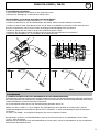
5 MAINTENANCE
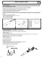
5.1 REMPLACEMENT DE LA GAINE
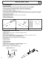
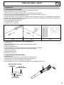
Avant son montage, la gaine en métal doit être coupée sur mesure; il faut donc:
• Placer la torche PUSH-PULL de façon qu’elle soit dans la position la plus droite possible.
• Desserrer l’écrou, extraire la gaine en téon et enler celle en métal.
• Étant la gaine plus longue par rapport à la torche, X mm restent en saillie (voir g. 1).
• Mesurer avec précision la partie en saillie (voir g. 1).
• Longueur de la gaine dans la torche ≈ 4 150 mm.
• Retirer la gaine, couper la partie terminale de la mesure prise précédemment (voir g. 2). La coupe doit être exécutée au
moyen d’un outil très tranchant de façon à ne pas former de bavures qui pourraient obstruer le passage du l (voir g. 3).
• Tailler en pointe le bout de la gaine.
• Former le bout de la gaine de façon à ce qu’elle soit droite.
• Insérer la gaine ainsi préparée.
• Resserrer l’écrou de serrage.
• Remplacer le tube contact.
g. 1 g. 2 g. 3
5.2 REMPLACEMENT DE LA GAINE DANS LE COL DE CYGNE
• Desserrer le bouton (A).
• Extraire la protection (B) de façon à avoir la vue sur le groupe d’entraînement.
• Desserrer l’écrou (L).
• Dévisser le col de cygne (M).
• Retirer la gaine (N) et la remplacer en la coupant à la longueur de 175 mm gaine laiton+ 6 mm gaine téon.
(si bourrage, remplacer la gaine (N) par une gaine téon).
• Revisser le col de cygne (M), ajuster son orientation.
• Resserrer l’écrou (L).
• Remonter la protection (B).
• Resserrer le bouton (A).
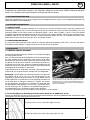
5.3 REMPLACEMENT DU GALET
• Desserrer le bouton (A).
• Extraire la protection (B) de façon à avoir la vue sur le groupe d’entraînement.
• Desserrer la vis (O) en bloquant le galet avec la clé (P).
• Appuyer sur le levier (E) pour extraire le galet (G).
Pour le remontage, faire l’opération inverse.
Utilisation de la clé P
P
Galet
Tube contact
(0.6-0.8mm)
Tube contact
(0.6-0.8-1-1.2mm)

5
PUSH PULL MB15 / MB 25
EN
IMPORTANT: BEFORE PUTTING THE MACHINE INTO SERVICE, READ THIS MANUAL AND KEEP IT IN A SAFE AND
KNOWN LOCATION. THIS PRODUCT MUST ONLY BE USED FOR WELDING OPERATIONS.
1 SAFETY PRECAUTIONS
Welding can be dangerous for yourself and for other people: it is important to be aware of the safety precautions
included in this manual.
2 GENERAL DESCRIPTION
2.1 SPECIFICATIONS
The torch is supplied with a contact tube of 0.8 mm aluminum (MB15) or 1.2 mm aluminum (MB25) and a Teon sheath
for the wire (MB15: 0.8 and 1 mm) or (MB25: 0.8 1.2 mm), which thanks to its slippery properties, is particularly suitable
for aluminum. Teon has a low coefcient of friction, but is very resistant to abrasion. When welding for extended
periods of time with iron or stainless steel, it is advisable to replace the Teon sheath by the metal sheath.
2.2 USE LIMITS
The torch must not be used over the specication limits (200A 15%) at the risk of important damages. In that is the
case, the torch will not be covered under warranty.
3 INSTALLATION
3.1 APPLICATION ON THE GENERATOR
Extract the metal tube located in the central xing of the generator.
Connect the PUSH PULL torch to the generator, mount the reel
guide onto the protruding teon liner. Fix the PUSH PULL torch by
screwing it to the centralised xing on the generator.
Before connecting the PUSH PULL torch to the generator, select the
brass tube to insert in the Teon sheath overhanging on the torch.
Insert and tighten the central xing of the PUSH PULL torch by
screwing it on the central xing of the generator.
Connect the PUSH PULL torch cable to the connector onthe
generator.
Important : For welding with aluminium wires, especially with Ø
0.6 ou 0.8 mm wires, it is extremely important to adjust the clutch
at the minimum pressure. For other wires you just need to adjust
the clutch to get the correct pressure.
Contact tube: Use a contact tube for aluminium at the wire diameter.
Select the welding program according to the wire being used.
To facilitate wire insertion into the motor part of the wire feeder, a
clean cut is advised, keep the wire straight and place
the torch as straight as possible.
3.1.2 Preparation of the wire traction assembly of the PUSH PULL torch
Use the traction roller with the correct wire groove. The diameter is represented by a groove on the side of the roller
MB15
(A) Groove side 0.6mm / (B) Opposite side 0.8-1mm
MB25
(A) Groove side 0.8-1mm / (B) Opposite side 1.2mm
When using a blue or red torch liner (aluminium welding),
it is recommended to use accessory 91151
(see picture). This stainless steel guide tube improves the
torch liner positioning and facilitates wire feeding.

6
PUSH PULL MB15 / MB 25
3.1.3 Wire loading
• Untighten the screw A and pull it towards the exterior.
• Remove the case B in order to see the traction group.
REM. For 1 mm wires or if when loading a wire diameter smaller there are jams:
• Loosen the gas nozzle D and the contact tube (C
+ C1 for MB25
).
•• Press on the lever E in order to lift the wire support to avoid obstacles for the rst insertion.
• Press the torch trigger F or on the wire feed button to feed the wire forward to the end of the torch. It is better to
bring the wire forward at low speed.
• Check that the wire is in the groove of the tracting roller of the wire G.
• Put the case B back in place and fasten it with the screw A.
• Tighten the contact tube C
+ C1 for MB25
and the gas nozzle D.
A
H
F
B
G
O
E
L
IK
J
C
M
N
D
C
M
N
D
C1
MB15 MB25
4 WELDING
4.1 SETTINGS OF THE PUSH PULL TORCH ACCORDING TO TYPE OF MATERIAL TO WELD
Make sure that the generator is set according to the wire diameter and type of metal to weld. Make sure that you have
mounted the roller G on the PUSH PULL torch matching the wire diameter and contact tube C.
On the generator, adjust the current according to the type of operation to perform.
Put the torch close to the intended weld and press the trigger F of the torch.
With the button «SELECT» H it is possible to choose the arc height by selecting the orange LED I or to choose the wire
speed by selecting the green LED J. These settings are different according to the generator.
The button «UP-DOWN» K with revert the function previously selected.
When welding iron wire or stainless steel for a very long period of time, it is advised to replace the teon sheath by the
one in metal (cf. §5.1). Replace the sheath N.
After replacing the teon sheath by the one in metal, the inside metal tube must be put back in place in the central
xing of the generator.
EN

7
PUSH PULL MB15 / MB 25
5 MAINTENANCE
5.1 SHEATH REPLACING
Before assembly, the metal sheath must be cut precisely:
• Put the PUSH PULL torch in position in order to have it as straight as possible.
• Loosen the nut, remove the teon sheath and insert the metal one.
• As the sheath is longer than the torch, X mm protrude (see g. 1).
• Measure precisely the length of the protrusion (see g. 1).
• Length of the sheath in the torch ≈ 4 150 mm.
• Remove the sheath, and cut to size part. Use only a very sharp tool in order to avoid burrs which could block the the
wire way (see g. 3).
• Cut the end of the liner into a point.
• Shape the tip of the liner so that it is straight.
• Insert the prepared sheath.
• Re-tighten the screw
• Replace the contact tube.
g. 1 g. 2 g. 3
5.2 REPLACEMENT OF THE SHEATH IN THE NECK
• Loosen the button A.
• Remove the protection B in order to have a view of the training group.
• Loosen the nut L.
• Unscrew the neck M.
• Remove the N liner and replace it by cutting to the length of 175 mm brass sheath + 6 mm Teon sheath.
(if it jams, replace the N liner with a Teon liner).
• Screw the neck M back and adjust the orientation.
• Tighten the nut L back.
• Put the casing B back in place.
• Tighten back button A.
5.3 ROLLER REPLACEMENT
• Loosen the button A.
• Remove the protection B in order to have a view on the traction group.
• Loosen the screw O by blocking the roller with the spanner P.
• Press the lever E to extract the roller G.
To reassemble simply reverse the process.
Using the spanner P
P
Roller
Contact tube
(0.6-0.8mm)
Contact tube
(0.6-0.8-1-1.2mm)
EN

8
PUSH PULL MB15 / MB 25
WICHTIG: VOR DER INBETRIEBNAHME LESEN SIE DIE BETRIEBSANLEITUNG SORGFÄLTIG DURCH UND BEWAHREN
SIE DIESE AN EINEM ZUGÄNGLICHEN ORT AUF. DER BRENNER DARF AUSSCHLIESSLICH ZUM SCHWEISSEN BENUTZT
WERDEN.
1 SICHERHEITSHINWEISE
Schweißvorgänge können Sie und andere gefährden; beachten Sie deshalb die Sicherheitshinweise der Betriebsanleitung
der Schweißstromquelle zu beachten.
2 ALLGEMEIN
2.1 BESCHREIBUNG
Der Brenner PUSH PULL ist besonders für das Schweißen mit dünnem Aluminiumdraht geeignet, kann aber auch mit
Stahl-, Edelstahl-, CuAl- und CuSi-Draht verwendet werden.
Ein Ø 0,8 mm (MB15) Alu- oder ein Ø 1,2 mm (MB25) Alu- Kontaktrohr und eine Teonseele für Draht (MB15 : 0,8
und 1 mm) oder (MB25: 0,8 und 1,2 mm) sind im Lieferumfang. Diese Seele ist insbesondere für die Führung von
Aluminiumdraht geeignet. Teon hat einen niedrigen Reibungskoefzient aber auch eine geringe Abriebfestigkeit. Bei
längerem Schweißen von Eisen- oder Edelstahldraht empehlt sich daher der Einsatz einer Metallseele an Stelle der
Teonseele.
2.2 BENUTZUNGSEINSCHRÄNKUNG
Ein Einsatz des Brenners über die Spezikationsgrenze (200 A 15 %) hinaus, kann zu Funktionsstörungen führen und
möglicherweise die Garantie gefährden.
3 MONTAGE
3.1 MONTAGE
Entfernen Sie das Kapillarrohr aus dem Brenneranschluss der
Stromquelle.
Schließen Sie den PUSH PULL-Brenner am Brenneranschluss am
Gerät an und führen Sie die Teonseele bis zur Drahtführung
am Brennerkopf . Schrauben Sie den PUSH PULL-Brenner am
Zentralanschluss am Gerät fest.
Verbinden Sie das Steuerkabel des PUSH PULL Brenners mit dem
Steuranschluss am Gerät.
Wichtig : Für das Schweißen von Aluminiumdrähten - speziell bei
Drähten Ø 0,6 oder 0,8 mm - sollte der Anpressdruck so gering wie
möglich sein. Bei anderen Drähten können Sie den Anpressdruck
erhöhen. Kontaktrohr: Benutzen Sie ein Kontaktrohr für Aluminium
mit dem entsprechenden Durchmesser.
Wählen Sie das zum Draht passende Schweißprogramm aus.
Ein möglichst gerader und glatter Draht, sauberer Zuschnitt und
ein gerade liegendes Schlauchpaket vereinfachen das Einführen
in den Drahtvorschub.
3.1.2 Vorbereitung des Drahtantriebs des PUSH PULL Brenners
Benutzen Sie die Drahtführungsrolle mit der zum Durchmesser passenden Nut. Der Durchmesser ist auf der Außenseite
der Rolle zu nden.
MB15
(A) gerillte Seite 0,6mm / (B) entgegensetzte Seite 0,8 - 1 mm
MB25
(A) gerillte Seite 0,8 - 1 mm / (B) entgegensetzte Seite 1,2 mm
DE
Lors de l’utilisation de gaine rouge ou bleu (soudage
aluminium), il est conseillé d’utiliser l’accessoire 91151. Ce
guide gaine inox améliore le centrage de la gaine et facilite
le débit du l.

9
PUSH PULL MB15 / MB 25
3.1.3 Einführen des Drahtes
• Lösen Sie die Schraube A und ziehen Sie den Draht nach innen.
• Entfernen Sie die Kappe B, so dass Sie den Antrieb sehen.
NB. Bei Drähten von weniger als Ø 1mm oder bei Drahtstau
• Lösen Sie die Gasdüse D und das Kontaktrohr C + C1 für MB25.
• Drücken Sie den Hebel E, um das Drahtstützlager anzuheben, dadurch werden Drahtstaus vermieden.
• Drücken Sie auf die Taste F des Brenners oder auf die Taste zur Drahtführung am Gerät, bis der Draht aus dem
Brenners herauskommt. Führen Sie den Draht mit niedriger Geschwindigkeit durch den Brenner.
• Stellen Sie sicher, dass der Draht in der Nut der Drahtführungsrolle G liegt.
• Monitieren Sie die Kappe B wieder und xieren Sie sie durch das Festschrauben der Schraube A.
• Ziehen Sie das Kontaktrohr C + C1 für MB25 und die Gasdüse D fest.
A
H
F
B
G
O
E
L
IK
J
C
M
N
D
C
M
N
D
C1
MB15 MB25
4 SCHWEISSEN
4.1 EINSTELLEN DES PUSH PULL BRENNERS JE NACH SCHWEISSMATERIAL
Stellen Sie sicher, dass das Gerät auf den richtigen Drahtdurchmesser und das Schweißmaterial eingestellt. Kontrollieren
Sie, ob die folgenden Teile in den Brenner eingebaut worden sind: die Rolle G mit zum Draht entsprechenden Durchmesser
und das Kontaktrohr C mit dem korrekten Durchmesser.
An der Stromquelle stellen Sie den zum Schweißvorgang passenden Strom ein.
Mithilfe der Taste « SELECT » H ist es möglich, die Lichtbogenhöhe durch Auswahl der orangen LED I oder die
Drahtgeschwindigkeit durch Auswahl der grünen LED J einzustellen. Je nach Stromquelletyp sind die Einstellungen
verschieden.
Die Taste « UP-DOWN » K ermöglicht die Regelung der vorher erwähnten Funktion.
Bei Schweißen von Eisen- und Edelstahldrähten sollte die die Teonseele durch eine Metalldraht ersetzt werden
(s. §5.1). Seele N ersetzen.
Nachdem Sie die Teonseele durch die Metalldrahtseele ersetzt haben, ziehen Sie das Metallrohr in den zentralisierten
Anschluss der Stromquelle herauf.
DE

10
PUSH PULL MB15 / MB 25
5 INSTANDHALTUNG
5.1 ERSETZEN DER SEELE
Vor der Montage muss die Metallseele auf Maß geschnitten werden. d. h.:
• Legen Sie den PUSH PULL Brenner so, dass er so gerade liegt.
• Klemmmutter lösen, Teonseele entfernen und durch die aus Metall ersetzen.
• Da die Seele länger als der Brenner ist, bleiben X mm über (s. Abb. 1).
• Sorgfältig den überstehenden Teil messen (s. Abb. 1).
• Länge der Seele im Brenner ≈ 4 150 mm.
• Die Seele entfernen, den Endteil laut der vorherigen Messung schneiden (s. Abb. 2). Der Schnitt soll mithilfe eines
scharfen Schneidwerkzeuges durchgeführt werden, so dass keine unsauberen Stellen entstehen, die die Drahtführung
stören könnten (s. Abb. 3).
• Schneiden Sie das Ende der Seele spitz zu.
• Schneiden Sie das Ende der Seele gerade zu.
• Die vorbereitete Seele einsetzen.
• Klemmmutter festschrauben.
• Kontaktrohr einsetzen.
g. 1 g. 2 g. 3
5.2 ERSETZEN DER SEELE IM SCHWANENHALS
• Taste A lösen.
• Kappe B entfernen, so dass Sie den Antrieb sehen können.
• Mutter L lösen.
• Schwanenhals M abschrauben.
•Ziehen Sie die N-Seele zurück und tauschen Sie es aus beim Schneiden einer 175 mm Gelbguss-seele + 6 mm
Teonseele (beim Materialstau tauschen die N-Seele mit einer Teonseele aus).
• Schwanenhals M festschrauben, Orientierung anpassen.
• Mutter L wieder festziehen.
• Legen Sie die Kappe B zurück.
• Taste A wieder festziehen.
5.3 ERSETZEN DER DRAHTFÜHRUNGSROLLE
• Taste A lösen.
• Kappe B entfernen, so dass Sie das Fahrantriebsaggregat sehen können.
• Schrauben O lösen, indem Sie die Drahtführungsrolle mit dem P-Schlüssel blockieren.
• Hebel E drücken, sodass die Drahtführungsrolle G entfernt werden kann.
Zum Wiederaufbauen, den umgekehrten Vorgang durchführen.
Anwendung des P-Schlüssels
P
Drahtführungsrolle
Kontaktrohr
(0.6-0.8mm)
Kontaktrohr
(0.6-0.8-1-1.2mm)
DE

11
PUSH PULL MB15 / MB 25
IMPORTANTE : ANTES DE LA PUESTA EN MARCHA DE LA MÁQUINA, LEA EL CONTENIDO DE ESTE MANUAL Y
CONSÉRVELO DURANTE TODA SU VIDA OPERACIONAL EN UN LUGAR QUE CONOZCAN LAS PERSONAS QUE PUDIERAN
REQUERIRLO. ESTE PRODUCTO SOLO DEBE USARSE PARA OPERACIONES DE SOLDADURA.
1 PRECAUCIONES DE SEGURIDAD
La soldadura puede dañarle a usted y a los otros, es importante conocer las precauciones de seguridad descritas en el
manual de instrucciones del generador.
2 DESCRIPCIÓN GENERAL
2.1 ESPECIFICACIONES
La antorcha incluye un tubo de contacto de 0,8mm para aluminio (MB15) o de 1,2mm para aluminio (MB25) y una funda
de teón para hilo de 0,8 y 1mm (MB15) o 0,8 y 1,2mm (MB25) que, gracias a sus cualidades deslizantes, lo hacen
particularmente indicado para el arrastre de hilos de aluminio. El teón tiene un coeciente de fricción muy bajo, pero
es poco resistente a la abrasión. Cuando se desee soldar hilos de hierro o de acero inoxidable, se aconseja reemplazar
la funda de teón por la de metal.
2.2 LÍMITES DE USO
La antorcha no se debe utilizar más allá de los límites especicados (200A 15%) a riesgo de importantes degradaciones.
En caso contrario, la antorcha perderá su garantía.
3 INSTALACIÓN
3.1 PUESTA EN MARCHA DEL EQUIPO
Extraer el tubo de metal situado en el interior de la jación
centralizada del generador.
Unir la antorcha PUSH PULL al generador, montar el guía-hilo de la
devanadera sobre la funda de teón que sobresale de la antorcha.
Bloquee la jación centralizada de la antorcha PUSH PULL
atornillándola en la jación centralizada del generador.
Antes de unir la antorcha PUSH PULL al generador, elija el tubo de
latón que se debe insertar en la funda de teón que sobresale de
la antorcha.
Inserte y bloquee la jación centralizada de la antorcha PUSH PULL
atornillándola en la jación centralizada del generador.
Una el cable de salida de la antorcha PUSH PULL al conector situado
en el panel delantero del equipo de soldadura.
Importante : Para la soldadura de hilos de aluminio, especícamente
hilos de Ø 0,6 o 0,8 mm, es extremadamente
importante ajustar el acoplamiento a su valor mínimo de presión,
mientras que para otros hilos sobra con darle varias vueltas sobre
el acoplamiento para obtener la presión correcta.
Tubo contacto: utilice un tubo de contacto para aluminio adaptado
al diámetro de hilo.
Seleccione el programa de soldadura que convenga al hilo que se va a utilizar.
Para facilitar la inserción del hilo en la parte del motor de la devanadera, intente que la punta esté entera y que el hilo
esté derecho y posicionar la antorcha lo más recta posible.
3.1.2 Preparación del equipo de arrastre del hilo de la antorcha PUSH PULL.
Utilice el rodillo de arrastre del hilo con la sujeción correspondiente al diámetro de hilo que se va a utilizar. El diámetro
se indica en una ranura del rodillo.
MB15
(A) el lado de la ranura es 0,6mm / (B) lado opuesto 0,8-1mm
MB25
(A) lado de la ranura 0.8-1mm / (B) lado opuesto 1.2mm
ES
Lors de l’utilisation de gaine rouge ou bleu (soudage
aluminium), il est conseillé d’utiliser l’accessoire 91151. Ce
guide gaine inox améliore le centrage de la gaine et facilite
le débit du l.

12
PUSH PULL MB15 / MB 25
3.1.3 Cambio del hilo
• Aoje el tornillo imperdible A y tire hacia el exterior.
• Extraiga el capó B de forma que se vea el equipo de arrastre.
REM. Para los hilos de 1mm o si cuando se cambie el hilo de diámetro inferior hay atascos :
• Aoje la boquilla de gas D y el tubo de contacto C + C1 para MB25.
• Presione la palanca E de forma que se eleve la zona del sujeta hilo, para evitar que el hilo encuentre obstáculos desde
la primera inserción.
• Presione sobre el gatillo F de la antorcha o sobre el botón de avance del hilo del equipo para hacer avanzar el hilo hasta
la salida de la antorcha. Es preferible hacer avanzar a velocidad reducida una vez que el hilo haya llegado a los rodillos.
• Compruebe que el hilo está situado en el interior del embudo del rodillo de arrastre de hilo G.
• Vuelva a colocar la protección B en su lugar y fíjela apretando el tornillo imperdible A.
• Apriete el tube de contacto C + C1 para MB25 y la boquilla de gas D.
A
H
F
B
G
O
E
L
IK
J
C
M
N
D
C
M
N
D
C1
MB15 MB25
4 SOLDADURA
4.1 AJUSTE DE LA ANTORCHA PUSH PULL SEGÚN EL TIPO DE MATERIAL QUE SE VA A SOLDAR.
Asegúrese de que el equipo de soldar esté congurado según el diámetro de hilo y tipo de material a soldar. Asegúrese
de haber montado el rodillo G con el díametro correspondiente al hilo que se va a utilizar y el tubo de contacto C con el
diámetro correcto en la antorcha PUSH PULL.
En el generador, ajuste la corriente relativa al tipo de operación que se va a realizar.
Acérquese al lugar de soldadura y presione el gatillo F de la antorcha.
Con el botón « SELECT » H es posible seleccionar la altura del arco mediante el LED orange I o la velocidad del hilo con
el LED verde J. Estos ajustes son diferentes según el tipo de generador.
El botón « UP-DOWN » K permite ajustar la función elegida anteriormente.
Cuando se desee soldar hilos de hierro o de acero inoxidable, se aconseja reemplazar la funda de teón por la de metal.
(ver 5.1). Reemplace la funda N.
Tras haber reemplazado la funda de teón por la de metal, hay que volver a instalar el tubo de metal en el interior de
la jación centralizada del generador.
ES

13
PUSH PULL MB15 / MB 25
5 MANTENIMIENTO
5.1 REPLAZAR LA FUNDA
Antes de su montaje, la funda de metal se debe cortar a medida; se debe:
• Colocar la antorcha PUSH PULL de forma que esté en la posición más recta posible.
• Aojar la tuerca, extraer la funda de teón y colocar la de metal.
• Como la funda es más larga que la antorcha, X mm sobresalen (ver gura 1).
• Mida con precisión la parte que sobresale (ver gura 1).
• Longitud de la funda en la antorcha ≈ 4 150 mm.
• Retire la funda, corte la parte terminal de la medida tomada anteriormente (ver gura 2). El corte se debe ejecutar
mediante una herramienta cortante de forma que no se creen rebabas que pudieran obstruir el paso de hilo (ver gura
3).
• Cortar en punta el extremo de la funda.
• Forme el extremo de la funda de forma que esté recta.
• Coloque la funda una vez preparada.
• Vuelva a apretar la tuerca de jación.
• Reemplace el tubo de contacto
g. 1 g. 2 g. 3
5.2 REEMPLAZO DE LA FUNDA SIN CUELLO DE CISNE
• Aoje el botón A.
• Extraiga la protección B de forma que quede a la vista el equipo de arrastre.
• Aoje la tuerca L.
• Destornille el cuello de cisne M.
• Retire la funda N y reemplácela cortando la longitud de 175 mm funda latón + 6 mm funda teón.
(si se obstruye reemplace la funda N par una funda de teón).
• Vuelva a atornillar el cuello de cisne M , ajuste su orientación.
• Vuelva a apretar la tuerca L.
• Coloque la protección B.
• Vuelva a apretar el botón A
5.3 REEMPLAZO DEL RODILLO
• Aoje el botón A.
• Extraiga la protección B de forma que quede a la vista el equipo de arrastre.
• Aoje el tornillo O bloqueando el tornillo con la llave P.
• Presione la palanca E para extraer el rodillo G.
Para el montaje vuelva a realizarlo en sentido contrario.
Uso de la llave P
P
Rodillo
Tubo de contacto
(0.6-0.8mm)
Tubo de contacto
(0.6-0.8-1-1.2mm)
ES

14
PUSH PULL MB15 / MB 25
ВНИМАНИЕ! ОБЯЗАТЕЛЬНО ПРОЧТИТЕ ДАННУЮ ИНСТРУКЦИЮ ПЕРЕД ИСПОЛЬЗОВАНИЕМ И СОХРАНИТЕ ЕЕ В
ТЕЧЕНИИ ВСЕГО ПЕРИОДА ИСПОЛЬЗОВАНИЯ В МЕСТЕ, ИЗВЕСТНОМ ВСЕМ ЗАИНТЕРЕСОВАННЫМ ЛИЦАМ. ЭТОТ
ИНСТРУМЕНТ ДОЛЖЕН БЫТЬ ИСПОЛЬЗОВАН ТОЛЬКО ДЛЯ СВАРОЧНЫХ РАБОТ.
1 МЕРЫ БЕЗОПАСНОСТИ
Сварка может быть вредной для вас и окружающих, поэтому очень важно знать все меры безопасности, описанные
в этой инструкции по использованию.
2 ОПИСАНИЕ
2.1 ТЕХНИЧЕСКИЕ ХАРАКТЕРИСТИКИ
Горелка поставляется с контактной трубкой 0.8мм (MB15) или 1,2мм (MB25) для алюминия, а также тефлоновым
шлангом для алюминиевой проволоки (MB15 : 0.8 и 1мм) или (MB25: 0,8 и 1,2мм), которая, благодаря своим
скользящим свойствам, идеально подходит для прохождения алюминиевой проволоки. Тефлон имеет очень
низкий коэффициент трения, но при этом малоустойчив к абразивному износу. В случае, если вы планируете
варить стальной или нержавеющий проволоки в течении длительного периода, мы советуем заменить тефлоновый
шланг на металлический.
2.2 ПРЕДЕЛЫ ИСПОЛЬЗОВАНИЯ
Горелка не должна быть использована при параметрах вне пределах, оговоренных в спецификации ( 200A 15%),
во избежании сильных повреждений. В этом случае гарантия на горелку распространяться не будет.
3 УСТАНОВКА
3.1 ПОДКЛЮЧЕНИЕ К АППАРАТУ
Вынуть металлическую трубку, расположенную внутри
централизованной фиксации источника.
Подключите горелку PUSH PULL к источнику, смонтируйте
нитевод подающего устройства на на выступающую из горелки
часть тефлонового шланга.
Завинтите централизованную фиксацию горелки PUSH PULL на
централизованную фиксацию источника.
Вставьте выходящий из горелки PUSH PULL кабель в гнездо,
расположенное на передней панели сварочного аппарата.
Внимание! Для сварки алюминиевой проволокой, в
особенности Ø 0,6 или 0,8 мм, очень важно, чтобы давление
сцепления было на минимуме, в то время как для других типов
проволоки достаточно сделать несколько оборотов сцепления,
чтобы достичь необходимого давления.
Контактная трубка : используйте контактную трубку для
алюминия, соответствующую диаметру проволоки.
Выберите ту программу сварки, которая соответствует
используемой проволоке.
Чтобы проволоку проще было заправить в подающее устройство,
чисто обрежьте ее и держите ровно проволоку и горелку.
3.1.2 Подготовка приводной системы проволоки горелки PUSH PULL.
Используйте приводной ролик с желобом, соответствующим диаметру используемой проволоки. Диаметр указан
с помощью борозды на поверхности ролика.
MB15
(A) с стороны борозды 0.6мм / (B) с обратной стороны 0.8-1мм
MB25
(A) с стороны борозды 0.8-1мм / (B) с обратной стороны 1.2мм
RU
При использовании красной или синей трубки (при
сварке алюминия) рекомендуется пользоваться
аксессуаром 91151 (см. фотографию). Этот аксессуар
из нержавеющей стали направляет трубку, улучшая ее
центрирование и облегчая подачу проволоки.

15
PUSH PULL MB15 / MB 25
3.1.3 Замена проволоки
• Развинтите невыпадающий винт A и потяните его наружу.
• Снимите корпус B таким образом, чтобы видеть приводную систему.
ПРИМЕЧАНИЕ : Для проволоки 1мм или если при замене на проволоку меньшего диаметра
произошло застревание :
• Развинтите газовое сопло C + C1 для MB25 и контактную трубку D.
• Нажмите на рычаг E таким образом, чтобы приподнять опору зажима проволоки, это позволит проволоке
беспрепятственно пройти при первом вводе.
• Нажмите на курок F горелки или на кнопку подачи проволоки на источнике для того, чтобы проволока
продвинулась до выхода из горелки. Советуется подавать проволоку на пониженной скорости как только она
достигнет уровня роликов.
• Убедитесь, что проволока находится внутри желоба приводного ролика G.
• Установите крышку B на ее место и зафиксируйте закручиванием невыпадаемого винта A.
• Закрутите контактную трубку C + C1 для MB25 и газовое сопло D.
A
H
F
B
G
O
E
L
IK
J
C
M
N
D
C
M
N
D
C1
MB15 MB25
4 СВАРКА
4.1 НАСТРОЙКА ГОРЕЛКИ PUSH PULL В СООТВЕТСТВИИ СО СВАРИВАЕМЫМ МАТЕРИАЛОМ.
Убедитесь в том, что сварочный аппарат настроен в соответствии с диаметром проволоки и с типом свариваемого
материала. Убедитесь, что на горелке PUSH PULL установлен ролик G диаметром, соответствующим используемой
проволоке, а также контактная трубка C правильного диаметра.
На источнике, настройте ток соответственно запланированной операции.
Приблизьтесь к точке сварки и нажмите на курок F горелки.
С помощью кнопки «SELECT» H можно выбрать высоту дуги выбрав оранжевый светодиод I или скорость
проволоки выбрав зеленый светодиод J. Эти настройки могут варьироваться в зависимости от типа источника.
Кнопка «UP-DOWN» K позволяет настроить функцию, выбранную ранее.
В случае, если вы планируете варить стальной или нержавеющий проволоки в течении длительного периода, мы
советуем заменить тефлоновый шланг на металлический (см. §5.1) и заменить шланг N.
После замены тефлоновый шланга на металлический, нужно поместить металлическую трубку внутри
централизованной фиксации источника.
RU

16
PUSH PULL MB15 / MB 25
5 ТЕХОБСЛУЖИВАНИЕ
5.1 ЗАМЕНА ШЛАНГА
Перед установкой, металлический шланг нужно правильно отрезать, для этого необходимо:
• Разместить горелку PUSH PULL таким образом чтобы она была как можно более прямой.
• Отвинтить гайку, достать тефлоновый шланг и замените его на металлический.
• Т.к. металлический шланг длиннее чем горелка, X мм остаются снаружи (см рис. 1).
• Длина шланга в горелке ≈ 4 150 мм.
• С точностью замерьте выступающую часть (см рис. 1).
• Выньте шланг и отрежьте конечную часть на длину, замеренную ранее (см рис. 2). Отрез должен быть сделан
с помощью хорошо заточенного инструмента, так, чтобы по краям не было загибов, которые могут затруднить
скольжение проволоки (см рис. 3).
• Заточите наконечник шланга.
• Сформируйте кончик шлага таким образом чтобы он был прямым.
• Вставьте обрезанный шланг.
• Завинтите зажимную гайку.
• Установите контактную трубку.
g. 1 g. 2 g. 3
5.2 ЗАМЕНА ШЛАНГА В ИЗОГНУТОЙ ЧАСТИ
• Ослабьте кнопку A.
• Снимите корпус B таким образом, чтобы видеть приводную систему.
• Ослабьте гайку L.
• Раскрутите изогнутую часть M.
• Выньте шланг N и замените отрезав до длины 175мм латунной трубки+ 6 тефлонового шланга.
(в случае затора замените шланг N на тефлоновый шланг).
• Выньте шланг и замените на шланг укороченный до 175 мм.
• Закрутите изогнутую часть M, закрепив ее в нужном направлении.
• Закрутите гайку L.
• Установите корпус B.
• Зкрутите кнопку A.
5.3 ЗАМЕНА РОЛИКА
• Ослабьте кнопку A.
• Снимите корпус B таким образом, чтобы видеть приводную систему.
• Открутите винт O удерживая ролик с помощью ключа P.
• Нажмите на рычаг E чтобы достать ролик G.
Для сбора, проведите операцию в обратном порядке.
Применение ключа P
P
Ролик
Контактная трубка
(0.6-0.8mm)
Контактная трубка
(0.6-0.8-1-1.2mm)
RU

17
PUSH PULL MB15 / MB 25
BELANGRIJK : LEEST U VOOR HET IN GEBRUIK NEMEN VAN DIT APPARAAT DEZE HANDLEIDING EERST GOED DOOR,
EN BEWAAR DE HANDLEIDING ZOLANG U DIT APPARAAT GEBRUIKT OP EEN VOOR IEDERE GEBRUIKER BEKENDE
PLAATS. DIT APPARAAT MAG ALLEEN GEBRUIKT WORDEN OM MEE TE LASSEN.
1 VEILIGHEIDSMAATREGELEN
Lassen kan gevaarlijk zijn voor u en voor anderen; het is belangrijk kennis te nemen van de veiligheidsmaatregelen die
beschreven staan in deze handleiding.
2 ALGEMENE OMSCHRIJVING
2.1 SPECIFICATIES
De PUSH PULL toorts is speciaal ontworpen voor het lassen met zeer dun aluminium draad, maar kan ook lassen met
staaldraad, rvs, CuAl en CuSi. De toorts wordt geleverd met een contactbuis van 0,8 mm aluminium (MB15) of 1,2 mm
aluminium (MB25) en een teon mantel voor draad van (MB15 : 0.8 en 1mm) of (MB25 : 0,8 en 1,2 mm), die dankzij
het gladde oppervlak speciaal aanbevolen wordt voor het lassen met aluminium-draad. Teon heeft een zeer lage frictie-
coëfciënt, maar is niet erg slijtvast. Wanneer u langere tijd achter elkaar met ijzer- of rvs-draad wilt lassen, wordt
aanbevolen de teon mantel te vervangen door een metalen mantel.
2.2 GEBRUIKSBEPERKINGEN
De toorts mag alleen gebruikt worden binnen de gestelde gebruiksvoorwaarden (200A 15%). De toorts kan anders
aanzienlijke schade oplopen. In dat geval valt de toorts niet binnen de garantie.
3 INSTALLATIE
3.1 GEBRUIK VAN HET APPARAAT
Verwijder de metalen buis die zich binnen in de centrale bevestiging
van de generator bevindt.
Kies, voor het verbinden van de PUSH PULL toorts met de generator,
de juiste messing buis die ingebracht moet worden op de teon
mantel aan het eind van de toorts. Neem de kortste buis (88,5 mm)
bij gebruik met de generator. Gebruik, op alle andere generatoren,
de langste buis (106,5 mm). Breng de centrale bevestiging van de
PUSH PULL toorts in en blokker de toorts door deze op de centrale
bevestiging van de generator te schroeven.
Koppel de kabel van de PUSH PULL toorts aan op de aansluiting die
zich bevindt op het paneel aan de voorzijde van het lasapparaat.
Belangrijk : Bij het lassen van aluminium draad, in het bijzonder
van draden van Ø 0,6 of 0,8 mm, is het erg belangrijk om de
koppeling op minimale druk af te stellen. Voor alle andere soorten
draad volstaat het om enkele keren om de koppeling te draaien om
zo de juiste druk te verkrijgen. Contact tip : gebruik een contact
tip voor Aluminium, geschikt voor de diameter van de draad. Kies
het lasprogramma dat geschikt is voor het door u gebruikte draad.
Om het inbrengen van de draad in het draadaanvoersysteem te
vergemakkelijken kunt u de draad het beste scherp afsnijden.
Zorg ervoor dat de draad mooi recht blijft en houd de toorts zo recht mogelijk.
3.1.2 Voorbereiding van de aandrijf eenheid van de draad van de PUSH PULL toorts.
Gebruik een aandrijfrol met een groef die overeenkomt met de diameter van de te gebruiken draad. De diameter wordt
weergegeven door een groef op de rand van de rol.
MB15
(A) kant groef 0.6-1 mm / (B) andere zijde 0.8-1 mm
MB25
(A) kant van de groef 0.8-1mm / (B) andere zijde 1.2 mm
NL
Tijdens het gebruik van een rode of blauwe mantel
(aluminium lassen) wordt aanbevolen accessoire 91151 te
gebruiken (Zie foto). Deze inox geleidingshuls zorgt voor
een betere centrering van de mantel en vergemakkelijkt de
aanvoer van de draad.

18
PUSH PULL MB15 / MB 25
3.1.3 Inbrengen van de draad
• Draai de kopschroef A los en trek deze naar de buitenkant.
• Verwijder kap B, zodat u zicht krijgt op de aandrijf-eenheid.
REM : Voor draden van 1mm, of wanneer tijdens het inbrengen van draad met een kleinere diameter de
draad vastloopt :
• Draai gasmondstuk C en contact tip D los. (C+C1 = MB25)
• Druk op hendel E, om zo te voorkomen dat het draad gehinderd wordt bij het inbrengen.
• Druk op de trekker F van de toorts of op de knop om het draad aan te voeren, en laat de draad vooruitgaan tot aan
de uitgang van de toorts. Het wordt aanbevolen om het draad met beperkte snelheid aan te voeren wanneer het draad
op het niveau van de aanvoerrollen is aangekomen
• Controleer of de draad zich aan de binnen in de groef van de aanvoerrol van draad G bevindt.
• Breng bescherming B terug op z’n plaats en bevestig deze door de kopschroef A aan te draaien.
• Draai de contact tip C (C+C1 = MB25) en het gasmondstuk D aan.
A
H
F
B
G
O
E
L
IK
J
C
M
N
D
C
M
N
D
C1
MB15 MB25
4 LASSEN
4.1 AFSTELLEN VAN DE PUSH PULL TOORTS VOLGENS HET TE LASSEN MATERIAAL.
Verzekert u zich ervan dat het lasapparaat staat afgesteld in overeenstemming met de diameter van het gebruikte draad
en het te lassen materiaal. Verzekert u zich ervan dat u aanvoerrol G, met een diameter die overeenkomt met de te
gebruiken draad, en contact tip C, met de juiste diameter, op de PUSH PULL toorts heeft aangesloten.
Regel, op de generator, de stroom die geschikt is voor het door u uit te voeren laswerk.
Begeef u naar de lasplek en druk op de trekker F van de toorts.
Met behulp van de « SELECT » knop H is het mogelijk de hoogte van de boog te kiezen, met het oranje LED lampje I,
of om de draadsnelheid te kiezen, met het groene lampje J. Deze instellingen verschillen volgens het type generator.
Met de knop « UP-DOWN » K kunt u de door u gekozen functie bijstellen.
Wanneer gedurende een langere periode met staaldraad of rvs-draad gelast moet worden, wordt aangeraden de teon
mantel te vervangen door een metalen mantel (zie §5.1)
Nadat u de teon mantel heeft vervangen door een metalen mantel, moet de metalen buis weer ingebracht worden in
de binnenkant van de centrale bevestiging van de generator.
NL

19
PUSH PULL MB15 / MB 25
5 ONDERHOUD
5.1 VERVANGEN VAN DE MANTEL :
Voor het inbrengen moet de metalen mantel op maat gesneden worden :
• Plaats de PUSH PULL toorts zo recht mogelijk
• Draai de moer los, verwijder de teon mantel en breng de metalen mantel aan.
• Dit is de langste mantel met betrekking tot de toorts, X mm blijven uitsteken (zie g. 1).
• Meet met precisie het uitstekende deel (zie g. 1).
• Verwijder de mantel, snij het zojuist door u opgemeten deel zeer precies af (zie g. 2). Het afsnijden moet gebeuren
met zeer scherp snijdend gereedschap, er mogen geen rafels of andere onzuiverheden ontstaan die de doorgaan van
de draad zouden kunnen hinderen (zie g. 3).
• Breng de geprepareerde mantel aan.
• Draai de spanmoer weer aan.
• Vervangen van de contact tip.
g. 1 g. 2 g. 3
5.2 VERVANGEN VAN DE MANTEL IN DE ZWANENHALS :
• Draai knop A los.
• Verwijder bescherming B zodat u zicht hebt op de aandrijf-eenheid.
• Draai de moer L los.
• Draai de zwanenhals M los.
• Verwijder mantel N en vervang deze door haar op 175 mm lengte af te snijden.
• Draai de zwanenhals M weer aan, draai deze naar de juiste positie.
• Draai moer L weer vast.
• Herplaats bescherming B.
• Draai knop A weer aan.
5.3 VERVANGEN VAN DE AANVOERROL :
• Draai knop A los.
• Verwijder bescherming B zodat u zicht heeft op de aandrijf-eenheid.
• Draai schroef O los, door de aandrijfrol te blokkeren met sleutel P.
• Druk op hendel E om zo de aandrijfrol G te verwijderen.
Voor het opnieuw monteren, voer dezelfde handelingen in de omgekeerde volgorde uit.
Gebruik van de P sleutel :
P
Galet
Tube contact
(0.6-0.8mm)
Tube contact
(0.6-0.8-1-1.2mm)
NL
Aanvoerrol
Contact tip
(0.6-0.8-1-1.2 mm)
Contact tip
(0.6-0.8 mm)

20
PUSH PULL MB15 / MB 25
IT
IMPORTANTE : PRIMA DI UTILIZZARE LA MACCHINA, LEGGERE IL CONTENUTO DI QUESTO MANUALE E CONSERVARLO
DURANTE IL PERIODO DI UTILIZZO , IN UN LUOGO CONOSCIUTO DAL PERSONALE INTERESSATO. QUESTA MACCHINA
DEV’ESSERE UTILIZZATA SOLO PER OPERAZIONI DI SALDATURA
1 PRECAUZIONI DI SSICUREZZA
La saldatura può nuocere a voi stessi e agli altri; è quindi importante conoscere le precauzioni di sicurezza descritte nel
manuake d’istruzione del generatore.
2 DESCRIZIONE GENERALE
2.1 CARATTERISTICHE
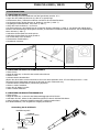
La torcia PUSH-PULL è stata progettata per facilitare la saldatura del lo di alluminio particolarmente sottile, ma è inoltre
possibile saldare li d’acciaio, di inox di CuAl e CuSi.
La torcia è dotata di una punta di contatto da 0,8 mm alluminio (MB15) o da 1,2 mm alluminio (MB25) e una guaina
in téon per lo da 0.8 e 1mm (MB15) o 0,8 e 1,2 mm (MB25) che, grazie alle sua scivolosità, è particolarmente
indicata per il trascinamento dei li in alluminio. Il teon ha un coefciente di attrito molto basso, ma è poco resistente
all’abrasione. Quando si vuole saldare li di ferro o di acciaio inossidabile per un lungo periodo, si consiglia di sostituire
la guaina in teon con una guaina in metallo.
2.2 LIMITI D’UTILIZZO
La torcia non dev’essere usata oltre le limitazioni delle speciche (200A 15%): ne possono conseguire danni signicativi.
Se fosse necessario, la tocia non sarà più garantita.
3 INSTALLAZIONE
3.1 INSTALLAZIONE
Estrarre il tubo metallico situato all’interno del ssaggio
centralizzato del generatore.
Collegare la torcia PUSH-PULL al generatore, montare la guida del
lo del trainalo sulla guaina in teon sporgente dalla torcia.
Bloccare il ssaggio centralizzato della torcia PUSH-PULL avvitandola
sul ssaggio del generatore.
Collegare il cavo uscente dalla torcia al connettore situato sul
frontale del dispositivo di saldatura.
Importante : Per saldare li d’alluminio, soprattutto li di Ø 0,6 o
0,8 mm, è estremamente importante regolare la frizione al valore
minimo della pressione, mentre per gli altri li è sufciente fare
qualche giro sulla frizione per ottenere la pressione corretta.
Punta di contatto : utilizzare una punta di contatto per alluminio del
diametro del lo.
Selezionare il programma di saldatuta più adatto al lo che si utilizza.
Per facilitare l’inserimento del ilo nel blocco motore del trainalo,
preferire un taglio netto e tenere il lo ben dritto, posizionando
la torcia il più a destra possibile.
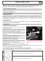
3.1.2 Preparazione del gruppo di trascinamento del lo della torcia PUSH-PULL
Utilizzare il rullo di trascinamento del lo con la scanalatura corrispondente al diametro del lo da utilizzare. Il diametro
è rappresentato da una scanalatura sul piano del rullo.
MB15
(A) lato scanalatura 0.6mm / (B) lato opposto 0.8-1mm
MB25
(A) lato scanalatura 0.8-1mm / (B) lato opposto 1.2mm

21
PUSH PULL MB15 / MB 25
IT
3.1.3 Caricamento del lo
• Allentare la vite di ssaggio (A) e tirarla verso l’esterno.
• Estrarre il coperchio B in modo da vedere il gruppo di trascinamento.
REM. Per i li da 1mm o se si carica un lo di diametro inferiore, ci sono degli inceppamenti :
• Allentare l’ugello del gas (D) e la punta di contatto (C + C1 per MB25).
• Premere sulla leva (E) per sollevare il cuscinetto appoggia-lo, per evitare che il lo incontri ostacoli nel momento
dell’inserimento.
• Premere sul pulsante (F) della torcia o sul pulsante di avanzamento del lo del dispositivo per far avanzare il lo no
all’uscita della torcia. E’ preferibile far avanzare a velocità ridotta Il lo appena sia arrivato a livello dei rulli.
• Vericare che il lo sia posizionato all’interno della scanalatura del rullo di trascinamento del lo (G).
• Rimettere la protezione (B) al suo posto e ssarla stringendo la vite di ssaggio (A).
• Stringere la punta di contatto (C + C1 per MB25) e l’ugello gas (D).
A
H
F
B
G
O
E
L
IK
J
C
M
N
D
C
M
N
D
C1
MB15 MB25
4. SALDATURA
4.1 IMPOSTAZIONI DELLA TORCIA PUSH-PULL A SECONDA DEL TIPO DI MATERIALE DA SALDARE
Vericare che il dispositivo di saldatura sia regolato a seconda del diametro lo e del tipo di materiale da saldare.
Assicurarsi del montaggio sulla torcia PUSH-PULL del rullo (G) con diametro corrispondente al lo da utilizzare e della
punta di contatto (C) con diametro corretto.
Sul generatore, regolare la corrente relativa al tipo di operazione da eseguire.
Avvicinarsi al punto di saldatura e premere sul pulsante (F) della torcia.
Per mezzo del pulsante « SELECT » (H) è possibile scegliere l’altezza dell’arco selezionando il LED arancione (I) o la
velocità del lo selezionando il LED verde (J). Queste regolazioni sono differenti a seconda del tipo di generatore.
Il pulsante « UP-DOWN » (K) permette di regolare la funzione scelta precedentemente.
Quando si deve saldare per lungo tempo li di ferro o di acciaio inossidabile, si consiglia di sostituire la guaina in teon
con quella in metallo (cf. §5.1). Sostituire la guaina (N).
Dopo aver sostituito la guaina in teon conquella in metallo, bisogna rimontare il tubo in metallo all’interno del ssaggio
centralizzato del generatore.

22
PUSH PULL MB15 / MB 25
IT
5 MANUTENZIONE
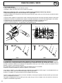
5.1 SOSTITUZIONE DELLA GUAINA
Prima del montaggio, la guaina in metallo dev’essere tagliata su misura; bisogna dunque:
• Posizionare la torcia PUSH-PULL in modo che sia in una posizione la più dritta possibile.
• Allentare il dado, estrarre la guaina in teon ed inlare quella in metallo.
• Essendo la guaina più lunga della torcia, X mm restano insporgenza (vedi g. 1).
• Misurare con precisione la parte sporgente (vedi g. 1).
• Lunghezza della guaina nella torcia ≈ 4 150 mm.
• Ritirare la guainam tagliare la parte terminale alla misura precedentemente presa (vedi g. 2). Il taglio dev’essere
eseguito con un utensile molto tagliente per non formare delle sbavature che potrebbero ostruire il passaggio del lo
(vedi g. 3).
• Tagliare in punta la cima della guaina.
• Tagliare la cima della guaina in modo che sia dritta.
• Inserire la guaina così preparata.
• Stringere il dado di serraggio.
• Sostituire la punta di contatto.
g. 1 g. 2 g. 3
5.2 SOSTITUZIONE DELLA GUANI NEL COLLO DEL CIGNO
• Allentare il pulsante (A).
• Estrarre la protezione (B) in modo da vedere il gruppo di trascinamento.
• Allentare il dado (L).
• Svitare il collo del cigno (M).
• Ritirare la guaina (N) e sostituirla tagliandola alla lunghezza di 175 mm guaina ottone + 6 mm guaina teon.
(se inceppata, sostituire la guaina (N) con una guaina teon).
• Riavvitare il collo del cigno (M), regolare il suo orientamento.
• Stringere il dado (L).
• Rimontare la protezione (B).
• Stringere il pulsante (A).
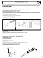
5.3 Sostituzione del rullo
• Allentare il pulsante (A).
• Estrarre la protezione (B) in modo da vedere il gruppo di trascinamento.
• Allentare la vite (O) che blocca il rullo con la chiave (P).
• Premere sulla leva (E) per estrarre il rullo (G).
Per il rimontaggio, eseguire l’operazione inversa.
Utilizzo della chiave P
P
Galet
Tube contact
(0.6-0.8mm)
Tube contact
(0.6-0.8-1-1.2mm)
Rullo
Punta di contatto
(0.6-0.8-1-1.2 mm)
Punta di contatto
(0.6-0.8 mm)

23
PUSH PULL MB15 / MB 25
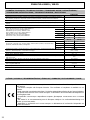
DONNÉES TECHNIQUES / TECHNICAL FEATURES / TECHNISCHE DATEN / DATOS TÉCNICOS /
ТЕХНИЧЕСКИЕ ХАРАКТЕРИСТИКИ / TECHNISCHE GEGEVENS / DATI TECNICI
PUSH PULL
Polarité de la torche de soudage / Welding torch polarity / Schweißbrennerpolarität / La polaridad de soldadura
de la antorcha / Полярность сварочной горелки / Lastoorts polariteit / Polarità della torcia di saldatura
Positive - MIG / MAG
Type de guide / Guide type / Typ-Führer / Guía de tipo / Руководство Тип / Type Guide / Tipo di guida Manuelle
Type de tension / Voltage type / Spannungsart / Tipo de tensión / Тип напряжения / Type voltage / Tipo di
tensione
DC
Gaz de protection / Shielding gas / Schutzgas / Gas protector / Защитный газ / beschermgas / Gas di protezione CO
2
- Argon - Argon/Co
2
Facteur de marche à 40°C (10 min)*
Norme EN60974-1.
Duty cycle at 40°C (10 min)* Standard EN60974-1.
Einschaltdauer @ 40°C (10 min)* EN60974-1-Norm.
Ciclo de trabajo a 40°C (10 min)* Norma EN60974-1
ПВ% при 40°C (10 мин)* Норма EN60974-1.
Inschakelduur bij 40°C (10 min)* Norm EN60974-1.
Ciclo di lavoro a 40°C (10 min)* Norma EN60974-1.
Standard Pulsé
Imax 40%
20 A 100 %
160 A 40 % 33 %
MB15
200 A 20 % 15 %
MB25
220 A 15 % 20 %
MB 15 MB 25
Fils supportés / Supported wires / geeignete Drähte / Alambres/hilos soportados / Подходящие виды
проволоки / Ondersteunde draden / Fili supportati
Aluminium Ø 0,6 / 0,8 / 1 mm Ø 0,8 / 1 / 1,2 mm
Acier Ø 0,6 / 0,8 / 1 mm Ø 0,8 / 1 mm
Inox Ø 0,8 / 1 mm Ø 0,8 / 1 mm
Cu/Si3% Ø 0,8 mm Ø 0,8 / 1 mm
Température de stockage / Storage temperature / Lagerungstemperatur / Temperatura de almacenaje / Температура
хранения / Bewaartemperatuur / Temperatura di stoccaggio
-10°C +40°C
(14°F / +104°F)
Mesure de tension manuelle / Manual voltage measurement / Misura di tensione manuale 113 V
Moteur / Motor / Двигатель / Motore 24 V - 1 A
Degré de protection / Protection level / Schutzart / Grado de protección / Степень защиты / Beschermingsklasse /
Grado di protezione
IP3X
Débit de gaz / Gas ow / Gasstrom / Flujo de gas / Поток газа / Gasstroom / Flusso di gas 10 to 20 l/min
Connection / Hose package lenght / Verbindung / Conexión / Подключение / Verbinding / Connessione Euro torche connecteur JAE
Longueur de la torche / Torch Length / Länge der Fackel / Longitud de la antorcha / Длина факела / Lengte van de
toorts / Lunghezza della torcia
4 m / 6 m
Poids / Weight / Gewicht / Вес / Peso / Gewicht / Peso 2,9 kg 3 kg (4.2 kg / 6m)
Norme / Constructed to standard / Standard / Norma / стандарт / standaard / Norma IEC 60974-7
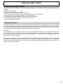
ICÔNES / SYMBOLS / ZEICHENERKLÄRUNG / SÍMBOLOS / СИМВОЛЫ / PICTOGRAMMEN / ICONA
- Appareil conforme aux directives européennes. La déclaration de conformité est disponible sur notre
site internet.
- The device complies with European Directive. The certicate of compliance is available on our
website.
- Gerät entspricht europäischen Richtlinien. Die Konformitätserklärung nden Sie auf unsere Webseite.
- El aparato está conforme a las normas europeas. La declaración de conformidad está disponible en
nuestra página Web.
- Устройство соответствует европейским нормам. Декларация соответствия есть на нашем
сайте.
- Het toestel is in overeenstemming met de Europese richtlijnen. De conformiteitsverklaring is te
vinden op onze internetsite.
- Dispositivo in conformità con le norme europee. La dichiarazione di conformità è disponibile sul
nostro sito internet.

24
PUSH PULL MB15 / MB 25
CONDITIONS DE GARANTIE FRANCE
La garantie couvre tous défauts ou vices de fabrication pendant 1 an, à compter de la date d’achat (pièces et main
d’oeuvre).
La garantie ne couvre pas :
• Toutes autres avaries dues au transport.
• L’usure normale des pièces (Ex. : câbles, pinces, etc.).
• Les incidents dus à un mauvais usage (erreur d’alimentation, chute, démontage).
• Les pannes liées à l’environnement (pollution, rouille, poussière).
En cas de panne, retourner l’appareil à votre distributeur, en y joignant :
- un justicatif d’achat daté (ticket de sortie de caisse, facture….)
- une note explicative de la panne.
HERSTELLERGARANTIE
Die Garantieleistung des Herstellers erfolgt ausschließlich bei Fabrikations- oder Materialfehlern, die binnen 12 Monate
nach Kauf angezeigt werden (Nachweis Kaufbeleg). Nach Anerkenntnis des Garantieanspruchs durch den Hersteller
bzw. seines Beauftragten erfolgen eine für den Käufer kostenlose Reparatur und ein kostenloser Ersatz von Ersatzteilen.
Der Garantiezeitraum bleibt aufgrund erfolgter Garantieleistungen unverändert.
Ausschluss:
Die Garantieleistung erfolgt nicht bei Defekten, die durch unsachgemäßen Gebrauch, Sturz oder harte Stöße sowie
durch nicht autorisierte Reparaturen oder durch Transportschäden, die infolge des Einsendens zur Reparatur,
hervorgerufen worden sind. Keine Garantie wird für Verschleißteile (z. B. Kabel, Klemmen, Vorsatzscheiben etc.) sowie
bei Gebrauchsspuren übernommen.
Das betreffende Gerät bitte immer mit Kaufbeleg und kurzer Fehlerbeschreibung ausschließlich über den Fachhandel
einschicken. Die Reparatur erfolgt erst nach Erhalt einer schriftlichen Akzeptanz (Unterschrift) des zuvor vorgelegten
Kostenvoranschlags durch den Besteller. Im Fall einer Garantieleistung trägt JBDC ausschließlich die Kosten für den
Rückversand an den Fachhändler.

25
PUSH PULL MB15 / MB 25
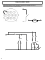
SCHÉMA ÉLECTRIQUE / CIRCUIT DIAGRAM / SCHALTPLAN / DIAGRAMA ELECTRICO /
ЭЛЕКТРИЧЕСКАЯ СХЕМА / SCHEMA ELETTRICO
-5
+ -
8
1
+4
M

26
NOTE :
.................................................................................................................................................................................................................
.................................................................................................................................................................................................................
.................................................................................................................................................................................................................
.................................................................................................................................................................................................................
.................................................................................................................................................................................................................
.................................................................................................................................................................................................................
.................................................................................................................................................................................................................
.................................................................................................................................................................................................................
.................................................................................................................................................................................................................
.................................................................................................................................................................................................................
.................................................................................................................................................................................................................
.................................................................................................................................................................................................................
.................................................................................................................................................................................................................
.................................................................................................................................................................................................................
.................................................................................................................................................................................................................
.................................................................................................................................................................................................................
.................................................................................................................................................................................................................
.................................................................................................................................................................................................................
.................................................................................................................................................................................................................
.................................................................................................................................................................................................................
.................................................................................................................................................................................................................
.................................................................................................................................................................................................................
.................................................................................................................................................................................................................
.................................................................................................................................................................................................................
.................................................................................................................................................................................................................
.................................................................................................................................................................................................................

27

28
-
 1
1
-
 2
2
-
 3
3
-
 4
4
-
 5
5
-
 6
6
-
 7
7
-
 8
8
-
 9
9
-
 10
10
-
 11
11
-
 12
12
-
 13
13
-
 14
14
-
 15
15
-
 16
16
-
 17
17
-
 18
18
-
 19
19
-
 20
20
-
 21
21
-
 22
22
-
 23
23
-
 24
24
-
 25
25
-
 26
26
-
 27
27
-
 28
28


GYS MB15 PUSH-PULL TORCH - Wire Ø 0.6 to 1.0 de handleiding
- Type
- de handleiding
- Deze handleiding is ook geschikt voor
in andere talen
Gerelateerde papieren
-
GYS AUTOPULSE 320-T3 de handleiding
-
GYS AUTOPULSE 320-T3 400V v2 - 3 TORCHES INCLUDED de handleiding
-
-
-
GYS MIG M1 GYS AUTO EQUIPE de handleiding
-
GYS TRIMIG 200-4S de handleiding
-
GYS AUTOPULSE 220-M1 de handleiding
-
GYS PROMIG 400-4S de handleiding
-