
LYNX 06
230V / 115V

ITALIANO
AVVERTENZE PER L’INSTALLATORE
OBBLIGHI GENERALI PER LA SICUREZZA
ATTENZIONE! È importante per la sicurezza delle persone seguire
attentamente tutta l’istruzione. Una errata installazione o un errato
uso del prodotto può portare a gravi danni alle persone.
Leggere attentamente le istruzioni prima di iniziare l’installazione del prodotto.
I materiali dell’imballaggio (plastica, polistirolo, ecc.) non devono essere lasciati alla
portata dei bambini in quanto potenziali fonti di pericolo.
Conservare le istruzioni per riferimenti futuri.
Questo prodotto è stato progettato e costruito esclusivamente per l’utilizzo indicato in
questa documentazione. Qualsiasi altro utilizzo non espressamente indicato potrebbe
pregiudicare l’integrità del prodotto e/o rappresentare fonte di pericolo.
GENIUS declina qualsiasi responsabilità derivata dall’uso improprio o diverso da quello
per cui l’automatismo è destinato.
Non installare l’apparecchio in atmosfera esplosiva: la presenza di gas o fumi
infiammabili costituisce un grave pericolo per la sicurezza.
Gli elementi costruttivi meccanici devono essere in accordo con quanto stabilito
dalle Norme EN 12604 e EN 12605.
Per i Paesi extra-CEE, oltre ai riferimenti normativi nazionali, per ottenere un livello di
sicurezza adeguato, devono essere seguite le Norme sopra riportate.
GENIUS non è responsabile dell’inosservanza della Buona Tecnica nella costru-
zione delle chiusure da motorizzare, nonché delle deformazioni che dovessero
intervenire nell’utilizzo.
L’installazione deve essere effettuata nell’osservanza delle Norme EN 12453 e EN
12445. Il livello di sicurezza dell’automazione deve essere C+D.
Prima di effettuare qualsiasi intervento sull’impianto, togliere l’alimentazione elettrica
e scollegare le batterie.
Prevedere sulla rete di alimentazione dell’automazione un interruttore onnipolare con
distanza d’apertura dei contatti uguale o superiore a 3 mm. È consigliabile l’uso di
un magnetotermico da 6A con interruzione onnipolare.
Verificare che a monte dell’impianto vi sia un interruttore differenziale con soglia
da 0,03 A.
Verificare che l’impianto di terra sia realizzato a regola d’arte e collegarvi le parti
metalliche della chiusura.
L’automazione dispone di una sicurezza intrinseca antischiacciamento costituita
da un controllo di coppia. E’ comunque necessario verificarne la sogli di intervento
secondo quanto previsto dalle Norme indicate al punto 10.
I dispositivi di sicurezza (norma EN 12978) permettono di proteggere eventuali
aree di pericolo da Rischi meccanici di movimento, come ad Es. schiacciamento,
convogliamento, cesoiamento.
Per ogni impianto è consigliato l’utilizzo di almeno una segnalazione luminosa nonché
di un cartello di segnalazione fissato adeguatamente sulla struttura dell’infisso, oltre
ai dispositivi citati al punto “16”.
GENIUS declina ogni responsabilità ai fini della sicurezza e del buon funzionamento
dell’automazione, in caso vengano utilizzati componenti dell’impianto non di
produzione GENIUS.
Per la manutenzione utilizzare esclusivamente parti originali GENIUS.
Non eseguire alcuna modifica sui componenti facenti parte del sistema d’au-
tomazione.
L’installatore deve fornire tutte le informazioni relative al funzionamento manuale
del sistema in caso di emergenza e consegnare all’Utente utilizzatore dell’impianto
il libretto d’avvertenze allegato al prodotto.
Non permettere ai bambini o persone di sostare nelle vicinanze del prodotto
durante il funzionamento.
L’applicazione non può essere utilizzata da bambini, da persone con ridotte ca-
pacità fisiche, mentali, sensoriali o da persone prive di esperienza o del necessario
addestramento.
Tenere fuori dalla portata dei bambini radiocomandi o qualsiasi altro datore di impul-
so, per evitare che l’automazione possa essere azionata involontariamente.
Il transito tra le ante deve avvenire solo a cancello completamente aperto.
L’utente utilizzatore deve astenersi da qualsiasi tentativo di riparazione o d’intervento
e deve rivolgersi solo ed esclusivamente a personale qualificato GENIUS o centri
d’assistenza GENIUS.
Tutto quello che non è previsto espressamente in queste istruzioni non è permesso.
ENGLISH
IMPORTANT NOTICE FOR THE INSTALLER
GENERAL SAFETY REGULATIONS
ATTENTION! To ensure the safety of people, it is important that you read
all the following instructions. Incorrect installation or incorrect use
of the product could cause serious harm to people.
Carefully read the instructions before beginning to install the product.
Do not leave packing materials (plastic, polystyrene, etc.) within reach of children
as such materials are potential sources of danger.
Store these instructions for future reference.
This product was designed and built strictly for the use indicated in this documen-
tation. Any other use, not expressly indicated here, could compromise the good
condition/operation of the product and/or be a source of danger.
GENIUS declines all liability caused by improper use or use other than that for which
the automated system was intended.
Do not install the equipment in an explosive atmosphere: the presence of inflam-
mable gas or fumes is a serious danger to safety.
The mechanical parts must conform to the provisions of Standards EN 12604 and
EN 12605.
For non-EU countries, to obtain an adequate level of safety, the Standards mentioned
above must be observed, in addition to national legal regulations.
GENIUS is not responsible for failure to observe Good Technique in the construction
of the closing elements to be motorised, or for any deformation that may occur
during use.
The installation must conform to Standards EN 12453 and EN 12445. The safety level
of the automated system must be C+D.
Before attempting any job on the system, cut out electrical power and disconnect
the batteries.
The mains power supply of the automated system must be fitted with an all-pole
switch with contact opening distance of 3mm or greater. Use of a 6A thermal breaker
with all-pole circuit break is recommended.
Make sure that a differential switch with threshold of 0.03 A is fitted upstream of
the system.
Make sure that the earthing system is perfectly constructed, and connect metal parts
of the means of the closure to it.
The automated system is supplied with an intrinsic anti-crushing safety device
consisting of a torque control. Nevertheless, its tripping threshold must be checked
1.
2.
3.
4.
5.
6.
7.
8.
9.
10.
11.
12.
13.
14.
15.
16.
17.
18.
19.
20.
21.
22.
23.
24.
25.
26.
27.
1.
2.
3.
4.
5.
6.
7.
8.
9.
10.
11.
12.
13.
14.
15.
as specified in the Standards indicated at point 10.
The safety devices (EN 12978 standard) protect any danger areas against mechanical
movement Risks, such as crushing, dragging, and shearing.
Use of at least one indicator-light is recommended for every system, as well as a
warning sign adequately secured to the frame structure, in addition to the devices
mentioned at point “16”.
GENIUS declines all liability as concerns safety and efficient operation of the automa-
ted system, if system components not produced by GENIUS are used.
For maintenance, strictly use original parts by GENIUS.
Do not in any way modify the components of the automated system.
The installer shall supply all information concerning manual operation of the system
in case of an emergency, and shall hand over to the user the warnings handbook
supplied with the product.
Do not allow children or adults to stay near the product while it is operating.
The application cannot be used by children, by people with reduced physical, mental,
sensorial capacity, or by people without experience or the necessary training.
Keep remote controls or other pulse generators away from children, to prevent the
automated system from being activated involuntarily.
Transit through the leaves is allowed only when the gate is fully open.
The User must not in any way attempt to repair or to take direct action and must solely
contact qualified GENIUS personnel or GENIUS service centres.
Anything not expressly specified in these instructions is not permitted.
FRANÇAIS
CONSIGNES POUR L’INSTALLATEUR
RÈGLES DE SÉCURITÉ
ATTENTION! Il est important, pour la sécurité des personnes, de suivre
à la lettre toutes les instructions. Une installation erronée ou un
usage erroné du produit peut entraîner de graves conséquences
pour les personnes.
Lire attentivement les instructions avant d’installer le produit.
Les matériaux d’emballage (matière plastique, polystyrène, etc.) ne doivent pas
être laissés à la portée des enfants car ils constituent des sources potentielles
de danger.
Conserver les instructions pour les références futures.
Ce produit a été conçu et construit exclusivement pour l’usage indiqué dans cette
documentation. Toute autre utilisation non expressément indiquée pourrait compro-
mettre l’intégrité du produit et/ou représenter une source de danger.
GENIUS décline toute responsabilité qui dériverait d’usage impropre ou différent de
celui auquel l’automatisme est destiné.
Ne pas installer l’appareil dans une atmosphère explosive: la présence de gaz ou de
fumées inflammables constitue un grave danger pour la sécurité.
Les composants mécaniques doivent répondre aux prescriptions des Normes EN
12604 et EN 12605.
Pour les Pays extra-CEE, l’obtention d’un niveau de sécurité approprié exige non
seulement le respect des normes nationales, mais également le respect des
Normes susmentionnées.
GENIUS n’est pas responsable du non-respect de la Bonne Technique dans la con-
struction des fermetures à motoriser, ni des déformations qui pourraient intervenir
lors de l’utilisation.
L’installation doit être effectuée conformément aux Normes EN 12453 et EN 12445.
Le niveau de sécurité de l’automatisme doit être C+D.
Couper l’alimentation électrique et déconnecter la batterie avant toute interven-
tion sur l’installation.
Prévoir, sur le secteur d’alimentation de l’automatisme, un interrupteur omnipolaire
avec une distance d’ouverture des contacts égale ou supérieure à 3 mm. On recom-
mande d’utiliser un magnétothermique de 6A avec interruption omnipolaire.
Vérifier qu’il y ait, en amont de l’installation, un interrupteur différentiel avec un
seuil de 0,03 A.
Vérifier que la mise à terre est réalisée selon les règles de l’art et y connecter les
pièces métalliques de la fermeture.
L’automatisme dispose d’une sécurité intrinsèque anti-écrasement, formée d’un
contrôle du couple. Il est toutefois nécessaire d’en vérifier le seuil d’intervention
suivant les prescriptions des Normes indiquées au point 10.
Les dispositifs de sécurité (norme EN 12978) permettent de protéger des zones
éventuellement dangereuses contre les Risques mécaniques du mouvement, comme
l’écrasement, l’acheminement, le cisaillement.
On recommande que toute installation soit doté au moins d’une signalisation lumi-
neuse, d’un panneau de signalisation fixé, de manière appropriée, sur la structure
de la fermeture, ainsi que des dispositifs cités au point “16”.
GENIUS décline toute responsabilité quant à la sécurité et au bon fonctionnement
de l’automatisme si les composants utilisés dans l’installation n’appartiennent pas
à la production GENIUS.
Utiliser exclusivement, pour l’entretien, des pièces GENIUS originales.
Ne jamais modifier les composants faisant partie du système d’automatisme.
L’installateur doit fournir toutes les informations relatives au fonctionnement manuel du
système en cas d’urgence et remettre à l’Usager qui utilise l’installation les “Instructions
pour l’Usager” fournies avec le produit.
Interdire aux enfants ou aux tiers de stationner près du produit durant le fonc-
tionnement.
Ne pas permettre aux enfants, aux personennes ayant des capacités physiques,
mentales et sensorielles limitées ou dépourvues de l’expérience ou de la formation
nécessaires d’utiliser l’application en question.
Eloigner de la portée des enfants les radiocommandes ou tout autre générateur
d’impulsions, pour éviter tout actionnement involontaire de l’automatisme.
Le transit entre les vantaux ne doit avoir lieu que lorsque le portail est complète-
ment ouvert.
L’utilisateur doit s’abstenir de toute tentative de réparation ou d’intervention et
doit s’adresser uniquement et exclusivement au personnel qualifié GENIUS ou aux
centres d’assistance GENIUS.
Tout ce qui n’est pas prévu expressément dans ces instructions est interdit.
ESPAÑOL
ADVERTENCIAS PARA EL INSTALADOR
REGLAS GENERALES PARA LA SEGURIDAD
ATENCION! Es sumamente importante para la seguridad de las
personas seguir atentamente las presentes instrucciones. Una
instalación incorrecta o un uso impropio del producto puede
causar graves daños a las personas.
Lean detenidamente las instrucciones antes de instalar el producto.
Los materiales del embalaje (plástico, poliestireno, etc.) no deben dejarse al alcance
16.
17.
18.
19.
20.
21.
22.
23.
24.
25.
26.
27.
1.
2.
3.
4.
5.
6.
7.
8.
9.
10.
11.
12.
13.
14.
15.
16.
17.
18.
19.
20.
21.
22.
23.
24.
25.
26.
27.
1.
2.

1
ITALIANO
Note per la lettura dell’istruzione
Leggere completamente questo manuale di installazione prima di iniziare l’installazione del prodotto.
Il simbolo evidenzia note importanti per la sicurezza delle persone e l’integrità dell’automazione.
Il simbolo richiama l’attenzione su note riguardanti le caratteristiche od il funzionamento del prodotto.
DICHIARAZIONE CE DI CONFORMITÁ
Fabbricante: GENIUS S.p.A.
Indirizzo: Via Padre Elzi, 32 - 24050 - Grassobbio- Bergamo - ITALIA
Dichiara che: L’apparecchiatura elettronica mod. LYNX 06
con alimentazione: 230 Vac
è conforme ai requisiti essenziali di sicurezza delle seguenti direttive CEE:
73/23/CEE e successiva modifica 93/68/CEE.
89/336/CEE e successiva modifica 92/31/CEE e 93/68/CEE
Nota aggiuntiva:
Questo prodotto è stato sottoposto a test in una configurazione tipica omogenea (tutti prodotti di costruzione GENIUS
S.p.A.)
Grassobbio, 23 Febbraio 2009
L’Amministratore Delegato
D. Gianantoni
•
•
•
INDICE
1. DESCRIZIONE pag.2
2. CARATTERISTICHE TECNICHE pag.2
3. PREDISPOSIZIONI pag.2
4. LAY OUT SCHEDA pag.3
5. COLLEGAMENTI E FUNZIONAMENTO pag.3
5.1. MORSETTIERA CN1 pag.3
5.2. CONNETTORE CN2 pag.4
5.3. MORSETTIERA CN3 pag.4
5.4. MORSETTIERA CN4 pag.4
5.5. CONNETTORE CN5 pag.5
6. INSERIMENTO MODULO RICEVITORE pag.5
7. MEMORIZZAZIONE CODIFICA RADIO pag.6
7.1. MEMORIZZAZIONE DEI RADIOCOMANDI 868 MHz pag.6
7.2. MEMORIZZAZIONE DEI RADIOCOMANDI 433 MHz pag.6
7.3. CANCELLAZIONE DEI CODICI RADIO pag.7
8. LED DI CONTROLLO pag.7
9. FUNZIONAMENTO DEL DISPLAY pag.7
10. PARAMETRI DI FUNZIONAMENTO pag.8
10.1. RICHIESTA ASSISTENZA pag.10
11. MESSA IN FUNZIONE pag.10
12. FUSIBILI DI PROTEZIONE pag.11
13. LOGICHE DI FUNZIONAMENTO pag.12

2
ITALIANO
APPARECCHIATURA ELETTRONICA PER BARRIERE
ISTRUZIONI PER L’USO - NORME DI INSTALLAZIONE
1. DESCRIZIONE
Le apparecchiature elettroniche LYNX 06 sono progettate e realizzate per la gestione di barriere elettromeccaniche
destinate al controllo di accessi residenziali.
I due modelli di scheda differiscono per la tensione d’alimentazione:
Lynx 06: Alimentazione 230V
Lynx 06: Alimentazione 115V
Queste centrali di comando, grazie all’ampio numero di parametri selezionabili, possono essere adattate alle proprie
esigenze garantendo un funzionamento ottimale dell’automazione.
La possibilità di gestire un encoder per la rilevazione di eventuali ostacoli permette di aumentare ulteriormente il livello
di sicurezza dell’automazione.
La programmazione dei principali parametri di funzionamento avviene tramite la pressione dei due tasti posti sulla
centrale e vengono visualizzati sull’ampio display retro illuminato. Durante il normale funzionamento il display permette
di visualizzare in ogni istante lo stato dell’automazione. L’apprendimento del ciclo di lavoro e delle battute meccaniche
avviene in modo automatico durante l’esecuzione del primo ciclo (ogni volta che viene a mancare la tensione la
centrale esegue la ricerca delle battute sia in apertura che in chiusura).
Sei led incorporati indicano costantemente lo stato degli ingressi.
2. CARATTERISTICHE TECNICHE
Tensione di alimentazione della centrale
230/115 Vac 50/60 Hz
a
Potenza assorbita 3 W
Potenza assorbita motore 500 W
Carico max. accessori 500 mA
Alimentazione e carico max. lampeggiante 230 Vac 25 W
Alimentazione e carico max. spia stato barriera 24 Vdc 5 W
Temperatura di funzionamento -20°C +55°C
Fusibili di protezione
F1= T5A (Primario trasformatore e motore)
F2= T500mA (accessori e lampada spia)
Logiche di funzionamento
Automatica / Automatica passo-passo / Semiautomatica
/ Semiautomatica passo-passo / Condominiale
Tempo di apertura / chiusura In autoapprendimento durante la prima manovra
Tempo di pausa Nove livelli selezionabili sino ad un massimo di 4 minuti
Forza motore Regolabile su più livelli
Tempo di rallentamento Tre livelli selezionabili
Rilevazione ostacolo Con encoder opzionale
Funzioni selezionabili
Funzionamento con o senza encoder / Sensibilità enco-
der/ Chiusura automatica / Funzionamento dell’ingresso
di open / Funzione condominiale / Percentuale di rallen-
tamento / Funzione riscaldamento / Chiusura immediata
/ Funzione timer / Soft start / Funzionamento fotocellule /
Richiesta manutenzione
Ingressi in morsettiera
Apertura / Chiusura / Fotocellule / Finecorsa in apertura
/ Finecorsa in chiusura / Stop / Alimentazione di rete /
Messa a terra
Ingressi con connettore Modulo radio / condensatore di spunto / encoder
Uscite in morsettiera
Alimentazione accessori / Lampeggiante / Motore /
Lampada spia
Dimensioni scheda 147 x 112 mm
a
A seconda del modello di scheda, 230 Vac o 115Vac.
3. PREDISPOSIZIONI
È importante ai fini della sicurezza delle persone seguire tutte le avvertenze e le istruzioni presenti in questo
libretto. Un’errata installazione o un errato uso del prodotto può portare a gravi danni alle persone.
Conservare le istruzioni per riferimenti futuri.
Verificare che a monte dell’impianto vi sia un adeguato interruttore differenziale come prescritto dalle vigenti
norme di sicurezza.
Prevedere, sulla rete d’alimentazione, un magnetotermico con interruzione onnipolare.
Verificare l’esistenza di un adeguato impianto di messa a terra.
Per la messa in opera dei cavi elettrici utilizzare adeguati tubi rigidi e/o flessibili.
Separare sempre i cavi d’alimentazione 230/115 Vac da quelli di collegamento a bassa tensione, utilizzando, per
evitare possibili interferenze, guaine separate.
•
•
•
•
•
•
•

3
ITALIANO
4. LAY OUT SCHEDA
Componenti
CN1 Morsettiera alimentazione
CN2 Connettore per encoder
CN3 Morsettiera finecorsa
CN4 Morsettiera comandi/alimentazione accessori
CN5 Connettore per condensatore
JP1 Connettore per modulo radio
DSP1 Display
F1
Fusibile primario trasformatore/Alimentazione
motore
F2 Fusibile accessori/lampada spia
P1 Pulsante regolazione parametri
P2 Pulsante regolazione parametri
P3
Pulsante memorizzazione canale radio OPEN/
CLOSE
P4 Pulsante memorizzazione canale radio CLOSE
P5 Pulsante di RESET
FCA Led ingresso FCA
FCC Led ingresso FCC
CLOSE Led ingresso CLOSE
OP/CL Led ingresso OPEN/CLOSE
FSW Led ingresso FSW
STOP Led ingresso STOP
DL7 Led canale radio OPEN/CLOSE
DL8 Led canale radio CLOSE
5. COLLEGAMENTI E FUNZIONAMENTO
5.1. MORSETTIERA CN1
5.1.1. Messa a terra
Morsetto “1”. Collegare a questo morsetto il cavo giallo-verde della linea
di alimentazione.
Questo collegamento è assolutamente necessario per il corretto
funzionamento della centrale.
5.1.2. aliMentazione
Morsetti “2 & 3”. A questi morsetti devono essere collegati i due fili provenienti
dalla rete di alimentazione a 230/115 Vac, a seconda del modello di scheda.
È opportuno collegare il neutro al morsetto 3 e la fase al morsetto 2.
5.1.3. laMpeggiante
Morsetti “4 & 5”. Uscita 230/115 Vac max. 25 W. A questi morsetti deve es-
sere collegato il cavo di alimentazione del lampeggiante. Il lampeggiante
è attivo durante il movimento dell’automazione mentre con l’automazione ferma, aperta o chiusa, è spento. Prima
della manovra di apertura il lampeggiante esegue un prelampeggio fisso di 0.5 sec. Se è stata attivata la funzione di
richiesta assistenza, una volta raggiunto il numero di cicli impostato, al termine della manovra di chiusura il lampeg-
giante continua a lampeggiare per altri 5 secondi indicando il raggiungimento dei cicli impostati. Per il funzionamento
e l’azzeramento dei cicli vedi paragrafo 10.1.
5.1.4. Motore
Morsetti “6, 7 & 8”. Uscita 230/115 Vac max. 500 W. Collegare a questi morsetti i cavi di alimentazione del motore. Per
la sequenza di collegamento dei cavi fare riferimento alla tabella di seguito:
N° morsetto Motore 230 Vac Motore 115 Vac
6 Nero Nero
7 Blu / Grigio Bianco
8 Marrone Rosso
1 Giallo Verde Verde

4
ITALIANO
Il colore dei fili collegati ai morsetti 6 & 8 possono essere invertiti a seconda del senso di rotazione del motore
5.2. CONNETTORE CN2
Questo connettore serve per il collegamento dell’encoder opzionale. Il connettore deve essere orientato in modo
corretto, non esercitare forzature.
La scheda viene fornita con una parametrizzazione standard che prevede l’utilizzo dell’encoder, “A0” (vedi paragrafo
10). Nel caso non si voglia utilizzare l’encoder è necessario modificare il valore del parametro “A” come descritto al
paragrafo 10 e lasciare libero questo connettore.
Non eseguire assolutamente dei ponticelli tra questi contatti.
La sensibilità di rilevamento dell’ostacolo viene regolata su quattro livelli agendo sul parametro “b”, vedi para-
grafo 10.
5.2.1. FunzionaMento dell’encoder
L’utilizzo dell’encoder permette di elevare ulteriormente il grado di sicurezza dell’automazione.
Questo dispositivo è attivo sia durante la fase di chiusura dell’automazione che durante la fase di apertura secondo
le seguenti modalità:
In fase di chiusura
Nel caso venga rilevato un ostacolo durante la fase di chiusura dell’automazione l’encoder interviene invertendo il
moto dell’automazione sino alla completa apertura, senza disattivare l’eventuale richiusura automatica.
Se interviene per tre volte consecutive, una volta raggiunta la posizione di apertura, l’automazione si posiziona in
STOP, disattivando l’eventuale richiusura automatica. per riprendere il normale funzionamento è necessario inviare un
impulso di OPEN o CLOSE dopo aver rimosso l’ostacolo.
In fase di apertura
Nel caso venga rilevato un ostacolo durante la fase di apertura dell’automazione l’encoder interviene invertendo il
moto dell’automazione sino alla completa richiusura.
5.3. MORSETTIERA CN3
5.3.1. Finecorsa in apertura Fca
Morsetto “12”. Collegare a questo morsetto il filo del contatto NC del finecorsa
di apertura. Questo agisce sul moto di apertura della sbarra arrestandone il mo-
vimento. Una volta attivato il finecorsa, l’automazione continua con la manovra
per altri 2 secondi. Lo stato di questo ingresso è segnalato dal led FCA.
Il finecorsa FCA non può essere utilizzato come inizio del tratto rallentato
ma solo come arresto.
Il collegamento del finecorsa è assolutamente necessario per il funziona-
mento dell’automazione.
5.3.2. coMune Finecorsa coMF
Morsetto “13”. Collegare a questo morsetto il filo del contatto comune dei
finecorsa.
Questo morsetto deve essere utilizzato solo per il contatto comune dei due
finecorsa. Non utilizzare come contatto negativo di altri dispositivi.
5.3.3. Finecorsa in chiusura Fcc
Morsetto “14”. Collegare a questo morsetto il filo del contatto NC del finecorsa di chiusura. Questo agisce sul moto
di chiusura della sbarra arrestandone il movimento. Una volta attivato il finecorsa, l’automazione continua con la
manovra per altri 2 secondi. Lo stato di questo ingresso è segnalato dal led FCC.
Il finecorsa FCC non può essere utilizzato come inizio del tratto rallentato ma solo come arresto.
Il collegamento del finecorsa è assolutamente necessario per il funzionamento dell’automazione.

5
ITALIANO
5.4. MORSETTIERA CN4
5.4.1. close
Morsetti “15 & 20”. Contatto NA. Collegare a questi morsetti un
qualsiasi datore d’impulso (pulsante, selettore a chiave ecc.) che,
chiudendo il contatto, comando un moto di chiusura dell’automa-
zione. Questo ingresso comanda solo la chiusura della sbarra quindi
a sbarra chiusa questo ingresso non ha nessun effetto, vedi tabelle
logiche. Lo stato di questo ingresso è segnalato dal led CLOSE.
Più datori d’impulso devono essere collegati in parallelo
5.4.2. open / close
Morsetti “16 & 20”. Contatto NA. Collegare a questi morsetti un
qualsiasi datore d’impulso (pulsante, selettore a chiave ecc..) che,
chiudendo il contatto, deve comandare un’apertura o una chiusura
dell’automazione.
Il comportamento di questo ingresso è definito dal parametro “d”
, vedi paragrafo 10. Lo stato di questo ingresso è segnalato dal led
OP/CL.
Più datori d’impulso devono essere collegati in parallelo
5.4.3. sicurezze
Morsetti “17 & 20”. Contatto NC. Collegare a questi morsetti un qualsiasi dispositivo di sicurezza (es. fotocellule) che,
aprendo il contatto, agisce sul moto dell’automazione. Tramite il parametro “y” si può scegliere se le sicurezze devono
essere solo in chiusura oppure in chiusura e apertura, vedi paragrafo 10. Lo stato di questo ingresso è segnalato dal
led FSW.
Sicurezze attive solo in chiusura.
Durante la fase di chiusura se vengono impegnate le sicurezze l’automazione inverte il movimento sino alla completa
apertura senza disabilitare, nel caso sia stata selezionata, la richiusura automatica.
Sicurezze attive in chiusura ed in apertura
In questo caso le sicurezze sono attive durante entrambi i movimenti dell’automazione.
Durante la fase di chiusura se vengono impegnate le sicurezze l’automazione arresta il funzionamento e rimane
ferma sino a quando le sicurezze non vengono ripristinate (ostacolo rimosso). Una volta che le sicurezze sono state
ripristinate l’automazione inverte il moto sino alla completa apertura senza disattivare, nel caso sia stata attivata, la
richiusura automatica.
Durante la fase d’apertura se vengono impegnate le sicurezze l’automazione arresta il funzionamento e rimane ferma
sino a quando non vengono ripristinate le sicurezze (ostacolo rimosso). Una volta ripristinate le sicurezza l’automazione
riprende il funzionamento sino alla completa apertura senza disattivare, nel caso sia stata selezionata, la richiusura
automatica.
Se non vengono utilizzate le sicurezze è necessario ponticellare questo ingresso, il led FSW deve essere acce-
so.
Più dispositivi di sicurezza devono essere collegati in serie.
5.4.4. stop
Morsetto “18 & 20”. Contatto NC. A questo contatto deve essere collegato un qualsiasi datore d’impulso (pulsante,
selettore a chiave ecc.) che , aprendo il contatto deve comandare l’arresto immediato dell’automazione e la
disattivazione dell’eventuale richiusura automatica. Dopo l’attivazione di questo contatto, per riprendere il normale
ciclo programmato, è necessario agire su di un qualsiasi datore d’impulso che comandi l’apertura e/o la chiusura
dell’automazione. Lo stato di questo ingresso è segnalato dal led STOP.
Più datori d’impulso devono essere collegati in serie.
5.4.5. laMpada spia
Morsetto “19 & 20”. A questi morsetti deve essere collegata l’eventuale lampada spia con alimentazione 24Vdc 5W
max. Il morsetto 19 è il polo positivo del collegamento, rispettare la polarità dei contatti. La lampada spia permette
di monitorare a distanza lo stato dell’automazione, in particolare:
Spia Spenta: automazione chiusa
Spia Accesa: automazione aperta
Spia lampeggiante lenta: automazione in chiusura
Spia lampeggiante veloce: automazione in apertura
A questo contatto non può essere applicato un carico superiore ai 5 W.
Per il collegamento della lampada spia è obbligatorio rispettare la polarità dei contatti.
•
•
•
•

6
ITALIANO
5.4.6. aliMentazione accessori
Morsetti “20 & 21”. Uscita 24Vdc max. 500 mA per l’alimentazione degli accessori esterni.
Il carico massimo di questa uscita è di 500 mA.
Rispettare la polarità di alimentazione.
5.5. CONNETTORE CN5
Questo connettore serve per il collegamento del condensatore di spunto.
Nel caso si disponga di un connettore senza morsetto per l’inserimento su questo connettore è possibile
collegare il condensatore in parallelo alle due fasi del motore, morsetti 6 & 8.
6. INSERIMENTO MODULO RICEVITORE
La centrale è predisposta per l’alloggiamento di un modulo ricevitore 868 o 433
Mhz. Il modulo ricevitore deve essere inserito sul connettore JP1, rispettando
l’orientamento definito dall’apposito alloggiamento, vedi figura.
L’inserimento e l’eventuale rimozione del modulo ricevitore deve avvenire
solo dopo aver tolto l’alimentazione alla centrale.
7. MEMORIZZAZIONE CODIFICA RADIO
La centrale di comando è provvista di un sistema di decodifica bi-canale integrato. Questo sistema permette di
memorizzare, tramite il modulo ricevitore, sia il comando di OPEN/CLOSE che il comando CLOSE.
Il sistema di decodifica permette di memorizzare sia i radiocomandi con frequenza 868 MHz che i radiocomandi con
frequenza 433 MHZ.
È possibile utilizzare una sola codifica radio per volta. Per passare da una codifica all’altra è necessario cancellare
la codifica radio esistente (vedi paragrafo 7.3), sostituire il modulo ricevitore e ripetere le fasi di programma-
zione.
L’inserimento e l’eventuale rimozione del modulo ricevitore deve avvenire solo dopo aver tolto tensione alla
scheda.
Il modulo ricevitore può essere inserito solo in una posizione. Orientare correttamente il modulo senza esercitare
forzature.
7.1. MEMORIZZAZIONE DEI RADIOCOMANDI 868 MHz
Prima di procedere con la memorizzazione del radiocomando è consigliabile eseguire una procedura di can-
cellazione, vedi paragrafo 7.3.
È possibile memorizzare fino ad un massimo di 250 codici, suddivisi tra i due canali, OPEN/CLOSE e CLOSE.
Sul radiocomando premere e tenere premuti i pulsanti P1 e P2 contemporaneamente (vedi istruzioni radioco-
mando).
Dopo circa un secondo il led del radiocomando inizia a lampeggiare.
Lasciare entrambi i pulsanti.
Premere e tenere premuto sulla scheda il pulsante P3 o P4 a seconda dell’ingresso che si vuole memorizzare (ingresso
di OPEN/CLOSE o CLOSE). Quando il relativo led inizia a lampeggiare rilasciare il pulsante.
Premere il pulsante del radiocomando al quale si vuole abbinare il comando scelto.
Verificare che il led relativo al comando che si sta memorizzando (DL7 per il canale di OPEN/CLOSE o DL8 per il
canale di CLOSE) si accenda a luce fissa per un paio di secondi a conferma della corretta memorizzazione.
Per terminare la programmazione è necessario premere per due volte, in breve successione, il pulsante del ra-
diocomando memorizzato.
L’automazione effettuerà una manovra d’apertura, assicurarsi che non vi siano ostacoli nel raggio d’azione.
Per memorizzare l’altro canale è necessario ripetere tutta la procedura dal punto 1.
Per aggiungere altri radiocomandi è necessario trasferire il codice del pulsante del radiocomando memorizzato al
1.
2.
3.
4.
5.
6.
7.
8.

7
ITALIANO
pulsante corrispondente dei radiocomandi da aggiungere, ripetendo la procedura di memorizzazione o seguendo
la seguente procedura:
Sul radiocomando memorizzato premere contemporaneamente i pulsanti P1 e P2 (vedi istruzioni radiocomando)
e tenerli premuti.
Il led del radiocomando inizia a lampeggiare.
Lasciare entrambi i pulsanti.
Accostare frontalmente a contatto i due radiocomandi.
Sul radiocomando memorizzato premere e tenere premuto il pulsante relativo al canale che si vuole trasferire, il led
del radiocomando si accende a luce fissa.
Sul radiocomando da memorizzare premere il pulsante desiderato e rilasciarlo dopo che il radiocomando ha
effettuato un doppio lampeggio.
Per terminare la programmazione è necessario premere per due volte, in breve successione, il pulsante del radio-
comando memorizzato.
L’automazione effettuerà una manovra d’apertura, assicurarsi che non vi siano ostacoli nel raggio d’azione.
7.2. MEMORIZZAZIONE DEI RADIOCOMANDI 433 MHz
Prima di procedere con la memorizzazione del radiocomando è consigliabile eseguire una procedura di can-
cellazione, vedi paragrafo 7.3.
È possibile memorizzare fino ad un massimo di 250 codici, suddivisi tra i due canali, OPEN/CLOSE e CLOSE.
Premere sulla centrale il pulsante relativo al canale che si desidera memorizzare, P3 per il canale di OPEN/CLOSE
o P4 per il canale di CLOSE.
Il relativo led sulla centrale inizia a lampeggiare, rilasciare il pulsante.
Sul radiocomando premere il pulsante al quale si vuole associare al canale scelto.
Il led sulla centrale si accende a luce fissa per circa un secondo, segnalando l’avvenuta memorizzazione del
radiocomando, per poi riprendere a lampeggiare.
In questa fase è possibile memorizzare ulteriori radiocomandi.
Trascorsi circa 10 secondi la centrale esce automaticamente dalla fase di apprendimento.
Per aggiungere altri radiocomandi o memorizzare il secondo canale ripetere le operazioni dal punto 1
7.2.1. MeMorizzazione reMota dei radiocoMandi 433 Mhz
Solo con radiocomandi 433 si possono memorizzare altri radiocomandi, in modo remoto, cioè senza intervenire sui
pulsanti della centrale, ma utilizzando un radiocomando precedentemente memorizzato.
Procurarsi un radiocomando già memorizzato su uno dei 2 canali.
Portarsi in prossimità dell’automazione.
Premere e tenere premuti i pulsanti P1 e P2 (vedi istruzioni del radiocomando) contemporaneamente per circa
5 secondi.
Entro 5 secondi premere sul radiocomando memorizzato il pulsante che si desidera trasferire al nuovo radiocomando.
In questo modo sulla centrale si attiva la fase di apprendimento sul canale selezionato.
Entro 5 secondi premere sul nuovo radiocomando il pulsante che si desidera associare al canale scelto.
Dopo la memorizzazione del nuovo radiocomando, la centrale mantiene attiva la modalità di apprendimento
sul canale scelto per circa 5 secondi.
Durante questi 5 secondi è possibile memorizzare sulla centrale altri radiocomandi, sempre abbinati al canale
attivato.
Trascorsi 5 secondi dalla memorizzazione dell’ultimo radiocomando la centrale esce in modo automatico dalla
fase di apprendimento.
Per verificare se il radiocomando è stato memorizzato in modo corretto è necessario attendere 5 secondi dall’invio
del codice.
7.3. CANCELLAZIONE DEI CODICI RADIO
Per cancellare tutti i codici dei radiocomandi memorizzati seguire la seguente procedura:
Premere e tenere premuto uno dei due pulsanti P3 o P4.
Il led corrispondente inizia a lampeggiare.
Trascorsi cinque secondi il led inizia a lampeggiare velocemente.
Dopo altri cinque secondi entrambi i led, DL7 e DL8 si accendono a luce fissa.
Rilasciare il pulsante.
Questa operazione non è reversibile e cancella tutti i radiocomandi associati sia al comando OPEN/CLOSE che
al comando CLOSE.
•
•
•
•
•
•
•
1.
2.
3.
4.
5.
6.
7.
1.
2.
3.
4.
5.
6.
7.
8.
9.
1.
2.
3.
4.
5.

8
ITALIANO
8. LED DI CONTROLLO
Sulla centrale ci sono 8 led di controllo che permettono di visualizzare lo stato degli ingressi. Nella tabella sottostante
è riportato il significato dei vari led
LED ACCESO SPENTO
FCA - Finecorsa in apertura FCA Finecorsa in apertura non impegnato Finecorsa in apertura impegnato
FCC - Finecorsa in chiusura FCC Finecorsa in chiusura non impegnato Finecorsa in chiusura impegnato
CLOSE - ingresso CLOSE Ingresso attivo Ingresso non attivo
OP/CL - Ingresso OPEN/CLOSE Ingresso attivo Ingresso non attivo
FSW - Ingresso sicurezze FSW Sicurezze non impegnate Sicurezze impegnate
STOP - Ingresso STOP Ingresso non attivo Ingresso attivo
DL7 - Ingresso radio OPEN/CLOSE Canale radio attivo Canale radio non attivo
DL8 - Ingresso radio CLOSE Canale radio attivo Canale radio non attivo
In neretto è evidenziata la condizione dei led con l’automazione chiusa a riposo.
Se non vengono collegati dispositivi di STOP è necessario eseguire un collegamento tra i morsetti 18 & 20. Il
led STOP deve essere sempre acceso.
Se non vengono utilizzati dispositivi di sicurezza è necessario eseguire un collegamento tra i morsetti 17 & 20.
Il led FSW deve essere sempre acceso.
9. FUNZIONAMENTO DEL DISPLAY
La centrale è dotata di un ampio display retro-illuminato che permette di visualizzare e programmare i diversi pa-
rametri di funzionamento dell’automazione. Inoltre, durante il normale funzionamento dell’automazione, visualizza
costantemente lo stato dell’automazione. Nella tabella che segue sono riportate tutte le indicazioni visualizzate dal
display durante il normale funzionamento:
Valore visualizzato Stato automazione / descrizione
– –
Automazione chiusa a riposo
O P
Automazione in apertura o aperta
t c
Automazione aperta in pausa (solo con la richiusura automatica selezionata)
C L
Automazione in chiusura
r r
Riscaldamento motore, viene visualizzato solo durante la fase di riscaldamento (per attivare la
funzione vedi paragrafo successivo)
A S
Richiesta assistenza, viene visualizzato solo se è stato abilitato il parametro corrispondente e se
è stato raggiunto il numero dei cicli impostato.
10. PARAMETRI DI FUNZIONAMENTO
I parametri di funzionamento e la loro programmazione vengono visualizzati sul display della centrale con due ca-
ratteri: una lettera, minuscola o maiuscola, ed un numero. La lettera identifica il parametro di funzionamento che
stiamo modificando mentre il numero indica il valore impostato. Ad esempio se sul display leggiamo “A2”significa
che stiamo modificando il parametro “A”, funzionamento con o senza encoder e forza motore, e che attualmente
è impostato al valore “2”.
Per accedere alla regolazione dei parametri di funzionamento, nel caso di prima messa in funzione, seguire la se-
guente procedura:
Alimentare l’impianto e verificare che tutti i led della centrale si trovino nella situazione indicata al paragrafo 8.
Verificare che il display visualizzi il valore “– –”, automazione a riposo.
Premere e tenere premuto il pulsante P1 fino a quando sul display compare il nome del primo parametro.
Per modificare il valore impostato premere il pulsante P2.
Per passare al parametro successivo premere il pulsante P1.
Trascorsi 60 secondi senza che si tocchi nessun tasto la centrale esce automaticamente dalla modalità di rego-
lazione. È possibile uscire manualmente dalla modalità di regolazione facendo scorrere, tramite il tasto P1, tutti i
parametri. Quando il display visualizza il valore “– –” si è tornati al funzionamento normale.
Nella tabella che segue sono riassunti tutti i parametri impostabili ed i valori assegnabili:
1.
2.
3.
4.
5.
6.

9
ITALIANO
Display
Descrizione
Parametro Valore
Funzionamento con encoder / regolazione forza motore
A
0
Funzionamento della centrale con encoder.
1
Forza motore bassa
2
3
4
5
6
7
8
9
Forza motore alta
Regolazione sensibilità encoder: Con questo parametro si gestisce la forza del motore e la sensibilità di rilevazione
ostacolo dell’encoder. Questo parametro è attivo solo se il parametro “A” è impostato a “0”.
b
1
Forza motore minima, sensibilità encoder alta.
2
Forza motore medio-bassa, sensibilità encoder medio-alta.
3
Forza motore medio-alta, sensibilità encoder medio-bassa.
4
Forza motore alta, sensibilità encoder bassa
Richiusura automatica: Con questo parametro si seleziona l’eventuale richiusura automatica dell’automazione ed il
relativo tempo di pausa.
c
0
Chiusura automatica disattivata
1
Chiusura automatica attiva con 5 secondi di pausa.
2
Chiusura automatica attiva con 10 secondi di pausa.
3
Chiusura automatica attiva con 20 secondi di pausa.
4
Chiusura automatica attiva con 40 secondi di pausa.
5
Chiusura automatica attiva con 60 secondi di pausa.
6
Chiusura automatica attiva con 90 secondi di pausa.
7
Chiusura automatica attiva con 120 secondi di pausa.
8
Chiusura automatica attiva con 180 secondi di pausa.
9
Chiusura automatica attiva con 240 secondi di pausa.
Comportamento dell’ingresso OPEN / CLOSE: Questo parametro determina il comportamento dell’ingresso di OPEN
/Close.
d
0
Ad ogni impulso corrisponde un movimento dell’automazione: Apre/Chiude/Apre......
1
I due movimenti dell’automazione sono separati da uno stop: Apre/Stop/Chiude/Stop/Apre...
2
L’ingresso di OPEN comanda solo l’apertura dell’automazione.
Funzione Condominiale: Attivando questa funzione, durante la manovra di apertura, l’automazione ignora successivi
impulsi sia di OPEN/CLOSE che di CLOSE sino a quando l’automazione non ha completato la fase di apertura.
E
0
Funzione Condominiale disattivata
1
Funzione Condominiale Attivata
Percentuale di rallentamento: Con questo parametro si seleziona la lunghezza del tratto rallentato prima dell’inter-
vento dei finecorsa. La lunghezza del tratto rallentato è calcolato in percentuale sulla durata della fase di apertura
e chiusura.
H
0
Nessun rallentamento
1
Rallentamento pari al 30% della corsa
2
Rallentamento pari al 40% della corsa
3
Rallentamento pari al 50% della corsa
Funzione riscaldamento: Attivando questa funzione la centrale alimenta il motore con una tensione molto bassa in modo
da mantenere il motore ad una temperatura superiore rispetto a quella ambiente. Questa funzione è attiva solo con la
l’automazione chiusa a riposo, nel caso venga inviato un comando di OPEN la funzione viene interrotta.

10
ITALIANO
Display
Descrizione
Parametro Valore
M
0
Funzione disattivata
1
Funzione attiva, un ciclo di riscaldamento ogni 5 minuti
2
Funzione attiva, un ciclo di riscaldamento ogni 15 minuti
3
Funzione attiva, un ciclo di riscaldamento ogni 30 minuti
4
Funzione attiva, un ciclo di riscaldamento ogni 40 minuti
Chiusura immediata: Questa funzione è attiva solo in abbinamento alle logiche di funzionamento con richiusura
automatica, Automatica Automatica passo-passo o Condominiale, e con le sicurezze attive solo in chiusura, “y0”.
Attivando questa funzione, con l’automazione aperta in pausa, quando viene rilevato un cambiamento di stato del
contatto delle sicurezze, ad esempio si transita davanti alle fotocellule, l’automazione chiude immediatamente senza
attendere lo scadere del tempo di pausa.
o
0
Chiusura immediata disattivata
1
Chiusura immediata attivata, solo con “y0”
Chiusura immediata / Timer: Questa funzione permette di attivare la chiusura immediata o il blocco dell’automazione
tramite il comando di OPEN/CLOSE. La funzione può essere attivata solo in abbinamento a logiche di funzionamento
con richiusura automatica, logica Automatica, Automatica passo-passo o Condominiale.
P
0
Chiusura immediata attivata: con l’automazione aperta i pausa un impulso del comando
OPEN/CLOSE provoca la chiusura immediata dell’automazione senza attendare lo scadere
del tempo di pausa.
1
Funzione timer attivata: attivando questa funzione, con l’automazione aperta in pausa, ad
ogni impulso del comando di OPEN/CLOSE, la centrale ricomincia il conteggio del tempo di
pausa. Mantenendo attivo il comando la centrale arresta il conteggio del tempo di pausa e
l’automazione rimarrà ferma. Solo al rilascio del comando di OPEN/CLOSE la centrale riprenderà
il conteggio del tempo di pausa.
Soft start: Questa funzione permette di avere una partenza dell’automazione più dolce.
r
0
Funzione Soft start disattivata
1
Funzione Soft start attivata
Funzionamento delle sicurezze: Questo parametro permette di selezionare la modalità di intervento delle sicurezze
collegate alla centrale.
y
0
Sicurezze attive solo durante ila fase di chiusura dell’automazione
1
Sicurezze attive durante la fase di chiusura e di apertura dell’automazione
Richiesta manutenzione: Questa funzione permette d’impostare il numero di cicli da eseguire prima dell’intervento di
manutenzione. Per informazioni sul funzionamento di questa funzione vedi paragrafo successivo.
U
0
Richiesta manutenzione disattivata
1
Richiesta manutenzione dopo 10000 cicli
2
Richiesta manutenzione dopo 20000 cicli
3
Richiesta manutenzione dopo 30000 cicli
4
Richiesta manutenzione dopo 40000 cicli
5
Richiesta manutenzione dopo 50000 cicli
6
Richiesta manutenzione dopo 60000 cicli
7
Richiesta manutenzione dopo 70000 cicli
8
Richiesta manutenzione dopo 80000 cicli
9
Richiesta manutenzione dopo 90000 cicli
Contacicli: Viene visualizzato il numero di cicli eseguiti dall’automazione espresso in migliaia. Ad esempio se compare
“15” vuol dire che l’automazione ha eseguito 15000 cicli. Per informazioni più dettagliate vedi paragrafo successivo.
00
Visualizza il numero di cicli eseguiti dall’automazione.
Le condizioni evidenziate sono quelle di default della centrale. Si consiglia di tenere traccia delle regolazioni
effettuate in modo di ripristinarle nel caso di sostituzione della centrale.
È possibile accedere e modificare i parametri di funzionamento solo quando l’automazione è chiusa a riposo,
il display deve visualizzare il valore “– –”.
Ogni volta che si accede alla visualizzazione / modifica dei parametri di funzionamento, la centrale al successivo
impulso di OPEN esegue una procedura di programmazione ricalcolando il tempo di apertura e chiusura.
Durante la prima apertura l’automazione non esegue i rallentamenti.

11
ITALIANO
10.1. RICHIESTA ASSISTENZA
Questa funzione permette di impostare il numero di cicli da eseguire prima di un intervento di assistenza tecnica. Il
raggiungimento del numero di cicli impostato è segnalato da un lampeggio di circa 5 secondi al termine di ogni
manovra di chiusura e il display della centrale visualizza il valore “AS”. Per azzerare il numero di cicli è necessario
agire manualmente.
Questa funzione segnala ma non impedisce il normale funzionamento dell’automazione.
La videata successiva al parametro “U” mostra il numero di cicli eseguiti espresso in migliaia, ad esempio se leggo “05”
significa che l’automazione ha eseguito 5000 cicli. Il numero massimo di cicli che la centrale può contare è 99000, una
volta raggiunto questo valore il conteggio si arresta e deve essere azzerato manualmente.
10.1.1. azzeraMento del nuMero cicli
Per azzerare il numero di cicli eseguiti è necessario procedere come di seguito:
Premere e tenere premuto il pulsante P1 fino a quando il display non visualizza il primo parametro, “A”.
Scorrere tutti i parametri di funzionamento sino alla visualizzazione del numero di cicli eseguiti.
Premere contemporaneamente i pulsanti P1 e P2 per circa 10 secondi.
Quando sul display compare il valore “00” la cancellazione è avvenuta.
Premere ancora una volta il tasto P1, o attendere 60 secondi, per tornare al funzionamento normale.
Dare un impulso di OPEN per far eseguire un ciclo.
11. MESSA IN FUNZIONE
Per la prima messa in funzione dell’impianto attenersi alla seguente procedura:
Alimentare l’automazione e verificare che tutti i led si trovino nella situazione descritta nel paragrafo 8.
Verificare che il display visualizzi il valore “– –”.
Procedere alla regolazione dei parametri di funzionamento, come descritto nel paragrafo 10.
Una volta terminata la regolazione dei parametri dare un impulso di OPEN/CLOSE agendo su un qualsiasi datore
d’impulso collegato a questo ingresso, o con il radiocomando se già memorizzato.
La centrale inizia una manovra di APERTURA sino al raggiungimento del finecorsa d’apertura ed il display visualizza
il valore “OP”.
Durante questa fase la centrale non esegue nessun rallentamento.
Se l’automazione non si muove ed il display visualizza il valore “OP” significa che sta eseguendo una manovra di
chiusura ed è necessario invertire i fili del motore. Dare un comando di RESET premendo il pulsante P5, togliere
tensione e procedere ad invertire i fili collegati ai morsetti 6 & 8. Ripristinare l’alimentazione e riprendere dal
punto 4.
Una volta raggiunto il finecorsa in apertura, se è stata abilitata la richiusura automatica, la centrale inizia il con-
teggio del tempo di pausa ed il display visualizza il valore “tc”. Se non è stata attivata la richiusura automatica
l’automazione rimane ferma in attesa di un nuovo impulso di OPEN/CLOSE ed il display visualizza il valore “OP”.
Trascorso il tempo di pausa impostato, con richiusura automatica, o al successivo impulso di OPEN/CLOSE, senza
la richiusura automatica, l’automazione inizia la manovra di chiusura sino al raggiungimento del finecorsa di
chiusura. Il display visualizzerà il valore “CL”.
Durante la manovra di chiusura la centrale esegue il rallentamento impostato.
Terminata la fase di chiusura il display visualizza il valore “– –” e l’automazione è pronta per il normale funziona-
mento.
Se la procedura descritta inizia con l’automazione semiaperta o aperta, ad esempio a seguito di un comando
di RESET, anche durante la manovra di chiusura la centrale non esegue il rallentamento. Comandare un altro
ciclo e verificare il corretto funzionamento dell’automazione.
Ogni volta che si accede alla visualizzazione dei parametri di funzionamento o viene interrotta l’alimentazione
elettrica, durante il primo ciclo la centrale esegue, in automatico, la procedura di apprendimento del ciclo
di lavoro. Durante l’apprendimento del ciclo di lavoro l’automazione non esegue i rallentamenti.
12. FUSIBILI DI PROTEZIONE
Sulla centrale sono presenti due fusibili di protezione, vedi Lay-out. Nel caso sia necessario sostituire uno di questi fusibili
attenersi alle specifiche riportate nella tabella che segue:
Fusibile Protezione Fusibile Protezione
F1=T5A 250V 5x20
Primario trasformatore /
Alimentazione motore
F2=T500mA 250V 5x20
Alimentazione accessori /
Luce Spia
1.
2.
3.
4.
5.
6.
1.
2.
3.
4.
5.
6.
7.
8.
9.

12
ITALIANO
13. LOGICHE DI FUNZIONAMENTO
Logica “A” Automatica C=da 1 a 9 d=0 E=0
Stato
automazione
Ingressi
Open / Close Close Stop
Sicurezze
y=0
Attive solo in chiusura
y=1
Attive in chiusura e apertura
Chiusa
Apre e richiude dopo il tempo
di pausa
Nessun effetto
Nessun effetto, se attivo inibisce
i comandi di OPEN
Nessun effetto Inibisce i comandi di OPEN
Aperta in pausa
P=0 (chiusura immediata attiva-
ta) Chiude immediatamente.
Chiude immediatamente Blocca il funzionamento.
O=0 Al disimpegno, se trascorso
il tempo di pausa richiude dopo
5 secondi.
Con la sicurezza impegnata se
riceve un comando di CLOSE
memorizza il comando ed al
disimpegno richiude dopo 5
secondi. Viene memorizzato an-
che il comando di OPEN/CLOSE
solo se P=0
Al disimpegno, se è trascorso il
tempo di pausa, richiude dopo
5 secondi. Con la sicurezza im-
pegnata se riceve un comando
di CLOSE memorizza il comando
ed al disimpegno richiude dopo
5 secondi. Viene memorizzato
anche il comando di OPEN/
CLOSE solo se P=0
P=1 (funzione timer attivata)
Ricarica il tempo di pausa. Se
mantenuto premuto blocca il
conteggio ed al disimpegno
riprende il conteggio.
O=1 Al disimpegno richiude
immediatamente, se trascorso
il tempo di pausa richiude dopo
5 secondi.
In chiusura
Inverte il movimento in aper-
tura
Nessun effetto Blocca il funzionamento Inverte il moto in apertura
Blocca il funzionamento ed al
disimpegno inverte in apertura
In apertura
Inverte il movimento in chiu-
sura
a
Inverte il movimento in chiu-
sura
Blocca il funzionamento Nessun effetto
Blocca il funzionamento ed al
disimpegno riprende
a Con il parametro
d=2
(solo OPEN) durante la fase di apertura dell’automazione l’ingresso di OPEN non ha nessun effetto.

13
ITALIANO
Logica “AP” Automatica Passo-Passo C=da 1 a 9 d=1 E=0
Stato
automazione
Ingressi
Open / Close Close Stop
Sicurezze
y=0
Attive solo in chiusura
y=1
Attive in chiusura e apertura
Chiusa
Apre e richiude dopo il tempo
di pausa
Nessun effetto
Nessun effetto, se attivo inibisce
i comandi di OPEN
Nessun effetto Inibisce i comandi di OPEN
Aperta in pausa
P=0 (chiusura immediata attiva-
ta) Chiude immediatamente.
Chiude immediatamente Blocca il funzionamento.
O=0 Al disimpegno, se trascorso
il tempo di pausa richiude dopo
5 secondi.
Con la sicurezza impegnata se
riceve un comando di CLOSE
memorizza il comando ed al
disimpegno richiude dopo 5
secondi. Viene memorizzato an-
che il comando di OPEN/CLOSE
solo se P=0
Al disimpegno, se è trascorso il
tempo di pausa, richiude dopo
5 secondi. Con la sicurezza im-
pegnata se riceve un comando
di CLOSE memorizza il comando
ed al disimpegno richiude dopo
5 secondi. Viene memorizzato
anche il comando di OPEN/
CLOSE solo se P=0
P=1 (funzione timer attivata)
Ricarica il tempo di pausa. Se
mantenuto premuto blocca il
conteggio ed al disimpegno
riprende il conteggio.
O=1 Al disimpegno richiude
immediatamente, se trascorso
il tempo di pausa richiude dopo
5 secondi.
In chiusura
Blocca il movimento ed al suc-
cessivo impulso apre.
Nessun effetto Blocca il funzionamento Inverte il moto in apertura
Blocca il funzionamento ed al
disimpegno inverte in apertura
In apertura
Blocca il movimento ed al suc-
cessivo impulso chiude
a
Inverte il movimento in chiu-
sura
Blocca il funzionamento Nessun effetto
Blocca il funzionamento ed al
disimpegno riprende
a Con il parametro
d=2
(solo OPEN) durante la fase di apertura dell’automazione l’ingresso di OPEN non ha nessun effetto.

14
ITALIANO
Logica “E” Semiautomatica C=0 d=0 E=0
Stato
automazione
Ingressi
Open / Close Close Stop
Sicurezze
y=0 y=1
Chiusa Apre Nessun effetto
Nessun effetto, se attivo inibisce
i comandi di OPEN
Nessun effetto Inibisce i comandi di OPEN
Aperta Chiude Chiude
Nessun effetto, se attivo inibisce
tutti i comandi
Se riceve un i mpul so dal
comando di OPEN o CLOSE
memorizza il comando ed al
disimpegno richiude dopo 5
secondi
Se riceve un i mpul so dal
comando di OPEN o CLOSE
memorizza il comando ed al
disimpegno richiude dopo 5
secondi
In chiusura
Inverte il movimento in aper-
tura
Nessun effetto Blocca il funzionamento Inverte il moto in apertura
Blocca il funzionamento ed al
disimpegno inverte in apertura
In apertura
Inverte il movimento in chiu-
sura
Inverte il movimento in chiu-
sura
Blocca il funzionamento Nessun effetto
Blocca il funzionamento ed al
disimpegno riprende
a Con il parametro
d=2
(solo OPEN) durante la fase di apertura dell’automazione l’ingresso di OPEN non ha nessun effetto.
Logica “EP” Semiautomatica Passo-Passo C=0 d=1 E=0
Stato
automazione
Ingressi
Open / Close Close Stop
Sicurezze
y=0 y=1
Chiusa Apre Nessun effetto
Nessun effetto, se attivo inibisce
i comandi di OPEN
Nessun effetto Inibisce i comandi di OPEN
Aperta Chiude Chiude
Nessun effetto, se attivo inibisce
tutti i comandi
Se impegnata memorizza il
comando di OPEN o Close ed
al disimpegno richiude dopo
5 secondi
Se impegnata memorizza il
comando di OPEN o Close ed
al disimpegno richiude dopo
5 secondi
In chiusura
Blocca il movimento ed al suc-
cessivo impulso apre.
Nessun effetto Blocca il funzionamento Inverte il moto in apertura
Blocca il funzionamento ed al
disimpegno inverte in apertura
In apertura
Blocca il movimento ed al suc-
cessivo impulso chiude
Inverte il movimento in chiu-
sura
Blocca il funzionamento Nessun effetto
Blocca il funzionamento ed al
disimpegno riprende
a Con il parametro
d=2
(solo OPEN) durante la fase di apertura dell’automazione l’ingresso di OPEN non ha nessun effetto.

15
ITALIANO
Logica “D” Condominiale C=da 1 a 9 d=0 E=1 P=1
Stato
automazione
Ingressi
Open / Close Close Stop
Sicurezze
y=0
Attive solo in chiusura
y=1
Attive in chiusura e apertura
Chiusa
Apre e richiude dopo il tempo
di pausa
Nessun effetto
Nessun effetto, se attivo inibisce
i comandi di OPEN
Nessun effetto Inibisce i comandi di OPEN
Aperta in pausa
Ricarica il tempo di pausa. Se
mantenuto premuto blocca il
conteggio ed al disimpegno
riprende il conteggio.
Chiude immediatamente Blocca il funzionamento.
O=0 Al disimpegno, se trascorso
il tempo di pausa richiude dopo
5 secondi.
Con la sicurezza impegnata se
riceve un comando di CLOSE
memorizza il comando ed al
disimpegno richiude dopo 5
secondi.
Al disimpegno, se è trascorso il
tempo di pausa, richiude dopo
5 secondi. Con la sicurezza im-
pegnata se riceve un comando
di CLOSE memorizza il comando
ed al disimpegno richiude dopo
5 secondi.
O=1 Al disimpegno richiude
immediatamente, se trascorso
il tempo di pausa richiude dopo
5 secondi.
In chiusura
Inverte il movimento in aper-
tura
Nessun effetto Blocca il funzionamento Inverte il moto in apertura
Blocca il funzionamento ed al
disimpegno inverte in apertura
In apertura Nessun effetto Nessun effetto Blocca il funzionamento Nessun effetto
Blocca il funzionamento ed al
disimpegno riprende

16
ENGLISH
CE DECLARATION OF CONFORMITY
Manufacturer: GENIUS S.p.A.
Address: Via Padre Elzi, 32 - 24050 - Grassobbio- Bergamo - ITALY
Declares that: Control unit mod. LYNX 06
with suplly: 230Vac
conforms to the essential safety requirements of the following EEC directives:
2006/95/EC Low Voltage directive./EC Low Voltage directive.
2004/108/EC Electromagnetic Compatibility directive.8/EC Electromagnetic Compatibility directive.
Additional information:
This product underwent a test in a typical uniform configuration (all products manufactured by GENIUS S.p.A.).
Grassobbio, 23 February 2009
Managing Director
D. Gianantoni
•
•
•
Notes on reading the instruction
Read this installation manual to the full before you begin installing the product.
The symbol indicates notes that are important for the safety of persons and for the good condition of the
automated system.
The symbol draws your attention to the notes on the characteristics and operation of the product.
INDEX
1. DESCRIPTION page.17
2. TECHNICAL SPECIFICATIONS page.17
3. PREPARATORY ACTIONS page.17
4. BOARD LAYOUT page.18
5. CONNECTION AND OPERATION page.18
5.1. CN1 TERMINAL-BOARD page.18
5.2. CONNECTOR CN2 page.19
5.3. CN3 TERMINAL-BOARD page.19
5.4. TERMINAL-BOARD CN4 page.19
5.5. CONNECTOR CN5 page.20
6. INSERTION OF A RECEIVER MODULE page.20
7. MEMORY STORING THE RADIO CODE page.21
7.1. MEMORY STORAGE OF 868 MHz RADIO CONTROLS page.21
7.2. MEMORY STORAGE OF 433 MHz RADIO CONTROLS page.21
7.3. DELETION OF RADIO CODES page.22
8. CONTROL LEDS page.22
9. OPERATION OF THE DISPLAY page.22
10. OPERATIONAL PARAMETERS page.23
10.1. ASSISTANCE REQUEST page.25
11. START-UP page.25
12. PROTECTIVE FUSES page.26
13. FUNCTION LOGICS page.27

17
ENGLISH
CONTROL UNIT FOR BARRIERS
OPERATING INSTRUCTIONS – INSTALLATION INSTRUCTIONS
1. DESCRIPTION
The LYNX 06control units are designed and built for managing electro – mechanical barriers for controlling residential
accesses.
The two models differ in their voltage:
Lynx 06: Power supply 230V
Lynx 06: Power supply 115V
Thanks to their wide ranging number of selectable parameters, these control units can be adapted to your requirements
guaranteeing optimal operation of the automated system.
The possibility of managing an encoder for detecting any obstacles enables you to further increase the safety level
of the automated system.
Programming the main operating parameters is done by pressing two keys on the control unit and is shown on the
generous back lit display. During normal operation, the display shows the status of the automated system at all times.
Learning the work cycle and the mechanical stop-points is performed automatically while the first cycle is being
performed (whenever power is cut, the control unit searches the stop-points both at opening and closing).
The six integrated LEDs constantly indicate the inputs status.
2. TECHNICAL SPECIFICATIONS
Supply voltage of control unit
230/115 Vac 50/60 Hz
a
Absorbed power 3 W
Motor absorbed power 500 W
Accessories max. load 500 mA
Power supply and indicator light max. load 230 Vac 25 W
Power supply and max load of barrier status indicator light 24 Vdc 5 W
Operating ambient temperature -20°C +55°C
Protective fuses
F1= T5A (Transformer and motor primary winding)
F2= T500mA (accessories and indicator light)
Function logics
Automatic / Step-by-step automatic /Semiautomatic
/Step-by-step semiautomatic / Condo
Opening / closing time In self learning mode during first manoeuvre
Pause time Nine levels selectable up to a maximum of 4 minutes
Motor power Adjustable on several levels
Slow-down time Three selectable levels
Obstacle detection With optional encoder
Selectable functions
Operates with or without encoder / Encoder sensitivity/
Automatic closure / Open input operation/Condo
function / Slow-down percentage/ Heating function /
Immediate closure / Timer function / Soft start / Photocells
operation /Maintenance request
Terminal board inputs
Opening / Closure / Photocells / Opening travel limit
device /Closure travel limit device / Stop / Mains power
supply / Earthing
Inputs with connector Radio module / thrust capacitor / encoder
Terminal board outputs
Power supply to accessories / Flashing lamp / Motor /
Indicator light
Board dimensions 147 x 112 mm
a
According to board model, 230 Vac or 115 Vac.
3. PREPARATORY ACTIONS
To ensure people’s safety, all warnings and instructions in this booklet must be carefully observed. Incorrect
installation or incorrect use of the product could cause serious harm to people.
Keep the instructions for future reference.
Make sure that an adequate differential switch is installed upstream of the system as specified by current safety
regulations.
On the main power supply, install a thermal breaker with omnipolar switching.
Make sure that an adequate earthing system is available.
To lay cables, use adequate rigid and/or flexible tubes.
Always separate the 230/115 Vac power cables from low voltage connections, using separate sheaths to avoid
possible interference.
•
•
•
•
•
•
•

18
ENGLISH
4. BOARD LAYOUT
Components
CN1 Power supply terminal-board
CN2 Encoder connector
CN3 Travel limit terminal-board
CN4
Terminal board for commands / powering acces-
sories
CN5 Capacitor connector
JP1 Connector for radio module
DSP1 Display
F1
Fuse for transformer primary winding/Motor
power supply
F2 Fuse for accessories/indicator light
P1 Parameters adjustment push-button
P2 Parameters adjustment push-button
P3
OPEN/CLOSE radio channel memory storage
push-button
P4
CLOSE radio channel memory storage push-but-
ton
P5 RESET push-button
FCA FCA input LED
FCC FCC input LED
CLOSE CLOSE input LED
OP/CL OPEN/CLOSE input LED
FSW FSW input LED
STOP STOP input LED
DL7 OPEN/CLOSE radio channel LED
DL8 CLOSE radio channel LED
5. CONNECTION AND OPERATION
5.1. CN1 TERMINAL-BOARD
5.1.1. earthing
Terminal “1”. Connect the yellow-green power cable to this terminal.
The connection is absolutely necessary for correct operation of the
control unit.
5.1.2. power supply
Terminals “2 & 3”. Connect, to these terminals, the two cables incoming from
the 230/115 Vac power supply line according to board model.
Connect the neutral wire to terminal 3 and the phase to terminal 2.
5.1.3. Flashing laMp
Terminals “4 & 5”. Output 230/115 Vac max. 25 W. The flashing lamp power
cable must be connected to these terminals. The flashing lamp is active
while the automated system is moving, whereas when the system is open
or closed, it stays OFF. Before the opening manoeuvre, the flashing lamp pre-flashes on steady beam for 0.5 sec. If the
assistance request function has been activated, an when the set number of cycles has been reached, at the end of
the closing manoeuvre, the flashing lamp continues to flash for another 5 seconds, indicating that the set cycles have
been reached. For the cycles resetting operation, see paragraph 10.1.
5.1.4. Motor
Terminals “6, 7 & 8”. Output 230/115 Vac max. 500 W. Connect the motor power cables to these terminals. For the cable
connection sequence, refer to the following table:
Terminal No. Motor 230 Vac Motor 115 Vac
6 Black Black
7 Blue / Grey White
8 Brown Red
1 Yellow Green Green
The colour of the wires connected to terminals 6 & 8 can be reversed according to motor rotation direction

19
ENGLISH
5.2. CONNECTOR CN2
This connector is used for connecting the optional encoder. The connector must be correctly oriented – do not
force.
The board is supplied with a standard parametrisation entailing the use of encoder “A0” (see paragraph 10). If you do
not wish to use the encoder, you must modify the value of parameter “A”, as described in paragraph 10, and leave
this connector free.
Do not on any account create jumper bridges between these contacts.
Four levels of obstacle detection sensitivity can be adjusted using the parameter “b”, see paragraph 10.
5.2.1. encoder operation
The encoder, if used, enables to further increase the level of the automated system safety.
This device is active both at closure and at opening of the automated system as explained below:
At closure
If an obstacle is detected during the closing phase of the automated system, the encoder reverses the movement of
the automated system till the complete opening, without disactivating the automatic re-closure if set.
If it activates three consecutive times the automated system, after having reached the opening position, sets to STOP,
disactivating the automatic re-closure, if set. To resume normal operation, send an OPEN or CLOSE impulse after having
removed the obstacle.
At opening
If an obstacle is detected during the opening phase of the automated system, the encoder reverses the movement
of the automated system till the complete re-closure.
5.3. CN3 TERMINAL-BOARD
5.3.1. opening travel liMit device Fca
Terminal “12”. Connect, to this the terminal, the wire of the NC contact opening
travel limit device. This acts on the opening movement of the beam, stopping
its movement.
When the travel limit device is activated, the automated system continues
manoeuvring for a further 2 seconds. The status of this input is signalled by LED
FCA.
The FCA travel limit device cannot be used as the start of the slowed down
section, but only for stopping.
The travel limit device is absolutely necessary to ensure that the automated
system operates.
5.3.2. coMMon contact For travel liMit device coMF
Terminal “13”. Connect to this terminal the common contact wire of the travel
limit devices.
This terminal must be used only for the common contact of the two travel limit devices. Do not use it as a negative
contact of other devices.
5.3.3. closing travel liMit device Fcc
Terminal “14”. Connect, to this terminal, the wire of the NC contact of the closing travel limit device. This acts on the
closing movement of the beam, stopping movement. When the travel limit device is activated, the automated system
continues the manoeuvre for another 2 seconds. The status of this input is signalled by LED FCC.
The FCC travel limit device cannot be used as the start of the slowed down section, but only for stopping.
The travel limit device is absolutely necessary to ensure that the automated system operates.

20
ENGLISH
5.4. TERMINAL-BOARD CN4
5.4.1. close
Terminals “15 & 20”. NO Contact. Connect any impulse generator
(push-button, key selector etc.) to these terminals which, by closing
the contact, commands a closing movement of the automated
system. This input commands the closure of the beam only, therefore
when the beam is closed, this input has no effect, see logic tables.
The status of this input is signalled by led CLOSE.
Several impulse generators must be connected in parallel
5.4.2. open / close
Terminals “16 & 20”. NO Contact. Connect any impulse generator
(push-button, key selector etc.) to these terminals which, by closing
the contact, commands the automated system to open or close.
The behaviour of this input is defined by parameter “d” – see
paragraph 10. The status of the input is signalled by LED OP/CL.
Several impulse generators must be connected in parallel
5.4.3. saFety devices
Terminals “17 & 20”. NC Contact. Connect any impulse generator (e.g. photocells) to these terminals which, by opening
the contact, commands the movement of the automated system. Use parameter “y” to select if the safety devices
should be enabled only during opening or during closure and opening – see paragraph 10. The status of this input is
signalled by LED FSW.
Safety devices active during closure only.
During the closure phase, if the safety devices are engaged, the automated system reverses the movement until the
beam is completely open, without disabling automatic re-closure if selected.
Safety devices active during closure and opening
In this case, the safety devices are active during both movements of the automated system..
If the safety devices are used during closure, the automated system stops operation and remains idle until the safety
devices are restored (obstacle removed). When the safety devices have been restored, the automated system reverses
motion to complete opening without disabling automatic re-closure, if activated.
If the safety devices are not used, this input must be bridge jumped – LED FSW must be lighted.
Several safety devices must be connected in series.
5.4.4. stop
Terminal “18 & 20”. NC Contact. Any impulse generator (push-button, key selector, etc.) must be connected to this
contact which, by opening the contact, commands immediate stop of the automated system, and deactivation of
any automatic re-closing. To resume the normal programmed cycle after this contact is activated, use any impulse
generator which commands the opening and/or closure of the automated system. The status of this input is signalled
by LED STOP.
Several impulse generators must be connected in series.
5.4.5. indicator light
Terminals “19 & 20”. An indicator light, if any, supplied on 24Vdc 5W max power must be connected
Terminal 19 is the positive pole of the connection – respect the polarity of the contacts. The indicator light enables you
to monitor the state of the automated system, particularly:
Indicator light OFF: automated system closed
Indicator light ON: automated system opened
Flashing lamp slow: automated system closing
Flashing lamp fast: automated system opening
A load of over 5 W cannot be applied to this contact
To connect the indicator light, the polarity of contacts must be respected.
5.4.6. power supply For accessories
Terminals “20 & 21”. 24 Vdc output max. 500 mA for feeding the external accessories.
Maximum load of this output is 500 mA.
Observe the power supply polarity.
5.5. CONNECTOR CN5
This connector is used for connecting the thrust capacitor.
If you have a connector without a terminal for insertion on this connector, the capacitor can be connected
in parallel to the two motor phases: terminals 6 & 8.
•
•
•
•

21
ENGLISH
6. INSERTION OF A RECEIVER MODULE
The control unit is designed to house an 868 or 433 MHz receiver module. The
receiver module must be fitted on the JP1 connector, respecting the orientation
defined by the housing - see figure.
Fitting and, if necessary, removing the receiver module must be done only
after cutting power to the control unit.
7. MEMORY STORING THE RADIO CODE
The control unit has an integrated 2-channel decoding system. The system makes it possible to memory store - via the
receiver module - both the OPEN/CLOSE command and the CLOSE command.
The decoding system makes it possible to memory store both the radio controls with a frequency of 868 MHz and the
radio controls with a frequency of 433 MHz.
Only one radio code can be used at a time. To change over from one code to the other, delete the existing radio
code (see paragraph 7.3), replace the receiver module and repeat the programming stages.
Fitting and, if necessary, removing the receiver module must be done only after cutting power to the board.
The receiver module can only be inserted in one position. Orient the module correctly without forcing.
7.1. MEMORY STORAGE OF 868 MHz RADIO CONTROLS
Before you save the radio control, we advise you to run a deletion procedure – see paragraph 7.3.
You can memory store up to a maximum of 250 codes, subdivided between the two channels, OPEN/CLOSE and
CLOSE.
On the radio control, simultaneously press and hold down push-buttons P1 and P2 (see radio control instructions).
After about one second, the LED of the radio control begins to flash.
Release both push-buttons.
Press and hold down push-button P3 or P4 on the board, according to the input you wish to save (input of OPEN/
CLOSE or CLOSE). When the relevant LED begins to flash - release the push-button.
Simultaneously press the push-button of the radio control with which you wish to associate the selected
command.
Check if the LED relating to the command being memory stored (DL7 for the OPEN/CLOSE channel or DL8 for the
CLOSE channel) lights up on steady beam for about two seconds to confirm correct memory storage.
To finish programming, press twice in close succession, the push-button of the memory stored radio control.
The automated system will perform an opening manoeuvre - make sure that there are no obstacles inside the
operating range.
To memory store the other channel, repeat all the procedure from point 1.
To add other radio controls, transfer the code of the memory-stored push-button of the radio control to the relevant
push-button of the radio controls to be added, repeating the memory storage procedure or observing the following
procedure:
On the memory stored radio control, simultaneously press and hold down push-buttons P1 and P2 (see radio control
instructions).
The radio control LED begins to flash.
Release both push-buttons.
Put the two radio controls frontally into contact.
On the memory stored radio control, press and hold down the push-button relating to the channel you wish to transfer
- the radio control LED lights up on steady beam.
On the radio control to be memory stored, press the required push-button and release it after the radio control has
flashed twice.
To finish programming, press twice in close succession, the push-button of the memory stored radio control.
The automated system will perform an opening manoeuvre - make sure that there are no obstacles inside the
operating range.
1.
2.
3.
4.
5.
6.
7.
8.
•
•
•
•
•
•
•

22
ENGLISH
7.2. MEMORY STORAGE OF 433 MHz RADIO CONTROLS
Before you save the radio control, we advise you to run a deletion procedure – see paragraph 7.3.
You can memory store up to a maximum of 250 codes, subdivided between the two channels, OPEN/CLOSE and
CLOSE.
On the control unit, press the push-button of the channel you wish to memory store, P3 for the OPEN/CLOSE channel
or P4 for the CLOSE channel.
The relevant LED on the control unit begins to flash - release the push-button.
On the radio control, press the push-button with which you wish to associate the selected channel.
The LED on the control unit lights up on steady beam for about one second, signalling that the radio control was
stored in the memory, then it resumes flashing.
During this stage further radio controls can be stored in the memory.
After about 10 seconds, the control unit automatically exits the learning stage.
To add other radio controls or memory store the second channel, repeat the operations from point 1
7.2.1. reMote MeMory storage oF 433 Mhz radio controls
Other radio controls can be remotely stored only with the 433 radio controls, i.e. without using the push-buttons of the
control unit, but using a previously stored radio control.
Get a radio control already memory stored on one of the 2 channels.
Step near to the automated system.
Press and hold down push-buttons P1 and P2 (see radio control instructions) simultaneously for about 5 seconds.
Within 5 seconds, press, on the memory stored radio control , the push-button you wish to transfer to the new radio
control. In this way the learning stage on the selected channel is activated on the control unit.
Within 5 seconds, press, on the new radio control, the push-button you wish to associate with the selected
channel.
After the new radio control has been stored in the memory, the control unit keeps the learning mode active on
the selected channel for about 5 seconds.
During these 5 seconds, other radio controls can be memory stored on the control unit, as ever associated with
the activated channel.
When 5 seconds have elapsed from memory-storage of the last radio control, the control unit automatically exits
the learning stage.
To check if the radio control was correctly memory stored, wait for 5 seconds after sending the code.
7.3. DELETION OF RADIO CODES
To delete all the radio controls stored in the memory, go through the following procedure:
Press and hold down one of the two push-buttons P3 or P4.
The relevant LED begins to flash.
After five seconds, the LED starts to flash at high speed.
After another five seconds both LEDS, DL7 and DL8 light up on steady beam.
Release the push-button.
This operation is irreversible, and all radio controls associated with both the OPEN/CLOSE and the CLOSE command
will be deleted.
8. CONTROL LEDS
There are 8 control LEDs on the control unit, displaying the state of the inputs. The meanings of the LEDs are shown on
the table below
LEDs ON OFF
FCA - Opening travel limit device
FCA
Opening travel limit device not engaged
Opening travel limit device engaged
FCC - Closure travel limit device
FCC
Closure travel limit device not engaged
Closure travel limit device engaged
CLOSE - CLOSE input Input active Input not active
OP/CL - OPEN/CLOSE input Input active Input not active
FSW - FSW safety devices input Safety devices not engaged Safety devices engaged
STOP - STOP input Input not active Input active
DL7 - OPEN/CLOSE radio input Radio channel active Radio channel not active
DL8 - CLOSE radio input Radio channel active Radio channel not active
The bold print indicates the condition of the LEDs with the automated system closed at rest.
If STOP devices are not connected, make a connection between terminals 18 & 20. LED STOP must always be
lighted.
If safety devices are not used, make a connection between terminals 17 & 20. LED FSW must always be
lighted.
1.
2.
3.
4.
5.
6.
7.
1.
2.
3.
4.
5.
6.
7.
8.
9.
1.
2.
3.
4.
5.

23
ENGLISH
9. OPERATION OF THE DISPLAY
The control unit has a back-lit display enabling you to view and program the operating parameters of the automated
system. Furthermore, it always shows the state of the automated system during normal operation. The following table
shows all the indications on the display during normal operation:
Displayed value State of automated system / description
– –
Automated system closed at rest
O P
Automated system opening or open
t c
Automated system on pause (only with the selected automatic re-closure)
C L
Automated system closing
r r
Motor heating: it is shown only during the heating phase (to activate the function, see next
paragraph)
A S
Assistance request: it is shown only if the relevant parameter was enabled and if the number
of set cycles has been reached.
10. OPERATIONAL PARAMETERS
The operational parameters and their programming are shown on the display of the control unit with two characters: a
letter, lower case or upper case, and a number. The letter indicates the operation of the parameter we are modifying,
whereas the number indicates the set value. For example, if we read “A2” on the display, this means we are modifying
parameter “A”, operation with or without encoder and motor power, and that it is currently set on “2”.
To access adjustment of operational parameters, at first start-up, make use of the following procedure:
Power up the system and check that all the LEDs in the control unit are in the situation indicated in paragraph 8.
Make sure that the display shows value “– –”, automated system at rest.
Press and hold down push-button P1 until the name of the first parameter appears on the display.
Press push-button P2 to modify the set value.
To move on to the next parameter, press push-button P1.
When 60 seconds have elapsed without any key being touched, the control unit automatically exits the adjustment
mode. You can manually exit the adjustment mode by scrolling all the parameters with key P1. When the displays
show value “– –” , you have returned to normal operation.
The following table summarises all settable parameters and the assignable values:
Display
Description
Parameter Value
Operation with encoder / motor power adjustment
A
0
Operation of control unit with encoder
1
Low motor power
2
3
4
5
6
7
8
9
High motor power
Encoder sensitivity adjustment: This parameter is used to manage motor power and the encoder’s obstacle detection
sensitivity. This parameter is active only if parameter “A” is set on “0”.
b
1
Minimum motor power, high encoder sensitivity
2
Medium-low motor power / medium-high encoder sensitivity
3
Medium-high motor power / medium-low encoder sensitivity
4
High motor power, low encoder sensitivity
1.
2.
3.
4.
5.
6.

24
ENGLISH
Display
Description
Parameter Value
Automatic reclosure: This parameter is used for selecting automatic re-closure, if any, of the automated system, and
the relevant pause time.
c
0
Automatic closure disabled
1
Automatic closure enabled with a 5 seconds pause
2
Automatic closure enabled with a 10 seconds pause
3
Automatic closure enabled with a 20 seconds pause
4
Automatic closure enabled with a 40 seconds pause
5
Automatic closure enabled with a 60 seconds pause
6
Automatic closure enabled with a 90 seconds pause
7
Automatic closure enabled with a 120 seconds pause
8
Automatic closure enabled with a 180 seconds pause
9
Automatic closure enabled with a 240 seconds pause
Behaviour of the OPEN / CLOSE input: This parameter determines the behaviour of the OPEN/Close input.
d
0
A movement of the automated system corresponds to every impulse: Opens / Closes /
Opens…
1
The two movements of the automated system are separated by a stop: Opens / Stops/ Closes
/ Opens …..
2
The OPEN input commands only the opening of the automated system.
Condo function: If this function is activated, during the opening manoeuvre, the automated system ignores successive
impulses both of OPEN/CLOSE and of CLOSE until the system has completed the opening stage.
E
0
Condo function disabled
1
Condo Function Activated
Slow-down percentage: This parameter is used to select the length of the slowed down section before the travel limit
device intervenes. The length of the slowed down section is calculated as a percentage of the opening and closure
times.
H
0
No slow-down
1
Slow-down is 30% of the stroke
2
Slow-down is 40% of the stroke
3
Slow-down is 50% of the stroke
Heating function: If you activate this function, the control unit feeds the motor at a very low voltage in order to maintain
the motor at a temperature above ambient temperature. This function is active only when the automated system is
closed at rest, and if an OPEN command is sent, the function is interrupted.
M
0
Function disabled
1
Function enabled – a heating cycle every 5 minutes
2
Function enabled – a heating cycle every 15 minutes
3
Function enabled – a heating cycle every 30 minutes
4
Function enabled – a heating cycle every 40 minutes
Immediate closure: This function is active only when the function can only be activated combined with function logics
with Automatic re-closure, Automatic, Step-by-step automatic or Condo, and with the safety devices active only in
closure “y0”.
With this function activated, and while the automated system is open in pause mode, when a change in the state of
the safety devices’ is detected, e.g. when transiting in front of the photocells, the automated system closes immediately
without waiting for the pause time to elapse.
o
0
Immediate closure disabled
1
Immediate closure activated, but only with “y0”

25
ENGLISH
Display
Description
Parameter Value
Immediate closure / Timer: This function enables you to activate immediate closure or automation shut-down with
the OPEN/CLOSE command. The function can be activated only when combined with function logics with automatic
re-closure, Automatic logic, Automatic step-by-step logic, or Condo.
P
0
Immediate closure activated: with the automated system open in pause mode, an impulse of
the OPEN/CLOSE command causes the automated system to close immediately without waiting
for the pause time to elapse.
1
Timer function activated: If you activate this function, with the automated system open in pause
state, at every OPEN/CLOSE command, the control unit restarts the pause time count. If the
command is maintained active, the control unit stops the pause time count and the automated
system remains idle. The control unit resumes the pause time count only when the OPEN/CLOSE
command is released.
Soft start: This function enables a softer start of the automated system.
r
0
Soft start function disabled
1
Soft start function enabled
Operation of safety devices: This parameter enables you to select the intervention method of the safety devices
connected to the control unit.
y
0
Safety devices active only during closure of the automated system
1
Safety devices active during the closure and opening of the automated system
Assistance request: This function allows you to set the number of cycles to be run before maintenance begins. For
information about the operation of this function, see the next paragraph.
U
0
Assistance request disabled
1
Assistance request after 10,000 cycles
2
Assistance request after 20,000 cycles
3
Assistance request after 30,000 cycles
4
Assistance request after 40,000 cycles
5
Assistance request after 50,000 cycles
6
Assistance request after 60,000 cycles
7
Assistance request after 70,000 cycles
8
Assistance request after 80,000 cycles
9
Assistance request after 90,000 cycles
Cycle counter: The number of cycles, in thousands, performed by the automated system is displayed. For example, if
“15” is shown, this means that the automated system has performed 15,000 cycles. For more detailed information, see
the next paragraph.
00
Indicates the number of cycles performed by the automated system
The indicated conditions are the control unit’s default. Make a note of the adjustments carried out in order
to restore them if the control unit is replaced.
You can access and modify the operation parameters only when the automated system is closed in rest
position - the display must indicate value “– –”.
Whenever you access display / modification of the operating parameters, at the next OPEN impulse, the control
unit runs a programming procedure, recalculating the opening and closing time. The automated system does
not perform the slow-downs during the first opening.
10.1. ASSISTANCE REQUEST
This function allows you to set the number of cycles to be run before a technical assistance job. When the number of
set cycles is reached, this is signalled by about 5 seconds flashing, at the end of every closure manoeuvre and the
control unit’s display indicates value “AS”. The resetting of the number of cycles must be done manually.
This function signals but does not prevent normal operation of the automated system.
The screen after parameter “U” shows the number of cycles in thousands, e.g., if you read “05”this means that the
automated system has performed 5,000 cycles. The maximum number of cycles the control unit can count is 99,000
- when this value is reached, the count stops and must be manually reset.
10.1.1. resetting the nuMber oF cycles
This is the procedure for resetting the number of cycles:
Press and hold down push-button P1 until the first parameter “A” appears on the display.
Scroll all the operating parameters until the number of performed cycles is shown.
Simultaneously press push-buttons P1 and P2 for about 10 seconds.
1.
2.
3.

26
ENGLISH
When value “00” appears on the display, cancellation has been done.
Press key P1 again, and wait for 60 seconds, to return to normal operation.
Give an OPEN impulse to perform a cycle.
11. START-UP
Follow the procedure below to start up the system for the first time:
Power up the automated system and check that all the LEDs are in the situation described in paragraph 8.
Make sure that the display shows value “– –”.
Adjust the operating parameters, as described in paragraph 10.
When you have finished adjusting the parameters, give an OPEN/CLOSE impulse, using any impulse generator
connected to this input, or the radio control if already memory-stored.
The control unit starts an OPENING manoeuvre, until the opening travel limit device is reached and the display
shows value “OP”.
During this stage, the control unit does not perform any slow-down.
If the automated system does not move and the display shows value “OP”, this means that it is performing a
closing manoeuvre and the motor wires must be reversed. Give a RESET command by pressing push-button
P5, cut power and reverse the wires connected to terminals 6 & 8. Restore the power supply and resume from
point 4.
When the opening travel limit device has been reached, providing automatic re-closing has been enabled, the
control unit starts counting the pause time and the display shows value “tc”. If automatic re-closure was not activated,
the automated system remains idle waiting for a new OPEN/CLOSE impulse, and the display shows value “OP”.
When the set pause time has elapsed, with automatic re-closure, or at the next OPEN/CLOSE impulse, without
automatic re-closure, the automated system starts the closing manoeuvre until the closing travel limit device is
reached. The display shows value “CL”.
During the closing manoeuvre, the control unit performs the set slow-down.
When the closing stage has finished, the display shows value “– –” and the automated system is ready for normal
operation.
If the described procedure begins with the automated system half open or fully open, e.g. following a RESET
command, the control unit does not perform slow-down either during the closing manoeuvre. Command
another cycle and check if the automated system is operating correctly.
Whenever you access the display of the operating parameters, or if power is cut, during the first cycle the control
unit automatically performs the work cycle learning procedure. While the work cycle is being learned, the
automated system does not perform any slow-downs.
12. PROTECTIVE FUSES
Two protective fuses are located on the control unit – see Lay-out. If one of these two fuses has to be replaced, observe
the specifications indicated in the following table:
Fuse Protection Fuse Protection
F1=T5A 250V 5x20
Transformer primary
winding / Power to motor
F2=T500mA 250V 5x20
Power to accessories /
Indicator Light
4.
5.
6.
1.
2.
3.
4.
5.
6.
7.
8.
9.

27
ENGLISH
13. FUNCTION LOGICS
Logic “A” Automatic C= from 1 to 9 d=0 E=0
Automated
system status
Inputs
Open / Close Close Stop
Safety devices
y=0
Active only for closure
y=1
Active for closing and opening
Closed
Opens and re-closes after
pause time
No effect
No effect, if active it disables the
OPEN commands
No effect
It disables the
OPEN commands
Open in pause
P=0 (immediate closure
activated) Closes immediately.
Closes immediately Stops operation
O=0 At release, if pause time
has elapsed, re-closes after 5
seconds.
I f i t re c e i v e s a C LO S E
command while the safety
device is engaged, it saves the
command and re-closes after 5
seconds at release. The OPEN/
CLOSE command is stored in the
memory only if
P=0
At release, if pause time has
elapsed, re-closes after 5
seconds.
I f i t re c e i v e s a C LO S E
command while the safety
device is engaged, it saves the
command and re-closes after 5
seconds at release. The OPEN/
CLOSE command is stored in the
memory only if
P=0
P=1 (timer function activated)
Recharges pause time. If held
down, it stops the count and
resumes counting at release.
O=1 Closes immediately at
release, if pause time has
elapsed, re-closes after 5
seconds.
At closure
Reverses movement to
opening
No effect Stops operation
Reverses movement to
opening
Stops operation and reverses to
opening after release
At opening
Reverses movement to clos-
ing
a
Reverses movement to closing Stops operation No effect
Stops operation and restarts
after release
a With parameter
d=2
(Open only) during the opening phase of the automated system, the OPEN input has no effect.

28
ENGLISH
Logic “AP” Automatic Step-by-Step C=from 1 to 9 d=1 E=0
Automated
system status
Inputs
Open / Close Close Stop
Safety devices
y=0
Active only for closure
y=1
Active for closing and opening
Closed
Opens and re-closes after
pause time
No effect
No effect, if active it disables the
OPEN commands
No effect
It disables the
OPEN commands
Open in pause
P=0 (immediate closure
activated) Closes immediately.
Closes immediately Stops operation
O=0 At release, if pause time
has elapsed, re-closes after 5
seconds.
I f i t re c e i v e s a C LO S E
command while the safety
device is engaged, it saves the
command and re-closes after 5
seconds at release. The OPEN/
CLOSE command is stored in the
memory only if
P=0
At release, if pause time has
elapsed, re-closes after 5
seconds.
I f i t re c e i v e s a C LO S E
command while the safety
device is engaged, it saves the
command and re-closes after 5
seconds at release. The OPEN/
CLOSE command is stored in the
memory only if
P=0
P=1 (timer function activated)
Recharges pause time. If held
down, it stops the count and
resumes counting at release.
O=1 Closes immediately at
release, if pause time has
elapsed, re-closes after 5
seconds
At closure
Stops the movement and opens
at next impulse
No effect Stops operation
Reverses movement to
opening
Stops operation and reverses to
opening after release
At opening
Stops the movement and closes
at next impulse
a
Reverses movement to
closure
Stops operation No effect
Stops operation and restarts
after release
a With parameter
d=2
(Open only) during the opening phase of the automated system, the OPEN input has no effect.

29
ENGLISH
Semi-automatic logic “E” C=1 d=0 E= 0
Automated
system status
Inputs
Open / Close Close Stop
Safety devices
y=0 y=1
Closed Opens No effect
No effect, if active it disables the
OPEN commands
No effect
It disables the
OPEN commands
Open Closes Closes
No effect, if active, it disables all
commands
If it receives an impulse from
the OPEN or CLOSE command,
it saves the command and
re-closes after 5 seconds at
release
If it receives an impulse from
the OPEN or CLOSE command,
it saves the command and
re-closes after 5 seconds at
release
At closure
Reverses movement to
opening
No effect Stops operation
Reverses movement to
opening
Stops operation and reverses to
opening after release
At opening
Reverses movement to
closure
a
Reverses movement to
closure
Stops operation No effect
Stops operation and restarts
after release
a With parameter
d=2
(Open only) during the opening phase of the automated system, the OPEN input has no effect.
Logic “EP” Stepped Semi-Automatic C=0 d=1 E= 0
Automated
system status
Inputs
Open / Close Close Stop
Safety devices
y=0 y=1
Closed Opens No effect
No effect, if active it disables the
OPEN commands
No effect
It disables the
OPEN commands
Open Closes Closes
No effect, if active, it disables all
commands
If engaged, it saves the OPEN
or Close command and, on
release it re-closes after 5
seconds
If engaged, it saves the OPEN
or CLOSE command and, on
release it re-closes after 5
seconds
At closure
Stops the movement and opens
at next impulse
No effect Stops operation
Reverses movement to
opening
Stops operation and reverses to
opening after release
At opening
Stops the movement and closes
at next impulse
a
Reverses movement to
closure
Stops operation No effect
Stops operation and restarts
after release
a With parameter
d=2
(Open only) during the opening phase of the automated system, the OPEN input has no effect.

30
ENGLISH
Logic “D” Condo C=from 1 to 9 d=0 E=1 P=1
Automated
system status
Inputs
Open / Close Close Stop
Safety devices
y=0
Active only for closure
y=1
Active for closing and opening
Closed
Opens and re-closes after
pause time
No effect
No effect, if active it disables the
OPEN commands
No effect
It disables the
OPEN commands
Open in pause
Recharges pause time. If held
down, it stops the count and
resumes counting at release.
Closes immediately Stops operation
O=0 At release, if pause time
has elapsed, re-closes after 5
seconds.
If it receives a CLOSE command
while the safety device is
engaged, it saves the command
and re-closes after 5 seconds at
release.
At release, if pause time has
elapsed, re-closes after 5
seconds.
If it receives a CLOSE command
while the safety device is
engaged, it saves the command
and re-closes after 5 seconds at
release.
O=1 Closes immediately at
release, if pause time has
elapsed, re-closes after 5
seconds
At closure
Reverses movement to
opening
No effect Stops operation
Reverses movement to
opening
Stops operation and reverses to
opening after release
At opening No effect No effect Stops operation No effect
Stops operation and restarts
after release

31
FRANÇAIS
DÉCLARATION CE DE CONFORMITÉ
Fabricant: GENIUS S.p.A.
Adresse: Via Padre Elzi, 32 - 24050 - Grassobbio- Bergamo - ITALIE
Déclare que: L’armoire électronique mod. LYNX 06
avec alimentation: 230Vac
est conforme aux exigences essentielles de sécurité des directives CEE suivantes:
2006/95/CE directive Basse Tension.
2004/108/CE directive Compatibilité Électromagnétique.
Note supplémentaire:
Ce produit a été testé dans une configuration typique homogène (tous les produits sont fabriqués par GENIUS
S.p.A.)
Grassobbio, le 23 Février 2009
L’Administrateur Délégué
D. Gianantoni
•
•
•
Remarques pour la lecture de l’instruction
Lire ce manuel d’installation dans son ensemble avant de commencer l’installation du produit.
Le symbole souligne des remarques importantes pour la sécurité des personnes et le parfait état de
l’automatisme.
Le symbole attire l’attention sur des remarques concernant les caractéristiques ou le fonctionnement du
produit.
INDEX
1. DESCRIPTION page.32
2. CARACTÉRISTIQUES TECHNIQUES page.32
3. DISPOSITIONS page.32
4. SCHÉMA DE LA PLATINE page.33
5. CONNEXIONS ET FONCTIONNEMENT page.33
5.1. BORNIER CN1 page.33
5.2. CONNECTEUR CN2 page.34
5.3. BORNIER CN3 page.34
5.4. BORNIER CN4 page.34
5.5. CONNECTEUR CN5 page.35
6. EMBROCHAGE DU MODULE RÉCEPTEUR page.35
7. MÉMORISATION DU CODAGE DE LA RADIO page.36
7.1. MÉMORISATION DES RADIOCOMMANDES 868 MHz page.36
7.2. MÉMORISATION DES RADIOCOMMANDES 433 MHz page.36
7.3. EFFACEMENT DES CODES RADIO page.37
8. LEDS DE CONTRÔLE page.37
9. FONCTIONNEMENT DE L’AFFICHEUR page.37
10. PARAMÈTRES DE FONCTIONNEMENT page.38
10.1. DEMANDE D’ASSISTANCE page.40
11. MISE EN FONCTION page.40
12. FUSIBLES DE PROTECTION page.41
13. LOGIQUES DE FONCTIONNEMENT page.42

32
FRANÇAIS
ARMOIRE ÉLECTRONIQUE POUR BARRIÈRES
INSTRUCTIONS POUR L’UTILISATION - CONSIGNES D’INSTALLATION
1. DESCRIPTION
Les armoires électroniques LYNX 06 sont conçues et réalisées pour la gestion des barrières électromécaniques destinées
au contrôle des accès résidentiels.
Les deux modèles de platine diffèrent par la tension d’alimentation :
Lynx 06 : Alimentation 230V
Lynx 06 : Alimentation 115V
Grâce à la vaste gamme de paramètres sélectionnables, ces centrales de commande s’adaptent à toutes les
exigences, en garantissant un fonctionnement optimal de l’automatisme.
La possibilité de gérer un encodeur pour la détection d’éventuels obstacles permet d’élever ultérieurement le niveau
de sécurité de l’automatisme.
La programmation des principaux paramètres de fonctionnement s’effectue en enfonçant les deux touches situées
sur la centrale et ceux-ci s’affichent sur le large afficheur rétroéclairé. Durant le fonctionnement normal, il affiche
constamment l’état de l’automatisme. L’apprentissage du cycle de fonctionnement et des butées mécaniques
s’effectue de façon entièrement automatique durant l’exécution du premier cycle (à chaque coupure de courant,
la centrale recherche les butées en ouverture et en fermeture).
Six LEDs incorporées indiquent constamment l’état des entrées.
2. CARACTÉRISTIQUES TECHNIQUES
Tension d’alimentation de la centrale
230/115 Vca 50/60 Hz
a
Puissance absorbée 3 W
Puissance absorbée moteur 500 W
Charge maxi accessoires 500 mA
Alimentation et charge maxi lampe clignotante 230 Vca 25 W
Alimentation et charge maxi voyant d’état barrière 24 Vcc 5 W
Température d’utilisation -20°C +55°C
Fusibles de protection
F1= T5A (Primaire transformateur et moteur)
F2= T500mA (accessoires et voyant)
Logiques de fonctionnement
Automatique / Automatique pas à pas /
Semi-automatique / Semi-automatique pas à pas /
Collectif
Temps d’ouverture / fermeture En autoapprentissage durant la première manœuvre
Temps de pause
Neuf niveaux sélectionnables jusqu’à un maximum
de 4 minutes
Force du moteur Réglable sur plusieurs niveaux
Temps de ralentissement Trois niveaux sélectionnables
Détection d’obstacle Avec encodeur en option
Fonctions sélectionnables
Fonctionnement avec ou sans encoder / Sensibilité
encodeur /Fermeture automatique / Fonctionnement de
l’entrée d’open / Fonction collective / Pourcentage de
ralentissement / Fonction chauffe / Fermeture immédiate
/ Fonction temporisateur / Soft start / Fonctionnement
photocellules /Demande d’entretien
Entrées bornier
Ouverture / Fermeture / Photocellules / Fin de course
en ouverture / Fin de course en fermeture / Stop /
Alimentation de réseau / Mise à la terre
Entrée avec connecteur Module radio / condensateur de démarrage / encodeur
Sorties bornier
Alimentation accessoires / Lampe clignotante / Moteur /Voyant
Dimensions de la platine 147 x 112 mm
a
Suivant le modèle de platine, 230 Vac ou 115 Vac
3. DISPOSITIONS
Pour la sécurité des personnes, il est important de suivre tous les avertissements et les instructions figurant sur
cette brochure. Une installation ou un usage erronés du produit peut provoquer de sérieuses blessures aux
personnes.
Conserver les instructions pour toute référence future.
Vérifier la présence, en amont de l’installation, d’un interrupteur différentiel adéquat conformément aux normes
en vigueur en matière de sécurité.
Prévoir sur le réseau d’alimentation un magnétothermique à interruption omnipolaire.
Vérifier l’existence d’une installation adéquate de mise à la terre.
Utiliser des tubes rigides et/ou flexibles pour la pose des câbles électriques.
Toujours séparer les câbles d’alimentation 230/115Vca des câbles de connexion basse tension, en utilisant des gaines
séparées pour éviter tout risque d’interférences.
•
•
•
•
•
•
•

33
FRANÇAIS
4. SCHÉMA DE LA PLATINE
Composants
CN1 Bornier alimentation
CN2 Connecteur pour l’encodeur
CN3 Bornier fin de course
CN4
Bornier commandes / alimentation acces-
soires
CN5 Connecteur pour condensateur
JP1 Connecteur pour module radio
DSP1 Afficheur
F1
Fusible primaire transformateur/Alimentation
moteur
F2 Fusible accessoires / voyant
P1 Bouton de réglage paramètres
P2 Bouton de réglage paramètres
P3
Bouton de mémorisation canal radio OPEN/
CLOSE
P4 Bouton de mémorisation canal radio CLOSE
P5 Bouton RESET
FCA LED entrée FCA
FCC LED entrée FCC
CLOSE LED entrée CLOSE
OP/CL LED entrée OPEN/CLOSE
FSW LED entrée FSW
STOP LED entrée STOP
DL7 LED canal radio OPEN/CLOSE
DL8 LED canal radio CLOSE
5. CONNEXIONS ET FONCTIONNEMENT
5.1. BORNIER CN1
5.1.1. Mise à la terre
Borne « 1 ». Connecter à cette borne le câble jaune-vert de la ligne
d’alimentation.
Cette connexion est fondamentale pour le fonctionnement correct
de la centrale.
5.1.2. aliMentation
Bornes « 2 & 3 ». Connecter à ces bornes les deux fils en provenance du
réseau d’alimentation 230/115Vca, suivant le modèle de platine.
Il est opportun de connecter le neutre à la borne 3 et la phase à la borne 2
.
5.1.3. laMpe clignotante
Bornes « 4 & 5 ». Sortie 230/115Vca maxi 25W. Connecter à ces bornes le
câble d’alimentation de la lampe clignotante. La lampe clignotante est
active durant le mouvement de l’automatisme et lorsque celui-ci est arrêté, ouvert ou fermé, elle reste éteinte. Avant
la manœuvre d’ouverture, la lampe clignotante exécute un préclignotement fixe de 0,5 s. Si la fonction de demande
d’assistance a été activée, la lampe clignotante continue de clignoter pendant 5 secondes, une fois que le nombre
de cycles sélectionné est atteint, au terme de la manœuvre de fermeture, indiquant que les cycles sélectionnés ont
été atteints. Pour le fonctionnement et la remise à zéro des cycles, voir le paragraphe 10.1.
5.1.4. Moteur
Bornes « 6, 7 & 8 ». Sortie 230/115Vca maxi 500W. Connecter à ces bornes les câbles d’alimentation du moteur. Pour
la séquence de connexion des câbles, voir le tableau ci-après :
N° borne Moteur 230 Vca Moteur 115 Vca
6 Noir Noir
7 Bleu / Gris Blanc
8 Marron Rouge
1 Jaune Vert Vert

34
FRANÇAIS
La couleur des fils connectés aux bornes 6 & 8 peut être inversée en fonction du sens de rotation du moteur
5.2. CONNECTEUR CN2
Ce connecteur sert à connecter l’encodeur en option. Le connecteur doit être correctement orienté, ne pas forcer.
La platine est fournie avec une paramétrisation standard qui prévoit l’utilisation de l’encodeur, « A0 » (voir le paragraphe
10). Si l’on souhaite utiliser l’encodeur, modifier la valeur du paramètre « A » tel qu’on le décrit au paragraphe 10 et
laisser ce connecteur libre.
Ne jamais réaliser de pontets entre ces contacts.
La sensibilité de détection de l’obstacle est réglée sur quatre niveaux, en agissant sur le paragraphe “b” – v. le
paragraphe 10.
5.2.1. FonctionneMent de l’encodeur
L’utilisation de l’encodeur permet d’augmenter encore plus le niveau de fiabilité de l’automation.
Ce dispositif est actif, aussi bien pendant la phase de fermeture de l’automation que pendant la phase d’ouverture,
suivant les modalités ci-après :
En phase de fermeture
Si un obstacle est détecté pendant la phase de fermeture de l’automation, l’encodeur entre en fonction, en inversant
le mouvement de l’automation, jusqu’à l’ouverture totale, sans désactiver la fermeture automatique possible.
S’il entre en action pour trois fois consécutivement, après avoir atteint la position d’ouverture, l’automation se positionne
en STOP; ce qui va désactiver la fermeture automatique possible. Pour revenir au fonctionnement ordinaire, il sera
nécessaire d’envoyer une impulsion d’OPEN ou de CLOSE, après avoir enlevé l’obstacle.
En phase d’ouverture
Si un obstacle est détecté pendant la phase d’ouverture de l’automation, l’encodeur entre en fonction, en invertissant
le mouvement de l’automation, jusqu’à la fermeture totale.
5.3. BORNIER CN3
5.3.1. Fin de course en ouverture Fca
Borne « 12 ». Connecter à cette borne le fil du contact NF du fin de course
d’ouverture. Celui-ci agit sur le mouvement d’ouverture de la lisse en en arrêtant
le mouvement.
Une fois le fin de course activé, l’automatisme poursuit la manœuvre pendant
2 secondes. L’état de cette entrée est signalé par la LED FCA.
Le fin de course FCA ne peut pas être utilisé comme point de départ du
parcours ralenti, mais uniquement comme un arrêt.
La connexion du fin de course est absolument nécessaire pour le
fonctionnement de l’automatisme.
5.3.2. coMMun Fin de course coMF
Borne « 13 ». Connecter à cette borne le fil du contact commun des fins de
course.
Utiliser la borne exclusivement pour le contact commun des deux fins de
course. Ne pas l’utiliser comme contact négatif d’autres dispositifs.
5.3.3. Fin de course en FerMeture Fcc
Borne « 14 ». Connecter à cette borne le fil du contact NF du fin de course de fermeture. Celui-ci agit sur le mouvement
de fermeture de la lisse en en arrêtant le mouvement. Une fois le fin de course activé, l’automatisme poursuit la
manœuvre pendant 2 secondes. L’état de cette entrée est signalé par la LED FCC.
Le fin de course FCC ne peut pas être utilisé comme point de départ du parcours ralenti, mais uniquement comme un arrêt.
La connexion du fin de course est absolument nécessaire pour le fonctionnement de l’automatisme.

35
FRANÇAIS
5.4. BORNIER CN4
5.4.1. close
Bornes « 15 & 20 ». Contact NO. Connecter entre ces deux bornes un
générateur d’impulsion quelconque (bouton, sélecteur à clé, etc.)
qui, en fermant le contact, commande un mouvement de fermeture
de l’automatisme.
Cette entrée commande uniquement la fermeture de la lisse ; ainsi,
lorsque la lisse est fermée, cette entrée n’a aucun effet, voir les
tableaux des logiques.
L’état de cette entrée est signalé par la LED CLOSE.
En cas de plusieurs générateurs d’impulsion, les connecter
en parallèle
5.4.2. open / close
Bornes « 16 & 20 ». Contact NO. Connecter entre ces deux bornes un
générateur d’impulsion quelconque (bouton, sélecteur à clé, etc.)
qui, en fermant le contact, doit commander une ouverture ou une
fermeture de l’automatisme.
Le comportement de cette entrée est défini par le paramètre « d
»,
voir le paragraphe 10. L’état de cette entrée est signalé par la LED
OP/CL.
En cas de plusieurs générateurs d’impulsion, les connecter en parallèle
5.4.3. sécurités
Bornes « 17 & 20 ». Contact NF. Connecter à ces bornes un dispositif de sécurité quelconque (ex. photocellules) qui,
en ouvrant le contact, agit sur le mouvement de l’automatisme. A travers le paramètre « y », on peut décider si les
sécurités doivent être uniquement actives en fermeture ou en fermeture et ouverture, voir le paragraphe 10. L’état
de cette entrée est signalé par la LED FSW.
Sécurités actives en fermeture uniquement.
Durant la phase de fermeture, si les sécurités sont engagées, l’automatisme invertit le mouvement jusqu’à l’ouverture
complète sans désactiver la refermeture automatique, si celle-ci avait été sélectionnée .
Sécurités actives en fermeture et ouverture
Dans ce cas, les sécurités sont actives durant les deux mouvements de l’automatisme.
Durant la phase de fermeture, si les sécurités sont engagées, l’automatisme arrête le fonctionnement et reste à l’arrêt
jusqu’au rétablissement des sécurités (obstacle éliminé). Une fois que les sécurités ont été rétablies, l’automatisme
invertit le mouvement jusqu’à l’ouverture complète sans désactiver la refermeture automatique, si celle-ci avait été
activée.
Durant la phase d’ouverture, si les sécurités sont engagées, l’automatisme arrête le fonctionnement et reste à l’arrêt
jusqu’au rétablissement des sécurités (obstacle éliminé). Une fois que les sécurités ont été rétablies, l’automatisme
recommence à fonctionner jusqu’à l’ouverture complète sans désactiver la refermeture automatique, si celle-ci avait
été sélectionnée.
Si l’on n’utilise pas les sécurités, ponter cette entrée ; la LED FSW doit rester allumée.
En présence de plusieurs dispositifs de sécurité, les connecter en série.
5.4.4. stop
Bornes « 18 & 20 ». Contact NF. Connecter à ce contact un générateur d’impulsion quelconque (bouton, sélecteur
à clé, etc.) qui, en ouvrant le contact, doit commander l’arrêt immédiat de l’automatisme et la désactivation de
l’éventuelle refermeture automatique. Après l’activation de ce contact, pour reprendre le cycle normal programmé,
agir sur un générateur d’impulsion quelconque commandant l’ouverture et/ou la fermeture de l’automatisme. L’état
de cette entrée est signalé par la LED STOP.
Connecter en série plusieurs générateurs d’impulsion.
5.4.5. voyant
Bornes « 19 & 20 ». Connecter à ces bornes l’éventuel voyant avec une alimentation de 24Vcc 15W maxi. La borne
19 est le pôle positif de la connexion, respecter la polarité des contacts. Le voyant permet de surveiller l’état de
l’automatisme à distance, en particulier :
Voyant Éteint : automatisme fermé
Voyant Allumé : automatisme ouvert
Voyant clignotant lent : automatisme en fermeture
Voyant clignotant rapide : automatisme en ouverture
On ne peut pas appliquer à ce contact une charge supérieure à 5W.
Pour la connexion du voyant, respecter obligatoirement la polarité des contacts.
•
•
•
•

36
FRANÇAIS
5.4.6. aliMentation des accessoires
Bornes « 20 & 21 ». Sortie 24Vcc maxi 500 mA pour l’alimentation des accessoires externes.
La charge maximale de cette sortie est de 500mA.
Respecter la polarité d’alimentation.
5.5. CONNECTEUR CN5
Ce connecteur sert à connecter le condensateur de démarrage.
Si l’on dispose d’un connecteur sans borne pour l’embrochage sur ce connecteur, connecter le condensateur
en parallèle aux deux phases du moteur, les bornes 6 & 8.
6. EMBROCHAGE DU MODULE RÉCEPTEUR
La centrale est disposée pour le logement d’un module récepteur 868 ou 433
Mhz. Embrocher le module récepteur sur le connecteur JP1 en respectant
l’orientation définie par le logement spécifique, voir la figure.
L’embrochage et l’éventuel démontage du module récepteur ne sont
possibles qu’après avoir mis la centrale hors tension.
7. MÉMORISATION DU CODAGE DE LA RADIO
La centrale de commande est équipée d’un système de décodage bicanal intégré. Ce système permet de mémoriser,
par l’intermédiaire du module récepteur, les commandes OPEN/CLOSE et CLOSE.
Le système de décodage permet de mémoriser les radiocommandes avec une fréquence 868 MHz et les
radiocommandes avec une fréquence 433 MHZ.
• On peut utiliser un seul codage radio à la fois. Pour passer d’un codage à l’autre, effacer le codage radio
existant (voir paragraphe 7.3), remplacer le module récepteur et répéter les phases de programmation.
• L’introduction et éventuellement le démontage du module récepteur ne sont possibles qu’après avoir mis la
carte hors tension.
• Le module récepteur peut être introduit dans une seule position. Orienter correctement le module sans
forcer.
7.1. MÉMORISATION DES RADIOCOMMANDES 868 MHz
Avant de mémoriser la radiocommande, on conseille d’exécuter une procédure d’effacement, voir le paragraphe 7.3
.
On peut mémoriser jusqu’à un maximum de 250 codes, subdivisés entre les deux canaux, OPEN/CLOSE et CLOSE
.
Sur la radiocommande, appuyer, en les maintenant enfoncés, simultanément sur les boutons-poussoirs P1 et P2
(voir instructions radiocommande).
Au bout d’une seconde environ, la LED de la radiocommande commence à clignoter
Relâcher les deux boutons-poussoirs
Appuyer en le maintenant enfoncé sur le bouton P3 ou P4 de la platine suivant l’entrée qu’on souhaite mémoriser
(entrée OPEN/CLOSE ou CLOSE). Quand la LED correspondante commence à clignoter, relâcher le bouton.
Appuyer simultanément sur le bouton-poussoir de la radiocommande auquel on souhaite associer la commande
choisie.
Vérifier que la LED relative à la commande qu’on est en train de mémoriser (DL7 pour le canal de OPEN/CLOSE
ou DL8 pour le canal CLOSE) s’allume fixe pendant deux secondes pour confirmer que la mémorisation a été
correctement effectuée.
Pour terminer la programmation, appuyer rapidement deux fois sur le bouton-poussoir de la radiocommande
mémorisé.
L’automatisme effectue une manœuvre d’ouverture, s’assurer qu’aucun obstacle ne se trouve dans le rayon
d’action.
Pour mémoriser l’autre canal, répéter toute la procédure à partir du point 1.
Pour ajouter d’autres radiocommandes, transférer le code du bouton-poussoir de la radiocommande mémorisée au
1.
2.
3.
4.
5.
6.
7.
8.

37
FRANÇAIS
bouton-poussoir correspondant des radiocommandes à ajouter, en répétant la procédure de mémorisation ou en
exécutant la procédure suivante:
Sur la radiocommande, appuyer simultanément sur les boutons-poussoirs P1 et P2 (voir instructions radiocommande)
et les maintenir enfoncés.
La LED de la radiocommande commence à clignoter.
Relâcher les deux boutons-poussoirs.
Placer les deux radiocommandes en contact face à face.
Sur la radiocommande mémorisée, appuyer en le maintenant enfoncé sur le bouton-poussoir relatif au canal qu’on
souhaite transférer, la LED de la radiocommande s’allume fixe.
Sur la radiocommande à mémoriser, appuyer sur le bouton-poussoir souhaité et le relâcher après que la
radiocommande a effectué un double clignotement.
Pour terminer la programmation, appuyer rapidement deux fois sur le bouton-poussoir de la radiocommande
mémorisée.
L’automatisme effectue une manœuvre d’ouverture, s’assurer qu’aucun obstacle ne se trouve dans le rayon
d’action.
7.2. MÉMORISATION DES RADIOCOMMANDES 433 MHz
Avant de mémoriser la radiocommande, on conseille d’exécuter une procédure d’effacement, voir le paragraphe 7.3
.
On peut mémoriser jusqu’à un maximum de 250 codes, subdivisés entre les deux canaux, OPEN/CLOSE et CLOSE
.
Appuyer sur le bouton-poussoir de la centrale relatif au canal qu’on souhaite mémoriser, P3 pour le canal
OPEN/
CLOSE
ou P4 pour le canal CLOSE.
La LED correspondante sur la centrale commence à clignoter, relâcher le bouton-poussoir.
Appuyer sur le bouton-poussoir de la radiocommande, qu’on souhaite associer au canal choisi.
La LED sur la centrale s’allume fixe pendant environ une seconde, en signalant que la mémorisation de la
radiocommande a bien eu lieu, puis recommence à clignoter.
Durant cette phase, on peut mémoriser d’autres radiocommandes.
Au bout d’environ 10 secondes, la centrale sort automatiquement de la phase d’apprentissage.
Pour ajouter d’autres radiocommandes ou mémoriser le deuxième canal, répéter les opérations à partir du point 1
7.2.1. MéMorisation à distance des radiocoMMandes 433 Mhz
Uniquement dans le cas des radiocommandes 433, on peut mémoriser d’autres radiocommandes, à distance,
c’est-à-dire sans intervenir sur les boutons-poussoirs de la centrale, mais en utilisant une radiocommande mémorisée
précédemment.
Se procurer une radiocommande déjà mémorisée sur l’un des 2 canaux.
Se placer à proximité de l’automatisme.
Appuyer en les maintenant enfoncés simultanément sur les boutons-poussoirs P1 et P2 (voir instructions de la
radiocommande) pendant environ 5 secondes.
Dans un délai de 5 secondes, appuyer sur le bouton-poussoir de la radiocommande mémorisée, qu’on souhaite
transférer à la nouvelle radiocommande. De cette manière, sur la centrale s’active la phase d’apprentissage sur
le canal sélectionné.
Dans un délai de 5 secondes, appuyer sur le bouton-poussoir de la nouvelle radiocommande, qu’on souhaite
associer au canal choisi.
Après la mémorisation de la nouvelle radiocommande, la centrale maintient active la modalité d’apprentissage
sur le canal choisi pendant environ 5 secondes.
Durant ces 5 secondes, on peut mémoriser sur la centrale d’autres radiocommandes, toujours associées au canal
activé.
5 secondes après la mémorisation de la dernière radiocommande, la centrale sort automatiquement de la phase
d’apprentissage.
Pour vérifier si la radiocommande a été correctement mémorisée, attendre 5 secondes après l’envoi du code.
7.3. EFFACEMENT DES CODES RADIO
Pour effacer tous les codes des radiocommandes mémorisées, exécuter la procédure suivante:
Appuyer en le maintenant enfoncé sur l’un des deux boutons-poussoirs P3 ou P4.
La LED correspondante commence à clignoter.
Au bout de cinq secondes, la LED commence à clignoter rapidement.
Au bout de cinq secondes supplémentaires, les deux LEDs DL7 et DL8 s’allument fixes.
Relâcher le bouton-poussoir.
Cette opération n’est pas réversible et toutes les radiocommandes associées à la commande OPEN/CLOSE et
la commande CLOSE seront effacées.
•
•
•
•
•
•
•
1.
2.
3.
4.
5.
6.
7.
1.
2.
3.
4.
5.
6.
7.
8.
9.
1.
2.
3.
4.
5.

38
FRANÇAIS
8. LEDS DE CONTRÔLE
La centrale est équipée de 8 LEDs de contrôle qui permettent d’afficher l’état des entrées. Le tableau ci-après indique
la signification des différentes LEDs
LEDs ALLUMÉE ÉTEINTE
FCA - Fin de course en ouverture
FCA
Fin de course en ouverture pas engagé Fin de course en ouverture engagé
FCC - Fin de course en fermeture
FCC
Fin de course en fermeture pas engagé
Fin de course en fermeture engagé
CLOSE - Entrée CLOSE Entrée active Entrée pas active
OP/CL - Entrée OPEN/CLOSE Entrée active Entrée pas active
FSW - Entrée sécurités FSW Sécurités pas engagées Sécurités engagées
STOP - Entrée STOP Entrée pas active Entrée active
DL7 - Entrée radio OPEN/CLOSE Canal radio actif Canal radio pas actif
DL8 - Entrée radio CLOSE Canal radio actif Canal radio pas actif
On indique en caractères gras la condition des LEDs quand l’automatisme est arrêté au repos.
Si l’on ne connecte aucun dispositif de STOP, réaliser une connexion entre les bornes 18 & 20. La LED STOP doit
toujours être allumée.
En l’absence de dispositifs de sécurité, réaliser une connexion entre les bornes 17 & 20. La LED FSW doit toujours
être allumée.
9. FONCTIONNEMENT DE L’AFFICHEUR
La centrale est munie d’un large afficheur rétroéclairé pour l’affichage et la programmation des différents paramètres de
fonctionnement de l’automatisme. En outre, durant le fonctionnement normal de l’automatisme, il affiche constamment
l’état de ce dernier. Le tableau ci-après fournit toutes les indications affichées durant le fonctionnement normal :
Valeur affichée État automatisme / description
– –
Automatisme fermé au repos
O P
Automatisme en ouverture ou ouvert
t c
Automatisme ouvert en pause (uniquement avec la refermeture automatique sélectionnée)
C L
Automatisme en fermeture
r r
Chauffe du moteur, affiché uniquement durant la phase de chauffe (pour activer la fonction,
voir le paragraphe suivant)
A S
Demande d’assistance, affichée uniquement si le paramètre correspondant a été validé et si
le nombre de cycles sélectionné a été atteint.
10. PARAMÈTRES DE FONCTIONNEMENT
Les paramètres de fonctionnement et leur programmation sont affichés sur l’afficheur de la centrale par deux
caractères: une lettre, minuscule ou majuscule, et un chiffre. La lettre identifie le paramètre de fonctionnement en
cours de modification et le chiffre indique la valeur sélectionnée. Par exemple, si l’afficheur indique le message «
A2 », cela signifie qu’on est train de modifier le paramètre « A » avec ou sans encodeur et force moteur, et qu’il est
actuellement sélectionné sur « 2 ».
Pour accéder au réglage des paramètres de fonctionnement, en cas de première mise en fonction, procéder comme
suit :
Mettre l’installation sous tension et vérifier que toutes les LEDs se trouvent dans la situation indiquée au paragraphe 8.
Vérifier que l’afficheur indique la valeur « – – », automatisme au repos.
Appuyer sur le bouton-poussoir P1 et le maintenir enfoncé jusqu’à l’affichage du nom du premier paramètre.
Pour modifier la valeur sélectionnée, appuyer sur le bouton P2.
Pour passer au paramètre suivant, appuyer sur le bouton P1.
Au bout de 60 secondes, sans enfoncer aucune touche, la centrale sort automatiquement du mode de réglage.
On peut sortir manuellement du mode de réglage en faisant défiler tous les paramètres avec la touche P1. Quand
l’afficheur indique la valeur « – – » cela signifie qu’on est revenu au fonctionnement normal.
Le tableau suivant récapitule tous les paramètres sélectionnables et les valeurs attribuables :
1.
2.
3.
4.
5.
6.

39
FRANÇAIS
Afficheur
Description
Paramètre Valeur
Fonctionnement avec encodeur / réglage de la force moteur
A
0
Fonctionnement de la centrale avec encodeur.
1
Force moteur faible
2
3
4
5
6
7
8
9
Force moteur élevée
Réglage de la sensibilité de l’encodeur : Ce paramètre permet de gérer la force du moteur et la sensibilité de détection
d’obstacle de l’encodeur. Ce paramètre n’est actif que si le paramètre « A » est sélectionné sur « 0 ».
b
1
Force minimale moteur, haute sensibilité encodeur.
2
Force moteur moyenne-faible, sensibilité encodeur moyenne-haute.
3
Force moteur moyenne-élevée, sensibilité encodeur moyenne-basse.
4
Force moteur élevée, sensibilité encodeur basse
Refermeture automatique : Ce paramètre permet de sélectionner l’éventuelle refermeture automatique de l’automatisme
et le temps de pause correspondant.
c
0
Fermeture automatique désactivée
1
Fermeture automatique active avec 5 secondes de pause.
2
Fermeture automatique active avec 10 secondes de pause.
3
Fermeture automatique active avec 20 secondes de pause.
4
Fermeture automatique active avec 40 secondes de pause.
5
Fermeture automatique active avec 60 secondes de pause.
6
Fermeture automatique active avec 90 secondes de pause.
7
Fermeture automatique active avec 120 secondes de pause.
8
Fermeture automatique active avec 180 secondes de pause.
9
Fermeture automatique active avec 240 secondes de pause.
Comportement de l’entrée OPEN/CLOSE : Ce paramètre détermine le comportement de l’entrée OPEN /Close.
d
0
A chaque impulsion correspond un mouvement de l’automatisme : Ouvre / Ferme / Ouvre…..
1
Les deux mouvements de l’automatisme sont séparés par un stop : Ouvre/Stop/Ferme/Stop/
Ouvre...
2
L’entrée d’OPEN commande l’ouverture de l’automation uniquement.
Fonction Collective : En activant cette fonction, durant la manœuvre d’ouverture, l’automatisme ignore les impulsions
successives d’OPEN/CLOSE et de CLOSE tant que l’automatisme n’a pas terminé la phase d’ouverture.
E
0
Fonction Collective désactivée
1
Fonction Collective Activée
Pourcentage de ralentissement : Ce paramètre sélectionne la longueur du parcours ralenti, avant l’intervention des fins
de course. La longueur du parcours ralenti est calculé en pourcentage par rapport à la durée de la phase d’ouverture
et de fermeture.
H
0
Aucun ralentissement
1
Ralentissement de 30% de la course
2
Ralentissement de 40% de la course
3
Ralentissement de 50% de la course

40
FRANÇAIS
Afficheur
Description
Paramètre Valeur
Fonction de chauffe : En activant cette fonction, la centrale alimente le moteur avec une tension très basse de manière
à maintenir une température du moteur supérieure à la température ambiante. Cette fonction n’est active que si
l’automatisme est fermé au repos ; si une commande d’OPEN est envoyée, la fonction est interrompue.
M
0
Fonction désactivée
1
Fonction active, un cycle de chauffe toutes les 5 minutes
2
Fonction active, un cycle de chauffe toutes les 15 minutes
3
Fonction active, un cycle de chauffe toutes les 30 minutes
4
Fonction active, un cycle de chauffe toutes les 40 minutes
Fermeture immédiate : Cette fonction n’est active que si elle est associée aux logiques de fonctionnement avec
refermeture automatique, Automatique, Automatique pas à pas ou Collective, et avec les sécurités actives uniquement
en fermeture, « y0 ».
Si l’automatisme est ouvert en pause, en activant cette fonction en cas de détection d’un changement d’état du
contact des sécurités, par exemple s’il transite devant les photocellules, l’automatisme ferme immédiatement sans
attendre l’échéance du temps de pause.
o
0
Fermeture immédiate désactivée
1
Fermeture immédiate activée, uniquement avec « y0 »
Fermeture immédiate / Temporisateur : Cette fonction permet d’activer la fermeture immédiate ou le blocage de
l’automatisme par l’intermédiaire de la commande d’OPEN/CLOSE. La fonction peut être activée uniquement si elle
est associée à des logiques de fonctionnement avec refermeture automatique, logique Automatique, Automatique
pas à pas ou Collective.
P
0
Fermeture immédiate activée : lorsque l’automatisme est ouvert en pause, une impulsion de la
commande OPEN/CLOSE provoque la fermeture immédiate de l’automatisme sans attendre
l’échéance du temps de pause.
1
Fonction temporisateur activée : en activant cette fonction, lorsque l’automatisme est ouvert
en pause, la centrale recommence le décompte du temps de pause à chaque impulsion de la
commande OPEN/CLOSE. En maintenant la commande active, la centrale arrête le décompte
du temps de pause et l’automatisme restera à l’arrêt. Ce n’est qu’au relâchement de la
commande d’OPEN/CLOSE que la centrale reprendra le décompte du temps de pause.
Soft start: Cette fonction permet d’obtenir un démarrage plus doux de l’automatisme.
r
0
Fonction Soft start désactivée
1
Fonction Soft start activée
Fonctionnement des sécurités : Ce paramètre permet de sélectionner la modalité d’intervention des sécurités
connectées à la centrale.
y
0
Sécurités actives uniquement durant la phase de fermeture de l’automatisme
1
Sécurités actives durant la phase de fermeture et d’ouverture de l’automatisme
Demande d’assistance : Cette fonction permet de sélectionner le nombre de cycles à exécuter avant l’intervention
d’entretien. Pour des informations complémentaires sur le fonctionnement de cette fonction, voir le paragraphe suivant.
U
0
Demande d’assistance désactivée
1
Demande d’assistance au bout de 10 000 cycles
2
Demande d’assistance au bout de 20 000 cycles
3
Demande d’assistance au bout de 30 000 cycles
4
Demande d’assistance au bout de 40 000 cycles
5
Demande d’assistance au bout de 50 000 cycles
6
Demande d’assistance au bout de 60 000 cycles
7
Demande d’assistance au bout de 70 000 cycles
8
Demande d’assistance au bout de 80 000 cycles
9
Demande d’assistance au bout de 90 000 cycles
Compteur de cycles : Affichage du nombre de cycles exécutés par l’automatisme, exprimé en milliers. Par exemple,
si « 15 » s’affiche, cela signifie que l’automatisme a exécuté 15 000 cycles. Pour de plus amples informations, voir le
paragraphe suivant.
00
Affiche le nombre de cycles exécutés par l’automatisme.
Les conditions indiquées sont les conditions par défaut de la centrale. On conseille de garder une trace des
réglages effectués de manière à pouvoir les rétablir en cas de remplacement de la centrale.
On ne peut accéder et modifier les paramètres de fonctionnement que lorsque l’automatisme est fermé au
repos ; l’afficheur doit indiquer la valeur « – – ».

41
FRANÇAIS
Chaque fois qu’on accède à l’affichage / modification des paramètres de fonctionnement, la centrale exécute,
à l’impulsion successive d’OPEN, une procédure de programmation en recalculant le temps d’ouverture et
fermeture. Durant la première ouverture, l’automatisme n’exécute pas les ralentissements.
10.1. DEMANDE D’ASSISTANCE
Cette fonction permet de sélectionner le nombre de cycles à exécuter avant une intervention d’assistance technique.
La réalisation du nombre de cycles sélectionné est signalé par un clignotement d’environ 5 secondes au terme de
chaque manœuvre de fermeture et l’afficheur de la centrale indique la valeur « AS ». Pour remettre le nombre de
cycles à zéro, il faut agir manuellement.
Cette fonction signale, sans l’inhiber, le fonctionnement normal de l’automatisme.
La page-écran qui suit le paramètre « U » affiche le nombre de cycles exécutés exprimé en milliers ; par exemple, si on
lit « 05 », cela signifie que l’automatisme a exécuté 5 000 cycles. Le nombre maximum de cycles que la centrale peut
compter est 99 000 ; une fois cette valeur atteinte, le calcul s’arrête et une remise à zéro manuelle est nécessaire.
10.1.1. reMise a zero du noMbre de cycles
Pour remettre le nombre de cycles exécutés à zéro, procéder comme suit :
Appuyer sur le bouton P1 et le maintenir enfoncé jusqu’à ce que l’afficheur indique le premier paramètre, « A ».
Faire défiler tous les paramètres de fonctionnement jusqu’à l’affichage du nombre de cycles exécutés.
Appuyer simultanément sur les boutons P1 et P2 pendant environ 10 secondes.
L’affichage de la valeur « 00 » indique que l’effacement a eu lieu.
Appuyer encore une fois sur la touche P1, ou attendre 60 secondes, pour revenir au fonctionnement normal.
Envoyer une impulsion d’OPEN pour exécuter un cycle.
11. MISE EN FONCTION
Pour la première mise en fonction de l’installation, procéder comme suit :
Mettre l’automatisme sous tension et vérifier que toutes les LEDs se trouvent dans la situation indiquée au
paragraphe 8.
Vérifier que l’afficheur indique la valeur « – – ».
Procéder au réglage des paramètres de fonctionnement, tel qu’on le décrit au paragraphe 10.
Au terme du réglage des paramètres, envoyer une impulsion d’OPEN/CLOSE en agissant sur un générateur
d’impulsion connecté à cette entrée, ou avec la radiocommande si celle-ci est déjà mémorisée.
La centrale commence une manœuvre d’OUVERTURE jusqu’à ce que le fin de course d’ouverture soit atteint et
que l’afficheur indique la valeur « OP ».
Durant cette phase, la centrale n’exécute aucun ralentissement.
Si l’automatisme ne se déplace pas et si l’afficheur indique la valeur « OP », cela signifie qu’on est en train
d’exécuter une manœuvre de fermeture et une inversion des fils du moteur est nécessaire. Envoyer une
commande de reset en appuyant sur le bouton P5, mettre hors tension et inverser les fils connectés aux bornes
6 & 8. Remettre sous tension et reprendre à partir du point 4.
Une fois que le fin de course en ouverture est atteint, si la refermeture automatique a été validée, la centrale
commence le décompte du temps de pause et l’afficheur indique la valeur « tc ». Si la refermeture automatique
n’a pas été activée, l’automatisme reste à l’arrêt en attendant une nouvelle impulsion d’OPEN/CLOSE et l’afficheur
indique la valeur « OP ».
Lorsque le temps de pause sélectionné s’est écoulé, avec la refermeture automatique ou à l’impulsion successive
d’OPEN/CLOSE, sans la refermeture automatique, l’automatisme commence la manœuvre de fermeture jusqu’à
ce que le fin de course de fermeture soit atteint. L’afficheur indiquera la valeur « CL ».
Durant la manœuvre de fermeture, la centrale exécute le ralentissement sélectionné.
Au terme de la phase de fermeture, l’afficheur indique la valeur « – – » et l’automatisme est prêt pour le
fonctionnement normal.
Si la procédure décrite commence avec l’automatisme semi-ouvert ou ouvert, par exemple à la suite d’une
commande de RESET, la centrale n’exécute pas le ralentissement même durant la manœuvre de fermeture.
Commander un autre cycle et vérifier le fonctionnement correct de l’automatisme.
Chaque fois qu’on accède à l’affichage des paramètres de fonctionnement ou que le courant est coupé, la centrale
exécute, en automatique, durant le premier cycle, la procédure d’apprentissage du cycle de fonctionnement.
Durant l’apprentissage du cycle de travail, l’automatisme n’exécute pas les ralentissements.
12. FUSIBLES DE PROTECTION
La centrale est munie de deux fusibles de protection, voir le Schéma. S’il faut remplacer l’un de ces fusibles, s’en tenir
aux spécifications indiquées dans le tableau suivant :
Fusible Protection Fusible Protection
F1=T5A 250V 5x20
Primaire transformateur /
Alimentation moteur
F2=T500mA 250V 5x20
Alimentation accessoires /
Voyant-témoin
1.
2.
3.
4.
5.
6.
1.
2.
3.
4.
5.
6.
7.
8.
9.

42
FRANÇAIS
13. LOGIQUES DE FONCTIONNEMENT
Logique « A » Automatique C=de 1 à 9 d=0 E=0
État de
l’automatisme
Entrées
Open / Close Close Stop
Sécurités
y=0
Actives uniquement en fermeture
y=1
Actives en fermeture et en ouverture
Fermé
Ouvre et referme après le
temps de pause
Aucun effet
Aucun effet, s’il est actif, il
inhibe les commandes d’OPEN
Aucun effet Inhibe les commandes d’OPEN
Ouvert en pause
P=0 (fe r m eture im m édiate
activée) Ferme immédiatement.
Ferme immédiatement Bloque le fonctionnement
O=0 Au désengagement, si le
temps de pause s’est écoulé, il
referme au bout de 5 secondes.
Lorsque la sécurité est engagée, s’il
reçoit une commande de CLOSE,
il mémorise la commande et au
désengagement, il referme au
bout de 5 secondes. Il mémorise
ég a le men t l a co mma nd e
d’OPEN/CLOSE uniquement si
P=0
Au désengagement, si le temps
de pause s’est écoulé, il referme
au bout de 5 secondes.
Lorsque la sécurité est engagée,
s’il reçoit une commande de
CLOSE, il mémorise la commande
et au désengagement, il
referme au bout de 5 secondes.
Il mémorise également la
commande d’OPEN/CLOSE
uniquement si P=0
P=1 (fonction temporisateur
activée). Recharge le temps
de pause. Si on le maintient
enfoncé, il bloque le décompte
et, au désengagement, il
reprend le décompte. O=1 Au désengagement, il
referme immédiatement ; il
referme au bout de 5 secondes
si le temps de pause s’est
écoulé
En fermeture
Invertit le mouvement en
ouverture
Aucun effet Bloque le fonctionnement
Invertit le mouvement en
ouverture
Il bloque le fonctionnement et
au désengagement, il inverse
en ouverture
En ouverture
Invertit le mouvement en
fermeture
a
Invertit le mouvement en
fermeture
Bloque le fonctionnement Aucun effet
Il bloque le fonctionnement et
reprend au désengagement
a. Avec le paramètre
d=2
(Ouvert uniquement) pendant la phase d’ouverture de l’automation, l’entrée d’OPEN n’a aucun effet.

43
FRANÇAIS
Logique « AP » Automatique Pas à Pas C=de 1 à 9 d=1 E=0
État de
l’automatisme
Entrées
Open / Close Close Stop
Sécurités
y=0
Actives uniquement en fermeture
y=1
Actives en fermeture et en ouverture
Fermé
Ouvre et referme après le
temps de pause
Aucun effet
Aucun effet, s’il est actif, il
inhibe les commandes d’OPEN
Aucun effet Inhibe les commandes d’OPEN
Ouvert en pause
P=0 (fe r m eture im m édiate
activée) Ferme immédiatement.
Ferme immédiatement Bloque le fonctionnement
O=0 Au désengagement, si le
temps de pause s’est écoulé, il
referme au bout de 5 secondes.
Lorsque la sécurité est engagée, s’il
reçoit une commande de CLOSE,
il mémorise la commande et au
désengagement, il referme au
bout de 5 secondes. Il mémorise
ég a le men t l a co mma nd e
d’OPEN/CLOSE uniquement si
P=0
Au désengagement, si le temps
de pause s’est écoulé, il referme
au bout de 5 secondes.
Lorsque la sécurité est engagée,
s’il reçoit une commande de
CLOSE, il mémorise la commande
et au désengagement, il
referme au bout de 5 secondes.
Il mémorise également la
commande d’OPEN/CLOSE
uniquement si P=0
P=1 (fonction temporisateur
activée). Recharge le temps
de pause. Si on le maintient
enfoncé, il bloque le décompte
et, au désengagement, il
reprend le décompte. O=1 Au désengagement, il
referme immédiatement ; il
referme au bout de 5 secondes
si le temps de pause s’est
écoulé
En fermeture
Il bloque le mouvement et ouvre
à l’impulsion successive
Aucun effet Bloque le fonctionnement
Invertit le mouvement en
ouverture
Il bloque le fonctionnement et
au désengagement, il inverse
en ouverture
En ouverture
Il bloque le mouvement et ferme
à l’impulsion successive
a
Invertit le mouvement en
fermeture
Bloque le fonctionnement Aucun effet
Il bloque le fonctionnement et
reprend au désengagement
a. Avec le paramètre
d=2
(Ouvert uniquement) pendant la phase d’ouverture de l’automation, l’entrée d’OPEN n’a aucun effet.

44
FRANÇAIS
Logique « E » Semi-automatique C=0 d=0 E=0
État de
l’automatisme
Entrées
Open / Close Close Stop
Sécurités
y=0 y=1
Fermé Ouvre Aucun effet
Aucun effet, s’il est actif, il
inhibe les commandes d’OPEN
Aucun effet Inhibe les commandes d’OPEN
Ouvert Ferme Ferme
Aucun effet, s’il est actif, il inhibe
toutes les commandes
S’il reçoit une impulsion de
commande d’OPEN ou CLOSE,
il mémorise la commande et
au désengagement, il referme
au bout de 5 secondes
S’il reçoit une impulsion de
commande d’OPEN ou CLOSE,
il mémorise la commande et
au désengagement, il referme
au bout de 5 secondes
En fermeture
Invertit le mouvement en
ouverture
Aucun effet Bloque le fonctionnement
Invertit le mouvement en
ouverture
Il bloque le fonctionnement et
au désengagement, il inverse
en ouverture
In apertura
Invertit le mouvement en
fermeture
a
Invertit le mouvement en
fermeture
Bloque le fonctionnement Aucun effet
Il bloque le fonctionnement et
reprend au désengagement
a. Avec le paramètre
d=2
(Ouvert uniquement) pendant la phase d’ouverture de l’automation, l’entrée d’OPEN n’a aucun effet.
Logique « AP » Automatique Pas à Pas C=0 d=1 E=0
État de
l’automatisme
Entrées
Open / Close Close Stop
Sécurités
y=0 y=1
Fermé Ouvre Aucun effet
Aucun effet, s’il est actif, il
inhibe les commandes d’OPEN
Aucun effet Inhibe les commandes d’OPEN
Ouvert Ferme Ferme
Aucun effet, s’il est actif, il inhibe
toutes les commandes
S’il est engagé, il mémorise la
commande d’OPEN ou Close et
au désengagement, il referme
au bout de 5 secondes
S’il est engagé, il mémorise la
commande d’OPEN ou Close et
au désengagement, il referme
au bout de 5 secondes
En fermeture
Il bloque le mouvement et ouvre
à l’impulsion successive
Aucun effet Bloque le fonctionnement
Invertit le mouvement en
ouverture
Il bloque le fonctionnement et
au désengagement, il inverse
en ouverture
En ouverture
Il bloque le mouvement et ferme
à l’impulsion successive
a
Invertit le mouvement en fer-
meture
Bloque le fonctionnement Aucun effet
Il bloque le fonctionnement et
reprend au désengagement
a. Avec le paramètre
d=2
(Ouvert uniquement) pendant la phase d’ouverture de l’automation, l’entrée d’OPEN n’a aucun effet.

45
FRANÇAIS
Logique « D » Collective C=de 1 à 9 d=0 E=1 P=1
État de
l’automatisme
Entrées
Open / Close Close Stop
Sécurités
y=0
Actives uniquement en fermeture
y=1
Actives en fermeture et en ouverture
Fermé
Ouvre et referme après le
temps de pause
Aucun effet
Aucun effet, s’il est actif, il
inhibe les commandes d’OPEN
Aucun effet Inhibe les commandes d’OPEN
Ouvert en pause
Recharge le temps de pause.
Si on le maintient enfoncé, il
bloque le décompte et, au
désengagement, il reprend le
décompte.
Ferme immédiatement Bloque le fonctionnement
O=0 Au désengagement, si le
temps de pause s’est écoulé, il
referme au bout de 5 secondes.
Lorsque la sécurité est engagée,
s’il reçoit une commande de
CLOSE, il mémorise la commande
et au désengagement, il referme
au bout de 5 secondes.
Au désengagement, si le temps
de pause s’est écoulé, il referme
au bout de 5 secondes.
Lorsque la sécurité est engagée,
s’il reçoit une commande de
CLOSE, il mémorise la commande
et au désengagement, il referme
au bout de 5 secondes.
O=1 Au désengagement, il
referme immédiatement ; il
referme au bout de 5 secondes
si le temps de pause s’est
écoulé
En fermeture
Invertit le mouvement en
ouverture
Aucun effet Bloque le fonctionnement
Invertit le mouvement en
ouverture
Il bloque le fonctionnement et
au désengagement, il inverse
en ouverture
En ouverture Aucun effet Aucun effet Bloque le fonctionnement Aucun effet
Il bloque le fonctionnement et
reprend au désengagement

46
ESPAÑOL
DECLARACIÓN CE DE CONFORMIDAD
Fabricante: GENIUS S.p.A.
Dirección: Via Padre Elzi, 32 - 24050 - Grassobbio- Bergamo - ITALIA
Declara que: El equipo electrónico mod. LYNX 06
con la alimentación: 230Vac
cumple con los requisitos esenciales de seguridad de las siguientes directivas CEE:
2006/95/CE directiva de Baja Tensión.
2004/108/CE directiva de Compatibilidad Electromagnética.
Nota adicional:
El presente producto ha sido sometido a ensayos en una configuración típica uniforme (todos los productos han sido
fabricados por GENIUS S.p.A.).
Grassobbio, 23 de Febrero de 2009
El Administrador Delegado
D. Gianantoni
•
•
•
Notas para la lectura de las instrucciones
Leer completamente este manual antes de empezar la instalación del producto.
El símbolo destaca notas importantes para la seguridad de las personas y la integridad de la automación.
El símbolo evidencia notas sobre las características o el funcionamiento del producto.
ÍNDICE
1. DESCRIPCIÓN pág.47
2. CARACTERÍSTICAS TÉCNICAS pág.47
3. PREDISPOSICIONES pág.47
4. LAY OUT TARJETA pág.48
5. CONEXIONES Y FUNCIONAMIENTO pág.48
5.1. REGLETA DE BORNES CN1 pág.48
5.2. CONECTOR CN2 pág.49
5.3. REGETA DE BORNES CN3 pág.49
5.4. REGLETA DE BORNES CN4 pág.49
5.5. CONECTOR CN5 pág.50
6. INSERCIÓN DEL MÓDULO RECEPTOR pág.50
7. MEMORIZACIÓN DE LA CODIFICACIÓN RADIO pág.51
7.1. MEMORIZACIÓN DE LOS RADIOMANDOS 868 MHz pág.51
7.2. MEMORIZACIÓN DE LOS RADIOMANDOS 433 MHz pág.51
7.3. BORRADO DE LOS CÓDIGOS pág.52
8. DIODOS DE CONTROL pág.52
9. FUNCIONAMIENTO DEL DISPLAY pág.52
10. PARÁMETROS DE FUNCIONAMIENTO pág.53
10.1. SOLICITUD DE ASISTENCIA pág.55
11. PUESTA EN FUNCIONAMIENTO pág.55
12. FUSIBLES DE PROTECCIÓN pág.56
13. LÓGICAS DE FUNCIONAMIENTO pág.57

47
ESPAÑOL
EQUIPO ELECTRÓNICO PARA BARRERAS
INSTRUCCIONES DE USO - NORMAS DE INSTALACIÓN
1. DESCRIPCIÓN
Los equipos electrónicos LYNX 06 han sido diseñados y fabricados para gestionar barreras electromecánicas destinadas
al control de accesos en ámbito residencial.
Los dos modelos de tarjeta se diferencian por la tensión de alimentación:
Lynx 06: Alimentación 230V
Lynx 06: Alimentación 115V
Gracias al gran número de parámetros seleccionables, estas centrales de mando pueden adaptarse a cada exigencia
y garantizar así un funcionamiento óptimo del automatismo.
La posibilidad de gestionar un encoder para detectar posibles obstáculos permite aumentar, aún más si cabe, el
nivel de seguridad del automatismo.
Los principales parámetros de funcionamiento se programan simplemente pulsando dos teclas situadas en la central
y se visualizan en el amplio display retroiluminado. Durante el funcionamiento normal en el display puede verse en
todo momento el estado del automatismo. El aprendizaje del ciclo de trabajo y de los topes mecánicos se realiza
de modo automático durante la ejecución del primer ciclo (cada vez que falta la tensión, la central busca los topes
tanto en apertura como en cierre).
Seis diodos incorporados indican constantemente el estado de las entradas.
2. CARACTERÍSTICAS TÉCNICAS
Tensión de alimentación de la central
230/115 Vac 50/60 Hz
a
Potencia absorbida 3 W
Potencia absorbida motor 500 W
Carga máxima accesorios 500 mA
Alimentación y carga máxima destellador 230 Vac 25 W
Alimentación y carga máxima testigo estado barrera 24 Vdc 5 W
Temperatura ambiente de funcionamiento -20°C +55°C
Fusibles de protección
F1= T5A (Primario transformador y motor)
F2= T500mA (accesorios y luz testigo)
Lógicas de funcionamiento
Automática / Automática paso-paso / Semiautomática
/ Semiautomática paso-paso / Edificios
Tiempo de apertura / cierre En autoaprendizaje durante la primera maniobra
Tiempo de pausa
Nueve niveles seleccionables hasta un máximo de 4
minutos
Fuerza motor Regulable en varios niveles
Tiempo de deceleración Tres niveles seleccionables
Detección del obstáculo Con encoder opcional
Funciones seleccionables
Funcionamiento con o sin encoder / Sensibilidad
encoder/Cierre automático / Funcionamiento de la
entrada de open / Función edificios / Porcentaje de
deceleración/ Función calentamiento / Cierre inmediato/
Función timer / Soft start / Funcionamiento fotocélulas
d/Solicitud de mantenimiento
Entradas en regleta de bornes
Apertura / Cierre / Fotocélulas / Final de carrera en
apertura/ Final de carrera en cierre / Stop / Alimentación
de red /Puesta a tierra
Entradas con conector Módulo radio / condensador de arranque / encoder
Salidas en regleta de bornes Alimentación accesorios / Destellador / Motor /Testigo
Dimensiones tarjeta 147 x 112 mm
a
En función del modelo de tarjeta, 230 Vac o 115 Vac.
3. PREDISPOSICIONES
Para poder garantizar la seguridad personal, es importante seguir atentamente todas las advertencias y las
instrucciones indicadas en el presente manual. La instalación incorrecta o el uso inapropiado del producto
pueden provocar graves daños personales.
Conserve las instrucciones para futuras consultas.
Compruebe que antes de la instalación haya un interruptor diferencial, tal y como establecen las normativas de
seguridad vigentes.
Prevea en la línea de alimentación un magnetotérmico con interrupción omnipolar
Compruebe la existencia de una eficiente toma de tierra.
Para tender los cables eléctricos, utilice tubos rígidos y/o flexibles adecuados.
No deje que los cables de conexión de baja tensión se toquen con los cables de alimentación 230/115 Vac. Para
evitar interferencias use vainas separadas.
•
•
•
•
•
•
•

48
ESPAÑOL
4. LAY OUT TARJETA
Componentes
CN1 Regleta de bornes alimentación
CN2 Conector para encoder
CN3 Regleta de bornes final de carrera
CN4
Regleta de bornes mandos/alimentación accesorios
CN5 Conector para condensador
JP1 Conector para módulo radio
DSP1 Display
F1
Fusible primario transformador/Alimentación
motor
F2 Fusible accesorios/luz testigo
P1 Pulsador regulación parámetros
P2 Pulsador regulación parámetros
P3
Pulsador memorización canal radio OPEN/
CLOSE
P4 Pulsador memorización canal radio CLOSE
P5 Pulsador de RESET
FCA Diodo entrada FCA
FCC Diodo entrada FCC
CLOSE Diodo entrada CLOSE
OP/CL Diodo entrada OPEN/CLOSE
FSW Diodo entrada FSW
STOP Diodo entrada STOP
DL7 Diodo canal radio OPEN/CLOSE
DL8 Diodo canal radio CLOSE
5. CONEXIONES Y FUNCIONAMIENTO
5.1. REGLETA DE BORNES CN1
5.1.1. puesta a tierra
Borne “1”. Conectar a este borne el cable amarillo-verde de la línea de
alimentación.
Esta conexión es absolutamente necesaria para el correcto
funcionamiento de la central.
5.1.2. aliMentación
Bornes “2 & 3”. A estos bornes deben conectarse los dos hilos procedentes
de la red de alimentación de 230/115 Vac, en función del modelo de
tarjeta.
Es conveniente conectar el neutro al borne 3 y la fase al borne 2.
5.1.3. destellador
Bornes “4 & 5”. Salida 230/115 Vac máx. 25 W A estos bornes debe
conectarse el cable de alimentación del destellador. El destellador está activo durante el movimiento del automatismo,
mientras que con el automatismo parado, tanto si está abierta como cerrada, permanece apagado. Antes de la
maniobra de apertura el destellador realiza un predestello fijo de 0.5 seg. Si se ha activado la función de solicitud de
asistencia, cuando se ha alcanzado el número de ciclos programado, al acabar la maniobra de cierre el destellador
continúa destellando durante otros 5 segundos para indicar que se han alcanzado los ciclos programados. Para el
funcionamiento y la puesta a cero de los ciclos véase el párrafo 10.1.
5.1.4. Motor
Bornes “6, 7 & 8”. Salida 230/115 Vac máx. 500 W Conecte a estos bornes los cables de alimentación del motor. Para
la secuencia de conexión de los cables consulte la siguiente tabla:
N° borne Motor 230 Vac Motor 115 Vac
6 Negro Negro
7 Azul / Gris Blanco
8 Marrón Rojo
1 Amarillo Verde Verde

49
ESPAÑOL
El color de los hilos conectados a los bornes 6 & 8 pueden invertirse en función del sentido de rotación del
motor
5.2. CONECTOR CN2
Este conector sirve para la conexión del encoder opcional. Oriente correctamente el conector, sin forzarlo.
La tarjeta se entrega con una parametrización estándar que prevé el uso del encoder, “A0” (véase párrafo 10). Si no
se quiere utilizar el encoder es necesario modificar el valor del parámetro “A”, tal y como se describe en el párrafo
10, y dejar libre este conector.
Por ningún motivo realice puentes entre estos contactos.
La sensibilidad de detección del obstáculo se regula en cuatro niveles por medio del parámetro “b”, véase
párrafo 10.
5.2.1. FuncionaMiento del encoder
El uso del encoder permite aumentar aún más el grado de seguridad del automatismo.
Este dispositivo es activo tanto durante la fase de cierre como en la fase de apertura del automatismo, según las
siguientes modalidades:
En fase de cierre
Si se detecta un obstáculo durante la fase de cierre del automatismo, el encoder interviene e invierte el movimiento
del automatismo hasta su completa apertura, sin desactivar el posible cierre automático.
Si interviene tres veces consecutivas, una vez alcanzada la posición de apertura el automatismo se coloca en STOP y
desactiva el posible cierre automático. Para reanudar el funcionamiento normal hay que enviar un impulso de OPEN
o CLOSE después de haber retirado el obstáculo.
En fase de apertura
Si se detecta un obstáculo durante la fase de apertura del automatismo, el encoder interviene e invierte el movimiento
del automatismo hasta su completo cierre.
5.3. REGETA DE BORNES CN3
5.3.1. Final de carrera en apertura Fca
Borne “12”. Conecte a este borne el hilo del contacto NC del final de carrera
de apertura. Éste actúa sobre el movimiento de apertura de la barra y detiene
el movimiento.
Una vez activado el final de carrera, el automatismo continúa realizando la
maniobra durante otros 2 segundos. El estado de esta entrada está indicado
por el diodo FCA.
El final de carrera FCA no puede utilizarse como inicio del tramo
decelerado, sino que sólo puede utilizarse como parada.
La conexión del final de carrera es absolutamente necesaria para el
funcionamiento del automatismo.
5.3.2. coMún Final de carrera coMF
Borne “13”. Conecte a este borne el hilo del contacto común de los finales de carrera.
Este borne debe utilizarse sólo para el contacto común de los dos finales de carrera. No utilice como contacto
negativo de otros dispositivos.
5.3.3. Final de carrera en cierre Fcc
Borne “14”. Conecte a este borne el hilo del contacto NC del final de carrera de cierre. Éste actúa sobre el movimiento
de cierre de la barra y detiene el movimiento. Una vez activado el final de carrera, el automatismo continúa realizando
la maniobra durante otros 2 segundos. El estado de esta entrada está indicado por el diodo FCC.
El final de carrera FCC no puede utilizarse como inicio del tramo decelerado, sino que sólo puede utilizarse
como parada.
La conexión del final de carrera es absolutamente necesaria para el funcionamiento del automatismo.

50
ESPAÑOL
5.4. REGLETA DE BORNES CN4
5.4.1. close
Bornes “15 & 20”. Contacto NA. Entre estos dos bornes hay que
conectar un emisor de impulsos cualquiera (pulsador, selector de
llave, etc.) que, al cerrar el contacto, manda un movimiento de
cierre del automatismo.
Esta entrada sólo manda el cierre de la barra, por lo que con la
barra cerrada esta entrada no tiene ningún efecto, véanse las
tablas lógicas.
El estado de esta entrada está indicado por el diodo CLOSE.
Varios emisores de impulso deben estar conectados en
paralelo
5.4.2. open / close
Bornes “16 & 20”. Contacto NA. Conecte a estos bornes un emisor
de impulsos cualquiera (pulsador, selector de llave, etc.) que, al
cerrar el contacto, debe mandar una apertura o un cierre del
automatismo.
El comportamiento de esta entrada está definido por el parámetro
“d”, véase el párrafo 10. El estado de esta entrada está indicado
por el diodo OP/CL.
Varios emisores de impulso deben estar conectados en paralelo
5.4.3. disp. de seguridad
Bornes “17 & 20”. Contacto NC. Conecte a estos bornes un dispositivo de seguridad cualquiera (p.ej. fotocélulas) que,
al abrir el contacto, actúe sobre el movimiento del automatismo. Por medio del parámetro “y” se puede elegir si los
dispositivos de seguridad deben estar sólo en cierre o bien en cierre y en apertura, véase el párrafo 10. El estado de
esta entrada está indicado por el diodo FSW.
Dispositivos de seguridad activos sólo en cierre.
Si se activan los dispositivos de seguridad, durante la fase de cierre el automatismo invierte el movimiento hasta la cierre el automatismo invierte el movimiento hasta la
completa apertura sin deshabilitar, en caso de que se haya seleccionado, el cierre automático.leccionado, el cierre automático.
Dispositivos de seguridad activos en cierre y en apertura
En este caso los dispositivos de seguridad están activos en ambos movimientos del automatismo.ovimientos del automatismo.
Si se activan los dispositivos de seguridad, durante la fase de cierre el automatismo detiene el funcionamiento y
permanece parado hasta que se restablezcan los dispositivos de seguridad (es decir, hasta que se haya eliminado
el obstáculo). Una vez que los dispositivos de seguridad se han restablecido, el automatismo invierte el movimiento
hasta la completa apertura sin desactivar, en caso de que se haya activado, el cierre automático.
Si se activan los dispositivos de seguridad, durante la fase de apertura el automatismo detiene el funcionamiento y
permanece parado hasta que se restablezcan los dispositivos de seguridad (es decir, hasta que se haya eliminado el
obstáculo). Una vez restablecidos los dispositivos de seguridad, el automatismo reanuda el funcionamiento hasta laatismo reanuda el funcionamiento hasta la
completa apertura sin desactivar, en caso de que se haya seleccionado, el cierre automático.
Si no se utilizan los dispositivos de seguridad hay que puentear esta entrada, el diodo FSW debe estar
encendido.
Varios dispositivos de seguridad deben estar conectados en serie.
5.4.4. stop
Borne “18 & 20”. Contacto NC. A este contacto debe conectarse un emisor de impulsos cualquiera (pulsador, selector
de llave, etc.) que, al abrir el contacto, debe mandar la parada inmediata del automatismo y la desactivación del
cierre automático, si estuviera activado. Después de la activación de este contacto, el ciclo normal programado se
reanuda mediante un emisor de impulsos cualquiera que mande la apertura y/o el cierre del automatismo. El estado
de esta entrada está indicado por el diodo STOP.
Varios emisores de impulso deben estar conectados en serie.
5.4.5. luz testigo
Bornes “19 & 20”. A estos bornes debe conectarse la eventual luz testigo con alimentación 24Vdc 5W máx. El borne 19
es el polo positivo de la conexión, respete la polaridad de los contactos. La luz testigo permite monitorizar a distancia
el estado del automatismo, y más concretamente:
Luz testigo apagada: automatismo cerrado
Luz testigo encendida: automatismo abierto
Luz testigo destellante lenta: automatismo en cierre
Luz testigo destellante rápida: automatismo en apertura
A este contacto no puede aplicarse una carga superior a 5 W.
Para la conexión de la luz testigo es obligatorio respetar la polaridad de los contactos.
•
•
•
•

51
ESPAÑOL
5.4.6. aliMentación accesorios
Bornes “20 & 21”. Salida 24 Vdc máx. 500 mA para la alimentación de los accesorios externos.
La carga máxima de esta salida es de 500 mA.
Respete la polaridad de alimentación.
5.5. CONECTOR CN5
Este conector sirve para la conexión del condensador de arranque.
Si se dispone de un conector sin borne para la inserción en este conector, se puede conectar el condensador
en paralelo a las dos fases del motor, bornes 6 & 8.
6. INSERCIÓN DEL MÓDULO RECEPTOR
La central está predispuesta para alojar un módulo receptor 868 o 433 Mhz. El
módulo receptor debe insertarse en el conector JP1, respetando la orientación
indicada en el mismo alojamiento, véase la figura.
La inserción y la posible retirada del módulo receptor debe realizarse sólo
después de haber quitado la alimentación a la central.
7. MEMORIZACIÓN DE LA CODIFICACIÓN RADIO
La central de mando está provista de un sistema de descodificación bi-canal incorporado. Este sistema permite
memorizar, mediante el módulo receptor, tanto el mando de OPEN/CLOSE como el mando CLOSE.
El sistema de descodificación permite memorizar tanto los radiomandos con frecuencia 868 MHz como los radiomandos
con frecuencia 433 MHZ.
• Sólo puede usarse una codificación radio a la vez. Para pasar de una codificación a la otra es necesario
borrar la codificación radio existente (véase párrafo 7.3), sustituir el módulo receptor y repetir las fases de
programación.
• La inserción y la posible retirada del módulo receptor debe realizarse sólo después de haber quitado la tensión
a la tarjeta.
• El módulo receptor sólo puede insertarse en una posición. Oriente correctamente el módulo sin forzarlo.
7.1. MEMORIZACIÓN DE LOS RADIOMANDOS 868 MHz
Antes de proceder a memorizar el radiomando es aconsejable realizar un procedimiento de borrado, véase el
párrafo 7.3.
Se pueden memorizar hasta un máximo de 250 códigos, divididos entre los dos canales, OPEN/CLOSE y
CLOSE.
En el radiomando memorizado presione y mantenga presionados los pulsadores P1 y P2 simultáneamente (véanse
las instrucciones del radiomando).
Al cabo de aproximadamente un segundo el diodo del radiomando empieza a destellar.
Suelte ambos pulsadores.
Presione y mantenga presionado el pulsador P3 o P4 en función de la entrada que se quiera memorizar (entrada
de OPEN/CLOSE o CLOSE). Cuando el correspondiente diodo empieza a destellar, suelte el pulsador.
Presione simultáneamente el pulsador del radiomando al cual se quiere combinar el mando elegido.
Compruebe que el diodo correspondiente al mando que se está memorizando (DL7 para el canal de OPEN/CLOSE
o DL8 para el canal de CLOSE) se encienda con luz fija durante un par de segundos para confirmar la correcta
memorización.
Para terminar la programación hay que presionar rápidamente dos veces seguidas el pulsador del radiomando
memorizado
El automatismo realizará una maniobra de apertura, asegúrese de que no haya ningún obstáculo en el radio
de acción.
Para memorizar el otro canal hay que repetir todo el procedimiento desde el punto 1.
Para añadir otros radiomandos es necesario transferir el código del pulsador del radiomando memorizado al
pulsador correspondiente de los radiomandos que se han de añadir, repetendo el procedimiento de memorización
1.
2.
3.
4.
5.
6.
7.
8.

52
ESPAÑOL
o procediendo del siguiente modo:
En el radiomando memorizado presione simultáneamente los pulsadores P1 y P2 (véanse las instrucciones del
radiomando) y manténgalos presionados.
El diodo del radiomando empezará a destellar.
Suelte ambos pulsadores.
Coloque frontalmente en contacto los dos radiomandos.
En el radiomando memorizado presione y mantenga presionado el pulsador del canal que quiere transferir, el diodo
del radiomando se enciende con luz fija.
En el radiomando que se quiere memorizar presione el pulsador deseado y suéltelo después de que el radiomando
haya efectuado un doble destello.
Para terminar la programación hay que presionar rápidamente dos veces seguidas el pulsador del radiomando
memorizado.
El automatismo realizará una maniobra de apertura, asegúrese de que no haya ningún obstáculo en el radio de acción
.
7.2. MEMORIZACIÓN DE LOS RADIOMANDOS 433 MHz
Antes de proceder a memorizar el radiomando es aconsejable realizar un procedimiento de borrado, véase el
párrafo 7.3.
Se pueden memorizar hasta un máximo de 250 códigos, divididos entre los dos canales, OPEN/CLOSE y
CLOSE.
Presione en la central el pulsador del canal que se quiere memorizar, P3 para el canal de OPEN/CLOSE o P4 para
el canal de CLOSE.
El correspondiente diodo de la central empieza a destellar, suelte el pulsador.
En el radiomando presione el pulsador al cual se quiere asociar el canal elegido.
El diodo de la central se enciende con luz fija durante aproximadamente un segundo para indicar que el
radiomando se ha memorizado, y luego vuelve a destellar.
En esta fase se pueden memorizar otros radiomandos.
Transcurridos unos 10 segundos la central sale automáticamente de la fase de aprendizaje.
Para añadir otros radiomandos o memorizar el segundo canal, repita las operaciones a partir del punto 1
7.2.1. MeMorización reMota de los radioMandos 433 Mhz
Sólo con radiomandos 433 se pueden memorizar otros radiomandos de modo remoto, es decir, sin intervenir en los
pulsadores de la central, pero utilizando un radiomando anteriormente memorizado.
Tome un radiomando ya memorizado en uno de los 2 canales.
Colóquese cerca del automatismo.
Presione y mantenga presionados los pulsadores P1 y P2 (véanse las instrucciones del radiomando) simultáneamente
durante unos 5 segundos.
Antes de que transcurran 5 segundos presione en el radiomando memorizado el pulsador que se desea transferir
al nuevo radiomando. De este modo, en la central se activa la fase de aprendizaje en el canal seleccionado.
Antes de que transcurran 5 segundos presione en el nuevo radiomando el pulsador que se quiere asociar al
canal elegido.
Después de la memorización del nuevo radiomando, la central mantiene activa la modalidad de aprendizaje en
el canal elegido durante unos 5 segundos.
Durante estos 5 segundos en la central se pueden memorizar otros radiomandos, siempre combinados con el
canal activado.
Transcurridos 5 segundos de la memorización del último radiomando, la central sale en modo automático de la
fase de aprendizaje.
Para verificar que el radiomando se ha memorizado correctamente hay que esperar 5 segundos desde que se
envía el código.
7.3. BORRADO DE LOS CÓDIGOS
Para borrar todos los códigos de los radiomandos memorizados proceda del siguiente modo:
Presione y mantenga presionado uno de los dos pulsadores P3 o P4.
El correspondiente diodo empieza a destellar.
Transcurridos cinco segundos, el diodo empieza a destellar rápidamente.
Transcurridos otros cinco segundos, ambos diodos, DL7 y DL8, se encienden con luz fija.
Suelte el pulsador.
Esta operación no es reversible y se borrarán todos los radiomandos asociados tanto al mando OPEN/CLOSE
como al mando CLOSE.
•
•
•
•
•
•
•
1.
2.
3.
4.
5.
6.
7.
1.
2.
3.
4.
5.
6.
7.
8.
9.
1.
2.
3.
4.
5.

53
ESPAÑOL
8. DIODOS DE CONTROL
La central tiene 8 diodos de control que permiten ver el estado de las entradas. En la siguiente tabla se explica el
significado de los diodos
DIODO ENCENDIDO APAGADO
FCA - Final de carrera en aper-
tura FCA
Final de carrera en apertura
no ocupado
Final de carrera en apertura ocupado
FCC - Final de carrera en cierre FCC
Final de carrera en cierre no ocupado Final de carrera en cierre ocupado
CLOSE - Entrada CLOSE Entrada activa Entrada no activa
OP/CL - Entrada OPEN/CLOSE Entrada activa Entrada no activa
FSW - Entrada disp. de seguridad
FSW
Disp. de seguridad no ocupados Disp. de seguridad ocupados
STOP - Entrada STOP Entrada no activa Entrada activa
DL7 - Entrada radio OPEN/CLOSE Canal radio activo Canal radio no activo
DL8 - Entrada radio CLOSE Canal radio activo Canal radio no activo
En negrita se destaca la condición de los diodos con el automatismo cerrado en reposo.
Si no se conectan dispositivos de STOP es necesario realizar una conexión entre los bornes 18 & 20. El diodo
STOP siempre debe estar encendido.
Si no se utilizan dispositivos de seguridad es necesario realizar una conexión entre los bornes 17 & 20.
El diodo FSW siempre debe estar encendido.
9. FUNCIONAMIENTO DEL DISPLAY
La central está provista de un amplio display retroiluminado que permite ver y programar los distintos parámetros
de funcionamiento del automatismo. Asimismo, durante el funcionamiento normal del automatismo, visualiza
constantemente el estado del mismo. En la siguiente tabla se describen todas las indicaciones que aparecen en el
display durante el funcionamiento normal:
Valor visualizado Estado automatismo / descripción
– –
Automatismo cerrado en reposo
O P
Automatismo en apertura o abierto
t c
Automatismo abierto en pausa (sólo con el cierre automático seleccionado)
C L
Automatismo en cierre
r r
Calentamiento del motor, sólo se visualiza durante la fase de calentamiento (para activar la
función véase el párrafo siguiente)
A S
Solicitud de asistencia, sólo se visualiza si se ha habilitado el parámetro correspondiente y si se
ha alcanzado el número de ciclos programado.
10. PARÁMETROS DE FUNCIONAMIENTO
Los parámetros de funcionamiento y su programación se visualizan en el display de la central con dos caracteres: una
letra, que puede ser minúscula o mayúscula, y un número. La letra identifica el parámetro de funcionamiento que
estamos modificando, mientras que el número nos indica el valor programado. Por ejemplo, si en el display leemos
“A2” significa que estamos modificando el parámetro “A”, funcionamiento con o sin encoder y fuerza motor, y que
actualmente está programado el valor “2”.
Para acceder a la regulación de los parámetros de funcionamiento, en caso de que se tratase de la primera puesta
en funcionamiento, proceda como se indica a continuación:
Alimente el equipo y compruebe que todos los diodos de la central estén en la situación indicada en el párrafo 8.
Compruebe que el display muestre el valor “– –”, automatismo en reposo.
Presione y mantenga presionado el pulsador P1 hasta que en el display aparezca el nombre del primer
parámetro.
Para modificar el valor programado presione el pulsador P2.
Para pasar al parámetro sucesivo, presione el pulsador P1.
Transcurridos 60 segundos sin que se toque ninguna otra tecla, la central sale automáticamente del modo
regulación. Se puede salir manualmente del modo de regulación recorriendo, con la tecla P1, todos los parámetros.
Cuando el display indica el valor “– –” significa que se ha regresado al funcionamiento normal.
En la siguiente tabla se resumen todos los parámetros programables y los valores que pueden asignarse:
1.
2.
3.
4.
5.
6.

54
ESPAÑOL
Display
Descripción
Parámetro Valor
Funcionamiento con encoder / regulación fuerza motor
A
0
Funcionamiento de la central con encoder
1
Fuerza del motor baja
2
3
4
5
6
7
8
9
Fuerza del motor alta
Regulación de la sensibilidad del encoder: Con este parámetro se gestiona la fuerza del motor y la sensibilidad de
detección del obstáculo del encoder. Este parámetro sólo está activo si el parámetro “A” está programado a “0”.
b
1
Fuerza motor mínima, sensibilidad encoder alta.
2
Fuerza motor medio-baja, sensibilidad encoder medio-alta.
3
Fuerza motor medio-alta, sensibilidad encoder medio-baja.
4
Fuerza motor alta, sensibilidad encoder baja.
Cierre automático: Con este parámetro se selecciona el posible cierre automático del automatismo y el correspon-
diente tiempo de pausa.
c
0
Cierre automático desactivado
1
Cierre automático activo con 5 segundos de pausa
2
Cierre automático activo con 10 segundos de pausa
3
Cierre automático activo con 20 segundos de pausa
4
Cierre automático activo con 40 segundos de pausa
5
Cierre automático activo con 60 segundos de pausa
6
Cierre automático activo con 90 segundos de pausa
7
Cierre automático activo con 120 segundos de pausa
8
Cierre automático activo con 180 segundos de pausa
9
Cierre automático activo con 240 segundos de pausa
Comportamiento de la entrada OPEN / CLOSE: Este parámetro determina el comportamiento de la entrada de OPEN
/Close.
d
0
A cada impulso corresponde un movimiento del automatismo: Abre/Cierra/Abre......
1
Los dos movimientos del automatismo están separados por un stop: Abre/Stop/Cierra/Stop/
Abre...
2
La entrada de OPEN sólo manda la apertura del automatismo.
Función Edificios: Activando esta función, durante la maniobra de apertura el automatismo ignora los impulsos sucesivos
tanto de OPEN/CLOSE como de CLOSE hasta que el automatismo haya completado la fase de apertura.
E
0
Función Edificios desactivada.
1
Función Edificios Activada.
Porcentaje de deceleración: Con este parámetro se selecciona la longitud del tramo decelerado antes de que
intervengan los finales de carrera. La longitud del tramo decelerado se calcula en porcentaje sobre la duración de
la fase de apertura y de cierre.
H
0
Ninguna deceleración
1
Deceleración igual al 30% de la carrera
2
Deceleración igual al 40% de la carrera
3
Deceleración igual al 50% de la carrera

55
ESPAÑOL
Display
Descripción
Parámetro Valor
Función calentamiento: Activando esta función la central alimenta el motor con una tensión muy baja, a fin de
mantener el motor a una temperatura superior respecto a la temperatura ambiente. Esta función sólo está activa con
el automatismo cerrado y en reposo. Si se envía un mando de OPEN la función se interrumpe.
M
0
Función desactivada
1
Función activa, un ciclo de calentamiento cada 5 minutos
2
Función activa, un ciclo de calentamiento cada 15 minutos
3
Función activa, un ciclo de calentamiento cada 30 minutos
4
Función activa, un ciclo de calentamiento cada 40 minutos
Cierre inmediato: Esta función sólo está activa en combinación con las lógicas de funcionamiento con cierre automático,
Automática, Automática paso-paso o Edificios, y con los dispositivos de seguridad activos sólo en cierre, “y0”.
Activando esta función y con el automatismo abierto en pausa, cuando se detecta un cambio de estado del contacto
de los dispositivos de seguridad -por ejemplo si se pasa delante de las fotocélulas- el automatismo cierra inmediatamente
sin esperar a que transcurra el tiempo de pausa
o
0
Cierre inmediato desactivado
1
Cierre inmediato activado, sólo con “y0”
Cierre inmediato / Timer: Esta función permite activar el cierre inmediato o el bloqueo del automatismo mediante el
mando de OPEN/CLOSE. La función sólo puede activarse en combinación con lógicas de funcionamiento con cierre
automático, lógica Automática, Automática paso-paso o Edificios.
P
0
Cierre inmediato activado: con el automatismo abierto y en pausa, un impulso del mando
OPEN/CLOSE ocasiona el cierre inmediato del automatismo sin esperar a que transcurra el
tiempo de pausa.
1
Función timer activada: Activando esta función, con el automatismo abierto y en pausa, a
cada impulso del mando de OPEN/CLOSE, la central empieza a contar otra vez el tiempo de
pausa. Si se mantiene activo el mando, la central detiene la cuenta del tiempo de pausa y el
automatismo permanece parado. Sólo cuando se suelta el mando de OPEN/CLOSE la central
reanudará la cuenta del tiempo de pausa.
Soft start: Esta función permite tener un arranque más suave del automatismo.
r
0
Función Soft start desactivada
1
Función Soft start activada
Funcionamiento de los dispositivos de seguridad: Este parámetro permite seleccionar el modo de intervención de los
dispositivos de seguridad conectados a la central.
y
0
Dispositivos de seguridad activos sólo durante la fase de cierre del automatismo
1
Dispositivos de seguridad activos durante la fase de cierre y de apertura del automatismo
Solicitud de asistencia: Esta función permite programar el número de ciclos que deben realizarse antes de realizar el
mantenimiento. Para más informaciones sobre el funcionamiento de esta función véase el párrafo siguiente.
U
0
Solicitud de asistencia desactivada
1
Solicitud de asistencia transcurridos 10000 ciclos
2
Solicitud de asistencia transcurridos 20000 ciclos
3
Solicitud de asistencia transcurridos 30000 ciclos
4
Solicitud de asistencia transcurridos 40000 ciclos
5
Solicitud de asistencia transcurridos 50000 ciclos
6
Solicitud de asistencia transcurridos 60000 ciclos
7
Solicitud de asistencia transcurridos 70000 ciclos
8
Solicitud de asistencia transcurridos 80000 ciclos
9
Solicitud de asistencia transcurridos 90000 ciclos
Contador de ciclos: Se muestra el número de ciclos, expresado en millares, realizados por el automatismo. Por ejemplo,
si aparece “15” quiere decir que el automatismo ha realizado 15000 ciclos. Para informaciones más detalladas véase
el párrafo siguiente.
00
Muestra el número de ciclos realizados por el automatismo
Las condiciones mostradas son las establecidas por defecto en la central. Se aconseja anotar las regulaciones
realizadas para poderlas restablecer en caso de sustitución de la central.
Se puede acceder a los parámetros de funcionamiento y modificarlos sólo cuando el automatismo está
cerrado y en reposo, el display debe mostrar el valor “– –”.

56
ESPAÑOL
Cada vez que se accede a la visualización / modificación de los parámetros de funcionamiento, cuando se
da el siguiente impulso de OPEN la central realiza un procedimiento de programación y vuelve a calcular el
tiempo de apertura y de cierre. Durante la primera apertura el automatismo no realiza las deceleraciones.
10.1. SOLICITUD DE ASISTENCIA
Esta función permite programar el número de ciclos que deben realizarse antes de una intervención de asistencia
técnica. Para indicar que se ha alcanzado el número de ciclos programado, se produce un destello de unos 5
segundos al final de cada maniobra de cierre y el display de la central muestra el valor “AS”. El número de ciclos
debe ponerse a cero manualmente.
Esta función indica, pero no impide el normal funcionamiento del automatismo.
La pantalla siguiente al parámetro “U” muestra el número de ciclos realizados expresado en millares. Por ejemplo, si leo
“05” significa que el automatismo ha realizado 5000 ciclos. El número máximo de ciclos que la central puede contar
es 99000, una vez alcanzado este valor la cuenta se para y debe ponerse a cero manualmente.
10.1.1. puesta a cero del núMero de ciclos
Para poner a cero el número de ciclos realizados proceda del siguiente modo:
Presione y mantenga presionado el pulsador P1 hasta que en el display aparezca el primer parámetro, “A”.
Recorra todos los parámetros de funcionamiento hasta ver el número de ciclos realizados.
Presione simultáneamente los pulsadores P1 y P2 durante unos 10 segundos.
Cuando en el display aparece el valor “00” significa que ya se ha realizado el borrado.
Presione de nuevo la tecla P1, o espere 60 segundos, para regresar al funcionamiento normal.
Dé un impulso de OPEN para realizar un ciclo.
11. PUESTA EN FUNCIONAMIENTO
Para poner en funcionamiento por primera vez el equipo aténgase a estas indicaciones:
Alimente el automatismo y compruebe que todos los diodos estén en la situación descrita en el párrafo 8.
Compruebe que el display muestre el valor “– –”.
Regule los parámetros de funcionamiento, como se describe en el párrafo 10.
Una vez terminada la regulación de los parámetros, dé un impulso de OPEN/CLOSE por medio de un emisor de
impulsos cualquiera conectado a esta entrada, o bien por medio del radiomando si ya estuviera memorizado.
La central inicia una maniobra de APERTURA hasta que se alcanza el final de carrera de apertura y el display
muestra el valor“OP”.
Durante esta fase la central no realiza ninguna deceleración.
Si el automatismo no se mueve y el display muestra el valor “OP” significa que está realizando una maniobra
de cierre y es necesario invertir los hilos del motor. Dé un mando de RESET presionando el pulsador P5, quite
tensión e invierta los hilos conectados a los bornes 6 & 8. Restablezca la alimentación y retome las operaciones
desde el punto 4.
Una vez alcanzado el final de carrera en apertura, si se ha habilitado el cierre automático, la central empieza a
contar el tiempo de pausa y el display muestra el valor “tc”. Si no se ha activado el cierre automático, el automatismo
permanece parado en espera de un nuevo impulso de OPEN/CLOSE y el display muestra el valor “OP”.
Transcurrido el tiempo de pausa programado, con el cierre automático, o bien al siguiente impulso de OPEN/
CLOSE sin el cierre automático, el automatismo empieza la maniobra de cierre hasta alcanzar el final de carrera
de cierre. El display mostrará el valor “CL”.
Durante la maniobra de cierre la central realiza la deceleración programada.
Terminada la fase de cierre, el display muestra el valor “– –” y el automatismo está listo para el funcionamiento
normal.
Si el procedimiento descrito empieza con el automatismo semiabierto o abierto, por ejemplo después de
un mando de RESET, la central no realiza la deceleración durante la maniobra de cierre. Ejecute otro ciclo y
compruebe que el automatismo funcione correctamente.
Cada vez que se accede a la visualización de los parámetros de funcionamiento o se interrumpe la alimentación
eléctrica, durante el primer ciclo la central realiza, en automático, el procedimiento de aprendizaje del ciclo
de trabajo. Durante el aprendizaje del ciclo de trabajo el automatismo no realiza las deceleraciones.
12. FUSIBLES DE PROTECCIÓN
La central está provista de dos fusibles de protección, véase el Lay-out. Si fuera necesario sustituir uno de estos fusibles,
hay que atenerse a las especificaciones de la siguiente tabla:
Fusible Protección Fusible Protección
F1=T5A 250V 5x20
Primario transformador
/Alimentación motor
F2=T500mA 250V 5x20
Alimentación accesorios /
Luz testigo
1.
2.
3.
4.
5.
6.
1.
2.
3.
4.
5.
6.
7.
8.
9.

57
ESPAÑOL
13. LÓGICAS DE FUNCIONAMIENTO
Lógica “A” Automática C=de 1 a 9 d=0 E=0
Estado
del automatismo
Entradas
Open / Close Close Stop
Disp. de seguridad
y=0
Activos sólo en cierre
y=1
Activos en cierre y apertura
Cerrado
Abre y vuelve a cerrar
transcurrido el tiempo de
pausa
Ningún efecto
Ningún efecto, si está activo
inhibe los mandos de OPEN
Ningún efecto Inhibe los mandos de OPEN
Abierto en pausa
P=0 (cierre inmediato activado)
Cierra inmediatamente.
Cierra inmediatamente Bloquea el funcionamiento
O=0 Al liberarse, si ha transcurrido
el tiempo de pausa, vuelve a
cerrar después de 5 segundos.
Con el dispositivo de seguridad
ocupado, si recibe un mando
de CLOSE memoriza el mando y,
al liberarse, cierra transcurridos
5 segundos. El mando OPEN/
CLOSE también se memoriza
sólo si P=0
Al liberarse, si ha transcurrido
el tiempo de pausa, vuelve a
cerrar después de 5 segundos.
Con el dispositivo de seguridad
ocupado, si recibe un mando
de CLOSE memoriza el mando y,
al liberarse, cierra transcurridos
5 segundos. El mando OPEN/
CLOSE también se memoriza
sólo si P=0
P=1 (función timer activada)
Recarga el tiempo de pausa.
Si se mantiene bloqueado
bloquea la cuenta y, al liberarse,
reanuda la cuenta. O=1 Al liberarse vuelve a
cerrar inmediatamente, si ha
transcurrido el tiempo de pausa
vuelve a cerrar después de 5
segundos..
En cierre
Invierte el movimiento en
apertura
Ningún efecto Bloquea el funcionamiento
Invierte el movimiento en
apertura
bloquea el funcionamiento ,
cuando se libera abre
En apertura
Invierte el movimiento
en cierre
a
Invierte el movimiento
en cierre
Bloquea el funcionamiento Ningún efecto
Bloquea el funcionamiento y
cuando se libera reanuda
a Con el parámetro
d=2
(Abierto sólo) durante la fase de apertura del automatismo, la entrada de OPEN no tiene ningún efecto.

58
ESPAÑOL
Lógica “AP” Automática Paso-Paso C=de 1 a 9 d=1 E=0
Estado
del automatismo
Entradas
Open / Close Close Stop
Disp. de seguridad
y=0
Activos sólo en cierre
y=1
Activos en cierre y apertura
Cerrado
Abre y vuelve a cerrar
transcurrido el tiempo de
pausa
Ningún efecto
Ningún efecto, si está activo
inhibe los mandos de OPEN
Ningún efecto Inhibe los mandos de OPEN
Abierto en pausa
P=0 (cierre inmediato activado)
Cierra inmediatamente.
Cierra inmediatamente Bloquea el funcionamiento
O=0 Al liberarse, si ha transcurrido
el tiempo de pausa, vuelve a
cerrar después de 5 segundos.
Con el dispositivo de seguridad
ocupado, si recibe un mando
de CLOSE memoriza el mando y,
al liberarse, cierra transcurridos
5 segundos. El mando OPEN/
CLOSE también se memoriza
sólo si P=0
Al liberarse, si ha transcurrido
el tiempo de pausa, vuelve a
cerrar después de 5 segundos.
Con el dispositivo de seguridad
ocupado, si recibe un mando
de CLOSE memoriza el mando y,
al liberarse, cierra transcurridos
5 segundos. El mando OPEN/
CLOSE también se memoriza
sólo si P=0
P=1 (función timer activada)
Recarga el tiempo de pausa.
Si se mantiene bloqueado
bloquea la cuenta y, al liberarse,
reanuda la cuenta. O=1 Al liberarse vuelve a
cerrar inmediatamente, si ha
transcurrido el tiempo de pausa
vuelve a cerrar después de 5
segundos..
En cierre
Bloquea el movimiento y al
siguiente impulso abre
Ningún efecto Bloquea el funcionamiento
Invierte el movimiento en
apertura
Bloquea el funcionamiento y,
cuando se libera, invierte en
apertura
En apertura
Bloquea el movimiento y al
siguiente impulso cierra
a
Invierte el movimiento
en cierre
Bloquea el funcionamiento Ningún efecto
Bloquea el funcionamiento y
cuando se libera reanuda
a Con el parámetro
d=2
(Abierto sólo) durante la fase de apertura del automatismo, la entrada de OPEN no tiene ningún efecto.

59
ESPAÑOL
Lógica “E” Semiautomática C=0 d=0 E=0
Estado
del automatismo
Entradas
Open / Close Close Stop
Disp. de seguridad
y=0 y=1
Cerrado Abre Ningún efecto
Ningún efecto, si está activo
inhibe los mandos de OPEN
Ningún efecto Inhibe los mandos de OPEN
Abierto Cierra Cierra
Ningún efecto, si está activo
inhibe todos los mandos
Si recibe un impulso desde
el mando de OPEN o CLOSE,
memor i za el mando y, al
liberarse, vuelve a cerra r
transcurridos 5 segundos
Si recibe un impulso desde
el mando de OPEN o CLOSE,
memor i za el mando y, al
liberarse, vuelve a cerra r
transcurridos 5 segundos
En cierre
Invierte el movimiento en
apertura
Ningún efecto Bloquea el funcionamiento
Invierte el movimiento en
apertura
Bloquea el funcionamiento y,
cuando se libera, invierte en
apertura
In apertura
Invierte el movimiento
en cierre
a
Invierte el movimiento
en cierre
Bloquea el funcionamiento Ningún efecto
Bloquea el funcionamiento y
cuando se libera reanuda
a Con el parámetro
d=2
(Abierto sólo) durante la fase de apertura del automatismo, la entrada de OPEN no tiene ningún efecto.
Lógica “EP” Semiautomática Paso-Paso C=0 d=1 E=0
Estado
del automatismo
Entradas
Open / Close Close Stop
Disp. de seguridad
y=0 y=1
Cerrado Abre Ningún efecto
Ningún efecto, si está activo
inhibe los mandos de OPEN
Ningún efecto Inhibe los mandos de OPEN
Abierto Cierra Cierra
Ningún efecto, si está activo
inhibe todos los mandos
Si está ocupado memoriza el
mando de OPEN o Close y,
al liberarse, vuelve a cerrar
transcurridos 5 segundos
Si está ocupado memoriza el
mando de OPEN o Close y,
al liberarse, vuelve a cerrar
transcurridos 5 segundos
En cierre
Bloquea el movimiento y al
siguiente impulso abre
Ningún efecto Bloquea el funcionamiento
Invierte el movimiento en
apertura
Bloquea el funcionamiento y,
cuando se libera, invierte en
apertura
En apertura
Bloquea el movimiento y al
siguiente impulso cierra
a
Invierte el movimiento
en cierre
Bloquea el funcionamiento Ningún efecto
Bloquea el funcionamiento y
cuando se libera reanuda
a Con el parámetro
d=2
(Abierto sólo) durante la fase de apertura del automatismo, la entrada de OPEN no tiene ningún efecto.

60
ESPAÑOL
Lógica “D” Edificios C=de 1 a 9 d=0 E=1 P=1
Estado
del automatismo
Entradas
Open / Close Close Stop
Disp. de seguridad
y=0
Activos sólo en cierre
y=1
Activos en cierre y apertura
Cerrado
Abre y vuelve a cerrar
transcurrido el tiempo de
pausa
Ningún efecto
Ningún efecto, si está activo
inhibe los mandos de OPEN
Ningún efecto Inhibe los mandos de OPEN
Abierto en pausa
Recarga el tiempo de pausa.
Si se mantiene bloqueado
bloquea la cuenta y, al liberarse,
reanuda la cuenta.
Cierra inmediatamente Bloquea el funcionamiento
O=0 Al liberarse, si ha transcurrido
el tiempo de pausa, vuelve a
cerrar después de 5 segundos.
Con el dispositivo de seguridad
ocupado, si recibe un mando
de CLOSE memoriza el mando y,
al liberarse, cierra transcurridos
5 segundos.
Al liberarse, si ha transcurrido
el tiempo de pausa, vuelve a
cerrar después de 5 segundos.
Con el dispositivo de seguridad
ocupado, si recibe un mando
de CLOSE memoriza el mando y,
al liberarse, cierra transcurridos
5 segundos.
O=1 Al liberarse vuelve a
cerrar inmediatamente, si ha
transcurrido el tiempo de pausa
vuelve a cerrar después de 5
segundos..
En cierre
Invierte el movimiento en
apertura
Ningún efecto Bloquea el funcionamiento
Invierte el movimiento en
apertura
Bloquea el funcionamiento y,
cuando se libera, invierte en
apertura
En apertura Ningún efecto Ningún efecto Bloquea el funcionamiento Ningún efecto
Bloquea el funcionamiento y
cuando se libera reanuda

61
DEUTSCH
CE KONFORMITÄTSERKLÄRUNG
Hersteller: GENIUS S.p.A.
Adresse: Via Padre Elzi, 32 - 24050 - Grassobbio- Bergamo – ITALIEN
Erklärt, dass: Das elektronisches Steuergerät Mod. LYNX 06
mit der Fütterung: 230Vac
den wesentlichen Sicherheitsbestimmungen der folgenden EWG-Richtlinien entspricht:
2006/95/EG Niederspannungsrichtlinie.
2004/108/EG Richtlinie zur elektromagnetischen verträglichkeit.
Zusätzliche Anmerkungen:
Dieses Produkt wurde in einer typischen, homogenen Konfiguration getestet (alle von GENIUS S.p.A. hergestellten
Produkte).
Grassobbio, 23. Februar 2009
Geschäftsführer
D. Gianantoni
•
•
•
Hinweise zu den Anleitungen
Vor der Installation des Produkts sind die Installationsanweisungen vollständig zu lesen.
Mit dem Symbol sind wichtige Anmerkungen für die Sicherheit der Personen und den störungsfreien Betrieb der
Automation gekennzeichnet.
Mit dem Symbol wird auf Anmerkungen zu den Eigenschaften oder dem Betrieb des Produkts verwiesen.
INHALT
1. BESCHREIBUNG Seite.62
2. TECHNISCHE DATEN Seite.62
3. EINRICHTUNGEN Seite.62
4. LAYOUT DER KARTE Seite.63
5. ANSCHLÜSSE UND BETRIEBSWEISE Seite.63
5.1. KLEMMENLEISTE CN1 Seite.63
5.2. STECKVERBINDER CN2 Seite.64
5.3. KLEMMENLEISTE CN3 Seite.64
5.4. KLEMMENLEISTE CN4 Seite.64
5.5. STECKVERBINDER CN5 Seite.65
6. EINSETZEN DES EMPFÄNGERMODULS Seite.66
7. EINSPEICHERUNG DER FUNKCODIERUNG Seite.66
7.1. EINSPEICHERUNG DER FUNKSTEUERUNGEN MIT 868 MHz Seite.66
7.2. EINSPEICHERUNG DER FUNKSTEUERUNGEN MIT 433 MHz Seite.67
7.3. FUNKCODES LÖSCHEN Seite.67
8. KONTROLL-LED Seite.67
9. FUNKTIONSWEISE DES DISPLAYS Seite.68
10. BETRIEBSPARAMETER Seite.68
10.1. SERVICEANFORDERUNG Seite.70
11. INBETRIEBNAHME Seite.71
12. SCHMELZSICHERUNGEN Seite.71
13. BETRIEBSLOGIKEN Seite.72

62
DEUTSCH
ELEKTRONISCHES STEUERGERÄT FÜR SCHRANKEN
BETRIEBSANLEITUNG – INSTALLATIONSVORSCHRIFTEN
1. BESCHREIBUNG
Die elektronischen Steuergeräte LYNX 06 wurden für die Steuerung von elektromechanischen Schranken für die
Zufahrtskontrolle in Wohnbereichen konstruiert und gebaut.
Die beiden Kartenmodelle unterscheiden sich durch die Anschlussspannung:
Lynx 06: Anschlussspannung 230V
Lynx 06: Anschlussspannung 115V
Dank der umfangreichen Anzahl an auswählbaren Parametern können diese Steuereinheiten benutzerspezifisch
angepasst werden, um den optimalen Betrieb der Automation zu garantieren.
Durch die Möglichkeit, einen Encoder zur Erfassung eventueller Hindernisse zu steuern, kann das Sicherheitsniveau der
Automation zusätzlich erhöht werden.
Die wichtigsten Betriebsparameter werden anhand von zwei Tasten an der Steuereinheit programmiert und auf einem
großen, hintergrundbeleuchteten Display angezeigt. Während des Normalbetriebs kann der Status der Automation
jederzeit am Display visualisiert werden. Das Lernverfahren des Betriebszyklus und der mechanischen Anschläge erfolgt
automatisch während der Ausführung des ersten Zyklus (immer wenn der Strom ausfällt, sucht das Steuergerät sowohl
die Anschläge beim Öffnen als auch die beim Schließen).
Sechs integrierte LED zeigen ständig den Status der Eingänge an.
2. TECHNISCHE DATEN
Versorgungsspannung der Steuereinheit
230/115 Vac 50/60 Hz
a
Aufgenommene Leistung 3 W
Aufgenommene Leistung des Motors 500 W
Max. Last Zubehör 500 mA
Versorgung und max. Last Blinkleuchte 230 Vac 25 W
Versorgung und max. Last Kontrollleuchte Schrankenstatus
24 Vdc 5 W
Betriebstemperatur am Aufstellungsort -20°C +55°C
Schmelzsicherungen
F1= T5A (Primärseite Transformator und Motor)
F2= T500mA (Zubehör und Kontrollleuchte)
Betriebslogiken
Automatikbetrieb/Automatischer Schrittbetrieb/
Halbautomatischer Betrieb/ Halbautomatischer
Schrittbetrieb / Mehrfamilienhausfunktion
Öffnungszeit / Schließzeit Im Lernverfahren während der ersten Bewegung
Pausenzeit Neun auswählbare Stufen bis max. 4 Min
Schubkraft des Motors Mehrstufig einstellbar
Abbremsungszeit Drei auswählbare Stufen
Hinderniserfassung mit optionalem Encoder
Auswählbare Funktionen
Betrieb mit oder ohne Encoder / Encoderempfindlichkeit
/Automatische Schließfunktion / Funktionsweise
Open-Eingang / Mehrfamilienhausfunktion /
Abbremsungsanteil / Erwärmungsfunktion / Sofortige
Schließfunktion/ Zeitschaltung / Softstartfunktion /
Funktionsweise der Fotozellen /Serviceanfrage
Eingänge auf der Klemmenleiste
Öffnen / Schließen / Fotozellen / Endschalter
beim Öffnen/ Endschalter beim Schließen / Stop /
Netzstromversorgung /Erdung
Eingänge mit Steckverbinder Funkmodul / Anlaufkondensator / Encoder
Ausgänge auf der Klemmenleiste Zubehörversorgung / Blinkleuchte / Motor /Kontrollleuchte
Abmessungen der Karte 147 x 112 mm
a
Je nach Kartenmodell 230 Vac oder 115 Vac.
3. EINRICHTUNGEN
Für die Sicherheit der Personen müssen alle in dieser Anleitung enthaltenen Hinweise und Anweisungen aufmerksam
befolgt werden. Die falsche Installation oder die unsachgemäße Anwendung des Produkts können schwere
Personenschäden verursachen.
Die Anleitungen für die zukünftige Konsultation aufbewahren.
Sicherstellen, dass vor der Anlage ein angemessener Fehlerstrom-Schutzschalter laut Vorschriften der geltenden
gesetzlichen Bestimmungen eingebaut ist.
Auf dem Versorgungsnetz einen thermomagnetischen Schutzschalter mit allpoliger Unterbrechung einbauen
Sicherstellen, dass eine angemessene Erdungsanlage vorhanden ist
Für die Verlegung der Kabel entsprechende Rohre und/oder Schläuche verwenden.
Die Stromkabel für die 230/115-V-Versorgung stets von den Niederspannungskabeln trennen, und getrennte
Ummantelungen verwenden, um mögliche Interferenzen zu vermeiden.
•
•
•
•
•
•
•

63
DEUTSCH
4. LAYOUT DER KARTE
Bauteile
CN1 Klemmenleiste Versorgung
CN2 Steckverbinder für Encoder
CN3 Klemmenleiste Endschalter
CN4
Klemmenleiste Schaltungen/Zubehörversorgung
CN5 Steckverbinder für Kondensator
JP1 Steckverbinder für Funkmodul
DSP1 Display
F1
Sicherung Primärseite Transformator /
Motorversorgung
F2 Sicherung Zubehör / Kontrollleuchte
P1 Taste zur Parametereinstellung
P2 Taste zur Parametereinstellung
P3 Taste zur Funkkanalspeicherung OPEN/CLOSE
P4 Taste zur Funkkanalspeicherung CLOSE
P5 RESET-Taste
FCA LED Eingang FCA
FCC LED Eingang FCC
CLOSE LED Eingang CLOSE
OP/CL LED Eingang OPEN/CLOSE
FSW LED Eingang FSW
STOP LED Eingang STOP
DL7 LED Funkkanal OPEN/CLOSE
DL8 LED Funkkanal CLOSE
5. ANSCHLÜSSE UND BETRIEBSWEISE
5.1. KLEMMENLEISTE CN1
5.1.1. erdung
Klemme „1”. An diese Klemmen das gelbgrüne Kabel der Versorgungsleitung
anschließen.
Für den reibungslosen Betrieb der Steuereinheit muss dieser Anschluss
unbedingt vorgenommen werden.
5.1.2. versorgung
Klemmen „2 & 3”. An diese Klemmen müssen die zwei Drähte von der
230-/115-Vac-Netzstromversorgung (je nach Kartenmodell) angeschlossen
werden.
Der Neutralleiter sollte an die Klemme 3, der Phasenleiter an die Klemme 2
angeschlossen werden.
5.1.3. blinkleuchte
Klemmen „4 & 5”. Ausgang 230/115 Vac max. 25 W. An diese Klemmen muss das Versorgungskabel der Blinkleuchte
angeschlossen werden. Die Blinkleuchte leuchtet während der Bewegung der Automation. Wenn sich die Automation
nicht bewegt (offen oder geschlossen) leuchtet die Blinkleuchte nicht. Vor der Öffnungsbewegung erfolgt ein Vorblinken
der Blinkleuchte mit einer fest vorgegebenen Dauer von 0,5 Sek. Wenn die Funktion Serviceanforderung aktiviert
wurde, blinkt die Blinkleuchte für weitere 5 Sekunden weiter, nachdem die festgelegte Anzahl an Zyklen erreicht und
die Schließbewegung abgeschlossen wurde, um zu signalisieren, dass die festgelegte Anzahl an Zyklen erreicht wurde.
Für die Funktionsweise und die Nullstellung der Zyklen wird auf den Abschnitt 10.1 verwiesen.
5.1.4. Motor
Klemmen „6, 7 & 8”. Ausgang 230/115 Vac max. 500 W. An diese Klemmen die Versorgungskabel des Motors anschließen.
Für die Reihenfolge beim Anschluss der Kabel wird auf die nachfolgende Tabelle verwiesen:
Klemme Nr. Motor 230 Vac Motor 115 Vac
6 Schwarz Schwarz
7 Blau / Grau Weiß
8 Braun Rot
1 Gelbgrün Grün

64
DEUTSCH
Die Farbe der an die Klemmen 6 und 8 angeschlossenen Drähte kann je nach Drehrichtung des Motors vertauscht
werden
5.2. STECKVERBINDER CN2
Dieser Steckverbinder dient zum Anschluss des optionalen Encoders. Der Steckverbinder muss korrekt ausgerichtet
werden, nicht forcieren.
Die Karte wird mit einer Standard-Parametrisierung geliefert, die den Einsatz des Encoders vorsieht – „A0” (siehe
Abschnitt 10). Wenn der Encoder nicht verwendet werden soll, muss der Wert des Parameters „A” geändert werden
(siehe Beschreibung im Abschnitt 10), und dieser Steckverbinder ist frei zu lassen.
Diese Kontakte auf keinen Fall überbrücken.
Die Empfindlichkeit bei der Erfassung des Hindernisses wird auf vier Stufen mittels des Parameters „b“ geregelt
(siehe Abschnitt 10).
5.2.1. betriebsweise des encoders
Mit der Verwendung des Encoders wird das Sicherheitsniveau der Automation erhöht.
Diese Einrichtung ist sowohl beim Schließen der Automation als auch beim Öffnen wie folgt aktiv:
Beim Schließen
Wenn ein Hindernis beim Schließen der Automation erfasst wird, bewirkt der Encoder die Umkehrung der Bewe-
gungsrichtung der Automation bis zur vollständigen Öffnung, ohne die eventuelle automatische Schließfunktion zu
deaktivieren.
Wenn der Encoder drei Mal hintereinander anspricht, schaltet die Automation nach dem Erreichen der Öffnungsposition
in den Ruhemodus um, wobei die eventuelle automatische Schließfunktion deaktiviert wird. Zur Wiederaufnahme des
Normalbetriebs muss nach dem Entfernen des Hindernisses ein OPEN- oder CLOSE-Impuls gesendet werden.
Beim Öffnen
Wenn ein Hindernis beim Öffnen der Automation erfasst wird, bewirkt der Encoder die Umkehrung der Bewegungsri-
chtung der Automation bis zum vollständigen erneuten Schließen.
5.3. KLEMMENLEISTE CN3
5.3.1. endschalter beiM ÖFFnen Fca
Klemme „12”. An diese Klemmen den Draht des Öffnerkontakts (NC) des
Endschalters beim Öffnen anschließen. Dieser wirkt auf die Öffnungsbewegung
des Balkens und hält ihn an.
Wenn der Endschalter erregt wurde, setzt die Automation die Bewegung für
weitere 2 Sekunden fort. Der Status dieses Eingangs wird durch die LED FCA
signalisiert.
Der Endschalter FCA kann nicht als Anfangspunkt für die abgebremste
Bewegung verwendet werden, sondern nur als Stopppunkt.
Für den einwandfreien Betrieb der Automation muss der Endschalter
unbedingt angeschlossen werden.
5.3.2. saMMelkontakt endschalter coMF
Klemme „13”. An diese Klemmen den Draht des Sammelkontakts der Endschalter
anschließen.
Diese Klemme darf nur für den Draht des Sammelkontakts der beiden Endschalter verwendet werden. Nicht als
Minuskontakt für andere Vorrichtungen verwenden.
5.3.3. endschalter beiM schliessen Fcc
Klemme „14”. An diese Klemmen den Draht des Öffnerkontakts (NC) des Endschalters beim Schließen anschließen. Dieser
wirkt auf die Schließbewegung des Balkens und hält ihn an. Wenn der Endschalter erregt wurde, setzt die Automation
die Bewegung für weitere 2 Sekunden fort. Der Status dieses Eingangs wird durch die LED FCC signalisiert.
Der Endschalter FCC kann nicht als Anfangspunkt für die abgebremste Bewegung verwendet werden, sondern
nur als Stopppunkt.
Für den einwandfreien Betrieb der Automation muss der Endschalter unbedingt angeschlossen werden.

65
DEUTSCH
5.4. KLEMMENLEISTE CN4
5.4.1. close
Klemmen „15 & 20”. Schließerkontakt (NA). Einen beliebigen
Impulsgeber (Taste, Schlüsselschalter usw.) an diese Klemmen
anschließen, der bei Schließen des Kontakts eine Schließbewegung
der Automation steuert.
Dieser Eingang steuert nur die Schließbewegung des Balkens. Bei
geschlossenem Balken hat dieser Eingang also keine Wirkung (siehe
Tabelle der Betriebslogiken).
Der Status dieses Eingangs wird durch die LED CLOSE angezeigt.
Mehrere Impulsgeber müssen parallel geschaltet werden
5.4.2. open / close
Klemmen „16 & 20”. Schließerkontakt (NA). Einen beliebigen
Impulsgeber (Taste, Schlüsselschalter usw.) an diese Klemmen
anschließen, der bei Schließen des Kontakts eine Öffnungs- oder eine
Schließbewegung der Automation steuern muss.
Das Verhalten dieses Eingangs wird über den Parameter „d” (siehe
Abschnitt 10) festgelegt. Der Status dieses Eingangs wird durch die
LED OP/CL signalisiert.
Mehrere Impulsgeber müssen parallel geschaltet werden
5.4.3. sicherheitsvorrichtungen
Klemmen „17 & 20”. Öffnerkontakt (NC). Eine beliebige Sicherheitsvorrichtung (zum Beispiel Fotozellen) an diese
Klemmen anschließen, die bei Öffnen des Kontakts auf die Bewegung der Automation wirkt. Über den Parameter „y”
kann ausgewählt werden, ob die Sicherheitsvorrichtungen nur beim Schließen oder beim Schließen und beim Öffnen
ansprechen sollen (siehe Abschnitt 10). Der Status dieses Eingangs wird von der LED FSW signalisiert.
Sicherheitsvorrichtungen nur beim Schließen aktiv.
Wenn die Sicherheitsvorrichtungen während des Schließvorgangs belegt werden, bewirkt die Automation die Umkehrung
der Bewegung bis zur vollständigen Öffnung, ohne dabei die automatische Schließfunktion (falls ausgewählt) zu
deaktivieren.
Sicherheitsvorrichtungen beim Schließen und beim Öffnen aktiv
In diesem Fall sind die Sicherheitsvorrichtungen während beider Bewegungen der Automation aktiv.
Während der Schließbewegung werden die Sicherheitsvorrichtungen belegt, die Automation hält die Bewegung an und
bleibt stillgesetzt, bis die Sicherheitsvorrichtungen zurückgesetzt werden (Hindernis entfernt). Nach der Wiederherstellung
der Sicherheitsvorrichtungen kehrt die Automation die Bewegung bis zur vollständigen Öffnung um, dabei wird die
automatische Schließfunktion (falls aktiviert) nicht deaktiviert.
Während des Öffnungsvorgangs werden die Sicherheitsvorrichtungen belegt, die Automation hält die Bewegung
an und bleibt stillgesetzt, bis die Sicherheitsvorrichtungen wiederhergestellt werden (Hindernis entfernt). Nach der
Wiederherstellung der Sicherheitsvorrichtungen nimmt die Automation den Betrieb bis zur vollständigen Öffnung wieder
auf, dabei wird die automatische Schließfunktion (falls aktiviert) nicht deaktiviert.
Wenn die Sicherheitsvorrichtungen nicht verwendet werden, muss dieser Eingang überbrückt werden. Die LED
FSW muss aufleuchten.
Mehrere Sicherheitsvorrichtungen müssen in Reihe geschaltet werden.
5.4.4. stop
Klemmen „18 & 20”. Öffnerkontakt (NC). Einen beliebigen Impulsgeber (Taste, Schlüsselschalter usw.) an diesen Kontakt
anschließen, der bei Öffnen des Kontakts den sofortigen Stillstand der Automation und die Deaktivierung der eventuellen
automatischen Schließfunktion bewirkt. Nach der Aktivierung dieses Kontakts muss die Wiederaufnahme des normalen
programmierten Betriebszyklus über einen beliebigen Impulsgeber gesteuert werden, der das Öffnen und/oder Schließen
der Automation bewirkt. Der Status dieses Eingangs wird durch die LED STOP signalisiert
Mehrere Impulsgeber müssen in Reihe geschaltet werden.
5.4.5. kontrollleuchte
Klemmen „19 & 20”. An diese Klemmen muss die eventuelle Kontrollleuchte mit Versorgung 24 Vdc 5 W max.
angeschlossen werden. Die Klemme 19 ist der Pluspol des Anschlusses, die Polarität der Kontakte beachten. Mithilfe der
Kontrollleuchte kann der Status der Automation aus der Ferne überwacht werden, insbesondere gilt Folgendes:
Kontrollleuchte AUS: Automation geschlossen
Kontrollleuchte EIN: Automation offen
Kontrollleuchte blinkt langsam: Automation schließt sich
Kontrollleuchte blinkt schnell: Automation öffnet sich
Die Höchstbelastung dieses Kontakts beträgt 5 W.
Für den Anschluss der Kontrollleuchte muss die Polarität der Kontakte beachtet werden.
•
•
•
•

66
DEUTSCH
5.4.6. zubehÖrversorgung
Klemmen „20 & 21”. Ausgang 24Vdc max. 500 mA für die Versorgung des externen Zubehörs.
Die Höchstbelastung dieses Ausgangs beträgt 500 mA.
Die Polarität der Versorgung beachten.
5.5. STECKVERBINDER CN5
Dieser Steckverbinder dient zum Anschluss des Anlaufkondensators.
Wenn ein Steckverbinder ohne Klemme zum Anschluss an diesen Steckverbinder zur Verfügung steht, kann
der Kondensator parallel an die beiden Phasenleiter des Motors (Klemmen 6 und 8) angeschlossen werden.
6. EINSETZEN DES EMPFÄNGERMODULS
Die Steuereinheit ist für die Aufnahme eines Empfängermoduls 868 oder 433
MHz eingerichtet. Das Empfängermodul muss an den Steckverbinder JP1
angeschlossen werden, wobei die durch die entsprechende Aufnahme
festgelegte Ausrichtung zu beachten ist, siehe Abbildung.
Das Einstecken und das eventuelle Entfernen des Empfängermoduls dürfen
erst erfolgen, nachdem die Stromzufuhr zur Steuereinheit unterbrochen
wurde.
7. EINSPEICHERUNG DER FUNKCODIERUNG
Die Steuereinheit ist mit einem zweikanaligen integrierten Entschlüsselungssystem ausgestattet. Dieses System ermöglicht
über das Empfängermodul sowohl die Einspeicherung des OPEN/CLOSE- als auch des CLOSE-Impulses.
Das Entschlüsselungssystem ermöglicht die Einspeicherung sowohl von Funksteuerungen mit Frequenz 868 MHz als auch
von Funksteuerungen mit Frequenz 433 MHz.
Möglich ist die Verwendung von jeweils nur einer einzigen Funkcodierung. Für den Übergang von einer
Funkcodierung zur anderen ist die bestehende zu löschen (siehe Abschnitt 7.3), das Empfängermodul ist
auszuwechseln und die Programmierphasen sind zu wiederholen.
Das Einstecken und das eventuelle Entfernen des Empfängermoduls dürfen erst erfolgen, nachdem die Stromzufuhr
zur Karte unterbrochen wurde.
Das Empfängermodul kann nur an einer Stelle eingesetzt werden. Das Modul ohne Gewaltanwendung korrekt
ausrichten.
7.1. EINSPEICHERUNG DER FUNKSTEUERUNGEN MIT 868 MHz
Vor der Einspeicherung der Funksteuerung sollte ein Löschvorgang durchgeführt werden (siehe Abschnitt 7.3).
Eingespeichert werden können maximal 250 Codes, aufgeteilt auf die beiden Kanäle OPEN/CLOSE und CLOSE.
Auf der Funksteuerung die Tasten P1 und P2 gleichzeitig anhaltend drücken (siehe Anweisungen zur
Funksteuerung).
Nach etwa einer Sekunde beginnt die LED der Funksteuerung zu blinken.
Beide Tasten loslassen.
Je nach Eingang, der eingespeichert werden soll, die Taste P3 bzw. P4 auf der Karte anhaltend drücken (Eingänge
OPEN/CLOSE oder CLOSE). Wenn die entsprechende LED blinkt, die Taste loslassen.
Gleichzeitig die Taste der Funksteuerung, mit der der ausgewählte Befehl kombiniert werden soll, drücken.
Sicherstellen, dass die dem eingespeicherten Befehl entsprechende LED (DL7 für den Kanal OPEN/CLOSE oder
DL8 für den Kanal CLOSE) einige Sekunden lang mit Dauerlicht aufleuchtet, um die korrekte Einspeicherung zu
bestätigen.
Zum Beenden des Programmiervorgangs die Taste der eingespeicherten Funksteuerung zweimal kurz hintereinander
drücken.
Die Automation bewirkt einen Öffnungsvorgang. Sicherstellen, dass sich keine Hindernisse im Bewegungsbereich
befinden.
Zur Einspeicherung des anderen Kanals muss der Vorgang ab Punkt 1 wiederholt werden.
Zum Hinzufügen weiterer Funksteuerungen muss der Code der Taste der eingespeicherten Funksteuerung auf
die entsprechende Taste der hinzuzufügenden Funksteuerungen übertragen werden. Hierzu den Vorgang für die
1.
2.
3.
4.
5.
6.
7.
8.

67
DEUTSCH
Einspeicherung wiederholen oder folgende Schritte ausführen:
Auf der eingespeicherten Funksteuerung die Tasten P1 und P2 gleichzeitig anhaltend drücken (siehe Anweisungen
zur Funksteuerung).
Die LED der Funksteuerung beginnt zu blinken.
Beide Tasten loslassen.
Die beiden Funksteuerungen frontal so aneinander annähern, dass sie sich berühren.
Auf der eingespeicherten Funksteuerung die Taste für den Kanal, der übertragen werden soll, anhaltend drücken.
Die LED der Funksteuerung leuchtet mit Dauerlicht auf.
Auf der einzuspeichernden Funksteuerung die gewünschte Taste drücken und loslassen, nachdem die Funksteuerung
zweimal geblinkt hat.
Zum Beenden des Programmiervorgangs die Taste der eingespeicherten Funksteuerung zweimal kurz hintereinander
drücken.
Die Automation bewirkt einen Öffnungsvorgang. Sicherstellen, dass sich keine Hindernisse im Bewegungsbereich
befinden.
7.2. EINSPEICHERUNG DER FUNKSTEUERUNGEN MIT 433 MHz
Vor der Einspeicherung der Funksteuerung sollte ein Löschvorgang durchgeführt werden (siehe Abschnitt 7.3).
Eingespeichert werden können maximal 250 Codes, aufgeteilt auf die beiden Kanäle OPEN/CLOSE und CLOSE.
Auf der Steuereinheit die Taste für den Kanal, der eingespeichert werden soll, drücken: P3 für den Kanal OPEN/CLOSE
oder P4 für den Kanal CLOSE.
Die entsprechende LED auf der Steuereinheit beginnt zu blinken, die Taste loslassen.
Auf der Funksteuerung die Taste drücken, der der ausgewählte Kanal zugeordnet werden soll.
Die LED auf der Steuereinheit leuchtet mit Dauerlicht etwa eine Sekunde als Zeichen für die erfolgte Einspeicherung
der Funksteuerung auf. Dann blinkt sie wieder.
In dieser Phase können weitere Funksteuerungen eingespeichert werden.
Nach Ablauf von etwa 10 Sekunden beendet die Steuereinheit automatisch die Lernphase.
Zum Hinzufügen weiterer Fernsteuerungen oder zur Speicherung des zweiten Kanals die Vorgänge ab Punkt 1
wiederholen
7.2.1. reMote-einspeicherung der Funksteuerungen Mit 433 Mhz
Nur mit Funksteuerungen zu 433 MHz können weitere Funksteuerungen im Remote-Modus eingespeichert werden. Das
bedeutet ohne Verwendung der Tasten der Steuereinheit, sondern über eine bereits eingespeicherte Funksteuerung.
Eine bereits auf einem der beiden Kanäle eingespeicherte Funksteuerung nehmen.
In die Nähe der Automation gehen.
Die Tasten P1 und P2 etwa 5 Sekunden lang gleichzeitig drücken (siehe Anweisungen zur Funksteuerung).
Innerhalb von 5 Sekunden auf der eingespeicherten Funksteuerung die Taste drücken, die auf die neue Funksteuerung
übertragen werden soll. Auf diese Weise wird die Lernphase auf der Steuereinheit auf dem ausgewählten Kanal
aktiviert.
Innerhalb von 5 Sekunden auf der neuen Funksteuerung die Taste drücken, die dem ausgewählten Kanal zugeordnet
werden soll.
Nach der Einspeicherung der neuen Funksteuerung behält die Steuereinheit die Lernphase etwa 5 Sekunden lang
auf dem ausgewählten Kanal bei.
Während dieser 5 Sekunden können auf der Steuereinheit weitere Funksteuerungen, ebenfalls dem aktivierten
Kanal zugeordnet, eingespeichert werden.
5 Sekunden nach der Einspeicherung der letzten Funksteuerung beendet die Steuereinheit automatisch die
Lernphase.
Um sicherzustellen, dass die Funksteuerung korrekt eingespeichert wurde, ab Einsenden des Codes 5 Sekunden
lang abwarten.
7.3. FUNKCODES LÖSCHEN
Für das Löschen aller Codes der eingespeicherten Funksteuerungen sind die nachfolgenden Schritte auszuführen:
Eine der beiden Tasten P3 oder P4 anhaltend drücken.
Die entsprechende LED beginnt zu blinken.
Nach fünf Sekunden beginnt die LED schnell zu blinken.
Nach weiteren fünf Sekunden leuchten beide LED (DL7 und DL8) mit Dauerlicht auf.
Die Taste loslassen.
Dieser Vorgang ist nicht reversibel und alle sowohl dem OPEN/CLOSE-Impuls als auch dem CLOSE-Impuls
zugeordneten Funksteuerungen werden gelöscht.
•
•
•
•
•
•
•
1.
2.
3.
4.
5.
6.
7.
1.
2.
3.
4.
5.
6.
7.
8.
9.
1.
2.
3.
4.
5.

68
DEUTSCH
8. KONTROLL-LED
Auf der Steuereinheit befinden sich 8 Kontroll-LED, die die Statusanzeige der Eingänge ermöglichen. In der unten
aufgeführten Tabelle sind die jeweiligen Bedeutungen der verschiedenen LED angegeben
LED EIN AUS
FCA - Endschalter beim Öffnen
FCA
Endschalter beim Öffnen frei Endschalter beim Öffnen belegt
FCC - Endschalter beim Schließen
FCC
Endschalter beim Schließen frei Endschalter beim Schließen belegt
CLOSE - Eingang CLOSE Eingang aktiv Eingang nicht aktiv
OP/CL - Eingang OPEN/CLOSE Eingang aktiv Eingang nicht aktiv
FSW - Eingang
Sicherheitsvorrichtungen FSW
Sicherheitsvorrichtungen frei Sicherheitseinrichtungen belegt
STOP - Eingang STOP Eingang nicht aktiv Eingang aktiv
DL7 - Funkeingang OPEN/CLOSE Funkkanal aktiv Funkkanal nicht aktiv
DL8 - Funkeingang CLOSE Funkkanal aktiv Funkkanal nicht aktiv
Fett gedruckt sind die Zustände der LED bei geschlossener Automation in Ruhestellung.
Wenn die STOP-Vorrichtungen nicht angeschlossen werden, muss eine Verbindung zwischen den
Klemmen 18 und 20 hergestellt werden. Die LED STOP muss immer leuchten.
Wenn keine Sicherheitsvorrichtungen eingesetzt werden, ist eine Verbindung zwischen Klemme 17 und Klemme
20 herzustellen. Die LED FSW muss immer leuchten.
9. FUNKTIONSWEISE DES DISPLAYS
Die Steuereinheit ist mit einem großen hintergrundbeleuchteten Display zur Anzeige und Programmierung der
verschiedenen Betriebsparameter der Automation ausgestattet. Während des Normalbetriebs zeigt das Display
außerdem ständig den Status der Automation an. In der nachfolgenden Tabelle sind alle am Display während des
Normalbetriebs visualisierten Angaben aufgeführt:
Angezeigter Wert Status der Automation / Beschreibung
– –
Automation geschlossen in Ruhestellung
O P
Automation wird geöffnet oder offen
t c
Automation offen in Pause (nur mit aktivierter automatischer Schließfunktion)
C L
Automation schließt sich
r r
Motorerwärmung, wird nur während der Erwärmung angezeigt (zur Aktivierung der Funktion wird
auf den nächsten Abschnitt verwiesen)
A S
Kundendienstanforderung – wird nur angezeigt, wenn der entsprechende Parameter aktiviert
wurde und wenn die Anzahl an festgelegten Zyklen erreicht wurde.
10. BETRIEBSPARAMETER
Die Betriebsparameter und ihre Programmierung werden am Display der Steuereinheit zweistellig angezeigt: mit einem
Buchstaben (groß oder klein) und einer Zahl. Der Buchstabe bezeichnet den Betriebsparameter, der geändert wird, die
Zahl entspricht dem festgelegten Wert. Wenn am Display beispielsweise die Meldung „A2” erscheint, wird der Parameter
„A” – Betrieb mit oder ohne Encoder und Motorschubkraft – geändert, dessen aktueller Wert „2” beträgt.
Bei der ersten Inbetriebnahme zum Aufrufen der Einstellung der Betriebsparameter die nachfolgenden Anweisungen
befolgen:
Die Anlage mit Strom versorgen und sicherstellen, dass die LED der Steuereinheit den im Abschnitt 8 angegebenen
Status aufweisen.
Sicherstellen, dass am Display der Wert „– –”,– Automation in Ruhestellung – angezeigt wird.
Die Taste P1 so lange drücken, bis am Display der Name des ersten Parameters erscheint.
Zur Änderung des Werts die Taste P2 drücken.
Für den Übergang zum nächsten Parameter die Taste P1 drücken.
Wenn nach Ablauf von 60 Sekunden keine Taste gedrückt wird, beendet die Steuereinheit automatisch den
Einstellungsmodus. Der Einstellungsmodus kann manuell beendet werden, und zwar durch Rollen aller Parameter
mithilfe der Taste P1. Wenn das Display den Wert „– –”anzeigt, ist wieder der Normalbetrieb aktiv.
In der nachfolgenden Tabelle sind alle Betriebsparameter, die festgelegt werden können, und die entsprechenden
Werte aufgelistet:
1.
2.
3.
4.
5.
6.

69
DEUTSCH
Display
Beschreibung
Parameter Wert
Betrieb mit Encoder / Motorschubkrafteinstellung
A
0
Betrieb der Steuereinheit mit Encoder
1
Motorschubkraft niedrig
2
3
4
5
6
7
8
9
Motorschubkraft hoch
Einstellung der Encoderempfindlichkeit: Mit diesem Parameter werden die Schubkraft des Motors und die Empfindlichkeit
bei der Hinderniserfassung des Encoders eingestellt. Dieser Parameter ist nur aktiv, wenn der Parameter „A” den Wert
„0” aufweist.
b
1
Minimale Motorschubkraft, hohe Encoderempfindlichkeit
2
Mittlere bis niedrige Motorschubkraft / mittlere bis hohe Encoderempfindlichkeit
3
Mittlere bis hohe Motorschubkraft / mittlere bis niedrige Encoderempfindlichkeit
4
Hohe Motorschubkraft, niedrige Encoderempfindlichkeit
Automatische Schließfunktion: Mit diesem Parameter werden die eventuelle automatische Schließfunktion der Automation
und die entsprechende Pausenzeit ausgewählt.
c
0
Automatische Schließfunktion nicht aktiv
1
Automatische Schließfunktion aktiv, 5 Sekunden Pause
2
Automatische Schließfunktion aktiv, 10 Sekunden Pause
3
Automatische Schließfunktion aktiv, 20 Sekunden Pause
4
Automatische Schließfunktion aktiv, 40 Sekunden Pause
5
Automatische Schließfunktion aktiv, 60 Sekunden Pause
6
Automatische Schließfunktion aktiv, 90 Sekunden Pause
7
Automatische Schließfunktion aktiv, 120 Sekunden Pause
8
Automatische Schließfunktion aktiv, 180 Sekunden Pause
9
Automatische Schließfunktion aktiv, 240 Sekunden Pause
Verhalten des Eingangs OPEN / CLOSE: Mit diesem Parameter wird das Verhalten des Eingangs OPEN/Close
festgelegt.
d
0
Jedem Impuls entspricht eine Bewegung der Automation: Öffnet / Schließt / Öffnet......
1
Die beiden Bewegungen der Automation sind durch einen Halt getrennt: Öffnet/Stop/Schließt/
Stop/Öffnet...
2
Der OPEN-Eingang steuert lediglich die Öffnung der Automation.
Mehrfamilienhausfunktion: Wenn diese Funktion bei der Öffnungsbewegung aktiviert wird, übergeht die Automation die
nachfolgenden OPEN/CLOSE und CLOSE-Impulse so lange, bis die Öffnungsphase abgeschlossen ist.
E
0
Mehrfamilienhausfunktion nicht aktiv
1
Mehrfamilienhausfunktion aktiv
Abbremsungsanteil: Mit diesem Parameter wird die Länge der Abbremsstrecke vor dem Ansprechen der Endschalter
festgelegt. Die Länge der Abbremsstrecke wird in Prozent an der Dauer der Öffnungs- und Schließphase berechnet.
H
0
Keine Abbremsung
1
Abbremsung gleich 30 % des Hubs
2
Abbremsung gleich 40 % des Hubs
3
Abbremsung gleich 50 % des Hubs
Aufwärmfunktion: Durch die Aktivierung dieser Funktion speist die Steuereinheit den Motor mit einer sehr geringen
Spannung, sodass die Temperatur des Motors über der Umgebungstemperatur beibehalten wird. Diese Funktion ist nur bei
geschlossener Automation in Ruhestellung aktiv. Falls ein OPEN-Impuls gesteuert wird, wird die Funktion unterbrochen.

70
DEUTSCH
Display
Beschreibung
Parameter Wert
M
0
Funktion nicht aktiv
1
Funktion aktiv, ein Erwärmungszyklus alle 5 Minuten
2
Funktion aktiv, ein Erwärmungszyklus alle 15 Minuten
3
Funktion aktiv, ein Erwärmungszyklus alle 30 Minuten
4
Funktion aktiv, ein Erwärmungszyklus alle 40 Minuten
Sofortige Schließfunktion: Diese Funktion ist nur in Kombination mit den Betriebslogiken mit automatischer
Schließfunktion, Automatikbetrieb, Automatischer Schrittbetrieb oder Mehrfamilienhausfunktion aktiv und wenn die
Sicherheitsvorrichtungen nur beim Schließen aktiv sind, „y0”.
Durch die Aktivierung dieser Funktion bei offener Automation in Ruhestellung schließt sich die Automation sofort, ohne
den Ablauf der Pausenzeit abzuwarten, wenn eine Statusveränderung des Kontakts der Sicherheitsvorrichtungen erfasst
wird, zum Beispiel wenn die Fotozellen belegt werden.
o
0
Sofortige Schließfunktion nicht aktiv
1
Sofortige Schließfunktion aktiv, nur bei „y0”
Sofortige Schließfunktion / Zeitschaltung: Diese Funktion ermöglicht die Aktivierung der sofortigen Schließfunktion oder
das Blockieren der Automation über den Befehl OPEN/CLOSE. Diese Funktion kann nur in Kombination mit Betriebslogiken
mit automatischer Schließfunktion, Automatikbetrieb, Automatischer Schrittbetrieb oder Mehrfamilienhausfunktion
aktiviert werden.
P
0
Sofortige Schließfunktion aktiv: Bei offener Automation in Pause bewirkt ein Impuls des Befehls
OPEN/CLOSE das sofortige Schließen der Automation, ohne den Ablauf der Pausenzeit
abzuwarten.
1
Zeitschaltung aktiv: Durch die Aktivierung dieser Funktion wird bei offener Automation in Pause
bei jedem Impuls des Befehls OPEN/CLOSE der erneute Ablauf der Pausenzeit bewirkt. Wenn der
Befehl beibehalten wird, hält die Steuereinheit den Ablauf der Pausenzeit an, und die Automation
bleibt stillgesetzt. Nur beim Loslassen des Befehls OPEN/CLOSE nimmt die Steuereinheit die
Zählung der Pausenzeit wieder auf.
Softstart: Diese Funktion ermöglicht den Softstart der Automation.
r
0
Softstartfunktion nicht aktiv
1
Softstartfunktion aktiv
Funktionsweise der Sicherheitsvorrichtungen: Dieser Parameter ermöglicht das Festlegen des Auslösemodus der an die
Steuereinheit angeschlossenen Sicherheitsvorrichtungen.
y
0
Sicherheitsvorrichtungen nur beim Schließen der Automation aktiv
1
Sicherheitsvorrichtungen beim Schließen und beim Öffnen der Automation aktiv
Serviceanforderung: Mit dieser Funktion kann die Anzahl an Zyklen festgelegt werden, die vor dem Serviceeinsatz
ausgeführt werden sollen. Für Informationen zur Funktionsweise dieser Funktion wird auf den nächsten Abschnitt
verwiesen.
U
0
Serviceanforderung nicht aktiv
1
Serviceanforderung nach 10000 Zyklen
2
Serviceanforderung nach 20000 Zyklen
3
Serviceanforderung nach 30000 Zyklen
4
Serviceanforderung nach 40000 Zyklen
5
Serviceanforderung nach 50000 Zyklen
6
Serviceanforderung nach 60000 Zyklen
7
Serviceanforderung nach 70000 Zyklen
8
Serviceanforderung nach 80000 Zyklen
9
Serviceanforderung nach 90000 Zyklen
Zyklenzähler:
Angezeigt wird die von der Automation ausgeführte Zyklenanzahl in Tausenden. „15” bedeutet zum Beispiel,
dass die Automation 15.000 Zyklen ausgeführt hat. Für weitere Informationen wird auf den nächsten Abschnitt verwiesen.
00
Angezeigt wird die von der Automation ausgeführte Zyklenanzahl.
Angezeigt werden die Default-Zustände der Steuereinheit. Die ausgeführten Einstellungen sollten am besten
vermerkt werden, um sie beim Auswechseln der Steuereinheit wiederherstellen zu können.
Die Betriebsparameter können nur aufgerufen und geändert werden, wenn die Automation geschlossen und
in Ruhestellung ist: Am Display muss der Wert „– –” angezeigt werden.

71
DEUTSCH
Immer wenn der Anzeige-/Bearbeitungsmodus der Betriebsparameter aufgerufen wird, führt die Steuereinheit
beim nächsten OPEN-Impuls ein Programmierungsverfahren mit der Neuberechnung von Öffnungs- und
Schließzeit durch. Bei der ersten Öffnungsbewegung führt die Automation keine Abbremsungen durch.
10.1. SERVICEANFORDERUNG
Mit dieser Funktion kann die Anzahl an Zyklen festgelegt werden, die vor dem Kundendiensteinsatz ausgeführt werden
sollen. Das Erreichen des festgelegten Zyklenanzahl wird durch ein Blinksignal mit einer Dauer von zirka 5 Sekunden
nach jeder Schließbewegung angezeigt. Am Display der Steuereinheit erscheint die Meldung „AS”. Die Zyklenanzahl
muss manuell zurückgesetzt werden.
Diese Funktion generiert eine Meldung, verhindert jedoch den Normalbetrieb der Automation nicht.
Auf der nächsten Bildschirmseite wird am Parameter „U” die Anzahl der ausgeführten Zyklen in Tausenden angezeigt:
„05” bedeutet zum Beispiel, dass die Automation 5000 Zyklen ausgeführt hat. Die Steuereinheit kann maximal 99.000
Zyklen zählen. Wenn dieser Wert erreicht ist, stoppt die Zählung und muss manuell rückgesetzt werden.
10.1.1. rücksetzen der zyklenanzahl
Zum Rücksetzen der Anzahl der ausgeführten Zyklen sind die nachfolgenden Anweisungen zu befolgen:
Die Taste P1 so lange drücken, bis der erste Parameter „A” am Display angezeigt wird.
Die Betriebsparameter rollen, bis die Anzahl der ausgeführten Zyklen angezeigt wird.
Die Tasten P1 und P2 gleichzeitig für zirka 10 Sekunden drücken.
Wenn der Wert „00” am Display erscheint, ist der Löschvorgang erfolgt.
Erneut die Taste P1 drücken oder 60 Sekunden abwarten, um wieder den Normalbetrieb zu starten.
Einen OPEN-Impuls senden, um einen Zyklus auszuführen.
11. INBETRIEBNAHME
Für die Erstinbetriebnahme der Anlage sind die nachfolgenden Anweisungen zu befolgen:
Die Automation mit Strom versorgen und sicherstellen, dass alle LED den im Abschnitt 8 beschriebenen Status
aufweisen.
Sicherstellen, dass am Display der Wert „– –”angezeigt wird.
Die Betriebsparameter festlegen (siehe Abschnitt 10).
Nach dem Festlegen der Betriebsparameter über einen beliebigen, an den entsprechenden Eingang
angeschlossenen Impulsgeber oder die Funksteuerung (falls bereits eingespeichert) einen OPEN/CLOSE-Impuls
senden.
Die Steuereinheit startet einen ÖFFNUNGSVORGANG bis zum Endschalter beim Öffnen. Am Display wird der Wert
„OP” angezeigt.
Während dieser Phase führt die Steuereinheit keine Abbremsungen durch.
Wenn sich die Automation nicht bewegt und am Display der Wert „OP” angezeigt wird, steuert die Einheit einen
Schließvorgang und die Drähte des Motors müssen vertauscht werden. Mit der Taste P5 einen RESET-Befehl
senden, die Stromzufuhr unterbrechen und die an die Klemmen 6 und 8 angeschlossenen Drähte vertauschen.
Die Stromzufuhr wiederherstellen und den Vorgang ab Punkt 4 fortsetzen.
Wenn der Endschalter beim Öffnen erreicht ist und die automatische Schließfunktion aktiviert ist, bewirkt die
Steuereinheit den Ablauf der Pausenzeit, und am Display wird „tc“ eingeblendet. Wenn die automatische
Schließfunktion nicht aktiviert wurde, bleibt die Automation stehen und wartet auf einen neuen OPEN/CLOSE-Impuls.
Am Display wird der Wert „OP“ angezeigt.
Nach Ablauf der festgelegten Pausenzeit (bei automatischer Schließfunktion) oder beim nächsten OPEN/CLOSE-
Impuls (ohne automatische Schließfunktion) startet die Automation den Schließvorgang bis zum Endschalter beim
Schließen. Am Display wird der Wert „CL“ angezeigt.
Während der Schließbewegung führt die Steuereinheit die festgelegte Abbremsung durch.
Wenn die Schließphase beendet ist, erscheint der Wert „– –“ am Display, und die Automation ist für den Normalbetrieb
bereit.
Wenn das beschriebene Verfahren bei halboffener oder offener Automation startet (zum Beispiel nach einem
RESET-Befehl), erfolgt auch während des Schließens keine Abbremsung. Den Impuls für einen weiteren Zyklus
senden und die Funktionstüchtigkeit der Automation überprüfen.
Immer wenn der Anzeigemodus der Betriebsparameter aufgerufen wird oder bei Unterbrechung der
Stromversorgung führt die Steuereinheit während des ersten Zyklus das Teach-in-Verfahren des Betriebszyklus
aus. Während des Einlernens des Betriebszyklus erfolgt keine Abbremsung.
12. SCHMELZSICHERUNGEN
An der Steuereinheit befinden zwei Schmelzsicherungen (siehe Layout). Zum Auswechseln der Sicherungen wird auf
die in der nachfolgenden Tabelle enthaltenen Spezifikationen verwiesen:
Sicherung Schutz Sicherung Schutz
F1=T5A 250V 5x20
Primärseite Transformator /
Motorspeisung
F2=T500mA 250V 5x20
Zubehörversorgung /
Kontrollleuchte
1.
2.
3.
4.
5.
6.
1.
2.
3.
4.
5.
6.
7.
8.
9.

72
DEUTSCH
13. BETRIEBSLOGIKEN
Logik “A” Automatikbetrieb C = von 1 bis 9, d=0, E=0
Status der
Automation
Eingänge
Open / Close Close Stop
Sicherheitsvorrichtungen
y=0
Nur beim Schließen aktiv
y=1
Beim Schließen und beim
Öffnen aktiv
Geschlossen
öffnet und schließt nach
Ablauf der Pausenzeit wieder
Keine Wirkung
Keine Wirkung, hemmt die
OPEN-Impulse wenn aktiv
Keine Wirkung hemmt die OPEN-Impulse
Geöffnet In Pause
P=0 (Sofortige Schließfunktion
aktiv) Schließt sofort.
Schließt sofort Blockiert den Betrieb
O=0 Schließt bei Freiwerden,
wenn die Pausenzeit abgelaufen
ist nach 5 Sekunden
Speichert bei Eingang eines
CLOSE-Impulses bei belegter
Sicherheitsvorrichtung den Befehl
und schließt bei Freiwerden
nach 5 Sekunden. Nur wenn
P=0 wird auch der OPEN/CLOSE-
Befehl gespeichert.
Schließt bei Freiwerden, wenn
die Pausenzeit abgelaufen ist
nach 5 Sekunden
Speichert bei Eingang eines
CLOSE-Impulses bei belegter
Sicherheitsvorrichtung den Befehl
und schließt bei Freiwerden
nach 5 Sekunden. Nur wenn
P=0 wird auch der OPEN/CLOSE-
Befehl gespeichert.
P=1 (Zeitschaltung aktiv)
Erneuter Ablauf der Pausenzeit
Bei anhaltendem Drücken wird
die Zählung unterbrochen,
b e i F r e i w e r d e n w i e d e r
aufgenommen. O=1 Schließt bei Freiwerden
sofort, schließt nach 5 Sekunden,
wenn die Pausenzeit abgelaufen
ist
Beim Schliessen
Bewirkt die Umkehrung der
Bewegung beim Öffnen
Keine Wirkung Blockiert den Betrieb
Bewirkt die Umkehrung der
Bewegung beim Öffnen
Blockiert den Betrieb und bewirkt
bei Freiwerden die Umkehrung
der Bewegung beim Öffnen
Beim Öffnen
Bewirkt die Umkehrung der
Bewegung beim Schließen
a
Bewirkt die Umkehrung der
Bewegung beim Schließen
Blockiert den Betrieb Keine Wirkung
Blockiert den Betrieb und nimmt
ihn bei Freiwerden wieder auf
a Bei Parameter
d=2
(Nur) hat der OPEN-Eingang beim Öffnen der Automation keine Wirkung.

73
DEUTSCH
Logik “AP” Automatischer Schrittbetrieb C = von 1 bis 9, d=11, E=0
Status der
Automation
Eingänge
Open / Close Close Stop
Sicherheitsvorrichtungen
y=0
Nur beim Schließen aktiv
y=1
Beim Schließen und beim
Öffnen aktiv
Geschlossen
öffnet und schließt nach
Ablauf der Pausenzeit wieder
Keine Wirkung
Keine Wirkung, hemmt die
OPEN-Impulse wenn aktiv
Keine Wirkung hemmt die OPEN-Impulse
Geöffnet In Pause
P=0 (Sofortige Schließfunktion
aktiv) Schließt sofort.
Schließt sofort Blockiert den Betrieb
O=0 Schließt bei Freiwerden,
wenn die Pausenzeit abge-
laufen ist nach 5 Sekunden
Speichert bei Eingang eines
CLOSE-Impulses bei belegter
Sicherheitsvorrichtung den Befehl
und schließt bei Freiwerden
nach 5 Sekunden. Nur wenn
P=0 wird auch der OPEN/CLOSE-
Befehl gespeichert.
Schließt bei Freiwerden, wenn
die Pausenzeit abgelaufen ist
nach 5 Sekunden
Speichert bei Eingang eines
CLOSE-Impulses bei belegter
Sicherheitsvorrichtung den Befehl
und schließt bei Freiwerden
nach 5 Sekunden. Nur wenn
P=0 wird auch der OPEN/CLOSE-
Befehl gespeichert.
P=1 (Zeitschaltung aktiv)
Erneuter Ablauf der Pausenzeit
Bei anhaltendem Drücken wird
die Zählung unterbrochen,
b e i F r e i w e r d e n w i e d e r
aufgenommen. O=1 Schließt bei Freiwerden
sofort, schließt nach 5 Sekunden,
wenn die Pausenzeit abgelaufen
ist
Beim Schliessen
Blockiert den Betrieb und öffnet
beim nächsten Impuls
Keine Wirkung Blockiert den Betrieb
Bewirkt die Umkehrung der
Bewegung beim Öffnen
Blockiert den Betrieb und bewirkt
bei Freiwerden die Umkehrung
der Bewegung beim Öffnen
Beim Öffnen
Blockiert den Betrieb und schließt
beim nächsten Impuls
a
Bewirkt die Umkehrung der
Bewegung beim Schließen
Blockiert den Betrieb Keine Wirkung
Blockiert den Betrieb und nimmt
ihn bei Freiwerden wieder auf
a Bei Parameter
d=2
(Nur) hat der OPEN-Eingang beim Öffnen der Automation keine Wirkung.

74
DEUTSCH
Logik „E“ Halbautomatischer Betrieb C=0 d=0 E=0
Status der
Automation
Eingänge
Open / Close Close Stop
Sicherheitsvorrichtungen
y=0 y=1
Geschlossen öffnet Keine Wirkung
Keine Wirkung, hemmt die
OPEN-Impulse wenn aktiv
Keine Wirkung hemmt die OPEN-Impulse
Geöffnet schließt schließt
Keine Wirkung, hemmt alle
Befehle wenn aktiv
Speichert bei Eingang eines
CLOSE- oder OPEN-Impulses
den Befehl und schließt bei
Freiwerden nach 5 Sekunden.
Speichert bei Eingang eines
CLOSE- oder OPEN-Impulses
den Befehl und schließt bei
Freiwerden nach 5 Sekunden.
Beim Schliessen
Bewirkt die Umkehrung der
Bewegung beim Öffnen
Keine Wirkung Blockiert den Betrieb
Bewirkt die Umkehrung der
Bewegung beim Öffnen
Blockiert den Betrieb und bewirkt
bei Freiwerden die Umkehrung
der Bewegung beim Öffnen
Beim Öffnen
Bewirkt die Umkehrung der
Bewegung beim Schließen
a
Bewirkt die Umkehrung der
Bewegung beim Schließen
Blockiert den Betrieb Keine Wirkung
Blockiert den Betrieb und nimmt
ihn bei Freiwerden wieder auf
a Bei Parameter
d=2
(Nur) hat der OPEN-Eingang beim Öffnen der Automation keine Wirkung.
Logik „EP“ Halbautomatischer Schrittbetrieb C=0 d=1 E=0
Status der
Automation
Eingänge
Open / Close Close Stop
Sicherheitsvorrichtungen
y=0 y=1
Geschlossen öffnet Keine Wirkung
Keine Wirkung, hemmt die
OPEN-Impulse wenn aktiv
Keine Wirkung hemmt die OPEN-Impulse
Geöffnet schließt schließt
Keine Wirkung, hemmt alle
Befehle wenn aktiv
Speichert bei Eingang eines
CLOSE- oder OPEN-Impulses
den Befehl wenn belegt und
schließt bei
Speichert bei Eingang eines
CLOSE- oder OPEN-Impulses
den Befehl wenn belegt und
schließt bei
Beim Schliessen
Blockiert den Betrieb und öffnet
beim nächsten Impuls
Keine Wirkung Blockiert den Betrieb
Bewirkt die Umkehrung der
Bewegung beim Öffnen
Blockiert den Betrieb und bewirkt
bei Freiwerden die Umkehrung
der Bewegung beim Öffnen
Beim Öffnen
Blockiert den Betrieb und schließt
beim nächsten Impuls
a
Bewirkt die Umkehrung der
Bewegung beim Schließen
Blockiert den Betrieb Keine Wirkung
Blockiert den Betrieb und nimmt
ihn bei Freiwerden wieder auf
a Bei Parameter
d=2
(Nur) hat der OPEN-Eingang beim Öffnen der Automation keine Wirkung.

75
DEUTSCH
Logik “D” Mehrfamilienhausfunktion C = von 1 bis 9, d=0, E=1 P=1
Status der
Automation
Eingänge
Open / Close Close Stop
Sicherheitsvorrichtungen
y=0
Nur beim Schließen aktiv
y=1
Beim Schließen und beim
Öffnen aktiv
Geschlossen
öffnet und schließt nach
Ablauf der Pausenzeit wieder
Keine Wirkung
Keine Wirkung, hemmt die
OPEN-Impulse wenn aktiv
Keine Wirkung hemmt die OPEN-Impulse
Geöffnet In Pause
Erneuter Ablauf der Pausenzeit
Bei anhaltendem Drücken wird
die Zählung unterbrochen,
b e i F r e i w e r d e n w i e d e r
aufgenommen.
Schließt sofort Blockiert den Betrieb
O=0 Schließt bei Freiwerden,
wenn die Pausenzeit abgelaufen
ist nach 5 Sekunden
Speichert bei Eingang eines
CLOSE-Impulses bei belegter
S i c h e r h e i t s v o r r i c h t u n g
den Befehl und schließt bei
Freiwerden nach 5 Sekunden.
Schließt bei Freiwerden, wenn
die Pausenzeit abgelaufen ist
nach 5 Sekunden
Speichert bei Eingang eines
CLOSE-Impulses bei belegter
S i c h e r h e i t s v o r r i c h t u n g
den Befehl und schließt bei
Freiwerden nach 5 Sekunden.
O=1 Schließt bei Freiwerden
sofort, schließt nach 5 Sekunden,
wenn die Pausenzeit abgelaufen
ist
Beim Schliessen
Bewirkt die Umkehrung der
Bewegung beim Öffnen
Keine Wirkung Blockiert den Betrieb
Bewirkt die Umkehrung der
Bewegung beim Öffnen
Blockiert den Betrieb und bewirkt
bei Freiwerden die Umkehrung
der Bewegung beim Öffnen
Beim Öffnen Keine Wirkung Keine Wirkung Blockiert den Betrieb Keine Wirkung
Blockiert den Betrieb und nimmt
ihn bei Freiwerden wieder auf

76
NEDERLANDS
EG-VERKLARING VAN OVEREENSTEMMING
Fabrikant: GENIUS S.p.A.
Adres: Via Padre Elzi, 32 - 24050 - Grassobbio - Bergamo - ITALIE
Verklaart dat: De elektronische apparatuur mod. LYNX 06
met het voeden: 230Vac
in overeenstemming is met de fundamentele veiligheidseisen van de volgende EEG-richtlijnen:
2006/95/EG Laagspanningsrichtijn.
2004/108/EG richtlijn Elektromagnetische Compatibiliteit./EG richtlijn Elektromagnetische Compatibiliteit.
Aanvullende opmerking:
Dit product is getest in een specifieke homogene configuratie (alle door GENIUS S.p.A. vervaardigde producten).
Grassobbio, 23 Februari 2009
De Algemeen Directeur
D. Gianantoni
•
•
•
Opmerkingen voor het lezen van de instructies
Lees deze installatiehandleiding aandachtig door alvorens te beginnen met de installatie van het product.
Het symbool is een aanduiding voor belangrijke opmerkingen voor de veiligheid van personen en om het automatische
systeem in goede staat te houden.
Het symbool vestigt de aandacht op opmerkingen over de eigenschappen of de werking van het product.
INHOUDSOPGAVE
1. BESCHRIJVING pag.77
2. TECHNISCHE EIGENSCHAPPEN pag.77
3. AANSLUITMOGELIJKHEDEN pag.77
4. LAY-OUT KAART pag.78
5. AANSLUITINGEN EN WERKING pag.78
5.1. KLEMMENBLOK CN1 pag.78
5.2. CONNECTOR CN2 pag.79
5.3. KLEMMENBLOK CN3 pag.79
5.4. KLEMMENBLOK CN4 pag.79
5.5. CONNECTOR CN5 pag.80
6. PLAATSEN ONTVANGSTMODULE pag.81
7. OPSLAG IN GEHEUGEN RADIOCODERING pag.81
7.1. OPSLAAN VAN RADIOAFSTANDSBEDIENINGEN 868 MHz pag.81
7.2. OPSLAAN VAN RADIOAFSTANDSBEDIENINGEN 433 MHz pag.82
7.3. WISSEN VAN DE RADIOCODES pag.82
8. CONTROLELEDS pag.82
9. WERKING VAN HET DISPLAY pag.83
10. BEDRIJFSPARAMETERS pag.83
10.1. VERZOEK ONDERHOUD pag.85
11. INBEDRIJFSTELLING pag.86
12. BEVEILIGINGSZEKERINGEN pag.86
13. BEDRIJFSLOGICA’S pag.87

77
NEDERLANDS
ELEKTRONISCHE APPARATUUR VOOR SLAGBOMEN
GEBRUIKSAANWIJZING - INSTALLATIEVOORSCHRIFTEN
1. BESCHRIJVING
De elektronische apparatuur LYNX 06 is ontworpen en vervaardigd voor het beheren van elektromechanische slagbo-
men bedoeld voor de controle van toegang tot wooncomplexen.
De twee kaartmodellen hebben een verschillende voedingsspanning:
Lynx 06: Voeding 230V
Lynx 06: Voeding 115V
Dankzij een groot aantal selecteerbare parameters, kunnen deze besturingseenheden worden aangepast aan de
eigen wensen, waardoor een optimale werking van het automatisch systeem wordt gegarandeerd.
Doordat het detecteren van eventuele obstakels kan worden beheerd door een encoder, kan het veiligheidsniveau
van het automatisch systeem nog verder worden verhoogd.
De belangrijkste bedrijfsparameters worden geprogrammeerd d.m.v. de twee toetsen op de besturingseenheid,
en worden weergegeven op het ruime display met achtergrondverlichting. Tijdens de normale werking kan op het
display op ieder moment de status van het automatisch systeem worden weergegeven. De zelflerende procedure
van de werkingscyclus en de mechanische aanslagen vindt automatisch plaats wanneer de eerste cyclus wordt
uitgevoerd (iedere keer dat de spanning wegvalt, zoekt de besturingseenheid de aanslagen voor zowel het openen
als het sluiten).
Zes ingebouwde leds geven constant de status van de ingangen aan.
2. TECHNISCHE EIGENSCHAPPEN
Voedingsspanning van de besturingseenheid
230/115 Vac 50/60 Hz
a
Opgenomen vermogen 3 W
Opgenomen vermogen motor 500 W
Max. belasting accessoires 500 mA
Voeding en max. belasting waarschuwingslamp 230 Vac 25 W
Voeding en max. belasting lampje status slagboom 24 Vdc 5 W
Bedrijfstemperatuur -20°C +55°C
Beveiligingszekeringen
F1= T5A (Primaire zijde transformator en motor)
F2= T500mA (accessoires en indicatielampje)
Bedrijfslogica’s
Automatisch / Automatisch stap voor stap /
Halfautomatisch/ Halfautomatisch stap voor stap /
Appartementencomplex
Openings-/sluitingstijd Zelflerend tijdens de eerste manoeuvre
Pauzetijd
Negen selecteerbare niveaus tot een maximum van 4 minuten
Kracht motor Op meerdere niveaus instelbaar
Vertragingstijd Drie selecteerbare niveaus
Obstakeldetectie Met optionele encoder
Beschikbare functies
Werking met of zonder encoder / Gevoeligheid
encoder / Automatische sluiting / Werking van de
ingang van open / Werking appartementencomplex
/ Vertragingspercentage / Functie verwarming /
Onmiddellijke sluiting / Functie timer / Soft start / Werking
fotocellen / Verzoek onderhoud
Ingangen op klemmenblok
Openen / Sluiten / Fotocellen / Eindschakelaar voor
openen / Eindschakelaar voor sluiten / Stop / Netvoeding
/ Aarding
Ingangen met connector Radiomodule / aanloopcondensator / encoder
Uitgangen op klemmenblok
Voeding accessoires / Waarschuwingslamp / Motor
Indicatielampje
Afmetingen kaart 147 x 112 mm
a
Afhankelijk van het model kaart, 230 Vac of 115 Vac.
3. AANSLUITMOGELIJKHEDEN
Het is belangrijk voor de veiligheid van personen, dat alle waarschuwingen en instructies in dit boekje in acht
worden genomen. Als het product verkeerd wordt geïnstalleerd of gebruikt, kan dit ernstig persoonlijk letsel
tot gevolg hebben.
Bewaar de instructies voor raadpleging in de toekomst.
Controleer of er stroomopwaarts van de installatie een geschikte differentieelschakelaar aanwezig is, zoals voorge-
schreven door de geldende veiligheidsvoorschriften.
Installeer een alpolige magnetothermische schakelaar op het voedingsnet.
Controleer of er een geschikte aardingsinstallatie is.
Gebruik geschikte harde en/of flexibele buizen bij het aanleggen van de elektriciteitskabels.
Houd de voedingskabels 230/115 Vac altijd gescheiden van de laagspanningskabels, en gebruik daarbij verschillende
beschermingsmantels om iedere interferentie te vermijden.
•
•
•
•
•
•
•

78
NEDERLANDS
4. LAY-OUT KAART
Onderdelen
CN1 Klemmenblok voeding
CN2 Connector voor encoder
CN3 Klemmenblok eindschakelaars
CN4
Klemmenblok commando’s/voeding acces-
soires
CN5 Connector voor condensator
JP1 Connector voor radiomodule
DSP1 Display
F1
Zekering primaire wikkeling transformator/
Voeding motor
F2 Zekering accessoires/indicatielampje
P1 Drukknop instellen parameters
P2 Drukknop instellen parameters
P3 Drukknop opslag radiokanaal OPEN/CLOSE
P4 Drukknop opslag radiokanaal CLOSE
P5 RESETknop
FCA Led ingang FCA
FCC Led ingang FCC
CLOSE Led ingang CLOSE
OP/CL Led ingang OPEN/CLOSE
FSW Led ingang FSW
STOP Led ingang STOP
DL7 Led radiokanaal OPEN/CLOSE
DL8 Led radiokanaal CLOSE
5. AANSLUITINGEN EN WERKING
5.1. KLEMMENBLOK CN1
5.1.1. aarding
Klem “1”. Sluit op deze klem de geel-groene kabel van de voedingslijn
aan.
Deze aansluiting is absoluut noodzakelijk voor een correcte werking
van de besturingseenheid.
5.1.2. voeding
Klemmen “2 & 3”. Op deze klemmen moeten de twee draden afkomstig
van het voedingsnet 230/115 Vac, afhankelijk van het model kaart, worden
aangesloten.
Het is beter de neutrale draad op klem 3 en de fase op klem 2 aan te
sluiten.
5.1.3. waarschuwingslaMp
Klemmen “4 & 5”. Uitgang 230/115 Vac max. 25 W. Op deze klemmen moet de voedingskabel van de waarschuwing-
slamp worden aangesloten. De waarschuwingslamp is in werking tijdens de beweging van het automatisch systeem,
terwijl hij gedoofd is wanneer het automatisch systeem stilstaat, in de open of gesloten stand. Vòòr de openingsma-
noeuvre blijft de waarschuwingslamp 0,5 sec. branden. Als de functie van verzoek om assistentie is geactiveerd, blijft
als het ingestelde aantal cycli eenmaal is bereikt, aan het einde van de sluitingsmanoeuvre de waarschuwingslamp
nog eens 5 seconden branden, waarmee wordt aangegeven dat de ingestelde cycli zijn bereikt. Voor de werking en
de nulstelling van de cycli, zie paragraaf 10.1.
5.1.4. Motor
Klemmen “6, 7 & 8”. Uitgang 230/115 Vac max. 500 W. Sluit op deze klemmen de voedingskabels van de motor aan.
Voor de aansluitvolgorde van de kabels, zie de volgende tabel:
N° klem Motor 230 Vac Motor 115 Vac
6 Zwart Zwart
7 Blauw / Grijs Wit
8 Bruin Rood
1 Geel Groen Groen

79
NEDERLANDS
De kleur van de op de klemmen 6 & 8 aangesloten draden kan worden omgewisseld afhankelijk van de draai-
richting van de motor
5.2. CONNECTOR CN2
Deze connector dient voor de aansluiting van de optionele encoder. De connector moet correct worden georiën-
teerd, forceer hem niet.
De kaart wordt geleverd met een standaard parameterinstelling die voorziet in het gebruik van de encoder, “A0” (zie
paragraaf 10). Als u de encoder niet wilt gebruiken, wijzig dan de waarde van de parameter “A” zoals beschreven in
paragraaf 10 en laat deze connector vrij.
Deze contacten mogen absoluut niet worden doorverbonden.
De gevoeligheid van de detectie van het obstakel wordt op vier niveaus geregeld door parameter “b” te wijzigen,
zie paragraaf 10.
5.2.1. werking van de encoder
Het gebruik van de encoder verhoogt het veiligheidsniveau van het automatische systeem nog verder.
Deze voorziening is zowel tijdens het sluiten als tijdens het openen van het automatische systeem op de volgende
wijze actief:
In sluitingsfase
Als tijdens het sluiten van het automatische systeem een obstakel gedetecteerd wordt, grijpt de encoder in door de
beweging van het automatische systeem om te keren tot het helemaal open is, zonder de eventuele automatische
sluiting te deactiveren.
Als er drie keer ingegrepen wordt, gaat het automatische systeem op STOP wanneer het helemaal open is en deac-
tiveert de eventuele automatische sluiting. Om de normale werking te herstellen, moet een impuls OPEN of CLOSE
gegeven worden na het obstakel verwijderd te hebben.
In openingsfase
Als tijdens het openen van het automatische systeem een obstakel gedetecteerd wordt, grijpt de encoder in door de
beweging van het automatische systeem om te keren tot het helemaal gesloten is.
5.3. KLEMMENBLOK CN3
5.3.1. eindschakelaar voor het openen Fca
Klem “12”. Sluit op deze klem de draad van het N.C.-contact van de eindschake-
laar voor het openen aan. Deze schakelaar grijpt in de openingsbeweging van
de slagboom in door deze beweging te stoppen.
Als de eindschakelaar eenmaal is geactiveerd, vervolgt het automatisch systeem
de manoeuvre nog 2 seconden. De status van deze ingang wordt gesignaleerd
door de led FCA.
De eindschakelaar FCA mag niet worden gebruikt als begin van het ver-
traagde traject, maar uitsluitend om te stoppen.
Het is absoluut noodzakelijk voor de werking van het automatisch systeem
dat de eindschakelaar is aangesloten.
5.3.2. geMeenschappelijk contact eindschakelaar coMF
Klem “13”. Sluit op deze klem de draad van het gemeenschappelijke contact
van de eindschakelaar aan.
Deze klem mag uitsluitend worden gebruikt voor het gemeenschappelijk contact van de twee eindschakelaars.
Gebruik het niet als negatief contact voor andere inrichtingen.
5.3.3. eindschakelaar voor het sluiten Fcc
Klem “14”. Sluit op deze klem de draad van het N.C.-contact van de eindschakelaar voor het sluiten aan. Deze
schakelaar grijpt in de sluitingsbeweging van de slagboom in door deze beweging te stoppen. Als de eindschakelaar
eenmaal is geactiveerd, vervolgt het automatisch systeem de manoeuvre nog 2 seconden. De status van deze ingang
wordt gesignaleerd door de led FCC.
De eindschakelaar FCC mag niet worden gebruikt als begin van het vertraagde traject, maar uitsluitend om te
stoppen.
Het is absoluut noodzakelijk voor de werking van het automatisch systeem dat de eindschakelaar is aangeslo-
ten.

80
NEDERLANDS
5.4. KLEMMENBLOK CN4
5.4.1. close
Klemmen “15 & 20”. N.O.-contact Sluit op deze twee klemmen een
willekeurige impulsgever (drukknop, sleutelschakelaar enz.) aan die,
door het contact te sluiten, het commando geeft voor een sluitbewe-
ging van het automatisch systeem.
Deze ingang geeft alleen het commando voor het sluiten van de
slagboom, dus als de slagboom gesloten is, heeft deze ingang geen
enkel effect, zie de logicatabellen.
De status van deze ingang wordt gesignaleerd door de led CLOSE.
Meerdere impulsgevers moeten parallel worden aangeslo-
ten
5.4.2. open / close
Klemmen “16 & 20”. N.O.-contact Sluit op deze twee klemmen een
willekeurige impulsgever (drukknop, sleutelschakelaar enz.) aan die,
door het contact te sluiten, het commando moet geven voor het
openen of sluiten van het automatisch systeem.
Het gedrag van deze ingang wordt bepaald door de parameter
“d”, zie paragraaf 10. De status van deze ingang wordt gesignaleerd
door de led OP/CL.
Meerdere impulsgevers moeten parallel worden aangesloten
5.4.3. veiligheidsvoorzieningen
Klemmen “17 & 20”. N.C.-contact. Op deze klemmen moet een willekeurige veiligheidsvoorziening worden aangeslo-
ten (bijv. fotocellen) die, door het contact te openen, ingrijpt in de beweging van het automatisch systeem. Met de
parameter “y” kan worden gekozen of de veiligheidsvoorzieningen alleen bij het sluiten of bij het sluiten en openen
werken, zie paragraaf 10. De status van deze ingang wordt gesignaleerd door de led FSW.
Veiligheidsvoorzieningen alleen tijdens het sluiten actief.
Als tijdens de sluitingsfase de veiligheidsvoorzieningen worden ingeschakeld, draait het automatisch systeem onmid-
dellijk de beweging om tot de slagboom helemaal open is, zonder – indien dat is ingesteld – het automatisch sluiten
te deactiveren.
Veiligheidsvoorzieningen tijdens het sluiten en het openen actief
In dit geval zijn de veiligheidsvoorzieningen tijdens beide bewegingen van het automatisch systeem actief.
Als tijdens de sluitingsfase de veiligheidsvoorzieningen worden ingeschakeld, zet het automatisch systeem de werking
stil en blijft het systeem stilstaan tot de veiligheidsvoorzieningen worden gereset (obstakel verwijderd). Zodra de veili-
gheidsvoorzieningen zijn gereset, draait het automatisch systeem de beweging om tot de slagboom helemaal open
is, zonder – indien dat is ingesteld – het automatisch sluiten te deactiveren.
Als tijdens de openingsfase de veiligheidsvoorzieningen worden ingeschakeld, zet het automatisch systeem de we-
rking stil en blijft het systeem stilstaan tot de veiligheidsvoorzieningen worden gereset (obstakel verwijderd). Zodra de
veiligheidsvoorzieningen zijn gereset, draait het automatisch systeem de werking om tot de slagboom helemaal open
is, zonder – indien dat is ingesteld – het automatisch sluiten te deactiveren.
Als er geen veiligheidsvoorzieningen worden gebruikt, moet deze ingang worden doorverbonden, de led
FSW moet branden.
Meerdere impulsgevers moeten in serie worden aangesloten.
5.4.4. stop
Klemmen “18 & 20”. N.C.-contact Op deze twee klemmen moet een willekeurige impulsgever (drukknop, sleutel-
schakelaar enz.) worden aangesloten die, door het contact te openen, het commando moet geven het automatisch
systeem onmiddellijk te stoppen en het eventuele automatische sluiten te deactiveren. Na dit contact te hebben
geactiveerd, moet, om de normale geprogrammeerde cyclus te hervatten, op een willekeurige impulsgever worden
gedrukt die het commando geeft voor het openen en/of sluiten van het automatisch systeem. De status van deze
ingang wordt gesignaleerd door de led STOP.
Meerdere impulsgevers moeten in serie worden aangesloten.
5.4.5. indicatielaMpje
Klemmen “19 & 20”. Op deze klemmen moet het eventuele indicatielampje met voeding 24Vdc max. 5W worden
aangesloten. Klem 19 is de positieve pool van de aansluiting, neem de polariteit van de contacten in acht. Met het
indicatielampje kan op afstand de status van het automatisch systeem worden gemonitord, en met name:
Lampje gedoofd: automatisch systeem dicht
Lampje brandt: automatisch systeem open
Lampje knippert langzaam: automatisch systeem gaat dicht
Lampje knippert snel: automatisch systeem gaat open
De belasting op dit contact mag niet groter zijn dan 5 W.
Bij het aansluiten van het indicatielampje moet de polariteit van de contacten in acht worden genomen.
•
•
•
•

81
NEDERLANDS
5.4.6. voeding accessoires
Klemmen “20 & 21”. Uitgang 24Vdc max. 500 mA voor de voeding van de externe accessoires.
De maximale belasting voor deze uitgang is 500 mA.
Neem de polariteit van de voeding in acht.
5.5. CONNECTOR CN5
Deze connector dient voor de aansluiting van de aanloopcondensator.
Als u een connector heeft zonder aansluitklem, kan op deze connector de condensator parallel aan de twee
fasen van de motor worden aangesloten, klemmen 6 & 8.
6. PLAATSEN ONTVANGSTMODULE
De besturingseenheid heeft een uitrusting voor een ontvangstmodule van 868 of 433 Mhz.
De ontvangstmodule moet worden aangesloten op de connector JP1, conform de door
de speciale houder bepaalde oriëntatie, zie de figuur.
De ontvangstmodule mag er uitsluitend in worden geplaatst en eventueel worden ve-
rwijderd na de voeding naar de besturingseenheid te hebben uitgeschakeld.
7. OPSLAG IN GEHEUGEN RADIOCODERING
De bedieningseenheid is voorzien van een geïntegreerd decoderingssysteem met twee kanalen. Met dit systeem kan
zowel het OPEN/CLOSE-commando als het CLOSE-commando in het geheugen worden opgeslagen.
Met het decoderingssysteem kunnen zowel radioafstandsbedieningen met de frequentie 868 MHz als die met de
frequentie 433 MHz worden opgeslagen.
Er kan slechts één radiocodering per keer worden gebruikt. Om van de ene codering naar de andere over te
gaan, moet de bestaande radiocodering worden gewist (zie paragraaf 7.3), de ontvangermodule worden
vervangen, en de programmering worden herhaald.
De ontvangermodule mag er uitsluitend in worden geplaatst en eventueel worden verwijderd na de spanning
naar de kaart te hebben uitgeschakeld.
De ontvangermodule kan op slechts één positie erin worden gezet. Oriënteer de module correct, zonder hem
te forceren.
7.1. OPSLAAN VAN RADIOAFSTANDSBEDIENINGEN 868 MHz
Alvorens de radioafstandsbediening in het geheugen op te slaan, is het raadzaam een wisprocedure uit te
voeren, zie paragraaf 7.3.
Er kunnen maximaal 250 codes worden opgeslagen, verdeeld over de twee kanalen, OPEN/CLOSE en CLOSE.
Druk op de in het geheugen opgeslagen radioafstandsbediening tegelijkertijd de knoppen P1 en P2 in en houd
ze ingedrukt (zie instructies radioafstandsbediening).
Na ongeveer een seconde begint de led van de afstandsbediening te knipperen.
Laat beide knoppen los.
Druk op de knop P3 of P4 op de kaart, afhankelijk van de ingang die u in het geheugen wilt opslaan (ingang OPEN/CLOSE
of CLOSE), en houd hem ingedrukt. Laat, zodra de bijbehorende led begint te knipperen, de knop los.
Druk tegelijkertijd op de knop van de radioafstandsbediening waarmee u het gekozen commando wilt combi-
neren.
Controleer of de led voor het commando dat in het geheugen wordt opgeslagen (DL7 voor het kanaal OPEN/CLOSE
of DL8 voor het kanaal CLOSE) een aantal seconden blijft branden, ter bevestiging dat het commando correct
is opgeslagen.
Om het programmeren te beëindigen moet de knop van de in het geheugen opgeslagen afstandsbediening
twee keer kort achter elkaar worden ingedrukt.
Het automatisch systeem zal een openingsmanoeuvre uitvoeren, controleer of er zich geen obstakels binnen
de actieradius bevinden.
Om het andere kanaal in het geheugen op te slaan, moet de hele procedure vanaf punt 1 worden herhaald.
Om verdere radioafstandsbedieningen toe te voegen, moet de code van de knop van de in het geheugen opge-
slagen afstandsbediening worden overgezet op de toe te voegen afstandsbedieningen, door de opslagprocedure
te herhalen, of door de volgende procedure te volgen:
Druk op de in het geheugen opgeslagen afstandsbediening de knoppen P1 en P2 tegelijkertijd in (zie instructies
1.
2.
3.
4.
5.
6.
7.
1.
•

82
NEDERLANDS
radioafstandsbediening) en houd ze ingedrukt.
De led van de afstandsbediening begint te knipperen.
Laat beide knoppen los.
Houd de twee radioafstandsbedieningen aan de voorkant tegen elkaar.
Druk op de radioafstandsbediening op de knop die bij het kanaal hoort dat u wilt overzetten, en houd hem ingedrukt;
de led van de afstandsbediening blijft branden.
Druk op de in het geheugen op te slaan radioafstandsbediening op de gewenste knop, en laat hem los als de
afstandsbediening twee keer heeft geknipperd.
Om het programmeren te beëindigen moet de knop van de in het geheugen opgeslagen afstandsbediening twee
keer kort achter elkaar worden ingedrukt.
Het automatisch systeem zal een openingsmanoeuvre uitvoeren, controleer of er zich geen obstakels binnen
de actieradius bevinden.
7.2. OPSLAAN VAN RADIOAFSTANDSBEDIENINGEN 433 MHz
Alvorens de radioafstandsbediening in het geheugen op te slaan, is het raadzaam een wisprocedure uit te
voeren, zie paragraaf 7.3.
Er kunnen maximaal 250 codes worden opgeslagen, verdeeld over de twee kanalen, OPEN/CLOSE en CLOSE.
Druk op de besturingseenheid op de knop van het kanaal dat u wenst op te slaan, P3 voor het kanaal OPEN/CLOSE
of P4 voor het kanaal CLOSE.
De bijbehorende led op de besturingseenheid begint te knipperen, laat de knop los.
Druk op de radioafstandsbediening op de knop waarmee u het gekozen kanaal wilt combineren.
De led op de besturingseenheid brandt ongeveer een seconde lang, waarmee wordt aangegeven dat de
afstandsbediening is opgeslagen, om vervolgens weer te gaan knipperen.
In deze fase kunnen verdere radioafstandsbedieningen worden opgeslagen.
Na ongeveer 10 seconden verlaat de besturingseenheid automatisch de zelflerende fase.
Herhaal de handelingen vanaf punt 1 om verdere radioafstandsbedieningen toe te voegen of het tweede kanaal
op te slaan.
7.2.1. op aFstand opslaan van radioaFstandsbedieningen 433 Mhz
Alleen bij radioafstandsbedieningen 433 is het mogelijk andere afstandsbedieningen op afstand in het geheugen
op te slaan, d.w.z. zonder op de knoppen van de besturingseenheid te drukken, maar door een eerder opgeslagen
afstandsbediening te gebruiken.
Neem een radioafstandsbediening die al op een van de 2 kanalen is opgeslagen.
Ga vlakbij het automatisch systeem staan.
Druk op de knoppen P1 en P2 in en houd ze ongeveer 5 seconden tegelijkertijd ingedrukt (zie instructies radioaf-
standsbediening).
Druk binnen 5 seconden op de in het geheugen opgeslagen radioafstandsbediening op de knop die u op de
nieuwe radioafstandsbediening wilt overzetten. Hierdoor wordt op de besturingseenheid de zelflerende fase op
het geselecteerde kanaal geactiveerd.
Druk binnen 5 seconden op de nieuwe radioafstandsbediening op de knop die u met het gekozen kanaal wilt
combineren.
Na de nieuwe radioafstandsbediening te hebben opgeslagen, houdt de besturingseenheid de zelflerende modus
op het gekozen kanaal ongeveer 5 seconden actief.
Tijdens deze 5 seconden kunnen andere radioafstandsbedieningen op de besturingseenheid worden opgeslagen,
eveneens in combinatie met het geactiveerde kanaal.
Als 5 seconden zijn verlopen na het opslaan van de laatste radioafstandsbediening, verlaat de besturingseenheid
automatisch de zelflerende procedure.
Om te controleren of de radioafstandsbediening correct in het geheugen is opgeslagen, moet na het invoeren
van de code 5 seconden worden gewacht.
7.3. WISSEN VAN DE RADIOCODES
Om alle codes van de in het geheugen opgeslagen radioafstandsbediening te wissen, moet de volgende procedure
worden gevolgd:
Druk een van de knoppen P3 of P4 in, en houd hem ingedrukt.
De bijbehorende led begint te knipperen.
Na vijf seconden begint de led snel te knipperen.
Na nog eens vijf seconden blijven de beide leds, DL7 en DL8, branden.
Laat de knop los.
Deze handeling kan niet ongedaan worden gemaakt, alle radioafstandsbedieningen die met zowel het com-
mando OPEN/CLOSE als met het commando CLOSE zijn gecombineerd, worden gewist.
•
•
•
•
•
•
1.
2.
3.
4.
5.
6.
7.
1.
2.
3.
4.
5.
6.
7.
8.
9.
1.
2.
3.
4.
5.

83
NEDERLANDS
8. CONTROLELEDS
Op de centrale zitten 8 controleleds waarmee de status van de ingangen kan worden weergegeven. In de tabel
hieronder is de betekenis van de verschillende leds weergegeven
LED AAN UIT
FCA - Eindschakelaar voor het
openen FCA
Eindschakelaar openen niet inge-
schakeld
Eindschakelaar openen ingeschakeld
FCC - Eindschakelaar voor het
sluiten FCC
Eindschakelaar sluiten niet ingeschakeld Eindaanslag sluiten ingeschakeld
CLOSE - ingang CLOSE Ingang actief Ingang niet actief
OP/CL - Ingang OPEN/CLOSE Ingang actief Ingang niet actief
FSW - Ingang veiligheidsvoorzie-
ningen FSW
Veiligheidsvoorzieningen niet inge-
schakeld
Veiligheidsvoorzieningen ingeschakeld
STOP - Ingang STOP Ingang niet actief Ingang actief
DL7 - Ingang radio OPEN/CLOSE Radiokanaal actief Radiokanaal niet actief
DL8 - Ingang radio CLOSE Radiokanaal actief Radiokanaal niet actief
De conditie van de leds met het automatisch systeem gesloten in de ruststand is vetgedrukt weergegeven.
Als er geen STOP-veiligheidsvoorzieningen worden aangesloten, moeten de klemmen 18 & 20 worden ver-
bonden. De led STOP moet altijd branden.
Als er geen veiligheidsvoorzieningen worden gebruikt, moeten de klemmen 17 & 20 worden verbonden.
De led FSW moet altijd branden.
9. WERKING VAN HET DISPLAY
De besturingseenheid heeft een ruim display met achtergrondverlichting waarmee de verschillende bedrijfsparameters
van het automatisch systeem kunnen worden weergegeven en geprogrammeerd. Daarnaast geeft dit display, tijdens
de normale werking van het automatisch systeem, constant de status van het systeem weer. In de volgende tabel zijn
alle indicaties aangegeven die tijdens de normale werking op het display worden weergegeven:
Weergegeven waarde
Status automatisch systeem / beschrijving
– –
Automatisch systeem gesloten in ruststand
O P
Automatisch systeem gaat open of is open
t c
Automatisch systeem open in pauze (alleen als de automatische sluiting is geselecteerd)
C L
Automatisch systeem gaat dicht
r r
Verwarming motor, wordt alleen weergegeven tijdens de verwarmingsfase (zie de volgende
paragraaf om de werking te activeren)
A S
Verzoek om assistentie wordt alleen weergegeven als de bijbehorende parameter is geactiveerd
en als het ingestelde aantal cycli is bereikt.
10. BEDRIJFSPARAMETERS
IDe bedrijfsparameters en hun programmering worden op het display van de besturingseenheid weergegeven met
twee tekens: een letter, hoofdletter of kleine letter, en een cijfer. De letter identificeert de bedrijfsparameter die wordt
gewijzigd, terwijl het cijfer de ingestelde waarde aangeeft. Als op het display bijvoorbeeld “A2” wordt afgelezen,
betekent dit dat de parameter “A” wordt gewijzigd, werking met of zonder encoder en kracht motor, en dat de
ingestelde waarde op dat moment “2” is.
Volg de volgende procedure om toegang te krijgen tot het instellen van de bedrijfsparameters, als het systeem voor
het eerst in bedrijf wordt gesteld:
Schakel de voeding naar de installatie in en controleer of alle leds zich in de in paragraaf 8 weergegeven toe-
stand bevinden.
Controleer of het display de waarde “– –”, automatisch systeem in de ruststand, weergeeft.
Druk de knop P1 in, en houd hem ingedrukt tot op het display de naam van de eerste parameter verschijnt.
Druk op de knop P2 om de ingestelde waarde te wijzigen.
Druk op knop P1 om naar de volgende parameter te gaan.
Als 60 seconden zijn verstreken zonder dat er een toets is aangeraakt, verlaat de besturingseenheid automatisch
de regelmodus. Het is mogelijk de regelmodus handmatig te verlaten, door met de toets P1 door alle parameters
te lopen. Wanneer het display de waarde “– –” weergeeft, bent u teruggekeerd naar de normale werking.
In de volgende tabel zijn alle instelbare parameters en de toekenbare waarden weergegeven:
1.
2.
3.
4.
5.
6.

84
NEDERLANDS
Display
Beschrijving
Parameter Waarde
Werking met encoder / instellen kracht motor
A
0
Werking van de besturingseenheid met encoder.
1
Lage kracht motor
2
3
4
5
6
7
8
9
Hoge kracht motor
Instellen gevoeligheid encoder: : Met deze parameter worden de kracht van de motor en de gevoeligheid van
obstakeldetectie van de encoder beheerd. Deze parameter is alleen actief als de parameter “A” op “0” is ingesteld.
b
1
Kracht motor minimaal, gevoeligheid encoder hoog.
2
Kracht motor gemiddeld-laag, gevoeligheid encoder gemiddeld-hoog.
3
Kracht motor gemiddeld-hoog, gevoeligheid encoder gemiddeld-laag.
4
Kracht motor hoog, gevoeligheid encoder laag
Automatische sluiting: Met deze parameter wordt het eventueel automatisch sluiten van het automatisch systeem en
de bijbehorende pauzetijd geselecteerd.
c
0
Automatische sluiting gedeactiveerd
1
Automatische sluiting actief met 5 seconden pauze.
2
Automatische sluiting actief met 10 seconden pauze.
3
Automatische sluiting actief met 20 seconden pauze.
4
Automatische sluiting actief met 40 seconden pauze.
5
Automatische sluiting actief met 60 seconden pauze.
6
Automatische sluiting actief met 90 seconden pauze.
7
Automatische sluiting actief met 120 seconden pauze.
8
Automatische sluiting actief met 180 seconden pauze.
9
Automatische sluiting actief met 240 seconden pauze.
Gedrag van de ingang OPEN / CLOSE: Deze parameter bepaalt het gedrag van de ingang van OPEN/Close.
d
0
Iedere impuls correspondeert met een beweging van het automatisch systeem. Opent/Sluit/
Opent…
1
De twee bewegingen van het automatisch systeem worden gescheiden door een stop:
Opent/Stop/Sluit/Stop/Opent…
2
De ingang OPEN geeft alleen het commando voor de opening van het automatische sy-
steem.
Functie Appartementencomplex: Als deze functie wordt geactiveerd, negeert het automatisch systeem tijdens de
openingsmanoeuvre daaropvolgende impulsen van zowel OPEN/CLOSE als CLOSE zolang het automatisch systeem
de openingsfase niet heeft voltooid.
E
0
Functie Appartementencomplex gedeactiveerd
1
Functie Appartementencomplex Geactiveerd
Vertragingspercentage: Met deze parameter kan worden geselecteerd hoe lang het vertraagde traject vòòr het
ingrijpen van de eindschakelaars is. De lengte van het vertraagde traject wordt berekend als een percentage van de
duur van de openings- en sluitingsfase.
H
0
Geen vertraging
1
Vertraging van 30% van de slag
2
Vertraging van 40% van de slag
3
Vertraging van 50% van de slag

85
NEDERLANDS
Display
Beschrijving
Parameter Waarde
Functie verwarming: Als deze functie wordt geactiveerd, voedt de besturingseenheid de motor met een zeer lage
spanning om de motor op een hogere temperatuur dan de omgevingstemperatuur te houden. Deze functie is alleen
actief met het automatisch systeem gesloten in de ruststand, als een OPEN-commando wordt gegeven wordt de
functie onderbroken.
M
0
Functie gedeactiveerd
1
Functie actief, een verwarmingscyclus iedere 5 minuten
2
Functie actief, een verwarmingscyclus iedere 15 minuten
3
Functie actief, een verwarmingscyclus iedere 30 minuten
4
Functie actief, een verwarmingscyclus iedere 40 minuten
Onmiddellijke sluiting: Deze functie is alleen actief in combinatie met bedrijfslogica’s met automatische sluiting,
Automatisch, Automatisch stap voor stap en Appartementencomplex, en met de veiligheidsvoorzieningen alleen bij
de sluiting actief, “y0”.
Als deze functie wordt geactiveerd, met het automatisch systeem open in pauze, sluit het automatisch systeem wanneer
een veranderde status van het contact van de veiligheidsvoorzieningen wordt gedetecteerd, bijvoorbeeld als men
voor de fotocellen langsgaat, onmiddellijk zonder te wachten tot de pauzetijd is verstreken.
o
0
Onmiddellijke sluiting gedeactiveerd
1
Onmiddellijke sluiting geactiveerd, alleen met “y0”
Onmiddellijke sluiting / Timer: Deze functie maakt het mogelijk de onmiddellijke sluiting of de blokkering van het
automatisch systeem te activeren d.m.v. het commando OPEN/CLOSE. Deze functie kan alleen worden geactiveerd
in combinatie met bedrijfslogica’s met automatische sluiting, logica Automatisch, Automatisch stap voor stap of
Appartementencomplex.
P
0
Onmiddellijke sluiting geactiveerd: met het automatisch systeem open in pauze zorgt het
commando OPEN/CLOSE voor de onmiddellijke sluiting van het automatisch systeem, zonder
te wachten tot de pauzetijd is verstreken.
1
Timer-functie geactiveerd: als deze functie wordt geactiveerd, met het automatisch systeem open
in pauze, begint de besturingseenheid na een enkele impuls van het commando OPEN/CLOSE
opnieuw de pauzetijd af te tellen. Als het commando ingedrukt wordt gehouden, stopt de
besturingseenheid het aftellen van de pauzetijd en blijft het automatisch systeem stilstaan.
Pas wanneer het commando OPEN/CLOSE wordt losgelaten begint de besturingseenheid de
pauzetijd opnieuw af te tellen.
Soft start: Deze functie maakt een zachtere start van het automatisch systeem mogelijk.
r
0
Functie Soft start gedeactiveerd
1
Functie Soft start geactiveerd
Werking van de veiligheidsvoorzieningen: Deze parameter maakt het mogelijk de wijze van ingrijpen van de op de
besturingseenheid aangesloten veiligheidsvoorzieningen te selecteren.
y
0
Veiligheidsvoorzieningen alleen actief tijdens de sluitingsfase van het automatisch systeem
1
Veiligheidsvoorzieningen actief tijdens de sluitings- en openingsfase van het automatisch
systeem
Verzoek onderhoud: Met deze functie kan worden ingesteld hoeveel cycli moeten worden uitgevoerd alvorens
onderhoud uit te voeren. Voor informatie over de werking van deze functie, zie de volgende paragraaf.
U
0
Verzoek onderhoud gedeactiveerd
1
Verzoek onderhoud na 10000 cycli
2
Verzoek onderhoud na 20000 cycli
3
Verzoek onderhoud na 30000 cycli
4
Verzoek onderhoud na 40000 cycli
5
Verzoek onderhoud na 50000 cycli
6
Verzoek onderhoud na 60000 cycli
7
Verzoek onderhoud na 70000 cycli
8
Verzoek onderhoud na 80000 cycli
9
Verzoek onderhoud na 90000 cycli
Cyclusteller: Geeft het aantal cycli weer, uitgedrukt in duizendtallen, dat het automatisch systeem heeft uitgevoerd.
Bijvoorbeeld, als “15” verschijnt, wil dit zeggen dat het automatisch systeem 15000 cycli heeft uitgevoerd. Voor nadere
informatie, zie de volgende paragraaf.
00
Geeft het aantal cycli weer dat het automatisch systeem heeft uitgevoerd.
De aangeduide condities zijn de defaultcondities van de centrale. Het is raadzaam de uitgevoerde instellingen
te noteren, zodat ze kunnen worden hersteld als de besturingseenheid wordt vervangen.

86
NEDERLANDS
Het is alleen mogelijk toegang te krijgen tot de bedrijfsparameters en ze te wijzigen wanneer het automatisch
systeem gesloten in de ruststand staat, het display moet de waarde “– –” weergeven.
Iedere keer dat toegang wordt verkregen tot de weergave/wijziging van de bedrijfsparameters, voert de be-
sturingseenheid bij de volgende OPEN-impuls een programmeringsprocedure uit, waarbij de openings- en
sluitingstijden worden herberekend. Tijdens de eerste opening voert het automatisch systeem geen vertragingen
uit.
10.1. VERZOEK ONDERHOUD
Met deze functie kan worden ingesteld hoeveel cycli moeten worden uitgevoerd alvorens technische assistentie uit
te voeren. Als het ingestelde aantal cycli is bereikt, wordt dit gesignaleerd doordat na iedere sluitingsmanoeuvre de
waarschuwingslamp 5 seconden knippert, en het display van de besturingseenheid de waarde “AS” weergeeft. Om
het aantal cycli op nul te stellen moet handmatig worden gehandeld.
Deze functie geeft een signalering, maar verhindert de normale werking van het automatisch systeem niet.
Het scherm dat volgt op de parameter “U” toont het aantal uitgevoerde cycli, uitgedrukt in duizendtallen; bijvoorbeeld,
als “05” wordt afgelezen, betekent dit dat het automatisch systeem 5000 cycli heeft uitgevoerd. Het maximaal aantal
cycli dat de besturingseenheid kan tellen is 99000, als deze waarde wordt bereikt stopt de eenheid en moet de teller
met de hand op nul worden gesteld.
10.1.1. nulstelling aantal cycli
Om het aantal uitgevoerde cycli op nul te stellen moet als volgt worden gehandeld:
Druk de knop P1 in, en houd hem ingedrukt tot op het display de eerste parameter “A” wordt weergegeven.
Loop door alle bedrijfsparameters tot het aantal uitgevoerde cycli wordt weergegeven.
Druk de knoppen P1 en P2 van de afstandsbediening tegelijkertijd ongeveer 10 seconden in.
Wanneer op het display de waarde “00” verschijnt is de waarde gewist.
Druk nogmaals de toets P1 in, of wacht 60 seconden, om naar de normale werking terug te keren.
Geef een OPEN-impuls om een cyclus te laten uitvoeren.
11. INBEDRIJFSTELLING
Voor de eerste inbedrijfstelling van de installatie moet de volgende procedure worden gevolgd:
Schakel de voeding naar het automatisch systeem in en controleer of alle leds zich in de in paragraaf 8 beschre-
ven toestand bevinden.
Controleer of het display de waarde “– –” weergeeft.
Stel vervolgens de bedrijfsparameters in, zoals beschreven in paragraaf 10.
Geef, zodra de parameters zijn ingesteld, een OPEN/CLOSE-impuls door op een willekeurige op deze ingang aan-
gesloten impulsgever te drukken, of met de radioafstandsbediening, als deze al in het geheugen is opgeslagen.
De besturingseenheid begint met het OPENEN tot de eindschakelaar voor het openen is bereikt en op het display
de waarde “OP” wordt weergegeven.
Tijdens deze fase voert de besturingseenheid geen vertraging uit.
Als het automatisch systeem niet beweegt en het display de waarde “OP” weergeeft, betekent dit dat een
sluitingsmanoeuvre wordt uitgevoerd en de draden van de motor moeten worden omgedraaid. Geef een
RESET-commando door op de knop P5 te drukken, schakel de spanning uit en draai de op de klemmen 6 &
8 aangesloten draden om, schakel de voeding weer in en hervat de procedure vanaf punt 4.
Als de eindschakelaar voor het openen is bereikt, begint, als de automatische sluiting is geactiveerd, de besturin-
gseenheid de pauzetijd af te tellen en geeft het display de waarde “tc” weer. Als de automatische sluiting niet is
geactiveerd, blijft het automatisch systeem stilstaan in afwachting van een nieuw OPEN/CLOSE-impuls, en geeft
het display de waarde “OP” weer.
Als de ingestelde pauzetijd is verstreken, begint het automatisch systeem, met automatische sluiting of, na een
OPEN/CLOSE-impuls, zonder de automatische sluiting, de sluitingsmanoeuvre tot de eindschakelaar voor het sluiten
is bereikt. Het display geeft de waarde “CL” weer.
Tijdens de sluitingsmanoeuvre voert de besturingseenheid de ingestelde vertraging uit.
Als de sluitingsfase is beëindigd, geeft het display de waarde “– –” weer en is het automatisch systeem gereed
voor de normale werking.
Als de beschreven procedure begint met het automatisch systeem half of helemaal open, bijvoorbeeld na
een RESET-commando, voert de besturingseenheid ook tijdens de sluitingsmanoeuvre geen vertraging uit.
Geef het commando voor nog een cyclus en controleer of het automatisch systeem goed werkt.
Iedere keer dat toegang wordt verkregen tot de weergave van de bedrijfsparameters, of dat de elektrische
voeding wegvalt, voert de besturingseenheid tijdens de eerste cyclus automatisch de zelflerende procedure
van de bedrijfscyclus uit. Tijdens het leren van de bedrijfscyclus voert het automatisch systeem geen vertra-
gingen uit.
12. BEVEILIGINGSZEKERINGEN
Op de besturingseenheid zitten twee beveiligingszekeringen, zie de lay-out. Als een van deze zekeringen moet worden
vervangen, houd u dan aan de specificaties in de volgende tabel:
Zekering Beveiliging Zekering Beveiliging
F1=T5A 250V 5x20
Primaire wikkeling
transformator / Voeding
motor
F2=T500mA 250V 5x20
Voeding accessoires /
Verlichting Indicatielampje
1.
2.
3.
4.
5.
6.
1.
2.
3.
4.
5.
1.
2.
3.
4.

87
NEDERLANDS
13. BEDRIJFSLOGICA’S
Logica “A” Automatisch C=van 1 tot 9 d=0 E=0
Status
automatisch
systeem
Ingangen
Open / Close Close Stop
Veiligheidsvoorzieningen
y=0
Alleen actief bij sluiting
y=1
Actief bij het openen en sluiten
Gesloten
Gaat open en na de pauzetijd
weer dicht
Geen effect
Geen effect, indien actief
onderdrukt de
OPEN-commando’s
Geen effect
Onderdrukt de
OPEN-commando’s
Geopend in
pauze
P=0 (onmiddellijke sluiting
geactiveerd) Gaat onmiddellijk
dicht.
Gaat onmiddellijk dicht Blokkeert de werking
O=0 Als hij vrij komt, sluit hij, als
de pauzetijd verstreken is, na 5
seconden weer.
A l s h i j , m e t d e
veiligheidsvoorziening bezet, een
CLOSE-commando ontvangt,
slaat hij het commando op
en sluit hij, als hij vrij komt, na 5
seconden weer. Alleen als P=0
wordt ook het OPEN/CLOSE-
commando opgeslagen
Als hij vrij komt, sluit hij, als de
pauzetijd verstreken is, na 5
seconden weer.
A l s h i j , m e t d e
veiligheidsvoorziening bezet, een
CLOSE-commando ontvangt,
slaat hij het commando op
en sluit hij, als hij vrij komt, na 5
seconden weer. Alleen als P=0
wordt ook het OPEN/CLOSE-
commando opgeslagen
P=1 (timer-functie geactiveerd)
De pauzetijd begint opnieuw
te lopen Als hij ingedrukt wordt
gehouden, wordt het aftellen
geblokkeerd, dat wordt hervat
wanneer hij wordt losgelaten. O=1 Als hij vrij komt sluit hij
onmiddellijk, als de pauzetijd
verstreken is sluit hij na 5
seconden weer
Gaat dicht
Keert de beweging
om in opening
Geen effect Blokkeert de werking
Keert de beweging om in
opening
Blokkeert de werking en keert de
beweging om in opening zodra
hij vrij komt
Gaat open
Keert de beweging om
in sluiting
Keert de beweging om
in sluiting
Blokkeert de werking Geen effect
Blokkeert de werking en hervat
de werking zodra hij vrijkomt
a Met de parameter
d=2
tijdens de openingsfase van het automatische systeem heeft de ingang OPEN geen effect.

88
NEDERLANDS
Logica “AP” Automatisch stap voor stap C=van 1 tot 9 d=1 E=0
Status
automatisch
systeem
Ingangen
Open / Close Close Stop
Veiligheidsvoorzieningen
y=0
Alleen actief bij sluiting
y=1
Actief bij het openen en sluiten
Gesloten
Gaat open en na de pauzetijd
weer dicht
Geen effect
Geen effect, indien actief
onderdrukt de
OPEN-commando’s
Geen effect
Onderdrukt de
OPEN-commando’s
Geopend in
pauze
P=0 (onmiddellijke sluiting
geactiveerd) Gaat onmiddellijk
dicht.
Gaat onmiddellijk dicht Blokkeert de werking
O=0 Als hij vrij komt, sluit hij, als
de pauzetijd verstreken is, na 5
seconden weer.
A l s h i j , m e t d e
veiligheidsvoorziening bezet, een
CLOSE-commando ontvangt,
slaat hij het commando op
en sluit hij, als hij vrij komt, na 5
seconden weer. Alleen als P=0
wordt ook het OPEN/CLOSE-
commando opgeslagen
Als hij vrij komt, sluit hij, als de
pauzetijd verstreken is, na 5
seconden weer.
A l s h i j , m e t d e
veiligheidsvoorziening bezet, een
CLOSE-commando ontvangt,
slaat hij het commando op
en sluit hij, als hij vrij komt, na 5
seconden weer. Alleen als P=0
wordt ook het OPEN/CLOSE-
commando opgeslagen
P=1 (timer-functie geactiveerd)
De pauzetijd begint opnieuw
te lopen Als hij ingedrukt wordt
gehouden, wordt het aftellen
geblokkeerd, dat wordt hervat
wanneer hij wordt losgelaten. O=1 Als hij vrij komt sluit hij
onmiddellijk, als de pauzetijd
verstreken is sluit hij na 5
seconden weer
Gaat dicht
Blokkeert de beweging en gaat
bij de volgende impuls open
Geen effect Blokkeert de werking
Keert de beweging om in
opening
Blokkeert de werking en keert de
beweging om in opening zodra
hij vrij komt
Gaat open
Blokkeert de beweging en sluit
bij de volgende impuls
Keert de beweging om
in sluiting
Blokkeert de werking Geen effect
Blokkeert de werking en hervat
de werking zodra hij vrijkomt
a Met de parameter
d=2
tijdens de openingsfase van het automatische systeem heeft de ingang OPEN geen effect.

89
NEDERLANDS
Logica “E” Halfautomatisch C=0 d=0 E=0
Status
automatisch
systeem
Ingangen
Open / Close Close Stop
Veiligheidsvoorzieningen
y=0 y=1
Gesloten Gaat open Geen effect
Geen effect, indien actief
onderdrukt de
OPEN-commando’s
Geen effect
Onderdrukt de
OPEN-commando’s
Geopend Gaat dicht Gaat dicht
Geen effect, indien actief
worden alle commando’s
onderdrukt
A l s h i j e e n O P E N o f
CLOSE-comando ontvangt,
slaat hij het commando op
en sluit hij, als hij vrij komt, na 5
seconden weer
A l s h i j e e n O P E N o f
CLOSE-comando ontvangt,
slaat hij het commando op
en sluit hij, als hij vrij komt, na 5
seconden weer
Gaat dicht
Keert de beweging om in
opening
Geen effect Blokkeert de werking
Keert de beweging om in
opening
Blokkeert de werking en keert de
beweging om in opening zodra
hij vrij komt
Gaat open
Keert de beweging om
in sluiting
Keert de beweging om
in sluiting
Blokkeert de werking Geen effect
Blokkeert de werking en hervat
de werking zodra hij vrijkomt
a Met de parameter
d=2
tijdens de openingsfase van het automatische systeem heeft de ingang OPEN geen effect.
Logica “EP” Halfautomatisch stap voor stap C=0 d=1 E=0
Status
automatisch
systeem
Ingangen
Open / Close Close Stop
Veiligheidsvoorzieningen
y=0 y=1
Gesloten Gaat open Geen effect
Geen effect, indien actief
onderdrukt de
OPEN-commando’s
Geen effect
Onderdrukt de
OPEN-commando’s
Geopend Gaat dicht Gaat dicht
Geen effect, indien actief
worden alle commando’s
onderdrukt
Als hij bezet is, slaat hij het
OPEN- of CLOSE-commando
op, en sluit hij, als hij vrij komt,
na 5 seconden weer
Als hij bezet is, slaat hij het
OPEN- of CLOSE-commando
op, en sluit hij, als hij vrij komt,
na 5 seconden weer
Gaat dicht
Blokkeert de beweging en gaat
bij de volgende impuls open
Geen effect Blokkeert de werking
Keert de beweging om in
opening
Blokkeert de werking en keert de
beweging om in opening zodra
hij vrij komt
Gaat open
Blokkeert de beweging en sluit
bij de volgende impuls
Keert de beweging om
in sluiting
Blokkeert de werking Geen effect
Blokkeert de werking en hervat
de werking zodra hij vrijkomt
a Met de parameter
d=2
tijdens de openingsfase van het automatische systeem heeft de ingang OPEN geen effect.

90
NEDERLANDS
Logica “D” Appartementencomplex C=van 1 tot 9 d=0 E=1 P=1
Status
automatisch
systeem
Ingangen
Open / Close Close Stop
Veiligheidsvoorzieningen
y=0
Alleen actief bij sluiting
y=1
Actief bij het openen en sluiten
Gesloten
Gaat open en na de pauzetijd
weer dicht
Geen effect
Geen effect, indien actief
onderdrukt de
OPEN-commando’s
Geen effect
Onderdrukt de
OPEN-commando’s
Geopend in
pauze
De pauzetijd begint opnieuw
te lopen Als hij ingedrukt wordt
gehouden, wordt het aftellen
geblokkeerd, dat wordt hervat
wanneer hij wordt losgelaten.
Gaat onmiddellijk dicht Blokkeert de werking
O=0 Als hij vrij komt, sluit hij, als
de pauzetijd verstreken is, na 5
seconden weer.
A l s h i j , m e t d e
veiligheidsvoorziening bezet, een
CLOSE-commando ontvangt,
slaat hij het commando op
en sluit hij, als hij vrij komt, na 5
seconden weer.
Als hij vrij komt, sluit hij, als de
pauzetijd verstreken is, na 5
seconden weer.
A l s h i j , m e t d e
veiligheidsvoorziening bezet, een
CLOSE-commando ontvangt,
slaat hij het commando op
en sluit hij, als hij vrij komt, na 5
seconden weer.
O=1 Als hij vrij komt sluit hij
onmiddellijk, als de pauzetijd
verstreken is sluit hij na 5
seconden weer
Gaat dicht
Keert de beweging om in
opening
Geen effect Blokkeert de werking
Keert de beweging om in
opening
Blokkeert de werking en keert de
beweging om in opening zodra
hij vrij komt
Gaat open Geen effect Geen effect Blokkeert de werking Geen effect
Blokkeert de werking en hervat
de werking zodra hij vrijkomt

NOTE - NOTES - NOTE - NOTAS - ANMERKUNG - OPMERKINGEN

NOTE - NOTES - NOTE - NOTAS - ANMERKUNG - OPMERKINGEN

de los niños, ya que constituyen fuentes potenciales de peligro.
Guarden las instrucciones para futuras consultas.
Este producto ha sido proyectado y fabricado exclusivamente para la utilización
indicada en el presente manual. Cualquier uso diverso del previsto podría perjudicar
el funcionamiento del producto y/o representar fuente de peligro.
GENIUS declina cualquier responsabilidad derivada de un uso impropio o diverso
del previsto.
No instalen el aparato en atmósfera explosiva: la presencia de gas o humos infla-
mables constituye un grave peligro para la seguridad.
Los elementos constructivos mecánicos deben estar de acuerdo con lo establecido
en las Normas EN 12604 y EN 12605.
Para los países no pertenecientes a la CEE, además de las referencias normativas
nacionales, para obtener un nivel de seguridad adecuado, deben seguirse las
Normas arriba indicadas.
GENIUS no es responsable del incumplimiento de las buenas técnicas de fabricación
de los cierres que se han de motorizar, así como de las deformaciones que pudieran
intervenir en la utilización.
La instalación debe ser realizada de conformidad con las Normas EN 12453 y EN
12445. El nivel de seguridad de la automación debe ser C+D.
Quiten la alimentación eléctrica y desconecten las baterías antes de efectuar
cualquier intervención en la instalación.
Coloquen en la red de alimentación de la automación un interruptor omnipolar con
distancia de apertura de los contactos igual o superior a 3 mm. Se aconseja usar un
magnetotérmico de 6A con interrupción omnipolar.
Comprueben que la instalación disponga línea arriba de un interruptor diferencial
con umbral de 0,03 A.
Verifiquen que la instalación de tierra esté correctamente realizada y conecten las
partes metálicas del cierre.
La automación dispone de un dispositivo de seguridad antiaplastamiento constituido
por un control de par. No obstante, es necesario comprobar el umbral de intervención
según lo previsto en las Normas indicadas en el punto 10.
Los dispositivos de seguridad (norma EN 12978) permiten proteger posibles áreas
de peligro de Riesgos mecánicos de movimiento, como por ej. aplastamiento,
arrastre, corte.
Para cada equipo se aconseja usar por lo menos una señalización luminosa así
como un cartel de señalización adecuadamente fijado a la estructura del bastidor,
además de los dispositivos indicados en el “16”.
GENIUS declina toda responsabilidad relativa a la seguridad y al buen funciona-
miento de la automación si se utilizan componentes de la instalación que no sean
de producción GENIUS.
Para el mantenimiento utilicen exclusivamente piezas originales GENIUS
No efectúen ninguna modificación en los componentes que forman parte del
sistema de automación.
El instalador debe proporcionar todas las informaciones relativas al funcionamiento
del sistema en caso de emergencia y entregar al usuario del equipo el manual de
advertencias que se adjunta al producto.
No permitan que niños o personas se detengan en proximidad del producto
durante su funcionamiento.
La aplicación no puede ser utilizada por niños, personas con reducida capacidad
física, mental, sensorial o personas sin experiencia o la necesaria formación.
Mantengan lejos del alcance los niños los telemandos o cualquier otro emisor de
impulso, para evitar que la automación pueda ser accionada involuntariamente.
Sólo puede transitarse entre las hojas si la cancela está completamente abierta.
El usuario debe abstenerse de intentar reparar o de intervenir directamente, y
debe dirigirse exclusivamente a personal cualificado GENIUS o a centros de
asistencia GENIUS.
Todo lo que no esté previsto expresamente en las presentes instrucciones debe
entenderse como no permitido
DEUTSCH
HINWEISE FÜR DEN INSTALLATIONSTECHNIKER
ALLGEMEINE SICHERHEITSVORSCHRIFTEN
ACHTUNG! Um die Sicherheit von Personen zu gewährleisten, sollte die
Anleitung aufmerksam befolgt werden. Eine falsche Installation
oder ein fehlerhafter Betrieb des Produktes können zu schwe-
rwiegenden Personenschäden führen.
Bevor mit der Installation des Produktes begonnen wird, sollten die Anleitungen
aufmerksam gelesen werden.
Das Verpackungsmaterial (Kunststoff, Styropor, usw.) sollte nicht in Reichweite von
Kindern aufbewahrt werden, da es eine potentielle Gefahrenquelle darstellt.
Die Anleitung sollte aufbewahrt werden, um auch in Zukunft Bezug auf sie nehmen
zu können.
Dieses Produkt wurde ausschließlich für den in diesen Unterlagen angegebenen
Gebrauch entwickelt und hergestellt. Jeder andere Gebrauch, der nicht ausdrücklich
angegeben ist, könnte die Unversehrtheit des Produktes beeinträchtigen und/oder
eine Gefahrenquelle darstellen.
Die Firma GENIUS lehnt jede Haftung für Schäden, die durch unsachgemäßen oder
nicht bestimmungsgemäßen Gebrauch der Automatik verursacht werden, ab.
Das Gerät sollte nicht in explosionsgefährdeten Umgebungen installiert werden: das
Vorhandensein von entflammbaren Gasen oder Rauch stellt ein schwerwiegendes
Sicherheitsrisiko dar.
Die mechanischen Bauelemente müssen den Anforderungen der Normen EN 12604
und EN 12605 entsprechen.
Für Länder, die nicht der Europäischen Union angehören, sind für die Gewährleistung
eines entsprechenden Sicherheitsniveaus neben den nationalen gesetzlichen
Bezugsvorschriften die oben aufgeführten Normen zu beachten.
Die Firma GENIUS übernimmt keine Haftung im Falle von nicht fachgerechten Au-
sführungen bei der Herstellung der anzutreibenden Schließvorrichtungen sowie bei
Deformationen, die eventuell beim Betrieb entstehen.
Die Installation muß unter Beachtung der Normen EN 12453 und EN 12445 erfolgen.
Die Sicherheitsstufe der Automatik sollte C+D sein.
Vor der Ausführung jeglicher Eingriffe auf der Anlage sind die elektrische Versorgung
und die Batterie abzunehmen.
Auf dem Versorgungsnetz der Automatik ist ein omnipolarer Schalter mit Öffnun-
gsabstand der Kontakte von über oder gleich 3 mm einzubauen. Darüber hinaus
wird der Einsatz eines Magnetschutzschalters mit 6A mit omnipolarer Abschaltung
empfohlen.
Es sollte überprüft werden, ob vor der Anlage ein Differentialschalter mit einer
Auslöseschwelle von 0,03 A zwischengeschaltet ist.
Es sollte überprüft werden, ob die Erdungsanlage fachgerecht augeführt wurde. Die
Metallteile der Schließung sollten an diese Anlage angeschlossen werden.
Die Automation verfügt über eine eingebaute Sicherheitsvorrichtung für den Quetsch-
schutz, die aus einer Drehmomentkontrolle besteht. Es ist in jedem Falle erforderlich,
deren Eingriffsschwelle gemäß der Vorgaben der unter Punkt 10 angegebenen
Vorschriften zu überprüfen.
Die Sicherheitsvorrichtungen (Norm EN 12978) ermöglichen den Schutz eventueller
Gefahrenbereiche vor mechanischen Bewegungsrisiken, wie zum Beispiel Quetschun-
gen, Mitschleifen oder Schnittverletzungen.
Für jede Anlage wird der Einsatz von mindestens einem Leuchtsignal empfohlen
3.
4.
5.
6.
7.
8.
9.
10.
11.
12.
13.
14.
15.
16.
17.
18.
19.
20.
21.
22.
23.
24.
25.
26.
27.
1.
2.
3.
4.
5.
6.
7.
8.
9.
10.
11.
12.
13.
14.
15.
16.
17.
sowie eines Hinweisschildes, das über eine entsprechende Befestigung mit dem
Aufbau des Tors verbunden wird. Darüber hinaus sind die unter Punkt “16” erwähnten
Vorrichtungen einzusetzen.
Die Firma GENIUS lehnt jede Haftung hinsichtlich der Sicherheit und des störungsfreien
Betriebs der Automatik ab, soweit Komponenten auf der Anlage eingesetzt werden,
die nicht im Hause GENIUS hergestellt urden.
Bei der Instandhaltung sollten ausschließlich Originalteile der Firma GENIUS ve-
rwendet werden.
Auf den Komponenten, die Teil des Automationssystems sind, sollten keine Verände-
rungen vorgenommen werden.
Der Installateur sollte alle Informationen hinsichtlich des manuellen Betriebs des
Systems in Notfällen liefern und dem Betreiber der Anlage das Anleitungsbuch, das
dem Produkt beigelegt ist, übergeben.
Weder Kinder noch Erwachsene sollten sich während des Betriebs in der unmittelbaren
Nähe der Automation aufhalten.
Die Anwendung darf nicht von Kindern, von Personen mit verminderter körperlicher,
geistiger, sensorieller Fähigkeit oder Personen ohne Erfahrungen oder der erforderli-
chen Ausbildung verwendet werden.
Die Funksteuerungen und alle anderen Impulsgeber sollten außerhalb der Rei-
chweite von Kindern aufbewahrt werden, um ein versehentliches Aktivieren der
Automation zu vermeiden.
Der Durchgang oder die Durchfahrt zwischen den Flügeln darf lediglich bei vollständig
geöffnetem Tor erfolgen.
Der Benutzer darf direkt keine Versuche für Reparaturen oder Arbeiten vornehmen
und hat sich ausschließlich an qualifiziertes Fachpersonal GENIUS oder an Kunden-
dienstzentren GENIUS zu wenden.
Alle Vorgehensweisen, die nicht ausdrücklich in der vorliegenden Anleitung vorge-
sehen sind, sind nicht zulässig
NEDERLANDS
WAARSCHUWINGEN VOOR DE INSTALLATEUR
ALGEMENE VEILIGHEIDSVOORSCHRIFTEN
LET OP! Het is belangrijk voor de veiligheid dat deze hele instructie
zorgvuldig wordt opgevolgd. Een onjuiste installatie of foutief
gebruik van het product kunnen ernstig persoonlijk letsel
veroorzaken.
Lees de instructies aandachtig door alvorens te beginnen met de installatie van
het product.
De verpakkingsmaterialen (plastic, polystyreen, enz.) mogen niet binnen het bereik
van kinderen worden gelaten, want zij vormen een mogelijke bron van gevaar.
Bewaar de instructies voor raadpleging in de toekomst.
Dit product is uitsluitend ontworpen en gebouwd voor het doel dat in deze documen-
tatie wordt aangegeven. Elk ander gebruik, dat niet uitdrukkelijk wordt vermeld, zou
het product kunnen beschadigen en/of een bron van gevaar kunnen vormen.
GENIUS aanvaardt geen enkele aansprakelijkheid voor schade die ontstaat uit
oneigenlijk gebruik of ander gebruik dan waarvoor het automatische systeem
is bedoeld.
Installeer het apparaat niet in een explosiegevaarlijke omgeving: de aanwezigheid
van ontvlambare gassen of dampen vormt een ernstig gevaar voor de veiligheid.
De mechanische bouwelementen moeten in overeenstemming zijn met de bepa-
lingen van de normen EN 12604 en EN 12605.
Voor niet-EEG landen moeten, om een goed veiligheidsniveau te bereiken,
behalve de nationale voorschriften ook de bovenstaande normen in acht worden
genomen.
GENIUS is niet aansprakelijk als de regels der goede techniek niet in acht genomen
zijn bij de bouw van het sluitwerk dat gemotoriseerd moet worden, noch voor
vervormingen die zouden kunnen ontstaan bij het gebruik.
De installatie dient te geschieden in overeenstemming met de normen EN 12453 en EN
12445. Het veiligheidsniveau van het automatische systeem moet C+D zijn.
Alvorens ingrepen te gaan verrichten op de installatie moet de elektrische voeding
worden weggenomen en moeten de batterijen worden afgekoppeld.
Zorg op het voedingsnet van het automatische systeem voor een meerpolige
schakelaar met een opening tussen de contacten van 3 mm of meer. Het wordt
geadviseerd een magnetothermische schakelaar van 6A te gebruiken met
meerpolige onderbreking.
Controleer of er bovenstrooms van de installatie een differentieelschakelaar is
geplaatst met een limiet van 0,03 A.
Controleer of de aardingsinstallatie vakkundig is aangelegd en sluit er de metalen
delen van het sluitsysteem op aan.
Het automatische systeem beschikt over een intrinsieke beveiliging tegen inklem-
ming, bestaande uit een controle van het koppel. De inschakellimiet hiervan dient
echter te worden gecontroleerd volgens de bepalingen van de normen die worden
vermeld onder punt 10.
De veiligheidsvoorzieningen (norm EN 12978) maken het mogelijk eventuele gevaar-
lijke gebieden te beschermen tegen Mechanische gevaren door beweging, zoals
bijvoorbeeld inklemming, meesleuren of amputatie.
Het wordt voor elke installatie geadviseerd minstens één lichtsignaal te gebruiken
alsook een waarschuwingsbord dat goed op de constructie van het hang- en
sluitwerk dient te worden bevestigd, afgezien nog van de voorzieningen die ge-
noemd zijn onder punt “16”.
GENIUS aanvaardt geen enkele aansprakelijkheid voor wat betreft de veiligheid en de
goede werking van het automatische systeem, als er in de installatie gebruik gemaakt
wordt van componenten die niet door GENIUS zijn geproduceerd.
Gebruik voor het onderhoud uitsluitend originele GENIUS-onderdelen.
Verricht geen wijzigingen op componenten die deel uitmaken van het automa-
tische systeem.
De installateur dient alle informatie te verstrekken over de handbediening van het
systeem in noodgevallen, en moet de gebruiker van de installatie het bij het product
geleverde boekje met aanwijzingen overhandigen.
De toepassing mag niet worden gebruikt door kinderen, personen met lichamelijke,
geestelijke en sensoriele beperkingen, of door personen zonder ervaring of de
benodigde training.
Sta het niet toe dat kinderen of volwassenen zich ophouden in de buurt van het
product terwijl dit in werking is.
Houd radio-afstandsbedieningen of alle andere impulsgevers buiten het bereik
van kinderen, om te voorkomen dat het automatische systeem onopzettelijk kan
worden aangedreven.
Ga alleen tussen de vleugels door als het hek helemaal geopend is.
De gebruiker mag zelf geen pogingen ondernemen tot reparaties of andere directe
ingrepen, en dient zich uitsluitend te wenden tot gekwalificeerd en geautoriseerd
GENIUS-personeel of een erkend GENIUS-servicecentrum.
Alles wat niet uitdrukkelijk in deze instructies wordt aangegeven, is niet toegestaan
18.
19.
20.
21.
22.
23.
24.
25.
26.
27.
1.
2.
3.
4.
5.
6.
7.
8.
9.
10.
11.
12.
13.
14.
15.
16.
17.
18.
19.
20.
21.
22.
23.
24.
25.
26.
27.

Le descrizioni e le illustrazioni del presente manuale non sono impegnative. GENIUS si riserva il diritto, lasciando inal-
terate le caratteristiche essenziali dell’apparecchiatura, di apportare in qualunque momento e senza impegnarsi
ad aggiornare la presente pubblicazione, le modifiche che essa ritiene convenienti per miglioramenti tecnici o per
qualsiasi altra esigenza di carattere costruttivo o commerciale.
The descriptions and illustrations contained in the present manual are not binding. GENIUS reserves the right, whils
leaving the main features of the equipments unaltered, to undertake any modifications to holds necessary for either
technical or commercial reasons, at any time and without revising the present publication.
Les descriptions et les illustrations du présent manuel sont fournies à titre indicatif. GENIUS se réserve le droit d’apporter
à tout moment les modifications qu’elle jugera utiles sur ce produit tout en conservant les caractéristiques essentielles,
sans devoir pour autant mettre à jour cette publication .
Las descripciones y las ilustraciones de este manual no comportan compromiso alguno. GENIUS se reserva el de-
recho, dejando inmutadas las características esenciales de los aparatos, de aportar, en cualquier momento y sin
comprometerse a poner al día la presente publicación, todas las modificaciones que considere oportunas para el
perfeccionamiento técnico o para cualquier otro tipo de exigencia de carácter constructivo o comercial.
Die Beschreibungen und Abbildungen in vorliegendem Handbuch sind unverbindlich. GENIUS behält sich das Recht
vor, ohne die wesentlichen Eigenschaften dieses Gerätes zu verändern und ohne Verbindlichkeiten in Bezung auf
die Neufassung der vorliegenden Anleitungen, technisch bzw, konstruktiv / kommerziell bedingte Verbesserungen
vorzunehmen.
De beschrijvingen in deze handleiding zijn niet bindend. GENIUS behoudt zich het recht voor op elk willekeurig moment
de veranderingen aan te brengen die het bedrijf nuttig acht met het oog op technische verbeteringen of alle mogelijke
andere productie- of commerciële eisen, waarbij de fundamentele eigenschappen van het apparaat gehandhaafd
blijven, zonder zich daardoor te verplichten deze publicatie bij te werken.
Timbro rivenditore: / Distributor’s stamp: / Timbre de l’agent: / Sello del revendedor: / Fachhändlerstempel: /
Stempel dealer:
Via Padre Elzi, 32
24050 - Grassobbio
BERGAMO-ITALY
tel. 0039.035.4242511
fax. 0039.035.4242600
www.geniusg.com
00058I0805 Rev.3
-
 1
1
-
 2
2
-
 3
3
-
 4
4
-
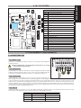 5
5
-
 6
6
-
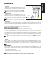 7
7
-
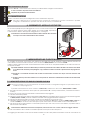 8
8
-
 9
9
-
 10
10
-
 11
11
-
 12
12
-
 13
13
-
 14
14
-
 15
15
-
 16
16
-
 17
17
-
 18
18
-
 19
19
-
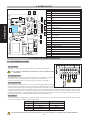 20
20
-
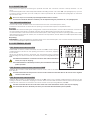 21
21
-
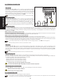 22
22
-
 23
23
-
 24
24
-
 25
25
-
 26
26
-
 27
27
-
 28
28
-
 29
29
-
 30
30
-
 31
31
-
 32
32
-
 33
33
-
 34
34
-
 35
35
-
 36
36
-
 37
37
-
 38
38
-
 39
39
-
 40
40
-
 41
41
-
 42
42
-
 43
43
-
 44
44
-
 45
45
-
 46
46
-
 47
47
-
 48
48
-
 49
49
-
 50
50
-
 51
51
-
 52
52
-
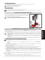 53
53
-
 54
54
-
 55
55
-
 56
56
-
 57
57
-
 58
58
-
 59
59
-
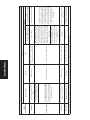 60
60
-
 61
61
-
 62
62
-
 63
63
-
 64
64
-
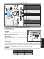 65
65
-
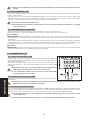 66
66
-
 67
67
-
 68
68
-
 69
69
-
 70
70
-
 71
71
-
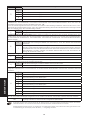 72
72
-
 73
73
-
 74
74
-
 75
75
-
 76
76
-
 77
77
-
 78
78
-
 79
79
-
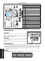 80
80
-
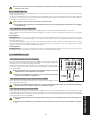 81
81
-
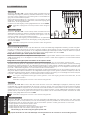 82
82
-
 83
83
-
 84
84
-
 85
85
-
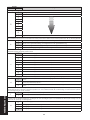 86
86
-
 87
87
-
 88
88
-
 89
89
-
 90
90
-
 91
91
-
 92
92
-
 93
93
-
 94
94
-
 95
95
-
 96
96


in andere talen
- English: Genius LINX06 Operating instructions
- italiano: Genius LINX06 Istruzioni per l'uso
- français: Genius LINX06 Mode d'emploi
- español: Genius LINX06 Instrucciones de operación
- Deutsch: Genius LINX06 Bedienungsanleitung
