
YAMAHA ELECTRONICS CORPORATION, USA 6660 ORANGETHORPE AVE., BUENA PARK, CALIF. 90620, U.S.A.
YAMAHA CANADA MUSIC LTD. 135 MILNER AVE., SCARBOROUGH, ONTARIO M1S 3R1, CANADA
YAMAHA ELECTRONIK EUROPA G.m.b.H. SIEMENSSTR. 22-34, 25462 RELLINGEN BEI HAMBURG, F.R. OF GERMANY
YAMAHA ELECTRONIQUE FRANCE S.A. RUE AMBROISE CROIZAT BP70 CROISSY-BEAUBOURG 77312 MARNE-LA-VALLEE CEDEX02, FRANCE
YAMAHA ELECTRONICS (UK) LTD. YAMAHA HOUSE, 200 RICKMANSWORTH ROAD WATFORD, HERTS WD1 7JS, ENGLAND
YAMAHA SCANDINAVIA A.B. J A WETTERGRENS GATA 1, BOX 30053, 400 43 VÄSTRA FRÖLUNDA, SWEDEN
YAMAHA MUSIC AUSTRALIA PTY, LTD. 17-33 MARKET ST., SOUTH MELBOURNE, 3205 VIC., AUSTRALIA
Printed in China ID V586140
OWNER’S MANUAL
MODE D’EMPLOI
BEDIENUNGSANLEITUNG
BRUKSANVISNING
MANUALE DI ISTRUZIONI
MANUAL DE INSTRUCCIONES
GEBRUIKSAANWIJZING
AV-S70
Home Theater Sound System
Systèm audio home cinéma
AV-S70
G B
00AV-S70-cv 3/29/0, 6:07 PM1

CAUTION
CAUTION: READ THIS BEFORE OPERATING YOUR UNIT.
1. To assure the finest performance, please read this
manual carefully. Keep it in a safe place for future
reference.
2. Install this unit in a cool, dry, clean place — away
from windows, heat sources, sources of excessive
vibration, dust, moisture and cold. Avoid sources of
humming (transformers, motors). To prevent fire or
electrical shock, do not expose the unit to rain or
water.
3. Never open the cabinet. If something drops into the
unit, contact your dealer.
4. Do not use force on switches, controls or connection
cables. When moving the unit, first disconnect the
power cord and then the cables connected to other
component. Never pull the cables themselves.
5. The openings on the cover assure proper ventilation
of the unit. If these openings are obstructed, the
temperature inside the unit will rise rapidly.
Therefore, avoid placing objects against these
openings, and install the unit in a well-ventilated area
to prevent fire and damage.
6. The voltage used must be the same as that specified
on this unit. Using this unit with a higher voltage than
specified is dangerous and may result in fire or other
accidents. YAMAHA will not be held responsible for
any damage resulting from the use of this unit with a
voltage other than that specified.
7. Digital signals generated by this unit may interfere
with other component such as tuners, receivers and
TVs. Move this unit farther away from such
component if interference is observed.
8. Always set the volume to the minimum level before
starting the audio source play. Increase the volume
gradually to an appropriate level after playback has
been started.
9. Do not attempt to clean the unit with chemical
solvents; this might damage the finish. Use a clean,
dry cloth.
10. Be sure to read the “TROUBLESHOOTING” section
regarding common operating errors before
concluding that the unit is faulty.
11. When not planning to use this unit for a long period
of time (e.g., a vacation), disconnect the AC power
cord from the wall outlet.
12. To prevent lightning damage, disconnect the AC
power cord and disconnect the antenna cable when
there is an electrical storm.
13. Grounding or polarization — Precautions should be
taken so that the grounding or polarization of the unit
is not defeated.
14. AC outlet — Do not connect audio component to the
AC outlet on the rear panel if that component
requires more power than the outlet is rated to
provide.
15. Though this speaker is a magnetic shielding type,
there may be some influence on a TV picture
depending on the type of TV or the placement of the
speaker. In such a case, place the speaker apart from
the TV so that there is no influence on TV picture.
This unit is not disconnected from the AC power source
as long as it is connected to the wall outlet, even if this
unit itself is turned off. This state is called the standby
mode. In this state, this unit is designed to consume a
very small quantity of power.
■ For U.K. customers
If the socket outlets in the home are not suitable for the plug
supplied with this appliance, it should be cut off and an
appropriate 3 pin plug fitted. For details, refer to the
instructions described below.
Note
• The plug severed from the mains lead must be destroyed, as a
plug with bared flexible cord is hazardous if engaged in a live
socket outlet.
■ Special Instructions for U.K. Model
IMPORTANT
THE WIRES IN MAINS LEAD ARE COLOURED IN
ACCORDANCE WITH THE FOLLOWING CODE:
Blue: NEUTRAL
Brown: LIVE
As the colours of the wires in the mains lead of this
apparatus may not correspond with the coloured
markings identifying the terminals in your plug, proceed
as follows:
The wire which is coloured BLUE must be connected to
the terminal which is marked with the letter N or
coloured BLACK. The wire which is coloured BROWN
must be connected to the terminal which is marked with
the letter L or coloured RED.
Making sure that neither core is connected to the earth
terminal of the three pin plug.
0101AV-S70_caution_EN 3/29/0, 12:47 PM2

1
EnglishREMOTE CONTROL APPENDIXPREPARATION
OPERATION
FEATURES
● Home Theater Sound
This system delivers a realistic and powerful sound
experience like that found in a movie theater just by
connecting the front speaker unit to the TV. You can
also enjoy stronger bass and surround effects by
adding the separately available YAMAHA NX-SW70,
consisting of a subwoofer and two rear speakers.
● Includes Dolby Digital* and Dolby Pro
Logic Decoder
This system can reproduce the sound field of the
software with the g or s logo
mark.
● Virtual Surround
The front speaker unit can produce a virtual Dolby
Surround sound field when playing software with the
g or s logo mark so that you can
enjoy surround effects that give motion to sound and
make you feel like you are inside the action.
● Seven DSP programs including
YAMAHA CINEMA DSP
Connecting the YAMAHA NX-SW70 (sold
separately) allows seven different DSP programs to be
used to enhance the power and realism of various
sources, from movies, to concerts, and sporting
events.
● Preset Remote Control
The remote control can be used to control not only the
front speaker unit, but component from other
manufacturers as well merely by setting the proper
manufacturer code.
y indicates a tip for your operation.
PREPARATION
Manufactured under license from Dolby
Laboratories. “Dolby”, “Pro Logic” and the
double-D symbol are trademarks of Dolby
Laboratories. Confidential Unpublished Works.
©1992 – 1997 Dolby Laboratories, Inc. All rights
reserved.
CONTENTS
OPERATION
OPERATING THE UNIT ......................................... 17
USING CONVENIENT FUNCTIONS .................... 18
DSP PROGRAM (DIGITAL SOUND FIELD
PROCESSOR EFFECT)........................................ 19
MENU FUNCTIONS................................................. 21
REMOTE CONTROL
OPERATING OTHER COMPONENTS USING
THE REMOTE CONTROL .................................. 23
APPENDIX
GLOSSARY................................................................ 28
TROUBLESHOOTING ............................................ 29
SPECIFICATIONS.................................................... 30
INDEX ........................................................................ 31
PREPARATION
FEATURES .................................................................. 1
GETTING STARTED ................................................. 2
NAMES OF ALL PARTS ............................................ 4
SPEAKER PLACEMENT .......................................... 6
INSTALLATION ......................................................... 7
CONNECTIONS.......................................................... 9
ADJUSTING THE SPEAKER
OUTPUT LEVELS ................................................. 15
0102AV-S70_01-08_EN 3/29/0, 12:49 PM1

2
GETTING STARTED
Checking the Package Contents
Check that the following accessories are included in the package.
Remote control Batteries (AAA, R03, UM-4 type) Audio connection cord (2 pin, 3m)
Velcro strips (2 sets) Connection guide
Readying the Remote Control
■ Inserting the batteries
1 Remove the battery compartment cover.
2 Insert the four batteries (AAA, R03, UM-4 type)
with + and – oriented properly.
3 Close the battery compartment cover.
■ Precautions regarding batteries
Misuse of dry cell batteries may result in leakage or
bursting. Be sure to follow the precautions given below.
• Insert batteries with (+) and (–) oriented according to the
marking in the battery compartment.
• Do not mix old and new batteries.
• Do not mix different types of batteries as they may offer
different voltage and performance even though they have
the same shape.
• Remove all batteries when they can no longer be used or
when the remote control will not be used for an extended
period.
• Do not use rechargeable batteries.
• If leakage occurs, wipe away all battery fluid inside the
compartment.
Preserving the manufacturer code
Replace batteries early before they become unusable.
The manufacturer code set by the user will be preserved
for about two minutes when batteries run out or when
they are removed. Note that the manufacturer code
setting may be lost if more than two minutes elapses.
0102AV-S70_01-08_EN 3/29/0, 12:49 PM2

3
EnglishREMOTE CONTROL APPENDIXPREPARATION OPERATION
GETTING STARTED
Operational Area of the Remote Control
Front speaker
Approx. 20 cm – 6 m
30° 30°
■ Battery replacement cycle
Replace all four batteries when the operational range of the
remote control starts to become shorter.
■ Precautions on handling the
remote control
• The remote control may not be able to operate the front
speaker unit when an object blocks the remote control
sensor on the unit.
• Do not subject the remote control to impact. Do not
allow it to get wet or place it in a location subject to high
humidity.
• The remote control operations become difficult when
direct sunlight or other strong light (such as from an
inverter fluorescent lamp) strikes the sensor. Adjust the
relative positions of the light and the front speaker if this
happens.
• Remote control operations may not be possible if another
remote control is being operated at the same time.
0102AV-S70_01-08_EN 3/29/0, 12:49 PM3

4
NAMES OF ALL PARTS
Front Speaker Unit (Front Panel)
INPUT selector button (page 17)
VOLUME +/– (page 17)
DSP selector button
(page 20)
STANDBY indicator
POWER (page 17)
Turns the unit’s power on and off. This
button also turns off the subwoofer’s
power when a YAMAHA subwoofer
and rear speakers NX-SW70 (sold
separately) are connected. The
STANDBY indicator will light when
power is turned off using p on the
remote control.
Display
VIRTUAL indicator (page 20) TRUBASS indicator (page 18) ENHANCED indicator
Processing indicators (page 20)
Display used for DSP program name, level,
and operational status
DSP
DIGITAL ENHANCED
SURROUND
PRO LOGIC
VIRTUAL TRUBASS
0102AV-S70_01-08_EN 3/29/0, 12:49 PM4

5
EnglishREMOTE CONTROL APPENDIXPREPARATION OPERATION
NAMES OF ALL PARTS
Remote Control
p (power) (page 17)
Remote control selector buttons
(page 23)
VOL – (page 17)
m (page 18)
SET/DSP (pages 20 and 23)
MENU – (page 21)
SUBWOOFER – (page 18)
NIGHT MODE (page 18)
t (page 18)
DSP ON/OFF (page 20)
Transmission indicator
Not used with this unit.
VOL + (page 17)
c (page 23)
INPUT selector button (page 17)
Numeric buttons (page 23)
SUBWOOFER + (page 18)
TEST (page 15)
Not used with this unit.
y
Of the buttons on the remote control, those used to control this unit
is colored in dark gray.
MENU + (page 21)
MENU (page 21)
0102AV-S70_01-08_EN 3/29/0, 12:49 PM5

6
SPEAKER PLACEMENT
Although speakers should ideally be placed as shown below, satisfactory effects may be obtained even if you do not strictly
follow these guidelines.
■ Front speaker unit
Place the front speaker unit on top of the television and
align the front surface of the speakers with the front surface
of the television monitor. For details on placement, refer to
page 7. If the system cannot be placed on top of the
television, place it on a rack beneath the television as close
to the television monitor as possible.
■ YAMAHA rear speakers NX-AVS70
(sold separately)
Depending on room conditions, it is possible to place
YAMAHA rear speakers NX-AVS70 on shelves or hang
them on the wall. Speakers should be placed about 1.8 m
above the floor.
About 1.8 m
■ YAMAHA subwoofer SW-AVS70
(sold separately)
Place the subwoofer at the either right or left side of the
front speaker unit and facing slightly toward the center of
the room so that the sound from it and the sound reflected
by the wall should not cancel out each other. Try altering the
position of the subwoofer versus the listening position as the
relative position will affect the way the bass sounds.
CAUTION
Although the speakers in this unit are magnetically
shielded, they may still affect the color on the television
monitor when using the speakers on top of the television.
Adjust the relative positions of the speakers and the
television if this happen. Perform the following steps if
you are using a magnetically shielded television.
1 Turn off the television.
2 Wait awhile and turn the television back on.
Front speaker unit
Place above the monitor in the center.
Subwoofer (sold separately or already owned)
Left rear
speaker
Rear speakers (sold separately)
Place behind or to the sides of the listening position.
Right rear
speaker
1.8 m
0102AV-S70_01-08_EN 3/29/0, 12:49 PM6

7
EnglishREMOTE CONTROL APPENDIXPREPARATION OPERATION
INSTALLATION
To prevent the front speaker unit from falling, secure it with the provided velcro strip when placing it on a television or other
device. Also, use the height adjustment bracket on the rear of the front speaker unit when there is not enough space for
installation or when the surface is sloped.
Using the Velcro Strips
Precautions before installation
• Do not touch the adhesive surface after peeling off the strip as this will weaken its adhesive strength.
• Thoroughly wipe clean the surface where the velcro strip is to be applied. Note that adhesive strength is weakened if the
surface is dusty, oily or wet and that this may cause the front speaker unit to drop.
1 Peel off the seal of the velcro strip with the
rough surface and apply to the protrusions on
the bottom of the front speaker unit.
Wrap the strip tightly with
sides of the tape well
aligned with the edges of
the protrusion.
Rough surface
Front speaker
(bottom panel)
Protrusion
2 Place the front speaker unit where it is to be
installed (ex. on top of the television ) to
determine where to apply the velcro strip with
the smooth surface.
Position so that the position of the velcro strip stuck to
the front speaker unit matches that of the velcro strip
stuck to the top of the television.
3 Peel off the seal of the velcro strip with the
smooth surface and apply to the positions
determined in step 2.
Peel off the seal.
Smooth surface
4 Align both the velcro strip on both sides and
firmly press downward on the top of the front
speaker unit.
Press down.
Note
• Once the front speaker unit is secured in this way, the paint on the
television surface used for installation may peel off when velcro
strip is removed later. Be sure to apply velcro strip after carefully
checking the surface to be used for installation.
0102AV-S70_01-08_EN 3/29/0, 12:49 PM7

8
INSTALLATION
Using the Height Adjustment Brackets
1 Loosen the screws securing the adjustment
bracket.
Loosen the screws.
2 Lower the bracket so that the front speaker
unit is level and securely tighten the screws.
Lower the
bracket and
adjust.
Securely tighten
the screws.
Place the front
speaker unit so that it
is level.
■ To further stabilize and prevent
falling
Wire attachment
hole
Secure the front speaker unit to the wall by attaching
sufficiently strong wire to the wire attachment hole on the
adjustment bracket. This prevents falling in two ways when
this method is used together with velcro strip. This can
prevent damage caused by the front speaker falling.
Note
• Please provide wire separately.
CAUTION
Never place anything on top of the front speaker unit.
0102AV-S70_01-08_EN 3/29/0, 12:49 PM8

9
EnglishREMOTE CONTROL APPENDIXPREPARATION OPERATION
CONNECTIONS
CAUTION
Always be sure to turn off the power of the main unit and any component to be connected when making connections.
To ensure proper connections
• Connect the white plug of the connection cord to the left “L” (white) audio signal terminal and connect the red plug to the
right “R”(red) terminal.
• Insert the plug securely. If the plug is not inserted securely, noise may result or sound may not be output.
• Since the method of connection and terminal names differ depending on the component being used, be sure to refer to the
instruction manuals for all components being connected.
• After connections have been made, check one more time that wiring has been made properly.
Pages 10 to 12
TV (monitor) VCR, etc.
DVD player,
LD player, etc.
Front speaker unit
Page 14
AC outlet
YAMAHA subwoofer and
rear speakers NX-SW70
(sold separately)
Page 14
0103AV-S70_09-16_EN 3/29/0, 1:00 PM9

10
CONNECTIONS
Connecting a TV or VCR
■ Connecting a TV (monitor) with audio output terminals
Connect the audio output terminal on the TV (monitor) to the TV terminal on the front speaker unit using the provided audio
connection cord.
y
Television audio can be heard using the front speaker unit. (Although you can also hear the audio using the TV speakers, we recommend you
reduce the TV volume so that you may enjoy the full benefit of the front speaker unit.) Audio can be heard using the TV speakers when the
front speaker unit is turned off.
Front speaker unit
Audio connection cord (provided)
VCR, etc.
TV (monitor)
RL
OUTPUT
INPUT
L
AUX TV VIDEO
MARK
SUBWOOFER
SYSTEM
CONNECTOR
THROUGH
OUT
R
DIGITAL 2
( /PCM)
DIGITAL 1
( /PCM)
R L
R
L
AUDIO IN R
AUDIO IN L
AUDIO OUT L
AUDIO OUT R
AUDIO/VIDEO
OUT
AUDIO/VIDEO
IN
0103AV-S70_09-16_EN 3/29/0, 1:00 PM10

11
EnglishREMOTE CONTROL APPENDIXPREPARATION OPERATION
CONNECTIONS
■ Connecting to a TV (monitor) without audio output terminals
There are two methods of making connection:
1. connecting only the VIDEO terminals or
2. connecting the THROUGH OUT terminals in addition to the VIDEO terminals.
When only the VIDEO terminals are connected
Connect the audio output terminals on the VCR to the VIDEO terminals on the front speaker unit using the provided audio
connection cord. VCR audio may always be heard using the front speaker unit. Audio cannot be heard when the front speaker
unit’s power is turned off. (Audio cannot be heard from the TV’s speakers either.)
When VIDEO terminals and THROUGH OUT terminals are connected
Connect the THROUGH OUT terminals of the front speaker unit to the audio input terminals of the TV (monitor) using a
commercially available audio connection cord. VCR audio can be heard using the front speaker unit when the front speaker
unit is turned on. Audio can be heard using the TV speakers when the front speaker unit is turned off.
VCR, etc.
TV (monitor)
Front speaker unit
Audio connection cord
(provided)
Audio connection cord
(commercially available)
RL
INPUT
RL
OUTPUT
INPUT
L
AUX TV VIDEO
MARK
SUBWOOFER
SYSTEM
CONNECTOR
THROUGH
OUT
R
DIGITAL 2
( /PCM)
DIGITAL 1
( /PCM)
R
L
R
L
R
L
R L
AUDIO
IN L
AUDIO
IN R
AUDIO
THROUGH
OUT R
AUDIO
THROUGH
OUT R
AUDIO
THROUGH
OUT L
AUDIO
OUT R
AUDIO
OUT L
AUDIO
IN R
AUDIO
IN L
VIDEO
OUT
VIDEO
IN
0103AV-S70_09-16_EN 3/29/0, 1:00 PM11

12
CONNECTIONS
■ Connecting a TV (monitor) to enjoy digital audio
Connect the optical terminal or coaxial terminal of the LD or DVD player to the DIGITAL 1 (optical) terminal or DIGITAL 2
(coaxial) terminal of the front speaker unit using a commercially available optical fiber cable or audio connection cord
(1 pin).
Notes
• You need to make digital connection between this unit and your component to enjoy a Dolby Digital source.
• The audio of the LD or DVD player can be heard from the front speaker unit, but not from the TV speakers. The audio of the LD or DVD
player cannot be heard when the front speaker unit’s power is turned off.
• If your LD player has a Dolby Digital RF signal output terminal, be sure to use the RF demodulator (separately purchased).
• No sound will be heard when connecting your LD player’s Dolby Digital RF signal output terminal directly to this unit’s DIGITAL 2
terminal.
Front speaker unit
Anti-dust cap
Anti-dust cap
Remove the cap covering the DIGITAL 1
terminal (optical) when connecting an
optical fiber cable. Safely store the cap
and always re-insert it in the terminal
when the terminal is not in use. (This cap
prevents the entrance of dust.)
Connect one
of these
Optical fiber cable
(EIA standard)
(commercially
available)
Audio connection cord (1 pin)
(commercially available)
TV (monitor)
DVD player, LD player, etc.
INPUT
L
AUX TV VIDEO
MARK
SUBWOOFER
SYSTEM
CONNECTOR
THROUGH
OUT
R
DIGITAL 2
( /PCM)
DIGITAL 1
( /PCM)
COAXIAL DIGITAL
OPTICAL DIGITAL
OUTPUT
VIDEO OUT
VIDEO IN
0103AV-S70_09-16_EN 3/29/0, 1:00 PM12

13
EnglishREMOTE CONTROL APPENDIXPREPARATION OPERATION
CONNECTIONS
Connecting a CD Player or MD Recorder
CD player, MD recorder, etc.
If the CD player or MD recorder has a digital output terminal, connect the optical or coaxial terminal on the CD player or
MD recorder to the DIGITAL 1 (optical) terminal or DIGITAL 2 (coaxial) terminal on the front speaker unit using a
commercially available optical fiber cable or audio connection cord (1 pin).
If there is no digital output terminal, connect the analog audio output terminals on the CD player or MD recorder to the AUX
input terminals on the front speaker unit using a commercially available audio connection cord (2 pin).
Front speaker unit
Anti-dust cap
Anti-dust cap
Remove the cap covering the DIGITAL 1
terminal (optical) when connecting an
optical fiber cable. Safely store the cap
and always re-insert it in the terminal
when the terminal is not in use. (This cap
prevents the entrance of dust.)
Connect one
of these
Optical fiber cable
(EIA standard)
(commercially
available)
Audio connection cord (1 pin)
(commercially available)
Audio connection cord
(commercially available)
Use the analog audio output
terminals if there is no digital
output terminal.
COAXIAL DIGITAL
OPTICAL DIGITAL
OUTPUT
RL
OUTPUT
INPUT
L
AUX TV VIDEO
MARK
SUBWOOFER
SYSTEM
CONNECTOR
THROUGH
OUT
R
DIGITAL 2
( /PCM)
DIGITAL 1
( /PCM)
R L
R
L
AUDIO IN R
AUDIO IN L
AUDIO OUT L
AUDIO OUT R
0103AV-S70_09-16_EN 3/29/0, 1:00 PM13

14
CONNECTIONS
INPUT
L
AUX TV VIDEO
MARK
SUBWOOFER
SYSTEM
CONNECTOR
THROUGH
OUT
R
DIGITAL 2
( /PCM)
DIGITAL 1
( /PCM)
Connecting the Front Speaker Unit and the Subwoofer
Although the front speaker unit alone can be used to reproduce rich, natural sounding audio, the additional use of a
subwoofer allows you to enjoy powerful bass tones.
Connecting a YAMAHA subwoofer and rear speakers NX-SW70 (sold separately) not only increases bass sensitivity but
improves the surround effect as well.
Front speaker unit
Note
• Turning off the front speaker unit’s power will also turn off the YAMAHA subwoofer SW-AVS70.
y
• When connecting your subwoofer, connect the input terminal on the subwoofer to the SUBWOOFER terminal on the front speaker unit
using a commercially available audio connection cord (1 pin).
• For details regarding connections, please refer to the instruction manuals for your subwoofer or the owner’s manual for the YAMAHA
subwoofer and rear speakers NX-SW70 (sold separately).
Connecting the AC Power Supply Cord
Front speaker unit
AC outlet
Once all connections have been made, check them one more
time. Finally, insert the plug of the power supply cord for
the front speaker unit into an AC outlet. Disconnect the
power supply cord if you will not use the unit for an
extended period.
MAINS
YAMAHA subwoofer and rear speakers
NX-SW70 (sold separately)
To SYSTEM
CONNECTOR
terminal
System connector cable
provided with the
YAMAHA NX-SW70
To SYSTEM
CONNECTOR terminal
Match the b mark on the plug
with the a mark on the
terminal and insert.
0103AV-S70_09-16_EN 3/29/0, 1:00 PM14

15
EnglishREMOTE CONTROL APPENDIXPREPARATION OPERATION
ADJUSTING THE SPEAKER OUTPUT LEVELS
When reproducing a Dolby Surround source using a DSP program such as DOLBY PRO LOGIC or DOLBY DIGITAL
ENHANCED, it is necessary to adjust each channel to the same output level in order to bring out the full digital effect of
these sound fields. Even when a different DSP program is used, it is possible to bring out the particular flavor of the sound
field in question.
Speaker output levels may be adjusted by using the remote control before playback by following the steps.
1 Press p to turn on the power.
If the STANDBY indicator is lit, turn on the power
using p on the remote control. If the main power is
off (when the STANDBY indicator is not lit), turn on
the power by pressing POWER on the front speaker
unit.
1
2
2 Press TEST.
Test tones (like pink noise) will be output in the
following order.
● When only the front speaker unit is being used
or the VIRTUAL SURROUND DSP program is
selected:
(Virtual) (Virtual)
● When an NX-SW70 is connected:
Front speaker unit
Rear speakers
RIGHTCENTERLEFT
RIGHT
SURROUND
LEFT
SURROUND
Front speaker unit
RIGHTLEFT
RIGHT
SURROUND
LEFT
SURROUND
0103AV-S70_09-16_EN 3/29/0, 1:00 PM15

16
ADJUSTING THE SPEAKER OUTPUT LEVELS
3 Adjust the level of the test tone using VOL +/–.
(This sets the standard audio level you will be
using.)
Pressing VOL + increases the level, while pressing
VOL – decreases the level.
4 Adjust the level of each channel while listening
to the test tone.
Pressing f increases the level, while pressing w
decreases the level.
5
4
3
y
• If only the front speaker unit being used, be sure to adjust the
level of the right and left rear virtual channels to match the level
of the right and left main channels. (Rear virtual channels sound
as if rear speakers are behind the listener.)
• If an NX-SW70 is connected, adjust so that the level of the center
channel (built into the front speaker unit) and rear channels (NX-
SW70 rear speakers) match the level of the right and left main
channels (built into the front speaker unit).
Notes
• When an NX-SW70 is connected, you can adjust the center
channel.
• If the right and left main channels have been adjusted, adjust the
level of the center and right and left rear channels (or right and
left rear virtual channels) one more time.
• The right and left rear virtual channels cannot be adjusted
separately. Adjusting either of the virtual channels sets the other
virtual channel to the same level.
5 When the adjustment is complete, press TEST.
A test tone will stop.
y
The level can be adjusted in the following range.
• When only the front speaker unit is being used or the VIRTUAL
SURROUND DSP program is selected:
– Right and left main channels: –10 to ±0 dB
– Rear virtual channels: –3 to +3 dB
– The minimum level for the main channel is –10 dB, while that
for the rear virtual channels is –3 dB.
• When an NX-SW70 is connected:
– Right and left main channels: –10 to ±0 dB
– Center channel: –20 to +3 dB
– Right and left rear channels: –20 to +6 dB
– The minimum level for the main channel is –10 dB, while that
for the rear channels is –20 dB.
0103AV-S70_09-16_EN 3/29/0, 1:00 PM16

17
EnglishREMOTE CONTROL APPENDIXPREPARATION
OPERATION
OPERATING THE UNIT
Enjoying the Home Theater Sound System
This section describes how to select audio output from A/V component such as a TV, VCR, or DVD, LD, CD player, or MD
recorder as input source to the Home Theater Sound System AV-S70 and how to adjust levels.
First turn on the playback component and the TV, and then follow the steps given below.
1 Press POWER (or p on the remote control) to
turn on the power.
12 3
3
1
2
Front panel
or
If the STANDBY indicator is lit, turn on the power
using p on the remote control. If the main power is
off (when the STANDBY indicator is not lit), turn on
the power by pressing POWER on the front speaker
unit.
2 Press the INPUT selector button.
Each time the button is pressed, the input source will be
switched in the order: VIDEO → TV → AUX →
DIGITAL 1 → DIGITAL 2.
Front panel
or
3 Adjust the level using VOLUME +/– (or VOL +/–
on the remote control).
Pressing VOLUME + (or VOL + on the remote control)
increases the level, while pressing VOLUME – (or
VOL – on the remote control) decreases the level.
Front panel
or
OPERATION
Remote control
Remote control
Remote control
0104AV-S70_17-22_EN 3/29/0, 4:31 PM17

18
USING CONVENIENT FUNCTIONS
You can use convenient functions with the remote control
during audio reproduction.
Å Increasing the power of the mid-
range
Press t.
• The TRUBASS* indicator will light in the display.
• This will increase the level of the mid-range, giving
more force to dialog and song lyrics.
To cancel TRUBASS mode, press t again.
*
TruBass and the symbol are trademarks of SRS Labs, Inc. in
the United States and selected foreign countries. TruBass
technology is incorporated under license from SRS Labs, Inc.
D
B
A
C
ı Listening to music clearly at low
levels
Press NIGHT MODE.
• Sounds will be clear.
• Use this function when it is difficult to output high
volumes such as late at night.
To cancel NIGHT MODE, press NIGHT MODE again.
Note
• Volume cannot be decreased using this button. To decrease the
volume, press VOLUME – (or VOL – on the remote control).
Ç Adjusting the subwoofer level
Subwoofer level can be adjusted if a subwoofer is
connected.
Pressing SUBWOOFER + increases the level,
while pressing SUBWOOFER – decreases the
level.
y
The level can be adjusted within the range –20 dB to +10 dB.
Î Temporarily reducing the audio
Press m.
y
“Mute ON” is displayed while audio is reduced.
To return to the original volume level, press m again.
0104AV-S70_17-22_EN 3/29/0, 4:31 PM18

19
EnglishREMOTE CONTROL APPENDIXPREPARATION
OPERATION
DSP PROGRAM (DIGITAL SOUND FIELD PROCESSOR EFFECT)
You can recreate the sound and feel of a movie theater, concert hall or other location by selecting from any of seven DSP
programs best suited to the source being reproduced. This allows you to enjoy the full experience of digital systems such as
DOLBY DIGITAL, DOLBY PRO LOGIC, or YAMAHA CINEMA DSP.
Description of DSP Programs
■ When only the front speaker unit is connected
No. Program name Features and applicable sources
1 VIRTUAL SURROUND
(input source: Dolby Digital or Dolby Surround)
For enjoying the virtual surround field created using Dolby
Digital or Dolby Pro Logic when using a front speaker unit.
7 MONO MOVIE For old monaural movies.
■ When the front speaker unit and a YAMAHA subwoofer and rear speakers
NX-SW70 (sold separately) are connected
No. Program name Features and applicable sources
1 VIRTUAL SURROUND
(input source: Dolby Digital or Dolby Surround)
For enjoying the virtual surround field created using Dolby
Digital or Dolby Pro Logic when using a front speaker unit.
2 DOLBY DIGITAL (input source: Dolby Digital)
DOLBY PRO LOGIC
For the straightforward reproduction of movie sound as
accurately processed using a Dolby Digital or Dolby Pro Logic
decoder.
3 DOLBY DIGITAL ENHANCED
(input source: Dolby Digital)
DOLBY PRO LOGIC ENHANCED
For adding sound field effects through digital signal processing
of the Dolby Digital or Dolby Surround signal.
4 DIGITAL MOVIE THEATER
(input source: Dolby Digital)
70 mm MOVIE THEATER
For reproduction of the rich, full sound found in a movie
theater using the latest movie sound design in which dialog and
sound effects are handled separately.
5 CONCERT For reproduction of the type of classical concert hall
atmosphere. This sound field is optimally suited for the
reproduction of operas and other classical pieces.
6 SPORTS For the wide area sound field effect of a variety show or live
broadcast program. Resonant sounds are restained so there is
not much variation even when this sound field is used for an
extended period of time.
7 MONO MOVIE For old monaural movies. Sound field effects and moderate
resonance processing are used to bring fuller life to the
monaural audio.
0104AV-S70_17-22_EN 3/29/0, 4:31 PM19

20
DSP PROGRAM (DIGITAL SOUND FIELD PROCESSOR EFFECT)
Enjoying DSP Programs
DSP selector button
DSP ON/OFF
DSP
Press the DSP selector button (on the front
speaker unit) or DSP (on the remote control).
Front panel
or
Each time this button is pressed, the DSP program will
be selected in the following order and the currently
selected DSP program name will be displayed.
● When only the front speaker unit is connected:
● When the front speaker unit and a YAMAHA
subwoofer and rear speakers NX-SW70 are
connected:
Notes
• The option “DSP OFF” only appears when using the DSP selector
button on the front speaker unit.
• Be sure to select the DSP program best suited for the atmosphere
of the source being listened to.
• The last DSP program used for each input source (AUX, TV,
VIDEO, DIGITAL 1, and DIGITAL 2) is stored in memory so
that the DSP program is automatically selected when the input
source is selected.
VIRTUAL SURROUND
MONO MOVIE
DSP OFF
VIRTUAL SURROUND
MONO MOVIE
DSP OFF
DOLBY DIGITAL/
DOLBY PRO LOGIC
DOLBY DIGITAL ENHANCED/
DOLBY PRO LOGIC ENHANCED
DIGITAL MOVIE THEATER/
70 mm MOVIE THEATER
CONCERT
SPORTS
■ To cancel sound field effects
(using the remote control)
Press DSP ON/OFF.
Ordinary stereo reproduction will result and “DSP
OFF” will be displayed when the sound field effect is
canceled. Pressing this button again will cause the
sound field effect to return.
■ Processing indicators
A processing indicator will light to show with the type of
input signal when reproducing a source using a DSP
program.
q DIGITAL: Lights when reproducing a source
encoded with Dolby Digital other than
2-channel.
VIRTUAL and SURROUND:
Lights when using VIRTUAL
SURROUND DSP program.
q PRO LOGIC: Lights when reproducing a source
encoded with Dolby Digital 2-channel,
PCM or an analog source using DSP
program No. 2 or 3.
DSP: Lights when reproducing a source using
DSP program No. 3 through 7.
Notes
• The VIRTUAL SURROUND, DOLBY DIGITAL/DOLBY PRO
LOGIC, DOLBY DIGITAL ENHANCED/DOLBY PRO LOGIC
ENHANCED, DIGITAL MOVIE THEATER/70 mm MOVIE
THEATER DSP programs are optimum for reproducing visual
software encoded with Dolby Digital that displays the g or
s logo marks.
• The volume level of the right and left main channels may differ
based on the input source being used because, except in the case
of Dolby Digital, sound field data as actually measured are used.
• Select the DSP program that you feel sounds best for a source
regardless of its name.
y
• Be sure to minimize the volume level of the TV to maximize the
virtual surround effect when reproducing a source with the
VIRTUAL SURROUND program.
• Refer to the glossary on page 28.
Remote control
0104AV-S70_17-22_EN 3/29/0, 4:31 PM20

21
EnglishREMOTE CONTROL APPENDIXPREPARATION
OPERATION
MENU FUNCTIONS
INPUT
selector button
The Auto Power function may not function properly
depending on the signal output level of connected
component. In this case, you can refer to the table given
below to change the sensitivity of the Auto Power function.
Pressing + will cycle through the selections from top to
bottom, while pressing – will cycle through the selections
from bottom to top.
Display Setting/Symptom
OFF Do not use the Auto Power function.
1 When Auto Power On does not function even though
a signal arrives or when Auto Power Off results even
though there is a continuing signal.
2 Ordinary setting when using the Auto Power
function.
3 When Auto Power On results even though no signal
has arrived, or when Auto Power Off does not result
even though there is no current signal.
To cancel the menu functions, press MENU until the input
display returns.
Adjusting Display Brightness
The display brightness of the front speaker unit can be
adjusted as follows.
1 Press MENU to display “Dimmer”.
The currently brightness level (such as “Dimmer: ±0”)
will be displayed.
2 Press MENU + or – to adjust the brightness.
Pressing + will brighten the display, while pressing –
will dim the display. Brightness can be adjusted from
–3 (dimmest) to +3 (brightest).
To cancel the menu functions, press MENU until the input
display returns.
The menu functions include: “Auto Power” for setting
automatic power on/off, “Dimmer” for adjusting display
brightness, “Input Name” for naming input, and “Delay
Time” for adjusting the delay time used for surround sound.
Adjustments on the menu functions should be performed
with the remote control.
Each time MENU on the remote control is pressed, the
function displayed will cycle in the order: “Auto Power”,
“Dimmer”, “Input Name”, “Delay Time” (only appears
when the selected DSP program is DOLBY DIGITAL/
DOLBY PRO LOGIC, or DOLBY DIGITAL ENHANCED/
DOLBY PRO LOGIC ENHANCED), and input display.
MENU +/–
MENU
Setting Auto Power On/Off
Auto Power functions as described below.
1. No input signal and no buttons have been operated for
30 minutes.
2. Auto Power Off automatically shuts off the power. (The
STANDBY indicator will slowly flash.)
3. If a signal is input, Auto Power On automatically turns
the power on. (Or power can be turned on again using
p on the remote control.)
You can set sensitivity for the Auto Power function or turn
the Auto Power function off completely.
1 Press MENU to display “Auto Power”.
2 To set Auto Power On, use the MENU + or – to
select the “Auto Power 2”. To set Auto Power
Off, use the MENU – to select the “OFF”.
0104AV-S70_17-22_EN 3/29/0, 4:31 PM21

22
MENU FUNCTIONS
Naming Input
It is possible to give names to the AUX, DIGITAL 1 and
DIGITAL 2 input terminals. (It is not possible to change the
input names for the TV or VIDEO input terminals.)
This function makes selecting input source easier by
allowing you to give a name that quickly allows you to see
which component is connected to the terminal in question.
For example, if an MD recorder is connected to the AUX,
you can name that source “MD”, or if a DVD player is
connected to the DIGITAL 1 terminal, you can name that
source “DVD”.
1 Press MENU to display “Input Name”.
2 Press the INPUT selector button and select the
input you want to name (AUX, DIGITAL 1 or
DIGITAL 2).
3 Press MENU + or – to select the name.
If you select AUX under step 2 above, names will be
displayed in the following order when you press +.
If you select DIGITAL 1 or 2 under step 2 above,
names will be displayed in the following order when
you press +.
Notes
• “D1:” is displayed before the name when DIGITAL 1 has been
selected, while “D2:” is displayed before the name when
DIGITAL 2 has been selected.
• Pressing – displays the names in reverse order.
4 You can repeat steps 1 through 3 to give
names to AUX, DIGITAL 1 and DIGITAL 2 input
terminals.
To cancel the menu functions, press MENU until the input
display returns.
Adjusting the Delay Time
When the selected DSP program is DOLBY DIGITAL/
DOLBY PRO LOGIC or DOLBY DIGITAL ENHANCED/
DOLBY PRO LOGIC ENHANCED, it is possible to adjust
the delay time. The delay time is that time difference
between when the main channel sound can be heard and the
surround sound can be heard. Although it is possible to set
the delay time separately for Dolby Digital and Dolby
Surround input, if the Dolby Digital (or Dolby Surround)
delay time is adjusted, the level for Dolby Surround (or
Dolby Digital) will also be raised or lowered accordingly.
Setting a longer delay time makes the sound field feel
larger, while setting a shorter delay time makes it feel
smaller.
1 Press MENU to display “Delay Time”.
2 Press MENU + or – to adjust the delay time.
y
• Adjustable range
– For Dolby Digital input: 0 to +15 ms
– For Dolby Surround input: 15 to 30 ms
To cancel the menu functions, press MENU until the input
display returns.
CAUTION
The variable sound intensity range is large in the case of
CDs and MDs. Listening for an extended period of time
at or near maximum volume to music that includes
sudden changes from soft to loud noises may damage the
speakers.
AUX
AUX: VIDEO2
AUX: CABLE
AUX: SAT
AUX: DVDAUX: LD
AUX: CD
AUX: MD
AUX: GAME
DIGITAL 1
D1: DVD
D1: LD
D1: SAT
D1: CD
D1: MD
0104AV-S70_17-22_EN 3/29/0, 4:31 PM22

23
EnglishREMOTE CONTROL APPENDIXPREPARATION OPERATION
OPERATING OTHER COMPONENTS USING THE REMOTE CONTROL
Setting the manufacturer code for your TV, VCR or satellite tuner/cable TV on the remote control allows you to operate the
front speaker unit and your TV, VCR or satellite tuner/cable TV by remote control. Note that there are two methods for
setting the code: manual preset and auto preset.
Notes
• Remote control of some component may not be possible depending on the model and the year of make even though its manufacturer is
listed on page i (at the end of this manual).
• Depending on the model in question, some component from other manufacturers cannot be controlled, or only limited functions can be
controlled, even though the proper manufacturer code has been set. If you encounter this problem, please use the remote control supplied
with the component in question.
• Setting the manufacture code can not be performed if your component to be controlled does not support remote control operation.
Setting the Manufacturer Code
■ Using manual preset
Transmission
indicator
1 Press the remote control selector button (TV,
VCR or SAT) for which the manufacturer code
is to be set.
The signals for controlling the front speaker unit have
already been set for the S70 button so that only the
manufacturer code for the TV, VCR or SAT needs to be
set. A manufacturer code can be set for a single button
if necessary.
2 Hold down SET and press c until the
transmission indicator lights.
1
2
4
3
The indicator will light.
3 While the transmission indicator is lit, use the
numeric buttons to enter the 4-digit
manufacturer code for the component to be
controlled.
The indicator will go out.
The transmission indicator will go out, the code has
been set properly. (The code has not been set properly
if the indicator flashes and then goes out.)
Refer to page i at the end of this manual for a list of
manufacturer codes.
4 Press p and check that the component to be
controlled turns on and off.
REMOTE CONTROL
0105AV-S70_23-30_EN 3/29/0, 4:04 PM23

24
OPERATING OTHER COMPONENTS USING THE REMOTE CONTROL
■ Using auto preset
Transmission
indicator
1 Turn on the power of the component (TV, VCR
or satellite tuner/cable TV) to be controlled by
the remote control.
2 Press the remote control selector button
corresponding to the component for which
auto preset is to be performed. (Press “TV” for
TV, “VCR” for VCR, and “SAT” for satellite
tuner/cable TV.)
The signals for controlling the front speaker unit have
already been set for the S70 button so that only the
manufacturer code for the TV, VCR or SAT needs to be
set. A manufacturer code can be set for a single button
if necessary.
2
3,5
4
The indicator will light.
4 While the transmission indicator is lit, using
the numeric buttons, if you selected “TV”
under step 2, enter “0001”; if you selected
“VCR”, enter “0002”; and if you selected
“SAT”, enter “0003” for satellite tuner or “0004”
for cable TV.
The indicator will go out.
3 Hold down SET and press c until the
transmission indicator lights.
5 Hold down SET and press c until the
transmission indicator lights.
The indicator will light.
0105AV-S70_23-30_EN 3/29/0, 4:04 PM24

25
EnglishREMOTE CONTROL APPENDIXPREPARATION OPERATION
OPERATING OTHER COMPONENTS USING THE REMOTE CONTROL
6 Point the remote control at the component to
be controlled (the component turned on in
step 1) and press p repeatedly until the
component’s power turns off.
If the transmission indicator flashes twice, this
indicates that you have cycled through all the codes
stored in the memory of the remote control. Up to 300
manufacturer codes (for TV) may be stored in the
memory of the remote control. Since a manufacturer
code is set by pressing p and cycling in order through
these codes, you may need to press p up to 300 times
to reach the proper code.
y
Up to 120 manufacturer codes for VCR, 170 for satellite tuner and
20 for cable TV may be stored in the memory of the remote control.
Note
• If you accidentally press p too many times after the power is
turned off, you may press m the same number of times to go
through the manufacturer codes in reverse order. The correct
manufacturer code will not be set unless you do this.
7
6
7 Press the remote control selector button you
pressed in step 2.
The indicator will go out.
The transmission indicator will go out once auto preset
has been performed properly.
Note
• During step 6, if you press p about 300 times and the
transmission indicator flashes twice slowly and the component’s
power still has not turned off, this indicates that auto preset
cannot be performed for the component in question. Check that
the component to be controlled supports remote control operation.
You may also try performing manual preset.
■ Precautions when performing
preset
The transmission indicator will go out once the
manufacturer code has been set properly.
If the transmission indicator does not go out, or if it flashes
and then goes out, repeat the procedure from step 1. Pay
attention to the following points when you repeat the preset
procedure.
• Check the manufacturer code number.
• Check that the correct remote control selector button has
been selected when setting the manufacturer code.
• If more than one code is given for a manufacturer, try
entering each code in the order given.
• Remove and replace the remote control’s batteries
(complete this step within 2 minutes) and then repeat the
procedure.
■ To clear a manufacturer code
Perform the procedure “Using manual preset” described on
page 23 and enter the following codes when you reach
step 3.
• To clear the “TV” button: 0000
• To clear the “VCR” button: 0000
• To clear the “SAT” button: 0000
• To clear all buttons for “TV”, “VCR” and “SAT”: 9990
Transmission
indicator
0105AV-S70_23-30_EN 3/29/0, 4:04 PM25

26
OPERATING OTHER COMPONENTS USING THE REMOTE CONTROL
Controlling a TV
You can control your TV by setting the corresponding manufacturer code for the remote control selector button “TV”.
TV power ON/OFF
Mutes the TV
Used to select 2-digit channels
Rewinds the VCR*
Stops the VCR*
Pauses the VCR*
Selects the next higher channel
Used to select the channel
Fast forwards the VCR*
Plays the VCR*
Records on the VCR*
Selects TV input
y
A VCR can be controlled using * marked buttons once the
manufacturer code for that VCR has been set for the remote control
selector button “VCR”.
Decreases TV volume
Selects the next lower channel
Increases TV volume
Press TV.
Used to select the channel/program
0105AV-S70_23-30_EN 3/29/0, 4:04 PM26

27
EnglishREMOTE CONTROL APPENDIXPREPARATION OPERATION
OPERATING OTHER COMPONENTS USING THE REMOTE CONTROL
Controlling a VCR
You can control your VCR by setting the corresponding manufacturer code for the remote control selector button “VCR”.
VCR power ON/OFF
Decreases TV volume*
Mutes the TV*
Rewind
Stop
Selects the next higher channel
Increases TV volume*
Selects TV input*
Used to select the channel
Fast forward
Play
Record
This button needs to be pressed twice in the
case of some models for the VCR to begin
recording.
Pause
y
A TV can be controlled using * marked buttons once the
manufacturer code for that TV has been set for the remote control
select button “TV”.
Selects the next lower channel
Press VCR.
0105AV-S70_23-30_EN 3/29/0, 4:04 PM27

28
GLOSSARY
■ Encode/Decode
When a signal or other information is processed,
compressed and digitized, this is called encoding. Encoding
can be used to record an extremely large amount of
information on a single CD or DVD.
An encoded signal cannot be listened to directly. It must be
returned to its original state (i.e. audible sound) and this is
called decoding.
■ Sound field
Not all sound travels from the sound source directly into the
human ear, but instead reflects off of walls, ceilings and
other objects to arrive at the ear slightly delayed (early
reflection). It may also reflect repeatedly in a complicated
manner before reaching the ear (subsequent reverberation).
A human is able to perceive the size and shape of a location
based on the various sounds heard in this way. The specific
acoustic space of a particular building is called a sound
field.
■ Dolby Surround
In movie theaters and in live theaters, the spectators are
surrounded by many speakers and sound effects geared to
each scene are used to make sound move from front to back
and right to left. This gives the sound a three dimensional
feel that surrounds the entire body. Dolby Surround is used
to implement this realistic effect. Originally, the Dolby
Surround system consisted of a total of four channels: two
front channels (right and left), one center channel, and one
rear channel. Later, two-channel stereo compatibility was
added to for broadcast and video media used in the home.
The ability to easily set up a home AV system capable of
stereo reproduction is one of the biggest features of Dolby
Surround.
■ Dolby Digital
Dolby Digital consists of a total of five channels: three front
channels and two rear channels, plus a distinct LFE channel
for low frequency effect. It is therefore commonly referred
to as a 5.1 channel system. Using digital compression
technology for all 5.1 channels, Dolby Digital can be used
for completely independent audio reproduction. Dolby
Digital offers superior sound quality and a more three
dimensional surround effect in comparison to the older
Dolby Surround, which mixes four channels (three front and
one rear) into two-channel stereo and separates them using a
matrix circuit.
■ Virtual surround
We basically perceive the direction from which sounds
come to us based on the difference in time they reach the
right and left ears and differences in sound level. Virtual
technology is based on this property of the human ear. A
DSP (digital sound field processor — a form of digital
signal processing) and right and left front speakers are used
so that the listener feels like he or she is hearing sounds that
come from virtual speakers located in directions other than
just the two physical speakers. This allows the listener to
experience surround effects as if rear speakers were present
as in a five-speaker system.
■ YAMAHA DSP (Digital Sound Field
Processor)
YAMAHA technicians traveled to world famous concert
halls, opera houses and other locations just to measure
acoustical information such as the direction, intensity, band
characteristics, and delay time of reflected sounds. This
wealth of information was then put on a ROM.
Using a built-in YAMAHA DSP (digital sound field
processor) to create sound fields, this front speaker unit
allows you to freely select various sound field programs
created from this actual acoustical data so that you can
reproduce the sound field of famous halls and live houses
right in your listening room.
Movie makers design sounds for a movie so that the sound
and screen become one. Dialog is positioned right on the
screen, sound effects behind the screen, music behind that,
and surround effects wrap around the audience.
CINEMA DSP is a program for use in AV reproduction that
has evolved from YAMAHA DSP. Fusing the movie sound
decoders, Dolby Pro Logic and Dolby Digital, with
YAMAHA DSP, allows you to reproduce the type of
surround sound field of the quality found on a dubbing stage
designed to optimize movie surround conditions. (A
dubbing stage is the final mix used to complete the final
sound design for a movie.)
By adding YAMAHA DSP processing to both the right and
left front channels and the center channel, the CINEMA
DSP program wraps the audience in a surround sound field
that not only makes dialog real, but penetrates and
surrounds the screen to give depth to sound effects and
music as well as a smooth sense of movement to sound
sources.
APPENDIX
0105AV-S70_23-30_EN 3/29/0, 4:04 PM28

29
EnglishREMOTE CONTROL APPENDIXPREPARATION OPERATION
TROUBLESHOOTING
Be sure to investigate thoroughly before requesting repairs or after service. If it cannot be corrected, or if the problem is not
listed in the SYMPTOM column, disconnect the power cord and contact your authorized YAMAHA dealer or service center.
Notes
• Sometimes the unit may cease to recognize operations due to a mistaken operation or as a result of strong external noise (such as irregular
voltage due to shock of impact, excessive static electricity, or lightning strike). If this happens, first disconnect the power cord, wait about
30 seconds, re-connect the power cord, and try the desired operation again.
• When requesting repairs or after service of the YAMAHA subwoofer and rear speakers NX-SW70 (sold separately), be sure to bring along
with this unit.
■ General
SYMPTOM CHECK Refer to page
■ When using a DSP program
SYMPTOM CHECK Refer to page
■ When using the remote control
SYMPTOM CHECK Refer to page
No sound output at all.
• Is the AC power supply cord connected?
• Is the TV or VCR connected correctly?
• Is the input source selected correctly?
• Has this unit’s audio temporarily been lowered?
A “humming” noise is present.
• Hum caused by external electromagnetic waves may be generated.
Try inverting the right-left polarity of the power cord and re-insert into
the AC outlet.
The STANDBY indicator
flashes slowly.
• The unit is in Auto Power Off mode.
Turn off the main power if the unit is not to be used for an extended
period of time.
There is noise in the tuner or
TV and the video image is
unstable.
• Is a tuner or TV that uses an indoor antenna located near the unit?
Use of an outdoor antenna is recommended.
Movie dialog and other audio
is difficult to hear.
• Are you using one of the DSP programs CONCERT or SPORTS?
Select the other program.
The remote control does not
function properly.
• Are the batteries used up?
• Is the remote control pointed at the sensor?
• Is the remote control too far from or too close to the sensor?
• Is direct sunlight or other intense light (such as an inverter fluorescent
lamp) striking the sensor?
• Is another remote control being used at the same time?
• Have the batteries been inserted in the correct direction?
Cannot control other
component.
• Has the correct manufacturer code been set?
14
10 – 12
17
18
14
21
—
19, 20
3
3
3
3
3
2
23
• Has the remote control selector button “S70” been pressed? Press “S70”
when you want to control this unit after controlling another component.
• Has the remote control selector button corresponding to the component to
be controlled been pressed?
—
26, 27
0105AV-S70_23-30_EN 3/29/0, 4:04 PM29

30
SPECIFICATIONS
Amplifier Section
Rated Output
Front.......................... 30 W + 30 W (1 kHz, 10% THD, 6 ohms)
Signal-to-Noise Ratio ..................................... 85 dB (AUX, IHF-A)
Total Harmonic Distortion
........................... 0.08% (Input: AUX, 1 kHz, 12.5 W/6 ohms)
Input Sensitivity/Impedance .................... AUX, 200 mV/50 k-ohms
Speaker Section
Front Speakers
Type ........................................................................... Bass reflex
Speakers ........................... 8-cm cone x 2, magnetically shielded
Maximum Input Power ..................................................30 W x 2
Impedance ........................................................................ 6 ohms
General
Power Supply .........................................................AC 230 V, 50 Hz
Power Consumption ................................................................. 68 W
Dimensions (W x H x D) .................................. 600 x 110 x 243 mm
Weight...................................................................................... 7.0 kg
Accessories ............................................................... Remote control
................................................................. UM-4 batteries (x 4)
........................................ Audio connection cable (2 pin, 3 m)
...................................................................... Connection guide
............................................................. Velcro strips (two sets)
Specifications are subject to change without notice.
0105AV-S70_23-30_EN 3/29/0, 4:04 PM30

31
EnglishREMOTE CONTROL APPENDIXPREPARATION OPERATION
INDEX
A
Adjusting display brightness ............................................. 21
Adjusting the bass (subwoofer level) ................................ 18
Adjusting the delay time.................................................... 22
Adjusting the volume level................................................ 17
Automatically setting a manufacturer code ....................... 24
Auto Power → Setting auto power on/off ......................... 21
AUX terminal .................................................................... 13
C
CINEMA DSP → DSP program........................................ 19
Connecting a CD player .................................................... 13
Connecting a DVD player ................................................. 12
Connecting a subwoofer and rear speakers ....................... 14
Connecting a TV.......................................................... 10, 11
Connecting a VCR....................................................... 10, 11
Connecting an LD player................................................... 12
Connecting an MD recorder .............................................. 13
Connecting the AC power supply cord.............................. 14
Controlling a TV with the remote control ......................... 26
Controlling a VCR with the remote control ...................... 27
D
Delay time → Adjusting the delay time ............................ 22
DIGITAL input terminal.............................................. 12, 13
Dimmer → Adjusting display brightness .......................... 21
Display................................................................................. 4
DOLBY DIGITAL, DOLBY PRO LOGIC ................. 19, 20
DSP programs.................................................................... 19
I
Input Name → Naming input ............................................ 22
M
Manually setting a manufacturer code .............................. 23
Manufacturer codes ................... i (at the end of this manual)
Menu functions .................................................................. 21
N
Naming input ..................................................................... 22
NIGHT MODE .................................................................. 18
R
Reducing the audio ............................................................ 18
S
Selecting a sound field ...................................................... 20
Selecting input ................................................................... 17
Speaker placement............................................................... 6
T
Test tone............................................................................. 15
THROUGH OUT terminal ................................................ 11
TRUBASS mode ............................................................... 18
U
Using the height adjustment bracket ................................... 8
Using velcro strips ............................................................... 7
V
VIRTUAL SURROUND ............................................. 19, 20
W
Wire installation (to prevent falling) ................................... 8
0105AV-S70_23-30_EN 3/29/0, 4:04 PM31

i
LIST OF MANUFACTURER’S CODES
LISTES DES CODES FABRICANT
VERZEICHNIS DER HERSTELLERCODES
LISTA ÖVER TILLVERKARKODER
ELENCO DEI CODICI DEL FABBRICANTE
LISTA DE CÓDIGOS DE FABRICANTES
LIJST VAN CODES VAN FABRIKANT
TV
ADMIRAL 0411, 0451, 0911,
1021, 1081
AIKO 0891
AKAI 0061, 0101, 0231,
1191, 1351, 1591,
1641, 1791, 1891,
1981
AKURA 1331
ALBA 1241, 1331, 2361
ALBIRAL 1971
AMSTRAD 1301, 1511
ANAM 1171
ARC EN CIEL 0571
ARCAM 0571, 0761
ARISTONA 0751
ARTHUR MARTIN 0451, 1641
ASA 0411, 0451, 0521,
0781, 0871, 1021,
1081, 1421, 2051,
2091, 2151, 2551
ASTRA 1511
ATANTIC 0761
ATLANTIC 0761
ATORI 1511
AUDIOSONIC 1181, 1321, 1411
AUSIND 0491, 1411
AUTOVOX 0091, 0351, 0481,
0491, 0601, 0781,
0951, 1051, 1081,
1391, 1421
BAIRD 1101, 1351
BANG & OLUFSEN 1081
BASIC LINE 1321, 1331
BAUER 1451
BAUR 0041, 0061, 0121,
0131, 0221, 1561
BEKO 2491, 2501
BLAUPUNKT 0221, 0231, 0241,
0251, 0471, 0741,
2201, 2211, 2221,
2231, 2241, 2261,
2571, 2581
BRANDT 0571, 0651, 0731,
0901, 1821
BRIGMTON 1321, 1511
BRIONVEGA 1021, 1051, 1081
BRITANNIA 0761
BRUNS 0821, 0991, 1021,
1081
BSR 0391, 0691, 1621,
1901, 1981
BUSH 0451, 1241, 1331,
1641, 1741, 2131,
2151
BUSH(UK) 0481, 1561, 1611
CANDLE 0791
CENTURY 1021, 1081
CGE 0491, 0811, 0981,
1401, 1531, 1611,
1621, 1981, 2201,
2251, 2271
CITIZEN 0791
CLARIVOX 0821, 0961, 1971
CLATRONIC 1181, 1331
CONCERTO 0791
CONDOR 0761
CONTEC 0151, 1171
CONTINENTAL EDISON
0571, 0651, 0901
CRAIG 1171
CROSLEY 0021, 0491, 1021,
1081, 1401, 1981,
2201, 2251, 2271
CROWN 2541
CTC CLATRONIC 0261
CXC 1171
DAEWOO 0101, 1501, 1511,
2611
DANSAI 0101
DECCA 0271, 0581, 0601,
0971, 1101, 1691
DECCA(UK) 0271, 0581, 0601,
1101, 1681
DEGRAAF 0451, 1351
DIXI 0991, 1511
DOMEOS 0101
DORIC 1031
DUAL 0091, 0601, 1611,
1641, 2101
DUAL-TEC 0601, 1511, 1621,
2111
DUMONT 0261, 0521, 0781,
1021, 1081, 1981,
2121, 2151
DYNATRON 0101
ELBE 1551, 1971, 2031
ELECTRO TECH 1511
ELEKTRONSKA 0771
ELMAN 0261, 1621
ELTA 1511
EMERSON 0921, 1021, 1081,
1121, 1171, 1261,
1301
ERRES 0101
ETRON 1981
EUROPHON 0261, 0581, 0601,
0771, 1091, 1621,
2001
FENNER 0101, 1511
FERGUSON 0281, 0371, 0551,
0651, 0781, 0861,
0881, 1131, 1181,
1361, 1461, 1971,
1991, 2281, 2311,
2341
FIDELITY 0451, 0761, 2281
FIDELITY(UK) 0561, 0591, 1931,
2281
FILMNET 1141
FINLANDIA 0451, 2321
FINLUX 0021, 0261, 0491,
0521, 0781, 0811,
0871, 1081, 1411,
1421, 1981, 2051,
2091, 2121, 2151,
2551
FIRST LINE 1511, 1981
FISHER 0021, 0091, 0141,
0511, 0601, 0801,
0821, 0981, 1021,
1081, 1981, 2091
FORGESTONE 2281
FORMENTI 0451, 0491, 0761,
1081, 1451, 1541,
1981
FORMENTI-PHOENIX
0021, 0431, 0451,
0591, 1411
FORTRESS 1081
FRONTECH 0451, 1181, 1981
FUJITSU 1261
FUNAI 0391, 0691, 1171,
1181, 1261
FUTURETECH 1171
GBC 0021, 0141, 1321,
1511, 1621, 1981
GEC 0451, 1101, 1281,
2321
GEC(UK) 0031, 0081, 0581,
0601, 1101, 1281,
1561
GELOSO 0021, 0411, 0451,
1321, 1511, 1621,
1981
GENERAL TECHNIC
2681
GENEXXA 0451, 1331
GOLDSTAR 0591, 0601, 0761,
0791, 1371, 1491,
1511, 1561, 1621,
1641
GOODMANS O141, 1101, 1371,
1641, 2301
GORENJE 0981, 1061
GRAETZ 0451
GRANADA 0141, 0451, 0491,
0581, 0601, 1101,
1111, 1351, 1981,
2321
GRANADA(UK) 0081, 0141,
0451, 0491,
0581, 0601,
1031, 1311,
1521, 1561,
1641
GRUNDIG 0221, 0231, 0471,
0491, 0711, 0741,
1381, 2021, 2041,
2141, 2151
HANSEATIC 0021, 0121, 0141,
0431, 0591, 1561
HANTAREX 0581
HEMMERMANN 0061
HIFIVOX 0331, 0571
HINARI 0071, 0141, 0451,
1261, 1351, 1511,
1641, 1981, 2011
HITACHI 0001, 0011, 0031,
0081, 0141, 0291,
0331, 0341, 0451,
0601, 0631, 0701,
1281, 1561, 1601,
1821, 1831, 1841,
1861, 1871, 1881,
1891, 1941, 1981,
2051, 2321, 2341
HYPER 0591, 0601, 1511,
1621
IMPERIAL 0451, 0491, 0811,
0981, 1401, 1611,
1621, 2201, 2251,
2271
INGERSOL 1511
INNO HIT 0581, 0601, 0841,
1101, 1331, 1371,
1511, 2011
INNOVATION 2591, 2601, 2611,
2621, 2641, 2651,
2661, 2711, 2721,
2761, 2771, 2781
INTERFUNK 0031, 0041, 0061,
0121, 0181, 0451,
0491, 1081, 1641,
1791, 1821, 1981,
2231
IRRADIO 0491, 1321, 1331,
1371, 1411, 1511,
2011
ISUKAI 1331
ITT 0031, 0041, 0051,
0061, 0071, 0081,
0181, 0411, 0451,
0491, 1241, 1291,
1351, 1501, 1601,
1641, 1741, 1921,
1981, 2091, 2331,
2431
ITT-NOKIA 0031, 0041, 0051,
0061, 0071, 0081,
0181, 0411, 0451,
0491, 1241, 1291,
1351, 1501, 1601,
1641, 1741, 1921,
1981, 2091, 2331,
2431
08AV-S70_code 3/29/0, 6:08 PM1

ii
JVC 0071, 0721, 1441,
1581, 1591, 1741,
1791
KAISUI 0591, 1321, 1331
KAMOSONIC 0601
KARCHER 0591, 0601, 0841,
1091, 1321, 1511,
1561, 2051
KAWASHO 0761
KENDO 0261
KENNEDY 0021, 0351, 0951,
1981
KNEISSEL 2911
KONKA 2701
KORTING 0431, 1011, 1021,
1081, 1541
KTV 0601, 1171
LENOIR 0601, 1511
LEYEO 1181
LIFETEC 2591, 2601, 2611,
2621, 2641, 2651,
2661, 2671, 2681,
2691, 2711, 2761,
2771, 2781
LOEWE OPTA 0121, 0131, 0581,
0611, 1081
LOGIC 1691, 2281
LOGIK 0551, 1681, 2281
LOWEWE 0831
LUMA 0351, 0451, 1901
LUXMAN 0791
LUXMAN STEREO TUNER
0791
LUXOR 0001, 0061, 0181,
0341, 0421, 0451,
0461, 0491, 0601,
0671, 1351, 1371,
1561, 1601, 1911,
1921, 1981
LYCO 1181
MAGNADYNE 0021, 0061, 0261,
0581, 0641, 0771,
1021, 1081, 1621,
1981
MAGNAFON 0261, 0491, 0581,
0591, 0641, 0761,
1091, 2001
MAGNUM 2851, 2871, 2881,
2891, 2901
MANESTH 0101
MARANTZ 0101
MARELLI 1081
MARK 0101
MATSUI 0061, 0451, 0601,
0691, 1101, 1151,
1241, 1271, 1301,
1511, 1561, 1681,
1691
MAXIMAL 0071, 1981
MCMICHAEL 1281
MEDION 2591, 2601, 2611,
2621, 2641, 2651,
2661, 2671, 2681,
2691, 2711, 2721,
2761, 2771, 2781
MEMOREX 1511
METRO 2851, 2861
METZ 0231, 0741, 1001,
1041, 1081, 1481,
2071, 2081
MGA 1231
MICROMAXX 2591, 2621, 2641,
2651, 2711, 2761,
2771, 2781
MINERVA 0221, 0231, 0491,
1381, 2141, 2151
MISTRAL 2281
MITSUBISHI 0141, 0201, 0231,
0661, 1191, 1201,
1231, 1671, 1691,
1741
MIVAR 0491, 0501, 0581,
0591, 0761, 0771,
1371, 1431, 2031,
2801, 2811, 2831
MTC 0791
MULTITECH 0261, 0581, 0601,
0641, 0981, 1321,
1511
MURPHY 0451, 2091
MURPHY(UK) 0081, 1031
N.E.I. 0101, 0961
NAD 1341
NEC 0141, 1721, 1731
NECKERMANN 0451, 0601,
0981, 1081,
1561, 1931,
1981, 2211,
2231, 2241
NEDIATOR 0101
NICAMAGIC 0761
NIKKAI 1101, 1331, 1641,
1701, 2011
NOBLIKO 0261, 0491, 0591,
0641, 1381, 1411
NOGAMATIC 0571
NOKIA 0031, 0041, 0051,
0061, 0071, 0081,
0181, 0411, 0451,
0491, 1241, 1291,
1351, 1501, 1601,
1641, 1741, 1921,
1981, 2091, 2331,
2431, 2461, 2791
NORDMENDE 0031, 0291, 0331,
0451, 0531, 0541,
0571, 1051, 1131
NORDMENDE 1591, 1791, 1811,
1821, 1891, 1941,
2631
OCEANIC 0321, 1651, 1981
OCEANIC(F) 0031, 0061, 0321,
0441, 1661
ONCEAS 0601
ONWA 1171
ORION 0061, 0391, 0691,
0851, 1211, 1241,
1251, 1301, 1481,
1511, 1681, 1691,
1981, 2371, 2421
OSAKA 2011
OSAKI 1101, 1331, 2011
OSUME 0151
OTTO VERSAND 0021, 0121,
0141, 0221,
0601, 1561,
1741, 1981
PAEL 0591, 1411
PANASONIC 0031, 0201, 0211,
0451, 0701, 1311,
1751, 1961, 2561,
2741
PANORAMIC 2351
PATHE MARCONI 0571
PATHE’ CINEMA(F) 0431, 0591,
1621, 1661,
1971
PAUSA 1511
PAUZA 1511
PERDIO 0891, 1101
PHILCO 0021, 0491, 0811,
0981, 1021, 1081,
1401, 1611, 1621,
1751, 2201, 2251,
2271, 2451, 2471
PHILIPS 0101, 0361, 0591,
0621, 0681, 0751,
0761, 1021, 1081,
1281, 2031, 2281,
2291, 2431, 2441,
2511, 2731
PHOENIX 1081
PHONOLA 0751, 1081
PIONEER 0291, 0451, 1341,
1821
PRANDONI-PRINCE
0411, 0451, 0491,
0581, 1411
PRANDONI-PROMCE
0451, 0491, 0581
PRIMA 0451
PROFEX 1981
PROTECH 0641, 1181, 1981
QUELLE 0041, 0061, 0121,
0221, 0231, 0391,
0491, 0521, 0601,
0781, 1371, 1381,
1411, 1421, 1641,
1681, 2051, 2091,
2141, 2151, 2201,
2211, 2231, 2241,
2251, 2271, 2551,
2571, 2581
RADIOMARELLI 0101, 0451,
0661, 0771,
1081
RADIONETTE 0031, 2051, 2091
RADIOLA 2291
RANK 0481, 2151
RBM 2131, 2151
RBM(UK) 0481
REDIFFUSION 0451, 0661, 1641,
1981, 2331
REDIFFUSION(UK) 0061, 0081,
1031
REX 0071, 0101, 0351,
0411, 0451, 0951,
1901, 2061, 2101,
2111
RFT 0991, 2511
ROADSTAR 1321, 1511
ROTEL 0151
SABA 0291, 0331, 0421,
0451, 0531, 0541,
0571, 0581, 0651,
0731, 0931, 1021,
1071, 1081, 1131,
1791, 1811, 1821,
1891, 1941, 2631
SACCS 1971
SAISHO 0451, 0601, 1161,
1241, 1301, 1511,
1671, 1681, 1691
SALORA 0011, 0041, 0061,
0071, 0341, 0451,
0671, 1291, 1351,
1521, 1561, 1601,
1641, 1911, 1921,
1931, 1981, 2321
SAMBERS 0261, 0491, 0581,
0641, 1091, 1371,
1411, 2001
SAMSUNG 0101, 0601, 0841,
0981, 1101, 1181,
1371, 1511, 2011,
2841
SANYO 0141, 0151, 0401,
0601, 0801, 0821,
0981, 1021, 1101,
1111, 1291, 1351,
1691, 1741, 2051,
2091, 2551
SBR 0681, 0751, 1281,
2281
SCHAUB LORENZ 0451
SCHNEIDER 0021, 0071, 0091,
0451, 0511, 0591,
0601, 0751, 1321,
1361, 1621, 1641,
2101, 2111, 2291
SCOTT 1171, 1261
SEG 0261, 0601, 0821,
0991
SEI 0641, 0691, 1081,
1301, 1481, 1981
SELECO 0071, 0101, 0351,
0411, 0451, 0951,
1901, 2061, 2101,
2111
SENTRA 1601
SHARP 0141, 0151, 0191,
1761, 1781
SIAREM 0021, 0261, 0581,
0641, 1021, 1081,
1981
SICATEL 1971
SIEMENS 0151, 0221, 0231,
0451, 0741, 2011,
2201, 2211, 2221,
2231, 2241, 2261,
2571, 2581
SILVER 1181
SINGER 0021, 0261, 1021,
1081
SINUDYNE 0101, 0021, 0061,
0261, 0391, 0641,
0691, 0851, 0941,
1021, 1081, 1241,
1301, 1321, 1481,
1631, 1981
SKANTIC 0451
SOLAVOX 0451, 1641, 2011
SONOKO 1181, 1511, 0101
SONY 0141, 0171, 1121,
1681, 1691, 2751,
2821
SOUNDESIGN 1171
SSS 1171
STERN 0071, 0101, 0351,
0411, 0451, 0951,
1901, 2061, 2101,
2111
SUNKAI 0691
SUPRA 0791
TANDBERG 0161, 0331, 0611,
1021, 1421, 1771,
1791, 2081
TANDY 0451, 0191, 1331,
1531
TASHIKO 0141
TATUNG 0271, 0581, 0601,
0971, 1101, 1681,
1691
TCM 2621, 2641, 2711,
2761, 2771, 2781
TECHNICS 1311
08AV-S70_code 3/29/0, 6:08 PM2

iii
TECHWOOD 0791
TEKNIKA 1171, 1231, 1261
TELE 1141
TELEAVIA 0571, 0651, 0731,
1821
TELEFUNKEN 0291, 0301, 0311,
0551, 0731, 1131,
1471, 1591, 1791,
1801, 1811, 1821,
1991, 2161, 2171,
2181, 2191, 2201,
2251, 2271, 2521,
2631
TELETECH 1511
TEMPEST 2381, 2391, 2401,
2411
TENSAI 1331, 2091
TEXET 0601
THOMSON 0331, 0481, 0531,
0571, 0631, 0651,
0731, 0901, 1241,
1571, 1591, 1791,
1811, 1821, 1891,
1941, 2531
THORN 0741, 0861, 2091,
2251, 2271, 2281
THORN-FERGUSON
0281, 0371, 0551,
0651, 0781, 0861,
0881, 1131, 1181,
1361, 1461, 1971,
1991, 2281
TMK 0141, 0791, 1471
TOSHIBA 0141, 0381, 0481,
1221, 1271, 1701,
1711, 1741, 1851,
2151
TRANS CONTINENS
0451
TRISTAR 2281
TRIUMPH 0481, 0581, 2121
UHER 0431, 0451, 0481,
0491, 0511, 1311,
1541
ULTRAVOX 0021, 0261, 0591,
1021, 1081, 1981
UNIVERSUM 1181, 2051
UNIVOX 1971
VEGAVOX 0811
VEXA 0101, 1511
VICTOR 1441, 1591
VIDEOTON 2481
VORTEC 0101, 0651
VOXSON 0411, 0451, 0491,
1021, 1081
WALTHAM 0451
WATSON 0431, 2201, 2241
WATT RADIO 0021, 0061, 0261,
0591, 0641, 0761,
1091, 1971, 1981,
2001
WEGA 0141, 1081, 1981
WEGA COLOR 1021
WELTBLICK 0101
WESTON 1621
WHITE WESTINGHOUSE
0101, 0261, 0431,
0591, 0761, 1401,
1541
YOKO 0601, 1511
ZANUSSI 0071, 0101, 0351,
0411, 0451, 0951,
1901, 2061, 2101,
2111
ZOPPAS 0451
VCR
AIWA 0042, 0352, 0432
AKAI 0042, 0422, 0492,
0582, 0612, 0642,
0652, 0762, 0912
ALBA 0002, 0112, 0282,
0332, 0342, 0972
AMSTRAD 0322, 0432, 0452
ANITECH 0002
ANITSCH 1002
ASA 0012, 0052
AUDIOSONIC 0002
BAIRD 0042, 0282, 0492
BANG & OLUFSEN 0042
BAUR 0052, 0062, 0812
BLAUPUNKT 0062, 0092, 0252,
0462, 0672, 0992
BRIONVEGA 0032
BUSH 0002, 0282, 0332,
0342, 0512, 0972
BUSH(UK) 0812
CAPEHART 0112
CGE 0042, 0432, 0762
CRAIG 0072, 0482
CROWN 0112, 0282, 0622
DAEWOO 0112, 0282, 0622
DANSAI 0012
DAYTRON 0112
DECCA 0042, 0052, 0432,
0942
DECCA(UK) 0052
DEGRAAF 0052, 0132, 0432,
0532, 0602
DIXI 0442
DUAL 0042, 0632
DUMONT 0052, 0432, 0532
DYNATECH 0432
DYNATRON 0012
ELBE 0122
ELIN 0072
EMERSON 0012, 0162, 0202,
0432, 0512, 0522
ERRES 0012
FERGUSON 0042, 0712, 0722,
0852, 0902, 1012,
1022, 1082
FIDELITY 0432
FINLANDIA 0052, 0532
FINLUX 0012, 0042, 0052,
0082, 0262, 0382,
0432, 0462, 0492,
0532, 0572, 0602,
0912
FIRST LINE 0002, 0912
FISHER 0162, 0482, 0532,
0542, 0572, 0592
FORMENTI-PHOENIX
0012, 0052
FRONTECH 0112
FUNAI 0432
GBC 0002
GEC(UK) 0022, 0052
GELOSO 0002
GENERAL TECHNIC1172
GOLDSTAR 0012, 0122, 0812,
0952
GOODMANS 0002, 0072, 0282,
0432, 0502
GOODMANS(UK) 0002
GRAETZ 0022, 0042
GRANADA 0052, 0132, 0532,
0572
GRANADA(UK) 0052, 0092,
0462, 0602,
0812, 0822
GRUNDIG 0052, 0062, 0092,
0232, 0252, 0262,
0752, 0802
HANSEATIC 0052, 0812
HARMAN/KARDON 0122, 0922
HCM 0002
HINARI 0002, 0202, 0412,
0442, 0522
HITACHI 0042, 0172, 0292,
0432, 0602, 0662,
0812, 1022
IMPERIAL 0072, 0432
INGERSOL 0442
INNO HIT 0002, 0052, 0072
INNOVATION 1142, 1162, 1172
INTERFUNK 0022, 0052
IRRADIO 0002, 0012
ITT 0022, 0032, 0042,
0072, 0292, 0492,
0532, 0572, 0762
ITT-NOKIA 0022, 0032, 0042,
0072, 0292, 0492,
0532, 0572, 0762
JENSEN 0042
JVC 0042, 0102, 0142,
0272, 0742, 0762,
0782, 0902
KARCHER 0052, 0072, 0812
KENDO 0492
KENWOOD 0042, 0142, 0572
LIFETEC 1142, 1162, 1172
LLOYD 0432
LOEWE OPTA 0052, 0092, 0152
LOGIK 0002, 0072, 0442
LUMA 0162
LUXOR 0492, 0572, 0812
M ELECTRONIC 0432
MAGNADYNE 0052
MAGNASONIC0572
MANESTH 0012
MARANTZ 0012, 0052, 0092,
0122, 0502
MARK 0012
MARTA 0012
MATSUI 0012, 0442, 0512,
0522, 0812, 0972
MEDION 1142, 1162, 1172
MEMOREX 0012, 0132, 0432,
0482, 0532, 0572
METZ 0062, 0092, 0932
MGA 0912
MICROMAXX 1142, 1162, 1172
MINERVA 0062, 0092, 0252
MINOLTA 0172, 0602
MITSUBISHI 0052, 0062, 0142,
0912, 0922
MTC 0072, 0432
MULTITECH 0002, 0052, 0062,
0282, 0432
MURPHY 0432
N.E.I. 0012, 0052
NATIONAL 0462
NEC 0042, 0122, 0142
NECKERMANN 0032, 0042,
0052, 0072,
0092, 0202,
0522, 0572,
0762, 0812
NIKKAI 0112
NOBLIKO 0092
NOKIA 0022, 0032, 0042,
0072, 0292, 0492,
0532, 0572, 0762,
1152
NORDMENDE 0042, 0102, 0142,
0192, 0222, 0242,
0392, 0402, 0632,
0732, 0742, 0762,
0782, 0792, 0832,
0842, 0872
OLYMPUS 0462
OPTONICA 0132, 0502
ORION 0162, 0202, 0312,
0442, 0512, 0522,
0982
OSAKA 0432
OSAKI 0002, 0012, 0432
OTTO VERSAND 0052, 0062,
0812
PANASONIC 0022, 0212, 0462,
0672, 0992, 1092,
1102, 1182
PENTAX 0172, 0602
PERDIO 0432
PHILCO 1062
PHILIPS 0052, 0082, 0092,
0152, 0182, 0362,
0372, 0382, 0472,
0502, 1072
PHONOLA 0052, 0152
PILOT 0012
PIONEER 0052, 0142, 0372,
0472
PORTLAND 0112
PROLINE 0432
PYE 0052, 0152
QUARTZ 0572
QUELLE 0012, 0032, 0042,
0052, 0062, 0072,
0092, 0202, 0462,
0522, 0942
RADIONETTE 0022
REALISTIC 0012, 0072, 0132,
0432, 0482, 0502,
0532, 0572
RET 1072
REX 0042, 0742, 0782
RICOH 0952
SABA 0042, 0142, 0192,
0222, 0242, 0392,
0632, 0732, 0742,
0762, 0772, 0782,
0792, 0872
SAISHO 0162, 0202, 0292,
0442, 0512, 0522,
0972
SALORA 0192, 0572, 0812,
0822, 0912
SAMSUNG 0052, 0072, 0622,
0652, 1192
SANSUI 0042, 0142
SANYO 0482, 0532, 0562,
0572
SBR 0052, 0152, 0182
SCHAUB LORENZ 0022, 0042
SCHNEIDER 0002, 0012, 0052,
0072, 0432
SEG 0002, 0072
SEI-SINUDYNE 0442
SELECO 0042
SENTRA 0112
SHARP 0132, 0502, 0702
SHINTOM 0002
08AV-S70_code 3/29/0, 6:08 PM3

iv
SIEMENS 0062, 0092, 0252,
0572
SINUDYNE 0052, 0382, 0442,
0932
SONITRON 0532, 0572
SONOKO 0282
SONY 0432, 0552, 0682,
0692, 0942, 0952,
0962, 1122, 1132
STS 0602
SUNKAI 0512
SUNSTAR 0432
SYLVANIA 0432, 0912
SYMPHONIC 0432, 0912
TANDBERG 0062, 0162, 0522,
0932
TASHIKO 0132, 0432
TATUNG 0042, 0052, 0432,
0922
TCM 1142, 1162, 1172
TEAC 0042, 0432
TECHNICS 0462
TEKNIKA 0012, 0432
TELEFUNKEN 0042, 0192, 0632,
0732, 0742, 0762,
0782, 0882, 0892
TEMPEST 1032, 1042, 1052
TENOSAL 0002
THOMSON 0042, 0102, 0142,
0192, 0402, 0632,
0762
THORN 0042, 0902
THORN-FERGUSON 0042, 0222,
0302, 0712,
0722, 0742,
0762, 0852,
0862, 0872,
0902
TMK 0522
TONSAI 0002
TOSHIBA 0042, 0622, 0912
TOTEVISION 0012, 0072
TRIUMPH 0922
UHER 0042, 0072
ULTRAVOX 0032
UNITECH 0072
VECTOR RESEARCH 0122
VICTOR 0042, 0102, 0142
VIDEON 1162, 1172
WELTBLICK 0012
WHITE WESTINGHOUSE
0032
XENON 0162
YAMAHA 0042, 0122
YOKO 0012, 0062, 0072
Satellite Tuner
AKAI 1273
ALBA 0823, 1273
AMSTRAD 0163, 0793, 1013,
1023, 1293
ANKARO 0473
AST 0403
ASTRA 0123
AUSTAR 1473, 1523
BARCOM 0473
BLAUPUNKT 0963
BMC SATELLITE 0103
BRITISH TELECOM 1273
BUSH 0823
BUSH(UK) 0953
CAMBRIDGE 0193, 1273
CANAL+ 1363
CHAPARRAL 0013, 0693, 1003
COLUMBUS 0613
CONNEXIONS 0303, 0423
DISCUS ELIPSE 0853, 0863
DISKXPRESS 0423, 0473
DRAKE 0003
ECHOSTAR 0223, 0233, 0603,
0623, 0663, 0923,
0993, 1043, 1053,
1063, 1103
ELTA 1283
ELTA SAT 0143
EURODEC 1223, 1233, 1243
EUROSTAR 0993
FERGUSON 0043, 0173, 0183,
0293, 0843 0953,
1303
FINLUX 0973
FOXTEL 1463, 1523
FRACARRO 0023, 0533, 0773
FUBA 0473, 0613, 0633,
1053
GIUCAR RECORD 0203, 0333
GRUNDIG 0173, 0943, 0953,
0963
HIGH PERFORMANCE
0913
HIRSCHMANN 0753, 0963,
1403, 1413,
1423, 1433,
1443
HITACHI 0443, 0513, 0703,
0943
ICX INTERNATIONAL
0883
INNOVATION 2711
ITT/NOKIA 0063, 0123, 0173,
0443, 1153
JEEMON 0143
JERROLD 0843, 0983
JOHANSSON 0243
JVC 1273
KATHREIN 0113, 0263, 0273,
0363, 1393
KOSMOS 0263
KYOSTAR 1033, 1083
LENG 0243
LIFESAT 1323, 1343, 1353,
2711
LUXOR 0123, 0133, 0443,
0463, 0503, 1153
MACAB 0353
MASPRO 0013, 0113, 0253,
0953
MEDION 1323, 1343, 2711
METZ 0963
MICROMAXX 1323, 1343, 2711
MITSUBISHI 0963
MORGANS 0593
MURATTO 0403
NEC 0283, 0313, 0763,
0783, 0833
NETWORK 0043
NIKKO 1133, 1143
NOKIA 0063, 0123, 0173,
0443, 1153, 1163,
1333
NORSAT 0783
OTTO VERSAND 0963
PACE 0043, 0173, 0293,
0933, 0953, 1303,
1493, 1523
PACE(ONdigital) 1493
PACE MSS 0943
PALCOM 0613, 0683, 0703
PALSAT 0393
PALTEC 0703
PANSAT 1073
PANASONIC 0803, 1303, 1463
PHILIPS 0323, 0343, 0473,
0953, 1123, 1183,
1193, 1203, 1213,
1303, 1313, 1533
PHILIPS(ONdigital) 1533
PROSAT 1173
PTT TELECOM 0303, 0893
QUELLE 0963
RADIX 1053
REDIFFUSION 0313, 0783
RFT 1183, 1193, 1203,
1213
SAGEM 1253
SAKURA 0563, 0813
SALORA 0063, 0123, 0133,
0443, 0453, 0483,
0493, 0573
SAMSUNG 0743, 0753, 1563
SAT 0403
SATCOM 0893
SATECO 0643
SATELLITE 1543
SECTOR 1263
SEDEA 1093
SENTRA 0413
SIEMENS 0893, 0963
SINTRACK 0903
SKY 1453
SKYLAB 0473
SKYSCAN 0873
SONY 0733, 0943
STELLA 0303
STRONG 0153, 0393, 1033,
1083
STV 0633
SUN/MOON/STAR 1473
TANDBERG 1113
TANDY 0913
TANTEC 0613
TATUNG 0513, 0543
TECHNISAT 0083, 0093, 0523,
0553, 1053
TELECOM 0303
TELEMAX 0583
TELEVES 1483, 1503, 1513,
1553
THORN-FERGUSON
0043, 0073, 0173,
0183, 0953
TOSHIBA 0943
TPS 1373
TRIAD 0403
UNIDEN 0033, 0213, 0673,
0713, 0723
US ELECTRONICS 0883
VORTEC 0753, 1033, 1073
VTECH 0433
WINERSAT 0243
WISI 0053, 0353, 0373,
0383, 0403, 0653,
1053, 1153
WOLSEY 0913
XSAT 1383
ZEHNDER 0263, 0403
ZENDER 0403
Cable TV
AUSTAR 0194
CABLETIME 0084, 0094, 0114
CLYDE CABLEVISION
0064
FILMNET 0034, 0074
FOXTEL 0154, 0164, 0174
FRANCE TELECOM 0024
GEC 0064
G.I. 0194
JERROLD 0054
MOVIE TIME 0104
NSC 0104
OPTUSVIS 0184
PHILIPS 0024
SAMSUNG 0134
SCIENTIFIC ATLANTA
0124, 0144
STARCOM 0054
STS 0104
TELE 0074
TELE + 1 0074
TELESERVICE 0044, 0114
TUDI 0014
UNITED CABLE 0054
ZENITH 0044
08AV-S70_code 3/29/0, 6:08 PM4

YAMAHA ELECTRONICS CORPORATION, USA 6660 ORANGETHORPE AVE., BUENA PARK, CALIF. 90620, U.S.A.
YAMAHA CANADA MUSIC LTD. 135 MILNER AVE., SCARBOROUGH, ONTARIO M1S 3R1, CANADA
YAMAHA ELECTRONIK EUROPA G.m.b.H. SIEMENSSTR. 22-34, 25462 RELLINGEN BEI HAMBURG, F.R. OF GERMANY
YAMAHA ELECTRONIQUE FRANCE S.A. RUE AMBROISE CROIZAT BP70 CROISSY-BEAUBOURG 77312 MARNE-LA-VALLEE CEDEX02, FRANCE
YAMAHA ELECTRONICS (UK) LTD. YAMAHA HOUSE, 200 RICKMANSWORTH ROAD WATFORD, HERTS WD1 7JS, ENGLAND
YAMAHA SCANDINAVIA A.B. J A WETTERGRENS GATA 1, BOX 30053, 400 43 VÄSTRA FRÖLUNDA, SWEDEN
YAMAHA MUSIC AUSTRALIA PTY, LTD. 17-33 MARKET ST., SOUTH MELBOURNE, 3205 VIC., AUSTRALIA
Printed in China ID V586140
OWNER’S MANUAL
MODE D’EMPLOI
BEDIENUNGSANLEITUNG
BRUKSANVISNING
MANUALE DI ISTRUZIONI
MANUAL DE INSTRUCCIONES
GEBRUIKSAANWIJZING
AV-S70
Home Theater Sound System
Systèm audio home cinéma
AV-S70
G B
00AV-S70-cv 3/29/0, 6:07 PM1

connection guide 3/29/0, 3:14 PM1

connection guide 3/29/0, 3:14 PM2
-
 1
1
-
 2
2
-
 3
3
-
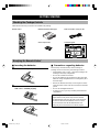 4
4
-
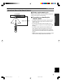 5
5
-
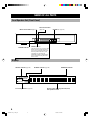 6
6
-
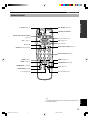 7
7
-
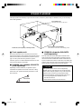 8
8
-
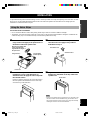 9
9
-
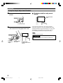 10
10
-
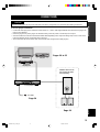 11
11
-
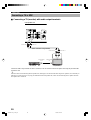 12
12
-
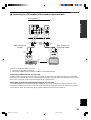 13
13
-
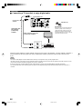 14
14
-
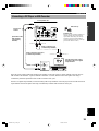 15
15
-
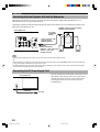 16
16
-
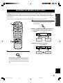 17
17
-
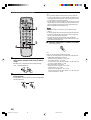 18
18
-
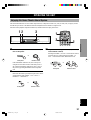 19
19
-
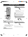 20
20
-
 21
21
-
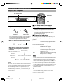 22
22
-
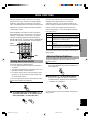 23
23
-
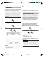 24
24
-
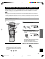 25
25
-
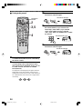 26
26
-
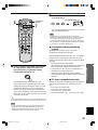 27
27
-
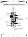 28
28
-
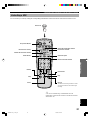 29
29
-
 30
30
-
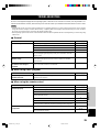 31
31
-
 32
32
-
 33
33
-
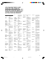 34
34
-
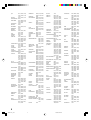 35
35
-
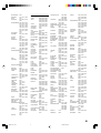 36
36
-
 37
37
-
 38
38
-
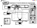 39
39
-
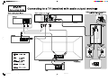 40
40


Yamaha AV-S7 Handleiding
- Categorie
- AV-ontvangers
- Type
- Handleiding
in andere talen
- English: Yamaha AV-S7 User manual
- italiano: Yamaha AV-S7 Manuale utente
- français: Yamaha AV-S7 Manuel utilisateur
- Deutsch: Yamaha AV-S7 Benutzerhandbuch
- dansk: Yamaha AV-S7 Brugermanual
- svenska: Yamaha AV-S7 Användarmanual
- Türkçe: Yamaha AV-S7 Kullanım kılavuzu
- română: Yamaha AV-S7 Manual de utilizare