Blaupunkt VD SIX de handleiding
- Categorie
- Auto audio versterkers
- Type
- de handleiding

Einführung (D)
Herzlichen Glückwunsch zum Kauf dieses hochwertigen Car Audio-
Verstärkers.
Als Innovationsträger im Bereich CarHifi bieten wir Ihnen mit unseren
Class D-Verstärkern den Einstieg in eine neue zukunftsweisende Tech-
nologie.
Im Vergleich zur herkömmlichen Analogtechnik verfügen Class D-Ver-
stärker über einen wesentlich höheren Wirkungsgrad. Liegt dieser bei
Analogverstärkern im Bereich von 60 %, so wandeln unsere digitalen
Endstufen bis zu 80 % der zugeführten Energie in Sound um. Das
Resultat könnte man als „Mehr Sound aus weniger“ bezeichnen.
Darüber hinaus erwärmen sich die Digitalverstärker nur so wenig, dass
sie auch an Orten mit schlechter Belüftung verbaut werden können,
wie z.B. unter den Sitzen.
Für eine bestmögliche Klangqualität empfehlen wir Ihnen den Einbau
Ihres neuen Velocity-Verstärkers durch einen autorisierten Velocity-
Händler.
Gestatten Sie uns noch ein Wort zum Thema Gesundheitsschutz:
Bitte bedenken Sie bei der Musikwiedergabe in Ihrem Fahrzeug, dass
dauerhafte Schalldruckpegel oberhalb von 100 dB zu bleibenden Schä-
digungen des menschlichen Ohres bis hin zum vollständigen Verlust
des Gehörs führen können. Mit modernen Hochleistungssystemen und
hochwertigen Lautsprecherkonfigurationen sind Schalldruckpegel von
über 130 dB zu erreichen.
Wir sind überzeugt, dass Sie die Vorteile unserer Class D-Verstärker
alsbald zu schätzen wissen und wünschen Ihnen viel Spaß an diesem
neuen Baustein Ihrer Soundanlage.
Für unsere innerhalb der Europäischen Union gekauften Produkte ge-
ben wir eine Herstellergarantie. Die Garantiebedingungen können Sie
unter www.blaupunkt.de abrufen oder direkt anfordern bei:
Blaupunkt GmbH
Hotline
Robert-Bosch-Str. 200
D-31139 Hildesheim
Weitere Informationen über unsere Velocity-Serie finden Sie auch unter
unserer Internet-Adresse http://www.velocity.de
Sicherheitshinweise
Einbau- und Anschlussvorschriften
Für die Dauer der Montage und des Anschlusses ist der Minuspol der
Batterie abzuklemmen.
Hierbei sind die Sicherheitshinweise des Kfz-Herstellers (Airbag, Alarm-
anlagen, Bordcomputer, Wegfahrsperren) zu beachten.
In Hinsicht auf Unfallsicherheit muss die Velocity-Endstufe professio-
nell befestigt werden. Die Montagefläche muss zur Aufnahme der bei-
liegenden Schrauben geeignet sein und sicheren Halt bieten.
Beim Bohren von Löchern darauf achten, dass keine Fahrzeugteile
(Batterie, Kabel, Sicherungskasten) beschädigt werden.
Der Amplifier wird an einem geeigneten Montageort, z. B. unter den
Sitzen oder im Kofferraum, montiert (siehe Fig. 1).
Bei der Auswahl des Einbauortes sollte eine trockene Stelle ausge-
wählt werden, die ausreichende Luftzirkulation für die Kühlung des
Verstärkers gewährleistet.
An scharfkantigen Löchern Kabeldurchführungen verwenden.
Lautsprecher mit 2-4 Ω Impedanz verwenden. Max. Belastbarkeit
(Musikleistung) beachten.
Lautsprecheranschlusskabel bis 8 mm
2
verwenden. Lautsprecher
nicht an Masse schließen, nur die bezeichneten Klemmen verwen-
den.
Der Querschnitt des Plus- und Minuskabels darf 16 mm
2
nicht
unterschreiten.
Das Pluskabel zwischen Batterie und Amplifier muss direkt an
der Batterie mit einem Sicherungshalter (160 Ampere) abgesichert
werden.
Velocity High End Reference Amplifier VD Six
Der Amplifier eignet sich zum Anschluss an Autoradios mit Cinch-An-
schluss.
Für den Anschluss an Autoradios mit ISO-Anschluss bitte Blaupunkt
ISO-Cinch-Adapter verwenden.
Velocity
VD Six
High End Reference Amplifier
Einbauanleitung / Bedienungsanleitung
Installation / operating instructions
Guide de montage / Guide d’utilisation
Istruzioni di montaggio / Istruzioni d’uso
Inbouwhandleiding / Gebruiksaanwijzing
Monteringsanvisning / Bruksanvisning
Instrucciones de montaje / Instrucciones de manejo
Instruções de instalação / Instruções de serviço
Monteringsvejledning / betjeningsvejledning 7 607 792 052

2
Einsatzmöglichkeiten und Lautsprecheranschluss:
VD Six
Kanäle Multi-Channel
Max. Power 4x110 + 2x220 / 2x300 + 1x600 Watt Fig. 5
4 Ohm
Max. Power 4x200 + 2x400 Watt Fig. 5
2 Ohm
RMS Power 4x50 + 2x100 / 2x150 + 1x300 Watt Fig. 5
4 Ohm (THD @ < 0,07 %)
RMS Power 4x100 + 2x200 Watt Fig. 5
2 Ohm (THD @ < 0,07 %)
Frequenzgang 20 - 20000 Hz
Signal-Rausch- > 95 dB/A
abstand
Eingangs- 0,3 - 8 V
empfindlichkeit
Stabilität 2 Ohm
Tiefpassfilter 40 - 160 Hz
(Low Pass)
Hochpassfilter 40 - 600 Hz
(High Pass)
Bass Boost +15 dB (45 Hz)
Sub Sonic-Filter 20 Hz Kanäle 5+6
Abmessungen
BxHxT (mm) 490 x 58 x 268
mit Endkappen 590 x 65 x 279
Plus-/Minus-Anschluss
Der Querschnitt des Plus- und Minuskabels darf 16 mm
2
nicht
unterschreiten.
An scharfkantigen Löchern Kabeldurchführungen verwenden.
Handelsübliche Minuskabel 16 mm
2
an einen störfreien Masse-
punkt (Karosserieschraube, Karosserieblech) sicher anschrau-
ben (nicht am Minuspol der Batterie). Kontaktfläche des Masse-
punktes metallisch blank kratzen und mit Graphitfett einfetten.
Anschlussbeispiele
Anschluss der Spannungsversorgung ....................................... Fig. 2
Anschluss an Autoradios mit Cinch-Ausgang ............................ Fig. 3
Anschluss an Autoradios mit Lautsprecher-Ausgang ................ Fig. 4
Lautsprecheranschlüsse ............................................................ Fig. 5
Beim Anschluss über die Cinch- oder Lautsprecherbuchsen des Auto-
radios muss die Schaltleitung angeschlossen werden.
+12V
Regler LEVEL
Mit Hilfe des LEVEL-Reglers kann die Eingangsempfindlichkeit der
Velocity-Endstufe an die Ausgangsspannung Ihres Autoradio-Vorver-
stärkerausganges angepasst werden.
Der Einstellbereich reicht von 0,3 V bis 8 V.
Bei Anschluss eines Autoradios anderer Hersteller ist die Eingangs-
empfindlichkeit entsprechend den Herstellerangaben anzupassen.
Bitte beachten Sie, das der LEVEL-Regler keine Lautstärkeeinstel-
lung ist!
INPUT
Vorverstärker-Eingänge für rechten (right) und linken (left) Kanal. Zu
diesem Anschluss verwenden Sie bitte hochwertige Velocity-Cinch/
RCA-Kabel.
Eingangswahlschalter INPUT MODE
In der Schalterstellung CH1+2 und CH3+4 kann jeder Kanal (CH1-
CH6) des Verstärkers einzeln betrieben werden. Die Mono/Stereo-
Schalter müssen sich in Stellung ST (Stereo) befinden.
In der Schalterstellung CH1+2/CH3+4 bzw. CH3+4/CH5+6 werden die
Kanäle des Verstärkers eingangsseitig miteinander verschaltet.
Schalterstellung CH1+2/CH3+4 bewirkt, dass CH1 mit CH3 und CH2
mit CH4 verbunden wird.
Schalterstellung CH3+4/CH5+6 bewirkt, dass CH3 mit CH5 und CH4
mit CH6 verbunden wird.
Durch die Kombination der Schalterstellungen können unterschiedli-
che Eingangs-/Ausgangskonstellationen realisiert werden.
Einige der gängigsten Anwendungsbeispiele sehen Sie in Fig. 5.
Eingangswahlschalter MO / ST
In der Schalterstellung ST arbeiten die Kanäle 1+2, 3+4 und 5+6 im
Stereo-Betrieb.
In der Schalterstellung MO werden jeweils die Kanäle 1 mit 2, 3 mit 4
sowie 5 mit 6 eingangsseitig miteinander verschaltet.
Beispiele hierzu sehen Sie in Fig. 5.
LP / HP / FULL - Schalter
Selektieren Sie vor der Montage den Crossover Schalter der Endstufe
um den Tiefpassfilter (LP), den Hochpassfilter (HP) oder Fullrange
(FULL) einzustellen. Bei der Position FULL wird der volle Frequenz-
gang am Ausgang benutzt.
Der Einsatz der integrierten Frequenzweichen ist vor allem sinnvoll
bei Mehrwege-Soundsystemen mit separatem Subwoofer.
Um einen Subwoofer sinnvoll zu betreiben und somit den besten Klang
zu erreichen, ist es notwendig diesen frequenzmäßig abzukoppeln um
ihm nur die tiefen (Bässe) Frequenzen zuzuführen.
Um dieses zu tun wählen Sie LP und regeln Sie mit Hilfe des Über-
gangsfrequenzreglers die obere Frequenz zwischen 40 Hz und 160 Hz.
Somit wird jeder Subwoofer optimal abgekoppelt.
Bei der Selektion HP kann mit dem zugehörigen Übergangsfrequenz-
regler die untere Grenzfrequenz zwischen 40 Hz und 600 Hz variiert
werden.
Zur genauen akustischen Abstimmung der Frequenzweiche empfeh-
len wir Ihnen die Beratung durch einen Velocity Fachhändler.
Die technischen Daten der eingesetzten Lautsprecher müssen bei
der Abstimmung der Frequenzweiche unbedingt berücksichtigt
werden.
Übergangsfrequenzregler (LOW PASS + HIGH PASS)
Ist über den Crossover Schalter die Frequenzweiche aktiviert (LP oder
HP), kann mit dem entsprechenden Regler die Übergangsfrequenz
des jeweiligen Filters zwischen 40 Hz und 160 Hz bzw. 40 Hz und
600 Hz stufenlos eingestellt werden. Bei Fullrange-Betrieb ist dieser
Regler ohne Funktion.
Einstellung für einen Subwoofer
Um einen Subwoofer sinnvoll zu betreiben und somit den besten Klang
zu erreichen, ist es notwendig diesen frequenzmäßig abzukoppeln,
um ihm nur die tiefen (Bässe) Frequenzen zuzuführen.
1. Stellen Sie am Verstärker zunächst den LEVEL-Regler auf Mini-
mum und den LOW PASS-Frequenzregler auf Mittelstellung.
2. Spielen Sie jetzt Musik, die Ihnen gut bekannt ist und Tiefbassan-
teile enthält (z.B. Pop), über Ihr Autoradio ab. Erhöhen Sie nun
langsam die Lautstärke des Subwoofers, indem Sie den LEVEL-
Regler am Verstärker im Uhrzeigersinn drehen, bis die Musik tonal
ausgewogen klingt, der Klang also weder zu bassschwach, noch
bassbetont wirkt.
3. Hören Sie jetzt auf das Verhältnis von tiefen Männerstimmen zum
oberen Bass, sowie auf das Verhältnis vom oberen Bass (Kick-
bass) zum Tiefbass. Der Bass sollte im Idealfall knackig und mit
deutlichem Tiefbass erklingen und Männerstimmen sollten weder
zu dünn, noch aufgebläht wirken. Entspricht der Klang Ihren Vor-
stellungen, kann der Abgleich beendet werden. Wenn nicht, fahren
Sie bitte wie unter 4. und 5. beschrieben fort.
4. Wirken Männerstimmen aufgebläht, oder der Tiefbass zu schwach,
sollten Sie den LOW PASS-Frequenzregler etwas in Richtung
Minimum drehen und die Abstimmung wieder bei Punkt 2. fortset-
zen.
5. Wirkt der Bass tief, aber unsauber und dröhnig oder klingen Män
nerstimmen zu dünn, ist der LOW PASS-Frequenzregler etwas in
Richtung Maximum zu drehen. Setzen Sie die Abstimmung dann
unter Punkt 2. fort.
Zur genauen akustischen Abstimmung der Frequenzweiche empfeh-
len wir Ihnen die Beratung durch einen Velocity Fachhändler.
Die technischen Daten der eingesetzten Lautsprecher müssen bei
der Abstimmung der Frequenzweiche unbedingt berücksichtigt
werden.

3
BASS BOOST
Mit Hilfe des Bass Boost-Reglers kann die Basswiedergabe des Veloci-
ty-Verstärkers eingestellt werden. Der Einstellbereich reicht von 0 dB
bis +15 dB.
SUB SONIC
Das Sub Sonic-Filter dient dem Verstärkerbetrieb bei angeschlosse-
nem Subwoofer. Es kann zugeschaltet werden um den Subwoofer vor
mechanischer Überlastung durch tiefe nicht mehr in den Hörbereich
fallende Frequenzen zu schützen.
Integrierte Sicherungen (FUSE)
Die im Amplifier integrierten Sicherungen (Fuse) schützen die End-
stufe und das gesamte elektrische System im Fehlerfall. Bei dem Ein-
satz einer Ersatzsicherung bitte niemals Sicherungen überbrücken oder
gegen Typen mit höherem Strom auswechseln.
Betriebsanzeige (POWER / PROTECTION)
Blaues Licht: Endstufe an, regulärer Betriebszustand.
Rotes Licht: Endstufe ist elektronisch abgeschaltet da Fehlerfall vor-
liegt.
Änderungen vorbehalten.
Introduction (GB)
Congratulations on purchasing this high-quality car audio amplifier.
As innovators in the world of car hi-fi, we are pleased to introduce you
to the new future-oriented technology that is integrated in our Class D
amplifiers.
Class D amplifiers are considerably more efficient than standard ana-
logue technologies. The efficiency of analogue amplifiers is around
60 % whilst our digital power amplifiers convert up to 80 % of the input
energy into sound. You could describe the results as “more sound
produced from less”.
Furthermore, digital amplifiers heat up so little that they can also be
installed in places that are not very well ventilated, such as beneath
the seats.
To ensure that the sound quality is optimised, we recommend that the
installation of your new Velocity amplifier be carried out by an author-
ised Velocity dealer.
Please allow us to make a few comments on the issue of health:
When listening to music in your vehicle, remember that continuous
sound pressure levels of over 100 dB can lead to permanent hearing
damage and even total hearing loss. Modern high-powered systems
and high-quality loudspeaker configurations are capable of producing
sound pressure levels exceeding 130 dB.
We are convinced that you will very quickly appreciate the advantag-
es of our Class D amplifiers and we would like to take this opportunity
to wish you a lot of fun with this new component in your sound system.
We provide a manufacturer guarantee for our products bought within
the European Union. You can view the guarantee conditions at
www.blaupunkt.de or ask for them directly at:
Blaupunkt GmbH
Hotline
Robert-Bosch-Str. 200
D-31139 Hildesheim
You can also obtain further information on our Velocity series on the
Internet at http://www.velocity.de
Safety notices
Installation and connection instructions
The battery’s negative terminal must be disconnected for the entire
time it takes to install and connect the device.
You must observe the vehicle manufacturer’s safety notices (airbags,
alarm systems, trip computers, immobilizers) regarding this.
As regards safety in the event of an accident, the Velocity power am-
plifier must be professionally secured in position. The surface to which
it is attached must be suitable for the screws that are included and
must provide a secure hold.
When drilling holes, you must make sure that none of the vehicle com-
ponents (e.g. battery, cables, fuse box) can be damaged in the process.
The amplifier must be secured in a suitable installation location, e.g.
beneath the seats or in the car boot (see Fig. 1).
When choosing an installation location, you should select one which
is dry and which provides sufficient air circulation to cool the amplifier.
Use cable grommets to protect cables against sharp-edged holes.
Use loudspeakers with an impedance of 2-4 Ω. Observe the max-
imum load rating (music power rating).
Use loudspeaker connecting cables up to 8 mm
2
. Do not connect loud-
speakers to earth – only use the correct terminals as indicated.
The cross section of the positive and negative cables must be at
least 16 mm
2
.
The positive cable between the battery and the amplifier must be
protected directly at the battery using a fuse holder (160 amperes).
Velocity High End Reference Amplifier VD Six
The amplifier is suitable for connection to car audio systems that are
equipped with RCA connections.
If you want to connect it to car audio systems that are equipped with
an ISO connection, please use the Blaupunkt ISO-RCA adapter.
Usage options and loudspeaker connection:
VD Six
Channels Multi-channel
Max. power 4x110 + 2x220 / 2x300 + 1x600 watts Fig. 5
4 ohms
Max. power 4x200 + 2x400 watts Fig. 5
2 ohms
RMS power 4x50 + 2x100 / 2x150 + 1x300 watts Fig. 5
4 ohms (THD @ < 0.07 %)
RMS power 4x100 + 2x200 watts Fig. 5
2 ohms (THD @ < 0.07 %)
Frequency 20-20000 Hz
response
Signal-to-noise > 95 dB/A
ratio
Input sensitivity 0.3 - 8 V
Stability 2 ohms
Low pass filter 40 - 160 Hz
(Low Pass)
High pass filter 40 - 600 Hz
(High Pass)
Bass boost +15 dB (45 Hz)
Subsonic filter 20 Hz Channels 5+6
Dimensions
WxHxD (mm) 490 x 58 x 268
with end caps 590 x 65 x 279
Positive/negative connection
The cross section of the positive and negative cables must be at
least 16 mm
2
.
Use cable grommets to protect cables against sharp-edged holes.
Securely screw a standard 16 mm
2
negative cable to an interfer-
ence-free earth connection point (bolt connected to the car body,
car body sheet metal) – though do not connect it to the negative
terminal of the battery. Scratch the surface down to the bare met-
al at the point at which the earth contact is made and apply graph-
ite grease.

4
Connection examples
Connecting the voltage supply................................................... Fig. 2
Connection to car radios with RCA output ................................. Fig. 3
Connection to car radios with loudspeaker output .................... Fig. 4
Loudspeaker connections .......................................................... Fig. 5
The switching line must be connected when connection is carried out
using the RCA jacks or the loudspeaker jacks of the car radio.
+12V
LEVEL control
You can use the LEVEL control to adjust the input sensitivity of the
Velocity power amplifier to the output voltage of your car radio’s preamp
output.
The setting can be adjusted between 0.3 V and 8 V.
When connecting a car radio produced by another manufacturer, you
must adjust the input sensitivity in accordance with the information
provided by the manufacturer.
Please note that the LEVEL control is not a control for adjusting the
volume!
INPUT
Preamp inputs for the right and left channels. Please use high-quality
Velocity RCA cables for this connection.
INPUT MODE input selector switch
In the CH1+2 and CH3+4 switch position, each channel (CH1-CH6) of
the amplifier can be operated separately. The mono/stereo switches
must be set to the ST (stereo) position.
In the CH1+2/CH3+4 or CH3+4/CH5+6 switch position, the amplifier
channels are connected together at the input side.
Switch position CH1+2/CH3+4 connects CH1 to CH3 and CH2 to CH4.
Switch position CH3+4/CH5+6 connects CH3 to CH5 and CH4 to CH6.
You can achieve various input/output groupings by combining the switch
settings.
Some examples of the most popular applications are provided in Fig. 5.
MO / ST input selector switches
In the ST switch position, channels 1+2, 3+4 and 5+6 operate in ster-
eo mode.
In the MO switch position, channel 1 is connected to 2, channel 3 is
connected to 4, and channel 5 is connected to 6 at the input side.
Examples of this are provided in Fig. 5.
LP / HP / FULL switch
Before installing, adjust the crossover switch on the power amplifier to
set the low pass filter (LP), high pass filter (HP) or full range (FULL). If
you select the FULL position, the full frequency response will be used
at the output.
Using the integrated crossovers is particularly useful in the case of
multi-channel sound systems with a separate subwoofer.
In order to obtain the best sound when a subwoofer is connected, the
subwoofer must be separated as far as the frequencies it receives are
concerned, i.e. it must only be fed with low frequencies (bass).
To ensure that this is the case, select LP and use the crossover fre-
quency control to adjust the upper frequency to between 40 Hz and
160 Hz. This ensures that every subwoofer is optimally separated as
far as the frequencies it receives are concerned.
If HP is selected, you can use the associated crossover frequency
control to adjust the lower cut-off frequency to between 40 Hz and
600 Hz.
If you want to precisely optimise the acoustic settings of the crosso-
ver, we recommend you obtain advice from a Velocity dealer.
It is very important that you take into account the specifications
of the loudspeakers being used whilst you are adjusting the cross-
over.
Crossover frequency control (LOW PASS + HIGH PASS)
If the crossover is activated (LP or HP) by adjusting the position of the
crossover switch, you can then use the corresponding control to ad-
just the crossover frequency of the respective filter to anywhere be-
tween 40 Hz and 160 Hz or 40 Hz and 600 Hz (i.e. continuously vari-
able setting). This control has no function in full range mode.
Settings for a subwoofer
In order to obtain the best sound when a subwoofer is connected, the
subwoofer must be separated as far as the frequencies it receives are
concerned, i.e. it must only be fed with low frequencies (bass).
1. Firstly, turn down the LEVEL control on the amplifier to minimum
and set the LOW PASS frequency control to its centre position.
2. Now play some music on your car sound system that you are very
familiar with and that contains some low bass (e.g. pop music).
Now slowly increase the volume of the subwoofer by turning the
LEVEL control on the amplifier in a clockwise direction until you
feel that the sound of the music is well balanced, i.e. the bass is
neither too weak nor overpowering.
3. Now listen to the relationship between deep male voices and the
upper bass and also take note of the relationship between the up-
per bass (kick bass) and the lower bass. The bass should ideally
sound crisp and have a clear low bass component, and male voic-
es should neither sound too weak nor should they billow out. You
can stop making adjustments if you are happy with the sound. If
not, move on to steps 4 and 5.
4. If male voices seem to billow out or the low bass is too weak, you
should turn the LOW PASS frequency control slightly towards min-
imum and then continue making your adjustments as described in
point 2 onwards.
5. If the bass sounds low but dirty and booming or the male voices
sound too weak, you should turn the LOW PASS frequency control
slightly towards maximum. Next, continue making your adjustments
as described in point 2 onwards.
If you want to precisely optimise the acoustic settings of the crosso-
ver, we recommend you obtain advice from a Velocity dealer.
It is very important that you take into account the specifications
of the loudspeakers being used whilst you are adjusting the cross-
over.
BASS BOOST
You can adjust the bass output of the Velocity amplifier using the bass
boost control. The settings range covers 0 dB to +15 dB.
SUB SONIC
The subsonic filter is used when a subwoofer is connected to the am-
plifier. It can be activated in order to protect the subwoofer against
mechanical overload by low frequencies that are outside our hearing
range.
Integrated fuses (FUSE)
The fuses that are integrated in the amplifier protect the power ampli-
fier and the entire electrical system in the event of a fault. If the fuse
needs to be replaced, never bypass/bridge the fuse and never replace
it with fuse types that are designed for higher currents.
Power-on indicator (POWER / PROTECTION)
Blue light: Power amplifier switched on, normal operating mode.
Red light: Power amplifier has been electronically deactivated due to
a fault.
Subject to changes.

5
Introduction (F)
Félicitations pour l’achat de cet amplificateur Car Audio haut de gamme.
En tant que promoteurs d’innovations dans le domaine de la hi-fi em-
barquée, nous avons le plaisir de vous offrir avec nos amplificateurs
de la classe D l’accès à une technologie prometteuse d’avenir.
Comparés aux amplificateurs analogiques traditionnels, les amplifica-
teurs de la classe D offrent une efficacité nettement plus élevée. Tan-
dis que l’efficacité des amplificateurs analogiques est de l’ordre de
60 %, nos étages de sortie numériques convertissent en son jusqu’à
80 % de l’énergie acheminée. On pourrait appeler ce résultat « Plus
de son à la sortie avec moins à l’entrée ».
De plus, les amplificateurs numériques chauffent si peu qu’ils peuvent
être montés à des endroits insuffisamment aérés, sous les sièges par
exemple.
Pour bénéficier d’un son de qualité optimale, nous vous recomman-
dons de faire installer votre nouvel amplificateur Velocity par un re-
vendeur Velocity agréé.
Permettez-nous d’ajouter encore quelques mots en matière de la pro-
tection de la santé.
Prenez conscience que l’écoute de musique à des niveaux sonores
permanents dépassant 100 dB peut endommager votre ouie de façon
irrémédiable, voir même entraîner la perte totale de celle-ci. Avec les
systèmes modernes, très puissants et les haut-parleurs haut de gam-
me, il est facile de dépasser des niveaux de pression sonore de130 dB.
Nous sommes sûrs que vous apprécierez les avantages de nos am-
plificateurs de la classe D et que cette nouvelle composante vous
apportera toute satisfaction.
Notre garantie constructeur s’étend à tous les produits achetés à l’in-
térieur de l’Union Européenne. Vous en trouverez les conditions sur
notre site : www.blaupunkt.de ou en vous adressant directement à :
Blaupunkt GmbH
Hotline
Robert-Bosch-Str. 200
31139 Hildesheim
Allemagne
Pour davantage d’informations sur notre série Velocity, consultez no-
tre site Internet à l’adresse http://www.velocity.de
Consignes de sécurité
Consignes d’installation et de connexion
Débrancher le pole (-) de la batterie pour toute la durée de l’installa-
tion et du branchement en observant les consignes de sécurité du
constructeur automobile (airbag, systèmes d’alarme, ordinateur de
bord, antidémarrages).
Pour prévenir tout accident, l’étage de sortie doit être fixé de manière
professionnelle. La surface de montage doit être appropriée aux vis
fournies et offrir un support sûr.
En perçant les trous, veiller à n’endommager aucune pièce du véhicu-
le (batterie, câbles, boîte à fusibles).
Monter l’amplificateur à un endroit adéquat, par exemple sous les siè-
ges ou dans le coffre (cf. Fig. 1).
Choisir un endroit sec où l’air y circule suffisamment pour assurer le
refroidissement de l’amplificateur.
Utiliser des passe-câbles si le bord des trous est tranchant.
Utiliser des haut-parleurs ayant une impédance de 2 à 4 Ω. Ob-
server la capacité de charge max. (puissance musicale).
Utiliser un câble de connexion de haut-parleur de 8 mm
2
max. Ne pas
raccorder les haut-parleurs à la masse, utiliser uniquement les bornes
marquées.
La section du câble (+) et du câble (-) ne doit pas être inférieure à
16 mm
2
.
Le câble (+) entre la batterie et l’amplificateur doit être protégé
directement sur la batterie au moyen d’un porte-fusible (160 A).
Amplificateur de référence haut de gamme VD Six
L’amplificateur est prévu pour être raccordé à des autoradios offrant
une connectique Cinch.
Pour les autoradios équipés d’une connectique ISO, prière d’utiliser
l’adaptateur Cinch-ISO Blaupunkt.
Utilisations possibles et connexion des haut-parleurs :
VD Six
Canaux Multi-canaux
Puissance max. 4x110 + 2x220 / 2x300 + 1x600 watts Fig. 5
4 ohms
Puissance max. 4x200 + 2x400 watts Fig. 5
2 ohms
Puissance RMS 4x50 + 2x100 / 2x150 + 1x300 watts Fig. 5
4 ohms (THD @ < 0,07 %)
Puissance RMS 4x100 + 2x200 watts Fig. 5
2 ohms (THD @ < 0,07 %)
Bande passante 20 - 20000 Hz
Rapport > 95 dB/A
signal/bruit
Résistance 0,3 - 8 V
d’entrée
Stabilité 2 Ohm
Filtre passe-bas 40 - 160 Hz
(Low Pass)
Filtre passe-haut 40 - 600 Hz
(High Pass)
Bass Boost +15 dB (45 Hz)
Filtre Sub Sonic 20 Hz Canaux 5+6
Dimensions
LxHxP (mm) 490 x 58 x 268
avec bouchons 590 x 65 x 279
Branchement des câbles (+) et (-)
La section du câble (+) et du câble (-) ne doit pas être inférieure à
16 mm
2
.
Utiliser des passe-câbles si les trous percés ont des bords vifs.
Bien visser le câble (-) de 16 mm
2
en vente dans le commerce à
un point de contact à la masse, libre d’interférence (vis de car-
rosserie, tôle de carrosserie) (et non pas au pôle (-) de la batte-
rie !). Mettre à nu la surface de contact à la masse en grattant, et
la graisser au moyen de graisse graphitique.
Exemples de branchement
Connexion de la tension d’alimentation ..................................... Fig. 2
Connexion à des autoradios avec sortie Cinch ......................... Fig. 3
Connexion à des autoradios avec sortie haut-parleurs............. Fig. 4
Connexions des haut-parleurs ................................................... Fig. 5
En cas de connexion au moyen des connecteurs Cinch ou haut-parleur
de l’autoradio, le câble de commutation doit être raccordé.
+12V
Bouton de réglage LEVEL
Le bouton de réglage LEVEL permet de régler la sensibilité d’entrée
de l’étage de sortie Velocity sur la tension de la sortie préampli de
votre autoradio.
La plage de réglage va de 0,3 V à 8 V.
Si l’autoradio a été fabriqué par un autre constructeur, régler la sensi-
bilité d’entrée en fonction des indications données par le constructeur.
Notez que le bouton de réglage LEVEL ne règle pas le volume !
INPUT
Entrées préampli pour le canal droit (right) et gauche (left). Pour le
branchement, prière d’utiliser des câbles cinch/RCA Velocity haut de
gamme.
Sélecteur d’entrée INPUT MODE
Quand le sélecteur est sur CH1+2 et CH3+4, il est possible de faire
fonctionner chaque canal (CH1-CH6) de l’amplificateur individuelle-
ment. Les sélecteurs mono/stéréo doivent être en position ST (sté-
réo).
Quand le sélecteur est sur CH1+2/CH3+4 ou CH3+4/CH5+6, les ca-
naux de l’amplificateur sont reliés entre eux côté entrée.
La position CH1+2/CH3+4 du sélecteur entraîne que CH1 est relié à
CH3 et CH2 à CH4.
La position CH3+4/CH5+6 du sélecteur entraîne que CH3 est relié à
CH5 et CH4 à CH6.

6
En combinant les différentes positions du sélecteur, il est possible de
réaliser différentes combinaisons d’entrée / de sortie.
Certains exemples d’utilisation les plus courants sont visibles sur la
Fig. 5.
Sélecteur d’entrée MO / ST
Si le sélecteur est sur ST, les canaux 1+2, 3+4 et 5+6 fonctionnent en
stéréo.
Si le sélecteur est sur MO, les canaux seront reliés entre eux côté
entrée : 1 avec 2, 3 avec 4 et 5 avec 6.
Voir les exemples sur la Fig. 5.
Commutateurs LP / HP / FULL
Avant de procéder à l’installation, sélectionner le commutateur Cross-
over de l’étage de sortie pour régler le filtre passe-bas (LP), le filtre
passe-haut (HP) ou la gamme complète (FULL). La position FULL si-
gnifie que toute la bande passante sera utilisée à la sortie.
Il est conseillé d’utiliser le séparateur de fréquences intégré sur le
système sonore canaux multiples à subwoofer séparé.
Afin d’utiliser au mieux un subwoofer et d’atteindre la meilleure tonali-
té, il est nécessaire de le découpler en fréquences pour lui amener
uniquement les fréquences basses (graves).
Pour ce faire, sélectionner le filtre passe-bas (LP) et régler la fréquen-
ce supérieure entre 40 Hz et 160 Hz à l’aide du réglage de la fréquen-
ce de recouvrement. Chaque subwoofer est ainsi découplé de maniè-
re optimale.
En sélectionnant le filtre passe-haut (HP), il est possible de varier la
fréquence inférieure entre 40 Hz et 600 Hz à l’aide du réglage de
fréquence de recouvrement correspondant.
Pour assurer un réglage acoustique précis du coupleur, nous vous
recommandons de prendre contact avec un revendeur spécialisé
Velocity.
Il est absolument nécessaire de prendre en compte les données
techniques des haut-parleurs utilisés lors du réglage du sépara-
teur de fréquences.
Réglage de la fréquence de recouvrement (LOW PASS + HIGH
PASS)
Lorsque le séparateur de fréquences est activé par le commutateur
Crossover (LP ou HP), il est possible de régler progressivement la
fréquence de recouvrement du filtre respectif de 40 Hz à 160 Hz /
40 Hz à 600 Hz. Ce réglage est sans fonction en mode Fullrange.
Réglage destiné à un subwoofer
Pour utiliser correctement un subwoofer et obtenir le meilleur son pos-
sible, il est nécessaire de le découpler sur le plan fréquence pour ne
lui acheminer que les fréquences basses (graves).
1. Sur l’amplificateur, mettez d’abord le bouton de réglage LEVEL sur
minimum et le bouton de réglage de fréquences LOW PASS au
milieu.
2. Écoutez d’abord une musique qui vous est connue, contenant en
partie des basses profondes (par musique pop) avec votre autora-
dio. Maintenant, augmentez lentement le volume du subwoofer en
tournant le bouton de réglage LEVEL sur l’amplificateur dans le
sens des aiguilles jusqu’à ce que la musique soit équilibrée sur le
plan de la tonalité, les graves n’étant ni faibles ni accentuées.
3. Faites maintenant attention au rapport entre les voix masculines
graves et les graves supérieures, et au rapport entre les graves
supérieures (kickbass) et les graves profondes. Dans le meilleur
des cas, la basse devrait pétiller et restituer des graves inférieures
nettes et les voix masculines devraient paraître ni grêles ni trop
gonflées. Si la tonalité répond à vos attentes, mettez fin à la mise
au point. Dans le cas contraire, procédez comme décrit aux para-
graphes 4. et 5.
4. Si les voix masculines sonnent gonflées ou si les graves profondes
sont trop faibles, il est conseillé de tourner légèrement le bouton
de réglage de fréquence LOW PASS vers le minimum et reprendre
la mise au point à partir du paragraphe 2.
5. Si la basse est profonde, mais pas nette et vrombissante ou si les
voix masculines sont trop grêles, tournez légèrement le bouton de
réglage de fréquence LOW PASS vers le maximum. Continuez
ensuite la mise au point à partir du paragraphe 2.
Pour le réglage acoustique précis du séparateur de fréquences, nous
vous recommandons de consulter un revendeur Velocity.
Les caractéristiques techniques des haut-parleurs utilisés doi-
vent être prises en considération pendant la mise au point du
séparateur de fréquences.
BASS BOOST
Le bouton de réglage Bass Boost (Amplification des basses) permet
de régler la restitution des basses de l’amplificateur Velocity. La plage
de réglage va de 0 dB à + 15 dB.
SUB SONIC
Le filtre Sub Sonic sert au fonctionnement de l’amplificateur quand un
subwoofer est connecté. Il peut être raccordé pour protéger le subwoo-
fer de la surcharge mécanique due aux fréquences basses n’apparte-
nant plus au domaine de l’audible.
Fusibles intégrés (FUSE)
L’étage de sortie et le système électrique complet sont protégés en cas
de défaillance par les fusibles (fuse) intégrés dans l’amplificateur. En
cas d’utilisation d’un fusible de recharge, ne jamais ponter les fusibles
ou les remplacer par d’autres présentant une intensité supérieure.
Voyant de fonctionnement (POWER / PROTECTION)
Lumière bleue : Etage de sortie allumé, état de fonctionnement nor-
mal.
Lumière rouge : Etage de sortie mis hors circuit dû à un défaut.
Sous réserve de modifications.
Introduzione (I)
Ci congratuliamo con voi per l’acquisto di questo amplificatore per Car
Audio di qualità superiore.
Basandoci sulla nostra esperienza nel campo delle innovazioni CarHifi,
vi offriamo i nostri amplificatori Class D, coi quali potete fare il primo
passo di avvicinamento ad una nuova tecnologia rivolta verso il futuro.
Nei confronti dei soliti amplificatori con tecnica analogica di vasto uso,
gli amplificatori Class D sono caratterizzati da un rendimento netta-
mente superiore. Mentre nel caso degli amplificatori analogici il rendi-
mento si aggira su circa il 60 %, nei nostri stadi di uscita digitali l’ener-
gia alimentata viene convertita in sound fino all’80 %. Il risultato si
potrebbe descrivere come “Si arriva a più sound partendo da meno”.
Inoltre, gli amplificatori digitali si riscaldano minimamente, tanto da
poter venir montati anche in posti con pessima ventilazione, come p.
es. sotto i sedili.
Al fine di ottenere un’ottima qualità di suono, vi consigliamo di far ese-
guire il montaggio del vostro nuovo amplificatore Velocity da un con-
cessionario Velocity.
Vorremmo ancora annotare qualcosa sul tema della protezione della
salute:
Quando ascoltate la musica all’interno della vostra autovettura, tene-
te presente che la presenza di un livello di pressione acustica conti-
nuamente al di sopra dei 100 dB provoca danni permanenti all’udito e
può anche comportare la perdita dell’udito. Con moderni sistemi di
alte prestazioni e con pregiate configurazioni degli altoparlanti si pos-
sono raggiungere livelli di pressione acustica di oltre 130 dB.
Con la convinzione che anche voi imparerete ben presto ad apprez-
zare i vantaggi dei nostri amplificatori Class D, vi auguriamo un buon
divertimento con questo nuovo componente del vostro impianto sound.
Per i prodotti acquistati nell’ambito della Comunità Europea concedia-
mo una garanzia di produttore. Le condizioni di garanzia potete richia-
marle all’indirizzo www.blaupunkt.de, oppure richiederle direttamente
presso di noi:
Blaupunkt GmbH
Hotline
Robert-Bosch-Str. 200
D-31139 Hildesheim
Troverete ulteriori informazioni sulla nostra serie Velocity anche al
nostro indirizzo Internet http://www.velocity.de

7
Cenni sulla sicurezza
Istruzioni di montaggio e di allacciamento
Mentre eseguite il montaggio e l’allacciamento assicuratevi che sia
staccato il polo negativo della batteria.
Negli interventi di montaggio e allacciamento osservate i cenni sulla
sicurezza indicati dal fabbricante d’auto (airbag, impianto di allarme,
computer di bordo, immobilizzatore).
Per quanto riguarda la protezione da infortuni, lo stadio di uscita Velo-
city deve venire fissato in modo professionale. La superficie di mon-
taggio deve aver posto sufficiente per l’avvitamento delle viti in dota-
zione e deve poter fungere da base sicura di supporto.
Quando praticate fori, fate attenzione a non danneggiare parti di auto-
vettura (batteria, cavi, scatola dei fusibili).
L’amplificatore si monta in un posto adatto, p. es. sotto un sedile o nel
bagagliaio (vedasi Fig. 1).
Come punto di montaggio scegliete un posto asciutto, in cui ci sia una
sufficiente circolazione d’aria per raffreddare l’amplificatore.
Usate passacavi per i fori con bordi taglienti.
Impiegate altoparlanti con impedenza di 2-4 Ω. Fate attenzione a
non superare il carico massimo ammissibile (prestazioni musi-
cali).
Per gli altoparlanti usate cavi con sezioni fino a 8 mm
2
. Non collegate
gli altoparlanti a massa, usate soltanto i morsetti indicati.
Le aree delle sezioni dei cavi positivo e negativo non devono es-
sere superiori ai 16 mm
2
.
Il cavo positivo tra batteria e amplificatore deve venir fissato per
bene direttamente sulla batteria, facendo uso di un supporto di
sicurezza (160 ampere).
Amplificatore Velocity High End Reference VD Six
L’amplificatore è adatto per l’allacciamento ad autoradio con attacco
cinch.
Per l’allacciamento ad autoradio con attacco ISO vi preghiamo di usa-
re l’adattatore ISO-cinch della Blaupunkt.
Possibilità di impiego e allacciamenti per gli altoparlanti:
VD Six
Canali Multi-Channel
Max. Power 4x110 + 2x220 / 2x300 + 1x600 watt Fig. 5
4 ohm
Max. Power 4x200 + 2x400 watt Fig. 5
2 ohm
RMS Power 4x50 + 2x100 / 2x150 + 1x300 watt Fig. 5
4 ohm (THD @ < 0,07 %)
RMS Power 4x100 + 2x200 watt Fig. 5
2 ohm (THD @ < 0,07 %)
Risposta in 20 - 20000 Hz
frequenza
Rapporto > 95 dB/A
segnale-rumore
Sensibilità in 0,3 - 8 V
entrata
Stabilità 2 ohm
Filtro passa-basso 40 - 160 Hz
(Low Pass)
Filtro passa-alto 40 - 600 Hz
(High Pass)
Bass Boost +15 dB (45 Hz)
Filtro Sub Sonic 20 Hz Canali 5+6
Dimensioni
LxAxP (mm) 490 x 58 x 268
con cappucci 590 x 65 x 279
Allacciamento positivo/negativo
Le aree delle sezioni dei cavi positivo e negativo non devono es-
sere inferiori a 16 mm
2
.
Usate passacavi per i fori di passaggio per cavi con orli taglienti.
I cavi negativi da 16 mm
2
, reperibili in commercio, devono venir
avvitati saldamente su un punto di massa privo di disturbi (vite di
carrozzeria, lamiera di carrozzeria) (non avvitare al polo negativo
della batteria). Strofinate la superficie di contatto del punto di
massa, fino a lucidezza metallica, poi ingrassate con grasso con-
tenente grafite.
Esempi di allacciamento
Allacciamento dell’alimentazione di tensione ............................ Fig. 2
Allacciamento ad autoradio con attacco cinch .......................... Fig. 3
Allacciamento ad autoradio con uscite per altoparlanti............. Fig. 4
Allacciamenti degli altoparlanti................................................... Fig. 5
Quando viene eseguito l’allacciamento tramite gli attacchi cinch o at-
tacchi per altoparlanti dell’autoradio, deve venire allacciata la direzio-
ne di rete.
+12V
Regolatore di LEVEL
Con il regolatore di LEVEL si può adattare la sensibilità in entrata del-
lo stadio di uscita di Velocity alla tensione in uscita dell’uscita del pre-
amplificatore della vostra autoradio.
Il settore di regolazione va da 0,3 V fino a 8 V.
Quando allacciate un’autoradio di un altro fabbricante, la sensibilità in
entrata deve venire regolata in corrispondenza dei dati indicati dal
fabbricante.
Vi preghiamo di tenere presente che con il regolatore di LEVEL non si
regola il livello del volume!
INPUT
Entrate di preamplificatore per il canale destro (right) e per quello sini-
stro (left). Per questo allacciamento impiegate per favore cinch Velo-
city rispettivamente cavi RCA di alta qualità.
Selettore di ingresso INPUT MODE
Con selettore sulle posizioni CH1+2 e CH3+4 si possono utilizzare
singolarmente tutti i canali (CH1-CH6) dell’amplificatore. I commuta-
tori Mono/Stereo devono trovarsi in posizione ST (Stereo).
Con selettore sulle posizioni CH1+2/CH3+4 o CH3+4/CH5+6 i canali
dell’amplificatore vengono collegati tra di loro sul lato di ingresso.
Con selettore in posizione CH1+2/CH3+4 il canale CH1 è collegato
con CH3 ed il canale CH2 con CH4.
Con selettore in posizione CH3+4/CH5+6 il canale CH3 è collegato
con CH5 ed il canale CH4 con CH6.
Con varie combinazioni delle posizioni di selettore si possono realiz-
zare differenti collegamenti in entrata e in uscita.
La Fig. 5 illustra alcuni dei più comuni esempi di applicazione.
Selettore di ingresso MO / ST
Con selettore sulla posizione ST i canali 1+2, 3+4 e 5+6 funzionano in
esercizio stereo.
Con selettore sulla posizione MO si hanno i seguenti collegamenti tra
i canali sul lato di entrata: 1 con 2, 3 con 4 e 5 con 6.
Esempi di tali collegamenti vengono illustrati dalla Fig. 5.
Commutatore LP / HP / FULL
Prima di eseguire il montaggio, selezionate il commutatore di crosso-
ver di stadio finale, per determinare il filtro passa-basso (LP), il filtro
passa-alto (HP) o il fullrange (FULL). In posizione FULL la risposta in
frequenza viene utilizzata al completo.
L’utilizzo dei separatori di frequenza integrati ha senso soprattutto nel
caso di sistemi di sound a più vie con subwoofer separato.
Per far funzionare un subwoofer nel modo migliore e per ottenere così
il miglior suono possibile sarà necessario disinnestare settori di fre-
quenza per il subwoofer, per fargli poi pervenire soltanto frequenze
basse (bassi).
Per fare ciò selezionate LP e con il regolatore delle frequenze transi-
torie impostate la frequenza superiore su un livello tra 40 Hz e 160 Hz.
In tal modo si ottiene un’ottimale disinnesto per ogni subwoofer.
Quando selezionate HP, con il corrispondente regolatore delle frequen-
ze transitorie potete variare la frequenza limite inferiore tra i 40 Hz ed
i 600 Hz.
Al fine di ottenere una combinazione acustica armonica per il separa-
tore di frequenze vi consigliamo di seguire i consigli di un negoziante
specializzato in prodotti Velocity.

8
Quando eseguite la regolazione del separatore di frequenze do-
vete assolutamente osservare i dati tecnici relativi agli altopar-
lanti allacciati.
Regolatore di frequenza transitoria (LOW PASS + HIGH PASS)
Quando con il commutatore di crossover viene attivato il separatore di
frequenze (LP o HP), con il corrispondente regolatore si possono im-
postare in continuo valori di frequenza transitoria del filtro tra 40 Hz e
160 Hz, relativamente tra 40 Hz e 600 Hz. In esercizio Fullrange que-
sto regolatore non esplica nessuna funzione.
Impostazione per un subwoofer
Per poter usare il subwoofer nel modo appropriato e ottenere così il
miglior suono possibile, è necessario disinserire per il subwoofer set-
tori di frequenza, in modo che gli pervengano soltanto le basse fre-
quenze (bassi).
1. Impostate innanzi tutto il regolatore LEVEL sul valore minimo ed il
regolatore di frequenze LOW PASS sul valore medio.
2. Con la vostra autoradio riproducete ora un brano musicale che
conoscete bene e che contiene passaggi con bassi profondi (p. es.
Pop). Aumentate poi pian piano il volume del subwoofer, girando in
senso orario il regolatore LEVEL, che si trova sull’amplificatore,
fino a raggiungere un effetto musicale perfettamente armonico, con
suono non troppo povero e non troppo carico di bassi.
3. Ascoltate ora come risulta il rapporto tra voci maschili di basso e
bassi superiori ed il rapporto tra bassi superiori (Kickbass) e bassi
profondi. Nell’impostazione ideale i bassi si sentono perfettamente
formati, con bassi profondi accentuati, e le voci maschili di basso
non si devono sentire ne troppo sottili ne troppo gonfiate. Quando
il suono corrisponde alle vostre aspettative, concludete il bilancia-
mento. In caso contrario proseguite come indicato ai sottostanti
punti 4. e 5.
4. Se le voci maschili di basso si percepiscono gonfiate, o se i bassi
profondi sono troppo deboli, girate il regolatore di frequenza LOW
PASS alquanto verso il punto di minimo, poi riprendete il bilancia-
mento dal punto 2.
5. Se i bassi si sentono profondi, ma non puliti e rimbombanti, con
voci maschili di basso troppo sottili, girate il regolatore LOW PASS
alquanto verso il punto di massimo. Continuate poi con il bilancia-
mento come descritto al punto 2.
Per un’esatta regolazione acustica del separatore di frequenze vi con-
sigliamo di rivolgervi ad un negoziante specializzato in prodotti Velocity.
Bisogna assolutamente prendere in considerazione i dati tecnici
degli altoparlanti installati quando si esegue la regolazione del
separatore di frequenze.
BASS BOOST
Con il regolatore Bass Boost si può impostare la riproduzione dei bas-
si dell’amplificatore Velocity. Il campo di regolazione va da 0 dB fino a
+15 dB.
SUB SONIC
Il filtro Sub Sonic viene utilizzato in amplificazione quando è allacciato
un subwoofer. Il filtro può venire inserito per proteggere il subwoofer
da sovraccarichi meccanici derivanti dalle basse frequenze che non
sono più percepibili dall’udito.
Fusibili integrati (FUSE)
I fusibili (Fuse) integrati nell’amplificatore proteggono lo stadio di usci-
ta e l’intero sistema elettrico nel caso di un errore tecnico. Quando
cambiate un fusibile fate attenzione a non escludere elettricamente
nessun fusibile e non inserite mai un fusibile adatto per correnti mag-
giori.
Indicazione di esercizio (POWER / PROTECTION)
Luce blu: Stadio di uscita inserito, regolare stadio di esercizio.
Luce rossa: Lo stadio di uscita è stato disinserito elettronicamente in
seguito ad un errore tecnico.
Con riserva di apporto modifiche.
Inleiding (NL)
Hartelijk gefeliciteerd met de aankoop van deze hoogwaardige Car
Audio-versterker.
Als vernieuwer op het gebied van autohifi bieden wij u met onze
Class D-versterkers toegang tot een nieuwe, op de toekomst gerichte
technologie.
In vergelijking met conventionele analoge techniek beschikken Class
D-versterkers over een wezenlijk hoger rendement. Terwijl dit bij ana-
loge versterkers rond de 60 procent ligt, zetten onze digitale eindtrap-
pen tot wel 80 procent van de toegevoerde energie om in geluid. Het
resultaat kan worden omschreven als "meer geluid met minder".
Bovendien treedt bij digitale versterkers zo weinig warmteontwikke-
ling op dat deze ook op plaatsen met slechte ventilatie kunnen wor-
den ingebouwd, bv. onder de stoelen.
Voor een optimale klankkwaliteit adviseren wij u uw nieuwe Velocity-
versterker door een geautoriseerde Velocity-dealer te laten inbouwen.
Staat u ons toe nog een woord te zeggen over de bescherming van
uw gezondheid.
Bedenk bij de muziekweergave in uw auto dat langdurige blootstelling
aan geluidsniveaus boven de 100 dB tot blijvende beschadiging van
het menselijk oor en zelfs tot volledig verlies van het gehoor kunnen
leiden. Met moderne vermogenssystemen en hoogwaardige luidspre-
kerconfiguraties kunnen geluidsniveaus van meer dan 130 dB worden
bereikt.
Wij zijn ervan overtuigd dat u de voordelen van onze Class D-verster-
ker direct zult weten te waarderen en wensen u veel plezier met deze
nieuwe component van uw geluidsinstallatie.
Voor onze producten die binnen de Europese Unie worden gekocht,
bieden wij een fabrieksgarantie. U kunt de garantiebepalingen oproe-
pen onder www.blaupunkt.de of direct opvragen bij:
Blaupunkt GmbH
Hotline
Robert-Bosch-Str. 200
D-31139 Hildesheim
Nadere informatie over onze Velocity-serie vindt u ook op onze web-
site: http://www.velocity.de
Veiligheidsinstructies
Inbouw- en aansluitvoorschriften
Voor de duur van de montage en de aansluiting moet de minpool van
de accu worden ontkoppeld.
Houd u hierbij aan de veiligheidsinstructies van de autofabrikant (air-
bag, alarminstallaties, boordcomputer, startonderbreking.
Met het oog op het voorkomen van ongevallen moet de Velocity-eind-
trap professioneel worden bevestigd. Het montageoppervlak moet ge-
schikt zijn voor de meegeleverde schroeven en een stevige onder-
grond bieden.
Let er bij het boren van gaten op dat er geen onderdelen van de auto
(bv. tank, benzineleiding) worden beschadigd.
De versterker wordt op een geschikte plaats, bv. onder de stoelen of
in de kofferruimte gemonteerd (zie fig. 1).
Bij de keuze van een inbouwplaats moet een droge plaats worden
gekozen die voldoende luchtcirculatie voor de koeling van de verster-
ker garandeert.
Gebruik bij gaten met scherpe randen kabeldoorvoeringen.
Gebruik luidsprekers met een impedantie van 2 tot 4 Ω. Let op de
maximale belastbaarheid (muziekvermogen).
Gebruik luidsprekeraansluitkabels tot 8 mm
2
. Sluit de luidsprekers niet
aan op de massa; gebruik alleen de aangegeven klemmen.
De doorsnede van de plus- en minkabel mag niet minder bedra-
gen dan 16 mm
2
.
De pluskabel tussen de accu en de versterker moet direct op de
accu met een zekeringhouder (160 A) worden gezekerd.

9
Velocity high end reference amplifier VD Six
De versterker is geschikt voor het aansluiten op autoradio’s met cinch-
aansluiting.
Voor het aansluiten op autoradio’s met ISO-aansluiting dient u een
ISO-cinch-adapter van Blaupunkt te gebruiken.
Toepassingen en luidsprekeraansluiting:
VD Six
Kanalen Multi-channel
Max. power 4x110 + 2x220 / 2x300 + 1x600 W fig. 5
4 ohm
Max. power 4x200 + 2x400 W fig. 5
2 ohm
RMS power 4x50 + 2x100 / 2x150 + 1x300 W fig. 5
4 ohm (THD @ < 0,07 %)
RMS power 4x100 + 2x200 W fig. 5
2 ohm (THD @ < 0,07 %)
Frequentiebereik 20 - 20000 Hz
Signaal-ruisafstand > 95 dB/A
Ingangsgevoeligheid 0,3 - 8 V
Stabiliteit 2 ohm
Laatdoorlaatfilter 40 - 160 Hz
(low pass)
Hoogdoorlaatfilter 40 - 600 Hz
(high pass)
Bass boost +15 dB (45 Hz)
Subsonic-filter 20 Hz kanalen 5+6
Afmetingen
bxhxd (mm) 490 x 58 x 268
met eindkappen 590 x 65 x 279
Plus-/minaansluiting
De doorsnede van de plus- en minkabel mag niet minder bedra-
gen dan 16 mm
2
.
Gebruik bij gaten met scherpe randen kabeldoorvoeringen.
Schroef een conventionele minkabel (16 mm
2
) stevig vast aan
een storingsvrij massapunt (carrosserieschroef, carrosseriestaal
- niet aan de minpool van de accu). Kras het metaal van het con-
tactoppervlak blank en vet het in met grafietvet (belangrijk voor
een goede massaverbinding.
Aansluitvoorbeelden
Aansluiting van de voedingsspanning .........................................fig. 2
Aansluiting op autoradio’s met cinch-uitgang ..............................fig. 3
Aansluiting op autoradio’s met luidsprekeruitgang......................fig. 4
Luidsprekeraansluitingen .............................................................fig. 5
Bij aansluiting via de cinch- of luidsprekerbussen van de autoradio
moet de geschakelde leiding worden aangesloten.
+12V
Regelaar LEVEL
Met behulp van de LEVEL-regelaar kan de ingangsgevoeligheid van
de Velocity-eindtrap worden aangepast aan de uitgangsspanning van
uw autoradiovoorversterker.
Het instelgebied loopt van 0,3 V tot 8 V.
Bij aansluiting van een autoradio van andere fabrikanten moet de in-
gangsgevoeligheid worden aangepast in overeenstemming met de
specificaties van de fabrikant.
Houdt u er rekening mee dat de LEVEL-regelaar geen volume-instel-
ling is!
INPUT
Voorversterkeringangen voor rechter- (right) en linker- (left) kanaal.
Voor deze aansluiting dient u hoogwaardige Velocity-cinch/RCA-ka-
bels te gebruiken.
Ingangskeuzeschakelaar INPUT MODE
In schakelstand CH1+2 en CH3+4 kan elk kanaal (CH1-CH6) van de
versterker afzonderlijk worden bediend. De mono-/stereoschakelaars
moeten in stand ST (stereo) staan.
In schakelstand CH1+2/CH3+4 resp. CH3+4/CH5+6 worden de kana-
len van de versterker aan de ingangszijde met elkaar verbonden.
Schakelstand CH1+2/CH3+4 zorgt ervoor dat CH1 met CH3 en CH2
met CH4 wordt verbonden.
Schakelstand CH3+4/CH5+6 zorgt ervoor dat CH3 met CH5 en CH4
met CH6 wordt verbonden.
Door de combinatie van de schakelstanden kunnen verschillende in-
gangs-/uitgangsconfiguraties worden gerealiseerd.
Enkele van de meest gangbare toepassingen vindt u in fig. 5.
Ingangskeuzeschakelaar MO / ST
In schakelstand ST werken de kanalen 1+2, 3+4 en 5+6 in de stereo-
modus.
In schakelstand MO worden de kanalen 1 en 2, 3 en 4 alsmede 5 en 6
telkens aan elkaar gekoppeld.
Voorbeelden hiervan ziet u in fig. 5.
LP/HP/FULL-schakelaar
Selecteer vóór de montage de crossover-schakelaar van de eindtrap
om het laagdoorlaatfilter (LP), het hoogdoorlaatfilter (HP) of full range
(FULL) in te stellen. In stand FULL wordt het volledige frequentiebe-
reik van de uitgang gebruikt.
Het gebruik van de geïntegreerde scheidingsfilters is vooral zinvol bij
meerweg-soundsystemen met aparte subwoofer.
Om een subwoofer zinvol te gebruiken en zodoende de beste klank te
bereiken, is het noodzakelijk om deze voor bepaalde frequenties af te
sluiten en alleen de lage frequenties (bassen) ernaartoe te leiden.
Om dit te doen kiest u LP en stelt u met behulp van de overgangsfre-
quentieregelaar de bovenste frequentie in tussen 40 Hz en 160 Hz.
Zodoende wordt elke subwoofer optimaal ontkoppeld.
Bij stand HP kan met de bijbehorende overgangsfrequentieregelaar de
onderste grensfrequentie worden gevarieerd tussen 40 Hz en 600 Hz.
Voor een exacte akoestische afstemming van het scheidingsfilter ra-
den wij u aan om zich te laten adviseren door een professionele Velo-
city-dealer.
De technische gegevens van de gebruikte luidsprekers dienen
bij de afstemming van het scheidingsfilter absoluut in acht te
worden genomen.
Overgangsfrequentieregelaar (LOW PASS + HIGH PASS)
Wanneer het scheidingsfilter met de crossover-schakelaar geactiveerd
is (LP of HP), kan de overgangsfrequentie van elk van de filters met
de desbetreffende regelaar traploos worden ingesteld tussen 40 Hz
en 160 Hz, resp. 40 Hz en 600 Hz. Bij full range-weergave heeft deze
regelaar geen functie.
Instelling voor een subwoofer
Om een subwoofer zinvol te gebruiken en zodoende de beste klank te
bereiken, is het noodzakelijk om deze voor bepaalde frequenties af te
sluiten en alleen de lage frequenties (bassen) ernaartoe te leiden.
1. Stel op de versterker allereerst de LEVEL-regelaar in op minimum
en de LOW PASS-frequentieregelaar op de middenstand.
2. Speel nu met uw autoradio muziek af die u goed kent en die lage
bassen bevat (bv. pop). Vergroot nu langzaam het volume van de
versterker door de LEVEL-regelaar met de klok mee te draaien,
totdat de muziek qua weergave evenwichtig klinkt, d.w.z. de bas-
weergave noch te zwak, noch te overheersend overkomt.
3. Luister nu naar de verhouding tussen de lage mannenstemmen tot
de hoge bas, alsmede naar de verhouding tussen de hoge bas
(kickbass) en de lage bas. De bas moet in het ideale geval strak en
gemarkeerd klinken, met een duidelijke lage bas. Mannenstem-
men moeten noch te dun, noch opgeblazen overkomen. Wanneer
de klank aan uw wensen voldoet, kan de afregeling worden beëin-
digd. Zo niet, dan gaat u verder zoals beschreven onder punt 4
en 5.
4. Wanneer mannenstemmen opgeblazen klinken of de lage bas te
zwak is, dient u de LOW PASS-frequentieregelaar iets in de rich-
ting van het minimum draaien en de afstemming voortzetten zoals
beschreven onder punt 2.
5. Wanneer de bas diep klinkt, maar onzuiver is en dreunt, of wan-
neer mannenstemmen te dun klinken, moet de LOW PASS-frequen-
tieregelaar iets in de richting van het maximum worden gedraaid.
Zet de afstemming dan voort bij punt 2.

10
Voor een exacte akoestische afstemming van het scheidingsfilter ra-
den wij u aan om zich te laten adviseren door een professionele Velo-
city-dealer.
De technische gegevens van de gebruikte luidsprekers dienen
bij de afstemming van het scheidingsfilter absoluut in acht te
worden genomen.
BASS BOOST
Met behulp van de Bass Boost-regelaar kan de basweergave van de
Velocity-versterker worden ingesteld. Het instelbereik loopt van 0 dB
tot +15 dB.
SUB SONIC
Het subsonic-filter dient voor het gebruik van de versterker wanneer
er een subwoofer is aangesloten. Het kan extra worden ingeschakeld
om de subwoofer te beschermen tegen mechanische overbelasting
door lage, niet meer in het hoorbare gebied vallende frequenties.
Geïntegreerde zekeringen (FUSE)
De in de versterker geïntegreerde zekeringen (fuse) beschermen de
eindtrap en het gehele elektrische systeem in het geval van een sto-
ring. Overbrug bij gebruik van een vervangende zekering nooit zeke-
ringen en vervang deze nooit door typen met een hoger ampèrage.
Indicatie 'in bedrijf' (POWER / PROTECTION)
Blauw lampje: eindtrap aan, normale bedrijfstoestand
Rood lampje: de eindtrap is elektronisch uitgeschakeld omdat er spra-
ke is van een storing.
Wijzigingen voorbehouden.
Inledning (S)
Vi gratulerar dig till köpet av denna högkvalitetsförstärkare för
bilstereoanläggningar.
Förstärkare ur klass D-serien är exempel på det senaste ur vårt kreativa
tekniska kunnande inom bilstereotekniken.
Klass D-förstärkare har avsevärt högre verkningsgrad jämfört med
konventionell analog teknik. Våra digitala slutsteg klarar nu att till ljud
omvandla upp till 80 % av tillförd energi, medan analoga förstärkare i
regel har en verkningsgrad på 60 %. Tala om ljudeffektivisering!
Dessutom värms de digitala förstärkarna upp så lite att de kan monteras
på platser med dålig ventilation, t ex under sätet.
För bästa möjliga ljudkvalitet rekommenderar vi att en auktoriserad
Velocity-återförsäljare monterar din nya Velocity-förstärkare.
En kort anmärkning bara om hälsa och bullerskydd:
När Du lyssnar på musik i ditt fordon, tänk då på att om man långvarigt
utsätts för ljudnivåer över 100 dB kan detta medföra permanent
nedsättning av hörseln och t o m leda till dövhet. Tänk på att moderna
högpresterande system och högklassiga högtalaranläggningar
möjliggör ljudtrycknivåer på över 130 dB.
Vi är säkra på att Du kommer att uppskatta alla fördelar med och ha
stor glädje av den nya klass D-förstärkaren i din ljudanläggning.
För produkter köpta inom Europeiska unionen ger vi en tillverkargaranti.
Villkoren för vårt garantiåtagande publiceras på www.blaupunkt.de och
kan beställas på följande adress.
Blaupunkt GmbH
Hotline
Robert-Bosch-Str. 200
31139 Hildesheim
Tyskland
Ytterligare information om vår modellserie Velocity finns på vår hemsida
www.velocity.de
Säkerhetsanvisningar
Anvisningar för montering och anslutning
Under hela monteringen och anslutningen skall batteriets minuspol
vara lossad.
Fordonstillverkarens säkerhetsanvisningar (rörande krockkudde, larm,
färddator, startspärr osv) skall härvid iakttas.
Velocity-slutsteget måste vara fackmässigt infästat med avseende på
säkerheten i händelse av olycka. Monteringsytan måste vara lämpad
för montering med bifogade skruvar och ge ordentligt stöd.
Se vid borrning av hål till att inga andra fordonsdetaljer (batteri, kablage,
säkringslåda) skadas.
Gör fast förstärkaren på lämplig plats, t ex under säte eller i bagagerum
(se figur 1).
Monteringen skall ske på en torr plats med luftcirkulation som kyler
förstärkaren i tillräcklig omfattning.
Använd kabelgenomföring för hål med skarpa kanter.
Använd högtalare med impedans 2-4 Ω. Iaktta högtalarnas
maximala effekttålighet (musikeffekt).
Använd högtalaranslutningskabel upp till 8 mm
2
. Jorda inte högtalare
och använd endast angivna kontakter.
Plus- och minuskabelns area får inte vara mindre än 16 mm
2
.
Pluskabeln mellan batteri och förstärkare skall säkras direkt till
batteriet med säkringshållare (160 ampere).
Velocity High End Reference Amplifier VD Six
Förstärkaren lämpar sig för anslutning till bilradio med RCA-uttag
(phonokontakt).
För anslutning till bilradio med ISO-uttag bör Blaupunkt ISO/RCA-
adapter användas.
Möjliga tillämpningar och högtalaranslutningar
VD Six
Kanaler Flerkanal
Max. effekt 4x110 + 2x220 / 2x300 + 1x600 watt fig 5
4 ohm
Max. effekt 4x200 + 2x400 watt fig 5
2 ohm
RMS effekt 4x50 + 2x100 / 2x150 + 1x300 watt fig 5
4 ohm (THD @ < 0,07 %)
RMS effekt 4x100 + 2x200 watt fig 5
2 ohm (THD @ < 0,07 %)
Frekvensomfång 20 - 20 000 Hz
Signal/brus- > 95 dB/A
förhållande
Ingångskänslighet 0,3 - 8 V
Impedansstabilitet 2 ohm
Lågpassfilter 40 - 160 Hz
Högpassfilter 40 - 600 Hz
Basförstärkning +15 dB (45 Hz)
Infraljudsfilter 20 Hz kanaler 5+6
Dimensioner
b x h x d (mm) 490 x 58 x 268
med gavelskydd 590 x 65 x 279
Anslutning plus/minus
Plus- och minuskabelns area får inte vara mindre än 16 mm
2
.
Använd kabelgenomföring för hål med skarpa kanter.
Jorda en
vanlig minuskabel 16 mm
2
med lämplig störningsfri förskruvning
mot stompunkt (skruv, plåtstycke el dyl) i karossen (inte till
batteriets minuspol). Skrapa kontaktytan för den jordade
anslutningen metalliskt blank och smörj in med grafitfett.
Anslutningsexempel
Anslutning av spänningsmatning .............................................. figur 2
Anslutning till bilradio med RCA-uttag ...................................... figur 3
Anslutning till bilradio med högtalarutgång............................... figur 4
Högtalaranslutningar ................................................................. figur 5
Vid anslutning via bilradions RCA- eller högtalaruttag måste den
kopplade ledningen
+12V
anslutas.

11
Nivåreglage
Med hjälp av nivåreglaget LEVEL kan Velocity-slutstegets ingångs-
känslighet anpassas till utgångsspänningen på bilradions förförstärkar-
utgång.
Inställningsområdet går från 0,3 V till 8 V.
Vid anslutning av bilradio av annat märke skall ingångskänsligheten
anpassas efter tillverkarens angivelser.
Observera att nivåinställningen LEVEL inte är ett volymreglage!
Insignal
Förförstärkaringångar (INPUT) för höger (right) och vänster (left) kanal.
Vänligen använd Velocitys högkvalitets phonokabel (RCA) för dessa
uttag.
Ingångsväljare
När väljaren INPUT MODE är i läge CH1+2 eller CH3+4 kan
förstärkarens samtliga kanaler (CH1-CH6) användas var för sig. Väljare
mono/stereo ska då vara i läge ST (stereo).
När väljaren är i läge CH1+2/CH3+4 eller CH3+4/CH5+6 samman-
kopplas förstärkarens kanaler på ingångssidan.
Väljaren i läge CH1+2/CH3+4 innebär att CH1 är sammankopplad med
CH3 och CH2 med CH4.
Väljaren i läge CH3+4/CH5+6 innebär att CH3 är sammankopplad med
CH5 och CH4 med CH6.
Genom att kombinera olika väljarlägen kan önskad ingångs- resp.
utgångskonstellation erhållas.
I figur 5 visas exempel på några av de vanligaste inställningarna.
Ingångsväljare mono / stereo
När väljaren är i läge ST arbetar kanalparen 1+2, 3+4 och 5+6
stereofoniskt.
När väljaren är i läge MO sammankopplas kanal 1 med 2, kanal 3 med
4 och kanal 5 med 6 på ingångssidan.
Exempel på detta visas i figur 5.
Väljare LP / HP / FULL
Välj här om delningsfilter skall användas och i så fall vilket. FULL (full
range) innebär att ingen filtrering sker, utan att hela frekvensområdet
passerar odämpat till utgången. LP är lågpassfilter och HP högpass-
filter. Välj vid behov delningsfilter före monteringen och justera sedan
in det med tillhörande reglage.
Att använda delningsfilter är främst meningsfullt vid flervägs ljudsystem
med separat lågbas.
För att kunna använda lågbasen på rätt sätt och för att få bästa ljudklang
är det nödvändigt att frekvensmässigt frikoppla denna så att bara de
låga frekvenserna (basen) tillförs.
Detta gör Du genom att ställa väljaren i läge lågpass (LP) och sedan
med tillhörande trimreglage justera tillämpad delningsfrekvens (mellan
40 och 160 Hz). På så sätt kan utsignalen anpassas optimalt efter
ansluten högtalare (lågbas).
Du kan även ställa väljaren i läge högpass (HP) för dämpa bort de
frekvenser som ligger under delningsfrekvensen. Även denna
delningsfrekvens kan justeras (mellan 40 och 600 Hz) med tillhörande
trimreglage.
För exakt akustisk avstämning av delningsfiltret rekommenderar vi att
Du rådfrågar en Velocity-återförsäljare.
Iakttag ovillkorligen vid varje inställning av delningsfiltret de
tekniska data som gäller för anslutna högtalare.
Trimreglage delningsfrekvens (LOW PASS + HIGH PASS)
Om delningsfiltret är aktiverat genom att väljaren står i läge LP eller
HP kan det aktiverade filtrets delningsfrekvens steglöst justeras med
tillhörande trimreglage mellan 40 och 160 Hz (LP) resp. 40 och 600 Hz
(HP). Om väljaren står i läge FL (full range), dvs ofiltrerad utsignal, är
båda trimreglage utan funktion.
Avstämning för lågbas
För att kunna använda lågbasen på rätt sätt och för att få bästa ljudklang
är det nödvändigt att frekvensmässigt frikoppla denna så att bara de
låga frekvenserna (basen) tillförs.
1. Ställ först nivåreglaget LEVEL i minimiläge och trimreglaget för
lågpassfiltret LOW PASS i mittläge.
2. Spela nu med anläggningen musik som Du känner väl till och som
innehåller lågbas (tex. pop). Höj sedan långsamt lågbasens volym
genom att vrida nivåreglaget LEVEL på förstärkaren medurs tills
musiken är tonbalanserad, dvs ljudtrycket i basregistret varken är
för svagt eller för starkt.
3. Lyssna nu till hur djupa mansröster förhåller sig till den ljusare delen
av basregistret (kickbas) och hur kickbasen förhåller sig till lågbasen.
Basen skall vid idealiska förhållanden vara rapp/distinkt och med
tydlig lågbas. Mansröster skall varken låta för tunna eller ihåliga.
När Du är nöjd med inställningarna kan inställningen avslutas. Är
Du inte nöjd så fortsätt såsom beskrivs under 4 och 5.
4. Om mansröster låter ihåliga eller om lågbasen är för svag, vrider
Du lågpassfiltrets trimreglage något i riktning minimum (dvs sänker
delningsfrekvensen) och återgår sedan till punkt 2.
5. Om basen är låg men verkar lös och oskarp eller dånande eller om
mansröster låter för tunna, vrider Du lågpassfiltrets trimreglage
något i riktning maximum (dvs höjer delningsfrekvensen) och återgår
sedan till punkt 2.
För exakt akustisk avstämning av delningsfiltret rekommenderar vi att
Du rådfrågar en Velocity-återförsäljare.
Iakttag ovillkorligen vid varje inställning av delningsfiltret de
tekniska data som gäller för anslutna högtalare.
Basförstärkning
Med detta basreglage (BASS BOOST) kan Du justera Velocity-
förstärkarens basåtergivning. Inställningsområdet går från 0 till +15 dB.
Infraljudsfilter
Förstärkarens infraljudfilter (SUB SONIC) används vid ansluten lågbas.
Infraljudfiltret kan kopplas till för att skydda lågbasen mot mekanisk
överbelastning till följd av lågfrekvent ljud under hörtröskeln.
Integrerade säkringar
Förstärkaren har inbyggda säkringar (FUSE) som skyddar slutsteget
och det kompletta elsystemet vid kortslutning eller annat fel. Utlöst
säkring får aldrig ersättas av säkring med högre strömtal eller byglas.
Indikator driftläge
Blått ljus: POWER (slutsteg tillkopplat, reguljärt tillstånd)
Rött ljus: PROTECTION (slutsteg elektroniskt frånkopplat pga fel)
Med förbehåll för ändringar.
Introducción (E)
¡Enhorabuena por la adquisición de este amplificador de sonido de
alta gama, especial para vehículos!
Siendo uno de los fabricantes más innovadores en el sector de equi-
pos de alta fidelidad para vehículos, con nuestros amplificadores
Class D le damos acceso a la nueva tecnología del futuro.
Comparados con los equipos propios de la tecnología analógica con-
vencional, los amplificadores Class D ofrecen un rendimiento mucho
más elevado. Mientras que en los amplificadores analógicos éste suele
hallarse entorno al 60 %, nuestros modelos digitales son capaces de
convertir en sonido puro hasta un 80 % de la energía suministrada. El
resultado se podría definir como “más sonido con menos”.
Además, los amplificadores digitales se calientan tan poco que tam-
bién se pueden instalar en lugares con mala ventilación como, por
ejemplo, debajo de los asientos.
Para obtener una calidad de sonido insuperable, le recomendamos
encargar la instalación de su nuevo amplificador Velocity a un taller
autorizado.

12
Permítanos darle ciertos consejos relacionados con la salud:
Tenga en cuenta que si escucha música dentro del vehículo a un nivel
acústico permanente por encima de 100 dB puede llegar a padecer
daños en el órgano auditivo o, incluso, a sufrir una pérdida total del
oído. Los modernos sistemas de alto rendimiento y los altavoces de
alta gama permiten alcanzar niveles acústicos por encima de 130 dB.
Estamos seguros que usted pronto sabrá apreciar también todas las
ventajas que le ofrecen nuestros amplificadores Class D. Le desea-
mos que disfrute del nuevo componente de su equipo de sonido.
Para los productos adquiridos dentro de la Unión Europea, le ofrece-
mos una garantía del fabricante. Las condiciones de esta garantía
pueden consultarse en www.blaupunkt.de o solicitarse directamente
a:
Blaupunkt GmbH
Línea de atención al cliente (Hotline)
Robert-Bosch-Str. 200
D-31139 Hildesheim
Para más información acerca de nuestra serie Velocity, visite nuestra
página web: http://www.velocity.de
Normas de seguridad
Instrucciones para el montaje y la conexión
Desemborne el polo negativo de la batería durante el montaje y la
conexión del equipo.
Tenga también en cuenta las normas de seguridad dadas por el fabri-
cante del vehículo (airbag, sistemas de alarma, ordenador de a bor-
do, inmovilizador).
En vistas a la prevención de accidentes, se recomienda encargar a
un profesional la fijación del amplificador Velocity. La superficie de
montaje tiene que ser apropiada para los tornillos que se adjuntan y
ha de ofrecer una buena sujeción.
En caso de perforar agujeros, asegúrese de no dañar ninguna parte
del vehículo (batería, cables, caja de fusibles).
El amplificador se monta en un lugar apropiado como, por ejemplo,
debajo de los asientos o en el maletero (v. Fig. 1).
Para el lugar de montaje es preferible elegir un lugar seco que garan-
tice una circulación de aire suficiente para refrigerar el amplificador.
En caso de tener que introducir los cables en orificios de aristas afila-
das, utilice pasacables.
Utilice altavoces con una impedancia de 2 - 4 Ω. Observe la capa-
cidad de carga máxima (potencia musical).
Utilice cables de conexión para altavoces de hasta 8 mm
2
. ¡No conec-
te a masa los altavoces! Utilice únicamente los bornes indicados.
La sección transversal del cable positivo y negativo no debe ex-
ceder de 16 mm
2
.
El cable positivo entre la batería y el amplificador tiene que ase-
gurarse directamente en la batería con el un portafusibles (160 am-
perios).
Velocity High End Reference Amplifier VD Six
El amplificador es apto para instalarlo en radios con conector Cinch.
Para instalarlo en radios con conector ISO, se ruega utilizar el adap-
tador ISO-Cinch de Blaupunkt.
Posibilidades de aplicación y conexión de altavoces:
VD Six
Canales Multi-Channel
Potencia máxima 4x110 + 2x220 / 2x300 + 1x600 vatios Fig. 5
4 ohmios
Potencia máxima 4x200 + 2x400 vatios Fig. 5
2 ohmios
Potencia RMS 4x50 2x100 / 2x150 + 1x300 vatios Fig. 5
4 ohmios (THD @ < 0,07 %)
Potencia RMS 4x100 + 2x200 vatios Fig. 5
2 ohmios (THD @ < 0,07 %)
Paso de 20 - 20000 Hz
frecuencia
Relación > 95 dB/A
señal-ruido
Sensibilidad de 0,3 - 8 V
entrada
Estabilidad 2 ohmios
Filtro de paso bajo 40 - 160 Hz
(Low Pass)
Filtro de paso alto 40 - 600 Hz
(High Pass)
Bass Boost +15 dB (45 Hz)
Filtro Sub Sonic 20 Hz Canales 5+6
Dimensiones
AxAxP (mm) 490 x 58 x 268
con cubiertas 590 x 65 x 279
Conexión del cable positivo/negativo
La sección transversal del cable positivo y negativo no debe ex-
ceder de 16 mm
2
.
En caso de tener que introducir los cables en orificios de aristas
afiladas, utilice pasacables. Fije un cable negativo de tipo co-
rriente de 16 mm
2
a un punto de puesta a tierra exento de pertur-
baciones (tornillo o chapa de la carrocería) pero no al polo nega-
tivo de la batería. Lije la superficie de contacto del punto de co-
nexión a tierra hasta dejarla sin pintura y aplique grasa grafitada.
Ejemplos de conexión
Conexión del suministro de tensión ........................................... Fig. 2
Conexión a autorradios con salida Cinch .................................. Fig. 3
Conexión a autorradios con salida para altavoces.................... Fig. 4
Conexiones de los altavoces ..................................................... Fig. 5
Al establecer la conexión con las hembrillas Cinch o para altavoces
de la autorradio, es necesario conectar el cable de mando.
+12V
Regulador LEVEL
El regulador LEVEL sirve para adaptar la sensibilidad de entrada del
amplificador Velocity a la tensión de salida de la salida de preamplifi-
cador de la autorradio.
El margen de regulación abarca de 0,3 V a 8 V.
En caso de conectar una radio de otra marca, adapte la sensibilidad
de entrada conforme se indique en las instrucciones del fabricante.
Tenga en cuenta que el regulador LEVEL no sirve para regular el vo-
lumen.
INPUT
Entradas de preamplificador para el canal derecho (right) e izquierdo
(left). Utilice para esta toma cables Velocity-Cinch / RCA de alta cali-
dad.
Selector de entrada INPUT MODE
Con el selector en la posición CH1+2 y CH3+4, se pueden manejar de
forma individual todos los canales (CH1-CH6) del amplificador. Los
selectores de mono / estéreo deben hallarse en posición ST (esté-
reo).
Con el selector en la posición CH1+2/CH3+4 o CH3+4/CH5+6 todos
los canales del amplificador están entrelazados a la entrada.
La posición CH1+2/CH3+4 hace que CH1 esté entrelazado con CH3
y CH2 con CH4.

13
La posición CH3+4/CH5+6 hace que CH3 esté entrelazado con CH5
y CH4 con CH6.
La combinación de las distintas posiciones del selector permite imple-
mentar diferentes constelaciones de entrada y salida.
Algunos de los ejemplos de aplicación más comunes pueden verse
en la Fig. 5.
Selector de entrada MO / ST
En la posición ST, los canales 1+2, 3+4 y 5+6 funcionan en modo
estéreo.
En la posición MO, los canales están entrelazados a la entrada del
siguiente modo: 1 con 2, 3 con 4 y 5 con 6.
Para más detalles, observe la Fig. 5.
Interruptor LP / HP / FULL
Antes de realizar el montaje, seleccione el interruptor Crossover del
amplificador para ajustar el filtro de paso bajo (LP), el filtro de paso
alto (HP) o todo el margen (FULL). En la posición FULL se utiliza todo
el paso de frecuencia a la salida.
El uso de los diplexores integrados es aconsejable sobre todo para
sistemas de sonido de varias vías con subwoofer autónomo.
Para sacar el mejor partido posible de un subwoofer, es necesario
desacoplarlo desde el punto de vista de la frecuencia con el fin de que
sólo entren en él las frecuencias bajas (graves).
Para hacerlo, seleccione LP y regule la frecuencia superior con ayuda
del regulador de la frecuencia de paso entre 40 Hz y 160 Hz. Con ello
el subwoofer queda desacoplado.
Seleccionando HP se puede variar la frecuencia límite inferior entre
40 Hz y 600 Hz con ayuda del regulador de la frecuencia de paso.
Para realizar un ajuste acústico exacto del diplexor, le recomenda-
mos que consulte con un proveedor Velocity.
Recuerde que es imprescindible tener en cuenta los datos técni-
cos de los altavoces a la hora de ajustar el diplexor.
Regulador de la frecuencia de paso (LOW PASS + HIGH PASS)
En caso de haber activado el diplexor con el interruptor Crossover
(LP o HP), existe la posibilidad de regular la frecuencia de paso de
cada filtro con el correspondiente regulador, disponiendo de un mar-
gen de 40 Hz a 160 Hz y de 40 Hz a 600 Hz. En el modo Full, este
regulador no tiene función.
Ajuste para un subwoofer
Para sacar el mejor partido posible de un subwoofer, es necesario
desacoplarlo desde el punto de vista de la frecuencia con el fin de que
sólo entren en él las frecuencias bajas (graves).
1. En primer lugar, coloque en el amplificador el regulador LEVEL al
mínimo y el regulador de frecuencia LOW PASS en el centro.
2. A continuación, escuche en la radio una pieza musical conocida
que tenga sonidos graves (p. ej. música pop). Ahora, suba lenta-
mente el volumen del subwoofer girando a la derecha el regulador
LEVEL del amplificador hasta que la impresión musical esté equi-
librada, es decir, de manera que los tonos graves no resulten ni
demasiado fuertes ni demasiado débiles.
3. Después, escuche la relación existente entre las voces masculi-
nas graves y los tonos bajos superiores así como la relación entre
los tonos bajos superiores y los inferiores. En el caso ideal, los
tonos bajos deben sonar claros y nítidos y las voces masculinas
no deben resultar ni tenues ni huecas. Cuando el sonido tenga la
impresión deseada, ya puede finalizar el ajuste. Si no está satisfe-
cho, proceda tal y como se describe en los puntos 4. y 5.
4. Si las voces masculinas tienen un efecto hueco o los tonos bajos
son demasiado débiles, gire el regulador LOW PASS un poco ha-
cia la posición de mínimo y continúe el ajuste en el punto 2.
5. Si los tonos bajos no son nítidos y retumban o si las voces mascu-
linas suenan demasiado tenues, gire el regulador LOW PASS un
poco hacia la posición de máximo. Continúe el ajuste en el pun-
to 2.
Para realizar un ajuste acústico exacto del diplexor, le recomenda-
mos que consulte con un proveedor Velocity.
Recuerde que es imprescindible tener en cuenta los datos técni-
cos de los altavoces a la hora de ajustar el diplexor.
BASS BOOST
Con el regulador Bass Boost se regula la reproducción de los tonos
graves del amplificador Velocity. El margen de regulación abarca de
0 dB a +15 dB.
SUB SONIC
El filtro Sub Sonic sirve para el modo de amplificador cuando hay un
altavoz de graves (subwoofer) conectado. Se puede activar para pro-
teger dicho altavoz de una sobrecarga mecánica provocada por fre-
cuencias graves que se hallan fuera de la gama audible.
Fusibles integrados (FUSE)
Los fusibles integrados en el amplificador (Fuse) protegen la etapa
final y todo el sistema eléctrico en caso de avería. En caso de utilizar
un fusible de repuesto, no puentee nunca los fusibles ni los cambie
por otros de mayor intensidad.
Indicación del estado (POWER / PROTECTION)
Luz azul: Amplificador encendido, modo de funcionamiento normal.
Luz roja: Amplificador electrónicamente apagado debido a un fallo.
¡Salvo modificaciones!
Introdução (P)
Felicitamo-lo pela compra deste amplificador Car Audio de alta quali-
dade.
Como líderes em inovações no sector de sistemas HiFi para automó-
vel, vimos oferecer-lhe, com os nossos amplificadores Class D, a en-
trada numa nova tecnologia pioneira.
Em comparação com a tecnologia analógica convencional, os ampli-
ficadores Class D dispõem de um nível de eficiência muito mais ele-
vado. Enquanto este se situa nos amplificadores analógicos na mar-
gem dos 60%, os nossos estágios finais digitais convertem até 80%
da energia num som brilhante. O resultado poder-se-ia caracterizar
por “mais som do que menos”.
Além disso, a temperatura dos amplificadores digitais é tão baixa, de
forma que podem ser embutidos em lugares com má circulação do ar,
por exemplo, por baixo dos assentos.
Para obter um som na melhor qualidade possível, recomendamos-lhe
que deixe instalar o seu amplificador Velocity numa oficina autorizada
Velocity.
Permita-nos ainda um comentário sobre a protecção da saúde:
Ao ouvir música a bordo do seu carro, queira ter em consideração
que a exposição contínua a volumes situados acima dos 100 dB pode
causar lesões irreversíveis no ouvido, inclusive uma perda total da
audição. Com os sistemas modernos de alta performance e as confi-
gurações de altifalantes de alta qualidade, consegue-se alcançar ní-
veis sonoros na ordem dos 130 dB.
Estamos convencidos que irá apreciar rapidamente as vantagens dos
nossos amplificadores Class D e desejamos-lhe muito prazer com este
novo componente do seu sistema áudio.
Concedemos uma garantia para todos os nossos produtos compra-
dos na União Europeia. As condições de garantia podem ser lidas na
nossa página da Internet www.blaupunkt.de ou encomendadas direc-
tamente na:
Blaupunkt GmbH
Hotline
Robert Bosch Str. 200
D-31139 Hildesheim
Para mais informações sobre a linha de produtos Velocity, queira visi-
tar a nossa página na Internet: http://www.velocity.de

14
Conselhos de segurança
Instruções para montagem e ligação
Para uma montagem e ligação, separe primeiro o contacto negativo
da bateria.
Para tal, preste atenção aos avisos de segurança do fabricante do
veículo (“airbags”, sistemas de alarme, computador de bordo, imobili-
zadores do veículo).
Com vista a garantir uma segurança contra acidentes, é imprescindí-
vel deixar fixar o estágio final do Velocity numa oficina especializada.
A superfície destinada à montagem tem de permitir um alojamento
dos parafusos inclusos e garantir uma fixação bem firme.
Quando é necessário furar buracos, tenha cuidado em não danificar
nenhumas peças essenciais da viatura (bateria, cabos, caixa de fusí-
veis).
O amplificador monta-se num local adequado, por ex., por baixo dos
assentos ou na mala (ver figura 1).
Para a montagem, deve escolher-se um lugar seco e com uma boa
circulação do ar, de forma a garantir um arrefecimento do amplifica-
dor.
Nos buracos com arrestas vivas, usar passagens de cabos.
Usar altifalantes com uma impedância de 2-4 Ω. Respeitar a po-
tência máxima musical.
Para ligação dos altifalantes, usar cabos com uma secção transversal
de até 8 mm
2
. Não ligar os altifalantes à terra, usar exclusivamente os
bornes indicados.
Os cortes transversais dos cabos positivo e negativo não devem
ser inferiores a 16 mm
2
.
O cabo positivo que liga a bateria ao amplificador tem de ser
protegido directamente na bateria mediante um porta-fusíveis
(160 A).
Amplificador de referência topo de gama Velocity VD Six
Este amplificador pode ligar-se a auto-rádios que estejam equipados
com uma tomada Cinch.
Para ligar o amplificador aos auto-rádios com uma tomada ISO, deve
usar-se um adaptador ISO Cinch da Blaupunkt.
Aplicações possíveis e ligação de altifalantes:
VD Six
Canais Multi-canal
Potência máx. 4x110 + 2x220 / 2x300 + 1x600 Watt Fig. 5
4 Ohm
Potência máx. 4x200 + 2x400 Watt Fig. 5
2 Ohm
Potência RMS 4x50 + 2x100 / 2x150 + 1x300 Watt Fig. 5
4 Ohm (THD @ < 0,07 %)
Potência RMS 4x100 + 2x200 Watt Fig. 5
2 Ohm (THD @ < 0,07 %)
Frequência em 20 - 20000 Hz
resposta
Relação > 95 dB/A
sinal/ruído
Sensibilidade de 0,3 - 8 V
entrada
Estabilidade 2 Ohm
Filtro passa-baixo 40 - 160 Hz
(Low Pass)
Filtro passa-alto 40 - 600 Hz
(High Pass)
Bass Boost +15 dB (45 Hz)
Filtro Sub Sonic 20 Hz Canais 5+6
Dimensões
LxAxP (mm) 490 x 58 x 268
com tampas
terminais 590 x 65 x 279
Ligação do cabo positivo/negativo
Os cortes transversais dos cabos positivo e negativo não devem
ser inferiores a 16 mm
2
.
Nos buracos com arrestas vivas, usar passagens de cabos. Fixar
firmemente um cabo negativo de uso corrente com 16 mm
2
a um
ponto de terra livre de interferências (parafuso da carroçaria,
chapa da carroçaria) (não ligar ao pólo negativo da bateria!). Po-
lir a superfície de metal no ponto de contacto à terra e lubrificar
com gordura grafítica.
Exemplos de ligação
Ligação da alimentação de tensão ............................................ Fig. 2
Ligação a auto-rádios com saída Cinch .................................... Fig. 3
Ligação a auto-rádios com saída para altifalantes.................... Fig. 4
Ligação dos altifalantes.............................................................. Fig. 5
No caso de ligação à tomada Cinch ou à tomada para altifalantes, é
necessário instalar o cabo de comando.
+12V
Regulador LEVEL
O regulador LEVEL permite-lhe adaptar a sensibilidade de entrada do
estágio final Velocity à tensão de saída disponível na saída de pré-
-amplificador do seu auto-rádio.
O domínio de regulação vai de 0,3 V até 8 V.
Quando se liga o amplificador a um auto-rádio de outra marca, é ne-
cessário adaptar a sensibilidade de entrada segundo as indicações
do fabricante.
Por favor, tenha em conta que o regulador LEVEL não é um regulador
de volume!
INPUT
Entradas de pré-amplificador para o canal direito (“right”) e esquerdo
(“left”). Para a ligação a estes terminais, use os cabos Velocity Cinch/
RCA de alta qualidade.
Selector de entrada INPUT MODE
A posição CH1+2 e CH3+4 permite operar os canais (CH1-CH6) do
amplificador um separado do outro. Os comutadores mono/estéreo
devem estar na posição ST (estéreo).
Quando posto na posição CH1+2/CH3+4 ou CH3+4/CH5+6, os ca-
nais do amplificador são interligados no lado de entrada.
A posição CH1+2/CH3+4 faz com que o canal CH1 seja ligado ao
CH3 e o canal CH2 ao CH4.
A posição CH3+4/CH6+6 faz com que o canal CH3 seja ligado ao
CH5 e o canal CH4 ao CH6.
Esta combinação de posições permite realizar diferentes constela-
ções de entrada/saída.
Para as aplicações mais comuns, ver figura 5.
Selector de entrada MO / ST
Na posição ST, os canais 1+2, 3+4 e 5+6 funcionam no modo esté-
reo.
Na posição MO, o canal 1 é interligado, no lado de entrada, ao 2, o
canal 3 ao 4 e o canal 5 ao 6.
Para exemplos, ver figura 5.
Selector LP / HP / FULL
Antes da montagem, comute o selector “crossover” do estágio final
para regular o filtro passa-baixo (LP), o filtro passa-alto (HP) ou “full-
range” (FULL). Na posição “FULL”, é usada uma resposta em fre-
quência completa na saída.
Convém usar divisores de frequência integrados, sobretudo nos sis-
temas sonoros com múltiplas vias e com subwoofer separado.
Para poder operar um subwoofer de forma optimizada e para obter
um som brilhante, é necessário dividir as frequências, por forma a
deixar passar apenas as frequências baixas (graves).
Para o fazer, seleccione LP e regule, com a ajuda do regulador da
frequência de transição, uma frequência superior situada entre 40 Hz
e 160 Hz. Desta forma, consegue-se um desacoplamento óptimo de
todo subwoofer.

15
Quando se selecciona a regulação HP, pode variar-se a frequência
limite inferior entre 40 Hz e 600 Hz usando o regulador da frequência
de transição.
Para um ajustamento acústico exacto do divisor de frequências, reco-
mendamos que se deixe aconselhar pelo seu revendedor Velocity.
Quando do ajustamento do divisor de frequências, é imprescin-
dível ter em conta os dados técnicos dos altifalantes usados.
Regulador da frequência de transição (LOW PASS + HIGH PASS)
Quando o divisor de frequências é activado através do comutador
“crossover” (LP ou HP), pode regular-se, com o regulador respectivo,
a frequência de transição do respectivo filtro progressivamente entre
40 Hz e 160 Hz ou entre 40 Hz e 600 Hz. No modo “fullrange”, este
regulador não tem função.
Configurações para utilização de um subwoofer
Para poder operar um subwoofer de forma optimizada e para obter
um som brilhante, é necessário dividir as frequências, por forma a
deixar passar apenas as frequências baixas (graves).
1. No amplificador, coloque primeiro o regulador LEVEL no mínimo e
o regulador da frequência LOW PASS na posição central.
2. Toque agora, no seu auto-rádio, uma música que conheça bem e
que contenha uma alta porção de graves baixos (por ex. “pop”).
Aumente agora, lentamente, o volume do subwoofer virando o re-
gulador LEVEL no amplificador no sentido dos ponteiros do reló-
gio, até a música ficar completamente equilibrada, ou seja, de for-
ma que os graves não pareçam demasiado realçados nem dema-
siado fracos.
3. Compare agora a relação entre as vozes masculinas baixas e os
graves altos, bem como entre os graves altos e os graves baixos.
O ideal são graves crepitantes, com graves baixos bem nítidos; as
vozes masculinas não devem soar muito finas, nem demasiado
sonoros. Quando as tonalidades correspondem às suas expectati-
vas, pode terminar a equilibração. Se não for o caso, prossiga com
os pontos 4. e 5.
4. Quando as vozes masculinas são demasiado sonoras ou os gra-
ves baixos muito fracos, convém rodar o regulador de frequência
LOW PASS um pouco na direcção do mínimo, continuando a equi-
libração com o ponto 2.
5. Quando os graves parecem baixos, mas pouco nítidos e vibran-
tes, ou quando as vozes masculinas soam muito finas, deve virar-
-se o regulador LOW PASS um pouco na direcção do máximo.
Prossiga depois a equilibração com ponto 2.
Para um ajustamento acústico exacto do divisor de frequências, reco-
mendamos que se deixe aconselhar pelo seu revendedor Velocity.
Quando do ajustamento do divisor de frequências, é imprescin-
dível ter em conta os dados técnicos dos altifalantes usados.
BASS BOOST
Com o regulador Bass Boost, controla-se o realce dos graves no am-
plificador Velocity. O domínio de regulação vai de 0 dB até +15 dB.
SUB SONIC
O filtro Sub Sonic destina-se ao controlo do amplificador quando este
está ligado a um subwoofer. Este pode ser activado adicionalmente,
de forma a proteger o subwoofer de sobrecargas mecânicas, devidas
a frequências baixas, situadas fora da área de percepção auditória.
Fusíveis integrados (FUSE)
Os fusíveis integrados no amplificador (Fuse) protegem o estágio fi-
nal e o sistema eléctrico completo no caso de ocorrer uma falha. Quan-
do do uso de um fusível de substituição, nunca curto-circuitar os fusí-
veis nem trocá-los por tipos concebidos para correntes superiores.
Luz avisadora (POWER / PROTECTION)
Luz azul: estágio final ligado, funcionamento regular
Luz vermelha: o estágio final foi electronicamente desligado devido à
ocorrência de uma falha.
Reservado o direito a alterações.
Indledning (DK)
Hjertelig til lykke med købet af denne førsteklasses audio forstærker
til bilen.
Som innovativ producent på området CarHiFi gør vi det med vore
Class D forstærkere muligt for dig at få adgang til en ny fremtidsorien-
teret teknologi.
Sammenlignet med sædvanlig analog teknik har Class D forstærkere
en betydelig højere virkningsgrad. Når denne ligger i et område på
60% ved analoge forstærkere, omformer vore digitale sluttrin op til
80 % af den tilførte energi til sound. Resultatet kan man betegne som
"Mere sound af mindre".
Derudover opvarmer de digitale forstærkere sig kun så lidt, at de også
kan monteres på steder med dårlig ventilation, f.eks. under sæderne.
Vi anbefaler at lade en autoriseret Velocity-forhandler montere din nye
Velocity-forstærker for at få en bedst mulig klangkvalitet.
Vi tillader os lige at nævne et par forholdsregler til beskyttelse af sund-
heden:
Når du lytter til musik i din bil, bør du tage højde for, at det konstante
lydtryksniveau over 100 dB kan resultere i irreparable høreskader og
endda fuldstændig døvhed. Med moderne, højeffektive systemer og
førsteklasses højttalerkonfigurationer kan der opnås lydtryksniveauer
på over 130 dB.
Vi er overbeviste om, at du snart vil sætte stor pris på vore Class D
forstærkeres fordele og ønsker dig god fornøjelse med det nye modul
til dit musikanlæg.
For vore produkter yder vi en producentgaranti for apparater, der er
købt inden for den Europæiske Union. Garantibetingelserne kan du
hente under www.blaupunkt.de eller bestille direkte hos:
Blaupunkt GmbH
Hotline
Robert-Bosch-Str. 200
D-31139 Hildesheim
Yderligere informationer om vor Velocity-serie finder du også på vor
internetadresse http://www.velocity.de
Sikkerhedshenvisninger
Monterings- og tilslutningsforskrifter
Under montering og tilslutning skal batteriets negative pol afbrydes.
Vær herved opmærksom på bilfabrikantens sikkerhedshenvisninger
(airbag, alarmanlæg, board computer, startspærre).
Med henblik på sikkerhed ved ulykker skal Velocity-sluttrinnet fastgø-
res professionelt. Monteringsfladen skal være egnet til at holde de
vedlagte skruer og byde på sikker fastgørelse.
Pas på, at ingen bildele (batteri, kabel, sikringskasse) ødelægges, når
der bores huller.
Forstærkeren monteres på et egnet monteringssted, f.eks. under sæ-
derne eller i bagagerummet (se fig. 1).
Vælg et monteringssted, der er tørt og som sikrer tilstrækkelig luftcir-
kulation til køling af forstærkeren.
Anvend kabelføringer ved huller med skarpe kanter.
Anvend højttalere med 2-4 Ω impedans. Vær opmærksom på den
max. belastningsevne (musikeffekt).
Anvend højttalerkabler op til 8 mm
2
. Højttalerne må ikke sluttes til stel-
let og anvend kun de angivne klemmer.
Tværsnittet af plus- og minuskablet må ikke underskride 16 mm
2
.
Det positive kabel mellem batteriet og forstærkeren skal sikres
direkte på batteriet med en sikringsholder (160 A).
Velocity High End Reference Amplifier VD Six
Forstærkeren kan sluttes til bilradioer med cinch-udgang.
Ved tilslutning til bilradioer med ISO-tilslutning anvendes Blaupunkt
ISO-cinch adapter.

16
Anvendelsesmuligheder og højttalertilslutning:
VD Six
Kanaler Multi-Channel
Max. Power 4 x 110 + 2x220 / 2x300 + 1x600 watt Fig. 5
4 ohm
Max. Power 4x200 + 2x400 watt Fig. 5
2 ohm
RMS Power 4x50 + 2x100 / 2x150 + 1x300 watt Fig. 5
4 ohm (THD @ < 0,07 %)
RMS Power 4x100 + 2x200 watt Fig. 5
2 ohm (THD @ < 0,07 %)
Frekvensgang 20 - 20000 Hz
Signalstøjafstand > 95 dB/A
Indgangs- 0,3 - 8 V
følsomhed
Stabilitet 2 ohm
Lavpasfilter 40 - 160 Hz
(Low Pass)
Højpasfilter 40 - 600 Hz
(High Pass)
Bass Boost +15 dB (45 Hz)
Sub Sonic-filter 20 Hz Kanaler 5+6
Dimensioner
BxHxD (mm) 490 x 58 x 268
med endehætter 590 x 65 x 279
Plus- / minus-tilslutning
Tværsnittet af plus- og minuskablet må ikke underskride 16 mm
2
.
Anvend kabelføringer ved huller med skarpe kanter. Normale mi-
nuskabler 16 mm
2
skrues sikkert på et støjfrit stelpunkt (karosse-
riskrue, karosseriplade) (ikke på batteriets negative pol). Stelpunk-
tets kontaktflade skrabes metallisk blank og smøres med grafit-
fedt.
Tilslutningseksempler
Tilslutning af spændingsforsyningen.......................................... Fig. 2
Tilslutning til bilradioer med cinch-udgang ................................ Fig. 3
Tilslutning til bilradioer med højttalerudgang ............................. Fig. 4
Højttalertilslutninger ................................................................... Fig. 5
Ved tilslutning via bilradioens cinch- eller højttalerbøsninger skal kob-
lingsledningen tilsluttes.
+12V
LEVEL-knap
Ved hjælp af LEVEL-knappen kan Velocity-sluttrinnets indgangsføl-
somhed tilpasses udgangsspændingen på din bilradios forforstærker-
udgang.
Indstillingsområdet er fra 0,3 V til 8 V.
Ved tilslutning af en bilradio fra andre producenter skal indgangsføl-
somheden tilpasses i henhold til producentens anvisninger.
Læg mærke til, at LEVEL-knappen ikker beregnet til indstilling af lyd-
styrken!
INPUT
Forforstærkerindgange for højre (right) og venstre (left) kanal. Anvend
højkvalitative Velocity-cinch/RCA-kabler til denne tilslutning.
Indgangskontakt INPUT MODE
I kontaktstillingen CH1+2 og CH3+4 kan enhver af forstærkerens ka-
naler (CH1-CH6) anvendes enkeltvis. Mono/stereo-kontakterne skal
være i stillingen ST (stereo).
I kontaktstillingen CH1+2/CH3+4 eller CH3+4/CH5+6 forbindes for-
stærkerens kanaler med hinanden på indgangssiden.
Kontaktstillingen CH1+2/CH3+4 bevirker, at CH1 forbindes med CH3
og CH2 med CH4.
Kontaktstillingen CH3+4/CH5+6 bevirker, at CH3 forbindes med CH5
og CH4 med CH6.
Ved hjælp af kontaktstillingernes kombination kan der oprettes for-
skellige indgangs-/udgangskonstellationer.
Nogle af de mest normale anvendelseseksempler fremgår af figur 5.
Indgangskontakt MO / ST
I kontaktstillingen ST fungerer kanalerne 1+2, 3+4 og 5+6 stereo.
I kontaktstillingen MO forbindes kanalerne 1 med 2, 3 med 4 og 5 med
6 med hinanden på indgangssiden.
Eksempler herpå fremgår af figur 5.
LP / HP / FULL - kontakt
Vælg før montering crossover-kontakten på sluttrinnet for at indstille
lavpasfiltret (LP), højpasfiltret (HP) eller Fullrange (FULL). Ved FULL-
positionen anvendes den fuldstændige frekvensgang på udgangen.
Brug af integrerede delefiltre er især formålstjenligt ved flervejs-sound-
systemer med separat subwoofer.
Det er nødvendigt at frakoble subwooferen, hvad frekvens angår, for
at den kun får tilført de dybe frekvenser (bas). Dette sørger for en
hensigtsmæssig brug af subwooferen.
For at kunne gøre dette, vælges LP og ved hjælp af regulatoren for
delefrekvens indstilles den øverste frekvens på mellem 40 Hz og
160 Hz. Således kobles enhver subwoofer optimalt fra.
Ved valg af HP kan den nederste grænsefrekvens reguleres mellem
40 Hz og 600 Hz med den tilhørende regulator for delefrekvens.
For en nøjagtig akustisk justering af delefiltret anbefaler vi at tale med
en Velocity-forhandler.
De tekniske data for de anvendte højttalere bør der ubetinget ta-
ges højde for ved justeringen af delefiltret.
Regulator for delefrekvens (LOW PASS + HIGH PASS)
Hvis delefiltret er aktiveret via crossover-kontakten (LP eller HP), kan
det pågældende filters delefrekvens indstilles trinløst mellem 40 Hz
og 160 Hz resp. 40 Hz og 600 Hz med den tilsvarende regulator. Ved
Fullrange-drift har denne regulator ingen funktion.
Indstilling for en subwoofer
Det er nødvendigt at frakoble subwooferen, hvad frekvens angår, for
at den kun får tilført de dybe frekvenser (bas). Dette sørger for en
hensigtsmæssig brug af subwooferen.
1. Indstil først LEVEL-knappen på minimum og LOW PASS-frekvens-
regulatoren på midterstilling på forstærkeren.
2. Spil derefter musik, som du kender godt og som har en dyb bas
(f.eks. pop). Forøg nu langsomt subwooferens lydstyrke ved at dreje
LEVEL-knappen på forstærkeren med uret, indtil musikken lyder
afbalanceret. Det vil sige, at lyden hverken har for lave eller høje
bastoner.
3. Lyt herefter til forholdet mellem dybe mandestemmer og den høje
bas samt forholdet mellem den høje bas (kickbass) og den dybe
bas. Bassen bør i det ideelle tilfælde lyde sprød og være tydelig
dyb og mandestemmerne bør hverken være for lave eller høje. Når
klangen er efter din smag, kan indstillingen afsluttes. Hvis ikke,
fortsæt som beskrevet under punkt 4. og 5.
4. Hvis mandestemmerne er for høje eller den dybe bas for lav, bør
LOW PASS-frekvensregulatoren drejes en anelse i retning af
minimum og indstillingen igen fortsættes fra punkt 2.
5. Hvis bassen virker dyb, men uren og larmende, eller hvis mande-
stemmerne er for lave, drejes LOW PASS-frekvensregulatoren en
anelse i retning af maksimum. Fortsæt indstillingen herefter under
punkt 2.
For en nøjagtig akustisk justering af delefiltret anbefaler vi at tale med
en Velocity-forhandler.
De tekniske data for de anvendte højttalere bør der ubetinget ta-
ges højde for ved justeringen af delefiltret.
BASS BOOST
Med Bass Boost-regulatoren kan Velocity-forstærkerens basgengivelse
indstilles. Indstillingsområdet er fra 0 dB til +15 dB.
SUB SONIC
Sub Sonic-filtret er beregnet til at understøtte forstærkeren, når en
subwoofer er tilsluttet. Det kan indkobles for at beskytte subwooferen
mod mekanisk overbelastning på grund af dybe frekvenser, der ligger
udenfor høreområdet.

17
Integrerede sikringer (FUSE)
De integrerede sikringer (Fuse) i forstærkeren beskytter sluttrinnet og
det komplette elektriske system i fejltilfælde. Ved brug af reservesik-
ringer må sikringerne aldrig kortsluttes eller udskiftes med typer med
højere amperetal.
Driftsindikator (POWER / PROTECTION)
Blåt lys: Sluttrinnet er tændt, regulær driftstilstand.
Rødt lys: Sluttrinnet er elektronisk afbrudt, da der foreligger en fejl.
Ret til ændringer forbeholdes.

18
Fig. 1
Abbildungen / Illustrations / Illustration / Illustrazioni / Afbeeldingen / Illustrationer / Illustraciones /
Illustraçoes / Illustrationer
Fig. 2
GROUNDREMOTESUPPLY
+12V
FUSEFUSEFUSEFUSE
SPEAKER
BRIDGE
CH6 CH5 CH4 CH3 CH2 CH1
BRIDGE BRIDGE
+12V
12V
( FUSE )
+12V
BPC-03, 16mm
2
7 607 603 093
+12V

19
Abbildungen / Illustrations / Illustration / Illustrazioni / Afbeeldingen / Illustrationer / Illustraciones /
Illustraçoes / Illustrationer
Fig. 3
Fig. 4
CH1
CH2
CH3 CH5
PROTECTION
POWER
CH4 CH6
INPUT INPUT
LOW PASS
LEVEL
BASS BOOSTHIGH PASS
CHANNEL 3+4
INPUT
MODE
LOW PASS
LEVEL
BASS BOOSTHIGH PASS
INPUT
MODE
CHANNEL 1+2
0.3V8V 0dB +15dB40Hz 600Hz40Hz160Hz CH3+4 CH3+4
CH5+6
LPHPFULL
STMO
0.3V8V 0dB +15dB40Hz 600Hz40Hz160Hz CH1+2 CH1+2
CH3+4
LPHPFULL
STMO
LOW PASS
LEVEL
HIGH PASS
CROSSOVER
SELECTOR
CHANNEL 5+6
0.3V8V 40Hz 600Hz40Hz160Hz
LPHPFULL
BASS BOOST
SUB SONIC
0dB +15dB
STMO ONOFF
1
0
A
INPUT
36 pin
7 607 893 093
26 pin
7 607 855 094
2x BEC-04, 6m
7 607 604 093
+12V
5A
+12V
CH1
CH2
CH3 CH5
PROTECTION
POWER
CH4 CH6
INPUT INPUT
LOW PASS
LEVEL
BASS BOOSTHIGH PASS
CHANNEL 3+4
INPUT
MODE
LOW PASS
LEVEL
BASS BOOSTHIGH PASS
INPUT
MODE
CHANNEL 1+2
0.3V8V 0dB +15dB40Hz 600Hz40Hz160Hz CH3+4 CH3+4
CH5+6
LPHPFULL
STMO
0.3V8V 0dB +15dB40Hz 600Hz40Hz160Hz CH1+2 CH1+2
CH3+4
LPHPFULL
STMO
LOW PASS
LEVEL
HIGH PASS
CROSSOVER
SELECTOR
CHANNEL 5+6
0.3V8V 40Hz 600Hz40Hz160Hz
LPHPFULL
BASS BOOST
SUB SONIC
0dB +15dB
STMO ONOFF
INPUT
2x BEC-04, 6m
7 607 604 093
+12V
7 607 873 093
+12V

20
Abbildungen / Illustrations / Illustration / Illustrazioni / Afbeeldingen / Illustrationer / Illustraciones /
Illustraçoes / Illustrationer
2-4Ω Subwoofer 2-4Ω 2-4Ω Rear 2-4Ω 2-4Ω Front 2-4Ω
Fig. 5
Stereo mode
GROUNDREMOTESUPPLY
+12V
FUSEFUSEFUSEFUSE
SPEAKER
BRIDGE
CH6 CH5 CH4 CH3 CH2 CH1
BRIDGE BRIDGE
CH1
CH2
CH3 CH5
PROTECTION
POWER
CH4 CH6
INPUT INPUT
LOW PASS
LEVEL
BASS BOOSTHIGH PASS
CHANNEL 3+4
INPUT
MODE
LOW PASS
LEVEL
BASS BOOSTHIGH PASS
INPUT
MODE
CHANNEL 1+2
0.3V8V 0dB +15dB40Hz 600Hz40Hz160Hz CH3+4 CH3+4
CH5+6
LPHPFULL
STMO
0.3V8V 0dB +15dB40Hz 600Hz40Hz160Hz CH1+2 CH1+2
CH3+4
LPHPFULL
STMO
LOW PASS
LEVEL
HIGH PASS
CROSSOVER
SELECTOR
CHANNEL 5+6
0.3V8V 40Hz 600Hz40Hz160Hz
LPHPFULL
BASS BOOST
SUB SONIC
0dB +15dB
STMO ONOFF
CH3+4 CH3+4
CH5+6
STMO
CH1+2 CH1+2
CH3+4
STMO STMO

21
Abbildungen / Illustrations / Illustration / Illustrazioni / Afbeeldingen / Illustrationer / Illustraciones /
Illustraçoes / Illustrationer
4Ω Subwoofer 2-4Ω Rear 2-4Ω 2-4Ω Front 2-4Ω
Fig. 5
Stereo mode
GROUNDREMOTESUPPLY
+12V
FUSEFUSEFUSEFUSE
SPEAKER
BRIDGE
CH6 CH5 CH4 CH3 CH2 CH1
BRIDGE BRIDGE
CH1
CH2
CH3 CH5
PROTECTION
POWER
CH4 CH6
INPUT INPUT
LOW PASS
LEVEL
BASS BOOSTHIGH PASS
CHANNEL 3+4
INPUT
MODE
LOW PASS
LEVEL
BASS BOOSTHIGH PASS
INPUT
MODE
CHANNEL 1+2
0.3V8V 0dB +15dB40Hz 600Hz40Hz160Hz CH3+4 CH3+4
CH5+6
LPHPFULL
STMO
0.3V8V 0dB +15dB40Hz 600Hz40Hz160Hz CH1+2 CH1+2
CH3+4
LPHPFULL
STMO
LOW PASS
LEVEL
HIGH PASS
CROSSOVER
SELECTOR
CHANNEL 5+6
0.3V8V 40Hz 600Hz40Hz160Hz
LPHPFULL
BASS BOOST
SUB SONIC
0dB +15dB
STMO ONOFF
CH3+4 CH3+4
CH5+6
STMO
CH1+2 CH1+2
CH3+4
STMO STMO

22
Abbildungen / Illustrations / Illustration / Illustrazioni / Afbeeldingen / Illustrationer / Illustraciones /
Illustraçoes / Illustrationer
Fig. 5
Bridge mode
4Ω 4Ω 4Ω
Subwoofer Right Left
GROUNDREMOTESUPPLY
+12V
FUSEFUSEFUSEFUSE
SPEAKER
BRIDGE
CH6 CH5 CH4 CH3 CH2 CH1
BRIDGE BRIDGE
CH1
CH2
CH3 CH5
PROTECTION
POWER
CH4 CH6
INPUT INPUT
LOW PASS
LEVEL
BASS BOOSTHIGH PASS
CHANNEL 3+4
INPUT
MODE
LOW PASS
LEVEL
BASS BOOSTHIGH PASS
INPUT
MODE
CHANNEL 1+2
0.3V8V 0dB +15dB40Hz 600Hz40Hz160Hz CH3+4 CH3+4
CH5+6
LPHPFULL
STMO
0.3V8V 0dB +15dB40Hz 600Hz40Hz160Hz CH1+2 CH1+2
CH3+4
LPHPFULL
STMO
LOW PASS
LEVEL
HIGH PASS
CROSSOVER
SELECTOR
CHANNEL 5+6
0.3V8V 40Hz 600Hz40Hz160Hz
LPHPFULL
BASS BOOST
SUB SONIC
0dB +15dB
STMO ONOFF
CH3+4 CH3+4
CH5+6
STMO
CH1+2 CH1+2
CH3+4
STMO STMO

23
Abbildungen / Illustrations / Illustration / Illustrazioni / Afbeeldingen / Illustrationer / Illustraciones /
Illustraçoes / Illustrationer
Fig. 5
4Ω 4Ω 4Ω
Subwoofer Right Left
GROUNDREMOTESUPPLY
+12V
FUSEFUSEFUSEFUSE
SPEAKER
BRIDGE
CH6 CH5 CH4 CH3 CH2 CH1
BRIDGE BRIDGE
CH1
CH2
CH3 CH5
PROTECTION
POWER
CH4 CH6
INPUT INPUT
LOW PASS
LEVEL
BASS BOOSTHIGH PASS
CHANNEL 3+4
INPUT
MODE
LOW PASS
LEVEL
BASS BOOSTHIGH PASS
INPUT
MODE
CHANNEL 1+2
0.3V8V 0dB +15dB40Hz 600Hz40Hz160Hz CH3+4 CH3+4
CH5+6
LPHPFULL
STMO
0.3V8V 0dB +15dB40Hz 600Hz40Hz160Hz CH1+2 CH1+2
CH3+4
LPHPFULL
STMO
LOW PASS
LEVEL
HIGH PASS
CROSSOVER
SELECTOR
CHANNEL 5+6
0.3V8V 40Hz 600Hz40Hz160Hz
LPHPFULL
BASS BOOST
SUB SONIC
0dB +15dB
STMO ONOFF
CH3+4 CH3+4
CH5+6
STMO
CH1+2 CH1+2
CH3+4
STMO STMO

24
Blaupunkt GmbH
05/04 St CM/PSS 8 622 403 864
Service-Nummern / Service numbers / Numéros du service après-vente / Numeri del servizio di assistenza
/ Servicenummers / Telefonnummer för service / Números de servicio / Números de serviço
Country: Phone: Fax: WWW:
Germany (D) 0180-5000225 05121-49 4002 http://www.blaupunkt.com
Austria (A) 01-610 390 01-610 393 91
Belgium (B) 02-525 5454 02-525 5263
Denmark (DK) 44 898 360 44-898 644
Finland (FIN) 09-435 991 09-435 99236
France (F) 01-4010 7007 01-4010 7320
Great Britain (GB) 01-89583 8880 01-89583 8394
Greece (GR) 210 57 85 350 210 57 69 473
Ireland (IRL) 01-4149400 01-4598830
Italy (I) 02-369 6331 02-369 6464
Luxembourg (L) 40 4078 40 2085
Netherlands (NL) 023-565 6348 023-565 6331
Norway (N) 66-817 000 66-817 157
Portugal (P) 01-2185 00144 01-2185 11111
Spain (E) 902-120234 916-467952
Sweden (S) 08-7501500 08-7501810
Switzerland (CH) 01-8471644 01-8471650
Czech. Rep. (CZ) 02-6130 0441 02-6130 0514
Hungary (H) 01-333 9575 01-324 8756
Poland (PL) 0800-118922 022-8771260
Turkey (TR) 0212-3350677 0212-3460040
USA (USA) 800-2662528 708-6817188
Brasil
(Mercosur) (BR) +55-19 3745 2769 +55-19 3745 2773
Malaysia
(Asia Pacific) (MAL) +604-6382 474 +604-6413 640
Documenttranscriptie
Velocity VD Six High End Reference Amplifier Einbauanleitung / Bedienungsanleitung Installation / operating instructions Guide de montage / Guide d’utilisation Istruzioni di montaggio / Istruzioni d’uso Inbouwhandleiding / Gebruiksaanwijzing Monteringsanvisning / Bruksanvisning Instrucciones de montaje / Instrucciones de manejo Instruções de instalação / Instruções de serviço Monteringsvejledning / betjeningsvejledning 7 607 792 052 Einführung (D) Sicherheitshinweise Herzlichen Glückwunsch zum Kauf dieses hochwertigen Car AudioVerstärkers. Einbau- und Anschlussvorschriften Als Innovationsträger im Bereich CarHifi bieten wir Ihnen mit unseren Class D-Verstärkern den Einstieg in eine neue zukunftsweisende Technologie. Im Vergleich zur herkömmlichen Analogtechnik verfügen Class D-Verstärker über einen wesentlich höheren Wirkungsgrad. Liegt dieser bei Analogverstärkern im Bereich von 60 %, so wandeln unsere digitalen Endstufen bis zu 80 % der zugeführten Energie in Sound um. Das Resultat könnte man als „Mehr Sound aus weniger“ bezeichnen. Darüber hinaus erwärmen sich die Digitalverstärker nur so wenig, dass sie auch an Orten mit schlechter Belüftung verbaut werden können, wie z.B. unter den Sitzen. Für eine bestmögliche Klangqualität empfehlen wir Ihnen den Einbau Ihres neuen Velocity-Verstärkers durch einen autorisierten VelocityHändler. Gestatten Sie uns noch ein Wort zum Thema Gesundheitsschutz: Bitte bedenken Sie bei der Musikwiedergabe in Ihrem Fahrzeug, dass dauerhafte Schalldruckpegel oberhalb von 100 dB zu bleibenden Schädigungen des menschlichen Ohres bis hin zum vollständigen Verlust des Gehörs führen können. Mit modernen Hochleistungssystemen und hochwertigen Lautsprecherkonfigurationen sind Schalldruckpegel von über 130 dB zu erreichen. Wir sind überzeugt, dass Sie die Vorteile unserer Class D-Verstärker alsbald zu schätzen wissen und wünschen Ihnen viel Spaß an diesem neuen Baustein Ihrer Soundanlage. Für unsere innerhalb der Europäischen Union gekauften Produkte geben wir eine Herstellergarantie. Die Garantiebedingungen können Sie unter www.blaupunkt.de abrufen oder direkt anfordern bei: Blaupunkt GmbH Hotline Robert-Bosch-Str. 200 D-31139 Hildesheim Weitere Informationen über unsere Velocity-Serie finden Sie auch unter unserer Internet-Adresse http://www.velocity.de Für die Dauer der Montage und des Anschlusses ist der Minuspol der Batterie abzuklemmen. Hierbei sind die Sicherheitshinweise des Kfz-Herstellers (Airbag, Alarmanlagen, Bordcomputer, Wegfahrsperren) zu beachten. In Hinsicht auf Unfallsicherheit muss die Velocity-Endstufe professionell befestigt werden. Die Montagefläche muss zur Aufnahme der beiliegenden Schrauben geeignet sein und sicheren Halt bieten. Beim Bohren von Löchern darauf achten, dass keine Fahrzeugteile (Batterie, Kabel, Sicherungskasten) beschädigt werden. Der Amplifier wird an einem geeigneten Montageort, z. B. unter den Sitzen oder im Kofferraum, montiert (siehe Fig. 1). Bei der Auswahl des Einbauortes sollte eine trockene Stelle ausgewählt werden, die ausreichende Luftzirkulation für die Kühlung des Verstärkers gewährleistet. An scharfkantigen Löchern Kabeldurchführungen verwenden. Lautsprecher mit 2-4 Ω Impedanz verwenden. Max. Belastbarkeit (Musikleistung) beachten. Lautsprecheranschlusskabel bis 8 mm 2 verwenden. Lautsprecher nicht an Masse schließen, nur die bezeichneten Klemmen verwenden. Der Querschnitt des Plus- und Minuskabels darf 16 mm2 nicht unterschreiten. Das Pluskabel zwischen Batterie und Amplifier muss direkt an der Batterie mit einem Sicherungshalter (160 Ampere) abgesichert werden. Velocity High End Reference Amplifier VD Six Der Amplifier eignet sich zum Anschluss an Autoradios mit Cinch-Anschluss. Für den Anschluss an Autoradios mit ISO-Anschluss bitte Blaupunkt ISO-Cinch-Adapter verwenden. Einsatzmöglichkeiten und Lautsprecheranschluss: Kanäle Max. Power 4 Ohm Max. Power 2 Ohm RMS Power 4 Ohm RMS Power 2 Ohm Frequenzgang Signal-Rauschabstand Eingangsempfindlichkeit Stabilität Tiefpassfilter (Low Pass) Hochpassfilter (High Pass) Bass Boost Sub Sonic-Filter Abmessungen BxHxT (mm) mit Endkappen Durch die Kombination der Schalterstellungen können unterschiedliche Eingangs-/Ausgangskonstellationen realisiert werden. VD Six Multi-Channel 4x110 + 2x220 / 2x300 + 1x600 Watt Fig. 5 Eingangswahlschalter MO / ST 4x200 + 2x400 Watt Fig. 5 In der Schalterstellung ST arbeiten die Kanäle 1+2, 3+4 und 5+6 im Stereo-Betrieb. 4x50 + 2x100 / 2x150 + 1x300 Watt (THD @ < 0,07 %) 4x100 + 2x200 Watt (THD @ < 0,07 %) 20 - 20000 Hz > 95 dB/A Fig. 5 In der Schalterstellung MO werden jeweils die Kanäle 1 mit 2, 3 mit 4 sowie 5 mit 6 eingangsseitig miteinander verschaltet. Einige der gängigsten Anwendungsbeispiele sehen Sie in Fig. 5. Beispiele hierzu sehen Sie in Fig. 5. Fig. 5 LP / HP / FULL - Schalter Selektieren Sie vor der Montage den Crossover Schalter der Endstufe um den Tiefpassfilter (LP), den Hochpassfilter (HP) oder Fullrange (FULL) einzustellen. Bei der Position FULL wird der volle Frequenzgang am Ausgang benutzt. 0,3 - 8 V Der Einsatz der integrierten Frequenzweichen ist vor allem sinnvoll bei Mehrwege-Soundsystemen mit separatem Subwoofer. 2 Ohm 40 - 160 Hz 40 - 600 Hz Um einen Subwoofer sinnvoll zu betreiben und somit den besten Klang zu erreichen, ist es notwendig diesen frequenzmäßig abzukoppeln um ihm nur die tiefen (Bässe) Frequenzen zuzuführen. +15 dB (45 Hz) 20 Hz Kanäle 5+6 Um dieses zu tun wählen Sie LP und regeln Sie mit Hilfe des Übergangsfrequenzreglers die obere Frequenz zwischen 40 Hz und 160 Hz. Somit wird jeder Subwoofer optimal abgekoppelt. 490 x 58 x 268 590 x 65 x 279 Bei der Selektion HP kann mit dem zugehörigen Übergangsfrequenzregler die untere Grenzfrequenz zwischen 40 Hz und 600 Hz variiert werden. Zur genauen akustischen Abstimmung der Frequenzweiche empfehlen wir Ihnen die Beratung durch einen Velocity Fachhändler. Plus-/Minus-Anschluss Der Querschnitt des Plus- und Minuskabels darf 16 mm2 nicht unterschreiten. Die technischen Daten der eingesetzten Lautsprecher müssen bei der Abstimmung der Frequenzweiche unbedingt berücksichtigt werden. An scharfkantigen Löchern Kabeldurchführungen verwenden. Handelsübliche Minuskabel 16 mm2 an einen störfreien Massepunkt (Karosserieschraube, Karosserieblech) sicher anschrauben (nicht am Minuspol der Batterie). Kontaktfläche des Massepunktes metallisch blank kratzen und mit Graphitfett einfetten. Übergangsfrequenzregler (LOW PASS + HIGH PASS) Ist über den Crossover Schalter die Frequenzweiche aktiviert (LP oder HP), kann mit dem entsprechenden Regler die Übergangsfrequenz des jeweiligen Filters zwischen 40 Hz und 160 Hz bzw. 40 Hz und 600 Hz stufenlos eingestellt werden. Bei Fullrange-Betrieb ist dieser Regler ohne Funktion. Anschlussbeispiele Anschluss der Spannungsversorgung ....................................... Fig. 2 Anschluss an Autoradios mit Cinch-Ausgang ............................ Fig. 3 Anschluss an Autoradios mit Lautsprecher-Ausgang ................ Fig. 4 Einstellung für einen Subwoofer Lautsprecheranschlüsse ............................................................ Fig. 5 Um einen Subwoofer sinnvoll zu betreiben und somit den besten Klang zu erreichen, ist es notwendig diesen frequenzmäßig abzukoppeln, um ihm nur die tiefen (Bässe) Frequenzen zuzuführen. Beim Anschluss über die Cinch- oder Lautsprecherbuchsen des Auto+12V radios muss die Schaltleitung angeschlossen werden. 1. Stellen Sie am Verstärker zunächst den LEVEL-Regler auf Minimum und den LOW PASS-Frequenzregler auf Mittelstellung. Regler LEVEL 2. Spielen Sie jetzt Musik, die Ihnen gut bekannt ist und Tiefbassanteile enthält (z.B. Pop), über Ihr Autoradio ab. Erhöhen Sie nun langsam die Lautstärke des Subwoofers, indem Sie den LEVELRegler am Verstärker im Uhrzeigersinn drehen, bis die Musik tonal ausgewogen klingt, der Klang also weder zu bassschwach, noch bassbetont wirkt. Mit Hilfe des LEVEL-Reglers kann die Eingangsempfindlichkeit der Velocity-Endstufe an die Ausgangsspannung Ihres Autoradio-Vorverstärkerausganges angepasst werden. Der Einstellbereich reicht von 0,3 V bis 8 V. Bei Anschluss eines Autoradios anderer Hersteller ist die Eingangsempfindlichkeit entsprechend den Herstellerangaben anzupassen. 3. Hören Sie jetzt auf das Verhältnis von tiefen Männerstimmen zum oberen Bass, sowie auf das Verhältnis vom oberen Bass (Kickbass) zum Tiefbass. Der Bass sollte im Idealfall knackig und mit deutlichem Tiefbass erklingen und Männerstimmen sollten weder zu dünn, noch aufgebläht wirken. Entspricht der Klang Ihren Vorstellungen, kann der Abgleich beendet werden. Wenn nicht, fahren Sie bitte wie unter 4. und 5. beschrieben fort. Bitte beachten Sie, das der LEVEL-Regler keine Lautstärkeeinstellung ist! INPUT Vorverstärker-Eingänge für rechten (right) und linken (left) Kanal. Zu diesem Anschluss verwenden Sie bitte hochwertige Velocity-Cinch/ RCA-Kabel. 4. Wirken Männerstimmen aufgebläht, oder der Tiefbass zu schwach, sollten Sie den LOW PASS-Frequenzregler etwas in Richtung Minimum drehen und die Abstimmung wieder bei Punkt 2. fortsetzen. Eingangswahlschalter INPUT MODE In der Schalterstellung CH1+2 und CH3+4 kann jeder Kanal (CH1CH6) des Verstärkers einzeln betrieben werden. Die Mono/StereoSchalter müssen sich in Stellung ST (Stereo) befinden. 5. Wirkt der Bass tief, aber unsauber und dröhnig oder klingen Män nerstimmen zu dünn, ist der LOW PASS-Frequenzregler etwas in Richtung Maximum zu drehen. Setzen Sie die Abstimmung dann unter Punkt 2. fort. In der Schalterstellung CH1+2/CH3+4 bzw. CH3+4/CH5+6 werden die Kanäle des Verstärkers eingangsseitig miteinander verschaltet. Schalterstellung CH1+2/CH3+4 bewirkt, dass CH1 mit CH3 und CH2 mit CH4 verbunden wird. Schalterstellung CH3+4/CH5+6 bewirkt, dass CH3 mit CH5 und CH4 mit CH6 verbunden wird. Zur genauen akustischen Abstimmung der Frequenzweiche empfehlen wir Ihnen die Beratung durch einen Velocity Fachhändler. Die technischen Daten der eingesetzten Lautsprecher müssen bei der Abstimmung der Frequenzweiche unbedingt berücksichtigt werden. 2 BASS BOOST Safety notices Mit Hilfe des Bass Boost-Reglers kann die Basswiedergabe des Velocity-Verstärkers eingestellt werden. Der Einstellbereich reicht von 0 dB bis +15 dB. Installation and connection instructions The battery’s negative terminal must be disconnected for the entire time it takes to install and connect the device. You must observe the vehicle manufacturer’s safety notices (airbags, alarm systems, trip computers, immobilizers) regarding this. As regards safety in the event of an accident, the Velocity power amplifier must be professionally secured in position. The surface to which it is attached must be suitable for the screws that are included and must provide a secure hold. When drilling holes, you must make sure that none of the vehicle components (e.g. battery, cables, fuse box) can be damaged in the process. The amplifier must be secured in a suitable installation location, e.g. beneath the seats or in the car boot (see Fig. 1). When choosing an installation location, you should select one which is dry and which provides sufficient air circulation to cool the amplifier. Use cable grommets to protect cables against sharp-edged holes. SUB SONIC Das Sub Sonic-Filter dient dem Verstärkerbetrieb bei angeschlossenem Subwoofer. Es kann zugeschaltet werden um den Subwoofer vor mechanischer Überlastung durch tiefe nicht mehr in den Hörbereich fallende Frequenzen zu schützen. Integrierte Sicherungen (FUSE) Die im Amplifier integrierten Sicherungen (Fuse) schützen die Endstufe und das gesamte elektrische System im Fehlerfall. Bei dem Einsatz einer Ersatzsicherung bitte niemals Sicherungen überbrücken oder gegen Typen mit höherem Strom auswechseln. Betriebsanzeige (POWER / PROTECTION) Blaues Licht: Endstufe an, regulärer Betriebszustand. Use loudspeakers with an impedance of 2-4 Ω. Observe the maximum load rating (music power rating). Rotes Licht: Endstufe ist elektronisch abgeschaltet da Fehlerfall vorliegt. Use loudspeaker connecting cables up to 8 mm2. Do not connect loudspeakers to earth – only use the correct terminals as indicated. Änderungen vorbehalten. The cross section of the positive and negative cables must be at least 16 mm2. The positive cable between the battery and the amplifier must be protected directly at the battery using a fuse holder (160 amperes). Introduction (GB) Velocity High End Reference Amplifier VD Six Congratulations on purchasing this high-quality car audio amplifier. The amplifier is suitable for connection to car audio systems that are equipped with RCA connections. As innovators in the world of car hi-fi, we are pleased to introduce you to the new future-oriented technology that is integrated in our Class D amplifiers. If you want to connect it to car audio systems that are equipped with an ISO connection, please use the Blaupunkt ISO-RCA adapter. Class D amplifiers are considerably more efficient than standard analogue technologies. The efficiency of analogue amplifiers is around 60 % whilst our digital power amplifiers convert up to 80 % of the input energy into sound. You could describe the results as “more sound produced from less”. Usage options and loudspeaker connection: Channels Max. power 4 ohms Max. power 2 ohms RMS power 4 ohms RMS power 2 ohms Frequency response Signal-to-noise ratio Input sensitivity Stability Low pass filter (Low Pass) High pass filter (High Pass) Bass boost Subsonic filter Dimensions WxHxD (mm) with end caps Furthermore, digital amplifiers heat up so little that they can also be installed in places that are not very well ventilated, such as beneath the seats. To ensure that the sound quality is optimised, we recommend that the installation of your new Velocity amplifier be carried out by an authorised Velocity dealer. Please allow us to make a few comments on the issue of health: When listening to music in your vehicle, remember that continuous sound pressure levels of over 100 dB can lead to permanent hearing damage and even total hearing loss. Modern high-powered systems and high-quality loudspeaker configurations are capable of producing sound pressure levels exceeding 130 dB. We are convinced that you will very quickly appreciate the advantages of our Class D amplifiers and we would like to take this opportunity to wish you a lot of fun with this new component in your sound system. We provide a manufacturer guarantee for our products bought within the European Union. You can view the guarantee conditions at www.blaupunkt.de or ask for them directly at: Blaupunkt GmbH Hotline Robert-Bosch-Str. 200 D-31139 Hildesheim VD Six Multi-channel 4x110 + 2x220 / 2x300 + 1x600 watts Fig. 5 4x200 + 2x400 watts Fig. 5 4x50 + 2x100 / 2x150 + 1x300 watts (THD @ < 0.07 %) 4x100 + 2x200 watts (THD @ < 0.07 %) 20-20000 Hz Fig. 5 Fig. 5 > 95 dB/A 0.3 - 8 V 2 ohms 40 - 160 Hz 40 - 600 Hz +15 dB (45 Hz) 20 Hz Channels 5+6 490 x 58 x 268 590 x 65 x 279 Positive/negative connection You can also obtain further information on our Velocity series on the Internet at http://www.velocity.de The cross section of the positive and negative cables must be at least 16 mm2. Use cable grommets to protect cables against sharp-edged holes. Securely screw a standard 16 mm2 negative cable to an interference-free earth connection point (bolt connected to the car body, car body sheet metal) – though do not connect it to the negative terminal of the battery. Scratch the surface down to the bare metal at the point at which the earth contact is made and apply graphite grease. 3 Connection examples Crossover frequency control (LOW PASS + HIGH PASS) Connecting the voltage supply ................................................... Fig. 2 Loudspeaker connections .......................................................... Fig. 5 If the crossover is activated (LP or HP) by adjusting the position of the crossover switch, you can then use the corresponding control to adjust the crossover frequency of the respective filter to anywhere between 40 Hz and 160 Hz or 40 Hz and 600 Hz (i.e. continuously variable setting). This control has no function in full range mode. The switching line must be connected when connection is carried out +12V using the RCA jacks or the loudspeaker jacks of the car radio. Settings for a subwoofer LEVEL control In order to obtain the best sound when a subwoofer is connected, the subwoofer must be separated as far as the frequencies it receives are concerned, i.e. it must only be fed with low frequencies (bass). Connection to car radios with RCA output ................................. Fig. 3 Connection to car radios with loudspeaker output .................... Fig. 4 You can use the LEVEL control to adjust the input sensitivity of the Velocity power amplifier to the output voltage of your car radio’s preamp output. 1. Firstly, turn down the LEVEL control on the amplifier to minimum and set the LOW PASS frequency control to its centre position. The setting can be adjusted between 0.3 V and 8 V. 2. Now play some music on your car sound system that you are very familiar with and that contains some low bass (e.g. pop music). Now slowly increase the volume of the subwoofer by turning the LEVEL control on the amplifier in a clockwise direction until you feel that the sound of the music is well balanced, i.e. the bass is neither too weak nor overpowering. When connecting a car radio produced by another manufacturer, you must adjust the input sensitivity in accordance with the information provided by the manufacturer. Please note that the LEVEL control is not a control for adjusting the volume! 3. Now listen to the relationship between deep male voices and the upper bass and also take note of the relationship between the upper bass (kick bass) and the lower bass. The bass should ideally sound crisp and have a clear low bass component, and male voices should neither sound too weak nor should they billow out. You can stop making adjustments if you are happy with the sound. If not, move on to steps 4 and 5. INPUT Preamp inputs for the right and left channels. Please use high-quality Velocity RCA cables for this connection. INPUT MODE input selector switch In the CH1+2 and CH3+4 switch position, each channel (CH1-CH6) of the amplifier can be operated separately. The mono/stereo switches must be set to the ST (stereo) position. 4. If male voices seem to billow out or the low bass is too weak, you should turn the LOW PASS frequency control slightly towards minimum and then continue making your adjustments as described in point 2 onwards. In the CH1+2/CH3+4 or CH3+4/CH5+6 switch position, the amplifier channels are connected together at the input side. Switch position CH1+2/CH3+4 connects CH1 to CH3 and CH2 to CH4. Switch position CH3+4/CH5+6 connects CH3 to CH5 and CH4 to CH6. 5. If the bass sounds low but dirty and booming or the male voices sound too weak, you should turn the LOW PASS frequency control slightly towards maximum. Next, continue making your adjustments as described in point 2 onwards. You can achieve various input/output groupings by combining the switch settings. If you want to precisely optimise the acoustic settings of the crossover, we recommend you obtain advice from a Velocity dealer. Some examples of the most popular applications are provided in Fig. 5. It is very important that you take into account the specifications of the loudspeakers being used whilst you are adjusting the crossover. MO / ST input selector switches In the ST switch position, channels 1+2, 3+4 and 5+6 operate in stereo mode. In the MO switch position, channel 1 is connected to 2, channel 3 is connected to 4, and channel 5 is connected to 6 at the input side. BASS BOOST Examples of this are provided in Fig. 5. You can adjust the bass output of the Velocity amplifier using the bass boost control. The settings range covers 0 dB to +15 dB. LP / HP / FULL switch SUB SONIC Before installing, adjust the crossover switch on the power amplifier to set the low pass filter (LP), high pass filter (HP) or full range (FULL). If you select the FULL position, the full frequency response will be used at the output. The subsonic filter is used when a subwoofer is connected to the amplifier. It can be activated in order to protect the subwoofer against mechanical overload by low frequencies that are outside our hearing range. Using the integrated crossovers is particularly useful in the case of multi-channel sound systems with a separate subwoofer. Integrated fuses (FUSE) In order to obtain the best sound when a subwoofer is connected, the subwoofer must be separated as far as the frequencies it receives are concerned, i.e. it must only be fed with low frequencies (bass). The fuses that are integrated in the amplifier protect the power amplifier and the entire electrical system in the event of a fault. If the fuse needs to be replaced, never bypass/bridge the fuse and never replace it with fuse types that are designed for higher currents. To ensure that this is the case, select LP and use the crossover frequency control to adjust the upper frequency to between 40 Hz and 160 Hz. This ensures that every subwoofer is optimally separated as far as the frequencies it receives are concerned. Power-on indicator (POWER / PROTECTION) Blue light: Power amplifier switched on, normal operating mode. If HP is selected, you can use the associated crossover frequency control to adjust the lower cut-off frequency to between 40 Hz and 600 Hz. Red light: Power amplifier has been electronically deactivated due to a fault. If you want to precisely optimise the acoustic settings of the crossover, we recommend you obtain advice from a Velocity dealer. Subject to changes. It is very important that you take into account the specifications of the loudspeakers being used whilst you are adjusting the crossover. 4 Introduction (F) Utilisations possibles et connexion des haut-parleurs : Félicitations pour l’achat de cet amplificateur Car Audio haut de gamme. En tant que promoteurs d’innovations dans le domaine de la hi-fi embarquée, nous avons le plaisir de vous offrir avec nos amplificateurs de la classe D l’accès à une technologie prometteuse d’avenir. Canaux Puissance max. 4 ohms Puissance max. 2 ohms Puissance RMS 4 ohms Puissance RMS 2 ohms Bande passante Rapport signal/bruit Résistance d’entrée Stabilité Filtre passe-bas (Low Pass) Filtre passe-haut (High Pass) Bass Boost Filtre Sub Sonic Dimensions LxHxP (mm) avec bouchons Comparés aux amplificateurs analogiques traditionnels, les amplificateurs de la classe D offrent une efficacité nettement plus élevée. Tandis que l’efficacité des amplificateurs analogiques est de l’ordre de 60 %, nos étages de sortie numériques convertissent en son jusqu’à 80 % de l’énergie acheminée. On pourrait appeler ce résultat « Plus de son à la sortie avec moins à l’entrée ». De plus, les amplificateurs numériques chauffent si peu qu’ils peuvent être montés à des endroits insuffisamment aérés, sous les sièges par exemple. Pour bénéficier d’un son de qualité optimale, nous vous recommandons de faire installer votre nouvel amplificateur Velocity par un revendeur Velocity agréé. Permettez-nous d’ajouter encore quelques mots en matière de la protection de la santé. Prenez conscience que l’écoute de musique à des niveaux sonores permanents dépassant 100 dB peut endommager votre ouie de façon irrémédiable, voir même entraîner la perte totale de celle-ci. Avec les systèmes modernes, très puissants et les haut-parleurs haut de gamme, il est facile de dépasser des niveaux de pression sonore de130 dB. Nous sommes sûrs que vous apprécierez les avantages de nos amplificateurs de la classe D et que cette nouvelle composante vous apportera toute satisfaction. VD Six Multi-canaux 4x110 + 2x220 / 2x300 + 1x600 watts Fig. 5 4x200 + 2x400 watts Fig. 5 4x50 + 2x100 / 2x150 + 1x300 watts (THD @ < 0,07 %) 4x100 + 2x200 watts (THD @ < 0,07 %) 20 - 20000 Hz > 95 dB/A Fig. 5 Fig. 5 0,3 - 8 V 2 Ohm 40 - 160 Hz 40 - 600 Hz +15 dB (45 Hz) 20 Hz Canaux 5+6 490 x 58 x 268 590 x 65 x 279 Branchement des câbles (+) et (-) Notre garantie constructeur s’étend à tous les produits achetés à l’intérieur de l’Union Européenne. Vous en trouverez les conditions sur notre site : www.blaupunkt.de ou en vous adressant directement à : La section du câble (+) et du câble (-) ne doit pas être inférieure à 16 mm2. Utiliser des passe-câbles si les trous percés ont des bords vifs. Bien visser le câble (-) de 16 mm2 en vente dans le commerce à un point de contact à la masse, libre d’interférence (vis de carrosserie, tôle de carrosserie) (et non pas au pôle (-) de la batterie !). Mettre à nu la surface de contact à la masse en grattant, et la graisser au moyen de graisse graphitique. Blaupunkt GmbH Hotline Robert-Bosch-Str. 200 31139 Hildesheim Allemagne Exemples de branchement Pour davantage d’informations sur notre série Velocity, consultez notre site Internet à l’adresse http://www.velocity.de Connexion de la tension d’alimentation ..................................... Fig. 2 Connexion à des autoradios avec sortie Cinch ......................... Fig. 3 Consignes de sécurité Connexion à des autoradios avec sortie haut-parleurs ............. Fig. 4 Consignes d’installation et de connexion Connexions des haut-parleurs ................................................... Fig. 5 Débrancher le pole (-) de la batterie pour toute la durée de l’installation et du branchement en observant les consignes de sécurité du constructeur automobile (airbag, systèmes d’alarme, ordinateur de bord, antidémarrages). Pour prévenir tout accident, l’étage de sortie doit être fixé de manière professionnelle. La surface de montage doit être appropriée aux vis fournies et offrir un support sûr. En perçant les trous, veiller à n’endommager aucune pièce du véhicule (batterie, câbles, boîte à fusibles). Monter l’amplificateur à un endroit adéquat, par exemple sous les sièges ou dans le coffre (cf. Fig. 1). Choisir un endroit sec où l’air y circule suffisamment pour assurer le refroidissement de l’amplificateur. Utiliser des passe-câbles si le bord des trous est tranchant. En cas de connexion au moyen des connecteurs Cinch ou haut-parleur +12V de l’autoradio, le câble de commutation doit être raccordé. Bouton de réglage LEVEL Le bouton de réglage LEVEL permet de régler la sensibilité d’entrée de l’étage de sortie Velocity sur la tension de la sortie préampli de votre autoradio. La plage de réglage va de 0,3 V à 8 V. Si l’autoradio a été fabriqué par un autre constructeur, régler la sensibilité d’entrée en fonction des indications données par le constructeur. Notez que le bouton de réglage LEVEL ne règle pas le volume ! INPUT Utiliser des haut-parleurs ayant une impédance de 2 à 4 Ω. Observer la capacité de charge max. (puissance musicale). Entrées préampli pour le canal droit (right) et gauche (left). Pour le branchement, prière d’utiliser des câbles cinch/RCA Velocity haut de gamme. Utiliser un câble de connexion de haut-parleur de 8 mm2 max. Ne pas raccorder les haut-parleurs à la masse, utiliser uniquement les bornes marquées. Sélecteur d’entrée INPUT MODE Quand le sélecteur est sur CH1+2 et CH3+4, il est possible de faire fonctionner chaque canal (CH1-CH6) de l’amplificateur individuellement. Les sélecteurs mono/stéréo doivent être en position ST (stéréo). La section du câble (+) et du câble (-) ne doit pas être inférieure à 16 mm2. Le câble (+) entre la batterie et l’amplificateur doit être protégé directement sur la batterie au moyen d’un porte-fusible (160 A). Quand le sélecteur est sur CH1+2/CH3+4 ou CH3+4/CH5+6, les canaux de l’amplificateur sont reliés entre eux côté entrée. La position CH1+2/CH3+4 du sélecteur entraîne que CH1 est relié à CH3 et CH2 à CH4. La position CH3+4/CH5+6 du sélecteur entraîne que CH3 est relié à CH5 et CH4 à CH6. Amplificateur de référence haut de gamme VD Six L’amplificateur est prévu pour être raccordé à des autoradios offrant une connectique Cinch. Pour les autoradios équipés d’une connectique ISO, prière d’utiliser l’adaptateur Cinch-ISO Blaupunkt. 5 En combinant les différentes positions du sélecteur, il est possible de réaliser différentes combinaisons d’entrée / de sortie. Pour le réglage acoustique précis du séparateur de fréquences, nous vous recommandons de consulter un revendeur Velocity. Certains exemples d’utilisation les plus courants sont visibles sur la Fig. 5. Les caractéristiques techniques des haut-parleurs utilisés doivent être prises en considération pendant la mise au point du séparateur de fréquences. Sélecteur d’entrée MO / ST BASS BOOST Si le sélecteur est sur ST, les canaux 1+2, 3+4 et 5+6 fonctionnent en stéréo. Le bouton de réglage Bass Boost (Amplification des basses) permet de régler la restitution des basses de l’amplificateur Velocity. La plage de réglage va de 0 dB à + 15 dB. Si le sélecteur est sur MO, les canaux seront reliés entre eux côté entrée : 1 avec 2, 3 avec 4 et 5 avec 6. Voir les exemples sur la Fig. 5. SUB SONIC Le filtre Sub Sonic sert au fonctionnement de l’amplificateur quand un subwoofer est connecté. Il peut être raccordé pour protéger le subwoofer de la surcharge mécanique due aux fréquences basses n’appartenant plus au domaine de l’audible. Commutateurs LP / HP / FULL Avant de procéder à l’installation, sélectionner le commutateur Crossover de l’étage de sortie pour régler le filtre passe-bas (LP), le filtre passe-haut (HP) ou la gamme complète (FULL). La position FULL signifie que toute la bande passante sera utilisée à la sortie. Fusibles intégrés (FUSE) Il est conseillé d’utiliser le séparateur de fréquences intégré sur le système sonore canaux multiples à subwoofer séparé. L’étage de sortie et le système électrique complet sont protégés en cas de défaillance par les fusibles (fuse) intégrés dans l’amplificateur. En cas d’utilisation d’un fusible de recharge, ne jamais ponter les fusibles ou les remplacer par d’autres présentant une intensité supérieure. Afin d’utiliser au mieux un subwoofer et d’atteindre la meilleure tonalité, il est nécessaire de le découpler en fréquences pour lui amener uniquement les fréquences basses (graves). Voyant de fonctionnement (POWER / PROTECTION) Pour ce faire, sélectionner le filtre passe-bas (LP) et régler la fréquence supérieure entre 40 Hz et 160 Hz à l’aide du réglage de la fréquence de recouvrement. Chaque subwoofer est ainsi découplé de manière optimale. Lumière bleue : Etage de sortie allumé, état de fonctionnement normal. Lumière rouge : Etage de sortie mis hors circuit dû à un défaut. En sélectionnant le filtre passe-haut (HP), il est possible de varier la fréquence inférieure entre 40 Hz et 600 Hz à l’aide du réglage de fréquence de recouvrement correspondant. Sous réserve de modifications. Pour assurer un réglage acoustique précis du coupleur, nous vous recommandons de prendre contact avec un revendeur spécialisé Velocity. Introduzione (I) Il est absolument nécessaire de prendre en compte les données techniques des haut-parleurs utilisés lors du réglage du séparateur de fréquences. Ci congratuliamo con voi per l’acquisto di questo amplificatore per Car Audio di qualità superiore. Basandoci sulla nostra esperienza nel campo delle innovazioni CarHifi, vi offriamo i nostri amplificatori Class D, coi quali potete fare il primo passo di avvicinamento ad una nuova tecnologia rivolta verso il futuro. Réglage de la fréquence de recouvrement (LOW PASS + HIGH PASS) Nei confronti dei soliti amplificatori con tecnica analogica di vasto uso, gli amplificatori Class D sono caratterizzati da un rendimento nettamente superiore. Mentre nel caso degli amplificatori analogici il rendimento si aggira su circa il 60 %, nei nostri stadi di uscita digitali l’energia alimentata viene convertita in sound fino all’80 %. Il risultato si potrebbe descrivere come “Si arriva a più sound partendo da meno”. Lorsque le séparateur de fréquences est activé par le commutateur Crossover (LP ou HP), il est possible de régler progressivement la fréquence de recouvrement du filtre respectif de 40 Hz à 160 Hz / 40 Hz à 600 Hz. Ce réglage est sans fonction en mode Fullrange. Réglage destiné à un subwoofer Inoltre, gli amplificatori digitali si riscaldano minimamente, tanto da poter venir montati anche in posti con pessima ventilazione, come p. es. sotto i sedili. Pour utiliser correctement un subwoofer et obtenir le meilleur son possible, il est nécessaire de le découpler sur le plan fréquence pour ne lui acheminer que les fréquences basses (graves). Al fine di ottenere un’ottima qualità di suono, vi consigliamo di far eseguire il montaggio del vostro nuovo amplificatore Velocity da un concessionario Velocity. 1. Sur l’amplificateur, mettez d’abord le bouton de réglage LEVEL sur minimum et le bouton de réglage de fréquences LOW PASS au milieu. Vorremmo ancora annotare qualcosa sul tema della protezione della salute: 2. Écoutez d’abord une musique qui vous est connue, contenant en partie des basses profondes (par musique pop) avec votre autoradio. Maintenant, augmentez lentement le volume du subwoofer en tournant le bouton de réglage LEVEL sur l’amplificateur dans le sens des aiguilles jusqu’à ce que la musique soit équilibrée sur le plan de la tonalité, les graves n’étant ni faibles ni accentuées. Quando ascoltate la musica all’interno della vostra autovettura, tenete presente che la presenza di un livello di pressione acustica continuamente al di sopra dei 100 dB provoca danni permanenti all’udito e può anche comportare la perdita dell’udito. Con moderni sistemi di alte prestazioni e con pregiate configurazioni degli altoparlanti si possono raggiungere livelli di pressione acustica di oltre 130 dB. 3. Faites maintenant attention au rapport entre les voix masculines graves et les graves supérieures, et au rapport entre les graves supérieures (kickbass) et les graves profondes. Dans le meilleur des cas, la basse devrait pétiller et restituer des graves inférieures nettes et les voix masculines devraient paraître ni grêles ni trop gonflées. Si la tonalité répond à vos attentes, mettez fin à la mise au point. Dans le cas contraire, procédez comme décrit aux paragraphes 4. et 5. Con la convinzione che anche voi imparerete ben presto ad apprezzare i vantaggi dei nostri amplificatori Class D, vi auguriamo un buon divertimento con questo nuovo componente del vostro impianto sound. Per i prodotti acquistati nell’ambito della Comunità Europea concediamo una garanzia di produttore. Le condizioni di garanzia potete richiamarle all’indirizzo www.blaupunkt.de, oppure richiederle direttamente presso di noi: 4. Si les voix masculines sonnent gonflées ou si les graves profondes sont trop faibles, il est conseillé de tourner légèrement le bouton de réglage de fréquence LOW PASS vers le minimum et reprendre la mise au point à partir du paragraphe 2. Blaupunkt GmbH Hotline Robert-Bosch-Str. 200 5. Si la basse est profonde, mais pas nette et vrombissante ou si les voix masculines sont trop grêles, tournez légèrement le bouton de réglage de fréquence LOW PASS vers le maximum. Continuez ensuite la mise au point à partir du paragraphe 2. D-31139 Hildesheim Troverete ulteriori informazioni sulla nostra serie Velocity anche al nostro indirizzo Internet http://www.velocity.de 6 Cenni sulla sicurezza della batteria). Strofinate la superficie di contatto del punto di massa, fino a lucidezza metallica, poi ingrassate con grasso contenente grafite. Istruzioni di montaggio e di allacciamento Mentre eseguite il montaggio e l’allacciamento assicuratevi che sia staccato il polo negativo della batteria. Negli interventi di montaggio e allacciamento osservate i cenni sulla sicurezza indicati dal fabbricante d’auto (airbag, impianto di allarme, computer di bordo, immobilizzatore). Per quanto riguarda la protezione da infortuni, lo stadio di uscita Velocity deve venire fissato in modo professionale. La superficie di montaggio deve aver posto sufficiente per l’avvitamento delle viti in dotazione e deve poter fungere da base sicura di supporto. Quando praticate fori, fate attenzione a non danneggiare parti di autovettura (batteria, cavi, scatola dei fusibili). L’amplificatore si monta in un posto adatto, p. es. sotto un sedile o nel bagagliaio (vedasi Fig. 1). Come punto di montaggio scegliete un posto asciutto, in cui ci sia una sufficiente circolazione d’aria per raffreddare l’amplificatore. Usate passacavi per i fori con bordi taglienti. Esempi di allacciamento Allacciamento dell’alimentazione di tensione ............................ Fig. 2 Allacciamento ad autoradio con attacco cinch .......................... Fig. 3 Allacciamento ad autoradio con uscite per altoparlanti ............. Fig. 4 Allacciamenti degli altoparlanti ................................................... Fig. 5 Quando viene eseguito l’allacciamento tramite gli attacchi cinch o attacchi per altoparlanti dell’autoradio, deve venire allacciata la direzio+12V ne di rete. Regolatore di LEVEL Con il regolatore di LEVEL si può adattare la sensibilità in entrata dello stadio di uscita di Velocity alla tensione in uscita dell’uscita del preamplificatore della vostra autoradio. Il settore di regolazione va da 0,3 V fino a 8 V. Impiegate altoparlanti con impedenza di 2-4 Ω. Fate attenzione a non superare il carico massimo ammissibile (prestazioni musicali). Quando allacciate un’autoradio di un altro fabbricante, la sensibilità in entrata deve venire regolata in corrispondenza dei dati indicati dal fabbricante. Per gli altoparlanti usate cavi con sezioni fino a 8 mm2. Non collegate gli altoparlanti a massa, usate soltanto i morsetti indicati. Vi preghiamo di tenere presente che con il regolatore di LEVEL non si regola il livello del volume! Le aree delle sezioni dei cavi positivo e negativo non devono essere superiori ai 16 mm2. INPUT Il cavo positivo tra batteria e amplificatore deve venir fissato per bene direttamente sulla batteria, facendo uso di un supporto di sicurezza (160 ampere). Entrate di preamplificatore per il canale destro (right) e per quello sinistro (left). Per questo allacciamento impiegate per favore cinch Velocity rispettivamente cavi RCA di alta qualità. Amplificatore Velocity High End Reference VD Six Selettore di ingresso INPUT MODE L’amplificatore è adatto per l’allacciamento ad autoradio con attacco cinch. Con selettore sulle posizioni CH1+2 e CH3+4 si possono utilizzare singolarmente tutti i canali (CH1-CH6) dell’amplificatore. I commutatori Mono/Stereo devono trovarsi in posizione ST (Stereo). Per l’allacciamento ad autoradio con attacco ISO vi preghiamo di usare l’adattatore ISO-cinch della Blaupunkt. Con selettore sulle posizioni CH1+2/CH3+4 o CH3+4/CH5+6 i canali dell’amplificatore vengono collegati tra di loro sul lato di ingresso. Con selettore in posizione CH1+2/CH3+4 il canale CH1 è collegato con CH3 ed il canale CH2 con CH4. Con selettore in posizione CH3+4/CH5+6 il canale CH3 è collegato con CH5 ed il canale CH4 con CH6. Possibilità di impiego e allacciamenti per gli altoparlanti: Canali Max. Power 4 ohm Max. Power 2 ohm RMS Power 4 ohm RMS Power 2 ohm Risposta in frequenza Rapporto segnale-rumore Sensibilità in entrata Stabilità Filtro passa-basso (Low Pass) Filtro passa-alto (High Pass) Bass Boost Filtro Sub Sonic Dimensioni LxAxP (mm) con cappucci VD Six Multi-Channel 4x110 + 2x220 / 2x300 + 1x600 watt Fig. 5 Con varie combinazioni delle posizioni di selettore si possono realizzare differenti collegamenti in entrata e in uscita. 4x200 + 2x400 watt Fig. 5 La Fig. 5 illustra alcuni dei più comuni esempi di applicazione. 4x50 + 2x100 / 2x150 + 1x300 watt (THD @ < 0,07 %) 4x100 + 2x200 watt (THD @ < 0,07 %) 20 - 20000 Hz Fig. 5 Selettore di ingresso MO / ST Fig. 5 Con selettore sulla posizione ST i canali 1+2, 3+4 e 5+6 funzionano in esercizio stereo. Con selettore sulla posizione MO si hanno i seguenti collegamenti tra i canali sul lato di entrata: 1 con 2, 3 con 4 e 5 con 6. Esempi di tali collegamenti vengono illustrati dalla Fig. 5. > 95 dB/A Commutatore LP / HP / FULL 0,3 - 8 V Prima di eseguire il montaggio, selezionate il commutatore di crossover di stadio finale, per determinare il filtro passa-basso (LP), il filtro passa-alto (HP) o il fullrange (FULL). In posizione FULL la risposta in frequenza viene utilizzata al completo. 2 ohm 40 - 160 Hz L’utilizzo dei separatori di frequenza integrati ha senso soprattutto nel caso di sistemi di sound a più vie con subwoofer separato. 40 - 600 Hz Per far funzionare un subwoofer nel modo migliore e per ottenere così il miglior suono possibile sarà necessario disinnestare settori di frequenza per il subwoofer, per fargli poi pervenire soltanto frequenze basse (bassi). +15 dB (45 Hz) 20 Hz Canali 5+6 490 x 58 x 268 590 x 65 x 279 Per fare ciò selezionate LP e con il regolatore delle frequenze transitorie impostate la frequenza superiore su un livello tra 40 Hz e 160 Hz. In tal modo si ottiene un’ottimale disinnesto per ogni subwoofer. Allacciamento positivo/negativo Le aree delle sezioni dei cavi positivo e negativo non devono essere inferiori a 16 mm2. Quando selezionate HP, con il corrispondente regolatore delle frequenze transitorie potete variare la frequenza limite inferiore tra i 40 Hz ed i 600 Hz. Usate passacavi per i fori di passaggio per cavi con orli taglienti. I cavi negativi da 16 mm2, reperibili in commercio, devono venir avvitati saldamente su un punto di massa privo di disturbi (vite di carrozzeria, lamiera di carrozzeria) (non avvitare al polo negativo Al fine di ottenere una combinazione acustica armonica per il separatore di frequenze vi consigliamo di seguire i consigli di un negoziante specializzato in prodotti Velocity. 7 Quando eseguite la regolazione del separatore di frequenze dovete assolutamente osservare i dati tecnici relativi agli altoparlanti allacciati. Inleiding (NL) Regolatore di frequenza transitoria (LOW PASS + HIGH PASS) Als vernieuwer op het gebied van autohifi bieden wij u met onze Class D-versterkers toegang tot een nieuwe, op de toekomst gerichte technologie. Hartelijk gefeliciteerd met de aankoop van deze hoogwaardige Car Audio-versterker. Quando con il commutatore di crossover viene attivato il separatore di frequenze (LP o HP), con il corrispondente regolatore si possono impostare in continuo valori di frequenza transitoria del filtro tra 40 Hz e 160 Hz, relativamente tra 40 Hz e 600 Hz. In esercizio Fullrange questo regolatore non esplica nessuna funzione. In vergelijking met conventionele analoge techniek beschikken Class D-versterkers over een wezenlijk hoger rendement. Terwijl dit bij analoge versterkers rond de 60 procent ligt, zetten onze digitale eindtrappen tot wel 80 procent van de toegevoerde energie om in geluid. Het resultaat kan worden omschreven als "meer geluid met minder". Impostazione per un subwoofer Bovendien treedt bij digitale versterkers zo weinig warmteontwikkeling op dat deze ook op plaatsen met slechte ventilatie kunnen worden ingebouwd, bv. onder de stoelen. Per poter usare il subwoofer nel modo appropriato e ottenere così il miglior suono possibile, è necessario disinserire per il subwoofer settori di frequenza, in modo che gli pervengano soltanto le basse frequenze (bassi). Voor een optimale klankkwaliteit adviseren wij u uw nieuwe Velocityversterker door een geautoriseerde Velocity-dealer te laten inbouwen. 1. Impostate innanzi tutto il regolatore LEVEL sul valore minimo ed il regolatore di frequenze LOW PASS sul valore medio. Staat u ons toe nog een woord te zeggen over de bescherming van uw gezondheid. 2. Con la vostra autoradio riproducete ora un brano musicale che conoscete bene e che contiene passaggi con bassi profondi (p. es. Pop). Aumentate poi pian piano il volume del subwoofer, girando in senso orario il regolatore LEVEL, che si trova sull’amplificatore, fino a raggiungere un effetto musicale perfettamente armonico, con suono non troppo povero e non troppo carico di bassi. Bedenk bij de muziekweergave in uw auto dat langdurige blootstelling aan geluidsniveaus boven de 100 dB tot blijvende beschadiging van het menselijk oor en zelfs tot volledig verlies van het gehoor kunnen leiden. Met moderne vermogenssystemen en hoogwaardige luidsprekerconfiguraties kunnen geluidsniveaus van meer dan 130 dB worden bereikt. 3. Ascoltate ora come risulta il rapporto tra voci maschili di basso e bassi superiori ed il rapporto tra bassi superiori (Kickbass) e bassi profondi. Nell’impostazione ideale i bassi si sentono perfettamente formati, con bassi profondi accentuati, e le voci maschili di basso non si devono sentire ne troppo sottili ne troppo gonfiate. Quando il suono corrisponde alle vostre aspettative, concludete il bilanciamento. In caso contrario proseguite come indicato ai sottostanti punti 4. e 5. Wij zijn ervan overtuigd dat u de voordelen van onze Class D-versterker direct zult weten te waarderen en wensen u veel plezier met deze nieuwe component van uw geluidsinstallatie. Voor onze producten die binnen de Europese Unie worden gekocht, bieden wij een fabrieksgarantie. U kunt de garantiebepalingen oproepen onder www.blaupunkt.de of direct opvragen bij: 4. Se le voci maschili di basso si percepiscono gonfiate, o se i bassi profondi sono troppo deboli, girate il regolatore di frequenza LOW PASS alquanto verso il punto di minimo, poi riprendete il bilanciamento dal punto 2. Blaupunkt GmbH Hotline Robert-Bosch-Str. 200 5. Se i bassi si sentono profondi, ma non puliti e rimbombanti, con voci maschili di basso troppo sottili, girate il regolatore LOW PASS alquanto verso il punto di massimo. Continuate poi con il bilanciamento come descritto al punto 2. D-31139 Hildesheim Nadere informatie over onze Velocity-serie vindt u ook op onze website: http://www.velocity.de Per un’esatta regolazione acustica del separatore di frequenze vi consigliamo di rivolgervi ad un negoziante specializzato in prodotti Velocity. Veiligheidsinstructies Bisogna assolutamente prendere in considerazione i dati tecnici degli altoparlanti installati quando si esegue la regolazione del separatore di frequenze. Inbouw- en aansluitvoorschriften Voor de duur van de montage en de aansluiting moet de minpool van de accu worden ontkoppeld. Houd u hierbij aan de veiligheidsinstructies van de autofabrikant (airbag, alarminstallaties, boordcomputer, startonderbreking. Met het oog op het voorkomen van ongevallen moet de Velocity-eindtrap professioneel worden bevestigd. Het montageoppervlak moet geschikt zijn voor de meegeleverde schroeven en een stevige ondergrond bieden. Let er bij het boren van gaten op dat er geen onderdelen van de auto (bv. tank, benzineleiding) worden beschadigd. De versterker wordt op een geschikte plaats, bv. onder de stoelen of in de kofferruimte gemonteerd (zie fig. 1). Bij de keuze van een inbouwplaats moet een droge plaats worden gekozen die voldoende luchtcirculatie voor de koeling van de versterker garandeert. Gebruik bij gaten met scherpe randen kabeldoorvoeringen. BASS BOOST Con il regolatore Bass Boost si può impostare la riproduzione dei bassi dell’amplificatore Velocity. Il campo di regolazione va da 0 dB fino a +15 dB. SUB SONIC Il filtro Sub Sonic viene utilizzato in amplificazione quando è allacciato un subwoofer. Il filtro può venire inserito per proteggere il subwoofer da sovraccarichi meccanici derivanti dalle basse frequenze che non sono più percepibili dall’udito. Fusibili integrati (FUSE) I fusibili (Fuse) integrati nell’amplificatore proteggono lo stadio di uscita e l’intero sistema elettrico nel caso di un errore tecnico. Quando cambiate un fusibile fate attenzione a non escludere elettricamente nessun fusibile e non inserite mai un fusibile adatto per correnti maggiori. Gebruik luidsprekers met een impedantie van 2 tot 4 Ω. Let op de maximale belastbaarheid (muziekvermogen). Gebruik luidsprekeraansluitkabels tot 8 mm2. Sluit de luidsprekers niet aan op de massa; gebruik alleen de aangegeven klemmen. De doorsnede van de plus- en minkabel mag niet minder bedragen dan 16 mm2. Indicazione di esercizio (POWER / PROTECTION) Luce blu: Stadio di uscita inserito, regolare stadio di esercizio. De pluskabel tussen de accu en de versterker moet direct op de accu met een zekeringhouder (160 A) worden gezekerd. Luce rossa: Lo stadio di uscita è stato disinserito elettronicamente in seguito ad un errore tecnico. Con riserva di apporto modifiche. 8 In schakelstand CH1+2/CH3+4 resp. CH3+4/CH5+6 worden de kanalen van de versterker aan de ingangszijde met elkaar verbonden. Schakelstand CH1+2/CH3+4 zorgt ervoor dat CH1 met CH3 en CH2 met CH4 wordt verbonden. Schakelstand CH3+4/CH5+6 zorgt ervoor dat CH3 met CH5 en CH4 met CH6 wordt verbonden. Velocity high end reference amplifier VD Six De versterker is geschikt voor het aansluiten op autoradio’s met cinchaansluiting. Voor het aansluiten op autoradio’s met ISO-aansluiting dient u een ISO-cinch-adapter van Blaupunkt te gebruiken. Door de combinatie van de schakelstanden kunnen verschillende ingangs-/uitgangsconfiguraties worden gerealiseerd. Toepassingen en luidsprekeraansluiting: Kanalen Max. power 4 ohm Max. power 2 ohm RMS power 4 ohm RMS power 2 ohm Frequentiebereik Signaal-ruisafstand Ingangsgevoeligheid Stabiliteit Laatdoorlaatfilter (low pass) Hoogdoorlaatfilter (high pass) Bass boost Subsonic-filter Afmetingen bxhxd (mm) met eindkappen Enkele van de meest gangbare toepassingen vindt u in fig. 5. VD Six Multi-channel 4x110 + 2x220 / 2x300 + 1x600 W fig. 5 4x200 + 2x400 W fig. 5 In schakelstand ST werken de kanalen 1+2, 3+4 en 5+6 in de stereomodus. 4x50 + 2x100 / 2x150 + 1x300 W (THD @ < 0,07 %) 4x100 + 2x200 W (THD @ < 0,07 %) 20 - 20000 Hz > 95 dB/A 0,3 - 8 V 2 ohm 40 - 160 Hz fig. 5 In schakelstand MO worden de kanalen 1 en 2, 3 en 4 alsmede 5 en 6 telkens aan elkaar gekoppeld. Ingangskeuzeschakelaar MO / ST Voorbeelden hiervan ziet u in fig. 5. fig. 5 LP/HP/FULL-schakelaar Selecteer vóór de montage de crossover-schakelaar van de eindtrap om het laagdoorlaatfilter (LP), het hoogdoorlaatfilter (HP) of full range (FULL) in te stellen. In stand FULL wordt het volledige frequentiebereik van de uitgang gebruikt. Het gebruik van de geïntegreerde scheidingsfilters is vooral zinvol bij meerweg-soundsystemen met aparte subwoofer. 40 - 600 Hz Om een subwoofer zinvol te gebruiken en zodoende de beste klank te bereiken, is het noodzakelijk om deze voor bepaalde frequenties af te sluiten en alleen de lage frequenties (bassen) ernaartoe te leiden. +15 dB (45 Hz) 20 Hz kanalen 5+6 Om dit te doen kiest u LP en stelt u met behulp van de overgangsfrequentieregelaar de bovenste frequentie in tussen 40 Hz en 160 Hz. Zodoende wordt elke subwoofer optimaal ontkoppeld. 490 x 58 x 268 590 x 65 x 279 Bij stand HP kan met de bijbehorende overgangsfrequentieregelaar de onderste grensfrequentie worden gevarieerd tussen 40 Hz en 600 Hz. Plus-/minaansluiting Voor een exacte akoestische afstemming van het scheidingsfilter raden wij u aan om zich te laten adviseren door een professionele Velocity-dealer. De doorsnede van de plus- en minkabel mag niet minder bedragen dan 16 mm2. De technische gegevens van de gebruikte luidsprekers dienen bij de afstemming van het scheidingsfilter absoluut in acht te worden genomen. Gebruik bij gaten met scherpe randen kabeldoorvoeringen. Schroef een conventionele minkabel (16 mm2 ) stevig vast aan een storingsvrij massapunt (carrosserieschroef, carrosseriestaal - niet aan de minpool van de accu). Kras het metaal van het contactoppervlak blank en vet het in met grafietvet (belangrijk voor een goede massaverbinding. Overgangsfrequentieregelaar (LOW PASS + HIGH PASS) Aansluiting op autoradio’s met cinch-uitgang .............................. fig. 3 Wanneer het scheidingsfilter met de crossover-schakelaar geactiveerd is (LP of HP), kan de overgangsfrequentie van elk van de filters met de desbetreffende regelaar traploos worden ingesteld tussen 40 Hz en 160 Hz, resp. 40 Hz en 600 Hz. Bij full range-weergave heeft deze regelaar geen functie. Aansluiting op autoradio’s met luidsprekeruitgang ...................... fig. 4 Instelling voor een subwoofer Luidsprekeraansluitingen ............................................................. fig. 5 Bij aansluiting via de cinch- of luidsprekerbussen van de autoradio +12V moet de geschakelde leiding worden aangesloten. Om een subwoofer zinvol te gebruiken en zodoende de beste klank te bereiken, is het noodzakelijk om deze voor bepaalde frequenties af te sluiten en alleen de lage frequenties (bassen) ernaartoe te leiden. Regelaar LEVEL 1. Stel op de versterker allereerst de LEVEL-regelaar in op minimum en de LOW PASS-frequentieregelaar op de middenstand. Aansluitvoorbeelden Aansluiting van de voedingsspanning ......................................... fig. 2 Met behulp van de LEVEL-regelaar kan de ingangsgevoeligheid van de Velocity-eindtrap worden aangepast aan de uitgangsspanning van uw autoradiovoorversterker. 2. Speel nu met uw autoradio muziek af die u goed kent en die lage bassen bevat (bv. pop). Vergroot nu langzaam het volume van de versterker door de LEVEL-regelaar met de klok mee te draaien, totdat de muziek qua weergave evenwichtig klinkt, d.w.z. de basweergave noch te zwak, noch te overheersend overkomt. Het instelgebied loopt van 0,3 V tot 8 V. Bij aansluiting van een autoradio van andere fabrikanten moet de ingangsgevoeligheid worden aangepast in overeenstemming met de specificaties van de fabrikant. 3. Luister nu naar de verhouding tussen de lage mannenstemmen tot de hoge bas, alsmede naar de verhouding tussen de hoge bas (kickbass) en de lage bas. De bas moet in het ideale geval strak en gemarkeerd klinken, met een duidelijke lage bas. Mannenstemmen moeten noch te dun, noch opgeblazen overkomen. Wanneer de klank aan uw wensen voldoet, kan de afregeling worden beëindigd. Zo niet, dan gaat u verder zoals beschreven onder punt 4 en 5. Houdt u er rekening mee dat de LEVEL-regelaar geen volume-instelling is! INPUT Voorversterkeringangen voor rechter- (right) en linker- (left) kanaal. Voor deze aansluiting dient u hoogwaardige Velocity-cinch/RCA-kabels te gebruiken. 4. Wanneer mannenstemmen opgeblazen klinken of de lage bas te zwak is, dient u de LOW PASS-frequentieregelaar iets in de richting van het minimum draaien en de afstemming voortzetten zoals beschreven onder punt 2. Ingangskeuzeschakelaar INPUT MODE In schakelstand CH1+2 en CH3+4 kan elk kanaal (CH1-CH6) van de versterker afzonderlijk worden bediend. De mono-/stereoschakelaars moeten in stand ST (stereo) staan. 5. Wanneer de bas diep klinkt, maar onzuiver is en dreunt, of wanneer mannenstemmen te dun klinken, moet de LOW PASS-frequentieregelaar iets in de richting van het maximum worden gedraaid. Zet de afstemming dan voort bij punt 2. 9 Säkerhetsanvisningar Voor een exacte akoestische afstemming van het scheidingsfilter raden wij u aan om zich te laten adviseren door een professionele Velocity-dealer. Anvisningar för montering och anslutning Under hela monteringen och anslutningen skall batteriets minuspol vara lossad. Fordonstillverkarens säkerhetsanvisningar (rörande krockkudde, larm, färddator, startspärr osv) skall härvid iakttas. Velocity-slutsteget måste vara fackmässigt infästat med avseende på säkerheten i händelse av olycka. Monteringsytan måste vara lämpad för montering med bifogade skruvar och ge ordentligt stöd. Se vid borrning av hål till att inga andra fordonsdetaljer (batteri, kablage, säkringslåda) skadas. Gör fast förstärkaren på lämplig plats, t ex under säte eller i bagagerum (se figur 1). Monteringen skall ske på en torr plats med luftcirkulation som kyler förstärkaren i tillräcklig omfattning. Använd kabelgenomföring för hål med skarpa kanter. De technische gegevens van de gebruikte luidsprekers dienen bij de afstemming van het scheidingsfilter absoluut in acht te worden genomen. BASS BOOST Met behulp van de Bass Boost-regelaar kan de basweergave van de Velocity-versterker worden ingesteld. Het instelbereik loopt van 0 dB tot +15 dB. SUB SONIC Het subsonic-filter dient voor het gebruik van de versterker wanneer er een subwoofer is aangesloten. Het kan extra worden ingeschakeld om de subwoofer te beschermen tegen mechanische overbelasting door lage, niet meer in het hoorbare gebied vallende frequenties. Använd högtalare med impedans 2-4 Ω. Iaktta högtalarnas maximala effekttålighet (musikeffekt). Geïntegreerde zekeringen (FUSE) Använd högtalaranslutningskabel upp till 8 mm2. Jorda inte högtalare och använd endast angivna kontakter. De in de versterker geïntegreerde zekeringen (fuse) beschermen de eindtrap en het gehele elektrische systeem in het geval van een storing. Overbrug bij gebruik van een vervangende zekering nooit zekeringen en vervang deze nooit door typen met een hoger ampèrage. Plus- och minuskabelns area får inte vara mindre än 16 mm2. Pluskabeln mellan batteri och förstärkare skall säkras direkt till batteriet med säkringshållare (160 ampere). Indicatie 'in bedrijf' (POWER / PROTECTION) Blauw lampje: eindtrap aan, normale bedrijfstoestand Velocity High End Reference Amplifier VD Six Rood lampje: de eindtrap is elektronisch uitgeschakeld omdat er sprake is van een storing. Förstärkaren lämpar sig för anslutning till bilradio med RCA-uttag (phonokontakt). För anslutning till bilradio med ISO-uttag bör Blaupunkt ISO/RCAadapter användas. Wijzigingen voorbehouden. Möjliga tillämpningar och högtalaranslutningar Inledning (S) Vi gratulerar dig till köpet av denna högkvalitetsförstärkare för bilstereoanläggningar. Kanaler Max. effekt 4 ohm Max. effekt 2 ohm RMS effekt 4 ohm RMS effekt 2 ohm Frekvensomfång Signal/brusförhållande Ingångskänslighet Impedansstabilitet Lågpassfilter Högpassfilter Basförstärkning Infraljudsfilter Dimensioner b x h x d (mm) med gavelskydd Förstärkare ur klass D-serien är exempel på det senaste ur vårt kreativa tekniska kunnande inom bilstereotekniken. Klass D-förstärkare har avsevärt högre verkningsgrad jämfört med konventionell analog teknik. Våra digitala slutsteg klarar nu att till ljud omvandla upp till 80 % av tillförd energi, medan analoga förstärkare i regel har en verkningsgrad på 60 %. Tala om ljudeffektivisering! Dessutom värms de digitala förstärkarna upp så lite att de kan monteras på platser med dålig ventilation, t ex under sätet. För bästa möjliga ljudkvalitet rekommenderar vi att en auktoriserad Velocity-återförsäljare monterar din nya Velocity-förstärkare. En kort anmärkning bara om hälsa och bullerskydd: När Du lyssnar på musik i ditt fordon, tänk då på att om man långvarigt utsätts för ljudnivåer över 100 dB kan detta medföra permanent nedsättning av hörseln och t o m leda till dövhet. Tänk på att moderna högpresterande system och högklassiga högtalaranläggningar möjliggör ljudtrycknivåer på över 130 dB. Vi är säkra på att Du kommer att uppskatta alla fördelar med och ha stor glädje av den nya klass D-förstärkaren i din ljudanläggning. För produkter köpta inom Europeiska unionen ger vi en tillverkargaranti. Villkoren för vårt garantiåtagande publiceras på www.blaupunkt.de och kan beställas på följande adress. VD Six Flerkanal 4x110 + 2x220 / 2x300 + 1x600 watt fig 5 4x200 + 2x400 watt fig 5 4x50 + 2x100 / 2x150 + 1x300 watt (THD @ < 0,07 %) 4x100 + 2x200 watt (THD @ < 0,07 %) 20 - 20 000 Hz > 95 dB/A fig 5 fig 5 0,3 - 8 V 2 ohm 40 - 160 Hz 40 - 600 Hz +15 dB (45 Hz) 20 Hz kanaler 5+6 490 x 58 x 268 590 x 65 x 279 Anslutning plus/minus Plus- och minuskabelns area får inte vara mindre än 16 mm2. Använd kabelgenomföring för hål med skarpa kanter. Jorda en vanlig minuskabel 16 mm2 med lämplig störningsfri förskruvning mot stompunkt (skruv, plåtstycke el dyl) i karossen (inte till batteriets minuspol). Skrapa kontaktytan för den jordade anslutningen metalliskt blank och smörj in med grafitfett. Blaupunkt GmbH Hotline Robert-Bosch-Str. 200 31139 Hildesheim Tyskland Anslutningsexempel Ytterligare information om vår modellserie Velocity finns på vår hemsida www.velocity.de Anslutning av spänningsmatning .............................................. figur 2 Anslutning till bilradio med RCA-uttag ...................................... figur 3 Anslutning till bilradio med högtalarutgång ............................... figur 4 Högtalaranslutningar ................................................................. figur 5 Vid anslutning via bilradions RCA- eller högtalaruttag måste den +12V anslutas. kopplade ledningen 10 Nivåreglage Avstämning för lågbas Med hjälp av nivåreglaget LEVEL kan Velocity-slutstegets ingångskänslighet anpassas till utgångsspänningen på bilradions förförstärkarutgång. För att kunna använda lågbasen på rätt sätt och för att få bästa ljudklang är det nödvändigt att frekvensmässigt frikoppla denna så att bara de låga frekvenserna (basen) tillförs. Inställningsområdet går från 0,3 V till 8 V. 1. Ställ först nivåreglaget LEVEL i minimiläge och trimreglaget för lågpassfiltret LOW PASS i mittläge. Vid anslutning av bilradio av annat märke skall ingångskänsligheten anpassas efter tillverkarens angivelser. 2. Spela nu med anläggningen musik som Du känner väl till och som innehåller lågbas (tex. pop). Höj sedan långsamt lågbasens volym genom att vrida nivåreglaget LEVEL på förstärkaren medurs tills musiken är tonbalanserad, dvs ljudtrycket i basregistret varken är för svagt eller för starkt. Observera att nivåinställningen LEVEL inte är ett volymreglage! Insignal Förförstärkaringångar (INPUT) för höger (right) och vänster (left) kanal. Vänligen använd Velocitys högkvalitets phonokabel (RCA) för dessa uttag. 3. Lyssna nu till hur djupa mansröster förhåller sig till den ljusare delen av basregistret (kickbas) och hur kickbasen förhåller sig till lågbasen. Basen skall vid idealiska förhållanden vara rapp/distinkt och med tydlig lågbas. Mansröster skall varken låta för tunna eller ihåliga. När Du är nöjd med inställningarna kan inställningen avslutas. Är Du inte nöjd så fortsätt såsom beskrivs under 4 och 5. Ingångsväljare När väljaren INPUT MODE är i läge CH1+2 eller CH3+4 kan förstärkarens samtliga kanaler (CH1-CH6) användas var för sig. Väljare mono/stereo ska då vara i läge ST (stereo). 4. Om mansröster låter ihåliga eller om lågbasen är för svag, vrider Du lågpassfiltrets trimreglage något i riktning minimum (dvs sänker delningsfrekvensen) och återgår sedan till punkt 2. När väljaren är i läge CH1+2/CH3+4 eller CH3+4/CH5+6 sammankopplas förstärkarens kanaler på ingångssidan. Väljaren i läge CH1+2/CH3+4 innebär att CH1 är sammankopplad med CH3 och CH2 med CH4. Väljaren i läge CH3+4/CH5+6 innebär att CH3 är sammankopplad med CH5 och CH4 med CH6. 5. Om basen är låg men verkar lös och oskarp eller dånande eller om mansröster låter för tunna, vrider Du lågpassfiltrets trimreglage något i riktning maximum (dvs höjer delningsfrekvensen) och återgår sedan till punkt 2. Genom att kombinera olika väljarlägen kan önskad ingångs- resp. utgångskonstellation erhållas. För exakt akustisk avstämning av delningsfiltret rekommenderar vi att Du rådfrågar en Velocity-återförsäljare. I figur 5 visas exempel på några av de vanligaste inställningarna. Iakttag ovillkorligen vid varje inställning av delningsfiltret de tekniska data som gäller för anslutna högtalare. Ingångsväljare mono / stereo Basförstärkning När väljaren är i läge ST arbetar kanalparen 1+2, 3+4 och 5+6 stereofoniskt. Med detta basreglage (BASS BOOST) kan Du justera Velocityförstärkarens basåtergivning. Inställningsområdet går från 0 till +15 dB. När väljaren är i läge MO sammankopplas kanal 1 med 2, kanal 3 med 4 och kanal 5 med 6 på ingångssidan. Infraljudsfilter Exempel på detta visas i figur 5. Förstärkarens infraljudfilter (SUB SONIC) används vid ansluten lågbas. Infraljudfiltret kan kopplas till för att skydda lågbasen mot mekanisk överbelastning till följd av lågfrekvent ljud under hörtröskeln. Väljare LP / HP / FULL Välj här om delningsfilter skall användas och i så fall vilket. FULL (full range) innebär att ingen filtrering sker, utan att hela frekvensområdet passerar odämpat till utgången. LP är lågpassfilter och HP högpassfilter. Välj vid behov delningsfilter före monteringen och justera sedan in det med tillhörande reglage. Integrerade säkringar Förstärkaren har inbyggda säkringar (FUSE) som skyddar slutsteget och det kompletta elsystemet vid kortslutning eller annat fel. Utlöst säkring får aldrig ersättas av säkring med högre strömtal eller byglas. Att använda delningsfilter är främst meningsfullt vid flervägs ljudsystem med separat lågbas. Indikator driftläge För att kunna använda lågbasen på rätt sätt och för att få bästa ljudklang är det nödvändigt att frekvensmässigt frikoppla denna så att bara de låga frekvenserna (basen) tillförs. Blått ljus: POWER (slutsteg tillkopplat, reguljärt tillstånd) Rött ljus: PROTECTION (slutsteg elektroniskt frånkopplat pga fel) Detta gör Du genom att ställa väljaren i läge lågpass (LP) och sedan med tillhörande trimreglage justera tillämpad delningsfrekvens (mellan 40 och 160 Hz). På så sätt kan utsignalen anpassas optimalt efter ansluten högtalare (lågbas). Med förbehåll för ändringar. Introducción (E) Du kan även ställa väljaren i läge högpass (HP) för dämpa bort de frekvenser som ligger under delningsfrekvensen. Även denna delningsfrekvens kan justeras (mellan 40 och 600 Hz) med tillhörande trimreglage. ¡Enhorabuena por la adquisición de este amplificador de sonido de alta gama, especial para vehículos! Siendo uno de los fabricantes más innovadores en el sector de equipos de alta fidelidad para vehículos, con nuestros amplificadores Class D le damos acceso a la nueva tecnología del futuro. För exakt akustisk avstämning av delningsfiltret rekommenderar vi att Du rådfrågar en Velocity-återförsäljare. Iakttag ovillkorligen vid varje inställning av delningsfiltret de tekniska data som gäller för anslutna högtalare. Comparados con los equipos propios de la tecnología analógica convencional, los amplificadores Class D ofrecen un rendimiento mucho más elevado. Mientras que en los amplificadores analógicos éste suele hallarse entorno al 60 %, nuestros modelos digitales son capaces de convertir en sonido puro hasta un 80 % de la energía suministrada. El resultado se podría definir como “más sonido con menos”. Trimreglage delningsfrekvens (LOW PASS + HIGH PASS) Om delningsfiltret är aktiverat genom att väljaren står i läge LP eller HP kan det aktiverade filtrets delningsfrekvens steglöst justeras med tillhörande trimreglage mellan 40 och 160 Hz (LP) resp. 40 och 600 Hz (HP). Om väljaren står i läge FL (full range), dvs ofiltrerad utsignal, är båda trimreglage utan funktion. Además, los amplificadores digitales se calientan tan poco que también se pueden instalar en lugares con mala ventilación como, por ejemplo, debajo de los asientos. Para obtener una calidad de sonido insuperable, le recomendamos encargar la instalación de su nuevo amplificador Velocity a un taller autorizado. 11 Posibilidades de aplicación y conexión de altavoces: Permítanos darle ciertos consejos relacionados con la salud: Tenga en cuenta que si escucha música dentro del vehículo a un nivel acústico permanente por encima de 100 dB puede llegar a padecer daños en el órgano auditivo o, incluso, a sufrir una pérdida total del oído. Los modernos sistemas de alto rendimiento y los altavoces de alta gama permiten alcanzar niveles acústicos por encima de 130 dB. Canales Potencia máxima 4 ohmios Potencia máxima 2 ohmios Potencia RMS 4 ohmios Potencia RMS 2 ohmios Paso de frecuencia Relación señal-ruido Sensibilidad de entrada Estabilidad Filtro de paso bajo (Low Pass) Filtro de paso alto (High Pass) Bass Boost Filtro Sub Sonic Dimensiones AxAxP (mm) con cubiertas Estamos seguros que usted pronto sabrá apreciar también todas las ventajas que le ofrecen nuestros amplificadores Class D. Le deseamos que disfrute del nuevo componente de su equipo de sonido. Para los productos adquiridos dentro de la Unión Europea, le ofrecemos una garantía del fabricante. Las condiciones de esta garantía pueden consultarse en www.blaupunkt.de o solicitarse directamente a: Blaupunkt GmbH Línea de atención al cliente (Hotline) Robert-Bosch-Str. 200 D-31139 Hildesheim Para más información acerca de nuestra serie Velocity, visite nuestra página web: http://www.velocity.de Normas de seguridad Instrucciones para el montaje y la conexión Desemborne el polo negativo de la batería durante el montaje y la conexión del equipo. Tenga también en cuenta las normas de seguridad dadas por el fabricante del vehículo (airbag, sistemas de alarma, ordenador de a bordo, inmovilizador). En vistas a la prevención de accidentes, se recomienda encargar a un profesional la fijación del amplificador Velocity. La superficie de montaje tiene que ser apropiada para los tornillos que se adjuntan y ha de ofrecer una buena sujeción. En caso de perforar agujeros, asegúrese de no dañar ninguna parte del vehículo (batería, cables, caja de fusibles). El amplificador se monta en un lugar apropiado como, por ejemplo, debajo de los asientos o en el maletero (v. Fig. 1). Para el lugar de montaje es preferible elegir un lugar seco que garantice una circulación de aire suficiente para refrigerar el amplificador. En caso de tener que introducir los cables en orificios de aristas afiladas, utilice pasacables. VD Six Multi-Channel 4x110 + 2x220 / 2x300 + 1x600 vatios Fig. 5 4x200 + 2x400 vatios Fig. 5 4x50 2x100 / 2x150 + 1x300 vatios (THD @ < 0,07 %) 4x100 + 2x200 vatios (THD @ < 0,07 %) 20 - 20000 Hz Fig. 5 Fig. 5 > 95 dB/A 0,3 - 8 V 2 ohmios 40 - 160 Hz 40 - 600 Hz +15 dB (45 Hz) 20 Hz Canales 5+6 490 x 58 x 268 590 x 65 x 279 Conexión del cable positivo/negativo La sección transversal del cable positivo y negativo no debe exceder de 16 mm2. En caso de tener que introducir los cables en orificios de aristas afiladas, utilice pasacables. Fije un cable negativo de tipo corriente de 16 mm2 a un punto de puesta a tierra exento de perturbaciones (tornillo o chapa de la carrocería) pero no al polo negativo de la batería. Lije la superficie de contacto del punto de conexión a tierra hasta dejarla sin pintura y aplique grasa grafitada. Ejemplos de conexión Conexión del suministro de tensión ........................................... Fig. 2 Utilice altavoces con una impedancia de 2 - 4 Ω. Observe la capacidad de carga máxima (potencia musical). Conexión a autorradios con salida Cinch .................................. Fig. 3 Utilice cables de conexión para altavoces de hasta 8 mm2. ¡No conecte a masa los altavoces! Utilice únicamente los bornes indicados. Conexiones de los altavoces ..................................................... Fig. 5 Conexión a autorradios con salida para altavoces .................... Fig. 4 Al establecer la conexión con las hembrillas Cinch o para altavoces +12V de la autorradio, es necesario conectar el cable de mando. La sección transversal del cable positivo y negativo no debe exceder de 16 mm2. El cable positivo entre la batería y el amplificador tiene que asegurarse directamente en la batería con el un portafusibles (160 amperios). Regulador LEVEL Velocity High End Reference Amplifier VD Six El margen de regulación abarca de 0,3 V a 8 V. El amplificador es apto para instalarlo en radios con conector Cinch. En caso de conectar una radio de otra marca, adapte la sensibilidad de entrada conforme se indique en las instrucciones del fabricante. El regulador LEVEL sirve para adaptar la sensibilidad de entrada del amplificador Velocity a la tensión de salida de la salida de preamplificador de la autorradio. Para instalarlo en radios con conector ISO, se ruega utilizar el adaptador ISO-Cinch de Blaupunkt. Tenga en cuenta que el regulador LEVEL no sirve para regular el volumen. INPUT Entradas de preamplificador para el canal derecho (right) e izquierdo (left). Utilice para esta toma cables Velocity-Cinch / RCA de alta calidad. Selector de entrada INPUT MODE Con el selector en la posición CH1+2 y CH3+4, se pueden manejar de forma individual todos los canales (CH1-CH6) del amplificador. Los selectores de mono / estéreo deben hallarse en posición ST (estéreo). Con el selector en la posición CH1+2/CH3+4 o CH3+4/CH5+6 todos los canales del amplificador están entrelazados a la entrada. La posición CH1+2/CH3+4 hace que CH1 esté entrelazado con CH3 y CH2 con CH4. 12 BASS BOOST La posición CH3+4/CH5+6 hace que CH3 esté entrelazado con CH5 y CH4 con CH6. La combinación de las distintas posiciones del selector permite implementar diferentes constelaciones de entrada y salida. Con el regulador Bass Boost se regula la reproducción de los tonos graves del amplificador Velocity. El margen de regulación abarca de 0 dB a +15 dB. Algunos de los ejemplos de aplicación más comunes pueden verse en la Fig. 5. SUB SONIC El filtro Sub Sonic sirve para el modo de amplificador cuando hay un altavoz de graves (subwoofer) conectado. Se puede activar para proteger dicho altavoz de una sobrecarga mecánica provocada por frecuencias graves que se hallan fuera de la gama audible. Selector de entrada MO / ST En la posición ST, los canales 1+2, 3+4 y 5+6 funcionan en modo estéreo. En la posición MO, los canales están entrelazados a la entrada del siguiente modo: 1 con 2, 3 con 4 y 5 con 6. Fusibles integrados (FUSE) Los fusibles integrados en el amplificador (Fuse) protegen la etapa final y todo el sistema eléctrico en caso de avería. En caso de utilizar un fusible de repuesto, no puentee nunca los fusibles ni los cambie por otros de mayor intensidad. Para más detalles, observe la Fig. 5. Interruptor LP / HP / FULL Antes de realizar el montaje, seleccione el interruptor Crossover del amplificador para ajustar el filtro de paso bajo (LP), el filtro de paso alto (HP) o todo el margen (FULL). En la posición FULL se utiliza todo el paso de frecuencia a la salida. Indicación del estado (POWER / PROTECTION) Luz azul: Amplificador encendido, modo de funcionamiento normal. Luz roja: Amplificador electrónicamente apagado debido a un fallo. El uso de los diplexores integrados es aconsejable sobre todo para sistemas de sonido de varias vías con subwoofer autónomo. Para sacar el mejor partido posible de un subwoofer, es necesario desacoplarlo desde el punto de vista de la frecuencia con el fin de que sólo entren en él las frecuencias bajas (graves). ¡Salvo modificaciones! Para hacerlo, seleccione LP y regule la frecuencia superior con ayuda del regulador de la frecuencia de paso entre 40 Hz y 160 Hz. Con ello el subwoofer queda desacoplado. Introdução (P) Felicitamo-lo pela compra deste amplificador Car Audio de alta qualidade. Seleccionando HP se puede variar la frecuencia límite inferior entre 40 Hz y 600 Hz con ayuda del regulador de la frecuencia de paso. Como líderes em inovações no sector de sistemas HiFi para automóvel, vimos oferecer-lhe, com os nossos amplificadores Class D, a entrada numa nova tecnologia pioneira. Para realizar un ajuste acústico exacto del diplexor, le recomendamos que consulte con un proveedor Velocity. Em comparação com a tecnologia analógica convencional, os amplificadores Class D dispõem de um nível de eficiência muito mais elevado. Enquanto este se situa nos amplificadores analógicos na margem dos 60%, os nossos estágios finais digitais convertem até 80% da energia num som brilhante. O resultado poder-se-ia caracterizar por “mais som do que menos”. Recuerde que es imprescindible tener en cuenta los datos técnicos de los altavoces a la hora de ajustar el diplexor. Regulador de la frecuencia de paso (LOW PASS + HIGH PASS) En caso de haber activado el diplexor con el interruptor Crossover (LP o HP), existe la posibilidad de regular la frecuencia de paso de cada filtro con el correspondiente regulador, disponiendo de un margen de 40 Hz a 160 Hz y de 40 Hz a 600 Hz. En el modo Full, este regulador no tiene función. Além disso, a temperatura dos amplificadores digitais é tão baixa, de forma que podem ser embutidos em lugares com má circulação do ar, por exemplo, por baixo dos assentos. Para obter um som na melhor qualidade possível, recomendamos-lhe que deixe instalar o seu amplificador Velocity numa oficina autorizada Velocity. Ajuste para un subwoofer Para sacar el mejor partido posible de un subwoofer, es necesario desacoplarlo desde el punto de vista de la frecuencia con el fin de que sólo entren en él las frecuencias bajas (graves). Permita-nos ainda um comentário sobre a protecção da saúde: Ao ouvir música a bordo do seu carro, queira ter em consideração que a exposição contínua a volumes situados acima dos 100 dB pode causar lesões irreversíveis no ouvido, inclusive uma perda total da audição. Com os sistemas modernos de alta performance e as configurações de altifalantes de alta qualidade, consegue-se alcançar níveis sonoros na ordem dos 130 dB. 1. En primer lugar, coloque en el amplificador el regulador LEVEL al mínimo y el regulador de frecuencia LOW PASS en el centro. 2. A continuación, escuche en la radio una pieza musical conocida que tenga sonidos graves (p. ej. música pop). Ahora, suba lentamente el volumen del subwoofer girando a la derecha el regulador LEVEL del amplificador hasta que la impresión musical esté equilibrada, es decir, de manera que los tonos graves no resulten ni demasiado fuertes ni demasiado débiles. Estamos convencidos que irá apreciar rapidamente as vantagens dos nossos amplificadores Class D e desejamos-lhe muito prazer com este novo componente do seu sistema áudio. 3. Después, escuche la relación existente entre las voces masculinas graves y los tonos bajos superiores así como la relación entre los tonos bajos superiores y los inferiores. En el caso ideal, los tonos bajos deben sonar claros y nítidos y las voces masculinas no deben resultar ni tenues ni huecas. Cuando el sonido tenga la impresión deseada, ya puede finalizar el ajuste. Si no está satisfecho, proceda tal y como se describe en los puntos 4. y 5. Concedemos uma garantia para todos os nossos produtos comprados na União Europeia. As condições de garantia podem ser lidas na nossa página da Internet www.blaupunkt.de ou encomendadas directamente na: Blaupunkt GmbH Hotline Robert Bosch Str. 200 4. Si las voces masculinas tienen un efecto hueco o los tonos bajos son demasiado débiles, gire el regulador LOW PASS un poco hacia la posición de mínimo y continúe el ajuste en el punto 2. D-31139 Hildesheim 5. Si los tonos bajos no son nítidos y retumban o si las voces masculinas suenan demasiado tenues, gire el regulador LOW PASS un poco hacia la posición de máximo. Continúe el ajuste en el punto 2. Para mais informações sobre a linha de produtos Velocity, queira visitar a nossa página na Internet: http://www.velocity.de Para realizar un ajuste acústico exacto del diplexor, le recomendamos que consulte con un proveedor Velocity. Recuerde que es imprescindible tener en cuenta los datos técnicos de los altavoces a la hora de ajustar el diplexor. 13 Conselhos de segurança Ligação do cabo positivo/negativo Instruções para montagem e ligação Os cortes transversais dos cabos positivo e negativo não devem ser inferiores a 16 mm2. Para uma montagem e ligação, separe primeiro o contacto negativo da bateria. Para tal, preste atenção aos avisos de segurança do fabricante do veículo (“airbags”, sistemas de alarme, computador de bordo, imobilizadores do veículo). Com vista a garantir uma segurança contra acidentes, é imprescindível deixar fixar o estágio final do Velocity numa oficina especializada. A superfície destinada à montagem tem de permitir um alojamento dos parafusos inclusos e garantir uma fixação bem firme. Quando é necessário furar buracos, tenha cuidado em não danificar nenhumas peças essenciais da viatura (bateria, cabos, caixa de fusíveis). O amplificador monta-se num local adequado, por ex., por baixo dos assentos ou na mala (ver figura 1). Para a montagem, deve escolher-se um lugar seco e com uma boa circulação do ar, de forma a garantir um arrefecimento do amplificador. Nos buracos com arrestas vivas, usar passagens de cabos. Nos buracos com arrestas vivas, usar passagens de cabos. Fixar firmemente um cabo negativo de uso corrente com 16 mm2 a um ponto de terra livre de interferências (parafuso da carroçaria, chapa da carroçaria) (não ligar ao pólo negativo da bateria!). Polir a superfície de metal no ponto de contacto à terra e lubrificar com gordura grafítica. Exemplos de ligação Ligação da alimentação de tensão ............................................ Fig. 2 Ligação a auto-rádios com saída Cinch .................................... Fig. 3 Ligação a auto-rádios com saída para altifalantes .................... Fig. 4 Ligação dos altifalantes .............................................................. Fig. 5 No caso de ligação à tomada Cinch ou à tomada para altifalantes, é +12V necessário instalar o cabo de comando. Regulador LEVEL Usar altifalantes com uma impedância de 2-4 Ω. Respeitar a potência máxima musical. O regulador LEVEL permite-lhe adaptar a sensibilidade de entrada do estágio final Velocity à tensão de saída disponível na saída de pré-amplificador do seu auto-rádio. Para ligação dos altifalantes, usar cabos com uma secção transversal de até 8 mm2. Não ligar os altifalantes à terra, usar exclusivamente os bornes indicados. O domínio de regulação vai de 0,3 V até 8 V. Os cortes transversais dos cabos positivo e negativo não devem ser inferiores a 16 mm2. Quando se liga o amplificador a um auto-rádio de outra marca, é necessário adaptar a sensibilidade de entrada segundo as indicações do fabricante. O cabo positivo que liga a bateria ao amplificador tem de ser protegido directamente na bateria mediante um porta-fusíveis (160 A). Por favor, tenha em conta que o regulador LEVEL não é um regulador de volume! INPUT Amplificador de referência topo de gama Velocity VD Six Entradas de pré-amplificador para o canal direito (“right”) e esquerdo (“left”). Para a ligação a estes terminais, use os cabos Velocity Cinch/ RCA de alta qualidade. Este amplificador pode ligar-se a auto-rádios que estejam equipados com uma tomada Cinch. Para ligar o amplificador aos auto-rádios com uma tomada ISO, deve usar-se um adaptador ISO Cinch da Blaupunkt. Selector de entrada INPUT MODE A posição CH1+2 e CH3+4 permite operar os canais (CH1-CH6) do amplificador um separado do outro. Os comutadores mono/estéreo devem estar na posição ST (estéreo). Aplicações possíveis e ligação de altifalantes: Canais Potência máx. 4 Ohm Potência máx. 2 Ohm Potência RMS 4 Ohm Potência RMS 2 Ohm Frequência em resposta Relação sinal/ruído Sensibilidade de entrada Estabilidade Filtro passa-baixo (Low Pass) Filtro passa-alto (High Pass) Bass Boost Filtro Sub Sonic Dimensões LxAxP (mm) com tampas terminais VD Six Multi-canal 4x110 + 2x220 / 2x300 + 1x600 Watt Fig. 5 4x200 + 2x400 Watt Fig. 5 4x50 + 2x100 / 2x150 + 1x300 Watt (THD @ < 0,07 %) 4x100 + 2x200 Watt (THD @ < 0,07 %) 20 - 20000 Hz Fig. 5 Quando posto na posição CH1+2/CH3+4 ou CH3+4/CH5+6, os canais do amplificador são interligados no lado de entrada. A posição CH1+2/CH3+4 faz com que o canal CH1 seja ligado ao CH3 e o canal CH2 ao CH4. A posição CH3+4/CH6+6 faz com que o canal CH3 seja ligado ao CH5 e o canal CH4 ao CH6. Esta combinação de posições permite realizar diferentes constelações de entrada/saída. Para as aplicações mais comuns, ver figura 5. Fig. 5 Selector de entrada MO / ST Na posição ST, os canais 1+2, 3+4 e 5+6 funcionam no modo estéreo. > 95 dB/A Na posição MO, o canal 1 é interligado, no lado de entrada, ao 2, o canal 3 ao 4 e o canal 5 ao 6. 0,3 - 8 V Para exemplos, ver figura 5. 2 Ohm 40 - 160 Hz Selector LP / HP / FULL 40 - 600 Hz Antes da montagem, comute o selector “crossover” do estágio final para regular o filtro passa-baixo (LP), o filtro passa-alto (HP) ou “fullrange” (FULL). Na posição “FULL”, é usada uma resposta em frequência completa na saída. +15 dB (45 Hz) 20 Hz Canais 5+6 Convém usar divisores de frequência integrados, sobretudo nos sistemas sonoros com múltiplas vias e com subwoofer separado. 490 x 58 x 268 Para poder operar um subwoofer de forma optimizada e para obter um som brilhante, é necessário dividir as frequências, por forma a deixar passar apenas as frequências baixas (graves). 590 x 65 x 279 Para o fazer, seleccione LP e regule, com a ajuda do regulador da frequência de transição, uma frequência superior situada entre 40 Hz e 160 Hz. Desta forma, consegue-se um desacoplamento óptimo de todo subwoofer. 14 Indledning (DK) Quando se selecciona a regulação HP, pode variar-se a frequência limite inferior entre 40 Hz e 600 Hz usando o regulador da frequência de transição. Hjertelig til lykke med købet af denne førsteklasses audio forstærker til bilen. Para um ajustamento acústico exacto do divisor de frequências, recomendamos que se deixe aconselhar pelo seu revendedor Velocity. Som innovativ producent på området CarHiFi gør vi det med vore Class D forstærkere muligt for dig at få adgang til en ny fremtidsorienteret teknologi. Quando do ajustamento do divisor de frequências, é imprescindível ter em conta os dados técnicos dos altifalantes usados. Sammenlignet med sædvanlig analog teknik har Class D forstærkere en betydelig højere virkningsgrad. Når denne ligger i et område på 60% ved analoge forstærkere, omformer vore digitale sluttrin op til 80 % af den tilførte energi til sound. Resultatet kan man betegne som "Mere sound af mindre". Regulador da frequência de transição (LOW PASS + HIGH PASS) Quando o divisor de frequências é activado através do comutador “crossover” (LP ou HP), pode regular-se, com o regulador respectivo, a frequência de transição do respectivo filtro progressivamente entre 40 Hz e 160 Hz ou entre 40 Hz e 600 Hz. No modo “fullrange”, este regulador não tem função. Derudover opvarmer de digitale forstærkere sig kun så lidt, at de også kan monteres på steder med dårlig ventilation, f.eks. under sæderne. Vi anbefaler at lade en autoriseret Velocity-forhandler montere din nye Velocity-forstærker for at få en bedst mulig klangkvalitet. Configurações para utilização de um subwoofer Vi tillader os lige at nævne et par forholdsregler til beskyttelse af sundheden: Para poder operar um subwoofer de forma optimizada e para obter um som brilhante, é necessário dividir as frequências, por forma a deixar passar apenas as frequências baixas (graves). Når du lytter til musik i din bil, bør du tage højde for, at det konstante lydtryksniveau over 100 dB kan resultere i irreparable høreskader og endda fuldstændig døvhed. Med moderne, højeffektive systemer og førsteklasses højttalerkonfigurationer kan der opnås lydtryksniveauer på over 130 dB. 1. No amplificador, coloque primeiro o regulador LEVEL no mínimo e o regulador da frequência LOW PASS na posição central. 2. Toque agora, no seu auto-rádio, uma música que conheça bem e que contenha uma alta porção de graves baixos (por ex. “pop”). Aumente agora, lentamente, o volume do subwoofer virando o regulador LEVEL no amplificador no sentido dos ponteiros do relógio, até a música ficar completamente equilibrada, ou seja, de forma que os graves não pareçam demasiado realçados nem demasiado fracos. Vi er overbeviste om, at du snart vil sætte stor pris på vore Class D forstærkeres fordele og ønsker dig god fornøjelse med det nye modul til dit musikanlæg. For vore produkter yder vi en producentgaranti for apparater, der er købt inden for den Europæiske Union. Garantibetingelserne kan du hente under www.blaupunkt.de eller bestille direkte hos: 3. Compare agora a relação entre as vozes masculinas baixas e os graves altos, bem como entre os graves altos e os graves baixos. O ideal são graves crepitantes, com graves baixos bem nítidos; as vozes masculinas não devem soar muito finas, nem demasiado sonoros. Quando as tonalidades correspondem às suas expectativas, pode terminar a equilibração. Se não for o caso, prossiga com os pontos 4. e 5. Blaupunkt GmbH Hotline Robert-Bosch-Str. 200 D-31139 Hildesheim 4. Quando as vozes masculinas são demasiado sonoras ou os graves baixos muito fracos, convém rodar o regulador de frequência LOW PASS um pouco na direcção do mínimo, continuando a equilibração com o ponto 2. Yderligere informationer om vor Velocity-serie finder du også på vor internetadresse http://www.velocity.de 5. Quando os graves parecem baixos, mas pouco nítidos e vibrantes, ou quando as vozes masculinas soam muito finas, deve virar-se o regulador LOW PASS um pouco na direcção do máximo. Prossiga depois a equilibração com ponto 2. Sikkerhedshenvisninger Monterings- og tilslutningsforskrifter Under montering og tilslutning skal batteriets negative pol afbrydes. Vær herved opmærksom på bilfabrikantens sikkerhedshenvisninger (airbag, alarmanlæg, board computer, startspærre). Med henblik på sikkerhed ved ulykker skal Velocity-sluttrinnet fastgøres professionelt. Monteringsfladen skal være egnet til at holde de vedlagte skruer og byde på sikker fastgørelse. Pas på, at ingen bildele (batteri, kabel, sikringskasse) ødelægges, når der bores huller. Forstærkeren monteres på et egnet monteringssted, f.eks. under sæderne eller i bagagerummet (se fig. 1). Vælg et monteringssted, der er tørt og som sikrer tilstrækkelig luftcirkulation til køling af forstærkeren. Anvend kabelføringer ved huller med skarpe kanter. Para um ajustamento acústico exacto do divisor de frequências, recomendamos que se deixe aconselhar pelo seu revendedor Velocity. Quando do ajustamento do divisor de frequências, é imprescindível ter em conta os dados técnicos dos altifalantes usados. BASS BOOST Com o regulador Bass Boost, controla-se o realce dos graves no amplificador Velocity. O domínio de regulação vai de 0 dB até +15 dB. SUB SONIC O filtro Sub Sonic destina-se ao controlo do amplificador quando este está ligado a um subwoofer. Este pode ser activado adicionalmente, de forma a proteger o subwoofer de sobrecargas mecânicas, devidas a frequências baixas, situadas fora da área de percepção auditória. Anvend højttalere med 2-4 Ω impedans. Vær opmærksom på den max. belastningsevne (musikeffekt). Anvend højttalerkabler op til 8 mm2. Højttalerne må ikke sluttes til stellet og anvend kun de angivne klemmer. Fusíveis integrados (FUSE) Tværsnittet af plus- og minuskablet må ikke underskride 16 mm2. Os fusíveis integrados no amplificador (Fuse) protegem o estágio final e o sistema eléctrico completo no caso de ocorrer uma falha. Quando do uso de um fusível de substituição, nunca curto-circuitar os fusíveis nem trocá-los por tipos concebidos para correntes superiores. Det positive kabel mellem batteriet og forstærkeren skal sikres direkte på batteriet med en sikringsholder (160 A). Velocity High End Reference Amplifier VD Six Luz avisadora (POWER / PROTECTION) Forstærkeren kan sluttes til bilradioer med cinch-udgang. Luz azul: Ved tilslutning til bilradioer med ISO-tilslutning anvendes Blaupunkt ISO-cinch adapter. estágio final ligado, funcionamento regular Luz vermelha: o estágio final foi electronicamente desligado devido à ocorrência de uma falha. Reservado o direito a alterações. 15 Indgangskontakt MO / ST Anvendelsesmuligheder og højttalertilslutning: I kontaktstillingen ST fungerer kanalerne 1+2, 3+4 og 5+6 stereo. Kanaler Max. Power 4 ohm Max. Power 2 ohm RMS Power 4 ohm RMS Power 2 ohm Frekvensgang Signalstøjafstand Indgangsfølsomhed Stabilitet Lavpasfilter (Low Pass) Højpasfilter (High Pass) Bass Boost Sub Sonic-filter Dimensioner BxHxD (mm) med endehætter VD Six Multi-Channel 4 x 110 + 2x220 / 2x300 + 1x600 watt Fig. 5 4x200 + 2x400 watt Fig. 5 4x50 + 2x100 / 2x150 + 1x300 watt (THD @ < 0,07 %) 4x100 + 2x200 watt (THD @ < 0,07 %) 20 - 20000 Hz > 95 dB/A 0,3 - 8 V Fig. 5 I kontaktstillingen MO forbindes kanalerne 1 med 2, 3 med 4 og 5 med 6 med hinanden på indgangssiden. Eksempler herpå fremgår af figur 5. LP / HP / FULL - kontakt Vælg før montering crossover-kontakten på sluttrinnet for at indstille lavpasfiltret (LP), højpasfiltret (HP) eller Fullrange (FULL). Ved FULLpositionen anvendes den fuldstændige frekvensgang på udgangen. Fig. 5 Brug af integrerede delefiltre er især formålstjenligt ved flervejs-soundsystemer med separat subwoofer. Det er nødvendigt at frakoble subwooferen, hvad frekvens angår, for at den kun får tilført de dybe frekvenser (bas). Dette sørger for en hensigtsmæssig brug af subwooferen. 2 ohm 40 - 160 Hz For at kunne gøre dette, vælges LP og ved hjælp af regulatoren for delefrekvens indstilles den øverste frekvens på mellem 40 Hz og 160 Hz. Således kobles enhver subwoofer optimalt fra. 40 - 600 Hz Ved valg af HP kan den nederste grænsefrekvens reguleres mellem 40 Hz og 600 Hz med den tilhørende regulator for delefrekvens. +15 dB (45 Hz) 20 Hz Kanaler 5+6 For en nøjagtig akustisk justering af delefiltret anbefaler vi at tale med en Velocity-forhandler. De tekniske data for de anvendte højttalere bør der ubetinget tages højde for ved justeringen af delefiltret. 490 x 58 x 268 590 x 65 x 279 Regulator for delefrekvens (LOW PASS + HIGH PASS) Hvis delefiltret er aktiveret via crossover-kontakten (LP eller HP), kan det pågældende filters delefrekvens indstilles trinløst mellem 40 Hz og 160 Hz resp. 40 Hz og 600 Hz med den tilsvarende regulator. Ved Fullrange-drift har denne regulator ingen funktion. Plus- / minus-tilslutning 2 Tværsnittet af plus- og minuskablet må ikke underskride 16 mm . Anvend kabelføringer ved huller med skarpe kanter. Normale minuskabler 16 mm2 skrues sikkert på et støjfrit stelpunkt (karosseriskrue, karosseriplade) (ikke på batteriets negative pol). Stelpunktets kontaktflade skrabes metallisk blank og smøres med grafitfedt. Indstilling for en subwoofer Det er nødvendigt at frakoble subwooferen, hvad frekvens angår, for at den kun får tilført de dybe frekvenser (bas). Dette sørger for en hensigtsmæssig brug af subwooferen. Tilslutningseksempler 1. Indstil først LEVEL-knappen på minimum og LOW PASS-frekvensregulatoren på midterstilling på forstærkeren. Tilslutning af spændingsforsyningen .......................................... Fig. 2 Tilslutning til bilradioer med cinch-udgang ................................ Fig. 3 2. Spil derefter musik, som du kender godt og som har en dyb bas (f.eks. pop). Forøg nu langsomt subwooferens lydstyrke ved at dreje LEVEL-knappen på forstærkeren med uret, indtil musikken lyder afbalanceret. Det vil sige, at lyden hverken har for lave eller høje bastoner. Tilslutning til bilradioer med højttalerudgang ............................. Fig. 4 Højttalertilslutninger ................................................................... Fig. 5 Ved tilslutning via bilradioens cinch- eller højttalerbøsninger skal kob+12V lingsledningen tilsluttes. 3. Lyt herefter til forholdet mellem dybe mandestemmer og den høje bas samt forholdet mellem den høje bas (kickbass) og den dybe bas. Bassen bør i det ideelle tilfælde lyde sprød og være tydelig dyb og mandestemmerne bør hverken være for lave eller høje. Når klangen er efter din smag, kan indstillingen afsluttes. Hvis ikke, fortsæt som beskrevet under punkt 4. og 5. LEVEL-knap Ved hjælp af LEVEL-knappen kan Velocity-sluttrinnets indgangsfølsomhed tilpasses udgangsspændingen på din bilradios forforstærkerudgang. Indstillingsområdet er fra 0,3 V til 8 V. 4. Hvis mandestemmerne er for høje eller den dybe bas for lav, bør LOW PASS-frekvensregulatoren drejes en anelse i retning af minimum og indstillingen igen fortsættes fra punkt 2. Ved tilslutning af en bilradio fra andre producenter skal indgangsfølsomheden tilpasses i henhold til producentens anvisninger. Læg mærke til, at LEVEL-knappen ikker beregnet til indstilling af lydstyrken! INPUT 5. Hvis bassen virker dyb, men uren og larmende, eller hvis mandestemmerne er for lave, drejes LOW PASS-frekvensregulatoren en anelse i retning af maksimum. Fortsæt indstillingen herefter under punkt 2. Forforstærkerindgange for højre (right) og venstre (left) kanal. Anvend højkvalitative Velocity-cinch/RCA-kabler til denne tilslutning. For en nøjagtig akustisk justering af delefiltret anbefaler vi at tale med en Velocity-forhandler. Indgangskontakt INPUT MODE De tekniske data for de anvendte højttalere bør der ubetinget tages højde for ved justeringen af delefiltret. I kontaktstillingen CH1+2 og CH3+4 kan enhver af forstærkerens kanaler (CH1-CH6) anvendes enkeltvis. Mono/stereo-kontakterne skal være i stillingen ST (stereo). BASS BOOST Med Bass Boost-regulatoren kan Velocity-forstærkerens basgengivelse indstilles. Indstillingsområdet er fra 0 dB til +15 dB. I kontaktstillingen CH1+2/CH3+4 eller CH3+4/CH5+6 forbindes forstærkerens kanaler med hinanden på indgangssiden. Kontaktstillingen CH1+2/CH3+4 bevirker, at CH1 forbindes med CH3 og CH2 med CH4. Kontaktstillingen CH3+4/CH5+6 bevirker, at CH3 forbindes med CH5 og CH4 med CH6. SUB SONIC Sub Sonic-filtret er beregnet til at understøtte forstærkeren, når en subwoofer er tilsluttet. Det kan indkobles for at beskytte subwooferen mod mekanisk overbelastning på grund af dybe frekvenser, der ligger udenfor høreområdet. Ved hjælp af kontaktstillingernes kombination kan der oprettes forskellige indgangs-/udgangskonstellationer. Nogle af de mest normale anvendelseseksempler fremgår af figur 5. 16 Integrerede sikringer (FUSE) De integrerede sikringer (Fuse) i forstærkeren beskytter sluttrinnet og det komplette elektriske system i fejltilfælde. Ved brug af reservesikringer må sikringerne aldrig kortsluttes eller udskiftes med typer med højere amperetal. Driftsindikator (POWER / PROTECTION) Blåt lys: Sluttrinnet er tændt, regulær driftstilstand. Rødt lys: Sluttrinnet er elektronisk afbrudt, da der foreligger en fejl. Ret til ændringer forbeholdes. 17 Abbildungen / Illustrations / Illustration / Illustrazioni / Afbeeldingen / Illustrationer / Illustraciones / Illustraçoes / Illustrationer Fig. 1 SPEAKER BRIDGE CH6 CH5 BRIDGE CH4 CH3 BRIDGE CH2 CH1 FUSE FUSE FUSE FUSE +12V SUPPLY REMOTE GROUND BPC-03, 16mm2 7 607 603 093 +12V+12V ( FUSE ) +12V Fig. 2 18 12V Abbildungen / Illustrations / Illustration / Illustrazioni / Afbeeldingen / Illustrationer / Illustraciones / Illustraçoes / Illustrationer 26 pin 7 607 855 094 1 0A 7 607 893 093 36 pin PROTECTION POWER CH2 INPUT CH4 INPUT CH6 CHANNEL 3+4 MO 8V ST 0.3V FULL HP LP CH3 CH5 MO 8V ST 0.3V 40Hz 160Hz 40Hz 600Hz 0dB +15dB CH3+4 LOW PASS HIGH PASS CROSSOVER SELECTOR LEVEL CH3+4 CH5+6 8V 0.3V 40Hz LOW PASS HIGH PASS BASS BOOST INPUT MODE LEVEL CH1 CHANNEL 5+6 LOW PASS HIGH PASS BASS BOOST INPUT MODE LEVEL FULL HP LP 40Hz 160Hz 40Hz 600Hz 0dB +15dB CH1+2 160Hz 40Hz SUB SONIC CH1+2 CH3+4 MO ST OFF 600Hz FULL HP LP BASS BOOST ON 0dB +15dB CHANNEL 1+2 +12V 2x BEC-04, 6m 7 607 604 093 INPUT Fig. 3 5A +12V +12V 7 607 873 093 PROTECTION POWER CH2 INPUT CH4 INPUT CH6 CHANNEL 3+4 LEVEL MO 8V ST 0.3V FULL HP LP CH3 CH5 MO 8V ST 0.3V 40Hz 160Hz 40Hz 600Hz 0dB +15dB CH3+4 CH3+4 CH5+6 CHANNEL 5+6 LEVEL 8V 0.3V LOW PASS HIGH PASS BASS BOOST INPUT MODE LEVEL CH1 LOW PASS HIGH PASS BASS BOOST INPUT MODE FULL HP LP 40Hz 160Hz 40Hz 600Hz 0dB +15dB CH1+2 CH1+2 CH3+4 LOW PASS HIGH PASS CROSSOVER SELECTOR 40Hz 160Hz 40Hz SUB SONIC MO ST OFF ON 600Hz FULL HP LP BASS BOOST 0dB +15dB CHANNEL 1+2 +12V 2x BEC-04, 6m 7 607 604 093 Fig. 4 INPUT 19 Abbildungen / Illustrations / Illustration / Illustrazioni / Afbeeldingen / Illustrationer / Illustraciones / Illustraçoes / Illustrationer Stereo mode SPEAKER BRIDGE CH6 CH5 BRIDGE CH4 CH3 BRIDGE CH2 CH1 2-4Ω Subwoofer 2-4Ω 2-4Ω MO Rear Front CH3+4 CH5+6 PROTECTION POWER LEVEL MO ST 8V 0.3V FULL HP LP MO ST 8V 0.3V LOW PASS HIGH PASS BASS BOOST INPUT MODE 40Hz 160Hz 40Hz 600Hz 0dB +15dB CH3+4 CH3+4 CH5+6 CHANNEL 5+6 LEVEL 8V 0.3V LOW PASS HIGH PASS BASS BOOST INPUT MODE LEVEL CH5 2-4Ω CH3+4 CHANNEL 3+4 CH3 2-4Ω ST CH2 INPUT CH4 INPUT CH6 CH1 +12V SUPPLY REMOTE GROUND FUSE FUSE FUSE FUSE FULL HP LP 40Hz 160Hz 40Hz 600Hz 0dB +15dB CH1+2 CH1+2 CH3+4 LOW PASS HIGH PASS CROSSOVER SELECTOR 40Hz 160Hz 40Hz SUB SONIC MO ST OFF CHANNEL 1+2 MO ST CH1+2 Fig. 5 20 CH1+2 CH3+4 MO ST ON 600Hz FULL HP LP BASS BOOST 0dB +15dB 2-4Ω Abbildungen / Illustrations / Illustration / Illustrazioni / Afbeeldingen / Illustrationer / Illustraciones / Illustraçoes / Illustrationer Stereo mode SPEAKER BRIDGE CH6 CH5 BRIDGE CH4 CH3 BRIDGE CH2 CH1 4Ω Subwoofer 2-4Ω MO Rear Front CH3+4 CH5+6 PROTECTION POWER LEVEL MO ST 8V 0.3V FULL HP LP MO ST 8V 0.3V LOW PASS HIGH PASS BASS BOOST INPUT MODE 40Hz 160Hz 40Hz 600Hz 0dB +15dB CH3+4 CH3+4 CH5+6 CHANNEL 5+6 LEVEL 8V 0.3V LOW PASS HIGH PASS BASS BOOST INPUT MODE LEVEL CH5 2-4Ω CH3+4 CHANNEL 3+4 CH3 2-4Ω ST CH2 INPUT CH4 INPUT CH6 CH1 +12V SUPPLY REMOTE GROUND FUSE FUSE FUSE FUSE FULL HP LP 40Hz 160Hz 40Hz 600Hz 0dB +15dB CH1+2 CH1+2 CH3+4 LOW PASS HIGH PASS CROSSOVER SELECTOR 40Hz 160Hz 40Hz SUB SONIC MO ST OFF CHANNEL 1+2 MO ST CH1+2 Fig. 5 21 CH1+2 CH3+4 MO ST ON 600Hz FULL HP LP BASS BOOST 0dB +15dB 2-4Ω Abbildungen / Illustrations / Illustration / Illustrazioni / Afbeeldingen / Illustrationer / Illustraciones / Illustraçoes / Illustrationer Bridge mode SPEAKER BRIDGE CH6 CH5 BRIDGE CH4 CH3 BRIDGE CH2 CH1 4Ω Subwoofer 4Ω Right MO 4Ω Left CH3+4 ST CHANNEL 3+4 LEVEL MO ST 8V 0.3V FULL HP LP CH5 MO ST 8V 0.3V LOW PASS HIGH PASS BASS BOOST INPUT MODE 40Hz 160Hz 40Hz 600Hz 0dB +15dB CH3+4 CH3+4 CH5+6 CHANNEL 5+6 LEVEL 8V 0.3V LOW PASS HIGH PASS BASS BOOST INPUT MODE LEVEL CH3 CH3+4 CH5+6 PROTECTION POWER CH2 INPUT CH4 INPUT CH6 CH1 +12V SUPPLY REMOTE GROUND FUSE FUSE FUSE FUSE FULL HP LP 40Hz 160Hz 40Hz 600Hz 0dB +15dB CH1+2 CH1+2 CH3+4 LOW PASS HIGH PASS CROSSOVER SELECTOR 40Hz 160Hz 40Hz SUB SONIC MO ST OFF CHANNEL 1+2 MO ST CH1+2 Fig. 5 22 CH1+2 CH3+4 MO ST ON 600Hz FULL HP LP BASS BOOST 0dB +15dB Abbildungen / Illustrations / Illustration / Illustrazioni / Afbeeldingen / Illustrationer / Illustraciones / Illustraçoes / Illustrationer SPEAKER BRIDGE CH6 CH5 BRIDGE CH4 CH3 BRIDGE CH2 CH1 4Ω Subwoofer 4Ω Right MO 4Ω Left CH3+4 ST CHANNEL 3+4 LEVEL MO ST 8V 0.3V FULL HP LP CH5 MO ST 8V 0.3V LOW PASS HIGH PASS BASS BOOST INPUT MODE 40Hz 160Hz 40Hz 600Hz 0dB +15dB CH3+4 CH3+4 CH5+6 CHANNEL 5+6 LEVEL 8V 0.3V LOW PASS HIGH PASS BASS BOOST INPUT MODE LEVEL CH3 CH3+4 CH5+6 PROTECTION POWER CH2 INPUT CH4 INPUT CH6 CH1 +12V SUPPLY REMOTE GROUND FUSE FUSE FUSE FUSE FULL HP LP 40Hz 160Hz 40Hz 600Hz 0dB +15dB CH1+2 CH1+2 CH3+4 LOW PASS HIGH PASS CROSSOVER SELECTOR 40Hz 160Hz 40Hz SUB SONIC MO ST OFF CHANNEL 1+2 MO ST CH1+2 Fig. 5 23 CH1+2 CH3+4 MO ST ON 600Hz FULL HP LP BASS BOOST 0dB +15dB Service-Nummern / Service numbers / Numéros du service après-vente / Numeri del servizio di assistenza / Servicenummers / Telefonnummer för service / Números de servicio / Números de serviço Country: Phone: Fax: WWW: http://www.blaupunkt.com Germany (D) 0180-5000225 05121-49 4002 Austria Belgium Denmark Finland France Great Britain Greece Ireland Italy Luxembourg Netherlands Norway Portugal Spain Sweden Switzerland (A) (B) (DK) (FIN) (F) (GB) (GR) (IRL) (I) (L) (NL) (N) (P) (E) (S) (CH) 01-610 390 02-525 5454 44 898 360 09-435 991 01-4010 7007 01-89583 8880 210 57 85 350 01-4149400 02-369 6331 40 4078 023-565 6348 66-817 000 01-2185 00144 902-120234 08-7501500 01-8471644 01-610 393 91 02-525 5263 44-898 644 09-435 99236 01-4010 7320 01-89583 8394 210 57 69 473 01-4598830 02-369 6464 40 2085 023-565 6331 66-817 157 01-2185 11111 916-467952 08-7501810 01-8471650 Czech. Rep. Hungary Poland (CZ) (H) (PL) 02-6130 0441 01-333 9575 0800-118922 02-6130 0514 01-324 8756 022-8771260 Turkey (TR) 0212-3350677 0212-3460040 USA (USA) 800-2662528 708-6817188 Brasil (Mercosur) (BR) +55-19 3745 2769 +55-19 3745 2773 Malaysia (Asia Pacific) (MAL) +604-6382 474 +604-6413 640 Blaupunkt GmbH 05/04 St CM/PSS 8 622 403 864 24-
 1
1
-
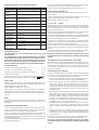 2
2
-
 3
3
-
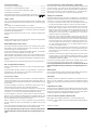 4
4
-
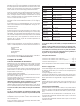 5
5
-
 6
6
-
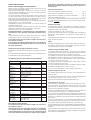 7
7
-
 8
8
-
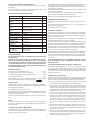 9
9
-
 10
10
-
 11
11
-
 12
12
-
 13
13
-
 14
14
-
 15
15
-
 16
16
-
 17
17
-
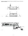 18
18
-
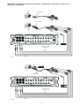 19
19
-
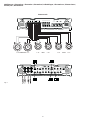 20
20
-
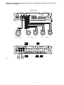 21
21
-
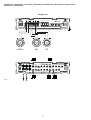 22
22
-
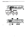 23
23
-
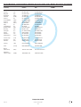 24
24


Blaupunkt VD SIX de handleiding
- Categorie
- Auto audio versterkers
- Type
- de handleiding
in andere talen
- English: Blaupunkt VD SIX Owner's manual
- italiano: Blaupunkt VD SIX Manuale del proprietario
- français: Blaupunkt VD SIX Le manuel du propriétaire
- español: Blaupunkt VD SIX El manual del propietario
- Deutsch: Blaupunkt VD SIX Bedienungsanleitung
- português: Blaupunkt VD SIX Manual do proprietário
- dansk: Blaupunkt VD SIX Brugervejledning
- svenska: Blaupunkt VD SIX Bruksanvisning
Gerelateerde papieren
-
Blaupunkt VR 504 VELOCITY AMP de handleiding
-
-
-
-
-
-
-
-
-