Monacor MMX-11USB Handleiding

Type
Handleiding
MMX-11USB
Bestellnummer 20.2840
R
L
OUTIN
MIN MAX
MIC / LINE LINE 2 / 3 TAPE
ON
CLIP
MASTER
OUT
GAIN
+ 10
0
LEVEL
LINE / USB TAPE
RL
CH 1 CH2/3 MASTER
+10
0
BOOTH/
PHONES
+ 10
0
LEVEL
+ 6
0
LEVEL
PK
PANLOHI
+15
–15
0 dB
L
C
R
BALLOHI
+15
–15
0 dB
L
C
R
LINE IN
USB PLAY
TO MASTER TO BOOTH/
PHONES
BOOTH
MM X-11U SB
PWR
MONACOR INTERNATIONAL GmbH & Co. KG • Zum Falsch 36 • 28307 Bremen • Germany Copyright
©
by MONACOR INTERNATIONAL. All rights reserved. A-1474.99.02.05.2018
ELECTRONICS FOR SPECIALISTS ELECTRONICS FOR SPECIALISTS ELECTRONICS FOR SPECIALISTS ELECTRONICS FOR SPECIALISTS ELECTRONICS FOR SPECIALISTS ELECTRONICS FOR SPECIALISTS ELECTRONICS FOR
2-Kanal-Audio-Mischer
Diese Anleitung richtet sich an Benutzer mit
Grundkenntnissen in der Audiotechnik. Bitte
lesen Sie die Anleitung vor dem Betrieb gründ-
lich durch und heben Sie sie für ein späteres
Nachlesen auf.
1 Einsatzmöglichkeiten
Dieser Miniatur-Mischer mit USB-Schnittstelle lässt sich
universell verwenden, z. B. für die Tonaufnahme am
Computer. Er verfügt über 2 Eingangskanäle:
1 × mono mit Mic / Line-Eingang,
1 × stereo mit Line-Eingang
Das Mischsignal wird über eine 3,5-mm-Klinkenbuchse
und die USB-Buchse ausgegeben. Diese lässt sich auch
als Eingang zur Übertragung von Audiodaten vom
Computer zum Mischer nutzen.
Die Stromversorgung erfolgt über das beiliegende
Netzgerät oder bei Anschluss an einen Computer über
die USB-Verbindung.
2 Sicherheitshinweise
Die Geräte (Mischer und Netzgerät) entsprechen allen
relevanten Richtlinien der EU und tragen deshalb das
-Zeichen.
WARNUNG Das Netzgerät wird mit lebensgefährli-
cher Netzspannung versorgt. Nehmen
Sie deshalb niemals selbst Eingriffe
daran vor. Durch unsachgemäßes Vor-
gehen besteht die Gefahr eines elekt-
rischen Schlages.
Setzen Sie die Geräte nur im Innenbereich ein.
Schützen Sie sie vor Tropf- und Spritzwasser, hoher
Luftfeuchtigkeit und Hitze (zulässiger Einsatztempe-
raturbereich 0 – 40 °C).
Nehmen Sie den Mischer nicht in Betrieb und ziehen
Sie sofort das Netzgerät aus der Steckdose, wenn:
1. sichtbare Schäden an einem der Geräte vorhan-
den sind,
2. nach einem Sturz oder Ähnlichem der Verdacht auf
einen Defekt besteht,
3. Funktionsstörungen auftreten.
Lassen Sie die Geräte in jedem Fall in einer Fachwerk-
statt reparieren.
Verwenden Sie zum Reinigen nur ein trockenes, wei-
ches Tuch, niemals Chemikalien oder Wasser.
Werden die Geräte zweckentfremdet, nicht richtig
angeschlossen / bedient oder nicht fachgerecht re-
pariert, kann keine Haftung für daraus resultierende
Sach- oder Personenschäden und keine Garantie für
die Geräte übernommen werden.
Sollen die Geräte endgültig aus dem
Betrieb genommen werden, übergeben
Sie sie zur umweltgerechten Entsorgung
einem örtlichen Recyclingbetrieb.
3 Inbetriebnahme
Vor dem Herstellen / Trennen von Verbindungen und
dem Einschalten sollten die Ausgangsregler (21, 23)
immer ganz zurückgedreht werden.
1) An die kombinierte Buchse MIC / LINE (3) des Mono-
Kanals ein Mikrofon oder eine Mono-Tonquelle mit
Line-Signalpegel anschließen:
Ein Mikrofon über einen symmetrisch beschalte-
ten XLR-Stecker anschließen. Am XLR-Anschluss
liegt eine 20-V-Phantomspannung an (zum Betrieb
eines Kondensatormikrofons, das mit dieser Phan-
tomspeisung arbeitet). Vorsicht: Kein Mikrofon mit
asymmetrischem Ausgang anschließen, da es durch
die Phantomspannung beschädigt werden kann!
Ein Gerät mit Line-Pegel (z. B. Empfänger eines
drahtlosen Mikrofonsystems) über einen 6,3-mm-
Klinkenstecker anschließen. Der Klinkenanschluss
ist symmetrisch beschaltet. Es lassen sich aber
auch Geräte mit asymmetrisch beschaltetem Aus-
gang über 2-polige Klinkenstecker anschließen.
2) An die Cinch-Buchsen LINE 2 / 3 (4) des Stereo- Kanals
(weiß = linker Kanal, rot = rechter Kanal) eine Ste-
reo-Tonquelle mit Line-Signalpegel, z. B. CD- Spieler,
anschließen.
3) Einen Stereo-Recorder an die Cinch-Buchsen TAPE
anschließen: Seinen Ausgang an den Eingang TAPEIN
(5) und seinen Eingang an den Ausgang TAPE OUT
(6). Die Anschlüsse können jedoch auch für andere
Geräte mit Line-Pegel genutzt werden, z. B. lässt sich
ein Wiedergabegerät wie CD- oder MP3-Spieler an
TAPE IN anschließen oder ein Verstärker an TAPE OUT.
4) Für Abhörzwecke einen Stereo-Kopfhörer (Impedanz
≥ 8
) oder den Verstärker einer kleinen Monitor-
anlage an die 3,5-mm-Stereo-Klinkenbuchse BOOTH
(8) anschließen.
5) Am Stereo-Ausgang MASTER OUT (7) steht das
mit dem MASTER-Regler (23) eingestellte Aus-
gangssignal zur Verfügung. Hier kann über einen
3,5-mm-Klinkenstecker z. B. ein Verstärker oder ein
zweites Mischpult angeschlossen werden.
6) Bei Betrieb ohne Computer das beiliegende Netzge-
rät über ein USB-Kabel mit der USB-Buchse (1) ver-
binden und in eine Steckdose (230 V / 50 Hz) stecken
(Betrieb mit Computer
Kapitel 3.1).
Wird der Mischer längere Zeit nicht betrieben,
das Netzgerät aus der Steckdose ziehen, da es selbst
bei ausgeschaltetem Mischer einen geringen Strom
verbraucht.
7) Zum Einschalten die Taste PWR (2) drücken, die Be-
triebsanzeige ON (9) leuchtet. Zum Ausschalten die
Taste wieder ausrasten.
3.1 Betrieb mit Computer
Für den Betrieb des Mischers mit einem Computer kann
die mit dem Betriebssystem mitgelieferte Audio-Soft-
ware verwendet werden oder eine zusätzlich instal-
lierte Audio-Software.
1) Den Computer hochfahren und die USB-Buchse (1)
über ein USB-Kabel mit einem USB-Anschluss am
Computer verbinden. Der eingeschaltete Mischer
wird vom Computer als USB-Audiogerät für die
Toneingabe und Tonausgabe erkannt.
Hinweis: Wird der Mischer nicht als USB-Audiogerät er-
kannt, müssen die erforderlichen Treiber (Standard-Treiber
des Betriebssystems) nachinstalliert werden, z. B. über die
Betriebssystem-Original-CD. Gegebenenfalls nach der Ins-
tallation den Computer neu starten.
2) Das Abspiel- /Aufnahmeprogramm aufrufen und dort
die erforderlichen Einstellungen für die Tonwieder-
gabe über den Mischer bzw. Tonaufnahme vom Mi-
scher vornehmen (
Anleitung des Programms). Der
Mischer kann dann anhand Kapitel 4 bedient werden.
Findet keine Tonaufnahme bzw. Tonwiedergabe statt,
in den Systemeinstellungen des Computer-Betriebs-
systems überprüfen, ob die USB-Schnittstelle für die
Toneingabe bzw. Tonausgabe angewählt ist.
Tipp: Ist der Mischer mit einem Computer verbunden sowie
mit Geräten, die über ihr Netzkabel geerdet sind (z. B. Verstär-
ker), können aufgrund von Masseschleifen Brummstörungen
auftreten. Um diese zu beseitigen, kann der Mischer über ein
Masse trennfilter (z. B. FGA-30 von MONACOR) mit dem jewei-
ligen Gerät verbunden werden.
4 Bedienung
WARNUNG Stellen Sie die Lautstärke der Audio-
anlage und des Kopfhörers nie sehr
hoch ein. Hohe Lautstärken können
auf Dauer das Gehör schädigen!
Das Ohr gewöhnt sich an hohe Lautstärken und emp-
findet sie nach einiger Zeit als nicht mehr so hoch.
Darum erhöhen Sie eine hohe Lautstärke nach der
Gewöhnung nicht weiter.
1) Mit der Taste LINE / USB (13) wählen, welches Ein-
gangssignal dem Kanal 2 / 3 zugeordnet wird:
Taste nicht gedrückt = Eingangssignal der Buchsen
LINE2 / 3 (4), Taste gedrückt = Eingangssignal der
USB-Buchse (1).
Hinweis: Beachten Sie bei Aufnahmen über die USB-Buchse
die Gefahr von Rückkopplungen, wenn das Aufnahme signal
des Computers dem Kanal 2 / 3 als Eingangssignal zugeord-
net wird.
2) Zur Grundeinstellung vorerst die Regler
– LEVEL (19, 20) ganz zurückdrehen
HI, LO (14, 16), PAN (15) und BAL (17) in die Mit-
telstellung schieben
GAIN (12) und MASTER (23) bis zur Mitte aufdrehen
Ein Tonsignal auf Kanal 1 geben. Den Regler LEVEL
(19) so weit aufdrehen, dass es gut zu hören ist und
der Klang mit den Reglern HI und LO (14) eingestellt
werden kann. Muss der Regler LEVEL dazu sehr weit
aufgedreht werden, die Eingangsverstärkung durch
Aufdrehen des Reglers GAIN (12) erhöhen. Leuchtet
jedoch die LED PK (18) länger auf, den Regler GAIN
entsprechend zurückstellen. Die LED PK darf nur bei
Signalspitzen kurz aufflackern.
Den Regler LEVEL von Kanal 1 wieder ganz zu-
rückdrehen, ein Tonsignal auf Kanal 2 / 3 geben und
seinen Regler LEVEL (20) so weit aufdrehen, dass
der Klang mit den Reglern HI und LO (16) eingestellt
werden kann.
3) Nach der Grundeinstellung können die Signale von
Kanal 1 und 2 / 3 mit den Reglern LEVEL im gewünsch-
ten Lautstärkeverhältnis gemischt oder einzeln
ein- und ausgeblendet werden. Wird ein Kanal nicht
benutzt, seinen Regler LEVEL ganz zurückdrehen.
4) Für Kanal 1 mit dem Regler PAN (15) das Mono-
Signal im Stereo-Klangbild platzieren und für Kanal
2 / 3 mit dem Regler BAL (17) die Balance des Ste-
reo-Signals einstellen.
5) Um das Signal des Eingangs TAPE IN (5) der Mi-
schung zuzufügen, die Taste TAPE TO MASTER (10)
drücken.
Hinweis: Wird eine über den Ausgang TAPE OUT (6) lau-
fende Aufnahme zeitgleich über den Eingang TAPE IN wie-
dergegeben, darf die Taste TAPE TO MASTER nicht gedrückt
sein, da sonst eine Rückkopplung auftritt.
6) Mit dem Regler MASTER (23) den Pegel für das Aus-
gangssignal einstellen, das über die Buchsen MASTER
OUT (7), TAPE OUT (6) und die USB-Buchse (1) ausge-
geben wird. Leuchtet eine der Übersteuerungs-LEDs
CLIP (22), den Regler MASTER oder zu weit aufge-
drehte Kanalregler (19, 20) entsprechend zurückdre-
hen. Damit die LEDs CLIP auf das Ausgangssignal
ansprechen, darf die Taste TAPE TO BOOTH / PHONES
(11) nicht gedrückt sein (
Punkt 7 unten).
7) Mit der Taste TAPE TO BOOTH / PHONES (11) wählen,
welches Signal dem Abhörausgang BOOTH (8) zuge-
ordnet wird:
Taste nicht gedrückt = Ausgangssignal,
Taste gedrückt = Signal des Eingangs TAPE IN (5).
Die Übersteuerungs-LEDs CLIP (22) sprechen auf
das Signal an, das für die Abhörfunktion ausgewählt
ist. Die Abhörlautstärke mit dem Regler BOOTH /
PHONES (21) einstellen.
5 Technische Daten
Empfindlichkeit / Impedanz
Mic: . . . . . . . . . . . 0,5 mV/ 1,6 k
(Gain min. 80 mV)
Line, Kanal 1: . . . 2 mV/ 10 k
(Gain min. 550 mV)
Line, Kanal 2 / 3: . . 150 mV/ 10 k
Tape . . . . . . . . . . 420 mV/ 7 k
Ausgangspegel: . . . max. 6 V (Master, Booth, Tape)
Kopfhörerimpedanz: ≥ 8
USB-Schnittstelle: . .
USB 2.0 (Full Speed), Buchse Typ B
Frequenzbereich: . . 20 – 20 000 Hz
Klirrfaktor: . . . . . . . < 0,05 %
Störabstand: . . . . . . 81 dB (A-bewertet)
Klangregler (LO, HI): ±15 dB / 80 Hz, ±15 dB / 12 kHz
Phantomspeisung: . +20 V (XLR), permanent
Stromversorgung: . . über USB-Port ( 5 V / 500 mA)
des Computers oder über beilie-
gendes Netzgerät an 230 V / 50 Hz
Maße, Gewicht: . . . 102 × 45 × 140 mm, 430 g
Geeignete Betriebssysteme für den Datentransfer über
die USB-Schnittstelle: Windows 2000, Windows XP oder
nachfolgende Windows-Versionen, Mac OS 9.0.4 oder
höher, Mac OS X
Windows ist ein registriertes Warenzeichen der Microsoft Corpora-
tion in den USA und anderen Ländern. Mac OS ist ein registriertes
Warenzeichen von Apple Inc. in den USA und anderen Ländern.
Änderungen vorbehalten.
Deutsch
MONACOR INTERNATIONAL GmbH & Co. KG • Zum Falsch 36 • 28307 Bremen • Germany Copyright
©
by MONACOR INTERNATIONAL. All rights reserved. A-1474.99.02.05.2018
ELECTRONICS FOR SPECIALISTS ELECTRONICS FOR SPECIALISTS ELECTRONICS FOR SPECIALISTS ELECTRONICS FOR SPECIALISTS ELECTRONICS FOR SPECIALISTS ELECTRONICS FOR SPECIALISTS ELECTRONICS FOR
MMX-11USB
Order number 20.2840
2-Channel Audio Mixer
These operating instructions are intended for
users with basic knowledge in audio technol-
ogy. Please read the instructions carefully prior
to operation and keep them for later reference.
1 Applications
This miniature mixer with USB interface is designed
for universal applications, e. g. for audio recordings
on the computer. It is equipped with 2 input channels:
1 × mono with mic / line input; 1 × stereo with line
input. The mixed signal is sent to a 3.5 mm jack and
the USB port. The USB port is also suited as an input
to transfer audio data from the computer to the mixer.
The mixer is supplied with power via the power
supply unit provided or, when connected to a computer,
via the USB connection.
2 Safety Notes
The units (mixer and power supply unit) correspond
to all relevant directives of the EU and are therefore
marked with .
WARNING The power supply unit uses dangerous
mains voltage. Leave servicing to skilled
personnel. Inexpert handling or modifi-
cation may result in electric shock.
The units are suitable for indoor use only. Protect
them against dripping water and splash water, high
air humidity and heat (admissible ambient tempera-
ture range: 0 – 40 °C).
Do not operate the mixer and immediately discon-
nect the power supply unit from the socket
1. if one of the units is visibly damaged,
2. if a defect might have occurred after a unit was
dropped or suffered a similar accident,
3. if malfunctions occur.
In any case the units must be repaired by skilled
personnel.
For cleaning only use a dry, soft cloth; never use
water or chemicals.
No guarantee claims for the units and no liability
for any resulting personal damage or material dam-
age will be accepted if the units are used for other
purposes than originally intended, if they are not
correctly connected or operated, or if they are not
repaired in an expert way.
If the units are to be put out of operation
definitively, take them to a local recycling
plant for a disposal which is not harmful
to the environment.
3 Before Operation
Prior to connecting / disconnecting and prior to switch-
ing on, always turn back the output controls (21, 23)
to the left stop.
1) Connect a microphone or a mono audio source with
line signal level to the combined jack MIC / LINE (3)
of the mono channel:
Connect a microphone via a balanced XLR plug.
A20 V phantom power is available at the XLR jack
(for operating a condenser microphone using this
phantom power). Caution: Do not connect any
microphone with unbalanced output; it may be
damaged by the phantom power!
Connect a unit with line level (e. g. receiver of a
wireless microphone system) via a 6.3 mm plug.
The 6.3 mm jack is balanced. To connect units with
unbalanced output, use 2-pole 6.3 mm plugs.
2) Connect a stereo audio source with line signal level
(e. g. CD player) to the RCA jacks LINE 2 / 3 (4) of the
stereo channel (white = left channel; red = right
channel).
3) Connect a stereo recorder to the RCA jacks TAPE:
Connect its output to the input TAPE IN (5) and its
input to the output TAPE OUT (6).
These jacks may also be used for other units with
line level, e. g. to connect a player (CD player or MP3
player) to TAPE IN or an amplifier to TAPE OUT.
4) For monitoring purposes, connect stereo head-
phones (impedance ≥ 8
) or the amplifier of a small
monitor system to the 3.5 mm stereo jack BOOTH (8).
5) The stereo output MASTER OUT (7) provides the out-
put signal adjusted with the MASTER control (23). To
connect, for example, an amplifier or a second mixer
to this output, use a 3.5 mm plug.
6) When operating the mixer without a computer, use a
USB cable to connect the power supply unit provided
to the USB port (1), then connect the power supply
unit to a mains socket (230 V / 50 Hz) [operation with
a computer
chapter 3.1].
Always disconnect the power supply unit from
the socket when the mixer is not in use for a longer
period of time; even when the mixer has been
switched off, the power supply unit will still consume
some power.
7) To switch on, press the button PWR (2); the power
LED ON (9) lights up. To switch off, disengage the
button.
3.1 Operation with a computer
When operating the mixer with a computer, either use
the audio software supplied with the operating system
or audio software installed additionally.
1) Start the computer. Use a USB cable to connect the
USB port (1) to a USB connection on the computer.
The computer will recognize the switched-on mixer
as a USB audio device for audio input and audio
output.
Note: If the computer fails to recognize the mixer as an USB
audio device, install the drivers required (default drivers of
the operating system), e. g. by means of the original CD
of the operating system. If necessary, restart the computer
after the drivers have been installed.
2) Call up the replay / recording program and make
the settings required for audio reproduction via the
mixer or audio recording from the mixer (
manual
of the program). The mixer can then be operated as
described in chapter 4.
If no audio recording or audio reproduction is possible,
check the system settings of the computer to find out
if the USB interface has been selected for audio input
or audio output.
Hint: If the mixer is connected to both a computer and to units
earthed via their mains cable (e. g. amplifiers), hum interfer-
ence may occur due to ground loops. To eliminate this inter-
ference, use a ground isolator (e. g. FGA-30 from MONACOR)
to connect the mixer to the corresponding unit.
4 Operation
WARNING Never adjust the audio system and the
headphones to a very high volume.
Permanent high volumes may damage
your hearing!
Your ear will get accustomed to high volumes which
do not seem to be that high any more after some time.
Therefore, do not further increase a high volume after
getting used to it.
1) Use the button LINE / USB (13) to select the input sig-
nal assigned to channel 2 / 3:
button disengaged = input signal of the jacks
LINE 2 / 3 (4);
button engaged = input signal of the USB jack (1).
Note: For recordings via the USB port, please take into
account that there is a risk of feedback if the recording
signal of the computer is assigned to channel 2 / 3 as an
input signal.
2) For the basic setting, first set the controls
LEVEL (19, 20) to the left stop
HI, LO (14, 16), PAN (15) and BAL (17) to mid-
position
GAIN (12) and MASTER (23) to mid-position
Feed an audio signal to channel 1. Turn up the con-
trol LEVEL (19) until the audio signal can be heard
well and it is possible to adjust its sound with the
controls HI and LO (14). If you have to turn up the
control LEVEL very far, turn up the control GAIN (12)
to increase the input gain. However, if the LED PK
(18) lights up for a longer period of time, turn back
the control GAIN accordingly. The LED PK should
briefly flash for signal peaks only.
Turn back the control LEVEL of channel 1. Feed
an audio signal to channel 2 / 3 and turn up its control
LEVEL (20) until it is possible to adjust the sound
with the controls HI and LO (16).
3) After the basic setting, use the controls LEVEL to mix
the signals of channels 1 and 2 / 3 in the volume ratio
desired or to fade them in or out individually. When
a channel is not used, always turn back its control
LEVEL to the left stop.
4) For channel 1, use the control PAN (15) to place the
mono signal in the stereo sound. For channel 2 / 3,
use the control BAL (17) to adjust the balance of
the stereo signal.
5) To add the signal of the input TAPE IN (5) to the
audio mix, press the button TAPE TO MASTER (10).
Note: When a recording is made via the output TAPE OUT
(6) and at the same time reproduced via the input TAPE IN,
make sure that the button TAPE TO MASTER is disengaged;
otherwise, there will be feedback.
6) Use the control MASTER (23) to adjust the level of
the output signal sent to the jacks MASTER OUT
(7), TAPE OUT (6) and the USB port (1). If one of
the overload LEDs CLIP (22) lights up, turn back the
control MASTER or any channel control (19, 20)
turned up too far. Make sure that the button TAPE
TO BOOTH / PHONES (11) is disengaged so that the
LEDs CLIP will be able to respond to the output sig-
nal (
item 7 below).
7) Use the button TAPE TO BOOTH / PHONES (11) to select
the signal assigned to the monitor output BOOTH (8):
button disengaged = output signal;
button engaged = signal of the input TAPE IN (5).
The overload LEDs CLIP (22) respond to the signal
selected for the monitor function. Use the control
BOOTH / PHONES (21) to adjust the monitoring vol-
ume.
5 Specifications
Sensitivity / impedance
Mic: . . . . . . . . . . . 0.5 mV/ 1.6 k
(gain min.: 80 mV)
Line, channel 1: . . 2 mV/ 10 k
(gain min.: 550 mV)
Line, channel 2 / 3: 150 mV/ 10 k
Tape: . . . . . . . . . . 420 mV/ 7 k
Output level: . . . . . 6 V max. (Master, Booth, Tape)
Headphone
impedance:. . . . . . . ≥ 8
USB interface: . . . . USB 2.0 (Full Speed), type B port
Frequency range: . . 20 – 20 000 Hz
THD: . . . . . . . . . . . . < 0.05 %
S / N ratio: . . . . . . . . 81 dB (A weighted)
Equalizer (LO, HI): . . ±15 dB / 80 Hz, ±15 dB / 12 kHz
Phantom power: . . . +20 V (XLR), permanent
Power supply: . . . . . via USB port ( 5 V / 500 mA) of
the computer or via power supply
unit provided and connected to
230 V / 50 Hz
Dimensions, weight: 102 × 45 × 140 mm, 430 g
Suitable operating systems for data transfer via USB
interface: Windows 2000, Windows XP or subsequent
Windows versions, Mac OS 9.0.4 or later, Mac OS X
Windows is a registered trademark of Microsoft Corporation in
the USA and other countries. Mac OS is a registered trademark of
AppleInc. in the USA and other countries.
Subject to technical modification.
English
R
L
OUTIN
MIN MAX
MIC / LINE LINE 2 / 3 TAPE
ON
CLIP
MASTER
OUT
GAIN
+ 10
0
LEVEL
LINE / USB TAPE
RL
CH 1 CH2/3 MASTER
+10
0
BOOTH/
PHONES
+ 10
0
LEVEL
+ 6
0
LEVEL
PK
PANLOHI
+15
–15
0 dB
L
C
R
BALLOHI
+15
–15
0 dB
L
C
R
LINE IN
USB PLAY
TO MASTER TO BOOTH /
PHONES
BOOTH
MM X-11U SB
PWR
MONACOR INTERNATIONAL GmbH & Co. KG • Zum Falsch 36 • 28307 Bremen • Germany Copyright
©
by MONACOR INTERNATIONAL. All rights reserved. A-1474.99.02.05.2018
ELECTRONICS FOR SPECIALISTS ELECTRONICS FOR SPECIALISTS ELECTRONICS FOR SPECIALISTS ELECTRONICS FOR SPECIALISTS ELECTRONICS FOR SPECIALISTS ELECTRONICS FOR SPECIALISTS ELECTRONICS FOR
MMX-11USB
Référence numérique 20.2840
Table de mixage audio 2canaux
Cette notice s’adresse aux utilisateurs avec des
connaissances techniques de base en audio.
Veuillez lire la présente notice avec attention
avant le fonctionnement et conservez-la pour
pouvoir vous y reporter ultérieurement.
1 Possibilités d’utilisation
Cette table de mixage miniature avec interface USB est
conçue pour une utilisation universelle, par exemple pour
un enregistrement audio sur un ordinateur. Elle dispose
de deux canaux d’entrée: 1 × mono avec entrée Mic /
Ligne, 1 × stéréo avec entrée Ligne. Le signal de mixage
est disponible à la prise jack 3,5 et au port USB. Ce
dernier peut également être utilisé comme entrée pour
transmettre des données audio de l’ordinateur vers la
table de mixage.
L’alimentation s’effectue via le bloc secteur livré
ou via le port USB si vous reliez la table de mixage à
un ordinateur.
2 Conseils d’utilisation et de sécurité
Les appareils (table de mixage et bloc secteur) ré-
pondent à toutes les directives nécessaires de l’Union
européenne et portent donc le symbole .
AVERTISSEMENT Le bloc secteur est alimenté par
une tension dangereuse. Ne tou-
chez jamais l’intérieur de l’appa-
reil car, en cas de mauvaise mani-
pulation, vous pouvez subir une
décharge électrique.
Les appareils ne sont conçus que pour une utilisa-
tion en intérieur. Protégez-les des éclaboussures, de
tout type de projections d’eau, d’une humidité d’air
élevée et de la chaleur (température ambiante ad-
missible 0 – 40 °C).
Ne faites pas fonctionner la table de mixage et dé-
branchez le bloc secteur immédiatement dans les cas
suivants :
1. un des appareils présente des dommages visibles.
2. après une chute ou accident similaire, vous avez
un doute sur l’état de l’appareil.
3. des dysfonctionnements apparaissent.
Dans tous les cas, les dommages doivent être réparés
par un technicien spécialisé.
Pour le nettoyage, utilisez un chiffon sec et doux, en
aucun cas de produits chimiques ou d’eau.
Nous déclinons toute responsabilité en cas de dom-
mages corporels ou matériels résultants si les appa-
reils sont utilisés dans un but autre que celui pour
lequel ils ont été conçus, s’ils ne sont pas correcte-
ment branchés ou utilisés ou s’ils ne sont pas répa-
rés par une personne habilitée ; en outre, la garantie
deviendrait caduque.
Lorsque les appareils sont définitivement re-
tirés du service, vous devez les déposer dans
une usine de recyclage de proximité pour
contribuer à leur élimination non polluante.
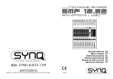
3 Fonctionnement
Avant d’effectuer les branchements ou de les séparer
et avant d’allumer la table de mixage, il faut mettre les
réglages de sortie (21, 23) toujours entièrement vers
la gauche.
1) Reliez un micro ou une source audio mono avec ni-
veau de signal ligne à la prise combo MIC / LINE (3)
du canal mono:
Reliez un micro via une fiche XLR symétrique.
Une alimentation fantôme 20 V est présente à la
prise XLR (pour faire fonctionner un microphone
à condensateur fonctionnant avec cette alimen-
tation fantôme). Attention : Ne reliez pas de
microphone avec sortie asymétrique, il peut être
endommagé par l’alimentation fantôme!
Reliez un appareil avec niveau ligne (par exemple
récepteur d’un système de micro sans fil) via une
fiche jack 6,35. La prise jack est symétrique. Il est
également possible de relier des appareils avec
sortie asymétrique via une fiche jack 2 pôles.
2) Reliez une source audio stéréo avec niveau de signal
ligne, par exemple lecteur CD, aux prises RCA LINE
2 / 3 (4) du canal stéréo (blanc = canal gauche, rouge
= canal droit).
3) Reliez un enregistreur stéréo aux prises RCA TAPE:
reliez sa sortie à l’entrée TAPE IN (5) et son entrée à
la sortie TAPE OUT (6).
Les branchements peuvent également être uti-
lisés pour d’autres appareils avec niveau ligne, par
exemple on peut relier un lecteur tel que lecteur CD
ou MP3 à TAPE IN ou un amplificateur à TAPE OUT.
4) Reliez un casque stéréo (impédance ≥ 8
) ou l’am-
plificateur d’une petite installation moniteur à la prise
jack 3,5 stéréo BOOTH (8) pour une écoute du signal.
5) Le signal de sortie réglé avec le réglage MASTER (23)
est disponible à la sortie stéréo MASTER OUT (7). On
peut ici, par exemple, relier un amplificateur ou une
seconde table de mixage via une fiche jack3,5.
6) Pour un fonctionnement sans ordinateur, reliez le
bloc secteur livré via un cordon USB au port USB (1)
et à une prise secteur 230 V / 50 Hz (fonctionnement
avec un ordinateur,
chapitre 3.1).
En cas de non utilisation prolongée de la table
de mixage, débranchez le bloc secteur, car même si
la table de mixage est éteinte, il a une faible con-
sommation.
7) Pour allumer, enfoncez la touche PWR (2), le témoin
de fonctionnement ON (9) brille. Pour éteindre,-
senclenchez la touche.
3.1 Fonctionnement avec un ordinateur
Pour faire fonctionner la table de mixage avec un ordi-
nateur, vous pouvez utiliser le logiciel audio livré avec
le système d’exploitation ou un logiciel audio installé
en plus.
1) Démarrez l’ordinateur et reliez le port USB (1) via un
cordon USB au branchement USB de l‘ordinateur. La
table de mixage allumée est reconnue par l’ordina-
teur comme appareil audio USB pour l’entrée audio
et la sortie audio.
Remarque : Si la table de mixage n’est pas reconnue
comme appareil audio USB, il faut installer les drivers
nécessaires (drivers standard du système d’exploitation),
p.ex. via le CD d’origine du système d’exploitation. Le cas
échéant, redémarrez l’ordinateur après l’installation.
2) Appelez le programme de lecture / d’enregistrement
et effectuez les réglages nécessaires pour la lecture
audio via la table de mixage ou l’enregistrement
audio depuis la table de mixage (
notice du
programme). La table de mixage peut ensuite être
utilisée comme décrit au chapitre 4.
S’il n’y a pas d’enregistrement audio ou de lecture
audio, vérifiez dans les réglages système du système
d’exploitation de l’ordinateur si l’interface USB est
sélectionnée pour l’entrée audio ou la sortie audio.
Conseil : Si la table de mixage est reliée à un ordinateur et
à des appareils mis à la terre via leur cordon secteur (p. ex.
amplificateurs), des ronflements causés par des bouclages de
masse peuvent se produire. Pour les éliminer, on peut relier la
table de mixage à l’appareil correspondant via un filtre sépa-
rateur galvanique (p. ex. FGA-30 de MONACOR).
4 Utilisation
AVERTISSEMENT Ne réglez pas le volume de l’ins-
tallation audio et du casque trop
fort. Un volume trop élevé peut, à
long terme, générer des troubles
de l’audition. L’oreille s’habitue à des volumes élevés
et ne les perçoit plus comme tels au bout d’un certain
temps. Nous vous conseillons donc de régler le volume
et de ne plus le modifier.
1) Avec la touche LINE / USB (13) sélectionnez quel si-
gnal d’entrée est attribué au canal 2 / 3: touche non
enfoncée = signal d’entrée des prises LINE 2 / 3 (4),
touche enfoncée = signal d’entrée du port USB (1).
Remarque: Faites attention aux risques de larsen en cas
d’enregistrements via le port USB si le signal d’enregistre-
ment de l’ordinateur est attribué au canal 2 / 3 comme signal
d’entrée.
2) Pour effectuer les réglages de base:
tournez les réglages LEVEL (19, 20) entièrement
à gauche
mettez les réglages HI, LO (14, 16), PAN (15) et BAL
(17) sur la position médiane
tournez les réglages GAIN (12) et MASTER (23)
jusqu’au milieu
Appliquez un signal audio au canal 1. Tournez le ré-
glage LEVEL (19) jusqu’à ce que le signal soit bien
audible et que la tonalité puisse être réglée avec les
réglages HI et LO (14). Si le réglage LEVEL doit être
tourné très loin, augmentez l’amplification d’entrée
en tournant le réglage GAIN (12) vers la droite. Si ce-
pendant la LED PK (18) brille plus longtemps, tournez
le réglage GAIN vers la gauche en conséquence pour
diminuer. La LED PK ne doit briller que brièvement
pour des pointes de signal.
Tournez le réglage LEVEL du canal 1 entièrement
vers la gauche, appliquez un signal audio sur le canal
2 / 3 et tournez son réglage LEVEL (20) jusqu’à ce que
la tonalité puisse être réglée avec les réglages HI
et LO (16).
3) Une fois les réglages de base effectués, vous pou-
vez mixer les signaux des canaux 1 et 2 / 3 avec les
réglages LEVEL dans le rapport de volume souhaité
ou les faire entrer et sortir séparément. Si un canal
n’est pas utilisé, tournez son réglage LEVEL entière-
ment vers la gauche.
4) Pour le canal 1, placez le signal mono dans la restitu-
tion sonore stéréo avec le réglage PAN (15) et pour
le canal 2 / 3, réglez la balance du signal stéréo avec
le réglage BAL (17).
5) Pour ajouter le signal de l’entrée TAPE IN (5) au
mixage, appuyez sur la touche TAPE TO MASTER (10).
Remarque : Si un enregistrement en cours via la sortie
TAPE OUT (6) est simultanément restitué via l’entrée TAPE
IN, la touche TAPE TO MASTER ne doit pas être enfoncée
sinon il y a des larsens.
6) Avec le réglage MASTER (23), réglez le niveau pour
le signal de sortie disponible aux prises MASTER
OUT (7), TAPE OUT (6) et au port USB (1). Si une
des LEDs de surcharge CLIP (22) brille, tournez le
réglage MASTER ou des réglages de canal (19, 20)
positionnés trop loin, vers la gauche. Pour que les
LEDs CLIP répondent au signal de sortie, la touche
TAPE TO BOOTH / PHONES (11) ne doit pas être en-
foncée (
point 7 ci-dessous).
7) Avec la touche TAPE TO BOOTH / PHONES (11), sé-
lectionnez quel signal doit être attribué à la sortie
d’écoute BOOTH (8):
touche non enfoncée = signal de sortie,
touche enfoncée = signal de l’entrée TAPE IN (5).
Les LEDs de surcharge CLIP (22) répondent au signal
sélectionné pour la fonction d’écoute. Réglez le vo-
lume d’écoute avec le réglage BOOTH / PHONES(21).
5 Caractéristiques techniques
Sensibilité d’entrée / impédance
Mic : . . . . . . . . . . . 0,5 mV/1,6 k
(gain min. 80 mV)
Line, canal 1 : . . . . 2 mV/10 k
(gain min. 550 mV)
Line, canal 2 / 3 : . . 150 mV/ 10 k
Tape : . . . . . . . . . . 420 mV/ 7 k
Niveau de sortie : . . . 6 V max. (Master, Booth, Tape)
Impédance casque : . ≥ 8
Interface USB : . . . . . .USB 2.0 (Full Speed), prise typeB
Bande passante : . . . 20 – 20 000 Hz
Taux de distorsion : . < 0,05 %
Rapport signal / bruit : 81 dB (A p ondéré)
Egaliseur (LO, HI) : . ±15 dB / 80 Hz, ±15 dB / 12 kHz
Alimentation
fantôme : . . . . . . . . . +20 V (XLR), permanent
Alimentation : . . . . . via port USB ( 5 V / 500 mA) de
l’ordinateur ou via bloc secteur
livré relié à 230 V / 50 Hz
Dimensions, poids : . 102 × 45 × 140 mm, 430 g
Systèmes d’exploitation adaptés pour le transfert de
données via le port USB: Windows 2000, Windows XP
ou versions Windows suivantes, Mac OS 9.0.4 ou supé-
rieur, Mac OS X
Windows est une marque déposée de Microsoft Corporation aux
Etats-Unis et dans les autres pays. Mac OS est une marque déposée
de Apple Inc. aux Etats-Unis et dans les autres pays.
Tout droit de modification réservé.
Français
R
L
OUTIN
MIN MAX
MIC / LINE LINE 2 / 3 TAPE
ON
CLIP
MASTER
OUT
GAIN
+ 10
0
LEVEL
LINE / USB TAPE
RL
CH 1 CH2/3 MASTER
+10
0
BOOTH/
PHONES
+ 10
0
LEVEL
+ 6
0
LEVEL
PK
PANLOHI
+15
–15
0 dB
L
C
R
BALLOHI
+15
–15
0 dB
L
C
R
LINE IN
USB PLAY
TO MASTER TO BOOTH /
PHONES
BOOTH
MM X-11U SB
PWR
MONACOR INTERNATIONAL GmbH & Co. KG • Zum Falsch 36 • 28307 Bremen • Germany Copyright
©
by MONACOR INTERNATIONAL. All rights reserved. A-1474.99.02.05.2018
ELECTRONICS FOR SPECIALISTS ELECTRONICS FOR SPECIALISTS ELECTRONICS FOR SPECIALISTS ELECTRONICS FOR SPECIALISTS ELECTRONICS FOR SPECIALISTS ELECTRONICS FOR SPECIALISTS ELECTRONICS FOR
MMX-11USB
Codice 20.2840
Mixer audio a 2 canali
Queste istruzioni sono rivolte a utenti con cono-
scenze base nella tecnica audio. Vi preghiamo di
leggerle attentamente prima dell’installazione e
di conservarle per un uso futuro.
1 Possibilità d‘impiego
Questo mixer mini con interfaccia USB è previsto per usi
universali, p. es. per la registrazione audio sul computer.
Dispone di 2 canali d‘ingresso:
1 × mono con ingresso Mic / Line,
1 × stereo con ingresso Line.
Il segnale miscelato viene emesse tramite una presa
jack 3,5 mm e tramite la presa USB. Quest‘ultima può
essere usata anche come ingresso per la trasmissione
di dati audio dal computer sul mixer.
L‘alimentazione avviene tramite l‘alimentatore in
dotazione oppure, in caso di collegamento con un com-
puter, tramite la linea USB.
2 Avvertenze di sicurezza
Gli apparecchi (mixer e alimentatore) sono conformi
a tutte le direttive rilevanti dell’UE e pertanto portano
la sigla .
AVVERTIMENTO L’alimentatore funziona con perico-
losa tensione di rete. Non interve-
nire mai personalmente al suo in-
terno! La manipolazione scorretta
può provocare una scarica elettrica
pericolosa.
Usare gli apparecchi solo all’interno di locali. Proteg-
gerli dall‘acqua gocciolante e dagli spruzzi d‘acqua,
da alta umidità dell‘aria e dal calore (temperatura
d’impiego ammessa fra 0 e 40 °C)
Non mettere in funzione il mixer e staccare subito
l‘alimentatore dalla presa di rete se:
1. uno degli l’apparecchi presenta dei danni visibili;
2. dopo una caduta o dopo eventi simili sussiste il
sospetto di un difetto;
3. gli apparecchi non funzionano correttamente.
Per la riparazione rivolgersi sempre ad un’officina
competente.
Per la pulizia usare solo un panno morbido, asciutto;
non impiegare in nessun caso acqua o prodotti chi-
mici.
Nel caso d’uso improprio, di collegamenti sbagliati,
d’impiego scorretto o di riparazione non a regola
d’arte degli apparecchi, non si assume nessuna re-
sponsabilità per eventuali danni consequenziali a
persone o a cose e non si assume nessuna garanzia
per gli apparecchi.
Se si desidera eliminare gli apparecchi
definitivamente, consegnarli per lo smal-
timento ad un'istituzione locale per il
riciclaggio.
3 Messa in funzione
Prima di effettuare / staccare i collegamenti e prima di
accendere gli apparecchi conviene chiudere completa-
menti i regolatori delle uscite (21, 23).
1) Alla presa combinata MIC / LINE (3) del canale mono
collegare un microfono o una fonte audio con se-
gnale Line:
Collegare un microfono tramite un connettore XLR
bilanciato. Al contatto XLR è presente una tensione
phantom di 20 V (per un microfono a condensa-
tore che funziona con tale tensione). Attenzione:
Non collegare un microfono con uscita sbilanciata
che potrebbe essere danneggiato dalla tensione
phantom!
Collegare un apparecchio con livello Line (p. es.
ricevitore di un sistema microfonico wireless) tra-
mite un jack 6,3 mm. Il contatto jack è bilanciato.
Tuttavia, è possibile collegare anche apparecchi
con uscita sbilanciata, usando dei jack a 2 poli.
2) Alle prese RCA LINE 2 / 3 (4) del canale stereo (bianco
= canale sinistro, rosso = canale destro) collegare
una fonte audio stereo con livello Line, p. es. un let-
tore CD.
3) Collegare un registratore stereo con le prese RCA
TAPE: la sua uscita con l‘ingresso TAPE IN (5) e il suo
ingresso con l‘uscita TAPE OUT (6).
I contatti possono essere utilizzati anche per altri
apparecchi con livello Line; per esempio e possibile
collegare con TAPE IN un dispositivo di riproduzione
come i lettori CD o MP3 oppure un amplificatore con
TAPE OUT.
4) Per l‘ascolto collegare una cuffia stereo (impedenza
≥ 8
) oppure l‘amplificatore di un piccolo impianto
di monitoraggio con la presa jack stereo 3,5 mm
BOOTH (8).
5) All‘uscita stereo MASTER OUT (7) è disponibile il se-
gnale d‘uscita impostato con il regolatore MASTER
(23). Qui si può collegare p. es. un amplificatore o un
secondo mixer servendosi di un jack 3,5 mm.
6) Se non si usa un computer, collegare l‘alimentatore in
dotazione con la presa USB (1) per mezzo di un cavo
USB e inserirlo in una presa di rete (230 V / 50 Hz)
(Funzionamento con un computer
Capitolo 3.1).
Se il mixer non viene usato per un certo periodo,
conviene staccare l‘alimentatore dalla presa perché
consuma un po‘ di corrente anche con il mixer spento.
7) Per l‘accensione premere il tasto PWR (2), si accende
la spia di funzionamento ON (9). Per lo spegnimento
sbloccare il tasto.
3.1 Funzionamento con un computer
Per il funzionamento del mixer con un computer si può
usare il software audio compreso nel sistema operativo,
come anche un software audio installato successiva-
mente.
1) Accendere il computer e collegare la presa USB (1)
con una porta USB del computer usando un cavo
USB. Il mixer acceso viene riconosciuto dal compu-
ter come dispositivo audio USB per l‘input e l‘output
audio.
N. B.: Se il mixer non viene riconosciuto come dispositivo
audio USB occorre installare i driver necessari (driver stan-
dard del sistema operativo), p. es. tramite il CD originale del
sistema operativo. Se necessario, riavviare il computer dopo
l‘installazione.
2) Aprire il programma di riproduzione / registrazione e
effettuare le impostazioni per la riproduzione audio
tramite il mixer, oppure per la registrazione dal mixer
(
Istruzioni del programma). Comandare il mixer
come descritto nel capitolo 4.
Se non avviene nessuna registrazione o riproduzione
audio, controllare nel pannello di controllo del compu-
ter se la porta USB è stata attivata per l’input o output
audio.
Un consiglio: Se il mixer è collegato con un computer e con
altri apparecchi messi a terra tramite il loro cavo rete (p. es.
amplificatori), per via degli anelli di terra si possono avere
dei ronzii. Per eliminarli, il mixer può essere collegato con il
relativo apparecchio per mezzo di un disaccoppiatore di massa
(p. es. FGA-30 di MONACOR).
4 Funzionamento
AVVERTIMENTO Mai tenere molto alto il volume
dell’impianto audio e della cuffia.
A lungo andare, il volume eccessivo
può procurare danni all’udito!
L’orecchio si abitua agli alti volumi e dopo un certo
tempo non se ne rende più conto. Perciò non aumen-
tare il volume successivamente.
1) Con il tasto LINE / USB (13) decidere, quale segnale
d‘ingresso viene assegnato al canale 2 / 3:
tasto non premuto = segnale d‘ingresso delle prese
LINE 2 / 3 (4), tasto premuto = segnale d‘ingresso
della presa USB (1).
N. B.: Durante le registrazioni tramite la presa USB, tener
conto del pericolo di feedback se il segnale di registrazione
del computer è assegnato al canale 2 / 3 come segnale d‘in-
gresso.
2) Per un‘impostazione base proseguire per il momento
come segue:
chiudere completamente i regolatori LEVEL (19, 20)
portare in posizione centrale i regolatori HI, LO (14,
16), PAN (15) e BAL (17)
aprire fino a metà i regolatori GAIN (12) e MA-
STER (23).
Portare un segnale audio sul canale 1. Aprire il rego-
latore LEVEL (19) al punto da sentire bene il segnale
e da poter impostare i toni con i regolatori HI e LO
(14). Se il regolatore LEVEL deve essere aperto molto,
aumentare l‘amplificazione all‘ingresso aprendo il
regolatore GAIN (12). Se invece il LED PK (18) si ac-
cende più a lungo, ridurre il regolatore GAIN in cor-
rispondenza. Il LED PK deve accendersi brevemente
solo con i picchi dei segnali.
Richiudere completamento il regolatore LEVEL
del canale 1, portare un segnale audio sul canale
2 / 3 e aprire il suo regolatore LEVEL (20) al punto da
poter impostare i toni con i regolatori HI e LO (16).
3) Dopo l‘impostazione base, i segnali dei canali 1 e 2 / 3
possono essere miscelati tramite i regolatori LEVEL
con il rapporto del volume desiderato, oppure si pos-
sono effettuare delle dissolvenze singole in o out. Se
un canale non viene usato, chiudere completamente
il suo regolatore LEVEL.
4) Per il canale 1, con il regolatore PAN (15) posizio-
nare il segnale mono nel suono stereo, e per il canale
2 / 3 con il regolatore BAL (17) impostare il bilancia-
mento del segnale stereo.
5) Per aggiungere alla miscelazione il segnale del-
l‘ingresso TAPE IN (5) premere il tasto TAPE TO
MASTER (10).
N. B.: Se una registrazione in corso tramite l‘uscita TAPE
OUT (6) viene riprodotta contemporaneamente tramite l‘in-
gresso TAPE IN, il tasto TAPE TO MASTER non deve essere
premuto per escludere dei feedback.
6) Con il regolatore MASTER (23) impostare il segnale
d‘uscita emesso tramite le prese MASTER OUT (7),
TAPE OUT (6) e la presa USB (1). Se si accende uno
dei LED di sovrapilotaggio CLIP (22), ridurre in cor-
rispondenza il regolatore MASTER oppure i regola-
tori dei canali (19, 20) troppo aperti. Perché i LED
CLIP reagiscano al segnale d‘uscita, il tasto TAPE
TO BOOTH / PHONES (11) non deve essere premuto
(
☞
punto 7 seguente).
7) Con il tasto TAPE TO BOOTH / PHONES (11) decidere
quale segnale viene assegnato all‘uscita d‘ascolto
BOOTH (8): tasto non premuto = segnale d‘uscita,
tasto premuto = segnale dell‘ingresso TAPE IN(5).
I LED di sovrapilotaggio CLIP (22) reagiscono al
segnale selezionato per la funzione d‘ascolto.
Impostare il volume d‘ascolto con il regolatore
BOOTH / PHONES (21).
5 Dati tecnici
Sensibilità / Impedenza
Mic:. . . . . . . . . . . . 0,5 mV/ 1,6 k
(Gain min. 80 mV)
Line, canale 1: . . . . 2 mV/ 10 k
(Gain min. 550 mV)
Line, canale 2 / 3: . . 150 mV/ 10 k
Tape: . . . . . . . . . . . 420 mV/ 7 k
Livello d‘uscita: . . . . max. 6 V (Master, Booth, Tape)
Impedenza cuffia: . . . ≥ 8
Porta USB: . . . . . . . . USB 2.0 (Full Speed), presa tipoB
Gamma di frequenza:
20 – 20 000 Hz
Fattore di distorsione:
< 0,05 %
Rapporto S / R: . . . . . . 81 dB (valutato A)
Regolatori toni: . . . . ±15 dB / 80 Hz (LO),
±15 dB / 12 kHz (HI)
Alimentazione
phantom: . . . . . . . . . +20 V (XLR), permanente
Alimentazione: . . . . .
tramite porta USB (
5 V / 500 mA
)
del computer o tramite alimenta-
tore in dotazione con 230 V / 50 Hz
Dimensioni, peso: . . . 102 × 45 × 140 mm, 430 g
Sistemi operativi adatti per il trasferimento dati tramite la
porta USB: Windows 2000, Windows XP e versioni Win-
dows successive, Mac OS 9.0.4 o maggiore, Mac OS X
Windows è un marchio registrato della Microsoft Corporation negli
USA e in altri paesi. Mac OS è un marchio registrato della Apple Inc.
negli USA e in altri paesi.
Con riserva di modifiche tecniche.
Italiano
R
L
OUTIN
MIN MAX
MIC / LINE LINE 2 / 3 TAPE
ON
CLIP
MASTER
OUT
GAIN
+ 10
0
LEVEL
LINE / USB TAPE
RL
CH 1 CH2/3 MASTER
+10
0
BOOTH/
PHONES
+ 10
0
LEVEL
+ 6
0
LEVEL
PK
PANLOHI
+15
–15
0 dB
L
C
R
BALLOHI
+15
–15
0 dB
L
C
R
LINE IN
USB PLAY
TO MASTER TO BOOTH /
PHONES
BOOTH
MM X-11U SB
PWR
MONACOR INTERNATIONAL GmbH & Co. KG • Zum Falsch 36 • 28307 Bremen • Germany Copyright
©
by MONACOR INTERNATIONAL. All rights reserved. A-1474.99.02.05.2018
ELECTRONICS FOR SPECIALISTS ELECTRONICS FOR SPECIALISTS ELECTRONICS FOR SPECIALISTS ELECTRONICS FOR SPECIALISTS ELECTRONICS FOR SPECIALISTS ELECTRONICS FOR SPECIALISTS ELECTRONICS FOR
MMX-11USB
Bestelnummer 20.2840
2-kanaals audiomengsysteem
Deze handleiding is bedoeld voor gebruikers
met basiskennis van de audiotechniek. Lees de
handleiding grondig door, alvorens het apparaat
in gebruik te nemen, en bewaar ze voor latere
raadpleging.
1 Toepassingen
Dit miniatuur mengsysteem met USB-aansluiting kan uni-
verseel gebruikt worden, bv. voor de geluidsopname op
de computer. Het is uitgerust met twee ingangskanalen:
1 × mono met Mic / lijningang,
1 × stereo met lijningang.
Het mengsignaal wordt via de 3,5 mm-stekkerbus en de
USB-aansluiting uitgevoerd. Deze aansluiting kan ook
worden gebruikt als ingang om audiogegevens van de
computer naar het mengsysteem over te dragen.
De voedingsspanning gebeurt via de bijgeleverde
netadapter of bij aansluiting op een computer via de
USB-verbinding.
2 Veiligheidsinstructies
De apparaten (mengsysteem en netadapter) zijn in
overeenstemming met alle relevante EU-richtlijnen en
dragen daarom het -kenmerk.
WAARSCHUWING De netspanning van de netadap-
ter is levensgevaarlijk. Open het
apparaat daarom nooit zelf, want
door onzorgvuldige ingrepen
loopt u het risico van elektrische
schokken.
De apparaten zijn uitsluitend geschikt voor gebruik
binnenshuis. Vermijd druip- en spatwater, uitzonder-
lijk warme plaatsen en plaatsen met een hoge voch-
tigheid (toegestaan omgevingstemperatuur bereik:
0 – 40 °C).
Schakel het mengsysteem niet in en trek de netadap-
ter onmiddellijk uit het stopcontact, wanneer:
1. een van de apparaten zichtbaar beschadigd is,
2. er een defect zou kunnen optreden nadat een ap-
paraat bijvoorbeeld gevallen is,
3. een apparaat slecht functioneert.
De apparaten moeten in elk geval hersteld worden
door een gekwalificeerd vakman.
Verwijder het stof enkel met een droge, zachte doek.
Gebruik zeker geen chemicaliën of water.
In geval van ongeoorloofd of verkeerd gebruik, ver-
keerde aansluiting, foutieve bediening of van herstel-
ling door een niet-gekwalificeerd persoon vervalt de
garantie en de verantwoordelijkheid voor hieruit
resulterende materiële of lichamelijke schade.
Wanneer de apparaten definitief uit bedrijf
worden genomen, bezorg ze dan voor
verwerking aan een plaatselijk recyclage-
bedrijf.
3 Ingebruikname
Voordat u verbindingen tot stand brengt / loskoppelt en
telkens voordat u inschakelt, moet u de uitgangsrege-
laars (21, 23) steeds volledig terugdraaien.
1) Sluit op de gecombineerde jack MIC / LINE (3) van het
monokanaal een microfoon of monogeluidsbron met
lijnsignaalniveau aan:
Sluit via een gebalanceerd bedrade XLR-stekker een
microfoon aan. Op de XLR-aansluiting is een fan-
toomspanning van 20 V aanwezig (voor gebruik van
een condensatormicrofoon, die met deze fantoom-
voeding werkt). Opgelet: Sluit geen microfoon met
ongebalanceerde uitgang aan, omdat deze door
fantoomspanning beschadigd kan worden!
Sluit een apparaat met lijnniveau (bv. ontvanger
van een draadloos microfoonsysteem) aan via
een 6,3 mm-stekker. De stekkeraansluiting is ge-
balanceerd bedraad. U kunt ook apparatuur met
onge balanceerd bedrade uitgang aansluiten via
2-polige stekkers.
2) Sluit op de Cinch-jacks LINE 2 / 3 (4) van het stereo-
kanaal (wit = linker kanaal, rood = rechter kanaal)
een stereogeluidsbron met lijn signaalniveau, bv. een
cd-speler, aan.
3) Sluit een stereorecorder aan op de Cinch-jacks TAPE
IN: de uitgang ervan op de ingang TAPE IN (5) en de
ingang ervan op de uitgang TAPE OUT (6). De aan-
sluitingen kunnen echter ook voor andere apparaten
met lijnniveau gebruikt worden, bv. kunt u een af-
speelapparaat zoals cd- of mp3-speler op TAPE IN of
een bijkomende versterker op TAPE OUT aansluiten.
4) Om voor te beluisteren sluit u een stereohoofd-
telefoon (impedantie ≥ 8
) of de versterker van een
kleine monitorinstallatie aan op de 3,5 mm-stereo-
jack BOOTH (8).
5) Op de stereo-uitgang MASTER OUT (7) is het met
de MASTER-regelaar (23) ingestelde uitgangssignaal
beschikbaar. Hier kunt u via een 3,5 mm-jack bv. een
versterker of een tweede mengpaneel aansluiten.
6) Bij bediening zonder computer verbindt u de bijge-
leverde adapter via een USB-kabel met de USB-bus
(1) en sluit u de netadapter aan op een stopcontact
(230 V / 50 Hz) [bediening met computer
hfdst3.1].
Wanneer u het mengsysteem langere tijd niet
gebruikt, trek dan de netadapter uit het stopcontact,
omdat deze zelfs bij uitgeschakeld mengpaneel toch
een geringe hoeveelheid stroom verbruikt.
7) Om in te schakelen, drukt u op de toets PWR (2),
de bedrijfsled ON (9) licht op. Om uit te schakelen,
schakelt u de toets opnieuw uit.
3.1 Bediening met een computer
Om het mengsysteem met een computer te bedienen,
kunt u gebruik maken van de audiosoftware die met
het besturingssysteem is meegeleverd, of u kunt bijko-
mende audiosoftware installeren.
1) Start de computer en verbind de USB-aansluiting (1)
via een USB-kabel met een USB-aansluiting van de
computer. Het ingeschakelde mengsysteem wordt
door de computer als USB-audioapparaat voor ge-
luidsinvoer en -uitvoer herkend.
Opmerking: Als het mengsysteem niet als USB-audioap-
paraat herkend wordt, moeten de vereiste besturingspro-
gramma’s (standaard besturingsprogramma van het bestu-
ringssysteem) nageïnstalleerd worden, bv. via de originele
cd van het besturingssysteem. Herstart de computer na de
installatie indien nodig.
2) Open het gebruikte weergave- / opname pro gramma
en voer hierin de nodige instellingen door voor de
geluidsweergave via het mengsysteem of voor de
geluidsopname van het mengsysteem (
handlei-
ding van het programma). U kunt het mengpaneel
dan aan de hand van hoofdstuk 4 bedienen.
Als er geen geluidsopname of geluidsweergave gebeurt,
dan moet u in de systeeminstellingen van het compu-
terbesturingssysteem controleren of de USB-aansluiting
voor de geluidsinvoer of geluidsuitvoer geselecteerd is.
Tip: Als het mengsysteem zowel met een computer verbon-
den is als met de apparaten die via hun netsnoer geaard zijn
(bv. versterker), kunnen door aardlussen storende bromtonen
optreden. Om deze te vermijden, kunt u het mengsysteem via
een massascheidingsfilter (bv. FGA-30 van MONACOR) met het
respectieve apparaat verbinden.
4 Bediening
WAARSCHUWING
Stel het volume van de geluids-
installatie en dat van de hoofdte-
lefoon nooit zeer hoog in. Langdu-
rige blootstelling aan hoge volu-
mes kan het gehoor beschadigen!
Het gehoor raakt
aangepast aan hoge volumes die na een tijdje niet
meer zo hoog lijken. Verhoog daarom het volume niet
nog meer, nadat u er gewoon aan bent geraakt.
1) Selecteer met de toets LINE / USB (13), welk ingangs-
signaal aan het kanaal 2 / 3 toegewezen wordt:
Toets niet ingedrukt = ingangssignaal van de jacks
LINE 2 / 3 (4), toets ingedrukt = ingangssignaal van
de USB-aansluiting (1).
Opmerking: Let bij opnames via de USB-aansluiting op het
gevaar van terugkoppelingen, wanneer het opnamesignaal
van de computer aan het kanaal 2 / 3 als ingangssignaal
toegewezen wordt.
2) Voor de basisinstelling eerst de regelaars
– LEVEL (19, 20) volledig terugdraaien
HI, LO (14, 16), PAN (15) en BAL (17) in de middel-
ste stand schuiven
GAIN (12) en MASTER (23) tot in de middelste
stand opendraaien
Stuur een geluidssignaal naar kanaal 1. Draai de re-
gelaar LEVEL (19) zover open dat het signaal goed
hoorbaar is en de klank met de regelaars HI en LO
(14) ingesteld kan worden. Als u de regelaar LEVEL
hiervoor heel ver moet opendraaien, verhoogt u de in-
gangsversterking door de regelaar GAIN (12) open te
draaien. Licht de led PK (18) echter langer op, plaats
u de regelaar GAIN overeenkomstig terug. De led PK
mag alleen bij signaalpieken eventjes gaan flikkeren.
Draai de regelaar LEVEL van kanaal 1 opnieuw
volledig terug, stuur een geluidssignaal naar kanaal
2 / 3 en draai de regelaar LEVEL (20) ervan zo ver
open dat de klank met de regelaars HI en LO (16)
ingesteld kan worden.
3) Na de basisinstelling kunnen de signalen van kanaal
1 en 2 / 3 met de regelaars LEVEL in de gewenste vo-
lumeverhouding gemengd of individueel in- en uitge-
mengd worden. Als er een kanaal niet gebruikt wordt,
draait u de regelaar LEVEL ervan volledig dicht.
4) Voor kanaal 1 plaatst u met de regelaar PAN (15) het
monosignaal in het stereoklankbeeld, en voor kanaal
2 / 3 stelt u met de regelaar BAL (17) de balans van
het stereosignaal in.
5) Om het signaal van de ingang TAPE IN (5) aan het
gemengde signaal toe te voegen, drukt u op de toets
TAPE TO MASTER (10).
Opmerking: Als er een opname die via de uitgang TAPE
OUT (6) gaat, tegelijk via de uitgang TAPE IN teruggevoerd
wordt, mag de toets TAPE TO MASTER niet ingedrukt zijn,
omdat er zich anders een terugkoppeling voordoet.
6) Stel met de regelaar MASTER (23) het niveau in
voor het uitgangssignaal, dat via de jacks MASTER
OUT (7), TAPE OUT (6) en de USB-jack (1) uitgevoerd
wordt. Als er een van de oversturingsleds CLIP (22)
oplicht, draait u de regelaar MASTER of te ver open-
gedraaide kanaalregelaars (19, 20) overeenkomstig
dicht. Om de leds CLIP op het uitgangssignaal te
laten aanspreken, mag toets TAPE TO BOOTH / PHO-
NES (11) niet ingedrukt zijn (
punt 7 onderaan).
7) Selecteer met de toets TAPE TO BOOTH / PHONES (11)
welk signaal aan de meeluisteruitgang BOOTH (8)
toegewezen wordt:
Toets niet ingedrukt = uitgangssignaal
toets ingedrukt = signaal van de ingang TAPE IN (5).
De oversturingsleds CLIP (22) spreken aan op het
signaal dat voor de beluisteringsfunctie geselec-
teerd is. Stel het meeluistervolume in met de regelaar
BOOTH / PHONES.
5 Technische gegevens
Gevoeligheid / Impedantie
Mic:. . . . . . . . . . . . . 0,5 mV/ 1,6 k
(Gain min. 80 mV)
Line, kanaal 1: . . . . . 2 mV/ 10 k
(Gain min. 550 mV)
Line, kanaal 2 / 3: . . 150 mV/ 10 k
Tape . . . . . . . . . . . . 420 mV/ 7 k
Uitgangsniveau: . . . . . max. 6 V (Master, Booth, Tape)
Hoofdtelefoon-
impedantie: . . . . . . . . ≥ 8
USB-aansluiting: . . . . . USB 2.0 (Full Speed), jack type B
Frequentiebereik: . . . . 20 – 20 000 Hz
THD: . . . . . . . . . . . . . . < 0,05 %
Signaal / Ruis-
verhouding: . . . . . . . . 81 dB (A-gewogen)
Equalizer (LO, HI): . . . . ±15 dB / 80 Hz, ±15 dB / 12 kHz
Fantoomvoeding: . . . . +20 V (XLR), permanent
Voedingsspanning: . . . via USB-poort ( 5 V / 500 mA)
van de computer of via bijgele-
verde adapter op 230 V / 50 Hz
Afmetingen, gewicht: 102 × 45 × 140 mm, 430 g
Geschikt besturingssysteem voor de gegevensoverdracht
via de USB-aansluiting: Windows 2000, Windows XP of
later Windows-versies, Mac OS 9.0.4 of hoger, Mac OS X
Windows is een gedeponeerd handelsmerk van de Microsoft Cor-
poration in de USA en andere landen. Mac OS is een gedeponeerd
handelsmerk van Apple Inc. in de Verenigde Staten en andere landen.
Wijzigingen voorbehouden.
Nederlands
R
L
OUTIN
MIN MAX
MIC / LINE LINE 2 / 3 TAPE
ON
CLIP
MASTER
OUT
GAIN
+ 10
0
LEVEL
LINE / USB TAPE
RL
CH 1 CH2/3 MASTER
+10
0
BOOTH/
PHONES
+ 10
0
LEVEL
+ 6
0
LEVEL
PK
PANLOHI
+15
–15
0 dB
L
C
R
BALLOHI
+15
–15
0 dB
L
C
R
LINE IN
USB PLAY
TO MASTER TO BOOTH /
PHONES
BOOTH
MM X-11U SB
PWR
MONACOR INTERNATIONAL GmbH & Co. KG • Zum Falsch 36 • 28307 Bremen • Germany Copyright
©
by MONACOR INTERNATIONAL. All rights reserved. A-1474.99.02.05.2018
ELECTRONICS FOR SPECIALISTS ELECTRONICS FOR SPECIALISTS ELECTRONICS FOR SPECIALISTS ELECTRONICS FOR SPECIALISTS ELECTRONICS FOR SPECIALISTS ELECTRONICS FOR SPECIALISTS ELECTRONICS FOR
MMX-11USB
Número de referencia 20.2840
Mezclador de Audio de 2 Canales
Estas instrucciones de funcionamiento van diri-
gidas a usuarios con conocimientos básicos en
audio. Lea atentamente estas instrucciones de
funcionamiento antes de utilizar el aparato y
guárdelas para usos posteriores.
1 Aplicaciones
Este mezclador miniatura con interfaz USB está dise-
ñado para aplicaciones universales, p. ej. para grabacio-
nes de audio en el ordenador. Está equipado con 2ca-
nales de entrada: 1 mono con entrada micrófono / línea,
1 estéreo con entrada de línea. La señal mezclada se
envía a una toma jack 3,5 mm y al puerto USB. El puerto
USB también se puede utilizar como entrada para trans-
ferir datos de audio desde el ordenador al mezclador.
El mezclador se alimenta mediante el alimentador
entregado o, cuando está conectado a un ordenador,
mediante la conexión USB.
2 Notas de Seguridad
Los aparatos (mezclador y alimentador) cumplen con
todas las directivas relevantes de la UE y por lo tanto
están marcados con el símbolo .
ADVERTENCIA El alimentador utiliza un voltaje pe-
ligroso. Deje el mantenimiento en
manos del personal cualificado. El
manejo inexperto o la modificación
del aparato pueden provocar una
descarga.
Los aparatos están adecuados para su aplicación
sólo en interiores. Protéjalos de goteos y salpicadu-
ras, elevada humedad del aire y calor (temperatura
ambiente admisible: 0 – 40 ºC).
No utilice el mezclador y desconecte inmediata-
mente el alimentador del enchufe si:
1. Uno de los aparatos está visiblemente dañado.
2. El aparato ha sufrido daños después de una caída
o accidente similar.
3. No funciona correctamente.
Sólo el personal técnico puede reparar los aparatos
bajo cualquier circunstancia.
Utilice sólo un paño suave y seco para la limpieza; no
utilice nunca ni agua ni productos químicos.
No podrá reclamarse garantía o responsabilidad
alguna por cualquier daño personal o material re-
sultante si los aparatos se utilizan para otros fines
diferentes a los originalmente concebidos, si no se
conectan correctamente, no se utilizan adecuada-
mente o no se reparan por expertos.
Si va a poner los aparatos fuera de servi-
cio definitivamente, llévelos a la planta de
reciclaje más cercana para que su elimi-
nación no perjudique el medioambiente.
3 Puesta en Marcha del Mezclador
Antes de la conexión / desconexión y antes del encen-
dido, baje siempre los controles de salida (21, 23) hasta
el tope izquierdo.
1) Conecte un micrófono o una fuente de audio mono
con nivel de señal de línea a la toma combinada
MIC / LINE (3) del canal mono:
Conecte un micrófono mediante un conector XLR
simétrico. En la toma XLR hay una alimentación
phantom de 20 V (para utilizar un micrófono
condensador con esta alimentación phantom).
Advertencia: No conecte ningún micrófono con
salida asimétrica: ¡la alimentación phantom po-
dría dañarlo!
Conecte un aparato con nivel de línea (p. ej. el re-
ceptor de un sistema de micrófono inalámbrico)
mediante un conector jack 6,3 mm. El jack 6,3 mm
es simétrico. Para conectar aparatos con salida asi-
métrica, utilice conectores jack 6,3 mm de 2 polos.
2) Conecte una fuente de audio estéreo con nivel de
señal de línea (p. ej. lector CD) a las tomas RCA LINE
2 / 3 (4) del canal estéreo (blanco = canal izquierdo,
rojo = canal derecho).
3) Conecte un grabador estéreo a las tomas RCA TAPE:
Conecte su salida a la entrada TAPE IN (5) y su
entrada a la salida TAPE OUT (6).
Estas tomas también se pueden utilizar para
otros aparatos con nivel de línea, p. ej. para conectar
un lector (lector CD o lector MP3) a TAPE IN o para
conectar un amplificador a TAPE OUT.
4) Para monitorización, conecte unos auriculares es-
téreo (impedancia ≥ 8
) o el amplificador de un
pequeño sistema monitor a la toma jack 3,5 mm
estéreo BOOTH (8).
5) La salida estéreo MASTER OUT (7) ofrece la señal
de salida ajustada con el control MASTER (23). Para
conectar, por ejemplo, un amplificador o un segundo
mezclador a esta salida, utilice un conector jack
3,5 mm.
6) Cuando utilice el mezclador sin un ordenador, utilice
un cable USB para conectar el alimentador entre-
gado al puerto USB (1), luego conecte el alimentador
a un enchufe (230 V / 50 Hz) [funcionamiento con un
ordenador
apartado 3.1].
Si no se va a utilizar el mezclador durante un
largo periodo de tiempo, desconecte el alimentador
del enchufe; incluso cuando se apaga el mezclador,
el alimentador tiene un consumo débil.
7) Para la conexión, pulse el botón PWR (2); se ilumina
el LED ON (9). Para la desconexión, libere el botón.
3.1 Funcionamiento con un ordenador
Cuando se utiliza el mezclador con un ordenador,
puede utilizar el software de audio entregado con el
sistema operativo o un software de audio instalado
adicionalmente.
1) Inicie el ordenador. Utilice un cable USB para conec-
tar el puerto USB (1) a la conexión USB del ordena-
dor. El ordenador reconocerá el mezclador conectado
como fuente de audio USB para entrada de audio y
salida de audio.
Nota: Si el ordenador no reconoce el mezclador como apa-
rato de audio USB, instale los drivers necesarios (drivers por
defecto del sistema operativo), p. ej. mediante el CD original
del sistema operativo. Si es necesario, reinicie el ordenador
después de instalar los drivers.
2) Abra el programa de reproducción / grabación, haga
los ajustes necesarios para la reproducción de audio
mediante el mezclador o para la grabación de audio
desde el mezclador (
manual del programa). El
mezclador puede utilizarse como se describe en el
apartado 4.
Si no se puede grabar o reproducir audio, compruebe
en los ajustes del sistema del ordenador si la interfaz
USB se ha seleccionado para entrada de audio o salida
de audio.
Consejo: Si el mezclador está conectado a un ordenador y a
aparatos con conexión de tierra mediante su cable de corriente
(p. ej. amplificadores), pueden aparecer zumbidos debido a los
bucles de masa. Para eliminar estas interferencias, utilice un
aislador de masa (p. ej. FGA-30 de MONACOR) para conectar
el mezclador al aparato correspondiente.
4 Funcionamiento
ADVERTENCIA No ajuste nunca el sistema de audio
y los auriculares en un volumen muy
elevado. Los volúmenes altos perma-
nentes pueden dañar su oído.
Su oído se acostumbrará a los volúmenes altos que no
lo parecen tanto después de un rato. Por lo tanto, no au-
mente un volumen alto después de acostumbrarse a él.
1) Utilice el botón LINE / USB (13) para seleccionar la
señal de entrada asignada al canal 2 / 3: botón sin
pulsar = señal de entrada de las tomas LINE 2 / 3 (4),
botón pulsado = señal de entrada de la toma USB (1).
Nota: Para grabaciones mediante el puerto USB, tenga en
cuenta que hay riesgo de feedback si se asigna la señal
de grabación del ordenador al canal 2 / 3 como señal de
entrada.
2) Para el ajuste básico, ajuste primero los controles
– LEVEL (19, 20) en su tope izquierdo
HI, LO (14, 16), PAN (15) y BAL (17) en la posición
intermedia
GAIN (12) y MASTER (23) en la posición intermedia
Envíe una señal de audio al canal 1. Aumente el
control LEVEL (19) hasta que la señal de audio se
pueda escuchar bien y se pueda ajustar su sonido
con los controles HI y LO (14). Si tiene que aumen-
tar demasiado el control LEVEL, aumente el control
GAIN (12) para aumentar la ganancia de entrada.
Sin embargo, si el LED PK (18) se ilumina durante
un periodo de tiempo largo, baje el control GAIN
según corresponda. El LED PK debería parpadear
brevemente sólo con picos de señal.
Baje el control LEVEL del canal 1. Envíe una
señal de audio al canal 2 / 3 y aumente su control
LEVEL (20) hasta donde sea posible ajustar el sonido
con los controles HI y LO (16).
3) Después del ajuste básico, utilice los controles LEVEL
para mezclar las señales de los canales 1 y 2 / 3 con
el nivel de volumen deseado o fúndalas individual-
mente. Cuando no se utilice un canal, baje siempre
su control LEVEL hasta el tope izquierdo.
4) Para el canal 1, utilice el control PAN (15) para colo-
car la señal mono en el sonido estéreo. Para el canal
2 / 3, utilice el control BAL (17) para ajustar el balance
de la señal estéreo.
5) Para añadir la señal de la entrada TAPE IN (5) a
la mezcla de audio, pulse el botón TAPE TO MAS-
TER(10).
Nota: Cuando se realiza una grabación a través de la sa-
lida TAPE OUT (6) y al mismo tiempo se reproduce a través
de la entrada TAPE IN, asegúrese de que el botón TAPE TO
MASTER no está pulsado, de lo contrario habrá feedback.
6) Utilice el control MASTER (23) para ajustar el nivel
de la señal de salida enviada a las tomas MASTER
OUT (7), TAPE OUT y al puerto USB (1). Si uno de
los LEDs de sobrecarga CLIP (22) se ilumina, baje el
control MASTER o cualquier control de canal (19, 20)
que esté demasiado alto. Asegúrese de que el botón
TAPE TO BOOTH / PHONES (11) no está pulsado de
modo que los LEDs CLIP puedan responder a la señal
de salida [
punto 7 a continuación].
7) Utilice el botón TAPE TO BOOTH / PHONES (11) para
seleccionar la señal asignada a la salida monitor
BOOTH (8): botón sin pulsar = señal de salida, botón
pulsado = señal de la entrada TAPE IN (5).
Los LEDs de sobrecarga CLIP (22) responden a la
señal seleccionada para la función monitor. Utilice
el control BOOTH / PHONES (21) para ajustar el volu-
men de monitorización.
5 Especificaciones
Sensibilidad / impedancia
Mic: . . . . . . . . . . . . . 0,5 mV/ 1,6 k
(Gain mín. 80 mV)
Line, canal 1: . . . . . . . 2 mV/ 10 k
(Gain mín. 550 mV)
Line, canal 2 / 3: . . . . . 150 mV/ 10 k
Tape: . . . . . . . . . . . . . 420 mV/ 7 k
Nivel de salida: . . . . . . . 6 V máx. (Master, Booth, Tape)
Impedancia de
auriculares:. . . . . . . . . . ≥ 8
Interfaz USB: . . . . . . . . USB 2.0 (Full Speed),
puerto del tipo B
Rango de frecuencias: 20 – 20 000 Hz
THD: . . . . . . . . . . . . . . . < 0,05 %
Relación sonido / ruido: . 81 dB (A ponderada)
Ecualizador (LO, HI) : . . ±15 dB / 80 Hz, ±15 dB / 12 kHz
Alimentación phantom: +20 V (XLR), permanente
Alimentación: . . . . . . . . Mediante puerto USB ( 5 V /
500 mA) del ordenador o me-
diante el alimentador entregado
y conectado a 230 V / 50 Hz
Dimensiones, peso:. . . . 102 × 45 × 140 mm, 430 g
Sistemas operativos adecuados para transferir datos por
interfaz USB: Windows 2000, Windows XP o versiones pos-
teriores de Windows, Mac OS 9.0.4 o posterior, Mac OS X
Windows es una marca registrada de Microsoft Corporation en
EE.UU. y otros países. Mac OS es una marca registrada de Apple Inc.
en EE.UU. y otros países.
Sujeto a modificaciones técnicas.
Español
R
L
OUTIN
MIN MAX
MIC / LINE LINE 2 / 3 TAPE
ON
CLIP
MASTER
OUT
GAIN
+ 10
0
LEVEL
LINE / USB TAPE
RL
CH 1 CH2/3 MASTER
+10
0
BOOTH/
PHONES
+ 10
0
LEVEL
+ 6
0
LEVEL
PK
PANLOHI
+15
–15
0 dB
L
C
R
BALLOHI
+15
–15
0 dB
L
C
R
LINE IN
USB PLAY
TO MASTER TO BOOTH /
PHONES
BOOTH
MM X-11U SB
PWR
MONACOR INTERNATIONAL GmbH & Co. KG • Zum Falsch 36 • 28307 Bremen • Germany Copyright
©
by MONACOR INTERNATIONAL. All rights reserved. A-1474.99.02.05.2018
ELECTRONICS FOR SPECIALISTS ELECTRONICS FOR SPECIALISTS ELECTRONICS FOR SPECIALISTS ELECTRONICS FOR SPECIALISTS ELECTRONICS FOR SPECIALISTS ELECTRONICS FOR SPECIALISTS ELECTRONICS FOR
MMX-11USB
Numer kat. 20.2840
2-kanałowy mikser audio
Niniejsza instrukcja przeznaczona jest dla użyt-
kowników posiadających co najmniej podsta-
wową wiedzą z zakresu technologii audio. Przed
rozpoczęciem użytkowania proszę zapoznać się
z instrukcją, a następnie zachować ją do wglądu.
1 Zastosowanie
Niniejszy miniaturowy mikser audio z interfejsem USB,
przeznaczony jest do uniwersalnych zastosowań, np.
do rejestracji sygnałów audio w komputerze. Wyposa-
żony jest w 2 kanały wejściowe: 1 × mono z wejściem
mikr. / linia oraz 1 × stereo z wejściem liniowym. Zmik-
sowany sygnał wysyłany jest na gniazdo wyjściowe
3,5 mm oraz na port USB. Port USB może służyć także
jako wejście do odtwarzania plików audio z komputera.
Zasilanie miksera odbywa się poprzez dołączony
zasilacz lub poprzez port USB – po podłączeniu do
komputera.
2 Środki bezpieczeństwa
Urządzenia (mikser oraz zasilacz) spełniają wszystkie
wymagania norm UE, dzięki czemu zostały oznaczone
symbolem .
UWAGA Zasilacz pracuje na niebezpiecznym
napięciu. Wszelkie naprawy serwisowe
należy zlecić specjaliście. Nieodpowied-
nia obsługa może spowodować poraże-
nie prądem elektrycznym.
Urządzenia przeznaczone są wyłącznie do pracy we-
wnątrz pomieszczeń. Należy chronić je przed dzia-
łaniem wody, wysokiej wilgotności oraz wysokiej
temperatury (dopuszczalny zakres wynosi 0 40 °C).
Nie należy używać urządzenia lub natychmiast odłą-
czyć zasilanie
1. jeżeli stwierdzono widoczne uszkodzenie urządze-
nia lub zasilacza,
2. jeżeli uszkodzenie mogło powstać na skutek
upadku lub podobnego zdarzenia,
3. jeżeli działa niepoprawnie.
W każdym przypadku, naprawę urządzenia należy
zlecić specjaliście.
Do czyszczenia używać suchej miękkiej ściereczki.
Nie stosować wody i środków chemicznych.
Producent ani dostawca nie ponoszą odpowiedzial-
ności za uszkodzenie sprzętu bądź obrażenia użyt-
kownika, jeżeli urządzenie było używane niezgodnie
z przeznaczeniem, zostało nieodpowiednio podłą-
czone lub poddane nieautoryzowanej naprawie.
Po całkowitym zakończeniu eksploatacji,
urządzenie należy oddać do punktu recy-
klingu, aby nie zaśmiecać środowiska.
3 Przygotowanie do pracy ipodłączanie
Przed przystąpieniem do podłączania / zmiany połączeń
oraz przed pierwszym uruchomieniem, należy skręcić
regulatory (21, 23) na minimum.
1) Mikrofon lub monofoniczne źródło audio z wyj-
ściem liniowym należy podłączać do gniazda combo
MIC / LINE (3) na kanale mono:
Podłączany mikrofon musi posiadać symetryczny
wtyk XLR. Na gnieździe XLR dostępne jest zawsze
zasilanie phantom 20 V (wymagane przez mikro-
fony pojemnościowe). Uwaga: Nie wolno pod-
łączać mikrofonu z niesymetrycznym wyjściem;
może on ulec uszkodzeniu!
Urządzenie z wyjściem liniowym (np. odbiornik mi-
krofonu bezprzewodowego) należy podłączać za
pomocą wtyku 6,3 mm. Gniazdo 6,3 mm jest syme-
tryczne. Możliwe jest także podłączanie urządzeń
z wyjściem niesymetrycznym, za pomocą 2-polo-
wego wtyku 6,3 mm.
2) Stereofoniczne źródło audio z wyjściem liniowym
(np. odtwarzacz CD) należy podłączać do gniazd RCA
LINE 2 / 3 (4) na kanale stereo (białe = lewy kanał,
czerwone = prawy kanał).
3) Gniazda RCA TAPE służą do podłączania rejestratora:
wyjście rejestratora należy podłączyć do wejścia
TAPE IN (5), natomiast jego wejście – do wyjścia
TAPE OUT (6).
Możliwe jest również wykorzystanie tych gniazd
do podłączania innych urządzeń z wyjściem linio-
wym np. odtwarzacza CD lub MP3 do wejścia TAPE
IN lub wzmacniacza do wyjścia TAPE OUT.
4) Gniazdo odsłuchowe 3,5 mm stereo BOOTH (8) służy
do podłączania słuchawek stereo (o impedancji
≥8
) lub wzmacniacza systemu odsłuchowego.
5) Na wyjściu stereo MASTER OUT (7) dostępny jest
sygnał wyjściowy regulowany pokrętłem MASTER
(23). Wyjście to służy do podłączania wzmacniacza
lub kolejnego miksera, za pomocą wtyku 3,5 mm.
6) Podczas pracy bez komputera, należy wykorzystać
port USB (1) jako podłączenie zasilania, łącząc go z
dołączonym zasilaczem za pomocą kabla USB, zasi-
lacz należy podłączyć do gniazda 230 V / 50 Hz (praca
z komputerem
rozdz. 3.1).
Jeżeli mikser nie będzie przez dłuższy czas wy-
korzystywany, należy odłączyć zasilacz od gniazdka
sieciowego, gdyż nawet przy wyłączonym mikserze
zasilacz pobiera niewielką ilość prądu.
7) Aby włączyć mikser, wcisnąć przycisk PWR (2); za-
pali się dioda ON (9). Aby wyłączyć mikser, zwolnić
przycisk.
3.1 Współpraca z komputerem
Do współpracy z mikserem można wykorzystać opro-
gramowanie systemowe komputera lub dodatkowo
zainstalowany program audio. Wiele takich darmowych
programów jest dostępnych w Internecie.
1) Włączyć komputer. Połączyć port USB (1) miksera
z wejściem USB komputera, za pomocą kabla USB.
Mikser zostanie automatycznie rozpoznany jako
zewnętrzne urządzenie wejściowe i wyjściowe USB.
Uwaga: Jeżeli na komputerze nie ma wszystkich niezbęd-
nych sterowników, może wystąpić konieczność wyszukania
ich w Internecie lub włożenia płyty instalacyjnej systemu.
Jeżeli trzeba, zrestartować komputer po zainstalowaniu
sterowników.
2) Uruchomić program do odtwarzania / rejestracji
dźwięku na komputerze i dokonać niezbędnych
ustawień (
instrukcja programu). Mikser można
już obsługiwać zgodnie z opisem w rozdz. 4.
Jeżeli nie następuje nagrywanie lub odtwarzanie
dźwięku, upewnić się że aktywowany został interfejs
USB dla wejścia lub wyjścia audio w ustawieniach sys-
temowych komputera.
Wskazówka: W przypadku gdy mikser jest podłączony za-
równo do komputera jak i innych urządzeń z uziemionym
kablem zasilającym (np. wzmacniacza), istnieje ryzyko wystą-
pienia pętli masy i związanego z nią przydźwięku. Aby wyeli-
minować to zakłócenie, między mikser a kolejne urządzenie
należy włączyć separator masy (np. FGA-30 marki MONACOR).
4 Obsługa
UWAGA Nie należy ustawiać zbyt wysokiej gło-
śności systemu audio ani na słuchaw-
kach. Długotrwałe działanie dużej gło-
śności może uszkodzić słuch!
Ucho ludzkie przyzwyczaja się do poziomu dźwięku
i po pewnym czasie nie odbiera go jako wysokiego.
Dlatego nie należy zwiększać ustawionego wcześnie
poziomu dźwięku.
1) Za pomocą przycisku LINE / USB (13) wybrać sygnał
wejściowy podawany na kanał 2 / 3: przycisk zwol-
niony = sygnał wejściowy z gniazd LINE 2/3 (4); przy-
cisk wciśnięty = sygnał wejściowy z portu USB (1).
Uwaga: W przypadku rejestracji miksów poprzez port USB,
należy wziąć pod uwagę możliwość wystąpienia sprzęże-
nia po przypisaniu sygnału wejściowego z komputera na
kanał2 / 3.
2) Początkowo, ustawić regulatory
LEVEL (19, 20) na minimum
HI, LO (14, 16), PAN (15) oraz BAL (17) na pozycję
środkową
GAIN (12) oraz MASTER (23) na pozycję środkową
Podać sygnał audio na kanał 1. Ustawić optymalny
poziom sygnału regulatorem LEVEL (19), a następ-
nie ustawić barwę dźwięku regulatorami HI oraz LO
(14). Jeżeli zakres regulacji pokrętła LEVEL jest nie-
wystarczający, zwiększyć wzmocnienie wejściowe za
pomocą regulatora GAIN (12). Jeżeli dioda PK (18)
zapala się często, należy skręcić regulator GAIN.
Dioda PK powinna zapalać się co najwyżej przy war-
tościach szczytowych sygnału.
Skręcić regulator LEVEL kanału 1. Podać sygnał
audio na kanał 2 / 3 i ustawić optymalny poziom sy-
gnału regulatorem LEVEL (20), a następnie barwę
dźwięku regulatorami HI i LO (16).
3) Po dokonaniu podstawowych ustawień, zmiksować
sygnały z poszczególnych kanałów wejściowych1 i
2 / 3 regulatorami LEVEL. Regulatory głośności LEVEL
nieużywanych kanałów skręcić maksymalnie w lewo.
4) Dla kanału 1, za pomocą regulatora panoramy PAN
(15) ustawić położenie sygnału w zmiksowanym sy-
gnale stereo. Dla kanału 2 / 3 ustawić balans sygna-
łów stereo, za pomocą regulatora BAL (17).
5) Aby dodać sygnał wejściowy z gniazd TAPE IN (5)
do zmiksowanego sygnału, wcisnąć przycisk TAPE
TO MASTER (10).
Uwaga: Jeżeli wyjście TAPE OUT (6) wykorzystywane jest
do nagrywania, aby móc równocześnie odtwarzać sygnał
przez wejście TAPE IN, przycisk TAPE TO MASTER nie może
być wciśnięty, w przeciwnym razie nastąpi sprzężenie.
6) Za pomocą regulatora MASTER (23) ustawić poziom
głośności zmiksowanego sygnału wysyłanego na
gniazda MASTER OUT (7), TAPE OUT (6) oraz do
portu USB (1). Jeżeli zapalają się diody przeste-
rowania CLIP (22), skręcić regulator MASTER lub
odpowiedni regulator (19, 20). Upewnić się, że
przycisk TAPE TO BOOTH / PHONES (11) jest zwol-
niony, w przeciwnym wypadku diody CLIP nie będą
sygnalizować przesterowania sygnału wyjściowego
(
punkt 7 poniżej).
7) Za pomocą przycisku TAPE TO BOOTH / PHONES (11)
wybrać przypisanie sygnału do wyjścia odsłuchowego
BOOTH (8): przycisk zwolniony = sygnał wyjściowy;
przycisk wciśnięty = sygnał z wejścia TAPE IN (5).
Diody CLIP (22) sygnalizują przesterowanie sygnału
wysyłanego na wyjście odsłuchowe. Do regulacji
głośności sygnału na wyjściu odsłuchowym służy
regulator BOOTH / PHONES (21).
5 Specyfikacja
Czułość / impedancja
Mic:. . . . . . . . . . . . 0,5 mV/ 1,6 k
(gain min.: 80 mV)
Line, kanał 1:. . . . . 2 mV/ 10 k
(gain min.: 550 mV)
Line, kanał 2 / 3: . . . 150 mV/ 10 k
Tape: . . . . . . . . . . . 420 mV/ 7 k
Poziom wyjściowy: . . 6 V max (Master, Booth, Tape)
Słuchawki
impedancja: . . . . . . . ≥ 8
Interfejs USB: . . . . . . USB 2.0 (Full Speed), port typu B
Pasmo przenoszenia: 20 – 20 000 Hz
THD: . . . . . . . . . . . . . < 0,05 %,
Stosunek S / N:. . . . . . 81 dB (ważony A)
Korektory barwy: . . . ±15 dB / 80 Hz (LO),
±15 dB / 12 kHz (HI)
Zasilanie phantom:. . +20 V (XLR), włączone na stałe
Zasilanie: . . . . . . . . . poprzez port USB ( 5 V / 500 mA)
z komputera lub przez dołączony
zasilacz 230 V / 50 Hz
Wymiary, waga: . . . . 102 × 45 × 140 mm, 430 g
Współpraca z systemami operacyjnymi do pracy USB:
Windows 2000, Windows XP lub późniejsze wersje Win-
dows, Mac OS 9.0.4 lub późniejsze, Mac OS X
Windows jest międzynarodową, prawnie chronioną marką należącą
do Microsoft Corporation. Mac OS jest międzynarodową, prawnie
chronioną marką należącą do Apple Inc.
Z zastrzeżeniem możliwości zmian.
Polski
R
L
OUTIN
MIN MAX
MIC / LINE LINE 2 / 3 TAPE
ON
CLIP
MASTER
OUT
GAIN
+ 10
0
LEVEL
LINE / USB TAPE
RL
CH 1 CH2/3 MASTER
+10
0
BOOTH/
PHONES
+ 10
0
LEVEL
+ 6
0
LEVEL
PK
PANLOHI
+15
–15
0 dB
L
C
R
BALLOHI
+15
–15
0 dB
L
C
R
LINE IN
USB PLAY
TO MASTER TO BOOTH /
PHONES
BOOTH
MM X-11U SB
PWR
  • Page 1 1
  • Page 2 2
  • Page 3 3
  • Page 4 4
  • Page 5 5
  • Page 6 6
  • Page 7 7

Monacor MMX-11USB Handleiding

Type
Handleiding