
73502_V1_01/12/2020
FR
EN
DE
ES
RU
NL
IT
3-10 / 59-64
11-18 / 59-64
19-26 / 59-64
27-34 / 59-64
35-42 / 59-64
43-50 / 59-64
50-58 / 59-64
PLASMA CUTTER 30FV
www.gys.fr
MADE IN FRANCE

MADE IN FRANCE
2
PLASMA CUTTER 30 FV
FIG-1
FIG-2
PLASMA 30 FV
PLASMA 30 FV
1
2
3
4
5
6
7
8
1
2
3

MADE IN FRANCE
3
PLASMA CUTTER 30 FV
FR
INSTRUCTIONS DE SÉCURITÉ
CONSIGNE GENERALE
Ces instructions doivent être lues et bien comprises avant toute opération.
Toute modication ou maintenance non indiquée dans le manuel ne doit pas être entreprise.
Tout dommage corporel ou matériel dû à une utilisation non-conforme aux instructions de ce manuel ne pourra être retenu à la charge du fabricant.
En cas de problème ou d’incertitude, consulter une personne qualiée pour manier correctement l’installation.
ENVIRONNEMENT
Ce matériel doit être utilisé uniquement pour faire des opérations de coupage dans les limites indiquées par la plaque signalétique et/ou le manuel.
Il faut respecter les directives relatives à la sécurité. En cas d’utilisation inadéquate ou dangereuse, le fabricant ne pourra être tenu responsable.
L’installation doit être utilisée dans un local sans poussière, ni acide, ni gaz inammable ou autres substances corrosives de même pour son stockage.
S’assurer d’une circulation d’air lors de l’utilisation.
Plages de température :
Utilisation entre -10 et +40°C (+14 et +104°F).
Stockage entre -20 et +55°C (-4 et 131°F).
Humidité de l’air :
Inférieur ou égal à 50% à 40°C (104°F).
Inférieur ou égal à 90% à 20°C (68°F).
Altitude :
Jusqu’à 1000 m au-dessus du niveau de la mer (3280 pieds).
PROTECTION INDIVIDUELLE ET DES AUTRES
Le coupage peut être dangereux et causer des blessures graves voire mortelles.
Le coupage expose les individus à une source dangereuse de chaleur, de rayonnement lumineux de l’arc, de champs électromagnétiques (attention
au porteur de pacemaker), de risque d’électrocution, de bruit et d’émanations gazeuses.
Pour bien se protéger et protéger les autres, respecter les instructions de sécurité suivantes :
An de se protéger de brûlures et rayonnements, porter des vêtements sans revers, isolants, secs, ignifugés et en bon état, qui
couvrent l’ensemble du corps.
Utiliser des gants qui garantissent l’isolation électrique et thermique.
Utiliser une protection de coupage et/ou une cagoule de soudage d’un niveau de protection sufsant (variable selon les applications).
Protéger les yeux lors des opérations de nettoyage. Les lentilles de contact sont particulièrement proscrites.
Il est parfois nécessaire de délimiter les zones par des rideaux ignifugés pour protéger la zone de coupage des rayons de l’arc, des
projections et des déchets incandescents.
Informer les personnes dans la zone de coupage de ne pas xer les rayons de l’arc ni les pièces en fusion et de porter les vêtements
adéquats pour se protéger.
Utiliser un casque contre le bruit si le procédé de coupage atteint un niveau de bruit supérieur à la limite autorisée (de même pour
toute personne étant dans la zone de soudage).
Tenir à distance des parties mobiles (ventilateur) les mains, cheveux, vêtements.
Ne jamais enlever les protections carter du groupe froid lorsque la source de courant de coupage est sous tension, le fabricant ne
pourrait être tenu pour responsable en cas d’accident.
Les pièces qui viennent d’être coupées sont chaudes et peuvent provoquer des brûlures lors de leur manipulation. Lors d’intervention
d’entretien sur la torche, il faut s’assurer que celle-ci soit sufsamment froide en attendant au moins 10 minutes avant toute
intervention. Le groupe froid doit être allumé lors de l’utilisation d’une torche refroidie eau an d’être sûr que le liquide ne puisse
pas causer de brûlures.
Il est important de sécuriser la zone de travail avant de la quitter an de protéger les personnes et les biens.
FUMÉES DE SOUDAGE ET GAZ
Les fumées, gaz et poussières émis par le coupage sont dangereux pour la santé. Il faut prévoir une ventilation sufsante, un
apport d’air est parfois nécessaire. Un masque à air frais peut être une solution en cas d’aération insufsante.
Vérier que l’aspiration est efcace en la contrôlant par rapport aux normes de sécurité.
Attention, le coupage dans des milieux de petites dimensions nécessite une surveillance à distance de sécurité. Par ailleurs le coupage de certains
matériaux contenant du plomb, cadmium, zinc ou mercure voire du béryllium peuvent être particulièrement nocifs, dégraisser également les pièces
avant de les couper.
Les bouteilles doivent être entreposées dans des locaux ouverts ou bien aérés. Elles doivent être en position verticale et maintenues à un support ou
sur un chariot. Le coupage doit être proscrit à proximité de graisse ou de peinture.

MADE IN FRANCE
4
PLASMA CUTTER 30 FV
FR
RISQUE DE FEU ET D’EXPLOSION
Protéger entièrement la zone de coupage, les matières inammables doivent être éloignées d’au moins 11 mètres.
Un équipement anti-feu doit être présent à proximité des opérations de coupage.
Attention aux projections de matières chaudes ou d’étincelles et même à travers des ssures, elles peuvent être source d’incendie ou d’explosion.
Éloigner les personnes, les objets inammables et les containers sous pressions à une distance de sécurité sufsante.
Le coupage dans des containers ou des tubes fermés est à proscrire et dans le cas où ils sont ouverts il faut les vider de toute matière inammable
ou explosive (huile, carburant, résidus de gaz …).
Les opérations de meulage ne doivent pas être dirigées vers la source de courant de coupage ou vers des matières inammables.
SÉCURITÉ ÉLECTRIQUE
Le réseau électrique utilisé doit impérativement avoir une mise à la terre. Utiliser la taille de fusible recommandée sur le tableau
signalétique.
Une décharge électrique peut être une source d’accident grave direct ou indirect, voire mortel.
Ne jamais toucher les parties sous tension à l’intérieur comme à l’extérieur de la source de courant sous-tension (Torches, pinces, câbles) car celles-ci
sont branchées au circuit de coupage.
Avant d’ouvrir la source de courant de coupage, il faut la déconnecter du réseau et attendre 2 minutes an que l’ensemble des condensateurs soit
déchargé.
Ne pas toucher en même temps la torche et la pince de masse.
Veiller à changer les câbles, torches si ces derniers sont endommagés, par des personnes qualiées et habilitées. Dimensionner la section des câbles
en fonction de l’application. Toujours utiliser des vêtements secs et en bon état pour s’isoler du circuit de coupage. Porter des chaussures isolantes,
quel que soit le milieu de travail.
CLASSIFICATION CEM DU MATERIEL
Ce matériel de Classe A n’est pas prévu pour être utilisé dans un site résidentiel où le courant électrique est fourni par le réseau
public d’alimentation basse tension. Il peut y avoir des difcultés potentielles pour assurer la compatibilité électromagnétique
dans ces sites, à cause des perturbations conduites, aussi bien que rayonnées à fréquence radioélectrique.
Ce matériel est conforme à la CEI 61000-3-11.
Ce matériel est conforme à la CEI 61000-3-12.
EMISSIONS ELECTRO-MAGNETIQUES
Le courant électrique passant à travers n’importe quel conducteur produit des champs électriques et magnétiques (EMF)
localisés. Le courant de coupage produit un champ électromagnétique autour du circuit de coupage et du matériel de coupage.
Les champs électromagnétiques EMF peuvent perturber certains implants médicaux, par exemple les stimulateurs cardiaques. Des mesures de
protection doivent être prises pour les personnes portant des implants médicaux. Par exemple, restrictions d’accès pour les passants ou une évaluation
de risque individuelle pour les utilisateurs.
Tous les utilisateurs devraient utiliser les procédures suivantes an de minimiser l’exposition aux champs électromagnétiques provenant du circuit de
coupage :
• positionner les câbles de coupage ensemble – les xer les avec une attache, si possible;
• se positionner (torse et tête) aussi loin que possible du circuit de coupage;
• ne jamais enrouler les câbles autour du corps;
• ne pas positionner le corps entre les câbles de coupage. Tenir les deux câbles de coupage sur le même côté du corps;
• raccorder le câble de retour à la pièce mise en œuvre aussi proche que possible à la zone à couper;
• ne pas travailler à côté de la source de courant de coupage, ne pas s’assoir dessus ou ne pas s’y adosser ;
• ne pas souder lors du transport de la source de courant de coupage.
Les porteurs de stimulateurs cardiaques doivent consulter un médecin avant d’utiliser ce matériel.
L’exposition aux champs électromagnétiques lors du soudage peut avoir d’autres effets sur la santé que l’on ne connaît pas
encore.
RECOMMANDATIONS POUR EVALUER LA ZONE ET L’INSTALLATION DE SOUDAGE
Généralités
L’utilisateur est responsable de l’installation et de l’utilisation du matériel de coupage à l’arc suivant les instructions du fabricant. Si des perturbations
électromagnétiques sont détectées, il doit être de la responsabilité de l’utilisateur du matériel de coupage à l’arc de résoudre la situation avec
l’assistance technique du fabricant. Dans certains cas, cette action corrective peut être aussi simple qu’une mise à la terre du circuit de coupage. Dans
d’autres cas, il peut être nécessaire de construire un écran électromagnétique autour de la source de courant de coupage et de la pièce entière avec
montage de ltres d’entrée. Dans tous les cas, les perturbations électromagnétiques doivent être réduites jusqu’à ce qu’elles ne soient plus gênantes.

MADE IN FRANCE
5
PLASMA CUTTER 30 FV
FR
Evaluation de la zone de coupage
Avant d’installer un matériel de coupage à l’arc, l’utilisateur doit évaluer les problèmes électromagnétiques potentiels dans la zone environnante. Ce
qui suit doit être pris en compte:
a) la présence au-dessus, au-dessous et à côté du matériel de coupage à l’arc d’autres câbles d’alimentation, de commande, de signalisation et de
téléphone;
b) des récepteurs et transmetteurs de radio et télévision;
c) des ordinateurs et autres matériels de commande;
d) du matériel critique de sécurité, par exemple, protection de matériel industriel;
e) la santé des personnes voisines, par exemple, emploi de stimulateurs cardiaques ou d’appareils contre la surdité;
f) du matériel utilisé pour l’étalonnage ou la mesure;
g) l’immunité des autres matériels présents dans l’environnement.
L’utilisateur doit s’assurer que les autres matériels utilisés dans l’environnement sont compatibles. Cela peut exiger des mesures de protection
supplémentaires;
h) l’heure du jour où le soudage ou d’autres activités sont à exécuter.
La dimension de la zone environnante à prendre en compte dépend de la structure du bâtiment et des autres activités qui s’y déroulent. La zone
environnante peut s’étendre au-delà des limites des installations.
Evaluation de l’installation de coupage
Outre l’évaluation de la zone, l’évaluation des installations de coupage à l’arc peut servir à déterminer et résoudre les cas de perturbations. Il convient
que l’évaluation des émissions comprenne des mesures in situ comme cela est spécié à l’Article 10 de la CISPR 11:2009. Les mesures in situ peuvent
également permettre de conrmer l’efcacité des mesures d’atténuation.
RECOMMANDATIONS SUR LES METHODES DE REDUCTION DES EMISSIONS ELECTROMAGNETIQUES
a. Réseau public d’alimentation: Il convient de raccorder le matériel de coupage à l’arc au réseau public d’alimentation selon les recommandations
du fabricant. Si des interférences se produisent, il peut être nécessaire de prendre des mesures de prévention supplémentaires telles que le ltrage
du réseau public d’alimentation. Il convient d’envisager de blinder le câble d’alimentation dans un conduit métallique ou équivalent d’un matériel de
coupage à l’arc installé à demeure. Il convient d’assurer la continuité électrique du blindage sur toute sa longueur. Il convient de raccorder le blindage
à la source de courant de coupage pour assurer un bon contact électrique entre le conduit et l’enveloppe de la source de courant de coupage.
b. Maintenance du matériel de coupage à l’arc : Il convient que le matériel de coupage à l’arc soit soumis à l’entretien de routine suivant les
recommandations du fabricant. Il convient que tous les accès, portes de service et capots soient fermés et correctement verrouillés lorsque le matériel
de coupage à l’arc est en service. Il convient que le matériel de coupage à l’arc ne soit modié en aucune façon, hormis les modications et réglages
mentionnés dans les instructions du fabricant. Il convient, en particulier, que l’éclateur d’arc des dispositifs d’amorçage et de stabilisation d’arc soit
réglé et entretenu suivant les recommandations du fabricant.
c. Câbles de coupage : Il convient que les câbles soient aussi courts que possible, placés l’un près de l’autre à proximité du sol ou sur le sol.
d. Liaison équipotentielle : Il convient d’envisager la liaison de tous les objets métalliques de la zone environnante. Toutefois, des objets métalliques
reliés à la pièce à couper accroissent le risque pour l’opérateur de chocs électriques s’il touche à la fois ces éléments métalliques et l’électrode. Il
convient d’isoler l’opérateur de tels objets métalliques.
e. Mise à la terre de la pièce à couper : Lorsque la pièce à couper n’est pas reliée à la terre pour la sécurité électrique ou en raison de ses
dimensions et de son emplacement, ce qui est le cas, par exemple, des coques de navire ou des charpentes métalliques de bâtiments, une connexion
raccordant la pièce à la terre peut, dans certains cas et non systématiquement, réduire les émissions. Il convient de veiller à éviter la mise à la terre
des pièces qui pourrait accroître les risques de blessure pour les utilisateurs ou endommager d’autres matériels électriques. Si nécessaire, il convient
que le raccordement de la pièce à couper à la terre soit fait directement, mais dans certains pays n’autorisant pas cette connexion directe, il convient
que la connexion soit faite avec un condensateur approprié choisi en fonction des réglementations nationales.
f. Protection et blindage : La protection et le blindage sélectifs d’autres câbles et matériels dans la zone environnante peuvent limiter les problèmes
de perturbation. La protection de toute la zone de soudage peut être envisagée pour des applications spéciales.
TRANSPORT ET TRANSIT DE LA SOURCE DE COURANT DE SOUDAGE
La source de courant de coupage est équipée d’une poignée supérieure permettant le portage à la main. Attention à ne pas sous-
évaluer son poids. La poignée n’est pas considérée comme un moyen d’élingage.
Ne pas utiliser les câbles ou torche pour déplacer la source de courant de coupage. Elle doit être déplacée en position verticale.
Ne pas faire transiter la source de courant au-dessus de personnes ou d’objets.
INSTALLATION DU MATERIEL
• Mettre la source de courant de coupage sur un sol dont l’inclinaison maximum est de 10°.
• Prévoir une zone sufsante pour aérer la source de courant de coupage et accéder aux commandes.
• Ne pas utiliser dans un environnement comportant des poussières métalliques conductrices.
• La source de courant de coupage doit être à l’abri de la pluie battante et ne pas être exposée aux rayons du soleil.
• Le matériel est de degré de protection IP21S, signiant :
- une protection contre l’accès aux parties dangereuses des corps solides de diam >12.5 mm et,
- une protection contre les chutes verticales de gouttes d’eau lorsque ses parties mobiles (ventilateur) sont stationnaires.
Les câbles d’alimentation, de rallonge et de coupage doivent être totalement déroulés an d’éviter toute surchauffe.
Le fabricant n’assume aucune responsabilité concernant les dommages provoqués à des personnes et objets dus à une utilisation
incorrecte et dangereuse de ce matériel.

MADE IN FRANCE
6
PLASMA CUTTER 30 FV
FR
ENTRETIEN / CONSEILS
Couper l’alimentation en débranchant la prise, et attendre deux minutes avant de travailler sur le matériel. A l’intérieur, les
tensions et intensités sont élevées et dangereuses.
L’entretien ne doit être effectué que par une personne qualiée. Un entretien annuel est conseillé.
1 - Entretien du ltre à air :
• Il est nécessaire de purger périodiquement le ltre à air. Pour cela, dévisser le robinet gris situé sous la cuve et appuyer dessus pour lancer la purge,
puis revisser la robinet.
• Démontage :
- Débrancher l’alimentation en air.
- Dévisser la cuve.
- Tirer la cuve vers le bas pour la déposer.
- La partie ltrante est blanche, la nettoyer ou la remplacer si besoin.
2 - Entretien périodique :
• Régulièrement, enlever le capot et dépoussiérer à la soufette. En proter pour faire vérier la tenue des connexions électriques avec un outil isolé
par un personnel qualié.
• Contrôler régulièrement l’état du cordon d’alimentation. Si le câble d’alimentation est endommagé, il doit être remplacé par le fabricant, son service
après-vente ou une personne de qualication similaire, an d’éviter un danger.
• Laisser les ouïes de la source de courant de soudage libres pour l’entrée et la sortie d’air.
• Vérier que le corps de la torche ne présente pas de ssures ni de ls exposés.
• Vérier que les consommables sont bien installés et pas trop usés.
• Ne pas utiliser cette source de courant de soudage pour dégeler des canalisations, recharger des batteries/accumulateurs ou démarrer des moteurs.
INSTALLATION – FONCTIONNEMENT PRODUIT
Seul le personnel expérimenté et habilité par le fabricant peut effectuer l’installation. Pendant l’installation, s’assurer que le générateur est déconnecté
du réseau. Il est recommandé d’utiliser les câbles de soudage fournis avec l’appareil an d’obtenir les réglages optimum du produit.
APPAREIL LIVRÉ AVEC
CUTTER 30 FV
Ref. 013858
4 m
2 m - 10 mm²
kit de démarrage
raccords pneumatiques
8 mm + 10 mm
Les accessoires livrés avec le générateur sont à utiliser uniquement avec les mêmes modèles.
DESCRIPTION DU POSTE (FIG. I)
1- Interface Homme Machine (IHM) 5- Régulateur d’air (
réglage de la pression d’air)
2- Connecteur pince de masse 6- Connectique d’alimentation en air comprimé
3- Connecteur pour torche déconnectable 7- Filtre à air
4- Manomètre 8- Câble d’alimentation
INTERFACE HOMME MACHINE (IHM) (FIG-2)
1- Voyant vert de fonctionnement 3- Potentiomètre de réglage du courant
2- Indicateur de protection thermique et de défaults
ALIMENTATION ELECTRIQUE
Ce matériel est livré avec une prise 16 A de type CEE7/7 et ne doit être utilisé que sur une installation électrique monophasée 230 V (50 - 60 Hz) à
trois ls avec un neutre relié à la terre.
Le courant effectif absorbé (I1eff) est indiqué sur l’appareil, pour les conditions d’utilisation maximales. Vérier que l’alimentation et ses protections
(fusible et/ou disjoncteur) sont compatibles avec le courant nécessaire en utilisation. Dans certains pays, il peut être nécessaire. de changer la prise
pour permettre une utilisation aux conditions maximales.

MADE IN FRANCE
7
PLASMA CUTTER 30 FV
FR
BRANCHEMENT SUR GROUPE ÉLECTROGÈNE
Ces appareils peuvent fonctionner avec des groupes électrogènes à condition que la puissance auxiliaire de 230V puisse fournir la quantité d’électricité
nécessaire. Le groupe électrogène doit répondre aux exigences suivantes :
- La tension alternative crête maximum est inférieure à 400V.
- La fréquence est comprise entre 50 et 60 Hz.
- La tension alternative efcace est toujours supérieure à 230Vac ±15%.
Il est impératif de vérier ces conditions car de nombreux groupes électrogènes produisent des pics de haute tension pouvant endommager les
appareils.
UTILISATION DE RALLONGE ÉLECTRIQUE
Toutes les rallonges doivent avoir une taille et une section appropriées à la tension de l’appareil.
Utiliser une rallonge conforme aux réglementations nationales.
Tension d’entrée Section de la rallonge (<45m)
230 V 6 mm²
ALIMENTATION EN AIR
L’entrée d’air peut être alimentée par un compresseur ou des bouteilles à haute pression. Un manomètre haute pression doit être utilisé sur n’importe
quel type d’alimentation et doit être capable d’acheminer du gaz à l’entrée d’air des découpeurs plasma. Ces appareils sont équipés d’un ltre à air
intégré (5μm), mais une ltration supplémentaire peut être nécessaire selon la qualité de l’air utilisé (ltre impuretés en option, ref. 039728).
En cas de mauvaise qualité de l’air, la vitesse de coupe est réduite, la qualité de coupe se détériore, la capacité d’épaisseur de coupe
diminue et la durée de vie des consommables est réduite.
Pour un rendement optimal, l’air comprimé doit répondre à la norme ISO8573-1, classe 1.2.2. Le point de vapeur maximal doit être - 40 °C.
La quantité maximale d’huile (aérosol, liquide et vapeur) doit être de 0.1 mg/m
3
.
Raccorder l’alimentation en gaz à la source de courant à l’aide d’un tuyau
à gaz inerte d’un diamètre interne de 9,5 mm et d’un coupleur à raccord
rapide.
La pression ne doit pas excéder 9 bars, la cuve du ltre
pourrait exploser.
La pression d’entrée recommandée durant la circulation de l’air est de 5 à 9 bars avec un débit minimum de 115 L/min.
CONFIGURATION DE LA TORCHE
Les torches sont refroidies à l’air ambiant et n’exigent aucune procédure spéciale de refroidissement.
1 - DURÉE DE VIE DES CONSOMMABLES
La fréquence de remplacement des consommables dépend d’un certain nombre de facteurs :
• L’épaisseur du métal coupé.
• La longueur moyenne de coupe.
• La qualité de l’air (présence d’huile, d’humidité ou d’autres contaminants).
• Le perçage du métal ou la coupe à partir du bord.
• La distance torche-pièce appropriée lors du coupage.
Dans des conditions normales d’utilisation :
- Pendant le coupage manuel, l’électrode s’use en premier.
Consommables de la torche
040168040175
4 m
Buse de
protection
Tuyère ÉlectrodeDiuseur
040236
040212

MADE IN FRANCE
8
PLASMA CUTTER 30 FV
FR
2 - INSTALLATION DES CONSOMMABLES DE LA TORCHE :
Débrancher l’appareil avant de changer les consommables.
Pour utiliser la torche, un ensemble complet de consommables doit être installé dans le bon ordre : électrode, diffuseur, tuyère et buse de protection.
Buse de protection Tuyère Diffuseur Électrode Torche
FONCTIONNEMENT DU GÉNÉRATEUR
1 - PLACER LA PINCE DE MASSE SUR LA PIÈCE À DÉCOUPER.
S’assurer du bon contact électrique et à ne pas mettre le câble sur la trajectoire de découpe.
Attention : la peinture empêche le contact entre la pièce métallique et la pince de masse, ne pas oublier de
décaper.
2 - VÉRIFIER LA PRÉSENCE DE TOUS LES CONSOMMABLES DE LA TORCHE
3 - DÉMARRER LA MACHINE et vérier que le voyant d’alimentation (1) est allumé.
4 - PANNEAU DE CONFIGURATION (FIG-2)
Voyant vert (1)
Lorsque la machine est allumée, le voyant s’allume. En cas de coupure de courant, le voyant vert s’éteint et l’appareil s’éteint.
Voyant jaune (2)
Surchauffe : dans ce cas, le voyant jaune s’allume. Attendre quelques minutes, la lumière s’éteindra et la machine recommencera à fonctionner.
Surtension du circuit d’alimentation : dans ce cas, la lumière jaune clignote. Débrancher la machine (avec le câble d’alimentation) et la rebrancher.
5 - RÉGLAGE DE LA PRESSION D’AIR
An d’optimiser les performances de découpe, il est nécessaire de régler correctement la pression d’air. Pour cela :
- Appuyez sur la gâchette de votre torche (l’arc s’établit).
- Relacher, l’arc électrique se coupe mais l’air continue de s’écouler pendant environ 15 secondes.
- Pendant cette période, régler la pression d’air à 5 bar à l’aide de la molette de régulation d’air (5).
- Pour une découpe inférieur à 10 A, se régler directement à 3 bars.
6 - RÉGLAGE DU COURANT (FIG-2)
Utiliser le potentiomètre pour régler le courant en fonction de l’épaisseur et du type de tôle. Généralement un réglage au courant maximum
couvre toutes les situations usuelles.
7 - DÉMARRAGE DE LA DÉCOUPE
• Le découpeur PLASMA est muni d’un système d’arc pilote permettant d’amorcer l’arc sans avoir besoin de toucher la pièce à découper. La découpe
peut donc s’effectuer de deux manières :
▪ Appui sur gâchette > formation de l’arc pilote > découpe en venant au contact de la pièce
▪ Contact avec la pièce > appui sur gâchette > découpe immédiate
• Pendant la découpe assurez-vous de bien maintenir le contact entre la tuyère et la pièce à découper
LOQUET DE SÉCURITÉ
La torche est équipée d’un loquet de sécurité pour prévenir les amorçages accidentels : Déverrouiller-le puis appuyer sur la gâchette comme ci-
dessous :
1 2 3
Portez un équipement de protection approprié. Tenez-vous à l’écart du bout de la torche. Éloignez vos mains de la trajectoire de cou-
page. Ne dirigez jamais la torche vers vous ou un autre.

MADE IN FRANCE
9
PLASMA CUTTER 30 FV
FR
ASTUCES POUR LE COUPAGE
• Traîner légèrement la buse sur la pièce pour maintenir une coupe régulière. Ceci permet d’assurer une distance constante et correcte.
• Lors de la coupe, assurez-vous que les étincelles sortent du bas de la pièce. Les étincelles doivent traîner légèrement derrière la torche lorsque vous
coupez (angle de 15° à 30° à partir de la verticale).
• Si les étincelles jaillissent du haut de la pièce, ralentissez le déplacement ou réglez le courant de sortie à un niveau plus élevé.
• Pour des coupes en ligne droite, utiliser une règle comme guide.
COUPE MANUELLE À PARTIR DU BORD DE LA PIÈCE
1
La pince de masse xée à la pièce, maintenez le patin de la torche perpendiculaire
(90°) à l’extrémité de la pièce.
2
Appuyez sur la gâchette de la torche pour amorcer l’arc jusqu’à ce que celui-ci ait
complètement entamé la pièce.
3
Lorsque la pièce est entamée, traînez légèrement le patin sur la pièce pour conti-
nuer la coupe. Essayez de maintenir un rythme régulier.
PERÇAGE D’UNE PIÈCE / DÉCOUPE EN MILIEU DE PIÈCE
1
La pince de masse xée à la pièce, maintenez la torche à un angle d’environ 30°
sur la pièce.
2
Appuyez sur la gâchette de la torche pour amorcez l’arc tout en maintenant l’angle
(30°) par rapport à la pièce. Faire pivoter
lentement la torche vers une position perpendiculaire (90°).
3
Immobilisez la torche tout en continuant à appuyer sur la
gâchette. Si les étincelles sortent au bas de la pièce, l’arc a percé le matériau.
4
Lorsque la pièce est entamée, traînez légèrement le patin sur la pièce pour continuer la coupe. Essayer de maintenir un rythme régulier.

MADE IN FRANCE
10
PLASMA CUTTER 30 FV
FR
INSPECTION DES CONSOMMABLES (MONTAGE ET DÉMONTAGE, VOIR P.8)
Pièces Actions Solutions
Buse
Vérier l’absence de dommages et d’usure sur la surface.
Remplacer la buse lorsque celle-ci semble très abimée
(trace de brûlures).
Tuyère
Vérier visuellement le trou interne de la tuyère.
OK NOK
Remplacer la tuyère si le diamètre interne est élargi
ou déformé.
Diffuseur
Vérier l’absence de dommages et d’usure sur la surface et à l’intérieur
du diffuseur.
L’absence d’obstructions des trous de sortie de gaz.
Remplacer le diffuseur si la surface est endomma-
gée ou usée ou si un des trous de sortie de gaz est
obstrué.
Électrode
Vérier visuellement le trou interne de l’électrode.
OK
NOK
Remplacer l’électrode dès que l’insert est usé (retrait
de 1.5 mm).
.
ANOMALIES, CAUSES, REMÈDES
Anomalies Causes Remèdes
L’appareil ne délivre pas de puissance.
Le vert de fonctionnement est allumé Le
voyant de protection thermique est allumé en
continu.
La protection thermique du poste s’est
déclenchée.
Attendre la n de la période de
refroidissement.
L’appareil ne délivre pas de puissance.
Le voyant vert de fonctionnement est allumé.
Le voyant de protection thermique clignote 2
fois puis s’éteint.
La tension d’alimentation depasse 85 V - 265V.
Vérier votre installation électrique ou votre
groupe, puis éteindre et rallumer votre
appareil.
L’appareil ne délivre pas de puissance.
Le vert de fonctionnement est allumé
Le voyant de protection thermique clignote
rapidement.
Alimentation d’air trop faible
Augmenter la pression d’air puis éteindre et
rallumer votre appareil
En appuyant sur la gachette, de l’air s’écoule
mais l’arc pilote ne fonctionne pas.
Consommables usés Vérier et changer les consommables.
L’arc électrique se coupe au bout de 3
secondes environ.
Problème de masse
Vérier que la pince de masse soit bien reliée
à une partie propre (non grasse et non peinte)
de la pièce à découper
Le poste est alimenté, vous ressentez
des picotements en posant la main sur la
carrosserie.
La mise à la terre est défectueuse.
Contrôler la prise et la terre de votre
installation.
Après avoir éteint le plasma (position O),
le ventillateur et l’air comprimé continue à
fonctionnner.
Phase de refroidissement de la torche
Comportement normal du poste, attendre la
n de la phase de refroidissement (+/-15 sec)

MADE IN FRANCE
11
PLASMA CUTTER 30 FV
EN
WARNING - SAFETY RULES
GENERAL INSTRUCTIONS
Read and understand the following safety recommendations before using or servicing the unit.
Any change or servicing that is not specied in the instruction manual must not be undertaken.
The manufacturer is not liable for any injury or damage caused due to non-compliance with the instructions featured in this manual.
In the event of problems or uncertainties, please consult a qualied person to handle the installation properly.
ENVIRONMENT
This equipment must only be used for cutting operations in accordance with the limits indicated on the descriptive panel and/or in the user manual.
The operator must respect the safety precautions that apply to this type of cutting. In case of inedaquate or unsafe use, the manufacturer cannot be
held liable for damage or injury.
This equipment must be used and stored in a place protected from dust, acid or any other corrosive agent. Operate the machine in an open, or
well-ventilated area.
Operating temperature:
Use between -10 and +40°C (+14 and +104°F).
Store between -20 and +55°C (-4 and 131°F).
Air humidity:
Lower or equal to 50% at 40°C (104°F).
Lower or equal to 90% at 20°C (68°F).
Altitude:
Up to 1000 meters above sea level (3280 feet).
PROTECTION OF THE INDIVIDUALS
Plasma cutting can be dangerous and can cause serious and even fatal injuries.
Cutting exposes the user to dangerous heat, arc rays, electromagnetic elds, noise, gas fumes, and electrical shocks. People wearing pacemakers are
advised to consult with their doctor before using this device.
To protect oneself as well as the other, ensure the following safety precautions are taken:
In order to protect you from burns and radiations, wear clothing without cuffs. These clothes must be insulated, dry, reproof and
in good condition, and cover the whole body.
Wear protective gloves which guarantee electrical and thermal insulation.
Use sufcient welding protective gear for the whole body: hood, gloves, jacket, trousers... (varies depending on the application/
operation). Protect the eyes during cleaning operations. Do not operate whilst wearing contact lenses.
It may be necessary to install reproof welding curtains to protect the area against arc rays, weld spatters and sparks.
Inform the people around the working area to never look at the arc nor the molten metal, and to wear protective clothes.
Ensure ear protection is worn by the operator if the work exceeds the authorised noise limit (the same applies to any person in
the welding area).
Stay away from moving parts (e.g. engine, fan...) with hands, hair, clothes etc...
Never remove the safety covers from the cooling unit when the machine is plugged in - The manufacturer is not responsible for
any accident or injury that happens as a result of not following these safety precautions.
The pieces that have just been welded are hot and may cause burns when manipulated. During maintenance work on the torch or
the electrode holder, you should make sure it’s cold enough and wait at least 10 minutes before any intervention. The cooling unit
must be on when using a water cooled torch in order to ensure that the liquid does not cause any burns.
ALWAYS ensure the working area is left as safe and secure as possible to prevent damage or accidents.
WELDING FUMES AND GAS
The fumes, gases and dust produced during cutting are hazardous. It is mandatory to ensure adequate ventilation and/or
extraction to keep fumes and gases away from the work area. An air fed helmet is recommended in cases of insufcient air supply
in the workplace.
Check that the air intake is in compliance with safety standards.
Care must be taken when welding in small areas, and the operator will need supervision from a safe distance. Welding certain pieces of metal
containing lead, cadmium, zinc, mercury or beryllium can be extremely toxic. The user will also need to degrease the workpiece before welding.
Gas cylinders must be stored in an open or ventilated area. The cylinders must be in a vertical position secured to a support or trolley.
Do not weld in areas where grease or paint are stored.

MADE IN FRANCE
12
PLASMA CUTTER 30 FV
EN
FIRE AND EXPLOSION RISKS
Protect the entire cutting area. Compressed gas containers and other inammable material must be moved to a minimum safe
distance of 11 meters.
A re extinguisher must be readily available.
Be careful of spatter and sparks, even through cracks. It can be the source of a re or an explosion.
Keep people, ammable objects and containers under pressure at a safe distance.
Cutting of sealed containers or closed pipes should not be undertaken, and if opened, the operator must remove any inammable or explosive
materials (oil, petrol, gas...).
Grinding operations should not be directed towards the device itself, the power supply or any ammable materials.
ELECTRIC SAFETY
The machine must be connected to an earthed electrical supply. Use the recommended fuse size.
An electrical discharge can directly or indirectly cause serious or deadly accidents .
Do not touch any live part of the machine (inside or outside) when it is plugged in (Torches, earth cable, cables, electrodes) because they are
connected to the welding circuit.
Before opening the device, it is imperative to disconnect it from the mains and wait 2 minutes, so that all the capacitors are discharged.
Do not touch the torch or electrode holder and earth clamp at the same time.
Damaged cables and torches must be changed by a qualied and skilled professional. Make sure that the cable cross section is adequate with the
usage (extensions and welding cables). Always wear dry clothes in good condition, in order to be insulated from the electrical circuit. Wear insulating
shoes, regardless of the environment in which you work in.
EMC CLASSIFICATION
These Class A devices are not intended to be used on a residential site where the electric current is supplied by the public
network, with a low voltage power supply. There may be potential difculties in ensuring electromagnetic compatibility on these
sites, because of the interferences, as well as radio frequencies.
This equipment complies with the IEC 61000-3-11.
This equipment complies with the IEC 61000-3-12.
ELECTROMAGNETIC INTERFERENCES
The electric currents owing through a conductor cause electrical and magnetic elds (EMF). The cutting current generates an
EMF eld around the welding circuit and the welding equipment.
The EMF elds may disrupt some medical implants, such as pacemakers. Protection measures should be taken for people wearing medical implants.
For example, access restrictions for passers-by or an individual risk evaluation for the welders.
All operators should take the following precautions in order to minimise exposure to the electromagnetic elds (EMF) generated by the cutting circuit::
• position the welding cables together – if possible, attach them;
• keep your head and torso as far as possible from the welding circuit;
• never enroll the cables around your body;
• never position your body between the welding cables. Hold both welding cables on the same side of your body;
• connect the earth clamp as close as possible to the area being welded;
• do not work too close to, do not lean and do not sit on the welding machine.
People wearing pacemakers are advised to consult their doctor before using this device.
Exposure to electromagnetic elds while welding may have other health effects which are not yet known.
RECOMMANDATIONS TO ASSES THE AREA AND WELDING INSTALLATION
Overview
The user is responsible for installing and using the cutting equipment in accordance with the manufacturer’s instructions. If electromagnetic
disturbances are detected, it is the responsibility of the user of the cutting equipment to resolve the situation with the manufacturer’s technical
assistance. In some cases, this remedial action may be as simple as earthing the welding circuit. In other cases, it may be necessary to construct an
electromagnetic shield around the welding power source and around the entire piece by tting input lters. In all cases, electromagnetic interferences
must be reduced until they are no longer bothersome.

MADE IN FRANCE
13
PLASMA CUTTER 30 FV
EN
Cutting area assessment
Before installing the machine, the user must evaluate the possible electromagnetic problems that may arise in the area where the installation is
planned.
In particular, it should consider the following:
a) the presence of other power cables (power supply cables, telephone cables, command cable, etc...) above, below and on the sides of the arc
welding machine.
b) television transmitters and receivers ;
c) computers and other hardware;
d) critical safety equipment such as industrial machine protections;
e) the health and safety of the people in the area such as people with pacemakers or hearing aids;
f) calibration and measuring equipment
g)The isolation of the equipment from other machinery.
The user will have to make sure that the devices and equipments that are in the same room are compatible with each other. This may require extra
precautions;
h) make sure of the exact hour when the welding and/or other operations will take place.
The surface of the area to be considered around the device depends on the the building’s structure and other activities that take place there. The area
taken in consideration can be larger than the limits determined by the companies.
Cutting area assessment
Besides the welding area, the assessment of the cutting systems intallation itself can be used to identify and resolve cases of disturbances. The
assessment of emissions must include in situ measurements as specied in Article 10 of CISPR 11: 2009. In situ measurements can also be used to
conrm the effectiveness of mitigation measures.
RECOMMENDATION ON METHODS OF ELECTROMAGNETIC EMISSIONS REDUCTION
a. National power grid: The arc cutting machine must be connected to the national power grid in accordance with the manufacturer’s recommendation.
If interferences occur, it may be necessary to take additional preventive measures such as the ltering of the power suplly network. Consideration
should be given to shielding the power supply cable in a metal conduit. It is necessary to ensure the shielding’s electrical continuity along the cable’s
entire length. The shielding should be connected to the cutting current’s source to ensure good electrical contact between the conduct and the casing
of the welding current source..
b. Maintenance of the cutting equipment: The cutting machine should be be submitted to a routine maintenance check according to the
manufacturer’s recommendations. All accesses, service doors and covers should be closed and properly locked when the cutting equipment is on. The
cutting equipment must not be modied in any way, except for the changes and settings outlined in the manufacturer’s instructions. The spark gap of
the arc start and arc stabilization devices must be adjusted and maintained according to the manufacturer’s recommendations.
c. Cutting cables: Cables must be as short as possible, close to each other and close to the ground, if not on the ground.
d. Electrical bonding : consideration shoud be given to bonding all metal objects in the surrounding area. However, metal objects connected to
the workpiece increase the riskof electric shock if the operator touches both these metal elements and the electrode. It is necessary to insulate the
operator from such metal objects.
e. Earthing of the cutted part : When the part is not earthed - due to electrical safety reasons or because of its size and its location (which is the
case with ship hulls or metallic building structures), the earthing of the part can, in some cases but not systematically, reduce emissions It is preferable
to avoid the earthing of parts that could increase the risk of injury to the users or damage other electrical equipment. If necessary, it is appropriate
that the earthing of the part is done directly, but in some countries that do not allow such a direct connection, it is appropriate that the connection is
made with a capacitor selected according to national regulations.
f. Protection and plating : The selective protection and plating of other cables and devices in the area can reduce perturbation issues. The
protection of the entire welding area can be considered for specic situations.
TRANSPORT AND TRANSIT OF THE CUTTING MACHINE
The machine is tted with handle(s) to facilitate transportation. Be careful not to underestimate the machine’s weight. The
handle(s) cannot be used for slinging.
Do not use the cables or torch to move the machine. The welding equipment must be moved in an upright position.
Do not place/carry the unit over people or objects.
A clear path is available when moving the item.
EQUIPMENT INSTALLATION
• Put the machine on the oor (maximum incline of 10°.)
• Ensure the work area has sufcient ventillation for cutting, and that there is easy access to the control panel.
• The machine must not be used in an area with conductive metal dusts.
• The machine must be placed in a sheltered area away from rain or direct sunlight.
• The machine protection level is IP21S, which means :
- Protection against acess to dangerous parts from solid bodies of a ≥12.5mm diameter and,
- A protection against vertical rainfall when its moving parts (fan) are not in motion.
The power cables, extensions and welding cables must be fully uncoiled to prevent overheating.
The manufacturer does not incur any responsability regarding damages to both objects and persons that result from an incorrect
and/or dangerous use of the machine .

MADE IN FRANCE
14
PLASMA CUTTER 30 FV
EN
MAINTENANCE / RECOMMENDATIONS
Ensure the machine is unplugged from the mains, and wait for two minutes before carrying out maintenance work. DANGER High
Voltage and Currents inside the machine.
Maintenance should only be carried out by a qualied person. Annual maintenance is recommended.
1 - Air lter maintenance :
• It is necessary to periodically purge the air lter. In order to do so, loosen the grey tap located under the tank and press it to start the purge. Tighten
the tap when nished.
• Disassembly :
- Unplug the air supply.
- Unscrew the tank.
- Pull the cube downwards and then put it down.
- The ltering part is white, clean or replace if necessary.
2 - Periodical maintenance:
• Periodically remove the cover and dust with an air gun. You are advised to have the electrical connections checked by a qualied person, with an
insulated tool.
• Regularly check the condition of the power supply cable. If the power cable is damaged, it must be replaced by the manufacturer, an after sales
service or a qualied person to prevent danger.
• Do not obstruct the machine’s air intake, to allow air circulation.
• Check that the torch does not have any cracks or exposed wires.
• Check that the consumables are installed properly and not worn.
• Do not use this equipment to thaw pipes, to charge batteries, or to start any engine.
INSTALLATION – PRODUCT OPERATION
Only qualied personnel authorized by the manufacturer should perform the installation of the cutting equipment. During set up, the operator must
ensure that the machine is unplugged. Connecting generators in a series or a parallel circuit is forbidden. It is recommended to use the welding
cables supplied with the unit in order to obtain the optimum product settings.
MACHINE SUPPLIED WITH
CUTTER 30 FV
Ref. 013858
4 m
2 m - 10 mm²
Starting kit
Pneumatic ttings
8 mm + 10 mm
The accessories supplies with the machine are to be used only with the same models.
HARDWARE DESCRIPTION (FIG-1)
1- Control board 5- Air regulator
(air pressure adjustment)
2- Earth cable connector 6- Compressed air connector
3- Torch connector 7- Air lter
4- Manometer 8- Power supply cable
CONTROL BOARD (IHM) (FIG-2)
1- Power indicator (green) 3- Current setting
2- Thermal protection and over current protection indicator
POWER SUPPLY – STARTING UP
PLASMA CUTTER 30 FV is supplied with a 16 A plug, type CEE7/7. Such 16A is suffcient for most of applications. However, for an optimal use of this
cutting machine, it can be necessary to replace this 16 A plug by a 25 A model.
They are power supplied by a 230V +/- 15% (50 - 60 Hz) EARTHED installation and are protected to work with generators. This hardware must only
be used with a one phase electricity supply protected by a earthing wire.
The absorbed effective current (I1eff) is displayed on the machine, for optimal use. Check that the power supply and its protection (fuse and/or circuit
breaker) are compatible with the current needed by the machine.

MADE IN FRANCE
15
PLASMA CUTTER 30 FV
EN
CONNECTION ON A GENERATOR
The machine can work with generators as long as the auxiliary power matches these requirements :
- The voltage must be AC, always set as specied, and the peak voltage below 400V,
- The frequency must be between 50 and 60 Hz.
It is imperative to check these requirements as several generators generate high voltage peaks that can damage these
machines.
USE WITH EXTENSION CABLES
All extension cables must have an adequate size and section, relative to the machine’s voltage.
Use an extension that complies with national safety regulations.
Voltage input Section of extension cable (<45m)
230 V 6 mm²
AIR SUPPLY
The air supply can come from a compressor or high pressure bottles. A high pressure manometer must be used on any type of air supply and must be
able to transport the gas to the plasma cutter. These machines come with an integrated air lter (5 μm), but an extra ltering system can be necessary
depending on the quality of the air supply (impurities lter in option, ref. 039728).
If the supplied air is of low quality, the cutting speed is reduced, the cutting quality deteriorates, the maximum cutting capacity
diminishes and the life cycle of the consumables is reduced.
For optimal performance, the compressed air must comply with the standard ISO8573-1, class 1.2.2. The maximum vapor pressure point must be - 40
°C. The maximum oil quantity (aerosol, liquid et vapor) must be 0.1 mg/m3.
Connecting the gas supply to the current source by means of an inert gas
pipe of an internal diameter of 9.5 mm and a quick connect coupler.
The pressure must not exceed 9 bars,
The lter’s cuve could explose.
The recommended entry pressure during air circulation is 5 to 9 bars with a minimum of 115 L/min.
TORCH SETUP
The torches are cooled with ambient air and do not require any special cooling.
1 - CONSUMABLES LIFE CYCLE
The replacement frequency of the Plasma’s consumables depends on several factors:
• The metal thickness.
• The average cutting time
• The air quality (presence of oil, humidity or other contaminants).
• The metal piercing or the cut from the edge.
• The adequate distance between the torch and the part when cutting.
In normal conditions :
- During manual cutting, the electrode wears out rst.
Torch consumables :
040168040175
4 m
Nozzle
Tip ElectrodeDiuser
040236
040212

MADE IN FRANCE
16
PLASMA CUTTER 30 FV
EN
2 - INSTALLATION OF THE TORCH CONSUMABLES :
Before changing the consumables, cut the power supply using the interrupor behind the machine.
To use the torch, a complete set of consumables must be installed in the correct order: electrode, diffuser, tip and nozzle.
Nozzle Tip Diffuser Electrode Torch
MACHINE OPERATION
1 - PLACE THE EARTH CLAMP ON THE PART TO CUT
Ensure proper electrical contact and do not to put the cable on the cutting trajectory.
Warning: painting prevents contact between the metal part and the earth clamp, do not forget to sand.
2 - CHECK THE PRESENCE OF ALL THE CONSUMABLES ON THE TORCH AND CONNECT AS FOLLOWS :
3 - START THE MACHINE and check that the power light (1) is on.
4 - SETTINGS PANEL (FIG-2)
Green indicator (1)
When the machine is powered, the indicator is on. In case of power cut, the green indicator switches off and the machine switches off.
Yellow indicator (2)
Overheating : in this case, the yellow indicator lights up. Wait for a few minutes for the indicator to switch off and the machine will be functioning.
Overheating of the power supply : in this case the yellow indicator ashes. Unplug the machine (using the power cable) and reconnect.
5 - SETTING FOR THE AIR PRESSURE
In order to improve cutting performance, make sure air pressure is set to an appropriate level. To check this :
- Press the trigger of the torch (the arc starts).
- Release the trigger, the arc stops but the air continues to ow for roughly 15 seconds.
- During this period, adjust the air pressure to 5 bar using the air scroll wheel (5).
- To use on low power below 10 A, set the pressure to 3 bars.
6 - CURRENT SETTING (FIG-2)
Use the adjuster to set the current relative to the thickness and type of the metal sheet. Adjusting the pressure at maximum power should cover
all other normal cutting situations.
7 - STARTING THE CUTTING MODE (FIG-2)
The PLASMA cutting machine is equipped with pilot arc system. This system allows starting the arc without touching the piece to cut. You have 2
ways to cut your piece :
▪ Press the trigger > pilot arc formation > cutting by contact with the piece.
▪ Contact with the piece > press on the trigger > immediate cutting
▪ During the cutting, make sure to maintain the contact between the nozzle and the piece to cut.
SAFETY TRIGGER
The torch is equipped with a safety latch to prevent accidental use: Unlock it and pull the trigger as below:
1 2 3
Wear appropriate protective equipment. Stay away from the tip of the torch. Keep your hands away from the cutting trajectory. Never
point the torch towards you or another person.

MADE IN FRANCE
17
PLASMA CUTTER 30 FV
EN
TIPS FOR CUTTING
• Lightly drag the tip on the part for an even cut. This will guarantee a constant, adapted distance.
• When cutting, ensure that the sparks come from the bottom of the part . The sparks should lag slightly behind the torch when cutting (angle of
15 ° to 30 ° from the vertical).
• If the sparks y from the top of the part, slow the movement, or set the output current to a higher level.
• For straight cuts, use a ruler as a guide.
MANUAL CUT FROM THE EDGE OF THE PART
1
With the earth clamp is fastened to the part, maintain the torch’s tip perpendicu-
larly (90°) to the edge of the part.
2
Press the torch’s trigger to start the arc until this one has completely cut into the
part.
3
Once the part is cut, slightly drag the tip on the part to continue the cut. Try to
maintain a regular rythmn.
PART PIERCING / CUT IN THE MIDDLE OF THE PART
1
With the earth clamp is fastened to the part, maintain the torche at an angle of
roughly 30° to the part.
2
Press the torch’s trigger to start the arc while maintaining an angle of 30° to the
part. Slowly rotate the torch
towards a perpendicular position (90°).
3
Immobilise the torch while keeping the trigger pressed. If the sparks come from
below the part, the arc has cut the material.
4
Once the part is cut, slightly drag the tip on the part to continue the cut. Try to maintain a regular rythmn.

MADE IN FRANCE
18
PLASMA CUTTER 30 FV
EN
CONSUMABLES INSPECTION (ASSEMBLY AND DISASSEMBLY, SEE P.16)
Parts Actions Solutions
Nozzle
Check the for damage and surface wear.
Replace the nozzle when it looks damaged (traces of
burns).
Tip
Visually check the tip’s internal hole.
OK NOK
Replace the tip if the inner diameter is enlarged or
distorted.
Diffuser
Check for damage and wear on the surface and inside the diffuser.
Check that the fumes’ exhausts are not obstructed.
Replace the diffuser if the surface is damaged or
worn, or if fume exhausts are obstructed.
Electrode
Visually check the electrode’s internal hole.
OK
NOK
Replace electrode when the insert is used (removal of
1.5 mm).
TROUBLESHOOTING
Anomalies Causes Remedies
The machine delivers no power.
The green working indicator is on.
The thermal protection indicator is conti-
nuously on.
The thermal protection of the welding unit is
on.
Wait until the end of the cooling phase.
The machine delivers no power.
The green working indicator is on.
The thermal protection ondicator blinks 2
times then lights off.
The input voltage is higher than 85-265V.
Check your electrical network or your elec-
tric generator then switch off and on your
machine.
The machine delivers no power.
The green working indicator is on.
The thermal protection indicator blinks quickly.
Air supply too weak.
Increase the air pressure, then switch off and
on your machine.
By pressing the trigger, the air ows but the
pilot arc is not working.
Consumables shabby.
Check and change the consumables, then
switch off and on your machine.
The electrical arc switches off after about 3
seconds.
Earth problem.
Check the earth clamp is well connected to
a clean area (not painted and not fat) of the
part to cut.
If you feel tingling sensation, when the unit
is on and you put your hand on the welding
unit’s body.
The welding unit is not correctly connected to
the earth.
Check the plug and the earth of your electrical
network.
After having switched off the plasma (position
« O »), the ventilator and the compressed air
continues to run.
Torch Cooling phase.
Normal behaviour of the machine, wait for the
end of the cooling phase (+/-15 sec).

MADE IN FRANCE
19
PLASMA CUTTER 30 FV
DE
SICHERHEITSANWEISUNGEN
ALLGEMEINE HINWEISE
Lesen Sie bitte die Betriebsanleitung vor der ersten Anwendung sorgfältig durch.
Veränderungen oder Wartungen am Gerät, die nicht im Handbuch aufgeführt sind, sind zu unterlas-
sen.
Der Hersteller haftet nich für Verletzungen oder Schäden, die durch unsachgemäße Handhabung dieses Gerätes enstanden sind. Bei Problemen oder
Fragen zum korrekten Gebrauch dieses Gerätes, wenden Sich sich bitte an entsprechend qualiziertes und geschultes Fachpersonal.
UMFELD
Das Gerät darf nur für Schneidarbeiten benutzt werden, die innerhalb des auf dem Typenschild und/oder im Handbuch angegeben Rahmens liegen.
Die Sicherheitsrichtlinien sind zu beachten. Bei unsachgemäßem oder fahrlässigem Gebrauch übernimmt der Hersteller keine Haftung. Verwenden Sie
das Gerät nicht in Räumen, in denen sich in der Luft metallische Staubpartikel benden, die Elektrizität leiten können. Achten Sie sowohl beim Betrieb
als auch bei der Lagerung des Gerätes auf eine Umgebung, die frei von Säuren, Gasen und anderen ätzenden Substanzen ist.
Achten Sie auf eine gute Belüftung und ausreichenden Schutz bzw.
Ausstattung der Räumlichkeiten.
Temperaturbereich:
Gebrauch zwischen -10 und +40 °C (+14 und +104 °F).
Lagerung zwischen -20 und +55 °C (-4 und 131 °F)
Luftfeuchtigkeit:
Unter oder bis einschließlich 50 % bei 40 °C (104 °F).
Unter oder bis einschließlich 90 % bei 20 °C (68 °F).
Höhe:
Bis zu 1000 m über NN (3280 Fuß).
INDIVIDUELLER SCHUTZ UND SCHUTZ FÜR ANDERE
Das Schneiden kann gefährlich sein und ernsthafte, sogar tödliche Verletzungen verursachen. Während des Schneidens sind die Personen einer
gefährlichen Hitzequelle, Lichtbogenstrahlungen, Magnetfeldern (Achtung beim Tragen von Schrittmachern), Elektroschockrisiken, Lärm und
Gasausströmungen ausgesetzt. Um sich und andere richtig zu schützen, sind die folgenden Sicherheitsanweisungen zu befolgen:
Die Strahlung des Lichtbogens kann zu schweren Augenschäden und Hautverbrennungen führen. Die Haut muss durch geeignete
trockene Schutzbekleidung (Schweißerhandschuhe, Lederschürze, Sicherheitsschuhe) geschützt werden.
Handschuhe tragen, die die elektrische und thermische Isolierung garantieren
Schweißschutz und/oder Schweißschutzhaube mit ausreichend hohem Schutzniveau tragen (je nach Anwendung verschieden). Bei
Reinigungstätigkeiten die Augen schützen. Insbesondere sind Kontaktlinsen zu vermeiden.
Schirmen Sie den Schweißbereich bei entsprechenden Umgebungsbedingungen durch Schweißvorhänge ab, um Dritte vor
Lichtbogenstrahlung, Schweißspritzern, usw. zu schützen. In der Nähe des Lichtbogens bendliche Personen müssen ebenfalls auf
Gefahren hingewiesen werden und mit den nötigen Schutzmitteln ausgerüstet werden.
Lärmschutzkopfhörer tragen, falls das Schneidverfahren einen Lärmpegel erreichen sollte, der die zugelassene Grenze übersteigt.
Bewegliche Teile (Ventilator) auf Abstand halten zu Händen, Haaren und Kleidung. Entfernen Sie unter keinen Umständen das
Gerätegehäuse, wenn dieses am Stromnetz angeschlossen ist. Der Hersteller haftet nicht für Verletzungen oder Schäden, die durch
unsachgemäße Handhabung dieses Gerätes bzw. Nichteinhaltung der Sicherheitshinweise entstanden sind.
Die gerade geschnittenen Werkstücke sind heiß und können bei ihrer Handhabung Verbrennungen verursachen. Lassen Sie
den Brenner vor jeder Instandhaltung / Reinigung bzw. nach jedem Gebrauch unbedingt ausreichend abkühlen (min. 10 min).
Achten Sie vor Instandhaltung / Reinigung eines wassergekühlten Brenners darauf, dass Kühlaggregat nach Schweißende ca.
10 min weiterlaufen zu lassen, damit die Kühlüssigkeit entsprechend abkühlt und Verbrennungen vermieden werden.
SCHWEISSRAUCH UND GAS
Beim Plasmaschneiden entstehen Rauchgase bzw. toxische Dämpfe, die zu Sauerstoffmangel in der Atemluft führen können.
Sorgen Sie daher immer für ausreichend Frischluft, technische Belüftung (oder ein zugelassenes Atmungsgerät). Verwenden Sie
die Schneidanlagen nur in gut belüfteten Hallen, im Freien oder in geschlossenen Räumen mit ausreichend starker Absaugung,
die den aktuellen Sicherheitsstandards entspricht.
Achtung, auch in kleineren Bereichen ist während des Schneidprozesses ein Sicherheitsabstand einzuhalten. Außerdem kann das Schneiden von
gewissen Werkstoffen, die Blei, Cadmium, Zink, Merkur oder sogar Beryllium enthalten, besonders schädlich sein. Die Werkstücke sind vor dem
Schneiden zu entfetten. Das Schneiden in der Nähe von Fetten oder Farben ist zu unterlassen.

MADE IN FRANCE
20
PLASMA CUTTER 30 FV
DE
BRAND- UND EXPLOSIONSGEFAHR
Sorgen Sie für ausreichenden Schutz des Schweißbereiches. Der Sicherheitsabstand für brennbare Materialien beträgt mindestens
11 Meter.
Eine Brandschutzausrüstung muss in der Nähe der Schneidearbeiten vorhanden sein.
Vorsicht vor Spritzern von heißen Substanzen oder Funkensprühungen, sogar durch Risse hindurch. Sie können eine Brand- oder Explosionsursache
sein. Ausreichenden Sicherheitsabstand einhalten. Das gilt sowohl für Personen als auch für brennbare Gegenstände und unter Druck stehende
Behälter. Das Schneiden in Containern oder geschlossenen Röhren ist zu unterlassen. Sollten diese offen sein, sind sie von allen brennbaren oder
explosiven Substanzen (Öl, Treibstoff, Gasrückstände, ...) zu entleeren. Schleifvorgänge dürfen nicht zur Schweißstromquelle oder zu den entzündbaren
Stoffen hin gerichtet sein.
ELEKTRISCHE SICHERHEIT
Das Schneidgerät darf ausschließlich an einer geerdeten Netzversorgung angeschlossen werden. Verwenden Sie nur die
empfohlenen Sicherungen. Das Berühren stromführender Teile kann tödliche elektrische Schläge oder schwere Verbrennungen
verursachen.
Berühren Sie daher UNTER KEINEN UMSTÄNDEN Teile des Geräteinneren oder das geöffnete Gehäuse, wenn das Gerät mit dem Stromnetz
verbunden ist. Trennen Sie IMMER das Gerät vom Stromnetz und warten 2 weitere Minuten BEVOR Sie das Gerät öffnen, damit sich die Spannung der
Kondensatoren entladen kann. Schneiden Sie nicht auf dem Boden oder auf feuchten Oberächen. Arbeiten bei Regen sind grundsätzlich verboten!
Die elektrischen Kabel dürfen unter keinen Umständen in Kontakt mit Flüssigkeiten jedweder Art kommen. Berühren Sie niemals gleichzeitig Brenner
und Masseklemme! Ausschließlich qualiziertem und geschultem Fachpersonal ist es vorbehalten beschädigte Kabel und Brenner auszutauschen.
Achten Sie beim Austausch stets darauf das entsprechende Äquivalent zu verwenden. Tragen Sie zur Isolierung beim Schweißen immer trockene
Kleidung in gutem Zustand, um selbst vom Schweißstromkreis getrennt zu sein. Achten Sie unabhängig der Umgebungsbedingungen stets auf
isolierendes Schuhwerk.
GERÄTEKLASSIFIZIERUNG
Dieses Gerät der Klasse A ist nicht für den Gebrauch in Wohngebieten vorgesehen, wo die Stromversorgung durch das
öffentliche Niederspannungsnetz erfolgt. Aufgrund von leitungsgebundenen Störaussendungen sowie Störstrahlungen im
Radiofrequenzbereich kann es zu Schwierigkeiten hinsichtlich der elektromechanischen Verträglichkeit in diesen Gebieten
kommen.
Das Gerät entspricht der Norm IEC 61000-3-11.
Das Gerät entspricht der Norm IEC 61000-3-12.
ELEKTROMAGNETISCHE AUSSENDUNGEN
Elektrischer Strom verursacht beim Durchuss durch einen Leiter elektrische und magnetische Felder (EMF). Der Schneidstrom
produziert um den Schneidstromkreis und um das Schneidegerät herum ein elektromagnetisches Feld.
Die elektromagnetischen Felder EMF können sich störend auf bestimmte medizinische Implantate auswirken, z.B. Herzschrittmacher. Schutzmaßnahmen
für Personen mit medizinischen Implantaten müssen getroffen werden. Zum Beispiel, Zugangsbeschränkungen für Passanten oder eine individuelle
Risikobewertung für die Benutzer des Gerätes.
Alle Gerätebenutzer sollten wie folgt vorgehen, um sich den elektromagnetischen Feldern, die vom Schneidstromkreis ausgehen, so wenig wie möglich
auszusetzen:
• Schneidstromkabel gebündelt verlegen und mit Kabelbindern befestigen, wenn möglich;
• sich so weit wie möglich mit Kopf und Brustkorb vom Schneidstrom fernhalten;
• darauf achten, dass sich die Kabel niemals um den Körper wickeln;
• Den Körper nicht zwischen die Schneidstromkabel bringen; die zwei Schneidstromkabel sollten sich auf der gleichen Körperseite benden;
• Massekabel des zu bearbeitenden Werkstücks so nahe wie möglich zum Schneidbereich anschließen
• nicht neben der Schneidstromquelle arbeiten, sich nicht darauf setzen oder daran anlehnen;
• beim Transport der Schneidstromquelle nicht schweißen.
Durch den Betrieb dieses Gerätes können elektromedizinische, informationstechnische und andere Geräte in ihrer Funktionsweise
beeinträchtigt werden. Personen, die Herzschrittmacher oder Hörgeräte tragen, sollten sich vor Arbeiten in der Nähe der
Maschine, von einem Arzt beraten lassen.
EMPFEHLUNGEN ZUR AUSWERTUNG DES SCHNEIDBEREICHS UND DES SCHNEIDGERÄTES
Allgemeines
Der Der Anwender ist für die korrekte Benutzung des Schweißgerätes und des Materials gemäß der Herstellerangaben verantwortlich. Treten
elektromagnetischer Störungen auf, liegt es in der Verantwortung des Anwenders mit Hilfe des Herstellers eine Lösung zu nden. Die korrekte Erdung
des Schweißplatzes inklusive aller Geräte hilft in vielen Fällen. In einigen Fällen kann eine elektromagnetische Abschirmung des Schweißstroms
erforderlich sein. Eine Reduzierung der elektromagnetische Störungen auf ein niedriges Niveau ist auf jeden Fall erforderlich.
Bewertung des Schneidbereichs
Vor der Installation eines Lichtbogenschneidgerätes muss der Benutzer die potentiellen elektromagnetischen Probleme im Umfeld bewerten. Folgendes
ist dabei zu beachten:
a) gibt es über, unter und seitlich des Lichtbogenschneidgerätes weitere Netz-, Steuer-, Signal- und Telefonleitungen;

MADE IN FRANCE
21
PLASMA CUTTER 30 FV
DE
b) Radio- und Fernsehempfänger bzw. Radio- und Fernsehsender;
c) Computer und andere Steuergeräte;
d) kritische Sicherheitsgeräte, wie z.B. Schutz von Industrieapparaten
e) Gesundheit von Personen in der Nähe, zum Beispiel mit Herzschrittmachern oder Hörgeräten;
f) Material für die Kalibrierung und Messung;
g) Immunität gegenüber anderen Geräten in der Umgebung
Der Benutzer muss sich vergewissern, dass die anderen Geräte, die in der Umgebung benutzt werden, kompatibel sind. Das kann zusätzliche
Schutzmaßnahmen erforderlich machen;
h) Tageszeit, wann das Schneiden oder die anderen Tätigkeiten ausgeführt werden sollen.
Die Größe des zu berücksichtigenden Umfelds ist abhängig von der Gebäudestruktur und den anderen Tätigkeiten (Gegebenheiten?), die dort
vorhanden sind. Das Umfeld kann sich über den Bereich der Anlage hinaus erstrecken.
Bewertung der Schneidanlage
Neben der Überprüfung des Schweißplatzes kann eine Überprüfung des Schneidgerätes dazu dienen, Störfälle zu ermitteln und zu lösen. Die
Auswertung der Emissionen sollte die Maßnahmen vor Ort einschließen, wie es vorgeschrieben ist in Artikel 10, CISPR 11:2009. Die Maßnahmen vor
Ort können es auch ermöglichen, die Wirksamkeit der Abschwächungsmaßnahmen zu bestätigen.
HINWEISE ÜBER DIE METHODEN ZUR REDUZIERUNG ELEKTROMAGNETISCHER FELDE
a. Öffentliches Stromversorgungsnetz: Das Lichtbogenschneidgerät sollte an das öffentliche Versorgungsnetz gemäß den Herstellerangaben
angeschlossen werden. Falls Störungen auftreten, kann es notwendig sein, zusätzliche Vorbeugemaßnahmen zu treffen, wie Filterung des
öffentlichen Versorgungsnetzes. Es empehlt sich, das Netzkabel eines installierten Lichtbogenschneidgerätes in einem metallischen Leitungsrohr
oder Entsprechendes dauerhaft abzuschirmen. Die elektrische Kontinuität der Abschirmung sollte über seine gesamte Länge erfolgen. Zweckmäßig
ist es, die Abschirmung an die Schneidstromquelle anzuschließen, um einen guten elektrischen Kontakt zu bekommen zwischen der Rohrleitung und
dem Gehäuse der Schneidstromquelle.
b. Wartung des Lichtbogenschneidgerätes: Das Lichtbogenschneidgerät sollte routinemäßig gewartet werden, unter Beachtung der
Empfehlungen des Herstellers. Es ist besser, wenn alle Anschlussstellen, Serviceklappen und Hauben geschlossen und korrekt verriegelt sind, wenn
das Lichtbogenschneidgerät in Betrieb ist. Das Lichbogenschneidgerät sollte auf keinen Fall verändert werden, abgesehen von den Änderungen
und Einstellungen, die in der Gebrauchsanweisung des Herstellers beschrieben sind. Insbesondere wird empfohlen, dass die Funkenstrecke der
Zündvorrichtungen und die Stabilisierung des Lichtbogens nach den Angaben des Herstellers eingestellt und gewartet werden.
c. Schneidkabel: Es empehlt sich, dass die Kabel so kurz wie möglich sind, dicht nebeneinander gebündelt verlegt, in Bodennähe oder auf dem
Boden verlaufen.
d. Potentialausgleich: Der Anschluss aller metallischen Gegenstände in der Umgebung sollte in die Planung einbezogen werden. Bei gleichzeitiger
Berührung der Elektrode und der Metallstücke, die an das zu schneidende Werkstück angeschlossen sind, erhöht sich für den Benutzer das Risiko
eines Elektroschocks. Es ist ratsam, den Benutzter vor solchen metallischen Gegenständen zu isolieren.
e. Erdung des zu schneidenden Werkstücks: Wenn das zu schneidende Werkstück wegen der elektrischen Sicherheit, oder aufgrund seiner
Abmessungen und seines Standortes nicht geerdet ist, was zum Beispiel der Fall ist bei Schiffsrümpfen oder bei Metallgerüsten an Gebäuden, kann
eine Erdung des Werkstücks - in gewissen Fällen und nicht systematisch - die Emissionen vermindern. Es ist darauf zu achten, dass die Erdung
von Werkstücken vermieden wird, die die Verletzungsgefahr für die Benutzer erhöhen oder weiteres elektrisches Material beschädigen könnten.
Falls notwendig, sollte die Erdung des zu schneidenden Werkstücks direkt erfolgen. Allerdings ist in gewissen Ländern der direkte Anschluss nicht
zugelassen. Dann ist es besser, den Anschluss mit Hilfe eines für das jeweilige Land geeigneten und zugelassenen Kondensators vorzunehmen.
f. Schutz und Trennung: Eine Abschirmung von anderen Einrichtungen in der Umgebung oder der gesamten Schweißeinrichtung kann die Störungen
reduzieren.
TRANSPORT
Die Schneidstromquelle ist oben mit einem Tragegriff versehen. Das Gewicht des Gerätes ist nicht zu unterschätzen.
Der Griff darf nicht zu Befestigungszwecken verwendet werden.
Ziehen Sie bitte niemals an Brenner oder Kabeln, um das Gerät zu bewegen. Das Gerät darf ausschließlich in vertikaler Position transportiert werden.
Stromquelle nicht über Personen oder Gegenstände hinweg reichen.
AUFSTELLUNG
Halten Sie sich an die folgenden Leitlinien:
• Stellen Sie das Gerät ausschließlich auf festen und sicheren Grund, dessen Neigungswinkel nicht größer als 10° ist.
• Für ausreichenden Raum für Belüftung der Schneidstromquelle und Zugang zu den Bedienelementen sorgen.
• Nicht in einer Umgebung mit metallischen, leitfähigen Staubpartikeln benutzen.
• Die Schneidstromquelle muss vor Regen und Sonnenstrahlen geschützt sein.
• Das Gerät erfüllt die Schutzklasse IP21S, das bedeutet:
- Schutz vor Eindringen von gefährlichen Festkörperpartikeln im Durchmesser von > 12.5 mm
- Geschützt gegen senkrecht fallendes Tropfwasser bei Stillstand der beweglichen Teile (z.B. Ventilator).
Die Kabel für den Netzanschluss, für die Verlängerung und für das Schneiden müssen vollständig abgerollt sein, um eine Überhitzung zu vermeiden.
Der Hersteller übernimmt keine Haftung für Beschädigungen, die durch unsachgemäße und fahrlässige Handhabung des Gerätes an Personen und
Gegenständen verursacht wurden.
Der Hersteller haftet nich für Verletzungen oder Schäden, die durch unsachgemäße Handhabung dieses Gerätes enstanden sind.

MADE IN FRANCE
22
PLASMA CUTTER 30 FV
DE
WARTUNG / HINWEISE
Das Gerät muss vor Wartungsarbeiten ausgeschaltet sein. Zwei Minuten abwarten, bevor es mit der Wartung des Gerätes
begonnen wird. Im Innenbereich sind die Spannungen und Stromstärken hoch und gefährlich.
1 - Instandhaltung des Druckluftlters :
• Der Druckluftlter muss regelmäßig gereinigt werden. Dafür den grauen Verschluß unter dem Behälter ein wenig losschrauben, auf den Verschluß
drücken und wieder anschrauben.
• Demontage:
- Die Luftversorgung abkoppeln.
- Behälter abschrauben.
- Behälter nach unten ziehen und absetzen.
- Der Filter sollte im Optimalzustand weiß sein und kann bei Bedarf ausgespült oder ersetzt werden.
2 - Regelmäßige Wartung:
• Das Gerät sollte regelmäßig mit Druckluft gereinigt und die elektrische Sicherheit (DGUV V3) geprüft werden. Bei der Gelegenheit den Anschluss
der elektrischen Verbindungen mit einem isolierten Werkzeug durch Fachpersonal überprüfen lassen.
• Regelmäßig den Zustand des Netzkabels kontrollieren. Wenn das Kabel beschädigt ist, muss es vom Hersteller, seinem Kundendienst oder einer
Person mit ähnlicher Qualikation ersetzt werden, um Gefahren vorzubeugen.
• Lüftungsschlitze des Gerätes nicht bedecken, um die Luftzirkulation zu erleichtern.
• Den Brennerkörper auf Risse oder ungeschützte Kabel überprüfen.
• Verschleißteile überprüfen, ob sie richtig montiert und nicht verschlissen sind.
INSTALLATION - PRODUKTFUNKTION
Nur vom Hersteller geschultes und erfahrenes Fachpersonal ist zur Durchführung der Installation befugt. Vor Installation ist sicherzustellen, dass der
Generator vom Netz getrennt ist. Es wird empfohlen, die mit dem Gerät mitgelieferten Schweißkabel zu verwenden, um die optimalen
Produkteinstellungen zu erhalten.
LIEFERZUSTAND DES GERÄTES
CUTTER 30 FV
Ref. 013858
4 m
2 m - 10 mm²
Starthilfekit
Druckluftverbindung
8 mm + 10 mm
Das mit dem Generator mitgelieferte Zubehör ist nur für das jeweilige Modell zu benutzen.
GERÄTEBESCHREIBUNG (ABB. I)
1- Mensch-maschine schnittstelle (mms) 5- Druckluftregler (Einstellung des Luftdrucks)
2- Buchse für Massklemme 6- Anschluss Druckluftversorgung
3- Buchse für Brenner 7- Luftlter
4- Manometer 8- Netzkabel
MENSCH-MASCHINE SCHNITTSTELLE (MMS) (ABB -2)
1- Kontrollleuchte Spannungsversorgung (grün) 3- Potentiometer zur Stromeinstellung
2- Thermoschutz- und Überstromschutzanzeige
SPANNUNGSVERSORGUNG
Der Plasmaschneider PLASMA CUTTER 30 FV wird mit einem 16-A-Stecker, Typ CEE7/7 geliefert (16 A sind für die meisten Anwendung ausreichend).
Sie werden von einer Stromquelle 230 V +/- 15 % (50 - 60 Hz) MIT ERDUNG versorgt. Das Gerät darf nur an eine einphasige Spannungsversorgung
mit verbundenem Erdungskabel angeschlossen werden.
Für eine maximale Auslastung während des Gebrauchs wird der aufgenommene Effektivstrom (I1eff) am Gerät angezeigt. Die Spannungsversorgung
und deren Schutz (Sicherung und/oder Sicherungsautomat) überprüfen, ob sie für den Strom geeignet sind, den das Gerät beim Einsatz benötigt.

MADE IN FRANCE
23
PLASMA CUTTER 30 FV
DE
ANSCHLUSS AN STROMAGGREGAT
Diese Maschine kann an Generatoren mit geregelter Ausgangsspannung betrieben werden, solange:
- der Generator die 400V mit der nötigen Leistung abgeben kann.
- die Frequenz zwischen 50 und 60Hz liegt.
Diese Bedingungen müssen eingehalten werden. Alte Generatoren mit hohen Spitzenspannungen können die Maschine
beschädigen und sind nicht erlaubt.
GEBRAUCH VON VERLÄNGERUNGSKABELN
Alle Verlängerungskabel müssen die für die Gerätespannung geeignete Größe und Querschnitt haben. Verlängerungskabel nach den nationalen Vor-
schriften verwenden.
Eingangsspannung Querschnitt der Verlängerung (<45m)
230 V 6 mm²
DRUCKLUFTVERSORGUNG
Die Druckluftversorgung kann durch einen Kompressor oder eine Druckluftasche erfolgen. Ein Druckluftmesser muss unabhängig von der Versor-
gungsart verwendet werden. Er muss in der Lage sein, das Gas an die Druckluftversorgung des Plasmaschneiders zu leiten. Das Gerät verfügt über
einen integrierten Luftlter (5 μm), aber eine zusätzliche Filterung kann je nach Luftqualität erforderlich sein (Schmutzlter, Ref. 039728 optional).
Eine schlechte Luftqualität hat eine Verringerung der Schnittgeschwindigkeit, eine Verschlechterung der Schnittqualität, eine Vemin-
derung der Schnittstärkenleistung und eine Verkürzung der Lebensdauer der Verschleißteile zur Folge.
Für einen optimalen Wirkungsgrad sollte der Druckluft entsprechend der Norm ISO 8573-1, Klasse 1.2.2 eingestellt sein. Der maximale Taupunkt
sollte - 40 °C , die maximale Ölkonzentration (Aerosol, Flüssigkeit und Dampf) 0,1 mg/m³ betragen.
Gasversorgung über einen Inertgasschlauch mit Innendurchmesser 9,5 mm
und einer Schnellkupplung an die Stromquelle anschließen.
Der Druck sollte 9 bar nicht übersteigen, sonst könnte die
Filterglocke explodieren.
Der empfohlene Eingangsdruck während der Luftzirkulation beträgt 5 bis 9 bar, mit einer Durchussmenge von mindestens 115 ltr/min.
KONFIGUARATION DES BRENNERS
Die Brenner werden von der Umgebungsluft gekühlt und benötigen kein besonderes Kühlverfahren.
1 -HALTBARKEIT DER VERSCHLEISSTEILE
Wie´häug die Verschleißteile ausgetauscht werden hängt von einigen Faktoren ab:
• Stärke des geschnittenen Materials
• Durchschnittliche Schnittmenge
• Luftqualität (Vorhandensein von Öl, Feuchtigkeit oder anderen Verschmutzungen)
• Durchstechen des Metalls oder Schnittbeginn an der Kante.
• Geeigneter Abstand zwischen Brenner und Werkstück beim Schneiden
Unter normalen Gebrauchsbedingungen:
- Beim manuellen Schneiden nutzt sich zuerst die Elektrode ab
Verschleißteile des Brenners
040168040175
4 m
Düsenhalter
Schneiddüse ElektrodeDiusor
040236
040212

MADE IN FRANCE
24
PLASMA CUTTER 30 FV
DE
2 - MONTAGE DER VERSCHLEISSTEILE DES BRENNERS.
Vor dem Auswechseln der Verschleißteile ist die Stromversorgung mit dem Schalter zu trennen, der sich hinten am Gerät bendet.
Für den Gebrauch des Brenners sind alle zugehörigen Verschleißteile in der richtigen Reihenfolge zu montieren: Elektrode, Diffusor, Schneiddüse
und Düsenhalter.
Düsenhalter Schneiddüse Diffusor Elektrode Brenner
GEBRAUCH DES GENERATORS
1 - MASSEKLEMME AN DAS ZU SCHNEIDENDE WERKSTÜCK ANSCHLIESSEN
Den richtigen elektrischen Kontakt sicherstellen und das Kabel nicht auf den Schneidpfad legen
Achtung: Farbe ist für den Kontakt zwischen dem metallischen Werkstück und der Masseklemme hinderlich und
deshalb zu entfernen.
2 - VORHANDENSEIN ALLER VERSCHLEISSTEILE DES BRENNERS ÜBERPRÜFEN UND WIE FOLGT ANSCHLIESSEN:
3 - GERÄT STARTEN und überprüfen, ob die Kontrollleuchte für die Spannungsversorgung (1) aueuchtet.
4 - KONFIGURATIONSTABELLE (Abb. -2)
Grüne Kontrollleuchte (1)
Wenn das Gerät eingeschaltet ist, leuchtet die Kontrollleuchte. Bei Stromausfall erlischt die grüne Kontrollleuchte und das Gerät schaltet automatisch ab.
Gelbe Kontrollleuchte (2)
Überhitzung: in diesem Fall leuchtet die gelbe Kontrollleuchte. Einige Minuten warten, die Kontrollleuchte erlischt und das Gerät ist wieder
einsatzbereit.
Überspannung: in diesem Fall blinkt die gelbe Kontrollleuchte. Das Gerät abschalten (bzw. den Netzsstecker ausstecken) und neustarten.
5 - DRUCKLUFTEINSTELLUNG
Für optimale Schnitteistung muss die Druckluft richtig eingestellt werden. Durchführung:
- Die Brennertaste drücken (der Lichtbogen zündet.
- Die Brennertaste loslassen, der Lichtbogen bricht aber die Luft ießt noch während ca. 15 Sekunden.
- Während dieser Zeit, den Luftdruck um 5 bar mit dem Luftdruck-Drehregler (5) einstellen.
- Bei Schneidarbeiten mit einer Leistung unter 10A, den Luftdruck um 3 bar einstellen.
6 - STROMEINSTELLUNG (Abb. -2)
Rändelschraube benutzen zur Einstellung des Stroms je nach Stärke und Art des Bleches. Generell kann die maximale Leistungseinstellung die
meisten Situationen abdecken.
7 - START DES SCHNEIDVORGANGS (Abb.-2)
Der Plasmaschneider verfügt über ein Pilotlichtbogensystem, durch das eine Zündung des Lichtbogens ohne Berührung des Schneidteils möglich ist
▪ Drücken Sie auf den Startkontakt > Zündung des Pilotlichtbogens > Schneiden mit Kontakt zum Schneidteil
▪ Kontakt zum Schneidteil > Drücken Sie auf dem Startkontakt > sofortiger Schneidebeginn
▪ Achten Sie während des Schneidens darauf, dass der Kontakt zwischen der Schneidedüse und dem Schneidteil aufrecht erhalten wird
SICHERHEITSWIPPTASTER
Zur Vorbeugung vor einem versehentlichen Zünden ist der Brenner mit einem Sicherheits-Schnappschloss ausgestattet: Schnappschloss entriegeln
und Brennertaster drücken wie unten beschrieben:
1 2 3
Tragen Sie eine geeignete Schutzausrüstung. Halten Sie den Brennerkopf von sich fern. Halten Sie die Hände weg vom Schneidpfad.
Richten Sie den Brenner niemals auf sich oder andere.

MADE IN FRANCE
25
PLASMA CUTTER 30 FV
DE
KNIFFE FÜR DAS SCHNEIDEN
• Brennerdüse leicht über das Werkstück führen, um einen gleichmäßigen Schnitt zu erzielen. Das ermöglicht einen konstanten und richtigen Abstand.
• Vergewissern Sie sich, dass während des Schneidens die Funken unterhalb des Werkstücks austreten. Die Funken sollten beim Schneiden leicht
hinter dem Brenner zurückbleiben (in einem Winkel von 15° bis 30° aus der Vertikalen).
• Wenn die Funken vom Werkstück nach oben entweichen, bewegen Sie den Brenner langsamer oder erhöhen Sie den Ausgangsstrom.
• Für gerade Schnitte nehmen Sie ein Lineal zur Hilfe.
MANUELLES SCHNEIDEN AN DER KANTE DES WERKSTÜCKS
1
Masseklemme am Werkstück befestigen, Brennerdüse senkrecht (90°) zur Werks-
tückkante halten.
2
Zur Zündung des Lichtbogens drücken Sie den Brennertaster, bis das Werkstück
vollständig durchtrennt ist.
3
Wenn das Werkstück durchtrennt ist, führen Sie die Brennerdüse leicht über
das Werkstück, um mit dem Schneiden fortzufahren. Versuchen Sie, einen
gleichmäßigen Rhythmus beizubehalten.
DURCHSTECHEN EINES WERKSTÜCKS / SCHNEIDEN IN WERKSSTÜCKMITTE
1
Halten Sie den Brenner mit angebrachter Masseklemme im Winkel von ungefähr
30° zum Werkstück.
2
Um den Lichtbogen zu zünden, drücken Sie auf den Brennertaster, und halten Sie
dabei einen Winkel von 30° zum Werkstück ein.
3
Brenner stillhalten und Brennertaster drücken. Wenn die Funken unter dem Werks-
tück austreten, hat der Lichtbogen das Material durchstochen.
4
Wenn das Werkstück durchtrennt ist, führen Sie die Brennerdüse leicht über das Werkstück, um mit dem Schneiden fortzufahren. Ver-
suchen Sie, einen gleichmäßigen Rhythmus beizubehalten.

MADE IN FRANCE
26
PLASMA CUTTER 30 FV
DE
INSPEKTION DER VERSCHLEISSTEILE (MONTAGE UND DEMONTAGE, SIEHE S. 24)
Ersatz-
teile
Aktionen Lösungen
Düsenhalter
Oberäche auf Beschädigungen oder Abnutzungen überprüfen.
Düsenhalter austauschen, wenn diese sehr beschädigt
zu sein scheint (Verbrennungsspuren).
Schneiddüse
Internes Loch der Schneiddüse visuell überprüfen.
OK NOK
Schneiddüse austauschen, falls das Loch nicht mehr
rund ist.
Diffusor
Oberäche und Innenraum des Diffusors auf Beschädigungen oder Abnu-
tzungen überprüfen.
Die Löcher für den Gasausgang dürfen nicht verstopft sein.
Diffusor austauschen, wenn die Oberäche beschä-
digt oder abgenutzt ist, oder wenn die Löcher für den
Gasausgang verstopft sind.
Elektrode
Internes Loch der Elektrode visuell überprüfen.
OK
NOK
Elektrode austauschen, sobald der Einsatz abgenutzt
ist (Schrumpfung 1,5 mm).
.
FEHLERSUCHE
Fehler Ursache Lösungen
Die grüne Netzanzeige leuchtet, das Gerät
liefert jedoch keinen Strom. Zudem leuchtet
die Fehleranzeige.
Der Überhitzungsschutz des Gerätes wurde
ausgelöst.
Warten Sie bis sich das Gerät wieder abgeküh-
lt hat. Die Anzeige erlischt danach.
Die grüne Netzanzeige leuchtet, das Gerät
liefert jedoch keinen Strom. Zudem blinkt die
Fehleranzeige 2 Mal hintereinander pausiert
kurz um dann erneut aufzublinken.
Die Netzspannung liegt außerhalb des zuläs-
sigen Bereiches von 85V-265V.
Überprüfen Sie zunächst die elektrische Ver-
sorgungsspannung des Gerätes. Schalten Sie
danach das Gerät aus und wieder ein.
Die grüne Netzanzeige leuchtet, das Gerät
liefert jedoch keinen Strom. Zudem blinkt die
Fehleranzeige schnell.
Die Luftzufuhr ist zu gering
Erhöhen Sie die Luftdruckzufuhr und schalten
Sie danach das Gerät aus und wieder ein.
Obwohl die Luftzufuhr normal funktioniert
wenn Sie den Brennertaster drücken, zündet
der Pilotlichtbogen nicht
Die Verschleißteile sind defekt
Überprüfen Sie die Verschleißteile und wech-
seln Sie sie gegebenenfalls aus.
Der Lichtbogen bricht nach ungefähr 3 sec ab. Problem mit der Masseklemme
Überprüfen Sie, ob die Masseklemme an
einem sauberen Werkstück (fett- und farbfrei)
angeschlossen wurde.
Wenn Sie bei eingeschaltetem Gerät die Hand
auf das Gehäuse legen, verspüren Sie ein
leichtes Kribbeln.
Der Schutzleiteranschluss ist defekt
Überprüfen Sie das Gerät, den Netzstecker
und Ihr Stromnetz.
Obwohl Sie das Gerät ausgeschaltet haben
(Position "0"), dreht sich der Ventilator weiter.
Der Brenner bendet sich in der Abkühlphase
Normale Reaktion des Schneidegerätes. War-
ten Sie so lange, bis der Kühlvorgang

MADE IN FRANCE
27
PLASMA CUTTER 30 FV
ES
INSTRUCCIONES DE SEGURIDAD
CONSIGNA GENERAL
Estas instrucciones se deben leer y comprender antes de toda operación.
Toda modicación o mantenimiento no indicado en el manual no se debe llevar a cabo.
Todo daño físico o material debido a un uso no conforme con las instrucciones de este manual no podrá atribuírsele al fabricante.
En caso de problema o de incertidumbre, consulte con una persona cualicada para manejar correctamente el aparato.
ENTORNO
Este material se debe utilizar solamente para realizar operaciones de corte dentro de los límites indicados en el aparato y el manual. Se deben respetar
las instrucciones relativas a la seguridad. En caso de uso inadecuado o peligroso, el fabricante no podrá considerarse responsable.
La instalación se debe hacer en un local sin polvo, ni ácido, ni gas inamable u otras sustancias corrosivas incluso donde se almacene el producto.
Hay que asegurarse de que haya una buena circulación de aire cuando se esté utilizando.
Zona de temperatura :
Uso entre -10 y +40°C (+14 y +104°F).
Almacenado entre -20 y +55°C (-4 y 131°F).
Humedad del aire :
Inferior o igual a 50% a 40°C (104°F).
Inferior o igual a 90% a 20°C (68°F).
Altitud:
Hasta 1000m por encima del nivel del mar (3280 pies).
PROTECCIÓN INDIVIDUAL Y DE LOS OTROS
El corte puede ser peligroso y causar lesiones graves e incluso mortales.
El corte expone a los individuos a una fuente peligrosa de calor, de radiación lumínica del arco, de campos electromagnéticos (atención a los que lleven
marcapasos), de riesgo de electrocución, de ruido y de emisiones gaseosas.
Para protegerse correctamente y proteger a los demás, siga las instrucciones de seguridad siguientes:
Para protegerse de quemaduras y de radiaciones, lleve ropas sin solapas, aislantes, secos, ignífugos y en buen estado que cubran
todo el cuerpo.
Utilice guantes que aseguren el aislamiento eléctrico y térmico.
Utilice una protección de corte y/o una capucha de soldadura de un nivel de protección suciente (variable según aplicaciones).
Protéjase los ojos durante operaciones de limpieza. Las lentillas de contacto están particularmente prohibidas.
A veces es necesario delimitar las zonas mediante cortinas ignífugas para proteger la zona de corte de los rayos del arco,
proyecciones y de residuos incandescentes.
Informe a las personas en la zona de corte de que no miren los rayos del arco ni las piezas en fusión y que lleven ropas
adecuadas para protegerse.
Utilice un casco contra el ruido si el proceso de soldadura alcanza un nivel de ruido superior al límite autorizado (así como
cualquier otra persona que estuviera en la zona de soldadura).
Las manos, el cabello y la ropa deben estar a distancia de las partes móviles (ventilador).
No quite nunca el cárter del grupo de refrigeración de la fuente de corriente de corte estando bajo tensión, el fabricante no
podrá ser considerado responsable en caso de accidente.
Las piezas que se han cortado están calientes y pueden provocar quemaduras durante su manipulación. Cuando se hace un
mantenimiento de la antorcha, se debe asegurar que esta esté lo sucientemente fría y espere al menos 10 minutos antes de
toda intervención. El grupo de refrigeración se debe encender cuando se utilice una antorcha refrigerada por líquido para que el
líquido no pueda causar quemaduras.
Es importante asegurar la zona de trabajo antes de dejarla para proteger las personas y los bienes materiales.
HUMOS DE SOLDADURA Y GAS
El humo, el gas y el polvo que se emite durante el corte son peligrosos para la salud. Hay que prever una ventilación suciente y
en ocasiones puede ser necesario un aporte de aire. Una máscara de aire puede ser una solución en caso de aireación insuciente.
Compruebe que la aspiración es ecaz controlándola conforme a las normas de seguridad.
Atención, el corte en los lugares de pequeñas dimensiones requiere una vigilancia a distancia de seguridad. El corte de algunos materiales que
contengan plomo, cadmio, zinc, mercurio o berilio pueden ser particularmente nocivos. Desengrase las piezas antes de cortarlas.
Las botellas se deben colocar en locales abiertos o bien aireados. Se deben colocar en posición vertical y sujetadas con un soporte o sobre un carro.
El corte no se debe efectuar cerca de grasa o de pintura.

MADE IN FRANCE
28
PLASMA CUTTER 30 FV
ES
RIESGO DE FUEGO Y DE EXPLOSIÓN
Proteja completamente la zona de corte, los materiales inamables deben alejarse al menos 11 metros.
Cerca de la zona de operaciones de corte debe haber un anti-incendios.
Atención a las proyecciones de materiales calientes o chispas incluso a través de las suras. Pueden generar un incendio o una explosión.
Aleje las personas, objetos inamables y contenedores a presión a una distancia de seguridad suciente.
El corte en contenedores o tubos cerrados está prohibida y en caso de que estén abiertos se les debe vaciar de cualquier material inamable o
explosivo (aceite, carburante, residuos de gas...).
Las operaciones de pulido no se deben dirigir hacia la fuente de energía de corriente o hacia materiales inamables.
SEGURIDAD ELÉCTRICA
La red eléctrica utilizada de tener imperativamente una conexión a tierra. Utilice el tamaño de fusible recomendado sobre la tabla
de indicaciones.
Una descarga eléctrica puede ser una fuente de accidente grave directo o indirecto, incluso mortal.
No toque nunca las partes bajo tensión tanto en el interior como en el exterior del generador de corriente cuando este está encendido (antorchas,
pinzas, cables) ya que están conectadas al circuito de corte.
Antes de abrir la fuente de corriente de corte, es necesario desconectarlo de la red eléctrica y esperar dos minutos, para que el conjunto de los
condensadores se descarguen.
No toque al mismo tiempo la antorcha y la pinza de masa.
Cambie los cables y antorcha si estos están dañados, acudiendo a una persona cualicada. Dimensione la sección de los cables de forma adecuada
a la aplicación. Utilizar siempre ropas secas y en buen estado para aislarse del circuito de corte. Lleve zapatos aislantes, sin importar el lugar donde
trabaje.
CLASIFICACIÓN CEM DEL MATERIAL
Este aparato de Clase A no está previstos para ser utilizado en un lugar residencial donde la corriente eléctrica está suministrada
por la red eléctrica pública de baja tensión. En estos lugares puede encontrar dicultades a nivel de potencia para asegurar
una compatibilidad electromagnética, debido a las interferencias propagadas por conducción y por radiación con frecuencia
radioeléctrica.
Este material es conforme a la norma CEI 61000-3-11.
Este material es conforme a la norma CEI 61000-3-12.
EMISIONES ELECTROMAGNÉTICAS
La corriente eléctrica causa campos electromagnéticos (EMF) localizados al pasar por cualquier conductor. La corriente de corte
produce un campo electromagnético alrededor del circuito de corte y del material de corte.
Los campos electromagnéticos EMF pueden alterar algunos implantes médicos, como los estimuladores cardíacos. Se deben tomar medidas de
protección para personas con implantes médicos. Por ejemplo, restricciones de acceso para las visitas o una evaluación de riesgo individual para los
usuarios.
Todos los usuarios deberían utilizar los procedimiento siguientes para minimizar la exposición a los campos electromagnéticos que provienen del
circuito de corte:
• Coloque los cables de corte juntos - fíjelos con una brida si es posible;
• Coloque su torso y su cabeza lo más lejos posible del circuito de corte;
• No enrolle nunca los cables alrededor de su cuerpo;
• No coloque su cuerpo entre los cables. Mantenga los dos cables sobre el mismo lado de su cuerpo;
• conecte el cable a la pieza lo más cerca posible de zona a soldar;
• no trabaje junto al generador de corriente de corte, no se siente sobre este, ni se coloque muy cerca de este.
• no suelde cuando transporte el generador de corriente de corte.
Las personas con marcapasos deben consultar un médico antes de utilizar este aparato.
La exposición a los campos electromagnéticos durante la soldadura puede tener otros efectos sobre la salud que se desconocen
hasta ahora.
RECOMENDACIONES PARA EVALUAR LA ZONA Y LA INSTALACIÓN DE SOLDADURA
Generalidades
El usuario se responsabiliza de instalar y usar el material de corte al arco siguiendo las instrucciones del fabricante. Si se detectan alteraciones
electromagnéticas, el usuario debe resolver la situación siguiendo las recomendaciones del manual de usuario o consultando el servicio técnico del
fabricante. En algunos casos, esta acción correctiva puede ser tan simple como una conexión a tierra del circuito de corte. En otros casos, puede ser
necesario construir una pantalla electromagnética alrededor de la fuente de corriente de corte y de la pieza entera con ltros de entrada. En cualquier
caso, las perturbaciones electromagnéticas deben reducirse hasta que no sean nocivas.

MADE IN FRANCE
29
PLASMA CUTTER 30 FV
ES
Evaluación de la zona de corte
Antes de instalar el aparato de corte al arco, el usuario deberá evaluar los problemas electromagnéticos potenciales que podría haber en la zona donde
se va a instalar. Lo que se debe tener en cuenta:
a) la presencia, encima, abajo y en los laterales del material de corte al arco de otros cables de red eléctrica, control, de señalización y de teléfono;
b) receptores y transmisores de radio y televisión;
c) ordenadores y otros materiales de control;
d) material crítico, por ejemplo, protección de material industrial;
e) la salud de personas cercanas, por ejemplo, que lleven estimuladores cardíacos o aparatos de audición;
f) material utilizado para el calibrado o la medición;
g) la inmunidad de los otros materiales presentes en el entorno.
El usuario deberá asegurarse de que los aparatos del local sean compatibles entre ellos. Ello puede requerir medidas de protección complementarias;
h) la hora del día en el que la soldadura u otras actividades se ejecutan.
La dimensión de la zona conjunta a tomar en cuenta depende de la estructura del edicio y de las otras actividades que se lleven a cabo en el lugar.
La zona se puede extender más allá de los límites de las instalaciones.
Evaluación de la instalación de corte
Además de la evaluación de la zona, la evaluación de las instalaciones de corte al arco puede servir para determinar y resolver los problemas de
alteraciones. Conviene que la evaluación de las emisiones incluya las medidas hechas en el lugar como especicado en el Artículo 10 de la CISPR
11:2009. Las medidas hechas en el lugar pueden permitir al mismo tiempo conrmar la ecacia de las medidas de mitigación.
RECOMENDACIONES SOBRE LOS MÉTODOS DE REDUCCIÓN DE EMISIONES ELECTROMAGNÉTICAS
a. Red eléctrica pública: conviene conectar el equipo de corte al arco a la red eléctrica pública según las recomendaciones del fabricante. Si
se produjeran interferencias, podría ser necesario tomar medidas de prevención suplementarias como el ltrado de la red pública de alimentación
eléctrica. Se recomienda apantallar el cable de red eléctrica en un conducto metálico o equivalente para material de corte al arco instalado de forma
ja. Conviene asegurar la continuidad eléctrica del apantallado sobre toda la longitud. Se recomienda conectar el cable apantallado al generador de
soldadura para asegurar un buen contacto eléctrico entre el conducto y la fuente de corriente de corte.
b. Mantenimiento del material de corte al arco: conviene que el material de corte al arco esté sometido a un mantenimiento regular según las
recomendaciones del fabricante. Los accesos, aperturas y carcasas metálicas estén correctamente cerradas cuando se utilice el material de corte al
arco. El material de corte al arco no se debe modicar de ningún modo, salvo modicaciones y ajustes mencionados en el manual de instrucciones
del fabricante. Se recomienda, en particular, que los dispositivos de cebado y de estabilización de arco se ajusten y se les haga un mantenimiento
siguiendo las recomendaciones del fabricante.
c. Cables de corte: Conviene que los cables sean lo más cortos posible, colocados cerca y a proximidad del suelo sobre este.
d. Conexión equipotencial: Se recomienda comprobar los objetos metálicos de la zona de alrededor que pudieran crear un paso de corriente. En
cualquier caso, los objetos metálicos junto a la pieza que se va a cortar incrementan el riesgo del operador a sufrir descargas eléctricas si toca estos
elementos metálicos y el hilo a la vez. Conviene aislar al operador de esta clase de objetos metálicos.
e. Conexión a tierra de la pieza a cortar: Cuando la pieza a cortar no está conectada a tierra para la seguridad eléctrica o debido a sus
dimensiones y lugar, como es el caso, por ejemplo de carcasas metálicas de barcos o en la carpintería metálica de edicios, una conexión a tierra de la
pieza puede reducir en algunos casos las emisiones. Conviene evitar la conexión a tierra de piezas que podrían incrementar el riesgo de heridas para
los usuarios o dañar otros materiales eléctricos. Si fuese necesario, conviene que la conexión a tierra de la pieza a cortar se haga directamente, pero
en algunos países no se autoriza este conexión directa, por lo que conviene que la conexión se haga con un condensador apropiado seleccionado en
función de la normativa nacional.
f. Protección y blindaje: La protección y el blindaje selectivo de otros cables y materiales de la zona puede limitar los problemas de alteraciones.
La protección de toda la zona de soldadura puedes ser necesaria para aplicaciones especiales.
TRANSPORTE Y TRÁNSITO DE LA FUENTE DE CORRIENTE DE SOLDADURA
El aparato de corriente de corte está equipado de un mango en la parte superior que permite transportarlo con la mano. No se
debe subestimar su peso. El mango no se debe considerar un modo para realizar la suspensión del producto.
No utilice los cables o la antorcha para desplazar la fuente de corriente de corte. Se debe desplazar en posición vertical.
No transporte el generador de corriente por encima de otras personas u objetos.
INSTALACIÓN DEL MATERIAL
• La fuente de corriente de corte se debe colocar sobre una supercie cuya inclinación máxima sea 10°.
• Coloque la fuente de corriente de corte en una zona lo sucientemente amplia para airearla y acceder a los comandos.
• No utilice en un entorno con polvos metálicos conductores.
• La fuente de corriente de corte debe ser protegida de la lluvia y no se debe exponer a los rayos del sol.
• El material tiene un grado de protección IP21S, lo cual signica:
- una protección contra el acceso a las partes peligrosas con objetos sólidos con un diámetro superior a 12.5mm.
- una protección contra caídas de gotas de agua verticales cuando las partes móviles (ventilador) están paradas.
Los cables de alimentación, de prolongación y de corte deben estar completamente desenrollados para evitar cualquier sobrecalentamiento.
El fabricante no asume ninguna responsabilidad respecto a daños provocados a personas y objetos debido a un uso incorrecto y
peligroso de este aparato.

MADE IN FRANCE
30
PLASMA CUTTER 30 FV
ES
MANTENIMIENTO / CONSEJOS
Interrumpa el suministro eléctrico, luego desconecte el enchufe y espere 2 minutos antes de trabajar sobre el aparato. En
su interior, la tensión y la intensidad son elevadas y peligrosas.
El mantenimiento sólo debe realizarse por personal cualicado. Se aconseja efectuar un mantenimiento anual.
1 - Mantenimiento del ltro de aire :
• Es necesario vaciar periódicamente el ltro de aire. Para ello, desatornille la válvula gris situada bajo la cubeta y presione sobre ella para iniciar el
vaciado, luego atornille de nuevo la válvula.
• Desmontaje :
- Desconecte la alimentación de aire.
- Desatornille la cubeta.
- Tire del recipiente hacia abajo para sacarlo.
- La parte ltrante es blanca, límpiela o reemplácela si fuese necesario.
2- Mantenimiento periódico:
• De forma regular, quite el capó y desempolve con un soplador de aire. Aproveche la ocasión para pedir a un personal cualicado que compruebe
que las conexiones eléctricas estén bien en sitio con una herramienta aislada.
• Compruebe regularmente el estado del cable de alimentación. Si el cable de alimentación está dañado, debe ser sustituido por el fabricante, su
servicio post-venta o una persona con cualicación similar, para evitar cualquier peligro.
• No obstruir los oricios del aparato para facilitar la circulación del aire.
• Compruebe que el cuerpo de la antorcha no presenta suras ni hilos expuestos.
• Compruebe que los consumibles están bien instalados y no muy desgastados.
INSTALACIÓN - FUNCIONAMIENTO DEL PRODUCTO
Solo el personal experimentado y habilitado por el fabricante puede efectuar la instalación. Durante la instalación, asegúrese que el generador está
desconectado de la red eléctrica. Se recomienda utilizar los cables de soldadura suministrados con la unidad para obtener los ajustes
óptimos del producto.
INCLUYE
CUTTER 30 FV
Ref. 013858
4 m
2 m - 10 mm²
kit de inicio
conectores neumáticos
8 mm + 10 mm
Los accesorios incluidos con el generador se deben utilizar solamente con los mismos modelos.
DESCRIPCIÓN DEL EQUIPO (FIG I)
1- Interfaz hombre-máquina (ihm) 5- Regulador de aire (ajuste de la presión de aire)
2- Conector pinza de masa 6- Conexión de aire comprimido
3- Conector antorcha 7- Filtro de aire
4- Manómetro 8- Cable de alimentación eléctrica
INTERFAZ HOMBRE-MÁQUINA (IHM) (FIG-2)
1- Testigo de alimentación (verde) 3- Potentiometro de reglaje de corriente
2- Indicador de protección térmica y de sobreintensidad
ALIMENTACIÓN ELÉCTRICA
El cortador al plasma PLASMA CUTTER 30 FV incluye una clavija de 16A, de tipo CEE7/7 (16 A es suciente para la mayoría de aplicaciones). Sin
embargo, para un uso a máxima potencia, puede ser necesario cambiar la toma de 16A por un modelo de 25A.
Se alimenta sobre una instalación eléctrica de 230V +/- 15% (50 - 60 Hz) CON TIERRA. Este material solo se debe utilizar sobre una red eléctrica
monofásica protegida por un cable unido a la tierra.
La corriente absorbida (I1eff) está señalada sobre el equipo para condiciones de uso máximas. Compruebe que la alimentación y sus protecciones
(fusible y/o disyuntor) sean compatibles con la corriente necesaria durante su uso.

MADE IN FRANCE
31
PLASMA CUTTER 30 FV
ES
CONEXIÓN SOBRE GRUPO ELECTRÓGENO
Este material puede funcionar con grupos electrógenos siempre y cuando la potencia auxiliar responda a las exigencias
siguientes:
- La tensión debe ser alterna, ajustada como se especica y la tensión pico inferior a 400V.
- La frecuencia debe estar entre 50 y 60 Hz.
Es imperativo comprobar estas condiciones, ya que muchos grupos electrógenos producen picos de alta tensión que
pueden dañar los aparatos.
USO DE PROLONGADOR ELÉCTRICO
Todos los prolongadores deben tener un tamaño de sección apropiados a la tensión del aparato.
Utilice un prolongador que se ajuste a las normativas nacionales.
Tensión de entrada Sección de la prolongación (<45m)
230 V 6 mm²
SUMINISTRO DE AIRE
La entrada de aire puede ser suministrada por un compresor de aire o botellas de alta presión. Se debe utilizar un manómetro de alta presión sobre
cualquier tipo de alimentación y debe ser capaz el gas a la entrada de aire de los cortadores de plasma. Estos aparatos poseen un ltro de aire
integrado (5μm), pero se puede requerir un ltrado complementario según la calidad del aire utilizado (ltro de impurezas opcional, ref. 039728).
En caso de mala calidad del aire, la velocidad de corte se reduce, la calidad de corte se deteriora, la capacidad de grosor de corte
disminuye y la duración de vida de los consumibles se reduce.
Para un rendimiento óptimo, el aire comprimido debe responde a la norma ISO8573-1, clase 1.2.2. El punto de vapor máximo debe ser de - 40 °C.
La cantidad máxima de aceites (aerosol, líquido y vapor) debe ser de 0.1 mg/m3.
Conecte el suministro de gas al generador mediante un conducto de gas
inerte de un diámetro interno de 9,5 mm y un acople rápido.
La presión no debe exceder los 9 bars, el recipiente del
ltro podría explotar.
La presión de entrada recomendada durante la circulación del aire es de 5 a 9 bars con un caudal mínimo de 115 L/min.
CONFIGURACIÓN DE LA ANTORCHA
Las antorchas están refrigeradas por el aire ambiente y no requieren ningún proceso especial de refrigeración.
1 - DURACIÓN DE VIDA DE LOS CONSUMIBLES
La frecuencia de reemplazo de los consumibles depende de un determinado número de factores :
• El grosor del metal cortado.
• La longitud media de corte.
• La calidad del aire (presencia de aceite, de humedad o de otros elementos contaminantes).
• Si se perfora el metal o se corta desde el borde.
• La distancia antorcha-pieza apropiada durante el corte.
En condiciones normales de uso:
- Durante el corte manual, el electrodo será lo primero en desgastarse.
Consumibles de la antorcha
040168040175
4 m
Boquilla de
protección
Tobera ElectrodoDifusor
040236
040212

MADE IN FRANCE
32
PLASMA CUTTER 30 FV
ES
2 - INSTALACIÓN DE LOS CONSUMIBLES EN LA ANTORCHA :
Interrumpa el suministro eléctrico mediante el conmutador situado en la parte trasera del aparato antes de cambiar los consu-
mibles.
Para utilizar la antorcha, un conjunto completo de consumibles se debe instalar en el buen orden: electrodo, difusor, tobera y boquilla de protec-
ción.
Boquilla de protección Tobera Difusor Electrodo Antorcha
FUNCIONAMIENTO DEL GENERADOR
1- COLOQUE LA PINZA DE MASA SOBRE LA PIEZA A CORTAR.
Asegúrese del buen contacto eléctrico y no coloque el cable sobre la trayectoria de corte.
Atención: la pintura impide el contacto entre la pieza metálica y la pinza de masa, no olvide decapar.
2 - COMPROBAR LA PRESENCIA DE TODOS LOS CONSUMIBLES DE LA ANTORCHA Y CONECTAR ASÍ :
3- ARRANQUE LA MÁQUINA y compruebe que el testigo de alimentación (1) esté encendido.
4 - PANEL DE CONFIGURACIÓN (FIG-2)
Testigo verde (1)
Cuando la máquina está encendida, el testigo se enciende. En caso de interrupción de corriente, el testigo verde se apaga y el aparato se apaga.
Testigo amarillo (2)
Sobrecalentamiento: en este caso, el testigo amarillo se enciende. Espere unos minutos, la luz se apagará y la máquina volverá a funcionar.
Sobretensión de la red eléctrica: en este caso, la luz amarilla parpadea. Desconecte la máquina (con el cable de corriente) y vuelva a conectarla.
5 - AJUSTE DE LA PRESIÓN DE AIRE
Para optimizar la ecacia de corte, es necesario ajustar correctamente la presión de aire. Para ello:
- Presione sobre el gatillo de su antorcha (el arco se establece).
- Suelte el gatillo, el arco eléctrico se interrumpe pero el aire continua saliendo durante 15 segundos.
- Durante este periodo, ajuste la presión de aire a 5 bar con la ayuda de la ruedecilla de regulación de aire (5).
- Para un corte inferior a 10A, ajústelo a 3 bars.
6 - AJUSTE DE CORRIENTE (FIG-2)
Utilice la ruedecilla para ajustar la corriente en función del grosor y del tipo de chapa. Generalmente un ajuste de corriente máxima cubre todas
las situaciones habituales.
7 - ARRANQUE DEL CORTE (FIG-2)
El aparato cortador PLASMA va provisto de un sistema de arco piloto que permite establecer el arco sin necesidad de tocar la pieza a cortar. El corte
puede crearse de dos maneras:
▪ Apretar el gatillo > formación del arco piloto > corte al entrar en contacto con la pieza.
▪ Contacto con la pieza > apretar el gatillo > operación de corte inmediata.
▪ Durante la operación de corte asegurarse de mantener el contacto entre la boquilla y la pieza a cortar
GATILLO DE SEGURIDAD
La antorcha está equipada de un gatillo de seguridad para prevenir los cebados accidentales, desbloquéelo y presione de nuevo sobre el gatillo
como aquí abajo:
1 2 3
Lleve un equipamiento de protección apropiado. Guarde distancia del extremo de la antorcha. Aleje sus manos de la trayectoria de
corte. No dirija la antorcha hacia usted o hacia otra persona.

MADE IN FRANCE
33
PLASMA CUTTER 30 FV
ES
CONSEJOS PARA EL CORTE
• Desplazar ligeramente la boquilla sobre la pieza para mantener un corte regular. Esto permite asegurar una distancia constante y correcta.
• Durante el corte, asegúrese de que las chispas salen de la parte inferior de la pieza. Las chispas deben desplazarse ligeramente tras la antorcha
cuando corta (angulo de 15º a 30º desde el eje vertical).
• Si las chispas brotan por la parte superior de la pieza, ralentice el desplazamiento o ajuste la corriente de salida a un nivel más elevado.
• Para los cortes en linea recta, utilice una regla como guía.
CORTE MANUAL A PARTIR DEL BORDE DE LA PIEZA
1
Con la pinza de masa jada a la pieza, mantenga el soporte de la antorcha de
forma perpendicular (90º) a la extremidad de la pieza.
2
Presione sobre el gatillo de la antorcha para cebar el arco hasta que se inicie.
3
Cuando se inicie el arco sobre la pieza, desplace la copa de protección sobre la
pieza para continuar el corte. Intente mantener un ritmo regular.
PERFORACIÓN DE UNA PIEZA / CORTE DESDE EL CENTRO DE UNA PIEZA
1
Con la pinza de masa jada a la pieza, mantenga la antorcha en un ángulo de
alrededor de 30º sobre la pieza.
2
Presione sobre el gatillo de la antorcha para cebar el arco mientras mantiene el
ángulo (30º) respecto a la pieza. Gire lentamente la antorcha hacia una posición
perpendicular (90º).
3
Inmovilice la antorcha mientras se sigue presionando sobre el gatillo. Si las chispas
salen por el inferior de la pieza, el arco a perforado el material.
4
Cuando se inicie el arco sobre la pieza, desplace la copa de protección sobre la pieza para continuar el corte. Intente mantener un ritmo
regular.

MADE IN FRANCE
34
PLASMA CUTTER 30 FV
ES
INSPECCIÓN DE LOS CONSUMIBLES (MONTAJE Y DESMONTAJE, VER PÁG. 32)
Piezas Acciones Soluciones
Boquilla
Compruebe la ausencia de daños y de desgaste sobre la supercie.
Reemplace la boquilla cuando parezca dañada (trazas
de quemaduras).
Tobera
Compruebe visualmente el agujero interno de la
tobera.
OK NOK
Reemplace la tobera si el diámetro interno se ha
ensanchado o deformado.
Difusor
Compruebe la ausencia de daños y desgastes sobre la supercie y en el
interior del difusor.
La ausencia de obstrucciones de los agujeros de salida de gas.
Reemplace el difusor si la supercie está dañada o
desgastada o si uno de los agujeros de salida de gas
está obstruido.
Electrodo
Compruebe visualmente el agujero interno del elec-
trodo.
OK
NOK
Reemplace el electrodo en cuanto el inserto se des-
gaste (1,5 mm)
ANOMALÍAS, CAUSAS, REMEDIOS
Anomalías Causas Remedios
El aparato no libera potencia.
El indicador verde de funcionamiento está
encendido.
El indicador de protección térmica está encen-
dido continuadamente.
La protección térmica del aparato se ha puesto
en marcha.
Esperar el n del tiempo de enfriamiento
El aparato no libera potencia
El indicador verde de funcionamiento queda
encendido El indicador de protección térmica
parpadea 2 veces y se apaga.
La tensión de alimentación es superiora 85–
265V.
Comprobar su instalación o su grupo, luego
apagar y encender otra vez su máquina
El aparato no libera potencia
El indicador verde de funcionamiento queda
encendido
El indicador de protección térmica parpadea 2
veces y se apaga.
Llegada de aire demasiado débil Aumentar la presión del aire
Apretando el gatillo, el aire circula pero no se
crea el arco piloto.
Consumibles gastados Comprobar y cambiar los consumibles.
El arco eléctrico se corta al cabo de 3 segun-
dos aproximadamente.
Problema de masa
Comprobar que la pinza de masa esté bien
conectada a una parte limpia (que no sea
grasa o pintada) de la pieza a cortar
Cuando el aparato esta encendido, poniendo el
mano sobre la carrocería, usted siente picores.
La puesta a tierra es defectuosa.
Vericar el añadido, el enchufe y la tierra de
su instalación.
Después de apagar el plasma (posición "O),
el ventilador y el aire comprimido siguen
funcionando.
Fase de enfriamiento de la antorcha
Comportamiento normal de la máquina, espe-
rar el n de la fase de enfriamiento (+/-15
seg)

MADE IN FRANCE
35
PLASMA CUTTER 30 FV
RU
ПРЕДОСТЕРЕЖЕНИЯ - ПРАВИЛА БЕЗОПАСНОСТИ
ОБЩИЕ УКАЗАНИЯ
Эти указания должны быть прочтены и поняты до начала сварочных работ.
Изменения и ремонт, не указанные в этой инструкции, не должны быть предприняты.
Производитель не несет ответственности за травмы и материальные повреждения связанные с несоответствующим данной инструкции
использованием аппарата.
В случае проблемы или сомнений, обратитесь к квалифицированному профессионалу для правильного подключения.
ОКРУЖАЮЩАЯ СРЕДА
Это оборудование должно быть использовано исключительно для резки, ограничиваясь указаниями заводской таблички и/или инструкции.
Необходимо соблюдать директивы по мерам безопасности. В случае ненадлежащего или опасного использования производитель не несет
ответственности.
Аппарат должен быть установлен в помещении без пыли, кислоты, возгораемых газов, или других коррозийных веществ. Такие же условия
должны быть соблюдены для его хранения. Убедитесь в присутствии вентиляции при использовании аппарата.
Температурные пределы:
Использование: от -10 до +40°C (от +14 до +104°F).
Хранение: от -20 до +55°C (от -4 до 131°F).
Влажность воздуха:
50% или ниже при 40°C (104°F).
90% или ниже при 20°C (68°F).
Высота над уровнем моря:
До 1000м высоты над уровнем моря (3280 футов).
ИНДИВИДУАЛЬНАЯ ЗАЩИТА И ЗАЩИТА ОКРУЖАЮЩИХ
Резка может быть опасной и вызвать тяжелые и даже смертельные ранения.
Операции резки подвергают пользователя воздействию опасного источника тепла, светового излучения дуги, электромагнитных полей
(особое внимание лицам, имеющим электрокардиостимулятор), риску поражения электрическим током, сильному шуму и выделениям газа.
Что бы правильно защитить себя и защитить окружающих, соблюдайте следующие правила безопасности:
Чтобы защитить себя от ожогов и облучения при работе с аппаратом, надевайте сухую рабочую защитную одежду (в
хорошем состоянии) из огнеупорной ткани, без отворотов, которая покрывает полностью все тело.
Работайте в защитных рукавицах, обеспечивающие электро- и термоизоляцию.
Используйте средства защиты для резки и/или шлем для сварки соответствующего уровня защиты (в зависимости от
использования). Защитите глаза при операциях очистки. Ношение контактных линз воспрещается.
В некоторых случаях необходимо окружить зону огнеупорными шторами, чтобы защитить зону резки от излучений дуги,
брызг и накаленного шлака.
Предупредите окружающих не смотреть на излучения дуги и расплавленные детали и надевать защитную рабочую одежду.
Носите наушники против шума, если процесс резки достигает звукового уровня выше дозволенного (это же относится ко
всем лицам, находящимся в зоне сварки).
Держите руки, волосы, одежду подальше от подвижных частей (двигатель, вентилятор…).
Никогда не снимайте защитный корпус с системы охлаждения, когда источник под напряжением. Производитель не несет
ответственности в случае несчастного случая.
Только что разрезанные детали горячи и могут вызвать ожоги при контакте с ними. Во время техобслуживания горелки
убедитесь, что она достаточно охладилась и подождите как минимум 10 минут перед началом работ. При использовании
горелки с жидкостным охлаждением система охлаждения должна быть включена, чтобы не обжечься жидкостью.
Очень важно обезопасить рабочую зону перед тем, как ее покинуть, чтобы защитить людей и имущество.
СВАРОЧНЫЕ ДЫМ И ГАЗ
Выделяемые при резке дым, газ и пыль опасны для здоровья. Вентиляция должна быть достаточной, и может потребоваться
дополнительная подача воздуха. При недостаточной вентиляции можно воспользоваться маской сварщика-респиратором.
Проверьте, чтобы всасывание воздуха было эффективным в соответствии с нормами безопасности.
Будьте внимательны: резка в небольших помещениях требует наблюдения на безопасном расстоянии. Кроме того, резка некоторых металлов,
содержащих свинец, кадмий, цинк, ртуть или даже бериллий, может быть чрезвычайно вредной. Следует очистить от жира детали перед
резкой.
Газовые баллоны должны храниться в открытых или хорошо проветриваемых помещениях. Они должны быть в вертикальном положении и
закреплены на стойке или тележке. Ни в коем случае не занимайтесь дуговой резкой вблизи жира или краски.

MADE IN FRANCE
36
PLASMA CUTTER 30 FV
RU
РИСК ПОЖАРА И ВЗРЫВА
Полностью защитите зону резки. Возгораемые материалы должны быть удалены как минимум на 11 метров.
Противопожарное оборудование должно находиться вблизи проведения работ дуговой резки.
Осторожно с брызгами горячего материала или искр, даже через щели. Они могут повлечь за собой пожар или взрыв.
Удалите людей, возгораемые предметы и все емкости под давлением на безопасное расстояние.
Ни в коем случае осуществляйте дуговой резки в контейнерах или закрытых трубах. В случае, если они открыты, то их нужно освободить от
всех взрывчатых или возгораемых веществ (масло, топливо, остаточные газы …).
Шлифовальные работы не должны быть направлены в сторону источника тока резки или в сторону возгораемых материалов.
ЭЛЕКТРИЧЕСКАЯ БЕЗОПАСНОСТЬ
Используемая электрическая сеть должна обязательно быть заземленной. Соблюдайте калибр предохранителя указанный
на аппарате.
Электрический разряд может вызвать прямые или косвенные ранения, и даже смерть.
Никогда не дотрагивайтесь до частей под напряжением как внутри, так и снаружи источника, когда он под напряжением (горелки, зажимы,
кабели), т.к. они подключены к цепи резки.
Перед тем, как открыть источник, его нужно отключить от сети и подождать 2 минуты, для того, чтобы все конденсаторы разрядились.
Никогда не дотрагивайтесь одновременно до горелки и до зажима массы.
Если кабели, горелки повреждены, попросите квалифицированных и уполномоченных специалистов их заменить. Размеры сечения кабелей
должны соответствовать применению. Всегда носите сухую одежду в хорошем состоянии для изоляции от цепи резки. Носите изолирующую
обувь независимо от той среды, где вы работаете.
КЛАССИФИКАЦИЯ ЭЛЕКТРОМАГНИТНОЙ СОВМЕСТИМОСТИ
Это оборудование класса A не подходит для использования в жилых кварталах, где электрический ток подается
общественной системой питания низкого напряжения. В таких кварталах могут возникнуть трудности обеспечения
электромагнитную совместимость из-за кондуктивных и индуктивных помех на радиочастоте.
Это оборудование соответствует норме CEI 61000-3-11.
Это оборудование соответствует норме CEI 61000-3-12.
МАГНИТНЫЕ ПОЛЯ
Электрический ток, проходящий через любой проводник вызывает локализованные электромагнитные поля (EMF). Ток
резки вызывает электромагнитное поле вокруг цепи резки и оборудования резки.
Электромагнитные поля EMF могут создать помехи для некоторых медицинских имплантатов, например электрокардиостимуляторов. Меры
безопасности должны быть приняты для людей, носящих медицинские имплантаты. Например: ограничение доступа для прохожих или
оценка индивидуального риска для пользователей.
Чтобы свести к минимуму воздействие электромагнитных полей электрической цепи, пользователи должны следовать следующим указаниям:
• кабели должны находиться вместе; если возможно соедините их хомутом;
• ваше туловище и голова должны находиться как можно дальше от электрической цепи;
• не обматывайте кабели вокруг вашего тела;
• ваше тело не должно быть расположено между кабелями. Оба кабеля должны быть расположены по одну сторону от вашего тела;
• закрепите кабель заземления на детали как можно ближе с зоне резки;
• не работаете рядом, не сидите и не облокачивайтесь на источник тока;
• не используйте источник тока, когда вы переносите его.
Лица, использующие электрокардиостимуляторы, должны проконсультироваться у врача перед работой с данным
оборудованием.
Воздействие электромагнитного поля в процессе сварки может иметь и другие, еще не известные науке, последствия
для здоровья.
РЕКОМЕНДАЦИИ ДЛЯ ОЦЕНКИ ЗОНЫ СВАРКИ И СВАРОЧНОЙ УСТАНОВКИ
Общие положения
Пользователь отвечает за установку и использование установки ручной дуговой резки, следуя указаниям производителя. При обнаружении
электромагнитных излучений пользователь аппарата ручной дуговой резки должен разрешить проблему с помощью технической поддержки
производителя. В некоторых случаях это корректирующее действие может быть достаточно простым, например заземление электрической
цепи. В других случаях возможно потребуется создание электромагнитного экрана вокруг источника тока и всей детали путем монтирования
входных фильтров. В любом случае электромагнитные излучения должны быть уменьшены так, чтобы они больше не создавали помех.

MADE IN FRANCE
37
PLASMA CUTTER 30 FV
RU
Оценка зоны резки
Перед установкой оборудования дуговой резки пользователь должен оценить возможные электромагнитные проблемы, которые могу
возникнуть в окружающей среде. Следующие моменты должны быть приняты во внимание:
а) наличие над, под или рядом с оборудованием для дуговой резки, других кабелей питания, управления, сигнализации и телефона;
b) приемники и передатчики радио и телевидения;
c) компьютеров и других устройств управления;
d) оборудование для безопасности, например, защита промышленного оборудования;
e) здоровье находящихся по-близости людей, например, использующих кардиостимуляторы и устройства от глухоты;
f) инструмент, используемый для калибровки или измерения;
g) помехоустойчивость другого оборудования, находящегося поблизости.
Пользователь должен убедиться в том, что все аппараты в помещении совместимы друг с другом. Это может потребовать соблюдения
дополнительных мер защиты:
h) определенное время дня, когда сварка или другие работы можно будет выполнить.
Размеры рассматриваемой зоны сварки зависят от структуры здания и других работ, которые в нем проводятся. Рассматриваемая зона может
простираться за пределы размещения установки.
Оценка установки для резки
Помимо оценки зоны, оценка аппаратов дуговой резки может помочь определить и решить случаи электромагнитных помех. Оценка
излучений должна учитывать измерения в условиях эксплуатации, как это указано в Статье 10 CISPR 11:2009. Измерения в условиях
эксплуатации могут также позволить подтвердить эффективность мер по смягчению воздействия.
РЕКОМЕНДАЦИИ ПО МЕТОДИКЕ СНИЖЕНИЯ ЭЛЕКТРОМАГНИТНОГО ИЗЛУЧЕНИЯ
a. Общественная система питания: аппарат дуговой резки нужно подключить к общественной сети питания, следуя рекомендациям
производителя. В случае возникновения помех возможно будет необходимо принять дополнительные предупредительные меры, такие
как фильтрация общественной системы питания. Возможно защитить шнур питания аппарата с помощью экранизирующей оплётки, либо
похожим приспособлением (в случае если аппарат дуговой резки постоянно находится на определенном рабочем месте). Необходимо
обеспечить электрическую непрерывность экранизирующей оплётки по всей длине. Необходимо подсоединить экранизирующую оплётку к
источнику тока для обеспечения хорошего электрического контакта между шнуром и корпусом источника тока.
b. Техобслуживание аппарата дуговой резки: аппарат дуговой резки необходимо периодически обслуживать согласно рекомендациям
производителя. Необходимо, чтобы все доступы, люки и откидывающиеся части корпуса были закрыты и правильно закреплены, когда
аппарат дуговой резки готов к работе или находится в рабочем состоянии. Необходимо, чтобы аппарат дуговой резки не был переделан
каким бы то ни было образом, за исключением настроек, указанных в руководстве производителя. В частности, следует отрегулировать и
обслуживать искровой промежуток дуги устройств поджига и стабилизации дуги в соответствии с рекомендациями производителя.
c. Силовые кабели : кабели должны быть как можно короче и помещены друг рядом с другом вблизи от пола или на полу.
d. Эквипотенциальные соединения: необходимо обеспечить соединение всех металлических предметов окружающей зоны. Тем не
менее, металлические предметы, соединенные с рабочей деталью увеличивают риск для пользователя удара электрическим током, если он
одновременно коснется этих металлических предметов и электрода. Оператор должен быть изолирован он таких металлических предметов.
e. Заземление детали: В случае, если деталь не заземлена по соображениям электрической безопасности или в силу своих размеров и
своего расположения, как, например, в случае корпуса судна или металлоконструкции промышленного объекта, то соединение детали с
землей, может в некоторых случаях, но не систематически, сократить выбросы. Необходимо избегать заземление деталей, которые могли бы
увеличить для пользователей риски ранений или же повредить другие электроустановки. При надобности, следует напрямую подсоединить
деталь к земле, но в некоторых странах, которые не разрешают прямое подсоединение, его нужно сделать с помощью подходящего
конденсатора, выбранного в зависимости от национального законодательства.
f. Защита и экранизирующая оплётка: выборочная защита и экранизирующая оплётка других кабелей и оборудования, находящихся в
близлежащем рабочем участке, поможет ограничить проблемы, связанные с помехами. Защита всей сварочной зоны может рассматриваться
в некоторых особых случаях.
ТРАНСПОРТИРОВКА И ТРАНЗИТ ИСТОЧНИКА СВАРОЧНОГО ТОКА
Сверху источника тока есть ручка для транспортировки, позволяющая переносить аппарат. Будьте внимательны: не
недооценивайте вес аппарата. Рукоятка не может быть использована для строповки.
Не пользуйтесь кабелями или горелкой для переноса источника тока. Его можно переносить только в вертикальном положении.
Не переносить источник тока над людьми или предметами.
УСТАНОВКА АППАРАТА
• Поставьте источник тока резки на пол, максимальный наклон которого 10°.
• Предусмотрите достаточно большое пространство для хорошего проветривания источника тока и доступа к управлению.
• Не использовать в среде содержащей металлическую пыль-проводник.
• Источник тока резки должен быть укрыт от проливного дождя и не стоять на солнце.
• Оборудование имеет защиту IP21S, что означает:
- защиту от попадания в опасные зоны твердых тел диаметром >12,5 мм и
- Защита от вертикальных капель воды когда подвижные детали (вентилятор) неподвижны.
Шнур питания, удлинитель и силовые кабели должны быть полностью раскручены во избежание перегрева.
Производитель не несет ответственности относительно ущерба, нанесенного лицам или предметам, из-за неправильного
и опасного использования этого оборудования.

MADE IN FRANCE
38
PLASMA CUTTER 30 FV
RU
ОБСЛУЖИВАНИЕ / СОВЕТЫ
Отключите питание, выдернув вилку из розетки, и подождите 2 минуты перед тем, как приступить к техобслуживанию.
Внутри аппарата высокие и опасные напряжение и ток.
Техническое обслуживание должно производиться только квалифицированным специалистом. Советуется проводить
ежегодное техобслуживание.
1 - Уход за воздушным фильтром :
• Необходимо периодически очищать воздушный фильтр. Для этого отвинтите серый кран под резервуаром и нажмите на него, чтобы начать
продувку, затем завинтите кран обратно.
• Разборка :
- Отсоедините подачу воздуха.
- Отвинтите резервуар.
- Потяните резервуар вниз и отставьте в сторону.
- Фильтрующая часть белого цвета. Очистите ее или при необходимости замените.
2 - Периодическое техническое обслуживание:
• Регулярно открывайте аппарат и продувайте его, чтобы очистить от пыли. Необходимо также проверять все электрические соединения с
помощью изолированного инструмента. Проверка должна осуществляться квалифицированным специалистом.
• Регулярно проверяйте состояние шнура питания. Если шнур питания поврежден, он должен быть заменен производителем, его сервисной
службой или квалифицированным специалистом во избежание опасности.
• Не заслоняйте вентиляционные отверстия устройства для облегчения циркуляции воздуха.
• Убедитесь, что корпус горелки не поврежден: нет ни трещин ни незащищенных проводов.
• Проверьте, что расходники правильно установлены и не слишком изношены.
УСТАНОВКА И ПРИНЦИП ДЕЙСТВИЯ
Только опытный и уполномоченный производителем специалист может осуществлять установку. Во время установки убедитесь, что источник
отключен от сети. Для получения оптимальных настроек изделия рекомендуется использовать сварочные кабели,
поставляемые в комплектес устройством.
В НАБОРЕ ПОСТАВЛЯЮТСЯ
CUTTER 30 FV
Ref. 013858
4 m
2 m - 10 mm²
начальный комплект
пневматические соединения
8 mm + 10 mm
Аксессуары, поставляемые с источником необходимо использовать исключительно с этой моделью.
ОПИСАНИЕ АППАРАТА (FIG. I)
1- Интерфейс человек/машина (ihm) 5- Регулятор воздуха (регулировка давления воздуха)
2- Коннектор зажима массы 6- Соединения подачи сжатого воздуха
3- Коннектор горелки 7- Воздушный фильтр
4- Манометр 8- Шнур питания
ИНТЕРФЕЙС ЧЕЛОВЕК/МАШИНА (IHM) (РИС-2)
1- Индикатор питания (зеленый) 3- Потенциометр регулировки тока
2- Индикатор термозащиты и сверхтока (желтый)
ЭЛЕКТРОПИТАНИЕ
Аппарат плазменной резки PLASMA CUTTER 30 FV поставляется с вилкой 16 A типа CEE7/7 (16 A достаточно для большинства применений).
Тем не менее, для максимального использования может понадобиться заменить вилку 16 A на вилку 25 A.
Аппарат питается от электрической установки 230В +/- 15% (50 - 60 Гц) С ЗАЗЕМЛЕНИЕМ. Данное оборудование должно быть подключено
только к однофазному питанию с одним заземленным проводом.
Потребляемый ток (I1eff) для использования в максимальных условиях указан на аппарате. Проверьте, что питание и его защиты (плавкий
предохранитель и/или прерыватель) совместимы с током, необходимым для работы аппарата.

MADE IN FRANCE
39
PLASMA CUTTER 30 FV
RU
ПОДКЛЮЧЕНИЕ К ЭЛЕКТРОГЕНЕРАТОРУ
Эти аппараты могут работать от электрогенераторов при условии, что вспомогательная мощность отвечает
следующим требованиям :
- Напряжение должно быть переменным, настроенным согласно указаниям и пиковое напряжение ниже 400 В,
- Частота должна быть 50 - 60 Гц.
Очень важно проверить эти условия, тк многие электрогенераторы выдают пики напряжения, которые могут
повредить аппараты.
ИСПОЛЬЗОВАНИЕ УДЛИНИТЕЛЯ
Удлинители должны иметь размер и сечение в соответствии с напряжением аппарата.
Используйте удлинитель, отвечающий национальным нормам.
Напряжение на входе Сечение удлинителя (<45м)
230 V 6 mm²
ПОДАЧА ВОЗДУХА
Подача воздуха может осуществляться компрессором или баллонами высокого давления. В любом случае необходимо использовать манометр
высокого давления, который должен быть способен подавать газ к диффузору плазмореза. Эти аппараты имеют встроенный воздушный
фильтр (5μm), но в зависимости от качества используемого воздуха может понадобится дополнительная очистка(фильтр для примеси в
опции, арт. 039728).
Если воздух плохого качества, то скорость резки и потенциальная толщина резки уменьшаются, качество резки понижается,
а срок службы расходников сокращается.
Для оптимальной производительности сжатый воздух должен соответствовать стандарту ISO8573-1, класс 1.2.2. Максимальный предел
испарения должен быть - 40 °C. Максимальное содержание масел (аэрозоль, жидкость и пар) должно быть 0.1 мг/м3.
Подсоедините подачу газа к источнику тока с помощью шланга для
инертного газа внутреннего диаметра 9,5 мм и быстроразъемного
соединителя.
Давление не должно превышать 9 бар, тк резервуар
фильтра может взорваться.
Рекомендованное входное давление во время циркуляции воздуха от 5 до 9 бар при минимальном расходе 115 л/мин.
НАСТРОЙКА ГОРЕЛКИ
Горелки охлаждаются с помощью окружающего воздуха и не требуют никакой специальной методики охлаждения.
1 - СРОК СЛУЖБЫ РАСХОДНЫХ КОМПЛЕКТУЮЩИХ
Частота замены расходников аппаратов зависит от определенного количества факторов:
• Толщина разрезаемого металла.
• Средняя длина разреза.
• Качество воздуха (присутствие масел, влажности или других загрязняющих примесей).
• Прожиг металла или рез начиная с края.
• Надлежащее расстояние горелка-деталь при резке.
В нормальных условиях использования :
- При ручной резке первым изнашивается электрод.
Расходные комплектующие для горелки
040168040175
4 m
Защитное
сопло
Насадка ЭлектродДиффузор
040236
040212

MADE IN FRANCE
40
PLASMA CUTTER 30 FV
RU
2 - УСТАНОВКА РАСХОДНЫХ КОМПЛЕКТУЮЩИХ ГОРЕЛКИ:
Перед заменой комплектующих отключите питание с помощью переключателя, расположенного сзади аппарата.
Для использования горелки нужно установить полный комплект расходных комплектующих в правильном порядке : электрод, диффузор,
насадку и защитное сопло.
Защитное сопло Насадка Диффузор Электрод Горелка
РАБОТА ИСТОЧНИКА
1 - ЗАКРЕПИТЕ ЗАЖИМ МАССЫ НА ДЕТАЛИ.
Убедитесь в хорошем электрическом контакте и не кладите кабель на траекторию реза.
Внимание: краска мешает контакту между металлической деталью и зажимом массы.
Не забудьте зачистить металл.
2 - ПРОВЕРЬТЕ НАЛИЧИЕ ВСЕХ РАСХОДНЫХ КОМПЛЕКТУЮЩИХ ГОРЕЛКИ И ПОДКЛЮЧИТЕ СЛЕДУЮЩИМ ОБРАЗОМ:
3 - ВКЛЮЧИТЕ АППАРАТ и проверьте, что горит индикатор питания (1).
4 - ПАНЕЛЬ УПРАВЛЕНИЯ (FIG-2)
Зеленый индикатор (1)
Когда аппарат включен, индикатор включается. В случае отключения электричества зеленый индикатор гаснет и аппарат отключается.
Жёлтый индикатор (2)
Перегрев: в этом случае загорается жёлтый индикатор. Подождите несколько минут. Свет погаснет и аппарат снова начнет работать.
Перенапряжение цепи питания: в этом случае мигает жёлтый свет. Отключите аппарат (отсоедините шнур питания) и включите его снова.
5 - РЕГУЛИРОВКА ВОЗДУШНОГО ДАВЛЕНИЯ
Для оптимизации рабочих характеристик резки необходимо правильно отрегулировать давление воздуха. Для этого:
- Нажмите на триггер горелки (дуга разжигается).
- Отпустите триггер. Электрическая дуга прерывается, но воздух продолжает идти в течении примерно 15 секунд.
- В это время отрегулируйте давление воздуха на 5 бар с помощью колёсика для регулировки воздуха (5).
- Для резки при токе меньше 10 A отрегулируйте давление воздуха на 3 бара.
6 - РЕГУЛИРОВКА ТОКА (FIG-2)
Настройте ток в зависимости от толщины и типа металла с помощью колесика . Как правило, настройка на максимальный ток отвечает
всем классическим ситуациям.
7 - НАЧАЛО РЕЗКИ (FIG-2)
Аппарат PLASMA оснащён системой управления дуги, которая обеспечивает розжиг, не касаясь детали, которую надо разрезать. Таким
образом, резка может осуществляться двумя способами :
▪ Нажатие на гашетку > образование управляемой дуги > резка при соприкосновении с деталью
▪ Соприкосновение с деталью > нажатие на гашетку > последующая резка
▪ Во время резки следует убедиться, что сопло касается разрезаемой детали.
БЛОКИРОВКА БЕЗОПАСНОСТИ
Горелка имеет предохранительную защёлку во избежание случайного поджига: Отомкните ее и затем нажмите на триггер, как показано
ниже:
1 2 3
Носите надлежащие средства защиты. Держитесь подальше от конца горелки. Держите руки вдали от траектории реза.
Никогда не направляйте горелку на себя или на другого человека.

MADE IN FRANCE
41
PLASMA CUTTER 30 FV
RU
СОВЕТЫ ДЛЯ РЕЗКИ
• Слегка тащите сопло по детали для получения ровного реза. Это позволяет держать постоянное и правильное расстояние.
• Во время реза искры должны идти из-под детали. Во время реза искры должны слегка тянуться за горелкой (угол от 15° до 30° от
вертикали).
• Если искрится верх детали, замедлите передвижение или увеличьте ток на выходе.
• Для реза по прямой линии воспользуйтесь линейкой в качестве направляющей.
РУЧНАЯ РЕЗКА ОТ КРАЯ ДЕТАЛИ
1
После закрепления массы на деталь держите подошву горелки
перпендикулярно (90°) к краю детали.
2
Нажмите на триггер горелки для поджига дуги до тех пор, пока эта дуга не
начнет прорезать деталь.
3
Как только деталь прорезана, слегка протащите подошву по детали для
продолжения реза. Старайтесь держать равномерный ритм.
ПРОЖИГ ДЕТАЛИ / РЕЗКА ПОСЕРЕДИНЕ ДЕТАЛИ
1
После закрепления массы на деталь держите горелку под углом примерно 30°
к детали.
2
Нажмите на триггер горелки для поджига дуги, продолжая удерживать наклон
(30°) относительно детали. Медленно поверните горелку в перпендикулярное
положение (90°).
3
Остановите горелку, продолжая нажимать на триггер. Если искры выходят из-
под детали, то дуга прожгла металл.
4
Как только деталь прорезана, слегка протащите подошву по детали для продолжения реза. Старайтесь держать равномерный
ритм.

MADE IN FRANCE
42
PLASMA CUTTER 30 FV
RU
ПРОВЕРКА РАСХОДНЫХ КОМПЛЕКТУЮЩИХ (СБОРКА И РАЗБОРКА, СМ. СТР. 40)
Детали Действия РЕШЕНИЕ
Сопло
Убедитесь в отсутствии повреждений и износа поверхности.
Замените сопло если оно вам кажется слишком
поврежденным (следы прогара).
Насадка
Визуально проверить внутреннее отверстие
насадки.
OK NOK
Замените насадку, если внутренний диаметр
расширен или деформирован.
Диффузор
Убедитесь в отсутствии повреждений и износа на поверхности и
внутри диффузора.
Отсутствие засорения отверстий для выхода газа.
Заменить диффузор, если поверхность повреждена
или изношена, или если одно из отверстий выхода
газа засорено.
Электрод
Визуально проверить внутреннее отверстие
электрода.
OK
NOK
Замените электрод, если втулка износилась
(отступает на 1,5 мм).
.
AНОМАЛИИ, ВОЗМОЖНЫЕ ПРИЧИНЫ, ВАРИАНТЫ РЕШЕНИЙ
Аномалия Возможная причина Решение
Аппарат не выдает мощности. Зеленый
индикатор функци-онирования горит.
Индикатор термозащиты беспрестанно
горит.
Сработала термическая защита аппарата.
Подождите окончания периода охлажде-
ния.
Аппарат не выдает мощности. Горит
зеленый индикатор функционирования.
Индикатор термозащиты мигает 2 раза, и
затем гаснет.
Напряжение сети превышает 85-265B.
Проверьте состояние электросети или
электрогенератора, затем выключите и
снова включите ваш аппарат.
Аппарат не выдает мощности. Горит
зеленый индикатор функционирования.
Индикатор термозащиты быстро мигает.
Слишком слабая подача воздуха.
Увеличьте давление воздуха, затем
выключите и снова включите ваш аппарат
При нажатии на гашетку идет подача
воздуха, но дуга не появляется.
Износ расходных материалов.
Проверьте и замените расходные
материалы.
Электрическая дуга исчезает после
приблизительно 3 секунд
Проблемы с массой
Проверьте, что зажим массы подключен
к чистой (не жирной и не покрашенной)
части разрезаемой детали.
после выключения аппарата (позиция «O»)
вентилятор и сжатый воздух продолжают
работать.
Цикл охлаждения горелки
Нормальное поведение аппарата.
Подождите окончания цикла охлаждения
(+/-15 сек)

MADE IN FRANCE
43
PLASMA CUTTER 30 FV
NL
VEILIGHEIDSINSTRUCTIES
ALGEMENE INSTRUCTIES
Voor het in gebruik nemen van het apparaat moeten deze instructies gelezen en goed begrepen wor-
den. Voer geen wijzigingen of onderhoud uit die niet in de handleiding vermeld staan.
Ieder lichamelijk letsel of schade, veroorzaakt door het niet naleven van de instructies in deze handleiding kan niet verhaald worden op de fabrikant van
het apparaat. Raadpleeg, in geval van problemen of onzekerheid over het gebruik, een gekwaliceerd persoon om het apparaat correct te gebruiken.
OMGEVING
Dit materiaal mag alleen gebruikt worden voor het verrichten van snijwerkzaamheden. Deze snijwerkzaamheden mogen uitsluitend uitgevoerd
worden volgens de op het typeplaatje en/of in de handleiding vermelde instructies. De veiligheidsvoorschriften moeten gerespecteerd worden. In
geval van onjuist of gevaarlijk gebruik kan de fabrikant niet aansprakelijk worden gesteld.
De installatie mag alleen worden gebruikt en bewaard in een stof- en zuurvrije ruimte, en in afwezigheid van ontvlambaar gas of andere corrosieve
substanties. Zorg voor voldoende ventilatie tijdens het gebruik.
Gebruikstemperatuur :
Gebruik tussen -10 en +40°C (+14 en +104°F).
Opslag tussen -20 en +55°C (-4 en 131°F).
Luchtvochtigheid :
Lager of gelijk aan 50% bij 40°C (104°F).
Lager of gelijk aan 90% bij 20°C (68°F).
Hoogte :
Tot 1000 m boven de zeespiegel (3280 voet).
PERSOONLIJKE BESCHERMING EN BESCHERMING VAN ANDEREN
Snijwerkzaamheden kunnen gevaarlijk zijn en ernstige en zelfs dodelijke verwondingen veroorzaken.
Tijdens snij-werkzaamheden worden individuen blootgesteld aan een gevaarlijke warmtebron, aan de lichtstraling van de boog, aan elektro-
magnetische velden (waarschuwing voor dragers van een pacemaker), aan elektrocutie gevaar, aan lawaai en aan uitstoting van gassen.
Bescherm uzelf en bescherm anderen, respecteer de volgende veiligheidsinstructies :
Draag, om uzelf te beschermen tegen brandwonden en straling, droge, goed isolerende kleding zonder omslagen, brandwerend en
in goede staat, die het gehele lichaam bedekt.
Draag handschoenen die de elektrische en thermische isolatie garanderen.
Draag een beschermende snij-uitrusting en/of een lashelm die voldoende bescherming biedt (afhankelijk van de toepassing).
Bescherm uw ogen tijdens schoonmaakwerkzaamheden. Contactlenzen zijn uitdrukkelijk verboden.
Soms is het nodig om de werk-zone met brandwerende gordijnen af te schermen tegen stralingen, projectie en wegspattende
gloeiende deeltjes.
Informeer de personen in het snij-gebied om niet naar de straling van de boog of naar de gesmolten stukken te kijken, en om
aangepaste kleding te dragen die voldoende bescherming biedt.
Gebruik een bescherming tegen lawaai als de snij-werkzaamheden een hoger geluidsniveau bereiken dan de toegestane norm
(dit geldt tevens voor alle personen die zich in de las-zone bevinden).
Houd uw handen, haar en kleding op voldoende afstand van bewegende delen (ventilator).
Verwijder nooit de behuizing van de koelgroep wanneer de snij-installatie aan een elektrische voedingsbron is aangesloten en
onder spanning staat. De fabrikant kan in dit geval niet aansprakelijk worden gesteld in geval van een ongeluk.
De elementen die net gesneden zijn zijn heet en kunnen brandwonden veroorzaken bij het aanraken ervan. Zorg ervoor dat,
tijdens onderhoudswerkzaamheden aan de toorts, deze voldoende is afgekoeld, en wacht minstens 10 minuten alvorens met
de werkzaamheden te beginnen. De koelgroep moet in werking zijn tijdens het gebruik van een watergekoelde toorts, om te
voorkomen dat de vloeistof brandwonden veroorzaakt.
Het is belangrijk om, voor vertrek, het werkgebied veilig achter te laten, om mensen en goederen niet in gevaar te brengen.
LASDAMPEN EN GAS
Rook, gassen en stof uitgestoten tijdens het snijden zijn gevaarlijk voor de gezondheid. Zorg voor voldoende ventilatie, soms
is toevoer van verse lucht tijdens het lassen noodzakelijk. Een lashelm met verse luchtaanvoer kan een oplossing zijn als er
onvoldoende ventilatie is.
Controleer of de zuigkracht voldoende is, en verieer of deze aan de gerelateerde veiligheidsnormen voldoet.
Waarschuwing : tijdens snij-werkzaamheden in kleinere ruimtes moet de veiligheid op afstand gecontroleerd worden. Bovendien kan het snijden van
materialen die bepaalde stoffen zoals lood, cadmium, zink, kwik of beryllium bevatten bijzonder schadelijk zijn. Ontvet de te lassen materialen voor
aanvang van de snijwerkzaamheden.
De gasessen moeten worden opgeslagen in een open of goed geventileerde ruimte. Ze moeten in verticale positie gehouden worden, in een houder
of op een trolley. Snijden in de buurt van vet of verf is verboden.

MADE IN FRANCE
44
PLASMA CUTTER 30 FV
NL
BRAND EN EXPLOSIE-RISICO
Scherm het snijgebied volledig af, ontvlambare materialen moeten op minimaal 11 meter afstand geplaatst worden.
Een brandblusinstallatie moet aanwezig zijn in de buurt van snijwerkzaamheden.
Pas op voor projectie van hete onderdelen of vonken, zelfs door kieren heen. Ze kunnen brand of explosies veroorzaken.
Houd personen, ontvlambare voorwerpen en containers onder druk op veilige en voldoende afstand.
Snij-werkzaamheden in containers of gesloten buizen moeten worden vermeden, en als ze open zijn moeten ze ontdaan worden van ieder ontvlambaar
of explosief materiaal (olie, brandstof, gas-residuen....).
Slijpwerkzaamheden mogen niet worden uitgevoerd in de richting van de stroombron, of in de richting van brandbare materialen.
ELEKTRISCHE VEILIGHEID
Het elektrische netwerk dat wordt gebruikt moet altijd geaard zijn. Gebruik het op de veiligheidstabel aanbevolen type zekering.
Een elektrische schok kan, direct of indirect, ernstige en zelfs dodelijke ongelukken veroorzaken.
Raak nooit delen aan de binnen- of buitenkant van het apparaat aan (toortsen, klemmen, kabels). Deze delen zijn aangesloten op het snijcircuit.
Koppel, voordat u het snij-apparaat opent, dit los van het stroomnetwerk en wacht 2 minuten totdat alle condensatoren ontladen zijn.
Raak nooit tegelijkertijd de toorts en de massaklem aan.
Zorg ervoor dat, als de kabels of toortsen beschadigd zijn, deze vervangen worden door gekwaliceerde en bevoegde personen. Gebruik alleen
kabels met de geschikte doorsnede. Draag altijd droge en in goede staat verkerende kleding om uzelf van het snijcircuit te isoleren. Draag isolerend
schoeisel, waar u ook werkt.
EMC CLASSIFICATIE VAN HET MATERIAAL
Dit Klasse A materiaal is niet geschikt voor gebruik in een woonomgeving waar de stroom wordt geleverd door een openbaar
laagspanningsnet. Het is mogelijk dat er problemen ontstaan met de elektromagnetische compatibiliteit in deze omgevingen,
vanwege storingen of radio-frequente straling.
Dit materiaal voldoet aan de CEI 61000-3-11 norm.
Dit materiaal voldoet aan de CEI 61000-3-12 norm.
ELEKTROMAGNETISCHE EMISSIES
Elektrische stroom die door een geleider gaat veroorzaakt elektrische en magnetische velden (EMF). De stroom gebruikt bij het
snijden wekt een elektromagnetische veld op rondom de snijzone en het snijmateriaal.
De elektromagnetische velden, EMF, kunnen de werking van bepaalde medische apparaten, zoals pacemakers, verstoren. Voor mensen met medische
implantaten moeten veiligheidsmaatregelen in acht genomen worden. Bijvoorbeeld : toegangsbeperking voor voorbijgangers of een individuele risico-
evaluatie voor de snijders.
Alle gebruikers zouden de volgende procedures moeten opvolgen, om een blootstelling aan elektromagnetische straling veroorzaakt door het uitvoeren
van snijwerkzaamheden zo beperkt mogelijk te houden :
• plaats de kabels dicht bij elkaar – bind ze indien mogelijk aan elkaar;
• houd uw hoofd en uw romp zo ver mogelijk van het circuit af;
• wikkel nooit de kabels om uw lichaam;
• zorg ervoor dat u zich niet tussen de kabels bevindt. Houd de twee kabels aan dezelfde kant van uw lichaam;
• bevestig de geaarde kabel zo dicht als mogelijk is bij de te snijden zone;
• voer geen werkzaamheden uit dichtbij de stroombron, ga niet zitten op of leun niet tegen het snij-apparaat;
• niet snijden wanneer het apparaat verplaatst wordt.
Personen met een pacemaker moeten een arts raadplegen voor gebruik van het apparaat.
Blootstelling aan elektromagnetische straling tijdens het lassen kan gevolgen voor de gezondheid hebben die nog niet bekend
zijn.
AANBEVELINGEN OM DE LASZONE EN DE LASINSTALLATIE TE EVALUEREN
Algemene aanbevelingen
De gebruiker is verantwoordelijk voor het installeren en het gebruik van de apparatuur volgens de instructies van de fabrikant. Als elektromagnetische
storingen worden geconstateerd, is het de verantwoordelijkheid van de gebruiker van het materiaal om het probleem op te lossen, met hulp van de
technische dienst van de fabrikant. In sommige gevallen kan de oplossing liggen in een eenvoudige aarding van het snij-circuit. In andere gevallen
kan het nodig zijn om met behulp van lters een elektromagnetisch schild rondom de stroomvoorziening en om het vertrek te creëren. In ieder geval
moeten de storingen veroorzaakt door elektromagnetische stralingen beperkt worden tot een aanvaardbaar niveau.
Evaluatie van de werk-zone
Voor het installeren van een snij-installatie moet de gebruiker de mogelijke elektro-magnetische problemen in de omgeving evalueren. Daarbij moeten
de volgende gegevens in acht genomen worden :
a) de aanwezigheid boven, onder, of naast het materiaal van andere voedingskabels, van besturingskabels, signaleringskabels of telefoonkabels;
b) ontvangers en zenders voor radio en televisie;

MADE IN FRANCE
45
PLASMA CUTTER 30 FV
NL
c) computers en ander besturingsapparatuur;
d) essentiële beveiligingsinstallaties, zoals bijvoorbeeld beveiliging van industriële apparatuur;
e) de gezondheid van personen in de omgeving, bijvoorbeeld bij gebruik van pacemakers of gehoorapparaten;
f) materiaal dat gebruikt wordt bij het kalibreren of meten;
g) de immuniteit van overig aanwezig materiaal.
De gebruiker moet zich ervan verzekeren dat alle apparatuur in de werkruimte compatibel is. Dit kan aanvullende veiligheidsmaatregelen vereisen;
h) het tijdstip waarop het lassen of andere activiteiten plaatsvinden.
De afmeting van het omliggende gebied dat in acht genomen moet worden hangt af van de structuur van het gebouw en van de overige activiteiten
die er plaatsvinden. Het omliggende gebied kan groter zijn dan de begrenzing van de installatie.
Evaluatie van de snij-installatie
Naast een evaluatie van de werk-zone kan een evaluatie van de snij-installaties elementen aanreiken om storingen vast te stellen en op te lossen. Bij
het evalueren van de emissies moeten de werkelijke resultaten worden bekeken, zoals die zijn gemeten in de reële situatie, zoals vermeld in Artikel
10 van de CISPR 11:2009. De metingen in de specieke situatie, op een specieke plek, kunnen tevens helpen de efciëntie van de maatregelen te
bevestigen.
AANBEVELINGEN VOOR METHODES OM ELEKTROMAGNETISCHE EMISSIES TE REDUCEREN
a. Openbare spanningsnet : het snij-materiaal moet aangesloten worden op het openbare net volgens de aanbevelingen van de fabrikant. Als
er storingen plaatsvinden kan het nodig zijn om extra voorzorgsmaatregelen te nemen, zoals het lteren van het openbare stroomnetwerk. Er kan
overwogen worden om de voedingskabel van de snij-installatie af te schermen in een metalen leiding of een equivalent daarvan. Het is wenselijk de
elektrische continuïteit van het omhulsel te verzekeren over de hele lengte. De bescherming moet aangekoppeld worden aan de stroomvoeding, om
er zeker van te zijn dat er een goed elektrisch contact is tussen de geleider en het omhulsel van de stroomvoeding.
b. Onderhoud van de snij-apparatuur : onderhoud regelmatig het materiaal, en volg daarbij de aanbevelingen van de fabrikant op. Alle toegangen,
service ingangen en kleppen moeten gesloten en correct vergrendeld zijn wanneer het materiaal in werking is. Het materiaal mag op geen enkele
wijze veranderd worden, met uitzondering van veranderingen en instellingen zoals genoemd in de handleiding van de fabrikant. Let u er in het
bijzonder op dat het vonkenhiaat van de toorts correct afgesteld is en goed onderhouden wordt, volgens de aanbevelingen van de fabrikant.
c. De kabels moeten zo kort mogelijk zijn, en dichtbij elkaar en vlakbij of, indien mogelijk, op de grond gelegd worden.
d. Potentiaal-vereffening : Het is wenselijk om alle metalen objecten in en om de werkomgeving te aarden. Waarschuwing : de metalen objecten
verbonden aan het te snijden voorwerp vergroten het risico op elektrische schokken voor de gebruiker, wanneer hij tegelijkertijd deze objecten en de
elektrode aanraakt. Het wordt aangeraden de gebruiker van deze voorwerpen te isoleren.
e. Aarding van het te snijden voorwerp : wanneer het te snijden voorwerp niet geaard is, vanwege elektrische veiligheid of vanwege de
afmetingen en de locatie, zoals bijvoorbeeld het geval kan zijn bij scheepsrompen of metalen structuren van gebouwen, kan een verbinding tussen
het voorwerp en de aarde, in sommige gevallen maar niet altijd, de emissies verkleinen. Vermijd het aarden van voorwerpen, wanneer daarmee het
risico op verwondingen van de gebruikers of op beschadigingen van ander elektrisch materiaal vergroot wordt. Indien nodig, is het wenselijk dat het
aarden van het te snijden voorwerp rechtstreeks plaatsvindt, maar in sommige landen waar deze directe aarding niet toegestaan is is het aan te raden
te aarden met een daarvoor geschikte condensator, die voldoet aan de reglementen in het betreffende land.
f. Beveiliging en afscherming : Selectieve afscherming en bescherming van andere kabels en materiaal in de omgeving kan problemen verminderen.
De beveiliging van de gehele laszone kan worden overwogen voor speciale toepassingen.
TRANSPORT EN VERVOER VAN DE LASSTROOMVOEDING
De stroombron is uitgerust met een handvat waarmee het apparaat met de hand gedragen kan worden. Let op : onderschat het
gewicht niet. Het handvat mag niet gebruikt worden om het apparaat aan omhoog te hijsen.
Gebruik de kabels of de toorts niet om het apparaat te verplaatsen. Het apparaat moet in verticale positie verplaatst worden.
Til nooit het apparaat boven personen of voorwerpen.
INSTALLATIE VAN HET MATERIAAL
• Plaats de voeding op een ondergrond met een helling van minder dan 10°.
• Zorg dat er voldoende ruimte is om de machine te ventileren en om toegang te hebben tot het controlepaneel.
• Niet geschikt voor gebruik in een ruimte waar stroomgeleidend metaalstof aanwezig is.
• Plaats het apparaat niet in de stromende regen, en stel het niet bloot aan zonlicht.
• Dit materiaal heeft beveiligingsgraad IP21S, wat betekent dat :
- het beveiligd is tegen toegang in gevaarlijke delen van solide voorwerpen met een diameter >12.5 mm en
- een beveiliging tegen verticaal vallende druppels wanneer de bewegende delen (ventilator) stationair zijn.
De voedingskabels, verlengkabels en snij-kabels moeten volledig uitgerold zijn om oververhitting te voorkomen.
De fabrikant kan niet verantwoordelijk gehouden worden voor lichamelijk letsel of schade aan voorwerpen veroorzaakt door niet
correct of gevaarlijk gebruik van dit materiaal.
ONDERHOUD / ADVIES
Haal de stekker uit het stopcontact om de elektriciteitsvoorziening te onderbreken en wacht twee minuten alvorens werkzaamheden
op het apparaat te verrichten. De spanning en de stroomsterkte binnen het toestel zijn hoog en gevaarlijk.
Het onderhoud mag alleen uitgevoerd worden door gekwaliceerd personeel. Een jaarlijkse onderhoudsbeurt wordt aangeraden.

MADE IN FRANCE
46
PLASMA CUTTER 30 FV
NL
1 - Onderhoud luchtlter :
• Het is noodzakelijk het luchtlter regelmatig te reinigen. Draai hiertoe de grijze kraan, die zich onder de tank bevindt, open en druk erop om het
reinigen te starten. Draai daarna de kraan weer dicht.
• Demonteren :
- Koppel de luchttoevoer los.
- Draai de tank los.
- Trek de tank naar beneden om deze neer te zetten.
- Het ltreergedeelte is wit, reinig dit deel of vervang het indien nodig.
2 - Regelmatig onderhoud :
• Regelmatig de kap afnemen en met een blazer stofvrij maken. Maak van deze gelegenheid gebruik om met behulp van geïsoleerd gereedschap ook
de elektrische verbindingen te laten controleren door gekwaliceerd personeel.
• Controleer regelmatig de voedingskabel. Als de voedingskabel beschadigd is, moet deze door de fabrikant, zijn reparatie dienst of een gekwaliceerde
technicus worden vervangen, om ieder gevaar te vermijden.
• Ventilatie openingen van het apparaat niet blokkeren om de luchtcirculatie te bevorderen.
• Controleer of er geen barstjes in de toorts zitten en of er geen blootliggende draden zijn.
• Controleer of de verbruiksartikelen correct geïnstalleerd zijn en of ze niet versleten zijn.
INSTALLATIE - GEBRUIK VAN HET PRODUKT
Alleen ervaren en door de fabrikant gekwaliceerd personeel mag de installatie uitvoeren. Verzekert u zich ervan dat de generator tijdens het
installeren niet op het stroomnetwerk aangesloten is. Het wordt aanbevolen om de bij het apparaat geleverde laskabels te gebruiken om
de optimale productinstellingen te verkrijgen.
APPARAAT WORDT GELEVERD MET
CUTTER 30 FV
Ref. 013858
4 m
2 m - 10 mm²
Starter set
pneumatische ttingen
8 mm + 10 mm
De met de generator meegeleverde accessoires moeten uitsluitend in combinatie met dezelfde modellen gebruikt worden.
BESCHRIJVING VAN HET APPARAAT (FIG. I)
1- Man machine interaction (mmi) 5- Luchtregelaar (regelt de luchtdruk)
2- Massa klem 6- Aansluiting persluchttoevoer
3- Toorts connector 7- Luchtlter
4- Manometer 8- Voedingskabel
MAN MACHINE INTERACTION (MMI) (FIG-2)
1- Voedingslampje (groen) 3- Stroom instelling draaiknop
2- Lampje thermische beveiliging en overbelasting (geel)
ELEKTRISCHE VOEDING
De PLASMA CUTTER 30 FV plasma-snijder wordt geleverd met een 16A aansluiting, type CEE7/7 (16A is voldoende voor het merendeel van de toe-
passingen). Voor een optimaal gebruik echter kan het noodzakelijk zijn om de 16A aansluiting te vervangen door een 25A model. Ze moeten aanges-
loten worden op een GEAARDE 230V +/- 15% (50 - 60 Hz) elektrische installatie. Dit materiaal mag alleen aangesloten worden aan een enkelfase
elektrische installatie, beveiligd met een geaarde kabel.
De effectieve stroomafname (I1eff) wordt aangegeven op het apparaat bij optimaal gebruik. Controleer of de voeding en de beveiliging (netzekering
en/of hoofdschakelaar) geschikt zijn voor de elektrische stroom die nodig is voor gebruik.

MADE IN FRANCE
47
PLASMA CUTTER 30 FV
NL
AANSLUITEN OP EEN GENERATOR
Dit materiaal kan functioneren met generators, mits de hulpstroom aan de volgende voorwaarden voldoet :
- De spanning moet wisselspanning zijn, afgesteld zoals gespeciceerd en met een topspanning lager dan 400V
- De frequentie moet tussen de 50 en de 60 Hz. liggen.
Het is belangrijk om deze omstandigheden te controleren, daar veel generators hoge spanningspieken produceren die
het materiaal kunnen beschadigen.
GEBRUIK VAN VERLENGSNOER
Alle gebruikte verlengsnoeren moeten de voor het apparaat geschikte afmeting en kabelsectie hebben.
Gebruik een verlengsnoer dat voldoet aan de nationale regelgeving.
Ingangsspanning Doorsnede van het verlengsnoer (<45m)
230 V 6 mm²
LUCHTTOEVOER
De luchttoevoer kan gevoed worden met een compressor of met hoge-druk essen. Een hoge drukmeter moet gebruikt worden op iedere type
luchttoevoer, en deze moet geschikt zijn om gas aan te voeren naar de luchtingang van de plasma cutter. Deze apparaten beschikken over een geïn-
tegreerde luchtlter (5μm), maar het kan nodig zijn een extra lter te gebruiken, naar gelang de kwaliteit van de gebruikte lucht (optioneel lter art.
code 039728).
Als de lucht van slechte kwaliteit is zal het snijden minder snel gaan, zal de snijkwaliteit minder zijn, het apparaat zal minder dikke
materialen kunnen snijden en de levensduur van de slijt-onderdelen zal korter zijn.
Voor een optimaal resultaat moet de kwaliteit van de lucht voldoen aan de norm ISO8573-1, klasse 1.2.2. De maximale dampdrukpunt moet -40 °C
zijn. De maximale hoeveelheid olie (spuitbus, vloeibaar en stoom) mag 0.1 mg/m3 zijn.
Koppel de gastoevoer aan aan de voedingsbron met behulp van een gasslang
(inert gas) met een binnendiameter van 9,5 mm en een snelkoppeling.
De druk mag niet hoger zijn dan 9 bar, anders zou de tank
kunnen exploderen.
De aanbevolen ingangsdruk tijdens de luchtcirculatie ligt tussen 5 en 9 bar, met een minimum afgifte van 115 L/min.
INSTELLEN VAN DE TOORTS
De toortsen worden gekoeld met lucht op kamertemperatuur, en vereisen geen speciale koelprocedure.
1 - LEVENSDUUR VAN DE SLIJTDELEN
De slijtage van de slijtdelen is afhankelijk van een aantal factoren :
• De gemiddelde snijlengte.
• De kwaliteit van de gebruikte lucht (aanwezigheid van olie, vocht of andere verontreinigingen).
• Het boren van het metaal of de manier van snijden vanaf de rand.
• De afstand toorts-materiaal tijdens het snijden.
Bij normale gebruiksomstandigheden :
- Tijdens het handmatig snijden slijt de elektrode als eerste.
Slijtonderdelen van de toorts
040168040175
4 m
Nozzle
Contacttip ElektrodeVerspreider
040236
040212

MADE IN FRANCE
48
PLASMA CUTTER 30 FV
NL
2 - INSTALLATIE VAN DE SLIJTONDERDELEN VAN DE TOORTS :
Schakel het apparaat uit met behulp van de schakelaar op de achterzijde van het apparaat voordat u de verbruiksartikelen gaat
vervangen.
Om de toorts te kunnen gebruiken, moet een complete reeks slijtonderdelen in de juiste volgorde geïnstalleerd worden : elektrode, verspreider,
contacttip en nozzle.
Nozzle Contacttip Verspreider Elektrode Toorts
WERKING VAN DE GENERATOR
1- ZET DE MASSAKLEM OP HET TE SNIJDEN WERKSTUK.
Verzeker u ervan dat er goed elektrisch contact is, en dat de kabel niet op het snijtraject ligt.
Waarschuwing : verf verhindert het contact tussen het metalen voorwerp en de massaklem, vergeet niet eerst
de verf te verwijderen.
2 - CONTROLEER DE AANWEZIGHEID VAN ALLE SLIJTDELEN VAN DE TOORTS EN MONTEER DEZE ALS VOLGT :
3 - START HET APPARAAT en controleer of het spanningslampje (1) brandt.
4 - BEDIENINGSPANEEL (FIG-2)
Groene lampje (1)
Wanneer het apparaat wordt aangeschakeld gaat het lampje branden. In geval van een stroomstoring zal het groene lampje uitgaan en zal het
apparaat uitschakelen.
Gele lampje (2)
Oververhitting : in dit geval gaat het gele lampje branden. Wacht enkele minuten, het lampje zal uitgaan en het apparaat zal opnieuw gaan werken.
Overspanning van het voedingscircuit : in dit geval zal het gele lampje gaan knipperen. Koppel het apparaat van de netspanning af (met de
voedingskabel) en koppel opnieuw weer aan.
5 - AFSTELLEN VAN DE LUCHTDRUK
Om zo optimaal mogelijke snij-resultaten te verkrijgen is het noodzakelijk de luchtdruk correct af te stellen. Hiervoor :
- Druk op de trekker van uw toorts (de boog vormt zich).
- Laat weer los, de elektrische boog zal onderbroken worden maar de lucht zal nog ongeveer 15 seconden doorstromen.
- Tijdens deze korte periode kunt u, met behulp van de draaiknop (5), de luchtdruk op 5 bar afstellen,
- Voor het snijden lager dan 10 A stelt u direct af op 3 bars.
6 - AFSTELLEN VAN DE STROOM (FIG-2)
Gebruik het wieltje om de stroom af te stellen, afhankelijk van de dikte en het type materiaal. Over het algemeen kunnen met een maximale
stroomafstelling alle gebruikelijke werkzaamheden uitgevoerd worden.
7 - OPSTARTEN VAN HET SNIJDEN (FIG-2)
De snijder PLASMA heeft een hulpboog systeem voor boogontsteking zonder contact met het werkstuk. Het snijden kan dus op twee manieren
gerealiseerd worden:
▪ Drukken op de trekker > boog vorming > snijden door in contact te komen met het werkstuk.
▪ Contact met het werkstuk > drukken op de trekker > onmiddellijke snijden.
▪ Tijdens het snijden zorg ervoor om een goed contact tussen het mondstuk en het werkstuk te behouden.
VEILIGHEIDSPAL
De toorts is uitgerust met een veiligheidspal, om ongelukken te voorkomen : Deblokkeer deze en druk vervolgens op de trekker zoals hieronder :
1 2 3
Draag geschikte veiligheidskleding. Blijf op afstand van het uiteinde van de toorts. Houd uw handen weg van het snij-traject. Richt de
toorts nooit naar uzelf of naar iemand anders.

MADE IN FRANCE
49
PLASMA CUTTER 30 FV
NL
TIPS VOOR HET SNIJDEN
• Sleep voorzichtig de nozzle over het te snijden werkstuk om zo een regelmatige snede te verkrijgen. Zo kan een correcte en constante afstand
bewaard worden.
• Vergewis u ervan dat tijdens het snijden de vonken vanonder het werkstuk komen. De vonken moeten zich iets achter de toorts bevinden wanneer
u snijdt (hoek van 15° tot 30° vanuit een verticale lijn).
• Als de vonken opspatten boven het werkstuk, vertraag dan de beweging of stel de uitgaande stroom bij tot een hoger niveau.
• Gebruik, bij het snijden van een rechte lijn, een liniaal.
HANDMATIG SNIJDEN VANAF DE RAND VAN HET WERKSTUK
1
De massaklem gekoppeld aan het werkstuk, houdt de beschermkap van de toorts
loodrecht (90°) op het uiteinde van het werkstuk.
2
Druk op de trekker van de toorts om de boog op te starten totdat deze het te
bewerken metaal raakt.
3
Sleep, wanneer het begin gemaakt is, voorzichtig met de beschermkap over het
werkstuk. Probeer een regelmatig ritme aan te houden.
HET WERKSTUK DOORBOREN / SNIJDEN IN HET MIDDEN VAN HET WERKSTUK
1
Houd, met de massaklem gekoppeld aan het werkstuk, de toorts in een hoek van
ongeveer 30° op het werkstuk.
2
Druk op de trekker van de toorts om de boog op te starten en houd hierbij een
hoek van 30°met betrekking tot het werkstuk aan. Draai de toorts langzaam in een
loodrechte positie (90°).
3
Houd de toorts stil, en blijf de trekker ingedrukt houden. Als de vonken vanonder
het werkstuk vandaan komen heeft de boog het materiaal doorgesneden.
4
Sleep, wanneer het begin gemaakt is, voorzichtig met de beschermkap over het werkstuk. Probeer een regelmatig ritme aan te houden.

MADE IN FRANCE
50
PLASMA CUTTER 30 FV
NL
CONTROLE VAN DE SLIJTONDERDELEN (MONTEREN EN DEMONTEREN, ZIE P.48)
Onderde-
len
Acties Oplossingen
Nozzle
Controleer of er geen beschadigingen of slijtage op het oppervlakte zijn.
Vervang de nozzle als deze beschadigd lijkt te zijn
(brandsporen).
Contacttip
Bekijk en controleer de opening in de contacttip.
OK NOK
Vervang de tip als de interne diameter vergroot of
vervormd is.
Verspreider
Controleer of er geen beschadigingen of slijtage op het oppervlakte of
binnen in de verspreider zijn.
Geen verstopping van de openingen waar het gas door moet gaan.
Vervang de verspreider als het oppervlak beschadigd
of versleten is of als de gasopeningen verstopt zijn.
Elektrode
Bekijk en controleer de inwendige opening van de
elektrode.
OK
NOK
Vervang de elektrode zodra het inzetstuk versleten is
(1,5 mm teruggetrokken).
AFWIJKINGEN, OORZAKEN, OPLOSSINGEN
Afwijkingen Oorzaken Oplossingen
Het toestel levert geen stroom.
De groene werkingsindicator brandt en het
lichtje van thermische beveiliging staat continu
aan.
De thermische beveiliging slaat aan. Wachten tot het lasapparaat afgekoeld is.
Het toestel levert geen stroom.
De groene werkingsindicator brandt.
Het geel lampjevan de thermische beveili-
gingknippert 2 keer en gaat dan uit.
De voedingsspanning is hoger dan 85V - 265V.
Controleer uw elektrische installatie of uw
generator, zet het toestel uit en daarna weer
aan.
Het toestel levert geen stroom.
De groene werkingsindicator brandt.
Het lampje van de thermische beveiliging is
snel aan het knipperen.
Defecte toorts.
Controleer of uw toorts goed gemonteerd is,
zet het toestel uit en daarna weer aan.
Lage luchttoevoer
Verhoog de luchttoevoer, zet het toestel uit en
daarna weer aan.
Bij het indrukken op de trekker, stroomt de
lucht door maar de boog functioneert niet.
Versleten verbruiksartikelen Controleer en vervang de verbruiksartikelen.
De elektrische boog stopt na ongeveer 3
seconden.
Probleem met beaarding
Controleer dat de massa klem goed verbonden
is met een schoon gedeelte (niet vettig en
ongeverfd) van het werkstuk.
Het apparaat is aangesloten, de gekriebel is
voelbaar als u het toestel aanraakt.
De aansluiting op aarde is defect.
Controleer de stekker en aarding van uw
installatie.
Na het blussen van het plasma («O-stand), de
ventilator en perslucht blijven functioneren.
Toorts koeltijd
Normaal gedrag van het toestel, wacht tot
koelfase afgelopen is (+/- 15 sec)

MADE IN FRANCE
51
PLASMA CUTTER 30 FV
IT
ISTRUZIONI DI SICUREZZA
ISTRUZIONI GENERALI
Queste istruzioni devono essere lette e comprese prima dell’uso.
Ogni modica o manutenzione non indicata nel manuale non deve essere effettuata.
Ogni danno corporale o materiale dovuto ad un uso non conforme alle istruzioni presenti su questo manuale non potrà essere considerato a carico del
fabbricante. In caso di problema o incertezza, consultare una persona qualicata per manipolare correttamente l’installazione.
AMBIENTE
Questo dispositivo deve essere utilizzato solamente per fare delle operazioni di taglio nei limiti indicati sulla targhetta indicativa e/o sul manuale.
Bisogna rispettare le direttive relative alla sicurezza. In caso di uso inadeguato o pericoloso, il fabbricante non potrà essere ritenuto responsabile.
Il dispositivo deve essere utilizzato in un locale senza polvere, né acido, né gas inammabili o altre sostanze corrosive, e lo stesso vale per il suo
stoccaggio. Assicurarsi che durante l’utilizzo ci sia una buona circolazione d’aria.
Intervallo di temperatura :
Utilizzo tra -10 e +40°C (+14 e +104°F).
Stoccaggio fra -20 e +55°C (-4 e 131°F).
Umidità dell’aria:
Inferiore o uguale a 50% a 40°C (104°F).
Inferiore o uguale a 90% a 20°C (68°F).
Altitudine :
Fino a 1000 m sopra il livello del mare (3280 piedi).
PROTEZIONE INDIVIDUALE E DEI TERZI
Il taglio può essere pericoloso e potrebbe causare ferite gravi o mortali.
Il taglio espone gli individui ad una fonte pericolosa di calore, di radiazione luminosa dell’arco, di campi elettromagnetici (attenzione ai portatori di
pacemaker), di rischio di folgorazione, di rumore e d’emanazioni gassose.
Proteggere voi e gli altri, rispettate le seguenti istruzioni di sicurezza:
Per proteggervi da ustioni e radiazioni, portare vestiti senza risvolto, isolanti, asciutti, ignifugati e in buono stato, che coprano tutto
il corpo.
Usare guanti che garantiscano l’isolamento elettrico e termico.
Utilizzare una protezione da taglio e/o un casco per saldatura di livello di protezione sufciente (variabile a seconda delle
applicazioni). Proteggere gli occhi durante le operazioni di pulizia. Le lenti a contatto sono particolarmente sconsigliate.
Potrebbe essere necessario limitare le aree con delle tende ignifughe per proteggere la zona di taglio dai raggi dell’arco, dalle
proiezioni e dalle scorie incandescenti.
Informare le persone nella zona di taglio di non ssare i raggi dell’arco né i pezzi in fusione e di indossare vestiti adeguati per
proteggersi.
Utilizzare un casco contro il rumore se le procedure di taglio arrivano ad un livello sonoro superiore al limite autorizzato (lo stesso
per tutte le persone in zona saldatura).
Mantenere a distanza dalle parti mobili (ventilatore) le mani, i capelli, i vestiti.
Non togliere mai le protezioni carter dall’unità di raffreddamento quando la fonte di corrente di saldatura è collegata alla presa di
corrente, il fabbricante non potrà essere ritenuto responsabile in caso d’incidente.
I pezzi appena tagliati sono caldi e possono causare ustioni durante la manipolazione. Durante l’intervento di manutenzione sulla
torcia, bisogna assicurarsi che quest’ultima sia sufcientemente fredda e aspettare almeno 10 minuti prima di qualsiasi intervento.
L’unità di raffreddamento deve essere accesa prima dell’uso di una torcia a raffreddamento liquido per assicurarsi che il liquido non
causi ustioni.
È importate rendere sicura la zona di lavoro prima di abbandonarla per proteggere le persone e gli oggetti.
FUMI DI SALDATURA E GAS
I fumi, i gas e le polveri emesse dal taglio sono pericolosi per la salute. È necessario prevedere una ventilazione sufciente e a
volte è necessario un apporto d’aria. Una maschera ad aria fresca potrebbe essere una soluzione in caso di aerazione insufciente.
Vericare che l’aspirazione sia efcace controllandola in relazione alle norme di sicurezza.
Attenzione il taglio in ambienti di piccola dimensione necessita di una sorveglianza a distanza di sicurezza. Inoltre il taglio di certi materiali contenenti
piombo, cadmio, zinco, mercurio o berillio può essere particolarmente nocivo; pulire e sgrassare le parti prima di tagliarle.
Le bombole devono essere posizionate in locali aperti ed aerati. Devono essere in posizione verticale su supporto o su un carrello. Il taglio è proibito
se effettuato in prossimità di grasso o vernici.

MADE IN FRANCE
52
PLASMA CUTTER 30 FV
IT
RISCHIO DI INCENDIO E DI ESPLOSIONE
Proteggere completamente la zona di taglio, i materiali inammabili devono essere allontanati di almeno 11 metri.
Un’attrezzatura antincendio deve essere presente in prossimità delle operazioni di taglio.
Attenzione alle proiezioni di materia calda o di scintille anche attraverso le fessure, queste possono essere causa di incendio o di esplosione.
Allontanare le persone, gli oggetti inammabili e i contenitori sotto pressione ad una distanza di sicurezza sufciente.
Il taglio nei container o tubature chiuse è proibito e se essi sono aperti devono prima essere svuotati di ogni materiale inammabile o esplosivo (olio,
carburante, residui di gas...).
Le operazioni di molatura non devono essere dirette verso la fonte di corrente di saldatura o verso dei materiali inammabili.
SICUREZZA ELETTRICA
La rete elettrica usata deve imperativamente avere una messa a terra. Usare la taglia di fusibile consigliata sulla tabella segnaletica.
Una scarica elettrica potrebbe essere fonte di un grave incidente diretto, indiretto, o anche mortale.
Non toccare mai le parti sotto tensione all’interno o all’esterno della fonte di corrente quando quest’ultima è alimentata (Torce,pinze, cavi, elettrodi)
perché sono collegate al circuito di taglio.
Prima di aprire la fonte di corrente di taglio, bisogna disconnetterla dalla rete e attendere 2 min. afnché l’insieme dei condensatori sia scaricato.
Non toccare nello stesso momento la torcia e il morsetto di terra.
Far sostituire i cavi e le torce danneggiati solo da persone abilitate e qualicate. Dimensionare la sezione dei cavi in funzione dell’applicazione.
Utilizzare sempre vestiti secchi e in buono stato per isolarsi dal circuito di taglio. Portare scarpe isolanti, indifferentemente dall’ambiente di lavoro.
CLASSIFICAZIONE CEM DEL DISPOSITIVO
Questo dispositivo di Classe A non è fatto per essere usato in una zona residenziale dove la corrente elettrica è fornita
dal sistema pubblico di alimentazione a basa tensione. Potrebbero esserci difcoltà potenziali per assicurare la compatibilità
elettromagnetica in questi siti, a causa delle perturbazioni condotte o irradiate.
Questo dispositivo è conforme alla CEI 61000-3-11.
Questo dispositivo è conforme alla CEI 61000-3-12.
EMISSIONI ELETTRO-MAGNETICHE
La corrente elettrica che attraversa un qualsiasi conduttore produce dei campi elettrici e magnetici (EMF) localizzati. La corrente
di taglio produce un campo elettromagnetico attorno al circuito di taglio e al dispositivo di taglio.
I campi elettromagnetici EMF possono disturbare alcuni impianti medici, per esempio i pacemaker. Devono essere attuate delle misure di protezione
per le persone che portano impianti medici. Per esempio, restrizioni di accesso per i passanti o una valutazione del rischio individuale per gli utilizzatori.
Tutti gli utilizzatori dovranno attenersi alle procedure seguenti al ne di minimizzare l’esposizione ai campi elettromagnetici provenienti dal circuito di
taglio:
• posizionate i cavi di taglio insieme - ssateli con una fascetta, se possibile;
• posizionate il vostro busto e la vostra testa il più lontano possibile dal circuito di taglio;
• non avvolgete mai i cavi attorno al corpo;
• non posizionate il vostro corpo tra i cavi di taglio. Tenete i due cavi di taglio sullo stesso lato del vostro corpo;
• collegate il cavo di ritorno al pezzo da lavorare il più vicino possibile alla zona da tagliare;
• non lavorate a anco, né sedetevi sopra, né addossatevi alla fonte di corrente di taglio;
• non saldate quando spostate la fonte di corrente di taglio.
I portatori di pacemaker devono consultare un medico prima di usare questo dispositivo di saldatura.
L’esposizione ai campi elettromagnetici durante la saldatura potrebbe avere altri effetti sulla salute che non sono ancora
conosciuti.
RACCOMMANDAZIONI PER VALUTARE LA ZONA E L’INSTALLAZIONE DI SALDATURA
Generalità
L’utilizzatore è responsabile dell’installazione e dell’uso del dispositivo di taglio ad arco secondo le istruzioni del fabbricante. Se vengono rilevate delle
perturbazioni elettromagnetiche, è responsabilità dell’utilizzatore del dispositivo di taglio ad arco risolvere la situazione con l’assistenza tecnica del
fabbricante. In certi casi, questa azione correttiva potrebbe essere molto semplice come ad esempio la messa a terra del circuito di taglio. In altri casi,
potrebbe essere necessario costruire uno schermo elettromagnetico intorno alla fonte di corrente di taglio e al pezzo completo con montaggio di ltri
d’entrata. In ogni caso, le perturbazioni elettromagnetiche devono essere ridotte no a non essere più fastidiose.
Valutazione della zona di taglio
Prima di installare un dispositivo di taglio ad arco, l’utente deve valutare i potenziali problemi elettromagnetici nella zona circostante. Bisogna tenere
conto di ciò che segue:
a) la presenza sopra, sotto e accanto al dispositivo di taglio ad arco di altri cavi di alimentazione, di comando, di segnalazione e telefonici;
b) di ricettori e trasmettitori radio e televisione;
c) di computer e altri dispositivi di comando;

MADE IN FRANCE
53
PLASMA CUTTER 30 FV
IT
d) di dispositivi critici di sicurezza, per esempio, protezione di dispositivi industriali;
e) la salute delle persone vicine, per esempio, l’azione di pacemaker o di apparecchi uditivi;
f) di dispositivi utilizzati per la calibratura o la misurazione;
g) l’immunità degli altri dispositivi presenti nell’ambiente.
L’utente deve assicurarsi che gli altri dispositivi usati nell’ambiente siano compatibili. Questo potrebbe richiedere delle misure di protezione
supplementari;
h) l’orario della giornata in cui la saldatura o altre attività devono essere eseguite.
La dimensione della zona circostante da prendere in considerazione dipende dalla struttura degli edici e dalle altre attività svolte sul posto. La zona
circostante può estendersi oltre ai limiti delle installazioni
Valutazione dell’installazione di taglio
Oltre alla valutazione della zona, la valutazione delle installazioni di taglio ad arco possono servire a determinare e risolvere i casi di perturbazioni.
Conviene che la valutazione delle emissioni includa delle misurazioni sul posto come specicato all’Articolo 10 della CISPR 11:2009. Le misurazioni sul
posto possono anche permettere di confermare l’efcacia delle misure di attenuazione.
CONSIGLI SUI METODI DI RIDUZIONE DELLE EMISSIONI ELETTROMAGNETICHE
a. Rete pubblica di alimentazione: conviene collegare il materiale di taglio ad arco a una rete pubblica di alimentazione secondo le raccomandazioni
del fabbricante. Se ci sono interferenze, potrebbe essere necessario prendere misure di prevenzione supplementari, come il ltraggio della rete
pubblica di rifornimento [elettrico]. Converrebbe prendere in considerazione di schermare il cavo della presa elettrica passandolo in un condotto
metallico o equivalente di un materiale di taglio ad arco ssati stabilmente. Converrebbe anche assicurarsi della continuità della schermatura elettrica
su tutta la sua lunghezza. Conviene collegare il blindaggio alla fonte di corrente di taglio per assicurare il buon contatto elettrico fra il condotto e
l’involucro della fonte di corrente di taglio.
b. Manutenzione del dispositivo di taglio ad arco: è opportuno che le manutenzioni del dispositivo di taglio ad arco siano eseguite seguendo
le raccomandazioni del fabbricante. È opportuno che ogni accesso, porte di servizio e coperchi siano chiusi e correttamente bloccati quando il
dispositivo di taglio ad arco è in funzione. È opportuno che il dispositivo di taglio ad arco non sia modicato in alcun modo, tranne le modiche e
regolazioni menzionate nelle istruzioni del fabbricante. È opportuno, in particolar modo, che lo spinterometro dell’arco dei dispositivi di avviamento e
di stabilizzazione siano regolati e mantenuti secondo le raccomandazioni del fabbricante.
c. Cavi di taglio: è opportuno che i cavi siano i più corti possibili, piazzati l’uno vicino all’altro in prossimità del suolo o sul suolo.
d. Collegamento equipotenziale: converrebbe considerare il collegamento di tutti gli oggetti metallici della zona circostante. Tuttavia, oggetti
metallici collegati al pezzo da tagliare potrebbero accrescere il rischio per l’operatore di scosse elettriche se costui tocca contemporaneamente questi
oggetti metallici e l’elettrodo. È opportuno isolare l’operatore di tali oggetti metallici.
e. Messa a terra del pezzo da tagliare: quando il pezzo da tagliare non è collegato a terra per sicurezza elettrica o a causa delle sue dimensioni
e del posto dove si trova, come, ad esempio, gli sca delle navi o le strutture metalliche di edici, una connessione collegando il pezzo alla terra può,
in certi casi e non sistematicamente, ridurre le emissioni. È opportuno assicurarsi di evitare la messa a terra dei pezzi che potrebbero accrescere i
rischi di ferire gli utenti o danneggiare altri materiali elettrici. Se necessario, è opportuno che il collegamento fra il pezzo da tagliare alla terra sia
fatto direttamente, ma in certi paesi che non autorizzano questo collegamento diretto, si consiglia che la connessione sia fatta con un condensatore
appropriato scelto in funzione delle regole nazionali
f. Protezione e schermatura: La protezione e la schermatura selettiva di altri cavi, dispositivi e materiali nella zona circostante può limitare i
problemi di perturbazioni. La protezione di tutta la zona di saldatura può essere considerata per applicazioni speciali.
TRASPORTO E SPOSTAMENTO DELLA FONTE DI CORRENTE DI TAGLIO
La fonte di corrente di taglio è dotata di maniglia superiore che permette di portarla a mano. Attenzione a non sottovalutarne il
peso. L’impugnatura non è considerata come un mezzo di imbragatura.
Non usare i cavi o la torcia per spostare la fonte di corrente di taglio. Deve essere spostata in posizione verticale.
Non far passare la fonte di corrente al di sopra di persone o oggetti.
INSTALLAZIONE DEL DISPOSITIVO
• Mettere la fonte di corrente di taglio su un suolo inclinato al massimo di 10°.
• Prevedere una zona sufciente per aerare il dispositivo di corrente di taglio e accedere ai comandi.
• Non utilizzare in un ambiente con polveri metalliche conduttrici.
• La fonte di corrente di taglio deve essere al riparo dalla pioggia e non deve essere esposta ai raggi del sole.
• Il dispositivo è di grado di protezione IP21S, ciò signica :
- protezione contro l’accesso alle parti pericolose di corpi solidi di diametro >12.5mm e,
- una protezione contro le cadute verticali di gocce d’acqua quando le sue parti mobili (ventilatore) sono ferme.
I cavi d’alimentazione, di prolunga e di taglio devono essere totalmente srotolati per evitare qualsiasi surriscaldamento.
Il fabbricante non si assume alcuna responsabilità circa i danni provocati a persone e oggetti dovuti ad un uso incorretto e
pericoloso di questo dispositivo.
MANUTENZIONE / CONSIGLI
Interrompere l’alimentazione staccando la presa, e attendere due minuti prima di lavorare sul dispositivo. All’interno, le
tensioni e l’intensità sono elevate e pericolose.
La manutenzione deve essere effettuata solo da una persona qualicata. È consigliata una manutenzione annuale.

MADE IN FRANCE
54
PLASMA CUTTER 30 FV
IT
1 - Manutenzione del ltro dell’aria :
• È necessario spurgare periodicamente il ltro dell’aria. Per fare questo, svitare il rubinetto grigio situato sotto il serbatoio e premerlo per iniziare lo
spurgo, quindi avvitare di nuovo il rubinetto.
• Smontaggio:
- Scollegare l’alimentazione dell’aria.
- Svitare il serbatoio.
- Tirare il serbatoio verso il basso per rimuoverlo.
- La parte ltrante è bianca, se necessario pulirla o sostituirla.
2 - Manutenzione periodica:
• Regolarmente, togliere il coperchio e spolverare all’aiuto del sofatore. Cogliere l’occasione per far vericare le connessioni elettriche con un utensile
isolato da persone qualicate.
• Vericare regolarmente lo stato del cavo di alimentazione. Se il cavo di alimentazione è danneggiato, deve essere sostituito dal fabbricante, suo
servizio post-vendita o una persona di qualica simile, per evitare pericoli.
• Non ostruire le aperture del dispositivo per facilitare la circolazione d’aria.
• Vericare che il corpo della torcia non presenti fessure o li esposti.
• Vericare che i ricambi siano installati correttamente e non siano logori.
INSTALLAZIONE - FUNZIONAMENTO DEL PRODOTTO
Solo le persone esperte e abilitate dal fabbricante possono effettuare l’installazione. Durante l’installazione, assicurarsi che il generatore sia scollegato
dalla rete. Si raccomanda di utilizzare i cavi di saldatura forniti con l’unità per ottenere le impostazioni ottimali del prodotto.
DISPOSITIVO CONSEGNATO CON
CUTTER 30 FV
Ref. 013858
4 m
2 m - 10 mm²
kit di avviamento
collegamenti pneumatici
8 mm + 10 mm
Gli accessori consegnati con il generatore sono da usare soltanto con gli stessi modelli.
DESCRIZIONE DEL DISPOSITIVO (FIG. I)
1- Interfaccia uomo-macchina (ium) 5- Regolatore dell’aria (regolazione della pressione dell’aria)
2- Connettore morsetto di terra 6- Connessioni entrata aria compressa
3- Connettore torcia 7- Filtro ad aria
4- Manometro 8- Cavo di alimentazione
INTERFACCIA UOMO-MACCHINA (IUM) (FIG-2)
1- Spia d'alimentazione (verde) 3- Potenziometro di regolazione di corrente
2- Indicatore di protezione termica e di sovraintensità (giallo)
ALIMENTAZIONE ELETTRICA
La macchina per taglio al PLASMA CUTTER 30 FV è fornita con una presa 16 A, tipo CEE7/7 (16 A è sufciente per la maggior parte delle applicazioni).
Ciò nonostante, per un utilizzo al massimo, può rendersi necessario sostituire la presa 16 A con un modello 25 A.
Si alimenta su un’installazione elettrica 230V +/- 15% (50 - 60 Hz) CON TERRA. Questo dispositivo dev’essere utilizzato esclusivamente su un’alimen-
tazione elettrica monofase protetta da un lo collegato a terra.
La corrente assorbita (I1eff) è visualizzata sull’apparecchio, per le condizioni d’uso ottimali. Vericare che l’alimentazione e le protezioni (fusibile e/o
disgiuntore) siano compatibili con la corrente necessaria alla macchina.
COLLEGAMENTO AD UN GRUPPO ELETTROGENO
Questo dispositivo può funzionare con dei moto generatori a condizione che la potenza ausiliaria risponda alle esigenze
seguenti:
- La tensione deve essere alternativa, regolata come specicato e di tensione di picco inferiore a 400V,
- La frequenza deve essere compresa tra i 50 e i 60 Hz.
È obbligatorio vericare queste condizioni, perché molti dei generatori producono dei picchi di alta tenzione che possono danneggiare il dispositivo.

MADE IN FRANCE
55
PLASMA CUTTER 30 FV
IT
USO DELLA PROLUNGA ELETTRICA
Tutte le prolunghe devono avere una dimensione e una sezione appropriate alla tensione del dispositivo.
Usare una prolunga in conformità con le regolamentazioni nazionali.
Tensione d’entrata Sezione della prolunga (<45m)
230 V 6 mm²
ALIMENTAZIONE IN ARIA
L’entrata d’aria può essere alimentata da un compressore o da bombole ad alta pressione. Un manometro alta pressione deve essere usato su ogni
alimentazione e deve essere capace di dirigere il gas all’entrata d’aria dei tranciatori plasma. Questi dispositivi sono forniti con un ltro d’aria integrato
(5μm), ma un ltro supplementare potrebbe avverarsi necessario a seconda della quantità d’aria usata (ltro impurità in opzione, rif. 039728).
In caso di quantità erronea d’aria, la velocità di taglio è ridotta, la qualità del taglio si deteriora, la capacità di spessore del taglio
diminuisce e la durata di vita dei ricambi è ridotta.
Per un rendimento ottimale, l’aria compressa deve rispondere alle norme ISO8573-1, classe 1.2.2. Il punto di vapore massimo deve essere - 40 °C.
La quantità massima d’olio (aerosol, liquido e vapore) deve essere di 0.1 mg/m3.
Collegare l’alimentazione gas alla fonte di corrente per mezzo di un tubo a
gas inerte di diametro interno di 9,5 mm e di un commutatore a raccordo
rapido.
La pressione non deve eccedere 9 bar, la vasca del ltro
potrebbe esplodere.
La pressione d’entrata consigliata durante la circolazione dell’aria è compresa fra 5 e 9 bar con un usso minimo di 115 L/min.
CONFIGURAZIONE DELLA TORCIA
Le torce sono raffreddate all’aria ambiente e non esigono nessuna procedura speciale di raffreddamento.
1 - DURATA DEI CONSUMABILI
La frequenza di sostituzione dei consumabili dipende da diversi fattori:
• Lo spessore del metallo da tagliare.
• La lunghezza media del taglio.
• La qualità dell’aria (presenza d’olio, d’umidità o di altri contaminanti).
• La perforazione del metallo o il taglio partendo dal bordo.
• La distanza torcia-pezzo appropriata quando si taglia.
In condizione normale d’uso:
- Durante il taglio manuale, l’elettrodo si consuma per primo.
Ricambi della torcia
040168040175
4 m
Ugello di
protezione
Ugello ElettrodoDiusore
040236
040212
2 - INSTALLAZIONE DEI RICAMBI E DELLA TORCIA:
Spegnere il dispositivo dal commutatore posto sul retro del dispositivo prima di cambiare i ricambi.

MADE IN FRANCE
56
PLASMA CUTTER 30 FV
IT
Per utilizzare la torcia è necessario installare un insieme completo di consumabili nell’ordine esatto: elettrodo, diffusore, ugello e ugello di prote-
zione.
Ugello di protezione Ugello Diffusore Elettrodo Torcia
FUNZIONAMENTO DEL GENERATORE
1 - COLLOCARE IL MORSETTO DI MASSA SUL PEZZO DA TAGLIARE
Assicurarsi del buon contatto elettrico e fare attenzione a non mettere il cavo sulla traiettoria di taglio.
Attenzione: la vernice impedisce il contatto fra il pezzo metallico e il morsetto di massa; non scordare di decapare.
2 - VERIFICARE LA PRESENZA DI TUTTI I RICAMBI DELLA TORCIA E COLLEGARE COME SEGUE:
3 - AVVIARE LA MACCHINA e vericare che la spia d’alimentazione (1) sia accesa.
4 - PANNELLO DI CONFIGURAZIONE (FIG-2)
Spia verde (1)
Quando la macchina è accesa, la spia si accende. In caso di interruzione di corrente , la spia verde e il dispositivo si spengono.
Spia gialla (2)
Surriscaldamento : in questo caso, la spia gialla si illumina. Aspettare qualche minuto, la luce si spegnerà e l’apparecchio ricomincierà a funzionare.
Sovratensione del circuito d’alimentazione : in questo caso, la luce gialla lampeggia. Scollegare la macchina (con il cavo di alimentazione) e ricol-
legarla.
5 - REGOLAZIONE DELLA PRESSIONE DELL’ARIA
Per ottimizzare le prestazioni di taglio, è necessario regolare correttamente la pressione dell’aria. Per questo:
- Premete il pulsante della vostra torcia (l’arco è stabilito).
- Rilascia, l’arco elettrico si spegne ma l’aria continua a uire per circa 15 secondi.
- Durante questo periodo, regolare la pressione dell’aria a 5 bar usando la manopola di controllo dell’aria (5).
- Per un taglio inferiore a 10 A, regolare direttamente su 3 bar.
6 - REGOLAZIONE DELLA CORRENTE (FIG-2)
Utilizzare la manopola per regolare la corrente in funzione dello spessore e del tipo di lamiera. Generalmente un’impostazione di corrente mas-
sima copre tutte le situazioni normali.
7 - AVVIAMENTO DEL TAGLIO (FIG-2)
Il dispositivo di taglio PLASMA ha un sistema di arco pilota che gli permette di avviare l’arco senza avec bisogno di toccare il pezzo da tagliare. Il taglio
può dunque essere fatto in due modi:
▪ Pressione sul grilletto > formazione dell’arco pilota > taglio venendo al contatto del pezzo
▪ Contatto col il pezzo > pressione sul grilletto > taglio immediato
▪ Duranto il taglio assicurarsi di mantenere il contatto fra l’ugello e il pezzo da tagliare
CHIUSURA DI SICUREZZA
La torche est équipée d’un loquet de sécurité pour prévenir les amorçages accidentels : Déverrouiller-le puis appuyer sur la gâchette comme ci-
dessous :
1 2 3
Tenersi lontani dalla punta della torcia. Allontanare le mani dalla traiettoria di taglio. Non dirigere mai la torcia verso se stessi o qual-
cun’altro.

MADE IN FRANCE
57
PLASMA CUTTER 30 FV
IT
ASTUZIE PER IL TAGLIO
• Trascinare leggermente il porta-ugello sul pezzo per mantenere un taglio regolare. Questo permette di assicurare una distanza costante e corretta.
• Durante il taglio, assicurarsi che le scintille escano dal basso del pezzo. Le scintille devono trascinare leggermente dietro la torcia durante il taglio
(angolo fra 15° a 30° a partire della verticale).
• Si les étincelles jaillissent du haut de la pièce, ralentissez le déplacement ou réglez le courant de sortie à un niveau plus élevé.
• Per tagli in linea retta, usare una riga come guida.
TAGLIO MANUALE A PARTIRE DAL BORDO DEL PEZZO
1
Con il morsetto di massa ssato al pezzo, mantenere la torcia perpendicolare (90°)
all’estremità del pezzo.
2
Premere sul pulsante della torcia per avviare l’arco no a che esso sia completa-
mente avviato sul pezzo da tagliare.
3
Quando il pezzo è iniziato, trascinare leggermente il pattino sul pezzo per conti-
nuare a tagliare. Provare a mantenere un ritmo regolare.
PERFORAZIONE DI UN PEZZO / TAGLIO NEL MEZZO DI UN PEZZO
1
Il morsetto di massa è ssato al pezzo, mantenera la torcia a un angolo di circa 30°
sul pezzo da tagliare.
2
Premere sul pulsante della torcia per avviare l’arco mantenendo l’angolo di 30° in
relazione al pezzo. Far girare
lentamente la torcia verso una posizione perpendicolare (90°).
3
Immobilizzare la torcia tenendo il pulsante
premuto. Se le scintille escono dal basso del pezzo, l’arco a perforato il materiale.
4
Quando il pezzo è iniziato, trascinare leggermente il pattino sul pezzo per continuare a tagliare. Provare a mantenere un ritmo regolare.

MADE IN FRANCE
58
PLASMA CUTTER 30 FV
IT
ISPEZIONE DEI RICAMBI (MONTAGGIO E SMONTAGGIO, VEDERE PAG.56)
Pezzi Azioni Soluzioni
Ugello di
protezione
Vericare l'assenza di danni e di usura sulla supercie.
Sostituire il condotto quando quest'ultimo sembra
troppo danneggiato (tracce di bruciato).
Ugello
Vericare visualmente l’orizio dell’ugello.
OK NOK
Sostituire l’ugello de il diametro interno è allargato o
deformato.
Diffusore
Vericare l'assenza di danni e di usura sulla supercie e all'interno del
diffusore.
L’assenza di ostruzioni di orizi d'uscita di gas
Sostituire il diffusore se la supercie è danneggiata
o usata, oppure se uno degli orizi di uscita di gas è
ostruita.
Elettrodo
Vericare visualmente tutti gli orizi interni dell’elet-
trodo.
OK
NOK
Sostituire l’elettrodo quando l’inserto è consumato
(ridotto di 1,5mm).
.
ANOMALIE, CAUSE, RIMEDI
Anomalie Cause Rimedi
Il dispositivo non rilascia corrente.
La spia verde di avviamento è accesa La spia
di protezione termica è acceso continuamente.
Il dispositivo si è messo in protezione termica.
Aspettare la ne del periodo di raffredda-
mento.
Il dispositivo non rilascia corrente.
La spia verde di avviamento è accesa.
La spia di protezione termica lampeggia 2
volte poi si spegne.
La corrente supera 85 V - 265V.
Vericare l'installazione elettrica o generatore,
poi spegnere e riaccendere il dispositivo.
Il dispositivo non rilascia corrente.
La spia verde di avviamento è accessa
La spia di protezione termica lampeggia velo-
cemente.
La spia d’errore lampeggia velocemente.
Alimentazione d'aria troppo debole
Aumentare la pressione d'aria poi spegnere e
riaccendere il dispositivo
Premendo sul grilleto, l'aria esce ma l'arco
pilota ’écoule mais l’arc pilote non funziona.
Consommabili logori Vericare e cambiare i consommabili.
L'arco elettrico s'interrompe dopo circa 3
secondi.
Problema di massa
Vericare che il morsetto di terra sia corretta-
mente collegato ad una parte pulita (sgrassata
e sverniciata) de pezzo da tagliare
Il dispositivo è alimentato, e si possono
sentire formicolii sula mano quando essa è in
contatto con la carrozzeria.
La messa à terra è difettosa.
Controllare la presa e la messa a terra dell'ins-
tallazione.
Dopo aver spento il plasma (posizione "O"),
il ventilatore e l'aria compressa continuano a
funzionare.
Fase di raffreddamento torcia
Comportamento normale del dispositivo,
aspettare la ne della fase di raffreddamento
(+/-15 sec)

MADE IN FRANCE
59
PLASMA CUTTER 30 FV
SPÉCIFICATIONS TECHNIQUES / TECHNICAL SPECIFICATIONS / TECHNISCHE DATEN /
ESPECIFICACIONES TÉCNICAS / ТЕХНИЧЕСКИЕ СПЕЦИФИКАЦИИ / TECHNISCHE GEGEVENS /
SPECIFICHE TECNICHE
PLASMA CUTTER
CUTTER 30 FV
Primaire / Primary / Primär / Primario / Первичка / Primario / Primaire
Tension d’alimentation / Power supply voltage / Stromversorgung / Tensione di alimentazione / Напряжение питания / Tensión de red eléctrica / Voedingss-
panning
110 V
+/- 15%
230 V
+/- 15%
Fréquence secteur / Mains frequency / Netzfrequenz / Frequenza settore / Частота сети / Frecuencia / Frequentie sector 50 / 60 Hz
Fusible disjoncteur / Fuse / Sicherung / Fusibile / Плавкий предохранитель / Fusible / Zekering
32 A 16 A
Secondaire / Secondary / Sekundär / Secondario / Вторичка / Secundario / Secondair
Tension à vide / No load voltage / Leerlaufspannung / Tensione a vuoto / Напряжение холостого хода / Tensión al vacío / Nullastspanning
460 V 459 V
Courant de sortie nominal (I
2
) / Normal current output (I
2
) / nominaler Ausgangsstrom (I
2
) / Corrente di uscita nominale (I
2
) / Номинальный выходной ток
(I
2
) / Corriente de salida nominal (I
2
) / Nominale uitgangsstroom (I2)
10
30 A
Tension de sortie conventionnelle (U
2
) / Conventional voltage output (U
2
) / entsprechende Arbeitsspannung (U
2
) / Tensione di uscita convenzionale (U
2
) /
Условное выходные напряжения (U
2
) / Tensión de salida convencional (U
2
) / Conventionele uitgangsspanning (U2)
84
92 V
Facteur de marche à 40°C (10 min)*
Norme EN60974-1.
Duty cycle at 40°C (10 min)*
Standard EN60974-1.
Einschaltdauer @ 40°C (10 min)*
EN60974-1 -Norm.
Ciclo de trabajo a 40°C (10 min)*
Norma EN60974-1
ПВ% при 40°C (10 мин)*
Норма EN60974-1
Ciclo di lavoro a 40°C (10 min)*
Norma EN60974-1
Imax 25% 30%
60% 19 A 23 A
100% 15 A 20 A
Pression de service / Service pressure / Schweißdruck / Pressione di servizio / Рабочее давление / Presión de trabajo / Werkdruk 2.5
>
9 bar
Débit d’air / Air debit / Luftdurchuss / Flusso d’aria / Расход воздуха / Caudal de aire / Luchtstroom 115 l/min
Température de fonctionnement / Functionning temperature / Betriebstemperatur / Temperatura di funzionamento / Рабочая температура / Temperatura de funciona-
miento / Gebruikstemperatuur
-10°
+40°C
Température de stockage / Storage temperature / Lagerungstemperatur / Temperatura di stoccaggio / Температура хранения / Temperatura de almacenaje / Bewaar-
temperatuur
-25°
+55°C
Degré de protection / Protection level / Schutzgrad / Grado di protezione / Степень защиты / Grado de protección / Beschermingsklasse IP21S
Dimensions (Lxlxh) / Dimensions (Lxlxh) / Abmessung (LxBxH) / Dimensioni (Lxlxh) / Размеры (ДхШхВ) / Dimensiones (Lxlxh) / Dimensies (Lxlxh) 45 x 28 x 20 cm
Poids / Weight / Gewicht / Peso / Вес / Peso / Gewicht 10.8 kg
*Les facteurs de marche sont réalisés selon la norme EN60974-1 à 40°C et sur un cycle de 10 min.
Lors d’utilisation intensive (> au facteur de marche) la protection thermique peut s’enclencher, dans ce cas, l’arc s’éteint et l’icône apparaît sur l’écran.
Laissez l’appareil alimenté pour permettre son refroidissement jusqu’à annulation de la protection.
La source de courant décrit une caractéristique de sortie de type tombante.
*The duty cycles are measured according to standard EN60974-1 à 40°C and on a 10 min cycle.
While under intense use (> to duty cycle) the thermal protection can turn on, which switches the arc off and the icon appears on the screen.
Keep the machine’s supply on, to enable cooling until protection cancellation.
The machine has a specication with a “dropping current output”
* Einschaltdauer gemäß EN 60974-1 (10 Minuten – 40°C).
Bei sehr intensivem Gebrauch (> Einschaltdauer) kann der Thermoschutz ausgelöst werden. In diesem Fall wird der Lichtbogen abgeschaltet und die entsprechende Warnung erscheint auf der Anzeige.
Das Gerät zum Abkühlen nicht ausschalten und laufen lassen bis das Gerät wieder bereit ist.
Die Stromquelle beschreibt eine fallende Ausgangseigenschaft
*Los ciclos de trabajo están realizados en acuerdo con la norma EN60974-1 a 40ºC y sobre un ciclo de diez minutos.
Durante un uso intensivo (> que el ciclo de trabajo), se puede activar la protección térmica. En este caso, el arco se apaga y el icono aparece sobre la pantalla.
Deje el aparato conectado para permitir que se enfríe hasta que se anule la protección.
La fuente de energía posee una salida de característica descendente.
*ПВ% указаны по норме EN60974-1 при 40°C и для 10-минутного цикла.
При интенсивном использовании (> ПВ%) может включиться тепловая защита. В этом случае дуга погаснет и на экране появится иконка.
Оставьте аппарат подключенным к питанию, чтобы он остыл до полной отмены защиты.
Источник сварочного тока имеет выходную характеристику «падающего типа».
*I cicli di lavoro sono realizzati secondo la norma EN60974-1 a 40°C e su un ciclo di 10 min.
Durante l’uso intensivo (> al ciclo di lavoro) la protezione termica può avviarsi; in tale caso, l’arco si spegne e l’icona appare sullo schermo.
Lasciare il dispositivo collegato alla presa per permettere il suo raffreddamento no all’annullamento della protezione.
La fonte di corrente descrive una caratteristica di uscita di tipo discendente.
* De inschakelduur is gemeten volgens de norm EN60974-1 bij een temperatuur van 40°C en bij een cyclus van 10 minuten.
Tijdens intensief gebruik (> inschakelduur) kan de thermische beveiliging zich in werking stellen. In dat geval gaat de boog uit en verschijnt het beveiligingsicoon op het scherm.
Laat het apparaat aan de netspanning staan om het te laten afkoelen, totdat de beveiliging afslaat.
De stroombron beschrijft een dalende uitgangskarakteristiek

MADE IN FRANCE
60
PLASMA CUTTER 30 FV
PIÈCES DE RECHANGE / SPARE PARTS / ERSATZTEILE / PIEZAS DE REPUESTO / ЗАПАСНЫЕ
ЧАСТИ / RESERVE ONDERDELEN / PEZZI DI RICAMBIO
1
Bouton potentiomètre
73099
2
Carte électronique
97717
3a
Presse étoupe
71148
3b
Cordon secteur 3 x 2,5 mm²
21462
4
Ventilateur
51021
5
Grille
51010
6
Patins d’angle
56120
7a
Connecteur Torche
71854
7b
Torche déconnectable
71853
8
Filtre à air
71457
9
Poignée
56048
10
Pince de masse déconnectable
91406ST
11
Electrovanne 2 voies 24V
71538
7a 7b
1
3a 3b
2
10
11
8
5
4
6
9
CUTTER 30 FV
1
Bouton potentionmètre / Potentiometer Button/ Potentiometer/ Potentiometro/ Потенциометр регулировки тока /
Draaiknop / Tasto potenziometro
73099
2
Carte électronique / Electronic card / Elektronikplatine / Tarjeta electrónica / Электронная плата / Print plaat / Carta
elettronica
97717C
3a Presse étoupe / Cable gland / Kabeldurchführung / Prensaestopa / Кабельный ввод / Passacavo / Wartel 71148
3b
Cordon secteur 3 x 2,5 mm² / Power cord 3 x 2,5 mm² / Netzzuleitung 3 x 2,5 mm²/ Cordón de alimentación 3 x 2,5
mm²/Сетевой шнур 3 x 2,5 мм² / Elektrische snoer 3 x 2,5 mm² / Cavi presa 3 x 2,5 mm²
21462
4 Ventillateur / Fan / Ventilator / ventilador / Вентилятор / Ventilator / Ventilatore 51021
5 Grille / Protective screen / Ventilator- Grill / rejilla / Решетка / Afrastering / Griglia 51010
6 Patins d’angle / feet / Füsse / pies / ножки / Poten / Piedi 56120
7a Connecteur torche / Connector / Anschlussbuchse / Conectador / коннектор / Connector/ Connettore 71854
7b Torche déconnectable / torche / Brenner/ antorcha / Горелка / Toorts / Torcia 71853
8 Filtre à air / Air lter / Luftlter / Filtro ad aria / Воздушный фильтр / Filtro de aire / Druk lter 71457
9 Poignée / handle / griff / puño / Рукоятка / Hendel / Impugnatura 56048
10
Pince de masse déconnectable / Earth cable / Massekabel / cable de masa / кабель массы / Massa klem / Morsetto di
terra
91406ST
11
Électrovanne 2 voies 24 V / solenoid vavle 2x24V / Magnetventil 2x24V / Electroválvulas 2x24V / Электроклапан 2x24B /
Elektromagnetische 2x24 V / Solenoide 2x24V
71538

MADE IN FRANCE
61
PLASMA CUTTER 30 FV
SCHÉMA ÉLECTRIQUE / CIRCUIT DIAGRAM /SCHALTPLAN/ DIAGRAMA ELECTRICO
/ЭЛЕКТРИЧЕСКАЯ СХЕМА / ELEKTRISCHE SCHEMA / SCEMA ELETTRICO
51469
REF?
51021
21462
71538
63690
63691
TERRE TERRE
TERRE
71854
TERRE
2
L
N
97717
R
SELF
Ev Pr-
G G
SELF
4
10
71454P
63598
N
N
N+J
N+J
Black
Black
Black
Black
1
4
3
5
2
Yellow
Yellow
N+J
N
N
6
7
N+J
8
9
Ev Pr-

MADE IN FRANCE
62
PLASMA CUTTER 30 FV
CONDITIONS DE GARANTIE FRANCE
La garantie couvre tous défauts ou vices de fabrication pendant 2 ans, à compter de la date d’achat (pièces et main d’oeuvre).
La garantie ne couvre pas :
• Toutes autres avaries dues au transport.
• L’usure normale des pièces (Ex. : câbles, pinces, etc.).
• Les incidents dus à un mauvais usage (erreur d’alimentation, chute, démontage).
• Les pannes liées à l’environnement (pollution, rouille, poussière).
En cas de panne, retourner l’appareil à votre distributeur, en y joignant :
- un justicatif d’achat daté (ticket de sortie de caisse, facture….)
- une note explicative de la panne.
WARRANTY
The warranty covers faulty workmanship for 2 years from the date of purchase (parts and labour).
The warranty does not cover:
• Transit damage.
• Normal wear of parts (eg. : cables, clamps, etc..).
• Damages due to misuse (power supply error, dropping of equipment, disassembling).
• Environment related failures (pollution, rust, dust).
In case of failure, return the unit to your distributor together with:
- The proof of purchase (receipt etc ...)
- A description of the fault reported
GARANTIE
Die Garantieleistung des Herstellers erfolgt ausschließlich bei Fabrikations- oder Materialfehlern, die binnen 24 Monate nach Kauf
angezeigt werden (Nachweis Kaufbeleg).
Die Garantieleistung erfolgt nicht bei:
• Durch Transport verursachten Beschädigungen.
• Normalem Verschleiß der Teile (z.B. : Kabel, Klemmen, usw.) sowie Gebrauchsspuren.
• Von unsachgemäßem Gebrauch verursachten Defekten (Sturz, harte Stöße, Demontage).
• Durch Umwelteinüsse entstandene Defekte (Verschmutzung, Rost, Staub).
Die Reparatur erfolgt erst nach Erhalt einer schriftlichen Akzeptanz (Unterschrift) des zuvor vorgelegten Kostenvoranschlages durch
den Besteller. Im Fall einer Garantieleistung trägt GYS ausschließlich die Kosten für den Rückversand an den Fachhändler.
GARANTÍA
La garantía cubre todos los defectos o vicios de fabricación durante 2 años, a partir de la fecha de compra (piezas y mano de obra)
La garantía no cubre:
• Todas las otras averías resultando del transporte
• El desgaste normal de las piezas (cables, pinzas…)
• Los incidentes resultando de un mal uso (error de alimentación, caída, desmontaje)
• Los fallos relacionados con el entorno (polución, oxidación, polvo…)
En caso de fallo, regresen la maquina a su distribuidor, adjuntando:
• Un justicativo de compra con fecha (recibo, factura…)
• Una nota explicativa del fallo
ГАРАНТИЯ
Гарантия распространяется на любой заводской дефект или брак в течение 2х лет с даты покупки изделия (запчасти и
рабочая сила).
Гарантия не распространяется на:
• Любые поломки, вызванные транспортировкой.
• Нормальный износ деталей (Например : кабели, зажимы и т.д.).
• Случаи неправильного использования (ошибка питания, падение, разборка).
• Случаи выхода из строя из-за окружающей среды (загрязнение воздуха, коррозия, пыль).
При выходе из строя, обратитесь в пункт покупки аппарата с предъявлением следующих документов:
- документ, подтверждающий покупку (с датой): кассовый чек, инвойс....
- описание поломки.

MADE IN FRANCE
63
PLASMA CUTTER 30 FV
GARANTIE
De garantie dekt alle gebreken en fabricagefouten gedurende twee jaar vanaf de aankoopdatum (onderdelen en arbeidsloon).
De garantie dekt niet :
• Alle overige schade als gevolg van vervoer.
• De gebruikelijke slijtage van onderdelen (Bijvoorbeeld : kabels, klemmen, enz.).
• Incidenten als gevolg van verkeerd gebruik (verkeerde elektrische voeding, vallen, ontmanteling).
• Gebreken ten gevolge van de gebruiksomgeving (vervuiling, roest, stof).
In geval van storing moet het apparaat teruggestuurd worden naar uw distributeur, samen met:
- Een gedateerd aankoopbewijs (betaalbewijs, factuur ...).
- Een beschrijving van de storing.
GARANZIA
La garanzia copre qualsiasi difetto di fabbricazione per 2 anni, a partire dalla data d’acquisto (pezzi e mano d’opera).
La garanzia non copre:
• Danni dovuti al trasporto.
• La normale usura dei pezzi (Es. : cavi, morsetti, ecc.).
• Gli incidenti causati da uso improprio (errore di alimentazione, cadute, smontaggio).
• I guasti legati all’ambiente (inquinamento, ruggine, polvere).
In caso di guasto, rinviare il dispositivo al distributore, allegando:
- la prova d’acquisto con data (scontrino, fattura...)
- una nota esplicativa del guasto.
ICÔNES / SYMBOLS / ZEICHENERKLÄRUNG / SÍMBOLOS / СИМВОЛЫ / PICTOGRAMMEN / ICONA
- Attention ! Lire le manuel d’instruction avant utilisation.
- Caution ! Read the user manual.
- Achtung! Betriebsanleitung vor Gebrauch lesen
- ¡Cuidado! Lea el manual de instrucciones antes de su uso.
- Внимание! Прочтите инструкцию перед использованием.
- Let op! Lees voor gebruik aandachtig de gebruiksaanwijzing door.
- Attenzione! Leggere il manuale d’istruzioni prima dell’uso.
f
f
1
2
1
- Convertisseur monophasé transformateur-redresseur
- Single phase inverter, converter-rectier
- Einphasiger Spannungswandler Transformator-Gleichrichter
- Convertidor monofásico transformador-recticador
- Однофазный преобразователь трансформатор-выпрямитель
- Enkelfase omvormer transformator-gelijkrichter
- Convertitore monofase trasformatore-raddrizzatore
- Coupage plasma
- Plasma cutting
- Corte plasma
- Plasmaschneiden
- Плазменная резка
- Plasma snijden
- Taglio plasma
- Convient au découpage dans un environnement avec risque accru de choc électrique. La source de courant elle-même ne doit toutefois pas être placée dans de
tels locaux.
- Suitable for welding in environment with an increased risk of electric shock. Such a current source must not however be placed in the welding room or in the
surroundings.
- Adaptado al corte en lugar con riesgo de choque eléctrico. Sin embargo, la fuente eléctrica no debe estar presente en dichos lugares.
- Geeignet zum Schneiden in Umgebungen mit erhöhtem Stromschlagrisiko. Die Stromquelle darf auf keinen Fall in solchen Räumlichkeiten aufgestellt werden.
- Подходит для резки в среде с повышенным риском удара электрическим током. В этом случае сам источник тока не должен находиться в таком
помещении.
- Geschikt voor snijwerkzaamheden in een ruimte met een verhoogd risico op elektrische schokken. De voedingsbron zelf moet echter niet in een dergelijke ruimte
worden geplaatst.
- Adatto al taglio in un ambiente a grande rischio di scosse elettriche. La fonte di corrente non deve essere localizzata in tale posto.
- Courant de découpage continu.
- Direct welding current.
- Corriente de corte continuo.
- Gleichstrom für das Schneiden
- Постоянный ток резки.
- Continue snijstroom.
- Corrente di taglio continua.
U0
- Tension assignée à vide - Off load voltage - Tensión asignada en vacío - Leerlauf-Bemessungsspannung - Номинальное напряжение холостого хода - Nul-
lastspanning - Tensione assegnata a vuoto
X(40°C)
- Facteur de marche selon la norme EN60974-1 (10 minutes – 40°C).
- Duty cycle according to standard EN 0974-1 (10 minutes – 40°C).
- Ciclo de trabajo según la norma EN60974-1 (10 minutos – 40°C).
- Einschaltdauer gemäß der Norm EN 60974-1 (10 Minuten -40 °C).
- ПВ% согласно норме EN 60974-1 (10 минут – 40°C).
- Inschakelduur volgens de norm EN60974-1 (10 minuten – 40°C).
- Ciclo di lavoro conforme alla norma EN60974-1 (10 minuti – 40°C).
I2
I2: courant de découpage conventionnnel correspondant / I2: corresponding conventional welding current / I2: Entsprechender konventioneller Schneidstrom / I2:
corriente de corte convencional correspondiente. / I2: соответствующий номинальный ток резки / I2: overeenkomstige conventionele stroom / I2: corrente di
taglio convenzionale corrispondente
A
Ampères - Amperes - Ampere - Amperios - Амперы - Ampère
U2
- U2: Tensions conventionnelles en charges correspondantes / U2: Conventional voltage in corresponding loads / U2: konventionelle Spannungen bei entsprechen-
der Belastung / - U2: Tensiones convencionales en cargas correspondientes. / - U2: Номинальные напряжения при соответствующих нагрузках / U2: Conventio-
nele spanning bij overeenkomstige belasting / U2: Tensioni convenzionali in cariche corrispondenti
V
Volt - Volt - Volt - Voltio - Вольт
Hz
Hertz - Hertz - Hertz - Hercios - Герц
- Alimentation électrique monophasée 50 ou 60Hz
- Single phase power supply 50 or 60Hz
- Einphasige Stromversorgung mit 50 oder 60 Hz
- Alimentación eléctrica monofásica 50 o 60Hz
- Однофазное электропитание 50 или 60Гц
- Enkel fase elektrische voeding 50Hz of 60Hz.
- Alimentazione elettrica monofase 50 o 60Hz
U1
- Tension assignée d’alimentation.
- Rated power supply voltage.
- Bemessungsspannung
- Tensión asignada de alimentación eléctrica.
- Номинальное напряжение питания.
- Nominale voedingsspanning.
- Tensione nominale di alimentazione.

64
PLASMA CUTTER 30 FV
MADE IN FRANCE
I1max
- Courant d’alimentation assigné maximal (valeur efcace).
- Maximum rated power supply current (effective value).
- Maximaler Bemessungsstrom (Effektivwert)
- Corriente de alimentación eléctrica asignada máxima (valor ecaz).
- Максимальный сетевой ток (эффективное значение).
- Nominale maximale voedingsstroom (effectieve waarde).
- Corrente di alimentazione nominale massima (valore efcace).
I1eff
- Courant d’alimentation effectif maximal.
- Maximum effective rated power supply current.
- Maximaler, effektiver Versorgungsstrom
- Corriente de alimentación eléctrica máxima.
- Максимальная эффективная подача тока.
- Maximale effectieve voedingsstroom
- Corrente di alimentazione effettiva massima.
- Matériel conforme aux directives européennes. La déclaration UE de conformité est disponible sur notre site (voir à la page de couverture).
- Device(s) compliant with European directives. The certicate of compliance is available on our website.
- Das Gerät erfüllt die europäischen Richtlinien. Die EU-Konformitätserklärung ist vorhanden auf unserer Webseite (siehe Titelseite)
- Aparato conforme a las directivas europeas. La declaración de conformidad UE está disponible en nuestra página web (dirección en la portada).
- Устройство соответствует директивам Евросоюза. Декларация UE о соответствии доступна для просмотра на нашем сайте (ссылка на обложке).
- Apparaat in overeenstemming met de Europese richtlijnen. De E.U. verklaring van overeenstemming is te downloaden op onze website (adres vermeld op de
omslag).
- Dispositivo conforme alle direttive europee La dichiarazione UE di conformità è disponibile sul nostro sito internet (vedere alla pagina di copertina).
EN60974-1
EN60974-10
Class A
- L’appareil respecte la norme EN60974-1 et EN60971-10 appareil de classe A.
- The device is compliant with standard EN60974-1 and EN60971-10 class A
device.
- Das Gerät erfüllt die Norm EN 60974-1 und EN 60971-10 der Geräteklasse A
- El aparato se ajusta a la norma EN60974-1 y EN 60971-10, aparato de clase A.
- Аппарат соответствует нормам EN60974-1 и EN60971-10 аппарат класса A.
- Dit klasse A apparaat voldoet aan de EN60974-1 en EN60971-10 normen.
- Il dispositivo rispetta la norma EN60974-1 e EN 60971-10 dispositivo classe A.
- Marque de conformité EAC (Communauté économique Eurasienne).
- EAC Conformity marking (Eurasian Economic Community).
- Eurasisches Konformitätskennzeichen EAC (Eurasische Wirtschaftsunion)
- Marca de conformidad EAC (Comunidad económica euroasiática).
- Знак соответствия EAC (Евразийское экономическое сообщество).
- EAC (Euraziatische Economische Gemeenschap) merkteken van overeenstem-
ming
- Marchio di conformità EAC (Comunità Economica Eurasiatica).
- Matériel conforme aux exigences britanniques. La déclaration de conformité britannique est disponible sur notre site (voir à la page de couverture).
- Equipment in compliance with British requirements. The British Declaration of Conformity is available on our website (see home page).
- Das Gerät entspricht den britischen Richtlinien und Normen. Die Konformitätserklärung für Grossbritannien ist auf unserer Internetseite verfügbar (siehe Titelseite).
- Equipo conforme a los requisitos británicos. La Declaración de Conformidad Británica está disponible en nuestra página web (véase la portada).
- Материал соответствует требованиям Великобритании. Заявление о соответствии для Великобритании доступно на нашем веб-сайте (см. главную
страницу).
- Materiaal conform aan de Britse eisen. De Britse verklaring van overeenkomt is beschikbaar op onze website (zie omslagpagina).
- Materiale conforme alla esigenze britanniche. La dichiarazione di conformità britannica è disponibile sul nostro sito (vedere pagina di copertina).
- Matériel conforme aux normes Marocaines. La déclaration Cم (CMIM) de conformité est disponible sur notre site (voir à la page de couverture).
- Equipment in conformity with Moroccan standards. The declaration Cم (CMIM) of conformity is available on our website (see cover page).
- Das Gerät entspricht die marokkanischen Standards. Die Konformitätserklärung Cم (CMIM) ist auf unserer Webseite verfügbar (siehe Titelseite).
- Equipamiento conforme a las normas marroquíes. La declaración de conformidad Cم (CMIM) está disponible en nuestra página web (ver página de portada).
- Товар соответствует нормам Марокко. Декларация Cم (CMIM) доступна для скачивания на нашем сайте (см на титульной странице).
- Dit materiaal voldoet aan de Marokkaanse normen. De verklaring Cم (CMIM) van overeenstemming is beschikbaar op onze internet site (vermeld op de omslag).
- Materiale conforme alle normative marocchine. La dichiarazione Cم (CMIM) di conformità è disponibile sul nostro sito (vedi scheda del prodotto)
- Ce matériel fait l’objet d’une collecte sélective selon la directive européenne 2012/19/UE. Ne pas jeter dans une poubelle domestique !
- This hardware is subject to waste collection according to the European directives 2002/96/UE. Do not throw out in a domestic bin !
- Das Gerät ist geeignet für die Mülltrennung gemäß den europäischen Richtlinien 2012/19/EU. Nicht in den Haushaltsmüll werfen!
- Este material requiere una recogida de basuras selectiva según la directiva europea 2012/19/UE. ¡No tirar este producto a la basura doméstica!
- Это оборудование подлежит переработке согласно директиве Евросоюза 2012/19/UE. Не выбрасывать в общий мусоросборник!
- Afzonderlijke inzameling vereist volgens de Europese richtlijn 2012/19/UE. Gooi het apparaat niet bij het huishoudelijk afval !
- Questo dispositivo è oggetto di raccolta differenziata secondo la direttiva europea 2012/19/UE. Non smaltire con i riuti domestici.
- Produit dont le fabricant participe à la valorisation des emballages en cotisant à un système global de tri, collecte sélective et recyclage des déchets d’emballages
ménagers.
- Producto sobre el cual el fabricante participa mediante una valorización de los embalajes cotizando a un sistema global de separación, recogida selectiva y reciclado
de los deshechos de embalajes domésticos.
- Produkt, dessen Hersteller sich an der Verwertung von Verpackungen beteiligt, indem er seinen Beitrag leistet zu einem globalen Müllsortierungssystems und
Wiederverwertung von Haushaltsverpackungen.
- Producto sobre el cual el fabricante participa mediante una valorización de los embalajes cotizando a un sistema global de separación, recogida selectiva y reciclado
de los deshechos de embalajes domésticos.
- Продукт, производитель которого участвует в глобальной программе переработки упаковки, выборочной утилизации и переработке бытовых отходов.
- De fabrikant van dit product neemt deel aan het hergebruik en recyclen van de verpakking, door middel van een contributie aan een globaal sorteer en recycle-
systeem van huishoudelijk verpakkingsafval.
- Prodotto con cui il fabbricante partecipa alla valorizzazione degli imballaggi in collaborazione con un sistema globale di smistamento, raccolta differenziata e
riciclaggio degli scarti d’imballaggio.
- Produit recyclable qui relève d’une consigne de tri.
- This product should be recycled appropriately
- Recycelbares Produkt, das sich zur Müllsortierung eignet
- Producto reciclable que requiere una separación determinada
- Этот продукт подлежит утилизации.
- Dit product is recyclebaar, niet met het huishoudelijk afval weggooien maar deponeren in het daarvoor bestemde gescheiden afval-circuit.
- Prodotto riciclabile soggetto a raccolta differenziata.
- Information sur la température (protection thermique).
- Temperature information (thermal protection).
- Informationen über die Temperatur (Thermoschutz)
- Información sobre la temperatura (protección térmica)
- Информация по температуре (термозащита).
- Informatie over de temperatuur (thermische beveiliging).
- Informazioni sulla temperatura (protezione termica).
- Le dispositif de déconnexion de sécurité est constitué par la prise secteur en coordination avec l’installation électrique domestique. L’utilisateur doit s’assurer de
l’accessibilité de la prise.
- The safety disconnection device is a combination of the power socket in coordination with the electrical installation. The user has to make sure that the plug can be
reached.
- Die Stromunterbrechung erfolgt durch Trennen des Netzsteckers vom häuslichen Stromnetz. Der Gerätanwender sollte den freien Zugang zum Netzstecker immer
gewährleisten.
- El dispositivo de desconexión de seguridad se constituye de la toma de la red eléctrica en coordinación con la instalación eléctrica doméstica. El usuario debe
asegurarse de la accesibilidad de la toma de corriente.
- Устройство безопасности отключения состоит из вилки, соответствующей домашней электросети. Пользователь должен обеспечить доступ к вилке.
- De veiligheidsontkoppeling van het apparaat bestaat uit de stekker samen met de elektrische installatie. De gebruiker moet zich ervan verzekeren dat de
elektrische aansluitingen goed toegankelijk zijn.
- Il dispositivo di scollegamento di sicurezza è costituito dalla presa in coordinazione con l’installazione elettrica domestica. L’utente deve assicurarsi dell’accessibilità
della presa.
GYS SAS
1, rue de la Croix des Landes
53941 SAINT BERTHEVIN – FRANCE
-
 1
1
-
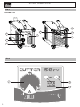 2
2
-
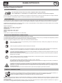 3
3
-
 4
4
-
 5
5
-
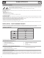 6
6
-
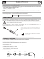 7
7
-
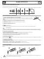 8
8
-
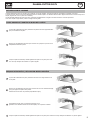 9
9
-
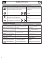 10
10
-
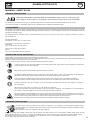 11
11
-
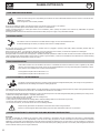 12
12
-
 13
13
-
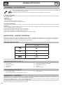 14
14
-
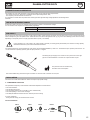 15
15
-
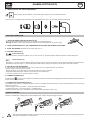 16
16
-
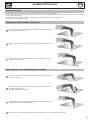 17
17
-
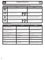 18
18
-
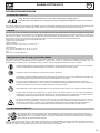 19
19
-
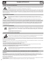 20
20
-
 21
21
-
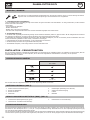 22
22
-
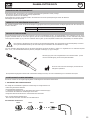 23
23
-
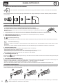 24
24
-
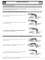 25
25
-
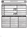 26
26
-
 27
27
-
 28
28
-
 29
29
-
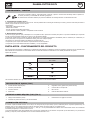 30
30
-
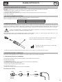 31
31
-
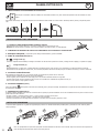 32
32
-
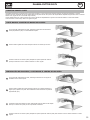 33
33
-
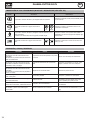 34
34
-
 35
35
-
 36
36
-
 37
37
-
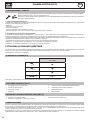 38
38
-
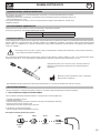 39
39
-
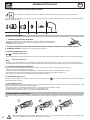 40
40
-
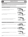 41
41
-
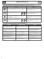 42
42
-
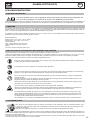 43
43
-
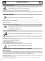 44
44
-
 45
45
-
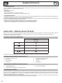 46
46
-
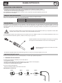 47
47
-
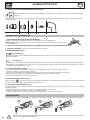 48
48
-
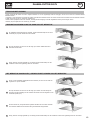 49
49
-
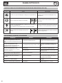 50
50
-
 51
51
-
 52
52
-
 53
53
-
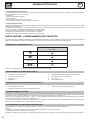 54
54
-
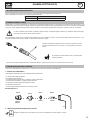 55
55
-
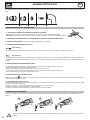 56
56
-
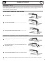 57
57
-
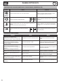 58
58
-
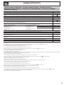 59
59
-
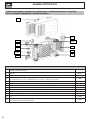 60
60
-
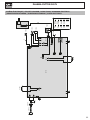 61
61
-
 62
62
-
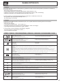 63
63
-
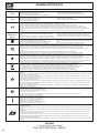 64
64


GYS PLASMA CUTTER 30 FV de handleiding
- Type
- de handleiding
- Deze handleiding is ook geschikt voor
in andere talen
Gerelateerde papieren
-
GYS PLASMA CUTTER EASYCUT 40 de handleiding
-
GYS PLASMA CUTTER 45 CT de handleiding
-
GYS Cutter 70 CT Handleiding
-
-
-
-
-
GYS PLASMA EASYCUT K35F Data papier
-
GYS Torch plasma automatic at-70 - 6m de handleiding
-
GYS PLASMA CUTTER 25 K Data papier