
Schlüter
®
-LIPROTEC
Art.-No.
Gebrauchsanleitung
LED-Streifen
Directions for use
for LED strips
Notice d’utilisation
ruban de LED
Gebruikershandleiding
LED-strip
Instrukcja użytkowania
taśm LED
LED șeritleri
kullanım kılavuzu
Instruções de utilização
fitas de LED
Istruzioni per l‘uso
delle strisce a LED
Manual de uso
de las tiras LED
Návod k použití
LED pásků
LED szalag használati
útmutató
Brugsanvisning
LED-strips
IT
EN
DE
CS
ES
HU
DA
FR
NL
PL
TR
PT
LT ES 1, LT ES 2, LT ES 3,
LT ES 4, LT ES 5, LT ES 6,
LT ES 9
01
19
36
54
73
91
108
126
144
162
179
197

A
ED
CB
2.
1
2
34
r ≥ 20mm
1.
24V R230V

F G
J
H I
24V230V 24V
W
+
R
+ + +
B
R
G
R
W
+
+ + +
3.
2.
4.
1.
9 mm

DE
Gebrauchsanleitung LED-Streifen
1
Inhaltsverzeichnis
DE
Gebrauchsanl eitung LED-Streife n
1 Allgemeine Hinweise .................................................................... 3
2 Sicherheit ...................................................................................... 3
2.1 Bestimmungsgemäßer Gebrauch ..................................................... 3
2.2 Einsatzbedingungen .......................................................................... 4
2.3 Grundlegende Sicherheitshinweise ................................................... 4
2.4 Sachschäden vermeiden ................................................................... 5
2.5 Personalqualifikationen ..................................................................... 6
2.6 Gestaltungsmerkmale von Warnhinweisen ....................................... 6
2.7 Gestaltungsmerkmale von Hinweisen auf Sachschäden .................. 6
2.8 Warn- und Hinweisschilder ................................................................ 7
3 Beschreibung ................................................................................ 7
3.1 Lieferumfang ...................................................................................... 7
3.2 Aufgabe und Funktion ....................................................................... 7
3.3 Technische Daten .............................................................................. 9
4 Transportieren und Lagern ........................................................ 10
5 Montieren .................................................................................... 10
5.1 LIPROTEC Profile im Nassbereich montieren ................................ 11
5.2 LED-Streifen montieren ................................................................... 11
6 Anschließen ................................................................................ 12
6.1 Funkentstörung optimieren .............................................................. 13
6.2 Anschlussvarianten ......................................................................... 13
6.3 LED-Streifen an Netzteil anschließen ............................................. 14
6.4 LED-Streifen an Receiver anschließen ........................................... 15
6.5 LED-Streifen an Gebäudeautomatisierung anschließen ................ 15
7 In Betrieb nehmen ....................................................................... 15
8 Bedienen ..................................................................................... 16
9 Warten ......................................................................................... 16
10 Störungen beheben .................................................................... 16
11 Reparieren ................................................................................... 17
12 Außer Betrieb nehmen, demontieren ......................................... 17
12.1 Außer Betrieb nehmen .................................................................... 17
12.2 LED-Streifen demontieren ............................................................... 18


DE
Allgemeine Hinweise
Gebrauchsanleitung LED-Streifen
3
1 Allgemeine Hinweise
Diese Anleitung hilft Ihnen beim Montieren und Anschließen des LIPROTEC LED-Streifens
an die verschiedenen Komponenten des Schlüter
®
-LIPROTEC Systems oder ein
marktübliches System zur Gebäudeautomatisierungen.
Dieser LED-Streifen wird im Folgenden auch kurz "Komponente" genannt, sofern nicht
verschiedene Komponenten des Schlüter®-LIPROTEC Systems unterschieden werden
müssen.
Diese Anleitung ist Bestandteil des Produkts. Stellen Sie sicher, dass die Anleitung ständig
am Einsatzort verfügbar und in einem leserlichen Zustand ist. Liefern Sie diese Anleitung
mit, wenn Sie das Produkt verkaufen oder in anderer Weise weitergeben.
Verschiedene Elemente dieser Anleitung sind mit festgelegten Gestaltungsmerkmalen
versehen. So können Sie die folgenden Elemente leicht unterscheiden:
Normaler Text
Aufzählungen
– Aufzählungen zweiter Ordnung
Ziel der Handlung
Handlungsaufforderung
Zwischenresultat
Endresultat
Tabellentitel sind fett gedruckt.
Tipps enthalten zusätzliche Informationen.
Herstelleradresse
Schlüter-Systems KG
Schmölestraße 7
D-58640 Iserlohn
Tel.: +49-23 71-971-0
Fax: +49-23 71-971-111
2 Sicherheit
2.1 Bestimmungsgemäßer Gebrauch
Die Komponenten des LIPROTEC Systems dienen ausschließlich zur Erzeugung von
dekorativen oder akzentuierenden Beleuchtungseffekten in Innenräumen im privaten oder
gewerblichen Bereich.
Das System darf in Bädern oder Feuchträumen nur unter Berücksichtigung der Schutzarten
der Komponenten und Schutzbereiche nach DIN VDE 0100-701 eingesetzt werden.
Der Einbau der LED-Streifen ist nur auf wärmeleitendem, glattem Untergrund zulässig.

DE
Sicherheit
4
Gebrauchsanleitung LED-Streifen
Verwenden Sie die Komponente in keinem Fall für folgende Anwendungen:
in Außenbereichen
unter Wasser
in explosionsgefährdeten Bereichen
in Schwimmbädern, Saunen oder Dampfbädern.
Ein Überschreiten der für das Netzteil vorgeschriebenen Belastungsgrenze ist durch falsche
Kombination der System-Komponenten möglich. Dies kann beispielsweise bei Verlängern
von LED-Streifen durch Anlöten der Fall sein. Ein Verwenden der Komponente des
LIPROTEC-Systems in falscher Kombination darf nicht erfolgen.
Zum bestimmungsgemäßen Gebrauch gehört auch das Lesen und Verstehen dieser
Anleitung sowie das Beachten und Befolgen aller Angaben in dieser Anleitung,
insbesondere der Sicherheitshinweise.
Jeder andere Gebrauch gilt ausdrücklich als nicht bestimmungsgemäß und führt zum Verfall
des Garantie- und Haftungsanspruchs.
2.2 Einsatzbedingungen
Stellen Sie sicher, dass die Komponenten ausschließlich unter folgenden
Umgebungsbedingungen eingesetzt werden:
Temperatur: -20 °C bis +40 °C
relative Luftfeuchtigkeit für Bluetooth-Receiver, Fernbedienung, Netzteil und
Klemmverbindungen: 45 % bis 85 %
Stellen Sie sicher, dass bei Verwendung der Komponenten in Bädern oder Feuchträumen
die Schutzbereiche gemäß DIN VDE 0100-7001 eingehalten werden.
2.3 Grundlegende Sicherheitshinweise
2.3.1 Schwere und tödliche Verletzungen vermeiden
Stromschläge beim Anschließen des LED-Streifens möglich.
– Stellen Sie sicher, dass das Netzteil nur von qualifiziertem Elektro-Fachpersonal
an den Netzanschluss angeschlossen wird.
– Stellen Sie sicher, dass alle sonstigen Arbeiten nur von qualifiziertem
Fachpersonal durchgeführt werden.
– Stellen Sie vor dem Anschließen von Komponenten sicher, dass das Netzteil nicht
unter Spannung steht.
– Schließen Sie den LED-Streifen oder den Receiver nur an das Netzteil und nicht
direkt an den Netzanschluss an.
Tödliche Brandverletzungen oder Rauchvergiftungen bei Entzünden des Dichtklebers
möglich.
– Halten Sie den Dichtkleber von Zündquellen fern.
Tödliche Brandverletzungen oder Rauchvergiftungen bei Entzünden falsch verlegter
Komponenten möglich.

DE
Sicherheit
Gebrauchsanleitung LED-Streifen
5
– Halten Sie die in dieser Anleitung angegebenen Mindestabstände ein.
Tod durch Ersticken bei Verschlucken von Kleinteilen durch Kinder möglich.
– Bewahren Sie die Endkappen vor Kindern geschützt auf.
– Bewahren Sie die Silicagel-Kugeln vor Kindern geschützt auf.
– Entsorgen Sie die Silicagel-Kugeln nach der Montage entsprechend der geltenden
Vorschriften.
2.3.2 Verletzungen vermeiden
Augenverletzungen durch blendende LED-Streifen.
– Blicken Sie nie direkt in einen leuchtenden LED-Streifen.
– Positionieren Sie LED-Streifen so, dass ein Betrachter niemals direkt in die
Lichtquelle blicken kann.
Übelkeit und Erbrechen durch Verschlucken des Dichtklebers.
– Bewahren Sie den Dichtkleber vor Kindern geschützt auf.
Reizung der Augen und der Haut durch Kontakt mit dem Dichtkleber.
– Vermeiden Sie Kontakt mit Augen und Haut.
– Bewahren Sie den Dichtkleber vor Kindern geschützt auf.
2.4 Sachschäden vermeiden
Beschädigung des LED-Streifens durch unsachgemäßes Anschließen.
– Stellen Sie sicher, dass alle Arbeiten nur von qualifiziertem Fachpersonal
durchgeführt werden.
– Verbinden Sie Kabel ausschließlich mit den mitgelieferten Klemm-Verbindern.
Beschädigung des LED-Streifens durch Feuchtigkeit.
– Beachten Sie die Schutzart der jeweiligen Komponente.
Beschädigung des LED-Streifens durch mechanische Belastungen.
– Stellen Sie sicher, dass ein Biegeradius von 20 mm nicht unterschritten wird (siehe
Abb. D).
Beschädigung des LED-Streifens durch elektrostatische Entladungen.
– Stellen Sie sicher, dass statische Aufladungen abgeleitet werden.
– Stellen Sie sicher, dass der LED-Streifen nur in der mitgelieferten Verpackung
gelagert wird.

DE
Sicherheit
6
Gebrauchsanleitung LED-Streifen
2.5 Personalqualifikationen
Alle Personen, die ein Beleuchtungssystem mit LIPROTEC-Komponenten auslegen oder an
Netzspannung anschließen, müssen folgende Fähigkeiten haben:
elektrischen Anschluss des Netzteils an eine Netzspannung nach gültigen Vorschriften
herstellen (Elektro-Fachkraft)
Anforderungen an den Einbau der LIPROTEC-Komponenten in Bäder und
Feuchträume kennen und umsetzen
Kombination von Komponenten des LIPROTEC-Systems richtig zusammenstellen
Alle Personen, die Komponenten montieren oder anschließen, müssen folgende Kenntnisse
und Fähigkeiten haben:
elektrische Anschlüsse an Sicherheitskleinspannung nach gültigen Vorschriften
herstellen
beim Umgang mit elektrischen Produkten entstehende Gefahren einschätzen und
vermeiden können
vor dem Einbau Schäden am Produkt feststellen können
LED-Streifen in Lichtprofile einbauen
Netzteil und Bluetooth-Receiver in eine Verkleidung einbauen
2.6 Gestaltungsmerkmale von Warnhinweisen
GEFAHR
Hinweise mit dem Wort GEFAHR warnen vor einer gefährlichen Situation, die zum Tod
oder zu schweren Verletzungen führt.
WARNUNG
Hinweise mit dem Wort WARNUNG warnen vor einer gefährlichen Situation, die
möglicherweise zum Tod oder zu schweren Verletzungen führen kann.
VORSICHT
Hinweise mit dem Wort VORSICHT warnen vor einer Situation, die zu leichten oder
mittleren Verletzungen führen kann.
2.7 Gestaltungsmerkmale von Hinweisen auf Sachschäden
ACHTUNG!
Diese Hinweise warnen vor einer Situation, die zu Sachschäden führt.

DE
Beschreibung
Gebrauchsanleitung LED-Streifen
7
2.8 Warn- und Hinweisschilder
Symbol
Erklärung
Entspricht den Forderungen der Richtlinien 2004/108/EG und 2006/95/EG.
Ist zur direkten Montage auf normal entflammbaren Oberflächen geeignet.
Normal entflammbare Oberflächen sind Baustoffe wie Holz und Werkstoffe
auf Holzbasis mit mehr als 2 mm Dicke.
Ist zur Montage auf oder in Möbel geeignet, die aus Werkstoffen mit
unbekannten Entflammungseigenschaften bestehen.
Entspricht der Schutzklasse III (verwendet Sicherheitskleinspannung)
Entspricht der EU-Richtlinie 2011/65/EU zur Beschränkung der Verwendung
bestimmter gefährlicher Stoffe in Elektro- und Elektronikgeräten.
Entspricht der Schutzart IP65 (IEC 60529:1989 + A1 :1999 + A2:2013):
Schutz gegen Strahlwasser (Düse) aus beliebigem Winkel.
Entspricht der Schutzart IP67 (IEC 60529:1989 + A1 :1999 + A2:2013):
Schutz gegen zeitweiliges Untertauchen
Unterliegt der WEEE-Richtlinie 2012/19/EU über Elektro- und Elektronik-
Altgeräte. Siehe Kapitel 13 "Entsorgen".
3 Beschreibung
3.1 Lieferumfang
Eine Darstellung des Lieferumfangs finden Sie auf den Ausklappseiten am Beginn des
Dokuments als Abbildung "A".
Der Lieferumfang eines LED-Streifens besteht aus:
LED-Streifen auf Rolle (1)
Endkappen (3)
Dichtkleber (4)
Gebrauchsanleitung
3.2 Aufgabe und Funktion
Die Schlüter®-LIPROTEC LichtProfilTechnik ist ein LED-System, das unterschiedliche,
überwiegend indirekte Lichteffekte ermöglicht. Das System, das im Wand- und
Deckenbereich eingesetzt werden kann, dient zur Herstellung von dekorativen oder
akzentuierenden Beleuchtungseffekten in Innenräumen.
Das LIPROTEC System besteht aus folgenden Komponenten:

DE
Beschreibung
8
Gebrauchsanleitung LED-Streifen
Trägerprofile mit Streuscheiben
LED-Streifen
Receiver
Fernbedienung
Netzteil
Anschlusszubehör
Der LED-Streifen dient als Lichtquelle. Das LIPROTEC System ermöglicht die Kombination
verschiedener LED-Streifen. Dadurch ist Licht unterschiedlicher Farbtemperaturen und
Farben möglich.
Der LED-Streifen wird über das Netzteil mit Strom versorgt. Der zwischen Netzteil und LED-
Streifen angeschlossene Receiver regelt, abhängig vom Typ der verwendeten
Komponenten, Lichtstärke und Farbe der LEDs.
Ein mobiles Endgerät (Smartphone oder Tablet) kann über Bluetooth mit dem Receiver
verbunden werden, um mit der Schlüter-App den Receiver zu programmieren oder direkt zu
steuern.
Mit der Fernbedienung können alternativ vorher festgelegte Einstellungen abgerufen
werden.
Das Netzteil wird an einen 230 V-Netzanschluss fest angeschlossen und versorgt die
übrigen Komponenten mit einer Sicherheitskleinspannung von 24 V DC .
Die LED-Streifen sind mit einem 2,3 m langen Anschlusskabel vorkonfektioniert. Die
Leitungen sind farbig gekennzeichnet, wobei der Plusleiter schwarz ist. Die Komponenten
sind für eine Spannung von 24 V DC ausgelegt.
Die LED-Streifen vom Typ LT ES 1 bis LT ES 6 unterscheiden sich in den Abmessungen
und ihrem Einsatzbereich. Sie sind jeweils in den Farbtemperaturen 3300 Kelvin (warmweiß)
und 4500 Kelvin (neutralweiß) erhältlich.
Bei dem LED-Streifen vom Typ LT ES 9 können gleichzeitig über 16 Millionen
unterschiedliche Farbtöne eingestellt sowie Weißlicht mit einer Farbtemperatur von
2500 Kelvin (warmweiß) bis 6500 Kelvin (tageslichtweiß).

DE
Beschreibung
Gebrauchsanleitung LED-Streifen
9
3.3 Technische Daten
Abmessungen
Typ
Breite
verfügbare
Längen
Teilung
Zuleitung
LT ES 1
12 mm
50 - 250 cm in
50 cm
Abstufung
50 mm
230 cm
LT ES 2
12 mm
50 mm
230 cm
LT ES 3
7 mm
50 mm
230 cm
LT ES 4
7 mm
50 mm
230 cm
LT ES 5
8 mm
50 mm
230 cm
LT ES 6
8 mm
50 mm
230 cm
LT ES 9
14 mm
62,5 mm
300 cm
Beleuchtungscharakteristik
Typ
Abstrahlrichtung
Lichtfarbe
Farbtemperatur
CRI*
LT ES 1
nach oben
warmweiß
3300 K
> 85
LT ES 2
nach oben
neutralweiß
4500 K
> 85
LT ES 3
nach oben
warmweiß
3300 K
> 85
LT ES 4
nach oben
neutralweiß
4500 K
> 85
LT ES 5
seitlich
warmweiß
3300 K
> 85
LT ES 6
seitlich
neutralweiß
4500 K
> 85
LT ES 9
nach oben
RGB und weiß
2500 - 6500 K
> 85
* Der CRI-Wert bezieht sich ausschließlich auf die einzelne weiße LED und kann bei
Mischung mit anderen Farben abweichen.
elektrische Anschlusswerte
Typ
Schutzart
Spannung
Leistung
LED/m
LT ES 1
IP65
24 V DC
9,6 W/m
120
LT ES 2
IP65
24 V DC
9,6 W/m
120
LT ES 3
IP65
24 V DC
9,6 W/m
120

DE
Transportieren und Lagern
10
Gebrauchsanleitung LED-Streifen
Typ
Schutzart
Spannung
Leistung
LED/m
LT ES 4
IP65
24 V DC
9,6 W/m
120
LT ES 5
IP65
24 V DC
9,6 W/m
120
LT ES 6
IP65
24 V DC
9,6 W/m
120
LT ES 9
IP67
24 V DC
15,0 W/m
192
Energieeffizienzklassen
Angaben zur Energieeffizienz finden Sie in der Tabelle am Ende des Dokuments.
4 Transportieren und Lagern
Um Komponenten des LIPROTEC Systems zu transportieren und zu lagern, gehen Sie
folgendermaßen vor:
Transportieren und lagern Sie die Komponenten in der Originalverpackung.
Lagern Sie die Komponenten in einem trockenen Raum.
Stellen Sie sicher, dass die Komponenten nicht in die Hände von Kindern gelangen.
5 Montieren
GEFAHR
Brandgefahr durch Entzünden des Dichtklebers!
Brände durch entzündeten Dichtkleber können zu tödlichen Brandverletzungen oder
Rauchvergiftungen führen.
Halten Sie den Dichtkleber von Zündquellen fern.
Stellen Sie sicher, dass beim Verwenden des Dichtklebers nicht geraucht wird.
Belüften Sie den Arbeitsbereich.
VORSICHT
Verletzungen durch Dichtkleber möglich!
Der Kontakt mit Dichtkleber kann zu Hautreizungen oder Augenverletzungen führen.
Tragen Sie bei Arbeiten mit Dichtkleber Schutzhandschuhe und eine Schutzbrille.

DE
Montieren
Gebrauchsanleitung LED-Streifen
11
VORSICHT
Schnittverletzungen bei Verwenden ungeeigneter Werkzeuge möglich!
Kürzen Sie den LED-Streifen nur mit einer ausreichend stabilen und scharfen
Schere.
ACHTUNG!
Funktionsstörung durch undicht verschlossenen LED-Streifen.
Durch das undichte Verschließen kann Wasser in den LED-Streifen eindringen. Dies
kann Funktionsstörungen zur Folge haben.
Stellen Sie sicher, dass die Endkappe vollständig mit Dichtkleber gefüllt ist.
Stellen Sie sicher, dass die Endkappe spaltfrei mit dem LED-Streifen verbunden ist.
5.1 LIPROTEC Profile im Nassbereich montieren
LED-Streifen der Serie Schlüter ® -LIPROTEC-ES entsprechen der Schutzart IP65 (Schutz
gegen Strahlwasser aus allen Richtungen oder IP67 (Schutz gegen zeitweiliges
Untertauchen) und dürfen somit temporären Wassereinwirkungen (Düsen) ausgesetzt
werden.
Wenn Sie LED-Streifen der Serie Schlüter ® -LIPROTEC-ES in LIPROTEC-Profilen im
Nassbereich einsetzen möchten, gehen Sie bei der Montage folgendermaßen vor:
Platzieren Sie Installationsdosen hinter der Abdichtungsebene oder außerhalb der
Nassbereiche.
Positionieren Sie die LIPROTEC-Profile im Nassbereich senkrecht, so dass sich in
ihnen kein Wasser sammeln bzw. eintretendes Wasser wieder ablaufen kann.
Führen Sie die Streuscheiben ca. 2 mm kürzer aus als die Aufnahmeprofile.
Stellen Sie sicher, dass sich der entstehende Spalt am tieferen Ende des Profils
befindet und nicht verschlossen oder verdeckt wird.
Durch diesen Spalt kann eindringendes Wasser sofort ablaufen, so dass es nicht in
Isolierungen und Abdichtungen kriechen kann.
Stellen Sie sicher, dass Kabeldurchführungen wasserdicht verschlossen sind.
5.2 LED-Streifen montieren
Um einen LED-Streifen montieren, gehen Sie wie folgt vor:
Stellen Sie sicher, dass der Untergrund, auf den der LED-Streifen aufgeklebt werden
soll, wärmeleitfähig und glatt ist.
Ermitteln Sie die benötigte Länge des LED-Streifens.
Zerschneiden Sie den LED-Streifen ausschließlich an den markierten Stellen (siehe
Abb. B). Verwenden Sie zum Zerschneiden eine stabile, scharfe Schere.

DE
Anschließen
12
Gebrauchsanleitung LED-Streifen
Das Ende des LED-Streifens verschließen Sie wasserfest. Verwenden Sie dazu eine
Endkappe und den Dichtkleber. Drücken Sie ausreichend Dichtkleber in die Endkappe
(siehe Abb. C , 1. Schritt).
Schieben Sie die Endkappe bis zum Anschlag über das Ende des LED-Streifens (siehe
Abb. C, 2. Schritt).
Stellen Sie sicher, dass die Endkappe spaltfrei mit dem LED-Streifen verbunden ist.
Entfernen Sie überschüssigen Dichtkleber mit einem Lappen.
Lassen Sie den Dichtkleber mindestens eine Stunde trocknen, bevor Sie mit dem LED-
Streifen weiter arbeiten.
Stellen Sie sicher, dass der Untergrund zum Befestigen des LED-Streifens sauber und
frei von haftungsfeindlichen Stoffen ist.
Entfernen Sie die Schutzfolie vom Klebestreifen auf der Rückseite des LED-Streifen
(siehe Abb. D).
Kleben Sie den LED-Streifen mit ausreichendem Druck auf den Untergrund.
Unterschreiten Sie hierbei einen Biegeradius von 20 mm nicht (siehe Abb. D,
Detailvergrößerung).
6 Anschließen
GEFAHR
Brandgefahr durch Überhitzen des Kabels!
Brände durch überhitzte Kabel können zu tödlichen Brandverletzungen oder
Rauchvergiftungen führen.
Verlegen Sie Kabel nicht in aufgerolltem Zustand.
Setzen Sie ausreichenden Kabelquerschnitt ein.
Berücksichtigen Sie die maximal zulässige Länge der Zuleitungen.
Beachten Sie die maximal zulässige Belastbarkeit der Netzteile und der Receiver.
ACHTUNG!
Funktionsstörung durch beschädigte Kabel.
Das Führen von Kabeln an scharfen Kanten kann Funktionsstörungen zur Folge haben.
Verlegen Sie Kabel in Leerrohren oder Kabelkanälen.
Entgraten Sie Bohrungen und Ausklinkungen in LIPROTEC-Profilen.
ACHTUNG!
Funktionsstörung durch Lösen der Kabelverbindung.
Das Verbinden von Kabeln unter Zug kann zum Lösen der Kabelverbindung führen.
Stellen Sie eine ausreichende Zugentlastung sicher.

DE
Anschließen
Gebrauchsanleitung LED-Streifen
13
6.1 Funkentstörung optimieren
Um eine gute Funkenstörung und eine größtmögliche Betriebssicherheit zu erhalten,
beachten Sie die folgenden Punkte bei der fachgerechten Leitungsverlegung:
Montieren Sie Netzteile mindestens 30 cm von den LED-führenden Aluminiumprofilen
entfernt. Beachten Sie dabei die Mindestabstände zu angrenzenden Bauteilen (siehe
"Gebrauchsanleitung Netzteil", Abb. C).
Verlegen Sie Ausgangsleitungen im entsprechenden Abstand fachgerecht zu den
geerdeten Metallflächen.
Dies reduziert kapazitive Einkopplungen.
Stellen Sie sicher, dass der Abstand zwischen Netzkabel und Anschlusskabel von
Receiver oder LED-Streifen möglichst groß ist (mindestens 5 cm) und die Netz- sowie
Anschlusskabel nicht parallel verlegt werden.
Dadurch wird die Einkopplung von Störungen zwischen Netzkabel und Lampen-
Anschlusskabeln vermieden.
Vermeiden Sie, Netzkabel und LED-Module zu kreuzen. Falls Sie eine Kreuzung nicht
ausschließen können, führen Sie diese mit möglichst großem Winkel aus, soweit dies
fachtechnisch und aus Sicherheitsgründen möglich ist.
Dies vermeidet HF-Einkopplungen auf das Netzkabel.
6.2 Anschlussvarianten
Die Komponenten des LIPROTEC Systems können in den folgenden Kombinationen
zusammengestellt und angeschlossen werden:
einer oder mehrere LED-Streifen (LTES1 bis LTES6), angeschlossen an ein Netzteil
mit vorgeschaltetem Lichtschalter (siehe "Gebrauchsanleitung LED-Streifen", Abb. F)
einer oder mehrere LED-Streifen (LTES1 bis LTES6, LTES9), angeschlossen an einen
Receiver zur Fernsteuerung, mit vorgeschaltetem Netzteil und optionalem Lichtschalter
(siehe "Gebrauchsanleitung LED-Streifen", Abb. E)
ein oder mehrere LED-Streifen (LTES1 bis LTES6, LTES9), angeschlossen an eine
Gebäudeautomatisierung, die die Stromversorgung und Steuerung übernimmt (siehe
"Gebrauchsanleitung LED-Streifen", Abb. G)
Die für die vorliegende Komponente zutreffenden Anschlussmöglichkeiten werden im
Folgenden beschrieben.

DE
Anschließen
14
Gebrauchsanleitung LED-Streifen
6.3 LED-Streifen an Netzteil anschließen
GEFAHR
Stromschläge beim Anschließen einer Komponente an unter Spannung stehendem
Netzteil möglich!
Das Anschließen einer Komponente an ein unter Spannung stehendes Netzteil kann zu
schwersten oder tödlichen Verletzungen führen.
Stellen Sie vor allen Arbeiten an den Komponenten sicher, dass das Netzteil nicht
unter Spannung steht.
Schließen Sie das Netzteil erst nach Abschluss aller Anschlussarbeiten an den
Netzanschluss an.
GEFAHR
Brandgefahr bei überlasteten Anschlüssen!
Brennende Komponenten und Kabel können zu schwersten oder tödlichen
Verletzungen führen.
Schließen Sie immer nur ein Kabel an die Anschlussklemmen oder die Klemm-Box
eines Netzteils an.
Folgen Sie den speziellen Anweisungen in den Gebrauchsanleitungen, falls
mehrere Komponenten angeschlossen werden sollen.
Einen LED-Streifen direkt an ein Netzteil anschließen
Führen Sie das Anschlusskabel des LED-Streifens durch die Bohrung des
Aufnahmeprofils in den ankommenden Kabelkanal.
Stellen Sie eine Kabelreserve her, indem Sie das Kabel am Beginn des Kanals in einer
Schleife verlegen. Stellen Sie im weiteren Verlauf der Montage sicher, dass diese
Kabelschleife nicht beeinträchtigt wird.
Dadurch ist sichergestellt, dass später der LED-Streifen aus dem Profil
entnommen werden kann, ohne das Kabel unter Zugspannung zu setzen.
Führen Sie das Kabel zum Netzteil.
Legen Sie das Kabel auf die 24V-Klemmen des Netzteils auf. Stellen Sie dabei die
richtige Polarität sicher. Lesen Sie dazu auch die Gebrauchsanleitung des Netzteils.
Mehrere LED-Streifen direkt an ein Netzteil anschließen
Ziehen Sie die Anschlusskabel der LED-Streifen in Kabelkanäle oder Leerrohre, wie
oben beschrieben.
Führen Sie die Anschlusskabel in einer Installationsdose zusammen.
Fassen sie die mit gleichen Farben gekennzeichneten Adern der Anschlüsse der LED-
Streifen auf jeweils einem LIPROTEC-ZKL Klemm-Verbinder zusammen. Benutzen Sie
für jede Ader einen einzelnen Kontakt des Klemm-Verbinders (siehe Abb. J).

DE
In Betrieb nehmen
Gebrauchsanleitung LED-Streifen
15
Sie können abhängig vom Typ des Klemm-Verbinders maximal zwei oder vier
LED-Streifen anschließen.
Verbinden sie die Klemmverbinder mit einem zusätzlichen Kabel mit dem Netzteil.
Verwenden Sie dazu ein LIPROTEC LT ZK 2A Kabel. Stellen Sie dabei sicher, die
richtige Polarität einzuhalten und die maximal zulässige Lange von 10 m nicht zu
überschreiten. Lesen Sie dazu auch die Gebrauchsanleitung des Netzteils.
6.4 LED-Streifen an Receiver anschließen
Einen oder mehrere LED-Streifen an einen Receiver anschließen
Führen Sie das Anschlusskabel des LED-Streifens durch die Bohrung des
Aufnahmeprofils in den ankommenden Kabelkanal.
Erzeugen Sie eine Kabelreserve, indem Sie das Kabel am Beginn des Kanals in einer
Schleife verlegen. Stellen Sie im weiteren Verlauf der Montage sicher, dass diese
Kabelschleife nicht beeinträchtigt wird.
Dadurch ist sichergestellt, dass später der LED-Streifen aus dem Profil
entnommen werden kann, ohne das Kabel unter Zugspannung zu setzen.
Führen Sie die Anschlusskabel von LED-Streifen und Receiver in einer
Installationsdose zusammen.
Fassen sie die mit gleichen Farben gekennzeichneten Adern der Anschlüsse der LED-
Streifen und des Receivers auf jeweils einem LIPROTEC-ZKL Klemm-Verbinder
zusammen. Benutzen Sie für jede Ader einen einzelnen Kontakt des Klemm-Verbinders
(siehe Abb. H, I und J).
Sie können abhängig vom Typ des Klemm-Verbinders maximal zwei oder vier
LED-Streifen anschließen.
6.5 LED-Streifen an Gebäudeautomatisierung anschließen
Eine Gebäudeautomatisierung mit 24V-Anschluss kann anstelle eines LIRPROTEC Netzteils
verwendet werden (siehe Abb. G).
Details zum Anschluss an die Gebäudeautomatisierung entnehmen Sie der
zugehörigen Dokumentation der externen Komponenten.
7 In Betrieb nehmen
Um das LIPROTEC System in Betrieb nehmen, gehen Sie folgendermaßen vor:
Stellen Sie sicher, dass alle Komponenten wie gewünscht und korrekt verbaut und
angeschlossen sind.
Schalten Sie die Netzstromversorgung ein.
Stellen Sie sicher, dass alle LED-Streifen leuchten.
Falls Sie einen Bluetooth-Receiver benutzten, können Sie jetzt mit der
Fernbedienung die vorprogrammierten Einstellungen abrufen. Lesen Sie dazu das
Kapitel „In Betrieb nehmen“ in der Montageanleitung des Bluetooth-Receivers.
Stellen Sie so sicher, dass das LIPROTEC-System grundsätzlich funktioniert.

DE
Bedienen
16
Gebrauchsanleitung LED-Streifen
Schließen Sie alle Kabelkanäle und Verkleidungen.
Ihr LIPROTEC System ist nun bereit für den täglichen Gebrauch!
8 Bedienen
Der LED-Streifen besitzt keine Bedien- oder Schaltelemente.
Falls Sie zwischen Netzteil und LED-Streifen einen Receiver geschaltet haben, lesen Sie
bitte die Bedienungsanleitung des Receivers.
9 Warten
Der LED-Streifen muss jährlich von Verunreinigungen gereinigt werden, wenn keine
Streuscheibe eingesetzt wird. Er besitzt keine wart- oder austauschbaren Teile.
Um den LED-Streifen zu reinigen, gehen Sie folgendermaßen vor:
Schalten Sie das LIPROTEC System ab.
Wischen Sie Verunreinigungen auf dem LED-Streifen mit einem trockenen, fusselfreien
und weichen Tuch ab.
10 Störungen beheben
Fehler
Fehlerursache
Fehlerbehebung
Keine Beleuchtung
Anschlüsse
vertauscht
Alle Kabelanschlüsse auf richtigen
Anschluss kontrollieren
keine Spannung
vorhanden
Überprüfung des Netzteils auf richtigen
Anschluss
Netzteil überlastet
größeres Netzteil wählen (bis 150 W)
Receiver überlastet
Max. Belastung der jeweiligen
Anschlüsse am Receiver kontrollieren.
Eventuell müssen die LED-Streifen
anders auf die jeweiligen Anschlüsse
verteilt werden (max. Belastung der
jeweiligen Anschlüsse beachten
Beleuchtung blinkt
bzw. flackert
Receiver überlastet
Max. Belastung der jeweiligen
Anschlüsse am Receiver kontrollieren.
Eventuell müssen die LED-Streifen
anders auf die jeweiligen Anschlüsse
verteilt werden (max. Belastung der
jeweiligen Anschlüsse beachten
Netzteil überlastet
größeres Netzteil wählen (bis 150 W)
Kabelanschlüsse sind
nicht fest
Kabelanschlüsse auf kraftschlüssige

DE
Reparieren
Gebrauchsanleitung LED-Streifen
17
Fehler
Fehlerursache
Fehlerbehebung
angeschlossen
Verbindung überprüfen.
Unterschiedliche
Lichtfarben
Anschlüsse
vertauscht
Alle Kabelanschlüsse auf richtigen
Anschluss kontrollieren. Test der Farben
Rot, Grün, Blau. Test der Farbtemperatur
Warmweiß bis Tageslichtweiß.
Leitungsschutzschalter
löst aus
Netzteil falsch
angeschlossen
Netzteil richtig anschließen (nur von
einer Elektrofachkraft).
11 Reparieren
Bauartbedingt ist die Reparatur einer LIPROTEC-Komponente nicht möglich.
Wenn eine Komponente einen Defekt oder Leistungsverlust aufweist, lassen Sie diese
gegen eine Neue austauschen.
Folgen Sie dabei den Anweisungen in den Abschnitten "Außer Betrieb nehmen",
"Montieren" und "In Betrieb nehmen".
12 Außer Betrieb nehmen, demontieren
GEFAHR
Stromschlag beim nicht fachgerechten Demontieren möglich.
Das Demontieren durch nicht befugte Personen kann einen tödlichen Stromschlag zur
Folge haben.
Lassen Sie die Komponente ausschließlich von qualifiziertem Fachpersonal außer
Betrieb nehmen und demontieren.
12.1 Außer Betrieb nehmen
Um das LIPROTEC System sicher außer Betrieb zu nehmen, gehen Sie folgendermaßen
vor:
Schalten Sie das LIPROTEC-System ab.
Schalten Sie den Netzanschluss des Netzteils stromlos und sichern Sie ihn gegen
Wiedereinschalten.
Trennen Sie das Netzteil vom Netzanschluss. Lösen Sie dazu die Schrauben (siehe
Gebrauchsanleitung Netzteil
, Abb. D Pos. 3) und entfernen Sie die
Gehäuseabdeckungen (siehe
Gebrauchsanleitung Netzteil
, Abb. D Pos. 2).
Lösen Sie das Netzkabel vom Netzteil und isolieren Sie die freiliegenden Adern.
Sie können jetzt die einzelnen Komponenten des LIPROTEC Systems
demontieren.

DE
Entsorgen
18
Gebrauchsanleitung LED-Streifen
12.2 LED-Streifen demontieren
Um LED-Streifen zu demontieren, gehen Sie folgendermaßen vor:
Öffnen Sie die betreffende Installationsdose.
Lösen Sie Anschlusskabel aus den Klemm-Verbindern.
Falls Sie Leerrohre verwenden und einen neuen LED-Streifen einbauen wollen,
verbinden Sie eine Zugschnur mit dem losen Ende des Anschlusskabels.
Sie können mit dieser Zugschnur später das Anschlusskabel des neuen LED-
Streifens in den Kabelkanal oder das Leerrohr einziehen.
Ziehen Sie das Anschlusskabel aus dem Leerrohr.
Stellen Sie gegebenenfalls sicher, dass die Zugschnur am anderen Ende
zugänglich bleibt.
Lösen Sie den LED-Streifen vom Untergrund, indem Sie ihn senkrecht nach oben
abziehen.
13 Entsorgen
Dieses Produkt darf innerhalb der EU nicht über den Hausmüll entsorgt werden.
Die in Altgeräten enthaltenen recyclingfähigen Materialien sollen einer
Wiederverwertung zugeführt werden und der Umwelt bzw. der menschlichen
Gesundheit nicht durch unkontrollierte Müllbeseitigung schaden. Bitte entsorgen
Sie Altgeräte deshalb über geeignete Sammelsysteme oder senden Sie das Gerät
zur Entsorgung an die Stelle, bei der Sie es gekauft haben. Diese wird dann das
Gerät der stofflichen Verwertung zuführen.
14 Gewährleistungsbedingungen
Die aktuellen Gewährleistungsbedingungen der Firma Schlüter-Systems KG für das System
Schlüter
®
-LIPROTEC finden Sie im Internet unter der Adresse "www.liprotec.de".

EN
Directions for use for LED strips
19
Table of contents
EN
Directions for us e for LED strips
1 General notes .............................................................................. 21
2 Safety ........................................................................................... 21
2.1 Intended use .................................................................................... 21
2.2 Conditions for use ............................................................................ 22
2.3 Basic safety instructions .................................................................. 22
2.4 Preventing property damage ........................................................... 23
2.5 Personnel qualifications .................................................................. 23
2.6 Design features of warning notices ................................................. 24
2.7 Design features of notices of property damage .............................. 24
2.8 Warning and information signs ........................................................ 25
3 Description .................................................................................. 25
3.1 Scope of supply ............................................................................... 25
3.2 Task and function ............................................................................ 25
3.3 Technical data ................................................................................. 26
4 Transport and storage ................................................................ 28
5 Mounting ..................................................................................... 28
5.1 Mounting the LIPROTEC profiles in wet areas ............................... 28
5.2 Mounting the LED strip .................................................................... 29
6 Connection .................................................................................. 30
6.1 Optimizing radio noise suppression ................................................ 30
6.2 Connection variants ......................................................................... 31
6.3 Connecting the LED strip to the power pack ................................... 31
6.4 Connecting the LED strip to the receiver ........................................ 32
6.5 Connecting the LED strip to a building automation system ............ 32
7 Commissioning ........................................................................... 33
8 Operation ..................................................................................... 33
9 Maintenance ................................................................................ 33
10 Elimination of faults .................................................................... 33
11 Repair .......................................................................................... 34
12 Decommissioning, disassembly ................................................ 34
12.1 Decommissioning ............................................................................ 34
12.2 Disassembly of the LED strip .......................................................... 35


EN
General notes
Directions for use for LED strips
21
1 General notes
These instructions help you mount and connect the LIPROTEC LED strip to the various
components of the Schlüter
®
LIPROTEC system or a commercial building automation
system.
This LED strip is referred to as the "component" hereinafter insofar as various components
of the Schlüter® LIPROTEC system do not have to be differentiated.
These instructions are part of the product. Make sure that the instructions are constantly
available at the place of use and in a legible state. Provide these instructions if you sell the
product or pass it on in another manner.
Various elements of these instructions have fixed design features. You can easily
differentiate the following elements:
Normal text
Lists
– Second-order lists
Objective of the action
Action prompt
Intermediate result
End result
Table titles are bolded.
Tips contain additional information.
Manufacturer's address
Schlüter-Systems KG
Schmölestraße 7
58640 Iserlohn, Germany
Phone: +49-2371-971-0
Fax: +49-2371-971-111
2 Safety
2.1 Intended use
The components of the LIPROTEC system are used only to create decorative or
accentuating lighting effects indoors, privately or commercially.
The system may be used in bathrooms or wet rooms only under consideration of the types of
protection of the components and scope of protection according to DIN VDE 0100-701.
The LED strips may be installed only on a heat-conductive, smooth foundation.

EN
Safety
22
Directions for use for LED strips
The component must not be used for the following applications under any circumstances:
Outdoors
Underwater
In potentially explosive atmospheres
In swimming pools, saunas or steam baths
Exceeding the load limit required for the power pack is possible through an incorrect
combination of the system components. This can be the case if LED strips are expanded by
soldering. The component of the LIPROTEC system must not be used in the wrong
combination.
Intended use includes the reading and understanding these instructions and the observance
and following of all information in these instructions, especially the safety instructions.
Any other use is expressly considered not to be intended and leads to an expiration of the
warranty and liability claim.
2.2 Conditions for use
Make sure that the components are used only under the following surrounding conditions:
Temperature: -20 °C to +40 °C
Relative humidity for Bluetooth receiver, remote control, power pack and terminal
connections: 45 % to 85 %
Make sure that the scope of protection is observed according to DIN VDE 0100-7001 when
the components are used in bathrooms or wet rooms.
2.3 Basic safety instructions
2.3.1 Preventing severe and deadly injuries
Electrical shocks during the connection of the LED strip are possible.
– Make sure that the power pack is connected to the mains connection by qualified
electricians only.
– Make sure that all other work is performed only by qualified, expert personnel.
– Before connecting the components, make sure the power pack is not energised.
– Connect the LED strip or receiver only to the power pack and not directly to the
mains connection.
Deadly burn injuries or smoke inhalation are possible if the sealing glue ignites.
– Keep the sealing glue away from ignition sources.
Deadly burn injuries or smoke inhalation are possible if incorrectly laid components
ignite.
– Observe the minimum distances specified in these instructions.
Children may die due to suffocation or the swallowing of small parts.
– Store the end caps in such a way that they are kept away from children.

EN
Safety
Directions for use for LED strips
23
– Store the silica gel balls in such a way that they are kept away from children.
– Dispose of the silica gel balls according to the applicable regulations after
mounting.
2.3.2 Preventing injuries
Eye injuries from dazzling LED strips.
– Never look directly into a lit LED strip.
– Position the LED strip in such a way that no one can look directly into the light
source.
Swallowing the sealing glue can result in nausea and vomiting.
– Store the sealing glue in such a way that it is kept away from children.
Irritation of the eyes or skin due to skin with the sealing glue.
– Prevent contact with the eyes and skin.
– Store the sealing glue in such a way that it is kept away from children.
2.4 Preventing property damage
Damage to the LED strip through improper connection.
– Make sure that all other work is performed only by qualified, expert personnel.
– Connect the cables only with the provided terminal connectors.
Damage to the LED strip due to moisture.
– Observe the protection class of the respective component.
Damage to the LED strip due to mechanical loads.
– Make sure a bending radius of 20 mm is not exceeded (see Fig. D).
Damage to the LED strip due to electrostatic discharges.
– Make sure static charges are discharged.
– Make sure that the LED strip is stored only in the provided packaging.
2.5 Personnel qualifications
Anyone who designs a lighting system with LIPROTEC components or connects it to the
mains voltage must have the following skills:
Establishment of an electrical connection of the power pack to the mains voltage
according to valid regulations (electrician)
Familiarity with and implementation of requirements on the installation of the
LIPROTEC components in bathrooms and wet rooms
Correct assembly of the combination of components of the LIPROTEC system
Anyone who mounts or connects components must have the following knowledge and skills:
Establishment of electrical connections to the safety extra low voltage (SELV)
Ability to estimate and prevent risks arising from the handling of electrical products

EN
Safety
24
Directions for use for LED strips
Ability to determine damage to the product before installation
Installation of the LED strips into light profiles
Installation of the power pack and a Bluetooth receiver into panelling
2.6 Design features of warning notices
DANGER
Notices with the word DANGER warn about dangerous situations that will lead to death
or severe injuries.
WARNING
Notices with the word WARNING warn about dangerous situations that can lead to
death or severe injuries.
CAUTION
Notices with the word CAUTION warn about dangerous situations that can lead to minor
or medium-severe injuries.
2.7 Design features of notices of property damage
ATTENTION!
These notices warn against situations that lead to property damage.

EN
Description
Directions for use for LED strips
25
2.8 Warning and information signs
Symbol
Explanation
Corresponds with the requirements of Directives 2004/108/EC and
2006/95/EC.
Suitable for direct assembly to normally flammable surfaces. Normal
flammable surfaces are materials such as wood and materials on a wooden
basis with a thickness of no more than 2 mm.
Suitable for mount onto or into furniture, consisting of materials with unknown
ignition properties.
Corresponds with protection class III (uses safety extra low voltage)
Corresponds with EU Directive 2011/65/EU to limit the use of certain
hazardous materials in electrical and electronic devices.
Corresponds with protection class IP65 (IEC 60529:1989 + A1 :1999 +
A2:2013):
Protection against spray water (nozzle) from any angle.
Corresponds with protection class IP67 (IEC 60529:1989 + A1 :1999 +
A2:2013):
Protection against occasional submersion
Subject to the Waste Electrical and Electronic Equipment (WEEE) Directive
2012/19/EU governing waste electrical and electronic equipment. See
Chapter 13 "Disposal."
3 Description
3.1 Scope of supply
A diagram of the scope of delivery can be found as Figure A on the fold-out pages at the
beginning of the document.
The scope of supply of an LED strip consists of:
LED strip on roll (1)
End caps (3)
Sealing glue (4)
Directions for use
3.2 Task and function
The Schlüter® LIPROTEC light profile technology is an LED system that enables a variety of
mainly indirect light effects. The system, which is installed into walls and ceilings, is used to
create decorative or accentuating indoor lighting effects.

EN
Description
26
Directions for use for LED strips
The LIPROTEC system consists of the following components:
Support profiles with spreading discs
LED strip
Receiver
Remote control
Power pack
Connection accessories
The LED strip acts as a light source. The LIPROTEC system permits the combination of
various LED strips. In this result, light of various colour temperatures and colours is possible.
The LED strip is supplied with power through the power pack. The receiver connected
between the power pack and LED strip regulates the light intensity and colour of the LEDs
depending on the type of components used.
A mobile device (smartphone or tablet) can be connected with the receiver through
Bluetooth so that the receiver can be programmed or controlled directly using the Schlüter
app.
Alternatively, previously defined settings can called using the remote control.
The power pack has a fixed connection with a 230 V mains connection and supplies the
other components with a safety extra low voltage of 24 V DC.
The LED strips are pre-assembled with a 2.3 m-long connection cable. The lines are marked
in colour, whereby the plus wire is black. The components are designed for a voltage of
24 V DC.
The LED strips of the type LT ES 1 through LT ES 6 differ in regard to dimensions and area
of application. They are available in the colour temperatures of 3300 K (warm white) and
4500 K (neutral white).
In the case of the LED strips of the type LT ES 9, more than 16 million different hues can be
set, as well as white light with a colour temperature of 2500 K (warm white) to 6500 K
(daylight white).
3.3 Technical data
Dimensions
Type
Width
Available
lengths
Division
Supply line
LT ES 1
12 mm
50 - 250 cm in
50 cm intervals
50 mm
230 cm
LT ES 2
12 mm
50 mm
230 cm
LT ES 3
7 mm
50 mm
230 cm
LT ES 4
7 mm
50 mm
230 cm
LT ES 5
8 mm
50 mm
230 cm

EN
Description
Directions for use for LED strips
27
Type
Width
Available
lengths
Division
Supply line
LT ES 6
8 mm
50 mm
230 cm
LT ES 9
14 mm
62.5 mm
300 cm
Lighting characteristics
Type
Direction of
beam
Light colour
Colour
temperature
CRI*
LT ES 1
Upwards
Warm white
3300 K
> 85
LT ES 2
Upwards
Neutral white
4500 K
> 85
LT ES 3
Upwards
Warm white
3300 K
> 85
LT ES 4
Upwards
Neutral white
4500 K
> 85
LT ES 5
On the side
Warm white
3300 K
> 85
LT ES 6
On the side
Neutral white
4500 K
> 85
LT ES 9
Upwards
RGB and white
2500 - 6500 K
> 85
* The CRI value refers only to the individual white LED and can deviate when mixed with
other colours.
Electrical connected loads
Type
Protection class
Voltage
Power
LED/m
LT ES 1
IP65
24 V DC
9.6 W/m
120
LT ES 2
IP65
24 V DC
9.6 W/m
120
LT ES 3
IP65
24 V DC
9.6 W/m
120
LT ES 4
IP65
24 V DC
9.6 W/m
120
LT ES 5
IP65
24 V DC
9.6 W/m
120
LT ES 6
IP65
24 V DC
9.6 W/m
120
LT ES 9
IP67
24 V DC
15.0 W/m
192
Energy efficiency ratings
Information regarding energy efficiency can be found in the table at the end of the document.

EN
Transport and storage
28
Directions for use for LED strips
4 Transport and storage
To transport and store components of the LIPROTEC system, proceed as follows:
Transport and store the components in the original packaging.
Store the components in a dry room.
Keep the components away from children.
5 Mounting
DANGER
Risk of fire due to the ignition of the sealing glue!
Fires resulting from ignited sealing glue can lead to deadly burn injuries or poisoning by
smoke inhalation.
Keep the sealing glue away from ignition sources.
Do not smoke while using the sealing glue.
Ventilate the working range.
CAUTION
Injuries possible due to sealing glue!
Contact with sealing glue can lead to skin irritations or eye injuries.
When working with sealing glue, wear protective gloves and safety goggles.
CAUTION
Cutting injuries possible when unsuitable tools are used!
Shorten the LED strip only using sufficiently stable and sharp shears.
ATTENTION!
Malfunction due to LED strips that are not closed in a seal-tight manner.
Due to this lack of seal-tight closure, water could penetrate the LED strip. This can lead
to malfunctions.
Make sure the end cap is completely filled with sealing glue.
Make sure the end cap is connected with the LED strip in a gap-free manner.
5.1 Mounting the LIPROTEC profiles in wet areas
LED strips of the Schlüter ® LIPROTEC-ES series correspond with protection class IP65
(projection against spray water from all directions) or IP67 (protection against occasional
submersion) and may thus be exposed temporarily to the effects of water (jets).

EN
Mounting
Directions for use for LED strips
29
If you would like to use LED strips of the series Schlüter® LIPROTEC-ES in LIPROTEC
profiles in wet areas, proceed as follows during mounting:
Place the installation boxes behind the sealing plane or above the wet areas.
Position the LIPROTEC profiles in the wet area in a vertical manner so that no water
collects inside them and/or water that does collect can drain.
Always design the spreading discs to be about 2 mm shorter than the mounting profile.
Make sure that the gap that arises at the lower end of the profile is not closed off or
covered.
Penetrating water can drain immediately through this gap so that it cannot creep
into insulation and seals.
Make sure the cable leads are closed off in a watertight manner.
5.2 Mounting the LED strip
To mount an LED strip, proceed as follows:
Make sure that the foundation onto which the LED strips should be adhered is heat-
conductive and smooth.
Determine the required length of the LED strip.
Cut the LED strip only at the marked positions (see Fig. B). Use stable, sharp shears for
cutting.
Close off the end of the LED strip in a watertight manner. For this purpose, use an end
cap and the sealing glue. Press sufficient sealing glue into the end cap (see Fig. C,
Step 1).
Push the end cap over the end of the LED strip to the limit stop (see Fig. C, Step 2).
Make sure the end cap is connected with the LED strip in a gap-free manner.
Remove the excess sealing glue with a cloth.
Let the sealing glue dry for at least one hour before continuing to work with the LED
strip.
Make sure that the foundation for mounting the LED strip is clean and free of
substances with anti-adhesive properties.
Remove the protective foil from the adhesive strip on the rear of the LED strip (see Fig.
D).
Adhere the LED strip to the foundation with sufficient pressure. In the process, do not
undershoot a bending radius of 20 mm (see Fig. D, enlarged, detail drawing).

EN
Connection
30
Directions for use for LED strips
6 Connection
DANGER
Risk of fire due to the overheating of the cable!
Fires resulting from overheated cables can lead to deadly burn injuries or poisoning by
smoke inhalation.
Do not lay the cable when it is unwound.
Use a sufficient cable cross-section.
Take the maximum permissible length of the supply lines into consideration.
Observe the maximum permissible capacity of the power packs and receivers.
ATTENTION!
Malfunction due to damaged cable.
Conducting the cables along sharp edges can lead to malfunctions.
Lay the cables in empty tubes or cable channels.
Deburr the boreholes and notches in LIPROTEC profiles.
ATTENTION!
Malfunction due to the loosening of the cable connection.
Connecting tensioned cables can lead to a loosening of the cable connection.
Guarantee sufficient tension relief.
6.1 Optimizing radio noise suppression
To obtain good radio noise suppression and the greatest possible operating safety, observe
the following points for expert line laying:
Mount the power packs at least 30 cm from the LED-conducting aluminium profiles. In
the process, observe the minimum distances to the neighbouring components (see the
"Directions for use for the power pack," Fig. C).
Properly lay the output lines at a corresponding distance to the earthed metal surfaces.
This reduces capacitive interference.
Make sure the distance between the mains cable and connection cable of the receiver
or LED strip is as large as possible (at least 5 cm) and mains and connection cables are
not laid in parallel.
As a result, interference between the mains cable and lamp connection cables is
prevented.
Avoid intersecting the mains cable and LED modules. If you cannot prevent an
intersection, design it with the largest possible angle as far as possible for technical and
safety reasons.
This prevent HF interference with the mains cable.

EN
Connection
Directions for use for LED strips
31
6.2 Connection variants
The components of the LIPROTEC system can be assembled and connected in the
following combinations:
One or more LED strips (LTES1 through LTES6), connected to a power pack with an
upstream light switch (see the "Directions for use of the LED strip," Fig. F)
One or more LED strips (LTES1 through LTES6, LTES9), connected to a receiver for
remote control, with an upstream power pack and optional light switch (see the
"Directions for use of the LED strip," Fig. E)
One or more LED strips (LTES1 through LTES6, LTES9), connected to a building
automation system, which assumes the power supply and control (see the "Directions
for use of the LED strip," Fig. G)
The connection possibilities applicable for the existing component are described in the
following.
6.3 Connecting the LED strip to the power pack
DANGER
There is a possibility of electrical shocks when a component is connected to an
energised power pack!
Connecting a component to an energised power pack can lead to very severe or deadly
injuries.
Before working on the components, make sure the power pack is not energised.
Do not connect the power pack to the mains connection until all connection work
has been concluded.
DANGER
Risk of fire on overloaded connections!
Burning components and cables can lead to severe or deadly injuries.
Always connect only one cable to the connection terminals or terminal box.
Follow the special directions in the directions for use in case several components
should be connected.
Connecting an LED strip directly to a power pack
Conduct the connection cable of the LED strip to the incoming cable channel through
the borehole of the mounting profile.
Establish a cable reserve by looping the cable at the beginning of the channel. During
the course of mounting, make sure this cable loop is not impaired.
This guarantees that the LED strips can be removed from the profile without the
cable becoming tensioned.

EN
Commissioning
32
Directions for use for LED strips
Conduct the cable to the power pack.
Lay the cable to the 24V terminals of the power pack. In the process, guarantee the
correct polarity. For this purpose, read the directions for use of the power pack as well.
Connecting several LED strips directly to a power pack
Pull the connection cable of the LED strips into cable channels or empty tubes as
described above.
Conduct the connection cables into an installation box.
Combine the wires of the connections of the LED strips to one LIPROTEC-ZKL terminal
connector having the same colour each. For each wire, use a single contact of the
terminal connector (see Fig. J).
Depending on the type of the terminal connector, you can connect two or four LED
strips.
Connect the terminal connectors to the power pack with an additional cable. For this
purpose, use a LIPROTEC LT ZK 2A cable. Make sure the correct polarity is observed
and the maximum permissible length of 10 m is not exceeded. For this purpose, read
the directions for use of the power pack as well.
6.4 Connecting the LED strip to the receiver
Connecting one or more LED strips to a receiver
Conduct the connection cable of the LED strip to the incoming cable channel through
the borehole of the mounting profile.
Establish a cable reserve by looping the cable at the beginning of the channel. During
the course of mounting, make sure this cable loop is not impaired.
This guarantees that the LED strips can be removed from the profile without the
cable becoming tensioned.
Conduct the connection cables of the LED strip and receiver into an installation box.
Combine the wires of the connections of the LED strips and the receivers to one
LIPROTEC-ZKL terminal connector having the same colour each. For each wire, use a
single contact of the terminal connector (see Fig. H, I and J).
Depending on the type of the terminal connector, you can connect two or four LED
strips.
6.5 Connecting the LED strip to a building automation system
A building automation system with a 24V connection can be used instead of a LIRPROTEC
power pack (see Fig. G).
Details regarding the connection to the building automation system can be found in the
respective documentation of the external components.

EN
Commissioning
Directions for use for LED strips
33
7 Commissioning
To commission the LIPROTEC system, proceed as follows:
Make sure all components are correctly mounted and connected as desired.
Switch on the mains power supply.
Make sure all LED strips light up.
If you use a Bluetooth receiver, you can now call the pre-programmed settings with
the remote control. For more information, read the "Commissioning" chapter in the
directions for use of the Bluetooth receiver.
Make sure the LIPROTEC system fundamentally works.
Connect all cable channels and cladding.
Your LIPROTEC system is now ready for daily use!
8 Operation
The LED strip does not having control or switch elements.
If you have switched a receiver between the power pack and LED strip, read the operating
instructions of the receiver.
9 Maintenance
Dirt must be cleaned off the LED strip if no spreading discs are used. No parts that have to
be maintained or exchanged are used.
To clean the LED strip, proceed as follows:
Switch off the LIPROTEC system.
Wipe contamination off the LED strip with a dry, non-linting, soft cloth.
10 Elimination of faults
Fault
Cause of fault
Troubleshooting
No lighting
Connections mixed up
Check all cable connections for a proper
connection
No voltage present
Check the power pack for a proper
connection
Power pack overloaded
Select a larger power pack (up to 150 W)
Receiver overloaded
Check the maximum load of the respective
connections on the receiver. The LED strips
might have to be distributed over the
respective connections (observe the
maximum load of the respective

EN
Repair
34
Directions for use for LED strips
Fault
Cause of fault
Troubleshooting
connections)
Lighting flashes
or flickers
Receiver overloaded
Check the maximum load of the respective
connections on the receiver. The LED strips
might have to be distributed over the
respective connections (observe the
maximum load of the respective
connections)
Power pack overloaded
Select a larger power pack (up to 150 W)
Cable connections are
not firmly tightened
Check the cable connections for non-
positive locking.
Different light
colours
Connections mixed up
Check all cable connections for a proper
connection Test the colours red, green and
blue. Test the colour temperature warm
white or daylight white.
Line protection
breaker triggers
Power pack incorrectly
connected
Connect the power pack correctly (only by
an electrician).
11 Repair
Due to the design, the repair of a LIPROTEC component is not possible.
If a component has a defect or power loss, you can exchange it for a new one.
In the process, follow the instructions in the "Decommissioning," "Mounting," and
"Commissioning" sections.
12 Decommissioning, disassembly
DANGER
Electrical shock is possible in case of improper disassembly.
Disassembly by unauthorised personnel can lead to a deadly electrical shock.
Have the component decommissioned and disassembled by qualified, expert
personnel only.
12.1 Decommissioning
To decommission the LIPROTEC system, proceed as follows:
Switch off the LIPROTEC system.
Switch off the mains connection of the power pack and secure it against reactivation.

EN
Disposal
Directions for use for LED strips
35
Disconnect the power pack from the mains connection. For this purpose, loosen the
screws (see
directions for using the power pack
, fig. D item 3) and remove the housing
covers (see
directions for using the power pack
, fig. D item 2).
Disconnect the mains cable from the power pack and strip the exposed wires.
You can now disassemble the individual components of the LIPROTEC system.
12.2 Disassembly of the LED strip
To disassemble the LED strip, proceed as follows:
Open the respective installation box.
Loosen the connection cable from the terminal connectors.
If you use empty tubes and want to install a new LED strip, connect a pull cord to the
loose end of the connection cable.
With this pull cord, you can later pull the connection cable of the new LED strip into
the cable channel or empty tube.
Pull the connection cable from the empty tube.
If necessary, make sure the pull cord remains accessible on the other end.
Loosen the LED strip from the foundation by pulling it off and upward vertically.
13 Disposal
This product must not be disposed of in domestic waste within the EU. The
recyclable materials contained in old components must be recycled. The
environment and/or human health must not be damaged by unmonitored waste
disposal. Please dispose of old components through suitable collection systems or
send the component to the place where you purchased it for disposal. The
component is then sent to material recycling.
14 Warranty conditions
The current warranty conditions of Schlüter-Systems KG for the Schlüter
®
LIPROTEC
system can be found on the Internet under the address "www.liprotec.de."

FR
36
Notice d’utilisation ruban de LED
Table des matières
FR
Notice d’utilisati on ruban de LED
1 Conseils généraux ..................................................................... 38
2 Sécurité ....................................................................................... 38
2.1 Utilisation conforme à l'affectation .................................................. 38
2.2 Conditions d’utilisation..................................................................... 39
2.3 Consignes de sécurité fondamentales ............................................ 39
2.4 Prévention des dommages matériels .............................................. 40
2.5 Qualification du personnel ............................................................... 41
2.6 Caractéristiques des mises en garde .............................................. 41
2.7 Caractéristiques des indications liées aux dommages matériels ... 41
2.8 Panneaux d'avertissement et de signalisation ................................ 42
3 Description ................................................................................. 42
3.1 Contenu de la livraison .................................................................... 42
3.2 Tâche et fonction ............................................................................. 43
3.3 Données techniques ........................................................................ 44
4 Transport et stockage ................................................................ 45
5 Montage ...................................................................................... 45
5.1 Montage des profilés LIPROTEC dans des pièces humides .......... 46
5.2 Montage des rubans de LED .......................................................... 47
6 Raccordement ............................................................................ 47
6.1 Optimisation du déparasitage radio ................................................ 48
6.2 Variantes de raccordement ............................................................. 48
6.3 Raccorder le ruban de LED au bloc d'alimentation ........................ 49
6.4 Raccorder le ruban de LED au récepteur ....................................... 50
6.5 Raccorder le ruban de LED à la domotique .................................... 50
7 Mise en service ........................................................................... 50
8 Maniement .................................................................................. 51
9 Maintenance ............................................................................... 51
10 Réparer les dysfonctionnements .............................................. 51
11 Réparer ....................................................................................... 52
12 Mise hors service, démontage ................................................... 52
12.1 Mise hors service ............................................................................ 52
12.2 Démonter les rubans de LED .......................................................... 53


FR
Conseils généraux
38
Notice d’utilisation ruban de LED
1 Conseils généraux
Cette notice vous aide lors du montage et du raccordement du ruban de LED LIPROTEC sur
les différents composants du système Schlüter
®
LIPROTEC ou d’un système usuel destiné à
la domotique.
Ce ruban de LED est également appelé « composant » ci-après, sauf si différents
composants du système Schlüter®-LIPROTEC doivent pas être différenciés.
Cette notice fait partie intégrante du produit. Veuillez vous assurer qu’elle soit toujours
accessible et lisible. Veuillez remettre cette notice lorsque vous vendez le produit ou le
transmettez de toute autre manière.
Plusieurs éléments de cette notice ont des caractéristiques bien définies en matière de
conception. Voici comment distinguer facilement les éléments suivants :
Texte normal
Énumérations
– Énumérations de second ordre
But de l'action
Demande d'action
Résultat intermédiaire
Résultat final
Les titres des tableaux apparaissent en caractères gras.
Les astuces comprennent des informations supplémentaires.
Adresse du fabricant
Schlüter-Systems KG
Schmölestraße 7
D-58640 Iserlohn
Tél. : +49-23 71-971-0
Fax : +49-23 71-971-111
2 Sécurité
2.1 Utilisation conforme à l'affectation
Les composants du système LIPROTEC sont destinés exclusivement à la production
d’effets lumineux décoratifs et accentués dans les espaces intérieurs de zones
commerciales ou privées.
Le système ne peut être utilisé dans les salles de bain ou les pièces humides qu’à condition
de respecter les indices de protection des composants et les zones de protection selon la
norme DIN VDE 0100-701 (VDE : association allemande des électriciens).
Le montage du ruban de LED n’est autorisé que sur un support lisse, thermoconducteur.

FR
Sécurité
Notice d’utilisation ruban de LED
39
Vous ne devez en aucun cas utiliser les composants pour les applications suivantes :
À l’extérieur
Sous l'eau
Dans les zones présentant des risques d'explosion
Dans les piscines, saunas ou hammams.
Il se peut que la limite de charge prescrite pour le bloc d'alimentation soit dépassée en cas
de combinaison incorrecte des composants du système. Cela peut notamment être le cas
lorsque l’on allonge le ruban de LED par soudure. Ne pas utiliser les composants du
système LIPROTEC dans une combinaison incorrecte.
L’utilisation conforme à l'affectation inclut également la lecture et la compréhension de la
présente notice ainsi que le respect et l’observation des indications qu’elle contient en
particulier des consignes de sécurité.
Toute autre utilisation est expressément considérée comme non conforme à l'affectation et
entraîne l'annulation du droit de garantie et de responsabilité.
2.2 Conditions d’utilisation
Assurez-vous que les composants sont utilisés exclusivement dans les conditions ambiantes
suivantes :
Température : -20 °C à +40 °C
Humidité relative de l'air pour le récepteur Bluetooth, la télécommande, le bloc
d’alimentation et les raccords de serrage : 45 % à 85 %
Veillez au respect des zones de protection, conformément à la norme DIN VDE 0100-7001,
lorsque vous utilisez les composants dans des salles de bain et pièces humides.
2.3 Consignes de sécurité fondamentales
2.3.1 Éviter les blessures graves et mortelles
Chocs électriques possibles lors du raccordement du ruban de LED.
– Veillez à ce que le raccordement du bloc d'alimentation au réseau électrique soit
réalisé uniquement par un électricien qualifié.
– Assurez-vous que tous les autres travaux soient réalisés uniquement par un
personnel qualifié.
– Avant de raccorder des composants, assurez-vous que le bloc d’alimentation n’est
pas sous tension.
– Raccordez le ruban de LED ou le récepteur uniquement au bloc d’alimentation et
non pas directement au réseau.
Risque de brûlures mortelles ou intoxication par la fumée en cas d’inflammation de la
colle étanche.
– Tenez la colle étanche éloignée des sources d'allumage.
Risque de brûlures mortelles ou intoxication par la fumée en cas d’inflammation de
composants posés de façon incorrecte.

FR
Sécurité
40
Notice d’utilisation ruban de LED
– Respectez les distances minimales indiquées dans la présente notice.
Risque de mort par étouffement en cas d'ingestion de petites pièces par les enfants.
– Conservez les capuchons d'extrémité hors de la portée des enfants.
– Conservez les billes de gel de silice hors de la portée des enfants.
– Après le montage, éliminez les billes de gel de silice conformément aux
prescriptions en vigueur.
2.3.2 Éviter les blessures
Lésions oculaires dues aux rubans de LED éblouissants.
– Ne jamais regarder directement dans un ruban de LED lumineux.
– Positionnez les rubans de LED de telle sorte que l’observateur ne puisse jamais
regarder la source lumineuse directement.
Nausées et vomissements en cas d'ingestion de la colle étanche.
– Conservez la colle étanche hors de la portée des enfants.
Irritation des yeux et de la peau en cas de contact avec la colle étanche.
– Évitez tout contact avec les yeux et la peau.
– Conservez la colle étanche hors de la portée des enfants.
2.4 Prévention des dommages matériels
Endommagement du ruban de LED dû à un raccordement incorrect.
– Assurez-vous que tous les travaux soient réalisés uniquement par un personnel
qualifié.
– Raccordez les câbles exclusivement avec les clips de serrage fournis.
Endommagement du ruban de LED dû à l’humidité.
– Tenez compte de l’indice de protection des composants respectifs.
Endommagement du ruban de LED dû aux contraintes mécaniques.
– Assurez-vous que le rayon de courbure n’est pas inférieur à 20 mm (voir fig. D).
Endommagement du ruban de LED dû aux décharges électrostatiques.
– Assurez-vous que les charges statiques sont dissipées.
– Assurez-vous que le ruban de LED soit stockée uniquement dans l’emballage
fourni.

FR
Sécurité
Notice d’utilisation ruban de LED
41
2.5 Qualification du personnel
Toutes les personnes qui posent un systèmes d'éclairage avec des composants LIPROTEC
ou le raccordent au réseau, doivent avoir les compétences suivantes :
Procéder au raccordement électrique du bloc d’alimentation au réseau conformément
aux prescriptions en vigueur (électricien qualifié)
Connaître et appliquer les exigences liées au montage des composants LIPROTEC
dans les salles de bain et pièces humides.
Combiner correctement les composants du système LIPROTEC
Toutes les personnes qui montent ou raccordent les composants doivent avoir les
connaissances et compétences suivantes :
Réaliser les raccordements électriques sur une très basse tension de sécurité
conformément aux prescriptions en vigueur
Savoir estimer et éviter les dangers résultant de la manipulation de produits électriques
Savoir détecter les dommages sur le produit avant le montage
Montage des rubans de LED dans des profilés lumineux
Monter le bloc d’alimentation et le récepteur Bluetooth dans un revêtement
2.6 Caractéristiques des mises en garde
DANGER
Les indications comportant le mot DANGER mettent en garde contre une situation
dangereuse entraînant la mort ou des blessures graves.
AVERTISSEMENT
Les indications comportant le mot AVERTISSEMENT mettent en garde contre une
situation dangereuse pouvant entraîner la mort ou des blessures graves.
PRUDENCE
Les indications comportant le mot PRUDENCE mettent en garde contre une situation
pouvant entraîner des blessures légères ou modérées.
2.7 Caractéristiques des indications liées aux dommages matériels
ATTENTION !
Cette indication met en garde contre une situation donnant lieu à des dommages
matériels.

FR
Description
42
Notice d’utilisation ruban de LED
2.8 Panneaux d'avertissement et de signalisation
Symbole
Explication
Correspond aux exigences des directives 2004/108/CE et 2006/95/CE.
Convient pour le montage direct sur des surfaces normalement inflammables.
Les surfaces normalement inflammables sont les matériaux de construction
comme le bois et les matériaux à base de bois d’une épaisseur supérieure à 2
mm.
Convient pour le montage sur ou dans des meubles fabriqués à partir de
matériaux dont l'inflammabilité est inconnue.
Correspond à la classe de protection III (utilise une très basse tension de
sécurité)
Correspond à la directive européenne 2011/65/UE relative à la limitation de
l’utilisation de certaines substances dangereuses dans les équipements
électriques et électroniques.
Correspond à l’indice de protection IP65 (IEC 60529 :1989 + A1 :1999 +
A2 :2013) :
protection contre les jets d'eau (buse) depuis n'importe quel angle.
Correspond à l’indice de protection IP67 (IEC 60529 :1989 + A1 :1999 +
A2 :2013) :
protection contre l’immersion temporaire
Est soumis à la directive DEEE 2012/19/UE relative aux déchets
d’équipements électriques et électroniques. Voir le chapitre 13
« Élimination ».
3 Description
3.1 Contenu de la livraison
Vous trouverez une représentation du contenu de la livraison sur les pages à rabat au début
du document sous la figure « A ».
Le contenu de la livraison d’un ruban de LED comprend :
Rouleau de DEL (1)
Capuchon de fermeture (3)
Colle étanche (4)
Notice d'utilisation

FR
Description
Notice d’utilisation ruban de LED
43
3.2 Tâche et fonction
La LichtProfilTechnik Schlüter®-LIPROTEC est un système de DEL qui permet d’obtenir
différents effets d'éclairage, pour la plupart indirects. Ce système, qui peut être utilisé dans
les murs et plafonds, sert à produire des effets lumineux décoratifs et accentués dans les
espaces intérieurs.
Le système LIPROTEC comprend les composants suivants :
Profilés porteurs avec écrans de diffusion
Ruban de LED
Récepteur
Télécommande
Bloc d'alimentation
Accessoires de raccordement
Le ruban de LED est utilisé comme source de lumière. Le système LIPROTEC permet de
combiner différents rubans de LED. Il est possible ainsi d’obtenir une lumière avec
différentes couleurs et températures de couleur.
Le ruban de LED est alimenté en courant par le bloc d’alimentation. Le récepteur connecté
entre le bloc d’alimentation et le ruban de LED régule l’intensité lumineuse et la couleur des
LED en fonction du type de composants utilisés.
Un terminal mobile (smartphone ou tablette) peut être connecté au récepteur via Bluetooth
afin de le programmer ou commander directement avec l'application Schlüter.
Sinon, il est possible d'interroger les réglages effectués préalablement avec la
télécommande.
Le bloc d’alimentation est raccordé de manière fixe au réseau 230 V et alimente les autres
composants avec une très basse tension de sécurité de 24 V CC.
Les rubans de LED sont préconfectionnés avec un câble de raccordement de 2,3 m. Les
câbles sont codés par couleurs, le pôle positif étant noir. Les composants sont conçus pour
une tension de 24 V CC.
Les rubans de LED de type LT ES 1 à LT ES 6 diffèrent au niveau de leurs dimensions et
leur utilisation. Elles sont disponibles respectivement sans les températures de couleur
3300 Kelvin (blanc chaud) et 4500 Kelvin (blanc neutre).
Dans le cas des rubans de LED de type LT ES 9, il est possible de régler simultanément
plus de 16 millions de tons différents ainsi que la lumière blanche avec une température de
couleur de 2500 Kelvin (blanc chaud) à 6500 Kelvin (blanc lumière du jour).

FR
Description
44
Notice d’utilisation ruban de LED
3.3 Données techniques
Dimensions
Type
Largeur
Longueurs
disponibles
Séparation
Alimentation
LT ES 1
12 mm
50 - 250 cm à
des intervalles
de 50 cm
50 mm
230 cm
LT ES 2
12 mm
50 mm
230 cm
LT ES 3
7 mm
50 mm
230 cm
LT ES 4
7 mm
50 mm
230 cm
LT ES 5
8 mm
50 mm
230 cm
LT ES 6
8 mm
50 mm
230 cm
LT ES 9
14 mm
62,5 mm
300 cm
Caractéristiques de l’éclairage
Type
Direction du
rayonnement
Tonalité
lumineuse
Température de
couleur
IRC*
LT ES 1
Vers le haut
Blanc chaud
3300 K
> 85
LT ES 2
Vers le haut
Blanc neutre
4500 K
> 85
LT ES 3
Vers le haut
Blanc chaud
3300 K
> 85
LT ES 4
Vers le haut
Blanc neutre
4500 K
> 85
LT ES 5
Sur le côté
Blanc chaud
3300 K
> 85
LT ES 6
Sur le côté
Blanc neutre
4500 K
> 85
LT ES 9
Vers le haut
RVB et blanc
2500 - 6500 K
> 85
* La valeur IRC se rapporte exclusivement aux différentes DEL blanches et peut varier en
cas de mélange avec d’autres couleurs.
Puissance électrique connectée
Type
Indice de
protection
Tension
Performance
DEL/m
LT ES 1
IP65
24 V CC
9,6 W/m
120
LT ES 2
IP65
24 V CC
9,6 W/m
120

FR
Transport et stockage
Notice d’utilisation ruban de LED
45
Type
Indice de
protection
Tension
Performance
DEL/m
LT ES 3
IP65
24 V CC
9,6 W/m
120
LT ES 4
IP65
24 V CC
9,6 W/m
120
LT ES 5
IP65
24 V CC
9,6 W/m
120
LT ES 6
IP65
24 V CC
9,6 W/m
120
LT ES 9
IP67
24 V CC
15,0 W/m
192
Classes d'efficacité énergétique
Vous trouverez des informations sur l’efficacité énergétique dans le tableau à la fin du
document.
4 Transport et stockage
Procédez comme suit pour transporter et stocker les composants du système LIPROTEC :
Transportez et stockez les composants dans l’emballage d'origine.
Stockez les composants dans une pièce sèche.
Veillez à garder les composants hors de la portée des enfants.
5 Montage
DANGER
Risque d’incendie en cas d’inflammation de la colle étanche !
Les incendies causés par l'inflammation de la colle étanche peuvent causer des
brûlures mortelles ou une intoxication par la fumée
Tenez la colle étanche éloignée des sources d'allumage.
Assurez-vous que personne ne fume lors de l’utilisation de la colle étanche.
Aérez la zone de travail.

FR
Montage
46
Notice d’utilisation ruban de LED
PRUDENCE
Risque de blessures par la colle étanche !
Le contact avec la colle étanche peut donner lieu à des irritations cutanées ou des
lésions oculaires.
Portez des gants et lunettes de protection lorsque vous travaillez avec la colle
étanche.
PRUDENCE
Risque de coupure en cas d’utilisation d’outils inappropriés !
Coupez le ruban de LED uniquement avec des ciseaux suffisamment solides et
aiguisés.
ATTENTION !
Dysfonctionnement dû à un scellement non étanche du ruban de LED.
De l'eau peut pénétrer dans le ruban de LED si le scellement n'est pas étanche. Cela
peut provoquer des dysfonctionnements.
Assurez-vous que le capuchon de fermeture soit complètement rempli avec de la
colle étanche.
Assurez-vous que le capuchon de fermeture soit raccordé au ruban de LED sans
laisser de fente.
5.1 Montage des profilés LIPROTEC dans des pièces humides
Les rubans de LED de la série Schlüter ® LIPROTEC-ES correspondent à l’indice de
protection IP65 (protection contre les jets d'eau venant de toutes les directions ou IP67
(protection contre l’immersion temporaire) et peuvent être, de ce fait, exposés aux effets
temporaires de l'eau (buses).
Si vous souhaitez utiliser des rubans de LED de la série Schlüter ® LIPROTEC-ES dans des
profilés LIPROTEC dans des pièces humides, procédez comme suit lors du montage :
Placez les boîtes de connexion derrière la couche d’étanchéité ou à l'extérieur des
pièces humides.
Positionnez les profilés LIPROTEC à la verticale dans la pièce humide de sorte que
l’eau ne puisse pas s’y accumuler ou qu’elle puisse s’écouler à nouveau.
Faites en sorte que les écrans de diffusion soient plus court d'environ 2 mm que les
profilés récepteur qui les accueillent.
Assurez-vous que la fente qui se forme soit à l'extrémité inférieure du profilé et ne soit
ni bloquée ni couverte.
L’eau qui pénètre dans cette fente peut s’écouler immédiatement si bien qu’elle ne
peut pas s’infiltrer dans l’isolation et l’étanchéité.
Assurez-vous que les passe-câbles soient scellés hermétiquement.

FR
Raccordement
Notice d’utilisation ruban de LED
47
5.2 Montage des rubans de LED
Procédez comme suit pour monter les rubans de LED :
Assurez-vous que le support sur lequel le ruban de LED sera collé soit
thermoconducteur et lisse.
Déterminez la longueur de ruban de LED nécessaire.
Découpez les rubans de LED uniquement aux endroits marqués (voir fig. B). Utilisez
des ciseaux solides et aiguisés pour le faire.
Scellez l'extrémité du ruban de LED hermétiquement. Utilisez un capuchon de
fermeture et la colle étanche à cet effet. Mettez suffisamment de colle étanche dans le
capuchon de fermeture (voir fig. C, 1ère étape).
Faites glisser le capuchon de fermeture sur l'extrémité du ruban de LED jusqu'à la
butée (voir fig. C, 2e étape).
Assurez-vous que le capuchon de fermeture soit raccordé au ruban de LED sans
laisser de fente.
Éliminez l'excédent de colle étanche avec un chiffon.
Laissez sécher la colle étanche au moins une heure avant de continuer à travailler avec
le ruban de LED.
Assurez-vous que le support sur lequel le ruban de LED sera fixé soit propre et exempt
de matières nuisant à l'adhérence.
Éliminez le film protecteur de la bande adhésive au dos du ruban de LED (voir fig. D).
Collez le ruban de LED sur le support en exerçant une pression suffisante. Le rayon de
courbure ne doit pas être inférieur à 20 mm (voir fig. D, détail agrandi).
6 Raccordement
DANGER
Risque d’incendie dû à une surchauffe du câble !
Les incendies dues à une surchauffe du câble peuvent causer des brûlures mortelles ou
une intoxication par la fumée.
Ne pas poser le câble enroulé.
Utilisez une section de câble suffisante.
Tenez compte de la longueur maximale admissible des câbles d’alimentation.
Respectez la capacité de charge maximale des blocs d'alimentation et du
récepteur.

FR
Raccordement
48
Notice d’utilisation ruban de LED
ATTENTION !
Dysfonctionnement dû à un câble endommagé.
L'acheminement des câbles le long d’arêtes vives peut causer des dysfonctionnements.
Posez les câble dans des gaines vides ou des goulottes de câbles.
Ébavurez les perçages et évidements dans les profilés LIPROTEC.
ATTENTION !
Dysfonctionnement dû au desserrage du raccord de câble.
Le raccordement de câbles sous l'effet de la traction peut desserrer les raccords de
câble.
Veillez à avoir une décharge de traction suffisante.
6.1 Optimisation du déparasitage radio
Afin d’obtenir déparasitage radio efficace et une fiabilité maximale, veuillez respecter les
points suivants lors de la pose conforme des câbles :
Montez les blocs d'alimentation à au moins 30 cm des profilés à DEL en aluminium. Ce
faisant, respectez les distances minimales par rapport aux éléments de construction
adjacents (voir « Notice d’utilisation bloc d’alimentation », fig. C).
Poser les câbles de sortie à une distance appropriée par rapport aux surfaces
métalliques mises à la terre.
Cela réduit les couplages capacitifs.
Assurez-vous que la distance entre le câble d'alimentation et le câble de raccordement
du récepteur ou des rubans de LED soit la plus élevée possible (au moins 5 cm) et que
les câbles d'alimentation et de raccordement ne soient pas posés parallèlement.
Cela permet d’éviter un couplage de perturbations entre le câble d'alimentation et
les câbles de raccordement des lampes.
Évitez de croiser le câble d'alimentation et les modules de DEL. Si vous ne pouvez pas
exclure un croisement, exécutez-le avec le plus grand angle possible pour autant que
cela soit possible techniquement et pour des raisons de sécurité.
Cela permet d’éviter les couplages HF sur le câble d'alimentation.
6.2 Variantes de raccordement
Les composants du système LIPROTEC peuvent être agencés et raccordés dans les
combinaisons suivantes :
Un ou plusieurs rubans de LED (LTES1 à LTES6), raccordés à un bloc d'alimentation
avec interrupteur monté en amont (voir « Notice d’utilisation ruban de LED », fig. F)
Un ou plusieurs rubans de LED (LTES1 à LTES6, LTES9), raccordés à un récepteur
pour la commande à distance, avec bloc d'alimentation monté en amont et interrupteur
optionnel (voir « Notice d’utilisation ruban de LED », fig. E)

FR
Raccordement
Notice d’utilisation ruban de LED
49
Un ou plusieurs rubans de LED (LTES1 à LTES6, LTES9), raccordés à la domotique
qui prend en charge l’alimentation en courant électrique et la commande (voir « Notice
d’utilisation ruban de LED », fig. G)
Les possibilité de raccordement pertinentes pour les présents composants sont décrites ci-
après.
6.3 Raccorder le ruban de LED au bloc d'alimentation
DANGER
Risques de chocs électriques lors du raccordement d’un composant à un bloc
d'alimentation sous tension !
Le raccordement d'un composant à un bloc d'alimentation sous tension peut provoquer
des blessures très graves, voire mortelles.
Avant tous travaux sur les composants, assurez-vous que le bloc d’alimentation
n’est pas sous tension.
Raccordez le bloc d’alimentation seulement après avoir terminé tous les travaux de
raccordement au réseau.
DANGER
Risque d’incendie en cas de surcharge des raccordements !
Les composants et câbles qui brûlent peuvent provoquer des blessures très graves,
voire mortelles.
Toujours raccorder un seul câble aux bornes de raccordement ou à la boîte à
bornes d’un bloc d'alimentation.
Suivez les instructions spécifiques de la notice d'utilisation si plusieurs composants
doivent être raccordés.
Raccorder un ruban de LED directement à un bloc d’alimentation.
Introduisez le câble de raccordement du ruban de LED dans le perçage du profilé
récepteur dans la goulotte de câbles entrant.
Créez une réserve de câbles en posant le câble dans une boucle à l’entrée du canal.
Dans la suite du montage, veillez à ce que cette boucle de câble ne soit pas gênée.
Cela permet de s'assurer qu’il soit possible plus tard d’enlever le ruban de LED du
profilé sans que le câble ne soit soumis à une tension de traction.
Guidez le câble vers le bloc d'alimentation.
Posez le câble sur les bornes 24 V du bloc d'alimentation. Veillez à respecter la polarité
correcte. Lisez la notice d'utilisation du bloc d'alimentation à cet effet.
Raccorder plusieurs rubans de LED directement à un bloc d’alimentation.
Tirez le câble de raccordement du ruban de LED dans la goulotte de câbles ou les
gaines vides, comme décrit ci-dessus.
Réunissez les câbles de raccordement dans un boîtier d'installation.

FR
Mise en service
50
Notice d’utilisation ruban de LED
Réunissez les conducteurs des rubans de LED marqués avec la même couleur sur un
clip de serrage LIPROTEC-ZKL chacun. Utilisez un seul contact du clip de serrage pour
chaque conducteur (voir fig. J).
Selon le type de clip de serrage, vous pouvez raccorder deux ou quatre rubans de
LED tout au plus.
Connectez le clip de serrage au bloc d'alimentation avec un câble supplémentaire.
Utilisez un câble LIPROTEC LT ZK 2A à cet effet. Ce faisant, veillez à respecter la
polarité correcte et à ne pas dépasser la longueur maximale admissible de 10 m. Lisez
la notice d'utilisation du bloc d'alimentation à cet effet.
6.4 Raccorder le ruban de LED au récepteur
Raccorder un ou plusieurs rubans de LED à un récepteur
Introduisez le câble de raccordement du ruban de LED dans le perçage du profilé
récepteur dans la goulotte de câbles entrant.
Créez une réserve de câbles en posant le câble dans une boucle à l’entrée du canal.
Dans la suite du montage, veillez à ce que cette boucle de câble ne soit pas gênée.
Cela permet de s'assurer qu’il soit possible plus tard d’enlever le ruban de LED du
profilé sans que le câble ne soit soumis à une tension de traction.
Réunissez les câbles de raccordement du ruban de LED et du récepteur dans un boîtier
d’installation.
Réunissez les conducteurs des rubans de LED marqués avec la même couleur et du
récepteur sur un clip de serrage LIPROTEC-ZKL chacun. Utilisez un seul contact du
clip de serrage pour chaque conducteur (voir fig. H, I et J).
Selon le type de clip de serrage, vous pouvez raccorder deux ou quatre rubans de
LED tout au plus.
6.5 Raccorder le ruban de LED à la domotique
Il est possible d’utiliser la domotique avec un raccordement de 24V à la place d’un bloc
d’alimentation LIRPROTEC (voir fig. G).
Vous trouverez les détails relatifs au raccordement de la domotique dans la
documentation correspondante des composants externes.
7 Mise en service
Procédez comme suit pour la mise en service du système LIPROTEC :
Assurez-vous que tous les composants sont montés et raccordés correctement et
comme vous le souhaitez.
Allumez l'alimentation secteur.
Assurez-vous que tous les rubans de LED brillent.
Si vous utilisez un récepteur Bluetooth, vous pouvez maintenant interroger les
réglages pré-programmés avec la télécommande. Lisez le chapitre « Mise en
service » dans la notice d'utilisation du récepteur Bluetooth.

FR
Maniement
Notice d’utilisation ruban de LED
51
Assurez-vous ainsi que le système LIPROTEC fonctionne à la base.
Fermez toutes les goulottes de câbles et les revêtements.
Votre système LIPROTEC est désormais prêt pour un usage quotidien !
8 Maniement
Le ruban de LED n’a pas d’éléments de commande et de commutation.
Si vous avez connecté un récepteur entre le bloc d'alimentation et le ruban de LED, veuillez
lire le mode d'emploi du récepteur.
9 Maintenance
Les impuretés doivent être éliminées chaque année du ruban de LED si aucun écran de
diffusion n’est utilisé. Il n’a pas de pièces maintenables ou remplaçables.
Procédez comme suit pour nettoyer le ruban de LED :
Éteignez le système LIPROTEC.
Enlevez les impuretés sur le ruban de LED avec un chiffon doux, sec et non pelucheux.
10 Réparer les dysfonctionnements
Erreur
Cause de l'erreur
Dépannage
Aucun éclairage
Raccordements inversés
Contrôler si tous les raccords de câbles sont
connectés correctement
Aucune tension
disponible
Vérifier si le bloc d'alimentation est raccordé
correctement
Surcharge du bloc
d’alimentation
Choisir un plus grand bloc d'alimentation
(jusqu'à 150 W)
Surcharge du récepteur
Contrôler la charge maximale des
raccordements respectifs sur le récepteur.
Les rubans de LED doivent éventuellement
être répartis différemment sur les
raccordements respectifs (respecter la
charge maximale des raccordements
respectifs)
L’éclairage
clignote ou
scintille
Surcharge du récepteur
Contrôler la charge maximale des
raccordements respectifs sur le récepteur.
Les rubans de LED doivent éventuellement
être répartis différemment sur les
raccordements respectifs (respecter la
charge maximale des raccordements
respectifs)

FR
Réparer
52
Notice d’utilisation ruban de LED
Erreur
Cause de l'erreur
Dépannage
Surcharge du bloc
d’alimentation
Choisir un plus grand bloc d'alimentation
(jusqu'à 150 W)
Les raccords de câbles
ne sont pas bien fixés.
Vérifier la liaison solidaire des raccords de
câbles.
Tonalités
lumineuses
différentes
Raccordements inversés
Contrôler si tous les raccords de câbles sont
connectés correctement. Test des couleurs
rouge, vert, bleu. Test des températures de
couleur blanc chaud à blanc lumière du jour.
Déclenchement
du disjoncteur
Bloc d’alimentation mal
raccordé
Raccorder le bloc d'alimentation
correctement (seulement par un électricien
qualifié).
11 Réparer
Selon le type de construction, la réparation des composants LIPROTEC n’est pas possible.
Si un composant est défectueux ou présente une perte de puissance, il peut être
remplacé par un nouveau.
Veuillez suivre les instructions des sections « Mise hors service », « Montage » et
« Mise en service ».
12 Mise hors service, démontage
DANGER
Risque de choc électrique si le démontage n'est pas réalisé correctement.
Le démontage par des personnes non autorisées peut donner lieu à une électrocution.
Faites réaliser la mise hors service et le démontage des composants uniquement
par un personnel qualifié.
12.1 Mise hors service
Procédez comme suit pour mettre le système LIPROTEC hors service en toute sécurité :
Éteignez le système LIPROTEC.
Mettez le raccordement au réseau du bloc d'alimentation hors tension et protégez-le
contre toute remise en marche.
Débranchez le bloc d'alimentation du raccordement au réseau. Pour ce faire, desserrez
les vis (voir
la notice d'utilisation du bloc d'alimentation
, figure D pos. 3) et enlevez les
couvercles du boîtier (voir
la notice d'utilisation du bloc d'alimentation
, figure D pos. 2).

FR
Élimination
Notice d’utilisation ruban de LED
53
Desserrer le câble d'alimentation du bloc d’alimentation et isolez les conducteurs
exposés.
Vous pouvez maintenant démonter les différents composants du système
LIPROTEC.
12.2 Démonter les rubans de LED
Procédez comme suit pour démonter le ruban de LED :
Ouvrez le boîtier d'installation concerné.
Desserrez le câble de raccordement du clip de serrage.
Si vous utilisez des gaines vides et souhaitez installer un nouveau ruban de LED, reliez
une tirette cordon à l’extrémité libre du câble de raccordement.
Vous pourrez utiliser cette tirette cordon plus tard afin de tirer le câble de
raccordement du nouveau ruban de LED dans la goulotte de câbles ou la gaine
vide.
Retirez le câble de raccordement de la gaine vide.
Veillez, le cas échéant, à ce que la tirette cordon reste accessible à l’autre
extrémité.
Détachez le ruban de LED du support en le tirant à la verticale vers le haut.
13 Élimination
Ce produit ne doit pas être éliminé avec les ordures ménagères au sein de l'UE.
Les matières recyclables contenues dans les déchets d'équipements doivent être
récupérées afin de ne par porter préjudice à l'environnement ou à la santé
humaine en raison d’une élimination incontrôlée. Par conséquent, veuillez éliminer
les déchets d'équipements par le biais des systèmes de collecte appropriés ou
renvoyer l'appareil là où vous l'avez acheté pour élimination. Il sera alors envoyé
au recyclage.
14 Conditions de garantie
Vous trouverez les conditions de garantie actuelles de l’entreprise Schlüter-Systems KG
pour le système Schlüter
®
-LIPROTEC sur internet à l’adresse « www.liprotec.de ».

NL
54
Gebruikershandleiding LED-strip
Inhoudsopgave
NL
Gebruikershandl eiding LED-strip
1 Algemene informatie .................................................................. 56
2 Veiligheid .................................................................................... 57
2.1 Reglementair gebruik ...................................................................... 57
2.2 Gebruiksvoorwaarden ..................................................................... 57
2.3 Fundamentele veiligheidsaanwijzingen .......................................... 58
2.4 Materiële schade voorkomen .......................................................... 58
2.5 Kwalificaties van het personeel ....................................................... 59
2.6 Vormgevingskenmerken van waarschuwingsaanwijzingen ............ 59
2.7 Vormgevingskenmerken voor aanwijzingen voor materiële schade60
2.8 Waarschuwings- en informatieborden ............................................ 60
3 Beschrijving................................................................................ 61
3.1 Leveringsomvang ............................................................................ 61
3.2 Functie en werking .......................................................................... 61
3.3 Technische gegevens ..................................................................... 62
4 Transporteren en opslaan .......................................................... 63
5 Monteren ..................................................................................... 63
5.1 LIPROTEC-profielen in natte ruimten monteren ............................. 64
5.2 LED-strip monteren ......................................................................... 65
6 Aansluiten ................................................................................... 65
6.1 Onderdrukking hoogfrequentstoringen optimaliseren ..................... 66
6.2 Aansluitvarianten ............................................................................. 67
6.3 LED-strip op voedingsadapter aansluiten ....................................... 67
6.4 LED-strip op receiver aansluiten ..................................................... 68
6.5 LED-strip op domotica aansluiten ................................................... 69
7 In gebruik nemen ........................................................................ 69
8 Bedienen ..................................................................................... 69
9 Onderhouden .............................................................................. 69
10 Storingen verhelpen ................................................................... 69
11 Repareren ................................................................................... 70
12 Buiten bedrijf stellen, demonteren ............................................ 71
12.1 Buiten bedrijf stellen ........................................................................ 71
12.2 LED-strip demonteren ..................................................................... 71


NL
Algemene informatie
56
Gebruikershandleiding LED-strip
1 Algemene informatie
Deze handleiding helpt u bij het monteren en aansluiten van de LIPROTEC LED-strip op de
verschillende componenten van het Schlüter
®
-LIPROTEC-systeem of op een gangbaar
systeem voor domotica.
Deze LED-strip wordt hierna ook afgekort tot "Component" voor zover er geen onderscheid
moet worden gemaakt tussen de componenten van het Schlüter®-LIPROTEC-systeem.
Deze handleiding vormt een onderdeel van het product. Zorg ervoor dat de handleiding altijd
op de gebruikslocatie beschikbaar is en in een leesbare toestand is. Geef deze handleiding
mee, wanneer u het product verkoopt of op een andere wijze doorgeeft.
Verschillende elementen van deze handleiding zijn voorzien van vastgelegde
vormgevingskenmerken. Op die manier kunt u gemakkelijk een onderscheid maken tussen
de volgende elementen:
Normale tekst
Opsommingen
– Opsommingen van tweede rang
Doel van de handeling
Verzoek tot handeling
Tussenresultaat
Eindresultaat
Titels van tabellen zijn vet gedrukt.
Tips bevatten aanvullende informatie.
Adres van de fabrikant
Schlüter-Systems KG
Schmölestraße 7
D-58640 Iserlohn
Tel.: +49-23 71-971-0
Fax: +49-23 71-971-111

NL
Veiligheid
Gebruikershandleiding LED-strip
57
2 Veiligheid
2.1 Reglementair gebruik
De componenten van het LIPROTEC-systeem zijn uitsluitend bestemd voor het aanbrengen
van decoratieve of accentuerende verlichtingseffecten in binnenruimten thuis of in het
bedrijf.
Het systeem mag in badkamers of in vochtige ruimten alleen worden gebruikt met
inachtneming van de beschermingsgraden van de componenten en de beschermingszones
conform DIN VDE 0100-701.
De inbouw van de LED-strips is alleen toegestaan op een warmtegeleidende, gladde
ondergrond.
Gebruik de componenten nooit voor de volgende toepassingen:
Buitenshuis
Onder water
In gebieden waar ontploffingsgevaar bestaat
In zwembaden, sauna's of stoombaden.
Het overschrijden van de belastingsgrens die voor de voedingsadapter is voorgeschreven, is
mogelijk door een verkeerde combinatie van de systeemcomponenten. Dat kan bijvoorbeeld
gebeuren door het verlengen van LED-strips door solderen. De componenten van het
LIPROTEC-systeem mogen niet worden gebruikt in een verkeerde combinatie.
Tot het reglementair gebruik behoort ook het lezen en begrijpen van deze handleiding,
alsmede het in acht nemen en opvolgen van alle aanwijzingen in deze handleiding, met
name de veiligheidsaanwijzingen.
Elk ander gebruik geldt uitdrukkelijk als niet-reglementair en leidt tot het vervallen van de
garantieclaims en de aansprakelijkheid.
2.2 Gebruiksvoorwaarden
Zorg ervoor dat de componenten uitsluitend onder de volgende omgevingsomstandigheden
worden gebruikt:
Temperatuur: -20 °C tot +40 °C
Relatieve luchtvochtigheid voor Bluetooth-receiver, afstandsbediening,
voedingsadapater en klemverbindingen: 45 % tot 85 %
Zorg ervoor dat bij het gebruik van de componenten in badkamers of vochtige ruimten de
beschermingszones conform DIN VDE 0100-7001 worden nageleefd.

NL
Veiligheid
58
Gebruikershandleiding LED-strip
2.3 Fundamentele veiligheidsaanwijzingen
2.3.1 Ernstig en dodelijk letsel voorkomen
Elektrische schokken zijn mogelijk bij het aansluiten van de LED-strip.
– Zorg ervoor dat de voedingsadapter alleen door gekwalificeerde elektriciens op de
netaansluiting wordt aangesloten.
– Zorg ervoor dat alle andere werkzaamheden alleen door gekwalificeerd personeel
worden uitgevoerd.
– Controleer voor het aansluiten van componenten of de voedingsadapter niet onder
spanning staat.
– Sluit de LED-strips of de receiver alleen aan op de voedingsadapter en niet direct
op de netaansluiting.
Dodelijke brandwonden of rookvergiftigingen bij het ontsteken van de afdichtingslijm zijn
mogelijk.
– Houd de afdichtingslijm uit de buurt van ontstekingsbronnen.
Dodelijke brandwonden of rookvergiftigingen bij het ontsteken van verkeerd gelegde
componenten zijn mogelijk.
– Houd de in deze handleiding opgegeven minimale afstanden aan.
Overlijden van kinderen door verstikking door het inslikken van kleine onderdelen is
mogelijk.
– Bewaar de eindkappen uit de buurt van kinderen.
– Bewaar de silicagel-korrels uit de buurt van kinderen.
– Gooi na montage de silicagel-korrels weg volgens de geldende voorschriften.
2.3.2 Letsel voorkomen
Oogletsel door verblindende LED-strips.
– Kijk nooit direct in een verlichte LED-strip.
– Plaats de LED-strips op een wijze dat de kijker nooit direct in de lichtbron kan
kijken.
Onpasselijkheid en braken door het inslikken van afdichtingslijm.
– Bewaar de afdichtingslijm uit de buurt van kinderen.
Irritatie van ogen en huid door contact met de afdichtingslijm.
– Voorkom contact met ogen en huid.
– Bewaar de afdichtingslijm uit de buurt van kinderen.
2.4 Materiële schade voorkomen
Beschadiging van de LED-strip door onvakkundig aansluiten.
– Zorg ervoor dat alle werkzaamheden alleen door gekwalificeerd personeel worden
uitgevoerd.
– Verbind de kabels uitsluitend met de meegeleverde verbindingsklemmen.

NL
Veiligheid
Gebruikershandleiding LED-strip
59
Beschadiging van de LED-strip door vochtigheid.
– Neem de beschermingsgraad van de betreffende componenten in acht.
Beschadiging van de LED-strip door mechanische belastingen.
– Zorg ervoor dat de buigstraal niet minder is dan 20 mm (zie afb. D).
Beschadiging van de LED-strip door elektrostatische ontladingen.
– Zorg ervoor dat statische ladingen worden afgeleid.
– Zorg ervoor dat de LED-strip alleen in de meegeleverde verpakking wordt
opgeslagen.
2.5 Kwalificaties van het personeel
Alle personen die een verlichtingssysteem met LIPROTEC-componenten dimensioneren of
op de netspanning aansluiten, moeten over de volgende vaardigheden beschikken:
Elektrische aansluitingen van de voedingsadapter op een netspanning tot stand
brengen volgens de geldende voorschriften (elektricien).
Vereisten aan de inbouw van de LIPROTEC-componenten in badkamers en vochtige
ruimten kennen en implementeren.
Combinatie van componenten van het LIPROTEC-systeem correct samenstellen.
Alle personen die componenten monteren of aansluiten, moeten over de volgende kennis en
vaardigheden beschikken:
Elektrische aansluitingen op veiligheidslaagspanning SELV tot stand brengen volgens
de geldende voorschriften.
Gevaren kunnen inschatten en voorkomen die in de omgang met elektrische producten
ontstaan.
Vóór de inbouw schade aan het product kunnen vaststellen.
LED-strip in verlichtingsprofielen monteren.
Voedingsadapter en Bluetooth-receiver in de bemanteling monteren.
2.6 Vormgevingskenmerken van waarschuwingsaanwijzingen
GEVAAR
Aanwijzingen met het woord GEVAAR waarschuwen voor een gevaarlijke situatie die
leidt tot overlijden of tot ernstig letsel.
WAARSCHUWING
Aanwijzingen met het woord WAARSCHUWING waarschuwen voor een gevaarlijke
situatie die mogelijk leidt tot overlijden of tot ernstig letsel.

NL
Beschrijving
60
Gebruikershandleiding LED-strip
VOORZICHTIG
Aanwijzingen met het woord VOORZICHTIG waarschuwen voor een situatie die
mogelijk leidt tot licht of tot gemiddeld letsel.
2.7 Vormgevingskenmerken voor aanwijzingen voor materiële schade
OPGELET!
Deze aanwijzingen waarschuwen tegen een situatie die leidt tot materiële schade.
2.8 Waarschuwings- en informatieborden
Symbool
Verklaring
Voldoet aan de vereisten van richtlijnen 2004/108/EG en 2006/95/EG.
Is geschikt voor directe montage op normaal ontvlambare oppervlakken.
Normaal ontvlambare oppervlakken zijn materialen zoals hout en materialen
op houtbasis met een dikte van meer dan 2 mm.
Is geschikt voor montage op of in meubels die uit materialen met onbekende
ontvlambaarheidseigenschappen bestaan.
Voldoet aan beschermingsklasse III (gebruikt veiligheidslaagspanning SELV)
Voldoet aan EU-richtlijn 2011/65/EU voor beperking van gebruik van bepaalde
gevaarlijke stoffen in elektronische en elektrische apparatuur.
Voldoet aan beschermingsgraad IP65 (IEC 60529:1989 + A1:1999 +
A2:2013):
Bescherming tegen spuitwater (mondstuk) uit willekeurige hoek.
Voldoet aan beschermingsgraad IP67 (IEC 60529:1989 + A1:1999 +
A2:2013):
Bescherming tegen tijdelijk onderdompelen
Is onderworpen aan AEEA-richtlijn 2012/19/EU voor oude elektronische en
elektrische apparaten. Zie hoofdstuk 13 “Afdanken”.

NL
Beschrijving
Gebruikershandleiding LED-strip
61
3 Beschrijving
3.1 Leveringsomvang
Een weergave van de leveringsomvang treft u aan op de uitklappagina's aan het begin van
het document als Afbeelding “A”.
De leveringsomvang van een LED-strip bestaat uit:
LED-strip op rol (1)
Eindkappen (3)
Afdichtingslijm (4)
Gebruikershandleiding
3.2 Functie en werking
De Schlüter®-LIPROTEC LichtProfilTechnik is een LED-systeem dat verschillende,
overwegend indirecte lichteffecten mogelijk maakt. Het systeem dat in de wand- en
plafondzone kan worden gebruikt, is bestemd voor het realiseren van decoratieve of
accentuerende verlichtingseffecten in binnenruimten.
Het LIPROTEC-systeem bestaat uit de volgende componenten:
Dragerprofielen met diffusieschermen
LED-strip
Receiver
Afstandsbediening
Voedingsadapter
Aansluittoebehoren
De LED-strip is bestemd als lichtbron. Het LIPROTEC-systeem maakt de combinatie
mogelijk van verschillende LED-strips. Daardoor is licht in uiteenlopende kleurtemperaturen
en kleuren mogelijk.
De LED-strip wordt via de voedingsadapter van stroom voorzien. De tussen de
voedingsadapter en de LED-strip aangesloten receiver regelt de lichtsterkte en de kleur van
de LED's, afhankelijk van het type gebruikte componenten.
Een mobiel eindtoestel (smartphone of tablet) kan via Bluetooth met de receiver worden
verbonden om met de Schlüter-app de receiver te programmeren of direct aan te sturen.
Met de afstandsbediening kunnen optioneel eerder vastgelegde instellingen worden
opgeroepen.
De voedingsadapter wordt vast aangesloten op een netaansluiting van 230 V en deze voedt
de overige componenten met een veiligheidslaagspanning SELV van 24 V DC.
De LED-strips zijn geprefabriceerd met een aansluitkabel van 2,3 m. De aders zijn in kleur
gemarkeerd, waarbij de plusader zwart is. De componenten zijn gedimensioneerd voor een
spanning van 24 V DC.

NL
Beschrijving
62
Gebruikershandleiding LED-strip
De LED-strips van Typ LT ES 1 tot LT ES 6 hebben verschillende afmetingen en zijn
geschikt voor verschillende toepassingsgebieden. Deze zijn telkens verkrijgbaar in de
kleurtemperaturen 3300 kelvin (warmwit) en 4500 kelvin (neutraalwit).
Bij de LED-strip van type LT ES 9 kunnen tegelijkertijd ruim 16 miljoen verschillende
kleurtinten worden ingesteld alsmede wit licht met een kleurtemperatuur van 2500 kelvin
(warmwit) tot 6500 kelvin (daglichtwit).
3.3 Technische gegevens
Afmetingen
Type
Breedte
Beschikbare
lengtes
Deling
Voedingskabel
LT ES 1
12 mm
50 - 250 cm in
delen van 50
cm
50 mm
230 cm
LT ES 2
12 mm
50 mm
230 cm
LT ES 3
7 mm
50 mm
230 cm
LT ES 4
7 mm
50 mm
230 cm
LT ES 5
8 mm
50 mm
230 cm
LT ES 6
8 mm
50 mm
230 cm
LT ES 9
14 mm
62,5 mm
300 cm
Verlichtingskarakteristiek
Type
Straalrichting
Lichtkleur
Kleurtemperatuur
CRI*
LT ES 1
Omhoog
Warmwit
3300 K
> 85
LT ES 2
Omhoog
Neutraalwit
4500 K
> 85
LT ES 3
Omhoog
Warmwit
3300 K
> 85
LT ES 4
Omhoog
Neutraalwit
4500 K
> 85
LT ES 5
Zijwaarts
Warmwit
3300 K
> 85
LT ES 6
Zijwaarts
Neutraalwit
4500 K
> 85
LT ES 9
Omhoog
RGB en wit
2500 - 6500 K
> 85
* De CRI-waarde heeft uitsluitend betrekking op de individuele, witte LED en kan bij menging
met andere kleuren afwijken.

NL
Transporteren en opslaan
Gebruikershandleiding LED-strip
63
Elektrische aansluitwaarden
Type
Beschermingsgraad
Spanning
Vermogen
LED/m
LT ES 1
IP65
24 V DC
9,6 W/m
120
LT ES 2
IP65
24 V DC
9,6 W/m
120
LT ES 3
IP65
24 V DC
9,6 W/m
120
LT ES 4
IP65
24 V DC
9,6 W/m
120
LT ES 5
IP65
24 V DC
9,6 W/m
120
LT ES 6
IP65
24 V DC
9,6 W/m
120
LT ES 9
IP67
24 V DC
15,0 W/m
192
Energie-efficiencyklasse
Gegevens over de energie-efficiency treft u aan in de tabel achterin het document.
4 Transporteren en opslaan
Ga als volgt te werk om componenten van het LIPROTEC-systeem te transporteren en op te
slaan:
Transporteer de componenten in de originele verpakking en sla deze daarin op.
Sla de componenten op in een droge ruimte.
Zorg ervoor dat de componenten niet in de handen van kinderen terechtkomen.
5 Monteren
GEVAAR
Brandgevaar door ontsteken van de afdichtingslijm!
Branden door ontstoken afdichtingslijm kunnen leiden tot dodelijke brandwonden of
rookvergiftigingen.
Houd de afdichtingslijm uit de buurt van ontstekingsbronnen.
Zorg ervoor dat er niet wordt gerookt, wanneer de afdichtingslijm wordt gebruikt.
Ventileer het werkgebied.

NL
Monteren
64
Gebruikershandleiding LED-strip
VOORZICHTIG
Letsel mogelijk door afdichtingslijm!
Het contact met afdichtingslijm kan leiden tot huidirritaties of oogletsel.
Draag bij werkzaamheden met afdichtingslijm veiligheidshandschoenen en een
beschermende bril.
VOORZICHTIG
Snijletsel mogelijk bij het gebruik van ongeschikte gereedschappen!
Kort de LED-strip alleen in met een schaar die voldoende stevig en scherp is.
OPGELET!
Storing van de goede werking door niet dicht genoeg gesloten LED-strip.
Als de LED-strip niet dicht genoeg is gesloten, kan er water in binnendringen. Dat kan
een storing van de goede werking veroorzaken.
Zorg ervoor dat de eindkap volledig met afdichtingslijm is gevuld.
Zorg ervoor dat de eindkap zonder spleet met de LED-strip is verbonden.
5.1 LIPROTEC-profielen in natte ruimten monteren
LED-strips van de reeks Schlüter®-LIPROTEC-ES voldoen aan beschermingsgraad IP65
(bescherming tegen spuitwater uit alle richtingen) of IP67 (bescherming tegen tijdelijk
onderdompelen) en mogen daardoor worden blootgesteld aan de tijdelijke inwerking van
water (mondstukken).
Ga bij de montage als volgt te werk, wanneer u LED-strips van de reeks Schlüter®-
LIPROTEC-ES in LIPROTEC-profielen in natte ruimten wilt gebruiken:
Plaats de installatiedozen achter het afdichtingniveau of buiten de natte ruimten.
Positioneer de LIPROTEC-profielen in de natte ruimte verticaal, zodat daarin geen
water kan verzamelen of dat binnendringend water weer kan uitlopen.
Voer de diffusieschermen ca. 2 mm korter uit dan de houderprofielen.
Zorg ervoor dat de spleet die ontstaat, aan het diepere einde van het profiel zit en niet
wordt gesloten of wordt bedekt.
Door deze spleet kan binnendringend water meteen uitlopen, zodat het niet in
isolaties en afdichtingen kan kruipen.
Controleer of de kabeldoorvoeren waterdicht zijn gesloten.

NL
Aansluiten
Gebruikershandleiding LED-strip
65
5.2 LED-strip monteren
Ga als volgt te werk om een LED-strip te monteren:
Controleer of de ondergrond waarop de LED-strip moet worden gelijmd,
warmtegeleidend en glad is.
Bepaal de benodigde lengte van de LED-strip.
Snijd de LED-strip uitsluitend door op de gemarkeerde plaats (zie afb. B). Gebruik voor
het doorsnijden een stevige, scherpe schaar.
Sluit het einde van de LED-strip waterdicht. Gebruik daarvoor een eindkap en de
afdichtingslijm. Druk voldoende afdichtingslijm in de eindkap (zie afb. C, 1e stap).
Schuif de eindkap tot aan de aanslag over het einde van de LED-strip (zie afb. C, 2e
stap).
Zorg ervoor dat de eindkap zonder spleet met de LED-strip is verbonden.
Verwijder overtollige afdichtingslijm met een doek.
Laat de afdichtingslijm ten minste één uur drogen, voordat u verder werkt met de LED-
strip.
Let erop dat de ondergrond voor het bevestigen van de LED-strip schoon is en vrij is
van stoffen die de hechting belemmeren.
Verwijder de beschermfolie van de lijmstroken aan de achterzijde van de LED-strip (zie
afb. D).
Lijm de LED-strip met voldoende druk op de ondergrond. Zorg ervoor dat de buigstraal
niet minder is dan 20 mm (zie afb. D, vergroting detail).
6 Aansluiten
GEVAAR
Brandgevaar door oververhitten van de kabel!
Branden door oververhitte kabels kunnen leiden tot dodelijke brandwonden of
rookvergiftigingen.
Leg de kabel niet in een opgerolde toestand.
Zorg ervoor dat er voldoende kabeldiameter is.
Neem de maximaal toegelaten lengte van de toevoerleidingen in acht.
Neem de maximaal toegelaten belastbaarheid van de voedingsadapter en de
receiver in acht.

NL
Aansluiten
66
Gebruikershandleiding LED-strip
OPGELET!
Storing van de goede werking door beschadigde kabel.
Kabels over scherpe randen leiden, kan storing van de goede werking veroorzaken.
Leg de kabel in kabelbuizen of kabelkanalen.
Ontbraam de boringen en uitsparingen in de LIPROTEC-profielen.
OPGELET!
Storing van de goede werking door losraken van de kabelverbinding.
Het verbinden van kabels die onder trekspanning staan, kan leiden tot het losraken van
de kabelverbinding.
Zorg ervoor dat er voldoende trekontlasting is.
6.1 Onderdrukking hoogfrequentstoringen optimaliseren
Neem de volgende punten in acht bij het vakkundig leggen van leidingen om een goede
onderdrukking van hoogfrequentstoringen en een zo groot mogelijke bedrijfsveiligheid te
realiseren:
Monteer de voedingsadapter minstens 30 cm van aluminiumprofielen af, waarin de
LED's zitten. Neem daarbij de minimale afstanden in acht tot aangrenzende
componenten (zie “Gebruikershandleiding voedingsadapter”, afb. C).
Leg uitgangsleidingen op de betreffende afstand vakkundig ten opzichte van de
geaarde, metalen oppervlakken.
Dit vermindert capacitieve inkoppelingen.
Zorg ervoor dat de afstand tussen voedingskabel en aansluitkabel van receiver of LED-
strip zo groot mogelijk is (minstens 5 cm) en dat de stroom- alsmede de aansluitkabel
niet parallel worden gelegd.
Daardoor wordt de inkoppeling van storingen vermeden tussen de voedingskabel
en de aansluitkabels van de lampen.
Kruis de voedingskabel en de LED-module niet. Als een kruising niet kan worden
uitgesloten, voer deze dan met een zo groot mogelijke hoek uit, voor zover dit
vaktechnisch en uit veiligheidsoogpunt haalbaar is.
Dit voorkomt HF-inkoppelingen op de voedingskabel.

NL
Aansluiten
Gebruikershandleiding LED-strip
67
6.2 Aansluitvarianten
De componenten van het LIPROTEC-systeem kunnen in de volgende combinaties worden
samengesteld en aangesloten:
Een of verschillende LED-strip(s) (LTES1 tot LTES6), aangesloten op een
voedingsadapter met voorgeschakelde lichtschakelaar (zie “Gebruikershandleiding
LED-strip", afb. F).
Een of verschillende LED-strip(s) (LTES1 tot LTES6, LTES9), aangesloten op een
receiver voor de afstandsbediening, met voorgeschakelde voedingsadapter en
optionele lichtschakelaar (zie “Gebruikershandleiding LED-strip", afb. E).
Een of verschillende LED-strip(s) (LTES1 tot LTES6, LTES9), aangesloten op een
domotica, die de stroomvoorziening en besturing overneemt (zie
“Gebruikershandleiding LED-strip", afb. G).
De aansluitmogelijkheden die van toepassing zijn voor de betreffende componenten, worden
hierna beschreven.
6.3 LED-strip op voedingsadapter aansluiten
GEVAAR
Elektrische schokken mogelijk bij het aansluiten van een component op onder spanning
staande voedingsadapter!
Het aansluiten van een component op een voedingsadapter die onder spanning staat,
kan tot het meest ernstige of dodelijk letsel leiden.
Controleer voor alle werkzaamheden aan de componenten of de voedingsadapter
niet onder spanning staat.
Sluit de voedingsadapter pas op de netaansluiting aan na afronding van alle
aansluitwerkzaamheden.
GEVAAR
Brandgevaar bij overbelaste aansluitingen!
Brandende componenten en kabels kunnen leiden tot het meest ernstige of dodelijk
letsel.
Sluit altijd slechts één kabel op de aansluitklemmen of het klemmen-box van een
voedingsadapter aan.
Volg de speciale aanwijzingen in de gebruikershandleidingen, indien er meerdere
componenten moeten worden aangesloten.

NL
Aansluiten
68
Gebruikershandleiding LED-strip
Een LED-strip direct op een voedingsadapter aansluiten
Leid de aansluitkabel van de LED-strip door de boring in het houderprofiel van het
kabelkanaal dat aankomt.
Zorg voor een kabelreserve door de kabel aan het begin van het kanaal in een lus te
leggen. Zorg er bij het verdere verloop van de montage voor dat deze kabellus niet in
gevaar wordt gebracht.
Daardoor is gewaarborgd dat de LED-strip op een later tijdstip uit het profiel kan
worden genomen zonder de kabel onder trekspanning te zetten.
Leid de kabel naar de voedingsadapter.
Plaats de kabel op de 24 V-klemmen van de voedingsadapter. Controleer daarbij de
juiste polariteit. Lees daarvoor ook de Gebruikershandleiding van de voedingsadapter.
Meerdere LED-strips direct op een voedingsadapter aansluiten
Trek de aansluitkabel van de LED-strips in kabelkanalen of kabelbuizen, zoals
hierboven is beschreven.
Leid de aansluitkabels samen in een installatiedoos.
Zet de met dezelfde kleuren gemarkeerde aders van de aansluitingen van de LED-
strips op telkens een LIPROTEC-ZKL-verbindingsklem samen vast. Gebruik voor iedere
ader een enkel contact van de verbindingsklem (zie afb. J).
Afhankelijk van het type verbindingsklem kunt u maximaal twee of vier LED-strips
aansluiten.
Verbind de verbindingsklem met een extra kabel met de voedingsadapter. Gebruik
daarvoor een LIPROTEC LT ZK 2A-kabel. Zorg er daarbij voor dat de juiste polariteit
wordt aangehouden en dat de maximaal toegelaten lengte van 10 m niet wordt
overschreden. Lees daarvoor ook de Gebruikershandleiding van de voedingsadapter.
6.4 LED-strip op receiver aansluiten
Een of meerdere LED-strip(s) op een receiver aansluiten
Leid de aansluitkabel van de LED-strip door de boring in het houderprofiel van het
kabelkanaal dat aankomt.
Maak een kabelreserve door de kabel aan het begin van het kanaal in een lus te
leggen. Zorg er bij het verdere verloop van de montage voor dat deze kabellus niet in
gevaar wordt gebracht.
Daardoor is gewaarborgd dat de LED-strip op een later tijdstip uit het profiel kan
worden genomen zonder de kabel onder trekspanning te zetten.
Leid de aansluitkabel van de LED-strip en de receiver in een installatiedoos samen.
Zet de met dezelfde kleuren gemarkeerde aders van de aansluitingen van de LED-
strips en de receiver op telkens een LIPROTEC-ZKL-verbindingsklem samen vast.
Gebruik voor iedere ader een enkel contact van de verbindingsklem (zie afb. H, I en J).
Afhankelijk van het type verbindingsklem kunt u maximaal twee of vier LED-strips
aansluiten.

NL
In gebruik nemen
Gebruikershandleiding LED-strip
69
6.5 LED-strip op domotica aansluiten
Een domotica met een aansluiting van 24 V kan worden gebruikt in plaats van een
LIRPROTEC-voedingsadapter (zie afb. G).
Bijzonderheden over de aansluiting op de domotica treft u aan in de bijbehorende
documentatie van de externe componenten.
7 In gebruik nemen
Ga als volgt te werk om het LIPROTEC-systeem in gebruik te nemen:
Zorg ervoor dat alle componenten zoals gewenst en correct zijn gemonteerd en zijn
aangesloten.
Schakel de netspanning in.
Controleer of alle LED-strips branden.
Als u een Bluetooth-receiver gebruikt, kunt u nu met de afstandsbediening de
voorgeprogrammeerde instellingen oproepen. Lees daarvoor hoofdstuk “In gebruik
nemen” in de Gebruikershandleiding van de Bluetooth-receiver.
Controleer op die manier of het LIPROTEC-systeem in principe werkt.
Sluit alle kabelkanalen en bekledingen.
Het LIPROTEC-systeem is nu gereed voor dagelijks gebruik!
8 Bedienen
De LED-strip heeft geen bedienings- of schakelelementen.
Lees de Gebruikershandleiding van de receiver, als u tussen de voedingsadapter en de
LED-strip een receiver hebt geschakeld.
9 Onderhouden
Wanneer er geen diffusiescherm wordt geplaatst, moeten de verontreinigingen van de LED-
strip jaarlijks worden gereinigd. Deze beschikt niet over onderhouds- of
vervangingsonderdelen.
Ga als volgt te werk om de LED-strip te reinigen:
Schakel het LIPROTEC-systeem uit.
Veeg de verontreinigingen op de LED-strip met een droge, pluisvrije en zachte doek af.
10 Storingen verhelpen
Fout
Oorzaak van de
fout
Probleemoplossing
Geen verlichting
Aansluitingen
verwisseld
Controleer alle kabelaansluitingen of
deze correct zijn aangesloten

NL
Repareren
70
Gebruikershandleiding LED-strip
Fout
Oorzaak van de
fout
Probleemoplossing
Geen spanning
aanwezig
Controleer de voedingsadapter of
deze correct is aangesloten
Voedingsadapter
overbelast
Kies een grotere voedingsadapter (tot
150 W)
Receiver
overbelast
Controleer de max. belasting van de
betreffende aansluitingen op de
receiver. Eventueel moeten de LED-
strips anders over de betreffende
aansluitingen worden verdeeld (let op
de max. belasting van de betreffende
aansluitingen)
Verlichting knippert resp.
flikkert
Receiver
overbelast
Controleer de max. belasting van de
betreffende aansluitingen op de
receiver. Eventueel moeten de LED-
strips anders over de betreffende
aansluitingen worden verdeeld (let op
de max. belasting van de betreffende
aansluitingen)
Voedingsadapter
overbelast
Kies een grotere voedingsadapter (tot
150 W)
Kabelaansluitingen
zijn niet stevig
aangesloten
Controleer de kabelaansluitingen op
krachtgesloten verbinding.
Verschillende lichtkleuren
Aansluitingen
verwisseld
Controleer alle kabelaansluiting of
deze correct zijn aangesloten. Test de
kleuren rood, groen, blauw. Test de
kleurtemperatuur warmwit tot
daglichtwit.
Kabelbeveiligingsschakelaar
in werking gesteld
Voedingsadapter
verkeerd
aangesloten
Sluit de voedingsadapter correct aan
(alleen door een elektricien).
11 Repareren
Vanwege zijn constructie is reparatie van een LIPROTEC-component niet mogelijk.
Vervang deze door een nieuwe, wanneer een component een defect of
vermogensverlies heeft.
Volg daarbij de aanwijzingen in de paragrafen “Buiten bedrijf stellen”, “Monteren” en “In
gebruik nemen”.

NL
Buiten bedrijf stellen, demonteren
Gebruikershandleiding LED-strip
71
12 Buiten bedrijf stellen, demonteren
GEVAAR
Een elektrische schok is mogelijk bij onvakkundige demontage.
Het demonteren door onbevoegde personen kan een dodelijke, elektrische schok
veroorzaken.
Laat de componenten uitsluitend door gekwalificeerd vakpersoneel buiten bedrijf
stellen en demonteren.
12.1 Buiten bedrijf stellen
Ga als volgt te werk om het LIPROTEC-systeem veilig buiten bedrijf te stellen:
Schakel het LIPROTEC-systeem uit.
Schakel de netaansluiting van de voedingsadapter stroomloos en beveilig deze tegen
opnieuw inschakelen.
Ontkoppel de voedingsadapter van de netaansluiting. Maak daarvoor de schroeven los
(zie
Gebruikershandleiding voedingsadapter
, afb. D pos. 3) en verwijder de afdekkingen
van de behuizing (zie
Gebruikershandleiding voedingsadapter
, afb. D pos. 2).
Maak de voedingskabel van de voedingsadapter los en isoleer de vrijliggende aders.
Nu kunt u de individuele componenten van het LIPROTEC-systeem demonteren.
12.2 LED-strip demonteren
Ga als volgt te werk om de LED-strip te demonteren:
Open de betreffende installatiedoos.
Maak de aansluitkabel uit de verbindingsklemmen los.
Verbind een trekkabel met het losse einde van de aansluitkabel, als u kabelbuizen
gebruikt en een nieuwe LED-strip wilt monteren.
Later kunt u met deze trekkabel de aansluitkabel van de nieuwe LED-strip in het
kabelkanaal of de mantelbuis trekken.
Trek de aansluitkabel uit de mantelbuis.
Zorg er tevens voor dat de trekkabel aan het andere einde toegankelijk blijft.
Maak de LED-strip los van de ondergrond door deze verticaal naar boven eraf te
trekken.
13 Afdanken
Dit product mag binnen de EU niet via het huishoudelijk afval worden afgevoerd.
De materialen in de oude apparaten die kunnen worden gerecycled, moeten naar
een inzamelpunt voor recycling worden gebracht en mogen het milieu resp. de
gezondheid van de mens niet door ongecontroleerde afvalverwijdering in gevaar
brengen. Voer oude apparaten daarom af via geschikte inzamelsystemen of stuur

NL
Garantievoorwaarden
72
Gebruikershandleiding LED-strip
het apparaat naar de plaats waar u het hebt gekocht, om het te laten afvoeren. Die
voert het apparaat dan af naar de recycling voor materialen.
14 Garantievoorwaarden
De actuele garantievoorwaarden van Schlüter-Systems KG voor het systeem Schlüter
®
-
LIPROTEC treft u aan op het internet onder het adres: "www.liprotec.de".

PL
Instrukcja użytkowania taśm LED
73
Spis treści
PL
Instrukcja użytkow ania taśm LED
1 Informacje ogólne ....................................................................... 75
2 Bezpieczeństwo .......................................................................... 76
2.1 Użytkowanie zgodne z przeznaczeniem ......................................... 76
2.2 Warunki użytkowania....................................................................... 76
2.3 Podstawowe zasady bezpieczeństwa ............................................. 77
2.4 Zapobieganie szkodom rzeczowym ................................................ 78
2.5 Kwalifikacje personelu ..................................................................... 78
2.6 Forma wskazówek bezpieczeństwa ................................................ 78
2.7 Forma wskazówek ostrzegających przez szkodami rzeczowymi ... 79
2.8 Tabliczki informacyjne i ostrzegawcze ............................................ 79
3 Opis ............................................................................................. 80
3.1 Zawartość zestawu .......................................................................... 80
3.2 Przeznaczenie i działanie ................................................................ 80
3.3 Dane techniczne .............................................................................. 81
4 Transport i przechowywanie ...................................................... 82
5 Montaż ......................................................................................... 82
5.1 Montaż profili LIPROTEC w strefie mokrej ..................................... 83
5.2 Montaż taśmy LED .......................................................................... 83
6 Podłączenie ................................................................................. 84
6.1 Zapobieganie zakłóceniom radiowym ............................................. 85
6.2 Warianty podłączenia ...................................................................... 85
6.3 Podłączenie taśmy LED do zasilacza ............................................. 86
6.4 Podłączenie taśmy LED do odbiornika ........................................... 87
6.5 Podłączenie taśmy LED do automatyki budynkowej ...................... 87
7 Uruchomienie .............................................................................. 87
8 Obsługa ....................................................................................... 88
9 Konserwacja................................................................................ 88
10 Usuwanie usterek ....................................................................... 88
11 Naprawa....................................................................................... 89
12 Wyłączenie z eksploatacji, demontaż ........................................ 89
12.1 Wyłączenie z eksploatacji ............................................................... 89
12.2 Demontaż taśmy LED...................................................................... 89


PL
Informacje ogólne
Instrukcja użytkowania taśm LED
75
1 Informacje ogólne
Niniejsza instrukcja ma za zadanie pomóc w montażu i podłączeniu taśm LED LIPROTEC
do różnych komponentów systemu Schlüter
®
-LIPROTEC bądź też dostępnych na rynku
systemów automatyki budynkowej.
Taśma LED jest nazywana w dalszej części w skrócie "komponentem", o ile nie muszą
zostać wyszczególnione różne komponenty systemu Schlüter®-LIPROTEC.
Niniejsza instrukcja stanowi element składowy produktu. Należy zapewnić, by niniejsza
instrukcja była stale dostępna w miejscu użytkowania i była czytelna. W razie odsprzedaży
lub przekazania produktu w inny sposób wraz z nim należy przekazać również niniejszą
instrukcję.
Różne rodzaje treści w niniejszej instrukcji są wyróżnione przy użyciu określonych
elementów formatowania. Dzięki temu można szybko rozpoznać dany typ treści:
Normalny tekst
Punktory
– Podpunktory
Cel działania
Prośba o podjęcie działań
Rezultat pośredni
Rezultat końcowy
Tytuły tabel są wyróżnione pogrubionym drukiem.
Porady zawierają dodatkowe informacje.
Adres producenta
Schlüter-Systems KG
Schmölestraße 7
D-58640 Iserlohn
Tel.: +49-23 71-971-0
Faks: +49-23 71-971-111

PL
Bezpieczeństwo
76
Instrukcja użytkowania taśm LED
2 Bezpieczeństwo
2.1 Użytkowanie zgodne z przeznaczeniem
Komponenty systemu LIPROTEC służą wyłącznie do tworzenia dekoracyjnych efektów
świetlnych w pomieszczeniach przeznaczonych do użytku prywatnego i komercyjnego.
System wolno użytkować w łazienkach lub w pomieszczeniach wilgotnych wyłącznie pod
warunkiem uwzględnienia stopnia ochrony komponentów oraz zakresu ochrony zgodnie z
normą DIN VDE 0100-701.
Montaż taśm LED jest dozwolony wyłącznie na przewodzącym ciepło, gładkim podłożu.
Komponentu pod żadnym pozorem nie wolno użytkować:
na zewnątrz pomieszczeń
pod wodą
w przestrzeniach zagrożonych wybuchem
na basenach, w saunach lub łaźniach parowych.
Przekroczenie dopuszczalnego obciążenia granicznego zasilacza może wystąpić w
przypadku zastosowania nieprawidłowej kombinacji komponentów systemu. Może się tak
zdarzyć na przykład w przypadku przedłużenia taśm LED poprzez ich zlutowanie. Nie wolno
stosować nieprawidłowych kombinacji komponentów systemu LIPROTEC.
W zakres użytkowania zgodnego z przeznaczeniem wchodzi również zapoznanie się i
zrozumienie treści niniejszej instrukcji oraz przestrzeganie i stosowanie się do zawartych w
niej informacji, w szczególności tych dotyczących bezpieczeństwa.
Wszelkie inne sposoby użytkowania uważa się za niezgodne z przeznaczeniem i skutkują
one utratą gwarancji i wykluczeniem odpowiedzialności producenta.
2.2 Warunki użytkowania
Zapewnić użytkowanie komponentów wyłącznie w następujących warunkach otoczenia:
Temperatura: -20°C do +40°C
Względna wilgotność powietrza dla odbiornika Bluetooth, pilota, zasilacza i złącz
zaciskowych: od 45% do 85%
W razie użytkowania komponentów w łazienkach lub pomieszczeniach wilgotnych zapewnić
przestrzeganie zakresów ochrony zgodnie z normą DIN VDE 0100-7001.

PL
Bezpieczeństwo
Instrukcja użytkowania taśm LED
77
2.3 Podstawowe zasady bezpieczeństwa
2.3.1 Zapobieganie ciężkim i śmiertelnym obrażeniom
Występuje niebezpieczeństwo porażenia prądem podczas podłączania taśm LED.
– Zapewnić, by zasilacz był podłączany do zasilania sieciowego wyłącznie przez
wykwalifikowanego elektryka.
– Zapewnić, by wszystkie pozostałe prace były wykonywane wyłącznie przez
wykwalifikowany specjalistyczny personel.
– Przed przystąpieniem do podłączania komponentów upewnić się, że zasilacz nie
znajduje się pod napięciem.
– Taśmę LED lub odbiornik podłączać wyłącznie do zasilacza a nie bezpośrednio do
zasilania sieciowego.
Niebezpieczeństwo śmiertelnych oparzeń lub zatrucia dymem w przypadku zapalenia
się kleju uszczelniającego.
– Klej uszczelniający trzymać z dala od źródeł zapłonu.
Niebezpieczeństwo śmiertelnych oparzeń lub zatrucia dymem w przypadku zapalenia
się nieprawidłowo zainstalowanych komponentów.
– Przestrzegać podanych w niniejszej instrukcji odległości minimalnych.
Niebezpieczeństwo uduszenia w przypadku połknięcia drobnych elementów przez małe
dzieci.
– Zaślepki końcowe przechowywać w miejscu niedostępnym dla dzieci.
– Saszetki z pochłaniaczem wilgoci trzymać w miejscu niedostępnym dla dzieci.
– Po zamontowaniu saszetki z pochłaniaczem wilgoci usunąć zgodnie z
obowiązującymi przepisami.
2.3.2 Zapobieganie obrażeniom
Uszkodzenie wzroku wskutek oślepienia taśmami LED.
– Nie patrzeć nigdy bezpośrednio w świecące taśmy LED.
– Taśmy LED umieścić tak, by patrzący nie mógł spoglądać bezpośrednio w źródło
światła.
Nudności i wymioty wskutek połknięcia kleju uszczelniającego.
– Klej uszczelniający przechowywać w miejscu niedostępnym dla dzieci.
Podrażnienie oczu i skóry wskutek kontaktu z klejem uszczelniającym.
– Unikać kontaktu z oczami i skórą.
– Klej uszczelniający przechowywać w miejscu niedostępnym dla dzieci.

PL
Bezpieczeństwo
78
Instrukcja użytkowania taśm LED
2.4 Zapobieganie szkodom rzeczowym
Uszkodzenie taśmy LED wskutek nieprawidłowego podłączenia.
– Zapewnić, by wszystkie prace były wykonywane wyłącznie przez wykwalifikowany
specjalistyczny personel.
– Kabel podłączać wyłącznie za pomocą dołączonych złączek instalacyjnych.
Uszkodzenie taśmy LED z powodu wilgoci.
– Przestrzegać informacji o stopniu ochrony danego komponentu.
Uszkodzenie taśmy LED wskutek obciążeń mechanicznych.
– Zapewnić, by promień gięcia nie był mniejszy niż 20 mm (patrz rys. D).
Uszkodzenie taśmy LED wskutek wyładowań elektrostatycznych.
– Zapewnić odprowadzanie ładunków elektrostatycznych.
– Zapewnić, by taśma LED była przechowywana wyłącznie w dołączonym do
zestawu opakowaniu.
2.5 Kwalifikacje personelu
Wszystkie osoby zajmujące się projektowanie systemu oświetleniowego z wykorzystaniem
komponentów LIPROTEC bądź też podłączeniem go do napięcia sieciowego muszą
posiadać następujące kwalifikacje:
Posiadać kwalifikacje do podłączania zasilaczy do napięcia sieciowego zgodnie z
obowiązującymi przepisami (wykwalifikowany elektryk)
Znać i przestrzegać wymagań dotyczących montaż komponentów LIPROTEC w
łazienkach i pomieszczeniach wilgotnych
Potrafić prawidłowo zmontować kombinację komponentów systemu LIPROTEC
Wszystkie osoby zajmujące się montażem i podłączeniem komponentów muszą posiadać
następujące kwalifikacje:
Posiadać kwalifikacje do podłączania obwód elektrycznych do niskiego napięcia
bezpiecznego
Potrafić rozpoznać i zapobiegać zagrożeniom występującym podczas obchodzenia się
z produktami elektrycznymi
Potrafić rozpoznać uszkodzenia produktu przed montażem
Potrafić zamontować taśmy LED w profilach świetlnych
Potrafić zamontować zasilacz i odbiornik Bluetooth w obudowie
2.6 Forma wskazówek bezpieczeństwa
NIEBEZPIECZEŃSTWO
Wskazówki ze słowem NIEBEZPIECZEŃSTWO ostrzegają przed niebezpieczną
sytuacją, która grozi śmiercią lub ciężkimi obrażeniami.

PL
Bezpieczeństwo
Instrukcja użytkowania taśm LED
79
OSTRZEŻENIE
Wskazówki ze słowem OSTRZEŻENIE ostrzegają przed niebezpieczną sytuacją, która
może grozić śmiercią lub ciężkimi obrażeniami.
OSTROŻNIE
Wskazówki ze słowem OSTROŻNIE ostrzegają przed sytuacją, która może grozić
lekkimi lub średnimi obrażeniami.
2.7 Forma wskazówek ostrzegających przez szkodami rzeczowymi
UWAGA!
Te wskazówki ostrzegają przed sytuacją, która grozi wystąpieniem szkód rzeczowych.
2.8 Tabliczki informacyjne i ostrzegawcze
Symbol
Objaśnienie
Spełnia wymagania dyrektyw 2004/108/WE i 2006/95/WE.
Produkt przeznaczony do montażu na powierzchniach normalnie palnych.
Normalnie palne powierzchnie to materiały budowlane takie jak drewno oraz
materiały na bazie drewna o grubości powyżej 2 mm.
Produkt przeznaczony do montażu na lub w meblach wykonanych z
materiałów o nieznanych właściwościach palnych.
Produkt spełnia wymagania klasy bezpieczeństwa III (wykorzystuje niskie
napięcie bezpieczne)
Produkt spełnia postanowienia dyrektywy 2011/65/UE w sprawie ograniczenia
stosowania niebezpiecznych substancji w sprzęcie elektrycznym i
elektronicznym.
Produkt spełnia wymagania dla stopnia ochrony IP65 (IEC 60529:1989 + A1
:1999 + A2:2013):
Ochrona przed strugą wody (z dyszy) laną na obudowę z dowolnej strony.
Produkt spełnia wymagania dla stopnia ochrony IP67 (IEC 60529:1989 + A1
:1999 + A2:2013):
Ochrona przed skutkami krótkotrwałego zanurzenia w wodzie
Podlega pod przepisy dyrektywy WEEE 2012/19/UE w sprawie zużytego
sprzętu elektrycznego i elektronicznego. Patrz rozdział 13 "Utylizacja".

PL
Opis
80
Instrukcja użytkowania taśm LED
3 Opis
3.1 Zawartość zestawu
Zawartość dostarczonego zestawu można znaleźć na rozkładanych stronach na początku
dokumentu w postaci rysunku "A".
W skład zestawu wchodzi:
Taśma LED na krążku (1)
Zaślepki końcowe (3)
Klej uszczelniający (4)
Instrukcja użytkowania
3.2 Przeznaczenie i działanie
Schlüter®-LIPROTEC (skr. od niem. LichtProfilTechnik - pol. Technika profili świetlnych) to
system LED umożliwiający uzyskanie różnych, efektów, w przeważającej mierze oświetlenia
pośredniego. System ten przeznaczonych do montażu w strefach ściennych lub sufitowych
pozwala na uzyskanie we wnętrzach efektów dekoracyjnych i akcentów świetlnych.
System LIPROTEC składa się z następujących komponentów:
Profile nośne z szybkami rozpraszającymi
Taśma LED
Odbiornik
Pilot
Zasilacz
Akcesoria przyłączeniowe
Taśma LED służy jako źródło światła. System LIPROTEC pozwala na łączenie różnych taśm
LED. Dzięki temu można uzyskać różną temperaturę barwową oraz kolory.
Taśma LED jest zasilana napięciem z zasilacza. Podłączony pomiędzy zasilaczem a taśmą
LED odbiornik reguluje w zależności o typu zastosowanych komponentów, natężenie światła
oraz kolor LEDów.
Mobilne urządzenie końcowe można połączyć przez Bluetooth z urządzeniem mobilnym
(smartfonem lub tabletem) i za pomocą aplikacji Schlüter zaprogramować i sterować
bezpośrednio odbiornikiem.
Za pomocą pilota można wybrać zdefiniowane uprzednio ustawienia.
Zasilacz podłącza się na stałe do zasilania sieciowego 230 V i zasila on pozostałe
komponenty niskim napięciem bezpiecznym 24 V DC .
Taśmy LED posiadają przewód przyłączeniowy o długości 2,3 m. Poszczególne przewody
różnią się kolorami, przewód plusowy jest czarny. Komponenty są zasilane napięciem
24 V DC.
Taśmy LED typu LT ES 1 do LT ES 6 różnią się wymiarami i zakresem zastosowania.
Wszystkie typy są dostępne w temperaturze barwowej 3300 K (ciepła) i 4500 K (neutralna).

PL
Opis
Instrukcja użytkowania taśm LED
81
W przypadku taśm LED typu LT ES 9 można ustawić jednocześnie ponad 16 milionów
różnych kolorów oraz światło białe o temperaturze barwowej od 2500 K (ciepła ) do 6500 K
(dzienna).
3.3 Dane techniczne
Wymiary
Typ
Szerokość
Dostępne
długości
Podziałka
Przewód
zasilający
LT ES 1
12 mm
50 - 250 cm,
gradacja co 50
cm
50 mm
230 cm
LT ES 2
12 mm
50 mm
230 cm
LT ES 3
7 mm
50 mm
230 cm
LT ES 4
7 mm
50 mm
230 cm
LT ES 5
8 mm
50 mm
230 cm
LT ES 6
8 mm
50 mm
230 cm
LT ES 9
14 mm
62,5 mm
300 cm
Charakterystyka oświetlenia
Typ
Kierunek
świecenia
Barwa światła
Temperatura
barwowa
CRI*
LT ES 1
w górę
ciepła
3300 K
> 85
LT ES 2
w górę
neutralna
4500 K
> 85
LT ES 3
w górę
ciepła
3300 K
> 85
LT ES 4
w górę
neutralna
4500 K
> 85
LT ES 5
na boki
ciepła
3300 K
> 85
LT ES 6
na boki
neutralna
4500 K
> 85
LT ES 9
w górę
RGB i biała
2500 - 6500 K
> 85
* Współczynnik CRI odnosi się wyłącznie do pojedynczej białej LED i w przypadku
zmieszania z innymi kolorami może być inny.

PL
Transport i przechowywanie
82
Instrukcja użytkowania taśm LED
Parametry przyłącza elektrycznego
Typ
Stopień ochrony
Napięcie
Moc
LED/m
LT ES 1
IP65
24 V DC
9,6 W/m
120
LT ES 2
IP65
24 V DC
9,6 W/m
120
LT ES 3
IP65
24 V DC
9,6 W/m
120
LT ES 4
IP65
24 V DC
9,6 W/m
120
LT ES 5
IP65
24 V DC
9,6 W/m
120
LT ES 6
IP65
24 V DC
9,6 W/m
120
LT ES 9
IP67
24 V DC
15,0 W/m
192
Klasy efektywności energetycznej
Dane dotyczące efektywności energetycznej można znaleźć w tabeli na końcu niniejszego
dokumentu.
4 Transport i przechowywanie
Sposób transportu i przechowywania komponentów systemu LIPROTEC jest następujący:
Komponenty transportować i przechowywać w oryginalnym opakowaniu.
Przechowywać komponenty w suchym pomieszczeniu.
Zapewnić, by komponenty nie dostały się w ręce dzieci.
5 Montaż
NIEBEZPIECZEŃSTWO
Niebezpieczeństwo pożaru wskutek zapalenia się kleju uszczelniającego!
Pożary powstałe wskutek zapalenia się kleju uszczelniającego grożą śmiertelnymi
oparzeniami i zatruciem dymem.
Klej uszczelniający trzymać z dala od źródeł zapłonu.
Podczas stosowania kleju uszczelniającego obowiązuje całkowity zakaz palenia.
Wietrzyć strefę roboczą.

PL
Montaż
Instrukcja użytkowania taśm LED
83
OSTROŻNIE
Niebezpieczeństwo obrażeń spowodowanych przez klej uszczelniający!
Kontakt z klejem uszczelniającym może skutkować podrażnieniami skóry i oczu.
Podczas prac z użyciem kleju uszczelniającego nosić rękawice i okulary ochronne.
OSTROŻNIE
Niebezpieczeństwo ran ciętych w przypadku zastosowania niewłaściwych narzędzi!
Taśmy LED skracać wyłącznie za pomocą dostatecznie stabilnych i ostrych
nożyczek.
UWAGA!
Nieprawidłowe działanie z powodu nieszczelnego zakończenia taśmy LED.
W przypadku nieszczelnego zakończenia do taśmy LED może dostać się woda. Może
to skutkować nieprawidłowym działaniem.
Zapewnić, by zakończenie był całkowicie wypełnione klejem uszczelniającym.
Zapewnić, by zakończenie było połączone bez luzów z taśmą LED.
5.1 Montaż profili LIPROTEC w strefie mokrej
Taśmy LED z serii Schlüter ® -LIPROTEC-ES spełniają wymagania stopnia ochrony IP65
(ochrona przed strugą wody z dowolnej strony) lub IP67 (ochrona przed skutkami
krótkotrwałego zanurzenia w wodzie) i tym samym mogą być narażone na tymczasowe
działanie wody (z dysz).
Chcąc zastosować taśmy LED z serii Schlüter ® -LIPROTEC-ES w profilach LIPROTEC w
strefie mokrej, podczas montażu należy postępować w następujący sposób:
Puszki instalacyjne umieścić za płaszczyzną uszczelniającą lub poza strefą mokrą.
Profile LIPROTEC umieścić w strefie mokrej prostopadle tak, by nie zbierała się w nich
woda i ewentualnie mogła z nich odpłynąć.
Szybki rozpraszające powinny być o 2 mm krótsze niż profile mocujące.
Zapewnić, by szczelina powstała na końcu profilu nie została zamknięta lub zakryta.
Przez tę szczeliną ewentualna woda może natychmiast odpłynąć nie dostając się
do izolacji i uszczelnień.
Zapewnić, by wszystkie przepusty kablowe byłe wodoszczelne.
5.2 Montaż taśmy LED
Aby zamontować taśmę LED, należy wykonać następujące czynności:
Upewnić się, że podłożę, do którego ma zostać przyklejona taśma LED, przewodzi
ciepło i jest gładkie.
Ustalić wymaganą długość taśmy LED.

PL
Podłączenie
84
Instrukcja użytkowania taśm LED
Taśmę LED przecinać wyłącznie w zaznaczonych miejscach (patrz rys. B). Do
przecinania używać stabilnych, ostrych nożyczek.
Koniec taśmy LED zakończyć tak, by była wodoszczelna. Użyć do tego celu
zakończenia i kleju uszczelniającego. Wcisnąć wystarczającą ilość kleju
uszczelniającego w zakończenie (patrz rys. C, 1. krok).
Nasunąć zakończenie do oporu na koniec taśmy LED (patrz rys. C, 2. krok).
Zapewnić, by zakończenie było połączone bez luzów z taśmą LED.
Nadmiar kleju uszczelniającego usunąć szmatką.
Przed podjęciem kolejnych czynności, odczekać co najmniej godzinę, aż klej
uszczelniający przeschnie.
Upewnić się, że podłoże, do którego ma zostać przymocowana taśma LED jest czyste i
nie jest zanieczyszczone substancjami zmniejszającymi przyczepność.
Zdjąć folię ochronną z warstwy klejącej z tyłu taśmy LED (patrz rys. D).
Dobrze dociskając przykleić taśmę LED do podłoża. Pamiętać, by promień gięcia nie
był mniejszy niż 20 mm (patrz rys. D, powiększenie detalu).
6 Podłączenie
NIEBEZPIECZEŃSTWO
Niebezpieczeństwo pożaru wskutek przegrzania kabla!
Pożary powstałe wskutek przegrzania kabli grożą śmiertelnymi oparzeniami i zatruciem
dymem.
Nie układać kabli w stanie zwiniętym.
Stosować kable o odpowiednim przekroju.
Przestrzegać maksymalnej dopuszczalnej długości przewodów zasilających.
Przestrzegać maksymalnej dopuszczalnej obciążalności zasilaczy i odbiorników.
UWAGA!
Nieprawidłowe działanie z powodu uszkodzonych kabli.
Ułożenie kabli na ostrych krawędziach może skutkować nieprawidłowym działaniem.
Kable należy układać w pustych rurach lub kanałach kablowych.
Usunąć zadziory w otworach i wycięciach w profilach LIPROTEC.
UWAGA!
Nieprawidłowe działanie wskutek poluzowania połączeń kablowych.
Łączenie naprężonych kabli może skutkować poluzowaniem połączeń kablowych.
Zapewnić odpowiednie zabezpieczenie przed wyrwaniem.

PL
Podłączenie
Instrukcja użytkowania taśm LED
85
6.1 Zapobieganie zakłóceniom radiowym
W celu zapobieżenia zakłóceniom radiowym i zapewnieniu możliwie jak największego
bezpieczeństwa eksploatacji podczas układania przewodów należy zastosować się do
następujących punktów:
Zasilacze montować co najmniej 30 cm od aluminiowych profili LED. Przestrzegać przy
tym odległości minimalnych od sąsiednich podzespołów (patrz "Instrukcja użytkowania
zasilacza", rys. C).
Przewody wyjściowej układać w odpowiedniej odległości od uziemionych metalowych
powierzchni.
Pozwala to zredukować sprzężenia indukcyjne.
Zapewnić możliwie jak największą odległość kabla sieciowego i przewodu
przyłączeniowego od odbiornika i taśm LED (co najmniej 5 cm). Kabli sieciowych i
podłączeniowych nie układać równolegle.
Pozwala to zapobiec sprzęganiu zakłóceń pomiędzy kablem sieciowym a
przewodami przyłączeniowymi lamp.
Unikać krzyżowania się kabli sieciowych i taśm LED. Jeżeli nie da się uniknąć ułożenia
na krzyż, należy je wykonać pod możliwie jak najmniejszym kątem, o ile jest to możliwe
ze względów technicznych i bezpieczeństwa.
Ma to na celu zapobieżenie sprzężeniom HF oddziałującym na kabel sieciowy.
6.2 Warianty podłączenia
Komponenty systemu LIPROTEC można zestawiać ze sobą i podłączać w następujących
kombinacjach:
jedna lub kilka taśm LED (LTES1 do LTES6), podłączone do jednego zasilacza z
wyłącznikiem oświetlenia (patrz "Instrukcja użytkowania taśmy LED", rys. F)
jedna lub kilka taśm LED (LTES1 do LTES6, LTES9), podłączone do jednego
odbiornika do zdalnego sterowania, z zasilaczem i opcjonalnym wyłącznikiem
oświetlenia (patrz "Instrukcja użytkowania taśmy LED", rys. E)
jedna lub klika taśm LED (LTES1 do LTES6, LTES9), podłączone do automatyki
budynkowej, która odpowiada za zasilanie i sterowanie (patrz "Instrukcja użytkowania
taśmy LED", rys. G)
Właściwe dla danego komponentu możliwości podłączenia opisano w dalszej części.

PL
Podłączenie
86
Instrukcja użytkowania taśm LED
6.3 Podłączenie taśmy LED do zasilacza
NIEBEZPIECZEŃSTWO
Niebezpieczeństwo porażenia prądem podczas podłączania komponentów do zasilacza
pod napięciem!
Podłączanie komponentów do zasilacza pod napięciem grozi ciężkimi lub śmiertelnymi
obrażeniami.
Przed przystąpieniem do jakichkolwiek prac na komponentach upewnić się, że
zasilacz nie znajduje się pod napięciem.
Zasilacz podłączać dopiero po zakończeniu wszystkich prac podłączeniowych na
zasilaniu sieciowym.
NIEBEZPIECZEŃSTWO
Niebezpieczeństwo pożaru w przypadku przeciążenia przyłączy!
Palące się komponenty oraz kable grożą ciężkimi lub śmiertelnymi obrażeniami.
Do zacisków podłączeniowych lub puszki zaciskowej zasilacza podłączać zawsze
tylko jeden kabel.
W przypadku podłączania wielu komponentów, należy przestrzegać specjalnych
wymagań podanych we właściwych instrukcjach użytkowania.
Podłączenie jednej taśmy LED bezpośrednio do zasilacza
Wprowadzić przewód przyłączeniowy taśmy LED przez otwór profilu mocującego w
kanał kablowy.
Pozostawić zapas kabla zwijając kabel w pętlę na początku kanału. Podczas dalszego
montażu sprawdzić, czy pętla kabla jest w porządku.
Dzięki temu w przyszłości podczas wyjmowania taśmy LED z profilu kabel nie
będzie poddawany naprężeniom.
Doprowadzić kabel do zasilacza.
Przyłożyć kabel do zacisków 24 V zasilacza. Upewnić się, że polaryzacja jest
prawidłowa. W tym celu zapoznać się również z instrukcją użytkowania zasilacza.
Podłączenie kilku taśm LED bezpośrednio do zasilacza
Wciągnąć przewody przyłączeniowe taśm LED w kanały kablowe lub puste rury,
zgodnie z opisem wyżej.
Doprowadzić przewody przyłączeniowe do jednej puszki instalacyjnej.
Podłączyć żyły o tym samym kolorze przyłączy taśm LED każdorazowo do jednej
złączki instalacyjnej LIPROTEC-ZKL. Dla każdej żyły wykorzystać pojedynczy styk
złączki instalacyjnej (patrz rys. J).
W zależności od typu złączki instalacyjnej można podłączyć maksymalnie dwie lub
cztery taśmy LED.

PL
Uruchomienie
Instrukcja użytkowania taśm LED
87
Połączyć złączki zaciskowe dodatkowym kablem z zasilaczem. Użyć do tego celu kabla
LIPROTEC LT ZK 2A. Sprawdzić poprawność polaryzacji i nie przekraczać
maksymalnej dopuszczalnej długości 10 m. W tym celu zapoznać się również z
instrukcją użytkowania zasilacza.
6.4 Podłączenie taśmy LED do odbiornika
Podłączenie jednej lub kilku taśm LED do jednego odbiornika
Wprowadzić przewód przyłączeniowy taśmy LED przez otwór profilu mocującego w
kanał kablowy.
Pozostawić zapas kabla zwijając kabel w pętlę na początku kanału. Podczas dalszego
montażu sprawdzić, czy pętla kabla jest w porządku.
Dzięki temu w przyszłości podczas wyjmowania taśmy LED z profilu kabel nie
będzie poddawany naprężeniom.
Doprowadzić przewody przyłączeniowe taśm LED do jednej puszki instalacyjnej.
Podłączyć żyły o tym samym kolorze przyłączy taśm LED i odbiornika każdorazowo do
jednej złączki instalacyjnej LIPROTEC-ZKL. Dla każdej żyły wykorzystać pojedynczy
styk złączki instalacyjnej (patrz rys. H, I i J).
W zależności od typu złączki instalacyjnej można podłączyć maksymalnie dwie lub
cztery taśmy LED.
6.5 Podłączenie taśmy LED do automatyki budynkowej
Zamiast zasilacza LIRPROTEC można wykorzystać automatykę budynkową z przyłączem
24 V (patrz rys. G).
Szczegóły dotyczące podłączenia do automatyki budynkowej można znaleźć we
właściwej dokumentacji zewnętrznych komponentów.
7 Uruchomienie
Aby uruchomić system LIPROTEC, należy wykonać następujące czynności:
Upewnić się, że wszystkie komponenty są prawidłowo zainstalowane i podłączone.
Włączyć zasilanie.
Sprawdzić, czy wszystkie taśmy LED świecą.
W przypadku podłączenia odbiornika Bluetooth w każdej chwili za pomocą pilota
można przywołać zaprogramowane wcześniej ustawienia. Informacje na ten temat
można znaleźć w rozdziale „Uruchomienie“ w instrukcji montażu odbiornika
Bluetooth.
W ten sposób sprawdzić, czy system LIPROTEC działa.
Zamknąć wszystkie kanały kablowe i obudowy.
System LIPOTREC jest już gotowy do codziennego użytku!

PL
Obsługa
88
Instrukcja użytkowania taśm LED
8 Obsługa
Taśma LED nie posiada elementów obsługowych i sterujących.
W przypadku podłączenia pomiędzy zasilaczem i taśmą LED odbiornika, należy zapoznać
się z instrukcją obsługi odbiornika.
9 Konserwacja
W przypadku braku szybki rozpraszającej taśmę LED należy wyczyścić raz do roku. Taśma
nie posiada żadnych elementów wymagających konserwacji lub wymiany.
Aby wyczyścić taśmę LED, należy wykonać następujące czynności:
Wyłączyć system LIPROTEC.
Usunąć zanieczyszczenia z taśmy LED miękką suchą i niepozostawiajacą włókien
szmatką.
10 Usuwanie usterek
Błąd
Przyczyna błędu
Sposób usunięcia
Brak
oświetlenia
Nieprawidłowe
podłączenie
Sprawdzić podłączenie wszystkich kabli
Brak napięcia
Kontrola podłączenia zasilacza
Przeciążony zasilacz
Wybrać mocniejszy zasilacz (do 150 W)
Przeciążony odbiornik
Sprawdzić maks. obciążenie na danym
przyłączu odbiornika. Ewentualnie należy
rozdzielić taśmy LED pomiędzy przyłączami
inaczej (przestrzegać maks. obciążenia
przyłączy)
Oświetlenie
miga
Przeciążony odbiornik
Sprawdzić maks. obciążenie na danym
przyłączu odbiornika. Ewentualnie należy
rozdzielić taśmy LED pomiędzy przyłączami
inaczej (przestrzegać maks. obciążenia
przyłączy)
Przeciążony zasilacz
Wybrać mocniejszy zasilacz (do 150 W)
Przyłącza kablowe są
poluzowane
Sprawdzić poprawność podłączeń kabli.
Różne kolory
światła
Nieprawidłowe
podłączenie
Sprawdzić podłączenie wszystkich kabli.
Test kolorów czerwony, zielony, niebieski.
Test barwy światła od ciepłej do dziennej.
Wyłącznik
nadmiarowo-
Nieprawidłowo
podłączony zasilacz
Podłączyć prawidłowo zasilacz (dozwolone
tylko przez wykwalifikowanego elektryka).

PL
Naprawa
Instrukcja użytkowania taśm LED
89
Błąd
Przyczyna błędu
Sposób usunięcia
prądowy
wyłącza
11 Naprawa
Ze względu na ich konstrukcję naprawa komponentów LIPOTREC nie jest możliwa.
W przypadku usterki lub utraty mocy przez któryś z komponentów, należy zlecić jego
wymianę na nowy.
Należy postępować zgodnie z instrukcjami podanymi w rozdziałach "Wyłączenie z
eksploatacji", "Montaż" i "Uruchomienie".
12 Wyłączenie z eksploatacji, demontaż
NIEBEZPIECZEŃSTWO
Nieprawidłowy demontaż grozi porażeniem prądem.
Demontaż przez nieuprawnioną osobę grozi śmiertelnym porażeniem prądem.
Wyłączenie z eksploatacji i demontaż komponentów zlecać wyłącznie
wykwalifikowanemu specjalistycznemu personelowi.
12.1 Wyłączenie z eksploatacji
Aby wyłączyć system LIPROTEC z eksploatacji, należy wykonać następujące czynności:
Wyłączyć system LIPROTEC.
Wyłączyć zasilanie sieciowe zasilacza i zabezpieczyć przed ponownym włączeniem.
Odłączyć zasilacz od zasilania sieciowego. W tym celu poluzować wkręty (patrz
Instrukcja obsługi zasilacza
, rys. D, poz. 3) i zdjąć pokrywkę obudowy (patrz
Instrukcja
użytkowania zasilacza
, rys. D, poz. 2).
Odłączyć przewód zasilający od zasilacza i zaizolować odsłonięte żyły.
Teraz można zdemontować poszczególne komponenty systemu LIPROTEC.
12.2 Demontaż taśmy LED
Aby zdemontować taśmę LED, należy wykonać następujące czynności:
Otworzyć daną puszkę instalacyjną.
Odłączyć przewód przyłączeniowy od złączek instalacyjnych.
W przypadku zastosowania pustych rur i zamiaru zamontowania nowej taśmy LED,
połączyć sznur do przeciągania z luźnym końcem przewodu przyłączeniowego.
Sznur pozwala na wciągnięcie przewodu przyłączeniowego nowej taśmy LED do
kanału kablowego lub pustej rury.
Wyciągnąć przewód przyłączeniowy z pustej rury.

PL
Utylizacja
90
Instrukcja użytkowania taśm LED
Upewnić się, że sznur do przeciągania pozostał na drugim końcu.
Odkleić taśmę LED od podłoża pociągając ją pionowo w górę.
13 Utylizacja
Tego produktu na terenie UE nie wolno usuwać razem z odpadami domowymi.
Materiały pochodzące ze zużytych urządzeń należy przekazać do odzysku, tak by
nie stanowiły zagrożenia dla środowiska i zdrowia ludzkiego w skutek
niekontrolowanego usuwania odpadów. Dlatego zużyte urządzenia należy
przekazać do punktów ich zbiórki lub odesłać urządzenie do sprzedawcy.
Urządzenie trafi w ten sposób do recyklingu.
14 Warunki gwarancji
Aktualne warunki gwarancji udzielanej przez firmę Schlüter-Systems KG na system
Schlüter
®
-LIPROTEC można znaleźć w Internecie pod adresem "www.liprotec.de".

TR
LED şeritleri kullanım kılavuzu
91
İçindekiler
TR
LED şeritleri k ullanım kılavuzu
1 Genel açıklamalar ....................................................................... 93
2 Güvenlik ...................................................................................... 93
2.1 Amaca uygun kullanım .................................................................... 93
2.2 Kullanım koşulları ............................................................................ 94
2.3 Temel güvenlik uyarıları .................................................................. 94
2.4 Maddi hasarları önleyin ................................................................... 95
2.5 Personel yeterlikleri ......................................................................... 95
2.6 Uyarı notlarının tasarım özellikleri ................................................... 96
2.7 Maddi hasarlara ilişkin uyarıların tasarım özellikleri........................ 96
2.8 Uyarı ve bilgi levhaları ..................................................................... 97
3 Tarif.............................................................................................. 97
3.1 Teslimat kapsamı ............................................................................ 97
3.2 Görev ve fonksiyon .......................................................................... 97
3.3 Teknik veriler ................................................................................... 98
4 Taşıma ve depolama ................................................................... 99
5 Montaj ........................................................................................ 100
5.1 LIPROTEC profillerinin ıslak alanda montajı ................................. 100
5.2 LED şeridin montajı ....................................................................... 101
6 Bağlama..................................................................................... 101
6.1 Girişim bastırmanın optimizasyonu ............................................... 102
6.2 Bağlantı seçenekleri ...................................................................... 102
6.3 LED şeridinin güç kaynağına bağlanması ..................................... 103
6.4 LED şeridinin alıcıya bağlanması .................................................. 104
6.5 LED şeridinin bina otomasyonuna bağlanması ............................. 104
7 İşletime alma ............................................................................. 104
8 Kullanım .................................................................................... 104
9 Bakım ......................................................................................... 105
10 Arıza giderme ............................................................................ 105
11 Onarım ....................................................................................... 106
12 Devre dışı bırakma, sökme ....................................................... 106
12.1 Devre dışı bırakma ........................................................................ 106
12.2 LED şeridin sökülmesi ................................................................... 106


TR
Genel açıklamalar
LED şeritleri kullanım kılavuzu
93
1 Genel açıklamalar
Bu kılavuz size LIPROTEC LED şeritlerinin Schlüter
®
-LIPROTEC sisteminin çeşitli
bileşenlerine veya bina otomasyonuna ilişkin piyasada yaygın bir sisteme montaj ve
bağlantısı konusunda yardımcı olur.
Schlüter®-LIPROTEC sisteminin çeşitli bileşenleri arasında ayrım yapılmak zorunda
olmadığı sürece bu LED şeridi bundan sonra kısaca "bileşen" olarak anılacaktır.
Bu kılavuz, ürünün bir parçasıdır. Bu kılavuzun sürekli olarak operasyon yerinde ve okunaklı
bir şekilde muhafaza edilmesini sağlayın. Ürünü satmanız veya başka bir şekilde
devretmeniz durumunda bu kılavuzu da birlikte verin.
Bu kılavuzun çeşitli öğeleri belirli tasarım özellikleri ile donatılmıştır. Böylece aşağıdaki
öğeler arasında kolayca ayrım yapılabilmektedir:
Normal metin
Madde işaretleri
– İkinci derece madde işaretleri
Eylemin hedefi
Eylem talebi
Ara sonuç
Nihai sonuç
Tablo başlıkları kalın yazıyla yazılmıştır.
Öneriler ek bilgiler içerir.
Üretici adresi
Schlüter-Systems KG
Schmölestraße 7
D-58640 Iserlohn
Tel.: +49-23 71-971-0
Faks: +49-23 71-971-111
2 Güvenlik
2.1 Amaca uygun kullanım
LIPROTEC sisteminin bileşenleri sadece hususi veya ticari alanda iç mekanlarda dekoratif
veya vurgulayıcı aydınlatma efektleri üretmek için kullanılır.
Bu sistem banyolarda ve nemli mekanlarda sadece bileşenlerin ve koruma alanlarının DIN
VDE 0100-701 uyarınca koruma türleri dikkate alındığında kullanılabilir.
LED şeritlerinin montajına sadece ısı ileten, düz zeminlerde izin verilir.

TR
Güvenlik
94
LED şeritleri kullanım kılavuzu
Bu bileşenleri aşağıdaki uygulamalarda asla kullanmayın:
Dış alanlarda
Su altında
Patlama tehlikesi bulunan bölgelerde
Yüzme havuzu, sauna ve buhar banyolarında.
Güç kaynağı için zorunlu yükleme sınırı, sistem bileşenlerinin yanlış kombinasyonları
nedeniyle aşılabilir. Bu örneğin LED şeritlerin lehimlenerek uzatılmasında söz konusu
olabilir. LIPROTEC sisteminin bileşenleri yanlış kombinasyonda kullanılmamalıdır.
Bu kılavuzun okunmuş ve anlaşılmış olması, ayrıca özellikle güvenlik uyarıları olmak üzere
bu kılavuzda verilen bilgilerin dikkate alınması ve bunların uygulanması da amaca uygun
kullanıma dahildir.
Her türlü farklı kullanım amaca aykırı kullanım olarak addedilir ve garanti ve sorumluluk
haklarının düşmesine yol açar.
2.2 Kullanım koşulları
Bileşenlerin sadece aşağıdaki ortam koşulları altında kullanılmasını sağlayın:
Sıcaklık: -20 °C ila +40 °C
Bluetooth alıcı, uzaktan kumanda, güç kaynağı ve terminal bağlantıları için bağıl hava
nemi: %45 ila %85
Bileşenlerin banyo ve nemli mekanlarda kullanılması durumunda DIN VDE 0100-7001
uyarınca koruma alanlarının korunmasına dikkat edin.
2.3 Temel güvenlik uyarıları
2.3.1 Ağır ve ölümcül yaralanmalardan kaçının
LED şeridinin bağlanması sırasında elektrik çarpması mümkündür.
– Güç kaynağının şebeke bağlantısına sadece elektrik uzmanı personel tarafından
bağlanmasını sağlayın.
– Diğer tüm işlerin sadece nitelikli teknik personeli tarafından yapılmasını sağlayın.
– Bileşenleri bağlamadan önce güç kaynağının gerilim altında olmamasına dikkat
edin.
– LED şeridini veya alıcıyı sadece güç kaynağına bağlayın ve şebeke bağlantısına
doğrudan bağlamayın.
Yalıtım yapıştırıcısının alev alması durumunda ölümcül yangın yaralanmaları veya
duman zehirlenmeleri mümkündür.
– Yalıtım yapıştırıcısını ateş kaynaklarından uzak tutun.
Yanlış döşenmiş bileşenler nedeniyle ölümcül yangın yaralanmaları veya duman
zehirlenmeleri mümkündür.
– Bu kılavuzda verilen asgari periyotlara riayet edin.

TR
Güvenlik
LED şeritleri kullanım kılavuzu
95
Küçük parçaların çocuklar tarafından yutulması halinde boğulma yoluyla ölüm
mümkündür.
– Final kapaklarını çocuklardan uzak şekilde muhafaza edin.
– Silika jel toplarını çocuklardan uzak şekilde muhafaza edin.
– Silika jel toplarını montajdan sonra geçerli düzenlemelere göre tasfiye edin.
2.3.2 Yaralanmaları önleyin
Göz kamaştıran LED şeritleri nedeniyle göz yaralanmaları.
– Yanan LED şeridine asla doğrudan bakmayın.
– LED şeritlerini, bakan bir kişinin doğrudan ışık kaynağına bakmayacağı bir şekilde
konumlandırın.
Yalıtım yapıştırıcısının yutulması nedeniyle bulantı ve kusma.
– Yalıtım yapıştırıcısını çocuklardan uzak şekilde muhafaza edin.
Yalıtım yapıştırıcısıyla temas sonucunda gözlerin ve cildin tahriş edilmesi.
– Gözler ve cilt ile temastan kaçının.
– Yalıtım yapıştırıcısını çocuklardan uzak şekilde muhafaza edin.
2.4 Maddi hasarları önleyin
Nizami olmayan bağlama nedeniyle LED şeridi hasar görebilir.
– Tüm işlerin sadece nitelikli teknik personeli tarafından yapılmasını sağlayın.
– Kabloları sadece birlikte teslim edilen terminal bağlantısı ile birleştirin.
Nem nedeniyle LED şeridi hasar görebilir.
– İlgili bileşenlerin koruma türünü dikkate alın.
Mekanik yüklemeler nedeniyle LED şeridi hasar görebilir.
– 20 mm bükme yarıçapının aşılmamasına dikkat edin (bkz. Şek. D).
Elektrostatik deşarjlar nedeniyle LED şeridi hasar görebilir.
– Statik şarjların aktarılmasını sağlayın.
– LED şeridinin sadece birlikte teslim edilen ambalajında depolanmasını sağlayın.
2.5 Personel yeterlikleri
LIPROTEC bileşenleri ile bir aydınlatma sistemi döşeyen veya bunları şebeke gerilimine
bağlayan kişiler aşağıdaki becerilere sahip olmalıdır:
Güç kaynağının geçerli kurallara göre şebeke gerilimine elektrik bağlantısının yapılması
(elektrik teknisyeni)
LIPROTEC bileşenlerinin banyo ve nemli mekanlarda montajına ilişkin gereksinimlerin
uygulanması
LIPROTEC sisteminin bileşenlerinin kombinasyonunun doğru oluşturulması

TR
Güvenlik
96
LED şeritleri kullanım kılavuzu
Bileşenleri monte eden veya bağlayan tüm kişiler aşağıdaki bilgi ve beceriye sahip olmalıdır:
Güvenli düşük gerilimde elektrik bağlantılarının geçerli düzenlemelere göre yapılması
Elektrikli ürünlerle çalışırken ortaya çıkabilecek tehlikeleri tahmin etmek ve
önleyebilmek
Montaj öncesinde üründeki hasarları tespit edebilmek
LED şeritlerinin ışık profillerine montajı
Güç kaynağı ve Bluetooth alıcının bir kaplamaya monte edilmesi
2.6 Uyarı notlarının tasarım özellikleri
TEHLİKE
TEHLİKE sözcüğüyle işaretlenmiş uyarı bilgileri, ölüm ya da ağır yaralanmalarla
sonuçlanabilecek tehlikeli durumlara işaret eder.
UYARI
UYARI sözcüğüyle işaretlenmiş uyarı bilgileri, muhtemelen ölüm ya da ağır
yaralanmalarla sonuçlanabilecek tehlikeli durumlara işaret eder.
İKAZ
İKAZ sözcüğüyle işaretlenmiş uyarı bilgileri, hafif ya da orta dereceli yaralanmalarla
sonuçlanabilecek durumlara işaret eder.
2.7 Maddi hasarlara ilişkin uyarıların tasarım özellikleri
DİKKAT!
Bu uyarılar maddi hasara yol açan bir duruma karşı uyarır.

TR
Tarif
LED şeritleri kullanım kılavuzu
97
2.8 Uyarı ve bilgi levhaları
Sembol
Açıklama
2004/108/AT ve 2006/95/AT direktiflerinin taleplerini karşılar.
Normal yanıcı yüzeylere doğrudan montaj için uygundur. Normal yanıcı
yüzeyler, 2 mm'den kalın ahşap veya ahşap bazında malzemeler biri yapı
malzemeleridir.
Alevlenme özellikleri bilinmeyen malzemelerden oluşan mobilyalar üzerine
veya içine montaj için uygundur.
Koruma sınıfı III uygunluğundadır (güvenli düşük gerilim kullanır)
Belirli tehlikeli maddelerin elektrikli ve elektronik cihazlarda kullanımının
sınırlanmasına ilişkin 2011/65/AB sayılı AB direktifine uygundur.
IP65 koruma türüne uygundur (IEC 60529:1989 + A1 :1999 + A2:2013):
Herhangi bir açıdan su jetine (meme) karşı koruma.
IP67 koruma türüne uygundur (IEC 60529:1989 + A1 :1999 + A2:2013):
Geçici suya daldırmada etkilere karşı koruma
Atık elektrikli ve elektronik aletlere ilişkin 2012/19/AB sayılı WEEE direktifine
tabidir. Bkz. Bölüm 13 "Tasfiye".
3 Tarif
3.1 Teslimat kapsamı
Teslimat kapsamının bir çizelgesini dokümanın başlangıcındaki katlanan sayfalarda Şekil "A"
olarak bulabilirsiniz.
LED şeridinin teslimat kapsamı:
Rulo üzerinde LED şeridi (1)
Final kapaklar (3)
Yalıtım yapıştırıcısı (4)
Kullanım kılavuzu
3.2 Görev ve fonksiyon
Schlüter®-LIPROTEC LichtProfilTechnik, ağırlıklı olarak endirekt olmak üzere farklı ışık
efektleri sağlayan bir LED sistemidir. Duvar ve tavan bölümünde kullanılabilen bu sistem, iç
mekanlarda dekoratif veya vurgulu aydınlatma efektleri üretmek için kullanılır.
LIPROTEC sistemi aşağıdaki bileşenlerden oluşur:

TR
Tarif
98
LED şeritleri kullanım kılavuzu
Difüzörlü taşıyıcı profiller
LED şerit
Alıcı
Uzaktan kumanda
Güç kaynağı
Bağlantı aksesuarları
LED şerit ışık kaynağı olarak görev görür. LIPROTEC sistemi farklı LED şeritlerinin
kombinasyonuna olanak sağlar. Bu sayede farklı renk sıcaklıkları ve renkler mümkün
olmaktadır.
LED şeridi bir güç kaynağı üzerinden akımla beslenir. Güç kaynağı ile LED şeridi arasına
bağlanan alıcı, kullanılan bileşenlerin tipine bağlı olarak LED'in ışık gücünü ve rengini
düzenler.
Schlüter-App ile alıcıyı programlamak veya alıcıya doğrudan kumanda etmek için bir mobil
cihaz (akıllı telefon veya tablet bilgisayar) Bluetooth üzerinden alıcı ile bağlanabilir.
Alternatif olarak önceden belirlenmiş ayarlar uzaktan kumandayla çağrılabilir.
Güç kaynağı bir 230 V şebeke bağlantısına sabit olarak bağlanır ve diğer bileşenleri 24 V
DC güvenli düşük gerilimle besler.
LED şeritleri 2,3 m uzunluğunda bağlantı kablosuyla hazırlanmıştır. Kablolar renkli olarak
işaretlenmiştir, toprak kablosu siyah renktedir. Bileşenler 24 V DC gerilim için tasarlanmıştır.
LT ES 1 ila LT ES 6 tipi LED şeritlerin ebatları ve kullanım alanları farklıdır. Bunlar
3300 Kelvin (sıcak beyaz) ve 4500 Kelvin (nötr beyaz) renk sıcaklıklarında temin edilebilir.
LT ES 9 tipi LED şeritlerde aynı anda 16 milyondan fazla renk tonu ve 2500 Kelvin (sıcak
beyaz) ila 6500 Kelvin (gündüz beyaz) renk sıcaklığında beyaz ışık ayarlanabilir.
3.3 Teknik veriler
Ölçüler
Tip
Genişlik
Mevcut boylar
Bölünme
Besleme hattı
LT ES 1
12 mm
50 - 250 cm, 50
cm'lik
basamaklarla
50 mm
230 cm
LT ES 2
12 mm
50 mm
230 cm
LT ES 3
7 mm
50 mm
230 cm
LT ES 4
7 mm
50 mm
230 cm
LT ES 5
8 mm
50 mm
230 cm
LT ES 6
8 mm
50 mm
230 cm
LT ES 9
14 mm
62,5 mm
300 cm

TR
Taşıma ve depolama
LED şeritleri kullanım kılavuzu
99
Aydınlatma karakteristiği
Tip
Işın yönü
Işık rengi
Renk sıcaklığı
CRI*
LT ES 1
yukarıya
sıcak beyaz
3300 K
> 85
LT ES 2
yukarıya
nötr beyaz
4500 K
> 85
LT ES 3
yukarıya
sıcak beyaz
3300 K
> 85
LT ES 4
yukarıya
nötr beyaz
4500 K
> 85
LT ES 5
yandan
sıcak beyaz
3300 K
> 85
LT ES 6
yandan
nötr beyaz
4500 K
> 85
LT ES 9
yukarıya
RGB ve beyaz
2500 - 6500 K
> 85
* CRI değeri sadece münferit beyaz LED ile ilgilidir ve başka renklerle karışımda sapma
gösterebilir.
Elektriksel bağlantı değerleri
Tip
Koruma türü
Gerilim
Güç
LED/m
LT ES 1
IP65
24 V DC
9,6 W/m
120
LT ES 2
IP65
24 V DC
9,6 W/m
120
LT ES 3
IP65
24 V DC
9,6 W/m
120
LT ES 4
IP65
24 V DC
9,6 W/m
120
LT ES 5
IP65
24 V DC
9,6 W/m
120
LT ES 6
IP65
24 V DC
9,6 W/m
120
LT ES 9
IP67
24 V DC
15,0 W/m
192
Enerji verimliliği sınıfları
Enerji verimliliği ile ilgili bilgileri bu dokümanın sonundaki tabloda bulabilirsiniz.
4 Taşıma ve depolama
LIPROTEC sisteminin bileşenlerini taşımak ve depolamak için aşağıdaki adımları izleyin:
Bileşenleri orijinal ambalajında taşıyın ve depolayın.

TR
Montaj
100
LED şeritleri kullanım kılavuzu
Bileşenleri kuru bir yerde depolayın.
Bileşenlerin çocukların eline geçmemesini sağlayın.
5 Montaj
TEHLİKE
Yalıtım yapıştırıcısının alevlenmesi nedeniyle yangın tehlikesi!
Alevlenen yalıtım yapıştırıcısından kaynaklanan yangınlar ölümcül yangın
yaralanmalarına veya duman zehirlenmelerine yol açabilir.
Yalıtım yapıştırıcısını ateş kaynaklarından uzak tutun.
Yalıtım yapıştırıcısı kullanımı sırasında sigara içilmemesini sağlayın.
Çalışma alanını havalandırın.
İKAZ
Yalıtım yapıştırıcısı nedeniyle yaralanmalar mümkündür!
Yalıtım yapıştırıcısı ile temas sonucunda cilt tahrişleri ve göz yaralanmaları oluşabilir.
Yalıtım yapıştırıcısı ile çalışırken koruyucu eldiven ve bir koruyucu gözlük kullanın.
İKAZ
Uygun olmayan aletlerin kullanılmasında kesik yaralanmaları mümkündür!
LED şeridini sadece yeterli derecede sağlam ve keskin bir makasla kısaltın.
DİKKAT!
Sızdırır şekilde olarak kapatılmış LED şeridi nedeniyle fonksiyon arızası.
Sızdırır şekilde kapatma sonucunda LED şeridine su girebilir. Bunun sonucunda
fonksiyon arızaları oluşabilir.
Final kapağın tamamen yalıtım yapıştırıcısıyla doldurulmasına dikkat edin.
Final kapağın LED şeritle boşluksuz olarak bağlandığından emin olun.
5.1 LIPROTEC profillerinin ıslak alanda montajı
Schlüter ® -LIPROTEC-ES serisi LED şeritler IP65 (herhangi bir yönden su jeti) veya IP67
(geçici suya daldırmada etkilere karşı koruma) koruma sınıfına uygundur ve bu sayede
geçici su etkilerine (memeler) maruz kalabilir.
Schlüter ® -LIPROTEC-ES serisi LED şeritler LIPROTEC profillerle birlikte ıslak alanlarda
kullanılacaksa montaj sırasında aşağıdaki yöntem izlenmelidir:
Kurulum kutularını mühürleme düzeyinin arkasına veya ıslak alanın dışına yerleştirin.
İçinde su birikmemesi ve giren suyun tekrar çıkabilmesi için LIPROTEC profillerini ıslak
alanda dikey şekilde konumlandırın.

TR
Bağlama
LED şeritleri kullanım kılavuzu
101
Difüzörleri yuva profilinden yakl. 2 mm daha kısa düzenleyin.
Oluşan boşluğun profilin derin ucunda olmasını, kapatılmamasını veya üstünün
örtülmemesini sağlayın.
içeri giren su bu boşluktan hemen dışarı akabilir ve izolasyonlara veya
mühürlemelere giremez.
Kablo geçişlerinin su geçirmez şekilde kapatılmasını sağlayın.
5.2 LED şeridin montajı
Bir LED şeridi monte etmek için aşağıdaki şekilde hareket edin:
LED şeridinin yapıştırılacağı zeminin düz ve ısı iletir olmasına dikkat edin.
LED şeridinin gerekli olan uzunluğunu tespit edin.
LED şeridini sadece işaretleri yerlerinden kesin (bakınız Şek. B). Kesmek için sağlam,
keskin bir makas kullanın.
LED şeridinin ucunu su geçirmez şekilde kapatın. Bunun için bir final kapak veya yalıtım
yapıştırıcısı kullanın. Final kapağa yeterli miktarda yalıtım yapıştırıcısı basın (bakınız
Şek. C, 1. adım).
Final kapağı LED şeridin ucu üzerinden dayanma noktasına kadar itin (bakınız Şek. C,
2. adım).
Final kapağın LED şeritle boşluksuz olarak bağlandığından emin olun.
Fazlalık yalıtım yapıştırıcısını bir bezle alın.
LED şeritle çalışmaya devam etmeden önce yalıtım yapıştırıcısını en az bir saat
kurumaya bırakın.
LED şeridinin sabitleneceği zeminin temiz ve yapışmayı engelleyici maddelerden
arındırılmış olmasına dikkat edin.
LED şeridinin arka yüzündeki koruyucu folyoyu yapışkan şeritten çıkarın (bakınız Şek.
D).
LED şeridi yeterli basınç uygulayarak zemine yapıştırın. Burada 20 mm'lik bükme
yarıçapını aşmayın (bakınız Şek. D, detay büyütme).
6 Bağlama
TEHLİKE
Kablonun aşırı ısınması nedeniyle yangın tehlikesi!
Aşırı ısınan kablolardan kaynaklanan yangınlar ölümcül yangın yaralanmalarına veya
duman zehirlenmelerine yol açabilir.
Kabloları sarılı haldeyken döşemeyin.
Yeterli kablo kesiti kullanın.
Besleme hatlarının izin verilen maksimum uzunluklarına dikkat edin.
Güç kaynakları ve alıcıların izin verilen maksimum yüklemelerine dikkat edin.

TR
Bağlama
102
LED şeritleri kullanım kılavuzu
DİKKAT!
Hasarlı kablolar nedeniyle fonksiyon arızası.
Kabloların keskin kenarlardan geçirilmesi fonksiyon arızalarına yol açabilir.
Kabloları daima boş borular veya kablo kanalları içinde döşeyin.
LIPROTEC profillerindeki delik ve çentiklerin çapaklarını temizleyin.
DİKKAT!
Kablo bağlantısının çözülmesi nedeniyle fonksiyon arızası.
Kabloların gergin haldeyken birleştirilmesi kablo bağlantısının çözülmesine yol açabilir.
Yeterli gerilim azaltması sağlayın.
6.1 Girişim bastırmanın optimizasyonu
İyi bir girişim bastırma ve mümkün olan en büyük işletim güvenliğini sağlamak için nizami
kablo döşeme sırasında aşağıdaki hususları dikkate alın:
Güç kaynaklarını LED ileten alüminyum profillerden en az 30 cm uzakta monte edin.
Komşu parçalara olan asgari mesafelere dikkat edin (bakınız "Güç kaynağı kullanım
kılavuzu", Şek. C).
Çıkış hatlarını topraklı metal yüzeylere uygun mesafede nizami olarak döşeyin.
Bu sayede kapasitif bağlantılar azaltılmış olur.
Elektrik kablosu ile alıcının veya LED şeridin bağlantı kablosu arasındaki mesafenin
büyük olmasına (en az 5 cm), elektrik ve bağlantı kablolarının paralel döşenmemesine
dikkat edin.
Bu sayede elektrik kablosu ile lamba bağlantı kabloları arasında girişim bağlantıları
engellenmiş olur.
Elektrik kablosu ile LED şeritlerinin kesişmesinden kaçının. Kesişme kaçınılmazsa bunu
teknik ve güvenlik açısından mümkün olduğu kadar büyük bir açıda gerçekleştirin.
Bu sayede elektrik kablosu üzerine yüksek frekans girişimleri engellenir.
6.2 Bağlantı seçenekleri
LIPROTEC sisteminin bileşenleri aşağıdaki kombinasyonlarda birleştirilebilir ve bağlanabilir:
Bir ya da birden fazla LED şeridi (LTES1 ila LTES6), ön devreli ışık şalterli bir güç
kaynağına bağlanmış (bakınız "LED şeridi kullanım kılavuzu", Şek. F)
Bir ya da birden fazla LED şeridi (LTES1 ila LTES6, LTES9), uzaktan kumanda için bir
alıcıya bağlanmış, ön devreli güç kaynaklı veya opsiyonel ışık şalterli (bakınız "LED
şeridi kullanım kılavuzu", Şek. E)
Bir ya da birden fazla LED şeridi (LTES1 ila LTES6, LTES9), akım beslemesi ve
kumanda görevini yerine getiren bir bina otomasyonuna bağlanmış (bakınız "LED şeridi
kullanım kılavuzu", Şek. G)
Mevcut bileşenler için geçerli bağlantı seçenekleri aşağıda açıklanmaktadır.

TR
Bağlama
LED şeritleri kullanım kılavuzu
103
6.3 LED şeridinin güç kaynağına bağlanması
TEHLİKE
Gerilim altında bulunan güç kaynağına bir bileşenin bağlanması sırasında elektrik
çarpması mümkündür!
Gerilim altında bulunan güç kaynağına bir bileşenin bağlanması ağır veya ölümcül
yaralanmalara yol açabilir.
Tüm çalışmalardan önce güç kaynağının gerilim altında olmamasına dikkat edin.
Güç kaynağını şebeke bağlantısına ancak tüm bağlantı işleri tamamlandıktan sonra
bağlayın.
TEHLİKE
Aşırı yüklü bağlantılarda yangın tehlikesi!
Yanan bileşen ve kablolar ağır ve ölümcül yaralanmalara neden olabilir.
Bir güç kaynağının bağlantı terminaline veya terminal kutusuna daima sadece tek
bir kablo bağlayın.
Birden fazla bileşen bağlanacaksa kullanım kılavuzlarındaki özel talimatları
uygulayın.
Bir LED şeridin bir güç kaynağına direkt bağlanması
LED şeridinin bağlantı kablosunu yuva profilinin deliğinden geçirerek gelen kablo
kanalına getirin.
Kabloyu kanalın başında bir döngü içinde döşeyerek bir kablo rezervi oluşturun.
Montajın ilerleyen bölümlerinde bu kablo döngüsünün etkilenmemesine dikkat edin.
Bu sayede LED şeridi daha sonraki bir zamanda kabloyu çekme gerginliğine
uğratmadan çıkarılabilir.
Kabloyu güç kaynağına yönlendirin.
Kabloyu güç kaynağının 24V terminaline bağlayın. Bu sırada doğru polariteye dikkat
edin. Bunun için güç kaynağının kullanım kılavuzunu okuyun.
Birden fazla LED şeridin bir güç kaynağına direkt bağlanması
LED şeridinin bağlantı kablosunu yukarıda açıklandığı şekilde kablo kanallarına veya
boş borulara çekin.
Bağlantı kablolarını bir kurulum kutusunda birleştirin.
LED şeritleri bağlantılarının aynı renkte işaretlenmiş tellerini bir LIPROTEC-ZKL
terminal bağlantısında birleştirin. Her tel için terminal bağlantısının tek bir kontağını
kullanın (bakınız Şek. J).
Terminal bağlantısının tipine bağlı olarak en fazla iki veya dört LED şerit
bağlayabilirsiniz.
Sıkmalı rakoru ek bir kabloyla güç kaynağına bağlayın. Bunun için bir LIPROTEC LT ZK
2A kablo kullanın. Bu sırada doğru polariteye uymaya ve izin verilen 10 m maksimum

TR
İşletime alma
104
LED şeritleri kullanım kılavuzu
uzunluğu aşmamaya dikkat edin. Bunun için güç kaynağının kullanım kılavuzunu
okuyun.
6.4 LED şeridinin alıcıya bağlanması
Bir ya da birden fazla LED şeridinin bir alıcıya bağlanması
LED şeridinin bağlantı kablosunu yuva profilinin deliğinden geçirerek gelen kablo
kanalına getirin.
Kabloyu kanalın başında bir döngü içinde döşeyerek bir kablo rezervi oluşturun.
Montajın ilerleyen bölümlerinde bu kablo döngüsünün etkilenmemesine dikkat edin.
Bu sayede LED şeridi daha sonraki bir zamanda kabloyu çekme gerginliğine
uğratmadan çıkarılabilir.
LED şeridi ve alıcının bağlantı kablolarını bir kurulum kutusunda birleştirin.
LED şeritleri ve alıcının bağlantılarının aynı renkte işaretlenmiş tellerini bir LIPROTEC-
ZKL terminal bağlantısında birleştirin. Her tel için terminal bağlantısının tek bir kontağını
kullanın (bakınız Şek. H, I ve J).
Terminal bağlantısının tipine bağlı olarak en fazla iki veya dört LED şerit
bağlayabilirsiniz.
6.5 LED şeridinin bina otomasyonuna bağlanması
LIRPROTEC adaptörünün yerine 24V bağlantılı bir bina otomasyonu kullanılabilir (bakınız
Şek. G).
Bina otomasyonuna bağlantı detayları için harici bileşenlerin ilgili dokümantasyonuna
bakınız.
7 İşletime alma
LIPROTEC sistemini işletime almak için aşağıdaki şekilde hareket edin:
Tüm bileşenlerin istendiği şekilde doğru takılıp bağlanmasına dikkat edin.
Şebeke akım beslemesini açın.
Tüm LED şeritlerinin yandığından emin olun.
Bir Bluetooth alıcı kullanıyorsanız uzaktan kumanda üzerinden önceden
programlanmış ayarları çağırabilirsiniz. Bunun için Bluetooth alıcının kullanım
kılavuzunun "İşletime alma" bölümünü okuyun.
Bu şekilde LIPROTEC sisteminin temel olarak işlev görmesini sağlarsınız.
Tüm kablo kanalları ve kaplamaları kapatın.
LIPROTEC sisteminiz artık günlük kullanım için hazırdır!
8 Kullanım
LED şeridinin kumanda veya devreleme elemanı yoktur.

TR
Bakım
LED şeritleri kullanım kılavuzu
105
Güç kaynağı ile LED şeridi arasına bir alıcı devrelenmişse lütfen alıcının kullanım kılavuzunu
okuyun.
9 Bakım
Difüzör kullanılmamışsa LED şeridi yılda bir kez temizlenmelidir. Bakım veya değişim
gerektiren parçaları yoktur.
LED şeridini temizlemek için aşağıda şekilde hareket edin:
LIPROTEC sistemini kapatın.
LED şeridinin kirlerini kuru, tüy bırakmayan ve yumuşak bir bezle temizleyin.
10 Arıza giderme
Hata
Hata nedeni
Hata giderme
Aydınlatma yok
Bağlantılar karıştırılmış
Tüm kablo bağlantılarının doğru
bağlandığını kontrol edin
Gerilim yok
Güç kaynağının doğru bağlantısını kontrol
edin
Güç kaynağında aşırı yük
Daha büyük bir güç kaynağı seçin (150 W'a
kadar)
Alıcı aşırı yüklendi
Alıcıdaki ilgili bağlantıların maks. yükünü
kontrol edin. Gerekirse LED şeritleri ilgili
bağlantılara farklı şekilde dağıtılmalıdır (ilgili
bağlantıların maks. yüküne dikkat edin)
Aydınlatma
yanıp sönüyor
veya titriyor
Alıcı aşırı yüklendi
Alıcıdaki ilgili bağlantıların maks. yükünü
kontrol edin. Gerekirse LED şeritleri ilgili
bağlantılara farklı şekilde dağıtılmalıdır (ilgili
bağlantıların maks. yüküne dikkat edin)
Güç kaynağında aşırı yük
Daha büyük bir güç kaynağı seçin (150 W'a
kadar)
Kablo bağlantıları sıkı
bağlanmamış
Kablo bağlantılarında sıkılamalı bağlantısını
kontrol edin.
Farklı ışık
renkleri
Bağlantılar karıştırılmış
Tüm kablo bağlantılarının doğru
bağlandığını kontrol edin. Kırmızı, yeşil,
mavi renklerin testi. Yumuşak beyazdan
gündüz beyaza kadar renk sıcaklıklarının
testi.
Devre kesici
devreye giriyor
Güç kaynağı yanlış
bağlanmış
Güç kaynağını doğru bağlayın (sadece bir
elektrik teknisyeni tarafından).

TR
Onarım
106
LED şeritleri kullanım kılavuzu
11 Onarım
LIPROTEC bileşenleri yapı türünden dolayı onarılamaz.
Bir bileşenin bozuk olması veya güç kaybı göstermesi durumunda bu bileşeni yenisiyle
değiştirin.
Bu sırada "Devre dışı bırakma", "Montaj" ve "İşletime alma" bölümlerindeki talimatları
uygulayın.
12 Devre dışı bırakma, sökme
TEHLİKE
Nizami olmayan sökme sırasında elektrik çarpması mümkündür.
Yetkisiz kişiler tarafından yapılan sökme işlemi ölümcül elektrik çarpmasına neden
olabilir.
Bileşenler sadece vasıflı teknik personel tarafından devre dışı bırakılmalı ve
sökülmelidir.
12.1 Devre dışı bırakma
LIPROTEC sistemini devre dışı bırakmak için aşağıdaki şekilde hareket edin:
LIPROTEC sistemini kapatın.
Güç kaynağının şebeke bağlantısını akımsız hale getirin ve tekrar açmaya karşı
emniyete alın.
Güç kaynağını şebeke bağlantısından ayırın. Bunun için vidaları sökün (bkz.
Güç
kaynağı kullanım kılavuzu
, Res. D, Poz. 3) ve gövde kapaklarını çıkarın (bkz.
Güç
kaynağı kullanım kılavuzu
, Res. D, Poz. 2).
Elektrik kablosunu güç kaynağından çözün ve boşta duran telleri izole edin.
Şimdi LIPROTEC sisteminin münferit bileşenlerini sökebilirsiniz.
12.2 LED şeridin sökülmesi
LED şeridini sökmek için aşağıda şekilde hareket edin:
İlgili kurulum kutusunu açın.
Terminal bağlantılarındaki bağlantı kablolarını çözün.
Boş boru kullanıyor ve yeni bir LED şeridi monte etmek istiyorsanız bağlantı kablosunun
boş ucu ile bir çekme ipi birleştirin.
Daha sonra yeni LED şeridin bağlantı kablosunu bu çekme ipiyle kablo kanalına
veya boş boruya çekebilirsiniz.
Bağlantı kablosunu boş borudan çekin.
Gerekirse çekme ipin diğer uçta erişilir olarak kalmasını sağlayın.
LED şeridi dikey olarak yukarı çekerek alt zeminden çözün.

TR
Tasfiye
LED şeritleri kullanım kılavuzu
107
13 Tasfiye
Bu ürün AB içinde evsel atıklarla birlikte tasfiye edilemez. Atık cihazların içindeki
geri dönüşüme uygun değerli malzemeler geri dönüşüme verilmeli ve kontrolsüz
atık bertarafı ile çevreye ve insan sağlığına zarar vermemelidir. Bu nedenle atık
bileşenleri uygun bir toplama sistemi üzerinden tasfiye edin veya tasfiye edilmek
üzere almış olduğunuz noktaya geri gönderin. Bileşenler bu noktadan yeniden
değerlendirme sistemine verilecektir.
14 Garanti koşulları
Schlüter-Systems KG firmasının Schlüter
®
-LIPROTEC ile ilgili güncel garanti koşullarını
internette "www.liprotec.de" adresinde bulabilirsiniz.

PT
108
Instruções de utilização fitas de LED
Índice
PT
Instruções de utiliz ação fitas de L ED
1 Avisos gerais .............................................................................110
2 Segurança ..................................................................................110
2.1 Utilização prevista ......................................................................... 110
2.2 Condições de utilização ................................................................ 111
2.3 Indicações de segurança fundamentais ....................................... 111
2.4 Evitar danos materiais ................................................................... 112
2.5 Qualificações de pessoal .............................................................. 113
2.6 Características das indicações de aviso ....................................... 113
2.7 Características das indicações de danos materiais...................... 113
2.8 Placas de aviso e indicação .......................................................... 114
3 Descrição ...................................................................................114
3.1 Volume de fornecimento ............................................................... 114
3.2 Função e funcionamento ............................................................... 114
3.3 Dados técnicos .............................................................................. 115
4 Transporte e armazenamento ...................................................117
5 Montagem ..................................................................................117
5.1 Montagem de perfis LIPOTREC em áreas húmidas .................... 118
5.2 Montar as fitas de LED .................................................................. 118
6 Ligar ...........................................................................................119
6.1 Otimizar interferências radiolétricas .............................................. 119
6.2 Variantes de ligação ...................................................................... 120
6.3 Ligar fita de LED à fonte de alimentação ...................................... 120
6.4 Ligar fitas de LED ao recetor ........................................................ 121
6.5 Ligar fitas de LED a imótica .......................................................... 122
7 Colocação em funcionamento ..................................................122
8 Operação ...................................................................................122
9 Manutenção ...............................................................................122
10 Reparação de avarias................................................................123
11 Reparação ..................................................................................123
12 Desativação, desmontagem .....................................................124
12.1 Desativação ................................................................................... 124
12.2 Desmontar as fitas de LED ........................................................... 124


PT
Avisos gerais
110
Instruções de utilização fitas de LED
1 Avisos gerais
As presentes instruções destinam-se a ajudá-lo na montagem e ligação da fita de LED
LIPROTEC aos diferentes componentes do Sistema Schlüter
®
LIPROTEC ou de um sistema
convencional para imótica.
Esta fita de LED será doravante designada por "Componente", desde que não seja
necessário distinguir entre diferentes componentes do sistema Schlüter®-LIPROTEC.
Estas instruções são parte integral do produto. Certifique-se que estas instruções se
encontram sempre disponíveis no local de instalação e que se encontram em estado legível.
Se vender ou transmitir o produto, entregue também estas instruções.
Diversos elementos do presente manual dispõem de marcações características definidas.
Desta forma, é possível distinguir facilmente os seguintes elementos:
Texto normal
Enumerações
– Enumerações de segunda ordem
Objetivo da ação
Requisitos para a ação
Resultado intermédio
Resultado final
Os títulos de tabelas estão impressos a negrito.
As dicas contêm informações adicionais.
Morada do fabricante
Schlüter-Systems KG
Schmölestraße 7
D-58640 Iserlohn
Tel.: +49-23 71-971-0
Fax: +49-23 71-971-111
2 Segurança
2.1 Utilização prevista
Os componentes do sistema LIPROTEC destinam-se exclusivamente à criação de efeitos
decorativos ou de iluminação de realce em espaços interiores de áreas particulares ou
comerciais.
O sistema pode ser utilizado em casas de banho ou espaços húmidos apenas sob
consideração dos tipos de proteção dos componentes e área de proteção de acordo com a
norma DIN VDE 0100-701.
A montagem da fita de LED é apenas permitida sobre bases condutoras de calor e lisas.

PT
Segurança
Instruções de utilização fitas de LED
111
Não utilize, em qualquer circunstância, o componente:
em áreas exteriores
debaixo de água
em áreas sujeitas a perigo de explosão
em piscinas, saunas ou banhos turcos.
A combinação incorreta dos componentes do sistema pode causar um excesso do limite de
carga definida para a fonte de alimentação. Isto pode acontecer, por exemplo, em caso de
extensão da fita de LED por meio de soldadura. Não é permitida a utilização do componente
do Sistema LIPROTEC em combinações incorretas.
A utilização prevista inclui também a leitura e compreensão das presentes instruções, bem
como a observância de todas as suas indicações, nomeadamente as indicações de
segurança.
Qualquer outra utilização é expressamente considerada incorreta e causa anulação da
garantia e da declaração de responsabilidade.
2.2 Condições de utilização
Certifique-se que os componentes são utilizados exclusivamente nas seguintes condições
ambiente:
temperatura: -20 °C até +40 °C
humidade relativa do ar para recetor de Bluetooth, controlo remoto, fonte de
alimentação e ligações de bornes: 45 % a 85 %
Certifique-se que, ao utilizar os componentes em casas de banho ou espaços húmidos, são
respeitadas as áreas de proteção conforme a norma DIN VDE 0100-7001.
2.3 Indicações de segurança fundamentais
2.3.1 Evitar ferimentos graves e fatais
Possíveis choques elétricos ao conetar a fita de LED.
– Certifique-se que a fonte de alimentação é ligada à alimentação elétrica apenas
por eletricistas qualificados.
– Certifique-se que todos os restantes trabalhos são apenas realizados por pessoal
técnico qualificado.
– Antes de ligar componentes, certifique-se que a fonte de alimentação se encontra
sem tensão.
– Ligue a fita de LED ou o recetor apenas à fonte de alimentação e não diretamente
à alimentação elétrica.
Possíveis queimaduras fatais ou intoxicação por fumo em caso de inflamação da cola
hidrófuga.
– Mantenha a cola hidrófuga afastada de fontes de ignição.
Possíveis queimaduras fatais ou intoxicação por fumo em caso de inflamação de
componentes instalados de forma incorreta.

PT
Segurança
112
Instruções de utilização fitas de LED
– Respeite as distâncias mínimas indicadas nestas instruções.
Possível morte por asfixia caso as peças pequenas sejam ingeridas por crianças.
– Mantenha as tampas afastadas das crianças.
– Mantenha as esferas de sílica-gel afastadas das crianças.
– Após a montagem, elimine as esferas de sílica-gel de acordo com as normas em
vigor.
2.3.2 Evitar ferimentos
Lesões oculares devido a encadeamento pela fita de LED.
– Não olhe diretamente para uma fita de LED acesa.
– Posicione a fita de LED de forma a que ninguém possa olhar diretamente para a
fonte de luz.
Náuseas e vómitos em caso de ingestão da cola hidrófuga.
– Mantenha a cola hidrófuga fora do alcance das crianças.
Irritação dos olhos e da pele em caso de contacto com a cola hidrófuga.
– Evite o contacto com os olhos e a pele.
– Mantenha a cola hidrófuga fora do alcance das crianças.
2.4 Evitar danos materiais
Danos na fita de LED devido a conexão incorreta.
– Certifique-se que todos os trabalhos são apenas realizados por pessoal técnico
qualificado.
– Ligue os cabos exclusivamente com os ligadores fornecidos.
Danos na fita de LED devido a humidade.
– Observe o tipo de proteção dos respetivos componentes.
Danos na fita de LED devido a sobrecargas mecânicas.
– Certifique-se que é atingido um raio de flexão mínimo de 20 mm (ver fig. D).
Danos na fita de LED devido a descargas eletrostáticas.
– Certifique-se que as descargas eletrostáticas são desviadas.
– Certifique-se que a fita de LED é guardada apenas na embalagem fornecida.

PT
Segurança
Instruções de utilização fitas de LED
113
2.5 Qualificações de pessoal
Todas as pessoas encarregues da montagem ou da ligação à tensão de rede de um
sistema de iluminação com componentes LIPROTEC deverão possuir as seguintes
competências:
efetuar a ligação elétrica da fonte de alimentação à tensão de rede conforme as
normas em vigor (eletricista)
conhecer e implementar os requisitos da montagem de componentes LIPROTEC em
casas de banho e espaços húmidos
combinar corretamente componentes do sistema LIPROTEC
Todas as pessoas encarregues da montagem ou ligação dos componentes deverão possuir
os seguintes conhecimentos e competências:
efetuar ligações elétricas à baixa tensão de segurança conforme as normas em vigor
compreender e evitar os perigos resultantes do manuseamento de produtos elétricos
identificar danos no produto antes da montagem
Montar a fita de LED num perfil de luz
Montar a fonte de alimentação e recetor de Bluetooth numa carcaça.
2.6 Características das indicações de aviso
PERIGO
As indicações com a palavra PERIGO avisam de uma situação perigosa que causa a
morte ou ferimentos graves.
AVISO
As indicações com a palavra AVISO avisam de uma situação perigosa que pode causar
a morte ou ferimentos graves.
CUIDADO
As indicações com a palavra CUIDADO avisam de uma situação que pode causar
ferimentos ligeiros ou intermédios.
2.7 Características das indicações de danos materiais
ATENÇÃO!
Estas indicações avisam de uma situação que causa danos materiais.

PT
Descrição
114
Instruções de utilização fitas de LED
2.8 Placas de aviso e indicação
Símbolo
Explicação
Corresponde às exigências das normas 2004/108/CE e 2006/95/CE.
Adequado para montagem direta em superfícies normalmente inflamáveis. As
superfícies normalmente inflamáveis são constituídas por materiais como
madeira ou com base de madeira com mais de 2 mm de espessura.
Adequada para montagem em móveis constituídos por materiais com
propriedades de ignição desconhecidas.
Corresponde à Classe de proteção III (utiliza baixa tensão de segurança)
Corresponde à diretiva UE 2011/65/UE para restrição da utilização de
determinados materiais perigosos em aparelhos elétrico e eletrónicos.
Corresponde ao tipo de proteção IP65 (IEC 60529:1989 + A1 :1999 +
A2:2013):
Protege contra jatos de água (bocais) em qualquer ângulo.
Corresponde ao tipo de proteção IP67 (IEC 60529:1989 + A1 :1999 +
A2:2013):
Protege contra imersão temporária
Sujeito à diretiva REEE 2012/19/EU relativa a aparelhos elétricos e
eletrónicos usados. Ver capítulo 13 "Eliminação".
3 Descrição
3.1 Volume de fornecimento
Nas páginas desdobráveis no início do documento, como figura "A", pode encontrar uma
representação do volume de fornecimento.
O volume de fornecimento de uma fita de LED é composto por:
fita de LED em rolo (1)
tampas (3)
cola hidrófuga (4)
instruções de utilização
3.2 Função e funcionamento
A Schlüter®-LIPROTEC LichtProfilTechnik é um sistema de LED que permite diversos
efeitos de luz, sobretudo indiretos. O sistema, que pode ser utilizado em paredes e tetos,

PT
Descrição
Instruções de utilização fitas de LED
115
destina-se à criação de efeitos decorativos ou de iluminação de realce em espaços
interiores.
O sistema LIPROTEC é composto pelos seguintes componentes:
perfis de suporte com difusores
fitas de LED
recetor
controlo remoto
fonte de alimentação
acessórios de conexão
A fita de LED serve de fonte de luz. O sistema LIPROTEC permite a combinação de
diferentes fitas de LED. Assim, é possível iluminação com diferentes temperaturas da cor e
cores.
A fita de LED é alimentada com corrente elétrica através da fonte de alimentação. O recetor
conetado entre a fonte de alimentação e a fita de LED regula a intensidade e a cor dos LED,
em função do tipo de componentes utilizados.
É possível ligar um terminal móvel (smartphone ou tablet) ao recetor por Bluetooth para
programar o recetor ou comandá-lo diretamente com a App Schlüter.
O controlo remoto permite, em alternativa, aceder a predefinições.
A fonte de alimentação é ligada fixamente a uma alimentação elétrica de 230 V e alimenta
todos os componentes com uma baixa tensão de segurança de 24 V DC.
As fitas de LED são pré-fabricadas com um cabo de alimentação de 2,3 m de comprimento.
Os cabos são marcados com cor, sendo o cabo positivo preto. Os componentes foram
concebidos para uma tensão de 24 V DC.
As fitas de LED de modelo LT ES 1 até LT ES 6 distinguem-se pelas dimensões e áreas de
aplicação. Estão disponíveis nas temperaturas da cor 3300 Kelvin (branco quente) e
4500 (branco neutro).
Nas fitas de LED de modelo LT ES 9 podem ser definidos, em simultâneo, mais de 16
milhões de tons de cor, bem como luz branca com temperatura da cor desde 2500 Kelvin
(branco quente) até 6500 Kelvin (branco diurno).
3.3 Dados técnicos
Dimensões
Modelo
Largura
comprimentos
disponíveis
Divisão
Cabo de
alimentação
LT ES 1
12 mm
50 - 250 cm em
níveis de 50 cm
50 mm
230 cm
LT ES 2
12 mm
50 mm
230 cm
LT ES 3
7 mm
50 mm
230 cm

PT
Descrição
116
Instruções de utilização fitas de LED
Modelo
Largura
comprimentos
disponíveis
Divisão
Cabo de
alimentação
LT ES 4
7 mm
50 mm
230 cm
LT ES 5
8 mm
50 mm
230 cm
LT ES 6
8 mm
50 mm
230 cm
LT ES 9
14 mm
62,5 mm
300 cm
Característica de iluminação
Modelo
Direção da
radiação
Cor da luz
Temperatura da
cor
CRI*
LT ES 1
para cima
branco quente
3300 K
> 85
LT ES 2
para cima
branco neutro
4500 K
> 85
LT ES 3
para cima
branco quente
3300 K
> 85
LT ES 4
para cima
branco neutro
4500 K
> 85
LT ES 5
lateral
branco quente
3300 K
> 85
LT ES 6
lateral
branco neutro
4500 K
> 85
LT ES 9
para cima
RGB e branco
2500 - 6500 K
> 85
* O valor CRI refere-se exclusivamente aos LED brancos individuais e pode divergir em
caso de mistura com outras cores.
valores de ligação elétrica
Modelo
Tipo de
proteção
Tensão
Potência
LED/m
LT ES 1
IP65
24 V DC
9,6 W/m
120
LT ES 2
IP65
24 V DC
9,6 W/m
120
LT ES 3
IP65
24 V DC
9,6 W/m
120
LT ES 4
IP65
24 V DC
9,6 W/m
120
LT ES 5
IP65
24 V DC
9,6 W/m
120
LT ES 6
IP65
24 V DC
9,6 W/m
120
LT ES 9
IP67
24 V DC
15,0 W/m
192

PT
Transporte e armazenamento
Instruções de utilização fitas de LED
117
Classes de eficiência energética
Os dados relativos à eficiência energética podem ser consultados na tabela no final do
documento.
4 Transporte e armazenamento
Proceda da seguinte forma para transportar e armazenar componentes do sistema
LIPROTEC:
transporte e armazene os componentes na embalagem original.
armazene os componentes num espaço seco.
certifique-se que mantém os componentes fora do alcance das crianças.
5 Montagem
PERIGO
Perigo de incêndio por inflamação da cola hidrófuga!
Os incêndios por inflamação da cola hidrófuga podem causar queimaduras ou
intoxicações fatais.
Mantenha a cola hidrófuga afastada de fontes de ignição.
Não fumar durante a utilização da cola hidrófuga.
Ventile a área de trabalho.
CUIDADO
Possibilidade de ferimentos causados pela cola hidrófuga!
O contacto com a cola hidrófuga pode causar irritação na pele ou lesões oculares.
Durante os trabalhos com a cola hidrófuga, utilize luvas e óculos de proteção.
CUIDADO
Cortes devido a utilização de ferramentas inadequadas!
Corte a fita de LED apenas com tesouras suficientemente estáveis e afiadas.

PT
Montagem
118
Instruções de utilização fitas de LED
ATENÇÃO!
Avaria devido a fita de LED não estanque.
A falta de estanqueidade pode permitir a penetração de água na fita de LED. Tal pode
causar avarias.
Certifique-se que a tampa está completamente cheia de cola hidrófuga.
Certifique-se que a tampa está ligada à fita de LED sem fendas.
5.1 Montagem de perfis LIPOTREC em áreas húmidas
As fitas de LED da série Schlüter ® -LIPROTEC-ES correspondem ao tipo de proteção IP65
(proteção contra jatos de água de todas as direções ou IP67 (proteção contra imersão
temporária) e podem, assim, ser sujeitas a efeitos temporários da água (bocais).
Se pretender utilizar fitas de LED da série Schlüter ® -LIPROTEC-ES em perfis LIPROTEC
em áreas húmidas, proceda da seguinte forma durante a montagem:
Coloque caixas de junção por trás do nível de vedação ou fora da área húmida.
Posicione o perfil LIPROTEC na área húmida na vertical, de modo a que não se possa
acumular água e que a água que entre possa ser escoada.
Introduza os difusores com menos aprox. 2 mm do que o perfil de suporte.
Certifique-se que na fenda daí resultante fique na extremidade inferior do perfil e que
não é fechada ou coberta.
Esta fenda permite que a água que entre seja escoada imediatamente e que não
se acumule nos isolamentos e vedantes.
Certifique-se que as guias de cabos são fechadas de forma estanque.
5.2 Montar as fitas de LED
Proceda da seguinte forma para montar uma fita de LED:
Certifique-se que a superfície onde pretende colar a fita de LED é condutora de calor e
lisa.
Determine o comprimento necessário da fita de LED.
Corte a fita de LED exclusivamente nos pontos marcados (ver fig. B). Para cortar,
utilize uma tesoura estável e afiada.
Vede a extremidade da fita de LED de forma estanque. Para o efeito, utilize uma tampa
e a cola hidrófuga. Pressione cola hidrófuga suficiente na tampa (ver fig. C , 1º. passo).
Empurre a tampa até ao batente, através da extremidade da fita de LED (ver fig. C, 2º
passo).
Certifique-se que a tampa está ligada à fita de LED sem fendas.
Retire o excesso de cola hidrófuga com um pano.
Deixe secar a cola hidrófuga durante, pelo menos, uma hora antes de retomar os
trabalhos com a fita de LED.

PT
Ligar
Instruções de utilização fitas de LED
119
Certifique-se que a base onde pretende fixar a fita de LED está limpa e livre de
materiais que impeçam a aderência.
Retire a película de proteção das tiras de cola no verso da fita de LED (ver fig. D).
Cole a fita de LED à base com pressão suficiente. Mantenha um raio de flexão mínimo
de 20 mm (ver fig. D, ampliação de detalhe).
6 Ligar
PERIGO
Perigo de incêndio por sobreaquecimento do cabo!
Os incêndios causados por cabos sobreaquecidos podem causar queimaduras ou
intoxicação.
Não assente cabos enrolados.
Defina secção de cabo suficiente.
Tenha em consideração o comprimento máximo permitido dos cabos de
alimentação.
Respeite a capacidade de carga máxima permitida da fonte de alimentação e do
recetor.
ATENÇÃO!
Avaria devido a cabos danificados.
A passagem de cabos por arestas afiadas pode causar avarias.
Assente os cabos em tubos vazios ou canais de cabos.
Elimine rebarbas e entalhes em perfis LIPROTEC.
ATENÇÃO!
Avaria devido a uniões de cabos soltas.
A junção de cabos sob tensão pode levar a que as conexões se soltem.
Garanta um alívio de tensão suficiente.
6.1 Otimizar interferências radiolétricas
De modo a obter uma boa interferência radioelétrica e a maior segurança funcional
possível, observe os seguintes pontos para uma disposição dos cabos tecnicamente
correta:
Monte fontes de alimentação a uma distância mínima de 30 cm dos perfis de alumínios
dos LED. Respeite as distâncias mínimas em relação a componentes adjacentes (ver
"Instruções de utilização Fonte de alimentação", fig. C).
Assente cabos de saída a uma distância correspondente em relação a superfícies
metálicas ligadas à terra, de forma tecnicamente correta.

PT
Ligar
120
Instruções de utilização fitas de LED
Tal reduz contactos capacitivos.
Certifique-se que a distância entre o cabo de alimentação e o cabo de conexão do
recetor ou fita de LED é a maior possível (mínimo de 5 cm) e que o cabo de rede e
cabo de conexão não são colocados em paralelo.
Assim, evitam-se contactos capacitivos e anomalias entre cabos de alimentação e
os cabos de conexão das lâmpadas.
Evite cruzar cabo de alimentação e fitas de LED. Caso não seja possível excluir um
cruzamento, assente-os com o maior ângulo possível, desde que tal seja possível do
ponto de vista técnico e por motivos de segurança.
Tal evita contactos de AF no cabo de alimentação.
6.2 Variantes de ligação
Os componentes do sistema LIPROTEC podem ser compilados e conetados nas seguintes
combinações:
uma ou mais fitas de LED (LTES1 a LTES6), ligadas a uma fonte de alimentação com
interruptor de luz conectado a montante (ver "Instruções de utilização fitas de LED", fig.
F)
uma ou mais fitas de LED (LTES1 a LTES6), ligadas a um recetor para controlo
remoto, com fonte de alimentação conectada a montante e interruptor de luz opcional
(ver "Instruções de utilização fitas de LED", fig. E)
uma ou mais fitas de LED (LTES1 a LTES6, LTES9), conetada a imótica, que assume
a alimentação de corrente e comando (ver "Instruções de utilização fitas de LED", fig.
G)
As possibilidades respeitantes aos componentes existentes são descritos em seguida.
6.3 Ligar fita de LED à fonte de alimentação
PERIGO
Possibilidade de choques elétricos ao conetar um componente a uma fonte de
alimentação sob tensão!
A ligação de um componente a uma fonte de alimentação sob tensão pode causar
ferimentos graves ou fatais.
Antes de todos os trabalhos nos componentes, certifique-se que a fonte de
alimentação não se encontra sob tensão.
Ligue a fonte de alimentação à alimentação elétrica apenas após a conclusão de
todos os trabalhos de ligação.

PT
Ligar
Instruções de utilização fitas de LED
121
PERIGO
Perigo de incêndio devido a conexões sobrecarregadas!
A combustão de componentes e cabos podem causar ferimentos graves ou fatais.
Ligue sempre apenas um cabo aos bornes de ligação ou à caixa de terminais de
uma fonte de alimentação.
Siga as instruções especiais nas instruções de utilização caso seja necessário
conetar vários componentes.
Ligar uma fita de LED diretamente a uma fonte de alimentação
Introduza o cabo de alimentação da fita de LED pelo orifício do perfil de suporte no
canal de cabos.
Crie uma reserva de cabo, criando um laço com o cabo no início do canal. Durante a
montagem, certifique-se que esta reserva de cabo não é comprometida.
Assim, garante que a fita de LED pode ser posteriormente retirada do perfil sem
tensionar o cabo.
Conduza o cabo até à fonte de alimentação.
Assente o cabo no terminal de 24V da fonte de alimentação. Garanta a polaridade
correta. Para o efeito, leia as instruções de utilização da fonte de alimentação.
Ligar várias fitas de LED diretamente a uma fonte de alimentação
Introduza os cabos de alimentação das fitas de LED em canais de cabos ou tubos
vazios como descrito anteriormente.
Conduza os cabos de alimentação em conjunto para uma caixa de junção.
Ligue os fios da mesma cor das ligações das fitas de LED a um ligador LIPROTEC-
ZKL. Para cada fio, utilize um contacto do ligador (ver fig. J).
Em função do tipo de ligador, é possível ligar um máximo de duas ou quatro fitas
de LED.
Ligue o ligador à fonte de alimentação com um cabo adicional. Utilize, para o efeito, um
cabo LIPROTEC LT ZK 2A. Certifique-se que mantém a polaridade correta e não
excede o comprimento máximo permitido de 10 m. Para o efeito, leia as instruções de
utilização da fonte de alimentação.
6.4 Ligar fitas de LED ao recetor
Ligar uma ou várias fitas de LED a um recetor
Introduza o cabo de alimentação da fita de LED pelo orifício do perfil de suporte no
canal de cabos.
Crie uma reserva de cabo, criando um laço com o cabo no início do canal. Durante a
montagem, certifique-se que esta reserva de cabo não é comprometida.
Assim, garante que a fita de LED pode ser posteriormente retirada do perfil sem
tensionar o cabo.

PT
Colocação em funcionamento
122
Instruções de utilização fitas de LED
Conduza os cabos de alimentação das fitas de LED e do recetor em conjunto para uma
caixa de junção.
Ligue os fios da mesma cor das ligações das fitas de LED e do recetor a um ligador
LIPROTEC-ZKL. Para cada fio, utilize um contacto do ligador (ver fig. H, I e J).
Em função do tipo de ligador, é possível ligar um máximo de duas ou quatro fitas
de LED.
6.5 Ligar fitas de LED a imótica
Em vez de uma fonte de alimentação LIRPROTEC, é possível utilizar imótica com ligação
de 24V (ver fig. G).
Os detalhes relativos à ligação à imótica podem ser consultados na respetiva
documentação dos componentes externos.
7 Colocação em funcionamento
Proceda da seguinte forma para colocar o sistema LIPROTEC em funcionamento:
Certifique-se que todos os componentes pretendidos estão corretamente montados e
conetados.
Ligue a alimentação de corrente de rede.
Certifique-se que todas as fitas de LED acendem.
Caso utilize um recetor de Bluetooth, poderá aceder às predefinições
programadas com o controlo remoto. Para o efeito, leia o capítulo "Colocação em
funcionamento" nas instruções de utilização do recetor de Bluetooth.
Certifique-se que o sistema LIPROTEC funciona.
Feche todos os canais de cabos e carcaças.
O seu sistema LIPROTEC está agora pronto para uso diário!
8 Operação
As fitas de LED não possuem quaisquer elementos de comando ou comutação.
Caso tenha ligado um recetor entre a fonte de alimentação e a fita de LED, leia o manual de
instruções do recetor.
9 Manutenção
A fita de LED deve ser limpa de sujidades uma vez por ano, se não forem utilizados
difusores. Não possui peças sujeitas a manutenção ou substituíveis.
Proceda da seguinte forma para limpar a fita de LED:
Desligue o sistema LIPROTEC.
Limpe as sujidades existentes na fita de LED com um pano seco, macio e que não
largue pêlo.

PT
Reparação de avarias
Instruções de utilização fitas de LED
123
10 Reparação de avarias
Erro
Causa do erro
Reparação do erro
Nenhuma
iluminação
Conexões trocadas
Verificar a conexão correta de todas as
ligações de cabos
Não existe tensão
Verificar a ligação correta da fonte de
alimentação
Fonte de alimentação
sobrecarregada
Escolher uma fonte de alimentação com
maior capacidade (até 150 W)
Recetor sobrecarregado
Verificar a carga máx. das ligações no
recetor. Eventualmente, as fitas de LED
deverão ser distribuídas pelas respetivas
ligações (respeitar a carga máx. das
respetivas ligações
Iluminação
pisca
Recetor sobrecarregado
Verificar a carga máx. das ligações no
recetor. Eventualmente, as fitas de LED
deverão ser distribuídas pelas respetivas
ligações (respeitar a carga máx. das
respetivas ligações
Fonte de alimentação
sobrecarregada
Escolher uma fonte de alimentação com
maior capacidade (até 150 W)
As ligações de cabos não
estão ligadas fixamente
Verificar a fixação das ligações de cabo.
Temperaturas
da cor
diferentes
Conexões trocadas
Verificar a conexão correta de todas as
ligações de cabos Teste das cores
Vermelho, Verde, Azul. Teste da
temperatura da cor Branco Quente até
Branco Diurno.
O disjuntor
dispara
Fonte de alimentação
ligada incorretamente
Ligar corretamente a fonte de alimentação
(apenas por um eletricista)
11 Reparação
Devido à sua construção, a reparação de um componente LIPROTEC não é possível.
Se um componente apresentar defeitos ou diminuição de desempenho, deve ser
substituído por um novo.
Para o efeito, siga as instruções das secções "Desativação", "Montagem" e "Colocação
em funcionamento".

PT
Desativação, desmontagem
124
Instruções de utilização fitas de LED
12 Desativação, desmontagem
PERIGO
Possível choque elétrico em caso de desmontagem incorreta.
A desmontagem realizada por pessoas não qualificadas pode causar choques elétricos
fatais.
Permita que os componentes sejam desativados e desmontagem apenas por
pessoal técnico qualificado.
12.1 Desativação
Proceda da seguinte forma para desativar o sistema LIPROTEC em segurança:
Desligue o sistema o sistema LIPROTEC.
Desligue a corrente da alimentação elétrica da fonte de alimentação e proteja-a contra
reativação.
Desligue a fonte de alimentação da alimentação elétrica. Para o efeito, desaperte os
parafusos (ver as
instruções de utilização da fonte de alimentação
, fig. D Pos. 3) e
remova as coberturas da caixa (ver as
instruções de utilização da fonte de alimentação
,
fig. D Pos. 2).
Solte o cabo de alimentação da fonte de alimentação e isole os fios expostos.
Pode agora desmontar os componentes individuais do sistema LIPROTEC.
12.2 Desmontar as fitas de LED
Proceda da seguinte forma para desmontar fitas de LED:
Abra a respetiva caixa de junção.
Retire o cabo de alimentação dos ligadores.
Caso utilize tubos vazios e pretender montar uma nova fita de LED, ligue um fio de
tração à extremidade solta do cabo de alimentação.
Com este fio, poderá mais tarde introduzir o cabo de alimentação da nova fita de
LED no canal de cabos ou no tubo vazio.
Retire o cabo de alimentação do tubo vazio.
Certifique-se que o fio de tração na outra extremidade permanece acessível.
Solte a fita de LED da base, puxando-a na vertical para cima.
13 Eliminação
Na UE, este produto não pode ser eliminado junto com o lixo doméstico. Os
materiais recicláveis de aparelhos usados devem ser encaminhados para
reutilização, de modo a não prejudicar o meio ambiente ou a saúde humana como
resíduos não controlados. Por isso, elimine componentes usados através de
sistemas de recolha adequados ou envie o componente para o local de compra.

PT
Condições da garantia
Instruções de utilização fitas de LED
125
Aí, o componente será enviado para reciclagem dos materiais.
14 Condições da garantia
As condições de garantia atuais da empresa Schlüter-Systems KG para o sistema
Schlüter
®
-LIPROTEC podem ser encontradas na internet, em "www.liprotec.de".

IT
126
Istruzioni per l’uso delle strisce a LED
Indice
IT
Istruzioni per l’uso delle strisce a L ED
1 Informazioni generali ................................................................128
2 Sicurezza ...................................................................................128
2.1 Uso previsto ................................................................................... 128
2.2 Condizioni d’impiego ..................................................................... 129
2.3 Avvertenze essenziali di sicurezza ............................................... 129
2.4 Evitare danni materiali ................................................................... 130
2.5 Qualifiche del personale ................................................................ 131
2.6 Parole chiave utilizzate per segnalare i pericoli personali ............ 131
2.7 Parole chiave utilizzate per segnalare i pericoli materiali ............. 131
2.8 Segnali di pericolo e avviso ........................................................... 132
3 Descrizione ................................................................................132
3.1 Dotazione ...................................................................................... 132
3.2 Compito e funzionamento ............................................................. 132
3.3 Dati tecnici ..................................................................................... 133
4 Trasporto e conservazione .......................................................135
5 Montaggio ..................................................................................135
5.1 Montaggio dei profili LIPROTEC in ambienti bagnati ................... 136
5.2 Montaggio della striscia a LED ...................................................... 136
6 Collegamento ............................................................................137
6.1 Ottimizzazione della schermatura ................................................. 138
6.2 Varianti di collegamento ................................................................ 138
6.3 Collegamento della striscia a LED all’alimentatore di rete ........... 139
6.4 Collegamento della striscia a LED al ricevitore ............................ 140
6.5 Collegamento delle strisce a LED a un impianto di domotica ...... 140
7 Messa in funzione .....................................................................140
8 Uso .............................................................................................141
9 Manutenzione ............................................................................141
10 Eliminazione dei guasti .............................................................141
11 Riparazione ................................................................................142
12 Messa fuori servizio, smontaggio ............................................142
12.1 Messa fuori servizio ....................................................................... 142
12.2 Smontaggio delle strisce a LED .................................................... 143


IT
Informazioni generali
128
Istruzioni per l’uso delle strisce a LED
1 Informazioni generali
Il presente manuale di istruzioni è stato studiato per aiutarvi nelle operazioni di montaggio e
collegamento della striscia a LED LIPROTEC ai vari componenti del sistema LIPROTEC
Schlüter
®
o a un impianto di domotica simile.
Qui di seguito, questa striscia a LED verrà chiamata anche semplicemente “componente”, a
meno che non debbano essere differenziati diversi componenti del sistema LIPROTEC
Schlüter®.
Il presente manuale di istruzioni è parte integrante del prodotto. Accertarsi che il manuale di
istruzioni sia sempre disponibile nel luogo d’impiego e in condizioni leggibili. Se il prodotto
viene venduto o ceduto in altro modo, allegare sempre anche il presente manuale di
istruzioni.
I vari elementi del presente manuale di istruzioni vengono evidenziate tramite stili grafici
prestabiliti. Ecco come distinguere facilmente questi elementi:
Testo normale
Elenco
– Sottoelenco
Obiettivo dell’operazione
Invito all’azione
Risultato intermedio
Risultato finale
I titoli delle tabelle sono scritti in grassetto.
I suggerimenti contengono utili informazioni supplementari.
Indirizzo del costruttore
Schlüter-Systems KG
Schmölestraße 7
D-58640 Iserlohn
Tel.: +49-23 71-971-0
Fax: +49-23 71-971-111
2 Sicurezza
2.1 Uso previsto
Il componenti del sistema LIPROTEC servono esclusivamente a creare effetti luminosi
decorativi o d’accento in ambienti interni del settore privato o commerciale.
Il sistema può essere utilizzato all’interno di bagni o ambienti umidi esclusivamente tenendo
conto delle classi di protezione dei componenti e delle aree di protezione secondo la norma
DIN VDE 0100-701.

IT
Sicurezza
Istruzioni per l’uso delle strisce a LED
129
Il montaggio delle strisce a LED è possibile esclusivamente su superfici termoconduttive e
lisce.
Evitare assolutamente di usare il componente per le seguenti applicazioni:
in ambienti esterni
sott’acqua
in ambienti potenzialmente esplosivi
in piscine, saune o bagni turchi.
Una combinazione sbagliata dei componenti del sistema può causare il superamento del
limite di carico previsto per l’alimentatore di rete. Ciò può avvenire ad es. in caso di
prolungamento delle strisce a LED tramite brasatura. Evitare assolutamente di combinare in
modo sbagliato i componenti del sistema LIPROTEC.
Nell’uso previsto rientra anche la lettura e comprensione così come il rispetto di tutte le
informazioni contenute nel presente manuale di istruzioni, in particolare delle avvertenze di
sicurezza.
Qualsiasi altro uso che va al di là di quello qui descritto si intende non regolamentare e
causa l’annullamento dei diritti di garanzia e responsabilità.
2.2 Condizioni d’impiego
Accertarsi che i componenti vengano utilizzati esclusivamente nelle seguenti condizioni
ambientali:
Temperatura: da -20 °C a +40 °C
Umidità relativa per ricevitore Bluetooth, telecomando, alimentatore di rete e morsetti:
dal 45 % all' 85 %
Se i componenti vengono utilizzati all’interno di bagni o ambienti umidi, accertarsi che
vengano rispettate le aree di protezione di cui alla norma DIN VDE 0100-7001.
2.3 Avvertenze essenziali di sicurezza
2.3.1 Come evitare lesioni gravi o mortali
Possibili folgorazioni elettriche durante il collegamento della striscia a LED.
– Accertarsi che l’alimentatore di rete venga collegato alla rete di connessione
elettrica esclusivamente da elettricisti qualificati.
– Accertarsi che tutti i restanti lavori vengano svolti esclusivamente da personale
qualificato.
– Prima di collegare i componenti, accertarsi che l’alimentatore di rete non si trovi
sotto tensione.
– Collegare la striscia a LED o il ricevitore esclusivamente all’alimentatore di rete e
non direttamente alla rete di connessione elettrica.
Possibili lesioni mortali o intossicazioni da fumo in caso di infiammazione dell’adesivo
sigillante.
– Tenere l’adesivo sigillante lontano dalle fonti di accensione.

IT
Sicurezza
130
Istruzioni per l’uso delle strisce a LED
Possibili lesioni mortali o intossicazioni da fumo in caso di infiammazione dei
componenti collegati in modo sbagliato.
– Mantenere le distanze minime specificare nel presente manuale di istruzioni.
Pericolo di morte causato da soffocamento in seguito all’ingestione dei piccoli
componenti da parte di bambini.
– Conservare i cappucci terminali lontano dalla portata dei bambini.
– Conservare le sfere in gel di silice lontano dalla portata dei bambini.
– Dopo il montaggio, smaltire le sfere in gel di silice in base alle norme vigenti.
2.3.2 Come evitare lesioni
Lesioni agli occhi causate dalle strisce a LED abbaglianti.
– Non guardare mai direttamente una striscia a LED accesa.
– Posizionare le strisce a LED in modo tale che l’osservatore non possa mai
guardare direttamente la sorgente di luce.
Pericolo di nausea e vomito in caso di ingestione dell’adesivo sigillante.
– Conservare l’adesivo sigillante lontano dalla portata dei bambini.
Pericolo di irritazione degli occhi o della pelle in caso di contatto con l’adesivo sigillante.
– Evitare il contatto con gli occhi e la pelle.
– Conservare l’adesivo sigillante lontano dalla portata dei bambini.
2.4 Evitare danni materiali
Pericolo di danneggiamento della striscia a LED in caso di collegamento inappropriato.
– Accertarsi che tutti i lavori vengano svolti esclusivamente da personale qualificato.
– Collegare i cavi utilizzando esclusivamente i morsetti di collegamento forniti in
dotazione.
Pericolo di danneggiamento della striscia a LED in caso di umidità.
– Osservare la classe di protezione dei relativi componenti.
Pericolo di danneggiamento della striscia a LED in caso di sollecitazioni meccaniche.
– Accertarsi che non venga superato il raggio di curvatura massimo di 20 mm
(vedere Fig. D).
Pericolo di danneggiamento della striscia a LED in caso di scariche elettrostatiche.
– Accertarsi che le cariche elettrostatiche vangano scaricate.
– Accertarsi che le strisce a LED vengano conservate esclusivamente all’interno
della loro confezione originale.

IT
Sicurezza
Istruzioni per l’uso delle strisce a LED
131
2.5 Qualifiche del personale
Tutte le persone addette alla posa o al collegamento della tensione elettrica di un sistema di
illuminazione con componenti LIPROTEC devono essere in grado di:
collegare l’alimentatore alla tensione di rete in base alle norme vigenti (elettricista
qualificato)
conoscere e realizzare i requisiti posti al montaggio dei componenti LIPROTEC
all’interno di bagni e ambienti umidi
combinare correttamente i componenti del sistema LIPROTEC
Tutte le persone incaricate di montare o collegare i componenti devono essere in grado di:
realizzare i collegamenti elettrici di un impianto a bassa tensione di sicurezza in base
alle norme vigenti
valutare ed evitare i pericoli che possono verificarsi durante l’uso di prodotti elettrici
prima del montaggio, localizzare eventuali danni presenti sul prodotto
montare le strisce a LED nel profili
montare l’alimentatore di rete e il ricevitore Bluetooth in un rivestimento
2.6 Parole chiave utilizzate per segnalare i pericoli personali
PERICOLO
La parola chiave PERICOLO richiama l’attenzione su una situazione pericolosa che, se
non evitata, causa la morte o gravi lesioni.
AVVERTENZA
La parola chiave AVVERTENZA richiama l’attenzione su una situazione pericolosa che,
se non evitata, può causare la morte o gravi lesioni.
ATTENZIONE
La parola chiave ATTENZIONE richiama l’attenzione su una situazione che, se non
evitata, può causare lesioni di lieve o media entità.
2.7 Parole chiave utilizzate per segnalare i pericoli materiali
ATTENZIONE!
Queste avvertenze richiamano l’attenzione su una situazione che causa danni materiali.

IT
Descrizione
132
Istruzioni per l’uso delle strisce a LED
2.8 Segnali di pericolo e avviso
Simbolo
Spiegazione
Risponde ai requisiti delle direttive 2004/108/CE e 2006/95/CE.
Indicato per il montaggio diretto su superfici normalmente infiammabili. Le
superfici normalmente infiammabili sono quelle realizzate con materiali come
legno o materiali a base di legno spessi più di 2 mm.
Indicato per il montaggio su o in mobili realizzati con materiali con proprietà
infiammabili sconosciute.
Risponde alla classe di protezione III (utilizza bassa tensione di sicurezza)
Risponde alla direttiva 2011/65/UE sulla restrizione dell’uso di determinate
sostanze pericolose nelle apparecchiature elettriche ed elettroniche.
Risponde alla classe di protezione IP65 (IEC 60529:1989 + A1 :1999 +
A2:2013):
protezione contro getti d’acqua (spruzzatori) da qualsiasi angolo.
Risponde alla classe di protezione IP67 (IEC 60529:1989 + A1 :1999 +
A2:2013):
protezione contro l'immersione temporanea in acqua
Soggetto alla direttiva 2012/19/UE sui rifiuti di apparecchiature elettriche ed
elettroniche (RAEE). Vedere capitolo 13 “Smaltimento”.
3 Descrizione
3.1 Dotazione
Un’illustrazione della dotazione si trova nel risvolto apribile della copertina all’inizio del
documento (Fig."A").
La dotazione di una striscia a LED è formata da:
striscia a LED avvolta in rotolo (1)
cappucci terminali (3)
adesivo sigillante (4)
istruzioni per l'uso
3.2 Compito e funzionamento
La tecnologia con profili LIPROTEC Schlüter® è un sistema a LED che permette di creare
svariati effetti luminosi, principalmente indiretti. Il sistema, che può essere impiegato su
pareti o soffitti, serve per creare effetti luminosi decorativi o d’accento in ambienti interni.

IT
Descrizione
Istruzioni per l’uso delle strisce a LED
133
Il sistema LIPROTEC è formato dai seguenti componenti:
profili portanti con schermi diffusori
striscia a LED
ricevitore
telecomando
alimentatore di rete
accessori di collegamento
La striscia a LED funge da sorgente di luce. Il sistema LIPROTEC permette di combinare
diverse strisce a LED. e quindi di creare effetti con luci di diversa temperatura e colore.
La striscia a LED viene alimentata con energia elettrica attraverso l’alimentatore di rete. Il
ricevitore, collegato tra alimentatore di rete e striscia a LED, regola la luminosità e il colore
dei LED in base ai componenti utilizzati.
Un terminale mobile (smartphone o tablet) può essere collegato via Bluetooth al ricevitore
per programmare o comandare direttamente il ricevitore tramite l’app Schlüter.
In alternativa, con il telecomando è possibile richiamare le regolazioni preimpostate.
L’alimentatore di rete viene collegato fisso a una connessione elettrica da 230 V e alimenta i
restanti componenti con una bassa tensione di sicurezza di 24 V DC .
Le strisce a LED vengono fornite preconfezionate con un cavo di collegamento lungo 2,3 m.
I cavi sono colorati e il conduttore positivo è di colore nero. I componenti sono configurati per
una tensione di 24 V DC.
Le strisce a LED del tipo da LT ES 1 a LT ES 6, che si differenziano per le dimensioni e i
campi d’impiego, sono disponibili con le temperature di 3300 Kelvin (bianco caldo) e di
4500 Kelvin (bianco neutro).
Le strisce a LED del tipo LT ES 9 possono essere impostate in oltre 16 milioni di colori
differenti oppure produrre una luce bianca con una temperatura da 2500 Kelvin (bianco
caldo) a 6500 Kelvin (luce diurna).
3.3 Dati tecnici
Dimensioni
Tipo
Larghezza
Lunghezze
disponibili
Suddivisione
Linea di
alimentazione
LT ES 1
12 mm
50 - 250 cm in
passi da 50 cm
50 mm
230 cm
LT ES 2
12 mm
50 mm
230 cm
LT ES 3
7 mm
50 mm
230 cm
LT ES 4
7 mm
50 mm
230 cm
LT ES 5
8 mm
50 mm
230 cm
LT ES 6
8 mm
50 mm
230 cm

IT
Descrizione
134
Istruzioni per l’uso delle strisce a LED
Tipo
Larghezza
Lunghezze
disponibili
Suddivisione
Linea di
alimentazione
LT ES 9
14 mm
62,5 mm
300 cm
Caratteristiche di illuminazione
Tipo
Direzione di
irradiazione
Colore della luce
Temperatura del
colore
CRI*
LT ES 1
verso l’alto
bianco caldo
3300 K
> 85
LT ES 2
verso l’alto
bianco neutro
4500 K
> 85
LT ES 3
verso l’alto
bianco caldo
3300 K
> 85
LT ES 4
verso l’alto
bianco neutro
4500 K
> 85
LT ES 5
laterale
bianco caldo
3300 K
> 85
LT ES 6
laterale
bianco neutro
4500 K
> 85
LT ES 9
verso l’alto
RGB e bianco
2500 - 6500 K
> 85
* Il valore CRI si riferisce esclusivamente ai singoli LED bianchi e può variare in caso di
miscela con altri colori.
Valori collegamento elettrico
Tipo
Classe di
protezione
Tensione
Potenza
LED/m
LT ES 1
IP65
24 V DC
9,6 W/m
120
LT ES 2
IP65
24 V DC
9,6 W/m
120
LT ES 3
IP65
24 V DC
9,6 W/m
120
LT ES 4
IP65
24 V DC
9,6 W/m
120
LT ES 5
IP65
24 V DC
9,6 W/m
120
LT ES 6
IP65
24 V DC
9,6 W/m
120
LT ES 9
IP67
24 V DC
15,0 W/m
192
Classi di efficienza energetica
Informazioni dettagliate sull’efficienza energetica sono reperibili nella tabella situata alla fine
del documento.

IT
Trasporto e conservazione
Istruzioni per l’uso delle strisce a LED
135
4 Trasporto e conservazione
Per trasportare e conservare i componenti del sistema LIPROTEC, procedere nel seguente
modo:
Trasportare e conservare i componenti nel loro imballo originale.
Conservare i componenti in un luogo asciutto.
Tenere i componenti lontano dalla portata dei bambini.
5 Montaggio
PERICOLO
Pericolo di incendio causato dall’infiammazione dell’adesivo sigillante!
Gli incendi provocati dall’infiammazione dell’adesivo sigillante possono causare lesioni
mortali o intossicazioni da fumo.
Tenere l’adesivo sigillante lontano dalle fonti di accensione.
Accertarsi che non si fumi durante l’uso dell’adesivo sigillante.
Ventilare l’ambiente di lavoro.
ATTENZIONE
Possibili lesioni causate dall’adesivo sigillante!
Il contatto con l’adesivo sigillante può causare irritazioni cutanee o lesioni agli occhi.
Durante i lavori con l’adesivo sigillante indossare guanti di sicurezza e occhiali
protettivi.
ATTENZIONE
Possibili lesioni da taglio causate dall’uso di attrezzi non idonei!
Accorciare le strisce a LED esclusivamente con un paio di forbici sufficientemente
stabili e affilate.

IT
Montaggio
136
Istruzioni per l’uso delle strisce a LED
ATTENZIONE!
Anomalia di funzionamento causata dalle strisce a LED non correttamente chiuse
(mancanza di tenuta).
Se le strisce a LED non sono chiuse correttamente, possono favorire le infiltrazioni di
acqua e quindi causare malfunzionamenti.
Accertarsi che il coperchio terminale sia completamente riempito di adesivo
sigillante.
Accertarsi che il coperchio terminale sia perfettamente collegato alla striscia a LED
(senza fessure).
5.1 Montaggio dei profili LIPROTEC in ambienti bagnati
Le strisce a LED della serie LIPROTEC-ES Schlüter ® rispondono alla classe di protezione
IP65 (protezione contro i getti d’acqua da tutte le direzioni) o IP67 (protezione contro
l’immersione temporanea in acqua) e possono quindi essere esposte a spruzzi d’acqua
temporanei (spruzzatori).
Per usare le strisce a LED della serie LIPROTEC-ES Schlüter ® in ambienti bagnati, durante
il montaggio procedere nel seguente modo:
Sistemare le prese di installazione dietro al piano di impermeabilizzazione o al di fuori
degli ambienti bagnati.
All’interno degli ambienti bagnati, sistemare i profili LIPROTEC in posizione verticale, in
modo che al loro interno non possano formarsi accumuli d’acqua e che eventuali
infiltrazioni d’acqua possano essere scaricate.
Tagliare gli schermi diffusori circa 2 mm più corti rispetto ai profili.
Accertarsi che la fessura che si crea si trovi all’estremità più bassa del profilo e che non
venga chiusa né ostruita.
Attraverso questa fessura, le eventuali infiltrazioni di acqua possono subito
fuoriuscire, evitando così che raggiungano gli isolamenti o le guarnizioni.
Accertarsi che i fori passacavo siano tappati e impermeabili.
5.2 Montaggio della striscia a LED
Per montare una striscia a LED procedere nel seguente modo:
Accertarsi che la superficie sulla quale viene incollata la striscia a LED sia
termoconduttiva e liscia.
Determinare la lunghezza necessaria della striscia a LED.
Tagliare la striscia a LED esclusivamente nei punti contrassegnati (vedere Fig. B). Per il
taglio utilizzare un paio di forbici stabili e affilate.
Tappare l’estremità della striscia a LED in modo che sia impermeabile. A tal fine
utilizzare un coperchio terminale e l’adesivo sigillante. Spalmare una quantità sufficiente
di adesivo sigillante nel coperchio terminale (vedere Fig. C , 1° passo).

IT
Collegamento
Istruzioni per l’uso delle strisce a LED
137
Chiudere il coperchio terminale sino all’arresto nell’estremità della striscia a LED
(vedere Fig. C, 2° passo).
Accertarsi che il coperchio terminale sia perfettamente collegato alla striscia a LED
(senza fessure).
Con l’aiuto di un panno, rimuovere l’adesivo sigillante in eccesso.
Lasciare asciugare l’adesivo sigillante per almeno un’ora, prima di continuare a lavorare
la striscia a LED.
Accertarsi che la superficie sulla quale viene fissata la striscia a LED sia pulita e priva di
materiali antiaderenti.
Rimuovere la pellicola protettiva dal nastro adesivo situato sul retro della striscia a LED
(vedere Fig. D).
Esercitando una sufficiente forza, incollare la striscia a LED alla superficie. Durante
questa operazione non superare il raggio di curvatura di max. 20 mm (vedere Fig. D,
dettaglio ingrandito).
6 Collegamento
PERICOLO
Pericolo di incendio causato dal surriscaldamento dei cavi!
Gli incendi provocati da cavi surriscaldati possono causare lesioni mortali o
intossicazioni da fumo.
Non posare il cavo arrotolato.
Utilizzare cavi di sezione sufficiente.
Rispettare la lunghezza massima consentita del cavo di alimentazione.
Rispettare il carico massimo consentito dell’alimentatore e del ricevitore.
ATTENZIONE!
Anomalia di funzionamento causata da cavi danneggiati.
Il passaggio dei cavi attraverso spigoli taglienti può causare malfunzionamenti.
Posare i cavi all’interno di tubazioni vuote o apposite canaline portacavi.
Sbavare gli eventuali fori e ritagli realizzati nei profili LIPROTEC.
ATTENZIONE!
Anomalia di funzionamento causata dalla rimozione del collegamento via cavo.
Il collegamento sotto trazione dei cavi può causare l’allentamento del collegamento via
cavo.
Prevedere una sufficiente riserva di trazione.

IT
Collegamento
138
Istruzioni per l’uso delle strisce a LED
6.1 Ottimizzazione della schermatura
Per garantire una buona schermatura e la massima sicurezza operativa possibile, durante la
posa dei cavi rispettare i seguenti punti:
Montare gli alimentatori a una distanza di almeno 30 cm dai profili d’alluminio che
contengono i LED. Mantenere le distanze minime dai componenti confinanti (vedere
“Istruzioni per l'uso dell'alimentatore di rete”, Fig. C).
Posare a regola d’arte i cavi di uscita, mantenendo una sufficiente distanza dalle
superfici metalliche collegate a terra.
Questo accorgimento permette di ridurre gli accoppiamenti capacitivi.
Accertarsi che la distanza tra il cavo di rete e il cavo di collegamento del ricevitore o
della striscia a LED sia più grande possibile (almeno 5 cm) e che i cavi di alimentazione
e quelli di collegamento non vengano posati in parallelo.
Ciò permette di evitare l’accoppiamento di disturbi tra il cavo di rete e i cavi di
collegamento delle lampadine.
Evitare di far incrociare il cavo di rete con le strisce a LED. Se non è possibile evitare
un incrocio, effettuarlo con il più ampio angolo possibile, se possibile dal punto di vista
tecnico e della sicurezza.
Ciò permette di evitare accoppiamenti ad alta frequenza sul cavo di rete.
6.2 Varianti di collegamento
I componenti del sistema LIPROTEC possono essere assemblati e collegati nelle seguenti
combinazioni:
una o più strisce a LED (da LTES1 a LTES6), collegate a un alimentatore di rete con
interruttore collegato a monte (vedere “Istruzioni per l’uso delle strisce a LED”, Fig. F)
una o più strisce a LED (da LTES1 a LTES6, LTES9), collegate a un ricevitore per il
comando a distanza, con alimentatore di rete collegato a monte e interruttore opzionale
(vedere “Istruzioni per l’uso delle strisce a LED”, Fig. E)
una o più strisce a LED (da LTES1 a LTES6, LTES9), collegate a un impianto di
domotica che gestisce l’alimentazione elettrica e il comando (vedere “Istruzioni per l’uso
delle strisce a LED”, Fig. G)
Le varianti di collegamento per i diversi componenti vengono descritte qui di seguito.

IT
Collegamento
Istruzioni per l’uso delle strisce a LED
139
6.3 Collegamento della striscia a LED all’alimentatore di rete
PERICOLO
Possibili folgorazioni elettriche causate dal collegamento di un componente
all’alimentatore di rete sotto tensione!
Il collegamento di un componente all’alimentatore di rete sotto tensione può causare
gravi lesioni o la morte.
Prima di qualsiasi lavoro sui componenti, accertarsi che l’alimentatore di rete non si
trovi sotto tensione.
Inserire l’alimentatore di rete nel collegamento di rete elettrica solo dopo aver
terminato tutti i lavori di collegamento.
PERICOLO
Pericolo di incendio causato dai componenti sovraccaricati!
I componenti o i cavi infiammati possono causare gravi lesioni o la morte.
Collegare sempre solo un cavo ai morsetti o alla scatola di connessione di un
alimentatore.
Se devono essere collegati più componenti, seguire le avvertenze contenute nelle
istruzioni per l'uso.
Collegamento diretto di una striscia a LED a un alimentatore di rete
Far passare il cavo di collegamento della striscia a LED attraverso il foro del profilo
nella canalina portacavi.
Garantire una sufficiente riserva di cavo realizzando un cappio all’inizio della canalina.
Durante tutte le operazioni di montaggio, accertarsi che questo cappio non venga mai
accorciato.
In questo modo si garantisce che in futuro la striscia a LED possa essere estratta
dal profilo senza mettere il cavo in trazione.
Posare il cavo verso l’alimentatore di rete.
Collegare il cavo ai morsetti a 24V dell’alimentatore. Durante questa operazione
rispettare la polarità corretta. Consultare a tal fine le istruzioni per l'uso dell’alimentatore
di rete.
Collegamento di più strisce a LED a un alimentatore di rete
Posare i cavi di collegamento delle strisce a LED all’interno di tubi corrugati portacavi o
canaline portacavi come descritto sopra.
Far arrivare tutti i cavi di collegamento nella stessa presa di installazione.
Raggruppare tutti i fili dello stesso colore dei cavi di collegamento delle strisce a LED
davanti al morsetto di collegamento LIPROTEC-ZKL. Collegare ciascun filo a un unico
contatto del morsetto di collegamento (vedere Fig. J).

IT
Messa in funzione
140
Istruzioni per l’uso delle strisce a LED
A seconda del tipo di morsetto di collegamento, è possibile collegare max. due o
quattro strisce a LED.
Con l’aiuto di un cavo supplementare, collegare la morsettiera all’alimentatore di rete. A
tal fine utilizzare un cavo LIPROTEC LT ZK 2A. Durante questa operazione, rispettare
la polarità corretta e non superare la massima lunghezza consentita di 10 m.
Consultare a tal fine le istruzioni per l'uso dell’alimentatore di rete.
6.4 Collegamento della striscia a LED al ricevitore
Collegamento di una o più strisce a LED a un ricevitore
Far passare il cavo di collegamento della striscia a LED attraverso il foro del profilo
nella canalina portacavi.
Garantire una sufficiente riserva di cavo realizzando un cappio all’inizio della canalina.
Durante tutte le operazioni di montaggio, accertarsi che questo cappio non venga mai
accorciato.
In questo modo si garantisce che in futuro la striscia a LED possa essere estratta
dal profilo senza mettere il cavo in trazione.
Far arrivare i cavi di collegamento delle strisce a LED e del ricevitore nella stessa presa
di installazione.
Raggruppare tutti i fili dello stesso colore dei cavi di collegamento delle strisce a LED e
del ricevitore davanti al morsetto di collegamento LIPROTEC-ZKL. Collegare ciascun
filo a un unico contatto del morsetto di collegamento (vedere Fig. H, I e J).
A seconda del tipo di morsetto di collegamento, è possibile collegare max. due o
quattro strisce a LED.
6.5 Collegamento delle strisce a LED a un impianto di domotica
Al posto di un alimentatore LIRPROTEC, è possibile utilizzare un impianto di domotica con
attacco da 24 V (vedere Fig. G).
I dettagli per il collegamento a un sistema di domotica sono rilevabili dalla relativa
documentazione dei componenti esterni.
7 Messa in funzione
Per mettere in funzione il sistema LIPROTEC, procedere nel seguente modo:
Accertarsi che tutti i componenti siano stati montati e collegati come desiderato e in
modo corretto.
Attivare l’alimentazione elettrica.
Accertarsi che le strisce a LED si accendano.
Se viene utilizzato un ricevitore Bluetooth, a questo punto è possibile richiamare
con il telecomando le regolazioni preimpostate. A tal fine consultare il capitolo
“Messa in funzione” delle istruzioni per l'uso del ricevitore Bluetooth.
Accertarsi che il sistema LIPROTEC funzioni correttamente.

IT
Uso
Istruzioni per l’uso delle strisce a LED
141
Chiudere tutte le canaline portacavi e i rivestimenti.
A questo punto il sistema LIPROTEC è pronto per essere utilizzato!
8 Uso
La striscia a LED non è dotata di nessun elemento di comando o commutazione.
Se tra l’alimentatore di rete e la striscia a LED è stato collegato un ricevitore, consultare il
manuale d'uso del ricevitore.
9 Manutenzione
Se non vengono utilizzati gli schermi diffusori, le strisce a LED devono essere pulite almeno
una volta all’anno dallo sporco. Le strisce a LED non sono dotate di componenti soggetti a
manutenzione o sostituibili.
Per pulire le strisce a LED, procedere nel seguente modo:
Spegnere il sistema LIPROTEC.
Con l’aiuto di un panno asciutto, morbido e che non sfilaccia, strofinale le strisce a LED
e rimuovere lo sporco.
10 Eliminazione dei guasti
Guasto
Causa
Rimedio
Nessuna
illuminazione
I collegamenti sono stati
invertiti
Controllare tutti i collegamenti e accertarsi
che siano stati realizzati correttamente
Nessuna tensione
presente
Controllare se l’alimentatore è collegato
correttamente
L’alimentatore di rete è
sovraccarico
Scegliere un alimentatore di rete più potente
(sino a 150 W)
Il ricevitore è
sovraccarico
Controllare il max. carico dei relativi
collegamenti del ricevitore. Eventualmente
ripartire diversamente le strisce a LED sui
collegamenti (rispettare il max. carico dei
relativi collegamenti)
L’illuminazione
lampeggia o
sfarfalla
Il ricevitore è
sovraccarico
Controllare il max. carico dei relativi
collegamenti del ricevitore. Eventualmente
ripartire diversamente le strisce a LED sui
collegamenti (rispettare il max. carico dei
relativi collegamenti)
L’alimentatore di rete è
sovraccarico
Scegliere un alimentatore di rete più potente
(sino a 150 W)

IT
Riparazione
142
Istruzioni per l’uso delle strisce a LED
Guasto
Causa
Rimedio
I cavi non sono collegati
in modo stabile
Accertarsi che i collegamenti dei cavi siano
stabili.
Colori della luce
differenti
I collegamenti sono stati
invertiti
Controllare tutti i collegamenti e accertarsi
che siano stati realizzati correttamente.
Testare i colori rosso, verde, blu. Testare la
temperatura del colore da bianco caldo a
luce diurna.
L’interruttore di
protezione
scatta
L’alimentatore di rete non
è stato collegato
correttamente
Collegare correttamente l’alimentatore di
rete (affidare i lavori esclusivamente a un
elettricista qualificato).
11 Riparazione
Per motivi costruttivi, la riparazione di un componente LIPROTEC non è possibile.
Se un componente presenta un difetto o un calo di rendimento, deve essere sostituito
con uno nuovo.
In questo caso seguire le istruzioni contenute nei capitoli “Messa fuori servizio”,
“Montaggio” e “Messa in funzione”.
12 Messa fuori servizio, smontaggio
PERICOLO
Possibile una folgorazione elettrica causata da uno smontaggio improprio.
Lo smontaggio svolto da persone non autorizzate può causare una folgorazione elettrica
mortale.
Affidare la messa fuori servizio e lo smontaggio dei componenti esclusivamente a
personale qualificato.
12.1 Messa fuori servizio
Per mettere fuori servizio il sistema LIPROTEC in totale sicurezza, procedere nel seguente
modo:
Spegnere il sistema LIPROTEC.
Togliere la corrente di connessione elettrica dall’alimentatore di rete e proteggerlo
contro la riaccensione.
Isolare l’alimentatore di rete dalla connessione elettrica. A tal fine svitare le viti (vedere
Istruzioni per l'uso dell'alimentatore di rete
, Fig. D, pos. 3) e rimuovere i coperchi del
corpo (vedere
Istruzioni per l'uso dell'alimentatore di rete
, Fig. D, pos. 2).

IT
Smaltimento
Istruzioni per l’uso delle strisce a LED
143
Scollegare il cavo elettrico dall’alimentatore di rete e isolare i fili scoperti.
A questo punto è possibile smontare i singoli componenti del sistema LIPROTEC.
12.2 Smontaggio delle strisce a LED
Per smontare le strisce a LED, procedere nel seguente modo:
Aprire la presa di installazione interessata.
Scollegare i cavi di collegamento dai morsetti di collegamento.
Se si usano canaline e si desidera montare una nuova striscia a LED, collegare un cavo
di trazione all’estremità libera del cavo elettrico.
Grazie a questo cavo di trazione, in futuro sarà possibile tirare il cavo di
collegamento della nuova striscia a LED nella canalina portacavi o nella tubazione
vuota.
Tirare il cavo di collegamento fuori dalla canalina.
Eventualmente accertarsi che il cavo di trazione rimanga accessibile all’altra
estremità.
Staccare la striscia a LED dalla superficie, sfilandola verticalmente verso l’alto.
13 Smaltimento
All’interno dell’UE, questo prodotto non può essere smaltito insieme ai rifiuti
domestici. I materiali riciclabili contenuti negli apparecchi da smaltire devono
essere riutilizzati e non danneggiare la salute o l’ambiente in seguito a uno
smaltimento incontrollato. Di conseguenza, smaltire i vecchi componenti
consegnandoli agli appositi centri di raccolta o restituendoli a chi li aveva venduti.
Essi provvederanno a riciclare i componenti nel pieno rispetto dell’ambiente.
14 Condizioni di garanzia
Le condizioni di garanzia aggiornate della società Schlüter-Systems KG e relative al sistema
LIPROTEC Schlüter
®
si trovano in internet all’indirizzo www.liprotec.de.

ES
144
Manual de uso de las tiras de LED
Índice de contenido
ES
Manual de uso de las tiras de LED
1 Indicaciones generales .............................................................146
2 Seguridad ..................................................................................146
2.1 Uso prescrito ................................................................................. 146
2.2 Condiciones de aplicación ............................................................ 147
2.3 Indicaciones de seguridad básicas ............................................... 147
2.4 Evitar daños materiales ................................................................. 148
2.5 Cualificaciones personales ........................................................... 149
2.6 Características de estructura de las indicaciones de advertencia 149
2.7 Características de la estructura de las indicaciones por daños ... 149
2.8 Carteles de advertencia e indicaciones ........................................ 150
3 Descripción ...............................................................................150
3.1 Volumen del suministro ................................................................. 150
3.2 Cometido y función ........................................................................ 150
3.3 Datos técnicos ............................................................................... 151
4 Transporte y almacenamiento ..................................................153
5 Montar ........................................................................................153
5.1 Monte los perfiles LIPROTEC en zonas húmedas ....................... 154
5.2 Montar las tiras de LED ................................................................. 154
6 Conexión ....................................................................................155
6.1 Optimizar las radiointerferencias................................................... 155
6.2 Variantes de conexión ................................................................... 156
6.3 Conectar las tiras de LED a la fuente de alimentación ................. 156
6.4 Conectar las tiras de LED al receptor ........................................... 157
6.5 Conecte las tiras de LED en la automatización de edificios ......... 158
7 Puesta en marcha ......................................................................158
8 Manejo .......................................................................................158
9 Mantenimiento ...........................................................................158
10 Solucionar averías ....................................................................159
11 Reparar ......................................................................................160
12 Puesta fuera de servicio, desmontar .......................................160
12.1 Puesta fuera de servicio ................................................................ 160
12.2 Desmontar las tiras de LED .......................................................... 160


ES
Indicaciones generales
146
Manual de uso de las tiras de LED
1 Indicaciones generales
Este manual le ayuda a montar y conectar las tiras de LED LIPROTEC en los diferentes
componentes del sistema Schlüter
®
-LIPROTEC o en un sistema ordinario en el mercado
para la automatización de edificios.
De aquí en adelante, la tira de LED se definirá como "componente" si no tienen que
distinguirse de los otros componentes del sistema Schlüter®-LIPROTEC.
Este manual es un componente del producto. Asegúrese de que este manual siempre está
disponible en el lugar de uso y en un estado legible. Entregue este manual si venden el
producto o si se lo entregan a terceros.
Los diferentes elementos de este manual están diseñados con una estructura fija. De esta
forma se pueden distinguir los siguientes elementos:
Texto normal
Numeraciones
– Numeración de segundo orden
Objetivo de la actuación
Indicaciones sobre la actuación
Resultado intermedio
Resultado final
Los títulos de la tabla están impresos en negrita.
Los consejos contienen información adicional.
Dirección del fabricante
Schlüter-Systems KG
Schmölestraße 7
D-58640 Iserlohn
Tel.: +49-23 71-971-0
Fax: +49-23 71-971-111
2 Seguridad
2.1 Uso prescrito
Los componentes del sistema LIPROTEC sirven para la creación de efectos de iluminación
decorativos o efectos de iluminación acentuados en los espacios internos en zonas privadas
o comerciales.
El sistema puede aplicarse en baños o espacios húmedos únicamente teniendo en cuenta
los grados de protección de los componentes y las áreas de protección conforme a DIN
VDE 0100-701.
La instalación de las tiras de LED únicamente es posible en bases lisas y termoconductivas.

ES
Seguridad
Manual de uso de las tiras de LED
147
Nunca use el componente para las siguientes aplicaciones:
En zonas exteriores
Bajo el agua
En zonas con peligro de explosiones
En piscinas, saunas secas o húmedas.
Podría excederse el límite de carga previsto para la fuente de alimentación por una
combinación incorrecta de los componentes del sistema. Esto podría producirse, por
ejemplo, alargando las tiras de LED por la soldadura. No debe realizarse un uso del
componente del sistema LIPROTEC con una combinación incorrecta.
Dentro del uso prescrito se incluye leer y entender el manual, así como el cumplir y seguir
todas las indicaciones, especialmente las indicaciones de seguridad.
Cualquier otro será considerado explícitamente como uso no prescrito y provocará la
pérdida del derecho de garantía y responsabilidad.
2.2 Condiciones de aplicación
Asegúrese de que los componentes se usan únicamente en las siguientes condiciones
ambientales:
Temperatura: -20 °C hasta +40 °C
Humedad relativa para el receptor Bluetooth, el mando a distancia, la fuente de
alimentación y las conexiones de bornes: 45 % hasta 85 %
Asegúrese de que se cumplen las áreas de protección conforme a DIN VDE 0100-7001 al
utilizar los componentes en baños o zonas húmedas.
2.3 Indicaciones de seguridad básicas
2.3.1 Evitar lesiones graves o mortales
Pueden producirse descargas eléctricas al conectar las tiras de LED.
– Asegúrese de que la fuente de alimentación sea conectada únicamente por
personal especializado en sistemas eléctricos y cualificado para la conexión a la
red.
– Asegúrese de que todos los demás trabajos únicamente sean realizados por
técnicos cualificados.
– Antes de conectar los componentes, asegúrese de que la fuente de alimentación
no esté bajo tensión.
– Asegúrese de que las tiras de LED o el receptor únicamente se conectan a la
fuente de alimentación y no directamente a la conexión a la red.
Quemaduras mortales o asfixia por humo al inflamarse el adhesivo elástico.
– Manténgase alejado el adhesivo elástico de las fuentes de ignición.
Quemaduras mortales o asfixia provocadas al inflamarse componentes
incorrectamente colocados.

ES
Seguridad
148
Manual de uso de las tiras de LED
– Mantenga las distancias mínimas indicadas en este manual.
Muertes por asfixia en caso de que los niños ingieran piezas pequeñas.
– Mantenga las tapas de terminación fuera del alcance de lo niños.
– Mantenga las bolitas de gel de sílice fuera del alcance de los niños .
– Deseche las bolitas de gel de sílice tras el montaje conforme a las directrices
vigentes.
2.3.2 Evitar lesiones
Lesiones en los ojos por tiras de LED que puedan deslumbrar.
– No mire directamente a una tira de LED luminosa.
– Coloque las tiras de LED de tal forma que un observador nunca mire directamente
a la fuente de luz.
Náuseas y vómitos por la ingestión del adhesivo elástico.
– Conserve el adhesivo elástico fuera del alcance de los niños.
Irritación de los ojos y la piel por contacto con el adhesivo elástico.
– Evite el contacto con los ojos y la piel.
– Conserve el adhesivo elástico fuera del alcance de los niños.
2.4 Evitar daños materiales
Daños en la tira de LED por conexión incorrecta.
– Asegúrese de que todos los trabajos únicamente sean realizados por técnicos
cualificados.
– Conecte el cable únicamente con las abrazaderas para cable suministradas.
Daños de las tiras de LED por humedad.
– Tenga en cuenta el grado de protección del componente correspondiente.
Daños de las tira de LED por cargas mecánicas.
– Asegúrese de que el radio de dobladura de 20 mm no se supera (véase la fig. D).
Daños de la tira de LED por descargas electroestáticas.
– Asegúrese de que se desvían las cargas estáticas.
– Asegúrese de que las tiras de LED se almacenan únicamente con el embalaje
suministrado.

ES
Seguridad
Manual de uso de las tiras de LED
149
2.5 Cualificaciones personales
Todos las personas que instalen un sistema de iluminación con componentes LIPROTEC, o
que lo conecten a la tensión de red, deben tener las siguientes capacidades:
Conexión eléctrica de la fuente de alimentación a una tensión de red conforme a las
directrices vigentes (técnica eléctrica)
Conocer y aplicar los requisitos para el montaje de los componentes LIPROTEC en
baños o espacios húmedos
Realizar la combinación correcta de los componentes del sistema LIPROTEC
Todas las personas que monten o conectan los componentes debe tener los siguientes
conocimientos y características:
Crear conexiones eléctricas con baja tensión de seguridad según las directivas
vigentes
Valorar o evitar los peligros producidos al manejar productos eléctricos
Antes del montaje, puede determinar los daños en el producto
Montar las tiras de LED en los perfiles de luz
Montar la fuente de alimentación y el receptor Bluetooth en un revestimiento
2.6 Características de estructura de las indicaciones de advertencia
PELIGRO
Las indicaciones con la palabra PELIGRO advierten de situaciones peligrosas que
producen la muerte o lestiones graves.
ADVERTENCIA
Las indicaciones con la palabra ADVERTENCIA advierten de posibles situaciones
peligrosas que pueden producir la muerte o lesiones graves.
PRECAUCIÓN
Las indicaciones con la palabra PRECAUCIÓN advierten de posibles situaciones que
pueden producir lesiones medias o leves.
2.7 Características de la estructura de las indicaciones por daños
¡ATENCIÓN!
Estas indicaciones le advierten de una situación que puede producir daños.

ES
Descripción
150
Manual de uso de las tiras de LED
2.8 Carteles de advertencia e indicaciones
Símbolo
Explicación
Cumple los requisitos de las Directivas 2004/108/CE y 2006/95/CE.
Es adecuado para un montaje directo en una superficie inflamable normal.
Superficies inflamables normales con componentes como la madera y los
materiales con base de madera con más de 2 mm de grosor.
Si es adecuado para el montaje sobre o en los muebles compuestos de
materiales con características inflamables desconocidas.
Se corresponde con la clase de protección III (baja tensión de seguridad
utilizada)
Cumple la Directiva 2011/65/UE para la limitación del uso de determinados
materiales peligrosos en dispositivos electrónicos y eléctricos.
Cumple el grado de protección IP65 (IEC 60529:1989 + A1 :1999 + A2:2013):
Protección contra salpicaduras de agua (toberas) del ángulo deseado.
Cumple el grado de protección IP67 (IEC 60529:1989 + A1 :1999 + A2:2013):
Protección contra inmersión temporal
Se rige por la Directiva WEEE 2012/19/UE sobre dispositivos antiguos
eléctricos y electrónicos. Véase el capítulo 13 "Eliminación".
3 Descripción
3.1 Volumen del suministro
Una representación del volumen de suministro se encuentra en las hojas desplegables al
inicio del documento como figura "A".
El volumen de suministro de una tira de LED se compone de:
Tira de LED en rollo (1)
Tapas de terminación (3)
Adhesivo elástico (4)
Manual de uso
3.2 Cometido y función
La técnica de perfiles de luz Schlüter®-LIPROTEC es un sistema LED que permite
principalmente efectos de luz cambiantes e indirectos. El sistema, que puede usarse en
paredes y techos, sirve para la creación de efectos de iluminación decorativos o acentuados
en espacios interiores.

ES
Descripción
Manual de uso de las tiras de LED
151
El sistema LIPROTEC tiene los siguientes componentes:
Perfiles de soporte con difusor
Tiras de LED
Receptor
Mando a distancia
Fuente de alimentación
Accesorios de conexión
La tira de LED sirve como fuente de luz. El sistema LIPROTEC permite la combinación de
diferentes tiras de LED. Por eso, la luz permite diferentes temperaturas de color y colores.
La tira de LED se alimenta con electricidad a través de la fuente de alimentación. El receptor
conectado entre la fuente de alimentación y la tira de LED regula, independientemente del
tipo de componentes utilizados, la intensidad de luz y los colores del LED.
Un dispositivo terminal móvil (smartphone o tablet) puede conectarse a través de Bluetooth
con el receptor para programar o controlar directamente el receptor con la App de Schlüter.
Con el mando a distancia pueden seleccionarse alternativamente los ajustes
predeterminados.
La fuente de alimentación se conecta fijamente a una conexión a la red de 230 V y alimenta
los componentes restantes con una baja tensión de seguridad de 24 V CC.
Las tiras de LED están preconfeccionadas con un cable de conexión de 2,3 m de largo. Los
cables están señalados con color y el conducto positivo está en negro. Los componentes
están equipados para una tensión de 24 V CC.
Las tiras de LED del tipo LT ES 1 hasta LT ES 6 se distinguen por las dimensiones y su
zona de aplicación. Están disponibles en las temperaturas de color 3300 Kelvin (blanco
cálido) y 4500 Kelvin (blanco neutro).
Para las tiras de LED del tipo LT ES 9 pueden ajustarse simultáneamente en más de 16
millones de tonos de colores diferentes, así como la luz blanca con una temperatura de
color de 2500 Kelvin (blanco cálido) hasta 6500 Kelvin (blanco luz diurna).
3.3 Datos técnicos
Dimensiones
Tipo
Anchura
Longitudes
disponibles
División
Conexión
LT ES 1
12 mm
50 - 250 cm en
graduación de
50 cm
50 mm
230 cm
LT ES 2
12 mm
50 mm
230 cm
LT ES 3
7 mm
50 mm
230 cm
LT ES 4
7 mm
50 mm
230 cm
LT ES 5
8 mm
50 mm
230 cm

ES
Descripción
152
Manual de uso de las tiras de LED
Tipo
Anchura
Longitudes
disponibles
División
Conexión
LT ES 6
8 mm
50 mm
230 cm
LT ES 9
14 mm
62,5 mm
300 cm
Característica de iluminación
Tipo
Dirección de
irradiación
Colores de luz
Temperatura de
color
CRI*
LT ES 1
hacia arriba
Blanco cálido
3300 K
> 85
LT ES 2
hacia arriba
Blanco neutro
4500 K
> 85
LT ES 3
hacia arriba
Blanco cálido
3300 K
> 85
LT ES 4
hacia arriba
Blanco neutro
4500 K
> 85
LT ES 5
lateral
Blanco cálido
3300 K
> 85
LT ES 6
lateral
Blanco neutro
4500 K
> 85
LT ES 9
hacia arriba
RGB y blanco
2500 - 6500 K
> 85
*El valor CRI hace referencia únicamente al LED blanco y puede desviarse por la mezcla
con otros colores.
Valores de conexión eléctrica
Tipo
Grado de
protección
Tensión
Potencia
LED/m
LT ES 1
IP65
24 V CC
9,6 W/m
120
LT ES 2
IP65
24 V CC
9,6 W/m
120
LT ES 3
IP65
24 V CC
9,6 W/m
120
LT ES 4
IP65
24 V CC
9,6 W/m
120
LT ES 5
IP65
24 V CC
9,6 W/m
120
LT ES 6
IP65
24 V CC
9,6 W/m
120
LT ES 9
IP67
24 V CC
15,0 W/m
192

ES
Transporte y almacenamiento
Manual de uso de las tiras de LED
153
Clase de eficiencia energética
Las indicaciones de eficiencia energía se encuentran en la tabla al final del documento.
4 Transporte y almacenamiento
Para transportar y almacenar componentes del sistema LIPROTEC, siga las siguientes
indicaciones:
Transporte y almacene los componentes en el embalaje original.
Almacene los componentes en un espacio seco.
Asegúrese de que los componentes no lleguan a las manos de los niños.
5 Montar
PELIGRO
¡Peligro de incendio al inflamarse el adhesivo elástico!
Los incendios provocados por la inflamación del adhesivo elástico pueden producir
quemaduras mortales o intoxicación por humo.
Manténgase alejado el adhesivo elástico de las fuentes de ignición.
Asegúrese de que no se fume durante el uso del adhesivo elástico.
Ventile la zona de trabajo.
PRECAUCIÓN
¡El adhesivo elástico puede provocar lesiones!
El contacto con el adhesivo elástico puede producir irritaciones de la piel o lesiones de
los ojos.
Lleve guantes y gafas de protección al trabajar con el adhesivo elástico.
PRECAUCIÓN
¡Cortes provocados por utilizar herramientas inadecuadas!
Acorte las tiras de LED solo con un corte suficientemente estable y afilado.

ES
Montar
154
Manual de uso de las tiras de LED
¡ATENCIÓN!
Fallo de funcionamiento por tiras de LED incorrectamente cerradas.
El agua puede entrar en llas tiras de LED si el cierre no es hermético. Esto puede
producir fallos de funcionamiento.
Asegúrese de que la tapa de terminación esté completamente llena de adhesivo
elástico.
Asegúrese de que no haya espacio entre la tapa de terminación y las tiras de LED.
5.1 Monte los perfiles LIPROTEC en zonas húmedas
Las tiras de LED de la serie Schlüter ® -LIPROTEC-ES se corresponden con el grado de
protección IP65 (protección contra la irradiación de agua desde todas las direcciones) o
IP67 (protección contra la inmersión temporal) y deben someterse temporalmente a los
efectos de agua (toberas).
Si quiere usar las tiras de LED de la serie Schlüter ® -LIPROTEC-ES en perfiles LIPROTEC
en la zona húmeda, realice el montaje de la siguiente forma:
Coloque las cajas de instalación detrás del nivel de obturación o fuera de la zona
húmeda.
Coloque los perfiles LIPROTEC verticales en la zona húmeda, de forma que no se
acumule agua o que el agua que entre vuelva a salir.
Instale los difusores aprox. 2 mm más corto que el perfil de toma.
Asegúrese de que el hueco producido se encuentra en el extremo más profundo del
perfil y no está cerrado ni cubierto.
Por este espacio puede correr el agua que haya entrado, de forma que no fluya
por el aislamiento y las obturaciones.
Asegúrese de que las conducciones de los cable están cerradas herméticamente para
que no entre el agua.
5.2 Montar las tiras de LED
Para montar las tiras de LED, siga de la siguiente forma:
Asegúrese de que la base en la que se deben pegar las tiras de LED sea conductora y
lisa.
Determine la longitud necesaria de la tira de LED.
Corte la tira de LED solo por las posiciones marcadas (véase la fig. B). Use para el
corte unas tijeras estables y afiladas.
El extremo de la tira de LED se cierra herméticamente. Use las tapa de terminación y el
adhesivo elástico. Aplique una cantidad suficiente adhesivo elástico en la tapa de
terminación (véase la fig. C, paso 1).
Deslice la tapa de terminación hasta el tope a través del extremo de la tira de LED
(véase la fig. C, paso 2).
Asegúrese de que no haya espacio entre la tapa de terminación y las tiras de LED.

ES
Conexión
Manual de uso de las tiras de LED
155
Retire los restos sobrantes de adhesivo elástico con un trapo.
Deje secar el adhesivo elástico al menos durante una hora antes de continuar con los
trabajos en la tira de LED.
Asegúrese de que la base para fijar la tira de LED está limpia y no tiene materiales
antiadherentes.
Retire la película de protección de la tira de LED en la parte trasera de la tira de LED
(véase la fig. D).
Pegue la tira de LED con la presión suficiente sobre la base. No supere el radio de
doblado máx. de 20 mm (véase la fig. D, aumento del detalle).
6 Conexión
PELIGRO
¡Peligro de fuego por sobrecalentamiento del cable!
Los incendios por sobrecalentamiento del cable pueden producir quemaduras mortales
o intoxicación por humo.
Coloque el cable sin estar enrollado.
Ajuste un corte transversal suficiente para el cable.
Tenga en cuenta la longitud máx. permitida de los conductos.
Tenga en cuenta la capacidad de carga máxima de la fuente de alimentación y del
receptor.
¡ATENCIÓN!
Fallo de funcionamiento por un cable dañado.
El paso de los cables por cantos afilados puede producir fallos de funcionamiento.
Coloque el cable por tubo para cables o canales para cables.
Desbarbe los orificios y los disparadores de los perfiles LIPROTEC.
¡ATENCIÓN!
Fallo de funcionamiento por el aflojamiento de las conexiones de cable.
La conexión de cables por arrastre puede producir el aflojamiento de las conexiones de
cable.
Asegure que haya una descarga de presión suficiente.
6.1 Optimizar las radiointerferencias
Para evitar que se produzcan radiointerferencias y obtener la mayor seguridad operativa
posible, tenga en cuenta los siguientes puntos para la correcta colocación de los conductos:
Monte la fuente de alimentación al menos a una distancia de 30 cm de los perfiles de
aluminio que conducen los LED. Cumpla con las distancias mínimas de los

ES
Conexión
156
Manual de uso de las tiras de LED
componentes situados en la zona adyacente (consulte el "Manual de uso de la fuente
de alimentación", fig. C).
Coloque los conductos de salida correctamente con la distancia correspondiente a una
superficie metálica conectada a tierra.
Esto reduce los acoplamientos capacitivos.
Asegúrese de que la distancia entre el cable de alimentación y el cable de conexión del
receptor o de las tiras de LED es lo suficientemente grande (al menos 5 cm) y de que el
cable de red y de conexión no se tiendan en paralelo.
De esta forma se evita el acoplamiento entre el cable de alimentación y los cables
de conexión de las luces.
Evite que se crucen el cable de alimentación y los módulos de LED. Si no se puede
evitar el cruce, realícelo con un ángulo del mayor tamaño posible, en caso de que sea
posible técnicamente y teniendo en cuenta la seguridad.
Esto evita un acoplamiento AF en cable de alimentación.
6.2 Variantes de conexión
Los componentes del sistema LIPROTEC pueden combinarse y conectarse con las
siguientes combinaciones:
Una o varias tiras de LED (LTES1 a LTES6), conectadas a una fuente de alimentación
con el interruptor d luz conectado previamente (véase el "Manual de uso de las tiras de
LED", fig. F)
Una o varias tiras de LED (LTES1 a LTES6, LTESE9), conectadas a un receptor para
el control remoto con una fuente de alimentación preconectada y con el interruptor de
luz opcional (véase el "Manual de uso de las tiras LED", fig. E)
Una o varias tiras de LED (LTES1 a LTES6, LTESE9), conectadas a una
automatización de edificios, que se encarga de la corriente eléctrica y del control
(véase el "Manual de uso de las tiras LED", fig. G)
A continuación se describen las posibilidades de conexión para el componente ya existente.
6.3 Conectar las tiras de LED a la fuente de alimentación
PELIGRO
¡Se pueden producir descargas eléctricas al conectar un componente bajo tensión a la
fuente de alimentación existente!
La conexión de un componente a una fuente de alimentación bajo tensión puede
producir lesiones graves o mortales.
Para los trabajos en los componentes asegúrese de que la fuente de alimentación
no está bajo tensión.
Conecte la fuente de alimentación únicamente cuando se hayan finalizado los
trabajos de conexión en la conexión a la red.

ES
Conexión
Manual de uso de las tiras de LED
157
PELIGRO
¡Peligro de incendio por conexiones sobrecargadas!
Los componentes y el cable en llamas pueden producir lesiones graves o mortales.
Conecte únicamente un cable a los bornes de conexión o la caja de conexión de
una fuente de alimentación.
Siga las indicaciones especiales de los manuales de uso, en caso de que se deban
conectar más componentes.
Conexión de una tira de LED directamente a una fuente de alimentación
Dirija el cable de conexión de la tira de LED por el orificio del perfil de toma en la
canaleta para cables que llega.
Cree una reserva de cable, dejando el cable en un lazo al principio del canal.
Asegúrese de que en el desarrollo del montaje este lazo de cable no se vea afectado.
De esta forma se asegura que más adelante se puedan extraer las tiras de LED
del perfil sin tener que someter al cable a tensiones de arrastre.
Conecte el cable a la fuente de alimentación.
Coloque el cable sobre los terminales de 24 V de la fuente de alimentación. Asegúrese
de la polaridad correcta. Lea el Manual de uso de la fuente de alimentación.
Conectar varias tiras de LED directamente a una fuente de alimentación
Tire del cable de conexión de las tiras de LED en los canales para cables o en los tubo
para cables, tal y como se describe arriba.
Dirija los cables de conexión juntos por una caja de instalación.
Agrupe los cables, marcados con el mismo color, de las conexiones de la tiras de LED,
con una abrazadera para cable LIPROTEC-ZKL respectivamente. Use para cada
conector un contacto único de la abrazadera para cable (véase la fig. J).
Pueden conectarse, dependiendo del tipo de abrazadera para cables, un máximo
de dos o cuatro tiras de LED.
Conecte el conector del borne con un cable adicional con la fuente de alimentación.
Para ello, utilice también el cable LIPROTEC LT ZK 2A. Asegúrese de que la polaridad
sea correcta y de que la longitud máx. permitida de 10 m no se supera. Lea el Manual
de uso de la fuente de alimentación.
6.4 Conectar las tiras de LED al receptor
Conectar una o varias tiras de LED a un receptor
Dirija el cable de conexión de la tira de LED por el orificio del perfil de toma en la
canaleta para cables que llega.
Cree una reserva de cable, dejando el cable en un lazo al principio del canal.
Asegúrese de que en el desarrollo del montaje este lazo de cable no se vea afectado.
De esta forma se asegura que más adelante se puedan extraer las tiras de LED
del perfil sin tener que someter al cable a tensiones de arrastre.

ES
Puesta en marcha
158
Manual de uso de las tiras de LED
Dirija el cable de conexión de las tiras de LED y el receptor a una caja de instalación.
Agrupe los conectores de los cables señalados con el mismo color de las tiras de LED
y del receptor con una abrazadera para cables LIPROTEC-ZKL. Use en cada conector
un contacto único de la abrazadera para cable (véase la fig. H, I y J).
Pueden conectarse, dependiendo del tipo de abrazadera para cables, un máximo
de dos o cuatro tiras de LED.
6.5 Conecte las tiras de LED en la automatización de edificios
Una automatización de edificios con conexión de 24 V puede usarse en vez de una fuente
de alimentación LIRPROTEC (véase la fig. G).
Consulte los detalles para la conexión con la automatización de edificios en la
documentación correspondiente de los componentes externos.
7 Puesta en marcha
Para poner en marcha el sistema LIPROTEC, proceda como se describe a continuación:
Asegúrese de que todos los componentes están conectados como se desea y
montados correctamente y están conectados.
Conecte la alimentación de red.
Asegúrese de que todas las tiras de LED están iluminadas.
Si usa un receptor Bluetooth, puede acceder con el mando a distancia a los
ajustes preestablecidos. Para ello, lea el capítulo "Puesta en marcha" en el Manual
de uso del receptor Bluetooth.
Asegúrese de que el sistema LIPROTEC funciona correctamente.
Cierre todos los canales para cables y los revestimientos.
¡Su sistema LIPROTEC está ahora preparado para el uso diario!
8 Manejo
La tira de LED no tiene elementos de control y conexión.
Si han conectado un receptor entre la fuente de alimentación y la tira de LED, lea las
instrucciones de uso del receptor.
9 Mantenimiento
La tira de LED debe limpiarse anualmente para eliminar impurezas, si no se aplica ningún
difusor. No existe ninguna pieza intercambiable o de la que hacer mantenimiento.
Para limpiar las tiras de LED, siga los siguientes pasos:
Desconecte el sistema LIPROTEC.
Limpie las impurezas de las tiras de LED con un trapo seco, suave y sin fibras.

ES
Solucionar averías
Manual de uso de las tiras de LED
159
10 Solucionar averías
Errores
Causa del fallo
Solución de errores
Sin iluminación
Conexiones cambiadas
Controlar que todas las conexiones
cableadas sean correctas
Sin tensión disponible
Comprobación de la correcta conexión de la
fuente de alimentación
Fuente de alimentación
sobrecargada
Selección una fuente de alimentación mayor
(hasta 150 W)
Receptor sobrecargado
Controlar la carga máx. de las conexiones
correspondiente en el receptor.
Eventualmente podría ser necesario
distribuir las tiras de LED de otra forma en
las conexiones correspondientes (tener en
cuenta la carga máx. de las conexiones
correspondientes)
La iluminación
parpadea o
centellea
Receptor sobrecargado
Controlar la carga máx. de las conexiones
correspondiente en el receptor.
Eventualmente podría ser necesario
distribuir las tiras de LED de otra forma en
las conexiones correspondientes (tener en
cuenta la carga máx. de las conexiones
correspondientes)
Fuente de alimentación
sobrecargada
Selección una fuente de alimentación mayor
(hasta 150 W)
Las conexiones de cable
no están conectadas
fijamente
Comprobar las conexiones de cable en el
modo de conexión accionado por gravedad.
Diferentes
colores de luz
Conexiones cambiadas
Controlar que todas las conexiones de cable
sean correctas. Prueba de colores roja,
verde, azul. Prueba de temperatura de color
blanco cálido hasta blanco luz diurna.
El interruptor de
protección de
conducto se
activa
Fuente de alimentación
conectada
incorrectamente
Conectar la fuente de alimentación
correctamente (solo por un electricista).

ES
Reparar
160
Manual de uso de las tiras de LED
11 Reparar
Según el tipo de estructura, puede no ser posible la reparación de un componente
LIPROTEC.
Si un componente tiene un defecto o una pérdida de potencia, sustitúyalo por uno
nuevo.
Siga las siguientes instrucciones en los párrafos "Puesta fuera de servicio", "Montaje" y
"Puesta en servicio".
12 Puesta fuera de servicio, desmontar
PELIGRO
Posible descarga eléctrica por un desmontaje incorrecto.
El desmontaje por personas no autorizadas podría ocasionar una descarga eléctrica
con consecuencias mortales.
Deje que únicamente personal cualificado ponga el componente fuera de servicio y
realice el desmontaje.
12.1 Puesta fuera de servicio
Para poner fuera de servicio el sistema LIPROTEC, proceda como se describe a
continuación:
Desconecte el sistema LIPROTEC.
Deje sin corriente la conexión a la red de la fuente de alimentación y asegúrela contra
la reconexión.
Desenchufe la fuente de alimentación de la conexión a la red. Para ello afloje los
tornillos (véase el
Manual de uso de la fuente de alimentación
, figura D pos. 3) y retire
las cubiertas de las carcasas (véase el
Manual de uso de la fuente de alimentación
,
figura D pos. 2).
Suelte el cable de alimentación de la fuente de alimentación y aísle las vetas sueltas.
Ahora puede desmontar cada uno de los componentes del sistema LIPROTEC.
12.2 Desmontar las tiras de LED
Para desmontar las tiras de LED, siga los siguientes pasos:
Abra la caja de instalación afectada.
Suelte el cable de conexión de las abrazaderas para cables.
Si usa los tubos para cables y desea montar una nueva tira de LED, conecte un cable
de arrastre con el extremo final del cable de conexión.
Con este cable de arrastre puede tirar más tarde del cable de conexión de la tira
de LED en la canaleta para cables o el tubo corrugado para cables.
Extraiga el cable de conexión del tubo corrugado para cables.

ES
Eliminación
Manual de uso de las tiras de LED
161
Dado el caso, asegúrese de que el cable de arrastre permanece accesible en el
otro extremo.
Suelte la tira de LED de la base tirando verticalmente hacia arriba.
13 Eliminación
Este producto no debe ser desechado dentro de la EU a través de la basura
doméstica. Los materiales reciclables que contienen los dispositivos antiguos
deben entregarse para su reciclaje y no debe dañarse al medio ambiente o la
salud de las personas por un tratamiento incontrolado de la basura. Elimine los
dispositivos antiguos a través de los sistemas de recogida adecuados o envíe su
dispositivo para la eliminación al lugar de adquisición. Desde allí se entregará el
dispositivo para su reciclaje.
14 Condiciones de garantía
Las condiciones de garantía actuales de la empresa Schlüter-Systems KG para el sistema
Schlüter
®
-LIPROTEC puede consultarse en Internet en la dirección "www.liprotec.de".

CS
162
Návod k použití LED pásků
Obsah
CS
Návod k použití L ED pásků
1 Všeobecná upozornění .............................................................164
2 Bezpečnost ................................................................................164
2.1 Použití v souladu s účelem ........................................................... 164
2.2 Podmínky použití ........................................................................... 165
2.3 Základní bezpečnostní pokyny ...................................................... 165
2.4 Zabraňte věcným škodám ............................................................. 166
2.5 Kvalifikace personálu .................................................................... 166
2.6 Význam výstražných upozornění .................................................. 167
2.7 Význam upozornění, která se týkají věcných škod ....................... 167
2.8 Výstražné a informační štítky ........................................................ 168
3 Popis ..........................................................................................168
3.1 Rozsah dodávky ............................................................................ 168
3.2 Úkoly a funkce ............................................................................... 168
3.3 Technické údaje ............................................................................ 169
4 Přeprava a skladování ...............................................................171
5 Montáž .......................................................................................171
5.1 Montáž profilů LIPROTEC ve vlhkých prostorách ........................ 171
5.2 Montáž LED pásků ........................................................................ 172
6 Připojení .....................................................................................173
6.1 Optimalizace odrušení................................................................... 173
6.2 Typy připojení ................................................................................ 174
6.3 Připojení pásků LED na síťový zdroj ............................................. 174
6.4 Připojení pásků LED na přijímač ................................................... 175
6.5 Připojení pásků LED na automatizaci budov ................................ 175
7 Uvedení do provozu ..................................................................176
8 Obsluha......................................................................................176
9 Údržba ........................................................................................176
10 Odstraňování poruch ................................................................176
11 Opravy .......................................................................................177
12 Vyřazení z provozu, demontáž ..................................................177
12.1 Vyřazení z provozu ........................................................................ 177
12.2 Demontáž LED pásků ................................................................... 178


CS
Všeobecná upozornění
164
Návod k použití LED pásků
1 Všeobecná upozornění
Tento provozní návod vám pomůže při montáži a připojování pásků LIPROTEC LED na
různé komponenty systému Schlüter
®
-LIPROTEC nebo na běžné systémy automatizace
budov.
Tento pásek LED bude v dalším textu uváděn zkráceně také pod označením "Komponenty",
pokud nebude nutné odlišit různé součástí systému Schlüter®-LIPROTEC.
Tento návod je součástí daného produktu. Zajistěte, aby tento provozní návod byl neustále k
dispozici v čitelném stavu na místě použití daného systému. Pokud budete tento produkt
prodávat nebo jiným způsobem předávat dále, předejte s ním i tento návod k použití.
Různé prvky z tohoto návodu mají odlišný způsob uspořádání. Tak můžete snadno odlišit
následující části:
Běžný text
Výpočty
– Výpočty druhého stupně
Cíl dané činnosti
Výzva k dané činnosti
Mezivýsledek
Konečný výsledek
Názvy tabulek jsou zvýrazněny tučně.
Rady obsahují doplňující informace.
Adresa výrobce
Schlüter-Systems KG
Schmölestraße 7
D-58640 Iserlohn
Tel.: +49-23 71-971-0
Fax: +49-23 71-971-111
2 Bezpečnost
2.1 Použití v souladu s účelem
Součásti systému LIPROTEC slouží výhradně k vytváření dekorativních a zvýrazněných
osvětlovacích efektů ve vnitřních prostorách, jak v privátním, tak i v živnostenském použití.
Tento výrobek se smí používat v koupelnách nebo vlhkých prostorách pouze při dodržení
druhů krytí a rozsahu krytí dle normy DIN VDE 0100-701.
Montáž pásků LED je povolena pouze na tepelně vodivém, hladkém povrchu.

CS
Bezpečnost
Návod k použití LED pásků
165
Komponenty daného výrobku nepoužívejte v žádném případě v těchto případech:
ve venkovním prostředí
pod vodou
v prostorech ohrožených výbuchem
v bazénech, saunách nebo parních kabinách.
Překročení hranice zatížení pro daný síťový zdroj je možné pouze chybnou kombinací
jednotlivých součástí daného systému. Může k tomu dojít například v případě prodlužování
pásků LED přiletováním. Používání komponent systému LIPROTEC v chybné kombinaci je
zakázáno.
K používání výrobku v souladu s určením patří také přečtení a porozumění tomuto
provoznímu návodu, jakož i dodržování všech údajů z tohoto provozního návodu, především
pak bezpečnostních pokynů.
Jakékoliv jiné použití je považováno výslovně za použití, které není v souladu s určením a
vede k zániku nároku za ručení a nároků ze záruky.
2.2 Podmínky použití
Zajistěte, aby se komponenty systému používaly výhradně v těchto okolních podmínkách:
Teplota: -20 °C až +40 °C
relativní vlhkost vzduchu pro Bluetooth - přijímač, dálkové ovládání, síťový zdroj a
svorkové spojení: 45 % až 85 %
Zajistěte, aby byly při použití součástí systému v koupelnách nebo vlhkých prostorách
dodrženy rozsahy krytí dle normy DIN VDE 0100-7001.
2.3 Základní bezpečnostní pokyny
2.3.1 Zabraňte vážným a smrtelným poraněním
Při připojování pásků LED může dojít k úderu elektrickým proudem.
– Zajistěte, aby byl síťový zdroj připojován do síťové přípojky pouze odbornými
elektrikáři.
– Zajistěte, aby i ostatní práce vykonával pouze kvalifikovaný odborný personál.
– Před připojením součástí systému se ujistěte, že síťový zdroj není pod napětím.
– Pásek LED nebo přijímač připojujte pouze do síťového zdroje, ne přímo do síťové
přípojky.
V případě vznícení těsnicího lepidla může dojít k poranění ohněm nebo k otravě
kouřem.
– Těsnicí lepidlo nesmí přijít do styku se zápalnými zdroji.
V případě chybně položených součástí může dojít k poranění ohněm nebo k otravě
kouřem.
– Dodržujte minimální vzdálenosti uvedené v tomto návodu.
U malých dětí hrozí nebezpečí zadušení v případě vdechnutí malých částí.

CS
Bezpečnost
166
Návod k použití LED pásků
– Chraňte koncovky před dětmi.
– Chraňte silikagel-kuličky před dětmi.
– Silikagel-kuličky zlikvidujte po ukončení montáže dle platných předpisů.
2.3.2 Zabraňte poraněním
Při oslnění páskem LED může dojít k poranění očí.
– Nikdy se nedívejte přímo do svítícího zdroje pásku LED.
– Umístěte pásek LED vždy tak, aby nikdo nemohl přímo hledět do světelného
zdroje.
V případě požití těsnicího lepidla může dojít k nevolnosti a k dávení.
– Chraňte těsnicí lepidlo před dětmi.
Při kontaktu s těsnicím lepidlem může dojít k podráždění očí a pokožky.
– Zabraňte kontaktu s okem a pokožkou.
– Chraňte těsnicí lepidlo před dětmi.
2.4 Zabraňte věcným škodám
V případě neodborného připojování může dojít k poškození pásku LED.
– Zajistěte, aby veškeré práce vykonával pouze kvalifikovaný odborný personál.
– Kabel připojujte výhradně dodanými upínacími spojkami.
Vlhkostí může dojít k poškození pásku LED.
– Dodržujte druh krytí daných komponent.
V případě mechanické zátěže může dojít k poškození pásku LED.
– Zajistěte, aby byl vždy dodržen poloměr ohybu nejméně 20 mm (viz obr. D).
V případě elektrostatických výbojů může dojít k poškození pásku LED.
– Zajistěte, aby byly statické výboje odváděny.
– Zajistěte, aby byl pásek LED skladován pouze v dodaném obalu.
2.5 Kvalifikace personálu
Všechny osoby, které provádějí instalaci nebo připojení do sítě osvětlovacího systému s
komponenty LIPROTEC, musejí mít tyto schopnosti:
musejí umět provést elektrické připojení síťového zdroje do síťového napětí dle
platných předpisů (odborný elektrikář)
musejí znát a realizovat požadavky týkající se instalace součástí LIPROTEC v
koupelnách a vlhkých prostorách
musejí umět správně sestavit kombinaci součástí systému LIPROTEC

CS
Bezpečnost
Návod k použití LED pásků
167
Všechny osoby, které provádějí montáž a instalaci jednotlivých součásti, musejí mít tyto
schopnosti a znalosti:
musejí umět správně zapojit elektrické přípojky bezpečnostního nízkého napětí dle
platných předpisů
musejí umět odhadnout při práci s elektrickými produkty možná rizika a umět jim
zabránit
musejí umět zjistit před montáží případné poškození produktu
musejí umět přimontovat pásky LED do světelných profilů
musejí umět zamontovat síťový zdroj a bluetooth - přijímač do opláštění
2.6 Význam výstražných upozornění
NEBEZPEČÍ
Informace uvedená slovem NEBEZPEČÍ varuje před nebezpečnou situací, která může
vést ke smrti nebo k závažným poraněním.
VAROVÁNÍ
Informace uvedená slovem VAROVÁNÍ varuje před nebezpečnou situací, která může
případně vést ke smrti nebo k závažným poraněním.
POZOR
Informace uvedená slovem POZOR varuje před situací, která může vést k lehkým či
středně závažným poraněním.
2.7 Význam upozornění, která se týkají věcných škod
POZOR!
Toto upozornění varuje před situací, která může vést k věcným škodám.

CS
Popis
168
Návod k použití LED pásků
2.8 Výstražné a informační štítky
Symbol
Vysvětlení
Je v souladu s požadavky směrnice 2004/108/ES a 2006/95/ES.
Je vhodné k přímé montáži na běžný hořlavý povrch. Běžné hořlavé povrchy
jsou materiály, jako dřevo a materiály na bázi dřeva o tloušťce větší než 2
mm.
Je vhodné k montáži na nábytek nebo do něj, který je vyroben z materiálů s
neznámými vlastnostmi z hlediska vzplanutí.
Odpovídá ochranné třídě III (používá bezpečnostní nízké napětí)
Je v souladu se směrnicí EU 2011/65/EU, která se týká omezení používání
určitých nebezpečných materiálů v elektrických a elektronických zařízeních.
Odpovídá druhu krytí IP65 (IEC 60529:1989 + A1 :1999 + A2:2013):
Ochrana proti postřikové vodě (tryska) z libovolného úhle.
Odpovídá druhu krytí IP67 (IEC 60529:1989 + A1 :1999 + A2:2013):
Ochrana proti dočasnému ponoření
Musí splňovat směrnici WEEE 2012/19/EU, která se týká vyřazených
elektrických a elektronických zařízeních. Viz kapitola 13 "Likvidace".
3 Popis
3.1 Rozsah dodávky
Soupis rozsahu dodávky naleznete na vyklápěcích stránkách na začátku dokumentu jako
obrázek "A".
Rozsah dodávky pásku LED se skládá z těchto částí:
Pásek LED navinutý na kotouči (1)
Koncovky (3)
Těsnicí lepidlo (4)
Návod k použití
3.2 Úkoly a funkce
Výrobek Schlüter®-LIPROTEC LichtProfilTechnik je systém LED, který umožňuje různé,
především nepřímé světelné efekty. Tento systém, který je možné používat jak na stěnách,
tak i na stropě, slouží k vytváření dekorativních a zvýrazněných osvětlovacích efektů ve
vnitřních prostorách.
Systém LIPROTEC se skládá z těchto součástí:

CS
Popis
Návod k použití LED pásků
169
Nosné profily s rozptylovými deskami
LED pásky
Přijímač
Dálkové ovládání
Síťový zdroj
Příslušenství pro připojení
Pásek LED slouží jako světelný zdroj. Systém LIPROTEC umožňuje kombinaci různých
pásků LED. Tak je možné vytvořit světlo různých teplot barev a barevných kombinací.
Pásek LED je zásobován proudem přes síťový zdroj. Přijímač, který je umístěn mezi
síťovým zdrojem a páskem LED řídí, v závislosti na typu použitých součástí, sílu světla a
barvu LED.
Přes bluetooth je možné propojit přijímač s mobilním koncovým přístrojem (chytrým
telefonem nebo tabletem) a pomocí aplikace Schlüter je možné přijímač naprogramovat
nebo přímo ovládat.
Dříve provedená nastavení je možné zrušit pomocí dálkového ovládání.
Síťový zdroj se připojí do síťové přípojky 230 V a dodává do ostatních součástí
bezpečnostní nízké napětí 24 V DC .
Pásek LED je vybaven 2,3 m dlouhým připojovacím kabelem. Vedení jsou barevně
označena, přičemž plusový vodič je označen černě. Součásti systému jsou vyrobeny pro
napětí 24 V DC.
Pásky LED typu LT ES 1 až LT ES 6 se odlišují rozměry a oblastmi použití. Jsou k dostání v
teplotách barev 3300 kelvinů (teplá bílá) a 4500 kelvinů (neutrální bílá).
U pásů LED typu LT ES 9 je možné současně nastavit více jak 16 miliónů různých
barevných tónů a také bílé světlo s barevnou teplotou 2500 kelvinů (teplá bílá) až
6500 kelvinů (bílé denní světlo).
3.3 Technické údaje
Rozměry
Typ
Šířka
dodávané délky
Dělení
Přívod
LT ES 1
12 mm
50 - 250 cm v
odstupňování
po 50 cm
50 mm
230 cm
LT ES 2
12 mm
50 mm
230 cm
LT ES 3
7 mm
50 mm
230 cm
LT ES 4
7 mm
50 mm
230 cm
LT ES 5
8 mm
50 mm
230 cm
LT ES 6
8 mm
50 mm
230 cm
LT ES 9
14 mm
62,5 mm
300 cm

CS
Přeprava a skladování
170
Návod k použití LED pásků
Vlastnosti osvětlení
Typ
Směr
vyzařování
Barva světla
Barevná teplota
CRI*
LT ES 1
směrem nahoru
teplá bílá
3300 K
> 85
LT ES 2
směrem nahoru
neutrální bílá
4500 K
> 85
LT ES 3
směrem nahoru
teplá bílá
3300 K
> 85
LT ES 4
směrem nahoru
neutrální bílá
4500 K
> 85
LT ES 5
bočně
teplá bílá
3300 K
> 85
LT ES 6
bočně
neutrální bílá
4500 K
> 85
LT ES 9
směrem nahoru
RGB a bílá
2500 - 6500 K
> 85
* Hodnota CRI se vztahuje výhradně na jednotlivé bílé LED a může se lišit v případě
propojení s jinými barvami.
elektrické přípojné hodnoty
Typ
Druh krytí
Napětí
Výkon
LED/m
LT ES 1
IP65
24 V DC
9,6 W/m
120
LT ES 2
IP65
24 V DC
9,6 W/m
120
LT ES 3
IP65
24 V DC
9,6 W/m
120
LT ES 4
IP65
24 V DC
9,6 W/m
120
LT ES 5
IP65
24 V DC
9,6 W/m
120
LT ES 6
IP65
24 V DC
9,6 W/m
120
LT ES 9
IP67
24 V DC
15,0 W/m
192
Třídy úspornosti
Údaje týkající se třídy úspornosti naleznete v tabulce na konci tohoto dokumentu.

CS
Přeprava a skladování
Návod k použití LED pásků
171
4 Přeprava a skladování
Při přepravě a skladování součástí systému LIPROTEC, postupujte tímto způsobem:
Přepravujte a skladujte součásti systému v originálních obalech.
Součásti systému skladujte v suché místnosti.
Zajistěte, aby se součásti systému nedostaly do rukou dětí.
5 Montáž
NEBEZPEČÍ
Nebezpečí požáru v případě vznícení těsnicího lepidla!
V případě vznícení těsnicího lepidla může dojít ke smrtelnému poranění ohněm nebo k
otravě kouřem.
Těsnicí lepidlo nesmí přijít do styku se zápalnými zdroji.
Zajistěte, aby se při používání těsnicího lepidla nekouřilo.
Pracovní oblast větrejte.
POZOR
Těsnicí lepidlo může způsobit poranění!
Kontakt s těsnicím lepidlem může způsobit podráždění pokožky a poranění očí.
Při práci s těsnicím lepidlem používejte ochranné rukavice a brýle.
POZOR
Při používání nevhodného nářadí nebezpečí pořezání!
Pásky LED zkracujte pouze dostatečně stabilními a ostrými nůžkami.
POZOR!
V případě netěsně uzavřených pásků LED funkční poruchy.
Při netěsném uzavření se může do LED pásků dostat voda. To může mít za následek
funkční poruchy.
Ujistěte se, že je koncovka zcela naplněna lepidlem.
Ujistěte se, že je koncovka spojena s LED páskem bez mezery.
5.1 Montáž profilů LIPROTEC ve vlhkých prostorách
Pásky LED série Schlüter ® -LIPROTEC-ES odpovídají druhu krytí IP65 (krytí proti
postřikové vodě ze všech směrů nebo IP67 (krytí proti dočasnému ponoření) a mohou tedy
být vystaveny dočasnému účinku vody (trysky).

CS
Připojení
172
Návod k použití LED pásků
Při montáži série pásků LED Schlüter ® -LIPROTEC-ES do profilů LIPROTEC ve vlhkých
prostorách, postupujte při montáži tímto způsobem:
Instalační krabice umístěte za těsnicí rovinou nebo mimo vlhký prostor.
Profily LIPROTEC instalujte ve vlhkých prostorách svisle, aby se zde nemohla
shromažďovat voda resp. aby mohla vnikající voda opět odtéci.
Rozptylové desky proveďte o cca 2 mm kratší, než jsou uchycovací profily.
Zajistěte, aby se vzniklá mezera nacházela na konci profilu, a aby nebyla uzavřená
nebo zakrytá.
Touto mezerou může vnikající voda opět okamžitě odtéci a nemůže se tak dostat
do izolace a těsnění.
Zajistěte, aby byly kabelové průchodky provedeny vodotěsně.
5.2 Montáž LED pásků
Při montáži LED pásku, postupujte následujícím způsobem:
Ujistěte se, že je podklad, na který se mají LED pásky lepit, tepelně vodivý a hladký.
Zjistěte požadovanou délku LED pásku.
LED pásky stříhejte výhradně na označených místech (viz obr. B). Na stříhání
používejte stabilní, ostré nůžky.
Konec pásku LED vodotěsně uzavřete. Použijte k tomu koncovku a těsnicí lepidlo. Do
koncovky vymačkejte dostatečné množství těsnicího lepidla (viz obr. C , 1. krok).
Protáhněte koncovku až na doraz přes konec LED pásek (viz obr. C, 2. krok).
Ujistěte se, že je koncovka spojena s LED páskem bez mezery.
Odstraňte přebytečné těsnicí lepidlo hadrem.
Před další prací s LED páskem nechte těsnicí lepidlo nejméně hodinu zaschnout.
Ujistěte se, že je podklad pro upevnění LED pásku čistý bez nečistot, které by mohly
přilnutí zkomplikovat.
Odstraňte na zadní straně LED pásku ochrannou fólii z lepicí pásky (viz obr. D).
Nelepte pásek LED na podklad pomocí dostatečného tlaku. Zajistěte, aby byl vždy
dodržen poloměr ohybu nejméně 20 mm (viz obr. D, detailní zvětšení).

CS
Připojení
Návod k použití LED pásků
173
6 Připojení
NEBEZPEČÍ
V případě přehřátí kabelu nebezpečí požáru!
Požáry z důvodu přehřátí kabelu mohou způsobit smrtelná poranění ohněm nebo otravu
kouřem.
Kabely nepokládejte v zavinutém stavu.
Používejte kabely s dostatečným průřezem.
Dodržujte maximální přípustnou délku přívodů.
Dodržujte maximální přípustný stupeň zatížení síťových zdrojů a přijímače.
POZOR!
V případě poškození kabelu dochází k funkčním poruchám.
Vedení kabelu kolem ostrých hran může mít za následek funkční poruchy.
Veďte kabely elektroinstalačními trubkami nebo kabelovými kanály.
Otvory a výřezy v profilech LIPROTEC odhrotujte.
POZOR!
V případě uvolnění kabelových spojů dochází k funkčním poruchám.
Spojování kabelů v tahu může vést k uvolnění kabelových spojů.
Zajistěte dostatečné odlehčení od tahu.
6.1 Optimalizace odrušení
Pro zajištění správného odrušení a zajištění co největší provozní bezpečnosti, dodržujte při
odborné pokládce vedení tyto body:
Instalujte síťové zdroje nejméně 30 cm od hliníkových profilů s LED. Dodržujte přitom
minimální vzdálenosti od sousedních dílů (viz „Návod k použití síťového zdroje", obr.
C).
Výstupní vedení pokládejte odborným způsobem v dostatečné vzdálenosti od
uzemněných kovových povrchů.
To sníží kapacitní vazby.
Ujistěte se, že je vzdálenost mezi síťovým a připojovacím kabelem přijímače nebo
pásků LED co největší (nejméně 5 cm), a že nejsou síťový a připojovací kabel položeny
paralelně.
Tím se zabrání vazbě poruch mezi síťovým kabelem a připojovacím kabelem
žárovek.

CS
Připojení
174
Návod k použití LED pásků
Vyvarujte se toho, aby se síťový kabel a LED pásky křížily. Pokud je křížení nezbytné,
proveďte ho s co největším úhlem, pokud je to z odborného a bezpečnostního hlediska
možné.
To zabrání kapacitní vazbě HF se síťovým kabelem.
6.2 Typy připojení
Součásti systému LIPROTEC se mohou spojovat a zapojit v těchto kombinacích:
jeden nebo více pásků LED (LTES1 až LTES6), připojených na jeden síťový zdroj s
předřazeným světelným spínačem (viz "Návod k použití LED pásků", obr. F)
jeden nebo více pásků LED (LTES1 až LTES6, LTES9), připojených na jeden přijímač
dálkového ovládání s předřazeným síťovým zdrojem a volitelným světelným spínačem
(viz "Návod k použití LED pásků", obr. E)
jeden nebo více pásků LED (LTES1 až LTES6, LTES9), připojených na jednu
automatizaci budov, která přejímá napájení proudem a ovládání (viz "Návod k použití
LED pásků", obr. G)
V dalším textu jsou popsány vhodné možnosti zapojení pro dané komponenty.
6.3 Připojení pásků LED na síťový zdroj
NEBEZPEČÍ
Při připojování komponent na síťový zdroj pod napětím, může dojít k úderu elektrickým
proudem!
Při připojování komponent na síťový zdroj pod napětím, může dojít k vážný nebo
smrtelným poraněním.
Před prací na součástech systému se ujistěte, že síťový zdroj není pod napětím.
Připojujte síťový zdroj do sítě až po ukončení všech prací v oblasti připojení.
NEBEZPEČÍ
V případě přetížení přípojek hrozí nebezpečí požáru!
Hořící součásti a kabely mohou vést k vážný nebo smrtelným poraněním.
Připojujte na připojovací svorky nebo do svorkovnicového boxu síťového zdroje
vždy pouze jeden kabel.
Pokud se má připojit více součástí, postupujte dle zvláštních pokynů, které jsou
uvedeny v návodech k použití.
Připojení jednoho pásku LED přímo na síťový zdroj
Veďte připojovací kabel pásku LED otvorem uchycovacího profilu do přívodního
kabelového kanálu.
Udělejte si rezervu kabelu takovým způsobem tak, že položíte kabel na začátku kanálu
do smyčky. Zajistěte, aby se během montáže tato kabelová smyčka nezkracovala.

CS
Uvedení do provozu
Návod k použití LED pásků
175
Tím je zajištěno, že bude následně možné, vyjmout pásek LED z profilu, aniž by se
kabel musel napínat.
Veďte kabel k síťovému zdroji.
Vložte kabel na svorky 24V síťového zdroje. Zajistěte správnou polaritu. Přečtěte si
také návod k použití síťového zdroje.
Připojení více pásků LED přímo na síťový zdroj
Protáhněte připojovací kabely pásků LED kabelovými kanály nebo elektroinstalačními
trubkami, dle popisu výše.
Přiveďte připojovací kabely do instalační krabice.
Veďte žíly přípojek LED pásků označené stejnou barvou vždy na jednu upínací spojku
LIPROTEC-ZKL. Pro každou žílu použijte samostatnou upínací spojku (viz obr. J).
Dle typu upínací spojky můžete připojovat maximálně dva nebo čtyři LED pásky.
Svorkové konektory spojte se síťovým zdrojem přídavným kabelem. Použijte kabel
LIPROTEC LT ZK 2A. Zajistěte, aby byla dodržena správná polarita, a aby nebyla
překročena maximální přípustná délka 10 m. Přečtěte si také návod k použití síťového
zdroje.
6.4 Připojení pásků LED na přijímač
Připojení jednoho nebo více pásků LED na jeden přijímač
Veďte připojovací kabel pásku LED otvorem uchycovacího profilu do přívodního
kabelového kanálu.
Udělejte si rezervu kabelu takovým způsobem tak, že položíte kabel na začátku kanálu
do smyčky. Zajistěte, aby se během montáže tato kabelová smyčka nezkracovala.
Tím je zajištěno, že bude následně možné, vyjmout pásek LED z profilu, aniž by se
kabel musel napínat.
Přiveďte připojovací kabely LED pásku a přijímače do instalační krabice.
Veďte žíly přípojek LED pásků a přijímače označené stejnou barvou vždy na jednu
upínací spojku LIPROTEC-ZKL. Pro každou žílu použijte samostatný kontakt upínací
spojky (viz obr. H, I a J).
Dle typu upínací spojky můžete připojovat maximálně dva nebo čtyři LED pásky.
6.5 Připojení pásků LED na automatizaci budov
Místo síťového zdroje LIRPROTEC je možné použít automatizaci budov s přípojkou 24V (viz
obr. G).
Detaily týkající se připojení automatizace budov naleznete v příslušné dokumentaci
externích součástí.

CS
Uvedení do provozu
176
Návod k použití LED pásků
7 Uvedení do provozu
Při uvádění systému LIPROTEC do provozu postupujte takto:
Ujistěte se, že jsou všechny součásti řádně a správně připojeny.
Zapněte hlavní přívod.
Ujistěte se, že všechny pásky LED svítí.
Pokud používáte bluetooth - přijímač, můžete nyní zrušit dálkovým ovládáním
naprogramované nastavení. Přečtěte si kapitolu „Uvádění do provozu“ v návodu k
použití bluetooth - přijímače.
Tak zajistíte, že bude systém LIPROTEC celkově fungovat.
Uzavřete všechny kabelové kanály a opláštění.
Systém LIPROTEC je nyní připraven pro běžné použití!
8 Obsluha
Pásek LED neobsahuje žádné obslužné nebo spínací prvky.
Pokud jste mezi síťový zdroj a pásek LED zapojili přijímač, přečtěte si prosím návod k
obsluze přijímače.
9 Údržba
Pokud se nevsazují žádné rozptylové desky, tak se musejí pásky LED každý rok vyčistit od
nečistot. Tento produkt neobsahuje žádné díly na údržbu nebo na výměnu.
Při čištění pásků LED postupujte tímto způsobem:
Systém LIPROTEC vypněte.
Otřete nečistoty na pásku LED pomocí suchého a měkkého hadříku bez vláken.
10 Odstraňování poruch
Chyba
Příčina chyby
Odstranění chyby
Produkt nesvítí
Přípojky jsou zapojeny
naopak
Zkontrolujte všechny kabelové přípojky z
hlediska správného zapojení
Napětí není k dispozici
Zkontrolujte síťový zdroj z hlediska
správného připojení
Síťový zdroj je přetížen
Vyberte si větší síťový zdroj (do 150 W)
Přijímač je přetížen
Zkontrolujte max. zatížení daných přípojek
přijímače. Případně bude nutné, rozdělit
pásky LED v rámci daných přípojek jiným
způsobem (dbejte na max. zatížení daných
přípojek)

CS
Opravy
Návod k použití LED pásků
177
Chyba
Příčina chyby
Odstranění chyby
Osvětlení bliká
resp. kolísá
jeho intenzita
Přijímač je přetížen
Zkontrolujte max. zatížení daných přípojek
přijímače. Případně bude nutné, rozdělit
pásky LED v rámci daných přípojek jiným
způsobem (dbejte na max. zatížení daných
přípojek)
Síťový zdroj je přetížen
Vyberte si větší síťový zdroj (do 150 W)
Kabelové přípojky nejsou
pevně připojeny
Zkontrolujte kabelové přípojky z hlediska
silového připojení.
Různé barvy
světla
Přípojky jsou zapojeny
naopak
Zkontrolujte všechny kabelové přípojky z
hlediska správného zapojení. Test barev
červená, zelená, modrá. Test barevné
teploty teplá bílá až bílé denní světlo.
Jistič vedení se
vypíná
Síťový zdroj je chybně
zapojen
Síťový zdroj zapojte správně (smí provádět
pouze elektrikář).
11 Opravy
Z důvodu konstrukce komponent systému LIPROTEC nejsou opravy možné.
Pokud se nějaký komponent rozbije nebo dochází ke snížení výkonu, nechte jej vyměnit
za nový.
Postupujte přitom dle pokynů v kapitolách "Vyřazení z provozu", "Montáž" a "Uvedení
do provozu".
12 Vyřazení z provozu, demontáž
NEBEZPEČÍ
V případě neodborné demontáže může dojít k úderu elektrickým proudem.
Demontáž nepovolanou osobou může mít za následek smrtelný úder elektrickým
proudem.
Demontáž a vyřazení z provozu jednotlivých komponentů smí provádět pouze
kvalifikovaný odborný personál.
12.1 Vyřazení z provozu
Při vyřazování systému LIPROTEC z provozu postupujte takto:
Systém LIPROTEC vypněte.
Odpojte síťovou přípojku síťového zdroje od proudu a zajistěte ji proti opětovnému
zapnutí.

CS
Likvidace
178
Návod k použití LED pásků
Odpojte síťový zdroj ze síťové přípojky. Uvolněte k tomu šrouby (viz
Návod k použití
síťového zdroje
, obr. D pol. 3) a odstraňte kryty pouzdra (viz
Návod k použití síťového
zdroje
, obr. D pol. 2).
Uvolněte síťový kabel ze síťového zdroje a volné žíly zaizolujte.
Nyní můžete demontovat jednotlivé součásti systému LIPROTEC.
12.2 Demontáž LED pásků
Při demontáži pásků LED postupujte tímto způsobem:
Otevřete příslušnou instalační krabici.
Uvolněte připojovací kabel z upínacích spojek.
Pokud používáte elektroinstalační trubky a chcete instalovat nový pásek LED, spojte
tažnou šňůru s volným koncem připojovacího kabelu.
Později můžete pomocí této tažné šňůry vtáhnout do kabelového kanálu nebo do
elektroinstalační trubky připojovací kabel nového pásku LED.
Připojovací kabel vytáhněte z elektroinstalační trubky.
Zajistěte případně, aby byla tažná šňůra přístupná i na opačném konci.
Uvolněte pásek LED z podkladu tak, že ho vytáhnete svisle směrem nahoru.
13 Likvidace
V EU se tento produkt nesmí likvidovat společně s domácím odpadem.
Recyklovatelné materiály, které jsou obsažené v použitých produktech, by měly být
odborně recyklovány, aby při nekontrolované likvidaci odpadů neohrožovaly lidské
zdraví a životní prostředí. Likvidujte prosím použité produkty ve vhodném sběrném
dvoře nebo zašlete výrobek na místo, kde jste ho zakoupili. Příslušná prodejna
poté zajistí odbornou recyklaci zařízení.
14 Záruční podmínky
Aktuálně platné záruční podmínky společnosti Schlüter-Systems KG, týkající se systému
Schlüter
®
-LIPROTEC naleznete na internetu na adrese "www.liprotec.de".

HU
LED szalag használati útmutató
179
Tartalomjegyzék
HU
LED szalag haszn álati útmutató
1 Általános utasítások ................................................................. 181
2 Biztonság .................................................................................. 181
2.1 Rendeltetés szerinti használat ...................................................... 181
2.2 Alkalmazási feltételek .................................................................... 182
2.3 Alapvető biztonsági utasítások ...................................................... 182
2.4 Anyagi kár elkerülése .................................................................... 183
2.5 Személyzet szakképesítése .......................................................... 183
2.6 Figyelmeztető utasítások kialakítási jellemzői .............................. 184
2.7 Anyagi károkra utaló utasítások kialakítási jellemzői .................... 184
2.8 Figyelmeztető- és utasítás táblák .................................................. 185
3 Leírás ......................................................................................... 185
3.1 Szállítási terjedelem ...................................................................... 185
3.2 Feladat és funkció ......................................................................... 185
3.3 Műszaki adatok .............................................................................. 186
4 Szállítás és tárolás .................................................................... 188
5 Felszerelés ................................................................................ 188
5.1 LIPROTEC profilok felszerelése nedves tartományban ............... 189
5.2 LED szalag felszerelése ................................................................ 189
6 Csatlakoztatás ........................................................................... 190
6.1 Rádió-zavarmentesítés optimalizálása ......................................... 190
6.2 Csatlakozási változatok ................................................................. 191
6.3 LED szalag csatlakoztatása hálózati adapterre ............................ 191
6.4 LED szalag csatlakoztatása vevőre .............................................. 192
6.5 LED szalag csatlakoztatása épület automatizáláshoz .................. 193
7 Üzembe helyezés ...................................................................... 193
8 Kezelés ...................................................................................... 193
9 Karbantartás.............................................................................. 193
10 Zavar elhárítása ........................................................................ 194
11 Javítás ....................................................................................... 194
12 Üzemen kívül helyezés, leszerelés........................................... 195
12.1 Üzemen kívül helyezés ................................................................. 195
12.2 LED szalag leszerelése ................................................................. 195


HU
Általános utasítások
LED szalag használati útmutató
181
1 Általános utasítások
Ez az útmutató segíti Önt a LIPROTEC LED szalag szerelésénél és csatlakoztatásánál a
Schlüter
®
-LIPROTEC rendszer különböző komponenseihez, vagy az épület automatizálás
egy kereskedelemben kapható rendszeréhez.
A LED szalagot a továbbiakban röviden „komponens” szóval nevezzük, amennyiben a
Schlüter®-LIPROTEC rendszer különböző komponenseit nem kell megkülönböztetni.
Ez az útmutató a termék részét képezi. Biztosítsa, hogy ez az útmutató mindig
rendelkezésre álljon és olvasható állapotban a használat helyén. A termékkel együtt
szállítsa ki ezt az útmutatót is, ha eladja a terméket, vagy más úton tovább adja azt.
Ezen útmutató különböző elemei fix kialakítási jellemzőkkel vannak ellátva. Így könnyen
megkülönböztetheti az alábbi elemeket:
Normál szöveg
Felsorolás
– Másodrendű felsorolás
Művelet célja
Műveleti felhívás
Köztes eredmény
Végeredmény
Táblázatcím kövér nyomtatással.
Tippek kiegészítő információkat tartalmaznak.
Gyártó címe
Schlüter-Systems KG
Schmölestraße 7
D-58640 Iserlohn
Tel.: +49-23 71-971-0
Fax: +49-23 71-971-111
2 Biztonság
2.1 Rendeltetés szerinti használat
A LIPROTEC rendszer komponensei kizárólag a beltéri dekorációs vagy hangsúlyozott
világítási hatások létrehozására szolgálnak privát vagy ipari területen.
A rendszert fürdőhelyiségekben vagy nedves helyiségekben csak a komponensek védelmi
típusának és a DIN VDE 0100-701 szerinti védőterületek figyelembe vétele mellett szabad
használni.
A LED szalag beépítése csak hővezető, sima alapon megengedett.

HU
Biztonság
182
LED szalag használati útmutató
Semmi esetre se használja a komponenseket az alábbi használatokra:
kültérre
víz alatt
robbanásveszélyeztetett területen
uszodában, szaunában vagy gőzfürdőben.
A hálózati adapterre előírt terhelési határérték átlépése a rendszer komponensek téves
kombinációja miatt lehetséges. Ez az eset állhat fenn, ha a LED szalagot forrasztással
meghosszabbítják. A LIPROTEC-rendszer komponenseinek használata hibás
kombinációban nem lehetséges.
A rendeltetésszerű használathoz tartozik ezen útmutató elolvasása, megértése és az összes
előírás betartása, különösen a biztonsági utasításoké.
Minden más használat nem rendeltetésszerűnek nyilvánul és a garancia, valamint a
szavatosság elveszítéséhez vezet.
2.2 Alkalmazási feltételek
Biztosítsa, hogy a komponenseket kizárólag az alábbi környezeti feltételek mellett
használják:
Hőmérséklet: -20 °C – +40 °C
relatív páratartalom Bluetooth-vevőre, távirányítóra, hálózati adapterre és
kapocskötésekre: 45 % – 85 %
Biztosítsa, hogy a komponensek fürdőszobában vagy nedves helyiségekben történő
használatánál betartsák a DIN VDE 0100-7001 szerinti védőterületeket.
2.3 Alapvető biztonsági utasítások
2.3.1 Súlyos és halálos sérülések elkerülése
Áramütés lehetséges a LED szalag csatlakoztatásánál.
– Biztosítsa, hogy a hálózati adaptert csak szakképzett villamossági szakember
csatlakoztassa a hálózati csatlakozásra.
– Biztosítsa, hogy minden egyéb munkát is csak szakképzett szakember végezzen.
– A komponensek csatlakoztatása előtt biztosítsa, hogy a hálózati adapter nem áll
feszültség alatt.
– A LED szalagot vagy vevőt csak a hálózati adapterre csatlakoztassa és soha
közvetlenül a hálózati csatlakozásra.
A tömítőragasztó meggyulladásánál halálos kimenetű égési sérülés vagy
füstgázmérgezés lehetséges.
– Gyújtóforrástól tartsa távol a tömítőragasztót.
A hibásan lefektetett komponensek meggyulladásánál halálos kimenetű égési sérülés
vagy füstgázmérgezés lehetséges.
– Tartsa be az ebben az útmutatóban megadott legkisebb távolságokat.

HU
Biztonság
LED szalag használati útmutató
183
Apró alkatrészek gyermekek általi lenyelése fulladásos halált okozhat.
– Tartsa gyermekek elől védetten a zárósapkákat.
– Tartsa gyermekek elől védetten a szilikagél golyókat.
– A felszerelés után az érvényes hulladékkezelési előírásoknak megfelelően
szállíttassa el a szilikagél golyókat.
2.3.2 Sérülések elkerülése
Vakító LED szalag okozta szemsérülés.
– Sohase nézzen a világító LED szalagba.
– Pozícionálja úgy a LED szalagot, hogy a néző sohase tekinthessen közvetlenül a
fényforrásba.
A tömítőragasztó lenyelése okozta hányinger és hányás.
– Tartsa gyermekek elől védetten a tömítőragasztót.
Szem és bőr irritálása a tömítőragasztóval való érintkezés miatt.
– Kerülje a szembe jutást és a bőrrel való érintkezést.
– Tartsa gyermekek elől védetten a tömítőragasztót.
2.4 Anyagi kár elkerülése
A LED szalag károsodása szakszerűtlen csatlakoztatás miatt.
– Biztosítsa, hogy minden munkát csak szakképzett szakember végezzen.
– A kábeleket kizárólag az együtt szállított összekötőkapcsokkal csatlakoztassa.
A LED szalag károsodása nedvesség miatt.
– Vegye figyelembe a mindenkori komponens védelmi típusát.
A LED szalag károsodása mechanikus terhelés miatt.
– Biztosítsa, hogy ne alkalmazzanak 20 mm-nél kisebb hajlítási sugarat (lásd D
ábra).
A LED szalag károsodása elektrosztatikus kisülés miatt.
– Biztosítsa, hogy le legyen vezetve a sztatikus feltöltődés.
– Biztosítsa, hogy a LED szalagot csak a vele szállított csomagolásban tárolják.
2.5 Személyzet szakképesítése
Minden személynek, aki világításrendszert LIPROTEC-komponensekkel méretez vagy
hálózati feszültségre csatlakoztat, az alábbi képességekkel kell rendelkeznie:
hálózati adapter elektromos csatlakoztatása hálózatra az érvényes előírásoknak
megfelelően (villamossági szakember)
LIPROTEC-komponensek beépítési követelményeinek ismerete és kivitelezése
fördőszobákban és nedves helyiségekben
A LIPROTEC-rendszer komponensek kombinációjának helyes összeállítása

HU
Biztonság
184
LED szalag használati útmutató
Minden személy, aki komponenseket szerel, vagy csatlakoztat, az alábbi ismeretekkel és
képességekkel kell rendelkeznie:
elektromos bekötések létrehozása biztonsági kisfeszültségre a hatályos előírásoknak
megfelelően
az elektromos termékek kezelésénél keletkező veszély felismerése és elkerülése
a beszerelés előtt a terméken esetleges károsodás megállapítása
LED szalag beszerelése fényprofilba
Hálózati adapter és Bluetooth-vevő beépítése burkolatba
2.6 Figyelmeztető utasítások kialakítási jellemzői
VESZÉLY
A VESZÉLY szóval jelölt utasítások olyan veszélyes helyzetre hívják fel a figyelmet,
amelyek következménye halál vagy súlyos sérülés lehet.
FIGYELMEZTETÉS
A FIGYELMEZTETÉS szóval jelölt utasítások olyan veszélyes helyzetre hívják fel a
figyelmet, amelyek esetleges következménye halál vagy súlyos sérülés lehet.
VIGYÁZAT
A VIGYÁZAT szóval jelölt utasítások olyan helyzetre hívják fel a figyelmet, amelyek
következménye könnyű vagy középes sérülés lehet.
2.7 Anyagi károkra utaló utasítások kialakítási jellemzői
FIGYELEM!
Ezek az utasítások olyan helyzetre figyelmeztetnek, amelyek anyagi kárhoz vezetnek.

HU
Leírás
LED szalag használati útmutató
185
2.8 Figyelmeztető- és utasítás táblák
Szimbólum
Magyarázat
Megfelel a 2004/108/EK és 2006/95/EK irányelvek követelményeinek.
Alkalmas közvetlenül a normál gyúlékony felületekre szerelésre. Normál
gyúlékony felületek mint például a fa és fa alapú anyagok, melyek vastagsága
nagyobb mint 2 mm.
Alkalmas olyan bútorra vagy bútorba szereléshez, mely ismeretlen
gyúlékonysági tulajdonságú anyagokból áll.
Megfelel a III. védelmi osztálynak (biztonsági kisfeszültséget használ)
Megfelel a 2011/65/EK EK-irányelveknek, egyes veszélyes anyagok
elektromos és elektronikus berendezésekben való alkalmazásának
korlátozásáról.
Megfelel az IP65 védelmi típusnak (IEC 60529:1989 + A1 :1999 + A2:2013):
védelem vízsugár ellen (fúvóka) tetszőleges szögből.
Megfelel az IP67 védelmi típusnak (IEC 60529:1989 + A1 :1999 + A2:2013):
Védelem időleges lemerülés ellen
Az elektromos és elektronikus berendezések hulladékairól szóló 2012/19/EU
WEEE-irányelv alá esik. Lásd a 13. „Hulladékkezelés” fejezetet.
3 Leírás
3.1 Szállítási terjedelem
A szállítási terjedelem ábrázolása megtalálható a dokumentum elején a felnyitható oldalakon
„A” ábraként.
A LED szalag szállítási terjedelme az alábbiakból áll:
LED szalag tekercsen (1)
Zárósapkák (3)
Tömítőragasztó (4)
Használati útmutató
3.2 Feladat és funkció
A Schlüter®-LIPROTEC LichtProfilTechnik egy LED-rendszer, mely különböző,
túlnyomórészt közvetett fényeffektusokat tesz lehetővé. A fal- és mennyezet tartományban
alkalmazható rendszer a dekoratív és hangsúlyozott világítási effektusok létrehozására
szolgál beltéren.

HU
Leírás
186
LED szalag használati útmutató
A LIPROTEC rendszer az alábbi komponensekből áll:
tartóprofilok diffúzorlemezzel
LED szalag
Vevő
Távirányító
Hálózati adapter
Csatlakoztatási tartozékok
A LED szalag fényforrásként szolgál. A LIPROTEC rendszer lehetővé teszi a különböző LED
szalagok kombinációját. Ezáltal lehetővé válik különböző színhőmérsékletű és színű fény
megvalósítása.
A LED szalag áramellátása a hálózati adapterrel történik. A hálózati adapter és a LED
szalag közé kapcsolt vevő szabályozza, az alkalmazott komponensektől függően, a LED-ek
fényerejét és színét.
Egy mobil végkészülék (okostelefon vagy táblagép) Bluetooth útján csatlakoztatható a
vevővel ahhoz, hogy a Schlüter-App segítségével programozza vagy közvetlenül vezérelje a
vevőt.
A távirányítóval alternatív lehívhatók az előzőleg rögzített beállítások.
A hálózati adaptert 230 V-hálózatra kell rögzítetten csatlakoztatni és ellátja a többi
komponenst 24 V DC biztonsági kisfeszültséggel.
A LED szalag 2,3 m hosszú csatlakozókábellel van előre szerelve. A vezetékek színesen
vannak jelölve, a plusz-vezető fekete. A komponensek 24 V DC feszültségre vannak
kialakítva.
Az LT ES 1 – LT ES 6 típusú LED szalagok a méretben és használati területükben
különböznek egymástól. Ezek mindig a 3300 Kelvin (melegfehér) und 4500 Kelvin
(természetes fehér) színhőmérséklettel kaphatók.
Az LT ES 9 típusú LED szalagoknál 16 millió feletti különböző színhőmérséklet állítható be
egyidejűleg, valamint fehérfény 2500 Kelvin (melegfehér) – 6500 Kelvinig (nappali fény
fehér) terjedő színhőmérséklettel.
3.3 Műszaki adatok
Méretek
Típus
Szélesség
Rendelkezésre
álló
hosszúságok
Osztás
Tápvezeték
LT ES 1
12 mm
50 - 250 cm 50
cm-es
fokozatban
50 mm
230 cm
LT ES 2
12 mm
50 mm
230 cm
LT ES 3
7 mm
50 mm
230 cm
LT ES 4
7 mm
50 mm
230 cm

HU
Leírás
LED szalag használati útmutató
187
Típus
Szélesség
Rendelkezésre
álló
hosszúságok
Osztás
Tápvezeték
LT ES 5
8 mm
50 mm
230 cm
LT ES 6
8 mm
50 mm
230 cm
LT ES 9
14 mm
62,5 mm
300 cm
Világítás jellemzők
Típus
Sugárzási irány
Fényszín
Színhőmérséklet
CRI*
LT ES 1
felfelé
melegfehér
3300 K
> 85
LT ES 2
felfelé
természetes
fehér
4500 K
> 85
LT ES 3
felfelé
melegfehér
3300 K
> 85
LT ES 4
felfelé
természetes
fehér
4500 K
> 85
LT ES 5
oldalra
melegfehér
3300 K
> 85
LT ES 6
oldalra
természetes
fehér
4500 K
> 85
LT ES 9
felfelé
RGB és fehér
2500 - 6500 K
> 85
* A CRI-érték kizárólag az egyes fehér LED-ekre vonatkozik és más színekkel való
keverésnél eltérhet.
elektromos csatlakozási értékek
Típus
Védettség
Feszültség
Teljesítmény
LED/m
LT ES 1
IP65
24 V DC
9,6 W/m
120
LT ES 2
IP65
24 V DC
9,6 W/m
120
LT ES 3
IP65
24 V DC
9,6 W/m
120
LT ES 4
IP65
24 V DC
9,6 W/m
120
LT ES 5
IP65
24 V DC
9,6 W/m
120
LT ES 6
IP65
24 V DC
9,6 W/m
120
LT ES 9
IP67
24 V DC
15,0 W/m
192

HU
Szállítás és tárolás
188
LED szalag használati útmutató
Energiahatékonysági osztályok
Az energiahatékonysággal kapcsolatos adatok táblázatban láthatók a dokumentum végén.
4 Szállítás és tárolás
A LIPROTEC rendszer komponenseinek szállításához és tárolásához járjon el a
következőképpen:
Szállítsa és tárolja a komponenseket az eredeti csomagolásban.
Tárolja száraz helyiségben a komponenseket.
Biztosítsa, hogy a komponensek ne kerüljenek gyermekek kezébe.
5 Felszerelés
VESZÉLY
Tűzveszély a tömítőragasztó meggyulladásától!
A meggyulladt tömítőragasztó tüze halálos kimenetelű égési sérülést vagy
füstgázmérgezést okozhat.
Gyújtóforrástól tartsa távol a tömítőragasztót.
Biztosítsa, hogy ne dohányozzanak a tömítőragasztó használatánál.
Szellőztesse a munkaterületet.
VIGYÁZAT
A tömítőragasztó sérülést okozhat!
A tömítőragasztóval való érintkezés irritálhatja a bőrt és a szem sérülését okozhatja.
A tömítőragasztóval való munkáknál viseljen védőkesztyűt és védőszemüveget.
VIGYÁZAT
Alkalmatlan szerszámok használata vágási sérüléshez vezethet!
Használjon a LED szalagok rövidítéséhez megfelelően stabil és éles ollót.

HU
Felszerelés
LED szalag használati útmutató
189
FIGYELEM!
Működési zavar a tömítetlenül lezárt LED szalag miatt.
A tömítetlen lezárás miatt víz juthat a LED szalagba. Ennek működési zavar lehet a
következménye.
Biztosítsa, hogy a zárósapkákat teljesen kitöltse a tömítőragasztó.
Biztosítsa, hogy a zárósapka hézagmentesen csatlakozzon a LED szalaggal.
5.1 LIPROTEC profilok felszerelése nedves tartományban
A Schlüter ® -LIPROTEC-ES sorozatú LED szalagok megfelelnek az IP65 védelmi típusnak
(vízsugárral szemben tömített minden irányban,vagy az IP67 védelmi típusnak (védelem
időleges lemerítés ellen) és így kitehetők ideiglenes vízbehatásnak (fúvókák).
Ha nedves tartományban szeretné alkalmazni a Schlüter ® -LIPROTEC-ES sorozatú LED
szalagot LIPROTEC-profilokban, járjon el az alábbiak szerint a szerelésnél:
Helyezze el az telepítődobozokat a tömítési szint mögött, vagy a nedves tartományon
kívül.
Pozícionálja a LIPROTEC-profilokat függőlegesen a nedves tartományban úgy, hogy
azokban ne gyűlhessen össze nedvesség, ill. a bejutott víz kifolyhasson.
Készítse el úgy a diffúzorlemezt, hogy azok 2 mm-rel rövidebbek legyenek, mint a
tartóprofilok.
Biztosítsa, hogy a keletkező rés a profil mélyebb végén legyen és ne legyen lezárva,
vagy eltakarva.
Ezen résen keresztül azonnal kifolyhat a bejutott víz úgy, hogy nem kúszhat a
szigetelésbe és tömítésekbe.
Biztosítsa, hogy a kábelátvezetések vízhatlanul le legyenek zárva.
5.2 LED szalag felszerelése
A LED szalag felszereléséhez járjon el az alábbiak szerint:
Biztosítsa, hogy az alapfelület, amelyre fel kell ragasztani a LED szalagot,
hővezetőképes és sima legyen.
Állapítsa meg a LED szalag szükséges hosszát.
Kizárólag a jelölt helyen vágja le a LED szalagot (lásd B ábra). A szétvágáshoz
használjon stabil, éles ollót.
Zárja le vízzárón a LED szalag végét. Használja ehhez a zárósapkát és a
tömítőragasztót. Nyomjon elég tömítőragasztót a zárósapkába (lásd C ábra 1. lépés).
Tolja a zárósapkát ütközésig a LED szalag végére (lásd C ábra 2. lépés).
Biztosítsa, hogy a zárósapka hézagmentesen csatlakozzon a LED szalaggal.
Távolítsa el kendővel a felesleges tömítőragasztót.
Hagyja száradni a tömítőragasztót legalább egy órán át, mielőtt tovább dolgozik a LED
szalaggal.

HU
Csatlakoztatás
190
LED szalag használati útmutató
Biztosítsa, hogy a LED-szalag rögzítésére szolgáló alapfelület tiszta legyen és mentes
tapadást gátló anyagoktól.
Távolítsa el a védőfóliát a ragasztócsíkról a LED szalag hátulján (lásd D ábra).
Ragassza a LED szalagot megfelelő mértékű nyomással az alapfelületre. Ne
használjon 20 mm-nél kisebb hajlítási sugarat (lásd D ábra, részletnagyítás).
6 Csatlakoztatás
VESZÉLY
A kábel túlmelegedése tűzveszéllyel jár!
A túlmelegedett kábel okozta tűz halálos kimenetelű égési sérülést vagy
füstgázmérgezést okozhat.
Ne fektessen le kábelt feltekercselt állapotban.
Alkalmazzon megfelelő keresztmetszetű kábeleket.
Vegye figyelembe a tápvezetékek maximális megengedett hosszát.
Vegye figyelembe a hálózati adapter és a vevő maximális megengedett
terhelhetőségét.
FIGYELEM!
Működési zavar sérült kábel miatt.
A kábelek éles sarkon történő vezetése működési zavarokat okozhat.
Fektesse a kábeleket külön erre a célra telepített üres csőbe vagy kábelcsatornába.
Sorjátlanítsa a LIPROTEC-profilokban készített furatokat és kivágásokat.
FIGYELEM!
Működési zavar a kábelösszekötések szétválása miatt.
A húzás alatt álló kábelek összekötése a kábelcsatlakozások szétválásához vezethet.
Biztosítson megfelelő húzó tehermentesítést.
6.1 Rádió-zavarmentesítés optimalizálása
A jó rádió-zavarmentesítés és a lehető legnagyobb üzembiztonság eléréséhez vegye
figyelembe az alábbi pontokat a szakszerű vezetékfektetéshez:
Szerelje a hálózati adaptert legalább 30 cm távolságban a LED-eket vezető alumínium
profiloktól. Ugyanakkor vegye figyelembe a határos alkatrészek legkisebb távolságát
(lásd Hálózati adapter használati útmutató”, C ábra).
Fektesse a kimeneti vezetékeket szakszerűen, megfelelő távolsággal a földelt fém
felületekhez.
Ez csökkenti a kapacitív becsatolást.

HU
Csatlakoztatás
LED szalag használati útmutató
191
Biztosítsa, hogy a hálózati kábel és a vevő vagy LED szalag csatlakozó kábelének
távolsága lehetőleg nagy (legalább 5 cm) legyen és a ne párhuzamosan legyen fektetve
a hálózati kábel és a csatlakozókábel.
Ez megakadályozza a hálózati kábel és a lámpa-csatlakozókábelek közti zavarok
becsatolását.
Kerülje a hálózati kábel és a LED-modulok kereszteződését. Ha nem lehet elkerülni a
kereszteződést, készítse el lehetőleg nagy szögben, amennyiben ez szakmailag és
biztonsági szempontból lehetséges.
Ezzel elkerülhető a HF-becsatolás a hálózati kábelre.
6.2 Csatlakozási változatok
A LIPROTEC rendszer komponensei az alábbi kombinációkban állíthatók össze és
csatlakoztathatók:
egy vagy több LED szalag (LTES1 – LTES6), egy elékapcsolt lámpakapcsolóval
felszerelt hálózati adapterre csatlakoztatva (lásd „LED szalag használati útmutató”, F
ábra)
egy vagy több LED szalag (LTES1 – LTES6, LTES9), távirányításra szolgáló vevőre
csatlakoztatva, elékapcsolt hálózati adapterrel és opcionális lámpakapcsolóval (lásd
„LED szalag használati útmutató”, E ábra)
egy vagy több LED szalag (LTES1 – LTES6, LTES9), épület automatizálásra
csatlakoztatva, amely átveszi az áramellátást és a vezérlést (lásd „LED szalag
használati útmutató”, G ábra)
Ezen komponenseket érintő csatlakozási lehetőségek leírása az alábbiakban található.
6.3 LED szalag csatlakoztatása hálózati adapterre
VESZÉLY
Komponensek feszültség alatt álló hálózati adapterre csatlakoztatásánál áramütés
lehetséges!
Komponens csatlakoztatása feszültség alatt álló hálózati adapterre súlyos, akár halálos
kimenetű sérüléshez vezethet.
A komponenseken végzett minden munka előtt biztosítsa, hogy a hálózati adapter
nem áll feszültség alatt.
Csak az összes csatlakoztatási munka befejezése után csatlakoztassa a hálózati
adaptert a hálózati csatlakozásra.

HU
Csatlakoztatás
192
LED szalag használati útmutató
VESZÉLY
Tűzveszély túlterhelt csatlakozóknál!
Égő komponensek és kábelek súlyos vagy akár halálos kimenetű sérüléshez
vezethetnek.
Mindig csak egy kábelt csatlakoztasson egy hálózati adapter csatlakozó kapcsaira
vagy kapocsdobozára.
Tartsa be a használati útmutató speciális utasításait, ha több komponenst kell
csatlakoztatni.
Egy LED szalag közvetlen csatlakoztatása a hálózati adapterre
Vezesse a LED szalag csatlakozókábelét a tartóprofil furatán át a hozzá jövő
kábelcsatornába.
Készítsen kábeltartalékot azzal, hogy a csatorna elején hurokba fekteti a kábelt. A
szerelés haladásával biztosítsa, hogy ne csökkenjen ez a kábelhurok.
Ez biztosítja, hogy később kivehető legyen a LED szalag a profilból anélkül, hogy a
kábelt húzásnak tennék ki.
Vezesse a kábelt a hálózati adapterre.
Helyezze a kábelt a hálózati adapter 24V-kapcsaira. Eközben biztosítsa a helyes
polaritást. Ehhez olvassa el a hálózati adapter használati útmutatóját.
Több LED szalag közvetlen csatlakoztatása a hálózati adapterre
Húzza be a LED szalag csatlakozókábeleit kábelcsatornákba vagy üres csövekbe, a
fenti leírás szerint.
Vezesse össze a csatlakozókábeleket egy telepítődobozba.
Fogja össze a LED szalag csatlakozók azonos színnel jelölt ereit egy LIPROTEC-ZKL
összekötőkapcson. Használjon minden érhez az összekötőkapocs egy egyedi
érintkezőjét (lásd J ábra).
Legfeljebb kettő vagy négy LED szalagot csatlakoztathat az összekötőkapocs
típusától függően.
Kösse össze a összekötőkapcsot egy plusz kábellel a hálózati adapterre. Használja
ehhez a LIPROTEC LT ZK 2A kábelt. Eközben biztosítsa, hogy betartsa a helyes
polaritást és a 10 m maximális megengedett hosszat. Ehhez olvassa el a hálózati
adapter használati útmutatóját.
6.4 LED szalag csatlakoztatása vevőre
Egy vagy több LED szalag csatlakoztatása vevőre
Vezesse a LED szalag csatlakozókábelét a tartóprofil furatán át a hozzá jövő
kábelcsatornába.
Készítsen kábeltartalékot azzal, hogy a csatorna elején hurokba fekteti a kábelt. A
szerelés haladásával biztosítsa, hogy ne csökkenjen ez a kábelhurok.

HU
Üzembe helyezés
LED szalag használati útmutató
193
Ez biztosítja, hogy később kivehető legyen a LED szalag a profilból anélkül, hogy a
kábelt húzásnak tennék ki.
Vezesse össze a LED szalag és vevő csatlakozókábeleit egy telepítődobozba.
Fogja össze a LED szalag és a vevő csatlakozóinak azonos színnel jelölt ereit egy
LIPROTEC-ZKL összekötőkapcson. Használjon minden érhez az összekötőkapocs egy
egyedi érintkezőjét (lásd H, I és J ábra).
Legfeljebb kettő vagy négy LED szalagot csatlakoztathat az összekötőkapocs
típusától függően.
6.5 LED szalag csatlakoztatása épület automatizáláshoz
A 24V csatlakozású épület automatizálás használható a LIRPROTEC hálózati adapter
helyett (lásd G ábra).
Az épület automatizálásra csatlakozás részletei a külső komponensek hozzá tartozó
dokumentációiban találhatók.
7 Üzembe helyezés
A LIPROTEC rendszer üzembe helyezéséhez járjon el a következőképpen:
Biztosítsa, hogy az összes komponenst helyesen építsék be és csatlakoztassák.
Kapcsolja be a hálózati áramellátást.
Biztosítsa, hogy az összes LED-szalag világítson.
Ha Bluetooth-vevőt használ, akkor most felhívhatja a távirányítóval az előre
programozott beállításokat. További részleteket az „Üzembe helyezés” fejezetben
olvashat a Bluetooth-vevő használati útmutatójában.
Állapítsa meg így, hogy LIPROTEC-rendszer alapvetően működik.
Zárjon le minden kábelcsatornát és burkolatot.
Ezzel kész az Ön LIPROTEC rendszere a mindennapi használatra!
8 Kezelés
A LED szalag nem rendelkezik kezelő- és kapcsoló elemekkel.
Ha vevőt kapcsolt a hálózati adapter és a LED szalag közé, ehhez olvassa el a vevő
kezelési útmutatóját.
9 Karbantartás
A LED szalagot évente meg kell tisztítani a szennyeződésektől, ha nincs felszerelve
diffúzorlemez. Nincs karbantartható vagy cserealkatrésze.
A LED szalag tisztításához járjon el az alábbiak szerint:
Kapcsolja ki a LIPROTEC rendszert.
Törölje le a LED szalagról a szennyeződéseket száraz nem rojtosodó, puha kendővel.

HU
Zavar elhárítása
194
LED szalag használati útmutató
10 Zavar elhárítása
Hiba
Hiba oka
Hiba elhárítása
Nincs világítás
Csatlakozások
felcserélve
Ellenőrizze az összes kábelcsatlakozás
helyes csatlakozását
Nincs feszültség
Hálózati adapter helyes csatlakozásának
ellenőrzése
Hálózati adapter túlterhelt
Válasszon nagyobb hálózati adaptert (150
W-ig)
Vevő túlterhelt
Ellenőrizze a max. terhelést a vevő
megfelelő csatlakozóin. Esetleg másképpen
kell a LED szalagokat elosztani a megfelelő
csatlakozókra (a megfelelő csatlakozások
max. terhelését figyelembe kell venni)
Világítás villog,
ill. pislog
Vevő túlterhelt
Ellenőrizze a max. terhelést a vevő
megfelelő csatlakozóin. Esetleg másképpen
kell a LED szalagokat elosztani a megfelelő
csatlakozókra (a megfelelő csatlakozások
max. terhelését figyelembe kell venni)
Hálózati adapter túlterhelt
Válasszon nagyobb hálózati adaptert (150
W-ig)
Kábelcsatlakozások
nincsenek szilárdan
csatlakoztatva
Ellenőrizze a kábelcsatlakozások erőzáró
kötését.
Különböző
fényszínek
Csatlakozások
felcserélve
Ellenőrizze az összes kábelcsatlakozó
helyes csatlakozását. Tesztelje a piros, zöld,
kék színeket. Tesztelje a melegfehér –
nappali fény fehér színhőmérsékletet
Vezeték
védőkapcsoló
kioldott
Hálózati adapter
helytelen csatlakoztatása
Hálózati adapter helyes csatlakoztatása
(csak villamossági szakember végezheti).
11 Javítás
A LIPROTEC komponensek javítása a felépítésüknél fogva nem lehetséges.
Ha egy komponens meghibásodásra vagy teljesítmény veszteségre utal, akkor
cseréltesse ki ezt egy újra.
Kövesse az „Üzemen kívül helyezés”, „Felszerelés” és „Üzembe helyezés” fejezetek
utasításait.

HU
Üzemen kívül helyezés, leszerelés
LED szalag használati útmutató
195
12 Üzemen kívül helyezés, leszerelés
VESZÉLY
Áramütés nem szakszerű leszerelés miatt lehetséges.
A nem jogosult személy általi leszerelésnek halálos kimenetelű áramütés lehet a
következménye.
A komponenseket kizárólag szakképzett szakemberrel helyeztesse üzemen kívül
és szereltesse le.
12.1 Üzemen kívül helyezés
A LIPROTEC rendszer üzemen kívül helyezéséhez járjon el a következőképpen:
Kapcsolja ki a LIPROTEC rendszert.
Kapcsolja árammentesre a hálózati adapter hálózati csatlakozását és biztosítsa
visszakapcsolás ellen.
Válassza le a hálózati adaptert a hálózati csatlakozásról. Ehhez lazítsa meg a
csavarokat (lásd
Hálózati adapter használati útmutató
, D ábra 3. poz.) és távolítsa el a
házburkolatokat (lásd
Hálózati adapter használati útmutató
, D ábra 2. poz.).
Válassza le a hálózati kábelt a hálózati adapterről és szigetelje le a szabad ereket.
Most leszerelheti a LIPROTEC rendszer egyes komponenseit.
12.2 LED szalag leszerelése
A LED szalag leszereléséhez járjon el az alábbiak szerint:
Nyissa fel az érintett telepítődobozt.
Kösse le a csatlakozókábelt az összekötőkapcsokról.
Ha üres csöveket használ és új LED szalagot szeretne beszerelni, kössön egy
húzózsinórt a csatlakozókábel szabad végére.
Ezzel a húzózsinórral behúzhatja később az új LED szalag csatlakozókábelét a
kábelcsatornába vagy az üres csőbe.
Húzza ki a csatlakozókábelt az üres csőből.
Biztosítsa adott esetben, hogy a húzózsinór hozzáférhető maradjon a másik
végen.
Válassza le a LED szalagot az alapfelületről azzal, hogy azt függőlegesen felfelé
lehúzza.
13 Hulladékkezelés
Ezt a terméket az EU-n belül nem szabad a háztartási hulladékba dobni. Az
újrahasznosítható anyagokat tartalmazó készülékhulladékot az újrahasznosításhoz
kell irányítani és nem szabad veszélyeztetnie az emberek egészségét
ellenőrizetlen hulladékkezelés miatt. Ezért kérjük, szállíttassa el alkalmas

HU
Szavatossági feltételek
196
LED szalag használati útmutató
gyűjtőrendszerrel a készülékhulladékot, vagy küldje a készüléket
hulladékkezelésre oda, ahol azt vásárolta. Ők ezután az anyaghasznosításhoz
irányítják a készüléket.
14 Szavatossági feltételek
A Schlüter-Systems KG cég Schlüter
®
-LIPROTEC rendszerre vonatkozó szavatossági
feltételei megtalálhatók az Interneten a "www.liprotec.de” alatt.

DA
Brugsanvisning LED-strips
197
Indholdsfortegnelse
DA
Brugsanvisning LE D-strips
1 Generelle henvisninger ............................................................ 199
2 Sikkerhed .................................................................................. 199
2.1 Formålsmæssig brug ..................................................................... 199
2.2 Anvendelsesbetingelser ................................................................ 200
2.3 Grundlæggende sikkerhedsanvisninger........................................ 200
2.4 Undgå materielle skader ............................................................... 201
2.5 Personalets kvalifikationer ............................................................. 201
2.6 Advarslernes karakteristikker ........................................................ 202
2.7 Karakteristikker ved oplysninger om materielle skader ................ 202
2.8 Advarsels- og oplysningsskilte ...................................................... 203
3 Beskrivelse ................................................................................ 203
3.1 Leveringsomfang ........................................................................... 203
3.2 Opgave og funktion ....................................................................... 203
3.3 Tekniske data ................................................................................ 204
4 Transport og opbevaring .......................................................... 205
5 Montering .................................................................................. 206
5.1 Montering af LIPROTEC-profiler i vådrum .................................... 206
5.2 Monter LED-strips .......................................................................... 207
6 Tilslutning ................................................................................. 207
6.1 Optimering af radiostøjdæmpning ................................................. 208
6.2 Tilslutningsvarianter ....................................................................... 208
6.3 Tilslutning af LED-strips på netdelen ............................................ 209
6.4 Tilslutning af LED-strips på modtageren ....................................... 210
6.5 Tilslutning af LED-strips på bygningsautomatisering .................... 210
7 Ibrugtagning .............................................................................. 210
8 Betjening ................................................................................... 211
9 Vedligeholdelse ........................................................................ 211
10 Udbedring af fejl........................................................................ 211
11 Reparation ................................................................................. 212
12 Udafdriftsættelse, afmontering ................................................ 212
12.1 Udafdriftsættelse ........................................................................... 212
12.2 Afmontering af LED-strips ............................................................. 212


DA
Generelle henvisninger
Brugsanvisning LED-strips
199
1 Generelle henvisninger
Denne vejledning understøtter dig ved montering og tilslutning af LIPROTEC LED-stripset på
de forskellige komponenter af Schlüter
®
-LIPROTEC.systemet eller et gængs system til
bygningsautomatiseringer.
Dette LED-strips kaldes efterfølgende også kort ”komponent”, såfremt der ikke skelnes
mellem forskellige komponenter i Schlüter®-LIPROTEC-systemet.
Denne vejledning gælder som bestanddel af produktet. Sørg for at denne vejledning altid
står til rådighed på anvendelsesstedet, og befinder sig i læselig tilstand. Lad denne
vejledning følge med, når du sælger produktet eller videregiver det på anden måde.
Forskellige elementer i denne vejledning er forsynet med fastlagte karakteristikker. Du kan
nemt skelne mellem følgende elementer:
Normal tekst
Punktopstillinger
– Punktopstillinger, underordnet
Handlingens mål
Handlingsopfordring
Mellemresultat
Slutresultat
Tabeloverskrift er trykt i fed skrift.
Råd indeholder yderligere oplysninger.
Producentens adresse
Schlüter-Systems KG
Schmölestraße 7
D-58640 Iserlohn
Tlf.: +49-23 71-971-0
Fax: +49-23 71-971-111
2 Sikkerhed
2.1 Formålsmæssig brug
Komponenterne i LIPROTEC-systemet anvendes kun til at generere dekorative eller
fremhævende belysningseffekter indendørs på privat- eller erhvervsområdet.
Systemet må kun anvendes i bad- eller vådrum under hensyntagen til komponenternes
kapslingsklasser og beskyttelsesområder iht. DIN VDE 0100-701.
LED-stripsene må kun monteres på varmeafledende, glat undergrund.

DA
Sikkerhed
200
Brugsanvisning LED-strips
Komponenten må aldrig bruges under følgende forhold:
udendørs
under vand
i eksplosionsfarlige omgivelser
I svømmehaller, saunaer, eller dampbade.
En overskridelse af den belastningsgrænse, der er foreskrevet for netdelen er mulig, hvis
systemkomponenterne kombineres forkert. Dette kan f. eks. ske, såfremt LED-stripsene
forlænges ved lodning. En komponent i LIPROTEC-systemet må ikke kombineres forkert.
En formålsmæssig brug omfatter også at denne vejledning er læst og forstået samt at alle
oplysninger i denne vejledning, og her især sikkerhedsvejledningen følges.
Enhver anden brug gælder udtrykkeligt som ikke-formålsmæssigt og medfører at garanti- og
erstatningskravene bortfalder.
2.2 Anvendelsesbetingelser
Sørg for, at komponenterne udelukkende anvendes under følgende omgivende betingelser:
Temperatur: -20 °C til +40 °C
relativ luftfugtighed for Bluetooth-modtager, fjernbetjening, netdel og
klemmeforbindelser: 45 % til 85 %
Søg for, at beskyttelsesområderne iht. DIN VDE 0100-7001 overholdes ved brug af
komponenterne i bad- eller vådrum.
2.3 Grundlæggende sikkerhedsanvisninger
2.3.1 Undgå alvorlige og dødelige kvæstelser
Elektrisk stød ved tilslutning af LED-stripset.
– Sørg for at kun kvalificerede elektrikere forbinder netdelen med nettilslutningen.
– Sørg for at alle andre arbejder kun gennemføres af kvalificerede fagfolk.
– Inden tilslutning af komponenter skal det kontrolleres, at netdelen ikke står under
spænding.
– LED-stripset eller modtageren må kun tilsluttes på netdelen eller direkte på
nettilslutningen.
Dødelige brandsår eller røgforgiftninger kan forekomme, hvis tætningslimen antændes.
– Tætningslimen skal holdes adskilt fra antændingskilder.
Dødelige brandsår eller røgforgiftninger kan forekomme, hvis forkert installerede
komponenter antændes.
– Overhold de mindsteafstande, der er angivet i denne vejledning.
Fare for kvælningsdøden når småbørn sluger små dele.
– Opbevar endepropperne utilgængeligt for børn.

DA
Sikkerhed
Brugsanvisning LED-strips
201
– Opbevar silicagel-kugler utilgængeligt for børn.
– Silicagel-kugler skal efter monteringen bortskaffes iht. de gældende forskrifter.
2.3.2 Undgå kvæstelser
Øjenskader pga. blændende LED-strips.
– Se aldrig direkte ind i en lysende LED-strips.
– Positioner LED-strips således, at ingen kan se direkte ind i lyskilden.
Kvalme og opkast ved indtagelse af tætningslim.
– Opbevar tætningslim utilgængeligt for børn.
Irritation af øjne og hud ved kontakt med tætningslim.
– Undgå kontakt med øjne og hud.
– Opbevar tætningslim utilgængeligt for børn.
2.4 Undgå materielle skader
Skader på LED-strips ved usagkyndig tilslutning.
– Sørg for at alle arbejder kun gennemføres af kvalificerede fagfolk.
– Kablet må kun tilsluttes ved hjælp af de medfølgende klemforbindelser.
Skader på LED-strips pga. fugt.
– Bemærk sikkerhedsklassen for den pågældende komponent.
Skader på LED-strips ved mekaniske belastninger.
– Sørg for at en bøjningsradius på 20 mm ikke underskrides (se fig. D).
Skader på LED-strips ved elektrostatiske afladninger.
– Sørg for at statiske opladninger afledes.
– Sørg for at LED-strips kun opbevares i den medfølgende emballage.
2.5 Personalets kvalifikationer
Alle personer, der planlægger et belysningssystem med LIPROTEC-komponenter eller
tilslutter på netspændingen, skal have følgende evner:
Elektrisk tilslutning af netdel på en netspænding iht. gældende forskrifter (elektriker)
Kravene til montering af LIPROTEC-komponenter i bad- og vådrum skal være kendt og
realiseres
Kombination af komponenterne i LIPROTEC-systemet skal udføres korrekt
Alle personer, der monterer eller tilslutter komponenter, skal have følgende kundskaber og
evner:
oprette tilslutninger på sikkerhedslavspænding efter gældende forskrifter
kunne vurdere de farer, der opstår ved håndtering med elektriske produkter, og undgå
dem
kunne finde skader på produktet inden montering

DA
Sikkerhed
202
Brugsanvisning LED-strips
montere LED-strips i lysprofiler
Monter netdelen og Bluetooth-modtageren i et kabinet
2.6 Advarslernes karakteristikker
FARE
Oplysninger med signalord FARE advarer mod en farlig situation, der medfører død og
alvorlige kvæstelser.
ADVARSEL
Oplysninger med signalord ADVARSLER advarer mod en farlig situation, der eventuelt
kan medføre død og alvorlige kvæstelser.
FORSIGTIGT
Oplysninger med signalord FORSIGTIGT advarer mod en situation, der eventuelt kan
medføre lette eller mellemsvære kvæstelser.
2.7 Karakteristikker ved oplysninger om materielle skader
BEMÆRK!
Oplysningerne advarer mod en situation, der medfører materielle skader.

DA
Beskrivelse
Brugsanvisning LED-strips
203
2.8 Advarsels- og oplysningsskilte
Symbol
Forklaring
Overholder kravene i direktiverne 2004/108/EF og 2006/95/EF.
Er egnet til den direkte montage på normalt brændbare overflader. Normalt
antændelige overfalder er byggematerialer som træ og materialer på træbasis
med over 2 mm tykkelse.
Er egnet til montering på eller i møbler, der består af materialer med ukendte
antændingsegenskaber.
Overholder beskyttelsesklasse III (anvender sikkerhedslavspænding)
Overholder EU-direktiv 2011/65/EU om begrænsning af brugen af bestemte
farlige stoffer i elektriske og elektroniske enheder.
Overholder sikkerhedsklasse IP65 (IEC 60529:1989 + A1 :1999 + A2:2013):
Beskyttet mod vandstråle (dyse) fra en vilkårlig vinkel.
Overholder sikkerhedsklasse IP67 (IEC 60529:1989 + A1 :1999 + A2:2013):
Beskyttelse mod forbigående neddykning
Er omfattet af WEEE-direktiv 2012/19/EU om affald af elektrisk og elektronisk
udstyr. Se kapitel 13 "Bortskaffelse".
3 Beskrivelse
3.1 Leveringsomfang
Leveringsomfangets visning findes på foldesiderne i start af dokumentet som billede ”A”.
Leveringsomfanget for et LED-strips omfatter:
LED-strips på rulle (1)
Endepropper (3)
Tætningslim (4)
Brugsanvisning
3.2 Opgave og funktion
Schlüter®-LIPROTEC LichtProfilTechnik er et LED-system, der tillader forskellig,
overvejende indirekte lyseffekter. Systemet, der kan anvendes i væg- og loftsområdet,
anvendes til at danne dekorative og fremhævende lyseffekter indendørs.
LIPROTEC-systemet består af følgende komponenter:
Bæreprofiler med diffuserende skærm

DA
Beskrivelse
204
Brugsanvisning LED-strips
LED-strips
Modtager
Fjernbetjening
Netdel
Tilslutningstilbehør
LED-strips anvendes som lyskilde. LIPROTEC-systemet tillader kombinationen af forskellige
LED-strips. Dette tillader lys i forskellige farvetemperaturer og farver.
LED-strips forsynes med strøm via netdelen. Den modtager, der er tilsluttet mellem netdel
og LED-strips, regulerer LED’ernes lysstyrke og farve afhængig af de anvendte
komponenters typer.
En mobil slutenhed (Smartphone eller mobil slutenhed) kan forbindes med modtageren via
Bluetooth for at programmere eller styre modtageren direkte via Schlüter-app.
Med fjernbetjeningen kan de indstillinger, der er fastlagt i forvejen hentes alternativt.
Netdelen forbindes fast med en 230 V-nettilslutning og forsyner de øvrige komponenter med
en sikkerhedslavspænding på 24 V DC .
LED-strips er forkonfektioneret med et 2,3 m langt tilslutningskabel. Ledningerne er
farvemarkeret, pluslederen er sort. Komponenterne er beregnet til en spænding på 24 V DC.
LED-strips af type LT ES 1 til LT ES 6 er forskellige i mål og anvendelsesområde. De findes i
farvetemperaturerne 3300 Kelvin (varm hvid) og 4500 Kelvin (neutral hvid).
Ved et LED-strips af type LT ES 9 kan der samtidigt indstilles over 16 millioner forskellige
farvetoner, samt hvidt lys med en farvetemperatur fra 2500 Kelvin (varm hvid) til 6500 Kelvin
(dagslyshvid).
3.3 Tekniske data
Mål
Type
Bredde
Tilgængelige
længder
deling
Tilførselsledning
LT ES 1
12 mm
50 - 250 cm i
50 cm trin
50 mm
230 cm
LT ES 2
12 mm
50 mm
230 cm
LT ES 3
7 mm
50 mm
230 cm
LT ES 4
7 mm
50 mm
230 cm
LT ES 5
8 mm
50 mm
230 cm
LT ES 6
8 mm
50 mm
230 cm
LT ES 9
14 mm
62,5 mm
300 cm

DA
Transport og opbevaring
Brugsanvisning LED-strips
205
Belysningskarakteristik
Type
Stråleretning
Lysfarve
Farvetemperatur
CRI*
LT ES 1
opad
Varm hvid
3300 K
> 85
LT ES 2
opad
Neutral hvid
4500 K
> 85
LT ES 3
opad
Varm hvid
3300 K
> 85
LT ES 4
opad
Neutral hvid
4500 K
> 85
LT ES 5
i siden
Varm hvid
3300 K
> 85
LT ES 6
i siden
Neutral hvid
4500 K
> 85
LT ES 9
opad
RGB og hvid
2500 - 6500 K
> 85
* CRI-værdien henviser udelukkende til den enkelte hvide LED, og kan afvige, når der
blandes med andre farver.
elektriske tilslutningsværdier
Type
Sikkerhedsklasse
Spænding
Effekt
LED/m
LT ES 1
IP65
24 V DC
9,6 W/m
120
LT ES 2
IP65
24 V DC
9,6 W/m
120
LT ES 3
IP65
24 V DC
9,6 W/m
120
LT ES 4
IP65
24 V DC
9,6 W/m
120
LT ES 5
IP65
24 V DC
9,6 W/m
120
LT ES 6
IP65
24 V DC
9,6 W/m
120
LT ES 9
IP67
24 V DC
15,0 W/m
192
Energieffektklasser
Oplysninger om energieffektivitet findes i tabellen sidst i dokumentet.
4 Transport og opbevaring
Gør følgende for at transportere komponenterne i LIPROTEC-systemet og opbevare dem:
Komponenterne skal transporteres og opbevares i den originale emballage.

DA
Montering
206
Brugsanvisning LED-strips
Komponenterne skal opbevares i et tørt rum.
Komponenterne skal opbevares utilgængeligt for børn.
5 Montering
FARE
Brandfare ved antænding af tætningslim!
Brande pga. antændt tætningslim kan medføre dødelige brandsår eller røgforgiftning.
Tætningslimen skal holdes adskilt fra antændingskilder.
Rygning forbudt ved brug af tætningslimen.
Ventiler arbejdsområdet.
FORSIGTIGT
Tætningslimen kan medføre kvæstelser!
Kontakten med tætningslim kan medføre hudirritationen eller øjenskader.
Bær sikkerhedshandsker og sikkerhedsbriller ved arbejder med tætningslim.
FORSIGTIGT
Snitsår mulig ved brug af uegnet værktøj!
Afkort LED-stripset kun med en tilstrækkelig kraftig og skarp saks.
BEMÆRK!
Funktionsforstyrrelse pga. utæt lukket LED-strips.
Når den ikke er lukket tæt, kan der trænge vand ind i LED-strips. Dette kan medføre
funktionsfejl.
Sørg for at endekappen er helt fyldt med tætningslim.
Sørg for at endekappen er tæt forbundet med LED-strips.
5.1 Montering af LIPROTEC-profiler i vådrum
LED-strips af serie Schlüter ® -LIPROTEC-ES overholder sikkerhedsklasse IP65
(beskyttelse mod vandstråle fra alle retninger) eller IP67 (beskyttelse mod forbigående
neddykning) og må derfor udsættes for temporære vandpåvirkninger (dyser).
Hvis LED-strips af serien Schlüter ® -LIPROTEC-ES skal anvendes i LIPROTEC-profiler i
vådrum skal du gøre følgende ved montering:
Placer installationsdåsen bag tætningsniveauet eller uden for vådrummet.
Installer LIPROTEC-profilerne lodret i vådrum, således at der ikke kan samle sig vand
eller indtrængende vand kan løbe af igen.

DA
Tilslutning
Brugsanvisning LED-strips
207
Udfør diffuserende skærm ca. 2 mm kortere end holdeprofilen.
Sørg for at den opstående afstand sidder på profilens dybere side og ikke er lukket eller
dækket.
Gennem denne afstand kan indtrængende vand afløbe straks, således at det ikke
kan trænge ind i isoleringer og tætninger.
Sørg for at kabelgennemføringerne er vandtæt lukket.
5.2 Monter LED-strips
Gør følgende for at montere et LED-strips:
Kontroller at den undergrund, hvor LED-strips skal limes på, er varmeledende og glat.
Udmål LED-stripsets nødvendige længde.
LED-strips må kun klippes de markerede steder (se billede B). Brug en kraftig, skarp
saks til at klippe.
Luk LED-stripsets ende vandtæt. Anvend dertil en endekappe og tætningslim. Tryk
tilstrækkelig med tætningslim ind i endekappen (se billede C, 1. skridt).
Skub endekappen til anslag hen over LED-stripsets ende (se billede C, 2. skridt).
Sørg for at endekappen er tæt forbundet med LED-strips.
Fjern den overskydende tætningslim med en klud.
Lad tætningslimen tørre i mindst en time, inden du fortsætter arbejdet med LED-
stripset.
Sørg for at undergrunden til montering af LED-stripset er ren og fri for stoffer, der ikke
forhindrer vedhæftningen.
Fjern afdækningsfolien fra klæbestrimlen på bagsiden af LED-stripset (se billede D).
Lim LED-stripset med tilstrækkeligt tryk på undergrunden. Her må bøjningsradius på
20 mm ikke underskrides (se billede D, forstørrelse af detaljer).
6 Tilslutning
FARE
Brandfare for at overopvarme kablet!
Brand pga. overopvarmede kabler kan medføre dødelige brandsår eller røgforgiftning.
Installer kablet ikke i oprullet tilstand.
Anvend tilstrækkelig kabeltværsnit.
Vær opmærksom på tilførselsledningernes maks. tilladte længde.
Bemærk den maks. tilladte belastningsevne for netdele og modtagere.

DA
Tilslutning
208
Brugsanvisning LED-strips
BEMÆRK!
Funktionsforstyrrelse pga. beskadigede kabler.
Hvis kablerne føres forbi skarpe kanter, kan der opstå funktionsfejl.
Installer kablerne i tomme rør eller kabelkanaler.
Boringer og udsnit i LIPROTEC-profiler skal afgrates.
BEMÆRK!
Funktionsforstyrrelse ved løsning af kabelforbindelser.
Hvis kabler forbindes under træk, kan kabelførbindelsen løsnes.
Opret en tilstrækkelige trækaflastning.
6.1 Optimering af radiostøjdæmpning
For at får en god radiostøjddæmpning og en maksimal driftssikkerhed, skal følgende punkter
overholdes ved den korrekte installation af ledninger:
Monter netdele med mindst 30 cm afstand fra LED-førende aluminiumprofiler. Bemærk
her de minimale afstande til de tilgrænsende komponenter (se ”brugsanvisning netdel”,
billede C).
Installer udgangsledningerne korrekt i passende afstand til jordforbundne metalflader.
Dette reducerer kapacitive indkoblinger.
Sørg for at afstanden mellem strømkablet og tilslutningskablet fra modtager eller LED-
strips er så stor som mulig (mindst 5 cm) og strøm- og tilslutningskablet ikke føres
parallelt.
Dette forhindrer at der indkobles fejl mellem netkablet og lampe-
tilslutningskablerne.
Undgå at krydse netkabler og LED-moduler. Hvis en krydsning kan udelukkes, udføres
den med en så stor vinkel som mulig, for så vidt dette er teknisk og sikkerhedsmæssigt
muligt.
Dette forhindrer HF-indkoblinger på strømkablet.
6.2 Tilslutningsvarianter
Komponenterne af LIPROTEC-systemet kan samles og tilsluttes i de følgende
kombinationer:
et eller flere LED-strips (LTES1 til LTES6), tilsluttet på en netdel med forkoblet
lyskontakt (se "brugsanvisning LED-strips", billede F)
et eller flere LED-strips (LTES1 til LTES6 , LTES9), tilsluttet på en modtager til
fjernstyring, med forkoblet netdel og valgfri lyskontakt (se "brugsanvisning LED-strips",
billede E)

DA
Tilslutning
Brugsanvisning LED-strips
209
et eller flere LED-strips (LTES1 til LTES6 , LTES9), tilsluttet på en
bygningsautomatisering, der overtager strømforsyningen og styring (se "brugsanvisning
LED-strips", billede G)
De tilslutningsmuligheder, der findes for den nærværende komponent, beskrives
efterfølgende.
6.3 Tilslutning af LED-strips på netdelen
FARE
Elektriske stød ved tilslutning af en komponent på en netdel, der står under spænding!
Tilslutning af en komponent på en netdel, der står under spænding, kan medføre meget
alvorlige eller dødelige kvæstelser.
Inden der udføres arbejder på komponenter skal det kontrolleres, at netdelen ikke
står under spænding.
Tilslut netdelen først på nettilslutningen efter at alle tilslutningsarbejder er udført.
FARE
Brandfare ved overbelastede tilslutninger!
Brændende komponenter og kabler kan medføre meget alvorlige eller dødelige
kvæstelser.
Tilslut altid kun et kabel på tilslutningsklemmer eller netdelens klemkasse
Følg de specielle anvisninger i brugsanvisningerne, hvis flere komponenter skal
tilsluttes.
Tilslutning af et LED-strips direkte på en netdel
Før LED-stripsets tilslutningskabel gennem hullet i holdekanalen i den tilkommende
kabelkanal.
Opret lidt kabelreserve, ved at lægge kablet i en løkke i begyndelsen af kanalen. Sørg i
monteringens videre forløb for, at denne kabelløkke ikke kan påvirkes.
Derved sikres, at LED-stripset senere kan fjernes fra profilen uden at kablet
udsættes for trækspænding.
Før kablet hen til netdelen.
Læg kablerne på 24V-klemmerne på netdelen. Sørg for korrekt polaritet. Læs hertil
også netdelens brugsanvisning.
Tilslutning af flere LED-strips direkte på en netdel
Træk LED-stripsenes tilslutningskabler i kabelkanaler eller tomme rør, som beskrevet
ovenpå.
Saml tilslutningskabler i en installationsdåse.

DA
Ibrugtagning
210
Brugsanvisning LED-strips
Saml de ledere i LED-stripset, der er markeret med samme farver på hver en
LIPROTEC-ZKL klemmeforbindelser. Brug hver leder i en enkel kontakt af
klemmeforbindelser (se billede J).
Du kan tilslutte maksimalt to eller fire LED-strips, afhængig af klemmeforbindelsens
type.
Forbind klemmeforbindelsen med netdelen via et ekstra kabel. Anvend her et
LIPROTEC LT ZK 2A kabel. Sørg her for at overholde den korrekte polaritet og
overskrid ikke den maks. tilladte længde på 10 m. Læs hertil også netdelens
brugsanvisning.
6.4 Tilslutning af LED-strips på modtageren
Tilslutning af en eller flere LED-strips på en modtager
Før LED-stripsets tilslutningskabel gennem hullet i holdekanalen i den tilkommende
kabelkanal.
Opret lidt kabelreserve, ved at lægge kablet i en løkke i begyndelsen af kanalen. Sørg i
monteringens videre forløb for, at denne kabelløkke ikke kan påvirkes.
Derved sikres, at LED-stripset senere kan fjernes fra profilen uden at kablet
udsættes for trækspænding.
Saml LED-stripsets og modtagerens tilslutningskabel i en installationsdåse.
Saml de ledere i LED-stripset og modtageren, der er markeret med samme farver på
hver en LIPROTEC-ZKL klemmeforbindelser. Brug hver leder i en enkel kontakt af
klemforbindelsen (se billede H, I og J).
Du kan tilslutte maksimalt to eller fire LED-strips, afhængig af klemmeforbindelsens
type.
6.5 Tilslutning af LED-strips på bygningsautomatisering
En bygningsautomatisering med 24V-tilslutning kan anvendes i stedet for en LIRPROTEC-
netdel (se billede G).
Detaljer til tilslutning på bygningsautomatisering fremgår af den tilhørende
dokumentation for de eksterne komponenter.
7 Ibrugtagning
Gør følgende for at tage LIPROTEC-systemet i brug:
Sørg for at alle komponenter er installeret og tilsluttet korrekt og efter ønske.
Tænd for strømforsyningen.
Sørg for at alle LED-strips lyser.
Hvis du har brugt en Bluetooth-modtager, kan du nu hente de forprogrammerede
indstillinger via fjernbetjeningen. Læs kapitlet ”Ibrugtagning” i Bluetooth-
modtagerens monteringsvejledning.
Sørg for, at LIPROTEC-systemet virker principielt.

DA
Betjening
Brugsanvisning LED-strips
211
Luk alle kabelkanaler og beklædninger.
Dit LIPROTEC-system er nu klar til daglig brug!
8 Betjening
LED-stripset har ingen betjenings- og koblingselementer.
Hvis netdelen og LED-stripsene har koblet en modtager, ses efter i modtagerens
betjeningsvejledning.
9 Vedligeholdelse
LED-stripset skal en gang om året renses, når der ikke anvendes en diffuserende skærm.
Den har ingen dele, der kan vedligeholdes eller udskiftes.
Gør følgende for at rense LED-strips:
Sluk for LIPROTEC-systemet.
Tør forureninger på LED-stripset af med en tør, fnugfri klud.
10 Udbedring af fejl
Fejl
Fejlårsag
Fejludbedring
Ingen belysning
Tilslutninger forbyttet
Kontroller alle kabelforbindelser for korrekt
tilslutning
ingen spænding
Kontrol af netdelen for korrekt tilslutning
Netdel overbelastet
Vælg en større netdel (til 150 W)
Modtager overbelastet
Kontroller den maks. belastning på de
pågældende tilslutninger på modtageren.
Eventuelt skal LED-stripsene fordeles
anderledes på de pågældende tilslutninger
(maks. belastning af de pågældende
tilslutninger)
Belysning
blinker
Modtager overbelastet
Kontroller den maks. belastning på de
pågældende tilslutninger på modtageren.
Eventuelt skal LED-stripsene fordeles
anderledes på de pågældende tilslutninger
(maks. belastning af de pågældende
tilslutninger)
Netdel overbelastet
Vælg en større netdel (til 150 W)
Kabelforbindelserne er
ikke fast tilsluttet
Kontroller at kabelforbindelserne er tilsluttet
korrekt.
Forskellige
Tilslutninger forbyttet
Kontroller alle kabelforbindelser for korrekt

DA
Reparation
212
Brugsanvisning LED-strips
Fejl
Fejlårsag
Fejludbedring
lysfarver
tilslutning. Test af farverne rød, grøn, blå.
Test af farvetemperatur varm hvid til
dagslyshvid.
Overstrømsrelæ
slår fra
Netdel tilsluttet forkert
Tilslut netdelen korrekt (må kun udføres af
elektriker).
11 Reparation
Pga. konstruktionen er det ikke muligt at reparere LIPROTEC-komponenten.
Hvis komponenten viser en defekt, kan den udskiftes med en ny.
Følg her vejledningen i afsnittet ”Udafdriftsættelse”, ”Montering” og ”Ibrugtagning”.
12 Udafdriftsættelse, afmontering
FARE
Elektrisk stød ved ikke faglig korrekt afmontering.
Hvis afmonteringen udføres af en uautoriseret person, kan dette medføre et dødeligt
strømstød.
Komponenterne må udelukkende sættes ud af drift og afmonteres af kvalificeret
fagpersonale.
12.1 Udafdriftsættelse
Sådan tager du LIPROTEC-systemet ud af drift:
Sluk for LIPROTEC-systemet.
Afbryd netdelens nettilslutning, og lås den mod genindkobling.
Afbryd netdelen fra nettilslutningen. Løsn skruerne (se
Brugsanvisningen til netdelen
,
fig. D pos. 3) og fjern husets afdækninger (se
Brugsanvisningen til netdelen
, fig. D pos.
2).
Løsn netkablet fra netdelen, og isoler de fritliggende ledere.
Du kan nu afmontere de enkelte komponenter i LIPROTEC-systemet.
12.2 Afmontering af LED-strips
Gør følgende for at afmontere LED-stripsene:
Åbn den tilsvarende installationsdåse.
Løsn tilslutningskablet fra klemforbindelsen.
Hvis der anvendes tomme rør, og der skal monteres et nyt LED-strips, forbindes en
træksnor med tilslutningskablets løse ende.

DA
Bortskaffelse
Brugsanvisning LED-strips
213
Ved hjælp af denne træksnor kan tilslutningskablets på det nye LED-strips trækkes
ind i kabelkanalen eller det tomme rør.
Træk tilslutningskablet ud af det tomme rør.
I givet fald skal det sikres, at træksnoren forbliver tilgængelig i den anden ende.
Løsn LED-strips fra undergrunden ved at trække det lodret af.
13 Bortskaffelse
Inden for EU må produktet ikke bortskaffes med dagrenovationen. De materialer,
genbrugsegnede materialer, der findes i gamle apparater bør tilføres genbrug, så
de ikke skader miljøet og menneskers helbred ved en ukontrolleret bortskaffelse af
affald. Derfor bør gammelt udstyr bortkaffes via egnede samlesystemer eller send
udstyret til forhandleren. Denne vil tage vare af en genindvinding.
14 Garantibetingelser
De aktuelle garantibetingelser fra firma Schlüter-Systems KG for systemet Schlüter
®
-
LIPROTEC findes i internettet under adressen "www.liprotec.de".

214
Typ
type
type
Länge (cm)
length (cm)
longueur (cm)
Energieeffizienzklasse
energy efficiency class
classe d'efficacité énergétique
kWh / 1000h
LT ES 1
LT ES 2
LT ES 3
LT ES 4
250
A+
23
LT ES 1/200
LT ES 2/200
LT ES 3/200
LT ES 4/200
200
A+
19
LT ES 1/150
LT ES 2/150
LT ES 3/150
LT ES 4/150
150
A+
15
LT ES 1/100
LT ES 2/100
LT ES 3/100
LT ES 4/100
100
A+
10
LT ES 1/50
LT ES 2/50
LT ES 3/50
LT ES 4/50
50
A+
5
LT ES 5
LT ES 6
250
A
22
LT ES 5/200
LT ES 6/200
200
A
19
LT ES 5/150
LT ES 6/150
150
A
14
LT ES 5/100
LT ES 6/100
100
A
10
LT ES 5/50
LT ES 6/50
50
A+
5
LT ES 9
250
A
33

215
Typ
type
type
Länge (cm)
length (cm)
longueur (cm)
Energieeffizienzklasse
energy efficiency class
classe d'efficacité énergétique
kWh / 1000h
LT ES 9/200
200
A
26
LT ES 9/150
150
A
22
LT ES 9/100
100
A
16
LT ES 9/50
50
A
8

Schlüter-Systems KG
Schmölestraße 7 · D-58640 Iserlohn
Tel.: +49 2371 971-240 · Fax: +49 2371 971-49 240
info@schlueter.de · www.schlueter.de
555 629 – 01/17
www.liprotec.com www.schlueter-systems.com/app/
-
 1
1
-
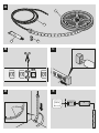 2
2
-
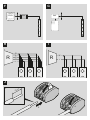 3
3
-
 4
4
-
 5
5
-
 6
6
-
 7
7
-
 8
8
-
 9
9
-
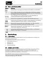 10
10
-
 11
11
-
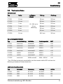 12
12
-
 13
13
-
 14
14
-
 15
15
-
 16
16
-
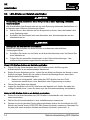 17
17
-
 18
18
-
 19
19
-
 20
20
-
 21
21
-
 22
22
-
 23
23
-
 24
24
-
 25
25
-
 26
26
-
 27
27
-
 28
28
-
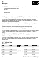 29
29
-
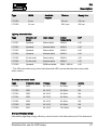 30
30
-
 31
31
-
 32
32
-
 33
33
-
 34
34
-
 35
35
-
 36
36
-
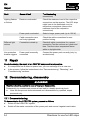 37
37
-
 38
38
-
 39
39
-
 40
40
-
 41
41
-
 42
42
-
 43
43
-
 44
44
-
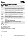 45
45
-
 46
46
-
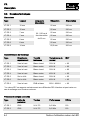 47
47
-
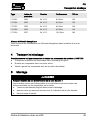 48
48
-
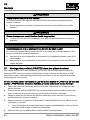 49
49
-
 50
50
-
 51
51
-
 52
52
-
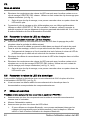 53
53
-
 54
54
-
 55
55
-
 56
56
-
 57
57
-
 58
58
-
 59
59
-
 60
60
-
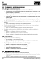 61
61
-
 62
62
-
 63
63
-
 64
64
-
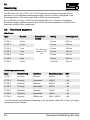 65
65
-
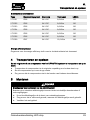 66
66
-
 67
67
-
 68
68
-
 69
69
-
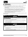 70
70
-
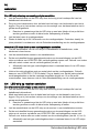 71
71
-
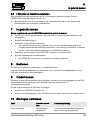 72
72
-
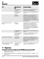 73
73
-
 74
74
-
 75
75
-
 76
76
-
 77
77
-
 78
78
-
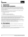 79
79
-
 80
80
-
 81
81
-
 82
82
-
 83
83
-
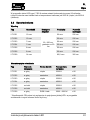 84
84
-
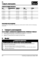 85
85
-
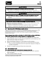 86
86
-
 87
87
-
 88
88
-
 89
89
-
 90
90
-
 91
91
-
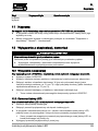 92
92
-
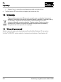 93
93
-
 94
94
-
 95
95
-
 96
96
-
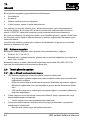 97
97
-
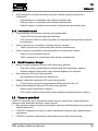 98
98
-
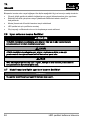 99
99
-
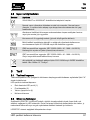 100
100
-
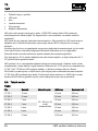 101
101
-
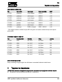 102
102
-
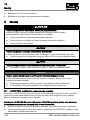 103
103
-
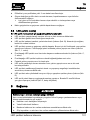 104
104
-
 105
105
-
 106
106
-
 107
107
-
 108
108
-
 109
109
-
 110
110
-
 111
111
-
 112
112
-
 113
113
-
 114
114
-
 115
115
-
 116
116
-
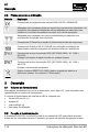 117
117
-
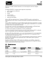 118
118
-
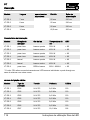 119
119
-
 120
120
-
 121
121
-
 122
122
-
 123
123
-
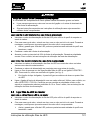 124
124
-
 125
125
-
 126
126
-
 127
127
-
 128
128
-
 129
129
-
 130
130
-
 131
131
-
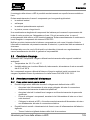 132
132
-
 133
133
-
 134
134
-
 135
135
-
 136
136
-
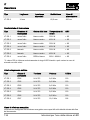 137
137
-
 138
138
-
 139
139
-
 140
140
-
 141
141
-
 142
142
-
 143
143
-
 144
144
-
 145
145
-
 146
146
-
 147
147
-
 148
148
-
 149
149
-
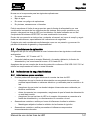 150
150
-
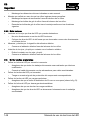 151
151
-
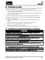 152
152
-
 153
153
-
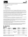 154
154
-
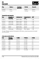 155
155
-
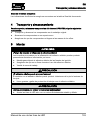 156
156
-
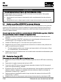 157
157
-
 158
158
-
 159
159
-
 160
160
-
 161
161
-
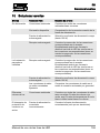 162
162
-
 163
163
-
 164
164
-
 165
165
-
 166
166
-
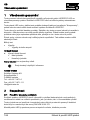 167
167
-
 168
168
-
 169
169
-
 170
170
-
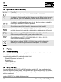 171
171
-
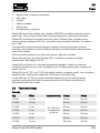 172
172
-
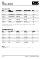 173
173
-
 174
174
-
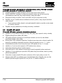 175
175
-
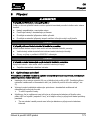 176
176
-
 177
177
-
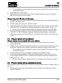 178
178
-
 179
179
-
 180
180
-
 181
181
-
 182
182
-
 183
183
-
 184
184
-
 185
185
-
 186
186
-
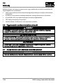 187
187
-
 188
188
-
 189
189
-
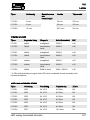 190
190
-
 191
191
-
 192
192
-
 193
193
-
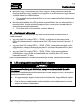 194
194
-
 195
195
-
 196
196
-
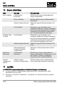 197
197
-
 198
198
-
 199
199
-
 200
200
-
 201
201
-
 202
202
-
 203
203
-
 204
204
-
 205
205
-
 206
206
-
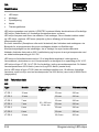 207
207
-
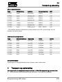 208
208
-
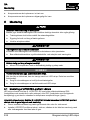 209
209
-
 210
210
-
 211
211
-
 212
212
-
 213
213
-
 214
214
-
 215
215
-
 216
216
-
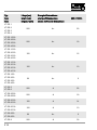 217
217
-
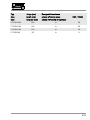 218
218
-
 219
219


Schluter Systems LIPROTEC LT ES 4 Directions For Use Manual
- Type
- Directions For Use Manual
- Deze handleiding is ook geschikt voor
in andere talen
- italiano: Schluter Systems LIPROTEC LT ES 4
- français: Schluter Systems LIPROTEC LT ES 4
- español: Schluter Systems LIPROTEC LT ES 4
- Deutsch: Schluter Systems LIPROTEC LT ES 4
- português: Schluter Systems LIPROTEC LT ES 4
- slovenčina: Schluter Systems LIPROTEC LT ES 4
- dansk: Schluter Systems LIPROTEC LT ES 4
- Türkçe: Schluter Systems LIPROTEC LT ES 4
Gerelateerde papieren
Andere documenten
-
Renkforce 1493868 de handleiding
-
-
Aurora AU-ST901 Installatie gids
-
-
Premier R+G+B Flexkit Handleiding
-
-
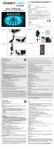 DreamLED DOIS 500 Handleiding
-
Robus RMUCOBRGB67 Handleiding
-
Roche Accutrend Plus Handleiding
-
Aurora ST324RGB Gebruikershandleiding
