
RX-V595RDS
Natural Sound AV Receiver
Récepteur audiovisuel
OWNER’S MANUAL
MODE D’EMPLOI
BEDIENUNGSANLEITUNG
BRUKSANVISNING
MANUALE DI ISTRUZIONI
MANUAL DE INSTRUCCIONES
GEBRUIKSAANWIJZING
B G
Printed in France ID
V296030
YAMAHA ELECTRONICS CORPORATION, USA 6660 ORANGETHORPE AVE., BUENA PARK, CALIF. 90620, U.S.A.
YAMAHA CANADA MUSIC LTD. 135 MILNER AVE., SCARBOROUGH, ONTARIO M1S 3R1, CANADA
YAMAHA ELECTRONIK EUROPA G.m.b.H. SIEMENSSTR. 22-34, 25462 RELLINGEN BEI HAMBURG, F.R. OF GERMANY
YAMAHA ELECTRONIQUE FRANCE S.A. RUE AMBROISE CROIZAT BP70 CROISSY-BEAUBOURG 77312 MARNE-LA-VALLEE CEDEX02, FRANCE
YAMAHA ELECTRONICS (UK) LTD. YAMAHA HOUSE, 200 RICKMANSWORTH ROAD WATFORD, HERTS WD1 7JS, ENGLAND
YAMAHA SCANDINAVIA A.B. J A WETTERGRENS GATA 1, BOX 30053, 400 43 VÄSTRA FRÖLUNDA, SWEDEN
YAMAHA MUSIC AUSTRALIA PTY, LTD. 17-33 MARKET ST., SOUTH MELBOURNE, 3205 VIC., AUSTRALIA
RX-V595RDS
00RX-V595RDS-cv1/4(AL) 6/23/99, 2:18 PM1

2
SUPPLIED ACCESSORIES
ACCESSOIRES FOURNIS
MITGELIEFERTE ZUBEHÖRTEILE
MEDFÖLJANDE TILLBEHÖR
ACCESSORI IN DOTAZIONE
ACCESORIOS INCLUIDOS
BIJGELEVERDE ACCESSOIRES
• After unpacking, check that the following parts are included.
• Après le déballage, vérifier que les pièces suivantes sont incluses.
• Nach dem Auspacken überprüfen, ob die folgenden Teile vorhanden sind.
• Kontrollera efter det apparaten packats upp att följande delar finns med.
•
Verificare che tutte le parti seguenti siano contenute nell’imballaggio dell’apparecchio.
• Desembalar el aparato y verificar que los siguientes accesorios están en la caja.
• Controleer na het uitpakken of de volgende onderdelen voorhanden zijn.
• Indoor FM Antenna
• Antenne FM intérieure
• UKW-Innenantenne
• Inomhus-FM-antenn
• Antenna FM interna
• Antena FM interior
• FM-binnenantenne
• AM Loop Antenna
• Cadre-antenna AM
• MW-Rahmenantenne
• AM-ramantenn
• Antenna AM ad anello
• Antena de cuadro de AM
• AM-raamantenne
• 75-ohm/300-ohm antenna adapter (U.K. model only)
• Adaptateur d’antenne 75 ohms/300 ohms
(Modèle Royaume-Uni seulement)
• 75-Ohm/300-Ohm Antennenstecker
(nur Großbritannien-Modell)
• 75 ohm/300 ohm antennadapter
(gäller endast modellen för Storbritannien)
• Adattatore per antenna da 75 e 300 ohm
(Soltanto il modello per la Gran Bretagna)
• Adaptador de antena de 75-ohmios/300-ohmios
(Sólo el modelo para el Reino Unido)
• 75 ohm/300 ohm antenneadapter
(Alleen modellen voor Verenigd Koninkrijk)
• Batteries (size AA, R6, UM-3)
• Piles (taille AA, R6, UM-3)
• Batterien (Größe AA, R6, UM-3)
• Batterier (storlek AA, R6, UM-3)
• Batterie (dimensioni AA, R6, UM-3)
• Pilas (tamaño AA, R6, UM-3)
• Batterijen (maat AA, R6, UM-3)
• Remote control transmitter
• Télécommande
• Fernbedienung
• Fjärrkontroll
• Telecomando
• Transmisor de control remoto
• Afstandsbediening
01RX-V595RDS-1 6/23/99, 1:10 PM2

3
English
● 5 Speaker Configuration
Main: 65 W + 65 W (8Ω) RMS Output
Power, 0.04% THD, 20 Hz – 20 kHz
Center: 65 W (8Ω) RMS Output
Power, 0.04% THD, 20 Hz – 20 kHz
Rear: 65 W + 65 W (8Ω) RMS Output
Power, 0.04% THD, 20 Hz – 20 kHz
● Digital Sound Field Processor
● Dolby Digital Decoder
● Dolby Pro Logic Surround Decoder
● CINEMA DSP: Theater-like Sound
Experience by the Combination of Dolby
Surround and YAMAHA DSP Technology
● 6-Channel External Decoder Input for DTS
and other future formats
SUPPLIED ACCESSORIES........................................... 2
FEATURES .................................................................... 3
CAUTION ....................................................................... 4
●Introduction
FEATURES ON SOUND EFFECT.................................5
CONTROLS AND THEIR FUNCTIONS ......................... 7
●Preparation
SPEAKER SETUP ....................................................... 10
CONNECTIONS........................................................... 12
ADJUSTMENTS
BEFORE USING THIS UNIT .................................. 20
●Basic Oparation
BASIC OPERATIONS .................................................. 25
TUNING OPERATIONS ............................................... 29
RECEIVING RDS STATIONS ...................................... 34
SETTING THE SLEEP TIMER..................................... 39
●Information about DSP
USING DIGITAL SOUND FIELD
PROCESSOR (DSP) .............................................. 40
●Advanced Information
ADJUSTMENTS
IN THE “SET MENU” MODE...................................46
●Remote Control Transmitter
REMOTE CONTROL TRANSMITTER......................... 48
SETUP CODES ........................................................... 53
NOTES ABOUT THE REMOTE CONTROL
TRANSMITTER ...................................................... 54
TROUBLESHOOTING ................................................. 55
SPECIFICATIONS .......................................................57
FEATURES
CONTENTS
● Automatic Input Balance Control for
Dolby Pro Logic Surround
● Test Tone Generator for Easier Speaker
Balance Adjustment
● Speaker Output Mode Changing
Capability
● 40-Station Random Access Preset Tuning
● Automatic Preset Tuning
● Preset Station Shifting Capability
(Preset Editing)
● Video Signal Input/Output Capability
(Including S Video Connections)
● SLEEP Timer
● Universal Remote Control
Transmitter with Preset Manufacturer
Codes
LIST OF MANUFACTURER’S CODES...................... 397
01RX-V595RDS-1 6/23/99, 1:10 PM3

4
CAUTION : READ THIS BEFORE OPERATING YOUR UNIT.
1. To assure the finest performance, please read this manual
carefully. Keep it in a safe place for future reference.
2. Install this unit in a cool, dry, clean place – away from
windows, heat sources, sources of excessive vibration,
dust, moisture and cold. Avoid sources of humming
(transformers, motors). To prevent fire or electrical shock,
do not expose the unit to rain or water.
3. Never open the cabinet. If something drops into the set,
contact your dealer.
4. Do not use force on switches, controls or connection wires.
When moving the unit, first disconnect the power plug and
the wires connected to other equipment. Never pull the
wires themselves.
5. The openings on the unit cover assure proper ventilation of
the unit. If these openings are obstructed, the temperature
inside the unit will rise rapidly. Therefore, avoid placing
objects against these openings, and install the unit in a
well-ventilated area to prevent fire and damage.
Be sure to allow a space of at least 20 cm behind, 20 cm
on the both sides and 30 cm above the top panel of the unit
to prevent fire and damage.
6. The voltage used must be the same as that specified on
this unit. Using this unit with a higher voltage than speci-
fied is dangerous and may result in fire or other accidents.
YAMAHA will not be held responsible for any damage
resulting from use of this unit with a voltage other than
specified.
7. Digital signals generated by this unit may interfere with
other equipment such as tuners, receivers or TVs. Move
this unit farther away from such equipment if interference is
observed.
8. Always set the VOLUME control to “∞” before starting the
audio source play. Increase the volume gradually to an
appropriate level after playback has been started.
9. Do not attempt to clean the unit with chemical solvents; this
might damage the finish. Use a clean, dry cloth.
10. Be sure to read the “TROUBLESHOOTING” section
regarding common operating errors before concluding that
the unit is faulty.
11. When not planning to use this unit for long periods of time
(ie., vacation, etc.), disconnect the AC power plug from the
wall outlet.
12. To prevent lightning damage, disconnect the AC power
plug and disconnect the antenna cable when there is an
electrical storm.
13. Grounding or polarization – Precautions should be taken so
that the grounding or polarization of an appliance is not
defeated.
14. AC outlet
Do not connect audio equipment to the AC outlet on the
rear panel if that equipment requires more power than the
outlet is rated to provide.
For U.K. customers
If the socket outlets in the home are not suitable for the plug
supplied with this appliance, it should be cut off and an appro-
priate 3 pin plug fitted. For details, refer to the instructions
described below.
Note: The plug severed from the mains lead must be de-
stroyed, as a plug with bared flexible cord is hazardous if
engaged in a live socket outlet.
Special Instructions for U.K. Model
IMPORTANT
THE WIRES IN THE MAINS LEAD ARE COLOURED IN
ACCORDANCE WITH THE FOLLOWING CODE:
Blue: NEUTRAL
Brown: LIVE
As the colours of the wires in the main lead of this apparatus
may not correspond with the coloured markings identifying
the terminals in your plug, proceed as follows:
The wire which is coloured BLUE must be connected to the
terminal which is marked with the letter N or coloured
BLACK. The wire which is coloured BROWN must be
connected to the terminal which is marked with the letter L or
coloured RED. Make sure that neither core is connected to
the earth terminal of the three pin plug.
This unit is not disconnected from the AC power source as
long as it is connected to the wall outlet, even if this unit
itself is turned off. This state is called the standby mode. In
this state, this unit is designed to consume a very small
quantity of power.
01RX-V595RDS-1 6/23/99, 1:10 PM4

5
English
FEATURES ON SOUND EFFECT
This unit incorporates a sophisticated, multi-program digital
sound field processor. The processor allows you to electroni-
cally expand and change the shape of the audio sound field
from both audio and video sources, creating a theater-like
experience in your listening room. This unit has a total of 8
digital sound field processor (DSP) modes. You can create an
excellent audio sound field by selecting a suitable sound field
(this will, of course, depend on what you will be listening to),
and adding desired adjustments.
In addition, this unit incorporates a Dolby Pro Logic Surround
decoder and Dolby Digital decoder for multi-channel sound
reproduction of Dolby Surround encoded video sources. The
operation of the Dolby Pro Logic Surround or Dolby Digital
decoder can be controlled by selecting a corresponding DSP
program including combined operations of the YAMAHA DSP
and the Dolby Pro Logic Surround or Dolby Digital decoder.
Digital Sound Field Processing
What is it that makes live music so good? Today’s advanced
sound reproduction technology lets you get extremely close to
the sound of a live performance, but chances are you’ll still
notice something missing, the acoustic environment of the live
concert hall. Extensive research into the exact nature of the
sonic reflections that create the ambience of a large hall has
made it possible for YAMAHA engineers to bring you this same
sound in your listening room, so you’ll feel all the sound of a
live concert.
Furthermore, our technicians, armed with sophisticated
measuring equipment, have even made it possible to capture
the acoustics of a variety of actual concert halls, theaters, etc.
from around the world, to allow you to accurately re-create any
one of these live performance environments, all in your home.
Dolby Pro Logic Surround
This unit employs a Dolby Pro Logic Surround decoder similar
to professional Dolby Stereo decoders used in many movie
theaters. By using the Dolby Pro Logic Surround decoder, you
can experience the dramatic realism and impact of Dolby
Surround movie theater sound in your own home. Dolby Pro
Logic employs a four channel five speaker system. The Pro
Logic Surround system divides the input signal into four levels:
the left and right main channels, the center channel (used for
dialog), and the rear surround sound channels (used for sound
effects, background noise, and other ambient noises). The
center channel allows listeners seated in even less-than-ideal
positions to hear the dialog originating from the action on the
screen while experiencing good stereo imaging.
Dolby Surround is encoded on the sound track of pre-recorded
video tapes, laser discs, and some TV/cable broadcasts. When
you play a source encoded with Dolby Surround on this unit,
the Dolby Pro Logic Surround decoder decodes the signal and
distributes the surround-sound effects.
This Dolby Pro Logic Surround decoder employs a digital signal
processing system. This system improves the stability of sound
at each channel and crosstalk between channels, so that
positioning of sounds around the room is more accurate
compared with conventional analog signal processing systems.
In addition, this unit features a built-in automatic input balance
control. This always assures you the best performance without
manual adjustment.
Dolby Digital
The built-in Dolby Digital decoder leads you into a totally new
sound experiences.
Dolby Digital is a new generation of multi-channel digital audio
technology, or the newest spatial sound processing format
developed for 35 mm film-movies by employing a new kind of
low bit-rate audio coding.
Dolby Digital is a digital surround sound system that provides
completely independent multi-channel audio to consumers. In
multi-channel form, Dolby Digital provides five full range
channels in what is sometimes referred to as a “3/2” configura-
tion: three front channels (left, center and right), plus two
surround channels. A sixth bass-only effect channel is also
provided for output of LFE (low frequency effect), or low bass
effects that are independent of other channels. This channel is
counted as 0.1, thus giving rise to the term 5.1 channels in
total.
Compared to Dolby Pro Logic that is referred to a “3/1” system
(left front, center, right front and just one surround channel),
Dolby Digital features two surround channels, called stereo or
split surrounds, each offering the same full range fidelity as the
three front channels.
Sound of wide dynamic range reproduced by the five full range
channels presents listeners much excitement that has never
been experienced before. Precise sound orientation by the
discrete digital sound processing expands realism that the
original movie possesses.
LD and DVD are home audio formats that could benefit from
Dolby Digital. In the near future, Dolby Digital will also be
applied to DBS, CATV and HDTV. The ongoing release of
Dolby Stereo Digital theatrical films now underway will provide
an immediate source of Dolby Digital encoded video software.
01RX-V595RDS-1 6/23/99, 1:10 PM5

6
Manufactured under license from Dolby Laboratories Licensing
Corporation. “Dolby”, “Pro Logic”, and the double-D symbol are
trademarks of Dolby Laboratories Licensing Corporation.
Copyright 1992 Dolby Laboratories, Inc. All rights reserved.
The following original functions make the surround-sound effect
of Dolby Digital become the most suitable for your audio
system and the listening conditions.
• Dynamic range (sound scale) of source can be changed
so that it will be suitable for the listening conditions.
• Output of low bass from any channel can be assigned to
either the MAIN SPEAKERS terminals or SUBWOOFER
terminal to maximize system performance.
• Output of LFE can be assigned to either the MAIN
SPEAKERS terminals or SUBWOOFER terminal to
maximize system performance.
Dolby Surround + DSP (CINEMA DSP)
Dolby Surround sound system shows its full ability in a large
movie theater, because movie sounds are originally designed to
be reproduced in a large movie theater using many speakers.
It is difficult to create a sound environment similar to that of a
movie theater in your listening room, because the room size,
materials of inside walls, the number of speakers, etc. of your
listening room is much different from those of a movie theater.
YAMAHA DSP technology made it possible to present you with
nearly the same sound experience as that of a large movie
theater in your listening room by compensating for lack of
presence and dynamics in your listening room with its original
digital sound fields combined with Dolby Surround sound field.
CINEMA DSP
The YAMAHA “CINEMA DSP” logo indicates those programs
are created by the combination of Dolby Surround and
YAMAHA DSP technology.
Dolby Pro Logic + 2 Digital Sound Fields
Digital sound fields are created on the presence side and the
rear surround side of the Dolby Pro Logic Surround-decoded
sound field respectively. They create a wide acoustic
environment and emphasize surround-effect in the room,
letting you feel much presence as if you are watching a
movie in a popular Dolby Stereo theater.
This combination is available when the sound field program
DOLBY PRO LOGIC ENHANCED/DOLBY DIGITAL
ENHANCED, 70 mm MOVIE THEATER/DIGITAL MOVIE
THEATER or TV SPORTS is selected, and the input signal of
source is analog, PCM audio or encoded with the Dolby
Digital in 2-channel.
Dolby Digital + 3 Digital Sound Fields
Digital sound fields are created on the presence side and the
independent left and right surround sides of the Dolby Digital-
decoded sound field respectively. They create a wide
acoustic environment and much surround effect in the room
without losing high channel separation. With wide dynamic
range of Dolby Digital sound, this sound field combination lets
you feel as if you are watching a movie in the newest Dolby
Stereo Digital theater. This will be the most ideal home
theater sound at the present time.
This combination is available when the sound field program
DOLBY PRO LOGIC ENHANCED/DOLBY DIGITAL
ENHANCED, 70 mm MOVIE THEATER/DIGITAL MOVIE
THEATER or TV SPORTS is selected, and the input signal of
source is encoded with the Dolby Digital (except in 2-chan-
nel).
01RX-V595RDS-1 6/23/99, 1:10 PM6

7
English
CONTROLS AND THEIR FUNCTIONS
FRONT PANEL
1 STANDBY/ON
Press this switch to turn the power of this unit on. Press it
again to turn this unit into the standby mode.
Standby mode
In this state, this unit consumes a very small quantity of
power to receive infrared-signals from the remote control
transmitter.
2 Remote control sensor
Receives signals from the remote control transmitter.
3 Display
Shows various information. (For details, refer to page 9.)
4 MEMORY (MAN’L/AUTO FM)
Press this button to store the broadcasting stations.
When this button is pressed and held for more than three
seconds, the automatic preset tuning begins.
5 EDIT
This button is used to exchange the places of two preset
stations with each other.
6 TUNING MODE (AUTO/MAN’L MONO)
Press this button to switch the tuning mode to automatic or
manual. To select the automatic tuning mode, press this button
so that the “AUTO TUNING” indicator lights up on the display.
To select the manual tuning mode, press this button so that the
“AUTO TUNING” indicator goes off.
7 FM/AM
Press this button to switch the reception band to FM or AM.
8 TUNING UP/DOWN
This button is used for tuning. Press the UP side to tune in to
higher frequencies, and press the DOWN side to tune in to
lower frequencies.
9 TAPE/MD MON / EXT. DECODER
Press this button to play a tape or an MD. The “TAPE/MD
MON” indicator lights up on the display.
When you press the button next, the “TAPE/MD MON” indicator
goes off and “EXT. DECDR” appears on the display and you
can play the signal connected to the EXTERNAL DECODER
INPUT terminals.
0 INPUT
Turn this selector to select the program source (VCR, VIDEO
AUX, TV/DBS, DVD/LD, CD, TUNER, PHONO) to listen to or
watch.
The name of the selected program source appears on the
display.
STANDBY/ON
TAPE/MD MON
/EXT. DECODER
–dB
0
2
4
8
12
18
20
22
40
80
1
0
2
3
4
55
4
3
2
1
2
3
4
4
3
2
1
BALANCETREBLEBASS
VIDEO AUX
PHONES
SPEAKERS
A
B
ON OFF
EON
START
PROGRAM
INPUT
VCR • V
–
AUX • TV
/
DBS • DVD
/
LD • CD • TUNER • PHONO
VOLUME
L
NATURAL SOUND AV RECEIVER
CINEMA DSP
8 VIDEO VIDEO
AUDIO R
A
/
B
/
C
/
D
/
E1 2
3
4
5
678
TUNING
MODE
MEMORY EDIT
FM/AM
DOWN
TUNING
UP
INPUT MODE
0
1
1
0
2
3
4
5 RL 5
4
3
2
1
RDS
MODE
TIME/
LEVEL
SET
MENU
EFFECT
PTY SEEK
MODE
55
MAN’L
/
AUTO FM AUTO
/
MAN’L MONO
01RX-V595RDS-1 6/23/99, 1:10 PM7

8
q INPUT MODE
Switches the DVD/LD and TV/DBS input signal mode (AUTO/
ANALOG).
w VOLUME
This control is used to raise or lower the volume level.
e PHONES jack
When you use headphones, connect the headphones to the
PHONES jack. You can listen to the sound to be output from
the main speakers through headphones.
When using headphones only, set both SPEAKERS A and B to
the OFF position and switch off the digital sound field processor
(so that no DSP program name appears on the display) by
pressing EFFECT.
PHONES
r SPEAKERS
Set A or B (or both A and B) to the ON position for the main
speaker system (connected to this unit) you will use. Set it (or
them) for the main speaker system you will not use to the OFF
position.
t A/B/C/D/E
Press this button to select a group (A to E) of preset stations.
y Preset station number selector
Select a preset station number (1 to 8).
u Tone controls
These controls are effective only for the sound from the main
speakers.
BASS
Used to increase or decrease the low frequency response. The
“0” position produces flat response.
TREBLE
Used to increase or decrease the high frequency response.
The “0” position produces flat response.
i BALANCE
This control is effective only for the sound from the main
speakers.
Adjusts the balance of the output volume to the left and right
speakers to compensate for sound imbalance caused by
speaker location or listening room conditions.
o RDS MODE
When an RDS station is received, pressing this button changes
the display mode into the PS mode, PTY mode, RT mode and/
or CT mode (if the station employs those RDS data services) in
turn.
p PTY SEEK MODE
When this button is pressed, the unit turns into the PTY SEEK
mode.
a PTY SEEK START
Press this button to begin searching for a station after the
desired program type is selected in the PTY SEEK mode.
s EON
Press this button to select a desired program type (NEWS,
INFO, AFFAIRS, SPORT) when you want to call a radio
program of that program type automatically.
d TIME/LEVEL
Press this button to select the setting of delay time or speaker
output levels in the TIME/LEVEL mode.
f +/–
These buttons are used to adjust settings of the SET MENU
mode and the TIME/LEVEL mode. In the TIME/LEVEL mode,
press + to increase delay time or speaker output levels. Press
– to decrease delay time or speaker output levels.
g SET MENU
Press this button to select functions in the SET MENU mode.
h PROGRAM selector
Press
or to select the DSP program.
The name of the selected program appears on the display.
j EFFECT
Switches on and off the output from the center and rear
speakers so that the sound becomes normal 2-channel.
* Even if the output from the center and rear speakers is off,
when the Dolby Digital is decoded, the signals at all channels
are distributed to the main channels and output from the main
speakers.
k VIDEO AUX terminals
Connect an auxiliary video or audio input source unit such as a
camcorder to these terminals. If the connected video unit has a
S video output terminal, connect it to the S VIDEO terminal to
obtain a high resolution picture. The source connected to these
terminals can be selected by INPUT.
01RX-V595RDS-1 6/23/99, 1:10 PM8

9
English
1 Multi-information display
Displays various information, for example station frequency,
preset station number and name of selected input source.
2 MEMORY indicator
When MEMORY is pressed, this indicator flashes for about five
seconds. During this period, the displayed station can be
stored to the memory.
3 AUTO TUNING indicator
Lights up when this unit is in the automatic tuning mode.
4 TAPE/MD MON indicator
Lights up when the tape deck (or MD recorder etc.) is selected as
the input source by pressing TAPE/MD MON / EXT. DECODER
on the front panel or TAPE/MD on the remote control transmitter.
5 STEREO indicator
Lights up when an FM stereo broadcast with sufficient signal
strength is received.
6 Signal-level meter
Indicates the signal level of the received station.
If multipath interference is detected, the indication decreases.
7 RDS mode indicators
The name(s) of RDS mode(s) employed by the currently
received RDS station light(s) up. Illumination of the indicator on
the head of a name shows that the corresponding RDS mode is
now selected.
DISPLAY PANEL
8
, and indicators
“
” lights up when the built-in Dolby Digital decoder is
on and the signals of selected source encoded with the Dolby
Digital is not in 2-channel. “ ” lights up when the built-in
digital sound field processor is on, and “
” lights up
when the built-in Dolby Pro Logic Surround decoder is on.
Depending on the selected DSP program, both “ ” and
“ ”, or both “ ” and “ ” will light up.
9 PTY HOLD indicator
Lights up while the search is performed in the PTY SEEK
mode.
0 EON indicator
Lights up when an RDS station that employs the EON data
service is received.
q Program type name indicators
The name selected in the EON mode lights up.
w SLEEP indicator
Lights up while the built-in SLEEP timer is functioning.
01RX-V595RDS-1 6/23/99, 1:11 PM9

10
SPEAKER SETUP
This unit is designed to provide the best sound-field quality with
a 5-speaker configuration, using main speakers, rear speakers
and a center speaker.
The main speakers are used for the main source sound plus
the effect sounds. They will probably be the speakers from
your present stereo system. The rear speakers are used for
the effect and surround sounds, and the center speaker is for
the center sounds (dialog, vocals, etc.). If for some reason it is
not practical to use a center speaker, you can do without it.
Best results, however, are obtained with the full system.
The main speakers should be high performance models and
have enough power handling capacity to accept the maximum
output of your audio system.
Other speakers do not have to be equal to the main speakers.
For precise sound localization, however, it is ideal to use high
performance models that can reproduce sounds in the full
range for the center speaker and the rear speakers.
5-Speaker Configuration
This configuration is the most effective and recommended one.
When playing back a source using the DSP program,
DOLBY PRO LOGIC/DOLBY DIGITAL, DOLBY PRO LOGIC
ENHANCED/DOLBY DIGITAL ENHANCED, 70 mm MOVIE
THEATER/DIGITAL MOVIE THEATER, MONO MOVIE or TV
SPORTS, or when playing back a source which contains
center-channel signals (dialog, vocals, etc.) using any DSP
program with the Dolby Digital decoded, conversations will be
output from the center speaker and the ambience will be
excellent.
Note: Set the CNTR (CENTER SPEAKER) mode to the
“LARGE” or “SMALL” position. (For details, see
page 20.)
SPEAKER CONFIGURATION
Use of a subwoofer expands your sound field
It is also possible to further expand your system with the
addition of a subwoofer and amplifier. The use of a subwoofer
is effective not only for reinforcing bass frequencies from any or
all channels, but also for reproducing the LFE (low frequency
effect) sound with high fidelity when playing back a source with
the Dolby Digital decoded. You may wish to choose the
convenience of a YAMAHA Active Servo Processing Subwoofer
System, which has its own built-in power amplifier.
4-Speaker Configuration
The center speaker is not used in this configuration. When
playing back a source using the DSP program, DOLBY PRO
LOGIC/DOLBY DIGITAL, DOLBY PRO LOGIC ENHANCED/
DOLBY DIGITAL ENHANCED, 70 mm MOVIE THEATER/
DIGITAL MOVIE THEATER, MONO MOVIE or TV SPORTS, or
when playing back a source which contains center-channel
signals (dialog, vocals, etc.) using any DSP program with the
Dolby Digital decoded, the center sound is output from the left
and the right main speakers. However, the sound effect of
other programs will be the same as that of the 5-speaker
configuration.
Note: Be sure to set the CNTR (CENTER SPEAKER) mode to
the “NONE” position. (For details, see page 20.)
Main L Center Main R
Surround sound
Dialog
Surround sound
Rear L
Rear R
Main L Main R
Surround sound
Dialog
Surround sound
Rear L Rear R
SPEAKERS TO BE USED
01RX-V595RDS-2 6/23/99, 1:11 PM10

11
English
SPEAKER PLACEMENT
When you place the speakers, refer to the following diagram:
Main: The position of your present stereo speaker
system.
Rear: Behind your listening position, facing slightly
inward. Nearly 1.8 m (approx. 6 feet) up from the
floor.
Center: Precisely between the main speakers. (To avoid
interference with TV sets, use a magnetically
shielded speaker.)
Subwoofer: The position of the subwoofer is not so critical
because low bass tones are not highly directional.
Main speaker
Center speaker Rear speaker
Subwoofer
01RX-V595RDS-2 6/23/99, 1:11 PM11

12
CONNECTIONS
Never plug in this unit and other components until all connections are completed.
CONNECTIONS WITH OTHER COMPONENTS
When making connections between this unit and other components, be sure all connections are made correctly, that is to say L
(left) to L, R (right) to R, “+” to “+” and “–” to “–”. Also, refer to the owner’s manual for each component to be connected to this unit.
* If you have YAMAHA components numbered as !, #, $, etc. on the rear panel, connections can be made easily by making sure
to connect the output (or input) terminals of each component to the same-numbered terminals of this unit.
, : See the next page.
Turntable Monitor TV DVD player, LD player, etc.
CD player Tape deck,
MD recorder, etc.
TV/DBS tuner VCR
(Video cassette recorder)
To AC outlet
(Europe model)
01RX-V595RDS-2 6/23/99, 1:11 PM12

13
English
R
L
R
L
SWITCHED AC OUTLET(S)
(Europe model) .................................. 2 SWITCHED OUTLETS
(U.K. model) ..........................................1 SWITCHED OUTLET
Use these to connect the power cords from your components to
this unit.
The power to the SWITCHED outlets is controlled by this unit’s
STANDBY/ON or the provided remote control transmitter’s
POWER and STANDBY. These outlets will supply power to
any component whenever this unit is turned on.
The maximum power (total power consumption of components)
that can be connected to the SWITCHED AC OUTLET(S) is
100 watts.
GND terminal (For turntable use)
Connecting the ground wire of the turntable to the GND
terminal will normally minimize hum, but in some cases better
results may be obtained with the ground wire disconnected.
CONNECTING TO AN EXTERNAL DECODER
When using the DTS or other decoder with 6-channel discrete outputs, connect the 6CH DISCRETE OUTPUT terminals of the
decoder to the EXTERNAL DECODER INPUT terminals of this unit.
DTS or other decoder with 6-channel
discrete outputs
DVD player, LD player or other
unit with digital outputs
(Europe model)
01RX-V595RDS-2 6/23/99, 1:11 PM13

14
CONNECTING TO DIGITAL (COAXIAL AND/OR OPTICAL) TERMINALS
If your DVD (LD) player, TV/DBS tuner, etc. are equipped with
coaxial or optical digital audio signal output terminals, they can
be connected to this unit’s COAXIAL and/or OPTICAL digital
signal input terminals.
To make a connection between optical digital audio signal
terminals, remove the cover from each terminal, and then
connect them by using a commercially available optical fiber
cable that conforms to EIAJ standards. Other cables might not
function correctly.
Even if you connect an audio/video unit to the COAXIAL (or
OPTICAL) terminal of this unit, you must keep the unit con-
nected with the same named analog audio signal terminals of
this unit, because digital signal cannot be recorded by a tape
deck or VCR connected to this unit. You can switch the
selection of input signals between “digital” and “analog” easily.
(See page 27 for details.)
Notes
• When connecting an audio/video unit to both of the digital
and analog terminals of this unit, make sure to connect to
both terminals of the same name.
• Be sure to attach the covers when the OPTICAL terminals
are not being used, in order to protect the terminals from
dust.
• The input signal from the DVD/LD input terminals is selected
in the following order of priority.
(input mode: AUTO position)
1 COAXIAL terminal
2 OPTICAL terminal
3 ANALOG terminal
• All digital audio signal input terminals are applicable to the
sampling frequency of 32 kHz, 44.1 kHz and 48 kHz.
DVD or LD player TV/DBS tuner
R
L
(Europe model)
01RX-V595RDS-2 6/23/99, 1:11 PM14

15
English
CONNECTING TO S VIDEO TERMINALS
If you have a VCR and a monitor equipped with “S” (high-
resolution) video terminals, those terminals can be connected
to this unit’s S VIDEO terminals. Connect the VCR’s “S” video
input and output terminals to this unit’s S VIDEO VCR OUT and
IN terminals respectively, and connect the monitor’s “S” video
input terminal to this unit’s S VIDEO MONITOR OUT terminal.
Otherwise, connect the VCR’s composite video terminals to this
unit’s composite VIDEO terminals, and connect the monitor’s
composite video input terminal to this unit’s composite
MONITOR OUT terminal.
Note
If video signals are sent to both S VIDEO input and com-
posite input terminals, the signals will be sent to their
respective output terminals.
Monitor TV
VCR
Camcorder
CONNECTING TO VIDEO AUX TERMINALS (ON THE FRONT PANEL)
These terminals are used to connect any video input source, such as a camcorder, to this unit.
01RX-V595RDS-2 6/23/99, 1:11 PM15

16
Note
Use speakers with the specified impedance shown on the
rear panel of this unit.
Note on main speaker connections:
One or two speaker systems can be connected to this unit. If
you use only one speaker system, connect it to either the
SPEAKERS A or B terminals.
Note on a subwoofer connection:
You may wish to add a subwoofer to reinforce low frequencies
or to output low bass sound from the subwoofer channel.
If you have a subwoofer with built-in amplifier, including the
YAMAHA Active Servo Processing Subwoofer System, connect
the SUBWOOFER OUTPUT terminal of this unit to the input
terminal of the subwoofer system.
If you have an amplifier and a subwoofer, connect the
SUBWOOFER OUTPUT terminal of this unit to the input
terminal of the subwoofer amplifier, and then connect the
speaker terminals of the subwoofer amplifier to the subwoofer.
Note on center speaker connection:
Center speaker can be connected to this unit. Place it on or
under the TV.
CONNECTING SPEAKERS
Rear speakers
Subwoofer system
Center speaker
Right
Left
Main speakers A Main speakers B
Right
Left
Right Left
01RX-V595RDS-2 6/23/99, 1:11 PM16

17
English
OUTPUT TERMINALS (FOR DRIVING SPEAKERS WITH EXTERNAL AMPLIFIERS)
MAIN OUTPUT terminals
These terminals are for the main channel line output. There is
no connection to these terminals when you use the built-in
amplifier.
However, if you drive the main speakers with an external stereo
power amplifier, connect the input terminals of the external
amplifier (MAIN IN or AUX terminals of a power amplifier or an
integrated amplifier) to these terminals.
* Output signals from the MAIN OUTPUT terminals are
affected by the use of BASS, TREBLE, and BALANCE.
CENTER OUTPUT terminals
These terminals are for the center channel line output. There is
no connection to these terminals when you use the built-in
amplifier.
How to connect
Connect the SPEAKERS terminals to your speakers with wire of the proper gauge, cut as short as possible. If the connections are
faulty, no sound will be heard from the speakers. Make sure that the polarity of the speaker wires is correct, that is the + and –
markings are observed. If these wires are reversed, the sound will be unnatural and lack bass.
Caution
Do not let the bare speaker wires touch each other and do not let them touch any metal part of this unit. This could
damage this unit and/or speakers.
For connecting to the MAIN SPEAKERS
terminals
Red: positive (+)
Black: negative (–)
1 Unscrew the knob.
2 Insert the bare wire.
[Remove approx. 5 mm
(1/4”) insulation from the
speaker wires.]
3 Tighten the knob and
secure the wire.
1 Press the tab.
2 Insert the bare wire.
[Remove approx. 5 mm
(1/4”) insulation from
the speaker wires.]
3 Release the tab and
secure the wire.
However, if you drive a center speaker with an external power
amplifier, connect the input terminal of the external amplifier to
this terminal.
If you are placing two center speakers on each side of the TV,
use two amplifiers and connect each amplifier to one of the two
CENTER OUTPUT terminals. Then connect the center
speakers to the amplifiers.
REAR (SURROUND) OUTPUT terminals
These terminals are for the rear channel line output. There is
no connection to these terminals when you use the built-in
amplifier.
However, if you drive the rear speakers with an external stereo
power amplifier, connect the input terminals of the external
amplifier (MAIN IN or AUX terminals of a power amplifier or an
integrated amplifier) to these terminals.
SUBWOOFER OUTPUT terminal
This terminal is for connecting to the input terminal of an
amplifier for driving a subwoofer.
When the input signals to this unit are in normal 2-channel
stereo, this terminal outputs only frequencies below 90 Hz from
the main and center channels. When discrete signals are input
to this unit and are selected as the input source, this terminal
outputs signals from the subwoofer channel.
Note
Output levels of signals from all of these terminals are
adjusted by the use of VOLUME on the front panel or
VOLUME (
) on the remote control transmitter.
1
2
3
2
3
1
For connecting to the REAR and CENTER
SPEAKERS terminals
Red: positive (+)
Black: negative (–)
01RX-V595RDS-2 6/23/99, 1:11 PM17

18
IMPEDANCE SELECTOR SWITCH
Select the position whose requirements your speaker system
meets.
(Upper position)
Main: If you use one pair of main speakers, the impedance of
each speaker must be 4Ω or higher.
If you use two pairs of main speakers, the impedance
of each speaker must be 8Ω or higher.
Center: The impedance of the speaker must be 6Ω or higher.
Rear: The impedance of each speaker must be 6Ω or higher.
(Lower position)
Main: If you use one pair of main speakers, the impedance of
each speaker must be 8Ω or higher.
If you use two pairs of main speakers, the impedance
of each speaker must be 16Ω or higher.
Center: The impedance of the speaker must be 8Ω or higher.
Rear: The impedance of each speaker must be 8Ω or higher.
WARNING
Do not change the IMPEDANCE SELECTOR switch setting
while the power of this unit is on, otherwise this unit may be
damaged.
IF THIS UNIT FAILS TO TURN ON WHEN THE STANDBY/
ON SWITCH IS PRESSED, the IMPEDANCE SELECTOR
switch may not be fully set to either end. If so, set the switch
to either end fully.
IMPEDANCE SELECTOR
(Europe model)
01RX-V595RDS-2 6/23/99, 1:11 PM18

19
English
Connecting the AM loop antenna
* The AM loop antenna should be placed away from this unit. The antenna may be hung on a wall.
* The AM loop antenna always should be connected, even if an outdoor AM antenna is connected to this unit.
PHONO
75
Ω
UNBAL.
FM
ANT
GND
AM
ANT
GND
1
3
2
ANTENNA CONNECTIONS
Each antenna should be correctly connected to the designated terminals, referring to the following diagram.
Both AM and FM indoor antennas are included with this unit. In general, these antennas will probably provide sufficient signal
strength. Nevertheless, a properly installed outdoor antenna will give clearer reception than an indoor one. If you experience poor
reception quality, an outdoor antenna may result in improvement.
GND TERMINAL
For maximum safety and minimum interference, connect the
GND terminal to a good earth ground. A good earth ground is a
metal stake driven into moist earth.
Notes
• When connecting the indoor FM
antenna, insert its connector into
the FM ANT terminal firmly.
• If you need an outdoor FM antenna
to improve FM reception quality,
either 300-ohm feeder or coaxial
cable may be used. In locations
troubled by electrical interference, coaxial cable is preferable.
Orient so that the best
reception is obtained.
12 3
Outdoor FM antenna
75-ohm/300-ohm
antenna adapter
75-ohm coaxial cable
75-ohm/300-ohm
antenna adapter
300-ohm feeder
Ground
AM loop
antenna
(included)
Outdoor AM antenna
Indoor FM
antenna
(included)
01RX-V595RDS-2 6/23/99, 1:11 PM19

20
ADJUSTMENTS BEFORE USING THIS UNIT
SELECTING THE OUTPUT MODES
This unit provides you the following five functions to determine the method of distributing output signals to speakers suitable for
your audio system. When speaker connections are all completed, select a proper position on each function to make the best use of
your speaker system. (See “ADJUSTMENTS IN THE ‘SET MENU’ MODE” on page 46.)
1. CNTR (CENTER SPEAKER) 2. REAR (REAR SPEAKER) 3. MAIN (MAIN SPEAKER)
4. BASS (LFE/BASS OUT) 5. M.LVL (MAIN LEVEL)
DESCRIPTION OF EACH FUNCTION
1. CNTR (CENTER SPEAKER)
Choices: LARGE/SMALL/NONE
Preset position: LARGE
LARGE: Select this position when your center speaker is
approximately the same size as the main speakers.
SMALL: Select this position when you use a center speaker
that is smaller than the main speakers.
In this position, low bass signals (below 90 Hz) at the
center channel are output from the main speakers (or
the SUBWOOFER OUTPUT terminal if the SMALL
position is selected on “3. MAIN” and the SW position
is selected on “4. BASS”).
NONE: Select this position when you do not have a center
speaker. The center channel sound will be output
from the left and right main speakers.
2. REAR (REAR SPEAKER)
Choices: LARGE/SMALL
Preset position: LARGE
LARGE: Select this position if your rear speakers have a high
ability for bass reproduction, or a subwoofer is
connected to the rear speaker in parallel.
In this position, full range signals are output from the
rear speakers.
SMALL: Select this position if your rear speakers do not have
a high ability for bass reproduction.
In this position, low bass signals (below 90 Hz) at the
rear channels are output from the SUBWOOFER
OUTPUT terminal (or the main speakers if the MAIN
position is selected on “4. BASS”).
3. MAIN (MAIN SPEAKER)
Choices: LARGE/SMALL
Preset position: LARGE
LARGE: Select this position if your main speakers have a
high ability for bass reproduction.
In this position, full range signals present at the main
channels are output from the main speakers.
SMALL: Select this position if your main speakers do not
have a high ability for bass reproduction. However, if
your system does not include a subwoofer, do not
select this position.
In this position, low bass signals (below 90 Hz) at the
main channels are output from the SUBWOOFER
OUTPUT terminal if the SW or BOTH position is
selected on “4. BASS”.
4. BASS (LFE/BASS OUT)
Choices: SW/MAIN/BOTH
Preset position: SW
MAIN: Select this position if your system does not include a
subwoofer.
In this position, full range signals present at the main
channels, signals from the LFE channel and other
low bass signals that are selected on “1. CNTR” to
“3. MAIN” to be distributed from other channels are
output from the main speakers.
SW/BOTH:
Select either the SW or BOTH position if your
system includes a subwoofer.
In either position, signals at LFE channel and other
low bass signals that are selected on “1. CNTR” to
“3. MAIN” to be distributed from other channels are
output from the SUBWOOFER OUTPUT terminal.
When the LARGE position is selected on “3. MAIN”,
in the SW position, no signal is distributed from the
main channels to the SUBWOOFER OUTPUT
terminal, however in the BOTH position, low bass
signals from the main channels are output to both of
the main speakers and the SUBWOOFER OUTPUT
terminal.
5. M.LVL (MAIN LEVEL)
Choices: NORMAL (NRML)/–10 dB
Preset position: NORMAL (NRML)
NORMAL (NRML):
Normally select this position.
–10 dB: Select this position if the sound output from the main
speakers is too loud and cannot be balanced with
the sound output from the center and rear speakers.
In this position, the sound output from the main
speakers is attenuated.
01RX-V595RDS-2 6/23/99, 1:11 PM20

21
English
ADJUSTING METHOD
Operations should be made while watching the information on this unit’s display.
If you are using the remote control transmitter, set the
SELECTOR DIAL to the AMP/TUN or DSP position on the
remote control transmitter.
or
1 Turn the power on.
Front panel Remote control
or
2 Press SET MENU once or more to select the title
“1. CNTR” (so that “CNTR” appears on the display).
Front panel Remote control
or
* After pressing SET MENU once on the remote control
transmitter, you can also select the title by pressing
.
(Pressing
goes back one selection.)
Appears.
1
2
3
1 2
3
3 Press + or – once or more to select the position you
want.
Front panel Remote control
or
Changes.
4 Repeat steps 2 and 3 to change selections on
“2. REAR”, “3. MAIN”, “4. BASS” and/or “5. M.LVL” in
the same way.
01RX-V595RDS-2 6/23/99, 1:11 PM21

22
SPEAKER BALANCE ADJUSTMENT
This procedure lets you adjust the sound output level balance between the main, center and rear speakers using the built-in test
tone generator. When this adjustment is performed, the sound output level heard at the listening position will be the same from
each speaker. This is important for the best performance of the digital sound field processor, the Dolby Digital decoder and the
Dolby Pro Logic Surround decoder.
The adjustment of each speaker output level should be done at your listening position with the remote control transmitter.
After completing the adjustment of the output level for each speaker, use VOLUME (
) on the remote control transmit-
ter at your listening position to check if the adjustments are satisfactory.
Set the SELECTOR DIAL to the AMP/TUN or DSP position
on the remote control transmitter.
or
1 Set VOLUME to the “∞” position.
Front panel
2 1
4,74
3
2
8
5,9
6
2 Turn the power on.
Front panel Remote control
or
3 Select the main speakers to be used.
Front panel
* If you use two main speaker systems, press both A and B.
01RX-V595RDS-2 6/23/99, 1:11 PM22

23
English
6 Turn up the volume.
Remote control
You will hear a test tone (like pink noise) from the left main
speaker, then the center speaker, then the right main
speaker, then the right rear speaker, and then the left rear
speaker, for about two seconds each. The display changes
as shown below.
* If the function “1. CNTR” in the SET MENU mode is set to
the NONE position, you will hear the center channel test
tone from the left and right main speakers.
7 Adjust BALANCE so that the sound output level of the
left main speaker and the right main speaker is the
same.
Front panel
Main (L)
Center
Main (R)
Rear (R)
Rear (L)
4 Set BASS, TREBLE and BALANCE to the “0” position.
Front panel
5 Press TEST (so that “TEST LEFT” appears on the
display).
Remote control
Appears.
01RX-V595RDS-2 6/23/99, 1:11 PM23

24
8 Adjust the sound output levels of the center speaker
and the rear speakers so that they become almost as
same as that of the main speakers.
Remote control
a) Press or once or more so that “CENTER”, “R SUR.”
or “L SUR.” appears on the display.
* Select “CENTER” to adjust the output level of the
center speaker and select “R SUR.” or “L SUR.” to
adjust the output level of the rear speakers.
Remote control
b) Adjust the level.
* Pressing
raises and lowers the level.
* While adjusting, the test tone is fixed on the selected
speaker.
Remote control
9 Press TEST once more to cancel the test tone.
Remote control
“TEST” disappears.
Notes
• Once you have completed these adjustments, you can adjust
the overall sound level on your audio system by using
VOLUME (or VOLUME (
) on the remote control
transmitter) only.
• If you use external power amplifiers, you may also use their
volume controls to achieve the proper balance.
• If the function “1. CNTR” in the SET MENU mode is set to the
NONE position, the sound output level of the center speaker
cannot be adjusted in step 8. The center sound is automati-
cally output from the left and right main speakers.
• If there is insufficient sound output from the center and rear
speakers, you may decrease the main speaker output level
by setting “5. M.LVL” to “–10 dB”.
01RX-V595RDS-2 6/23/99, 1:11 PM24

25
English
BASIC OPERATIONS
TO PLAY A SOURCE
3 Select the desired input source by using INPUT.
(For video sources, turn the TV/monitor ON.)
See page 27 if you are using an external decoder or
playing a tape or an MD.
Front panel Remote control
or
The name of the selected input source will appear on the
display.
Notes
• Set the SELECTOR DIAL to the AMP/TUN position on the remote control transmitter.
• To operate the CD player, DVD/LD player, tape deck, MD recorder, or other components using this remote control transmitter, set
the SELECTOR DIAL to the component to be used. (See “SETUP CODES” on page 53.)
1 Set VOLUME to the “∞” position.
Front panel
2 Turn the power on.
Front panel Remote control
or
2
5 4
3 1,7
2
7
3,4
01RX-V595RDS-3 6/23/99, 1:12 PM25

26
8 If desired, adjust BASS, TREBLE, BALANCE, etc.
(see below) and use the digital sound field processor.
(see page 40.)
Selecting the SPEAKER system
Because one or two speaker systems (as main speakers) can
be connected to this unit, SPEAKERS allow you to select
speaker system A or B, or both at once.
Adjusting the BALANCE control
Adjust the balance of the output volume from the left and right
speakers to compensate for sound imbalances caused by
speaker location or listening room conditions.
Note
This control is effective only for the sound from the main
speakers.
Adjusting the BASS and TREBLE controls
BASS: Turn this clockwise to increase (or counter-clockwise
to decrease) the low frequency response.
TREBLE
: Turn this clockwise to increase (or counter-clockwise
to decrease) the high frequency response.
Note
These controls are effective only for the sound from the main
speakers.
4 For the DVD/LD or TV/DBS source, the current input
mode is also shown.
* To change the input mode for the DVD/LD or TV/DBS
source, press INPUT MODE (or the button that you
have pressed to select the input source in step 3 on
the remote control transmitter) once or more until the
desired input mode (AUTO or ANALOG) is shown on
the display. (See page 27 for details on switching the
input mode.)
Front panel Remote control
or
Input mode
5 Select the main speakers to be used.
Front panel
* If you use two main speaker systems, press both A and B.
6 Play the source. (For detailed information on tuning,
see page 29.)
7 Adjust the volume to the desired output level.
Front panel Remote control
or
01RX-V595RDS-3 6/23/99, 1:12 PM26

27
English
To play a tape or an MD
Press TAPE/MD MON / EXT. DECODER so that the “TAPE/MD
MON” indicator lights up on the display, then play the tape or MD.
Front panel Remote control
or
To stop playing the tape or MD, press TAPE/MD MON / EXT.
DECODER twice so that the “TAPE/MD MON” indicator and
“EXT. DECDR” disappear from the display and the play stops
(or press TAPE/MD once on the remote control transmitter).
To use a decoder connected to the EXTERNAL
DECODER INPUT terminals
Press TAPE/MD MON / EXT. DECODER once or more so that
the “EXT. DECDR” appears on the display.
Start the play by operating the DTS or other external decoder,
DVD player or LD player.
Front panel Remote control
or
To stop playing, press TAPE/MD MON / EXT. DECODER once
so that “EXT. DECDR” disappears from the display and the play
stops (or press EXT. DEC. on the remote control transmitter).
When you finish using this unit
Press STANDBY/ON on the front panel again or STANDBY on
the remote control transmitter to turn this unit into the standby
mode.
Notes on using INPUT
• By using INPUT, you can select the program sources
connected to the input terminals on the rear panel.
• To play a video source connected to the VIDEO AUX
terminals on the front panel, set INPUT to the VIDEO AUX
position.
• The audio source selected by INPUT will not be played if the
“TAPE/MD MON” indicator lights up or if “EXT. DECDR” is
displayed.
• If you select INPUT for a video source without canceling the
selection of TAPE/MD MON / EXT. DECODER on the front
panel (or, TAPE/MD or EXT. DEC. on the remote control
transmitter), the playback result will be the video image from
the video source and the sound from the input source
selected by TAPE/MD MON / EXT. DECODER on the front
panel (or, TAPE/MD or EXT. DEC. on the remote control
transmitter).
• Once you play a video source, its video image will not be
interrupted even if INPUT for an audio source is selected.
• When you select an input source by using INPUT, the DSP
program (or no DSP program) that was used when the same
input source was selected the last time, will be automatically
recalled.
Switching the input mode
(for DVD/LD and TV/DBS)
This unit allows you to switch the input mode only for sources
connected to the DVD/LD and TV/DBS input terminals (on the
rear panel of this unit) that input two or three types of signals.
The following two input modes are provided.
AUTO: For the source connected to the DVD/LD input
terminals:
This mode is automatically selected when you turn the
power of this unit on. In this mode, input signal is
automatically selected in the following order of priority.
1. Digital input signal from the COAXIAL terminal
2. Digital input signal from the OPTICAL terminal
3. Analog input signal
For the source connected to the TV/DBS input
terminals:
This mode is selected when you turn the power of this
unit on if the AUTO position is selected on “10. INPUT”
in the SET MENU mode. (For details, see page 47.)
In this mode, input signal is automatically selected in
the following order of priority.
1. Digital input signal from the OPTICAL terminal
2. Analog input signal
ANALOG:
In this mode, only analog input signal is selected even
if a digital signal is input at the same time.
Select this mode when you want to use the analog
input signal instead of the digital input signal.
Notes on input mode selection
• To playback a source with the Dolby Digital-decoded, set the
input mode to AUTO.
• For the TV/DBS source only, the input mode selected on the
function “10. INPUT” in the SET MENU mode is effective
when you turn the power of this unit on.
• When you want to enjoy a source which has normal
2-channel signals with a Dolby Pro Logic Surround program,
select the ANALOG mode.
• In the AUTO mode, there may be a case depending on some
LD players or DVD players that when you make a search on
a source encoded with the Dolby Digital during the play and
then the play is restored, sound output is interrupted for a
moment because the digital input signal is selected again.
01RX-V595RDS-3 6/23/99, 1:12 PM27

28
TO RECORD A SOURCE TO TAPE OR MD
4 1 2
2
1,4
1 Select the source to be recorded.
Front panel Remote control
or
2 Play the source and then turn VOLUME up to confirm
the input source. (For detailed information on tuning,
see page 29.)
Front panel Remote control
or
3 Begin recording on the tape deck, MD recorder or VCR
connected to this unit.
4 When the tape deck or MD recorder is used for
recording, you can monitor the sounds being recorded
by pressing TAPE/MD MON / EXT. DECODER so that
the “TAPE/MD MON” indicator lights up on the display.
Front panel Remote control
or
Notes
• The settings of DSP and VOLUME, BASS, TREBLE and
BALANCE have no effect on the material being recorded.
• Composite video and S video signals pass independently
through this unit’s video circuits. Therefore, when recording
or dubbing video signals, if your video source unit is con-
nected to provide only an S video (or only a composite video)
signal, you can record only an S video (or only a composite
video) signal on your VCR.
• A source that is connected to this unit through digital termi-
nals only cannot be recorded by a tape deck or VCR con-
nected to this unit.
• Please check the copyright laws in your country to record
from records, compact discs, radio, etc. Recording of
copyright material may infringe copyright laws.
If you watch a video software that uses scrambled or
encoded signals to prevent it from being dubbed, there may
be a case that the picture itself will be affected by those
signals.
01RX-V595RDS-3 6/23/99, 1:12 PM28

29
English
AUTOMATIC TUNING
1 Select the reception band (FM or AM) confirming it on
the display.
Front panel
or
2 Press TUNING MODE (so that the “AUTO TUNING”
indicator lights up on the display).
Front panel
Lights up.
3 To tune in to a higher frequency, press the UP side of
TUNING once.
To tune in to a lower frequency, press the DOWN side
of TUNING once.
Front panel
* If the station where the tuning search stops is not the
desired one, press once more.
* If the tuning search does not stop at the desired station
(because the signal from the station is weak), operate the
manual tuning procedure.
TUNING OPERATIONS
Set the SELECTOR DIAL to the AMP/TUN position on the remote control transmitter and select the tuner by using INPUT.
Normally, if station signals are strong and there is no interference, quick automatic-search tuning (AUTOMATIC TUNING) is
possible. However, if the signal from the station you want to select is weak, you must tune in to it manually (MANUAL TUNING).
MANUAL TUNING
1 Select the reception band (FM or AM) confirming it on
the display.
Front panel
or
2 Press TUNING MODE.
Front panel
3 Tune in to the desired station manually.
Front panel
* To continue the tuning search, press and hold the button.
Notes
• If you tune in to an FM station manually, it is received in
monaural mode automatically to increase the signal quality.
• If an RDS station that employs PS data service is received,
the station name is shown on the display.
2 3
1
Confirm that the “AUTO
TUNING” indicator goes off.
01RX-V595RDS-3 6/23/99, 1:12 PM29

30
MANUAL PRESET TUNING
This unit can store station frequencies selected by tuning. With this function, you can recall any desired station simply by selecting
the preset station number with which it was stored. Up to 40 stations (8 stations x 5 groups) can be stored.
4 Select the preset station number with which you want to
store the station before the “MEMORY” indicator goes
off from the display.
Front panel
The displayed station has been stored to A1.
* In the same way, store other stations to A2, A3 ... A8.
* You can store more stations to preset station numbers in
other groups in the same way by selecting other groups in
step 2.
To store stations
1 Tune in to the desired station.
(See the previous page for tuning procedure.)
2 Press A/B/C/D/E once or more to select the desired
group (A to E) of preset stations confirming it on the
display.
Front panel Remote control
or
3 Press MEMORY (so that the “MEMORY” indicator
flashes for about five seconds).
Front panel
Flashes.
2,1 4,2
3
2
2,1
01RX-V595RDS-3 6/23/99, 1:12 PM30

31
English
To recall a preset station
(See the illustration on previous page.)
11 Select the group of preset stations.
Front panel Remote control
or
22 Select the preset station number.
Front panel Remote control
or
Notes
• A new setting can be stored in place of the former one.
• For presets, the setting of the reception mode (stereo or
monaural) is stored along with the station frequency.
Memory back-up
The memory back-up circuit prevents the stored data from
being lost even if this unit is turned into the standby mode, or
the power plug is disconnected from the AC outlet, or the power
is cut due to temporary power failure. If, however, the power is
cut for more than one week, the memory may be erased. If so,
it can be re-stored by simply following the preset tuning
procedures.
01RX-V595RDS-3 6/23/99, 1:12 PM31

32
To store stations
1 Select the FM.
Front panel
2 Press TUNING MODE (so that the “AUTO TUNING”
indicator lights up on the display).
Front panel
Lights up.
3 Press MEMORY and hold for about three seconds.
Front panel
Flashes.
AUTOMATIC PRESET TUNING (For RDS stations only)
You can also make use of an automatic preset tuning function for RDS stations only. Using this function, this unit performs auto-
matic tuning and sequentially stores RDS stations with strong signals. Up to 40 stations are stored automatically in the same way
as in the manual preset tuning method on page 30. Note that a new setting can be stored in place of the former one.
* See pages 34 to 38 for details on RDS stations.
4 To tune in to higher frequencies, press the UP side of
TUNING once.
To tune in to lower frequencies, press the DOWN side
of TUNING once.
Front panel
* If TUNING is not pressed, in a while, the automatic preset
tuning begins automatically toward higher frequencies.
The automatic preset tuning begins from the frequency
currently displayed. Received stations are stored to A1, A2
... A8 sequentially.
* If more than 8 stations are received, they are also stored
to the preset station numbers in other groups (B, C, D and
E) in that order.
If you want to store the first station received by the auto-
matic preset tuning to a desired preset station number.
For example, if you want to store the first received station to C5,
select “C5” while “A1”, the “MEMORY” indicator and the “AUTO
TUNING” indicator flash after pressing MEMORY in step 3. Then
press TUNING. The first received station is stored to C5, and next
stations to C6, C7 ... sequentially.
If stations are stored up to E8, automatic preset tuning stops
automatically.
When automatic preset tuning is finished
The display shows the frequency of the last preset station.
Check the contents and the number of preset stations by
following the procedures in the section “To recall a preset
station” on page 31.
3
2
1
4
01RX-V595RDS-3 6/23/99, 1:12 PM32

33
English
EXCHANGING PRESET STATIONS
You can exchange the places of two preset stations with each other as shown below.
3 Next, recall the preset station on A5 by following the
same procedures as in step 1.
Flashes.
4 Press EDIT once more.
Front Panel
Shows the exchange of
stations is completed.
Notes
• You can replace a preset station with another FM or AM station manually by simply following the procedures in the section “To
store stations” on page 30.
• The automatic preset tuning search will be performed through all RDS network frequencies until stations are stored up to E8.
Even if the number of received stations is not enough to be stored up to E8, the search is finished automatically after searching
all frequencies.
• With this function, only RDS stations with sufficient signal strength are stored automatically. If the station you want to store is
weak in signal strength, tune in to it in monaural manually and store it by following the procedures in the section “To store
stations” on page 30.
* There may be a case that this function cannot receive a station which could be received by the automatic tuning method. This
is because this function receives a large volume of PI (Program Identification) data along with the station.
Example
If you want to shift the preset station on E1 to A5, and vice versa.
1 Recall the preset station on E1 (by following the
procedures in the section “To recall a preset station” on
page 31).
2 Press EDIT.
Front Panel
Flashes.
2,4
01RX-V595RDS-3 6/23/99, 1:12 PM33

34
PS (Program Service name) mode:
The name of the RDS station now being received is displayed.
PTY (Program Type) mode:
The type of the program on the RDS station now being re-
ceived is displayed. There are 15 program types to classify
RDS stations. You can make this unit search for a station
which is broadcasting a program of your desired program type.
For details, see page 36.
RT (Radio Text) mode:
Information about the program (such as title of the song, name
of the singer, etc.) on the RDS station now being received is
displayed using a maximum of 64 alphabetical characters,
including umlaut sign. If other characters are used on the RT
data, they are displayed with under-bars.
CT (Clock Time) mode:
Current time is displayed in the following form. The CT data
from the station being received changes every minute.
Hour Minute
If the data is accidentally cut off, “CT WAIT” may appear.
EON (Enhanced Other Networks):
See page 38.
In areas where RDS broadcasts cannot be received, the RDS broadcast functions do not operate. (In such case, the
procedures from pages 34 to 38 are not necessary.)
RECEIVING RDS STATIONS
RDS (Radio Data System) is a data transmission system gradually being introduced by FM stations in many countries. Stations
using this system transmit an inaudible stream of data in addition to the normal radio signal.
RDS data contains various information, such as PI (Program Identification), PS (Program Service name), PTY (Program Type), RT
(Radio Text), CT (Clock Time), EON (Enhanced Other Networks), etc.
RDS function is used by network stations.
DESCRIPTION OF RDS DATA
This unit can receive PI, PS, PTY, RT, CT, and EON when receiving RDS broadcast stations.
01RX-V595RDS-3 6/23/99, 1:12 PM34

35
English
CHANGING THE RDS MODES
When an RDS station is received, PS, PTY, RT and/or CT that correspond to the RDS data services employed by the station light
up on the display. By pressing RDS MODE, you can change the display mode among the RDS modes employed by the received
station in the order shown below. Illumination of the RDS modes indicator shows that the corresponding RDS mode is now
selected.
* When an RDS station is received, do not press RDS MODE until one or some names of RDS modes light up on the display. If
the button is pressed before one or some names light up on the display, the mode cannot be changed. This is because the unit
has not received all of the RDS data on the station yet.
* If no RDS mode lights up on the display, the mode cannot be changed.
* An RDS mode not employed by the station cannot be selected.
Front panel
Notes
• RDS data service cannot be utilized by this unit if the received signal is not strong enough. Especially, the RT (Radio Text mode)
requires a large amount of data to be received, so it is possible that the RT mode cannot be displayed even if other RDS modes
(PS, PTY, etc.) are displayed.
• There may be a case that RDS data reception is not possible due to poor reception conditions. If so, press TUNING MODE so
that the “AUTO TUNING” indicator goes off from the display. Though the reception mode is changed to monaural by this opera-
tion, when you change the display to an RDS mode, RDS data may be displayed.
• If the signal strength is weakened by external interference during reception of an RDS station, the RDS data service may be cut
off suddenly and “
...
WAIT” will appear on the display.
PS PTY RT CT
mode mode mode mode
01RX-V595RDS-3 6/23/99, 1:12 PM35

36
3 Press PTY SEEK START to begin searching all preset
RDS stations.
Front panel
Flashes.
* The “PTY HOLD” indicator lights up on the display.
* If the station that is broadcasting a program of the
program type is found, the unit stops at the station and
displays the frequency of the station.
* If the called station is not the desired one, press PTY
SEEK START once more.
The unit begins searching for another station that is
brodcasting a program of the same program type.
To cancel this function
Press PTY SEEK MODE twice.
PTY SEEK
By designating a program type, the unit automatically searches all preset RDS stations that is broadcasting a program of that type.
* There are 15 program types to classify RDS stations. For details, see page 37.
1 Press PTY SEEK MODE to turn the unit into the PTY
SEEK mode.
Front panel
The program type of the station
now being received or “NEWS”
flashes on the display.
2 Press TUNING (UP side or DOWN side) to select the
desired program type.
Front panel
1 2
3
01RX-V595RDS-3 6/23/99, 1:12 PM36

37
English
PROGRAM TYPES IN THE PTY MODE
NEWS
AFFAIRS
INFO
SPORT
EDUCATE
DRAMA
CULTURE
SCIENCE
VARIED
News:
Short accounts of facts, events and publicly
expressed views, reportage and actuality.
Current affairs:
Topical program expanding or enlarging upon
the news, generally in different presentation
style or concept, including documentary
debate, or analysis.
Information:
Program whose purpose is to impart advice in
the widest sense, including meteorological
reports and forecasts, consumer affairs,
medical help, etc.
Sport:
Program concerned with any aspect of sport.
Education:
Program intended primarily to educate, of
which the formal element is fundamental.
Drama:
All radio plays and serials.
Culture:
Programs concerned with any aspect of
national or regional culture, including religious
affairs, philosophy, social science, language,
theatre, etc.
Science:
Programs about the natural sciences and
technology.
Varied:
Used for mainly speech-based programs
usually of light-entertainment nature, not
covered by above categories. Examples are:
quizzes, panel games, personality interviews,
comedy and satire.
Pop:
Commercial music, which would generally be
considered to be of current popular appeal,
often featuring in current or recent record
sales charts.
Rock:
Contemporary modern music, usually written
and performed by young musicians.
M.O.R.:
(Middle of the Road Music). Common term to
describe music considered to be “easy-
listening”, as opposed to Pop, Rock or
Classical. Music in this category is often but
not always, vocal, and usually of short
duration (<5 min.)
Light classics:
Classical Musical for general, rather than
specialist appreciation. Examples of music in
this category are instrumental music, and
vocal or choral works.
Serious classics:
Performances of major orchestral works,
symphonies, chamber music etc., and
including Grand Opera.
Other music:
Musical styles not fitting into any of the above
categories. Particularly used for specialist
music, of which Jazz, Rhythm & Blues, Folk,
Country, and Reggae are examples.
POP M
ROCK M
M.O.R. M
LIGHT M
CLASSICS
OTHER M
01RX-V595RDS-3 6/23/99, 1:12 PM37

38
EON FUNCTION
This function uses the EON (Enhanced Other Networks) data service on the RDS station network.
By simply selecting a desired program type (NEWS, INFO, AFFAIRS or SPORT), the unit will automatically monitor all preset RDS
stations that broadcasts a program of that type and switch (from the program currently received) to that program when the broad-
cast starts.
* This function can be used only when an RDS station that employs the EON data service is received. (When such a station is
received, the “EON” indicator lights up on the display.)
1 Make sure that the “EON” indicator lights up on the
display.
Lights up.
* If the “EON” indicator does not light up on the display, tune
in to another RDS station so that the “EON” indicator lights
up on the display.
2 Press EON once or more to select a desired program
type, NEWS, INFO, AFFAIRS or SPORT.
Front panel
Lights up.
If a preset RDS program of a designated type starts broad-
casting, the unit will automatically switch (from the program
currently received) to that program.
Flashes.
3 When the broadcast of the called program ends, the
previously received program (or another program on
the same station) is recalled.
To cancel this function
Press EON once or more so that no program type name lights
up on the display.
2
01RX-V595RDS-3 6/23/99, 1:12 PM38

39
English
SETTING THE SLEEP TIMER
If you use the SLEEP timer of this unit, you can make this unit automatically switch to the standby mode. When you are going to
sleep while enjoying a broadcast or other desired input source, this timer function is useful. The SLEEP timer can be controlled
only with the remote control transmitter.
Notes
• To set the SLEEP timer for this unit, set the SELECTOR DIAL to a position other than the TV position. To set the SLEEP timer
for your TV, set the SELECTOR DIAL to the TV position.
• The components on which the SLEEP timer is effective are the sources connected to the SWITCHED AC OUTLET(S) on the rear
panel of this unit.
To set the SLEEP time
1 Press SLEEP once or more to select the desired
SLEEP time.
Remote control
Indicates the SLEEP time.
Flashes.
Whenever SLEEP is pressed, the SLEEP time will change
as follows.
(Minutes)
120 90 60 30
The SLEEP timer is off (SLEEP OFF).
(The state before SLEEP is
pressed.)
After a while, the “SLEEP” indicator lights up and the display
returns to the indication before the SLEEP timer was set.
2 The unit will be switched to the standby mode automati-
cally at the selected SLEEP time.
To cancel the selected SLEEP time
Remote control
Press SLEEP once or more so that “SLEEP OFF” appears on
the display. (It will soon disappear and the “SLEEP” indicator
will go off from the display.)
Note
The SLEEP timer setting can also be canceled by tuning this
unit into the standby mode with STANDBY/ON on the front
panel (or STANDBY on the remote control transmitter) or
disconnecting the power plug of this unit from the AC outlet.
1
01RX-V595RDS-3 6/23/99, 1:13 PM39

40
FEATURE
Reproduces video discs, video tapes and similar sources which
are Dolby Surround encoded and bear the “DOLBY SUR-
ROUND” logo.
The built-in Dolby Pro Logic Surround decoder or Dolby Digital
decoder precisely reproduces sounds and sound effects of a
source encoded with Dolby Surround. The realization of a
highly efficient decoding process improves crosstalk and
channel separation and makes sound positioning smoother
and more precise.
Reproduces video discs, video tapes and similar sources which
are Dolby Surround encoded and bear the “DOLBY SUR-
ROUND” logo.
This program ideally simulates the multi-surround speaker
systems of the 35 mm film theater. The Dolby Surround
decoding and the digital sound field processing is precisely
performed without altering the original sound orientation. The
surround effects produced by this sound field folds around the
viewer naturally from the rear to the left and right and toward
the screen.
Note: If the main channel sound is considerably altered by
overadjustment of BASS or TREBLE, the relationship with the
rear channels may produce an unnatural effect.
Ideal for reproducing video discs, video tapes and similar
sources which are Dolby Surround encoded and bear the
“DOLBY SURROUND” logo.
This program is ideal for precisely reproducing the sound
design of the newest 70 mm/Dolby Digital multi-track films.
The sound field is made to be similar to that of the newest
movie theaters, so the reverberations of the sound field itself
are restrained as much as possible. The three dimensional
feeling of the sound field is emphasized, and dialog is precisely
oriented on the screen. You can enjoy watching Sci-Fi,
adventure movies, etc. with considerable presence.
No. PROGRAM
1 DOLBY PRO LOGIC (
)
Functions when the input signal is analog or PCM
audio, or encoded with the Dolby Digital in
2-channel.
Speaker output: main, center, rear
DOLBY DIGITAL (
)
Functions when the input signal is encoded with the
Dolby Digital (not in 2-channel).
Speaker output: main, center, rear
2 DOLBY PRO LOGIC ENHANCED
(
)
Functions when the input signal is analog or PCM
audio, or encoded with the Dolby Digital in
2-channel.
Speaker output: main, center, rear
DOLBY DIGITAL ENHANCED
(
)
Functions when the input signal is encoded with the
Dolby Digital (not in 2-channel).
Speaker output: main, center, rear
3 70 mm MOVIE THEATER
(
)
Functions when the input signal is analog or PCM
audio, or encoded with the Dolby Digital in
2-channel.
Speaker output: main, center, rear
DIGITAL MOVIE THEATER
(
)
Functions when the input signal is encoded with the
Dolby Digital (not in 2-channel).
Speaker output: main, center, rear
USING DIGITAL SOUND FIELD PROCESSOR
(
DSP
)
This unit incorporates a sophisticated, multi-program digital sound field processor. The processor allows you to electronically
expand and change the shape of the audio sound field from both audio and video sources, creating a theater-like experience in
your listening room. You can create an excellent audio sound field by selecting a suitable sound field program (this will, of course,
depend on what you are listening to), and adding any desired adjustments.
The following list gives you a brief description of the sound fields produced by each of the DSP programs. Keep in mind that most
of these are precise digital recreations of actual acoustic environments. The data for these sound fields was recorded at actual
locations using sophisticated sound field measurement equipment.
Note
The channel level balance between the left and right rear speakers may vary depending on the sound field you are listen-
ing to. This is due to the fact that most of these sound field are re-creation of actual acoustic environments.
BRIEF OVERVIEW OF DIGITAL SOUND FIELD PROGRAMS
01RX-V595RDS-4 6/23/99, 1:13 PM40

41
English
FEATURE
This program is designed specifically to enhance mono source
programs. Compared to a strictly mono setting, the sound
image created in this mode is wider and slightly forward of the
speaker pair, lending an immediacy to the overall sound. It is
particularly effective when used with old mono movies, news
broadcasting and dialog.
This program is furnished with a tight sound field in which the
sound will not spread excessively on the front side, but the rear
surround side produces a dynamic sound expansion. This
program is the most suitable for sports programs.
This program recreates the acoustic environment of a lively
disco in the heart of a very lively city. The sound is dense and
highly concentrated. It is also characterized by a high-energy,
“immediate” sound.
This program is ideally suited for rock music. You will experi-
ence a very dynamic and lively sound field.
In this program, the center will appear to be deep behind the
main speakers, creating an expansive, large hall ambience.
Orchestra and opera music are suited to this sound field.
No. PROGRAM
4 MONO MOVIE
(
)
Functions when the input signal is analog or PCM
audio, or encoded with the Dolby Digital in
2-channel.
Speaker output: main, center, rear
(
)
Functions when the input signal is encoded with
the Dolby Digital (not in 2-channel).
Speaker output: main, center, rear
5 TV SPORTS
(
)
Functions when the input signal is analog or PCM
audio, or encoded with the Dolby Digital in
2-channel.
Speaker output: main, center, rear
(
)
Functions when the input signal is encoded with
the Dolby Digital (not in 2-channel).
Speaker output: main, center, rear
6 DISCO
(
)
Functions when the input signal is analog or PCM
audio, or encoded with the Dolby Digital in
2-channel.
Speaker output: main, rear
(
)
Functions when the input signal is encoded with
the Dolby Digital (not in 2-channel).
Speaker output: main, center, rear
7 ROCK CONCERT
(
)
Functions when the input signal is analog or PCM
audio, or encoded with the Dolby Digital in
2-channel.
Speaker output: main, rear
(
)
Functions when the input signal is encoded with
the Dolby Digital (not in 2-channel).
Speaker output: main, center, rear
8 CONCERT HALL
(
)
Functions when the input signal is analog or PCM
audio, or encoded with the Dolby Digital in
2-channel.
Speaker output: main, rear
(
)
Functions when the input signal is encoded with
the Dolby Digital (not in 2-channel).
Speaker output: main, center, rear
Note: When the NONE position is selected on “1. CNTR” in the SET MENU mode, no sound is output from the center speaker(s).
01RX-V595RDS-4 6/23/99, 1:13 PM41

42
2
2
PLAYING A SOURCE WITH THE DIGITAL SOUND FIELD PROCESSOR (DSP)
EFFECT
1 Follow steps 1 to 7 shown in “BASIC OPERATIONS” on
pages 25 to 26.
2 Select the desired DSP program that is suitable for the
source.
Front panel Remote control
or
Press DSP. While the indicator lights up for
about three seconds, select a DSP program
using the numeric buttons (1 to 8).
* If the SELECTOR DIAL is set to the DSP position, you
can also select a DSP program using the numeric buttons
(1 to 8).
The name of selected program appears on
the display.
3 If desired, adjust the delay time and the output level of
each speaker. (For details, see pages 44 and 45.)
Notes
• You can select the program for each of the input sources.
Once you select a program, it is linked with the input source
selected at that time. So, when you select the input source
next time, the same program is automatically called.
• If you prefer to cancel the DSP, press EFFECT or EFCT ON/
OFF. The sound will be the normal 2-channel stereo without
surround sound effect.
• When a monaural sound source is played with DOLBY PRO
LOGIC or DOLBY PRO LOGIC ENHANCED, no sound is
heard from the main speakers and the rear speakers. Sound
is heard only from the center speaker. However, if the NONE
position is selected on “1. CNTR” in the SET MENU mode,
the main speakers output the sound of the center channel.
• If the main-source sound is considerably altered by
overadjustment of BASS or TREBLE when this unit’s Dolby
Pro Logic Surround decoder or Dolby Digital decoder is used,
the relationship between the center and rear channels may
produce an unnatural effect.
01RX-V595RDS-4 6/23/99, 1:13 PM42

43
English
To enjoy a video source with the Dolby Pro
Logic Surround or Dolby Digital decoded
When you select the program DOLBY PRO LOGIC/DOLBY
DIGITAL, DOLBY PRO LOGIC ENHANCED/DOLBY DIGITAL
ENHANCED or 70 mm MOVIE THEATER/DIGITAL MOVIE
THEATER, and the input signal of the source is 2-channel
stereo, Dolby Pro Logic Surround is decoded. When some
program is selected and the input signal of the source is
encoded with Dolby Digital, Dolby Digital is automatically
decoded.
* The following indicators on the display show you what sound
processing is being made.
Lights up when the Dolby Digital is being decoded and the
input signals of selected source encoded with Dolby Digital is
not in 2-channel.
Lights up when the digital sound field
processor is turned on.
Lights up when the Dolby Pro Logic Surround is being
decoded.
* In addition, for the program DOLBY PRO LOGIC/DOLBY
DIGITAL, DOLBY PRO LOGIC ENHANCED/DOLBY
DIGITAL ENHANCED or 70 mm MOVIE THEATER/DIGITAL
MOVIE THEATER, the name of the program on the display
will change according to the type of decoding. (For details,
see page 40.)
Note
If the input signals of the source are encoded with Dolby Digital
in 2-channel only, the sound processing for them is similar to
that for analog or PCM audio signals.
To cancel the effect sound
EFFECT on the front panel and EFCT ON/OFF on the remote
control transmitter make it simple to compare the normal stereo
sound with the fully processed effect sound.
To cancel the effect sound and monitor only the main sound,
press EFFECT or EFCT ON/OFF. Press EFFECT or EFCT
ON/OFF once more to turn effect sounds on.
Front panel Remote control
or
Notes
• If the effect sound is canceled when signals encoded with
Dolby Digital are input to this unit, signals of all channels are
mixed and are output from the main speakers.
• If EFFECT or EFCT ON/OFF is pressed to turn effect sounds
off when the Dolby Digital is decoded, it may happen that the
sound is output faintly or not output normally depending on
the source. In that case, press EFFECT or EFCT ON/OFF to
turn effect sounds on, or use input signals not encoded with
Dolby Digital.
This unit incorporates a Dolby Digital decoder and a Dolby Pro Logic Surround decoder for multi-channel sound reproduction of
sources encoded with Dolby Surround. The operation of these decoders can be controlled by selecting a corresponding DSP
program including the combined operation of YAMAHA DSP and Dolby Digital or Dolby Pro Logic Surround.
01RX-V595RDS-4 6/23/99, 1:13 PM43

44
2 Press + or – to adjust the settings for delay time or
speaker output levels.
Front panel Remote control
or
3 Repeat steps 1 to 3 to adjust settings on any other
item.
ADJUSTING DELAY TIME AND SPEAKER OUTPUT LEVELS
When using the digital sound field processor including the Dolby Pro Logic Surround decoder or the Dolby Digital decoder, you can
adjust the delay time between the main sound and effect sound, and each speaker’s output level as you prefer.
Adjusting method
If you are using the remote control transmitter, set the
SELECTOR DIAL to the AMP/TUN or DSP position on the
remote control transmitter.
or
1 Press TIME/LEVEL once or more until the name of item
which you want to adjust appears on the display.
Front panel Remote control
or
* After pressing TIME/LEVEL once on the remote control
transmitter, you can also select the name of item by
pressing
.
When pressed, the selection changes as follows:
DELAY
CENTER
R SUR.
L SUR.
SWFR
* Pressing on the remote control transmitter changes the
selection in the reverse order.
* Depending on the mode of this unit, you cannot select all
items.
1
2
2
1
Delay time
Center speaker output level
Right rear speaker output level
Left rear speaker output level
Subwoofer output level
01RX-V595RDS-4 6/23/99, 1:13 PM44

45
English
Adjusting delay time
You can adjust the time difference between the beginning of the
sound from the main speakers and the beginning of the effect
sound from the rear speakers.
The larger the value, the later the effect sound is generated.
This adjustment can be made to all programs individually.
Notes
• Adding too much delay will cause an unnatural effect with
some sources.
• When + or – is pressed, the sound is momentarily inter-
rupted.
Adjusting output level of the center, right rear and left rear speakers, and subwoofer
Program
1. DOLBY PRO LOGIC
DOLBY DIGITAL
2. DOLBY PRO LOGIC ENHANCED
DOLBY DIGITAL ENHANCED
3. 70 mm MOVIE THEATER
DIGITAL MOVIE THEATER
4. MONO MOVIE
5. TV SPORTS
6. DISCO
7. ROCK CONCERT
8. CONCERT HALL
If desired, you can adjust the sound output level of each
speaker even if the output level is already set in “SPEAKER
BALANCE ADJUSTMENT” on pages 22 to 24.
Notes
• Output level of the center speaker cannot be adjusted when
the program DISCO, ROCK CONCERT or CONCERT HALL
is selected, and the input signal is analog, PCM audio, or
encoded with Dolby Digital in 2-channel.
• If the function “1. CNTR” in the SET MENU mode is set to the
NONE position, the sound output level of the center speaker
cannot be adjusted. This is because, in this mode, the center
sound is automatically output from the left and right main
speakers.
• Once the output level is adjusted, the level will be the same
for all digital sound field programs.
Note
The values of the delay time, center/rear/subwoofer output level you set the last time will remain memorized even when this unit is
in the standby mode. However, if the power cord is kept disconnected for more than one week, these values will automatically
change back to the original factory settings.
Speakers
CENTER
RIGHT SURROUND (Rear)
LEFT SURROUND (Rear)
SUBWOOFER
Control range (dB)
MIN, –20 to +10
MIN, –20 to +10
MIN, –20 to +10
MIN, –20 to 0
Preset value
0
0
0
0
Preset value
20
5
20
5
20
16
49
9
40
16
44
Control range (ms)
15 to 30
0 to 15
15 to 30
0 to 15
15 to 30
1 to 99
1 to 99
1 to 99
1 to 99
1 to 99
1 to 99
01RX-V595RDS-4 6/23/99, 1:13 PM45

46
7. D.RNG (Adjusting dynamic range)
Choices: MAX/STD/MIN
Preset position: MAX
* This adjustment is effective only when the Dolby Digital is
decoded.
MAX: “Dynamic range” is the difference between the
maximum level and the minimum level of sounds.
Sounds on a movie originally designed for movie
theaters feature very wide dynamic range.
Dolby Digital technology can bring the original sound
track into a home audio format with this wide
dynamic range unchanged.
In this position, a source encoded with the Dolby
Digital is reproduced in the original sound track’s
wide dynamic range providing you with powerful
sounds just like in a movie theater.
Selecting this position will be even better if you can
listen to a source in a high output level in a room
specially soundproofed for audio/video enjoyment.
STD (Standard):
Powerful sounds of extremely wide dynamic range
are not always suitable for home use. Depending
upon the condition of your listening environment, it
may not be possible to increase the sound output
level as high as a movie theater. However, in a level
suitable for listening to in your room, the low level
parts of source sound often cannot be heard so well
because they will be lost among noises in your
environment.
Dolby Digital technology also made it possible to
reduce an original sound track’s dynamic range for a
home audio format by “compressing” the data of
sound.
In this position, a source encoded with the Dolby
Digital is reproduced in the “compressed” dynamic
range of the source suitable for low level listening.
MIN: In this position, dynamic range is more reduced than
in the STD position.
Selecting this position will be effective when you
must listen to a source at lower level.
ADJUSTMENTS IN THE “SET MENU” MODE
The following ten types of functions maximize the performance of your system and expand your enjoyment for audio listening and
video watching.
1. CNTR (CENTER SPEAKER)
2. REAR (REAR SPEAKER)
3. MAIN (MAIN SPEAKER)
4. BASS (LFE/BASS OUT)
5. M.LVL (MAIN LEVEL)
For details on “1. CNTR”, “2. REAR”, “3. MAIN”, “4. BASS” and
“5. M.LVL”, see page 20. (Once you have selected the
appropriate modes, you do not have to change settings unless
any alteration is made in your speaker system.)
6.
LFE [Adjusting the output level of the
LFE (low frequency effect) channel]
Control range: –20 dB to 0 dB (in 1 dB step)
Preset value: 0 dB
* This adjustment is effective only when the Dolby Digital is
decoded and the signals of selected source encoded with the
Dolby Digital contain LFE signals.
Adjusts the output level of the LFE (low frequency effect)
channel. If the LFE signals are mixed with signals of other
channels to output them from the same speakers, the ratio of
LFE signal level to the level of other signals are adjusted.
(See page 5 for details about the LFE channel.)
6. LFE (LFE LEVEL)
7. D.RNG (DYNAMIC RANGE)
8. C.DELAY (CENTER DELAY)
9. GUARD (MEMORY GUARD)
10. INPUT (INPUT MODE)
01RX-V595RDS-5 6/23/99, 1:13 PM46

47
English
8. C.DELAY [Adjusting the delay of
center sounds (dialog etc.)]
Control range: 0 ms to 5 ms (in 1 ms step)
Preset value: 0 ms
* This adjustment is effective only when the Dolby Digital is
decoded and the signals of selected source encoded with the
Dolby Digital contain center-channel signals.
Adjusts the delay between the main sounds (at the main
channels) and dialog etc. (at the center channel).
The larger the value, the later the dialog etc. is generated.
This is for making sounds from the left main, center and right
main speakers reach your listening position at the same time.
This is achieved by delaying the sound from the center speaker
if the distance from the center speaker to your listening position
is shorter than the distance from the left or right main speaker
to your listening position.
9. GUARD
Choices: ON/OFF
Preset position: OFF
If you wish to prevent accidental alteration to SET MENU and
other adjustments on this unit, select ON. The following
functions on this unit can be locked by this operation.
• Functions in the SET MENU mode
• Functions in the TIME/LEVEL mode
• Functions when using TEST
10. INPUT (Selecting the initial input
mode of the sources connected to
the TV/DBS input terminals)
For the sources connected to the TV/DBS input terminals of
this unit only, you can designate the input mode that is auto-
matically selected when the power of this unit is switched on.
AUTO: In this position, the AUTO input mode is always
selected when the power of this unit is switched on.
LAST: In this position, the input mode you selected last time
is memorized and will not be changed even if the
power of this unit is switched on.
* See page 27 for details on switching the input mode.
Adjusting method
Operations should be made while watching the information on
this unit’s display.
If you are using the remote control transmitter, set the
SELECTOR DIAL to the AMP/TUN or DSP position on the
remote control transmitter.
or
Press SET MENU once or more so that the title of function
which you want to change appears on the display.
Front panel Remote control
or
* After pressing SET MENU once on the remote control
transmitter, you can also select the title by pressing
.
(Pressing
goes back one selection.)
Press + or – to select any desired position or edit parameters
on the function.
Front panel Remote control
or
Repeat these steps to change and adjust settings on any other
function.
01RX-V595RDS-5 6/23/99, 1:13 PM47

48
You can use this remote control transmitter to control not only this unit but also other components connected to it. This is factory
set to control this unit and most YAMAHA audio components. To control other brands of components, you must preset the remote
control transmitter with the manufacturer’s codes listed on pages 397 to 402.
2 Press the desired operation button.
Note: Press the button with the remote control transmitter
aimed at the front panel.
REMOTE CONTROL TRANSMITTER
Basic Operations
1 Select the component that you want to control by turning
the SELECTOR DIAL.
Note: Turn the SELECTOR DIAL until it stops with a click.
Components which can be controlled
There are nine positions that you can select to control connected components with this remote control transmitter. When turning
the SELECTOR DIAL, the position changes as follows:
SELECTOR
DIAL
Notes
1. The shaded positions in the diagram above indicate that you can preset the code for the manufacturer of your component.
Note that you can preset only one code for one position. For details, see “SETUP CODES” on page 53.
2. The DVD/LD and DVD MENU positions
• Be sure that the SELECTOR DIAL is set to the DVD/LD position when presetting the code for a DVD or an LD player. The
code that you preset to the DVD/LD position is also preset to the DVD MENU position simultaneously. You cannot preset the
code for a DVD player when the SELECTOR DIAL is set to the DVD MENU position.
• DVD MENU operations cannot be performed for some DVD players.
3. When using a second (and third) VCR (For details, see “To use a second (and third) VCR” on page 53.)
• If you are not using a CBL/DBS (cable TV or DBS tuner), the second (or third) VCR can be preset using the CBL/DBS
position.
• If you are not using a DVD player, the second (or third) VCR can be preset using the DVD MENU position. Note that in this
case you must preset a code for an LD player to the DVD/LD position even if an LD player is not used.
DVD/LD & DVD MENU:
An LD player can be controlled using the DVD/LD position.
A DVD player can be controlled using the DVD/LD and DVD
MENU positions. When using the YAMAHA DVD player
(DVD-1000 or DVD-S700), be sure to preset the code number
“4490”.
AMP/TUN:
You can perform basic opera-
tions of this unit with the
SELECTOR DIAL set to this
position.
TAPE/MD:
The code for a YAMAHA tape deck is preset.
(Be sure to preset the proper code when operating a YAMAHA
MD recorder.)
CD:
The code for a YAMAHA CD player is preset.
DSP:
This unit can be controlled and DSP programs can be selected
directly.
VCR:
A VCR can be controlled.
CBL/DBS:
A cable television or
DBS tuner can be
controlled.
TV:
A television can be
controlled.
Indicator
The indicator will flash when the button
is pressed.
The component name is
displayed in this window.
01RX-V595RDS-6 6/23/99, 1:13 PM48

49
English
■ AMP/TUN Note: TV POWER and TV VOLUME function if you have preset the code for your TV.
1 POWER
This button turns this unit on.
2 INPUT
Press these buttons to select the program source.
3 EXT. DEC.
Press this button when using a external decoder.
4 A/B/C/D/E
Press this button to select a group of preset stations.
5 DSP selector
Press this button. While the indicator lights up for about three
seconds, select a DSP program using the number buttons (1 to
8). No DSP program can be selected after the indicator goes off.
6 PRESET (+/–)
Press these buttons to select the preset station number.
7 VOLUME ( )
Press these buttons to adjust the volume level.
8 MUTE
Press this button to mute the sound. To cancel mute, press this
button once more, or press the operation buttons of this unit.
9 SLEEP
Press this button to set the SLEEP timer.
q (LEFT)
This button is used to adjust the settings of the SET MENU
mode and the TIME/LEVEL mode.
r TIME/LEVEL
Press this button to select the item in the TIME/LEVEL mode.
t STANDBY
Press this button to turn this unit into Standby mode.
y TEST
Press this button to output a test tone for adjusting the output
level of the speakers.
u EFCT (EFFECT) ON/OFF
Press this button to switch the DSP program on or off.
p (BACK)
Press this button to go back one selection in the SET MENU
mode and TIME/LEVEL mode.
a (RIGHT)
This button is used to adjust the settings of the SET MENU
mode and the TIME/LEVEL mode.
s (NEXT)
Press this button to advance one selection in the SET MENU
mode and TIME/LEVEL mode.
f SET MENU
Press this button to select functions in the SET MENU mode.
2 DSP program
Press these buttons to select the DSP program (1 to 8). When
you select the input source, set the SELECTOR DIAL to the
AMP/TUN position.
Note: The function of all buttons other than DSP program is
the same as with the AMP/TUN position.
t
1
2
3
7
5
4
8
9
u
y
f
s
a
p
r
q
6
2
■ DSP
Indicator:
Flashes in red
when the button
is pressed.
Indicator window:
Displays the names of
components which
can be controlled.
SELECTOR DIAL:
Selects the
component to be
controlled.
Faintly colored buttons do not function.
(TV VOLUME)
(TV POWER)
01RX-V595RDS-6 6/23/99, 1:13 PM49

50
Faintly colored buttons do not function. For the buttons which are not described here, see “AMP/TUN” on page 49.
For details, please refer to the owner’s manual for each component.
1
q
e
w
6
d
s
p
■CD
■TAPE/MD
Note: TV POWER, TV VOLUME and TV INPUT function if you have preset the code
for your TV.
1 POWER
This button turns this unit on under the default settings. (The code for a YAMAHA CD
player is preset as the default code.) If other codes are preset, only those preset CD
players having a remote controller with a POWER button will be turned on.
6 DISC SKIP (+/–)
Press this button to skip to the next or previous CD.
q , (SKIP)
Press
to skip to the next track. Press to skip to the previous track.
w (PLAY)
Press this button to play a CD.
e (BACKWARD)
Press this button to backward the track that is playing.
p (PAUSE)
Press this button to pause operation. This button functions as PAUSE/STOP for
operating YAMAHA CD players under default settings.
s (STOP)
Press this button to stop operation. This button functions as PAUSE/STOP for
operating YAMAHA CD players under default settings.
d (FAST FORWARD)
Press this button to fast forward the track that is playing.
1
0
q
w
e
p
o
i
a
s
d
Notes: •
TV POWER and TV VOLUME function if you have preset the code for your TV.
• Be sure to preset the proper code for your MD recorder.
TAPE
1 POWER
This button turns this unit on under the default settings. (The
code for a YAMAHA tape deck is preset as the default code.)
If other codes are preset, only those preset tape decks having
a remote controller with a POWER button will be turned on.
0 (REC/PAUSE)
Press this button to pause recording on a tape deck.
q DIR A
Press this button to select the playing direction of deck A.
w (PLAY)
Press this button to play a tape.
e (REWIND)
Press this button to rewind a tape.
o DECK A/B
Press this button to select double cassette tape deck A or B.
a DIR B
Press this button to select the playing direction of deck B.
s (STOP)
Press this button to stop operation of a tape.
d (FAST FORWARD)
Press this button to fast forward a tape.
MD
1 POWER
This button turns this unit on if
you have preset the code for
the YAMAHA MD recorder. If
other codes are preset, only
those preset MD recorders
having a remote controller with
a POWER button will be turned
on.
0 (REC/PAUSE)
q (SKIP)
w (PLAY)
e (BACKWARD)
i DISPLAY
p (PAUSE)
a (SKIP)
s (STOP)
d (FAST FORWARD)
(TV
VOLUME)
(TV
POWER)
(TV
VOLUME)
(TV
POWER)
(TV INPUT)
DISPLAY
01RX-V595RDS-6 6/23/99, 1:13 PM50

51
English
■DVD MENU
Faintly colored buttons do not function. For the buttons which are not described here, see “AMP/TUN” on page 49.
For details, please refer to the owner’s manual for each component.
DISC SKIP
SKIP/SEARCH
PLAY
SUBTITLE (DVD)/BACKWARD (LD)
SUBTITLE ON/OFF (DVD)
DISPLAY
PAUSE
STOP
ANGLE (DVD)/FAST FORWARD (LD)
AUDIO (DVD)
Numeric buttons
+10
DISC SKIP
MENU LEFT
MENU SELECT
SET UP
TITLE
CLEAR
TITLE/INDEX
MENU UP
MENU RIGHT
MENU DOWN
RETURN
MENU
Note: TV POWER, TV VOLUME and TV INPUT
function if you have preset the code for your TV.
■DVD/LD
Note: TV POWER, TV VOLUME and TV INPUT
function if you have preset the code for your TV.
(TV POWER)
(TV VOLUME)
(TV INPUT)
(TV POWER)
(TV VOLUME)
(TV INPUT)
POWER
(DVD) This button turns this unit on under the default
settings. (The code for a YAMAHA DVD player is preset
as the default code.) If other codes are preset, only
those preset DVD players having a remote controller
with a POWER button will be turned on.
(LD) This button turns this unit on if you have preset the
code for the YAMAHA LD player. If other codes are
preset, only those preset LD players having a remote
controller with a POWER button will be turned on.
POWER
(DVD) This button turns this unit on under the default
settings. (The code for a YAMAHA DVD player is preset
as the default code.) If other codes are preset, only
those preset DVD players having a remote controller
with a POWER button will be turned on.
01RX-V595RDS-6 6/23/99, 1:14 PM51

52
■CBL/DBS
Note: TV POWER, TV VOLUME and TV
INPUT function if you have preset
the code for your TV.
■VCR
Note: TV POWER, TV VOLUME and TV INPUT function if you
have preset the code for your TV.
POWER
DISPLAY
CHANNEL
CHANNEL ENTER
VCR REC
Press this button twice
to start recording.
CHANNEL UP DOWN
PLAY
REWIND
PAUSE
STOP
FAST FORWARD
POWER
DISPLAY
CHANNEL
CHANNEL ENTER
MENU LEFT
CHANNEL UP DOWN
MENU SELECT
MENU UP
MENU RIGHT
MENU DOWN
+100
RECALL
MENU
■TV
Note: You can control your VCR if you have preset the code for
it.
DISPLAY
CHANNEL
CHANNEL ENTER
TV MUTE
CHANNEL UP DOWN
TV SLEEP
TV POWER
TV INPUT
TV EFFECT ON/OFF
TV VOLUME
Faintly colored buttons do not function. For the buttons which are not described here, see “AMP/TUN” on page 49.
For details, please refer to the owner’s manual for each component.
(TV VOLUME)
(TV INPUT)
(TV POWER)
(TV VOLUME)
(TV INPUT)
(VCR REC
Press this button twice.)
(VCR REWIND)
(VCR PLAY)
(VCR PAUSE)
(VCR STOP)
(VCR FAST
FORWARD)
(TV POWER)
01RX-V595RDS-6 6/23/99, 1:14 PM52

53
English
SETUP CODES
To use a second (and third) VCR
You can use the CBL/DBS and/or DVD
MENU positions to control a second
VCR (and/or third) if a CBL (or DBS) or
DVD player is not used.
If you are using the DVD MENU position
for a second (or third) VCR, you must
preset a code for an LD player to the
DVD/LD position.
1. Turn on the VCR to be used.
2. Set the SELECTOR DIAL to the
CBL/DBS or DVD MENU position.
3. Press both VOLUME buttons (
) at the same time until the
indicator flashes twice.
4. Press MUTE.
5. Use the numeric buttons to enter the
four-digit code for a second (or third)
VCR. Make sure that the indicator
flashes twice. If the indicator does
not flash, repeat step 3 and 4, and
re-enter the code.
To control your components
(MD recorder, DVD player,
TV etc.)
1. Turn on the component to be used.
2. Set the SELECTOR DIAL to the
desired component (TAPE/MD,
DVD/LD, TV etc.).
3. Press both VOLUME buttons (
) at the same time until the
indicator flashes twice.
4. Use the numeric buttons to enter the
four-digit manufacturer’s code for
the component to be used. Make
sure that the indicator flashes twice.
If the indicator does not flash, repeat
step 3 and re-enter the code.
5. Press POWER (or any other button)
on the remote control transmitter to
check if you have preset the code
correctly. If the component cannot
be controlled using the remote
control transmitter, try entering
another code for the same manufac-
turer.
6. Press POWER (or any other button)
on the remote control transmitter to
check if you have preset the code
correctly. If the VCR cannot be
controlled using the remote control
transmitter, try entering another
code for the same manufacturer.
Returning to the default code
To return all components to the default
code, follow these steps.
1. Press both VOLUME buttons (
) at the same time until the
indicator flashes twice.
2. Enter the code number “9987”.
3. Make sure that the indicator flashes
twice.
To return each component to the default
code, follow these steps.
1. Set the SELECTOR DIAL to the
component to be return to the
default code.
2. Press both VOLUME buttons (
) at the same time until the
indicator flashes twice.
3. Enter the code number “9999”.
4. Make sure that the indicator flashes
twice.
The following codes are preset as the
default code.
Default codes
POSITION Component Code
TV TV 0037
CBL/DBS DBS tuner 2455
VCR VCR 3072
DVD/LD DVD player
4545 YAMAHA
CD CD player
6187 YAMAHA
TAPE/MD Tape deck
8524 YAMAHA
We recommend that you write all code
numbers you have preset on the “Quick
Reference Card”.
Presetting the remote control transmitter
Perform the presetting procedure for each component you want to control with this remote control transmitter.
Note: If your component does not respond to any of the codes listed for the manufacturer, use the original remote control that
came with the component.
01RX-V595RDS-6 6/23/99, 1:14 PM53

54
NOTES ABOUT THE REMOTE
CONTROL TRANSMITTER
Battery installation
Battery replacement
If the remote control transmitter operates only when it is closed
to this unit, the batteries are weak. Replace both batteries with
new ones.
Be sure to replace batteries within about two minutes. If it
takes longer than two minutes, the codes preset for the
remote control transmitter will return to the default codes.
Notes
• Use only AA, R6, UM-3 batteries for replacement.
• Be sure the polarities are correct. (See the illustration inside
the battery compartment.)
• Remove the batteries if the remote control transmitter will not
be used for an extended period of time.
• If batteries leak, dispose of them immediately. Avoid touch-
ing the leaked material or letting it come in contact with
clothing, etc. Clean the battery compartment thoroughly
before installing new batteries.
Remote control transmitter operation range
Notes
• There should be no large obstacles between the remote
control transmitter and this unit.
• If the remote control sensor is directly illuminated by strong
lighting (especially an inverter type of fluorescent lamp etc.),
it might cause the remote control transmitter not to work
correctly. In this case, reposition this unit to avoid direct
lighting.
1
2
3
Remote control
sensor
Within approximately
6 m (20 feet)
01RX-V595RDS-6 6/23/99, 1:14 PM54

55
English
SYMPTOM
The unit fails to turn on when
STANDBY/ON is pressed, or turns
into the standby mode suddenly
soon after the power is turned on.
The unit does not work normally.
No sound or no picture.
No picture.
The sound suddenly goes off.
Only one side speaker outputs
sound.
A “humming” sound can be heard.
The volume level is low while playing
a record.
The volume level cannot be
increased, or the sound is distorted.
No sound from the rear speakers.
No sound from the center speaker.
CAUSE
Power cord is not plugged in or is not
completely inserted.
The IMPEDANCE SELECTOR switch
on the rear panel is not fully set to the
upper or lower end.
There is an influence of strong external
noise (lightning, excessive static
electricity, etc.) or a misoperation while
using this unit.
Incorrect output cord connections.
Appropriate input source is not
selected.
SPEAKERS are not set properly.
Speaker connections are not secure.
There is no S video terminal connection
between this unit and the TV, though S
video signals are input to this unit.
The protection circuit has been
activated because of short circuit etc.
The SLEEP timer has functioned.
Incorrect setting of BALANCE.
Incorrect cord connections.
Incorrect cord connections.
No connection from the turntable to the
GND terminal.
The record is being played on a
turntable with an MC cartridge.
The component connected to the REC
OUT terminals of this unit is in the
standby mode.
The sound output level of the rear
speakers is set to minimum.
A monaural sound source is being
played in DOLBY PRO LOGIC or
DOLBY PRO LOGIC ENHANCED
mode.
The sound output level of the center
speaker is set to minimum.
The center channel mode is in NONE
mode.
Incorrect sound field program selection.
REMEDY
Firmly plug in the power cord.
Set the switch fully to the upper or
lower end.
Turn this unit into the standby mode
and disconnect the AC power cord from
the AC outlet. After about 30 seconds
have passed, connect the power and
operate this unit again.
Connect the cords properly. If the
problem persists, the cords may be
defective.
Select an appropriate input source with
INPUT.
Set SPEAKERS corresponding to the
speakers in use to the ON position.
Secure the connections.
Connect this unit’s S VIDEO MONITOR
OUT terminal to the TV’s S video input
terminal.
Turning the unit into the standby mode
and then on again will reset the
protection circuit.
Cancel the SLEEP timer function.
Adjust it to the appropriate position.
Connect the cords properly. If the
problem persists, the cords may be
defective.
Firmly connect the audio plugs. If the
problem persists, the cords may be
defective.
Make the GND connection between the
turntable and this unit.
The turntable should be connected to
the unit through the MC head amplifier.
Turn the power to the component on.
Raise the sound output level of the rear
speakers.
Select another sound field program
suitable for the monaural sound source.
Raise the sound output level of the
center speaker.
Select LARGE or SMALL.
Select the appropriate program.
Amplifier
TROUBLESHOOTING
If the unit fails to operate normally, check the following points to determine whether the fault can be corrected by the simple
measures suggested. If it cannot be corrected, or if the fault is not listed in the SYMPTOM column, disconnect the power cord and
contact your authorized YAMAHA dealer or service center for help.
01RX-V595RDS-7 6/23/99, 1:14 PM55

56
SYMPTOM
FM stereo reception is noisy.
There is distortion and clear
reception cannot be obtained even
with a good FM antenna.
The desired station cannot be tuned
in with the automatic tuning method.
Previously preset stations can no
longer be tuned in.
The desired station cannot be tuned
in with the automatic tuning method.
There are continuous crackling and
hissing noises.
There are buzzing and whining
noises (especially in the evening).
The remote control transmitter does
not work.
The sound is degraded when
listening with headphones to a
CD player or tape deck that is
connected to this unit.
CAUSE
Because of the characteristics of FM
stereo broadcasts, this is limited to
cases where the transmitter is too far
away or the antenna input is poor.
There is multipath interference.
The station is too weak.
This unit has been unplugged for a long
period.
Weak signal or loose antenna
connections.
Noises will result from ligtning,
fluorescent lamps, motors, thermostats
and other electrical equipment.
A television set is being used nearby.
Direct sunlight or lighting (of an inverter
type of fluorescent lamp etc.) is striking
the remote control sensor of the main
unit.
The manufacturer’s code is not set
properly.
The proper manufacturer’s code for the
component to be controlled is not set.
The component to be controlled is not
selected.
This unit is in the standby mode.
REMEDY
Check the antenna connections.
Try using a high quality directional FM
antenna.
Set TUNING MODE to the manual
tuning mode.
Adjust antenna placement to eliminate
multipath interference.
Use the manual tuning method.
Use a high quality directional FM
antenna.
Repeat the presetting procedure.
Tighten the AM loop antenna
connections and rotate it for best
reception.
Use the manual tuning method.
Use an outdoor antenna and a ground
wire. This will help somewhat but it is
difficult to eliminate all noise.
Relocate this unit away from the TV.
Change the position of the main unit.
Set the code again.
Try entering another code for the same
manufacturer.
Set the SELECTOR DIAL to the proper
position.
Turn the power of the unit on.
Remote control transmitter
AM FM
Others
01RX-V595RDS-7 6/23/99, 1:14 PM56

57
English
AUDIO SECTION
Minimum RMS Output Power
MAIN L/R
8 ohms, 20 Hz to 20 kHz, 0.04% THD
............................................. 65 W + 65 W
CENTER
8 ohms, 20 Hz to 20 kHz, 0.04% THD
.......................................................... 65 W
REAR L/R
8 ohms, 20 Hz to 20 kHz, 0.04% THD
............................................. 65 W + 65 W
Dynamic Power per Channel
(by IHF Dynamic Headroom measuring
method)
8/6/4/2 ohms................... 90/110/135/160 W
DIN Standard Output Power per Channel
[Europe model only]
4 ohms, 1 kHz, 0.7% THD ................. 110 W
IEC Power
[Europe model only]
8 ohms, 1 kHz, 0.04% THD .... 75 W + 75 W
Power Band Width
8 ohms, 35 W, 0.1% THD
.........................................10 Hz to 50 kHz
Damping Factor (SPEAKERS A)
8 ohms, 20 Hz to 20 kHz ............ 60 or more
Input Sensitivity/Impedance
PHONO MM ................... 2.5 mV/47 k-ohms
CD/TAPE·MD/DVD·LD/TV·DBS/VCR/
VIDEO AUX ................... 150 mV/47 k-ohms
EXT. DECODER
MAIN L/R .................... 150 mV/47 k-ohms
CENTER/SURROUND L/R/SUBWOOFER
.................................... 150 mV/40 k-ohms
Maximum Input Signal
PHONO MM
1 kHz, 0.1% THD .............100 mV or more
CD/TAPE·MD/DVD·LD/TV·DBS/VCR/
VIDEO AUX (EFFECT ON)
1 kHz, 0.5% THD .................2.2 V or more
Output Level/Impedance
REC OUT ..................... 150 mV/1.2 k-ohms
PRE OUT.......................... 2.1 V/1.2 k-ohms
SUBWOOFER
(MAIN SP: SMALL) ........ 4.0 V/1.2 k-ohms
Headphones Jack Rated Output/Impedance
CD/TAPE·MD/DVD·LD/TV·DBS/VCR/
VIDEO AUX input,
1 kHz, 150 mV, 8 ohms ...... 0.5 V/390 ohms
Frequency Response (20 Hz to 20 kHz)
CD/TAPE·MD/DVD·LD/TV·DBS/VCR/
VIDEO AUX to MAIN L/R SP OUT
.................................................... 0±0.5 dB
RIAA Equalization Deviation
PHONO MM .................................. 0±0.5 dB
Total Harmonic Distortion (20 Hz to 20 kHz)
PHONO MM to REC OUT
1 V........................................0.02% or less
Signal-to-Noise Ratio (IHF-A Network)
PHONO MM to REC OUT
(5 mV, Input Shorted)..........81 dB or more
CD/TAPE·MD/DVD·LD/TV·DBS/VCR/
VIDEO AUX to SP OUT (EFFECT OFF)
(150 mV, Input Shorted)......96 dB or more
Residual Noise (IHF-A Network)
MAIN L/R SP OUT................ 150 µV or less
Channel Separation
(Vol. –30 dB, EFFECT OFF)
PHONO MM
(Input Shorted, 1 kHz/10 kHz)
....................60 dB or more/55 dB or more
CD/TAPE·MD/DVD·LD/TV·DBS/VCR/
VIDEO AUX
(Input 5.1 k-ohms Terminated, 1 kHz/10 kHz)
....................60 dB or more/45 dB or more
Tone Control Characteristics
BASS: Boost/cut ............. ±10 dB (50 Hz)
Turnover Frequency......... 350 Hz
TREBLE: Boost/cut ........... ±10 dB (20 kHz)
Turnover Frequency........ 3.5 kHz
Filter Characteristics
MAIN L/R, REAR L/R (SPEAKER: SMALL)
(H.P.F) ..................... fc = 90 Hz, 12 dB/oct.
SUBWOOFER
(L.P.F) ..................... fc = 90 Hz, 18 dB/oct.
VIDEO SECTION
Video Signal Type ....................................PAL
Video Signal Level ................ 1 Vp-p/75 ohms
S-Video Signal Level
Y ......................................... 1 Vp-p/75 ohms
C .................................. 0.286 Vp-p/75 ohms
Maximum Input Level .......... 1.5 Vp-p or more
Signal-to-Noise Ratio ...............50 dB or more
Monitor Out Frequency Response
.............................. 5 Hz to 10 MHz, –3 dB
FM SECTION
Tuning Range.................... 87.5 to 108.0 MHz
Usable Sensitivity (75 ohms)
DIN, Mono (S/N 26 dB)...................... 0.9 µV
DIN, Stereo (S/N 46 dB) ..................... 28 µV
Selectivity
(two signals, 40 kHz Dev. ±300 kHz)
......................................................... 55 dB
Signal-to-Noise Ratio
(DIN-Weighted, 40 kHz Dev.)
Mono/Stereo .............................75 dB/69 dB
Harmonic Distortion (1 kHz)
Mono/Stereo .................................. 0.1/0.2%
Stereo Separation (1 kHz) .................... 48 dB
Frequency Response
20 Hz to 15 kHz ................................ 0±1 dB
Antenna Input.............. 75 ohms, Unbalanced
Output Level
(40 kHz Dev., 1 kHz)........................ 550 mV
SPECIFICATIONS
01RX-V595RDS-7 6/23/99, 1:14 PM57

58
AM SECTION
Tuning Range...................... 531 to 1,611 kHz
Usable Sensitivity............................ 300 µV/m
Signal-to-Noise Ratio ............................ 52 dB
Antenna.................................... Loop antenna
Output Level
(30% mod., 1 kHz)........................... 150 mV
GENERAL
Power Supply....................... AC 230 V, 50 Hz
Power Consumption............................. 300 W
AC Outlets
2 SWITCHED OUTLETS
[Europe model]............... 100 W max. total
1 SWITCHED OUTLET
[U.K. model] ................... 100 W max. total
Dimensions (W x H x D)
..................................435 x 151 x 391 mm
(17-1/8” x 5-15/16” x 15-3/8”)
Weight .......................... 12.5 kg (27 lbs. 8 oz.)
Accessories......................... AM loop antenna
Indoor FM antenna
75-ohm/300-ohm antenna adapter
(U.K. model only)
Remote control transmitter
Batteries
Specifications are subject to change without
notice.
01RX-V595RDS-7 6/23/99, 1:14 PM58

397
TV
Manufacturer Code
Abex 0032
Acura 0009
Admiral 0093, 0163, 0213
Adyson 0217, 0032
Akai 0208, 0361
Akura 0218, 0264, 0369
Alaron 0216
Alba 0037, 0218, 0371, 0009,
0036, 0235
Allorgan 0294
Amplivision 0217
Amstrad 0371, 0009, 0362, 0369
Anam 0009, 0068
Anitech 0009, 0068, 0076
Arcam 0216, 0217
Asberg 0076
Asuka 0218
Atlantic 0206
Audiosonic 0037, 0109
Autovox 0206, 0076, 0336
BPL 0282
BSR 0294
BTC 0218
Baird 0343
Basic Line 0218, 0009
Baur 0037, 0010, 0554, 0349, 0361
Beko 0370
Beon 0037
Binatone 0217
Blaupunkt 0554, 0191, 0195, 0200,
0213, 0327, 0328
Blue Sky 0218
Blue Star 0282
Bondstec 0247
Boots 0217
Brandt 0109, 0196, 0198,
0205, 0333, 0335
Brionvega 0362
Britannia 0216
Bush 0037, 0218, 0374, 0371, 0294,
0009, 0282, 0036, 0349
CCE 0037, 0217
CGE 0074, 0076, 0084, 0247, 0306
CS Electronics 0216
CTC 0247
Carrefour 0036
Cascade 0009
Cathay 0037
Centurion 0037
Century 0213
Cimline 0009
Clarivox 0037
Clatronic 0370, 0076, 0247
Condor 0370, 0320
Contec 0216, 0009, 0036, 0157
Continental Edison 0196, 0198,
0205, 0333
Crosley 0074, 0076, 0084, 0213
Crown 0037, 0370, 0418, 0009, 0076
Crystal 0431
Curtis Mathes 0093
Cybertron 0218
Daewoo 0037, 0374, 0009
Dainichi 0218, 0215
Dansai 0037
Dayton 0009
De Graaf 0208
Decca 0037, 0072
Dixi 0037, 0009
Dual 0336, 0352
Dual Tec 0217
Dumont 0070
Elbe 0259
Elin 0037
Elite 0218, 0320
Elta 0009
Emerson 0282, 0213, 0361
Erres 0037, 0012
Expert 0206
Ferguson 0037, 0109, 0005, 0073,
0190, 0238, 0287, 0335, 0343
Fidelity 0216, 0361
Finlandia 0208, 0346, 0359
Finlux 0037, 0072, 0070, 0105, 0346
Firstline 0216, 0217, 0294, 0009,
0321, 0247
Fisher 0370, 0217, 0208, 0303
Flint 0455
Formenti 0037, 0320, 0213
Frontech 0264, 0431, 0163, 0247
Fujitsu 0072, 0206
Funai 0294, 0264, 0303
GE 0282, 0093
GEC 0037, 0217, 0072, 0043, 0205
GPM 0218
Geloso 0009, 0213
Genexxa 0218, 0163
GoldStar 0037, 0217, 0109,
0032, 0290
Goodmans 0037, 0217, 0374, 0371,
0072, 0036, 0235, 0317, 0343
Gorenje 0370
Gradiente 0053
Graetz 0163, 0361
Granada 0037, 0217, 0072, 0146,
0208, 0339, 0359
Grandin 0282
Grundig 0037, 0554, 0070, 0191,
0195, 0205
HCM 0009, 0282
Hanseatic 0037, 0320, 0361
Harley Davidson 0043
Harvard 0068
Hinari 0037, 0218, 0009, 0036
Hisawa 0282, 0455
Hitachi 0217, 0036, 0109, 0032, 0043,
0044, 0105, 0163, 0196,
0198, 0225, 0306, 0349
Huanyu 0216, 0374
Hypson 0037, 0282, 0264
ICE 0217, 0371, 0264
ICeS 0218
ITS 0371
ITT 0163, 0361
Imperial 0370, 0418, 0074, 0076,
0084, 0247
Indiana 0037
Ingelen 0163
Inno Hit 0072
Interbuy 0068
Interfunk 0037, 0163, 0247, 0361
Intervision 0037, 0217, 0264,
0102, 0068
Isukai 0218
JVC 0371, 0036, 0053, 0190, 0192
KTV 0217
Kaisui 0216, 0217, 0218, 0009, 0282
Kamp 0216
Kapsch 0206, 0163
Kawasho 0216
Kendo 0037, 0235, 0362
Kingsley 0216
Kneissel 0259
LIST OF MANUFACTURER’S CODES
LISTE DES CODES FABRICANTS
VERZEICHNIS DER HERSTELLER CODES
LISTA ÖVER TILLVERKARKODER
ELENCO DEI CODICI DEL FABBRICANTE
LISTA DE CÓDIGOS DE FABRICANTES
LIJST VAN CODES VAN FABRIKANT
08RX-V595RDS-CODE 6/23/99, 3:02 PM397

398
Pathe Cinema 0216, 0320, 0213, 0238
Pathe Marconi 0196, 0198, 0205, 0333
Pausa 0009
Penney 0032
Perdio 0320
Phase 0032
Philco 0074, 0076, 0084, 0213, 0247
Philips 0037, 0374, 0554, 0012,
0043, 0323
Phonola 0037, 0012
Pioneer 0109, 0163, 0287
Profex 0009, 0076, 0361
Proline 0321
Protech 0037, 0217, 0418, 0009,
0264, 0102, 0431, 0247, 0337
Pye 0012
Quasar 0250
Quelle 0037, 0010, 0554, 0011,
0070, 0074, 0084, 0200,
0213, 0306, 0327, 0328, 0361
Questa 0036
R-Line 0037
RBM 0070
RCA 0090, 0093
Radio Shack 0032
Radiola 0037, 0012, 0323
Rank Arena 0036
Realistic 0032
Rediffusion 0361
Revox 0037
Rex 0206, 0264, 0163, 0259
Rhapsody 0216
Roadstar 0218, 0418, 0009, 0264
SBR 0037, 0012, 0043
SEG 0217, 0264, 0036, 0076
SEI 0294, 0102, 0213
Saba 0109, 0075, 0163, 0196, 0198,
0205, 0213, 0287, 0335, 0343
Saccs 0238
Saisho 0009, 0264, 0431, 0011, 0235
Salora 0163, 0349, 0359, 0361
Sambers 0102, 0076, 0213
Sampo 0032
Samsung 0037, 0370, 0217, 0009,
0264, 0032, 0090, 0290
Sandra 0216
Sanyo 0072, 0036, 0011, 0146, 0157,
0208, 0213, 0339
Schaub Lorenz 0361
Schneider 0037, 0218, 0371, 0247,
0303, 0323, 0336, 0352
Sears 0146
Sei-Sinudyne 0010
Seleco 0206, 0163, 0259, 0362
Sentra 0035
Sharp 0036, 0093, 0157
Shorai 0294
Siarem 0102, 0213
Siemens 0037, 0554, 0157, 0191,
0195, 0200, 0213, 0327, 0328
Silver 0036
Sinudyne 0294, 0102, 0213, 0235
Korpel 0037
Koyoda 0009
Leyco 0037, 0294, 0072, 0264
Liesenk & Tter 0037
Lloytron 0032
Loewe 0075
Luma 0206
Luxor 0349, 0361
M Electronic 0037, 0217, 0374, 0009,
0109, 0068, 0105, 0163,
0287, 0346
MGA 0150
MTC 0216, 0349
Magnadyne 0102, 0247
Magnafon 0102, 0076, 0213
Magnavox 0036
Manesth 0217, 0320, 0264, 0235
Marantz 0037
Mark 0037
Matsui 0037, 0217, 0371, 0294,
0009, 0072, 0036, 0035,
0011, 0208, 0235
Matsushita 0250
McMichael 0043
Mediator 0037, 0012
Memorex 0009, 0250, 0150
Memphis 0337
Metz 0213, 0367
Midland 0032
Minerva 0554, 0070
Minoka 0369
Mitsubishi 0036, 0093, 0108, 0150
Mivar 0216, 0290, 0291, 0292
Motion 0076
Motorola 0093
Multitech 0216, 0217, 0009, 0102, 0076
NEC 0455, 0036
NEI 0037, 0431, 0337
Neckermann 0037, 0554, 0191,
0213, 0349
Nikkai 0037, 0216, 0218, 0072,
0264, 0035, 0032, 0337
Nikko 0317
Nobliko 0102, 0076
Nokia 0361
Nordmende 0109, 0196, 0198,
0213, 0287, 0343
Oceanic 0163, 0215, 0361
Optimus 0250
Optonica 0093
Orion 0037, 0294, 0320, 0321, 0235
Osaki 0217, 0218, 0072, 0264, 0032
Oso 0218
Osume 0072, 0032, 0157
Otake 0317
Otto Versand 0037, 0217, 0320, 0036,
0010, 0554, 0191, 0213,
0343, 0349
Palladium 0370, 0418
Panama 0217, 0264
Panasonic 0250, 0163, 0213, 0214,
0226, 0367
Solavox 0032, 0163
Sonitron 0208
Sonoko 0037, 0009
Sonolor 0163, 0208, 0215
Sontec 0037
Sony 0036, 0010, 0011
Soundwave 0037, 0418
Standard 0217, 0218, 0009
Stern 0206, 0163, 0259
Sunkai 0294, 0321
Susumu 0218
Sysline 0037
Tandy 0217, 0218, 0072, 0093, 0163
Tashiko 0217, 0036, 0043, 0359
Tatung 0037, 0217, 0072
Tec 0217, 0247
Technema 0320
Technics 0250
Teknika 0150
Teleavia 0205, 0333, 0343
Telefunken 0109, 0005, 0074, 0084,
0101, 0213, 0262, 0306,
0335, 0343
Telemeister 0320
Teletech 0009
Teleton 0217, 0206, 0349
Tensai 0218, 0294, 0320, 0317
Texet 0216, 0218
Thomson 0109, 0196, 0198, 0205,
0287, 0333, 0343, 0349
Thorn 0037, 0072, 0035, 0074,
0084, 0190, 0192, 0361
Thorn-Ferguson 0343
Tomashi 0282
Toshiba 0036, 0035, 0070, 0243
Trical 0157
Triumph 0243
Uher 0206, 0320, 0303
Ultra 0192
Ultravox 0102
Universum 0037, 0370, 0264,
0105, 0346
Vestel 0037
Victor 0053
Videosat 0247
Videotechnic 0217
Vidtech 0036
Vision 0320
Voxson 0163
Waltham 0217
Watson 0037, 0320
Watt Radio 0102
Wega 0036
White Westinghouse 0037, 0216, 0320
Yoko 0037, 0217, 0264, 0431
Zanussi 0206
08RX-V595RDS-CODE 6/23/99, 3:02 PM398

399
CABLE
Manufacturer Code
ABC 1003, 1008, 1014, 1017
Birgmingham Cable Communications
1276
British Telecom 1003, 1105
Cabletime 1161, 1271, 1377
Clyde 1086
Contec 1019
Decsat 1423
Filmnet 1443
France Telecom 1451
GEC 1086
General Instrument 1276
GoldStar 1144
Jerrold 1003, 1276, 1014
MNet 1443, 1019
Magnavox 1032
Memorex 1000
Movie Time 1156
NSC 1156
Oak 1019
PVP Stereo Visual Matrix 1003
Panasonic 1000
Paragon 1000
Pioneer 1144, 1260
Pulsar 1000
Runco 1000
STS 1156
Salora 1382
Samsung 1144
Satbox 1375
Scientific Atlanta 1008, 1277, 1017
Starcom 1003
Tele+1 1443
Teleservice 1281
Toshiba 1000
Tudi 1286
United Cable 1003
Videoway 1250
Westminster 1105
Zenith 1000
DBS TUNER
Manufacturer Code
AST 2321, 2351
Alba 2455, 2421, 2362, 2613
Aldes 2288
Allantide 2333
Amstrad 2080, 2252, 2345, 2461, 2501
Ankaro 2369, 2288, 2220, 2519, 2217
Anttron 2421, 2183
Arcon 2368
Armstrong 2243
Astra 2108, 2539
Astro 2520, 2173, 2358, 2501
Avalon 2396
Axis 2369, 2530
BT 2668
Barcom 2217
Beko 2189
Best 2369, 2217
Blaupunkt 2173
Boca 2243, 2513
Brain Wave 2332
Bush 2067
CNT 2520
Cambridge 2344
Channel Master 2362
Chaparral 2053, 2209
CityCom 2394
Commlink 2288
Connexions 2396
Crown 2243
Cyrus 2200
D-box 2723
DDC 2362
DNT 2396, 2200
Diskxpress 2217
Drake 2268
EIF 2417
Echostar 2396, 2871
Emanon 2421
FTE 2331
Ferguson 2183, 2067, 2189, 2336
Fidelity 2252
Finlux 2455, 2108, 2344, 2397
Fracarro 2871
Freecom 2421, 2335
Fuba 2421, 2369, 2396, 2217,
2297, 2417
G-Sat 2183
Galaxis 2288, 2834, 2863
Galaxisat 2321
GoldStar 2335
Gooding 2571
Goodmans 2189
Grothusen 2335
Grundig 2571, 2173, 2189, 2328
Harting und Helling 2333
Hinari 2183
Hirschmann 2502, 2173, 2573,
2287, 2333, 2397, 2398
Hitachi 2455
Houston 2668
Huth 2243, 2288, 2220, 2346
ITT 2108
InVideo 2871
Intervision 2592
JVC 2571
Johansson 2332
Kathrein 2173, 2200, 2092, 2331,
2358, 2394, 2442, 2480, 2504
Kosmos 2331, 2335
Kreiselmeyer 2173
Kyostar 2421
La Sat 2520, 2513, 2464
Lemon 2692
Lenco 2421, 2335
Lennox 2592
Lupus 2369
Luxor 2573, 2108
Manhattan 2455, 2592, 2520
Marantz 2200
Maspro 2092, 2328, 2336
Matsui 2571, 2344
Mediamarkt 2243
Micro Technology 2333, 2539
Minerva 2571
Morgan’s 2243, 2513
Multistar 2331, 2464
Muratto 2335
Navex 2332
Neuhaus 2501
Neusat 2692, 2834
Newhaus 2220
Nikko 2360
Nokia 2455, 2573, 2108, 2328,
2397, 2873
Nordmende 2362
Orbitech 2501
Oxford 2344
Pace 2455, 2183, 2067, 2328,
2336, 2791
Palcom 2297
Palladium 2571
Palsat 2501
Panda 2455
Philips 2455, 2571, 2200, 2292, 2328
Phonotrend 2288, 2592
Planet 2871
Plasmatic 2442
Polytron 2394
Promax 2455
Prosat 2288
Quadral 2362, 2519
RFT 2288, 2220, 2200
Radiola 2200
Radix 2396, 2882
SAT 2321, 2351, 2461
SEG 2421, 2369, 2539
STVI 2417
Saba 2520, 2336
Sabre 2455
Sagem 2820
Salora 2108
Samsung 2287
SatPartner 2421, 2332, 2520, 2502,
2335, 2692
Satcom 2605, 2346
Satec 2183, 2328
Satmaster 2346
Schwaiger 2183, 2394, 2504
Seemann 2396, 2530
Siemens 2173
08RX-V595RDS-CODE 6/23/99, 3:02 PM399

400
Skymaster 2288, 2605, 2519
Star Trak 2421
Strong 2421
Sunstar 2513
TPS 2820
Tantec 2455, 2297, 2336
TechniSat 2262, 2501
Techniland 2346
Telefunken 2421
Teleka 2243, 2613
Telesat 2605
Thomson 2455
Tonna 2668, 2346
Triad 2321, 2333, 2335, 2351
Triasat 2501
Unitor 2332, 2217
Universum 2571, 2173
Vector 2333
Ventana 2200
Vortec 2421
Vtech 2351
Wevasat 2333
Winersat 2332
Wisi 2455, 2396, 2173, 2321,
2351, 2372, 2406, 2407
XSat 2889
Xcom Multimedia 2889
Zehnder 2520, 2321, 2331
VCR
Manufacturer Code
ASA 3037, 3081
Admiral 3048
Adventura 3000
Aiko 3278
Aiwa 3000, 3037, 3307, 3348, 3352
Akai 3315, 3106, 3041, 3053
Akiba 3072
Alba 3072, 3020, 3278, 3209,
3315, 3352
Ambassador 3020
Amstrad 3000, 3278, 3325, 3332
Anitech 3072
Asha 3240
Asuka 3037
Audiovox 3037
Baird 3000, 3041, 3104, 3107
Basic Line 3072, 3020, 3278
Beaumark 3240
Bell & Howell 3104
Blaupunkt 3034, 3226, 3195,
3003, 3006, 3154,
3162, 3227, 3403
Brandt 3320, 3187, 3321
Brandt Electronic 3041
Broksonic 3209
Bush 3072, 3278, 3209, 3352
CCE 3072, 3278
CGE 3000
Calix 3037
Capehart 3020
Carver 3081
Catron 3020
Cimline 3072
Cineral 3278
Citizen 3037, 3278
Clatronic 3020
Colt 3072
Combitech 3352
Condor 3020
Craig 3072, 3037, 3047, 3240
Crown 3072, 3020, 3278
Curtis Mathes 3041, 3162
Cybernex 3240
Cyrus 3081
Daewoo 3020, 3278, 3045
Dansai 3072
Daytron 3020
De Graaf 3042, 3166
Decca 3000, 3081
Denon 3042
Dual 3041
Dumont 3000, 3081, 3104
Dynatech 3000
ESC 3278, 3240
Elbe 3038
Elcatech 3072
Electrohome 3037
Electrophonic 3037
Emerex 3032
Emerson 3000, 3037, 3278, 3209,
3036, 3043, 3088
Ferguson 3320, 3041, 3107, 3321
Fidelity 3000
Finlandia 3081, 3104
Finlux 3000, 3081, 3042, 3104
Firstline 3072, 3037, 3209,
3045, 3043
Fisher 3046, 3047, 3054, 3104
Frontech 3020
Fuji 3033
Funai 3000
GE 3048, 3240
GEC 3081
Garrard 3000
General 3020
Go Video 3432
GoldHand 3072
GoldStar 3037, 3038, 3225
Goodmans 3072, 3000, 3020,
3037, 3278, 3403
Gradiente 3000, 3008
Graetz 3005, 3041, 3104, 3240
Granada 3081, 3046, 3104
Grandin 3072, 3000, 3037
Grundig 3072, 3081, 3347, 3226,
3195, 3003, 3006, 3007,
3207, 3349, 3403
HCM 3072
HI-Q 3047
Hanseatic 3037
Harley Davidson 3000
Harman/Kardon 3038
Harwood 3072
Headquarter 3046
Hinari 3072, 3004, 3240, 3352
Hitachi 3000, 3004, 3042, 3041,
3166, 3235, 3240
Hypson 3072
ITT 3106, 3046, 3384, 3005,
3041, 3104, 3240
ITV 3037, 3278
Imperial 3000
Ingersol 3004
Interfunk 3081
JVC 3067, 3384, 3008, 3041,
3206, 3207, 3486
Jensen 3041
KEC 3037, 3278
KLH 3072
Kaisui 3072
Kendo 3209, 3106
Kenwood 3067, 3384, 3038, 3041
Kodak 3037
Korpel 3072
LXI 3037
Lenco 3278
Leyco 3072
LIoyd’s 3000
Loewe 3037, 3004, 3081, 3006
Logik 3072, 3004, 3240
Luxor 3106, 3048, 3046, 3043, 3104
M Electronic 3000
MGA 3043, 3240
MGN Technology 3240
MTC 3000, 3240
Magnasonic 3278
Magnavox 3000, 3081
Magnin 3240
Manesth 3072, 3045
Marantz 3081, 3003, 3006
Marta 3037
Matsui 3209, 3004, 3036,
3088, 3348, 3352
Matsushita 3162
Memorex 3000, 3037, 3048,
3046, 3047, 3104,
3162, 3240, 3307
Memphis 3072
Metz 3347, 3195, 3003,
3006, 3162, 3227
Minerva 3195, 3006
Minolta 3042
Mitsubishi 3081, 3067, 3048, 3043
Motorola 3048
Multitech 3072, 3000
Murphy 3000
NEC 3067, 3038, 3041, 3104
Neckermann 3081
Nesco 3072
Nikko 3037
Nikon 3034
08RX-V595RDS-CODE 6/23/99, 3:02 PM400

401
Noblex 3240
Nokia 3106, 3046, 3041, 3104, 3240
Nordmende 3320, 3384, 3041,
3297, 3321
Oceanic 3000, 3041
Okano 3315, 3348
Olympus 3226
Optimus 3037, 3432, 3048, 3104, 3162
Orion 3209, 3004, 3036,
3088, 3348, 3352
Osaki 3072, 3000, 3037
Otto Versand 3081
Palladium 3072, 3037, 3006, 3041
Panasonic 3226, 3162, 3225, 3227
Pathe Cinema 3036
Pathe Marconi 3041
Penney 3037, 3042, 3038, 3054, 3240
Pentax 3042
Perdio 3000
Philco 3209, 3038
Philips 3081, 3384, 3403
Phonola 3081
Pilot 3037
Pioneer 3081, 3067, 3162, 3235
Portland 3020
Profex 3322
Profitronic 3240
Proline 3000
Protec 3072
Pye 3081
Quarter 3046
Quartz 3046
Quasar 3162
Quelle 3081
RCA 3106, 3042, 3048, 3240
RFT 3403
Radio Shack 3000, 3037
Radiola 3081
Radix 3037
Randex 3037
Realistic 3000, 3037, 3048,
3046, 3047, 3104
Rex 3384, 3041
Ricoh 3034
Roadstar 3072, 3037, 3278, 3240
SBR 3081
SEG 3322, 3240
SEI 3004, 3081
STS 3042
Saba 3320, 3384, 3041, 3206,
3207, 3297, 3321
Saisho 3209, 3004, 3036, 3088
Salora 3106, 3046, 3043
Samsung 3432, 3045, 3053, 3240
Sanky 3048
Sansui 3000, 3067, 3041
Sanyo 3046, 3047, 3104, 3240
Saville 3352
Schaub Lorenz 3000, 3005,
3041, 3104
Schneider 3072, 3000, 3081
Scott 3045, 3043
Sears 3000, 3037, 3042, 3046,
3047, 3054, 3104
Seleco 3041
Semp 3045
Sentra 3020
Sharp 3048
Shintom 3072, 3104
Shogun 3240
Shorai 3004
Siemens 3037, 3081, 3195, 3003,
3006, 3054, 3104
Silva 3037
Singer 3072, 3045
Sinudyne 3004, 3081
Solavox 3020
Sonolor 3046
Sontec 3037
Sony 3000, 3032, 3033, 3034, 3011
Sunkai 3348
Sunstar 3000
Suntronic 3000
Sylvania 3000, 3081, 3043
Symphonic 3000
TMK 3036, 3240
Tashiko 3000
Tatung 3000, 3081, 3041
Teac 3000, 3041
Tec 3020
Technics 3226, 3162
Teknika 3000, 3037
Teleavia 3041
Telefunken 3320, 3384, 3041,
3187, 3321
Tenosal 3072
Tensai 3322, 3000
Thomas 3000
Thomson 3320, 3384, 3041
Thorn 3036, 3041, 3104
Toshiba 3081, 3045, 3384,
3041, 3043
Totevision 3037, 3240
Towada 3322
Uher 3240
Unitech 3240
Universum 3000, 3037, 3081, 3106,
3195, 3006, 3240, 3325
Vector 3045
Vector Research 3038
Video Concepts 3045
Videosonic 3240
Wards 3072, 3000, 3081, 3042,
3048, 3047, 3240
White Westinghouse 3278
XR-1000 3072, 3000
Yamaha 3038
Yamishi 3072
Yokan 3072
Yoko 3020, 3240
Zenith 3000, 3033, 3034
DVD PLAYER
Manufacturer Code
Kenwood 4534
Magnavox 4503
Onkyo 4503
Panasonic 4490
Philips 4539, 4503
Pioneer 4525
Sony 4533
Technics 4490
Thomson 4551
Toshiba 4503
Yamaha 4490, 4545
Zenith 4503
LD PLAYER
Manufacturer Code
Aiwa 5203
Carver 5064, 5194
Cyrus 5388
Denon 5059, 5172
Disco Vision 5023
Funai 5203
Hitachi 5023
Magnavox 5194, 5217
Marantz 5064, 5194
Mitsubishi 5059
NAD 5059
Panasonic 5204, 5496
Philips 5064, 5388, 5194
Pioneer 5023, 5059
Quasar 5204
Radiola 5388
Realistic 5203
Salora 5064
Sega 5023
Sharp 5001
Sony 5193, 5201
Technics 5204, 5496
Telefunken 5059
Theta Digital 5194
Thorn 5014
Yamaha 5217
08RX-V595RDS-CODE 6/23/99, 3:02 PM401

402
CD PLAYER
Manufacturer Code
Aiwa 6124, 6157, 6419
Akai 6108, 6156, 6199
Alba 6536, 6288, 6334
Arcam 6157
Audio Research 6157
Audio Ton 6157
Audiolab 6157
Audiomeca 6157
BSR 6134
Bestar 6164
Binatone 6452
California Audio Lab 6029
Carver 6157, 6179
Condor 6134, 6164
Cyrus 6157
DKK 6000
Denon 6003, 6034
Dual 6196
Emerson 6164
Fisher 6048, 6179, 6342
GE 6334
Genexxa 6032, 6164
GoldStar 6525, 6383
Goodmans 6536
Grundig 6157
Harman/Kardon 6108, 6173
Hitachi 6032, 6291
JVC 6072
Kenwood 6037, 6523, 6028,
6048, 6190
Kodak 6287
Krell 6157
Linn 6157
Luxman 6328
M Electronic 6525
MCS 6029
Magnavox 6157, 6038, 6129
Marantz 6157, 6029, 6038, 6129
Matsui 6157, 6288, 6307
Mclntosh 6287
Memorex 6032, 6164
Meridian 6157
Micromega 6157
Mission 6157
Mitsubishi 6108, 6156
NAD 6000
NSM 6157
Naim 6157
Nikko 6525, 6164
Onkyo 6101, 6102
Optimus 6000, 6032, 6037, 6536,
6048, 6179, 6196, 6342
Panasonic 6303, 6029, 6367
Philips 6157, 6274, 6287
Pioneer 6032
Poppy 6164
Proton 6157
QED 6157
Quad 6157
Quasar 6029
RCA 6179
Realistic 6164, 6179
Revox 6157, 6113
Roadstar 6461, 6525, 6527
Rotel 6157
SAE 6157
Sansui 6157, 6202, 6513
Sanyo 6048, 6179, 6342
Schneider 6134
Scott 6164
Sharp 6037, 6262, 6265
Sherwood 6114, 6196
Siemens 6516
Signature 6108
Sony 6000, 6490
Teac 6378
Technics 6207, 6303, 6029
Toshiba 6481
Universum 6157
Victor 6072
Wards 6157, 6108
Yamaha 6036, 6082, 6187, 6712
Yorx 6461
MD RECORDER
Manufacturer Code
Kenwood 7826
Sony 7490
Yamaha 7888, 7490
TAPE DECK
Manufacturer Code
Aiwa 8029, 8197, 8200
Akai 8188, 8189
Arcam 8076
Carver 8029
Denon 8076, 8412
Fisher 8074
Grundig 8029
Harman/Kardon 8182
JVC 8244, 8273, 8274
Kenwood 8070, 8071, 8092,
8205, 8233, 8234
Magnavox 8029
Marantz 8029, 8009
Memorex 8099, 8101
Mitsubishi 8189
Onkyo 8136, 8135
Optimus 8027, 8220
Panasonic 8229
Philips 8029
Pioneer 8027, 8099, 8101, 8220
Revox 8029
Sansui 8029, 8009
Sanyo 8074
Sharp 8205
Sony 8170, 8243
Technics 8229
Victor 8273, 8274
Wards 8027
Yamaha 8094, 8097, 8205, 8478, 8524
08RX-V595RDS-CODE 6/23/99, 3:02 PM402

RX-V595RDS
Natural Sound AV Receiver
Récepteur audiovisuel
OWNER’S MANUAL
MODE D’EMPLOI
BEDIENUNGSANLEITUNG
BRUKSANVISNING
MANUALE DI ISTRUZIONI
MANUAL DE INSTRUCCIONES
GEBRUIKSAANWIJZING
B G
Printed in France ID
V296030
YAMAHA ELECTRONICS CORPORATION, USA 6660 ORANGETHORPE AVE., BUENA PARK, CALIF. 90620, U.S.A.
YAMAHA CANADA MUSIC LTD. 135 MILNER AVE., SCARBOROUGH, ONTARIO M1S 3R1, CANADA
YAMAHA ELECTRONIK EUROPA G.m.b.H. SIEMENSSTR. 22-34, 25462 RELLINGEN BEI HAMBURG, F.R. OF GERMANY
YAMAHA ELECTRONIQUE FRANCE S.A. RUE AMBROISE CROIZAT BP70 CROISSY-BEAUBOURG 77312 MARNE-LA-VALLEE CEDEX02, FRANCE
YAMAHA ELECTRONICS (UK) LTD. YAMAHA HOUSE, 200 RICKMANSWORTH ROAD WATFORD, HERTS WD1 7JS, ENGLAND
YAMAHA SCANDINAVIA A.B. J A WETTERGRENS GATA 1, BOX 30053, 400 43 VÄSTRA FRÖLUNDA, SWEDEN
YAMAHA MUSIC AUSTRALIA PTY, LTD. 17-33 MARKET ST., SOUTH MELBOURNE, 3205 VIC., AUSTRALIA
RX-V595RDS
00RX-V595RDS-cv1/4(AL) 6/23/99, 2:18 PM1

Quick Reference Card
AMP/TUN
DSP
TAPE/MD CD DVD/LD
POWER
INPUT
EXT. DEC.
A/B/C/D/E
DSP selector
PRESET
UP DOWN
VOLUME
MUTE
SLEEP
(TV POWER)
TIME/LEVEL
DSP program
STANDBY
SELECTOR
DIAL
TEST
EFFECT
ON/OFF
(TV VOLUME)
POWER
(TV POWER)
REC/PAUSE
PLAY
DIR A (TAPE)
SKIP (MD)
REWIND (TAPE)
BACKWARD (MD)
INPUT
(TV VOLUME)
DISPLAY (MD)
PAUSE (MD)
DECK A/B (TAPE)
DIR B (TAPE)
SKIP (MD)
STOP
FAST
FORWARD
POWER
(TV POWER)
PLAY
SUBTITLE
ON/OFF (DVD)
SKIP/SEARCH
SUBTITLE (DVD)
BACKWARD (LD)
INPUT
(TV VOLUME)
DISPLAY
PAUSE
(TV INPUT)
STOP
ANGLE (DVD)
FAST
FORWARD (LD)
AUDIO (DVD)
POWER
(TV POWER)
DISC SKIP DISC SKIP
PLAY
SKIP
BACKWARD
INPUT
(TV VOLUME)
PAUSE
(TV INPUT)
STOP
FAST
FORWARD
DISPLAY
SET MENU
V296090

Quick Reference Card
AMP/TUN
DSP
TAPE/MD CD DVD/LD
POWER
INPUT
EXT. DEC.
A/B/C/D/E
DSP selector
PRESET
UP DOWN
VOLUME
MUTE
SLEEP
(TV POWER)
TIME/LEVEL
DSP program
STANDBY
SELECTOR
DIAL
TEST
EFFECT
ON/OFF
(TV VOLUME)
POWER
(TV POWER)
REC/PAUSE
PLAY
DIR A (TAPE)
SKIP (MD)
REWIND (TAPE)
BACKWARD (MD)
INPUT
(TV VOLUME)
DISPLAY (MD)
PAUSE (MD)
DECK A/B (TAPE)
DIR B (TAPE)
SKIP (MD)
STOP
FAST
FORWARD
POWER
(TV POWER)
PLAY
SUBTITLE
ON/OFF (DVD)
SKIP/SEARCH
SUBTITLE (DVD)
BACKWARD (LD)
INPUT
(TV VOLUME)
DISPLAY
PAUSE
(TV INPUT)
STOP
ANGLE (DVD)
FAST
FORWARD (LD)
AUDIO (DVD)
POWER
(TV POWER)
DISC SKIP DISC SKIP
PLAY
SKIP
BACKWARD
INPUT
(TV VOLUME)
PAUSE
(TV INPUT)
STOP
FAST
FORWARD
DISPLAY
SET MENU
V296050
Documenttranscriptie
BG RX-V595RDS YAMAHA YAMAHA YAMAHA YAMAHA YAMAHA YAMAHA YAMAHA ELECTRONICS CORPORATION, USA 6660 ORANGETHORPE AVE., BUENA PARK, CALIF. 90620, U.S.A. CANADA MUSIC LTD. 135 MILNER AVE., SCARBOROUGH, ONTARIO M1S 3R1, CANADA ELECTRONIK EUROPA G.m.b.H. SIEMENSSTR. 22-34, 25462 RELLINGEN BEI HAMBURG, F.R. OF GERMANY ELECTRONIQUE FRANCE S.A. RUE AMBROISE CROIZAT BP70 CROISSY-BEAUBOURG 77312 MARNE-LA-VALLEE CEDEX02, FRANCE ELECTRONICS (UK) LTD. YAMAHA HOUSE, 200 RICKMANSWORTH ROAD WATFORD, HERTS WD1 7JS, ENGLAND SCANDINAVIA A.B. J A WETTERGRENS GATA 1, BOX 30053, 400 43 VÄSTRA FRÖLUNDA, SWEDEN MUSIC AUSTRALIA PTY, LTD. 17-33 MARKET ST., SOUTH MELBOURNE, 3205 VIC., AUSTRALIA 00RX-V595RDS-cv1/4(AL) 1 RX-V595RDS Natural Sound AV Receiver Récepteur audiovisuel OWNER’S MANUAL MODE D’EMPLOI BEDIENUNGSANLEITUNG BRUKSANVISNING MANUALE DI ISTRUZIONI MANUAL DE INSTRUCCIONES GEBRUIKSAANWIJZING Printed in France ID V296030 6/23/99, 2:18 PM SUPPLIED ACCESSORIES ACCESSOIRES FOURNIS MITGELIEFERTE ZUBEHÖRTEILE MEDFÖLJANDE TILLBEHÖR ACCESSORI IN DOTAZIONE ACCESORIOS INCLUIDOS BIJGELEVERDE ACCESSOIRES • After unpacking, check that the following parts are included. • Après le déballage, vérifier que les pièces suivantes sont incluses. • Nach dem Auspacken überprüfen, ob die folgenden Teile vorhanden sind. • Kontrollera efter det apparaten packats upp att följande delar finns med. • Verificare che tutte le parti seguenti siano contenute nell’imballaggio dell’apparecchio. • Desembalar el aparato y verificar que los siguientes accesorios están en la caja. • Controleer na het uitpakken of de volgende onderdelen voorhanden zijn. • • • • • • • • • • • • • • Indoor FM Antenna Antenne FM intérieure UKW-Innenantenne Inomhus-FM-antenn Antenna FM interna Antena FM interior FM-binnenantenne • • • • • • • AM Loop Antenna Cadre-antenna AM MW-Rahmenantenne AM-ramantenn Antenna AM ad anello Antena de cuadro de AM AM-raamantenne Remote control transmitter Télécommande Fernbedienung Fjärrkontroll Telecomando Transmisor de control remoto Afstandsbediening • 75-ohm/300-ohm antenna adapter (U.K. model only) • Adaptateur d’antenne 75 ohms/300 ohms (Modèle Royaume-Uni seulement) • 75-Ohm/300-Ohm Antennenstecker (nur Großbritannien-Modell) • 75 ohm/300 ohm antennadapter (gäller endast modellen för Storbritannien) • Adattatore per antenna da 75 e 300 ohm (Soltanto il modello per la Gran Bretagna) • Adaptador de antena de 75-ohmios/300-ohmios (Sólo el modelo para el Reino Unido) • 75 ohm/300 ohm antenneadapter (Alleen modellen voor Verenigd Koninkrijk) • • • • • • • Batteries (size AA, R6, UM-3) Piles (taille AA, R6, UM-3) Batterien (Größe AA, R6, UM-3) Batterier (storlek AA, R6, UM-3) Batterie (dimensioni AA, R6, UM-3) Pilas (tamaño AA, R6, UM-3) Batterijen (maat AA, R6, UM-3) 2 01RX-V595RDS-1 2 6/23/99, 1:10 PM English FEATURES ● 5 Speaker Configuration Main: ● Automatic Input Balance Control for 65 W + 65 W (8Ω) RMS Output Power, 0.04% THD, 20 Hz – 20 kHz Center: 65 W (8Ω) RMS Output ● Test Tone Generator for Easier Speaker Balance Adjustment Power, 0.04% THD, 20 Hz – 20 kHz Rear: Dolby Pro Logic Surround 65 W + 65 W (8Ω) RMS Output Power, 0.04% THD, 20 Hz – 20 kHz ● Speaker Output Mode Changing Capability ● 40-Station Random Access Preset Tuning ● Digital Sound Field Processor ● Automatic Preset Tuning ● Dolby Digital Decoder ● Dolby Pro Logic Surround Decoder ● Preset Station Shifting Capability (Preset Editing) ● CINEMA DSP: Theater-like Sound Experience by the Combination of Dolby Surround and YAMAHA DSP Technology ● 6-Channel External Decoder Input for DTS ● Video Signal Input/Output Capability (Including S Video Connections) ● SLEEP Timer ● Universal Remote Control and other future formats Transmitter with Preset Manufacturer Codes CONTENTS SUPPLIED ACCESSORIES ........................................... 2 FEATURES .................................................................... 3 CAUTION ....................................................................... 4 ● Information about DSP ● Introduction ● Advanced Information FEATURES ON SOUND EFFECT ................................. 5 CONTROLS AND THEIR FUNCTIONS ......................... 7 ADJUSTMENTS IN THE “SET MENU” MODE ................................... 46 ● Preparation ● Remote Control Transmitter SPEAKER SETUP ....................................................... 10 CONNECTIONS ........................................................... 12 ADJUSTMENTS BEFORE USING THIS UNIT .................................. 20 REMOTE CONTROL TRANSMITTER ......................... 48 SETUP CODES ........................................................... 53 NOTES ABOUT THE REMOTE CONTROL TRANSMITTER ...................................................... 54 USING DIGITAL SOUND FIELD PROCESSOR (DSP) .............................................. 40 ● Basic Oparation BASIC OPERATIONS .................................................. 25 TUNING OPERATIONS ............................................... 29 RECEIVING RDS STATIONS ...................................... 34 SETTING THE SLEEP TIMER ..................................... 39 TROUBLESHOOTING ................................................. 55 SPECIFICATIONS ....................................................... 57 LIST OF MANUFACTURER’S CODES ...................... 397 3 01RX-V595RDS-1 3 6/23/99, 1:10 PM CAUTION : READ THIS BEFORE OPERATING YOUR UNIT. 1. To assure the finest performance, please read this manual carefully. Keep it in a safe place for future reference. 2. Install this unit in a cool, dry, clean place – away from windows, heat sources, sources of excessive vibration, dust, moisture and cold. Avoid sources of humming (transformers, motors). To prevent fire or electrical shock, do not expose the unit to rain or water. 3. Never open the cabinet. If something drops into the set, contact your dealer. 4. Do not use force on switches, controls or connection wires. When moving the unit, first disconnect the power plug and the wires connected to other equipment. Never pull the wires themselves. 5. The openings on the unit cover assure proper ventilation of the unit. If these openings are obstructed, the temperature inside the unit will rise rapidly. Therefore, avoid placing objects against these openings, and install the unit in a well-ventilated area to prevent fire and damage. Be sure to allow a space of at least 20 cm behind, 20 cm on the both sides and 30 cm above the top panel of the unit to prevent fire and damage. 6. The voltage used must be the same as that specified on this unit. Using this unit with a higher voltage than specified is dangerous and may result in fire or other accidents. YAMAHA will not be held responsible for any damage resulting from use of this unit with a voltage other than specified. 7. Digital signals generated by this unit may interfere with other equipment such as tuners, receivers or TVs. Move this unit farther away from such equipment if interference is observed. 8. Always set the VOLUME control to “∞” before starting the audio source play. Increase the volume gradually to an appropriate level after playback has been started. 9. Do not attempt to clean the unit with chemical solvents; this might damage the finish. Use a clean, dry cloth. For U.K. customers If the socket outlets in the home are not suitable for the plug supplied with this appliance, it should be cut off and an appropriate 3 pin plug fitted. For details, refer to the instructions described below. Note: The plug severed from the mains lead must be destroyed, as a plug with bared flexible cord is hazardous if engaged in a live socket outlet. Special Instructions for U.K. Model IMPORTANT THE WIRES IN THE MAINS LEAD ARE COLOURED IN ACCORDANCE WITH THE FOLLOWING CODE: Blue: NEUTRAL Brown: LIVE As the colours of the wires in the main lead of this apparatus may not correspond with the coloured markings identifying the terminals in your plug, proceed as follows: The wire which is coloured BLUE must be connected to the terminal which is marked with the letter N or coloured BLACK. The wire which is coloured BROWN must be connected to the terminal which is marked with the letter L or coloured RED. Make sure that neither core is connected to the earth terminal of the three pin plug. This unit is not disconnected from the AC power source as long as it is connected to the wall outlet, even if this unit itself is turned off. This state is called the standby mode. In this state, this unit is designed to consume a very small quantity of power. 10. Be sure to read the “TROUBLESHOOTING” section regarding common operating errors before concluding that the unit is faulty. 11. When not planning to use this unit for long periods of time (ie., vacation, etc.), disconnect the AC power plug from the wall outlet. 12. To prevent lightning damage, disconnect the AC power plug and disconnect the antenna cable when there is an electrical storm. 13. Grounding or polarization – Precautions should be taken so that the grounding or polarization of an appliance is not defeated. 14. AC outlet Do not connect audio equipment to the AC outlet on the rear panel if that equipment requires more power than the outlet is rated to provide. 4 01RX-V595RDS-1 4 6/23/99, 1:10 PM English FEATURES ON SOUND EFFECT This unit incorporates a sophisticated, multi-program digital sound field processor. The processor allows you to electronically expand and change the shape of the audio sound field from both audio and video sources, creating a theater-like experience in your listening room. This unit has a total of 8 digital sound field processor (DSP) modes. You can create an excellent audio sound field by selecting a suitable sound field (this will, of course, depend on what you will be listening to), and adding desired adjustments. In addition, this unit incorporates a Dolby Pro Logic Surround decoder and Dolby Digital decoder for multi-channel sound reproduction of Dolby Surround encoded video sources. The operation of the Dolby Pro Logic Surround or Dolby Digital decoder can be controlled by selecting a corresponding DSP program including combined operations of the YAMAHA DSP and the Dolby Pro Logic Surround or Dolby Digital decoder. Digital Sound Field Processing What is it that makes live music so good? Today’s advanced sound reproduction technology lets you get extremely close to the sound of a live performance, but chances are you’ll still notice something missing, the acoustic environment of the live concert hall. Extensive research into the exact nature of the sonic reflections that create the ambience of a large hall has made it possible for YAMAHA engineers to bring you this same sound in your listening room, so you’ll feel all the sound of a live concert. Furthermore, our technicians, armed with sophisticated measuring equipment, have even made it possible to capture the acoustics of a variety of actual concert halls, theaters, etc. from around the world, to allow you to accurately re-create any one of these live performance environments, all in your home. Dolby Pro Logic Surround This unit employs a Dolby Pro Logic Surround decoder similar to professional Dolby Stereo decoders used in many movie theaters. By using the Dolby Pro Logic Surround decoder, you can experience the dramatic realism and impact of Dolby Surround movie theater sound in your own home. Dolby Pro Logic employs a four channel five speaker system. The Pro Logic Surround system divides the input signal into four levels: the left and right main channels, the center channel (used for dialog), and the rear surround sound channels (used for sound effects, background noise, and other ambient noises). The center channel allows listeners seated in even less-than-ideal positions to hear the dialog originating from the action on the screen while experiencing good stereo imaging. Dolby Surround is encoded on the sound track of pre-recorded video tapes, laser discs, and some TV/cable broadcasts. When you play a source encoded with Dolby Surround on this unit, the Dolby Pro Logic Surround decoder decodes the signal and distributes the surround-sound effects. This Dolby Pro Logic Surround decoder employs a digital signal processing system. This system improves the stability of sound at each channel and crosstalk between channels, so that positioning of sounds around the room is more accurate compared with conventional analog signal processing systems. In addition, this unit features a built-in automatic input balance control. This always assures you the best performance without manual adjustment. Dolby Digital The built-in Dolby Digital decoder leads you into a totally new sound experiences. Dolby Digital is a new generation of multi-channel digital audio technology, or the newest spatial sound processing format developed for 35 mm film-movies by employing a new kind of low bit-rate audio coding. Dolby Digital is a digital surround sound system that provides completely independent multi-channel audio to consumers. In multi-channel form, Dolby Digital provides five full range channels in what is sometimes referred to as a “3/2” configuration: three front channels (left, center and right), plus two surround channels. A sixth bass-only effect channel is also provided for output of LFE (low frequency effect), or low bass effects that are independent of other channels. This channel is counted as 0.1, thus giving rise to the term 5.1 channels in total. Compared to Dolby Pro Logic that is referred to a “3/1” system (left front, center, right front and just one surround channel), Dolby Digital features two surround channels, called stereo or split surrounds, each offering the same full range fidelity as the three front channels. Sound of wide dynamic range reproduced by the five full range channels presents listeners much excitement that has never been experienced before. Precise sound orientation by the discrete digital sound processing expands realism that the original movie possesses. LD and DVD are home audio formats that could benefit from Dolby Digital. In the near future, Dolby Digital will also be applied to DBS, CATV and HDTV. The ongoing release of Dolby Stereo Digital theatrical films now underway will provide an immediate source of Dolby Digital encoded video software. 5 01RX-V595RDS-1 5 6/23/99, 1:10 PM Manufactured under license from Dolby Laboratories Licensing Corporation. “Dolby”, “Pro Logic”, and the double-D symbol are trademarks of Dolby Laboratories Licensing Corporation. Copyright 1992 Dolby Laboratories, Inc. All rights reserved. • Dynamic range (sound scale) of source can be changed so that it will be suitable for the listening conditions. • Output of low bass from any channel can be assigned to either the MAIN SPEAKERS terminals or SUBWOOFER terminal to maximize system performance. • Output of LFE can be assigned to either the MAIN SPEAKERS terminals or SUBWOOFER terminal to maximize system performance. The following original functions make the surround-sound effect of Dolby Digital become the most suitable for your audio system and the listening conditions. Dolby Surround + DSP (CINEMA DSP) Dolby Surround sound system shows its full ability in a large movie theater, because movie sounds are originally designed to be reproduced in a large movie theater using many speakers. It is difficult to create a sound environment similar to that of a movie theater in your listening room, because the room size, materials of inside walls, the number of speakers, etc. of your listening room is much different from those of a movie theater. YAMAHA DSP technology made it possible to present you with nearly the same sound experience as that of a large movie theater in your listening room by compensating for lack of presence and dynamics in your listening room with its original digital sound fields combined with Dolby Surround sound field. CINEMA DSP The YAMAHA “CINEMA DSP” logo indicates those programs are created by the combination of Dolby Surround and YAMAHA DSP technology. Dolby Pro Logic + 2 Digital Sound Fields Dolby Digital + 3 Digital Sound Fields Digital sound fields are created on the presence side and the rear surround side of the Dolby Pro Logic Surround-decoded sound field respectively. They create a wide acoustic environment and emphasize surround-effect in the room, letting you feel much presence as if you are watching a movie in a popular Dolby Stereo theater. Digital sound fields are created on the presence side and the independent left and right surround sides of the Dolby Digitaldecoded sound field respectively. They create a wide acoustic environment and much surround effect in the room without losing high channel separation. With wide dynamic range of Dolby Digital sound, this sound field combination lets you feel as if you are watching a movie in the newest Dolby Stereo Digital theater. This will be the most ideal home theater sound at the present time. This combination is available when the sound field program DOLBY PRO LOGIC ENHANCED/DOLBY DIGITAL ENHANCED, 70 mm MOVIE THEATER/DIGITAL MOVIE THEATER or TV SPORTS is selected, and the input signal of source is analog, PCM audio or encoded with the Dolby Digital in 2-channel. This combination is available when the sound field program DOLBY PRO LOGIC ENHANCED/DOLBY DIGITAL ENHANCED, 70 mm MOVIE THEATER/DIGITAL MOVIE THEATER or TV SPORTS is selected, and the input signal of source is encoded with the Dolby Digital (except in 2-channel). 6 01RX-V595RDS-1 6 6/23/99, 1:10 PM English CONTROLS AND THEIR FUNCTIONS FRONT PANEL NATURAL SOUND CINEMA DSP AV RECEIVER INPUT VCR • V–AUX • TV/DBS • DVD/LD • CD • TUNER • PHONO VOLUME 18 12 20 STANDBY/ON 22 8 80 2 40 TAPE/MD MON /EXT. DECODER 4 0 –dB A/ B/ C / D/ E 1 2 3 5 4 6 7 8 MEMORY MAN’L/AUTO FM BASS PHONES TREBLE 1 1 1 2 2 OFF 4 4 5 5 2 2 3 3 4 4 5 5 TUNING MODE 1 FM/AM DOWN TUNING UP INPUT MODE AUTO/MAN’L MONO RDS MODE 0 1 1 2 3 3 ON BALANCE 0 0 SPEAKERS A B EDIT EON TIME/ LEVEL SET MENU VIDEO AUX EFFECT 2 3 3 PROGRAM PTY SEEK 4 4 L 5 5 R MODE START 8 VIDEO VIDEO L AUDIO R 1 STANDBY/ON 6 TUNING MODE (AUTO/MAN’L MONO) Press this switch to turn the power of this unit on. Press it again to turn this unit into the standby mode. Press this button to switch the tuning mode to automatic or manual. To select the automatic tuning mode, press this button so that the “AUTO TUNING” indicator lights up on the display. To select the manual tuning mode, press this button so that the “AUTO TUNING” indicator goes off. Standby mode In this state, this unit consumes a very small quantity of power to receive infrared-signals from the remote control transmitter. 2 Remote control sensor Receives signals from the remote control transmitter. 3 Display 7 FM/AM Press this button to switch the reception band to FM or AM. 8 TUNING UP/DOWN This button is used for tuning. Press the UP side to tune in to higher frequencies, and press the DOWN side to tune in to lower frequencies. Shows various information. (For details, refer to page 9.) 9 TAPE/MD MON / EXT. DECODER 4 MEMORY (MAN’L/AUTO FM) Press this button to play a tape or an MD. The “TAPE/MD MON” indicator lights up on the display. When you press the button next, the “TAPE/MD MON” indicator goes off and “EXT. DECDR” appears on the display and you can play the signal connected to the EXTERNAL DECODER INPUT terminals. Press this button to store the broadcasting stations. When this button is pressed and held for more than three seconds, the automatic preset tuning begins. 5 EDIT This button is used to exchange the places of two preset stations with each other. 0 INPUT Turn this selector to select the program source (VCR, VIDEO AUX, TV/DBS, DVD/LD, CD, TUNER, PHONO) to listen to or watch. The name of the selected program source appears on the display. 7 01RX-V595RDS-1 7 6/23/99, 1:10 PM q INPUT MODE o RDS MODE Switches the DVD/LD and TV/DBS input signal mode (AUTO/ ANALOG). When an RDS station is received, pressing this button changes the display mode into the PS mode, PTY mode, RT mode and/ or CT mode (if the station employs those RDS data services) in turn. w VOLUME This control is used to raise or lower the volume level. e PHONES jack When you use headphones, connect the headphones to the PHONES jack. You can listen to the sound to be output from the main speakers through headphones. When using headphones only, set both SPEAKERS A and B to the OFF position and switch off the digital sound field processor (so that no DSP program name appears on the display) by pressing EFFECT. PHONES p PTY SEEK MODE When this button is pressed, the unit turns into the PTY SEEK mode. a PTY SEEK START Press this button to begin searching for a station after the desired program type is selected in the PTY SEEK mode. s EON Press this button to select a desired program type (NEWS, INFO, AFFAIRS, SPORT) when you want to call a radio program of that program type automatically. d TIME/LEVEL Press this button to select the setting of delay time or speaker output levels in the TIME/LEVEL mode. f +/– r SPEAKERS Set A or B (or both A and B) to the ON position for the main speaker system (connected to this unit) you will use. Set it (or them) for the main speaker system you will not use to the OFF position. These buttons are used to adjust settings of the SET MENU mode and the TIME/LEVEL mode. In the TIME/LEVEL mode, press + to increase delay time or speaker output levels. Press – to decrease delay time or speaker output levels. g SET MENU Press this button to select functions in the SET MENU mode. t A/B/C/D/E h PROGRAM selector Press this button to select a group (A to E) of preset stations. Press or to select the DSP program. The name of the selected program appears on the display. y Preset station number selector Select a preset station number (1 to 8). j EFFECT u Tone controls Switches on and off the output from the center and rear speakers so that the sound becomes normal 2-channel. * Even if the output from the center and rear speakers is off, when the Dolby Digital is decoded, the signals at all channels are distributed to the main channels and output from the main speakers. These controls are effective only for the sound from the main speakers. BASS Used to increase or decrease the low frequency response. The “0” position produces flat response. TREBLE Used to increase or decrease the high frequency response. The “0” position produces flat response. i BALANCE This control is effective only for the sound from the main speakers. Adjusts the balance of the output volume to the left and right speakers to compensate for sound imbalance caused by speaker location or listening room conditions. k VIDEO AUX terminals Connect an auxiliary video or audio input source unit such as a camcorder to these terminals. If the connected video unit has a S video output terminal, connect it to the S VIDEO terminal to obtain a high resolution picture. The source connected to these terminals can be selected by INPUT. 8 01RX-V595RDS-1 8 6/23/99, 1:10 PM English DISPLAY PANEL 1 Multi-information display Displays various information, for example station frequency, preset station number and name of selected input source. 2 MEMORY indicator When MEMORY is pressed, this indicator flashes for about five seconds. During this period, the displayed station can be stored to the memory. 3 AUTO TUNING indicator Lights up when this unit is in the automatic tuning mode. 4 TAPE/MD MON indicator Lights up when the tape deck (or MD recorder etc.) is selected as the input source by pressing TAPE/MD MON / EXT. DECODER on the front panel or TAPE/MD on the remote control transmitter. 5 STEREO indicator Lights up when an FM stereo broadcast with sufficient signal strength is received. 8 , and indicators ” lights up when the built-in Dolby Digital decoder is “ on and the signals of selected source encoded with the Dolby Digital is not in 2-channel. “ ” lights up when the built-in digital sound field processor is on, and “ ” lights up when the built-in Dolby Pro Logic Surround decoder is on. Depending on the selected DSP program, both “ ” and “ ”, or both “ ” and “ ” will light up. 9 PTY HOLD indicator Lights up while the search is performed in the PTY SEEK mode. 0 EON indicator Lights up when an RDS station that employs the EON data service is received. q Program type name indicators The name selected in the EON mode lights up. w SLEEP indicator 6 Signal-level meter Indicates the signal level of the received station. If multipath interference is detected, the indication decreases. Lights up while the built-in SLEEP timer is functioning. 7 RDS mode indicators The name(s) of RDS mode(s) employed by the currently received RDS station light(s) up. Illumination of the indicator on the head of a name shows that the corresponding RDS mode is now selected. 9 01RX-V595RDS-1 9 6/23/99, 1:11 PM SPEAKER SETUP SPEAKERS TO BE USED This unit is designed to provide the best sound-field quality with a 5-speaker configuration, using main speakers, rear speakers and a center speaker. The main speakers are used for the main source sound plus the effect sounds. They will probably be the speakers from your present stereo system. The rear speakers are used for the effect and surround sounds, and the center speaker is for the center sounds (dialog, vocals, etc.). If for some reason it is not practical to use a center speaker, you can do without it. Best results, however, are obtained with the full system. Use of a subwoofer expands your sound field It is also possible to further expand your system with the addition of a subwoofer and amplifier. The use of a subwoofer is effective not only for reinforcing bass frequencies from any or all channels, but also for reproducing the LFE (low frequency effect) sound with high fidelity when playing back a source with the Dolby Digital decoded. You may wish to choose the convenience of a YAMAHA Active Servo Processing Subwoofer System, which has its own built-in power amplifier. The main speakers should be high performance models and have enough power handling capacity to accept the maximum output of your audio system. Other speakers do not have to be equal to the main speakers. For precise sound localization, however, it is ideal to use high performance models that can reproduce sounds in the full range for the center speaker and the rear speakers. SPEAKER CONFIGURATION 5-Speaker Configuration 4-Speaker Configuration This configuration is the most effective and recommended one. When playing back a source using the DSP program, DOLBY PRO LOGIC/DOLBY DIGITAL, DOLBY PRO LOGIC ENHANCED/DOLBY DIGITAL ENHANCED, 70 mm MOVIE THEATER/DIGITAL MOVIE THEATER, MONO MOVIE or TV SPORTS, or when playing back a source which contains center-channel signals (dialog, vocals, etc.) using any DSP program with the Dolby Digital decoded, conversations will be output from the center speaker and the ambience will be excellent. Note: Set the CNTR (CENTER SPEAKER) mode to the “LARGE” or “SMALL” position. (For details, see page 20.) The center speaker is not used in this configuration. When playing back a source using the DSP program, DOLBY PRO LOGIC/DOLBY DIGITAL, DOLBY PRO LOGIC ENHANCED/ DOLBY DIGITAL ENHANCED, 70 mm MOVIE THEATER/ DIGITAL MOVIE THEATER, MONO MOVIE or TV SPORTS, or when playing back a source which contains center-channel signals (dialog, vocals, etc.) using any DSP program with the Dolby Digital decoded, the center sound is output from the left and the right main speakers. However, the sound effect of other programs will be the same as that of the 5-speaker configuration. Note: Be sure to set the CNTR (CENTER SPEAKER) mode to the “NONE” position. (For details, see page 20.) Main L Center Main R Main L Dialog Dialog Surround sound Rear R Rear L Surround sound Rear L 10 01RX-V595RDS-2 10 Main R 6/23/99, 1:11 PM Rear R English SPEAKER PLACEMENT When you place the speakers, refer to the following diagram: Main: The position of your present stereo speaker system. Rear: Behind your listening position, facing slightly inward. Nearly 1.8 m (approx. 6 feet) up from the floor. Center: Precisely between the main speakers. (To avoid interference with TV sets, use a magnetically shielded speaker.) Subwoofer: The position of the subwoofer is not so critical because low bass tones are not highly directional. Main speaker Center speaker Rear speaker Subwoofer 11 01RX-V595RDS-2 11 6/23/99, 1:11 PM CONNECTIONS Never plug in this unit and other components until all connections are completed. CONNECTIONS WITH OTHER COMPONENTS When making connections between this unit and other components, be sure all connections are made correctly, that is to say L (left) to L, R (right) to R, “+” to “+” and “–” to “–”. Also, refer to the owner’s manual for each component to be connected to this unit. * If you have YAMAHA components numbered as !, #, $, etc. on the rear panel, connections can be made easily by making sure to connect the output (or input) terminals of each component to the same-numbered terminals of this unit. Turntable Monitor TV DVD player, LD player, etc. (Europe model) To AC outlet CD player , Tape deck, MD recorder, etc. TV/DBS tuner VCR (Video cassette recorder) : See the next page. 12 01RX-V595RDS-2 12 6/23/99, 1:11 PM English SWITCHED AC OUTLET(S) GND terminal (For turntable use) (Europe model) .................................. 2 SWITCHED OUTLETS Connecting the ground wire of the turntable to the GND terminal will normally minimize hum, but in some cases better results may be obtained with the ground wire disconnected. (U.K. model) .......................................... 1 SWITCHED OUTLET Use these to connect the power cords from your components to this unit. The power to the SWITCHED outlets is controlled by this unit’s STANDBY/ON or the provided remote control transmitter’s POWER and STANDBY. These outlets will supply power to any component whenever this unit is turned on. The maximum power (total power consumption of components) that can be connected to the SWITCHED AC OUTLET(S) is 100 watts. CONNECTING TO AN EXTERNAL DECODER When using the DTS or other decoder with 6-channel discrete outputs, connect the 6CH DISCRETE OUTPUT terminals of the decoder to the EXTERNAL DECODER INPUT terminals of this unit. DTS or other decoder with 6-channel discrete outputs L L R R (Europe model) DVD player, LD player or other unit with digital outputs 13 01RX-V595RDS-2 13 6/23/99, 1:11 PM CONNECTING TO DIGITAL (COAXIAL AND/OR OPTICAL) TERMINALS If your DVD (LD) player, TV/DBS tuner, etc. are equipped with coaxial or optical digital audio signal output terminals, they can be connected to this unit’s COAXIAL and/or OPTICAL digital signal input terminals. To make a connection between optical digital audio signal terminals, remove the cover from each terminal, and then connect them by using a commercially available optical fiber cable that conforms to EIAJ standards. Other cables might not function correctly. Even if you connect an audio/video unit to the COAXIAL (or OPTICAL) terminal of this unit, you must keep the unit connected with the same named analog audio signal terminals of this unit, because digital signal cannot be recorded by a tape deck or VCR connected to this unit. You can switch the selection of input signals between “digital” and “analog” easily. (See page 27 for details.) Notes • When connecting an audio/video unit to both of the digital and analog terminals of this unit, make sure to connect to both terminals of the same name. • Be sure to attach the covers when the OPTICAL terminals are not being used, in order to protect the terminals from dust. • The input signal from the DVD/LD input terminals is selected in the following order of priority. (input mode: AUTO position) 1 COAXIAL terminal 2 OPTICAL terminal 3 ANALOG terminal • All digital audio signal input terminals are applicable to the sampling frequency of 32 kHz, 44.1 kHz and 48 kHz. DVD or LD player TV/DBS tuner (Europe model) L R 14 01RX-V595RDS-2 14 6/23/99, 1:11 PM English CONNECTING TO S VIDEO TERMINALS If you have a VCR and a monitor equipped with “S” (highresolution) video terminals, those terminals can be connected to this unit’s S VIDEO terminals. Connect the VCR’s “S” video input and output terminals to this unit’s S VIDEO VCR OUT and IN terminals respectively, and connect the monitor’s “S” video input terminal to this unit’s S VIDEO MONITOR OUT terminal. Otherwise, connect the VCR’s composite video terminals to this unit’s composite VIDEO terminals, and connect the monitor’s composite video input terminal to this unit’s composite MONITOR OUT terminal. Monitor TV Note If video signals are sent to both S VIDEO input and composite input terminals, the signals will be sent to their respective output terminals. VCR CONNECTING TO VIDEO AUX TERMINALS (ON THE FRONT PANEL) These terminals are used to connect any video input source, such as a camcorder, to this unit. Camcorder 15 01RX-V595RDS-2 15 6/23/99, 1:11 PM CONNECTING SPEAKERS Main speakers A Right Main speakers B Left Right Left Rear speakers Left Right Center speaker Subwoofer system Note Use speakers with the specified impedance shown on the rear panel of this unit. Note on main speaker connections: One or two speaker systems can be connected to this unit. If you use only one speaker system, connect it to either the SPEAKERS A or B terminals. Note on a subwoofer connection: You may wish to add a subwoofer to reinforce low frequencies or to output low bass sound from the subwoofer channel. If you have a subwoofer with built-in amplifier, including the YAMAHA Active Servo Processing Subwoofer System, connect the SUBWOOFER OUTPUT terminal of this unit to the input terminal of the subwoofer system. If you have an amplifier and a subwoofer, connect the SUBWOOFER OUTPUT terminal of this unit to the input terminal of the subwoofer amplifier, and then connect the speaker terminals of the subwoofer amplifier to the subwoofer. Note on center speaker connection: Center speaker can be connected to this unit. Place it on or under the TV. 16 01RX-V595RDS-2 16 6/23/99, 1:11 PM English How to connect Connect the SPEAKERS terminals to your speakers with wire of the proper gauge, cut as short as possible. If the connections are faulty, no sound will be heard from the speakers. Make sure that the polarity of the speaker wires is correct, that is the + and – markings are observed. If these wires are reversed, the sound will be unnatural and lack bass. Caution Do not let the bare speaker wires touch each other and do not let them touch any metal part of this unit. This could damage this unit and/or speakers. For connecting to the MAIN SPEAKERS terminals For connecting to the REAR and CENTER SPEAKERS terminals Red: positive (+) Black: negative (–) Red: positive (+) Black: negative (–) 1 Unscrew the knob. 2 Insert the bare wire. [Remove approx. 5 mm (1/4”) insulation from the speaker wires.] 3 Tighten the knob and secure the wire. 2 1 3 1 3 2 1 Press the tab. 2 Insert the bare wire. [Remove approx. 5 mm (1/4”) insulation from the speaker wires.] 3 Release the tab and secure the wire. OUTPUT TERMINALS (FOR DRIVING SPEAKERS WITH EXTERNAL AMPLIFIERS) However, if you drive a center speaker with an external power amplifier, connect the input terminal of the external amplifier to this terminal. If you are placing two center speakers on each side of the TV, use two amplifiers and connect each amplifier to one of the two CENTER OUTPUT terminals. Then connect the center speakers to the amplifiers. REAR (SURROUND) OUTPUT terminals MAIN OUTPUT terminals These terminals are for the main channel line output. There is no connection to these terminals when you use the built-in amplifier. However, if you drive the main speakers with an external stereo power amplifier, connect the input terminals of the external amplifier (MAIN IN or AUX terminals of a power amplifier or an integrated amplifier) to these terminals. * Output signals from the MAIN OUTPUT terminals are affected by the use of BASS, TREBLE, and BALANCE. These terminals are for the rear channel line output. There is no connection to these terminals when you use the built-in amplifier. However, if you drive the rear speakers with an external stereo power amplifier, connect the input terminals of the external amplifier (MAIN IN or AUX terminals of a power amplifier or an integrated amplifier) to these terminals. SUBWOOFER OUTPUT terminal This terminal is for connecting to the input terminal of an amplifier for driving a subwoofer. When the input signals to this unit are in normal 2-channel stereo, this terminal outputs only frequencies below 90 Hz from the main and center channels. When discrete signals are input to this unit and are selected as the input source, this terminal outputs signals from the subwoofer channel. CENTER OUTPUT terminals These terminals are for the center channel line output. There is no connection to these terminals when you use the built-in amplifier. Note Output levels of signals from all of these terminals are adjusted by the use of VOLUME on the front panel or VOLUME ( ) on the remote control transmitter. 17 01RX-V595RDS-2 17 6/23/99, 1:11 PM IMPEDANCE SELECTOR SWITCH WARNING Do not change the IMPEDANCE SELECTOR switch setting while the power of this unit is on, otherwise this unit may be damaged. IF THIS UNIT FAILS TO TURN ON WHEN THE STANDBY/ ON SWITCH IS PRESSED, the IMPEDANCE SELECTOR switch may not be fully set to either end. If so, set the switch to either end fully. Select the position whose requirements your speaker system meets. (Upper position) Main: If you use one pair of main speakers, the impedance of each speaker must be 4Ω or higher. If you use two pairs of main speakers, the impedance of each speaker must be 8Ω or higher. Center: The impedance of the speaker must be 6Ω or higher. IMPEDANCE SELECTOR (Europe model) Rear: The impedance of each speaker must be 6Ω or higher. (Lower position) Main: If you use one pair of main speakers, the impedance of each speaker must be 8Ω or higher. If you use two pairs of main speakers, the impedance of each speaker must be 16Ω or higher. Center: The impedance of the speaker must be 8Ω or higher. Rear: The impedance of each speaker must be 8Ω or higher. 18 01RX-V595RDS-2 18 6/23/99, 1:11 PM English ANTENNA CONNECTIONS Each antenna should be correctly connected to the designated terminals, referring to the following diagram. Both AM and FM indoor antennas are included with this unit. In general, these antennas will probably provide sufficient signal strength. Nevertheless, a properly installed outdoor antenna will give clearer reception than an indoor one. If you experience poor reception quality, an outdoor antenna may result in improvement. Outdoor FM antenna Outdoor AM antenna Indoor FM antenna (included) 75-ohm/300-ohm antenna adapter AM loop antenna (included) 75Ω UNBAL. FM ANT 75-ohm coaxial cable GND GND AM ANT 75-ohm/300-ohm antenna adapter PHONO 300-ohm feeder Ground Connecting the AM loop antenna 1 2 1 3 2 Orient so that the best reception is obtained. 3 * The AM loop antenna should be placed away from this unit. The antenna may be hung on a wall. * The AM loop antenna always should be connected, even if an outdoor AM antenna is connected to this unit. GND TERMINAL For maximum safety and minimum interference, connect the GND terminal to a good earth ground. A good earth ground is a metal stake driven into moist earth. Notes • When connecting the indoor FM antenna, insert its connector into the FM ANT terminal firmly. • If you need an outdoor FM antenna to improve FM reception quality, either 300-ohm feeder or coaxial cable may be used. In locations troubled by electrical interference, coaxial cable is preferable. 19 01RX-V595RDS-2 19 6/23/99, 1:11 PM ADJUSTMENTS BEFORE USING THIS UNIT SELECTING THE OUTPUT MODES This unit provides you the following five functions to determine the method of distributing output signals to speakers suitable for your audio system. When speaker connections are all completed, select a proper position on each function to make the best use of your speaker system. (See “ADJUSTMENTS IN THE ‘SET MENU’ MODE” on page 46.) 1. CNTR (CENTER SPEAKER) 4. BASS (LFE/BASS OUT) 2. REAR (REAR SPEAKER) 5. M.LVL (MAIN LEVEL) 3. MAIN (MAIN SPEAKER) DESCRIPTION OF EACH FUNCTION 1. CNTR (CENTER SPEAKER) Choices: LARGE/SMALL/NONE Preset position: LARGE LARGE: Select this position when your center speaker is approximately the same size as the main speakers. SMALL: Select this position when you use a center speaker that is smaller than the main speakers. In this position, low bass signals (below 90 Hz) at the center channel are output from the main speakers (or the SUBWOOFER OUTPUT terminal if the SMALL position is selected on “3. MAIN” and the SW position is selected on “4. BASS”). NONE: Select this position when you do not have a center speaker. The center channel sound will be output from the left and right main speakers. 2. REAR (REAR SPEAKER) Choices: LARGE/SMALL Preset position: LARGE LARGE: Select this position if your rear speakers have a high ability for bass reproduction, or a subwoofer is connected to the rear speaker in parallel. In this position, full range signals are output from the rear speakers. SMALL: Select this position if your rear speakers do not have a high ability for bass reproduction. In this position, low bass signals (below 90 Hz) at the rear channels are output from the SUBWOOFER OUTPUT terminal (or the main speakers if the MAIN position is selected on “4. BASS”). 3. MAIN (MAIN SPEAKER) Choices: LARGE/SMALL Preset position: LARGE LARGE: Select this position if your main speakers have a high ability for bass reproduction. In this position, full range signals present at the main channels are output from the main speakers. SMALL: Select this position if your main speakers do not have a high ability for bass reproduction. However, if your system does not include a subwoofer, do not select this position. In this position, low bass signals (below 90 Hz) at the main channels are output from the SUBWOOFER OUTPUT terminal if the SW or BOTH position is selected on “4. BASS”. 4. BASS (LFE/BASS OUT) Choices: SW/MAIN/BOTH Preset position: SW MAIN: Select this position if your system does not include a subwoofer. In this position, full range signals present at the main channels, signals from the LFE channel and other low bass signals that are selected on “1. CNTR” to “3. MAIN” to be distributed from other channels are output from the main speakers. SW/BOTH: Select either the SW or BOTH position if your system includes a subwoofer. In either position, signals at LFE channel and other low bass signals that are selected on “1. CNTR” to “3. MAIN” to be distributed from other channels are output from the SUBWOOFER OUTPUT terminal. When the LARGE position is selected on “3. MAIN”, in the SW position, no signal is distributed from the main channels to the SUBWOOFER OUTPUT terminal, however in the BOTH position, low bass signals from the main channels are output to both of the main speakers and the SUBWOOFER OUTPUT terminal. 5. M.LVL (MAIN LEVEL) Choices: NORMAL (NRML)/–10 dB Preset position: NORMAL (NRML) NORMAL (NRML): Normally select this position. –10 dB: Select this position if the sound output from the main speakers is too loud and cannot be balanced with the sound output from the center and rear speakers. In this position, the sound output from the main speakers is attenuated. 20 01RX-V595RDS-2 20 6/23/99, 1:11 PM English ADJUSTING METHOD Operations should be made while watching the information on this unit’s display. 1 2 1 3 2 3 If you are using the remote control transmitter, set the SELECTOR DIAL to the AMP/TUN or DSP position on the remote control transmitter. 3 Front panel or 1 Press + or – once or more to select the position you want. Remote control Turn the power on. Front panel or Remote control or 2 Changes. Press SET MENU once or more to select the title “1. CNTR” (so that “CNTR” appears on the display). Front panel Remote control 4 Repeat steps 2 and 3 to change selections on “2. REAR”, “3. MAIN”, “4. BASS” and/or “5. M.LVL” in the same way. or * After pressing SET MENU once on the remote control transmitter, you can also select the title by pressing . (Pressing goes back one selection.) Appears. 21 01RX-V595RDS-2 21 6/23/99, 1:11 PM SPEAKER BALANCE ADJUSTMENT This procedure lets you adjust the sound output level balance between the main, center and rear speakers using the built-in test tone generator. When this adjustment is performed, the sound output level heard at the listening position will be the same from each speaker. This is important for the best performance of the digital sound field processor, the Dolby Digital decoder and the Dolby Pro Logic Surround decoder. The adjustment of each speaker output level should be done at your listening position with the remote control transmitter. After completing the adjustment of the output level for each speaker, use VOLUME ( ) on the remote control transmitter at your listening position to check if the adjustments are satisfactory. 2 1 5,9 2 6 3 4 4,7 Set the SELECTOR DIAL to the AMP/TUN or DSP position on the remote control transmitter. 8 2 Turn the power on. Front panel Remote control or or 1 Set VOLUME to the “∞” position. Front panel 3 Select the main speakers to be used. Front panel * If you use two main speaker systems, press both A and B. 22 01RX-V595RDS-2 22 6/23/99, 1:11 PM Set BASS, TREBLE and BALANCE to the “0” position. 6 Front panel 5 English 4 Turn up the volume. Remote control Press TEST (so that “TEST LEFT” appears on the display). Remote control You will hear a test tone (like pink noise) from the left main speaker, then the center speaker, then the right main speaker, then the right rear speaker, and then the left rear speaker, for about two seconds each. The display changes as shown below. Main (L) Appears. Center Main (R) Rear (R) Rear (L) * If the function “1. CNTR” in the SET MENU mode is set to the NONE position, you will hear the center channel test tone from the left and right main speakers. 7 Adjust BALANCE so that the sound output level of the left main speaker and the right main speaker is the same. Front panel 23 01RX-V595RDS-2 23 6/23/99, 1:11 PM 8 Adjust the sound output levels of the center speaker and the rear speakers so that they become almost as same as that of the main speakers. Remote control a) Press or once or more so that “CENTER”, “R SUR.” or “L SUR.” appears on the display. * Select “CENTER” to adjust the output level of the center speaker and select “R SUR.” or “L SUR.” to adjust the output level of the rear speakers. Notes • Once you have completed these adjustments, you can adjust the overall sound level on your audio system by using VOLUME (or VOLUME ( ) on the remote control transmitter) only. • If you use external power amplifiers, you may also use their volume controls to achieve the proper balance. • If the function “1. CNTR” in the SET MENU mode is set to the NONE position, the sound output level of the center speaker cannot be adjusted in step 8. The center sound is automatically output from the left and right main speakers. • If there is insufficient sound output from the center and rear speakers, you may decrease the main speaker output level by setting “5. M.LVL” to “–10 dB”. Remote control b) Adjust the level. * Pressing raises and lowers the level. * While adjusting, the test tone is fixed on the selected speaker. Remote control 9 Press TEST once more to cancel the test tone. Remote control “TEST” disappears. 24 01RX-V595RDS-2 24 6/23/99, 1:11 PM English BASIC OPERATIONS TO PLAY A SOURCE 2 3 1,7 2 3,4 7 5 4 Notes • Set the SELECTOR DIAL to the AMP/TUN position on the remote control transmitter. • To operate the CD player, DVD/LD player, tape deck, MD recorder, or other components using this remote control transmitter, set the SELECTOR DIAL to the component to be used. (See “SETUP CODES” on page 53.) 1 3 Set VOLUME to the “∞” position. Front panel Select the desired input source by using INPUT. (For video sources, turn the TV/monitor ON.) See page 27 if you are using an external decoder or playing a tape or an MD. Front panel Remote control or 2 Turn the power on. Front panel Remote control or The name of the selected input source will appear on the display. 25 01RX-V595RDS-3 25 6/23/99, 1:12 PM 4 For the DVD/LD or TV/DBS source, the current input mode is also shown. * To change the input mode for the DVD/LD or TV/DBS source, press INPUT MODE (or the button that you have pressed to select the input source in step 3 on the remote control transmitter) once or more until the desired input mode (AUTO or ANALOG) is shown on the display. (See page 27 for details on switching the input mode.) Front panel Remote control 8 If desired, adjust BASS, TREBLE, BALANCE, etc. (see below) and use the digital sound field processor. (see page 40.) Selecting the SPEAKER system Because one or two speaker systems (as main speakers) can be connected to this unit, SPEAKERS allow you to select speaker system A or B, or both at once. or Adjusting the BALANCE control Input mode 5 Adjust the balance of the output volume from the left and right speakers to compensate for sound imbalances caused by speaker location or listening room conditions. Select the main speakers to be used. Front panel Note This control is effective only for the sound from the main speakers. * If you use two main speaker systems, press both A and B. 6 7 Adjusting the BASS and TREBLE controls BASS: Play the source. (For detailed information on tuning, see page 29.) Turn this clockwise to increase (or counter-clockwise to decrease) the low frequency response. TREBLE: Turn this clockwise to increase (or counter-clockwise to decrease) the high frequency response. Adjust the volume to the desired output level. Front panel Remote control or Note These controls are effective only for the sound from the main speakers. 26 01RX-V595RDS-3 26 6/23/99, 1:12 PM Press TAPE/MD MON / EXT. DECODER so that the “TAPE/MD MON” indicator lights up on the display, then play the tape or MD. Front panel Remote control Switching the input mode (for DVD/LD and TV/DBS) or To stop playing the tape or MD, press TAPE/MD MON / EXT. DECODER twice so that the “TAPE/MD MON” indicator and “EXT. DECDR” disappear from the display and the play stops (or press TAPE/MD once on the remote control transmitter). To use a decoder connected to the EXTERNAL DECODER INPUT terminals Press TAPE/MD MON / EXT. DECODER once or more so that the “EXT. DECDR” appears on the display. Start the play by operating the DTS or other external decoder, DVD player or LD player. Front panel • Once you play a video source, its video image will not be interrupted even if INPUT for an audio source is selected. • When you select an input source by using INPUT, the DSP program (or no DSP program) that was used when the same input source was selected the last time, will be automatically recalled. Remote control or To stop playing, press TAPE/MD MON / EXT. DECODER once so that “EXT. DECDR” disappears from the display and the play stops (or press EXT. DEC. on the remote control transmitter). When you finish using this unit Press STANDBY/ON on the front panel again or STANDBY on the remote control transmitter to turn this unit into the standby mode. Notes on using INPUT • By using INPUT, you can select the program sources connected to the input terminals on the rear panel. • To play a video source connected to the VIDEO AUX terminals on the front panel, set INPUT to the VIDEO AUX position. • The audio source selected by INPUT will not be played if the “TAPE/MD MON” indicator lights up or if “EXT. DECDR” is displayed. • If you select INPUT for a video source without canceling the selection of TAPE/MD MON / EXT. DECODER on the front panel (or, TAPE/MD or EXT. DEC. on the remote control transmitter), the playback result will be the video image from the video source and the sound from the input source selected by TAPE/MD MON / EXT. DECODER on the front panel (or, TAPE/MD or EXT. DEC. on the remote control transmitter). This unit allows you to switch the input mode only for sources connected to the DVD/LD and TV/DBS input terminals (on the rear panel of this unit) that input two or three types of signals. The following two input modes are provided. AUTO: For the source connected to the DVD/LD input terminals: This mode is automatically selected when you turn the power of this unit on. In this mode, input signal is automatically selected in the following order of priority. 1. Digital input signal from the COAXIAL terminal 2. Digital input signal from the OPTICAL terminal 3. Analog input signal For the source connected to the TV/DBS input terminals: This mode is selected when you turn the power of this unit on if the AUTO position is selected on “10. INPUT” in the SET MENU mode. (For details, see page 47.) In this mode, input signal is automatically selected in the following order of priority. 1. Digital input signal from the OPTICAL terminal 2. Analog input signal ANALOG: In this mode, only analog input signal is selected even if a digital signal is input at the same time. Select this mode when you want to use the analog input signal instead of the digital input signal. Notes on input mode selection • To playback a source with the Dolby Digital-decoded, set the input mode to AUTO. • For the TV/DBS source only, the input mode selected on the function “10. INPUT” in the SET MENU mode is effective when you turn the power of this unit on. • When you want to enjoy a source which has normal 2-channel signals with a Dolby Pro Logic Surround program, select the ANALOG mode. • In the AUTO mode, there may be a case depending on some LD players or DVD players that when you make a search on a source encoded with the Dolby Digital during the play and then the play is restored, sound output is interrupted for a moment because the digital input signal is selected again. 27 01RX-V595RDS-3 27 6/23/99, 1:12 PM English To play a tape or an MD TO RECORD A SOURCE TO TAPE OR MD 4 1 2 1,4 2 1 4 Select the source to be recorded. Front panel Remote control When the tape deck or MD recorder is used for recording, you can monitor the sounds being recorded by pressing TAPE/MD MON / EXT. DECODER so that the “TAPE/MD MON” indicator lights up on the display. Front panel Remote control or or 2 Play the source and then turn VOLUME up to confirm the input source. (For detailed information on tuning, see page 29.) Front panel Remote control or 3 Begin recording on the tape deck, MD recorder or VCR connected to this unit. Notes • The settings of DSP and VOLUME, BASS, TREBLE and BALANCE have no effect on the material being recorded. • Composite video and S video signals pass independently through this unit’s video circuits. Therefore, when recording or dubbing video signals, if your video source unit is connected to provide only an S video (or only a composite video) signal, you can record only an S video (or only a composite video) signal on your VCR. • A source that is connected to this unit through digital terminals only cannot be recorded by a tape deck or VCR connected to this unit. • Please check the copyright laws in your country to record from records, compact discs, radio, etc. Recording of copyright material may infringe copyright laws. If you watch a video software that uses scrambled or encoded signals to prevent it from being dubbed, there may be a case that the picture itself will be affected by those signals. 28 01RX-V595RDS-3 28 6/23/99, 1:12 PM English TUNING OPERATIONS Set the SELECTOR DIAL to the AMP/TUN position on the remote control transmitter and select the tuner by using INPUT. Normally, if station signals are strong and there is no interference, quick automatic-search tuning (AUTOMATIC TUNING) is possible. However, if the signal from the station you want to select is weak, you must tune in to it manually (MANUAL TUNING). 2 3 1 AUTOMATIC TUNING 1 MANUAL TUNING Select the reception band (FM or AM) confirming it on the display. 1 Front panel Select the reception band (FM or AM) confirming it on the display. Front panel or 2 Press TUNING MODE (so that the “AUTO TUNING” indicator lights up on the display). or 2 Press TUNING MODE. Front panel Front panel Confirm that the “AUTO TUNING” indicator goes off. Lights up. 3 To tune in to a higher frequency, press the UP side of TUNING once. To tune in to a lower frequency, press the DOWN side of TUNING once. 3 Tune in to the desired station manually. Front panel Front panel * To continue the tuning search, press and hold the button. * If the station where the tuning search stops is not the desired one, press once more. * If the tuning search does not stop at the desired station (because the signal from the station is weak), operate the manual tuning procedure. Notes • If you tune in to an FM station manually, it is received in monaural mode automatically to increase the signal quality. • If an RDS station that employs PS data service is received, the station name is shown on the display. 29 01RX-V595RDS-3 29 6/23/99, 1:12 PM MANUAL PRESET TUNING This unit can store station frequencies selected by tuning. With this function, you can recall any desired station simply by selecting the preset station number with which it was stored. Up to 40 stations (8 stations x 5 groups) can be stored. 2,1 3 4,2 2,1 2 To store stations 1 2 Tune in to the desired station. (See the previous page for tuning procedure.) 4 Select the preset station number with which you want to store the station before the “MEMORY” indicator goes off from the display. Front panel Press A/B/C/D/E once or more to select the desired group (A to E) of preset stations confirming it on the display. Front panel Remote control or 3 The displayed station has been stored to A1. Press MEMORY (so that the “MEMORY” indicator flashes for about five seconds). Front panel * In the same way, store other stations to A2, A3 ... A8. * You can store more stations to preset station numbers in other groups in the same way by selecting other groups in step 2. Flashes. 30 01RX-V595RDS-3 30 6/23/99, 1:12 PM English To recall a preset station (See the illustration on previous page.) 1 Select the group of preset stations. Front panel Remote control or 2 Select the preset station number. Front panel Remote control or Notes • A new setting can be stored in place of the former one. • For presets, the setting of the reception mode (stereo or monaural) is stored along with the station frequency. Memory back-up The memory back-up circuit prevents the stored data from being lost even if this unit is turned into the standby mode, or the power plug is disconnected from the AC outlet, or the power is cut due to temporary power failure. If, however, the power is cut for more than one week, the memory may be erased. If so, it can be re-stored by simply following the preset tuning procedures. 31 01RX-V595RDS-3 31 6/23/99, 1:12 PM AUTOMATIC PRESET TUNING (For RDS stations only) You can also make use of an automatic preset tuning function for RDS stations only. Using this function, this unit performs automatic tuning and sequentially stores RDS stations with strong signals. Up to 40 stations are stored automatically in the same way as in the manual preset tuning method on page 30. Note that a new setting can be stored in place of the former one. * See pages 34 to 38 for details on RDS stations. 3 1 2 4 To store stations 1 4 Select the FM. Front panel To tune in to higher frequencies, press the UP side of TUNING once. To tune in to lower frequencies, press the DOWN side of TUNING once. Front panel 2 Press TUNING MODE (so that the “AUTO TUNING” indicator lights up on the display). * If TUNING is not pressed, in a while, the automatic preset tuning begins automatically toward higher frequencies. Front panel Lights up. 3 The automatic preset tuning begins from the frequency currently displayed. Received stations are stored to A1, A2 ... A8 sequentially. * If more than 8 stations are received, they are also stored to the preset station numbers in other groups (B, C, D and E) in that order. Press MEMORY and hold for about three seconds. Front panel Flashes. If you want to store the first station received by the automatic preset tuning to a desired preset station number. For example, if you want to store the first received station to C5, select “C5” while “A1”, the “MEMORY” indicator and the “AUTO TUNING” indicator flash after pressing MEMORY in step 3. Then press TUNING. The first received station is stored to C5, and next stations to C6, C7 ... sequentially. If stations are stored up to E8, automatic preset tuning stops automatically. When automatic preset tuning is finished The display shows the frequency of the last preset station. Check the contents and the number of preset stations by following the procedures in the section “To recall a preset station” on page 31. 32 01RX-V595RDS-3 32 6/23/99, 1:12 PM EXCHANGING PRESET STATIONS You can exchange the places of two preset stations with each other as shown below. 2,4 Example If you want to shift the preset station on E1 to A5, and vice versa. 1 2 Recall the preset station on E1 (by following the procedures in the section “To recall a preset station” on page 31). 3 Next, recall the preset station on A5 by following the same procedures as in step 1. Press EDIT. Front Panel Flashes. 4 Flashes. Press EDIT once more. Front Panel Shows the exchange of stations is completed. 33 01RX-V595RDS-3 33 6/23/99, 1:12 PM English Notes • You can replace a preset station with another FM or AM station manually by simply following the procedures in the section “To store stations” on page 30. • The automatic preset tuning search will be performed through all RDS network frequencies until stations are stored up to E8. Even if the number of received stations is not enough to be stored up to E8, the search is finished automatically after searching all frequencies. • With this function, only RDS stations with sufficient signal strength are stored automatically. If the station you want to store is weak in signal strength, tune in to it in monaural manually and store it by following the procedures in the section “To store stations” on page 30. * There may be a case that this function cannot receive a station which could be received by the automatic tuning method. This is because this function receives a large volume of PI (Program Identification) data along with the station. In areas where RDS broadcasts cannot be received, the RDS broadcast functions do not operate. (In such case, the procedures from pages 34 to 38 are not necessary.) RECEIVING RDS STATIONS RDS (Radio Data System) is a data transmission system gradually being introduced by FM stations in many countries. Stations using this system transmit an inaudible stream of data in addition to the normal radio signal. RDS data contains various information, such as PI (Program Identification), PS (Program Service name), PTY (Program Type), RT (Radio Text), CT (Clock Time), EON (Enhanced Other Networks), etc. RDS function is used by network stations. DESCRIPTION OF RDS DATA This unit can receive PI, PS, PTY, RT, CT, and EON when receiving RDS broadcast stations. PS (Program Service name) mode: RT (Radio Text) mode: The name of the RDS station now being received is displayed. Information about the program (such as title of the song, name of the singer, etc.) on the RDS station now being received is displayed using a maximum of 64 alphabetical characters, including umlaut sign. If other characters are used on the RT data, they are displayed with under-bars. PTY (Program Type) mode: The type of the program on the RDS station now being received is displayed. There are 15 program types to classify RDS stations. You can make this unit search for a station which is broadcasting a program of your desired program type. For details, see page 36. CT (Clock Time) mode: Current time is displayed in the following form. The CT data from the station being received changes every minute. Hour Minute If the data is accidentally cut off, “CT WAIT” may appear. EON (Enhanced Other Networks): See page 38. 34 01RX-V595RDS-3 34 6/23/99, 1:12 PM English CHANGING THE RDS MODES When an RDS station is received, PS, PTY, RT and/or CT that correspond to the RDS data services employed by the station light up on the display. By pressing RDS MODE, you can change the display mode among the RDS modes employed by the received station in the order shown below. Illumination of the RDS modes indicator shows that the corresponding RDS mode is now selected. * When an RDS station is received, do not press RDS MODE until one or some names of RDS modes light up on the display. If the button is pressed before one or some names light up on the display, the mode cannot be changed. This is because the unit has not received all of the RDS data on the station yet. * If no RDS mode lights up on the display, the mode cannot be changed. * An RDS mode not employed by the station cannot be selected. Front panel PS mode PTY mode RT mode CT mode Notes • RDS data service cannot be utilized by this unit if the received signal is not strong enough. Especially, the RT (Radio Text mode) requires a large amount of data to be received, so it is possible that the RT mode cannot be displayed even if other RDS modes (PS, PTY, etc.) are displayed. • There may be a case that RDS data reception is not possible due to poor reception conditions. If so, press TUNING MODE so that the “AUTO TUNING” indicator goes off from the display. Though the reception mode is changed to monaural by this operation, when you change the display to an RDS mode, RDS data may be displayed. • If the signal strength is weakened by external interference during reception of an RDS station, the RDS data service may be cut off suddenly and “...WAIT” will appear on the display. 35 01RX-V595RDS-3 35 6/23/99, 1:12 PM PTY SEEK By designating a program type, the unit automatically searches all preset RDS stations that is broadcasting a program of that type. * There are 15 program types to classify RDS stations. For details, see page 37. 1 2 3 1 Press PTY SEEK MODE to turn the unit into the PTY SEEK mode. Front panel 3 Press PTY SEEK START to begin searching all preset RDS stations. Front panel The program type of the station now being received or “NEWS” flashes on the display. 2 Press TUNING (UP side or DOWN side) to select the desired program type. Flashes. Front panel * The “PTY HOLD” indicator lights up on the display. * If the station that is broadcasting a program of the program type is found, the unit stops at the station and displays the frequency of the station. * If the called station is not the desired one, press PTY SEEK START once more. The unit begins searching for another station that is brodcasting a program of the same program type. To cancel this function Press PTY SEEK MODE twice. 36 01RX-V595RDS-3 36 6/23/99, 1:12 PM English PROGRAM TYPES IN THE PTY MODE NEWS News: Short accounts of facts, events and publicly expressed views, reportage and actuality. AFFAIRS Current affairs: Topical program expanding or enlarging upon the news, generally in different presentation style or concept, including documentary debate, or analysis. INFO Information: Program whose purpose is to impart advice in the widest sense, including meteorological reports and forecasts, consumer affairs, medical help, etc. SPORT Sport: Program concerned with any aspect of sport. EDUCATE Education: Program intended primarily to educate, of which the formal element is fundamental. DRAMA Drama: All radio plays and serials. CULTURE Culture: Programs concerned with any aspect of national or regional culture, including religious affairs, philosophy, social science, language, theatre, etc. SCIENCE Science: Programs about the natural sciences and technology. VARIED Varied: Used for mainly speech-based programs usually of light-entertainment nature, not covered by above categories. Examples are: quizzes, panel games, personality interviews, comedy and satire. POP M Pop: Commercial music, which would generally be considered to be of current popular appeal, often featuring in current or recent record sales charts. ROCK M Rock: Contemporary modern music, usually written and performed by young musicians. M.O.R. M M.O.R.: (Middle of the Road Music). Common term to describe music considered to be “easylistening”, as opposed to Pop, Rock or Classical. Music in this category is often but not always, vocal, and usually of short duration (<5 min.) LIGHT M Light classics: Classical Musical for general, rather than specialist appreciation. Examples of music in this category are instrumental music, and vocal or choral works. CLASSICS Serious classics: Performances of major orchestral works, symphonies, chamber music etc., and including Grand Opera. OTHER M Other music: Musical styles not fitting into any of the above categories. Particularly used for specialist music, of which Jazz, Rhythm & Blues, Folk, Country, and Reggae are examples. 37 01RX-V595RDS-3 37 6/23/99, 1:12 PM EON FUNCTION This function uses the EON (Enhanced Other Networks) data service on the RDS station network. By simply selecting a desired program type (NEWS, INFO, AFFAIRS or SPORT), the unit will automatically monitor all preset RDS stations that broadcasts a program of that type and switch (from the program currently received) to that program when the broadcast starts. * This function can be used only when an RDS station that employs the EON data service is received. (When such a station is received, the “EON” indicator lights up on the display.) 2 1 Make sure that the “EON” indicator lights up on the display. 3 When the broadcast of the called program ends, the previously received program (or another program on the same station) is recalled. Lights up. * If the “EON” indicator does not light up on the display, tune in to another RDS station so that the “EON” indicator lights up on the display. 2 To cancel this function Press EON once or more so that no program type name lights up on the display. Press EON once or more to select a desired program type, NEWS, INFO, AFFAIRS or SPORT. Front panel Lights up. If a preset RDS program of a designated type starts broadcasting, the unit will automatically switch (from the program currently received) to that program. Flashes. 38 01RX-V595RDS-3 38 6/23/99, 1:12 PM English SETTING THE SLEEP TIMER If you use the SLEEP timer of this unit, you can make this unit automatically switch to the standby mode. When you are going to sleep while enjoying a broadcast or other desired input source, this timer function is useful. The SLEEP timer can be controlled only with the remote control transmitter. Notes • To set the SLEEP timer for this unit, set the SELECTOR DIAL to a position other than the TV position. To set the SLEEP timer for your TV, set the SELECTOR DIAL to the TV position. • The components on which the SLEEP timer is effective are the sources connected to the SWITCHED AC OUTLET(S) on the rear panel of this unit. 1 To set the SLEEP time 1 To cancel the selected SLEEP time Press SLEEP once or more to select the desired SLEEP time. Remote control Remote control Press SLEEP once or more so that “SLEEP OFF” appears on the display. (It will soon disappear and the “SLEEP” indicator will go off from the display.) Indicates the SLEEP time. Note The SLEEP timer setting can also be canceled by tuning this unit into the standby mode with STANDBY/ON on the front panel (or STANDBY on the remote control transmitter) or disconnecting the power plug of this unit from the AC outlet. Flashes. Whenever SLEEP is pressed, the SLEEP time will change as follows. (Minutes) 120 90 60 30 The SLEEP timer is off (SLEEP OFF). (The state before SLEEP is pressed.) After a while, the “SLEEP” indicator lights up and the display returns to the indication before the SLEEP timer was set. 2 The unit will be switched to the standby mode automatically at the selected SLEEP time. 39 01RX-V595RDS-3 39 6/23/99, 1:13 PM USING DIGITAL SOUND FIELD PROCESSOR (DSP) This unit incorporates a sophisticated, multi-program digital sound field processor. The processor allows you to electronically expand and change the shape of the audio sound field from both audio and video sources, creating a theater-like experience in your listening room. You can create an excellent audio sound field by selecting a suitable sound field program (this will, of course, depend on what you are listening to), and adding any desired adjustments. The following list gives you a brief description of the sound fields produced by each of the DSP programs. Keep in mind that most of these are precise digital recreations of actual acoustic environments. The data for these sound fields was recorded at actual locations using sophisticated sound field measurement equipment. Note The channel level balance between the left and right rear speakers may vary depending on the sound field you are listening to. This is due to the fact that most of these sound field are re-creation of actual acoustic environments. BRIEF OVERVIEW OF DIGITAL SOUND FIELD PROGRAMS No. 1 PROGRAM DOLBY PRO LOGIC ( ) Functions when the input signal is analog or PCM audio, or encoded with the Dolby Digital in 2-channel. Speaker output: main, center, rear DOLBY DIGITAL ( ) Functions when the input signal is encoded with the Dolby Digital (not in 2-channel). Speaker output: main, center, rear 2 DOLBY PRO LOGIC ENHANCED ( ) Functions when the input signal is analog or PCM audio, or encoded with the Dolby Digital in 2-channel. Speaker output: main, center, rear DOLBY DIGITAL ENHANCED ( ) Functions when the input signal is encoded with the Dolby Digital (not in 2-channel). Speaker output: main, center, rear FEATURE Reproduces video discs, video tapes and similar sources which are Dolby Surround encoded and bear the “DOLBY SURROUND” logo. The built-in Dolby Pro Logic Surround decoder or Dolby Digital decoder precisely reproduces sounds and sound effects of a source encoded with Dolby Surround. The realization of a highly efficient decoding process improves crosstalk and channel separation and makes sound positioning smoother and more precise. Reproduces video discs, video tapes and similar sources which are Dolby Surround encoded and bear the “DOLBY SURROUND” logo. This program ideally simulates the multi-surround speaker systems of the 35 mm film theater. The Dolby Surround decoding and the digital sound field processing is precisely performed without altering the original sound orientation. The surround effects produced by this sound field folds around the viewer naturally from the rear to the left and right and toward the screen. Note: If the main channel sound is considerably altered by overadjustment of BASS or TREBLE, the relationship with the rear channels may produce an unnatural effect. 3 70 mm MOVIE THEATER ( ) Functions when the input signal is analog or PCM audio, or encoded with the Dolby Digital in 2-channel. Speaker output: main, center, rear DIGITAL MOVIE THEATER ( ) Functions when the input signal is encoded with the Dolby Digital (not in 2-channel). Speaker output: main, center, rear Ideal for reproducing video discs, video tapes and similar sources which are Dolby Surround encoded and bear the “DOLBY SURROUND” logo. This program is ideal for precisely reproducing the sound design of the newest 70 mm/Dolby Digital multi-track films. The sound field is made to be similar to that of the newest movie theaters, so the reverberations of the sound field itself are restrained as much as possible. The three dimensional feeling of the sound field is emphasized, and dialog is precisely oriented on the screen. You can enjoy watching Sci-Fi, adventure movies, etc. with considerable presence. 40 01RX-V595RDS-4 40 6/23/99, 1:13 PM PROGRAM English No. FEATURE 4 MONO MOVIE ( ) Functions when the input signal is analog or PCM audio, or encoded with the Dolby Digital in 2-channel. Speaker output: main, center, rear ( ) Functions when the input signal is encoded with the Dolby Digital (not in 2-channel). Speaker output: main, center, rear This program is designed specifically to enhance mono source programs. Compared to a strictly mono setting, the sound image created in this mode is wider and slightly forward of the speaker pair, lending an immediacy to the overall sound. It is particularly effective when used with old mono movies, news broadcasting and dialog. 5 TV SPORTS ( ) Functions when the input signal is analog or PCM audio, or encoded with the Dolby Digital in 2-channel. Speaker output: main, center, rear ( ) Functions when the input signal is encoded with the Dolby Digital (not in 2-channel). Speaker output: main, center, rear This program is furnished with a tight sound field in which the sound will not spread excessively on the front side, but the rear surround side produces a dynamic sound expansion. This program is the most suitable for sports programs. 6 DISCO ( ) Functions when the input signal is analog or PCM audio, or encoded with the Dolby Digital in 2-channel. Speaker output: main, rear ( ) Functions when the input signal is encoded with the Dolby Digital (not in 2-channel). Speaker output: main, center, rear This program recreates the acoustic environment of a lively disco in the heart of a very lively city. The sound is dense and highly concentrated. It is also characterized by a high-energy, “immediate” sound. 7 ROCK CONCERT ( ) Functions when the input signal is analog or PCM audio, or encoded with the Dolby Digital in 2-channel. Speaker output: main, rear ( ) Functions when the input signal is encoded with the Dolby Digital (not in 2-channel). Speaker output: main, center, rear This program is ideally suited for rock music. You will experience a very dynamic and lively sound field. 8 CONCERT HALL ( ) Functions when the input signal is analog or PCM audio, or encoded with the Dolby Digital in 2-channel. Speaker output: main, rear ( ) Functions when the input signal is encoded with the Dolby Digital (not in 2-channel). Speaker output: main, center, rear In this program, the center will appear to be deep behind the main speakers, creating an expansive, large hall ambience. Orchestra and opera music are suited to this sound field. Note: When the NONE position is selected on “1. CNTR” in the SET MENU mode, no sound is output from the center speaker(s). 41 01RX-V595RDS-4 41 6/23/99, 1:13 PM PLAYING A SOURCE WITH THE DIGITAL SOUND FIELD PROCESSOR (DSP) EFFECT 2 2 1 2 Follow steps 1 to 7 shown in “BASIC OPERATIONS” on pages 25 to 26. Select the desired DSP program that is suitable for the source. Front panel Remote control or Press DSP. While the indicator lights up for about three seconds, select a DSP program using the numeric buttons (1 to 8). * If the SELECTOR DIAL is set to the DSP position, you can also select a DSP program using the numeric buttons (1 to 8). 3 If desired, adjust the delay time and the output level of each speaker. (For details, see pages 44 and 45.) Notes • You can select the program for each of the input sources. Once you select a program, it is linked with the input source selected at that time. So, when you select the input source next time, the same program is automatically called. • If you prefer to cancel the DSP, press EFFECT or EFCT ON/ OFF. The sound will be the normal 2-channel stereo without surround sound effect. • When a monaural sound source is played with DOLBY PRO LOGIC or DOLBY PRO LOGIC ENHANCED, no sound is heard from the main speakers and the rear speakers. Sound is heard only from the center speaker. However, if the NONE position is selected on “1. CNTR” in the SET MENU mode, the main speakers output the sound of the center channel. • If the main-source sound is considerably altered by overadjustment of BASS or TREBLE when this unit’s Dolby Pro Logic Surround decoder or Dolby Digital decoder is used, the relationship between the center and rear channels may produce an unnatural effect. The name of selected program appears on the display. 42 01RX-V595RDS-4 42 6/23/99, 1:13 PM English This unit incorporates a Dolby Digital decoder and a Dolby Pro Logic Surround decoder for multi-channel sound reproduction of sources encoded with Dolby Surround. The operation of these decoders can be controlled by selecting a corresponding DSP program including the combined operation of YAMAHA DSP and Dolby Digital or Dolby Pro Logic Surround. To enjoy a video source with the Dolby Pro Logic Surround or Dolby Digital decoded When you select the program DOLBY PRO LOGIC/DOLBY DIGITAL, DOLBY PRO LOGIC ENHANCED/DOLBY DIGITAL ENHANCED or 70 mm MOVIE THEATER/DIGITAL MOVIE THEATER, and the input signal of the source is 2-channel stereo, Dolby Pro Logic Surround is decoded. When some program is selected and the input signal of the source is encoded with Dolby Digital, Dolby Digital is automatically decoded. To cancel the effect sound EFFECT on the front panel and EFCT ON/OFF on the remote control transmitter make it simple to compare the normal stereo sound with the fully processed effect sound. To cancel the effect sound and monitor only the main sound, press EFFECT or EFCT ON/OFF. Press EFFECT or EFCT ON/OFF once more to turn effect sounds on. Front panel * The following indicators on the display show you what sound processing is being made. Lights up when the Dolby Digital is being decoded and the input signals of selected source encoded with Dolby Digital is not in 2-channel. Lights up when the digital sound field processor is turned on. Lights up when the Dolby Pro Logic Surround is being decoded. Remote control or Notes • If the effect sound is canceled when signals encoded with Dolby Digital are input to this unit, signals of all channels are mixed and are output from the main speakers. • If EFFECT or EFCT ON/OFF is pressed to turn effect sounds off when the Dolby Digital is decoded, it may happen that the sound is output faintly or not output normally depending on the source. In that case, press EFFECT or EFCT ON/OFF to turn effect sounds on, or use input signals not encoded with Dolby Digital. * In addition, for the program DOLBY PRO LOGIC/DOLBY DIGITAL, DOLBY PRO LOGIC ENHANCED/DOLBY DIGITAL ENHANCED or 70 mm MOVIE THEATER/DIGITAL MOVIE THEATER, the name of the program on the display will change according to the type of decoding. (For details, see page 40.) Note If the input signals of the source are encoded with Dolby Digital in 2-channel only, the sound processing for them is similar to that for analog or PCM audio signals. 43 01RX-V595RDS-4 43 6/23/99, 1:13 PM ADJUSTING DELAY TIME AND SPEAKER OUTPUT LEVELS When using the digital sound field processor including the Dolby Pro Logic Surround decoder or the Dolby Digital decoder, you can adjust the delay time between the main sound and effect sound, and each speaker’s output level as you prefer. 1 2 1 2 Adjusting method If you are using the remote control transmitter, set the SELECTOR DIAL to the AMP/TUN or DSP position on the remote control transmitter. 2 Press + or – to adjust the settings for delay time or speaker output levels. Front panel Remote control or 1 Press TIME/LEVEL once or more until the name of item which you want to adjust appears on the display. Front panel or Remote control or 3 Repeat steps 1 to 3 to adjust settings on any other item. * After pressing TIME/LEVEL once on the remote control transmitter, you can also select the name of item by pressing . When pressed, the selection changes as follows: DELAY CENTER Delay time Center speaker output level R SUR. Right rear speaker output level L SUR. Left rear speaker output level SWFR Subwoofer output level * Pressing on the remote control transmitter changes the selection in the reverse order. * Depending on the mode of this unit, you cannot select all items. 44 01RX-V595RDS-4 44 6/23/99, 1:13 PM You can adjust the time difference between the beginning of the sound from the main speakers and the beginning of the effect sound from the rear speakers. The larger the value, the later the effect sound is generated. This adjustment can be made to all programs individually. Notes • Adding too much delay will cause an unnatural effect with some sources. • When + or – is pressed, the sound is momentarily interrupted. Program Control range (ms) Preset value 1. 15 to 30 0 to 15 15 to 30 0 to 15 15 to 30 1 to 99 1 to 99 1 to 99 1 to 99 1 to 99 1 to 99 20 5 20 5 20 16 49 9 40 16 44 2. 3. 4. 5. 6. 7. 8. DOLBY PRO LOGIC DOLBY DIGITAL DOLBY PRO LOGIC ENHANCED DOLBY DIGITAL ENHANCED 70 mm MOVIE THEATER DIGITAL MOVIE THEATER MONO MOVIE TV SPORTS DISCO ROCK CONCERT CONCERT HALL English Adjusting delay time Adjusting output level of the center, right rear and left rear speakers, and subwoofer If desired, you can adjust the sound output level of each speaker even if the output level is already set in “SPEAKER BALANCE ADJUSTMENT” on pages 22 to 24. Notes • Output level of the center speaker cannot be adjusted when the program DISCO, ROCK CONCERT or CONCERT HALL is selected, and the input signal is analog, PCM audio, or encoded with Dolby Digital in 2-channel. • If the function “1. CNTR” in the SET MENU mode is set to the NONE position, the sound output level of the center speaker cannot be adjusted. This is because, in this mode, the center sound is automatically output from the left and right main speakers. • Once the output level is adjusted, the level will be the same for all digital sound field programs. Speakers Control range (dB) Preset value CENTER RIGHT SURROUND (Rear) LEFT SURROUND (Rear) SUBWOOFER MIN, –20 to +10 MIN, –20 to +10 MIN, –20 to +10 MIN, –20 to 0 0 0 0 0 Note The values of the delay time, center/rear/subwoofer output level you set the last time will remain memorized even when this unit is in the standby mode. However, if the power cord is kept disconnected for more than one week, these values will automatically change back to the original factory settings. 45 01RX-V595RDS-4 45 6/23/99, 1:13 PM ADJUSTMENTS IN THE “SET MENU” MODE The following ten types of functions maximize the performance of your system and expand your enjoyment for audio listening and video watching. 1. 2. 3. 4. 5. CNTR (CENTER SPEAKER) REAR (REAR SPEAKER) MAIN (MAIN SPEAKER) BASS (LFE/BASS OUT) M.LVL (MAIN LEVEL) For details on “1. CNTR”, “2. REAR”, “3. MAIN”, “4. BASS” and “5. M.LVL”, see page 20. (Once you have selected the appropriate modes, you do not have to change settings unless any alteration is made in your speaker system.) 6. LFE [Adjusting the output level of the LFE (low frequency effect) channel] Control range: –20 dB to 0 dB (in 1 dB step) Preset value: 0 dB * This adjustment is effective only when the Dolby Digital is decoded and the signals of selected source encoded with the Dolby Digital contain LFE signals. Adjusts the output level of the LFE (low frequency effect) channel. If the LFE signals are mixed with signals of other channels to output them from the same speakers, the ratio of LFE signal level to the level of other signals are adjusted. (See page 5 for details about the LFE channel.) 6. 7. 8. 9. 10. LFE (LFE LEVEL) D.RNG (DYNAMIC RANGE) C.DELAY (CENTER DELAY) GUARD (MEMORY GUARD) INPUT (INPUT MODE) 7. D.RNG (Adjusting dynamic range) Choices: MAX/STD/MIN Preset position: MAX * This adjustment is effective only when the Dolby Digital is decoded. MAX: “Dynamic range” is the difference between the maximum level and the minimum level of sounds. Sounds on a movie originally designed for movie theaters feature very wide dynamic range. Dolby Digital technology can bring the original sound track into a home audio format with this wide dynamic range unchanged. In this position, a source encoded with the Dolby Digital is reproduced in the original sound track’s wide dynamic range providing you with powerful sounds just like in a movie theater. Selecting this position will be even better if you can listen to a source in a high output level in a room specially soundproofed for audio/video enjoyment. STD (Standard): Powerful sounds of extremely wide dynamic range are not always suitable for home use. Depending upon the condition of your listening environment, it may not be possible to increase the sound output level as high as a movie theater. However, in a level suitable for listening to in your room, the low level parts of source sound often cannot be heard so well because they will be lost among noises in your environment. Dolby Digital technology also made it possible to reduce an original sound track’s dynamic range for a home audio format by “compressing” the data of sound. In this position, a source encoded with the Dolby Digital is reproduced in the “compressed” dynamic range of the source suitable for low level listening. MIN: In this position, dynamic range is more reduced than in the STD position. Selecting this position will be effective when you must listen to a source at lower level. 46 01RX-V595RDS-5 46 6/23/99, 1:13 PM Control range: 0 ms to 5 ms (in 1 ms step) Preset value: 0 ms * This adjustment is effective only when the Dolby Digital is decoded and the signals of selected source encoded with the Dolby Digital contain center-channel signals. English 8. C.DELAY [Adjusting the delay of center sounds (dialog etc.)] Adjusting method Operations should be made while watching the information on this unit’s display. If you are using the remote control transmitter, set the SELECTOR DIAL to the AMP/TUN or DSP position on the remote control transmitter. or Adjusts the delay between the main sounds (at the main channels) and dialog etc. (at the center channel). The larger the value, the later the dialog etc. is generated. This is for making sounds from the left main, center and right main speakers reach your listening position at the same time. This is achieved by delaying the sound from the center speaker if the distance from the center speaker to your listening position is shorter than the distance from the left or right main speaker to your listening position. 9. GUARD Press SET MENU once or more so that the title of function which you want to change appears on the display. Front panel Remote control or * After pressing SET MENU once on the remote control transmitter, you can also select the title by pressing . (Pressing goes back one selection.) Choices: ON/OFF Preset position: OFF If you wish to prevent accidental alteration to SET MENU and other adjustments on this unit, select ON. The following functions on this unit can be locked by this operation. • Functions in the SET MENU mode • Functions in the TIME/LEVEL mode • Functions when using TEST Press + or – to select any desired position or edit parameters on the function. Front panel Remote control or 10. INPUT (Selecting the initial input mode of the sources connected to the TV/DBS input terminals) For the sources connected to the TV/DBS input terminals of this unit only, you can designate the input mode that is automatically selected when the power of this unit is switched on. AUTO: LAST: Repeat these steps to change and adjust settings on any other function. In this position, the AUTO input mode is always selected when the power of this unit is switched on. In this position, the input mode you selected last time is memorized and will not be changed even if the power of this unit is switched on. * See page 27 for details on switching the input mode. 47 01RX-V595RDS-5 47 6/23/99, 1:13 PM REMOTE CONTROL TRANSMITTER You can use this remote control transmitter to control not only this unit but also other components connected to it. This is factory set to control this unit and most YAMAHA audio components. To control other brands of components, you must preset the remote control transmitter with the manufacturer’s codes listed on pages 397 to 402. Components which can be controlled There are nine positions that you can select to control connected components with this remote control transmitter. When turning the SELECTOR DIAL, the position changes as follows: AMP/TUN: You can perform basic operations of this unit with the SELECTOR DIAL set to this position. TV: A television can be controlled. CBL/DBS: A cable television or DBS tuner can be controlled. VCR: A VCR can be controlled. TAPE/MD: The code for a YAMAHA tape deck is preset. (Be sure to preset the proper code when operating a YAMAHA MD recorder.) CD: The code for a YAMAHA CD player is preset. SELECTOR DIAL DSP: This unit can be controlled and DSP programs can be selected directly. DVD/LD & DVD MENU: An LD player can be controlled using the DVD/LD position. A DVD player can be controlled using the DVD/LD and DVD MENU positions. When using the YAMAHA DVD player (DVD-1000 or DVD-S700), be sure to preset the code number “4490”. Notes 1. The shaded positions in the diagram above indicate that you can preset the code for the manufacturer of your component. Note that you can preset only one code for one position. For details, see “SETUP CODES” on page 53. 2. The DVD/LD and DVD MENU positions • Be sure that the SELECTOR DIAL is set to the DVD/LD position when presetting the code for a DVD or an LD player. The code that you preset to the DVD/LD position is also preset to the DVD MENU position simultaneously. You cannot preset the code for a DVD player when the SELECTOR DIAL is set to the DVD MENU position. • DVD MENU operations cannot be performed for some DVD players. 3. When using a second (and third) VCR (For details, see “To use a second (and third) VCR” on page 53.) • If you are not using a CBL/DBS (cable TV or DBS tuner), the second (or third) VCR can be preset using the CBL/DBS position. • If you are not using a DVD player, the second (or third) VCR can be preset using the DVD MENU position. Note that in this case you must preset a code for an LD player to the DVD/LD position even if an LD player is not used. Basic Operations 1 Select the component that you want to control by turning the SELECTOR DIAL. Note: Turn the SELECTOR DIAL until it stops with a click. 2 Press the desired operation button. Note: Press the button with the remote control transmitter aimed at the front panel. The component name is displayed in this window. Indicator The indicator will flash when the button is pressed. 48 01RX-V595RDS-6 48 6/23/99, 1:13 PM ■ AMP/TUN Note: TV POWER and TV VOLUME function if you have preset the code for your TV. 1 POWER t 1 Indicator window: Displays the names of components which can be controlled. Indicator: Flashes in red when the button is pressed. SELECTOR DIAL: Selects the component to be controlled. 2 This button turns this unit on. 2 INPUT Press these buttons to select the program source. 3 EXT. DEC. Press this button when using a external decoder. 4 A/B/C/D/E Press this button to select a group of preset stations. 5 DSP selector Press this button. While the indicator lights up for about three seconds, select a DSP program using the number buttons (1 to 8). No DSP program can be selected after the indicator goes off. 3 4 5 6 7 8 y 6 PRESET (+/–) u Press these buttons to select the preset station number. (TV VOLUME) 7 VOLUME ( ) Press these buttons to adjust the volume level. 8 MUTE Press this button to mute the sound. To cancel mute, press this button once more, or press the operation buttons of this unit. 9 9 SLEEP (TV POWER) Press this button to set the SLEEP timer. q p a q (LEFT) This button is used to adjust the settings of the SET MENU mode and the TIME/LEVEL mode. s r TIME/LEVEL Press this button to select the item in the TIME/LEVEL mode. f r t STANDBY Press this button to turn this unit into Standby mode. y TEST Press this button to output a test tone for adjusting the output level of the speakers. u EFCT (EFFECT) ON/OFF Press this button to switch the DSP program on or off. p (BACK) Press this button to go back one selection in the SET MENU mode and TIME/LEVEL mode. ■ DSP a (RIGHT) This button is used to adjust the settings of the SET MENU mode and the TIME/LEVEL mode. s (NEXT) Press this button to advance one selection in the SET MENU mode and TIME/LEVEL mode. f SET MENU Press this button to select functions in the SET MENU mode. 2 DSP program 2 Press these buttons to select the DSP program (1 to 8). When you select the input source, set the SELECTOR DIAL to the AMP/TUN position. Note: The function of all buttons other than DSP program is the same as with the AMP/TUN position. 49 01RX-V595RDS-6 49 6/23/99, 1:13 PM English Faintly colored buttons do not function. Faintly colored buttons do not function. For the buttons which are not described here, see “AMP/TUN” on page 49. For details, please refer to the owner’s manual for each component. ■ TAPE/MD 1 Notes: • TV POWER and TV VOLUME function if you have preset the code for your TV. • Be sure to preset the proper code for your MD recorder. TAPE MD 1 POWER 1 POWER This button turns this unit on under the default settings. (The code for a YAMAHA tape deck is preset as the default code.) If other codes are preset, only those preset tape decks having a remote controller with a POWER button will be turned on. This button turns this unit on if you have preset the code for the YAMAHA MD recorder. If other codes are preset, only those preset MD recorders having a remote controller with a POWER button will be turned on. 0 (REC/PAUSE) Press this button to pause recording on a tape deck. q DIR A Press this button to select the playing direction of deck A. w (TV VOLUME) (TV POWER) i o p a s d 0 q w e (PLAY) Press this button to play a tape. e (REWIND) Press this button to rewind a tape. o DECK A/B Press this button to select double cassette tape deck A or B. a DIR B Press this button to select the playing direction of deck B. s (STOP) Press this button to stop operation of a tape. d (FAST FORWARD) Press this button to fast forward a tape. ■ CD 0 (REC/PAUSE) q (SKIP) w (PLAY) e (BACKWARD) i DISPLAY p (PAUSE) a (SKIP) s (STOP) d (FAST FORWARD) Note: TV POWER, TV VOLUME and TV INPUT function if you have preset the code for your TV. 1 1 POWER This button turns this unit on under the default settings. (The code for a YAMAHA CD player is preset as the default code.) If other codes are preset, only those preset CD players having a remote controller with a POWER button will be turned on. 6 DISC SKIP (+/–) Press this button to skip to the next or previous CD. q Press , (SKIP) to skip to the next track. Press to skip to the previous track. w (PLAY) Press this button to play a CD. 6 (TV VOLUME) (TV POWER) DISPLAY (TV INPUT) q w e e (BACKWARD) Press this button to backward the track that is playing. p p (PAUSE) Press this button to pause operation. This button functions as PAUSE/STOP for operating YAMAHA CD players under default settings. s d s (STOP) Press this button to stop operation. This button functions as PAUSE/STOP for operating YAMAHA CD players under default settings. d (FAST FORWARD) Press this button to fast forward the track that is playing. 50 01RX-V595RDS-6 50 6/23/99, 1:13 PM English Faintly colored buttons do not function. For the buttons which are not described here, see “AMP/TUN” on page 49. For details, please refer to the owner’s manual for each component. ■ DVD/LD POWER (DVD) This button turns this unit on under the default settings. (The code for a YAMAHA DVD player is preset as the default code.) If other codes are preset, only those preset DVD players having a remote controller with a POWER button will be turned on. (LD) This button turns this unit on if you have preset the code for the YAMAHA LD player. If other codes are preset, only those preset LD players having a remote controller with a POWER button will be turned on. Note: TV POWER, TV VOLUME and TV INPUT function if you have preset the code for your TV. DISC SKIP (TV VOLUME) (TV POWER) SKIP/SEARCH PLAY SUBTITLE (DVD)/BACKWARD (LD) SUBTITLE ON/OFF (DVD) DISPLAY (TV INPUT) PAUSE STOP ANGLE (DVD)/FAST FORWARD (LD) AUDIO (DVD) ■ DVD MENU Note: TV POWER, TV VOLUME and TV INPUT function if you have preset the code for your TV. POWER (DVD) This button turns this unit on under the default settings. (The code for a YAMAHA DVD player is preset as the default code.) If other codes are preset, only those preset DVD players having a remote controller with a POWER button will be turned on. Numeric buttons CLEAR +10 DISC SKIP (TV VOLUME) (TV POWER) MENU LEFT MENU SELECT SET UP TITLE TITLE/INDEX (TV INPUT) MENU UP MENU RIGHT MENU DOWN RETURN MENU 51 01RX-V595RDS-6 51 6/23/99, 1:14 PM Faintly colored buttons do not function. For the buttons which are not described here, see “AMP/TUN” on page 49. For details, please refer to the owner’s manual for each component. ■ VCR ■ TV Note: TV POWER, TV VOLUME and TV INPUT function if you have preset the code for your TV. Note: You can control your VCR if you have preset the code for it. POWER CHANNEL CHANNEL CHANNEL ENTER CHANNEL ENTER CHANNEL UP DOWN CHANNEL UP DOWN TV EFFECT ON/OFF (TV VOLUME) (TV POWER) VCR REC Press this button twice to start recording. DISPLAY (TV INPUT) PAUSE PLAY STOP REWIND FAST FORWARD TV MUTE TV SLEEP TV POWER (VCR REC Press this button twice.) (VCR REWIND) POWER CHANNEL CHANNEL ENTER +100 CHANNEL UP DOWN (TV VOLUME) (TV POWER) MENU LEFT MENU SELECT DISPLAY (TV INPUT) MENU UP MENU RIGHT MENU DOWN RECALL MENU 52 01RX-V595RDS-6 52 DISPLAY TV INPUT (VCR PAUSE) (VCR PLAY) ■ CBL/DBS Note: TV POWER, TV VOLUME and TV INPUT function if you have preset the code for your TV. TV VOLUME 6/23/99, 1:14 PM (VCR STOP) (VCR FAST FORWARD) English SETUP CODES Presetting the remote control transmitter Perform the presetting procedure for each component you want to control with this remote control transmitter. Note: If your component does not respond to any of the codes listed for the manufacturer, use the original remote control that came with the component. To control your components (MD recorder, DVD player, TV etc.) 1. 2. Turn on the component to be used. Set the SELECTOR DIAL to the desired component (TAPE/MD, DVD/LD, TV etc.). To use a second (and third) VCR You can use the CBL/DBS and/or DVD MENU positions to control a second VCR (and/or third) if a CBL (or DBS) or DVD player is not used. If you are using the DVD MENU position for a second (or third) VCR, you must preset a code for an LD player to the DVD/LD position. 1. 2. 3. 4. 6. Press both VOLUME buttons ( ) at the same time until the indicator flashes twice. Turn on the VCR to be used. Set the SELECTOR DIAL to the CBL/DBS or DVD MENU position. 3. Press both VOLUME buttons ( ) at the same time until the indicator flashes twice. 4. Press MUTE. Use the numeric buttons to enter the four-digit manufacturer’s code for the component to be used. Make sure that the indicator flashes twice. If the indicator does not flash, repeat step 3 and re-enter the code. Press POWER (or any other button) on the remote control transmitter to check if you have preset the code correctly. If the VCR cannot be controlled using the remote control transmitter, try entering another code for the same manufacturer. Returning to the default code To return all components to the default code, follow these steps. 1. Press both VOLUME buttons ( ) at the same time until the indicator flashes twice. 2. Enter the code number “9987”. 3. Make sure that the indicator flashes twice. To return each component to the default code, follow these steps. 1. Set the SELECTOR DIAL to the component to be return to the default code. 2. Press both VOLUME buttons ( ) at the same time until the indicator flashes twice. 3. Enter the code number “9999”. 4. Make sure that the indicator flashes twice. The following codes are preset as the default code. 5. Press POWER (or any other button) on the remote control transmitter to check if you have preset the code correctly. If the component cannot be controlled using the remote control transmitter, try entering another code for the same manufacturer. 5. Use the numeric buttons to enter the four-digit code for a second (or third) VCR. Make sure that the indicator flashes twice. If the indicator does not flash, repeat step 3 and 4, and re-enter the code. Default codes POSITION Component Code TV TV 0037 CBL/DBS DBS tuner 2455 VCR 3072 VCR DVD/LD DVD player 4545 YAMAHA CD CD player 6187 YAMAHA TAPE/MD Tape deck 8524 YAMAHA We recommend that you write all code numbers you have preset on the “Quick Reference Card”. 53 01RX-V595RDS-6 53 6/23/99, 1:14 PM NOTES ABOUT THE REMOTE CONTROL TRANSMITTER Battery installation Remote control transmitter operation range 2 Remote control sensor 1 Within approximately 6 m (20 feet) 3 Battery replacement If the remote control transmitter operates only when it is closed to this unit, the batteries are weak. Replace both batteries with new ones. Be sure to replace batteries within about two minutes. If it takes longer than two minutes, the codes preset for the remote control transmitter will return to the default codes. Notes • There should be no large obstacles between the remote control transmitter and this unit. • If the remote control sensor is directly illuminated by strong lighting (especially an inverter type of fluorescent lamp etc.), it might cause the remote control transmitter not to work correctly. In this case, reposition this unit to avoid direct lighting. Notes • Use only AA, R6, UM-3 batteries for replacement. • Be sure the polarities are correct. (See the illustration inside the battery compartment.) • Remove the batteries if the remote control transmitter will not be used for an extended period of time. • If batteries leak, dispose of them immediately. Avoid touching the leaked material or letting it come in contact with clothing, etc. Clean the battery compartment thoroughly before installing new batteries. 54 01RX-V595RDS-6 54 6/23/99, 1:14 PM If the unit fails to operate normally, check the following points to determine whether the fault can be corrected by the simple measures suggested. If it cannot be corrected, or if the fault is not listed in the SYMPTOM column, disconnect the power cord and contact your authorized YAMAHA dealer or service center for help. Amplifier SYMPTOM CAUSE REMEDY The unit fails to turn on when STANDBY/ON is pressed, or turns into the standby mode suddenly soon after the power is turned on. Power cord is not plugged in or is not completely inserted. Firmly plug in the power cord. The IMPEDANCE SELECTOR switch on the rear panel is not fully set to the upper or lower end. Set the switch fully to the upper or lower end. The unit does not work normally. There is an influence of strong external noise (lightning, excessive static electricity, etc.) or a misoperation while using this unit. Turn this unit into the standby mode and disconnect the AC power cord from the AC outlet. After about 30 seconds have passed, connect the power and operate this unit again. No sound or no picture. Incorrect output cord connections. Connect the cords properly. If the problem persists, the cords may be defective. Appropriate input source is not selected. Select an appropriate input source with INPUT. SPEAKERS are not set properly. Set SPEAKERS corresponding to the speakers in use to the ON position. Speaker connections are not secure. Secure the connections. No picture. There is no S video terminal connection between this unit and the TV, though S video signals are input to this unit. Connect this unit’s S VIDEO MONITOR OUT terminal to the TV’s S video input terminal. The sound suddenly goes off. The protection circuit has been activated because of short circuit etc. Turning the unit into the standby mode and then on again will reset the protection circuit. The SLEEP timer has functioned. Cancel the SLEEP timer function. Only one side speaker outputs sound. Incorrect setting of BALANCE. Adjust it to the appropriate position. Incorrect cord connections. Connect the cords properly. If the problem persists, the cords may be defective. A “humming” sound can be heard. Incorrect cord connections. Firmly connect the audio plugs. If the problem persists, the cords may be defective. No connection from the turntable to the GND terminal. Make the GND connection between the turntable and this unit. The volume level is low while playing a record. The record is being played on a turntable with an MC cartridge. The turntable should be connected to the unit through the MC head amplifier. The volume level cannot be increased, or the sound is distorted. The component connected to the REC OUT terminals of this unit is in the standby mode. Turn the power to the component on. No sound from the rear speakers. The sound output level of the rear speakers is set to minimum. Raise the sound output level of the rear speakers. A monaural sound source is being played in DOLBY PRO LOGIC or DOLBY PRO LOGIC ENHANCED mode. Select another sound field program suitable for the monaural sound source. The sound output level of the center speaker is set to minimum. Raise the sound output level of the center speaker. The center channel mode is in NONE mode. Select LARGE or SMALL. Incorrect sound field program selection. Select the appropriate program. No sound from the center speaker. 55 01RX-V595RDS-7 55 6/23/99, 1:14 PM English TROUBLESHOOTING FM SYMPTOM REMEDY CAUSE FM stereo reception is noisy. Because of the characteristics of FM stereo broadcasts, this is limited to cases where the transmitter is too far away or the antenna input is poor. Check the antenna connections. Try using a high quality directional FM antenna. Set TUNING MODE to the manual tuning mode. There is distortion and clear reception cannot be obtained even with a good FM antenna. There is multipath interference. Adjust antenna placement to eliminate multipath interference. The desired station cannot be tuned in with the automatic tuning method. The station is too weak. Use the manual tuning method. Use a high quality directional FM antenna. Previously preset stations can no longer be tuned in. This unit has been unplugged for a long period. Repeat the presetting procedure. The desired station cannot be tuned in with the automatic tuning method. Weak signal or loose antenna connections. Tighten the AM loop antenna connections and rotate it for best reception. There are continuous crackling and hissing noises. Noises will result from ligtning, fluorescent lamps, motors, thermostats and other electrical equipment. Use an outdoor antenna and a ground wire. This will help somewhat but it is difficult to eliminate all noise. There are buzzing and whining noises (especially in the evening). A television set is being used nearby. Relocate this unit away from the TV. The remote control transmitter does not work. Direct sunlight or lighting (of an inverter type of fluorescent lamp etc.) is striking the remote control sensor of the main unit. Change the position of the main unit. The manufacturer’s code is not set properly. Set the code again. The proper manufacturer’s code for the component to be controlled is not set. Try entering another code for the same manufacturer. The component to be controlled is not selected. Set the SELECTOR DIAL to the proper position. This unit is in the standby mode. Turn the power of the unit on. Others Remote control transmitter AM Use the manual tuning method. The sound is degraded when listening with headphones to a CD player or tape deck that is connected to this unit. 56 01RX-V595RDS-7 56 6/23/99, 1:14 PM English SPECIFICATIONS AUDIO SECTION Minimum RMS Output Power MAIN L/R 8 ohms, 20 Hz to 20 kHz, 0.04% THD ............................................. 65 W + 65 W CENTER 8 ohms, 20 Hz to 20 kHz, 0.04% THD .......................................................... 65 W REAR L/R 8 ohms, 20 Hz to 20 kHz, 0.04% THD ............................................. 65 W + 65 W Dynamic Power per Channel (by IHF Dynamic Headroom measuring method) 8/6/4/2 ohms ................... 90/110/135/160 W DIN Standard Output Power per Channel [Europe model only] 4 ohms, 1 kHz, 0.7% THD ................. 110 W IEC Power [Europe model only] 8 ohms, 1 kHz, 0.04% THD .... 75 W + 75 W Power Band Width 8 ohms, 35 W, 0.1% THD ......................................... 10 Hz to 50 kHz Damping Factor (SPEAKERS A) 8 ohms, 20 Hz to 20 kHz ............ 60 or more Input Sensitivity/Impedance PHONO MM ................... 2.5 mV/47 k-ohms CD/TAPE·MD/DVD·LD/TV·DBS/VCR/ VIDEO AUX ................... 150 mV/47 k-ohms EXT. DECODER MAIN L/R .................... 150 mV/47 k-ohms CENTER/SURROUND L/R/SUBWOOFER .................................... 150 mV/40 k-ohms Maximum Input Signal PHONO MM 1 kHz, 0.1% THD ............. 100 mV or more CD/TAPE·MD/DVD·LD/TV·DBS/VCR/ VIDEO AUX (EFFECT ON) 1 kHz, 0.5% THD ................. 2.2 V or more Headphones Jack Rated Output/Impedance CD/TAPE·MD/DVD·LD/TV·DBS/VCR/ VIDEO AUX input, 1 kHz, 150 mV, 8 ohms ...... 0.5 V/390 ohms VIDEO SECTION Frequency Response (20 Hz to 20 kHz) CD/TAPE·MD/DVD·LD/TV·DBS/VCR/ VIDEO AUX to MAIN L/R SP OUT .................................................... 0±0.5 dB S-Video Signal Level Y ......................................... 1 Vp-p/75 ohms C .................................. 0.286 Vp-p/75 ohms Video Signal Type .................................... PAL Video Signal Level ................ 1 Vp-p/75 ohms Maximum Input Level .......... 1.5 Vp-p or more RIAA Equalization Deviation PHONO MM .................................. 0±0.5 dB Signal-to-Noise Ratio ............... 50 dB or more Total Harmonic Distortion (20 Hz to 20 kHz) PHONO MM to REC OUT 1 V ........................................ 0.02% or less Monitor Out Frequency Response .............................. 5 Hz to 10 MHz, –3 dB Signal-to-Noise Ratio (IHF-A Network) PHONO MM to REC OUT (5 mV, Input Shorted) .......... 81 dB or more CD/TAPE·MD/DVD·LD/TV·DBS/VCR/ VIDEO AUX to SP OUT (EFFECT OFF) (150 mV, Input Shorted) ...... 96 dB or more FM SECTION Residual Noise (IHF-A Network) MAIN L/R SP OUT ................ 150 µV or less Channel Separation (Vol. –30 dB, EFFECT OFF) PHONO MM (Input Shorted, 1 kHz/10 kHz) .................... 60 dB or more/55 dB or more CD/TAPE·MD/DVD·LD/TV·DBS/VCR/ VIDEO AUX (Input 5.1 k-ohms Terminated, 1 kHz/10 kHz) .................... 60 dB or more/45 dB or more Tone Control Characteristics BASS: Boost/cut ............. ±10 dB (50 Hz) Turnover Frequency ......... 350 Hz TREBLE: Boost/cut ........... ±10 dB (20 kHz) Turnover Frequency ........ 3.5 kHz Filter Characteristics MAIN L/R, REAR L/R (SPEAKER: SMALL) (H.P.F) ..................... fc = 90 Hz, 12 dB/oct. SUBWOOFER (L.P.F) ..................... fc = 90 Hz, 18 dB/oct. Tuning Range .................... 87.5 to 108.0 MHz Usable Sensitivity (75 ohms) DIN, Mono (S/N 26 dB) ...................... 0.9 µV DIN, Stereo (S/N 46 dB) ..................... 28 µV Selectivity (two signals, 40 kHz Dev. ±300 kHz) ......................................................... 55 dB Signal-to-Noise Ratio (DIN-Weighted, 40 kHz Dev.) Mono/Stereo ............................. 75 dB/69 dB Harmonic Distortion (1 kHz) Mono/Stereo .................................. 0.1/0.2% Stereo Separation (1 kHz) .................... 48 dB Frequency Response 20 Hz to 15 kHz ................................ 0±1 dB Antenna Input .............. 75 ohms, Unbalanced Output Level (40 kHz Dev., 1 kHz) ........................ 550 mV Output Level/Impedance REC OUT ..................... 150 mV/1.2 k-ohms PRE OUT .......................... 2.1 V/1.2 k-ohms SUBWOOFER (MAIN SP: SMALL) ........ 4.0 V/1.2 k-ohms 57 01RX-V595RDS-7 57 6/23/99, 1:14 PM AM SECTION Tuning Range ...................... 531 to 1,611 kHz Usable Sensitivity ............................ 300 µV/m Signal-to-Noise Ratio ............................ 52 dB Antenna .................................... Loop antenna Output Level (30% mod., 1 kHz) ........................... 150 mV GENERAL Power Supply ....................... AC 230 V, 50 Hz Power Consumption ............................. 300 W AC Outlets 2 SWITCHED OUTLETS [Europe model] ............... 100 W max. total 1 SWITCHED OUTLET [U.K. model] ................... 100 W max. total Dimensions (W x H x D) .................................. 435 x 151 x 391 mm (17-1/8” x 5-15/16” x 15-3/8”) Weight .......................... 12.5 kg (27 lbs. 8 oz.) Accessories ......................... AM loop antenna Indoor FM antenna 75-ohm/300-ohm antenna adapter (U.K. model only) Remote control transmitter Batteries Specifications are subject to change without notice. 58 01RX-V595RDS-7 58 6/23/99, 1:14 PM LIST OF MANUFACTURER’S CODES LISTE DES CODES FABRICANTS VERZEICHNIS DER HERSTELLER CODES LISTA ÖVER TILLVERKARKODER ELENCO DEI CODICI DEL FABBRICANTE LISTA DE CÓDIGOS DE FABRICANTES LIJST VAN CODES VAN FABRIKANT TV Manufacturer Code Abex Acura Admiral Adyson Akai Akura Alaron Alba 0032 0009 0093, 0163, 0213 0217, 0032 0208, 0361 0218, 0264, 0369 0216 0037, 0218, 0371, 0009, 0036, 0235 Allorgan 0294 Amplivision 0217 Amstrad 0371, 0009, 0362, 0369 Anam 0009, 0068 Anitech 0009, 0068, 0076 Arcam 0216, 0217 Asberg 0076 Asuka 0218 Atlantic 0206 Audiosonic 0037, 0109 Autovox 0206, 0076, 0336 BPL 0282 BSR 0294 BTC 0218 Baird 0343 Basic Line 0218, 0009 Baur 0037, 0010, 0554, 0349, 0361 Beko 0370 Beon 0037 Binatone 0217 Blaupunkt 0554, 0191, 0195, 0200, 0213, 0327, 0328 Blue Sky 0218 Blue Star 0282 Bondstec 0247 Boots 0217 Brandt 0109, 0196, 0198, 0205, 0333, 0335 Brionvega 0362 Britannia 0216 Bush 0037, 0218, 0374, 0371, 0294, 0009, 0282, 0036, 0349 CCE 0037, 0217 CGE 0074, 0076, 0084, 0247, 0306 CS Electronics 0216 CTC 0247 Carrefour 0036 Cascade 0009 Cathay 0037 Centurion 0037 Century 0213 Cimline 0009 Clarivox 0037 Clatronic 0370, 0076, 0247 Condor 0370, 0320 Contec 0216, 0009, 0036, 0157 Continental Edison 0196, 0198, 0205, 0333 Crosley 0074, 0076, 0084, 0213 Crown 0037, 0370, 0418, 0009, 0076 Crystal 0431 Curtis Mathes 0093 Cybertron 0218 Daewoo 0037, 0374, 0009 Dainichi 0218, 0215 Dansai 0037 Dayton 0009 De Graaf 0208 Decca 0037, 0072 Dixi 0037, 0009 Dual 0336, 0352 Dual Tec 0217 Dumont 0070 Elbe 0259 Elin 0037 Elite 0218, 0320 Elta 0009 Emerson 0282, 0213, 0361 Erres 0037, 0012 Expert 0206 Ferguson 0037, 0109, 0005, 0073, 0190, 0238, 0287, 0335, 0343 Fidelity 0216, 0361 Finlandia 0208, 0346, 0359 Finlux 0037, 0072, 0070, 0105, 0346 Firstline 0216, 0217, 0294, 0009, 0321, 0247 Fisher 0370, 0217, 0208, 0303 Flint 0455 Formenti 0037, 0320, 0213 Frontech 0264, 0431, 0163, 0247 Fujitsu 0072, 0206 Funai 0294, 0264, 0303 GE 0282, 0093 GEC 0037, 0217, 0072, 0043, 0205 GPM Geloso Genexxa GoldStar 0218 0009, 0213 0218, 0163 0037, 0217, 0109, 0032, 0290 Goodmans 0037, 0217, 0374, 0371, 0072, 0036, 0235, 0317, 0343 Gorenje 0370 Gradiente 0053 Graetz 0163, 0361 Granada 0037, 0217, 0072, 0146, 0208, 0339, 0359 Grandin 0282 Grundig 0037, 0554, 0070, 0191, 0195, 0205 HCM 0009, 0282 Hanseatic 0037, 0320, 0361 Harley Davidson 0043 Harvard 0068 Hinari 0037, 0218, 0009, 0036 Hisawa 0282, 0455 Hitachi 0217, 0036, 0109, 0032, 0043, 0044, 0105, 0163, 0196, 0198, 0225, 0306, 0349 Huanyu 0216, 0374 Hypson 0037, 0282, 0264 ICE 0217, 0371, 0264 ICeS 0218 ITS 0371 ITT 0163, 0361 Imperial 0370, 0418, 0074, 0076, 0084, 0247 Indiana 0037 Ingelen 0163 Inno Hit 0072 Interbuy 0068 Interfunk 0037, 0163, 0247, 0361 Intervision 0037, 0217, 0264, 0102, 0068 Isukai 0218 JVC 0371, 0036, 0053, 0190, 0192 KTV 0217 Kaisui 0216, 0217, 0218, 0009, 0282 Kamp 0216 Kapsch 0206, 0163 Kawasho 0216 Kendo 0037, 0235, 0362 Kingsley 0216 Kneissel 0259 397 08RX-V595RDS-CODE 397 6/23/99, 3:02 PM Korpel 0037 Koyoda 0009 Leyco 0037, 0294, 0072, 0264 Liesenk & Tter 0037 Lloytron 0032 Loewe 0075 Luma 0206 Luxor 0349, 0361 M Electronic 0037, 0217, 0374, 0009, 0109, 0068, 0105, 0163, 0287, 0346 MGA 0150 MTC 0216, 0349 Magnadyne 0102, 0247 Magnafon 0102, 0076, 0213 Magnavox 0036 Manesth 0217, 0320, 0264, 0235 Marantz 0037 Mark 0037 Matsui 0037, 0217, 0371, 0294, 0009, 0072, 0036, 0035, 0011, 0208, 0235 Matsushita 0250 McMichael 0043 Mediator 0037, 0012 Memorex 0009, 0250, 0150 Memphis 0337 Metz 0213, 0367 Midland 0032 Minerva 0554, 0070 Minoka 0369 Mitsubishi 0036, 0093, 0108, 0150 Mivar 0216, 0290, 0291, 0292 Motion 0076 Motorola 0093 Multitech 0216, 0217, 0009, 0102, 0076 NEC 0455, 0036 NEI 0037, 0431, 0337 Neckermann 0037, 0554, 0191, 0213, 0349 Nikkai 0037, 0216, 0218, 0072, 0264, 0035, 0032, 0337 Nikko 0317 Nobliko 0102, 0076 Nokia 0361 Nordmende 0109, 0196, 0198, 0213, 0287, 0343 Oceanic 0163, 0215, 0361 Optimus 0250 Optonica 0093 Orion 0037, 0294, 0320, 0321, 0235 Osaki 0217, 0218, 0072, 0264, 0032 Oso 0218 Osume 0072, 0032, 0157 Otake 0317 Otto Versand 0037, 0217, 0320, 0036, 0010, 0554, 0191, 0213, 0343, 0349 Palladium 0370, 0418 Panama 0217, 0264 Panasonic 0250, 0163, 0213, 0214, 0226, 0367 Pathe Cinema 0216, 0320, 0213, 0238 Pathe Marconi 0196, 0198, 0205, 0333 Pausa 0009 Penney 0032 Perdio 0320 Phase 0032 Philco 0074, 0076, 0084, 0213, 0247 Philips 0037, 0374, 0554, 0012, 0043, 0323 Phonola 0037, 0012 Pioneer 0109, 0163, 0287 Profex 0009, 0076, 0361 Proline 0321 Protech 0037, 0217, 0418, 0009, 0264, 0102, 0431, 0247, 0337 Pye 0012 Quasar 0250 Quelle 0037, 0010, 0554, 0011, 0070, 0074, 0084, 0200, 0213, 0306, 0327, 0328, 0361 Questa 0036 R-Line 0037 RBM 0070 RCA 0090, 0093 Radio Shack 0032 Radiola 0037, 0012, 0323 Rank Arena 0036 Realistic 0032 Rediffusion 0361 Revox 0037 Rex 0206, 0264, 0163, 0259 Rhapsody 0216 Roadstar 0218, 0418, 0009, 0264 SBR 0037, 0012, 0043 SEG 0217, 0264, 0036, 0076 SEI 0294, 0102, 0213 Saba 0109, 0075, 0163, 0196, 0198, 0205, 0213, 0287, 0335, 0343 Saccs 0238 Saisho 0009, 0264, 0431, 0011, 0235 Salora 0163, 0349, 0359, 0361 Sambers 0102, 0076, 0213 Sampo 0032 Samsung 0037, 0370, 0217, 0009, 0264, 0032, 0090, 0290 Sandra 0216 Sanyo 0072, 0036, 0011, 0146, 0157, 0208, 0213, 0339 Schaub Lorenz 0361 Schneider 0037, 0218, 0371, 0247, 0303, 0323, 0336, 0352 Sears 0146 Sei-Sinudyne 0010 Seleco 0206, 0163, 0259, 0362 Sentra 0035 Sharp 0036, 0093, 0157 Shorai 0294 Siarem 0102, 0213 Siemens 0037, 0554, 0157, 0191, 0195, 0200, 0213, 0327, 0328 Silver 0036 Sinudyne 0294, 0102, 0213, 0235 Solavox 0032, 0163 Sonitron 0208 Sonoko 0037, 0009 Sonolor 0163, 0208, 0215 Sontec 0037 Sony 0036, 0010, 0011 Soundwave 0037, 0418 Standard 0217, 0218, 0009 Stern 0206, 0163, 0259 Sunkai 0294, 0321 Susumu 0218 Sysline 0037 Tandy 0217, 0218, 0072, 0093, 0163 Tashiko 0217, 0036, 0043, 0359 Tatung 0037, 0217, 0072 Tec 0217, 0247 Technema 0320 Technics 0250 Teknika 0150 Teleavia 0205, 0333, 0343 Telefunken 0109, 0005, 0074, 0084, 0101, 0213, 0262, 0306, 0335, 0343 Telemeister 0320 Teletech 0009 Teleton 0217, 0206, 0349 Tensai 0218, 0294, 0320, 0317 Texet 0216, 0218 Thomson 0109, 0196, 0198, 0205, 0287, 0333, 0343, 0349 Thorn 0037, 0072, 0035, 0074, 0084, 0190, 0192, 0361 Thorn-Ferguson 0343 Tomashi 0282 Toshiba 0036, 0035, 0070, 0243 Trical 0157 Triumph 0243 Uher 0206, 0320, 0303 Ultra 0192 Ultravox 0102 Universum 0037, 0370, 0264, 0105, 0346 Vestel 0037 Victor 0053 Videosat 0247 Videotechnic 0217 Vidtech 0036 Vision 0320 Voxson 0163 Waltham 0217 Watson 0037, 0320 Watt Radio 0102 Wega 0036 White Westinghouse 0037, 0216, 0320 Yoko 0037, 0217, 0264, 0431 Zanussi 0206 398 08RX-V595RDS-CODE 398 6/23/99, 3:02 PM CABLE Manufacturer Code ABC 1003, 1008, 1014, 1017 Birgmingham Cable Communications 1276 British Telecom 1003, 1105 Cabletime 1161, 1271, 1377 Clyde 1086 Contec 1019 Decsat 1423 Filmnet 1443 France Telecom 1451 GEC 1086 General Instrument 1276 GoldStar 1144 Jerrold 1003, 1276, 1014 MNet 1443, 1019 Magnavox 1032 Memorex 1000 Movie Time 1156 NSC 1156 Oak 1019 PVP Stereo Visual Matrix 1003 Panasonic 1000 Paragon 1000 Pioneer 1144, 1260 Pulsar 1000 Runco 1000 STS 1156 Salora 1382 Samsung 1144 Satbox 1375 Scientific Atlanta 1008, 1277, 1017 Starcom 1003 Tele+1 1443 Teleservice 1281 Toshiba 1000 Tudi 1286 United Cable 1003 Videoway 1250 Westminster 1105 Zenith 1000 DBS TUNER Manufacturer Code AST 2321, 2351 Alba 2455, 2421, 2362, 2613 Aldes 2288 Allantide 2333 Amstrad 2080, 2252, 2345, 2461, 2501 Ankaro 2369, 2288, 2220, 2519, 2217 Anttron 2421, 2183 Arcon 2368 Armstrong 2243 Astra 2108, 2539 Astro 2520, 2173, 2358, 2501 Avalon 2396 Axis 2369, 2530 BT 2668 Barcom 2217 Beko 2189 Best 2369, 2217 Blaupunkt 2173 Boca 2243, 2513 Brain Wave 2332 Bush 2067 CNT 2520 Cambridge 2344 Channel Master 2362 Chaparral 2053, 2209 CityCom 2394 Commlink 2288 Connexions 2396 Crown 2243 Cyrus 2200 D-box 2723 DDC 2362 DNT 2396, 2200 Diskxpress 2217 Drake 2268 EIF 2417 Echostar 2396, 2871 Emanon 2421 FTE 2331 Ferguson 2183, 2067, 2189, 2336 Fidelity 2252 Finlux 2455, 2108, 2344, 2397 Fracarro 2871 Freecom 2421, 2335 Fuba 2421, 2369, 2396, 2217, 2297, 2417 G-Sat 2183 Galaxis 2288, 2834, 2863 Galaxisat 2321 GoldStar 2335 Gooding 2571 Goodmans 2189 Grothusen 2335 Grundig 2571, 2173, 2189, 2328 Harting und Helling 2333 Hinari 2183 Hirschmann 2502, 2173, 2573, 2287, 2333, 2397, 2398 Hitachi 2455 Houston 2668 Huth 2243, 2288, 2220, 2346 ITT 2108 InVideo 2871 Intervision 2592 JVC 2571 Johansson 2332 Kathrein 2173, 2200, 2092, 2331, 2358, 2394, 2442, 2480, 2504 Kosmos 2331, 2335 Kreiselmeyer 2173 Kyostar 2421 La Sat 2520, 2513, 2464 Lemon 2692 Lenco 2421, 2335 Lennox 2592 Lupus 2369 Luxor 2573, 2108 Manhattan 2455, 2592, 2520 Marantz 2200 Maspro 2092, 2328, 2336 Matsui 2571, 2344 Mediamarkt 2243 Micro Technology 2333, 2539 Minerva 2571 Morgan’s 2243, 2513 Multistar 2331, 2464 Muratto 2335 Navex 2332 Neuhaus 2501 Neusat 2692, 2834 Newhaus 2220 Nikko 2360 Nokia 2455, 2573, 2108, 2328, 2397, 2873 Nordmende 2362 Orbitech 2501 Oxford 2344 Pace 2455, 2183, 2067, 2328, 2336, 2791 Palcom 2297 Palladium 2571 Palsat 2501 Panda 2455 Philips 2455, 2571, 2200, 2292, 2328 Phonotrend 2288, 2592 Planet 2871 Plasmatic 2442 Polytron 2394 Promax 2455 Prosat 2288 Quadral 2362, 2519 RFT 2288, 2220, 2200 Radiola 2200 Radix 2396, 2882 SAT 2321, 2351, 2461 SEG 2421, 2369, 2539 STVI 2417 Saba 2520, 2336 Sabre 2455 Sagem 2820 Salora 2108 Samsung 2287 SatPartner 2421, 2332, 2520, 2502, 2335, 2692 Satcom 2605, 2346 Satec 2183, 2328 Satmaster 2346 Schwaiger 2183, 2394, 2504 Seemann 2396, 2530 Siemens 2173 399 08RX-V595RDS-CODE 399 6/23/99, 3:02 PM Skymaster Star Trak Strong Sunstar TPS Tantec TechniSat Techniland Telefunken Teleka Telesat Thomson Tonna Triad Triasat Unitor Universum Vector Ventana Vortec Vtech Wevasat Winersat Wisi 2288, 2605, 2519 2421 2421 2513 2820 2455, 2297, 2336 2262, 2501 2346 2421 2243, 2613 2605 2455 2668, 2346 2321, 2333, 2335, 2351 2501 2332, 2217 2571, 2173 2333 2200 2421 2351 2333 2332 2455, 2396, 2173, 2321, 2351, 2372, 2406, 2407 XSat 2889 Xcom Multimedia 2889 Zehnder 2520, 2321, 2331 VCR Manufacturer Code ASA 3037, 3081 Admiral 3048 Adventura 3000 Aiko 3278 Aiwa 3000, 3037, 3307, 3348, 3352 Akai 3315, 3106, 3041, 3053 Akiba 3072 Alba 3072, 3020, 3278, 3209, 3315, 3352 Ambassador 3020 Amstrad 3000, 3278, 3325, 3332 Anitech 3072 Asha 3240 Asuka 3037 Audiovox 3037 Baird 3000, 3041, 3104, 3107 Basic Line 3072, 3020, 3278 Beaumark 3240 Bell & Howell 3104 Blaupunkt 3034, 3226, 3195, 3003, 3006, 3154, 3162, 3227, 3403 Brandt 3320, 3187, 3321 Brandt Electronic 3041 Broksonic 3209 Bush 3072, 3278, 3209, 3352 CCE 3072, 3278 CGE 3000 Calix 3037 Capehart 3020 Carver 3081 Catron 3020 Cimline 3072 Cineral 3278 Citizen 3037, 3278 Clatronic 3020 Colt 3072 Combitech 3352 Condor 3020 Craig 3072, 3037, 3047, 3240 Crown 3072, 3020, 3278 Curtis Mathes 3041, 3162 Cybernex 3240 Cyrus 3081 Daewoo 3020, 3278, 3045 Dansai 3072 Daytron 3020 De Graaf 3042, 3166 Decca 3000, 3081 Denon 3042 Dual 3041 Dumont 3000, 3081, 3104 Dynatech 3000 ESC 3278, 3240 Elbe 3038 Elcatech 3072 Electrohome 3037 Electrophonic 3037 Emerex 3032 Emerson 3000, 3037, 3278, 3209, 3036, 3043, 3088 Ferguson 3320, 3041, 3107, 3321 Fidelity 3000 Finlandia 3081, 3104 Finlux 3000, 3081, 3042, 3104 Firstline 3072, 3037, 3209, 3045, 3043 Fisher 3046, 3047, 3054, 3104 Frontech 3020 Fuji 3033 Funai 3000 GE 3048, 3240 GEC 3081 Garrard 3000 General 3020 Go Video 3432 GoldHand 3072 GoldStar 3037, 3038, 3225 Goodmans 3072, 3000, 3020, 3037, 3278, 3403 Gradiente 3000, 3008 Graetz 3005, 3041, 3104, 3240 Granada 3081, 3046, 3104 Grandin 3072, 3000, 3037 Grundig 3072, 3081, 3347, 3226, 3195, 3003, 3006, 3007, 3207, 3349, 3403 HCM 3072 HI-Q 3047 Hanseatic 3037 Harley Davidson 3000 Harman/Kardon 3038 Harwood 3072 Headquarter 3046 Hinari 3072, 3004, 3240, 3352 Hitachi 3000, 3004, 3042, 3041, 3166, 3235, 3240 Hypson 3072 ITT 3106, 3046, 3384, 3005, 3041, 3104, 3240 ITV 3037, 3278 Imperial 3000 Ingersol 3004 Interfunk 3081 JVC 3067, 3384, 3008, 3041, 3206, 3207, 3486 Jensen 3041 KEC 3037, 3278 KLH 3072 Kaisui 3072 Kendo 3209, 3106 Kenwood 3067, 3384, 3038, 3041 Kodak 3037 Korpel 3072 LXI 3037 Lenco 3278 Leyco 3072 LIoyd’s 3000 Loewe 3037, 3004, 3081, 3006 Logik 3072, 3004, 3240 Luxor 3106, 3048, 3046, 3043, 3104 M Electronic 3000 MGA 3043, 3240 MGN Technology 3240 MTC 3000, 3240 Magnasonic 3278 Magnavox 3000, 3081 Magnin 3240 Manesth 3072, 3045 Marantz 3081, 3003, 3006 Marta 3037 Matsui 3209, 3004, 3036, 3088, 3348, 3352 Matsushita 3162 Memorex 3000, 3037, 3048, 3046, 3047, 3104, 3162, 3240, 3307 Memphis 3072 Metz 3347, 3195, 3003, 3006, 3162, 3227 Minerva 3195, 3006 Minolta 3042 Mitsubishi 3081, 3067, 3048, 3043 Motorola 3048 Multitech 3072, 3000 Murphy 3000 NEC 3067, 3038, 3041, 3104 Neckermann 3081 Nesco 3072 Nikko 3037 Nikon 3034 400 08RX-V595RDS-CODE 400 6/23/99, 3:02 PM Noblex 3240 Nokia 3106, 3046, 3041, 3104, 3240 Nordmende 3320, 3384, 3041, 3297, 3321 Oceanic 3000, 3041 Okano 3315, 3348 Olympus 3226 Optimus 3037, 3432, 3048, 3104, 3162 Orion 3209, 3004, 3036, 3088, 3348, 3352 Osaki 3072, 3000, 3037 Otto Versand 3081 Palladium 3072, 3037, 3006, 3041 Panasonic 3226, 3162, 3225, 3227 Pathe Cinema 3036 Pathe Marconi 3041 Penney 3037, 3042, 3038, 3054, 3240 Pentax 3042 Perdio 3000 Philco 3209, 3038 Philips 3081, 3384, 3403 Phonola 3081 Pilot 3037 Pioneer 3081, 3067, 3162, 3235 Portland 3020 Profex 3322 Profitronic 3240 Proline 3000 Protec 3072 Pye 3081 Quarter 3046 Quartz 3046 Quasar 3162 Quelle 3081 RCA 3106, 3042, 3048, 3240 RFT 3403 Radio Shack 3000, 3037 Radiola 3081 Radix 3037 Randex 3037 Realistic 3000, 3037, 3048, 3046, 3047, 3104 Rex 3384, 3041 Ricoh 3034 Roadstar 3072, 3037, 3278, 3240 SBR 3081 SEG 3322, 3240 SEI 3004, 3081 STS 3042 Saba 3320, 3384, 3041, 3206, 3207, 3297, 3321 Saisho 3209, 3004, 3036, 3088 Salora 3106, 3046, 3043 Samsung 3432, 3045, 3053, 3240 Sanky 3048 Sansui 3000, 3067, 3041 Sanyo 3046, 3047, 3104, 3240 Saville 3352 Schaub Lorenz 3000, 3005, 3041, 3104 Schneider 3072, 3000, 3081 Scott 3045, 3043 Sears 3000, 3037, 3042, 3046, 3047, 3054, 3104 Seleco 3041 Semp 3045 Sentra 3020 Sharp 3048 Shintom 3072, 3104 Shogun 3240 Shorai 3004 Siemens 3037, 3081, 3195, 3003, 3006, 3054, 3104 Silva 3037 Singer 3072, 3045 Sinudyne 3004, 3081 Solavox 3020 Sonolor 3046 Sontec 3037 Sony 3000, 3032, 3033, 3034, 3011 Sunkai 3348 Sunstar 3000 Suntronic 3000 Sylvania 3000, 3081, 3043 Symphonic 3000 TMK 3036, 3240 Tashiko 3000 Tatung 3000, 3081, 3041 Teac 3000, 3041 Tec 3020 Technics 3226, 3162 Teknika 3000, 3037 Teleavia 3041 Telefunken 3320, 3384, 3041, 3187, 3321 Tenosal 3072 Tensai 3322, 3000 Thomas 3000 Thomson 3320, 3384, 3041 Thorn 3036, 3041, 3104 Toshiba 3081, 3045, 3384, 3041, 3043 Totevision 3037, 3240 Towada 3322 Uher 3240 Unitech 3240 Universum 3000, 3037, 3081, 3106, 3195, 3006, 3240, 3325 Vector 3045 Vector Research 3038 Video Concepts 3045 Videosonic 3240 Wards 3072, 3000, 3081, 3042, 3048, 3047, 3240 White Westinghouse 3278 XR-1000 3072, 3000 Yamaha 3038 Yamishi 3072 Yokan 3072 Yoko 3020, 3240 Zenith 3000, 3033, 3034 DVD PLAYER Manufacturer Kenwood Magnavox Onkyo Panasonic Philips Pioneer Sony Technics Thomson Toshiba Yamaha Zenith Code 4534 4503 4503 4490 4539, 4503 4525 4533 4490 4551 4503 4490, 4545 4503 LD PLAYER Manufacturer Aiwa Carver Cyrus Denon Disco Vision Funai Hitachi Magnavox Marantz Mitsubishi NAD Panasonic Philips Pioneer Quasar Radiola Realistic Salora Sega Sharp Sony Technics Telefunken Theta Digital Thorn Yamaha Code 5203 5064, 5194 5388 5059, 5172 5023 5203 5023 5194, 5217 5064, 5194 5059 5059 5204, 5496 5064, 5388, 5194 5023, 5059 5204 5388 5203 5064 5023 5001 5193, 5201 5204, 5496 5059 5194 5014 5217 401 08RX-V595RDS-CODE 401 6/23/99, 3:02 PM CD PLAYER Manufacturer Code Aiwa 6124, 6157, 6419 Akai 6108, 6156, 6199 Alba 6536, 6288, 6334 Arcam 6157 Audio Research 6157 Audio Ton 6157 Audiolab 6157 Audiomeca 6157 BSR 6134 Bestar 6164 Binatone 6452 California Audio Lab 6029 Carver 6157, 6179 Condor 6134, 6164 Cyrus 6157 DKK 6000 Denon 6003, 6034 Dual 6196 Emerson 6164 Fisher 6048, 6179, 6342 GE 6334 Genexxa 6032, 6164 GoldStar 6525, 6383 Goodmans 6536 Grundig 6157 Harman/Kardon 6108, 6173 Hitachi 6032, 6291 JVC 6072 Kenwood 6037, 6523, 6028, 6048, 6190 Kodak 6287 Krell 6157 Linn 6157 Luxman 6328 M Electronic 6525 MCS 6029 Magnavox 6157, 6038, 6129 Marantz 6157, 6029, 6038, 6129 Matsui 6157, 6288, 6307 Mclntosh 6287 Memorex Meridian Micromega Mission Mitsubishi NAD NSM Naim Nikko Onkyo Optimus Panasonic Philips Pioneer Poppy Proton QED Quad Quasar RCA Realistic Revox Roadstar Rotel SAE Sansui Sanyo Schneider Scott Sharp Sherwood Siemens Signature Sony Teac Technics Toshiba Universum Victor Wards Yamaha Yorx 6032, 6164 6157 6157 6157 6108, 6156 6000 6157 6157 6525, 6164 6101, 6102 6000, 6032, 6037, 6536, 6048, 6179, 6196, 6342 6303, 6029, 6367 6157, 6274, 6287 6032 6164 6157 6157 6157 6029 6179 6164, 6179 6157, 6113 6461, 6525, 6527 6157 6157 6157, 6202, 6513 6048, 6179, 6342 6134 6164 6037, 6262, 6265 6114, 6196 6516 6108 6000, 6490 6378 6207, 6303, 6029 6481 6157 6072 6157, 6108 6036, 6082, 6187, 6712 6461 MD RECORDER Manufacturer Kenwood Sony Yamaha 402 7826 7490 7888, 7490 TAPE DECK Manufacturer Aiwa Akai Arcam Carver Denon Fisher Grundig Harman/Kardon JVC Kenwood Code 8029, 8197, 8200 8188, 8189 8076 8029 8076, 8412 8074 8029 8182 8244, 8273, 8274 8070, 8071, 8092, 8205, 8233, 8234 Magnavox 8029 Marantz 8029, 8009 Memorex 8099, 8101 Mitsubishi 8189 Onkyo 8136, 8135 Optimus 8027, 8220 Panasonic 8229 Philips 8029 Pioneer 8027, 8099, 8101, 8220 Revox 8029 Sansui 8029, 8009 Sanyo 8074 Sharp 8205 Sony 8170, 8243 Technics 8229 Victor 8273, 8274 Wards 8027 Yamaha 8094, 8097, 8205, 8478, 8524 402 08RX-V595RDS-CODE Code 6/23/99, 3:02 PM BG RX-V595RDS YAMAHA YAMAHA YAMAHA YAMAHA YAMAHA YAMAHA YAMAHA ELECTRONICS CORPORATION, USA 6660 ORANGETHORPE AVE., BUENA PARK, CALIF. 90620, U.S.A. CANADA MUSIC LTD. 135 MILNER AVE., SCARBOROUGH, ONTARIO M1S 3R1, CANADA ELECTRONIK EUROPA G.m.b.H. SIEMENSSTR. 22-34, 25462 RELLINGEN BEI HAMBURG, F.R. OF GERMANY ELECTRONIQUE FRANCE S.A. RUE AMBROISE CROIZAT BP70 CROISSY-BEAUBOURG 77312 MARNE-LA-VALLEE CEDEX02, FRANCE ELECTRONICS (UK) LTD. YAMAHA HOUSE, 200 RICKMANSWORTH ROAD WATFORD, HERTS WD1 7JS, ENGLAND SCANDINAVIA A.B. J A WETTERGRENS GATA 1, BOX 30053, 400 43 VÄSTRA FRÖLUNDA, SWEDEN MUSIC AUSTRALIA PTY, LTD. 17-33 MARKET ST., SOUTH MELBOURNE, 3205 VIC., AUSTRALIA 00RX-V595RDS-cv1/4(AL) 1 RX-V595RDS Natural Sound AV Receiver Récepteur audiovisuel OWNER’S MANUAL MODE D’EMPLOI BEDIENUNGSANLEITUNG BRUKSANVISNING MANUALE DI ISTRUZIONI MANUAL DE INSTRUCCIONES GEBRUIKSAANWIJZING Printed in France ID V296030 6/23/99, 2:18 PM Quick Reference Card TAPE/MD AMP/TUN POWER STANDBY CD DVD/LD POWER POWER POWER INPUT INPUT INPUT DISC SKIP DISC SKIP SELECTOR DIAL INPUT EXT. DEC. TEST A/B/C/D/E DSP selector PRESET UP DOWN VOLUME MUTE EFFECT ON/OFF (TV VOLUME) (TV VOLUME) (TV VOLUME) (TV VOLUME) (TV POWER) DISPLAY (MD) SLEEP (TV POWER) REC/PAUSE DIR A (TAPE) SKIP (MD) PLAY SET MENU TIME/LEVEL REWIND (TAPE) BACKWARD (MD) DECK A/B (TAPE) PAUSE (MD) DIR B (TAPE) SKIP (MD) STOP FAST FORWARD DISPLAY DISPLAY (TV POWER) SKIP PLAY BACKWARD (TV POWER) (TV INPUT) PAUSE STOP FAST FORWARD SKIP/SEARCH PLAY SUBTITLE (DVD) BACKWARD (LD) SUBTITLE ON/OFF (DVD) (TV INPUT) PAUSE STOP ANGLE (DVD) FAST FORWARD (LD) AUDIO (DVD) DSP DSP program V296090 Quick Reference Card TAPE/MD AMP/TUN POWER STANDBY CD DVD/LD POWER POWER POWER INPUT INPUT INPUT DISC SKIP DISC SKIP SELECTOR DIAL INPUT EXT. DEC. TEST A/B/C/D/E DSP selector PRESET UP DOWN VOLUME MUTE EFFECT ON/OFF (TV VOLUME) (TV VOLUME) (TV VOLUME) (TV VOLUME) (TV POWER) DISPLAY (MD) SLEEP (TV POWER) REC/PAUSE DIR A (TAPE) SKIP (MD) PLAY SET MENU TIME/LEVEL REWIND (TAPE) BACKWARD (MD) DECK A/B (TAPE) PAUSE (MD) DIR B (TAPE) SKIP (MD) STOP FAST FORWARD DISPLAY DISPLAY (TV POWER) SKIP PLAY BACKWARD (TV POWER) (TV INPUT) PAUSE STOP FAST FORWARD SKIP/SEARCH PLAY SUBTITLE (DVD) BACKWARD (LD) SUBTITLE ON/OFF (DVD) (TV INPUT) PAUSE STOP ANGLE (DVD) FAST FORWARD (LD) AUDIO (DVD) DSP DSP program V296050-
 1
1
-
 2
2
-
 3
3
-
 4
4
-
 5
5
-
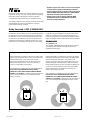 6
6
-
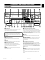 7
7
-
 8
8
-
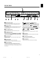 9
9
-
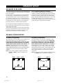 10
10
-
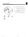 11
11
-
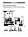 12
12
-
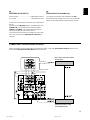 13
13
-
 14
14
-
 15
15
-
 16
16
-
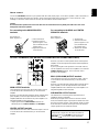 17
17
-
 18
18
-
 19
19
-
 20
20
-
 21
21
-
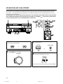 22
22
-
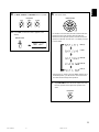 23
23
-
 24
24
-
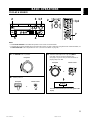 25
25
-
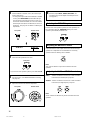 26
26
-
 27
27
-
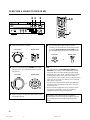 28
28
-
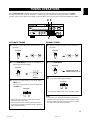 29
29
-
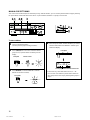 30
30
-
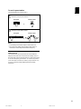 31
31
-
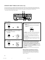 32
32
-
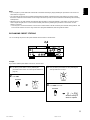 33
33
-
 34
34
-
 35
35
-
 36
36
-
 37
37
-
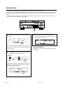 38
38
-
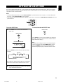 39
39
-
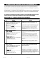 40
40
-
 41
41
-
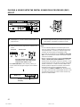 42
42
-
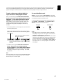 43
43
-
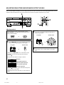 44
44
-
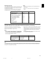 45
45
-
 46
46
-
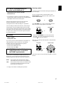 47
47
-
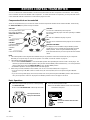 48
48
-
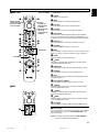 49
49
-
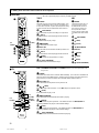 50
50
-
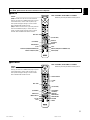 51
51
-
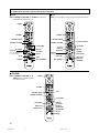 52
52
-
 53
53
-
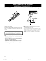 54
54
-
 55
55
-
 56
56
-
 57
57
-
 58
58
-
 59
59
-
 60
60
-
 61
61
-
 62
62
-
 63
63
-
 64
64
-
 65
65
-
 66
66
-
 67
67


in andere talen
- English: Yamaha RX-V595RDS User manual
- italiano: Yamaha RX-V595RDS Manuale utente
- русский: Yamaha RX-V595RDS Руководство пользователя
- français: Yamaha RX-V595RDS Manuel utilisateur
- español: Yamaha RX-V595RDS Manual de usuario
- Deutsch: Yamaha RX-V595RDS Benutzerhandbuch
- português: Yamaha RX-V595RDS Manual do usuário
- dansk: Yamaha RX-V595RDS Brugermanual
- suomi: Yamaha RX-V595RDS Ohjekirja
- čeština: Yamaha RX-V595RDS Uživatelský manuál
- svenska: Yamaha RX-V595RDS Användarmanual
- Türkçe: Yamaha RX-V595RDS Kullanım kılavuzu
- polski: Yamaha RX-V595RDS Instrukcja obsługi
- română: Yamaha RX-V595RDS Manual de utilizare
Gerelateerde papieren
-
Yamaha HTR-5140RDS Handleiding
-
-
-
-
-
Yamaha HTR-6280 de handleiding
-
-
-
-