Yamaha KX-W321 Handleiding
- Categorie
- Cassettespelers
- Type
- Handleiding
Deze handleiding is ook geschikt voor

KX-W421
KX-W321
OWNER’S MANUAL
MODE D’EMPLOI
Natural Sound Stereo Cassette Deck
Platine à cassette stéréo de la série “Natural Sound”
NATURAL SOUND CASSETTE DECK KX-W421
DOLBY NR
OFF/ B/ C
REC LEVELBALANCEPLAY TRIM
PHONES
STANDBY/ON
MODE
O / p / ∏ / RELAY
PLAYBACK
DECK A
L R MIN MAX
—+
CLOSE % % CLOSE
DIRECTION RESETRESET DIRECTION
! ⁄
&
SEARCH
!⁄
&
MUTE/SEARCH
PLAYPLAY
REC/PAUSE
EJECT EJECT
NORMAL HIGH
DUBBING A # B
00
NATURAL SOUND CASSETTE DECK KX-W321
DOLBY NR
OFF/ B/ C
REC LEVEL
PHONES
STANDBY/ON
MODE
O / p / ∏ / RELAY
PLAYBACK
DECK A
RECORD/PLAYBACK
DECK B
MIN MAX
RECORD/PLAYBACK
DECK B
DIRECTION RESETRESET DIRECTION
! ⁄
&
SEARCH
!⁄
&
MUTE/SEARCH
REC/PAUSE
EJECT EJECT
NORMAL HIGH
DUBBING A # B
CLOSE % % CLOSE
PLAYPLAY
U C A

2
Thank you for purchasing this YAMAHA stereo cassette deck.
SAFETY INSTRUCTIONS
÷ Explanation of Graphical Symbols
The lightning flash with arrowhead symbol,
within an equilateral triangle, is intended to
alert you to the presence of uninsulated
“dangerous voltage” within the product's
enclosure that may be of sufficient magnitude
to constitute a risk of electric shock to persons.
The exclamation point within an equilateral
triangle is intended to alert you to the presence
of important operating and maintenance
(servicing) instructions in the literature
accompanying the appliance.
CAUTION
RISK OF ELECTRIC SHOCK
DO NOT OPEN
CAUTION: TO REDUCE THE RISK OF ELECTRIC
SHOCK, DO NOT REMOVE COVER (OR BACK).
NO USER-SERVICEABLE PARTS INSIDE. REFER
SERVICING TO QUALIFIED SERVICE PERSONNEL.
1 Read Instructions — All the safety and operating
instructions should be read before the unit is operated.
2 Retain Instructions — The safety and operating
instructions should be retained for future reference.
3 Heed Warnings — All warnings on the unit and in the
operating instructions should be adhered to.
4 Follow Instructions — All operating and other instructions
should be followed.
5 Water and Moisture — The unit should not be used near
water — for example, near a bathtub, washbowl, kitchen
sink, laundry tub, in a wet basement, or near swimming
pool, etc.
6 Carts and Stands — The unit should be used only with a
cart or stand that is recommended by the manufacturer.
6A A unit and cart combination
should be moved with care. Quick
stops, excessive force, and uneven
surfaces may cause the unit and cart
combination to overturn.
7 Wall or Ceiling Mounting — The unit should be mounted
to a wall or ceiling only as recommended by the
manufacturer.
8 Ventilation — The unit should be situated so that its
location or position does not interfere with its proper
ventilation. For example, the unit should not be situated on a
bed, sofa, rug or similar surfaces that may block the
ventilation openings: or placed in a built-in installation, such
as a bookcase or cabinet that may impede the flow of air
through the ventilation openings.
9 Heat — The unit should be situated away from heat
sources such as radiators, stoves, or other units that
produce heat.
10 Power Sources — The unit should be connected to a
power supply only of the type described in the operating
instructions or as marked on the unit.
11 Power-Cord Protection — Power-supply cords should
be routed so that they are not likely to be walked on or
pinched by items placed upon or against them, paying
attention to receptacles, and the point where they exit from
the unit.
12 Cleaning — The unit should be cleaned only as
recommended by the manufacturer.
13 No Use Periods — The power cord of the unit should be
unplugged from the outlet when left unused for a long
period of time.
14 Object and Liquid Entry — Care should be taken so
that objects do not fall into and liquids not spilled into the
inside of the unit.
15 Damage Requiring Service — The unit should be
serviced by qualified service personnel when:
A. The power-supply cord or the plug has been damaged;
or
B. Objects have fallen, or liquid has been spilled into the
unit; or
C. The unit has been exposed to rain; or
D. The unit does not appear to operate normally or exhibits
a marked change in performance; or
E. The unit has been dropped, or the cabinet damaged.
16 Servicing — The user should not attempt to service the
unit beyond those means described in the operating
instructions. All other servicing should be referred to
qualified service personnel.
17 Grounding or Polarization — The precautions should be
taken so that the grounding or polarization of the unit is not
defeated.
This unit is not disconnected from the AC power source
as long as it is connected to the wall outlet, even if the
unit itself is turned off. This state is called the standby
mode. In this state, the unit is designed to consume a
very small quantity of power.
WARNING
TO REDUCE THE RISK OF FIRE OR ELECTRIC
SHOCK, DO NOT EXPOSE THIS APPLIANCE TO RAIN
OR MOISTURE.

3
ENGLISHFRANÇAISDEUTSCHSVENSKAITALIANOESPAÑOLDUTCH
CAUTION: READ THIS BEFORE OPERATING
YOUR UNIT.
1. This unit is a sophisticated stereo cassette deck. To ensure
proper operation for the best possible performance, please
read this manual carefully.
2. Choose the installation location of your unit carefully. Avoid
placing it in direct sunlight or close to source of heat. Also
avoid locations subject to vibration and excessive dust, heat,
cold or moisture. Keep it away from sources of hum such as
transformers or motors.
3. Do not open the cabinet as this may result in damage to the
deck or electrical shock. If a foreign object should get into
the deck, contact your local dealer.
4. When removing the power plug from the wall outlet, always
pull directly on the plug; never pull the cord itself.
5. Do not apply excessive force when operating switches and
knobs.
6. When moving the deck, be sure to first pull out the power
plug and remove all cords connecting the deck to other
equipment.
7. Do not attempt to clean this unit with chemical solvents as
this may damage the finish. Use a clean, dry cloth.
8. Never allow metallic items (e.g. screwdrivers, tools, etc.) to
come near the record/playback head assembly. Doing so
may not only scratch or damage the head’s mirror-smooth
finish, it may also change the magnetic characteristics of the
heads, causing a deterioration in reproduction quality.
9. Although the record/playback head used in this unit is a high
quality head with outstanding reproduction characteristics, it
can become dirty through the use of old tapes or from dust
accumulation over time. This can have a serious effect on
reproduction quality. Clean the heads regularly with one of
the commonly available head cleaners or with cleaning
solutions as explained later in this manual.
10. Be sure to read the “TROUBLESHOOTING” section of this
manual for advice on common operating errors before
concluding that your unit is faulty.
11. Keep this manual in a safe place for future reference.
12. Voltage Selector (General model only)
The voltage selector on the rear panel of this unit must
be set for your local mains voltage BEFORE plugging in
the AC mains supply. (Voltage selector adjustable
between 110/120/220/240 V AC.)
Note
Please check the copyright laws in your country to record from
records, compact discs, radio, etc. Recording of copyright
material may infringe copyright laws.
FOR CANADIAN CUSTOMERS
TO PREVENT ELECTRIC SHOCK, MATCH WIDE
BLADE OF PLUG TO WIDE SLOT AND FULLY
INSERT.
THIS CLASS B DIGITAL APPARATUS MEETS ALL
REQUIREMENTS OF THE CANADIAN
INTERFERENCE-CAUSING EQUIPMENT
REGULATIONS.
We Want You Listening For A Lifetime
YAMAHA and the Electronic Industries Association's
Consumer Electronics Group want you to get the most out of
your equipment by playing it at a safe level. One that lets the
sound come through loud and clear without annoying blaring
or distortion – and, most importantly, without affecting your
sensitive hearing.
Since hearing damage from loud sounds
is often undetectable until it is too late,
YAMAHA and the Electronic Industries
Association's Consumer Electronics
Group recommend you avoid prolonged
exposure to excessive volume levels.
We
Want You
LISTENING
For A Lifetime
FCC INFORMATION (U.S.A.)
1.IMPORTANT NOTICE: DO NOT MODIFY THIS UNIT!
This product, when installed as indicated in the
instructions contained in this manual, meets FCC
requirements. Modifications not expressly approved by
Yamaha may void your authority, granted by the FCC, to
use the product.
2.IMPORTANT: When connecting this product to
accessories and/or another product use only high quality
shielded cables. Cables supplied with this product
MUST be used. Follow all installation instructions.
Failure to follow instructions could void your FCC
authorization to use this product in the USA.
3.NOTE: This product has been tested and found to
comply with the requirements listed in FCC Regulations,
Part 15 for Class "B" digital devices. Compliance with
these requirements provides a reasonable level of
assurance that your use of this product in a residential
environment will not result in harmful interference with
other electronic devices. This equipment generates/uses
radio frequencies and, if not installed and used
according to the instructions found in the users manual,
may cause interference harmful to the operation of other
electronic devices. Compliance with FCC regulations
does not guarantee that interference will not occur in all
installations. If this product is found to be the source of
interference, which can be determined by turning the unit
"OFF" and "ON", please try to eliminate the problem by
using one of the following measures:
Relocate either this product or the device that is being
affected by the interference.
Utilize power outlets that are on different branch (circuit
breaker or fuse) circuits or install AC line filter/s.
In the case of radio or TV interference, relocate/reorient
the antenna. If the antenna lead-in is 300 ohm ribbon
lead, change the lead-in to coaxial type cable.
If these corrective measures do not produce satisfactory
results, please contact your local retailer that is
authorized to distribute this type of product. If you
cannot locate the appropriate retailer, please contact
Yamaha Electronics Corp., U.S.A.
6660 Orangethorpe Ave, Buena Park, CA 90620
The above statements apply ONLY to those products
distributed by Yamaha Corporation of America or its
subsidiaries.

4
TABLE OF CONTENTS
FEATURES ......................................................................... 4
CONNECTIONS.................................................................. 5
NOTES ON THIS MANUAL ................................................ 5
PLAYBACK (Common to DECKs A and B)......................... 6
BASIC OPERATION........................................................ 6
SELECTION SEARCH .................................................... 8
RELAY PLAYBACK ......................................................... 9
PLAY TRIM CONTROL ADJUSTMENT (KX-W421 only) 9
RECORDING .................................................................... 10
BASIC OPERATION...................................................... 10
REC MUTE OPERATION.............................................. 12
REC RETURN OPERATION ......................................... 12
DUBBING (From DECK A to DECK B) ............................. 13
CASSETTE TAPES .......................................................... 14
MAINTENANCE ................................................................ 15
OPTIONAL REMOTE CONTROL TRANSMITTER .......... 15
TROUBLESHOOTING ...................................................... 16
SPECIFICATIONS ............................................................ 17
FEATURES
÷ High Quality Hard Permalloy Recording/Playback Head in
Deck B and Playback Head in Deck A
÷ Dolby B/C Noise Reduction
÷ Play Trim Control for improved playback compatibility with
other decks (KX-W421 only)
÷ Auto Tape Selector
÷ Dolby HX Pro Dynamic Bias Servo (KX-W421 only)
÷ Relay Playback from DECK A to DECK B
÷ Selection Search
÷ Recording Mute Function
÷ Rec Return Operation
÷ Easy Dubbing Operation at Selectable Speed (Normal/
High)
÷ Peak Level Meters with Peak Hold Function
÷ Remote Control Capability with Optional Remote Control
Transmitter
Dolby noise reduction and HX Pro headroom extension
manufactured under license from Dolby Laboratories
Licensing Corporation. HX Pro originated by Bang &
Olufsen.
“DOLBY”, the double-D symbol
and “HX PRO” are
trademarks of Dolby Laboratories Licensing Corporation.

5
ENGLISHFRANÇAISDEUTSCHSVENSKAITALIANOESPAÑOLDUTCH
PLAY
LINE IN-LINE OUT
L
R
TAPE PBREC OUT
L
R
3
REC
4
CONNECTIONS
To an AC outlet
NOTES ON THIS MANUAL
In this manual, the main operation buttons of the front panel are indicated based on DECK B when the operation is common to
both DECKs A and B. Since the locations of the buttons of DECK A and DECK B are the same, you can easily find the desired
button even when operating DECK A. This manual covers two models. In most cases, however, only model KX-W421 is shown
in the example illustrations.
Example: KX-W421
Main operation buttons of DECK A
(U.S.A. model)
Amplifier or receiver
REAR PANEL CONNECTIONS
Make sure that power to both the deck and your amplifier/receiver is turned off
before making any connections.
÷ The White plug on the paired connecting cables corresponds to the Left
channel and the Red plug corresponds to the Right channel. Make sure that
the left and right channel connections are properly made, and that the plugs
are inserted firmly.
÷ The LINE OUT/PLAY jacks on the deck should be connected to the TAPE PB
(Playback/Input) jacks on your amplifier/receiver, and the LINE IN/REC jacks
on the deck should be connected to the REC OUT (Recording/Output) jacks
on your amplifier/receiver.
÷ The LINE OUT terminals on this unit are numbered 3 and the LINE IN jacks
are numbered 4. When connecting this unit to a YAMAHA amplifier or
receiver whose terminals are numbered 1, 2, 3, 4 ... (etc.), connect this
unit's LINE OUT terminals to the input terminals numbered 3 and connect this
unit's LINE IN terminals to the output terminals numbered 4 on the rear panel
of the amplifier or receiver.
÷ Connect the power cord to an AC wall outlet or to an AC outlet on the rear
panel of your amplifier/receiver (if provided).
NATURAL SOUND CASSETTE DECK KX-W421
DOLBY NR
OFF/ B/ C
REC
LEVELBALANCE
PLAY TRIM
PHONES
STANDBY/ON
MODE
O / p / ∏ / RELAY
PLAYBACK
DECK A
Stabilizer
RECORD/PLAYBACK
DECK B
L R MIN MAX
–+
CassetteStabilizerCassette
CLOSE
% %
CLOSE
DIRECTION RESETRESET DIRECTION
! ⁄
&
SEARCH
!⁄
&
MUTE/SEARCH
REC/PAUSE
PLAYPLAY
EJECT EJECT
NORMAL HIGH
DUBBING A # B
0 0
Main operation buttons of DECK B

6
PLAYBACK (Common to DECKs A and B)
Preparation for playback
÷ Turn on the STANDBY/ON switch.
÷ Set your amplifier or receiver to cassette deck function mode.
BASIC OPERATION - To play back a cassette tape
Example: KX-W421
EJECT
DOLBY NR
OFF/ B/ C
Refer to the following
description.
MODE
“/[/”/
RELAY
21
35
4
Refer to the following
description.
DIRECTION
Select the tape running direction for DECK A
or B. Each time this button is pressed, the
tape running direction changes between
forward (#) and reverse (@), and the
corresponding indicator lights on the display.
To stop playback
Press the & button. To remove the cassette tape, press the
EJECT button. The cassette compartment door opens. To
set the unit to standby mode, press the STANDBY/ON
button.
To set the counter reading to “0000”
Press the RESET button. Use the tape counter to aid in
locating a point on a tape (0000 to 9999).
To fast forward or rewind the tape
When the tape running indicator # is lit:
Pressing the ⁄ button fast forwards the tape while
pressing the ! button rewinds the tape.
When the tape running indicator @ is lit:
Pressing the ! button fast forwards the tape while
pressing the ⁄ button rewinds the tape.
Insert the cassette with the exposed tape side facing down. (The side
facing you is called the forward side and the opposite side is called the
reverse side.) To close the compartment, push the section of the
compartment door marked % CLOSE until it locks shut.
PLAY
NATURAL SOUND CASSETTE DECK KX-W421
DOLBY NR
OFF/ B/ C
REC
LEVELBALANCE
LR
PLAY TRIM
PHONES
DIRECTION
STANDBY/ON
MODE
O / p / ∏ / RELAY
! ⁄
&
SEARCH
PLAY PLAY
EJECT
NORMAL HIGH
DUBBING A # B
!⁄
&
MUTE/SEARCH REC/PAUSE
EJECT
RESET
RESET DIRECTION
Stabilizer
%
CLOSECLOSE
%
PLAYBACK
DECK A
Cassette
RECORD/PLAYBACK
DECK B
StabilizerCassette
–+
MIN MAX
0
23
1
STANDBY/ON
PHONES
RESET
!
45
⁄
&
0

7
ENGLISHFRANÇAISDEUTSCHSVENSKAITALIANOESPAÑOLDUTCH
DOLBY NR selector setting (in step 2)
Be sure to set the DOLBY NR selector according to the
system used for recording.
OFF: For a tape recorded with DOLBY NR OFF.
B: For a tape recorded with DOLBY B NR.
C: For a tape recorded with DOLBY C NR.
REVERSE MODE selector setting (in step 3)
The auto reverse function allows the tape running direction
be reversed automatically. Select an auto reverse mode
(
, , or
RELAY
) or manual reverse mode
(
).
: When playback or fast forwarding (or rewinding) of
one side of a tape is finished, the deck stops at the
end of the tape.
:Both sides of the tape are played back. After
playing, the deck stops at the end of the tape.
(When the tape running direction is set to ¤, only
the reverse side is played.)
: Both sides of the tape are repeatedly played back
(up to 8 times).
RELAY
: Cassette tapes loaded in DECKs A and B
are played back sequentially. (See “RELAY
PLAYBACK” on page 9.)
Display during playback
Tape counter
Tape counter
Peak level meters
Indicate the peaks of the signal levels during recording and playback over a –30 dB to +6 dB range. There are separate meters for each left
and right channel. These level meters have a peak hold function which holds the peak level for about 1.5 seconds.
¤
30 dB
—
A
NORM
‹
R
L
20 15 10 8 6 4 2 0 2 4 6
+
¤
B
‹
RELAY
DUB HIGH RECB C
KX-W421/
KX-W321
The A or B indicator shown in
the display represents the
last deck operated.
Note
Never press the EJECT button when the tape is in motion.
To adjust the volume level
Use the volume control of the amplifier or receiver.
To use headphones
Insert the headphones plug into the PHONES jack. Since
the sound is also heard from the speakers, operate the
amplifier to cut off the sound from the speakers for private
listening.
Tape running direction
indicator (DECK A)
Tape running direction
indicator (DECK B)

8
Notes
÷ The blank interval between selections must be at least 4 seconds long.
÷ Selection search may not operate properly with tapes recorded at a low recording level or which have excessive noise.
Example: KX-W421
SELECTION SEARCH - To play back a desired selection by searching for the beginning of the selection
When the @ tape running indicator is lit:
To search for the next selection
When the # tape running indicator is lit:
When the @ tape running indicator is lit:
To search for the beginning of the current selection
When the # tape running indicator is lit:
To search for the selection located before the current selection
÷ Operate the following buttons when the beginning of the current selection is being played.
When the # tape running indicator is lit:
When the @ tape running indicator is lit:
Press
simultaneously.
⁄
MUTE/SEARCH
!
MUTE/SEARCH
MUTE/SEARCH
!
Press
simultaneously.
Press
simultaneously.
⁄
MUTE/SEARCH
Press
simultaneously.
!
MUTE/SEARCH
Press
simultaneously.
MUTE/SEARCH
⁄
Press
simultaneously.
NATURAL SOUND CASSETTE DECK KX-W421
DOLBY NR
OFF/ B/ C
REC
LEVELBALANCE
PLAY TRIM
PHONES
STANDBY/ON
MODE
O / p / ∏ / RELAY
PLAYBACK
DECK A
Stabilizer
RECORD/PLAYBACK
DECK B
L R MIN MAX
–+
CassetteStabilizerCassette
DIRECTION RESETRESET DIRECTION
! ⁄
&
SEARCH
!⁄
&
MUTE/SEARCH
REC/PAUSE
EJECT EJECT
NORMAL HIGH
DUBBING A # B
0
RESET
!⁄
MUTE/SEARCH
CLOSE
% %
CLOSE
PLAYPLAY
0

9
ENGLISHFRANÇAISDEUTSCHSVENSKAITALIANOESPAÑOLDUTCH
Example: KX-W421
RELAY PLAYBACK - To play DECK A and DECK B sequentially
Load the cassette tapes into DECKs A and B, start playback from DECK A.
The playback patterns differ according to the setting of the MODE button. Refer to the following.
When the MODE button is set to
RELAY
:
DECK A (forward side \ reverse side) \ DECK B (forward side \ reverse side)
When the MODE button is set to
:
DECK A (forward side \ reverse side) DECK B (forward side \ reverse side)
When the MODE button is set to
:
DECK A (forward side \ reverse side) DECK B ( forward side \ reverse side)
÷ When the tape running direction is set to ™, only the reverse side is played.
When the MODE button is set to
:
DECK A (forward side or reverse side) DECK B (forward side or reverse side)
Display
5
Up to 8 times
Up to 8 times
5
Up to 8 times
RELAY
1
2
3
100
10 dB
1k
10kHz
When the level of high frequencies is either over emphasized or absent while playing a tape recorded on another cassette deck,
adjust the high frequency response with the PLAY TRIM control.
When high frequencies are too loud,
attenuate the high frequencies.
PLAY TRIM
When high frequencies are too soft, boost
the high frequencies.
0
0
1 High frequency sound is too loud.
2 Flat
3 High-frequency sound is too soft.
PLAY TRIM CONTROL ADJUSTMENT ( KX-W421 only)
5
NATURAL SOUND CASSETTE DECK KX-W421
DOLBY NR
OFF/ B/ C
REC
LEVELBALANCE
PLAY TRIM
PHONES
STANDBY/ON
MODE
O / p / ∏ / RELAY
PLAYBACK
DECK A
Stabilizer
RECORD/PLAYBACK
DECK B
L R MIN MAX
–+
CassetteStabilizerCassette
DIRECTION RESETRESET DIRECTION
! ⁄
&
SEARCH
!⁄
&
MUTE/SEARCH
REC/PAUSE
EJECT EJECT
NORMAL HIGH
DUBBING A # B
0
PLAY TRIMMODE
CLOSE
% %
CLOSE
PLAYPLAY
0
PLAY TRIM

10
RECORDING
EJECT
Recording
starts.
Play the program source to be
recorded and adjust the
recording level and balance.
(KX-W321 does not have a
REC BALANCE control.)
LEVELBALANCE
REC
1
67
Preparation for recording
÷ Turn on the STANDBY/ON switch.
÷ Set your amplifier or receiver to cassette deck function mode.
BASIC OPERATION - To record a program source
Example: KX-W421
LRMIN MAX
0
3
DOLBY NR
OFF/ B/ C
2
Insert the cassette into DECK B with the
exposed tape side facing down. (The
side facing you is called the forward side
and the opposite side is called the
reverse side.)
To close the compartment, push the
section of the compartment door marked
% CLOSE until it locks shut.
4
Select the tape running direction.
(Press the DIRECTION button for DECK B.) Each
time the button is pressed, the tape running direction
changes between forward (#) and reverse (@), and
the indicator lights on the display.
5
The REC indicator
lights on the display.
The deck enters the
Rec/Pause mode.
REC/PAUSE
DIRECTION
MODE
“/[/”/
RELAY
Refer to the following
description.
Refer to the following
description.
PLAY
NATURAL SOUND CASSETTE DECK KX-W421
DOLBY NR
OFF/ B/ C
REC
LEVELBALANCE
LR
PLAY TRIM
PHONES
DIRECTION
STANDBY/ON
MODE
O / p / ∏ / RELAY
! ⁄
&
SEARCH
EJECT
NORMAL HIGH
DUBBING A # B
!⁄
&
MUTE/SEARCH REC/PAUSE
EJECT
RESET
RESET DIRECTION
Stabilizer
PLAYBACK
DECK A
Cassette
RECORD/PLAYBACK
DECK B
StabilizerCassette
–+
MIN MAX
0
23
STANDBY/ON
PHONES
RESET
!
47
⁄
&
5
6
MUTE/SEARCH
PLAY PLAY
%
CLOSECLOSE
%
1
0

11
ENGLISHFRANÇAISDEUTSCHSVENSKAITALIANOESPAÑOLDUTCH
¤
30 dB
—
A
‹
R
L
20 15 10 8 6 4 2 0 2 4 6
+
¤
B
‹
REC
RELAY
B C
DOLBY NR selector setting (in step 2)
Set the DOLBY NR selector according to your purpose.
OFF: No noise reduction.
B: For recording the sources with Dolby B NR.
C: For recording the sources with Dolby C NR.
÷ Dolby noise reduction is an extremely effective method of
reducing undesirable background hiss on tapes. This unit
incorporates both Dolby B NR and the newer Dolby C NR
system. Dolby C NR is approximately twice as effective
as the earlier Dolby B NR.
REVERSE MODE selector setting (in step 3)
The auto reverse function allows the tape running direction
to be reversed automatically. Select the auto reverse mode
(
) or manual reverse mode ( ).
: When recording on one side of a tape is finished, the
deck stops at the end of the tape.
:Both sides of a tape are recorded. After recording,
the deck stops at the end of the tape.
÷ When the tape running direction is set to ™, only
the reverse side is recorded.
÷ If you select
or
RELAY
, the reverse mode
automatically switches to
in step 5.
Display during recording
Peak level meters
Indicate the peaks of the signal levels during recording and playback over a –30 dB to +6 dB range. There are separate meters
for each left and right channel. These level meters have a peak hold function which holds the peak level for about 1.5 seconds.
Tape counter
Use the tape counter to aid in locating a point on a tape (0000 to 9999).
To set the counter reading to “0000”, press the RESET button.
The A or B indicator shown in
the display represents the
last deck operated.
Setting the recording level (in step 6)
Play the loudest passage of the source to be recorded and
watch the meter readings.
Adjust the REC LEVEL control so that the highest peak
reaches +4 of the optimum recording level. Normally, it is
best to adjust the REC BALANCE control (KX-W421 only)
such that the left and right meter readings are even.
KX-W421/
KX-W321
To stop recording:
Press the & button.
To stop recording temporarily:
Press the REC/PAUSE button. To resume recording, press
the PLAY button.
REC indicator
DOLBY B/ C indicator
MODE indicator
Tape running direction indicator

12
Example: KX-W421
REC MUTE OPERATION - Inserting a blank space during recording
REC RETURN OPERATION - To return to the point at which the recording started
A 4-second blank interval is automatically recorded on the
tape and then the deck enters Rec/Pause mode.
If a blank interval longer than 4 seconds is desired, keep
pressing for as long as you want. When the MUTE/
SEARCH button is released, the deck enters Rec/Pause
mode after making a 4-second blank interval.
To resume recording, press the PLAY button.
÷ If a blank interval shorter than 4 seconds is desired, press
the PLAY button at the desired point during Rec mute
mode. Recording will be resumed from that point.
During recording:
During Rec mute operation, the REC indicator blinks.
During recording:
When the # indicator
is lit:
!
⁄
When the @ indicator
is lit:
÷ If you press the PLAY button during recording, Rec Return
automatically rewinds the tape to the point where the
PLAY button was pressed.*
If you reset the tape counter to “0000” during recording,
Rec Return automatically rewinds the tape to the “0000”
point.
Rec Return functions according to the most recent
operation. For example, if you reset the tape counter to
“0000” and then press the PLAY button later, Rec Return
rewinds to the point where the PLAY button was pressed.
* The PLAY button cannot be used to mark a return point
while dubbing.
MUTE/SEARCH
DOLBY HX PRO DYNAMIC BIAS SERVO SYSTEM
(KX-W421 only)
This unit incorporates the Dolby HX Pro system which
automatically controls the effective bias to reduce
distortion and noise, improving high frequency
response during recording. Tapes recorded with this
system retain the same high quality even when played
back on any other cassette deck.
Synchronized recording function
When operating this unit in combination with the
YAMAHA CD Player which has SYNCHRO button on its
remote control transmitter, CD Synchronized recording
function can be utilized. This function is operated with
the remote control transmitter of the CD Player.
(Regarding the operation, refer to the manual of the CD
Player.)
NATURAL SOUND CASSETTE DECK KX-W421
DOLBY NR
OFF/ B/ C
REC
LEVELBALANCE
PLAY TRIM
PHONES
STANDBY/ON
MODE
O / p / ∏ / RELAY
PLAYBACK
DECK A
Stabilizer
RECORD/PLAYBACK
DECK B
L R MIN MAX
–+
CassetteStabilizerCassette
DIRECTION RESETRESET DIRECTION
! ⁄
&
SEARCH
!⁄
&
MUTE/SEARCH
REC/PAUSE
EJECT EJECT
NORMAL HIGH
DUBBING A # B
0
!⁄
MUTE/SEARCH
CLOSE
% %
CLOSE
PLAYPLAY
0

13
ENGLISHFRANÇAISDEUTSCHSVENSKAITALIANOESPAÑOLDUTCH
DUBBING (From DECK A to DECK B)
12
Set the MODE selector to
or position.
If you select or
RELAY
, the reverse
mode automatically switches to
.
Set the
DIRECTION
buttons for DECKs
A and B.
3
Set the dubbing speed to either NORMAL
(normal speed) or HIGH (twice the normal
speed) with the DUBBING buttons*.
Dubbing starts automatically.
DUBBING A # B
NORMAL HIGH
The corresponding NORM
or HIGH indicator lights on
the display.
* Higher quality sound will be obtained with the
NORMAL setting.
Note
During dubbing, Dolby NR is automatically set to off and the
recorded tape can be dubbed as is. (When the tape to be
dubbed is recorded with Dolby NR, this effect is also
dubbed.)
PLAY TRIM control adjustment (KX-W421 only)
For normal use, set the PLAY TRIM control to the center
position.
When the high frequencies sound is too noticeable or too
weak while monitoring the sound of DECK B, compensate
the high frequency response with the PLAY TRIM control
before dubbing. The compensated sound can be dubbed
onto DECK B.
As the compensation result depends on the quality of the
tape loaded in DECK A, the monitored sound cannot be
recorded as it is.
Refer to “PLAY TRIM CONTROL ADJUSTMENT” on page
9.
To stop dubbing
Press the & button. (If you press the & button on DECK B,
both decks stop simultaneously and the dubbing mode is
cancelled. If you press the & button on DECK A, DECK A
stops immediately and then DECK B stops after recording a
4-second blank section.)
When the tape in DECK B reaches its end, DECK B stops
and then DECK A stops.
When the tape in DECK A reaches its end, DECK A stops
and DECK B stops after providing a blank section of about 4
seconds.
Available operations while dubbing
The Rec Return function can be carried out on DECK B.
Refer to “REC RETURN OPERATION” on the previous
page.
You can make dubbing from DECK A to DECK B. Open the cassette compartments by pressing the EJECT buttons and load a
blank cassette tape in DECK B and the original cassette tape in DECK A.
Example: KX-W421
Display during dubbing
MODE
“/[/”/
RELAY
DIRECTION
NORM or HIGH
indicator lights during
dubbing.
Lights during dubbing.
NATURAL SOUND CASSETTE DECK KX-W421
DOLBY NR
OFF/ B/ C
REC
LEVELBALANCE
PLAY TRIM
PHONES
STANDBY/ON
MODE
O / p / ∏ / RELAY
PLAYBACK
DECK A
Stabilizer
RECORD/PLAYBACK
DECK B
L R MIN MAX
–+
CassetteStabilizerCassette
DIRECTION RESETRESET DIRECTION
! ⁄
&
SEARCH
!⁄
&
MUTE/SEARCH
REC/PAUSE
EJECT EJECT
NORMAL HIGH
DUBBING A # B
0
3
2
1
¤
30 dB
–
A
NORM
‹
R
L
20 15 10 8 6 4 2 0 2 4 6
+
¤
B
‹
RELAY
DUB HIGH RECB C
CLOSE
% %
CLOSE
PLAYPLAY
0

14
PROTECTING YOUR RECORDINGS
All cassette tapes are provided with erasure protection holes
to prevent accidental erasure of recorded contents. There is
a small tab covering the hole on each side of the cassette,
and it should be broken off after recording the tape. Without
this tab covering the hole, it is impossible to record onto that
tape. Thus, you can safely protect a recording for as long as
you wish without fear of accidental erasure. Should you wish
to use a cassette tape protected in this way for recording,
simply covering the hole with adhesive tape will permit
erasure and re-recording.
÷ When using Chrome (Type II/HIGH <CrO
2>) or Metal
(Type IV/METAL) tapes, make sure you do not cover the
hole intended for the Auto Tape Selector operation.
TAKING UP SLACK IN THE TAPE
As a precaution against tape entanglement and damage,
remove any slack in the tape before inserting cassettes into
the deck. This is accomplished by inserting a pencil, pen or
similar object into one of the spools and gently winding it
until all the slack is removed. You do not have to wind it too
tightly.
Be careful not to touch the tape part itself. It is very delicate
and touching it may damage the tape and its recorded
contents.
STORING CASSETTES
After putting a cassette tape back into its case, store it in a
location away from exposure to direct sunlight, humidity,
high temperatures, and magnetic fields (away from television
sets, speakers, etc.). High temperatures and humidity will
damage the tape itself, while exposure to magnetic fields
may cause a loss of recorded material. Avoid touching the
tape surface with your fingers, since dirt or finger oil will
contaminate the deck’s heads.
CASSETTE TAPES
CASSETTE TAPES
There are many different types of cassette tapes available.
However, they all conform to standard specifications so any
brand may be used with the deck.
÷ Classification of Cassette Tapes by Formulation:
Cassette tapes are available in four basic types depending
on their formulation, or type of magnetic material and
manufacturing process. These four types are commonly
known as Normal (Type I/NORM), Chrome (Type II/HIGH
<CrO
2>), Ferrichrome (Type III/FeCr), and Metal (Type IV/
METAL), and they each require specific tape deck
adjustments for optimum performance.
* YAMAHA does not recommend the use of 120 minute
length cassettes since the extreme thinness of the tape
makes them susceptible to mechanical and recording
problems.
AUTO TAPE SELECTOR DETECTION SLOTS
The deck has a built-in Auto Tape Selector which
automatically adjusts for the proper bias, level and
equalization according to the tape formulation — all you
have to do is to load a cassette and the Auto Tape Selector
does the rest.
The Auto Tape Selector determines which type of tape is
loaded by sensing detector slots in the top of the tape shell.
Each tape formulation has its own characteristic hole
markings standardized by the tape industry.
÷ Early model Metal (Type IV/Metal) tape formulation
cassette shells do not have the slots for Auto Tape
Selector operation. As a result, early model Metal type
tapes recorded on another deck will be played back with
the deck at the Chrome (Type II/HIGH <CrO
2>) settings.
YAMAHA does not recommend using this kind of tape.
÷ The deck does not have the required setting for
Ferrichrome (Type III/FeCr) tape, since this tape
formulation is not widely used. Should you use a
Ferrichrome tape, it will be recorded and played back at
the Normal (Type I/NORM) settings, which will result in an
unnatural high frequency emphasis. This effect may be
compensated for somewhat by adjusting the PLAY TRIM
control and/or the tone controls of your amplifier/receiver
during playback.
Detector slotsDetector slots
TYPE II TYPE IV

15
ENGLISHFRANÇAISDEUTSCHSVENSKAITALIANOESPAÑOLDUTCH
With the optional remote control transmitter RKX1, you can
operate this unit at your listening position. For details, refer
to the instruction manual supplied with the remote control
transmitter.
REMOTE CONTROL OPERATION RANGE
MAINTENANCE
CLEANING OF THE TAPE PATH
Continued high quality performance of your deck is
dependent upon periodic cleaning of the heads, capstan,
pinch roller, and all surfaces over which the tape travels.
Normal use will cause an accumulation of dirt and dust on
the heads, capstans, and pinch rollers. This can lead to
poor sound quality, drop outs (intervals with no sound),
unsteady tape speed, loss of high frequency response, etc.
Thus, clean the heads and all surfaces over which the tape
travels with a commercially available cleaning cassette and
fluid type cleaner.
DEMAGNETIZATION
After 20-30 hours of use, enough residual magnetism will
build up on the heads to cause poor high frequency
reproduction. At this time you should use a commercially
available cassette tape-type head demagnetizer.
÷ When cleaning the tape path or demagnetizing the heads,
be sure to follow carefully the instructions of the
concerning materials such as cleaning fluid or head
demagnetizer.
CapstanCapstan
Pinch rollerPinch roller
Heads
OPTIONAL REMOTE CONTROL TRANSMITTER
Example: KX-W421
DECK B
30°
30°
7 m (23 feet)
Remote sensor
SINGLE DECK
INTRO SCAN
DOUBLE DECK
DUBBING
DECK A/B DIR A DIR B
COUNTER
RESET
PLAY
SEARCH
REC/PAUSE REC MUTE
STOP
RKX1
s
¤‹
!
!
⁄
⁄

16
If your cassette deck fails to operate normally, check the following table. It lists common operating errors and simple measures
which you can take to correct the problem. If it cannot be corrected, or the symptom is not listed, disconnect the deck’s power
cord and contact your authorized YAMAHA dealer or authorized service center for help.
Cause
÷ Power plug is not properly plugged in.
÷ Cassette shell is warped or damaged.
÷ There is an influence of strong external
noise (lightning, excessive static
electricity, etc.) or a misoperation was
performed while using this unit.
÷ No cassette tape loaded.
÷ Protective tabs are broken off.
÷ Head is dirty.
÷ Head is magnetized.
÷ Tape is damaged or of poor quality.
÷ Tape is bad (stretched, deformed, etc.).
÷ Cassette shell is warped.
÷ Recording level is too high.
÷ Faulty connection between deck and
stereo amplifier/receiver.
÷ Head is dirty.
÷ Head is magnetized.
÷ Worn out or poor quality tape.
÷ Connection(s) improperly made.
÷ Affected by external electrical noise.
÷ Dirty capstan, pinch roller, etc., or poor
tape.
÷ Tape is wound unevenly.
÷ Slack tape, or tape spillage wound
around capstan.
÷ REC LEVEL control is set to too low.
÷ Protective tabs are broken off.
÷ Blank section is too short.
÷ Recorded section has low-level portions.
÷ Conversation, etc. has been recorded.
÷ Dolby NR-recorded tape is played back
in OFF position.
Cure
÷ Reinsert plug properly.
÷ Do not play damaged tapes.
÷ Turn the unit off and disconnect the AC
power from the AC outlet. After about
30 seconds have passed, connect the
power and try again.
÷ Load a cassette tape.
÷ Change tape or cover protective hole
with adhesive tape.
÷ Clean head.
÷ Demagnetize head using head
demagnetizer.
÷ Change to a different tape.
÷ Replace with a fresh tape.
÷ A warped cassette shell cannot be
fixed. Replace with another tape and
test.
÷ Check input level with signal level meter
and use lower rec level when recording.
÷ Check and secure connections.
÷ Clean head.
÷ Demagnetize head with head
demagnetizer.
÷ Change to better tape.
÷ Check input and output connections
and reinsert properly.
÷ Move deck away from electrical
appliances (TV, fluorescent light,
electric blanket, etc.).
÷ Clean capstan and pinch roller, or
change to better tape.
÷ Rewind tape.
÷ Insert pencil in hole in cassette shell
and turn to take up slack.
÷ Adjust REC LEVEL control.
÷ Change tape or cover protective hole
with adhesive tape.
÷ Blank sections must be at least 4
seconds long.
÷ No remedy
÷ No remedy
÷ Play back in appropriate Dolby NR
position.
Fault
Tape doesn’t move in recording or
playback.
If it happens that this unit does not
work normally.
REC/PAUSE button fails to function.
Sounds become faint and sometimes
inaudible.
Recorded sound is distorted.
Tape is playing back, but no sound is
heard.
Excessive noise.
Excessive wow (wavering of the
sound).
Tape stops in the middle of recording
or playback.
Fails to record.
Search does not operate correctly.
High frequencies in the playback
sound are emphasized and unpleasant
to listen to, and noise level (hiss) is
also high.
TROUBLESHOOTING

17
ENGLISHFRANÇAISDEUTSCHSVENSKAITALIANOESPAÑOLDUTCH
Cause
÷ Normally-recorded tape is played back in
Dolby NR.
÷ Heads are dirty.
÷ Heads are magnetized.
÷ Basic levels are different for different
cassette decks.
÷ The batteries are exhausted.
÷ The remote control transmitter is
operated from an incorrect distance or
angle.
÷ The remote control sensor is lighted
strongly.
Cure
÷ Play back in OFF position.
÷ Clean heads and carry out
demagnetization with head
demagnetizer.
÷ This is not a fault.
÷ Replace batteries.
÷ Operate it from less than 7 meters
(about 23 ft.) and 30°.
÷ Place the unit away from the strong
light.
Fault
Playback sound is muffled and high
frequencies are inaudible.
When playing back tapes recorded on
other decks, meter deflections are
greater (smaller) than when recorded.
The remote control transmitter cannot
be operated.
Type..................................... Auto reverse 4-track, 2-channel
recording and playback stereo double cassette deck
Motors .........................................DC servo motor x 2 (main)
Heads .................... Recording/playback: Hard Permalloy x 1
Erase: Double-gap Ferrite x 1
Playback: Hard Permalloy x 1
Rapid Transport .......................................... 100 sec. (C-60)
Wow and Flutter
WRMS ...................................................................... 0.08%
W.Peak ...................................................................±0.15%
Signal-to-Noise Ratio
(Dolby NR off)...........................................................58 dB
(Dolby B NR on) .......................................................66 dB
(Dolby C NR on) .......................................................74 dB
Frequency Response (–20 dB)
<KX-W421>
Type I/Normal.............................. 20 ~ 17,000 Hz ±3 dB
Type II/High (CrO
2) .................... 20 ~ 18,000 Hz ±3 dB
Type IV/Metal .............................. 20 ~ 20,000 Hz ±3 dB
<KX-W321>
Type I/Normal.............................. 20 ~ 16,000 Hz ±3 dB
Type II/High (CrO
2) .................... 20 ~ 17,000 Hz ±3 dB
Type IV/Metal .............................. 20 ~ 19,000 Hz ±3 dB
Harmonic Distortion
KX-W421 .................................................... less than 0.8%
KX-W321 .................................................... less than 1.0%
Input Sensitivity/Impedance
Line ...................................................... 100 mV/43 k-ohms
Output Level
Line .....................................................570 mV/1.4 k-ohms
Phones..................................................... 0.25 mV/8 ohms
Channel Separation (1 kHz)...................... more than 40 dB
Crosstalk (125 Hz) ..................................... more than 55 dB
SPECIFICATIONS
GENERAL
Power Supply
U.S.A. and Canada model ........................... 120 V, 60 Hz
Europe and U.K. model ............................... 230 V, 50 Hz
Australia model............................................ 240 V, 50 Hz
General model.................... 110/120/220/240 V, 50/60 Hz
Power Consumption
KX-W421 ............................................14 W/7 W (Standby)
KX-W321
U.S.A. and Canada model.............11 W/7 W (Standby)
Other models .................................12 W/7 W (Standby)
Dimensions (W x H x D)...................... 435 x 146 x 279 mm
(17-1/8" x 5-3/4" x 11")
Weight ........................................................... 5.0 kg (11 lbs.)
Accessory
Audio cord................................................................ 1 pair
* Specifications subject to change without notice.

32
Problème
Le son de lecture est étouffé et les
hautes fréquences sont inaudibles.
Lors de la lecture de bandes
enregistrées sur d’autres platines, les
déflexions du compteur sont plus
grandes (plus petites) qu’à
l’enregistrement.
La télécommande ne fonctionne pas.
Remède
÷ Lire en position OFF.
÷ Nettoyer les têtes et effectuer la
démagnétisation avec un
démagnétiseur de tête.
÷ Ceci n’est pas un défaut.
÷ Remplacer la pile.
÷ La faire fonctionner à moins de 7
mètres et sur 30°.
÷ Placer l’appareil à l’abri de lumières
fortes.
Cause
÷ Une bande enregistrée normalement est
lue avec Dolby NR.
÷ Les têtes sont sales.
÷ Les têtes sont magnétisées.
÷ Les niveaux de base sont différents pour
diverses platines.
÷ La pile est déchargée.
÷ La télécommande est actionnée d’une
distance ou sous un angle incorrects.
÷ Le détecteur de la télécommande est
fortement éclairé.
Configuration des pistes ............. Platine à cassette double
stéréo avec inversion automatique pour l’enregistrement et
la lecture, 4 pistes, 2 canaux
Moteur ..............Moteur asservi CC x 2 (moteurs principaux)
Têtes...................Enregistrement/Lecture: Permalloy dur x 1
Effacement: Ferrite à double entrefer x 1
Lecture: Permalloy dur x 1
Transport rapide................................. 100 secondes (C-60)
Pleurage et scintillement
Eff., pondéré........................................................... 0,08%
Crête, pondéré ..................................................... ±0,15%
Rapport signal/bruit
(Dolby NR à l’arrêt)...............................................58 dB
(Dolby B NR en marche) ......................................66 dB
(Dolby C NR en marche) ......................................74 dB
Réponse en fréquence (–20dB)
<KX-W421>
Type I/normale ............................ 20 ~ 17.000 Hz ±3 dB
Type II/élevée (CrO
2) .................. 20 ~ 18.000 Hz ±3 dB
Type IV/métal .............................. 20 ~ 20.000 Hz ±3 dB
<KX-W321>
Type I/normale ............................ 20 ~ 16.000 Hz ±3 dB
Type II/élevée (CrO
2) .................. 20 ~ 17.000 Hz ±3 dB
Type IV/métal .............................. 20 ~ 19.000 Hz ±3 dB
Distorsion harmonique
KX-W421 ................................................... Moins de 0,8%
KX-W321 ................................................... Moins de 1,0%
Sensibilité d’entrée/impédance
Ligne ....................................................100 mV/43 k-ohms
Niveau de sortie
Ligne ...................................................570 mV/1,4 k-ohms
Casque.....................................................0,25 mV/8 ohms
Séparation des canaux (1 kHz) ...............inférieure à 40 dB
Diaphonie (125 Hz) ...................................inférieure à 55 dB
GENERALES
Alimentation
Modèle pour les Etats-Unis et le Canada
................................................................... 120 V, 60 Hz
Modèle pour l’Europe et le Royaume-Uni
................................................................... 230 V, 50 Hz
Modèle pour l’Australie ............................... 240 V, 50 Hz
Modèle général............................................ 110/120/220/
240 V, 50/60 Hz
Consommation
KX-W421 ................................................ 14 W/7 W (Veille)
KX-W321
Modèle pour les Etats-Unis et le Canada
............................................................ 11 W/7 W (Veille)
Autres modèles ................................. 12 W/7 W (Veille)
Dimensions (L x H x P) ....................... 435 x 146 x 279 mm
Poids ........................................................................... 5,0 kg
Câbles audio ......................................................... 1 paire
* Les caractéristiques techniques sont sujettes à des
changements sans préavis.
CARACTERISTIQUES TECHNIQUES
YAMAHA ELECTRONICS CORPORATION, USA 6660 ORANGETHORPE AVE., BUENA PARK, CALIF. 90620, U.S.A.
YAMAHA CANADA MUSIC LTD. 135 MILNER AVE., SCARBOROUGH, ONTARIO M1S 3R1, CANADA
YAMAHA ELECTRONIK EUROPA G.m.b.H. SIEMENSSTR, 22-34, 25462 RELLINGEN, BEI HAMBURG, F.R. OF GERMANY
YAMAHA ELECTRONIQUE FRANCE S.A. RUE AMBROISE CROIZAT BP70 CROISSY-BEAUBOURG 77312 MARNE-LA-VALLEE CEDEX02, FRANCE
YAMAHA ELECTRONICS (UK) LTD. YAMAHA HOUSE, 200 RICKMANSWORTH ROAD WATFORD, HERTS WD1 7JS, ENGLAND
YAMAHA SCANDINAVIA A.B. J A WETTERGRENS GATA 1, BOX 30053, 400 43 VASTRA FRÖLUNDA, SWEDEN
YAMAHA MUSIC AUSTRALIA PTY, LTD. 17-33 MARKET ST., SOUTH MELBOURNE, 3205 VIC., AUSTRALIA
Printed in Malaysia
VZ 79000-1
Documenttranscriptie
UCA KX-W421 KX-W321 OWNER’S MANUAL Natural Sound Stereo Cassette Deck MODE D’EMPLOI Platine à cassette stéréo de la série “Natural Sound” NATURAL SOUND CASSETTE DECK KX-W421 RESET DIRECTION DIRECTION RESET CLOSE % % CLOSE ! DECK A PLAYBACK STANDBY/ON SEARCH PLAY ⁄ & ! PLAY ⁄ MUTE/SEARCH & REC/PAUSE O / p / ∏ / RELAY DOLBY NR OFF/ B/ C EJECT DUBBING A # B NORMAL 0 EJECT HIGH — NATURAL SOUND CASSETTE DECK KX-W321 DECK B RECORD/PLAYBACK PLAY TRIM MODE RESET + BALANCE 0 L R REC PHONES LEVEL MIN MAX DIRECTION DIRECTION RESET CLOSE % % CLOSE ! DECK A PLAYBACK STANDBY/ON SEARCH PLAY ⁄ & ! PLAY ⁄ MUTE/SEARCH & REC/PAUSE DECK B RECORD/PLAYBACK REC LEVEL MODE O / p / ∏ / RELAY DOLBY NR OFF/ B/ C EJECT DUBBING A # B NORMAL HIGH EJECT MIN MAX PHONES Thank you for purchasing this YAMAHA stereo cassette deck. SAFETY INSTRUCTIONS 7 Wall or Ceiling Mounting — The unit should be mounted CAUTION RISK OF ELECTRIC SHOCK DO NOT OPEN CAUTION: TO REDUCE THE RISK OF ELECTRIC SHOCK, DO NOT REMOVE COVER (OR BACK). NO USER-SERVICEABLE PARTS INSIDE. REFER SERVICING TO QUALIFIED SERVICE PERSONNEL. to a wall or ceiling only as recommended by the manufacturer. 8 Ventilation — The unit should be situated so that its location or position does not interfere with its proper ventilation. For example, the unit should not be situated on a bed, sofa, rug or similar surfaces that may block the ventilation openings: or placed in a built-in installation, such as a bookcase or cabinet that may impede the flow of air through the ventilation openings. 9 Heat — The unit should be situated away from heat ÷ Explanation of Graphical Symbols The lightning flash with arrowhead symbol, within an equilateral triangle, is intended to alert you to the presence of uninsulated “dangerous voltage” within the product's enclosure that may be of sufficient magnitude to constitute a risk of electric shock to persons. The exclamation point within an equilateral triangle is intended to alert you to the presence of important operating and maintenance (servicing) instructions in the literature accompanying the appliance. WARNING TO REDUCE THE RISK OF FIRE OR ELECTRIC SHOCK, DO NOT EXPOSE THIS APPLIANCE TO RAIN OR MOISTURE. 1 Read Instructions — All the safety and operating instructions should be read before the unit is operated. 2 Retain Instructions — The safety and operating instructions should be retained for future reference. 3 Heed Warnings — All warnings on the unit and in the operating instructions should be adhered to. 4 Follow Instructions — All operating and other instructions should be followed. 5 Water and Moisture — The unit should not be used near water — for example, near a bathtub, washbowl, kitchen sink, laundry tub, in a wet basement, or near swimming pool, etc. sources such as radiators, stoves, or other units that produce heat. 10 Power Sources — The unit should be connected to a power supply only of the type described in the operating instructions or as marked on the unit. 11 Power-Cord Protection — Power-supply cords should be routed so that they are not likely to be walked on or pinched by items placed upon or against them, paying attention to receptacles, and the point where they exit from the unit. 12 Cleaning — The unit should be cleaned only as recommended by the manufacturer. 13 No Use Periods — The power cord of the unit should be unplugged from the outlet when left unused for a long period of time. 14 Object and Liquid Entry — Care should be taken so that objects do not fall into and liquids not spilled into the inside of the unit. 15 Damage Requiring Service — The unit should be serviced by qualified service personnel when: A. The power-supply cord or the plug has been damaged; or B. Objects have fallen, or liquid has been spilled into the unit; or C. The unit has been exposed to rain; or D. The unit does not appear to operate normally or exhibits a marked change in performance; or E. The unit has been dropped, or the cabinet damaged. 16 Servicing — The user should not attempt to service the unit beyond those means described in the operating instructions. All other servicing should be referred to qualified service personnel. 6 Carts and Stands — The unit should be used only with a cart or stand that is recommended by the manufacturer. 17 Grounding or Polarization — The precautions should be 6A A unit and cart combination taken so that the grounding or polarization of the unit is not defeated. should be moved with care. Quick stops, excessive force, and uneven surfaces may cause the unit and cart combination to overturn. 2 This unit is not disconnected from the AC power source as long as it is connected to the wall outlet, even if the unit itself is turned off. This state is called the standby mode. In this state, the unit is designed to consume a very small quantity of power. Relocate either this product or the device that is being affected by the interference. Utilize power outlets that are on different branch (circuit breaker or fuse) circuits or install AC line filter/s. In the case of radio or TV interference, relocate/reorient the antenna. If the antenna lead-in is 300 ohm ribbon lead, change the lead-in to coaxial type cable. If these corrective measures do not produce satisfactory results, please contact your local retailer that is authorized to distribute this type of product. If you cannot locate the appropriate retailer, please contact Yamaha Electronics Corp., U.S.A. 6660 Orangethorpe Ave, Buena Park, CA 90620 The above statements apply ONLY to those products distributed by Yamaha Corporation of America or its subsidiaries. FRANÇAIS 4. When removing the power plug from the wall outlet, always pull directly on the plug; never pull the cord itself. 5. Do not apply excessive force when operating switches and knobs. DEUTSCH 3. NOTE: This product has been tested and found to comply with the requirements listed in FCC Regulations, Part 15 for Class "B" digital devices. Compliance with these requirements provides a reasonable level of assurance that your use of this product in a residential environment will not result in harmful interference with other electronic devices. This equipment generates/uses radio frequencies and, if not installed and used according to the instructions found in the users manual, may cause interference harmful to the operation of other electronic devices. Compliance with FCC regulations does not guarantee that interference will not occur in all installations. If this product is found to be the source of interference, which can be determined by turning the unit "OFF" and "ON", please try to eliminate the problem by using one of the following measures: 3. Do not open the cabinet as this may result in damage to the deck or electrical shock. If a foreign object should get into the deck, contact your local dealer. 6. When moving the deck, be sure to first pull out the power plug and remove all cords connecting the deck to other equipment. 7. Do not attempt to clean this unit with chemical solvents as this may damage the finish. Use a clean, dry cloth. 8. Never allow metallic items (e.g. screwdrivers, tools, etc.) to come near the record/playback head assembly. Doing so may not only scratch or damage the head’s mirror-smooth finish, it may also change the magnetic characteristics of the heads, causing a deterioration in reproduction quality. SVENSKA 2. IMPORTANT: When connecting this product to accessories and/or another product use only high quality shielded cables. Cables supplied with this product MUST be used. Follow all installation instructions. Failure to follow instructions could void your FCC authorization to use this product in the USA. 2. Choose the installation location of your unit carefully. Avoid placing it in direct sunlight or close to source of heat. Also avoid locations subject to vibration and excessive dust, heat, cold or moisture. Keep it away from sources of hum such as transformers or motors. 9. Although the record/playback head used in this unit is a high quality head with outstanding reproduction characteristics, it can become dirty through the use of old tapes or from dust accumulation over time. This can have a serious effect on reproduction quality. Clean the heads regularly with one of the commonly available head cleaners or with cleaning solutions as explained later in this manual. 10. Be sure to read the “TROUBLESHOOTING” section of this manual for advice on common operating errors before concluding that your unit is faulty. ITALIANO 1. IMPORTANT NOTICE: DO NOT MODIFY THIS UNIT! This product, when installed as indicated in the instructions contained in this manual, meets FCC requirements. Modifications not expressly approved by Yamaha may void your authority, granted by the FCC, to use the product. 1. This unit is a sophisticated stereo cassette deck. To ensure proper operation for the best possible performance, please read this manual carefully. 11. Keep this manual in a safe place for future reference. 12. Voltage Selector (General model only) The voltage selector on the rear panel of this unit must be set for your local mains voltage BEFORE plugging in the AC mains supply. (Voltage selector adjustable between 110/120/220/240 V AC.) ESPAÑOL FCC INFORMATION (U.S.A.) ENGLISH CAUTION: READ THIS BEFORE OPERATING YOUR UNIT. Note Please check the copyright laws in your country to record from records, compact discs, radio, etc. Recording of copyright material may infringe copyright laws. We Want You Listening For A Lifetime FOR CANADIAN CUSTOMERS TO PREVENT ELECTRIC SHOCK, MATCH WIDE BLADE OF PLUG TO WIDE SLOT AND FULLY INSERT. DUTCH YAMAHA and the Electronic Industries Association's Consumer Electronics Group want you to get the most out of your equipment by playing it at a safe level. One that lets the sound come through loud and clear without annoying blaring or distortion – and, most importantly, without affecting your sensitive hearing. Since hearing damage from loud sounds is often undetectable until it is too late, YAMAHA and the Electronic Industries Association's Consumer Electronics We Want You Group recommend you avoid prolonged LISTENING For A Lifetime exposure to excessive volume levels. THIS CLASS B DIGITAL APPARATUS MEETS ALL REQUIREMENTS OF THE CANADIAN INTERFERENCE-CAUSING EQUIPMENT REGULATIONS. 3 TABLE OF CONTENTS FEATURES ......................................................................... 4 CONNECTIONS .................................................................. 5 NOTES ON THIS MANUAL ................................................ 5 PLAYBACK (Common to DECKs A and B) ......................... 6 BASIC OPERATION ........................................................ 6 SELECTION SEARCH .................................................... 8 RELAY PLAYBACK ......................................................... 9 PLAY TRIM CONTROL ADJUSTMENT (KX-W421 only) 9 RECORDING .................................................................... 10 BASIC OPERATION ...................................................... 10 REC MUTE OPERATION .............................................. 12 REC RETURN OPERATION ......................................... 12 DUBBING (From DECK A to DECK B) ............................. CASSETTE TAPES .......................................................... MAINTENANCE ................................................................ OPTIONAL REMOTE CONTROL TRANSMITTER .......... TROUBLESHOOTING ...................................................... SPECIFICATIONS ............................................................ 13 14 15 15 16 17 FEATURES ÷ High Quality Hard Permalloy Recording/Playback Head in Deck B and Playback Head in Deck A ÷ Dolby B/C Noise Reduction ÷ Play Trim Control for improved playback compatibility with other decks (KX-W421 only) ÷ Auto Tape Selector ÷ Dolby HX Pro Dynamic Bias Servo (KX-W421 only) Dolby noise reduction and HX Pro headroom extension manufactured under license from Dolby Laboratories Licensing Corporation. HX Pro originated by Bang & Olufsen. 4 ÷ ÷ ÷ ÷ ÷ Relay Playback from DECK A to DECK B Selection Search Recording Mute Function Rec Return Operation Easy Dubbing Operation at Selectable Speed (Normal/ High) ÷ Peak Level Meters with Peak Hold Function ÷ Remote Control Capability with Optional Remote Control Transmitter “DOLBY”, the double-D symbol and “HX PRO” are trademarks of Dolby Laboratories Licensing Corporation. ENGLISH CONNECTIONS LINE IN-LINE OUT REC PLAY 4 3 L REC OUT TAPE PB L R Amplifier or receiver NOTES ON THIS MANUAL In this manual, the main operation buttons of the front panel are indicated based on DECK B when the operation is common to both DECKs A and B. Since the locations of the buttons of DECK A and DECK B are the same, you can easily find the desired button even when operating DECK A. This manual covers two models. In most cases, however, only model KX-W421 is shown in the example illustrations. DEUTSCH REAR PANEL CONNECTIONS Make sure that power to both the deck and your amplifier/receiver is turned off before making any connections. ÷ The White plug on the paired connecting cables corresponds to the Left channel and the Red plug corresponds to the Right channel. Make sure that the left and right channel connections are properly made, and that the plugs are inserted firmly. ÷ The LINE OUT/PLAY jacks on the deck should be connected to the TAPE PB (Playback/Input) jacks on your amplifier/receiver, and the LINE IN/REC jacks on the deck should be connected to the REC OUT (Recording/Output) jacks on your amplifier/receiver. ÷ The LINE OUT terminals on this unit are numbered 3 and the LINE IN jacks are numbered 4. When connecting this unit to a YAMAHA amplifier or receiver whose terminals are numbered 1, 2, 3, 4 ... (etc.), connect this unit's LINE OUT terminals to the input terminals numbered 3 and connect this unit's LINE IN terminals to the output terminals numbered 4 on the rear panel of the amplifier or receiver. ÷ Connect the power cord to an AC wall outlet or to an AC outlet on the rear panel of your amplifier/receiver (if provided). SVENSKA To an AC outlet ITALIANO (U.S.A. model) FRANÇAIS R Main operation buttons of DECK B NATURAL SOUND CASSETTE DECK KX-W421 RESET DIRECTION DIRECTION ESPAÑOL Main operation buttons of DECK A RESET CLOSE % % CLOSE ! PLAY SEARCH & ⁄ ! PLAY ⁄ MUTE/SEARCH & REC/PAUSE Cassette Stabilizer STANDBY/ON Cassette Stabilizer DECK A PLAYBACK PLAY TRIM MODE O / p / ∏ / RELAY DOLBY NR OFF/ B/ C EJECT DUBBING A # B NORMAL HIGH DECK B RECORD/PLAYBACK BALANCE 0 EJECT – + 0 L R REC MIN PHONES LEVEL MAX DUTCH Example: KX-W421 5 PLAYBACK (Common to DECKs A and B) Preparation for playback ÷ Turn on the STANDBY/ON switch. ÷ Set your amplifier or receiver to cassette deck function mode. BASIC OPERATION - To play back a cassette tape Example: KX-W421 45 ! NATURAL SOUND CASSETTE DECK KX-W421 RESET DIRECTION DIRECTION ⁄ RESET RESET CLOSE % % CLOSE ! PLAY SEARCH & ⁄ ! PLAY ⁄ MUTE/SEARCH & REC/PAUSE Cassette Stabilizer Cassette Stabilizer DECK A PLAYBACK PLAY TRIM STANDBY/ON MODE O / p / ∏ / RELAY DOLBY NR OFF/ B/ C EJECT DUBBING A # B NORMAL 0 EJECT 2 BALANCE 0 REC PHONES LEVEL HIGH – 3 DECK B RECORD/PLAYBACK + L R MIN MAX & PHONES 1 STANDBY/ON 1 2 DOLBY NR OFF/ B/ C EJECT Insert the cassette with the exposed tape side facing down. (The side facing you is called the forward side and the opposite side is called the reverse side.) To close the compartment, push the section of the compartment door marked % CLOSE until it locks shut. Refer to the following description. 3 MODE “/[/”/RELAY 4 DIRECTION Refer to the following description. To fast forward or rewind the tape When the tape running indicator # is lit: Pressing the ⁄ button fast forwards the tape while pressing the ! button rewinds the tape. When the tape running indicator @ is lit: Pressing the ! button fast forwards the tape while pressing the ⁄ button rewinds the tape. 6 Select the tape running direction for DECK A or B. Each time this button is pressed, the tape running direction changes between forward (#) and reverse (@), and the corresponding indicator lights on the display. 5 PLAY To stop playback Press the & button. To remove the cassette tape, press the EJECT button. The cassette compartment door opens. To set the unit to standby mode, press the STANDBY/ON button. To set the counter reading to “0000” Press the RESET button. Use the tape counter to aid in locating a point on a tape (0000 to 9999). ENGLISH DOLBY NR selector setting (in step 2) Be sure to set the DOLBY NR selector according to the system used for recording. : Both sides of the tape are played back. After playing, the deck stops at the end of the tape. (When the tape running direction is set to ¤, only the reverse side is played.) OFF: For a tape recorded with DOLBY NR OFF. B: For a tape recorded with DOLBY B NR. C: For a tape recorded with DOLBY C NR. RELAY : Cassette tapes loaded in DECKs A and B are played back sequentially. (See “RELAY PLAYBACK” on page 9.) REVERSE MODE selector setting (in step 3) The auto reverse function allows the tape running direction be reversed automatically. Select an auto reverse mode ( , , or RELAY ) or manual reverse mode ). ( SVENSKA DEUTSCH : When playback or fast forwarding (or rewinding) of one side of a tape is finished, the deck stops at the end of the tape. Display during playback Tape running direction indicator (DECK B) Tape counter Tape counter KX-W421/ KX-W321 ¤ A ‹ RELAY NORM HIGH DUB ¤ B ‹ B C REC L —30 dB 20 15 10 8 6 4 2 0 2 4 6 + R To adjust the volume level Use the volume control of the amplifier or receiver. ESPAÑOL Peak level meters Indicate the peaks of the signal levels during recording and playback over a –30 dB to +6 dB range. There are separate meters for each left and right channel. These level meters have a peak hold function which holds the peak level for about 1.5 seconds. ITALIANO Tape running direction indicator (DECK A) The A or B indicator shown in the display represents the last deck operated. FRANÇAIS : Both sides of the tape are repeatedly played back (up to 8 times). Note Never press the EJECT button when the tape is in motion. DUTCH To use headphones Insert the headphones plug into the PHONES jack. Since the sound is also heard from the speakers, operate the amplifier to cut off the sound from the speakers for private listening. 7 Example: KX-W421 MUTE/SEARCH NATURAL SOUND CASSETTE DECK KX-W421 RESET ! DIRECTION ⁄ RESET DIRECTION RESET CLOSE % % CLOSE ! PLAY SEARCH & ⁄ ! PLAY ⁄ MUTE/SEARCH & REC/PAUSE Cassette Stabilizer Cassette Stabilizer DECK A PLAYBACK PLAY TRIM STANDBY/ON MODE O / p / ∏ / RELAY DOLBY NR OFF/ B/ C EJECT DUBBING A # B NORMAL HIGH DECK B RECORD/PLAYBACK 0 EJECT – + BALANCE 0 L R REC PHONES LEVEL MIN MAX SELECTION SEARCH - To play back a desired selection by searching for the beginning of the selection To search for the next selection When the # tape running indicator is lit: ⁄ MUTE/SEARCH When the @ tape running indicator is lit: ! MUTE/SEARCH Press simultaneously. To search for the beginning of the current selection When the # tape running indicator is lit: ! MUTE/SEARCH Press simultaneously. When the @ tape running indicator is lit: ⁄ Press simultaneously. MUTE/SEARCH Press simultaneously. To search for the selection located before the current selection ÷ Operate the following buttons when the beginning of the current selection is being played. When the # tape running indicator is lit: ! MUTE/SEARCH Press simultaneously. When the @ tape running indicator is lit: ⁄ MUTE/SEARCH Press simultaneously. Notes ÷ The blank interval between selections must be at least 4 seconds long. ÷ Selection search may not operate properly with tapes recorded at a low recording level or which have excessive noise. 8 ENGLISH Example: KX-W421 NATURAL SOUND CASSETTE DECK KX-W421 RESET DIRECTION DIRECTION RESET CLOSE % % CLOSE ! PLAY SEARCH & ⁄ ! PLAY ⁄ MUTE/SEARCH & REC/PAUSE Cassette Stabilizer Cassette Stabilizer STANDBY/ON PLAY TRIM MODE O / p / ∏ / RELAY EJECT DOLBY NR OFF/ B/ C DUBBING A # B NORMAL HIGH BALANCE 0 EJECT – MODE DECK B RECORD/PLAYBACK + 0 L R REC PHONES LEVEL MIN FRANÇAIS DECK A PLAYBACK MAX PLAY TRIM RELAY PLAYBACK - To play DECK A and DECK B sequentially DEUTSCH Load the cassette tapes into DECKs A and B, start playback from DECK A. The playback patterns differ according to the setting of the MODE button. Refer to the following. Display When the MODE button is set to RELAY : DECK A (forward side \ reverse side) \ DECK B (forward side \ reverse side) 5 RELAY When the MODE button is set to SVENSKA Up to 8 times : DECK A (forward side \ reverse side) DECK B (forward side \ reverse side) 5 5 Up to 8 times Up to 8 times When the MODE button is set to : DECK A (forward side or reverse side) ITALIANO : When the MODE button is set to DECK A (forward side \ reverse side) DECK B ( forward side \ reverse side) ÷ When the tape running direction is set to ™, only the reverse side is played. DECK B (forward side or reverse side) PLAY TRIM CONTROL ADJUSTMENT ( KX-W421 only) PLAY TRIM 0 1 2 3 10 dB 100 When high frequencies are too soft, boost the high frequencies. PLAY TRIM 0 1 2 3 1k 10kHz High frequency sound is too loud. DUTCH When high frequencies are too loud, attenuate the high frequencies. ESPAÑOL When the level of high frequencies is either over emphasized or absent while playing a tape recorded on another cassette deck, adjust the high frequency response with the PLAY TRIM control. Flat High-frequency sound is too soft. 9 RECORDING Preparation for recording ÷ Turn on the STANDBY/ON switch. ÷ Set your amplifier or receiver to cassette deck function mode. BASIC OPERATION - To record a program source Example: KX-W421 NATURAL SOUND CASSETTE DECK KX-W421 RESET 4 7 RESET ! MUTE/SEARCH DIRECTION DIRECTION RESET % CLOSE CLOSE % ! PLAY SEARCH & ⁄ ! PLAY ⁄ MUTE/SEARCH & REC/PAUSE Cassette Stabilizer Cassette Stabilizer DECK A PLAYBACK PLAY TRIM MODE DOLBY NR OFF/ B/ C EJECT DUBBING A # B NORMAL 0 EJECT 2 + L 2 Insert the cassette into DECK B with the exposed tape side facing down. (The side facing you is called the forward side and the opposite side is called the reverse side.) To close the compartment, push the section of the compartment door marked % CLOSE until it locks shut. DIRECTION PHONES LEVEL MIN R MAX 5 REC/PAUSE 3 DOLBY NR OFF/ PHONES 6 1 1 4 REC & STANDBY/ON EJECT BALANCE 0 HIGH – 3 DECK B RECORD/PLAYBACK STANDBY/ON O / p / ∏ / RELAY 5 ⁄ B/ MODE “/[/”/RELAY C Refer to the following description. Refer to the following description. 6 BALANCE REC 7 LEVEL PLAY 0 L Select the tape running direction. (Press the DIRECTION button for DECK B.) Each time the button is pressed, the tape running direction changes between forward (#) and reverse (@), and the indicator lights on the display. 10 The REC indicator lights on the display. The deck enters the Rec/Pause mode. R MIN MAX Play the program source to be recorded and adjust the recording level and balance. (KX-W321 does not have a REC BALANCE control.) Recording starts. Adjust the REC LEVEL control so that the highest peak reaches +4 of the optimum recording level. Normally, it is best to adjust the REC BALANCE control (KX-W421 only) such that the left and right meter readings are even. ÷ Dolby noise reduction is an extremely effective method of reducing undesirable background hiss on tapes. This unit incorporates both Dolby B NR and the newer Dolby C NR system. Dolby C NR is approximately twice as effective as the earlier Dolby B NR. : When recording on one side of a tape is finished, the deck stops at the end of the tape. :Both sides of a tape are recorded. After recording, the deck stops at the end of the tape. ÷ When the tape running direction is set to ™, only the reverse side is recorded. The A or B indicator shown in the display represents the last deck operated. SVENSKA Display during recording RELAY , the reverse mode in step 5. Tape counter Use the tape counter to aid in locating a point on a tape (0000 to 9999). To set the counter reading to “0000”, press the RESET button. MODE indicator Tape running direction indicator KX-W421/ KX-W321 ITALIANO ÷ If you select or automatically switches to ENGLISH DEUTSCH REVERSE MODE selector setting (in step 3) The auto reverse function allows the tape running direction to be reversed automatically. Select the auto reverse mode ( ) or manual reverse mode ( ). FRANÇAIS Setting the recording level (in step 6) Play the loudest passage of the source to be recorded and watch the meter readings. DOLBY NR selector setting (in step 2) Set the DOLBY NR selector according to your purpose. OFF: No noise reduction. B: For recording the sources with Dolby B NR. C: For recording the sources with Dolby C NR. DOLBY B/ C indicator REC indicator ¤ A ‹ RELAY ¤ B ‹ B C REC L —30 dB 20 15 10 8 6 4 2 0 2 4 6 + Peak level meters Indicate the peaks of the signal levels during recording and playback over a –30 dB to +6 dB range. There are separate meters for each left and right channel. These level meters have a peak hold function which holds the peak level for about 1.5 seconds. To stop recording temporarily: Press the REC/PAUSE button. To resume recording, press the PLAY button. DUTCH To stop recording: Press the & button. ESPAÑOL R 11 Example: KX-W421 MUTE/SEARCH NATURAL SOUND CASSETTE DECK KX-W421 RESET ! DIRECTION ⁄ DIRECTION RESET CLOSE % % CLOSE ! PLAY SEARCH & ⁄ ! PLAY ⁄ MUTE/SEARCH & REC/PAUSE Cassette Stabilizer Cassette Stabilizer DECK A PLAYBACK STANDBY/ON PLAY TRIM MODE O / p / ∏ / RELAY DOLBY NR OFF/ B/ C EJECT DUBBING A # B NORMAL HIGH DECK B RECORD/PLAYBACK 0 EJECT – + BALANCE 0 L R REC MIN PHONES LEVEL MAX REC MUTE OPERATION - Inserting a blank space during recording During recording: A 4-second blank interval is automatically recorded on the tape and then the deck enters Rec/Pause mode. If a blank interval longer than 4 seconds is desired, keep pressing for as long as you want. When the MUTE/ SEARCH button is released, the deck enters Rec/Pause mode after making a 4-second blank interval. To resume recording, press the PLAY button. MUTE/SEARCH During Rec mute operation, the REC indicator blinks. ÷ If a blank interval shorter than 4 seconds is desired, press the PLAY button at the desired point during Rec mute mode. Recording will be resumed from that point. REC RETURN OPERATION - To return to the point at which the recording started During recording: When the # indicator is lit: ! When the @ indicator is lit: ⁄ ÷ If you press the PLAY button during recording, Rec Return automatically rewinds the tape to the point where the PLAY button was pressed.* If you reset the tape counter to “0000” during recording, Rec Return automatically rewinds the tape to the “0000” point. Rec Return functions according to the most recent operation. For example, if you reset the tape counter to “0000” and then press the PLAY button later, Rec Return rewinds to the point where the PLAY button was pressed. * The PLAY button cannot be used to mark a return point while dubbing. DOLBY HX PRO DYNAMIC BIAS SERVO SYSTEM (KX-W421 only) This unit incorporates the Dolby HX Pro system which automatically controls the effective bias to reduce distortion and noise, improving high frequency response during recording. Tapes recorded with this system retain the same high quality even when played back on any other cassette deck. 12 Synchronized recording function When operating this unit in combination with the YAMAHA CD Player which has SYNCHRO button on its remote control transmitter, CD Synchronized recording function can be utilized. This function is operated with the remote control transmitter of the CD Player. (Regarding the operation, refer to the manual of the CD Player.) You can make dubbing from DECK A to DECK B. Open the cassette compartments by pressing the EJECT buttons and load a blank cassette tape in DECK B and the original cassette tape in DECK A. ENGLISH DUBBING (From DECK A to DECK B) Lights during dubbing. Example: KX-W421 ¤A‹ ¤B‹ RELAY NORM HIGH DUB B C REC L 15 10 8 6 4 2 0 2 6 + 4 RESET DIRECTION DIRECTION RESET CLOSE % % CLOSE ! PLAY SEARCH & ⁄ ! PLAY ⁄ MUTE/SEARCH & REC/PAUSE 2 Cassette Stabilizer STANDBY/ON Cassette Stabilizer PLAY TRIM MODE O / p / ∏ / RELAY DOLBY NR OFF/ B/ C EJECT DUBBING A # B NORMAL – 1 Set the MODE selector to or position. If you select or RELAY , the reverse mode automatically switches to . MODE “/[/”/RELAY 2 Set the DIRECTION buttons for DECKs A and B. 3 BALANCE 0 EJECT HIGH DECK B RECORD/PLAYBACK + 0 L R REC PHONES LEVEL MIN MAX 3 SVENSKA 1 DECK A PLAYBACK DEUTSCH NATURAL SOUND CASSETTE DECK KX-W421 Set the dubbing speed to either NORMAL (normal speed) or HIGH (twice the normal speed) with the DUBBING buttons*. Dubbing starts automatically. DUBBING A # B DIRECTION NORMAL HIGH The corresponding NORM or HIGH indicator lights on the display. * Higher quality sound will be obtained with the NORMAL setting. To stop dubbing Press the & button. (If you press the & button on DECK B, both decks stop simultaneously and the dubbing mode is cancelled. If you press the & button on DECK A, DECK A stops immediately and then DECK B stops after recording a 4-second blank section.) When the tape in DECK B reaches its end, DECK B stops and then DECK A stops. When the tape in DECK A reaches its end, DECK A stops and DECK B stops after providing a blank section of about 4 seconds. Available operations while dubbing The Rec Return function can be carried out on DECK B. Refer to “REC RETURN OPERATION” on the previous page. Note During dubbing, Dolby NR is automatically set to off and the recorded tape can be dubbed as is. (When the tape to be dubbed is recorded with Dolby NR, this effect is also dubbed.) PLAY TRIM control adjustment (KX-W421 only) For normal use, set the PLAY TRIM control to the center position. When the high frequencies sound is too noticeable or too weak while monitoring the sound of DECK B, compensate the high frequency response with the PLAY TRIM control before dubbing. The compensated sound can be dubbed onto DECK B. As the compensation result depends on the quality of the tape loaded in DECK A, the monitored sound cannot be recorded as it is. Refer to “PLAY TRIM CONTROL ADJUSTMENT” on page 9. 13 ITALIANO 20 ESPAÑOL – 30 dB R DUTCH NORM or HIGH indicator lights during dubbing. FRANÇAIS Display during dubbing CASSETTE TAPES CASSETTE TAPES There are many different types of cassette tapes available. However, they all conform to standard specifications so any brand may be used with the deck. ÷ Classification of Cassette Tapes by Formulation: Cassette tapes are available in four basic types depending on their formulation, or type of magnetic material and manufacturing process. These four types are commonly known as Normal (Type I/NORM), Chrome (Type II/HIGH <CrO2>), Ferrichrome (Type III/FeCr), and Metal (Type IV/ METAL), and they each require specific tape deck adjustments for optimum performance. * YAMAHA does not recommend the use of 120 minute length cassettes since the extreme thinness of the tape makes them susceptible to mechanical and recording problems. AUTO TAPE SELECTOR DETECTION SLOTS The deck has a built-in Auto Tape Selector which automatically adjusts for the proper bias, level and equalization according to the tape formulation — all you have to do is to load a cassette and the Auto Tape Selector does the rest. The Auto Tape Selector determines which type of tape is loaded by sensing detector slots in the top of the tape shell. Each tape formulation has its own characteristic hole markings standardized by the tape industry. ÷ Early model Metal (Type IV/Metal) tape formulation cassette shells do not have the slots for Auto Tape Selector operation. As a result, early model Metal type tapes recorded on another deck will be played back with the deck at the Chrome (Type II/HIGH <CrO2>) settings. YAMAHA does not recommend using this kind of tape. ÷ The deck does not have the required setting for Ferrichrome (Type III/FeCr) tape, since this tape formulation is not widely used. Should you use a Ferrichrome tape, it will be recorded and played back at the Normal (Type I/NORM) settings, which will result in an unnatural high frequency emphasis. This effect may be compensated for somewhat by adjusting the PLAY TRIM control and/or the tone controls of your amplifier/receiver during playback. TYPE II Detector slots PROTECTING YOUR RECORDINGS All cassette tapes are provided with erasure protection holes to prevent accidental erasure of recorded contents. There is a small tab covering the hole on each side of the cassette, and it should be broken off after recording the tape. Without this tab covering the hole, it is impossible to record onto that tape. Thus, you can safely protect a recording for as long as you wish without fear of accidental erasure. Should you wish to use a cassette tape protected in this way for recording, simply covering the hole with adhesive tape will permit erasure and re-recording. ÷ When using Chrome (Type II/HIGH <CrO2>) or Metal (Type IV/METAL) tapes, make sure you do not cover the hole intended for the Auto Tape Selector operation. TAKING UP SLACK IN THE TAPE As a precaution against tape entanglement and damage, remove any slack in the tape before inserting cassettes into the deck. This is accomplished by inserting a pencil, pen or similar object into one of the spools and gently winding it until all the slack is removed. You do not have to wind it too tightly. Be careful not to touch the tape part itself. It is very delicate and touching it may damage the tape and its recorded contents. TYPE IV Detector slots STORING CASSETTES After putting a cassette tape back into its case, store it in a location away from exposure to direct sunlight, humidity, high temperatures, and magnetic fields (away from television sets, speakers, etc.). High temperatures and humidity will damage the tape itself, while exposure to magnetic fields may cause a loss of recorded material. Avoid touching the tape surface with your fingers, since dirt or finger oil will contaminate the deck’s heads. 14 DECK B Heads Capstan Capstan Pinch roller DEMAGNETIZATION After 20-30 hours of use, enough residual magnetism will build up on the heads to cause poor high frequency reproduction. At this time you should use a commercially available cassette tape-type head demagnetizer. ÷ When cleaning the tape path or demagnetizing the heads, be sure to follow carefully the instructions of the concerning materials such as cleaning fluid or head demagnetizer. FRANÇAIS Pinch roller DEUTSCH CLEANING OF THE TAPE PATH Continued high quality performance of your deck is dependent upon periodic cleaning of the heads, capstan, pinch roller, and all surfaces over which the tape travels. Normal use will cause an accumulation of dirt and dust on the heads, capstans, and pinch rollers. This can lead to poor sound quality, drop outs (intervals with no sound), unsteady tape speed, loss of high frequency response, etc. Thus, clean the heads and all surfaces over which the tape travels with a commercially available cleaning cassette and fluid type cleaner. ENGLISH MAINTENANCE OPTIONAL REMOTE CONTROL TRANSMITTER REMOTE CONTROL OPERATION RANGE SVENSKA With the optional remote control transmitter RKX1, you can operate this unit at your listening position. For details, refer to the instruction manual supplied with the remote control transmitter. Example: KX-W421 Remote sensor ¤ SINGLE DECK ‹ ITALIANO INTRO SCAN DOUBLE DECK DUBBING DECK A/B DIR A COUNTER ! RESET ! DIR B ⁄ SEARCH REC/PAUSE REC MUTE PLAY ⁄ 7 m (23 feet) STOP RKX1 30° DUTCH 30° ESPAÑOL s 15 TROUBLESHOOTING If your cassette deck fails to operate normally, check the following table. It lists common operating errors and simple measures which you can take to correct the problem. If it cannot be corrected, or the symptom is not listed, disconnect the deck’s power cord and contact your authorized YAMAHA dealer or authorized service center for help. Cause Fault Cure Tape doesn’t move in recording or playback. ÷ Power plug is not properly plugged in. ÷ Cassette shell is warped or damaged. ÷ Reinsert plug properly. ÷ Do not play damaged tapes. If it happens that this unit does not work normally. ÷ There is an influence of strong external noise (lightning, excessive static electricity, etc.) or a misoperation was performed while using this unit. ÷ Turn the unit off and disconnect the AC power from the AC outlet. After about 30 seconds have passed, connect the power and try again. REC/PAUSE button fails to function. ÷ No cassette tape loaded. ÷ Protective tabs are broken off. ÷ Load a cassette tape. ÷ Change tape or cover protective hole with adhesive tape. Sounds become faint and sometimes inaudible. ÷ Head is dirty. ÷ Head is magnetized. ÷ Clean head. ÷ Demagnetize head using head demagnetizer. ÷ Change to a different tape. ÷ Tape is damaged or of poor quality. Recorded sound is distorted. ÷ Tape is bad (stretched, deformed, etc.). ÷ Cassette shell is warped. ÷ Recording level is too high. ÷ Replace with a fresh tape. ÷ A warped cassette shell cannot be fixed. Replace with another tape and test. ÷ Check input level with signal level meter and use lower rec level when recording. Tape is playing back, but no sound is heard. ÷ Faulty connection between deck and stereo amplifier/receiver. ÷ Check and secure connections. Excessive noise. ÷ ÷ ÷ ÷ ÷ Clean head. ÷ Demagnetize head with head demagnetizer. ÷ Change to better tape. ÷ Check input and output connections and reinsert properly. ÷ Move deck away from electrical appliances (TV, fluorescent light, electric blanket, etc.). Head is dirty. Head is magnetized. Worn out or poor quality tape. Connection(s) improperly made. ÷ Affected by external electrical noise. Excessive wow (wavering of the sound). ÷ Dirty capstan, pinch roller, etc., or poor tape. ÷ Tape is wound unevenly. ÷ Clean capstan and pinch roller, or change to better tape. ÷ Rewind tape. Tape stops in the middle of recording or playback. ÷ Slack tape, or tape spillage wound around capstan. ÷ Insert pencil in hole in cassette shell and turn to take up slack. Fails to record. ÷ REC LEVEL control is set to too low. ÷ Protective tabs are broken off. ÷ Adjust REC LEVEL control. ÷ Change tape or cover protective hole with adhesive tape. Search does not operate correctly. ÷ Blank section is too short. ÷ Recorded section has low-level portions. ÷ Conversation, etc. has been recorded. ÷ Blank sections must be at least 4 seconds long. ÷ No remedy ÷ No remedy ÷ Dolby NR-recorded tape is played back in OFF position. ÷ Play back in appropriate Dolby NR position. High frequencies in the playback sound are emphasized and unpleasant to listen to, and noise level (hiss) is also high. 16 ÷ Normally-recorded tape is played back in Dolby NR. ÷ Heads are dirty. ÷ Heads are magnetized. ÷ Play back in OFF position. When playing back tapes recorded on other decks, meter deflections are greater (smaller) than when recorded. ÷ Basic levels are different for different cassette decks. ÷ This is not a fault. The remote control transmitter cannot be operated. ÷ The batteries are exhausted. ÷ The remote control transmitter is operated from an incorrect distance or angle. ÷ The remote control sensor is lighted strongly. ÷ Replace batteries. ÷ Operate it from less than 7 meters (about 23 ft.) and 30°. ÷ Place the unit away from the strong light. FRANÇAIS ÷ Clean heads and carry out demagnetization with head demagnetizer. SPECIFICATIONS GENERAL Power Supply U.S.A. and Canada model ........................... 120 V, 60 Hz Europe and U.K. model ............................... 230 V, 50 Hz Australia model ............................................ 240 V, 50 Hz General model .................... 110/120/220/240 V, 50/60 Hz Power Consumption KX-W421 ............................................ 14 W/7 W (Standby) KX-W321 U.S.A. and Canada model ............. 11 W/7 W (Standby) Other models ................................. 12 W/7 W (Standby) Dimensions (W x H x D) ...................... 435 x 146 x 279 mm (17-1/8" x 5-3/4" x 11") Weight ........................................................... 5.0 kg (11 lbs.) Accessory Audio cord ................................................................ 1 pair ESPAÑOL * Specifications subject to change without notice. DUTCH Type ..................................... Auto reverse 4-track, 2-channel recording and playback stereo double cassette deck Motors ......................................... DC servo motor x 2 (main) Heads .................... Recording/playback: Hard Permalloy x 1 Erase: Double-gap Ferrite x 1 Playback: Hard Permalloy x 1 Rapid Transport .......................................... 100 sec. (C-60) Wow and Flutter WRMS ...................................................................... 0.08% W.Peak ................................................................... ±0.15% Signal-to-Noise Ratio (Dolby NR off) ........................................................... 58 dB (Dolby B NR on) ....................................................... 66 dB (Dolby C NR on) ....................................................... 74 dB Frequency Response (–20 dB) <KX-W421> Type I/Normal .............................. 20 ~ 17,000 Hz ±3 dB Type II/High (CrO2) .................... 20 ~ 18,000 Hz ±3 dB Type IV/Metal .............................. 20 ~ 20,000 Hz ±3 dB <KX-W321> Type I/Normal .............................. 20 ~ 16,000 Hz ±3 dB Type II/High (CrO2) .................... 20 ~ 17,000 Hz ±3 dB Type IV/Metal .............................. 20 ~ 19,000 Hz ±3 dB Harmonic Distortion KX-W421 .................................................... less than 0.8% KX-W321 .................................................... less than 1.0% Input Sensitivity/Impedance Line ...................................................... 100 mV/43 k-ohms Output Level Line ..................................................... 570 mV/1.4 k-ohms Phones ..................................................... 0.25 mV/8 ohms Channel Separation (1 kHz) ...................... more than 40 dB Crosstalk (125 Hz) ..................................... more than 55 dB SVENSKA Playback sound is muffled and high frequencies are inaudible. ENGLISH Cure DEUTSCH Cause ITALIANO Fault 17 Cause Problème Remède ÷ Une bande enregistrée normalement est lue avec Dolby NR. ÷ Les têtes sont sales. ÷ Les têtes sont magnétisées. ÷ Lire en position OFF. Lors de la lecture de bandes enregistrées sur d’autres platines, les déflexions du compteur sont plus grandes (plus petites) qu’à l’enregistrement. ÷ Les niveaux de base sont différents pour diverses platines. ÷ Ceci n’est pas un défaut. La télécommande ne fonctionne pas. ÷ La pile est déchargée. ÷ La télécommande est actionnée d’une distance ou sous un angle incorrects. ÷ Le détecteur de la télécommande est fortement éclairé. ÷ Remplacer la pile. ÷ La faire fonctionner à moins de 7 mètres et sur 30°. ÷ Placer l’appareil à l’abri de lumières fortes. Le son de lecture est étouffé et les hautes fréquences sont inaudibles. ÷ Nettoyer les têtes et effectuer la démagnétisation avec un démagnétiseur de tête. CARACTERISTIQUES TECHNIQUES Configuration des pistes ............. Platine à cassette double stéréo avec inversion automatique pour l’enregistrement et la lecture, 4 pistes, 2 canaux Moteur .............. Moteur asservi CC x 2 (moteurs principaux) Têtes ................... Enregistrement/Lecture: Permalloy dur x 1 Effacement: Ferrite à double entrefer x 1 Lecture: Permalloy dur x 1 Transport rapide ................................. 100 secondes (C-60) Pleurage et scintillement Eff., pondéré ........................................................... 0,08% Crête, pondéré ..................................................... ±0,15% Rapport signal/bruit (Dolby NR à l’arrêt) ............................................... 58 dB (Dolby B NR en marche) ...................................... 66 dB (Dolby C NR en marche) ...................................... 74 dB Réponse en fréquence (–20dB) <KX-W421> Type I/normale ............................ 20 ~ 17.000 Hz ±3 dB Type II/élevée (CrO2) .................. 20 ~ 18.000 Hz ±3 dB Type IV/métal .............................. 20 ~ 20.000 Hz ±3 dB <KX-W321> Type I/normale ............................ 20 ~ 16.000 Hz ±3 dB Type II/élevée (CrO2) .................. 20 ~ 17.000 Hz ±3 dB Type IV/métal .............................. 20 ~ 19.000 Hz ±3 dB Distorsion harmonique KX-W421 ................................................... Moins de 0,8% KX-W321 ................................................... Moins de 1,0% Sensibilité d’entrée/impédance Ligne .................................................... 100 mV/43 k-ohms Niveau de sortie Ligne ................................................... 570 mV/1,4 k-ohms Casque ..................................................... 0,25 mV/8 ohms Séparation des canaux (1 kHz) ............... inférieure à 40 dB Diaphonie (125 Hz) ................................... inférieure à 55 dB YAMAHA YAMAHA YAMAHA YAMAHA YAMAHA YAMAHA YAMAHA 32 GENERALES Alimentation Modèle pour les Etats-Unis et le Canada ................................................................... 120 V, 60 Hz Modèle pour l’Europe et le Royaume-Uni ................................................................... 230 V, 50 Hz Modèle pour l’Australie ............................... 240 V, 50 Hz Modèle général ............................................ 110/120/220/ 240 V, 50/60 Hz Consommation KX-W421 ................................................ 14 W/7 W (Veille) KX-W321 Modèle pour les Etats-Unis et le Canada ............................................................ 11 W/7 W (Veille) Autres modèles ................................. 12 W/7 W (Veille) Dimensions (L x H x P) ....................... 435 x 146 x 279 mm Poids ........................................................................... 5,0 kg Câbles audio ......................................................... 1 paire * Les caractéristiques techniques sont sujettes à des changements sans préavis. ELECTRONICS CORPORATION, USA 6660 ORANGETHORPE AVE., BUENA PARK, CALIF. 90620, U.S.A. CANADA MUSIC LTD. 135 MILNER AVE., SCARBOROUGH, ONTARIO M1S 3R1, CANADA ELECTRONIK EUROPA G.m.b.H. SIEMENSSTR, 22-34, 25462 RELLINGEN, BEI HAMBURG, F.R. OF GERMANY ELECTRONIQUE FRANCE S.A. RUE AMBROISE CROIZAT BP70 CROISSY-BEAUBOURG 77312 MARNE-LA-VALLEE CEDEX02, FRANCE ELECTRONICS (UK) LTD. YAMAHA HOUSE, 200 RICKMANSWORTH ROAD WATFORD, HERTS WD1 7JS, ENGLAND SCANDINAVIA A.B. J A WETTERGRENS GATA 1, BOX 30053, 400 43 VASTRA FRÖLUNDA, SWEDEN MUSIC AUSTRALIA PTY, LTD. 17-33 MARKET ST., SOUTH MELBOURNE, 3205 VIC., AUSTRALIA Printed in Malaysia VZ 79000-1-
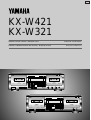 1
1
-
 2
2
-
 3
3
-
 4
4
-
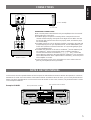 5
5
-
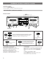 6
6
-
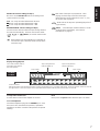 7
7
-
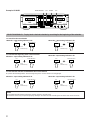 8
8
-
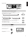 9
9
-
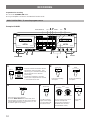 10
10
-
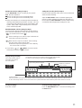 11
11
-
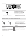 12
12
-
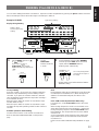 13
13
-
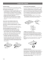 14
14
-
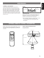 15
15
-
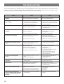 16
16
-
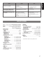 17
17
-
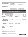 18
18


Yamaha KX-W321 Handleiding
- Categorie
- Cassettespelers
- Type
- Handleiding
- Deze handleiding is ook geschikt voor
in andere talen
- English: Yamaha KX-W321 User manual
- italiano: Yamaha KX-W321 Manuale utente
- русский: Yamaha KX-W321 Руководство пользователя
- français: Yamaha KX-W321 Manuel utilisateur
- español: Yamaha KX-W321 Manual de usuario
- Deutsch: Yamaha KX-W321 Benutzerhandbuch
- português: Yamaha KX-W321 Manual do usuário
- dansk: Yamaha KX-W321 Brugermanual
- suomi: Yamaha KX-W321 Ohjekirja
- čeština: Yamaha KX-W321 Uživatelský manuál
- svenska: Yamaha KX-W321 Användarmanual
- Türkçe: Yamaha KX-W321 Kullanım kılavuzu
- polski: Yamaha KX-W321 Instrukcja obsługi
- română: Yamaha KX-W321 Manual de utilizare