
POWER AMPLIFIER
Owner's Manual
Mode d'emploi
Bedienungsanleitung
Manual de instrucciónes
TEMP
PROTECTION
POWER
ON OFF
AB
CLIP
SIGNAL
–dB∞ 0 ∞ 0
40
30
20
15
10
3
6
25
40
30
20
15
10
3
6
25
EEEngine
M

Introduction
English
Thank you for purchasing a Yamaha P4500/3200/1600 series power amplifier.
This series of audio amps was developed from Yamaha's wealth of experience in building PA
equipment and its tradition of careful attention to every detail of circuit design. These amps
feature high power and superb quality together with superior reliability and stability, guarantee-
ing the highest possible audio performance.
Main features of the P4500/P3200/P1600 series
• Three types of input jack (balanced XLR type connectors, balanced phone jacks, and barrier
strip), and five-way binding post output jacks are provided, allowing use in a wide variety
of situations including installed applications.
• Three operating modes are provided: STEREO mode in which CHANNEL A and B operate
independently, PARALLEL mode in which a mono source is output by two amp systems, and
BRIDGE mode in which the unit operates as a single high-power amplifier.
• A SIGNAL indicator and CLIP indicator is provided for each channel.
• The PROTECTION indicator shows the status of protective circuitry such as power-on/off
protection, output muting, and the DC detection circuit. The TEMP indicator warns of heat
sink overheating.
• Variable-speed low-noise fan(s) ensures high reliability even under demanding conditions.
This owner's manual covers the three models P4500, P3200 and P1600. In order to take full
advantage of your power amp and enjoy long and trouble-free operation, please read this owner's
manual carefully before use.
IMPORTANT NOTICE FOR
THE UNITED KINGDOM
Connecting the Plug and Cord
WARNING: THIS APPARATUS MUST BE EARTHED
IMPORTANT: The wires in this mains lead are coloured in accordance with
the following code:
GREEN-AND-YELLOW : EARTH
BLUE : NEUTRAL
BROWN : LIVE
As the colours of the wires in the mains lead of this apparatus may not
correspond with the coloured markings identifying the terminals in your
plug, proceed as follows:
The wire which is coloured GREEN and YELLOW must be connected to
the terminal in the plug which is marked by the letter E or by the safety earth
symbol or coloured GREEN and YELLOW.
The wire which is coloured BLUE must be connected to the terminal which
is marked with the letter N or coloured BLACK.
The wire which is coloured BROWN must be connected to the terminal
which is marked with the letter L or coloured RED.
* This applies only to products distributed by YAMAHA KEMBLE
MUSIC (U.K.) LTD.

Precautions
1. Avoid excessive heat, humidity, dust and vibration.
Keep the unit away from locations where it is likely to be
exposed to high temperatures or humidity — such as
near radiators, stoves, etc. Also avoid locations which
are subject to excessive dust accumulation or vibration
which could cause mechanical damage.
2. Ventilation
Allow a distance of 10 cm between the unit and the wall
so that heat generated from the unit will be released
effectively. Also, allow enough space between the unit
and other devices. If you mount the unit in an audio rack,
keep a space of 10 cm on the top panel, and a space of
1 cm to the side panel. Remove the rear panel of the rack
or open a vent hole. If heat release is inadequate, the unit
will retain heat inside the unit, which may cause a fire.
3. Avoid physical shocks.
Strong physical shocks to the unit can cause damage.
Handle it with care.
4. Do not open the case or attempt repairs or modifica-
tions yourself.
This product contains no user-serviceable parts. Refer
all maintenance to qualified Yamaha service personnel.
Opening the case and/or tampering with the internal
circuitry will void the warranty.
5. Make sure power is off before making or removing
connections.
Always turn the power OFF prior to connecting or
disconnecting cables. This is important to prevent dam-
age to the unit itself as well as other connected equip-
ment.
6. Handle cables carefully.
Always plug and unplug cables — including the AC cord
— by gripping the connector, not the cord.
7. Clean with a soft dry cloth.
Never use solvents such as benzine or thinner to clean
the unit. Wipe clean with a soft, dry cloth.
8. Always use the correct power supply.
Make sure that the power supply voltage specified on the
rear panel matches your local AC mains supply. Also
make sure that the AC mains supply can deliver more
than enough current to handle all equipment used in your
system.
Contents
Controls and Functions ............................................................. 2
Front Panel........................................................................... 2
Rear Panel ........................................................................... 3
Modes: STEREO/PARALLEL/BRIDGE................................ 4
SPEAKER IMPEDANCE...................................................... 4
Caution for Speaker Connection ............................................... 5
Rack Mounting .......................................................................... 6
Mounting in an EIA standard rack ....................................... 6
Mounting four or fewer amps in an open-backed rack......... 6
Mounting five or more amps, or when (even with four or
fewer units) the back of the rack cannot be left open.......... 6
Portable Rack Mounting ...................................................... 7
Positioning the Housed Amplifier......................................... 7
Specifications ............................................................................ 8
General Specifications......................................................... 8
Block Diagram...................................................................... 9
Dimensions .......................................................................... 9
Performance Graphs.......................................................... 10
Troubleshooting ...................................................................... 10

2
Controls and Functions
■ Front Panel
TEMP
PROTECTION
POWER
ON OFF
AB
CLIP
SIGNAL
61
23
4
5
–dB∞ 0 ∞ 0
40
30
20
15
10
3
6
25
40
30
20
15
10
3
6
25
EEEngine
1 POWER switch and indicator
This is the main POWER switch. Press to power ON the
amplifier. Press again to power OFF. The POWER
indicator lights up when the amplifier is powered ON.
2 TEMP indicator
When the temperature of the heat sink exceeds 85
degrees Celsius, this indicator will light red.
3 PROTECTION indicator
This red LED indicator lights up for approximately 3
seconds when the amplifier is powered ON, indicating
that the soft-start protection system is working. No
sound is output during soft-start up. If one of the protec-
tion systems is activated during normal use, this indica-
tor lights up and no sound is output. The speaker system
is actually disconnected from the amplifier outputs when
this indicator lights up. The protection systems are
activated when overheating occurs or a DC voltage is
present at the amplifier outputs. If the problem is cor-
rected, the protection systems deactivate automatically,
this indicator goes out, and normal amplifier operation is
resumed.
4 CLIP indicators
These red LED indicators light up when the respective
channel’s output signal distortion exceeds 1% (i.e. clip-
ping). Output signal clipping is usually due to excessive
input signal levels.
5 SIGNAL indicators
These green LED indicators light up when the respective
channel’s output signal exceeds 2 Vrms. This is equiva-
lent to 1/2 watt into 8Ω, 1 W into 4Ω.
6 Volume controls
These volume controls allow you to adjust the volume
level in 31 steps in the range between –∞ dB and 0 dB.
To fix the volume setting by protecting the controls,
install the included security cover over the controls and
tighten the screws in the holes as shown below.
–dB∞ 0 ∞ 0
40
30
20
15
10
3
6
25
40
30
20
15
10
3
6
25

3
■ Rear Panel
INPUT SPEAKERS
CHANNEL B CHANNEL A
CHANNEL B CHANNEL A
GG
(BRIDGE)
(PARALLEL)
BRIDGE
STEREO PARALLEL
STEREO
BRIDGE
MAX. OUTPUT 450W/4Ω (STEREO)
MAX. OUTPUT 900W/8Ω (BRIDGE)
(STEREO)
4-8Ω/SP
(BRIDGE)
8-16Ω/SP
3214
3 SPEAKERS terminals
For polarity in each mode, refer to the following dia-
gram.
• STEREO, PARALLEL mode
SPEAKERS
CHANNEL B CHANNEL A
STEREO
BRIDGE
• BRIDGE mode
SPEAKERS
CHANNEL B CHANNEL A
STEREO
BRIDGE
In BRIDGE mode, the (-) jacks of CHANNELS A and
B are not used.
The minimum impedance for the connected speaker
system is specified in “Speaker Impedance” on page 4.
4 GND terminals
This is the grounding screw terminal. If hum or noise
occurs, ground (earth) the unit via this jack, or try
connecting it to the chassis of the mixer or preamp, etc.
1 INPUT terminals (CHANNEL A, B)
Three types of balanced terminals for channels A and B
are provided.
Channel A input terminal is used in Bridge and Parallel
mode.
• XLR-3-31 type connector
They are wired pin 1–ground, pin 2–hot (
+
), and pin 3 cold
(
-
).
1
2
3
Cold
GroundHot
• Phone jack
They are wired tip–hot (+), ring–cold (-), and sleeve–
ground.
Ring
Sleeve Tip
• Barrier strip
Hot (+), Cold (-) and Ground (G).
2 STEREO/BRIDGE/PARALLEL switch
This slide switch is used to set the amplifier operating
mode: STEREO, BRIDGE or PARALLEL.
For details on the functionality of each mode, refer to
“Modes” on page 4.

4
■ Modes: STEREO/PARALLEL/BRIDGE
BRIDGE mode
In this mode, the CHANNEL A input signal will be
output from the BRIDGE output jacks. In this case, use
the front panel (channel)
A
volume control to adjust the
volume.
■ SPEAKER IMPEDANCE
In STEREO and PARALLEL modes, the minimum load
(=speaker) impedance is 4Ω. In BRIDGE mode it is 8Ω.
Make sure that the impedance does not fall below this
specified impedance.
STEREO mode connections
SPEAKERS
CHANNEL B CHANNEL A
BRIDGE
STEREO PARALLEL
STEREO
BRIDGE
MAX. OUTPUT 450W/4Ω (STEREO)
MAX. OUTPUT 900W/8Ω (BRIDGE)
–+
–+
Set to STEREO
Speaker S
y
stem
4Ω min. 4Ω min.
PARALLEL mode connections
SPEAKERS
CHANNEL B CHANNEL A
BRIDGE
STEREO PARALLEL
STEREO
BRIDGE
MAX. OUTPUT 450W/4Ω (STEREO)
MAX. OUTPUT 900W/8Ω (BRIDGE)
– +
– +
Set to PARALLEL
Speaker S
y
stem
4Ω min. 4Ω min.
BRIDGE mode connections
SPEAKERS
CHANNEL B CHANNEL A
BRIDGE
STEREO PARALLEL
STEREO
BRIDGE
MAX. OUTPUT 450W/4Ω (STEREO)
MAX. OUTPUT 900W/8Ω (BRIDGE)
– +
Set to BRIDGE
Speaker S
y
stem
8Ω min.
STEREO mode
In this mode, channels A and B operate independently
(as a conventional stereo amp).
The CHANNEL A input signal will be output from the
CHANNEL A output jacks, and the CHANNEL B input
signal will be output from the CHANNEL B output
jacks.
PARALLEL mode
In this mode, the CHANNEL A input signal will be
output from the output jacks of both channels A and B.
The CHANNEL B input jack is not used. The (channel)
A
and volumes can be adjusted independently.

5
Caution for Speaker Connection
1. Turn off the POWER switch.
2. Remove the cover attachment screw(s) and remove the
protective cover from the speaker terminals.
Screw
3. After removing approx. 10 mm of insulation from the
ends of the speaker cables, pass the bare ends of the
speaker wires through the holes in the corresponding
speaker terminals and tighten the terminals to securely
clamp the wires.
Refer to page 3 for speaker porality.
10 mm
At this time make sure that the bare ends of the speaker
cables do not extend from the terminals in such a way
that they touch the chassis.
4. Reattach the protective cover over the speaker termi-
nals.
• Speaker fuse
The output capacity of your amplifier is very high: 460
W+460 W (8Ω) in stereo and 1240 W (8Ω) in monaural
on the P4500; 340 W+340 W (8Ω) in stereo and 880 W
(8Ω) in monaural on the P3200; 160 W+160 W (8Ω) in
stereo and 400 W (8Ω) in monaural on the P1600. Be
sure to use a speaker system that has sufficient input
capacity.
If the input capacity of your speaker system is lower than
the rated output of the power amplifier, you can protect
your speakers by connecting a fuse serially between the
speaker and amplifier as shown below.
_
+ _
+
Power amplifier
Speaker system
Fuse
Use the following formula to determine the fuse capacity
according to the speaker’s input capacity.
Po = I R → I = √Po/R
2
P0 [W] : Speaker’s continuous input capacity (noise or
RMS)
R [Ω] : Speaker’s nominal impedance
I [A] : Required fuse capacity
ex.) Speaker’s continuous input capacity : 100 W
Speaker’s impedance : 8Ω
I = √100/8
In this example, the required fuse capacity is calculated
as 3.5 [A].
• Speaker cable
If you use a long speaker cable, use as thick a cable as
possible to prevent deterioration of the damping factor
or power loss inside the cable.

6
Rack Mounting
■ Mounting in an EIA standard rack
If multiple high-power amp units are mounted in a rack with poor ventilation, the heat from the amps will cause the interior
of the amp to become very hot, causing the performance of the amps to be impaired. When mounting amps in a rack, you
must make provision for ventilation so that the heat can escape.
When mounting amps in a rack, please attach ventilation panels above and below the amp to allow air circulation. When
doing so, it is necessary for 35% or more of the entire surface area of a 1U size panel to be open.
Air circulation will be even better if the top surface of the rack has ventilation openings.
Ventilation panel
Yamaha provides an optional 1U-size ventilation panel VP1.
Unit: mm
480
44
■ Mounting four or fewer amps in
an open-backed rack
Install the ventilation panel above the amps, as shown in
the following figure.
Ventilation panel
(attach to the front
or rear of the rack)
TEMP
PROTECTION
POWER
ON OFF
AB
CLIP
SIGNAL
–dB∞ 0 ∞ 0
40
30
20
15
10
3
6
25
40
30
20
15
10
3
6
25
EEEngine
TEMP
PROTECTION
POWER
ON OFF
AB
CLIP
SIGNAL
–dB∞ 0 ∞ 0
40
30
20
15
10
3
6
25
40
30
20
15
10
3
6
25
EEEngine
TEMP
PROTECTION
POWER
ON OFF
AB
CLIP
SIGNAL
–dB∞ 0 ∞ 0
40
30
20
15
10
3
6
25
40
30
20
15
10
3
6
25
EEEngine
■ Mounting five or more amps, or
when (even with four or fewer
units) the back of the rack cannot
be left open
Install ventilation panels above and below each amp, as
shown in the following figure.
TEMP
PROTECTION
POWER
ON OFF
AB
CLIP
SIGNAL
–dB∞ 0 ∞ 0
40
30
20
15
10
3
6
25
40
30
20
15
10
3
6
25
EEEngine
TEMP
PROTECTION
POWER
ON OFF
AB
CLIP
SIGNAL
–dB∞ 0 ∞ 0
40
30
20
15
10
3
6
25
40
30
20
15
10
3
6
25
EEEngine
TEMP
PROTECTION
POWER
ON OFF
AB
CLIP
SIGNAL
–dB∞ 0 ∞ 0
40
30
20
15
10
3
6
25
40
30
20
15
10
3
6
25
EEEngine
TEMP
PROTECTION
POWER
ON OFF
AB
CLIP
SIGNAL
–dB∞ 0 ∞ 0
40
30
20
15
10
3
6
25
40
30
20
15
10
3
6
25
EEEngine

7
■ Portable Rack Mounting
The amplifier intakes cool air through the front panel and exhausts warm air out the rear panel. When mounting amplifiers
in a portable rack, make sure the rear panel is completely open for ventilation.
Front
Air intake Air exhaust
Completely open
(Rear View)(Side View)
INPUT SPEAKERS
CHANNEL B CHANNEL A
CHANNEL B CHANNEL A
GG
(BRIDGE)
(PARALLEL)
BRIDGE
STEREO PARALLEL
STEREO
BRIDGE
MAX. OUTPUT 450W/4Ω (STEREO)
MAX. OUTPUT 900W/8Ω (BRIDGE)
(STEREO)
4-8Ω/SP
(BRIDGE)
8-16Ω/SP
■ Positioning the Housed Amplifier
Place the case so that the ventilation airflow paths are not blocked.
Front
Less than 10 cm
NO
Front
NO

8
Specifications
■ General Specifications
P4500 P3200 P1600
Power Output Level (Rated Power) 8Ω/STEREO 460 W + 460 W 340 W + 340 W 160 W + 160 W
20 Hz~20 kHz 4Ω/STEREO 620 W + 620 W 440 W + 440 W 200 W + 200 W
0.05% 8Ω/BRIDGE 1240 W 880 W 400 W
1 kHz 8Ω/STEREO 520 W + 520 W 370 W + 370 W 175 W + 175 W
0.05% 4Ω/STEREO 720 W + 720 W 520 W + 520 W 230 W + 230 W
8Ω/BRIDGE 1440 W 1040 W 460 W
1 kHz, 20 ms, no clip 2Ω/STEREO 1300 W + 1300 W 950 W + 950 W 350 W + 350 W
Power Bandwidth Half Power, 0.1% 10 Hz~40 kHz
Total Harmonic Distortion (THD + N) 4~8Ω/STEREO
20 Hz~20 kHz, Half Power 8Ω/BRIDGE
0.05%
Frequency Response 10 Hz~50 kHz, +0, –1 dB
Intermodulation distortion (IMD) 4~8Ω/STEREO
7 kHz: 60 Hz, 1: 4, Half Power 8Ω/BRIDGE
0.05%
Damping factor 1 kHz, 8Ω 200
Input Impedance 30 kΩ/Balance, 15 kΩ/Unbalanced
Residual Noise Vol. min. 12.7 kHz LPF
IHF-A network
–80 dB
SN Ratio Input 600Ω shunt 12.7 kHz LPF
IHF-A network
105 dB 104 dB 101 dB
Channel Separation Half Power, 8Ω, Vol. max. 65 dB, 20 Hz~20 kHz
input 600Ω shunt 75 dB, 1 kHz
Slew Rate STEREO >30 V/µ sec
8Ω full swing BRIDGE >50 V/µ sec
Sensitivity (Vol. max.) Rated Power into 8Ω +5.7 dB +4.2 dB +1.2 dB
Voltage Gain (Vol. max.) 32.1 dB
Controls Front Panel POWER switch (Push on/Push off)
Volume (31 position dB calibrated)
Rear Panel Mode switch (STEREO/BRIDGE/PARALLEL)
Connectors Input Barrier strip terminal
XLR-3-31 type
1/4-inch phone jack (balanced)
Output 5-way binding posts
Indicators POWER
TEMP (heatsink temp ≥ 85°C)
PROTECTION (mute)
CLIP × 2
OUTPUT SIGNAL × 2
Protection Circuits POWER switch ON/OFF, Muting, DC detection
TEMP (heatsink temp ≥ 95°C)
PC limiter RL ≤ 1Ω
Fan Circuits Low speed (50°C), Variable, High speed (70°C)
Power Requirements United States & Canada 120 V, 60 Hz
Europe 230 V, 50 Hz
Other 240 V, 50 Hz
Power Consumption 500 W/650 VA 400 W/500 VA 200 W/250 VA
Dimensions (W × H × D) 480 × 103.5 × 455 mm
Weight 16 kg 15 kg 12 kg
Accessories Security cover
Options Ventilation panel: VP1
0 dB=0.775 Vrms, Half Power=1/2 Power Output Level (Rated Power)
Specifications subject to change without notice.

9
■ Block Diagram
Temperature
CHANNEL B
CHANNEL A
CLIP
CLIP
SIGNAL
Bch Power Amp
PC Limiter
Ach Power Amp
PC Limiter
SPEAKERS
(BRIDGE)
(PARALLEL)
CHANNEL A
CHANNEL B
B
A
INPUT
PROTECTION
TEMP
(Heat Sink)
Sensor
Circuit
Protection
STEREO
PARALLEL
BRIDGE
G
G
SIGNAL
■ Dimensions
15.5
61.229255.2
308
88
H:103.5
W:480
424
45
4.4
D:455
379.6 26
Unit: mm

10
■ Performance Graphs
Mode:STEREO
Both ch Driven
RL=4Ω, f=1kHz
Mode:STEREO
Both ch Driven
RL=4Ω, f=1kHz
Mode:STEREO
Both ch Driven
RL=4Ω, f=1kHz
P1600
P3200P4500
Output Power [W]
Power Consumption [W]
Power Consumption [W]
Output Power [W]Output Power [W]
Power Consumption [W]
1k100101
5k
1k
100
20
20
100
1k
5k
1 10 100 1k1k100101
5k
1k
100
20
Troubleshooting
The following table lists the main causes of abnormal operation and the corrective measures required, as well as the protective
circuit operation in each case.
Indicator Probable Cause Remedy Protection Circuit
Locate and correct the cause
of the short.
Use a speaker system with
an impedance of at least 4Ω
(stereo) or 8Ω (bridge).
Check the ventilation slots,
and improve the airflow
around the amplifier.
Check the amplifier ventila-
tion conditions and take
appropriate measures to
improve airflow around the
amplifier.
Consult your dealer or
nearest Yamaha service
center.
There is a short at a speaker
terminal, amplifier terminal,
or wire.
The amplifier load is exces-
sive.
The heat sink temperature
has exceed 85˚C.
The heat sink temperature
has exceeded 95˚C.
A DC voltage of +/–2 V or
greater was generated in the
power amplifier’s output
circuit.
The PC limiter circuit
operates to protect the power
transistors.
Warning by the TEMP
indicator.
The thermal protection circuit
operates to protect the power
transistors.
The relay operates to protect
the speaker system.
CLIP indicator lights.
TEMP indicator lights.
PROTECTION indicator
lights.

P4500/3200/1600 Mode d'emploi
Table des matières
Commandes et fonctions .........................................2
Panneau avant ...................................................... 2
Panneau arrière ....................................................3
Modes: STEREO/PARALLEL/BRIDGE................. 4
Impedance des enceintes.....................................4
Connexion des enceintes ........................................5
Montage en rack ......................................................6
Montage dans un rack standard EIA ....................6
Montage de quatre amplificateurs maximum avec
face arrière ouverte...............................................6
Montage de cinq amplificateurs ou plus ou lorsque
(avec moins de 4 amplificateurs) la face arrière ne
peut rester ouverte................................................6
Montage en “flightcase” ........................................7
Installation de l’amplificateur à tout autre endroit.7
Fiche technique .......................................................8
Caractéristiques générales...................................8
Schéma.................................................................9
Dimensions ...........................................................9
Graphiques de performance...............................10
En cas de probleme...............................................10
Nous vous remercions d’avoir opté pour un amplificateur de
puissance Yamaha P4500/3200/1600.
Cette série d’amplificateurs audio est le fruit d’une longue
expérience que Yamaha a accumulée en fabricant du matériel
PA ainsi que d’une attention traditionnelle portée à tous les
détails de la conception d’un circuit. Ces amplificateurs
n’offrent donc pas seulement une performance sortant de
l’ordinaire mais également une qualité, une fiabilité et une
solidité qui garantit la meilleure reproduction audio possible.
Voici les caractéristiques principales de la série P4500/
3200/1600:
• Trois types d’entrées (connecteurs symétriques de type
XLR, des jacks symétriques et des connecteurs pour câbles
dénudés) ainsi que des sorties à bornes de connexion ce
qui permet d’insérer cet amplificateur dans n’importe
quel type d’installation.
•
Trois modes: Le mode STEREO qui permet aux canaux A
et B d’opérer indépendamment, le mode PARALLEL qui
reproduit un signal mono via les deux circuits d’amplifica-
tion et le mode BRIDGE qui permet de transformer l’appa-
reil en un amplificateur à un canal de très haute puissance.
• Un témoin SIGNAL et CLIP par canal.
• Un témoin PROTECTION qui indique le statut du circuit
de protection tel que la protection lors de la mise sous/hors
tension, l’étouffement de la sortie et le circuit de détection
de courant continu. Le témoin TEMP s’allume lorsqu’il y
a surchauffe du radiateur dissipateur de chaleur.
• Un ou plusieurs ventilateur(s) à vitesse variable d’un
niveau de bruit très bas garantissent une excellente fiabi-
lité même dans les conditions les plus difficiles.
Ce manuel couvre les modèles P4500, P3200 et P1600. Veuillez
le lire complètement pour éviter toute erreur de manipulation et
pouvoir jouir de votre amplificateur durant de longues années.
Précautions
1. Evitez des endroits excessivement poussiéreux et
humides, ainsi que des vibrations trop importantes.
Tenez cet appareil à l’écart d’endroits où il risque d’êtres
soumis à des températures ou des degrés d’humidité trop
importants – tels des radiateurs, des poêles etc. Ne le
placez jamais à un endroit fortement poussiéreux ou
soumis à des vibrations qui pourraient entraîner des
dommages mécaniques.
2. Ventilation
Veiller à garder une distance minimum de 10 cm entre
l’unité et un mur pour que l’air dégagé par cette unité
puisse se dissiper. De plus, veillez à ce que la distance entre
cet amplificateur et d’autres unités soit suffisamment
grande. Si vous logez cette unité dans un rack audio, laissez
un espace de 10 cm entre dans la partie supérieure du rack
et 1 cm sur les côtés. Retirez la face arrière du rack ou
utilisez un rack ouvert. Si la chaleur ne peut pas se dissiper,
le manque de ventilation peut provoquer un incendie.
3. Manipuler avec soin.
Ne laissez jamais tomber cet appareil et manipulez-le
avec soin.
4. N’ouvrez jamais le boîtier et surtout ne tentez jamais
de le réparer vous-même.
Ce produit ne contient pas de pièces pouvant être répa-
rées par l’utilisateur. Confiez tout travail d’entretien à
une service technique agréé par Yamaha. Notez qu’en
ouvrant le boîtier, vous mettez automatiquement un
terme aux conditions de garantie.
5. Veillez à éteindre cet appareil avant d’établir ou de
défaire des connexions.
Il importe de mettre cet appareil hors tension avant d’y
connecter ou de déconnecter des câbles afin d’éviter
d’endommager cet appareil ou tout autre appareil utilisé.
6. Prudence avec les câbles.
Veillez à toujours déconnecter tous les câbles –y com-
pris le cordon d’alimentation– en tirant sur les fiches. Ne
tirez jamais sur les câbles.
7. Nettoyez avec un chiffon doux et sec.
N’utilisez jamais de benzène ou de diluant pour nettoyer
le boîtier. Nettoyez-le avec un chiffon doux et sec.
8. Utilisez toujours la tension requise.
Vérifiez d’abord si les données concernant la tension en
face arrière correspondent à la tension fournie par la
prise à laquelle vous reliez cet appareil. Assurez-vous en
outre que cette prise est capable de fournir suffisamment
de courant pour alimenter votre système.
FRANÇAIS

2
Commandes et fonctions
■ Panneau avant
TEMP
PROTECTION
POWER
ON OFF
AB
CLIP
SIGNAL
61
23
4
5
–dB∞ 0 ∞ 0
40
30
20
15
10
3
6
25
40
30
20
15
10
3
6
25
EEEngine
1 Touche et témoin POWER
Il s’agit de la touche de mise sous tension. Enfoncez-la
pour mettre l’amplificateur sous tension et appuyez une
fois de plus sur cette touche pour le mettre hors tension.
Le témoin POWER s’allume lorsque l’amplificateur est
mis sous tension.
2 Témoin TEMP
Ce témoin s’allume en rouge dès que la température du
radiateur excède 85°C.
3 Témoin PROTECTION
Ce témoin rouge s’allume pendant environ 3 secondes
après que vous ayez allumé l’amplificateur et indique
que le système de protection de démarrage doux fonc-
tionne. Aucun son n’est audible durant ce démarrage. Si
un de systèmes de protection s’enclenche, ce témoin
s’allume et l’appareil ne sort plus aucun son. Les encein-
tes sont virtuellement débranchées de l’amplificateur
quand ce témoin est allumé. Ces systèmes de protection
s’allument en cas de surchauffe ou lorsque les sorties
émettent un voltage trop important. Une fois le problème
résolu, le circuit de protection se désenclenche automa-
tiquement et l’amplificateur reprend son fonctionne-
ment normal.
4 Témoins CLIP
Ces témoins rouges s’allument lorsque la distorsion du
signal à la sortie de leur canal respectif dépasse 1%
(saturation). Cette saturation est généralement due à des
niveaux d’entrée trop élevés.
5 Témoins SIGNAL
Ces témoins verts s’allument lorsque le voltage aux
connecteurs des enceintes dépasse 2 Vrms, ce qui équi-
vaut à 1/2 W sous 8Ω ou 1 W sous 4Ω.
6 Volume
Ces atténuateurs sont crantés à 31 positions. Leur plage
d’atténuation va de –∞ dB à 0 dB.
Pour éviter que les réglages puissent être changés, nous
vous conseillons d’installer le cache et de l’attacher avec
les vis (voyez l’illustration).
–dB∞ 0 ∞ 0
40
30
20
15
10
3
6
25
40
30
20
15
10
3
6
25

3
■ Panneau arrière
INPUT SPEAKERS
CHANNEL B CHANNEL A
CHANNEL B CHANNEL A
GG
(BRIDGE)
(PARALLEL)
BRIDGE
STEREO PARALLEL
STEREO
BRIDGE
MAX. OUTPUT 450W/4Ω (STEREO)
MAX. OUTPUT 900W/8Ω (BRIDGE)
(STEREO)
4-8Ω/SP
(BRIDGE)
8-16Ω/SP
3214
3 Bornes SPEAKERS
Pour la polarité à choisir en fonction du mode, veuillez
consulter l’illustration suivante.
• Mode STEREO, PARALLEL
SPEAKERS
CHANNEL B CHANNEL A
STEREO
BRIDGE
• Mode BRIDGE
SPEAKERS
CHANNEL B CHANNEL A
STEREO
BRIDGE
En mode BRIDGE, les bornes (–) des canaux A et B ne
sont pas utilisées.
Vous trouverez les explications relatives à l’impédance
minimale pour les enceintes dans la section “Impédance
des enceintes” à la page 4.
4 Borne GND
Il s’agit de la borne de mise à la terre. Si vous entendez
des bruits ou des bourdonnements durant le fonctionne-
ment, mettez l’appareil à la terre en vous servant de cette
borne ou en le reliant au châssis du mélangeur ou du
préampli, etc.
1 Bornes d’entrée (INPUT: CHANNEL A, B)
Vous avez le choix entre trois types de bornes pour les
canaux A et B.
Utilisez la borne d’entrée du canal A en mode Bridge et
Parallel (pont).
• Borne de type XLR-3-31
La masse est à la broche 1, le signal chaud à la broche 2
(+) et le signal froid à la broche 3 (-).
1
2
3
Froid
MasseChaud
• Entrées jack TRS
Le signal chaud est à la pointe (+), le froid à l’anneau
(-) et la masse à la gaine.
Anneau
Gaine Pointe
• Vis de serrage
Chaud (+), froid (-) et masse.
2 Commutateur STEREO/BRIDGE/PARALLEL
Ce commutateur coulissant vous permet de sélectionner
un des deux modes de fonctionnement: STEREO,
BRIDGE ou PARALLEL.
Pour en savoir plus sur chaque mode, voyez “Modes” à
la page 4.

4
■ Modes: STEREO/PARALLEL/BRIDGE
Mode BRIDGE
Avec ce mode, le signal du canal A est envoyé aux
sorties BRIDGE. Dans ce cas, servez-vous de la com-
mande de volume
A
.
■ Impedance des enceintes
Pour les modes STEREO et PARALLEL, l’impédance
minimale de charge (des enceintes) est de 4Ω, contre 8Ω
pour le mode BRIDGE. N’utilisez que des enceintes
satisfaisant à ces conditions.
Connexions en mode STEREO
SPEAKERS
CHANNEL B CHANNEL A
BRIDGE
STEREO PARALLEL
STEREO
BRIDGE
MAX. OUTPUT 450W/4Ω (STEREO)
MAX. OUTPUT 900W/8Ω (BRIDGE)
– +
– +
Réglé sur
STEREO
S
y
stème d’enceintes
4Ω min. 4Ω min.
Connexions en mode PARALLEL
SPEAKERS
CHANNEL B CHANNEL A
BRIDGE
STEREO PARALLEL
STEREO
BRIDGE
MAX. OUTPUT 450W/4Ω (STEREO)
MAX. OUTPUT 900W/8Ω (BRIDGE)
– +
– +
Réglé sur
PARALLEL
S
y
stème d’enceintes
4Ω min. 4Ω min.
Connexions en mode BRIDGE
SPEAKERS
CHANNEL B CHANNEL A
BRIDGE
STEREO PARALLEL
STEREO
BRIDGE
MAX. OUTPUT 450W/4Ω (STEREO)
MAX. OUTPUT 900W/8Ω (BRIDGE)
– +
Réglé sur
BRIDGE
S
y
stème d’enceintes
8Ω min.
Mode STEREO
Avec ce mode, les canaux A et B sont indépendants
(comme sur n’importe quel amplificateur stéréo tradi-
tionnel).
Le signal du canal A sera émis via les bornes de sortie du
canal A tandis que le signal du canal B sera émis via les
bornes de sortie du canal B.
Mode PARALLEL
Avec ce mode, le signal du canal A est envoyé aux deux
sorties SPEAKERS (A et B). Dans ce cas, les entrées du
canal B ne sont donc pas utilisées. Toutefois, vous
pouvez régler le volume des signaux des sorties.
A et B séparément (avec les commandes
A
et ).

5
Connexion des enceintes
1. Mettez l’amplificateur hors tension.
2. Dévissez le couvercle de protection et retirez-le des
bornes pour enceintes.
Vis
3. Retirez environ 10 mm de l’isolant de câbles et faites
glisser le fil en cuivre dans les trous des bornes pour
enceintes. Resserrez ensuite les boulons jusqu’à ce que
les fils soient solidement attachés.
Voyez page 3 pour en savoir davantage sur la polarité
des enceintes.
10 mm
Veillez à ce que les fils en cuivre ne ressortent pas des
ouvertures et qu’il n’aient aucun contact avec le châssis.
Le fil en cuivre ne doit en
aucun cas toucher le chassis.
4. Reposez le couvercle de protection sur les bornes de
connexion.
• Fusible des enceintes
Votre amplificateur est très puissant: 460 W+460 W
(8Ω) en stéréo et 1240 W (8Ω) en mono sur le P4500;
340 W+340 W (8Ω) en stéréo et 880 W (8Ω) en mono
sur le P3200; 160 W+160 W (8Ω) en stéréo et 400 W
(8Ω) en mono sur le P1600. Assurez-vous que la puis-
sance d’entrée de vos enceintes est adéquate.
Si la puissance d’entrée de votre système d’enceintes est
inférieure à la puissance de sortie de votre amplificateur,
vous pouvez protéger vos enceintes en insérant un fusi-
ble entre l’enceinte et l’amplificateur comme illustré ci-
dessous.
_
+ _
+
Amplificateur
Enceinte
Fusible
La formule suivante vous aidera à déterminer la capacité
du fusible en fonction de la puissance d’entrée de vos
enceintes:
Po = I R → I = √Po/R
2
P0 [W] : Entrée continue maximale de l’enceinte (bruit
ou RMS)
R [Ω] : Impédance nominale de l’enceinte
I [A] : Capacité du fusible
ex.) Entrée continue maximale de l’enceinte: 100 W
Impedance de l’enceinte: 8Ω
I = √100/8
Capacité requise du fusible pour cet exemple: 3,5 [A].
• Câble des enceintes
Si vous utilisez un câble fort long, il convient d’utiliser
le plus gros diamètre possible pour éviter des pertes de
puissance ainsi qu’une dégradation du signal causée par
le facteur d’amortissement.

6
Montage en rack
■ Montage dans un rack standard EIA
Si vous montez plusieurs amplificateur de haute puissance dans un rack mal aéré, la chaleur accumulée des amplificateurs
peut finir par affecter leur performance. Veillez donc à favoriser une bonne ventilation qui évacuera cette chaleur.
Idéalement, il faudrait installer une grille de ventilation au-dessus et en dessous de chaque amplificateur. Veillez alors à
laisser au moins 35% de la surface d’1U ouverte pour assurer une circulation d’air suffisante.
Pour obtenir une ventilation optimale du rack, placez également une grille de ventilation en haut du rack.
Grille de ventilation
Yamaha propose une grille de ventilation de 1U (VP1, disponible en option).
Unité: mm
480
44
■ Montage de quatre amplificateurs
maximum avec face arrière
ouverte
Montez une grille de ventilation au-dessus des amplifi-
cateurs (voyez l’illustration).
Grille de ventilation
(à monter à l’avant
ou à l’arrière du
rack)
TEMP
PROTECTION
POWER
ON OFF
AB
CLIP
SIGNAL
–dB∞ 0 ∞ 0
40
30
20
15
10
3
6
25
40
30
20
15
10
3
6
25
EEEngine
TEMP
PROTECTION
POWER
ON OFF
AB
CLIP
SIGNAL
–dB∞ 0 ∞ 0
40
30
20
15
10
3
6
25
40
30
20
15
10
3
6
25
EEEngine
TEMP
PROTECTION
POWER
ON OFF
AB
CLIP
SIGNAL
–dB∞ 0 ∞ 0
40
30
20
15
10
3
6
25
40
30
20
15
10
3
6
25
EEEngine
■ Montage de cinq amplificateurs
ou plus ou lorsque (avec moins de
4 amplificateurs) la face arrière
ne peut rester ouverte
Montez une grille de ventilation entre chaque amplifica-
teur (voyez l’illustration).
TEMP
PROTECTION
POWER
ON OFF
AB
CLIP
SIGNAL
–dB∞ 0 ∞ 0
40
30
20
15
10
3
6
25
40
30
20
15
10
3
6
25
EEEngine
TEMP
PROTECTION
POWER
ON OFF
AB
CLIP
SIGNAL
–dB∞ 0 ∞ 0
40
30
20
15
10
3
6
25
40
30
20
15
10
3
6
25
EEEngine
TEMP
PROTECTION
POWER
ON OFF
AB
CLIP
SIGNAL
–dB∞ 0 ∞ 0
40
30
20
15
10
3
6
25
40
30
20
15
10
3
6
25
EEEngine
TEMP
PROTECTION
POWER
ON OFF
AB
CLIP
SIGNAL
–dB∞ 0 ∞ 0
40
30
20
15
10
3
6
25
40
30
20
15
10
3
6
25
EEEngine

7
■ Montage en “flightcase”
L’amplificateur de puissance aspire l’air froid par le panneau avant et dégage l’air chaud par le panneau arrière. Utilisez
toujours des racks avec une face arrière amovible.
Face avant
Arrivée d’air Dégagement d’air
Complètement ouverte
(Face arrière)(Face latérale)
INPUT SPEAKERS
CHANNEL B CHANNEL A
CHANNEL B CHANNEL A
GG
(BRIDGE)
(PARALLEL)
BRIDGE
STEREO PARALLEL
STEREO
BRIDGE
MAX. OUTPUT 450W/4Ω (STEREO)
MAX. OUTPUT 900W/8Ω (BRIDGE)
(STEREO)
4-8Ω/SP
(BRIDGE)
8-16Ω/SP
■ Installation de l’amplificateur à tout autre endroit
Disposez toujours votre amplificateur de manière à assurer une ventilation optimale.
Face avant
Moins de 10 cm
NO
Face avant
NO

8
Fiche technique
■ Caractéristiques générales
P4500 P3200 P1600
Niveau de sortie (nominal) 8Ω/STEREO 460 W + 460 W 340 W + 340 W 160 W + 160 W
20 Hz~20 kHz 4Ω/STEREO 620 W + 620 W 440 W + 440 W 200 W + 200 W
0,05% 8Ω/BRIDGE 1240 W 880 W 400 W
1 kHz 8Ω/STEREO 520 W + 520 W 370 W + 370 W 175 W + 175 W
0,05% 4Ω/STEREO 720 W + 720 W 520 W + 520 W 230 W + 230 W
8Ω/BRIDGE 1440 W 1040 W 460 W
1 kHz, 20 ms, sans distorsion 2Ω/STEREO 1300 W + 1300 W 950 W + 950 W 350 W + 350 W
Largeur de bande Mi-régime, 0,1% 10 Hz~40 kHz
Distorsion typique (THD + N) 4~8Ω/STEREO
20 Hz~20 kHz, Mi-régime 8Ω/BRIDGE
0,05%
Réponse en fréquence 10 Hz~50 kHz, +0, –1 dB
Distorsion intermodulaire (IMD) 4~8Ω/STEREO
7 kHz: 60 Hz, 1: 4, Mi-régime 8Ω/BRIDGE
0,05%
Facteur d’atténuation 1 kHz, 8Ω 200
Impédance d’entrée 30kΩ/Symétrique, 15kΩ/Asymétrique
Bruit résiduel vol. min. 12,7kHz LPF
IHF-A
–80 dB
Rapport signal/bruit 12,7kHz LPF
entrée à 600Ω shuntée IHF-A
105 dB 104 dB 101 dB
Séparation des canaux Mi-régime, 8Ω, vol. max., 65 dB, 20 Hz~20 kHz
entrée à 600Ω shuntée 75 dB, 1 kHz
Vitesse de balayage de tension STEREO >30 V/µ sec
8Ω toute la bande de fréq BRIDGE >50 V/µ sec
Sensibilité (Vol. max.), niveau nominal à 8Ω +5,7 dB +4,2 dB +1,2 dB
Gain de tension (Vol. max.) 32,1 dB
Commandes Face avant POWER (interrupteur) (coupe et active en alternance)
Commande de volume (31 positions, calibrée en dB)
Face arrière Sélecteur de mode (STEREO/BRIDGE/PARALLEL)
Connecteurs Entrées Connecteurs pour fils dénudés
Bornes XLR-3-31
Jacks 1/4" (symétriques)
Sorties Connecteurs à bornes à 5 voies
Indicateurs POWER
TEMP (lorsque le radiateur ≥ 85°C)
PROTECTION (Etouff.)
CLIP × 2
OUTPUT SIGNAL × 2
Circuits de protection Commutateur POWER (activé/coupé), Etouffement,
Détection de sauts de tension
TEMP (température du radiateur ≥ 95°C)
Limiteur de tension RL ≤ 1Ω
Circuits de ventilation Faible vitesse (50°C), Variable, Grande vitesse (70°C)
Alimentation Etats-Unis et Canada 120 V, 60 Hz
Europe 230 V, 50 Hz
Autres 240 V, 50 Hz
Consommation 500 W/650 VA 400 W/500 VA 200 W/250 VA
Dimensions (L × H × P) 480 × 103,5 × 455 mm
Poids 16 kg 15 kg 12 kg
Accessoires Cache de protection
Options Grille de ventilation: VP1
0dB= 0,775Vrms, mi-régime = 1/2 niveau de sortie (nominal)
Ces caractéristiques peuvent être modifiées sans avis préalable.

9
■ Schéma
Temperature
CHANNEL B
CHANNEL A
CLIP
CLIP
SIGNAL
Bch Power Amp
PC Limiter
Ach Power Amp
PC Limiter
SPEAKERS
(BRIDGE)
(PARALLEL)
CHANNEL A
CHANNEL B
B
A
INPUT
PROTECTION
TEMP
(Heat Sink)
Sensor
Circuit
Protection
STEREO
PARALLEL
BRIDGE
G
G
SIGNAL
■ Dimensions
15.5
61.229255.2
308
88
H:103.5
L:480
424
45
4.4
P:455
379.6 26
Unité: mm

10
■ Graphiques de performance
Mode:STEREO
Both ch Driven
RL=4Ω, f=1kHz
Mode:STEREO
Both ch Driven
RL=4Ω, f=1kHz
Mode:STEREO
Both ch Driven
RL=4Ω, f=1kHz
P1600
P3200P4500
Output Power [W]
Power Consumption [W]
Power Consumption [W]
Output Power [W]Output Power [W]
Power Consumption [W]
1k100101
5k
1k
100
20
20
100
1k
5k
1 10 100 1k1k100101
5k
1k
100
20
En cas de probleme
La liste suivante présente les causes principales d’un fonctionnement anormal et les mesures de correction requises ainsi que
le fonctionnement du circuit de protection dans chaque cas.
Fonctionnement du
Affichage de l’indicateur Cause probable Remède
circuit de protection
Localiser et corriger la cause
du court-circuit.
Utiliser un système de haut-
parleurs ayant une impédance
d’au moins 4Ω (stéréo) ou 8Ω
(bridge).
Vérifiez les orifices de
ventilation et assurez suffisam-
ment d’aération autour de
l’amplificateur.
Vérifier les conditions d’aéra-
tion de l’amplificateur et
prendre les mesures néces-
saire pour améliorer la
circulation autour de l’amplifi-
cateur.
Consulter votre distributeur ou
centre de service Yamaha le
plus proche.
Il y a un court-circuit à une
borne de haut-parleur, une
borne d’amplificateur ou un
câble.
La charge de l’amplificateur
est excessive.
La température des capteurs
thermiques vient de dépasser
les 85°C.
La température de la plaque
de refroidissement a dépassé
95˚C.
Une tension CC de ±2V ou
plus est générée dans le
circuit de sortie de l’amplifica-
teur de puissance.
Le circuit de limiteur PC
fonctionne pour protéger les
transistors de puissance.
Le témoin TEMP s'allume.
Le circuit de protection
thermique fonctionne pour
protéger les transistors de
puissance.
Le relais fonctionne pour
protéger le système de haut-
parleurs.
L’indicateur CLIP s’allume.
Témoin TEMP s’allume.
L’indicateur PROTECTION
s’allume.

P4500/3200/1600 Bedienungsanleitung
Inhalt
Bedienelemente und Funktionen.............................2
Frontplatte.............................................................2
Rückseite ..............................................................3
Betrieb: STEREO/PARALLEL/BRIDGE ................4
Lautsprecherimpedanz .........................................4
Achtung beim Anschließen der Lautsprecher .........5
Rack-Einbau ............................................................6
Einbau in ein genormtes EIA-Rack.......................6
Einbau von höchstens vier Endstufen in ein Rack
mit offener Rückseite ............................................6
Einbau von fünf oder mehr Endstufen oder wenn
(auch bei höchstens vier Endstufen) die Rückseite
nicht freibleiben kann............................................6
Einbau in ein Bühnen-Rack ..................................7
Festeinbau einer Endstufe....................................7
Spezifikationen ........................................................8
Allgemeine Spezifikationen ..................................8
Blockschaltbild ......................................................9
Abmessungen.......................................................9
Leistungsgrafik....................................................10
Fehlersuche ...........................................................10
Vielen Dank, daß Sie sich für einen Yamaha P4500/3200/
1600 Leistungsverstärker entschieden haben.
Diese Endstufenserie beruht auf Yamahas reichhaltiger Er-
fahrung bei der Herstellung von PA-Geräten und einer
traditionsreichen Liebe zum Detail bei der Entwicklung aller
verwendeten Schaltkreise. Diese Endstufen bieten nicht nur
eine Leistung, die sich sehen lassen kann, sondern auch eine
einmalige Qualität, Verläßlichkeit und Stabilität, so daß Sie
jederzeit über die bestmögliche Audiowiedergabe verfügen.
Die wichtigsten Eigenschaften der P4500/3200/1600-Serie
sind:
• Drei Eingangstypen (symmetrische XLR-Anschlüsse, sym-
metrische Klinkenbuchsen und Anschlußleiste) sowie
Schraubklemmen-Ausgänge, so daß sich diese Endstufen
nahtlos in jeden Installationstyp einfügen.
•
Drei Betriebsarten: STEREO-Betrieb, in dem Kanal A und
B separat angetrieben werden, PARALLEL-Betrieb, in dem
beide Verstärkerschaltkreise ein Monosignal ausgeben und
BRIDGE-Betrieb, in dem die Endstufe als einkanaliger
Hochleistungsverstärker verwendet werden kann.
• Eine SIGNAL- und CLIP-Diode pro Kanal.
• Eine PROTECTION-Diode, die den Status der Schutz-
schaltung anzeigt, z.B. die Schutzschaltung beim Ein- und
Ausschalten, die Ausgabestummschaltung und die
Gleichstromaufspürung. Die TEMP-Diode beginnt zu
leuchten, sobald der Kühlkörper überhitzt ist.
• Einer oder mehrere Ventilatoren mit niedrigem Geräusch-
pegel garantieren selbst bei hoher Beanspruchung eine
optimale Funktion.
Diese Bedienungsanleitung bezieht sich auf die Modelle
P4500, P3200 und P1600. Bitte lesen Sie sie sich vollständig
durch, um bei der Bedienung alles richtig zu machen und über
Jahre hinaus einen verläßlichen Betrieb zu gewährleisten.
Vorsichtsmaßnahmen
1. Setzen Sie den P4500/3200/1600 niemals extremen
Temperaturen, Feuchtigkeit, Staub oder starken
Vibrationen aus.
Stellen Sie das Gerät nicht an feuchten oder extrem
warmen Orten auf –meiden Sie also Heizkörper und Öfen.
Meiden Sie außerdem sehr staubige Orte und Vibrationen,
die zu mechanischen Schäden führen könnten.
2. Belüftung
Lassen Sie einen Abstand von mindestens 10 cm zwi-
schen diesem Gerät und der Wand, damit die ferigesetzte
Wärme entweichen kann. Außerdem sollten Sie zwi-
schen diesem und anderen Geräten enefalls diesen Min-
destabstand. Wenn Sie dieses Gerät in ein Rack schrau-
ben, sollten Sie oben 10 cm und an den Seiten 1 cm
freilassen. Verwenden Sie ein hinten offenes Rack oder
bauen Sie eine Lüftungsblende ein. Bei ungenügender
Lüftung kann es zu einem Wärmestau kommen, der zu
Brandgefahr führen kann.
3. Behandeln Sie das Gerät mit der gebotenen Umsicht.
Lassen Sie den P4500/3200/1600 niemals fallen und
behandeln Sie ihn niemals mit roher Gewalt.
4. Niemals das Gehäuse öffnen oder den P4500/3200/
1600 selbst reparieren.
Dieses Gerät sollten Sie niemals selbst reparieren. Über-
lassen Sie diese Arbeiten dem qualifizierten Yamaha-
Kundendienst. Außerdem erlischt beim Öffnen oder
Modifizieren des P4500/3200/1600 automatisch der
Garantieanspruch.
5. Vor dem Anschließen ausschalten.
Schalten Sie den P4500/3200/1600 und die übrigen
Geräte AUS, bevor Sie Anschlüsse vornehmen oder
abtrennen.
6. Kabel umsichtig behandeln.
Ziehen Sie niemals an den Kabeln, sondern immer nur an
den Steckern, um das Reißen der Adern zu vermeiden.
7. Mit einem weichen trockenen Tuch abwischen.
Verwenden Sie zum Reinigen des P4500/3200/1600 ein
trockenes Tuch, aber niemals Benzol, Verdünner usw.
8. Richtige Netzspannung verwenden.
Um Schäden zu vermeiden, dürfen Sie das P4500/3200/
1600 ausschließlich mit der erforderlichen Netzspan-
nung betreiben. Kontrollieren Sie also immer, ob das
Gerät an das Stromnetz in Ihrer Gegend angeschlossen
werden darf (siehe das Typenschild auf der Geräte-
rückseite). Achten Sie außerdem darauf, daß die Strom-
quelle eine ausreichende Spannung für alle verwendeten
Geräte liefert.
DEUTSCH

2
Bedienelemente und Funktionen
■ Frontplatte
TEMP
PROTECTION
POWER
ON OFF
AB
CLIP
SIGNAL
61
23
4
5
–dB∞ 0 ∞ 0
40
30
20
15
10
3
6
25
40
30
20
15
10
3
6
25
EEEngine
1 POWER-Taste und -Diode
Dies ist der Netzschalter. Drücken Sie ihn einmal, um
die Endstufe einzuschalten und noch einmal, um sie
wieder auszuschalten. Die POWER-Diode leuchtet, so-
bald Sie den P4500/3200/1600 einschalten.
2 TEMP-Diode
Diese Diode leuchtet rot, sobald die Temperatur des
Kühlkörpers 85°C oder mehr beträgt.
3 PROTECTION-Diode
Nach dem Einschalten leuchtet diese Diode ungefähr 3
Sekunden, um anzuzeigen, daß die Schutzschaltung
aktiv ist. Während dieses “Soft Starts” hören Sie nichts.
Solange diese Diode leuchtet, ist die Verbindung zwi-
schen der Endstufe und den Lautsprechern nämlich
unterbrochen. Diese Diode leuchtet außerdem, wenn die
Schutzschaltung während des Betriebs aktiviert wird,
was meistens auf Überhitzung oder übermäßige Span-
nung an den Lautsprecherausgängen zurückzuführen
ist. Sobald das betreffende Problem behoben ist, wird
die Schutzschaltung wieder deaktiviert – die Diode
erlischt dann wieder, so daß die Endstufe wieder normal
funktioniert.
4 CLIP-Dioden
Diese roten Dioden leuchten, wenn die Ausgangsüber-
steuerung (Verzerrung) mehr als 1% beträgt. Das Über-
steuern der Ausgänge ist in der Regel auf einen zu hohen
Eingangspegel zurückzuführen.
5 SIGNAL-Dioden
Diese grünen Dioden leuchten, sobald der Signalpegel
an dem betreffenden Ausgang höher liegt als 2 Vrms.
Das entspricht 1/2 W an 8Ω bzw. 1 W an 4Ω.
6 Laustärkeregler
Diese Regler sind mit 31 Stufen ausgestattet. Die
Eingangsbedämpfung liegt zwischen –∞ dB und 0 dB.
Um zu verhindern, daß die Einstellungen geändert wer-
den können, sollten Sie die Schutzblende anbringen und
an den nachstehend abgebildeten Stellen festschrauben.
–dB∞ 0 ∞ 0
40
30
20
15
10
3
6
25
40
30
20
15
10
3
6
25

3
■ Rückseite
INPUT SPEAKERS
CHANNEL B CHANNEL A
CHANNEL B CHANNEL A
GG
(BRIDGE)
(PARALLEL)
BRIDGE
STEREO PARALLEL
STEREO
BRIDGE
MAX. OUTPUT 450W/4Ω (STEREO)
MAX. OUTPUT 900W/8Ω (BRIDGE)
(STEREO)
4-8Ω/SP
(BRIDGE)
8-16Ω/SP
3214
3 SPEAKERS-Anschlüsse
Bitte entnehmen Sie die erforderliche Polarität den nach-
stehenden Zeichnungen.
• STEREO, PARALLEL-Betrieb
SPEAKERS
CHANNEL B CHANNEL A
STEREO
BRIDGE
• BRIDGE-Betrieb
SPEAKERS
CHANNEL B CHANNEL A
STEREO
BRIDGE
Im BRIDGE-Betrieb werden die (–) Buchsen von Kanal
A und B nicht verwendet.
Die Mindestimpedanz der verwendeten Lautsprecher
entnehmen Sie bitte dem Abschnitt “Lautsprecher-
impedanz” auf Seite 4.
4 GND-Anschluß
Über diese Schraubklemme kann der P4500/3200/1600
geerdet werden. Wenn während des Betriebes Brummen
oder Rauschen auftreten, sollten Sie das Gerät über diese
Schraubklemme erden (an die Masse legen) bzw. mit
dem Chassis des Mischpultes, Vorverstärkers usw. ver-
binden.
1 INPUT-Anschlüsse (KANAL A, B)
Diese Endstufen sind mit drei symmetrischen Eingangs-
typen für Kanal A und B ausgestattet.
Im Bridge-Betrieb müssen Sie die Signalquelle an Kanal
A anschließen.
• XLR-3-31-Buchsen
Die Belegung dieser Anschlüsse lautet 1= Masse, 2=
heiß (+) und 3= kalt (-).
1
2
3
Kalt
MasseHeiß
• Klinken
Die Belegung dieser Buchsen lautet: Spitze= heiß (+),
Ring= kalt (-) und Mantel= Masse.
Ring
Mantel Spitze
• Anschlußklemnen
Heiß (+), kalt (-), masse
2 STEREO/BRIDGE/PARALLEL Schalter
Mit diesem Schalter wählen Sie eine der beiden Be-
triebsarten an: STEREO, BRIDGE oder PARALLEL.
Alles Weitere zu den Betriebsarten erfahren Sie unter 4.

4
■ Betrieb: STEREO/PARALLEL/BRIDGE
BRIDGE-Betrieb
In dieser Betriebsart liegt das an CHANNEL A angeleg-
te Signal an den BRIDGE-Ausgängen an. In dem Fall ist
nur noch der
A
-Lautstärkeregler (Kanal A) belegt.
■ Lautsprecherimpedanz
Im STEREO- und PARALLEL-Betrieb beträgt die mi-
nimale Lastimpedanz (der Lautsprecher) 4Ω, im BRID-
GE-Betrieb hingegen 8Ω. Verwenden Sie immer nur
Lautsprecher, die diesen Anforderungen genügen.
Anschlüsse im STEREO-Betrieb
SPEAKERS
CHANNEL B CHANNEL A
BRIDGE
STEREO PARALLEL
STEREO
BRIDGE
MAX. OUTPUT 450W/4Ω (STEREO)
MAX. OUTPUT 900W/8Ω (BRIDGE)
– +
– +
Auf STEREO
stellen
Lautsprechers
y
stem
Min. 4Ω Min. 4Ω
Anschlüsse im PARALLEL-Betrieb
SPEAKERS
CHANNEL B CHANNEL A
BRIDGE
STEREO PARALLEL
STEREO
BRIDGE
MAX. OUTPUT 450W/4Ω (STEREO)
MAX. OUTPUT 900W/8Ω (BRIDGE)
– +
– +
Auf PARALLEL
stellen
Lautsprechers
y
stem
Min. 4Ω Min. 4Ω
Anschlüsse im BRIDGE-Betrieb
SPEAKERS
CHANNEL B CHANNEL A
BRIDGE
STEREO PARALLEL
STEREO
BRIDGE
MAX. OUTPUT 450W/4Ω (STEREO)
MAX. OUTPUT 900W/8Ω (BRIDGE)
– +
Auf BRIDGE
stellen
Lautsprechers
y
stem
Min. 8Ω
STEREO-Betrieb
In dieser Betriebsart werden Kanal A und B separat
angetrieben (genau wie bei einem herkömmlichen Ste-
reo-Verstärker).
Das an CHANNEL A angelegte Signal liegt dann an den
SPEAKERS CHANNEL A-Buchsen an, während das
über die CHANNEL B-Eingänge empfangene Signal an
SPEAKERS CHANNEL B anliegt.
PARALLEL-Betrieb
In dieser Betriebsart wird das an CHANNEL A angeleg-
te Signal über beide SPEAKERS-Ausgänge (A und B)
ausgegeben. In dem Fall werden die CHANNEL B-
Eingänge also nicht verwendet. Allerdings können Sie
die Lautstärke der an SPEAKERS CHANNEL A und B
anliegenden Signale separat (mit Regler
A
und )
einstellen.

5
Achtung beim Anschließen der Lautsprecher
1. Schalten Sie die Endstufe aus (POWER).
2. Entfernen Sie die Schrauben der Blende(n) und nehmen
Sie die Blende von den Lautsprecheranschlüssen ab.
Schraube
3. Entfernen Sie ungefähr 10 mm des Kabelmantels und
schieben Sie die freien Adern durch die Öffnung der
Klemmen. Drehen Sie die Klemmen anschließend so
weit an, bis die Adern festsitzen.
Die erforderliche Polarität entnehmen Sie bitte den
Hinweisen auf Seite 3.
10 mm
Achten Sie darauf, daß die Adern zu keiner Zeit das
Chassis der Endstufe berühren können.
Die Ader darf das
Chassis nicht berühren.
4. Bringen Sie die Klemmenblende wieder an.
• Lautsprechersicherung
Die Leistung dieser Endstufen kann sich sehen lassen:
460 W+460 W (8Ω) im Stereo-Betrieb und 1240 W
(8Ω) im Bridge-Betrieb beim P4500; 340 W+340 W
(8Ω) im Stereo-Betrieb und 880 W (8Ω) im Bridge-
Betrieb beim P3200; 160 W+160 W (8Ω) im Stereo-
Betrieb und 400 W (8Ω) im Bridge-Betrieb beim P1600.
Verwenden Sie also ausschließlich Lautsprecher mit
einer ausreichenden Kapazität.
Liegt die Kapazität der Lautsprecher unter der Aus-
gangsleistung der Endstufe, können Sie die Lautspre-
cher mit Hilfe einer Sicherung gegen Durchbrennen
sichern. Schließen Sie die Sicherung wie in nachstehen-
der Abbildung gezeigt an:
_
+ _
+
Endstufe
Lautsprechersystem
Sicherung
Folgende Formel hilft Ihnen bestimmt beim Errechnen
der Sicherungskapazität:
Po = I R → I = √Po/R
2
P0 [W] : Maximale Dauereingangskapazität der Laut-
sprecher (Rauschen oder RMS)
R [Ω] : Nennimpedanz der Lautsprecher
I [A] : Erforderliche Sicherungskapazität
z.B.) Maximale Eingangskapazität der Lautsprecher:
100 W
Lautsprecherimpedanz: 8Ω
I = √100/8
Erforderliche Kapazität der Sicherung: 3,5 [A].
• Lautsprecherkabel
Wenn Sie lange Anschlußkabel verwenden, sollten sie
den größtmöglichen Durchmesser haben, um Signal-
beeinträchtigungen durch Dämpfung bzw. Leistungs-
verlust zu vermeiden.

6
Rack-Einbau
■ Einbau in ein genormtes EIA-Rack
Wenn Sie mehrere Endstufen in ein unzureichend belüftetes Rack einbauen, kann es zu Wärmestaus kommen, die zu
Funktionsstörungen führen. Achten Sie also beim Rackeinbau darauf, daß die aufgestaute Wärme entweichen kann.
Am besten bringen Sie oberhalb und unterhalb jeder Endstufe eine Lüftungsblende an. Achten Sie dabei darauf, daß
mindestens 35% einer 1U-Oberfläche offen sind, um eine ausreichende Luftzirkulation zu gewährleisten.
Um eine optimale Belüftung des Racks zu erzielen, sollten Sie auch ganz oben im Rack eine Lüftungsblende verwenden.
Lüftungsblende
Yamaha bietet eine 1U-Lüftungsblende (VP1, Sonderzubehör) an.
Einheit: mm
480
44
■ Einbau von höchstens vier
Endstufen in ein Rack mit offener
Rückseite
Bringen Sie oberhalb der ersten Endstufe eine Lüftungs-
blende an (siehe Abbildung).
Lüftungsblende
(an der Vorder- oder
Rückseite des Racks
anbringen).
TEMP
PROTECTION
POWER
ON OFF
AB
CLIP
SIGNAL
–dB∞ 0 ∞ 0
40
30
20
15
10
3
6
25
40
30
20
15
10
3
6
25
EEEngine
TEMP
PROTECTION
POWER
ON OFF
AB
CLIP
SIGNAL
–dB∞ 0 ∞ 0
40
30
20
15
10
3
6
25
40
30
20
15
10
3
6
25
EEEngine
TEMP
PROTECTION
POWER
ON OFF
AB
CLIP
SIGNAL
–dB∞ 0 ∞ 0
40
30
20
15
10
3
6
25
40
30
20
15
10
3
6
25
EEEngine
■ Einbau von fünf oder mehr
Endstufen oder wenn (auch bei
höchstens vier Endstufen) die
Rückseite nicht freibleiben kann
Bringen Sie zwischen zwei Endstufen jeweils eine
Lüftungsblende an (siehe Abbildung).
TEMP
PROTECTION
POWER
ON OFF
AB
CLIP
SIGNAL
–dB∞ 0 ∞ 0
40
30
20
15
10
3
6
25
40
30
20
15
10
3
6
25
EEEngine
TEMP
PROTECTION
POWER
ON OFF
AB
CLIP
SIGNAL
–dB∞ 0 ∞ 0
40
30
20
15
10
3
6
25
40
30
20
15
10
3
6
25
EEEngine
TEMP
PROTECTION
POWER
ON OFF
AB
CLIP
SIGNAL
–dB∞ 0 ∞ 0
40
30
20
15
10
3
6
25
40
30
20
15
10
3
6
25
EEEngine
TEMP
PROTECTION
POWER
ON OFF
AB
CLIP
SIGNAL
–dB∞ 0 ∞ 0
40
30
20
15
10
3
6
25
40
30
20
15
10
3
6
25
EEEngine

7
■ Einbau in ein Bühnen-Rack
Die Endstufe saugt Kaltluft an der Frontplatte ein und bläst an der Rückseite Warmluft aus. Deshalb sollten Sie nur Racks
mit abnehmbarer Front- und Rückplatte verwenden.
Frontplatte
Luftstrom Warmluft
Muß frei sein
(Rückansicht)(Seitenansicht)
INPUT SPEAKERS
CHANNEL B CHANNEL A
CHANNEL B CHANNEL A
GG
(BRIDGE)
(PARALLEL)
BRIDGE
STEREO PARALLEL
STEREO
BRIDGE
MAX. OUTPUT 450W/4Ω (STEREO)
MAX. OUTPUT 900W/8Ω (BRIDGE)
(STEREO)
4-8Ω/SP
(BRIDGE)
8-16Ω/SP
■ Festeinbau einer Endstufe
Stellen Sie die Endstufe immer so auf, daß eine optimale Luftzirkulation gewährleistet ist.
Frontseite
Weniger als 10cm
SO NICHT
Frontseite
SO NICHT

8
Spezifikationen
■ Allgemeine Spezifikationen
P4500 P3200 P1600
Ausgangsleistung (Nennwert) 8Ω/Stereo 460 W + 460 W 340 W + 340 W 160 W + 160 W
20 Hz~20 kHz 4Ω/Stereo 620 W + 620 W 440 W + 440 W 200 W + 200 W
0,05% 8Ω/Gebrückt 1240 W 880 W 400 W
1 kHz 8Ω/Stereo 520 W + 520 W 370 W + 370 W 175 W + 175 W
0,05% 4Ω/Stereo 720 W + 720 W 520 W + 520 W 230 W + 230 W
8Ω/Gebrückt 1440 W 1040 W 460 W
1 kHz, 20 ms, ohne Verzerrung 2Ω/Stereo 1300 W + 1300 W 950 W + 950 W 350 W + 350 W
Leistungsbandbreite Halbe Leistung, 0,1% 10 Hz~40 kHz
Klirrfaktor (THD + N) 4~8Ω/Stereo
20 Hz~20 kHz, Halbe Leistung 8Ω/Gebrückt
0,05%
Frequenzgang 10 Hz~50 kHz, +0, –1 dB
Intermodulationsverzerrung (IMD) 4~8Ω/Stereo
7 kHz: 60 Hz, 1: 4, Halbe Leistung 8Ω/Gebrückt
0,05%
Dämpfungsfaktor 1 kHz, 8Ω 200
Eingangsimpedanz 30 kΩ/Symmetrisch, 15 kΩ/Asymmetrisch
Restrauschen Vol. min. 12,7 kHz LPF
IHF-A-bewertet
–80 dB
Fremdspannungsabstand 12,7 kHz LPF
Eingänge mit 600Ω kurzgeschlossen IHF-A-bewertet
105 dB 104 dB 101 dB
Kanaltrennung Halbe Leistung, 8Ω, Vol. max., 65 dB, 20 Hz~20 kHz
Eingang mit 600Ω kurzgeschlossen 75 dB, 1 kHz
Anstiegsrate Stereo >30 V/µ sec
8Ω voller Frequenzgang Gebrückt >50 V/µ sec
Empfindlichkeit (Vol. max.), Nennleistung an 8Ω +5,7 dB +4,2 dB +1,2 dB
Spannungsanhebung (Vol. max.) 32,1 dB
Bedienelemente Frontplatte POWER Netzschalter (drücken=an, drücken=aus)
Lautstärkeregler (31 Positionen, dB-kalibriert)
Rückseite Betriebswahlschalter (STEREO/BRIDGE/PARALLEL)
Anschlüsse Eingänge Anschlußleiste
XLR-3-31-Buchsen
1/4" Klinken (symmetrisch)
Ausgänge 5-Wege-Schraubklemmen
Anzeigen POWER
TEMP (wenn Kühlkörpertemperatur ≥ 85°C)
PROTECTION (Stummsch.)
CLIP × 2
OUTPUT SIGNAL × 2
Schutzschaltungen POWER-Schalter (Strom An/Aus), Stummschaltung,
Spannungsspitzenaufspührung
TEMP (Kühlkörpertemperatur ≥ 95°C)
Spannungsbegrenzer RL ≤ 1Ω
Ventilatorschaltungen Geringe Geschwindigkeit (50°C), Variabel,
Hohe Geschwindigkeit (70°C)
Stromversorgung Vereinigte Staaten & Kanada 120 V, 60 Hz
Europa 230 V, 50 Hz
Andere Länder 240 V, 50 Hz
Leistungsaufnahme 500 W/650 VA 400 W/500 VA 200 W/250 VA
Abmessungen (B × H × T) 480 × 103,5 × 455 mm
Gewicht 16 kg 15 kg 12 kg
Zubehör Schutzblende
Optionen Lüftungsblende: VP1
0 dB = 0,775 Vrms, halbe Leistung = 1/2 Ausgangspegel (Nennleistung)
Änderungen der technischen Werte ohne Vorankündigung vorbehalten.

9
■ Blockschaltbild
Temperature
CHANNEL B
CHANNEL A
CLIP
CLIP
SIGNAL
Bch Power Amp
PC Limiter
Ach Power Amp
PC Limiter
SPEAKERS
(BRIDGE)
(PARALLEL)
CHANNEL A
CHANNEL B
B
A
INPUT
PROTECTION
TEMP
(Heat Sink)
Sensor
Circuit
Protection
STEREO
PARALLEL
BRIDGE
G
G
SIGNAL
■ Abmessungen
15.5
61.229255.2
308
88
H:103.5
B:480
424
45
4.4
T:455
379.6 26
Einheit: mm

10
■ Leistungsgrafik
Mode:STEREO
Both ch Driven
RL=4Ω, f=1kHz
Mode:STEREO
Both ch Driven
RL=4Ω, f=1kHz
Mode:STEREO
Both ch Driven
RL=4Ω, f=1kHz
P1600
P3200P4500
Output Power [W]
Power Consumption [W]
Power Consumption [W]
Output Power [W]Output Power [W]
Power Consumption [W]
1k100101
5k
1k
100
20
20
100
1k
5k
1 10 100 1k1k100101
5k
1k
100
20
Fehlersuche
In nachstehender Tabelle sind alle wichtigen Störungsursachen und Lösungen aufgeführt. Außerdem erfahren Sie hier, welche
Schutzschaltung jeweils aktiviert wird.
Anzeige Mögliche Ursache Abhilfe Schutzschaltung
Die Ursache des Kurzschlus-
ses beseitigen.
Lautsprecher mit einer
Impedanz von mindestens
4Ω (Stereo) oder 8Ω (Bridge)
verwenden.
Vielleicht sind die Lüftungs-
schlitze verstopft; oder der
Verstärker bekommt nicht
genug Luft.
Die Belüftung des Verstär-
kers prüfen und für ausrei-
chende Abführung der
entstehenden Wärme
sorgen.
Händler bzw. Yamaha-
Service zu Rat ziehen.
Lautsprecherklemme,
Buchse oder Draht kurzge-
schlossen.
Zu hohe Last.
Temperatur der Kühlköpers
höher als 85°C.
Temperatur des Kühlköpers
höher als 95˚C.
Gleichspannung von ±2V
oder mehr im Ausgangskreis
der Endstufe.
Die Begrenzungsschaltung
gegen pulsierenden Strom
arbeitet zum Schutz des
Leistungstransistors.
Die TEMP-Dïode leuchtet.
Die Temperatur-Schutz-
schaltung arbeitet zum
Schutz des Leistungs-
transistors.
Das Relais arbeitet zum
Schutz der Lautsprecher.
CLIP-Anzeige leuchtet.
TEMP-Anzeige leuchtet.
PROTECTION-Anzeige
leuchtet.

P4500/3200/1600 Manual de instrucciónes
Muchas gracias por la adquisición de este amplificador de
la serie P4500/3200/1600 Yamaha.
Esta serie de amplificadores de audio fue desarrollada con
la rica experiencia de Yamaha en la construcción de equipos
de audiodifusión, y su tradición de atención cuidadosa a
cada uno de los detalles del diseño de circuitos. Estos
amplificadores se caracterizan pos su gran potencia y cali-
dad, junto con su excelente fiabilidad y estabilidad, que
garantizan el rendimiento de audio más alto posible.
Principales características de la serie P4500/P3200/P1600.
• Tres tipos de tomas de entrada (conectores de tipo XLR
equilibrados, tomas telefónicas equilibradas, y regletas
de barrera), y cinco tomas de salida con bornes, que
permiten la utilización en gran variedad de situaciones,
incluyendo aplicaciones de montaje en bastidor.
• Tres modos de operación: modo STEREO (estéreo) en el
que los canales CHANNEL A y B funcionan independien-
temente, modo PARALLEL (paralelo) en el que una fuente
monoaural sale mediante dos sistemas amplificadores, y
modo BRIDGE (puente) en el que la unidad funciona como
un solo amplificador de potencia.
• Indicador SIGNAL (señal) e indicador CLIP (recorte)
para cada canal.
• Indicador PROTECTION (protección) que muestra el
estado de los circuitos de protección, tales como el de
protección de conexión/desconexión de la alimentación,
el de silenciamiento de salida, y el de detección de CC. El
indicador TEMP (temperatura) indica el recalentamiento
del disipador térmico.
• Ventilador(s) de velocidad variable y bajo ruido que
asegura(n) una alta fiabilidad incluso en condiciones
exigentes.
Este manual de instrucciones cubre tres modelos, P4500,
P3200, y P1600. Para sacar el máximo partido de su ampli-
ficador de potencia y disfrutar de un funcionamiento dura-
dero y sin averías, lea cuidadosamente este manual de
instrucciones antes de utilizar el amplificador.
Precauciones
1. Evite la humedad, polvo y vibraciones excesivos.
Mantenga la unidad apartada de lugares en los que
pudiera quedar expuesta a altas temperaturas o hume-
dad, como pueda ser cerca de radiadores, estufas, etc.
Evite también los lugares sujetos a una acumulación de
suciedad o vibraciones excesivas porque pueden causar
daños mecánicos.
2. Ventilación
Deje una distancia de 10 cm entre la unidad y la pared
para que el calor generado por la unidad pueda disiparse
efectivamente. Además, deje espacio suficiente entre la
unidad y otros dispositivos. Si monta la unidad en un
bastidor, deje un espacio de 10 cm sobre el panel supe-
rior, y de 1 cm de los paneles laterales. Si el calor no se
disipa adecuadamente, la unidad lo retendrá, y es posible
que provoque un incendio.
Contenido
Controles y funciones...............................................2
Panel frontal..........................................................2
Panel posterior......................................................3
Modo: STEREO/PARALLEL/BRIDGE .................. 4
Impedancia de los altavoces ................................4
Precauciones para la conexión de los altavoces .....5
Montaje en bastidor..................................................6
Montaje en un bastidor de normas de la EIA .......6
Montaje de cuatro amplificadores en un bastidor
con la parte posterior abierta ...............................6
Montaje de cinco o más amplificadores, o cuando
(incluso con cuatro o menos unidades) la parte
del bastidor no pueda dejarse abierta..................6
Montaje en bastidor portátil ..................................7
Ubicación del amplificador alojado.......................7
Especificaciones ......................................................8
Especificaciones generales ..................................8
Diagramas en bloques..........................................9
Dimensiones .........................................................9
Gráficos de rendimiento .....................................10
Solución de problemas...........................................10
3. Evite los golpes físicos.
Los golpes físicos fuertes a la unidad puedan ser causa
de daños. Manipúlela con cuidado.
4. No abra la unidad ni intente hacer usted mismo
reparaciones o modificaciones.
Este producto no contiene partes que pueda reparar el
usuario. Solicite todo el mantenimiento al personal del
servicio técnico cualificado de Yamaha. Si abre la uni-
dad y/o toca sus circuitos internos anulará la garantía.
5. Asegúrese de que la alimentación esté descanectada
antes de hacer canexiones o desconexiones.
Asegúrese de haber desconectado la alimentación antes
de conectar o desconectar cables. Es importante para
evitar daños en la unidad misma y en los otros equipos
conectados.
6. Manipule los cables con cuidado.
Enchufe y desenchufe siempre los cables, incluyendo el de
alimentación, tomándolos por el conector y no por el cable.
7. Limpie con un paño suave y seco.
No utilice nunca solventes como puedan ser bencina o
disolvente para limpiar la unidad. Límpiela con un paño
suave y seco.
8.
Utilice siempre una fuente de alimentación adecuada.
Asegúrese de que la tensión de alimentación especificada
en el panel posterior corresponde con la de la red eléctrica
de CA de su localidad. Además, cerciórese de que la
fuente de CA pueda suministrar suficiente corriente como
para alimentar todos los componentes de su sistema.
ESPAÑOL

2
Controles y funciones
■ Panel frontal
TEMP
PROTECTION
POWER
ON OFF
AB
CLIP
SIGNAL
61
23
4
5
–dB∞ 0 ∞ 0
40
30
20
15
10
3
6
25
40
30
20
15
10
3
6
25
EEEngine
1 Interruptor e indicador de alimentación (POWER)
Éste es el interruptor de alimentación principal. Presió-
nelo para conectar la alimentación del amplificador.
Vuelva a presionarlo para desconectarla. Cuando conec-
te la alimentación del amplificador, se encenderá el
indicador POWER.
2 Indicador de temperatura (TEMP)
Cuando la temperatura del disipador térmico sobrepase
los 85 grados centígrados, este indicador se encenderá
en rojo.
3 Indicador de protección (PROTECTION)
Este indicador electroluminiscente rojo se encenderá
durante aproximadamente 3 segundos cuando conecte la
alimentación del amplificador, para señalar que el siste-
ma de protección de inicio suave está trabajando. Duran-
te el inicio suave no habrá sonido. Si se activa uno de los
sistemas de protección durante la utilización normal,
este indicador se encenderá y no habrá salida. Cuando se
encienda este indicador, el sistema de altavoces se des-
conectará de las salidas del amplificador. Los sistemas
de protección se activarán cuando se produzca un reca-
lentamiento o cuando en la salida del amplificador exista
tensión de CC. Si corrige el problema, los sistemas de
protección se desactivarán automáticamente, el indica-
dor se apagará, y se reanudará la operación normal del
amplificador.
4 Indicadores de recorte (CLIP)
Estos indicadores electroluminiscentes rojos se encen-
derán cuando la distorsión de la señal de salida del canal
respectivo sobrepase el 1% (es decir, recorte). El recorte
de la señal de salida se debe normalmente a niveles de
señal de entrada excesivos.
5 Indicadores de señal (SIGNAL)
Estos indicadores electroluminiscentes verdes se encen-
derán cuando la señal de salida del canal respectivo
sobrepase 1 V efectivo. Esto es equivalente a 1/2 vatios
con 8Ω y 1 vatio con 4Ω.
6 Estos controles de volumen
Estos controles de volumen le permitirán ajustar el nivel
del volumen en 31 pasos dentro del margen de –∞ dB a
0 dB.
Para fijar el ajuste del volumen protegiendo los contro-
les, instale la cubierta de seguridad incluida sobre los
controles y apriete los tornillos en los orificios como se
muestra a continuación.
–dB∞ 0 ∞ 0
40
30
20
15
10
3
6
25
40
30
20
15
10
3
6
25

3
■ Panel posterior
INPUT SPEAKERS
CHANNEL B CHANNEL A
CHANNEL B CHANNEL A
GG
(BRIDGE)
(PARALLEL)
BRIDGE
STEREO PARALLEL
STEREO
BRIDGE
MAX. OUTPUT 450W/4Ω (STEREO)
MAX. OUTPUT 900W/8Ω (BRIDGE)
(STEREO)
4-8Ω/SP
(BRIDGE)
8-16Ω/SP
3214
3 Terminales para altavoces (SPEAKERS)
Con respecto a la polaridad en cada modo, consulte el
diagrama siguiente.
• Modo estéreo, paralelo
SPEAKERS
CHANNEL B CHANNEL A
STEREO
BRIDGE
• Modo en puente
SPEAKERS
CHANNEL B CHANNEL A
STEREO
BRIDGE
En el modo en puente (BRIDGE), las tomas (-) de los
canales A y B (CHANNEL A y B) no se utilizan.
La impedancia mínima para el sistema de altavoces
conectado se especifica en “Impedancia de los altavo-
ces” de la página 4.
4 Terminal de puesta a tierra (GND)
Éste es un terminal de tornillo para puesta a tierra. Si se
produce zumbido o ruido, conecte a tierra la unidad a
través de este terminal, o pruebe a conectarlo al chasis
del mezclador, el preamplificador, etc.
1 Terminales de entrada de los canales A y B (INPUT
CHANNEL B CHANNEL A)
Existen tres tipos de terminales equilibrados para los
canales A y B.
Los terminales de entrada del canal A se utilizan en el
modo en puente.
• Conector de tipo XLR-3-31
Los contactos del conector son los siguientes: 1: masa,
2: activo (+), y 3: pasivo (-).
1
2
3
Pasivo
MasaActivo
• Clavija telefónica
Los contactos de la clavija son los siguientes: punta:
activo (+), anillo: pasivo (-), y manguito: masa.
Anillo
Manguito Punta
• Regleta de barrera
Activo (+), pasivo (-) y masa.
2 Selector de estéreo, en puente y paralelo (STEREO/
BRIDGE/PARALLEL)
Este selector deslizable se utiliza para elegir el modo de
operación del amplificador: estéreo (STEREO), puente
(BRIDGE) o en paralelo (PARALLEL).
Con respecto a los detalles sobre la funcionalidad de
cada modo, consulte “Modo” de la página 4.

4
■ Impedancia de los altavoces
En los modos STEREO y PARALLEL, la carga mínima
(de los altavoces) es de 4Ω. En el modo BRIDGE es de
8Ω. Cerciórese de que la impedancia no caiga por debajo
de esta impedancia especificada.
■ Modo: STEREO/PARALLEL/BRIDGE
Modo en puente (BRIDGE)
En este modo, la señal de entrada de CHANNEL A
saldrá a través de las tomas de salida BRIDGE. En este
caso, utilice el control de volumen del canal
A
del panel
frontal para ajustar el volumen.
Conexiones para el modo estéreo (STEREO)
SPEAKERS
CHANNEL B CHANNEL A
BRIDGE
STEREO PARALLEL
STEREO
BRIDGE
MAX. OUTPUT 450W/4Ω (STEREO)
MAX. OUTPUT 900W/8Ω (BRIDGE)
– +
– +
Ponga en
STEREO
Altavoces
4Ω mín. 4Ω mín.
Conexiones para el modo paralelo (PARALLEL)
SPEAKERS
CHANNEL B CHANNEL A
BRIDGE
STEREO PARALLEL
STEREO
BRIDGE
MAX. OUTPUT 450W/4Ω (STEREO)
MAX. OUTPUT 900W/8Ω (BRIDGE)
– +
– +
Ponga en
PARALLEL
Altavoces
4Ω mín. 4Ω mín.
Conexiones para el modo en puente (BRIDGE)
SPEAKERS
CHANNEL B CHANNEL A
BRIDGE
STEREO PARALLEL
STEREO
BRIDGE
MAX. OUTPUT 450W/4Ω (STEREO)
MAX. OUTPUT 900W/8Ω (BRIDGE)
– +
Ponga en
BRIDGE
Altavoces
8Ω mín.
Modo estéreo (STEREO)
En este modo, los canales A y B funcionarán indepen-
dientemente (como un amplificador estéreo convencio-
nal).
La señal de entrada de CHANNEL A saldrá a través de
las tomas de salida CHANNEL A, y la señal de entrada
de CHANNEL B a través de las tomas de salida
CHANNEL B.
Modo paralelo (PARALLEL)
En este modo, la señal de entrada de CHANNEL A
saldrá a través de las tomas de salida de ambos canales
A y B. La toma de entrada de CHANNEL B no se utiliza.
Los volúmenes de los canales
A
y podrán ajustarse
independientemente.

5
Precauciones para la conexión de los altavoces
1. Ponga el interruptor POWER en OFF.
2. Extraiga el (los) tornillo(s) de fijación de la cubierta, y
quite la cubierta protectora de los terminales para los
altavoces.
Tornillo
3. Después de pelar unos 10 mm del aislante de los extre-
mos de los conductores de los altavoces, pase los extre-
mos desnudos de los conductores de los altavoces a
través de los orificios de los terminales para altavoces
correspondientes y apriete los terminales para fijarlos
con seguridad.
Con respecto a la polaridad de los altavoces, consulte la
página 3.
10 mm
Después de esto, cerciórese de que los extremos desnu-
dos de los conductores de los altavoces no sobresalgan
de los terminales de forma que toquen el chasis.
Los conductores no
deberán tocar el chasis.
4. Vuelva a colocar la cubierta protectora sobre los termi-
nales para altavoces.
• Fusible de altavoz
La capacidad de salida de su amplificador es muy alta:
460 W + 460 W (8Ω) en estéreo y 1240 W (8Ω) en
monoaural en el P4500, 340 W + 340 W (8Ω) en estéreo
y 880 W (8Ω) en monoaural en el P3200, y 160 W
+ 160 W (8Ω) en estéreo y 400 W (8Ω) en monoaural en
el P1600. Cerciórese de utilizar un sistema de altavoces
con suficiente capacidad de entrada.
Si la capacidad de entrada de su sistema de altavoces es
inferior a la salida nominal del amplificador de potencia,
podrá proteger sus altavoces conectando un fusible en
serie entre los altavoces y el amplificador, como se
muestra a continuación.
_
+ _
+
Amplificador de
potencia
Sistema de altavoces
Fusible
Utilice la fórmula siguiente para determinar la capaci-
dad del fusible de acuerdo con la capacidad de entrada de
sus altavoces.
Po = I R → I = √Po/R
2
P0 [W] : Capacidad de entrada continua del altavoz
(ruido o eficaz)
R [Ω] : Impedancia nominal del altavoz
I [A] : Capacidad del fusible requerida
ej: Capacidad de entrada continua del altavoz: 100 W
Impedancia del altavoz: 8Ω
I = √100/8
En este ejemplo, la capacidad del fusible requerida
calculada es de 3,5 [A].
• Cables de los altavoces
Si utiliza cables de altavoces largos, utilice cables lo más
gruesos posible a fin de evitar el deterioro del factor de
amortiguación o la pérdida de energía dentro del cable.

6
Montaje en bastidor
■ Montaje en un bastidor de normas de la EIA
Si instala múltiples unidades en un bastidor con mala ventilación, el calor del interior de los amplificadores puede aumentar
mucho, causando el deterioro del rendimiento de los amplificadores. Cuando monte amplificadores en un bastidor, tendrá
que tener en cuenta la ventilación para que pueda disiparse el calor.
Cuando monte amplificadores en un bastidor, coloque paneles de ventilación sobre y debajo de los mismos para permitir
la circulación de aire. Cuando realice esto, será necesario que un 35% o más de todo al superficie de un panel de tamaño
IU esté abierta.
La circulación de aire será mejor si la superficie superior del bastidor posee aberturas de ventilación.
Panel de ventilación
Yamaha proporciona un panel de ventilación VP1 de tamaño IU opcional.
Unidad: mm
480
44
■ Montaje de cuatro amplificadores
en un bastidor con la parte
posterior abierta
Instale el panel de ventilación sobre los amplificadores,
como se muestra en la figura siguiente.
(fijado a la parte
frontal o a la
posterior del
bastidor)
Panel de ventilación
TEMP
PROTECTION
POWER
ON OFF
AB
CLIP
SIGNAL
–dB∞ 0 ∞ 0
40
30
20
15
10
3
6
25
40
30
20
15
10
3
6
25
EEEngine
TEMP
PROTECTION
POWER
ON OFF
AB
CLIP
SIGNAL
–dB∞ 0 ∞ 0
40
30
20
15
10
3
6
25
40
30
20
15
10
3
6
25
EEEngine
TEMP
PROTECTION
POWER
ON OFF
AB
CLIP
SIGNAL
–dB∞ 0 ∞ 0
40
30
20
15
10
3
6
25
40
30
20
15
10
3
6
25
EEEngine
■ Montaje de cinco o más
amplificadores, o cuando (incluso
con cuatro o menos unidades) la
parte del bastidor no pueda
dejarse abierta
Instale paneles de ventilación sobre y debajo de cada
amplificador, como se muestra en la figura siguiente.
TEMP
PROTECTION
POWER
ON OFF
AB
CLIP
SIGNAL
–dB∞ 0 ∞ 0
40
30
20
15
10
3
6
25
40
30
20
15
10
3
6
25
EEEngine
TEMP
PROTECTION
POWER
ON OFF
AB
CLIP
SIGNAL
–dB∞ 0 ∞ 0
40
30
20
15
10
3
6
25
40
30
20
15
10
3
6
25
EEEngine
TEMP
PROTECTION
POWER
ON OFF
AB
CLIP
SIGNAL
–dB∞ 0 ∞ 0
40
30
20
15
10
3
6
25
40
30
20
15
10
3
6
25
EEEngine
TEMP
PROTECTION
POWER
ON OFF
AB
CLIP
SIGNAL
–dB∞ 0 ∞ 0
40
30
20
15
10
3
6
25
40
30
20
15
10
3
6
25
EEEngine

7
■ Montaje en bastidor portátil
El amplificador toma aire frío a través del panel frontal y expulsa aire cálido a través del panel posterior. Cuando monte
amplificadores en una bastidor portátil, cerciórese de que el panel posterior esté completamente abierto a fin de permitir
la ventilación.
Panel frontal
Entrada de aire Salida de aire
Completamente abierto
(Vista posterior)(Vista lateral)
INPUT SPEAKERS
CHANNEL B CHANNEL A
CHANNEL B CHANNEL A
GG
(BRIDGE)
(PARALLEL)
BRIDGE
STEREO PARALLEL
STEREO
BRIDGE
MAX. OUTPUT 450W/4Ω (STEREO)
MAX. OUTPUT 900W/8Ω (BRIDGE)
(STEREO)
4-8Ω/SP
(BRIDGE)
8-16Ω/SP
■ Ubicación del amplificador alojado
Coloque la caja de forma que las vías de flujo del aire de ventilación no queden bloqueadas.
Parte frontal
Menos de 10 cm
NO
Parte frontal
NO

8
■ Especificaciones generales
P4500 P3200 P1600
Nivel de salida de potencia 8Ω/Estéreo 460 W + 460 W 340 W + 340 W 160 W + 160 W
(Potencia nominal) 4Ω/Estéreo 620 W + 620 W 440 W + 440 W 200 W + 200 W
20 Hz~20 kHz, 0,05% 8Ω/Puente 1240 W 880 W 400 W
1 kHz 8Ω/Estéreo 520 W + 520 W 370 W + 370 W 175 W + 175 W
0,05% 4Ω/Estéreo 720 W + 720 W 520 W + 520 W 230 W + 230 W
8Ω/Puente 1440 W 1040 W 460 W
1 kHz, 20 ms, sin recorte 2Ω/Estéreo 1300 W + 1300 W 950 W + 950 W 350 W + 350 W
Achura de banda de potencia, Mitad de potencia, 0,1% 10 Hz~40 kHz
Distorsión armónica total (THD + N) 4~8Ω/Estéreo
20 Hz~20 kHz, Mitad de potencia 8Ω/Puente
0,05%
Respuesta en frecuencia 10 Hz~50 kHz, +0, –1 dB
Distorsión por intermodulación (IMD) 4~8Ω/Estéreo
7 kHz: 60 Hz, 1: 4, Mitad de potencia 8Ω/Puente
0,05%
Factor de amortiguación 1 kHz, 8Ω 200
Impedancia de entrada 30 kΩ/Equilibrada, 15 kΩ/Desequilibrada
Ruido residual 12,7 kHz, filtro de paso bajo
volumen mínimo Red IHF-A
–80 dB
Relación señal-ruido 12,7 kHz, filtro de paso bajo
derivación de entrada de 600Ω Red IHF-A
105 dB 104 dB 101 dB
Separación entre canales
Mitad de potencia, 8Ω, volumen máximo, 65 dB, 20 Hz~20 kHz
derivación de entrada de 600Ω 75 dB, 1 kHz
Rapidez de respuesta Estéreo >30 V/µ seg
Oscilación completa a 8Ω Puente >50 V/µ seg
Sensibilidad (volumen máximo) Potencia nominal a 8Ω +5,7 dB +4,2 dB +1,2 dB
Ganancia de tensión (volumen máximo) 32,1 dB
Controles Panel frontal Interruptor de alimentación [POWER (ON/OFF)],
Silenciamiento, Detección de DC
Volumen (31 posiciones, calibrado en dB)
Panel posterior Selector de modo (STEREO/BRIDGE/PARALLEL)
Conectores Entrada Terminal de regleta de barrera
Tipo XLR-31
Toma telefónica de 1,4 pulgadas (equilibrada)
Salida Bornes de 5 vías
Indicadores POWER
TEMP (temperatura del disipador térmico ≥ 85°C)
PROTECTION (silenciamiento)
CLIP × 2
OUTPUT SIGNAL × 2
Circuitos de protección
Interruptor de alimentación (POWER), ON/OFF de silenciamiento
TEMP (temperatura del disipador térmico > 95°C)
Limitador de PC RL ≤ 1Ω
Circuitos de ventilador
Baja velocidad (50°C), velocidad variable, alta velocidad (70°C)
Alimentación Estados Unidos y Canadá 120 V, 60 Hz
Europa 230 V, 50 Hz
Otros 240 V, 50 Hz
Consumo 500 W/650 VA 400 W/500 VA 200 W/250 VA
Dimensiones (An × Al × Prf) 480 × 103,5 × 455 mm
Peso 16 kg 15 kg 12 kg
Accesorio Cubierta de seguridad
Opciones Panel de ventilación: VP1
0 dB = 0,775 V eficaces, Mitad de potencia = 1/2 del nivel de salida de potencia (Potencia nominal)
Especificaciones sujetas a cambio sin previo aviso.
Especificaciones

9
■ Diagramas en bloques
Temperature
CHANNEL B
CHANNEL A
CLIP
CLIP
SIGNAL
Bch Power Amp
PC Limiter
Ach Power Amp
PC Limiter
SPEAKERS
(BRIDGE)
(PARALLEL)
CHANNEL A
CHANNEL B
B
A
INPUT
PROTECTION
TEMP
(Heat Sink)
Sensor
Circuit
Protection
STEREO
PARALLEL
BRIDGE
G
G
SIGNAL
■ Dimensiones
15,5
61.229255,2
308
88
Al: 103,5
An: 480
424
45
4,4
Prf: 455
379,6 26
Unidad: mm

10
■ Gráficos de rendimiento
Mode:STEREO
Both ch Driven
RL=4Ω, f=1kHz
Mode:STEREO
Both ch Driven
RL=4Ω, f=1kHz
Mode:STEREO
Both ch Driven
RL=4Ω, f=1kHz
P1600
P3200P4500
Output Power [W]
Power Consumption [W]
Power Consumption [W]
Output Power [W]Output Power [W]
Power Consumption [W]
1k100101
5k
1k
100
20
20
100
1k
5k
1 10 100 1k1k100101
5k
1k
100
20
Solución de problemas
En la tabla siguiente se indican las causas principales de la operación anormal y las medidas correctivas requeridas, así como
la operación del circuito protector en cada caso.
Indicador Causa del problema Solución Circuito protector
Localice y corrija la causa del
cortocircuito.
Utilice un sistema de altavoces
con una impedancia de por lo
menos 4Ω (estéreo) u 8Ω
(bridge).
Compruebe las ranuras de
ventilación y mejore la
circulación de aire alrededor
del amplificador.
Compruebe las condiciones de
ventilación del amplificador y
tome las medidas apropiadas
para mejorar el flujo de aire
alrededor del amplificador.
Consulte a su proveedor o a
un centro de reparaciones
Yamaha.
Existe un cortocircuito en los
terminales de los altavoces,
los terminales del amplificador,
o los cables.
La carga del amplificador es
excesiva.
La temperatura del disipador
térmico es superior a 85°C.
La temperatura del disipador
térmico es superior a 95°C.
En el circuito de salida del
amplificador de potencia se
ha generado una tensión de
CC de ±2 V o más.
El circuito limitador de
corriente de gran amperaje ha
funcionado para proteger los
transistores de potencia.
Aviso del indicador TEMP.
El circuito protector de
terminales ha funcionado
para proteger los transistores
de potencia.
El relé ha funcionado para
proteger el sistema de
altavoces.
Se enciende el indicador
CLIP.
Se enciende el indicador
TEMP.
Se enciende el indicador
PROTECTION.
Documenttranscriptie
POWER AMPLIFIER Owner's Manual Mode d'emploi Bedienungsanleitung Manual de instrucciónes CLIP A B SIGNAL TEMP 20 PROTECTION POWER 15 20 25 15 25 10 10 30 30 6 6 40 ON ∞ OFF 40 3 0 –dB 3 ∞ 0 EEEngine M Introduction This series of audio amps was developed from Yamaha's wealth of experience in building PA equipment and its tradition of careful attention to every detail of circuit design. These amps feature high power and superb quality together with superior reliability and stability, guaranteeing the highest possible audio performance. Main features of the P4500/P3200/P1600 series • Three types of input jack (balanced XLR type connectors, balanced phone jacks, and barrier strip), and five-way binding post output jacks are provided, allowing use in a wide variety of situations including installed applications. • Three operating modes are provided: STEREO mode in which CHANNEL A and B operate independently, PARALLEL mode in which a mono source is output by two amp systems, and BRIDGE mode in which the unit operates as a single high-power amplifier. • A SIGNAL indicator and CLIP indicator is provided for each channel. • The PROTECTION indicator shows the status of protective circuitry such as power-on/off protection, output muting, and the DC detection circuit. The TEMP indicator warns of heat sink overheating. • Variable-speed low-noise fan(s) ensures high reliability even under demanding conditions. This owner's manual covers the three models P4500, P3200 and P1600. In order to take full advantage of your power amp and enjoy long and trouble-free operation, please read this owner's manual carefully before use. IMPORTANT NOTICE FOR THE UNITED KINGDOM Connecting the Plug and Cord WARNING: THIS APPARATUS MUST BE EARTHED IMPORTANT: The wires in this mains lead are coloured in accordance with the following code: GREEN-AND-YELLOW : EARTH BLUE : NEUTRAL BROWN : LIVE As the colours of the wires in the mains lead of this apparatus may not correspond with the coloured markings identifying the terminals in your plug, proceed as follows: The wire which is coloured GREEN and YELLOW must be connected to the terminal in the plug which is marked by the letter E or by the safety earth symbol or coloured GREEN and YELLOW. The wire which is coloured BLUE must be connected to the terminal which is marked with the letter N or coloured BLACK. The wire which is coloured BROWN must be connected to the terminal which is marked with the letter L or coloured RED. * This applies only to products distributed by YAMAHA KEMBLE MUSIC (U.K.) LTD. English Thank you for purchasing a Yamaha P4500/3200/1600 series power amplifier. Precautions 1. Avoid excessive heat, humidity, dust and vibration. Keep the unit away from locations where it is likely to be exposed to high temperatures or humidity — such as near radiators, stoves, etc. Also avoid locations which are subject to excessive dust accumulation or vibration which could cause mechanical damage. 5. Make sure power is off before making or removing connections. Always turn the power OFF prior to connecting or disconnecting cables. This is important to prevent damage to the unit itself as well as other connected equipment. 2. Ventilation Allow a distance of 10 cm between the unit and the wall so that heat generated from the unit will be released effectively. Also, allow enough space between the unit and other devices. If you mount the unit in an audio rack, keep a space of 10 cm on the top panel, and a space of 1 cm to the side panel. Remove the rear panel of the rack or open a vent hole. If heat release is inadequate, the unit will retain heat inside the unit, which may cause a fire. 6. Handle cables carefully. Always plug and unplug cables — including the AC cord — by gripping the connector, not the cord. 3. Avoid physical shocks. Strong physical shocks to the unit can cause damage. Handle it with care. 7. Clean with a soft dry cloth. Never use solvents such as benzine or thinner to clean the unit. Wipe clean with a soft, dry cloth. 8. Always use the correct power supply. Make sure that the power supply voltage specified on the rear panel matches your local AC mains supply. Also make sure that the AC mains supply can deliver more than enough current to handle all equipment used in your system. 4. Do not open the case or attempt repairs or modifications yourself. This product contains no user-serviceable parts. Refer all maintenance to qualified Yamaha service personnel. Opening the case and/or tampering with the internal circuitry will void the warranty. Contents Controls and Functions ............................................................. 2 Front Panel ........................................................................... 2 Rear Panel ........................................................................... 3 Modes: STEREO/PARALLEL/BRIDGE ................................ 4 SPEAKER IMPEDANCE...................................................... 4 Caution for Speaker Connection ............................................... 5 Rack Mounting .......................................................................... 6 Mounting in an EIA standard rack ....................................... 6 Mounting four or fewer amps in an open-backed rack......... 6 Mounting five or more amps, or when (even with four or fewer units) the back of the rack cannot be left open .......... 6 Portable Rack Mounting ...................................................... 7 Positioning the Housed Amplifier ......................................... 7 Specifications ............................................................................ 8 General Specifications ......................................................... 8 Block Diagram ...................................................................... 9 Dimensions .......................................................................... 9 Performance Graphs .......................................................... 10 Troubleshooting ...................................................................... 10 Controls and Functions ■ Front Panel 2 4 3 CLIP A B SIGNAL TEMP 20 PROTECTION POWER 15 20 25 15 25 10 10 30 30 6 6 40 ON ∞ OFF 40 3 0 –dB 3 ∞ 0 EEEngine 1 1 POWER switch and indicator This is the main POWER switch. Press to power ON the amplifier. Press again to power OFF. The POWER indicator lights up when the amplifier is powered ON. 2 TEMP indicator When the temperature of the heat sink exceeds 85 degrees Celsius, this indicator will light red. 3 PROTECTION indicator This red LED indicator lights up for approximately 3 seconds when the amplifier is powered ON, indicating that the soft-start protection system is working. No sound is output during soft-start up. If one of the protection systems is activated during normal use, this indicator lights up and no sound is output. The speaker system is actually disconnected from the amplifier outputs when this indicator lights up. The protection systems are activated when overheating occurs or a DC voltage is present at the amplifier outputs. If the problem is corrected, the protection systems deactivate automatically, this indicator goes out, and normal amplifier operation is resumed. 5 6 4 CLIP indicators These red LED indicators light up when the respective channel’s output signal distortion exceeds 1% (i.e. clipping). Output signal clipping is usually due to excessive input signal levels. 5 SIGNAL indicators These green LED indicators light up when the respective channel’s output signal exceeds 2 Vrms. This is equivalent to 1/2 watt into 8Ω, 1 W into 4Ω. 6 Volume controls These volume controls allow you to adjust the volume level in 31 steps in the range between –∞ dB and 0 dB. To fix the volume setting by protecting the controls, install the included security cover over the controls and tighten the screws in the holes as shown below. 20 15 20 25 10 30 6 40 6 40 3 ∞ 2 25 10 30 15 0 –dB 3 ∞ 0 ■ Rear Panel 1 2 INPUT CHANNEL B CHANNEL A G G 3 4 SPEAKERS (BRIDGE) (PARALLEL) CHANNEL B CHANNEL A (STEREO) 4-8Ω/SP (BRIDGE) 8-16Ω/SP BRIDGE STEREO BRIDGE STEREO 1 INPUT terminals (CHANNEL A, B) Three types of balanced terminals for channels A and B are provided. Channel A input terminal is used in Bridge and Parallel mode. • XLR-3-31 type connector They are wired pin 1–ground, pin 2–hot (+), and pin 3 cold (-). Hot MAX. OUTPUT 450W/4Ω (STEREO) MAX. OUTPUT 900W/8Ω (BRIDGE) 3 SPEAKERS terminals For polarity in each mode, refer to the following diagram. • STEREO, PARALLEL mode SPEAKERS CHANNEL B 3 Cold CHANNEL A STEREO BRIDGE Ground 1 2 PARALLEL • BRIDGE mode • Phone jack They are wired tip–hot (+), ring–cold (-), and sleeve– ground. SPEAKERS CHANNEL B CHANNEL A Ring STEREO BRIDGE Sleeve Tip • Barrier strip Hot (+), Cold (-) and Ground (G). 2 STEREO/BRIDGE/PARALLEL switch This slide switch is used to set the amplifier operating mode: STEREO, BRIDGE or PARALLEL. For details on the functionality of each mode, refer to “Modes” on page 4. In BRIDGE mode, the (-) jacks of CHANNELS A and B are not used. The minimum impedance for the connected speaker system is specified in “Speaker Impedance” on page 4. 4 GND terminals This is the grounding screw terminal. If hum or noise occurs, ground (earth) the unit via this jack, or try connecting it to the chassis of the mixer or preamp, etc. 3 ■ Modes: STEREO/PARALLEL/BRIDGE STEREO mode In this mode, channels A and B operate independently (as a conventional stereo amp). The CHANNEL A input signal will be output from the CHANNEL A output jacks, and the CHANNEL B input signal will be output from the CHANNEL B output jacks. BRIDGE mode In this mode, the CHANNEL A input signal will be output from the BRIDGE output jacks. In this case, use the front panel (channel) A volume control to adjust the volume. PARALLEL mode In this mode, the CHANNEL A input signal will be output from the output jacks of both channels A and B. The CHANNEL B input jack is not used. The (channel) A and B volumes can be adjusted independently. ■ SPEAKER IMPEDANCE In STEREO and PARALLEL modes, the minimum load (=speaker) impedance is 4Ω. In BRIDGE mode it is 8Ω. Make sure that the impedance does not fall below this specified impedance. STEREO mode connections BRIDGE mode connections SPEAKERS CHANNEL B SPEAKERS CHANNEL A CHANNEL B BRIDGE Set to STEREO Set to BRIDGE STEREO BRIDGE STEREO PARALLEL STEREO BRIDGE MAX. OUTPUT 450W/4Ω (STEREO) MAX. OUTPUT 900W/8Ω (BRIDGE) – + + 4Ω min. – 4Ω min. Speaker System SPEAKERS CHANNEL B CHANNEL A BRIDGE Set to PARALLEL STEREO BRIDGE STEREO PARALLEL MAX. OUTPUT 450W/4Ω (STEREO) MAX. OUTPUT 900W/8Ω (BRIDGE) – + 4Ω min. + – 4Ω min. Speaker System STEREO PARALLEL MAX. OUTPUT 450W/4Ω (STEREO) MAX. OUTPUT 900W/8Ω (BRIDGE) – + 8Ω min. Speaker System PARALLEL mode connections 4 CHANNEL A BRIDGE Caution for Speaker Connection 1. Turn off the POWER switch. 2. Remove the cover attachment screw(s) and remove the protective cover from the speaker terminals. Screw 3. After removing approx. 10 mm of insulation from the ends of the speaker cables, pass the bare ends of the speaker wires through the holes in the corresponding speaker terminals and tighten the terminals to securely clamp the wires. Refer to page 3 for speaker porality. • Speaker fuse The output capacity of your amplifier is very high: 460 W+460 W (8Ω) in stereo and 1240 W (8Ω) in monaural on the P4500; 340 W+340 W (8Ω) in stereo and 880 W (8Ω) in monaural on the P3200; 160 W+160 W (8Ω) in stereo and 400 W (8Ω) in monaural on the P1600. Be sure to use a speaker system that has sufficient input capacity. If the input capacity of your speaker system is lower than the rated output of the power amplifier, you can protect your speakers by connecting a fuse serially between the speaker and amplifier as shown below. Speaker system Power amplifier _ + + _ Fuse Use the following formula to determine the fuse capacity according to the speaker’s input capacity. 10 mm Po = I R → I = √Po/R 2 At this time make sure that the bare ends of the speaker cables do not extend from the terminals in such a way that they touch the chassis. P0 [W] : Speaker’s continuous input capacity (noise or RMS) R [Ω] : Speaker’s nominal impedance I [A] : Required fuse capacity ex.) Speaker’s continuous input capacity : 100 W Speaker’s impedance : 8Ω I = √100/8 In this example, the required fuse capacity is calculated as 3.5 [A]. Wire should not touch the chassis. • Speaker cable If you use a long speaker cable, use as thick a cable as possible to prevent deterioration of the damping factor or power loss inside the cable. 4. Reattach the protective cover over the speaker terminals. 5 Rack Mounting ■ Mounting in an EIA standard rack If multiple high-power amp units are mounted in a rack with poor ventilation, the heat from the amps will cause the interior of the amp to become very hot, causing the performance of the amps to be impaired. When mounting amps in a rack, you must make provision for ventilation so that the heat can escape. When mounting amps in a rack, please attach ventilation panels above and below the amp to allow air circulation. When doing so, it is necessary for 35% or more of the entire surface area of a 1U size panel to be open. Air circulation will be even better if the top surface of the rack has ventilation openings. Ventilation panel Yamaha provides an optional 1U-size ventilation panel VP1. 44 480 Unit: mm ■ Mounting four or fewer amps in an open-backed rack Install the ventilation panel above the amps, as shown in the following figure. ■ Mounting five or more amps, or when (even with four or fewer units) the back of the rack cannot be left open Install ventilation panels above and below each amp, as shown in the following figure. Ventilation panel (attach to the front or rear of the rack) CLIP A B SIGNAL TEMP 15 20 PROTECTION POWER 15 20 25 25 10 10 30 30 6 6 40 ON ∞ OFF 40 3 0 3 ∞ –dB 0 EEEngine CLIP A B SIGNAL TEMP 15 20 PROTECTION POWER 15 20 25 25 10 CLIP A 10 B SIGNAL TEMP 30 30 6 6 ON OFF 40 3 ∞ 0 0 15 20 25 3 ∞ –dB 15 20 PROTECTION POWER 40 25 10 10 30 30 6 6 EEEngine 40 ON ∞ OFF 40 3 0 3 ∞ –dB 0 EEEngine CLIP A B SIGNAL TEMP 20 PROTECTION POWER 15 20 25 15 25 10 10 30 30 6 6 40 ON 40 3 ∞ OFF 0 –dB 3 ∞ 0 EEEngine CLIP A B SIGNAL TEMP 15 20 PROTECTION POWER 15 20 25 25 10 30 10 30 6 40 ON ∞ OFF 6 40 3 0 3 ∞ –dB 0 EEEngine CLIP A B SIGNAL TEMP 15 20 PROTECTION POWER 15 20 25 25 10 30 10 30 6 40 ON ∞ OFF 6 40 3 0 3 ∞ –dB 0 EEEngine CLIP A B SIGNAL TEMP 20 PROTECTION POWER 15 20 25 15 25 10 30 10 30 6 40 ON ∞ OFF EEEngine 6 6 40 3 0 –dB 3 ∞ 0 ■ Portable Rack Mounting The amplifier intakes cool air through the front panel and exhausts warm air out the rear panel. When mounting amplifiers in a portable rack, make sure the rear panel is completely open for ventilation. (Side View) (Rear View) Completely open Front Air intake INPUT Air exhaust CHANNEL B CHANNEL A G G SPEAKERS (BRIDGE) (PARALLEL) CHANNEL B CHANNEL A (STEREO) 4-8Ω/SP (BRIDGE) 8-16Ω/SP BRIDGE STEREO BRIDGE STEREO PARALLEL MAX. OUTPUT 450W/4Ω (STEREO) MAX. OUTPUT 900W/8Ω (BRIDGE) ■ Positioning the Housed Amplifier Place the case so that the ventilation airflow paths are not blocked. Front Less than 10 cm Front NO NO 7 Specifications ■ General Specifications P4500 P3200 P1600 8Ω/STEREO 4Ω/STEREO 8Ω/BRIDGE 460 W + 460 W 620 W + 620 W 1240 W 340 W + 340 W 440 W + 440 W 880 W 160 W + 160 W 200 W + 200 W 400 W 1 kHz 0.05% 8Ω/STEREO 4Ω/STEREO 8Ω/BRIDGE 520 W + 520 W 720 W + 720 W 1440 W 370 W + 370 W 520 W + 520 W 1040 W 175 W + 175 W 230 W + 230 W 460 W 1 kHz, 20 ms, no clip 2Ω/STEREO 1300 W + 1300 W 950 W + 950 W 350 W + 350 W Power Output Level (Rated Power) 20 Hz~20 kHz 0.05% Power Bandwidth Half Power, 0.1% Total Harmonic Distortion (THD + N) 20 Hz~20 kHz, Half Power 4~8Ω/STEREO 8Ω/BRIDGE Frequency Response 4~8Ω/STEREO 8Ω/BRIDGE Damping factor 1 kHz, 8Ω Input Impedance SN Ratio 0.05% 10 Hz~50 kHz, +0, –1 dB Intermodulation distortion (IMD) 7 kHz: 60 Hz, 1: 4, Half Power Residual Noise 10 Hz~40 kHz 0.05% 200 30 kΩ/Balance, 15 kΩ/Unbalanced Vol. min. Input 600Ω shunt Channel Separation Slew Rate 8Ω full swing 12.7 kHz LPF IHF-A network –80 dB 12.7 kHz LPF IHF-A network 105 dB Half Power, 8Ω, Vol. max. input 600Ω shunt STEREO BRIDGE >30 V/µ sec >50 V/µ sec +5.7 dB Voltage Gain (Vol. max.) 32.1 dB Front Panel Rear Panel Connectors Input Output Indicators POWER TEMP PROTECTION (mute) CLIP OUTPUT SIGNAL +4.2 dB +1.2 dB POWER switch (Push on/Push off) Volume (31 position dB calibrated) Mode switch (STEREO/BRIDGE/PARALLEL) Barrier strip terminal XLR-3-31 type 1/4-inch phone jack (balanced) 5-way binding posts (heatsink temp ≥ 85°C) ×2 ×2 Protection Circuits POWER switch ON/OFF, Muting, DC detection TEMP (heatsink temp ≥ 95°C) PC limiter RL ≤ 1Ω Fan Circuits Power Requirements Low speed (50°C), Variable, High speed (70°C) United States & Canada Europe Other 120 V, 60 Hz 230 V, 50 Hz 240 V, 50 Hz Power Consumption 500 W/650 VA Dimensions (W × H × D) 480 × 103.5 × 455 mm Weight 16 kg Accessories Security cover Options Ventilation panel: VP1 0 dB=0.775 Vrms, Half Power=1/2 Power Output Level (Rated Power) Specifications subject to change without notice. 8 101 dB 65 dB, 20 Hz~20 kHz 75 dB, 1 kHz Sensitivity (Vol. max.) Rated Power into 8Ω Controls 104 dB 400 W/500 VA 15 kg 200 W/250 VA 12 kg ■ Block Diagram SIGNAL Ach Power Amp CHANNEL A A PC Limiter CHANNEL A (BRIDGE) (PARALLEL) CLIP Temperature Sensor (Heat Sink) G INPUT G Protection Circuit PROTECTION TEMP SPEAKERS CLIP CHANNEL B SIGNAL B PARALLEL BRIDGE STEREO Bch Power Amp CHANNEL B PC Limiter 292 45 4.4 55.2 D:455 379.6 61.2 26 ■ Dimensions 424 308 15.5 H:103.5 88 W:480 Unit: mm 9 ■ Performance Graphs Mode:STEREO Both ch Driven RL=4Ω, f=1kHz P4500 1k 100 20 5k Power Consumption [W] Power Consumption [W] 5k 1 10 100 1k 1k 100 20 1 Output Power [W] 10 100 1k Output Power [W] Mode:STEREO Both ch Driven RL=4Ω, f=1kHz P1600 5k Power Consumption [W] Mode:STEREO Both ch Driven RL=4Ω, f=1kHz P3200 1k 100 20 1 10 100 1k Output Power [W] Troubleshooting The following table lists the main causes of abnormal operation and the corrective measures required, as well as the protective circuit operation in each case. Indicator CLIP indicator lights. TEMP indicator lights. PROTECTION indicator lights. 10 Probable Cause Remedy Protection Circuit There is a short at a speaker terminal, amplifier terminal, or wire. Locate and correct the cause of the short. The amplifier load is excessive. Use a speaker system with an impedance of at least 4Ω (stereo) or 8Ω (bridge). The heat sink temperature has exceed 85˚C. Check the ventilation slots, and improve the airflow around the amplifier. Warning by the TEMP indicator. The heat sink temperature has exceeded 95˚C. Check the amplifier ventilation conditions and take appropriate measures to improve airflow around the amplifier. The thermal protection circuit operates to protect the power transistors. A DC voltage of +/–2 V or greater was generated in the power amplifier’s output circuit. Consult your dealer or nearest Yamaha service center. The relay operates to protect the speaker system. The PC limiter circuit operates to protect the power transistors. Nous vous remercions d’avoir opté pour un amplificateur de puissance Yamaha P4500/3200/1600. Cette série d’amplificateurs audio est le fruit d’une longue expérience que Yamaha a accumulée en fabricant du matériel PA ainsi que d’une attention traditionnelle portée à tous les détails de la conception d’un circuit. Ces amplificateurs n’offrent donc pas seulement une performance sortant de l’ordinaire mais également une qualité, une fiabilité et une solidité qui garantit la meilleure reproduction audio possible. Voici les caractéristiques principales de la série P4500/ 3200/1600: • Trois types d’entrées (connecteurs symétriques de type XLR, des jacks symétriques et des connecteurs pour câbles dénudés) ainsi que des sorties à bornes de connexion ce qui permet d’insérer cet amplificateur dans n’importe quel type d’installation. • Trois modes: Le mode STEREO qui permet aux canaux A et B d’opérer indépendamment, le mode PARALLEL qui reproduit un signal mono via les deux circuits d’amplification et le mode BRIDGE qui permet de transformer l’appareil en un amplificateur à un canal de très haute puissance. • Un témoin SIGNAL et CLIP par canal. • Un témoin PROTECTION qui indique le statut du circuit de protection tel que la protection lors de la mise sous/hors tension, l’étouffement de la sortie et le circuit de détection de courant continu. Le témoin TEMP s’allume lorsqu’il y a surchauffe du radiateur dissipateur de chaleur. • Un ou plusieurs ventilateur(s) à vitesse variable d’un niveau de bruit très bas garantissent une excellente fiabilité même dans les conditions les plus difficiles. Ce manuel couvre les modèles P4500, P3200 et P1600. Veuillez le lire complètement pour éviter toute erreur de manipulation et pouvoir jouir de votre amplificateur durant de longues années. Précautions 1. Evitez des endroits excessivement poussiéreux et humides, ainsi que des vibrations trop importantes. Tenez cet appareil à l’écart d’endroits où il risque d’êtres soumis à des températures ou des degrés d’humidité trop importants – tels des radiateurs, des poêles etc. Ne le placez jamais à un endroit fortement poussiéreux ou soumis à des vibrations qui pourraient entraîner des dommages mécaniques. 2. Ventilation Veiller à garder une distance minimum de 10 cm entre l’unité et un mur pour que l’air dégagé par cette unité puisse se dissiper. De plus, veillez à ce que la distance entre cet amplificateur et d’autres unités soit suffisamment grande. Si vous logez cette unité dans un rack audio, laissez un espace de 10 cm entre dans la partie supérieure du rack et 1 cm sur les côtés. Retirez la face arrière du rack ou utilisez un rack ouvert. Si la chaleur ne peut pas se dissiper, le manque de ventilation peut provoquer un incendie. 3. Manipuler avec soin. Ne laissez jamais tomber cet appareil et manipulez-le avec soin. 4. N’ouvrez jamais le boîtier et surtout ne tentez jamais de le réparer vous-même. Ce produit ne contient pas de pièces pouvant être réparées par l’utilisateur. Confiez tout travail d’entretien à une service technique agréé par Yamaha. Notez qu’en ouvrant le boîtier, vous mettez automatiquement un terme aux conditions de garantie. 5. Veillez à éteindre cet appareil avant d’établir ou de défaire des connexions. Il importe de mettre cet appareil hors tension avant d’y connecter ou de déconnecter des câbles afin d’éviter d’endommager cet appareil ou tout autre appareil utilisé. 6. Prudence avec les câbles. Veillez à toujours déconnecter tous les câbles –y compris le cordon d’alimentation– en tirant sur les fiches. Ne tirez jamais sur les câbles. 7. Nettoyez avec un chiffon doux et sec. N’utilisez jamais de benzène ou de diluant pour nettoyer le boîtier. Nettoyez-le avec un chiffon doux et sec. 8. Utilisez toujours la tension requise. Vérifiez d’abord si les données concernant la tension en face arrière correspondent à la tension fournie par la prise à laquelle vous reliez cet appareil. Assurez-vous en outre que cette prise est capable de fournir suffisamment de courant pour alimenter votre système. Table des matières Commandes et fonctions ......................................... 2 Panneau avant ...................................................... 2 Panneau arrière .................................................... 3 Modes: STEREO/PARALLEL/BRIDGE ................. 4 Impedance des enceintes ..................................... 4 Connexion des enceintes ........................................ 5 Montage en rack ...................................................... 6 Montage dans un rack standard EIA .................... 6 Montage de quatre amplificateurs maximum avec face arrière ouverte ............................................... 6 Montage de cinq amplificateurs ou plus ou lorsque (avec moins de 4 amplificateurs) la face arrière ne peut rester ouverte................................................ 6 Montage en “flightcase” ........................................ 7 Installation de l’amplificateur à tout autre endroit . 7 Fiche technique ....................................................... 8 Caractéristiques générales ................................... 8 Schéma ................................................................. 9 Dimensions ........................................................... 9 Graphiques de performance ............................... 10 En cas de probleme ............................................... 10 FRANÇAIS P4500/3200/1600 Mode d'emploi Commandes et fonctions ■ Panneau avant 2 4 3 CLIP A B SIGNAL TEMP 20 PROTECTION POWER 15 20 25 15 25 10 30 10 30 6 40 ON ∞ OFF 6 40 3 0 –dB 3 ∞ 0 EEEngine 1 1 Touche et témoin POWER Il s’agit de la touche de mise sous tension. Enfoncez-la pour mettre l’amplificateur sous tension et appuyez une fois de plus sur cette touche pour le mettre hors tension. Le témoin POWER s’allume lorsque l’amplificateur est mis sous tension. 2 Témoin TEMP Ce témoin s’allume en rouge dès que la température du radiateur excède 85°C. 3 Témoin PROTECTION Ce témoin rouge s’allume pendant environ 3 secondes après que vous ayez allumé l’amplificateur et indique que le système de protection de démarrage doux fonctionne. Aucun son n’est audible durant ce démarrage. Si un de systèmes de protection s’enclenche, ce témoin s’allume et l’appareil ne sort plus aucun son. Les enceintes sont virtuellement débranchées de l’amplificateur quand ce témoin est allumé. Ces systèmes de protection s’allument en cas de surchauffe ou lorsque les sorties émettent un voltage trop important. Une fois le problème résolu, le circuit de protection se désenclenche automatiquement et l’amplificateur reprend son fonctionnement normal. 5 6 4 Témoins CLIP Ces témoins rouges s’allument lorsque la distorsion du signal à la sortie de leur canal respectif dépasse 1% (saturation). Cette saturation est généralement due à des niveaux d’entrée trop élevés. 5 Témoins SIGNAL Ces témoins verts s’allument lorsque le voltage aux connecteurs des enceintes dépasse 2 Vrms, ce qui équivaut à 1/2 W sous 8Ω ou 1 W sous 4Ω. 6 Volume Ces atténuateurs sont crantés à 31 positions. Leur plage d’atténuation va de –∞ dB à 0 dB. Pour éviter que les réglages puissent être changés, nous vous conseillons d’installer le cache et de l’attacher avec les vis (voyez l’illustration). 20 20 25 30 15 25 10 10 30 6 40 6 40 3 ∞ 2 15 0 –dB 3 ∞ 0 ■ Panneau arrière 1 2 INPUT CHANNEL B CHANNEL A G G 3 4 SPEAKERS (BRIDGE) (PARALLEL) CHANNEL B CHANNEL A (STEREO) 4-8Ω/SP (BRIDGE) 8-16Ω/SP BRIDGE STEREO BRIDGE STEREO 1 Bornes d’entrée (INPUT: CHANNEL A, B) Vous avez le choix entre trois types de bornes pour les canaux A et B. Utilisez la borne d’entrée du canal A en mode Bridge et Parallel (pont). • Borne de type XLR-3-31 La masse est à la broche 1, le signal chaud à la broche 2 (+) et le signal froid à la broche 3 (-). Chaud 1 2 PARALLEL MAX. OUTPUT 450W/4Ω (STEREO) MAX. OUTPUT 900W/8Ω (BRIDGE) 3 Bornes SPEAKERS Pour la polarité à choisir en fonction du mode, veuillez consulter l’illustration suivante. • Mode STEREO, PARALLEL SPEAKERS CHANNEL B CHANNEL A STEREO BRIDGE Masse 3 Froid • Mode BRIDGE SPEAKERS • Entrées jack TRS Le signal chaud est à la pointe (+), le froid à l’anneau (-) et la masse à la gaine. Anneau Gaine Pointe • Vis de serrage Chaud (+), froid (-) et masse. 2 Commutateur STEREO/BRIDGE/PARALLEL Ce commutateur coulissant vous permet de sélectionner un des deux modes de fonctionnement: STEREO, BRIDGE ou PARALLEL. Pour en savoir plus sur chaque mode, voyez “Modes” à la page 4. CHANNEL B CHANNEL A STEREO BRIDGE En mode BRIDGE, les bornes (–) des canaux A et B ne sont pas utilisées. Vous trouverez les explications relatives à l’impédance minimale pour les enceintes dans la section “Impédance des enceintes” à la page 4. 4 Borne GND Il s’agit de la borne de mise à la terre. Si vous entendez des bruits ou des bourdonnements durant le fonctionnement, mettez l’appareil à la terre en vous servant de cette borne ou en le reliant au châssis du mélangeur ou du préampli, etc. 3 ■ Modes: STEREO/PARALLEL/BRIDGE Mode STEREO Avec ce mode, les canaux A et B sont indépendants (comme sur n’importe quel amplificateur stéréo traditionnel). Le signal du canal A sera émis via les bornes de sortie du canal A tandis que le signal du canal B sera émis via les bornes de sortie du canal B. Mode BRIDGE Avec ce mode, le signal du canal A est envoyé aux sorties BRIDGE. Dans ce cas, servez-vous de la commande de volume A . Mode PARALLEL Avec ce mode, le signal du canal A est envoyé aux deux sorties SPEAKERS (A et B). Dans ce cas, les entrées du canal B ne sont donc pas utilisées. Toutefois, vous pouvez régler le volume des signaux des sorties. A et B séparément (avec les commandes A et B ). ■ Impedance des enceintes Pour les modes STEREO et PARALLEL, l’impédance minimale de charge (des enceintes) est de 4Ω, contre 8Ω pour le mode BRIDGE. N’utilisez que des enceintes satisfaisant à ces conditions. Connexions en mode STEREO Connexions en mode BRIDGE SPEAKERS CHANNEL B Réglé sur STEREO SPEAKERS CHANNEL A CHANNEL B Réglé sur BRIDGE BRIDGE STEREO BRIDGE STEREO PARALLEL STEREO BRIDGE MAX. OUTPUT 450W/4Ω (STEREO) MAX. OUTPUT 900W/8Ω (BRIDGE) – + + 4Ω min. – 4Ω min. Système d’enceintes SPEAKERS Réglé sur PARALLEL CHANNEL A BRIDGE STEREO BRIDGE STEREO PARALLEL MAX. OUTPUT 450W/4Ω (STEREO) MAX. OUTPUT 900W/8Ω (BRIDGE) – + 4Ω min. + 4 – 4Ω min. Système d’enceintes STEREO PARALLEL MAX. OUTPUT 450W/4Ω (STEREO) MAX. OUTPUT 900W/8Ω (BRIDGE) – + 8Ω min. Système d’enceintes Connexions en mode PARALLEL CHANNEL B CHANNEL A BRIDGE Connexion des enceintes 1. Mettez l’amplificateur hors tension. 2. Dévissez le couvercle de protection et retirez-le des bornes pour enceintes. Vis 3. Retirez environ 10 mm de l’isolant de câbles et faites glisser le fil en cuivre dans les trous des bornes pour enceintes. Resserrez ensuite les boulons jusqu’à ce que les fils soient solidement attachés. Voyez page 3 pour en savoir davantage sur la polarité des enceintes. • Fusible des enceintes Votre amplificateur est très puissant: 460 W+460 W (8Ω) en stéréo et 1240 W (8Ω) en mono sur le P4500; 340 W+340 W (8Ω) en stéréo et 880 W (8Ω) en mono sur le P3200; 160 W+160 W (8Ω) en stéréo et 400 W (8Ω) en mono sur le P1600. Assurez-vous que la puissance d’entrée de vos enceintes est adéquate. Si la puissance d’entrée de votre système d’enceintes est inférieure à la puissance de sortie de votre amplificateur, vous pouvez protéger vos enceintes en insérant un fusible entre l’enceinte et l’amplificateur comme illustré cidessous. Enceinte Amplificateur _ + + _ Fusible La formule suivante vous aidera à déterminer la capacité du fusible en fonction de la puissance d’entrée de vos enceintes: 10 mm Po = I R → I = √Po/R 2 Veillez à ce que les fils en cuivre ne ressortent pas des ouvertures et qu’il n’aient aucun contact avec le châssis. P0 [W] : Entrée continue maximale de l’enceinte (bruit ou RMS) R [Ω] : Impédance nominale de l’enceinte I [A] : Capacité du fusible ex.) Entrée continue maximale de l’enceinte: 100 W Impedance de l’enceinte: 8Ω I = √100/8 Capacité requise du fusible pour cet exemple: 3,5 [A]. Le fil en cuivre ne doit en aucun cas toucher le chassis. • Câble des enceintes Si vous utilisez un câble fort long, il convient d’utiliser le plus gros diamètre possible pour éviter des pertes de puissance ainsi qu’une dégradation du signal causée par le facteur d’amortissement. 4. Reposez le couvercle de protection sur les bornes de connexion. 5 Montage en rack ■ Montage dans un rack standard EIA Si vous montez plusieurs amplificateur de haute puissance dans un rack mal aéré, la chaleur accumulée des amplificateurs peut finir par affecter leur performance. Veillez donc à favoriser une bonne ventilation qui évacuera cette chaleur. Idéalement, il faudrait installer une grille de ventilation au-dessus et en dessous de chaque amplificateur. Veillez alors à laisser au moins 35% de la surface d’1U ouverte pour assurer une circulation d’air suffisante. Pour obtenir une ventilation optimale du rack, placez également une grille de ventilation en haut du rack. Grille de ventilation Yamaha propose une grille de ventilation de 1U (VP1, disponible en option). 44 480 Unité: mm ■ Montage de quatre amplificateurs maximum avec face arrière ouverte Montez une grille de ventilation au-dessus des amplificateurs (voyez l’illustration). Grille de ventilation (à monter à l’avant ou à l’arrière du rack) CLIP A ■ Montage de cinq amplificateurs ou plus ou lorsque (avec moins de 4 amplificateurs) la face arrière ne peut rester ouverte Montez une grille de ventilation entre chaque amplificateur (voyez l’illustration). B SIGNAL TEMP 15 20 PROTECTION POWER 15 20 25 25 10 30 10 30 6 40 ON ∞ OFF 6 40 3 0 3 ∞ –dB 0 EEEngine CLIP A B SIGNAL TEMP POWER 15 20 PROTECTION 25 10 ON 0 0 6 3 ∞ –dB 0 EEEngine 6 40 3 ∞ OFF ∞ OFF 30 6 40 40 3 10 ON 30 10 30 6 15 20 25 25 10 30 40 POWER 15 20 25 B SIGNAL TEMP 15 20 PROTECTION CLIP A 3 ∞ –dB 0 EEEngine CLIP A B SIGNAL TEMP 20 PROTECTION POWER 15 20 25 15 25 10 10 CLIP A B SIGNAL 30 TEMP 30 6 40 ON OFF 6 40 3 ∞ 0 –dB 3 ∞ 15 20 PROTECTION POWER 15 20 25 0 25 10 30 EEEngine 10 30 6 40 ON ∞ OFF 6 40 3 0 3 ∞ –dB 0 EEEngine CLIP A B SIGNAL TEMP 15 20 PROTECTION POWER 15 20 25 25 10 30 10 30 6 40 ON ∞ OFF 6 40 3 0 3 ∞ –dB 0 EEEngine CLIP A B SIGNAL TEMP 20 PROTECTION POWER 15 20 25 15 25 10 30 10 30 6 40 ON ∞ OFF EEEngine 6 6 40 3 0 –dB 3 ∞ 0 ■ Montage en “flightcase” L’amplificateur de puissance aspire l’air froid par le panneau avant et dégage l’air chaud par le panneau arrière. Utilisez toujours des racks avec une face arrière amovible. (Face latérale) (Face arrière) Complètement ouverte Face avant Arrivée d’air Dégagement d’air INPUT CHANNEL B CHANNEL A G G SPEAKERS (BRIDGE) (PARALLEL) CHANNEL B CHANNEL A (STEREO) 4-8Ω/SP (BRIDGE) 8-16Ω/SP BRIDGE STEREO BRIDGE STEREO PARALLEL MAX. OUTPUT 450W/4Ω (STEREO) MAX. OUTPUT 900W/8Ω (BRIDGE) ■ Installation de l’amplificateur à tout autre endroit Disposez toujours votre amplificateur de manière à assurer une ventilation optimale. Face avant Moins de 10 cm Face avant NO NO 7 Fiche technique ■ Caractéristiques générales P4500 P3200 P1600 8Ω/STEREO 4Ω/STEREO 8Ω/BRIDGE 460 W + 460 W 620 W + 620 W 1240 W 340 W + 340 W 440 W + 440 W 880 W 160 W + 160 W 200 W + 200 W 400 W 1 kHz 0,05% 8Ω/STEREO 4Ω/STEREO 8Ω/BRIDGE 520 W + 520 W 720 W + 720 W 1440 W 370 W + 370 W 520 W + 520 W 1040 W 175 W + 175 W 230 W + 230 W 460 W 1 kHz, 20 ms, sans distorsion 2Ω/STEREO 1300 W + 1300 W 950 W + 950 W 350 W + 350 W Niveau de sortie (nominal) 20 Hz~20 kHz 0,05% Largeur de bande Distorsion typique (THD + N) 20 Hz~20 kHz, Mi-régime Mi-régime, 0,1% 4~8Ω/STEREO 8Ω/BRIDGE Réponse en fréquence 10 Hz~40 kHz 0,05% 10 Hz~50 kHz, +0, –1 dB Distorsion intermodulaire (IMD) 7 kHz: 60 Hz, 1: 4, Mi-régime 4~8Ω/STEREO 8Ω/BRIDGE 0,05% Facteur d’atténuation 1 kHz, 8Ω 200 Impédance d’entrée Bruit résiduel 30kΩ/Symétrique, 15kΩ/Asymétrique vol. min. 12,7kHz LPF IHF-A –80 dB Rapport signal/bruit entrée à 600Ω shuntée 12,7kHz LPF IHF-A 105 dB Séparation des canaux Vitesse de balayage de tension 8Ω toute la bande de fréq Mi-régime, 8Ω, vol. max., entrée à 600Ω shuntée STEREO BRIDGE >30 V/µ sec >50 V/µ sec +5,7 dB Gain de tension (Vol. max.) 32,1 dB Face avant Face arrière Connecteurs Entrées Sorties Indicateurs POWER TEMP PROTECTION (Etouff.) CLIP OUTPUT SIGNAL +4,2 dB +1,2 dB POWER (interrupteur) (coupe et active en alternance) Commande de volume (31 positions, calibrée en dB) Sélecteur de mode (STEREO/BRIDGE/PARALLEL) Connecteurs pour fils dénudés Bornes XLR-3-31 Jacks 1/4" (symétriques) Connecteurs à bornes à 5 voies (lorsque le radiateur ≥ 85°C) ×2 ×2 Circuits de protection Commutateur POWER (activé/coupé), Etouffement, Détection de sauts de tension TEMP (température du radiateur ≥ 95°C) Limiteur de tension RL ≤ 1Ω Circuits de ventilation Alimentation Faible vitesse (50°C), Variable, Grande vitesse (70°C) Etats-Unis et Canada Europe Autres 120 V, 60 Hz 230 V, 50 Hz 240 V, 50 Hz Consommation 500 W/650 VA Dimensions (L × H × P) 480 × 103,5 × 455 mm Poids 16 kg Accessoires Cache de protection Options Grille de ventilation: VP1 0dB= 0,775Vrms, mi-régime = 1/2 niveau de sortie (nominal) Ces caractéristiques peuvent être modifiées sans avis préalable. 8 101 dB 65 dB, 20 Hz~20 kHz 75 dB, 1 kHz Sensibilité (Vol. max.), niveau nominal à 8Ω Commandes 104 dB 400 W/500 VA 15 kg 200 W/250 VA 12 kg ■ Schéma SIGNAL Ach Power Amp CHANNEL A A PC Limiter CHANNEL A (BRIDGE) (PARALLEL) CLIP Temperature Sensor (Heat Sink) G INPUT G Protection Circuit PROTECTION TEMP SPEAKERS CLIP CHANNEL B SIGNAL B PARALLEL BRIDGE STEREO Bch Power Amp CHANNEL B PC Limiter 45 4.4 55.2 P:455 379.6 292 61.2 26 ■ Dimensions 424 308 15.5 H:103.5 88 L:480 Unité: mm 9 ■ Graphiques de performance Mode:STEREO Both ch Driven RL=4Ω, f=1kHz P4500 1k 100 20 5k Power Consumption [W] Power Consumption [W] 5k 1 10 100 1k 1k 100 20 1 Output Power [W] 10 100 1k Output Power [W] Mode:STEREO Both ch Driven RL=4Ω, f=1kHz P1600 5k Power Consumption [W] Mode:STEREO Both ch Driven RL=4Ω, f=1kHz P3200 1k 100 20 1 10 100 1k Output Power [W] En cas de probleme La liste suivante présente les causes principales d’un fonctionnement anormal et les mesures de correction requises ainsi que le fonctionnement du circuit de protection dans chaque cas. Affichage de l’indicateur L’indicateur CLIP s’allume. Témoin TEMP s’allume. L’indicateur PROTECTION s’allume. 10 Cause probable Remède Fonctionnement du circuit de protection Il y a un court-circuit à une borne de haut-parleur, une borne d’amplificateur ou un câble. Localiser et corriger la cause du court-circuit. La charge de l’amplificateur est excessive. Utiliser un système de hautparleurs ayant une impédance d’au moins 4Ω (stéréo) ou 8Ω (bridge). La température des capteurs thermiques vient de dépasser les 85°C. Vérifiez les orifices de ventilation et assurez suffisamment d’aération autour de l’amplificateur. Le témoin TEMP s'allume. La température de la plaque de refroidissement a dépassé 95˚C. Vérifier les conditions d’aération de l’amplificateur et prendre les mesures nécessaire pour améliorer la circulation autour de l’amplificateur. Le circuit de protection thermique fonctionne pour protéger les transistors de puissance. Une tension CC de ±2 V ou plus est générée dans le circuit de sortie de l’amplificateur de puissance. Consulter votre distributeur ou centre de service Yamaha le plus proche. Le relais fonctionne pour protéger le système de hautparleurs. Le circuit de limiteur PC fonctionne pour protéger les transistors de puissance. Vielen Dank, daß Sie sich für einen Yamaha P4500/3200/ 1600 Leistungsverstärker entschieden haben. Diese Endstufenserie beruht auf Yamahas reichhaltiger Erfahrung bei der Herstellung von PA-Geräten und einer traditionsreichen Liebe zum Detail bei der Entwicklung aller verwendeten Schaltkreise. Diese Endstufen bieten nicht nur eine Leistung, die sich sehen lassen kann, sondern auch eine einmalige Qualität, Verläßlichkeit und Stabilität, so daß Sie jederzeit über die bestmögliche Audiowiedergabe verfügen. Die wichtigsten Eigenschaften der P4500/3200/1600-Serie sind: • Drei Eingangstypen (symmetrische XLR-Anschlüsse, symmetrische Klinkenbuchsen und Anschlußleiste) sowie Schraubklemmen-Ausgänge, so daß sich diese Endstufen nahtlos in jeden Installationstyp einfügen. • Drei Betriebsarten: STEREO-Betrieb, in dem Kanal A und B separat angetrieben werden, PARALLEL-Betrieb, in dem beide Verstärkerschaltkreise ein Monosignal ausgeben und BRIDGE-Betrieb, in dem die Endstufe als einkanaliger Hochleistungsverstärker verwendet werden kann. • Eine SIGNAL- und CLIP-Diode pro Kanal. • Eine PROTECTION-Diode, die den Status der Schutzschaltung anzeigt, z.B. die Schutzschaltung beim Ein- und Ausschalten, die Ausgabestummschaltung und die Gleichstromaufspürung. Die TEMP-Diode beginnt zu leuchten, sobald der Kühlkörper überhitzt ist. • Einer oder mehrere Ventilatoren mit niedrigem Geräuschpegel garantieren selbst bei hoher Beanspruchung eine optimale Funktion. Diese Bedienungsanleitung bezieht sich auf die Modelle P4500, P3200 und P1600. Bitte lesen Sie sie sich vollständig durch, um bei der Bedienung alles richtig zu machen und über Jahre hinaus einen verläßlichen Betrieb zu gewährleisten. Vorsichtsmaßnahmen 1. Setzen Sie den P4500/3200/1600 niemals extremen Temperaturen, Feuchtigkeit, Staub oder starken Vibrationen aus. Stellen Sie das Gerät nicht an feuchten oder extrem warmen Orten auf –meiden Sie also Heizkörper und Öfen. Meiden Sie außerdem sehr staubige Orte und Vibrationen, die zu mechanischen Schäden führen könnten. 2. Belüftung Lassen Sie einen Abstand von mindestens 10 cm zwischen diesem Gerät und der Wand, damit die ferigesetzte Wärme entweichen kann. Außerdem sollten Sie zwischen diesem und anderen Geräten enefalls diesen Mindestabstand. Wenn Sie dieses Gerät in ein Rack schrauben, sollten Sie oben 10 cm und an den Seiten 1 cm freilassen. Verwenden Sie ein hinten offenes Rack oder bauen Sie eine Lüftungsblende ein. Bei ungenügender Lüftung kann es zu einem Wärmestau kommen, der zu Brandgefahr führen kann. 3. Behandeln Sie das Gerät mit der gebotenen Umsicht. Lassen Sie den P4500/3200/1600 niemals fallen und behandeln Sie ihn niemals mit roher Gewalt. 4. Niemals das Gehäuse öffnen oder den P4500/3200/ 1600 selbst reparieren. Dieses Gerät sollten Sie niemals selbst reparieren. Überlassen Sie diese Arbeiten dem qualifizierten YamahaKundendienst. Außerdem erlischt beim Öffnen oder Modifizieren des P4500/3200/1600 automatisch der Garantieanspruch. 5. Vor dem Anschließen ausschalten. Schalten Sie den P4500/3200/1600 und die übrigen Geräte AUS, bevor Sie Anschlüsse vornehmen oder abtrennen. 6. Kabel umsichtig behandeln. Ziehen Sie niemals an den Kabeln, sondern immer nur an den Steckern, um das Reißen der Adern zu vermeiden. 7. Mit einem weichen trockenen Tuch abwischen. Verwenden Sie zum Reinigen des P4500/3200/1600 ein trockenes Tuch, aber niemals Benzol, Verdünner usw. 8. Richtige Netzspannung verwenden. Um Schäden zu vermeiden, dürfen Sie das P4500/3200/ 1600 ausschließlich mit der erforderlichen Netzspannung betreiben. Kontrollieren Sie also immer, ob das Gerät an das Stromnetz in Ihrer Gegend angeschlossen werden darf (siehe das Typenschild auf der Geräterückseite). Achten Sie außerdem darauf, daß die Stromquelle eine ausreichende Spannung für alle verwendeten Geräte liefert. Inhalt Bedienelemente und Funktionen ............................. 2 Frontplatte ............................................................. 2 Rückseite .............................................................. 3 Betrieb: STEREO/PARALLEL/BRIDGE ................ 4 Lautsprecherimpedanz ......................................... 4 Achtung beim Anschließen der Lautsprecher ......... 5 Rack-Einbau ............................................................ 6 Einbau in ein genormtes EIA-Rack....................... 6 Einbau von höchstens vier Endstufen in ein Rack mit offener Rückseite ............................................ 6 Einbau von fünf oder mehr Endstufen oder wenn (auch bei höchstens vier Endstufen) die Rückseite nicht freibleiben kann ............................................ 6 Einbau in ein Bühnen-Rack .................................. 7 Festeinbau einer Endstufe .................................... 7 Spezifikationen ........................................................ 8 Allgemeine Spezifikationen .................................. 8 Blockschaltbild ...................................................... 9 Abmessungen ....................................................... 9 Leistungsgrafik .................................................... 10 Fehlersuche ........................................................... 10 DEUTSCH P4500/3200/1600 Bedienungsanleitung Bedienelemente und Funktionen ■ Frontplatte 2 4 3 CLIP A B SIGNAL TEMP 20 PROTECTION POWER 15 20 25 15 25 10 10 30 30 6 6 40 ON ∞ OFF 40 3 0 –dB 3 ∞ 0 EEEngine 1 5 6 1 POWER-Taste und -Diode Dies ist der Netzschalter. Drücken Sie ihn einmal, um die Endstufe einzuschalten und noch einmal, um sie wieder auszuschalten. Die POWER-Diode leuchtet, sobald Sie den P4500/3200/1600 einschalten. 4 CLIP-Dioden Diese roten Dioden leuchten, wenn die Ausgangsübersteuerung (Verzerrung) mehr als 1% beträgt. Das Übersteuern der Ausgänge ist in der Regel auf einen zu hohen Eingangspegel zurückzuführen. 2 TEMP-Diode Diese Diode leuchtet rot, sobald die Temperatur des Kühlkörpers 85°C oder mehr beträgt. 5 SIGNAL-Dioden Diese grünen Dioden leuchten, sobald der Signalpegel an dem betreffenden Ausgang höher liegt als 2 Vrms. Das entspricht 1/2 W an 8Ω bzw. 1 W an 4Ω. 3 PROTECTION-Diode Nach dem Einschalten leuchtet diese Diode ungefähr 3 Sekunden, um anzuzeigen, daß die Schutzschaltung aktiv ist. Während dieses “Soft Starts” hören Sie nichts. Solange diese Diode leuchtet, ist die Verbindung zwischen der Endstufe und den Lautsprechern nämlich unterbrochen. Diese Diode leuchtet außerdem, wenn die Schutzschaltung während des Betriebs aktiviert wird, was meistens auf Überhitzung oder übermäßige Spannung an den Lautsprecherausgängen zurückzuführen ist. Sobald das betreffende Problem behoben ist, wird die Schutzschaltung wieder deaktiviert – die Diode erlischt dann wieder, so daß die Endstufe wieder normal funktioniert. 6 Laustärkeregler Diese Regler sind mit 31 Stufen ausgestattet. Die Eingangsbedämpfung liegt zwischen –∞ dB und 0 dB. Um zu verhindern, daß die Einstellungen geändert werden können, sollten Sie die Schutzblende anbringen und an den nachstehend abgebildeten Stellen festschrauben. 20 20 25 30 15 25 10 10 30 6 40 6 40 3 ∞ 2 15 0 –dB 3 ∞ 0 ■ Rückseite 1 2 INPUT CHANNEL B CHANNEL A G G 3 4 SPEAKERS (BRIDGE) (PARALLEL) CHANNEL B CHANNEL A (STEREO) 4-8Ω/SP (BRIDGE) 8-16Ω/SP BRIDGE STEREO BRIDGE STEREO 1 INPUT-Anschlüsse (KANAL A, B) Diese Endstufen sind mit drei symmetrischen Eingangstypen für Kanal A und B ausgestattet. Im Bridge-Betrieb müssen Sie die Signalquelle an Kanal A anschließen. • XLR-3-31-Buchsen Die Belegung dieser Anschlüsse lautet 1= Masse, 2= heiß (+) und 3= kalt (-). Heiß 1 2 PARALLEL MAX. OUTPUT 450W/4Ω (STEREO) MAX. OUTPUT 900W/8Ω (BRIDGE) 3 SPEAKERS-Anschlüsse Bitte entnehmen Sie die erforderliche Polarität den nachstehenden Zeichnungen. • STEREO, PARALLEL-Betrieb SPEAKERS CHANNEL B CHANNEL A STEREO BRIDGE Masse 3 Kalt • BRIDGE-Betrieb SPEAKERS • Klinken Die Belegung dieser Buchsen lautet: Spitze= heiß (+), Ring= kalt (-) und Mantel= Masse. Ring Mantel Spitze • Anschlußklemnen Heiß (+), kalt (-), masse 2 STEREO/BRIDGE/PARALLEL Schalter Mit diesem Schalter wählen Sie eine der beiden Betriebsarten an: STEREO, BRIDGE oder PARALLEL. Alles Weitere zu den Betriebsarten erfahren Sie unter 4. CHANNEL B CHANNEL A STEREO BRIDGE Im BRIDGE-Betrieb werden die (–) Buchsen von Kanal A und B nicht verwendet. Die Mindestimpedanz der verwendeten Lautsprecher entnehmen Sie bitte dem Abschnitt “Lautsprecherimpedanz” auf Seite 4. 4 GND-Anschluß Über diese Schraubklemme kann der P4500/3200/1600 geerdet werden. Wenn während des Betriebes Brummen oder Rauschen auftreten, sollten Sie das Gerät über diese Schraubklemme erden (an die Masse legen) bzw. mit dem Chassis des Mischpultes, Vorverstärkers usw. verbinden. 3 ■ Betrieb: STEREO/PARALLEL/BRIDGE STEREO-Betrieb In dieser Betriebsart werden Kanal A und B separat angetrieben (genau wie bei einem herkömmlichen Stereo-Verstärker). Das an CHANNEL A angelegte Signal liegt dann an den SPEAKERS CHANNEL A-Buchsen an, während das über die CHANNEL B-Eingänge empfangene Signal an SPEAKERS CHANNEL B anliegt. BRIDGE-Betrieb In dieser Betriebsart liegt das an CHANNEL A angelegte Signal an den BRIDGE-Ausgängen an. In dem Fall ist nur noch der A -Lautstärkeregler (Kanal A) belegt. PARALLEL-Betrieb In dieser Betriebsart wird das an CHANNEL A angelegte Signal über beide SPEAKERS-Ausgänge (A und B) ausgegeben. In dem Fall werden die CHANNEL BEingänge also nicht verwendet. Allerdings können Sie die Lautstärke der an SPEAKERS CHANNEL A und B anliegenden Signale separat (mit Regler A und B ) einstellen. ■ Lautsprecherimpedanz Im STEREO- und PARALLEL-Betrieb beträgt die minimale Lastimpedanz (der Lautsprecher) 4Ω, im BRIDGE-Betrieb hingegen 8Ω. Verwenden Sie immer nur Lautsprecher, die diesen Anforderungen genügen. Anschlüsse im STEREO-Betrieb Anschlüsse im BRIDGE-Betrieb SPEAKERS CHANNEL B Auf STEREO stellen SPEAKERS CHANNEL A CHANNEL B Auf BRIDGE stellen BRIDGE STEREO BRIDGE STEREO PARALLEL STEREO BRIDGE MAX. OUTPUT 450W/4Ω (STEREO) MAX. OUTPUT 900W/8Ω (BRIDGE) – + + Min. 4Ω – Min. 4Ω Lautsprechersystem SPEAKERS Auf PARALLEL stellen CHANNEL A BRIDGE STEREO BRIDGE STEREO PARALLEL MAX. OUTPUT 450W/4Ω (STEREO) MAX. OUTPUT 900W/8Ω (BRIDGE) – + Min. 4Ω + 4 – Min. 4Ω Lautsprechersystem STEREO PARALLEL MAX. OUTPUT 450W/4Ω (STEREO) MAX. OUTPUT 900W/8Ω (BRIDGE) – + Min. 8Ω Lautsprechersystem Anschlüsse im PARALLEL-Betrieb CHANNEL B CHANNEL A BRIDGE Achtung beim Anschließen der Lautsprecher 1. Schalten Sie die Endstufe aus (POWER). 2. Entfernen Sie die Schrauben der Blende(n) und nehmen Sie die Blende von den Lautsprecheranschlüssen ab. Schraube 3. Entfernen Sie ungefähr 10 mm des Kabelmantels und schieben Sie die freien Adern durch die Öffnung der Klemmen. Drehen Sie die Klemmen anschließend so weit an, bis die Adern festsitzen. Die erforderliche Polarität entnehmen Sie bitte den Hinweisen auf Seite 3. • Lautsprechersicherung Die Leistung dieser Endstufen kann sich sehen lassen: 460 W+460 W (8Ω) im Stereo-Betrieb und 1240 W (8Ω) im Bridge-Betrieb beim P4500; 340 W+340 W (8Ω) im Stereo-Betrieb und 880 W (8Ω) im BridgeBetrieb beim P3200; 160 W+160 W (8Ω) im StereoBetrieb und 400 W (8Ω) im Bridge-Betrieb beim P1600. Verwenden Sie also ausschließlich Lautsprecher mit einer ausreichenden Kapazität. Liegt die Kapazität der Lautsprecher unter der Ausgangsleistung der Endstufe, können Sie die Lautsprecher mit Hilfe einer Sicherung gegen Durchbrennen sichern. Schließen Sie die Sicherung wie in nachstehender Abbildung gezeigt an: Endstufe _ Lautsprechersystem + + _ Sicherung Folgende Formel hilft Ihnen bestimmt beim Errechnen der Sicherungskapazität: 10 mm Po = I R → I = √Po/R 2 Achten Sie darauf, daß die Adern zu keiner Zeit das Chassis der Endstufe berühren können. P0 [W] : Maximale Dauereingangskapazität der Lautsprecher (Rauschen oder RMS) R [Ω] : Nennimpedanz der Lautsprecher I [A] : Erforderliche Sicherungskapazität z.B.) Maximale Eingangskapazität der Lautsprecher: 100 W Lautsprecherimpedanz: 8Ω I = √100/8 Erforderliche Kapazität der Sicherung: 3,5 [A]. Die Ader darf das Chassis nicht berühren. 4. Bringen Sie die Klemmenblende wieder an. • Lautsprecherkabel Wenn Sie lange Anschlußkabel verwenden, sollten sie den größtmöglichen Durchmesser haben, um Signalbeeinträchtigungen durch Dämpfung bzw. Leistungsverlust zu vermeiden. 5 Rack-Einbau ■ Einbau in ein genormtes EIA-Rack Wenn Sie mehrere Endstufen in ein unzureichend belüftetes Rack einbauen, kann es zu Wärmestaus kommen, die zu Funktionsstörungen führen. Achten Sie also beim Rackeinbau darauf, daß die aufgestaute Wärme entweichen kann. Am besten bringen Sie oberhalb und unterhalb jeder Endstufe eine Lüftungsblende an. Achten Sie dabei darauf, daß mindestens 35% einer 1U-Oberfläche offen sind, um eine ausreichende Luftzirkulation zu gewährleisten. Um eine optimale Belüftung des Racks zu erzielen, sollten Sie auch ganz oben im Rack eine Lüftungsblende verwenden. Lüftungsblende Yamaha bietet eine 1U-Lüftungsblende (VP1, Sonderzubehör) an. 44 480 Einheit: mm ■ Einbau von höchstens vier Endstufen in ein Rack mit offener Rückseite Bringen Sie oberhalb der ersten Endstufe eine Lüftungsblende an (siehe Abbildung). Lüftungsblende (an der Vorder- oder Rückseite des Racks anbringen). CLIP A ■ Einbau von fünf oder mehr Endstufen oder wenn (auch bei höchstens vier Endstufen) die Rückseite nicht freibleiben kann Bringen Sie zwischen zwei Endstufen jeweils eine Lüftungsblende an (siehe Abbildung). B SIGNAL TEMP 15 20 PROTECTION POWER 15 20 25 25 10 30 10 30 6 40 ON ∞ OFF 6 40 3 0 3 ∞ –dB 0 EEEngine CLIP A B SIGNAL TEMP POWER 15 20 PROTECTION 25 10 ON 0 0 6 3 ∞ –dB 0 EEEngine 6 40 3 ∞ OFF ∞ OFF 30 6 40 40 3 10 ON 30 10 30 6 15 20 25 25 10 30 40 POWER 15 20 25 B SIGNAL TEMP 15 20 PROTECTION CLIP A 3 ∞ –dB 0 EEEngine CLIP A B SIGNAL TEMP 20 PROTECTION POWER 15 20 25 15 25 10 10 CLIP A B SIGNAL 30 TEMP 30 6 40 ON OFF 6 40 3 ∞ 0 –dB 3 ∞ 15 20 PROTECTION POWER 15 20 25 0 25 10 30 EEEngine 10 30 6 40 ON ∞ OFF 6 40 3 0 3 ∞ –dB 0 EEEngine CLIP A B SIGNAL TEMP 15 20 PROTECTION POWER 15 20 25 25 10 30 10 30 6 40 ON ∞ OFF 6 40 3 0 3 ∞ –dB 0 EEEngine CLIP A B SIGNAL TEMP 20 PROTECTION POWER 15 20 25 15 25 10 30 10 30 6 40 ON ∞ OFF EEEngine 6 6 40 3 0 –dB 3 ∞ 0 ■ Einbau in ein Bühnen-Rack Die Endstufe saugt Kaltluft an der Frontplatte ein und bläst an der Rückseite Warmluft aus. Deshalb sollten Sie nur Racks mit abnehmbarer Front- und Rückplatte verwenden. (Seitenansicht) (Rückansicht) Muß frei sein Frontplatte Luftstrom INPUT Warmluft CHANNEL B CHANNEL A G G SPEAKERS (BRIDGE) (PARALLEL) CHANNEL B CHANNEL A (STEREO) 4-8Ω/SP (BRIDGE) 8-16Ω/SP BRIDGE STEREO BRIDGE STEREO PARALLEL MAX. OUTPUT 450W/4Ω (STEREO) MAX. OUTPUT 900W/8Ω (BRIDGE) ■ Festeinbau einer Endstufe Stellen Sie die Endstufe immer so auf, daß eine optimale Luftzirkulation gewährleistet ist. Frontseite Weniger als 10cm Frontseite SO NICHT SO NICHT 7 Spezifikationen ■ Allgemeine Spezifikationen P4500 P3200 P1600 8Ω/Stereo 4Ω/Stereo 8Ω/Gebrückt 460 W + 460 W 620 W + 620 W 1240 W 340 W + 340 W 440 W + 440 W 880 W 160 W + 160 W 200 W + 200 W 400 W 1 kHz 0,05% 8Ω/Stereo 4Ω/Stereo 8Ω/Gebrückt 520 W + 520 W 720 W + 720 W 1440 W 370 W + 370 W 520 W + 520 W 1040 W 175 W + 175 W 230 W + 230 W 460 W 1 kHz, 20 ms, ohne Verzerrung 2Ω/Stereo 1300 W + 1300 W 950 W + 950 W 350 W + 350 W Ausgangsleistung (Nennwert) 20 Hz~20 kHz 0,05% Leistungsbandbreite Halbe Leistung, 0,1% Klirrfaktor (THD + N) 20 Hz~20 kHz, Halbe Leistung 4~8Ω/Stereo 8Ω/Gebrückt Frequenzgang 0,05% 10 Hz~50 kHz, +0, –1 dB Intermodulationsverzerrung (IMD) 7 kHz: 60 Hz, 1: 4, Halbe Leistung 4~8Ω/Stereo 8Ω/Gebrückt Dämpfungsfaktor 1 kHz, 8Ω Eingangsimpedanz Restrauschen 10 Hz~40 kHz 0,05% 200 30 kΩ/Symmetrisch, 15 kΩ/Asymmetrisch Vol. min. 12,7 kHz LPF IHF-A-bewertet –80 dB Fremdspannungsabstand 12,7 kHz LPF Eingänge mit 600Ω kurzgeschlossen IHF-A-bewertet 105 dB Kanaltrennung Halbe Leistung, 8Ω, Vol. max., Eingang mit 600Ω kurzgeschlossen Anstiegsrate 8Ω voller Frequenzgang Stereo Gebrückt >30 V/µ sec >50 V/µ sec +5,7 dB Spannungsanhebung (Vol. max.) 32,1 dB Frontplatte Rückseite Anschlüsse Eingänge Ausgänge Anzeigen POWER TEMP PROTECTION (Stummsch.) CLIP OUTPUT SIGNAL +4,2 dB +1,2 dB POWER Netzschalter (drücken=an, drücken=aus) Lautstärkeregler (31 Positionen, dB-kalibriert) Betriebswahlschalter (STEREO/BRIDGE/PARALLEL) Anschlußleiste XLR-3-31-Buchsen 1/4" Klinken (symmetrisch) 5-Wege-Schraubklemmen (wenn Kühlkörpertemperatur ≥ 85°C) ×2 ×2 Schutzschaltungen POWER-Schalter (Strom An/Aus), Stummschaltung, Spannungsspitzenaufspührung TEMP (Kühlkörpertemperatur ≥ 95°C) Spannungsbegrenzer RL ≤ 1Ω Ventilatorschaltungen Geringe Geschwindigkeit (50°C), Variabel, Hohe Geschwindigkeit (70°C) Stromversorgung Vereinigte Staaten & Kanada Europa Andere Länder 120 V, 60 Hz 230 V, 50 Hz 240 V, 50 Hz Leistungsaufnahme 500 W/650 VA Abmessungen (B × H × T) 480 × 103,5 × 455 mm Gewicht 16 kg Zubehör Schutzblende Optionen Lüftungsblende: VP1 0 dB = 0,775 Vrms, halbe Leistung = 1/2 Ausgangspegel (Nennleistung) Änderungen der technischen Werte ohne Vorankündigung vorbehalten. 8 101 dB 65 dB, 20 Hz~20 kHz 75 dB, 1 kHz Empfindlichkeit (Vol. max.), Nennleistung an 8Ω Bedienelemente 104 dB 400 W/500 VA 15 kg 200 W/250 VA 12 kg ■ Blockschaltbild SIGNAL Ach Power Amp CHANNEL A A PC Limiter CHANNEL A (BRIDGE) (PARALLEL) CLIP Temperature Sensor (Heat Sink) G INPUT G Protection Circuit PROTECTION TEMP SPEAKERS CLIP CHANNEL B SIGNAL B PARALLEL BRIDGE STEREO Bch Power Amp CHANNEL B PC Limiter 292 45 4.4 55.2 T:455 379.6 61.2 26 ■ Abmessungen 424 308 15.5 H:103.5 88 B:480 Einheit: mm 9 ■ Leistungsgrafik Mode:STEREO Both ch Driven RL=4Ω, f=1kHz P4500 1k 100 20 5k Power Consumption [W] Power Consumption [W] 5k 1 10 100 1k 1k 100 20 1 Output Power [W] 10 100 1k Output Power [W] Mode:STEREO Both ch Driven RL=4Ω, f=1kHz P1600 5k Power Consumption [W] Mode:STEREO Both ch Driven RL=4Ω, f=1kHz P3200 1k 100 20 1 10 100 1k Output Power [W] Fehlersuche In nachstehender Tabelle sind alle wichtigen Störungsursachen und Lösungen aufgeführt. Außerdem erfahren Sie hier, welche Schutzschaltung jeweils aktiviert wird. Anzeige Mögliche Ursache Abhilfe Lautsprecherklemme, Buchse oder Draht kurzgeschlossen. Die Ursache des Kurzschlusses beseitigen. Zu hohe Last. Lautsprecher mit einer Impedanz von mindestens 4Ω (Stereo) oder 8Ω (Bridge) verwenden. Temperatur der Kühlköpers höher als 85°C. Vielleicht sind die Lüftungsschlitze verstopft; oder der Verstärker bekommt nicht genug Luft. Die TEMP-Dïode leuchtet. Temperatur des Kühlköpers höher als 95˚C. Die Belüftung des Verstärkers prüfen und für ausreichende Abführung der entstehenden Wärme sorgen. Die Temperatur-Schutzschaltung arbeitet zum Schutz des Leistungstransistors. Gleichspannung von ±2 V oder mehr im Ausgangskreis der Endstufe. Händler bzw. YamahaService zu Rat ziehen. Das Relais arbeitet zum Schutz der Lautsprecher. CLIP-Anzeige leuchtet. TEMP-Anzeige leuchtet. PROTECTION-Anzeige leuchtet. 10 Schutzschaltung Die Begrenzungsschaltung gegen pulsierenden Strom arbeitet zum Schutz des Leistungstransistors. Muchas gracias por la adquisición de este amplificador de la serie P4500/3200/1600 Yamaha. Esta serie de amplificadores de audio fue desarrollada con la rica experiencia de Yamaha en la construcción de equipos de audiodifusión, y su tradición de atención cuidadosa a cada uno de los detalles del diseño de circuitos. Estos amplificadores se caracterizan pos su gran potencia y calidad, junto con su excelente fiabilidad y estabilidad, que garantizan el rendimiento de audio más alto posible. Principales características de la serie P4500/P3200/P1600. • Tres tipos de tomas de entrada (conectores de tipo XLR equilibrados, tomas telefónicas equilibradas, y regletas de barrera), y cinco tomas de salida con bornes, que permiten la utilización en gran variedad de situaciones, incluyendo aplicaciones de montaje en bastidor. • Tres modos de operación: modo STEREO (estéreo) en el que los canales CHANNEL A y B funcionan independientemente, modo PARALLEL (paralelo) en el que una fuente monoaural sale mediante dos sistemas amplificadores, y modo BRIDGE (puente) en el que la unidad funciona como un solo amplificador de potencia. • Indicador SIGNAL (señal) e indicador CLIP (recorte) para cada canal. • Indicador PROTECTION (protección) que muestra el estado de los circuitos de protección, tales como el de protección de conexión/desconexión de la alimentación, el de silenciamiento de salida, y el de detección de CC. El indicador TEMP (temperatura) indica el recalentamiento del disipador térmico. • Ventilador(s) de velocidad variable y bajo ruido que asegura(n) una alta fiabilidad incluso en condiciones exigentes. Este manual de instrucciones cubre tres modelos, P4500, P3200, y P1600. Para sacar el máximo partido de su amplificador de potencia y disfrutar de un funcionamiento duradero y sin averías, lea cuidadosamente este manual de instrucciones antes de utilizar el amplificador. Precauciones 1. Evite la humedad, polvo y vibraciones excesivos. Mantenga la unidad apartada de lugares en los que pudiera quedar expuesta a altas temperaturas o humedad, como pueda ser cerca de radiadores, estufas, etc. Evite también los lugares sujetos a una acumulación de suciedad o vibraciones excesivas porque pueden causar daños mecánicos. 2. Ventilación Deje una distancia de 10 cm entre la unidad y la pared para que el calor generado por la unidad pueda disiparse efectivamente. Además, deje espacio suficiente entre la unidad y otros dispositivos. Si monta la unidad en un bastidor, deje un espacio de 10 cm sobre el panel superior, y de 1 cm de los paneles laterales. Si el calor no se disipa adecuadamente, la unidad lo retendrá, y es posible que provoque un incendio. 3. Evite los golpes físicos. Los golpes físicos fuertes a la unidad puedan ser causa de daños. Manipúlela con cuidado. 4. No abra la unidad ni intente hacer usted mismo reparaciones o modificaciones. Este producto no contiene partes que pueda reparar el usuario. Solicite todo el mantenimiento al personal del servicio técnico cualificado de Yamaha. Si abre la unidad y/o toca sus circuitos internos anulará la garantía. 5. Asegúrese de que la alimentación esté descanectada antes de hacer canexiones o desconexiones. Asegúrese de haber desconectado la alimentación antes de conectar o desconectar cables. Es importante para evitar daños en la unidad misma y en los otros equipos conectados. 6. Manipule los cables con cuidado. Enchufe y desenchufe siempre los cables, incluyendo el de alimentación, tomándolos por el conector y no por el cable. 7. Limpie con un paño suave y seco. No utilice nunca solventes como puedan ser bencina o disolvente para limpiar la unidad. Límpiela con un paño suave y seco. 8. Utilice siempre una fuente de alimentación adecuada. Asegúrese de que la tensión de alimentación especificada en el panel posterior corresponde con la de la red eléctrica de CA de su localidad. Además, cerciórese de que la fuente de CA pueda suministrar suficiente corriente como para alimentar todos los componentes de su sistema. Contenido Controles y funciones ............................................... 2 Panel frontal .......................................................... 2 Panel posterior ...................................................... 3 Modo: STEREO/PARALLEL/BRIDGE .................. 4 Impedancia de los altavoces ................................ 4 Precauciones para la conexión de los altavoces ..... 5 Montaje en bastidor .................................................. 6 Montaje en un bastidor de normas de la EIA ....... 6 Montaje de cuatro amplificadores en un bastidor con la parte posterior abierta ............................... 6 Montaje de cinco o más amplificadores, o cuando (incluso con cuatro o menos unidades) la parte del bastidor no pueda dejarse abierta .................. 6 Montaje en bastidor portátil .................................. 7 Ubicación del amplificador alojado ....................... 7 Especificaciones ...................................................... 8 Especificaciones generales .................................. 8 Diagramas en bloques .......................................... 9 Dimensiones ......................................................... 9 Gráficos de rendimiento ..................................... 10 Solución de problemas ........................................... 10 ESPAÑOL P4500/3200/1600 Manual de instrucciónes Controles y funciones ■ Panel frontal 2 4 3 CLIP A B SIGNAL TEMP 20 PROTECTION POWER 15 20 25 15 25 10 30 10 30 6 40 ON ∞ OFF 6 40 3 0 –dB 3 ∞ 0 EEEngine 1 5 6 1 Interruptor e indicador de alimentación (POWER) Éste es el interruptor de alimentación principal. Presiónelo para conectar la alimentación del amplificador. Vuelva a presionarlo para desconectarla. Cuando conecte la alimentación del amplificador, se encenderá el indicador POWER. 4 Indicadores de recorte (CLIP) Estos indicadores electroluminiscentes rojos se encenderán cuando la distorsión de la señal de salida del canal respectivo sobrepase el 1% (es decir, recorte). El recorte de la señal de salida se debe normalmente a niveles de señal de entrada excesivos. 2 Indicador de temperatura (TEMP) Cuando la temperatura del disipador térmico sobrepase los 85 grados centígrados, este indicador se encenderá en rojo. 5 Indicadores de señal (SIGNAL) Estos indicadores electroluminiscentes verdes se encenderán cuando la señal de salida del canal respectivo sobrepase 1 V efectivo. Esto es equivalente a 1/2 vatios con 8Ω y 1 vatio con 4Ω. 3 Indicador de protección (PROTECTION) Este indicador electroluminiscente rojo se encenderá durante aproximadamente 3 segundos cuando conecte la alimentación del amplificador, para señalar que el sistema de protección de inicio suave está trabajando. Durante el inicio suave no habrá sonido. Si se activa uno de los sistemas de protección durante la utilización normal, este indicador se encenderá y no habrá salida. Cuando se encienda este indicador, el sistema de altavoces se desconectará de las salidas del amplificador. Los sistemas de protección se activarán cuando se produzca un recalentamiento o cuando en la salida del amplificador exista tensión de CC. Si corrige el problema, los sistemas de protección se desactivarán automáticamente, el indicador se apagará, y se reanudará la operación normal del amplificador. 6 Estos controles de volumen Estos controles de volumen le permitirán ajustar el nivel del volumen en 31 pasos dentro del margen de –∞ dB a 0 dB. Para fijar el ajuste del volumen protegiendo los controles, instale la cubierta de seguridad incluida sobre los controles y apriete los tornillos en los orificios como se muestra a continuación. 20 20 25 30 15 25 10 10 30 6 40 6 40 3 ∞ 2 15 0 –dB 3 ∞ 0 ■ Panel posterior 1 2 INPUT CHANNEL B CHANNEL A G G 3 4 SPEAKERS (BRIDGE) (PARALLEL) CHANNEL B CHANNEL A (STEREO) 4-8Ω/SP (BRIDGE) 8-16Ω/SP BRIDGE STEREO BRIDGE STEREO 1 Terminales de entrada de los canales A y B (INPUT CHANNEL B CHANNEL A) Existen tres tipos de terminales equilibrados para los canales A y B. Los terminales de entrada del canal A se utilizan en el modo en puente. • Conector de tipo XLR-3-31 Los contactos del conector son los siguientes: 1: masa, 2: activo (+), y 3: pasivo (-). PARALLEL MAX. OUTPUT 450W/4Ω (STEREO) MAX. OUTPUT 900W/8Ω (BRIDGE) 3 Terminales para altavoces (SPEAKERS) Con respecto a la polaridad en cada modo, consulte el diagrama siguiente. • Modo estéreo, paralelo SPEAKERS CHANNEL B CHANNEL A STEREO BRIDGE Activo 1 2 Masa 3 • Modo en puente Pasivo SPEAKERS CHANNEL B CHANNEL A • Clavija telefónica Los contactos de la clavija son los siguientes: punta: activo (+), anillo: pasivo (-), y manguito: masa. Anillo Manguito Punta • Regleta de barrera Activo (+), pasivo (-) y masa. 2 Selector de estéreo, en puente y paralelo (STEREO/ BRIDGE/PARALLEL) Este selector deslizable se utiliza para elegir el modo de operación del amplificador: estéreo (STEREO), puente (BRIDGE) o en paralelo (PARALLEL). Con respecto a los detalles sobre la funcionalidad de cada modo, consulte “Modo” de la página 4. STEREO BRIDGE En el modo en puente (BRIDGE), las tomas (-) de los canales A y B (CHANNEL A y B) no se utilizan. La impedancia mínima para el sistema de altavoces conectado se especifica en “Impedancia de los altavoces” de la página 4. 4 Terminal de puesta a tierra (GND) Éste es un terminal de tornillo para puesta a tierra. Si se produce zumbido o ruido, conecte a tierra la unidad a través de este terminal, o pruebe a conectarlo al chasis del mezclador, el preamplificador, etc. 3 ■ Modo: STEREO/PARALLEL/BRIDGE Modo estéreo (STEREO) En este modo, los canales A y B funcionarán independientemente (como un amplificador estéreo convencional). La señal de entrada de CHANNEL A saldrá a través de las tomas de salida CHANNEL A, y la señal de entrada de CHANNEL B a través de las tomas de salida CHANNEL B. Modo en puente (BRIDGE) En este modo, la señal de entrada de CHANNEL A saldrá a través de las tomas de salida BRIDGE. En este caso, utilice el control de volumen del canal A del panel frontal para ajustar el volumen. Modo paralelo (PARALLEL) En este modo, la señal de entrada de CHANNEL A saldrá a través de las tomas de salida de ambos canales A y B. La toma de entrada de CHANNEL B no se utiliza. Los volúmenes de los canales A y B podrán ajustarse independientemente. ■ Impedancia de los altavoces En los modos STEREO y PARALLEL, la carga mínima (de los altavoces) es de 4Ω. En el modo BRIDGE es de 8Ω. Cerciórese de que la impedancia no caiga por debajo de esta impedancia especificada. Conexiones para el modo estéreo (STEREO) Conexiones para el modo en puente (BRIDGE) SPEAKERS CHANNEL B Ponga en STEREO SPEAKERS CHANNEL A CHANNEL B Ponga en BRIDGE BRIDGE STEREO BRIDGE STEREO PARALLEL STEREO BRIDGE MAX. OUTPUT 450W/4Ω (STEREO) MAX. OUTPUT 900W/8Ω (BRIDGE) – + + 4Ω mín. – 4Ω mín. Altavoces SPEAKERS Ponga en PARALLEL CHANNEL A BRIDGE STEREO BRIDGE STEREO PARALLEL MAX. OUTPUT 450W/4Ω (STEREO) MAX. OUTPUT 900W/8Ω (BRIDGE) – + + 4Ω mín. 4 – 4Ω mín. Altavoces STEREO PARALLEL MAX. OUTPUT 450W/4Ω (STEREO) MAX. OUTPUT 900W/8Ω (BRIDGE) – + 8Ω mín. Altavoces Conexiones para el modo paralelo (PARALLEL) CHANNEL B CHANNEL A BRIDGE Precauciones para la conexión de los altavoces 1. Ponga el interruptor POWER en OFF. 2. Extraiga el (los) tornillo(s) de fijación de la cubierta, y quite la cubierta protectora de los terminales para los altavoces. Tornillo 3. Después de pelar unos 10 mm del aislante de los extremos de los conductores de los altavoces, pase los extremos desnudos de los conductores de los altavoces a través de los orificios de los terminales para altavoces correspondientes y apriete los terminales para fijarlos con seguridad. Con respecto a la polaridad de los altavoces, consulte la página 3. • Fusible de altavoz La capacidad de salida de su amplificador es muy alta: 460 W + 460 W (8Ω) en estéreo y 1240 W (8Ω) en monoaural en el P4500, 340 W + 340 W (8Ω) en estéreo y 880 W (8Ω) en monoaural en el P3200, y 160 W + 160 W (8Ω) en estéreo y 400 W (8Ω) en monoaural en el P1600. Cerciórese de utilizar un sistema de altavoces con suficiente capacidad de entrada. Si la capacidad de entrada de su sistema de altavoces es inferior a la salida nominal del amplificador de potencia, podrá proteger sus altavoces conectando un fusible en serie entre los altavoces y el amplificador, como se muestra a continuación. Sistema de altavoces Amplificador de potencia _ + + _ Fusible Utilice la fórmula siguiente para determinar la capacidad del fusible de acuerdo con la capacidad de entrada de sus altavoces. Po = I R → I = √Po/R 2 10 mm P0 [W] : Capacidad de entrada continua del altavoz (ruido o eficaz) R [Ω] : Impedancia nominal del altavoz I [A] : Capacidad del fusible requerida Después de esto, cerciórese de que los extremos desnudos de los conductores de los altavoces no sobresalgan de los terminales de forma que toquen el chasis. ej: Capacidad de entrada continua del altavoz: 100 W Impedancia del altavoz: 8Ω I = √100/8 En este ejemplo, la capacidad del fusible requerida calculada es de 3,5 [A]. • Cables de los altavoces Si utiliza cables de altavoces largos, utilice cables lo más gruesos posible a fin de evitar el deterioro del factor de amortiguación o la pérdida de energía dentro del cable. Los conductores no deberán tocar el chasis. 4. Vuelva a colocar la cubierta protectora sobre los terminales para altavoces. 5 Montaje en bastidor ■ Montaje en un bastidor de normas de la EIA Si instala múltiples unidades en un bastidor con mala ventilación, el calor del interior de los amplificadores puede aumentar mucho, causando el deterioro del rendimiento de los amplificadores. Cuando monte amplificadores en un bastidor, tendrá que tener en cuenta la ventilación para que pueda disiparse el calor. Cuando monte amplificadores en un bastidor, coloque paneles de ventilación sobre y debajo de los mismos para permitir la circulación de aire. Cuando realice esto, será necesario que un 35% o más de todo al superficie de un panel de tamaño IU esté abierta. La circulación de aire será mejor si la superficie superior del bastidor posee aberturas de ventilación. Panel de ventilación Yamaha proporciona un panel de ventilación VP1 de tamaño IU opcional. 44 480 Unidad: mm ■ Montaje de cuatro amplificadores en un bastidor con la parte posterior abierta Instale el panel de ventilación sobre los amplificadores, como se muestra en la figura siguiente. Panel de ventilación (fijado a la parte frontal o a la posterior del bastidor) ■ Montaje de cinco o más amplificadores, o cuando (incluso con cuatro o menos unidades) la parte del bastidor no pueda dejarse abierta Instale paneles de ventilación sobre y debajo de cada amplificador, como se muestra en la figura siguiente. CLIP A B SIGNAL TEMP 15 20 PROTECTION POWER 15 20 25 25 10 30 10 30 6 40 ON ∞ OFF 6 40 3 0 3 ∞ –dB 0 EEEngine CLIP A B SIGNAL TEMP 15 20 PROTECTION POWER 15 20 25 25 10 CLIP A 10 B SIGNAL TEMP 30 30 6 6 ON ∞ OFF 40 3 0 0 15 20 25 3 ∞ –dB 15 20 PROTECTION POWER 40 25 10 10 30 30 6 6 EEEngine 40 ON ∞ OFF 40 3 0 3 ∞ –dB 0 EEEngine CLIP A B SIGNAL TEMP 20 PROTECTION POWER 15 20 25 15 25 10 30 10 30 6 40 ON OFF 6 40 3 ∞ 0 –dB 3 ∞ 0 EEEngine CLIP A B SIGNAL TEMP 15 20 PROTECTION POWER 15 20 25 25 10 30 10 30 6 40 ON ∞ OFF 6 40 3 0 3 ∞ –dB 0 EEEngine CLIP A B SIGNAL TEMP 15 20 PROTECTION POWER 15 20 25 25 10 10 30 30 6 6 40 ON ∞ OFF 40 3 0 3 ∞ –dB 0 EEEngine CLIP A B SIGNAL TEMP 20 PROTECTION POWER 15 20 25 15 25 10 30 10 30 6 40 ON OFF EEEngine 6 6 40 3 ∞ 0 –dB 3 ∞ 0 ■ Montaje en bastidor portátil El amplificador toma aire frío a través del panel frontal y expulsa aire cálido a través del panel posterior. Cuando monte amplificadores en una bastidor portátil, cerciórese de que el panel posterior esté completamente abierto a fin de permitir la ventilación. (Vista lateral) (Vista posterior) Completamente abierto Panel frontal Entrada de aire Salida de aire INPUT CHANNEL B CHANNEL A G G SPEAKERS (BRIDGE) (PARALLEL) CHANNEL B CHANNEL A (STEREO) 4-8Ω/SP (BRIDGE) 8-16Ω/SP BRIDGE STEREO BRIDGE STEREO PARALLEL MAX. OUTPUT 450W/4Ω (STEREO) MAX. OUTPUT 900W/8Ω (BRIDGE) ■ Ubicación del amplificador alojado Coloque la caja de forma que las vías de flujo del aire de ventilación no queden bloqueadas. Parte frontal Menos de 10 cm Parte frontal NO NO 7 Especificaciones ■ Especificaciones generales P4500 P3200 P1600 8Ω/Estéreo 4Ω/Estéreo 8Ω/Puente 460 W + 460 W 620 W + 620 W 1240 W 340 W + 340 W 440 W + 440 W 880 W 160 W + 160 W 200 W + 200 W 400 W 1 kHz 0,05% 8Ω/Estéreo 4Ω/Estéreo 8Ω/Puente 520 W + 520 W 720 W + 720 W 1440 W 370 W + 370 W 520 W + 520 W 1040 W 175 W + 175 W 230 W + 230 W 460 W 1 kHz, 20 ms, sin recorte 2Ω/Estéreo 1300 W + 1300 W 950 W + 950 W 350 W + 350 W Nivel de salida de potencia (Potencia nominal) 20 Hz~20 kHz, 0,05% Achura de banda de potencia, Mitad de potencia, 0,1% 10 Hz~40 kHz Distorsión armónica total (THD + N) 20 Hz~20 kHz, Mitad de potencia 0,05% 4~8Ω/Estéreo 8Ω/Puente Respuesta en frecuencia 10 Hz~50 kHz, +0, –1 dB Distorsión por intermodulación (IMD) 4~8Ω/Estéreo 7 kHz: 60 Hz, 1: 4, Mitad de potencia 8Ω/Puente 0,05% Factor de amortiguación 200 1 kHz, 8Ω Impedancia de entrada Ruido residual volumen mínimo 30 kΩ/Equilibrada, 15 kΩ/Desequilibrada 12,7 kHz, filtro de paso bajo Red IHF-A –80 dB Relación señal-ruido 12,7 kHz, filtro de paso bajo derivación de entrada de 600Ω Red IHF-A 105 dB 104 dB Separación entre canales Mitad de potencia, 8Ω, volumen máximo, derivación de entrada de 600Ω 65 dB, 20 Hz~20 kHz 75 dB, 1 kHz Rapidez de respuesta Oscilación completa a 8Ω >30 V/µ seg >50 V/µ seg Estéreo Puente Sensibilidad (volumen máximo) Potencia nominal a 8Ω +5,7 dB +4,2 dB +1,2 dB Ganancia de tensión (volumen máximo) 32,1 dB Controles Interruptor de alimentación [POWER (ON/OFF)], Silenciamiento, Detección de DC Volumen (31 posiciones, calibrado en dB) Selector de modo (STEREO/BRIDGE/PARALLEL) Panel frontal Panel posterior Conectores Entrada Salida Indicadores POWER TEMP PROTECTION (silenciamiento) CLIP OUTPUT SIGNAL Terminal de regleta de barrera Tipo XLR-31 Toma telefónica de 1,4 pulgadas (equilibrada) Bornes de 5 vías (temperatura del disipador térmico ≥ 85°C) ×2 ×2 Circuitos de protección Interruptor de alimentación (POWER), ON/OFF de silenciamiento TEMP (temperatura del disipador térmico > 95°C) Limitador de PC RL ≤ 1Ω Circuitos de ventilador Alimentación Baja velocidad (50°C), velocidad variable, alta velocidad (70°C) Estados Unidos y Canadá Europa Otros 120 V, 60 Hz 230 V, 50 Hz 240 V, 50 Hz Consumo 500 W/650 VA 400 W/500 VA Dimensiones (An × Al × Prf) 480 × 103,5 × 455 mm Peso 16 kg Accesorio Cubierta de seguridad Opciones Panel de ventilación: VP1 15 kg 0 dB = 0,775 V eficaces, Mitad de potencia = 1/2 del nivel de salida de potencia (Potencia nominal) Especificaciones sujetas a cambio sin previo aviso. 8 101 dB 200 W/250 VA 12 kg ■ Diagramas en bloques SIGNAL Ach Power Amp CHANNEL A A PC Limiter CHANNEL A (BRIDGE) (PARALLEL) CLIP Temperature Sensor (Heat Sink) G INPUT G Protection Circuit PROTECTION TEMP SPEAKERS CLIP CHANNEL B SIGNAL B PARALLEL BRIDGE STEREO Bch Power Amp CHANNEL B PC Limiter 292 45 4,4 55,2 Prf: 455 379,6 61.2 26 ■ Dimensiones 424 308 15,5 Al: 103,5 88 An: 480 Unidad: mm 9 ■ Gráficos de rendimiento Mode:STEREO Both ch Driven RL=4Ω, f=1kHz P4500 1k 100 20 5k Power Consumption [W] Power Consumption [W] 5k 1 10 100 1k 1k 100 20 1 Output Power [W] 10 100 1k Output Power [W] Mode:STEREO Both ch Driven RL=4Ω, f=1kHz P1600 5k Power Consumption [W] Mode:STEREO Both ch Driven RL=4Ω, f=1kHz P3200 1k 100 20 1 10 100 1k Output Power [W] Solución de problemas En la tabla siguiente se indican las causas principales de la operación anormal y las medidas correctivas requeridas, así como la operación del circuito protector en cada caso. Indicador Se enciende el indicador CLIP. Se enciende el indicador TEMP. Causa del problema Circuito protector Existe un cortocircuito en los terminales de los altavoces, los terminales del amplificador, o los cables. Localice y corrija la causa del cortocircuito. La carga del amplificador es excesiva. Utilice un sistema de altavoces con una impedancia de por lo menos 4Ω (estéreo) u 8Ω (bridge). La temperatura del disipador térmico es superior a 85°C. Compruebe las ranuras de ventilación y mejore la circulación de aire alrededor del amplificador. Aviso del indicador TEMP. La temperatura del disipador térmico es superior a 95°C. Compruebe las condiciones de ventilación del amplificador y tome las medidas apropiadas para mejorar el flujo de aire alrededor del amplificador. El circuito protector de terminales ha funcionado para proteger los transistores de potencia. En el circuito de salida del amplificador de potencia se ha generado una tensión de CC de ±2 V o más. Consulte a su proveedor o a un centro de reparaciones Yamaha. El relé ha funcionado para proteger el sistema de altavoces. Se enciende el indicador PROTECTION. 10 Solución El circuito limitador de corriente de gran amperaje ha funcionado para proteger los transistores de potencia.-
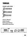 1
1
-
 2
2
-
 3
3
-
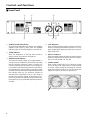 4
4
-
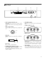 5
5
-
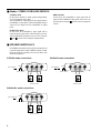 6
6
-
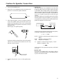 7
7
-
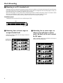 8
8
-
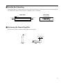 9
9
-
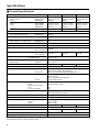 10
10
-
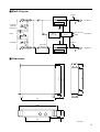 11
11
-
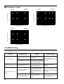 12
12
-
 13
13
-
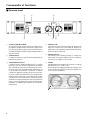 14
14
-
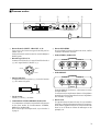 15
15
-
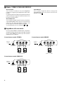 16
16
-
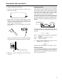 17
17
-
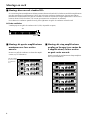 18
18
-
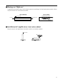 19
19
-
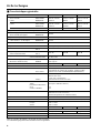 20
20
-
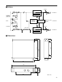 21
21
-
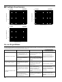 22
22
-
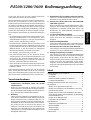 23
23
-
 24
24
-
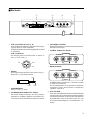 25
25
-
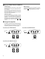 26
26
-
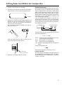 27
27
-
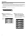 28
28
-
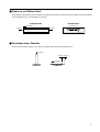 29
29
-
 30
30
-
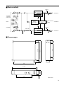 31
31
-
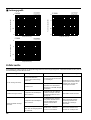 32
32
-
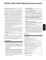 33
33
-
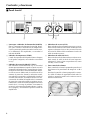 34
34
-
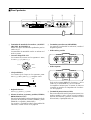 35
35
-
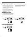 36
36
-
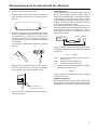 37
37
-
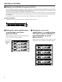 38
38
-
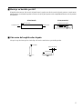 39
39
-
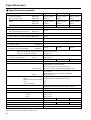 40
40
-
 41
41
-
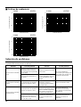 42
42


Yamaha P1600 de handleiding
- Categorie
- Audio versterkers
- Type
- de handleiding
in andere talen
- English: Yamaha P1600 Owner's manual
- italiano: Yamaha P1600 Manuale del proprietario
- русский: Yamaha P1600 Инструкция по применению
- français: Yamaha P1600 Le manuel du propriétaire
- español: Yamaha P1600 El manual del propietario
- Deutsch: Yamaha P1600 Bedienungsanleitung
- português: Yamaha P1600 Manual do proprietário
- dansk: Yamaha P1600 Brugervejledning
- čeština: Yamaha P1600 Návod k obsluze
- svenska: Yamaha P1600 Bruksanvisning
- Türkçe: Yamaha P1600 El kitabı
- polski: Yamaha P1600 Instrukcja obsługi
- română: Yamaha P1600 Manualul proprietarului