
Mastervolt International B.V. P.O.Box 22947, NL-1100 DK Amsterdam, The Netherlands. Tel.: +31-20-3422100 Email: [email protected] Web: www.mastervolt.com Version 110310 Mar 2011
ENGLISH
Safety regulations and measures
1. The electrical installation must be switched off during installation.
2. Install the power-inlet according to the stated instructions and directions in this
manual.
3. Use cables with appropriate wire size. See table “WIRE SIZE”.
4. Connections and safety features must be executed according to the locally
applicable regulations.
Things you need for installation
• Pencil
• Electric drill
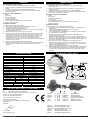
• Hole saw (see figure 1)
• 4.5 mm or 1/8 drill bit
• Small flat blade screwdriver
• 2.5 mm hexagonal socket wrench for the 4mm SS screws
• Cutting / wire stripping pliers
Installation directions
To install the power-inlet, proceed as follows:
1. Make a cut out in ship’s hull using the outline drawings of figure 1.
2. Remove the rear safety enclosure from the inlet.
3. Pull internal wiring through the hull opening
4. Thread the wiring through the strain relief on the rear safety enclosure. Slide the
mounting gasket over the wiring
5. Back off terminal screws on the rear housing of the inlet
6. Dismantle cable 50 mm, cut back green/yellow wire for 20 mm, strip wire ends 6
mm. Make sure the wire strands are clean and not corroded. If necessary, cut
back the wire until clean wire is uncovered. Do not solder the ends of the wire!
7. Insert wires into the proper colour coded terminal openings (see table
“specifications” for the proper colour codes) on the back of the inlet. Tighten
terminal screws to 1.6-2.2Nm (14-20 in.-lbs.) torque. Make certain there is no wire
insulation under any terminal
8. Slide the rear safety enclosure onto the back of the inlet.
9. Position the gasket and inlet over the hull opening, align the mounting holes and
attach the inlet to the hull with screws. Install the inlet with the M4 screws
included.
SPECIFICATIONS
SPECIFICATIONS
PARTNUMBER: 121160000
General
Connections: 2p + PE
Voltage: 230 V
Maximum current (Amps): 16A @ 230V
Protection degree: IP 56 (IEC529)
Marking CE
Materials
Cap and bezel:
316 SS
Contact blades / terminal parts: Nickel plated brass
Plug body PA6, V0 quality
COLOUR CODES
Function: Wire colour: Terminal colour code
PE (ground) Yellow / green Green
N (neutral) Blue Blue
L1 (phase, load) Brown or black Brown
WIRE SIZE
Voltage (Volts) Current (Amps) Cross section American Wire Gauge
230 V AC 16 A 2.5 mm² AWG 13
EG DECLARATION OF CONFORMITY
We, Manufacturer Mastervolt International B.V.
Address Snijdersbergweg 93,1105 AN Amsterdam, The Netherlands,
Declare under our sole responsibility that
Product: 121160000 Shore Power Inlet
Is in conformity with the EC directives:
2006/95/EC (Safety directive);
The following harmonized standards have been applied:
EN 60309-1/2
Amsterdam,
H.A. Poppelier
Product Manager marine
11
NEDERLANDS
Veiligheidsvoorschriften en –maatregelen
1. Gedurende de installatiewerkzaamheden moet de elektrische installatie
spanningsloos zijn.
2. Monteer de landaansluiting volgens de voorschriften en aanwijzingen in dit
montagevoorschrift.
3. Gebruik kabels met voldoende aderdoorsnee; zie tabel “WIRE SIZE”.
4. Aansluitingen en beveiligingen moeten in overeenstemming met de plaatselijk
geldende voorschriften worden uitgevoerd.
Dit heeft u nodig voor de installatie:
• Potlood
• Boormachine
• Gatenzaag (zie afbeelding 1)
• 4,5 mm boortje
• Kleine platte schroevendraaier
• 2.5 mm inbussleutel voor de meegeleverde M4 RVS schroeven.
• Kniptang en striptang
Installatievoorschrift
Ga bij de installatie van de contactdoos als volgt te werk
1. Maak aan de hand van de inbouwmaten in afbeelding 1 een uitsparing in de
scheepswand.
2. Verwijder de isolatiekap aan de achterzijde van de contactdoos.
3. Trek de bedrading door de isolatiekap.
4. Voer de bedrading door de trekontlasting van de isolatiekap. Plaats de rubberen
montage pakking over de bedrading.
5. Draai de schroeven van de aansluitklemmen aan de achterzijde van de
contactdoos een paar slagen los.
6. Ontmantel de isolatie van de kabel over 50 mm, en knip de geel/groene ader
20mm terug. Strip de draadeinde 6 mm. Let er op dat de aders blank zijn en niet
gecorrodeerd. Zonodig de bedrading inkorten en de kabel opnieuw strippen. De
aders mogen niet vertind worden!
7. Sluit de aders op de juiste aansluitklemmen aan de achterzijde van de
contactdoos aan (zie tabel “specifications” voor de juiste kleurcodes). Draai de
schroeven van aansluitklemmen goed aan. (1.6-2.2Nm). Let er op dat er geen
isolatie onder de aansluitklemmen zit.
8. Monteer de isolatiekap aan de achterzijde van de contactdoos.
9. Plaats de rubber pakking tezamen met de contactdoos zodanig in de uitsparing in
de scheepswand dat de montagegaten op de juiste plaats zitten. Bevestig de
contactdoos op de scheepswand met behulp van de meegeleverde vier M4-
schroeven.
STAINLESS STEEL INLET
Figure 1: Mounting (dimensions in mm)
Afbeelding 1: Inbouw (afmetingen in mm)
Abbildung 1: Montage(abmessungen in mm)
Figure 1: Montage, cotes en mm
Figura 1: Montaje, dimensiones en mm
Figura 1: Montaggio, dimensioni in mm
55
50
50
Gasket L1, N, PE Cover Rubber sleeve
Pakking L1, N, PE Isolatiekap Rubber manchet
Dichtung L1, N, PE Deckung Sicherheitsabdeckung
Joint L1, N, PE Couvercle Manchon en caoutchouc
Junta L1, N, PE Protección Manguito de goma
Giunto L1, N, PE Protezione Manicotto di caucciù
Pagina wordt geladen...
Documenttranscriptie
NEDERLANDS ENGLISH Veiligheidsvoorschriften en –maatregelen Safety regulations and measures 3. 4. The electrical installation must be switched off during installation. Install the power-inlet according to the stated instructions and directions in this manual. Use cables with appropriate wire size. See table “WIRE SIZE”. Connections and safety features must be executed according to the locally applicable regulations. Things you need for installation • • • • • • • Pencil Electric drill Hole saw (see figure 1) 4.5 mm or 1/8 drill bit Small flat blade screwdriver 2.5 mm hexagonal socket wrench for the 4mm SS screws Cutting / wire stripping pliers Installation directions To install the power-inlet, proceed as follows: 1. Make a cut out in ship’s hull using the outline drawings of figure 1. 2. Remove the rear safety enclosure from the inlet. 3. Pull internal wiring through the hull opening 4. Thread the wiring through the strain relief on the rear safety enclosure. Slide the mounting gasket over the wiring 5. Back off terminal screws on the rear housing of the inlet 6. Dismantle cable 50 mm, cut back green/yellow wire for 20 mm, strip wire ends 6 mm. Make sure the wire strands are clean and not corroded. If necessary, cut back the wire until clean wire is uncovered. Do not solder the ends of the wire! 7. Insert wires into the proper colour coded terminal openings (see table “specifications” for the proper colour codes) on the back of the inlet. Tighten terminal screws to 1.6-2.2Nm (14-20 in.-lbs.) torque. Make certain there is no wire insulation under any terminal 8. Slide the rear safety enclosure onto the back of the inlet. 9. Position the gasket and inlet over the hull opening, align the mounting holes and attach the inlet to the hull with screws. Install the inlet with the M4 screws included. 1. 2. 3. 4. Gedurende de installatiewerkzaamheden moet de elektrische installatie spanningsloos zijn. Monteer de landaansluiting volgens de voorschriften en aanwijzingen in dit montagevoorschrift. Gebruik kabels met voldoende aderdoorsnee; zie tabel “WIRE SIZE”. Aansluitingen en beveiligingen moeten in overeenstemming met de plaatselijk geldende voorschriften worden uitgevoerd. Dit heeft u nodig voor de installatie: • • • • • • • Potlood Boormachine Gatenzaag (zie afbeelding 1) 4,5 mm boortje Kleine platte schroevendraaier 2.5 mm inbussleutel voor de meegeleverde M4 RVS schroeven. Kniptang en striptang Installatievoorschrift Ga bij de installatie van de contactdoos als volgt te werk 1. Maak aan de hand van de inbouwmaten in afbeelding 1 een uitsparing in de scheepswand. 2. Verwijder de isolatiekap aan de achterzijde van de contactdoos. 3. Trek de bedrading door de isolatiekap. 4. Voer de bedrading door de trekontlasting van de isolatiekap. Plaats de rubberen montage pakking over de bedrading. 5. Draai de schroeven van de aansluitklemmen aan de achterzijde van de contactdoos een paar slagen los. 6. Ontmantel de isolatie van de kabel over 50 mm, en knip de geel/groene ader 20mm terug. Strip de draadeinde 6 mm. Let er op dat de aders blank zijn en niet gecorrodeerd. Zonodig de bedrading inkorten en de kabel opnieuw strippen. De aders mogen niet vertind worden! 7. Sluit de aders op de juiste aansluitklemmen aan de achterzijde van de contactdoos aan (zie tabel “specifications” voor de juiste kleurcodes). Draai de schroeven van aansluitklemmen goed aan. (1.6-2.2Nm). Let er op dat er geen isolatie onder de aansluitklemmen zit. 8. Monteer de isolatiekap aan de achterzijde van de contactdoos. 9. Plaats de rubber pakking tezamen met de contactdoos zodanig in de uitsparing in de scheepswand dat de montagegaten op de juiste plaats zitten. Bevestig de contactdoos op de scheepswand met behulp van de meegeleverde vier M4schroeven. STAINLESS STEEL INLET SPECIFICATIONS SPECIFICATIONS PARTNUMBER: General Connections: Voltage: Maximum current (Amps): 121160000 2p + PE 230 V 16A @ 230V Protection degree: IP 56 (IEC529) Marking CE Materials Cap and bezel: 316 SS Contact blades / terminal parts: Nickel plated brass Plug body PA6, V0 quality COLOUR CODES Function: Wire colour: Terminal colour code PE (ground) Yellow / green Green N (neutral) Blue Blue L1 (phase, load) Brown or black Brown WIRE SIZE Voltage (Volts) Current (Amps) Cross section American Wire Gauge 230 V AC 16 A 2.5 mm² AWG 13 50 55 50 1. 2. EG DECLARATION OF CONFORMITY We, Address Manufacturer Mastervolt International B.V. Snijdersbergweg 93,1105 AN Amsterdam, The Netherlands, Declare under our sole responsibility that Product: 121160000 Shore Power Inlet Is in conformity with the EC directives: 2006/95/EC (Safety directive); The following harmonized standards have been applied: EN 60309-1/2 Gasket Pakking Dichtung Joint Junta Giunto L1, N, PE L1, N, PE L1, N, PE L1, N, PE L1, N, PE L1, N, PE Cover Isolatiekap Deckung Couvercle Protección Protezione Rubber sleeve Rubber manchet Sicherheitsabdeckung Manchon en caoutchouc Manguito de goma Manicotto di caucciù Figure 1: Afbeelding 1: Abbildung 1: Figure 1: Figura 1: Figura 1: Mounting (dimensions in mm) Inbouw (afmetingen in mm) Montage(abmessungen in mm) Montage, cotes en mm Montaje, dimensiones en mm Montaggio, dimensioni in mm Amsterdam, H.A. Poppelier Product Manager marine 11 Mastervolt International B.V. P.O.Box 22947, NL-1100 DK Amsterdam, The Netherlands. Tel.: +31-20-3422100 Email: [email protected] Web: www.mastervolt.com Version 110310 Mar 2011-
 1
1
-
 2
2


Mastervolt Stainless steel inlet, 2 PE, 16 A/230 V Handleiding
- Type
- Handleiding
- Deze handleiding is ook geschikt voor
in andere talen
- English: Mastervolt Stainless steel inlet, 2 PE, 16 A/230 V User manual
- italiano: Mastervolt Stainless steel inlet, 2 PE, 16 A/230 V Manuale utente
- français: Mastervolt Stainless steel inlet, 2 PE, 16 A/230 V Manuel utilisateur
- español: Mastervolt Stainless steel inlet, 2 PE, 16 A/230 V Manual de usuario
- Deutsch: Mastervolt Stainless steel inlet, 2 PE, 16 A/230 V Benutzerhandbuch
Gerelateerde papieren
-
Mastervolt Valox shore connection kit, 2+PE, 16 A/230 V Handleiding
-
Mastervolt Valox shore connection kit, 2+PE, 16 A/230 V Handleiding
-
-
-
-
-
-