Pagina wordt geladen...

THE AUDIO COMPANY THE AUDIO COMPANY THE AUDIO COMPANY THE AUDIO COMPANY THE AUDIO COMPANY THE AUDIO COMPANY THE AUDIO COMPANY THE AUDIO COMPANY THE AUDIO COMPANY
BEDIENUNGSANLEITUNG
INSTRUCTION MANUAL
GEBRUIKSAANWIJZING
MANUAL DE INSTRUCCIONES
INSTRUKCJA OBSŁUGI
USB Recording Interface
BEE
Bestellnummer • Order Number 1000987
1/L
+48 V
2/R
HI-Z
GAIN
PEAK
MIC /LINE
INPUT
+48 V
LOW
CUT
010 010 010 010
1/ L2/R PHONESMAIN
POWER
LOOP
BACK DIRECT STEREO
24BIT 192K
2 1
3
2 1
3
BEE

2
GAIN 1/L
MIC
INPUT 1/L
INPUT 2/R
LINE
+48 V
GAIN 2/R
MIC
LINE
HI-Z
+48 V
LOW
CUT
USB
PHONES
MAIN OUTPUT
1/L
PHONES
MAIN
2/R
STEREO
stereomono
DIRECT
LOOP
BACK
PHANTOM POWER
PHANTOM POWER
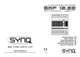
➀ Blockschaltbild • Block diagram • Blokschema • Diagrama de bloques • Schemat blokowy


4
1/L
+48 V
2/R
HI-Z
GAIN
PEAK
MIC /LINE
INPUT
+48 V
LOW
CUT
010 010 010 010
1/ L2/R PHONESMAIN
POWER
LOOP
BACK DIRECT STEREO
24BIT 192K
2 1
3
2 1
3
BEE
1
13
2
3
6
8 9 10 11 12 14
5
7
4
➁ Vorderseite
MAIN OUTPUT
POWER SOURCE
2/R 1/L USB 3.0
5 V
+48 V PHANTOM POWER
2/R 1/L
USB
POWER
ON
OFF
ON
OFF
15
20
19
17
18
16
➂ Rückseite
Deutsch
Deutsch
Deutsch Seite
USB-Recording-Interface
Diese Anleitung richtet sich an Benutzer mit Grundkenntnissen in der
Audiotechnik und Computerbedienung. Bitte lesen Sie die Anleitung
vor dem Betrieb gründlich durch und heben Sie sie für ein späteres
Nachlesen auf.
1 Verwendungsmöglichkeiten
Das Audio-Interface BEE dient zur Audioaufnahme auf einem Com-
puter und wird von diesem als externe Soundkarte erkannt. Es besitzt
zwei analoge Eingänge, um Audiosignale von Mikrofonen, Instrumen-
ten und anderen Tonquellen auf einem Computer in hoher Qualität
aufzuzeichnen. Zwei analoge Ausgänge ermöglichen die Wiedergabe
der Audiosignale des Computers, z. B. über aktive Lautsprecher. Über
einen Kopfhörerausgang können dieselben Signale abgehört werden.
Das Gerät bietet zudem eine für beide Eingänge separat schaltbare
Phantomspeisung, ein schaltbares Hochpassfilter für einen Eingang
sowie die Option eines hochohmigen Eingangs für Instrumente.
Die Stromversorgung erfolgt über einen USB-C-Anschluss des
Computers oder über eine zusätzlich angeschlossene 5-V-Spannungs-
quelle, z. B. ein Netzgerät. Ein USB-Adapterkabel mit Typ-A-Stecker
wird mitgeliefert.

5
Deutsch
2 Übersicht
1
kombinierte Eingangsbuchse für Kanal 1 zum Anschluss eines
Mikrofons (XLR) oder einer Tonquelle mit Line-Signalpegel
(6,3-mm-Klinke) mit Umschaltmöglichkeit HI-Z für ein Instrument
2
kombinierte Eingangsbuchse für Kanal 2 zum Anschluss eines
Mikrofons (XLR) oder einer Tonquelle mit Line-Signalpegel
(6,3-mm-Klinke)
3
Schalter HI-Z: Bei eingerastetem Schalter ist der Eingang von
Kanal1 hochohmig.
4 Anzeige + 48 V der Phantomspeisung jeweils für Kanal1 und 2
5 Schalter LOW CUT des Hochpassfilters für Kanal2
6 Regler GAIN der Eingangsverstärkung jeweils für Kanal1 und 2
7 Anzeige PEAK zur Anzeige des erreichten Maximalpegels jeweils
für Kanal1 und 2
8
Schalter LOOP BACK; bei eingerastetem Schalter wird mit den
Signalen der Eingänge auch das vom Computer kommende Audio-
signal wieder zurück an den Computer geleitet
9 Schalter DIRECT; bei eingerastetem Schalter wird das Signal der
Eingänge auf die Ausgänge MAIN OUTPUT (15) und PHONES
(13) geleitet
10 Schalter STEREO [nur für DIRECT-Modus (9)]: bei eingerastetem
Schalter gelangen die Eingangssignale getrennt auf den rechten
und linken Ausgang, bei ausgerastetem Schalter gelangen beide
Eingangssignale auf beide Ausgänge
11 Lautstärkeregler MAIN für die Ausgänge MAIN OUTPUT (15)
12 Lautstärkeregler PHONES für den Kopfhörerausgang (13)
13 6,3-mm-Klinkenbuchse zum Anschluss eines Stereokopfhörers
14 Betriebsanzeige POWER
15
Ausgänge MAIN OUTPUT (6,3-mm-Klinkenbuchsen), z. B. zum
Anschluss von Aktivlautsprechern
16
USB POWER als Typ-C-Buchse zum Anschluss einer 5-V-Gleich-
stromversorgung, z. B. Netzgerät
17 Schalter POWER SOURCE zur Wahl der Stromversorgungsbuchse
18
USB-Datenanschluss zur Verbindung mit einem Computer; bei
Anschluss an eine Typ-C-Buchse auch zur Stromversorgung nutzbar
19 Gehäuseöffnung zur Befestigung einer Diebstahlsicherung
20 Schalter +48 V PHANTOM POWER zum Einschalten (Position ON)
der Phantomspeisung jeweils für die XLR-Kontakte der Eingangs-
buchsen von Kanal1 (1) und Kanal2 (2)
3 Wichtige Hinweise
Das Produkt entspricht allen relevanten Richtlinien der EU und trägt
deshalb das -Zeichen.
• Verwenden Sie das Produkt nur im Innenbereich und schützen Sie
es vor Tropf- und Spritzwasser sowie vor hoher Luftfeuchtigkeit. Der
zulässige Einsatztemperaturbereich beträgt 0 – 40 °C.
• Säubern Sie das Produkt nur mit einem trockenen, weichen Tuch,
niemals mit Wasser oder Chemikalien.
•
Wird das Produkt falsch verwendet oder nicht fachgerecht repariert,
kann keine Haftung für daraus resultierende Sach- oder Personen-
schäden und keine Garantie für das Produkt übernommen werden.
Soll das Produkt endgültig aus dem Betrieb genommen
werden, entsorgen Sie es gemäß den örtlichen Vorschriften.

6
Deutsch
4 Anschluss
Zur Vermeidung lauter Schaltgeräusche alle Ausgangsregler vor dem
Anschluss oder dem Trennen einer Tonquelle auf Minimum drehen.
4.1 Mikrofone
Wichtig: Vor dem Anschluss eines Mikrofons die Einstellung der Phan-
tomspeisung des betreffenden Eingangs überprüfen und ggf. korri-
gieren (Kapitel 5.1). Mikrofone mit asymmetrischem Ausgangssignal
können durch die Phantomspannung beschädigt werden. Die Phan-
tomspannung nur einschalten, wenn ein Mikrofon diese benötigt.
Mikrofone mit XLR-Steckern an die Eingangsbuchsen INPUT (1, 2) an-
schließen. Für Kanal 2 / R ist ein Hochpassfilter zuschaltbar (Kapitel 5.1).
4.2 Instrumente, Tonquellen mit Line-Pegel
Instrumente oder andere Tonquellen mit Line-Signalpegel (z. B. CD-/
MP3-Spieler) mit Klinkensteckern an die Eingangsbuchsen INPUT (1,
2) anschließen. Die Buchsen sind symmetrisch beschaltet. Asymmet-
rische Tonquellen können aber über 2-polige Klinkenstecker ebenfalls
angeschlossen werden. Für den Anschluss eines Instruments kann für
Kanal 1/ L der Eingang hochohmig geschaltet werden (Kapitel 5.1).
4.3 Aktive Lautsprecher, Verstärker, Kopfhörer
Zum Abhören der Audiosignale über Lautsprecher die Ausgänge MAIN
OUTPUT (15) mit den Eingangsbuchsen von Aktivlautsprechern oder
mit den Eingangsbuchsen eines Verstärkers verbinden. Die Ausgänge
sind elektronisch symmetriert, können aber auch asymmetrisch (mit
2-poligen Klinkensteckern) angeschlossen werden.
Einen Stereokopfhörer an die Buchse (13) anschließen.
4.4 Computer
Einen Computer mit der Buchse (18) verbinden. Verfügt dieser
über eine Typ-C-Buchse, kann das BEE auch hierüber mit Strom ver-
sorgt werden. Den Schalter POWER SOURCE (17) dafür in die rechte
Position stellen.
Verfügt der Computer nur über Anschlussbuchsen vom Typ A,
kann er über das beiliegende Adapterkabel angeschlossen werden.
In diesem Fall ist eine zusätzliche Stromversorgung erforderlich (Ka-
pitel4.5), weil der Computeranschluss nicht genügend Strom liefern
kann.
4.5 Alternative Stromversorgung
Kann das Interface nicht über den Computer mit Strom versorgt
werden, eine 5-V-Gleichstromversorgung mit einer Belastbarkeit von
1250 mA mit der Buchse USB POWER (16) verbinden. Den Schalter
POWER SOURCE (17) in die linke Position stellen.
5 Bedienung
Zur Vermeidung einer zu großen Anfangslautstärke die Regler
MAIN(11) und PHONES (12) vor dem ersten Betrieb zunächst auf
Mini mum drehen. Nach dem Anschluss an Computer / Stromversor
-
gung leuchtet die LED POWER (14).
5.1 Eingänge einstellen
Zur Vermeidung lauter Schaltgeräusche immer alle Ausgangsregler
vor dem Betätigen eines Schalters (3, 5, 20) auf Minimum drehen.
1) HI-Z (3) – schaltet den Eingang von Kanal1 hochohmig (z. B. um
eine E-Gitarre direkt anzuschließen)
2)
LOW CUT (5) – schaltet ein Hochpassfilter in Kanal2, z. B. um
Trittschall zu unterdrücken

7
Deutsch
3)
+48 V PHANTOM POWER (20) – zum Einschalten der Phantom-
speisung für Mikrofone; Hinweis in Kapitel 4.1 beachten!
Bei eingeschalteter Phantomspeisung leuchtet die LED +48 V (4)
unter der entsprechenden Eingangsbuchse.
4)
Die Eingangsverstärkung mit den Reglern GAIN (6) soweit auf-
drehen, dass die Anzeigen PEAK (7) nur bei Pegelspitzen kurz
aufleuchten.
5.2 Ausgänge einstellen
1) Mit dem Regler MAIN (11) den Ausgangspegel einstellen.
2) Mit dem Regler PHONES (12) die Kopfhörerlautstärke einstellen.
VORSICHT
Stellen Sie die Kopfhörerlautstärke nicht zu hoch
ein. Hohe Lautstärken können auf Dauer das Gehör
schädigen!
3)
Mit dem Schalter DIRECT (9) können die Signale der Eingänge
ohne Umweg über den Computer latenzfrei abgehört werden. Der
Schalter STEREO (10) bestimmt dabei, ob die Eingangssignale als
Monosignal (Schalter ausgerastet) oder als Stereosignal (Schalter
eingerastet) gehört werden.
4) Mit dem Schalter LOOP BACK (8) kann zusätzlich zu den Signalen
der Eingänge (Monomischung) auch das vom Computer kommen-
des Audiosignal wieder zurück an den Computer geleitet werden.
Hinweis: Tritt dabei eine Rückkopplung auf, in der Aufnahme-Software die
Monitor- oder Durchschleiffunktion ausschalten.
6 Technische Daten
Eingänge (Eingangsempfindlichkeit / Impedanz; Anschluss)
2 × MIC INPUT 2,5 mV/1,4 kΩ; XLR, symmetrisch
Phantomspeisung +48 V, schaltbar
2 × LINE INPUT 19 mV/10,5 kΩ / 500 kΩ (HI-Z); 6,3-mm-Klinke, symmetrisch
LOW CUT 100 Hz, schaltbar
Ausgänge
MAIN OUTPUT max. 6,5 V; 2 × 6,3-mm-Klinke, symmetrisch
Kopfhörer ≥ 16 Ω; 6,3-mm-Klinke, stereo
Frequenzbereich 20 – 20 000 Hz
Klirrfaktor ≤ 0,001 %
Störabstand ≥ 87 dB
Übersprechdämpfung ≥ 55 dB
digitale Auflösung max. 192 kHz / 24 Bit
Computerschnittstelle USB-3.0-kompatibel, Vollduplex; Typ-C-Buchse
USB-Adapterkabel Typ-C-Stecker ⇒ Typ-A-Stecker, 1 m
unterstützte Betriebssysteme Windows 10 / 11, Mac OS, iOS, Linux
Stromversorgung
⎓ 5 V/1250 mA über USB-C-Port am Computer oder eine
entsprechende Stromversorgung, z. B. Netzgerät
Einsatztemperatur 0 – 40 °C
Abmessungen (B × H × T) 190 mm × 40 mm × 117 mm
Gewicht 717 g
Windows ist ein registriertes Warenzeichen der Microsoft Corporation in den USA und anderen
Ländern. Mac OS und iOS sind registrierte Warenzeichen von Apple Inc. in den USA und anderen
Ländern.
Änderungen vorbehalten.
Diese Bedienungsanleitung ist urheberrechtlich für MONACOR ® INTERNATIONAL GmbH & Co. KG geschützt.
Eine Reproduktion für eigene kommerzielle Zwecke – auch auszugsweise – ist untersagt.

8
English
1/L
+48 V
2/R
HI-Z
GAIN
PEAK
MIC /LINE
INPUT
+48 V
LOW
CUT
010 010 010 010
1/ L2/R PHONESMAIN
POWER
LOOP
BACK DIRECT STEREO
24BIT 192K
2 1
3
2 1
3
BEE
1
13
2
3
6
8 9 10 11 12 14
5
7
4
MAIN OUTPUT
POWER SOURCE
2/R 1/L USB 3.0
5 V
+48 V PHANTOM POWER
2/R 1/L
USB
POWER
ON
OFF
ON
OFF
15
20
19
17
18
16
➂ Rear panel
➁ Front panel
USB Recording Interface
These instructions are intended for users with basic knowledge of audio
technology and computing. Please read the instructions carefully prior
to operation and keep them for later reference.
1 Applications
The BEE audio interface is used for audio recording on a computer. It is
recognised by the computer as an external sound card. It features two
analogue inputs to record audio signals from microphones, instruments
and other audio sources on a computer in high quality. Two analogue
outputs allow reproduction of audio signals from the computer, e. g. via
active speakers. These signals can also be monitored via a headphone
output. The device also offers phantom power that can be activated
separately for both inputs, a switchable high-pass filter for one input
and an input that can be switched to high impedance for instruments.
Power is supplied via a USB-C port on the computer or via a 5V
power source additionally connected, e. g. a power supply unit. A USB
adapter cable with Type-A plug is provided.
English
English Page

9
English
2 Overview
1
Combined input jack for channel 1 to connect a microphone (XLR)
or an audio source with line signal level (6.3 mm jack) with switch
HI-Z for an instrument
2
Combined input jack for channel 2 to connect a microphone (XLR)
or an audio source with line signal level (6.3 mm jack)
3 Switch HI-Z: When the switch is engaged, the input of channel 1
is of high impedance.
4 Phantom power LED + 48 V for channels 1 and 2 respectively
5 Switch LOW CUT of the high-pass filter for channel 2
6 Control GAIN of the input gain for channels 1 and 2 respectively
7 LED PEAK to indicate the maximum level reached for channels 1
and 2 respectively
8
Switch LOOP BACK; when the switch is engaged, the audio signal
coming from the computer will be routed back to the computer
along with the signals of the inputs
9 Switch DIRECT; when the switch is engaged, the signal of the in-
puts will be routed to the outputs MAIN OUTPUT (15) and PHONES
(13)
10 Switch STEREO [for DIRECT mode (9) only]: when the switch is
engaged, the input signals will be sent separately to the right and
left outputs; when the switch is disengaged, both input signals
will be sent to both outputs
11 Volume control MAIN for the outputs MAIN OUTPUT (15)
12 Volume control PHONES for the headphone output (13)
13 6.3 mm jack to connect stereo headphones
14 POWER LED
15
Outputs MAIN OUTPUT (6.3 mm jacks), e. g. to connect active
speakers
16
USB POWER (Type-C) port to connect a 5 V DC power supply, e. g.
a power supply unit
17 Switch POWER SOURCE to select the port for power supply
18
USB data port for connection to a computer; can also be used
for power supply when it is connected to a Type-C port
19 Opening in the housing to attach an anti-theft device
20 Switch +48 V PHANTOM POWER to activate the phantom power
(position ON) each for the XLR contacts of the input jacks of
channel 1 (1) and channel 2 (2)
3 Important Notes
This product corresponds to all relevant directives of the EU and is
therefore marked with .
The product corresponds to the relevant UK legislation and is therefore
marked with UKCA.
•
The product is suitable for indoor use only. Protect it against dripping
water, splash water and high air humidity. The admissible ambient
temperature range is 0 – 40 °C.
•
For cleaning only use a dry, soft cloth; never use water or chemicals.
•
No guarantee claims for the product and no liability for any resulting
personal damage or material damage will be accepted if the product
is not correctly used or not expertly repaired.
If the product is to be put out of operation definitively, dispose
of the product in accordance with local regulations.

10
English
4 Connection
To avoid loud switching noise, set all output controls to minimum
before connecting or disconnecting an audio source.
4.1 Microphones
Important: Before connecting a microphone, check the phantom
power setting of the relevant input and change it if necessary (chapter
5.1). Phantom power may damage microphones with unbalanced
output signals. Only activate the phantom power when a microphone
requires phantom power.
Connect microphones with XLR plugs to the input jacks INPUT (1,
2). A high-pass filter can be activated for channel 2 / R (chapter 5.1).
4.2 Instruments, audio sources with line level
Connect instruments or other audio sources with line signal level (e. g.
CD/MP3 player) with 6.3 mm plugs to the input jacks INPUT (1, 2). The
jacks are balanced; however, unbalanced audio sources can also be
connected via 2-pole 6.3 mm plugs. When connecting an instrument,
the input for channel 1/ L can be set to high impedance (chapter 5.1).
4.3 Active speakers, amplifier, headphones
To monitor the audio signals via speakers, connect the outputs MAIN
OUTPUT (15) to the inputs of active speakers or to the input jacks
of an amplifier. The outputs are electronically balanced, but they can
also be connected in an unbalanced way (with 2-pole 6.3 mm plugs).
Connect stereo headphones to the jack (13).
4.4 Computer
Connect a computer to the port (18). If the computer has a Type-C
port, BEE can also be supplied with power via this port. To do this, set
the switch POWER SOURCE (17) to the right.
If the computer only has Type-A ports, it can be connected via
the adapter cable provided. In this case, an additional power supply
is required (chapter 4.5); the computer connection will not be able
to supply sufficient power.
4.5 Alternative power supply
If it is not possible to supply the interface with power via the computer,
connect a 5 V DC power supply with a current rating of 1250 mA to the
port USB POWER (16). Set the switch POWER SOURCE (17) to the left.
5 Operation
To make sure that the initial volume is not too high, set the controls
MAIN (11) and PHONES (12) to minimum before first operation. After
connection to a computer / power supply, the POWER LED (14) will
light up.
5.1 Adjusting the inputs
To avoid loud switching noise, always set all output controls to mini-
mum before using a switch (3, 5, 20).
1) HI-Z (3) – to set the input of channel 1 to high impedance (e. g. to
directly connect an electric guitar)
2) LOW CUT (5) – to activate a high-pass filter in channel 2, e. g. to
suppress impact sound
3) +48 V PHANTOM POWER (20) – to activate the phantom power
for microphones; please note the information in chapter 4.1!

11
English
When phantom power has been activated, the LED +48 V (4) un-
derneath the corresponding input jack will light up.
4)
Use the GAIN controls (6) to turn up the input gain so that the LEDs
PEAK (7) only light up briefly during level peaks.
5.2 Adjusting the outputs
1) Use the control MAIN (11) to adjust the output level.
2) Use the control PHONES (12) to adjust the headphone volume.
CAUTION
Never adjust the headphones to a very high volume.
Permanent high volumes may damage your hearing!
3) The switch DIRECT (9) can be used to directly monitor the signals
of the inputs without the latency caused by the computer. The
position of the switch STEREO (10) determines whether the input
signals are reproduced as a mono signal (switch disengaged) or as
a stereo signal (switch engaged).
4) The switch LOOP BACK (8) can be used to route the audio signal
coming from the computer back to the computer along with the
signals of the inputs (mono mix).
Note: If feedback occurs, deactivate the monitoring function or feed-through
function in the recording software.
6 Specifications
Inputs (input sensitivity / impedance; connection)
2 × MIC INPUT 2.5 mV/1.4 kΩ; XLR, balanced
phantom power +48 V, switchable
2 × LINE INPUT 19 mV/10.5 kΩ/500 kΩ (HI-Z); 6.3 mm jack, balanced
LOW CUT 100 Hz, switchable
Outputs
MAIN OUTPUT 6.5 V max.; 2 × 6.3 mm jack, balanced
Headphones ≥ 16 Ω; 6.3 mm jack, stereo
Frequency range 20 – 20 000 Hz
THD ≤ 0.001 %
S / N ratio ≥ 87 dB
Crosstalk attenuation ≥ 55 dB
Digital resolution 192 kHz / 24 bits max.
Computer interface compatible with USB 3.0, full duplex; Type-C port
USB adapter cable Type-C plug ⇒ Type-A plug, 1 m
Operating systems supported Windows 10 / 11, Mac OS, iOS, Linux
Power supply ⎓ 5 V/1250 mA via USB-C port on the computer or suitable
power supply, e. g. power supply unit
Ambient temperature 0 – 40 °C
Dimensions (W × H × D) 190 mm × 40 mm × 117 mm
Weight 717 g
Windows is a registered trademark of Microsoft Corporation in the USA and other countries. MacOS
and iOS are registered trademarks of Apple Inc. in the USA and other countries.
Subject to technical modification.
All rights reserved by MONACOR
® INTERNATIONAL GmbH & Co. KG.
No part of this instruction manual may be reproduced in any form or by any means for any commercial use.

12
Nederlands
1/L
+48 V
2/R
HI-Z
GAIN
PEAK
MIC /LINE
INPUT
+48 V
LOW
CUT
010 010 010 010
1/ L2/R PHONESMAIN
POWER
LOOP
BACK DIRECT STEREO
24BIT 192K
2 1
3
2 1
3
BEE
1
13
2
3
6
8 9 10 11 12 14
5
7
4
MAIN OUTPUT
POWER SOURCE
2/R 1/L USB 3.0
5 V
+48 V PHANTOM POWER
2/R 1/L
USB
POWER
ON
OFF
ON
OFF
15
20
19
17
18
16
➂ Achteraanzicht
➁ Vooraanzicht
USB-recording-interface
Deze handleiding is bedoeld voor gebruikers met basiskennis van
de audiotechniek. Lees de handleiding grondig door, alvorens het
apparaat in gebruik te nemen, en bewaar ze voor latere raadpleging.
1 Toepassingen
De audio-interface BEE wordt gebruikt om geluid op te nemen op een
computer. Deze detecteert de interface als een geluidskaart. Hij heeft
twee analoge ingangen om audiosignalen van microfoons, instrumen-
ten en andere geluidsbronnen in hoge kwaliteit op een computer te
registreren. Twee analoge uitgangen zorgen dat de audiosignalen van
de computer worden weergegeven, bijv. via actieve luidsprekers. Via
een hoofdtelefoonuitgang kunnen deze signalen worden beluisterd.
Het apparaat biedt bovendien een voor beide ingangen afzonderlijk
inschakelbare fantoomvoeding, een inschakelbaar hoogdoorlaatfilter
voor een ingang evenals een optionele hoogohmige ingang voor
instrumenten.
De voeding gebeurt via een USB-C-aansluiting van de computer
of via een aanvullend aangesloten spanningsbron van 5 V, bijv. een
netvoeding. Een USB-adapterkabel met een stekker van het type A is
in de levering inbegrepen.
Nederlands
Nederlands Pagina

13
Nederlands
2 Overzicht
1 Gecombineerde ingangsbus voor kanaal 1 voor aansluiting van een
microfoon (XLR) of een geluidsbron met lijnsignaalniveau (6,3 mm -
stekker) met omschakelmogelijkheid HI-Z voor een instrument
2 Gecombineerde ingangsbus voor kanaal 2 voor aansluiting van
een microfoon (XLR) of een geluidsbron met lijnsignaalniveau
(6,3 mm-stekker)
3
Schakelaar HI-Z: Bij ingedrukte schakelaar is de ingang van ka-
naal1 hooghohmig.
4
LED + 48 V van de fantoomvoeding voor elk van de kanalen1 en 2
5 Schakelaar LOW CUT van het hoogdoorlaatfilter voor kanaal2
6 Regelaar GAIN van de ingangsversterking voor elk van de kana-
len1 en 2
7
LED PEAK voor aanduiding van het bereikte maximumniveau voor
elk van de kanalen1 en 2
8 Schakelaar LOOP BACK; bij ingedrukte schakelaar wordt samen
met de signalen van de ingangen ook het vanaf de computer
gestuurde audiosignaal opnieuw naar de computer gestuurd
9
Schakelaar DIRECT; bij ingedrukte schakelaar wordt het signaal van
de ingangen naar de uitgangen MAIN OUTPUT (15) en PHONES
(13) gestuurd
10
Schakelaar STEREO [alleen voor DIRECT-modus (9)]: bij ingedrukte
schakelaar worden de ingangssignalen gescheiden naar de rechter
en linker uitgang geleid, bij niet-ingedrukte schakelaar gaan beide
ingangssignalen naar beide uitgangen
11 Volumeregelaar MAIN voor de uitgangen MAIN OUTPUT (15)
12 Volumeregelaar PHONES voor de hoofdtelefoonuitgang (13)
13
6,3 mm-stekkerbus voor de aansluiting van een stereohoofd-
telefoon
14 POWER-LED
15 Uitgangen MAIN OUTPUT (6,3 mm-stekkerbussen), bijv. voor de
aansluiting van actieve luidsprekers
16 USB POWER als bus van het type C voor de aansluiting van een
gelijkstroomvoeding van 5 V, bijv. netadapter
17
Schakelaar POWER SOURCE voor de selectie van de voedings-
spanningsbus
18 USB-gegevensaansluiting voor de aansluiting op een compu-
ter; bij aansluiting op een bus van het type C ook te gebruiken
voor de voeding
19
Behuizingsopening voor het bevestigen van een diefstalbeveiliging
20 Schakelaar +48 V PHANTOM POWER voor het inschakelen (Posi-
tion ON) van de fantoomvoeding voor de XLR-contacten van de
ingangsbussen van elk van de kanalen1 (1) en2 (2)
3 Veiligheidsvoorschriften
Het product is in overeenstemming met alle relevante EU-richtlijnen
en is daarom gekenmerkt met de -markering.
•
Het product is alleen geschikt voor gebruik binnen. Vermijd druip- en
spatwater en plaatsen met een hoge vochtigheid. Het toegestane
omgevingstemperatuurbereik bedraagt 0 – 40 °C.
• Maak het product uitsluitend schoon met een droge, zachte doek,
en gebruik nooit water of chemicaliën.
•
In geval van ongeoorloofd of verkeerd gebruik, verkeerde bediening
of van herstelling door een niet-gekwalificeerd persoon vervalt de
garantie en de aansprakelijkheid voor hieruit resulterende materiële
of lichamelijke schade.
Wanneer het product definitief uit bedrijf genomen wordt,
voert u het af volgens de plaatselijke voorschriften.

14
Nederlands
4 Aansluiting
Draai alle uitgangsregelaars voor het aansluiten of het loskoppelen van
een geluidsbron in de stand “0”. Zo vermijdt u luide schakelploppen.
4.1 Microfoons
Belangrijk: Controleer voor het aansluiten van een microfoon de
instelling van de fantoomvoeding van de respectieve ingang en cor-
rigeer indien nodig (hoofdstuk 5.1). Microfoons met ongebalanceerd
uitgangssignaal kunnen door de fantoomvoeding beschadigd gera-
ken. Schakel de fantoomvoeding enkel in, als een microfoon deze
nodig heeft.
Sluit microfoons met XLR-stekkers aan op de ingangsbussen INPUT (1,
2). Voor kanaal 2 / R kunt u een hoogdoorlaatfilter aansluiten (hoofd-
stuk 5.1).
4.2 Instrumenten, geluidsbronnen met lijnniveau
Sluit instrumenten of andere geluidsbronnen met lijnsignaalniveau
(bijv. cd-/mp3-spelers) met stekkers aan op de ingangsbussen INPUT (1,
2). De jacks zijn gebalanceerd bedraad. Ongebalanceerde geluidsbron
-
nen kunnen evenwel ook via 2-polige stekkers worden aangesloten.
Voor de aansluiting van een instrument kan voor kanaal 1/ L de ingang
hoogohmig worden geschakeld (hoofdstuk 5.1).
4.3 Aktieve luidsprekers, versterker, hoofdtelefoon
Om de geluidssignalen via luidsprekers te beluisteren, verbindt u de
uitgangen MAIN OUTPUT (15) met de ingangsbussen van actieve luid-
sprekers of met de ingangsbussen van een versterker. De uitgangen
zijn elektronisch gebalanceerd, maar u kunt ze ook ongebalanceerd
(met 2-polige stekkers) aansluiten.
Sluit een stereohoofdtelefoon aan op de bus (13).
4.4 Computer
Sluit een computer aan op de bus (18). Als de computer met een
bus van het type C is uitgerust, kan de BEE ook hierlangs worden
gevoed. Plaats de schakelaar POWER SOURCE (17) hiervoor in de
rechter stand.
Als de computer alleen met aansluitbussen van het type A is
uitgerust, kunt u hem aansluiten met de adapterkabel die in de leve-
ring is inbegrepen. In dit geval is een bijkomende voedingsspanning
vereist (hoofdstuk 4.5), omdat de computeraansluiting onvoldoende
stroom kan leveren.
4.5 Alternatieve voedingsspanning
Als de interface via de computer niet van stroom kan worden voorzien,
sluit u een gelijkstroomvoeding van 5 V met een belastbaarheid van
1250 mA aan op de bus USB POWER (16). Plaats de schakelaar POWER
SOURCE (17) in de linker stand.
5 Bediening
Om een te hoog beginvolume te vermijden, draait u de regelaars MAIN
(11) en PHONES (12) eerst in de stand “0”, voordat u het apparaat
in gebruik neemt. Na het aansluiten op de computer/ voeding brandt
de led POWER (14).
5.1 Ingangen instellen
Draai alle uitgangsregelaars voor het bedienen van een schakelaar
(3, 5, 20) steeds in de stand “0”. Zo vermijdt u luide schakelploppen.
1)
HI-Z (3) – hiermee schakelt u de ingang van kanaal 1 naar
hoogohmig (bijv. om een elektrische gitaar rechtstreeks aan te
sluiten)

15
Nederlands
2) LOW CUT (5) – hiermee schakelt u een hoogdoorlaatfilter in voor
kanaal 2, bijv. om contactgeluid te onderdrukken
3) +48 V PHANTOM POWER (20) – voor het inschakelen van de fan-
toomvoeding voor microfoons; let op aanwijzing in hoofdstuk4.1!
Bij ingeschakelde fantoomvoeding brandt de led +48 V (4) onder
de respectieve ingangsbus.
4)
Draai de ingangsversterking met de regelaars GAIN (6) zo ver open,
dat de leds PEAK (7) enkel nog bij niveaupieken gaan branden.
5.2 Uitgangen instellen
1) Stel met de regelaar MAIN (11) het uitgangsniveau in.
2) Stel met de regelaar PHONES (12) het volume van de hoofdtele-
foon in.
OPGELET
Stel het geluidsvolume van de hoofdtelefoon niet te
hoog in. Langdurige blootstelling aan hoge volumes
kan het gehoor beschadigen!
3) Met de schakelaar DIRECT (9) kunt u de signalen van de ingangen
zonder omleiding via de computer zonder latentie beluisteren.
De schakelaar STEREO (10) bepaalt hierbij of de ingangssignalen
als monosignaal (schakelaar niet-ingedrukt) of als stereosignaal
(schakelaar ingedrukt) worden gehoord.
4)
Met de schakelaar LOOP BACK (8) kunt u bovenop de signalen
van de ingangen (mono-mengsignaal) ook het vanaf de computer
gestuurde audiosignaal opnieuw naar de computer sturen.
Opmerking: In geval van terugkoppeling schakelt u de monitor- of doorlus-
functie in de opnamesoftware uit.
6 Technische gegevens
Ingangen (ingangsgevoeligheid / impedantie; aansluiting)
2 × MIC INPUT 2,5 mV/1,4 kΩ; XLR, gebalanceerd
fantoomvoeding +48 V, inschakelbaar
2 × LINE INPUT
19 mV/10,5 kΩ / 500 kΩ (HI-Z); 6,3 mm-stekker, gebalanceerd
LOW CUT 100 Hz, inschakelbaar
Uitgangen
MAIN OUTPUT max. 6,5 V; 2 × 6,3 mm-stekker, gebalanceerd
Hoofdtelefoon ≥ 16 Ω; 6,3 mm-stekker, stereo
Frequentiebereik 20 – 20 000 Hz
THD ≤ 0,001 %
Signaal / Ruis-verhouding ≥ 87 dB
Overspraakdemping ≥ 55 dB
Digitale resolutie max. 192 kHz / 24 Bit
Computerinterface compatibel met USB 3.0, volledige duplex; bus type C
USB-adapterkabel Stekker type C ⇒ stekker type A, 1 m
Ondersteunde besturings-
systemen
Windows 10 / 11, Mac OS, iOS, Linux
Voeding ⎓ 5 V/1250 mA via USB-C-poort op de computer of een ge-
lijkaardige voeding, bijv. netadapter
Omgevingstemperatuur 0 – 40 °C
Afmetingen (B × H × D) 190 mm × 40 mm × 117 mm
Gewicht 717 g
Windows is een gedeponeerd handelsmerk van de Microsoft Corporation in de USA en andere
landen. Mac OS en iOS zijn gedeponeerde handelsmerken van Apple Computer, Inc. in de Verenigde
Staten en andere landen.
Wijzigingen voorbehouden.
Deze gebruiksaanwijzing is door de auteurswet be schermd eigendom van MONACOR ® INTERNATIONAL GmbH & Co. KG.
Een reproductie – ook gedeeltelijk – voor eigen commerciële doeleinden is verboden.

16
Español
1/L
+48 V
2/R
HI-Z
GAIN
PEAK
MIC /LINE
INPUT
+48 V
LOW
CUT
010 010 010 010
1/ L2/R PHONESMAIN
POWER
LOOP
BACK DIRECT STEREO
24BIT 192K
2 1
3
2 1
3
BEE
1
13
2
3
6
8 9 10 11 12 14
5
7
4
MAIN OUTPUT
POWER SOURCE
2/R 1/L USB 3.0
5 V
+48 V PHANTOM POWER
2/R 1/L
USB
POWER
ON
OFF
ON
OFF
15
20
19
17
18
16
➂ Dorso
➁ Frontal
Interfaz de grabación USB
Esta guía está dirigida a usuarios con conocimientos básicos en tec-
nología de audio y manejo de ordenadores. Lea detenidamente las
instrucciones antes de su uso y consérvelas para futuras consultas.
1 Posibles usos
La interfaz de audio BEE es un dispositivo que se utiliza para grabar
audio en un ordenador y es reconocida por éste como una tarjeta de
sonido externa. Tiene dos entradas analógicas para grabar en alta cali-
dad señales de audio procedentes de micrófonos, instrumentos u otras
fuentes de sonido en un ordenador. Dos salidas analógicas facilitan la
reproducción de las señales de audio del ordenador, por ejemplo, en
unos altavoces activos. Las mismas señales pueden escucharse a través
de una salida de auriculares. La unidad también ofrece alimentación
phantom conmutable por separado para ambas entradas, un filtro de
paso alto conmutable para una entrada y la opción de una entrada
de alta impedancia para instrumentos.
La alimentación se realiza desde un puerto USB-C del ordenador
o mediante un adaptador de 5 V. Se incluye un cable adaptador tipo
USB-A.
Español
Español Página

17
Español
2 Resumen
1
Entrada combinada en el canal 1 para conectar un micrófono
(XLR) o una fuente de sonido con nivel de señal de línea (jack de
6,3 mm) con opción de conmutación HI-Z para un instrumento
2
Entrada combinada en el canal 2 para conectar un micrófono (XLR)
o una fuente de sonido con nivel de señal de línea (jack de 6,3 mm)
3
Conmutador HI-Z: Con el interruptor activado, la entrada del
canal1 es de alta impedancia
4 Indicador + 48 V de alimentación fantasma en los canales 1 y 2
5 Conmutador LOW CUT del filtro paso alto en el canal 2
6 Control GAIN de ganancia de entrada en los canales 1 y 2
7 Indicador PEAK de nivel máximo alcanzado en los canales 1 y 2
8 Con el conmutador LOOP BACK activado, la señal de audio pro-
cedente del ordenador también se reenvía al ordenador junto con
las señales de las entradas
9 Con el conmutador DIRECT activado, la señal de las entradas se
dirige a las salidas MAIN OUTPUT (15) y PHONES (13)
10
Con el conmutador STEREO [sólo para modo DIRECT (9)] activado,
las señales de entrada se envían por separado a las salidas derecha
e izquierda; con el conmutador desactivado, las dos señales de
entrada se envían a ambas salidas
11 Control de volumen MAIN para las salidas MAIN OUTPUT (15)
12 Control de volumen PHONES para la salida de auriculares (13)
13 Toma jack de 6,3 mm para conectar auriculares estéreo
14 Indicador POWER
15
Salidas MAIN OUTPUT (tomas jack de 6,3 mm), para conectar, por
ejemplo, altavoces activos
16 USB POWER como toma de tipo C para conectar un adaptador
de 5 VCC
17
Conmutador POWER SOURCE para seleccionar la toma de ali-
mentación
18 Puerto de datos USB para la conexión a un ordenador; tam-
bién se puede utilizar para la alimentación si se conecta a una
toma de tipo C
19 Abertura en la carcasa para fijar un antirrobo
20 Conmutador +48 V PHANTOM POWER para activar (posición ON)
la alimentación fantasma para los contactos XLR de las tomas de
entrada del canal 1 (1) y del canal 2 (2) respectivamente
3 Notas importantes
El producto cumple con todas las directivas pertinentes de la UE y,
por tanto, lleva la marca .
•
Utilice el producto sólo en interiores. Protéjalo de gotas/salpicaduras
de agua, así como de la alta humedad. El rango de temperatura de
uso admisible es de 0 °C a 40 °C.
• Limpie el producto siempre con un paño seco y suave, nunca con
agua o productos químicos.
• Si el producto se utiliza de forma incorrecta o no se repara profe-
sionalmente, no se aceptará ninguna responsabilidad por los daños
materiales o personales resultantes y no se ofrecerá ninguna garantía
por el producto.
Si el producto debe ser retirado definitivamente del servicio,
elimínelo de acuerdo con la normativa local.

18
Español
4 Conexión
Para evitar molestos chasquidos de conmutación, lleve todos los con-
troles de salida al mínimo antes de conectar o desconectar una fuente
de audio.
4.1 Micrófonos
Importante: antes de conectar un micrófono, compruebe el ajuste de
la alimentación fantasma de la entrada correspondiente y corríjalo
en caso necesario (capítulo 5.1). Micrófonos con una señal de salida
asimétrica pueden resultar dañados por la alimentación phantom.
Conecte la alimentación fantasma sólo si el micrófono lo necesita.
Conecte los micrófonos con conectores XLR a las tomas INPUT (1, 2).
Se puede activar un filtro paso alto para el canal 2 / R (capítulo 5.1).
4.2 Instrumentos, fuentes de sonido con nivel de línea
Conecte instrumentos u otras fuentes de sonido con nivel de señal
de línea (por ejemplo, reproductores de CD/ MP3) con clavijas jack a
las tomas INPUT (1, 2). Las tomas son simétricas. Sin embargo, las
fuentes de sonido asimétricas también pueden conectarse mediante
clavijas de 2 polos. Para conectar un instrumento, la entrada del canal
1/ L puede conmutarse a alta impedancia (capítulo 5.1).
4.3 Altavoces activos, amplificador, auriculares
Para escuchar las señales de audio a través de altavoces, conecte las
salidas MAIN OUTPUT (15) a las tomas de entrada de unos altavoces
activos o de un amplificador. Las salidas están balanceadas electró-
nicamente, pero también se pueden conectar asimétricamente (con
conectores jack de 2 polos).
Conectar unos auriculares en la toma (13).
4.4 Ordenador
Conectar un ordenador en la toma (18). Si el ordenador dispone
de una toma USB de tipo C, el BEE también puede alimentarse a
través de esta toma. Ajuste el conmutador POWER SOURCE (17) en
la posición correcta.
Si el ordenador sólo dispone de tomas de conexión de tipo A,
puede utilizar el cable adaptador adjunto. En este caso, se necesita
una fuente de alimentación adicional (capítulo 4.5) porque la conexión
del ordenador no puede suministrar suficiente corriente.
4.5 Alimentación alternativa
Si la interfaz no puede alimentarse desde el ordenador, conecte una
fuente de alimentación de 5 VCC con una capacidad de carga de
1250 mA a la toma USB POWER (16). Ajuste el conmutador POWER
SOURCE (17) a la izquierda.
5 Manejo
Para evitar un volumen de inicio demasiado alto, gire primero los
controles MAIN (11) y PHONES (12) al mínimo antes de utilizarlo por
primera vez. Tras la conexión al ordenador o a la fuente de alimenta-
ción, se enciende el LED POWER (14).
5.1 Ajuste de las entradas
Para evitar molestos chasquidos de conmutación, lleve siempre todos
los reguladores de salida al mínimo antes de accionar un conmutador
(3, 5, 20).
1) HI-Z (3) – cambia la entrada del canal 1 a alta impedancia (para
conectar, p. ej., una guitarra eléctrica directamente).

19
Español
2) LOW CUT (5) – activa un filtro paso alto en el canal 2, p. ej., para
suprimir el sonido transmitido por estructuras.
3)
+48 V PHANTOM POWER (20) – para activar la alimentación fantasma
para micrófonos; ¡Tenga en cuenta la información en el capítulo 4.1!
Con la alimentación fantasma activada, se enciende el LED +48 V
(4) situado bajo la toma de entrada correspondiente.
4) Suba la ganancia de entrada con los controles GAIN (6) hasta que
los indicadores PEAK (7) alcancen brevemente los picos de nivel.
5.2 Ajuste de las salidas
1) Ajuste el nivel de salida con el regulador MAIN (11).
2)
Ajuste el volumen de los auriculares con el regulador PHONES (12).
ATENCIÓN No ajuste el volumen de los auriculares demasiado
alto. A largo plazo, un volumen alto puede dañar
el oído.
3) Con el conmutador DIRECT (9), las señales de las entradas pueden
monitorizarse sin latencia y sin desvíos a través del ordenador. El
conmutador STEREO (10) determina si las señales de entrada se
escuchan como señal mono (conmutador desactivado) o como
señal estéreo (conmutador activado).
4) Con el conmutador LOOP BACK (8), además de las señales proce-
dentes de las entradas (mezcla mono), la señal de audio procedente
del ordenador también se puede enrutar de vuelta al ordenador.
Nota: si se produce un feedback, desactive la función de monitorización o
loop-through en el software de grabación.
6 Datos técnicos
Entradas (sensibilidad / impedancia de entrada; conexión)
2 × MIC INPUT 2,5 mV/1,4 kΩ; XLR, balanceadas
Alimentación fantasma +48 V, conmutable
2 × LINE INPUT 19 mV/10,5 kΩ / 500 kΩ (HI-Z); toma de 6,3 mm, balanceada
LOW CUT 100 Hz, conmutable
Salidas
MAIN OUTPUT máx. 6,5 V; 2 tomas de 6,3 mm, balanceadas
Auriculares ≥ 16 Ω; toma de 6,3 mm, estéreo
Rango de frecuencias 20 – 20 000 Hz
Factor de distorsión ≤ 0,001 %
Relación señal /ruido ≥ 87 dB
Atenuación de diafonía ≥ 55 dB
Resolución digital máx. 192 kHz / 24 Bit
Interfaz de ordenador USB 3.0 compatible, dúplex completo; toma Type-C
Cable adaptador USB Conector tipo C ⇒ Conector tipo A, 1 m
Sistemas operativos compa-
tibles
Windows 10 / 11, Mac OS, iOS, Linux
Alimentación ⎓ 5 V/1250 mA a través del puerto USB-C del ordenador o
una fuente de alimentación correspondiente, por ejemplo,
un adaptador de red.
Temperatura de funcionamiento
0 – 40 °C
Dimensiones
(ancho × alto × fondo)
190 mm × 40 mm × 117 mm
Peso 717 g
Windows es una marca registrada de Microsoft Corporation en Estados Unidos y otros países.
MacOS e iOS son marcas registradas de Apple Inc. en Estados Unidos y otros países.
Sujeto a cambios sin previo aviso.
Manual de instrucciones protegido por el copyright de MONACOR
® INTERNATIONAL GmbH & Co. KG.
Toda reproducción, incluso parcial, para fines comerciales está prohibida.

20
Polski
1/L
+48 V
2/R
HI-Z
GAIN
PEAK
MIC /LINE
INPUT
+48 V
LOW
CUT
010 010 010 010
1/ L2/R PHONESMAIN
POWER
LOOP
BACK DIRECT STEREO
24BIT 192K
2 1
3
2 1
3
BEE
1
13
2
3
6
8 9 10 11 12 14
5
7
4
MAIN OUTPUT
POWER SOURCE
2/R 1/L USB 3.0
5 V
+48 V PHANTOM POWER
2/R 1/L
USB
POWER
ON
OFF
ON
OFF
15
20
19
17
18
16
➂ Panel tylny
➁ Panel przedni
Interfejs rejestrujący USB
Niniejsza instrukcja przeznaczona jest użytkowników posiadających
co najmniej podstawową wiedzę w zakresie systemów audio oraz
technologii komputerowej. Przed rozpoczęciem użytkowania należy
zapoznać się z instrukcją, a następnie zachować ją do wglądu.
1 Zastosowanie
Interfejs audio BEE służy do rejestracji sygnału audio na komputerze.
Urządzenie wykrywane jest przez komputer jako zewnętrzna karta
dźwiękowa. Wyposażone jest w dwa analogowe wejścia do pod-
łączana mikrofonów, instrumentów muzycznych lub innych źródeł
sygnału audio. Dwa analogowe wyjścia pozwalają na odtwarzanie
sygnałów audio z komputera np. poprzez aktywne zestawy głośnikowe.
Sygnały te mogą być monitorowane za pomocą słuchawek.
Na wejściach mikrofonowych dostępne jest zasilanie phantom,
filtr górnoprzepustowy oraz przełącznik impedancji do pracy
z instrumentami muzycznymi.
Zasilanie urządzenia realizowane jest poprzez port USB-C i może
odbywać się z poziomu komputera lub zewnętrznego zasilacza.
Odpowiedni kabel USB typu A dostarczany jest wraz z urządzeniem.
Polski
Polski Strona

21
Polski
2 Elementy operacyjne i złącza
1
Gniazdo wejściowe Combo dla kanału 1, do podłączania
mikrofonu (XLR) lub źródła sygnału z wyjściem liniowym (6.3 mm)
z dodatkowym przełącznikiem impedancji HI-Z dla instrumentu
2
Gniazdo wejściowe Combo dla kanału 2, do podłączania
mikrofonu (XLR) lub źródła sygnału z wyjściem liniowym (6.3 mm)
3 Przełącznik HI-Z: Jeżeli przycisk jest wciśnięty, wejście na kanale 1
posiada wysoką impedancję.
4 Diodowe wskaźniki zasilania phantom + 48 V dla kanałów 1 i 2
5
Przełącznik LOW CUT do włączania filtru górnoprzepustowego
dla kanału 2
6 Regulatory wzmocnienia wejściowego GAIN dla kanałów 1 i 2
7
Diodowe wskaźniki PEAK sygnalizujące przesterowanie sygnału
w kanałach 1 i 2
8
Przełącznik LOOP BACK; jeżeli przycisk jest wciśnięty, sygnał audio
z komputera będzie przesyłany z powrotem do komputera wraz
z sygnałem z wejść
9 Przełącznik DIRECT; jeżeli przycisk jest wciśnięty, sygnał audio z
wejść będzie przesyłany do wyjść MAIN OUTPUT (15) oraz PHO-
NES (13)
10 Przełącznik STEREO [tylko w trybie DIRECT (9) ]: jeżeli przycisk jest
wciśnięty, sygnały audio z wejść będą niezależnie przesyłane do
lewego i prawego kanału wyjściowego; jeżeli przycisk jest wyci-
śnięty, sygnały z obu wejść będą wysyłane na oba wyjścia
11 Regulator głośności MAIN dla wyjść MAIN OUTPUT (15)
12 Regulator głośności PHONES dla wyjścia słuchawkowego (13)
13 Gniazdo 6.3 mm do podłączania słuchawek
14 Dioda zasilania POWER
15 Gniazda wyjściowe MAIN OUTPUT (6.3 mm), do podłączania np.
aktywnych zestawów głośnikowych
16 Port USB POWER (typ C) do podłączania napięcia zasilającego 5 V
DC np. z zewnętrznego zasilacza
17 Przełącznik POWER SOURCE do wyboru portu zasilającego
18
Port danych USB do podłączania komputera; może być również
wykorzystywany do zasilania urządzenia
19
Otwór w obudowie do montaż zabezpieczenia antykradzieżowego
20
Przełączniki +48 V PHANTOM POWER do włączania zasilania phan-
tom (pozycja ON) dla wejść mikrofonowych XLR na kanałach 1(1)
i 2 (2)
3 Środki bezpieczeństwa
Urządzenie spełnia wszystkie wymagania norm UE dzięki temu zostało
oznaczone symbolem .
• Urządzenie przeznaczone jest wyłącznie do użytku wewnątrz po-
mieszczeń. Należy chronić je przez wodą, dużą wilgotnością oraz wy-
soką temperaturą. Dopuszczalny zakres temperatur wynosi 0 – 40 °C.
•
Do czyszczenia należy używać suchej, miękkiej tkaniny. Nie stosować
wody ani środków chemicznych.
•
Producent ani dostawca nie ponoszą odpowiedzialności za wynikłe
szkody: uszkodzenie sprzętu lub obrażenia użytkownika, jeśli urzą-
dzenie było używane niezgodnie z ich przeznaczeniem, nieprawi-
dłowo zamontowane, podłączone lub obsługiwane bądź poddane
nieautoryzowanej naprawie.
Po całkowitym zakończeniu eksploatacji, urządzenie należy
oddać do punktu recyklingu, aby nie zaśmiecać środowiska.

22
Polski
4 Podłączanie
Aby uniknąć trzasku, przed przystapieniem do podłączania lub zmiany
połączeń, skręcić wszystkie regulatory głośności na minimum.
4.1 Mikrofony
Uwaga: Przed podłączeniem mikrofonu sprawdzić ustawienie prze-
łącznika phantom i zmienić je w razie potrzeby (rozdz. 5.1). Napięcie
zasilania phantom może spowodować uszkodzenie mikrofonu z nie-
symetrycznym wyjściem. Zasilanie phantom należy włączać tylko w
przypadku podłączania mikronofu, który tego wymaga.
Mikrofony należy podłączać do złączy XLR w gniazdach INPUT (1, 2). Na
kanale 2 / R dostępny jest również filtr górnoprzepustowy (rozdz.5.1).
4.2 Instrumenty, źródła audio z wyjściem liniowym
Instrumenty oraz źródła audio z wyjściem liniowym (np. odtwarzacze
CD/ MP3) należy podłączać do złączy 6.3 mm w gniazdach INPUT (1, 2).
Złącza te są symetryczne; możliwe jest również podłączanie sygnałów
niesymetrycznch, za pomocą 2-polowych wtyków 6.3 mm. Zaleca się
podłączanie instrumentów do wejścia 1/ L posiadającego przełącznik
impedancji (rozdz. 5.1).
4.3 Aktywne głośniki, wzmacniacz, słuchawki
Odsłuchiwanie sygnału audio może odbywać się za pomocą aktywnych
zestawów głośnikowych, podłączonych do wyjść MAIN OUTPUT (15).
Wyjście to służy także do podłączania wzmacniacza. Złącza wyjściowe
są elektronicznie symetryzowane, ale możliwe jest również połączenie
niesymetryczne (za pomocą 2-polowych wtyków 6.3 mm).
Słuchawki należy podłączać do gniazda (13).
4.4 Komputer
Do podłączania komputera należy wykorzystać port (18). Jeżeli
komputer posiada port USB typu C, można przez niego równocześnie
zasilać interfejs BEE. przesunąć przełącznik POWER SOURCE (17) w
prawo.
Jeżeli komputer wyposażony jest w port USB typu A, do podłącza-
nia należy wykorzystać odpowiednią przejściówkę (w komplecie). W
tym przypadku należy zapewnić zasilanie urządzenia z zewnętrznego
zasilacza (rozdz. 4.5).
4.5 Zewnętrzny zasilacz
Jeżeli zasilanie z komputera jest niemożliwe, podłączyć 5 V zasilacz DC
o wydajności prądowej co najmniej 1250 mA do portu USB POWER
(16). Przełącznik POWER SOURCE (17) należy wówczas przesunąć w
lewo.
5 Obsługa
Przed pierwszym uruchomieniem, ustawić wszystkie regulatory MAIN
(11) oraz PHONES (12) na minimum. Po podłączeniu komputera /
zasilacza, zapali się dioda POWER (14).
5.1 Regulacja wejść
Aby uniknąć trzasku, przed przystąpieniem do zmiany ustawienia
przełączników (3, 5, 20), skręcić regulatory głośności na minimum.
1) HI-Z (3) – do włączania wysokiej impedancji kanału 1 (np. dla pod-
łączania gitary elektrycznej)

23
Polski
2) LOW CUT (5) – do włączania filtru górnoprzepustowego na kana-
le2, np. w celu tłumienia zakłóceń
3)
+48 V PHANTOM POWER (20) – do aktywacji zasilania
phantom dla mikrofonów; patrz uwagi w rozdz. 4.1!
Po włączeniu zasilania phantom zapali się dioda +48 V (4).
4) Za pomocą regulatorów GAIN (6) ustawić żądany poziom sygnału,
aby diody PEAK (7) zapalały się tylko przy wartościach szczytowych
sygnału.
5.2 Regulaja wyjść
1) Za pomocą regulatorów MAIN (11) ustawić poziom na wyjściu.
2)
Za pomocą regulatora PHONES (12) ustawić poziom na wyjściu
słuchawkowym.
UWAGA
Nie ustawiać wysokiej głośności na słuchawkach.
Zbyt wysoki poziom dźwięku może uszkodzić słuch!
3) Przełącznik DIRECT (9) pozwala na bezpośrednie monitorowanie
sygnału z wejść, bez opóźnienia wprowadzanego przez komputer.
Ustawienie przełącznika STEREO (10) determinuje czy sygnały z
obu kanałów przetwarzane są niezależnie (zwolniony) czy w trybie
stereo (wciśnięty).
4) Przełącznik LOOP BACK (8) pozwala na przesyłanie sygnału audio
z komputera wraz z sygnałem z wejść z powrotem do komputera
(mono mix).
Uwaga: Jeżeli pojawi się sprzężenie, wyłączyć funkcję monitorowania lub
przepuszczania w oprogramowaniu nagrywającym.
6 Specyfikacja
Wejścia (czułość / impedancja; złącza)
2 × MIC INPUT 2.5 mV/1.4 kΩ; XLR, symetryczne
phantom +48 V, włączane
2 × LINE INPUT 19 mV/10.5 kΩ / 500 kΩ (HI-Z); 6.3 mm, symetryczne
LOW CUT 100 Hz, włączany
Wyjścia
MAIN OUTPUT 6.5 V max.; 2 × 6.3 mm, symetryczne
Słuchawki ≥ 16 Ω; 6.3 mm, stereo
Pasmo przenoszenia 20 – 20 000 Hz
THD ≤ 0.001 %
Stosunek S / N ≥ 87 dB
Tłumienie przesłuchów ≥ 55 dB
Rozdzielczość cyfrowa 192 kHz / 24 bits max.
Interfejs komputerowy kompatybilny z USB 3.0, full duplex; port typu C
Kabel USB wtyk typu C plug ⇒ wtyk typu A, 1 m
Systemy operacyjne Windows 10 / 11, Mac OS, iOS, Linux
Zasilanie ⎓ 5 V/1250 mA poprzez port USB-C z komputera lub przez
zwenętrzny zasilacz
Zakres temperatur 0 – 40 °C
Wymiary (S × W × D) 190 mm × 40 mm × 117 mm
Waga 717 g
Windows jest nazwą zastrzeżoną dla Microsoft Corporation w USA i innych krajach. MacOS oraz
iOS jest nazwą zastrzeżoną dla Apple Inc. w USA i innych krajach.
Z zastrzeżeniem możliwości zmian.
Wszystkie prawa zastrzeżone dla MONACOR
® INTERNATIONAL GmbH & Co. KG.
Żadna część niniejszej instrukcji nie może być powielana w jakiejkolwiek formie dla celów komercyjnych.

© MONACOR INTERNATIONAL
All rights reserved
A-2142.99.01.02.2023
MONACOR INTERNATIONAL GmbH & Co. KG
Zum Falsch 36, 28307 Bremen
Germany
Importer: Epic Audio Ltd, Unit 9 Apollo Park
Station road, Long Buckby, NN6 7PF
United Kingdom, Company Registration: 13878247
1/24