
D600
D600

Leggere completamente questo manuale di istruzioni prima di iniziare l’installazione del prodotto.
Il simbolo evidenzia le note importanti per la sicurezza delle persone e l’integrità dell’automazione.
Il simbolo richiama l’attenzione sulle note riguardanti le caratteristiche od il funzionamento del prodotto.
Read this instruction manual to the letter before you begin to install the product.
Symbol highlights notes that are important for people’s safety and for the good condition of the automated system.
Symbol draws your attention to the notes about the product’s characteristics or operation.
Lire ce manuel d’instructions dans son entier avant de commencer l’installation du produit.
Le symbole met en évidence les remarques pour la sécurité des personnes et le parfait état de l’automatisme.
Le symbole attire l’attention sur les remarques concernant les caractéristiques ou le fonctionnement du produit.
Vor der Installation des Produkts sind die Anweisungen vollständig zu lesen.
Mit dem Symbol sind wichtige Anmerkungen für die Sicherheit der Personen und den störungsfreien Betrieb der Auto-
mation gekennzeichnet.
Mit dem Symbol wird auf Anmerkungen zu den Eigenschaften oder dem Betrieb des Produkts verwiesen.
Lean completamente este manual de instrucciones antes de empezar la instalación del producto.
El símbolo identifica notas importantes para la seguridad de las personas y para la integridad de la automación.
El símbolo llama la atención sobre las notas relativas a las características o al funcionamiento del producto.
Lees deze instructiehandleiding helemaal door alvorens het product te installeren.
Het symbool is een aanduiding van opmerkingen die belangrijk zijn voor de veiligheid van personen en voor een goede
automatische werking.
Het symbool vestigt de aandacht op opmerkingen over de eigenschappen of de werking van het product.

1
ITALIANO
Indice
INDICAZIONI GENERALI DI SICUREZZA PER L’INSTALLAZIONE E LA MANUTENZIONE ....................... p. 2
UTENSILI E MATERIALI ........................................................................................................................... p. 2
DICHIARAZIONE DI CONFORMITÀ ..................................................................................................... p. 3
AVVERTENZE PER L’INSTALLATORE ....................................................................................................... p. 3
1 DIMENSIONI ...................................................................................................................................... p. 4
2 CARATTERISTICHE TECNICHE ........................................................................................................... p. 4
3 PREDISPOSIZIONI ELETTRICHE .......................................................................................................... p. 4
4 DESCRIZIONE .................................................................................................................................... p. 5
5 VERIFICHE PRELIMINARI ................................................................................................................... p. 5
6 ASSEMBLAGGIO ............................................................................................................................... p. 6
6.1 Guida di scorrimento ...................................................................................................................... p. 6
6.2 Attacco posteriore ........................................................................................................................... p. 6
6.3 Sblocco esterno (opzionale) .......................................................................................................... p. 7
7 INSTALLAZIONE ................................................................................................................................. p. 7
7.1 Guida di scorrimento ...................................................................................................................... p. 7
7.2 Attacco sulla porta .......................................................................................................................... p. 8
7.3 Operatore ......................................................................................................................................... p. 9
7.4 Sblocco automazione ..................................................................................................................... p. 9
7.5 Sblocco esterno ............................................................................................................................... p. 9
8 SCHEDA ELETTRONICA E600 ............................................................................................................ p. 10
8.1 Caratteristiche tecniche ........................................................................................................................... p. 10
8.2 Componenti scheda E600 ........................................................................................................................ p. 10
8.3. Morsettiere e connettori .......................................................................................................................... p. 10
8.4 Dip-switches di programmazione ........................................................................................................... p. 10
8.5 Logiche di funzionamento ........................................................................................................................ p. 10
9 LAMPADA DI CORTESIA .................................................................................................................... p. 11
10 COLLEGAMENTI .............................................................................................................................. p. 11
11 PROGRAMMAZIONE ...................................................................................................................... p. 12
11.1 Impostazioni della scheda ..................................................................................................................... p. 12
11.2 Apprendimento ....................................................................................................................................... p. 12
11.2 Apprendimento ....................................................................................................................................... p. 12
11.3 Prelampeggio .......................................................................................................................................... p. 13
12 MEMORIZZAZIONE CODIFICA RADIOCOMANDI ......................................................................... p. 14
12.1 Memorizzazione dei radiocomandi DS ................................................................................................. p. 14
12.2 Memorizzazione dei radiocomandi SLH ............................................................................................... p. 14
12.3 Memorizzazione dei radiocomandi LC (solo per alcuni mercati) ..................................................... p. 14
12.3.1 Memorizzazione remota dei radiocomandi LC ............................................................... p. 15
12.4 Procedura di cancellazione dei radiocomandi .................................................................................. p. 15
13 MESSA IN FUNZIONE ....................................................................................................................... p. 15
14 CAVETTI PARACADUTE .................................................................................................................... p. 15
15 MANUTENZIONE ............................................................................................................................. p. 15
16 RIPARAZIONI ................................................................................................................................... p. 15
17 ACCESSORI ..................................................................................................................................... p. 16
17.1 Supporto centrale ................................................................................................................................... p. 16
17.2 Sblocco a chiave .................................................................................................................................... p. 16
17.3 Costa di sicurezza CN60E ...................................................................................................................... p. 16
17.4 KIT Batterie ................................................................................................................................................ p. 16
18 GUIDA ALLA RISOLUZIONE DEI PROBLEMI ..................................................................................... p. 17

2
ITALIANO
INDICAZIONI GENERALI DI SICUREZZA PER
L’INSTALLAZIONE E LA MANUTENZIONE
Seguire correttamente la procedura di installazione e le indicazioni per l’utilizzo sono i presupposti per ottenere una porta au-
tomatizzata efficiente e sicura. L’installazione e l’utilizzo non corretti possono essere causa di gravi danni a persone e cose.
Si raccomanda di leggere attentamente tutto il manuale di installazione prima di iniziare l’installazione.
Non eseguire modifiche che non siano menzionate da questo manuale.
Non installare l’operatore per usi diversi da quelli indicati.
Per il fissaggio utilizzare gli accessori forniti in dotazione o, comunque, sistemi di fissaggio (viti, tasselli, ecc.) adatti al tipo di
supporto ed alle sollecitazioni meccaniche esercitate dall’automazione.
Verificare che la porta sezionale sia conforme alle normative EN12604 e EN12605 (informazione reperibile nella documentazione
della porta stessa). Per i Paesi extra-CEE, oltre ai riferimenti normativi nazionali, per ottenere un livello di sicurezza adeguato,
devono essere seguite le Norme sopra riportate.
Controllare che la porta sia correttamente bilanciata, correttamente funzionante e dotata di arresti meccanici in apertura.
Nella fase di installazione si raccomanda di:
•procurarsi e tenere a portata di mano il materiale e gli utensili indicati nel seguente paragrafo “Utensili e materiali”.
•utilizzare un supporto stabile per l’esecuzioni di operazioni senza appoggio a terra.
•proteggere adeguatamente il viso e le mani prima di eseguire le forature con il trapano.
•non permettere a bambini di giocare nei pressi durante l’installazione, l’utilizzo e la manovra di sblocco dell’automazione.
•rimuovere detriti e oggetti che possano creare intralcio al movimento prima di azionare elettricamente il sistema.
•rimuovere le chiusure meccaniche della porta affinché sia l’automatismo a bloccarla in chiusura.
•applicare gli adesivi di avvertimento secondo quanto riportato nell’istruzione.
•installare i dispositivi di sblocco manuale ad un’altezza non superiore a 180cm.
•installare i dispositivi di comando esterni ad un’altezza non inferiore a 150cm, distanti dall’area interessata dal movimento
della porta, ma in posizione tale da averla sotto controllo visivo.
Ad installazione terminata si raccomanda di:
•controllare che il dispositivo antischiacciamento sia in grado di rilevare un oggetto alto 50mm posto a terra e che un peso
di Kg 20 applicato alla porta causi l’arresto del movimento di apertura.
•assicurarsi che nessuna parte della porta interferisca con spazi pubblici come marciapiedi e/o strade.
•Utilizzare l’automazione seguendo le prescrizioni contenute nella “Guida per l’utente”.
•Redigere, conservare ed aggiornare il registro di manutenzione.
•L’automazione D600 non richiede la sostituzione periodica di parti.
•Controllare mensilmente il funzionamento dei dispositivi di sicurezza e del sistema antischiacciamento: un oggetto indefor-
mabile alto 50mm posto a terra deve essere correttamente rilevato.
ATTENZIONE! PERICOLO DI SCHIACCIAMENTO.
L’automazione non deve essere utilizzata da bambini o persone con capacità motorie, sensoriali e mentali,
ridotte, o da persone inesperte, a meno chè non vi sia la supervisione di persone esperte ed istruite.
I bambini non devono maneggiare l’automazione e devono essere sorvegliati.
•Se il cavo di alimentazione dell’operatore D600 è danneggiato, esso deve essere sostituito da personale qualificato, con un
cavo nuovo dello stesso tipo. Non utilizzare cavi di alimentazione differenti.
UTENSILI E MATERIALI
Utensili necessari per l’installazione dell’operatore D600:
•trapano dotato di percussione con relative punte da muro e ferro
•cacciaviti per viti con testa a croce ed a taglio
•due chiavi piane per viti a testa esagonale 13mm
Materiale necessario per l’installazione dell’operatore D600 e relativi accessori (se presenti):
•cavo 2x0,5 mm² (fotocellule emettitrici, datori di impulso apertura e stop)
•cavo 4x0,5 mm² (fotocellule riceventi)
•cavo 2x0,75 mm² (lampeggiatore)
•cavo 2 x 1,5 mm² (alimentazione)
Utilizzare cavi dotati di adeguato grado di isolamento.
L’impianto elettrico deve essere conforme a quanto indicato nel capitolo “Avvertenze per l’installatore”.
Il cavo di alimentazione a 230Vac deve esser posato e collegato da un installatore qualificato. Farsi installare una presa tipo
2P da 10A - 250 V. nei pressi dell’operatore.
Posare i cavi in apposite tubazioni ed evitare che eventuali cavi liberi possano entrare in contatto con parti in movimento
dell’automazione e della porta.

3
ITALIANO
1) ATTENZIONE! È importante per la sicurezza delle persone seguire atten-
tamente tutta l’istruzione. Una errata installazione o un errato uso del
prodotto può portare a gravi danni alle persone.
2) Leggere attentamente le istruzioni prima di iniziare l’installazione del
prodotto.
3) I materiali dell’imballaggio (plastica, polistirolo, ecc.) non devono essere
lasciati alla portata dei bambini in quanto potenziali fonti di pericolo.
4) Conservare le istruzioni per riferimenti futuri.
5) Questo prodotto è stato progettato e costruito esclusivamente per
l’utilizzo indicato in questa documentazione. Qualsiasi altro utilizzo non
espressamente indicato potrebbe pregiudicare l’integrità del prodotto
e/o rappresentare fonte di pericolo.
6) FAAC declina qualsiasi responsabilità derivata dall’uso improprio o diverso
da quello per cui l’automatismo è destinato.
7) Non installare l’apparecchio in atmosfera esplosiva: la presenza di gas
o fumi infiammabili costituisce un grave pericolo per la sicurezza.
8) Gli elementi costruttivi meccanici devono essere in accordo con quanto
stabilito dalle Norme EN 12604 e EN 12605.
Per i Paesi extra-CEE, oltre ai riferimenti normativi nazionali, per ottenere
un livello di sicurezza adeguato, devono essere seguite le Norme sopra
riportate.
9) FAAC non è responsabile dell’inosservanza della Buona Tecnica nella
costruzione delle chiusure da motorizzare, nonché delle deformazioni
che dovessero intervenire nell’utilizzo.
10) L’installazione deve essere effettuata nell’osservanza delle Norme EN
12453 e EN 12445.
Per i Paesi extra-CEE, oltre ai riferimenti normativi nazionali, per ottenere
un livello di sicurezza adeguato, devono essere seguite le Norme sopra
riportate.
11) Prima di effettuare qualsiasi intervento sull’impianto, togliere l’alimenta-
zione elettrica.
12) Prevedere sulla rete di alimentazione dell’automazione un interruttore
onnipolare con distanza d’apertura dei contatti uguale o superiore a 3
mm. È consigliabile l’uso di un magnetotermico da 6A con interruzione
onnipolare.
13) Verificare che a monte dell’impianto vi sia un interruttore differenziale
con soglia da 0,03 A.
14) Verificare che l’impianto di terra sia realizzato a regola d’arte e colle-
garvi le parti metalliche della chiusura.
15) I dispositivi di sicurezza (norma EN 12978) permettono di proteggere
eventuali aree di pericolo da Rischi meccanici di movimento, come
ad Es. schiacciamento, convogliamento, cesoiamento.
16) Per ogni impianto è consigliato l’utilizzo di almeno una segnalazione
luminosa (es: FAACLIGHT) nonché di un cartello di segnalazione fissato
adeguatamente sulla struttura dell’infisso, oltre ai dispositivi citati al
punto “15”.
17) FAAC declina ogni responsabilità ai fini della sicurezza e del buon fun-
zionamento dell’automazione, in caso vengano utilizzati componenti
dell’impianto non di produzione FAAC.
18) Per la manutenzione utilizzare esclusivamente parti originali FAAC.
19) Non eseguire alcuna modifica sui componenti facenti parte del sistema
d’automazione.
20) L’installatore deve fornire tutte le informazioni relative al funzionamento
manuale del sistema in caso di emergenza e consegnare all’Utente
utilizzatore dell’impianto il libretto d’avvertenze allegato al prodotto.
21) Non permettere ai bambini o persone di sostare nelle vicinanze del
prodotto durante il funzionamento.
22) Tenere fuori dalla portata dei bambini radiocomandi o qualsiasi altro
datore di impulso, per evitare che l’automazione possa essere azionata
involontariamente.
23) Il transito sotto la porta deve avvenire solo ad automazione ferma.
24) L’Utente utilizzatore deve astenersi da qualsiasi tentativo di riparazione
o d’intervento diretto e rivolgersi solo a personale qualificato.
25) Manutenzione: effettuare almeno semestralmente la verifica funzionale
dell’impianto, con particolare attenzione all’efficienza dei dispositivi di
sicurezza (compresa, ove previsto, la forza di spinta dell’operatore) e
di sblocco.
26) Tutto quello che non è previsto espressamente in queste istruzioni non
è permesso.
AVVERTENZE PER L’INSTALLATORE
OBBLIGHI GENERALI PER LA SICUREZZA
DICHIARAZIONE CE DI CONFORMITÁ PER MACCHINE
(DIRETTIVA 98/37/CE)
Fabbricante: FAAC S.p.A.
Indirizzo: Via Benini, 1 - 40069 Zola Predosa BOLOGNA - ITALIA
Dichiara che: L’operatore mod. D600 con apparecchiatura E600,
• è costruito per essere incorporato in una macchina o per essere assemblato con altri macchinari per costituire
una macchina ai sensi della Direttiva 98/37/CE;
• è conforme ai requisiti essenziali di sicurezza delle seguenti altre direttive CEE:
73/23/CEE e successiva modifica 93/68/CEE.
89/336/CEE e successiva modifica 92/31/CEE e 93/68/CEE
e inoltre dichiara che non è consentito mettere in servizio il macchinario fino a che la macchina in cui sarà
incorporato o di cui diverrà componente sia stata identificata e ne sia stata dichiarata la conformità alle condizioni
della Direttiva 89/392/CEE e successive modifiche trasposta nella legislazione nazionale dal DPR n° 459 del 24
luglio 1996.
Bologna, 01 gennaio 2006
L’Amministratore Delegato
A. Bassi

4
200
145
2168 / 2768 / 3368
360
ITALIANO
Il livello di emissione del rumore dell’operatore D600,
riferito alla postazione di lavoro è di 52 dB(A).
Le presenti istruzioni sono valide per il modello FAAC D600.
Le automazioni D600 consentono di automatizzare porte sezio-
nali bilanciate di garage singoli ad uso residenziale.
Sono costituite da un operatore elettromeccanico, appa-
recchiatura elettronica di comando e lampada di cortesia
integrati in un unico monoblocco che, applicato a soffitto,
tramite trasmissione a catena od a cinghia permette l’apertura
della porta.
Il sistema irreversibile garantisce il blocco meccanico della
porta quando il motore non è in funzione e quindi non occorre
installare alcuna serratura; uno sblocco manuale interno ed
uno esterno (opzionale) rendono manovrabile la porta in caso
di mancanza di alimentazione elettrica o disservizio.
L’operatore è fornito di un dispositivo elettronico atto a rilevare
la presenza di un eventuale ostacolo al movimento della porta
ed evitarne lo schiacciamento od il sollevamento.
La presente istruzione è riferita all’operatore con trazione a
catena, ma le medesime procedure, regolazioni e limiti di
applicazione, valgono anche per l’operatore con trazione a
cinghia.
Le automazioni D600 sono state progettate e costruite per uso
interno e per controllare l’ accesso veicolare. Evitare qualsiasi
altro utilizzo.
1 DIMENSIONI
2 CARATTERISTICHE TECNICHE
AUTOMAZIONE D600
3 PREDISPOSIZIONI ELETTRICHE
Predisporre l’impianto elettrico in conformità alle indicazioni
contenute nel capitolo “Avvertenze per l’installatore”.
Ad installazione terminata, controllare che eventuali tubazioni
o cavi esterni non possano entrare in contatto con parti in
movimento.
Installare i punti fissi di comando ad un’altezza minima di 150
cm, distanti dall’area interessata dal movimento della porta,
ma in posizione tale da averla sotto controllo visivo.
Cavo 2 x 0,5 mm² (fotocellula TX)
Cavo 4 x 0,5 mm² (fotocellula RX)
Tubazione di potenza (230V)
Tubazione a bassa tensione
Cavo 2 x 1,5 mm² (alimentazione)
Fig. 2
Quote in mm.
Fig. 1
Modello D600
Alimentazione (V ~ / 50 Hz.) 230
Motore elettrico (Vdc) 24
Potenza massima assorbita (W) 220
Forza di spinta (N) 600
Tipo di utilizzo continuo
Ingombro massimo dal soffitto (mm) 35 (Fig. 4)
Lampada di cortesia (V ~ / W) 230 / 40 max.
Temporizzazione lampada di cortesia (sec.) 120
Velocità standard carrello a vuoto (m/min) 6,6
Velocità ridotta carrello a vuoto (m/min) 3,8
Velocitàcarrello in rallentamento (m/min) 1,3
Rumorosità a velocità standard (db(A)) 52
Lunghezza corsa in rallentamento variabile da setup
Dispositivo di sicurezza intrinseco Categoria 2
Larghezza massima porta sezionale (mm) 5000
Altezza massima porta sezionale (mm) (vedi corsa utile)
Corsa utile guida di scorrimento (mm) 1900 - 2500 - 3100
Grado di protezione solo ad uso interno (IP20)
Temperatura ambiente (°C) -20 / +55

5
ITALIANO
5 VERIFICHE PRELIMINARI
- La struttura della porta deve essere idonea per essere auto-
matizzata. In particolare verificare che le dimensioni della
porta siano conformi a quelle indicate nelle caratteristiche
tecniche e sia sufficientemente robusta.
- Verificare che la porta sia conforme alle normative EN12604
e EN12605.
- La porta, durante il movimento, non deve invadere aree pub-
bliche preposte al transito pedonale o veicolare.
- Controllare l’efficienza dei cuscinetti e dei giunti della porta.
- Verificare che la porta sia priva di attriti; eventualmente pulire
e lubrificare le guide con prodotti a base di silicone, evitando
di utilizzare grasso e comunque secondo la prescrizione del
costruttore.
- Verificare il corretto bilanciamento e che siano installati gli
arresti meccanici in apertura.
- Rimuovere le chiusure meccaniche della porta affinché sia
l’automatismo a bloccarla in chiusura.
- Controllare che vi sia uno spazio di almeno 35 mm tra il soffitto
ed il punto più alto di scorrimento del portone (Fig. 4).
- Verificare che il rullo di guida superiore della porta sezionale
si trovi nella parte orizzontale della guida a porta chiusa
(fig. 5).
Fig. 3
Plafoniera
Sportello posteriore
Lampada di cortesia
Carter plastico operatore D600
Attacco posteriore
Guida di scorrimento
Carrello di trascinamento
Pomello di sblocco
Staffa attacco porta
Gruppo di rinvio
Attacco anteriore e tendicatena
Staffa attacco anteriore
Fig. 5Fig. 4
4 DESCRIZIONE

6
ITALIANO
6 ASSEMBLAGGIO
6.1 Guida di scorrimento
Nel caso si utilizzi una guida di scorrimento in due pezzi occor-
re eseguirne l’assemblaggio, procedendo come di seguito
riportato. Se si dispone di una guida già assemblata, passare
al paragrafo 6.2.
1) Assemblare i due pezzi della guida di scorrimento inserendoli
nel giunto centrale (Fig. 6 rif. A) fino a portare in battuta i
rilievi metallici di riferimento (Fig. 6 rif. B). Per facilitare l’innesto
della guida di scorrimento si consiglia di inserirla nel giunto
centrale comprimendola come indicato in Fig. 6 rif. C. Non
utilizzare utensili che potrebbero deformare la guida od il
giunto.
2) Fare scorrere lungo tutta la guida di scorrimento il gruppo di
rinvio (Fig. 7 rif. A) fino a portarlo in prossimità del terminale
anteriore, quello opposto al gruppo innesto trazione.
3) Assemblare l’attacco anteriore (Fig. 7 rif. B) al gruppo di
rinvio (Fig. 7 rif. A).
4) Mettere leggermente in tensione la catena avvitando il
dado (Fig. 7 rif. C).
5) Coricare la guida di scorrimento sul fianco (Fig. 8)
6) Spingere il carrello in prossimità del gruppo innesto trazione
(Fig. 8 rif. C).
7) Regolare il tensionatore (fig. 8 rif. A) in modo che la zona
centrale dell’ansa, formata dal ramo superiore della ca-
tena, coincida all’incirca con la mezzeria della guida di
scorrimento (Fig. 8 rif. B)
Attenzione: una tensione eccessiva può provocare danni ai
gruppi rinvio e innesto trazione.
6.2 Attacco posteriore
Prima di fissare la guida di scorrimento al soffitto, assemblare
l’attacco posteriore nell’apposita sede sul gruppo innesto tra-
zione ed avvitare le viti come indicato in Fig. 9 rif. .
Fig. 6
Fig. 8
Fig. 7 Fig. 9

7
ITALIANO
6.3 Sblocco esterno (opzionale)
Qualora sia prevista l’installazione del sistema di sblocco ester-
no, occorre procedere alla messa in sede del cavetto prima di
iniziare l’installazione:
1) Sbloccare il carrello (vedi par. 7.4. punto 3) e portarlo in
corrispondenza dell’asola posta sulla parte superiore della
guida di scorrimento.
2) Inserire il terminale del cavetto nell’apposita sede di colore
rosso (Fig. 10).
3) Arretrare il carrello verso il gruppo innesto trazione fino a
far corrispondere il foro passante sul carrello con l’asola ed
infilare il cavetto sguainato (Fig. 11).
4) Sfilare totalmente il cavetto dalla parte inferiore del carrel-
lo.
5) Avvolgere il cavetto su se stesso per evitare che risulti d’in-
tralcio durante l’installazione della guida di scorrimento.
7.1 Guida di scorrimento
Una volta terminate le operazioni preliminari di assemblaggio,
si può procedere con l’installazione della guida di scorrimento
agendo come di seguito descritto:
1) Tracciare sull’architrave una linea corrispondente alla mez-
zeria verticale della porta (Fig. 12).
2) Tracciare sull’architrave una linea orizzontale corrispon-
dente alla massima altezza raggiunta dalla porta durante
il movimento (vedi Fig. 4).
3) Posizionare la staffa di fissaggio dell’attacco anteriore con
il bordo inferiore almeno 5 mm al di sopra del punto di in-
tersezione delle linee e centrato con la linea verticale (Fig.
12). Fare riferimento anche al paragrafo 7.2. per il corretto
posizionamento della staffa rispetto al punto di attacco sulla
porta.
4) Segnare i due punti di fissaggio.
5) Procedere alla foratura ed al montaggio, tramite le viti (rif.
Fig. 12) NON fornite a corredo.
6) Posizionare la guida di scorrimento a terra e perpendicolare
alla porta.
7) Sollevare la guida dall’attacco anteriore ed assemblare
quest’ultimo con la staffa di fissaggio utilizzando l’apposita
vite passante ed il dado (Fig. 13).
7 INSTALLAZIONE
- Al fine di lavorare in sicurezza si consiglia di effettuare
l’installazione dell’operatore tenendo la porta com-
pletamente chiusa.
- Utilizzare tutti i punti di ancoraggio previsti.
- I sistemi di fissaggio debbono essere adatti al tipo di
supporto e sufficientemente robusti .
- Proteggere adeguatamente il viso e le mani durante
le operazioni di foratura.
- Leggere completamente questo capitolo prima di
iniziare l’installazione.
Fig. 10
Fig. 11
Fig. 12
Fig. 13

8
ITALIANO
Posizionare l’attacco sulla porta in modo che il passante
del cavetto di sblocco si trovi rivolto verso il lato sinistro della
porta (rif. Fig. 17).
2) Chiudere la porta e portare il carrello in prossimità di essa.
3) Posizionare l’attacco sulla porta centrato con la mezzeria
della stessa.
4) Controllare che la distanza tra gli interassi dei fori di fissaggio
dell’attacco anteriore e dell’attacco sulla porta non sia
superiore a 20 cm (Fig. 17). Per un corretto funzionamento
dell’automazione, si consiglia di evitare inclinazioni del brac-
cetto superiori a 30° rispetto alla guida di scorrimento.
Se si utilizza il braccetto curvo per porte sezionali (opzionale)
eseguire l’assemblaggio con il braccetto dritto del carrello
come indicato in Fig. 18. Per migliorare l’efficienza del siste-
ma antischiacciamento, si consiglia di fissare l’attacco sulla
porta sezionale il più in basso possibile, senza superare però
la distanza di 40 cm dall’attacco anteriore dell’operatore.
5) Tracciare, forare e fissare l’attacco alla porta, tramite le viti
(rif. Fig. 17) NON fornite a corredo.
Fig. 14
Fig. 15 Fig. 18
Fig. 17
Fig. 16
8) Sollevare la guida di scorrimento fino a portare l’attacco
posteriore al medesimo livello di quello anteriore oppure
fino a raggiungere la medesima inclinazione del binario
orizzontale della porta. Nel caso di fissaggio diretto a soffitto,
passare al punto 12.
9) Misurare la distanza tra il soffitto e l’interasse dei dadi di
fissaggio dell’attacco posteriore.
10) Piegare alla misura rilevata le staffe in dotazione (effettuare
la misura a partire dal centro della prima asola della staf-
fa).
11) Montare le staffe sull’attacco posteriore e riposizionare la
guida di scorrimento (Fig. 14).
12) Segnare i punti di fissaggio a soffitto dell’attacco posteriore e
forare (avendo cura di proteggere la guida di scorrimento).
Terminare l’installazione della guida.
13) Se si utilizza una guida in due pezzi con raccordo centrale
(Fig. 15 rif. A) od il supporto centrale per binario unico (Fig.
15 rif. B - opzionale), procedere al fissaggio a soffitto utiliz-
zando le apposite staffe e procedendo come ai passi 9,10
e 12 (Fig. 15).
7.2 Attacco sulla porta
1) Assemblare l’attacco con l’asta del carrello (Fig. 16).

9
15°/20°
ITALIANO
7.3 Operatore
Una volta assemblato l’attacco posteriore con la guida di scor-
rimento e terminata l’installazione della guida di scorrimento
stessa, si può procedere al montaggio dell’operatore:
1) Tenendo inclinato di 15°/20° l’operatore (Fig. 20), inserire l’al-
berino del motoriduttore nell’innesto presente nell’attacco
posteriore della guida di scorrimento e avvicinare le alette
(Fig. 19 rif. ) alle sedi sul fondo della base dell’operatore
(Fig. 19 rif. ).
2) Ruotare l’operatore nel senso di Fig. 20 fino a raggiungere la
posizione di Fig. 21 ed inserire la spina nel foro dell’attacco
posteriore (Fig. 21 rif. ).
Fig. 19
Fig. 20
Fig. 24
Fig. 23
Fig. 22
Fig. 21
7.4 Sblocco automazione
1) Definire l’altezza del pomello di sblocco, considerando che
esso deve trovarsi ad un’altezza non superiore a 180 cm da
terra, e tagliare la fune in eccesso.
2) Realizzare un nodo al capo della fune ed assemblare la
maniglia di sblocco (Fig. 22).
3) Tirare la maniglia di sblocco verso il basso e controllare che
sia possibile muovere manualmente la porta (Fig. 22).
4) Tirare la maniglia di sblocco orizzontalmente in direzione del-
la porta (Fig. 23). Controllare che, al rilascio della maniglia,
la finestrella LOCK posta sotto al carrello sia di colore rosso.
Muovere manualmente la porta fino a ritrovare il punto di
aggancio del carrello.
Attenzione: evitare che persone, animali od oggetti si
trovino nella zona di movimento della porta durante la
manovra di sblocco.
7.5 Sblocco esterno
Se l’automazione è dotata di sblocco esterno, terminarne l’in-
stallazione già avviata (vedi par. 6.3.):
1) Tagliare a misura la guaina del cavetto (Fig. 24 rif. A).
2) Infilare il cavetto nella guaina e farlo passare nell’apposito
occhiello dell’attacco sulla porta (Fig. 24 rif. B).
3) Tagliare a misura il cavetto ed assemblarlo con la leva in-
terna della maniglia di sblocco (Fig. 24 rif. C).

10
J7
J8
J4
J1
J2
J5
J3
J12
DS1
SET UP
OPEN
LD6
LD5
LD4
OPEN BOPEN A
LD3
LD2
LD1
ITALIANO
8.3 Morsettiere e connettori
8.2 Componenti scheda E600
8 SCHEDA ELETTRONICA E600
8.1 Caratteristiche tecniche
Fig. 25
8.4 DS1 Dip-switches di programmazione
8.5 Logiche di funzionamento
Logica A (automatica)
Logica E (semi automatica)
(1) Con l’impulso mantenuto inibisce la chiusura.
(2) Con l’impulso mantenuto inibisce la chiusura
e/o l’apertura.
Descrizione Dispositivo collegato
OPEN A
Dispositivo di comando con contatto N.A.
(vedere cap. LOGICHE DI FUNZIONAMENTO)
STOP
Dispositivo con contatto N.C. che provoca il
blocco dell’automazione
Negativo per dispositivi OPEN A e STOP
FSW
Dispositivo di sicurezza in chiusura con contatto
N.C. (vedere cap. LOGICHE DI FUNZIONAMENTO)
LAMP
Uscita OPEN COLLECTOR 24 Vdc 100 mA. per
lampeggiatore
-TX FSW
Negativo alimentazione accessori di sicurezza
(funzione FAIL SAFE)
Negativo alimentazione accessori
+24 Vdc alimentazione accessori
N° funzione OFF ON
1 Fail Safe Attivo Non attivo
2 Sensibilità antischiacciamento Bassa Alta
3 Non Usato / /
4 Velocità carrello Alta Bassa
Stato Open (impulso) Stop Fsw
CHIUSO
Apre e richiude dopo
il tempo pausa
Nessun effetto (2) Nessun effetto
IN APERTURA Nessun effetto Blocca (2) Nessun effetto (1)
APERTO IN
PAU SA
Ricomincia il con-
teggio del tempo
pausa(1)
Blocca (1)
Ricomincia il conteggio
del tempo pausa(1)
IN CHIUSURA Inverte il moto Blocca(2) Inverte il moto
BLOCCATO Chiude Nessun effetto (2) Nessun effetto (1)
Stato Open (impulso) Stop Fsw
CHIUSO Apre Nessun effetto (2) Nessun effetto
IN APERTURA Blocca Blocca (2) Nessun effetto (1)
APERTO Chiude Nessun effetto (2) Nessun effetto (1)
IN CHIUSURA Inverte il moto Blocca(2) Inverte il moto
BLOCCATO Chiude Nessun effetto (2) Nessun effetto (1)
Tensione di alimentazione (V ~ / Hz.)
230 / 50
Alimentazione accessori (Vdc.)
24
Carico max. accessori (mA.)
200
Temperatura ambiente (°C)
-20 / +55
Connettore rapido
per schede riceventi XF433 /
XF868 e modulo batterie
Logiche di funzionamento
Automatica/Semiautomatica
Collegamenti in morsettiera
Open/Stop/Sicurezze/ Fail Safe/
Lampeggiatore 24 Vdc.
Temporizz. lampada di cortesia (min.)
2
J1 Morsettiera bassa tensione ingressi/accessori
J2
Connettore rapido riceventi XF433 o XF868
J3 Morsettiera ingresso alimentazione 230V
J4 Connettore primario trasformatore
J5 Morsettiera lampada di cortesia
J7 Connettore secondario trasformatore
J8 Connettore uscita motore
J12 Connettore modulo batterie
OPEN A Pulsante programmazione segnale radio
OPEN B Pulsante programmazione segnale radio
OPEN
Pulsante di OPEN
SETUP
Pulsante di SET UP
DS1
Dip-switch di programmazione
LD1
Led segnalazione ingresso OPEN
LD2
Led segnalazione ingresso STOP
LD3
Led segnalazione ingresso FSW
LD4
Led segnalazione ciclo di SET UP
LD5
Led segn. memorizzazione canale radio OPEN A
LD6
Led segn. memorizzazione canale radio OPEN B
Fail Safe
Se attivato abilita il test di funzionamento delle fotocellule prima
di ogni movimento.
Sensibilità antischiacciamento
In caso di porte che presentano un movimento irregolare, per-
mette di ridurre la sensibilità del dispositivo antischiacciamento
per evitarne interventi indesiderati.

11
ITALIANO
Fig. 26
9 LAMPADA DI CORTESIA
- Il tempo di accensione della lampada di cortesia è di 2 minuti
dal termine della manovra (non modificabile).
Fig. 27
OPEN A
ALTRE SICUREZZE
10 COLLEGAMENTI
ATTENZIONE: Prima di effettuare qualsiasi tipo di intervento
sulla scheda, (collegamenti, manutenzione) togliere sempre
l’alimentazione elettrica.
- Per evitare qualsiasi disturbo elettrico, utilizzare guaine sepa-
rate per l’alimentazione di rete, i segnali e gli accessori.
- L’operatore D600 è dotato di cavo con spina bipolare per
l’alimentazione 230 Vac.
- Per il collegamento dei comandi esterni, delle sicurezze e delle
segnalazioni, sfondare la prefratturazione (Fig. 26 rif. ).
- Per il collegamento della costa di sicurezza, (vedere par. 18.3.),
sfondare la prefratturazione (Fig. 26 rif. )
- Realizzare i collegamenti elettrici facendo riferimento alla
Fig. 27.
Se non si utilizza l’ingresso STOP, occorre ponticellare
l’ingresso al morsetto
.
Se non si utilizzano le fotocellule occorre collegare
l’ingresso FSW al morsetto -TX FSW.
LEDS stato ingressi
In neretto è indicata, per ogni ingresso, la condizione
ad automazione ferma ed a riposo.
STOP
Durante la manovra di apertura, l’intervento del
dispositivo antischiacciamento provoca l’arre-
sto immediato. Durante la manovra di chiusura,
provoca la riapertura della porta.
Se viene rilevato un ostacolo in chiusura nella stessa
posizione per tre volte consecutive, l’automazione
assume tale quota come nuova battuta di chiusura
e si pone in stato di chiuso. Per ripristinare le corrette
posizioni, rimuovere l’ostacolo e comandare un nuovo
ciclo: alla successiva chiusura l’automazione avanzerà
a velocità rallentata fino ad individuare la battuta.
LD Significato Spento Accesso
1 Stato ingresso OPEN Non attivo Attivo
2 Stato ingresso STOP Attivo Non attivo
3 Stato ingresso FSW Sicurezze impegnate Sicurezze disimpegnate

12
OPEN A
STOP
FSW
SET UP
OPEN A
OPEN B
RADIO SET UP
ITALIANO
11 PROGRAMMAZIONE
11.1 Impostazioni della scheda
Effettuare le impostazioni dell’apparecchiatura tramite il Dip-
Switch DS1 per ottenere il funzionamento desiderato.
11.2 Apprendimento
Durante la procedura di apprendimento il dispositivo di
rilevamento ostacolo non è in funzione. Sono invece attivi
il comando STOP e le sicurezze in chiusura (FSW); il loro
intervento provoca l’interruzione dell’apprendimento e
la segnalazione di anomalia.
Il ciclo di SET UP va eseguito con il carter plastico mon-
tato. E’ sufficiente togliere lo sportello posteriore. (Fig.
28).
Afferrare con due mani lo sportello posteriore e tirare
delicatamente verso il basso. Terminata la procedura
indicata in questo capitolo rimontare lo sportello.
Il ciclo di apprendimento permette di definire:
- la forza necessaria alla movimentazione della porta.
- i punti di rallentamento.
- i punti di arresto in apertura e chiusura.
- il tempo pausa (in logica automatica).
L’apprendimento deve essere avviato con l’operatore blocca-
to, indipendentemente dalla posizione della porta.
La procedura determina anche la logica di funzionamento.
Le tabelle delle logiche riportano il comportamento dell’au-
tomazione nelle varie condizioni ed in seguito a comandi od
intervento dei dispositivi di sicurezza.
L’apprendimento può essere effettuato in modo automatico
o manuale; in quest’ultimo caso è possibile determinare i punti
di rallentamento in apertura e chiusura; in automatico, invece,
l’apparecchiatura determina autonomamente i parametri di
movimentazione.
Se la procedura non si conclude correttamente (es. a causa di
eccessivi attriti durante il movimento della porta), l’apparec-
chiatura segnala lo stato di anomalia (il led di SET UP lampeggia
lentamente). In questo caso è necessario, una volta eliminata
la causa, ripetere la procedura.
APPRENDIMENTO AUTOMATICO CON LOGICA “E” (SEMIAUTO-
MATICA)
Premere per un secondo il pulsante SET UP.
Il led di SET UP inizia a lampeggiare al rilascio del tasto.
1) Dopo 8 secondi l’operatore effettua automaticamente una
chiusura fino a rilevare la battuta.
2) L’operatore inizia il movimento di apertura. Attendere l’arrivo
in battuta oppure dare un comando di OPEN nella posizione
in cui si desidera arrestare il moto.
3) L’operatore richiude la porta.
4) Attendere che la porta arrivi in battuta e l’operatore si ar-
resti.
Se la procedura di apprendimento si è conclusa positivamente
il led di SET UP smette di lampeggiare e rimane accesa per 5
secondi.
Fig. 29
Fig. 28
Pulsante di programmazione segnale radio OPEN B.
Led RADIO SET UP per segnalazione memorizzazione segnale radio OPEN B.
Pulsante di programmazione segnale radio OPEN A.
Led RADIO SET UP per segnalazione memorizzazione segnale radio OPEN A.
Led segnalazione fase di SET UP.
Led segnalazione stato fotocellule.
Led segnalazione STOP.
Led segnalazione OPEN A.
Pulsante OPEN per apertura totale porta sezionale.
Pulsante SET UP per programmazione logiche di funzionamento ed apprendimento tempi di lavoro.

13
ITALIANO
Durante questi 5 secondi è possibile, al fine di alleggerire il cari-
co sul sistema di sblocco, inviare degli impulsi di OPEN entro un
intervallo di 2 secondi l’uno dall’altro per fare arretrare il carrello.
Un impulso corrisponde ad una corsa di 5 millimetri.
N.B.: L’ arretramento del carrello è visibile solo durante il normale
funzionamento dell’automazione.
I punti di rallentamento saranno definiti dall’apparecchiatura
elettronica.
APPRENDIMENTO MANUALE CON LOGICA “E” (SEMIAUTOMATI-
CA)
Premere per un secondo il pulsante SET UP. Il led di SET UP inizia
a lampeggiare al rilascio del tasto. Avviare la seguente proce-
dura entro 8 secondi (in caso contrario l’ operatore effettuerà
l’apprendimento automatico):
1) Dare il 1° comando OPEN: l’operatore effettua una chiusura
rallentata fino a rilevare la battuta e si arresta.
2) Dare il 2° comando OPEN: l’operatore procede con una
movimentazione di apertura.
3) Dare il 3° comando OPEN per definire il punto in cui si de-
sidera iniziare il rallentamento.
4) Dare il 4° comando OPEN per definire il punto di arresto in
apertura, oppure attendere che l’automazione rilevi l’arrivo
in battuta e si arresti.
5) Dare il 5° comando OPEN: l’automazione inizia il movimento
di chiusura.
6) Dare il 6° comando OPEN per definire il punto in cui si desi-
dera iniziare il rallentamento.
7) Attendere che la porta arrivi in battuta e l’operatore si ar-
resti.
Se la procedura di apprendimento si è conclusa positivamente
il led di SET UP smette di lampeggiare e rimane accesa per 5
secondi.
Durante questi 5 secondi è possibile, al fine di alleggerire il cari-
co sul sistema di sblocco, inviare degli impulsi di OPEN entro un
intervallo di 2 secondi l’uno dall’altro per fare arretrare il carrello.
Un impulso corrisponde ad una corsa di 5 millimetri.
N.B.: L’ arretramento del carrello è visibile solo durante il normale
funzionamento dell’automazione.
APPRENDIMENTO AUTOMATICO CON LOGICA “A” (AUTOMA-
TICA)
Tenere premuto il pulsante SET UP fino a che non si accende il
led di SET UP (circa 5 secondi). Al rilascio del tasto il led di SET
UP inizia a lampeggiare .
1) Dopo 4 secondi l’operatore effettua automaticamente la
chiusura in rallentamento fino a rilevare la battuta.
2) L’operatore muove la porta in apertura. Attendere l’arrivo in
battuta oppure dare un comando di OPEN nella posizione
in cui si desidera arrestare il moto.
3) L’operatore richiude la porta.
4) Attendere che la porta arrivi in battuta e l’operatore si ar-
resti.
Se la procedura di apprendimento si è conclusa positivamente
il led di SET UP smette di lampeggiare e rimane accesa per 5
secondi.
Durante questi 5 secondi è possibile, al fine di alleggerire il cari-
co sul sistema di sblocco, inviare degli impulsi di OPEN entro un
intervallo di 2 secondi l’uno dall’altro per fare arretrare il carrello.
Un impulso corrisponde ad una corsa di 5 millimetri.
N.B.: L’ arretramento del carrello è visibile solo durante il normale
funzionamento dell’automazione.
I punti di rallentamento saranno definiti dalla apparecchiatura
elettronica.
Il tempo pausa è fisso a 3 minuti.
APPRENDIMENTO MANUALE CON LOGICA “A” (AUTOMATICA)
Tenere premuto il pulsante SET UP fino a che non si accende il
led di SET UP (circa 5 secondi). Al rilascio del tasto il led di SET
UP inizia a lampeggiare. Avviare la seguente procedura entro
4 secondi (in caso contrario l’operatore effettuerà il SET UP
automatico).
1) Dare il 1° comando OPEN: l’operatore effettua una chiusura
rallentata fino a rilevare la battuta.
2) Dare il 2° comando OPEN: l’operatore procede con una
movimentazione di apertura.
3) Dare il 3° comando OPEN per definire il punto in cui si de-
sidera iniziare il rallentamento.
4) Dare il 4° comando OPEN per definire il punto di arresto in
apertura, oppure attendere che l’automazione rilevi l’arrivo
in battuta. In seguito all’arresto inizia il conteggio del tempo
in cui l’automazione viene lasciata aperta. Questo sarà il
tempo pausa che verrà rispettato nel funzionamento nor-
male (massimo 3 minuti).
5) Dare il 5° comando OPEN: il conteggio del tempo pausa
viene arrestato ed inizia il movimento di chiusura.
6) Dare il 6° comando OPEN per definire il punto in cui si desi-
dera iniziare il rallentamento.
7) Attendere che la porta arrivi in battuta e l’operatore si ar-
resti.
Se la procedura di apprendimento si è conclusa positivamente
il led di SET UP smette di lampeggiare e rimane accesa per 5
secondi.
Durante questi 5 secondi è possibile, al fine di alleggerire il cari-
co sul sistema di sblocco, inviare degli impulsi di OPEN entro un
intervallo di 2 secondi l’uno dall’altro per fare arretrare il carrello.
Un impulso corrisponde ad una corsa di 5 millimetri.
N.B.: L’ arretramento del carrello è visibile solo durante il normale
funzionamento dell’automazione.
IMPOSTAZIONE MANUALE DELLA BATTUTA A TERRA (in appren-
dimento)
Durante la fase di apprendimento, l’operatore effettua la ricer-
ca della battuta a terra utilizzando la forza massima erogabile
(600N). Per evitare eccessive sollecitazioni, è anche possibile
determinare manualmente il punto di arresto: quando l’auto-
mazione esegue i movimenti di chiusura, dare un comando
OPEN al raggiungimento della battuta. Se i comandi di arresto
alla prima ed alla seconda chiusura dovessero risultare incon-
gruenti, l’automazione segnalerà lo stato di anomalia e sarà
necessario ripetere il ciclo di apprendimento.
Durante il normale funzionamento l’automazione effettua co-
munque la ricerca della battuta, ma esercitando solo la forza
necessaria al movimento della porta.
Al termine del ciclo di apprendimento far eseguire
all’automazione un ciclo completo per permetterle di
acquisire il corretto punto di arresto in chiusura. Se, al
termine di questo ciclo, l’automazione riapre nuova-
mente la porta, comandare la richiusura.
11.3 Prelampeggio
E’ possibile attivare e disattivare la funzione di prelampeggio
(in seguito a un comando di OPEN, l’apparecchiatura attiva
il lampeggiatore per 5 secondi prima di iniziare il movimento)
agendo come di seguito descritto:
1) Premere il tasto SET UP e tenerlo premuto.
2) Dopo circa 3 secondi premere anche il tasto OPEN. Se il led
di SET UP si accende, il prelampeggio è stato attivato, se
invece rimane spenta il prelampeggio è stato disattivato.
3) Rilasciare entrambe i pulsanti.

14
OPEN B OPEN A
RADIO SET UP
ITALIANO
Le 3 tipologie di codifica radio (DS, SLH, LC) non possono
coesistere.
Sarà possibile utilizzare una sola codifica radio per
volta.
Per passare da una codifica all’altra occorre cancellare
quella esistente (vedere paragrafo relativo alla cancel-
lazione), e ripetere la procedura di memorizzazione.
E’ possibile memorizzare max. 2 codici. Uno sul canale
OPEN A ed uno sul canale OPEN B
1) Sul radiocomando DS scegliere la combinazione ON - OFF
desiderata dei 12 dip switches.
2) Premere, per 1 secondo, il pulsante OPEN A o OPEN B (Fig.
31 rif. ), per memorizzare rispettivamente l’apertura totale
o quella parziale.
3) Il led corrispondente (Fig. 31 rif. ), inizia a lampeggiare
12.1 Memorizzazione dei radiocomandi DS
Fig. 30
12 MEMORIZZAZIONE CODIFICA RADIOCOMANDI
L’apparecchiatura elettronica è provvista di un sistema di de-
codifica (DS, SLH, LC) bi-canale integrato chiamato OMNIDEC.
Questo sistema permette di memorizzare, tramite un modulo
ricevente aggiuntivo (Fig. 30 rif. ) e radiocomandi della stessa
frequenza , sia l’apertura totale (OPEN A) sia l’apertura parziale
(OPEN B) dell’automazione.
lentamente per 5 sec.
4) Entro questi 5 sec. premere il pulsante desiderato sul radio-
comando.
5) Il led corrispondente si accenderà fisso per 1 secondo per
poi spegnersi, indicando l’avvenuta memorizzazione.
6) Per aggiungere altri radiocomandi è necessario impostare la
stessa combinazione ON - OFF utilizzata al punto 1).
12.2 Memorizzazione dei radiocomandi SLH
E’ possibile memorizzare max. 250 codici, divisi fra OPEN
A ed OPEN B.
1) Sul radiocomando SLH premere e tenere premuti i pulsanti
P1 e P2 contemporaneamente.
2) Il led del radiocomando inizierà a lampeggiare.
3) Lasciare entrambi i pulsanti.
4) Premere, per 1 secondo, il pulsante OPEN A o OPEN B (Fig.
31 rif. ), per memorizzare rispettivamente l’apertura totale
o quella parziale.
5) Il led corrispondente inizia a lampeggiare lentamente per
5 sec.
6) Entro questi 5 sec. mentre il led del radiocomando sta an-
cora lampeggiando, premere e tenere premuto il pulsante
desiderato sul radiocomando (il led del radiocomando si
accenderà a luce fissa).
7) Il led sulla scheda si accenderà a luce fissa per 1 secondo per
poi spegnersi, indicando l’avvenuta memorizzazione.
8) Rilasciare il pulsante del radiocomando.
9) Premere per 2 volte, il pulsante del radiocomando memoriz-
zato, in breve successione.
L’automazione effettuerà una apertura. Accertarsi che
l’automazione sia libera da ogni ostacolo creato da
persone o cose.
10) Per aggiungere altri radiocomandi, è necessario trasferire
il codice del pulsante del radiocomando memorizzato al
pulsante corrispondente dei radiocomandi da aggiungere,
seguendo la seguente procedura:
- Sul radiocomando memorizzato premere e tenere premuti i
pulsanti P1 e P2 contemporaneamente.
- Il led del radiocomando inizierà a lampeggiare.
- Lasciare entrambi i pulsanti.
- Premere il pulsante memorizzato e tenerlo premuto (il led del
radiocomando si accenderà a luce fissa).
- Avvicinare i radiocomandi, premere e tenere premuto il pul-
sante corrispondende del radiocomando da aggiungere,
rilasciandolo solo dopo il doppio lampeggio del led del radio-
comando che indica l’avvenuta memorizzazione.
-
Premere per 2 volte, il pulsante del nuovo radiocomando
memorizzato, in breve successione.
L’automazione effettuerà una apertura. Accertarsi che
l’automazione sia libera da ogni ostacolo creato da
persone o cose.
12.3 Memorizzazione dei radiocomandi LC (solo per alcuni
mercati)
E’ possibile memorizzare max. 250 codici, divisi fra OPEN
A ed OPEN B.
1) Utilizzare i telecomandi LC solo con modulo ricevente a 433
MHz. .
2) Premere, per 1 secondo, il pulsante OPEN A o OPEN B (Fig.
31 rif. ), per memorizzare rispettivamente l’apertura totale
o quella parziale.
3) Il led corrispondente inizia a lampeggiare lentamente per
5 sec.
Fig. 31

15
ITALIANO
4) Entro questi 5 sec. premere il pulsante desiderato sul tele-
comando LC.
5) Il led si accenderà a luce fissa per 1 secondo, indicando
l’avvenuta memorizzazione, per poi riprendere a lampeggiare
per altri 5 sec. durante i quali si può memorizzare un altro
radiocomando (punto 4).
6) Terminati i 5 sec. il led si spegne indicando la fine della pro-
cedura.
7) Per aggiungere altri radiocomandi ripetere l’operazione dal
punto 1).
12.3.1 Memorizzazione remota dei radiocomandi LC
Solo con radiocomandi LC si possono memorizzare altri radio-
comandi, in modo remoto, cioè senza intervenire sui pulsanti
RADIO SETUP, ma utilizzando un radiocomando precedente-
mente memorizzato.
1) Prendere un radiocomando già memorizzato su uno dei 2
canali (OPEN A o OPEN B).
2) Premere e tenere premuti i pulsanti P1 e P2 contemporanea-
mente fino all’accensione a luce lampeggiante di entrambi
i led sulla scheda.
3) Entrambi i led lampeggeranno lentamente per 5 sec.
4) Entro 5 sec. premere il pulsante precedentemente memoriz-
zato del radiocomando per attivare la fase di apprendimento
sul canale selezionato (OPEN A o OPEN B).
5) Il led sulla scheda corrispondente al canale in apprendimento
lampeggia per 5 sec. entro i quali si deve trasmettere il codice
di un altro radiocomando.
6) il led si accende a luce fissa per 2 sec., indicando l’avvenuta
memorizzazione, per poi riprendere a lampeggiare per 5 sec.
durante i quali si possono memorizzare altri radiocomandi,
come da punto 5, ed infine spegnersi.
12.4 Procedura di cancellazione dei radiocomandi
1) Per cancellare TUTTI i codici dei radiocomandi inseriti è suf-
ficiente tenere premuto il pulsante OPEN A o OPEN B per
10 sec.
2) Il led corrispondente al pulsante premuto lampeggerà per
i primi 5 sec. per poi lampeggiare più velocemente per i
successivi 5 sec.
3) Entrambi i led si accenderanno a luce fissa per 2 sec. per
poi spegnersi.
4) Rilasciare il pulsante premuto nel momento in cui entrambi i
led si accendono a luce fissa.
Questa operazione NON è reversibile.
Si cancelleranno tutti i codici dei radiocomandi memo-
rizzati come OPEN A che come OPEN B.
13 MESSA IN FUNZIONE
Terminata l’installazione assicurarsi che nessuna parte
della porta interferisca con spazi pubblici come marciapiedi
e/o strade.
Controllare lo stato degli ingressi dell’apparecchiatura e ve-
rificare che tutti i dispositivi di sicurezza siano correttamente
collegati (i Led corrispondenti devono essere accesi).
Eseguire alcuni cicli completi per verificare il corretto funziona-
mento dell’automazione e degli accessori ad essa collegati,
con particolare cura per i dispositivi di sicurezza ed il dispositivo
di antischiacciamento dell’operatore. Verificare che l’auto-
mazione sia in grado di rilevare un ostacolo di altezza 50mm
posto a terra.
Applicare gli adesivi indicanti la manovra di sblocco in pros-
simità dell’automazione e, ben visibile vicino alla porta o al
dispositivo di comando, quello di segnalazione di pericolo
(Fig. 32).
Consegnare al cliente la pagina “Guida per l’utente”, ed illu-
Fig. 33
Fig. 32
strare il funzionamento del sistema e le operazioni di sblocco e
blocco dell’operatore indicate nella suddetta guida.
14 CAVETTI PARACADUTE
Collegare i cavetti paracadute allo sportello posteriore ed alla
plafoniera (Fig. 33).
15 MANUTENZIONE
Effettuare almeno semestralmente la verifica funzionale dell’im-
pianto, con particolare attenzione all’efficienza dei dispositivi
di sicurezza e di sblocco.
Verificare mensilmente l’efficienza del dispositivo antischiaccia-
mento e controllare che esso sia in grado di rilevare un ostacolo
alto 50mm posto a terra.
16 RIPARAZIONI
Per eventuali riparazioni, rivolgersi ai Centri di Riparazione FAAC
autorizzati.

16
ITALIANO
17 ACCESSORI
17.2 Sblocco a chiave
Lo sblocco esterno può essere installato con sistema a leva
(Fig.35 rif. A) od a chiave (Fig. 35 rif. B). Vedere le istruzioni al
par. 6.3. ed al par. 7.5.
Fig. 35
17.1 Supporto centrale
Il supporto centrale (Fig. 34) permette di avere un punto di
fissaggio centrale anche per la guida di scorrimento a pezzo
unico.
Fig. 34
17.3 Costa di sicurezza CN60E
L’utilizzo della costa di sicurezza ad elemento conduttivo è
agevolato dalla possibilità di alloggiare a bordo dell’operatore
l’apposita centralina (Fig. 36 rif. ).
Procedere nel seguente modo:
- Afferrare con una mano lo sportello posteriore.
- Tirare leggermente separandolo dal carter plastico.
- Afferrare con una mano la plafoniera.
- Tirare leggermente separandola dal carter plastico.
- Svitare le 4 viti presenti nei 4 angoli del carter plastico.
- Separarlo dalla base.
- Alloggiare l’unità di controllo come indicato in Fig. 36.
- Agganciare prima le due clip di fissaggio sull’innesto presente
sulla base.
- Poi premere leggermente fino a sentire lo scatto di aggan-
cio.
Fig. 36
- Per i collegamenti fare riferimento alle istruzioni specifiche
della costa di sicurezza CN60E ed alla Fig. 27 della presente
istruzione.
Fig. 37
17.4 KIT Batterie
Il kit batterie tampone permette di azionare l’automazione
anche in assenza di alimentazione di rete. L’alloggiamento
delle batterie è previsto all’interno dell’operatore (Fig. 37 rif. )
tramite una vite fornita a corredo.
Per l’installazione fare riferimento alle istruzioni specifiche.
Le batterie entrano in funzione quando viene a man-
care la tensione di rete.
Montate le batterie, collegare il connettore maschio
al connettore femmina J12 sull’apparecchiatura elet-
tronica E600.

17
ITALIANO
Anomalia Possibili cause Soluzione
Quando si avvia la procedura di ap-
prendimento il LED di SET UP lampeggia
ma l’automazione non esegue alcuna
manovra
Anche durante la fase di apprendimento
le sicurezze STOP e FSW sono attive. Il loro
mancato od errato collegamento inibisce
il funzionamento dell’operatore
Controllare lo stato dei leds seguendo
le indicazioni della tabella “Leds stato
ingressi”. Verificare i collegamenti riportati
in fig. 27
L’automazione non esegue alcun movi-
mento
Il comando STOP è attivo
L’automazione apre la porta, ma non
esegue la richiusura
Le sicurezze FSW risultano impegnate
La funzione Fail-Safe è attiva, ma il contat-
to NC dei dispositivi collegati all’ingresso
FSW non si apre durante il test eseguito
dall’apparecchiatura prima di iniziare la
manovra
L’apprendimento non viene terminato
correttamente ed il LED di SET UP lampeg-
gia segnalando una anomalia
L’automazione esegue frequenti inversioni
di moto durante la manovra di apertura
e/o di chiusura
L’automazione rileva una eccessiva diffi-
coltà di movimento della porta
Controllare il bilanciamento della porta
e che essa si muova senza eccessivi
attriti. Muovere la porta manualmente
utilizzando l’attacco dell’asta sulla porta
e controllare che il movimento sia rego-
lare e non richieda una trazione o spinta
eccessive.
Lo sblocco dell’automazione risulta diffi-
coltoso a porta chiusa
Il carico meccanico cui è sottoposto i
sistema di sblocco con la porta chiusa è
eccessivo
Eseguire un nuovo ciclo di apprendimento
e, al termine di questo, alleggerire la spinta
in chiusura comandando l’arretramento
del carrello come descritto nel paragrafo
11.2.
Il LED di SET UP lampeggia segnalando lo
stato di anomalia
Il ciclo di apprendimento non si è conclu-
so positivamente.
Effettuare un nuovo ciclo di apprendi-
mento
18 GUIDA ALLA RISOLUZIONE DEI PROBLEMI

1
ENGLISH
Index
GENERAL SAFETY INSTRUCTIONS FOR INSTALLATION AND MAINTENANCE ....................................... p. 2
TOOLS AND MATERIALS ........................................................................................................................ p. 2
DECLARATION OF CONFORMITY ....................................................................................................... p. 3
WARNINGS FOR THE INSTALLER ........................................................................................................... p. 3
1 DIMENSIONS ...................................................................................................................................... p. 4
2 TECHNICAL SPECIFICATIONS .......................................................................................................... p. 4
3 ANCILLARY ELECTRICAL EQUIPMENT ............................................................................................. p. 4
4 DESCRIPTION .................................................................................................................................... p. 5
5 PRELIMINARY CHECKS ...................................................................................................................... p. 5
6 ASSEMBLY ......................................................................................................................................... p. 6
6.1 Sliding guide .................................................................................................................................... p. 6
6.2 Rear fitting ....................................................................................................................................... p. 6
6.3 External release (optional) ............................................................................................................. p. 7
7 INSTALLATION .................................................................................................................................... p. 7
7.1 Sliding guide .................................................................................................................................... p. 7
7.2 On-door fitting .................................................................................................................................. p. 8
7.3 Operator .......................................................................................................................................... p. 9
7.4 Releasing the automated system .................................................................................................. p. 9
7.5 External release ................................................................................................................................ p. 9
8 E600 CONTROL BOARD ..................................................................................................................... p. 10
8.1 Technical specifications ........................................................................................................................... p. 10
8.2 E600 board components .......................................................................................................................... p. 10
8.3 Terminal-boards and connectors .............................................................................................................. p. 10
8.4 DS1 Programming dip-switches .............................................................................................................. p. 10
8.5 Operating logics ...................................................................................................................................... p. 10
9 COURTESY LIGHT ............................................................................................................................... p. 11
10 CONNECTIONS ............................................................................................................................... p. 11
11 PROGRAMMING ............................................................................................................................. p. 12
11.1 Setting the board ..................................................................................................................................... p. 12
11.2 Learning ................................................................................................................................................... p. 12
11.3 Pre-flashing .............................................................................................................................................. p. 13
12 MEMORY STORAGE OF RADIO CONTROLS CODING ................................................................... p. 14
12.1 Memory storage of radio controls DS ................................................................................................... p. 14
12.2 Memory storage of radio controls SLH .................................................................................................. p. 14
12.3 Memory storage of radio controls LC (for some markets only) .......................................................... p. 14
12.3.1 Remote memory storage of LC radio controls ................................................................ p. 15
12.4 Radio controls deletion procedure ....................................................................................................... p. 15
13 START-UP .......................................................................................................................................... p. 15
14 PARACHUTE CABLES ....................................................................................................................... p. 15
15 MAINTENANCE ............................................................................................................................... p. 15
16 REPAIRS ........................................................................................................................................... p. 15
17 ACCESSORIES ................................................................................................................................. p. 16
17.1 Central support ........................................................................................................................................ p. 16
17.2 Key-operated release ............................................................................................................................ p. 16
17.3 Safety edge CN60E ................................................................................................................................. p. 16
17.4 Battery KIT ................................................................................................................................................ p. 16
18 TROUBLESHOOTING ....................................................................................................................... p. 17

2
ENGLISH
•
GENERAL SAFETY INSTRUCTIONS
FOR INSTALLATION AND MAINTENANCE
For an efficient and safe automated door, correctly observe the installation procedures and instructions for use.
Incorrect installation and use can cause serious damage to persons and property.
Carefully read the whole installation manual before you begin installing.
Do not make any modifications which are not mentioned in this manual.
Do not install the operator for uses other than those indicated.
To fasten, use the supplied accessories or, in any case, fastening systems (screws, expansion plugs, etc.) suitable for the type
of support and for the mechanical stresses exerted by the automated system.
Check if the sectional door conforms to standards EN12604 and EN 12605 (the information can be found in the documentation
accompanying the door itself). For non-EU countries, the above mentioned standards must be observed in addition to the
national standard references to obtain a suitable safety level.
Make sure that the door is correctly balanced, correctly operational, and supplied with mechanical opening stops.
When installing we advise you to:
•obtain the material and tools indicated in the following paragraph “Tools and materials” and keep them near at hand.
•use a stable support for performing operations without a floor support.
•protect your face and hands adequately before making the holes with the drill.
•do not allow children to play near during installation, use and during the automated system release manoeuvre.
•remove any debris and objects which could hamper movement, before powering up the system.
•remove the door’s closing mechanism to ensure the door is closed by the automatism.
•stick on the warning stickers as shown in the instruction.
•install the manual release devices at a height of not over 180cm.
•install the external control devices at a height of not below 150cm, clear of the door movement area, but in a position
enabling visual control of the area.
When you have finished installing we advise you to:
•check if the anti-crushing device is able to detect a 50mm high object on the ground and if a weight of 20 kg applied to the
door, causes the opening movement to stop.
•make sure that no part of the door interferes with public spaces such as pavements and/or roads.
•Use the automated system observing the instructions in the “User’s guide”.
•Fill in, keep and update the maintenance register.
•The D600 automated system does not require periodic replacement of parts.
•Every month, run a functional check of the safety devices and of the anti-crushing system: a non-deformable object with
a height of 50 mm laid on the ground, must be correctly detected.
IMPORTANT! DANGER OF CRUSHING.
The appliance is not to be used by children or persons with reduced physical, sensory or mental capabilities,
or lack of experience and knowledge, unless they have been given supervision or instruction.
Children being supervised to not play with the appliance.
•If the power cable of operator D600 is damaged, it must be replaced by qualified personnel, using a new cable of the same
type. Do not use different power cables.
TOOLS AND MATERIALS
Tools you will require to install the D600 operator:
•a hammer drill with relevant wall and iron bits
•screwdrivers for cross-head and cut-head screws
•two flat wrenches for 13 mm hexagon head screws
Material required for installing the D600 operator and the relevant accessories (if present):
•cable 2x0,5 mm
2
(emitting photocells, pulse generators for opening movement and stop)
•cable 4x0.5 mm
2
(receiver photocells)
•cable 2x0.75 mm
2
(flashing lamp)
•cable 2 x1.5 mm
2
(power)
Use cables with an adequate degree of insulation.
The electric system must conform to the prescriptions in the chapter entitled “Warnings for the installer”.
The 230 Vac power cable must be laid and connected by a qualified installation technician. Arrange for a 2P 10A 250 V
socket to be installed near the operator.
Lay the cables in the appropriate pipes and do not allow loose cables to come into contact with moving parts of the
automated system and the door.

3
ENGLISH
1) ATTENTION! To ensure the safety of people, it is important that you read
all the following instructions. Incorrect installation or incorrect use of the
product could cause serious harm to people.
2) Carefully read the instructions before beginning to install the product.
3) Do not leave packing materials (plastic, polystyrene, etc.) within reach
of children as such materials are potential sources of danger.
4) Store these instructions for future reference.
5) This product was designed and built strictly for the use indicated in this
documentation. Any other use, not expressly indicated here, could
compromise the good condition/operation of the product and/or be
a source of danger.
6) FAAC declines all liability caused by improper use or use other than
that for which the automated system was intended.
7) Do not install the equipment in an explosive atmosphere: the presence
of inflammable gas or fumes is a serious danger to safety.
8) The mechanical parts must conform to the provisions of Standards EN
12604 and EN 12605.
For non-EU countries, to obtain an adequate level of safety, the
Standards mentioned above must be observed, in addition to national
legal regulations.
9) FAAC is not responsible for failure to observe Good Technique in
the construction of the closing elements to be motorised, or for any
deformation that may occur during use.
10) The installation must conform to Standards EN 12453 and EN 12445.
For non-EU countries, to obtain an adequate level of safety, the
Standards mentioned above must be observed, in addition to national
legal regulations.
11) Before attempting any job on the system, cut out electrical power .
12) The mains power supply of the automated system must be fitted with
an all-pole switch with contact opening distance of 3mm or greater. Use
of a 6A thermal breaker with all-pole circuit break is recommended.
13) Make sure that a differential switch with threshold of 0.03 A is fitted
upstream of the system.
14) Make sure that the earthing system is perfectly constructed, and connect
metal parts of the means of the closure to it.
15) The safety devices (EN 12978 standard) protect any danger areas
against mechanical movement Risks, such as crushing, dragging, and
shearing.
16) Use of at least one indicator-light (e.g. FAACLIGHT ) is recommended
for every system, as well as a warning sign adequately secured to the
frame structure, in addition to the devices mentioned at point “15”.
17) FAAC declines all liability as concerns safety and efficient operation of
the automated system, if system components not produced by FAAC
are used.
18) For maintenance, strictly use original parts by FAAC.
19) Do not in any way modify the components of the automated
system.
20) The installer shall supply all information concerning manual operation
of the system in case of an emergency, and shall hand over to the user
the warnings handbook supplied with the product.
21) Do not allow children or adults to stay near the product while it is
operating.
22) Keep remote controls or other pulse generators away from children, to
prevent the automated system from being activated involuntarily.
23) Transit under the door must occur only when the automated system
has stopped.
24) The user must not attempt any kind of repair or direct action whatever
and contact qualified personnel only.
25) Maintenance: check at least every 6 months the efficiency of the
system, particularly the efficiency of the safety devices (including, where
foreseen, the operator thrust force) and of the release devices.
26) Anything not expressly specified in these instructions is not permitted.
WARNINGS FOR THE INSTALLER
GENERAL SAFETY OBLIGATIONS
CE DECLARATION OF CONFORMITY FOR MACHINES
(DIRECTIVE 98/37/EC)
Manufacturer: FAAC S.p.A.
Address: Via Benini, 1 - 40069 Zola Predosa BOLOGNA - ITALY
Declares that: Operator model. D600 with E600 unit,
• is built to be integrated into a machine or to be assembled with other machinery to create a machine under
the provisions of Directive 98/37/EC;
• conforms to the essential safety requirements of the other following EEC directives:
73/23/EEC and subsequent amendment 93/68/EEC.
89/336/EEC and subsequent amendment 92/31/EEC and 93/68/EEC
Furthermore, the manufacturer declares that the machinery must not be put into service until the machine into
which it will be integrated or of which it will become a component has been identified and its conformity to the
conditions of Directive 89/392/EEC and subsequent modifications assimilated in Italian National legislation under
Presidential Decree No. 459 of 24 July 1996 has been declared.
Bologna, 01 January 2006
The Managing Director
A. Bassi

4
200
145
2168 / 2768 / 3368
360
ENGLISH
The level of noise emission of operator D600, referred
to the work station, is 52 dB(A).
These instructions apply to model FAAC D600.
The D600 automated systems make it possible to automate
balanced sectional doors of single garages for residential
use.
They consist of an electro-mechanical operator, electronic
control unit and courtesy light built into a single unit. This unit is
fitted to the ceiling and opens the door by means of a transmission
chain or belt.
The system is non-reversing and, therefore, the door locks
mechanically when the motor is not operating and, consequently,
no lock is necessary; two manual releases, one on the inside
and one on the outside (optional) make it possible to move the
door in case of a power cut or fault.
The operator is supplied with an electronic device that detects
the presence of an obstacle that would hinder door movement
- the device prevents crushing or lifting.
This instruction refers to the operator with chain drive, but the
same procedures, regulations and application limits apply also
to the belt driven operator.
The D600 automated systems were designed and built for
indoor use and to control vehicle access. Do not use them for
any other purpose.
1 DIMENSIONS
2 TECHNICAL SPECIFICATIONS
AUTOMATED SYSTEM D600
3 ANCILLARY ELECTRICAL EQUIPMENT
Prepare the electric system in keeping with the instructions in
the chapter entitled “Warnings for the installer”.
When you have finished installing, check if any external pipes
or cables can come into contact with moving parts.
Install the fixed control points at a minimum height of 150 cm,
clear of the door movement area, but in a position enabling
visual control of that area.
Cable 2 x 0.5 mm
2
(TX photocell)
Cable 4 x 0.5 mm
2
(RX photocell)
Power pipe (230V)
Low voltage pipe
Cable 2 x 1.5 mm
2
(power)
Fig. 2
Dimensions in mm.
Fig. 1
Model D600
Power supply (V ~ / 50 Hz.) 230
Electric motor (Vdc) 24
Maximum absorbed power (W) 220
Thrust force (N) 600
Type of use continuous
Maximum dimensions from ceiling (mm) 35 (Fig. 4)
Courtesy light (V ~/W) 230 / 40 max.
Courtesy light timer (sec) 120
Standard speed with no-load carriage (m/min)
6,6
Slow speed with no-load carriage (m/min) 3,8
Carriage deceleration speed (m/min) 1,3
Noise at standard speed (dB(A)) 52
Travel length at deceleration
varies according to set-up
Intrinsic safety device Category 2
Maximum sectional door width (mm) 5000
Maximum sectional door height (mm) (see useful travel)
Sliding guide useful travel (mm) 1900 - 2500 - 3100
Protection class for indoor use only (IP20)
Operating ambient temperature (°C) -20 / +55

5
ENGLISH
5 PRELIMINARY CHECKS
- The structure of the door must be suitable for fitting automation.
In particular, check that the door dimensions conform to
those indicated in the technical specifications, and that it is
sufficiently sturdy.
- Check if the door conforms to standards EN12604 and
EN12605.
- As it moves, the door must not encroach public areas
dedicated to pedestrian or vehicular transport.
- Check the efficiency of the door bearings and joints.
- Make sure that the door is friction-free. If necessary clean
and lubricate the guides with silicone based products, but do
not use grease, and, in any event, follow the manufacturer’s
instructions.
- Check correct balance and if the opening mechanical stops
have been installed.
- Remove the door’s existing closing mechanism to ensure the
door is closed by the automated system.
- Make sure there is a clearance of at least 35 mm between the
ceiling and the highest sliding point of the door (Fig.4).
- Check if the upper guide roller of the sectional door is in the
horizontal part of the guide while the door is closed (fig. 5).
Fig. 3
Ceiling lamp
Rear door
Courtesy light
Plastic housing for D600 operator
Rear fitting
Sliding guide
Drive carriage
Release knob
Door fitting bracket
Transmission unit
Front fitting and chain tensioner
Front fitting bracket
Fig. 5Fig. 4
4 DESCRIPTION

6
ENGLISH
6 ASSEMBLY
6.1 Sliding guide
If you use a sliding guide in two pieces, you must assemble it,
as explained below. If you have a pre-assembled guide, go
on to paragraph 6.2.
1) Assemble the two pieces of the sliding guide, fitting them
in the central joint (Fig. 6 ref. A) until they come to a stop
against the metal reference reliefs (Fig. 6 ref. B). To facilitate
engaging the sliding guide, we advise you to insert it in the
central joint, compressing it as shown in Fig. 6 ref. C. Do not
use tools which could deform the guide or joint.
2) Slide the transmission unit (Fig.7 ref. A) along the whole sliding
guide, until it is near the front terminal, the one opposite the
drive coupling.
3) Assemble the front fitting (Fig. 7 ref. B) to the transmission unit
(Fig. 7 ref. A).
4) Apply slight tension to the chain, tightening the nut (Fig. 7
ref. C.).
5) Place the sliding guide on the side (Fig. 8).
6) Push the carriage toward the drive clutch unit (Fig.8
ref. C).
7) Adjust the tensioner (fig. 8 ref. A) so that the central zone of
the loop, formed by the top branch of the chain, coincides
with about the mid-point of the sliding guide (Fig. 8 ref. B)
Attention: too much tension can cause damage to the
transmission and drive clutch units.
6.2 Rear fitting
Before securing the sliding guide to the ceiling, assemble the
rear fitting in the seat of the drive clutch unit and fasten the
screws as shown in Fig. 9 ref. .
Fig. 6
Fig. 8
Fig. 7 Fig. 9

7
ENGLISH
6.3 External release (optional)
If the external release system has to be installed, the cable
must be placed in its seat before beginning to install.
1) Release the carriage (see par. 7.4 point 3), and take it to
the slot on the top of the sliding guide.
2) Fit the cable terminal on the red seat (Fig. 10).
3) Take the carriage back toward the drive clutch unit until
the through-hole on the carriage coincides with the slot,
and fit the unsheathed cable (Fig. 11).
4) Fully withdraw the cable from the bottom of the
carriage.
5) Wind the cable around itself to prevent it getting in the way
while the sliding guide is being installed.
7.1 Sliding guide
When you have finished the preliminary assembly operations,
you can begin installing the sliding guide, as follows:
1) On the architrave, mark a line corresponding to the vertical
mid-point of the door (Fig. 12).
2) On the architrave, mark a horizontal line corresponding to
the maximum height reached by the door during movement
(see Fig. 4).
3) Position the securing bracket of the front fitting, so that the
lower edge is at least 5 mm above the intersection point of
the lines and centred with respect to the vertical line (Fig.
12). Also refer to paragraph 7.2 for correct positioning of the
bracket with respect to the fitting point on the door.
4) Mark the two securing points.
5) Next, drill and install, using the screws (ref. Fig. 12) NOT
supplied.
6) Position the sliding guide on the floor, perpendicular with
respect to the door.
7) Lift guide off the front fitting and assemble the latter with
the securing bracket, using the through screw and nut (Fig.
13).
7 INSTALLATION
- To ensure you work in safe conditions, we advise you
to install the operator while keeping the door fully
closed.
- Use all the specified anchorage points.
- The fastening systems must be suitable for the type of
support and sufficiently tough.
- Protect your hands and face adequately while drilling
the holes.
- Read this chapter to the full before you begin
installing.
Fig. 10
Fig. 11
Fig. 12
Fig. 13

8
ENGLISH
Position the fitting on the door so that the through-element
of the release cable is facing toward the left side of the door
(ref. Fig. 17).
2) Close the door and take the carriage near to it.
3) Position the fitting on the door, centred with respect to its
mid-point.
4) Make sure that the distance between the between-centres
of the securing holes of the front fitting and the on-door fitting
does not exceed 20 cm (Fig. 17). To ensure correct operation
of the automated system, we advise you to avoid arm
inclinations of over 30° compared to the sliding guide.
If using the curved arm for sectional doors (optional), carry
out the assembly with the straight arm of the carriage as
shown in Fig. 18. To improve efficiency of the anti-crushing
system, we advise you to secure the fitting on the sectional
door as low as possible, without, however, exceeding the
distance of 40 cm from the operator’s front fitting.
5) Mark, drill and secure the fitting to the door, using the screws
(ref Fig. 17) NOT supplied.
Fig. 14
Fig. 15 Fig. 18
Fig. 17
Fig. 16
8) Lift the sliding guide until the rear fitting is at the same level
as the front fitting, or until you reach the same inclination as
the door’s horizontal rail. If you are securing directly to the
ceiling, go to point 12.
9) Measure the distance between the ceiling and the between-
axis position of the nuts securing the rear fitting.
10) Bend the supplied brackets according to the measurement
you have taken (measure starting from the centre of the
bracket’s first slot).
11) Fit the brackets on the rear fitting and re-position the sliding
guide (Fig. 14).
12) Mark the on-ceiling securing points of the rear fitting and drill
(taking care to protect the sliding guide). Finish installing the
guide.
13) If using a two-piece guide with central joint (Fig. 15 ref. A) or
the central support for a single rail (Fig. 15 ref. B - optional),
secure to the ceiling, using the brackets and proceed
according to steps 9, 10 and 12 (Fig. 15).
7.2 On-door fitting
1) Assemble the fitting with the carriage rod (Fig. 16).

9
15°/20°
ENGLISH
7.3 Operator
When you have assembled the rear fitting to the sliding guide
and finished installing the sliding guide, you can install the
operator:
1) While keeping the operator inclined at 15/20° (Fig. 20), insert
the gearmotor shaft in the coupling on the rear fitting of the
sliding guide and make the fins (Fig. 19 ref. ) near to the
seats at the bottom of the operator base (Fig. 19 ref. ).
2) Turn the operator in the direction of Fig. 20 until you reach
position of Fig. 21, and fit the pin in the hole of the rear fitting
(Fig.21 ref. ).
Fig. 19
Fig. 20
Fig. 24
Fig. 23
Fig. 22
Fig. 21
7.4 Releasing the automated system
1) Define the height of the release knob, taking into account
that it must not be over 180 cm off the ground, and cut off
the excess section of rope.
2) Make a knot at the end of the rope and assemble the release
handle (Fig. 22).
3) Pull the release handle down and check if the door can be
moved manually (Fig. 22).
4) Pull the release handle horizontally in the direction of the
door (Fig. 23). Check if, when the handle is released, the
LOCK window under the carriage is red. Move the door
manually until you find the carriage’s hook-on point.
Attention: make sure that there are no persons, animals
or objects in the door movement area during the release
manoeuvre.
7.5 External release
If the automated system has an external release, finish
installing (see par. 6.3):
1) Cut the cable sheath to size (Fig. 24 ref. A).
2) Fit the cable inside the sheath and route it through the eyelet
of the door fitting (Fig. 24 ref. B).
3) Cut the cable to size and assemble it together to the internal
lever of the release handle (Fig. 24 ref. C).

10
J7
J8
J4
J1
J2
J5
J3
J12
DS1
SET UP
OPEN
LD6
LD5
LD4
OPEN BOPEN A
LD3
LD2
LD1
ENGLISH
8.3 Terminal-boards and connectors
8.2 E600 board components
8 E600 CONTROL BOARD
8.1 Technical specifications
Fig. 25
8.4 DS1 Programming dip-switches
8.5 Operating logics
Logic A (automatic)
Logic E (semi-automatic)
(1) Prevents closing if pulse is maintained.
(2) Prevents closing and/or opening if pulse is
maintained.
Description Connected device
OPEN A
Command device with N.O. contact
(see chap. OPERATING LOGICS)
STOP
Device with N.C. contact which stops the
automated system
Negative for OPEN A and STOP devices
FSW
Closing safety device with N.C. contact (see
chap. OPERATING LOGICS)
LAMP
OPEN COLLECTOR 24 Vdc 100 mA. output for
flashing lamp
-TX FSW
Negative for powering safety accessories (FAIL
SAFE function)
Negative for powering accessories
+24 Vdc for powering accessories
No. Function OFF ON
1 Fail Safe Enabled
Not enabled
2 Anti-crushing sensitivity Low High
3 Not used / /
4 Carriage speed High Low
Status Open (pulse) Stop Fsw
CLOSED
Opens and closes
after pause time
No effect (2) No effect
OPENING No effect Locks (2) No effect (1)
OPEN IN
PAU SE
Resumes counting of
pause time (1)
Locks (1)
Resumes counting of
pause time (1)
CLOSING Reverses motion Locks (2) Reverses motion
LOCKED Closes No effect (2) No effect (1)
Status Open (pulse) Stop Fsw
CLOSED Opens No effect (2) No effect
OPENING Locks Locks (2) No effect (1)
OPEN Closes No effect (2) No effect (1)
CLOSING Reverses motion Locks (2) Reverses motion
LOCKED Closes No effect (2) No effect (1)
Supply voltage (V ~ / Hz.)
230 / 50
Power supply to accessories (Vdc)
24
Accessories max. load (mA.)
200
Operating ambient temperature (°C)
-20 / +55
Quick-fit connector
for receiver boards XF433 /
XF868 and battery module
Operating logics
Automatic / Semiautomatic
Terminal-board connections
Open/Stop/Safety devices/Fail-
safe/Flashing lamp 24 Vdc
Courtesy light timer (min.)
2
J1 Low voltage inputs/accessories terminal board
J2
Quick-fit connector for receivers XF433 or XF868
J3 230V power supply input terminal board
J4 Connector for transformer primary winding
J5 Courtesy light terminal-board
J7 Connector for transformer secondary winding
J8 Motor output connector
J12 Battery module connector
OPEN A Radio signal programming push-button
OPEN B Radio signal programming push-button
OPEN OPEN push-button
SETUP SET-UP push-button
DS1 Programming dip-switch
LD1 Signalling LED: OPEN input
LD2 Signalling LED: STOP input
LD3 Signalling LED: FSW input
LD4 Signalling LED: SET UP cycle
LD5
LED signalling memory-storage: radio channel OPEN A
LD6
LED signalling memory-storage: radio channel OPEN B
Fail Safe
If activated, it enables the photocell operating test before every
movement.
Operating logics
For doors with an irregular movement, it reduces the sensitivity of
the anti-crushing device to prevent unwanted action by it.

11
ENGLISH
Fig. 26
9 COURTESY LIGHT
- The courtesy light stays lighted for 2 minutes after the end of
the manoeuvre (cannot be modified).
Fig. 27
OPEN A
OTHER SAFETY DEVICES
10 CONNECTIONS
IMPORTANT: Before attempting any work on the board
(connections, maintenance), always cut off power.
- To prevent any electric noise whatever, use separate sheaths
for powering the network, signals and accessories.
- The D600 operator has a cable with a two-pole plug for 230
Vac power supply.
- To connect the external controls, safety devices and signals,
break open the pre-holed element (Fig. 26 ref. ).
- To connect the safety edge (see par. 18.3), break open the
pre-holed element (Fig. 26 ref. ).
- Make the electrical connections, referring to Fig. 27.
If the STOP input is not used, jumper connect the input
to the terminal
.
If the photocells are not used, connect the FSW
input to terminal -TX FSW.
Input status LEDS
The automated system stopped and at rest is indicated
in bold for each input.
STOP
During the opening manoeuvre, the
anti-crushing device causes an immediate
stop. During the closing manoeuvre, it opens
the door.
If, during closure, an obstacle is detected more than
three consecutive times, the automated system
considers this distance as the new closing contact point
and goes into closed status. To restore the correct
positions, remove the obstacle and command a new
cycle: at the next closure, the automated system will
advance at low speed until it detects the contact point.
LD Meaning OFF ON
1 Input status OPEN Not enabled Enabled
2 Input status STOP Enabled Not Enabled
3 Input status FSW
Safety devices engaged Safety devices disengaged

12
OPEN A
STOP
FSW
SET UP
OPEN A
OPEN B
RADIO SET UP
ENGLISH
11 PROGRAMMING
11.1 Setting the board
Set the unit with Dip-Switch DS1 to obtain the operation you
require.
11.2 Learning
During the learning procedure, the obstacle detection device
does not operate. However, the STOP command and the
closing safety devices (FSW) are enabled; if they are triggered,
learning is interrupted and a fault is signalled.
The SETUP cycle is carried out with the plastic housing
installed. Just remove the rear door (Fig. 28).
Grip the rear door with both hands and pull gently
downward. When you have finished the procedure
described in this chapter, put the door back in place.
The learning cycle makes it possible to define the following:
- the force required to move the door.
- the slow-down points.
- the opening and closing stop points.
- the pause time (in automatic logic).
Learning must be started with the operator locked, irrespective
of the door’s position.
The procedure also determines the operating logic.
The logic tables indicate the behaviour of the automated
system in different conditions, and following commands or
action by the safety devices.
Learning can be automatic or manual. In the latter case, the
opening and closing deceleration points can be determined.
However, in automatic mode, the unit independently determines
the movement parameters.
If the procedure is not correctly concluded (e.g. due to excessive
friction during door movement), the unit signals a fault status
(the SET UP LED flashes slowly). In this case, the procedure must
be repeated after the cause is eliminated.
AUTOMATIC LEARNING WITH LOGIC “E” (SEMI-AUTOMATIC)
Press the SET UP push-button for one second.
The SET UP LED starts to flash when you release the
push-button.
1) After 8 seconds the operator automatically closes the door
until the stop point is detected.
2) The operator begins the opening movement. Wait until the
stop point is reached, or give an OPEN command in the
position where you wish to stop motion.
3) The operator closes the door.
4) Wait for the door to reach the stop point and for the
operator to stop.
If the learning procedure terminated positively, the SET UP LED
stops flashing and stays lighted for 5 seconds.
Fig. 29
Fig. 28
Radio signal programming push-button OPEN B.
RADIO SET UP LED signalling that the OPEN B radio signal is stored in the memory.
Radio signal programming push-button OPEN A.
RADIO SET UP LED signalling that the OPEN A radio signal is stored in the memory.
LED signalling the SET UP stage.
LED signalling photocells status.
LED signalling STOP.
LED signalling OPEN A.
OPEN push-button to totally open sectional door.
SET UP push-button for programming operating logics and learning work times.

13
ENGLISH
During these 5 seconds, in order to lighten the load on the
release system, you can send OPEN pulses within a time interval
of 2 seconds from each other, in order to reverse the carriage.
One pulse corresponds to a 5 millimetre travel.
N.B.: The carriage can be seen reversing only during normal
operation of the automated system.
The control unit establishes the deceleration points.
MANUAL LEARNING WITH LOGIC “E” (SEMI-AUTOMATIC)
Press the SET UP push-button for one second. The SET UP LED starts
to flash when you release the push-button. Start the following
procedure within 8 seconds (otherwise the operator will perform
automatic learning):
1) Give the 1st OPEN command: the operator performs a
slowed-down closing manoeuvre until it detects the stop
point and stops.
2) Give the 2nd OPEN command: the operator continues with
an opening movement.
3) Give the 3rd OPEN command in order to define the point
where you wish deceleration to begin.
4) Give the 4th OPEN command to define the opening stop
point, or wait for the automated system to detect arrival at
the stop point and then stop.
5) Give the 5th OPEN command: the automated system begins
the closing movement.
6) Give the 6th OPEN command in order to define the point
where you wish deceleration to begin.
7) Wait for the door to reach the stop point and for the
operator to stop.
If the learning procedure terminated positively, the SET UP LED
stops flashing and stays lighted for 5 seconds.
During these 5 seconds, in order to lighten the load on the
release system, you can send OPEN pulses within a time interval
of 2 seconds from each other, in order to reverse the carriage.
One pulse corresponds to a 5 millimetre travel.
N.B.: The carriage can be seen reversing only during normal
operation of the automated system.
AUTOMATIC LEARNING WITH LOGIC “A” (AUTOMATIC)
Hold down the SET UP push-button until the SET UP LED goes
on (about 5 seconds). The SET UP LED starts to flash when you
release the push-button.
1) After 4 seconds the operator automatically closes the door
by deceleration until the stop point is detected.
2) The operator moves the door to open. Wait until the stop
point is reached, or give an OPEN command in the position
where you wish to stop motion.
3) The operator closes the door.
4) Wait for the door to reach the stop point and for the
operator to stop.
If the learning procedure terminated positively, the SET UP LED
stops flashing and stays lighted for 5 seconds.
During these 5 seconds, in order to lighten the load on the
release system, you can send OPEN pulses within a time interval
of 2 seconds from each other, in order to reverse the carriage.
One pulse corresponds to a 5 millimetre travel.
N.B.: The carriage can be seen reversing only during normal
operation of the automated system.
The control unit establishes the deceleration points.
Pause time is fixed at 3 minutes.
MANUAL LEARNING WITH LOGIC “A” (AUTOMATIC)
Hold down the SETUP push-button until the SET UP LED goes
on (about 5 seconds). The SET UP LED starts to flash when you
release the push-button. Start the following procedure within
4 seconds (otherwise the operator will perform automatic SET
UP).
1) Give the 1st OPEN command: the operator performs a
deceleration closing manoeuvre until it detects the stop
point.
2) Give the 2nd OPEN command: the operator continues with
an opening movement.
3) Give the 3rd OPEN command in order to define the point
where you wish deceleration to begin.
4) Give the 4th OPEN command to define the opening stop
point, or wait for the automated system to detect arrival at
the stop point. After the stop, the time when the automated
system is left open starts to be counted . This will be the pause
time which will be observed during manual operation (3
minutes maximum).
5) Give the 5th OPEN command: the pause time count is stopped
and the closing movement starts.
6) Give the 6th OPEN command in order to define the point
where you wish deceleration to begin.
7) Wait for the door to reach the stop point and for the
operator to stop.
If the learning procedure terminated positively, the SET UP LED
stops flashing and stays lighted for 5 seconds.
During these 5 seconds, in order to lighten the load on the
release system, you can send OPEN pulses within a time interval
of 2 seconds from each other, in order to reverse the carriage.
One pulse corresponds to a 5 millimetre travel.
N.B.: The carriage can be seen reversing only during normal
operation of the automated system.
ON GROUND MANUAL SETTING OF STOP CONTACT POINT (at the
learning stage)
During the learning stage, the operator searches for the
on-ground stop point, using the maximum force that can be
supplied (600N). To prevent excessive stress, the stop point can
be determined also manually: when the automated system
performs the closing movements, give an OPEN command
when the stop point is reached. If the stop commands at first and
second closing were inconsistent, the automated system signals
the fault status and the learning cycle must be repeated.
During normal operation, the automated system in any case
searches for the stop contact point, but it exercises only the
force necessary to move the door.
When the learning cycle has finished, make the automated
system perform a complete cycle, in order to acquire
the correct closing stop point. If, after the end of this
cycle, the automated system opens the door again,
command closure.
11.3 Pre-flashing
The pre-flashing function can be enabled and disabled
(following an OPEN command, the unit activates the flashing
lamp for 5 seconds before it starts the movement).
Procedure:
1) Press and hold down the SET UP push-button.
2) Press the OPEN push-button too after about 3 seconds. If the
SET UP LED goes ON, pre-flashing was activated, if instead,
it stays OFF, pre-flashing was disabled.
3) Release both push-buttons.

14
OPEN B OPEN A
RADIO SET UP
ENGLISH
The 3 types of radio codes (DS, LSH, LC) cannot
coexist.
Only one radio code can be used at a time.
To change over from one code to another, you must
delete the existing one (see paragraph on deletion),
and repeat the memory-storage procedure.
A maximum of two codes can be stored. One on the
OPEN A channel and one on the OPEN B channel
1) On the DS radio control, select the required ON-OFF combination
for the 12 dip-switches.
2) To respectively memory store total or partial opening, press
the OPEN A or OPEN B push-button for one second (Fig. 31
ref. )
3) The relevant LED (Fig. 31 ref ), begins to flash for 5 sec.
12.1 Memory storage of radio controls DS
Fig. 30
12 MEMORY STORAGE OF RADIO CONTROLS CODING
The control unit has an integrated 2-channel decoding system
(DS, SLH, LC) named OMNIDEC. This system makes it possible to
memory-store both total opening (OPEN A) and partial opening
(OPEN B) of the automated system - this is made possible by an
additional receiver module (Fig. 30 ref. ) and radio controls
on the same frequency.
4) Within these 5 secs., press the appropriate push-button on
the radio control.
5) The relevant LED lights up on steady beam for 1 second and
then goes OFF, indicating that storage was executed.
6) To add other radio controls, set the same ON - OFF combination
used in point 1).
12.2 Memory storage of radio controls SLH
A Maximum of 250 codes can be memory stored, split
between OPEN A and OPEN B.
1) On the SLH radio control, simultaneously press and hold down
push-buttons P1 and P2.
2) The radio control LED begins to flash.
3) Release both push-buttons.
4) To respectively memory store total or partial opening, press
the OPEN A or OPEN B push-button for one second (Fig. 31
ref. ).
5) The relevant LED starts to flash slowly for 5 sec.
6) Within these 5 sec., while the radio control LED is still flashing,
press and hold down the required push-button on the radio
control (the radio control LED lights up on steady beam).
7) The LED on the board lights up on steady beam for 1 second
and then goes OFF, indicating that storage was executed.
8) Release the radio control push-button.
9) Quickly press twice in succession the memory stored radio
control push-button.
The automated system performs one opening operation.
Make sure that the automated system is free of any
obstacle created by persons or things.
10) To add other radio controls, transfer the code of the
memory-stored push-button of the radio control to the
relevant push-button of the radio controls to be added,
observing the following procedure:
- On the memory stored radio control, simultaneously press and
hold down push-buttons P1 and P2.
- The radio control LED begins to flash.
- Release both push-buttons.
- Press and hold down the memory-stored push-button (the radio
control LED lights up on steady beam).
- Approach the radio controls to each other and hold down the
push-button corresponding to the radio control to be added;
then release it after a double flash of the radio control LED
indicating that storage was executed.
- Quickly press twice in succession the memory stored radio
control push-button.
The automated system performs one opening operation.
Make sure that the automated system is free of any
obstacle created by persons or things.
12.3 Memory storage of radio controls LC (for some markets
only)
A Maximum of 250 codes can be memory stored, split
between OPEN A and OPEN B.
1) Use LC remote controls only with receiver module at 433
MHz.
2) To respectively memory store total or partial opening, press
the OPEN A or OPEN B push-button for one second (Fig. 31
ref. ).
3) The relevant LED starts to flash slowly for 5 sec.
Fig. 31

15
ENGLISH
4) Within these 5 secs., press the appropriate push-button on
the LC remote control.
5) The LED lights up on steady beam for 1 second, indicating
memory storage executed, and then resumes flashing for
another 5 sec., during which another radio control (point 4)
can be memory stored.
6) When the 5 secs. have elapsed, the LED goes OFF indicating
the end of the procedure.
7) To add other radio controls, repeat the operation from point
1).
12.3.1 Remote memory storage of LC radio controls
Other radio controls can be remotely stored only with the LC
radio controls, i.e. without using the RADIO SETUP
push-buttons, but using a previously stored radio control.
1) Obtain a radio control already stored on one of the 2
channels (OPEN A or OPEN B).
2) Press and simultaneously hold down push-buttons P1 and P2
until the lights of both the LEDs on the board light up.
3) Both LEDs flash slowly for 5 sec.
4) Within 5 sec. press the push-button of the radio control that
had been memory stored to enable learning on the selected
channel (OPEN A or OPEN B).
5) The LED on the board relating to the channel being learned
flashes for 5 sec., within which time the code of another radio
control must be transmitted.
6) The LED lights up on steady beam for 2 seconds, indicating
memory storage executed, and then resumes flashing for 5
sec., during which other radio controls can be memory stored,
as in point 5, and then goes OFF.
12.4 Radio controls deletion procedure
1) To delete ALL the radio control codes, hold down push-button
OPEN A or OPEN B for 10 sec.
2) The LED relating to the pressed push-button flashes for the first
5 sec, and then flashes more quickly for the next 5 sec.
3) Both LEDs light up on steady beam for 2 sec and then go
OFF.
4) Release the pressed push-button when both LEDs light up on
a steady beam.
This operation is NOT reversible.
All codes of radio controls stored as OPEN A and OPEN
B will be deleted.
13 START-UP
After installation, make sure that no part of the door
interferes with public spaces such as pavements and/or
roads.
Check the status of the unit’s inputs and make sure that all the
safety devices are correctly connected (the relevant LEDs must
be lighted).
Run a few complete cycles to check if the automated system
and the accessories connected to it are operating correctly,
addressing special care to the safety devices and the
anti-crushing device of the operator. Check if the automated
system is able to detect an obstacle with a height of 50mm
laid on the ground.
Apply the stickers indicating the release manoeuvre near the
automated system. Apply the danger signal sticker (Fig. 32), so
that it is clearly visible, near to the door or near to the control
device.
Hand the customer the page entitled “User’s guide”, and
Fig. 33
Fig. 32
describe how the system works, and the operator release and
locking operations indicated in the guide.
14 PARACHUTE CABLES
Connect the parachute cables to the rear door and to the
ceiling lamp to prevent accidental falls (Fig. 33).
15 MAINTENANCE
Run a functional check of the system at least every 6 months,
with special attention to the efficiency of the safety and release
devices.
Once a month: check the efficiency of the anti-crushing device
and also check if it is able to detect a 50mm high obstacle laid
on the ground.
16 REPAIRS
For repairs, contact FAAC’s authorised Repair Centres.

16
ENGLISH
17 ACCESSORIES
17.2 Key-operated release
The external release can be installed with the lever system
(Fig. 35 ref. A) or the key system (Fig. 35 ref. B). See instructions
in par. 6.3 and par. 7.5.
Fig. 35
17.1 Central support
The central support (Fig. 34) provides a central securing point
also for the single-piece sliding guide.
Fig. 34
17.3 Safety edge CN60E
The use of the safety edge with conductive element, is
facilitated because the control unit (Fig. 36 ref ) can be
housed on board the operator.
Procedure:
- Grip the rear door with one hand.
- Pull gently, separating it from the plastic housing.
- Grip the ceiling light with one hand.
- Pull gently, separating it from the plastic housing.
- Unscrew the 4 screws in the 4 corners of the plastic housing.
- Separate it from the base.
- House the control unit as shown in Fig. 36.
- First hook on the two fastening clips on the coupling on the
base.
- Then press lightly until you can hear the hooking snap sound.
Fig. 36
- For the connections, refer to the specific instructions for the
CN60E safety edge, and Fig. 27 of these instructions.
Fig. 37
17.4 Battery kit
The buffer battery kit will activate the automated system in
the event of a power cut. The batteries are housed inside the
operator (Fig. 37 ref. ) fastened by a supplied screw.
To install, consult the specific instructions.
The batteries come into operation when a power cut
occurs.
After installing the batteries, connect the male
connector to the J12 female connector on the E600
control board.

17
ENGLISH
Trouble Possible causes Solution
When the learning procedure is started,
the SET UP LED flashes but the automated
system does not perform any
manoeuvre
The STOP and FSW safety devices are
enabled also during the learning stage.
Non-connection or wrong connection
prevents the operator from working
Check the LEDs’ status following the
instructions of the “Inputs status LEDs”.
Check the connections shown in fig. 27
The automated system does not perform
any movement
STOP command enabled
The automated system opens the door
but does not close it
FSW safety devices engaged
The Fail-Safe function is enabled, but the
NC contact of the devices connected to
the FSW input does not open during test by
the unit before the manoeuvre is started
Learning is not finished correctly and the
SET UP LED flashes to signal a fault
The automated system frequently reverses
motion during the opening and/or closing
manoeuvre
The automated system detects that the
door movement is too difficult
Check the balance of the door and
make sure that it moves without too much
friction. Move the door manually, using the
rod fitting on the door, and check if the
movement is smooth and does not require
too much traction or thrust.
It is difficult to release the automated
system while the door is closed
Too much mechanical load on the release
system with the door closed
Run a new learning cycle and, when over,
lighten the closing thrust, commanding
the carriage to withdraw as described in
paragraph 11.2.
The SET UP LED flashes to signal a fault
status
The learning cycle did not finish
positively.
Run a new learning cycle
18 TROUBLESHOOTING

1
FRANÇAIS
Index
INDICATIONS GÉNÉRALES DE SÉCURITÉ POUR L’INSTALLATION ET L’ENTRETIEN ................................ p. 2
OUTILS ET MATÉRIEL ............................................................................................................................. p. 2
DÉCLARATION DE CONFORMITÉ ........................................................................................................ p. 3
PRECAUTIONS POUR L’INSTALLATEUR .................................................................................................. p. 3
1 DIMENSIONS ...................................................................................................................................... p. 4
2 CARACTÉRISTIQUES TECHNIQUES .................................................................................................... p. 4
3 DISPOSITIONS ÉLECTRIQUES ............................................................................................................ p. 4
4 DESCRIPTION .................................................................................................................................... p. 5
5 VÉRIFICATIONS PRÉLIMINAIRES ....................................................................................................... p. 5
6 ASSEMBLAGE .................................................................................................................................... p. 6
6.1 Rail de guidage ............................................................................................................................... p. 6
6.2 Patte d’attache postérieure ........................................................................................................... p. 6
6.3 Déverrouillage externe (en option) ............................................................................................... p. 7
7 INSTALLATION .................................................................................................................................... p. 7
7.1 Rail de guidage ............................................................................................................................... p. 7
7.2 Patte d’attache sur la porte ............................................................................................................ p. 8
7.3 Opérateur ......................................................................................................................................... p. 9
7.4 Déverrouillage de l’automatisme .................................................................................................. p. 9
7.5 Déverrouillage externe ................................................................................................................... p. 9
8 PLATINE ÉLECTRONIQUE E600 .......................................................................................................... p. 10
8.1 Caractéristiques techniques .................................................................................................................... p. 10
8.2 Composants de la platine E600 ............................................................................................................... p. 10
8.3 Borniers et connecteurs ............................................................................................................................ p. 10
8.4 DS1 Dip-switches de programmation ..................................................................................................... p. 10
8.5 Logiques de fonctionnement ................................................................................................................... p. 10
9 LAMPE DE COURTOISIE .................................................................................................................... p. 11
10 CONNEXIONS ................................................................................................................................ p. 11
11 PROGRAMMATION ........................................................................................................................ p. 12
11.1 Réglages de la platine ........................................................................................................................... p. 12
11.2 Apprentissage ......................................................................................................................................... p. 12
11.3 Préclignotement ...................................................................................................................................... p. 13
12 MÉMORISATION DE LA CODIFICATION DES RADIOCOMMANDES .............................................. p. 14
12.1 Mémorisation des radiocommandes DS .............................................................................................. p. 14
12.2 Mémorisation des radiocommandes SLH ............................................................................................. p. 14
12.3 Mémorisation des radiocommandes LC (uniquement pour certains marchés) .............................. p. 14
12.3.1 Mémorisation à distance des radiocommandes LC ...................................................... p. 15
12.4 Procédure d’effacement des radiocommandes ................................................................................ p. 15
13 MISE EN FONCTION ......................................................................................................................... p. 15
14 CÂBLES PARACHUTE ....................................................................................................................... p. 15
15 ENTRETIEN ....................................................................................................................................... p. 15
16 RÉPARATIONS .................................................................................................................................. p. 15
17 ACCESSOIRES ................................................................................................................................. p. 16
17.1 Support centrale ..................................................................................................................................... p. 16
17.2 Déverrouillage à clé ............................................................................................................................... p. 16
17.3 Bord de sécurité CN60E .......................................................................................................................... p. 16
17.4 KIT des Batteries ....................................................................................................................................... p. 16
18 COMMENT RÉSOUDRE LES PROBLÈMES ......................................................................................... p. 17

2
FRANÇAIS
•
INDICATIONS GÉNÉRALES DE SÉCURITÉ POUR
L’INSTALLATION ET L’ENTRETIEN
Il est fondamental de suivre correctement la procédure d’installation et les indications pour l’utilisation afin d’obtenir une porte
automatisée efficiente et sûre. Une installation ou un usage erronés du produit peut provoquer de sérieuses blessures aux
personnes et des dégâts aux choses.
Lire attentivement ce manuel d’installation dans son ensemble avant de commencer l’installation.
N’effectuer aucune modification qui ne soit pas mentionnée dans ce manuel.
Ne pas installer l’opérateur pour des usages différents de ceux qui sont indiqués.
Pour la fixation, utiliser les accessoires fournis ou, quoi qu’il en soit, des systèmes de fixation (vis, tasseaux, etc.) adaptés au
type de support et aux contraintes mécaniques exercées par l’automatisme.
Vérifier que la porte sectionnale est conforme aux normes EN12604 et EN12605 (information figurant dans la documentation
de la porte même). Pour les Pays extra-CEE, pour obtenir un niveau de sécurité adéquat, outre les références aux normes
nationales, suivre les Normes susmentionnées.
Contrôler que la porte est correctement équilibrée, en parfait état de marche et munie d’arrêts mécaniques en ouverture.
En phase d’installation, on recommande de:
•se procurer et garder à portée de la main le matériel et les outils indiqués au paragraphe suivant “Outils et matériel”.
•utiliser un support stable pour effectuer les opérations sans prendre appui au sol.
•se protéger le visage et les mains de façon adéquate avant d’effectuer les opérations de perçage avec la perceuse.
•interdire aux enfants de jouer dans les environs durant l’installation, l’utilisation et la manœuvre de déverrouillage de
l’automatisme.
•enlever les détritus et les objets risquant d’entraver le mouvement avant d’actionner le système du point de vue électrique.
•démonter les fermetures mécaniques de la porte afin que son blocage soit effectué par l’automatisme en fermeture.
•appliquer les autocollants d’avertissement d’après les instructions.
•installer les dispositifs de déverrouillage manuel à une hauteur non supérieure à 180cm.
•installer les dispositifs externes de commande à une hauteur non inférieure à 150cm, loin de la zone concernée par le
mouvement de la porte, mais dans une position permettant un contrôle visuel.
Au terme de l’installation, on recommande de:
•vérifier que le dispositif anti-écrasement est en mesure de détecter un obstacle d’une hauteur de 50mm placé au sol et qu’un
poids de 20 kg appliqué à la porte provoque l’arrêt du mouvement d’ouverture.
•s’assurer qu’aucune partie de la porte n’interfère avec des espaces publics comme les trottoirs et/ou les routes.
•Utiliser l’automatisme en suivant les prescriptions des “Instructions pour l’utilisateur”.
•Rédiger, conserver et mettre à jour le registre d’entretien.
•L’automatisme D600 n’exige pas le remplacement périodique de pièces.
•Contrôler tous les mois le fonctionnement des dispositifs de sécurité et du système anti-écrasement: un objet indéformable
haut de 50mm placé au sol doit être correctement détecté.
ATTENTION! DANGER D’ÉCRASEMENT.
L’automation ne doit pas être utilisée par les enfants ou des personnes avec de réduites capacités phy-
siques, mentales et sensorielles ou par des personnes inexpertes, à moins que il y ait la supervision de
personnes expertes ou instruites.
Les enfants ne doivent pas manier l’automation et doivent être surveillés.
•Si le câble d’alimentation de l’opérateur D600 est endommagé, celui-ci doit être remplacé par un câble neuf du même type,
par du personnel qualifié. Ne pas utiliser des câbles d’alimentation différents.
OUTILS ET MATÉRIEL
Outils nécessaires pour l’installation de l’opérateur D600:
•perceuse à percussion avec des forets béton et des mèches à bois
•tournevis cruciforme et plat
•deux clés plates pour vis à tête hexagonale 13mm
Matériel nécessaire pour l’installation de l’opérateur D600 et accessoires correspondants (si présents):
•câble 2x0,5 mm
2
(photocellules émettrices, générateurs d’impulsions ouverture et arrêt)
•câble 4x0.5 mm
2
(photocellules réceptrices)
•câble 2x0.75 mm
2
(lampe clignotante)
•câble 2 x1.5 mm
2
(alimentation)
Utiliser des câbles possédant un degré d’isolation adéquat. L’installation électrique doit être conforme aux indications du
chapitre “Avertissements pour l’installateur”.
Le câble d’alimentation 230Vca doit être posé et connecté par un installateur qualifié. Faire installer une prise de type 2P de
10A - 250 V à proximité de l’opérateur.
Poser les câbles dans des conduites spécifiques et éviter que des câbles libres éventuels ne puissent entrer en contact avec
des pièces en mouvement de l’automatisme et de la porte

3
FRANÇAIS
1)
ATTENTION! Il est important, pour la sécurité des personnes, de suivre à la
lettre toutes les instructions. Une installation erronée ou un usage erroné du
produit peut entraîner de graves conséquences pour les personnes.
2) Lire attentivement les instructions avant d’installer le produit.
3) Les matériaux d’emballage (matière plastique, polystyrène, etc.) ne
doivent pas être laissés à la portée des enfants car ils constituent des
sources potentielles de danger.
4) Conserver les instructions pour les références futures.
5) Ce produit a été conçu et construit exclusivement pour l’usage indiqué
dans cette documentation. Toute autre utilisation non expressément
indiquée pourrait compromettre l’intégrité du produit et/ou représenter
une source de danger.
6) FAAC décline toute responsabilité qui dériverait d’usage impropre ou
différent de celui auquel l’automatisme est destiné.
7) Ne pas installer l’appareil dans une atmosphère explosive: la présence
de gaz ou de fumées inflammables constitue un grave danger pour la
sécurité.
8) Les composants mécaniques doivent répondre aux prescriptions des
Normes EN 12604 et EN 12605.
Pour les Pays extra-CEE, l’obtention d’un niveau de sécurité approprié
exige non seulement le respect des normes nationales, mais également
le respect des Normes susmentionnées.
9) FAAC n’est pas responsable du non-respect de la Bonne Technique
dans la construction des fermetures à motoriser, ni des déformations
qui pourraient intervenir lors de l’utilisation.
10) L’installation doit être effectuée conformément aux Normes EN 12453
et EN 12445.
Pour les Pays extra-CEE, l’obtention d’un niveau de sécurité approprié
exige non seulement le respect des normes nationales, mais également
le respect des Normes susmentionnées.
11) Couper l’alimentation électrique avant toute intervention sur
l’installation.
12) Prévoir, sur le secteur d’alimentation de l’automatisme, un interrupteur
omnipolaire avec une distance d’ouverture des contacts égale ou
supérieure à 3 mm. On recommande d’utiliser un magnétothermique
de 6A avec interruption omnipolaire.
13) Vérifier qu’il y ait, en amont de l’installation, un interrupteur différentiel
avec un seuil de 0,03 A.
14) Vérifier que la mise à terre est réalisée selon les règles de l’art et y
connecter les pièces métalliques de la fermeture.
15) Les dispositifs de sécurité (norme EN 12978) permettent de protéger des
zones éventuellement dangereuses contre les Risques mécaniques du
mouvement, comme l’écrasement, l’acheminement, le cisaillement.
16) On recommande que toute installation soit doté au moins d’une
signalisation lumineuse (par ex.:FAACLIGHT), d’un panneau de
signalisation fixé, de manière appropriée, sur la structure de la fermeture,
ainsi que des dispositifs cités au point “15”.
17) FAAC décline toute responsabilité quant à la sécurité et au bon
fonctionnement de l’automatisme si les composants utilisés dans
l’installation n’appartiennent pas à la production FAAC.
18) Utiliser exclusivement, pour l’entretien, des pièces FAAC originales.
19) Ne jamais modifier les composants faisant partie du système
d’automatisme.
20) L’installateur doit fournir toutes les informations relatives au
fonctionnement manuel du système en cas d’urgence et remettre à
l’Usager qui utilise l’installation les “Instructions pour l’Usager” fournies
avec le produit.
21) Interdire aux enfants ou aux tiers de stationner près du produit durant
le fonctionnement.
22) Eloigner de la portée des enfants les radiocommandes ou tout autre
générateur d’impulsions, pour éviter tout actionnement involontaire
de l’automatisme.
23)
Le transit sous la porte n’est permis que lorsque l’automatisme est immobile.
24) L’Usager qui utilise l’installation doit éviter toute tentative de réparation
ou d’intervention directe et s’adresser uniquement à un personnel
qualifié.
25) Entretien: procéder tous les six mois au moins à la vérification fonctionnelle
de l’installation, en faisant particulièrement attention à l’efficience des
dispositifs de sécurité (y compris, lorsqu’elle est prévue, la force de
poussée de l’opérateur) et de déverrouillage.
26) Tout ce qui n’est pas prévu expressément dans ces instructions est
interdit.
PRECAUTIONS POUR L’INSTALLATEUR
OBLIGATIONS GENERALES DE SECURITE
DÉCLARATION CE DE CONFORMITÉ POUR MACHINES
(DIRECTIVE 98/37/EC)
Fabricant: FAAC S.p.A.
Adresse: Via Benini, 1 - 40069 Zola Predosa BOLOGNA - ITALIE
Déclare que: L’opérateur mod. D600 avec armoire E600,
• est construit pour être incorporé à une machine ou pour être assemblé à d’autres machines afin de constituer
une machine conforme à la Directive 98/37/CE;
• est conforme aux exigences essentielles de sécurité des directives CEE suivantes:
73/23/CEE et modification 93/68/CEE successive.
89/336/CEE et modifications 92/31/CEE et 93/68/CEE successives
on déclare en outre que la mise en service de la machine est interdite tant que la machine à laquelle elle sera
incorporée ou dont elle deviendra un composant n’a pas été identifiée et déclarée conforme aux conditions
de la Directive 89/392/CEE et modifications successives transposée dans la législation nationale par le DPR n°459
du 24 juillet 1996.
Bologne, le 1er janvier 2006
L’Administrateur Délégué
A. Bassi

4
200
145
2168 / 2768 / 3368
360
FRANÇAIS
Le niveau d’émission du bruit de l’opérateur D600,
référé au poste de travail, est de 52 dB(A).
Ces instructions sont valables pour le modèle FAAC D600.
Les automatismes D600 permettent d’automatiser les portes
sectionnales équilibrées de garage individuels à usage
domestique.
Elles sont constituées par un opérateur électromagnétique, une
armoire de manœuvre électronique et une lampe de courtoisie
en un seul monobloc qui, monté au plafond, par l’intermédiaire
d’une transmission à chaîne ou à courroie, permet l’ouverture
de la porte.
Le système irréversible garantit le blocage mécanique de la
porte quand le moteur n’est pas en fonction; il n’est donc pas
nécessaire d’installer de serrure; un déverrouillage manuel
interne et un déverrouillage externe (en option) permettent
de manœuvrer la porte en cas de coupure de courant ou de
dysfonctionnement.
L’opérateur est muni d’un dispositif électronique destiné
à détecter la présence d’un obstacle éventuel gênant le
mouvement de la porte et à en éviter l’écrasement ou le
soulèvement.
Cette instruction concerne l’opérateur à traction à chaîne, mais
les mêmes procédures, réglages et limites d’application sont
valables pour l’opérateur à traction à courroie.
Les automatismes D600 ont été conçus et construits pour un
usage interne et pour contrôler l’accès des véhicules. Éviter
toute autre utilisation.
1 DIMENSIONS
2 CARACTÉRISTIQUES TECHNIQUES
AUTOMATISME D600
3 DISPOSITIONS ÉLECTRIQUES
Disposer l’installation électrique conformément aux indications
du chapitre “Avertissements pour l’installateur”.
Au terme de l’installation, contrôler qu’aucune conduite ni
câble éventuels ne puissent se trouver au contact des pièces
en mouvement.
Installer les points fixes de commande à une hauteur non
inférieure à 150cm, loin de la zone concernée par le mouvement
de la porte, mais dans une position permettant un contrôle
visuel constant.
Câble 2 x 0.5 mm
2
(photocellule TX)
Câble 4 x 0.5 mm
2
(photocellule RX)
Conduite de puissance (230V)
Conduite basse tension
Câble 2 x 1.5 mm
2
(alimentation)
Fig. 2
Cotes en mm.
Fig. 1
Modèle D600
Alimentation (V ~ / 50 Hz.) 230
Moteur électrique (Vdc) 24
Puissance maxi absorbée (W) 220
Force de poussée (N) 600
Type d’utilisation continue
Encombrement maximum à partir du plafond (mm)
35 (Fig. 4)
Lampe de courtoise (V ~/W) 230 / 40 maxi
Temporisation lampe de courtoisie (s) 120
Vitesse standard chariot à vide (m/min) 6,6
Vitesse réduite chariot à vide (m/min) 3,8
Vitesse chariot en ralentissement (m/min) 1,3
Niveau de bruit à la vitesse standard (db(A)) 52
Longueur course en ralentissement
modifiable à partir du setup
Dispositif de sécurité intrinsèque Catégorie 2
Largeur maximum de la porte sectionnale (mm)
5000
Hauteur maximum de la porte sectionnale (mm)
(voir course utile)
Course utile rail de guidage (mm) 1900 - 2500 - 3100
Degré de protection
uniquement usage interne (IP20)
Température de fonctionnement (°C) -20 / +55

5
FRANÇAIS
5 VÉRIFICATIONS PRÉLIMINAIRES
- La structure de la porte doit être indiquée pour l’automatisation.
En particulier, vérifier la conformité des dimensions de la porte
à celles qui figurent dans les caractéristiques techniques et
sa solidité.
- Vérifier que la porte est conforme aux normes EN12604 et
EN12605.
- Au cours du mouvement, la porte ne doit pas envahir les aires
publiques destinées au transit de piétons ou de véhicules.
- Contrôler l’efficience des paliers et des joints de la porte.
- Vérifier que la porte ne présente pas de frottements;
éventuellement, nettoyer et lubrifier les rails avec des produits
à base de silicone, en évitant d’utiliser de la graisse, toujours
en suivant les conseils du constructeur.
- Vérifier l’équilibrage ainsi que la présence des arrêts
mécaniques en ouverture.
- Démonter les fermetures mécaniques de la porte afin que son
blocage soit effectué par l’automatisme en fermeture.
- Contrôler qu’il existe un espace d’au moins 35 mm entre le
plafond et le point de coulissement le plus élevé de la porte
(Fig. 4).
- Vérifier que le rouleau de guidage supérieur de la porte
sectionnale se trouve dans la partie horizontale du rail lorsque
la porte est fermée (fig. 5).
Fig. 3
Plafonnier
Capot postérieur
Lampe de courtoisie
Carter plastique opérateur D600
Patte d’attache postérieure
Rail de guidage
Chariot d’entraînement
Poignée de déverrouillage
Bride patte d’attache porte
Groupe de renvoi
Patte d’attache antérieure et tendeur de chaîne
Bride patte d’attache antérieure
Fig. 5Fig. 4
4 DESCRIPTION

6
FRANÇAIS
6 ASSEMBLAGE
6.1 Rail de guidage
Si l’on utilise un rail de guidage en deux éléments, procéder à
l’assemblage comme suit. Si l’on dispose d’un rail déjà assemblé,
passer au paragraphe 6.2.
1) Assembler les deux éléments du rail de guidage en les
introduisant dans le joint central (Fig. 6 réf. A) jusqu’à la
rencontre des reliefs métalliques de référence (Fig. 6 réf. B).
Pour faciliter l’embrayage du rail de guidage, l’introduire
dans le joint central en le comprimant d’après la Fig. 6 réf.
C. Ne pas utiliser d’outils risquant de déformer le rail ou le
joint.
2) Faire coulisser le groupe de renvoi sur toute la longueur du
rail de guidage (Fig. 7 réf. A) pour l’amener à proximité de
l’élément antérieur, opposé au groupe d’embrayage de la
traction.
3) Assembler la patte d’attache antérieure (Fig. 7 réf. B) au
groupe de renvoi (Fig. 7 réf. A).
4)
Tendre légèrement la chaîne en vissant l’écrou (Fig. 7 réf. C).
5) Coucher le rail de guidage sur le côté (Fig. 8)
6) Pousser le chariot à proximité du groupe d’embrayage de
la traction (Fig. 8 réf. C).
7) Régler le tendeur (Fig. 8 réf. A) de manière à ce que la zone
centrale de l’anse, formée par la branche supérieure de
la chaîne, coïncide plus ou moins avec le milieu du rail de
guidage (Fig. 8 réf. B)
Attention: une tension excessive peut endommager les groupes
de renvoi et d’embrayage de la traction.
6.2 Patte d’attache postérieure
Avant de fixer le rail de guidage au plafond, assembler la
patte d’attache postérieure dans le logement spécifique du
groupe d’embrayage de la traction et serrer les vis d’après la
Fig. 9 ref. .
Fig. 6
Fig. 8
Fig. 7 Fig. 9

7
FRANÇAIS
6.3 Déverrouillage externe (en option)
Si l’on a prévu d’installer le système de déverrouillage externe,
préparer le fil avant de commencer l’installation:
1)
Débloquer le chariot (voir par. 7.4. point 3) et l’amener au
niveau de la rainure située sur le dessus du rail de guidage.
2) Introduire la cosse du fil dans son logement de couleur rouge
(Fig. 10).
3) Faire reculer le chariot vers le groupe de l’embrayage de
la traction jusqu’à ce que le trou de passage sur le chariot
coïncide avec la rainure et y passer le fil dénudé (Fig. 11).
4) Extraire totalement le fil de la partie inférieure du chariot.
5) Enrouler le fil sur lui-même pour éviter qu’il ne représente
une gêne durant l’installation du rail de guidage.
7.1 Rail de guidage
Après avoir terminé les opérations préliminaires d’assemblage,
on peut commencer l’installation du rail de guidage comme
suit:
1) Tracer sur le linteau une ligne correspondant au centre
vertical de la porte (Fig. 12).
2) Tracer sur le linteau une ligne horizontale correspondant
à la hauteur maximale atteinte par la porte au cours du
mouvement (voir Fig. 4).
3) Positionner la patte de fixation de la patte d’attache
antérieure avec le bord inférieur au moins 5 mm au-dessus
du point d’intersection des lignes et centré par rapport à la
ligne verticale (Fig. 12). Consulter également le paragraphe
7.2. pour le positionnement correct de la patte par rapport
au point d’attache sur la porte.
4) Marquer les deux points de fixation.
5) Procéder au perçage et au montage, par l’intermédiaire
des vis (ref. Fig. 12) NON fournies.
6) Positionner le rail de guidage au sol et perpendiculaire à la
porte.
7) Soulever le rail par la patte d’attache antérieure et assembler
cette dernière à la patte de fixation au moyen de la vis
passante et de l’écrou (Fig. 13).
7 INSTALLATION
- Afin de travailler en toute sécurité, on conseille d’installer
l’opérateur en laissant la porte complètement
fermée.
- Utiliser tous les points d’ancrage prévus.
- Les systèmes de fixation doivent être indiqués pour le
type de support et suffisamment solides.
- Se protéger le visage et les mains de façon adéquate
durant les opérations de perçage.
- Lire ce chapitre jusqu’au bout avant de commencer
l’installation.
Fig. 10
Fig. 11
Fig. 12
Fig. 13

8
FRANÇAIS
que le trou de passage du fil de déverrouillage soit tourné
vers le côté gauche de la porte (ref. Fig. 17).
2) Fermer la porte et amener le chariot à proximité de cette
dernière.
3) Positionner la patte d’attache sur la porte en la centrant
par rapport au milieu de cette dernière.
4) Contrôler que la distance entre les entraxes des trous de
fixation de la patte d’attache antérieure et de la patte
d’attache sur la porte n’est pas supérieure à 20 cm (Fig.
17). Pour un fonctionnement correct de l’automatisme, on
conseille d’éviter d’incliner le bras de plus de 30° par rapport
au rail de guidage.
Si l’on utilise le bras courbe pour portes sectionnales (en
option) réaliser l’assemblage avec le bras droit du chariot
d’après la Fig. 18. Pour améliorer l’efficience du système
anti-écrasement, on conseille de fixer la patte d’attache sur
la porte sectionnale le plus bas possible, mais sans dépasser la
distance de 40 cm à partir de la patte d’attache antérieure
de l’opérateur
5) Tracer, percer et fixer la patte d’attache à la porte, par
l’intermédiaire des vis (ref Fig. 17) NON fournies.
Fig. 14
Fig. 15 Fig. 18
Fig. 17
Fig. 16
8) Soulever le rail de guidage de manière à amener la patte
d’attache postérieure au même niveau que la patte d’attache
antérieure ou bien de manière à obtenir la même inclinaison
que le rail horizontal de la porte. En cas de fixation directe
au plafond, passer au point 12.
9) Mesurer la distance entre le plafond et l’entraxe des écrous
de fixation de la patte d’attache postérieure.
10) Plier les brides fournies à la dimension relevée (mesurer à
partir du centre de la première rainure de la patte).
11) Monter les brides sur la patte d’attache postérieure et
repositionner le rail de guidage (Fig. 14).
12) Marquer au plafond les points de fixation de la patte
d’attache postérieure et percer (protéger le rail de guidage).
Achever l’installation du rail.
13) Si l’on utilise un rail en deux éléments avec un raccord central
(Fig. 15 réf. A) ou le support central pour le rail unique (Fig.
15 réf. B - en option), procéder à la fixation au plafond au
moyen des brides spécifiques et en agissant comme aux
points 9, 10 et 12 (Fig. 15).
7.2 Patte d’attache sur la porte
1) Assembler la patte d’attache à la tige du chariot (Fig. 16).
Positionner la patte d’attache sur la porte de manière à ce

9
15°/20°
FRANÇAIS
7.3 Opérateur
Après avoir assemblé la patte d’attache postérieure au
rail de guidage et terminé son installation, on peut monter
l’opérateur:
1) En maintenant l’opérateur incliné de 15°/20° (Fig. 20),
introduire l’arbre du motoréducteur dans l’embrayage de la
patte d’attache postérieure du rail de guidage et approcher
les ailettes (Fig. 19 ref. ) des logements sur le fond de la
base de l’opérateur (Fig. 19 ref. ).
2) Tourner l’opérateur en sens horaire (Fig. 20) pour atteindre
la position de la Fig. 21 et introduire la goupille dans le trou
de la patte d’attache postérieure (Fig.21 ref. ).
Fig. 19
Fig. 20
Fig. 24
Fig. 23
Fig. 22
Fig. 21
7.4 Déverrouillage de l’automatisme
1) Définir la hauteur de la poignée de déverrouillage en tenant
compte du fait qu’elle doit se trouver à une hauteur maxi
de 180 cm du sol, et couper le câble en excès.
2) Réaliser un nœud à l’extrémité du câble et assembler la
poignée de déverrouillage (Fig. 22).
3)
Tirer la poignée de déverrouillage vers le bas et contrôler que
l’actionnement manuel de la porte est possible (Fig. 22).
4) Tirer la poignée de déverrouillage horizontalement en direction
de la porte (Fig. 23). Contrôler qu’au relâchement de la
poignée, la fenêtre LOCK sous le chariot est de couleur
rouge. Actionner manuellement la porte pour retrouver le
point d’accrochage du chariot.
Attention: éviter que des personnes, des animaux ou des
objets ne se trouvent dans la zone de mouvement de la
porte durant la manœuvre de déverrouillage.
7.5 Déverrouillage externe
Si l’automatisme est équipé d’un dispositif de déverrouillage
externe, achever l’installation (voir par. 6.3.):
1) Couper la gaine du fil sur mesure (Fig. 24 réf. A).
2) Introduire le fil dans la gaine et le faire passer dans la bouche
spécifique de la patte d’attache sur la porte (Fig. 24 réf.
B).
3) Couper le fil sur mesure et l’assembler au levier interne de
la poignée de déverrouillage (Fig. 24 réf. C).

10
J7
J8
J4
J1
J2
J5
J3
J12
DS1
SET UP
OPEN
LD6
LD5
LD4
OPEN BOPEN A
LD3
LD2
LD1
FRANÇAIS
8.3 Borniers et connecteurs
8.2 Composants de la platine E600
8. PLATINE ÉLECTRONIQUE E600
8.1 Caractéristiques techniques
Fig. 25
8.4 DS1 Dip-switches de programmation
8.5 Logiques de fonctionnement
Logique A (automatique)
Logique E (semi-automatique)
(1) En maintenant l’impulsion inhibe la fermeture.
(2) En maintenant l’impulsion inhibe la fermeture
et/ou l’ouverture.
Description Dispositif connecté
OPEN A
Dispositif de commande avec contact N.O.
(voir chap. LOGIQUES DE FONCTIONNEMENT)
STOP
Dispositif avec contact N.F. qui provoque le
blocage de l’automatisme
Négatif pour dispositifs OPEN A et STOP
FSW
Dispositif de sécurité en fermeture avec contact
N.F. (voir chap. LOGIQUES DE FONCTIONNEMENT)
LAMP
Sortie OPEN COLLECTOR 24 Vcc 100 mA. pour
lampe clignotante
-TX FSW
Négatif alimentation accessoires de sécurité
(fonction FAIL SAFE)
Négatif alimentation accessoires
+24 Vcc alimentation accessoires
N° fonction OFF ON
1 Fail Safe Actif
Pas actif
2 Sensibilité anti-écrasement Faible Élevée
3 Pas utilisé / /
4 Vitesse chariot Élevée Faible
État
Open (impulsion)
Stop Fsw
FERMÉ
Ouvre et referme après
le temps de pause
Aucun effet (2) Aucun effet
EN OUVERTURE
Aucun effet Bloque (2) Aucun effet (1)
OUVERT EN
PAU SE
Recommence le compta-
ge du temps de pause (1)
Bloque (1)
Recommence le comptage
du temps de pause (1)
EN FERMETURE
Inverse le mouvement
Bloque (2)
Inverse le mouvement
BLOQUÉ Ferme Aucun effet (2) Aucun effet (1)
État
Open (impulsion)
Stop Fsw
FERMÉ Ouvre Aucun effet (2) Aucun effet
EN OUVERTURE
Bloque Bloque (2) Aucun effet (1)
OUVERT Ferme Aucun effet (2) Aucun effet (1)
EN FERMETURE
Inverse le mouvement
Bloque (2)
Inverse le mouvement
BLOQUÉ Ferme Aucun effet (2) Aucun effet (1)
Tension d’alimentation (V ~ / Hz.)
230 / 50
Alimentation accessoires (Vdc.)
24
Charge maxi accessoires (mA.)
200
Température de fonctionnement (°C)
-20 / +55
Connecteur rapide
Pour platines réceptrices XF433 /
XF868 et module batteries
Logiques de fonctionnement
Automatique/Semi-automatique
Connexions au bornier
Open/Stop/Sécurités/ Fail Safe/
Lampe clignotante 24 Vcc.
Temporisation lampe de courtoisie (min.)
2
J1 Bornier basse tension entrées/accessoires
J2
Connecteur rapide récepteurs XF433 ou XF868
J3 Bornier entrée alimentation 230V
J4 Connecteur primaire transformateur
J5 Bornier lampe de courtoisie
J7 Connecteur secondaire transformateur
J8 Connecteur sortie moteur
J12 Connecteur module batteries
OPEN A Bouton-poussoir de programmation signal radio
OPEN B Bouton-poussoir de programmation signal radio
OPEN Bouton-poussoir d’OPEN
SETUP Bouton-poussoir de SET UP
DS1 Dip-switche programmation
LD1 LED de signalisation entrée OPEN
LD2 LED de signalisation entrée STOP
LD3 LED de signalisation entrée FSW
LD4 LED de signalisation cycle de SET UP
LD5 LED sign. mémorisation canal radio OPEN A
LD6
LED sign. mémorisation canal radio OPEN B
Fail Safe
S’il est activé, il valide le test de fonctionnement des
photocellules avant chaque mouvement.
Sensibilité anti-écrasement
En cas de portes au mouvement irrégulier, elle permet de réduire
la sensibilité du dispositif anti-écrasement pour en éviter les
interventions indésirables

11
FRANÇAIS
Fig. 26
9 LAMPE DE COURTOISIE
- Le temps d’allumage de la lampe de courtoisie est de 2 minutes
à partir de la fin de la manœuvre (non modifiable).
Fig. 27
OPEN A
AUTRES SÉCURITÉS
10 CONNEXIONS
ATTENTION: Avant tout type d’intervention sur la platine,
(connexions, entretien) toujours couper le courant électrique.
- Utiliser des gaines séparées pour l’alimentation de réseau,
les signaux et les accessoires, pour éviter toute perturbation
électrique.
- L’opérateur D600 est équipé d’un câble avec une fiche
bipolaire pour l’alimentation 230 Vca.
- Pour la connexion des commandes externes, des sécurités et
des signalisations, défoncer la pré-cassure (Fig. 26 ref. ).
- Pour la connexion du bord de sécurité, (voir par. 18,3), défoncer
la pré-cassure (Fig. 26 ref. ).
- Réaliser les connexions électriques d’après la Fig. 27.
Si l’on n’utilise pas l’entrée STOP, ponter l’entrée vers
la borne
.
Si l’on n’utilise pas les photocellules, connecter l’entrée
FSW à la borne -TX FSW.
LEDS d’etat des entrées
On indique en caractères gras, pour chaque entrée, la
condition d’automatisme arrêté et au repos.
STOP
Durant la manœuvre d’ouverture, l’intervention
du dispositif anti-écrasement provoque l’arrêt
immédiat. Durant la manœuvre de fermeture, il
provoque la réouverture de la porte.
Si un obstacle est détecté en fermeture dans la même
position trois fois de suite, l’automatisme considère cette
cote comme une nouvelle butée de fermeture et se met
en état de fermé. Pour rétablir les positions correctes,
enlever l’obstacle et commander un nouveau cycle: à
la fermeture successive, l’automatisme avance à une
vitesse ralentie jusqu’à l’identification de la butée.
LD Signification Éteinte Allumée
1 État entrée OPEN Pas active Actif
2 État entrée STOP Active Pas active
3 État entrée FSW
Sécurités engagées Sécurités désengagées

12
OPEN A
STOP
FSW
SET UP
OPEN A
OPEN B
RADIO SET UP
FRANÇAIS
11 PROGRAMMATION
11.1 Réglages de la platine
Régler l’armoire par l’intermédiaire du Dip-Switche DS1 pour
obtenir le fonctionnement souhaité.
11.2 Apprentissage
Durant la procédure d’apprentissage, le dispositif de
détection d’obstacle n’est pas en fonction. En revanche,
la commande STOP et les sécurités en fermeture (FSW)
sont actives; leur intervention provoque l’interruption de
l’apprentissage et la signalisation d’anomalie.
Effectuer le cycle de SET UP après avoir préalablement
monté le carter en plastique. Il suffit d’enlever le capot
postérieur (Fig. 28).
Saisir des deux mains le capot postérieur et tirer délicatement
vers le bas. Au terme de la procédure indiquée à ce
chapitre, remonter le capot.
Le cycle d’apprentissage permet de définir:
- la force nécessaire pour l’actionnement de la porte.
- les points de ralentissement.
- les points d’arrêt en ouverture et fermeture.
- le temps de pause (en logique automatique).
Lancer l’apprentissage avec l’opérateur bloqué,
indépendamment de la position de la porte.
La procédure détermine également la logique de fonctionnement.
Les tableaux des logiques indiquent le comportement de
l’automatisme dans les différentes conditions et suite à des
commandes ou à une intervention des dispositifs de sécurité.
L’apprentissage peut être effectué en mode automatique ou
manuel; dans ce dernier cas, il est possible de déterminer les points
de ralentissement en ouverture et fermeture; en automatique,
en revanche, l’armoire détermine de façon autonome les
paramètres d’actionnement.
Si la procédure ne se termine pas correctement (ex. en raison
de frottements excessifs durant le mouvement de la porte),
l’armoire signale l’état d’anomalie (la LED de SET UP clignote
lentement). Dans ce cas, il est nécessaire de répéter la procédure,
après avoir éliminé la cause de l’anomalie.
APPRENTISSAGE AUTOMATIQUE AVEC LOGIQUE “E”
(SEMI-AUTOMATIQUE)
Appuyer pendant 1 seconde sur le bouton-poussoir SET UP.
La LED de SET UP commence à clignoter au relâchement de
la touche.
1) Au bout de 8 secondes, l’opérateur effectue automatiquement
une fermeture jusqu’à la détection de la butée.
2) L’opérateur commence le mouvement d’ouverture. Attendre
l’arrivée en butée ou bien donner une commande d’OPEN
dans la position dans laquelle on souhaite arrêter le mouvement.
3) L’opérateur referme la porte.
4) Attendre que la porte atteigne la butée et que l’opérateur
s’arrête.
Si la procédure d’apprentissage s’est terminée positivement,
la LED de SET UP cesse de clignoter et reste allumée pendant
5 secondes.
Fig. 29
Fig. 28
Bouton-poussoir de programmation signal radio OPEN B.
LED RADIO SET UP de signalisation mémorisation signal radio OPEN B.
Bouton-poussoir de programmation signal radio OPEN A.
LED RADIO SET UP de signalisation mémorisation signal radio OPEN A.
LED de signalisation phase de SET UP.
LED de signalisation état photocellules.
LED de signalisation STOP.
LED de signalisation OPEN A.
Bouton-poussoir OPEN pour ouverture totale porte sectionnale.
Bouton-poussoir SET UP pour programmation des logiques de fonctionnement et apprentissage des temps de fonctionnement.

13
FRANÇAIS
Durant ces 5 secondes, il est possible, afin d’alléger la charge sur
le système de déverrouillage, d’envoyer des impulsions d’OPEN
toutes les 2 secondes pour faire reculer le chariot. Une impulsion
correspond à une course de 5 millimètres.
N.B.: Le recul du chariot n’est visible que durant le fonctionnement
normal de l’automatisme.
Les points de ralentissement seront définis par l’armoire
électronique.
APPRENTISSAGE MANUEL AVEC LOGIQUE “E” (SEMI-AUTOMATIQUE)
Appuyer pendant 1 seconde sur le bouton-poussoir SET UP.
La LED de SET UP commence à clignoter au relâchement de
la touche. Lancer la procédure suivante dans un délai de
8 secondes (dans le cas contraire, l’ opérateur effectuera
l’apprentissage automatique):
1) Envoyer la 1ère commande OPEN: l’opérateur effectue
une fermeture ralentie jusqu’à la détection de la butée et
s’arrête.
2) Envoyer la 2
e
commande OPEN: l’opérateur continue avec
un actionnement d’ouverture.
3) Envoyer la 3
e
commande OPEN pour définir le point où l’on
souhaite commencer le ralentissement.
4) Envoyer la 4
e
commande OPEN pour définir le point d’arrêt
en ouverture, ou bien attendre que l’automatisme détecte
l’arrivée sur la butée et s’arrête.
5) Envoyer la 5
e
commande OPEN: L’opérateur commence
le mouvement de fermeture.
6) Envoyer la 6
e
commande OPEN pour définir le point où l’on
souhaite commencer le ralentissement.
7) Attendre que la porte atteigne la butée et que l’opérateur
s’arrête.
Si la procédure d’apprentissage s’est terminée positivement,
la LED de SET UP cesse de clignoter et reste allumée pendant
5 secondes.
Durant ces 5 secondes, il est possible, afin d’alléger la charge sur
le système de déverrouillage, d’envoyer des impulsions d’OPEN
toutes les 2 secondes pour faire reculer le chariot. Une impulsion
correspond à une course de 5 millimètres.
N.B.: Le recul du chariot n’est visible que durant le fonctionnement
normal de l’automatisme.
APPRENTISSAGE AUTOMATIQUE AVEC LOGIQUE “A” (AUTOMATIQUE)
Maintenir le bouton-poussoir SET UP enfoncé jusqu’à l’allumage
de la LED de SET UP (environ 5 secondes). La LED de SET UP
commence à clignoter au relâchement de la touche.
1) Au bout de 4 secondes, l’opérateur effectue automatiquement
la fermeture en ralentissement jusqu’à la détection de la butée.
2) L’opérateur actionne la porte en ouverture. Attendre l’arrivée
en butée ou bien donner une commande d’OPEN dans la
position dans laquelle on souhaite arrêter le mouvement.
3) L’opérateur referme la porte.
4) Attendre que la porte atteigne la butée et que l’opérateur s’arrête.
Si la procédure d’apprentissage s’est terminée positivement,
la LED de SET UP cesse de clignoter et reste allumée pendant
5 secondes.
Durant ces 5 secondes, il est possible, afin d’alléger la charge sur
le système de déverrouillage, d’envoyer des impulsions d’OPEN
toutes les 2 secondes pour faire reculer le chariot. Une impulsion
correspond à une course de 5 millimètres.
N.B.: Le recul du chariot n’est visible que durant le fonctionnement
normal de l’automatisme.
Les points de ralentissement seront définis par l’armoire
électronique. Le temps pause est fixe à 3 minutes.
APPRENTISSAGE MANUEL AVEC LOGIQUE “A” (AUTOMATIQUE)
Maintenir le bouton-poussoir SET UP enfoncé jusqu’à l’allumage
de la LED de SET UP (environ 5 secondes). La LED de SET UP
commence à clignoter au relâchement de la touche. Lancer
la procédure suivante dans un délai de 4 secondes (dans le cas
contraire, l’opérateur effectuera le SET UP automatique).
1) Envoyer la 1ère commande OPEN: l’opérateur effectue une
fermeture ralentie jusqu’à la détection de la butée.
2) Envoyer la 2e commande OPEN: l’opérateur continue avec
un actionnement d’ouverture.
3) Envoyer la 3e commande OPEN pour définir le point où l’on
souhaite commencer le ralentissement.
4) Envoyer la 4e commande OPEN pour définir le point d’arrêt
en ouverture, ou bien attendre que l’automatisme détecte
l’arrivée sur la butée. Après l’arrêt commence le comptage
du temps durant lequel l’automatisme reste ouvert. C’est
le temps de pause qui sera respecté lors du fonctionnement
normal (maximum 3 minutes).
5) Envoyer la 5e commande OPEN: le comptage du temps de
pause cesse et le mouvement de fermeture commence.
6) Envoyer la 6e commande OPEN pour définir le point où l’on
souhaite commencer le ralentissement.
7) Attendre que la porte atteigne la butée et que l’opérateur
s’arrête.
Si la procédure d’apprentissage s’est terminée positivement,
la LED de SET UP cesse de clignoter et reste allumée pendant
5 secondes.
Durant ces 5 secondes, il est possible, afin d’alléger la charge sur
le système de déverrouillage, d’envoyer des impulsions d’OPEN
toutes les 2 secondes pour faire reculer le chariot. Une impulsion
correspond à une course de 5 millimètres.
N.B.: Le recul du chariot n’est visible que durant le fonctionnement
normal de l’automatisme.
RÉGLAGE MANUEL DE LA BUTÉE AU SOL (en apprentissage)
Durant la phase d’apprentissage, l’opérateur effectue la
recherche de la butée au sol, en utilisant la force maximum
possible (600N). Pour éviter les contraintes excessives, il est
également possible de déterminer manuellement le point
d’arrêt: quand l’automatisme exécute les mouvements de fer-
meture, envoyer une commande OPEN lorsque la butée est at-
teinte. Si les commandes d’arrêt à la première et à la deuxième
fermeture étaient incohérentes, l’automatisme signale l’état
d’anomalie et il faudra répéter le cycle d’apprentissage.
Durant le fonctionnement normal, l’automatisme effectue quoi
qu’il en soit la recherche de la butée, mais en exerçant uniquement
la force nécessaire au mouvement de la porte.
Au terme du cycle d’apprentissage, faire exécuter à
l’automatisme un cycle complet pour lui permettre de
saisir le point d’arrêt correct en fermeture. Si, à la fin de
ce cycle, l’automatisme rouvre de nouveau la porte,
commander la refermeture.
11.3 Préclignotement
Il est possible d’activer et de désactiver la fonction de
préclignotement (à la suite d’une commande d’OPEN, l’armoire
active la lampe clignotante pendant 5 secondes avant de
commencer le mouvement) en agissant comme suit:
1) Appuyer sur la touche SET UP et la maintenir enfoncée.
2) Au bout de 3 secondes environ, appuyer également sur la
touche OPEN. Si la LED de SET UP s’allume, le préclignotement
a été activé, si en revanche elle reste éteinte, le précligno-
tement a été désactivé.
3) Relâcher les deux boutons.

14
OPEN B OPEN A
RADIO SET UP
FRANÇAIS
Les 3 types de codification radio (DS, SLH, LC) ne peuvent
pas coexister.
On pourra utiliser une seule codification radio à la fois.
Pour passer d’une codification à l’autre, effacer la
codification existante (voir paragraphe relatif à
l’effacement), et répéter la procédure de mémorisation.
On peut mémoriser maxi 2 codes. Un code sur le canal
OPEN A et un code sur le canal OPEN B
1) Sur la radiocommande DS, choisir la combinaison ON - OFF
souhaitée des 12 dip-switches.
2) Appuyer, pendant 1 seconde, sur le bouton-poussoir OPEN
A ou OPEN B. (Fig. 31 ref. ) pour mémoriser respectivement
l’ouverture totale ou l’ouverture partielle.
3) La LED correspondante (Fig. 31 ref ), commence à clignoter
lentement pendant 5 s.
12.1 Mémorisation des radiocommandes DS
Fig. 30
12
MÉMORISATION DE LA CODIFICATION DES RADIOCOMMANDES
L’armoire électronique est munie d’un système de décodage
(DS, SLH, LC) bicanal intégré appelé OMNIDEC. Ce système per-
met de mémoriser, par l’intermédiaire d’un module récepteur
supplémentaire (Fig. 30 ref. ) et de radiocommandes de la
même fréquence, tant l’ouverture totale (OPEN A) que l’ou-
verture partielle (OPEN B) de l’automatisme.
4) Pendant ces 5 s, appuyer sur le bouton-poussoir souhaité sur
la radiocommande.
5) La LED correspondante s’allumera fixe pendant 1 seconde
puis elle s’éteindra, indiquant que la mémorisation a été
effectuée.
6) Pour ajouter d’autres radiocommandes, sélectionner la
même combinaison ON - OFF utilisée au point 1).
12.2 Mémorisation des radiocommandes SLH
On peut mémoriser maxi 250 codes, répartis entre OPEN
A et OPEN B.
1) Sur la radiocommande SLH, appuyer, en les maintenant
enfoncés, simultanément sur les boutons-poussoirs P1 et P2.
2) La LED de la radiocommande commencera à clignoter.
3) Relâcher les deux boutons-poussoirs.
4) Appuyer, pendant 1 seconde, sur le bouton-poussoir OPEN
A ou OPEN B (Fig. 31 ref. ), pour mémoriser respectivement
l’ouverture totale ou l’ouverture partielle.
5) La LED correspondante commencera à clignoter lentement
pendant 5 s.
6) Pendant ces 5 s, tandis que la LED de la radiocommande
est encore en train de clignoter, appuyer, en le maintenant
enfoncé, sur le bouton-poussoir souhaité de la radiocommande
(la LED de la radiocommande s’allumera fixe).
7) La LED de la platine s’allumera fixe pendant 1 seconde
puis elle s’éteindra, indiquant que la mémorisation a été
effectuée.
8) Relâcher le bouton-poussoir de la radiocommande.
9) Appuyer 2 fois sur le bouton-poussoir de la radiocommande
mémorisée, en une brève succession.
L’automatisme effectuera une ouverture. S’assurer que
l’automatisme est libre de tout obstacle créé par des
personnes ou des choses.
10) Pour ajouter d’autres radiocommandes, transférer le code
du bouton-poussoir de la radiocommande mémorisée vers
le bouton-poussoir correspondant des radiocommandes à
ajouter, en procédant comme suit:
- Sur la radiocommande mémorisée, appuyer, en les maintenant
enfoncés, simultanément sur les boutons-poussoirs P1 et P2.
- La LED de la radiocommande commencera à clignoter.
- Relâcher les deux boutons-poussoirs.
- Appuyer sur le bouton-poussoir mémorisé et le maintenir enfoncé
(la LED de la radiocommande s’allumera fixe).
- Rapprocher les radiocommandes, appuyer, en le maintenant
enfoncé, sur le bouton-poussoir correspondant de la
radiocommande à ajouter, ne le relâcher qu’après le double
clignotement de la LED de la radiocommande indiquant que
la mémorisation a été effectuée.
- Appuyer 2 fois sur le bouton-poussoir de la nouvelle
radiocommande mémorisée, en une brève succession.
L’automatisme effectuera une ouverture. S’assurer que
l’automatisme est libre de tout obstacle créé par des
personnes ou des choses.
12.3 Mémorisation des radiocommandes LC (uniquement
pour certains marchés)
On peut mémoriser maxi 250 codes, répartis entre OPEN
A et OPEN B.
1) N’utiliser les télécommandes LC qu’avec le module récepteur
à 433 MHz. .
2) Appuyer, pendant 1 seconde, sur le bouton-poussoir OPEN
A ou OPEN B (Fig. 31 ref. ) pour mémoriser respectivement
l’ouverture totale ou l’ouverture partielle.
3) La LED correspondante commencera à clignoter lentement
pendant 5 s.
Fig. 31

15
FRANÇAIS
4) Pendant ces 5 s appuyer sur le bouton-poussoir souhaité de
la télécommande LC.
5) La LED s’allumera fixe pendant 1 seconde, indiquant que la
mémorisation a été effectuée, puis elle recommencera à
clignoter pendant 5 s supplémentaires durant lesquelles on
peut mémoriser une autre radiocommande (point 4).
6) Au bout des 5 s, La LED s’éteint indiquant la fin de la
procédure.
7) Pour ajouter d’autres radiocommandes, répéter l’opération
à partir du point 1).
12.3.1
Mémorisation à distance des radiocommandes LC
Uniquement avec les radiocommandes LC, on peut mémoriser
d’autres radiocommandes, à distance, c’est-à-dire sans intervenir
sur les boutons-poussoirs RADIO SET UP, mais en utilisant une
radiocommande mémorisée précédemment.
1) Se procurer une radiocommande déjà mémorisée sur l’un
des 2 canaux (OPEN A ou OPEN B).
2) Appuyer, en les maintenant enfoncés, simultanément sur
les boutons-poussoirs P1 et P2 jusqu’à ce que les deux LEDs
clignotent sur la platine.
3) Les deux LEDs clignoteront lentement pendant 5 s.
4) Dans un délai de 5 s, appuyer sur le bouton-poussoir
mémorisé précédemment de la radiocommande pour
activer la phase d’apprentissage sur le canal sélectionné
(OPEN A ou OPEN B).
5) La LED sur la platine correspondant au canal en apprentissage,
clignote pendant 5 s, durant lesquelles on doit transmettre
le code d’une autre radiocommande.
6) La LED s’allume fixe pendant 2 secondes, indiquant que
la mémorisation a été effectuée, puis elle recommence à
clignoter pendant 5 s supplémentaires durant lesquelles on
peut mémoriser d’autres radiocommandes, d’après le point
5, et enfin elle s’éteint.
12.4 Procédure d’effacement des radiocommandes
1) Pour effacer TOUS les codes des radiocommandes introduites,
il suffit de maintenir le bouton-poussoir OPEN A ou OPEN B
enfoncé pendant 10 s.
2) La LED correspondant au bouton-poussoir enfoncé clignote
pendant les 5 premières secondes, puis le clignotement
s’accélère pendant les 5 secondes suivantes.
3) Les deux LEDs s’allument fixes pendant 2 s, puis elles
s’éteignent.
4) Relâcher le bouton-poussoir enfoncé au moment où les deux
LEDs s’allument fixes.
Cette opération N’EST PAS réversible.
On effacera tous les codes des radiocommandes
mémorisées aussi bien comme OPEN A que comme
OPEN B.
13 MISE EN FONCTION
Au terme de l’opération, s’assurer qu’aucune partie de
la porte n’interfère avec des espaces publics comme les
trottoirs et/ou les routes.
Contrôler l’état des entrées de l’armoire et vérifier que tous les
dispositifs de sécurité sont correctement connectés (les LEDs
correspondantes doivent être allumées).
Exécuter quelques cycles complets pour vérifier le fonctionnement
correct de l’automatisme et des accessoires qui y sont
connectés, en veillant en particulier aux dispositifs de sécurité
et au dispositif anti-écrasement de l’opérateur. Vérifier que
l’automatisme est en mesure de détecter un obstacle d’une
hauteur 50mm placé au sol.
Appliquer les autocollants indiquant la manœuvre de déverrouil-
lage à proximité de l’automatisme et, bien visible à proximité
de la porte ou du dispositif de commande, l’autocollant de
Fig. 33
Fig. 32
signalisation de danger (Fig. 32).
Remettre au client la page “Instructions pour l’utilisateur”, et
illustrer le fonctionnement du système ainsi que les opérations
de déverrouillage et de blocage de l’opérateur y figurant.
14 CÂBLES PARACHUTE
Connecter les câbles parachute au capot postérieur et au
plafonnier (Fig. 33).
15 ENTRETIEN
Effectuer au moins une fois tous les six mois un contrôle fonction-
nel de l’installation, et en particulier de l’efficience des dispositifs
de sécurité et de déverrouillage.
Vérifier tous les mois l’efficience du dispositif anti-écrasement
et contrôler qu’il est en mesure de détecter un obstacle d’une
hauteur de 50mm placé au sol.
16 RÉPARATIONS
Pour les réparations éventuelles, s’adresser aux Centres de
Réparation FAAC agréés.

16
FRANÇAIS
17 ACCESSOIRES
17.2 Déverrouillage à clé
Le déverrouillage externe peut être installé avec un système à
levier (Fig.35 réf. A) ou à clé (Fig. 35 réf. B). Voir les instructions
au par. 6.3. et au par. 7.5.
Fig. 35
17.1 Support central
Le support central (Fig. 34) permet d’avoir un point de fixation
central également pour le rail de guidage à pièce unique.
Fig. 34
17.3 Bord de sécurité CN60E
L’utilisation du bord de sécurité à élément conducteur est
facilitée par la possibilité de loger sur l’opérateur la centrale
spécifique (Fig. 36 ref ).
Procéder comme suit:
- Saisir le capot postérieur d’une seule main.
- Tirer légèrement en le séparant du carter en plastique.
- Saisir le plafonnier d’une seule main.
- Tirer légèrement en le séparant du carter en plastique.
- Dévisser les 4 vis présentes aux quatre coins du carter en
plastique.
- Le séparer de la base.
- Loger l’unité de contrôle d’après la Fig. 36.
- Accrocher d’abord les deux clips de fixation sur l’embrayage
présent sur la base.
- Ensuite, appuyer légèrement jusqu’à ce qu’on entende le
déclic de l’accrochage.
Fig. 36
- Pour les connexions, consulter les instructions spécifiques du
bord de sécurité CN60E et la Fig. 27 de cette instruction.
Fig. 37
17.4 KIT des Batteries
Le kit des batteries tampon permet d’actionner l’automatisme
même en cas de coupure de courant. Elles sont logées à
l’intérieur de l’opérateur (Fig. 37 ref. ) par l’intermédiaire
d’une vis fournie.
Pour l’installation, consulter les instructions spécifiques.
Les batteries entrent en fonction en cas de coupure
de courant.
Une fois les batteries montées, brancher le connecteur
mâle sur le connecteur femelle J12 de l’armoire
électronique E600.

17
FRANÇAIS
Anomalie Causes possibles Solution
Au lancement de la procédure
d’apprentissage, la LED de SET UP clignote
mais l’automatisme n’exécute aucune
manœuvre
Même durant la phase d’apprentissage, les
sécurités ARRÊT et FSW sont actives. Leur non
connexion ou leur connexion erronée inhibe
le fonctionnement de l’opérateur
Contrôler l’état des LEDs en suivant les
indications du tableau “LEDs état entrées”.
Vérifier les connexions dans la fig. 27
L’automatisme n’exécute aucun
mouvement
La commande STOP est active
L’automatisme ouvre la porte mais
n’exécute pas la refermeture
Les sécurités FSW sont engagées
La fonction Fail-Safe est active, mais le
contact NF des dispositifs connectés à
l’entrée FSW ne s’ouvre pas durant le test
exécuté par l’armoire avant de commencer
la manœuvre
L’apprentissage ne se termine pas
correctement et la LED de SET UP clignote
signalant une anomalie
L’automatisme exécute des inversions
fréquentes du mouvement durant
la manœuvre d’ouverture et/ou de
fermeture
L’automatisme détecte une difficulté de
mouvement excessive de la porte
Contrôler l’équilibrage de la porte et son
actionnement sans frottements excessifs.
Actionner la porte manuellement en
utilisant la patte d’attache de la tige sur la
porte et contrôler que le mouvement est
régulier et qu’il n’exige aucune traction
ni poussée excessive.
Le déverrouillage de l’automatisme est
difficile lorsque la porte est fermée
La charge mécanique à laquelle est
soumis le système de déverrouillage avec
la porte fermée est excessive
Exécuter un nouveau cycle
d’apprentissage, et à la fin de ce der-
nier, alléger la poussée en fermeture en
commandant le recul du chariot d’après
les indications du paragraphe 11.2.
La LED de SET UP clignote signalant l’état
d’anomalie
Le cycle d’apprentissage ne s’est pas
terminé positivement
Effectuer un nouveau cycle
d’apprentissage
18 COMMENT RÉSOUDRE LES PROBLÈMES

1
DEUTSCH
Inhalt
ALLGEMEINE SICHERHEITSHINWEISE FÜR MONTAGE UND WARTUNG.................................................. p. 2
WERKZEUGE UND MATERIALIEN ........................................................................................................... p. 2
KONFORMITÄTSERKLÄRUNG ............................................................................................................... p. 3
HINWEISE FÜR DEN MONTEUR .............................................................................................................. p. 3
1 ABMESSUNGEN ................................................................................................................................. p. 4
2 TECHNISCHE DATEN ......................................................................................................................... p. 4
3 ELEKTRISCHE EINRICHTUNGEN ......................................................................................................... p. 4
4 BESCHREIBUNG ................................................................................................................................ p. 5
5 VORABPRÜFUNGEN .......................................................................................................................... p. 5
6 MONTAGE ......................................................................................................................................... p. 6
6.1 Gleitführung ...................................................................................................................................... p. 6
6.2 Hintere Befestigung .......................................................................................................................... p. 6
6.3 Externe Entriegelung (Extra) ............................................................................................................ p. 7
7 INSTALLATION ................................................................................................................................... p. 7
7.1 Gleitführung ...................................................................................................................................... p. 7
7.2 Befestigung am Tor .......................................................................................................................... p. 8
7.3 Antrieb ............................................................................................................................................... p. 9
7.4 Entriegelung der Automation .......................................................................................................... p. 9
7.5 Externe Entriegelung ........................................................................................................................ p. 9
8 ELEKTRONISCHE KARTE E600 ............................................................................................................ p. 10
8.1 Technische Daten ...................................................................................................................................... p. 10
8.2 Elemente der Karte E600 ........................................................................................................................... p. 10
8.3 Klemmenleisten und Steckverbinder ...................................................................................................... p. 10
8.4 DS1 Dip-switches für die Programmierung ............................................................................................. p. 10
8.5 Steuerungslogiken ..................................................................................................................................... p. 10
9 SERVICELAMPE .................................................................................................................................. p. 11
10 ANSCHLÜSSE ................................................................................................................................... p. 11
11 PROGRAMMIERUNG ....................................................................................................................... p. 12
11.1 Einstellungen der Karte .......................................................................................................................... p. 12
11.2 Lernverfahren ........................................................................................................................................... p. 12
11.3 Vorblinken ................................................................................................................................................ p. 13
12 EINSPEICHERUNG DER FUNKSTEUERUNGSCODIERUNG ................................................................ p. 14
12.1 Einspeicherung der DS-Funksteuerungen ............................................................................................ p. 14
12.2 Einspeicherung derSLH-Funksteuerungen ............................................................................................ p. 14
12.3 Einspeicherung der LC-Funksteuerungen (nur für einige Märkte ....................................................... p. 14
12.3.1 Ferneinpeicherung der LC-Funksteuerungen .................................................................. p. 15
12.4 Löschen der Funksteuerungen ............................................................................................................... p. 15
13 INBETRIEBNAHME ............................................................................................................................ p. 15
14 AUFFANGKABEL .............................................................................................................................. p. 15
15 WARTUNG ....................................................................................................................................... p. 15
16 REPARATUREN .................................................................................................................................. p. 15
17 ZUBEHÖR ......................................................................................................................................... p. 16
17.1 Mittlere Halterung .................................................................................................................................... p. 16
17.2 Entriegelung mit Schlüssel ...................................................................................................................... p. 16
17.3 Sicherheitsleiste CN60E ........................................................................................................................... p. 16
17.4 SATZ Batterien ........................................................................................................................................... p. 16
18 HINWEISE ZUR LÖSUNG VON PROBLEMEN .................................................................................... p. 17

D600
D600


Fig.1
AUTOMAZIONE D600
RIBLOCCARE
SBLOCCARE
Fig.2
Fig.3
Guida per l’utente
Leggere attentamente le istruzioni prima di utilizzare il prodotto e conservarle per eventuali necessità
future.
NORME GENERALI DI SICUREZZA
L’automazione D600, se correttamente installata ed utilizzata, garantisce un elevato grado di sicurez-
za.
Alcune semplici norme di comportamento possono evitare inoltre inconvenienti accidentali:
- Non sostare assolutamente sotto alla porta.
- Non permettere a persone, animali o cose di sostare nelle vicinanze delle automazioni specialmente
durante il funzionamento.
- Il transito deve avvenire a porta totalmente aperta e con automazione ferma.Tenere sotto controllo la
porta per tutto il movimento ed impedire l’avvicinamento di altre persone all’area interessata.
- Tenere fuori dalla portata dei bambini radiocomandi o qualsiasi altro datore di impulso che possa azionare la porta.
- ATTENZIONE! PERICOLO DI SCHIACCIAMENTO.
- Controllare mensilmente che il sistema antischiacciamento sia in grado di rilevare la presenza
di un ostacolo alto 50 mm posto a terra.
- Non permettere a bambini di giocare con l’automazione.
- Non contrastare volontariamente il movimento della porta.
- Evitare che rami o arbusti possano interferire col movimento della porta.
- Mantenere efficienti e ben visibili i sistemi di segnalazione luminosa.
- Non tentare di azionare manualmente la porta se non dopo averla sbloccata.
- In caso di malfunzionamenti, sbloccare la porta per consentire l’accesso ed attendere l’intervento tecnico di personale qualificato.
- Una volta predisposto il funzionamento manuale, prima di ripristinare il funzionamento normale, togliere alimentazione elettrica all’impianto.
- Non eseguire alcuna modifica sui componenti facenti parte il sistema di automazione.
- Astenersi da qualsiasi tentativo di riparazione o d’intervento diretto e rivolgersi solo a personale qualificato FAAC.
- Far verificare almeno semestralmente l’efficienza dell’automazione, dei dispositivi di sicurezza da personale qualificato.
DESCRIZIONE
L’ automazione D600 è ideale per automatizzare porte sezionali bilanciate di garages singoli residenziali.
Le automazioni sono costituite da un operatore elettromeccanico, un‘apparecchiatura elettronica di controllo, una lampada di cortesia e un
carter di protezione integrati in un unico monoblocco.
Il sistema irreversibile garantisce il blocco meccanico della porta quando il motore non è in funzione e quindi non occorre installare alcuna ser-
ratura; uno sblocco manuale rende manovrabile la porta in caso di black-out o disservizio.
L’automazione è dotata di un sistema elettronico per il rilevamento di ostacolo. Se viene rilevato un os-
tacolo durante la manovra di chiusura, l’automazione riapre completamente la porta. Se l’automazione
funziona in logica automatica, la porta si richiuderà dopo il tempo di pausa, in caso contrario occorrerà
dare un nuovo impulso per comandare la chiusura. Durante la manovra di apertura, la rilevazione di
un ostacolo causa l’arresto del moto (ciò ad evitare sollevamento di cose o persone). Per ripristinare il
normale funzionamento occorre dare un nuovo impulso di apertura.
Se viene rilevato un ostacolo in chiusura nella stessa posizione per tre volte consecutive, l’automazione
assume tale quota come nuova battuta di chiusura e si pone in stato di chiuso. Per ripristinare le corrette
posizioni, rimuovere l’ostacolo e comandare un nuovo ciclo: alla successiva chiusura l’automazione
avanzerà a velocità rallentata fino ad individuare la battuta.
La porta normalmente si trova chiusa; quando la centralina elettronica riceve un comando di apertura
tramite il radiocomando, o qualsiasi altro datore di impulso (Fig. 1), aziona il motore elettrico che tramite
trasmissione a catena od a cinghia trascina il portone in posizione di apertura e consente l’accesso.
- Se è stato impostato il funzionamento automatico, la porta si richiude da sola dopo il tempo pausa.
Un impulso di apertura dato durante la fase di apertura non ha nessun effetto.
- Se è stato impostato il funzionamento semiautomatico, è necessario inviare un secondo impulso per
ottenere la richiusura.
- Un impulso di apertura dato durante la fase di apertura provoca l’ arresto del movimento. Un impulso
di apertura dato durante la fase di richiusura provoca sempre l’inversione del movimento.
- Un impulso di stop (se previsto) arresta sempre il movimento.
Per il dettagliato comportamento della porta nelle diverse logiche fare riferimento al Tecnico instal-
latore.
Nelle automazioni possono essere presenti accessori (fotocellule) che impediscono la richiusura della
porta quando un ostacolo si trova nella zona da essi controllata.
L’apertura manuale d’emergenza è possibile intervenendo sull’apposito sistema di sblocco.
La segnalazione luminosa (se prevista) indica il movimento in atto della porta.
La luce di cortesia si attiva alla partenza del motore e permane per un tempo di circa 2 minuti dal suo
spegnimento. Se la lampada di cortesia lampeggia, l’automazione è in stato di blocco per anomalia
ed occorre richiedere l’intervento di personale qualificato per la riparazione.
FUNZIONAMENTO MANUALE
L’ operatore D600 è dotato di un sistema di sblocco di emergenza azionabile dall’interno; è possibile, a
richiesta, applicare una serratura che permetta l’azionamento dello sblocco anche dall’esterno.
Nel caso sia necessario azionare la porta a causa di mancanza di alimentazione elettrica o disservizio
dell’automazione è necessario agire sul dispositivo di sblocco come segue:
- Togliere l’alimentazione elettrica all’impianto.
- Sbloccare l’operatore tirando verso il basso la maniglia di sblocco (Fig. 2 rif. A).
Attenzione: evitare che persone, animali od oggetti si trovino nella zona di movimento della porta du-
rante la manovra di sblocco.
RIPRISTINO DEL FUNZIONAMENTO AUTOMATICO
- Ribloccare l’automazione tirando orizzontalmente la maniglia (Fig. 2 rif. B) ed accertarsi che, al rilascio,
la finestrella “LOCK” posta sotto al carrello sia di colore rosso, a conferma del corretto riarmo.
- Muovere la porta fino a ritrovare il punto di aggancio.
- Alimentare nuovamente l’impianto.
MANUTENZIONE
L’automazione D600 non richiede alcuna sostituzione periodica di parti.
SOSTITUZIONE LAMPADA DI CORTESIA
Per la sostituzione della lampada, afferrare con una mano la plafoniera e tirare verso il basso, come
indicato in Fig. 3.
Svitare la lampada (tipo E27 - 230 Vac - max 40 W) e riposizionare la plafoniera.

REGISTRO DI MANUTENZIONE
Installatore
Cliente
Tipo impianto
Matricola
Data installazione
Attivazione
COMPONENTE MODELLO MATRICOLA
Operatore
Dispositivo di sicurezza 1
Dispositivo di sicurezza 2
Coppia fotocellule 1
Coppia fotocellule 2
Dispositivo di comando 1
Dispositivo di comando 2
Radiocomando
Lampeggiante
Nr Data Descrizione intervento Firme
1
Tecnico
Cliente
2
Tecnico
Cliente
3
Tecnico
Cliente
4
Tecnico
Cliente
5
Tecnico
Cliente
6
Tecnico
Cliente
7
Tecnico
Cliente
8
Tecnico
Cliente
9
Tecnico
Cliente
10
Tecnico
Cliente
Dati impianto
Configurazione impianto
Indicazione dei rischi residui e dell’uso improprio prevedibile

D600 AUTOMATED SYSTEM
RE-LOCK
RELEASE
Fig.2
User’s guide
Read the instructions carefully before using the product and store them for future use.
GENERAL SAFETY REGULATIONS
If correctly installed and used, the D600 automated system will ensure a high degree of safety.
Some simple rules on behaviour can prevent accidental trouble:
- Do not, under any circumstances, stand under the door.
- Do not allow persons, animals or things to stay near the automated systems, especially while they are
operating.
- Transit must occur while the door is fully open and with the automated system stopped. Keep the door
under control during the entire movement and prevent other people accessing the area involved.
- Keep remote-controls, or other pulse generators that could open the door, well away from children.
- IMPORTANT! DANGER OF CRUSHING.
- Once a month: check if the anti-crushing system is able to detect the presence of a 50 mm high
obstacle laid on the ground.
- Do not allow children to play with the automated system.
- Do not willingly obstruct door movement.
- Prevent any branches or shrubs from interfering with door movement.
- Keep the indicator-lights efficient and easy to see.
- Do not attempt to activate the door by hand unless you have released it.
- In the event of malfunctions, release the door to allow access and wait for qualified technical personnel to do the necessary work.
- When you have set manual operation mode, cut power to the system before restoring normal operation.
- Do not in any way modify the components of the automated system.
- Do not attempt any kind of repair or direct action whatever and contact qualified FAAC personnel only.
- At least every six months: arrange a check by qualified personnel of the automated system and the safety devices.
system fully re-opens the door. If the automated system operates in automatic logic, the door re-closes
after the pause time, otherwise, a new pulse has to be given to command closure. If an obstacle is
detected during the opening manoeuvre, this will stop motion (e.g. thus preventing things and people
from being lifted). To restore normal operation, give a new opening pulse.
If, during closure, an obstacle is detected in the same position more than three consecutive times, the
automated system considers this distance as the new closing contact point and goes into closed status.
To restore the correct positions, remove the obstacle and command a new cycle: at the next closure,
the automated system will advance at low speed until it detects the closing contact point.
The door is normally closed; when the control unit receives an opening command by radio control,
or from another type of pulse generator (Fig. 1), it activates the electric motor which, by means of a
transmission chain or belt, pulls the door open to allow access.
- If the automatic mode was set, the door closes automatically after pause time has elapsed. An
opening pulse given during the opening stage has no effect.
- If the semi-automatic mode was set, a second pulse must be sent to close the leaf again.
- An opening pulse supplied during opening, stops movement. An opening pulse given during re-closing,
always causes movement to be reversed.
- A stop pulse (if specified) always stops movement.
For details of door activity during the different logics, consult the installation engineer.
Accessories (photocells) may be present in automated systems, that prevent the door from closing when
there is an obstacle in the area they control.
Emergency manual opening is possible by using the release system.
The indicator-light (if supplied) indicates the current door movement.
The courtesy light is activated when the motor starts and continues for about 2 minutes after it turns off.
If the courtesy light flashes, this means that automated system is in shut-down status due to a fault, and
qualified personnel must be called in to repair.
MANUAL OPERATION
The D600 operator is equipped with an emergency release system activated from the inside – however,
a lock can be fitted on request, for activating the release from the outside too.
If the door has to be moved manually due to a power cut or fault of the automated system, use the
release device as follows:
- Turn off electric power to the system.
- Release the operator, by pulling the release handle downward (Fig. 2 ref. A).
Attention: make sure that there are no persons, animals or objects in the door movement area during
the release manoeuvre.
RESTORING AUTOMATIC OPERATION MODE
- Relock the automated system by pulling the handle horizontally (Fig. 2 ref. B) and make sure that, when
you release it, the “LOCK” window under the carriage is red, to confirm correct resetting.
- Move the door until you find the hook-on point.
- Power up the system.
MAINTENANCE
The D600 automated system does not require any periodic replacement of parts.
COURTESY LIGHT REPLACEMENT
To replace the lamp, grip the ceiling light with one hand and pull downward, as shown in Fig. 3.
Unscrew the lamp (type E27 - 230 Vac - max 40 W) and re-position the ceiling light.
DESCRIPTION
The D600 automated system is ideal to automate balanced sectional doors of single garages for residential use.
The automated systems consist of an electro-mechanical operator, electronic control unit and courtesy light built into a single unit.
The system is non-reversing and, therefore, the door locks mechanically when the motor is not operating and, consequently, no lock is necessary;
a manual release makes it possible to move the door in case of a power cut or fault.
The automated system has an electronic obstacle detection system. If an obstacle is detected during the closing manoeuvre, the automated
Fig.3
Fig.1

REGISTRO DI MANUTENZIONE
No.
Date Job description Signatures
1
Technician
Customer
2
Technician
Customer
3
Technician
Customer
4
Technician
Customer
5
Technician
Customer
6
Technician
Customer
7
Technician
Customer
8
Technician
Customer
9
Technician
Customer
10
Technician
Customer
Installer
Customer
Type of system
Serial No.
Installation date
Start-up
PART MODEL SERIAL NUMBER
Operator
Safety device 1
Safety device 2
Pair of photocells 1
Pair of photocells 2
Control device 1
Control device 2
Radio control
Flashing lamp
System data
System configuration
Indication of residual risks and of foreseeable improper use
MAINTENANCE REGISTER

AUTOMATISME D600
BLOQUER DE NOUVEAU
DÉVERROUILLER
Fig.2
Instructions pour l’utilisateur
Lire attentivement les instructions avant d’utiliser le produit et les conserver pour toute nécessité future éventuelle.
RÈGLES GÉNÉRALES DE SÉCURITÉ
S’il est correctement installé et utilisé, l’automatisme D600 garantit un haut niveau de sécurité.
Par ailleurs, quelques règles simples de comportement peuvent éviter bien des accidents:
- Ne jamais stationner sous la porte.
- Ne pas permettre aux personnes, aux animaux ou aux choses de stationner à proximité des automatismes
en particulier durant le fonctionnement.
- Ne transiter que lorsque la porte est totalement ouverte et que l’automatisme est arrêté. Contrôler la porte
durant tout le mouvement et empêcher d’autres personnes de s’approcher de la zone concernée.
- Éloigner de la portée des enfants: les radiocommandes ou tout autre dispositif générateur d’impulsion
en mesure d’actionner la porte.
- ATTENTION! DANGER D’ÉCRASEMENT.
- Contrôler tous les mois que le système anti-écrasement est en mesure de détecter la présence d’un
obstacle d’une hauteur de 50 mm placé au sol.
- Interdire aux enfants de jouer avec l’automatisme.
- Ne pas contraster volontairement le mouvement de la porte.
- Éviter que des branches ou des arbustes n’entravent le mouvement de la porte.
- Faire en sorte que les systèmes de signalisation lumineuse soient toujours efficients et bien visibles.
- N’actionner manuellement la porte qu’après l’avoir déverrouillée.
- En cas de dysfonctionnement, déverrouiller la porte pour permettre l’accès et attendre l’intervention technique du personnel qualifié.
- Lorsque le fonctionnement manuel a été disposé, couper le courant sur l’installation avant de rétablir le fonctionnement normal.
- N’effectuer aucune modification sur les composants qui font partie du système d’automation.
- Éviter toute tentative de réparation ou d’intervention directe et s’adresser uniquement à du personnel qualifié FAAC.
- Faire vérifier, au moins tous les six mois, l’efficience de l’automatisme, des dispositifs de sécurité par du personnel qualifié.
L’automatisme est équipé d’un système électronique de détection d’obstacles. Si un obstacle est détecté
durant la manœuvre de fermeture, l’automatisme rouvre complètement la porte. Si l’automatisme
fonctionne en logique automatique, la porte se referme à la fin du temps de pause; dans le cas contraire,
donner une nouvelle impulsion pour commander la fermeture. Durant la manœuvre d’ouverture, la
détection d’un obstacle provoque l’arrêt du mouvement (pour éviter le soulèvement de choses ou de
personnes). Pour rétablir le fonctionnement normal, donner une nouvelle impulsion d’ouverture.
Si un obstacle est détecté en fermeture dans la même position trois fois de suite, l’automatisme
considère cette cote comme une nouvelle butée de fermeture et se met en état de fermé. Pour rétablir
les positions correctes, enlever l’obstacle et commander un nouveau cycle: à la fermeture successive,
l’automatisme avancera à une vitesse ralentie jusqu’à l’identification de la butée.
La porte est normalement fermée; quand la centrale électronique reçoit une commande d’ouverture
par l’intermédiaire de la radiocommande ou de tout autre générateur d’impulsions (Fig. 1), elle actionne
le moteur électrique qui, par l’intermédiaire de la transmission à chaîne ou à courroie entraîne la porte
en position d’ouverture et permet l’accès.
- Si l’on a sélectionné le fonctionnement automatique, la porte se referme d’elle-même après le temps
de pause. Une impulsion d’ouverture donnée durant la phase d’ouverture n’a aucun effet.
- Si l’on a sélectionné le fonctionnement semi-automatique, envoyer une deuxième impulsion pour
obtenir la refermeture.
- Une impulsion d’ouverture donnée durant la phase d’ouverture provoque l’ arrêt du mouvement. Une
impulsion d’ouverture donnée durant la phase de refermeture provoque l’inversion du mouvement.
- Une impulsion de stop (si elle est prévue) arrête toujours le mouvement.
Pour le comportement détaillé de la porte dans les différentes logiques, s’adresser au Technicien installateur.
Les automatismes peuvent présenter des accessoires (photocellules) empêchant la refermeture de la
porte en présence d’un obstacle dans la zone qu’ils contrôlent.
L’ouverture manuelle d’urgence est possible en intervenant sur le système de déverrouillage spécifique.
La signalisation lumineuse (si elle est prévue) indique que la porte est en mouvement.
La lampe de courtoisie s’allume au démarrage du moteur et reste allumée pendant une durée d’environ
2 minutes après son extinction. Si la lampe de courtoisie clignote, l’automatisme est en état de blocage
dû à une anomalie; il faut donc demander l’intervention du personnel qualifié pour la réparation.
FONCTIONNEMENT MANUEL
L’ opérateur D600 est équipé d’un système de déverrouillage d’urgence à actionner de l’intérieur; sur
demande, on peut appliquer une serrure permettant également l’actionnement du déverrouillage de
l’extérieur.
S’il est nécessaire d’actionner la porte en raison d’une coupure de courant ou d’un dysfonctionnement
de l’automatisme, agir sur le dispositif de déverrouillage comme suit:
- Couper le courant électrique sur l’installation.
- Déverrouiller l’opérateur en tirant la poignée de déverrouillage vers le bas (Fig. 2 réf. A).
Attention: éviter que des personnes, des animaux ou des objets ne se trouvent dans la zone de
mouvement de la porte durant la manœuvre de déverrouillage.
RÉTABLISSEMENT DU FONCTIONNEMENT AUTOMATIQUE
- Bloquer de nouveau l’automatisme en tirant la poignée horizontalement (Fig. 2 réf. B) et s’assurer qu’ au relâchement,
la fenêtre “LOCK” sous le chariot est de couleur rouge, confirmant le réarmement correct.
- Actionner la porte pour retrouver le point d’accrochage.
- Remettre l’installation sous tension.
ENTRETIEN
L’automatisme D600 n’exige pas le remplacement périodique de pièces.
REMPLACEMENT DE LA LAMPE DE COURTOISIE
Pour le remplacement de l’ampoule, saisir le plafonnier d’une main et tirer vers le bas, d’après la Fig.3.
Dévisser l’ampoule (type E27 – 230 Vca – 40 W maxi) et remettre le plafonnier en place.
DESCRIPTION
L’ automatisme D600 est l’idéal pour automatiser les portes sectionnales équilibrées de garages individuels domestiques.
Les automatismes sont constitués par un opérateur électromagnétique, une armoire électronique de contrôle, une lampe de courtoisie et un
carter de protection intégrés en un seul monobloc.
Le système irréversible garantit le blocage mécanique de la porte quand le moteur n’est pas en fonction; il n’et donc pas nécessaire d’installer
de serrure; un déverrouillage manuel permet de manœuvrer la porte en cas de coupure de courant ou de dysfonctionnement.
Fig.3
Fig.1

REGISTRO DI MANUTENZIONE
N°
Date Description de l’intervention Signatures
1
Technicien
Client
2
Technicien
Client
3
Technicien
Client
4
Technicien
Client
5
Technicien
Client
6
Technicien
Client
7
Technicien
Client
8
Technicien
Client
9
Technicien
Client
10
Technicien
Client
Installateur
Client
Type d’installation
N° de série
Date d’installation
Activation
COMPOSANT MODÈLE N° DE SERIE
Opérateur
Dispositif de sécurité 1
Dispositif de sécurité 2
Paire de photocellules 1
Paire de photocellules 2
Dispositif de commande 1
Dispositif de commande 2
Radiocommande
Lampe clignotante
Données de l’installation
Configuration de l’installation
Indication des risques résiduels et de l’usage impropre prévisible
REGISTRE D’ENTRETIEN

AUTOMATION D600
VERRIEGELN
ENTRIEGELN
Abb.2
Anleitungen für den Benutzer
Vor der Verwendung des Produkts sind die Anweisungen aufmerksam zu lesen und dann für den
eventuellen zukünftigen Bedarf aufzubewahren.
ALLGEMEINE SICHERHEITSVORSCHRIFTEN
Bei korrekter Installation und sachgemäßer Anwendung gewährleistet die Automation D600 ein hohes
Sicherheitsniveau.
Einige einfache Verhaltensregeln können außerdem ungewollte Störungen vermeiden:
- Auf keinen Fall unter dem Tor aufhalten.
- Personen, Tiere oder Dinge dürfen sich nicht in der Nähe der Automationen, insbesondere während des
Betriebs, befinden.
- Der Durchgang bzw. die Durchfahrt muss bei vollständig geöffnetem Tor und still stehender Automation erfolgen. Das Tor während
der gesamten Bewegung kontrollieren und verhindern, dass andere Personen sich dem betreffenden Bereich nähern.
- Funksteuerungen oder andere Impulsgeber, die das Tor betätigen können, sind außerhalb der Reichweite von Kindern
aufzubewahren.
- ACHTUNG! QUETSCHGEFAHR.
- Monatlich überprüfen, ob das Quetschschutzsystem in der Lage ist, ein 50 mm hohes, auf
dem Boden liegendes Hindernis zu erfassen.
- Kinder dürfen nicht mit der Automation spielen.
- Die Bewegung des Tors darf nicht absichtlich behindert werden.
- Vermeiden, dass Zweige oder Büsche die Bewegung des Tors beeinträchtigen.
- Darauf achten, dass die Leuchtsignalsysteme stets funktionstüchtig und gut sichtbar sind.
- Das Tor darf nur dann mit der Hand betätigt werden, wenn es entriegelt wurde.
- Bei Betriebsstörungen das Tor mit der Hand entriegeln, um den Zutritt/die Zufahrt zu ermöglichen und technische Fachkräfte benachrichtigen.
- Wenn der Handbetrieb eingestellt ist, muss vor der Wiederherstellung des Normalbetriebs die Stromzufuhr zur Anlage unterbrochen werden.
die in ein einziges Kompaktteil integriert sind.
Das irreversible System gewährleistet die mechanische Verriegelung des Tors, wenn der Motor nicht läuft,
daher muss kein Schloss eingebaut werden. Durch eine manuelle Entriegelung kann das Tor bei Stromausfall
oder Betriebsstörungen bewegt werden.
Die Automation ist mit einem elektronischen System für die Hinderniserfassung ausgerüstet. Wenn ein
Hindernis während des Schließens erfasst wird, öffnet die Automation erneut vollständig das Tor. Wenn der
Automatikbetrieb eingestellt wurde, schließt sich das Tor nach einer Pausenzeit, anderenfalls ist ein neuer
Impuls für die Steuerung des Schließvorgangs erforderlich. Während des Öffnens verursacht die Erfassung eines
Hindernisses den Stillstand der Bewegung (dies geschieht um zu vermeiden, dass Gegenstände oder Personen
angehoben werden). Zur Wiederherstellung des Normalbetriebs ist ein neuer Öffnungsimpuls erforderlich.
Wenn ein Hindernis drei Mal hintereinander beim Schließen an derselben Stelle erfasst wird, erkennt die
Automation diese Position als neuen Schließanschlag und setzt sich in den Zustand „geschlossen“. Für die
Wiederherstellung der korrekten Positionen das Hindernis entfernen und einen neuen Zyklus fahren: Beim näch-
sten Schließen fährt die Automation bei verlangsamter Geschwindigkeit bis sie den Anschlag ermittelt.
In der Regel ist das Tor geschlossen. Wenn die elektronische Steuerung einen Öffnungsimpuls über die
Funksteuerung oder einen beliebigen anderen Impulsgeber empfängt (Abb. 1), wird der Elektromotor in
Betrieb gesetzt, der das Tor über einen Ketten- oder Riemenantrieb öffnet und Zugang/Zufahrt ermöglicht.
- Wenn der Automatikbetrieb eingestellt wurde, schließt sich das Tor selbsttätig nach der Pausenzeit. Ein
während der Öffnung gesendeter Öffnungsimpuls hat keinerlei Wirkung.
- Wenn der halbautomatische Betrieb eingestellt wurde, muss ein zweiter Impuls gesendet werden, damit
sich das Tor wieder schließt.
- Wenn beim Öffnen ein Impuls für die Öffnung gesendet wird, wird die Bewegung angehalten. Wenn beim
Schließen ein Impuls für die Öffnung gesendet wird, erfolgt stets die Umkehrung der Bewegung.
- Ein Halteimpuls (wenn vorgesehen) stoppt stets die Bewegung.
Für die detaillierte Beschreibung des Verhaltens des Tors mit den verschiedenen Steuerungslogiken wenden
Sie sich bitte an den mit der Installation beauftragten Techniker.
Die Automationen können Zubehörteile (Fotozellen) enthalten, die das erneute Schließen des Tors verhindern,
wenn sich ein Hindernis in dem jeweiligen abgesicherten Bereich befindet.
Die Notöffnung per Hand kann mit Hilfe des entsprechenden Entriegelungssystems ermöglicht werden.
Das Leuchtsignal (wenn vorgesehen) signalisiert die laufende Torbewegung.
Die Servicelampe geht beim Anlaufen des Motors an und geht etwa 2 Minuten nach dem Stillstand des
Motors aus. Wenn die Servicelampe blinkt, ist die Automation aufgrund einer Störung blockiert. Qualifizierte
Fachkräfte für die Reparatur benachrichtigen.
HANDBETRIEB
Der Antrieb D600 ist mit einem System für die Notentrieglung von innen ausgerüstet. Auf Anfrage kann ein
Schloss angebracht werden, durch das die Betätigung der Entriegelung auch von außen möglich ist.
Sollte es aufgrund von Stromausfall oder Betriebsstörungen der Automation erforderlich sein, das Tor mit der
Hand zu betätigen, sind folgende Maßnahmen an der Entriegelungsvorrichtung vorzunehmen:
- Die Stromzufuhr zur Anlage unterbrechen.
- Den Antrieb entriegeln und hierzu den Freigabeknauf nach unten ziehen (Abb. 2 Bez. A).
Achtung: Vermeiden, dass sich Personen, Tiere oder Gegenstände während der Entriegelung im
Bewegungsbereich des Tors aufhalten bzw. befinden.
WIEDERHERSTELLUNG DES AUTOMATIKBETRIEBS
- Die Automation erneut verriegeln und hierzu den Griff waagrecht ziehen (Abb. 2 Bez. B) und sicherstellen,
dass das Fenster „LOCK“ unterhalb des Schlittens beim Loslassen rot ist. Dies bedeutet, dass der Betrieb
ordnungsgemäß wiederhergestellt wurde.
- Das Tor bis zur Kupplungsstelle bewegen.
- Die Anlage wieder mit Strom versorgen.
WARTUNG
Bei der Automation D600 müssen keine Teile regelmäßig ausgewechselt werden.
AUSWECHSELN DER SERVICELAMPE
Zum Auswechseln der Servicelampe ist die Deckenbefestigung mit einem Hand zu greifen und nach unten
zu ziehen, wie in der Abb. 3 angegeben.
Die Birne herausschrauben (Typ E27 - 230 Vac - max 40 W) und die Deckenbefestigung wieder montieren.
- Keine Änderungen an den Bauteilen des Automationssystems vornehmen.
- Keine Reparaturen oder direkten Arbeiten selbst ausführen und sich nur an Fachtechniker der Firma FAAC wenden.
- Im Abstand von mindestens 6 Monaten die Funktionstüchtigkeit der Automation, der Sicherheitsvorrichtungen von Fachkräften prüfen lassen.
BESCHREIBUNG
Die Automation D600 ist ideal für die Automatisierung von ausgeglichenen Sektionaltoren von Einzelgaragen in Wohngebäuden.
Die Automationen bestehen aus einem elektromechanischen Antrieb, einem elektronischen Steuergerät, einer Servicelampe und einem Schutzgehäuse,
Abb.3
Fig.1

REGISTRO DI MANUTENZIONE
Nr.
Datum Beschreibung der Arbeiten Unterschrift
1
Techniker
Kunde
2
Techniker
Kunde
3
Techniker
Kunde
4
Techniker
Kunde
5
Techniker
Kunde
6
Techniker
Kunde
7
Techniker
Kunde
8
Techniker
Kunde
9
Techniker
Kunde
10
Techniker
Kunde
Monteur
Kunde
Art der Anlage
Seriennummer
Installationsdatum
Inbetriebnahme
BAUTEIL MODELL SERIENNUMMER
Antrieb
Sicherheitsvorrichtung 1
Sicherheitsvorrichtung 2
Fotozellenpaar 1
Fotozellenpaar 2
Schaltvorrichtung 1
Schaltvorrichtung 2
Funksteuerung
Blinkleuchte
Daten der Anlage
Konfiguration der Anlage
Angabe der Restrisiken und der voraussehbaren unsachgemäßen Anwendung
WARTUNGSPROGRAMM

AUTOMACIÓN D600
BLOQUEAR
DESBLOQUEAR
Fig.2
Guía para el usuario
Lea detenidamente las instrucciones antes de utilizar el producto y consérvelas para posibles usos
futuros.
NORMAS GENERALES DE SEGURIDAD
La automación D600, si se instala y utiliza correctamente, garantiza un elevado grado de seguridad.
Algunas simples normas de comportamiento pueden evitar inconvenientes o accidentes:
- No se detenga absolutamente debajo de la puerta.
- No permita que personas, animales u objetos estén detenidos cerca de la automación, especialmente
durante el funcionamiento.
- Sólo puede transitarse con la puerta completamente abierta y con la automación parada. Mantenga
bajo control la puerta durante todo el movimiento e impida que otras personas se acerquen al área
interesada.
- Mantenga fuera del alcance de los niños los radiomandos o cualquier otro generador de impulsos para evitar que la
automación pueda accionarse involuntariamente.
- ¡ATENCIÓN! PELIGRO DE APLASTAMIENTO.
- Compruebe mensualmente que el sistema antiaplastamiento pueda detectar la
presencia de un obstáculo de 50mm de altura situado en el suelo.
- No permita que los niños jueguen con la automación.
- No obstaculice voluntariamente el movimiento de la puerta.
- Evite que ramas o arbustos interfieran con el movimiento de la puerta.
- Mantenga en buen estado y bien visibles los sistemas de señalización luminosa.
- No intente accionar manualmente la puerta si no está desbloqueada.
- En caso de mal funcionamiento, desbloquee la puerta para permitir el acceso y espere a que personal técnico cualificado intervenga para
solucionar el problema.
- Una vez preparado el funcionamiento manual, quite la alimentación eléctrica al equipo antes de reanudar el funcionamiento normal.
- No efectúe ninguna modificación en los componentes que formen parte del sistema de automación.
automación abre de nuevo completamente la puerta. Si la automación funciona en lógica automática,
la puerta se volverá a cerrar después del tiempo de pausa, en caso contrario será necesario dar un nuevo
impulso para mandar el cierre. Durante la maniobra de apertura, si se detecta un obstáculo, se detiene el
movimiento (esto para evitar la elevación de personas o cosas). Para restablecer el normal funcionamiento
hay que dar un nuevo impulso de apertura.
Si durante el cierre se detecta un obstáculo en la misma posición durante tres veces consecutivas, la au-
tomación toma dicha cota como nuevo tope de cierre y se pone en estado de cerrado. Para restablecer
las correctas posiciones, elimine el obstáculo y mande un nuevo ciclo: al siguiente cierre la automación
avanzará a velocidad reducida hasta localizar el tope.
La puerta normalmente está cerrada; cuando la centralita electrónica recibe un mando de apertura
mediante un radiomando, o cualquier otro generador de impulsos (Fig. 1), acciona el motor eléctrico
el cual, mediante transmisión de cadena o de correa, arrastra el portón hasta la posición de apertura y
permite el acceso.
- Si se ha programado el funcionamiento automático, la puerta se cierra sola transcurrido el tiempo de
pausa. Un impulso de apertura durante la fase de apertura no tiene ningún efecto.
- Si se ha programado el funcionamiento semiautomático, es necesario enviar un segundo impulso
para obtener el cierre.
- Un impulso de apertura durante la fase de apertura detiene el movimiento. Un impulso de apertura
durante la fase de cierre causa siempre la inversión del movimiento.
- Un impulso de stop (si estuviera previsto) detiene siempre el movimiento.
Para conocer en detalle el comportamiento de la puerta en las diferentes lógicas de funcionamiento,
consulte al Técnico instalador.
En las automaciones pueden estar presentes accesorios (fotocélulas) que impiden que la puerta se cierre
cuando hay un obstáculo en la zona por las mismas controladas.
La apertura manual de emergencia sólo es posible si se interviene en el correspondiente sistema de
desbloqueo.
La señalización luminosa (si estuviera prevista) indica el movimiento en acto de la puerta.
La luz de cortesía se activa cuando arranca el motor y permanece encendida durante unos 2 minutos
después de que se apaga el motor. Si la luz de cortesía destella significa que la automación está
bloqueada debido a una anomalía, por lo que hay que solicitar la intervención de personal cualificado
para la reparación.
FUNCIONAMIENTO MANUAL
El operador D600 está dotado de un sistema de desbloqueo de emergencia que puede accionarse desde
el interior; bajo pedido se puede aplicar una cerradura que permita el accionamiento del desbloqueo
también desde el exterior.
Si fuera necesario mover la puerta, por ejemplo por un corte de corriente o un fallo de la automación, es
necesario manipular el dispositivo de desbloqueo del siguiente modo:
- Quite la alimentación eléctrica del equipo.
- Desbloquee el operador tirando hacia abajo la manilla de desbloqueo (Fig. 2 ref. A).
Atención: evite que personas, animales u objetos estén en la zona de movimiento de la puerta durante
la maniobra de desbloqueo.
RESTABLECIMIENTO DEL FUNCIONAMIENTO AUTOMÁTICO
- Bloquee de nuevo la automación tirando horizontalmente de la manilla (Fig. 2 ref. B) y asegúrese de
que, al soltarla, la ventanilla “LOCK” situada debajo del carro sea de color rojo, para confirmar que
se ha rearmado correctamente.
- Mueva la puerta hasta encontrar el punto de enganche.
- Alimente de nuevo el equipo.
MANTENIMIENTO
La automación D600 no requiere la sustitución periódica de piezas.
SUSTITUCIÓN DE LA LUZ DE CORTESÍA
Para sustituir la luz aferre con una mano el plafón y tire del mismo hacia abajo, como se indica en la Fig. 3.
Desenrosque la bombilla (tipo E27 - 230 Vac - máx. 40 W) y coloque de nuevo el plafón.
- Absténgase de intentar reparar o de intervenir directamente, diríjase exclusivamente a personal cualificado FAAC.
- Haga verificar por lo menos semestralmente el funcionamiento de la automación y de los dispositivos de seguridad por personal cualificado.
DESCRIPCIÓN
La automación D600 es ideal para automatizar puertas seccionales equilibradas de garajes individuales residenciales.
Las automaciones están formadas por un operador electromecánico, un equipo electrónico de control, una luz de cortesía y un cárter de protección
integrados en un único monobloque.
El sistema irreversible garantiza el bloqueo mecánico de la puerta cuando el motor no está en funcionamiento, por lo que no es necesario instalar
cerradura alguna; un desbloqueo manual permite maniobrar la puerta en caso de falta de alimentación eléctrica o de avería.
La automación está provista de un sistema electrónico para la detección de obstáculos. Si se detecta un obstáculo durante la maniobra de cierre, la
Fig.3
Fig.1

REGISTRO DI MANUTENZIONE
N°
Fecha Descripción de la intervención Firma
1
Técnico
Cliente
2
Técnico
Cliente
3
Técnico
Cliente
4
Técnico
Cliente
5
Técnico
Cliente
6
Técnico
Cliente
7
Técnico
Cliente
8
Técnico
Cliente
9
Técnico
Cliente
10
Técnico
Cliente
Instalador
Cliente
Tipo de equipo
N° de serie
Fecha de instalación
Activación
COMPONENTE MODELO N° DE SERIE
Operador
Dispositivo de seguridad 1
Dispositivo de seguridad 2
Par de fotocélulas 1
Par de fotocélulas 2
Dispositivo de mando 1
Dispositivo de mando 2
Radiomando
Destellador
Datos equipo
Configuración del equipo
Indicación de los riesgos residuos y del uso impropio previsible
REGISTRO DE MANTENIMIENTO

AUTOMATISCH SYSTEEM D600
WEER VERGRENDELEN
ONTGRENDELEN
Fig.2
Gebruikersgids
Lees de instructies aandachtig door alvorens het product te gebruiken, en bewaar ze voor eventuele
toekomstige raadpleging.
ALGEMENE VEILIGHEIDSVOORSCHRIFTEN
Het automatische systeem D600 garandeert, als het op correcte wijze is geïnstalleerd en gebruikt, een hoge mate
van veiligheid.
Daarnaast kunnen een aantal simpele gedragsregels accidentele ongemakken voorkomen:
- Blijf nooit onder de deur staan.
- Zorg dat er geen personen, dieren of voorwerpen in de buurt van het automatische systeem staan, vooral terwijl hij
in werking is.
- Er mag pas onder de deur door worden gegaan als het automatische systeem stil staat. Houd gedurende heel de
beweging de deur in de gaten en zorg dat er geen andere personen in de betreffende zone komen.
- Houd de afstandsbediening en alle andere impulsgevers waarmee de deur kan worden bediend buiten het bereik van kinderen.
- LET OP! BEKNELLINGSGEVAAR.
- Controleer maandelijks of de beknellingsbeveiliging in staat is een obstakel op de grond
met een hoogte van 50 mm te detecteren.
- Laat kinderen nooit met het automatische systeem spelen.
- Houd niet opzettelijk de beweging van de deur tegen.
- Zorg dat takken of struiken de beweging van de deur niet kunnen hinderen.
- Zorg dat de lichtsignalen altijd goed werken en goed zichtbaar zijn.
- Probeer de deur niet met de hand te bewegen als hij niet eerst ontgrendeld is.
- In geval van storing moet de deur worden ontgrendeld om toegang mogelijk te maken, en wacht op de technische assistentie van deskundig personeel.
- Als de handbediende werking is ingesteld, moet de elektrische voeding naar de installatie worden uitgeschakeld alvorens de normale werking te hervatten
- Voer geen wijzigingen uit op onderdelen die deel uitmaken van het automatische systeem.
- Doe geen pogingen tot reparaties of directe ingrepen, en wend u uitsluitend tot deskundig personeel van FAAC.
Het automatische systeem is voorzien van een elektronisch systeem om obstakels te detecteren. Als tijdens de
sluitingsmanoeuvre een obstakel wordt gedetecteerd, opent het automatische systeem de deur weer helemaal. Als
het automatische systeem met een automatische logica werkt zal de deur na een pauzetijd weer sluiten, als dat niet
het geval is, moet opnieuw een impuls worden gegeven om de deur te sluiten. Al tijdens de openingsmanoeuvre een
obstakel wordt gedetecteerd, wordt de beweging stopgezet (om te voorkomen dat personen of voorwerpen worden
opgetild). Om de normale werking te herstellen moet opnieuw een openingsimpuls worden gegeven.
Als tijdens het sluiten drie keer achter elkaar een obstakel op dezelfde plaats wordt gedetecteerd, beschouwt het
automatische systeem deze waarde als de nieuwe aanslag voor het sluiten, en gaat hij over op de gesloten stand.
Om de correcte posities te herstellen moet het obstakel worden verwijderd en het commando voor een nieuwe
cyclus worden gegeven: als de deur vervolgens wordt gesloten, zal het automatische systeem vertraagd bewegen
tot de aanslag wordt gedetecteerd.
De deur is normaal gesproken gesloten; wanneer de elektronische besturingseenheid een openingscommando on-
tvangt van een afstandsbediening of een willekeurige andere impulsgever (Fig. 1), schakelt hij de elektrische motor
in, die door middel van een ketting- of riemtransmissie de deur open trekt en toegang mogelijk maakt.
- Als de automatische werking is ingesteld, sluit de deur vervolgens uit zichzelf na de pauzetijd. Als tijdens de
openingsfase een openingsimpuls wordt gegeven, heeft dit geen enkel effect.
- Als de halfautomatische werking is ingesteld, moet een tweede impuls worden gegeven om de poort weer te
sluiten.
- Als tijdens het openen een impuls voor opening wordt gegeven, wordt de beweging stopgezet. Als tijdens het sluiten
een impuls voor opening wordt gegeven, wordt altijd de beweging omgekeerd.
- Een stop-impuls (indien voorzien) zorgt er altijd voor dat de beweging wordt gestopt.
Raadpleeg een installatietechnicus voor het gedetailleerde gedrag van de deur met de verschillende logica’s.
Automatische systemen kunnen veiligheidsvoorzieningen (fotocellen) hebben die verhinderen dat de deur weer sluit
als er zich een obstakel in het door hen beveiligde gebied bevindt.
De handbediende opening in noodgevallen is alleen mogelijk met behulp van het speciale ontgrendelingsmechanisme.
Het lichtsignaal (indien voorzien) geeft aan dat de deur in beweging is.
De verlichting gaat aan wanneer de motor start, en blijft branden tot ongeveer 2 minuten nadat de motor is uitgegaan.
Als de verlichting knippert, is het automatische systeem geblokkeerd vanwege een storing en moet er deskundig
personeel bij worden gehaald om de storing te verhelpen.
HANDBEDIENDE WERKING
De aandrijving D600 is uitgerust met een ontgrendelingsmechanisme voor noodgevallen dat van binnenuit kan
worden bediend; er kan, op verzoek, een slot worden aangebracht waarmee de deur tevens van buitenaf kan
worden ontgrendeld.
Als de deur moet worden bediend omdat de elektrische voeding is uitgevallen of omdat het automatische systeem
niet goed werkt, dient het ontgrendelingsmechanisme te worden gebruikt, en wel als volgt.
- Schakel de stroomtoevoer naar de installatie uit.
- Ontgrendel de aandrijving door de ontgrendelingshendel naar beneden te trekken (Fig. 2 ref. A).
Let op: zorg dat er zich tijdens de ontgrendelingsmanoeuvre geen mensen, dieren of voorwerpen in de
bewegingszone van de deur bevinden.
HERVATTING AUTOMATISCHE WERKING
- Vergrendel het automatische systeem weer door het handvat horizontaal te trekken (Fig. 2 ref. B) en controleer,
wanneer hij wordt losgelaten, of het “LOCK”-venstertje onder de geleideslede rood is, ter bevestiging dat het
mechanisme weer is ingesteld.
- Beweeg de deur tot aan het aangrijppunt.
- Schakel de stroomtoevoer naar de installatie weer in.
ONDERHOUD
Het automatische systeem D600 vereist geen periodieke vervanging van onderdelen.
VERVANGING LAMPJE VERLICHTING
Om de lamp te vervangen moet de plafonnière met één hand worden vastgepakt en naar benedworden
getrokken, zoals aangegeven in Fig. 3.
Draai de lamp (type E27 - 230 Vac – max. 40 W) los en zet de plafonnière weer op zijn plaats.
- Laat de werking van het automatische systeem en de veiligheidsvoorzieningen minstens eenmaal per half jaar controleren door deskundig personeel.
BESCHRIJVING
Het automatische systeem D600 is ideaal om gebalanceerde sectionale garagedeuren bij woningen te automatiseren.
De automatische systemen bestaan uit een elektromechanische aandrijving, elektronische bedieningsapparatuur, verlichting en een behuizing, ondergebracht in
een monoblok.
Het onomkeerbare systeem garandeert een mechanische vergrendeling van de deur wanneer de motor niet in werking is, zodat er geen slot hoeft te worden
geïnstalleerd; een handmatige ontgrendeling zorgt ervoor dat de deur kan worden bewogen in geval van een black-out of een storing.
Fig.3
Fig.1

REGISTRO DI MANUTENZIONE
Nr.
Datum Beschrijving ingreep Handtekeningen
1
Technicus
Klant
2
Technicus
Klant
3
Technicus
Klant
4
Technicus
Klant
5
Technicus
Klant
6
Technicus
Klant
7
Technicus
Klant
8
Technicus
Klant
9
Technicus
Klant
10
Technicus
Klant
Installateur
Klant
Type installatie
Serienummer
Datum installatie
Activering
ONDERDEEL MODEL SERIENUMMER
Aandrijving
Veiligheidsvoorziening 1
Veiligheidsvoorziening 2
Paar fotocellen 1
Paar fotocellen 2
Bedieningsvoorziening 1
Bedieningsvoorziening 2
Afstandsbediening
Signaallamp
Gegevens installatie
Configuratie installatie
Aanduiding van de restrisico’s en van voorzienbaar oneigenlijk gebruik
ONDERHOUDREGISTER


Le descrizioni e le illustrazioni del presente manuale non sono impegnative. La FAAC si riserva il diritto, lasciando inal-
terate le caratteristiche essenziali dell’apparecchiatura, di apportare in qualunque momento e senza impegnarsi
ad aggiornare la presente pubblicazione, le modifiche che essa ritiene convenienti per miglioramenti tecnici o per
qualsiasi altra esigenza di carattere costruttivo o commerciale.
The descriptions and illustrations contained in the present manual are not binding. FAAC reserves the right, whilst
leaving the main features of the equipments unaltered, to undertake any modifications it holds necessary for either
technical or commercial reasons, at any time and without revising the present publication.
Les descriptions et les illustrations du présent manuel sont fournies à titre indicatif. FAAC se réserve le droit d’apporter à
tout moment les modifications qu’elle jugera utiles sur ce produit tout en conservant les caractéristiques essentielles,
sans devoir pour autant mettre à jour cette publication.
Die Beschreibungen und Abbildungen in vorliegendem Handbuch sind unverbindlich. FAAC behält sich das Recht
vor, ohne die wesentlichen Eigenschaften dieses Gerätes zu verändern und ohne Verbindlichkeiten in Bezug auf die
Neufassung der vorliegenden Anleitungen, technisch bzw. konstruktiv/kommerziell bedingte Verbesserungen vorzu-
nehmen.
Las descripciones y las ilustraciones de este manual no comportan compromiso alguno. FAAC se reserva el derecho,
dejando inmutadas las características esenciales de los aparatos, de aportar, en cualquier momento y sin compro-
meterse a poner al día la presente publicación, todas las modificaciones que considere oportunas para el perfec-
cionamiento técnico o para cualquier otro tipo de exigencia de carácter constructivo o comercial.
De beschrijvingen in deze handleiding zijn niet bindend. FAAC behoudt zich het recht voor op elk willekeurig moment de
veranderingen aan te brengen die het bedrijf nuttig acht met het oog op technische verbeteringen of alle mogelijke
andere productie- of commerciële eisen, waarbij de fundamentele eigenschappen van de apparaat gehandhaafd
blijven, zonder zich daardoor te verplichten deze publicatie bij te werken.
FAAC S.p.A.
Via Benini, 1
40069 Zola Predosa (BO) - ITALIA
Tel. 0039.051.61724 - Fax. 0039.051.758518
www.faac.it
www.faacgroup.com
732541 - Rev. A

2
DEUTSCH
•
ALLGEMEINE SICHERHEITSHINWEISE FÜR
MONTAGE UND WARTUNG
Die korrekte Befolgung der Montageschritte und der Hinweise für die Anwendung sind Voraussetzung für ein sicheres und
funktionstüchtiges Automatiktor. Unsachgemäße Installation und Verwendung können schwere Personen- und Sachschäden
verursachen.
Vor Beginn der Montage sollte die gesamte Montageanleitung aufmerksam gelesen werden.
Nur dann Änderungen vornehmen, wenn diese ausdrücklich in diesen Anleitungen erwähnt sind.
Der Antrieb ausschließlich für die sachgemäße Anwendung installieren.
Zur Befestigung die im Lieferumfang enthaltenen Zubehörteile oder Befestigungssysteme (Schrauben, Dübel, u.s.w.) verwenden,
die dem Untergrund und den von der Automation ausgeübten mechanischen Beanspruchungen entsprechen.
Sicherstellen, dass das Sektionaltor den Vorschriften EN12604 und EN12605 entspricht (Informationen sind in den Unterlagen des
Tors enthalten). In Ländern außerhalb der EG sind neben den nationalen Vorschriften ebenfalls die oben genannten Normen
zu befolgen, um ein angemessenes Sicherheitsniveau zu erreichen.
Sicherstellen, dass das Tor ordnungsgemäß ausgeglichen sowie funktionstüchtig und mit mechanischen Öffnungsanschlägen
ausgestattet ist.
Bei der Montage ist folgendes zu beachten:
•das im nachfolgenden Abschnitt „Werkzeuge und Materialien“ angegebene Materialien und Werkzeuge beschaffen und
bereit halten
•bei Arbeiten ohne Bodenauflage eine stabile Unterlage verwenden.
•Vor Bohrarbeiten Gesicht und Hände entsprechend schützen.
•Kinder dürfen während der Montage, Verwendung und Entriegelung der Automation nicht in der Nähe spielen.
•Vor der elektrischen Betätigung des Systems Abfall und Gegenstände, die die Bewegung behindern können, entfernen.
•Die mechanischen Schließvorrichtungen des Tors entfernen, damit die Automation das Tor beim Schließen verriegelt.
•Die Hinweisaufkleber entsprechend der Angaben in den Anleitungen anbringen.
•Die Vorrichtungen für die manuelle Entriegelung auf einer Höhe von maximal 180cm montieren.
•Die externen Schaltvorrichtungen auf einer Höhe von mindestens 150cm montieren und dabei darauf achten, dass sie zwar
entfernt von dem von der Bewegung des Tors betroffenen Bereich, jedoch gut sichtbar angebracht sind.
Nach der Montage ist wie folgt vorzugehen:
•sicherstellen, dass die Quetschschutzvorrichtung in der Lage ist, einen 50mm hohen, auf dem Boden liegenden Gegenstand
zu erfassen und dass ein Gewicht von 20 Kg am Tor die Öffnungsbewegung anhält.
•sicherstellen, dass Torteile keine öffentlichen Bereichen, wie Gehwege und/oder Straßen behindern.
•Die Automation in Übereinstimmung mit den Vorschriften in den “Anleitungen für den Benutzer” verwenden.
•Das Wartungsprogramm abfasse, aufbewahren und aktualisieren.
•Bei der Automation D600 müssen keine Teile regelmäßig ausgewechselt werden.
•Die Funktionskontrolle der Sicherheitsvorrichtungen und des Quetschschutzsystems ist monatlich vorzunehmen: ein nicht
verformbarer, 50 mm hoher auf dem Boden liegender Gegenstand muss ordnungsgemäß erfasst werden.
ACHTUNG! QUETSCHGEFAHR
Die Automation darf nicht von Kindern order Personen mit reduzierte Bewegungs – Sinnes - und Geisteskapa-
zitäten oder unerfahrene Personen verwendet sein, außer wenn es die Gegenwart einiger Experten gibt.
Kindern dürfen nicht di Automation handhaben und müssen überwacht werden sein.
•Ist das Versorgungskabel des Antriebs D600 beschädigt, soll es mit einem neuen Kabel der gleichen Art von Fachpersonal
ersetzt werden. Andersartige Versorgungskabel können nicht verwendet werden.
WERKZEUGE UND MATERIALIEN
Erforderliche Werkzeuge für die Montage des Antriebs D600:
•Schlagbohrer mit entsprechendem Bohrsatz für Mauerwerk und Eisen
•Schraubenzieher für Kreuz- und Schlitzschrauben
•zwei Flachschlüssel für Sechskantschrauben 13mm
Erforderliches Material für die Installation des Antriebs D600 und des entsprechenden Zubehörs (falls vorhanden):
•Kabel 2x0,5 mm
2
(Senderfotozellen, Impulsgeber Öffnung und Stopp)
•Kabel 4x0.5 mm
2
(Empfängerfotozellen)
•Kabel 2x0.75 mm
2
(Blinkleuchte)
•Kabel 2 x1.5 mm
2
(Versorgung)
Kabel mit entsprechender Isolierungsklasse verwenden.
Die elektrische Anlage muss den Angaben des Abschnitts “Hinweise für den Monteur” entsprechen.
Das Versorgungskabel zu 230Vac muss von einem Fachmonteur verlegt und angeschlossen werden. Eine Steckdose Typ 2P zu
10A - 250 V. in der Nähe des Antriebs einbauen lassen.
Die Kabel in entsprechenden Führungen verlegen und vermeiden, dass eventuelle frei liegende Kabel mit den sich in Bewegung
befindlichen Teile der Automation und des Tors in Kontakt treten können.

3
DEUTSCH
1) ACHTUNG! Um die Sicherheit von Personen zu gewährleisten, sollte die Anleitung
aufmerksam befolgt werden. Eine falsche Installation oder ein fehlerhafter
Betrieb des Produktes können zu schwerwiegenden Personenschäden
führen.
2) Bevor mit der Installation des Produktes begonnen wird, sollten die Anleitungen
aufmerksam gelesen werden.
3) Das Verpackungsmaterial (Kunststoff, Styropor, usw.) sollte nicht in Reichweite
von Kindern aufbewahrt werden, da es eine potentielle Gefahrenquelle
darstellt.
4) Die Anleitung sollte aufbewahrt werden, um auch in Zukunft Bezug auf sie
nehmen zu können.
5) Dieses Produkt wurde ausschließlich für den in diesen Unterlagen angegebenen
Gebrauch entwickelt und hergestellt. Jeder andere Gebrauch, der nicht
ausdrücklich angegeben ist, könnte die Unversehrtheit des Produktes
beeinträchtigen und/oder eine Gefahrenquelle darstellen.
6)
Die Firma FAAC lehnt jede Haftung für Schäden, die durch unsachgemäßen oder
nicht bestimmungsgemäßen Gebrauch der Automatik verursacht werden, ab.
7) Das Gerät sollte nicht in explosionsgefährdeten Umgebungen installiert
werden: das Vorhandensein von entflammbaren Gasen oder Rauch stellt ein
schwerwiegendes Sicherheitsrisiko dar.
8) Die mechanischen Bauelemente müssen den Anforderungen der Normen
EN 12604 und EN 12605 entsprechen.
Für Länder, die nicht der Europäischen Union angehören, sind für die
Gewährleistung eines entsprechenden Sicherheitsniveaus neben den
nationalen gesetzlichen Bezugsvorschriften die oben aufgeführten Normen
zu beachten.
9) Die Firma FAAC übernimmt keine Haftung im Falle von nicht fachgerechten
Ausführungen bei der Herstellung der anzutreibenden Schließvorrichtungen
sowie bei Deformationen, die eventuell beim Betrieb entstehen.
10) Die Installation muß unter Beachtung der Normen EN 12453 und EN 12445
erfolgen.
Für Länder, die nicht der Europäischen Union angehören, sind für die
Gewährleistung eines entsprechenden Sicherheitsniveaus neben den
nationalen gesetzlichen Bezugsvorschriften die oben aufgeführten Normen
zu beachten.
11) Vor der Ausführung jeglicher Eingriffe auf der Anlage ist die elektrische
Versorgung auszushlalten.
12) Auf dem Versorgungsnetz der Automatik ist ein omnipolarer Schalter mit
Öffnungsabstand der Kontakte von über oder gleich 3 mm einzubauen.
Darüber hinaus wird der Einsatz eines Magnetschutzschalters mit 6 A mit
omnipolarer Abschaltung empfohlen.
13) Es sollte überprüft werden, ob vor der Anlage ein Differentialschalter mit einer
Auslöseschwelle von 0,03 A zwischengeschaltet ist.
14) Es sollte überprüft werden, ob die Erdungsanlage fachgerecht ausgeführt
wurde. Die Metallteile der Schließung sollten an diese Anlage angeschlossen
werden.
15) Die Sicherheitsvorrichtungen (Norm EN 12978) ermöglichen den Schutz
eventueller Gefahrenbereiche vor mechanischen Bewegungsrisiken, wie
zum Beispiel Quetschungen, Mitschleifen oder Schnittverletzungen.
16) Für jede Anlage wird der Einsatz von mindestens einem Leuchtsignal empfohlen
(bspw.: FAACLIGHT) sowie eines Hinweisschildes, das über eine entsprechende
Befestigung mit dem Aufbau des Tors verbunden wird. Darüber hinaus sind
die unter Punkt “15” erwähnten Vorrichtungen einzusetzen.
17) Die Firma FAAC lehnt jede Haftung hinsichtlich der Sicherheit und des
störungsfreien Betriebs der Automatik ab, soweit Komponenten auf der
Anlage eingesetzt werden, die nicht im Hause FAAC hergestellt wurden.
18) Bei der Instandhaltung sollten ausschließlich Originalteile der Firma FAAC
verwendet werden.
19) Auf den Komponenten, die Teil des Automationssystems sind, sollten keine
Veränderungen vorgenommen werden.
20) Der Installateur sollte alle Informationen hinsichtlich des manuellen Betriebs des
Systems in Notfällen liefern und dem Betreiber der Anlage das Anleitungsbuch,
das dem Produkt beigelegt ist, übergeben.
21) Weder Kinder noch Erwachsene sollten sich während des Betriebs in der
unmittelbaren Nähe der Automation aufhalten.
22) Die Funksteuerungen und alle anderen Impulsgeber sollten außerhalb der
Reichweite von Kindern aufbewahrt werden, um ein versehentliches Aktivieren
der Automation zu vermeiden.
23) Der Durchgang/die Durchfahrt unter dem Tor darf nur bei stillstehender
Automation erfolgen.
24) Der Betreiber sollte keinerlei Reparaturen oder direkte Eingriffe auf der
Automation ausführen, sondern sich hierfür ausschließlich an qualifiziertes
Fachpersonal wenden.
25)
Wartung: mindestens halbjährlich die Anlagefunktionstüchtigkeit, besonders die
Funktionstüchtigkeit der Sicherheitsvorrichtungen (einschl. falls vorgesehen, die
Schubkraft des Antriebs) und der Entriegelungsvorrichtungen überprüfen.
26) Alle Vorgehensweisen, die nicht ausdrücklich in der vorliegenden Anleitung
vorgesehen sind, sind nicht zulässig
HINWEISE FÜR DIE INSTALLATION
ALLGEMEINE SICHERHEITSVORSCHRIFTEN
CE-KONFORMITÄTSERKLÄRUNG FÜR MASCHINEN
(RICHTLINIE 98/37/EG)
Hersteller: FAAC S.p.A.
Adresse: Via Benini, 1 - 40069 Zola Predosa BOLOGNA - ITALIEN
Erklärt, dass: der Antrieb Mod. D600 mit Steuergerät E600,
• zum Einbau in eine Maschine oder mit anderen Maschinen zum Bau einer Maschine im Sinne der Richtlinie
98/37/EG gebaut ist;
• den wesentlichen Sicherheitsbestimmungen der folgenden EWG-Richtlinien entspricht:
73/23/EWG und nachträgliche Änderung 93/68/EWG.
89/336/EWG und nachträgliche Änderung 92/31/EWG und 93/68/EWG
und erklärt außerdem, dass die Inbetriebnahme solange untersagt ist, bis die Maschine, in welche diese
Maschine eingebaut wird oder von der sie ein Bestandteil ist, bestimmt wurde und deren Übereinstimmung mit
den Voraussetzungen der Richtlinie 89/392/EWG und nachträgliche Änderungen, umgesetzt von der nationalen
Gesetzgebung durch das Dekret des Präsidenten der Republik Nr. 459 vom 24. Juli 1996, erklärt ist.
Bologna, 1. Januar 2006
Geschäftsführer
A. Bassi

4
200
145
2168 / 2768 / 3368
360
DEUTSCH
Der Geräuschpegel des Antriebs D600, mit Bezug auf
die Arbeitsstelle, beträgt 52 dB(A).
Die vorliegenden Anleitungen beziehen sich auf das Modell
FAAC D600.
Die Automationen D600 ermöglichen die Automatisierung von
ausgeglichenen Sektionaltoren
von Einzelgaragen in Wohnbereichen.
Die Automationen bestehen aus einem elektromechanischen
Antrieb, einem elektronischen Steuergerät und einer Servicelampe,
die in einem einzigen Kompaktteil integriert sind, das an der
Decke angebracht wird und die Öffnung des Tors über einen
Ketten- oder Riemenantrieb ermöglicht.
Das irreversible System gewährleistet die mechanische Verriegelung
des Tors, wenn der Motor nicht in Betrieb ist, wodurch der Einbau
eines Schlosses nicht erforderlich ist; durch eine manuelle interne
Entriegelung und eine externe Entriegelung (Extra) kann das
Tor ebenfalls bei Stromausfall oder Betriebsstörungen bewegt
werden. Der Antrieb ist mit einer elektronischen Vorrichtung au-
sgestattet, die dazu dient, die Anwesenheit eines eventuellen
Hindernisses bei der Bewegung des Tors zu erfassen und dessen
Quetschung oder Anheben zu vermeiden.
Diese Anweisungen beziehen sich auf eine Automation mit
Kettenantrieb, aber dieselben Arbeitsschritte, Einstellungen und
Anwendungsgrenzen gelten auch für
die Automation mit Riemenantrieb.
Die Automationen D600 wurden für die Innenanwendung und
für die Zufahrtskontrolle entwickelt und realisiert. Alle anderen
Anwendungen sind zu vermeiden.
1 ABMESSUNGEN
2 TECHNISCHE DATEN
AUTOMATION D600
3 ELEKTRISCHE EINRICHTUNGEN
Die elektrische Anlage entsprechend den Angaben im Kapitel
„Hinweise für den Monteur“ einrichten.
Nach der Montage sicherstellen, dass eventuelle Leitungen
oder externe Kabel nicht mit den Bewegungsorganen in Kontakt
treten können.
Die ortsfesten Schaltstellen auf einer Höhe von mindestens 150
cm montieren und dabei darauf achten, dass sie zwar entfernt
von dem von der Bewegung des Tors betroffenen Bereich,
jedoch gut sichtbar angebracht sind.
Kabel 2 x 0.5 mm
2
(Fotozelle Sender)
Kabel 4 x 0.5 mm
2
(Fotozelle Empfänger)
Leistungsleitung (230V)
Niederspannungsleitung
Kabel 2 x 1.5 mm
2
(Versorgung)
Abb. 2
Maße in mm
Abb. 1
Modell D600
Versorgungsspannung (V ~ / 50 Hz.) 230
Elektromotor (Vdc.) 24
Maximaler Stromverbrauch (W) 220
Schubkraft (N) 600
Anwendung Dauerbetrieb
Maximaler Platzbedarf von der Decke (mm) 35 (Abb. 4)
Servicelampe (V ~/W) 230 / 40 max.
Zeitschaltung Servicelampe (Sek.) 120
Standardgeschwindigkeit des Schlittens im Leerlauf (m/Min)
6,6
Verminderte Geschwindigkeit des Schlittens im Leerlauf (m/Min)
3,8
Geschwindigkeit des Schlittens beim Abbremsen (m/Min)
1,3
Geräuschentwicklung bei Standardgeschwindigkeit (db(A))
52
Hublänge beim Abbremsen
variabel nach Setup
Integrierte Sicherheitsvorrichtung Kategorie 2
Maximale Breite des Sektionaltors (mm) 5000
Maximale Höhe des Sektionaltors (mm) (siehe Arbeitshub)
Arbeitshub Gleitführung (mm) 1900 - 2500 - 3100
Schutzart
nur für Innenanwendung (IP20)
Temperatur am Aufstellungsort (°C) -20 / +55

5
DEUTSCH
5 VORABPRÜFUNGEN
- Die Konstruktion des Tors muss automatisierungsfähig sein.
Insbesondere ist sicherzustellen, dass die Abmessungen des
Tors den Angaben in den technischen Daten entsprechen
und dass dieses ausreichend robust ist.
- Sicherstellen, dass das Tor den Vorschriften EN12604 und
EN12605 entspricht.
- Bei der Bewegung darf das Tor nicht auf öffentliche
Durchgangs- oder Durchfahrtsbereiche übergreifen.
- Die Funktionstüchtigkeit der Lager und der Gelenke des Tors
kontrollieren.
- Sicherstellen, dass das Tor reibungsfrei ist; eventuell die Führungen
entsprechend den Herstellervorschriften mit Silikonprodukten
reinigen und schmieren, wobei die Verwendung von Fett zu
vermeiden ist.
- Den korrekten Ausgleich prüfen und sicherstellen, dass die
mechanischen Öffnungsanschläge installiert sind.
- Die mechanischen Schließvorrichtungen des Tors entfernen,
damit der automatische Antrieb das Tor beim Schließen
verriegelt.
- Sicherstellen, dass zwischen Decke und dem höchsten
Gleitpunkt des Tors ein Freiraum von mindestens 35 mm be-
steht (Abb. 4).
- Sicherstellen, dass sich die obere Führungsrolle des Sektional-
tors bei geschlossenem Tor im waagrechten Teil der Führung
befindet (Abb. 5).
Abb. 3
Deckenbefestigung
Hintere Klappe
Servicelampe
Kunststoffgehäuse Antrieb D600
Hintere Befestigung
Gleitführung
Schlitten
Freigabeknauf
Bügel für die Befestigung am Tor
Umlenkung
vordere Befestigung und Kettenspanner
Bügel für die vordere Befestigung
Abb. 5Abb. 4
4 BESCHREIBUNG

6
DEUTSCH
6 MONTAGE
6.1 Gleitführung
Wenn eine zweiteilige Gleitführung verwendet wird, ist
diese zuerst entsprechend den nachfolgenden Anweisungen
zusammenzubauen. Wenn eine bereits montierte Führung zur
Verfügung steht, die Anweisungen ab Abschnitt 6.2 befolgen.
1) Die beiden Teile der Gleitführung zusammenbauen und
hierfür in die mittlere Verbindung (Abb. 6 Bez. A) bis zum Anschlag
der Bezugsmarkierungen aus Metall einführen (Abb. 6 Bez.
B). Zur Erleichterung des Einsatzes der Gleitführung wird
empfohlen, diese in die mittlere Verbindung einzusetzen und
laut Angaben in Abb. 6, Bez. C, zusammenzudrücken. Keine
Werkzeuge verwenden, die die Führung oder die Verbindung
verformen könnten.
2) Die Umlenkung auf der ganzen Gleitführung entlang (Abb.
7 Bez. A) bis in die Nähe des vorderen Endverschlusses
entgegen der Zugkupplungsgruppe schieben.
3) Die vordere Befestigung (Abb. 7 Bez. B) an der Umlenkung
montieren (Abb. 7 Bez. A).
4) Die Kette leicht spannen und hierzu die Mutter anschrauben
(Abb. 7 Bez. C).
5) Die Gleitführung auf die Seite legen (Abb. 8).
6) Den Schlitten in die Nähe der Zugkupplung schieben (Abb.
8 Bez. C).
7) Den Spanner (Abb. 8 Bez. A) so einstellen, dass der mit-
tlere Bereich der Schleife (bestehend aus dem oberen
Kettentrum) in etwa mit der Mittellinie der Gleitführung
übereinstimmt (Abb. 8 Bez. B)
Achtung: Eine übermäßige Spannung kann Schäden an
Umlenkung und Zugkupplung verursachen.
6.2 Hintere Befestigung
Vor der Fixierung der Gleitführung an der Decke die hintere Befe-
stigung an die entsprechende Aufnahme auf der Zugkupplung
zusammenbauen und die Schrauben laut Abb. 9 Bez
anschrauben.
Abb. 6
Abb. 8
Abb. 7 Abb. 9

7
DEUTSCH
6.3 Externe Entriegelung (Extra)
Wenn der Einbau des externen Entriegelungssystems geplant ist,
muss der Draht vor Beginn des Einbaus eingesetzt werden:
1) Den Schlitten entriegeln (siehe Abschnitt 7.4 Punkt 3) und an
das Langloch auf der Oberseite der Gleitführung fahren.
2) Das Ende des Drahts in die entsprechende rote Aufnahme
einziehen (Abb. 10).
3) Den Schlitten so weit in Richtung Zugkupplung zurückfahren,
bis die Durchgangsbohrung auf dem Schlitten mit dem
Langloch übereinstimmt und dann den von der Ummantelung
befreiten Draht einführen (Abb. 11).
4) Den Draht vollständig aus der Unterseite des Schlittens
herausziehen.
5) Den Draht aufwickeln, damit er keine Behinderung während
des Einbaus der Gleitführung darstellt.
7.1 Gleitführung
Nach Beendigung der Montagearbeiten kann die Gleitführung
entsprechend den nachfolgend beschriebenen Schritten
eingebaut werden:
1) Auf dem Sturz eine Linie anzeichnen, die mit der vertikalen
Mittellinie des Tors übereinstimmt (Abb. 12).
2) Auf dem Sturz eine horizontale Linie anzeichnen, die mit
der maximalen vom Tor während der Bewegung erreichten
Höhe übereinstimmt (siehe Abb. 4).
3) Den Fixierbügel der vorderen Befestigung positionieren,
wobei die Unterkante mindestens 5 mm über der Stelle, an
der sich die Linien überschneiden, liegen und zur vertikalen
Linie zentriert sein muss (Abb. 12). Für die korrekte Positionie-
rung des Bügels zum Befestigungspunkt am Tor wird auf den
Abschnitt 7.2 verwiesen.
4) Die beiden Befestigungspunkte anzeichnen.
5) Bohren und mit den Schrauben montieren (Bez Abb. 12)
NICHT im Lieferumfang enthalten
6) Die Gleitführung senkrecht zur Tür auf den Boden stellen.
7) Die Führung von der vorderen Befestigung anheben und diese
am Fixierbügel unter Zuhilfenahme der entsprechenden
Durchgangsschraube und der Mutter fixieren (Abb. 13).
7 INSTALLATION
- Damit die Sicherheitsbedingungen für die Arbeiten
gewährleistet sind, wird empfohlen, den Antrieb bei
vollständig geschlossenem Tor zu montieren.
- Alle vorgesehenen Verankerungsstellen verwenden.
- Die Befestigungssysteme müssen sich für den jeweiligen
Untergrund eignen und ausreichend robust sein.
- Während der Bohrarbeiten sind Gesicht und Hände
entsprechend zu schützen.
- Vor Beginn der Installation ist dieses Kapitel vollständig
zu lesen.
Abb. 10
Abb. 11
Abb. 12
Abb. 13

8
DEUTSCH
Die Befestigung an der Tür so positionieren, dass die
Durchgangsöffnung des Entriegelungsdrahts zur linken Seite des
Tors hin gerichtet ist (Bez. Abb. 17).
2) Das Tor schließen und den Schlitten in dessen Nähe fahren.
3) Die Befestigung am Tor, zentriert zu dessen Mittellinie,
positionieren.
4) Sicherstellen, dass die Distanz zwischen den Abständen der
Bohrungen zur Fixierung der vorderen Befestigung und der
Befestigung am Tor höchstens 20 cm beträgt (Abb. 17). Für den
einwandfreien Betrieb der Automation sollten Neigungen des
Arms über 30 zur Gleitführung vermieden werden.
Wenn der gebogene Arm für Sektionaltore (Extra) verwendet
wird, ist die Montage mit dem geraden Arm des Schlittens
entsprechend den Angaben in Abb. 18 vorzunehmen. Zur
Optimierung der Wirksamkeit des Quetschschutzsystems wird
empfohlen, die Befestigung am Sektionaltor so weit unten wie
möglich zu fixieren, ohne dabei jedoch den Abstand von 40 cm
von der vorderen Befestigung des Antriebs zu überschreiten.
5) Anzeichnen, bohren und die Befestigung am Tor mit den
Schrauben fixieren (Bez. Abb. 17) NICHT im Lieferumfang
enthalten.
Abb. 14
Abb. 15 Abb. 18
Abb. 17
Abb. 16
8) Die Gleitführung so weit anheben, dass sich die hintere Befe-
stigung auf derselben Höhe der vorderen Befestigung befin-
det oder dass dieselbe Neigung der waagrechten Schiene
des Tors erreicht wird. Bei direkter Deckenbefestigung
die Anweisungen ab Punkt 12 befolgen.
9) Die Distanz zwischen der Decke und dem Abstand der
Befestigungsmuttern für die hintere Befestigung messen.
10) Die im Lieferumfang enthaltenen Bügel entsprechend dem
gemessenen Wert biegen (die Messung ist ausgehend von
der Mitte des ersten Langlochs des Bügels vorzunehmen).
11) Die Bügel auf der hinteren Befestigung montieren und die
Gleitführung erneut positionieren (Abb. 14).
12) Die Befestigungspunkte der hinteren Befestigung an der
Decke anzeichnen und bohren (und dabei die Gleitführung
schützen). Die Führung fertig einbauen.
13) Wenn eine zweiteilige Führung mit mittlerem Verbindungsstück
(Abb. 15 Bez. A) oder mittlerer Halterung für Einzelschiene
(Abb. 15 Bez. B – Extra) verwendet wird, die Befestigung an
der Decke mit Hilfe der entsprechenden Bügel vornehmen
und laut Angaben in den Schritten 9, 10 und 12 fortfahren
(Abb. 15).
7.2 Befestigung am Tor
1) Die Befestigung mit der Stange des Schlittens
zusammenbauen (Abb. 16).

9
15°/20°
DEUTSCH
7.3 Antrieb
Nach der Montage der hinteren Befestigung an der Gleitführung
und nach dem Einbau der Gleitführung kann der Antrieb
montiert werden:
1) Den Antrieb um 15°/20° kippen (Abb. 20), die Welle des
Getriebemotors in die Aufnahme an der hinteren Befestigung
der Gleitführung einführen und dabei darauf achten, dass
die Flügel (Abb. 19 Bez. ) mit den Aufnahmen am Boden
des Antriebs übereinstimmen (Abb. 19 Bez. ).
2) Den Antrieb so weit in Richtung der Abb. 20 drehen, dass
die Position von Abb. 21 erreicht und der Stift in die Öffnung
der hinteren Befestigung eingesetzt werden kann (Abb. 21
Bez. ).
Abb. 19
Abb. 20
Abb. 24
Abb. 23
Abb. 22
Abb. 21
7.4 Entriegelung der Automation
1) Die Höhe des Freigabeknaufs bestimmen. Dabei ist zu
berücksichtigen, dass sich der Knauf auf einer Höhe von maximal
180 cm vom Boden befindet. Gegebenenfalls das überschüssige
Seil abschneiden.
2) Einen Knoten am Seilende schlingen und den Freigabeknauf
zusammenbauen (Abb. 22).
3) Den Freigabeknauf nach unten ziehen und sicherstellen, dass
das Tor manuell bewegt werden kann (Abb. 22).
4) Den Freigabeknauf waagrecht in Richtung des Tors ziehen
(Abb. 23). Sicherstellen, dass das Fenster LOCK unterhalb des
Schlittens rot ist, wenn der Freigabeknauf losgelassen wird. Das
Tor so weit mit der Hand bewegen, bis der Kupplungspunkt
des Schlittens erneut erreicht ist.
Achtung: Vermeiden, dass sich Personen, Tiere oder
Gegenstände während der Entriegelung im Bewegungsberei-
ch des Tors aufhalten bzw. befinden.
7.5 Externe Entriegelung
Wenn die Automation mit einer externen Entriegelung ausgestattet ist,
die bereits begonnene Montage fertigstellen (siehe Abschnitt 6.3.):
1)
Die Ummantelung des Drahts auf Maß abschneiden (Abb. 24 Bez. A).
2) Den Draht in die Ummantelung einführen und durch die entsprechende
Öse der Befestigung am Tor ziehen (Abb. 24 Bez. B).
3) Den Draht auf Maß abschneiden und am internen Hebel des
Entriegelungsknaufs befestigen (Abb. 24 Bez. C).

10
J7
J8
J4
J1
J2
J5
J3
J12
DS1
SET UP
OPEN
LD6
LD5
LD4
OPEN BOPEN A
LD3
LD2
LD1
DEUTSCH
8.3 Klemmenleisten und Steckverbinder
8.2 Elemente der Karte E600
8. ELEKTRONISCHE KARTE E600
8.1 Technische Daten
Abb. 25
8.4 DS1 Dip-switches für die Programmierung
8.5 Steuerungslogiken
Steuerungslogik A (Automatikbetrieb)
Steuerungslogik E (halbautomatischer Betrieb)
(1)
Bei beibehaltenem Impuls wird der Schließvorgang
gehemmt.
(2)
Bei beibehaltenem Impuls werden der
Schließ- und/oder Öffnungsvorgang gehemmt.
Beschreibung
Angeschlossene Vorrichtung
OPEN A
Steuerungsvorrichtung mit Arbeitskontakt (siehe
Kap. STEUERUNGSLOGIKEN)
STOP
Vorrichtung mit Ruhekontakt, die die Sperre der
Automation bewirkt
Minuspol für Vorrichtungen OPEN A und STOP
FSW
Sicherheitsvorrichtung beim Schließen mit
Ruhekontakt (siehe Kap. STEUERUNGSLOGIKEN)
LAMP
Ausgang OPEN COLLECTOR 24 Vdc 100 mA. für
Blinkleuchte
-TX FSW
Minuspol Versorgung des Sicherheitszubehör
(Funktion FAIL SAFE)
Minuspol Zubehörversorgung
+24 Vdc Zubehörversorgung
Nr. der Funktion OFF ON
1 Fail Safe Aktiv
Nicht aktiv
2 Empfindlichkeit des Quetschschutzes
Niedrig Hoch
3 Nicht verwendet / /
4 Geschwindigkeit des Schlittens Hoch Niedrig
Zustand Open (Impuls) Stop Fsw
GESCHLOSSEN
Öffnet das Tor und schließt
nach Ablauf der Pausenzeit
Keine Wirkung (2) Keine Wirkung
BEIM ÖFFNEN
Keine Wirkung Blockiert (2) Keine Wirkung (1)
GEÖFFNET IN
PAU SE
Erneuter Ablauf
Pausenzeit (1)
Blockiert (1)
Erneuter Ablafu
Pausenzeit (1)
BEIM SCHLIESSEN
Bewirkt die Umkehrung der
Bewegung
Blockiert (2)
Bewirkt die Umkehrung
der Bewegung
GESPERRT Schließt Keine Wirkung (2) Keine Wirkung (1)
Zustand Open (Impuls) Stop Fsw
GESCHLOSSEN
Öffnet Keine Wirkung (2) Keine Wirkung
BEIM ÖFFNEN
Blockiert Blockiert (2) Keine Wirkung (1)
GEÖFFNET Schließt Keine Wirkung (2) Keine Wirkung (1)
BEIM SCHLIESSEN
Bewirkt die Umkehrung der
Bewegung
Blockiert (2)
Bewirkt die Umkehrung
der Bewegung
GESPERRT Schließt Keine Wirkung (2) Keine Wirkung (1)
Versorgungsspannung (V ~ / Hz.)
230 / 50
Zubehörversorgung (Vdc.)
24
Max. Last Zubehör (mA.)
200
Temperatur am Aufstellungsort (°C)
-20 / +55
Schnellanschluss
Für Empfängerkarten XF433 /
XF868 und Batteriemodul
Steuerungslogiken
Automatikbetrieb/ halbautomatischer Betrieb
Anschlüsse auf der Klemmenleiste
Open/Stop/Sicherheitseinrichtun-
gen/ Fail Safe/Blinkleuchte 24 Vdc.
Zeitschaltung Servicelampe (min.)
2
J1
Niederspannungsklemmenleiste Eingänge / Zubehör
J2
Schnellanschluss Empfänger XF433 oder XF868
J3 Klemmenleiste Eingang Versorgung 230V
J4 Steckverbinder Primärwicklung Transformator
J5 Klemmenleiste Servicelampe
J7 Steckverbinder Sekundärwicklung Transformator
J8 Steckverbinder Ausgang Motor
J12 Steckverbinder Batteriemodul
OPEN A Taste zur Programmierung des Funksignals
OPEN B Taste zur Programmierung des Funksignals
OPEN OPEN-Taste
SETUP SET UP-Taste
DS1 Dip-switch für die Programmierung
LD1 Anzeige-Led Eingang OPEN
LD2 Anzeige-Led Eingang STOP
LD3 Anzeige-Led Eingang FSW
LD4 Anzeige-Led Zyklus SET UP
LD5
Anzeige-Led Speicherung Funkkanal OPEN A
LD6
Anzeige-Led Speicherung Funkkanal OPEN B
Fail Safe
Wenn aktiviert, gibt den Funktionstest der Fotozellen vor jeder
Bewegung frei.
Empfindlichkeit des Quetschschutzes
Bei Toren mit unregelmäßiger Bewegung erlaubt diese Funktion,
die Empfindlichkeit der Quetschschutzvorrichtung zu verringern,
um ein ungewünschtes Auslösen zu vermeiden.

11
DEUTSCH
Abb. 26
9 SERVICELAMPE
- Die Servicelampe bleibt 2 Minuten lang nach Abschluss der
Bewegung eingeschaltet (kann nicht geändert werden).
Abb. 27
OPEN A
ANDERE SICHERHEITSVORRICHTUNGEN
10 ANSCHLÜSSE
ACHTUNG: Vor Arbeiten auf der Karte (Anschlüsse, Wartung)
stets die Stromzufuhr unterbrechen.
- Um elektrische Störungen zu vermeiden, getrennte
Ummantelungen für Netzversorgung, Signale und Zubehör
verwenden.
- Der Antrieb D600 ist mit einem Kabel mit zweipoligem Stecker
für die Versorgung mit 230 V Wechselstrom ausgerüstet.
- Für den Anschluss der externen Bedienelemente, der
Sicherheitseinrichtungen und der Signalvorrichtungen sind die
vorgearbeiteten Stellen zu durchbrechen (Abb. 26 Bez. ).
- Für den Anschluss der Sicherheitsleiste (siehe Abschnitt 18.3.)
die vorgearbeitete Stelle durchbrechen (Abb. 26 Bez. ).
- Die elektrischen Anschlüsse unter Bezugnahme auf Abb. 27
herstellen.
Wenn der STOP-Eingang nicht verwendet wird, den
Eingang zur Klemme
überbrücken.
Wenn keine Fotozellen verwendet werden, den
Eingang FSW an die Klemme -TX FSW anschließen.
LED-Anzeigen Eingangszustand
Der Zustand bei stillstehender Automation und bei
Automation in Ruhestellung ist für jeden Eingang fett
gedruckt angegeben.
STOP
Während der Öffnungsbewegung verursacht das
Auslösen der Quetschschutzvorrichtung den
sofortigen Stillstand. Während der Schließbewegung
wird die erneute Öffnung des Tors bewirkt.
Wenn ein Hindernis drei Mal hintereinander beim Schließen
an derselben Stelle erfasst wird, erkennt die Automation diese
Position als neuen Schließanschlag und setzt sich in den
Zustand „geschlossen“. Für die Wiederherstellung der
korrekten Positionen das Hindernis entfernen und einen
neuen Zyklus fahren: Beim nächsten Schließen fährt die
Automation bei verlangsamter Geschwindigkeit bis sie den
Anschlag ermittelt.
LD Bedeutung Aus Ein
1
Status Eingang OPEN
Nicht aktiv Aktiv
2 Status Eingang STOP Aktiv Nicht aktiv
3 Status Eingang FSW
Sicherheitsvorrichtungen
belegt
Sicherheitsvorrichtungen frei

12
OPEN A
STOP
FSW
SET UP
OPEN A
OPEN B
RADIO SET UP
DEUTSCH
11 PROGRAMMIERUNG
11.1 Einstellungen der Karte
Die Einstellungen des Geräts über den Dip-Switch DS1 für den
gewünschten Betriebsmodus vornehmen.
11.2 Lernverfahren
Während des Lernverfahrens ist die Vorrichtung für die
Hinderniserfassung nicht in Funktion. Aktiv sind hingegen
der STOP-Impuls und die Sicherheitseinrichtungen beim
Schließen (FSW). Wenn diese auslösen, wird das Lernverfahren
unterbrochen und eine Störung signalisiert.
Der SET UP-Zyklus ist bei montiertem Kunststoffgehäuse
auszuführen. Einfach die hintere Klappe abnehmen (Abb. 28).
Die intere Klappe mit beiden Händen greifen und leicht
nach unten ziehen. Wenn der in diesem Abschnitt
angegebene Vorgang abgeschlossen ist, ist die Klappe
wieder zu montieren.
Anhand des Lernverfahrens können folgende Parameter festgelegt
werden:
- notwendige Kraft für die Bewegung des Tors.
- Verlangsamungsstellen.
- Anschlagstellen beim Öffnen und beim Schließen.
- Pausenzeit (bei Automatikbetrieb).
Das Lernverfahren muss mit gesperrtem Antrieb gestartet werden,
unabhängig von der Position des Tors.
Das Verfahren legt auch die Steuerungslogik fest.
In den Tabellen der Steuerungslogiken ist das Verhalten der
Automation in den verschiedenen Zuständen und infolge
von Impulsen und Auslösen der Sicherheitseinrichtungen
aufgeführt.
Das Lernverfahren kann automatisch oder manuell durchgeführt
werden. Bei manueller Durchführung können die Stellen für den
Beginn der Verlangsamung beim Öffnen und beim Schließen
festgelegt werden. Bei automatischer Durchführung legt das
Gerät hingegen die Bewegungsparameter selbstständig fest.
Wenn das Verfahren nicht ordnungsgemäß abgeschlossen wird
(z. B. aufgrund übermäßiger Reibungen während der Bewegung
des Tors), signalisiert das Gerät eine Störung (die LED SET UP blinkt
langsam). In diesem Fall muss das Verfahren nach Behebung
der Ursache für die Störung wiederholt werden.
AUTOMATISCHER LERNVERFAHREN MIT STEUERUNGSLOGIK “E”
(HALBAUTOMATISCHER BETRIEB)
Eine Sekunde lang die Taste SET UP drücken.
Die LED SET UP beginnt beim Loslassen der Taste zu blinken.
1) Nach 8 Sekunden führt der Antrieb automatisch einen
Schließvorgang durch, bis der Anschlag erfasst wird.
2) Der Antrieb startet die Öffnungsbewegung. Abwarten, bis
der Anschlag erreicht ist oder einen OPEN-Impuls an der Position
senden, an der die Bewegung angehalten werden soll.
3) Der Antrieb schließt das Tor.
4) Abwarten, bis das Tor den Anschlag erreicht und der Antrieb
zum Stillstand kommt.
Wenn das Lernverfahren erfolgreich abgeschlossen ist, hört
die LED SET UP zu blinken auf und bleibt 5 Sekunden lang mit
Dauerlicht eingeschaltet.
Abb. 29
Abb. 28
Taste zur Programmierung des Funksignals OPEN B.
Anzeige-LED RADIO SET UP Speicherung des Funksignals OPEN B.
Taste zur Programmierung des Funksignals OPEN A.
Anzeige-LED RADIO SET UP Speicherung des Funksignals OPEN A.
Anzeige-LED SET UP-Phase.
Anzeige-LED Zustand der Fotozellen.
Anzeige-LED STOP.
Anzeige-LED OPEN A.
Taste OPEN für das ganze Öffnen des Sektionaltors.
Taste SET UP für die Programmierung der Steuerungslogiken und das Lernverfahren der Betriebszeiten.

13
DEUTSCH
Während dieser 5 Sekunden besteht die Möglichkeit, im Abstand
von jeweils 2 Sekunden OPEN-Impulse zu senden, um den Schlitten
zurückzufahren und somit die Belastung des Entriegelungssystem zu
erleichtern. Ein Impuls entspricht einem Hub von etwa 5 mm.
N.B.: Die Rückwärtsbewegung des Schlittens ist nur während des
Normalbetriebs der Automation sichtbar.
Die Verlangsamungsstellen werden vom elektronischen
Steuergerät festgelegt.
MANUELLES LERNVERFAHREN MIT STEUERUNGSLOGIK “E”
(HALBAUTOMATISCHER BETRIEB)
Eine Sekunde lang die Taste SET UP drücken. Die LED SET UP beginnt
beim Loslassen der Taste zu blinken. Das nachfolgende Verfahren
innerhalb von 8 Sekunden starten (anderenfalls erfolgt die Lernphase
automatisch):
1) Den ersten OPEN-Impuls senden: der Antrieb schließt bei
verlangsamter Geschwindigkeit bis der Anschlag erfasst wird
und hält dann an.
2) Den zweiten OPEN-Impuls senden: der Antrieb fährt mit einer
Öffnungsbewegung fort.
3) Den dritten OPEN-Impuls senden, um die Stelle festzulegen,
an der die Verlangsamung beginnen soll.
4) Den vierten OPEN-Impuls senden, um die Stelle für den
Stillstand beim Öffnen festzulegen oder abwarten, bis die
Automation die Ankunft am Anschlag erfasst hat und zum
Stillstand kommt.
5) Den fünften OPEN-Impuls senden: die Automation startet
die Schließbewegung.
6) Den sechsten OPEN-Impuls senden, um die Stelle festzulegen,
an der die Verlangsamung beginnen soll.
7) Abwarten, bis das Tor den Anschlag erreicht und der Antrieb
zum Stillstand kommt.
Wenn das Lernverfahren erfolgreich abgeschlossen ist, hört die LED
SET UP auf zu blinken und bleibt 5 Sekunden lang mit Dauerlicht
eingeschaltet.
Während dieser 5 Sekunden besteht die Möglichkeit, im Abstand
von jeweils 2 Sekunden OPEN-Impulse zu senden, um den Schlitten
zurückzufahren und somit die Belastung des Entriegelungssystem zu
erleichtern. Ein Impuls entspricht einem Hub von etwa 5 mm.
N.B.: Die Rückwärtsbewegung des Schlittens ist nur während des
Normalbetriebs der Automation sichtbar.
AUTOMATISCHER LERNVERFAHREN MIT STEUERUNGSLOGIK “A”
(AUTOMATIKBETRIEB)
Die Taste SET UP so lange drücken, bis die LED SET UP aufleuchtet
(etwa 5 Sekunden lang). Die LED SET UP beginnt beim Loslassen
der Taste zu blinken.
1) Nach 4 Sekunden führt der Antrieb automatisch einen
Schließvorgang bei verlangsamter Geschwindigkeit durch,
bis der Anschlag erfasst wird.
2) Der Antrieb führt eine Öffnungsbewegung des Tors aus.
Abwarten, bis der Anschlag erreicht ist oder einen
OPEN-Impuls an der Stelle senden, an der die Bewegung
angehalten werden soll.
3) Der Antrieb schließt das Tor.
4) Abwarten, bis das Tor den Anschlag erreicht und der Antrieb
zum Stillstand kommt.
Wenn das Lernverfahren erfolgreich abgeschlossen ist, hört die LED
SET UP auf zu blinken und bleibt 5 Sekunden lang mit Dauerlicht
eingeschaltet.
Während dieser 5 Sekunden besteht die Möglichkeit, im
Abstand von jeweils 2 Sekunden OPEN-Impulse zu senden,
um den Schlitten zurückzufahren und somit die Belastung des
Entriegelungssystems zu erleichtern. Ein Impuls entspricht einem
Hub von etwa 5 mm.
N.B.: Die Rückwärtsbewegung des Schlittens ist nur während des
Normalbetriebs der Automation sichtbar.
Die Verlangsamungsstellen werden vom elektronischen Steuergerät
festgelegt.
Die Länge der Pausenzeit ist fest eingestellt und beträgt 3 Minuten.
MANUELLES LERNVERFAHREN MIT STEUERUNGSLOGIK “A”
(AUTOMATIKBETRIEB)
Die Taste SET UP so lange drücken, bis die LED SET UP aufleuchtet
(etwa 5 Sekunden lang). Die LED SET UP beginnt beim Loslassen
der Taste zu blinken. Das nachfolgende Verfahren innerhalb von 4
Sekunden starten (anderenfalls erfolgt das SET UP automatisch).
1)
Den ersten OPEN-Impuls senden: der Antrieb schließt bei
verlangsamter Geschwindigkeit, bis der Anschlag erfasst wird
.
2) Den zweiten OPEN-Impuls senden: der Antrieb fährt mit einer
Öffnungsbewegung fort.
3) Den dritten OPEN-Impuls senden, um die Stelle festzulegen,
an der die Verlangsamung beginnen soll.
4) Den vierten OPEN-Impuls senden, um die Stelle für den
Stillstand beim Öffnen festzulegen oder abwarten, bis die
Automation die Ankunft am Anschlag erfasst hat. Nach dem
Stillstand startet der Ablauf des Zeitraums, während dessen
die Automation offen gelassen wird. Dies ist die Pausenzeit,
die während des Normalbetriebs eingehalten wird (maximal
3 Minuten).
5) Den fünften OPEN-Impuls senden: die Zählung der Pausenzeit
wird angehalten und die Schließbewegung beginnt.
6) Den sechsten OPEN-Impuls senden, um die Stelle festzulegen,
an der die Verlangsamung beginnen soll.
7) Abwarten, bis das Tor den Anschlag erreicht und der Antrieb
zum Stillstand kommt.
Wenn das Lernverfahren erfolgreich abgeschlossen ist, hört die LED
SET UP auf zu blinken und bleibt 5 Sekunden lang mit Dauerlicht
eingeschaltet.
Während dieser 5 Sekunden besteht die Möglichkeit, im Abstand
von jeweils 2 Sekunden OPEN-Impulse zu senden, um den Schlitten
zurückzufahren und somit die Belastung des Entriegelungssystems zu
erleichtern. Ein Impuls entspricht einem Hub von etwa 5 mm.
N.B.: Die Rückwärtsbewegung des Schlittens ist nur während des
Normalbetriebs der Automation sichtbar.
MANUELLE EINSTELLUNG DES BODENANSCHLAGS (im
Lernverfahren)
Während des Lernverfahrens sucht der Antrieb den Bodenanschlag
unter Aufwendung der maximalen Kraft (600 N). Um übermäßige
Beanspruchungen zu vermeiden, kann die Stelle für den Stillstand
auch manuell festgelegt werden: Wenn die Automation die
Schließbewegungen ausführt, einen OPEN-Impuls senden, sobald
der Anschlag erreicht ist. Wenn die Stopp-Impulse beim ersten und
beim zweiten Schließen nicht übereinstimmen sollten, signalisiert die
Automation eine Störung und das Lernverfahren muss wiederholt
werden.
Während des Normalbetriebs sucht die Automation den Anschlag,
übt jedoch nur die für die Bewegung des Tors erforderliche Kraft
aus.
Am Ende des Lernverfahrens einen kompletten Zyklus fahren,
damit die korrekte Stelle für den Stillstand beim Schließen
eingelernt wird. Wenn die Automation nach Abschluss dieses
Zyklus das Tor erneut öffnet, ist ein Impuls für das Schließen
zu senden.
11.3 Vorblinken
Es besteht die Möglichkeit, die Vorblinkfunktion (nach einem OPEN-
Impuls aktiviert das Gerät das Vorblinken 5 Sekunden lang bevor
die Bewegung gestartet wird) laut nachfolgender Beschreibung
ein- bzw. auszuschalten:
1) Die Taste SET UP anhaltend drücken.
2) Nach etwa 3 Sekunden ebenfalls die Taste OPEN drücken. Wenn
die LED SET UP aufleuchtet, wurde das Vorblinken eingeschaltet,
wenn sie hingegen dunkel bleibt, wurde das Vorblinken ausge-
schaltet.
3) Beide Tasten loslassen.

14
OPEN B OPEN A
RADIO SET UP
DEUTSCH
Die 3 Arten Funkcodierung (DS, SLH, LC) können nicht
zusammen funktionieren.
Nur eine Funkcodierung pro Mal kann verwendet werden.
Um von einer Codierung zur anderen wechseln zu
können, ist die bestehende Codierung zu löschen (siehe
Abschnitt über den Löschvorgang) und die Einspeicherung
zu wiederholen.
Max. 2 Codes können eingespeichert werden: Ein Code
auf Kanal OPEN A und ein Codes auf Kanal OPEN B
1) Auf der DS-Funbedienung die gewünschte Kombination ON - OFF
der 12 Dip-Switches auswählen.
2) Die Taste OPEN A oder OPEN B eine Sekunde lang drücken
(Abb. 31 Bez. ), um bzw. die vollständige oder Teilöffnung
einzuspeichern.
3) Die entsprechende LED (Abb. 31 Bez. ), beginnt 5 Sekunden
lang zu blinken.
12.1 Einspeicherung der DS-Funksteuerungen
Abb. 30
12 EINSPEICHERUNG DER FUNKSTEUERUNGSCODIERUNG
Das elektronische Steuergerät ist mit einem zweikanaligen
integrierten Entschlüsselungssystem (DS, SLH, LC), OMNIDEC,
ausgestattet. Dank dieses Systems können, über ein zusätzliches
Empfängermodul (Abb. 30 Bez. ) und Funksteuerungen mit
derselben Frequenz, sowohl die vollständige Öffnung (OPEN A)
als auch die Teilöffnung (OPEN B) der Automation durchgeführt
werden.
4) Innerhalb dieser 5 Sekunden die gewünschte Taste auf der
Funksteuerung drücken.
5) Die entsprechende LED leuchtet 1 Sekunde lang mit
Dauerlicht auf und geht dann aus. Auf diese Weise wird die
erfolgreich abgeschlossene Speicherung angezeigt.
6) Um weitere Funksteuerung addieren zu können, sollte die
gleiche Kombination ON-OFF (wie in Punkt 1) verwendet)
eingestellt werden.
12.2 Einspeicherung der SLH-Funksteuerungen
Max. 250 Codes können eingespeichert werden,
unterteilt zwischen OPEN A und OPEN B.
1) Auf der SLH-Funksteuerung die Tasten P1 und P2 gleichzeitig
anhaltend drücken.
2) Die LED der Funksteuerung beginnt zu blinken.
3) Beide Tasten loslassen.
4) Die Taste OPEN A oder OPEN B eine Sekunde lang drücken
(Abb. 31 Bez. ), um bzw. die vollständige oder Teilöffnung
einzuspeichern.
5) Die entsprechende LED beginnt 5 Sekunden lang langsam
zu blinken.
6) Innerhalb dieser 5 Sekunden, während die LED der Funksteuerung
noch blinkt, die gewünschte Taste auf der Funksteuerung
anhaltend drücken (die LED der Funksteuerung leuchet mit
Dauerlicht auf).
7) Die LED der Karte leuchtet mit Dauerlicht eine Sekunde lang
auf und geht dann aus. Auf diese Weise wird die erfolgreich
abgeschlossene Speicherung angezeigt.
8) Die Taste der Funksteuerung loslassen.
9) 2mal schnell hintereinander die Taste der eingespeicherten
Funksteuerung drücken.
Die Automation führt einen Öffnungsvorgang aus.
Sicherstellen, dass die Bewegung der Automation nicht
von Personen oder Gegenständen behindert ist.
10) Um weitere Funksteuerungen zu addieren, ist der Code
der Taste der eingespeicherten Funksteuerung auf die
Taste der zu addierenden Funksteuerungen zu übertragen.
Vorgehensweise:
- Auf der eingespeicherten Funksteuerung die Tasten P1 und P2
gleichzeitig anhaltend drücken.
- Die LED der Funksteuerung beginnt zu blinken.
- Beide Tasten loslassen.
- Die eingespeicherte Taste anhalten drücken (die LED der
Funksteuerung leuchtet mit Dauerlicht auf).
- Die Funksteuerungen annähern, die Taste der zu addierenden
Funksteuerung anhaltend drücken und dann die Taste erst nach
einem Doppelblinken der LED der Funksteuerung loslassen, die
die erfolgreich abgeschlossene Speicherung anzeigt.
-2mal schnell hintereinander die Taste der neu eingespeicherten
Funksteuerung drücken.
Die Automation führt einen Öffnungsvorgang aus.
Sicherstellen, dass die Bewegung der Automation nicht
von Personen oder Gegenständen behindert ist.
12.3 Einspeicherung der LC-Funksteuerungen (nur für einige
Märkte)
Max. 250 Codes können eingespeichert werden, unter-
teilt zwischen OPEN A und OPEN B.
1) Die LC-Fernbedienungen nur mit Empfängermodul zu 433
MHz. verwenden .
2) Die Taste OPEN A oder OPEN B eine Sekunde lang drücken
(Abb. 31 Bez. ), um bzw. die vollständige oder teilweise
Öffnung einzuspeichern.
3) Die entsprechende LED beginnt 5 Sekunden lang langsam
zu blinken.
Abb. 31

15
DEUTSCH
4) Innerhalb dieser 5 Sekunden, die gewünschte Taste auf der
LC-Fernbedienung drücken.
5) Die LED leuchtet 1 Sekunde lang mit Dauerlicht auf. Auf diese
Weise wird die erfolgreich abgeschlossene Speicherung
angezeigt. Dann beginnt die LED weitere 5 Sekunden lang
zu blinken, während dessen, eine weitere Funksteuerung
eingespeichert werden kann (Punkt 4).
6) Nach Abschluss dieser 5 Sekunden, geht die LED aus und
zeigt das Ende des Vorgangs.
7) Um weitere Funksteuerungen zu addieren, ist der Vorgang
von Punkt 1) zu wiederholen.
12.3.1 Fernspeicherung der LC-Funksteuerungen
Weitere Funksteuerungen können nur mit LC-Funksteuerungen
ferngespeichert werden, d.h. ohne die Tasten RADIO
SETUP zu drücken, sondern mit einer schon eingespeicherten
Funksteuerung.
1) Eine auf einem der beiden Kanäle (OPEN A oder OPEN B)
schon eingespeicherte Funksteuerung drücken.
2) Die Tasten P1 und P2 gleichzeitig anhaltend drücken, bis beide
LEDs auf der Karte blinken.
3) Beide LEDs werden langsam 5 Sekunden lang blinken.
4) Innerhalb dieser 5 Sekunden, die Taste der schon eingespei-
cherten Funksteuerung drücken, um die Lernphase auf den
gewünschten Kanal (OPEN A oder OPEN B) zu aktivieren.
5) Die LED auf der Karte entsprechend des Kanals in der Lernphase
blinkt 5 Sekunden lang. Innerhalb dieses Zeitraums sollte der
Code einer anderen Funksteuerung gesandt werden.
6) Die LED leuchtet mit Dauerlicht 2 Sekunden lang auf und zeigt
die erfolgreich abgeschlossene Speicherung. Dann blinkt
noch 5 Sekunden lang. Innerhalb dieses Zeitraums können
weitere Funksteuerungen eingespeichert werden, wie in Punkt
5 angegeben. Dann geht die LED aus.
12.4 Löschen der Funksteuerungen
1) Für das Löschen ALLER eingespeicherten Codes der
Funksteuerungen einfach die Taste OPEN A oder OPEN B 10
Sekunden lang drücken.
2) Die der gedrückten Taste entsprechende LED blinkt in den
ersten 5 Sekunden schnell, erhöht dann die Blinkfrequenz in
den nächsten 5 Sekunden.
3) Beide LED leuchten mit Dauerlicht 2 Sekunden lang auf und
gehen dann aus.
4) Die gedrückte Taste loslassen, wenn beide LED mit Dauerlicht
aufleuchten.
Dieser Vorgang kann NICHT mehr umgekehrt werden.
Alle Codes der Funksteuerung, die als OPEN A oder als
OPEN B eingespeichert wurden, werden gelöscht.
13 INBETRIEBNAHME
Wenn die Installation abgeschlossen ist, sicherstellen,
dass Torteile keine öffentliche Bereichen wie Gehwege und/
oder Straßen behindern.
Den Status der Eingänge des Geräts prüfen und sicherstellen, dass
alle Sicherheitsvorrichtungen ordnungsgemäß angeschlossen
sind (die entsprechenden LED müssen aufleuchten).
Einige vollständige Zyklen fahren, um den reibungslosen Betrieb
der Automation und der angeschlossenen Teile zu prüfen.
Insbesondere ist dabei auf die Sicherheitsvorrichtungen und
die Quetschschutzvorrichtung zu achten. Sicherstellen, dass
die Automation in der Lage ist, ein auf dem Boden liegendes
50 mm hohes Hindernis zu erfassen.
Die Aufkleber mit der Angabe des Entriegelungsvorgangs
in der Nähe der Automation und den Gefahrenaufkleber
gut sichtbar in der Nähe des Tors oder der Schaltvorrichtung
Abb. 33
Abb. 32
anbringen (Abb. 32).
Dem Kunden die Seite „Anleitungen für den Benutzer“ übergeben
und die Funktionsweise des Systems sowie die in diesen
Anleitungen enthaltenen Maßnahmen für Entriegeln und
Verriegeln des Antriebs erklären.
14 AUFFANGKABEL
Die Auffangkabel an die hintere Klappe und die Deckenbefestigung
anschließen (Abb. 33).
15 WARTUNG
Mindestens im Abstand von 6 Monaten die Funktionsprüfung
der Anlage vornehmen und dabei besonders auf die
Funktionstüchtigkeit der Sicherheits- und
Entriegelungsvorrichtungen achten.
Monatlich die Funktionstüchtigkeit der Quetschschutzvorrichtung
prüfen und sicherstellen, dass diese in der Lage ist, ein auf dem
Boden liegendes 50mm hohes Hindernis zu erfassen.
16 REPARATUREN
Mit eventuellen Reparaturen ist ein autorisiertes
Kundendienstcenter FAAC zu beauftragen.

16
DEUTSCH
17 ZUBEHÖR
17.2 Entriegelung mit Schlüssel
Die externe Entrieglung kann mit Hebelsystem (Abb.35 Bez. A)
oder mit Schlüssel (Abb. 35 Bez. B) eingebaut werden. Siehe
hierzu die Anweisungen im Abschnitt 6.3 und im Abschnitt 7.5.
Abb. 35
17.1 Mittlere Halterung
Durch die mittlere Halterung (Abb. 34) entsteht auch für die
einteilige Gleitführung ein zentraler Befestigungspunkt.
Abb. 34
17.3 Sicherheitsleiste CN60E
Die Verwendung der Sicherheitsleiste mit Leiterelement wird
dadurch erleichtert, dass die entsprechende Steuereinheit in
den Antrieb integriert werden kann (Abb. 36 Bez. ).
Vorgehensweise:
- Die hintere Klappe mit einem Hand greifen.
- Leicht ziehen und vom Plastik-Gehäuse trennen.
- Die Deckenbefestigung mit einem Hand greifen.
- Leicht ziehen und vom Plastik-Gehäuse trennen.
- Die 4 Schrauben in den 4 Ecken des Plastik-Gehäuses
herausschrauben.
- Vom Unterteil trennen.
-
Die Kontrolleinheit wie in der Abb. 36 angegeben positionieren.
- Die beiden Befestigungsclip auf der Kupplung auf der Basis
anhaken.
- Dann leicht drücken, bis die Kupplungeinspannung gehört wird.
Abb. 36
- Für die Anschlüsse ist auf die spezifischen Anleitungen der
Sicherheitsleiste CN60E und auf die Abb. 27 der vorliegenden
Anleitungen Bezug zu nehmen.
Abb. 37
17.4 SATZ Batterien
Der Pufferbatteriensatz ermöglicht die Betätigung der Automation
auch bei Ausfall der Stromversorgung. Die Batterien werden im
Antrieb mit Hilfe einer mitgelieferten Schraube untergebracht
(Abb. 37 Bez. ).
Für die Installation ist auf die spezifischen Anleitungen Bezug
zu nehmen.
Die Batterien kommen beim Ausfall der Netzspannung
in Einsatz.
Nach der Montage der Batterien ist der Stecker an die
Steckdose J12 auf dem elektronischen Steuergerät E600
anzuschließen.

17
DEUTSCH
Störung Mögliche Ursachen Lösung
Wenn das Lernverfahren gestartet wird,
blinkt die LED SET UP, aber die Automation
bewirkt keine Bewegung
Die Sicherheitseinrichtungen STOP und FSW sind auch
während des Lernverfahrens aktiv. Wenn sie gar nicht
oder unsachgemäß angeschlossen sind, wird die
Funktionstüchtigkeit des Antriebs gehemmt
Den Status der LED kontrollieren und hierzu
die Angaben der Tabelle „Anzeige-LED
der Eingänge” beachten. Die in Abb. 27
aufgeführten Anschlüsse überprüfen
Die Automation bewirkt gar keine
Bewegung
Der STOP-Impuls ist aktiv
Die Automation öffnet das Tor, schließt es
aber nicht wieder
Die Sicherheitseinrichtungen FSW sind
belegt
Die Failsafe-Funktion ist aktiv, aber der Ruhekon-
takt der an den FSW-Eingang angeschlossenen
Vorrichtungen öffnet sich während des vom
Steuergerät vor dem Start der Bewegung
ausgeführten Tests nicht
Das Lernverfahren wird nicht korrekt
abgeschlossen und das Blinken der LED
SET UP signalisiert eine Störung
Die Automation steuert häufige
Umkehrungen der Bewegungsrichtung
beim Öffnen und/oder beim Schließen
Die Automation erfasst eine übermäßige
Bewegungsschwierigkeit des Tors
Den Ausgleich des Tors überprüfen und
sicherstellen, dass das Tor sich ohne
übermäßige Reibungen bewegt.
Das Tor mit der Hand bewegen
und hierzu die Verbindung
der Stange auf dem Tor verwenden
und sicherstellen, dass die Bewegung
reibungslos ist und keine übermäßige
Zug- oder Schubkraft erfordert.
Die Entriegelung der Automation ist
schwierig bei geschlossenem Tor
Die mechanische Belastung des
Entriegelungssystems bei geschlossenem
Tor ist zu hoch
Ein neues Lernverfahren starten und nach
Abschluss des Verfahrens die Schubkraft beim
Schließen erleichtern und das Zurückfahren des
Schlittens entsprechend der Beschreibung in
Abschnitt 11.2 steuern.
Die LED SET UP blinkt und signalisiert eine
Störung
Das Lernverfahren wurde nicht erfolgreich
abgeschlossen
Ein neues Lernverfahren ausführen
18 HINWEISE ZUR LÖSUNG VON PROBLEMEN

1
ESPAÑOL
Índice
INDICACIONES GENERALES DE SEGURIDAD PARA LA INSTALACIÓN Y EL MANTENIMIENTO ............ p. 2
HERRAMIENTAS Y MATERIALES ........................................................................................................... p. 2
DECLARACIÓN DE CONFORMIDAD ................................................................................................... p. 3
ADVERTENCIAS PARA EL INSTALADOR ................................................................................................. p. 3
1 DIMENSIONES .................................................................................................................................... p. 4
2 CARACTERÍSTICAS TÉCNICAS ............................................................................................................ p. 4
3 PREDISPOSICIONES ELÉCTRICAS ....................................................................................................... p. 4
4 DESCRIPCIÓN .................................................................................................................................... p. 5
5 COMPROBACIONES PREVIAS .......................................................................................................... p. 5
6 ENSAMBLAJE ..................................................................................................................................... p. 6
6.1 Guía de deslizamiento .................................................................................................................... p. 6
6.2 Empalme posterior ........................................................................................................................ p. 6
6.3 Desbloqueo externo (opcional) ..................................................................................................... p. 7
7 INSTALACIÓN .................................................................................................................................... p. 7
7.1 Guía de deslizamiento ................................................................................................................... p. 7
7.2 Empalme en la puerta .................................................................................................................... p. 8
7.3 Operador ........................................................................................................................................ p. 9
7.4 Desbloqueo automación ............................................................................................................... p. 9
7.5 Desbloqueo externo ........................................................................................................................ p. 9
8 TARJETA ELECTRÓNICA E600 ............................................................................................................ p. 10
8.1 Características técnicas ........................................................................................................................... p. 10
8.2 Componentes de la tarjeta E600 ............................................................................................................ p. 10
8.3 Regletas de bornes y conectores ............................................................................................................ p. 10
8.4 DS1 Dip-switches de programación ....................................................................................................... p. 10
8.5 Lógicas de funcionamiento ..................................................................................................................... p. 10
9 LUZ DE CORTESÍA .............................................................................................................................. p. 11
10 CONEXIONES ................................................................................................................................. p. 11
11 PROGRAMACIÓN ........................................................................................................................... p. 12
11.1 Configuraciones de la tarjeta ................................................................................................................ p. 12
11.2 Aprendizaje ............................................................................................................................................. p. 12
11.3 Predestello ............................................................................................................................................... p. 13
12 MEMORIZACIÓN DE LA CODIFICACIÓN DE LOS RADIOMANDOS .............................................. p. 14
12.1 Memorización de los radiomandos DS .................................................................................................. p. 14
12.2 Memorización de los radiomandos SLH ............................................................................................... p. 14
12.3 Memorización de los radiomandos LC (sólo para algunos mercados) ........................................... p. 14
12.3.1 Memorización remota de los radiomandos LC .............................................................. p. 15
12.4 Procedimiento de borrado de los radiomandos ................................................................................. p. 15
13 PUESTA EN FUNCIONAMIENTO ...................................................................................................... p. 15
14 CABLES PARACAÍDAS ..................................................................................................................... p. 15
15 MANTENIMIENTO ............................................................................................................................ p. 15
16 REPARACIONES ............................................................................................................................... p. 15
17 ACCESORIOS .................................................................................................................................. p. 16
17.1 Soporte central ........................................................................................................................................ p. 16
17.2 Desbloqueo con llave ............................................................................................................................ p. 16
17.3 Borde de seguridad CN60E .................................................................................................................... p. 16
17.4 KIT Baterías ............................................................................................................................................... p. 16
18 GUÍA PARA LA SOLUCIÓN DE PROBLEMAS ................................................................................... p. 17

2
ESPAÑOL
•
INDICACIONES GENERALES DE SEGURIDAD PARA
LA INSTALACIÓN Y EL MANTENIMIENTO
Seguir correctamente el procedimiento de instalación y las indicaciones para el uso son los presupuestos para obtener una
puerta automatizada eficiente y segura. La instalación o el uso inapropiado pueden ocasionar graves daños a personas y
cosas.
Se aconseja leer detenidamente el manual de instalación antes de empezar a instalar el equipo.
No realizar ninguna modificación que no se mencione en el presente manual.
No instalar el operador para usos diferentes de los indicados.
Para la fijación utilizar los accesorios suministrados en dotación o bien sistemas de fijación (tornillos, tacos, etc.) adecuados
para el tipo de soporte y a los esfuerzos mecánicos ejercitados por la automación.
Comprobar que la puerta seccional cumpla con las normativas EN12604 y EN12605 (esta información se encuentra en la
documentación de la puerta). Para los países no pertenecientes a la CEE, además de respetarse las normativas nacionales,
para obtener un nivel de seguridad adecuado deben cumplirse las normas arriba mencionadas.
Comprobar que la puerta esté correctamente equilibrada, que funcione correctamente y que esté provista de bloqueos
mecánicos en apertura.
En la fase de instalación se aconseja:
•preparar y tener al alcance de la mano el material y las herramientas indicadas en el siguiente párrafo “Herramientas y
materiales”.
•utilizar un soporte estable para realizar las operaciones sin apoyo en el suelo.
•protegerse adecuadamente la cara y las manos antes de realizar taladrados con el taladro.
•no permitir que los niños se acerquen cuando se instale, se use o se realice la maniobra de desbloqueo del equipo.
•quitar todos los residuos y objetos que puedan obstaculizar el movimiento antes de accionar eléctricamente el sistema.
•quitar los cierres mecánicos de la puerta para que sea el automatismo quien la bloquee en cierre.
•aplicar los adhesivos de advertencia según lo indicado en las instrucciones.
•instalar los dispositivos de desbloqueo manual a una altura no superior a 180cm.
•instalar los dispositivos de mando externos a una altura no inferior a 150cm, distantes de la zona interesada por el movimiento
de la puerta, pero en una posición que permita tenerla bajo control visual.
Una vez finalizada la instalación, se aconseja:
•comprobar que el dispositivo antiaplastamiento pueda detectar un objeto de 50mm de altura situado en el suelo, y que un
peso de 20 kilos aplicado a la puerta detenga el movimiento de apertura.
•asegurarse de que ninguna parte de la puerta interfiera con espacios públicos como aceras y/o calles.
•Utilizar la automación siguiendo las prescripciones indicadas en la “Guía para el usuario”.
•Redactar, conservar y actualizar el registro de mantenimiento.
•La automación D600 no requiere la sustitución periódica de piezas.
•Mensualmente compruebe el funcionamiento de los dispositivos de seguridad y del sistema antiaplastamiento: debe detectar
correctamente un objeto indeformable de 50mm de altura colocado en el suelo.
¡ATENCIÓN! PELIGRO DE APLASTAMIENTO.
El automatismo no puede ser utilizado por los niños o personas con capacitades modorias, sensoriales
y mentales reducidas o por personas sin esperiencia sin la supervision de personas con experiencia o
capacitadas.
Los niños no deben manejar el automatismo y deben ser controlados.
•Si el cable de alimentación del operador D600 está dañado, deberá ser sustituido por otro nuevo del mismo tipo. Esta
operación ha de ser realizada por personal cualificado. No utilice cables de alimentación diferentes.
HERRAMIENTAS Y MATERIALES
Herramientas necesarias para instalar el operador D600:
•taladro equipado con percusión con las adecuadas brocas para pared y hierro
•destornilladores para tornillos con cabeza cruciforme y ranurada
•dos llaves planas para tornillos de cabeza hexagonal 13mm
Material required for installing the D600 operator and the relevant accessories (if present):
•cable 2x0,5 mm
2
(fotocélulas emisoras, emisores de impulso apertura y stop)
•cable 4x0.5 mm
2
(fotocélulas receptoras)
•cable 2x0.75 mm
2
(destellador)
•cable 2 x1.5 mm
2
(alimentación)
Utilizar cables provistos de un adecuado grado de aislamiento.
La instalación eléctrica debe estar conforme con lo indicado en el capítulo “Advertencias para el instalador”.
El cable de alimentación de 230Vac debe ser instalado y conectado por un instalador cualificado. Instalar una toma tipo 2P de 10A
- 250 V. cerca del operador.
Colocar los cables en adecuados canales para evitar que cables libres puedan entrar en contacto con partes en movimiento de
la automación y de la puerta.

3
ESPAÑOL
1) ATENCION! Es sumamente importante para la seguridad de las personas
seguir atentamente las presentes instrucciones. Una instalación incorrecta
o un uso impropio del producto puede causar graves daños a las
personas.
2) Lean detenidamente las instrucciones antes de instalar el producto.
3) Los materiales del embalaje (plástico, poliestireno, etc.) no deben
dejarse al alcance de los niños, ya que constituyen fuentes potenciales
de peligro.
4) Guarden las instrucciones para futuras consultas.
5) Este producto ha sido proyectado y fabricado exclusivamente para la
utilización indicada en el presente manual. Cualquier uso diverso del
previsto podría perjudicar el funcionamiento del producto y/o representar
fuente de peligro.
6) FAAC declina cualquier responsabilidad derivada de un uso impropio
o diverso del previsto.
7) No instalen el aparato en atmósfera explosiva: la presencia de gas o
humos inflamables constituye un grave peligro para la seguridad.
8) Los elementos constructivos mecánicos deben estar de acuerdo con
lo establecido en las Normas EN 12604 y EN 12605.
Para los países no pertenecientes a la CEE, además de las referencias
normativas nacionales, para obtener un nivel de seguridad adecuado,
deben seguirse las Normas arriba indicadas.
9) FAAC no es responsable del incumplimiento de las buenas técnicas
de fabricación de los cierres que se han de motorizar, así como de las
deformaciones que pudieran intervenir en la utilización.
10) La instalación debe ser realizada de conformidad con las Normas EN
12453 y EN 12445.
Para los países no pertenecientes a la CEE, además de las referencias
normativas nacionales, para obtener un nivel de seguridad adecuado,
deben seguirse las Normas arriba indicadas.
11) Quiten la alimentación eléctrica antes de efectuar cualquier intervención
en la instalación.
12) Coloquen en la red de alimentación de la automación un interruptor
omnipolar con distancia de apertura de los contactos igual o superior
a 3 mm. Se aconseja usar un magnetotérmico de 6A con interrupción
omnipolar.
13) Comprueben que la instalación disponga línea arriba de un interruptor
diferencial con umbral de 0,03 A.
14) Verifiquen que la instalación de tierra esté correctamente realizada y
conecten las partes metálicas del cierre.
15) Los dispositivos de seguridad (norma EN 12978) permiten proteger
posibles áreas de peligro de Riesgos mecánicos de movimiento, como
por ej. aplastamiento, arrastre, corte.
16) Para cada equipo se aconseja usar por lo menos una señalización
luminosa (ej: FAACLIGHT) así como un cartel de señalización
adecuadamente fijado a la estructura del bastidor, además de los
dispositivos indicados en el “15”.
17) FAAC declina toda responsabilidad relativa a la seguridad y al buen
funcionamiento de la automación si se utilizan componentes de la
instalación que no sean de producción FAAC.
18) Para el mantenimiento utilicen exclusivamente piezas originales
FAAC
19) No efectúen ninguna modificación en los componentes que forman
parte del sistema de automación.
20) El instalador debe proporcionar todas las informaciones relativas al
funcionamiento del sistema en caso de emergencia y entregar al usuario
del equipo el manual de advertencias que se adjunta al producto.
21) No permitan que niños o personas se detengan en proximidad del
producto durante su funcionamiento.
22) Mantengan lejos del alcance los niños los telemandos o cualquier otro
emisor de impulso, para evitar que la automación pueda ser accionada
involuntariamente.
23) Sólo puede pasarse por debajo de la puerta con la automación
parada.
24) El usuario no debe por ningún motivo intentar reparar o modificar el
producto, debe siempre dirigirse a personal cualificado.
25) Mantenimiento: compruebe por lo menos semestralmente que el equipo
funcione correctamente, prestando especial atención a la eficiencia
de los dispositivos de seguridad (incluida, donde estuviera previsto, la
fuerza de empuje del operador) y de desbloqueo.
26) Todo lo que no esté previsto expresamente en las presentes instrucciones
debe entenderse como no permitido
ADVERTENCIAS PARA EL INSTALADOR
OBLIGACIONES GENERALES EN MATERIA DE SEGURIDAD
DECLARACIÓN CE DE CONFORMIDAD PARA MÁQUINAS
(DIRECTIVA 98/37/CE)
Fabricante: FAAC S.p.A.
Dirección: Via Benini, 1 - 40069 Zola Predosa BOLOGNA - ITALIA
Declara que: El operador mod. D600 con equipo E600,
• ha sido fabricado para ser incorporado en una máquina o para ser ensamblado con otras maquinarias para
constituir una máquina de conformidad con la Directiva 98/37/CE;
• cumple con los requisitos esenciales de seguridad de las siguientes directivas CEE:
73/23/CEE y sucesiva modificación 93/68/CEE.
89/336/CEE y sucesiva modificación 92/31/CEE y 93/68/CEE
asimismo declara que no está permitido poner en funcionamiento la maquinaria hasta que la máquina en la que
deberá incorporarse o de la cual será un componente haya sido identificada y se haya declarado su conformidad
con las condiciones de la Directiva 89/392/CEE y sucesivas modificaciones incorporada a la legislación nacional
por el DPR n° 459 del 24 de julio de 1996
.
Bologna, 1 de enero de 2006
El Administrador Delegado
A. Bassi

4
200
145
2168 / 2768 / 3368
360
ESPAÑOL
El nivel de emisión sonora del operador D600 en el
puesto de trabajo es de 52 dB(A).
Las presentes instrucciones son válidas para el modelo FAAC
D600.
Las automaciones D600 permiten automatizar puertas
seccionales equilibradas de garajes individuales de uso
residencial. Están formadas por un operador electromecánico,
un equipo electrónico de mando y una luz de cortesía
integrados en un único monobloque que, aplicado en el techo,
permite la apertura de la puerta mediante transmisión de
cadena o de correa.
El sistema irreversible garantiza el bloqueo mecánico de la puerta
cuando el motor no está en funcionamiento, por lo que no es
necesario instalar cerradura alguna; un desbloqueo manual
interno y otro externo (opcional) permiten maniobrar la puerta
en caso de falta de alimentación eléctrica o de avería.
El operador está provisto de un dispositivo electrónico que
detecta la presencia de un obstáculo en la trayectoria de la
puerta, y evitar así el aplastamiento o la elevación.
Las presentes instrucciones hacen referencia al operador con
tracción por cadena, pero tanto los procedimientos como las
regulaciones y los límites de aplicación también son válidos
para el operador con tracción por correa.
Las automaciones D600 han sido diseñadas y fabricadas para
uso interno y para controlar el acceso de vehículos. Evítese
cualquier otro uso.
1 DIMENSIONES
2 CARACTERÍSTICAS TÉCNICAS
AUTOMACIÓN D600
3 PREDISPOSICIONES ELÉCTRICAS
Realizar la instalación eléctrica de conformidad con las
indicaciones contenidas en el capítulo “Advertencias para el
instalador”.
Una vez finalizada la instalación, comprobar que no haya
cables o tubos externos que puedan entrar en contacto con
las partes en movimiento.
Instalar los puntos fijos de mando a una altura mínima de
150cm, distantes de la zona interesada por el movimiento
de la puerta, pero en una posición que permita tenerla bajo
control visual.
Cable 2 x 0.5 mm
2
(fotocélula TX)
Cable 4 x 0.5 mm
2
(fotocélula RX)
Tubería de potencia (230V)
Tubería de baja tensión
Cable 2 x 1.5 mm
2
(alimentación)
Fig. 2
Cotas in mm.
Fig. 1
Modelo D600
Alimentación (V ~ / 50 Hz.) 230
Motor eléctrico (Vdc) 24
Potencia máxima absorbida (W) 220
Fuerza de empuje (N) 600
Tipo de utilización continua
Dimensiones totales máximas desde el techo (mm)
35 (Fig. 4)
Luz de cortesía (V ~/W) 230 / 40 max.
Temporización luz de cortesía (seg) 120
Velocidad estándar del carro en vacío (m/min)
6,6
Velocidad reducida del carro en vacío (m/min)
3,8
Velocidad del carro en deceleración (m/min)
1,3
Nivel sonoro a velocidad estándar (dB(A)) 52
Longitud de la carrera en deceleración
variable desde setup
Dispositivo de seguridad intrínseco Categoría 2
Anchura máxima de la puerta seccional (mm)
5000
Altura máxima de la puerta seccional (mm) (véase carrera útil)
Carrera útil guía de deslizamiento (mm) 1900 - 2500 - 3100
Grado de protección
sólo para uso interno (IP20)
Temperatura ambiente de funcionamiento (°C)
-20 / +55

5
ESPAÑOL
5 COMPROBACIONES PREVIAS
- La estructura de la puerta ha de ser idónea para ser
automatizada. En especial, compruebe que las dimensiones de
la puerta correspondan con las indicadas en las características
técnicas y que sea suficientemente robusta.
- Compruebe que la puerta esté conforme con las normativas
EN12604 y EN12605.
- La puerta, durante su movimiento, no debe invadir áreas
públicas destinadas a tránsito peatonal o de vehículos.
- Compruebe que los cojinetes y la juntas de la puerta estén
en buen estado y funcionen correctamente.
- Compruebe que la puerta no tenga rozamientos, si fuera
necesario limpie y lubrique las guías con productos a base
de silicona, evitando utilizar grasa y de conformidad con las
prescripciones del fabricante.
- Compruebe que la puerta esté bien equilibrada y que estén
instalados los bloqueos mecánicos en apertura.
- Quite los cierres mecánicos de la puerta para que sea el
automatismo quien la bloquee en cierre.
- Compruebe que entre el techo y el punto más alto de
deslizamiento de la puerta quede un espacio de por lo menos
35 mm. (Fig. 4).
- Compruebe que el rodillo de guía superior de la puerta
seccional se halle, con la puerta cerrada, en la parte hori-
zontal de la guía (fig. 5).
Fig. 3
Plafón
Portezuela trasera
Luz de cortesía
Cárter de plástico operador D600
Empalme posterior
Guía de deslizamiento
Carro de arrastre
Pomo de desbloqueo
Brida empalme puerta
Grupo de reenvío
Empalme anterior y tensor de cadena
Brida empalme anterior
Fig. 5Fig. 4
4 DESCRIPCIÓN

6
ESPAÑOL
6 ENSAMBLAJE
6.1 Guía de deslizamiento
Si se utiliza una guía de deslizamiento dividida en dos piezas
hay que realizar el ensamblaje de la misma, para ello proceda
del siguiente modo. Si dispone de una guía ya ensamblada,
pase al párrafo 6.2.
1) Ensamble las dos piezas de la guía de deslizamiento
introduciéndolas en la junta central (Fig. 6 ref. A) hasta que
los salientes metálicos de referencia lleguen hasta el tope
(Fig. 6 ref. B). Para facilitar el acoplamiento de la guía de
deslizamiento se aconseja introducirla en la junta central
comprimiéndola como se indica en la Fig. 6 ref. C. No utilice
herramientas que puedan deformar la guía o la junta.
2) Deslice el grupo de reenvío a lo largo de toda la guía de de-
slizamiento (Fig. 7 ref. A) hasta colocarlo cerca del terminal
anterior, es decir, el opuesto al grupo de acoplamiento
tracción.
3) Ensamble el empalme anterior (Fig. 7 ref. B) al grupo de
reenvío (Fig. 7 ref. A).
4) Tense ligeramente la cadena atornillando la tuerca (Fig. 7
ref. C).
5) Incline la guía de deslizamiento sobre el lado (Fig. 8)
6) Empuje el carro hasta que quede cerca del grupo de
acoplamiento tracción (Fig. 8 ref. C).
7) Regule el tensor (fig. 8 ref. A) de modo que la zona central
del bucle, formada por el tramo superior de la cadena,
coincida aproximadamente con la línea media central de
la guía de deslizamiento (Fig. 8 ref. B)
Atención: una tensión excesiva puede ocasionar daños a los
grupos de reenvío y de acoplamiento tracción.
6.2 Empalme posterior
Antes de fijar la guía de deslizamiento en el techo, ensamble
el empalme posterior al correspondiente alojamiento en el
grupo acoplamiento tracción y atornille los tornillos como se
indica en la Fig. 9 ref. .
Fig. 6
Fig. 8
Fig. 7 Fig. 9

7
ESPAÑOL
6.3 Desbloqueo externo (opcional)
Si estuviera previsto instalar el sistema de desbloqueo externo,
antes de empezar la instalación hay que proceder a colocar
en su alojamiento el cable:
1) Desbloquee el carro (véase párrafo 7.4. punto 3) y llévelo
hasta que coincida con la ranura situada en la parte superior
de la guía de deslizamiento.
2) Introduzca el terminal del cable en el alojamiento de color
rojo (Fig. 10).
3) Haga retroceder el carro hacia el grupo de acoplamiento
tracción hasta que el orificio pasante del carro coincida
con la ranura, seguidamente introduzca el cable sin la vaina
(Fig. 11).
4) Extraiga completamente el cable por la parte inferior del
carro.
5) Envuelva el cable sobre sí mismo para que no estorbe
durante la instalación de la guía de deslizamiento.
7.1 Guía de deslizamiento
Una vez terminadas las operaciones preliminares de ensamblaje,
se puede proceder a instalar la guía de deslizamiento procediendo
del siguiente modo:
1) Trace en el dintel una línea correspondiente a la línea media
vertical de la puerta (Fig. 12).
2) Trace en el dintel una línea horizontal correspondiente a la
máxima altura que alcanza la puerta durante el movimiento
(véase Fig. 4).
3) Coloque la brida de fijación del empalme anterior de modo
que el borde inferior esté por lo menos 5 mm por encima
del punto de intersección de las líneas y centrado con la
línea vertical (Fig. 12). Consulte también el párrafo 7.2. para
el correcto posicionamiento de la brida respecto al punto
de empalme en la puerta.
4) Marque los dos puntos de fijación.
5) Proceda al taladrado y al montaje por medio de los tornillos
(ref. Fig. 12) NO suministrados en dotación.
6) Coloque la guía de deslizamiento en el suelo y perpendicular
a la puerta.
7) Levante la guía del empalme anterior y ensamble éste
último con la brida de fijación, utilice para ello el tornillo
pasante y la tuerca (Fig. 13).
7 INSTALACIÓN
- Con el objeto de trabajar en condiciones de seguridad,
se aconseja instalar el operador con la puerta
completamente cerrada.
- Utilice todos los puntos de anclaje previstos.
- Los sistemas de fijación deben ser adecuados al tipo
de soporte y suficientemente robustos.
- Protéjase adecuadamente la cara y las manos durante
las operaciones de taladrado.
- Lea completamente este capítulo antes de empezar
la instalación.
Fig. 10
Fig. 11
Fig. 12
Fig. 13

8
ESPAÑOL
Coloque el empalme en la puerta de modo que el pasante
del cable de desbloqueo esté dirigido hacia el lado izquierdo
de la puerta (ref. Fig. 17).
2) Cierre la puerta y coloque el carro cerca de la misma.
3) Coloque el empalme en la puerta centrado con la línea
media de la misma.
4) Compruebe que la distancia entre los ejes de los orificios
de fijación del empalme anterior y del empalme situado
en la puerta no sea superior a 20 cm (Fig. 17). Para un cor-
recto funcionamiento de la automación, se aconseja evitar
inclinaciones del brazo superiores a 30° respecto a la guía
de deslizamiento.
Si se utiliza el brazo curvado para puertas seccionales
(opcional) realice el ensamblaje con el brazo recto del
carro, tal y como se indica en la Fig. 18. Para mejorar la
eficiencia del sistema antiaplastamiento, se aconseja fijar el
empalme en la puerta seccional lo más bajo posible, pero
sin superar la distancia de 40 cm del empalme anterior del
operador.
5) Trace, taladre y fije el empalme a la puerta por medio de
los tornillos (ref. Fig. 17) NO suministrados en dotación.
Fig. 14
Fig. 15 Fig. 18
Fig. 17
Fig. 16
8) Levante la guía de deslizamiento hasta que el empalme
posterior esté al mismo nivel que el empalme anterior, o
bien hasta alcanzar la misma inclinación del riel horizontal
de la puerta. En caso de fijación directa en el techo, pase
al punto 12.
9) Mida la distancia entre el techo y la distancia entre ejes de
las tuercas de fijación del empalme posterior.
10) Doble a la medida obtenida las bridas suministradas en
dotación (mida a partir del centro de la primera ranura de
la brida).
11) Monte las bridas en el empalme posterior y coloque de
nuevo la guía de deslizamiento (Fig. 14).
12) Marque los puntos de fijación del empalme posterior en el
techo y taladre (teniendo cuidado de proteger la guía de
deslizamiento). Termine la instalación de la guía.
13) Si se utiliza una guía en dos piezas con unión central (Fig.
15 ref. A) o el soporte central para riel único (Fig. 15 ref.
B - opcional), realice la fijación en el techo utilizando las
específicas bridas y siguiendo los pasos 9, 10 y 12 (Fig. 15).
7.2 Empalme en la puerta
1) Ensamble el empalme con la barra del carro (Fig. 16).

9
15°/20°
ESPAÑOL
7.3 Operador
Una vez ensamblado el empalme posterior con la guía de
deslizamiento, y finalizada la instalación de la guía de deslizamiento,
se puede proceder a montar el operador:
1) Manteniendo inclinado 15°/20° el operador (Fig. 20), introduzca
el eje del motorreductor en el acoplamiento presente en el
empalme posterior de la guía de deslizamiento y acerque
las aletas (Fig. 19 ref. ) a los alojamientos situados en el
fondo de la base del operador (Fig. 19 ref. ).
2) Gire el operador en el sentido indicado en la Fig. 20 hasta
la posición mostrada en la Fig. 21 de modo que la chaveta
se introduzca en el orificio del empalme posterior (Fig.21
ref. ).
Fig. 19
Fig. 20
Fig. 24
Fig. 23
Fig. 22
Fig. 21
7.4 Desbloqueo automación
1) Defina la altura del pomo de desbloqueo, considerando
que el mismo debe estar a una altura no superior a 180 cm
del suelo, y corte el cable que sobre.
2) Haga un nudo en el extremo del cable y ensamble la manilla
de desbloqueo (Fig. 22).
3) Tire de la manilla de desbloqueo hacia abajo y compruebe
que se pueda mover manualmente la puerta (Fig. 22).
4) Tire de la manilla de desbloqueo horizontalmente en
dirección a la puerta (Fig. 23). Compruebe que, cuando
se suelta la manilla, la ventanilla LOCK situada debajo del
carro sea de color rojo. Mueva manualmente la puerta
hasta encontrar el punto de enganche del carro.
Atención: evite que personas, animales u objetos estén en
la zona de movimiento de la puerta durante la maniobra
de desbloqueo.
7.5 Desbloqueo externo
Si la automación está provista de desbloqueo externo, termine
la instalación ya empezada (véase párrafo 6.3.):
1) Corte a medida la vaina del cable (Fig. 24 ref. A).
2) Introduzca el cable en la vaina y páselo por el ojal del
empalme en la puerta (Fig. 24 ref. B).
3) Corte a medida el cable y ensámblelo con la palanca
interna de la manilla de desbloqueo (Fig. 24 ref. C).

10
J7
J8
J4
J1
J2
J5
J3
J12
DS1
SET UP
OPEN
LD6
LD5
LD4
OPEN BOPEN A
LD3
LD2
LD1
ESPAÑOL
8.3 Regletas de bornes y conectores
8.2 Componentes de la tarjeta E600
8 TARJETA ELECTRÓNICA E600
8.1 Características técnicas
Fig. 25
8.4 DS1 Dip-switches de programación
8.5 Lógicas de funcionamiento
Lógica A (automática)
Lógica E (semiautomática)
(1) Con el impulso mantenido inhibe el cierre.
(2) Con el impulso mantenido inhibe el cierre
y/o la apertura.
Descripción Dispositivo conectado
OPEN A
Dispositivo de mando con contacto N.A.
(véase cap. LÓGICAS DE FUNCIONAMIENTO)
STOP
Dispositivo con contacto N.C. que ocasiona el
bloqueo de la automación
Negativo para dispositivos OPEN A y STOP
FSW
Dispositivo de seguridad en cierre con contacto
N.C. (véase cap. LÓGICAS DE FUNCIONAMIENTO)
LAMP
Salida OPEN COLLECTOR 24 Vdc 100 mA. para
destallador
-TX FSW
Negativo alimentación accesorios de seguridad
(función FAIL SAFE)
Negativo alimentación accesorios
+24 Vdc alimentación accesorios
N° función OFF ON
1 Fail Safe Activo
Inactivo
2 Sensibilidad antiaplastamiento Baja Alta
3 No usado / /
4 Velocidad carro Alta Baja
Estado Open (impulso) Stop Fsw
CERRADO
Abre y vuelve a cerrar
transcurrido el tiempo
de pausa
Ningún efecto (2) Ningún efecto
EN APERTURA
Ningún efecto Bloquea (2) Ningún efecto (1)
ABIERTO EN
PAU SA
Empieza de nuevo el
conteo del tiempo de
pausa (1)
Bloquea (1)
Empieza de nuevo el
conteo del tiempo de
pausa (1)
EN CIERRE
Invierte el movimiento
Bloquea (2)
Invierte el movimiento
BLOQUEADO
Cierra Ningún efecto (2) Ningún efecto (1)
Estado Open (impulso) Stop Fsw
CERRADO Abre Ningún efecto(2) Ningún efecto
EN APERTURA
Bloquea Bloquea (2) Ningún efecto (1)
ABIERTO Cierra Ningún efecto (2) Ningún efecto (1)
EN CIERRE
Invierte el movimiento
Bloquea (2)
Invierte el movimiento
BLOQUEADO
Cierra Ningún efecto (2) Ningún efecto (1)
Tensión de alimentación (V ~ / Hz.)
230 / 50
Alimentación accesorios (Vdc.)
24
Carga máxima accesorios (mA.)
200
Temperatura ambiente de funcionamiento(°C)
-20 / +55
Conector rápido
para tarjetas receptores XF433 /
XF868 y módulo baterías
Lógicas de funcionamiento
Automática/Semiautomática
Conexiones en regleta de bornes
Open/Stop/Disp. de seguridad/
Fail Safe/Destellador 24 Vdc
Temporiz. luz de cortesía (min.)
2
J1
Regleta de bornes baja tensión entradas/accesorios
J2
Conector rápido receptores XF433 o XF868
J3 Regleta de bornes entrada alimentación 230V
J4 Conector primario transformador
J5 Regleta de bornes luz de cortesía
J7 Conector secundario transformador
J8 Conector salida motor
J12 Conector módulo baterías
OPEN A Pulsador programación señal radio
OPEN B Pulsador programación señal radio
OPEN Pulsador de OPEN
SETUP Pulsador de SETUP
DS1 Dip-switches de programación
LD1 Diodo de señalización entrada OPEN
LD2 Diodo de señalización entrada STOP
LD3 Diodo de señalización entrada FSW
LD4 Diodo de señalización ciclo de SET UP
LD5
Diodo de señal. memorización canal radio OPEN A
LD6
Diodo de señal. memorización canal radio OPEN B
Fail Safe
Si está activado habilita el test de funcionamiento de las
fotocélulas antes de cada movimiento.
Sensibilidad antiaplastamiento
En caso de puertas que presentan un movimiento irregular,
permite reducir la sensibilidad del dispositivo antiaplastamiento
para evitar intervenciones indeseadas.

11
ESPAÑOL
Fig. 26
9 LUZ DE CORTESÍA
- El tiempo de encendido de la luz de cortesía es de 2 minutos
desde el final de la maniobra (no modificable).
Fig. 27
OPEN A
OTROS DISPOSITIVOS DE SEGURIDAD
10 CONEXIONES
ATENCIÓN: Antes de efectuar cualquier tipo de intervención
en la tarjeta (conexiones, mantenimiento) quite siempre la
alimentación eléctrica.
- Para evitar cualquier interferencia eléctrica utilice vainas
separadas para la alimentación de red, las señales y los
accesorios.
- El operador D600 está provisto de cable con clavija bipolar
para la alimentación 230 Vac.
- Para la conexión de los mandos externos, de los dispositivos
de seguridad y de las señalizaciones, rompa la zona precor-
tada (Fig. 26 ref. ).
- Para la conexión del borde de seguridad, (véase párrafo
18.3.), rompa la zona precortada (Fig. 26 ref. ).
- Realice las conexiones eléctricas tomando como referencia
la Fig. 27.
Si no se utiliza la entrada STOP, hay que puentear la
entrada al borne
.
Si no se utilizan fotocélulas hay que conectar la
entrada FSW al borne -TX FSW.
LEDS de estado de las entradas
Se indica en negrita, para cada entrada, la condición
de automación parada y en reposo.
STOP
Durante la maniobra de apertura, la
intervención del dispositivo antiaplastamiento
ocasiona la parada inmediata. Durante la
maniobra de cierre, ocasiona la reapertura de
la puerta.
Si durante el cierre se detecta un obstáculo en la
misma posición durante tres veces consecutivas, la
automación toma dicha cota como nuevo tope de
cierre y se pone en estado de cerrado. Para restablecer
las correctas posiciones, elimine el obstáculo y mande
un nuevo ciclo: al siguiente cierre la automación avan-
zará a velocidad reducida hasta localizar el tope.
LD Significado Apagado Encendido
1
Estado entrada OPEN
Inactivo Activo
2
Estado entrada STOP
Activo Inactivo
3 Estado entrada FSW
Dispositivos de
seguridad ocupados
Dispositivos de seguridad
libres

12
OPEN A
STOP
FSW
SET UP
OPEN A
OPEN B
RADIO SET UP
ESPAÑOL
11 PROGRAMACIÓN
11.1 Configuraciones de la tarjeta
Configure el equipo mediante el Dip-Switch DS1 para obtener
el funcionamiento deseado.
11.2 Aprendizaje
Durante el procedimiento de aprendizaje el dispositivo de
detección del obstáculo no está en funcionamiento. Sin embargo,
el mando de STOP y los dispositivos de seguridad en cierre
(FSW) sí que están activos; cuando intervienen se interrumpe el
aprendizaje y aparece la señalización de anomalía.
El ciclo de SET UP debe realizarse con el cárter de plástico
montado. Es suficiente quitar la portezuela posterior. (Fig. 28).
Aferre con las dos manos la portezuela posterior y tire de la
misma con cuidado hacia abajo. Una vez terminadas las
operaciones indicadas en este capítulo, monte de nuevo la
portezuela
.
El ciclo de aprendizaje permite definir:
- la fuerza necesaria para mover la puerta.
- los puntos de deceleración.
- los puntos de parada en apertura y cierre.
- el tiempo de pausa (en lógica automática).
El aprendizaje debe empezarse con el operador bloqueado,
independientemente de la posición de la puerta.
El procedimiento también determina la lógica de funcionamiento.
Las tablas de las lógicas indican el comportamiento de la
automación en las diferentes condiciones y después de haber
ejecutado un mando o de la intervención de un dispositivo
de seguridad.
El aprendizaje puede realizarse de modo automático o ma-
nual; en este último caso se puede determinar los puntos de
deceleración en apertura y cierre; mientras que en automático
es el equipo el que establece autónomamente los parámetros
de movimiento.
Si el procedimiento no se termina correctamente (por ejemplo,
debido a un excesivo roce durante el movimiento de la puerta),
el equipo señala el estado de anomalía (el diodo de SET
UP destella lentamente). En este caso es necesario, una vez
eliminada la causa, repetir el procedimiento.
APRENDIZAJE AUTOMÁTICO CON LÓGICA “E” (SEMIAUTOMÁTICA)
Pulse durante un segundo el pulsador SET UP.
Cuando se suelta el pulsador, el diodo de SET UP empieza a
destellar.
1) Transcurridos 8 segundos el operador efectúa automáticamente
un cierre hasta detectar el tope.
2) El operador empieza el movimiento de apertura. Espere
que llegue hasta el tope o bien dé un mando de OPEN en
la posición en la que desea detener el movimiento.
3) El operador cierra la puerta.
4) Espere a que la puerta llegue hasta el tope y a que el operador
se detenga.
Si el procedimiento de aprendizaje se ha terminado
correctamente, el diodo de SET UP deja de destellar y
permanece encendido durante 5 segundos.
Fig. 29
Fig. 28
Pulsador de programación señal radio OPEN B.
Diodo RADIO SET UP para señalización memorización señal radio OPEN B.
Pulsador de programación señal radio OPEN A.
Diodo RADIO SET UP para señalización memorización señal radio OPEN A.
Diodo de señalización fase de SET UP.
Diodo de señalización estado fotocélulas.
Diodo de señalización STOP.
Diodo de señalización OPEN A.
Pulsador OPEN para apertura total puerta seccional.
Pulsador SET UP para programación lógicas de funcionamiento y aprendizaje de los tiempos de trabajo.

13
ESPAÑOL
Para aligerar la carga del sistema de desbloqueo, durante estos
5 segundos se pueden enviar unos impulsos de OPEN, con un
intervalo de máximo 2 segundos entre cada impulso, para hacer
retroceder el carro. Un impulso corresponde a una carrera de 5
milímetros.
NOTA: El retroceso del carro sólo puede verse durante el normal
funcionamiento de la automación.
Los puntos de deceleración serán establecidos por el equipo
electrónico.
APRENDIZAJE MANUAL CON LÓGICA “E” (SEMIAUTOMÁTICA)
Pulse durante un segundo el pulsador SET UP. Cuando se suelta
el pulsador, el diodo de SET UP empieza a destellar. Empiece
el siguiente procedimiento antes de que transcurran 8 segun-
dos (en caso contrario el operador realizará el aprendizaje
automático):
1) Dé el 1
er
mando de OPEN: el operador efectúa un cierre
ralentizado hasta detectar el tope y se para.
2) Dé el 2° mando de OPEN: el operador procede con un
movimiento de apertura.
3) Dé el 3
er
mando de OPEN para establecer el punto en el
que se desea empezar la deceleración.
4) Dé el 4° mando de OPEN para establecer el punto de parada
en apertura, o bien espere a que la automación detecte
la llegada hasta el tope y se pare.
5) Dé el 5° mando de OPEN: la automación empieza el
movimiento de cierre.
6) Dé el 6° mando de OPEN para establecer el punto en el
que se desea empezar la deceleración.
7) Espere a que la puerta llegue hasta el tope y a que el
operador se detenga.
Si el procedimiento de aprendizaje se ha terminado correctamente,
el diodo de SET UP deja de destellar y permanece encendido
durante 5 segundos.
Para aligerar la carga del sistema de desbloqueo, durante estos
5 segundos se pueden enviar unos impulsos de OPEN, con un
intervalo de máximo 2 segundos entre cada impulso, para hacer
retroceder el carro. Un impulso corresponde a una carrera de 5
milímetros.
NOTA: El retroceso del carro sólo puede verse durante el normal
funcionamiento de la automación.
APRENDIZAJE AUTOMÁTICO CON LÓGICA “A” (AUTOMÁTICA)
Mantenga presionado el pulsador SET UP hasta que se encienda el
diodo de SET UP (unos 5 segundos). Cuando se suelta el pulsador
el diodo de SET UP empieza a destellar.
1) Transcurridos 4 segundos el operador efectúa
automáticamente un cierre ralentizado hasta detectar
el tope.
2) El operador mueve la puerta en apertura. Espere que llegue
hasta el tope o bien dé un mando de OPEN en la posición
en la que desea detener el movimiento.
3) El operador cierra la puerta.
4) Espere a que la puerta llegue hasta el tope y a que el operador
se detenga.
Si el procedimiento de aprendizaje se ha terminado correctamente,
el diodo de SET UP deja de destellar y permanece encendido
durante 5 segundos.
Para aligerar la carga del sistema de desbloqueo, durante estos
5 segundos se pueden enviar unos impulsos de OPEN, con un
intervalo de máximo 2 segundos entre cada impulso, para hacer
retroceder el carro. Un impulso corresponde a una carrera de 5
milímetros.
NOTA: El retroceso del carro sólo puede verse durante el normal
funcionamiento de la automación.
Los puntos de deceleración serán establecidos por el equipo
electrónico.
El tiempo de pausa está programado a 3 minutos y es fijo.
APRENDIZAJE MANUAL CON LÓGICA “A” (AUTOMÁTICA)
Mantenga presionado el pulsador SET UP hasta que se encienda el
diodo de SET UP (unos 5 segundos). Cuando se suelta el pulsador,
el diodo de SET UP empieza a destellar. Empiece el siguiente
procedimiento antes de que transcurran 4 segundos (en caso
contrario el operador realizará el SET UP automático):
1) Dé el 1er mando de OPEN: el operador efectúa un cierre
ralentizado hasta detectar el tope.
2) Dé el 2° mando de OPEN: el operador procede con un
movimiento de apertura.
3) Dé el 3er mando de OPEN para establecer el punto en el que
se desea empezar la deceleración.
4) Dé el 4° mando de OPEN para establecer el punto de parada
en apertura, o bien espere a que la automación detecte la
llegada hasta el tope. Después de la parada empieza a contar
el tiempo en el que la automación se deja abierta. Este será el
tiempo de pausa que se respetará en el funcionamiento normal
(máximo 3 minutos).
5) Dé el 5° mando de OPEN: el conteo del tiempo de pausa se
detiene y empieza el movimiento de cierre.
6) Dé el 6° mando de OPEN para establecer el punto en el que
se desea empezar la deceleración.
7) Espere a que la puerta llegue hasta el tope y a que el
operador se detenga.
Si el procedimiento de aprendizaje se ha terminado correctamente,
el diodo de SET UP deja de destellar y permanece encendido
durante 5 segundos.
Para aligerar la carga del sistema de desbloqueo, durante estos
5 segundos se pueden enviar unos impulsos de OPEN, con un
intervalo de máximo 2 segundos entre cada impulso, para hacer
retroceder el carro. Un impulso corresponde a una carrera de 5
milímetros.
NOTA: El retroceso del carro sólo puede verse durante el normal
funcionamiento de la automación.
PROGRAMACIÓN MANUAL DEL TOPE EN EL SUELO (en
aprendizaje)
Durante la fase de aprendizaje el operador realiza la búsqueda
del tope en el suelo utilizando la fuerza máxima admitida (600N).
Para evitar excesivos esfuerzos, el punto de parada también
puede establecerse manualmente: cuando la automación realiza
los movimientos de cierre, dé un mando de OPEN cuando alcance
el tope. Si los mandos de parada en el primer y en el segundo
cierre fueran incongruentes, la automación indicará el estado de
anomalía y será necesario repetir el ciclo de aprendizaje.
Durante el normal funcionamiento, la automación realiza la
búsqueda del tope, pero ejercitando sólo la fuerza necesaria
para el movimiento de la puerta.
Cuando termine el ciclo de aprendizaje haga realizar
un ciclo completo a la automación, a fin de que pueda
adquirir el correcto punto de parada en cierre. Si una
vez terminado este ciclo la automación abre otra vez la
puerta, mande el cierre.
11.3 Predestello
Se puede activar y desactivar la función de predestello (después
de un mando de OPEN, el equipo activa el destellador durante
5 segundos antes de empezar el movimiento) procediendo del
siguiente modo:
1) Presione la tecla SET UP y manténgala presionada.
2) Transcurridos unos 3 segundos pulse también la tecla OPEN.
Si el diodo de SET UP se enciende significa que el predestello
ha sido activado, y si permanece apagado significa que el
predestello ha sido desactivado.
3) Suelte ambos pulsadores.

14
OPEN B OPEN A
RADIO SET UP
ESPAÑOL
Las 3 tipologías de codificación radio (DS, SLH, LC) no
pueden coexistir.
Sólo puede usarse una codificación radio a la vez.
Para pasar de una codificación a la otra hay que borrar
la existente (véase párrafo correspondiente al borrado),
y repetir el procedimiento de memorización
.
Se pueden memorizar al máximo 2 códigos. Uno en el
canal OPEN A y otro en el canal OPEN B
1) En el radiomando DS escoja la combinación ON - OFF
deseada de los 12 dip-switches.
2) Presione 1 segundo el pulsador OPEN A o OPEN B (Fig. 31
ref. )
3) El correspondiente diodo (Fig. 31 ref ), empieza a destellar
lentamente durante 5 seg.
4) Antes de que se agoten estos 5 seg. presione el pulsador
deseado en el radiomando.
12.1 Memorización de los radiomandos DS
Fig. 30
12
MEMORIZACIÓN DE LA CODIFICACIÓN DE LOS RADIOMANDOS
El equipo electrónico está provisto de un sistema de
descodificación (DS, SLH, LC) bi-canal integrado llamado
OMNIDEC. Este sistema permite memorizar, mediante un módulo
receptor adicional (Fig. 30 ref. ) y radiomandos de la misma
frecuencia, tanto la apertura total (OPEN A) como la apertura
parcial (OPEN B) de la automación.
5) El diodo correspondiente se encenderá con luz fija durante
1 segundo y seguidamente se apagará, lo que indica que
la memorización se ha llevado a cabo.
6) Para añadir otros radiomandos hay que programar la misma
combinación ON - OFF utilizada en el punto 1).
12.2 Memorización de los radiomandos SLH
Se pueden memorizar al máximo 250 códigos, divididos
entre OPEN A y OPEN B.
1) En el radiomando SLH presione y mantenga presionados los
pulsadores P1 y P2 simultáneamente.
2) El diodo del radiomando empezará a destellar.
3) Suelte ambos pulsadores.
4) Presione 1 segundo el pulsador OPEN A o OPEN B (Fig. 31
ref. ) para memorizar, respectivamente, la apertura total
o la parcial.
5)
El correspondiente diodo empezará a destellar durante 5 seg.
6) Antes de que se agoten estos 5 seg. mientras el diodo del
radiomando todavía está destellando, presione y mantenga
presionado el pulsador deseado del radiomando (el diodo
del radiomando se encenderá con luz fija).
7) El diodo de la tarjeta se encenderá con luz fija durante 1
segundo y luego se apagará, lo que indica que la memori-
zación se ha llevado a cabo.
8) Suelte el pulsador del radiomando.
9) Presione 2 veces seguidas rápidamente el pulsador del
radiomando memorizado.
La automación realizará una apertura. Asegúrese de
que la automación esté libre de todo obstáculo creado
por personas o cosas.
10) Para añadir otros radiomandos es necesario transferir el
código del pulsador del radiomando memorizado al pulsador
correspondiente de los radiomandos que se han de añadir,
para ello proceda del siguiente modo:
- En el radiomando memorizado presione y mantenga presionados
los pulsadores P1 y P2 simultáneamente.
- El diodo del radiomando empezará a destellar.
- Suelte ambos pulsadores.
- Presione el pulsador memorizado y manténgalo presionado (el
diodo del radiomando se encenderá con luz fija).
- Acerque los radiomandos, presione y mantenga presionado el
pulsador correspondiente del radiomando que se quiere añadir,
suéltelo sólo después de que el diodo del radiomando emita un
doble destello para indicar que la memorización se ha llevado
a cabo.
- Presione 2 veces seguidas rápidamente el pulsador del
radiomando memorizado.
La automación realizará una apertura. Asegúrese de
que la automación esté libre de todo obstáculo creado
por personas o cosas.
12.3 Memorización de los radiomandos LC (sólo para
algunos mercados)
Se pueden memorizar al máximo 250 códigos, divididos
entre OPEN A y OPEN B.
1) Utilice los telemandos LC sólo con módulo receptor a 433
MHz.
2) Presione 1 segundo el pulsador OPEN A o OPEN B (Fig. 31
ref. ), para memorizar, respectivamente, la apertura total
o la parcial.
3) El correspondiente diodo empezará a destellar lentamente
durante 5 seg.
Fig. 31

15
ESPAÑOL
4) Antes de que se agoten estos 5 seg. presione el pulsador
deseado en el telemando LC.
5) El diodo se encenderá con luz fija durante 1 segundo, para
indicar que la memorización se ha realizado correctamente,
y seguidamente volverá a destellar durante otros 5 seg.
durante los cuales se puede memorizar otro radiomando
(punto 4).
6) Agotados los 5 segundos el diodo se apaga para indicar
que el procedimiento ha terminado.
7) Para añadir otros radiomandos repita las operaciones desde
el punto 1).
12.3.1 Memorización remota de los radiomandos LC
1) Tome un radiomando ya memorizado en uno de los 2 canales
(OPEN A u OPEN B).
2) Presione y mantenga presionados los pulsadores P1 y P2
simultáneamente hasta que ambos diodos de la tarjeta se
enciendan con luz destellante.
3) Ambos diodos destellarán lentamente durante 5 seg.
4) Antes de que se agoten estos 5 seg. presione el pulsador
anteriormente memorizado del radiomando para activar
la fase de aprendizaje en el canal seleccionado (OPEN A
u OPEN B).
5) El diodo de la tarjeta correspondiente al canal en aprendizaje
destella durante 5 seg., antes de que se agoten estos 5 seg.
hay que transmitir el código de otro radiomando.
6) El diodo se encenderá con luz fija durante 2 seg., para indi-
car que la memorización se ha realizado correctamente, y
seguidamente volverá a destellar durante otros 5 seg. duran-
te los cuales se pueden memorizar otros radiomandos, como
indicado en el punto 5, y para finalizar se apagará.
12.4 Procedimiento de borrado de los radiomandos
1) Para borrar TODOS los códigos de los radiomandos basta
mantener presionado el pulsador OPEN A u OPEN B durante
10 seg.
2) El diodo correspondiente al pulsador presionado destellará
durante los primeros 5 seg., y seguidamente destellará más
rápidamente durante los siguientes 5 seg.
3) Ambos diodos se encenderán con luz fija durante 2 seg. y
luego se apagarán.
4) Suelte el pulsador presionado cuando ambos diodos se
enciendan con luz fija.
Esta operación NO es reversible.
Se borrarán todos los códigos de los radiomandos
memorizados, ya sean OPEN A como OPEN B.
13 PUESTA EN FUNCIONAMIENTO
Finalizada la instalación, asegúrese de que ninguna
parte de la puerta interfiera con espacios públicos como
aceras y/o calles.
Compruebe el estado de las entradas del equipo y verifique
que todos los dispositivos de seguridad estén correctamente
conectados (los correspondientes diodos deben estar encen-
didos).
Realice algunos ciclos completos para verificar que la
automación y los accesorios conectados a la misma funcionen
correctamente, especialmente compruebe el funcionamiento
de los dispositivos de seguridad y del dispositivo antiaplastamiento
del operador. Compruebe que la automación pueda detectar
un obstáculo de 50mm de altura situado en el suelo.
Aplique cerca de la automación los adhesivos que indican la
maniobra de desbloqueo, y coloque el adhesivo de señaliza-
ción de peligro en un lugar bien visible cerca de la puerta o
del dispositivo de mando (fig. 32).
Fig. 33
Fig. 32
Entregue al cliente la página “Guía para el usuario” y explíquele
el funcionamiento del sistema y las operaciones de desbloqueo
y bloqueo del operador que se describen en la citada guía.
14 CABLES PARACAÍDAS
Conecte los cables paracaídas a la portezuela posterior y al
plafón (Fig. 33).
15 MANTENIMIENTO
Compruebe por lo menos semestralmente que el equipo
funcione correctamente, prestando especial atención al
funcionamiento de los dispositivos de seguridad y de desbloqueo.
Compruebe mensualmente la eficiencia del dispositivo
antiaplastamiento y que el mismo pueda detectar un obstáculo
de 50mm de altura colocado en el suelo.
16 REPARACIONES
Para eventuales reparaciones diríjase a los Centros de Reparación
FAAC autorizados.

16
ESPAÑOL
17 ACCESORIOS
17.2 Desbloqueo con llave
El desbloqueo externo puede instalarse con sistema de palanca
(Fig.35 ref. A) o de llave (Fig. 35 ref. B). Véanse las instrucciones
del párrafo 6.3. y del párrafo 7.5.
Fig. 35
17.1 Soporte central
El soporte central (Fig. 34) permite tener un punto de fijación
central también para la guía de deslizamiento de una sola
pieza.
Fig. 34
17.3 Borde de seguridad CN60E
El uso del borde de seguridad con elemento conductivo está
facilitado por la posibilidad de alojar a bordo del operador la
correspondiente centralita (Fig. 36 ref ).
Proceda del siguiente modo:
- Aferre con una mano la portezuela posterior.
- Tire ligeramente de la misma para separarla del cárter plástico.
- Aferre con una mano el plafón.
- Tire ligeramente del mismo para separarlo del cárter plástico.
- Destornille los 4 tornillos situados en los 4 ángulos del cárter
plástico.
- Sepárelo de la base.
- Aloje la unidad de control como se indica en la Fig. 36.
- Enganche en primer lugar los dos clips de fijación en el
acoplamiento situado en la base.
- A continuación presione ligeramente hasta oír el chasquido
de enganche.
Fig. 36
- Para las conexiones remítase a las instrucciones del borde
de seguridad CN60E y a la Fig. 27 de las presentes
instrucciones.
Fig. 37
17.4 KIT Baterías
El kit baterías tampón permite accionar la automación cuando
falta la alimentación de línea. El alojamiento de las baterías está
previsto en el interior del operador (Fig. 37 ref. ) por medio
de un tornillo suministrado en dotación.
Para la instalación consulte las correspondientes instrucciones.
Las baterías entran en funcionamiento cuando falta
la tensión de red.
Monte las baterías, conecte el conector macho al
conector hembra J12 en el equipo electrónico E600.

17
ESPAÑOL
Anomalía Posibles causas Solución
Cuando se empieza el procedimiento de
aprendizaje el DIODO de SET UP destella,
pero la automación no realiza ninguna
maniobra
También durante la fase de aprendizaje los dispo-
sitivos de seguridad STOP y FSW están activos. La
falta de conexión o la conexión incorrecta de los
mismos inhibe el funcionamiento del operador
Compruebe el estado de los diodos
siguiendo las indicaciones de la tabla
“Diodos estado entradas”. Compruebe las
conexiones indicadas en la fig. 27
La automación no realiza ningún
movimiento
El mando de STOP está activo
La automación abre la puerta, pero no
realiza el sucesivo cierre
Los dispositivos de seguridad FSW están
ocupados
La función Fail-Safe está activa, pero el
contacto NC de los dispositivos conectados
a la entrada FSW no se abre durante
el test realizado por el equipo antes de
empezar la maniobra
El aprendizaje no se termina correctamente
y el DIODO de SET UP destella para indicar
una anomalía
La automación realiza frecuentes
inversiones de movimiento durante la
maniobra de apertura y/o de cierre
La automación detecta una excesiva
dificultad de movimiento de la puerta
Compruebe el equilibrado de la puerta y
que se mueva sin excesivos roces. Mueva
la puerta manualmente utilizando el
empalme de la barra en la puerta y
compruebe que el movimiento sea
regular y que no requiera una tracción o
empuje excesivos.
El desbloqueo de la automación es
dificultoso con la puerta cerrada
La carga mecánica a la que está
sometido el sistema de desbloqueo con
la puerta cerrada es excesiva
Realice un nuevo ciclo de aprendizaje
y, cuando finalice el mismo, aligere el
empuje en cierre mandando el retroceso
del carro, tal y como se describe en el
párrafo 11.2
El DIODO de SET UP destella para indicar
el estado de anomalía
El ciclo de aprendizaje no ha acabado
correctamente
Efectúe un nuevo ciclo de aprendizaje
18 GUÍA PARA LA SOLUCIÓN DE PROBLEMAS

1
NEDERLANDS
Inhoudsopgave
ALGEMENE VEILIGHEIDSVOORSCHRIFTEN VOOR DE INSTALLATIE EN HET ONDERHOUD ................ p. 2
GEREEDSCHAPPEN EN MATERIALEN ................................................................................................... p. 2
VERKLARING VAN OVEREENSTEMMING ........................................................................................... p. 3
WAARSCHUWINGEN VOOR DE INSTALLATEUR ................................................................................... p. 3
1 AFMETINGEN .................................................................................................................................... p. 4
2 TECHNISCHE EIGENSCHAPPEN ........................................................................................................ p. 4
3 ELEKTRICITEITSAANSLUITINGEN ........................................................................................................ p. 4
4 BESCHRIJVING .................................................................................................................................. p. 5
5 CONTROLES VOORAF ....................................................................................................................... p. 5
6 ASSEMBLAGE .................................................................................................................................... p. 6
6.1 Geleiderail ....................................................................................................................................... p. 6
6.2 Bevestiging achterkant .................................................................................................................. p. 6
6.3 Externe ontgrendeling (optioneel) ................................................................................................ p. 7
7 INSTALLATIE ....................................................................................................................................... p. 7
7.1 Geleiderail ....................................................................................................................................... p. 7
7.2 Bevestiging op de deur .................................................................................................................. p. 8
7.3 Aandrijving ....................................................................................................................................... p. 9
7.4 Ontgrendeling automatisch systeem ............................................................................................ p. 9
7.5 Externe ontgrendeling ..................................................................................................................... p. 9
8 ELEKTRONISCHE KAART E600 ........................................................................................................... p. 10
8.1 Technische eigenschappen ..................................................................................................................... p. 10
8.2 Onderdelen kaart E600 ............................................................................................................................. p. 10
8.3 Klemmenborden en connectoren ........................................................................................................... p. 10
8.4 DS1-Dipschakelaars voor programmering ............................................................................................. p. 10
8.5 Bedrijfslogica’s .......................................................................................................................................... p. 10
9 VERLICHTING ................................................................................................................................... p. 11
10 AANSLUITINGEN ............................................................................................................................. p. 11
11 PROGRAMMERING ......................................................................................................................... p. 12
11.1 Instellingen van de kaart ........................................................................................................................ p. 12
11.2 Zelflerend systeem .................................................................................................................................. p. 12
11.3 Voorknipperfunctie ................................................................................................................................. p. 13
12 CODERING AFSTANDSBEDIENINGEN IN HET GEHEUGEN OPSLAAN ........................................... p. 14
12.1 DS-afstandsbedieningen in het geheugen opslaan ........................................................................... p. 14
12.2 SLH-afstandsbedieningen in het geheugen opslaan .......................................................................... p. 14
12.3 LC-afstandsbedieningen in het geheugen opslaan (slechts voor enkele markten) ....................... p. 14
12.3.1 Op afstand LC-afstandsbedieningen in het geheugen opslaan ................................... p. 15
12.4 Procedure voor het wissen van afstandsbedieningen ........................................................................ p. 15
13 INBEDRIJFSTELLING ......................................................................................................................... p. 15
14 KABELS VALBEVEILIGING ............................................................................................................... p. 15
15 ONDERHOUD .................................................................................................................................. p. 15
16 REPARATIES ..................................................................................................................................... p. 15
17 ACCESSOIRES ................................................................................................................................. p. 16
17.1 Centrale steun ......................................................................................................................................... p. 16
17.2 Ontgrendeling met sleutel ..................................................................................................................... p. 16
17.3 Veiligheidslijst CN60E .............................................................................................................................. p. 16
17.4 Kit batterijen ............................................................................................................................................ p. 16
18 GIDS VOOR HET OPLOSSEN VAN PROBLEMEN ............................................................................. p. 17

2
NEDERLANDS
•
ALGEMENE VEILIGHEIDSVOORSCHRIFTEN VOOR
DE INSTALLATIE EN HET ONDERHOUD
Volg de installatieprocedure en de gebruiksaanwijzing op correcte wijze; dit zijn de voorwaarden voor een goed en
veilig werkende geautomatiseerde deur. Een verkeerde installatie en verkeerd gebruik kunnen ernstig persoonlijk letsel en
zaakschade tot gevolg hebben.
Het wordt aanbevolen de gehele installatiehandleiding aandachtig door te lezen alvorens met het installeren te beginnen.
Voer geen wijzigingen uit die niet in deze handleiding zijn vermeld.
Installeer de aandrijving niet voor andere doeleinden dan die zijn aangegeven.
Gebruik voor het bevestigen de bijgeleverde accessoires, of in ieder geval bevestigingsmiddelen (schroeven, pluggen, enz.) die
geschikt zijn voor het soort ondergrond, en voor de mechanische druk die door het automatische systeem wordt uitgeoefend.
Controleer of de sectionale deur conform de normen EN12604 en EN12605 is (deze informatie is te vinden in de documentatie
van de deur zelf). Voor de landen buiten de EEG dienen naast de hierboven vermelde regelgeving, ook de nationale voor-
schriften te worden opgevolgd om het juiste veiligheidsniveau te bereiken.
Controleer of de deur goed is uitgebalanceerd, goed werkt en voorzien is van mechanische aanslagen voor het openen.
Bij het installeren wordt aangeraden:
•zich de in de volgende paragraaf “Gereedschappen en materialen” aangeduide materialen en gereedschappen te
verschaffen, en ze binnen handbereik te houden.
•een stabiele ondergrond te gebruiken bij handelingen die niet op de grond worden uitgevoerd.
•het gezicht en de handen goed te beschermen alvorens gaten te boren.
•het kinderen niet toe te staan tijdens het installeren, het gebruik en het ontgrendelen van het automatische systeem in de
buurt te spelen.
•puin en voorwerpen te verwijderen die de beweging kunnen hinderen, alvorens het systeem op elektrische wijze te
bewegen.
•de mechanische vergrendelingen van de deur t verwijderen, zodat hij bij het sluiten door het automatische systeem wordt
vergrendeld.
•de waarschuwingsstickers aan overeenkomstig de instructies aan te brengen.
•de handmatige ontgrendelingsvoorzieningen op een hoogte van minstens 180cm te installeren.
•de externe bedieningspanelen op een hoogte van minstens 150cm te installeren, uit de buurt van de zone waarbinnen de
deur zich beweegt, maar op een plek waar u zicht hebt op de deur.
Wanneer de installatie is beëindigd wordt aangeraden:
•te controleren of de beknellingsbeveiliging in staat is een voorwerp op de grond met een hoogte van 50mm te detecteren,
en of als er een gewicht van 20 kg op de deur wordt aangebracht, de openingsbeweging wordt gestopt.
•te controleren of de deur nergens in openbare ruimten komt, zoals de stoep en/of de straat.
•het automatische systeem volgens de voorschriften in de “Gebruikersgids” te gebruiken.
•het onderhoudsregister in te vullen, te bewaren en bij te houden.
•Het automatische systeem D600 vereist geen periodieke vervanging van onderdelen.
•Controleer maandelijks de werking van de veiligheidsvoorzieningen en de beknellingsbeveiliging: een vormvast voorwerp
op de grond met een hoogte van 50 mm moet op correcte wijze worden gedetecteerd.
LET OP! BEKNELLINGSGEVAAR.
•Als de voedingskabel van de aandrijving D600 beschadigd is, moet hij door gekwalificeerd personeel worden vervangen
met een nieuwe kabel van hetzelfde type. Gebruik geen andere voedingskabels.
GEREEDSCHAPPEN EN MATERIALEN
Gereedschappen die nodig zijn voor het installeren van de aandrijving D600:
•klopboor met bijbehorende boortjes voor het boren in muren en ijzer
•platte en kruiskopschroevendraaiers
•twee steeksleutels voor zeskantschroeven 13mm
Materiaal dat nodig is voor het installeren van de aandrijving D600, en bijbehorende accessoires (indien aanwezig):
•kabel 2x0,5 mm
2
(zender-fotocellen, impulsgevers openen en stop)
•kabel 4x0.5 mm
2
(ontvanger-fotocellen)
•kabel 2x0.75 mm
2
(lichtsignaal)
•kabel 2 x1.5 mm
2
(voeding)
Gebruik kabels met een geschikte isolatiegraad.
De elektrische installatie moet conform de aanwijzingen in het hoofdstuk “Waarschuwingen voor de installateur” zijn.
De voedingskabel van 230Vac moet door een gekwalificeerde installateur worden aangelegd en aangesloten. Laat een
stopcontact van het type 2P van 10A - 250 V aanleggen in de buurt van de aandrijving.
Plaats de kabels in speciale buizen en zorg ervoor dat eventuele losse kabels niet in aanraking kunnen komen met de
bewegende delen van de aandrijving en van de deur.

3
NEDERLANDS
1) LET OP! Het is belangrijk voor de veiligheid dat deze hele instructie zorgvuldig
wordt opgevolgd. Een onjuiste installatie of foutief gebruik van het product
kunnen ernstig persoonlijk letsel veroorzaken.
2) Lees de instructies aandachtig door alvorens te beginnen met de installatie
van het product.
3) De verpakkingsmaterialen (plastic, polystyreen, enz.) mogen niet binnen het
bereik van kinderen worden gelaten, want zij vormen een mogelijke bron van
gevaar.
4) Bewaar de instructies voor raadpleging in de toekomst.
5) Dit product is uitsluitend ontworpen en gebouwd voor het doel dat in deze
documentatie wordt aangegeven. Elk ander gebruik, dat niet uitdrukkelijk
wordt vermeld, zou het product kunnen beschadigen en/of een bron van
gevaar kunnen vormen.
6) FAAC aanvaardt geen enkele aansprakelijkheid voor schade die ontstaat uit
oneigenlijk gebruik of ander gebruik dan waarvoor het automatische systeem
is bedoeld.
7) Installeer het apparaat niet in een explosiegevaarlijke omgeving: de aanwe-
zigheid van ontvlambare gassen of dampen vormt een ernstig gevaar voor
de veiligheid.
8) De mechanische bouwelementen moeten in overeenstemming zijn met de
bepalingen van de normen EN 12604 en EN 12605.
Voor niet-EEG landen moeten, om een goed veiligheidsniveau te bereiken,
behalve de nationale voorschriften ook de bovenstaande normen in acht
worden genomen.
9) FAAC is niet aansprakelijk als de regels der goede techniek niet in acht ge-
nomen zijn bij de bouw van het sluitwerk dat gemotoriseerd moet worden,
noch voor vervormingen die zouden kunnen ontstaan bij het gebruik.
10) De installatie dient te geschieden in overeenstemming met de normen EN
12453 en EN 12445.
Voor niet-EEG landen moeten, om een goed veiligheidsniveau te bereiken,
behalve de nationale voorschriften ook de bovenstaande normen in acht
worden genomen.
11) Alvorens ingrepen te gaan verrichten op de installatie moet de elektrische
voeding worden weggenomen en moeten de batterijen worden afgekop-
peld.
12) Zorg op het voedingsnet van het automatische systeem voor een meerpolige
schakelaar met een opening tussen de contacten van 3 mm of meer. Het
wordt geadviseerd een magnetothermische schakelaar van 6A te gebruiken
met meerpolige onderbreking.
13) Controleer of er bovenstrooms van de installatie een differentieelschakelaar
is geplaatst met een limiet van 0,03 A.
14) Controleer of de aardingsinstallatie vakkundig is aangelegd en sluit er de
metalen delen van het sluitsysteem op aan.
15) De veiligheidsvoorzieningen (norm EN 12978) maken het mogelijk eventuele
gevaarlijke gebieden te beschermen tegen Mechanische gevaren door
beweging, zoals bijvoorbeeld inklemming, meesleuren of amputatie.
16) Het wordt voor elke installatie geadviseerd minstens één lichtsignaal te ge-
bruiken (b.v. FAACLIGHT) alsook een waarschuwingsbord dat goed op de
constructie van het hang- en sluitwerk dient te worden bevestigd, afgezien
nog van de voorzieningen die genoemd zijn onder punt “15”.
17) FAAC aanvaardt geen enkele aansprakelijkheid voor wat betreft de vei-
ligheid en de goede werking van het automatische systeem, als er in de
installatie gebruik gemaakt wordt van componenten die niet door FAAC
zijn geproduceerd.
18) Gebruik voor het onderhoud uitsluitend originele FAAC-onderdelen.
19) Verricht geen wijzigingen op componenten die deel uitmaken van het
automatische systeem.
20) De installateur dient alle informatie te verstrekken over de handbediening
van het systeem in noodgevallen, en moet de gebruiker van de installatie
het bij het product geleverde boekje met aanwijzingen overhandigen.
21) Sta het niet toe dat kinderen of volwassenen zich ophouden in de buurt van
het product terwijl dit in werking is.
22) Houd radio-afstandsbedieningen of alle andere impulsgevers buiten het bereik
van kinderen, om te voorkomen dat het automatische systeem onopzettelijk
kan worden aangedreven.
23) Men mag alleen onder de deur passeren als het automatische systeem
stilstaat.
24) De gebruiker mag geen pogingen tot reparatie doen of directe ingrepen
plegen, en dient zich uitsluitend te wenden tot gekwalificeerd personeel.
25) Onderhoud: de werking van de installatie dient minstens eenmaal per half
jaar te worden gecontroleerd. Hierbij dient bijzondere aandacht te wor-
den besteed aan de veiligheidsvoorzieningen (inclusief, waar voorzien, de
trekkracht van de aandrijving) en de ontgrendelmechanismen.
26) Alles wat niet uitdrukkelijk in deze instructies wordt aangegeven, is niet
toegestaan
WAARSCHUWINGEN VOOR DE INSTALLATEUR
ALGEMENE VEILIGHEIDSVOORSCHRIFTEN
CE VERKLARING VAN OVEREENSTEMMING VOOR MACHINES
(RICHTLIJN 98/37/EG)
Fabrikant: FAAC S.p.A.
Adres: Via Benini, 1 - 40069 Zola Predosa BOLOGNA - ITALIË
Verklaart dat: De apparatuur mod. D600 met apparatuur E600,
• is vervaardigd om te worden ingebouwd in een machine of om te worden geassembleerd met andere machines,
om een machine te vormen in de zin van Richtlijn 98/37/EG;
• voldoet aan de fundamentele veiligheidsvereisten van de volgende andere EEG-richtlijnen:
73/23/EEG en latere wijziging 93/68/EEG.
89/336/EEG en latere wijzigingen 92/31/EEG en 93/68/EEG
en verklaart daarnaast dat het niet is toegestaan het apparaat in bedrijf te stellen tot de machine waarin het
wordt ingebouwd of waar het een onderdeel van zal worden, is geïdentificeerd, en conform de vereisten van
Richtlijn 89/392/EEG en daaropvolgende wijzigingen, zoals overgenomen in de nationale wetgeving bij presidentieel
besluit DPR n. 459 van 24 juli 1996, is verklaard.
Bologna, 01 januari 2006
De Algemeen Directeur
A. Bassi

4
200
145
2168 / 2768 / 3368
360
NEDERLANDS
Het geluidsniveau van de aandrijving D600 op de
werkplaats is 52 dB(A).
Deze instructies gelden voor het model FAAC D600.
Met de automatische systemen D600 kunnen sectionale
garagedeuren met contragewicht voor woningen worden
geautomatiseerd.
Ze bestaan uit één geheel met een elektromechanische
aandrijving, elektronische apparatuur en ingebouwde
verlichting dat, na aan het plafond te zijn aangebracht, door
middel van een ketting- of riemtransmissie de deur kan openen.
Het onomkeerbare systeem garandeert een mechanische
vergrendeling van de deur wanneer de motor niet in
werking is, zodat er geen slot hoeft te worden geïnstalleerd; een
handmatige interne en (optionele) externe ontgrendeling
zorgen ervoor dat de deur in geval van een black-out of een
storing kan worden bewogen.
De aandrijving is voorzien van een elektronische inrichting die
de aanwezigheid detecteert van eventuele obstakels die de
beweging van de deur kunnen verhinderen, om te voorkomen
dat het obstakel bekneld raakt of wordt opgetild.
Deze instructies hebben betrekking op de aandrijving met
kettingtractie, maar dezelfde procedures, instellingen en
gebruiksbeperkingen gelden eveneens voor aandrijvingen
met riemtractie.
De automatische systemen D600 zijn ontworpen en gebouwd
voor extern gebruik, en om de toegang van voertuigen te
regelen. Vermijd ieder ander gebruik.
1 AFMETINGEN
2 TECHNISCHE EIGENSCHAPPEN
AUTOMATISCH SYSTEEM D600
3 ELEKTRICITEITSAANSLUITINGEN
Leg de elektrische installatie aan overeenkomstig de aanwijzingen
in het hoofdstuk “Waarschuwingen voor de installateur”.
Controleer wanneer de installatie is voltooid, of de eventuele
externe buizen of kabels niet met bewegende delen in aanraking
kunnen komen.
Installeer de vaste bedieningspanelen op een hoogte van
minstens 150cm, uit de buurt van de zone waarbinnen de
deur zich beweegt, maar op een plek waar u zicht hebt op
de deur.
Kabel 2 x 0.5 mm
2
(fotocel TX)
Kabel 4 x 0.5 mm
2
(fotocel RX)
Vermogensleiding (230V)
Laagspanningsleiding
Kabel 2 x 1.5 mm
2
(voeding)
Fig. 2
Waarden in mm.
Fig. 1
Model D600
Voeding (V ~ / 50 Hz.) 230
Elektrische motor (Vdc) 24
Maximaal opgenomen vermogen (W) 220
Duwkracht (N) 600
Soort gebruik continu
Benodigde afstand vanaf het plafond (mm) 35 (Fig. 4)
Lampje verlichting (V ~/W) 230 / 40 max.
Duur verlichting (sec) 120
Standaardsnelheid onbelaste geleideslede (m/min)
6,6
Lage snelheid onbelaste geleideslede (m/min)
3,8
Snelheid geleideslede tijdens vertraging (m/min)
1,3
Geluidsniveau standaardsnelheid (dB(A)) 52
Afgelegde afstand tijdens vertraging
afhankelijk van instelling
Intrinsieke veiligheidsvoorziening Categorie 2
Maximale breedte sectionale deur (mm) 5000
Maximale hoogte sectionale deur (mm) (zie bruikbare lengte rail)
Bruikbare lengte geleiderail (mm) 1900 - 2500 - 3100
Beschermingsgraad
uitsluitend voor gebruik
binnenshuis (IP20)
Omgevingstemperatuur (°C) -20 / +55

5
NEDERLANDS
5 CONTROLES VOORAF
- De structuur van de deur moet geschikt zijn om te worden
geautomatiseerd. Controleer met name of de afmetingen
van de deur overeenkomen met die aangegeven bij de
technische eigenschappen, en of hij stevig genoeg is.
- Controleer of de deur in overeenstemming is met de normen
EN12604 en EN12605.
- De deur mag tijdens de beweging niet uitsteken in openbare
ruimten bestemd voor de doorgang van voetgangers of
voertuigen.
- Controleer of de lagers en de verbindingspunten van de deur
goed werken.
- Controleer of de deur soepel loopt; reinig en smeer de gelei-
ders eventueel met siliconenolie, gebruik geen vet, en volg in
ieder geval de aanwijzingen van de fabrikant.
- Controleer of de deur goed is uitgebalanceerd en of de
mechanische aanslagen voor het openen zijn gemonteerd.
- Verwijder de mechanische vergrendelingen van de deur,
zodat hij bij het sluiten door het automatische systeem wordt
vergrendeld.
- Controleer of er minstens 35 mm ruimte is tussen het plafond
en het hoogste punt dat de deur tijdens de beweging bereikt
(Fig. 4).
- Controleer of de bovenste geleiderrol van de sectionale
deur zich, als de deur dicht is, in het horizontale deel van de
geleiderail bevindt (fig. 5).
Fig. 3
Plafonnière
Klepje achterkant
Lampje verlichting
Kunststof behuizing aandrijving D600
Bevestiging achterkant
Geleiderail
Geleideslede
Ontgrendelingsknop
Bevestigingsbeugel deur
Transmissiegroep
Bevestiging voorkant en kettingspanner
Bevestigingsbeugel voorkant
Fig. 5Fig. 4
4 BESCHRIJVING

6
NEDERLANDS
6 ASSEMBLAGE
6.1 Geleiderail
Als een geleiderail in twee delen wordt gebruikt, moet hij
worden geassembleerd door te handelen zoals hieronder is
weergegeven. Als u over een reeds geassembleerde geleiderail
beschikt, ga dan verder naar paragraaf 6.2.
1) Assembleer de twee delen van de geleiderail door ze in het
centrale verbindingsstuk te zetten (Fig 6 ref. A) tot aan de me-
talen profielen (Fig. 6 ref. B). Om de rail er makkelijker in te krij-
gen wordt aangeraden hem in het centrale verbindingsstuk
te steken terwijl u hem in elkaar drukt, zoals aangegeven in
Fig. 6 ref. C. Gebruik geen gereedschappen die de rail of
het verbindingsstuk kunnen vervormen.
2) Schuif de transmissie-eenheid over heel de geleiderail (Fig.
7 ref. A) tot vlakbij het uiteinde aan de voorkant, de kant
tegenover de aandrijfkoppelingsgroep.
3) Assembleer de bevestiging aan de voorkant (Fig. 7 ref. B)
met de transmissie-eenheid (Fig. 7 ref. A).
4) Span de ketting iets door de moer aan te draaien (Fig. 7
ref. C).
5) Leg de geleiderail op zijn zij (Fig. 8)
6) Duw de geleideslede naar de aandrijfkoppeling (Fig. 8
ref. C).
7) Stel de kettingspanner zo af (Fig. 8 ref. A) dat het centrale
deel van de lus die wordt gevormd door het bovenste deel
van de ketting, ongeveer samenvalt met het middelpunt
van de rail (Fig. 8 ref. B).
Let op: als de ketting te strak wordt gespannen kunnen de
transmissie-eenheid en de aandrijfkoppeling beschadigd
raken.
6.2 Bevestiging achterkant
Assembleer, alvorens de geleiderail aan het plafond te bevestigen,
de bevestiging aan de achterkant, monteer hem in de speciale
uitsparing in de aandrijfkoppelingsgroep en draai de schroeven
vast zoals aangeduid in Fig. 9 ref. .
Fig. 6
Fig. 8
Fig. 7 Fig. 9

7
NEDERLANDS
6.3 Externe ontgrendeling (optioneel)
Als de installatie met een externe ontgrendeling is uitgerust,
moet het kabeltje op zijn plaats worden gezet alvorens met het
installeren te beginnen:
1) Ontgrendel de geleideslede (zie par. 7.4. punt 3) en schuif
hem over het gat op de bovenkant van de geleiderail.
2) Steek het uiteinde van het kabeltje in de speciale rode
aansluiting (Fig. 10).
3) Schuif de geleideslede achteruit richting de aandrijfkoppeling
tot het gat in de geleideslede samenvalt met dit gat, en
steek het kabeltje er, zonder isolatie, in (Fig. 11).
4) Trek het kabeltje helemaal uit de onderkant van de
geleideslede.
5) Wikkel het kabeltje op om te voorkomen dat hij in de weg
zit bij het installeren van de geleiderail.
7.1 Geleiderail
Als alle assemblagehandelingen vooraf zijn verricht, kan met
het installeren van de geleiderail worden begonnen door te
handelen zoals hieronder beschreven:
1) Trek een streep op de latei ter hoogte van de verticale
middellijn van de deur (Fig 12).
2) Trek een horizontale streep op de latei op de maximale
hoogte die de deur tijdens de beweging bereikt (zie Fig.
4).
3) Zet de bevestigingsbeugel van de bevestiging aan de voorkant
met de onderste rand minstens 5 mm boven het kruispunt
van de strepen en gecentreerd op de verticale streep
(Fig. 12). Zie ook paragraaf 7.2 voor de correcte plaatsing
van de beugel ten opzichte van het bevestigingspunt op
de deur.
4) Markeer de twee bevestigingspunten.
5) Boor vervolgens de gaten en monteer de bevestigingspunten
met behulp van de schroeven (ref. Fig. 12) NIET
bijgeleverd.
6) Zet de geleiderail op de grond, haaks op de deur.
7) Licht de rail op aan de bevestiging aan de voorkant en
bevestig deze aan de bevestigingsbeugel met de schroef
die er doorheen wordt gestoken, en de moer (Fig. 13).
7 INSTALLATIE
- Om in veiligheid te werken wordt aangeraden de
aandrijving te installeren met de deur helemaal
dicht.
- Gebruik alle voorziene bevestigingspunten.
- De bevestigingssystemen moeten geschikt zijn voor
het soort steun, en stevig genoeg zijn.
- Bescherm uw gezicht en handen tijdens het gaten
boren.
- Lees dit hele hoofdstuk door alvorens met het installeren
te beginnen.
Fig. 10
Fig. 11
Fig. 12
Fig. 13

8
NEDERLANDS
Zet de bevestiging zo op de deur dat het gat voor het
ontgrendelingskabeltje naar de linkerkant van de deur is
gericht (ref. Fig. 17).
2) Sluit de deur en schuif de geleideslede er vlak tegenaan.
3) Zet de bevestiging gecentreerd op de middellijn van de
deur.
4) Controleer of de afstand tussen de middellijn van de
bevestigingsgaten van de bevestiging aan de voorkant en
die van de bevestiging op de deur niet groter is dan 20 cm
(Fig. 17). Voor een correcte werking van het automatische
systeem wordt aangeraden te vermijden dat de hoek tussen
de bovenste arm en de geleiderail groter is dan 30°.
Als een (optionele) gebogen arm voor sectionale deuren
wordt gebruikt, assembleer hem dan met de rechte arm
van de geleideslede zoals aangeduid in Fig. 18. Voor een
efficiëntere beknellingsbeveiliging wordt aangeraden de
bevestiging zo laag mogelijk op de sectionale deur vast te
zetten, maar niet meer dan 40 cm van de bevestiging van
de aandrijving aan de voorkant.
5) Markeer de plaats van bevestiging op de deur, boor de gaten
en zet de bevestiging op de deur vast met de schroeven
(ref Fig. 17) NIET bijgeleverd.
Fig. 14
Fig. 15 Fig. 18
Fig. 17
Fig. 16
8) Licht de rail op tot de achterste bevestiging op dezelfde
hoogte is als de voorste, of tot de geleiderail dezelfde hoek
heeft als de horizontale rail van de deur. Als de geleiderail
rechtstreeks op het plafond wordt gemonteerd, ga dan
verder naar punt 12.
9) Meet de afstand tussen het plafond en de hartafstand
tussen de bevestigingsmoeren van de bevestiging aan de
achterkant.
10) Buig de bijgeleverde beugels op maat (meet vanaf het
midden van het eerste gat van de beugel).
11) Monteer de beugels op de bevestiging aan de achterkant
en zet de geleiderail weer terug (Fig 14).
12) Markeer de bevestigingspunten van de bevestiging aan de
achterkant op het plafond en boor de gaten (zorg ervoor
dat de geleiderail daarbij wordt beschermd). Voltooi de
installatie van de geleiderail.
13) Als een rail in twee delen wordt gebruikt met een centraal
verbindingsstuk (Fig.15 ref. A) of de centrale steun voor één
enkele geleiderail (Fig. 15 ref. B - optioneel), bevestig de
geleiderail dan aan het plafond met behulp van de speciale
beugels en volg daarbij de stappen 9,10 en 12 (Fig. 15).
7.2 Bevestiging op de deur
1) Assembleer de bevestiging met de stang van de geleideslede
(Fig.16).

9
15°/20°
NEDERLANDS
7.3 Aandrijving
Zodra de bevestiging aan de achterkant met de rail is
geassembleerd en de geleiderail zelf is geïnstalleerd, kan de
aandrijving worden gemonteerd:
1) Steek, terwijl de aandrijving met een hoek van 15°/20°
wordt gehouden (Fig. 20), het asje van de motorreductor
in de verbinding aan de achterkant van de geleiderail, en
duw de pootjes (Fig. 19 ref.) naar de uitsparingen op de
onderkant van de aandrijving (Fig. 19 ref. ).
2) Draai de aandrijving in de richting van Fig. 20 tot hij in de
positie van Fig. 21 komt, en steek de pen in het gat van de
verbinding aan de achterkant (Fig.21 ref. ).
Fig. 19
Fig. 20
Fig. 24
Fig. 23
Fig. 22
Fig. 21
7.4 Ontgrendeling automatisch systeem
1) Stel de hoogte van de ontgrendelingsknop vast, en bedenk
daarbij dat hij niet hoger mag komen dan 180 cm van de
grond, en snijd de rest van het koord eraf.
2) Leg een knoop in het uiteinde van het koord en zet de
ontgrendelingsknop in elkaar (Fig. 22).
3) Trek de ontgrendelingsknop naar beneden en controleer of
de deur met de hand kan worden bewogen (Fig. 22).
4) Trek de ontgrendelingsknop horizontaal richting de deur
(Fig. 23). Controleer of, wanneer de knop wordt losgelaten,
het LOCK-venstertje onder de geleideslede rood is. Beweeg
de deur met de hand tot het punt is gevonden waar de
geleideslede aangrijpt.
Let op: zorg dat er zich tijdens de ontgrendelingsmanoeuvre
geen mensen, dieren of voorwerpen in de bewegingszone
van de deur bevinden.
7.5 Externe ontgrendeling
Als het automatische systeem is uitgerust met een externe
ontgrendeling, stop dan met installeren (zie par. 6.3.):
1) Snijd de isolatie van het kabeltje op maat (Fig. 24 ref. A).
2) Steek het kabeltje in de buis en haal hem door het speciale
oogje van de bevestiging op de deur (Fig. 24 ref. B).
3) Knip het kabeltje op maat en bevestig hem aan de interne
hendel van de ontgrendelingsknop (Fig. 24 ref. C).

10
J7
J8
J4
J1
J2
J5
J3
J12
DS1
SET UP
OPEN
LD6
LD5
LD4
OPEN BOPEN A
LD3
LD2
LD1
NEDERLANDS
8.3 Klemmenborden en connectoren
8.2 Onderdelen kaart E600
8 ELEKTRONISCHE KAART E600
8.1 Technische eigenschappen
Fig. 25
8.4 DS1-Dipschakelaars voor programmering
8.5 Bedrijfslogica’s
Logica A (automatisch)
Logica E (halfautomatisch)
(1)
Als de impuls aanhoudt wordt het sluiten
verhinderd.
(2)
Als de impuls aanhoudt wordt het sluiten en/of
openen verhinderd.
Beschrijving
Aangesloten inrichting
OPEN A
Bedieningsinrichting met N.O.-contact (zie hst.
BEDRIJFSLOGICA’S)
STOP
Inrichting met N.C.-contact die het
automatische systeem blokkeert
Minpool voor OPEN A en STOP
FSW
Veiligheidsvoorziening voor sluiting met
N.C.-contact (zie hst. BEDRIJFSLOGICA’S)
LAMP
Uitgang OPEN COLLECTOR 24 Vdc 100 mA. voor
signaallamp
-TX FSW
Minpool voeding veiligheidsaccessoires (functie
FAIL-SAFE)
Minpool voeding accessoires
+24 Vdc voeding accessoires
N° functie OFF ON
1 Fail Safe Actief
Niet actief
2
Gevoeligheid beknellingsbeveiliging
Laag Hoog
3 Niet gebruikt / /
4 Snelheid geleideslede Hoog Laag
Status Open (impuls) Stop Fsw
GESLOTEN
Gaat open en sluit
weer na de pauzetijd
Geen effect (2) Geen effect
GAAT OPEN Geen effect Blokkeert (2) Geen effect (1)
GEOPEND IN
PAU ZE
Pauzetijd begint
opnieuw te lopen (1)
Blokkeert (1)
Pauzetijd begint
opnieuw te lopen (1)
GAAT DICHT
Keert de beweging om
Blokkeert (2) Keert de beweging om
GEBLOKKEERD
Sluit Geen effect (2) Geen effect (1)
Status Open (impuls) Stop Fsw
GESLOTEN Opent Geen effect (2) Geen effect
GAAT OPEN Blokkeert Blokkeert (2) Geen effect (1)
GEOPEND Sluit Geen effect (2) Geen effect (1)
GAAT DICHT
Keert de beweging om
Blokkeert (2) Keert de beweging om
GEBLOKKEERD
Sluit Geen effect (2) Geen effect (1)
Voedingsspanning (V ~ / Hz.)
230 / 50
Voeding accessoires (Vdc.)
24
Max. belasting accessoires (mA.)
200
Omgevingstemperatuur (°C)
-20 / +55
Snelconnector
voor ontvangerkaarten XF433 /
XF868 en batterijenmodule
Bedrijfslogica’s
Automatisch / Halfautomatisch
Aansluitingen op klemmenbord
Open/ Stop / Veiligheidsvoorzieningen
/ Fail safe / Signaallamp 24 Vdc
.
Duur verlichting (min.)
2
J1 Klemmenbord laagspanning ingangen/accessoires
J2
Snelconnector ontvangers XF433 of XF868
J3 Klemmenbord ingang voeding 230V
J4 Connector primaire wikkeling transformator
J5 Klemmenbord lampje verlichting
J7 Connector secundaire wikkeling transformator
J8 Connector uitgang motor
J12 Connector batterijenmodule
OPEN A Programmeerknop radiosignaal
OPEN B Programmeerknop radiosignaal
OPEN OPEN-knop
SETUP SET-UP-knop
DS1 Dipschakelaar voor programmering
LD1 Signaleringsled ingang OPEN
LD2 Signaleringsled ingang STOP
LD3 Signaleringsled ingang FSW
LD4 Signaleringsled SET-UP-cyclus
LD5
Signaleringsled opslag radiokanaal OPEN A
LD6
Signaleringsled opslag radiokanaal OPEN B
Fail Safe
Als deze functie actief is, wordt voorafgaand aan iedere
beweging de werkingstest van de fotocellen uitgevoerd.
Gevoeligheid beknellingsbeveiliging
Als deuren onregelmatige bewegen, kan de gevoeligheid van
de beknellingsbeveiliging worden verminderd, om ongewenst
ingrijpen te voorkomen.

11
NEDERLANDS
Fig. 26
9 VERLICHTING
- De verlichting blijft 2 minuten lang aan vanaf het moment dat
de manoeuvre is voltooid (kan niet worden gewijzigd).
Fig. 27
OPEN A
ANDERE VEILIGHEIDSVOORZIENINGEN
10 AANSLUITINGEN
LET OP: Alvorens een willekeurige ingreep op de kaart uit te voeren
(aansluitingen, onderhoud) moet altijd de stroomvoorziening
worden losgekoppeld
- Gebruik, om iedere elektrische storing te voorkomen, gescheiden
beschermingsmantels voor de netvoeding, de signalen en
de accessoires.
- De aandrijving D600 heeft een kabel met tweepolige stekker
voor een voeding van 230 Vac.
- Om externe bedieningsinstrumenten, veiligheidsvoorzieningen
en signalen aan te sluiten moet het dekplaatje worden ingedrukt
(Fig. 26 ref. ).
- Om de veiligheidslijst aan te sluiten (zie par. 18,3), moet het
dekplaatje worden ingedrukt (Fig. 26 ref. ).
- Sluit de elektriciteitsverbindingen aan overeenkomstig Fig.
27.
Als de ingang STOP niet wordt gebruikt, moet de
ingang worden overbrugd met de klem
.
Als geen fotocellen worden gebruikt, moet de ingang
FSW op klem -TX FSW worden aangesloten.
LEDS status ingangen
Voor iedere ingang is vetgedrukt de status weergegeven
voor als het automatische systeem stilstaat en in de
ruststand staat.
STOP
Als tijdens de openingsmanoeuvre de
beknellingsbeveiliging ingrijpt, wordt de beweging
onmiddellijk gestopt. Als dit gebeurt tijdens de
sluitingsmanoeuvre, wordt de deur weer geopend.
Als tijdens het sluiten drie keer achter elkaar een obstakel op
dezelfde plaats wordt gedetecteerd, beschouwt het automa-
tische systeem deze waarde als de nieuwe aanslag voor het
sluiten, en gaat over op de gesloten stand. Om de correcte
posities te herstellen moet het obstakel worden verwijderd en
het commando voor een nieuwe cyclus worden gegeven:
als de deur vervolgens wordt gesloten, zal het automatische
systeem vertraagd bewegen tot de aanslag is gedetecteerd.
LD Betekenis Uit Aan
1 Status ingang OPEN Niet actief Actief
2 Status ingang STOP Actief Niet actief
3 Status ingang FSW
Veiligheidsvoorzieningen
ingeschakeld
Veiligheidsvoorzieningen vrij

12
OPEN A
STOP
FSW
SET UP
OPEN A
OPEN B
RADIO SET UP
NEDERLANDS
11 PROGRAMMERING
11.1 Instellingen van de kaart
Stel de apparatuur in met behulp van de dipschakelaar DS1
voor de gewenst werking.
11.2 Zelflerend systeem
Tijdens de zelflerende procedure werkt de obstakeldetectie
niet. De STOP-commando’s en de veiligheidsvoorzieningen
voor het sluiten (FSW) zijn daarentegen wel actief; als
ze worden ingeschakeld wordt het zelflerende proces
onderbroken en wordt storing gesignaleerd.
De SET-UP-cyclus moet worden uitgevoerd met de kunststof
behuizing gemonteerd. Alleen het klepje aan de achterkant
hoeft te worden verwijderd (Fig. 28).
Pak het klepje aan de achterkant met twee handen vast en
trek hem zachtjes naar beneden. Monteer het klepje weer
na de procedure in dit hoofdstuk te hebben beëindigd.
Met de zelflerende cyclus kan het volgende worden bepaald:
- de kracht die nodig is om de deur te bewegen.
- de vertragingspunten.
- het punt waarop moet worden gestopt bij het openen en sluiten.
- de pauzetijd (bij automatische logica)
De zelflerende procedure moet worden gestart met de aan-
drijving vergrendeld, ongeacht de positie van de deur.
De procedure bepaalt eveneens de bedrijfslogica.
De logicatabellen geven het gedrag van het automatische
systeem weer in de verschillende omstandigheden en na com-
mando’s of ingrijpen van veiligheidsvoorzieningen.
De zelflerende procedure kan op automatische of handmatige
wijze worden uitgevoerd; in het laatstgenoemde geval kunnen de
vertragingspunten bij het openen en sluiten worden vastgesteld;
bij de automatische procedure bepaalt het apparaat echter
op autonome wijze de bewegingsparameters.
Als de procedure niet op correcte wijze wordt afgesloten
(bijv. door te grote wrijving tijdens de beweging van de deur),
signaleert de apparatuur storing (de led van de SET-UP knippert
langzaam). In dit geval moet, zodra de oorzaak is verwijderd,
de procedure worden herhaald.
AUTOMATISCHE ZELFLERENDE PROCEDURE MET LOGICA “E”
(HALFAUTOMATISCH)
Druk de SET-UP-knop een seconde lang in.
De SET-UP-led begint te knipperen zodra de toets wordt
losgelaten.
1) Na 8 seconden begint de aandrijving automatisch met
sluiten tot een aanslag wordt gedetecteerd.
2) De aandrijving begint met de openingsmanoeuvre. Wacht
tot hij de aanslag bereikt of geef een OPEN-commando op
het punt waarop u de beweging wenst te stoppen.
3) De aandrijving sluit de deur weer.
4) Wacht tot de deur de aanslag bereikt, en de aandrijving
stopt.
Als de zelflerende procedure goed is afgesloten, stopt de SET-UP-led
met knipperen en blijft hij 5 seconden lang branden.
Fig. 29
Fig. 28
Programmeerknop radiosignaal OPEN B.
Signaleringsled SET-UP RADIO voor signalering en opslag radiosignaal OPEN B.
Programmeerknop radiosignaal OPEN A.
Signaleringsled SET-UP RADIO voor signalering en opslag radiosignaal OPEN A.
Signaleringsled SET-UP-fase.
Signaleringsled status fotocellen.
Signaleringsled STOP.
Signaleringsled OPEN A.
Drukknop OPEN om de sectionale deur helemaal te openen.
SET-UP-knop voor programmering bedrijfslogica’s en zelflerende procedure werkingstijden.

13
NEDERLANDS
Tijdens deze 5 seconden kunnen, om de belasting van het
ontgrendelingssysteem te verlichten, de OPEN-impulsen achter
elkaar worden verzonden met een interval van 2 seconden,
teneinde de geleideslede achteruit te laten gaan. Een impuls
komt overeen met een verplaatsing van 5 millimeter.
NB: Het achteruitgaan van de geleideslede is alleen zichtbaar
tijdens de normale werking van het automatische systeem.
De vertragingspunten zullen worden vastgesteld door de
elektronische apparatuur.
HANDMATIG BEDIENDE ZELFLERENDE PROCEDURE MET LOGICA “E”
(HALFAUTOMATISCH)
Druk de SET-UP-knop een seconde lang in. De SET-UP-led begint
te knipperen zodra de toets wordt losgelaten. Start de procedure
binnen 8 seconden (als dat niet gebeurt, voert de aandrijving
een automatische zelflerende procedure uit):
1) Geef het 1e OPEN-commando: de aandrijving sluit de deur
vertraagd tot een aanslag wordt gedetecteerd, en zij stopt.
2) Geef het 2e OPEN-commando: De aandrijving gaat verder
met een openingsmanoeuvre.
3) Geef het 3e OPEN-commando om het punt te bepalen
waarop u wilt dat de vertraging begint.
4) Geeft het 4e OPEN-commando om vast te stellen op welk
punt het openen moet stoppen, of wacht tot het automatische
systeem de aanslag detecteert en zelf stopt.
5) Geef het 5e OPEN-commando: De aandrijving begint met
de sluitingsbeweging.
6) Geef het 6e OPEN-commando om het punt vast te stellen
waarop u wilt dat de vertraging begint.
7) Wacht tot de deur de aanslag bereikt, en de aandrijving
stopt.
Als de zelflerende procedure goed is afgesloten, stopt de
SET-UP-led met knipperen en blijft hij 5 seconden lang branden.
Tijdens deze 5 seconden kunnen, om de belasting van het
ontgrendelingssysteem te verlichten, de OPEN-impulsen achter
elkaar worden verzonden met een interval van 2 seconden,
teneinde de geleideslede achteruit te laten gaan. Een impuls
komt overeen met een verplaatsing van 5 millimeter.
NB: Het achteruitgaan van de geleideslede is alleen zichtbaar
tijdens de normale werking van het automatische systeem.
AUTOMATISCHE ZELFLERENDE PROCEDURE MET LOGICA “A”
(AUTOMATISCH)
Houd de SET-UP-knop ingedrukt tot de SET-UP-led gaat branden
(ongeveer 5 seconden). De SET-UP-led begint te knipperen zodra
de toets wordt losgelaten.
1) Na 4 seconden begint de aandrijving automatisch vertraagd
te sluiten tot de aanslag wordt gedetecteerd.
2) De aandrijving opent de deur. Wacht tot hij de aanslag
bereikt, of geef een OPEN-commando op het punt waarop
u de beweging wenst te stoppen.
3) De aandrijving sluit de deur weer.
4) Wacht tot de deur de aanslag bereikt, en de aandrijving
stopt.
Als de zelflerende procedure goed is afgesloten, stopt de
SET-UP-led met knipperen en blijft hij 5 seconden lang branden.
Tijdens deze 5 seconden kunnen, om de belasting van het
ontgrendelingssysteem te verlichten, de OPEN-impulsen achter
elkaar worden verzonden met een interval van 2 seconden, te-
neinde de geleideslede achteruit te laten gaan. Een impuls komt
overeen met een verplaatsing van 5 millimeter.
NB: Het achteruitgaan van de geleideslede is alleen zichtbaar
tijdens de normale werking van het automatische systeem.
De vertragingspunten zullen worden vastgesteld door de
elektronische apparatuur.
De pauzetijd staat vast op 3 minuten.
HANDBEDIENDE ZELFLERENDE PROCEDURE MET LOGICA “A”
(AUTOMATISCH)
Houd de SET-UP-knop ingedrukt tot de SET-UP-led gaat branden
(ongeveer 5 seconden). De SET-UP-led begint te knipperen zodra
de toets wordt losgelaten. Start de procedure binnen 4 seconden
(als dat niet gebeurt voert de aandrijving een automatische
SET-UP uit).
1) Geef het 1e OPEN-commando: de aandrijving sluit de deur
vertraagd tot de aanslag wordt gedetecteerd.
2) Geef het 2e OPEN-commando: De aandrijving gaat verder
met een openingsmanoeuvre.
3) Geef het 3e OPEN-commando om het punt te bepalen
waarop u wilt dat de vertraging begint.
4) Geeft het 4e OPEN-commando om het punt vast te stellen
waarop het openen moet stoppen, of wacht tot het
automatische systeem de aanslag detecteert. Nadat de
deur is gestopt begint de tijd te lopen dat het automatische
systeem open wordt gelaten. Dit zal de pauzetijd zijn die
bij normale werking in acht zal worden genomen (maximaal
3 minuten).
5) Geef het 5e OPEN-commando: het aftellen van de pauzetijd
wordt gestopt en de sluitingsmanoeuvre begint.
6) Geef het 6e OPEN-commando om het punt vast te stellen
waarop u wilt dat de vertraging begint.
7) Wacht tot de deur de aanslag bereikt, en de aandrijving
stopt.
Als de zelflerende procedure goed is afgesloten, stopt de
SET-UP-led met knipperen en blijft hij 5 seconden lang branden.
Tijdens deze 5 seconden kunnen, om de belasting van het
ontgrendelingssysteem te verlichten, de OPEN-impulsen achter
elkaar worden verzonden met een interval van 2 seconden, te-
neinde de geleideslede achteruit te laten gaan. Een impuls komt
overeen met een verplaatsing van 5 millimeter.
NB: Het achteruitgaan van de geleideslede is alleen zichtbaar
tijdens de normale werking van het automatische systeem.
HANDBEDIENDE INSTELLING VAN DE AANSLAG OP DE GROND
(zelflerend)
Tijdens de zelflerende fase zoekt de aandrijving de grondaan-
slag met de grootste haalbare kracht (600N). Om te grote
krachtsinspanningen te vermijden is het ook mogelijk het stoppunt
handmatig te bepalen: geef, wanneer het automatische systeem
de sluitingsmanoeuvre uitvoert, een OPEN-commando wanneer
de aanslag is bereikt. Als de stopcommando’s bij de eerste
en de tweede keer sluiten niet overeenkomen, signaleert het
automatische systeem een storing en moet de zelflerende
procedure worden herhaald.
Ook tijdens de normale werking zoekt het automatische systeem
de aanslag, maar hij oefent dan slechts de kracht uit die nodig
is om de deur te bewegen.
Laat het automatische systeem aan het eind van de
zelflerende procedure een hele cyclus uitvoeren
om het correcte stoppunt bij het sluiten te kunnen
vaststellen. Als aan het einde van deze cyclus het
automatische systeem de deur weer opent, geef dan een
sluitcommando.
11.3 Voorknipperfunctie
De voorknipperfunctie (na een OPEN-commando activeert de
apparatuur de signaallamp 5 seconden alvorens de beweging
te starten) kan worden geactiveerd en gedeactiveerd door als
volgt te handelen:
1) Druk de SET-UP-toets in en houd hem ingedrukt.
2) Druk na ongeveer 3 seconden ook de OPEN-toets in.
Als de SET-UP-led gaat branden is de voorknipperfunctie
geactiveerd, als hij echter gedoofd blijft is de functie
gedeactiveerd.
3) Laat beide knoppen los.

14
OPEN B OPEN A
RADIO SET UP
NEDERLANDS
De 3 types radiocodificatie (DS, SLH, LC) kunnen niet
naast elkaar bestaan.
Er kan slechts één radiocodering per keer worden
gebruikt.
Om van één codering naar een andere over te schakelen
moet de bestaande worden gewist (zie paragraaf over
het wissen), en de opslagprocedure worden herhaald.
Er kunnen max. 2 codes in het geheugen worden
opgeslagen. Eén op kanaal OPEN A en één op kanaal OPEN B
1) Kies op de DS-afstandsbediening de gewenste combinatie
ON - OFF van de 12 dipschakelaars.
2) Druk 1 seconde lang de knop OPEN A of OPEN B in (Fig. 31
ref. ), om respectievelijk de volledige of de gedeeltelijke
opening in het geheugen op te slaan.
3) De bijbehorende led (Fig. 31 ref ), begint 5 seconden lang
langzaam te knipperen.
12.1
DS-afstandsbedieningen in het geheugen opslaan
Fig. 30
12
CODERING AFSTANDSBEDIENINGEN IN HET GEHEUGEN OPSLAAN
De apparatuur is voorzien van een geïntegreerd
decoderingsysteem (DS, SLH, LC) met twee kanalen, OMNIDEC
genaamd. Met dit systeem kan, door middel van een aanvullende
ontvangstmodule (Fig. 30 ref. ) en afstandsbedieningen met
dezelfde frequentie, zowel de volledige opening (OPEN A)
als de gedeeltelijke opening (OPEN B) van het automatische
systeem in het geheugen worden opgeslagen.
4) Druk binnen deze 5 sec. op de gewenste knop op de
afstandsbediening.
5) De bijbehorende led blijft 1 seconde lang branden om
vervolgens te doven, waarmee wordt aangegeven dat
opslag heeft plaatsgevonden.
6) Om verdere afstandsbedieningen in het geheugen op te
slaan moet dezelfde combinatie ON – OFF worden ingesteld
als die bij punt 1) is gebruikt.
12.2 SLH-afstandsbedieningen in het geheugen opslaan
Er kunnen max. 250 codes in het geheugen worden
opgeslagen, verdeeld tussen OPEN A en OPEN B.
1) Druk op de SLH-afstandsbediening de knoppen P1 en P2 in
en houd ze tegelijkertijd ingedrukt.
2) De led van de afstandsbediening begint snel te knipperen.
3) Laat beide knoppen los.
4) Druk 1 seconde lang de knop OPEN A of OPEN B in (Fig. 31
ref. ), om respectievelijk de volledige of de gedeeltelijke
opening in het geheugen op te slaan.
5) De bijbehorende led begint langzaam te knipperen gedurende
5 sec.
6) Druk binnen deze 5 sec., terwijl de led van de afstandsbediening
nog knippert, op de gewenste knop op de afstandsbediening,
en houd hem ingedrukt (de led van de afstandsbediening
blijft branden).
7) De led op de kaart blijft 1 seconde lang branden om vervolgens
te doven, waarmee wordt aangegeven dat opslag heeft
plaatsgevonden.
8) Laat de knop van de afstandsbediening los.
9) Druk de knop van de afstandbediening die in het geheugen
is opgeslagen 2 keer kort achter elkaar in.
Het automatische systeem zal de poort openen.
Zorg ervoor dat het automatische systeem niet wordt
gehinderd door personen of voorwerpen.
10) Om verdere afstandsbedieningen toe te voegen, moet
de code van de knop van de afstandsbediening die in
het geheugen is opgeslagen worden overgenomen in de
toe te voegen afstandsbedieningen, volgens de volgende
procedure:
- Druk op de in het geheugen opgeslagen afstandsbediening de
knoppen P1 en P2 in en houd ze tegelijkertijd ingedrukt.
- De led van de afstandsbediening begint snel te knipperen.
- Laat beide knoppen los.
- Druk op de in het geheugen opgeslagen knop en houd hem
ingedrukt (de led van de afstandsbediening blijft branden).
- Houd de afstandsbedieningen in de buurt, druk op de
bijbehorende knop van de toe te voegen afstandsbediening
,en laat hem pas los nadat de led van de afstandsbediening
twee keer heeft geknipperd, waarmee wordt aangegeven
dat opslag heeft plaatsgevonden.
- Druk de knop van de nieuwe in het geheugen opgeslagen
afstandbediening 2 keer kort achter elkaar in.
Het automatische systeem zal de deur openen. Zorg
ervoor dat het automatische systeem niet wordt
gehinderd door personen of voorwerpen.
12.3 LC-afstandsbedieningen in het geheugen opslaan
(slechts voor enkele markten)
Er kunnen max. 250 codes in het geheugen worden
opgeslagen, verdeeld tussen OPEN A en OPEN B.
1) Gebruik de LC-afstandsbedieningen uitsluitend met de 433
MHz-ontvangstmodule. .
2) Druk 1 seconde lang de knop OPEN A of OPEN B in (Fig. 31
ref. ), om respectievelijk de volledige of de gedeeltelijke
opening in het geheugen op te slaan.
3) De bijbehorende led begint langzaam te knipperen
gedurende 5 sec.
Fig. 31

15
NEDERLANDS
4) Druk binnen deze 5 sec. op de gewenste knop op de
LC-afstandsbediening.
5) De led blijft 1 seconde lang branden, waarmee wordt
aangegeven dat de afstandsbediening in het geheugen is
opgeslagen, om vervolgens 5 sec. lang te knipperen,
gedurende welke periode nog een afstandsbediening in het
geheugen kan worden opgeslagen (punt 4).
6) Na afloop van de 5 sec. dooft de led, waarmee wordt
aangegeven dat de procedure beëindigd is.
7) Om andere afstandsbedieningen toe te voegen moet de
handeling vanaf punt 1) worden herhaald.
12.3.1 Op afstand LC-afstandsbedieningen in het geheugen opslaan
Alleen bij LC-afstandsbedieningen kunnen andere
afstandsbedieningen op afstand in het geheugen worden
opgeslagen, d.w.z. zonder op de knoppen RADIO SETUP te
drukken, maar door een eerder opgeslagen afstandsbediening
te gebruiken.
1) Neem een afstandsbediening die al op een van de 2 kanalen
(OPEN A of OPEN B) is opgeslagen.
2) Druk de knoppen P1 en P2 tegelijkertijd in en houd ze ingedrukt
tot beide leds op de kaart beginnen te knipperen.
3) Beide leds zullen 5 seconden lang langzaam knipperen.
4) Druk binnen 5 sec. op de eerder in het geheugen opgeslagen
knop van de afstandsbediening om de zelflerende procedure
op het gekozen kanaal te activeren (OPEN A of OPEN B).
5) De led op de kaart die bij het kanaal in de zelflerende fase
hoort knippert gedurende 5 sec., binnen welk tijdsbestek
de code van een andere afstandsbediening moet worden
verzonden.
6) De led blijft 2 seconde lang branden, waarmee wordt
aangegeven dat opslag heeft plaatsgevonden, om
vervolgens 5 sec. lang te knipperen, gedurende welk tijdsbestek
andere afstandsbedieningen in het geheugen kunnen worden
opgeslagen, zoals aangegeven bij punt 5, om tot slot te doven.
12.4 Procedure voor het wissen van de afstandsbedieningen
1) Om ALLE codes van de ingevoerde afstandsbedieningen te
wissen hoeft enkel de knop OPEN A of OPEN B 10 sec. lang
ingedrukt te worden gehouden.
2)
De led die bij de ingedrukte knop hoort knippert gedurende 5
sec., om vervolgens de volgende 5 sec. sneller te knipperen.
3) Beide leds blijven 2 sec. lang branden om vervolgens te
doven.
4) Laat de ingedrukte knop los op het moment dat beide leds
blijven branden.
Deze handeling kan NIET ongedaan worden gemaakt.
Alle codes van de afstandsbedieningen die als OPEN A en als
OPEN B in het geheugen zijn opgeslagen zullen worden gewist.
13 INBEDRIJFSTELLING
Controleer, nadat de installatie is beëindigd, of de deur
nergens in openbare ruimten komt zoals de stoep en/of de
straat.
Controleer de status van de ingangen van de apparatuur en
controleer of alle veiligheidsvoorzieningen op correcte wijze zijn
aangesloten (de bijbehorende leds moeten blijven branden).
Voer een aantal volledige cycli uit om te controleren of het auto-
matische systeem en de daarop aangesloten accessoires goed
werken, en kijk daarbij met name naar de veiligheidsvoorzieningen
en de beknellingsbeveiliging van de aandrijving. Controleer of
het automatische systeem in staat is een obstakel op de grond
met een hoogte van 50mm te detecteren.
Breng de stickers met de aanduiding van de
ontgrendelingsmanoeuvre aan in de buurt van het automatische
systeem, en breng de sticker met het gevaarsignaal goed zichtbaar
Fig. 33
Fig. 32
vlakbij de deur of de bedieningsinrichting aan (Fig. 32).
Geef de klant de pagina “Gebruikersgids” en toon hoe het
automatische systeem werkt en hoe de aandrijving moet
worden ontgrendeld en vergrendeld, zoals aangegeven in
deze gids.
14 KABELS VALBEVEILIGING
Sluit de kabels van de valbeveiliging aan op het klepje aan de
achterkant en op de plafonnière (Fig. 33).
15 ONDERHOUD
Controleer minstens ieder half jaar of de installatie goed
werkt, en kijk daarbij met name of de veiligheids- en
ontgrendelingsvoorzieningen goed werken.
Controleer iedere maand of de beknellingsbeveiliging goed
werkt en of hij in staat is een obstakel op de grond met een
hoogte van 50mm te detecteren.
16 REPARATIES
Wend u voor eventuele reparaties tot door FAAC erkende
servicecentra.

16
NEDERLANDS
17 ACCESSOIRES
17.2 Ontgrendeling met sleutel
De externe ontgrendeling kan worden geïnstalleerd met een
hefsysteem (Fig 35 ref. A) of met een sleutel (Fig. 35 ref. B). Zie
de instructies in par. 6.3. en in par. 7.5.
Fig. 35
17.1 Centrale steun
De centrale steun (Fig. 34) biedt een centraal bevestigingspunt,
ook voor de geleiderail uit één stuk.
Fig. 34
17.3 Veiligheidslijst CN60E
Het gebruik van de veiligheidslijst met een geleidend element
wordt vereenvoudigd door de mogelijkheid de bijbehorende
besturingseenheid in de aandrijving te plaatsen (Fig. 36 ref ).
Handel als volgt:
- Pak het klepje aan de achterkant met beide handen vast.
-Trek er zachtjes aan om hem van de plastic behuizing los te
halen.
- Pak de plafonnière met een hand vast.
- Trek er zachtjes aan om hem van de plastic behuizing los te
halen.
- Draai de 4 schroeven in de 4 hoeken van de plastic behuizing
los.
- Haal hem los van de basis.
- Plaats de bedieningseenheid erin zoals aangegeven in Fig.
36.
Fig. 36
- Haak eerst de twee bevestigingsclips aan de aansluiting op
de basis.
- Druk er vervolgens zachtjes op tot u hem hoort vastklikken.
- Raadpleeg voor de aansluitingen de specifieke instructies van
de veiligheidslijst CN60E en Fig. 27 in deze handleiding.
Fig. 37
17.4 Kit batterijen
Met de kit bufferbatterijen kan het automatische systeem ook
worden ingeschakeld als er geen netvoeding is. De plaats voor
de batterijen is voorzien binnenin de aandrijving (Fig. 37 ref. )
met behulp van een bijgeleverde schroef.
Zie de specifieke instructies voor de installatie daarvan.
De batterijen treden in werking wanneer de
netspanning wegvalt.
Monteer de batterijen, sluit de mannelijke connector aan
op de vrouwelijke connector J12 op de elektronische
apparatuur E600.

17
NEDERLANDS
Storing Mogelijke oorzaken Oplossing
Bij het starten van de zelflerende procedure
knippert de SET-UP-led, maar het
automatische systeem voert geen enkele
beweging uit
Ook tijdens de zelflerende fase zijn de
veiligheidsinrichtingen STOP en FSW actief. Als
ze niet of verkeerd zijn aangesloten wordt de
werking van de aandrijving verhinderd
Controleer de status van de leds met
behulp van de aanwijzingen in de tabel
“Leds status ingangen”. Controleer de
aansluitingen weergegeven in fig. 27
Het automatische systeem voert geen
enkele beweging uit
Het STOP-commando is actief
Het automatische systeem opent de deur,
maar sluit hem vervolgens niet
De FSW-veiligheidsvoorzieningen blijken te
zijn ingeschakeld
De Fail-safe functie is actief, maar het
N.C.-contact van de inrichtingen die op
de FSW-ingang zijn aangesloten gaat niet
open tijdens de test die de apparatuur
uitvoert alvorens de beweging te starten
De zelflerende procedure wordt niet op
correcte wijze beëindigd en de led van
de SET-UP signaleert een storing
Het automatische systeem draait vaak
de beweging om tijdens het openen
en/of sluiten
Het automatische systeem detecteert
stroefheid bij het bewegen van de deur
Controleer of de deur is uitgebalanceerd
en of hij zonder te veel wrijving beweegt.
Beweeg de deur met de hand met
behulp van de greep op de deurstang,
en controleer of de beweging gelijkmatig
is en geen te grote duw- of trekkracht
vereist.
Als de deur gesloten is, lukt het moeilijk het
automatische systeem te ontgrendelen
Het ontgrendelingsmechanisme wordt is
te zwaar belast als de deur gesloten
Voer een nieuwe zelflerende procedure uit, en
stel, na afloop daarvan, de duwkracht voor
het sluiten lichter af door de geleideslede het
commando te geven naar achteren te gaan,
zoals beschreven in paragraaf 11.2.
De led van de SET-UP knippert, waarmee
een storing wordt gesignaleerd
De zelflerende cyclus is niet tot een goed
einde gekomen.
Voer een nieuwe zelflerende cyclus uit
18 GIDS VOOR HET OPLOSSEN VAN PROBLEMEN

note - notes - note - notas - anmerkung - opmerkingen

note - notes - note - notas - anmerkung - opmerkingen


Le descrizioni e le illustrazioni del presente manuale non sono impegnative. La FAAC si riserva il diritto, lasciando inal-
terate le caratteristiche essenziali dell’apparecchiatura, di apportare in qualunque momento e senza impegnarsi
ad aggiornare la presente pubblicazione, le modifiche che essa ritiene convenienti per miglioramenti tecnici o per
qualsiasi altra esigenza di carattere costruttivo o commerciale.
The descriptions and illustrations contained in the present manual are not binding. FAAC reserves the right, whilst
leaving the main features of the equipments unaltered, to undertake any modifications it holds necessary for either
technical or commercial reasons, at any time and without revising the present publication.
Les descriptions et les illustrations du présent manuel sont fournies à titre indicatif. FAAC se réserve le droit d’apporter à
tout moment les modifications qu’elle jugera utiles sur ce produit tout en conservant les caractéristiques essentielles,
sans devoir pour autant mettre à jour cette publication.
Die Beschreibungen und Abbildungen in vorliegendem Handbuch sind unverbindlich. FAAC behält sich das Recht
vor, ohne die wesentlichen Eigenschaften dieses Gerätes zu verändern und ohne Verbindlichkeiten in Bezug auf die
Neufassung der vorliegenden Anleitungen, technisch bzw. konstruktiv/kommerziell bedingte Verbesserungen vorzu-
nehmen.
Las descripciones y las ilustraciones de este manual no comportan compromiso alguno. FAAC se reserva el derecho,
dejando inmutadas las características esenciales de los aparatos, de aportar, en cualquier momento y sin compro-
meterse a poner al día la presente publicación, todas las modificaciones que considere oportunas para el perfec-
cionamiento técnico o para cualquier otro tipo de exigencia de carácter constructivo o comercial.
De beschrijvingen in deze handleiding zijn niet bindend. FAAC behoudt zich het recht voor op elk willekeurig moment de
veranderingen aan te brengen die het bedrijf nuttig acht met het oog op technische verbeteringen of alle mogelijke
andere productie- of commerciële eisen, waarbij de fundamentele eigenschappen van de apparaat gehandhaafd
blijven, zonder zich daardoor te verplichten deze publicatie bij te werken.
FAAC S.p.A.
Via Benini, 1
40069 Zola Predosa (BO) - ITALIA
Tel. 0039.051.61724 - Fax. 0039.051.758518
www.faac.it
www.faacgroup.com
732541 - Rev. B
-
 1
1
-
 2
2
-
 3
3
-
 4
4
-
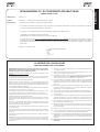 5
5
-
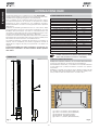 6
6
-
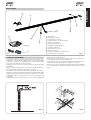 7
7
-
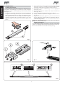 8
8
-
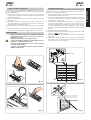 9
9
-
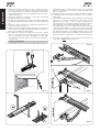 10
10
-
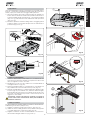 11
11
-
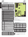 12
12
-
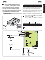 13
13
-
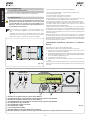 14
14
-
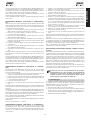 15
15
-
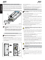 16
16
-
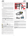 17
17
-
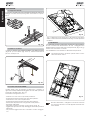 18
18
-
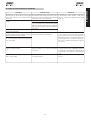 19
19
-
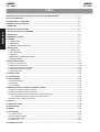 20
20
-
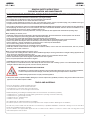 21
21
-
 22
22
-
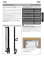 23
23
-
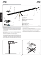 24
24
-
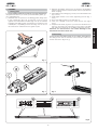 25
25
-
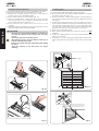 26
26
-
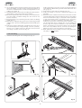 27
27
-
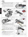 28
28
-
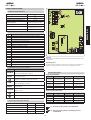 29
29
-
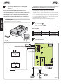 30
30
-
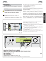 31
31
-
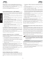 32
32
-
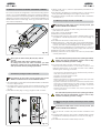 33
33
-
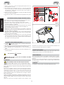 34
34
-
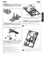 35
35
-
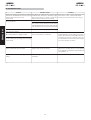 36
36
-
 37
37
-
 38
38
-
 39
39
-
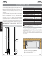 40
40
-
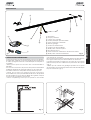 41
41
-
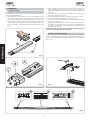 42
42
-
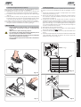 43
43
-
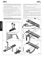 44
44
-
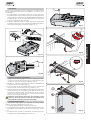 45
45
-
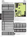 46
46
-
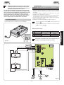 47
47
-
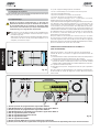 48
48
-
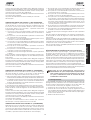 49
49
-
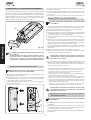 50
50
-
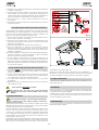 51
51
-
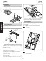 52
52
-
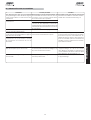 53
53
-
 54
54
-
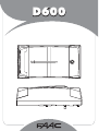 55
55
-
 56
56
-
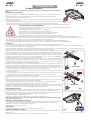 57
57
-
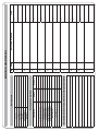 58
58
-
 59
59
-
 60
60
-
 61
61
-
 62
62
-
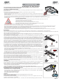 63
63
-
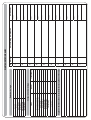 64
64
-
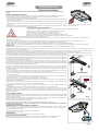 65
65
-
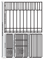 66
66
-
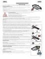 67
67
-
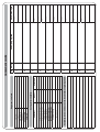 68
68
-
 69
69
-
 70
70
-
 71
71
-
 72
72
-
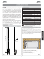 73
73
-
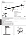 74
74
-
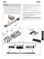 75
75
-
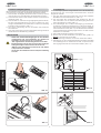 76
76
-
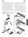 77
77
-
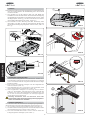 78
78
-
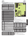 79
79
-
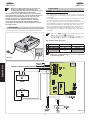 80
80
-
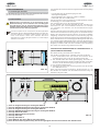 81
81
-
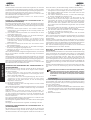 82
82
-
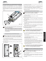 83
83
-
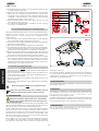 84
84
-
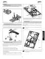 85
85
-
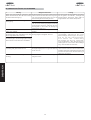 86
86
-
 87
87
-
 88
88
-
 89
89
-
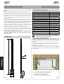 90
90
-
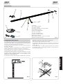 91
91
-
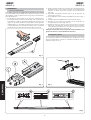 92
92
-
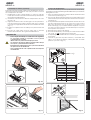 93
93
-
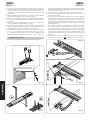 94
94
-
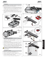 95
95
-
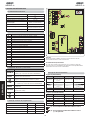 96
96
-
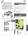 97
97
-
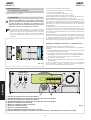 98
98
-
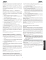 99
99
-
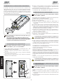 100
100
-
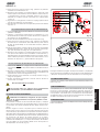 101
101
-
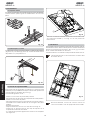 102
102
-
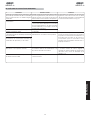 103
103
-
 104
104
-
 105
105
-
 106
106
-
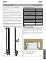 107
107
-
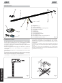 108
108
-
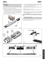 109
109
-
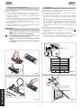 110
110
-
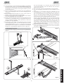 111
111
-
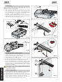 112
112
-
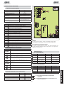 113
113
-
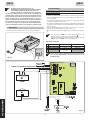 114
114
-
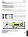 115
115
-
 116
116
-
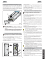 117
117
-
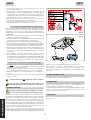 118
118
-
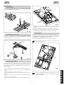 119
119
-
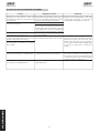 120
120
-
 121
121
-
 122
122
-
 123
123
-
 124
124


in andere talen
- English: FAAC D600 User manual
- italiano: FAAC D600 Manuale utente
- français: FAAC D600 Manuel utilisateur
- español: FAAC D600 Manual de usuario
- Deutsch: FAAC D600 Benutzerhandbuch