Pagina wordt geladen...


Deutsch
4
English
English Page
Français
Français Page
Italiano
Italiano Pagina
Español
Español Página
Nederlands
Nederlands Pagina
Polski
Polski Strona
2-Kanal-DI-Box
Diese Anleitung richtet sich an Benutzer
mit Grundkenntnissen in der Audiotechnik.
Bitte lesen Sie die Anleitung vor dem Be-
trieb gründlich durch und heben Sie sie für
ein späteres Nachlesen auf.
1 Verwendungsmöglichkeiten
Die DI-Box (Direct Injection) dient zum op-
timalen Anschluss eines Musikins truments
mit hochohmigem, asymmetrischem Aus-
gang an einen niederohmi gen, symmetri-
schen Eingang eines Misch pults (siehe Ab-
bildung auf Seite7). Durch die symmetri-
sche Verbindung zum Mischpult lassen sich
auch bei langen Anschlussleitungen Stör-
einstrahlungen vermeiden. Bei Problemen
mit Brummschleifen kann die Masseverbin-
dung zwischen Instrument und Misch pult
durch den Groundlift-Schalter unterbro-
chen werden.
Hohe Signalpegel können mit dem Ab-
schwächer reduziert und an den Misch-
pulteingang angepasst werden. Dadurch
lässt sich die DI-Box auch direkt an den
Lautsprecherausgang eines Instrumenten-
verstärkers anschließen. Die Klangbeein-
flussung durch den Verstärker (z. B. Gitar-
ren- oder Röhrenverstärker) bleibt somit
am Mischpulteingang erhalten.
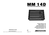
2 Übersicht für Kanal A
(Kanal B ist identisch)
1 XLR-Ausgangsbuchse, sym.
2 Groundlift-Schalter
3 Eingangsbuchse, asym.
4 parallele Durchschleifbuchse, asym.
5 Schiebeschalter zum Abschwächen des
Eingangssignals
Deutsch
Deutsch Seite
Deutsch
DIB-102
OUTPUT
BAL. 600Ω
GROUND LIFT
OFF ON
OUTPUT
BAL. 600Ω
GROUND LIFT
OFF ON
PAR. OUT
UNBAL. 50 kΩ
INPUT
0 dB – 40–20
ATT.
PAR. OUT
UNBAL. 50 kΩ
INPUT
0 dB – 40–20
ATT.
3 4 5
21

5
Deutsch
3 Wichtige Hinweise
Das Produkt entspricht allen relevanten
Richtlinien der EU und trägt deshalb das
-Zeichen.
•
Das Produkt ist nur zur Verwendung
im Innenbereich geeignet. Schützen Sie
es vor Tropf- und Spritzwasser sowie
vor hoher Luftfeuchtigkeit. Der zuläs-
sige Einsatztemperaturbereich beträgt
0 – 40 °C.
•
Säubern Sie das Produkt nur mit einem
trockenen, weichen Tuch, niemals mit
Wasser oder Chemikalien.
•
Wird das Produkt falsch verwendet
oder nicht fachgerecht repariert, kann
keine Haftung für daraus resultierende
Sach- oder Personenschäden und keine
Garantie für das Produkt übernommen
werden.
Soll das Produkt endgültig aus
dem Betrieb genommen wer-
den, entsorgen Sie es gemäß
den örtlichen Vorschriften.
4 Inbetriebnahme
Die DI-Box benötigt keine Stromversor-
gung. Im folgenden Text wird nur der Ka-
nal A beschrieben. Die Inbetriebnahme des
Kanals B ist identisch.
4.1 Eingang anschließen
An die Eingangsbuchse INPUT (3) den Aus-
gang des Musikinstruments anschließen.
Den Schiebeschalter ATT. (5) ganz nach
links in die Position „0 dB“ stellen. Treten
am nachfolgenden Mischpult Verzerrun-
gen auf, den Schalter in die Position „−20“
oder bei sehr hohen Signalpegeln in die
Position „−40“ stellen.
Alternativ kann die Eingangsbuchse auch
mit dem Lautsprecherausgang eines Instru-
mentenverstärkers verbunden werden, um
die Klangbeeinflussung durch den Verstär-
ker zu übertragen.
Achtung! Lautsprecherausgänge von
Verstärkern, die in Brückenschaltung ar-
beiten, nicht anschließen, da diese durch
die DI-Box kurzgeschlossen werden.
Die Ausgangsspannung des Verstärkers
darf nicht über 32 V liegen, sonst kann
die DI-Box übersteuert werden. Das sind
125 W an einem 8-Ω-Lautsprecher oder
250 W an einem 4-Ω-Lautsprecher.
Den Schiebeschalter ATT. (5) ganz nach
rechts in die Position „−40“ stellen, ggf.
bei geringer Lautstärke in die mittlere Po-
sition „−20“.

6
Deutsch
4.2 Durchschleifausgang nutzen
Soll das Instrumentensignal auch direkt
auf einen Verstärker gegeben werden,
den Verstärkereingang an die Buchse PAR.
OUT(4) anschließen. Hier liegt direkt das
vom Instrument kommende Signal an.
Achtung! Der Durchschleifausgang ist
nicht zum Anschluss von Lautsprechern
geeignet. Überlastungsgefahr!
4.3 Symmetrischen Ausgang
anschließen
Die XLR-Buchse OUTPUT (1) über ein sym-
metrisches Kabel an einen hochempfind-
lichen Eingang eines Mischpultes (z. B.
Mikrofoneingang) anschließen.
4.4 Groundlift-Schalter
Steht der Groundlift-Schalter (2) in der Po-
sition „OFF“, ist die Masse des asymmetri-
schen Eingangs (3) mit der Masse des sym-
metrischen Ausgangs(1) verbunden. Diese
Schalterstellung sollte zuerst gewählt wer-
den. Tritt jedoch eine Brummschleife auf,
den Schalter in die Position „ON“ (Massen
getrennt) stellen.
5 Technische Daten
Frequenzbereich: . . . 15 – 30 000 Hz,
±0 dB
Eingänge
2 × 6,3-mm-Klinke: 50 kΩ, asym.
max. Eingangs-
spannung: . . . . . . . 32 V (entspricht
125 W an 8 Ω bzw.
250 W an 4 Ω)
Ausgänge
2 × 6,3-mm-Klinke: Durchschleif-
ausgänge, asym.
2 × XLR:. . . . . . . . . 600 Ω, sym.
Übertragungs-
verhältnis: . . . . . . . . 10 : 1
Einsatztemperatur:. . 0 – 40 °C
Abmessungen:. . . . . 148 × 50 × 130 mm
(B × H × T)
Gewicht: . . . . . . . . . 755 g
Änderungen vorbehalten.

7
Deutsch
Diese Bedienungsanleitung ist urheberrechtlich für MONACOR
® INTERNATIONAL GmbH & Co. KG
geschützt. Eine Reproduktion für eigene kommerzielle Zwecke – auch auszugsweise – ist untersagt.
PROFESSIONAL
GUITAR AMPLIFI ER
GAIN 1
010
OVERDRIVE CHANNEL
GAIN 2
INPUT
CONTOUR
GAIN
SELECT
1
2
BASS
010
MIDDLE
010
TREBLE
010
LEVEL
010
LEVEL
010
BASS
010
MIDDLE
010
TREBLE
010
REVERB
010
VOLUME
010
MIN. 8 Ω
PHONESNORMAL CHANNEL
CHANNEL
SELECT
MASTER
POWER
010 010
12-INPUT MIXING CONSOLE
AUX RTN1 AUX RT N2 AUX SEND MAIN OUT
TAPE IN
CH 1CH2 CH 3CH4 CH 5/6 CH 7/8 CH 9/10 CH11/12
5/6 7/8 9/10 11/12
LINE LINE LINE LINE
HIGH
AUX1
AUX RTN1 AUX RTN2
LEVEL
HIGH
AUX1
HIGH
AUX1
HIGH
AUX1
HIGH
AUX1
HIGH
AUX1
HIGH
AUX1
HIGH
AUX1
PHANTOM POWER
POWER
PHONES
LEFT RIGHT
LR
C
010
5
-15 +15
0
-15 +15
0
010
5
010
5
GAIN
LOW
AUX2
PAN
10
0
5
+20
∞
U
10
0
5
+20
∞
U
10
0
5
+20
∞
U
10
0
5
+20
∞
U
10
0
5
+20
∞
U
10
0
5
+20
∞
U
10
0
5
+20
∞
U
10
0
5
+20
∞
U
10
0
5
+10
∞
U
10
0
5
+10
∞
U
010
5
010
5
010
5
LR
C
010
5
-15 +15
0
-15 +15
0
010
5
010
5
GAIN
LOW
AUX2
PAN
LR
C
010
5
-15 +15
0
-15 +15
0
010
5
010
5
GAIN
LOW
AUX2
PAN
LR
C
010
5
-15 +15
0
-15 +15
0
010
5
010
5
GAIN
LOW
AUX2
PAN
LR
C
010
5
-15 +15
0
-15 +15
0
010
5
010
5
GAIN
LOW
AUX2
BAL
LR
C
010
5
-15 +15
0
-15 +15
0
010
5
010
5
GAIN
LOW
AUX2
BAL
LR
C
010
5
-15 +15
0
-15 +15
0
010
5
LOW
AUX2
BAL
LR
C
010
5
-15 +15
0
-15 +15
0
010
5
LOW
AUX2
BAL
TAPE OUT
L
R
L
R
1
2
L
R
L
R
L
R
L
R
L
R
L
R
L
R
MIC MIC MIC MIC
LINE
INSER T
LINE
INSER T
LINE
INSER T
LINE
INSER T
+22
+10
+7
+4
+2
0
–2
–4
–7
–10
–20
–30
CLIP
LR1234
DIB -102
GROUND LIFTOUTPUT
BAL. 600Ω OFF ON
GROUND LIFTOUTPUT
BAL. 600Ω OFF ON
PAR. OUT
UNBAL. 5 0kΩ
INPUT
0dB –40–20
ATT. PAR. OUT
UNBAL. 5 0kΩ
INPUT
0dB –40–20
ATT.
Instrumentenverstärker
Mischpult
DIB-102
Musikinstrument

English
8
Deutsch
Deutsch Seite
Français
Français Page
Italiano
Italiano Pagina
Español
Español Página
Nederlands
Nederlands Pagina
Polski
Polski Strona
English
English Page
2-Channel DI Box
These instructions are intended for users
with basic knowledge of audio technol-
ogy. Please read the instructions carefully
prior to operation and keep them for later
reference.
1 Applications
The DI Box (Direct Injection) allows for op-
timal connection of a musical instrument
with a high-impedance, unbalanced out-
put to a low-impedance, balanced input
of a mixer (see figure on page 11). Due to
the balanced connection to the mixer, in-
terference can be avoided even when long
connection cables are used. If hum loops
occur, the ground connection between
the instrument and the mixer can be inter-
rupted by means of the ground lift switch.
High signal levels can be reduced by
means of the attenuator and matched to
the mixer input. Thus, the DI Box can also
be connected directly to the speaker out-
put of an instrument amplifier; the effect
of the amplifier (e. g. guitar amplifier or
tube amplifier) on the sound will be main-
tained at the mixer input.
1 Overview for channel A
(channel B is identical)
1 XLR output jack, bal.
2 Ground lift switch
3 Input jack, unbal.
4 Parallel feed-through jack, unbal.
5 Sliding switch to attenuate the input
signal
DIB-102
OUTPUT
BAL. 600Ω
GROUND LIFT
OFF ON
OUTPUT
BAL. 600Ω
GROUND LIFT
OFF ON
PAR. OUT
UNBAL. 50 kΩ
INPUT
0 dB – 40–20
ATT.
PAR. OUT
UNBAL. 50 kΩ
INPUT
0 dB – 40–20
ATT.
3 4 5
21

9
English
2 Important Notes
The product corresponds to all relevant di-
rectives of the EU and is therefore marked
with .
The product corresponds to the relevant
UK legislation and is therefore marked
with UKCA.
•
The product is suitable for indoor use
only. Protect it against dripping water,
splash water and high air humidity. The
admissible ambient temperature range is
0 – 40 °C.
•
For cleaning only use a dry, soft cloth;
never use water or chemicals.
•
No guarantee claims for the product
and no liability for any resulting personal
damage or material damage will be
accepted if the product is not correctly
used or not expertly repaired.
If the product is to be put out of
operation definitively, dispose of
the product in accordance with
local regulations.
3 Operation
The DI Box does not need any power sup-
ply. In the text below, only channel A is
described. Proceed in the same way to set
channel B into operation.
3.1 Connection of the input
Connect the output of the musical instru-
ment to the jack INPUT (3). Set the sliding
switch ATT. (5) to the left stop (“0 dB”).
If there are any distortions on the subse-
quent mixer, set the switch to the position
“−20” or, in case of very high signal levels,
to the position “−40”.
Alternatively, connect the input jack to the
speaker output of an instrument amplifier
to transmit the effect of the amplifier on
the sound.
Attention!
Do not connect speaker outputs of am-
plifiers operating in bridge mode; they
will be short-circuited by the DI Box.
The output voltage of the amplifier must
not exceed 32 V ; otherwise, the DI Box
may be overloaded. This means: 125 W
with an 8 Ω speaker or 250 W with a 4 Ω
speaker.
Set the sliding switch ATT. (5) to the right
stop (“−40 ”), or, if necessary, in case of
low volume, to the mid-position “−20 ”.

10
English
3.2 Using the feed-through output
To route the instrument signal directly to
an amplifier, connect the amplifier input to
the jack PAR. OUT (4). The signal received
from the instrument is directly available at
this jack.
Attention!
The feed-through output is not suitable
for connecting speakers. Risk of overload!
3.3 Connecting the balanced output
Use a balanced cable to connect the XLR
jack OUTPUT (1) to a high-sensitivity input
of a mixer (e. g. microphone input).
3.4 Ground lift switch
When the ground lift switch (2) is in the
position “OFF”, the ground of the unbal-
anced input (3) is connected to the ground
of the balanced output (1). This switch po-
sition should be chosen first. However, in
case of hum loops, set the switch to the
position “ON” (grounds separated).
4 Specifications
Frequency range: . . . 15 – 30 000 Hz,
±0 dB
Inputs
2 × 6.3 mm jack: . . 50 kΩ, unbalanced
max. input voltage: 32 V (corresponds to
125 W at 8 Ω or
250 W at 4 Ω)
Outputs
2 × 6.3 mm jack: . . feed-through out-
puts, unbalanced
2 × XLR:. . . . . . . . . 600 Ω, balanced
Transmission ratio: . . 10 : 1
Ambient
temperature: . . . . . . 0 – 40 °C
Dimensions:. . . . . . . 148 × 50 × 130 mm
(W × H × D)
Weight: . . . . . . . . . . 755 g
Subject to technical modification.

11
English
All rights reserved by MONACOR
® INTERNATIONAL GmbH & Co. KG. No part of this instruction
manual may be reproduced in any form or by any means for any commercial use.
PROFESSIONAL
GUITAR AMPLIFI ER
GAIN 1
010
OVERDRIVE CHANNEL
GAIN 2
INPUT
CONTOUR
GAIN
SELECT
1
2
BASS
010
MIDDLE
010
TREBLE
010
LEVEL
010
LEVEL
010
BASS
010
MIDDLE
010
TREBLE
010
REVERB
010
VOLUME
010
MIN. 8 Ω
PHONESNORMAL CHANNEL
CHANNEL
SELECT
MASTER
POWER
010 010
12-INPUT MIXING CONSOLE
AUX RTN1 AUX RT N2 AUX SEND MAIN OUT
TAPE IN
CH 1CH2 CH 3CH4 CH 5/6 CH 7/8 CH 9/10 CH11/12
5/6 7/8 9/10 11/12
LINE LINE LINE LINE
HIGH
AUX1
AUX RTN1 AUX RTN2
LEVEL
HIGH
AUX1
HIGH
AUX1
HIGH
AUX1
HIGH
AUX1
HIGH
AUX1
HIGH
AUX1
HIGH
AUX1
PHANTOM POWER
POWER
PHONES
LEFT RIGHT
LR
C
010
5
-15 +15
0
-15 +15
0
010
5
010
5
GAIN
LOW
AUX2
PAN
10
0
5
+20
∞
U
10
0
5
+20
∞
U
10
0
5
+20
∞
U
10
0
5
+20
∞
U
10
0
5
+20
∞
U
10
0
5
+20
∞
U
10
0
5
+20
∞
U
10
0
5
+20
∞
U
10
0
5
+10
∞
U
10
0
5
+10
∞
U
010
5
010
5
010
5
LR
C
010
5
-15 +15
0
-15 +15
0
010
5
010
5
GAIN
LOW
AUX2
PAN
LR
C
010
5
-15 +15
0
-15 +15
0
010
5
010
5
GAIN
LOW
AUX2
PAN
LR
C
010
5
-15 +15
0
-15 +15
0
010
5
010
5
GAIN
LOW
AUX2
PAN
LR
C
010
5
-15 +15
0
-15 +15
0
010
5
010
5
GAIN
LOW
AUX2
BAL
LR
C
010
5
-15 +15
0
-15 +15
0
010
5
010
5
GAIN
LOW
AUX2
BAL
LR
C
010
5
-15 +15
0
-15 +15
0
010
5
LOW
AUX2
BAL
LR
C
010
5
-15 +15
0
-15 +15
0
010
5
LOW
AUX2
BAL
TAPE OUT
L
R
L
R
1
2
L
R
L
R
L
R
L
R
L
R
L
R
L
R
MIC MIC MIC MIC
LINE
INSER T
LINE
INSER T
LINE
INSER T
LINE
INSER T
+22
+10
+7
+4
+2
0
–2
–4
–7
–10
–20
–30
CLIP
LR1234
DIB -102
GROUND LIFTOUTPUT
BAL. 600Ω OFF ON
GROUND LIFTOUTPUT
BAL. 600Ω OFF ON
PAR. OUT
UNBAL. 5 0kΩ
INPUT
0dB –40–20
ATT. PAR. OUT
UNBAL. 5 0kΩ
INPUT
0dB –40–20
ATT.
Instrument amplifier
Mixer
DIB-102
Musical
instrument

Français
12
Deutsch
Deutsch Seite
English
English Page
Italiano
Italiano Pagina
Español
Español Página
Nederlands
Nederlands Pagina
Polski
Polski Strona
Boîte de direct « DI-Box »
2canaux
Cette notice s‘adresse aux utilisateurs avec
des connaissances techniques de base en
audio. Veuillez lire la présente notice avant
le fonctionnement et conservez-la pour
pouvoir vous y reporter ultérieurement.
1 Possibilités d’utilisation
La boîte de direct DI (Direct Injection) per-
met d’effectuer un branchement optimal
d’un instrument de musique à sortie asy-
métrique haute impédance à une entrée
symétrique basse impédance d’une table
de mixage (voir schéma à la page 15). La
connexion symétrique à la table de mixage
permet d’éviter toute interférence due à
des cordons de liaison longs. En cas de
problèmes de ronflements, la connexion
masse entre l’instrument et la table de
mixage peut être interrompue grâce à l’in-
terrupteur Groundlift.
Les niveaux de signal élevés peuvent
être ré duits avec un atténuateur et adap-
tés à l’entrée de la table de mixage. Il est
ainsi possible de connecter directement
la boîte de direct à la sortie haut-parleur
d’un amplificateur d’instrument. La modi-
fication de tonalité par l’amplificateur (par
exemple amplifi cateur guitare ou amplifi-
cateur à tubes) est maintenue à l’entreé de
la table de mixage.
2 Présentation du canal A
(le canal B est identique)
1 Prise de sortie XLR symétrique
2 Interrupteur Groundlift
3 Prise d’entrée, asymétrique
4 Prise repiquage parallèle, asymétrique
5 Sélecteur pour atténuer le signal d’en-
trée
Français
Français Page
DIB-102
OUTPUT
BAL. 600Ω
GROUND LIFT
OFF ON
OUTPUT
BAL. 600Ω
GROUND LIFT
OFF ON
PAR. OUT
UNBAL. 50 kΩ
INPUT
0 dB – 40–20
ATT.
PAR. OUT
UNBAL. 50 kΩ
INPUT
0 dB – 40–20
ATT.
3 4 5
21

13
Français
3 Conseils d’utilisation
Le produit répond à toutes les directives
nécessaires de l’Union européenne et
porte donc le symbole .
•
Le produit n’est conçu que pour une uti-
lisation en intérieur. Protégez-le des écla-
boussures, de tout type de projections
d’eau et d’une humidité élevée de l’air.
La température ambiante admissible est
0 – 40 °C.
•
Pour le nettoyer, utilisez uniquement un
chiffon sec et doux, en aucun cas de pro-
duits chimiques ou d’eau.
•
Nous déclinons toute responsabilité en
cas de dommages corporels ou matériels
résultants si le produit n’est pas correcte-
ment utilisé ou réparé; en outre, la ga-
rantie deviendrait caduque.
Lorsque le produit est définiti-
vement retiré du service, élimi-
nez-le conformément aux direc-
tives locales.
CARTONS ET EMBALLAGE
PAPIER À TRIER
4 Mise en fonction
La boîte de direct ne nécessite aucun ali-
mentation. Sont décrites ci-après les étapes
pour le canal A ; elles sont identiques pour
le canal B.
4.1 Branchement de l’entrée
Branchez la sortie d’un instrument à la prise
INPUT (3). Mettez le sélecteur ATT.(5) en-
tièrement à gauche sur la position « 0 dB » ;
en cas de distorsion sur la table de mixage
reliée, mettez le sélecteur sur la position
« −20 » ou pour des niveaux de signal très
élevés, sur la position « −40 ».
Alternativement la prise d’entrée peut être
reliée à la sortie haut-parleur d’un ampli-
ficateur d’instrument pour transmettre les
modifications de tonalité par l’amplifica-
teur.
Attention !
Les sorties haut-parleurs des amplifi-
cateurs qui fonctionnement en mode
bridgé, ne doivent pas être reliées car
elles sont court-circuitées par le DI-Box.
La tension de sortie de l’amplificateur ne
doit pas dépasser 32 V pour éviter toute
surcharge du DI-Box. Pour un haut-
parleur 8 Ω, la puissance maximale est
de 125 W, pour un haut-parleur en 4 Ω,
de 250 W.
Mettez le sélecteur ATT. (5) entièrement
à droite sur la position « −40 », ou pour
un volume faible, sur la position médiane
« −20 », si nécessaire.

14
Français
4.2 Sortie repiquage
Si le signal de l’instrument doit être distri-
bué sur un amplificateur, branchez l’entrée
de l’amplificateur à la prise PAR. OUT (4).
A cette prise se trouve directement le si-
gnal venant de l’instrument.
Attention !
La sortie repiquage ne convient pas pour
brancher des haut-parleurs. Danger de
surcharge !
4.3 Sortie symétrique
Utilisez un câble symétrique pour relier la
prise XLR OUTPUT (1) à une entrée haute
sensibilité d’une table de mixage (par
exemple entrée micro).
4.4 Interrupteur Groundlift
Si l’interrupteur Groundlift (2) est sur la
position « OFF », la masse de l’entrée asy-
métrique (3) est reliée à la masse de la
sortie symétrique (1). Sélectionnez tout
d’abord cette position. En cas de ronfle-
ment, mettez l’interrupteur sur la position
« ON » (masses séparées).
5 Caractéristiques techniques
Bande passante : . . . 15 – 30 000 Hz,
±0 dB
Entrées
2 × Jack 6,35 :. . . . 50 kΩ, asymétriques
Tension
d’entrée max. : . . . . 32 V (correspondà
125 W / 8 Ω ou
250 W / 4 Ω)
Sorties
2 × Jack 6,35 :. . . . sorties repiquage,
asymétriques
2 × XLR : . . . . . . . . 600 Ω, symétriques
Rapport
transmission :. . . . . . 10 : 1
Température
ambiante : . . . . . . . . 0 – 40 °C
Dimensions : . . . . . . 148 × 50 × 130 mm
(L × H × P)
Poids : . . . . . . . . . . . 755 g
Tout droit de modification réservé.

15
Français
Notice d’utilisation protégée par le copyright de MONACOR
® INTERNATIONAL GmbH & Co. KG.
Toute reproduction même partielle à des fins commerciales est interdite.
PROFESSIONAL
GUITAR AMPLIFI ER
GAIN 1
010
OVERDRIVE CHANNEL
GAIN 2
INPUT
CONTOUR
GAIN
SELECT
1
2
BASS
010
MIDDLE
010
TREBLE
010
LEVEL
010
LEVEL
010
BASS
010
MIDDLE
010
TREBLE
010
REVERB
010
VOLUME
010
MIN. 8 Ω
PHONESNORMAL CHANNEL
CHANNEL
SELECT
MASTER
POWER
010 010
12-INPUT MIXING CONSOLE
AUX RTN1 AUX RT N2 AUX SEND MAIN OUT
TAPE IN
CH 1CH2 CH 3CH4 CH 5/6 CH 7/8 CH 9/10 CH11/12
5/6 7/8 9/10 11/12
LINE LINE LINE LINE
HIGH
AUX1
AUX RTN1 AUX RTN2
LEVEL
HIGH
AUX1
HIGH
AUX1
HIGH
AUX1
HIGH
AUX1
HIGH
AUX1
HIGH
AUX1
HIGH
AUX1
PHANTOM POWER
POWER
PHONES
LEFT RIGHT
LR
C
010
5
-15 +15
0
-15 +15
0
010
5
010
5
GAIN
LOW
AUX2
PAN
10
0
5
+20
∞
U
10
0
5
+20
∞
U
10
0
5
+20
∞
U
10
0
5
+20
∞
U
10
0
5
+20
∞
U
10
0
5
+20
∞
U
10
0
5
+20
∞
U
10
0
5
+20
∞
U
10
0
5
+10
∞
U
10
0
5
+10
∞
U
010
5
010
5
010
5
LR
C
010
5
-15 +15
0
-15 +15
0
010
5
010
5
GAIN
LOW
AUX2
PAN
LR
C
010
5
-15 +15
0
-15 +15
0
010
5
010
5
GAIN
LOW
AUX2
PAN
LR
C
010
5
-15 +15
0
-15 +15
0
010
5
010
5
GAIN
LOW
AUX2
PAN
LR
C
010
5
-15 +15
0
-15 +15
0
010
5
010
5
GAIN
LOW
AUX2
BAL
LR
C
010
5
-15 +15
0
-15 +15
0
010
5
010
5
GAIN
LOW
AUX2
BAL
LR
C
010
5
-15 +15
0
-15 +15
0
010
5
LOW
AUX2
BAL
LR
C
010
5
-15 +15
0
-15 +15
0
010
5
LOW
AUX2
BAL
TAPE OUT
L
R
L
R
1
2
L
R
L
R
L
R
L
R
L
R
L
R
L
R
MIC MIC MIC MIC
LINE
INSER T
LINE
INSER T
LINE
INSER T
LINE
INSER T
+22
+10
+7
+4
+2
0
–2
–4
–7
–10
–20
–30
CLIP
LR1234
DIB -102
GROUND LIFTOUTPUT
BAL. 600Ω OFF ON
GROUND LIFTOUTPUT
BAL. 600Ω OFF ON
PAR. OUT
UNBAL. 5 0kΩ
INPUT
0dB –40–20
ATT. PAR. OUT
UNBAL. 5 0kΩ
INPUT
0dB –40–20
ATT.
amplificateur d’instrument
table de mixage
DIB-102
instrument
de musique

Italiano
16
Deutsch
Deutsch Seite
English
English Page
Français
Français Page
Español
Español Página
Nederlands
Nederlands Pagina
Polski
Polski Strona
DI-Box a 2 Canali
Queste istruzioni sono rivolte a utenti con
conoscenze base nella tecnica audio. Vi
preghiamo di leggerle attentamente prima
della messa in funzione e di conservarle
per un uso futuro.
1 Possibilità d’impiego
La DI-Box (Direct Injection) serve per il col-
legamento ottimale di uno strumento mu-
sicale con uscita asimmetrica, ad alta impe-
denza, con l’ingresso simmetrico, a bassa
impedenza di un mixer (vedi illustrazione
a pagina 19). Grazie al collegamento sim-
metrico con il mixer si possono escludere,
anche nel caso di cavi lunghi, le radiazioni
di disturbo. Se esistono problemi di ronzio,
il collegamento di massa può essere ta-
gliato fra lo strumento ed il mixer tramite
l’interruttore groundlift.
Gli alti livelli di segnale possono essere
smorzati e adattati all’ingresso del mixer.
Così è possibile collegare la DI-box diret-
tamente all’uscita per altoparlanti di un
amplificatore per strumenti musicali. La
regolazione del suono dell’amplificatore
(p. es. amplificatore per chitarre o a val-
vole) rimane valida all’ingresso del mixer.
2 Panoramica per canale A
(il canale B è identico)
1 Presa d’uscita XLR, simm.
2 Interruttore groundlift
3 Presa d’ingresso, asimm.
4 Presa di passante parallela, asimm.
5 Cursore per smorzare il segnale d’in-
gresso
Italiano
Italiano Pagina DIB-102
OUTPUT
BAL. 600Ω
GROUND LIFT
OFF ON
OUTPUT
BAL. 600Ω
GROUND LIFT
OFF ON
PAR. OUT
UNBAL. 50 kΩ
INPUT
0 dB – 40–20
ATT.
PAR. OUT
UNBAL. 50 kΩ
INPUT
0 dB – 40–20
ATT.
3 4 5
21

17
Italiano
3 Avvertenze importanti
Il prodotto è conforme a tutte le diret-
tive rilevanti dell’UE e pertanto porta la
sigla .
•
Il prodotto è adatto solo per uso interno.
Proteggerlo da gocce e spruzzi d’acqua
e da un’elevata umidità dell’aria. L’inter-
vallo di temperatura ambiente ammissi-
bile è 0 – 40 °C.
•
Per la pulizia usare solo un panno mor-
bido e asciutto; non impiegare in nessun
caso prodotti chimici o acqua.
•
Non si accettano richieste di garanzia per
il prodotto e nessuna responsabilità per
eventuali danni alle persone o alle cose
che ne derivano, se il prodotto non viene
usato correttamente o non viene ripa-
rato a regola d’arte.
Se il prodotto deve essere messo
definitivamente fuori uso, smal-
tire il prodotto in conformità alle
norme locali.
4 Messa in funzione
La DI-Box non richiede nessuna alimen-
tazione di corrente. Nel testo seguente si
descrive solo il canale A, in quanto la situa-
zione per il canale B è identica.
4.1 Collegare l’ingresso
Collegare l’uscita dello strumento musicale
con la presa d’ingresso INPUT (3). Spo-
stare il cursore ATT. (5) completamente a
sinistra in posizione “0 dB”. Se il mixer a
valle presenta delle distorsioni, posizionare
il cursore su “−20” oppure, con livelli di
segnale molto alti, su “−40”.
In alternativa, la presa d’ingresso può es-
sere collegata anche con l’uscita per alto-
parlanti di un amplificatore per strumenti
musicali per trasmettere la regolazione del
suono da parte dell’amplificatore.
Attenzione! Non collegare le uscite per
altoparlanti degli amplificatori con circu-
ito a ponte perché si avrebbe un cortocir-
cuito per mezzo della DI-Box.
La tensione d’uscita dell’amplificatore non
deve superare i 32 V per non sovrapilotare
la DI-Box. Ciò equivale a 125 W max. con
un altoparlante di 8 Ω o a 250 W con uno
di4 Ω.
Spostare il cursore ATT. (5) completamente
a destra in posizione “−40” o eventual-
mente, in caso di volume medio, in posi-
zione “−20”.

18
Italiano
4.2 Sfruttare l’uscita di passante
Se il segnale dello strumento deve arrivare
direttamente ad un amplificatore, collegare
l’ingresso dell’amplificatore con la presa
PAR. OUT (4), dove è presente il segnale
proveniente dallo strumento musicale.
Attenzione! L’uscita di passante non
è adatta per il collegamento di altopar-
lanti. Pericolo di sovraccarico!
4.3 Collegare l’uscita simmetrica
Collegare la presa XLR OUTPUT (1) con
un ingresso ad alta sensibilità di un mixer
(p. es. l’ingresso per un microfono), serven-
dosi di un cavo simmetrico.
4.4 Interruttore groundlift
Se l’interruttore groundlift (2) è in posi-
zione “OFF”, la massa dell’ingresso asim-
metrico (3) è collegata con la massa dell’u-
scita simmetrica (1). Questa è la configura-
zione normale. Se si presentano invece
degli ronzii, portare l’interruttore su “ON”
(masse separate).
5 Dati tecnici
Banda passante:. . . . 15 – 30 000 Hz,
±0 dB
Ingressi
2 × jack 6,3 mm: . . 50 kΩ, asimm.
tensione max.
d’ingresso: . . . . . . . 32 V (corrisp.
125 W / 8 Ω o
250 W / 4 Ω)
Uscite
2 × jack 6,3 mm: . . uscite passanti,
asimm.
2 × XLR: . . . . . . . . 600 Ω, simm.
Rapporto di
trasmissione: . . . . . . 10 : 1
Temperatura
d’impiego: . . . . . . . . 0 – 40 °C
Dimensioni: . . . . . . . 148 × 50 × 130 mm
(L × H × P)
Peso: . . . . . . . . . . . . 755 g
Con riserva di modifiche tecniche.

19
Italiano
La MONACOR
® INTERNATIONAL GmbH & Co. KG si riserva ogni diritto di elaborazione in qual-
siasi forma delle presenti istruzioni per l’uso. La riproduzione – anche parziale – per propri scopi
commerciali è vietata.
amplificatore per
strumenti musicali
PROFESSIONAL
GUITAR AMPLIFI ER
GAIN 1
010
OVERDRIVE CHANNEL
GAIN 2
INPUT
CONTOUR
GAIN
SELECT
1
2
BASS
010
MIDDLE
010
TREBLE
010
LEVEL
010
LEVEL
010
BASS
010
MIDDLE
010
TREBLE
010
REVERB
010
VOLUME
010
MIN. 8 Ω
PHONESNORMAL CHANNEL
CHANNEL
SELECT
MASTER
POWER
010 010
12-INPUT MIXING CONSOLE
AUX RTN1 AUX RT N2 AUX SEND MAIN OUT
TAPE IN
CH 1CH2 CH 3CH4 CH 5/6 CH 7/8 CH 9/10 CH11/12
5/6 7/8 9/10 11/12
LINE LINE LINE LINE
HIGH
AUX1
AUX RTN1 AUX RTN2
LEVEL
HIGH
AUX1
HIGH
AUX1
HIGH
AUX1
HIGH
AUX1
HIGH
AUX1
HIGH
AUX1
HIGH
AUX1
PHANTOM POWER
POWER
PHONES
LEFT RIGHT
LR
C
010
5
-15 +15
0
-15 +15
0
010
5
010
5
GAIN
LOW
AUX2
PAN
10
0
5
+20
∞
U
10
0
5
+20
∞
U
10
0
5
+20
∞
U
10
0
5
+20
∞
U
10
0
5
+20
∞
U
10
0
5
+20
∞
U
10
0
5
+20
∞
U
10
0
5
+20
∞
U
10
0
5
+10
∞
U
10
0
5
+10
∞
U
010
5
010
5
010
5
LR
C
010
5
-15 +15
0
-15 +15
0
010
5
010
5
GAIN
LOW
AUX2
PAN
LR
C
010
5
-15 +15
0
-15 +15
0
010
5
010
5
GAIN
LOW
AUX2
PAN
LR
C
010
5
-15 +15
0
-15 +15
0
010
5
010
5
GAIN
LOW
AUX2
PAN
LR
C
010
5
-15 +15
0
-15 +15
0
010
5
010
5
GAIN
LOW
AUX2
BAL
LR
C
010
5
-15 +15
0
-15 +15
0
010
5
010
5
GAIN
LOW
AUX2
BAL
LR
C
010
5
-15 +15
0
-15 +15
0
010
5
LOW
AUX2
BAL
LR
C
010
5
-15 +15
0
-15 +15
0
010
5
LOW
AUX2
BAL
TAPE OUT
L
R
L
R
1
2
L
R
L
R
L
R
L
R
L
R
L
R
L
R
MIC MIC MIC MIC
LINE
INSER T
LINE
INSER T
LINE
INSER T
LINE
INSER T
+22
+10
+7
+4
+2
0
–2
–4
–7
–10
–20
–30
CLIP
LR1234
DIB -102
GROUND LIFTOUTPUT
BAL. 600Ω OFF ON
GROUND LIFTOUTPUT
BAL. 600Ω OFF ON
PAR. OUT
UNBAL. 5 0kΩ
INPUT
0dB –40–20
ATT. PAR. OUT
UNBAL. 5 0kΩ
INPUT
0dB –40–20
ATT.
mixer
DIB-102
strumento
musicale

Nederlands
20
Deutsch
Deutsch Seite
English
English Page
Français
Français Page
Italiano
Italiano Pagina
Español
Español Página
Polski
Polski Strona
2-kanaals DI-box
Deze handleiding is bedoeld voor gebrui-
kers met basiskennis van de audiotech-
niek. Lees de handleiding grondig door,
alvorens het apparaat in gebruik te nemen,
en bewaar ze voor latere raadpleging.
1 Toepassingen
De DI-box (Direct Injection) zorgt voor een
optimale aansluiting van een muziekin-
strument met hoogohmige, ongebalan-
ceerde uitgang op een laagohmige, ge-
balanceerde ingang van een mengpaneel
(zie figuur op pagina 23). Door de geba-
lanceerde verbinding met het mengpaneel
kunnen ook bij lange aansluitleidingen sto-
ringen vermeden worden. Bij problemen
met bromlussen kan de massaverbinding
tussen instrument en mengpaneel door
middel van de groundlift-schakelaar losge-
koppeld worden.
Hoge signaalniveaus kunnen met de
demper afgezwakt en op de mengpa-
neelingang aangepast worden. Zo kan de
DI-box ook rechtstreeks op de luidspre-
keruitgang van een instrumentversterker
aangesloten worden. De vervorming van
de klank door de versterker (bv. gitaar-
of buisversterker) blijft zodoende op de
mengpaneelingang beschikbaar.
2 Overzicht voor kanaal A
(kanaal B is identiek)
1 XLR-uitgangsjack, gebalanceerd
2 Groundlift-schakelaar
3 Ingangsjack, ongebalanceerd
4 Parallelle doorvoerjack, ongebalanceerd
5 Schuifschakelaar om het ingangssignaal
te dempen
Nederlands
Nederlands Pagina
DIB-102
OUTPUT
BAL. 600Ω
GROUND LIFT
OFF ON
OUTPUT
BAL. 600Ω
GROUND LIFT
OFF ON
PAR. OUT
UNBAL. 50 kΩ
INPUT
0 dB – 40–20
ATT.
PAR. OUT
UNBAL. 50 kΩ
INPUT
0 dB – 40–20
ATT.
3 4 5
21

21
Nederlands
3 Veiligheidsvoorschriften
Het product is in overeenstemming met
alle relevante EU-richtlijnen en is daarom
gekenmerkt met de -markering.
•
Het product is alleen geschikt voor ge-
bruik binnen. Vermijd druip- en spatwa-
ter en plaatsen met een hoge vochtig-
heid. Het toegestane omgevingstempe-
ratuurbereik bedraagt 0 – 40 °C.
•
Maak het product uitsluitend schoon
met een droge, zachte doek, en gebruik
nooit water of chemicaliën.
•
In geval van ongeoorloofd of verkeerd
gebruik, verkeerde bediening of van
herstelling door een niet-gekwalificeerd
persoon vervalt de garantie en de aan-
sprakelijkheid voor hieruit resulterende
materiële of lichamelijke schade.
Wanneer het product definitief
uit bedrijf genomen wordt, voert
u het af volgens de plaatselijke
voorschriften.
4 Ingebruikname
De DI-box heeft geen voedingsspanning
nodig. In de onderstaande tekst wordt
enkel kanaal A beschreven. De ingebruik-
name van kanaal B is identiek.
4.1 De ingang aansluiten
Sluit op de ingangsjack INPUT (3) de uit-
gang van het muziekinstrument aan. Plaats
de schuifschakelaar ATT. (5) helemaal naar
links in de stand “0 dB”. Indien er op het
nageschakelde mengpaneel vervormingen
optreden, plaats de schakelaar dan in de
stand “−20” of in de stand “−40” in geval
van zeer hoge signaalniveaus.
De ingangsjack kan echter ook met de
luidsprekeruitgang van een instrumentver-
sterker verbonden worden, om de vervor-
ming van de klank via de versterker over
te brengen.
Opgelet! Sluit geen luidsprekeruitgan-
gen van versterkers aan die in brugscha-
keling werken, omdat ze door de DI-box
kortge sloten worden.
De uitgangsspanning van de ver sterker
mag niet hoger dan 32 V liggen, anders
kan de DI-box overstuurd worden. Dit be-
tekent maximaal 125 W op een 8-Ω-luid-
spreker of 250 W op een 4-Ω-luidspreker.
Plaats de schuifschakelaar ATT. (5) hele-
maal naar rechts in de stand “−40”, of
eventueel bij laag volume in de middelste
stand “−20”.

22
Nederlands
4.2 De doorvoeruitgang gebruiken
Wenst u het instrumentsignaal ook recht-
streeks naar een versterker te sturen, sluit
de ingang van de versterker dan aan op
de jack PAR. OUT (4). Op deze jack kan
het signaal afgenomen worden dat recht-
streeks van het instrument komt.
Opgelet! De doorvoeruitgang is niet ge-
schikt voor aansluiting van luidsprekers.
Gevaar voor overbelasting!
4.3 De gebalanceerde uitgang
aansluiten
Sluit de XLR-jack OUTPUT (1) via een geba-
lanceerde kabel aan op een hooggevoelige
ingang van een mengpaneel (bv. micro-
fooningang).
4.4 Groundlift-schakelaar
Wanneer de groundlift-schakelaar (2) in
de “OFF”-stand staat, is de massa van
de ongebalanceerde ingang (3) verbon-
den met de massa van de gebalanceerde
uitgang (1). Deze schakelaarstand moet
vooraf ingesteld worden. Indien er zich
toch een bromlus voordoet, plaats de
schakelaar dan in de stand “ON” (de mas-
sa’s zijn gescheiden).
5 Technische gegevens
Frequentiebereik: . . . 15 – 30 000 Hz,
±0 dB
Ingangen
2 × 6,3 mm-jack: . . 50 kΩ, ongebalan-
ceerd
max. ingangs-
spanning:. . . . . . . . 32 V (d.w.z. 125 W
op 8 Ω resp. 250 W
op 4 Ω)
Uitgangen
2 × 6,3 mm-jack: . . doorvoeruitgangen,
ongebalanceerd
2 × XLR:. . . . . . . . . 600 Ω, gebalanceerd
Transmissie-
verhouding: . . . . . . . 10 : 1
Omgevings-
temperatuurbereik: . 0 – 40 °C
Afmetingen: . . . . . . 148 × 50 × 130 mm
(B × H × D)
Gewicht: . . . . . . . . . 755 g
Wijzigingen voorbehouden.

23
Nederlands
Deze gebruiksaanwijzing is door de auteurswet be schermd eigendom van MONACOR
® INTERNA-
TIONAL GmbH& Co. KG. Een reproductie – ook gedeeltelijk – voor eigen commerciële doeleinden
is verboden.
PROFESSIONAL
GUITAR AMPLIFI ER
GAIN 1
010
OVERDRIVE CHANNEL
GAIN 2
INPUT
CONTOUR
GAIN
SELECT
1
2
BASS
010
MIDDLE
010
TREBLE
010
LEVEL
010
LEVEL
010
BASS
010
MIDDLE
010
TREBLE
010
REVERB
010
VOLUME
010
MIN. 8 Ω
PHONESNORMAL CHANNEL
CHANNEL
SELECT
MASTER
POWER
010 010
12-INPUT MIXING CONSOLE
AUX RTN1 AUX RT N2 AUX SEND MAIN OUT
TAPE IN
CH 1CH2 CH 3CH4 CH 5/6 CH 7/8 CH 9/10 CH11/12
5/6 7/8 9/10 11/12
LINE LINE LINE LINE
HIGH
AUX1
AUX RTN1 AUX RTN2
LEVEL
HIGH
AUX1
HIGH
AUX1
HIGH
AUX1
HIGH
AUX1
HIGH
AUX1
HIGH
AUX1
HIGH
AUX1
PHANTOM POWER
POWER
PHONES
LEFT RIGHT
LR
C
010
5
-15 +15
0
-15 +15
0
010
5
010
5
GAIN
LOW
AUX2
PAN
10
0
5
+20
∞
U
10
0
5
+20
∞
U
10
0
5
+20
∞
U
10
0
5
+20
∞
U
10
0
5
+20
∞
U
10
0
5
+20
∞
U
10
0
5
+20
∞
U
10
0
5
+20
∞
U
10
0
5
+10
∞
U
10
0
5
+10
∞
U
010
5
010
5
010
5
LR
C
010
5
-15 +15
0
-15 +15
0
010
5
010
5
GAIN
LOW
AUX2
PAN
LR
C
010
5
-15 +15
0
-15 +15
0
010
5
010
5
GAIN
LOW
AUX2
PAN
LR
C
010
5
-15 +15
0
-15 +15
0
010
5
010
5
GAIN
LOW
AUX2
PAN
LR
C
010
5
-15 +15
0
-15 +15
0
010
5
010
5
GAIN
LOW
AUX2
BAL
LR
C
010
5
-15 +15
0
-15 +15
0
010
5
010
5
GAIN
LOW
AUX2
BAL
LR
C
010
5
-15 +15
0
-15 +15
0
010
5
LOW
AUX2
BAL
LR
C
010
5
-15 +15
0
-15 +15
0
010
5
LOW
AUX2
BAL
TAPE OUT
L
R
L
R
1
2
L
R
L
R
L
R
L
R
L
R
L
R
L
R
MIC MIC MIC MIC
LINE
INSER T
LINE
INSER T
LINE
INSER T
LINE
INSER T
+22
+10
+7
+4
+2
0
–2
–4
–7
–10
–20
–30
CLIP
LR1234
DIB -102
GROUND LIFTOUTPUT
BAL. 600Ω OFF ON
GROUND LIFTOUTPUT
BAL. 600Ω OFF ON
PAR. OUT
UNBAL. 5 0kΩ
INPUT
0dB –40–20
ATT. PAR. OUT
UNBAL. 5 0kΩ
INPUT
0dB –40–20
ATT.
instrumentversterker
mengpaneel
DIB-102
muziekinstrument

© MONACOR INTERNATIONAL
All rights reserved
A-0538.00.05.10.2023
MONACOR INTERNATIONAL GmbH & Co. KG
Zum Falsch 36, 28307 Bremen
Germany
1/24