Yamaha RX-A3010 de handleiding
- Categorie
- AV-ontvangers
- Type
- de handleiding

En 1
AV Receiver
Owner’s Manual
English for Canada, Europe, Asia, Africa, Oceania and Latin America
Be sure to read “Safety Brochure” (supplied booklet) before using this unit.

En 2
CONTENTS
Accessories . . . . . . . . . . . . . . . . . . . . . . . . . . . . . . . . . . . . . . . . . . . . . . . . . . . . . 5
What you can do with this unit . . . . . . . . . . . . . . . . . . . . . . . . . . . . . . . . . . . 6
Part names and functions . . . . . . . . . . . . . . . . . . . . . . . . . . . . . . . . . . . . . . . 8
Front panel . . . . . . . . . . . . . . . . . . . . . . . . . . . . . . . . . . . . . . . . . . . . . . . . . . . . . . . . . . . . . . . . . . . . . . . . . . . . . . . . . . . . . . . 8
Front display (indicators) . . . . . . . . . . . . . . . . . . . . . . . . . . . . . . . . . . . . . . . . . . . . . . . . . . . . . . . . . . . . . . . . . . . . . . . . .10
Rear panel . . . . . . . . . . . . . . . . . . . . . . . . . . . . . . . . . . . . . . . . . . . . . . . . . . . . . . . . . . . . . . . . . . . . . . . . . . . . . . . . . . . . . . .11
Remote control . . . . . . . . . . . . . . . . . . . . . . . . . . . . . . . . . . . . . . . . . . . . . . . . . . . . . . . . . . . . . . . . . . . . . . . . . . . . . . . . . .12
General setup procedure . . . . . . . . . . . . . . . . . . . . . . . . . . . . . . . . . . . . . . . 14
1 Connecting speakers . . . . . . . . . . . . . . . . . . . . . . . . . . . . . . . . . . . . . . . . . 15
Basic speaker configuration . . . . . . . . . . . . . . . . . . . . . . . . . . . . . . . . . . . . . . . . . . . . . . . . . . . . . . . . . . . . . . . . . . . . . .16
Advanced speaker configuration . . . . . . . . . . . . . . . . . . . . . . . . . . . . . . . . . . . . . . . . . . . . . . . . . . . . . . . . . . . . . . . . .21
Input/output jacks and cables . . . . . . . . . . . . . . . . . . . . . . . . . . . . . . . . . . 30
2 Connecting a TV . . . . . . . . . . . . . . . . . . . . . . . . . . . . . . . . . . . . . . . . . . . . . . 31
3 Connecting playback devices . . . . . . . . . . . . . . . . . . . . . . . . . . . . . . . . . 37
Connecting video devices (BD/DVD players, etc.) . . . . . . . . . . . . . . . . . . . . . . . . . . . . . . . . . . . . . . . . . . . . . . . . . .37
Connecting audio devices (CD players, etc.) . . . . . . . . . . . . . . . . . . . . . . . . . . . . . . . . . . . . . . . . . . . . . . . . . . . . . . .39
Connecting to the jacks on the front panel . . . . . . . . . . . . . . . . . . . . . . . . . . . . . . . . . . . . . . . . . . . . . . . . . . . . . . . .40
4 Connecting the FM/AM antennas . . . . . . . . . . . . . . . . . . . . . . . . . . . . . . 41
5 Connecting to the network . . . . . . . . . . . . . . . . . . . . . . . . . . . . . . . . . . . 42
6 Connecting other devices . . . . . . . . . . . . . . . . . . . . . . . . . . . . . . . . . . . . . 43
Connecting video/audio recording devices . . . . . . . . . . . . . . . . . . . . . . . . . . . . . . . . . . . . . . . . . . . . . . . . . . . . . . .43
Connecting a device with analog multi-channel output . . . . . . . . . . . . . . . . . . . . . . . . . . . . . . . . . . . . . . . . . . .43
Connecting a device compatible with SCENE link playback (remote connection) . . . . . . . . . . . . . . . . . . .44
Connecting a device compatible with the trigger function . . . . . . . . . . . . . . . . . . . . . . . . . . . . . . . . . . . . . . . . .44
7 Connecting the power cable . . . . . . . . . . . . . . . . . . . . . . . . . . . . . . . . . . 45
8 Selecting an on-screen menu language . . . . . . . . . . . . . . . . . . . . . . . . 46
9 Optimizing the speaker settings automatically (YPAO) . . . . . . . . . 47
Measuring at one listening position (single measure) . . . . . . . . . . . . . . . . . . . . . . . . . . . . . . . . . . . . . . . . . . . . . 50
Measuring at multiple listening positions (multi measure) . . . . . . . . . . . . . . . . . . . . . . . . . . . . . . . . . . . . . . . . 51
Checking the measurement results . . . . . . . . . . . . . . . . . . . . . . . . . . . . . . . . . . . . . . . . . . . . . . . . . . . . . . . . . . . . . . 53
Reloading the previous YPAO results . . . . . . . . . . . . . . . . . . . . . . . . . . . . . . . . . . . . . . . . . . . . . . . . . . . . . . . . . . . . . 54
Error messages . . . . . . . . . . . . . . . . . . . . . . . . . . . . . . . . . . . . . . . . . . . . . . . . . . . . . . . . . . . . . . . . . . . . . . . . . . . . . . . . . . 55
Warning messages . . . . . . . . . . . . . . . . . . . . . . . . . . . . . . . . . . . . . . . . . . . . . . . . . . . . . . . . . . . . . . . . . . . . . . . . . . . . . . 56
Basic playback procedure . . . . . . . . . . . . . . . . . . . . . . . . . . . . . . . . . . . . . . 57
Selecting an HDMI output jack . . . . . . . . . . . . . . . . . . . . . . . . . . . . . . . . . . . . . . . . . . . . . . . . . . . . . . . . . . . . . . . . . . . 57
Selecting the input source and favorite settings at once (SCENE) . . 58
Configuring scene assignments . . . . . . . . . . . . . . . . . . . . . . . . . . . . . . . . . . . . . . . . . . . . . . . . . . . . . . . . . . . . . . . . . . 59
Selecting the sound mode . . . . . . . . . . . . . . . . . . . . . . . . . . . . . . . . . . . . . . 60
Enjoying sound field effects (CINEMA DSP) . . . . . . . . . . . . . . . . . . . . . . . . . . . . . . . . . . . . . . . . . . . . . . . . . . . . . . . 61
Enjoying unprocessed playback . . . . . . . . . . . . . . . . . . . . . . . . . . . . . . . . . . . . . . . . . . . . . . . . . . . . . . . . . . . . . . . . . 63
Enjoying pure high fidelity sound (Pure Direct) . . . . . . . . . . . . . . . . . . . . . . . . . . . . . . . . . . . . . . . . . . . . . . . . . . . 64
Enjoying compressed music with enhanced sound (Compressed Music Enhancer) . . . . . . . . . . . . . . . . . 64
Enjoying surround sound with headphones (SILENT CINEMA) . . . . . . . . . . . . . . . . . . . . . . . . . . . . . . . . . . . . . 64
Listening to FM/AM radio . . . . . . . . . . . . . . . . . . . . . . . . . . . . . . . . . . . . . . 65
Setting the frequency steps . . . . . . . . . . . . . . . . . . . . . . . . . . . . . . . . . . . . . . . . . . . . . . . . . . . . . . . . . . . . . . . . . . . . . . 65
Selecting a frequency for reception . . . . . . . . . . . . . . . . . . . . . . . . . . . . . . . . . . . . . . . . . . . . . . . . . . . . . . . . . . . . . . 65
Registering favorite radio stations (preset) . . . . . . . . . . . . . . . . . . . . . . . . . . . . . . . . . . . . . . . . . . . . . . . . . . . . . . . 66
Radio Data System tuning . . . . . . . . . . . . . . . . . . . . . . . . . . . . . . . . . . . . . . . . . . . . . . . . . . . . . . . . . . . . . . . . . . . . . . . 67
Operating the radio on the TV . . . . . . . . . . . . . . . . . . . . . . . . . . . . . . . . . . . . . . . . . . . . . . . . . . . . . . . . . . . . . . . . . . . 68
Playing back iPod music/videos . . . . . . . . . . . . . . . . . . . . . . . . . . . . . . . . 70
Connecting an iPod . . . . . . . . . . . . . . . . . . . . . . . . . . . . . . . . . . . . . . . . . . . . . . . . . . . . . . . . . . . . . . . . . . . . . . . . . . . . . 70
Playback of iPod contents . . . . . . . . . . . . . . . . . . . . . . . . . . . . . . . . . . . . . . . . . . . . . . . . . . . . . . . . . . . . . . . . . . . . . . . 72
FEATURES
SETUP
PLAYBACK

En 3
Playing back music via Bluetooth . . . . . . . . . . . . . . . . . . . . . . . . . . . . . . . 75
Connecting a Bluetooth receiver . . . . . . . . . . . . . . . . . . . . . . . . . . . . . . . . . . . . . . . . . . . . . . . . . . . . . . . . . . . . . . . . . .75
Pairing Bluetooth components . . . . . . . . . . . . . . . . . . . . . . . . . . . . . . . . . . . . . . . . . . . . . . . . . . . . . . . . . . . . . . . . . . .75
Establishing a wireless connection and playing back . . . . . . . . . . . . . . . . . . . . . . . . . . . . . . . . . . . . . . . . . . . . . .76
Playing back music stored on a USB storage device . . . . . . . . . . . . . . 77
Connecting a USB storage device . . . . . . . . . . . . . . . . . . . . . . . . . . . . . . . . . . . . . . . . . . . . . . . . . . . . . . . . . . . . . . . . .77
Playback of USB storage device contents . . . . . . . . . . . . . . . . . . . . . . . . . . . . . . . . . . . . . . . . . . . . . . . . . . . . . . . . .77
Playing back music stored on PCs . . . . . . . . . . . . . . . . . . . . . . . . . . . . . . . 80
Media sharing setup . . . . . . . . . . . . . . . . . . . . . . . . . . . . . . . . . . . . . . . . . . . . . . . . . . . . . . . . . . . . . . . . . . . . . . . . . . . . .80
Playback of PC music contents . . . . . . . . . . . . . . . . . . . . . . . . . . . . . . . . . . . . . . . . . . . . . . . . . . . . . . . . . . . . . . . . . . .80
Listening to Internet radio . . . . . . . . . . . . . . . . . . . . . . . . . . . . . . . . . . . . . . 83
Playing back music in multiple rooms (multi-zone) . . . . . . . . . . . . . . . 85
Preparing for Zone2, Zone3 or Zone4 . . . . . . . . . . . . . . . . . . . . . . . . . . . . . . . . . . . . . . . . . . . . . . . . . . . . . . . . . . . . .85
Controlling Zone2, Zone3 or Zone4 . . . . . . . . . . . . . . . . . . . . . . . . . . . . . . . . . . . . . . . . . . . . . . . . . . . . . . . . . . . . . . .89
Useful functions . . . . . . . . . . . . . . . . . . . . . . . . . . . . . . . . . . . . . . . . . . . . . . . 91
Registering favorite items (shortcut) . . . . . . . . . . . . . . . . . . . . . . . . . . . . . . . . . . . . . . . . . . . . . . . . . . . . . . . . . . . . . .91
Controlling this unit from the web browser (web control) . . . . . . . . . . . . . . . . . . . . . . . . . . . . . . . . . . . . . . . . .92
Viewing the current status . . . . . . . . . . . . . . . . . . . . . . . . . . . . . . . . . . . . . . . . . . . . . . . . . . . . . . . . . . . . . . . . . . . . . . . .94
Configuring settings in accordance with a playback source (Option menu)
. . . 95
Option menu items . . . . . . . . . . . . . . . . . . . . . . . . . . . . . . . . . . . . . . . . . . . . . . . . . . . . . . . . . . . . . . . . . . . . . . . . . . . . . .95
Configuring input sources (Input menu) . . . . . . . . . . . . . . . . . . . . . . . . . 98
Input menu items . . . . . . . . . . . . . . . . . . . . . . . . . . . . . . . . . . . . . . . . . . . . . . . . . . . . . . . . . . . . . . . . . . . . . . . . . . . . . . . .98
Configuring the SCENE function (Scene menu) . . . . . . . . . . . . . . . . . . 100
Scene menu items . . . . . . . . . . . . . . . . . . . . . . . . . . . . . . . . . . . . . . . . . . . . . . . . . . . . . . . . . . . . . . . . . . . . . . . . . . . . . 101
Configuring sound programs/surround decoders (Sound Program menu)
. . . 103
Sound Program menu items . . . . . . . . . . . . . . . . . . . . . . . . . . . . . . . . . . . . . . . . . . . . . . . . . . . . . . . . . . . . . . . . . . . . 104
Configuring various functions (Setup menu) . . . . . . . . . . . . . . . . . . . . 106
Setup menu items . . . . . . . . . . . . . . . . . . . . . . . . . . . . . . . . . . . . . . . . . . . . . . . . . . . . . . . . . . . . . . . . . . . . . . . . . . . . . 107
Speaker (Manual Setup) . . . . . . . . . . . . . . . . . . . . . . . . . . . . . . . . . . . . . . . . . . . . . . . . . . . . . . . . . . . . . . . . . . . . . . . . 109
Sound . . . . . . . . . . . . . . . . . . . . . . . . . . . . . . . . . . . . . . . . . . . . . . . . . . . . . . . . . . . . . . . . . . . . . . . . . . . . . . . . . . . . . . . . . 113
Video . . . . . . . . . . . . . . . . . . . . . . . . . . . . . . . . . . . . . . . . . . . . . . . . . . . . . . . . . . . . . . . . . . . . . . . . . . . . . . . . . . . . . . . . . . 114
HDMI . . . . . . . . . . . . . . . . . . . . . . . . . . . . . . . . . . . . . . . . . . . . . . . . . . . . . . . . . . . . . . . . . . . . . . . . . . . . . . . . . . . . . . . . . . 117
Network . . . . . . . . . . . . . . . . . . . . . . . . . . . . . . . . . . . . . . . . . . . . . . . . . . . . . . . . . . . . . . . . . . . . . . . . . . . . . . . . . . . . . . . 118
Multi Zone . . . . . . . . . . . . . . . . . . . . . . . . . . . . . . . . . . . . . . . . . . . . . . . . . . . . . . . . . . . . . . . . . . . . . . . . . . . . . . . . . . . . . 119
Function . . . . . . . . . . . . . . . . . . . . . . . . . . . . . . . . . . . . . . . . . . . . . . . . . . . . . . . . . . . . . . . . . . . . . . . . . . . . . . . . . . . . . . . 121
Language . . . . . . . . . . . . . . . . . . . . . . . . . . . . . . . . . . . . . . . . . . . . . . . . . . . . . . . . . . . . . . . . . . . . . . . . . . . . . . . . . . . . . . 123
Viewing information about this unit (Information menu) . . . . . . . . 124
Types of information . . . . . . . . . . . . . . . . . . . . . . . . . . . . . . . . . . . . . . . . . . . . . . . . . . . . . . . . . . . . . . . . . . . . . . . . . . . 124
Configuring the system settings (ADVANCED SETUP menu) . . . . . 125
ADVANCED SETUP menu items . . . . . . . . . . . . . . . . . . . . . . . . . . . . . . . . . . . . . . . . . . . . . . . . . . . . . . . . . . . . . . . . . 126
Changing the speaker impedance setting (SPEAKER IMP.) . . . . . . . . . . . . . . . . . . . . . . . . . . . . . . . . . . . . . . . 126
Turning on/off the remote control sensor (REMOTE SENSOR) . . . . . . . . . . . . . . . . . . . . . . . . . . . . . . . . . . . . 126
Selecting the remote control ID (REMOTE CON AMP) . . . . . . . . . . . . . . . . . . . . . . . . . . . . . . . . . . . . . . . . . . . . 126
Changing the frequency step setting (TUNER FRQ STEP) . . . . . . . . . . . . . . . . . . . . . . . . . . . . . . . . . . . . . . . . . 127
Switching the video signal type (TV FORMAT) . . . . . . . . . . . . . . . . . . . . . . . . . . . . . . . . . . . . . . . . . . . . . . . . . . . 127
Removing the limitation on HDMI video output (MONITOR CHECK) . . . . . . . . . . . . . . . . . . . . . . . . . . . . . . 127
Backing up/recovering the settings (RECOV./BACKUP) . . . . . . . . . . . . . . . . . . . . . . . . . . . . . . . . . . . . . . . . . . . 128
Restoring the default settings (INITIALIZE) . . . . . . . . . . . . . . . . . . . . . . . . . . . . . . . . . . . . . . . . . . . . . . . . . . . . . . . 128
Updating the firmware (FIRM UPDATE) . . . . . . . . . . . . . . . . . . . . . . . . . . . . . . . . . . . . . . . . . . . . . . . . . . . . . . . . . . 128
Checking the firmware version (VERSION) . . . . . . . . . . . . . . . . . . . . . . . . . . . . . . . . . . . . . . . . . . . . . . . . . . . . . . . 128
Controlling external devices with the remote control . . . . . . . . . . . 129
Setting remote control codes . . . . . . . . . . . . . . . . . . . . . . . . . . . . . . . . . . . . . . . . . . . . . . . . . . . . . . . . . . . . . . . . . . . 129
Programming from other remote controls (learning) . . . . . . . . . . . . . . . . . . . . . . . . . . . . . . . . . . . . . . . . . . . . 131
Editing device names . . . . . . . . . . . . . . . . . . . . . . . . . . . . . . . . . . . . . . . . . . . . . . . . . . . . . . . . . . . . . . . . . . . . . . . . . . . 132
Operating multiple functions at once (macro) . . . . . . . . . . . . . . . . . . . . . . . . . . . . . . . . . . . . . . . . . . . . . . . . . . . 133
Resetting the remote control configurations . . . . . . . . . . . . . . . . . . . . . . . . . . . . . . . . . . . . . . . . . . . . . . . . . . . . 134
Using the simplified remote control . . . . . . . . . . . . . . . . . . . . . . . . . . . . 136
Updating the firmware of this unit . . . . . . . . . . . . . . . . . . . . . . . . . . . . . 137
CONFIGURATIONS

En 4
Frequently asked questions . . . . . . . . . . . . . . . . . . . . . . . . . . . . . . . . . . . 138
Troubleshooting . . . . . . . . . . . . . . . . . . . . . . . . . . . . . . . . . . . . . . . . . . . . . . 139
Power and system . . . . . . . . . . . . . . . . . . . . . . . . . . . . . . . . . . . . . . . . . . . . . . . . . . . . . . . . . . . . . . . . . . . . . . . . . . . . . 139
Audio . . . . . . . . . . . . . . . . . . . . . . . . . . . . . . . . . . . . . . . . . . . . . . . . . . . . . . . . . . . . . . . . . . . . . . . . . . . . . . . . . . . . . . . . . . 140
Video . . . . . . . . . . . . . . . . . . . . . . . . . . . . . . . . . . . . . . . . . . . . . . . . . . . . . . . . . . . . . . . . . . . . . . . . . . . . . . . . . . . . . . . . . . 141
FM/AM radio . . . . . . . . . . . . . . . . . . . . . . . . . . . . . . . . . . . . . . . . . . . . . . . . . . . . . . . . . . . . . . . . . . . . . . . . . . . . . . . . . . . 142
USB and network . . . . . . . . . . . . . . . . . . . . . . . . . . . . . . . . . . . . . . . . . . . . . . . . . . . . . . . . . . . . . . . . . . . . . . . . . . . . . . 143
Remote control . . . . . . . . . . . . . . . . . . . . . . . . . . . . . . . . . . . . . . . . . . . . . . . . . . . . . . . . . . . . . . . . . . . . . . . . . . . . . . . . 144
Error indications on the front display . . . . . . . . . . . . . . . . . . . . . . . . . . . 145
Glossary . . . . . . . . . . . . . . . . . . . . . . . . . . . . . . . . . . . . . . . . . . . . . . . . . . . . . . 146
Audio information . . . . . . . . . . . . . . . . . . . . . . . . . . . . . . . . . . . . . . . . . . . . . . . . . . . . . . . . . . . . . . . . . . . . . . . . . . . . . 146
Video information . . . . . . . . . . . . . . . . . . . . . . . . . . . . . . . . . . . . . . . . . . . . . . . . . . . . . . . . . . . . . . . . . . . . . . . . . . . . . . 148
Video signal flow . . . . . . . . . . . . . . . . . . . . . . . . . . . . . . . . . . . . . . . . . . . . . . . . . . . . . . . . . . . . . . . . . . . . . . . . . . . . . . . 149
Information on HDMI . . . . . . . . . . . . . . . . . . . . . . . . . . . . . . . . . . . . . . . . . 150
HDMI Control . . . . . . . . . . . . . . . . . . . . . . . . . . . . . . . . . . . . . . . . . . . . . . . . . . . . . . . . . . . . . . . . . . . . . . . . . . . . . . . . . . 150
HDMI signal compatibility . . . . . . . . . . . . . . . . . . . . . . . . . . . . . . . . . . . . . . . . . . . . . . . . . . . . . . . . . . . . . . . . . . . . . . 151
Reference diagram (rear panel) . . . . . . . . . . . . . . . . . . . . . . . . . . . . . . . . 152
Trademarks . . . . . . . . . . . . . . . . . . . . . . . . . . . . . . . . . . . . . . . . . . . . . . . . . . 153
Specifications . . . . . . . . . . . . . . . . . . . . . . . . . . . . . . . . . . . . . . . . . . . . . . . . 154
APPENDIX

En 5
Accessories
Check that the following accessories are supplied with this product.
■ Remote control ■ Batteries (AAA, LR03, UM-4) (x 4)
Insert into the remote control in the correct polarity (+/-)
■ Simplified remote control ■ Power cable
* The figure of the supplied power cable differs depending
on regions.
■ YPAO microphone ■ Microphone base
* Used for angle measurement during YPAO.
■ AM antenna ■ FM antenna
* The figure of the supplied FM antenna differs depending
on regions.
■ Easy Setup Guide ■ Safety Brochure ■
CD-ROM (Owner’s Manual)
Operating range of the remote control
• Aim the remote control directly at the remote control sensor on this unit during operation.
• Some features are not available in certain regions.
• Design and specifications are subject to change in part as a result of improvements, etc. In case of
differences between the manual and product, the product has priority.
• This manual mainly explains operations using the supplied remote control.
• This manual describes both the “iPod” and “iPhone” as the “iPod”. “iPod” means both “iPod” and
“iPhone” unless the explanation describes exceptions.
• “ ” indicates the cautions concerning operations or setup of the unit.
• “ ” indicates the explanations for better use.
30° 30°
Within 6 m

En 6
FEATURES
What you can do with this unit
Supports 2 to 9 channel (plus rear presence)
speaker system and up to 2 subwoofer
connections. Allows you to enjoy favorite
acoustic spaces in various styles.
Plus, bi-amp connections, channel
expansion (with external power-amp)
and multi-zone configurations to
enhance your system
p.21
Automatically optimizing the speaker
settings to suit your room (YPAO)
p.47
Sound field reproductions like actual
movie theaters and concert halls from
stereo or multi-channel audio sources
(CINEMA DSP)
p.61
Enjoying compressed music with
enhanced sound (Compressed Music
Enhancer)
p.64
Ready for any kind of contents
iPod
p.70
Network
p.80 to p.83
USB
p.77
Bluetooth
p.75
*Requires optional Bluetooth receiver for playback via Bluetooth
Operating external
devices with the supplied
remote control
p.129
Operating the TV, AV
receiver and BD/DVD
player in combination
(HDMI Control)
p.150
Selecting the input source and favorite
settings at once (SCENE)
p.58
AV receiver (this unit)
Speakers
USB device
Network contents
via Bluetooth
iPod
BD/DVD player
HDMI Control
Audio/Video
Remote control
of this unit
TV remote control
Audio
Audio
HDMI Control
Audio
Video
TV

En 7
Full of useful functions!
● Connecting various devices (p.37)
A number of HDMI jacks and various input/output jacks
on this unit allow you to connect video devices such as
BD/DVD players, audio devices such as CD players,
game consoles and camcorders, and so on.
● Playing back TV audio in surround sound
with a single HDMI cable connection
(Audio Return Channel: ARC) (p.31)
When using a TV that supports ARC, you only need a
single HDMI cable to connect the TV and this unit to
output video to the TV, input audio from the TV, and
transmit HDMI Control signals.
● Creating stereoscopic sound fields (p.63)
Connection of presence speakers enables to create an
unprecedented natural stereoscopic sound field in your
room (CINEMA DSP HD³). Even when no presence
speakers are connected, this unit automatically creates
Virtual Presence Speaker (VPS) to produce 3D surround
sound.
● Listening to FM/AM radio (p.65)
This unit is equipped with the built-in FM/AM tuner. You
can register favorite radio stations as presets.
● Enjoying pure high fidelity sound (p.64)
When the Pure Direct mode is enabled, this unit plays
back the selected source with the least circuitry. It
allows you to enjoy Hi-Fi sound quality.
● Easy operation with a TV screen
You can navigate the various contents (iPod, USB,
network, etc.), view the information, or configure the
settings using the on-screen menu.
At time like this
I want to connect a playback device using HDMI for video
and non-HDMI for audio...
Use “Audio Select” in the “Option” menu to specify the type
of an audio input jack to be used for the corresponding
input source (p.97).
Video and audio are not synchronized...
Use “Lipsync” in the “Setup” menu to adjust the delay
between video and audio output (p.113).
I want to hear audio from the TV speakers...
Use “Audio Output” in the “Setup” menu to select whether
to output audio signals through this unit and the TV (p.118).
I want to this unit to be turned off automatically when not in
use...
Use “Auto Power Down” in the “Setup” menu to set the
amount of time for auto-standby (p.121).
I want to change the on-screen menu language...
Use “Language” in the “Setup” menu to select a language
from English, Japanese, French, German, Spanish and
Russian (p.123).
I want to update the firmware...
Use “UPDATE” in the “ADVANCED SETUP” menu to update
the firmware of this unit (p.128). If this unit is connected to
the Internet, the corresponding message will be displayed
on the TV when a newer firmware is available (p.137).
There are many other settings to customize this unit.
For details, see the following pages.
●Input settings (p.98)
●Scene settings (p.101)
●Sound program and surround decoder settings (p.104)
●Various function settings (p.107)
●Information view (audio signal, video signal, etc.) (p.124)
●System settings (p.126)
Turntable
BD/DVD
player
Game
console
Camcorder
TV
CD player
HDMI Control
TV audio
Video from
external device

En 8
Front panel
1 MAIN ZONE
Turns on/off (standby) this unit.
2 Standby indicator
Lights up when this unit is in standby mode under any of the
following conditions.
- HDMI Control is enabled (p.150)
- The standby through function is enabled (p.118)
- The network standby function is enabled (p.119)
- The iPod is being charged (p.99)
- An iPod wireless system is connected (p.71)
3 Front display
Displays information (p.10).
4 Remote control sensor
Receives remote control signals (p.5).
5 PURE DIRECT
Enables/disables Pure Direct (p.64).
6 INPUT
Selects an input source.
7 Front panel door
For protecting controls and jacks (p.9).
8 VOLUME
Adjusts the volume.
Part names and functions
SCENE
MULTI ZONE
HDMI IN
VIDEO AUX
TONE/BALANCEOPTIONON SCREEN
DISPLAYRETURN
STRAIGHT
1
ENTER
ZONE 2 ZONE 3 ZONE 4
2 3 4
ZONE CONTROL
INFO MEMORY
YPAO MIC
PHONES
SILENT CINEMA
USB
iPod/iPhone
PROGRAM TUNING/CH
PRESET
ROPTICALL AUDIOVIDEOS VIDEO
PURE DIRECT
VOLUMEINPUT
MAIN ZONE
NATURAL SOUND AV RECEIVER RX-A3010
FM AM
5321
6 7 8
4
Opening the front panel door
• To use controls or jacks behind the front panel door, gently
press the bottom of the door to open it. Keep the door closed
when not using controls or jacks behind the front panel door.

En 9
■ Inside of the front panel cover
9 ON SCREEN
Displays the on-screen menu on the TV.
0 Menu operation keys
Cursor keys Select a menu or parameter.
ENTER Confirms a selected item.
RETURN Returns to the previous screen.
A OPTION
Displays the option menu (p.95).
B DISPLAY
Display the status information on the TV (p.94).
C TONE/BALANCE
Adjusts the high-frequency range and low-frequency range
of sounds output from speakers and headphones (p.96).
Adjusts the right/left channel volume balance for Zone2 or
Zone3 (p.90).
D STRAIGHT
Enables/disables the straight decode mode (p.63).
E PROGRAM
Selects a sound program or a surround decoder (p.60).
F SCENE
Selects the registered input source, sound program, HDMI
output and various settings at once. Additionally, you can
turn on this unit when it is in standby mode (p.58).
G MULTI ZONE
ZONE 2~4 Enables/disables the audio output to
each zone (p.89).
ZONE CONTROL Switches the zones (main, Zone2, Zone3
or Zone4) to operate with the front panel
controllers (p.89).
H INFO
Selects the information displayed on the front display (p.94).
I MEMORY
Registers FM/AM radio stations as preset stations (p.66).
Registers USB/network contents as shortcuts (p.91).
J FM/AM
Switches between FM and AM (p.65).
K PRESET
Selects a preset FM/AM radio station (p.66).
Selects a USB/network content from shortcuts (p.91).
L TUNING/CH
Selects the radio frequency (p.65).
M USB jack
For connecting a USB storage device (p.77) or an iPod via
USB (p.70).
N YPAO MIC jack
For connecting the supplied YPAO microphone (p.47).
O PHONES jack
For connecting headphones.
P VIDEO AUX jacks
For connecting camcorders, game consoles, etc (p.40).
SCENE
MULTI ZONE
HDMI IN
VIDEO AUX
TONE/BALANCEOPTIONON SCREEN
DISPLAYRETURN
STRAIGHT
1
ENTER
ZONE 2 ZONE 3 ZONE 4
2 3 4
ZONE CONTROL
INFO MEMORY
YPAO MIC
PHONES
SILENT CINEMA
USB
iPod/iPhone
PROGRAM TUNING/CH
PRESET
ROPTICALL AUDIOVIDEOS VIDEO
FM AM
9 0 A CB D E F H I KJ L
M N O P
G

En 10
Front display (indicators)
1 HDMI
Lights up during normal HDMI communication.
IN
Lights up when HDMI signals are being input.
OUT1/OUT2
Indicate the HDMI OUT jacks currently outputting an HDMI
signal.
2 STEREO
Lights up when this unit is receiving a stereo FM radio signal.
TUNED
Lights up when this unit is receiving an FM/AM radio station
signal.
3 ZONE indicators
Light up when the audio output to Zone2, Zone3 or Zone4 is
enabled.
4 PARTY
Lights up when this unit is in the party mode.
5 Information display
Displays the current status (input name, sound mode name,
etc). You can switch the information by pressing INFO (p.94).
6 MUTE
Flashes when audio is muted.
7 Volume indicator
Indicates the current volume.
8 ADAPTIVE DRC
Lights up when Adaptive DRC (p.96) is working.
9 ENHANCER
Lights up when Compressed Music Enhancer (p.64) is
working.
0 CINEMA DSP HD
Lights up when CINEMA DSP (p.61) is working.
CINEMA DSP HD
Lights up when CINEMA DSP HD³ (p.63) is working.
A SLEEP
Lights up when the sleep timer is on.
B Cursor indicators
Indicate the remote control cursor keys currently operational.
C Speaker indicators
Indicate speaker terminals from which signals are output.
Front speaker (L)
Front speaker (R)
Center speaker
Surround speaker (L)
Surround speaker (R)
Surround back speaker (L)
Surround back speaker (R)
Surround back speaker
Front/rear presence speakers (L)
Front/rear presence speakers (R)
Subwoofer (1)
Subwoofer (2)
OUT
1
IN
OUT
2
VOLUME
MUTE
DRCADAPTIVE
3
ZONE
2
SBLPL SBRSB PR
SW1
SL
SW2
SR
PL
CL R
PR
STEREO
ENHANCER
SLEEP
HD
TUNED PARTY
ZONE
3
ZONE
4
2
876
0
9 BCB
1 43
5
A
3

En 11
Rear panel
1 PHONO jacks
For connecting a turntable (p.39).
2 DOCK jack
For connecting an optional Yamaha products such as iPod
dock (p.71), iPod wireless system (p.71), and Bluetooth
receiver (p.75).
3 AV1~4 jacks
For connecting video/audio playback devices to input video/
audio signals (p.37).
4 NETWORK jack
For connecting to the network (p.42).
5 AV OUT jacks
For outputting video/audio to a recording device (VCR, tape
deck, etc.) (p.43).
For connecting an external amplifier used in Zone4 to output
audio signals (p.86).
6 MONITOR OUT/ZONE OUT
(composite video/S-video) jacks
For connecting a TV compatible with composite video or
S-video to output video signals (p.35).
For connecting a zone video monitor (p.87).
7 HDMI OUT 1~2 jacks
For connecting HDMI-compatible TVs to output video/audio
signals (p.31). When using ARC, TV audio signal is input
through the HDMI OUT 1 jack.
8 COMPONENT VIDEO (AV1~4) jacks
For connecting video playback devices compatible with
component video to input video signals (p.38).
9 HDMI (AV1~7) jacks
For connecting HDMI-compatible playback devices to input
video/audio signals (p.37).
0 MONITOR OUT/ZONE OUT
(component video) jacks
For connecting a TV compatible with component video to
output video signals (p.35).
For connecting a zone video monitor (p.87).
A REMOTE 1~2 (IN/OUT) jacks
For connecting a Yamaha product compatible with SCENE
link playback (p.44), or connecting an infrared signal
receiver/emitter to operate devices including this unit from
another room (p.88).
B TRIGGER OUT 1~2 jacks
For connecting devices that support the trigger function
(p.44).
C RS-232C terminal
This is a control expansion terminal for custom installation.
Consult your dealer for details.
D VOLTAGE SELECTOR
(General model only)
Select the switch position according to your local voltage
(p.45).
E ANTENNA jacks
For connecting FM and AM antennas (p.41).
F AUDIO1~4 jacks
For connecting audio playback devices to input audio
signals (p.39).
G MULTI CH INPUT jacks
For connecting a device that supports multi-channel output
to input audio signals (p.43).
H ZONE OUT/PRE OUT jacks
For connecting an external amplifier used in Zone2 or Zone3
to output audio signals (p.86).
For connecting an external power amplifier for front and rear
presence channels (p.29).
I PRE OUT jacks
For connecting subwoofers with built-in amplifier (p.20) or an
external power amplifier (p.29).
J SPEAKERS terminals
For connecting speakers (p.15).
K AC IN
For connecting the supplied power cable (p.45).
RS-232C
SPEAKER IMPEDANCE
FM
75Ω
ANTENNA
AM
(4 RADIO)
AV 1
(1 BD/DVD)
COAXIAL
1
+12V 0.1A MAX.
AC IN
TRIGGER
OUT
DOCK
YP
B PR
YPB PR
YPB PR
OPTICAL
AV OUT
AV OUT/
ZONE 4
R
L
HDMI OUT
ARC
1
1
1
2
2
HDMI
(1 BD/DVD)
MONITOR OUT/
ZONE OUT
MONITOR OUT/ZONE OUT
IN OUT
2
IN OUT
AV 1
AV 1
AV 3
AV 2 AV 3 AV 4 AV 5 AV 6 AV 7
1
2
REMOTE
COMPONENT VIDEO
AV 3 AV 4AV 2
AUDIO 4
MULTI CH INPUT
ZONE OUT/PRE OUT
AUDIO 3AUDIO 2
(3 CD)
AUDIO 1
(2 TV)
CENTER
SUBWOOFER
ZONE 2/
F.PRESENCE
ZONE 3/
R.PRESENCE
FRONT
SURROUND SUR. BACK
SPEAKERS
CENTER FRONT
ZONE 2/ZONE 3/R.PRESENCE
SURROUND BACK
BI–AMP
ZONE 2/ZONE 3/F.PRESENCE/
R
5
OPTICAL
4
OPTICAL
3
COAXIAL
2
COAXIAL
6
L
SURROUND
R L
R
R
R
L
L
L
PHONO
NETWORK
A
AV 2
B
C
AV 4
D
PRE OUT
SUBWOOFER
CENTER
FRONT
SURROUND SUR. BACK
(SINGLE) (FRONT)
(REAR)
GND
EXTRA SP1
EXTRA SP2
SINGLE
42 C1 53 6 8 9 0 A B
E F G H I J K
7
D

En 12
Remote control
1 Remote control signal transmitter
Transmits infrared signals.
2 SOURCE
Turns on/off an external device.
SOURCE/RECEIVER
Switches the devices (this unit or external device) to operate
with the remote control (p.131). You can operate this unit
when this key lights up in orange, and an external device
when this key lights up in green.
RECEIVER
Turns on/off (standby) this unit.
3 Display window
Displays remote control information.
4 Input selection keys
Select an input source to play back.
AV1~7 AV1~7 jacks
V-AUX VIDEO AUX jacks (on the front panel)
AUDIO1~4 AUDIO1~4 jacks
PHONO PHONO jacks
MULTI MULTI CH INPUT jacks
USB USB jack (on the front panel)
NET NETWORK jack (press repeatedly to select a
desired network source)
DOCK DOCK jack
TUNER FM/AM radio
[A], [B] Changes the external device to operate with the
remote control without switching the input
source.
5 SCENE
Selects the assigned input source, sound program, HDMI
output and various settings at once. Additionally, you can
turn on this unit when it is in standby mode (p.58).
6 PROGRAM
Selects a sound program (p.60).
7 External device operation keys
Operate playback and menu display etc. for external
devices (p.131).
8 ON SCREEN
Displays the on-screen menu on the TV.
9 Menu operation keys
Cursor keys Select a menu or a parameter.
ENTER Confirms a selected item.
RETURN Returns to the previous screen.
0 MODE
Switches between stereo and monaural for FM radio reception.
Switches the iPod operation modes (p.73).
A PRESET
Selects a preset FM/AM radio station (p.66).
Selects a USB/network content from shortcuts (p.91).
B TV operation keys
Operate TV input, TV volume, etc (p.130).
C VOLUME
Adjusts the volume.
D MUTE
Mutes the audio output.
E OPTION
Displays the option menu (p.95).
F LIGHT
Turns on the backlight of the remote control keys for about
10 seconds.
G DISPLAY
Displays the status information on the TV (p.94).
H Sound mode keys
Select a sound mode (p.60).
SOURCE
RECEIVER
AV
AUDIO
1 2 3 4
5 6 7
V-AUX
1 2 3 4
MULTI
PHONO
USB NET
TUNER
DOCK [ B ][ A ]
CLASSICAL
LIVE
CLUB
ENTERTAIN
MOVIE
STEREO STRAIGHT
INPUT
PURE
DIRECT
MUTE
TV
SCENE
1 2 3 4
PROGRAM
VOLUME
TV VOL
MUTE
MODE
TOP MENU
RETURN DISPLAY
POP-UP/MENU
TV CH
PRESET
ENTER
ON SCREEN
OPTION
1
3
4
7
8
E
D
0
B
H
G
F
A
6 C
7
9
5
2

En 13
■ Inside of the remote control cover
I Sound mode keys
Select a sound mode (p.60).
J INFO
Selects the information displayed on the front display (p.94).
K Numeric keys
Enter numerical values such as radio frequencies.
L ZONE
Switches the zones (main, Zone2, Zone3 or Zone4) to
operate with the remote control (p.89).
M PARTY
Turns on/off the party mode (p.90).
N HDMI OUT
Selects HDMI OUT jacks to be used for video/audio output
(p.57).
O Radio keys
Operate the FM/AM radio when “TUNER” is selected as the
input source.
MEMORY Registers FM/AM radio stations as presets.
FM Switches to FM radio.
AM Switches to AM radio.
TUN./CH Selects the radio frequency.
P SLEEP
Switches this unit to standby mode automatically after a
specified period of time has elapsed (sleep timer). Press
repeatedly to set the time (120 min, 90 min, 60 min, 30 min,
off).
Q LEVEL
Adjusts the volume of each speaker (p.111).
R SETUP
Switches the remote control to the setup mode (p.129)
• To operate external devices with the remote control, register a
remote control code for each device in advance (p.129).
SOURCE
RECEIVER
AV
AUDIO
1 2 3 4
5 6 7
V-AUX
1 2 3 4
MULTI
PHONO
USB NET
TUNER
DOCK [ B ][ A ]
CLASSICAL
LIVE
CLUB
ENTERTAIN
MOVIE
STEREO STRAIGHT
INPUT
PURE
DIRECT
MUTE
TV
SCENE
1 2 3 4
PROGRAM
VOLUME
TV VOL
MUTE
MODE
TOP MENU
RETURN DISPLAY
POP-UP/MENU
TV CH
PRESET
ENTER
ON SCREEN
OPTION
2 3
5
1
4 6
TUN./ CH
ENHANCER
SUR.
DECODE
HDMI OUT
MEMORY
INFO AM
PA RT Y
FM
0
10
LEVELENT
SETUPZONE
87
SLEEP
9
K
O
N
M
P
Q
R
I
L
J

En 14
SETUP
Now all the preparations are complete. Enjoy playing movies, music, radio, etc. with this unit!
General setup procedure
1 Connecting speakers (p.15)
Basic speaker configuration (p.16)
Select the speaker layout and connect the speakers to this unit.
Advanced speaker configuration (p.21)
Apply bi-amp connections, channel expansion (using an external power amplifier) or multi-zone configurations
to enhance the system.
2 Connecting a TV (p.31)
Connect a TV to this unit.
3 Connecting playback devices (p.37)
Connect video devices (BD/DVD players, etc.) and audio devices (CD players, etc.) to this unit.
4 Connecting the FM/AM antennas (p.41)
Connect the supplied FM/AM antennas to this unit.
5 Connecting to the network (p.42)
Connect this unit to the network.
6 Connecting other devices (p.43)
Connect external devices such as recording devices.
7 Connecting the power cable (p.45)
After all the connections are complete, plug in the power cable.
8
Selecting an on-screen menu language (p.46)
Select a desired on-screen menu language (default: English).
9
Optimizing the speaker settings automatically (YPAO) (p.47)
Optimize the speaker settings such as volume balance and acoustic parameters to suit your room (YPAO).

En 15
This unit has 9 built-in amplifiers. You can connect 2 to 11 speakers and up to 2 subwoofers (with built-in amplifier) to create the favorite acoustic space in your room.
You can also apply bi-amp connections, channel expansion (using an external power amplifier) or multi-zone configurations to enhance your system (p.21).
Functions of each speaker
• We recommend using presence speakers to have a full effect of the stereoscopic sound fields. However,
this unit creates Virtual Presence Speaker (VPS) using the front, center and surround speakers to produce
stereoscopic sound fields even when no presence speakers are connected (p.63).
• Use “Ideal speaker layout” (diagram on the right) as reference. You do not need to exactly adjust the
speaker layout to this diagram since the YPAO function of this unit will automatically optimize the speaker
settings (distance, etc.) to suit the speaker layout.
• When using only one surround back speaker, place it straight behind the listening position (middle of “SBL”
and “SBR” in the diagram).
Ideal speaker layout
1 Connecting speakers
Caution
• This unit is configured for 8-ohm speakers at the factory. When connecting 6-ohm speakers, set the speaker impedance of this unit to “6 Ω MIN”. In this case, you can also use 4-ohm speakers as the front speakers. For
details, see “Setting the speaker impedance” (p.18).
Speaker type Abbr. Function
Front (L)
Produce front right/left channel sounds (stereo sounds).
Front (R)
Center Produces center channel sounds (dialogs, vocals, etc).
Surround (L) Produce surround right/left channel sounds. Surround speakers
also produce surround back channel sounds when no surround
back speakers are connected.
Surround (R)
Surround back (L) Produce surround back right/left channel sounds. When no
surround back speakers are connected, Surround back channel
sounds are produced from the surround speakers.
Surround back (R)
Front presence (L)
Produce CINEMA DSP effect sounds. In combination with
CINEMA DSP HD³ (p.63), the presence speakers create a
natural stereoscopic sound field in your room.
Front presence (R)
Rear presence (L)
Rear presence (R)
Subwoofer
Produces LFE (low-frequency effect) channel sounds and
reinforces bass parts of other channels.
This channel is counted as “0.1”. You can connect 2 subwoofers
(with built-in amplifier) to this unit and place them on the right/
left (or front/rear) sides of the room.
30 cm or more
1.8 m
0.5 to 1 m
1.8 m
0.5 to 1 m
10°~30°10°~30°
1.8 m1.8 m
1
Speaker connections
2 3 4 5 6 7 8 9

En 16
Basic speaker configuration
■ Placing speakers in your room
Depending on the number of speakers, place the speakers and subwoofer (with built-in amplifier) in your room. This section describes the representative speaker layout examples.
❑ 9.2+2 channel system
(using both surround back and rear presence speakers)
This speaker system brings out the full performance of this unit and allows you to enjoy
a highly-natural stereoscopic sound field with any contents (CINEMA DSP HD³).
• The surround back speakers and rear presence speakers do not produce sounds simultaneously. This unit
automatically switches the speakers to be used depending on a selected CINEMA DSP (p.61).
❑ 9.2 channel system
(using rear presence speakers)
This speaker system uses the front and rear presence speakers to produce a highly-
natural stereoscopic sound field (CINEMA DSP HD³), and is suited for enjoying
5.1-channel contents.
❑ 9.2 channel system (using surround back speakers)
This speaker system uses the front presence speakers to produce a natural
stereoscopic sound field, and also allows you to enjoy extended surround sounds using
the surround back speakers.
1
Speaker connections
2 3 4 5 6 7 8 9

En 17
❑ 7.1 channel system (using front presence speakers)
This speaker system uses the front presence speakers to produce a natural
stereoscopic sound field, and is suited for enjoying 5.1-channel contents.
❑ 7.1 channel system (using surround back speakers)
This speaker system creates Virtual Presence Speaker (VPS) using the front, center and
surround speakers to produce a stereoscopic sound field, and also allows you to enjoy
extended surround sounds using the surround back speakers.
❑ 5.1 channel system
This speaker system creates Virtual Presence Speaker (VPS) using the front, center and
surround speakers to produce a stereoscopic sound field, and is suited for enjoying
5.1-channel contents.
❑ 2.1 channel system
Even when no surround speakers are connected, this unit creates the virtual surround
speakers using the front speakers to allow you to enjoy multi-channel surround sound
(Virtual CINEMA DSP).
• Add the center speaker to configure a 3.1-channel system.
1
Speaker connections
2 3 4 5 6 7 8 9

En 18
■ Setting the speaker impedance
This unit is configured for 8-ohm speakers at the factory. When connecting 6-ohm
speakers, set the speaker impedance to “6 Ω MIN”. In this case, you can also use
4-ohm speakers as the front speakers.
1
Before connecting speakers, connect the supplied power cable to
this unit and then to an AC wall outlet.
2
While holding down STRAIGHT on the front panel, press
MAIN ZONE .
3
Check that “SPEAKER IMP.” is displayed on the front display.
4
Press STRAIGHT to select “6 Ω MIN”.
5
Press MAIN ZONE to set this unit to standby mode and remove the
power cable from the AC wall outlet.
Now you are ready to connect the speakers.
MAIN ZONE
STRAIGHT
OUT
1
IN
OUT
2
VOLUME
MUTE
DRCADAPTIVE
3
ZONE
2
SBLPL SBRSB PR
SW1
SL
SW2SW
SR
PL
CL R
PR
STEREO
ENHANCER
SLEEP
HD
TUNED
PRE
AMP
PAR TY
ZONE
3
ZONE
4
HD
TAG
DOCK
8MIN
SPEAKERIMP.
SPIMP.-
1
Speaker connections
2 3 4 5 6 7 8 9

En 19
■ Connecting speakers
Connect the speakers placed in your room to this unit.
Speakers to be connected
If you have 9 speakers, use two of them as surround back speakers (*1) or rear
presence speakers (*2). If you have 7 speakers, use two of them as surround back
speakers (*3) or front presence speakers (*4).
• You can also connect up to 2 subwoofers (with built-in amplifier) to this unit. When using 2 subwoofers,
configure the “SWFR Layout” setting (p.111) in the “Setup” menu after connecting the power cable to an AC
wall outlet.
• To use an external power amplifier (Hi-Fi amplifier, etc.) to enhance speaker output, see “Connecting an
external power amplifier” (p.29).
Cables necessary for connection (commercially available)
Speaker cables (x the number of speakers)
Audio pin cable (2 for connecting 2 subwoofers)
Connection diagram
Refer to the following diagram and connect the speakers to this unit.
• When using only one surround back speaker, connect it to the SINGLE jack (L side).
Caution
• Remove the power cable of this unit from an AC wall outlet and turn off the subwoofer before
connecting the speakers.
• Be careful that the core of the speaker cable does not touch anything or come into contact with the
metal areas of this unit. This may damage this unit or the speakers. If the speaker cables short circuit,
“CHECK SP WIRES” will appear on the front display when this unit is turned on.
Room Speaker type Abbr.
Speaker system
(the number of channels)
Power Amp
Assign
(p.109)
9+2 9 7 5 2
Main zone
Front (L) ●●●●●
Basic (default)
Front (R) ●●●●●
Center ●●●●
Surround (L) ●●●●
Surround (R) ●●●●
Surround back (L) ● {*1 {*3
Surround back (R) ● {*1 {*3
Front presence (L) ●●{*4
Front presence (R) ●●{*4
Rear presence (L) ● {*2
Rear presence (R) ● {*2
–
+
–
+
SPEAKER IMPEDANCE
1
2
AUDIO 4
MULTI CH INPUT
ZONE OUT/PRE OUT
AUDIO 3
CENTER
SUBWOOFER
ZONE 2/
F.PRESENCE
ZONE 3/
R.PRESENCE
FRONT
SURROUND SUR. BACK
SPEAKERS
CENTER FRONT
ZONE 2/ZONE 3/R.PRESENCE
SURROUND BACK
BI–AMP
ZONE 2/ZONE 3/F.PRESENCE/
R L
SURROUND
R L
R
R
R
L
L
L
PRE OUT
SUBWOOFER
CENTER
FRONT
SURROUND SUR. BACK
(SINGLE) (FRONT)
(REAR)
EXTRA SP1EXTRA SP2
SINGLE
This unit (rear)
1
Speaker connections
2 3 4 5 6 7 8 9

En 20
❑ Connecting speaker cables
Speaker cables have two wires. One is for connecting the negative (-) terminal of the unit
and the speaker, and the other is for the positive (+) terminal. If the wires are colored to
prevent confusion, connect the black wire to the negative and the other wire to the positive.
a Remove approximately 10 mm of insulation from the ends of the speaker cable, and twist
the bare wires of the cable together firmly.
b Loosen the speaker terminal.
c Insert the bare wires of the cable into the gap on the side (upper right or bottom left) of the
terminal.
d Tighten the terminal.
Using a banana plug
(Canada, China, Australia and General models only)
a Tighten the speaker terminal.
b Insert a banana plug into the end of the terminal.
❑ Connecting the subwoofer
Use an audio pin cable to connect the subwoofer.
FRONT
-
+
aa
c
c
b
b
d
d
+ (red)
– (black)
FRONT
+
aa
b
b
Banana plug
(
SINGLE
)
PRE OUT
CENTER
CENTER
SUR. BACKSURRUND
1
2
FRONT
(
REAR
)
SUBWOOFER
(
FRONT
)
Audio pin cable
1
Speaker connections
2 3 4 5 6 7 8 9

En 21
Advanced speaker configuration
In addition to the basic speaker configuration (p.16), this unit also allows you to apply the following speaker configurations to enhance your system.
Using the four internal
amplifiers for front speakers to
have more high-quality sounds
(Example) (Example) (Example)
Bi-amp
connection
Combining with an external
power amplifier (Hi-Fi
amplifier, etc.) to build an
extended system
Using the excess internal
amplifiers for stereo speakers
in another room
External power
amplifier
Main zone
Zone2
Bi-amp connection Power-amp channel expansion Multi-zone configuration
1
Speaker connections
2 3 4 5 6 7 8 9

En 22
■ Available speaker configurations
• When applying one of these configurations, you need to configure the “Power Amp Assign” setting (p.109)
in the “Setup” menu.
• When applying a multi-zone configuration, you can select a zone (Zone2 or Zone3) to be assigned to the
EXTRA SP1~2 jacks in “Power Amp Assign” (p.109) in the “Setup” menu. By default, Zone2 is assigned to
the EXTRA SP1 jacks and Zone3 is assigned to the EXTRA SP2 jacks. The following explanation is based
on the default zone assignments.
❑ 7ch BI-AMP
Main zone
Multi-zone Power Amp Assign (p.109) Page
Output
channel
(max)
Bi-amp
External power
amplifier
(required)
7 { 7ch BI-AMP 22
9 { Front presence 7ch BI-AMP +FP 23
11 {
Front presence
Rear presence
7ch BI-AMP FP+RP 23
11 Rear Presence 9ch +RP 24
11 Front 9ch +FRONT 24
11
Front presence
Rear presence
7ch +FP+RP 25
9 Front +1 room 7ch +FRONT+1ZONE 25
7 Front +2 rooms 5ch +FRONT+2ZONE 26
7 +1 room 7ch +1ZONE 26
9 +1 room 9ch +1ZONE 27
7 +2 rooms 7ch +2ZONE 27
Bi-amp
Speaker Connect to
FRONT and EXTRA SP1 (bi-amp connection)
CENTER
SURROUND
SURROUND BACK
(not used)
(not used)
SUBWOOFER 1~2
1
Speaker connections
2 3 4 5 6 7 8 9

En 23
❑ 7ch BI-AMP +FP ❑ 7ch BI-AMP +FP+RP
Bi-amp
via external ampvia external amp
• When this configuration is applied, you cannot utilize the ZONE OUT/PRE OUT jacks for connecting an
external amplifier for Zone2 (p.86).
Speaker Connect to
FRONT and EXTRA SP1 (bi-amp connection)
CENTER
SURROUND
SURROUND BACK
F.PRESENCE (PRE OUT) via external power amplifier
(not used)
SUBWOOFER 1~2
Bi-amp
via external ampvia external amp
via external amp
via external amp
• When this configuration is applied, you cannot utilize the ZONE OUT/PRE OUT jacks for connecting
external amplifiers for Zone2 and Zone3 (p.86).
Speaker Connect to
FRONT and EXTRA SP1 (bi-amp connection)
CENTER
SURROUND
SURROUND BACK
F.PRESENCE (PRE OUT) via external power amplifier
R.PRESENCE (PRE OUT) via external power amplifier
SUBWOOFER 1~2
1
Speaker connections
2 3 4 5 6 7 8 9

En 24
❑ 9ch +RP ❑ 9ch +FRONT
via external amp
via external amp
• When this configuration is applied, you cannot utilize the ZONE OUT/PRE OUT jacks for connecting an
external amplifier for Zone3 (p.86).
Speaker Connect to
FRONT
CENTER
SURROUND
SURROUND BACK
EXTRA SP1
R.PRESENCE (PRE OUT) via external power amplifier
SUBWOOFER 1~2
via external amp
• When this configuration is applied, you cannot utilize the ZONE OUT/PRE OUT jacks for connecting an
external amplifier for Zone3 (p.86).
Speaker Connect to
FRONT (PRE OUT) via external power amplifier
CENTER
SURROUND
SURROUND BACK
EXTRA SP1
EXTRA SP2
SUBWOOFER 1~2
1
Speaker connections
2 3 4 5 6 7 8 9

En 25
❑ 7ch +FP+RP ❑ 7ch +FRONT+1ZONE
via external ampvia external amp
via external amp
via external amp
• When this configuration is applied, you cannot utilize the ZONE OUT/PRE OUT jacks for connecting
external amplifiers for Zone2 and Zone3 (p.86).
Speaker Connect to
FRONT
CENTER
SURROUND
SURROUND BACK
F.PRESENCE (PRE OUT) via external power amplifier
R.PRESENCE (PRE OUT) via external power amplifier
SUBWOOFER 1~2
via external amp
Main zone
Zone3
Speaker Connect to
FRONT (PRE OUT) via external power amplifier
CENTER
SURROUND
SURROUND BACK
EXTRA SP1
(not used)
SUBWOOFER 1~2
Zone3 speakers EXTRA SP2
1
Speaker connections
2 3 4 5 6 7 8 9

En 26
❑ 5ch +FRONT+2ZONE ❑ 7ch +1ZONE
Zone2
Zone3
Main zone
via external amp
Speaker Connect to
FRONT (PRE OUT) via external power amplifier
CENTER
SURROUND
SURROUND BACK
(not used)
(not used)
SUBWOOFER 1~2
Zone2 speakers EXTRA SP1
Zone3 speakers EXTRA SP2
Main zone
Zone2
Speaker Connect to
FRONT
CENTER
SURROUND
SURROUND BACK
(not used)
(not used)
SUBWOOFER 1~2
Zone2 speakers EXTRA SP1
1
Speaker connections
2 3 4 5 6 7 8 9

En 27
❑ 9ch +1ZONE ❑ 7ch +2ZONE
Main zone
Zone3
• When Zone3 output is enabled (p.89), the surround back speakers in the main zone do not output sound.
Speaker Connect to
FRONT
CENTER
SURROUND
SURROUND BACK
EXTRA SP1
(not used)
SUBWOOFER 1~2
Zone3 speakers EXTRA SP2
Zone2
Zone3
Main zone
• When Zone3 output is enabled (p.89), the surround back speakers in the main zone do not output sound.
Speaker Connect to
FRONT
CENTER
SURROUND
SURROUND BACK
(not used)
(not used)
SUBWOOFER 1~2
Zone2 speakers EXTRA SP1
Zone3 speakers EXTRA SP2
1
Speaker connections
2 3 4 5 6 7 8 9

En 28
■
Connecting front speakers that support bi-amp connections
When using front speakers that support bi-amp connections, connect them to the
FRONT jacks and EXTRA SP1 jacks.
To enable the bi-amp function, configure the “Power Amp Assign” setting (p.109) in the
“Setup” menu after connecting the power cable to an AC wall outlet.
■ Connecting Zone2/3 speakers
When using Zone2/3 speakers, connect them to the EXTRA SP1~2 jacks.
To utilize the EXTRA SP1~2 jacks for Zone2/3 speakers, configure the “Power Amp
Assign” setting (p.109) in the “Setup” menu after connecting the power cable to an AC
wall outlet.
• You can select a zone (Zone2 or Zone3) to be assigned to the EXTRA SP1~2 jacks in “Power Amp Assign”
(p.109) in the “Setup” menu. By default, Zone2 is assigned to the EXTRA SP1 jacks and Zone3 is assigned
to the EXTRA SP2 jacks.
• You can also connect Zone2, Zone3 and Zone4 speakers using an external amplifier (p.86).
Caution
• Before making bi-amp connections, remove any brackets or cables that connect a woofer with a
tweeter. Refer to the instruction manual of the speakers for details. When not making bi-amp
connections, make sure that the brackets or cables are connected before connecting the speaker
cables.
SPEAKER IMPEDANCE
SPEAKERS
CENTER FRONT
ZONE 2/ZONE 3/R.PRESENCE
SURROUND BACK
BI–AMP
ZONE 2/ZONE 3/F.PRESENCE/
R L
SURROUND
R L
R
R
R
L
L
L
EXTRA SP1EXTRA SP2
SINGLE
This unit (rear)
SPEAKER IMPEDANCE
SPEAKERS
CENTER FRONT
ZONE 2/ZONE 3/R.PRESENCE
SURROUND BACK
BI–AMP
ZONE 2/ZONE 3/F.PRESENCE/
R L
SURROUND
R L
R
R
R
L
L
L
EXTRA SP1EXTRA SP2
SINGLE
This unit (rear)
Main zone
Zone2 Zone3
1
Speaker connections
2 3 4 5 6 7 8 9

En 29
■ Connecting an external power amplifier
When using an external power amplifier to enhance speaker output, connect the input
jacks of the power amplifier to the PRE OUT jacks of this unit. The same channel signals
are output from the PRE OUT jacks as from their corresponding SPEAKERS terminals.
1 F.PRESENCE jacks
Output front presence channel audio signals or Zone2 audio signals depending on the “Power
Amp Assign” setting (p.109).
2 R.PRESENCE jacks
Output rear presence channel audio signals or Zone3 audio signals depending on the “Power
Amp Assign” setting (p.109).
3 FRONT jacks
Output front channel audio signals
4 SURROUND jacks
Output surround channel audio signals
5 SUR. BACK jacks
Output surround back channel audio signals. When using only one external amplifier for the
surround back channel, connect it to the SINGLE jack (L side).
6 CENTER jack
Outputs center channel audio signals.
(Example)
Connecting front speakers via an external power amplifier
About external power amplifiers
We recommend using power amplifiers that meet the following conditions.
- With unbalanced inputs
- With volume control bypass (or without volume control circuit)
- Output power: 100 W (8Ω) or more
• When using an external amplifier that does no have the volume control bypass, turn up the volume of the
external amplifier enough and fix it.
Caution
• To prevent the generation of loud noises or abnormal sounds, make sure the followings before making
connections.
- Remove the power cable of this unit and turn off the external power amplifier before connecting them.
- When using the PRE OUT jacks, do not connect speakers to the corresponding SPEAKERS
terminals.
- When using an external amplifier that does not have the volume control bypass, do not connect other
devices (except this unit) to the amplifier.
RS-232C
SPEAKER IMPEDANCE
+12V 0.1A MAX.
AC IN
TRIGGER
OUT
P
B PR
YPB PR
YPB PR
1
1
2
2
HDMI
(1 BD/DVD)
MONITOR OUT/ZONE OUT
IN OUT
2
IN OUT
AV 1
AV 3
AV 2 AV 3 AV 4 AV 5 AV 6 AV 7
1
2
REMOTE
COMPONENT VIDEO
O
4
MULTI CH INPUT
ZONE OUT/PRE OUT
CENTER
SUBWOOFER
ZONE 2/
F.PRESENCE
ZONE 3/
R.PRESENCE
FRONT
SURROUND SUR. BACK
SPEAKERS
CENTER FRONT
ZONE 2/ZONE 3/R.PRESENCE
SURROUND BACK
BI–AMP
ZONE 2/ZONE 3/F.PRESENCE/
R L
R
OUND
L
R
R
R
L
L
L
C
AV 4
D
PRE OUT
SUBWOOFER
CENTER
FRONT
SURROUND SUR. BACK
(SINGLE) (FRONT)
(REAR)
EXTRA SP1EXTRA SP2
SINGLE
3 41 2 56
This unit (rear)
RS-232C
SPEAKER IMPEDANCE
+12V 0.1A MAX.
AC IN
TRIGGER
OUT
P
B PR
1
1
2
M
I
M
ONITOR OUT/ZONE OUT
IN OUT
2
IN OUT
AV 4 AV 5 AV 6 AV 7
1
2
REMOTE
/
C
E
SPEAKERS
CENTER FRONT
E
2/ZONE 3/R.PRESENCE
BI–AMP
ZONE 2/ZONE 3/F.PRESENCE/
R
R
L
L
L
PRE OUT
SUBWOOFER
CENTER
FRONT
SURROUND SUR. BACK
(SINGLE) (FRONT)
(REAR)
EXTRA SP1EXTRA SP2
MAIN IN
PR
SU
R
FRONT
L
R
L
R
This unit (rear)
PRE OUT (FRONT) jacks
Main input jack
Amplifier with volume
control bypass
(A-S2000, etc.)
1
Speaker connections
2 3 4 5 6 7 8 9

En 30
■ Video/audio jacks
❑ HDMI jacks
Transmit digital video and digital sound through a single
jack. Use an HDMI cable.
• Use a 19-pin HDMI cable with the HDMI logo. We recommend using
a cable less than 5.0 m long to prevent signal quality degradation.
• To connect a device that has a DVI jack, an HDMI/DVI-D cable is
required.
• The HDMI jacks of this unit support the HDMI Control, Audio Return
Channel (ARC), and 3D video transmission (through output)
features.
■ Video jacks
❑ COMPONENT VIDEO jacks
Transmit video signals separated into three
components: luminance (Y), chrominance blue (PB),
and chrominance red (PR). Use a component video
cable with three plugs.
❑ S VIDEO jack
Transmits S-video signals that include luminance (Y)
and chrominance (C) components. Use an S-video
cable.
❑ VIDEO jacks
Transmit analog video signals. Use a video pin cable.
■ Audio jacks
❑ OPTICAL jacks
Transmit digital audio signals. Use a digital optical
cable. Remove the tip protector (if available) before
using the cable.
❑ COAXIAL jacks
Transmit digital audio signals. Use a digital coaxial
cable.
❑ AUDIO jacks
Transmit analog stereo audio signals. Use a stereo pin
cable.
Input/output jacks and cables
AV 1
HDMI cable
COMPONEN
AV 1
A
Component video cable
S-video cable
AV 1
Video pin cable
Digital Optical cable
Digital coaxial cable
Stereo pin cable

En 31
Connect a TV to this unit so that videos input to this unit can be output to the TV.
You can also enjoy playback of TV audio on this unit.
The connection method varies depending on functions and video input jacks available
on your TV.
Refer to the instruction manual of the TV and choose a connection method.
■ Connection method 1 (HDMI Control/ARC-compatible
TV)
Connect the TV to this unit with an HDMI cable.
• The following explanation is based on the assumption that you have not changed the “HDMI” parameters
(p.117) in the “Setup” menu.
• HDMI Control is available only on the HDMI OUT 1 jack.
• If you make an HDMI connection between your TV and this unit, any videos input to this unit can be output
to the TV no matter how you connect video devices to this unit. For details, see “Video signal flow” (p.149).
• You can connect another TV or a projector by using the HDMI OUT 2 jack (p.36).
2 Connecting a TV
About HDMI Control
HDMI Control allows you to operate external devices via HDMI. If you connect a TV
that supports HDMI Control to this unit with an HDMI cable, you can control this unit
(power, volume, etc.) in conjunction with TV remote control operations. You can also
control playback devices (HDMI Control-compatible BD/DVD player, etc.)
connected to this unit with an HDMI cable. For details, see “HDMI Control” (p.150).
About Audio Return Channel (ARC)
ARC allows audio signals to travel both ways under HDMI Control. So if you connect
a TV that supports HDMI Control and ARC to this unit with a single HDMI cable, you
can output video/audio to the TV or input TV audio to this unit.
Does your TV support
Audio Return Channel (ARC)?
Does your TV support
HDMI Control?
Does your TV have an
HDMI input jack?
■ Connection method 3 (p.34)
■ Connection method 2 (p.33)
■ Connection method 1 (p.31)
■ Connection method 4 (p.35)
Yes
Yes
Yes
No
No
No
FM
75Ω
ANTENNA
AM
(4 RADIO)
AV 1
(1 BD/DVD)
COAXIAL
1
DOCK
YP
B
OPTICAL
AV OUT
AV OU T/
ZONE 4
R
L
HDMI OUT
ARC
1 2
(1
MONITOR OUT/
ZONE OUT
AV 1
AV 1
AV 3 AV 4AV 2
AUDIO 4AUDIO 3AUDIO 2
(3 CD)
AUDIO 1
(2 TV)
FRONT
5
OPTICAL
4
OPTICAL
3
COAXIAL
2
COAXIAL
6
SURROUND
R L
PHONO
NETWORK
A
AV 2
B
GND
HDMI OUT
ARC
12
HDMI
HDMI
HDMI
HDMI OUT 1 jack
HDMI input
(ARC-compatible)
This unit (rear)
TV
1 2
TV connection
3 4 5 6 7 8 9

En 32
❑ Necessary settings
To use HDMI Control and ARC, you need to configure the following settings.
For details on settings and operations of your TV, refer to the instruction manual of the TV.
1
After connecting external devices (TV, playback devices, etc.) and
power cable of this unit, turn on this unit, TV and playback devices.
2
Configure the settings of this unit.
a Check that ARC is enabled on the TV.
b Switch the TV input to display the video from this unit.
c Press ON SCREEN.
d Use the cursor keys to select “Setup” and press ENTER.
e Use the cursor keys ( / ) to select “HDMI”.
f Use the cursor keys ( / ) to select “HDMI Control” and press ENTER.
g Use the cursor keys to select “On”.
h Press ON SCREEN.
3
Configure the settings for HDMI Control.
a Enable HDMI Control on the TV and playback devices (HDMI Control-compatible BD/
DVD player, etc).
b Turn off the main power of the TV and then turn off this unit and playback devices.
c Turn on this unit and playback devices and then turn on the main power of the TV.
d Switch the TV input to display the video from this unit.
e Check the followings.
On this unit: The input to which the playback device is connected is selected. If not,
select the input source manually.
On the TV: The video from the playback device is displayed.
f Check that this unit is properly synchronized with the TV by turning off the TV or
adjusting the TV volume with the TV remote control.
Now the necessary settings are complete.
If you select a TV program with the TV remote control, the input source of this unit will
be automatically switched to “AUDIO1” and the TV audio will be played back on this
unit.
If TV audio cannot be heard, check that “ARC” (p.117) in the “Setup” menu is set to
“On”.
• If HDMI Control does not work properly, try turning off and on (or unplugging and re-plugging) the
devices. It may solve the problem.
• If any audio interruption happens while using ARC, set “ARC” (p.117) in the “Setup” menu to “Off”
and use an audio cable (digital optical or stereo pin cable) to input TV audio to this unit (p.33).
• “AUDIO1” is set as TV audio input at the factory. If you have connected any external device to the
AUDIO1 jacks, use “TV Audio Input” (p.117) in the “Setup” menu to change the TV audio input
assignment. To use the SCENE function (p.58), you also need to change the input assignment for
SCENE(TV).
RETURN DISPLAY
ENTER
ON SCREEN
OPTION
ON SCREEN
Cursor keys
ENTER
1 2
TV connection
3 4 5 6 7 8 9

En 33
■ Connection method 2 (HDMI Control-compatible TV)
Connect the TV to this unit with an HDMI cable and an audio cable (digital optical or
stereo pin cable).
• The following explanation is based on the assumption that you have not changed the “HDMI” parameters
(p.117) in the “Setup” menu.
• HDMI Control is available only on the HDMI OUT 1 jack.
• If you make an HDMI connection between your TV and this unit, any videos input to this unit can be output
to the TV no matter how you connect video devices to this unit. For details, see “Video signal flow” (p.149).
• You can connect another TV or a projector by using the HDMI OUT 2 jack (p.36).
❑ Necessary settings
To use HDMI Control, you need to configure the following settings.
For details on settings and operations of your TV, refer to the instruction manual of the
TV.
1
After connecting external devices (TV, playback devices, etc.) and
power cable of this unit, turn on this unit, TV and playback devices.
2
Configure the settings of this unit.
a Switch the TV input to display the video from this unit.
b Press ON SCREEN.
c Use the cursor keys to select “Setup” and press ENTER.
d Use the cursor keys ( / ) to select “HDMI”.
e Use the cursor keys ( / ) to select “HDMI Control” and press ENTER.
f Use the cursor keys to select “On”.
g Press ON SCREEN.
FM
75Ω
ANTENNA
AM
(4 RADIO)
AV 1
(1 BD/DVD)
COAXIAL
1
DOCK
YP
B
OPTICAL
AV OUT
AV OU T/
ZONE 4
R
L
HDMI OUT
ARC
1 2
(1
MONITOR OUT/
ZONE OUT
AV 1
AV 1
AV 3 AV 4AV 2
AUDIO 4AUDIO 3AUDIO 2
(3 CD)
AUDIO 1
(2 TV)
FRONT
5
OPTICAL
4
OPTICAL
3
COAXIAL
2
COAXIAL
6
SURROUND
R L
PHONO
NETWORK
A
AV 2
B
GND
HDMI
HDMI OUT
ARC
12
OPTICAL
AUDIO 1
(2 TV)
5
AUDIO
OPTICAL
R
L
OO
L
R
L
R
HDMI
HDMI
This unit (rear)
HDMI OUT 1 jack
AUDIO1 (OPTICAL or AUDIO)
jacks
Audio output
(digital optical or analog stereo)
TV
HDMI input
RETURN DISPLAY
ENTER
ON SCREEN
OPTION
ON SCREEN
Cursor keys
ENTER
1 2
TV connection
3 4 5 6 7 8 9

En 34
3
Configure the settings for HDMI Control.
a Enable HDMI Control on the TV and playback devices (HDMI Control-compatible BD/
DVD player, etc).
b Turn off the main power of the TV and then turn off this unit and playback devices.
c Turn on this unit and playback devices and then turn on the main power of the TV.
d Switch the TV input to display the video from this unit.
e Check the followings.
On this unit: The input to which the playback device is connected is selected. If not,
select the input source manually.
On the TV: The video from the playback device is displayed.
f Check that this unit is properly synchronized with the TV by turning off the TV or
adjusting the TV volume with the TV remote control.
Now the necessary settings are complete.
If you select a TV program with the TV remote control, the input source of this unit will
be automatically switched to “AUDIO1” and the TV audio will be played back on this
unit.
• If HDMI Control does not work properly, try turning off and on (or unplugging and re-plugging) the
devices. It may solve the problem.
• “AUDIO1” is set as TV audio input at the factory. If you have connected any external device to the
AUDIO1 jacks, use “TV Audio Input” (p.117) in the “Setup” menu to change the TV audio input
assignment. To use the SCENE function (p.58), you also need to change the input assignment for
SCENE(TV).
■ Connection method 3 (TV with HDMI input jacks)
Connect the TV to this unit with an HDMI cable and an audio cable (digital optical or
stereo pin cable).
If switch the input source of this unit to “AUDIO1” by pressing AUDIO1 or SCENE(TV),
the TV audio will be played back on this unit.
• If you make an HDMI connection between your TV and this unit, any videos input to this unit can be output
to the TV no matter how you connect video devices to this unit. For details, see “Video signal flow” (p.149).
• You can connect another TV or a projector by using the HDMI OUT 2 jack (p.36).
• If you have connected any external device to the AUDIO1 jacks, connect the TV to one of the AUDIO2~4
jacks. To use the SCENE function (p.58), you also need to change the input assignment for SCENE(TV).
FM
75Ω
ANTENNA
AM
(4 RADIO)
AV 1
(1 BD/DVD)
COAXIAL
1
DOCK
YP
B
OPTICAL
AV OUT
AV OU T/
ZONE 4
R
L
HDMI OUT
ARC
1 2
(1
MONITOR OUT/
ZONE OUT
AV 1
AV 1
AV 3 AV 4AV 2
AUDIO 4AUDIO 3AUDIO 2
(3 CD)
AUDIO 1
(2 TV)
FRONT
5
OPTICAL
4
OPTICAL
3
COAXIAL
2
COAXIAL
6
SURROUND
R L
PHONO
NETWORK
A
AV 2
B
GND
HDMI
HDMI OUT
ARC
12
OPTICAL
AUDIO 1
(2 TV)
5
AUDIO
OPTICAL
R
L
OO
L
R
L
R
HDMI
HDMI
This unit (rear)
HDMI OUT 1 jack
AUDIO1 (OPTICAL or AUDIO)
jacks
Audio output
(digital optical or analog stereo)
TV
HDMI input
1 2
TV connection
3 4 5 6 7 8 9

En 35
■ Connection method 4 (TV without HDMI input jacks)
Depending on the video input jacks available on your TV, choose one of the following
connections.
If you select “AUDIO1” as the input source by pressing AUDIO1 or SCENE(TV), the TV
audio will be played back on this unit.
• If you connect your TV to this unit with a cable other than HDMI, videos input to this unit via HDMI cannot
be output to the TV. Also, analog videos that can be output to the TV differ according to the “Analog to
Analog Conversion” setting. For details, see “Video signal flow” (p.149).
• If you have connected any external device to the AUDIO1 jacks, connect the TV to one of the AUDIO2~4
jacks. To use the SCENE function (p.58), you also need to change the input assignment for SCENE(TV).
• To use the MONITOR OUT jacks for the TV in the main zone, set “Monitor Out Assign” (p.120) in the
“Setup” menu to “Main” (default).
COMPONENT VIDEO connection (with a component video cable)
S VIDEO connection (with an S-video cable)
VIDEO (composite video) connection (with a video pin cable)
YPB PR
YPB PR
YPB PR
OPTICAL
U
T
T
/
4
HDMI OUT
ARC
1 2
HDMI
(1 BD/DVD)
MONITOR OUT/
ZONE OUT
MONITOR OUT/ZONE OUT
I
AV 1
AV 1
AV 3
AV 2 AV 3 AV 4 AV 5
COMPONENT VIDEO
AUDIO 4
MULTI CH INPUT
ZONE OUT/PRE OUT
AUDIO 3AUDIO 2
(3 CD)
AUDIO 1
(2 TV)
CENTER
SUBWOOFER
ZONE 2/
F.PRESENCE
ZONE 3/
R.PRESENCE
FRONT
SURROUND SUR. BACK
SPEAKERS
ZONE 2/ZONE 3/R.PRESENCE
SURROUND BACK
R
5
COAXIAL
6
L
SURROUND
R L
R L
A
AV 2
B
C
AV 4
D
PRE OUT
FRONT
SURROUND SUR
.
(SI
N
EXTRA SP2
SINGLE
OPTICAL
AUDIO 1
(2 TV)
5
AUDIO
OPTICAL
R
L
YP
B
P
R
MONITOR OUT/ZONE OUT
YP
B
P
R
COMPONENT VIDEO
OO
L
R
L
R
P
R
P
B
Y
P
R
P
B
Y
This unit (rear)
MONITOR OUT
(COMPONENT VIDEO) jacks
Video input (component video)
TV
AUDIO1
(OPTICAL or AUDIO) jacks
Audio output
(digital optical or analog stereo)
FM
75Ω
ANTENNA
AM
(4 RADIO)
AV 1
(1 BD/DVD)
COAXIAL
1
DOCK
YP
B P
R
OPTICAL
AV OUT
AV OU T/
ZONE 4
R
L
HDMI OUT
ARC
1 2
(1 BD/DV
D
MONITOR OUT/
ZONE OUT
AV 1
AV 1
COM
P
AV 3 AV 4AV 2
AUDIO 4
MU
L
AUDIO 3AUDIO 2
(3 CD)
AUDIO 1
(2 TV)
FRONT
SURRO
U
5
OPTICAL
4
OPTICAL
3
COAXIAL
2
COAXIAL
6
SURROUND
R L
PHONO
NETWORK
A
AV 2
B
GND
OPTICAL
AUDIO 1
(2 TV)
5
AUDIO
OPTICAL
R
L
MONITOR OUT/
ZONE OUT
S VIDEO
OO
L
R
L
R
S
S
This unit (rear)
MONITOR OUT
(S VIDEO) jack
Video input (S-video)
AUDIO1 (OPTICAL or AUDIO)
jacks
Audio output
(digital optical or analog stereo)
TV
FM
75Ω
ANTENNA
AM
(4 RADIO)
AV 1
(1 BD/DVD)
COAXIAL
1
DOCK
YP
B P
R
OPTICAL
AV OUT
AV OU T/
ZONE 4
R
L
HDMI OUT
ARC
1 2
(1 BD/DV
D
MONITOR OUT/
ZONE OUT
AV 1
AV 1
COM
P
AV 3 AV 4AV 2
AUDIO 4
MU
L
AUDIO 3AUDIO 2
(3 CD)
AUDIO 1
(2 TV)
FRONT
SURRO
U
5
OPTICAL
4
OPTICAL
3
COAXIAL
2
COAXIAL
6
SURROUND
R L
PHONO
NETWORK
A
AV 2
B
GND
MONITOR OUT/
ZONE OUT
VIDEO
V
V
This unit (rear)
MONITOR OUT
(VIDEO) jack
TV
Video input
(composite video)
1 2
TV connection
3 4 5 6 7 8 9

En 36
■ Connecting another TV or a projector
This unit has 2 HDMI output jacks. If you connect another TV or a projector to this unit
with an HDMI cable, you can switch the TVs (or projector) to be used for watching
videos with the remote control (p.57).
• HDMI Control is not available on the HDMI OUT 2 jack.
FM
75Ω
ANTENNA
AM
(4 RADIO)
AV 1
(1 BD/DVD)
COAXIAL
1
DOCK
YP
B P
R
OPTICAL
AV OUT
AV OU T/
ZONE 4
R
L
HDMI OUT
ARC
1 2
(1 BD/DV
D
MONITOR OUT/
ZONE OUT
AV 1
AV 1
COM
P
AV 3 AV 4AV 2
AUDIO 4
MU
L
AUDIO 3AUDIO 2
(3 CD)
AUDIO 1
(2 TV)
FRONT
SURRO
U
5
OPTICAL
4
OPTICAL
3
COAXIAL
2
COAXIAL
6
SURROUND
R L
PHONO
NETWORK
A
AV 2
B
GND
HDMI OUT
ARC
12
HDMI
HDMI
HDMI
This unit (rear)
HDMI OUT 2 jack
HDMI input
Projector
TV (already connected)
1 2
TV connection
3 4 5 6 7 8 9

En 37
This unit is equipped with a variety of input jacks including HDMI input jacks to allow
you to connect different types of playback devices. For information on how to connect
an iPod, a Bluetooth component or a USB storage device, see the following pages.
- Connecting an iPod (p.70)
- Connecting a Bluetooth receiver (p.75)
- Connecting a USB storage device (p.77)
Connecting video devices (BD/DVD players, etc.)
Connect video devices such as BD/DVD players, set-top boxes (STBs) and game consoles
to this unit. Depending on the video/audio output jacks available on your video device,
choose one of the following connections. We recommend using an HDMI connection if the
video device has an HDMI output jack.
• Videos input to this unit via HDMI cannot be output to a TV connected to this unit with a cable other than
HDMI.
• The following explanation is based on the assumption that you have not changed the “Input Assignment”
setting (p.121) in the “Setup” menu. As necessary, you can assign the COMPONENT VIDEO ( , , ,
), COAXIAL (a, b, f) and OPTICAL (c, d, e) jacks to another input source.
• If you make more than one audio connection for one input source, an audio signal played back on this unit
will be determined according to the “Audio Select” setting (p.97) in the “Option” menu.
■ HDMI connection
Connect a video device to this unit with an HDMI cable.
If you select the input source by pressing AV1~7, the video/audio played back on the
video device will be output from this unit.
3 Connecting playback devices
SPEAKER IMPEDANCE
+12V 0.1A
TRIGG
OU
T
PB PR
YPB PR
YPB PR
1
1
2
2
HDMI
(1 BD/DVD)
MONITOR OUT/ZONE OUT
IN OUT
2
IN OUT
AV 1
AV 3
AV 2 AV 3 AV 4 AV 5 AV 6 AV 7
1
2
REMOTE
COMPONENT VIDEO
MULTI CH INPUT
ZONE OUT/PRE OUT
CENTER
SUBWOOFER
ZONE 2/
F.PRESENCE
ZONE 3/
R.PRESENCE
FRONT
SURROUND SUR. BACK
SPEAKERS
CENTER FRONT
ZONE 2/ZONE 3/R.PRESENCE
SURROUND BACK
R L
U
ND
L
R
R
L
L
C
AV 4
D
PRE OUT
SUBWOOFER
CENTER
FRONT
SURROUND SUR. BACK
(SINGLE) (FRONT)
(REAR)
EXTRA SP2
SINGLE
HDMI
HDMI
HDMI
This unit (rear)
HDMI output
Video device
HDMI (AV1~7) jacks
1 2 3
Playback device connections
4 5 6 7 8 9

En 38
■ Component video connection
Connect a video device to this unit with a component video cable and an audio cable
(digital coaxial, digital optical or stereo pin cable). Choose a set of input jacks (on this
unit) depending on the audio output jacks available on your video device.
If you select the input source by pressing AV1~4, the video/audio played back on the
video device will be output from this unit.
■ S-video connection
Connect a video device to this unit with an S-video cable and an audio cable (digital
coaxial, digital optical or stereo pin cable). Choose a set of input jacks (on this unit)
depending on the audio output jacks available on your video device.
If you select the input source by pressing AV1~4, the video/audio played back on the
video device will be output from this unit.
Output jacks on video device
Input jacks on this unit
Video Audio
Component video
Digital coaxial AV1~2 (COMPONENT VIDEO + COAXIAL)
Digital optical AV3~4 (COMPONENT VIDEO + OPTICAL)
Analog stereo AV1~4 (COMPONENT VIDEO + AUDIO)
FM
75Ω
ANTENNA
AM
(4 RADIO)
AV 1
(1 BD/DVD)
COAXIAL
1
DOCK
YP
B PR YPB PR
OPTICAL
AV OUT
AV OU T/
ZONE 4
R
L
HDMI OUT
ARC
1 2
H
(1 BD/DVD)
MONITOR OUT/
ZONE OUT
AV 1
AV 1
AV 3
AV 2 AV 3
COMPONENT VIDEO
AV 3 AV 4AV 2
AUDIO 4
MULTI CH INPUT
ZONE OUT/PRE
AUDIO 3AUDIO 2
(3 CD)
AUDIO 1
(2 TV)
CENTER
SUBWOOFER
ZONE 2/
F.PRESENCE
Z
O
R.PR
E
FRONT
SURROUND SUR. BACK
Z
O
SURROUND BACK
R
5
OPTICAL
4
OPTICAL
3
COAXIAL
2
COAXIAL
6
L
SURROUND
R L
R
PHONO
NETWORK
A
AV 2
B
C
AV 4
D
GND
SINGLE
YPB PR
YPB PR
R
L
COAXIAL
OPTICAL
CC
L
R
L
R
OO
P
R
P
B
Y
P
R
P
B
Y
This unit (rear)
AV1~4
(COMPONENT VIDEO)
jacks
Video output
(component video)
Video device
Audio output
(any of digital coaxial, digital optical,
analog stereo)
Any of AV1~2 (COAXIAL),
AV3~4 (OPTICAL),
AV1~4 (AUDIO) jacks
Output jacks on video device
Input jacks on this unit
Video Audio
S-video
Digital coaxial AV1~2 (S VIDEO + COAXIAL)
Digital optical AV3~4 (S VIDEO + OPTICAL)
Analog stereo AV1~4 (S VIDEO + AUDIO)
FM
75Ω
ANTENNA
AM
(4 RADIO)
AV 1
(1 BD/DVD)
COAXIAL
1
DOCK
OPTICAL
AV OUT
AV OU T/
ZONE 4
R
L
H
ARC
1
MONITOR OUT/
ZONE OUT
AV 3 AV 4AV 2
AUDIO 2
(3 CD)
AUDIO 1
(2 TV)
5
OPTICAL
4
OPTICAL
3
COAXIAL
2
COAXIAL
6
PHONO
NETWORK
GND
S VIDEO
CC
L
R
L
R
OO
S
S
R
L
COAXIAL
OPTICAL
This unit (rear)
AV1~4
(S VIDEO) jacks
Video output
(S-video)
Video device
Audio output
(any of digital coaxial, digital optical,
analog stereo)
Any of AV1~2 (COAXIAL),
AV3~4 (OPTICAL),
AV1~4 (AUDIO) jacks
1 2 3
Playback device connections
4 5 6 7 8 9

En 39
■ Composite video connection
Connect a video device to this unit with a video pin cable and an audio cable (digital
coaxial, digital optical or stereo pin cable). Choose a set of input jacks (on this unit)
depending on the audio output jacks available on your video device.
If you select the input source by pressing AV1~4, the video/audio played back on the
video device will be output from this unit.
Connecting audio devices (CD players, etc.)
Connect audio devices such as CD players, MD players and a turntable to this unit.
Depending on the audio output jacks available on your audio device, choose one of the
following connections.
• The following explanation is based on the assumption that you have not changed the “Input Assignment”
setting (p.121) in the “Setup” menu. As necessary, you can assign the COAXIAL (a, b, f) and OPTICAL
(c, d, e) jacks to another input source.
• If you make more than one audio connection for one input source, an audio signal played back on this unit
will be determined according to the “Audio Select” setting (p.97) in the “Option” menu.
Output jacks on video device
Input jacks on this unit
Video Audio
Composite video
Digital coaxial AV1~2 (VIDEO + COAXIAL)
Digital optical AV3~4 (VIDEO + OPTICAL)
Analog stereo AV1~4 (VIDEO + AUDIO)
FM
75Ω
ANTENNA
AM
(4 RADIO)
AV 1
(1 BD/DVD)
COAXIAL
1
DOCK
OPTICAL
AV OUT
AV OU T/
ZONE 4
R
L
H
ARC
1
MONITOR OUT/
ZONE OUT
AV 3 AV 4AV 2
AUDIO 2
(3 CD)
AUDIO 1
(2 TV)
5
OPTICAL
4
OPTICAL
3
COAXIAL
2
COAXIAL
6
PHONO
NETWORK
GND
VIDEO
COAXIAL
OPTICAL
CC
L
R
L
R
OO
V
V
R
L
This unit (rear)
AV1~4 (VIDEO)
jacks
Video output
(composite video)
Video device
Audio output
(any of digital coaxial, digital optical,
analog stereo)
Any of AV1~2 (COAXIAL),
AV3~4 (OPTICAL),
AV1~4 (AUDIO) jacks
Audio output jacks on audio device Audio input jacks on this unit
Digital coaxial
AV1~2 (COAXIAL)
AUDIO2 (COAXIAL)
Digital optical
AV3~4 (OPTICAL)
AUDIO1 (OPTICAL)
Analog stereo
AV1~4 (AUDIO)
AUDIO1~4 (AUDIO)
Turntable (PHONO) PHONO
1 2 3
Playback device connections
4 5 6 7 8 9

En 40
If you select the input source by pressing AV1~4, AUDIO1~4 or PHONO, the audio
played back on the audio device will be output from this unit.
Connecting to the jacks on the front panel
Use the VIDEO AUX jacks on the front panel to temporarily connect devices such as a
game console and a camcorder to this unit.
Before making a connection, stop playback on the device and turn down the volume of
this unit.
If you select “V-AUX” as the input source by pressing V-AUX, the video/audio played
back on the device will be output from this unit.
• If you connect video devices to both the HDMI IN jack and analog video/audio jacks, this unit outputs video/
audio input through the HDMI IN jack.
FM
75Ω
ANTENNA
AM
(4 RADIO)
AV 1
(1 BD/DVD)
COAXIAL
1
DOCK
YP
B
OPTICAL
AV OUT
AV OU T/
ZONE 4
R
L
HDMI OUT
ARC
1 2
(1
MONITOR OUT/
ZONE OUT
AV 1
AV 1
AV 3 AV 4AV 2
AUDIO 4AUDIO 3AUDIO 2
(3 CD)
AUDIO 1
(2 TV)
FRONT
5
OPTICAL
4
OPTICAL
3
COAXIAL
2
COAXIAL
6
SURROUND
R L
PHONO
NETWORK
A
AV 2
B
GND
R
L
PHONO
GND
R
L
PHONO
GND
COAXIAL
OPTICAL
CC
L
R
L
R
OO
L
R
L
R
This unit
(rear)
PHONO jacks
Audio output
(PHONO)
Turntable
Audio output
(any of digital coaxial, digital optical,
analog stereo)
Any of AV1~4, AUDIO1~4
(COAXIAL, OPTICAL, AUDIO) jacks
Audio device
UO
HDMI IN
VIDEO AUX
DISPLAYRETURN
ENTER
ZONE 2 ZONE 3 ZONE 4
ZONE CONTROL
YPAO MIC
PHONES
SILENT CINEMA
USB
iPod/iPhone
PROGRAM TUNING/CH
ROPTICALL AUDIOVIDEOS VIDEO
FM AM
V RL
HDMI
S
O
Game console
Camcorder
This unit (front)
1 2 3
Playback device connections
4 5 6 7 8 9

En 41
Connect the supplied FM/AM antennas to this unit.
Assembling and connecting the AM antenna
• Unwind the antenna cable from the AM antenna unit only the length needed.
• The wires of the AM antenna have no polarity.
4 Connecting the FM/AM antennas
SPEAKER I
M
FM
75Ω
ANTENNA
AM
(4 RADIO)
AV 1
(1 BD/DVD)
COAXIAL
1
DOCK
YP
B PR
YPB PR
YPB PR
OPTICAL
AV OUT
AV OU T/
ZONE 4
R
L
HDMI OUT
ARC
1
1
1
2
2
HDMI
(1 BD/DVD)
MONITOR OUT/
ZONE OUT
MONITOR OUT/ZONE OUT
IN OUT
2
IN OU
T
AV 1
AV 1
AV 3
AV 2 AV 3 AV 4 AV 5 AV 6 AV 7
REMOTE
COMPONENT VIDEO
AV 3 AV 4AV 2
AUDIO 4
MULTI CH INPUT
ZONE OUT/PRE OUT
AUDIO 3AUDIO 2
(3 CD)
AUDIO 1
(2 TV)
CENTER
SUBWOOFER
ZONE 2/
F.PRESENCE
ZONE 3/
R.PRESENCE
FRONT
SURROUND SUR. BACK
SPEAKERS
CENTER FR
O
ZONE 2/ZONE 3/R.PRESENCE
SURROUND BACK
R
5
OPTICAL
4
OPTICAL
3
COAXIAL
2
COAXIAL
6
L
SURROUND
R L
R
R
L
PHONO
NETWORK
A
AV 2
B
C
AV 4
D
PRE OUT
SUBWOOFER
CENTER
FRONT
SURROUND SUR. BACK
(SINGLE) (FRONT)
(REAR)
GND
EXTRA SP2
SINGLE
FM antenna
AM antenna
This unit (rear)
Hold down Insert Release
1 2 3 4
FM/AM antenna connections
5 6 7 8 9

En 42
Connect this unit to your router with a commercially-available STP network cable (CAT-5
or higher straight cable).
You can enjoy Internet radio or music files stored on PCs and DLNA servers such as
Network Attached Storage (NAS) on this unit.
• When using a router that supports the DHCP function, the network parameters (IP address, etc.) will be
automatically assigned to this unit without configuring the network settings of this unit. If your router does
not support the DHCP function or you want to configure the network parameters manually, configure the
network settings (p.118).
• You can check whether the network parameters (IP address, etc.) are properly assigned to this unit in
“Network” (p.125) in the “Information”.
• Some security software installed on your PC or the firewall settings of your network devices (such as a
router) may block the access of this unit to the network devices or the Internet. In such cases, configure the
security software or firewall settings appropriately.
• You can connect this unit to up to 16 music servers (PC, etc.), and each server must be connected to the
same subnet as this unit.
• To use the service via the Internet, broadband connection is strongly recommended.
5 Connecting to the network
FM
75Ω
ANTENNA
AM
(4 RADIO)
AV 1
(1 BD/DVD)
COAXIAL
1
DOCK
YP
B PR
Y
OPTICAL
AV OUT
AV OU T/
ZONE 4
R
L
HDMI OUT
ARC
1 2
(1 BD/DVD)
MONITOR OUT/
ZONE OUT
AV 1
AV 1
A
V
COMPONENT V
I
AV 3 AV 4AV 2
AUDIO 4
MULTI CH IN
P
AUDIO 3AUDIO 2
(3 CD)
AUDIO 1
(2 TV)
FRONT
SURROUND SUR.
S
U
R
5
OPTICAL
4
OPTICAL
3
COAXIAL
2
COAXIAL
6
SURROUND
R L
PHONO
NETWORK
A
AV 2
B
GND
LAN
WAN
Network Attached Storage
(NAS)
Internet
Modem
Router
Network cable
PC
This unit (rear)
1 2 3 4 5
Network connections
6 7 8 9

En 43
Connecting video/audio recording devices
You can connect video/audio recording devices to the AV OUT jacks. These jacks
output video/audio signals selected as the input.
• The AV OUT jacks cannot output video/audio signals input through the HDMI or COMPONENT VIDEO
jacks.
Connecting a device with analog multi-channel
output
You can connect an analog multi-channel output device such as a DVD player and an
SACD player to the MULTI CH INPUT jacks.
If you select “MULTI CH” as the input source by pressing MULTI, the audio played back
on the device will be output from this unit.
• You can select a video source to be displayed when “MULTI CH” is selected as the input source using
“Video Out” (p.100) in the “Input” menu. When connecting a video device (DVD player, etc.) to the MULTI
CH INPUT jacks, use the input jack specified in “Video Out” for the video connection.
• Since this unit does not redirect signals input to the MULTI CH INPUT jacks to accommodate for missing
speakers, make appropriate settings on the external device (DVD player, etc.) that suit to the speaker
configuration.
• When “MULTI CH” is selected as the input source, sound mode selection and tone control adjustment are
not available.
6 Connecting other devices
FM
75Ω
ANTENNA
AM
(4 RADIO)
AV 1
(1 BD/DVD)
COAXIAL
1
DOCK
OPTICAL
AV OUT
AV OU T/
ZONE 4
R
L
HDMI OUT
ARC
1
MONITOR OUT/
ZONE OUT
AV 1
AV 3 AV 4AV 2
AU
D
AUDIO 3AUDIO 2
(3 CD)
AUDIO 1
(2 TV)
5
OPTICAL
4
OPTICAL
3
COAXIAL
2
COAXIAL
6
SU
R
R
PHONO
NETWORK
A
AV 2
B
GND
VIDEO
S VIDEO
AUDIO
OPTICAL
R
L
V
L
R
L
R
OO
S
S
V
AV OUT
AV OUT/
ZONE 4
T
his unit (rear)
AV OUT jacks
Video/audio input
Video/audio
recording device
FM
75Ω
ANTENNA
AM
(4 RADIO)
AV 1
(1 BD/DVD)
COAXIAL
1
DOCK
YP
B PR YPB
OPTICAL
AV OUT
AV OU T/
ZONE 4
R
L
HDMI OUT
ARC
1 2
(1 BD/DVD)
MONITOR OUT/
ZONE OUT
AV 1
AV 1
AV 3
AV 2 AV
3
COMPONENT VIDEO
AV 3 AV 4AV 2
AUDIO 4
MULTI CH INPUT
Z
O
AUDIO 3AUDIO 2
(3 CD)
AUDIO 1
(2 TV)
CENTER
SUBWOOFER
Z
O
F.P R
E
FRONT
SURROUND SUR. BACK
SURROUND BACK
R
5
OPTICAL
4
OPTICAL
3
COAXIAL
2
COAXIAL
6
L
SURROUND
R L
PHONO
NETWORK
A
AV 2
B
C
AV 4
D
GND
SINGLE
MULTI CH INPUT
CENTER
SUBWOOFER
FRONT
SURROUND SUR. BACK
L
R
L
R
L
R
This unit (rear)
MULTI CH
INPUT jacks
Channel output
(Center)
Device with analog
multi-channel output
(Subwoofer)
(Surround
back)
(Surround)
(Front)
1 2 3 4 5 6
Other connections
7 8 9

En 44
Connecting a device compatible
with SCENE link playback (remote connection)
If you have a Yamaha product that has the capability of the SCENE control signal
transmission, you can control the Yamaha product in conjunction with a scene selection
(p.58) by connecting it to one of the REMOTE (OUT) jacks with a monaural mini-jack
cable.
• If you connect a Yamaha product compatible with SCENE link playback to one of the REMOTE (OUT)
jacks, you can start playback on the Yamaha product in conjunction with a scene selection (p.58). To enable
the SCENE link playback, specify the device type in “Device Control” (p.101) in the “Scene” menu.
• You also connect an infrared signal receiver/emitter to operate devices in the main zone from Zone2 (p.88).
Connecting a device compatible
with the trigger function
The trigger function can control an external device in conjunction with operations
(power-on/off, input selection, etc.) on this unit. If you have a Yamaha subwoofer that
supports a system connection or a device with a trigger input jack, you can use the
trigger function by connecting the external device to one of the TRIGGER OUT jacks.
• You can configure the trigger function settings in “Trigger Output1” and “Trigger Output2” (p.122) in the
“Setup” menu.
SPEAKER IMPEDANCE
+12V 0.1A MAX.
TRIGGER
OUT
YP
B PR
PR
1
1
2
HDMI
MONITOR OUT/ZONE OUT
IN OUT
2
IN OUT
AV 3 AV 4 AV 5 AV 6 AV 7
1
2
REMOTE
ZONE OUT/PRE OUT
R
ZONE 2/
F.PRESENCE
ZONE 3/
R.PRESENCE
SPEAKERS
CENTER FRONT
ZONE 2/ZONE 3/R.PRESENCE
K
BI–AM
P
ZONE
2
L
R
R
R
L
L
C
D
PRE OUT
SUBWOOFER
CENTER
FRONT
SURROUND SUR. BACK
(SINGLE) (FRONT)
(REAR)
EXTRA SP2
N
GLE
IN
REMOTE
1
IN OUT
2
IN OUT
REMOTE
This unit (rear)
REMOTE (OUT) jacks
Yamaha product
(DVD player, etc.)
Remote input
RS-232C
SPEAKER IMPEDANCE
+12V 0.1A MAX.
A
C
TRIGGER
OUT
YP
B PR
PR
1
1
2
HDMI
MONITOR OUT/ZONE OUT
IN OUT
2
IN OUT
AV 3 AV 4 AV 5 AV 6 AV 7
1
2
REMOTE
ZONE OUT/PRE OUT
R
ZONE 2/
F.PRESENCE
ZONE 3/
R.PRESENCE
SPEAKERS
CENTER FRONT
ZONE 2/ZONE 3/R.PRESENCE
K
BI–AMP
ZONE 2/ZONE 3/F.PRESENCE/
L
R
R
R
L
L
L
C
D
PRE OUT
SUBWOOFER
CENTER
FRONT
SURROUND SUR. BACK
(SINGLE) (FRONT)
(REAR)
EXTRA SP1EXTRA SP2
N
GLE
+12V 0.1A MAX.
TRIGGER
OUT
1
2
This unit (rear)
TRIGGER OUT
1~2 jacks
System connection
input
Yamaha subwoofer that
supports a system connection
1 2 3 4 5 6
Other connections
7 8 9

En 45
After all the connections are complete, connect the supplied power cable to this unit
and then to an AC wall outlet.
7 Connecting the power cable
Before connecting the power cable (General model only)
Set the switch position of VOLTAGE SELECTOR according to your local voltage.
Voltages are AC 110-120/220-240 V, 50/60 Hz.
• Make sure you set VOLTAGE SELECTOR of the unit BEFORE plugging the power cable into an AC
wall outlet. Improper setting of VOLTAGE SELECTOR may cause damage to this unit and create a
potential fire hazard.
RS-232C
SPEAKER IMPEDANCE
+12V 0.1A MAX.
AC IN
TRIGGER
OUT
P
B PR
1
1
2
O
R OUT/ZONE OUT
IN OUT
2
IN OUT
AV 5AV 6AV 7
1
2
REMOTE
P
EAKERS
CENTER FRONT
NE 3/R.PRESENCE
BI–AMP
ZONE 2/ZONE 3/F.PRESENCE/
R
R
L
L
L
PRE OUT
SUBWOOFER
CENTER
FRONT
SURROUND SUR. BACK
(SINGLE) (FRONT)
(REAR)
EXTRA SP1
X
TRA SP2
VOLTAGE SELECTOR
220V-
240V
110V-
120V
This unit (rear)
VOLTAGE
SELECTOR
RS-232C
SPEAKER IMPEDANCE
+12V 0.1A MAX.
AC IN
TRIGGER
OUT
P
B PR
1
1
2
O
R OUT/ZONE OUT
IN OUT
2
IN OUT
AV 5AV 6AV 7
1
2
REMOTE
P
EAKERS
CENTER FRONT
NE 3/R.PRESENCE
BI–AMP
ZONE 2/ZONE 3/F.PRESENCE/
R
R
L
L
L
PRE OUT
SUBWOOFER
CENTER
FRONT
SURROUND SUR. BACK
(SINGLE) (FRONT)
(REAR)
EXTRA SP1
X
TRA SP2
To an AC wall outlet
This unit (rear)
1 2 3 4 5 6 7
Power cable connection
8 9

En 46
Select a desired on-screen menu language from English (default),
Japanese, French, German, Spanish and Russian.
1
Press RECEIVER to turn on this unit.
2
Turn on the TV and switch the TV input to display
the video from this unit.
3
Press ON SCREEN.
4
Use the cursor keys to select “Setup” and press
ENTER.
5
Use the cursor keys ( / ) to select “Language” and
the cursor keys ( / ) to select a desired language.
6
To exit from the menu, press ON SCREEN.
• The information on the front display is provided in English only.
8 Selecting an on-screen menu language
SOURCE
RECEIVER
AV
AUDIO
1 2 3 4
5 6 7
V-A UX
1 2 3 4
MULTI
PHONO
USB NET
TUNER
DOCK [ B ][ A ]
CLASSICAL
LIVE
CLUB
ENTERTAIN
MOVIE
STEREO STRAIGHT
INPUT
PURE
DIRECT
MUTE
TV
SCENE
1 2 3 4
PROGRAM
VOLUME
TV VOL
MUTE
MODE
TOP MENU
RETURN DISPLAY
POP-UP/MENU
TV CH
PRESET
ENTER
ON SCREEN
OPTION
SO
UR
CE
RE
C
EIV
E
R
AV
AU
DI
O
1
2
3
4
5
6
7
V-
AU
X
1
2
3
4
M
U
LT
I
PH
ON
O
US
B
N
E
T
T
UNER
D
OCK
[
B
]
[
A
]
ON SCREEN ON SCREEN
ENTER ENTER
RECEIVER RECEIVER
1 2 3 4 5 6 7 8
Language setting
9
Cursor keys

En 47
By using the Yamaha Parametric room Acoustic Optimizer (YPAO)
function, this unit automatically detects speaker connections and
distances from the listening position, and optimizes the speaker
settings such as volume balance and acoustic parameters to suit
your room.
Please note the following when using YPAO.
• Use YPAO after connecting a TV and speakers to this unit.
• During the measuring process, the test tones are output at high volume. Take care
that the test tone does not frighten small children. Also, refrain from using this
function at night when it may be a nuisance to others.
• During the measuring process, you cannot adjust the volume.
• During the measuring process, keep the room as quiet as possible.
• Do not connect headphones.
• If your subwoofer supports the auto-standby function, disable it.
1
Press RECEIVER to turn on this unit.
2
Turn on the TV and switch the TV input to display
the video from this unit.
3
Turned on the subwoofer and set the volume to half.
If the cross-over frequency is adjustable, set it to
maximum.
4
According to your speaker configuration, configure
the “Power Amp Assign” setting (p.109) in the
“Setup” menu.
For the basic speaker configuration (p.16): set to “Basic”
(default).
For any of the advanced speaker configurations (p.21): set
to the appropriate setting.
5
Place the YPAO microphone at ear height in your
listening position and connect it to the YPAO MIC
jack on the front panel.
9 Optimizing the speaker settings automatically (YPAO)
VOLUME HIGH CUT
CROSSOVER/
MIN MAXMIN MAX
This unit (front)
YPAO microphone
Listening position
Ear height
Place the YPAO microphone at ear
height in your listening position. We
recommend using a tripod to adjust the
height. You can use the tripod screws to
fix the microphone in place.
1 2 3 4 5 6 7 8 9
Automatic speaker setup
SOURCE
RECEIVER
AV
AUDIO
1 2 3 4
5 6 7
V-A UX
1 2 3 4
MULTI
PHONO
USB NET
TUNER
DOCK [ B ][ A ]
CLASSICAL
LIVE
CLUB
ENTERTAIN
MOVIE
STEREO STRAIGHT
INPUT
PURE
DIRECT
MUTE
TV
SCENE
1 2 3 4
PROGRAM
VOLUME
TV VOL
MUTE
MODE
TOP MENU
RETURN DISPLAY
POP-UP/MENU
TV CH
PRESET
ENTER
ON SCREEN
OPTION
SO
UR
CE
RE
C
EIV
E
R
AV
AU
DI
O
1
2
3
4
5
6
7
V-
AU
X
1
2
3
4
M
U
LT
I
PH
ON
O
US
B
N
E
T
T
UNER
D
OCK
[
B
]
[
A
]
RECEIVER RECEIVER

En 48
The following screen appears on the TV.
• To cancel the operation, disconnect the YPAO microphone before starting
the measurement.
6
If desired, select the measuring options.
a Use the cursor keys to select “Multi Position” (p.48) or “Angle”
(p.49) and press ENTER.
b Use the cursor keys to select a setting and then press ENTER.
Now all preparations are complete. See the following page to start
the measurement.
When “Multi Position” is set to “Yes”:
“Measuring at multiple listening positions (multi measure)” (p.51)
When “Multi Position” is set to “No”:
“Measuring at one listening position (single measure)” (p.50)
❑ Multi Position
Selects multi measure or single measure.
Settings
• If you perform the single measure, you will be able to enjoy surround sound at that
position with optimized speaker settings. If you perform the multi measure, the
speaker settings will be optimized for you to enjoy surround sound in a wider
space.
Yes
Select this if your listening position is variable or you
will enjoy surround sound with your company. You can
perform the measurement at up to 8 positions to
optimize the speaker settings to suit all of those
positions (multi measure).
No (default)
Select this if your listening position is fixed in one
position. You will perform the measurement only once
to optimize the speaker settings suit to the position
(single measure).
SOURCE
RECEIVER
AV
AUDIO
1 2 3 4
5 6 7
V-A UX
1 2 3 4
MULTI
PHONO
USB NET
TUNER
DOCK [ B ][ A ]
CLASSICAL
LIVE
CLUB
ENTERTAIN
MOVIE
STEREO STRAIGHT
INPUT
PURE
DIRECT
MUTE
TV
SCENE
1 2 3 4
PROGRAM
VOLUME
TV VOL
MUTE
MODE
TOP MENU
RETURN DISPLAY
POP-UP/MENU
TV CH
PRESET
ENTER
ON SCREEN
OPTION
SO
UR
CE
RE
C
EIV
E
R
AV
AU
DI
O
1
2
3
4
5
6
7
V-
AU
X
1
2
3
4
M
U
LT
I
PH
ON
O
US
B
N
E
T
T
UNER
D
OCK
[
B
]
[
A
]
ENTER ENTER
Cursor keys
1 2 3 4 5 6 7 8 9
Automatic speaker setup

En 49
❑ Angle
Enables/disables the angle measurement.
Settings
Single measure
1 2
3
4
1
1
3 5
2
4
123
45
Multi measure
(5 listening positions)
Multi measure
(2 listening positions + front/back)
Multi measure
(1 listening position + 4 circumferences)
Yes
Enables the angle measurement. This unit will
measure the angle of each speaker and correct the
speaker parameters so that CINEMA DSP can create
more effective sound fields.
No (default) Disables the angle measurement.
1 2 3 4 5 6 7 8 9
Automatic speaker setup

En 50
Measuring at one listening position
(single measure)
When “Multi Position” is set to “No”, follow the procedure below to
make the measurement.
• YPAO measurement is not performed correctly when any obstacles are in the
room.
• During the measuring process (about 5 minutes), keep stuff in the corners or
remove it from the room.
• If any error message (such as E-1) or warning message (such as W-1) appears,
see “Error messages” (p.55) or “Warning messages” (p.56).
1
To start the measurement, use the cursor keys to
select “Measure” and press ENTER.
The measurement will start in 10 seconds. Press ENTER
again to start the measurement immediately.
• To cancel the measurement, press RETURN.
The following screen appears on the TV when the
measurement finishes.
(When the angle measurement is disabled)
Proceed to step 3.
(When the angle measurement is enabled)
Proceed to step 2.
2
Perform the angle measurement.
a Use the cursor keys to select “YES” and press ENTER.
Select “NO” to cancel the angle measurement.
b Place the supplied microphone base at the listening position
and set the YPAO microphone to the position “1”.
• We recommend using a tripod to place the microphone base at ear height.
Use the tripod screws to fix the microphone base in place.
c Press ENTER to start the first angle measurement.
The following screen appears on the TV when the first angle
measurement finishes.
FRONT
DIRECTION
Microphone
base
SOURCE
RECEIVER
AV
AUDIO
1 2 3 4
5 6 7
V-A UX
1 2 3 4
MULTI
PHONO
USB NET
TUNER
DOCK [ B ][ A ]
CLASSICAL
LIVE
CLUB
ENTERTAIN
MOVIE
STEREO STRAIGHT
INPUT
PURE
DIRECT
MUTE
TV
SCENE
1 2 3 4
PROGRAM
VOLUME
TV VOL
MUTE
MODE
TOP MENU
RETURN DISPLAY
POP-UP/MENU
TV CH
PRESET
ENTER
ON SCREEN
OPTION
SO
UR
CE
RE
C
EIV
E
R
AV
AU
DI
O
1
2
3
4
5
6
7
V-
AU
X
1
2
3
4
M
U
LT
I
PH
ON
O
US
B
N
E
T
T
UNER
D
OCK
[
B
]
[
A
]
ENTER
RETURN
ENTER
RETURN
Cursor keys
1 2 3 4 5 6 7 8 9
Automatic speaker setup

En 51
d In the same way, perform the angle measurement for the
positions “2” and “3”.
The following screen appears on the TV when the third angle
measurement finishes.
3
Use the cursor keys to select “Save/Cancel” and
press ENTER.
• To check the measurement results, select “Result”. For details, see
“Checking the measurement results” (p.53).
4
To save the measurement results, use the cursor
keys to select “SAVE” and press ENTER.
The corrected speaker settings are applied.
• To finish the measurement without saving the result, select “CANCEL”.
5
Disconnect the YPAO microphone from this unit.
Now optimization of the speaker settings is complete.
Measuring at multiple listening positions
(multi measure)
When “Multi Position” is set to “Yes”, follow the procedure below to
make the measurement.
• YPAO measurement is not performed correctly when any obstacles are in the
room.
• During the measuring process, keep stuff in the corners or remove it from the
room. It takes about 15 minutes to make the measurement at 8 listening positions.
• If any error message (such as E-1) or warning message (such as W-1) appears,
see “Error messages” (p.55) or “Warning messages” (p.56).
1
To start the measurement, use the cursor keys to
select “Measure” and press ENTER.
The measurement will start in 10 seconds. Press ENTER
again to start the measurement immediately.
• To cancel the measurement, press RETURN.
The following screen appears on the TV when the
measurement at the first position finishes.
Caution
• Since the YPAO microphone is sensitive to heat, do not place the microphone
in any place where it will be subjected to direct sunlight or high temperatures
(top of an AV equipment, etc).
SOURCE
RECEIVER
AV
AUDIO
1 2 3 4
5 6 7
V-A UX
1 2 3 4
MULTI
PHONO
USB NET
TUNER
DOCK [ B ][ A ]
CLASSICAL
LIVE
CLUB
ENTERTAIN
MOVIE
STEREO STRAIGHT
INPUT
PURE
DIRECT
MUTE
TV
SCENE
1 2 3 4
PROGRAM
VOLUME
TV VOL
MUTE
MODE
TOP MENU
RETURN DISPLAY
POP-UP/MENU
TV CH
PRESET
ENTER
ON SCREEN
OPTION
SO
UR
CE
RE
C
EIV
E
R
AV
AU
DI
O
1
2
3
4
5
6
7
V-
AU
X
1
2
3
4
M
U
LT
I
PH
ON
O
US
B
N
E
T
T
UNER
D
OCK
[
B
]
[
A
]
ENTER
RETURN
ENTER
RETURN
Cursor keys
1 2 3 4 5 6 7 8 9
Automatic speaker setup

En 52
2
Move the YPAO microphone to the next listening
position and press ENTER.
Repeat step 2 until the measurement at all listening
positions (up to 8) are made.
3
If the measurement at all listening position are
made, use the cursor keys to select “CANCEL” and
press ENTER.
If you have made the measurement at 8 listening positions,
the following screen appears automatically.
(When the angle measurement is disabled)
Proceed to step 5.
(When the angle measurement is enabled)
Proceed to step 4.
4
Perform the angle measurement.
a Use the cursor keys to select “YES” and press ENTER.
Select “NO” to cancel the angle measurement.
b Place the supplied microphone base at the listening position
you will be seated most frequently and set the YPAO
microphone to the position “1”.
• We recommend using a tripod to place the microphone base at ear height.
Use the tripod screws to fix the microphone base in place.
c Press ENTER to start the first angle measurement.
The following screen appears on the TV when the first angle
measurement finishes.
d In the same way, perform the angle measurement for the
positions “2” and “3”.
The following screen appears on the TV when the third angle
measurement finishes.
FRONT
DIRECTION
Microphone
base
SOURCE
RECEIVER
AV
AUDIO
1 2 3 4
5 6 7
V-A UX
1 2 3 4
MULTI
PHONO
USB NET
TUNER
DOCK [ B ][ A ]
CLASSICAL
LIVE
CLUB
ENTERTAIN
MOVIE
STEREO STRAIGHT
INPUT
PURE
DIRECT
MUTE
TV
SCENE
1 2 3 4
PROGRAM
VOLUME
TV VOL
MUTE
MODE
TOP MENU
RETURN DISPLAY
POP-UP/MENU
TV CH
PRESET
ENTER
ON SCREEN
OPTION
SO
UR
CE
RE
C
EIV
E
R
AV
AU
DI
O
1
2
3
4
5
6
7
V-
AU
X
1
2
3
4
M
U
LT
I
PH
ON
O
US
B
N
E
T
T
UNER
D
OCK
[
B
]
[
A
]
ENTER ENTER
Cursor keys
1 2 3 4 5 6 7 8 9
Automatic speaker setup

En 53
5
Use the cursor keys to select “Save/Cancel” and
press ENTER.
• To check the measurement results, select “Result”. For details, see
“Checking the measurement results” (p.53).
6
To save the measurement result, use the cursor
keys to select “SAVE” and press ENTER.
The corrected speaker settings are applied.
• To finish the measurement without saving the result, select “CANCEL”.
7
Disconnect the YPAO microphone from this unit.
Now optimization of the speaker settings is complete.
Checking the measurement results
You can check the YPAO measurement results.
1
After the measurement, use the cursor keys to
select “Result” and press ENTER.
• You can also select “Result” from “Auto Setup” (p.107) in the “Setup” menu.
In this case, the previous measurement results are displayed.
The following screen appears.
1 Measurement result items
2 Measurement result details
3 The number of measured positions (when multi
measure is performed)
2
Use the cursor keys to select an item
• A speaker with any problem is indicated with a red-boxed message.
3
To finish checking the results and return to the
previous screen, press RETURN.
Caution
• Since the YPAO microphone is sensitive to heat, do not place the microphone
in any place where it will be subjected to direct sunlight or high temperatures
(top of an AV equipment, etc).
Wiring
Polarity of each speaker
Normal: The speaker cable is connected with the
correct polarity (+/-).
Reverse: The speaker cable may be connected with
the reversed polarity (+/-).
Size
Size of each speaker (cross-over frequency of the
subwoofer)
Large: The speaker can reproduce low-frequency
signals effectively.
Small: The speaker cannot reproduce low-frequency
signals effectively.
Distance Distance from the listening position to each speaker
Level Output level adjustment for each speaker
Angle Angle of each speaker at the listening position
2
3
1
1 2 3 4 5 6 7 8 9
Automatic speaker setup
SOURCE
RECEIVER
AV
AUDIO
1 2 3 4
5 6 7
V-A UX
1 2 3 4
MULTI
PHONO
USB NET
TUNER
DOCK [ B ][ A ]
CLASSICAL
LIVE
CLUB
ENTERTAIN
MOVIE
STEREO STRAIGHT
INPUT
PURE
DIRECT
MUTE
TV
SCENE
1 2 3 4
PROGRAM
VOLUME
TV VOL
MUTE
MODE
TOP MENU
RETURN DISPLAY
POP-UP/MENU
TV CH
PRESET
ENTER
ON SCREEN
OPTION
SO
UR
CE
RE
C
EIV
E
R
AV
AU
DI
O
1
2
3
4
5
6
7
V-
AU
X
1
2
3
4
M
U
LT
I
PH
ON
O
US
B
N
E
T
T
UNER
D
OCK
[
B
]
[
A
]
ENTER
RETURN
ENTER
RETURN
Cursor keys

En 54
Reloading the previous YPAO results
When the speaker settings you have configured manually are not
suitable, follow the procedure below to discard the manual settings
and reload the previous YPAO results.
1
In the “Setup” menu, select “Speaker”, “Auto
Setup” and then “Result” (p.106).
2
Use the cursor keys to select “Setup Reload” and
press ENTER.
3
To exit from the menu, press ON SCREEN.
SOURCE
RECEIVER
AV
AUDIO
1 2 3 4
5 6 7
V-A UX
1 2 3 4
MULTI
PHONO
USB NET
TUNER
DOCK [ B ][ A ]
CLASSICAL
LIVE
CLUB
ENTERTAIN
MOVIE
STEREO STRAIGHT
INPUT
PURE
DIRECT
MUTE
TV
SCENE
1 2 3 4
PROGRAM
VOLUME
TV VOL
MUTE
MODE
TOP MENU
RETURN DISPLAY
POP-UP/MENU
TV CH
PRESET
ENTER
ON SCREEN
OPTION
SO
UR
CE
RE
C
EIV
E
R
AV
AU
DI
O
1
2
3
4
5
6
7
V-
AU
X
1
2
3
4
MU
LT
I
PH
ON
O
US
B
NE
T
TU
NER
DOC
K
[
B
]
[
A
]
ENTER ENTER
ON SCREEN ON SCREEN
Cursor keys
1 2 3 4 5 6 7 8 9
Automatic speaker setup

En 55
Error messages
If any error message is displayed during the measurement, resolve the problem and perform YPAO again.
Error message Cause Remedy
E-1: No Front SP Front speakers are not detected.
Follow the on-screen instructions to exit YPAO, turn off this unit, and then check the speaker connections.E-2: No Sur. SP Either of surround speakers is not detected.
E-3: No F.PRNS SP Either of front presence speakers is not detected.
E-4: SBRSBL A surround back speaker is connected to the R side only.
When using only one surround back speaker, you need to connect it to the SINGLE jack (L side). Follow the
on-screen instructions to exit YPAO, turn off this unit, and then reconnect the speaker.
E-5: Noisy The noise is too loud.
Keep the room quiet and follow the on-screen instructions to start the measurement again. If you select
“PROCEED”, the measurement starts again on the condition this unit ignores the noisy error even if noises
are detected.
E-6: Check Sur.
Any surround back speaker is connected while no surround
speakers are connected.
Surround speakers should be connected when using surround back speakers. Follow the on-screen
instructions to exit YPAO, turn off this unit, and then reconnect the speakers.
E-7: No MIC The YPAO microphone has been removed.
Connect the YPAO microphone to the YPAO MIC jack firmly and follow the on-screen instructions to start the
measurement again.
E-8: No Signal The YPAO microphone cannot detect test tones.
Connect the YPAO microphone to the YPAO MIC jack firmly and follow the on-screen instructions to start the
measurement again. If this error occurs repeatedly, contact the nearest authorized Yamaha dealer or service
center.
E-9: User Cancel The measurement has been canceled. Follow the on-screen instructions to start the measurement again. To cancel the measurement, select “EXIT”.
E-10: Internal Error An internal error has occurred.
Follow the on-screen instructions to exit YPAO, turn off and on this unit. If this error occurs repeatedly,
contact the nearest authorized Yamaha dealer or service center.
E-11: No R.PRNS SP Either of rear presence speakers is not detected. Follow the on-screen instructions to exit YPAO, turn off this unit, and then check the speaker connections.
1 2 3 4 5 6 7 8 9
Automatic speaker setup

En 56
Warning messages
Even if any warning message is displayed after the measurement, you can save the measurement results by following on-screen instructions.
However, we recommend you perform YPAO again to use this unit with the optimal speaker settings.
Warning message Cause Remedy
W-1: Out of Phase
Any of the speaker cables may be connected with the
reversed polarity (+/-).
Select “Wiring” in “Result” (p.53) and check the cable connections (+/-) of the speaker indicated with
“Reverse”. If the speaker is connected incorrectly, turn off this unit and then reconnect the speaker cable.
Depending on the type of speakers or room environment, this message may appear even if the speakers are
connected correctly.
W-2: Over Distance
Any of the speakers is placed more than 24 m from the
listening position.
Select “Distance” in “Result” (p.53) and move the speaker indicated with “>24.0m (>80.0ft)” within 24 m of
the listening position.
W-3: Level Error
There are a significant volume differences between the
speakers.
Check the use environment and cable connections (+/-) of each speaker, and the volume of the subwoofer.
We recommend using the same speakers or speakers with as similar specifications as possible.
1 2 3 4 5 6 7 8 9
Automatic speaker setup

En 57
PLAYBACK
1
Turn on external devices (TV, BD/DVD player, etc.)
connected to this unit.
2
Use the input selection keys to select an input
source.
3
Start playback on the external device, or select a
radio station.
Refer to the instruction manual of the external device.
For details on the following operations, see the
corresponding pages.
- Listening to FM/AM radio (p.65)
- Playing back iPod music/videos (p.70)
- Playing back music via Bluetooth (p.75)
- Playing back music stored on a USB storage device (p.77)
- Playing back music stored on PCs (p.80)
- Listening to Internet radio (p.83)
4
Press VOLUME to adjust the volume.
• To mute the audio output, press MUTE. Press MUTE again to unmute.
• To adjust treble/bass parts of sound, use the “Option” menu or TONE/
BALANCE on the front panel (p.96).
On-screen input selection
a Press ON SCREEN.
b Use the cursor keys to select “Input” and press ENTER.
c Use the cursor keys to select a desired input source and press
ENTER.
Selecting an HDMI output jack
1
Press HDMI OUT to select an HDMI OUT jack.
Each time you press the key, the HDMI OUT jack to be
used for signal output switches.
• You can also select an HDMI output jack by selecting a scene (p.58).
• When “HDMI OUT 1+2” is selected, this unit outputs video signals at the
highest resolution that both TVs connected to this unit support. (For
example, if you have connected a 1080p TV to the HDMI OUT 1 jack, and a
720p TV to the HDMI OUT 2 jack, this unit outputs 720p video signals.)
Basic playback procedure
HDMI OUT 1+2
Outputs the same signal at both the HDMI OUT 1
and HDMI OUT 2 jacks.
HDMI OUT 1
Outputs the signals at the selected HDMI OUT
jack.
HDMI OUT 2
HDMI OUT Off Does not output the signals at the HDMI OUT jacks.
OUT
1
IN
OUT
2
VOLUME
MUTE
DRCADAPTIVE
3
ZONE
2
SBLPL SBRSB PR
SW1
SL
SW2SW
SR
PL
CL R
PR
STEREO
ENHANCER
SLEEP
HD
TUNED
PRE
AMP
PAR TY
ZONE
3
ZONE
4
HD
TAG
DOCK
OUT1+2
HDMIOUTSel.
SOURCE
RECEIVER
AV
AUDIO
1 2 3 4
5 6 7
V-A UX
1 2 3 4
MULTI
PHONO
USB NET
TUNER
DOCK [ B ][ A ]
CLASSICAL
LIVE
CLUB
ENTERTAIN
MOVIE
STEREO STRAIGHT
INPUT
PURE
DIRECT
MUTE
TV
SCENE
1 2 3 4
PROGRAM
VOLUME
TV VOL
MUTE
MODE
TOP MENU
RETURN DISPLAY
POP-UP/MENU
TV CH
PRESET
ENTER
ON SCREEN
OPTION
2 3
5
1
46
TUN./ CH
ENHANCER
SUR.
DECODE
HDMI OUT
MEMORY
INFO AM
PAR TY
FM
0
10
LEVELENT
SETUPZONE
87
SLEEP
9
SO
UR
CE
RE
C
EIV
E
R
T
U
N.
/
C
H
HDMI OUTHDMI OUT
ON SCREEN ON SCREEN
ENTER ENTER
MUTE
VOLUME
[
B
]
[
A
]
Cursor keys
Input selection keys

En 58
The SCENE function allows you to select the assigned input source, sound program, HDMI output and various settings at once.
You can use up to 12 scenes to register your favorite settings and switch them depending on a playback source.
1
Press SCENE.
The input source and settings registered to the
corresponding scene are selected. This unit turns on
automatically when it is in standby mode.
By default, the following settings are registered for each scene.
• You can select SCENE1~4 by pressing SCENE on the remote control.
Additionally, you can create 8 scenes (SCENE5~12) and select those scenes from
the “Scene” menu (p.100).
• You can also include other setting items (surround settings, video settings, etc.) as
the scene assignments (p.102).
On-screen scene selection
a Press ON SCREEN.
b Use the cursor keys to select “Scene” and press ENTER.
c Use the cursor keys to select a desired scene and press
ENTER.
Selecting the input source and favorite settings at once (SCENE)
SCENE (SCENE key) 1 (BD/DVD) 2 (TV) 3 (CD) 4 (RADIO)
Input
Input (p.57) AV1 AUDIO1 AUDIO2 TUNER
Audio Select (p.97) Auto Auto Auto -
HDMI Output HDMI Output (p.57) OUT 1+2 OUT 1+2 OUT 1+2 OUT 1+2
Mode
Sound Program (p.60) Drama STRAIGHT STRAIGHT 9ch Stereo
Pure Direct Mode (p.113) Auto Auto Auto Auto
Sound
Tone Control (p.96):
SP (speakers), HP (headphones)
Treble/Bass: 0.0dB Treble/Bass: 0.0dB Treble/Bass: 0.0dB Treble/Bass: 0.0dB
Adaptive DRC (p.96) Off On Off Off
Enhancer (p.64) Off On Off On
SOURCE
RECEIVER
AV
AUDIO
1 2 3 4
5 6 7
V-A UX
1 2 3 4
MULTI
PHONO
USB NET
TUNER
DOCK [ B ][ A ]
CLASSICAL
LIVE
CLUB
ENTERTAIN
MOVIE
STEREO STRAIGHT
INPUT
PURE
DIRECT
MUTE
TV
SCENE
1 2 3 4
PROGRAM
VOLUME
TV VOL
MUTE
MODE
TOP MENU
RETURN DISPLAY
POP-UP/MENU
TV CH
PRESET
ENTER
ON SCREEN
OPTION
SO
UR
CE
RE
C
EIV
E
R
AV
AU
DI
O
1
2
3
4
5
6
7
V-
AU
X
1
2
3
4
M
U
LT
I
PH
ON
O
US
B
N
E
T
T
UNER
D
OCK
[
B
]
[
A
]
ON SCREEN ON SCREEN
ENTER ENTER
SCENE
Cursor keys

En 59
Configuring scene assignments
Follow the procedure below to register the current status (input
source, sound program, etc.) to a scene. As necessary, you can
select items to be included as the scene assignments (p.102).
1
Set this unit to the condition (input source, sound
program, etc.) that you want to assign to a scene.
2
Hold down the desired SCENE key until “SET
Complete” appears on the front display.
3
If you want to control the corresponding playback
device after selecting the scene, hold down the
corresponding SCENE key and input selection key
together for more than 3 seconds.
Once the setting is completed successfully, SOURCE/
RECEIVER blinks twice.
• If you have not registered the remote control code of the playback device
yet, see “Setting the remote control codes for playback devices” (p.130) to
register it.
• You can start playback of external devices connected to this unit via HDMI
or a Yamaha product connected to the REMOTE OUT jack, in conjunction
with a scene selection (SCENE link playback). To enable the SCENE link
playback, specify the device type in “Device Control” (p.101) in the “Scene”
menu.
OUT
1
IN
OUT
2
VOLUME
MUTE
DRCADAPTIVE
3
ZONE
2
SBLPL SBRSB PR
SW1
SL
SW2SW
SR
PL
CL R
PR
STEREO
ENHANCER
SLEEP
HD
TUNED
PRE
AMP
PAR TY
ZONE
3
ZONE
4
HD
TAG
DOCK
SETComplete
SCENE1
SOURCE
RECEIVER
AV
AUDIO
1 2 3 4
5 6 7
V-A UX
1 2 3 4
MULTI
PHONO
USB NET
TUNER
DOCK [ B ][ A ]
CLASSICAL
LIVE
CLUB
ENTERTAIN
MOVIE
STEREO STRAIGHT
INPUT
PURE
DIRECT
MUTE
TV
SCENE
1 2 3 4
PROGRAM
VOLUME
TV VOL
MUTE
MODE
TOP MENU
RETURN DISPLAY
POP-UP/MENU
TV CH
PRESET
ENTER
ON SCREEN
OPTION
AV
AU
DI
O
1
2
3
4
5
6
7
V-
AU
X
1
2
3
4
M
U
LT
I
PH
ON
O
US
B
N
E
T
T
UNER
D
OCK
[
B
]
[
A
]
SCENE
SOURCE/RECEIVER

En 60
This unit is equipped with a variety of sound programs and
surround decoders that allow you to enjoy playback sources with a
favorite sound mode (sound field effect, stereo playback, etc).
Selecting a sound program suitable for movies
- MOVIE THEATER category (p.61):
Press MOVIE repeatedly.
- ENTERTAINMENT category (p.61):
Press ENTERTAIN repeatedly.
Selecting a sound program suitable for music or stereo
playback
- CLASSICAL category (p.62):
Press CLASSICAL repeatedly.
- LIVE/CLUB category (p.62):
Press LIVE/CLUB repeatedly.
- STEREO category (p.62):
Press STEREO repeatedly.
Selecting a surround decoder (p.63)
Press SUR.DECODE repeatedly.
Switching to the straight decode mode (p.63)
Press STRAIGHT.
Switching to the Pure Direct mode (p.64)
Press PURE DIRECT.
Enable Compressed Music Enhancer (p.64)
Press ENHANCER.
• You can also select a sound program or the surround decoder by pressing
PROGRAM.
On-screen sound program/surround decoder selection
a Press ON SCREEN.
b Use the cursor keys to select “Sound Program” and press
ENTER.
c Use the cursor keys to select a sound program/surround
decoder and press ENTER.
• You can change the settings of the surround programs and surround decoders in
the “Sound Program” menu (p.103).
• The sound mode can be applied separately to each input source.
• You can check which speakers are currently outputting sound with the speaker
indicators on the front panel (p.10) or the “Audio Signal” screen in the
“Information” menu (p.124).
Selecting the sound mode
2 3
5
1
46
TUN./ CH
ENHANCER
SUR.
DECODE
HDMI OUT
MEMORY
INFO AM
PAR TY
FM
0
10
LEVELENT
SETUPZONE
87
SLEEP
9
SOURCE
RECEIVER
AV
AUDIO
1 2 3 4
5 6 7
V-A UX
1 2 3 4
MULTI
PHONO
USB NET
TUNER
DOCK [ B ][ A ]
CLASSICAL
LIVE
CLUB
ENTERTAIN
MOVIE
STEREO STRAIGHT
INPUT
PURE
DIRECT
MUTE
TV
SCENE
1 2 3 4
PROGRAM
VOLUME
TV VOL
MUTE
MODE
TOP MENU
RETURN DISPLAY
POP-UP/MENU
TV CH
PRESET
ENTER
ON SCREEN
OPTION
TUN.
/
C
H
SO
UR
CE
RE
C
EIV
E
R
AV
AU
DI
O
1
2
3
4
5
6
7
V-
AU
X
1
2
3
4
M
U
LT
I
PH
ON
O
US
B
N
E
T
T
UNER
D
OCK
[
B
]
[
A
]
SUR.DECODE
ENHANCER
SUR.DECODE
ENHANCER
CLASSICAL
LIVE/CLUB
ENTERTAIN
MOVIE
STEREO
STRAIGHT
PURE DIRECT
ON SCREEN ON SCREEN
ENTER ENTER
PROGRAM
Cursor keys

En 61
Enjoying sound field effects (CINEMA DSP)
This unit is equipped with a variety of sound programs that utilize Yamaha's original
DSP technology (CINEMA DSP). It allows you to easily create sound fields like actual
movie theaters or concert halls in your room.
■ Sound programs suitable for movies (MOVIE)
The following sound programs are optimized for viewing video sources such as movies,
TV programs and games.
❑ MOVIE THEATER
❑ ENTERTAINMENT
Standard
This program creates a sound field emphasizing the surround feeling
without disturbing the original acoustic positioning of multi-channel audio
such as Dolby Digital and DTS. It has been designed with the concept of an
ideal movie theater, in which the audience is surrounded by beautiful
reverberations from the left, right and rear.
Spectacle
This program represents the spectacular feeling of large-scale movie
productions. It reproduces a broad theater sound field that matches
cinemascope and wider-screen movies with an excellent dynamic range
providing everything from very small sound effects to large, impressive
sounds.
Sci-Fi
This program clearly reproduces the finely elaborated sound design of the
latest science fiction and special effects-featuring movies. You can enjoy a
variety of cinematographically created virtual spaces reproduced with clear
separation between dialog, sound effects and background music.
Adventure
This program is ideal for precisely reproducing the sound design of action
and adventure movies. The sound field restrains reverberations but puts
emphasis on reproducing a powerful space expanded widely to the left and
right. The reproduced depth is also restrained relatively to ensure the
separation between audio channels and the clarity of the sound.
Drama
This program features stable reverberations that match a wide range of
movie genres from serious dramas to musicals and comedies. The
reverberations are modest but offer an optimum 3D feeling, reproducing
effects tones and background music softly but cubically around clear words
and center positioning in a way that does not fatigue the listener even after
long hours of viewing.
OUT
1
IN
OUT
2
VOLUME
MUTE
DRCADAPTIVE
3
ZONE
2
SBLPL SBRSB PR
SW1
SL
SW2SW
SR
PL
CL R
PR
STEREO
ENHANCER
SLEEP
HD
TUNED
PRE
AMP
PAR TY
ZONE
3
ZONE
4
HD
TAG
DOCK
Sci-Fi
MOVIETHEATER
MOVIE
Sound program category
Sound program
“CINEMA DSP HD”
lights up
Mono Movie
This program is provided for reproducing monaural video sources such as a
classic movie in an atmosphere of a good old movie theater. The program
produces the optimum expansion and reverberation to the original audio to
create a comfortable space with a certain sound depth.
Sports
This program allows the listeners to enjoy stereo sport broadcasts and
studio variety programs with enriched live feeling. In sports broadcasts, the
voices of the commentator and sportscaster are positioned clearly at the
center while the atmosphere of the stadium expands in an optimal space to
offer the listeners a feeling of presence in the stadium.
Action Game
This program is suitable for action games such as car racing, fighting
games and FPS games. The reality of, and emphasis on, various effects
makes the player feel like they are right in the middle of the action, allowing
for greater concentration. Use this program in combination with
Compressed Music Enhancer for a more dynamic and strong sound field.
Roleplaying Game
This program is suitable for role-playing and adventure games. This
program adds depth to the sound field for natural and realistic reproduction
of background music, special effects and dialog from a wide variety of
scenes. Use this program in combination with Compressed Music Enhancer
for a more clear and spatial sound field.
Music Video
This program offers an image of a concert hall for live performance of pop,
rock and jazz music. The listener can indulge oneself in a hot live space
thanks to the presence sound field that emphasizes the vividness of vocals
and solo play and the beat of rhythm instruments, and to the surround
sound field that reproduces the space of a big live hall.
Recital/Opera
This program controls the amount of reverberations at an optimum level and
emphasizes the depth and clarity of human voices to offer the
reverberations of an orchestra box in front the listener at the same time as
providing the acoustic positioning and feeling of presence on the stage. The
surround sound field is relatively moderate, but the data for concert hall
effects are used to represent the inherent beauty of music. The listener will
not be fatigued even after long hours of opera entertainment.

En 62
■ Sound programs suitable for music/stereo playback
(MUSIC)
The following sound programs are optimized for listening to music sources.
You can also select stereo playback.
❑ CLASSICAL
❑ LIVE/CLUB
❑ STEREO
Hall in Munich
This program simulates a concert hall with approximately 2500 seats in
Munich, using stylish wood for the interior finishing as normal standards for
European concert halls. Fine, beautiful reverberations spread richly,
creating a calming atmosphere. The listener's virtual seat is at the center left
of the arena.
Hall in Vienna
This program simulates an approximately 1700-seat, middle-sized concert
hall with a shoebox shape that is traditional in Vienna. Pillars and ornate
carvings create extremely complex reflections from all around the audience,
producing a very full, rich sound.
Hall in Amsterdam
The large, shoe box shaped hall seats about 2200 around the circle stage.
Reflections are rich and pleasing while the sound travels freely.
Church in Freiburg
Located in the south of Germany, this grand, stone-built church has a
pointed tower at 120 meters in height. Its long and narrow shape and the
high ceiling enable the elongated reverberation time and limited initial
reflection time. Thus, the rich reverberation rather than the sound itself
reproduces the atmosphere of the church.
Church in
Royaumont
This program features the sound field created by the refectory (dining hall)
of a beautiful medieval Gothic monastery located in Royaumont on the
outskirts of Paris.
Chamber
This program creates a relatively wide space with a high ceiling like an
audience hall in a palace. It offers pleasant reverberations that are suitable
for courtly music and chamber music.
Village Vanguard
The Jazz club is on 7th Avenue, New York. This small club with the low
ceiling makes the powerful reflections converge toward the stage located in
the center.
Warehouse Loft
The warehouse resembles some lofts in Soho. Sound reflects off the
concrete walls clearly with a lot of energy.
Cellar Club
This program simulates a live house with a low ceiling and homey
atmosphere. A realistic, live sound field features powerful sound as if the
listener is in a row in front of a small stage.
The Roxy Theatre
This program creates the sound field of a rock music live house in Los
Angeles, with approximately 460 seats. The listener's virtual seat is at the
center left of the hall.
The Bottom Line
This program creates the sound field at stage front in The Bottom Line, a
famous New York jazz club once. The floor can seat 300 people to the left
and right in a sound field offering real and vibrant sound.
2ch Stereo
Use this program to mix down multi-channel sources to 2 channels. When
multi-channel signals are input, they are down mixed to 2 channels and
output from the front speakers (this program does not utilizes CINEMA DSP).
9ch Stereo
Use this program to output sound from all speakers. When you playback
multi-channel sources, this unit down-mixes the source to 2 channels, and
then outputs the sound from all speakers. This program creates a larger
sound field and is ideal for background music at parties, etc.

En 63
■ Enjoying stereoscopic sound fields
(CINEMA DSP HD)
CINEMA DSP HD³ enables to create an intensive and accurate
stereoscopic sound field in your room.
CINEMA DSP HD³ functions when both of the following conditions
are met.
- One of the sound programs (except 2ch Stereo and 9ch Stereo) is
selected (p.61).
- “CINEMA DSP 3D Mode” (p.96) in the “Option” menu is set to
“On” (default).
• We recommend using front presence speakers to have a full effect of the
stereoscopic sound fields (and rear presence speakers for further spatial sounds).
However, this unit creates Virtual Presence Speaker (VPS) using the front, center
and surround speakers to produce stereoscopic sound fields even when no front
presence speakers are connected.
■ Enjoying sound field effects without
surround speakers (Virtual CINEMA DSP)
If you select one of the sound programs (except 2ch Stereo and
9ch Stereo) when no surround speakers are connected, this unit
automatically creates the surround sound field using the front-side
speakers.
Enjoying unprocessed playback
You can play back input sources without any sound field effect
processing.
■ Enjoying unprocessed sounds in original
channels (straight decode)
When the straight decode mode is enabled, each speaker
produces each channel audio signal directly (without sound field
processing). When you play back 2-channel sources such as CD,
stereo sound is heard from the front speakers. When you play back
multi-channel sources, this unit produces unprocessed multi-
channel sounds.
1
Press STRAIGHT.
Each time you press the key, the straight decode mode is
enabled or disabled.
■ Enjoying unprocessed multi-channel
sounds (surround decoder)
The surround decoder enables unprocessed multi-channel
playback from 2-channel sources. When a multi-channel source is
input, it works the same way as the straight decode mode.
For details on each decoder see “Glossary” (p.146).
1
Press SUR.DECODE to select a surround decoder.
Each time you press the key, the surround decoder
switches.
OUT
1
IN
OUT
2
VOLUME
MUTE
DRCADAPTIVE
3
ZONE
2
SBLPL SBRSBPR
SW1
SL
SW2SW
SR
PL
CL R
PR
STEREO
ENHANCER
SLEEP
HD
TUNED
PRE
AMP
PAR TY
ZONE
3
ZONE
4
HD
TAG
DOCK
HallinVienna
CLASSICAL
MUSIC
“CINEMA DSP ” lights up
3
HD
Pro Logic
Uses the Dolby Pro Logic decoder suitable for any
sources.
PLIIx Movie
Uses the Dolby Pro Logic IIx decoder (or Dolby Pro
Logic II decoder) suitable for movies.
PLII Movie
OUT
1
IN
OUT
2
VOLUME
MUTE
DRCADAPTIVE
3
ZONE
2
SBLPL SBRSBPR
SW1
SL
SW2SW
SR
PL
CL R
PR
STEREO
ENHANCER
SLEEP
HD
TUNED
PRE
AMP
PAR TY
ZONE
3
ZONE
4
HD
TAG
DOCK
STRAIGHT
OUT
1
IN
OUT
2
VOLUME
MUTE
DRCADAPTIVE
3
ZONE
2
SBLPL SBRSBPR
SW1
SL
SW2SW
SR
PL
CL R
PR
STEREO
ENHANCER
SLEEP
HD
TUNED
PRE
AMP
PAR TY
ZONE
3
ZONE
4
HD
TAG
DOCK
ProLogic
SUR.DECODE
2 3
5
1
46
TUN./ CH
ENHANCER
SUR.
DECODE
HDMI OUT
MEMORY
INFO AM
PAR TY
FM
0
10
LEVELENT
SETUPZONE
87
SLEEP
9
SOURCE
RECEIVER
AV
AUDIO
1 2 3 4
5 6 7
V-A UX
1 2 3 4
MULTI
PHONO
USB NET
TUNER
DOCK [ B ][ A ]
CLASSICAL
LIVE
CLUB
ENTERTAIN
MOVIE
STEREO STRAIGHT
INPUT
PURE
DIRECT
MUTE
TV
SCENE
1 2 3 4
PROGRAM
VOLUME
TV VOL
MUTE
MODE
TOP MENU
RETURN DISPLAY
POP-UP/MENU
TV CH
PRESET
ENTER
ON SCREEN
OPTION
TUN.
/
C
H
SO
UR
CE
RE
C
EIV
E
R
AV
AU
DI
O
1
2
3
4
5
6
7
V-
AU
X
1
2
3
4
M
U
LT
I
PH
ON
O
US
B
N
E
T
T
UNER
D
OCK
[
B
]
[
A
]
SUR.DECODESUR.DECODE
STRAIGHTSTRAIGHT

En 64
• You cannot select the Dolby Pro Logic IIx decoders when headphones are
connected or when “Surround Back” in the “Setup” menu is set to “None”.
• To enable 6.1/7.1-channel playback from 5.1-channel sources when surround
back speakers are used, set “Extended Surround” (p.97) in the “Option” menu to
“ PLIIx Movie”, “ PLIIx Music” or “EX/ES”.
Enjoying pure high fidelity sound
(Pure Direct)
When the Pure Direct mode is enabled, this unit plays back the
selected source with the least circuitry to reduce the electrical
noise from other circuitry (front display, etc). It allows you to enjoy
Hi-Fi sound quality.
1
Press PURE DIRECT.
Each time you press the key, the Pure Direct mode is
enabled or disabled.
• When the Pure Direct mode is enabled, the following functions are not available.
- Selecting sound programs
- Adjusting the tone control
- Operating the on-screen menu
- Viewing information on the front display (when not operated)
Enjoying compressed music with enhanced
sound (Compressed Music Enhancer)
Compressed Music Enhancer improves the sound enhancer near
to the original depth and width of compressed music sources. This
function can be used along with any other sound modes.
1
Press ENHANCER.
Each time you press the key, Compressed Music Enhancer
is enabled or disabled.
• Compressed Music Enhancer does not work on the following audio sources.
- Signals of which sampling rate is over 48kHz
- High-definition streaming audio
• You can also use “Enhancer” (p.97) in the “Option” menu to enable/disable
Compressed Music Enhancer.
Enjoying surround sound with headphones
(SILENT CINEMA)
You can enjoy surround or sound field effects like a multi-channel
speaker system with stereo headphones by connecting the
headphones to the PHONES jack and selecting a sound program
or a surround decoder.
PLIIx Music
Uses the Dolby Pro Logic IIx decoder (or Dolby Pro
Logic II decoder) suitable for music.
PLII Music
PLIIx Game
Uses the Dolby Pro Logic IIx decoder (or Dolby Pro
Logic II decoder) suitable for games.
PLII Game
Neo: 6 Cinema Uses the DTS Neo: 6 decoder suitable for movies.
Neo: 6 Music Uses the DTS Neo: 6 decoder suitable for music.
OUT
1
IN
OUT
2
VOLUME
MUTE
DRCADAPTIVE
3
ZONE
2
SBLPL SBRSBPR
SW1
SL
SW2SW
SR
PL
CL R
PR
STEREO
ENHANCER
SLEEP
HD
TUNED
PRE
AMP
PAR TY
ZONE
3
ZONE
4
HD
TAG
DOCK
PUREDIRECT
OUT
1
IN
OUT
2
VOLUME
MUTE
DRCADAPTIVE
3
ZONE
2
SBLPL SBRSBPR
SW1
SL
SW2SW
SR
PL
CL R
PR
STEREO
ENHANCER
SLEEP
HD
TUNED
PRE
AMP
PAR TY
ZONE
3
ZONE
4
HD
TAG
DOCK
EnhancerOn
“ENHANCER” lights up
2 3
5
1
46
TUN./ CH
ENHANCER
SUR.
DECODE
HDMI OUT
MEMORY
INFO AM
PAR TY
FM
0
10
LEVELENT
SETUPZONE
87
SLEEP
9
SOURCE
RECEIVER
AV
AUDIO
1 2 3 4
5 6 7
V-A UX
1 2 3 4
MULTI
PHONO
USB NET
TUNER
DOCK [ B ][ A ]
CLASSICAL
LIVE
CLUB
ENTERTAIN
MOVIE
STEREO STRAIGHT
INPUT
PURE
DIRECT
MUTE
TV
SCENE
1 2 3 4
PROGRAM
VOLUME
TV VOL
MUTE
MODE
TOP MENU
RETURN DISPLAY
POP-UP/MENU
TV CH
PRESET
ENTER
ON SCREEN
OPTION
TUN.
/
C
H
SO
UR
CE
RE
C
EIV
E
R
AV
AU
DI
O
1
2
3
4
5
6
7
V-
AU
X
1
2
3
4
M
U
LT
I
PH
ON
O
US
B
N
E
T
T
UNER
D
OCK
[
B
]
[
A
]
ENHANCERENHANCER
PURE DIRECTPURE DIRECT

En 65
You can tune into a radio station by specifying its frequency or
selecting from registered radio stations.
• The radio frequencies differ depending on the country or region where the unit is
being used. The explanation of this section uses a display with frequencies used
in U.K. and Europe models.
• If you cannot have a good reception on the radio, adjust the direction of the FM/
AM antennas.
Setting the frequency steps
(Asia and General models only)
At the factory, the frequency step setting is set to 50 kHz for FM and
9 kHz for AM. Depending on your listening environment, set the
frequency steps to 100 kHz for FM and 10 kHz for AM.
1
Set this unit to standby mode.
2
When holding down STRAIGHT on the front panel,
press MAIN ZONE .
3
Press PROGRAM repeatedly to select “TUNER FRQ
STEP”.
4
Press STRAIGHT to select “FM100/AM10”.
5
Press MAIN ZONE to set this unit to standby
mode and turn it on again.
Selecting a frequency for reception
1
Press TUNER to select “TUNER” as the input
source.
2
Press FM or AM to select a band.
3
Use the following keys to set a frequency.
TUN./CH: Increase/decrease the frequency.
Hold down the key for about a second to search the station
automatically.
Numeric keys: Enter a frequency directly. For example, to
select 98.50 MHz, press “9”, “8”, “5” and “0” (or ENT).
“TUNED” lights up when a signal is received from a radio
station.
“STEREO” also lights up when a stereo signal is received.
• “Wrong Station!” appears when you enter a frequency that is out of
receivable range.
• You can switch between “Stereo” (stereo) and “Mono” (monaural) for FM
radio reception by pressing MODE. When signal reception for FM radio
station is unstable, switching to “Mono” may improve it.
Listening to FM/AM radio
MAIN ZONE
PROGRAM
STRAIGHT
OUT
1
IN
OUT
2
3
ZONE
2
STEREO
SLEEP
HD
TUNED
PRE
AMP
PAR TY
ZONE
3
ZONE
4
HD
TAG
DOCK
FM50/AM9
TUNERFRQSTEP
OUT
1
IN
OUT
2
VOLUME
MUTE
DRCADAPTIVE
3
ZONE
2
SBLPL SBRSBPR
SW1
SL
SW2SW
SR
PL
CLR
PR
STEREO
SLEEP
HD
TUNED
PRE
AMP
PAR TY
ZONE
3
ZONE
4
HD
TAG
DOCK
FM87.50MHz
OUT
1
IN
OUT
2
VOLUME
MUTE
DRCADAPTIVE
3
ZONE
2
SBLPL SBRSBPR
SW1
SL
SW2SW
SR
PL
CL R
PR
STEREO
SLEEP
HD
TUNED
PRE
AMP
PAR TY
ZONE
3
ZONE
4
HD
TAG
DOCK
FM98.50MHz
2 3
5
1
4 6
TUN./ CH
ENHANCER
SUR.
DECODE
HDMI OUT
MEMORY
INFO AM
PAR TY
FM
0
10
LEVELENT
SETUPZONE
87
SLEEP
9
SOURCE
RECEIVER
AV
AUDIO
1 2 3 4
5 6 7
V-A UX
1 2 3 4
MULTI
PHONO
USB NET
TUNER
DOCK [ B ][ A ]
CLASSICAL
LIVE
CLUB
ENTERTAIN
MOVIE
STEREO STRAIGHT
INPUT
PURE
DIRECT
MUTE
TV
SCENE
1 2 3 4
PROGRAM
VOLUME
TV VOL
MUTE
MODE
TOP MENU
RETURN DISPLAY
POP-UP/MENU
TV CH
PRESET
ENTER
ON SCREEN
OPTION
SO
UR
CE
RE
C
EIV
E
R
AV
AU
DI
O
1
2
3
4
5
6
7
V-
AU
X
1
2
3
4
MU
LT
I
PH
ON
O
US
B
NE
T
DOC
K
[
B
]
[
A
]
ENT
TUN./CHTUN./CH
FM
AM
FM
AM
MEMORYMEMORY
MODEMODE
TUNERTUNER
Numeric keys

En 66
Registering favorite radio stations (preset)
You can register up to 40 radio stations as presets. Once you
registered stations, you can easily tune into those stations by
selecting the preset number.
• You can automatically register FM radio stations with strong signals using “Auto
Preset” (p.69).
■ Registering a radio station
Select a radio station manually and register it to a preset number.
1
Follow “Selecting a frequency for reception” (p.65)
to tune into a desired radio station.
2
Hold down MEMORY for more than 2 seconds.
The radio station will be registered to the preset number
“01” for the first time. After that, it will be registered to an
empty preset number (next to the lastly-registered preset
number).
• To select a preset number to which the station will be registered, press
MEMORY once after tuning into a desired radio station, use PRESET or
numeric keys to select a preset number, and then press MEMORY again.
■ Selecting a preset station
Tune into a registered radio station by selecting the preset number.
1
Press TUNER to select “TUNER” as the input
source.
2
Press PRESET repeatedly to select a desired radio
station.
You can also enter a preset number (01 to 40) directly by
using the numeric keys after pressing PRESET once.
• “No Presets” appears when no radio stations are registered.
• “Wrong Num.” appears when an invalid number is entered.
• “Empty” appears when a preset number not in use is entered.
• To clear preset stations, use “Clear Preset” or “Clear All Preset” (p.69).
OUT
1
IN
OUT
2
VOLUME
MUTE
DRCADAPTIVE
3
ZONE
2
SBLPL SBRSBPR
SW1
SL
SW2SW
SR
PL
CL R
PR
STEREO
SLEEP
HD
TUNED
PRE
AMP
PAR TY
ZONE
3
ZONE
4
HD
TAG
DOCK
PresetOK
01:FM98.50MHz
Preset
Preset number
OUT
1
IN
OUT
2
VOLUME
MUTE
DRCADAPTIVE
3
ZONE
2
SBLPL SBRSBPR
SW1
SL
SW2SW
SR
PL
CL R
PR
STEREO
SLEEP
HD
TUNED
PRE
AMP
PAR TY
ZONE
3
ZONE
4
HD
TAG
DOCK
FM98.50MHz
02:Empty
Preset
“Empty” (not in use) or frequency currently registered
OUT
1
IN
OUT
2
VOLUME
MUTE
DRCADAPTIVE
3
ZONE
2
SBLPL SBRSBPR
SW1
SL
SW2SW
SR
PL
CL R
PR
STEREO
SLEEP
HD
TUNED
PRE
AMP
PAR TY
ZONE
3
ZONE
4
HD
TAG
DOCK
01:FM98.50MHz
Preset
2 3
5
1
4 6
TUN./ CH
ENHANCER
SUR.
DECODE
HDMI OUT
MEMORY
INFO AM
PAR TY
FM
0
10
LEVELENT
SETUPZONE
87
SLEEP
9
SOURCE
RECEIVER
AV
AUDIO
1 2 3 4
5 6 7
V-A UX
1 2 3 4
MULTI
PHONO
USB NET
TUNER
DOCK [ B ][ A ]
CLASSICAL
LIVE
CLUB
ENTERTAIN
MOVIE
STEREO STRAIGHT
INPUT
PURE
DIRECT
MUTE
TV
SCENE
1 2 3 4
PROGRAM
VOLUME
TV VOL
MUTE
MODE
TOP MENU
RETURN DISPLAY
POP-UP/MENU
TV CH
PRESET
ENTER
ON SCREEN
OPTION
TUN.
/
C
H
SO
UR
CE
RE
C
EIV
E
R
AV
AU
DI
O
1
2
3
4
5
6
7
V-
AU
X
1
2
3
4
M
U
LT
I
PH
ON
O
US
B
N
E
T
D
OCK
[
B
]
[
A
]
MEMORYMEMORY
PRESETPRESET
TUNERTUNER
Numeric keys

En 67
Radio Data System tuning
(U.K. and Europe models only)
Radio Data System is a data transmission system used by FM
stations in many countries. This unit can receive various Radio Data
System data such as “Program Service”, “Program Type,” “Radio
Text” and “Clock Time” when tuning into a Radio Data System
broadcasting station.
■ Displaying the Radio Data System
information
1
Tune into a desired Radio Data System broadcasting
station.
• We recommend using “Auto Preset” to tune into the Radio Data System
broadcasting stations (p.69).
2
Press INFO.
Each time you press the key, the item switches.
About 3 seconds later, the information is displayed.
• “Program Service”, “Program Type”, “Radio Text” and “Clock Time” do not
appear when the radio station does not provide the Radio Data System
service.
■ Receiving traffic information
automatically
When “TUNER” is selected as the input source, this unit
automatically receives traffic information. To enable this function,
follow the procedure below to set the traffic information station.
1
When “TUNER” is selected as the input source,
press OPTION.
2
Use the cursor keys to select “Traffic Program”
(TrafficProgram) and press ENTER.
The traffic information station search will start in 5 seconds.
Press ENTER again to start the search immediately.
• To search upward/downward from the current frequency, press the cursor
keys ( / ) while “Ready” is displayed.
• To cancel the search, press RETURN.
• Texts in parentheses denote indications on the front display.
The following screen appears for about 3 seconds when the
search finishes.
• “TP Not Found” appears for about 3 seconds when no traffic information
stations are found.
Program Service Program service name
Program Type Type of the current program
Radio Text Information on the current program
Clock Time Current time
DSP Program Sound mode name
Audio Decoder Decoder name
OUT
1
IN
OUT
2
VOLUME
MUTE
DRCADAPTIVE
3
ZONE
2
SBLPL SBRSBPR
SW1
SL
SW2SW
SR
PL
CL R
PR
STEREO
SLEEP
HD
TUNED
PRE
AMP
PAR TY
ZONE
3
ZONE
4
HD
TAG
DOCK
ProgramType
Info
Item name
OUT
1
IN
OUT
2
VOLUME
MUTE
DRCADAPTIVE
3
ZONE
2
SBLPL SBRSBPR
SW1
SL
SW2SW
SR
PL
CL R
PR
STEREO
SLEEP
HD
TUNED
PRE
AMP
PAR TY
ZONE
3
ZONE
4
HD
TAG
DOCK
CLASSICS
FM98.50MHz
Information
Frequency (always displayed)
OUT
1
IN
OUT
2
VOLUME
MUTE
DRCADAPTIVE
3
ZONE
2
SBLPL SBRSBPR
SW1
SL
SW2SW
SR
PL
CL R
PR
STEREO
SLEEP
HD
TUNED
PRE
AMP
PAR TY
ZONE
3
ZONE
4
HD
TAG
DOCK
TPFM101.30MHz
TrafficProgram
Finished
Traffic information station (frequency)
SOURCE
RECEIVER
AV
AUDIO
1 2 3 4
5 6 7
V-A UX
1 2 3 4
MULTI
PHONO
USB NET
TUNER
DOCK [ B ][ A ]
CLASSICAL
LIVE
CLUB
ENTERTAIN
MOVIE
STEREO STRAIGHT
INPUT
PURE
DIRECT
MUTE
TV
SCENE
1 2 3 4
PROGRAM
VOLUME
TV VOL
MUTE
MODE
TOP MENU
RETURN DISPLAY
POP-UP/MENU
TV CH
PRESET
ENTER
ON SCREEN
OPTION
SO
UR
CE
RE
C
EIV
E
R
AV
AU
DI
O
1
2
3
4
5
6
7
V-
AU
X
1
2
3
4
M
U
LT
I
PH
ON
O
US
B
N
E
T
T
UNER
D
OCK
[
B
]
[
A
]
INFOINFO
OPTIONOPTION
ENTER
RETURN
ENTER
Cursor keys

En 68
Operating the radio on the TV
You can view the radio information or select a radio station on the TV.
1
Press TUNER to select “TUNER” as the input
source.
The playback screen is displayed on the TV.
■ Playback screen
1 Radio station information
Displays the information of the selected radio station such as the selected
band (FM/AM) and frequency.
(U.K. and Europe models only)
When tuning into a Radio Data System broadcasting station (p.67), the
Radio Data System information (“Program Service”, “Program Type,”
“Radio Text” and “Clock Time”) is also displayed.
2 Band icon
(Except for U.K. and Europe models)
Select this icon and press ENTER to switch between FM and AM.
3 TUNED/STEREO indicators
“TUNED” lights up when a signal is received from a radio station.
“STEREO” lights up when a stereo signal is received.
4 Operation menu
Use the cursor keys to select an item and press ENTER to confirm the
selection.
To close the submenu, press RETURN.
1
4
3
2
Menu Submenu Function
Manual Tuning
FM
(U.K. and Europe models only)
Switches to FM/AM.
AM
Tuning (+/-) Selects a frequency.
Auto (+/-) Selects a radio station automatically.
Memory
Registers the selected station as
presets.
Direct Enters a frequency directly.
Browse
Moves to the browse screen (preset
station list).
Screen Off
Closes the screen display and shows
the background. Press one of the
menu operation keys to redisplay it.
SOURCE
RECEIVER
AV
AUDIO
1 2 3 4
5 6 7
V-A UX
1 2 3 4
MULTI
PHONO
USB NET
TUNER
DOCK [ B ][ A ]
CLASSICAL
LIVE
CLUB
ENTERTAIN
MOVIE
STEREO STRAIGHT
INPUT
PURE
DIRECT
MUTE
TV
SCENE
1 2 3 4
PROGRAM
VOLUME
TV VOL
MUTE
MODE
TOP MENU
RETURN DISPLAY
POP-UP/MENU
TV CH
PRESET
ENTER
ON SCREEN
OPTION
SO
UR
CE
RE
C
EIV
E
R
AV
AU
DI
O
1
2
3
4
5
6
7
V-
AU
X
1
2
3
4
M
U
LT
I
PH
ON
O
US
B
N
E
T
D
OCK
[
B
]
[
A
]
ENTER
RETURN
ENTER
RETURN
TUNERTUNER
Menu operation keys
Cursor keys

En 69
■ Browse screen
1 Preset station list
Displays the list of preset stations. Use the cursor keys to select a preset
station and press ENTER to tune into it.
2 Preset number
3 Operation menu
Use the cursor keys to select an item and press ENTER to confirm the
selection.
To close the submenu, press RETURN.
Menu Submenu Function
Utility
Memory
Registers the current station to the
preset number selected in the list.
Auto Preset
Automatically registers FM radio
stations with strong signals (up to 40
stations).
Clear Preset
Clear the preset station selected in the
list.
Clear All Preset Clear all the preset stations.
1 Page Up
Moves to the previous/next page of
the list.
1 Page Down
Now Playing Moves to the playback screen.
Screen Off
Closes the screen display and shows
the background. Press one of the
menu operation keys to redisplay it.
3
2
1
SOURCE
RECEIVER
AV
AUDIO
1 2 3 4
5 6 7
V-A UX
1 2 3 4
MULTI
PHONO
USB NET
TUNER
DOCK [ B ][ A ]
CLASSICAL
LIVE
CLUB
ENTERTAIN
MOVIE
STEREO STRAIGHT
INPUT
PURE
DIRECT
MUTE
TV
SCENE
1 2 3 4
PROGRAM
VOLUME
TV VOL
MUTE
MODE
TOP MENU
RETURN DISPLAY
POP-UP/MENU
TV CH
PRESET
ENTER
ON SCREEN
OPTION
SO
UR
CE
RE
C
EIV
E
R
AV
AU
DI
O
1
2
3
4
5
6
7
V-
AU
X
1
2
3
4
M
U
LT
I
PH
ON
O
US
B
N
E
T
T
UNER
D
OCK
[
B
]
[
A
]
ENTER
RETURN
ENTER
RETURN
Menu operation keys
Cursor keys

En 70
You can play back iPod music/videos on this unit using a USB cable supplied with iPod,
an optional Yamaha iPod dock (such as YDS-12) or an optional Yamaha iPod wireless
system (YID-W10).
• This manual describes both the “iPod” and “iPhone” as the “iPod”. “iPod” means both “iPod” and “iPhone”
unless the explanation describes exceptions.
• Some features may not be compatible depending on the model or software version of an iPod, or the model
of an iPod dock.
Functional differences depending on the way of connection
* Requires an Apple Composite AV Cable (not supplied). Connect the USB and composite video plugs of the
Apple Composite AV cable to the USB jack and VIDEO AUX (VIDEO) jack of this unit and set “Video Out
(USB)” (p.100) in the “Input” menu to “V-AUX”.
Connecting an iPod
■ Using a USB cable
Connect your iPod to this unit with the USB cable supplied with the iPod.
1
Connect the USB cable to the iPod.
2
Connect the USB cable to the USB jack.
Playing back iPod music/videos
USB cable supplied
with iPod
Yamaha iPod universal
dock
(such as YDS-12)
Yamaha iPod wireless
system
(YID-W10)
Audio output ✓✓✓
Video output ✓* ✓ —
Operation with
remote control of
the unit
✓✓—
Operation with
iPod
✓✓✓
Operation on TV
screen
✓✓—
Charging ✓✓✓
Charging during
standby mode
— ✓✓
Supported iPod
(as of April 2011)
iPod touch
iPod nano (2 gen. to
6 gen.)
iPod classic
iPhone 4
iPhone 3GS
iPhone 3G
iPhone
iPod touch
iPod nano
iPod classic
iPod with video
iPod with color display
iPod with click wheel
iPod mini
iPhone 4
iPhone 3GS
iPhone 3G
iPhone
iPod touch
iPod nano
iPod classic
iPod with video
iPhone 4
iPhone 3GS
iPhone 3G
iPhone
SCENE
MULTI ZONE
VIDEO AUX
TONE/BALANCEOPTIONON SCREEN
DISPLAYRETURN
STRAIGHT
1
ENTER
ZONE 2 ZONE 3 ZONE 4
2 3
4
ZONE C
O
YPAO MIC
PHONES
SILENT CINEMA
USB
iPod/iPhone
PROGRAM
RLAUDIOVIDEOS VIDEO
INPUT
This unit (front)
OUT
1
IN
OUT
2
VOLUME
MUTE
DRCADAPTIVE
3
ZONE
2
SBLPL SBRSBPR
SW1
SL
SW2SW
SR
PL
CL R
PR
SLEEP
HD
PRE
AMP
PAR TY
ZONE
3
ZONE
4
HD
TAG
DOCK
Connected
USB

En 71
■ Using an iPod dock
Refer to the instruction manual of the iPod dock in addition.
1
Set this unit to standby mode and connect the iPod
dock to the DOCK jack.
Locate the iPod dock at the distance as far as from this unit.
2
Connect your iPod to the iPod dock and turn on this
unit.
• While an iPod is connected to the iPod dock, the iPod is charged. You can
select whether to charge the iPod when this unit is in standby mode using
“Standby Charge” (p.99) in the “Input” menu.
■ Using an iPod wireless system
When using an iPod wireless system, operate your iPod itself to
start playback after making a connection. Refer to the instruction
manual of the iPod wireless system in addition.
1
Disconnect the power cable from the AC wall outlet
and connect the iPod wireless system (receiver) to
the DOCK jack.
Locate the iPod wireless system (receiver) at the distance
as far as from this unit.
2
Connect the power cable to an AC wall outlet.
3
Connect your iPod to the iPod wireless system
(transmitter).
4
On your iPod, select the content and start playback.
This unit automatically turns on and selects “DOCK” as the
input source.
• You can select whether to control this unit (power on/off, input selection and
volume adjustment) in conjunction with iPod operations using “iPod
Interlock” (p.99) in the “Input” menu. When the iPod interlock function is
disabled, turn on this unit and select the input source manually.
• While the iPod wireless system (transmitter) is placed on the iPod wireless
system (receiver), the iPod is charged. You can select whether to charge the
iPod when this unit is in standby mode using “Standby Charge” (p.99) in the
“Input” menu.
FM
75Ω
ANTENNA
AM
(4 RADIO)
AV 1
(1 BD/DVD)
COAXIAL
1
DOCK
OPTICAL
AV OUT
AV OU T/
ZONE 4
R
L
ARC
1
MONITOR OUT/
ZONE OUT
AV 3 AV 4AV 2
AUDIO 2
(3 CD)
AUDIO 1
(2 TV)
5
OPTICAL
4
OPTICAL
3
COAXIAL
2
COAXIAL
6
PHONO
NETWORK
GND
DOCK
This unit (rear)
iPod dock
Caution
• When you use iPod controls to adjust volume, the volume may be
unexpectedly loud. This could result in damage to this unit or speakers. If the
volume suddenly increases during playback, remove the iPod from the iPod
wireless system (transmitter) immediately. To prevent this problem, we
recommend using “Max Volume” (p.113) in the “Setup” menu to set the
maximum volume level for this unit.
FM
75Ω
ANTENNA
AM
(4 RADIO)
AV 1
(1 BD/DVD)
COAXIAL
1
DOCK
OPTICAL
AV OUT
AV OU T/
ZONE 4
R
L
ARC
1
MONITOR OUT/
ZONE OUT
AV 3 AV 4AV 2
AUDIO 2
(3 CD)
AUDIO 1
(2 TV)
5
OPTICAL
4
OPTICAL
3
COAXIAL
2
COAXIAL
6
PHONO
NETWORK
GND
DOCK
A
B
1
2
3
This unit (rear)
iPod wireless system (receiver)

En 72
Playback of iPod contents
When using a USB cable or an iPod dock, you can control the iPod
with the menu displayed on the TV.
• When using an iPod wireless system, you cannot control the iPod from the TV
screen. Operate your iPod itself to select the content and start playback.
1
When using a USB cable: press USB to select
“USB” as the input source.
When using an iPod dock: press DOCK to select
“DOCK” as the input source.
The browse screen is displayed on the TV.
* Display example (when using an iPod dock)
2
Use the cursor keys to select an item and press
ENTER.
If a song is selected, playback starts and the playback
screen is displayed.
• To return to the previous screen, press RETURN.
• To operate the iPod itself to select a content or control playback, switch to
the simple play mode (p.73).
■ Browse screen
1 Status indicators
Display the current shuffle/repeat settings (p.74) and playback status
(play/pause, etc).
2 List name
3 Contents list
Displays the list of iPod contents. Use the cursor keys to select an item
and press ENTER to confirm the selection.
4 Item number/total
5 Operation menu
Use the cursor keys to select an item and press ENTER to confirm the
selection.
Menu Function
1 Page Up
Moves to the previous/next page of the list.
1 Page Down
10 Pages Up
Moves to 10 pages forward/backward.
10 Pages Down
Return Returns to the higher-level list.
Now Playing Moves to the playback screen.
Screen Off
Closes the screen display and shows the
background. Press one of the menu operation keys
to redisplay it.
5
4
3
2
1
SOURCE
RECEIVER
AV
AUDIO
1 2 3 4
5 6 7
V-A UX
1 2 3 4
MULTI
PHONO
USB NET
TUNER
DOCK [ B ][ A ]
CLASSICAL
LIVE
CLUB
ENTERTAIN
MOVIE
STEREO STRAIGHT
INPUT
PURE
DIRECT
MUTE
TV
SCENE
1 2 3 4
PROGRAM
VOLUME
TV VOL
MUTE
MODE
TOP MENU
RETURN DISPLAY
POP-UP/MENU
TV CH
PRESET
ENTER
ON SCREEN
OPTION
SO
UR
CE
RE
C
EIV
E
R
AV
AU
DI
O
1
2
3
4
5
6
7
V-
AU
X
1
2
3
4
M
U
LT
I
PH
ON
O
N
E
T
T
UNER
[
B
]
[
A
]
ENTER
RETURN
ENTER
RETURN
DOCKDOCK
USBUSB
Menu operation keys
Cursor keys

En 73
■ Playback screen
1 Status indicators
Display the current shuffle/repeat settings (p.74) and playback status
(play/pause, etc).
2 Playback information
Displays the artist name, album name, song title and elapsed/remaining
time.
Use the cursor keys to select information to be scrolled.
3 Album image
4 Operation menu
Use the cursor keys to select an item and press ENTER to confirm the
selection.
To close the submenu, press RETURN.
• You can also use the external device operation keys on the remote control to
control playback.
■ Operating the iPod itself or remote control
(simple play)
1
Press MODE to switch to the simple play mode.
The TV menu screen turns off and iPod operations are
enabled.
To display the TV menu screen, press MODE again.
2
Operate your iPod itself or the remote control to
start playback.
Menu Submenu Function
Play Control
Resumes playback from pause.
Stops playback.
Stops playback temporarily.
Skips forward/backward.
Searches forward/backward (by holding
down).
Browse Moves to the browse screen.
Screen Off
Closes the screen display and shows the
background. Press one of the menu
operation keys to redisplay it.
4
3
2
1
Operational remote control
keys
Function
Cursor keys Select an item.
ENTER Confirms the selection.
RETURN Returns to the previous screen.
External
device
operation keys
Starts playback or stops playback
temporarily.
Stops playback.
Skips forward/backward.
Searches forward/backward (while holding
down).
SOURCE
RECEIVER
AV
AUDIO
1 2 3 4
5 6 7
V-A UX
1 2 3 4
MULTI
PHONO
USB NET
TUNER
DOCK [ B ][ A ]
CLASSICAL
LIVE
CLUB
ENTERTAIN
MOVIE
STEREO STRAIGHT
INPUT
PURE
DIRECT
MUTE
TV
SCENE
1 2 3 4
PROGRAM
VOLUME
TV VOL
MUTE
MODE
TOP MENU
RETURN DISPLAY
POP-UP/MENU
TV CH
PRESET
ENTER
ON SCREEN
OPTION
SO
UR
CE
RE
C
EIV
E
R
AV
AU
DI
O
1
2
3
4
5
6
7
V-
AU
X
1
2
3
4
M
U
LT
I
PH
ON
O
US
B
N
E
T
T
UNER
D
OCK
[
B
]
[
A
]
MODEMODE
ENTER
RETURN
ENTER
RETURN
Menu operation keys
Cursor keys
External device
operation keys
External device
operation keys

En 74
■ Shuffle/repeat settings
You can configure the shuffle/repeat settings of your iPod.
• When using an iPod wireless system, configure the shuffle/repeat settings directly
on your iPod.
• During simple play, configure the shuffle/repeat settings directly on your iPod, or
press MODE to display the TV menu screen and then follow the procedure below.
• Texts in parentheses denote indications on the front display.
1
When “USB” or “DOCK” is selected as the input
source, press OPTION.
2
Use the cursor keys to select “Shuffle” (Shuffle) or
“Repeat” (Repeat) and press ENTER.
• To return to the previous screen during menu operations, press RETURN.
• Texts in parentheses denote indications on the front display.
3
Use the cursor keys ( / ) to select a setting and
press ENTER.
4
To exit from the menu, press OPTION.
Item Setting Function
Shuffle
(Shuffle)
Off (Off) Turns off the shuffle function.
Songs
(Songs)
Plays back songs in random order. “ ”
appears in the TV screen.
Albums
(Albums)
Plays back albums in random order. “ ”
appears in the TV screen.
Repeat
(Repeat)
Off (Off) Turns off the repeat function.
One (One)
Plays back the current song repeatedly.
“ ” appears in the TV screen.
All (All)
Plays back all songs repeatedly. “ ”
appears in the TV screen.
1
SOURCE
RECEIVER
AV
AUDIO
1 2 3 4
5 6 7
V-A UX
1 2 3 4
MULTI
PHONO
USB NET
TUNER
DOCK [ B ][ A ]
CLASSICAL
LIVE
CLUB
ENTERTAIN
MOVIE
STEREO STRAIGHT
INPUT
PURE
DIRECT
MUTE
TV
SCENE
1 2 3 4
PROGRAM
VOLUME
TV VOL
MUTE
MODE
TOP MENU
RETURN DISPLAY
POP-UP/MENU
TV CH
PRESET
ENTER
ON SCREEN
OPTION
SO
UR
CE
RE
C
EIV
E
R
AV
AU
DI
O
1
2
3
4
5
6
7
V-
AU
X
1
2
3
4
M
U
LT
I
PH
ON
O
US
B
N
E
T
T
UNER
D
OCK
[
B
]
[
A
]
MODEMODE
OPTIONOPTION
ENTER
RETURN
ENTER
RETURN
Cursor keys

En 75
You can play back music stored on a Bluetooth component on this
unit using a Yamaha Bluetooth wireless audio receiver (such as
YBA-10, optional). Refer to the instruction manuals of the Bluetooth
receiver and your Bluetooth component in addition.
This unit supports A2DP (Advanced Audio Distribution Profile) of
the Bluetooth profile.
• When connecting your Bluetooth component to the Bluetooth receiver for the first
time, you need to perform “pairing” (mutual recognition for 2 Bluetooth
components). After that, you only need to establish a wireless connection between
those components to play back music via Bluetooth. “Pairing” must be performed
between each combination. So if you have several Bluetooth components, you
need to pair each of your Bluetooth components with the Bluetooth receiver.
Connecting a Bluetooth receiver
1
When this unit is in standby mode, connect the
Bluetooth receiver to the DOCK jack.
Locate the Bluetooth receiver at the distance as far as from
this unit.
2
Turn on this unit.
Pairing Bluetooth components
Be sure to perform pairing when connecting a Bluetooth
component to the Bluetooth receiver for the first time, or when the
pairing setting has been deleted.
• The Yamaha Bluetooth receiver (YBA-10) can be paired with up to eight Bluetooth
components. When the ninth component is paired, the pairing setting for the
component which has not been used for the longest period of time will be deleted.
• Texts in parentheses denote indications on the front display.
1
Press DOCK to select “DOCK” as the input source.
2
Turn on your Bluetooth component and set it to the
pairing mode.
3
Press OPTION, use the cursor keys to select
“Pairing” (Pairing), and then press ENTER.
Searching starts. If your Bluetooth component recognizes
the Bluetooth receiver, the model name (such as “YBA-10
YAMAHA”) will be displayed in the device list of your
component.
• To cancel the search, press RETURN.
• You can also start the search by holding down MEMORY instead of step 3.
(To cancel the search, press MEMORY again.)
Playing back music via Bluetooth
FM
75Ω
ANTENNA
AM
(4 RADIO)
AV 1
(1 BD/DVD)
COAXIAL
1
DOCK
OPTICAL
AV OUT
AV OU T/
ZONE 4
R
L
ARC
1
MONITOR OUT/
ZONE OUT
AV 3 AV 4AV 2
AUDIO 2
(3 CD)
AUDIO 1
(2 TV)
5
OPTICAL
4
OPTICAL
3
COAXIAL
2
COAXIAL
6
PHONO
NETWORK
GND
DOCK
This unit (rear)
Bluetooth receiver
OUT
1
IN
OUT
2
VOLUME
MUTE
DRCADAPTIVE
3
ZONE
2
SBLPL SBRSBPR
SW1
SL
SW2SW
SR
PL
CLR
PR
SLEEP
HD
PRE
AMP
PAR TY
ZONE
3
ZONE
4
HD
TAG
DOCK
Searching...
DOCK
SOURCE
RECEIVER
AV
AUDIO
1 2 3 4
5 6 7
V-A UX
1 2 3 4
MULTI
PHONO
USB NET
TUNER
DOCK [ B ][ A ]
CLASSICAL
LIVE
CLUB
ENTERTAIN
MOVIE
STEREO STRAIGHT
INPUT
PURE
DIRECT
MUTE
TV
SCENE
1 2 3 4
PROGRAM
VOLUME
TV VOL
MUTE
MODE
TOP MENU
RETURN DISPLAY
POP-UP/MENU
TV CH
PRESET
ENTER
ON SCREEN
OPTION
2 3
5
1
46
TUN./ CH
ENHANCER
SUR.
DECODE
HDMI OUT
MEMORY
INFO AM
PAR TY
FM
0
10
LEVELENT
SETUPZONE
87
SLEEP
9
SO
UR
CE
RE
C
EIV
E
R
AV
AU
DI
O
1
2
3
4
5
6
7
V-
AU
X
1
2
3
4
M
U
LT
I
PH
ON
O
US
B
N
E
T
T
UNER
[
B
]
[
A
]
T
U
N.
/
C
H
MEMORYMEMORY
OPTIONOPTION
ENTER
RETURN
ENTER
RETURN
DOCKDOCK
Cursor keys

En 76
4
Select the Bluetooth receiver from the device list
and enter the pass key “0000”.
“Completed” appears when the pairing is complete.
• Depending on Bluetooth components, “BT connected” appears when the
pairing is complete. In this case, the wireless connection has been already
established. You just need to start playback on your Bluetooth component to
enjoy it on this unit.
5
To exit from the menu, press OPTION.
Establishing a wireless connection and
playing back
When the pairing is complete, follow the procedure below to
establish a wireless connection between your Bluetooth component
and the Bluetooth receiver. When the connection is established,
this unit outputs sounds played back on the Bluetooth component.
• Depending on Bluetooth components, a wireless connection is established
automatically or by operating the Bluetooth component. In this case, you can skip
steps 2 and 3 below.
• Texts in parentheses denote indications on the front display.
1
Press DOCK to select “DOCK” as the input source.
2
Press OPTION.
3
Use the cursor keys to select “Connect” (Connect)
and then press ENTER.
“BT connected” appears when the wireless connection is
established.
• If the Bluetooth receiver is paired with more than one Bluetooth component,
the lastly-connected component is automatically chosen. When you cannot
establish a connection with an intended component, perform pairing again
or perform the connection operation from the intended component.
• “Not found” appears if a connection cannot be established. Check the
followings and try again.
- The Bluetooth component and Bluetooth receiver are paired.
- The Bluetooth component is turned on and the Bluetooth mode is enabled.
- The Bluetooth component is within 10 m (32 ft) of the Bluetooth receiver.
4
Start playback on your Bluetooth component.
• To terminate the wireless connection, select “Disconnect” (Disconnect) in
step 3.
OUT
1
IN
OUT
2
VOLUME
MUTE
DRCADAPTIVE
3
ZONE
2
SBLPL SBRSBPR
SW1
SL
SW2SW
SR
PL
CLR
PR
SLEEP
HD
PRE
AMP
PAR TY
ZONE
3
ZONE
4
HD
TAG
DOCK
Completed
DOCK
OUT
1
IN
OUT
2
VOLUME
MUTE
DRCADAPTIVE
3
ZONE
2
SBLPL SBRSBPR
SW1
SL
SW2SW
SR
PL
CL R
PR
SLEEP
HD
PRE
AMP
PAR TY
ZONE
3
ZONE
4
HD
TAG
DOCK
BTconnected
SOURCE
RECEIVER
AV
AUDIO
1 2 3 4
5 6 7
V-A UX
1 2 3 4
MULTI
PHONO
USB NET
TUNER
DOCK [ B ][ A ]
CLASSICAL
LIVE
CLUB
ENTERTAIN
MOVIE
STEREO STRAIGHT
INPUT
PURE
DIRECT
MUTE
TV
SCENE
1 2 3 4
PROGRAM
VOLUME
TV VOL
MUTE
MODE
TOP MENU
RETURN DISPLAY
POP-UP/MENU
TV CH
PRESET
ENTER
ON SCREEN
OPTION
SO
UR
CE
RE
C
EIV
E
R
AV
AU
DI
O
1
2
3
4
5
6
7
V-
AU
X
1
2
3
4
M
U
LT
I
PH
ON
O
US
B
N
E
T
T
UNER
[
B
]
[
A
]
OPTIONOPTION
ENTER ENTER
DOCKDOCK
Cursor keys

En 77
You can play back music files stored on a USB storage device on
this unit. Refer to the instruction manuals of the USB storage device
in addition.
This unit supports USB mass storage class devices (FAT16 or
FAT32 format, except USB HDDs).
• This unit supports playback of WAV (PCM format only), MP3, WMA, MPEG-4 AAC
and FLAC files.
• This unit is compatible with sampling frequency of up to 96 kHz for WAV and
FLAC files, and 48 kHz for other files.
Connecting a USB storage device
1
Connect the USB storage device to the USB jack.
• If the USB storage device contains many files, it may take time to load the
files. In this case, “Loading...” appears in the front display.
Playback of USB storage device contents
Follow the procedure below to operate the USB storage device
contents and start playback.
1
Press USB to select “USB” as the input source.
The browse screen is displayed on the TV.
• If playback is ongoing on your USB storage device, the playback screen is
displayed.
2
Use the cursor keys to select an item and press
ENTER.
If a song is selected, playback starts and the playback
screen is displayed.
• To return to the previous screen, press RETURN.
• Files not supported by this unit are not listed.
• You can register your favorite items as shortcuts (p.91) and access them
directly by selecting the shortcut numbers.
Playing back music stored on a USB storage device
MULTI ZONE
VIDEO AUX
DISPLAYRETURN
ENTER
ZONE 2 ZONE 3 ZONE 4
ZONE C
O
YPAO MIC
PHONES
SILENT CINEMA
USB
iPod/iPhone
PROGRAM
RL AUDIOVIDEOS VIDEO
USB
This unit (front)
USB storage device
OUT
1
IN
OUT
2
VOLUME
MUTE
DRCADAPTIVE
3
ZONE
2
SBLPL SBRSBPR
SW1
SL
SW2SW
SR
PL
CL R
PR
SLEEP
HD
PRE
AMP
PAR TY
ZONE
3
ZONE
4
HD
TAG
DOCK
Connected
USB
SOURCE
RECEIVER
AV
AUDIO
1 2 3 4
5 6 7
V-A UX
1 2 3 4
MULTI
PHONO
USB NET
TUNER
DOCK [ B ][ A ]
CLASSICAL
LIVE
CLUB
ENTERTAIN
MOVIE
STEREO STRAIGHT
INPUT
PURE
DIRECT
MUTE
TV
SCENE
1 2 3 4
PROGRAM
VOLUME
TV VOL
MUTE
MODE
TOP MENU
RETURN DISPLAY
POP-UP/MENU
TV CH
PRESET
ENTER
ON SCREEN
OPTION
SO
UR
CE
RE
C
EIV
E
R
AV
AU
DI
O
1
2
3
4
5
6
7
V-
AU
X
1
2
3
4
M
U
LT
I
PH
ON
O
N
E
T
T
UNER
D
OCK
[
B
]
[
A
]
ENTER
RETURN
ENTER
USBUSB
Cursor keys

En 78
■ Browse screen
1 Status indicators
Display the current shuffle/repeat settings (p.79) and playback status.
2 List name
3 Contents list
Displays the list of USB storage device contents. Use the cursor keys to
select an item and press ENTER to confirm the selection.
4 Item number/total
5 Operation menu
Use the cursor keys to select an item and press ENTER to confirm the
selection.
■ Playback screen
1 Status indicators
Display the current shuffle/repeat settings (p.79) and playback status.
2 Playback information
Displays the artist name, album name, song title and elapsed time.
Use the cursor keys to select information to be scrolled.
3 Album image
4 Operation menu
Use the cursor keys to select an item and press ENTER to confirm the
selection.
To close the submenu, press RETURN.
• You can also use the external device operation keys ( , , , ) on the
remote control to control playback.
Menu Function
1 Page Up
Moves to the previous/next page of the list.
1 Page Down
10 Pages Up
Moves to 10 pages forward/backward.
10 Pages Down
Return Returns to the higher-level list.
Now Playing Moves to the playback screen.
Screen Off
Closes the screen display and shows the
background. Press one of the menu operation keys
to redisplay it.
5
4
3
2
1
Menu Submenu Function
Play
Control
Stops playback.
Skips forward/backward.
Browse Moves to the browse screen.
Screen Off
Closes the screen display and shows the
background. Press one of the menu operation
keys to redisplay it.
4
3
22
1
SOURCE
RECEIVER
AV
AUDIO
1 2 3 4
5 6 7
V-A UX
1 2 3 4
MULTI
PHONO
USB NET
TUNER
DOCK [ B ][ A ]
CLASSICAL
LIVE
CLUB
ENTERTAIN
MOVIE
STEREO STRAIGHT
INPUT
PURE
DIRECT
MUTE
TV
SCENE
1 2 3 4
PROGRAM
VOLUME
TV VOL
MUTE
MODE
TOP MENU
RETURN DISPLAY
POP-UP/MENU
TV CH
PRESET
ENTER
ON SCREEN
OPTION
SO
UR
CE
RE
C
EIV
E
R
AV
AU
DI
O
1
2
3
4
5
6
7
V-
AU
X
1
2
3
4
M
U
LT
I
PH
ON
O
US
B
N
E
T
T
UNER
D
OCK
[
B
]
[
A
]
ENTER
RETURN
ENTER
Menu operation keys
Cursor keys
External device
operation keys
External device
operation keys

En 79
■ Shuffle/repeat settings
You can configure the shuffle/repeat settings for playback of USB
storage device contents.
• The shuffle/repeat settings are shared by USB and network sources.
1
When “USB” is selected as the input source, press
OPTION.
2
Use the cursor keys to select “Shuffle” (Shuffle) or
“Repeat” (Repeat) and press ENTER.
• To return to the previous screen during menu operations, press RETURN.
• Texts in parentheses denote indications on the front display.
3
Use the cursor keys ( / ) to select a setting and
press ENTER.
4
To exit from the menu, press OPTION.
Item Setting Function
Shuffle
(Shuffle)
Off (Off) Turns off the shuffle function.
On (On)
Plays back songs in the current album
(folder) in random order. “ ” appears in
the TV screen.
Repeat
(Repeat)
Off (Off) Turns off the repeat function.
Single
(Single)
Plays back the current song repeatedly.
“ ” appears in the TV screen.
All (All)
Plays back all songs in the current album
(folder) repeatedly. “ ” appears in the
TV screen.
1
SOURCE
RECEIVER
AV
AUDIO
1 2 3 4
5 6 7
V-A UX
1 2 3 4
MULTI
PHONO
USB NET
TUNER
DOCK [ B ][ A ]
CLASSICAL
LIVE
CLUB
ENTERTAIN
MOVIE
STEREO STRAIGHT
INPUT
PURE
DIRECT
MUTE
TV
SCENE
1 2 3 4
PROGRAM
VOLUME
TV VOL
MUTE
MODE
TOP MENU
RETURN DISPLAY
POP-UP/MENU
TV CH
PRESET
ENTER
ON SCREEN
OPTION
SO
UR
CE
RE
C
EIV
E
R
AV
AU
DI
O
1
2
3
4
5
6
7
V-
AU
X
1
2
3
4
M
U
LT
I
PH
ON
O
US
B
N
E
T
T
UNER
D
OCK
[
B
]
[
A
]
OPTIONOPTION
ENTER
RETURN
ENTER
Cursor keys

En 80
You can play back music files stored on your PC or DLNA-
compatible NAS on this unit.
• To use this function, this unit and your PC must be connected to the network
properly (p.42). You can check whether the network parameters (IP address, etc.)
are properly assigned to this unit in “Network” (p.125) in the “Information”.
• This unit supports playback of WAV (PCM format only), MP3, WMA, MPEG-4 AAC
and FLAC files.
• This unit is compatible with sampling frequency of up to 96 kHz for WAV and
FLAC files, and 48 kHz for other files.
• To play back FLAC files, you need to install server software that supports sharing
of FLAC files via DLNA on your PC or use a NAS that supports FLAC files.
Requirements
This unit can play back music files stored on the following music
servers.
- PC with Windows Media Player 11 or later installed
- PC with DLNA/UPnP certificate server software installed
- NAS with DLNA/UPnP certification
Media sharing setup
To play back music files stored on your PC or DLNA-compatible
NAS, first you need to configure the media sharing setting on each
music server.
■ For a PC with Windows Media Player
installed
1
Check that Windows Media Player 11 or later is
installed on your PC.
2
In the media sharing settings, enable the media
sharing and select this unit as a device to which the
media is shared.
■ For a NAS or a PC with other DLNA sever
software installed
Refer to the instruction manual of the device or software and
configure the media sharing setting.
Playback of PC music contents
Follow the procedure below to operate the PC music contents and
start playback.
1
Press NET repeatedly to select “PC” as the input
source.
The browse screen is displayed on the TV.
• If playback of a music file selected from this unit is ongoing on your PC, the
playback screen is displayed. This function works only when “DMC Control”
(p.100) in the “Input” menu is set to “Disable”.
2
Use the cursor keys to select a music server and
press ENTER.
3
Use the cursor keys to select an item and press
ENTER.
If a song is selected, playback starts and the playback
screen is displayed.
Playing back music stored on PCs
SOURCE
RECEIVER
AV
AUDIO
1 2 3 4
5 6 7
V-A UX
1 2 3 4
MULTI
PHONO
USB NET
TUNER
DOCK [ B ][ A ]
CLASSICAL
LIVE
CLUB
ENTERTAIN
MOVIE
STEREO STRAIGHT
INPUT
PURE
DIRECT
MUTE
TV
SCENE
1 2 3 4
PROGRAM
VOLUME
TV VOL
MUTE
MODE
TOP MENU
RETURN DISPLAY
POP-UP/MENU
TV CH
PRESET
ENTER
ON SCREEN
OPTION
SO
UR
CE
RE
C
EIV
E
R
AV
AU
DI
O
1
2
3
4
5
6
7
V-
AU
X
1
2
3
4
M
U
LT
I
PH
ON
O
US
B
T
UNER
D
OCK
[
B
]
[
A
]
ENTER ENTER
NETNET
Cursor keys

En 81
• To return to the previous screen, press RETURN.
• Files not supported by this unit are not listed (or cannot be selected even if
listed).
• You can register your favorite items as shortcuts (p.91) and access them
directly by selecting the shortcut numbers.
■ Browse screen
1 Status indicators
Display the current shuffle/repeat settings (p.82) and playback status
(play/pause).
2 List name
3 Contents list
Displays the list of PC contents. Use the cursor keys to select an item and
press ENTER to confirm the selection.
4 Album image
5 Item number/total
6 Operation menu
Use the cursor keys to select an item and press ENTER to confirm the
selection.
■ Playback screen
1 Status indicators
Display the current shuffle/repeat settings (p.82) and playback status
(play/pause).
2 Playback information
Displays the artist name, album name, song title and elapsed time.
Use the cursor keys to select information to be scrolled.
3 Album image
4 Operation menu
Use the cursor keys to select an item and press ENTER to confirm the
selection.
To close the submenu, press RETURN.
• You can also use the external device operation keys ( , , , , ) on the
remote control to control playback.
• You can also use a DLNA-compatible Digital Media Controller (DMC) to control
playback. For details, see “DMC Control” (p.100).
Menu Function
1 Page Up
Moves to the previous/next page of the list.
1 Page Down
10 Pages Up
Moves to 10 pages forward/backward.
10 Pages Down
Return Returns to the higher-level list.
Now Playing Moves to the playback screen.
Screen Off
Closes the screen display and shows the
background. Press one of the menu operation keys
to redisplay it.
6
5
4
3
2
1
Menu Submenu Function
Play
Control
Resumes playback from pause.
Stops playback.
Stops playback temporarily.
Skips forward/backward.
Browse Moves to the browse screen.
Screen Off
Closes the screen display and shows the
background. Press one of the menu operation
keys to redisplay it.
4
3
2
2
1
SOURCE
RECEIVER
AV
AUDIO
1 2 3 4
5 6 7
V-A UX
1 2 3 4
MULTI
PHONO
USB NET
TUNER
DOCK [ B ][ A ]
CLASSICAL
LIVE
CLUB
ENTERTAIN
MOVIE
STEREO STRAIGHT
INPUT
PURE
DIRECT
MUTE
TV
SCENE
1 2 3 4
PROGRAM
VOLUME
TV VOL
MUTE
MODE
TOP MENU
RETURN DISPLAY
POP-UP/MENU
TV CH
PRESET
ENTER
ON SCREEN
OPTION
SO
UR
CE
RE
C
EIV
E
R
AV
AU
DI
O
1
2
3
4
5
6
7
V-
AU
X
1
2
3
4
M
U
LT
I
PH
ON
O
US
B
N
E
T
T
UNER
D
OCK
[
B
]
[
A
]
ENTER
RETURN
ENTER
Menu operation keys
Cursor keys
External device
operation keys
External device
operation keys

En 82
■ Shuffle/repeat settings
You can configure the shuffle/repeat settings for playback of PC
music contents.
• The shuffle/repeat settings are shared by USB and network sources.
1
When “PC” is selected as the input source, press
OPTION.
2
Use the cursor keys to select “Shuffle” (Shuffle) or
“Repeat” (Repeat) and press ENTER.
• To return to the previous screen during menu operations, press RETURN.
• Texts in parentheses denote indications on the front display.
3
Use the cursor keys ( / ) to select a setting and
press ENTER.
4
To exit from the menu, press OPTION.
Item Setting Function
Shuffle
(Shuffle)
Off (Off) Turns off the shuffle function.
On (On)
Plays back songs in the current album
(folder) in random order. “ ” appears in
the TV screen.
Repeat
(Repeat)
Off (Off) Turns off the repeat function.
Single
(Single)
Plays back the current song repeatedly.
“ ” appears in the TV screen.
All (All)
Plays back all songs in the current album
(folder) repeatedly. “ ” appears in the
TV screen.
1
SOURCE
RECEIVER
AV
AUDIO
1 2 3 4
5 6 7
V-A UX
1 2 3 4
MULTI
PHONO
USB NET
TUNER
DOCK [ B ][ A ]
CLASSICAL
LIVE
CLUB
ENTERTAIN
MOVIE
STEREO STRAIGHT
INPUT
PURE
DIRECT
MUTE
TV
SCENE
1 2 3 4
PROGRAM
VOLUME
TV VOL
MUTE
MODE
TOP MENU
RETURN DISPLAY
POP-UP/MENU
TV CH
PRESET
ENTER
ON SCREEN
OPTION
SO
UR
CE
RE
C
EIV
E
R
AV
AU
DI
O
1
2
3
4
5
6
7
V-
AU
X
1
2
3
4
M
U
LT
I
PH
ON
O
US
B
N
E
T
T
UNER
D
OCK
[
B
]
[
A
]
OPTIONOPTION
ENTER
RETURN
ENTER
Cursor keys

En 83
You can listen to Internet radio stations using the vTuner Internet
radio station database service particularly customized for this unit,
providing a database of numerous radio stations in the world.
• To use this function, this unit must be connected to the Internet (p.42). You can
check whether the network parameters (IP address, etc.) are properly assigned to
this unit in “Network” (p.125) in the “Information”.
• This service may be discontinued without notice.
• Some Internet radio stations may not be played.
1
Press NET repeatedly to select “NET RADIO” as the
input source.
The browse screen is displayed on the TV.
2
Use the cursor keys to select an item and press
ENTER.
If an Internet radio station is selected, playback starts and
the playback screen is displayed.
• To return to the previous screen, press RETURN.
• You can register your favorite Internet radio stations as shortcuts (p.91) and
access them directly by selecting the shortcut numbers.
■ Browse screen
1 Playback indicator
2 List name
3 Contents list
Displays the list of Internet radio contents. Use the cursor keys to select
an item and press ENTER to confirm the selection.
4 Station art
5 Item number/total
6 Operation menu
Use the cursor keys to select an item and press ENTER to confirm the
selection.
Listening to Internet radio
Menu Function
Bookmark On Adds the station selected in the list to “Bookmarks”.
1 Page Up
Moves to the previous/next page of the list.
1 Page Down
10 Pages Up
Moves to 10 pages forward/backward.
10 Pages Down
Return Returns to the higher-level list.
Now Playing Moves to the playback screen.
Screen Off
Closes the screen display and shows the
background. Press one of the menu operation keys
to redisplay it.
6
5
4
3
2
1
SOURCE
RECEIVER
AV
AUDIO
1 2 3 4
5 6 7
V-A UX
1 2 3 4
MULTI
PHONO
USB NET
TUNER
DOCK [ B ][ A ]
CLASSICAL
LIVE
CLUB
ENTERTAIN
MOVIE
STEREO STRAIGHT
INPUT
PURE
DIRECT
MUTE
TV
SCENE
1 2 3 4
PROGRAM
VOLUME
TV VOL
MUTE
MODE
TOP MENU
RETURN DISPLAY
POP-UP/MENU
TV CH
PRESET
ENTER
ON SCREEN
OPTION
SO
UR
CE
RE
C
EIV
E
R
AV
AU
DI
O
1
2
3
4
5
6
7
V-
AU
X
1
2
3
4
M
U
LT
I
PH
ON
O
US
B
T
UNER
D
OCK
[
B
]
[
A
]
ENTER
RETURN
ENTER
NETNET
Menu operation keys
Cursor keys

En 84
• By adding your favorite Internet radio stations to “Bookmarks”, you can access to
them quickly from “Bookmarks”. To remove stations from “Bookmarks”, select the
station in “Bookmarks” and then “Bookmark Off”.
• You can also register your favorite Internet radio stations by accessing the
following website with the web browser on your PC. To use this feature, you need
the vTuner ID of this unit and your e-mail address to create your personal account.
You can check the vTunerID (MAC address of this unit) in the “Network” screen
(p.125) in the “Information” menu.
http://yradio.vtuner.com/
■ Playback screen
1 Playback indicators
2 Playback information
Displays the station name and elapsed time.
3 Station art
4 Operation menu
Use the cursor keys to select an item and press ENTER to confirm the
selection.
To close the submenu, press RETURN.
• You can also use the external device operation keys ( , ) on the remote
control to control playback.
Menu Submenu Function
Bookmark
On
Adds the current station to “Bookmarks”.
Play
Control
Stops playback.
Browse Moves to the browse screen.
Screen Off
Closes the screen display and shows the
background. Press one of the menu operation
keys to redisplay it.
4
3
2
1
SOURCE
RECEIVER
AV
AUDIO
1 2 3 4
5 6 7
V-A UX
1 2 3 4
MULTI
PHONO
USB NET
TUNER
DOCK [ B ][ A ]
CLASSICAL
LIVE
CLUB
ENTERTAIN
MOVIE
STEREO STRAIGHT
INPUT
PURE
DIRECT
MUTE
TV
SCENE
1 2 3 4
PROGRAM
VOLUME
TV VOL
MUTE
MODE
TOP MENU
RETURN DISPLAY
POP-UP/MENU
TV CH
PRESET
ENTER
ON SCREEN
OPTION
SO
UR
CE
RE
C
EIV
E
R
AV
AU
DI
O
1
2
3
4
5
6
7
V-
AU
X
1
2
3
4
M
U
LT
I
PH
ON
O
US
B
N
E
T
T
UNER
D
OCK
[
B
]
[
A
]
ENTER
RETURN
ENTER
Menu operation keys
Cursor keys
External device
operation keys
External device
operation keys

En 85
The multi-zone function allows you to play back separate input
sources in the room where this unit is installed (main zone) and
other rooms (Zone2, Zone3 and Zone4).
For example, while you are watching a TV in the living room (main
zone), another person can listen to radio in the bedroom (Zone2),
and another can listen to PC music in the study room (Zone3) and
play CD music in the guest room (Zone4).
• Since there are many possible ways to use this unit in a multi-zone configuration,
we recommend that you consult with your nearest authorized Yamaha dealer or
service center about the multi-zone connections that best meet your
requirements.
• Only analog audio signals (including radio, USB and network sources) can be
output to Zone2 or Zone3. To listen to playback sounds of an external device in
Zone2 or Zone3, you need to connect the device to the AUDIO jacks of this unit
with a stereo pin cable. The party mode (p.90) allows you to enjoy main zone
sources in all zones simultaneously regardless of input audio signal types.
• Only digital audio signals can be output to Zone4. To listen to playback sounds of
an external device in Zone4, you need to connect the device to the OPTICAL or
COAXIAL jack of this unit with a corresponding audio cable.
Preparing for Zone2, Zone3 or Zone4
Connect devices to be set in Zone2, Zone3 or Zone4 to this unit.
The connection method varies depending on an amplifier to use
(this unit or external amplifier).
■ Using the internal amplifier of this unit
Connect the speakers placed in Zone2 or Zone3 to this unit with
speaker cables. For details, see “Connecting Zone2/3 speakers”
(p.28).
Playing back music in multiple rooms (multi-zone)
Living room (main zone)
Bedroom (Zone2)
Study room
(Zone3)
Guest room
(Zone4)
Caution
• Remove the power cable of this unit from an AC wall outlet before connecting
speakers or an external amplifier.
• Be careful that the core of the speaker cable does not touch anything or come
into contact with the metal areas of this unit. This may damage this unit or the
speakers. If the speaker cables short circuit, “CHECK SP WIRES” will appear
on the front display when this unit is turned on.

En 86
■ Using an external amplifier
Connect the external amplifier placed in Zone2 or Zone3 to this unit
with a stereo pin cable.
• You cannot utilize the ZONE OUT/PRE OUT jacks for connecting an external
amplifier for Zone2 or Zone3 depending on the “Power Amp Assign” setting
(p.109).
Connect the external amplifier placed in Zone4 to this unit with a
digital optical cable.
To utilize the AV OUT/ZONE 4 (digital optical) jack for Zone4, set
“Digital Out Assign” (p.120) in the “Setup” menu to “Zone4”.
PB PR
YPB PR
YPB PR
HDMI
(1 BD/DVD)
MONITOR OUT/ZONE OUT
I
AV 1
AV 3
AV 2 AV 3 AV 4 AV 5
COMPONENT VIDEO
MULTI CH INPUT
ZONE OUT/PRE OUT
CENTER
SUBWOOFER
ZONE 2/
F.PRESENCE
ZONE 3/
R.PRESENCE
FRONT
SURROUND SUR. BACK
SPEAKERS
ZONE 2/ZONE 3/R.PRESENCE
SURROUND BACK
R L
D
L
R L
C
AV 4
D
PRE OUT
FRONT
SURROUND SUR.
(SI
N
EXTRA SP2
SINGLE
ZONE OUT/PRE OUT
ZONE 2/
F.PRESENCE
ZONE 3/
R.PRESENCE
L
R
L
R
AUDIO
This unit (rear)
ZONE OUT
(ZONE 2 or ZONE 3)
jacks
Zone2 or Zone3
Main zone
External amplifier
Audio input (analog stereo)
FM
75Ω
ANTENNA
AM
(4 RADIO)
AV 1
(1 BD/DVD)
COAXIAL
1
DOCK
OPTICAL
AV OUT
AV OU T/
ZONE 4
R
L
MONI
T
ZON
AV 3 AV 4AV 2
A
AUDIO 1
(2 TV)
5
OPTICAL
4
OPTICAL
3
COAXIAL
2
6
PHONO
NETWORK
GND
OPTICAL
O
O
AV OUT/
ZONE 4
This unit (rear)
ZONE 4 jack
Zone4
Main zone
External amplifier
Audio input (digital optical)

En 87
■ Connecting a zone video monitor
Connect a zone video monitor to watch videos at Zone2, Zone3 or
Zone4. Depending on the video input jacks available on your video
monitor, choose one of the video connection methods.
• The following features are also available for Zone2 or Zone3.
- Navigating contents on the browse screen or viewing information in the playback
screen
- Configuring “Tone Control”, “Shuffle” and “Repeat” in the “Option” menu (p.95)
• The video conversion between the analog video jacks does not work for
multi-zone video output. To watch videos played back on a video device on the
zone video monitor, you need to connect the video monitor to this unit in the same
way as the video device.
To assign the MONITOR OUT/ZONE OUT jacks to the zone video
monitor, select the corresponding zone in “Monitor Out Assign”
(p.120) in the “Setup” menu.
YPB PR
YPB PR
YPB PR
OPTICAL
HDMI OUT
ARC
1 2
HDMI
(1 BD/DVD)
MONITOR OUT/
ZONE OUT
MONITOR OUT/ZONE OUT
I
N
AV 1
AV 1
AV 3
AV 2 AV 3 AV 4 AV 5
COMPONENT VIDEO
AUDIO 4
MULTI CH INPUT
ZONE OUT/PRE OUT
AUDIO 3AUDIO 2
(3 CD)
AUDIO 1
(2 TV)
CENTER
SUBWOOFER
ZONE 2/
F.P R ES E NC E
ZONE 3/
R.PRESENCE
FRONT
SURROUND SUR. BACK
SPEAKERS
ZONE 2/ZONE 3/R.PRESENCE
SURROUND BACK
R
5
COAXIAL
6
L
SURROUND
R L
R L
A
AV 2
B
C
AV 4
D
PRE OUT
FRONT
SURROUND SUR.
B
(SIN
G
EXTRA SP2
SINGLE
YP
B
P
R
MONITOR OUT/ZONE OUT
YP
B
P
R
COMPONENT VIDEO
P
R
P
B
Y
P
R
P
B
Y
MONITOR OUT/
ZONE OUT
S VIDEO
S
S
V
V
VIDEO
This unit (rear)
ZONE OUT jacks
(any of COMPONENT VIDEO,
VIDEO, S VIDEO)
Zone2, Zone3 or Zone4
Main zone
Video input
(any of component video,
composite video, S-video)

En 88
■ Operating this unit from another room
(remote connection)
By connecting an infrared signal receiver/emitter to the REMOTE1
(IN/OUT) or REMOTE2 (IN/OUT) jacks of this unit, you can operate
this unit and external devices from Zone2, Zone3 or Zone4 with the
supplied remote control.
• To operate external devices with the supplied remote control, register a remote
control code for each device in advance (p.129).
❑ Remote connections between Yamaha products
If you are using Yamaha products that support remote connections
like this unit, an infrared signal transmitter is unnecessary. You can
transmit remote control signals by connecting the REMOTE IN/OUT
jacks with monaural mini-jack cables and an infrared signal
receiver.
SPEAKER IMPEDANCE
+12V 0.1A M
A
TRIGGER
OUT
YP
B PR
PR
1
1
2
HDMI
MONITOR OUT/ZONE OUT
IN OUT
2
IN OUT
AV 3 AV 4 AV 5 AV 6 AV 7
1
2
REMOTE
ZONE OUT/PRE OUT
R
ZONE 2/
F.PRESENCE
ZONE 3/
R.PRESENCE
SPEAKERS
CENTER FRONT
ZONE 2/ZONE 3/R.PRESENCE
K
L
R
R
L
L
C
D
PRE OUT
SUBWOOFER
CENTER
FRONT
SURROUND SUR. BACK
(SINGLE) (FRONT)
(REAR)
EXTRA SP2
N
GLE
1
IN OUT
2
IN OUT
REMOTE
This unit (rear)
REMOTE1~2 (IN/OUT) jacks
Infrared signal
transmitter
External device
(CD player, etc.)
Remote control
Infrared
signal
receiver
Zone2, Zone3 or Zone4
Main zone
IN
OUT
REMOTE
IN
OUT
REMOTE
Remote control
Infrared signal
receiver
Yamaha products
(up to 6, including this unit)
REMOTE IN/OUT jacks REMOTE IN/OUT jacks
Zone2, Zone3 or Zone4

En 89
Controlling Zone2, Zone3 or Zone4
1
Press ZONE repeatedly to select a zone.
Each time you press the key, the zone to be operated
switches.
2
Press RECEIVER .
Each time you press the key, audio output to the selected
zone is enabled or disabled.
When audio output to any of zones is enabled, the
corresponding zone indicator lights up in the front display.
3
Use the following keys to select an input source.
For Zone2 or Zone3
AV1~4: AV1~4 (AUDIO) jacks
V-AUX: VIDEO AUX (AUDIO) jacks (on the front panel)
AUDIO1~4: AUDIO1~4 (AUDIO) jacks
PHONO: PHONO jacks
USB: USB jack (on the front panel)
NET: NETWORK jack (press repeatedly to select a desired
network source)
DOCK: DOCK jack
TUNER: FM/AM radio
• You cannot select USB and network sources exclusively for each zone. For
example, if you select “PC” for Zone2 when “USB” is selected for the main
zone, the input source for the main zone also switches to “PC”.
For Zone4
AV1~4: AV1~4 (OPTICAL or COAXIAL) jack
V-AUX: VIDEO AUX (OPTICAL) jack (on the front panel)
AUDIO1~2: AUDIO1~2 (OPTICAL or COAXIAL) jack
4
Start playback on the external device, or select a
radio station.
Refer to the instruction manual of the external device.
For details on the following operations, see the
corresponding pages.
- Listening to FM/AM radio (p.65)
- Playing back iPod music (p.70)
- Playing back music via Bluetooth (p.75)
- Playing back music stored on a USB storage device (p.77)
- Playing back music stored on PCs (p.80)
- Listening to Internet radio (p.83)
RECEIVER
Selected zone (turns off when main zone is selected)
Caution
• To avoid unexpected noise, never play back DTS-CDs in Zone2 or Zone3.
SOURCE
RECEIVER
AV
AUDIO
1 2 3 4
5 6 7
V-A UX
1 2 3 4
MULTI
PHONO
USB NET
TUNER
DOCK [ B ][ A ]
CLASSICAL
LIVE
CLUB
ENTERTAIN
MOVIE
STEREO STRAIGHT
INPUT
PURE
DIRECT
MUTE
TV
SCENE
1 2 3 4
PROGRAM
VOLUME
TV VOL
MUTE
MODE
TOP MENU
RETURN DISPLAY
POP-UP/MENU
TV CH
PRESET
ENTER
ON SCREEN
OPTION
SO
UR
CE
RE
C
EIV
E
R
5
6
7
[
B
]
[
A
]
AV1~4
V-AUX
AUDIO1~4
PHONO
USB
NET
DOCK
TUNER
RECEIVER RECEIVER

En 90
■ Other operations for Zone2, Zone3 or
Zone4
The following functions are also available when audio output to the
zone you want to operate is enabled.
Adjusting the volume (for Zone2 and Zone3 only)
Press VOLUME or MUTE.
Selecting the input source and settings at once (SCENE)
Press SCENE.
• To register the current settings (input source, volume and tone control) to a scene,
hold down the desired SCENE key until “SET Complete” appears on the front
display. (Only an input source can be registered for Zone4.)
Setting the sleep timer
Press SLEEP repeatedly to set the time (120 min, 90 min, 60 min, 30
min, off).
Adjusting the high-/low-frequency range of sounds (for Zone2
and Zone3 only)
a Press ZONE CONTROL on the front panel to select the zone you
want to operate.
b Press TONE/BALANCE repeatedly to select “Treble” or “Bass”.
c Press PROGRAM to make an adjustment.
Setting range
-10.0dB ~ +10.0dB (2.0dB steps)
Default
0.0dB
Adjusting the front speaker balance (for Zone2 and Zone3 only)
a Press ZONE CONTROL on the front panel to select the zone you
want to operate.
b Press TONE/BALANCE repeatedly to select “Balance”.
c Press PROGRAM to make an adjustment.
■ Enjoying main zone sources in all zones
(party mode)
The party mode allows you to enjoy main zone sources in all zones
simultaneously. During the party mode, stereo playback is
automatically selected for all zones. Utilize this function when you
want to play back main sources as background music in a home
party, etc.
1
Pr ess PARTY.
Each time you press the key, the party mode is turned on or
off.
When the party mode is turned on, “PARTY” lights up in the
front display.
• You can select the zones to be included in the party mode in “Party Mode
Set” (p.120) in the “Setup” menu.
SOURCE
RECEIVER
AV
AUDIO
1 2 3 4
5 6 7
V-A UX
1 2 3 4
MULTI
PHONO
USB NET
TUNER
DOCK [ B ][ A ]
CLASSICAL
LIVE
CLUB
ENTERTAIN
MOVIE
STEREO STRAIGHT
INPUT
PURE
DIRECT
MUTE
TV
SCENE
1 2 3 4
PROGRAM
VOLUME
TV VOL
MUTE
MODE
TOP MENU
RETURN DISPLAY
POP-UP/MENU
TV CH
PRESET
ENTER
ON SCREEN
OPTION
2 3
5
1
46
TUN./ CH
ENHANCER
SUR.
DECODE
HDMI OUT
MEMORY
INFO AM
PAR TY
FM
0
10
LEVELENT
SETUPZONE
87
SLEEP
9
SO
UR
CE
RE
C
EIV
E
R
AV
AU
DI
O
1
2
3
4
5
6
7
V-
AU
X
1
2
3
4
M
U
LT
I
PH
ON
O
US
B
N
E
T
T
UNER
D
OCK
[
B
]
[
A
]
T
U
N.
/
C
H
SLEEPSLEEP
PARTYPARTY
MUTE
VOLUME
SCENE

En 91
Registering favorite items (shortcut)
You can register up to 40 favorite USB and network contents as
shortcuts and access them directly by selecting the shortcut
numbers.
• You can also use the “Bookmarks” feature to register Internet radio stations (p.83).
■ Registering an item
Select a desired item and register it to a shortcut number.
1
Play back a song or a radio station to be registered.
2
Press MEMORY.
• To change a shortcut number to which the item will be registered, use
PRESET or numeric keys to select the shortcut number after step 2.
3
To confirm the registration, press MEMORY.
■ Recalling a registered item
Recall a registered item by selecting the shortcut number.
1
Press NET or USB.
2
Press PRESET repeatedly to select a desired item.
You can also enter a shortcut number (01 to 40) directly by
using the numeric keys.
• “No Presets” appears when no items are registered.
• “Empty” appears when a preset number not in use is entered.
• The registered item cannot be recalled in the following cases.
- A USB storage device which contains the registered item is not connected
to this unit.
- A PC which contains the registered item is turned off or not connected to
the network.
- The registered network content is temporarily unavailable or out of service.
- The registered item (file) has been deleted or moved to another location.
• When you register music files stored on a USB storage device or a PC, this
unit memorizes the relative position of the music files in the folder. If you
have added or deleted any music files to or from the folder, this unit may not
recall the music file correctly. In such cases, register the items again.
Useful functions
OUT
1
IN
OUT
2
VOLUME
MUTE
DRCADAPTIVE
3
ZONE
2
SBLPL SBRSBPR
SW1
SL
SW2SW
SR
PL
CL R
PR
SLEEP
HD
PRE
AMP
PAR TY
ZONE
3
ZONE
4
HD
TAG
DOCK
01:Empty
MemoryPreset
Shortcut number (flashes)
OUT
1
IN
OUT
2
VOLUME
MUTE
DRCADAPTIVE
3
ZONE
2
SBLPL SBRSBPR
SW1
SL
SW2SW
SR
PL
CL R
PR
SLEEP
HD
PRE
AMP
PAR TY
ZONE
3
ZONE
4
HD
TAG
DOCK
02:Empty
MemoryPreset
“Empty” (not in use) or item currently registered
OUT
1
IN
OUT
2
VOLUME
MUTE
DRCADAPTIVE
3
ZONE
2
SBLPL SBRSBPR
SW1
SL
SW2SW
SR
PL
CL R
PR
SLEEP
HD
PRE
AMP
PAR TY
ZONE
3
ZONE
4
HD
TAG
DOCK
01:USB
RecallPreset
2 3
5
1
4 6
TUN./ CH
ENHANCER
SUR.
DECODE
HDMI OUT
MEMORY
INFO AM
PAR TY
FM
0
10
LEVELENT
SETUPZONE
87
SLEEP
9
SOURCE
RECEIVER
AV
AUDIO
1 2 3 4
5 6 7
V-A UX
1 2 3 4
MULTI
PHONO
USB NET
TUNER
DOCK [ B ][ A ]
CLASSICAL
LIVE
CLUB
ENTERTAIN
MOVIE
STEREO STRAIGHT
INPUT
PURE
DIRECT
MUTE
TV
SCENE
1 2 3 4
PROGRAM
VOLUME
TV VOL
MUTE
MODE
TOP MENU
RETURN DISPLAY
POP-UP/MENU
TV CH
PRESET
ENTER
ON SCREEN
OPTION
TUN.
/
C
H
SO
UR
CE
RE
C
EIV
E
R
AV
AU
DI
O
1
2
3
4
5
6
7
V-
AU
X
1
2
3
4
M
U
LT
I
PH
ON
O
T
UNER
D
OCK
[
B
]
[
A
]
MEMORYMEMORY
PRESETPRESET
NETNET
USBUSB
Numeric keys

En 92
Controlling this unit from the web browser
(web control)
You can control this unit with the web control screen displayed in
the web browser.
• To use this function, this unit and your PC must be connected to the network
properly (p.42).
• Some security software installed on your PC may block the access of this
unit to your PC. In such cases, configure the security software appropriately.
• We recommend using Internet Explorer 7.x or 8.x as a web browser.
• If you set “Network Standby” (p.93) to “On”, you can display the web control
screen even when this unit is in standby mode.
• You can limit access to this unit from the network devices (PCs, etc.) with
the MAC address filter (p.93).
1
Start the web browser.
2
Enter the IP address of this unit in the address bar
of the web browser.
(Example)
• You can check the IP address in “Network” (p.125) in the “Information”
menu.
• By adding the IP address of this unit to the bookmark of the browser, you will
be able to open it without entering the IP address from the next time.
However, the IP address of this unit may change if you are using a DHCP
server.
■ Top menu screen
1 CONTROL
Moves to the control screen for the selected zone.
2 STATUS
Turns on/off the power for each zone, or displays the input source and
volume set for each zone.
3 SETTINGS
Moves to the settings screen.
4 PARTY MO D E
Turns on/off the party mode (p.90).
5 SYSTEM POWER
Turns on/off the power for all zones.
6 MAIN VOLUME
Adjusts the volume or mutes the audio output for the main zone. You can
also switch the step for the volume adjustment.
7 RELOAD
Reloads the current status of this unit.
Web browser
Web control
PC
Router This unit
Web control
3
4
1
2
5
6
7

En 93
■ Control screen
1 PLAY INFO
Selects an input source or controls playback for the selected zone.
2 TOP MENU
Moves to the top menu screen.
3 SCENE
Select a scene for the selected zone.
4 POWER
Turns on/off the power for the selected zone.
5 VOLUME
Adjusts the volume or mutes the audio output for the selected zone
(except Zone4). You can also switch the step for the volume adjustment.
6 RELOAD
Reloads the current status of this unit.
■ Settings screen
1 Rename
Edits the friendly name (name for this unit in the network) or the name of
each zone (p.121). Click “APPLY” to apply the changes to this unit.
MAC Filter
Sets the MAC address filter (p.119) to limit access to this unit from the
network devices. Click “APPLY” to apply the changes to this unit.
Auto Reload
Enables/disables automatic reloading. When “Auto Reload” is “On”
(enabled), the web control screen reloads the status of this unit every 5
seconds.
Network Standby
Enables/disables the network standby function (p.119).
Tips 1/ 2
Displays the tips for use of the web control.
Create Link
Creates a shortcut link to the desired control screen.
Backup/Recovery
Creates backup of the settings of this unit on the PC, or restores the
settings from the backup.
2 BACK
Moves to the top menu screen.
3 RELOAD
Reloads the current status of this unit.
2
1
4
3
5
6
Note
• Do not operate this unit during the recovery process (restoring the settings).
Otherwise, the settings may not be restored correctly. When the recovery
finishes, click “OK” to set this unit to standby mode.
• The backup does not contain user information (user account, password, etc.)
or unit-specific information (MAC address, IP address, etc).
2
1
3

En 94
Viewing the current status
■ Switching information on the front display
1
Press INFO.
Each time you press the key, the display item switches.
About 3 seconds later, the corresponding information
appears.
• Available items vary depending on the selected input source. Also, the
display item can be applied separately to each input source group.
■ Viewing the status information on the TV
1
Press DISPLAY.
The following information is displayed on the TV.
2
To close the information display, press DISPLAY.
Input source group Item
AV1~7
V-AUX
AUDIO1~4
PHONO
DSP Program (sound mode name), Audio Decoder
(decoder name)
TUNER
Frequency (frequency), DSP Program (sound mode
name), Audio Decoder (decoder name)
* (U.K. and Europe models only)
When tuning into a Radio Data System
broadcasting station, Radio Data System data is
also available (p.67).
DOCK
Song (song title), Artist (artist name), Album (album
name), DSP Program (sound mode name), Audio
Decoder (decoder name)
* When using iPod wireless system, Bluetooth
receiver, or during simple play:
DSP Program (sound mode name), Audio Decoder
(decoder name)
OUT
1
IN
OUT
2
VOLUME
MUTE
DRCADAPTIVE
3
ZONE
2
SBLPL SBRSBPR
SW1
SL
SW2SW
SR
PL
CL R
PR
SLEEP
HD
PRE
AMP
PAR TY
ZONE
3
ZONE
4
HD
TAG
DOCK
DSPProgram
Info
Item name
OUT
1
IN
OUT
2
VOLUME
MUTE
DRCADAPTIVE
3
ZONE
2
SBLPL SBRSBPR
SW1
SL
SW2SW
SR
PL
CL R
PR
SLEEP
HD
PRE
AMP
PAR TY
ZONE
3
ZONE
4
HD
TAG
DOCK
TheRoxyTheat
AV1
Information
PC
USB
Song (song title), Artist (artist name), Album (album
name), DSP Program (sound mode name), Audio
Decoder (decoder name)
* When iPod is connected via USB, the display item
switches in the same manner as “DOCK”.
NET RADIO
Station (station name), DSP Program (sound mode
name), Audio Decoder (decoder name)
Input
source
Audio
format/
Decoder
Volume
Sound
mode
CINEMA DSP status
SOURCE
RECEIVER
AV
AUDIO
1 2 3 4
5 6 7
V-A UX
1 2 3 4
MULTI
PHONO
USB NET
TUNER
DOCK [ B ][ A ]
CLASSICAL
LIVE
CLUB
ENTERTAIN
MOVIE
STEREO STRAIGHT
INPUT
PURE
DIRECT
MUTE
TV
SCENE
1 2 3 4
PROGRAM
VOLUME
TV VOL
MUTE
MODE
TOP MENU
RETURN DISPLAY
POP-UP/MENU
TV CH
PRESET
ENTER
ON SCREEN
OPTION
2 3
5
1
46
TUN./ CH
ENHANCER
SUR.
DECODE
HDMI OUT
MEMORY
INFO AM
PAR TY
FM
0
10
LEVELENT
SETUPZONE
87
SLEEP
9
SO
UR
CE
RE
C
EIV
E
R
AV
AU
DI
O
1
2
3
4
5
6
7
V-
AU
X
1
2
3
4
M
U
LT
I
PH
ON
O
US
B
N
E
T
T
UNER
D
OCK
[
B
]
[
A
]
T
U
N.
/
C
H
INFOINFO
DISPLAYDISPLAY

En 95
You can configure the playback-related settings in accordance with a playback source.
Since this menu is operational on the front panel (or on the TV screen), you can easily
configure the settings during playback.
1
Press OPTION.
Front display
TV screen
2
Use the cursor keys to select an item and press ENTER.
• To return to the previous screen during menu operations, press RETURN.
3
Use the cursor keys ( / ) to select a setting and press ENTER.
4
To exit from the menu, press OPTION.
Option menu items
• Available items vary depending on the selected input source.
• Texts in parentheses denote indications on the front display.
Configuring settings in accordance with a playback source (Option menu)
OUT
1
IN
OUT
2
VOLUME
MUTE
DRCADAPTIVE
3
ZONE
2
SBLPL SBRSBPR
SW1
SL
SW2SW
SR
PL
CL R
PR
SLEEP
HD
PRE
AMP
PAR TY
ZONE
3
ZONE
4
HD
TAG
DOCK
ToneControl
Option
Item Function Page
Tone Control
(Tone Control)
Adjusts the high-frequency range and low-frequency range
of sounds.
96
Adaptive DRC
(Adaptive DRC)
Sets whether dynamic range (from maximum to minimum)
is adjusted automatically in conjunction with adjusting the
volume level.
96
CINEMA DSP 3D Mode
(CINEMA DSP 3D)
Enables/disables CINEMA DSP HD³. 96
Dialogue Lift
(Dialog Lift)
Adjusts the vertical position of center sound when front
presence speakers are used.
96
Extended Surround
(EXTD Surround)
Selects the 5.1 to 7.1-channel signal playback method
when surround back speakers are used.
97
Volume Trim
(Volume Trim)
Corrects volume differences between input sources. 97
Enhancer (Enhancer) Enables/disables Compressed Music Enhancer. 97
Video Adjustment
(Video Adjust)
Selects a video adjustment setting from presets. 97
Audio Select
(Audio Select)
Selects the audio input jack to use when more than one
audio connection is made for one input source.
97
Traffic Program
(TrafficProgram)
(U.K. and Europe models only)
Searches for a traffic information station automatically.
67
Shuffle (Shuffle)
Configures the shuffle setting for the iPod (p.74), USB
storage device (p.79) or PC (p.82).
—
Repeat (Repeat)
Configures the repeat setting for the iPod (p.74), USB
storage device (p.79) or PC (p.82).
—
Connect/Disconnect
(Connect/Disconnect)
Establishes/terminates a wireless connection between your
Bluetooth component and the Bluetooth receiver.
76
Pairing (Pairing)
Performs pairing of your Bluetooth component and the
Bluetooth receiver.
75

En 96
■ Tone Control (Tone Control)
Adjusts the high-frequency range (Treble) and low-frequency range (Bass) of speaker
sounds. When connecting headphones, you can adjust high-frequency range and low-
frequency range of sounds output from headphones.
Choices
Treble (Treble), Bass (Bass)
Setting range
-6.0db ~ Bypass (Bypass) ~ +6.0dB *0.5dB steps
Default
Bypass (Bypass)
• If you set the balance extremely off, sounds may not match those from other channels well.
Adjusting with the front panel controls
a Press TONE/BALANCE to select “Treble” or “Bass”.
b Press PROGRAM to make an adjustment.
■ Adaptive DRC (Adaptive DRC)
Sets whether dynamic range (from maximum to minimum) is adjusted automatically in
conjunction with adjusting the volume level. When it is set to “On”, it is useful for
listening to playback at low volume at night.
Settings
If “On” is selected, the dynamic range becomes narrow at a low volume, and becomes
wide at a high volume.
■ CINEMA DSP 3D Mode (CINEMA DSP 3D)
Enables/disables CINEMA DSP HD³. If this function is set to “On”, CINEMA DSP HD³
functions according to the selected sound programs (except 2ch Stereo and 9ch
Stereo).
Settings
■ Dialogue Lift (Dialog Lift)
Adjusts the vertical position of center sound such as dialogues when front presence
speakers are used. If dialogues are heard from a position lower than the TV screen,
adjust this setting to raise the position.
Setting range
0~5 (higher raises the position)
Default
0
On (On) Adjusts the dynamic range automatically.
Off (Off) (default) Does not adjust the dynamic range automatically.
Volume: low Volume: high
Input level Input level
On
Off
On
Off
Output level
O
utput
l
eve
l
On (On) (default) Enables CINEMA DSP HD³.
Off (Off) Disables CINEMA DSP HD³.
Ideal position

En 97
■ Extended Surround (EXTD Surround)
Selects how to play back 5.1- to 7.1-channel sources when surround back speakers
are used.
Settings
■ Volume Trim (Volume Trim)
Corrects volume differences between input sources. If you are bothered by volume
differences when switching between input sources, use this function to correct it.
• This setting is applied separately to each input source.
Setting range
-6.0dB ~ +6.0dB (0.5dB steps)
Default
0.0dB
■ Enhancer (Enhancer)
Enables/disables Compressed Music Enhancer (p.64).
• This setting is applied separately to each input source.
Settings
Default
TUNER, DOCK, (network sources), USB: On (On)
Others: Off (Off)
■ Video Adjustment (Video Adjust)
Selects a video adjustment setting from presets you have configured in “Adjustment”
(p.115) in the “Setup” menu.
• This setting is applied separately to each input source.
Settings
1~6
■ Audio Select (Audio Select)
Selects the audio input jack to use when more than one audio connection is made for
one input source.
• This setting is applied separately to each input source.
Settings
Auto (Auto) (default)
Automatically selects the most suitable decoder if a flag for
reproducing surround back channel is present, and reproduces the
signals in 6.1- or 7.1-channel.
When the DTS or DTS-HD signal is input, the unit reproduces the
signal in 7.1-channel regardless of a flag for surround back channel.
PLIIx Movie
( PLIIxMo)
Always reproduces signals in 7.1-channel using the Dolby Pro Logic
IIx Movie decoder. This setting is available only when two surround
back speakers are connected.
PLIIx Music
( PLIIxMu)
Always reproduces signals in 6.1- or 7.1-channel using the Dolby Pro
Logic IIx Music decoder. This setting is available only when one or two
surround back speakers are connected.
EX/ES (EX/ES)
Automatically selects the most suitable decoder, and reproduces
signals in 6.1-channel.
Off (Off) Always reproduces signals in original channels.
Off (Off) Disables Compressed Music Enhancer.
On (On) Enables Compressed Music Enhancer.
Auto (Auto) (default)
Automatically selects the audio input jack in the following priority order.
1. HDMI input
2. Digital input (COAXIAL or OPTICAL)
3. Analog input (AUDIO)
HDMI (HDMI)
Always selects HDMI input. No sounds are produced when no signals
are input through the HDMI jack.
Coax/Opt (Coax/Opt)
Always selects digital input (COAXIAL or OPTICAL). No sounds are
produced when no signals are input through the COAXIAL or
OPTICAL jack.
Analog (Analog)
Always selects analog input (AUDIO). No sounds are produced when
no signals are input through the AUDIO jacks.

En 98
CONFIGURATIONS
You can change the input source settings using the TV screen.
1
Press ON SCREEN.
2
Use the cursor keys to select “Input” and press ENTER.
3
Use the cursor keys ( / ) to select an input source to be configured
and press the cursor key ( ).
The input source of this unit also changes.
• You can still switch the input source by using cursor keys ( / ) after step 3.
4
Use the cursor keys ( / ) to select an item and press ENTER.
• To return to the previous screen during menu operations, press RETURN.
5
Use the cursor keys to select a setting and press ENTER.
6
To exit from the menu, press ON SCREEN.
Input menu items
• Available items vary depending on the selected input source.
Configuring input sources (Input menu)
Item Function Page
Rename/Icon Select Changes the input source name and icon. 99
Decoder Mode Sets the format of digital audio playback to DTS. 99
Standby Charge
Selects whether to charge the iPod when this unit is in
standby mode.
99
iPod Interlock
Selects whether to control this unit in conjunction with
iPod operations.
99
Video Out
Selects a video to be output with the audio input
source.
100
DMC Control
Selects whether to allow a DLNA-compatible Digital
Media Controller (DMC) to control playback.
100

En 99
■ Rename/Icon Select
Changes the input source name and icon displayed on the front display or TV screen.
Input sources
AV1~7, V-AUX, AUDIO1~4, PHONO, USB, DOCK, MULTI CH
■ Setup procedure
1
Use the cursor keys ( / ) to select an icon and press the cursor key ( ).
2
Press ENTER, use the cursor keys to rename, and then press ENTER again.
3
Use the cursor keys to select “OK” and press ENTER.
• To clear the entry, select “CLEAR”.
4
To exit from the menu, press ON SCREEN.
■ Decoder Mode
Sets the format of digital audio playback to DTS.
For example, if this unit does not detect DTS audio and outputs noise, set “Decoder
Mode” to “DTS”.
Input sources
AV1~7, V-AUX, AUDIO1~4 (available only when any audio digital input jack is assigned)
Settings
■ Standby Charge
Selects whether to charge the iPod connected to the iPod dock or iPod wireless system
when this unit is in standby mode.
Input sources
DOCK (iPod)
Settings
■ iPod Interlock
Selects whether to control this unit in conjunction with operations of the iPod connected
to the iPod wireless system.
Input sources
DOCK (iPod)
• This function is available only when an iPod wireless system is connected to this unit.
❑ Power & Input
Selects whether to control the power and input source selection of this unit in
conjunction with iPod operations.
Settings
• When “Power & Input” is set to “On”, the iPod connected to the iPod wireless system is charged regardless
of the “Standby Charge” setting (p.99).
❑ Volume
Selects whether to control the volume of this unit in conjunction with iPod operations.
Settings
Auto (default) Automatically selects an audio format to match the input audio signal.
DTS Selects DTS only. (Other audio signals are not reproduced.)
On (default) Charges the iPod even when this unit is in standby mode.
Off Does not charge the iPod when this unit is in standby mode.
On (default)
Enables power and input interlocking controls. When you start
playback of the iPod, this unit turns on and “DOCK” is selected as the
input source. When you stop playback, this unit enters standby mode
after a short time.
Off Disables power and input interlocking controls.
On (default)
Enables volume interlocking controls. When you adjust the iPod
volume, the volume of the unit is also adjusted.
Off Disables volume interlocking control.

En 100
■ Video Out
Selects a video to be output with the audio input source.
Input sources
TUNER, (network sources), USB, MULTI CH
Settings
■ DMC Control
Selects whether to allow DLNA-compatible Digital Media Controller (DMC) to control
playback.
Input source
PC
Settings
• A Digital Media Controller (DMC) is a device that can control other network devices through the network.
When this function is enabled, you can control playback of this unit from DMCs (Windows Media Player 12,
etc.) on the same network.
You can change the settings of the SCENE function (p.58) using the TV screen.
1
Press ON SCREEN.
2
Use the cursor keys to select “Scene” and press ENTER.
3
Use the cursor keys ( / ) to select a scene to be configured and
press the cursor key ( ).
• You can still switch the scene by using cursor keys ( / ) after step 3.
4
Use the cursor keys ( / ) to select an item and press ENTER.
Off (default) Does not output videos.
AV1~7, V-AUX Outputs videos input through the corresponding video input jacks.
Disable Does not allow DMCs to control playback.
Enable (default) Allows DMCs to control playback.
Configuring the SCENE function (Scene menu)

En 101
5
Use the cursor keys and ENTER to change the setting.
6
To exit from the menu, press ON SCREEN.
Scene menu items
■ Save
Registers the settings currently applied to this unit (input source, sound program, etc.)
to the selected scene.
• If you have changed the input assignment for a scene, you also need to change the external device
assigned to the corresponding SCENE key (p.59).
■ Load
Loads the settings registered to the selected scene.
Select “DETAIL” to configure the SCENE link playback setting, select items to be
included as the scene assignments, or view the settings currently assigned to the
selected scene.
❑ Device Control
Enables to start playback of external devices connected to this unit via HDMI or a
Yamaha product connected to one of the REMOTE (OUT) jacks, in conjunction with a
scene selection (SCENE link playback)
Settings
Default
SCENE1 (BD/DVD), SCENE2 (TV): HDMI Control
SCENE3 (CD): IR: Yamaha CD
SCENE4 (RADIO), SCENE5~12: Off
• To control playback of an HDMI Control-compatible device by SCENE link playback, you need to set “HDMI
Control” in the “Setup” menu to “On” and perform the HDMI Control link setup (p.150).
Item Function Page
Save
Registers the settings currently applied to this unit to the
selected scene.
101
Load
Loads the settings registered to the selected scene. You
can also configure the SCENE link playback setting, select
items to be included as the scene assignments, or view the
settings currently assigned to the selected scene.
101
Rename/Icon Select Changes the scene name and icon. 102
Reset Restores the default settings for the selected scene. 102
Off Disables the SCENE link playback function.
HDMI Control
Enables SCENE link playback using HDMI Control signals. Select this if
HDMI Control-compatible device (BD/DVD players, etc.) is connected
to this unit via HDMI. It also turns on the HDMI Control-compatible TV
concurrently.
IR: Yamaha BD/DVD 1
Enables SCENE link playback using remote control signals. Select this
if a Yamaha BD/DVD player is connected to one of the REMOTE (OUT)
jacks.
IR: Yamaha BD/DVD 2
Enables SCENE link playback using remote control signals. Select this
if a Yamaha BD/DVD player is connected to one of the REMOTE (OUT)
jacks and “IR: Yamaha BD/DVD 1” does not work properly.
IR: Yamaha CD
Enables SCENE link playback using remote control signals. Select this
if a Yamaha CD player is connected to one of the REMOTE (OUT) jacks.

En 102
❑ Detail
Selects items to be included as the scene assignments. You can also view the settings
currently assigned to the selected scene.
To include items as the scene assignments, use the cursor keys to select an item and
press ENTER to check the box (or uncheck the box to exclude).
For example, if you often adjust the volume while watching TV but listen to radio with
low volume at night, exclude “Volume” from the assignments for SCENE2 (TV) and
include “Volume” in the assignments for SCENE4 (RADIO).
Choices
Default
Input, HDMI Output, Mode, Sound: selected
Surround, Video, Volume, Lipsync, Speaker Setup: not selected
■ Rename/Icon Select
Changes the scene name and icon displayed on the front display or TV screen.
■ Setup procedure
1
Use the cursor keys ( / ) to select an icon and press the cursor key ( ).
2
Press ENTER, use the cursor keys to rename, and then press ENTER again.
3
Use the cursor keys to select “OK” and press ENTER.
• To clear the entry, select “CLEAR”.
4
To exit from the menu, press ON SCREEN.
■ Reset
Restores the default settings (p.58) for the selected scene.
Input Input (p.57), Audio Select (p.97)
HDMI Output HDMI Output (p.57)
Mode Sound Program (p.60), Pure Direct Mode (p.113)
Sound Tone Control (p.96), Adaptive DRC (p.96), Enhancer (p.64)
Surround
CINEMA DSP 3D Mode (p.96), Dialogue Lift (p.96), Extended Surround
(p.97)
Video Video Processing (p.115), Video Adjustment (p.115)
Volume Master Volume (p.57)
Lipsync Lipsync (p.113), Delay (p.113)
Speaker Setup Setting Pattern (p.109), PEQ Select (p.112)
Check or uncheck

En 103
You can change the settings of the sound programs and surround decoders using the
TV screen.
1
Press ON SCREEN.
2
Use the cursor keys to select “Sound Program” and press ENTER.
3
Use the cursor keys ( / ) to select a sound program to be
configured and press the cursor key ( ).
• You can still switch the sound program by using cursor keys ( / ) after step 3.
4
Use the cursor keys ( / ) to select an item and press ENTER.
• To return to the previous screen during menu operations, press RETURN.
• To restore the default settings for the selected sound program, select “Reset”.
5
Use the cursor keys to select a setting and press ENTER.
6
To exit from the menu, press ON SCREEN.
Configuring sound programs/surround
decoders (Sound Program menu)

En 104
Sound Program menu items
• Available items vary depending on the selected sound program or surround decoder.
■ Settings for sound programs
The following items are available when you select “2ch Stereo” or “9ch Stereo”.
• Available items in “9ch Stereo” vary depending on the speaker system being used.
Item Function Settings
Decode Type
Selects a surround decoder to be used
in combination with the selected sound
program.
PLIIx Movie ( PLII
Movie), Neo:6 Cinema
DSP Level Adjusts the sound field effect level.
-6dB ~ +3dB (default: 0dB)
Higher to enhance the
sound field effect and lower
to reduce.
Initial Delay
Adjusts the delay between the direct
sound and presence sound field
generation.
1ms ~ 99ms
Higher to enhance the delay
effect and lower to reduce.
Surround Initial Delay
Adjusts the delay between the direct
sound and surround sound field
generation.
1ms ~ 49ms
Higher to enhance the delay
effect and lower to reduce.
Surround Back Initial
Delay
Adjusts the delay between the direct
sound and surround back sound field
generation.
Room Size
Adjusts the broadening effect of the
presence sound field.
0.1 ~ 2.0
Higher to enhance the
broadening effect and lower
to reduce.
Surround Room Size
Adjusts the broadening effect of the
surround sound field.
Surround Back Room
Size
Adjusts the broadening effect of the
surround back sound field.
Liveness
Adjusts the loss of the presence sound
field.
0 ~ 10
Higher to enhance the
reflectivity and lower to
reduce.
Surround Liveness
Adjusts the loss of the surround sound
field.
Surround Back
Liveness
Adjusts the loss of the surround back
sound field.
Reverb Time
Adjust the decay time of the reverberant
sound.
1.0s ~ 5.0s
Higher to enrich the
reverberant sound and
lower to have clear sound.
Reverb Delay
Adjusts the delay between the direct
sound and reverberant sound
generation.
0 ms ~ 250ms
Higher to enhance the delay
effect and lower to reduce.
Reverb Level
Adjusts the volume of the reverberant
sound.
0% ~ 100%
Higher to strengthen the
reverberant sound and
lower to weaken.
Sound
program
Item Function Settings
2ch Stereo Direct
Selects whether to
automatically bypass the DSP
and tone control circuits when
an analog audio source is
played back.
Auto (default), Off
Select “Auto” to
bypass the circuits
(when both “Treble”
and “Bass” are set to
“Bypass”).
9ch Stereo
Center Level
Adjusts the volume of the
center channel.
0% ~ 100%
(default: 100%)
Surround L Level
Adjusts the volume of the
surround left channel.
Surround R Level
Adjusts the volume of the
surround right channel.
Surround Back Level
Adjusts the volume of the
surround back channel.
0% ~ 100%
(default: 50%)
Surround Back L
Level
Adjusts the volume of the
surround back left channel.
0% ~ 100%
(default: 35%)
Surround Back R
Level
Adjusts the volume of the
surround back right channel.
Front Presence L
Level
Adjusts the volume of the front
presence left channel.
0% ~ 100%
(default: 33%)
Front Presence R
Level
Adjusts the volume of the front
presence right channel.
Rear Presence L
Level
Adjusts the volume of the rear
presence left channel.
Rear Presence R
Level
Adjusts the volume of the rear
presence right channel.
Item Function Settings

En 105
■ Settings for decoders
The following items are available when you set “Decode Type” of “Surround Decoder”
to “PLIIx Music” or “Neo:6 Music”.
Decode Type Item Function Settings
PLIIx Music
Panorama
Adjusts the broadening
effect of the front sound
field.
Off (default), On
Select “On” to wrap front right/left
channel sounds around the field
and generate a spacious sound
field in combination with the
surround sound field.
Center Width
Adjusts the broadening
effect of the center
sound field.
0 ~ 7 (default: 3)
Higher to enhance the broadening
effect and lower to reduce (closer
to center).
Dimension
Adjusts the difference in
level between the front
and surround sound
fields.
-3 ~ +3 (default: 0)
Higher to strengthen the front
sound field and lower to
strengthen the surround sound
field.
Neo:6 Music Center Image
Adjusts the center
orientation level
(broadening effect) of
the front sound field.
0.0 ~ 1.0 (default: 0.3)
Higher to strengthen the center
orientation level (less broadening
effect) and lower to weaken (more
broadening effect).

En 106
You can configure the various functions of this unit using the TV screen.
1
Press ON SCREEN.
2
Use the cursor keys to select “Setup” and press ENTER.
3
Use the cursor keys ( / ) to select a menu.
4
Use the cursor keys
(/)
to select an item and press ENTER.
• To return to the previous screen during menu operations, press RETURN.
5
Use the cursor keys to select a setting and press ENTER.
6
To exit from the menu, press ON SCREEN.
Configuring various functions (Setup menu)

En 107
Setup menu items
Menu Item Function Page
Speaker
Auto Setup Optimizes the speaker settings automatically (YPAO). 47
Manual Setup
Setting Pattern Registers two speaker setting patterns and switches between them. 109
Setting Data Copy Copies the “Setting Pattern” parameters in the specified direction. 109
Power Amp Assign Selects a speaker system. 109
Configuration
Front Selects the size of the front speakers. 110
Center Selects whether or not a center speaker is connected and its size. 110
Surround Selects whether or not surround speakers are connected and its size. 110
Surround Back Selects whether or not surround back speakers are connected and its size. 110
Front Presence Selects whether or not front presence speakers are connected. 110
Rear Presence Selects whether or not rear presence speakers are connected. 110
Subwoofer 1
Subwoofer 2
Selects whether or not a subwoofer is connected to the SUBWOOFER 1 or SUBWOOFER 2 jack and its phase. 111
SWFR Layout Selects a subwoofer layout when 2 subwoofers are used. 111
Extra Bass Sets the speakers to produce the front channel low-frequency components. 111
Distance Sets the distance between each speaker and listening position. 111
Level Adjusts the volume of each speaker. 111
Parametric EQ
PEQ Select Selects a type of equalizer to be used. 112
PEQ Data Copy Copies the parametric equalizer values acquired with “Auto Setup” to the “Manual” fields for fine adjustment. 112
Test Tone Enables/disabled the test tone output. 112
Sound
Lipsync Adjusts the delay between video and audio output. 113
Dynamic Range Selects the dynamic range adjustment method for bitstream audio (Dolby Digital and DTS signals) playback. 113
Max Volume Sets the maximum volume so that sound is not too loud. 113
Initial Volume Sets the initial volume for when this receiver is turned on. 113
Pure Direct Mode Selects whether to output video signals during the Pure Direct mode. 113
Adaptive DSP Level Selects whether to automatically adjust the CINEMA DSP effect level in conjunction with volume adjustments. 114
Video
Analog to Analog Conversion Enables/disables the video conversion between the analog video jacks. 114
Processing Enables/disables the video signal processing (resolution, aspect ratio and video adjustments). 115
HDMI
HDMI Control Enables/disables HDMI Control. You can also configure the relevant settings (ARC, TV audio input, etc). 117
Audio Output Selects a device to output audio. 118
Standby Through Select whether to output videos/audio (input through HDMI jacks) to the TV when this unit is in standby mode. 118

En 108
Network
IP Address Configures the network parameters (IP address, etc). 118
Network Standby Selects whether or not to turn on this unit by the command from other network devices. 119
MAC Address Filter Sets the MAC address filter to limit access to this unit from other network devices. 119
Multi Zone
Zone2 Set
Zone3 Set
Vol ume Enables/disables volume adjustments for Zone2 or Zone3 output. 119
Max Volume Sets the Zone2 or Zone3 maximum volume so that sound is not too loud. 119
Initial Volume Sets the Zone2 or Zone3 initial volume for when this unit is turned on. 119
Mono Switches between stereo and monaural for Zone2 or Zone3 output. 120
Digital Out Assign Select the zone (main zone or Zone4) for which the AV OUT/ZONE4 (digital optical) jack is used. 120
Monitor Out Assign Select the zone for which the MONITOR OUT/ZONE OUT jacks are used. 120
Party Mode Set Enables/disables switching to the party mode for each zone. 120
Zone Scene Rename Changes the scene names (for Zone2, Zone3 or Zone4) displayed on the front display or TV screen. 120
Zone Rename Changes the zone names displayed on the front display or TV screen. 121
Function
Auto Power Down Sets the amount of time for auto-standby. 121
Input Assignment Assigns the COMPONENT VIDEO, COAXIAL and OPTICAL jacks to another input source. 121
Display Set
Front Panel Display
Dimmer Adjusts the brightness of the front display. 122
Scroll Sets the scrolling manner of the front display. 122
Short Message Selects whether to display short messages on the TV screen when this unit is operated. 122
Wall Paper Selects a wall paper displayed on the TV. 122
Trigger Output1
Trigger Output2
Trigger Mode Specifies the condition for the TRIGGER OUT jack to function. 122
Target Zone Specifies the zone with which the TRIGGER OUT jack functions synchronized. 122
Target Source Specifies the output level of the electronic signal transmitted with each input switching. 123
Manual Switches the output level for electronic signal transmission manually. 123
Memory Guard Prevents accidental changes to the settings. 123
Language Select an on-screen menu language. 123
Menu Item Function Page

En 109
Speaker (Manual Setup)
Configures the speaker settings manually.
■ Setting Pattern
Registers two speaker setting patterns and switches between them.
When you configure the following speaker settings, the settings will be memorized in
the selected pattern.
- Measurement results (Auto Setup)
- Power Amp Assign
- Configuration
- Distance
- Level
- Parametric EQ
Settings
Pattern1 (default), Pattern2
• The setting pattern currently selected is shown at the top of the “Auto Setup” and “Manual Setup” screens.
■ Setting Data Copy
Copies the “Setting Pattern” parameters in the specified direction.
Choices
■ Power Amp Assign
Selects a speaker system.
This unit has 9 built-in amplifiers. You can connect 2 to 11 speakers and up to 2
subwoofers (with built-in amplifier) to create the favorite acoustic space in your room.
You can also apply bi-amp connections, channel expansion (using an external power
amplifier) or multi-zone configurations to enhance your system.
Settings
Pattern1 > 2 Copies the “Pattern1” parameters to “Pattern2”.
Pattern2 > 1 Copies the “Pattern2” parameters to “Pattern1”.
Basic (default)
Select this when you use the basic speaker configuration (9-channel
plus rear presence speakers) (p.16).
7ch +1ZONE
Select this when you use 7-channel speakers in the main zone and
Zone2 (or Zone3) speakers (p.26).
You can select a zone to be assigned to the EXTRA SP1 jacks (default:
Zone2).
9ch +1ZONE
Select this when you use 9-channel speakers in the main zone and
Zone3 (or Zone2) speakers (p.27).
You can select a zone to be assigned to the EXTRA SP2 jacks (default:
Zone3).
7ch +2ZONE
Select this when you use 7-channel speakers in the main zone, plus
Zone2 and Zone3 speakers (p.27).
You can select a zone to be assigned to the EXTRA SP1 jacks (default:
Zone2) and EXTRA SP2 jacks (default: Zone3).
9ch +RP
Select this when you use 9-channel speakers plus rear presence
channel expansion using an external amplifier (p.24).
9ch +FRONT
Select this when you use 9-channel speakers plus front channel
expansion using an external amplifier (p.24).
7ch +FP+RP
Select this when you use 7-channel speakers, plus front presence and
rear presence channel expansion using an external amplifier (p.25).
7ch
+FRONT+1ZONE
Select this when you use 7-channel speakers plus front channel
expansion using an external amplifier in the main zone and Zone3 (or
Zone2) speakers (p.25).
You can select a zone to be assigned to the EXTRA SP2 jacks (default:
Zone3).
5ch
+FRONT+2ZONE
Select this when you use 5-channel speakers plus front channel
expansion using an external amplifier in the main zone, plus Zone2 and
Zone 3 speakers (p.26).
You can select a zone to be assigned to the EXTRA SP1 jacks (default:
Zone2) and EXTRA SP2 jacks (default: Zone3).
7ch BI-AMP
Select this when you use 7-channel speakers (including bi-amp front
speakers) (p.22).
7ch BI-AMP +FP
Select this when you use 7-channel speakers (including bi-amp front
speakers) plus front presence channel expansion using an external
amplifier (p.23).
7ch BI-AMP
+FP+RP
Select this when you use 7-channel speakers (including bi-amp front
speakers), plus front presence and rear presence channel expansion
using an external amplifier (p.23).

En 110
■ Configuration
Configures the output characteristics of the speakers.
• When you configure the speaker size, select “Large” if the woofer diameter of your speaker is
16 cm or larger or “Small” if it is smaller than 16 cm.
❑ Front
Selects the size of the front speakers.
Settings
• “Front” is automatically set to “Large” when both “Subwoofer 1” and “Subwoofer 2” are set to “None”.
❑ Center
Selects whether or not a center speaker is connected and its size.
Settings
❑ Surround
Selects whether or not surround speakers are connected and its size.
Settings
❑ Surround Back
Selects whether or not surround back speakers are connected and its size.
Settings
• “Surround Back” is automatically set to “None” when “Surround” is set to “None”.
❑ Front Presence
Selects whether or not front presence speakers are connected.
Settings
❑ Rear Presence
Selects whether or not rear presence speakers are connected.
Settings
• “Rear Presence” is automatically set to “None” when “Surround” or “Front Presence” is set to “None”.
Large
Select this for large speakers.
The front speakers will produce all of the front channel frequency
components.
Small (default)
Select this for small speakers.
The subwoofer will produce front channel components lower than the
specified crossover frequency (default: 80Hz).
Large
Select this for large speaker.
The center speaker will produce all of the center channel frequency
components.
Small (default)
Select this for small speaker.
The subwoofer will produce center channel components lower than the
specified crossover frequency (default: 80Hz).
None
Select this when no center speaker is connected.
The front speakers will produce center channel audio.
Large
Select this for large speakers.
The surround speakers will produce all of the surround channel
frequency components.
Small (default)
Select this for small speakers.
The subwoofer will produce surround channel components lower than
the specified crossover frequency (default: 80Hz).
None
Select this when no surround speakers are connected.
The front speakers will produce surround channel audio. Virtual
CINEMA DSP works when you select a sound program.
Large x1
Select this when 1 large speaker is connected.
The surround back speaker will produce all of the surround back channel
frequency components.
Large x2
Select this when 2 large speakers are connected.
The surround back speakers will produce all of the surround back channel
frequency components.
Small x1
Select this when 1 small speaker is connected.
The subwoofer will produce surround back channel components lower than
the specified crossover frequency (default: 80Hz).
Small x2
(default)
Select this when 2 small speakers are connected.
The subwoofer will produce surround back channel components lower than
the specified crossover frequency (default: 80Hz).
None
Select this when no surround back speakers are connected.
The surround speakers and subwoofer (or front speakers) will produce
surround back channel audio.
Use (default) Select this when front presence speakers are connected.
None Select this when no front presence speakers are connected.
Use Select this when rear presence speakers are connected.
None (default) Select this when no rear presence speakers are connected.

En 111
❑ Subwoofer 1, Subwoofer 2
Selects whether or not subwoofer is connected to the SUBWOOFER 1 or
SUBWOOFER 2 jack and its phase.
Settings
• When the bass sound is lacking or unclear, switch the subwoofer phase.
❑ SWFR Layout
Selects a subwoofer layout when 2 subwoofers are used.
Settings
• This setting is not available when “Subwoofer 1” or “Subwoofer 2” is set to “None”.
❑ Extra Bass
Sets the speakers to produce the front channel low-frequency components.
Settings
• This setting is not available when both “Subwoofer 1” and “Subwoofer 2” are set to “None”, or “Front” is set
to “Small”.
■ Distance
Sets the distance between each speaker and listening position so that sounds from the
speakers reach the listening position at the same time. First, select the unit of distance
from “Meter” or “Feet”.
Choices
Front L, Front R, Center, Surround L, Surround R, Surround Back L, Surround Back R, Front
Presence L, Front Presence R, Rear Presence L, Rear Presence R, Subwoofer 1, Subwoofer 2
Setting range
0.30m ~ 24.00m (1.0ft ~ 80.0ft) *0.05m (0.2ft) steps
Default
3.00m (10.0ft)
■ Level
Adjusts the volume of each speaker.
Choices
Front L, Front R, Center, Surround L, Surround R, Surround Back L, Surround Back R, Front
Presence L, Front Presence R, Rear Presence L, Rear Presence R, Subwoofer 1, Subwoofer 2
Setting range
-10.0dB ~ +10.0dB (0.5dB steps)
Default
0.0dB
Adjusting while viewing the front display
a Press LEVEL.
b Use the cursor keys ( / ) to select a speaker.
c Use the cursor keys ( / ) to adjust the volume of the selected speaker.
Use
Normal
(default)
Select this when a subwoofer is connected to the SUBWOOFER 1 or
SUBWOOFER 2 jack (not to reverse the phase). The subwoofer will
produce LFE (low-frequency effect) channel audio and low-frequency
components from other channels.
Reverse
Select this when a subwoofer is connected to the SUBWOOFER 1 or
SUBWOOFER 2 jack (reverse the phase). The subwoofer will produce
LFE (low-frequency effect) channel audio and low-frequency
components from other channels.
None
Select this when no subwoofer is connected to the SUBWOOFER 1 or
SUBWOOFER 2 jack. The front speakers will produce LFE (low-
frequency effect) channel audio and low-frequency components from
other channels when both “Subwoofer 1” and “Subwoofer 2” are set
to “None”.
Left + Right
Select this when 2 subwoofers are placed on the left and right sides of
the room.
Front + Rear
Select this when 2 subwoofers are placed on the front and rear sides of
the room.
Monaural x2
(default)
Select this when 2 subwoofers are placed freely.
Off (default)
Depending on the size of the front speakers, either the subwoofer or
front speakers produce the front channel low-frequency components.
On
Both the front speakers and subwoofer produce the front channel low-
frequency components.

En 112
■ Parametric EQ
Adjusts sound quality of tone with an equalizer.
❑ PEQ Select
Selects a type of equalizer to be used.
Settings
• “YPAO:Flat”, “YPAO:Front” and “YPAO:Natural” are available only when the measurement results of “Auto
Setup” have already been saved (p.47).
❑ PEQ Data Copy
Copies the parametric equalizer values acquired with “Auto Setup” (p.47) to the
“Manual” fields for fine adjustment.
Choices
■ Manual equalizer adjustment
1
Set “PEQ Select” to “Manual” and press ENTER.
2
Use the cursor keys to select a speaker and press ENTER.
3
Use the cursor keys to select an item and press ENTER.
Band / Gain:
You can select a center frequency from the preset 7 bands and adjust the gain.
Freq. / Gain: You can adjust the center frequency of the selected band and adjust the gain.
Q / Gain: You can adjust the Q factor (bandwidth) of the selected band and adjust the gain.
Clear: Restores the default settings for the selected speaker.
4
Use the cursor keys to adjust parameters and press ENTER.
Setting range
Gain: -20.0dB ~ +6.0dB (0.5dB steps)
Center frequency: 31.3Hz ~ 16.0kHz
Q factor: 0.500 ~ 10.08
5
To exit from the menu, press ON SCREEN.
■ Test Tone
Enables/disabled the test tone output. Test tone output helps you to adjust the speaker
balance or equalizer while confirming its effect.
Settings
Manual
Select this when you want to adjust the equalizer manually.
For details, see “Manual equalizer adjustment”.
YPAO:Flat Adjusts individual speakers to achieve the same characteristics.
YPAO:Front
Adjusts individual speakers to achieve the characteristics same as the
front speakers.
YPAO:Natural Adjusts all speakers to achieve a natural sound.
Through Does not use the equalizer.
Flat > Manual Copies the “Flat” values acquired with “Auto Setup”.
Front > Manual Copies the “Front” values acquired with “Auto Setup”.
Natural > Manual Copies the “Natural” values acquired with “Auto Setup”.
Off (default) Does not output test tones.
On
Outputs test tones automatically when you adjust the speaker balance,
equalizer, etc.

En 113
Sound
Configures the audio output settings.
■ Lipsync
Adjusts the delay between video and audio output.
❑ Auto
Adjusts the delay between video and audio output automatically when a TV that
supports an automatic lipsync function is connected to this unit via HDMI. If necessary,
you can fine-adjust the audio output timing. “Offset” shows the difference between
automatic adjustment and fine adjustment.
Setting range
0ms ~ 500ms (1ms steps)
Default
0ms
❑ Manual
Adjusts the delay between video and audio output manually.
Setting range
0ms ~ 500ms (1ms steps)
Default
0ms
■ Dynamic Range
Selects the dynamic range adjustment method for bitstream audio (Dolby Digital and
DTS signals) playback.
Settings
■ Max Volume
Sets the maximum volume so that sound is not too loud.
Setting range
-30.0dB ~ +15.0dB (5.0dB steps), +16.5dB
Default
+16.5dB
■ Initial Volume
Sets the initial volume for when this receiver is turned on.
Settings
■ Pure Direct Mode
Selects whether to output video signals during the Pure Direct mode (p.64).
Settings
Maximum (default) Produces audio without adjusting the dynamic range.
Standard Optimizes the dynamic range for regular home use.
Minimum/Auto
Sets the dynamic range to make clear sound even at night or at low
volumes.
When playing back Dolby TrueHD signals, the dynamic range is
automatically adjusted based on the input signal information.
Off (default) Sets at the level when this unit last entered standby mode.
On
Sets at Mute, or -80.0dB ~ +16.5dB (0.5dB steps). (This setting works
only when “Max Volume” is set higher.)
Auto (default)
Automatically outputs video signals when any videos are input from the
selected input source or an input source that can be operated with the
on-screen display is selected. When no video signals are input, the wall
paper is displayed.
Video Off Does not output video signals including the wall paper.

En 114
■ Adaptive DSP Level
Selects whether to automatically adjust the CINEMA DSP effect level in conjunction with
volume adjustments.
Settings
Video
Configures the video output settings.
■ Analog to Analog Conversion
Enables/disables the video conversion (p.149) between the analog video jacks
(COMPONENT VIDEO, S VIDEO and VIDEO).
Settings
• This function works only when “Monitor Out Assign” (p.120) is set to “Main”.
• This unit does not convert 480-line and 576-line video signals interchangeably.
• 480p/576p-, 1080i- and 720p-resolution video signals cannot be output from the S VIDEO and VIDEO
jacks (p.149).
Off Does not adjust the effect level automatically.
On (default)
Adjusts the effect level automatically. Also, the effect level is corrected
according to the measurement results of “Auto Setup” (p.47).
Off Disables the video conversion between the analog video jacks.
On (default)
Enables the video conversion between the analog video jacks.
Converted video signals are output from the MONITOR OUT jacks only.

En 115
■ Processing
Enables/disables the video signal processing (resolution, aspect ratio and video
adjustments).
Settings
❑ Resolution
Selects a resolution to output HDMI video signals when “Processing” is set to “On”.
Settings
• If you need to select a resolution that is not supported by your TV, set “MONITOR CHECK” (p.127) in the
“ADVANCED SETUP” menu to “SKIP” and try again. (Note that output videos may not be displayed on your
TV normally.)
❑ Aspect
Selects an aspect ratio to output HDMI video signals when “Processing” is set to “On”.
Settings
• This setting functions only when 480i/576i or 480p/576p signals are converted into 720p, 1080i or 1080p
signals.
❑ Adjustment
Configures the video adjustments when “Processing” is set to “On”. You can register
the video adjustments as presets (up to 6).
■ Setup procedure
1
Use the cursor keys ( / ) to select a preset number and press ENTER.
2
Use the cursor keys ( / ) to select an item.
3
Use the cursor keys ( / ) to select a setting and press ENTER.
4
To exit from the menu, press ON SCREEN.
Contrast Enhancement
Selects whether to automatically enhance the video contrast.
Settings
Resolution Enhancement
Selects whether to enhance the video resolution.
Settings
Detail Enhancement
Adjusts the enhancement effect of video details manually when “Resolution
Enhancement” is set to “Manual”.
Setting range
0 ~ 50
Default
0
Off (default) Disables the video signal processing.
On
Enables the video signal processing.
Configure the settings in “Resolution”, “Aspect” and “Adjustment”.
Through Does not convert the resolution.
Auto (default)
Selects a resolution automatically in accordance with TV
resolution.
480p/576p, 720p, 1080i,
1080p
Output video signals with a selected resolution.
(Only the resolutions supported by your TV are selectable.)
Through (default) Does not convert the aspect ratio.
16:9 Normal
Outputs 4:3 video signals to a 16:9 TV with black bands on either
side of the screen.
Smart Zoom
Adjusts 4:3 video signals to fit a 16:9 TV. (The edges of video
images may be distorted.)
Off (default) Does not enhance the video contrast.
Auto Enhances the video contrast automatically.
Off (default) Does not enhance the video resolution.
Auto Enhances the video resolution automatically.
Manual
Adjusts the video resolution settings manually.
Configure the settings in “Detail Enhancement” and “Edge
Enhancement”.

En 116
Edge Enhancement
Adjusts the enhancement effect of video edges manually when “Resolution
Enhancement” is set to “Manual”.
Setting range
0 ~ 50
Default
0
Noise Reduction (NR)
Selects whether to use the noise reduction functions.
Settings
Mosquito NR
Selects the effect of the mosquito noise reduction when “Noise Reduction (NR)” is set to
“Manual”. Mosquito noise is a distortion that comes out at the video edges.
Settings
Block NR
Selects the effect of the block noise reduction when “Noise Reduction (NR)” is set to
“Manual”. Block noise is a block-shaped distortion that often appears during playback
of low bit-rate videos.
Settings
Temporal NR
Selects the effect of the temporal noise (film-grain noise and random noise of analog
video signals) reduction when “Noise Reduction (NR)” is set to “Manual”.
Settings
Brightness
Adjusts the video brightness.
Setting range
-100 ~ +100
Default
0
Contrast
Adjusts the video contrast.
Setting range
-100 ~ +100
Default
0
Saturation
Adjusts the video saturation.
Setting range
-100 ~ +100
Default
0
Off (default) Does not use the noise reduction functions.
Auto Reduces the video noises automatically.
Manual
Selects noise types and noise reduction effects manually.
Configure the settings in “Mosquito NR”, “Block NR” and “Temporal
NR”.
Off (default) Does not use the mosquito noise reduction.
Low, Medium, High Reduces mosquito noises according to the selected effect level.
Off (default) Does not use the block noise reduction.
Low, Medium, High Reduces block noises according to the selected effect level.
Off (default) Does not use the temporal noise reduction.
Low, Medium, High Reduces temporal noises according to the selected effect level.

En 117
HDMI
Configures the settings related to HDMI.
■ HDMI Control
Enables/disables HDMI Control (p.150).
Settings
• To use HDMI control, you need to perform the HDMI Control link setup (p.150) after connecting HDMI
Control-compatible devices.
❑ TV Audio Input
Selects an audio input jack of this unit to be used for TV audio input when “HDMI
Control” is set to “On”. The input source of this unit automatically switches to TV audio
(input jack selected in here) when the TV input is switched to its built-in tuner.
Settings
AUDIO1~4
Default
AUDIO1
• When using ARC to input TV audio to this unit, you cannot use the input jacks selected in here for
connecting an external device because the input will be used for TV audio input.
❑ ARC
Enables/disables ARC (p.31) when “HDMI Control” is set to “On”.
Settings
• You do not need to change this setting normally. In case noises are produced from the speakers connected
to this unit because TV audio signals input to this unit via ARC are not supported by this unit, set “ARC” to
“Off” and use the TV speaker.
❑ Standby Sync
Select whether to set this unit to standby in conjunction with TV power-off when “HDMI
Control” is set to “On”.
Settings
Off (default) Disables HDMI Control.
On
Enables HDMI Control.
Configure the settings in “TV Audio Input”, “ARC” and
“Standby Sync”.
Off Disables ARC.
On (default) Enables ARC.
Off
Does not set this unit to standby mode in conjunction with TV
power-off.
On
Sets this unit to standby mode in conjunction with TV power-
off.
Auto (default)
Sets this unit to standby mode in conjunction with TV power-off
only when this unit is receiving TV audio or HDMI signals.

En 118
■ Audio Output
Selects a device to output audio.
• The “Amp” and “HDMI OUT1” settings are available only when “HDMI Control” is set to “Off”.
❑ Amp
Enables/disables the audio output from the speakers connected to this unit.
Settings
❑ HDMI OUT1, HDMI OUT2
Enables/disables the audio output from a TV connected to the HDMI OUT 1 jack or
HDMI OUT 2 jack.
Settings
■ Standby Through
Select whether to output videos/audio (input through HDMI jacks) to the TV when this
unit is in standby mode.
Settings
• This setting is available only when “HDMI Control” is set to “Off”.
Network
Configures the network settings.
■ IP Address
Configures the network parameters (IP address, etc).
❑ DHCP
Select whether to use a DHCP server.
Settings
❑ Manual Setup
Configures the network parameters of this unit manually when “DHCP” is set to “Off”.
Submenu
Off Disables the audio output from the speakers.
On (default) Enables the audio output from the speakers.
Off (default) Disables the audio output from the TV.
On Enables the audio output from the TV.
Off (default) Does not output videos/audio to the TV.
On
Outputs videos/audio to the TV.
(This unit consumes approximately 3 W of power.)
Off
Does not use a DHCP server. Configure the network parameters
manually.
On (default)
Uses a DHCP server to automatically obtain the network parameters (IP
address, etc.) of this unit.
IP Address Specifies an IP address.
Subnet Mask Specifies a subnet mask.
Default Gateway Specifies the IP address of the default gateway.
DNS Server (P) Specifies the IP address of the primary DNS server.
DNS Server (S) Specifies the IP address of the secondary DNS server.

En 119
■ Network Standby
Selects whether to turn on this unit by the command from other network devices
(network standby).
Settings
■ MAC Address Filter
Sets the MAC address filter to limit access to this unit from other network devices.
❑ Mode
Enables/disables the MAC address filter.
Settings
❑ Address Setup
Specifies the MAC addresses (up to 10) of the network devices that will be permitted
access to this unit when “Mode” is set to “On”.
Multi Zone
Configures the multi zone settings.
■ Zone2 Set, Zone3 Set
Configures the audio output settings for Zone2 or Zone3.
❑ Volume
Enables/disables volume adjustments for Zone2 or Zone3 output.
Settings
• This setting is available only when the corresponding zone speakers are connected to this unit via an
external amplifier (p.86).
❑ Max Volume
Sets the Zone2 or Zone3 maximum volume so that sound is not too loud.
Setting range
-30.0dB ~ +15.0dB (5.0dB steps), +16.5dB
Default
+16.5dB
❑ Initial Volume
Sets the Zone2 or Zone3 initial volume for when this unit is turned on.
Settings
Off (default) Disables the network standby function.
On
Enables the network standby function.
(This unit consumes approximately 5 W of power.)
Off (default) Disables the MAC address filter.
On
Enables the MAC address filter. In “Address Setup”, specify the MAC
addresses of the network devices that will be permitted access to this
unit.
Fixed Disables volume adjustments for Zone2 or Zone3 output.
Variable (default) Enables volume adjustments for Zone2 or Zone3 output.
Off (default) Sets at the level when this unit last entered standby mode.
On
Sets at Mute, or -80.0dB ~ +16.5dB (0.5dB steps).
(This setting works only when “Max Volume” is set higher.)

En 120
❑ Mono
Switches between stereo and monaural for Zone2 or Zone3 output.
Settings
■ Digital Out Assign
Select the zone (main zone or Zone4) for which the AV OUT/ZONE4 (digital optical) jack
is used.
Settings
Main (default), Zone4
■ Monitor Out Assign
Select the zone for which the MONITOR OUT/ZONE OUT (COMPONENT VIDEO, S
VIDEO and VIDEO) jacks are used.
Settings
Main (default), Zone2, Zone3, Zone4
• The video conversion between the analog video jacks does not work for multi-zone video output. To watch
videos played back on a video device on the zone video monitor, you need to connect the video monitor to
this unit in the same way as the video device.
■ Party Mode Set
Enables/disables switching to the party mode (p.90) for each zone.
Choice
Target: Zone2, Target: Zone3, Target: Zone4
Settings
■ Zone Scene Rename
Changes the scene names (for Zone2, Zone3 or Zone4) displayed on the front display
or TV screen.
■ Setup procedure
1
Use the cursor keys to select a zone and press ENTER.
2
Use the cursor keys to select a scene to be renamed and press ENTER.
3
Press ENTER, use the cursor keys to rename, and then press ENTER again.
4
Use the cursor keys to select “OK” and press ENTER.
• To clear the entry, select “CLEAR”.
5
To exit from the menu, press ON SCREEN.
Off (default) Produces stereo sounds in Zone2 or Zone3.
On Produces monaural sounds in Zone2 or Zone3.
Disable Disables switching to the party mode.
Enable (default)
Enables switching to the party mode. You can turn on/off the party
mode by pressing PARTY on the remote control.

En 121
■ Zone Rename
Changes the zone names displayed on the front display or TV screen.
■ Setup procedure
1
Use the cursor keys to select a zone to be renamed and press ENTER.
2
Press ENTER, use the cursor keys to rename, and then press ENTER again.
3
Use the cursor keys to select “OK” and press ENTER.
• To clear the entry, select “CLEAR”.
4
To exit from the menu, press ON SCREEN.
Function
Configures the functions that make this unit easier to use.
■ Auto Power Down
Sets the amount of time for auto-standby. If you do not operate this unit for the specified
time, this unit will automatically go into standby mode.
Settings
Default
U.K. and Europe models: 8 Hours
Other models: Off
■ Input Assignment
Assigns the COMPONENT VIDEO, COAXIAL and OPTICAL jacks to another input
source.
■ Setup procedure
Example: assigning the OPTICAL (e) jack to the input source “AV2”
1
Use the cursor keys to select the cell at the intersection of “AV2” and “Optical”, and
press ENTER.
2
Use the cursor keys to select “e” and press ENTER.
3
To exit from the menu, press ON SCREEN.
• You cannot assign both COAXIAL and OPTICAL jacks to the same input source.
Off Does not set this unit to standby mode automatically.
4 Hours, 8 Hours,
12 Hours
Sets this unit to standby mode when you have not operated this unit for the
specified time.

En 122
■ Display Set
Configures the settings related to the front display and TV screen display.
❑ Front Panel Display
Configures the front display settings.
Dimmer
Adjusts the brightness of the front display.
Setting range
-4 ~ 0 (higher to brighten)
Default
0
Scroll
Sets the scrolling manner of the front display.
The display scrolls automatically if the text exceeds 14 characters.
Settings
❑ Short Message
Selects whether to display short messages on the TV screen when this unit is operated
(input selection, volume adjustment, etc).
Settings
❑ Wall Paper
Selects a wall paper displayed on the TV.
Settings
■ Trigger Output1, Trigger Output2
Sets the TRIGGER OUT 1~2 jacks to function synchronized with power status of each
zone or input switching.
❑ Trigger Mode
Specifies the condition for the TRIGGER OUT jack to function.
Settings
❑ Target Zone
Specifies the zone with which the TRIGGER OUT jack functions synchronized.
Settings
Continue (default) Sets the display to scroll continuously.
Once
Sets the display to scroll all characters once and then halt scrolling for
display of the first 14 characters.
On (default) Displays short messages on the TV screen.
Off Does not display short messages on the TV screen.
Picture1, Picture2, Picture3
Displays the selected image on the TV screen when there
is no video signal.
Gray
Displays a gray background on the TV screen when there
is no video signal.
Power (default)
The TRIGGER OUT jack functions synchronized with the power status of the zone
specified with “Target Zone.”
Source
The TRIGGER OUT jack functions synchronized with the input switching in
the zone specified with “Target Zone.”
Electronic signal is transmitted according to the setting made in “Target
Source.”
Manual
Select this to manually switch the output level for electronic signal transmission with
“Manual.”
Main
When “Trigger Mode” is set to “Power,” electronic signal transmission is
synchronized with power status of the main zone.
When “Trigger Mode” is set to “Source,” electronic signal transmission is
synchronized with input switching in the main zone.
Zone2
When “Trigger Mode” is set to “Power,” electronic signal transmission is
synchronized with power status of Zone2.
When “Trigger Mode” is set to “Source,” electronic signal transmission is
synchronized with input switching in Zone2.
Zone3
When “Trigger Mode” is set to “Power,” electronic signal transmission is
synchronized with power status of Zone3.
When “Trigger Mode” is set to “Source,” electronic signal transmission is
synchronized with input switching in Zone3.
Zone4
When “Trigger Mode” is set to “Power,” electronic signal transmission is
synchronized with power status of Zone4.
When “Trigger Mode” is set to “Source,” electronic signal transmission is
synchronized with input switching in Zone4.
All (default)
When “Trigger Mode” is set to “Power,” electronic signal transmission is
synchronized with power status of the main zone, Zone2, Zone3 or Zone4.
When “Trigger Mode” is set to “Source,” electronic signal transmission is
synchronized with input switching in the main zone, Zone2, Zone3 or Zone4.

En 123
❑ Target Source
Specifies the output level of the electronic signal transmitted with each input switching
when “Trigger Mode” is set to “Source”.
Choices
AV1~7, V-AUX, AUDIO1~4, PHONO, TUNER, (network sources), USB, DOCK, MULTI CH
Settings
❑ Manual
Switches the output level for electronic signal transmission manually when “Trigger
Mode” is set to “Manual”. This setting can also be used to confirm proper function of
the external component connected via the TRIGGER OUT jack.
Choices
■ Memory Guard
Prevents accidental changes to the settings.
Settings
Language
Select an on-screen menu language.
Settings
• The information on the front display is provided in English only.
Low
Stops the electronic signal transmission when you switch to the input source
specified in this option.
High (default)
Transmits the electronic signal when you switch to the input source
specified in this option.
Low Stops the electronic signal transmission.
High (default) Transmits the electronic signal.
Off (default) Does not protect the settings.
On Protects the settings until “Off” is selected.
English (default) English
Japanese
French
German
Spanish
Russian
Français
Deutsch
Español

En 124
You can view information about this unit using the TV screen.
1
Press ON SCREEN.
2
Use the cursor keys to select “Information” and press ENTER.
3
Use the cursor keys ( / ) to select an information type.
4
To exit from the menu, press ON SCREEN.
Types of information
■ Audio Signal
Displays information about the current audio signal.
• Even when this unit is set to output bitstream signals directly, the signal may be converted depending on
the specifications and settings of the playback device.
■ Video Signal
Displays information about the current video signal.
■ HDMI Monitor
Displays information about the TVs connected to the HDMI OUT jacks.
Use the cursor keys ( / ) to switch between “OUT1” and “OUT2”.
Viewing information about this unit
(Information menu)
Input
Format Audio format of the input signal
Channel
The number of source channels in the input signal (front/
surround/LFE)
For example, “5.1 (3/2/0.1)” means 5.1ch in total (3 front
channels, 2 surround channels, and LFE).
Sampling The number of samples per second of the input digital signal
Bitrate The amount of data per second of the input bitstream signal
Dialogue The dialogue normalization level of the input bitstream signal
Output The speaker terminals from which signals are output
HDMI Signal Presence or absence of HDMI signal input/output
HDMI Resolution Resolutions of input signal (analog or HDMI) and output signal (HDMI)
Analog Resolution
Resolutions of input signal (analog) and signal output at the MONITOR
OUT jacks (analog)
HDMI Error
Errors related to HDMI
HDCP Error: The TV does not support HDCP (High-bandwidth Digital
Content Protection).
Device Over: The number of devices connected to the HDMI OUT jack is
over the limit.
Interface TV interface
Video Resolution Resolutions supported by the TV

En 125
■ Network
Displays the network information on this unit.
■ System
Displays the system information on this unit.
• If this unit detects a newer firmware over the network, “!” (exclamation mark) appears at the upper right of
the “Information” and “System” icons, and the corresponding message will be displayed in this screen. You
can update the firmware of this unit by pressing ENTER in this screen and following the procedure in
“Updating the firmware of this unit” (p.137).
■ Zone
Displays information about Zone2, Zone3 and Zone4.
You can configure the system settings of this unit using the front display.
1
Set this unit to standby mode.
2
While holding down STRAIGHT on the font panel, press MAIN ZONE .
3
Press PROGRAM to select an item.
4
Press STRAIGHT to select a setting.
5
Press MAIN ZONE to set this unit to standby mode and turn it on
again.
The new settings become effective.
IP Address IP address
Subnet Mask Subnet mask
Default Gateway The IP address of the default gateway
DNS Server (P) The IP address of the primary DNS server
DNS Server (S) The IP address of the secondary DNS server
MAC Address MAC address
Status Network connection status
Remote ID The remote control ID setting of the main unit (p.126)
TV Format The video signal type setting of this unit (p.127)
Speaker Impedance The speaker impedance setting of this unit (p.126)
System ID System ID number
Firmware Version The version of firmware installed on this unit
Input The input source selected for Zone2, Zone3 or Zone4
Volume The volume setting for Zone2 or Zone3
Configuring the system settings
(ADVANCED SETUP menu)
MAIN ZONE
PROGRAM
STRAIGHT

En 126
ADVANCED SETUP menu items
Changing the speaker impedance setting (SPEAKER IMP.)
Change the speaker impedance settings of unit depending on the impedance of the
speakers connected.
Settings
Turning on/off the remote control sensor
(REMOTE SENSOR)
Turn on/off the remote control sensor on the main unit. While the remote control sensor
is turned off, you cannot control this unit from the remote control.
Settings
Selecting the remote control ID (REMOTE CON AMP)
Select the remote control ID of the main unit so that it matches to the ID of the remote
control (default: ID1). When using multiple Yamaha AV receivers, you can set each
remote control with a unique remote control ID for its corresponding receiver.
Settings
ID1 (default), ID2
■ Changing the remote control ID of the remote control
Perform each of the following steps within 30 seconds. Otherwise, the setting will be
automatically canceled.
1
Press SETUP.
2
Use the cursor keys ( / ) to select “PRESET” and press ENTER.
3
Press RECEIVER and press ENTER.
4
Use the numeric keys or cursor keys to enter “5019” (ID1) or “5020” (ID2).
Item Function Page
SPEAKER IMP. Changes the speaker impedance setting. 126
REMOTE SENSOR
Turns on/off of the remote control sensor on the main
unit.
126
REMOTE CON AMP Selects the remote control ID of the main unit. 126
TUNER FRQ STEP
(Asia and General models only)
Changes the frequency step setting.
127
TV FORMAT Switches the video signal type. 127
MONITOR CHECK Removes the limitation on HDMI video output. 127
RECOV./BACKUP
Creates backup of the settings of this unit, or recovers
the settings from the backup.
128
INITIALIZE Restores the default settings. 128
FIRM UPDATE Updates the firmware. 128
VERSION
Checks the version of firmware currently installed on
this unit.
128
6 Ω MIN
Select this when you connect 6-ohm speakers to this unit. You can also
use 4-ohm speakers as the front speakers.
8 Ω MIN (default) Select this when you connect 8-ohm or higher speakers to this unit.
OUT
1
IN
OUT
2
VOLUME
MUTE
DRCADAPTIVE
3
ZONE
2
SBLPL SBRSB PR
SW1
SL
SW2SW
SR
PL
CL R
PR
STEREO
ENHANCER
SLEEP
HD
TUNED
PRE
AMP
PAR TY
ZONE
3
ZONE
4
HD
TAG
DOCK
8MIN
SPEAKERIMP.
SPIMP.-
ON (default) Turns on the remote control sensor.
OFF Turns off the remote control sensor.
OUT
1
IN
OUT
2
VOLUME
MUTE
DRCADAPTIVE
3
ZONE
2
SBLPL SBRSB PR
SW1
SL
SW2SW
SR
PL
CL R
PR
STEREO
ENHANCER
SLEEP
HD
TUNED
PRE
AMP
PAR TY
ZONE
3
ZONE
4
HD
TAG
DOCK
ON
REMOTESENSOR
SPIMP.-
OUT
1
IN
OUT
2
VOLUME
MUTE
DRCADAPTIVE
3
ZONE
2
SBLPL SBRSB PR
SW1
SL
SW2SW
SR
PL
CL R
PR
STEREO
ENHANCER
SLEEP
HD
TUNED
PRE
AMP
PAR TY
ZONE
3
ZONE
4
HD
TAG
DOCK
ID1
REMOTECONAMP
SPIMP.-
PRESET
5020

En 127
5
Press ENTER to confirm the setting.
Once the remote control ID is registered successfully, “OK” appears in the display window.
If “ERROR” appears, registration failed. Repeat from step 3.
6
To exit from the setup menu, press SETUP.
• The registered remote control codes (p.129) are not cleared even if you change the remote control ID.
Changing the frequency step setting (TUNER FRQ STEP)
(Asia and General models only)
Change the frequency step setting of this unit depending on your listening environment.
Settings
Switching the video signal type (TV FORMAT)
Switch the video signal type of this unit so that it matches to the format of your TV.
Settings
NTSC, PAL
Default
Canada, Korea and General models: NTSC
Other models: PAL
Removing the limitation on HDMI video output
(MONITOR CHECK)
This unit automatically detects resolutions supported by a TV connected to the HDMI
OUT jacks.
If you want to select a resolution in “Resolution” (p.115) regardless of the detection
results or if this unit does not detect it correctly, disable the monitor check function.
Settings
• In case this unit becomes inoperable because videos from this unit cannot be displayed on the TV after
“MONITOR CHECK” is set to “SKIP”, reset the setting to “YES”.
FM100/AM10
Select this when you want to adjust the FM frequency by 100-kHz steps and
AM by 10-kHz steps.
FM50/AM9
(default)
Select this when you want to adjust the FM frequency by 50-kHz steps and
AM by 9-kHz steps.
OUT
1
IN
OUT
2
3
ZONE
2
STEREO
SLEEP
HD
TUNED
PRE
AMP
PAR TY
ZONE
3
ZONE
4
HD
TAG
DOCK
FM50/AM9
TUNERFRQSTEP
OUT
1
IN
OUT
2
3
ZONE
2
STEREO
SLEEP
HD
TUNED
PRE
AMP
PAR TY
ZONE
3
ZONE
4
HD
TAG
DOCK
PAL
TVFORMAT
YES (default)
Enables the monitor check function. (Outputs video signals with a
resolution supported by the TV only.)
SKIP
Disables the monitor check function. (Outputs video signals with a
specified resolution regardless of compatibility with the TV.)
OUT
1
IN
OUT
2
VOLUME
MUTE
DRCADAPTIVE
3
ZONE
2
SBLPL SBRSB PR
SW1
SL
SW2SW
SR
PL
CL R
PR
STEREO
ENHANCER
SLEEP
HD
TUNED
PRE
AMP
PAR TY
ZONE
3
ZONE
4
HD
TAG
DOCK
YES
MONITORCHECK
SPIMP.-

En 128
Backing up/recovering the settings (RECOV./BACKUP)
Creates backup of the settings of this unit, or recovers the settings from the backup.
■ Backup/recovery procedure
1
Press STRAIGHT repeatedly to select “BACKUP” or “RECOVERY” and press INFO to
start the process.
Choices
Restoring the default settings (INITIALIZE)
Restores the default settings for the selected item.
Choices
Updating the firmware (FIRM UPDATE)
New firmware will be released irregularly for the purpose of additional features or
product improvements. It can be downloaded from our website. If this unit is connected
to the Internet, you can download the firmware via the network. For details, refer to the
information supplied with updates.
■ Firmware update procedure
Do not perform this procedure unless firmware update is necessary. Also, make sure
you read the information supplied with updates before updating the firmware.
1
Press STRAIGHT repeatedly to select “USB” or “NETWORK” and press INFO to start
firmware update.
Choices
• If this unit detects a newer firmware over the network, the corresponding message will be displayed after
ON SCREEN is pressed. In this case, you can also update the firmware of this unit by following the
procedure in “Updating the firmware of this unit” (p.137).
Checking the firmware version (VERSION)
Check the version of firmware currently installed on this unit.
• You can also check the firmware version in “System” (p.125) in the “Information” menu.
BACKUP Creates backup of the settings of this unit in the internal memory.
RECOVERY
Recovers the settings of this unit from the backup (available only when
backup has been created).
Note
• Do not turn off this unit during the recovery process. Otherwise, the settings may not be restored
correctly.
• The backup does not contain user information (user account, password, etc.) or unit-specific
information (MAC address, IP address, etc).
VIDEO Restores the default settings for video configurations.
ALL Restores the default settings for this unit.
CANCEL Does not perform an initialization.
OUT
1
IN
OUT
2
VOLUME
MUTE
DRCADAPTIVE
3
ZONE
2
SBLPL SBRSB PR
SW1
SL
SW2SW
SR
PL
CL R
PR
STEREO
ENHANCER
SLEEP
HD
TUNED
PRE
AMP
PAR TY
ZONE
3
ZONE
4
HD
TAG
DOCK
BACKUP
RECOV./BACKUP
SPIMP.-
OUT
1
IN
OUT
2
VOLUME
MUTE
DRCADAPTIVE
3
ZONE
2
SBLPL SBRSB PR
SW1
SL
SW2SW
SR
PL
CL R
PR
STEREO
ENHANCER
SLEEP
HD
TUNED
PRE
AMP
PAR TY
ZONE
3
ZONE
4
HD
TAG
DOCK
CANCEL
INITIALIZE
SPIMP.-
USB Update the firmware using a USB memory device.
NETWORK Update the firmware via the network.
OUT
1
IN
OUT
2
VOLUME
MUTE
DRCADAPTIVE
3
ZONE
2
SBLPL SBRSB PR
SW1
SL
SW2SW
SR
PL
CL R
PR
STEREO
ENHANCER
SLEEP
HD
TUNED
PRE
AMP
PAR TY
ZONE
3
ZONE
4
HD
TAG
DOCK
USB
FIRMUPDATE
SPIMP.-
OUT
1
IN
OUT
2
VOLUME
MUTE
DRCADAPTIVE
3
ZONE
2
SBLPL SBRSB PR
SW1
SL
SW2SW
SR
PL
CL R
PR
STEREO
ENHANCER
SLEEP
HD
TUNED
PRE
AMP
PAR TY
ZONE
3
ZONE
4
HD
TAG
DOCK
x.xx
VERSION
SPIMP.-

En 129
2 3
5
1
46
TUN./ CH
ENHANCER
SUR.
DECODE
HDMI OUT
MEMORY
INFO AM
PAR TY
FM
0
10
LEVELENT
SETUPZONE
87
SLEEP
9
SOURCE
RECEIVER
AV
AUDIO
1 2 3 4
5 6 7
V-A UX
1 2 3 4
MULTI
PHONO
USB NET
TUNER
DOCK [ B ][ A ]
CLASSICAL
LIVE
CLUB
ENTERTAIN
MOVIE
STEREO STRAIGHT
INPUT
PURE
DIRECT
MUTE
TV
SCENE
1 2 3 4
PROGRAM
VOLUME
TV VOL
MUTE
MODE
TOP MENU
RETURN DISPLAY
POP-UP/MENU
TV CH
PRESET
ENTER
ON SCREEN
OPTION
TUN.
/
C
H
SO
UR
CE
RE
C
EIV
E
R
AV
AU
DI
O
1
2
3
4
5
6
7
V-
AU
X
1
2
3
4
M
U
LT
I
PH
ON
O
US
B
N
E
T
T
UNER
D
OCK
[
B
]
[
A
]
SETUP
TV
ENTER ENTER
By setting the code for external devices (BD/DVD players, etc.) or
assigning a function to each key using the learning function, you
can operate the external device with the remote control of this unit.
You can also use the macro function to sequentially operate
multiple functions at once.
1
Press SETUP.
• If no operation is performed within 30 seconds, the remote control
automatically exits from the setup menu.
2
Use the cursor keys ( / ) to select an item and
press ENTER.
• You cannot control an external device that does not have a remote control sensor.
Setting remote control codes
■ Setting the remote control code for a TV
By setting the remote control code for your TV, you can operate it
with the remote control of this unit.
• You can also register a remote control code of your TV to the input selection keys
(p.130). In this case, you can use the cursor keys or numeric keys to operate the
TV depending on its model. However, you need to press the corresponding input
selection key to play back TV audio on this unit.
1
Use “Remote Control Code Search” in the CD-ROM
to find a remote control code for your TV.
• If multiple remote control codes exist, first set the first code in the list, if it
does not work then try the other codes.
2
Press SETUP.
Perform each of the following steps within 30 seconds.
Otherwise, the setting will be canceled. In this case, repeat
from step 2.
3
Use the cursor keys ( / ) to select “PRESET” and
press ENTER.
4
Press TV and press ENTER.
Controlling external devices with the remote control
Item Function Page
LEARN
Assigns a function to each key by learning the code
from other remote controls.
131
PRESET Sets the remote control code for external devices. 129
RENAME
Edits the device names or scene names displayed
on the remote control’s display window.
132
MACRO
Programs macro operations (sequence of control
commands).
133
CLEAR Clears the remote control configurations. 134
ERASE Erases a function assigned to each key by learning. 135
EX-IR
Extended IR code mode. This feature is for the
authorized custom installers only.
—
SETUP
PRESET
Item name
PRESET
----
“----” (empty) or code currently registered
Cursor keys

En 130
5
Use the numeric keys or cursor keys to enter the
4-digit remote control and press ENTER.
Once the remote control code is set successfully, “OK”
appears in the display window.
If “ERROR” appears, registration failed. Repeat from
step 3.
6
To exit from the setup menu, press SETUP.
❑ TV operations
Once you have set the remote control code for your TV, you can
control it using the TV operation keys regardless of an input source
selected on this unit.
■ Setting the remote control codes for
playback devices
By setting the remote control codes for your playback devices, you
can operate those devices with the remote control of this unit. Since
the codes are assigned to each input source key, you can select
the input source and device to control with the remote control
concurrently.
• At the factory, Yamaha CD player code (5095) is set for AUDIO2 and Yamaha AV
receiver code (5098) is set for the other input selection keys.
• If you assign the remote control code for an external device to the [A] or [B] key,
you can operate the device with the remote control without switching the input
source after pressing the [A] or [B] key.
• When HDMI control of both this unit and playback device such as a BD/DVD
player are enabled, you may be able to control the device with the remote control
without registering the remote control code.
1
Use “Remote Control Code Search” in the CD-ROM
to find a remote control code for your playback
device.
• If multiple remote control codes exist, first set the first code in the list, if it
does not work then try the other codes.
2
Press SETUP.
Perform each of the following steps within 30 seconds.
Otherwise, the setting will be canceled. In this case, repeat
from step 2.
3
Use the cursor keys ( / ) to select “PRESET” and
press ENTER.
4
Press a corresponding input selection key and
press ENTER.
For example, press AV1 to set the remote control code for
the playback device connected to the AV1 jack.
5
Use the numeric keys or cursor keys to enter the
4-digit remote control and press ENTER.
Once the remote control code is set successfully, “OK”
appears in the display window.
If “ERROR” appears, registration failed. Repeat from
step 3.
6
To set another remote control code, repeat steps 4
and 5.
TV operation keys
INPUT Switches the video inputs of the TV.
MUTE Mutes the audio output of the TV.
TV VOL Adjust the volume of the TV.
TV CH Switch the channels of the TV.
TV Turns on/off the TV.
PRESET
5098
Code currently registered
2 3
5
1
4 6
TUN./ CH
ENHANCER
SUR.
DECODE
HDMI OUT
MEMORY
INFO AM
PAR TY
FM
0
10
LEVELENT
SETUPZONE
87
SLEEP
9
SOURCE
RECEIVER
AV
AUDIO
1 2 3 4
5 6 7
V-A UX
1 2 3 4
MULTI
PHONO
USB NET
TUNER
DOCK [ B ][ A ]
CLASSICAL
LIVE
CLUB
ENTERTAIN
MOVIE
STEREO STRAIGHT
INPUT
PURE
DIRECT
MUTE
TV
SCENE
1 2 3 4
PROGRAM
VOLUME
TV VOL
MUTE
MODE
TOP MENU
RETURN DISPLAY
POP-UP/MENU
TV CH
PRESET
ENTER
ON SCREEN
OPTION
TUN.
/
C
H
SO
UR
CE
RE
C
EIV
E
R
SETUP
ENTER ENTER
Cursor keys
Input selection keys
Numeric keys
TV operation keys

En 131
7
To exit from the setup menu, press SETUP.
• For details on how to register the input selection key applied the remote
control code on a corresponding SCENE key, refer to “Configuring scene
assignments” (p.59).
❑ Playback device operations
Once you have registered the remote control code for your
playback device, you can control it using the following keys after
selecting the input source or scene.
• By pressing SOURCE/RECEIVER, you can switch the devices (this unit or
external device) to operate with the menu operation keys, DISPLAY and numeric
keys. You can operate this unit when SOURCE/RECEIVER lights up in orange,
and an external device when SOURCE/RECEIVER lights up in green.
For example, if you register the remote control code of your external device on
TUNER, you can operate FM/AM radio built in this unit when SOURCE/
RECEIVER lights up in orange, and the external device when SOURCE/
RECEIVER lights up in green.
• These keys work only when the corresponding function is available on your
playback device and is possible to be operated with an infrared remote control.
Programming from other remote controls
(learning)
The remote control of this unit can receive remote control signals
from other remote controls and learn the remote control operation. If
you cannot find a remote control code for your playback device or if
any key on the remote control does not work after you set the
remote control code, use the learning function to assign a function
to each key.
1
Press SETUP.
Perform each of the following steps within 30 seconds.
Otherwise, the setting will be canceled. In this case, repeat
from step 1.
2
Use the cursor keys ( / ) to select “LEARN” and
press ENTER.
3
Press one of the following keys depending on the
type of your device.
For playback device: press the input selection key
(corresponding to the input jacks where the device is
connected).
For TV: press TV .
4
Press ENTER.
SOURCE Turns on/off the playback device.
Menu operation
keys
Cursor keys Select an item.
ENTER Confirms a selected item.
RETURN Returns to the previous screen.
DISPLAY Switches information on the display.
MODE Switches between modes.
External device
operation keys
TOP MENU Displays the top menu.
POP-UP/MENU Displays the pop-up menu.
Stops playback.
Stops playback temporarily.
Starts playback of the selected song/
video.
Search forward/backward (by holding
down).
Skip forward/backward.
Numeric keys Enter numerical values.
TV operation keys Control the TV (p.130).
LEARN
2 3
5
1
4 6
TUN./ CH
ENHANCER
SUR.
DECODE
HDMI OUT
MEMORY
INFO AM
PAR TY
FM
0
10
LEVELENT
SETUPZONE
87
SLEEP
9
SOURCE
RECEIVER
AV
AUDIO
1 2 3 4
5 6 7
V-A UX
1 2 3 4
MULTI
PHONO
USB NET
TUNER
DOCK [ B ][ A ]
CLASSICAL
LIVE
CLUB
ENTERTAIN
MOVIE
STEREO STRAIGHT
INPUT
PURE
DIRECT
MUTE
TV
SCENE
1 2 3 4
PROGRAM
VOLUME
TV VOL
MUTE
MODE
TOP MENU
RETURN DISPLAY
POP-UP/MENU
TV CH
PRESET
ENTER
ON SCREEN
OPTION
TUN./ CH
AV
AU
DI
O
1
2
3
4
5
6
7
V-
A
U
X
1
2
3
4
MU
LT
I
PH
ON
O
US
B
NE
T
TUNER
DOC
K
[
B
]
[
A
]
SETUP
TV
MODEMODE
DISPLAYDISPLAY
ENTER ENTER
SOURCE/RECEIVER
SOURCE
Numeric keys
TV operation keys
Menu operation keys
Cursor keys
External device
operation keys
External device
operation keys

En 132
5
Aim the infrared transmitters of the remote controls
at each other.
6
Perform the following steps (a and b) within 10
seconds.
a On this unit, press one of the following keys to which you want to
assign a function.
For playback device: SOURCE , menu operations keys,
DISPLAY, MODE, external device operation keys, numeric keys
For TV: TV operation keys
b On the external device, press the key from which the operation
is learned until “OK” appears in the display window.
If “NG” appears, learning failed. Repeat from step 4.
7
Repeat steps 3 to 6 until all desired operations are
learned.
8
To exit from the setup menu, press SETUP.
• This remote control can learn approximately 200 functions (may be
decreased depending on the signals). If “FULL” appears in the display
window, clear unnecessary assignments to free some memory space for the
new functions.
Editing device names
You can edit the device names or scene names displayed on the
remote control’s display window.
1
Press SETUP.
Perform each of the following steps within 30 seconds.
Otherwise, the setting will be canceled. In this case, repeat
from step 1.
2
Use the cursor keys ( / ) to select “RENAME” and
press ENTER.
3
Press one of the following keys to select a device or
a scene.
For playback device: press the input selection key
(corresponding to the input jacks where the device is
connected).
For TV: press TV .
For AV receiver (this unit): press RECEIVER .
For scene: press one of the SCENE keys.
• To edit scene names of each zone, press one of the SCENE keys and press
ZONE to select a zone.
SOURCE
RECEIVER
AV
AUDIO
1 2 3 4
5 6 7
V-A UX
1 2 3 4
MULTI
PHONO
USB NET
TUNER
DOCK [ B ][ A ]
SCENE
1 2 3 4
PROGRAM
VOLUME
MUTE
Remote control of external device
5 to 10 cm apart
Note
• If you press RECEIVER in step 3, you can assign functions of an external
receiver to the menu operation keys, external device operation keys or
numeric keys. However, it makes these keys to control this unit impossible. If
you need to restore the remote control code for this unit, perform the following
steps.
a Press SETUP.
b Use the cursor keys ( / ) to select “CLEAR” and press ENTER.
c Use the cursor keys ( / ) to select “LEARN” and press ENTER.
d Press RECEIVER .
e Hold down ENTER until “OK” appears on the window display.
f To exit from the setup menu, press SETUP.
RENAME
2 3
5
1
4 6
TUN./ CH
ENHANCER
SUR.
DECODE
HDMI OUT
MEMORY
INFO AM
PAR TY
FM
0
10
LEVELENT
SETUPZONE
87
SLEEP
9
SOURCE
RECEIVER
AV
AUDIO
1 2 3 4
5 6 7
V-A UX
1 2 3 4
MULTI
PHONO
USB NET
TUNER
DOCK [ B ][ A ]
CLASSICAL
LIVE
CLUB
ENTERTAIN
MOVIE
STEREO STRAIGHT
INPUT
PURE
DIRECT
MUTE
TV
SCENE
1 2 3 4
PROGRAM
VOLUME
TV VOL
MUTE
MODE
TOP MENU
RETURN DISPLAY
POP-UP/MENU
TV CH
PRESET
ENTER
ON SCREEN
OPTION
TUN./ CH
SOURC
E
RE
C
EIV
E
R
SETUP
ZONE
TV
MODEMODE
DISPLAYDISPLAY
ENTER ENTER
SCENE
RECEIVER RECEIVER
SOURCE
Numeric keys
TV operation keys
Menu operation keys
Cursor keys
External device
operation keys
External device
operation keys
Input selection keys

En 133
4
Press ENTER.
5
Use the cursor keys to rename.
To locate the position, use the cursor keys ( / ).
To select a character (A to Z, a to z, 0 to 9, space,
symbols), use the cursor keys ( / ).
6
Press ENTER to set the new name.
Once the new name is set successfully, “OK” appears in the
display window.
7
To edit another device name (or scene name), repeat
steps 3 to 6.
8
To exit from the setup menu, press SETUP.
Operating multiple functions at once
(macro)
The macro function allows you to sequentially operate multiple
functions at once.
For example, when you want to listen to a CD, you can turn on the
CD player, select the corresponding input source on this unit and
start playback on the CD player sequentially with a single key
operation.
■ Enabling the macro operations
1
Press SETUP.
Perform each of the following steps within 30 seconds.
Otherwise, the setting will be canceled. In this case, repeat
from step 1.
2
Use the cursor keys ( / ) to select “MACRO” and
press ENTER.
3
Use the cursor keys ( / ) to select “ON” and press
ENTER.
4
To exit from the setup menu, press SETUP.
• To disable the macro operations, select “OFF” in step 3.
By default, the following macro operations are available after
pressing a macro operation key when the macro operations are
enabled.
■ Programming macro operations
You can program up to 10 remote control commands for each
macro operation key. If you press the corresponding macro
operation key, the multiple operations will be carried out
sequentially according to the programmed remote control
commands.
BD/DVD
Macro operation key
Macro operations
1st command 2nd commend
RECEIVER Turns on this unit. (unregistered)
Input selection keys Turns on this unit.
Selects the
corresponding input
source. (unregistered
for the [A] and [B] keys)
MACRO
ON
RECEIVER
“MACRO” lights up (when macro operations are enabled)
SOURCE
RECEIVER
AV
AUDIO
1 2 3 4
5 6 7
V-A UX
1 2 3 4
MULTI
PHONO
USB NET
TUNER
DOCK [ B ][ A ]
CLASSICAL
LIVE
CLUB
ENTERTAIN
MOVIE
STEREO STRAIGHT
INPUT
PURE
DIRECT
MUTE
TV
SCENE
1 2 3 4
PROGRAM
VOLUME
TV VOL
MUTE
MODE
TOP MENU
RETURN DISPLAY
POP-UP/MENU
TV CH
PRESET
ENTER
ON SCREEN
OPTION
2 3
5
1
46
TUN./ CH
ENHANCER
SUR.
DECODE
HDMI OUT
MEMORY
INFO AM
PAR TY
FM
0
10
LEVELENT
SETUPZONE
87
SLEEP
9
SO
UR
CE
RE
C
EIV
E
R
T
U
N.
/
C
H
SETUP
ENTER ENTER
RECEIVER RECEIVER
Input selection keys
Cursor keys

En 134
• Before programming macro operations, you need to set the remote control codes
(p.129) or assign a function to each key using the learning function (p.131).
• We do not recommend including continuous operations (such as volume
adjustment) in macro operations.
1
Press SETUP.
Perform each of the following steps within 30 seconds.
Otherwise, the setting will be canceled. In this case, repeat
from step 1.
2
Use the cursor keys ( / ) to select “MACRO” and
press ENTER.
3
Use the cursor keys ( / ) to select “EDIT” and
press ENTER.
4
Press the macro operation key (RECEIVER or
input selection key) to which macro operations are
assigned and press ENTER.
“MACRO 1” appears in the display window.
5
Press the keys for functions (up to 10) you want to
include in the macro operations in sequence.
To switch the devices (this unit or external device) to
control, press SOURCE/RECEIVER.
(Example)
Programming for aturning on this unit, bselecting “AV1”
as the input source, cturning on the DVD player assigned
to “AV1” and dturning on the TV
a (MACRO 1) Press RECEIVER .
b (MACRO 2) Press AV1.
c (MACRO 3) Press SOURCE/RECEIVER repeatedly to select
“AV1” and press SOURCE .
d (MACRO 4) Press SOURCE/RECEIVER repeatedly to select
“TV” and press TV .
6
To confirm the setting, hold down ENTER until “OK”
appears on the window display.
If you have programmed 10 functions, “FULL” appears and
the setting is confirmed automatically.
7
To exit from the setup menu, press SETUP.
Resetting the remote control configurations
■ Clearing the remote control configurations
You can clear remote control configurations by selecting a type of
settings or clear all the remote control configurations.
1
Press SETUP.
Perform each of the following steps within 30 seconds.
Otherwise, the setting will be canceled. In this case, repeat
from step 1.
2
Use the cursor keys ( / ) to select “CLEAR” and
press ENTER.
MACRO
EDIT
MACRO1
CLEAR
2 3
5
1
46
TUN./ CH
ENHANCER
SUR.
DECODE
HDMI OUT
MEMORY
INFO AM
PAR TY
FM
0
10
LEVELENT
SETUPZONE
87
SLEEP
9
SOURCE
RECEIVER
AV
AUDIO
1 2 3 4
5 6 7
V-A UX
1 2 3 4
MULTI
PHONO
USB NET
TUNER
DOCK [ B ][ A ]
CLASSICAL
LIVE
CLUB
ENTERTAIN
MOVIE
STEREO STRAIGHT
INPUT
PURE
DIRECT
MUTE
TV
SCENE
1 2 3 4
PROGRAM
VOLUME
TV VOL
MUTE
MODE
TOP MENU
RETURN DISPLAY
POP-UP/MENU
TV CH
PRESET
ENTER
ON SCREEN
OPTION
TUN./ CH
SETUP
TV
ENTER ENTER
RECEIVER RECEIVER
SOURCE/RECEIVER
SOURCE
Input selection keys
Cursor keys

En 135
3
Use the cursor keys ( / ) to select the settings to
be cleared and press ENTER.
“ALL” appears in the display window.
To apply the selection to all the corresponding keys,
proceed to step 5.
To apply the selection to a specific key, proceed to step 4.
• When “RESET” is selected, all remote control configurations will be cleared.
You cannot select a specific key. Proceed to step 5.
4
Press a key to which the selected process is
applied.
When “LEARN” or “PRESET” is selected: press the
input selection key or TV .
When “RENAME” is selected: press the input selection
key, RECEIVER , TV or SCENE.
When “MACRO” is selected: press the macro operation
key (input selection key or RECEIVER ).
5
Hold down ENTER until “OK” appears on the
window display.
If “NG” or “ERROR” appears, clearing failed. Repeat from
step 2.
6
To exit from the setup menu, press SETUP.
■ Erasing a function assigned to each key by
learning
You can erase a function assigned to each key by learning
and restore the default key assignments.
1
Press SETUP.
Perform each of the following steps within 30 seconds.
Otherwise, the setting will be canceled. In this case, repeat
from step 1.
2
Use the cursor keys ( / ) to select “ERASE” and
press ENTER.
3
Press one of the following keys to select the device
for which key assignments will be cleared.
For playback device: press the input selection key.
For TV: press TV .
4
Press ENTER.
5
Hold down the key to be reset until “OK” appears on
the window display.
If “NG” or “ERROR” appears, clearing failed. Repeat from
step 2.
6
Repeat steps 3 to 5 until all desired key
assignments are erased.
7
To exit from the setup menu, press SETUP.
LEARN
Clears the functions learned from other remote
controls.
PRESET Restores the default remote control code settings.
RENAME Restores the default device name settings.
MACRO Clears the macro operation settings.
RESET
Clears all remote control configurations and restores
default settings.
PRESET
ALL
ERASE
2 3
5
1
46
TUN./ CH
ENHANCER
SUR.
DECODE
HDMI OUT
MEMORY
INFO AM
PAR TY
FM
0
10
LEVELENT
SETUPZONE
87
SLEEP
9
SOURCE
RECEIVER
AV
AUDIO
1 2 3 4
5 6 7
V-A UX
1 2 3 4
MULTI
PHONO
USB NET
TUNER
DOCK [ B ][ A ]
CLASSICAL
LIVE
CLUB
ENTERTAIN
MOVIE
STEREO STRAIGHT
INPUT
PURE
DIRECT
MUTE
TV
SCENE
1 2 3 4
PROGRAM
VOLUME
TV VOL
MUTE
MODE
TOP MENU
RETURN DISPLAY
POP-UP/MENU
TV CH
PRESET
ENTER
ON SCREEN
OPTION
TUN.
/
C
H
SO
UR
CE
RE
C
EIV
E
R
SETUP
TV
ENTER ENTER
SCENE
RECEIVER RECEIVER
Input selection keys
Cursor keys

En 136
1 Remote control signal transmitter
Transmits infrared signals.
2 NET/USB
Press repeatedly to select a desired network source or
“USB”.
3 SCENE
Selects the assigned input source, sound program, HDMI
output and various settings at once. Additionally, you can
turn on this unit when it is in standby mode (p.58).
4 INPUT
Selects an input source.
5 ON SCREEN
Displays the on-screen menu on the TV.
6 Menu operation keys
Cursor keys Select a menu or a parameter.
ENTER Confirms a selected item.
RETURN Returns to the previous screen.
7 External device operation keys
Operate playback of the iPod, USB storage device or
network sources.
8 PRESET
Selects a preset FM/AM radio station (p.66).
Selects a USB/network content from shortcuts (p.91).
9 (Power)
Turns on/off (standby) this unit.
0 OPTION
Displays the option menu (p.95).
A VOLUME
Adjusts the volume.
B MUTE
Mutes the audio output.
C DISPLAY
Displays the status information on the TV (p.94).
Switching the zones to operate with the simplified
remote control
• Main zone: Hold down the cursor key ( ) and
SCENE1 together for 3 seconds.
• Zone2: Hold down the cursor key ( ) and SCENE2
together for 3 seconds.
• Zone3: Hold down the cursor key ( ) and SCENE3
together for 3 seconds.
• Zone4: Hold down the cursor key ( ) and SCENE4
together for 3 seconds.
Selecting the remote control ID
• ID1: Hold down the cursor key ( ) and SCENE1
together for 3 seconds.
• ID2: Hold down the cursor key ( ) and SCENE2
together for 3 seconds.
Replacing the battery
Replace with a new battery (CR2025) when the
operation range of the simplified remote control
decreases.
Using the simplified remote control
RETURN
NET
USB
DISPLAY
1
4
32
ON SCREEN
OPTION
MUTE
VOLUME
ENTER
PRESET
SCENE
INPUT
A
1
2
3
4
8
7
5
6
0
9
B
C
Remove the insulation
sheet before using the
remote control.
Use a straight
pin to remove
the cover.
Replace with a
new battery.
Close the
cover.

En 137
If this unit is connected to the Internet, the corresponding message
will be displayed on the TV when a newer firmware is available. In
this case, follow the procedure below to update the firmware of this
unit.
• You can also update the firmware using the USB memory device from the
“ADVANCED SETUP” menu (p.128).
If the following message is displayed after ON SCREEN is pressed,
firmware update is available.
1
Read the on-screen description.
2
To start the firmware update, use the cursor keys to
select “START” and press ENTER.
The on-screen display turns off.
3
If “UPDATE SUCCESS PLEASE POWER OFF!”
appears on the front display, press MAIN ZONE
on the front panel.
The firmware update is complete.
• If you want to update the firmware later, select “CLOSE” in step 2. In this
case, “!” (exclamation mark) appears at the upper right of the “Information”
and “System” icons, and the corresponding message will be displayed in the
“System” screen (p.125). You can update the firmware of this unit by
pressing ENTER in the “System” screen.
Updating the firmware of this unit
Note
• Do not operate this unit or disconnect the power cable or network cable during
firmware update. Firmware update takes about 15 minutes.
Information
icon
Message
System icon
SOURCE
RECEIVER
AV
AUDIO
1 2 3 4
5 6 7
V-A UX
1 2 3 4
MULTI
PHONO
USB NET
TUNER
DOCK [ B ][ A ]
CLASSICAL
LIVE
CLUB
ENTERTAIN
MOVIE
STEREO STRAIGHT
INPUT
PURE
DIRECT
MUTE
TV
SCENE
1 2 3 4
PROGRAM
VOLUME
TV VOL
MUTE
MODE
TOP MENU
RETURN DISPLAY
POP-UP/MENU
TV CH
PRESET
ENTER
ON SCREEN
OPTION
SO
UR
CE
RE
C
EIV
E
R
AV
AU
DI
O
1
2
3
4
5
6
7
V-
AU
X
1
2
3
4
M
U
LT
I
PH
ON
O
US
B
N
E
T
T
UNER
D
OCK
[
B
]
[
A
]
ENTER ENTER
Cursor keys

En 138
APPENDIX
The new speaker system does not provide an ideal sound
balance...
If you have changed speakers or speaker system, use “Auto Setup” to optimize the
speaker settings again (p.47). If you want to adjust the speaker settings manually, use
“Manual Setup” in the “Setup” menu (p.109).
Since we have small children, we want to set limitations on the
volume control...
If a small child, etc. accidentally operates the controls on the main unit or remote
control, the volume may suddenly increase. And this may cause injury or damage this
unit or speakers. We recommend using “Max Volume” in the “Setup” menu to set the
maximum volume level for this unit in advance (p.113). You can also set the maximum
volume for Zone2 or Zone3 (p.119).
I am occasionally startled by a sudden large sound when
turning on this unit...
By default, the volume level when this unit last entered standby mode is automatically
applied. If you want to fix the volume, use “Initial Volume” to set the volume to be
applied when this receiver is turned on (p.113). You can also set the initial volume for
Zone2 or Zone3 (p.119).
I made HDMI connections but HDMI Control does not work at
all...
To use HDMI Control, you need to perform the HDMI Control link setup (p.150). After
connecting HDMI Control-compatible devices (TV, BD/DVD players, etc.) to this unit,
enable HDMI Control on each device and perform the HDMI Control link setup. This
setup is required every time when you add a new HDMI Control-compatible device to
your system. For information on how HDMI Control works between your TV and
playback devices, refer to the instruction manuals of each device.
I want to turn off the onscreen messages displayed during
operations...
By default, short messages are displayed on the TV screen when this unit is operated
(input selection, volume adjustment, etc). In case that the short messages bother you
when you are watching movies or sports, configure “Short Message” (p.122) in the
“Setup” menu to turn off the short messages.
I want to prevent accidental changes to the settings...
You can protect the settings configured on this unit (speaker settings, etc.) by utilizing
“Memory Guard” in the “Setup” menu (p.123).
The web control screen (p.92) becomes inaccessible...
If you are using a DHCP server, the IP address of this unit may change each time this
unit is turned on. Check the IP address of this unit in “Network” (p.125) in the
“Information” menu. Also, if you have enabled “MAC Address Filter” (p.119), you need
to specify the MAC address of your PC in “Address Setup” (p.119) to allow the PC to
access this unit. For information on how to check the MAC address of your PC, refer to
the instruction manuals of it.
The supplied remote control concurrently controls this unit and
another Yamaha product that is not intended...
When using multiple Yamaha products, the supplied remote control may work on
another Yamaha product or another remote control may work on this unit. In this case,
set each remote control with a unique remote control ID for its corresponding receiver
(p.126).
Frequently asked questions

En 139
Refer to the table below when this unit does not function properly.
If the problem you are experiencing is not listed below, or if the instructions below do not help, turn off this unit, disconnect the power cable, and contact the nearest authorized
Yamaha dealer or service center.
First, check the followings:
a The power cables of this unit, TV and playback devices (BD/DVD player, etc.) are connected to AC outlets securely.
b This unit, subwoofer, TV and playback devices (BD/DVD player, etc.) are turned on.
c The connectors of each cable are inserted to jacks on each devices securely.
Power and system
Troubleshooting
Problem Cause Remedy
The power does not turn on.
The protection circuitry has been activated 3 times consecutively.
As a safety precaution, capability to turn on the power is disabled. Contact your
nearest Yamaha dealer or service center to request repair.
The power does not turn off.
The internal microcomputer is hung-up due to an external electric
shock (such as lightning and excessive static electricity) or by a
drop in power supply voltage.
Hold down MAIN ZONE on the front panel for more than 10 seconds to initialize
and reboot this unit.
The power turns off (standby mode)
immediately.
This unit was turned on while a speaker cable was shorted.
Twist the bare wires of each speaker cable firmly and reconnect to this unit and
speakers (p.20).
The unit enters
standby mode automatically.
The sleep timer worked. Turn on the unit and start playback again.
Since this unit was not operated for the specified time, auto-
standby worked.
To disable auto-standby, set “Auto Power Down” in the “Setup” menu to “Off”
(p.121).
The speaker impedance setting is incorrect. Set the speaker impedance to match your speakers (p.126).
The protection circuitry has been activated because of a short
circuit.
Twist the bare wires of each speaker cable firmly and reconnect to this unit and
speakers (p.20).
This unit is uncontrollable.
The internal microcomputer is hung-up due to an external electric
shock (such as lightning and excessive static electricity) or by a
drop in power supply voltage.
Hold down MAIN ZONE on the front panel for more than 10 seconds to initialize
and reboot this unit.

En 140
Audio
Problem Cause Remedy
No sound.
Another input source is selected. Select an appropriate input source with the input selection keys
Signals that this unit cannot reproduce are being input.
Some digital audio formats cannot be played back on this unit. To check the
audio format of the input signal, use “Audio Signal” in the “Information” menu
(p.124).
The cable connecting this unit and playback device is defective. If there is no problem with the connection, replace with another cable.
The volume cannot be increased.
The maximum volume is set. Use “Max Volume” in the “Setup” menu to adjust the maximum volume (p.113).
Any device connected to the output jacks of this unit is not turned
on. (This may happen due to the nature of AV receivers.)
Turn on all devices connected to the output jacks of this unit
No sound is heard from a specific
speaker.
The playback source does not contain corresponding channel
signals.
To check it, select “9ch Stereo” (p.60).
The sound program/decoder currently selected does not use the
corresponding speaker.
To check it, select “9ch Stereo” (p.60).
Audio output of the corresponding speaker is disabled.
Perform “Auto Setup” (p.47) or use “Configuration” in the “Setup” menu to change
the speaker setting (p.110).
The volume of the corresponding speaker is too low.
Perform “Auto Setup” (p.47) or use “Level” in the “Setup” menu to adjust the
speaker volume (p.111).
The speaker cable connecting this unit and corresponding
speaker is defective.
If there is no problem with the connection, replace with another speaker cable.
The corresponding speaker is malfunctioning.
To check it, replacing with another speaker. If the problem persists, this unit may
be malfunctioning.
No sound is heard from the surround
back speaker.
The extended surround is disabled.
Use “Extended Surround” in the “Option” menu to select a decoder to be used
(p.97).
No sound is heard from the subwoofer.
The playback source does not contain LFE or low-frequency
signals.
To check it, set “Extra Bass” in the “Setup” menu to “On”, to output the front
channel low-frequency components from the subwoofer (p.111).
Subwoofer output is disabled.
Perform “Auto Setup” (p.47) or set “Subwoofer 1” or “Subwoofer 2” in the “Setup”
menu to “Use” (p.111).
The subwoofer is turned off by the auto-standby function on it. Disable the auto-standby function of the subwoofer or adjust its sensitivity level.
No sound from the playback device
(connected to this unit with HDMI).
The TV does not support HDCP (High-bandwidth Digital Content
Protection).
To check it, use “Video Signal” in the “Information” menu (p.124).
This unit is set not to output audio input through HDMI jacks from
the SPEAKERS terminals.
In “Audio Output” in the “Setup” menu, set “Amp” to “On” (p.118).
The number of devices connected to the HDMI OUT jack is over
the limit.
Disconnect some of the HDMI devices.
No sound from the TV (when HDMI
Control is used).
(If the TV is connected to this unit with an audio cable)
The TV audio input setting does not match the actual connection.
Use “TV Audio Input” in the “Setup” menu to select the correct audio input jack
(p.117).
(If you are trying to use ARC)
ARC is disabled on this unit or TV.
Set “ARC” in the “Setup” menu to “On” (p.117). Also, enable ARC on the TV.

En 141
Video
Only the front speakers work on multi-
channel audio.
The playback device is set to output 2-channel audio (PCM, etc.)
only.
Change the digital audio output setting on the playback device.
Noise/hum is heard.
This unit is too close to other digital or radio frequency device. Move this unit further away from such device.
The cable connecting this unit and playback device is defective. If there is no problem with the connection, replace with another cable.
The sound is distorted.
Any device connected to the output jacks of this unit is not turned
on. (This may happen due to the nature of AV receivers.)
Turn on all devices connected to the output jacks of this unit
Problem Cause Remedy
No video.
Another input source is selected on this unit. Select an appropriate input source with the input selection keys
Another input source is selected on the TV. Switch the TV input to display the video from this unit.
The video signal output from this unit is not supported by the TV. Set “MONITOR CHECK” in the “ADVANCED SETUP” menu to “YES” (p.127).
The cable connecting this unit and TV (or playback device) is
defective.
If there is no problem with the connection, replace with another cable.
No video from the playback device
(connected to this unit with HDMI).
The input video signal (resolution) is not supported by this unit.
To check the information about the current video signal (resolution), use “Video
Signal” in the “Information” menu (p.124). For information about video signals
supported by this unit, see “HDMI signal compatibility” (p.151).
The TV does not support HDCP (High-bandwidth Digital Content
Protection).
To check it, use “Video Signal” in the “Information” menu (p.124).
The number of devices connected to the HDMI OUT jack is over
the limit.
Disconnect some of the HDMI devices.
Problem Cause Remedy

En 142
FM/AM radio
Problem Cause Remedy
FM radio reception is weak or noisy.
There is multi-path interference. Adjust the FM antenna height or orientation, or place it in a different location.
Your area is too far from the FM station transmitter.
Press MODE to select “Mono” (monaural reception) (p.65).
Use an outdoor FM antenna commercially available. We recommend using a
sensitive multi-element antenna.
AM radio reception is weak or noisy.
The noises may be caused by fluorescent lamps, motors,
thermostats, or other electrical equipment.
It is difficult to completely eliminate noise. It may be reduced by using an outdoor
AM antenna commercially available.
Radio stations cannot be selected
automatically.
Your area is too far from the FM station transmitter.
Select the station manually (p.65).
Use an outdoor antenna commercially available. We recommend using a
sensitive multi-element antenna.
The AM radio signal is weak.
Adjust the AM antenna orientation.
Select the station manually (p.65).
Use an outdoor AM antenna commercially available. Connect it to the ANTENNA
(AM) jack together with the supplied AM antenna.
AM radio stations cannot be registered
as presets.
“Auto Preset” has been used.
“Auto Preset” is for registering FM radio stations only. Register AM radio stations
manually (p.66).

En 143
USB and network
Problem Cause Remedy
This unit does not detect the USB
device.
The USB cable connecting this unit and USB device is not
compliant with USB 2.0.
Use a USB cable compliant with USB 2.0.
Folders and files in the USB device
cannot be viewed.
The folder structure not supported by this unit is applied.
This unit supports folder hierarchies of up to 8 levels and up to 500 items (total of
files and subfolders) per folder. If necessary, modify the folder structure on your
USB device.
The network feature does not function.
The network parameters (IP address) is not obtained properly.
Enable the DHCP server function on your router and set “DHCP” in the “Setup”
menu to “On” on this unit (p.118). If you want to configure the network parameters
manually, make sure using an IP address which is not used by other network
devices in your network (p.118).
This unit does not detect the PC.
The media sharing setting is not correct.
Configure the sharing setting and select this unit as a device to which music
contents are shared (p.80).
Some security software installed on your PC is blocking the access
of this unit to your PC.
Check the settings of security software installed on your PC.
This unit and PC are not in the same network.
Check the network connections and the settings of your router to connect them to
the same network.
The files in the PC cannot be viewed or
played back.
The files are not supported by this unit or the media server.
Use the file format supported by both this unit and the media server. For
information about the file formats supported by this unit, see “Playing back music
stored on PCs” (p.80).
The Internet radio cannot be played.
The selected Internet radio station is currently not available.
It may not be available to listen because there might be a network problem, or the
station might be broadcasting in limited hour. Try the station later or select another
station.
The selected Internet radio station broadcasts audio silence
currently.
Some Internet radio stations broadcast audio silence during particular periods of
time in a day. Try the station later or select another station.
Access to the network is restricted by the firewall settings of your
network devices (router, etc).
Check the firewall settings of your network devices. The Internet radio can be
played only when it passes through the port designated by each radio station.
The port number is variable depending on radio station.

En 144
Remote control
Problem Cause Remedy
This unit cannot be controlled using the
remote control.
Out of the operating range. Use the remote control in the operating range (p.5).
The batteries are weak. Replace with new batteries.
Direct sunlight or lighting is striking the remote control sensor of
this unit.
Adjust the lighting angle, or reposition this unit.
The remote control is set to control external devices.
Press SOURCE/RECEIVER to set the remote control to control this unit (the key
lights up in orange).
The remote control IDs of the main unit and remote control are not
identical.
Change the remote control ID of the main unit or remote control (p.126).
External devices cannot be controlled
using the remote control.
The remote control is set to control this unit.
Press SOURCE/RECEIVER to set the remote control to control external devices
(the key lights up in green).
The corresponding remote control code is not set properly.
Set the remote control code again (p.129). Even if the remote control code is
registered properly set, some products may not respond to the remote control.
The remote control does not learn new
functions.
The batteries of the remote control of this unit and/or the external
device are weak.
Replace with new batteries.
The distance between the two remote controls is not appropriate. Place the remote controls at a proper distance (p.131).
The signal coding or modulation of the other remote control is not
compatible with this remote control.
Learning is impossible in this case.
Memory capacity is full.
Clear unnecessary assignments to free some memory space for the new
functions (p.134).

En 145
Error indications on the front display
Message
(alphabetical order)
Cause Remedy
Access denied
Access to the PC is denied. Configure the sharing setting and select this unit as a device to which music contents are shared (p.80).
Access error
This unit cannot access the USB device. Turn off this unit and reconnect your USB device. If the problem persists, try another USB device.
This unit cannot access the iPod connected to the USB jack. Turn off the iPod and turn on it again.
There is a problem with the signal path from the network to this unit.
Make sure your router and modem are turned on.
Check the connection between this unit and your router (or hub) (p.42).
No device
This unit cannot detect the USB device. Turn off this unit and reconnect your USB device. If the problem persists, try another USB device.
This unit cannot detect the iPod connected to the USB jack. Turn off the iPod and turn on it again.
Not found
The Bluetooth component is not found.
(When pairing)
Turn on the Bluetooth component and set it in pairing mode.
(When establishing a wireless connection)
- Turn on the Bluetooth component.
- Place the Bluetooth component within 10 m of the Bluetooth receiver.
- Perform pairing again.
Unknown iPod
The connected iPod is not supported by the unit. Use an iPod supported by this unit (p.70).
Unable to play
The unit cannot play back the songs stored on the iPod for some
reasons.
Check the song data. If it cannot be played on the iPod itself, the song data or storage area may be
defective.
The unit cannot play back the songs stored on the PC for some
reasons.
Check if the format of files you are trying to play is supported by this unit. For information about the
formats supported by this unit, see “Playing back music stored on PCs” (p.80). If this unit cannot play
back any files, the network may be overloaded with heavy traffic, and playback is interrupted.
USB Overloaded
Over current passes through the USB device. Turn off this unit and reconnect your USB device. If the problem persists, try another USB device.

En 146
Audio information
Audio and video synchronization (Lipsync)
Lip sync, an abbreviation for lip synchronization, is a technical term that involves both a problem, and the capability of
maintaining audio and video signals synchronized during post-production and transmission.
Whereas the audio and video latency requires complex end-user adjustment, HDMI version 1.3 incorporates an
automatic audio and video syncing capability that allows devices to perform this synchronization automatically and
accurately without user interaction.
Bi-amplification connection (Bi-amp)
A bi-amplification connection uses two amplifiers for a speaker. One amplifier is connected to the woofer section of a
loudspeaker while the other is connected to the combined mid and tweeter section. With this arrangement each
amplifier operates over a restricted frequency range. This restricted range presents each amplifier with a much simpler
job and each amplifier is less likely to influence the sound in some way.
CINEMA DSP
Since the Dolby Surround and DTS systems were originally designed for use in movie theaters, their effect is best felt in
a theater having many speakers designed for acoustic effects. Since home conditions, such as room size, wall material,
number of speakers, and so on, can differ so widely, it is inevitable that there are differences in the sound that is heard.
Based on a wealth of actually measured data, Yamaha CINEMA DSP uses Yamaha’s original DSP technology to
combine Dolby Pro Logic, Dolby Digital, and DTS systems to provide the audiovisual experience of a movie theater in
the listening room of your own home.
CINEMA DSP HD³
The actually measured sound field data contain the information of the height of the sound images. CINEMA DSP HD³
feature achieves the reproduction of the accurate height of the sound images so that it creates the accurate and
intensive stereoscopic sound fields in a listening room.
Compressed Music Enhancer
The Compressed Music Enhancer feature of this unit enhances your listening experience by regenerating the missing
harmonics in compression artifacts. As a result, it compensates for flattened complexity due to the loss of high-
frequency fidelity as well as lack of bass due to the loss of low-frequency bass, providing improved performance for the
overall sound system.
Dolby Digital
Dolby Digital is a digital surround sound system that gives you completely independent multi-channel audio. With 3 front
channels (front L/R and center), and 2 surround stereo channels, Dolby Digital provides 5 full-range audio channels.
With an additional channel especially for bass effects, referred to as LFE (Low-Frequency Effect), the system has a total
of 5.1-channels (LFE is counted as 0.1 channel). By using 2-channel stereo for the surround speakers, more accurate
moving sound effects and surround sound environments are possible than with Dolby Surround. The wide dynamic
range from maximum to minimum volumes that are reproduced by the 5 full-range channels, and the precise sound
orientation generated using digital sound processing provides listeners with unprecedented excitement and realism.
With this unit, any sound environment from monaural up to a 5.1-channel configuration can be freely selected for your
enjoyment.
Dolby Digital Plus
Dolby Digital Plus is an advanced audio technology developed for highdefinition programming and BD (Blu-ray disc).
Selected as an optional audio standard for BD, this technology delivers multichannel sound with discrete channel
output. Supporting bitrates up to 6.0 Mbps, Dolby Digital Plus can carry up to 7.1 discreet audio channels
simultaneously. Supported by HDMI version 1.3 and designed for the optical disc players and AV receivers/amplifiers of
the future, Dolby Digital Plus also remains fully compatible with the existing multichannel audio systems that incorporate
Dolby Digital.
Dolby Pro Logic II
Dolby Pro Logic II is an improved technique used to decode vast numbers of existing Dolby Surround sources. This new
technology enables a discrete 5-channel playback with 2 front left and right channels, 1 center channel, and 2 surround
left and right channels, instead of only 1 surround channel for conventional Pro Logic technology. There are three modes
available: “Music mode” for music sources, “Movie mode” for movie sources, and “Game mode” for game sources.
Dolby Pro Logic IIx
Dolby Pro Logic IIx is a new technology enabling discrete multichannel playback from 2-channel or multi-channel
sources. There are three modes available: “Music mode” for music sources, “Movie mode” for movie sources (for 2-
channel sources only) and “Game mode” for game sources.
Dolby Surround
Dolby Surround uses a 4-channel analog recording system to reproduce realistic and dynamic sound effects: 2 front left
and right channels (stereo), a center channel for dialog (monaural), and a surround channel for special sound effects
(monaural). The surround channel reproduces sound within a narrow frequency range. Dolby Surround is widely used
with nearly all video tapes and laser discs, as well as in many TV and cable broadcasts. The Dolby Pro Logic decoder
built into this unit employs a digital signal processing system that automatically stabilizes the volume on each channel to
enhance moving sound effects and directionality.
Dolby TrueHD
Dolby TrueHD is an advanced lossless audio technology developed for high-definition disc-based media including Blu-
ray Disc. Selected as an optional audio standard for BD (Blu-ray disc), this technology delivers sound that is bit-for-bit
identical to the studio master, offering a high-definition home theater experience. Supporting bitrates up to 18.0 Mbps,
Dolby TrueHD can carry up to 8 discrete channels of 24-bit/96 kHz audio simultaneously. Dolby TrueHD also remains
fully compatible with the existing multichannel audio systems and retains the metadata capability of Dolby Digital,
allowing dialog normalization and dynamic range control.
DTS 96/24
DTS 96/24 offers an unprecedented level of audio quality for multichannel sound on DVD video, and is fully backward-
compatible with all DTS decoders. “96” refers to a 96 kHz sampling rate compared to the typical 48 kHz sampling rate.
“24” refers to 24-bit word length. DTS 96/24 offers sound quality transparent to the original 96/24 master, and 96/24 5.1-
channel sound with full-quality full-motion video for music programs and motion picture soundtracks on DVD video.
Glossary

En 147
DTS Digital Surround
DTS Digital Surround was developed to replace the analog soundtracks of movies with a 5.1-channel digital sound
track, and is now rapidly gaining popularity in movie theaters around the world. DTS, Inc. has developed a home theater
system so that you can enjoy the depth of sound and natural spatial representation of DTS Digital Surround in your
home. This system produces practically distortion-free 5.1-channel sound (technically, left, right and center channels, 2
surround channels, plus an LFE 0.1 channel as a subwoofer, for a total of 5.1-channels). This unit incorporates a DTS-ES
decoder that enables 6.1-channel reproduction by adding the surround back channel to the existing 5.1-channel format.
DTS Express
This is an audio format for next-generation optical discs such as BD (Blu-ray disc). It uses optimized low bit rate signals
for network streaming. In the case of a BD, this format is used with secondary audio, enabling you to enjoy the
commentary of the movie producer via the Internet while playing the main program.
DTS-HD High Resolution Audio
DTS-HD High Resolution Audio is a high resolution audio technology developed for high-definition disc-based media
including BD (Blu-ray disc). Selected as an optional audio standard for BD, this technology delivers sound that is
virtually indistinguishable from the original, offering a high-definition home theater experience.
Supporting bitrates up to 6.0 Mbps for BD, DTS-HD High Resolution Audio can carry up to 7.1 discrete channels of 24-
bit/96 kHz audio simultaneously.
DTS-HD High Resolution Audio also remains fully compatible with the existing multichannel audio systems that
incorporate DTS Digital Surround.
DTS-HD Master Audio
DTS-HD Master Audio is an advanced lossless audio technology developed for high-definition disc-based media
including BD (Blu-ray disc). Selected as an optional audio standard for BD, this technology delivers sound that is bit-for-
bit identical to the studio master, offering a high-definition home theater experience.
Supporting bitrates up to 24.5 Mbps for BD, DTS-HD Master Audio can carry up to 7.1 discrete channels of 24-bit/96
kHz audio simultaneously. Supported by HDMI version 1.3 and designed for the optical disc players and AV receivers/
amplifiers of the future, DTS-HD Master Audio also remains fully compatible with the existing multichannel audio
systems that incorporate DTS Digital Surround.
DSD
Direct Stream Digital (DSD) technology stores audio signals on digital storage media, such as Super Audio CDs. Using
DSD, signals are stored as single bit values at a high-frequency sampling rate of 2.8224 MHz, while noise shaping and
oversampling are used to reduce distortion, a common occurrence with very high quantization of audio signals. Due to
the high sampling rate, better audio quality can be achieved than that offered by the PCM format used for normal audio
CDs. The frequency is equal to or higher than 100 kHz, with a dynamic range of 120 dB. This unit can transmit or receive
DSD signals via the HDMI jack.
FLAC
This is a file format for lossless audio data compression. FLAC is inferior to lossy compression formats in compression
rate but provides higher audio quality.
LFE 0.1 channel
This channel reproduces low-frequency bass signals, and has a frequency range from 20 Hz to 120 Hz. This channel is
counted as 0.1, because it only enforces a low-frequency range compared to the full-range reproduced by the other 5-
channels in Dolby Digital or DTS 5.1-channel systems.
MP3
One of the audio compression methods used by MPEG. It employs the irreversible compression method, which
achieves a high compression rate by thinning out the data of hardly audible part to the human ears. It is said to be
capable of compressing the data quantity by about 1/11 (128 kbps) while maintaining a similar audio quality to music
CD.
MPEG-4 AAC
An MPEG-4 audio standard. As it allows compression of data at a bit rate lower than that of MPEG-2 AAC, it is used
among others for mobile telephones, portable audio players and other low-capacity devices requiring high sound
quality. In addition to the above types of devices, MPEG-4 AAC is also used to distribute contents on the Internet, and
as such is supported by computers, media servers and many other devices.
Neo:6
Neo:6 decodes the conventional 2-channel sources for 6-channel playback by the specific decoder. It enables
playback with the full-range channels with higher separation just like digital discrete signal playback. There are two
modes available: “Music mode” for music sources and “Cinema mode” for movie sources.
PCM (Linear PCM)
Linear PCM is a signal format under which an analog audio signal is digitized, recorded and transmitted without using
any compression. This is used as a method of recording CDs and DVD audio. The PCM system uses a technique for
sampling the size of the analog signal per very small unit of time. Standing for “Pulse Code Modulation,” the analog
signal is encoded as pulses and then modulated for recording.
Sampling frequency and number of quantized bits
When digitizing an analog audio signal, the number of times the signal is sampled per second is called the sampling
frequency, while the degree of accuracy when converting the sound level into a numeric value is called the number of
quantized bits. The range of rates that can be played back is determined based on the sampling rate, whereas the
dynamic range representing the sound level difference is determined by the number of quantized bits. In principle, the
higher the sampling frequency, the wider the range of frequencies that can be played back, and the higher the number
of quantized bits, the more accurately the sound level can be reproduced.
SILENT CINEMA
Yamaha has developed a natural, realistic sound effect DSP algorithm for headphones. Parameters for headphones
have been set for each sound program, so that accurate representations of all the sound programs can be enjoyed on
headphones.
Virtual CINEMA DSP
Yamaha has developed a Virtual CINEMA DSP algorithm that allows you to enjoy DSP surround effects even without any
surround speakers, by using virtual surround speakers. It is even possible to enjoy Virtual CINEMA DSP using a minimal
two-speaker system that does not include a center speaker.
WAV
Windows standard audio file format, which defines the method of recording the digital data obtained by converting
audio signals. It does not specify the compression (coding) method so a desired compression method can be used with
it. By default, it is compatible with the PCM method (no compression) and some compression methods including the
ADPCM method.
WMA
An audio compression method developed by Microsoft Corporation. It employs the irreversible compression method,
which achieves a high compression rate by thinning out the data of hardly audible part to the human ears. It is said to be
capable of compressing the data quantity by about 1/22 (64 kbps) while maintaining a similar audio quality to music CD.

En 148
Video information
Component video signal
With the component video signal system, the video signal is separated into the Y signal for luminance and the Pb and Pr
signals for chrominance. Color can be reproduced more faithfully with this system because each of these signals is
independent. The component signal is also called the “color difference signal” because the luminance signal is
subtracted from the color signal. A monitor with component input jacks is required in order to output component signals.
Composite video signal
With the composite video signal system, the video signal comprises the three basic elements of a video picture: color,
brightness and synchronization data. A composite video jack on a video component transmits these three elements
combined.
Deep Color
Deep Color refers to the use of various color depths in displays, up from the 24-bit depths in previous versions of the
HDMI specification. This extra bit depth allows HDTVs and other displays increase from millions of colors to billions of
colors and eliminate on-screen color banding for smooth tonal transitions and subtle gradations between colors. The
increased contrast ratio can represent many times more shades of gray between black and white. Additionally, Deep
Color increases the number of available colors within the boundaries defined by the RGB or YCbCr color space.
HDMI
HDMI (High-Definition Multimedia Interface) is the first industry supported, uncompressed, all-digital audio/video
interface. Providing an interface between any sources (such as set-top boxes or AV receivers) and audio/video monitors
(such as digital televisions), HDMI supports standard, enhanced or high-definition video as well as multichannel digital
audio using a single cable. HDMI transmits all ATSC HDTV standards and supports 8-channel digital audio, with
bandwidth to spare to accommodate future enhancements and requirements.
When used in combination with HDCP (High-bandwidth Digital Content Protection), HDMI provides a secure audio/
video interface that meets the security requirements of content providers and system operators. For further information
on HDMI, visit the HDMI website at “http://www.hdmi.org/.”
S-video signal
With the S-video signal system, the video signal normally transmitted using a pin cable is separated and transmitted as
the Y signal for the luminance and the C signal for the chrominance through the S-video cable. Using the S VIDEO jack
eliminates video signal transmission loss and allows recording and playback of even more beautiful images.
“x.v.Color”
A color space standard supported by HDMI version 1.3. It is a more extensive color space than sRGB, and allows the
expression of colors that were not hitherto possible. While remaining compatible with the color gamut of sRGB
standards, “x.v.Color” expands the color space, and can thus produce more vivid, natural images. It is particularly
effective for still pictures and computer graphics.

En 149
Video signal flow
Video signals input from a video device to this unit are
output to a TV as shown below.
(solid line) is always available. (dotted line) is
available only when “Analog to Analog Conversion”
(p.114) in the “Setup” menu is set to “On” (default).
■ Video conversion table
• You can select a resolution and an aspect ratio applied to HDMI-output video processing.
• This unit does not convert 480-line and 576-line video signals interchangeably.
HDMI out COMPONENT VIDEO out
S VIDEO
out
VIDEO
out
Resolution
480i/
576i
480p/
576p
720p 1080i 1080p
480i/
576i
480p/
576p
720p 1080i
480i/
576i
480i/
576i
HDMI in
480i/576i
480p/576p
720p
1080i
1080p
COMPONENT
VIDEO in
480i/576i
480p/576p
720p
1080i
S VIDEO in 480i/576i
VIDEO in 480i/576i
HDMI
PR
PB
Y
COMPONENT
VIDEO
HDMI
PR
PB
Y
COMPONENT
VIDEO
HDMI
PR
PB
Y
COMPONENT
VIDEO
HDMI
PR
PB
Y
COMPONENT
VIDEO
S VIDEO
VIDEO VIDEO VIDEOVIDEO
S VIDEO S VIDEO S VIDEO
Video device This unit TV
HDMI outHDMI in
COMPONENT
VIDEO in
COMPONENT
VIDEO out
VIDEO outVIDEO in
S VIDEO
in
S VIDEO
out

En 150
HDMI Control
HDMI Control allows you to operate external devices via HDMI. If you connect a TV that
supports HDMI Control to this unit with an HDMI cable, you can control this unit (power,
volume, etc.) in conjunction with TV remote control operations. You can also control
playback devices (HDMI Control-compatible BD/DVD players, etc.) connected to this
unit with an HDMI cable.
For details on connections, see “Connecting a TV” (p.31) and “Connecting video
devices (BD/DVD players, etc.)” (p.37).
Operations available from the TV’s remote control
- Standby synchronization
- Volume control including mute
- Switching to input audio from the TV when the TV input is switched to its built-in tuner
- Switching to input video/audio from the selected playback device and output the
video to the TV
- Switching between audio output devices (this unit or TV speaker)
(Example)
Operations available from this unit’s remote control
- Starting playback on the playback device and turning on the TV in conjunction with a
scene selection (p.58)
- Switching the TV input to display the on-screen menu (when ON SCREEN is pressed)
- Controlling the playback device (playback and menu operations) without registering
remote control codes (p.129)
(Example)
To use HDMI Control, you need to perform the following HDMI Control link setup after
connecting the TV and playback devices.
• This setup is required every time when you add a new HDMI Control-compatible device to your system.
• To use HDMI Control, connect the TV to the HDMI OUT 1 jack.
1
Turn on this unit, TV and playback devices.
2
Enable HDMI Control on this unit, TV and playback devices (HDMI
Control-compatible BD/DVD players, etc).
To enable HDMI Control on this unit, set “HDMI Control” (p.117) in the “Setup”
menu to “On” and configure the related items (“TV Audio Input”, “ARC” and
“Standby Sync”).
3
Turn off the main power of the TV and then turn off this unit and
playback devices.
4
Turn on this unit and playback devices and then turn on the main
power of the TV.
5
Switch the TV input to display the video from this unit.
6
Check the followings.
On this unit: The input to which the playback device is connected is selected. If
not, select the input source manually.
On the TV: The video from the playback device is displayed.
7
Check that this unit is properly synchronized with the TV by turning
off the TV or adjusting the TV volume with the TV remote control.
• If HDMI Control does not work properly, try unplugging the TV in step 2 and re-plugging the TV in step 3. It
may solve the problem. Also, HDMI Control may not work if the number of connected devices is over the
limit. In this case, disable HDMI Control on the devices not in use.
• If the unit is not synchronized to the TV's power operations, check the priority of the audio output setting on
the TV.
• We recommend using TV and playback devices from the same manufacturer so that HDMI Control works
more effectively.
Information on HDMI
HDMI Control
Turn off the TV
This unit turns off
(standby)
HDMI Control
Playback device
also turns off
HDMI Control
Press SCENE
(BD/DVD)
Turns on and displays video
from the playback device
HDMI Control
Playback starts

En 151
HDMI signal compatibility
Audio signals
Video signals
This unit is compatible with the video signals of the following resolutions:
- 480i/60 Hz - 720p/60 Hz, 50 Hz
- 576i/50 Hz - 1080i/60 Hz, 50 Hz
- 480p/60 Hz - 1080p/60 Hz, 50 Hz, 24 Hz
- 576p/50 Hz
• When CPPM copy-protected DVD-Audio is played back, video/audio signals may not be output, depending
on the type of the DVD player.
• This unit is not compatible with HDCP-incompatible HDMI or DVI devices. For details, refer to the
instruction manual of each device.
• To decode audio bitstream signals on this unit, set the input source device appropriately so that the device
outputs the bitstream audio signals directly (does not decode the bitstream signals on the playback device).
For details, refer to the instruction manual of the playback device.
• This unit is not compatible with the audio commentary features (for example, the special audio contents
downloaded via Internet) of BD or HD DVD. This unit does not playback the audio commentaries of the BD
or HD DVD content.
Audio signal type Audio signal format Compatible media (example)
2ch Linear PCM 2ch, 32 to 192 kHz, 16/20/24 bit CD, DVD-Video, DVD-Audio
Multi-channel Linear PCM 8ch, 32 to 192 kHz, 16/20/24 bit
DVD-Audio, BD (Blu-ray disc),
HD DVD
DSD 2/5.1ch, 2.8224 MHz, 1 bit SACD
Bitstream Dolby Digital, DTS DVD-Video
Bitstream
(High definition audio)
Dolby TrueHD, Dolby Digital
Plus, DTS-HD Master Audio,
DTS-HD High Resolution Audio,
DTS Express
BD (Blu-ray disc), HD DVD

En 152
• The area around the video/audio output jacks is marked in white on the actual product.
Reference diagram (rear panel)
RS-232C
SPEAKER IMPEDANCE
FM
75Ω
ANTENNA
AM
(4 RADIO)
AV 1
(1 BD/DVD)
COAXIAL
1
+12V 0.1A MAX.
AC IN
TRIGGER
OUT
DOCK
YP
B
P
R
YP
B
P
R
YP
B
P
R
OPTICAL
AV OUT
AV OUT/
ZONE 4
R
L
HDMI OUT
ARC
1
1
1
2
2
HDMI
(1 BD/DVD)
MONITOR OUT/
ZONE OUT
MONITOR OUT/ZONE OUT
IN OUT
2
IN OUT
AV 1
AV 1
AV 3
AV 2 AV 3 AV 4 AV 5 AV 6 AV 7
1
2
REMOTE
COMPONENT VIDEO
AV 3 AV 4AV 2
AUDIO 4
MULTI CH INPUT
ZONE OUT/PRE OUT
AUDIO 3AUDIO 2
(3 CD)
AUDIO 1
(2 TV)
CENTER
SUBWOOFER
ZONE 2/
F.PRESENCE
ZONE 3/
R.PRESENCE
FRONT
SURROUND SUR. BACK
SPEAKERS
CENTER FRONT
ZONE 2/ZONE 3/R.PRESENCE
SURROUND BACK
BI–AMP
ZONE 2/ZONE 3/F.PRESENCE/
R
5
OPTICAL
4
OPTICAL
3
COAXIAL
2
COAXIAL
6
L
SURROUND
R L
R
R
R
L
L
L
PHONO
NETWORK
A
AV 2
B
C
AV 4
D
PRE OUT
SUBWOOFER
CENTER
FRONT
SURROUND SUR. BACK
(SINGLE) (FRONT)
(REAR)
GND
EXTRA SP1
EXTRA SP2
SINGLE

En 153
Manufactured under license from Dolby Laboratories. Dolby, Pro Logic and the double-D symbol are trademarks of
Dolby Laboratories.
Manufactured under license under U.S. Patent #’s:
5,451,942; 5,956,674; 5,974,380; 5,978,762; 6,226,616; 6,487,535; 7,212,872; 7,333,929; 7,392,195; 7,272,567 & other
U.S. and worldwide patents issued & pending. DTS and the Symbol are registered trademarks, & DTS-HD, DTS-HD
Master Audio, and the DTS logos are trademarks of DTS, Inc.
Product includes software. © DTS, Inc. All Rights Reserved.
iPod™, iPhone™
“Made for iPod” and “Made for iPhone” mean that an electronic accessory has been designed to connect specifically to
iPod or iPhone, respectively, and has been certified by the developer to meet Apple performance standards.
Apple is not responsible for the operation of this device or its compliance with safety and regulatory standards. Please
note that the use of this accessory with iPod or iPhone may affect wireless performance.
iPhone, iPod, iPod classic, iPod nano, and iPod touch are trademarks of Apple Inc., registered in the U.S. and other
countries.
MPEG Layer-3 audio coding technology licensed from Fraunhofer IIS and Thomson.
This receiver supports network connections.
Bluetooth™
Bluetooth is a registered trademark of the Bluetooth SIG and is used by Yamaha in accordance with a license
agreement.
“HDMI,” the “HDMI” logo and “High-Definition Multimedia Interface” are trademarks, or registered trademarks of HDMI
Licensing LLC.
x.v.Color™
“x.v.Color” is a trademark of Sony Corporation.
“SILENT CINEMA” is a trademark of Yamaha Corporation.
DLNA Certified is a trademark of the Digital Living Network Alliance in the United States and other countries.
Windows is a registered trademark of Microsoft Corporation in the United States and other countries.
Windows XP, Windows Vista, Windows 7, Windows Media Audio, Windows Media Connect and Windows Media Player
are either registered trademarks or trademarks of Microsoft corporation in the United States and/or other countries.
Trademarks

En 154
❑ Input jacks
• Analog Audio
Audio x 10 (AV1~4, AUDIO1~4, PHONO, V-AUX)
MULTI CH INPUT (8ch) x 1
(FRONT L/R, CENTER, SURROUND L/R,
SURROUND BACK L/R, SUBWOOFER)
• Digital Audio (Support fs: 32 kHz to 96 kHz)
Optical x 4 (AV3~4, AUDIO1, V-AUX)
Coaxial x 3 (AV1~2, AUDIO2)
•Video
Composite x 5 (AV1~4, V-AUX)
S-video x 5 (AV1~4, V-AUX)
Component x 4 (AV1~4)
• HDMI Input
HDMI (Front Panel) x 1 (V-AUX)
HDMI (Rear Panel) x 7 (AV1~7)
•Other
DOCK x 1 (Audio, Composite Video, S-video)
USB x 1 (USB2.0)
NETWORK x 1 (100Base-TX/10Base-T)
❑ Output jacks
• Analog Audio
Speaker out x 11 (9 ch) (FRONT L/R, CENTER,
SURROUND L/R, SURROUND BACK L/R, EXTRA SP1
*1
,
EXTRA SP2
*2
)
*1 Note: assignment is possible.
[ZONE2, ZONE3, F.PRESENCE, BI-AMP (FRONT L/R)]
*2 Note: assignment is possible.
[ZONE2, ZONE3, R.PRESENCE]
Pre Out x 11 (FRONT L/R, CENTER, SURROUND L/R,
SURROUND BACK L/R, F.PRESENCE L/R
*3
,
R.PRESENCE L/R
*4
)
*3 Note: barter to ZONE2
*4 Note: barter to ZONE3
Subwoofer Out x 2
(SUBWOOFER 1~2, Stereo/Front&Rear/Monox2)
Audio x 1 (AV OUT)
• Digital Audio
Optical x 1 (AV OUT/ZONE4)
•Video
MONITOR OUT/ZONE OUT
- Composite x 1
- S-video x 1
- Component x 1
AV OUT
- Composite x 1
- S-video x 1
• HDMI Output
HDMI OUT x 2 (HDMI OUT1~2)
❑ Remote jacks
• REMOTE IN x 2
• REMOTE OUT x 2
• TRIGGER OUT x 2
• RS-232C x 1
❑ HDMI
• HDMI Specification: Deep Color, “x.v.Color,” Auto Lip Sync,
HDMI Control (CEC), ARC (Audio Return Channel), 3D
• Video Format (Repeater Mode)
- VGA
- 480i/60 Hz
- 576i/50 Hz
- 480p/60 Hz
- 576p/50 Hz
- 720p/60 Hz, 50 Hz
- 1080i/60 Hz, 50 Hz
- 1080p/60 Hz, 50 Hz, 24 Hz
• Audio Format
- Dolby Digital
- DTS
- DSD 6ch
- Dolby Digital Plus
- Dolby TrueHD
- DTS-HD
- PCM 2ch-8ch (Max 192 kHz/24 bit)
• Content Protection: HDCP compatible
❑ TUNER
• Analog Tuner
[U.K. and Europe models]
FM/AM with RDS x 1 (TUNER)
[Other models]
FM/AM x 1 (TUNER)
• HD Radio tuner with iTunes Tagging [U.S.A. model] x 1
(TUNER)
• Satellite Radio Ready [U.S.A. model]
SIRIUS Radio x 1 (SIRIUS)
❑ USB
• Capable of iPod, Mass Storage Class USB Memory, MTP
(Media Transfer Protocol)
• Current Supply Capacity: 1 A
❑ Network
• PC Client Function
• Compatible with Windows 7, DLNA ver. 1.5
• Internet Radio
Specifications

En 155
❑ Compatible Decoding Formats
• Decoding Format
- Dolby TrueHD, Dolby Digital Plus
- DTS-HD Master Audio, DTS-HD High Resolution,
DTS Express
- Dolby Digital, Dolby Digital EX
- DTS, DTS 96/24, DTS-ES Matrix 6.1, DTS-ES Discrete 6.1
• Post Decoding Format
- Dolby Pro Logic
- Dolby Pro Logic II Music, Dolby Pro Logic II Movie,
Dolby Pro Logic II Game
- Dolby Pro Logic IIx Music, Dolby Pro Logic IIx Movie,
Dolby Pro Logic IIx Game
- DTS Neo:6 Music, DTS Neo:6 Cinema
❑ Audio Section
• Rated Output Power
(20 Hz to 20 kHz, 0.06% THD, 8Ω)
Front L/R .............................................................150 W+150 W
Center............................................................................. 150 W
Surround L/R.......................................................150 W+150 W
Surround Back L/R .............................................150 W+150 W
Front Presence L/R.............................................150 W+150 W
(1 kHz, 0.9% THD, 8Ω)
Front L/R .......................................... 185 W/ch (165 W+165 W)
Center...........................................................185 W/ch (165 W)
Surround L/R.................................... 185 W/ch (165 W+165 W)
Surround Back L/R .......................... 185 W/ch (165 W+165 W)
Front Presence L/R.......................... 185 W/ch (165 W+165 W)
(1 kHz, 0.9% THD, 4Ω) [U.K. and Europe models]
Front L/R .................................................................... 230 W/ch
• Maximum Effective Output Power (JEITA, 1 kHz, 10% THD, 8
Ω
)
[China, Korea, Asia and General models]
Front L/R .................................................................... 230 W/ch
Center ........................................................................ 230 W/ch
Surround L/R.............................................................. 230 W/ch
Surround Back L/R .................................................... 230 W/ch
Front Presence L/R.................................................... 230 W/ch
• Dynamic Power (IHF)
Front L/R (8/6/4/2 Ω)...................................175/220/295/410 W
• Damping Factor
Front L/R, 1 kHz, 8 Ω ............................................. 150 or more
• Input Sensitivity / Input Impedance
PHONO (1 kHz, 100 W/8 Ω) ................................ 3.5 mV/47 kΩ
AUDIO2 etc. (1 kHz, 100 W/8 Ω) ....................... 200 mV/47 kΩ
• Maximum Input Signal
PHONO (1 kHz, 0.5% THD) .............................. 60 mV or more
AUDIO2 etc. (1 kHz, 0.5% THD) ......................... 2.4 V or more
• Output Level / Output Impedance
AV OUT.............................................................. 200 mV/1.2 kΩ
HEADPHONE OUT.............................................150 mV/100 Ω
PRE OUT
SUBWOOFER (50 Hz) ........................................... 1.0 V/1.2 kΩ
Except SUBWOOFER (1 kHz) ............................... 1.0 V/1.2 kΩ
ZONE OUT ............................................................ 1.0 V/1.2 kΩ
• Frequency Response
AUDIO2 etc. to Front (Pure Direct, 10 kHz to 100 kHz)
....................................................................................+0/-3 dB
• RIAA Equalization Deviation
PHONO (20 Hz to 20 kHz) .........................................0±0.5 dB
• Total Harmonic Distortion
PHONO to AV OUT.............................................. 0.02% or less
MULTI CH INPUT to SP OUT (Pure Direct, 70W, 8Ω)
............................................................................ 0.04% or less
• Signal to Noise Ratio (IHF-A Network)
PHONO to AV OUT (Input shorted 5 mV)
[U.S.A., Canada, China and General models]...86 dB or more
[Other models] ...................................................81 dB or more
AUDIO2 etc. to SP OUT (Pure Direct, Input shorted 250 mV)
.........................................................................100 dB or more
• Residual Noise (IHF-A Network)
Front L/R (SP OUT)............................................. 150 µV or less
• Channel Separation
PHONO (Input Shorted, 1 kHz/10 kHz)... 60 dB/55 dB or more
AUDIO2 etc.
(Input 5.1 kΩ Shorted, 1 kHz/10 kHz) ..... 60 dB/45 dB or more
• Volume Control
Main Zone ..................MUTE, -80 dB to +16.5dB (0.5 dB step)
Zone2, Zone3.............MUTE, -80 dB to +16.5dB (0.5 dB step)
• Tone Control Characteristics (Front L/R)
Main Zone
Bass Boost/Cut .........................±6.0 dB/50 Hz (0.5 dB step)
Bass Turnover .............................................................350 Hz
Treble Boost/Cut...................... ±6.0 dB/20 kHz (0.5 dB step)
Treble Turnover ..........................................................3.5 kHz
Zone2, Zone3
Bass Boost/Cut .............................±10 dB/50 Hz (2 dB step)
Bass Turnover .............................................................350 Hz
Treble Boost/Cut............................±10 dB/50 Hz (2 dB step)
Treble Turnover ..........................................................3.5 kHz
• Filter Characteristics
(fc=40/60/80/90/100/110/120/160/200 Hz)
H.P.F. (Front, Center, Surround, Surround Back: Small)
..................................................................................12 dB/oct.
L.P.F. (Subwoofer) .....................................................24 dB/oct.
❑ Video Section
• Video Signal Type
[U.S.A., Canada, Korea and General models] ................NTSC
[Other models]....................................................................PAL
• Video Signal Type (Video Conversion)..................... NTSC/PAL
• Video Signal Level
Composite..............................................................1 Vp-p/75 Ω
S-Video
Y ..........................................................................1 Vp-p/75 Ω
C (NTSC) [U.S.A., Canada, Korea and General models]
.....................................................................0.286 Vp-p/75 Ω
C (PAL) [Other models]....................................0.3 Vp-p/75 Ω
Component
Y ..........................................................................1 Vp-p/75 Ω
Pb/Pr ................................................................0.7 Vp-p/75 Ω
• Video Maximum Input Level (Video Conversion Off)
....................................................................... 1.5 Vp-p or more
• Signal to Noise Ratio (Video Conversion Off) .... 60 dB or more
• Monitor Out Frequency Response (Video Conversion Off)
Component (MONITOR OUT/ZONE OUT)
........................................................... 5 Hz to 100 MHz, ±3 dB

En 156
❑ FM Section
• Tuning Range
[U.S.A. and Canada models] ..............87.5 MHz to 107.9 MHz
[Asia and General models]
.......................................87.5/87.50 MHz to 108.0/108.00 MHz
[Other models].................................87.50 MHz to 108.00 MHz
• 50 dB Quiet Sensitivity (IHF, 1 kHz, 100% MOD.)
Mono................................................................. 3 µV (20.8 dBf)
• Signal to Noise Ratio (IHF)
Mono/Stereo [except U.S.A. model]..................... 72 dB/70 dB
HD [U.S.A. model] ...........................................................80 dB
• Harmonic Distortion (IHF, 1 kHz)
Mono/Stereo [except U.S.A. model]........................ 0.3%/0.5%
HD [U.S.A. model] .......................................................... 0.03%
• Antenna Input ................................................75 Ω unbalanced
❑ AM section
• Tuning Range
[U.S.A. and Canada models] .................. 530 kHz to 1710 kHz
[Asia and General models]...... 530/531 kHz to 1710/1611 kHz
[Other models]......................................... 531 kHz to 1611 kHz
❑ General
• Power Supply
[U.S.A. and Canada models] ......................... AC 120 V, 60 Hz
[General model] ................... AC 110-120/220-240 V, 50/60 Hz
[China model]..................................................AC 220 V, 50 Hz
[Korea model] .................................................AC 220 V, 60 Hz
[Australia model] .............................................AC 240 V, 50 Hz
[U.K. and Europe models] ..............................AC 230 V, 50 Hz
[Asia model] ....................................... AC 220-240 V, 50/60 Hz
• Power Consumption
[U.S.A. model].................................................... 490 W/620 VA
[Canada model] ................................................. 400 W/510 VA
[Other models] ................................................................490 W
• Standby Power Consumption
HDMI Control Off / Standby Through Off .............0.3 W or less
HDMI Control On / Standby Through On (Typical)...........2.7 W
Network Standby On (Typical) .........................................2.5 W
• Maximum Power Consumption
[Asia and General models] ...........................................1210 W
• Dimensions (W x H x D) ........................... 435 x 192 x 467 mm
(17-1/8” x 7-1/2” x 18-3/8”)
•Weight
[China and Europe models] ..........................19.9 kg (43.9 lbs)
[Other models] ..............................................18.2 kg (40.1 lbs)
* Specifications are subject to change without notice.

© 2011 Yamaha Corporation
YD507A0/OMEN2
-
 1
1
-
 2
2
-
 3
3
-
 4
4
-
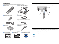 5
5
-
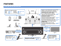 6
6
-
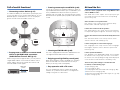 7
7
-
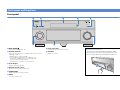 8
8
-
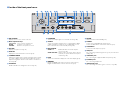 9
9
-
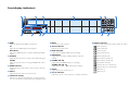 10
10
-
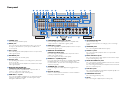 11
11
-
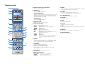 12
12
-
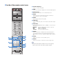 13
13
-
 14
14
-
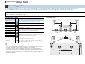 15
15
-
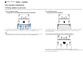 16
16
-
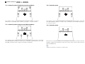 17
17
-
 18
18
-
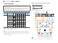 19
19
-
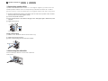 20
20
-
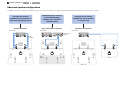 21
21
-
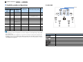 22
22
-
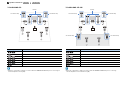 23
23
-
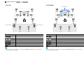 24
24
-
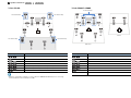 25
25
-
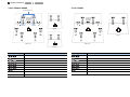 26
26
-
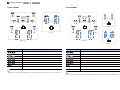 27
27
-
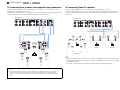 28
28
-
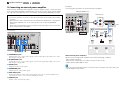 29
29
-
 30
30
-
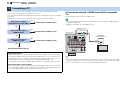 31
31
-
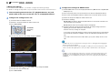 32
32
-
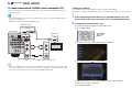 33
33
-
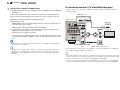 34
34
-
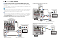 35
35
-
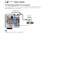 36
36
-
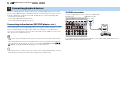 37
37
-
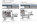 38
38
-
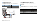 39
39
-
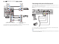 40
40
-
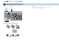 41
41
-
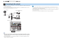 42
42
-
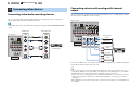 43
43
-
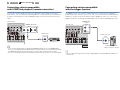 44
44
-
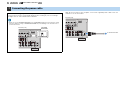 45
45
-
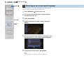 46
46
-
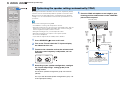 47
47
-
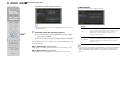 48
48
-
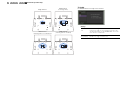 49
49
-
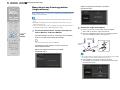 50
50
-
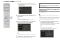 51
51
-
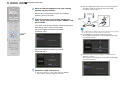 52
52
-
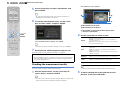 53
53
-
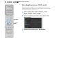 54
54
-
 55
55
-
 56
56
-
 57
57
-
 58
58
-
 59
59
-
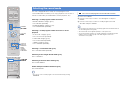 60
60
-
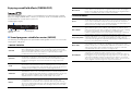 61
61
-
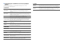 62
62
-
 63
63
-
 64
64
-
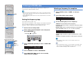 65
65
-
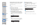 66
66
-
 67
67
-
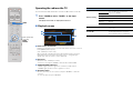 68
68
-
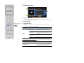 69
69
-
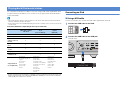 70
70
-
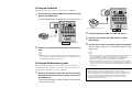 71
71
-
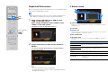 72
72
-
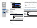 73
73
-
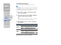 74
74
-
 75
75
-
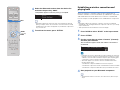 76
76
-
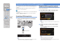 77
77
-
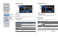 78
78
-
 79
79
-
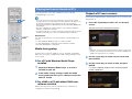 80
80
-
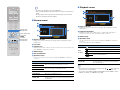 81
81
-
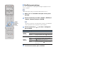 82
82
-
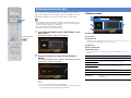 83
83
-
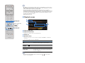 84
84
-
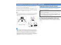 85
85
-
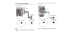 86
86
-
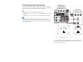 87
87
-
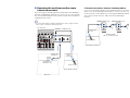 88
88
-
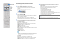 89
89
-
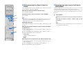 90
90
-
 91
91
-
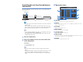 92
92
-
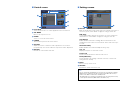 93
93
-
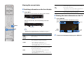 94
94
-
 95
95
-
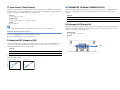 96
96
-
 97
97
-
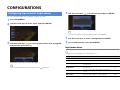 98
98
-
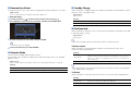 99
99
-
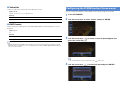 100
100
-
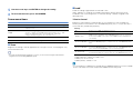 101
101
-
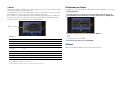 102
102
-
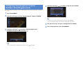 103
103
-
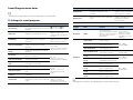 104
104
-
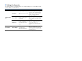 105
105
-
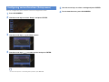 106
106
-
 107
107
-
 108
108
-
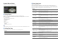 109
109
-
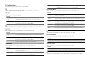 110
110
-
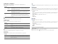 111
111
-
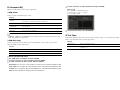 112
112
-
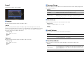 113
113
-
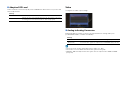 114
114
-
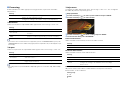 115
115
-
 116
116
-
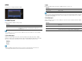 117
117
-
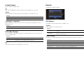 118
118
-
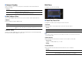 119
119
-
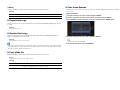 120
120
-
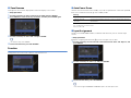 121
121
-
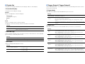 122
122
-
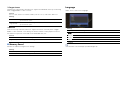 123
123
-
 124
124
-
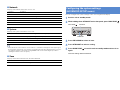 125
125
-
 126
126
-
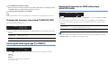 127
127
-
 128
128
-
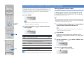 129
129
-
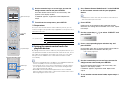 130
130
-
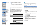 131
131
-
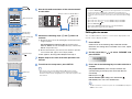 132
132
-
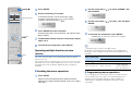 133
133
-
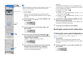 134
134
-
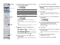 135
135
-
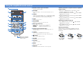 136
136
-
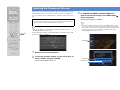 137
137
-
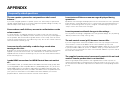 138
138
-
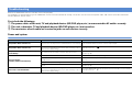 139
139
-
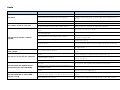 140
140
-
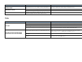 141
141
-
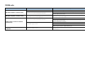 142
142
-
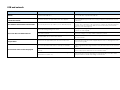 143
143
-
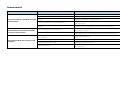 144
144
-
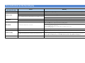 145
145
-
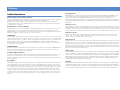 146
146
-
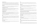 147
147
-
 148
148
-
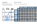 149
149
-
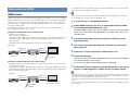 150
150
-
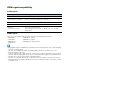 151
151
-
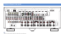 152
152
-
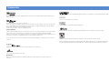 153
153
-
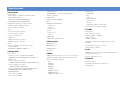 154
154
-
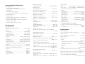 155
155
-
 156
156
-
 157
157


Yamaha RX-A3010 de handleiding
- Categorie
- AV-ontvangers
- Type
- de handleiding
in andere talen
- English: Yamaha RX-A3010 Owner's manual
- italiano: Yamaha RX-A3010 Manuale del proprietario
- русский: Yamaha RX-A3010 Инструкция по применению
- français: Yamaha RX-A3010 Le manuel du propriétaire
- español: Yamaha RX-A3010 El manual del propietario
- Deutsch: Yamaha RX-A3010 Bedienungsanleitung
- português: Yamaha RX-A3010 Manual do proprietário
- dansk: Yamaha RX-A3010 Brugervejledning
- suomi: Yamaha RX-A3010 Omistajan opas
- svenska: Yamaha RX-A3010 Bruksanvisning
- Türkçe: Yamaha RX-A3010 El kitabı
- română: Yamaha RX-A3010 Manualul proprietarului