Yamaha DSP1D de handleiding
- Categorie
- Muzikale uitrusting
- Type
- de handleiding

V480360 R3 1 IP 16
100 CR Printed in Japan
Owner’s Manual
-EX
E

2
Windows® is a registered trademark of Microsoft in the U.S.A. and other countries.
FCC INFORMATION (U.S.A.)
1. IMPORTANT NOTICE: DO NOT MODIFY THIS UNIT! This product, when installed as indicated in the instructions contained in this manual, meets FCC
requirements. Modifications not expressly approved by Yamaha may void your authority, granted by the FCC, to use the product.
2. IMPORTANT: When connecting this product to accessories and/or another product use only high quality shielded cables. Cable/s supplied with this product MUST
be used. Follow all installation instructions. Failure to follow instructions could void your FCC authorization to use this product in the USA.
3. NOTE: This product has been tested and found to comply with the requirements listed in FCC Regulations, Part 15 for Class “B” digital devices. Compliance with
these requirements provides a reasonable level of assurance that your use of this product in a residential environment will not result in harmful interference with
other electronic devices. This equipment generates/uses radio frequencies and, if not installed and used according to the instructions found in the users manual, may
cause interference harmful to the operation of other electronic devices. Compliance with FCC regulations does not guarantee that interference will not occur in all
installations. If this product is found to be the source of interference, which can be determined by turning the unit “OFF” and “ON”, please try to eliminate the
problem by using one of the following measures: Relocate either this product or the device that is being affected by the interference. Utilize power outlets that are on
different branch (circuit breaker or fuse) circuits or install AC line filter/s. In the case of radio or TV interference, relocate/reorient the antenna. If the antenna lead-in
is 300 ohm ribbon lead, change the lead-in to coaxial type cable. If these corrective measures do not produce satisfactory results, please contact the local retailer
authorized to distribute this type of product. If you can not locate the appropriate retailer, please contact Yamaha Corporation of America, Electronic Service
Division, 6600 Orangethorpe Ave, Buena Park, CA 90620
The above statements apply ONLY to those products distributed by Yamaha Corporation of America or its subsidiaries.
* This applies only to products distributed by YAMAHA
CORPORATION OF AMERICA.
COMPLIANCE INFORMATION STATEMENT
(DECLARATION OF CONFORMITY PROCEDURE)
Responsible Party : Yamaha Corporation of America
Address : 6600 Orangethorpe Ave., Buena Park, Calif. 90620
Telephone : 714-522-9011
Type of Equipment : DSP Unit
Model Name : DSP1D/DSP1D-EX
This device complies with Part 15 of the FCC Rules.
Operation is subject to the following two conditions:
1) this device may not cause harmful interference, and
2) this device must accept any interference received including interference
that may cause undesired operation.
See user manual instructions if interference to radio reception is sus-
pected.
(FCC DoC)
ADVARSEL!
Lithiumbatteri—Eksplosionsfare ved fejlagtig
håndtering. Udskiftning må kun ske med batteri
af samme fabrikat og type. Levér det brugte
batteri tilbage til leverandoren.
VARNING
Explosionsfara vid felaktigt batteribyte. Använd
samma batterityp eller en ekvivalent typ som
rekommenderas av apparattillverkaren.
Kassera använt batteri enligt fabrikantens
instruktion.
VAROITUS
Paristo voi räjähtää, jos se on virheellisesti
asennettu. Vaihda paristo ainoastaan
laitevalmistajan suosittelemaan tyyppiin. Hävitä
käytetty paristo valmistajan ohjeiden
mukaisesti.
WARNING: THIS APPARATUS MUST BE EARTHED
IMPORTANT
THE WIRES IN THIS MAINS LEAD ARE COLOURED IN
ACCORDANCE WITH THE FOLLOWING CODE:
GREEN-AND-YELLOW : EARTH
BLUE : NEUTRAL
BROWN : LIVE
As the colours of the wires in the mains lead of this apparatus may
not correspond with the coloured markings identifying the terminals in
your plug, proceed as follows:
The wire which is coloured GREEN and YELLOW must be
connected to the terminal in the plug which is marked by the letter E
or by the safety earth symbol or coloured GREEN and YELLOW.
The wire which is coloured BLUE must be connected to the terminal
which is marked with the letter N or coloured BLACK.
The wire which is coloured BROWN must be connected to the
terminal which is marked with the letter L or coloured RED.
* This applies only to products distributed by YAMAHA KEMBLE
MUSIC (U.K.) LTD.
NEDERLAND / THE NETHERLANDS
• Dit apparaat bevat een lithium batterij voor geheugen
back-up.
• This apparatus contains a lithium battery for memory
back-up.
• Raadpleeg uw leverancier over de verwijdering van de bat-
terij op het moment dat u het apparaat ann het einde van
de levensduur of gelieve dan contact op te nemen met de
vertegenwoordiging van Yamaha in uw land.
•For the removal of the battery at the moment of the dis-
posal at the end of life please consult your retailer or
Yamaha representative office in your country.
• Gooi de batterij niet weg, maar lever hem in als KCA.
• Do not throw away the battery. Instead, hand it in as small
chemical waste.
(lithium disposal)
* This applies only to products distributed by YAMAHA CORPORATION OF AMERICA. (Perchlorate)
This product contains a battery that contains perchlorate material.
Perchlorate Material—special handling may apply,
See www.dtsc.ca.gov/hazardouswaste/perchlorate.

3
■
Precautions
•Do not place a container with liquid or small metal
objects on top of this unit. Liquid or metal objects inside
this unit are a fire and electrical shock hazard.
•Do not allow water to enter this unit or allow the unit to
become wet. Fire or electrical shock may result.
•Connect this unit’s power cord only to an AC outlet of the
type stated in this Owner’s Manual or as marked on the
unit. Failure to do so is a fire and electrical shock hazard.
•Be sure to connect to an appropriate outlet with a protec-
tive grounding connection. Improper grounding can
result in electrical shock.
•Do not scratch, bend, twist, pull, or heat the power cord.
A damaged power cord is a fire and electrical shock haz-
ard.
•Do not place heavy objects, including this unit, on top of
the power cord. A damaged power cord is a fire and elec-
trical shock hazard. In particular, be careful not to place
heavy objects on a power cord covered by a carpet.
•Be sure to ground the unit to avoid the risk of electrical
shock
•If you notice any abnormality, such as smoke, odor, or
noise, or if a foreign object or liquid gets inside the unit,
turn it off immediately. Remove the power cord from the
AC outlet. Consult your dealer for repair. Using the unit
in this condition is a fire and electrical shock hazard.
• Should this unit/AC adapter/power supply be dropped or
the cabinet be damaged, turn the power switch off,
remove the power plug from the AC outlet, and contact
your dealer. If you continue using the unit without heed-
ing this instruction, fire or electrical shock may result.
•If the power cord is damaged (i.e., cut or a bare wire is
exposed), ask your dealer for a replacement. Using the
unit with a damaged power cord is a fire and electrical
shock hazard.
•Do not remove the unit’s cover. You could receive an
electrical shock. If you think internal inspection, mainte-
nance, or repair is necessary, contact your dealer.
•Do not modify the unit. Doing so is a fire and electrical
shock hazard.
•When setting up the product, make sure that the AC out-
let you are using is easily accessible. If some trouble or
malfunction occurs, immediately turn off the power
switch and disconnect the plug from the outlet. Even
when the power switch is turned off, electricity is still
flowing to the product at the minimum level. When you
are not using the product for a long time, make sure to
unplug the power cord from the wall AC outlet.
•When rack-mounting the unit, allow enough free space
around the unit for normal ventilation. This should be:
10 cm behind, and 20 cm above.
•For normal ventilation during use, remove the rear of the
rack or open a ventilation hole.
•If the airflow is not adequate, the unit will heat up inside
and may cause a fire.
•This unit has ventilation holes at the rear and bottom to
prevent the internal temperature rising too high. Do not
block them. Blocked ventilation holes are a fire hazard.
•Hold the power cord plug when disconnecting it from an
AC outlet. Never pull the cord. A damaged power cord is
a potential fire and electrical shock hazard.
•Do not touch the power plug with wet hands. Doing so is
a potential electrical shock hazard.
•The digital circuits of this unit may induce a slight noise
into nearby radios and TVs. If noise occurs, relocate the
affected equipment.
•If the message “WARNING LOW BATTERY!” appears
when you turn on this unit, contact your dealer as soon
as possible about replacing the internal data backup bat-
tery. The unit will still operate correctly, but data other
than the presets will be lost.
•Before you replace the battery, store your data to an ATA-
compliant PC flash storage card via the CS1D, or store
the data to the personal computer by connecting the
computer to the PC CONTROL “RS-232-C” connector
on the DSP1D/DSP1D-EX.
•The unit is equipped with the ground connector to avoid
the risk of electrical shock.
•Be sure to ground the unit before you insert the power
plug into an AC outlet.
•If the power cord has three pins and the ground connec-
tor on the AC outlet is grounded, the unit will be
grounded effectively.
Operating Notes
•The power must be turned on/off using the POWER
switch of this unit. Do not turn the power on/off by
plugging in the power cable, or by using a power strip or
circuit breaker. Doing so may cause malfunctions.
•Do not rapidly turn on and off the POWER switch of this
unit. Doing so may cause excessive current to damage the
system. You must allow at least five seconds to elapse
between power-on and power-off.
•For this unit, be sure to use a power voltage of the value
specified in the Specifications section of this Owner’s
Manual. If you apply a higher or lower voltage, a mal-
function may result.
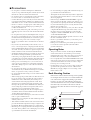
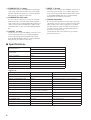
Rack Mounting Caution
If the unit is rack mounted and transported regularly,
for example, when on a tour, we recommend that the
rear of the unit be supported by fitting a pair metal
brackets, one each side. The following drawing pro-
vides the information necessary to make such brackets.
Note that only one bracket is shown here and the
bracket for the other side must be bent in the opposite
direction.
86.5
20.5
3.1
4-
ø
6.5
2-R2
R2
2-R2
R5
t = 1.6
(82.1)
76.2
44.45
31.75
5.9
0
36.5
14.5
7.5
8
0
12
134
200
0

4
The following optional boards can be installed in the DSP1D.
•
CIB1D :
Console interface board
•
EMB1D :
Engine management board
•
PDB1D :
Patch DSP board
•
GDB1D :
Group DSP board
•
EDB1D :
Effect DSP board
•
IDB1D :
Input DSP board
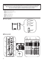
■
Front panel
■
Rear panel
Thank you for choosing the DSP unit “DSP1D/DSP1D-EX”, specifically designed for the Yamaha PM1D
digital audio mixing system. The DSP1D/DSP1D-EX is an engine controlled by the CS1D control surface.
Be sure to ask an authorized Yamaha service engineer to install the boards and
set up the unit. Never perform installation and setup by yourself.
POWER
ON/ OFF
A B
ENGINE ID
1 2
CONTROL I/O
48CH 96CH
INPUT
CONFIGURATION
POWER
ON/ OFF
A B
ENGINE ID
1 2
CONTROL I/O
48CH 96CH
INPUT
CONFIGURATION
1
2
3
4
22
22
IN
OUT
IN
2
OUT
IN
1
1IN531 975 31
2OUT6 4 2 10 8 6 4 2
OUT
THRU
PC
CONTROL
WORD CLOCK
TIME CODE IN
GPI
RS-422
REMOTE
IN
OUT
OFF
ON
RS-232-C
USB
75Ω
MIDI
OUTPUT INPUT
CONTROL I/O
CONSOLE
CONSOLE
I/O
CASCADE
DIGITAL I/O
1IN 531 975 31
2OUT 6 4 2 108 6 4 2
OUTPUT INPUT
CONSOLE
I/O
CASCADE
DIGITAL I/O
22
22
IN
OUT
IN
2
OUT
IN
1
OUT
THRU
PC
CONTROL
WORD CLOCK
TIME CODE IN
GPI
RS-422
REMOTE
IN
OUT
OFF
ON
RS-232-C
USB
75Ω
MIDI CONTROL I/O
CONSOLE
5
N OM
6
7
8
9
J
K
L
P

5
A
ENGINE ID A/B indicators
These indicators indicate whether the DSP1D/
DSP1D-EX is connected to the engine A or engine B
channel.
Indicator A lights up if the DSP1D/DSP1D-EX is con-
nected to the engine A channel jacks of the CS1D con-
trol surface (DIGITAL I/O jack A and CONTROL I/O
jack A). Indicator B lights up if the DSP1D/DSP1D-
EX is connected to the engine B channel jacks of the
CS1D control surface (DIGITAL I/O jack B and CON-
TROL I/O jack B).
Error indication
• If both ENGINE ID A and B indicators are flash-
ing:
→
There is a malfunction in the internal board
(PDB, GDB, IDB1/2, EDB, EMB, or CIB). Or
the necessary board does not exist.
• If either ENGINE ID A or B indicator is flashing:
→
During the Mirror mode operation, the
ENGINE ID indicator for the unused DSP1D/
DSP1D-EX flashes, indicating that the unit is in
standby mode.
→
If Indicator A is flashing, unit A is in standby
mode. If Indicator B is flashing, unit B is in
standby mode.
B
CONTROL I/O 1/2 indicators
These indicators indicate which one of two CON-
SOLE 1, 2 IN/OUT jacks (
8
) on the rear panel is cur-
rently effective.
Error indication
• If the CONTROL I/O 1 indicator is flashing:
→
Communication between the CS1D control
surface and the DSP1D is not established.The
CONSOLE 1, 2 IN OUT jacks or the PC CON-
TROL port is not connected correctly.
C
INPUT CONFIGURATION 48CH/96CH
indicators
These indicators indicate how many input channels
are currently available. On the DSP1D, the 48CH
indicator lights up. On the DSP1D-EX, the 96CH
indicator lights up.
Error indication
• If the INPUT CONFIGURATION 48CH is flashing:
→
The signal is not locking to the word clock.
D
POWER ON/OFF switch
Use this switch to turn the power to the DSP1D/
DSP1D-EX on or off. When the power is turned on,
the indicators
1
-
3
light up.
E
MIDI IN/OUT/THRU connectors
These connectors are used to transmit and receive
Program change messages, MMC, and other MIDI
messages among external MIDI devices.
F
PC CONTROL RS-232-C/USB ports
Connect these ports to a PC that runs Windows 2000
or Windows XP to control the PM1D system from the
PC. Use a D-sub, 9-pin cross cable (female to female)
to connect the RS-232-C port to the serial (COM)
port on the PC. Alternatively use a USB cable to con-
nect the USB port to the USB port on the PC.
G
WORD CLOCK IN jack, 75
Ω
ON/OFF
switch, and WORD CLOCK OUT jack
The WORD CLOCK IN jack is used to provide word
clock to the PM1D system from the connected exter-
nal device, such as a clock generator. Use the WORD
CLOCK OUT jack to provide the word clock to the
connected external device from the PM1D. Use a BNC
cable with an impedance of 75
Ω
for the WORD
CLOCK IN/OUT jacks.
The WORD CLOCK ON/OFF switch is used to termi-
nate the word clock connection. Basically, if the
DSP1D/DSP1D-EX is the last device of the word clock
chain, or if nothing is connected to the WORD
CLOCK IN/OUT jacks, set this switch to ON.
H
CONSOLE 1, 2 IN/OUT jacks
These jacks are connected to the CONTROL I/O
CONSOLE jacks of the CS1D control surface to trans-
mit or receive control signals. For connection, use a
genuine Yamaha cable or a BNC cable with an imped-
ance of 50
Ω
.
I
REMOTE RS-422 connector
This D-sub 9-pin connector is used to control a con-
nected tape recorder or a hard disk recorder. Serial
commands can be transmitted through this connector
to play or stop such a recorder.
J
GPI connector
This connector is used to connect an external device
that supports GPI (General Purpose Interface), such
as a video editor to control the external device from
the PM1D system or to perform certain functions of
the PM1D system while controlling from the external
device. You can connect a custom-made external
switch here.
K
TIME CODE IN connector
This balanced XLR3-31 connector receives SMPTE
time code (LTC) for analog input from the external
device. The rated input level is –10 dB, and the pin
assignment is as follows.
1=ground, 2=hot, 3=cold
Note:
When you turn on the power to the DSP1D/
DSP1D-EX and the CS1D, and communication
between the DSP1D/DSP1D-EX and the CS1D is
established, one of these two indicators lights up. If
neither one lights up, check the connection of the
CONSOLE 1, 2 IN OUT jacks on the rear panel.

6
L
CONSOLE I/O 1, 2 slots
Connect these slots to the DIGITAL I/O CONSOLE
jacks of the CS1D control surface to transmit multi-
channel digital audio signals. Use a genuine Yamaha
half-pitch 68-pin cable for connection.
M
CASCADE IN, OUT slots
Use one of these connectors to cascade two DSP1D/
DSP1D-EX units to transmit multi-channel digital
audio signals. Use a genuine Yamaha half-pitch 68-pin
cable to connect the CASCADE IN (or OUT) to the
CASCADE OUT (or IN) of another DSP1D/DSP1D-
EX.
N
OUTPUT 1–6 slot
Use these slots to connect the INPUT connectors of an
analog output unit AO8 series or DIO8 digital I/O
unit to output multi-channel digital audio signals
from the DSP1D/DSP1D-EX. Use a genuine Yamaha
half-pitch 68-pin cable for connection.
O
INPUT 1–10 slot
Use these slots to connect the OUTPUT connectors of
an analog input unit AI8 series or DIO8 digital I/O
unit series to input multi-channel digital audio signals
to the DSP1D/DSP1D-EX. Use a genuine Yamaha
half-pitch 68-pin cable for connection.
P
Ground connector
Be sure to ground the unit to avoid the risk of electrical
shock before you insert the power plug into an AC outlet.
This product comes with a 3-pin power cord. If the
ground connector of the AC outlet has already been
grounded, the unit will be grounded effectively by
using the 3-pin power cord.
Grounding the unit is also effective for preventing
hum and other noise.
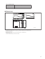
■
Specifications
Digital I/Os
Sampling frequency
<External sync> 39.69 kHz – 50.88 kHz
<Internal sync> 44.1 kHz, 48 kHz
Power supply
USA and Canada : 120 V, 60 Hz
Others : 230 V, 50 Hz
Power consumption 170 W
Dimensions (W
×
H
×
D) 480 mm
×
408.7
mm
×
460.8 mm
Weight 33 kg
Operating temperature 10 – 35˚C
Fan circuit always fixed
Accessories power cable 2.5 m
×
1
I/O connectors Level Type
DIGITAL I/O INPUT 1 –10 RS-422 D-sub, half-pitch, 68-pin connector (female)
×
10
DIGITAL I/O OUTPUT 1 – 6 RS-422 D-sub, half-pitch, 68-pin connector (female)
×
6
DIGITAL I/O CASCADE IN, OUT RS-422 D-sub, half-pitch, 68-pin connector (female)
×
2
DIGITAL I/O CONSOLE I/O 1, 2 RS-422 D-sub, half-pitch, 68-pin connector (female)
×
2
CONTROL I/O CONSOLE 1 IN, OUT –0.225V — –1.825V/50
Ω
BNC connector
×
2
CONTROL I/O CONSOLE 2 IN, OUT –0.225V — –1.825V/50
Ω
BNC connector
×
2
REMOTE RS-422 RS-422 D-sub, 9-pin connector (female)
GPI
C-MOS IN, Open collector OUT
1 pin: 150mA, 8pin total: 500mA
D-sub, 25-pin connector (female)
TIME CODE IN SMPTE format, Nominal –10 dB/10 k
Ω
XLR-3-31 type connector
MIDI IN, OUT, THRU MIDI format 5-pin DIN connector
×
3
PC CONTROL RS-232-C RS-232-C D-sub, 9-pin connector (male)
PC CONTROL USB 0V — 3.3V B type USB connector
WORD CLOCK IN TTL/75
Ω
(ON/OFF) BNC connector
WORD CLOCK OUT TTL/75
Ω
BNC connector

7
Slots (for IDB1D board)
■
Dimensions
•Specifications and appearance are subject to change without notice for improvement.
•For European Model
Purchaser/User information specified in EN55103-1 and EN55103-2.
Inrush Current: 31A
Conformed Environment: E1, E2, E3 and E4.
Unit Input channel
DPS1D INPUT 1-48 & ST IN 1-4
*
*The DSP1D has an empty slot available for the IDB1D board.
DPS1D-EX INPUT 1-96 & ST IN 1-8 (DSP1D + IDB1D for expansion)
POWER
ON/ OFF
A B
ENGINE ID
1 2
CONTROL I/O
48CH 96CH
INPUT
CONFIGURATION
460.8
450
480
399.2
408.7
9.5
unit: mm

For details of products, please contact your nearest Yamaha
representative or the authorized distributor listed below.
Pour plus de détails sur les produits, veuillez-vous adresser à Yamaha ou
au distributeur le plus proche de vous figurant dans la liste suivante.
Die Einzelheiten zu Produkten sind bei Ihrer unten aufgeführten
Niederlassung und bei Yamaha Vertragshändlern in den jeweiligen
Bestimmungsländern erhältlich.
Para detalles sobre productos, contacte su tienda Yamaha más cercana
o el distribuidor autorizado que se lista debajo.
CANADA
Yamaha Canada Music Ltd.
135 Milner Avenue, Scarborough, Ontario,
M1S 3R1, Canada
Tel: 416-298-1311
U.S.A.
Yamaha Corporation of America
6600 Orangethorpe Ave., Buena Park, Calif. 90620,
U.S.A.
Tel: 714-522-9011
MEXICO
Yamaha de México S.A. de C.V.
Calz. Javier Rojo Gómez #1149,
Col. Guadalupe del Moral
C.P. 09300, México, D.F., México
Tel: 55-5804-0600
BRAZIL
Yamaha Musical do Brasil Ltda.
Rua Joaquim Floriano, 913 - 4' andar, Itaim Bibi,
CEP 04534-013 Sao Paulo, SP. BRAZIL
Tel: 011-3704-1377
ARGENTINA
Yamaha Music Latin America, S.A.
Sucursal de Argentina
Viamonte 1145 Piso2-B 1053,
Buenos Aires, Argentina
Tel: 1-4371-7021
PANAMA AND OTHER LATIN
AMERICAN COUNTRIES/
CARIBBEAN COUNTRIES
Yamaha Music Latin America, S.A.
Torre Banco General, Piso 7, Urbanización Marbella,
Calle 47 y Aquilino de la Guardia,
Ciudad de Panamá, Panamá
Tel: +507-269-5311
THE UNITED KINGDOM
Yamaha-Kemble Music (U.K.) Ltd.
Sherbourne Drive, Tilbrook, Milton Keynes,
MK7 8BL, England
Tel: 01908-366700
GERMANY
Yamaha Music Central Europe GmbH
Siemensstraße 22-34, 25462 Rellingen, Germany
Tel: 04101-3030
SWITZERLAND/LIECHTENSTEIN
Yamaha Music Central Europe GmbH,
Branch Switzerland
Seefeldstrasse 94, 8008 Zürich, Switzerland
Tel: 01-383 3990
AUSTRIA
Yamaha Music Central Europe GmbH,
Branch Austria
Schleiergasse 20, A-1100 Wien, Austria
Tel: 01-60203900
CZECH REPUBLIC/SLOVAKIA/
HUNGARY/SLOVENIA
Yamaha Music Central Europe GmbH,
Branch Austria, CEE Department
Schleiergasse 20, A-1100 Wien, Austria
Tel: 01-602039025
POLAND
Yamaha Music Central Europe GmbH
Sp.z. o.o. Oddzial w Polsce
ul. 17 Stycznia 56, PL-02-146 Warszawa, Poland
Tel: 022-868-07-57
THE NETHERLANDS/
BELGIUM/LUXEMBOURG
Yamaha Music Central Europe GmbH,
Branch Benelux
Clarissenhof 5-b, 4133 AB Vianen, The Netherlands
Tel: 0347-358 040
FRANCE
Yamaha Musique France
BP 70-77312 Marne-la-Vallée Cedex 2, France
Tel: 01-64-61-4000
ITALY
Yamaha Musica Italia S.P.A.
Combo Division
Viale Italia 88, 20020 Lainate (Milano), Italy
Tel: 02-935-771
SPAIN/PORTUGAL
Yamaha-Hazen Música, S.A.
Ctra. de la Coruna km. 17, 200, 28230
Las Rozas (Madrid), Spain
Tel: 91-639-8888
SWEDEN
Yamaha Scandinavia AB
J. A. Wettergrens Gata 1
Box 30053
S-400 43 Göteborg, Sweden
Tel: 031 89 34 00
DENMARK
YS Copenhagen Liaison Office
Generatorvej 6A
DK-2730 Herlev, Denmark
Tel: 44 92 49 00
NORWAY
Norsk filial av Yamaha Scandinavia AB
Grini Næringspark 1
N-1345 Østerås, Norway
Tel: 67 16 77 70
OTHER EUROPEAN COUNTRIES
Yamaha Music Central Europe GmbH
Siemensstraße 22-34, 25462 Rellingen, Germany
Tel: +49-4101-3030
Yamaha Corporation,
Asia-Pacific Music Marketing Group
Nakazawa-cho 10-1, Naka-ku, Hamamatsu,
Japan 430-8650
Tel: +81-53-460-2313
TURKEY/CYPRUS
Yamaha Music Central Europe GmbH
Siemensstraße 22-34, 25462 Rellingen, Germany
Tel: 04101-3030
OTHER COUNTRIES
Yamaha Music Gulf FZE
LOB 16-513, P.O.Box 17328, Jubel Ali,
Dubai, United Arab Emirates
Tel: +971-4-881-5868
THE PEOPLE’S REPUBLIC OF CHINA
Yamaha Music & Electronics (China) Co.,Ltd.
25/F., United Plaza, 1468 Nanjing Road (West),
Jingan, Shanghai, China
Tel: 021-6247-2211
INDONESIA
PT. Yamaha Music Indonesia (Distributor)
PT. Nusantik
Gedung Yamaha Music Center, Jalan Jend. Gatot
Subroto Kav. 4, Jakarta 12930, Indonesia
Tel: 21-520-2577
KOREA
Yamaha Music Korea Ltd.
8F, 9F, Dongsung Bldg. 158-9 Samsung-Dong,
Kangnam-Gu, Seoul, Korea
Tel: 080-004-0022
MALAYSIA
Yamaha Music Malaysia, Sdn., Bhd.
Lot 8, Jalan Perbandaran, 47301 Kelana Jaya,
Petaling Jaya, Selangor, Malaysia
Tel: 3-78030900
SINGAPORE
Yamaha Music Asia Pte., Ltd.
#03-11 A-Z Building
140 Paya Lebor Road, Singapore 409015
Tel: 747-4374
TAIWAN
Yamaha KHS Music Co., Ltd.
3F, #6, Sec.2, Nan Jing E. Rd. Taipei.
Taiwan 104, R.O.C.
Tel: 02-2511-8688
THAILAND
Siam Music Yamaha Co., Ltd.
891/1 Siam Motors Building, 15-16 floor
Rama 1 road, Wangmai, Pathumwan
Bangkok 10330, Thailand
Tel: 02-215-2626
OTHER ASIAN COUNTRIES
Yamaha Corporation,
Asia-Pacific Music Marketing Group
Nakazawa-cho 10-1, Naka-ku, Hamamatsu,
Japan 430-8650
Tel: +81-53-460-2317
AUSTRALIA
Yamaha Music Australia Pty. Ltd.
Level 1, 99 Queensbridge Street, Southbank,
Victoria 3006, Australia
Tel: 3-9693-5111
COUNTRIES AND TRUST
TERRITORIES IN PACIFIC OCEAN
Yamaha Corporation,
Asia-Pacific Music Marketing Group
Nakazawa-cho 10-1, Naka-ku, Hamamatsu,
Japan 430-8650
Tel: +81-53-460-2313
NORTH AMERICA
CENTRAL & SOUTH AMERICA
EUROPE
AFRICA
MIDDLE EAST
ASIA
OCEANIA
HEAD OFFICE Yamaha Corporation, Pro Audio & Digital Musical Instrument Division
Nakazawa-cho 10-1, Naka-ku, Hamamatsu, Japan 430-8650
Tel: +81-53-460-2441
PA17
U.R.G., Pro Audio & Digital Musical Instrument Division, Yamaha Corporation
© 2001 Yamaha Corporation
Documenttranscriptie
-EX Owner’s Manual V480360 R3 1 IP 16 100 CR Printed in Japan E FCC INFORMATION (U.S.A.) 1. IMPORTANT NOTICE: DO NOT MODIFY THIS UNIT! This product, when installed as indicated in the instructions contained in this manual, meets FCC requirements. Modifications not expressly approved by Yamaha may void your authority, granted by the FCC, to use the product. 2. IMPORTANT: When connecting this product to accessories and/or another product use only high quality shielded cables. Cable/s supplied with this product MUST be used. Follow all installation instructions. Failure to follow instructions could void your FCC authorization to use this product in the USA. 3. NOTE: This product has been tested and found to comply with the requirements listed in FCC Regulations, Part 15 for Class “B” digital devices. Compliance with these requirements provides a reasonable level of assurance that your use of this product in a residential environment will not result in harmful interference with other electronic devices. This equipment generates/uses radio frequencies and, if not installed and used according to the instructions found in the users manual, may cause interference harmful to the operation of other electronic devices. Compliance with FCC regulations does not guarantee that interference will not occur in all installations. If this product is found to be the source of interference, which can be determined by turning the unit “OFF” and “ON”, please try to eliminate the problem by using one of the following measures: Relocate either this product or the device that is being affected by the interference. Utilize power outlets that are on different branch (circuit breaker or fuse) circuits or install AC line filter/s. In the case of radio or TV interference, relocate/reorient the antenna. If the antenna lead-in is 300 ohm ribbon lead, change the lead-in to coaxial type cable. If these corrective measures do not produce satisfactory results, please contact the local retailer authorized to distribute this type of product. If you can not locate the appropriate retailer, please contact Yamaha Corporation of America, Electronic Service Division, 6600 Orangethorpe Ave, Buena Park, CA 90620 The above statements apply ONLY to those products distributed by Yamaha Corporation of America or its subsidiaries. ADVARSEL! Lithiumbatteri—Eksplosionsfare ved fejlagtig håndtering. Udskiftning må kun ske med batteri af samme fabrikat og type. Levér det brugte batteri tilbage til leverandoren. COMPLIANCE INFORMATION STATEMENT (DECLARATION OF CONFORMITY PROCEDURE) Responsible Party : Address : Telephone : Type of Equipment : Model Name : Yamaha Corporation of America 6600 Orangethorpe Ave., Buena Park, Calif. 90620 714-522-9011 DSP Unit DSP1D/DSP1D-EX VARNING Explosionsfara vid felaktigt batteribyte. Använd samma batterityp eller en ekvivalent typ som rekommenderas av apparattillverkaren. Kassera använt batteri enligt fabrikantens instruktion. This device complies with Part 15 of the FCC Rules. Operation is subject to the following two conditions: 1) this device may not cause harmful interference, and 2) this device must accept any interference received including interference that may cause undesired operation. See user manual instructions if interference to radio reception is suspected. * This applies only to products distributed by YAMAHA CORPORATION OF AMERICA. (FCC DoC) WARNING: THIS APPARATUS MUST BE EARTHED IMPORTANT THE WIRES IN THIS MAINS LEAD ARE COLOURED IN ACCORDANCE WITH THE FOLLOWING CODE: GREEN-AND-YELLOW : EARTH BLUE : NEUTRAL BROWN : LIVE As the colours of the wires in the mains lead of this apparatus may not correspond with the coloured markings identifying the terminals in your plug, proceed as follows: The wire which is coloured GREEN and YELLOW must be connected to the terminal in the plug which is marked by the letter E or by the safety earth symbol or coloured GREEN and YELLOW. The wire which is coloured BLUE must be connected to the terminal which is marked with the letter N or coloured BLACK. VAROITUS Paristo voi räjähtää, jos se on virheellisesti asennettu. Vaihda paristo ainoastaan laitevalmistajan suosittelemaan tyyppiin. Hävitä käytetty paristo valmistajan ohjeiden mukaisesti. NEDERLAND / THE NETHERLANDS • Dit apparaat bevat een lithium batterij voor geheugen back-up. • This apparatus contains a lithium battery for memory back-up. • Raadpleeg uw leverancier over de verwijdering van de batterij op het moment dat u het apparaat ann het einde van de levensduur of gelieve dan contact op te nemen met de vertegenwoordiging van Yamaha in uw land. • For the removal of the battery at the moment of the disposal at the end of life please consult your retailer or Yamaha representative office in your country. • Gooi de batterij niet weg, maar lever hem in als KCA. • Do not throw away the battery. Instead, hand it in as small chemical waste. (lithium disposal) The wire which is coloured BROWN must be connected to the terminal which is marked with the letter L or coloured RED. * This applies only to products distributed by YAMAHA KEMBLE MUSIC (U.K.) LTD. This product contains a battery that contains perchlorate material. Perchlorate Material—special handling may apply, See www.dtsc.ca.gov/hazardouswaste/perchlorate. * This applies only to products distributed by YAMAHA CORPORATION OF AMERICA. (Perchlorate) Windows® is a registered trademark of Microsoft in the U.S.A. and other countries. 2 ■ Precautions • Do not touch the power plug with wet hands. Doing so is a potential electrical shock hazard. • The digital circuits of this unit may induce a slight noise into nearby radios and TVs. If noise occurs, relocate the affected equipment. • If the message “WARNING LOW BATTERY!” appears when you turn on this unit, contact your dealer as soon as possible about replacing the internal data backup battery. The unit will still operate correctly, but data other than the presets will be lost. • Before you replace the battery, store your data to an ATAcompliant PC flash storage card via the CS1D, or store the data to the personal computer by connecting the computer to the PC CONTROL “RS-232-C” connector on the DSP1D/DSP1D-EX. • The unit is equipped with the ground connector to avoid the risk of electrical shock. • Be sure to ground the unit before you insert the power plug into an AC outlet. • If the power cord has three pins and the ground connector on the AC outlet is grounded, the unit will be grounded effectively. Operating Notes • The power must be turned on/off using the POWER switch of this unit. Do not turn the power on/off by plugging in the power cable, or by using a power strip or circuit breaker. Doing so may cause malfunctions. • Do not rapidly turn on and off the POWER switch of this unit. Doing so may cause excessive current to damage the system. You must allow at least five seconds to elapse between power-on and power-off. • For this unit, be sure to use a power voltage of the value specified in the Specifications section of this Owner’s Manual. If you apply a higher or lower voltage, a malfunction may result. Rack Mounting Caution If the unit is rack mounted and transported regularly, for example, when on a tour, we recommend that the rear of the unit be supported by fitting a pair metal brackets, one each side. The following drawing provides the information necessary to make such brackets. Note that only one bracket is shown here and the bracket for the other side must be bent in the opposite direction. 2-R2 2-R2 (82.1) 76.2 86.5 44.45 200 R2 134 3.1 R5 0 8 12 0 7.5 14.5 0 5.9 4- ø 6.5 20.5 31.75 36.5 • Do not place a container with liquid or small metal objects on top of this unit. Liquid or metal objects inside this unit are a fire and electrical shock hazard. • Do not allow water to enter this unit or allow the unit to become wet. Fire or electrical shock may result. • Connect this unit’s power cord only to an AC outlet of the type stated in this Owner’s Manual or as marked on the unit. Failure to do so is a fire and electrical shock hazard. • Be sure to connect to an appropriate outlet with a protective grounding connection. Improper grounding can result in electrical shock. • Do not scratch, bend, twist, pull, or heat the power cord. A damaged power cord is a fire and electrical shock hazard. • Do not place heavy objects, including this unit, on top of the power cord. A damaged power cord is a fire and electrical shock hazard. In particular, be careful not to place heavy objects on a power cord covered by a carpet. • Be sure to ground the unit to avoid the risk of electrical shock • If you notice any abnormality, such as smoke, odor, or noise, or if a foreign object or liquid gets inside the unit, turn it off immediately. Remove the power cord from the AC outlet. Consult your dealer for repair. Using the unit in this condition is a fire and electrical shock hazard. • Should this unit/AC adapter/power supply be dropped or the cabinet be damaged, turn the power switch off, remove the power plug from the AC outlet, and contact your dealer. If you continue using the unit without heeding this instruction, fire or electrical shock may result. • If the power cord is damaged (i.e., cut or a bare wire is exposed), ask your dealer for a replacement. Using the unit with a damaged power cord is a fire and electrical shock hazard. • Do not remove the unit’s cover. You could receive an electrical shock. If you think internal inspection, maintenance, or repair is necessary, contact your dealer. • Do not modify the unit. Doing so is a fire and electrical shock hazard. • When setting up the product, make sure that the AC outlet you are using is easily accessible. If some trouble or malfunction occurs, immediately turn off the power switch and disconnect the plug from the outlet. Even when the power switch is turned off, electricity is still flowing to the product at the minimum level. When you are not using the product for a long time, make sure to unplug the power cord from the wall AC outlet. • When rack-mounting the unit, allow enough free space around the unit for normal ventilation. This should be: 10 cm behind, and 20 cm above. • For normal ventilation during use, remove the rear of the rack or open a ventilation hole. • If the airflow is not adequate, the unit will heat up inside and may cause a fire. • This unit has ventilation holes at the rear and bottom to prevent the internal temperature rising too high. Do not block them. Blocked ventilation holes are a fire hazard. • Hold the power cord plug when disconnecting it from an AC outlet. Never pull the cord. A damaged power cord is a potential fire and electrical shock hazard. t = 1.6 3 Thank you for choosing the DSP unit “DSP1D/DSP1D-EX”, specifically designed for the Yamaha PM1D digital audio mixing system. The DSP1D/DSP1D-EX is an engine controlled by the CS1D control surface. Be sure to ask an authorized Yamaha service engineer to install the boards and set up the unit. Never perform installation and setup by yourself. The following optional boards can be installed in the DSP1D. • • • • • • CIB1D : Console interface board EMB1D : Engine management board PDB1D : Patch DSP board GDB1D : Group DSP board EDB1D : Effect DSP board IDB1D : Input DSP board ■ Front panel ENGINE ID A 1 B CONTROL I/O 1 ENGINE ID A 2 2 B CONTROL I/O 1 INPUT CONFIGURATION 2 INPUT CONFIGURATION 48CH 96CH 3 POWER ON/ OFF 48CH 96CH POWER ON/ OFF 4 ■ Rear panel MIDI CONTROL I/O L M CONSOLE 1 N O IN DIGITAL I/O IN 5 OUT 8 OUT OUTPUT INPUT CONSOLE I/O CASCADE 1 IN 5 3 1 9 7 5 3 1 2 OUT 6 4 2 10 8 6 4 2 2 IN THRU OUT MIDI DIGITAL I/O CONTROL I/O CONSOLE PC CONTROL OUTPUT INPUT CONSOLE I/O CASCADE 1 IN 5 3 1 9 7 5 3 1 2 OUT 6 4 2 10 8 6 4 2 1 IN IN OUT OUT REMOTE 2 IN THRU OUT PC CONTROL REMOTE RS-232-C RS-422 USB 2 9 2 RS-422 2 RS-232-C 2 6 GPI WORD CLOCK IN 75Ω OFF ON 2 2 2 2 TIME CODE IN USB OUT GPI WORD CLOCK J IN 7 75Ω OFF ON TIME CODE IN OUT K P 4 A ENGINE ID A/B indicators These indicators indicate whether the DSP1D/ DSP1D-EX is connected to the engine A or engine B channel. Indicator A lights up if the DSP1D/DSP1D-EX is connected to the engine A channel jacks of the CS1D control surface (DIGITAL I/O jack A and CONTROL I/O jack A). Indicator B lights up if the DSP1D/DSP1DEX is connected to the engine B channel jacks of the CS1D control surface (DIGITAL I/O jack B and CONTROL I/O jack B). Error indication • If both ENGINE ID A and B indicators are flashing: → There is a malfunction in the internal board (PDB, GDB, IDB1/2, EDB, EMB, or CIB). Or the necessary board does not exist. • If either ENGINE ID A or B indicator is flashing: → During the Mirror mode operation, the ENGINE ID indicator for the unused DSP1D/ DSP1D-EX flashes, indicating that the unit is in standby mode. → If Indicator A is flashing, unit A is in standby mode. If Indicator B is flashing, unit B is in standby mode. B CONTROL I/O 1/2 indicators These indicators indicate which one of two CONSOLE 1, 2 IN/OUT jacks (8) on the rear panel is currently effective. Note: When you turn on the power to the DSP1D/ DSP1D-EX and the CS1D, and communication between the DSP1D/DSP1D-EX and the CS1D is established, one of these two indicators lights up. If neither one lights up, check the connection of the CONSOLE 1, 2 IN OUT jacks on the rear panel. Error indication • If the CONTROL I/O 1 indicator is flashing: → Communication between the CS1D control surface and the DSP1D is not established.The CONSOLE 1, 2 IN OUT jacks or the PC CONTROL port is not connected correctly. C INPUT CONFIGURATION 48CH/96CH indicators These indicators indicate how many input channels are currently available. On the DSP1D, the 48CH indicator lights up. On the DSP1D-EX, the 96CH indicator lights up. Error indication • If the INPUT CONFIGURATION 48CH is flashing: → The signal is not locking to the word clock. D POWER ON/OFF switch Use this switch to turn the power to the DSP1D/ DSP1D-EX on or off. When the power is turned on, the indicators 1 - 3 light up. E MIDI IN/OUT/THRU connectors These connectors are used to transmit and receive Program change messages, MMC, and other MIDI messages among external MIDI devices. F PC CONTROL RS-232-C/USB ports Connect these ports to a PC that runs Windows 2000 or Windows XP to control the PM1D system from the PC. Use a D-sub, 9-pin cross cable (female to female) to connect the RS-232-C port to the serial (COM) port on the PC. Alternatively use a USB cable to connect the USB port to the USB port on the PC. G WORD CLOCK IN jack, 75 Ω ON/OFF switch, and WORD CLOCK OUT jack The WORD CLOCK IN jack is used to provide word clock to the PM1D system from the connected external device, such as a clock generator. Use the WORD CLOCK OUT jack to provide the word clock to the connected external device from the PM1D. Use a BNC cable with an impedance of 75 Ω for the WORD CLOCK IN/OUT jacks. The WORD CLOCK ON/OFF switch is used to terminate the word clock connection. Basically, if the DSP1D/DSP1D-EX is the last device of the word clock chain, or if nothing is connected to the WORD CLOCK IN/OUT jacks, set this switch to ON. H CONSOLE 1, 2 IN/OUT jacks These jacks are connected to the CONTROL I/O CONSOLE jacks of the CS1D control surface to transmit or receive control signals. For connection, use a genuine Yamaha cable or a BNC cable with an impedance of 50 Ω. I REMOTE RS-422 connector This D-sub 9-pin connector is used to control a connected tape recorder or a hard disk recorder. Serial commands can be transmitted through this connector to play or stop such a recorder. J GPI connector This connector is used to connect an external device that supports GPI (General Purpose Interface), such as a video editor to control the external device from the PM1D system or to perform certain functions of the PM1D system while controlling from the external device. You can connect a custom-made external switch here. K TIME CODE IN connector This balanced XLR3-31 connector receives SMPTE time code (LTC) for analog input from the external device. The rated input level is –10 dB, and the pin assignment is as follows. 1=ground, 2=hot, 3=cold 5 L CONSOLE I/O 1, 2 slots O INPUT 1–10 slot Connect these slots to the DIGITAL I/O CONSOLE jacks of the CS1D control surface to transmit multichannel digital audio signals. Use a genuine Yamaha half-pitch 68-pin cable for connection. Use these slots to connect the OUTPUT connectors of an analog input unit AI8 series or DIO8 digital I/O unit series to input multi-channel digital audio signals to the DSP1D/DSP1D-EX. Use a genuine Yamaha half-pitch 68-pin cable for connection. M CASCADE IN, OUT slots Use one of these connectors to cascade two DSP1D/ DSP1D-EX units to transmit multi-channel digital audio signals. Use a genuine Yamaha half-pitch 68-pin cable to connect the CASCADE IN (or OUT) to the CASCADE OUT (or IN) of another DSP1D/DSP1DEX. P Ground connector N OUTPUT 1–6 slot Use these slots to connect the INPUT connectors of an analog output unit AO8 series or DIO8 digital I/O unit to output multi-channel digital audio signals from the DSP1D/DSP1D-EX. Use a genuine Yamaha half-pitch 68-pin cable for connection. ■ Be sure to ground the unit to avoid the risk of electrical shock before you insert the power plug into an AC outlet. This product comes with a 3-pin power cord. If the ground connector of the AC outlet has already been grounded, the unit will be grounded effectively by using the 3-pin power cord. Grounding the unit is also effective for preventing hum and other noise. Specifications Sampling frequency Power supply <External sync> 39.69 kHz – 50.88 kHz <Internal sync> 44.1 kHz, 48 kHz USA and Canada : 120 V, 60 Hz Others : 230 V, 50 Hz Power consumption 170 W Dimensions (W × H × D) 480 mm × 408.7 mm × 460.8 mm Weight 33 kg Operating temperature 10 – 35˚C Fan circuit always fixed Accessories power cable 2.5 m × 1 Digital I/Os I/O connectors 6 Level Type DIGITAL I/O INPUT 1 –10 RS-422 D-sub, half-pitch, 68-pin connector (female) × 10 DIGITAL I/O OUTPUT 1 – 6 RS-422 D-sub, half-pitch, 68-pin connector (female) × 6 DIGITAL I/O CASCADE IN, OUT RS-422 D-sub, half-pitch, 68-pin connector (female) × 2 DIGITAL I/O CONSOLE I/O 1, 2 RS-422 D-sub, half-pitch, 68-pin connector (female) × 2 CONTROL I/O CONSOLE 1 IN, OUT –0.225V — –1.825V/50 Ω BNC connector × 2 CONTROL I/O CONSOLE 2 IN, OUT –0.225V — –1.825V/50 Ω BNC connector × 2 REMOTE RS-422 RS-422 D-sub, 9-pin connector (female) GPI C-MOS IN, Open collector OUT 1 pin: 150mA, 8pin total: 500mA D-sub, 25-pin connector (female) TIME CODE IN SMPTE format, Nominal –10 dB/10 kΩ XLR-3-31 type connector MIDI IN, OUT, THRU MIDI format 5-pin DIN connector × 3 PC CONTROL RS-232-C RS-232-C D-sub, 9-pin connector (male) PC CONTROL USB 0V — 3.3V B type USB connector WORD CLOCK IN TTL/75 Ω (ON/OFF) BNC connector WORD CLOCK OUT TTL/75 Ω BNC connector Slots (for IDB1D board) Unit Input channel DPS1D INPUT 1-48 & ST IN 1-4* DPS1D-EX INPUT 1-96 & ST IN 1-8 (DSP1D + IDB1D for expansion) *The DSP1D has an empty slot available for the IDB1D board. 460.8 Dimensions 450 ■ 480 ENGINE ID A B CONTROL I/O 1 2 INPUT CONFIGURATION 48CH 96CH 408.7 9.5 399.2 POWER ON/ OFF unit: mm • Specifications and appearance are subject to change without notice for improvement. • For European Model Purchaser/User information specified in EN55103-1 and EN55103-2. Inrush Current: 31A Conformed Environment: E1, E2, E3 and E4. 7 For details of products, please contact your nearest Yamaha representative or the authorized distributor listed below. Pour plus de détails sur les produits, veuillez-vous adresser à Yamaha ou au distributeur le plus proche de vous figurant dans la liste suivante. NORTH AMERICA CANADA Yamaha Canada Music Ltd. 135 Milner Avenue, Scarborough, Ontario, M1S 3R1, Canada Tel: 416-298-1311 U.S.A. Yamaha Corporation of America 6600 Orangethorpe Ave., Buena Park, Calif. 90620, U.S.A. Tel: 714-522-9011 Die Einzelheiten zu Produkten sind bei Ihrer unten aufgeführten Niederlassung und bei Yamaha Vertragshändlern in den jeweiligen Bestimmungsländern erhältlich. Para detalles sobre productos, contacte su tienda Yamaha más cercana o el distribuidor autorizado que se lista debajo. ASIA POLAND Yamaha Music Central Europe GmbH Sp.z. o.o. Oddzial w Polsce ul. 17 Stycznia 56, PL-02-146 Warszawa, Poland Tel: 022-868-07-57 THE NETHERLANDS/ BELGIUM/LUXEMBOURG Yamaha Music Central Europe GmbH, Branch Benelux Clarissenhof 5-b, 4133 AB Vianen, The Netherlands Tel: 0347-358 040 FRANCE CENTRAL & SOUTH AMERICA MEXICO Yamaha de México S.A. de C.V. Calz. Javier Rojo Gómez #1149, Col. Guadalupe del Moral C.P. 09300, México, D.F., México Tel: 55-5804-0600 BRAZIL Yamaha Musical do Brasil Ltda. Rua Joaquim Floriano, 913 - 4' andar, Itaim Bibi, CEP 04534-013 Sao Paulo, SP. BRAZIL Tel: 011-3704-1377 ARGENTINA Yamaha Music Latin America, S.A. Sucursal de Argentina Viamonte 1145 Piso2-B 1053, Buenos Aires, Argentina Tel: 1-4371-7021 PANAMA AND OTHER LATIN AMERICAN COUNTRIES/ CARIBBEAN COUNTRIES Yamaha Music Latin America, S.A. Torre Banco General, Piso 7, Urbanización Marbella, Calle 47 y Aquilino de la Guardia, Ciudad de Panamá, Panamá Tel: +507-269-5311 EUROPE THE UNITED KINGDOM Yamaha-Kemble Music (U.K.) Ltd. Sherbourne Drive, Tilbrook, Milton Keynes, MK7 8BL, England Tel: 01908-366700 GERMANY Yamaha Music Central Europe GmbH Siemensstraße 22-34, 25462 Rellingen, Germany Tel: 04101-3030 SWITZERLAND/LIECHTENSTEIN Yamaha Music Central Europe GmbH, Branch Switzerland Seefeldstrasse 94, 8008 Zürich, Switzerland Tel: 01-383 3990 AUSTRIA Yamaha Music Central Europe GmbH, Branch Austria Schleiergasse 20, A-1100 Wien, Austria Tel: 01-60203900 CZECH REPUBLIC/SLOVAKIA/ HUNGARY/SLOVENIA Yamaha Music Central Europe GmbH, Branch Austria, CEE Department Schleiergasse 20, A-1100 Wien, Austria Tel: 01-602039025 Yamaha Musique France BP 70-77312 Marne-la-Vallée Cedex 2, France Tel: 01-64-61-4000 ITALY Yamaha Musica Italia S.P.A. Combo Division Viale Italia 88, 20020 Lainate (Milano), Italy Tel: 02-935-771 SPAIN/PORTUGAL Yamaha-Hazen Música, S.A. Ctra. de la Coruna km. 17, 200, 28230 Las Rozas (Madrid), Spain Tel: 91-639-8888 SWEDEN Yamaha Scandinavia AB J. A. Wettergrens Gata 1 Box 30053 S-400 43 Göteborg, Sweden Tel: 031 89 34 00 THE PEOPLE’S REPUBLIC OF CHINA Yamaha Music & Electronics (China) Co.,Ltd. 25/F., United Plaza, 1468 Nanjing Road (West), Jingan, Shanghai, China Tel: 021-6247-2211 INDONESIA PT. Yamaha Music Indonesia (Distributor) PT. Nusantik Gedung Yamaha Music Center, Jalan Jend. Gatot Subroto Kav. 4, Jakarta 12930, Indonesia Tel: 21-520-2577 KOREA Yamaha Music Korea Ltd. 8F, 9F, Dongsung Bldg. 158-9 Samsung-Dong, Kangnam-Gu, Seoul, Korea Tel: 080-004-0022 MALAYSIA Yamaha Music Malaysia, Sdn., Bhd. Lot 8, Jalan Perbandaran, 47301 Kelana Jaya, Petaling Jaya, Selangor, Malaysia Tel: 3-78030900 SINGAPORE Yamaha Music Asia Pte., Ltd. #03-11 A-Z Building 140 Paya Lebor Road, Singapore 409015 Tel: 747-4374 TAIWAN Yamaha KHS Music Co., Ltd. 3F, #6, Sec.2, Nan Jing E. Rd. Taipei. Taiwan 104, R.O.C. Tel: 02-2511-8688 DENMARK YS Copenhagen Liaison Office Generatorvej 6A DK-2730 Herlev, Denmark Tel: 44 92 49 00 THAILAND NORWAY Norsk filial av Yamaha Scandinavia AB Grini Næringspark 1 N-1345 Østerås, Norway Tel: 67 16 77 70 OTHER EUROPEAN COUNTRIES Yamaha Music Central Europe GmbH Siemensstraße 22-34, 25462 Rellingen, Germany Tel: +49-4101-3030 Siam Music Yamaha Co., Ltd. 891/1 Siam Motors Building, 15-16 floor Rama 1 road, Wangmai, Pathumwan Bangkok 10330, Thailand Tel: 02-215-2626 OTHER ASIAN COUNTRIES Yamaha Corporation, Asia-Pacific Music Marketing Group Nakazawa-cho 10-1, Naka-ku, Hamamatsu, Japan 430-8650 Tel: +81-53-460-2317 OCEANIA AFRICA AUSTRALIA Yamaha Corporation, Asia-Pacific Music Marketing Group Nakazawa-cho 10-1, Naka-ku, Hamamatsu, Japan 430-8650 Tel: +81-53-460-2313 MIDDLE EAST TURKEY/CYPRUS Yamaha Music Central Europe GmbH Siemensstraße 22-34, 25462 Rellingen, Germany Tel: 04101-3030 Yamaha Music Australia Pty. Ltd. Level 1, 99 Queensbridge Street, Southbank, Victoria 3006, Australia Tel: 3-9693-5111 COUNTRIES AND TRUST TERRITORIES IN PACIFIC OCEAN Yamaha Corporation, Asia-Pacific Music Marketing Group Nakazawa-cho 10-1, Naka-ku, Hamamatsu, Japan 430-8650 Tel: +81-53-460-2313 OTHER COUNTRIES Yamaha Music Gulf FZE LOB 16-513, P.O.Box 17328, Jubel Ali, Dubai, United Arab Emirates Tel: +971-4-881-5868 HEAD OFFICE Yamaha Corporation, Pro Audio & Digital Musical Instrument Division Nakazawa-cho 10-1, Naka-ku, Hamamatsu, Japan 430-8650 Tel: +81-53-460-2441 PA17 U.R.G., Pro Audio & Digital Musical Instrument Division, Yamaha Corporation © 2001 Yamaha Corporation-
 1
1
-
 2
2
-
 3
3
-
 4
4
-
 5
5
-
 6
6
-
 7
7
-
 8
8


Yamaha DSP1D de handleiding
- Categorie
- Muzikale uitrusting
- Type
- de handleiding
in andere talen
- English: Yamaha DSP1D Owner's manual
- italiano: Yamaha DSP1D Manuale del proprietario
- русский: Yamaha DSP1D Инструкция по применению
- français: Yamaha DSP1D Le manuel du propriétaire
- español: Yamaha DSP1D El manual del propietario
- Deutsch: Yamaha DSP1D Bedienungsanleitung
- português: Yamaha DSP1D Manual do proprietário
- dansk: Yamaha DSP1D Brugervejledning
- čeština: Yamaha DSP1D Návod k obsluze
- 日本語: Yamaha DSP1D 取扱説明書
- svenska: Yamaha DSP1D Bruksanvisning
- Türkçe: Yamaha DSP1D El kitabı
- polski: Yamaha DSP1D Instrukcja obsługi
- română: Yamaha DSP1D Manualul proprietarului