Yamaha YAS-70 Handleiding
- Categorie
- Subwoofers
- Type
- Handleiding
Deze handleiding is ook geschikt voor

YAS-70
(YAS-70CU + YAS-70SPX)
CENTER SYSTEM + SUBWOOFER/SYSTEM CONTROL
OWNER’S MANUAL
U

IMPORTANT SAFETY INSTRUCTIONS
i En
• Explanation of Graphical Symbols
The lightning flash with arrowhead symbol, within an
equilateral triangle, is intended to alert you to the
presence of uninsulated “dangerous voltage” within
the product’s enclosure that may be of sufficient
magnitude to constitute a risk of electric shock to
persons.
The exclamation point within an equilateral triangle
is intended to alert you to the presence of important
operating and maintenance (servicing) instructions in
the literature accompanying the appliance.
1 Read these instructions.
2 Keep these instructions.
3 Heed all warnings.
4 Follow all instructions.
5 Do not use this apparatus near water.
6 Clean only with dry cloth.
7 Do not block any ventilation openings. Install in accordance
with the manufacturer’s instructions.
8 Do not install near any heat sources such as radiators, heat
registers, stoves, or other apparatus (including amplifiers)
that produce heat.
9 Do not defeat the safety purpose of the polarized or
grounding-type plug. A polarized plug has two blades with
one wider than the other. A grounding type plug has two
blades and a third grounding prong. The wide blade or the
third prong are provided for your safety. If the provided plug
does not fit into your outlet, consult an electrician for
replacement of the obsolete outlet.
10 Protect the power cord from being walked on or pinched
particularly at plugs, convenience receptacles, and the point
where they exit from the apparatus.
11 Only use attachments/accessories specified by the
manufacturer.
12 Use only with the cart, stand, tripod, bracket,
or table specified by the manufacturer, or
sold with the apparatus. When a cart is used,
use caution when moving the cart/apparatus
combination to avoid injury from tip-over.
13 Unplug this apparatus during lightning storms or
when unused for long periods of time.
14 Refer all servicing to qualified service personnel. Servicing
is required when the apparatus has been damaged in any
way, such as power-supply cord or plug is damaged, liquid
has been spilled or objects have fallen into the apparatus, the
apparatus has been exposed to rain or moisture, does not
operate normally, or has been dropped.
IMPORTANT SAFETY INSTRUCTIONS
Note to CATV system installer:
This reminder is provided to call the CATV system
installer’s attention to Article 820-40 of the NEC that
provides guidelines for proper grounding and, in
particular, specifies that the cable ground shall be
connected to the grounding system of the building, as
close to the point of cable entry as practical.
CAUTION
CAUTION: TO REDUCE THE RISK OF
ELECTRIC SHOCK, DO NOT REMOVE
COVER (OR BACK). NO USER-SERVICEABLE
PARTS INSIDE. REFER SERVICING TO
QUALIFIED SERVICE PERSONNEL.
RISK OF ELECTRIC SHOCK
DO NOT OPEN

IMPORTANT SAFETY INSTRUCTIONS
ii En
FCC INFORMATION (for US customers)
1 IMPORTANT NOTICE: DO NOT MODIFY THIS
UNIT!
This product, when installed as indicated in the
instructions contained in this manual, meets FCC
requirements. Modifications not expressly approved by
Yamaha may void your authority, granted by the FCC, to
use the product.
2 IMPORTANT: When connecting this product to
accessories and/or another product use only high quality
shielded cables. Cable/s supplied with this product MUST
be used. Follow all installation instructions. Failure to
follow instructions could void your FCC authorization to
use this product in the USA.
3 NOTE: This product has been tested and found to comply
with the requirements listed in FCC Regulations, Part 15
for Class “B” digital devices. Compliance with these
requirements provides a reasonable level of assurance that
your use of this product in a residential environment will
not result in harmful interference with other electronic
devices.
This equipment generates/uses radio frequencies and, if
not installed and used according to the instructions found
in the users manual, may cause interference harmful to the
operation of other electronic devices.
Compliance with FCC regulations does not guarantee that
interference will not occur in all installations. If this
product is found to be the source of interference, which
can be determined by turning the unit “OFF” and “ON”,
please try to eliminate the problem by using one of the
following measures:
Relocate either this product or the device that is being
affected by the interference.
Utilize power outlets that are on different branch (circuit
breaker or fuse) circuits or install AC line filter/s.
In the case of radio or TV interference, relocate/reorient
the antenna. If the antenna lead-in is 300 ohm ribbon lead,
change the lead-in to coaxial type cable.
If these corrective measures do not produce satisfactory
results, please contact the local retailer authorized to
distribute this type of product. If you can not locate the
appropriate retailer, please contact Yamaha Electronics
Corp., U.S.A. 6660 Orangethorpe Ave., Buena Park, CA
90620.
The above statements apply ONLY to those products
distributed by Yamaha Corporation of America or its
subsidiaries.

CAUTION: READ THIS BEFORE OPERATING YOUR UNIT.
iii En
1 To assure the finest performance, please read this manual
carefully. Keep it in a safe place for future reference.
2 Install this sound system in a well ventilated, cool, dry, clean
place – away from direct sunlight, heat sources, vibration,
dust, moisture, and/or cold. Allow ventilation space of at least
30 cm on the top, 20 cm on the left and right, and 20 cm on
the back of this unit.
3 Locate this unit away from other electrical appliances, motors,
or transformers to avoid humming sounds.
4 Do not expose this unit to sudden temperature changes from
cold to hot, and do not locate this unit in an environment with
high humidity (i.e. a room with a humidifier) to prevent
condensation inside this unit, which may cause an electrical
shock, fire, damage to this unit, and/or personal injury.
5 Avoid installing this unit where foreign objects may fall onto
this unit and/or this unit may be exposed to liquid dripping or
splashing. On the top of this unit, do not place:
– Other components, as they may cause damage and/or
discoloration on the surface of this unit.
– Burning objects (i.e. candles), as they may cause fire,
damage to this unit, and/or personal injury.
– Containers with liquid in them, as they may fall and liquid
may cause electrical shock to the user and/or damage to
this unit.
6 Do not cover this unit with a newspaper, tablecloth, curtain,
etc. in order not to obstruct heat radiation. If the temperature
inside this unit rises, it may cause fire, damage to this unit,
and/or personal injury.
7 Do not plug in this unit to a wall outlet until all connections
are complete.
8 Do not operate this unit upside-down. It may overheat,
possibly causing damage.
9 Do not use force on switches, knobs and/or cords.
10 When disconnecting the power cable from the wall outlet,
grasp the plug; do not pull the cable.
11 Do not clean this unit with chemical solvents; this might
damage the finish. Use a clean, dry cloth.
12 Only voltage specified on this unit must be used. Using this
unit with a higher voltage than specified is dangerous and may
cause fire, damage to this unit, and/or personal injury. Yamaha
will not be held responsible for any damage resulting from use
of this unit with a voltage other than specified.
13 To prevent damage by lightning, keep the power cord and
outdoor antennas disconnected from a wall outlet or the unit
during a lightning storm.
14 Do not attempt to modify or fix this unit. Contact qualified
Yamaha service personnel when any service is needed. The
cabinet should never be opened for any reasons.
15 When not planning to use this unit for long periods of time
(i.e. vacation), disconnect the AC power plug from the wall
outlet.
16 Install this unit near the AC outlet and where the AC power
plug can be reached easily.
17 Be sure to read the “Troubleshooting” section on common
operating errors before concluding that this unit is faulty.
18 Before moving this unit, press STANDBY/ON to set this unit
in standby mode, and disconnect the power supply cable from
the wall outlet.
19 Condensation will form when the surrounding temperature
changes suddenly. Disconnect the power supply cable from
the outlet, then leave the unit alone.
20 The batteries shall not be exposed to excessive heat such as
sunshine, fire or like.
Caution: Read this before operating your unit.
WARNING
TO REDUCE THE RISK OF FIRE OR ELECTRIC
SHOCK, DO NOT EXPOSE THIS UNIT TO RAIN
OR MOISTURE.
This unit is not disconnected from the AC power
source as long as it is connected to the AC wall outlet,
even if this unit itself is turned off by STANDBY/ON.
This state is called the standby mode. In this state, this
unit is designed to consume a very small quantity of
power.
FOR CANADIAN CUSTOMERS
To prevent electric shock, match wide blade of plug to
wide slot and fully insert.
This Class B digital apparatus complies with Canadian
ICES-003.
POUR LES CONSOMMATEURS CANADIENS
Pour éviter les chocs électriques, introduire la lame la
plus large de la fiche dans la borne correspondante de
la prise et pousser jusqu’au fond.
Cet appareil numérique de la classe B est conforme à
la norme NMB-003 du Canada.
IMPORTANT
Please record the serial number of this unit in the space
below.
MODEL:
Serial No.:
The serial number is located on the rear of the unit.
Retain this Owner’s Manual in a safe place for future
reference.

1 En
INTRODUCTION PREPARATION
BASIC
OPERATION
ADVANCED
OPERATION English
ADDITIONAL
INFORMATION
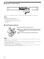
Getting started ............................................................ 2
Supplied parts ................................................................ 2
Controls and functions ................................................... 3
Placing this system...................................................... 7
Placing the center system............................................... 7
Connection................................................................... 9
Connecting the center system and the subwoofer/system
control........................................................................ 9
Connecting external components................................. 10
Connecting a Yamaha iPod universal dock ................. 12
Connecting the indoor FM antenna ............................. 12
Connecting the power cable......................................... 12
Basic playback operation ......................................... 13
Enjoying various sound features ............................. 14
Enjoying realistic sounds (Sound field program) ........ 14
Enjoying stereo sounds with multi speaker channels
(Dolby Pro Logic II)................................................ 15
Listening at low volume (Night listening mode)......... 15
FM tuning.................................................................. 16
Overview...................................................................... 16
Controls and functions for the FM tuning ................... 16
Basic tuning operation ................................................. 17
Using station preset feature ......................................... 18
Using iPod™.............................................................. 20
Controls and functions for iPod™ ............................... 20
Useful operation........................................................ 21
Changing the brightness of the front panel display ..... 21
Turning off the front panel display.............................. 21
Adjusting the virtual speaker settings.....................22
Using the speaker test mode ........................................ 23
Adjusting the characteristics of the tonal quality
(ROOM EQ) ........................................................... 25
Adjusting the speaker balance during playback .......... 25
Additional information .............................................26
Troubleshooting........................................................... 26
Glossary ....................................................................... 28
Specifications............................................................... 29
Contents
INTRODUCTION
PREPARATION
BASIC OPERATION
ADVANCED OPERATION
ADDITIONAL INFORMATION
■ Introduction
YAS-70 consists of the center system (YAS-70CU) and subwoofer/system control (YAS-70SPX). This product provides
you with the best sound possible with simple operations, allowing you to enjoy various audio sources. We hope the
“YAS-70” brings you great listening pleasure and satisfaction.
■ About this manual
• In this manual, operations that can be performed using either the front panel buttons or remote control are explained
using the remote control.
• y indicates a tip for your operation. Notes contain important information about safety and operating instructions.
• This manual is printed prior to production. Design and specifications are subject to change in part as a result of
improvements, etc. In case of differences between the manual and the product, the product has priority.

GETTING STARTED
2 En
This product consists of the following parts. Before making connections, make sure you received all of the following
parts.
■ Units
■ Accessories
The form of the supplied accessories varies depending on the models.
Getting started
Supplied parts
Note
Center system (YAS-70CU) x 1
Subwoofer/system control
(YAS-70SPX) x 1
System control cable
(4 m) x 1
Spacer x 2
Remote control x 1Speaker cable
(4 m) x 2
Battery x 2
(AAA, R03, UM4)
Indoor FM
antenna x 1
DISP. MODE DIMMER
ROOM EQ
DEC MODE
CENTER
SW
NIGHT
MEMORY
MUTE
A-E A-E
MENU
DOCK FM INPUT
INPUT 3INPUT 2INPUT 1
MOVIE MUSIC
SPORTS
GAME
STANDBY/ON
VOLUME
AUTO
/MAN'L
PRESET
/TUNE
R
SUR
LTEST
ENTER
Mounting template x 1
Double-sided tape
(Small, 4 pieces) x 1
Double-sided tape
(Large, 2 pieces) x 2
Owner’s manual x 1
YAS-70
(YAS-70CU + YAS-70SPX)
CENTER SYSTEM + SUBWOOFER/SYSTEM CONTROL
OWNER’S MANUAL
U

3 En
Getting started
INTRODUCTION English
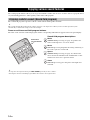
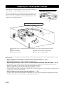
■ Front panel of the center system
Controls and functions
INPUT
STANDBY/ON
VOLUME
-
+
INPUT VOLUME
-
+ STANDBY/ON
Front panel display
Shows the information about the operational
status of this system. (☞ P. 4)
Remote control sensor
Receives infrared signals from the remote
control. (☞ P. 5)
Power indicator
Lights up when this
system is turned on.
(☞ P. 13)
VOLUME +/–
Controls the volume of this
system. (☞ P. 13)
INPUT
Selects an input source you want
to listen to. (☞ P. 13)
STANDBY/ON
Turns on this system or sets it to
the standby mode. (☞ P. 13)

4 En
Getting started
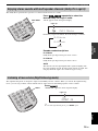
■ Front panel display of the center system
MUTE
TUNED
STEREO
MEMORY
AUTO
DOCK
HiFi
DSP
q
DIGITAL
NIGHT
PCM
q
P
L
VOLUME
dB
DSP indicators
CINEMA DSP indicator
Lights up when CINEMA DSP is activated.
(☞ P. 14)
HiFi DSP indicator
Lights up when HiFi DSP is activated.
(☞ P. 14)
AUTO/TUNED/STEREO/MEMORY
indicator
AUTO indicator
Shows that this system is in the automatic tuning
mode. (☞ P. 17)
TUNED indicator
Lights up when this system is tuned into a radio
station. (☞ P. 17)
STEREO indicator
Lights up when this system is receiving a strong
signal from an FM stereo broadcast while the
AUTO indicator is lit. (☞ P. 17)
MEMORY indicator
Flashes to show a station can be stored.
(☞ P. 18)
Multi information display
Shows the selected input source. When you are adjusting or
changing setting, the name of the current sound field program
and other information is displayed.
Decoder indicators
The respective indicator lights up when any
of the decoders of this system functions.
MUTE indicator
Flashes while the mute function is activated.
(☞ P. 13)
DOCK indicator
Lights up when this unit recognizes iPod.
(☞ P. 12)
NIGHT indicator
Lights up when you select a night
listening mode. (☞ P. 15)
VOLUME
Indicates the current
volume level.
(☞ P. 13)

5 En
Getting started
INTRODUCTION English
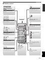
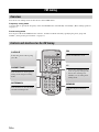
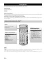
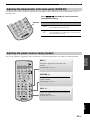
■ Remote control
ENTER
DISP. MODE DIMMER
ROOM EQ
DEC. MODE
CENTER
SW
NIGHT
MEMORY
AUTO
/MAN'L
PRESET
/TUNE
R
SUR.
LTEST
MUTE
A E A E
MENU
DOCK FM INPUT
INPUT 3INPUT 2INPUT 1
MOVIE MUSIC
SPORTS
GAME
STANDBY/ON
VOLUME
MOVIE MUSIC
SPORTS
GAME
ENTER
DISP. MODE DIMMER
ROOM EQ
DEC. MODE
CENTER
SW
NIGHT
MEMORY
AUTO
/MAN'L
PRESET
/TUNE
R
SUR.
LTEST
MUTE
A E A E
MENU
DOCK FM INPUT
INPUT 3INPUT 2INPUT 1
STANDBY/ON
VOLUME
Sound field program
buttons
Select a sound field program.
(☞ P. 14)
Input buttons
Select an input source you want to
listen to. (☞ P. 13)
Control iPod and FM tuner.
(☞ P. 16 and 20)
Control iPod. (☞ P. 20)
Adjust the brightness of the front
panel display. (☞ P. 21)
Turns on this system or sets it to
the standby mode. (☞ P. 13)
Control the volume of this
system. (☞ P. 13)
Turns on or off the night listening
mode. (☞ P. 15)
Adjust the speaker balance.
(☞ P. 25)
Selects a decoder mode (PL II
Movie, PL II Music and Auto).
(☞ P. 15).
Sets the room equalizer.
(☞ P. 25)
Adjust the virtual
speaker balance.
(☞ P. 23)
Infrared signal
transmitter

6 En
Getting started
■ Using the remote control
Use the remote control within 6 m (20 feet) of the center system and point it toward the remote control sensor.
• Be careful not to spill liquid on the remote control.
• Be careful not to drop the remote control.
• Do not leave the remote control in the following places:
– hot or humid places, such as near a heater or in a bathroom
– extremely cold places
– dusty places
■ Installing the batteries
• If the effective operation distance of the remote control decreases considerably, replace the batteries with two new ones as soon as
possible.
• Do not use an old battery together with new one.
• Do not use different types of batteries (for example, alkaline and manganese) together. Each type of battery has its own characteristics
even if they are similar in shape.
• If the batteries run out, immediately remove them from the remote control to prevent an explosion or acid leak.
• Dispose of the batteries according to the regional regulations.
• If a battery starts leaking, dispose of it immediately. Be careful not to let leaking battery acid come into contact with your skin or
clothing. Before inserting new batteries, wipe the compartment clean.
Notes
Notes
INPUT
STANDBY/ON
VOLUME
-
+
30˚ 30˚
Within 6 m
(20 feet)
1
3
2
1
Take off the battery compartment cover.
2
Insert the 2 supplied batteries (AAA, R03, UM4) according to
the polarity markings (+ and –) on the inside of the battery
compartment.
3
Snap the battery compartment cover back into place.

7 En
PREPARATION English
To enjoy quality sounds thoroughly, you need to place this system in their appropriate positions and install them
correctly. After deciding the layout, follow the procedure below to install this system.
Center system (YAS-70CU)
Place the center system above a TV or beneath the TV so that the
center system and your TV aligned vertically. Make sure that the
center system is placed in parallel with the wall.
Main roles: Produces front channel (stereo) sounds. Also
produces center channel sounds (dialogues or vocal sounds) and
surround channel sounds effectively using the Yamaha Air
Surround system.
Subwoofer/system control (YAS-70SPX)
Place the subwoofer near a the center system and turn it slightly
toward the center of the room to reduce wall reflections.
Main roles: Produces bass sounds and low frequency (LFE)
sounds contained in Dolby Digital or DTS sources.
• This system is shielded against magnetic rays. However, if the picture on your TV screen becomes blurred or distorted, we recommend
moving this unit away from your TV.
• Bass sounds produced by the subwoofer/system control may be heard differently depending on the listening position and subwoofer
location. To enjoy desired sounds, try changing the location of the subwoofer.
• Depending on your installation environment, connections with external components can be done before installing this system. We
recommend that you temporarily place and arrange all components in order to decide which procedure must come first.
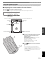
You can place the center system on a rack or attach it to a wall. Select an installation method that suits your environment.
■ Placing the center system above/beneath a TV
y
If there is any obstacle (TV stand etc.) under the center system,
use the supplied spacers as follows.
1 Attach the supplied double-sided tapes on the spacers.
2 Attach the spacers to the bottom.
• Do not hide the remote control sensor of your TV etc. by the
center system.
• The spacers may scratch or damage the surface of your rack or
flooring. Be careful when placing or moving the center system.
• For your safety, take measures in advance to prevent the center
system from falling.
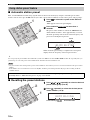
Placing this system
Center system
(YAS-70CU)
Subwoofer/system
control (YAS-70SPX)
Notes
Placing the center system
Example 1: Above your TV
Example 2:
Beneath your TV
Example 3: Under your TV
Notes
Fig. A Fig. B
Large
double-sided
tape
Small
double-
sided tape
INPUT
STANDBY/ON
VOLUME
-
+

8 En
Placing this system
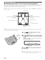
■ Attaching the center system to a wall
You can attach the center system to a wall using commercially available screws (#8, Diameter: 7.5 mm or more
(9/32” or more)).
1
Attach the supplied mounting template on a
wall and then mark the holes of the mounting
template.
2
Remove the mounting template and then
install the commercially available screws at
the marks.
y
To install the cables above the center system, refer to the right
column.
3
Hang the center system on the screws using
the holes on the back of the center system.
• The center system weighs about 4.5 kg (9 lbs. 15 oz.). To attach the center system to a wall using screws, the wall must be firm. Do not
attach the center system to a wall that is made of weak materials such as plaster or veneered woods. Doing so may cause the center
system to fall.
• Use commercially available screws that can endure weight enough.
• Make sure you use specified screws to attach the center system to a wall. Using clamps other than specified screws, such as short
screws, nails, or two-sided tape, may cause the center system to fall.
• When connecting the center system, fix the speaker cables in place so that cables do not loosen. If your foot or hand accidentally gets
caught on a loose speaker cable, the center system may fall.
• After attaching the center system, check that the center system is fixed securely. Yamaha will bear no responsibility for any accidents
caused by improper installations.
When installing the center system on a wall, all installation work must be performed by a qualified contractor or
dealer personnel. The customer must never attempt to perform this installation work. Improper or inadequate
installation could cause the center system to fall, resulting in personal injury.
Tapes or thumbtacks
Mark
4 to 6 mm (3/16” to 1/4”)
Diameter:
7.5 mm or more
(#8, 9/32” or more)
Installing the cables above the center system
To pass the cables upward, you need to attach the
spacers to make room on the back of the center system.
In step 2 of the left column;
2-a: Attach the supplied spacers to the rear panel of the
center system using the supplied double-sided
tapes. You can choose either the side A or the side
B.
2-b: Remove the mounting template and then install
the commercially available screws at the marks.
For narrow space For wide space
Large double-
sided tape
Small double-
sided tape
Attach Attach
22 to 24 mm
(7/7” to 15/16”)
34 to 36 mm
(5/16” to 7/16”)
Notes

9 En
PREPARATION English
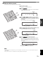
Follow the procedure below to connect the center system and the subwoofer/system control.
Connecting speaker cables
Connecting system control cable
Connection
• Do not connect the power cable until all connections are completed.
• Do not use excessive force when inserting the cable plug. Doing so may damage the cable plug and/or
terminal.
Connecting the center system and the subwoofer/system control
SYSTEM CONNECTOR
DOCK INPUT
L
ANALOG
FM
75Ω UNBAL
OPTICAL COAXIAL
312
SPEAKERS
ANTENNA
L
R
R
Speaker cables (supplied)
Connect the
cable plug
to the
speaker
jack of the
same color.
Connect the
cable plug
to the
speaker
jack of the
same color.
SYSTEM CONNECTOR
DOCK INPUT
L
ANALOG
FM
75Ω UNBAL
OPTICAL COAXIAL
312
SPEAKERS
ANTENNA
L
R
R
System control cable (supplied)
Tighten the screws.
Tighten the screws.

10 En
Connection
The subwoofer/system control has 3 digital/analog input jacks (optical digital x 1, coaxial digital x 1, analog x 1). Before
connecting your external components, check the output jacks of the components and be sure to use correct connection
cables.
■ Digital connection
• The digital jacks of this system support PCM, Dolby Digital, and DTS signal system.
• The digital jacks support digital signals of which sampling frequency is 96 kHz or less.
[INPUT 1] OPTICAL jack
Example 1: DVD player
Example 2: TV game console
[INPUT 2] COAXIAL jack
Connecting external components
Notes
SYSTEM CONNECTOR
DOCK INPUT
L
ANALOG
FM
75Ω UNBAL
OPTICAL COAXIAL
312
SPEAKERS
ANTENNA
L
R
R
DIGITAL OUT
(OPTICAL)
DVD playerTV
Optical digital
cable
SYSTEM CONNECTOR
DOCK INPUT
L
ANALOG
FM
75Ω UNBAL
OPTICAL COAXIAL
312
SPEAKERS
ANTENNA
L
R
R
OPTICAL
DIGITAL OUTPUT
Game console
TV
Optical digital
cable
SYSTEM CONNECTOR
DOCK INPUT
L
ANALOG
FM
75Ω UNBAL
OPTICAL COAXIAL
312
SPEAKERS
ANTENNA
L
R
R
COAXIAL
DIGITAL OUTPUT
CD player
Coaxial digital
cable

11 En
Connection
PREPARATION English
■ Analog connection
[INPUT 3] ANALOG jacks
Example1: TV
Example 2: VCR or video camera
VCR or video camera, etc. with no digital output.
SYSTEM CONNECTOR
DOCK INPUT
L
ANALOG
FM
75Ω UNBAL
OPTICAL COAXIAL
312
SPEAKERS
ANTENNA
L
R
R
L
R
AUDIO OUTPUT
TV
SYSTEM CONNECTOR
DOCK INPUT
L
ANALOG
FM
75Ω UNBAL
OPTICAL COAXIAL
312
SPEAKERS
ANTENNA
L
R
R
R
L
AUDIO OUTPUT
Video camera
VCR etc.

12 En
Connection
This system is equipped with the DOCK terminal that allows you to connect a Yamaha iPod universal dock (such as the
YDS-10, sold separately) where you can station your iPod and control playback of your iPod using the supplied remote
control. Connect a Yamaha iPod universal dock to the DOCK terminal of the subwoofer/system control using its
dedicated cable.
To enjoy FM radio broadcast, connect the supplied indoor FM antenna.
After you made all connections, connect the power cable of the subwoofer/system control.
Connecting a Yamaha iPod universal dock
Connecting the indoor FM antenna
Connecting the power cable
SYSTEM CONNECTOR
DOCK INPUT
L
ANALOG
FM
75Ω UNBAL
OPTICAL COAXIAL
312
SPEAKERS
ANTENNA
L
R
R
Yamaha iPod universal dock
(such as the YDS-10, sold separately)
SYSTEM CONNECTOR
DOCK INPUT
L
ANALOG
FM
75Ω UNBAL
OPTICAL COAXIAL
312
SPEAKERS
ANTENNA
L
R
R
Indoor FM antenna
(supplied)
y
If the radio wave reception is weak in your area or you want to
improve the radio wave reception, we recommend that you use
outdoor antennas. For details, consult the nearest authorized
Yamaha dealer or service center.
SYSTEM CONNECTOR
DOCK INPUT
L
ANALOG
FM
75Ω UNBAL
OPTICAL COAXIAL
312
SPEAKERS
ANTENNA
L
R
R
To AC wall outlet

Basic playback operation
13 En
BASIC
OPERATION
English
Once you have finished all cable connections (see pages 9 to 12) and remote control preparation (page 6), follow the
procedure below to start basic playback operation.
Basic playback operation
1
Press STANDBY/ON.
This system turns on and the power indicator lights up. To set this system to the
standby mode, press STANDBY/ON again.
y
This system has the auto-sleep function which automatically switches to the standby mode if you
do not operate this system for about 24 hours while this system is turned on.
2
Press one of the input buttons to select an input source.
For example, if a DVD player is connected to the INPUT 1 jack of the subwoofer/
system control, press INPUT 1 to select the DVD player.
y
You can also switch the input source by pressing INPUT repeatedly. The input source changes as
follows:
3
Start playback on the selected external component.
For information on the external component, refer to the manual for the product.
4
Press VOLUME +/– to adjust the volume level.
y
To turn off the volume temporarily, press MUTE. While the mute function is activated, the
MUTE indicator flashes. To resume the volume, press MUTE again.
INPUT 1 INPUT 2 INPUT 3 DOCK FM
Enjoy
Sounds
R
SW
H
T
MEMO
R
Y
MUTE
A-E
A-E
MENU
DOCK
FM INP
UT
INPUT 3INPUT 2
IN
PUT 1
MOVIE MUSIC
SPORTS
GAME
STANDBY/ON
VOLUME
A
U
TO
/MAN'L
PRE
SET
/TUNE
ENTER
1
2
4
Now, try various features of this system!
Using various sound features
• To enjoy high realistic sounds with a sound field
program ☞ P. 14
• To enjoy stereo sounds such as CD audio with multi
channels ☞ P. 15
• To enjoy various input sources at lower volume
☞ P. 15
• To configure the position of virtual surround
speakers ☞ P. 22
Enjoying FM broadcast/iPod playback
• To listen to FM broadcast ☞ P. 16
• To control iPod playback ☞ P. 20

Enjoying various sound features
14 En
The sound program features allow you to enjoy various kinds of audio such as movie or music. Choose a program based
on your listening preference, and not purely on the name of the program.
The sound field programs reproduce realistic sounds with the multi speaker channels.
y
This system automatically memorizes the settings assigned to each input source. When you select another input, this system
automatically recalls the last settings for the selected input.
Press one of the sound field program buttons.
The name of the selected sound field program and the corresponding DSP indicator appear in the front panel display.
y
• To reproduce the original sounds, press DEC. MODE repeatedly to select “AUTO”.
• Pressing the selected sound field program button also returns to the original sound.
Enjoying various sound features
Enjoying realistic sounds (Sound field program)
SW
MEMORY
MUTE
A-E
A-
E
MENU
DOCK FM INPUT
INPUT 3
INPUT 2
INPUT 1
MOVIE MUSIC
SPORTS
GAME
STANDBY/ON
VOLUME
UTO
L
ENTER
Sound field
program buttons
SPORTS
MOVIE
MUSIC
GAME
Sound field program descriptions
Movie
CINEMA DSP processing (see page 28) produces the
rich acoustical presence of a movie theater.
Music
HiFi DSP processing magnifies the feeling of listening to
live rock or jazz in a concert hall.
Sports
CINEMA DSP processing (see page 28) enhances the
cheers and emotional whirl of the stadium with a center
narrations in a live stereo sports broadcast.
Game
HiFi DSP processing gives TV games extra depth and
surround.

Enjoying various sound features
15 En
BASIC
OPERATION
English
The Dolby Pro Logic II modes reproduce 5.1-channel audio from stereo sounds.
The night listening mode is designed to improve listenability at lower volumes. When you activate the night listening
mode, you can enjoy realistic sounds with the effects of the selected sound field programs at lower volume.
Enjoying stereo sounds with multi speaker channels (Dolby Pro Logic II)
Listening at low volume (Night listening mode)
DISP. MODE DIMMER
ROOM EQ
DEC. MODE
CENTER
SW
NIGHT
MEMORY
-E
AUTO
/MAN'L
PRESET
/TUNE
R
SUR.
LTEST
Press DEC. MODE repeatedly to select the
desired Dolby Pro Logic II mode.
“PL II” appears in the front panel display.
Each time you press the button, the mode changes as follows.
Decoder mode descriptions
PL II Movie
Dolby Pro Logic II processing for movie sources.
PL II Music
Dolby Pro Logic II processing for music sources.
AUTO
This unit decodes the input digital audio signals straightly with
the corresponding decoder. If analog audio signals are input, this
unit plays back the input source without any processing.
PLII Movie
q PL
Lights up
PLII Movie
PLII Music
AUTO
DEC. MODE
Press NIGHT.
“NIGHT ON” appears in the front panel display.
y
To cancel the night listening mode, press NIGHT again.
NIGHT
NIGHT ON
Lights up
DISP. MODE DIMMER
ROOM EQ
DEC. MODE
CENTER
SW
NIGHT
MEMORY
AUTO
/MAN'L
PRESET
/TUNE
R
SUR.
LTES
T
NIGHT

FM tuning
16 En
You can use two tuning modes to tune into the desired FM station:
Frequency tuning mode
you can search or specify the frequency of the desired FM station automatically or manually. (“Basic tuning operation”
on page 17)
Preset tuning mode
You can preset the desired FM station in advance, and then recall the station by specifying the preset group and
number. (“Using station preset feature” on page 18)
FM tuning
Overview
Controls and functions for the FM tuning
ENTER
DISP. MODE DIMMER
ROOM EQ
DEC. MODE
CENTER
SW
NIGHT
MEMORY
AUTO
/MAN'L
PRESET
/TUNE
R
SUR.
LTEST
MUTE
A E A E
MENU
DOCK FM INPUT
INPUT 3INPUT 2INPUT 1
MOVIE MUSIC
SPORTS
GAME
STANDBY/ON
VOLUME
A_E/A` E
Selects the preset station group
(A to E).
PRESET/TUNE
Switches between the frequency
tuning mode and preset tuning
mode.
AUTO/MAN’L
Switches between the automatic
and manual tuning mode.
FM
Selects the FM tuner mode.
+/–
• Selects the desired frequency
in the frequency tuning mode.
• Selects the desired preset
number (1 to 8) in the preset
tuning mode.
MEMORY
Activates the preset memory
mode.

FM tuning
17 En
BASIC
OPERATION
English
Basic tuning operation
Manual tuning
If the signal received from the station you want to select is weak, you can tune into the desired station by specifying
the frequency manually. In the FM tuning mode, press AUTO/MAN’L repeatedly so that the AUTO indicator
disappears and then press +/– repeatedly to specify the frequency of the desired station.
If you tune into a station by using the manual tuning feature, this system receives the FM radio signals in the monaural
reception mode to increase the signal quality.
ROOM EQ
DE
C
MODE
C
E
NTER
SW
NIGHT
MEMORY
MUTE
A-E
A-E
MENU
DOCK
FM INPUT
INPUT 3INPUT 2
INPUT 1
MOVIE MUSIC
SPORTS
VOLUME
AUTO
/MAN'L
PRESET
/
TUNE
SUR
ENTER
1
2
3
1
Press FM to select this system to the FM tuner
mode.
“FM” appears in the front panel display.
2
Press AUTO/MAN’L so that the AUTO indicator
lights up in the front panel display.
This system is set to the automatic tuning mode.
y
If a colon (:) appears, this system is set to the preset tuning mode
and the frequency tuning is not possible. Press PRESET/TUNE
to
turn the colon (:) off.
3
Press +/– once to begin automatic tuning.
When this system is tuned into a station, the TUNED
indicator lights up and the frequency of the received station
is shown in the front panel display.
y
When you tune into an FM station by using the automatic tuning
mode, this system receives the FM radio signal in the stereo
reception mode. The STEREO indicator appears in the front panel
display.
FM
AUTO
A FM 88.9 MHz
No colon (:)
Lights up
TUNED
A FM 89.1 MHz
Lights up

FM tuning
18 En
■ Automatic station preset
First, scan the FM stations with strong signals and store them to the memory by using the automatic preset station
feature. You can store up to 40 FM stations (A1 to E8: 8 preset station numbers in each of the 5 preset station groups).
y
You can specify the preset number from which this system stores FM stations. Press A_ E or A`E and then +/– repeatedly after you
perform step 2 to select the preset station number under which the first station will be stored.
• Any stored station data existing under a preset station number is cleared when you store a new station under the same preset station
number.
• If the number of received stations does not reach 40 (E8), automatic preset tuning automatically stops after searching for all the
available stations.
■ Recalling the preset stations
Using station preset feature
Notes
If the desired station is not stored, or a station is not stored to the desired preset group and number, preset the station
manually. Refer to “Manual station preset” on page 19 for details.
OOM EQ
DE
C
MO
DE
C
ENTER
SW
N
I
GHT
MEMORY
MUTE
A-E
A-E
MENU
DOCK
FM INPUT
INPUT 3INPUT 2
INPUT 1
MOVIE MUSIC
SPORTS
G
VOLUME
AUTO
/MAN'L
PRESET
/
TUNE
UR
ENTER
1
2
1
Press FM to select this system to the FM tuner
mode.
“FM” appears in the front panel display.
2
Press and hold MEMORY for more than 3
seconds.
The preset station number as well as the MEMORY and
AUTO indicators flashes. After approximately 5 seconds,
automatic presetting starts from the current frequency and
proceeds toward higher frequencies.
When automatic preset tuning is completed, the front panel
display shows the frequency of the last preset station.
MEMORY
AUTO
A1:FM 88.9 MHz
Flash
Flashes
ROOM EQ
DE
C
MODE
C
E
NTER
SW
NIGHT
MEMORY
MUTE
A-E
A-E
MENU
DOCK
FM INPUT
INPUT 3INPUT 2
INPUT 1
MOVIE MUSIC
SP
VOLUME
AUTO
/MAN'L
PRESET
/
T
U
NE
S
UR
ENTER
2
1
1
Press A _E or A` E repeatedly to select the desired
preset station group (A to E).
2
Press +/– repeatedly to select the desired preset
station number (1 to 8).
A1:FM 88.9 MHz
Preset station group and
number
Preset FM station

FM tuning
19 En
BASIC
OPERATION
English
■ Manual station preset
Use this feature to preset your desired station manually.
• Any stored station data existing under a preset station number is cleared when you store a new station under the same preset
station number.
• The reception mode (stereo or monaural) is stored along with the station frequency.
Notes
ROOM EQ
DE
C
MODE
C
E
NTER
SW
NIGHT
MEMORY
MUTE
A-E
A-E
MENU
DOCK
FM INPUT
INPUT 3INPUT 2
INPUT 1
MOVIE MUSIC
SPORTS
VOLUME
AUTO
/MAN'L
PRESET
/
T
U
NE
SUR
ENTER
3
2
1
Tune into a station.
See page 17 for tuning instructions.
2
Press MEMORY.
The MEMORY indicator flashes in the front panel display
for approximately 10 seconds.
3
Press A_ E or A`E repeatedly to select a preset
station group (A to E) while the MEMORY indicator
is flashing.
The selected preset station group letter appears.
4
Press +/– to select a preset station number (1 to 8)
while the MEMORY indicator is flashing.
5
Press MEMORY to confirm the preset.
The station band and frequency appear in the front panel
display with the preset station group and number you have
selected. The MEMORY indicator disappears from the front
panel display.
MEMORY
A :FM 88.9 MHz
Flashes
MEMORY
A :FM 88.9 MHz
Preset station group
Flashes
MEMORY
A1:FM 88.9 MHz
Flashes
Preset station number
A1:FM 88.9 MHz
The displayed station has been stored as A1.
ROOM EQ
DE
C
MODE
C
E
NTER
SW
NIGHT
MEMORY
MUTE
A-E
A-E
MENU
DOCK FM INPUT
INPUT 3INPUT 2
INPUT 1
MOVIE MUSIC
SPORTS
VOLUME
AUTO
/MAN'L
PRESET
/
T
U
NE
S
UR
ENTER
4
5

Using iPod™
20 En
You can play back the audio sources stored on your iPod on this system.
Supported iPod
iPod (Click and Wheel)
iPod nano
iPod mini
Battery charge feature
This system charges the battery of the iPod stationed to the Yamaha iPod universal dock connected to the DOCK terminal
of the subwoofer/system control while this system is turned on.
Stationing your iPod to the Yamaha iPod universal dock
Once you station your iPod to the Yamaha iPod universal dock, “iPod connected” and the DOCK indicator appears in the
front panel display.
• Operations can be also done with the controls on your iPod. Refer to the instruction manuals of your iPod for the operations on your
iPod.
• Some features may not be compatible depending on the model or the software version of your iPod.
• For a complete list of status messages that appear in the front panel display, see the “iPod” section in “Troubleshooting” on page 26.
Using iPod™
Controls and functions for iPod™
Notes
ENTER
DISP. MODE DIMMER
ROOM EQ
DEC. MODE
CENTER
SW
NIGHT
MEMORY
AUTO
/MAN'L
PRESET
/TUNE
R
SUR.
LTEST
MUTE
A E A E
MENU
DOCK FM INPUT
INPUT 3INPUT 2INPUT 1
MOVIE MUSIC
SPORTS
GAME
STANDBY/ON
VOLUME
DOCK
Sets this system to the iPod
playback mode.
MENU/Cursor buttons
(S/T/W/X)/ENTER
Navigate the menu of your iPod.
• Press MENU or W to move to
the previous menu level.
• Press S/T to move to the
upper/lower menu level.
• Press ENTER or X to move to
the subsequent menu, start
playback of the selected menu
level, or change the selected
setting.
Playback control buttons
Control the playback of the
connected iPod.
p/e: Play/pause
s: Stop
w/f:
Search backward/forward
b/a:
Skip backward/forward

Useful operation
21 En
BASIC
OPERATION
English
You can change the brightness of the front panel display.
You can turn off the front panel display. This feature is useful when you enjoy a movie in a dark listening room.
y
• The front panel display turns on momentarily when an operation is performed.
• To turn on the front panel display, press DISP. MODE again.
Useful operation
Changing the brightness of the front panel display
Turning off the front panel display
Press DIMMER repeatedly.
Each time you press DIMMER, the brightness of the front
panel changes.
DIMMER OFF
DIMMER -1
DIMMER -2
DIMMER -3
DIMMER -4
Bright
Dark
DISP. MODE DIMMER
ROOM E
Q
DEC. MODE
CEN
T
ER
SW
NIGHT
MEMORY
AUTO
/MAN'L
PRESET
/TUNE
R
SUR.
L
TEST
DIMMER
Press DISP. MODE.
After “DISPLAY OFF” appears in the front panel display,
this system turns off the front panel display.
DISP. MODE DIMMER
R
OOM EQ
DEC. MODE
CENTER
SW
NIGHT
MEMORY
AUTO
/MAN'L
PRESET
/TUNE
R
SUR.
L
TEST
DISP. MODE

Adjusting the virtual speaker settings
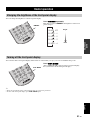
22 En
Ordinarily, the 5.1 channel speaker system needs two front speakers, a
center speaker, two surround speakers, and a subwoofer.
This system employs the Air Surround technology that enables you to
enjoy the surround sound with the front left and right speakers in the
center system; you can hear the center and surround channel sounds
without the corresponding speakers.
In this section, you can adjust the following surround sound settings for your preference and the characteristics of your
listening room:
• Adjusting the volume balance of each channel with test tones ☞ P. 23
By adjusting the balance, you can enjoy seamless surround sound.
• Adjusting the positions of the virtual surround speaker channels with test tones ☞ P. 24
This unit creates the surround channel sounds that locate the side or behind of the listening position by using the
reflection of the walls. Use this setting to locate the surround channel sounds.
• Adjusting the characteristics of the tonal quality ☞ P. 25
Use this feature to adjust the tonal quality according to the acoustic characteristics of your listening room. This feature
is useful if the sound is too dark or bright.
• Adjusting the volume balance during playback ☞ P. 25
Use this feature to adjust the volume balance of the subwoofer, center, and surround channels during playback. This
feature is useful when you want to change the volume balance tentatively.
Adjusting the virtual speaker settings
Ordinal 5.1 channel speaker system
Front speaker
Subwoofer
Center speaker
Surround speaker
B
A
A
C
C
D
This unit creates the 5.1-channel surround sound with the center system and the subwoofer/system
control.
A: Front left and right
B: Virtual center channel
C: Virtual surround left and right channel
D: Low-frequency or LFE channel
The sound image of this system

Adjusting the virtual speaker settings
23 En
ADVANCED
OPERATION
English
Use this feature to adjust the volume balance of each (virtual) speaker and the position of the virtual surround speakers.
■ Adjusting the volume balance of each channel
1
Press TEST to activate the speaker test mode.
Following message appears in the front panel display and this system outputs the test tones.
Test tone is output at each (virtual) speaker for about 2.5 seconds in the following order.
Using the speaker test mode
TEST FL 0dB
Active (virtual)
speaker channel
Volume balance
1: Front left
(FL)
3: Front right
(FR)
6: Subwoofer
(SW)
5: Virtual surround left
(SL)
2: Virtual center
(C)
4: Virtual surround right
(SR)
DISP. MODE DIMMER
ROOM EQ
DEC. MODE
C
E
NTE
R
SW
NIGHT
MEMORY
MUTE
A-E
A-E
MENU
OCK
FM INPUT
INPUT 3INPUT 2
1
US
VOLUME
AUTO
/MAN'L
PRESE
T
/
T
U
NE
R
S
U
R.
L
T
EST
ENTER
2
1,3
2
Press S/T repeatedly to adjust the output
level of the currently selected (virtual)
speaker channel.
The adjustable range for the output level of each
speaker channel is as follows:
Front left/right (FL/FR): –6 to 0 dB
Center (C): –4 to +4 dB
Surround left/right (SL/SR): –4 to +4 dB
Subwoofer (SW): –8 to +8 dB
3
Press TEST again to exit from the speaker
test mode.
y
• To reset the volume level and the beam angle (see
page 24) of all virtual speaker channels to the factory
settings, press INPUT on the front panel while a test tone
is output.
• You can adjust overall the volume level of the test tone
using VOLUME +/–.

Adjusting the virtual speaker settings
24 En
■ Adjusting the position of the virtual surround speakers
This system employs the Yamaha Air Surround system that enables the surround sound field using the center system and
the subwoofer/system control. This system creates the surround sounds by using the reflections on the walls of your
listening room. Use this feature to achieve the ideal surround sound.
y
To reset the volume level and the beam angle of all virtual speaker channels to the factory settings, press INPUT on the front panel while
a test tone is output.
y
Adjust the angle so that the first reflection point is located posterior to the listening position and the sound of surround speaker channel
audio reaches the listening position after reflections.
Virtual surround speaker
positions
Listening position
Center system
BEAM R
(Right surround virtual speaker
angle setting)
BEAM L
(Left surround virtual speaker
angle setting)
First reflection point
First reflection point
1
Press TEST to activate the speaker test mode.
This system outputs test tones.
2
Press L or R repeatedly to select the desired angle
setting of the left or right surround virtual speaker
channel.
“BEAM L” or “BEAM R” and the angle setting appears in
the front panel display.
Choice: 20º, 30º, 40º, 50º, 60º
3
Press TEST again to exit from the speaker test
mode.
y
This system automatically returns to the speaker balance setting mode
after a few seconds that you perform the operation of step 2.
BEAM L 40
Selected virtual surround
speaker channel
Current angle setting
DISP. MODE DIMMER
ROOM EQ
DEC. MODE
CENTER
SW
NIGHT
MEMO
AUTO
/MAN'L
PRESET
/TUNE
R
SUR.
L
TEST
1,3
2

Adjusting the virtual speaker settings
25 En
ADVANCED
OPERATION
English
Use this feature to set the equalizer to optimize the tonal quality of the sound for the acoustic characteristics of your
listening room.
You can also adjust the output level of the virtual center, virtual surround speakers, and subwoofer during playback.
Adjusting the characteristics of the tonal quality (ROOM EQ)
Adjusting the speaker balance during playback
DISP. MODE DIMMER
ROOM EQ
DEC. MODE
CENTER
SW
NIGHT
MEMORY
A
AUTO
/MAN'L
PRESET
/TUNE
R
SUR.
L
TEST
Press ROOM EQ repeatedly to select the desired
room equalizer setting.
Choice Descriptions
HARD
If the walls in your listening room are hard and you can
get the sufficiently reflected sounds
SOFT
If the walls are covered over some soft objects or there
are some furniture on the walls and you cannot get the
sufficiently reflected sounds
ROOM EQ
ENTER
DISP. MODE DIMMER
ROOM EQ
DEC. MODE
CENTER
SW
NIGHT
MEMORY
AUTO
/MAN'L
PRESET
/TUNE
R
SUR.
LTEST
MUTE
A E A E
MENU
DOCK FM INPUT
INPUT 3INPUT 2INPUT 1
MOVIE MUSIC
SPORTS
GAME
STANDBY/ON
VOLUME
SW +/–
Adjusts the output level of the subwoofer
channel.
Control range: +8 to –8
CENTER +/–
Adjusts the output level of the virtual center
speaker channel.
Control range: +4 to –4
SUR. +/–
Adjusts the output level of the virtual surround
speaker channels.
Control range: +4 to –4

ADDITIONAL INFORMATION
26 En
If there is any problem with this system, check the following items. If you cannot solve your problem with the following
remedies or if your problem was not listed below, turn off and unplug this system, and then consult the nearest authorized
Yamaha dealer or service center.
Additional information
Troubleshooting
Problem Cause Solution
See
page
Power turns on but
immediately shuts off.
The power cable may be connected
improperly.
Make sure the power cable is plugged into the
outlet firmly.
12
The speaker cable may be shorted. Make sure all speaker cables are connected
properly.
9
This system may receive a strong
electrical shock such as from a lightening
bolt or excessive static electricity.
Set this system to the standby mode, and then
disconnect the power cable. Wait for about 30
seconds, connect the power cable, and then turn
on this system.
13
The speakers make no
sound.
The volume may be set to minimum
level.
Adjust the volume level.
13
The mute function may be activated. Cancel the mute function. 13
The input source or input setting may be
incorrect.
Select the correct input source or input setting.
13
The cables may be connected
improperly.
Make sure all cables are connected properly.
9, 12
Sound is too low on
one side.
The cables may be connected
improperly.
Make sure all cables are connected properly.
9, 12
Speaker channels other
than the front ones
make no sound.
You may be listening to stereo sounds
without the sound field effect.
Press sound field program button to enable the
sound field effect.
14
The center speaker
channel makes no
sound.
The volume of the center speaker
channel may be set to minimum level.
Adjust the volume level of the center speaker
channel using test tones.
23
The surround speaker
channels make no
sound.
The volume of the surround speaker
channels may be set to minimum level.
Increase the output level of SL/SR by pressing
S.
23
Increase the output level of the virtual surround
speaker channel by pressing SUR. +.
25
The subwoofer makes
no sound.
The volume of the subwoofer channel
may be set to minimum level.
Adjust the volume level of the subwoofer.
25
You may be listening to an audio source
that does not contain any low tone signal.
The subwoofer does not support signals outside
the specified range.
23
Sound is poor (noisy).
The speaker cable may be shorted. Make sure all cables are connected properly.
9, 12
This system does not
operate properly.
This system may receive a strong
electrical shock, such as from a
lightening bolt or excessive static
electricity, or drop in power supply.
Set this system to the standby mode, and then
disconnect the power cable. Wait for about 30
seconds, connect the power cable, and then turn
on this system.
13
The system control cable may be
connected improperly.
Connect the system cable firmly.
9
A digital or high-
frequency equipment
produces noises.
This system may be placed close to the
digital equipment or high-frequency
equipment.
Place this system further away from such
equipment.
—

27 En
Additional information
English
ADDITIONAL
INFORMATION
\
■ Tuner
■ iPod
In case of a transmission error without a status message appearing in the front panel, check the connection to your iPod (page 12).
The remote control
does not work for
operating this system.
This system may be operated outside the
remote control operation range.
For information on the remote control operation
range, refer to “Remote control”.
5
The remote control sensor of this system
may be exposed to direct sunlight of
lighting.
Change the lighting.
—
The batteries may be worn out. Replace the batteries. 5
Problem Cause Solution
See
page
Problem Cause Remedy
See
page
FM stereo reception is
noisy.
The characteristics of FM stereo
broadcasts may cause this problem when
the transmitter is too far away or the
antenna input is poor.
Check the antenna connections.
12
Try using a high-quality directional FM
antenna.
—
Use the manual tuning method.
17
There is distortion, and
clear reception cannot be
obtained even with a
good FM antenna.
There is multi-path interference. Adjust the antenna position to eliminate multi-
path interference.
—
The desired station
cannot be tuned into with
the automatic tuning
method.
The signal is too weak. Use a high-quality directional FM antenna.
—
Use the manual tuning method.
17
Previously preset
stations can no longer be
tuned into.
This system has been disconnected for a
long period and preset station memory
has been cleared.
Set preset stations again.
18
Note
Status message Cause Remedy
See
page
Unknown iPod
The iPod being used is not supported by
this system.
Only iPod (Click and Wheel), iPod nano, and iPod
mini are supported.
—
iPod connected
Your iPod is properly stationed in a
Yamaha iPod universal dock (such as
YDS-10, sold separately) connected to the
DOCK terminal of this system, and the
connection between your iPod and this
system is completed.
Disconnected
Your iPod was removed from a Yamaha
iPod universal dock (such as YDS-10,
sold separately) connected to the DOCK
terminal of this system.
Station your iPod back in a Yamaha iPod universal
dock (YDS-10, sold separately) connected to the
DOCK terminal of this system.
12

28 En
Additional information
■ Air Surround
Front surround sound system which is developed by
Yamaha enables the surround sound field. In comparison
with traditional front surround technologies, the Air
Surround system enables a wide range of natural surround
sound field.
■ Channel (ch)
A channel is an audio type that has been divided based on
range and other characteristics.
Ex. 5.1 channel
• Front speakers, Left (1ch), Right (1ch)
• Center speaker (1 ch)
• Surround speakers, Left (1ch), Right (1ch)
• Subwoofer (1 ch x 0.1
*
= 0.1 ch)
*
In contrast to a full 1-channel band, a component designed to
enhance low frequency sound for added effect.
■ CINEMA DSP
(Digital Sound Field Processor)
Since the Dolby Surround and DTS systems were
originally designed for use in movie theaters, their effect
is best felt in a theater having many speakers and designed
for acoustic effects. Since home conditions, such as room
size, wall material, number of speakers, and so on, can
differ so widely, it’s inevitable that there are differences in
the sound heard as well. Based on a wealth of actually
measured data, Yamaha CINEMA DSP uses Yamaha
original sound field technology to combine Dolby Pro
Logic, Dolby Digital and DTS systems to provide the
visual and audio experience of movie theater in the
listening room of your own home.
■ Dolby Digital
Digital surround sound system which is developed by
Dolby Laboratories provides completely independent
multi-channel audio. With 3 front channels (left, center,
and right) and 2 surround stereo channels, Dolby Digital
provides five full-range audio channels. With an additional
channel especially for bass effects (called LFE, or low
frequency effect), the system has a total of 5.1-channels
(LFE is counted as 0.1 channel). By using 2-channel
stereo for the surround speakers, more accurate moving
sound effects and surround sound environment are
possible than with Dolby Surround.
■ Dolby Pro Logic II
It is an improved matrix decoding technology that
provides better spatiality and directionality on Dolby
Surround programmed material; provides a convincing
three-dimensional sound field on conventional stereo
music recordings; and is ideally suited to bring the
surround experience to automotive sound. While
conventional surround programming is fully compatible
with Dolby Surround Pro Logic II decoders, soundtracks
will be able to be encoded specifically to take full
advantage of Pro Logic II playback, including separate left
and right surround channels.
■ DTS
Digital surround sound system developed by DTS, Inc.,
which provides 5.1 channel audio. With an abundance of
audio data, it is able to provide authentic-sounding effects.
■ PCM (Pulse Code Modulation)
A signal that is changed to digital format without
compression. A CD is recorded with 16-bit sound at 44.1
kHz, while DVD recording is anywhere from 16 bits at 48
kHz to 24 bits at 192 kHz, which makes it a higher quality
sound than CD.
■ Sampling frequency
The number of sampling (process for digitalizing analog
signals) per second. In principle, the higher the sampling
rate, the wider the frequency range that can be played
back, and the higher the quantized bit rate, the finer the
sound that can be reproduced.
Glossary

29 En
Additional information
English
ADDITIONAL
INFORMATION
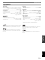
YAS-70CU
• Type ........... Full range acoustic suspension magnetic shielding type
• Driver (Full range)
........................5 cm (2”) cone magnetic shielding type × 6 (L3, R3)
• Frequency Response .............................................. 100 Hz to 25 kHz
• Input impedance............................................................................6 Ω
• Maximum Input ......................................................................... 35 W
• Sensitivity (2.83 V, 1 m) ........................................................... 84 dB
• Dimensions (W × H × D)............................... 930 × 100.5 × 103 mm
(Approx. 36-5/8” × 3-15/16” × 4-1/16”)
• We ight .....................................................................................4.5 kg
(Approx. 9 lbs. 15 oz.)
YAS-70SPX
Amplifier
• Minimum RMS output power per channel
.............................................................30 W (1 kHz, 6 Ω, 1% THD)
• Maximum power........................................... 35 W (6 Ω, 10% THD)
FM Tuner
• Tuning range ...................................................... 87.5 to 107.9 MHz
• Antenna Input (unbalanced) ..................................................... 75 Ω
Subwoofer
• Type................Advanced Yamaha Active Servo Technology System
• Output Power...................................50 W (100 Hz, 5Ω, 10% T.H.D)
• Dynamic Power .................................................................100 W, 5Ω
• Driver .........................16 cm (6 1/2”) cone, Magnetic shielding type
• Frequency Response.................................................30 Hz to 200 Hz
• Input impedance ....................................................................... 12 kΩ
Other sections
• Power supply .......................................................... AC 120 V, 60 Hz
• Power consumption .................................................................. 60 W
• Standby Power Consumption ................................................... 0.9 W
• Dimensions (W × H × D) ............................... 281 x 495.5 x 340 mm
(Approx. 11 1/16” × 19 1/2” × 13 3/8”)
• Weight .................................................................................... 15.0 kg
(Approx. 33 lbs. 1 oz.)
* Specifications are subject to change without notice.
This system employs Yamaha Air Surround system which enables the
surround sound field using six speaker units built in center system.
This system employs Advanced Yamaha Active Servo Technology
which Yamaha has developed for reproducing higher quality super-
bass sound.
Manufactured under license from Dolby Laboratories. “Dolby”, “Pro
Logic” and the double-D symbol are trademarks of Dolby
Laboratories.
“DTS” and “DTS Digital Surround” are registered trademarks of
DTS, Inc.
Specifications

YAMAHA ELECTRONICS CORPORATION, USA
6660 ORANGETHORPE AVE., BUENA PARK, CALIF. 90620, U.S.A.
YAMAHA CANADA MUSIC LTD.
135 MILNER AVE., SCARBOROUGH, ONTARIO M1S 3R1, CANADA
YAMAHA ELECTRONIK EUROPA G.m.b.H.
SIEMENSSTR. 22-34, 25462 RELLINGEN BEI HAMBURG, GERMANY
YAMAHA ELECTRONIQUE FRANCE S.A.
RUE AMBROISE CROIZAT BP70 CROISSY-BEAUBOURG 77312 MARNE-LA-VALLEE CEDEX02, FRANCE
YAMAHA ELECTRONICS (UK) LTD.
YAMAHA HOUSE, 200 RICKMANSWORTH ROAD WATFORD, HERTS WD18 7GQ, ENGLAND
YAMAHA SCANDINAVIA A.B.
J A WETTERGRENS GATA 1, BOX 30053, 400 43 VÄSTRA FRÖLUNDA, SWEDEN
YAMAHA MUSIC AUSTRALIA PTY, LTD.
17-33 MARKET ST., SOUTH MELBOURNE, 3205 VIC., AUSTRALIA
©
2007 All rights reserved.
Printed in Malaysia
WM26020
-
 1
1
-
 2
2
-
 3
3
-
 4
4
-
 5
5
-
 6
6
-
 7
7
-
 8
8
-
 9
9
-
 10
10
-
 11
11
-
 12
12
-
 13
13
-
 14
14
-
 15
15
-
 16
16
-
 17
17
-
 18
18
-
 19
19
-
 20
20
-
 21
21
-
 22
22
-
 23
23
-
 24
24
-
 25
25
-
 26
26
-
 27
27
-
 28
28
-
 29
29
-
 30
30
-
 31
31
-
 32
32
-
 33
33
-
 34
34


Yamaha YAS-70 Handleiding
- Categorie
- Subwoofers
- Type
- Handleiding
- Deze handleiding is ook geschikt voor
in andere talen
- English: Yamaha YAS-70 User manual
- italiano: Yamaha YAS-70 Manuale utente
- русский: Yamaha YAS-70 Руководство пользователя
- français: Yamaha YAS-70 Manuel utilisateur
- español: Yamaha YAS-70 Manual de usuario
- Deutsch: Yamaha YAS-70 Benutzerhandbuch
- português: Yamaha YAS-70 Manual do usuário
- dansk: Yamaha YAS-70 Brugermanual
- suomi: Yamaha YAS-70 Ohjekirja
- čeština: Yamaha YAS-70 Uživatelský manuál
- svenska: Yamaha YAS-70 Användarmanual
- Türkçe: Yamaha YAS-70 Kullanım kılavuzu
- polski: Yamaha YAS-70 Instrukcja obsługi
- română: Yamaha YAS-70 Manual de utilizare
Gerelateerde papieren
-
Yamaha YAS-71 de handleiding
-
-
Yamaha YSP-4000 de handleiding
-
-
Yamaha RX-V863 de handleiding
-
-
-
Yamaha RXV363-B - Home Theater Receiver de handleiding
-
-