Yamaha RX-V1000RDS de handleiding
- Categorie
- AV-ontvangers
- Type
- de handleiding

YAMAHA ELECTRONICS CORPORATION, USA 6660 ORANGETHORPE AVE., BUENA PARK, CALIF. 90620, U.S.A.
YAMAHA CANADA MUSIC LTD. 135 MILNER AVE., SCARBOROUGH, ONTARIO M1S 3R1, CANADA
YAMAHA ELECTRONIK EUROPA G.m.b.H. SIEMENSSTR. 22-34, 25462 RELLINGEN BEI HAMBURG, F.R. OF GERMANY
YAMAHA ELECTRONIQUE FRANCE S.A. RUE AMBROISE CROIZAT BP70 CROISSY-BEAUBOURG 77312 MARNE-LA-VALLEE CEDEX02, FRANCE
YAMAHA ELECTRONICS (UK) LTD. YAMAHA HOUSE, 200 RICKMANSWORTH ROAD WATFORD, HERTS WD1 7JS, ENGLAND
YAMAHA SCANDINAVIA A.B. J A WETTERGRENS GATA 1, BOX 30053, 400 43 VÄSTRA FRÖLUNDA, SWEDEN
YAMAHA MUSIC AUSTRALIA PTY, LTD. 17-33 MARKET ST., SOUTH MELBOURNE, 3205 VIC., AUSTRALIA
Printed in Malaysia ID
V641400
RX-V1000RDS
Natural Sound AV Receiver
Ampli-tuner audio-vidéo
G B
OWNER’S MANUAL
MODE D’EMPLOI
BEDIENUNGSANLEITUNG
BRUKSANVISNING
MANUALE DI ISTRUZIONI
MANUAL DE INSTRUCCIONES
GEBRUIKSAANWIJZING
RX-V1000RDS
0100V1000RDS-cv1/4 9/11/0, 6:04 PM1

II
1 To assure the finest performance, please read this
manual carefully. Keep it in a safe place for future
reference.
2 Install this unit in a well ventilated, cool, dry, clean
place with at least 5 cm of ventilation space on the
top, right and left, and at the back of this unit
— away from direct sunlight, heat sources,
vibration, dust, moisture, and/or cold.
3 Locate this unit away from other electrical
appliances, motors, or transformers to avoid
humming sounds. To prevent fire or electrical
shock, do not place this unit where it may get
exposed to rain, water, and/or any type of liquid.
4 Do not expose this unit to sudden temperature
changes from cold to hot, and do not locate this
unit in a environment with high humidity (i.e. a
room with a humidifier) to prevent condensation
inside this unit, which may cause an electrical
shock, fire, damage to this unit, and/or personal
injury.
5 On the top of this unit, do not place:
– Other components, as they may cause damage
and/or discoloration on the surface of this unit.
– Buring objects (i.e. candles), as they may cause
fire, damage to this unit, and/or personal injury.
– Containers with liquid in them, as they may cause
electrical shock to the user and/or damage to this
unit.
6 Do not cover the rear panel of this unit with a
newspaper, tablecloth, curtain, etc. in order not to
obstruct heat radiation. If the temperature inside
this unit rises, it may cause fire, damage to this
unit, and/or personal injury.
7 Do not plug in this unit to a wall outlet until all
connections are complete.
8 Do not operate this unit upside-down. It may
overheat, possibly causing damage.
9 Do not use force on switches, knobs and/or cords.
10 When disconnecting the power cord from the wall
outlet, grasp the plug; do not pull the cord.
11 Do not clean this unit with chemical solvents; this
might damage the finish. Use a clean, dry cloth.
12 Only voltage specified on this unit must be used.
Using this unit with a higher voltage than specified
is dangerous and may cause fire, damage to this
unit, and/or personal injury. YAMAHA will not be
held responsible for any damage resulting from use
of this unit with a voltage other than specified.
13 To prevent damage by lightning, disconnect the
power cord from the wall outlet during an electrical
storm.
14 Take care of this unit so that no foreign objects and/
or liquid drops inside this unit.
CAUTION: READ THIS BEFORE OPERATING YOUR UNIT.
15 Do not attempt to modify or fix this unit. Contact
qualified YAMAHA service personnel when any
service is needed. The cabinet should never be
opened for any reasons.
16 When not planning to use this unit for long periods
of time (i.e. vacation), disconnect the AC power
plug from the wall outlet.
17 Be sure to read the “TROUBLESHOOTING” section
on common operating errors before concluding that
this unit is faulty.
18 Before moving this unit, press STANDBY/ON to set
this unit in the standby mode, and disconnect the
AC power plug from the wall outlet.
This unit is not disconnected from the AC power
source as long as it is connected to the wall outlet,
even if this unit itself is turned off. This state is called
the standby mode. In this state, this unit is designed to
consume a very small quantity of power.
■ For U.K. customers
If the socket outlets in the home are not suitable for the
plug supplied with this appliance, it should be cut off and
an appropriate 3 pin plug fitted. For details, refer to the
instructions described below.
Note
• The plug severed from the mains lead must be destroyed, as a
plug with bared flexible cord is hazardous if engaged in a live
socket outlet.
■ Special Instructions for U.K.
Model
IMPORTANT
THE WIRES IN MAINS LEAD ARE COLOURED
IN ACCORDANCE WITH THE FOLLOWING
CODE:
Blue: NEUTRAL
Brown: LIVE
As the colours of the wires in the mains lead of this
apparatus may not correspond with the coloured
markings identifying the terminals in your plug,
proceed as follows:
The wire which is coloured BLUE must be connected
to the terminal which is marked with the letter N or
coloured BLACK. The wire which is coloured
BROWN must be connected to the terminal which is
marked with the letter L or coloured RED.
Making sure that neither core is connected to the earth
terminal of the three pin plug.
CAUTION
0101V1000RDS_Cau_EN 9/5/0, 4:41 PM2

1
EnglishINTRODUCTION PREPARATION
BASIC
OPERATION
ADDITIONAL
INFORMATION
APPENDIX
ADVANCED
OPERATION
CONTENTS
INTRODUCTION
INTRODUCTION
CONTENTS........................................................... 1
FEATURES............................................................ 2
GETTING STARTED........................................... 3
Checking the Package Contents ............................... 3
Installing Batteries in the Remote Control ............... 3
CONTROLS AND FUNCTIONS ........................ 4
Front Panel ............................................................... 4
Remote Control ........................................................ 6
Using the Remote Control ........................................ 8
Front Panel Display .................................................. 9
Rear Panel .............................................................. 10
PREPARATION
SPEAKER SETUP .............................................. 11
Speakers to Be Used............................................... 11
Speaker Placement ................................................. 11
CONNECTIONS ................................................. 12
Before Connecting Components ............................ 12
Connecting Audio Components ............................. 12
Connecting Video Components .............................. 14
Connecting the Speakers ........................................ 16
Connecting to an External Amplifier ..................... 18
Connecting an External Decoder ........................... 18
IMPEDANCE SELECTOR Switch ....................... 19
Connecting the Power Supply Cords ..................... 19
ON-SCREEN DISPLAY (OSD) ......................... 20
OSD Modes ............................................................ 20
Selecting the OSD Mode........................................ 20
SPEAKER MODE SETTINGS ......................... 21
Summary of SPEAKER SET Items
1A through 1F .................................................... 21
ADJUSTING THE SPEAKER
OUTPUT LEVELS ......................................... 22
Before You Begin ................................................... 22
Using the Test Tone (TEST DOLBY SUR.) .......... 23
BASIC OPERATION
BASIC PLAYBACK ........................................... 24
Input Modes and Indications .................................. 26
Selecting a Sound Field Program ........................... 28
Normal Stereo Reproduction.................................. 29
TUNING............................................................... 30
Connecting the Antennas........................................ 30
Automatic (or Manual) Tuning .............................. 31
Presetting Stations .................................................. 32
Tuning in to a Preset Station .................................. 33
Exchanging Preset Stations .................................... 34
RECEIVING RDS STATIONS .......................... 35
Description of RDS Data ....................................... 35
Changing the RDS Mode ....................................... 35
PTY SEEK Function .............................................. 36
EON Function ........................................................ 37
BASIC RECORDING......................................... 38
ADVANCED OPERATION
SET MENU .......................................................... 39
Adjusting the Items on the SET MENU................. 39
1 SPEAKER SET (speaker mode settings)........... 40
2 LOW FRQ TEST ............................................... 43
3 L/R BALANCE
(balance of the left and right main speakers) ..... 44
4 HP TONE CTRL (headphone tone control) ....... 44
5 CENTER GEQ (center graphic equalizer)......... 44
6 INPUT RENAME .............................................. 44
7 I/O ASSIGNMENT ............................................ 44
8 INPUT MODE (initial input mode) ................... 45
9 PARAM. INI (parameter initialization) ............. 45
10DOLBY D. SET (Dolby Digital set) .................. 45
11DTS LFE LEVEL .............................................. 46
126.1/ES AUTO ..................................................... 46
13SP DELAY TIME............................................... 46
14DISPLAY SET ................................................... 47
15MEMORY GUARD ........................................... 47
ADJUSTING THE LEVEL OF THE EFFECT
SPEAKERS...................................................... 48
SLEEP TIMER.................................................... 49
Setting the Sleep Timer .......................................... 49
Canceling the Sleep Timer ..................................... 49
REMOTE CONTROL FEATURES .................. 50
Control Area ........................................................... 50
Each Component Control Area .............................. 52
Setting the Manufacturer Code .............................. 57
Programming a New Remote Control Function
(Learn Feature)................................................... 58
Using the Macro Feature ........................................ 60
Changing the Source Name
in the Display Window....................................... 62
Clearing a Learned Function or Macro .................. 62
Clearing Learned Functions, Macros,
Renamed Source Names,
and Setup Manufacturer Codes .......................... 63
ADDITIONAL INFORMATION
SOUND FIELD PROGRAM ............................. 64
Hi-Fi DSP Programs............................................... 64
CINEMA DSP Programs ........................................ 65
MOVIE THEATER Programs................................ 68
SOUND FIELD PROGRAM PARAMETER
EDITING ......................................................... 69
What is a sound field? ............................................ 69
Sound Field Program Parameters ........................... 69
Changing Parameter Settings ................................. 70
Resetting a Parameter to the Factory-set Value ...... 70
Digital Sound Field Parameter Descriptions .......... 71
APPENDIX
TROUBLESHOOTING ..................................... 75
SPECIFICATIONS ............................................. 80
0102V1000RDS_1-10_EN 9/5/0, 4:41 PM1

2
Thank you for selecting this YAMAHA AV receiver.
Built-in 5-Channel Power Amplifier
◆ Minimum RMS Output Power
(0.04% THD, 20 Hz – 20 kHz)
Main: 100 W + 100 W (8 Ω)
Center: 100 W (8 Ω)
Rear: 100 W + 100 W (8 Ω)
Multi-Mode Digital Sound Field
Processing
◆ Digital Sound Field Processor (DSP)
◆ Dolby Pro Logic decoder
◆ Dolby Digital/Dolby Digital Matrix 6.1
Decoder
◆ DTS/DTS ES Decoder
◆ CINEMA DSP: Combination of YAMAHA
DSP Technology and Dolby Pro Logic, Dolby
Digital or DTS
◆ Virtual CINEMA DSP
◆ SILENT CINEMA DSP
Sophisticated AM/FM Tuner
◆ 40-Station Random Access Preset Tuning
◆ Automatic Preset Tuning
◆ Preset Station Shifting Capability (Preset
Editing)
◆ Multi-Function for RDS Broadcast Reception
Other Features
◆ 96-kHz/24-bit D/A Converter
◆ “SET MENU” which Provides You with
15 Items for Optimizing This Unit for Your
Audio/Video System
◆ Test Tone Generator for Easier Speaker Balance
Adjustment
◆ 6-Channel External Decoder Input for Other
Future Formats
◆ BASS EXTENSION Button for Reinforcing
Bass Response
◆ On Screen Display Function Helpful in
Controlling This Unit
◆ S Video Signal Input/Output Capability
◆ Component Video Input/Output Capability
◆ Optical and Coaxial Digital Audio Signal
Jacks
◆ Sleep Timer
◆ Multi-Function Remote Control
FEATURES
Manufactured under license from Dolby Laboratories. “Dolby”,
“AC-3”, “Pro Logic”, “Surround EX” and the double-D symbol
are trademarks of Dolby Laboratories.
Confidential Unpublished Works. © 1992-1997 Dolby
Laboratories, Inc. All rights reserved.
Manufactured under license from Digital Theater Systems, Inc.
US Pat. No. 5,451,942 and other world-wide patents issued and
pending. “DTS”, “DTS Digital Surround” and “DTS ES” are
trademarks of Digital Theater Systems, Inc. Copyright 1996
Digital Theater Systems, Inc. All Rights Reserved.
• y indicates a tip for your operation.
• Some operations can be performed by using either the buttons on the main unit or on the remote control. In cases when the button
names differ between the main unit and the remote control for such operations, the button name on the remote control is given in
parentheses in this manual.
0102V1000RDS_1-10_EN 9/5/0, 4:41 PM2

3
EnglishINTRODUCTION PREPARATION
BASIC
OPERAIONT
ADDITIONAL
INFORMATION
APPENDIX
ADVANCED
OPERATION
GETTING STARTED
Checking the Package Contents
Check your package to make sure it has the following items.
Remote control
Manganese batteries (3)
(AA, R6, UM-3)
Indoor FM antenna
AM loop antenna
Quick Reference Card
Installing Batteries in the Remote
Control
Insert the batteries in the correct direction by aligning the
+ and – marks on the batteries with the polarity markings
(+ and –) inside the battery compartment.
RESET button
■ Notes on batteries
• Change the batteries periodically.
• Do not use old batteries together with new ones.
• Do not use different types of batteries (such as alkaline
and manganese batteries) together. Read the packaging
carefully as these different types of batteries may have
the same shape and color.
■ Changing batteries
As the batteries lose power, the operating range of the
remote control decreases and the TRANSMIT indicator
does not flash or its light becomes dim. When you notice
any of these conditions, change all of the batteries.
After you have inserted new batteries, be sure to push
RESET in the battery compartment by using a ballpoint
pen or similar object before using the remote control.
(This does not clear the contents of the memory.)
If the remote control is without batteries for more than
3 minutes, or if exhausted batteries remain in the
remote control, the contents of the memory may be
cleared. When the memory is cleared, insert new
batteries, set up the manufacturer code and program
any acquired functions that may have been cleared.
TRANSMIT RE-NAME CLEAR
MACRO
MACROLEARN
OFF ON
SYSTEM
POWER
STANDBY
PHONO
V-AUX TUNER MD/TAPE CD-R CD
D-TV/LD CBL/SAT VCR 1 VCR 2/DVR DVD
6CH INPUT
TITLE
ENTER
MENU
SOUND
DISPLAY
SOURCE
SELECT
SEARCH CHAPTER
10KEY DSP HALL 1 HALL 2 CHURCH JAZZ CLUB
ROCK
CONCERT STADIUM
TV
SPORTS
ENTER-
TAINMENT
POWER REC STOP PAUSE PLAY
6.1/ES
MONO
MOVIE
MOVIE
THEATER 2
MOVIE
THEATER 1
/DTS
SUR.
0 +10 +100
1234
5678
9101112
++ +
TV VOL
A / B / C / D / E PRESET
TV INPUT
TV MUTE
CH
DISC
MUTE
EFFECT
VOLUME
+–
/
CHP/INDEX
–– –
Note
• If the batteries have leaked, dispose of them immediately.
Avoid touching the leaked material or letting it come into
contact with clothing, etc. Clean the battery compartment
thoroughly before installing new batteries.
75-ohm/300-ohm antenna
adapter (U.K. model only)
0102V1000RDS_1-10_EN 9/5/0, 4:41 PM3

4
CONTROLS AND FUNCTIONS
Front Panel
1 STANDBY/ON
Turns on and sets this unit in the standby mode. When
you turn on this unit, you will hear a click and there will
be a 4 to 5-second delay before this unit can reproduce
sound.
Standby mode
In this mode, this unit consumes a small amount of
power to receive infrared-signals from the remote
control.
2 Remote control sensor
Receives signals from the remote control.
3 Front panel display
Shows information about the operational status of this
unit (see page 9).
4 INPUT MODE
Selects the mode of input for sources that send two or
more types of signals to this unit (see page 26).
You cannot control the input mode when you select 6CH
INPUT as the input source.
5 INPUT l / h
Selects the input source (DVD, D-TV/LD, CBL/SAT,
VCR 1, VCR 2/DVR, V-AUX, PHONO, CD, TUNER,
CD-R, MD/TAPE) you want to listen to or watch.
6 VOLUME
Controls the output level of all audio channels.
This does not affect the REC OUT level.
7 6CH INPUT
Selects the source connected to the 6CH INPUT jacks.
The source selected by pressing 6CH INPUT takes
priority over the source selected with INPUT l / h (or
the input selector buttons).
8 SPEAKERS A/B
Turn on or off the set of main speakers connected to the A
and/or B terminals on the rear panel.
9 BASS EXTENSION ON/OFF
When pushed in (ON), this feature boosts the bass
frequency of the left and right main channels by +6 dB
(60 Hz) while maintaining overall tonal balance. This
boost is useful if you do not use a subwoofer.
However, this boost may not be noticeable if “1B MAIN
SP” on the SET MENU is set to SMALL and “1E LFE/
BASS OUT” is set to SWFR.
0 PROCESSOR DIRECT ON/OFF
When pushed in (ON), BASS, TREBLE, and BASS
EXTENSION are bypassed, eliminating any alteration of
the original signal.
VCR2
/DVR
V-AUX
VCR 1
CBL/SAT
D-TV/LD
DVD
SOURCE
REC OUT
A/B/C/D/E
SPEAKERS
STANDBY
/ON
AB
BASS
EXTENSION
PROCESSOR
DIRECT
PRESET/
TUNING
MD/TAPE
CD-R
TUNER
CD
PHONO
BASS
6CH INPUT
VOLUME
INPUT
INPUT MODE
–
+
TREBLE
–
+
PRESET
/TUNING
EDIT
MEMORY
MAN'L/AUTO FM
TUNING
MODE
AUTO/MAN'L MONO
RDS MODE
/FREQ
EON PTY SEEK
MODE
START
FM/AM
PHONES S VIDEO VIDEO
L AUDIO R OPTICAL
SILENT
VIDEO AUX
EFFECT
PROGRAM
ON OFF
SURROUND
DIGITAL
DIGITAL
123 4567
89 0
q
w
e
rt yu
hj
PRESET
/TUNING
EDIT
MEMORY
MAN'L/AUTO FM
TUNING
MODE
AUTO/MAN'L MONO
RDS MODE
/FREQ
EON PTY SEEK
MODE
START
FM/AM
i
o
pa
s
d
fg
0102V1000RDS_1-10_EN 9/5/0, 4:41 PM4

5
EnglishINTRODUCTION PREPARATION
BASIC
OPERAIONT
ADVANCED
OPERATION
ADDITIONAL
INFORMATION
APPENDIX
CONTROLS AND FUNCTIONS
q REC OUT
Selects the source you want to direct to the audio/video
recorder outputs. When set to the SOURCE position, the
input source is directed to all outputs.
w EFFECT
Switches the effect speakers (center, rear and rear center
(see page 17)) on and off. If you turn off the output of
these speakers by using EFFECT, all Dolby Digital and
DTS audio signals except for the LFE channel are
directed to the left and right main channels.
When Dolby Digital or DTS signals are mixed, the left
and right main channel signal levels may not match.
e A/B/C/D/E
Selects one of the 5 preset station groups (A to E).
r PROGRAM l / h
Selects the DSP program (see page 28).
t PRESET/TUNING l / h
Selects preset station number 1 to 8 when the colon (:)
appears next to the band indication on the front panel
display, and selects the tuning frequency when the colon
(:) does not appear.
y PHONES jack
Outputs audio signals for private listening with
headphones. When you connect headphones, no signals
are output to the PRE OUT jacks or to the speakers.
u VIDEO AUX jacks
Inputs audio and video signals from a portable external
source such as a game console. To reproduce source
signals from these jacks, select V-AUX as the input
source. To direct this source to the VCR 1 output jacks,
select V-AUX by using REC OUT.
i PRESET/TUNING (EDIT)
Switches the function of PRESET/TUNING l / h (the
colon (:) turns on or off) between selecting a preset station
number and tuning.
This button is also used to exchange the assignment of
two preset stations with each other.
o FM/AM
Switches the reception band between FM and AM.
p MEMORY (MAN’L/AUTO FM)
Stores a station in the memory. Hold down this button for
more than 3 seconds to start automatic preset tuning.
a TUNING MODE (AUTO/MAN’L MONO)
Switches the tuning mode between automatic and manual.
To select the automatic tuning mode, press this button so
that the “AUTO” indicator lights up on the front panel
display. To select the manual tuning mode, press this
button so that the “AUTO” indicator does not light up.
DIGITAL
sRDS MODE/FREQ
When an RDS station is received, press this button to
change the display mode among the PS mode, PTY mode,
RT mode, CT mode (if the station offers those RDS data
services) and/or frequency display mode in turn.
d EON
Press this button to select the desired program type
(NEWS, INFO, AFFAIRS, SPORT) when you want to
tune in to a radio program of that type automatically.
f PTY SEEK MODE
Press this button to set the unit in the PTY SEEK mode.
g PTY SEEK START
Press this button to begin searching for a station after the
desired program type has been selected in the PTY SEEK
mode.
h BASS
Adjusts the low-frequency response for the left and right
main channels.
Turn the control to the right to increase or to the left to
decrease the low-frequency response.
j TREBLE
Adjusts the high-frequency response for the left and right
main channels.
Turn the control to the right to increase or to the left to
decrease the high-frequency response.
Note
• If you increase or decrease the high-frequency or the low-
frequency sound to an extreme level, the tonal quality from the
center, rear and rear center speakers may not match that of the
left and right main speakers.
■ Opening and closing the front
panel door
When you are not operating the controls behind the front
panel door, close the door.
To open, press gently on the lower part of the panel.
0102V1000RDS_1-10_EN 9/5/0, 4:41 PM5

6
CONTROLS AND FUNCTIONS
A Programming section
Provides a selection of programming types you can utilize to
conveniently operates your other components.
B A and B buttons
See page 50.
C Operation section
Provides functions such as play, stop, skip, etc. for operating
your other components.
D Others
Functions vary depending on your components that are set up
with the manufacturer code.
E Setup section
Sets speaker output levels, SET MENU, DSP parameters, etc.
Remote Control
This section describes the basic operation of this unit with the remote control. See “REMOTE CONTROL FEATURES”
on pages 50 to 63 for full details.
ON SCREEN
LEVEL
SLEEP TEST
PARAMETER
SET MENU
TRANSMIT RE-NAME CLEAR
MACRO
MACROLEARN
OFF ON
SYSTEM
POWER
STANDBY
PHONO
V-AUX TUNER MD/TAPE CD-R CD
D-TV/LD CBL/SAT VCR 1 VCR 2/DVR DVD
6CH INPUT
TITLE
ENTER
MENU
SOUND
DISPLAY
SOURCE
SELECT
SEARCH CHAPTER
10KEY DSP HALL 1 HALL 2 CHURCH JAZZ CLUB
ROCK
CONCERT STADIUM
TV
SPORTS
ENTER-
TAINMENT
POWER REC STOP PAUSE PLAY
6.1/ES
MONO
MOVIE
MOVIE
THEATER 2
MOVIE
THEATER 1
/DTS
SUR.
0 +10 +100
1234
5678
9101112
++ +
TV VOL
A / B / C / D / E PRESET
TV INPUT
TV MUTE
CH
DISC
MUTE
EFFECT
VOLUME
+–
/
CHP/INDEX
–– –
e
t
r
y
u
i
o
p
a
s
l
j
k
d
w
q
0
9
8
7
6
4
5
3
2
1
f
g
h
A
B
C
D
E
0102V1000RDS_1-10_EN 9/5/0, 4:41 PM6

7
EnglishINTRODUCTION PREPARATION
BASIC
OPERAIONT
ADVANCED
OPERATION
ADDITIONAL
INFORMATION
APPENDIX
CONTROLS AND FUNCTIONS
1 Infrared window
Outputs infrared control signals. Aim this window at the
component you want to operate.
2 TRANSMIT indicator
Flashes while the remote control is sending signals.
3 STANDBY
Sets this unit in the standby mode.
4 SYSTEM POWER
Turns on the power of this unit.
5 Input selector buttons
Select the input source.
6 Display window
Shows the selected source component that you are
controlling.
7 SOURCE SELECT k/n
Selects the source component without switching the
input.
8 10KEY/DSP
Selects the numeric button (10KEY) mode or DSP mode.
9 DSP program group/Numeric buttons
Select DSP programs or numbers according to the
position of 10KEY/DSP. (Press a button repeatedly to
select a DSP program within that group.)
0 6.1/ES
Turns on or off the Dolby Digital Matrix 6.1 or DTS ES
decoder with 10KEY/DSP set to the DSP position.
q A/B/C/D/E
Selects one of the 5 preset station groups.
w PRESET +/–
Selects a preset station number (1 to 8).
e RE-NAME
Used for changing the input source name in the display
window (see page 62).
r CLEAR
Used for clearing functions acquired when using the learn
and rename features, programmed macros, and set
manufacturer codes (see pages 62 and 63).
t LEARN
Used for setting up the manufacturer code or for
programming the functions of other remote controls (see
pages 57 to 59).
y MACRO
Used to program a series of operations for control by a
single button (see page 61).
u MACRO ON/OFF
Turns the macro function on and off.
i 6CH INPUT
Selects the source connected to the 6CH INPUT jacks.
o MUTE
Mutes the sound. Press again to restore the audio output
to the previous volume level.
p VOLUME +/–
Increases or decreases the volume level.
a EFFECT
Switches the effect speakers (center, rear and rear center
(see page 17)) on and off. If the output of these speakers
is turned off, all Dolby Digital and DTS audio signals
except for the LFE channel are directed to the left and
right main channels.
s Cover
Slides down to show the setup buttons.
d LEVEL
Selects the effect speaker channels (center, rear, rear
center (see page 17) and subwoofer) so you can adjust
their output level independently.
f ON SCREEN
Selects the on-screen display (OSD) mode for your video
monitor.
g SLEEP
Sets the sleep timer.
h TEST
Outputs the test tone.
j PARAMETER/SET MENU
Selects the PARAMETER mode or SET MENU mode.
k Cursor buttons k/n/–/+
Select and adjust DSP program parameters and SET
MENU items according to the position of PARAMETER/
SET MENU.
l RESET
Press this button after you have changed the batteries or
when the remote control stops working properly.
(Pressing RESET does not clear the acquired functions.)
0102V1000RDS_1-10_EN 9/5/0, 4:41 PM7

8
CONTROLS AND FUNCTIONS
Using the Remote Control
The remote control transmits a directional infrared beam.
Be sure to aim the remote control directly at the remote
control sensor on the main unit during operation.
■ Handling the remote control
• Do not spill water or other liquids on the remote
control.
• Do not drop the remote control.
• Do not leave or store the remote control in the
following types of conditions:
– high humidity or temperature such as near a heater,
stove or bath;
– dusty places; or
– in places subject to extremely low temperatures.
STANDBY
/ON
–
+
–
+
SURROUND
DIGITAL
DIGITAL
30° 30°
0
1234
5678
9101112
++ +
+–
/
–– –
Approximately 6 m (20 feet)
0102V1000RDS_1-10_EN 9/5/0, 4:41 PM8

9
EnglishINTRODUCTION PREPARATION
BASIC
OPERAIONT
ADVANCED
OPERATION
ADDITIONAL
INFORMATION
APPENDIX
CONTROLS AND FUNCTIONS
Front Panel Display
1 t indicator
Lights up when the built-in DTS decoder is on.
2 VIRTUAL indicator
Lights up when using Virtual CINEMA DSP (see
page 29).
3 g and o indicators
Light up according to the type of Dolby signals this unit
is reproducing. “ g ” lights up when the built-
in Dolby Digital decoder is on. “ o ” lights up
when the built-in Dolby Pro Logic decoder is on.
4 x indicator
Lights up when you select a DSP program.
5 DSP program indicators
The name of the selected DSP program lights up when the
ENTERTAINMENT, MOVIE THEATER 1, MOVIE
THEATER 2 or q/DTS SURROUND DSP program is
selected.
6 PTY HOLD indicator
Lights up while searching for stations in the PTY SEEK
mode.
7 RDS mode indicators
The name(s) of the RDS data offered by the currently
received RDS station light(s) up. Illumination of the red
indicator next to the RDS data name shows that the
corresponding RDS mode is now selected.
8 EON indicator
Lights up when an RDS station that offers the EON data
service is being received.
9 STEREO indicator
Lights up when the unit is receiving a strong signal for an
FM stereo broadcast while the “AUTO” indicator is lit.
0 AUTO indicator
Shows that this unit is in the automatic tuning mode.
q VOLUME level indicator
Indicates the volume level.
w Input source indicator
Shows the current input source with the arrow-shaped
cursor.
e c indicator
Lights up when the built-in Dolby Digital Matrix 6.1 or
DTS ES decoder is on.
r v indicator
Lights up when this unit is reproducing PCM (pulse code
modulation) digital audio signals.
t SP A/B indicator
Lights up according to which set of main speakers is
selected. Both indicators light up when both sets of
speakers are selected.
y Headphones indicator
Lights up when headphones are connected.
u Multi-information display
Shows the current DSP program name and other
information when adjusting or changing settings.
i MEMORY indicator
Flashes to show a station can be stored.
o Program type name indicators
The name of the selected program type lights up when the
“EON” indicator lights up.
p TUNED indicator
Lights up when this unit tunes in to a station.
a SLEEP indicator
Lights up while the sleep timer is on.
DIGITAL
DTS MOVIE THEATER 1
2
DOLBY DIGITAL
PRO LOGIC ENTERTAINMENT
DSP
6.1/ES
PCM
PRO LOGIC
A
SP
B
D-TV/LD
CBL/SAT
VCR 1
VCR2/DVR
V-AUX
DVD
MD/TAPE
CD-R
TUNER
CD
PHONO
VIRTUAL
PS
PTY
RT
CT
PTY
HOLD
EON
STEREO
AUTO
NEWS INFO AFFAIRS SPORT
MEMORY TUNED
VOLUME
dB
ms
SLEEP
1 234 wq87
apio
6
uyre t
09 5
0102V1000RDS_1-10_EN 9/5/0, 4:41 PM9

10
CONTROLS AND FUNCTIONS
Rear Panel
1 DIGITAL INPUT jacks
2 DIGITAL OUTPUT jacks
3 Antenna input terminals
See page 30 for connection information.
4 Audio component jacks
See pages 12 and 13 for connection information.
5 Video component jacks
See pages 14 and 15 for connection information.
6 Speaker terminals
See pages 16 and 17 for connection information.
7 PRE OUT/MAIN IN jacks
See page 18 for connection information.
DIGITAL OUTPUT AUDIO AUDIO VIDEO
SPEAKERS
MAIN
CENTER
REAR
(SURROUND)
TUNER
DIGITAL INPUT 6CH INPUT
MD/
TAPE
CD-R
CD-R
CD
DVD
FM
ANT
AM
ANT
GND
GND
75
UNBAL.
D-TV
/LD
OPTICAL
OPTICAL
COAXIAL
CD
IN
(PLAY)
DVD
S VIDEO VIDEO COMPONENT
DVD
Y
P
B
/
C
B
P
R
/
C
R
S VIDEO VIDEO
D-TV
/LD
CBL
/SAT
IN
VCR 1
OUT
IN
VCR 2
/DVR
OUT
MONITOR
OUT
R
MD/TAPE
CBL
/SAT
OUT
(REC)
CD
PHONO
MAIN
CENTER
SUB
WOOFER
SURROUND
IN
(PLAY)
CD-R
OUT
(REC)
L R L
CENTER
SUB
WOOFER
LR
R
+
–
L
R L
D-TV/LD
A
Y
P
B
/
C
B
P
R
/
C
R
MONITOR
OUT
Y
P
B
/
C
B
P
R
/
C
R
+
–
–
+
+
– –
+
B
REAR
(SURROUND)
MAIN A OR B: 4
MIN. /SPEAKER
A
+
B: 8
MIN. /SPEAKER
CENTER
: 6
MIN. /SPEAKER
REAR
: 6
MIN. /SPEAKER
MAIN A OR B: 8
MIN. /SPEAKER
A
+
B:
16
MIN. /SPEAKER
CENTER
: 8
MIN. /SPEAKER
REAR
: 8
MIN. /SPEAKER
IMPEDANCE SELECTOR
SET BEFORE POWER ON
SWITCHED
100W MAX. TOTAL
AC OUTLETS
RS-
232C
PRE OUT/MAIN IN
REAR
CENTER
R L
MAINS
MAIN
IN
MAIN
OUT
5
8
wq09
7
64321
(Europe model)
8 AC power cord
Connect to a power outlet.
9 RS-232C connector
This is a control expansion connector for commercial use.
Consult your dealer for details.
0 6CH INPUT jacks
See pages 13 and 18 for connection information.
q IMPEDANCE SELECTOR switch
Use this switch to match the amplifier output to your
speaker impedance. Set this unit in the standby mode
before you change the setting of this switch (see page 19).
w AC OUTLET(S)
Use these outlets to supply power to your other A/V
components (see page 19).
0102V1000RDS_1-10_EN 9/5/0, 4:41 PM10

11
EnglishINTRODUCTION PREPARATION
BASIC OPERA-
TION
ADVANCED
OPERATION
ADDITIONAL
INFORMATION
APPENDIX
SPEAKER SETUP
Speakers to Be Used
This unit has been designed to provide the best sound-
field quality with a 5-speaker system, using left and right
main speakers, left and right rear speakers and a center
speaker. The 6-speaker system, which adds a rear center
speaker to the 5 speaker configuration, is the latest
advancement in surround sound technology. (See page 17
for using the rear center speaker.) If you use different
brands of speakers (with different tonal qualities) in your
system, the tone of a moving human voice and other types
of sound may not shift smoothly. We recommend that you
use speakers from the same manufacturer or speakers
with the same tonal quality.
The main speakers are used for the main source sound
plus the effect sounds. They will probably be the speakers
from your present stereo system. The rear speakers are
used for the effect and surround sounds, and the center
speaker is for the center sounds (dialog, vocals, etc.). If
for some reason it is not practical to use a center speaker,
you can do without it. Best results, however, are obtained
with the full system.
The main speakers should be high-performance models
and have enough power-handling capacity to accept the
maximum output of your audio system. The other
speakers do not have to be equal to the main speakers.
For precise sound localization, however, it is ideal to use
high-performance models that can reproduce sounds over
the full range for the center speaker and the rear speakers.
■ Use of a subwoofer expands your
sound field
It is also possible to further expand your system with the
addition of a subwoofer. The use of a subwoofer is
effective not only for reinforcing bass frequencies from
any or all channels, but also for reproducing the LFE
(low-frequency effect) channel with high fidelity when
the Dolby Digital signal or the DTS signal is played back.
The YAMAHA Active Servo Processing Subwoofer
System is ideal for natural and lively bass reproduction.
Speaker Placement
Refer to the following diagram when you place the
speakers.
Main
speaker (L)
Center speaker
Main speaker (R)
Subwoofer
Rear speaker (R)
Rear center
speaker
See page 17.
Rear speaker (L)
■ Main speakers
Place the left and right main speakers an equal distance
from the ideal listening position. The distance of each
speaker from each side of the video monitor should be the
same.
■ Rear speakers
Place these speakers behind your listening position,
facing slightly inwards, nearly 1.8 m (approx. 6 feet)
above the floor.
■ Center speaker
Align the front face of the center speaker with the front
face of your video monitor. Place the speaker as close to
the monitor as possible, such as directly over or under the
monitor and centrally between the main speakers.
Note
• If the center speaker is not used, the center channel sound will
be heard from the left and right main speakers. In this case,
“1A CENTER SP” on the SET MENU is set to NONE (see
page 41 for details).
■ Subwoofer
The position of the subwoofer is not so critical, because
low bass sounds are not highly directional. But it is better
to place the subwoofer near the main speakers. Turn it
slightly toward the center of the room to reduce the wall
reflections.
CAUTION
Some types of speakers interfere with a video monitor.
If this problem occurs, move the speakers away from
the monitor. If you cannot avoid installing the center
speaker or subwoofer near the video monitor, use a
magnetically shielded speaker.
PREPARATION
1.8 m
0103V1000RDS_11-18_EN 9/5/0, 4:41 PM11

12
CONNECTIONS
Before Connecting Components
CAUTION
Never connect this unit and other components to mains power until all connections between components have been
completed.
• Be sure all connections are made correctly, that is to say L (left) to L, R (right) to R, “+” to “+” and “–” to “–”. Some
components require different connection methods and have different jack names. Refer to the operation instructions
for each component to be connected to this unit.
• When you connect other YAMAHA audio components (such as a tape deck, MD recorder and CD player or
changer), connect them to the jack with the same number labels as !, #, $ etc. YAMAHA applies this labeling
system to all its products.
• After you have completed all connections, check them again to make sure they are correct.
Connecting Audio Components
■ Connecting to digital jacks
This unit has digital jacks for direct transmission of
digital signals through either coaxial or fiber optic cables.
You can use the digital jacks to input PCM, Dolby Digital
and DTS bitstreams. When you connect components to
both the COAXIAL and OPTICAL jacks, priority is given
to the input signals from the COAXIAL jack. All digital
input jacks are acceptable for 96-kHz sampling digital
signals (see page 25 for details).
y
• You can designate the input for each digital jack according to
your component by using “7 I/O ASSIGNMENT” on the SET
MENU (see page 44 for details).
About the dust protection cap
Pull out the cap from the optical jack
before you connect the fiber optic cable.
Do not discard the cap. When you are not
using the optical jack, be sure to put the
cap back in place. This cap protects the
jack from dust.
Note
• The OPTICAL jacks on this unit conform to the EIA standard.
If you use a fiber optic cable that does not conform to this
standard, this unit may not function properly.
■ Connecting a turntable
PHONO jacks are for connecting a turntable with an MM
or high-output MC cartridge. If you have a turntable with
a low-output MC cartridge, use an inline boosting
transformer or MC-head amplifier when connecting to
these jacks.
y
• The GND terminal does not electrically ground the turntable. It
simply reduces noise in the signal. In some cases, you may
hear less noise if you do not connect to the GND terminal.
■ Connecting a CD player
y
• The COAXIAL CD and OPTICAL CD jacks are available for a
CD player which has coaxial or optical digital output jacks.
• When you connect a CD player to both the COAXIAL CD and
OPTICAL CD jacks, priority is given to the input signals from
the COAXIAL CD jack.
■ Connecting an MD recorder, tape
deck or CD recorder
y
• Only digital signals input from a source such as a CD or DVD
are output from the DIGITAL OUTPUT jacks.
• When you connect your recording component to both the
analog and digital input and output jacks, the priority is given
to the digital signal.
• You can connect an MD recorder to any digital input jack by
using “7 I/O ASSIGNMENT” on the SET MENU (see
page 44).
Notes
• When you connect a recording component to this unit, keep its
power on while using this unit. If the power is off, this unit
may distort the sound from other components.
• When you record from a source component connected to this
unit while this unit is set in the standby mode, the recorded
sound may be distorted. To avoid this problem, turn on this
unit.
0103V1000RDS_11-18_EN 9/5/0, 4:41 PM12

13
EnglishINTRODUCTION PREPARATION
BASIC OPERA-
TION
ADVANCED
OPERATION
ADDITIONAL
INFORMATION
APPENDIX
CONNECTIONS
DIGITAL OUTPUT AUDIO AUDIO VIDEO
TUNER
DIGITAL INPUT 6CH INPUT
CD-R
CD-R
DVD
FM
ANT
AM
ANT
GND
GND
75
UNBAL.
D-TV
/LD
OPTICAL
OPTICAL
COAXIAL
CD
IN
(PLAY)
DVD
S VIDEO VIDEO COMPONENT
DVD
Y
P
B
/
C
B
P
R
/
C
R
S VIDEO VIDEO
D-TV
/LD
CBL
/SAT
IN
VCR 1
OUT
IN
VCR 2
/DVR
OUT
MONITOR
OUT
R
MD/TAPE
CBL
/SAT
OUT
(REC)
CD
PHONO
MAIN
CENTER
SUB
WOOFER
SURROUND
IN
(PLAY)
CD-R
OUT
(REC)
L R L
D-TV/LD
Y
P
B
/
C
B
P
R
/
C
R
MONITOR
OUT
Y
P
B
/
C
B
P
R
/
C
R
RS-
232C
MD/
TAPE
CD
L
R
C
O
L
R
L
R
O
O
O
OUTPUT
GND
L
R
L R
L R
INPUT OUTPUT INPUTOUTPUT
OUTPUT
O
C
COAXIAL
OUTPUT
L
R
L
R
OPTICAL
OUTPUT
OPTICAL
INPUT
OPTICAL
INPUT
OPTICAL
OUTPUT
SUBWOOFER
OUTPUT
CENTER OUTPUT
MAIN
OUTPUT
SURROUND
OUTPUT
L R
indicates signal direction
indicates left analog cables
indicates right analog cables
indicates optical cables
indicates coaxial cables
MD recorder or
tape deck
CD recorder
CD player
Turntable
External decoder
See page 18.
(Europe model)
0103V1000RDS_11-18_EN 9/5/0, 4:41 PM13

14
CONNECTIONS
y
• Each type of video jack works independently. Signals input
through the composite video, S-video and component jacks are
output through the corresponding composite video, S-video, and
component jacks, respectively.
• If you make S-video connections to this unit, it is not necessary
to make composite video connections. If both types of
connections are made, this unit gives priority to the S-video
signal.
• You can designate the input for the COMPONENT VIDEO A
and B jacks according to your component by using “7 I/O
ASSIGNMENT” on the SET MENU (see page 44 for details).
Notes
• Use a commercially available S-video cable when connecting to the S VIDEO jack, and commercially available video cables when
connecting to the COMPONENT VIDEO jacks.
• When you are using the COMPONENT VIDEO jacks, check the details in the owner’s manual that came with the component being
connected.
■ Video monitor with a 21-pin connector
Make a connection as shown on page 15 with a commercially available SCART-plug connector cable.
■ VIDEO AUX jacks (on the front panel)
Y
P
B
/
C
B
P
R
/
C
R
Connecting Video Components
■ About the video jacks
There are three types of video jacks. Video signals input through the VIDEO jacks are the conventional composite video
signals. Video signals input through the S VIDEO jacks are separated into luminance (Y) and color (C) video signals.
The S-video signals achieve high-quality color reproduction. Video signals input through the COMPONENT VIDEO
jacks are separated into luminance (Y) and color difference (P
B
/C
B
, P
R
/C
R
) video signals. The jacks are also separated
into three for each signal. The description of the component video jacks may be different depending on the component
(e.g. Y, C
B
, C
R
/Y, P
B
, P
R
/Y, B-Y, R-Y etc.). Component video signals provide the best quality in picture reproduction.
If your video component has an S-video output or component video output, you can connect it to this unit. Connect the
S-video signal output jack on your video component to the S VIDEO jack or connect the component signal output jacks
on your video component to the COMPONENT VIDEO jacks.
VIDEO jack
(composite)
S VIDEO jack COMPONENT VIDEO jacks
Game console
S VIDEO VIDEO
L AUDIO R OPTICAL
VIDEO AUX
AUDIO OUT R
AUDIO OUT L
VIDEO OUT
OPTICAL OUT
S VIDEO OUT
O
V
L
R
S
These jacks are used to connect any video input source
such as a game console to this unit.
0103V1000RDS_11-18_EN 9/5/0, 4:41 PM14

15
EnglishINTRODUCTION PREPARATION
BASIC OPERA-
TION
ADVANCED
OPERATION
ADDITIONAL
INFORMATION
APPENDIX
CONNECTIONS
DIGITAL OUTPUT AUDIO AUDIO VIDEO
TUNER
DIGITAL INPUT 6CH INPUT
MD/
TAPE
CD-R
CD-R
CD
DVD
FM
ANT
AM
ANT
GND
GND
75
UNBAL.
D-TV
/LD
OPTICAL
OPTICAL
COAXIAL
CD
IN
(PLAY)
DVD
S VIDEO VIDEO COMPONENT
DVD
Y
P
B/
C
B
PR/
C
R
S VIDEO VIDEO
D-TV
/LD
CBL
/SAT
IN
VCR 1
OUT
IN
VCR 2
/DVR
OUT
MONITOR
OUT
R
MD/TAPE
CBL
/SAT
OUT
(REC)
CD
PHONO
MAIN
CENTER
SUB
WOOFER
SURROUND
IN
(PLAY)
CD-R
OUT
(REC)
L R L
D-TV/LD
Y
P
B/
C
B
PR/
C
R
MONITOR
OUT
Y
P
B/
C
B
PR/
C
R
RS-
232C
C
L
R
S VIDEO
OUTPUT
S VIDEO
OUTPUT
S VIDEO
OUTPUT
S VIDEO
INPUT
VIDEO
INPUT
S VIDEO
OUTPUT
*1
AUDIO
OUTPUT
AUDIO
OUTPUT
AUDIO INPUT
AUDIO OUTPUT
COAXIAL
OUTPUT
OPTICAL
OUTPUT
RF
OUTPUT
OPTICAL
OUTPUT
VIDEO
OUTPUT
VIDEO
OUTPUT
AUDIO
OUTPUT
VIDEO
OUTPUT
S VIDEO
INPUT
VIDEO
OUTPUT
VIDEO
INPUT
RF
INPUT
O
V
S
O
L
R
L
R
L
R
L
R
V
S
COMPONENT
INPUT
COMPONENT
OUTPUT
COMPONENT
OUTPUT
V
S
V
V
S S
L
R
C
C
VV
S
L
S
R
V
O
TV/digital TV or
LD player
DVD player
Cable TV or
satellite tuner
Note
• If your LD player has a Dolby Digital RF signal output jack,
connect it to this unit through an RF demodulator (separately
purchased).
VCR 1 or
VCR 2/DVR (digital
video recorder)
Video monitor
indicates signal direction
(Europe model)
LD player
RF
demodulator
indicates left analog cables
indicates right analog cables
indicates optical cables
indicates coaxial cables
indicates video cables
indicates S-video cables
No connection
SCART-plug
*1 You can connect the Dolby
Digital RF signal output of
your LD player to the
COAXIAL jack by using
“7 I/O ASSIGNMENT” on
the SET MENU (see
page 44).
0103V1000RDS_11-18_EN 9/5/0, 4:41 PM15

16
CONNECTIONS
Connecting the Speakers
Be sure to connect the left channel (L), right channel (R), “+” (red) and “–” (black) properly. If the connections are
faulty, no sound will be heard from the speakers, and if the polarity of the speaker connections is incorrect, the sound
will be unnatural and lack bass.
CAUTION
• Use speakers with the specified impedance shown on the rear panel of this unit.
• Do not let the bare speaker wires touch each other and do not let them touch any metal part of this unit. This could
damage the unit and/or speakers.
If necessary, use the SET MENU to change the speaker mode settings according to the number and size of the speakers
in your configuration after you finish connecting your speakers.
■ Speaker cables
A speaker cord is actually a pair of insulated cables
running side by side. One of the cables is colored or
shaped differently, perhaps with a stripe, groove or ridge.
1 Remove approx. 10 mm (3/8”) of insulation
from each of the speaker cables.
2 Twist the exposed wires of the cable together
to prevent short circuits.
■ Connecting to the SPEAKERS terminals
1 Unscrew the knob.
2 Insert one bare wire into the hole in the side
of each terminal.
3 Tighten the knob to secure the wire.
2
1
3
12
10 mm (3/8”)
Red: positive (+)
Black: negative (–)
■ MAIN SPEAKERS terminals
One or two speaker systems can be connected to these terminals. If you use only one speaker system, connect it to either
of the MAIN A or B terminals.
■ REAR SPEAKERS terminals
A rear speaker system can be connected to these terminals.
■ CENTER SPEAKER terminals
A center speaker can be connected to these terminals.
0103V1000RDS_11-18_EN 9/5/0, 4:41 PM16

17
EnglishINTRODUCTION PREPARATION
BASIC OPERA-
TION
ADVANCED
OPERATION
ADDITIONAL
INFORMATION
APPENDIX
CONNECTIONS
SPEAKERS
MAIN
CENTER
REAR
(SURROUND)
CENTER
SUB
WOOFER
LR
R
+
–
L
R L
A
+
–
–
+
+
– –
+
B
REAR
(SURROUND)
MAIN A OR B: 4
MIN. /SPEAKER
A
+
B: 8
MIN. /SPEAKER
CENTER
: 6
MIN. /SPEAKER
REAR
: 6
MIN. /SPEAKER
MAIN A OR B: 8
MIN. /SPEAKER
A
+
B:
16
MIN. /SPEAKER
CENTER
: 8
MIN. /SPEAKER
REAR
: 8
MIN. /SPEAKER
IMPEDANCE SELECTOR
SET BEFORE POWER ON
SWITCHED
100W MAX. TOTAL
AC OUTLETS
PRE OUT/MAIN IN
REAR
CENTER
R L
MAINS
MAIN
IN
MAIN
OUT
Main speakers A
Right Left
Main speakers B
Right Left
(Europe model)
Center speaker Subwoofer
system
Subwoofer connection
See “SUBWOOFER jack”
on page 18.
Rear speakers
Right Left
Rear center
speaker
Power
amplifier
■ Using the rear center speaker
You can enjoy the Dolby Digital Surround EX software or DTS ES software by adding the rear center speaker to the 5-
speaker configuration.
Rear center speaker placement
Place the rear center speaker in the center between the left and right rear speakers at the same height from the floor as
the rear speakers.
Connecting the rear center speaker
1 Connect the PRE OUT REAR CENTER jack on this unit to the input jack on the separately
prepared power amplifier.
2 Connect the rear center speaker to the speaker terminals on this power amplifier.
Note
• Be sure to correctly connect the + terminal of the speaker to the + terminal on the power amplifier, and the – terminal of the speaker
to the – terminal on the power amplifier.
Setting up this unit for using the rear center speaker
When you use a rear center speaker, “1D REAR CT SP” on the SET MENU must be set to LRG or SML (see page 42).
Note
• No sound is output from the rear center speaker when “1C REAR L/R SP” on the SET MENU is set to NONE (see page 41 for
details).
0103V1000RDS_11-18_EN 9/5/0, 4:41 PM17

18
CONNECTIONS
Connecting to an External
Amplifier
If you want to increase the power output to the speakers,
or want to use another amplifier, connect an external
amplifier to the PRE OUT jacks as follows.
Note
• When RCA pin plugs are connected to the PRE OUT jacks for
output to an external amplifier, do not use the corresponding
SPEAKERS terminals.
1 MAIN jacks
• MAIN IN jacks
Line input to this unit’s main channel amplifiers.
• MAIN OUT jack
Main channel line output jacks.
Note
• The signals output through these jacks are affected by the
BASS, TREBLE and BASS EXTENSION settings.
2 REAR CENTER jack
Rear center channel line output jack.
3 CENTER jack
Center channel line output jack.
4 REAR (SURROUND) jacks
Rear channel line output jacks.
PRE OUT/MAIN IN
MAIN
IN
MAIN
OUT
REAR
CENTER
CENTER
SUB
WOOFER
R L
LR
REAR
(SURROUND)
1
5
2
3
4
5 SUBWOOFER jack
When using a subwoofer with built-in amplifier,
including the YAMAHA Active Servo Processing
Subwoofer System, connect the input jack of the
subwoofer system to this jack.
Low bass signals distributed from the main, center and/or
rear channels are directed to this jack. (The cut-off
frequency of this jack is 90 Hz.) The LFE (low-frequency
effect) signals generated when Dolby Digital or DTS is
decoded are also directed if they are assigned to this jack.
Notes
• Adjust the volume level of the subwoofer with the control on
the subwoofer. The subwoofer volume cannot be adjusted from
this unit.
• Depending on the settings of “1 SPEAKER SET”, “10A LFE
LEVEL” and “11 DTS LFE LEVEL” on the SET MENU,
some signals may not be output from the SUBWOOFER jack.
Connecting an External Decoder
This unit is equipped with 6 additional input jacks (left
and right MAIN, CENTER, left and right SURROUND
and SUBWOOFER) for discrete multi-channel input from
an external decoder, sound processor or pre-amplifier.
Connect the output jacks on your external decoder to the
6CH INPUT jacks. Be sure to match the left and right
outputs to the left and right input jacks for the main and
surround channels.
Notes
• When you select 6CH INPUT as the input source, this unit
automatically turns off the digital sound field processor, and
you cannot listen to DSP programs.
• When you select 6CH INPUT as the input source, changing
items 1A to 1F on the SET MENU is not affected.
0103V1000RDS_11-18_EN 9/5/0, 4:41 PM18

19
EnglishINTRODUCTION PREPARATION
BASIC OPERA-
TION
ADVANCED
OPERATION
ADDITIONAL
INFORMATION
APPENDIX
CONNECTIONS
IMPEDANCE SELECTOR Switch
WARNING
Do not change the IMPEDANCE SELECTOR switch setting while the power of this unit is on, otherwise the unit
may be damaged.
If this unit fails to turn on when STANDBY/ON (or SYSTEM POWER) is pressed, the IMPEDANCE SELECTOR
switch may not be fully slid to either position. If so, slide the switch to either position fully when this unit is in the
standby mode.
Select the left or right position according to the impedance of the speakers in your system. Be sure to move this switch
only when this unit is in the standby mode.
Switch
position
Speaker
Impedance level
If you use one set of main speakers, the impedance of each
speaker must be 4 Ω or higher.
The impedance must be 6 Ω or higher.
The impedance of each speaker must be 8 Ω or higher.
IMPEDANCE SELECTOR
If you use two sets of main speakers, the impedance of
each speaker must be 8 Ω or higher.
Center
Rear The impedance of each speaker must be 6 Ω or higher.
Main
If you use one set of main speakers, the impedance of each
speaker must be 8 Ω or higher.
If you use two sets of main speakers, the impedance of
each speaker must be 16 Ω or higher.
Center
The impedance must be 8 Ω or higher.
Rear
MAIN A OR B: 4
MIN. /SPEAKER
A
+
B: 8
MIN. /SPEAKER
CENTER
: 6
MIN. /SPEAKER
REAR
: 6
MIN. /SPEAKER
MAIN A OR B: 8
MIN. /SPEAKER
A
+
B:
16
MIN. /SPEAKER
CENTER
: 8
MIN. /SPEAKER
REAR
: 8
MIN. /SPEAKER
IMPEDANCE SELECTOR
SET BEFORE POWER ON
SWITCHED
100W MAX. TOTAL
AC OUTLETS
MAINS
Left
Right
Main
(Europe model)
Connecting the Power Supply Cords
After completing all connections, connect the AC power cord to an AC power outlet. Disconnect the AC power cord if
you will not use this unit for a long period of time.
■ AC OUTLET(S) (SWITCHED)
Europe model ............................................... 2 OUTLETS
U.K. model..................................................... 1 OUTLET
Use these outlets to connect the power cords from your
components to this unit. The power to the AC
OUTLET(S) is controlled by this unit’s STANDBY/ON
(or SYSTEM POWER and STANDBY). These outlets
will supply power to any connected component whenever
this unit is turned on. The maximum power (total power
consumption of components) that can be connected to the
AC OUTLET(S) is 100 W.
To AC outlet
(Europe model)
MAIN A OR B: 4
MIN. /SPEAKER
A
+
B: 8
MIN. /SPEAKER
CENTER
: 6
MIN. /SPEAKER
REAR
: 6
MIN. /SPEAKER
MAIN A OR B: 8
MIN. /SPEAKER
A
+
B:
16
MIN. /SPEAKER
CENTER
: 8
MIN. /SPEAKER
REAR
: 8
MIN. /SPEAKER
IMPEDANCE SELECTOR
SET BEFORE POWER ON
SWITCHED
100W MAX. TOTAL
AC OUTLETS
MAINS
SWITCHED
0104V1000RDS_19-23_EN 9/5/0, 4:41 PM19

20
ON-SCREEN DISPLAY (OSD)
Selecting the OSD Mode
1 When you turn on the power, the video
monitor and front panel display show the
level of the main volume for a few seconds
and then switch to show the current DSP
program.
2 Press ON SCREEN on the remote control
repeatedly to change the display mode.
The OSD mode changes in the following order: full
display, short display, and display off.
You can display the operation information for this unit on
a video monitor. If you display the SET MENU and DSP
program parameter settings on a monitor, it is much easier
to see the available options and parameters than it is by
reading this information on the front panel display.
y
• If a video source is being reproduced, the OSD is
superimposed over the image.
• The OSD signal is not output to the REC OUT jack, and will
not be recorded with any video signal.
• You can set the OSD to turn on (blue background) or off when
a video source is not being reproduced (or the source
component is turned off) by using “14 DISPLAY SET” on the
SET MENU (see page 47).
OSD Modes
You can change the amount of information the OSD
shows.
Full display
This mode always shows the DSP program parameter
settings on the video monitor (see page 70).
Short display
This mode briefly shows the same contents as the front
panel display at the bottom of the screen and then
disappears.
Display off
This mode briefly shows the “DISPLAY OFF” message
at the bottom of the screen and then disappears.
Afterwards, no changes to operations appear on the
monitor except those of the ON SCREEN button.
Full display Short display
y
• When you choose the full display mode, INPUT l / h,
VOLUME and some other types of operation information are
displayed at the bottom of the screen in the same format as that
for the front panel display.
• The SET MENU and test tone display appear regardless of the
OSD mode.
ON SCREEN
LEVEL
SLEEP TEST
PARAMETER
SET MENU
Notes
• If you choose a video input source that has a component
connected to both the S VIDEO IN and composite VIDEO IN
jacks, and both the S VIDEO OUT and composite VIDEO
OUT jacks are connected to a video monitor, the video signal is
output to both the S VIDEO OUT and VIDEO OUT jacks.
However, the OSD is carried only on the S-video signal. If no
video signal is input, the OSD is carried on both the S-video
and composite video signals.
• If your video monitor is connected only to the COMPONENT
VIDEO jacks of this unit, the OSD is not shown. Make sure to
connect your video monitor to the COMPONENT VIDEO
jacks and either VIDEO or S VIDEO jacks if you want to see
the OSD.
• Playing back video software that has an anti-copy signal or
video signals with a lot of noise may produce unstable images.
P01 CONCERT HALL 1
INIT. DLY
30ms
ROOM SIZE 1.0
LIVENESS
5
P01 CONCERT HALL 1
0104V1000RDS_19-23_EN 9/5/0, 4:41 PM20

21
EnglishINTRODUCTION PREPARATION
BASIC OPERA-
TION
ADVANCED
OPERATION
ADDITIONAL
INFORMATION
APPENDIX
SPEAKER MODE SETTINGS
This unit has 6 SPEAKER SET items on the SET MENU that you must set according to the number of speakers in your
configuration and their size. The following table summarizes these SPEAKER SET items, and shows the initial settings
as well as other possible settings. If the initial settings are not appropriate for your speaker configuration, change the
settings on the SET MENU (see page 39).
Summary of SPEAKER SET Items 1A through 1F
Item Description Initial setting
1A CENTER SP
LRG
Selects the center channel output mode according to the size of the center speaker.
The possible settings are LRG (large), SML (small) and NONE.
1B MAIN
SP Selects the main channel output mode according to the size of the main speakers.
The possible settings are LARGE and SMALL.
LARGE
1C REAR L/R SP Selects the rear channel output mode according to the size of the rear speakers.
The possible settings are LRG (large), SML (small) and NONE.
LRG
1D REAR CT SP Selects the rear center channel output mode according to the size of the rear
center speaker.
The possible settings are LRG (large), SML (small) and NONE.
NONE
1E LFE/BASS OUT Selects a speaker for the LFE signal output and low bass signal.
The possible settings are SWFR (subwoofer), MAIN, and BOTH.
BOTH
1F MAIN LEVEL Selects the output level for the main channel signal.
The possible settings are Normal and –10 dB.
Normal
0104V1000RDS_19-23_EN 9/5/0, 4:41 PM21

22
ADJUSTING THE SPEAKER OUTPUT LEVELS
This section explains how to adjust the speaker output
levels by using the test tone generator. When this
adjustment is made, the output level heard at the listening
position will be the same from each speaker. This is
important for the best performance of the digital sound
field processor, the Dolby Pro Logic decoder, Dolby
Digital decoder and DTS decoder.
Note
• Since this unit cannot enter the test mode while headphones are
connected to this unit, be sure to unplug the headphones from
the PHONES jack when using the test tone.
Before You Begin
STANDBY
/ON
1 Press STANDBY/ON to turn on the power.
Turn on the video monitor.
2 Press SPEAKERS A or B
to select the main
speakers to be used.
If you are using two sets of the
main speakers, press both A
and B.
BASS
EXTENSION
PROCESSOR
DIRECT
ON OFF
BASS
–
+
TREBLE
–
+
Remote control
PARAMETER
SET MENU
VCR2
/DVR
V-AUX
VCR 1
CBL/SAT
D-TV/LD
DVD
SOURCE
REC OUT
A/B/C/D/E
SPEAKERS
AB
BASS
EXTENSION
PROCESSOR
DIRECT
PRESET/
TUNING
MD/TAPE
CD-R
TUNER
CD
PHONO
BASS
6CH INPUT
VOLUME
INPUT
INPUT MODE
–
+
TREBLE
–
+
PRESET
/TUNING
EDIT
MEMORY
MAN'L/AUTO FM
TUNING
MODE
AUTO/MAN'L MONO
RDS MODE
/FREQ
EON PTY SEEK
MODE
START
FM/AM
PHONES S VIDEO VIDEO
L AUDIO R OPTICAL
SILENT
VIDEO AUX
EFFECT
PROGRAM
ON OFF
SURROUND
DIGITAL
DIGITAL
STANDBY
/ON
1
2
3
3
DISC
ON SCREEN
LEVEL
SLEEP TEST
PARAMETER
SET MENU
4
SPEAKERS
AB
Front panel
3 Set BASS and TREBLE on the front panel to
the center position and set BASS
EXTENSION to OFF.
Front panel
4 Sit in the listening
position and set
PARAMETER/SET MENU
on the remote control to
PARAMETER.
Front panel
Set to OFF.
0104V1000RDS_19-23_EN 9/5/0, 4:41 PM22

23
EnglishINTRODUCTION PREPARATION
BASIC OPERA-
TION
ADVANCED
OPERATION
ADDITIONAL
INFORMATION
APPENDIX
ADJUSTING THE SPEAKER OUTPUT LEVELS
TEST
+
VOLUME
–
LEFT SURROUND
(TEST L SUR.)
RIGHT SURROUND
(TEST R SUR.)
CENTER
(TEST CENTER)
REAR CENTER
(TEST R CENTER)
RIGHT
(TEST RIGHT)
LEFT
(TEST LEFT)
Using the Test Tone (TEST DOLBY
SUR.)
Use the test tone to balance the output levels of the
6 speakers required for a surround sound system. The
adjustment of each speaker output level should be made
at your listening position with the remote control. After
completing the adjustments, use VOLUME +/– at your
listening position to check if the adjustments are
satisfactory.
1 Press TEST to output the test tone.
2 Adjust the volume so you can hear the test
tone.
The test tone is heard from the left main speaker,
center speaker, right main speaker, right rear speaker,
rear center speaker (see page 17) and left rear
speaker in order. The tone is produced for
2.5 seconds each time.
++ +
TV VOL
A / B / C / D / E
PRESET
TV INPUT
TV MUTE
CH
DISC
MUTE
EFFECT
VOLUME
–– –
ON SCREEN
LEVEL
SLEEP TEST
PARAMETER
SET MENU
1,5
3
4
2
The state of the test tone output is also shown on the
monitor by an image of the audio listening room.
This is convenient for adjusting each speaker level.
y
• If “1A CENTER SP” on the SET MENU is set to NONE, the
center channel sound is automatically output from the left and
right main speakers.
Note
• If the test tone cannot be heard, turn down the volume, set the
unit in the standby mode and check the speaker connections.
3 Press k / n repeatedly to
select the speaker to be
adjusted.
y
• You can stop the sequence temporarily by holding down k / n.
4 Press –/+ repeatedly to
adjust the output level of
the effect speakers so that
the output level coming
from each speaker is the
same.
While adjusting, the test tone is heard from the
selected speaker.
5 When the adjustment is complete, press
TEST.
The test tone stops and the
current DSP program appears
on the front panel display and
on the video monitor.
y
• The tonal quality of the center speaker can be adjusted by using
“5 CENTER GEQ” on the SET MENU (see page 44).
• You can increase the output levels of the effect speakers
(center, left rear, right rear and rear center) to +10 dB. If the
output level of these speakers is lower than that of the main
speakers even after you have increased the output level of these
speakers up to +10 dB, set “1F MAIN LEVEL” on the SET
MENU to –10 dB (see page 43). This setting decreases the
main speaker output level to about one-third of the normal
level. After you have set “1F MAIN LEVEL” on the SET
MENU to –10 dB, adjust the levels for the center, rear and rear
center speakers again.
TEST
TEST DOLBY SUR.
LEFT
0104V1000RDS_19-23_EN 9/5/0, 4:42 PM23

24
BASIC PLAYBACK
1 Press STANDBY/ON (or SYSTEM POWER) to
turn on the power. Turn on the video
monitor.
The front panel display and the video monitor show
the level of the main volume for a few seconds and
then switch to show the current DSP program.
2 Press SPEAKERS A or B
to select the main
speakers to be used.
If you are using two sets of
main speakers, press both A
and B.
3 Press INPUT l / h repeatedly (or press one
of the input selector buttons) to select the
input source.
• The current input source is indicated on the front
panel display with an arrow.
• The current input source name and input mode
appear on the front panel display and on the video
monitor for a few seconds.
Front panel
or
Remote control
Selected input source
To reproduce the signal from
this component
Select this:
DVD: DVD player
D-TV/LD: TV or digital TV/LD player
CBL/SAT: Cable TV/satellite tuner
VCR 1: Video cassette recorder 1
VCR 2/DVR: Video cassette recorder 2/digital
video recorder
V-AUX: Another A/V component (connected to
the VIDEO AUX jacks on the front
panel)
PHONO: Turntable
CD: CD player
TUNER: AM/FM tuner
CD-R: CD recorder
MD/TAPE: MD recorder/tape deck
BASIC OPERATION
SPEAKERS
AB
INPUT
PHONO
V-AUX TUNER MD/TAPE CD-R CD
D-TV/LD CBL/SAT VCR 1 VCR 2/DVR DVD
DIGITAL
DTS MOVIE THEATER 1DTS MOVIE THEATER 1
2
DOLBY DIGITALDOLBY DIGITAL
PRO LOGIC ENTERTAINMENTPRO LOGIC ENTERTAINMENT
DSP
6.1/ES
PCM
PRO LOGIC
A
SP
B
D-TV/LD
CBL/SAT
VCR 1
VCR2/DVR
V-AUX
DVD
MD/TAPE
CD-R
TUNER
CD
PHONO
VIRTUAL
PS
PTY
RT
CT
PTY
HOLD
EON
STEREO
AUTO
NEWS INFO AFFAIRS SPORTNEWS INFO AFFAIRS SPORT
MEMORY TUNED
ZONE 2
VOLUME
dB
ms
SLEEP
VCR2
/DVR
V-AUX
VCR 1
CBL/SAT
D-TV/LD
DVD
SOURCE
REC OUT
A/B/C/D/E
SPEAKERS
AB
BASS
EXTENSION
PROCESSOR
DIRECT
PRESET/
TUNING
MD/TAPE
CD-R
TUNER
CD
PHONO
BASS
6CH INPUT
VOLUME
INPUT
INPUT MODE
–
+
TREBLE
–
+
PRESET
/TUNING
EDIT
MEMORY
MAN'L/AUTO FM
TUNING
MODE
AUTO/MAN'L MONO
RDS MODE
/FREQ
EON PTY SEEK
MODE
START
FM/AM
PHONES S VIDEO VIDEO
L AUDIO R OPTICAL
SILENT
VIDEO AUX
EFFECT
PROGRAM
ON OFF
SURROUND
DIGITAL
DIGITAL
STANDBY
/ON
1
5
6
5
3
5
3
2
TRANSMIT RE-NAME CLEAR
MACRO
MACROLEARN
OFF ON
SYSTEM
POWER
STANDBY
PHONO
V-AUX TUNER MD/TAPE CD-R CD
D-TV/LD CBL/SAT VCR 1 VCR 2/DVR DVD
6CH INPUT
TITLE
ENTER
MENU
SOUND
DISPLAY
SOURCE
SELECT
SEARCH CHAPTER
10KEY DSP HALL 1 HALL 2 CHURCH JAZZ CLUB
ROCK
CONCERT STADIUM
TV
SPORTS
ENTER-
TAINMENT
POWER REC STOP PAUSE PLAY
6.1/ES
MONO
MOVIE
MOVIE
THEATER 2
MOVIE
THEATER 1
/DTS
SUR.
0 +10 +100
1234
5678
9101112
++ +
TV VOL
A / B / C / D / E
PRESET
TV INPUT
TV MUTE
CH
DISC
MUTE
EFFECT
VOLUME
+–
/
CHP/INDEX
–– –
1
6
3
5
Front panel
Front panel
STANDBY
/ON
SYSTEM
POWER
or
Remote control
0105V1000RDS_24-29_EN 9/5/0, 4:42 PM24

25
EnglishINTRODUCTION PREPARATION
BASIC
OPERATION
ADVANCED
OPERATION
ADDITIONAL
INFORMATION
APPENDIX
BASIC PLAYBACK
6 Use the digital sound field processor.
See page 28.
To select a source connected to the 6CH INPUT
jacks
Press 6CH INPUT until “6CH INPUT” appears on the
front panel display and on the video monitor.
6CH INPUT
6CH INPUT
Front panel
or
Remote control
Notes
• If “6CH INPUT” is shown on the front panel display and on
the video monitor, no other source can be played. To select
another input source with INPUT l / h (or the input selector
buttons), press 6CH INPUT to turn off “6CH INPUT” from the
front panel display and the video monitor.
• If you want to enjoy an audio source connected to the 6CH
INPUT jacks together with a video source, first select the video
source and then press 6CH INPUT.
4 Start playback (or select a broadcast station)
on the source component.
Refer to the operation instructions for the
component.
5 Adjust the volume to the desired output
level.
If desired, use BASS, TREBLE and BASS
EXTENSION, etc. These controls are only effective
for sound from the main speakers.
BASS
–
+
TREBLE
–
+
VOLUME
+
VOLUME
–
Front panel
or
Remote control
Front panel
Note
• If the component connected to the VCR 1 OUT, VCR 2/DVR
OUT, CD-R OUT and MD/TAPE OUT jacks is turned off, the
reproduced sound may be distorted or the volume may be
lowered. In these cases, turn on the component.
PROGRAM
Front panel
or
Remote control
■ To mute the sound
Press MUTE on the
remote control.
To restore the audio output to
the previous volume level,
press MUTE again.
y
• You can also cancel mute to press any operation buttons such
as VOLUME +/–.
• During muting, “MUTE ON” appears on the front panel
display and on the video monitor.
■ When you have finished using
this unit
Press STANDBY/ON (or STANDBY) to set
this unit in the standby mode.
■ Notes on the digital signal
The digital input jacks of this unit can also handle
96-kHz sampling digital signals. (To utilize this, use a
source that supports 96-kHz sampling digital signals and
set the player for digital output. Refer to the operation
instructions for the player.) Note the following when a
96-kHz sampling digital signal is input to this unit:
1. The following indication will appear on the front panel
display.
2. DSP programs cannot be selected. Sound will be
output as normal 2-channel stereo sound from only the
left and right main speakers.
Note
• If “1B MAIN SP” on the SET MENU is set to SMALL or “1E
LFE/BASS OUT” is set to BOTH, the sound is also output
from the subwoofer.
3. Adjustment of the speaker output level described on
page 48 cannot be made.
MUTE
DIGITAL
DTS MOVIE THEATER 1
2
DOLBY DIGITAL
PRO LOGIC ENTERTAINMENT
DSP
6.1/ES
PCM
PRO LOGIC
A
SP
B
D-TV/LD
CBL/SAT
VCR 1
VCR2/DVR
V-AUX
DVD
MD/TAPE
CD-R
TUNER
CD
PHONO
VIRTUAL
PS
PTY
RT
CT
PTY
HOLD
EON
STEREO
AUTO
NEWS INFO AFFAIRS SPORT
MEMORY TUNED
ZONE 2
VOLUME
dB
ms
SLEEP
HALL 1 HALL 2 CHURCH JAZZ CLUB
ROCK
CONCERT STADIUM
TV
SPORTS
ENTER-
TAINMENT
MONO
MOVIE
MOVIE
THEATER 2
MOVIE
THEATER 1
/DTS
SUR.
0 +10 +100
1234
5678
9101112
10KEY DSP
BASS
EXTENSION
PROCESSOR
DIRECT
ON OFF
0105V1000RDS_24-29_EN 9/5/0, 4:42 PM25

26
BASIC PLAYBACK
■ BGV (background video) function
The BGV function allows you to combine a video image
from a video source with a sound from an audio source.
(For example, you can listen to classical music while you
are watching a video.)
Select a source from the video group and then select a
source from the audio group with the input selector
buttons on the remote control. The BGV function does
not work if you select the sources with INPUT l / h on
the front panel.
AUTO: In this mode, the input signal is
automatically selected in the following
order:
1) Dolby Digital or DTS signal
2) Digital (PCM) signal
3) Analog signal
DTS: In this mode, only the digital input signal
encoded with DTS is selected even if
another signal is input at the same time.
ANALOG: In this mode, only the analog input signal
is selected even if a digital signal is input
at the same time.
Notes
• If digital signals are input from both the COAXIAL and
OPTICAL jacks, the digital signal from the COAXIAL jack is
selected.
• When AUTO is selected, this unit automatically determines the
type of signal. If this unit detects a Dolby Digital or DTS
signal, the decoder automatically switches to the appropriate
setting and reproduces 5.1 channel source.
• The sound output may be interrupted for some LD and DVD
players in the following situation: The input mode is set to
AUTO. A search is performed while playing the disc encoded
with Dolby Digital or DTS, and then disc playing is restored.
The sound output is interrupted for a moment because the
digital signal was selected again.
INPUT MODE
PHONO
V-AUX TUNER MD/TAPE CD-R CD
D-TV/LD CBL/SAT VCR 1 VCR 2/DVR DVD
Front panel
or
Remote control
DIGITAL
DTS MOVIE THEATER 1DTS MOVIE THEATER 1
2
DOLBY DIGITALDOLBY DIGITAL
PRO LOGIC ENTERTAINMENTPRO LOGIC ENTERTAINMENT
DSP
6.1/ES
PCM
PRO LOGIC
A
SP
B
D-TV/LD
CBL/SAT
VCR 1
VCR2/DVR
V-AUX
DVD
MD/TAPE
CD-R
TUNER
CD
PHONO
VIRTUAL
PS
PTY
RT
CT
PTY
HOLD
EON
STEREO
AUTO
NEWS INFO AFFAIRS SPORTNEWS INFO AFFAIRS SPORT
MEMORY TUNEDMEMORY TUNED
ZONE 2
VOLUME
dB
ms
SLEEP
Input mode
PHONO
V-AUX TUNER MD/TAPE CD-R CD
D-TV/LD CBL/SAT VCR 1 VCR 2/DVR DVD
Remote control
Input Modes and Indications
This unit comes with various input jacks. If your
component is connected to more than one type of input
jack, you can set the priority of the input signal.
When you turn on the power of this unit, the input mode
is set according to “8 INPUT MODE” on the SET MENU
(see page 45 for details).
Press INPUT MODE (or the input selector
button that you have pressed to select the
input source on the remote control)
repeatedly until the desired input mode is
shown on the front panel display and on the
video monitor.
0105V1000RDS_24-29_EN 9/5/0, 4:42 PM26

27
EnglishINTRODUCTION PREPARATION
BASIC
OPERATION
ADVANCED
OPERATION
ADDITIONAL
INFORMATION
APPENDIX
BASIC PLAYBACK
■ Notes on playing an LD source
• For LD software that does not contain a digital
soundtrack, connect the LD player to the analog jacks
and set the input mode to AUTO or ANALOG.
• If the LD player is transmitting a signal by a non-
standard method, this unit cannot detect the Dolby
Digital or DTS signal. In this case, the decoder
automatically switches to PCM or analog.
• Some A/V components such as LD players output
different audio signals through their analog and digital
jacks. Change the input mode as necessary.
• While you are operating the LD player and playing a
disc encoded with a Dolby Digital signal, if you
switch from the pause or chapter forwarding function
to normal playback, you may hear the PCM or analog
sound an instant before the Dolby Digital signal is
played.
■ Notes on playing a source
encoded with a DTS signal
• If the digital output data of the player has been
processed in any way, you may not be able to perform
DTS decoding even if you make a digital connection
between this unit and the player.
• If you play a source encoded with a DTS signal and
set the input mode to ANALOG, this unit reproduces
the noise of an unprocessed DTS signal. When you
want to play a DTS source, be sure to connect the
source to a digital input jack and set the input mode to
AUTO or DTS.
• If you switch the input mode to ANALOG while
playing a source encoded with a DTS signal, this unit
reproduces no sound.
• If you play a source encoded with a DTS signal and
set the input mode to AUTO, there will be a moment
of noise while the unit recognizes the DTS signal and
turns on the DTS decoder. This is not a malfunction.
You can avoid this by setting the input mode to DTS
beforehand.
• If you continue to play a source encoded with a DTS
signal with the input mode setting left to AUTO, this
unit automatically switches to the “DTS-decoding”
mode to prevent noise from being generated during
subsequent operation. (The “t” indicator lights up
on the front panel display.) The “t” indicator will
flash immediately after playback of a source encoded
with a DTS signal has finished. Only a source encoded
with a DTS signal can be played back while this
indicator is flashing. If you want to play a normal
PCM source soon, set the input mode back to AUTO.
• The “t” indicator will flash when the input mode
is set to AUTO and a search or skip operation is
performed while playing back a source encoded with a
DTS signal. If this status continues for 30 or more
seconds, the unit will automatically switch from the
“DTS-decoding” mode to PCM digital signal input
mode and the “t” indicator will go out.
0105V1000RDS_24-29_EN 9/5/0, 4:42 PM27

28
BASIC PLAYBACK
Selecting a Sound Field Program
You can enhance your listening experience by selecting a
DSP program. For details about each program, see
pages 64 to 67.
Notes
• Choose a DSP program based on your listening preference, and
not on the name of the program. The acoustics of your listening
room affect the DSP program. Minimize the sound reflections
in your room to maximize the effect created by the program.
• When you select an input source, this unit automatically selects
the last DSP program used with that source.
• When you set this unit in the standby mode, the current source
and DSP program are memorized and are automatically
selected when you turn on the power again.
• If a Dolby Digital or DTS signal is input when the input mode
is set to AUTO, the DSP program automatically switches to the
appropriate decoding program.
• When a monaural source is being played with PRO LOGIC/
Normal or PRO LOGIC/ENHANCED, no sound will be heard
from the main speakers and the rear speakers. Sound can only
be heard from the center speaker. However, if “1A CENTER
SP” on the SET MENU is set to NONE, the center channel
sound is output from the main speakers.
• When a source connected to the 6CH INPUT jacks of this unit
is selected, the digital sound field processor cannot be used.
• When 96-kHz sampling digital signals are input to this unit, the
DSP program cannot be selected. In this case, the sound is
reproduced as normal 2-channel stereo.
■ Dolby Digital Matrix 6.1 or DTS
ES decoder
If you want to utilize the rear center speaker with a 5.1
channel source, press 6.1/ES. However, note that to
achieve the proper effect with the rear center channel, the
Dolby Digital Surround EX or DTS ES software should
be used (see “12 6.1/ES AUTO” on pages 46 and 67 for
details).
1 Set 10KEY/DSP to DSP on
the remote control.
10KEY DSP
HALL 1 HALL 2 CHURCH JAZZ CLUB
ROCK
CONCERT STADIUM
TV
SPORTS
ENTER-
TAINMENT
MONO
MOVIE
MOVIE
THEATER 2
MOVIE
THEATER 1
/DTS
SUR.
0 +10 +100
1234
5678
9101112
DIGITAL
DTS MOVIE THEATER 1
2
DSP
6.1/ES
PCM
PRO LOGIC
A
SP
B
D-TV/LD
CBL/SAT
VCR 1
VCR2/DVR
V-AUX
DVD
MD/TAPE
CD-R
TUNER
CD
PHONO
VIRTUAL
PS
PTY
RT
CT
PTY
HOLD
EON
STEREO
AUTO
NEWS INFO AFFAIRS SPORT
MEMORY TUNED
ZONE 2
VOLUME
dB
ms
SLEEP
6.1/ES
CHP/INDEX
10KEY DSP HALL 1 HALL 2 CHURCH JAZZ CLUB
ROCK
CONCERT STADIUM
TV
SPORTS
ENTER-
TAINMENT
6.1/ES
MONO
MOVIE
MOVIE
THEATER 2
MOVIE
THEATER 1
/DTS
SUR.
0 +10 +100
1234
5678
9101112
++ +
TV VOL
A / B / C / D / E
PRESET
TV INPUT
TV MUTE
CH
DISC
MUTE
EFFECT
VOLUME
CHP/INDEX
–– –
1
2
Remote control
2 Press one of the DSP program group
buttons (or PROGRAM l / h on the front
panel) repeatedly until the DSP program you
want appears on the front panel display and
on the video monitor.
For example, to select the sub-program “Spectacle,”
press MOVIE THEATER 1 repeatedly.
PROGRAM
Front panel
Remote control
Program group
Program name (sub-program)
Remote control
or
VCR2
/DVR
V-AUX
VCR 1
CBL/SAT
D-TV/LD
DVD
SOURCE
REC OUT
A/B/C/D/E
SPEAKERS
AB
BASS
EXTENSION
PROCESSOR
DIRECT
PRESET/
TUNING
MD/TAPE
CD-R
TUNER
CD
PHONO
BASS
6CH INPUT
VOLUME
INPUT
INPUT MODE
–
+
TREBLE
–
+
PRESET
/TUNING
EDIT
MEMORY
MAN'L/AUTO FM
TUNING
MODE
AUTO/MAN'L MONO
RDS MODE
/FREQ
EON PTY SEEK
MODE
START
FM/AM
PHONES S VIDEO VIDEO
L AUDIO R OPTICAL
SILENT
VIDEO AUX
EFFECT
PROGRAM
ON OFF
SURROUND
DIGITAL
DIGITAL
STANDBY
/ON
2
DIGITAL
DTS MOVIE THEATER 1
2
DSP
6.1/ES
PCM
PRO LOGIC
A
SP
B
D-TV/LD
CBL/SAT
VCR 1
VCR2/DVR
V-AUX
DVD
MD/TAPE
CD-R
TUNER
CD
PHONO
VIRTUAL
PS
PTY
RT
CT
PTY
HOLD
EON
STEREO
AUTO
NEWS INFO AFFAIRS SPORT
MEMORY TUNED
ZONE 2
VOLUME
SLEEP
The “ c ” indicator lights up.
0105V1000RDS_24-29_EN 9/5/0, 4:42 PM28

29
EnglishINTRODUCTION PREPARATION
BASIC
OPERATION
ADVANCED
OPERATION
ADDITIONAL
INFORMATION
APPENDIX
BASIC PLAYBACK
■ Virtual CINEMA DSP and SILENT
CINEMA DSP
You can experience the virtual CINEMA DSP sound field
by setting “1C REAR L/R SP” on the SET MENU to
NONE. The sound field processing is changed to the
Virtual CINEMA DSP mode according to the selected
DSP program. Virtual CINEMA DSP is performed by
using the main speakers. You can also listen to SILENT
CINEMA DSP by connecting your headphones to the
PHONES jack while the digital sound field processor is
on.
Note
• This unit is not set in the virtual CINEMA DSP mode even if
“1C REAR L/R SP” is set to NONE in the following cases:
– when the 6ch Stereo, DOLBY DIGITAL/Normal or DTS/
Normal program is selected;
– when the sound effect is turned off;
– when 6CH INPUT is selected as the input source;
– when 96-kHz sampling digital signals are input to this unit;
– when the Dolby Digital KARAOKE source is played;
– when using the test tone; or
– when connecting the headphones.
EFFECT
EFFECT
Front panel
or
Remote control
Notes
• If you turn off the sound effect, no sound is output from the
center, rear and rear center speakers.
• If you turn off the sound effect while a Dolby Digital or DTS
signal is being output, the dynamic range of the signal is
automatically compressed and the sounds of the center, rear
and rear center channels are mixed and output from the main
speakers.
• The volume may be greatly reduced when you turn off the
sound effect or if you set “10B D-RANGE” on the SET MENU
to MIN. In this case turn on the sound effect.
Normal Stereo Reproduction
Press EFFECT to turn off the sound effect
for normal stereo reproduction.
Press EFFECT again to turn the sound effect back
on.
0105V1000RDS_24-29_EN 9/5/0, 4:42 PM29

30
TUNING
Connecting the Antennas
Both AM and FM indoor antennas are included with this unit. In general, these antennas should provide sufficient signal
strength.
Connect each antenna correctly to the designated terminals.
AM loop antenna
(included)
Indoor FM
antenna
(included)
Ground (GND terminal)
For maximum safety and minimum
interference, connect the antenna GND
terminal to a good earth ground. A good
earth ground is a metal stake driven
into moist earth.
■ Connecting the indoor FM
antenna
Connect the included indoor FM antenna to the 75Ω
UNBAL. FM ANT terminal.
Note
• Do not connect an outdoor FM antenna and the indoor FM
antenna at the same time.
■ Connecting the AM loop antenna
Antenna stand
3 Release the tab to lock the lead wires.
Lightly pull the lead wires to confirm a good
connection.
4 Attach the loop antenna to the antenna
stand.
5 Orient the AM loop antenna so that the best
reception is obtained.
y
• The AM loop antenna can be removed from the stand and
attached to a wall, etc.
Notes
• The AM loop antenna should be placed away from this unit.
• The AM loop antenna should always be connected, even if an
outdoor AM antenna is connected to this unit.
A properly installed outdoor antenna provides clearer
reception than an indoor one. If you experience poor
reception quality, an outdoor antenna may improve the
quality. Consult the nearest authorized YAMAHA
dealer or service center about the outdoor antennas.
DIGITAL OUTPUT
TUNER
DIGITAL INPUT
MD/
TAPE
CD-R
CD-R
CD
DVD
FM
ANT
AM
ANT
GND
GND
75
UNBAL.
D-TV
/LD
OPTICAL
OPTICAL
COAXIAL
CD
CBL
/SAT
RS-
232C
5
4
(Europe model)
1
2
3
1 Press and hold the tab to unlock the
terminal hole.
2 Insert the AM loop antenna lead wires into
the AM ANT and GND terminals.
Connecting a coaxial cable to the included
75-ohm/300-ohm antenna adapter (U.K. model
only)
1
Cover
Unit:
mm (inch)
11 (7/16)
8 (5/16)
6 (1/14)
2
Open the cover of the
included 75-ohm/300-ohm
antenna adapter.
3
Lead wire
Cut the external sleeve of
the 75-ohm coaxial cable
and prepare it for
connection.
4
Clamp
with
pliers.
Clamp with
pliers.
5
Cut the lead wire and
remove it.
Insert the cable wire into
the slot, and clamp it with
pliers.
Insert the wire
into the slot.
Snap the cover into
place.
0106V1000RDS_30-34_EN 9/5/0, 4:42 PM30

31
EnglishINTRODUCTION PREPARATION
BASIC
OPERATION
ADVANCED
OPERATION
ADDITIONAL
INFORMATION
APPENDIX
TUNING
Automatic (or Manual) Tuning
Automatic tuning is effective when station signals are
strong and there is no interference.
3 Press TUNING MODE (AUTO/MAN’L MONO)
so that the “AUTO” indicator lights up on
the front panel display.
If the colon (:) appears on the front panel display
next to the band indication, press PRESET/TUNING
(EDIT) to turn it off.
y
• Use the manual tuning method if the tuning search does not
stop at the desired station because the signal is weak.
• When tuned in to a station, the “TUNED” indicator lights up
and the frequency of the received station is shown on the front
panel display. If an RDS station that offers the PS data service
is being received, the station name is shown instead of the
frequency on the front panel display.
If the signal from the station you want to select is weak,
you must tune in to it manually.
3 Press TUNING MODE (AUTO/MAN’L MONO)
so that the “AUTO” indicator goes off from
the front panel display.
INPUT
FM/AM
or
VCR2
/DVR
V-AUX
VCR 1
CBL/SAT
D-TV/LD
DVD
SOURCE
REC OUT
A/B/C/D/E
SPEAKERS
AB
BASS
EXTENSION
PROCESSOR
DIRECT
PRESET/
TUNING
MD/TAPE
CD-R
TUNER
CD
PHONO
BASS
6CH INPUT
VOLUME
INPUT
INPUT MODE
–
+
TREBLE
–
+
PRESET
/TUNING
EDIT
MEMORY
MAN'L/AUTO FM
TUNING
MODE
AUTO/MAN'L MONO
RDS MODE
/FREQ
EON PTY SEEK
MODE
START
FM/AM
PHONES S VIDEO VIDEO
L AUDIO R OPTICAL
SILENT
VIDEO AUX
EFFECT
PROGRAM
ON OFF
SURROUND
DIGITAL
DIGITAL
STANDBY
/ON
423
1
1Press INPUT l / h to
select TUNER as the input
source.
2 Press FM/AM to select the reception band.
“FM” or “AM” appears on the front panel display.
Lights up
Turn this indicator off.
TUNING
MODE
AUTO/MAN'L MONO
AUTO
PRESET
/TUNING
EDIT
DIGITAL
DTS MOVIE THEATER 1DTS MOVIE THEATER 1
2
DOLBY DIGITALDOLBY DIGITAL
PRO LOGIC ENTERTAIN
M
PRO LOGIC ENTERTAIN
M
DSP
6.1/ES
PCM
PRO LOGIC
A
SP
B
VIRTUAL
4 Press PRESET/TUNING l or h once to
begin automatic tuning.
Press h to tune in to a higher
frequency, or press l to tune
in to a lower frequency. Press
the same button again if the
tuning search does not stop at
the desired station.
PRESET/
TUNING
PRESET
/TUNING
EDIT
DIGITAL
DTS MOVIE THEATER 1DTS MOVIE THEATER 1
2
DOLBY DIGITALDOLBY DIGITAL
PRO LOGIC ENTERTAIN
M
PRO LOGIC ENTERTAIN
M
DSP
6.1/ES
PCM
PRO LOGIC
A
SP
B
VIRTUAL
TUNING
MODE
AUTO/MAN'L MONO
Turn this indicator off.
4 Press PRESET/TUNING l / h to tune in to
the desired station manually.
Hold down the button to
continue the tuning search.
Note
• Manually tuning in to an FM station will automatically change
the reception mode to monaural to increase the signal quality.
AUTO
Goes off
If the colon (:) appears on the front panel display
next to the band indication, press PRESET/TUNING
(EDIT) to turn it off.
PRESET/
TUNING
0106V1000RDS_30-34_EN 9/5/0, 4:42 PM31

32
TUNING
TUNING
MODE
AUTO/MAN'L MONO
AUTO
MEMORY
MAN'L/AUTO FM
DIGITAL
DTS MOVIE THEATER 1DTS MOVIE THEATER 1
2
DOLBY DIGITALDOLBY DIGITAL
PRO LOGIC ENTERTAINMENTPRO LOGIC ENTERTAINMENT
DSP
6.1/ES
PCM
PRO LOGIC
A
SP
B
VIRTUAL
PS
PTY
RT
CT
PTY
HOLD
EON
STEREO
AUTO
NEWS INFO AFFAIRS SPORTNEWS INFO AFFAIRS SPORT
MEMORY TUNED
ZO
SL
E
SL
E
FM/AM
Presetting Stations
■ Automatically presetting stations
(for RDS stations)
You can use the automatic preset tuning feature to store
RDS stations. This function enables the unit to
automatically tune in to RDS stations with strong signals,
and to store up to 40 (8 stations x 5 groups) of those
stations in order. (See pages 35 to 37 for details on RDS
stations.) This feature enables you to easily tune in to any
preset station by selecting the preset station number (see
page 33).
1 Press FM/AM to select the FM band.
2 Press TUNING MODE (AUTO/MAN’L MONO)
so that the “AUTO” indicator lights up on the
front panel display.
Notes
• Any stored station data existing under a preset number is
cleared when you store a new station under that preset number.
• You can manually replace a preset station with another FM or
AM station by simply following the procedure of the section
“Manually presetting stations” on page 33.
• If the number of the received stations does not reach E8,
automatic preset tuning has automatically stopped after
searching all stations.
• Only RDS stations with sufficient signal strength are stored
automatically by automatic preset tuning. If the station you
want to store is weak in signal strength, tune in to it manually
in the monaural mode, and store it by following the procedure
in “Manually presetting stations” on page 33. (There may be a
case that this unit cannot receive a station which could be
received by using the automatic tuning method. This is because
this unit receives a large amount of PI (Program Identification)
data along with the station.)
Automatic preset tuning options
You can select the preset number from which the unit will
store RDS stations and/or begin tuning toward lower
frequencies. Before automatic preset tuning begins (after
pressing MEMORY in step 3):
1. Press A/B/C/D/E and PRESET/TUNING l / h to
select the preset number under which the first station
will be stored. Automatic preset tuning will stop when
stations have all been stored up to E8.
2. Press PRESET/TUNING (EDIT) to turn off the colon
(:) and then press PRESET/TUNING l to begin
tuning toward lower frequencies.
Memory back-up
The memory back-up circuit prevents the stored data
from being lost even if this unit is set in the standby
mode, the power cord is disconnected from the AC
outlet, or the power supply is temporarily cut due to
power failure. However, if the power is cut for more
than one week, the preset stations may be cleared. If
so, store the stations again by using the presetting
station methods.
Lights up
3 Press and hold MEMORY (MAN’L/AUTO FM)
for more than 3 seconds.
The preset number, the “MEMORY” and “AUTO”
indicators flash. Then, after about 5 seconds,
automatic preset tuning begins from the frequency
currently displayed toward the higher frequencies.
When automatic preset tuning is completed, the
front panel display shows the frequency of the last
preset station.
VCR2
/DVR
V-AUX
VCR 1
CBL/SAT
D-TV/LD
DVD
SOURCE
REC OUT
A/B/C/D/E
SPEAKERS
AB
BASS
EXTENSION
PROCESSOR
DIRECT
PRESET/
TUNING
MD/TAPE
CD-R
TUNER
CD
PHONO
BASS
6CH INPUT
VOLUME
INPUT
INPUT MODE
–
+
TREBLE
–
+
PRESET
/TUNING
EDIT
MEMORY
MAN'L/AUTO FM
TUNING
MODE
AUTO/MAN'L MONO
RDS MODE
/FREQ
EON PTY SEEK
MODE
START
FM/AM
PHONES S VIDEO VIDEO
L AUDIO R OPTICAL
SILENT
VIDEO AUX
EFFECT
PROGRAM
ON OFF
SURROUND
DIGITAL
DIGITAL
STANDBY
/ON
2
3
1
0106V1000RDS_30-34_EN 9/5/0, 4:42 PM32

33
EnglishINTRODUCTION PREPARATION
BASIC
OPERATION
ADVANCED
OPERATION
ADDITIONAL
INFORMATION
APPENDIX
TUNING
■ Manually presetting stations
You can also store up to 40 stations (8 stations x 5
groups) manually.
1 Tune in to a station.
See page 31 for tuning instructions.
2 Press MEMORY (MAN’L/AUTO FM).
The “MEMORY” indicator flashes for about
5 seconds.
5 Press MEMORY (MAN’L/AUTO FM) while the
“MEMORY” indicator is flashing.
The station band and
frequency appear on the front
panel display with the preset
group and number you have
selected.
++ +
TV VOL
A / B / C / D / E
PRESET
TV INPUT
TV MUTE
CH
DISC
MUTE
EFFECT
VOLUME
–– –
1
2
MEMORY
MAN'L/AUTO FM
DIGITAL
DTS MOVIE THEATER 1DTS MOVIE THEATER 1
2
DOLBY DIGITALDOLBY DIGITAL
PRO LOGIC ENTERTAINMENTPRO LOGIC ENTERTAINMENT
DSP
6.1/ES
PCM
PRO LOGIC
A
SP
B
D-TV/LD
CBL/SAT
VCR 1
VCR2/DVR
V-AUX
DVD
MD/TAPE
CD-R
TUNER
CD
PHONO
VIRTUAL
PS
PTY
RT
CT
PTY
HOLD
EON
STEREO
AUTO
NEWS INFO AFFAIRS SPORTNEWS INFO AFFAIRS SPORT
MEMORY TUNED
ZONE 2
VOLUME
dB
ms
SLEEP
MEMORY
MAN'L/AUTO FM
MEMORY
A/B/C/D/E
DIGITAL
DTS MOVIE THEATER 1DTS MOVIE THEATER 1
2
DOLBY DIGITALDOLBY DIGITAL
PRO LOGIC ENTERTAIN
M
PRO LOGIC ENTERTAIN
M
DSP
6.1/ES
PCM
PRO LOGIC
A
SP
B
VIRTUAL
PRESET/
TUNING
Shows the displayed station has been stored as A1.
6 Repeat steps 1 to 5 to store other stations.
Notes
• Any stored station data existing under a preset number is
cleared when you store a new station under that preset number.
• The reception mode (stereo or monaural) is stored along with
the station frequency.
Tuning in to a Preset Station
You can tune any desired station simply by selecting the
preset station number under which it was stored.
You can also tune a preset station with the remote
control. Press TUNER to select TUNER as the input
source.
Flashes
3 Press A/B/C/D/E repeatedly to select a
preset station group (A to E) while the
“MEMORY” indicator is flashing.
The group letter appears and make sure that the
colon (:) appears on the front panel display next to
the band indication.
4 Press PRESET/TUNING l / h to select a
preset station number (1 to 8) while the
“MEMORY” indicator is flashing.
Press h to select a higher
preset station number. Press l
to select a lower preset station
number.
VCR2
/DVR
V-AUX
VCR 1
CBL/SAT
D-TV/LD
DVD
SOURCE
REC OUT
A/B/C/D/E
SPEAKERS
AB
BASS
EXTENSION
PROCESSOR
DIRECT
PRESET/
TUNING
MD/TAPE
CD-R
TUNER
CD
PHONO
BASS
6CH INPUT
VOLUME
INPUT
INPUT MODE
–
+
TREBLE
–
+
PRESET
/TUNING
EDIT
MEMORY
MAN'L/AUTO FM
TUNING
MODE
AUTO/MAN'L MONO
RDS MODE
/FREQ
EON PTY SEEK
MODE
START
FM/AM
PHONES S VIDEO VIDEO
L AUDIO R OPTICAL
SILENT
VIDEO AUX
EFFECT
PROGRAM
ON OFF
SURROUND
DIGITAL
DIGITAL
STANDBY
/ON
4
2,5
3
VCR2
/DVR
V-AUX
VCR 1
CBL/SAT
D-TV/LD
DVD
SOURCE
REC OUT
A/B/C/D/E
SPEAKERS
AB
BASS
EXTENSION
PROCESSOR
DIRECT
PRESET/
TUNING
MD/TAPE
CD-R
TUNER
CD
PHONO
BASS
6CH INPUT
VOLUME
INPUT
INPUT MODE
–
+
TREBLE
–
+
PRESET
/TUNING
EDIT
MEMORY
MAN'L/AUTO FM
TUNING
MODE
AUTO/MAN'L MONO
RDS MODE
/FREQ
EON PTY SEEK
MODE
START
FM/AM
PHONES S VIDEO VIDEO
L AUDIO R OPTICAL
SILENT
VIDEO AUX
EFFECT
PROGRAM
ON OFF
SURROUND
DIGITAL
DIGITAL
STANDBY
/ON
2
1
0106V1000RDS_30-34_EN 9/5/0, 4:42 PM33

34
TUNING
1 Press A/B/C/D/E to select the preset station
group.
The preset group letter appears on the front panel
display and changes each time you press A/B/C/D/E.
PRESET/
TUNING
+
PRESET
CH
DISC
–
PRESET
/TUNING
EDIT
DIGITAL
DTS MOVIE THEATER 1DTS MOVIE THEATER 1
2
DOLBY DIGITALDOLBY DIGITAL
PRO LOGIC ENTERTAINMENTPRO LOGIC ENTERTAINMENT
DSP
6.1/ES
PCM
PRO LOGIC
A
SP
B
VIRTUAL
PS
PT
Y
PT
Y
PTY
HOLD
EO
N
EO
N
NEWS INFO AF
F
NEWS INFO AF
F
MEMORY
T
DIGITAL
DTS MOVIE THEATER 1DTS MOVIE THEATER 1
2
DOLBY DIGITALDOLBY DIGITAL
PRO LOGIC ENTERTAINMENTPRO LOGIC ENTERTAINMENT
DSP
6.1/ES
PCM
PRO LOGIC
A
SP
B
D-TV/LD
CBL/SAT
VCR 1
VCR2/DVR
V-AUX
DVD
MD/TAPE
CD-R
TUNER
CD
PHONO
VIRTUAL
PS
PTY
RT
CT
PTY
HOLD
EON
STEREO
AUTO
NEWS INFO AFFAIRS SPORTNEWS INFO AFFAIRS SPORT
MEMORY TUNED
ZONE 2
VOLUME
dB
ms
SLEEP
Exchanging Preset Stations
You can exchange the assignment of two preset stations
with each other. The example below describes the
procedure for exchanging preset station “E1” with “A5”.
1 Tune in to preset station “E1”.
See “Tuning in to a Preset Station” on page 33.
2 Press and hold PRESET/TUNING (EDIT) for
more than 3 seconds.
“E1” and the “MEMORY” indicator flash on the
front panel display.
3 Tune in to preset station “A5” by using the
buttons on the front panel.
“A5” and the “MEMORY” indicator flash on the
front panel display.
4 Press PRESET/TUNING (EDIT) again.
The stations stored at the two preset assignments are
exchanged.
VCR2
/DVR
V-AUX
VCR 1
CBL/SAT
D-TV/LD
DVD
SOURCE
REC OUT
A/B/C/D/E
SPEAKERS
AB
BASS
EXTENSION
PROCESSOR
DIRECT
PRESET/
TUNING
MD/TAPE
CD-R
TUNER
CD
PHONO
BASS
6CH INPUT
VOLUME
INPUT
INPUT MODE
–
+
TREBLE
–
+
PRESET
/TUNING
EDIT
MEMORY
MAN'L/AUTO FM
TUNING
MODE
AUTO/MAN'L MONO
RDS MODE
/FREQ
EON PTY SEEK
MODE
START
FM/AM
PHONES S VIDEO VIDEO
L AUDIO R OPTICAL
SILENT
VIDEO AUX
EFFECT
PROGRAM
ON OFF
SURROUND
DIGITAL
DIGITAL
STANDBY
/ON
2,4
PRESET
/TUNING
EDIT
DIGITAL
DTS MOVIE THEATER 1DTS MOVIE THEATER 1
2
DOLBY DIGITALDOLBY DIGITAL
PRO LOGIC ENTERTAINMENTPRO LOGIC ENTERTAINMENT
DSP
6.1/ES
PCM
PRO LOGIC
A
SP
B
VIRTUAL
PS
PTY
RT
CT
PTY
HOLD
EON
STEREO
AUTO
NEWS INFO AFFAIRS SPORTNEWS INFO AFFAIRS SPORT
MEMORY TUNED
ZO
N
ZO
N
SL
E
SL
E
Front panel
A/B/C/D/E
A / B / C / D / E
TV INPUT
Front panel
or
Remote control
2 Press PRESET/TUNING l / h (or
PRESET +/–) to select a preset station
number (1 to 8).
The preset group and number appear on the front
panel display along with the station band, frequency
and the “TUNED” indicator lights up.
or
Shows the exchange of stations
has been completed.
Remote control
PS
PTY
RT
CT
PTY
HOLD
EON
STEREO
AUTO
NEWS INFO AFFAIRS SPORTNEWS INFO AFFAIRS SPORT
MEMORY TUNED
DTS MOVIE THEATER 1
2
DOLBY DIGITAL
PRO LOGIC ENTERTAINMENT
DIGITAL
DSP
6.1/ES
PCM
PRO LOGIC
A
SP
B
VIRTUAL
0106V1000RDS_30-34_EN 9/5/0, 4:43 PM34

35
EnglishINTRODUCTION PREPARATION
BASIC
OPERATION
ADVANCED
OPERATION
ADDITIONAL
INFORMATION
APPENDIX
RECEIVING RDS STATIONS
RDS (Radio Data System) is a data transmission system
by FM stations in many countries. Stations using this
system transmit an inaudible stream of data in addition to
the normal radio signal.
RDS data contains various information such as PI
(Program Identification), PS (Program Service name),
PTY (Program Type), RT (Radio Text), CT (Clock Time),
EON (Enhanced Other Networks), etc. The RDS function
is carried out among the network stations.
Description of RDS Data
This unit can receive PI, PS, PTY, RT, CT, and EON data
when receiving RDS broadcasting stations.
■ PS (Program Service name)
mode:
The name of the RDS station being received is displayed.
■ PTY (Program Type) mode:
The program type on the RDS station being received is
displayed. There are 15 program types to classify RDS
stations. You can make this unit search for a station
which is broadcasting a program of the desired type. See
page 36 for details.
■ RT (Radio Text) mode:
Information about the program (such as the title of the
song, name of the singer, etc.) on the RDS station being
received is displayed by a maximum of 64 alphanumeric
characters, including the umlaut symbol. If other
characters are used for RT data, they are displayed with
under-bars.
■ CT (Clock Time) mode:
The current time is displayed and updated every minute.
If the data are accidentally cut off, “CT WAIT” may
appear.
■ EON (Enhanced Other Networks):
See page 37.
Changing the RDS Mode
The four modes are available in this unit for displaying
RDS data. When an RDS station is being received, PS,
PTY, RT and/or CT mode indicators that correspond to
the RDS data services offered by the station light up on
the front panel display. Press RDS MODE/FREQ
repeatedly to change the display mode among the RDS
data offered by the transmitting station in the order
shown below. Illumination of the red indicator next to the
RDS mode indicator shows that the corresponding RDS
mode is now selected.
Notes
• When an RDS station is being received, do not press RDS
MODE/FREQ until one or more RDS mode indicators light up
on the front panel display. If you press the button before the
indicators light up on the front panel display, the mode cannot
be changed. This is because the unit has not yet received all of
the RDS data on the station.
• RDS data not offered by the station cannot be selected.
• The RDS data service cannot be utilized by this unit if the
received signal is not strong enough. In particular, the RT
mode requires a large amount of data to be received, so it is
possible that the RT mode may not be displayed even if other
RDS modes (PS, PTY, etc.) are displayed.
• RDS data cannot sometimes be received under poor reception
conditions. If so, press TUNING MODE so that the “AUTO”
indicator goes off from the front panel display. Although the
reception mode is changed to monaural by this operation,
when you change the display to RDS mode, RDS data may be
displayed.
• If the signal strength is weakened by external interference
during the reception of an RDS station, the RDS data service
may be cut off suddenly and “...WAIT” will appear on the
front panel display.
PS mode
PTY mode
RT mode
CT mode
Frequency
display mode
RDS MODE
/FREQ
0107V1000RDS_35-38_EN 9/5/0, 4:43 PM35

36
RECEIVING RDS STATIONS
PTY SEEK Function
If you select the desired program type, the unit
automatically searches all preset RDS stations that are
broadcasting a program of the required type.
1 Press PTY SEEK MODE to set the unit in the
PTY SEEK mode.
The program type of the station being received or
“NEWS” flashes on the front panel display.
■ To cancel this function
Press PTY SEEK MODE twice.
■ Program types in the PTY mode
There are 15 program types to classify RDS stations.
NEWS News
AFFAIRS Current affairs
INFO General information
SPORT Sports
EDUCATE Education
DRAMA Drama
CULTURE Culture
SCIENCE Science
VARIED Light entertainment
POP M Pops
ROCK M Rock
M.O.R. M Middle-of-the-road music (easy-
listening)
LIGHT M Light classics
CLASSICS Serious classics
OTHER M Other music
PTY SEEK
MODE
START
VIRTUAL
PRESET/
TUNING
PTY SEEK
MODE
START
DIGITAL
DTS MOVIE THEATER 1DTS MOVIE THEATER 1
2
DOLBY DIGITALDOLBY DIGITAL
PRO LOGIC ENTERTAINMENTPRO LOGIC ENTERTAINMENT
PS
PTY
RT
CT
PTY
HOLD
EON
STEREO
AUTO
NEWS INFO AFFAIRS SPORTNEWS INFO AFFAIRS SPORT
MEMORY TUNED
Z
S
VCR2
/DVR
V-AUX
VCR 1
CBL/SAT
D-TV/LD
DVD
SOURCE
REC OUT
A/B/C/D/E
SPEAKERS
STANDBY
/ON
AB
BASS
EXTENSION
PROCESSOR
DIRECT
PRESET/
TUNING
MD/TAPE
CD-R
TUNER
CD
PHONO
BASS
6CH INPUT
VOLUME
INPUT
INPUT MODE
–
+
TREBLE
–
+
PRESET
/TUNING
EDIT
MEMORY
MAN'L/AUTO FM
TUNING
MODE
AUTO/MAN'L MONO
RDS MODE
/FREQ
EON PTY SEEK
MODE
START
FM/AM
PHONES S VIDEO VIDEO
L AUDIO R OPTICAL
SILENT
VIDEO AUX
EFFECT
PROGRAM
ON OFF
SURROUND
DIGITAL
DIGITAL
213
Lights up
The selected program
type flashes.
Flashes
2 Press PRESET/TUNING l / h to select the
desired program type.
The selected program type appears on the front
panel display.
3 Press PTY SEEK START to begin searching
all preset RDS stations.
The selected program type flashes and the “PTY
HOLD” indicator lights up on the front panel display
while searching for stations.
• If a station that is broadcasting a program of the
required type is found, the unit stops at that station
and displays the frequency of the station.
• If the called station is not the desired one, press
PTY SEEK START again. The unit begins
searching for another station that is broadcasting a
program of the same type.
0107V1000RDS_35-38_EN 9/5/0, 4:43 PM36

37
EnglishINTRODUCTION PREPARATION
BASIC
OPERATION
ADVANCED
OPERATION
ADDITIONAL
INFORMATION
APPENDIX
RECEIVING RDS STATIONS
EON Function
This function uses the EON data service on the RDS
station network. If you simply select the desired program
type (NEWS, INFO, AFFAIRS or SPORT), the unit
automatically searches for all preset RDS stations that are
scheduled to broadcast a program of the required type
and switches from the station being currently received to
the new station when the broadcasts starts.
Note
• This function can only be used when an RDS station that offers
the EON data service is being received. When such a station is
being received, the “EON” indicator lights up on the front
panel display.
1 Make sure that the “EON” indicator lights up
on the front panel display.
If the “EON” indicator does not light up, tune in to
another RDS station so that the “EON” indicator
lights up.
2 Press EON repeatedly to select the desired
program type (NEWS, INFO, AFFAIRS or
SPORT).
The selected program type name indicator lights up
on the front panel display.
DTS
2
D-TV/LD
CBL/SAT
VCR 1
VCR2/DVR
V-AUX
DVD
MD/TAPE
CD-R
TUNER
CD
PHONO
V
IRTUAL
V
IRTUAL
PS
PTY
RT
CT
PTY
HOLD
EON
STEREO
AUTO
INFO AFFAIRS SPORT
MEMORY TUNED
ZONE 2
VOLUME
dB
ms
SLEEP
EON
DTS
2
D-TV/LD
CBL/SAT
VCR 1
VCR2/DVR
V-AUX
DVD
MD/TAPE
CD-R
TUNER
CD
PHONO
V
IRTUAL
V
IRTUAL
PS
PTY
RT
CT
PTY
HOLD
EON
STEREO
AUTO
NEWS INFO AFFAIRS SPORT
MEMORY TUNED
ZONE 2
VOLUME
dB
ms
SLEEP
Lights up
• If a preset RDS station of the selected program
type starts broadcasting, the unit will
automatically switch from the program being
currently received to that program. The program
type name indicator flashes.
DTS
2
D-TV/LD
CBL/SAT
VCR 1
VCR2/DVR
V-AUX
DVD
MD/TAPE
CD-R
TUNER
CD
PHONO
V
IRTUAL
V
IRTUAL
PS
PTY
RT
CT
PTY
HOLD
EON
STEREO
AUTO
NEWS INFO AFFAIRS SPORT
MEMORY TUNED
ZONE 2
VOLUME
dB
ms
SLEEP
DTS
2
D-TV/LD
CBL/SAT
VCR 1
VCR2/DVR
V-AUX
DVD
MD/TAPE
CD-R
TUNER
CD
PHONO
V
IRTUAL
V
IRTUAL
PS
PTY
RT
CT
PTY
HOLD
EON
STEREO
AUTO
INFO AFFAIRS SPORT
MEMORY TUNED
ZONE 2
VOLUME
dB
ms
SLEEP
VCR2
/DVR
V-AUX
VCR 1
CBL/SAT
D-TV/LD
DVD
SOURCE
REC OUT
A/B/C/D/E
SPEAKERS
STANDBY
/ON
AB
BASS
EXTENSION
PROCESSOR
DIRECT
PRESET/
TUNING
MD/TAPE
CD-R
TUNER
CD
PHONO
BASS
6CH INPUT
VOLUME
INPUT
INPUT MODE
–
+
TREBLE
–
+
PRESET
/TUNING
EDIT
MEMORY
MAN'L/AUTO FM
TUNING
MODE
AUTO/MAN'L MONO
RDS MODE
/FREQ
EON PTY SEEK
MODE
START
FM/AM
PHONES S VIDEO VIDEO
L AUDIO R OPTICAL
SILENT
VIDEO AUX
EFFECT
PROGRAM
ON OFF
SURROUND
DIGITAL
DIGITAL
2
Flashes
• When broadcasting of the required program ends,
the previously received station (or another
program on the same station) is recalled.
■ To cancel this function
Press EON repeatedly until no program type name lights
up on the front panel display.
0107V1000RDS_35-38_EN 9/5/0, 4:43 PM37

38
BASIC RECORDING
REC OUT allows you to record one source while
watching and/or listening to another source.
Recording adjustments and other operations are
performed from the recording components. Refer to the
operation instructions for these components.
1 Turn on the power to the unit and all
connected components.
2 Select the source component you want to
record from by using REC OUT.
• To record the current input source, set REC OUT
to SOURCE.
• To record a source that you do not want to
simultaneously watch or listen to, set REC OUT to
the source you want to record.
3 Start playback (or select a broadcast station)
on the source component.
4 Start recording on the recording component.
If you want to listen to another source, and REC
OUT is not set to SOURCE, select the source you
want to reproduce with INPUT l / h and adjust the
volume.
y
• Setting REC OUT to SOURCE and using the BGV function
(see page 26) allows the recording of audio and video from a
different source.
VCR2
/DVR
V-AUX
VCR 1
CBL/SAT
D-TV/LD
DVD
SOURCE
REC OUT
MD/TAPE
CD-R
TUNER
CD
PHONO
Notes
• Do a test recording before you start an actual recording.
• When this unit is set in the standby mode, you cannot record
between other components connected to this unit.
• The setting of BASS, TREBLE, BASS EXTENSION,
VOLUME, “3 L/R BALANCE” on the SET MENU and DSP
programs does not affect the recorded material.
• A source connected to the 6CH INPUT jacks of this unit cannot
be recorded.
• S-video and composite video signals pass independently
through this unit’s video circuits. Therefore, when recording or
dubbing video signals, if your video source component is
connected to provide only an S-video (or only a composite
video) signal, you can record only an S-video (or only a
composite video) signal by your VCR.
• A given input source is not output on the same REC OUT
channel. (For example, the signal input from VCR 1 IN is not
output on VCR 1 OUT.)
• Check the copyright laws in your country to record from
records, CDs, radio, etc. Recording of copyrighted material
may infringe copyright laws.
If you playback a video source that uses scrambled or
encoded signals to prevent it from being dubbed, the
picture itself may be disturbed due to those signals.
■ Special considerations when
recording DTS software
The DTS signal is a digital bitstream. Attempting to
digitally record the DTS bitstream will result in noise
being recorded. Therefore, if you want to use this unit to
record sources that have DTS signals recorded on them,
the following considerations and adjustments need to be
made.
For LDs, DVDs and CDs encoded with DTS
Only 2-channel analog audio signals may be recorded as
follows:
• LDs
Set your LD player’s left and right outputs to the
analog soundtrack.
• DVDs
Use the disc menu to set the DVD player’s mixed 2-
channel left and right audio outputs to the PCM or
Dolby Digital soundtrack.
• CDs
The DTS signal recorded on CDs can only be output
as a digital bitstream, and therefore cannot be
recorded.
VCR2
/DVR
V-AUX
VCR 1
CBL/SAT
D-TV/LD
DVD
SOURCE
REC OUT
A/B/C/D/E
SPEAKERS
AB
BASS
EXTENSION
PROCESSOR
DIRECT
PRESET/
TUNING
MD/TAPE
CD-R
TUNER
CD
PHONO
BASS
6CH INPUT
VOLUME
INPUT
INPUT MODE
–
+
TREBLE
–
+
PRESET
/TUNING
EDIT
MEMORY
MAN'L/AUTO FM
TUNING
MODE
AUTO/MAN'L MONO
RDS MODE
/FREQ
EON PTY SEEK
MODE
START
FM/AM
PHONES S VIDEO VIDEO
L AUDIO R OPTICAL
SILENT
VIDEO AUX
EFFECT
PROGRAM
ON OFF
SURROUND
DIGITAL
DIGITAL
STANDBY
/ON
2
VCR2
/DVR
V-AUX
VCR 1
CBL/SAT
D-TV/LD
DVD
SOURCE
REC OUT
MD/TAPE
CD-R
TUNER
CD
PHONO
0107V1000RDS_35-38_EN 9/5/0, 4:43 PM38

39
EnglishINTRODUCTION PREPARATION
BASIC OPERA-
TION
ADVANCED
OPERATION
ADDITIONAL
INFORMATION
APPENDIX
SET MENU
ADVANCED OPERATION
The SET MENU consists of 15 items including the
speaker mode setting, center graphic equalizer and
parameter initialization features. Choose the appropriate
item and adjust or select the values as necessary.
y
• You can adjust the items on the SET MENU while playing a
source.
• We recommend that you adjust the items on the SET MENU
while using a video monitor. It is easier to see the video monitor
than it is to see the front panel display on this unit while
adjusting the items.
Note
• The indication on the front panel display is the abbreviation of
the OSD.
1 SPEAKER SET
1A CENTER SP
1B MAIN SP
1C REAR L/R SP
1D REAR CT SP
1E LFE/BASS OUT
1F MAIN LEVEL
2 LOW FRQ TEST
3 L/R BALANCE
4 HP TONE CTRL
5 CENTER GEQ
6 INPUT RENAME
7 I/O ASSIGNMENT
8 INPUT MODE
9 PARAM. INI
10 DOLBY D. SET
10A LFE LEVEL
10B D-RANGE
11 DTS LFE LEVEL
12 6.1/ES AUTO
13 SP DELAY TIME
14 DISPLAY SET
15 MEMORY GUARD
Adjusting the Items on the SET
MENU
Adjustment should be made with the remote control.
Note
• Some items require extra steps to change to the desired setting.
1 Set PARAMETER/SET
MENU to SET MENU.
2 Press k / n repeatedly to select the item (1 to
15) you want to adjust.
3 Press – or + once to enter the setup mode of
the selected item.
The last setting you adjusted appears on the video
monitor or on the front panel display.
PARAMETER
SET MENU
10KEY DSP HALL 1 HALL 2 CHURCH JAZZ CLUB
ROCK
CONCERT STADIUM
TV
SPORTS
ENTER-
TAINMENT
6.1/ES
MONO
MOVIE
MOVIE
THEATER 2
MOVIE
THEATER 1
/DTS
SUR.
0 +10 +100
1234
5678
9101112
++ +
TV VOL
A / B / C / D / E
PRESET
TV INPUT
TV MUTE
CH
DISC
MUTE
EFFECT
VOLUME
CHP/INDEX
–– –
ON SCREEN
LEVEL
SLEEP TEST
PARAMETER
SET MENU
5
2,5
3,4
1
2 LOW FRQ TEST
TEST TONE • • • • • OFF
OUTPUT • • • MAIN L/R
FRQ • • • • • • • • • • 88Hz
SET MENU 1/4
1 SPEAKER SET
2 LOW FRQ TEST
3 L/R BALANCE
4 HP TONE CTRL
:Up/Down
/
–/+ Enter
0108V1000RDS_39-49_EN 9/5/0, 4:43 PM39

40
SET MENU
1 SPEAKER SET (speaker mode
settings)
Use this feature to select suitable output modes for your
speaker configuration. You must set the output mode
when you use a subwoofer.
Notes
• When 96-kHz sampling digital signals are input to this unit,
level adjustments in items 1B and 1E are possible, but those in
items 1A, 1C, 1D and 1F arenot affected.
• When 6CH INPUT is selected as the input source, level
adjustments in items 1A through 1F are not affected.
■ 1A CENTER SP (center speaker
mode)
By adding a center speaker to your speaker configuration,
the unit can provide good dialog localization for many
listeners and superior synchronization of sound and
images. The OSD shows a large, small or no center
speaker depending on how you set this item.
Choices: LRG (large), SML (small), NONE
Initial setting: LRG
LRG
Select this if you have a large center speaker. The entire
range of the center channel signal is directed to the center
speaker.
SML
Select this if you have a small center speaker. The low-
frequency signals (90 Hz and below) of the center
channel are directed to the speakers selected with “1E
LFE/BASS OUT”.
Depending on the item, press k / n to select a sub
item.
2 LOW FRQ TEST
TEST TONE • • • • • OFF
OUTPUT • • • MAIN L/R
FRQ • • • • • • • • • 88Hz
4 Press –/+ repeatedly to change the setting of
the item.
5 Press k / n repeatedly until the current DSP
program appears or simply press one of the
DSP program group buttons to exit from the
SET MENU.
or
HALL 1 HALL 2 CHURCH JAZZ CLUB
ROCK
CONCERT STADIUM
TV
SPORTS
ENTER-
TAINMENT
MONO
MOVIE
MOVIE
THEATER 2
MOVIE
THEATER 1
/DTS
SUR.
0 +10 +100
1234
5678
9101112
10KEY DSP
1A CENTER SP
LRG
SML
NONE
Memory back-up
The memory back-up circuit prevents the stored data
from being lost even if this unit is set in the standby
mode, the power cord is disconnected from the AC
outlet, or the power supply is temporarily cut due to
power failure. However, if the power is cut for more
than one week, the settings of the SET MENU you
adjusted will return to the factory settings. If so, adjust
the items again.
1A CENTER SP
LRG
SML
NONE
2 LOW FRQ TEST
TEST TONE • • • • • •ON
OUTPUT • • • MAIN L/R
FRQ • • • • • • • • • 88Hz
0108V1000RDS_39-49_EN 9/5/0, 4:43 PM40

41
EnglishINTRODUCTION PREPARATION
BASIC OPERA-
TION
ADVANCED
OPERATION
ADDITIONAL
INFORMATION
APPENDIX
SET MENU
NONE
Select this if you do not have a center speaker. All of the
center channel signals are directed to the left and right
main speakers.
■ 1B MAIN SP (main speaker mode)
The OSD shows large or small main speakers depending
on how you set this item.
Choices: LARGE, SMALL
Initial setting: LARGE
LARGE
Select this if you have large main speakers. The entire
range of the left and right main channel signal is directed
to the left and right main speakers.
SMALL
Select this if you have small main speakers. The low-
frequency signals (90 Hz and below) of the main channel
are directed to the speakers selected with “1E LFE/BASS
OUT”.
Note
• When you select MAIN for “1E LFE/BASS OUT”, the low-
frequency signals (90 Hz and below) of the main channel are
directed to the main speakers even if you select SMALL for the
main speaker mode.
■ 1C REAR L/R SP (rear speaker
mode)
The OSD shows large, small or no rear speakers
depending on how you set this item.
Choices: LRG (large), SML (small), NONE
Initial setting: LRG
LRG
Select this if you have large left and right rear speakers or
if a rear subwoofer is connected to the rear speakers. The
entire range of the rear channel signal is directed to the
left and right rear speakers.
SML
Select this if you have small left and right rear speakers.
The low-frequency signals (90 Hz and below) of the rear
channel are directed to the speakers selected with “1E
LFE/BASS OUT”.
NONE
Select this if you do not have rear speakers. In this case,
the rear center speaker mode will automatically be set to
NONE and “1D REAR CT SP” will be skipped.
y
• This unit is set in the virtual CINEMA DSP mode by selecting
NONE for “1C REAR L/R SP”.
1A CENTER SP
LRG
SML
NONE
1B MAIN SP
LARGE
SMALL
1B MAIN SP
LARGE
SMALL
1C REAR L/R SP
LRG
SML
NONE
1C REAR L/R SP
LRG
SML
NONE
1C REAR L/R SP
LRG
SML
NONE
0108V1000RDS_39-49_EN 9/5/0, 4:43 PM41

42
SET MENU
■ 1D REAR CT SP (rear center
speaker mode)
By adding a rear center speaker to your speaker
configuration, the unit can provide more realistic front-to-
back and back-to-front transitions.
Choices: LRG (large), SML (small), NONE
Initial setting: NONE
LRG
Select this if you have a large rear center speaker. The
entire range of the rear center channel signal is directed to
the rear center speaker.
SML
Select this if you have a small rear center speaker. The
low-frequency signals (90 Hz and below) of the rear
center channel are directed to the speakers selected with
“1E LFE/BASS OUT”.
NONE
Select this if you do not have a rear center speaker. All of
the rear center channel signals are directed to the left and
right rear speakers.
■ 1E LFE/BASS OUT (bass out
mode)
LFE signals carry low-frequency effects when this unit
decodes a Dolby Digital or DTS signal. Low-frequency
signals are defined as 90 Hz and below.
Choices: SWFR (subwoofer), MAIN, BOTH
Initial setting: BOTH
SWFR
Select this if you use a subwoofer. The LFE signals are
directed to the subwoofer.
MAIN
Select this if you do not use a subwoofer. The LFE
signals are directed to the main speakers.
BOTH
Select this if you use a subwoofer and you want to mix
the main channel low-frequency signals with the LFE
signals.
Note
• The low-frequency signals (90 Hz and below) from all main,
center, rear and rear center (see page 17) channels are directed
to the LFE channel when you select the small speaker setting in
items 1A, 1B, 1C and 1D.
1D REAR CT SP
LRG
SML
NONE
1D REAR CT SP
LRG
SML
NONE
1D REAR CT SP
LRG
SML
NONE
1E LFE/BASS OUT
SWFR
MAIN BOTH
1E LFE/BASS OUT
SWFR
MAIN BOTH
1E LFE/BASS OUT
SWFR
MAIN BOTH
0108V1000RDS_39-49_EN 9/5/0, 4:43 PM42

43
EnglishINTRODUCTION PREPARATION
BASIC OPERA-
TION
ADVANCED
OPERATION
ADDITIONAL
INFORMATION
APPENDIX
SET MENU
■ 1F MAIN LEVEL (main level
mode)
Change this setting if you cannot match the output level
of the center and rear speakers with the main speakers
because of the unusually high-efficiency performance of
the main speakers.
Choices: Normal, –10 dB
Initial setting: Normal
Normal
Select this if you can match the output level of your effect
speakers with that of your main speakers when using the
test tone.
–10 dB
Select this if you cannot match the output level of your
effect speakers with that of your main speakers when
using the test tone.
2 LOW FRQ TEST
Use this feature to adjust the output level of the
subwoofer so it matches that of the other speakers in your
configuration. Change the setting with the remote control
while sitting in the listening position.
1 Press –/+ to set “TEST TONE” to ON, and
adjust the volume with VOLUME +/– so you
can hear the tone.
Notes
• Do not turn up the volume too high.
• If no test tone is heard, turn down the volume, set this unit in
the standby mode and make sure all the necessary connections
are correct.
2 Press n to go to “OUTPUT” and press –/+ to
select the speaker you want to compare with
the subwoofer.
If SWFR is selected, the test tone above 90 Hz will
not be output from the subwoofer. The test tone will
not necessarily be output from the selected speakers.
The output mode of the test tone depends on the
settings of “1 SPEAKER SET” on the SET MENU.
3 Press n to go to “FRQ” and press –/+ to
select the frequency you want to use.
4 Adjust the volume of the subwoofer with the
controls on the subwoofer so it matches that
of the speaker you are comparing it to.
■ About the test tone
The test tone is produced by the tone generator.
The tone generator produces a narrow-band noise
centered on a specified frequency by the band pass filter.
You can change this center frequency from 35 Hz through
250 Hz in one-sixth octave steps.
You can use the test tone not only for adjusting the
subwoofer level, but also for checking the low-frequency
characteristics of your listening room. Low-frequency
sounds are especially affected by the listener’s position,
speaker placement, subwoofer polarity and other
conditions.
1F MAIN LEVEL
Normal
–10dB
1F MAIN LEVEL
Normal
–10dB
Digital generator
(wide band noise produced)
Noise
Freq.
Center freq. 35 Hz – 250 Hz
Band pass filter
0108V1000RDS_39-49_EN 9/5/0, 4:43 PM43

44
SET MENU
3 L/R BALANCE (balance of the
left and right main speakers)
Use this feature to adjust the balance of the output level
from the left and right main speakers.
Control range: 10 steps for L/R
Initial setting: 0
Press + to decrease the output level for the
left main speaker. Press – for the right main
speaker.
4 HP TONE CTRL (headphone
tone control)
Use this feature to adjust the level of the bass and treble
when you use your headphones.
Control range (dB): –6 to +3
Initial setting: 0 dB for both BASS and TRBL (treble)
5 CENTER GEQ (center graphic
equalizer)
Use this feature to adjust the built-in 5-band graphic
equalizer so that the center speaker tonal quality matches
that of the left and right main speakers. You can select the
100 Hz, 300 Hz, 1 kHz, 3 kHz, or 10 kHz frequencies.
Control range (dB): –6 to +6
Initial setting: 0 dB for 5-band
1 Press n to select a higher frequency and k
to select a lower frequency.
2 Press –/+ to adjust the level of that
frequency.
y
• You can monitor the center speaker sound while adjusting this
item by using the test tone. Press TEST before starting the
foregoing procedure. “TEST DOLBY SUR.” appears on the
video monitor, and the test tone starts alternating among the
speakers. Once you begin this procedure, the test tone remains
at the center speaker and you can hear how the sound changes
as you adjust the various frequency levels. To stop the test tone,
press TEST (see pages 22 and 23).
6 INPUT RENAME
Use this feature to change the name of the input which
appears on the OSD or the front panel display.
1 Press an input selector button (or use INPUT
l / h) to select the input you want to
change the name of.
2 Press –/+ to place the _ (under-bar) under
the space or the character you want to edit.
3 Press k / n to select the character you want
to use and –/+ to move to the next one.
• Press n to change the character in the following
order, or press k to go in the reverse order.
A to Z, a space, 0 to 9, a space, a to z, a space, #,
*, +, and so on.
• Follow the foregoing procedure to rename other
inputs.
Note
• You can use up to 8 characters to rename the inputs.
4 Press + repeatedly to exit from INPUT
RENAME.
7 I/O ASSIGNMENT
Use this feature to designate the input for the
COMPONENT jacks (A and B) and the DIGITAL
INPUT/OUTPUT jacks (1 to 8) to any sources you
want.
■ 7A [A] [B] (for the COMPONENT
VIDEO jacks)
Initial settings: [A] DVD
[B] D-TV/LD
■ 7B (1) (2) (for the OPTICAL
OUTPUT jacks)
Initial settings: (1) MD/TAPE
(2) CD-R
■ 7C (3) to (6) (for the OPTICAL
INPUT jacks)
Initial settings: (3) CD
(4) CD-R
(5) DVD
(6) D-TV/LD
■ 7D (7) (8) (for the COAXIAL INPUT
jacks)
Initial settings: (7) CD
(8) CBL/SAT
Note
• You cannot select an item more than once for the same type of
jack.
0108V1000RDS_39-49_EN 9/5/0, 4:43 PM44

45
EnglishINTRODUCTION PREPARATION
BASIC OPERA-
TION
ADVANCED
OPERATION
ADDITIONAL
INFORMATION
APPENDIX
SET MENU
L-LEVEL BST
H-LEVEL CUT
0.0
0.0
1.0
1.0
8 INPUT MODE (initial input
mode)
Use this feature to designate the input mode for sources
connected to the DIGITAL INPUT jacks when you turn
on this unit (see page 26 for details about the input
mode).
Choices: AUTO, LAST
Initial setting: AUTO
AUTO
Select this to allow this unit to automatically detect the
type of input signal and select the appropriate input mode.
LAST
Select this to set this unit to automatically select the last
input mode used for that source.
9 PARAM. INI (parameter
initialization)
Use this feature to initialize the parameters for each DSP
program within a DSP program group. When you
initialize a DSP program group, all of the parameter
values within that group revert to their initial settings.
Press the DSP program group button on the
remote control for the DSP program you
want to initialize.
All of the DSP programs within the selected program
group are initialized.
y
• The asterisk mark (*) next to a DSP program group number
indicates that you have changed the parameter values in one or
more DSP programs within that group.
Notes
• You cannot initialize the individual DSP programs within a
group separately.
• The parameter values of the DSP programs do not change if
you initialize a program group that does not have the asterisk
mark (*).
• When “15 MEMORY GUARD” is set to ON (see page 47),
you cannot initialize any program groups.
• Once you initialize a DSP program group, you cannot
automatically revert to the previous parameter settings.
10 DOLBY D. SET (Dolby Digital
set)
This setting is effective only when this unit decodes
Dolby Digital signals.
■ 10A LFE LEVEL
Use this feature to adjust the output level of the LFE
(low-frequency effect) channel when playing back a
Dolby Digital signal. The LFE signal carries the low-
frequency special effect sound which is only added to
certain scenes.
Control value (dB): –20 to 0
Initial setting: 0 dB for both SPEAKER and
HEADPHONE
Note
• Adjust the LFE level according to the capacity of your
subwoofer or headphones.
■ 10B D-RANGE (dynamic range)
Use this feature to adjust the dynamic range.
Choices: MAX, STD (standard), MIN
Initial setting: MAX for both SP (speaker) and HP
(headphones)
• Select MAX for feature films.
• Select STD for general use.
• Select MIN for listening to sources at an extremely
low volume level.
MAX
Output level
Dialog
level
Input level
STD
Output level
Dialog
level
Input level
MIN
Output level
Dialog
level
Input level
Note
• When you select MIN, the sound output may be faint because
some Dolby Digital signals are not compatible with the
minimum-level dynamic range. In this case, select MAX or
STD.
0108V1000RDS_39-49_EN 9/5/0, 4:43 PM45

46
SET MENU
13 SP DELAY TIME
Use this feature to adjust the delay of the center and rear
center channel sounds. This feature works when this unit
decodes a Dolby Digital or DTS signal. Ideally, the center
speaker and rear center speaker should be the same
distance from the listening position as the left and right
main speakers. However, in most home situations, the
center speaker or the rear center speaker is placed in line
with the main speakers or rear speakers. By delaying the
sound from the center speaker and the rear center speaker,
the apparent distance from the center speaker and the rear
center speaker to the listening position can be adjusted to
make it seem the same as the distance between the left
and right main speakers and the left and right rear
speakers to the listening position. Adjusting the delay
time for the center speaker is especially important for
giving depth to the dialog.
Control range (ms): 0 to 5 for the center speaker
0 to 30 for the rear center speaker
y
• Increasing the delay by 1 ms simulates moving the speakers
about 30 cm (one foot) farther away from the listening
position.
11 DTS LFE LEVEL
This setting is effective only when this unit decodes DTS
signals.
Use this feature to adjust the output level of the LFE
(low-frequency effect) channel when playing back a DTS
signal. The LFE signal carries the low-frequency special
effect sound which is only added to certain scenes.
Control range (dB): –10 to +10
Initial setting: 0 dB for both SPEAKER and
HEADPHONE
Note
• Adjust the LFE level according to the capacity of your
subwoofer or headphones.
12 6.1/ES AUTO
Use this feature to switch the auto mode of the Dolby
Digital Matrix 6.1 or DTS ES decoder on or off.
Choices: ON, OFF
Initial setting: ON
ON
Select this to allow this unit to automatically turn on the
Dolby Digital Matrix 6.1 or DTS ES decoder when a
signal with the appropriate identification is detected.
OFF
Select this if you want to turn on or off the Dolby Digital
Matrix 6.1 or DTS ES decoder manually by pressing 6.1/
ES on the remote control.
L
C
C
RC
R
RL
RR
RC
Center speaker image
Rear center speaker image
0108V1000RDS_39-49_EN 9/5/0, 4:43 PM46

47
EnglishINTRODUCTION PREPARATION
BASIC OPERA-
TION
ADVANCED
OPERATION
ADDITIONAL
INFORMATION
APPENDIX
SET MENU
14 DISPLAY SET
■ BLUE BACK > AUTO/OFF
You can set the OSD background to blue if the video
source is not being reproduced (or the power of the
source component is off).
■ OSD SHIFT (OSD off-set position)
This setting is used to adjust the vertical position of the
OSD.
■ DIMMER
You can adjust the brightness of the front panel display.
15 MEMORY GUARD
Use this feature to prevent accidental changes to DSP
program parameter values and other settings on this unit.
Choices: ON, OFF
Initial setting: OFF
Select ON to protect the following features:
• DSP program parameters
• All SET MENU items
• Center, rear, rear center (see page 17) speakers and
subwoofer levels
• The on-screen display (OSD) mode
Notes
• When “15 MEMORY GUARD” is set to ON, you cannot use
the test tone.
• When “15 MEMORY GUARD” is set to ON, you cannot select
any other SET MENU items.
0108V1000RDS_39-49_EN 9/5/0, 4:43 PM47

48
3 Press –/+ to adjust the speaker output level.
• The control range for the center, left and right rear
or rear center speakers is from +10 dB to –10 dB.
• The control range for the subwoofer is from 0 dB
to –20 dB.
y
• When PARAMETER/SET MENU is set to SET MENU, you
cannot adjust the output level by using LEVEL. However, each
time you press LEVEL, the current level of each speaker
appears on the front panel display and you can check the
speaker level.
Notes
• If the speaker output mode is set to NONE, the output level of
that speaker cannot be adjusted.
• When you adjust the output level with LEVEL, the settings you
made with the test tone will be changed.
Memory back-up
The memory back-up circuit prevents the stored data
from being lost even if this unit is set in the standby
mode, the power cord is disconnected from the AC
outlet, or the power supply is temporarily cut due to
power failure. However, if the power is cut for more
than one week, the output level of the effect speakers
you adjusted will return to the factory settings. If so,
adjust the output level again.
ADJUSTING THE LEVEL OF THE EFFECT SPEAKERS
PARAMETER
SET MENU
LEVEL
You can adjust the output level of each effect speaker
(center, left and right rear, rear center (see page 17) and
subwoofer) while listening to a music source.
Adjustment should be made with the remote control.
1 Set PARAMETER/SET
MENU to PARAMETER.
2 Press LEVEL repeatedly to select the
speaker(s) you want to adjust.
Each time you press LEVEL, the selected speaker
changes and appears on the front panel display and
on the video monitor as follows: center, right rear,
rear center (see page 17), left rear and subwoofer.
ON SCREEN
LEVEL
SLEEP TEST
PARAMETER
SET MENU
3
2
1
LEVEL
Center speaker output level
Right rear speaker output
level
Rear center speaker output
level
Left rear speaker output
level
Subwoofer output level
y
• Once you press LEVEL, you can also select the speaker(s) to
be adjusted by pressing n. (Pressing k changes the selection in
the reverse order.)
0108V1000RDS_39-49_EN 9/5/0, 4:43 PM48

49
EnglishINTRODUCTION PREPARATION
BASIC OPERA-
TION
ADVANCED
OPERATION
ADDITIONAL
INFORMATION
APPENDIX
SLEEP TIMER
3 The “SLEEP” indicator soon lights up on the
front panel display after the sleep timer has
been set.
The display then returns to the previous indication.
Canceling the Sleep Timer
Press SLEEP repeatedly until “SLEEP OFF”
appears on the front panel display.
After a few seconds, “SLEEP OFF” disappears, the
“SLEEP” indicator goes off and the display returns
to the previous indication.
y
• The sleep timer setting can also be canceled by setting this unit
in the standby mode by using STANDBY on the remote control
(or STANDBY/ON on the front panel) or by disconnecting the
AC power cord from the AC outlet.
Use this feature to automatically set this unit in the
standby mode after the amount of time you have set. The
sleep timer is useful when you are going to sleep while
this unit is playing or recording a source. The sleep timer
also automatically turns off the external components
connected to AC OUTLET(S).
The sleep timer can only be set with the remote control.
y
• By connecting a commercially available timer to this unit, you
can also set a wake-up timer. Refer to the operation instructions
for the timer.
Setting the Sleep Timer
1 Select a source and start playback on the
source component.
2 Press SLEEP repeatedly to set the amount of
time before this unit automatically turns off.
Each time you press SLEEP, the front panel display
changes as shown below.
DTS MOVIE THEATER 1DTS MOVIE THEATER 1
2
DOLBY DIGITALDOLBY DIGITAL
PRO LOGIC ENTERTAINMENTPRO LOGIC ENTERTAINMENT
DSP
6.1/ES
PCM
PRO LOGIC
A
SP
B
D-TV/LD
CBL/SAT
VCR 1
VCR2/DVR
V-AUX
DVD
MD/TAPE
CD-R
TUNER
CD
PHONO
VIRTUAL
PS
PTY
RT
CT
PTY
HOLD
EON
STEREO
AUTO
NEWS INFO AFFAIRS SPORT
MEMORY TUNED
ZONE 2
VOLUME
dB
ms
SLEEP
DIGITAL
SLEEP
ON SCREEN
LEVEL
SLEEP TEST
PARAMETER
SET MENU
0108V1000RDS_39-49_EN 9/5/0, 4:43 PM49

50
REMOTE CONTROL FEATURES
The remote control can operate this unit as well as other YAMAHA A/V components. To control the components from
other manufacturers (or some from YAMAHA), you must set up the remote control with the manufacturer codes.
This remote control also has two sophisticated features: Learn and Macro. The Learn feature allows it to acquire
functions from the remote controls of other components in your system (or other household appliances) equipped with
an infrared remote control receiver. The Macro feature allows you to program a series of operations in sequence for
operation by a single button, or to use the factory-set macros to operate other YAMAHA components. These features
make it possible for you to reduce the number of remote control in your entertainment room.
Notes
• For the operating distance of the remote control and notes about batteries, see pages 3 and 8.
• For the name and function of each part and button, see pages 6 and 7.
• If the memory on the remote control becomes full, no further learning is possible, even if there are still some programmable buttons
available (see page 59).
Control Area
■ Control area of this unit
The control area of this unit is the shaded area shown
below. You can use the functions within this area no
matter which component control area is selected.
■ Component control area
The component control area is the shaded area shown
below. Each component has different functions for the
operation buttons in the component control area. The
component which has been chosen by pressing an input
selector button can be controlled and the display window
shows the corresponding name of the input.
Input
selector
buttons
10KEY/DSP
(DSP is
selected)
Input selector
buttons and these
buttons also switch
the control area for
each component
10KEY/DSP
(10KEY is selected)
Component control area
There are 14 component control areas. You can set up the
manufacturer code and program other remote control functions in
each area (you cannot set up the manufacturer code in the OPTN
area). See pages 57 to 59.
These buttons
switch the
control area
Factory settings:
A for the LD
player and B for
the satellite tuner.
TRANSMIT RE-NAME CLEAR
MACRO
MACROLEARN
OFF ON
SYSTEM
POWER
STANDBY
PHONO
V-AUX TUNER MD/TAPE CD-R CD
D-TV/LD CBL/SAT VCR 1 VCR 2/DVR DVD
6CH INPUT
TITLE
ENTER
MENU
SOUND
DISPLAY
SOURCE
SELECT
SEARCH CHAPTER
POWER REC STOP PAUSE PLAY
+–
/
10KEY DSP HALL 1 HALL 2 CHURCH JAZZ CLUB
ROCK
CONCERT STADIUM
TV
SPORTS
ENTER-
TAINMENT
6.1/ES
MONO
MOVIE
MOVIE
THEATER 2
MOVIE
THEATER 1
/DTS
SUR.
0 +10 +100
1234
5678
9101112
++ +
TV VOL
A / B / C / D / E
PRESET
TV INPUT
TV MUTE
CH
DISC
MUTE
EFFECT
VOLUME
CHP/INDEX
–– –
ON SCREEN
LEVEL
SLEEP TEST
PARAMETER
SET MENU
HALL 1 HALL 2 CHURCH JAZZ CLUB
ROCK
CONCERT STADIUM
TV
SPORTS
ENTER-
TAINMENT
6.1/ES
MONO
MOVIE
MOVIE
THEATER 2
MOVIE
THEATER 1
/DTS
SUR.
0 +10 +100
1234
5678
9101112
++
TV VOL
A / B / C / D / E
PRESET
TV INPUT
TV MUTE
CH
DISC
CHP/INDEX
––
TITLE
ENTER
MENU
SOUND
DISPLAY
SEARCH CHAPTER
POWER REC STOP PAUSE PLAY
+–
/
TRANSMIT RE-NAME CLEAR
MACRO
MACROLEARN
OFF ON
SYSTEM
POWER
STANDBY
PHONO
V-AUX TUNER MD/TAPE CD-R CD
D-TV/LD CBL/SAT VCR 1 VCR 2/DVR DVD
6CH INPUT
SOURCE
SELECT
+
MUTE
EFFECT
VOLUME
–
TITLE
ENTER
MENU
SOUND
DISPLAY
SEARCH CHAPTER
POWER REC STOP PAUSE PLAY
+–
/
HALL 1 HALL 2 CHURCH JAZZ CLUB
ROCK
CONCERT STADIUM
TV
SPORTS
ENTER-
TAINMENT
6.1/ES
MONO
MOVIE
MOVIE
THEATER 2
MOVIE
THEATER 1
/DTS
SUR.
0 +10 +100
1234
5678
9101112
++
TV VOL
A / B / C / D / E
PRESET
TV INPUT
TV MUTE
CH
DISC
CHP/INDEX
––
10KEY DSP
0109V1000RDS_50-56_EN 9/5/0, 4:43 PM50

51
EnglishINTRODUCTION PREPARATION
BASIC OPERA-
TION
ADVANCED
OPERATION
ADDITIONAL
INFORMATION
APPENDIX
REMOTE CONTROL FEATURES
■ SOURCE SELECT k / n
You can control another component independently from
the input you have selected by pressing an input selector
button.
Press SOURCE SELECT k / n to choose the
component and set the remote control to be
used for it.
The display window will show one of the following:
(when pressing n) OPTN (option), A, B, PHONO, V-
AUX, TUNER, MD, CD-R, CD, TV/LD (TV or
digital TV/LD), CBSAT (cable TV/satellite tuner),
VCR 1, VCR 2, DVD.
y
• Pressing k shows the same in the reverse order, but you cannot
select OPTN.
■ OPTN (option) area
OPTN is an extra component control area that can be
programmed with other remote control functions.
Note
• You cannot set up the manufacturer code in this area. See
page 56 for the programmable area.
SOURCE
SELECT
Pressing n always selects OPTN first
6CH INPUT
TITLE
ENTER
MENU
SOUND
DISPLAY
SOURCE
SELECT
SEARCH CHAPTER
POWER REC STOP PAUSE PLAY
+–
/
0109V1000RDS_50-56_EN 9/5/0, 4:43 PM51

52
REMOTE CONTROL FEATURES
Each Component Control Area
The general operational buttons are shown for each area. Some of them may not function depending on the component
you have.
First, press an input selector button or SOURCE SELECT k / n to select a component you want to control.
y
• The YAMAHA code is factory set for the A, TUNER, MD/TAPE, CD, CD-R and DVD buttons. You must set up the manufacturer
code when operating your component (see page 57).
■ Operating a tuner (TUNER area)
Preset group A
Preset group B
Preset group A/B/C/D/E
PRESET +/–
Preset number 1 to 8
Preset group E
Preset group D
Preset group C
■ Operating a CD player (CD area)
POWER
SYSTEM
POWER
STANDBY
PHONO
V-AUX TUNER MD/TAPE CD-R CD
D-TV/LD CBL/SAT VCR 1 VCR 2/DVR DVD
6CH INPUT
TITLE
ENTER
MENU
SOUND
DISPLAY
SOURCE
SELECT
SEARCH CHAPTER
10KEY DSP HALL 1 HALL 2 CHURCH JAZZ CLUB
ROCK
CONCERT STADIUM
TV
SPORTS
ENTER-
TAINMENT
POWER REC STOP PAUSE PLAY
6.1/ES
MONO
MOVIE
MOVIE
THEATER 2
MOVIE
THEATER 1
/DTS
SUR.
0 +10 +100
1234
5678
9101112
++ +
TV VOL
A / B / C / D / E
PRESET
TV INPUT
TV MUTE
CH
DISC
MUTE
EFFECT
VOLUME
+–
/
CHP/INDEX
–– –
SYSTEM
POWER
STANDBY
PHONO
V-AUX TUNER MD/TAPE CD-R CD
D-TV/LD CBL/SAT VCR 1 VCR 2/DVR DVD
6CH INPUT
TITLE
ENTER
MENU
SOUND
DISPLAY
SOURCE
SELECT
SEARCH CHAPTER
10KEY DSP HALL 1 HALL 2 CHURCH JAZZ CLUB
ROCK
CONCERT STADIUM
TV
SPORTS
ENTER-
TAINMENT
POWER REC STOP PAUSE PLAY
6.1/ES
MONO
MOVIE
MOVIE
THEATER 2
MOVIE
THEATER 1
/DTS
SUR.
0 +10 +100
1234
5678
9101112
++ +
TV VOL
A / B / C / D / E PRESET
TV INPUT
TV MUTE
CH
DISC
MUTE
EFFECT
VOLUME
+–
/
CHP/INDEX
–– –
DISPLAY
SEARCH
POWER
INDEX
TV VOL +/–, TV INPUT, and
TV MUTE function if you
have set up the
manufacturer code for
your TV in the D-TV/LD or
PHONO area.
Skip search
PLAY
PAUSE
(YAMAHA: Pause/Stop)
STOP
Numeric buttons 1 to 9
Clear
Numeric button +10
Numeric button 0
DISC +/– (disc skip)
Note
• When the manufacturer code for your TV is set up in the both D-TV/LD and PHONO areas, priority is given to the signal in the D-
TV/LD area.
0109V1000RDS_50-56_EN 9/5/0, 4:43 PM52

53
EnglishINTRODUCTION PREPARATION
BASIC OPERA-
TION
ADVANCED
OPERATION
ADDITIONAL
INFORMATION
APPENDIX
REMOTE CONTROL FEATURES
■ Operating an MD recorder (MD/TAPE area)
■ Operating a CD recorder (CD-R area)
DISPLAY
SEARCH
POWER
INDEX
Skip search
PLAY
STOP
PAUSE
Numeric buttons 1 to 9
Clear
Numeric button +10
TV VOL +/–, TV INPUT, and
TV MUTE function if you
have set up the
manufacturer code for
your TV in the D-TV/LD or
PHONO area.
Numeric button 0
SYSTEM
POWER
STANDBY
PHONO
V-AUX TUNER MD/TAPE CD-R CD
D-TV/LD CBL/SAT VCR 1 VCR 2/DVR DVD
6CH INPUT
TITLE
ENTER
MENU
SOUND
DISPLAY
SOURCE
SELECT
SEARCH CHAPTER
10KEY DSP HALL 1 HALL 2 CHURCH JAZZ CLUB
ROCK
CONCERT STADIUM
TV
SPORTS
ENTER-
TAINMENT
POWER REC STOP PAUSE PLAY
6.1/ES
MONO
MOVIE
MOVIE
THEATER 2
MOVIE
THEATER 1
/DTS
SUR.
0 +10 +100
1234
5678
9101112
++ +
TV VOL
A / B / C / D / E
PRESET
TV INPUT
TV MUTE
CH
DISC
MUTE
EFFECT
VOLUME
+–
/
CHP/INDEX
–– –
DISPLAY
SEARCH
POWER
TV VOL +/–, TV INPUT,
and TV MUTE function if
you have set up the
manufacturer code for
your TV in the D-TV/LD or
PHONO area.
Rec/Pause
Skip search
PLAY
PAUSE
STOP
Numeric buttons 1 to 9
Numeric button +10
Numeric button 0
SYSTEM
POWER
STANDBY
PHONO
V-AUX TUNER MD/TAPE CD-R CD
D-TV/LD CBL/SAT VCR 1 VCR 2/DVR DVD
6CH INPUT
TITLE
ENTER
MENU
SOUND
DISPLAY
SOURCE
SELECT
SEARCH CHAPTER
10KEY DSP HALL 1 HALL 2 CHURCH JAZZ CLUB
ROCK
CONCERT STADIUM
TV
SPORTS
ENTER-
TAINMENT
POWER REC STOP PAUSE PLAY
6.1/ES
MONO
MOVIE
MOVIE
THEATER 2
MOVIE
THEATER 1
/DTS
SUR.
0 +10 +100
1234
5678
9101112
++ +
TV VOL
A / B / C / D / E
PRESET
TV INPUT
TV MUTE
CH
DISC
MUTE
EFFECT
VOLUME
+–
/
CHP/INDEX
–– –
Note
• When the manufacturer code for your TV is set up in the both D-TV/LD and PHONO areas, priority is given to the signal in the D-
TV/LD area.
Note
• When the manufacturer code for your TV is set up in the both D-TV/LD and PHONO areas, priority is given to the signal in the D-
TV/LD area.
0109V1000RDS_50-56_EN 9/5/0, 4:43 PM53

54
REMOTE CONTROL FEATURES
■ Operating an LD player (A area)
DISPLAY
SEARCH
POWER
STOP
Chapter/Time
Numeric button 0
TV VOL +/–, TV INPUT, and
TV MUTE function if you
have set up the
manufacturer code for
your TV in the D-TV/LD or
PHONO area.
SOUND
CHAPTER –/+ (chapter search)
PLAY
PAUSE
Numeric buttons 1 to 9
Clear
Numeric button +10
■ Operating a DVD player (DVD area)
TITLE
MENU
DISPLAY
SEARCH
POWER
Return
Title/Index
Numeric button 0
TV VOL +/–, TV INPUT,
and TV MUTE function if
you have set up the
manufacturer code for
your TV in the D-TV/LD
or PHONO area.
Menu cursor/ENTER
Audio
Skip search
PLAY
PAUSE
STOP
Numeric buttons 1 to 9
Clear
Numeric button +10
DISC +/– (disc skip)
SYSTEM
POWER
STANDBY
PHONO
V-AUX TUNER MD/TAPE CD-R CD
D-TV/LD CBL/SAT VCR 1 VCR 2/DVR DVD
6CH INPUT
TITLE
ENTER
MENU
SOUND
DISPLAY
SOURCE
SELECT
SEARCH CHAPTER
10KEY DSP HALL 1 HALL 2 CHURCH JAZZ CLUB
ROCK
CONCERT STADIUM
TV
SPORTS
ENTER-
TAINMENT
POWER REC STOP PAUSE PLAY
6.1/ES
MONO
MOVIE
MOVIE
THEATER 2
MOVIE
THEATER 1
/DTS
SUR.
0 +10 +100
1234
5678
9101112
++ +
TV VOL
A / B / C / D / E
PRESET
TV INPUT
TV MUTE
CH
DISC
MUTE
EFFECT
VOLUME
+–
/
CHP/INDEX
–– –
SYSTEM
POWER
STANDBY
PHONO
V-AUX TUNER MD/TAPE CD-R CD
D-TV/LD CBL/SAT VCR 1 VCR 2/DVR DVD
6CH INPUT
TITLE
ENTER
MENU
SOUND
DISPLAY
SOURCE
SELECT
SEARCH CHAPTER
10KEY DSP HALL 1 HALL 2 CHURCH JAZZ CLUB
ROCK
CONCERT STADIUM
TV
SPORTS
ENTER-
TAINMENT
POWER REC STOP PAUSE PLAY
6.1/ES
MONO
MOVIE
MOVIE
THEATER 2
MOVIE
THEATER 1
/DTS
SUR.
0 +10 +100
1234
5678
9101112
++ +
TV VOL
A / B / C / D / E PRESET
TV INPUT
TV MUTE
CH
DISC
MUTE
EFFECT
VOLUME
+–
/
CHP/INDEX
–– –
Notes
• The A button is not the input selector and only switches the component area for operating an LD player.
• When the manufacturer code for your TV is set up in the both D-TV/LD and PHONO areas, priority is given to the signal in the D-
TV/LD area.
Note
• When the manufacturer code for your TV is set up in the both D-TV/LD and PHONO areas, priority is given to the signal in the D-
TV/LD area.
0109V1000RDS_50-56_EN 9/5/0, 4:43 PM54

55
EnglishINTRODUCTION PREPARATION
BASIC OPERA-
TION
ADVANCED
OPERATION
ADDITIONAL
INFORMATION
APPENDIX
REMOTE CONTROL FEATURES
■ Operating a VCR (VCR 1, VCR 2/DVR and V-AUX areas)
Rewind/Fast forward
POWER
REC
(Press twice
to start
recording)
TV/Video input
TV VOL +/–, TV INPUT, and
TV MUTE function if you
have set up the
manufacturer code for
your TV in the D-TV/LD or
PHONO area.
PLAY
PAUSE
STOP
Numeric buttons 1 to 9
Numeric button 10 or 0
CH +/– (channel)
■ Operating a TV/digital TV (D-TV/LD and PHONO areas)
Note
• If you operate an LD player in the D-TV/LD area, set the manufacturer code for your LD player in D-TV/LD area, and the
manufacturer code for your TV in PHONO area.
DISPLAY
POWER
Enter
TV INPUT
TV VOL +/–
TV MUTE
You can control your VCR
if you have set up the code for VCR 1.
Numeric buttons 1 to 9
Numeric button 10 or 0
CH +/– (channel)
SYSTEM
POWER
STANDBY
PHONO
V-AUX TUNER MD/TAPE CD-R CD
D-TV/LD CBL/SAT VCR 1 VCR 2/DVR DVD
6CH INPUT
TITLE
ENTER
MENU
SOUND
DISPLAY
SOURCE
SELECT
SEARCH CHAPTER
10KEY DSP HALL 1 HALL 2 CHURCH JAZZ CLUB
ROCK
CONCERT STADIUM
TV
SPORTS
ENTER-
TAINMENT
POWER REC STOP PAUSE PLAY
6.1/ES
MONO
MOVIE
MOVIE
THEATER 2
MOVIE
THEATER 1
/DTS
SUR.
0 +10 +100
1234
5678
9101112
++ +
TV VOL
A / B / C / D / E PRESET
TV INPUT
TV MUTE
CH
DISC
MUTE
EFFECT
VOLUME
+–
/
CHP/INDEX
–– –
SYSTEM
POWER
STANDBY
PHONO
V-AUX TUNER MD/TAPE CD-R CD
D-TV/LD CBL/SAT VCR 1 VCR 2/DVR DVD
6CH INPUT
TITLE
ENTER
MENU
SOUND
DISPLAY
SOURCE
SELECT
SEARCH CHAPTER
10KEY DSP HALL 1 HALL 2 CHURCH JAZZ CLUB
ROCK
CONCERT STADIUM
TV
SPORTS
ENTER-
TAINMENT
POWER REC STOP PAUSE PLAY
6.1/ES
MONO
MOVIE
MOVIE
THEATER 2
MOVIE
THEATER 1
/DTS
SUR.
0 +10 +100
1234
5678
9101112
++ +
TV VOL
A / B / C / D / E
PRESET
TV INPUT
TV MUTE
CH
DISC
MUTE
EFFECT
VOLUME
+–
/
CHP/INDEX
–– –
Note
• When the manufacturer code for your TV is set up in the both D-TV/LD and PHONO areas, priority is given to the signal in the D-
TV/LD area.
0109V1000RDS_50-56_EN 9/5/0, 4:43 PM55

56
REMOTE CONTROL FEATURES
■ Operating a cable TV (CBL/SAT area) or satellite tuner (B area)
MENU
DISPLAY
POWER
Enter
TV VOL +/–, TV INPUT, and
TV MUTE function if you
have set up the
manufacturer code for
your TV in the D-TV/LD or
PHONO area.
Menu cursor/Menu select
You can control your VCR
if you have set up the code for VCR 1.
Numeric buttons 1 to 9
Recall
Numeric button 0
CH +/– (channel)
■ Free area (OPTN area)
TV VOL +/–, TV INPUT, and
TV MUTE function if you
have set up the
manufacturer code for
your TV in the D-TV/LD or
PHONO area.
SYSTEM
POWER
STANDBY
PHONO
V-AUX TUNER MD/TAPE CD-R CD
D-TV/LD CBL/SAT VCR 1 VCR 2/DVR DVD
6CH INPUT
TITLE
ENTER
MENU
SOUND
DISPLAY
SOURCE
SELECT
SEARCH CHAPTER
10KEY DSP HALL 1 HALL 2 CHURCH JAZZ CLUB
ROCK
CONCERT STADIUM
TV
SPORTS
ENTER-
TAINMENT
POWER REC STOP PAUSE PLAY
6.1/ES
MONO
MOVIE
MOVIE
THEATER 2
MOVIE
THEATER 1
/DTS
SUR.
0 +10 +100
1234
5678
9101112
++ +
TV VOL
A / B / C / D / E PRESET
TV INPUT
TV MUTE
CH
DISC
MUTE
EFFECT
VOLUME
+–
/
CHP/INDEX
–– –
Notes
• The B button is not the input selector and only switches the component area for operating a satellite tuner.
• When the manufacturer code for your TV is set up in the both D-TV/LD and PHONO areas, priority is given to the signal in the D-
TV/LD area.
Note
• When the manufacturer code for your TV is set up in the both D-TV/LD and PHONO areas, priority is given to the signal in the D-
TV/LD area.
0109V1000RDS_50-56_EN 9/5/0, 4:43 PM56

57
REMOTE CONTROL FEATURES
EnglishINTRODUCTION PREPARATION
BASIC OPERA-
TION
ADVANCED
OPERATION
ADDITIONAL
INFORMATION
APPENDIX
Setting the Manufacturer Code
You can control other components by setting a
manufacturer code. A code can be set up in each
component control area except for the OPTN area.
The YAMAHA code is factory set for A, TUNER, CD,
MD/TAPE, CD-R and DVD. There is no factory-set code
for B, PHONO, V-AUX, D-TV/LD, CBL/SAT, VCR 1
and VCR 2/DVR.
1 Press an input selector button, A or B to
select the source component you want to set
up.
2 Press and hold LEARN for about 3 seconds
by using a ballpoint pen or similar object.
“SETUP” and the selected component name appear
alternately in the display window.
Notes
• Press LEARN for at least 3 seconds, otherwise the learning
process is started.
• If you do not press any button within 30 seconds during step 3,
the setup process is canceled. If this happens, start over from
step 2.
3 Press k / n to select the name of your
component’s manufacturer.
You will find the names of most worldwide audio-
video manufacturers in alphabetical order in the
display window.
4 Press POWER (or any other button) to check
if you have set up the code correctly.
If the component cannot be
controlled with the remote
control, try setting another
code for the same
manufacturer.
y
• If you continuously want to set up another code for another
component, press ENTER and repeat steps 1, 3 and 4.
5 Press LEARN again to exit from the setup
mode.
Notes
• If you have already programmed a remote control function for
a button, the function by learning or macro programming takes
priority over the setup manufacturer code’s function.
• “ERROR” appears in the display window under the following
circumstances:
– when pressing a button other than the cursor and ENTER;
– when pressing more than one button at once; or
– when MACRO ON/OFF, 10KEY/DSP or PARAMETER/SET
MENU is switched to another position.
POWER
/
6CH INPUT
TITLE
ENTER
MENU
SOUND
DISPLAY
SOURCE
SELECT
SEARCH CHAPTER
POWER REC STOP PAUSE PLAY
+–
/
SYSTEM
POWER
STANDBY
PHONO
V-AUX TUNER MD/TAPE CD-R CD
D-TV/LD CBL/SAT VCR 1 VCR 2/DVR DVD
LEARN
LEARN
0110V1000RDS_57-63_EN 9/5/0, 4:43 PM57

REMOTE CONTROL FEATURES
58
■ Controlling a different
component from the source
component (input) you have
selected
1 Repeat steps 1 and 2 of the procedure in
“Setting the Manufacturer Code”.
2 Press l / h to select a library (component
category).
There are 13 libraries to set up a manufacturer code:
L:TV, L:CAB (CABLE), L:DBS, L:SAT, L:VCR,
L:DVD, L:LD, L:CD, L:CDR, L:MD, L:TAP (TAPE),
L:TUN (TUNER) and *L:AMP.
3 Repeat steps 3 and 4 of the procedure in
“Setting the Manufacturer Code”.
About amplifier libraries (L:AMP)
L:AMP has 4 codes: YPC (factory setting), Zone2,
DSP, and No. “YPC” should be selected to operate this
unit. “Zone2” is for operating YAMAHA DSP
amplifiers with Zone 2 feature. “DSP” is for operating
YAMAHA DSP amplifiers other than this unit. “No” is
to clear this unit control area functions.
6CH INPUT
TITLE
ENTER
MENU
SOUND
DISPLAY
SOURCE
SELECT
SEARCH CHAPTER
POWER REC STOP PAUSE PLAY
+–
/
TRANSMIT RE-NAME CLEAR
MACRO
MACROLEARN
OFF ON
SYSTEM
POWER
STANDBY
PHONO
V-AUX TUNER MD/TAPE CD-R CD
D-TV/LD CBL/SAT VCR 1 VCR 2/DVR DVD
6CH INPUT
TITLE
ENTER
SYSTEM
POWER
STANDBY
PHONO
V-AUX TUNER MD/TAPE CD-R CD
D-TV/LD CBL/SAT VCR 1 VCR 2/DVR DVD
10KEY DSP
Programming a New Remote
Control Function (Learn Feature)
If you want to program functions not included in the basic
operations covered by the manufacturer code, or a
manufacturer code is not available, the following
procedure needs to be performed. The possible
programming area is the same as a component control
area, so the buttons are programmable independently for
each source component area.
Note
• This remote control transmits infrared rays. If the other remote
control also uses infrared rays, this remote control can learn
most of the other remote control’s functions. However, you
may not be able to program some special signals or extremely
long transmissions. (Refer to the operation instructions for the
other remote control.)
1 Set 10KEY/DSP to 10KEY.
2 Press an input selector button, A or B to
select a source component.
3 Place this remote control and the other
remote control about 50 to 100 mm (2 to
4 in.) apart on a flat surface so that their
infrared transmitters are aimed at each other.
about 50 to 100 mm
(2 to 4 in.)
0110V1000RDS_57-63_EN 9/5/0, 4:43 PM58

59
REMOTE CONTROL FEATURES
EnglishINTRODUCTION PREPARATION
BASIC OPERA-
TION
ADVANCED
OPERATION
ADDITIONAL
INFORMATION
APPENDIX
LEARN
LEARN
TRANSMIT RE-NAME CLEAR
MACRO
MACROLEARN
OFF ON
SYSTEM
POWER
STANDBY
PHONO
V-AUX TUNER MD/TAPE CD-R CD
D-TV/LD CBL/SAT VCR 1 VCR 2/DVR DVD
6CH INPUT
TITLE
ENTER
TRANSMIT RE-NAME CLEAR
MACRO
MACROLEARN
OFF ON
SYSTEM
POWER
STANDBY
PHONO
V-AUX TUNER MD/TAPE CD-R CD
D-TV/LD CBL/SAT VCR 1 VCR 2/DVR DVD
6CH INPUT
TITLE
ENTER
4 Press LEARN by using a ballpoint pen or
similar object.
“LEARN” and the selected component name appear
alternately in the display window.
Note
• If you do not press any button within 30 seconds during steps 5
and 6, the learning process is canceled. If this happens, start
over from step 4.
5 Press the button for which you want to
program the new function.
“LEARN” is displayed.
6 Press and hold the button on the other
remote control that has the function you
want to program into this remote control
until “OK” appears in the display window.
Notes
• “NG” appears in the display window when programming has
not been done correctly. In this case, start over from step 5.
• When the memory is full, “FULL” appears in the display
window, and this remote control cannot acquire any more
functions. Clear unnecessary programmed functions to allow
this remote control to acquire new functions.
7 Repeat steps 5 and 6 to program additional
functions.
8 Press LEARN again to exit from the learning
mode.
Notes
• It is also possible to program in the control area of this unit
with 10KEY/DSP set to DSP. However, if you program
functions in this area, you cannot control this unit and select a
DSP program.
• Even if the batteries in the other remote control have enough
power to transmit signals for operation, they may not have
enough power to transmit signals to this remote control.
• When the remote controls are either too close together or too
far apart, you may not be able to program this remote control.
• Direct sunlight interferes with infrared rays.
• “ERROR” appears in the display window in the following
circumstances:
– when pressing more than one button at once; or
– when MACRO ON/OFF is switched to another position.
0110V1000RDS_57-63_EN 9/5/0, 4:44 PM59

REMOTE CONTROL FEATURES
60
(*4)
STANDBY
POWER
/
PLAY
PLAY
PLAY
PLAY
PLAY
PLAY
CBL/SAT
CD
DVD
D-TV/LD
CD-R
PHONO
MD/TAPE
VCR 2/DVR
VCR 1
V-AUX
TUNER
CBL/SAT
CD
DVD
D-TV/LD
CD-R
STANDBY
PHONO
MD/TAPE
VCR 2/DVR
VCR 1
V-AUX
TUNER
SYSTEM
POWER
SYSTEM
POWER
CD
PLAY
CD
SYSTEM
POWER
–
–
–
–
–
–
–
–
–
–
–
–
Using the Macro Feature
The Macro feature makes it possible to perform a series of operations by pressing just one button. For example, when
you want to play a CD, normally you would turn on the components, select the CD input, and press the play button to
start playback. The Macro feature lets you perform all those operations by simply pressing the CD macro button. The
macro buttons (the input selector buttons, A and B buttons, SYSTEM POWER and STANDBY) are factory set with
macro programs. You can also program your own macros (see page 61).
Press one of the macro buttons Automatically transmits signals of each button sequentially
(CD area)
Macro buttons
First Second Third
(*1)
(MD/TAPE area) (*3)
(CD-R area) (*3)
(CD area) (*3)
(VCR 1 area) (*3)
(VCR 2/DVR area) (*3)
(DVD area) (*3)
(D-TV/LD area) (*2)
*1 In order to turn on some components (including YAMAHA components) connected to this unit, connect those components to the
AC OUTLET(S) on the rear panel. (Power control may not be synchronized with this unit depending on the component. For details,
please refer to the operation instruction for the connected component.)
*2 If the macro you select includes power control functions, the component may be turned off if it is already on when you press the
macro button. For example, if your TV is on and you press the SYSTEM POWER macro button, the TV is turned off.
*3 Playback can be started with any YAMAHA remote control-compatible MD recorders, CD players, CD recorders, DVD players,
and LD players. When using macros to operate other components, it is either necessary to program the PLAY button on the control
area of that component (see page 58) or to set up a manufacturer code (see page 57).
*4 When TUNER is selected as the input source, this unit receives the last station when this unit was set in the standby mode.
0110V1000RDS_57-63_EN 9/5/0, 4:44 PM60

61
REMOTE CONTROL FEATURES
EnglishINTRODUCTION PREPARATION
BASIC OPERA-
TION
ADVANCED
OPERATION
ADDITIONAL
INFORMATION
APPENDIX
MACRO
TRANSMIT RE-NAME CLEAR
MACRO
MACROLEARN
OFF ON
SYSTEM
POWER
STANDBY
PHONO
V-AUX TUNER MD/TAPE CD-R CD
D-TV/LD CBL/SAT VCR 1 VCR 2/DVR DVD
6CH INPUT
SYSTEM
POWER
STANDBY
PHONO
V-AUX TUNER MD/TAPE CD-R CD
D-TV/LD CBL/SAT VCR 1 VCR 2/DVR DVD
SYSTEM
POWER
STANDBY
PHONO
V-AUX TUNER MD/TAPE CD-R CD
D-TV/LD CBL/SAT VCR 1 VCR 2/DVR DVD
6CH INPUT
TITLE
ENTER
MENU
SOUND
DISPLAY
SOURCE
SELECT
SEARCH CHAPTER
POWER REC STOP PAUSE PLAY
+–
/
1
2
3
■ Operating the macro
MACRO
MACRO ON/OFF
Macro buttons
1 Set MACRO ON/OFF to ON.
2 Press a macro button.
Notes
• When you have finished using the Macro feature, set MACRO
ON/OFF to OFF.
• While this unit is carrying out a macro program, the unit does
not receive any other button’s function until the macro
operation has been completed (the TRANSMIT indicator stops
flashing).
• Continue to aim the remote control at the component the macro
is operating until the macro operation has been completed.
■ Programming a macro
You can program your own macros and use the Macro
feature to transmit many remote control commands by
pressing a single button.
Notes
• The factory-set macro is not cleared when a new macro is
programmed for a button. The factory-set macro can be used
again when the programmed macro is cleared.
• It is not possible to add a new signal (macro step) to the
factory-set macro. Programming a macro changes all macro
contents.
• A macro programming is used to transmit learning or setup (or
YAMAHA preset) button signals of this remote control to a
macro button. If necessary, set up the manufacturer code or
program a function with the remote control for your
component.
• This remote control handles button signals that operate
continuously, such as volume control, as short time interval
codes. Macro programming that include these types of macro
steps are therefore not recommended.
1 Press MACRO by using a ballpoint pen or
similar object.
“MCR ?” appears in the display window.
Note
• If you do not press any button within 30 seconds during steps 2
and 3, the macro programming process is canceled. If this
happens, start over from step 1.
2 Press a macro button for which you want to
program the macro operation.
The button you chose for programming the macro
operation and the selected component name appear
alternately in the display window.
Note
• “AGAIN” appears in the display window when a button other
than the macro buttons is pressed.
y
• If you want to change the source component, use SOURCE
SELECT k / n or input selector buttons. When you use the
input selector buttons, selecting the input is programmed as a
macro step, whereas SOURCE SELECT k / n only changes
the component.
3 Press the buttons of the functions that you
want to include in the macro operation
sequence in order.
y
• You can set up to 10 steps (10 functions). After you have set 10
steps, “FULL” appears and the remote control automatically
exits from the macro mode.
MCR 1: DVD input
MCR 2: DVD a
MCR 3: DVD p
indicate the
number of macro
steps you entered
appear alternately so that you
can set up the next step
Note
• “NG” appears in the display window when programming has
not been done correctly. In this case, start over from step 2.
0110V1000RDS_57-63_EN 9/5/0, 4:44 PM61

REMOTE CONTROL FEATURES
62
RE-NAME
MACRO
SYSTEM
POWER
STANDBY
PHONO
V-AUX TUNER MD/TAPE CD-R CD
D-TV/LD CBL/SAT VCR 1 VCR 2/DVR DVD
6CH INPUT
TITLE
ENTER
MENU
SOUND
DISPLAY
SOURCE
SELECT
SEARCH CHAPTER
POWER REC STOP PAUSE PLAY
+–
/
6CH INPUT
TITLE
ENTER
MENU
SOUND
DISPLAY
SOURCE
SELECT
SEARCH CHAPTER
POWER REC STOP PAUSE PLAY
+–
/
SYSTEM
POWER
STANDBY
PHONO
V-AUX TUNER MD/TAPE CD-R CD
D-TV/LD CBL/SAT VCR 1 VCR 2/DVR DVD
RE-NAME
LEARN
MACRO
4 Press MACRO again when
the operation sequence
you want to program is
complete.
Note
• “ERROR” appears in the display window under the following
circumstances:
– when pressing more than one button at once; or
– when MACRO ON/OFF is switched to another position.
Memory back-up
If the remote control is without batteries for more than
3 minutes, or if exhausted batteries remain in the
remote control, the contents of the memory may be
cleared. When the memory is cleared, insert new
batteries, set up the manufacturer code and program
any acquired functions that may have been cleared.
Changing the Source Name in the
Display Window
1 Press an input selector button, A or B to
select the source component you want to
rename.
The selected component name appears in the display
window.
2 Press RE-NAME by using
a ballpoint pen or similar
object.
3 Press k / n to select and enter a character.
Pressing n changes the character in the following
order: A to Z, a to z, 0 to 9, space, - (hyphen).
(Pressing k goes in the reverse order.)
4 Press l / h to move the cursor to the next
position.
y
• If you continuously want to rename another source component,
press ENTER and repeat steps 1, 3 and 4.
5 Press RE-NAME again to exit from the
renaming mode.
Clearing a Learned Function or
Macro
1 Press an input selector button, A or B to
select the source component for which you
want to clear the function.
The selected component name appears in the display
window.
2 Press LEARN if you want to clear a learned
function, or press MACRO to clear a
programmed macro by using a ballpoint pen
or similar object.
or
Note
• If you do not press any button within 30 seconds during step 3,
the clearing process is canceled. If this happens, start over from
step 2.
0110V1000RDS_57-63_EN 9/5/0, 4:44 PM62

63
REMOTE CONTROL FEATURES
EnglishINTRODUCTION PREPARATION
BASIC OPERA-
TION
ADVANCED
OPERATION
ADDITIONAL
INFORMATION
APPENDIX
CLEAR
LEARN
MACRO
CLEAR
CLEAR
CLEAR
3 Press and hold CLEAR by using a ballpoint
pen or similar object, and at the same time
press the button for which you want to clear
the learned function or macro for about
3 seconds.
“C:OK” appears in the display window.
y
• You can clear other learned functions and macros at this time
by holding down CLEAR again and pressing the other buttons
for which those learned functions or macros have been
programmed.
Note
• “C:NG” appears in the display window if the operation is
unsuccessful. In this case, try step 3 again.
4 Press LEARN or MACRO again to exit from
the clearing mode.
Once you have cleared a learned function or macro
for a button, the button reverts to the factory setting.
or
Clearing Learned Functions,
Macros, Renamed Source Names,
and Setup Manufacturer Codes
1 Press CLEAR by using a ballpoint pen or
similar object.
Note
• If you do not press any button within 30 seconds during steps 2
and 3, the clearing process is canceled. If this happen, start
over from step 1.
2 Press k / n to select the clear mode.
The mode is shown in the display window in the
following order:
(L: name of a component) Clears
all learned functions for the
component area. Press the input
selector button, A or B to select
the component.
Clears all learned functions for
this unit control area.
Clears all learned functions.
Clears all programmed macros.
Clears all renamed source
names in the display window.
Clears all programmed functions
including setup manufacturer
codes. This returns to the
factory settings.
3 Press and hold CLEAR again for about 3
seconds.
“C:OK” appears in the display window.
Note
• “C:NG” appears in the display window if the operation is
unsuccessful. In this case, start over from step 2.
4 Press CLEAR to exit from the clearing mode.
Once you have cleared a learned function or macro
for a button, the button reverts to the factory setting.
Note
• “ERROR” appears in the display window under the following
circumstances:
– when pressing a button other than the cursor and ENTER;
– when pressing more than one button at once; or
– when MACRO ON/OFF, 10KEY/DSP or PARAMETER/SET
MENU is switched to another position.
0110V1000RDS_57-63_EN 9/5/0, 4:44 PM63

64
SOUND FIELD PROGRAM
This unit incorporates a sophisticated, multi-program digital sound field processor (DSP). This processor allows you to
electronically expand and change the shape of the audio sound field from both audio and video sources, creating a
theater-like experience in your listening room. You can create outstanding audio sound field by selecting a suitable DSP
program (this will, of course, depend on what you are listening to) and making desired adjustments.
The following list gives you a brief description of the sound fields produced by each of the DSP programs. Keep in
mind that most of these are precise digital recreations of actual acoustic environments.
Note
• Select the DSP program that you feel sounds best regardless of the name and description given for it below.
Hi-Fi DSP Programs
■ For audio sources: Nos. 1 to 7
ADDITIONAL INFORMATION
No. Program (group) Sub-program Features
1 CONCERT HALL 1 —
2 CONCERT HALL 2 — A large round concert hall with a rich surround effect. Pronounced reflections
from all directions emphasize the extension of sounds. The sound field has a great
deal of presence, and your virtual seat is near the center, close to the stage.
3 CHURCH —
This program recreates the acoustic environment of a big church with a high
dome and columns along each side. The reverberation delay is very long while
the early reflections are smaller than with other sound field programs.
4 JAZZ CLUB — This is the sound field at stage front in “The Bottom Line”, a famous New York
jazz club. The floor can seat 300 people to the left and right in a sound field
offering a real and vibrant sound.
5 ROCK CONCERT — The ideal program for lively, dynamic rock music. The data for this program was
recorded at LA’s “hottest” rock club. The listener’s virtual seat is at the center-left
of the hall.
6 STADIUM — This program gives you the long delays and extraordinarily spacious feel of an
outdoor stadium in Los Angeles that is no less than 300 meters (990 feet) in
diameter.
7 ENTERTAINMENT Disco This program recreates the acoustic environment of a lively disco in the heart of a
big city. The sound is dense and highly concentrated. It is also characterized by a
high-energy, “immediate” sound.
6ch Stereo
Using this program increases the listening position range. This is a sound field
suitable for background music at parties.
Note
• If “1A CENTER SP” on the SET MENU is set to NONE, no sound is output from the center speaker.
This is a large fan-shaped concert hall which has approximately 2500 seats.
Almost the whole interior is made of wood. There is relatively little reflection
from the walls, and sound spreads finely and beautifully.
0111V1000RDS_64-68_EN 9/5/0, 4:44 PM64

65
EnglishINTRODUCTION PREPARATION
BASIC OPERA-
TION
ADVANCED
OPERATION
ADDITIONAL
INFORMATION
APPENDIX
SOUND FIELD PROGRAM
No.
MOVIE
THEATER 1
Analog,
PCM, Dolby
Digital in
2-channel
DGTL Spectacle *
1
Spectacle 6.1 *
2
DTS Spectacle *
1
Spectacle ES *
2
This program creates the extremely wide sound
field of a 70-mm movie theater. It precisely
reproduces the source sound in detail, making
both the video and the sound field incredibly real.
This is ideal for any kind of video source encoded
with Dolby Surround, Dolby Digital or DTS
(especially large-scale movie productions).
Sci-Fi 70 mm Sci-Fi
Analog,
PCM, Dolby
Digital in
2-channel
DGTL Sci-Fi *
1
Sci-Fi 6.1 *
2
DTS Sci-Fi *
1
Sci-Fi ES *
2
This program clearly reproduces dialog and sound
effects in the latest sound form of science fiction
films, thus creating a broad and expansive
cinematic space amid the silence. You can enjoy
science fiction films in a virtual-space sound field
that includes Dolby Surround, Dolby Digital and
DTS-encoded software employing the most
advanced techniques.
Program
(group)
10
Sub-program
Input source
Features
Spectacle 70 mm Spectacle
Dolby Digital
DTS
Dolby Digital
DTS
CINEMA DSP Programs
■ For audio-video sources: Nos. 7 to 9
■ For movie programs: Nos. 10 to 12
No. Program (group) Sub-program Features
7 ENTERTAINMENT Game
9 MONO MOVIE — This program is provided for reproducing monaural video sources (such as old
movies). The program produces the optimum reverberation to create sound
depth by using only the presence sound field.
8 TV SPORTS —
This program adds a deep and spatial feeling to video game sounds.
Although the presence sound field is relatively narrow, the surround sound field
employs the sound environment of a large concert hall. With this program, you
can enjoy watching various TV programs such as news, variety shows, music
programs or sports programs. In a stereo broadcast of a sports game, the
commentator is oriented at the center position, and the shouts and the
atmosphere in the stadium spread on the surround side, while their spread to the
rear is properly restrained.
0111V1000RDS_64-68_EN 9/5/0, 4:44 PM65

66
SOUND FIELD PROGRAM
11 MOVIE
THEATER 2
Analog,
PCM, Dolby
Digital in
2-channel
DGTL Adventure *
1
Adventure 6.1 *
2
DTS Adventure *
1
Adventure ES *
2
This program is ideal for precisely reproducing
the sound design of the newest 70-mm and
multichannel soundtrack films. The sound field is
made to be similar to that of the newest movie
theaters, so the reverberations of the sound field
itself are restrained as much as possible.
General 70 mm General Analog,
PCM, Dolby
Digital in
2-channel
DGTL General *
1
General 6.1 *
2
DTS General *
1
General ES *
2
This program is for reproducing sounds from
70-mm and multichannel soundtrack films, and is
characterized by a soft and extensive sound field.
The presence sound field is relatively narrow. It
spatially spreads all around and toward the
screen, restraining the echo effect of
conversations without losing clarity. For the
surround sound field, the harmony of music or
chorus sounds beautifully in a wide space at the
rear of the sound field.
Adventure 70 mm Adventure
Dolby Digital
DTS
Dolby Digital
DTS
No.
Sub-program
Input source
Features
Program
(group)
0111V1000RDS_64-68_EN 9/5/0, 4:44 PM66

67
EnglishINTRODUCTION PREPARATION
BASIC OPERA-
TION
ADVANCED
OPERATION
ADDITIONAL
INFORMATION
APPENDIX
SOUND FIELD PROGRAM
No.
q/DTS
SURROUND
Normal/
Matrix
6.1/ES
Analog, PCM,
Dolby Digital
in 2-channel
*1 The Dolby Digital Matrix 6.1 or DTS ES decoder is off.
*2 The Dolby Digital Matrix 6.1 or DTS ES decoder is on. The “ c ” indicator lights up on the front panel display.
y
• If a Dolby Digital signal or DTS signal is input when the input mode is set to AUTO, the DSP program will be automatically
switched to the Dolby Digital playback sound field or DTS playback sound field.
• If Dolby Digital Surround EX software or DTS ES software is played when “12 6.1/ES AUTO” on the SET MENU is set to ON, the
Dolby Digital Matrix 6.1 or DTS ES decoder will automatically turn on and the corresponding DSP program will be selected.
• 6.1/ES on the remote control can be used to turn the Dolby Digital Matrix 6.1 or DTS ES decoder on or off during Dolby Digital 5.1-
channel source or DTS 5.1-channel source playback.
Notes
• The “ x ” indicator does not light up when selecting the sub-program “Normal” of the q/DTS SURROUND program.
• If “1A CENTER SP” on the SET MENU is set to NONE, no sound is output from the center speaker.
• The effect sound is output from the main speakers when a monaural source is played with CINEMA DSP program groups 7 (Game)
and 8 to 11.
Program
(group)
12 PRO LOGIC/Normal
DOLBY DIGITAL/
Normal *
1
DOLBY DIGITAL/
Matrix 6.1 *
2
DTS DIGITAL SUR./
Normal *
1
DTS DIGITAL SUR./
ES *
2
The built-in decoder precisely reproduces sounds
and sound effects from sources.
The highly efficient decoding process improves
crosstalk and channel separation, and makes
sound positioning smoother and more precise.
In this program, the digital sound field processor
is not turned on.
Enhanced PRO LOGIC/Enhanced
Analog,
PCM, Dolby
Digital in
2-channel
DOLBY DIGITAL/
Enhanced *
1
DOLBY DIGITAL/
Enhanced 6.1 *
2
DTS DIGITAL SUR./
Enhanced *
1
DTS DIGITAL SUR./
Enhanced ES *
2
This program ideally simulates the multi-surround
speaker systems of the 35-mm film theaters.
Dolby Pro Logic decoding, Dolby Digital
decoding or DTS decoding and digital sound field
processing create precise effects without altering
the original sound orientation.
The surround effects produced by this sound field
wrap around the viewer naturally from the back to
the left and right, and toward the screen.
Sub-program
Input source
Features
Dolby Digital
DTS
Dolby Digital
DTS
0111V1000RDS_64-68_EN 9/5/0, 4:44 PM67

68
SOUND FIELD PROGRAM
MOVIE THEATER Programs
Most movie software has 4-channel (left, center, right and surround) sound information encoded by Dolby Surround
matrix processing and stored on the left and right tracks. These signals are processed by the Dolby Pro Logic decoder.
The MOVIE THEATER programs are designed to recreate the spaciousness and delicate nuances of sound that tend to
be lost in the encoding and decoding processes.
The 6-channel soundtracks found on 70-mm film produce precise sound field localization and rich, deep sound without
using matrix processing. This unit’s MOVIE THEATER 70-mm programs provide the same quality of sound and sound
localization that 6-channel soundtracks do. The built-in Dolby Digital or DTS decoder brings the professional-quality
sound designed for movie theaters into your home. With the unit’s MOVIE THEATER programs, you can recreate a
dynamic sound that gives you the feeling of being at a public theater in your listening room by using Dolby Digital or
DTS technology.
■ Dolby Pro Logic + DSP sound field effect
These programs express an immense sound field and a
large surround effect. They also give depth to the sound
from the main speakers to recreate the realistic sound of
a Dolby Stereo theater.
■ Dolby Digital/DTS + DSP sound field effect
These programs use YAMAHA’s tri-field DSP
processing on each of the Dolby Digital or DTS signals
for the front, left surround and right surround channels.
This processing enables the this unit to reproduce the
immense sound field and surround expression of a Dolby
Digital- or DTS-equipped movie theater without
sacrificing the clear separation of all channels.
■ Dolby Digital Matrix 6.1/DTS ES + DSP sound field effect
These programs provide you with the maximum experience of the spacious surround effects since an extra rear center
DSP sound field created from the rear center channel is added.
Presence DSP
sound field
Surround DSP
sound field
Presence DSP
sound field
Left surround DSP
sound field
Right surround DSP
sound field
0111V1000RDS_64-68_EN 9/5/0, 4:44 PM68

69
EnglishINTRODUCTION PREPARATION
BASIC OPERA-
TION
ADDITIONAL
INFORMATION
ADDITIONAL
INFORMATION
APPENDIX
SOUND FIELD PROGRAM PARAMETER EDITING
What is a sound field?
What really creates the rich, full tones of a live instrument
are the multiple reflections from the walls of the room. In
addition to making the sound “live”, these reflections
enable us to tell where the player is situated, and the size
and shape of the room in which we are sitting.
■ Elements of a sound field
In any environment, in addition to the direct sound
coming straight to our ears from the player’s instrument,
there are two distinct types of sound reflections that
combine to make up the sound field:
Early reflections
Reflected sounds reach our ears extremely rapidly
(50 ms – 100 ms after the direct sound), after reflecting
from one surface only — for example, from the ceiling or
a wall. These reflections fall into specific patterns as
shown in the diagram on page 71 for any particular
environment, and provide vital information to our ears.
Early reflections actually add clarity to the direct sound.
Reverberations
These are caused by reflections from more than one
surface — walls, ceiling, the back of the room — so
numerous that they merge together to form a continuous
sonic “afterglow”. They are non-directional, and lessen
the clarity of the direct sound.
Direct sound, early reflections and subsequent
reverberation taken together help us to determine the
subjective size and shape of the room, and it is this
information that the digital sound field processor
reproduces in order to create sound fields.
If you could create the appropriate early reflections and
subsequent reverberations in your listening room, you
would be able to create your own listening environment.
The acoustics in your room could be changed to those of
a concert hall, a dance floor, or virtually any size room at
all. This ability to create sound fields at will is exactly
what YAMAHA has done with the digital sound field
processor.
Sound Field Program Parameters
DSP programs consist of some parameters to determine
the apparent room size, reverberation time, distance from
you to the performer, etc. In each program, these
parameters are set with values precisely calculated by
YAMAHA to create a sound field unique to the program.
It is recommended to use DSP programs without
changing the values of parameters; however, this unit also
allows you to create your own sound fields. Starting with
one of the built-in programs, you can adjust those
parameters.
Each DSP program has a set of parameters that allow you
to change the characteristics of the acoustic environment
to precisely create the effect you want. These parameters
correspond to the many natural acoustic factors that
create the sound field you experience in an actual concert
hall or other listening environment. The size of the room,
for example, affects the length of time between the early
reflections. The “ROOM SIZE” parameter provided in
many of the DSP programs alters the timing between
these reflections, thus changing the shape of the “room”
you are listening. In addition to room size, the shape of
the room and the characteristics of its surfaces have a
significant effect on the final sound. Surfaces that absorb
sound, for example, cause the reflections and
reverberations to die out more quickly, while highly
reflective surfaces allow the reflections to carry on for a
longer period of time. The digital sound field parameters
allow you to control these and many other factors that
contribute to your personal sound field, allowing you to
essentially “redesign” the concert halls, theaters, etc.
provided to create custom-tailored listening environments
that ideally match your mood and music.
See “Digital Sound Field Parameter Descriptions” on
pages 71 to 74.
0112V1000RDS_69-74_EN 9/5/0, 4:44 PM69

70
SOUND FIELD PROGRAM PARAMETER EDITING
Changing Parameter Settings
You can enjoy good quality sound with the factory-set
parameters. Although you do not have to change the
initial settings, you can change some of the parameters to
better suit the input source or your listening room.
Adjustments should be made with the remote control.
y
• We recommended that you edit the parameter while using a
video monitor. It is easier to see the video monitor than it is to
see the front panel display.
1 Set PARAMETER/SET
MENU to PARAMETER.
2 Turn on the video monitor
and press ON SCREEN
repeatedly to select the
full display mode.
Program No.
Program name (group)
Cursor
Parameters
Example of ROCK CONCERT
4 Press k / n to select the
parameter.
5 Press –/+ to change the
parameter value.
y
• When you set the parameter to a value other than the factory-
set value, an asterisk mark (*) appears by the parameter name
on the video monitor.
6 Repeat steps 3 to 5 above as necessary to
change other program parameters.
Memory back-up
The memory back-up circuit prevents the stored data
from being lost even if this unit is set in the standby
mode, the power cord is disconnected from the AC
outlet, or the power supply is temporarily cut due to
power failure. However, if the power is cut for more
than one week, the parameter value you edited will
return to the factory setting. If so, edit the parameter
value again.
Resetting a Parameter to the
Factory-set Value
■ To reset some of the parameters
to the factory-set values
Select the parameter you want to reset. Then press and
hold – or + until the value temporarily stops at the
factory-set value. The asterisk mark (*) by the parameter
name disappears on the video monitor.
■ To reset all of the parameters to
the factory-set values
Use “9 PARAM. INI” on the SET MENU to reset all of
the parameter values of all DSP programs within the
selected group to the factory-set values (see page 45).
This operation resets all of the parameter values of all
DSP programs within that group to the factory-set values.
Notes
• The available parameters may be displayed on more than one
OSD page for some of the programs. To scroll through pages,
press k / n.
• You cannot change parameter values when “15 MEMORY
GUARD” on the SET MENU is set to ON. If you want to
change the parameter values, set “15 MEMORY GUARD” to
OFF (see page 47).
PARAMETER
SET MENU
ON SCREEN
10KEY DSP HALL 1 HALL 2 CHURCH JAZZ CLUB
ROCK
CONCERT STADIUM
TV
SPORTS
ENTER-
TAINMENT
6.1/ES
MONO
MOVIE
MOVIE
THEATER 2
MOVIE
THEATER 1
/DTS
SUR.
0 +10 +100
1234
5678
9101112
++ +
TV VOL
A / B / C / D / E PRESET
TV INPUT
TV MUTE
CH
DISC
MUTE
EFFECT
VOLUME
CHP/INDEX
–– –
ON SCREEN
LEVEL
SLEEP TEST
PARAMETER
SET MENU
3
2
4
5
1
P05 ROCK CONCERT
INIT.DLY
15ms
5
7%
REV.TIME
LIVENESS
REV.DELAY
REV.LEVEL
100ms
1.6s
3 Select a DSP program you want to adjust.
HALL 1 HALL 2 CHURCH JAZZ CLUB
ROCK
CONCERT STADIUM
TV
SPORTS
ENTER-
TAINMENT
MONO
MOVIE
MOVIE
THEATER 2
MOVIE
THEATER 1
/DTS
SUR.
0 +10 +100
1234
5678
9101112
10KEY DSP
0112V1000RDS_69-74_EN 9/5/0, 4:44 PM70

71
EnglishINTRODUCTION PREPARATION
BASIC OPERA-
TION
ADDITIONAL
INFORMATION
ADDITIONAL
INFORMATION
APPENDIX
SOUND FIELD PROGRAM PARAMETER EDITING
Digital Sound Field Parameter Descriptions
You can adjust the values of certain digital sound field parameters so the sound fields are recreated accurately in your
listening room.
Note
• Not all of the following parameters can be found in every program.
■ INIT.DLY (initial delay)
(P.INIT.DLY — for the presence sound field)
Function: This parameter changes the apparent distance from the sound source by adjusting the delay between the
direct sound and the first reflection heard by the listener.
Control range: 1 – 99 msec
Description: The smaller the value, the closer the sound source seems to the listener. The larger the value, the farther
the apparent distance seems. For a small room, this parameter would be set to a small value, for a large
room, set it to a large value.
INT. DLY INT. DLY INT. DLY
Level
Time
Level
Sound source
First reflection
Early
reflections
Time
Level
Time
Sound source
Reflection surface
Small value = 1 ms
Large value = 99 ms
■ ROOM SIZE
(P.ROOM SIZE — for the presence sound field)
Function: This parameter adjusts the apparent size of the surround sound field. The larger the value, the larger the
surround sound field becomes.
Control range: 0.1 – 2.0
Description: As the sound is repeatedly reflected around a room, the larger the hall is, the longer the time between
the original reflected sound and the subsequent reflections. By controlling the time between the
reflected sounds, you can change the apparent size of the virtual venue. Changing this parameter from
one to two, doubles the apparent length of the room.
Level
Time
Level
Time
Sound source
Early reflections
Time
Level
Sound source
Small value = 0.1
Large value = 2.0
0112V1000RDS_69-74_EN 9/5/0, 4:44 PM71

72
SOUND FIELD PROGRAM PARAMETER EDITING
■ LIVENESS
Function: This parameter adjusts the reflectivity of the virtual walls in the hall by changing the rate at which the
early reflections decay.
Control range: 0 – 10
Description: The early reflections of a sound source decay much faster in a room with acoustically absorbent wall
surfaces than in one which has highly reflective surfaces. A room with acoustically absorbent surfaces
is referred to as “dead,” while a room with highly reflective surfaces is referred to as “live.” The
“LIVENESS” parameter lets you adjust the early reflection decay rate, and thus the “liveness” of the
room.
Level
Time
Dead
Level
Sound source
Time
Level
Time
Live
Sound source
Small reflected sound
Small value = 0
Large reflected sound
Large value = 10
■ S.DELAY (surround delay)
Function: This parameter adjusts the delay between the direct sound and the first reflection in the surround sound
field.
Control range: 0 – 49 msec (The range depends on the signal format.)
■ S.INIT.DLY (surround initial delay)
Function: This parameter adjusts the delay between the direct sound and the first reflection on the surround side
of the sound field. You can only adjust this parameter when at least two front channels and two rear
channels are used.
Control range: 1 – 49 msec
■ S.ROOM SIZE (surround room size)
Function: This parameter adjusts the apparent size of the surround sound field.
Control range: 0.1 – 2.0
■ S.LIVENESS (surround liveness)
Function: This parameter adjusts the apparent reflectivity of the virtual walls in the surround sound field.
Control range: 0 – 10
0112V1000RDS_69-74_EN 9/5/0, 4:44 PM72

73
EnglishINTRODUCTION PREPARATION
BASIC OPERA-
TION
ADDITIONAL
INFORMATION
ADDITIONAL
INFORMATION
APPENDIX
SOUND FIELD PROGRAM PARAMETER EDITING
■ RC.INIT.DLY (rear center initial delay)
Function: This parameter adjusts the delay between the direct sound and the first reflection in the rear center
sound field.
Control range: 1 – 49 msec
■ RC.ROOM SIZE (rear center room size)
Function: This parameter adjusts the apparent size of the rear center sound field.
Control range: 0.1 – 2.0
■ RC.LIVENESS (rear center liveness)
Function: This parameter adjusts the apparent reflectivity of the virtual wall in the rear center sound field.
Control range: 0 – 10
■ REV.TIME (reverberation time)
Function: This parameter adjusts the amount of time it takes for the dense, subsequent reverberation sound to
decay by 60 dB (at 1 kHz). This changes the apparent size of the acoustic environment over an
extremely wide range.
Control range: 1.0 – 5.0 sec
Description: Set a longer reverberation time for “dead” sources and listening room environments and a shorter time
for “live” sources and listening room environments.
60 dB
REV. TIME REV. TIME REV. TIME
60 dB 60 dB
Level
Time
Reverberations
Level
Time
Sound source
Early reflections
Reverberations
Level
Time
Reverberations
Short reverberations
Sound source
Long reverberations
Small value = 1.0 s
Large value = 5.0 s
0112V1000RDS_69-74_EN 9/5/0, 4:44 PM73

74
SOUND FIELD PROGRAM PARAMETER EDITING
REV. LEVEL
■ REV.LEVEL (reverberation level)
Function: This parameter adjusts the volume of the reverberation sound.
Control range: 0 – 100%
Description: The larger the value, the stronger the reverberation becomes.
Level
Sound source
Time
■ CT.DELAY (center delay)
■ LS.DELAY (left surround delay)
■ RC.DELAY (rear center delay)
■ RS.DELAY (right surround delay)
Function: These parameters adjust the sound delay for each channel in 6 channel stereo mode.
Control range: 0 – 50 msec
60 dB
(dB)
REV.
DELAY
REV TIME
Sound
source
Reverberation
Time
■ REV.DELAY (reverberation delay)
Function: This parameter adjusts the time difference between the beginning of the direct sound and the beginning
of the reverberation sound.
Control range: 0 – 250 msec
Description: The larger the value, the later the reverberation sound begins. A later reverberation sound makes you
feel like you are in a larger acoustic environment.
Level
0112V1000RDS_69-74_EN 9/5/0, 4:44 PM74

75
EnglishINTRODUCTION PREPARATION
BASIC
OPERAIONT
ADVANCED
OPERATION
ADDITIONAL
INFORMATION
APPENDIX
TROUBLESHOOTING
Refer to the chart below when the unit does not function properly. If the problem you are experiencing is not listed
below or if the instruction below does not help, set this unit in the standby mode, disconnect the power cord, and
contact the nearest authorized YAMAHA dealer or service center.
■ General
Problem Cause Remedy
Refer to
page
The unit fails to turn on
when STANDBY/ON (or
SYSTEM POWER) is
pressed, or enters in the
standby mode soon
after the power has
been turned on.
19
The power cord is not connected or the plug
is not completely inserted.
Firmly connect the power cord.
The IMPEDANCE SELECTOR switch
on the rear panel is not fully set to the
left or right position.
Set the switch fully to the left or right
position when the unit is in the standby
mode.
The protection circuitry has been
activated.
Make sure all speaker wire connections on
this unit and on all speakers are secure and
that the wire for each connection does not
touch anything other than its respective
connection.
No sound and/or no
picture.
Incorrect input or output cable connections. Connect the cables properly. If the problem
persists, the cables may be defective.
An appropriate input source has not
been selected.
Select an appropriate input source with
INPUT l / h or 6CH INPUT (or the input
selector buttons).
The speaker connections are not secure. Secure the connections.
The main speakers to be used have not
been selected properly.
Select the main speakers with SPEAKERS A
and/or B.
The volume is turned down. Turn up the volume.
The sound is muted. Press MUTE or any operation buttons of this
unit to cancel a mute and adjust the volume.
Digital signals other than PCM audio,
Dolby Digital or DTS signal which this
unit cannot reproduce are being input to
this unit by playing a CD-ROM, etc.
Play a source whose signals this unit can
reproduce.
No picture. There is no S-video connection between this
unit and the video monitor, although
S-video signals are being input to this unit.
Connect the monitor’s S-video input jack to
this unit’s S VIDEO MONITOR OUT jack.
The sound suddenly
goes off.
The protection circuit has been activated
because of a short circuit, etc.
Check the IMPEDANCE SELECTOR
switch is set to the appropriate position and
then turn the unit back on.
The sleep timer has functioned. Turn on the power, and play the source
again.
Only the speaker on one
side can be heard.
Incorrect cable connections. Connect the cables properly. If the problem
persists, the cables may be defective.
Incorrect setting of “3 L/R BALANCE”
on the SET MENU.
Adjust it to the appropriate position.
19
16, 17
12 – 15
24
16, 17
25
25
—
14, 15
19
49
12 – 17
44
24
APPENDIX
Check the speaker wires are not touching
each other and then turn the unit back on.
The sound is muted. Press MUTE or any operation buttons of this
unit to cancel a mute and adjust the volume.
25
16, 17
0113V1000RDS_75-80_EN 9/5/0, 4:44 PM75

76
TROUBLESHOOTING
Problem Cause Remedy
Refer to
page
No sound from the
effect speakers.
The sound effect is off.
Press EFFECT to turn it on.
A Dolby Surround, Dolby Digital or
DTS decoding DSP program is being
used with material not encoded with
Dolby Surround, Dolby Digital or DTS.
Select another DSP program.
A 96-kHz sampling digital signal is
being input to this unit.
No sound from the
center speaker.
The output level of the center speaker is set
to minimum.
Raise the level of the center speaker.
“1A CENTER SP” on the SET MENU
is set to NONE.
Select the appropriate mode for your center
speaker.
One of the Hi-Fi DSP programs (1 to 7)
has been selected.
Select another DSP program.
The source encoded with a Dolby
Digital or DTS signal does not have a
center channel signal.
No sound from the rear
speakers.
The output level of the rear speakers is set
to minimum.
Raise the output level of the rear speakers.
A monaural source is being played with
the program 12.
Select another DSP program.
No sound from the
subwoofer.
“1E LFE/BASS OUT” on the SET MENU
is set to MAIN when a Dolby Digital or
DTS signal is being played.
Select SWFR or BOTH.
“1E LFE/BASS OUT” on the SET
MENU is set to SWFR or MAIN when a
2-channel source is being played.
Poor bass reproduction. “1E LFE/BASS OUT” on the SET MENU
is set to SWFR or BOTH and your system
does not include a subwoofer.
No sound from the rear
center speaker.
“1D REAR CT SP” on the SET MENU is
set to NONE.
Select LRG or SML.
Incorrect cable connections.
The volume level is low
while playing a record.
The record is being played on a turntable
with an MC cartridge.
The turntable should be connected to the unit
through an MC-head amplifier.
The output mode for each speaker (main,
center or rear) on the SET MENU does not
match your speaker configuration.
Select MAIN.
Select the appropriate output mode for each
speaker based on the size of the speakers in
your configuration.
Select BOTH.
The source does not contain low bass
signals (90 Hz and below).
29
64 – 67
25
48
41
64 – 67
—
48
64 – 67
42
42
—
42
40 – 42
42
12
Firmly connect the audio plugs. If the
problem persists, the cables may be
defective.
No connection from the turntable to the
GND terminal.
Connect the grounding cord of your
turntable to the GND terminal of this unit.
12, 13
A “humming” sound can
be heard.
12 – 15
0113V1000RDS_75-80_EN 9/5/0, 4:44 PM76

77
EnglishINTRODUCTION PREPARATION
BASIC
OPERAIONT
ADVANCED
OPERATION
ADDITIONAL
INFORMATION
APPENDIX
TROUBLESHOOTING
The sound effect cannot
be recorded.
Problem Cause Remedy
Refer to
page
The volume level cannot
be increased, or the
sound is distorted.
The component connected to the REC OUT
jacks of this unit is turned off.
It is not possible to record the sound effect
by a recording component.
Turn on the power to the component.
A source cannot be
recorded by a digital
recording component
connected to the
DIGITAL OUTPUT jack of
this unit.
This unit does not
operate properly.
A source component is only connected to
the analog input jacks of this unit.
Connect the source component to the digital
input jacks of this unit.
The sound field
parameters and some
other settings on this
unit cannot be changed.
“15 MEMORY GUARD” on the SET MENU
is set to ON.
Select OFF.
The internal microcomputer has been frozen
by an external electric shock (such as
lightning or excessive static electricity) or
by a power supply with low voltage.
“CHECK SP WIRES”
appears on the front
panel display.
Speaker cables are short circuited. Make sure all speaker cables are connected
correctly.
The sound is degraded
when listening with
headphones connected
to a tape deck or CD
player that is connected
to this unit.
This unit is in the standby mode. Turn on the power of the unit.
There is noise
interference from digital
or high-frequency
equipment, or the unit.
The unit is too close to the digital or high-
frequency equipment.
Move the unit further away from such
equipment.
12
38
12 – 15
47
—
16, 17
—
—
Disconnect the AC power cord from the
outlet and then plug it in again after about
30 seconds.
0113V1000RDS_75-80_EN 9/5/0, 4:44 PM77

78
TROUBLESHOOTING
■ Tuner
Problem Cause Remedy
Refer to
page
FM stereo reception
is noisy.
The characteristics of FM stereo broadcasts
may cause this problem when the
transmitter is too far away or the antenna
input is poor.
Check the antenna connections.
Try using a high-quality directional FM
antenna.
Use the manual tuning method.
There is distortion,
and clear reception
cannot be obtained
even with a good FM
antenna.
There is multipath interference. Adjust the antenna position to eliminate
multipath interference.
The desired station
cannot be tuned in
with the automatic
tuning method.
The station is too weak. Use the manual tuning method.
Use a high-quality directional FM antenna.
Previously preset
stations can no
longer be tuned in.
The unit has been disconnected for a long
period.
Re-store the stations.
The desired station
cannot be tuned in
with the automatic
tuning method.
The signal is weak or the antenna
connections are loose.
Tighten the AM loop antenna connections
and orient it for best reception.
Use the manual tuning method.
There are continuous
crackling and hissing
noises.
Noises result from lightning, fluorescent
lamps, motors, thermostats and other
electrical equipment.
Use an outdoor antenna and a ground wire.
This will help somewhat, but it is difficult to
eliminate all noise.
There are buzzing
and whining noises
(especially in the
evening).
A TV set is being used nearby. Move this unit away from the TV.
FM
AM
30, 31
30
30, 31
32
30, 31
30
—
0113V1000RDS_75-80_EN 9/5/0, 4:44 PM78

79
EnglishINTRODUCTION PREPARATION
BASIC
OPERAIONT
ADVANCED
OPERATION
ADDITIONAL
INFORMATION
APPENDIX
TROUBLESHOOTING
■ Remote control
Problem Cause Remedy
Refer to
page
The remote control does
not work nor function
properly.
Wrong distance or angle. The remote control will function within a
maximum range of 6 m (20 feet) and no
more than 30 degrees off-axis from the front
panel.
Direct sunlight or lighting (from an
inverter type of fluorescent lamp, etc.) is
striking the remote control sensor of this
unit.
Reposition the unit.
The batteries are weak. Replace all batteries with new ones and press
RESET.
The internal microcomputer has
“frozen”.
Press RESET on the remote control.
The remote control does
not “learn” new
functions. (The
TRANSMIT indicator
does not light up nor
flash.)
The batteries of this remote control and/or
the other remote control are too weak.
Replace the batteries (and press RESET on
the remote control).
The distance between the two remote
controls is too much or too little.
Place the remote controls at the proper
distance.
The signal coding or modulation of the
other remote control is not compatible
with this remote control.
Learning is not possible.
Memory capacity is full. Further learning is not possible without
deleting unnecessary functions.
The internal microcomputer has
“frozen”.
Press RESET on the remote control.
Continuous functions
such as volume
adjustment are learned,
but operate only for a
moment before
stopping.
The learning process is incomplete. Be sure to press and hold the function button
on the other remote control until
TRANSMIT begins flashing slowly.
8
—
3
3
3
58
58
59, 62, 63
3
59
After this unit has been exposed to a strong external electric shock (such as lightning and strong static electricity) or if
you mishandle the operation of this unit, it may not function properly. In these cases, set this unit in the standby mode,
disconnect the power cord, plug it back in after 30 seconds, and start operating.
0113V1000RDS_75-80_EN 9/5/0, 4:44 PM79

80
SPECIFICATIONS
AUDIO SECTION
• Minimum RMS Output Power for Main, Center, Rear
20 Hz to 20 kHz, 0.04% THD, 8 ohms ............................... 100 W
1 kHz, 0.04% THD, 8 ohms ................................................ 105 W
• DIN Standard Output Power
1 kHz, 0.7% THD, 4 ohms .................................................. 140 W
• IEC Output Power
1 kHz, 0.04%, 8 ohms ......................................................... 105 W
• Dynamic Power (IHF)
8/6/4/2 ohms ................................................... 125/160/195/230 W
• Damping Factor
20 Hz to 20 kHz, 8 ohms .............................................. 80 or more
• Frequency Response
CD to Main L/R...................................... 10 Hz to 100 kHz, –3 dB
• Total Harmonic Distortion
20 Hz to 20 kHz, 50 W, 8 ohms, Main L/R ..........................0.04%
• Signal to Noise Ratio (IHF-A Network)
PHONO MM to REC OUT (5 mV, shorted) ........................ 81 dB
CD (250 mV, shorted) to Main L/R, Effect Off ................. 100 dB
• Residual Noise (IHF-A Network)
Main L/R ................................................................ 150 µV or less
• Channel Separation (1 kHz/10 kHz)
CD (5.1 kohms terminated) to Main L/R .................. 60 dB/45 dB
• Tone Control (Main L/R)
BASS Boost/Cut...................................................... ±10 dB/50 Hz
TREBLE Boost/Cut............................................... ±10 dB/20 kHz
BASS EXTENSION ................................................. +6 dB/60 Hz
• Phones Output ..................................................... 150 mV/100 ohms
• Input Sensitivity
CD, etc.............................................................. 150 mV/47 kohms
PHONO ............................................................. 2.5 mV/47 kohms
6CH INPUT.............................................. 150 mV/40 – 47 kohms
• Output Level
REC OUT ........................................................ 150 mV/0.9 kohms
PRE OUT ............................................................ 2.6 V/1.2 kohms
SUBWOOFER .................................................... 4.0 V/1.2 kohms
VIDEO SECTION
• Video Signal Type ......................................................................PAL
• Composite Video Signal Level ................................ 1 Vp-p/75 ohms
• S-Video Signal Level
Y ........................................................................... 1 Vp-p/75 ohms
C .................................................................... 0.286 Vp-p/75 ohms
• Component Video Signal Level
Y ........................................................................... 1 Vp-p/75 ohms
P
B
/C
B
, P
R
/C
R
....................................................... 0.7 Vp-p/75 ohms
• Signal to Noise Ratio ............................................................... 50 dB
• Frequency Response (MONITOR OUT)
Composite, S-Video ................................. 5 Hz to 10 MHz, –3 dB
Component ................................................. DC to 30 MHz, –3 dB
FM SECTION
• Tuning Range ..................................................87.50 to 108.00 MHz
• 50 dB Quieting Sensitivity (IHF, 100% mod.)
Mono/Stereo ......................... 2.0 µV (17.3 dBf)/25 µV (39.2 dBf)
• Selectivity (400 kHz)............................................................... 70 dB
• Signal to Noise Ratio (IHF)
Mono/Stereo .............................................................. 76 dB/70 dB
• Harmonic Distortion (1 kHz)
Mono/Stereo ................................................................. 0.2%/0.3%
• Stereo Separation (1 kHz) ....................................................... 45 dB
• Frequency Response ........................... 20 Hz to 15 kHz +0.5, –2 dB
AM SECTION
• Tuning Range ......................................................... 531 to 1611 kHz
• Usable Sensitivity ............................................................. 300 µV/m
GENERAL
• Power Supply ......................................................... AC 230 V/50 Hz
• Power Consumption .................................................. approx. 300 W
Standby Mode ......................................................... approx. 1.2 W
• AC Outlets (Total 100 W maximum)
[Europe model].....................................................2 (SWITCHED)
[U.K. model] ........................................................1 (SWITCHED)
• Dimension (W x H x D)
............................ 435 x 171 x 432 mm (17-1/8” x 6-3/4” x 17”)
• Weight .........................................................................15 kg (33 lbs)
• Accessories .............................................................. Remote Control
.......................................................................................Batteries
......................................................................... AM loop antenna
...................................................................... Indoor FM antenna
................ 75-ohm/300-ohm antenna adapter (U.K. model only)
................................................................. Quick Reference Card
* Specifications are subject to change without notice.
0113V1000RDS_75-80_EN 9/11/0, 4:44 PM80

YAMAHA ELECTRONICS CORPORATION, USA 6660 ORANGETHORPE AVE., BUENA PARK, CALIF. 90620, U.S.A.
YAMAHA CANADA MUSIC LTD. 135 MILNER AVE., SCARBOROUGH, ONTARIO M1S 3R1, CANADA
YAMAHA ELECTRONIK EUROPA G.m.b.H. SIEMENSSTR. 22-34, 25462 RELLINGEN BEI HAMBURG, F.R. OF GERMANY
YAMAHA ELECTRONIQUE FRANCE S.A. RUE AMBROISE CROIZAT BP70 CROISSY-BEAUBOURG 77312 MARNE-LA-VALLEE CEDEX02, FRANCE
YAMAHA ELECTRONICS (UK) LTD. YAMAHA HOUSE, 200 RICKMANSWORTH ROAD WATFORD, HERTS WD1 7JS, ENGLAND
YAMAHA SCANDINAVIA A.B. J A WETTERGRENS GATA 1, BOX 30053, 400 43 VÄSTRA FRÖLUNDA, SWEDEN
YAMAHA MUSIC AUSTRALIA PTY, LTD. 17-33 MARKET ST., SOUTH MELBOURNE, 3205 VIC., AUSTRALIA
Printed in Malaysia ID
V641400
RX-V1000RDS
Natural Sound AV Receiver
Ampli-tuner audio-vidéo
G B
OWNER’S MANUAL
MODE D’EMPLOI
BEDIENUNGSANLEITUNG
BRUKSANVISNING
MANUALE DI ISTRUZIONI
MANUAL DE INSTRUCCIONES
GEBRUIKSAANWIJZING
RX-V1000RDS
0100V1000RDS-cv1/4 9/11/0, 6:04 PM1

ON SCREEN
LEVEL
SLEEP TEST
PARAMETER
SET MENU
TRANSMIT RE-NAME CLEAR
MACRO
MACROLEARN
OFF ON
SYSTEM
POWER
STANDBY
PHONO
V-AUX TUNER MD/TAPE CD-R CD
D-TV/LD CBL/SAT VCR 1 VCR 2/DVR DVD
6CH INPUT
TITLE
ENTER
MENU
SOUND
DISPLAY
SOURCE
SELECT
SEARCH CHAPTER
10KEY DSP HALL 1 HALL 2 CHURCH JAZZ CLUB
ROCK
CONCERT STADIUM
TV
SPORTS
ENTER-
TAINMENT
POWER REC STOP PAUSE PLAY
6.1/ES
MONO
MOVIE
MOVIE
THEATER 2
MOVIE
THEATER 1
/DTS
SUR.
0 +10 +100
1234
5678
9101112
++ +
TV VOL
A / B / C / D / E PRESET
TV INPUT
TV MUTE
CH
DISC
MUTE
EFFECT
VOLUME
+–
/
CHP/INDEX
–– –
SYSTEM
POWER
STANDBY
PHONO
V-AUX TUNER MD/TAPE CD-R CD
D-TV/LD CBL/SAT VCR 1 VCR 2/DVR DVD
6CH INPUT
TITLE
ENTER
MENU
SOUND
DISPLAY
SOURCE
SELECT
SEARCH CHAPTER
10KEY DSP HALL 1 HALL 2 CHURCH JAZZ CLUB
ROCK
CONCERT STADIUM
TV
SPORTS
ENTER-
TAINMENT
POWER REC STOP PAUSE PLAY
6.1/ES
MONO
MOVIE
MOVIE
THEATER 2
MOVIE
THEATER 1
/DTS
SUR.
0 +10 +100
1234
5678
9101112
++ +
TV VOL
A / B / C / D / E
PRESET
TV INPUT
TV MUTE
CH
DISC
MUTE
EFFECT
VOLUME
+–
/
CHP/INDEX
–– –
SYSTEM
POWER
STANDBY
PHONO
V-AUX TUNER MD/TAPE CD-R CD
D-TV/LD CBL/SAT VCR 1 VCR 2/DVR DVD
6CH INPUT
TITLE
ENTER
MENU
SOUND
DISPLAY
SOURCE
SELECT
SEARCH CHAPTER
10KEY DSP HALL 1 HALL 2 CHURCH JAZZ CLUB
ROCK
CONCERT STADIUM
TV
SPORTS
ENTER-
TAINMENT
POWER REC STOP PAUSE PLAY
6.1/ES
MONO
MOVIE
MOVIE
THEATER 2
MOVIE
THEATER 1
/DTS
SUR.
0 +10 +100
1234
5678
9101112
++ +
TV VOL
A / B / C / D / E PRESET
TV INPUT
TV MUTE
CH
DISC
MUTE
EFFECT
VOLUME
+–
/
CHP/INDEX
–– –
Quick Reference Card
■ Remote Control
Programming
section
TRANSMIT
indicator
A and B buttons
STANDBY
SYSTEM POWER
Display window
SOURCE
SELECT k/n
10KEY/DSP
6.1/ES
A/B/C/D/E
Others
PRESET +/–
LEVEL
ON SCREEN
SLEEP
TEST
RE-NAME
CLEAR
LEARN
MACRO
MACRO ON/
OFF
Input selector
buttons
6CH INPUT
Operation
section
DSP program
group/Numeric
buttons
MUTE
VOLUME +/–
EFFECT
PARAMETER/
SET MENU
Cursor buttons
k/n/–/+
Setup section
■ TUNER
POWER
Preset group A
Preset group B
Preset group
A/B/C/D/E
PRESET +/–
Preset number
1 to 8
Preset group E
Preset group D
Preset group C
■ CD
DISPLAY
SEARCH
POWER
INDEX
*1
Skip search
PLAY
PAUSE
(YAMAHA: Pause/Stop)
STOP
Numeric buttons
1 to 9
Clear
Numeric button +10
Numeric button 0
DISC +/– (disc skip)
■ MD
DISPLAY
SEARCH
POWER
Rec/Pause
*1
Skip search
PLAY
PAUSE
STOP
Numeric buttons
1 to 9
Numeric button
+10
Numeric button 0
■ CD-R
DISPLAY
SEARCH
POWER
STOP
INDEX
Numeric
button 0
*1
Skip search
PLAY
PAUSE
Numeric buttons
1 to 9
Clear
Numeric button +10
V647510
Q-Ref(V1000)-8/24 8/30/0, 1:26 PM1

SYSTEM
POWER
STANDBY
PHONO
V-AUX TUNER MD/TAPE CD-R CD
D-TV/LD CBL/SAT VCR 1 VCR 2/DVR DVD
6CH INPUT
TITLE
ENTER
MENU
SOUND
DISPLAY
SOURCE
SELECT
SEARCH CHAPTER
10KEY DSP HALL 1 HALL 2 CHURCH JAZZ CLUB
ROCK
CONCERT STADIUM
TV
SPORTS
ENTER-
TAINMENT
POWER REC STOP PAUSE PLAY
6.1/ES
MONO
MOVIE
MOVIE
THEATER 2
MOVIE
THEATER 1
/DTS
SUR.
0 +10 +100
1234
5678
9101112
++ +
TV VOL
A / B / C / D / E PRESET
TV INPUT
TV MUTE
CH
DISC
MUTE
EFFECT
VOLUME
+–
/
CHP/INDEX
–– –
SYSTEM
POWER
STANDBY
PHONO
V-AUX TUNER MD/TAPE CD-R CD
D-TV/LD CBL/SAT VCR 1 VCR 2/DVR DVD
6CH INPUT
TITLE
ENTER
MENU
SOUND
DISPLAY
SOURCE
SELECT
SEARCH CHAPTER
10KEY DSP HALL 1 HALL 2 CHURCH JAZZ CLUB
ROCK
CONCERT STADIUM
TV
SPORTS
ENTER-
TAINMENT
POWER REC STOP PAUSE PLAY
6.1/ES
MONO
MOVIE
MOVIE
THEATER 2
MOVIE
THEATER 1
/DTS
SUR.
0 +10 +100
1234
5678
9101112
++ +
TV VOL
A / B / C / D / E
PRESET
TV INPUT
TV MUTE
CH
DISC
MUTE
EFFECT
VOLUME
+–
/
CHP/INDEX
–– –
SYSTEM
POWER
STANDBY
PHONO
V-AUX TUNER MD/TAPE CD-R CD
D-TV/LD CBL/SAT VCR 1 VCR 2/DVR DVD
6CH INPUT
TITLE
ENTER
MENU
SOUND
DISPLAY
SOURCE
SELECT
SEARCH CHAPTER
10KEY DSP HALL 1 HALL 2 CHURCH JAZZ CLUB
ROCK
CONCERT STADIUM
TV
SPORTS
ENTER-
TAINMENT
POWER REC STOP PAUSE PLAY
6.1/ES
MONO
MOVIE
MOVIE
THEATER 2
MOVIE
THEATER 1
/DTS
SUR.
0 +10 +100
1234
5678
9101112
++ +
TV VOL
A / B / C / D / E PRESET
TV INPUT
TV MUTE
CH
DISC
MUTE
EFFECT
VOLUME
+–
/
CHP/INDEX
–– –
SYSTEM
POWER
STANDBY
PHONO
V-AUX TUNER MD/TAPE CD-R CD
D-TV/LD CBL/SAT VCR 1 VCR 2/DVR DVD
6CH INPUT
TITLE
ENTER
MENU
SOUND
DISPLAY
SOURCE
SELECT
SEARCH CHAPTER
10KEY DSP HALL 1 HALL 2 CHURCH JAZZ CLUB
ROCK
CONCERT STADIUM
TV
SPORTS
ENTER-
TAINMENT
POWER REC STOP PAUSE PLAY
6.1/ES
MONO
MOVIE
MOVIE
THEATER 2
MOVIE
THEATER 1
/DTS
SUR.
0 +10 +100
1234
5678
9101112
++ +
TV VOL
A / B / C / D / E
PRESET
TV INPUT
TV MUTE
CH
DISC
MUTE
EFFECT
VOLUME
+–
/
CHP/INDEX
–– –
SYSTEM
POWER
STANDBY
PHONO
V-AUX TUNER MD/TAPE CD-R CD
D-TV/LD CBL/SAT VCR 1 VCR 2/DVR DVD
6CH INPUT
TITLE
ENTER
MENU
SOUND
DISPLAY
SOURCE
SELECT
SEARCH CHAPTER
10KEY DSP HALL 1 HALL 2 CHURCH JAZZ CLUB
ROCK
CONCERT STADIUM
TV
SPORTS
ENTER-
TAINMENT
POWER REC STOP PAUSE PLAY
6.1/ES
MONO
MOVIE
MOVIE
THEATER 2
MOVIE
THEATER 1
/DTS
SUR.
0 +10 +100
1234
5678
9101112
++ +
TV VOL
A / B / C / D / E
PRESET
TV INPUT
TV MUTE
CH
DISC
MUTE
EFFECT
VOLUME
+–
/
CHP/INDEX
–– –
Quick Reference Card
■ LD (A)
DISPLAY
SEARCH
POWER
STOP
Chapter/Time
Numeric button 0
*1
SOUND
CHAPTER –/+
(chapter search)
PLAY
PAUSE
Numeric buttons
1 to 9
Clear
Numeric button
+10
■ DVD
TITLE
MENU
DISPLAY
SEARCH
POWER
Return
Title/Index
Numeric button 0
*1
Menu cursor/
ENTER
Audio
Skip search
PLAY
PAUSE
STOP
Numeric buttons
1 to 9
Clear
Numeric button
+10
DISC +/–
(disc skip)
■ VCR
Rewind/Fast
forward
POWER
REC
(Press twice to start
recording)
TV/Video input
*1
PLAY
PAUSE
STOP
Numeric buttons
1 to 9
Numeric button
10 or 0
CH +/– (channel)
■ TV (TV/LD)
DISPLAY
POWER
Enter
TV INPUT
TV VOL +/–
TV MUTE
*2
Numeric buttons
1 to 9
Numeric button
10 or 0
CH +/– (channel)
■ CBL/SAT (CBSAT)
MENU
DISPLAY
POWER
Enter
*1
Menu cursor/
Menu select
*2
Numeric buttons
1 to 9
Recall
Numeric button 0
CH +/– (channel)
*1
• TV VOL +/–, TV INPUT, and TV MUTE function if you have set up the
manufacturer code for your TV in the D-TV/LD or PHONO area.
• Commandes TV VOL +/–, TV INPUT et TV MUTE si l’on a programmé le code
fabricant du téléviseur dans la section D-TV/LD ou PHONO.
• TV VOL +/–, TV INPUT- und TV MUTE-Funktion, falls Sie den Herstellercode
für Ihr Fernsehgerät im Bereich D-TV/LD oder PHONO eingestellt haben.
• Knapparna TV VOL +/–, TV INPUT och TV MUTE fungerar om du ställt in
tillverkarkoden för din TV i D-TV/LD-området eller PHONO-området.
• TV VOL +/–, TV INPUT e TV MUTE sono operativi se nell’area D-TV/LD o
PHONO è stato impostato il codice del fabbricante del televisore di cui si
dispone.
• Funciones TV VOL +/–, TV INPUT y TV MUTE si ha ajustado el código de
fabricante para su televisor en el área D-TV/LD o PHONO.
• TV VOL +/– (tv-volumeniveau), TV INPUT (tv-ingangsbron) en TV MUTE (tv-
dempingsfunctie) als u de fabrikantcode voor uw tv hebt ingesteld in het D-TV/
LD- of PHONO-bedieningsgedeelte.
•
*2
• You can control your VCR if you have set up the code for VCR 1.
• Permet de commander le magnétoscope si l’on a programmé le code fabricant
pour VCR 1.
• Sie können Ihren Videorecorder bedienen, falls Sie den Code für VCR 1
eingestellt haben.
• Du kan styra din videobandspelare om du ställt in koden för VCR 1.
• Se è stato impostato il codice di VCR 1 è possibile comandare il
videoregistratore di cui si dispone.
• Puede controlar su videorreproductor si ha ajustado el código para VCR 1.
• U kunt uw videorecorder bedienen als u de fabrikantcode voor VCR 1 hebt
ingesteld.
•
V647510
Q-Ref(V1000)-8/24 8/30/0, 1:26 PM2
Documenttranscriptie
GB RX-V1000RDS YAMAHA YAMAHA YAMAHA YAMAHA YAMAHA YAMAHA YAMAHA ELECTRONICS CORPORATION, USA 6660 ORANGETHORPE AVE., BUENA PARK, CALIF. 90620, U.S.A. CANADA MUSIC LTD. 135 MILNER AVE., SCARBOROUGH, ONTARIO M1S 3R1, CANADA ELECTRONIK EUROPA G.m.b.H. SIEMENSSTR. 22-34, 25462 RELLINGEN BEI HAMBURG, F.R. OF GERMANY ELECTRONIQUE FRANCE S.A. RUE AMBROISE CROIZAT BP70 CROISSY-BEAUBOURG 77312 MARNE-LA-VALLEE CEDEX02, FRANCE ELECTRONICS (UK) LTD. YAMAHA HOUSE, 200 RICKMANSWORTH ROAD WATFORD, HERTS WD1 7JS, ENGLAND SCANDINAVIA A.B. J A WETTERGRENS GATA 1, BOX 30053, 400 43 VÄSTRA FRÖLUNDA, SWEDEN MUSIC AUSTRALIA PTY, LTD. 17-33 MARKET ST., SOUTH MELBOURNE, 3205 VIC., AUSTRALIA 0100V1000RDS-cv1/4 1 RX-V1000RDS Natural Sound AV Receiver Ampli-tuner audio-vidéo OWNER’S MANUAL MODE D’EMPLOI BEDIENUNGSANLEITUNG BRUKSANVISNING MANUALE DI ISTRUZIONI MANUAL DE INSTRUCCIONES GEBRUIKSAANWIJZING Printed in Malaysia ID V641400 9/11/0, 6:04 PM CAUTION: READ THIS BEFORE OPERATING YOUR UNIT. 1 To assure the finest performance, please read this manual carefully. Keep it in a safe place for future reference. 2 Install this unit in a well ventilated, cool, dry, clean place with at least 5 cm of ventilation space on the top, right and left, and at the back of this unit — away from direct sunlight, heat sources, vibration, dust, moisture, and/or cold. 3 Locate this unit away from other electrical appliances, motors, or transformers to avoid humming sounds. To prevent fire or electrical shock, do not place this unit where it may get exposed to rain, water, and/or any type of liquid. 4 Do not expose this unit to sudden temperature changes from cold to hot, and do not locate this unit in a environment with high humidity (i.e. a room with a humidifier) to prevent condensation inside this unit, which may cause an electrical shock, fire, damage to this unit, and/or personal injury. 15 Do not attempt to modify or fix this unit. Contact qualified YAMAHA service personnel when any service is needed. The cabinet should never be opened for any reasons. 16 When not planning to use this unit for long periods of time (i.e. vacation), disconnect the AC power plug from the wall outlet. 17 Be sure to read the “TROUBLESHOOTING” section on common operating errors before concluding that this unit is faulty. 18 Before moving this unit, press STANDBY/ON to set this unit in the standby mode, and disconnect the AC power plug from the wall outlet. This unit is not disconnected from the AC power source as long as it is connected to the wall outlet, even if this unit itself is turned off. This state is called the standby mode. In this state, this unit is designed to consume a very small quantity of power. 5 On the top of this unit, do not place: – Other components, as they may cause damage and/or discoloration on the surface of this unit. – Buring objects (i.e. candles), as they may cause fire, damage to this unit, and/or personal injury. – Containers with liquid in them, as they may cause electrical shock to the user and/or damage to this unit. ■ For U.K. customers 6 Do not cover the rear panel of this unit with a newspaper, tablecloth, curtain, etc. in order not to obstruct heat radiation. If the temperature inside this unit rises, it may cause fire, damage to this unit, and/or personal injury. • The plug severed from the mains lead must be destroyed, as a plug with bared flexible cord is hazardous if engaged in a live socket outlet. 7 Do not plug in this unit to a wall outlet until all connections are complete. 8 Do not operate this unit upside-down. It may overheat, possibly causing damage. 9 Do not use force on switches, knobs and/or cords. 10 When disconnecting the power cord from the wall outlet, grasp the plug; do not pull the cord. 11 Do not clean this unit with chemical solvents; this might damage the finish. Use a clean, dry cloth. 12 Only voltage specified on this unit must be used. Using this unit with a higher voltage than specified is dangerous and may cause fire, damage to this unit, and/or personal injury. YAMAHA will not be held responsible for any damage resulting from use of this unit with a voltage other than specified. 13 To prevent damage by lightning, disconnect the power cord from the wall outlet during an electrical storm. 14 Take care of this unit so that no foreign objects and/ or liquid drops inside this unit. If the socket outlets in the home are not suitable for the plug supplied with this appliance, it should be cut off and an appropriate 3 pin plug fitted. For details, refer to the instructions described below. Note ■ Special Instructions for U.K. Model IMPORTANT THE WIRES IN MAINS LEAD ARE COLOURED IN ACCORDANCE WITH THE FOLLOWING CODE: Blue: NEUTRAL Brown: LIVE As the colours of the wires in the mains lead of this apparatus may not correspond with the coloured markings identifying the terminals in your plug, proceed as follows: The wire which is coloured BLUE must be connected to the terminal which is marked with the letter N or coloured BLACK. The wire which is coloured BROWN must be connected to the terminal which is marked with the letter L or coloured RED. Making sure that neither core is connected to the earth terminal of the three pin plug. CAUTION II 0101V1000RDS_Cau_EN 2 9/5/0, 4:41 PM INTRODUCTION CONTENTS CONTENTS ........................................................... 1 FEATURES ............................................................ 2 GETTING STARTED ........................................... 3 Checking the Package Contents ............................... 3 Installing Batteries in the Remote Control ............... 3 CONTROLS AND FUNCTIONS ........................ 4 PREPARATION SPEAKER SETUP .............................................. 11 Speakers to Be Used ............................................... 11 Speaker Placement ................................................. 11 Before Connecting Components ............................ 12 Connecting Audio Components ............................. 12 Connecting Video Components .............................. 14 Connecting the Speakers ........................................ 16 Connecting to an External Amplifier ..................... 18 Connecting an External Decoder ........................... 18 IMPEDANCE SELECTOR Switch ....................... 19 Connecting the Power Supply Cords ..................... 19 ON-SCREEN DISPLAY (OSD) ......................... 20 SPEAKER MODE SETTINGS ......................... 21 Summary of SPEAKER SET Items 1A through 1F .................................................... 21 ADJUSTING THE SPEAKER OUTPUT LEVELS ......................................... 22 Before You Begin ................................................... 22 Using the Test Tone (TEST DOLBY SUR.) .......... 23 ADJUSTING THE LEVEL OF THE EFFECT SPEAKERS ...................................................... 48 SLEEP TIMER .................................................... 49 Setting the Sleep Timer .......................................... 49 Canceling the Sleep Timer ..................................... 49 REMOTE CONTROL FEATURES .................. 50 Control Area ........................................................... 50 Each Component Control Area .............................. 52 Setting the Manufacturer Code .............................. 57 Programming a New Remote Control Function (Learn Feature) ................................................... 58 Using the Macro Feature ........................................ 60 Changing the Source Name in the Display Window ....................................... 62 Clearing a Learned Function or Macro .................. 62 Clearing Learned Functions, Macros, Renamed Source Names, and Setup Manufacturer Codes .......................... 63 ADVANCED OPERATION OSD Modes ............................................................ 20 Selecting the OSD Mode ........................................ 20 Adjusting the Items on the SET MENU ................. 39 1 SPEAKER SET (speaker mode settings) ........... 40 2 LOW FRQ TEST ............................................... 43 3 L/R BALANCE (balance of the left and right main speakers) ..... 44 4 HP TONE CTRL (headphone tone control) ....... 44 5 CENTER GEQ (center graphic equalizer) ......... 44 6 INPUT RENAME .............................................. 44 7 I/O ASSIGNMENT ............................................ 44 8 INPUT MODE (initial input mode) ................... 45 9 PARAM. INI (parameter initialization) ............. 45 10DOLBY D. SET (Dolby Digital set) .................. 45 11 DTS LFE LEVEL .............................................. 46 126.1/ES AUTO ..................................................... 46 13SP DELAY TIME ............................................... 46 14DISPLAY SET ................................................... 47 15MEMORY GUARD ........................................... 47 BASIC OPERATION CONNECTIONS ................................................. 12 SET MENU .......................................................... 39 PREPARATION Front Panel ............................................................... 4 Remote Control ........................................................ 6 Using the Remote Control ........................................ 8 Front Panel Display .................................................. 9 Rear Panel .............................................................. 10 INTRODUCTION ADVANCED OPERATION INTRODUCTION ADDITIONAL INFORMATION ADDITIONAL INFORMATION BASIC OPERATION SOUND FIELD PROGRAM ............................. 64 BASIC PLAYBACK ........................................... 24 Input Modes and Indications .................................. 26 Selecting a Sound Field Program ........................... 28 Normal Stereo Reproduction .................................. 29 Hi-Fi DSP Programs ............................................... 64 CINEMA DSP Programs ........................................ 65 MOVIE THEATER Programs ................................ 68 SOUND FIELD PROGRAM PARAMETER EDITING ......................................................... 69 Connecting the Antennas ........................................ 30 Automatic (or Manual) Tuning .............................. 31 Presetting Stations .................................................. 32 Tuning in to a Preset Station .................................. 33 Exchanging Preset Stations .................................... 34 What is a sound field? ............................................ 69 Sound Field Program Parameters ........................... 69 Changing Parameter Settings ................................. 70 Resetting a Parameter to the Factory-set Value ...... 70 Digital Sound Field Parameter Descriptions .......... 71 APPENDIX TUNING ............................................................... 30 RECEIVING RDS STATIONS .......................... 35 Description of RDS Data ....................................... 35 Changing the RDS Mode ....................................... 35 PTY SEEK Function .............................................. 36 EON Function ........................................................ 37 TROUBLESHOOTING ..................................... 75 SPECIFICATIONS ............................................. 80 English BASIC RECORDING ......................................... 38 APPENDIX 1 0102V1000RDS_1-10_EN 1 9/5/0, 4:41 PM Thank you for selecting this YAMAHA AV receiver. FEATURES Built-in 5-Channel Power Amplifier Other Features ◆ Minimum RMS Output Power (0.04% THD, 20 Hz – 20 kHz) Main: 100 W + 100 W (8 Ω) Center: 100 W (8 Ω) Rear: 100 W + 100 W (8 Ω) ◆ 96-kHz/24-bit D/A Converter ◆ “SET MENU” which Provides You with 15 Items for Optimizing This Unit for Your Audio/Video System ◆ Test Tone Generator for Easier Speaker Balance Adjustment ◆ 6-Channel External Decoder Input for Other Future Formats ◆ BASS EXTENSION Button for Reinforcing Bass Response ◆ On Screen Display Function Helpful in Controlling This Unit ◆ S Video Signal Input/Output Capability ◆ Component Video Input/Output Capability ◆ Optical and Coaxial Digital Audio Signal Jacks ◆ Sleep Timer ◆ Multi-Function Remote Control Multi-Mode Digital Sound Field Processing ◆ Digital Sound Field Processor (DSP) ◆ Dolby Pro Logic decoder ◆ Dolby Digital/Dolby Digital Matrix 6.1 Decoder ◆ DTS/DTS ES Decoder ◆ CINEMA DSP: Combination of YAMAHA DSP Technology and Dolby Pro Logic, Dolby Digital or DTS ◆ Virtual CINEMA DSP ◆ SILENT CINEMA DSP Sophisticated AM/FM Tuner ◆ 40-Station Random Access Preset Tuning ◆ Automatic Preset Tuning ◆ Preset Station Shifting Capability (Preset Editing) ◆ Multi-Function for RDS Broadcast Reception • y indicates a tip for your operation. • Some operations can be performed by using either the buttons on the main unit or on the remote control. In cases when the button names differ between the main unit and the remote control for such operations, the button name on the remote control is given in parentheses in this manual. Manufactured under license from Dolby Laboratories. “Dolby”, “AC-3”, “Pro Logic”, “Surround EX” and the double-D symbol are trademarks of Dolby Laboratories. Confidential Unpublished Works. © 1992-1997 Dolby Laboratories, Inc. All rights reserved. Manufactured under license from Digital Theater Systems, Inc. US Pat. No. 5,451,942 and other world-wide patents issued and pending. “DTS”, “DTS Digital Surround” and “DTS ES” are trademarks of Digital Theater Systems, Inc. Copyright 1996 Digital Theater Systems, Inc. All Rights Reserved. 2 0102V1000RDS_1-10_EN 2 9/5/0, 4:41 PM GETTING STARTED INTRODUCTION Checking the Package Contents Check your package to make sure it has the following items. Remote control Manganese batteries (3) (AA, R6, UM-3) AM loop antenna Indoor FM antenna Quick Reference Card MACRO TRANSMIT RE-NAME CLEAR LEARN MACRO OFF ON SYSTEM POWER STANDBY PHONO TUNER MD/TAPE CD-R CD CBL/SAT VCR 1 VCR 2/DVR DVD PREPARATION V-AUX D-TV/LD 6CH INPUT TITLE ENTER SOURCE DISPLAY SELECT MENU POWER REC SOUND – CHAPTER + SEARCH STOP PAUSE PLAY CHURCH JAZZ CLUB / 10KEY DSP HALL 1 2 3 4 STADIUM ENTERTAINMENT TV SPORTS 5 6 7 MOVIE MOVIE THEATER 1 THEATER 2 9 8 /DTS SUR. 10 11 12 0 +10 +100 CHP/INDEX BASIC OPERAIONT MONO MOVIE 6.1/ES HALL 2 1 ROCK CONCERT A/B/C/D/E PRESET + TV INPUT TV VOL – + MUTE CH TV MUTE – + VOLUME EFFECT – 75-ohm/300-ohm antenna adapter (U.K. model only) DISC RESET button If the remote control is without batteries for more than 3 minutes, or if exhausted batteries remain in the remote control, the contents of the memory may be cleared. When the memory is cleared, insert new batteries, set up the manufacturer code and program any acquired functions that may have been cleared. Note • If the batteries have leaked, dispose of them immediately. Avoid touching the leaked material or letting it come into contact with clothing, etc. Clean the battery compartment thoroughly before installing new batteries. English • Change the batteries periodically. • Do not use old batteries together with new ones. • Do not use different types of batteries (such as alkaline and manganese batteries) together. Read the packaging carefully as these different types of batteries may have the same shape and color. After you have inserted new batteries, be sure to push RESET in the battery compartment by using a ballpoint pen or similar object before using the remote control. (This does not clear the contents of the memory.) APPENDIX ■ Notes on batteries As the batteries lose power, the operating range of the remote control decreases and the TRANSMIT indicator does not flash or its light becomes dim. When you notice any of these conditions, change all of the batteries. 3 0102V1000RDS_1-10_EN 3 ADDITIONAL INFORMATION Insert the batteries in the correct direction by aligning the + and – marks on the batteries with the polarity markings (+ and –) inside the battery compartment. ■ Changing batteries ADVANCED OPERATION Installing Batteries in the Remote Control 9/5/0, 4:41 PM CONTROLS AND FUNCTIONS Front Panel 1 2 3 4 5 6 INPUT VOLUME 7 6CH INPUT INPUT MODE D I G I T A L D I G I TA L SURROUND STANDBY /ON SOURCE MD/TAPE DVD D-TV/LD CD-R SPEAKERS A B BASS PROCESSOR EXTENSION DIRECT A/B/C/D/E PRESET/ TUNING TUNER CBL/SAT VCR 1 EDIT PHONES CD ON EFFECT VCR2 /DVR V-AUX OFF PRESET TUNING RDS MODE /TUNING FM/AM MEMORY MODE /FREQ PTY SEEK BASS TREBLE PROGRAM – SILENT e qw r t 0 EON MODE START L AUDIO R OPTICAL PHONO REC OUT 8 9 MAN'L/AUTO FM AUTO/MAN'L MONO S VIDEO VIDEO PRESET TUNING RDS MODE /TUNING FM/AM MEMORY MODE /FREQ i EON MAN'L/AUTO FM AUTO/MAN'L MONO EDIT yu + – PTY SEEK MODE START o pas dfg 1 STANDBY/ON 6 VOLUME Turns on and sets this unit in the standby mode. When you turn on this unit, you will hear a click and there will be a 4 to 5-second delay before this unit can reproduce sound. Controls the output level of all audio channels. This does not affect the REC OUT level. Standby mode In this mode, this unit consumes a small amount of power to receive infrared-signals from the remote control. 2 Remote control sensor + VIDEO AUX h j 7 6CH INPUT Selects the source connected to the 6CH INPUT jacks. The source selected by pressing 6CH INPUT takes priority over the source selected with INPUT l / h (or the input selector buttons). 8 SPEAKERS A/B Receives signals from the remote control. Turn on or off the set of main speakers connected to the A and/or B terminals on the rear panel. 3 Front panel display 9 BASS EXTENSION ON/OFF Shows information about the operational status of this unit (see page 9). When pushed in (ON), this feature boosts the bass frequency of the left and right main channels by +6 dB (60 Hz) while maintaining overall tonal balance. This boost is useful if you do not use a subwoofer. However, this boost may not be noticeable if “1B MAIN SP” on the SET MENU is set to SMALL and “1E LFE/ BASS OUT” is set to SWFR. 4 INPUT MODE Selects the mode of input for sources that send two or more types of signals to this unit (see page 26). You cannot control the input mode when you select 6CH INPUT as the input source. 0 PROCESSOR DIRECT ON/OFF 5 INPUT l / h Selects the input source (DVD, D-TV/LD, CBL/SAT, VCR 1, VCR 2/DVR, V-AUX, PHONO, CD, TUNER, CD-R, MD/TAPE) you want to listen to or watch. When pushed in (ON), BASS, TREBLE, and BASS EXTENSION are bypassed, eliminating any alteration of the original signal. 4 0102V1000RDS_1-10_EN 4 9/5/0, 4:41 PM CONTROLS AND FUNCTIONS q REC OUT w EFFECT s RDS MODE/FREQ When an RDS station is received, press this button to change the display mode among the PS mode, PTY mode, RT mode, CT mode (if the station offers those RDS data services) and/or frequency display mode in turn. d EON Press this button to select the desired program type (NEWS, INFO, AFFAIRS, SPORT) when you want to tune in to a radio program of that type automatically. e A/B/C/D/E g PTY SEEK START Press this button to begin searching for a station after the desired program type has been selected in the PTY SEEK mode. Selects one of the 5 preset station groups (A to E). r PROGRAM l / h Selects the DSP program (see page 28). t PRESET/TUNING l / h y PHONES jack Outputs audio signals for private listening with headphones. When you connect headphones, no signals are output to the PRE OUT jacks or to the speakers. j TREBLE Adjusts the high-frequency response for the left and right main channels. Turn the control to the right to increase or to the left to decrease the high-frequency response. Note • If you increase or decrease the high-frequency or the lowfrequency sound to an extreme level, the tonal quality from the center, rear and rear center speakers may not match that of the left and right main speakers. i PRESET/TUNING (EDIT) ■ Opening and closing the front panel door Switches the function of PRESET/TUNING l / h (the colon (:) turns on or off) between selecting a preset station number and tuning. This button is also used to exchange the assignment of two preset stations with each other. When you are not operating the controls behind the front panel door, close the door. o FM/AM Switches the reception band between FM and AM. ADDITIONAL INFORMATION Inputs audio and video signals from a portable external source such as a game console. To reproduce source signals from these jacks, select V-AUX as the input source. To direct this source to the VCR 1 output jacks, select V-AUX by using REC OUT. ADVANCED OPERATION u VIDEO AUX jacks h BASS Adjusts the low-frequency response for the left and right main channels. Turn the control to the right to increase or to the left to decrease the low-frequency response. BASIC OPERAIONT Selects preset station number 1 to 8 when the colon (:) appears next to the band indication on the front panel display, and selects the tuning frequency when the colon (:) does not appear. f PTY SEEK MODE Press this button to set the unit in the PTY SEEK mode. PREPARATION Switches the effect speakers (center, rear and rear center (see page 17)) on and off. If you turn off the output of these speakers by using EFFECT, all Dolby Digital and DTS audio signals except for the LFE channel are directed to the left and right main channels. When Dolby Digital or DTS signals are mixed, the left and right main channel signal levels may not match. INTRODUCTION Selects the source you want to direct to the audio/video recorder outputs. When set to the SOURCE position, the input source is directed to all outputs. D I G I T A L p MEMORY (MAN’L/AUTO FM) APPENDIX Stores a station in the memory. Hold down this button for more than 3 seconds to start automatic preset tuning. a TUNING MODE (AUTO/MAN’L MONO) To open, press gently on the lower part of the panel. English Switches the tuning mode between automatic and manual. To select the automatic tuning mode, press this button so that the “AUTO” indicator lights up on the front panel display. To select the manual tuning mode, press this button so that the “AUTO” indicator does not light up. 5 0102V1000RDS_1-10_EN 5 9/5/0, 4:41 PM CONTROLS AND FUNCTIONS Remote Control This section describes the basic operation of this unit with the remote control. See “REMOTE CONTROL FEATURES” on pages 50 to 63 for full details. 1 A 2 B 3 4 5 MACRO TRANSMIT RE-NAME CLEAR LEARN MACRO OFF e r t y ON u SYSTEM POWER STANDBY V-AUX TUNER MD/TAPE CD-R CD D-TV/LD CBL/SAT VCR 1 VCR 2/DVR DVD PHONO 6CH INPUT i TITLE 6 ENTER SOURCE DISPLAY 7 C 8 SELECT POWER – CHAPTER + REC STOP PAUSE PLAY HALL 1 HALL 2 CHURCH JAZZ CLUB 1 2 3 4 ROCK CONCERT STADIUM ENTERTAINMENT TV SPORTS 6 7 10KEY DSP 5 MONO MOVIE 6.1/ES MOVIE MOVIE THEATER 1 THEATER 2 9 11 12 0 +10 +100 o A/B/C/D/E PRESET + TV INPUT TV VOL D 8 /DTS SUR. 10 CHP/INDEX q l / 9 0 SOUND MENU SEARCH – + MUTE CH TV MUTE – + VOLUME EFFECT p – DISC w a sd f g h A B C D E PARAMETER ON SCREEN LEVEL SET MENU SLEEP TEST Programming section Provides a selection of programming types you can utilize to conveniently operates your other components. A and B buttons See page 50. Operation section Provides functions such as play, stop, skip, etc. for operating your other components. Others Functions vary depending on your components that are set up with the manufacturer code. Setup section Sets speaker output levels, SET MENU, DSP parameters, etc. 6 0102V1000RDS_1-10_EN 6 9/5/0, 4:41 PM j k E CONTROLS AND FUNCTIONS 1 Infrared window Outputs infrared control signals. Aim this window at the component you want to operate. Flashes while the remote control is sending signals. 3 STANDBY Sets this unit in the standby mode. 4 SYSTEM POWER Turns on the power of this unit. i 6CH INPUT Selects the source connected to the 6CH INPUT jacks. o MUTE Mutes the sound. Press again to restore the audio output to the previous volume level. PREPARATION 5 Input selector buttons u MACRO ON/OFF Turns the macro function on and off. INTRODUCTION 2 TRANSMIT indicator y MACRO Used to program a series of operations for control by a single button (see page 61). p VOLUME +/– Increases or decreases the volume level. Select the input source. 6 Display window Shows the selected source component that you are controlling. 7 SOURCE SELECT k/n Selects the source component without switching the input. Selects the numeric button (10KEY) mode or DSP mode. 9 DSP program group/Numeric buttons Select DSP programs or numbers according to the position of 10KEY/DSP. (Press a button repeatedly to select a DSP program within that group.) Turns on or off the Dolby Digital Matrix 6.1 or DTS ES decoder with 10KEY/DSP set to the DSP position. q A/B/C/D/E Selects one of the 5 preset station groups. w PRESET +/– Selects a preset station number (1 to 8). Used for changing the input source name in the display window (see page 62). r CLEAR Used for clearing functions acquired when using the learn and rename features, programmed macros, and set manufacturer codes (see pages 62 and 63). Used for setting up the manufacturer code or for programming the functions of other remote controls (see pages 57 to 59). f ON SCREEN Selects the on-screen display (OSD) mode for your video monitor. g SLEEP Sets the sleep timer. h TEST Outputs the test tone. j PARAMETER/SET MENU Selects the PARAMETER mode or SET MENU mode. k Cursor buttons k/n/–/+ Select and adjust DSP program parameters and SET MENU items according to the position of PARAMETER/ SET MENU. l RESET Press this button after you have changed the batteries or when the remote control stops working properly. (Pressing RESET does not clear the acquired functions.) APPENDIX t LEARN d LEVEL Selects the effect speaker channels (center, rear, rear center (see page 17) and subwoofer) so you can adjust their output level independently. ADDITIONAL INFORMATION e RE-NAME s Cover Slides down to show the setup buttons. ADVANCED OPERATION 0 6.1/ES BASIC OPERAIONT 8 10KEY/DSP a EFFECT Switches the effect speakers (center, rear and rear center (see page 17)) on and off. If the output of these speakers is turned off, all Dolby Digital and DTS audio signals except for the LFE channel are directed to the left and right main channels. English 7 0102V1000RDS_1-10_EN 7 9/5/0, 4:41 PM CONTROLS AND FUNCTIONS Using the Remote Control D I G I T A L D I G I TA L SURROUND STANDBY /ON – 30° 30° – + – + Approximately 6 m (20 feet) + / 1 2 3 5 6 7 10 11 9 4 8 12 0 + + + – – – The remote control transmits a directional infrared beam. Be sure to aim the remote control directly at the remote control sensor on the main unit during operation. ■ Handling the remote control • Do not spill water or other liquids on the remote control. • Do not drop the remote control. • Do not leave or store the remote control in the following types of conditions: – high humidity or temperature such as near a heater, stove or bath; – dusty places; or – in places subject to extremely low temperatures. 8 0102V1000RDS_1-10_EN 8 9/5/0, 4:41 PM CONTROLS AND FUNCTIONS Front Panel Display 2 34 VIRTUAL e r 6 78 PS PTY 90q RT CT DTS MOVIE THEATER 1 2 PTY HOLD EON STEREO AUTO DOLBY DIGITAL NEWS INFO AFFAIRS SPORT SLEEP PRO LOGIC ENTERTAINMENT MEMORY TUNED VOLUME dB ms t y u i op 1 t indicator Lights up when the built-in DTS decoder is on. Lights up when using Virtual CINEMA DSP (see page 29). 3 g and o indicators 4 x indicator Lights up when you select a DSP program. 5 DSP program indicators 6 PTY HOLD indicator Lights up while searching for stations in the PTY SEEK mode. 7 RDS mode indicators q VOLUME level indicator Indicates the volume level. w Input source indicator Shows the current input source with the arrow-shaped cursor. e c indicator Lights up when the built-in Dolby Digital Matrix 6.1 or DTS ES decoder is on. r v indicator Lights up when this unit is reproducing PCM (pulse code modulation) digital audio signals. t SP A/B indicator Lights up according to which set of main speakers is selected. Both indicators light up when both sets of speakers are selected. y Headphones indicator Lights up when headphones are connected. u Multi-information display Shows the current DSP program name and other information when adjusting or changing settings. i MEMORY indicator Flashes to show a station can be stored. Lights up when an RDS station that offers the EON data service is being received. p TUNED indicator Lights up when this unit tunes in to a station. 9 STEREO indicator a SLEEP indicator Lights up while the sleep timer is on. Lights up when the unit is receiving a strong signal for an FM stereo broadcast while the “AUTO” indicator is lit. English 8 EON indicator o Program type name indicators The name of the selected program type lights up when the “EON” indicator lights up. 0 AUTO indicator Shows that this unit is in the automatic tuning mode. 9 0102V1000RDS_1-10_EN 9 9/5/0, 4:41 PM APPENDIX The name(s) of the RDS data offered by the currently received RDS station light(s) up. Illumination of the red indicator next to the RDS data name shows that the corresponding RDS mode is now selected. a ADDITIONAL INFORMATION The name of the selected DSP program lights up when the ENTERTAINMENT, MOVIE THEATER 1, MOVIE THEATER 2 or q/DTS SURROUND DSP program is selected. DVD MD/TAPE CD-R TUNER CD PHONO ADVANCED OPERATION Light up according to the type of Dolby signals this unit is reproducing. “ g ” lights up when the builtin Dolby Digital decoder is on. “ o ” lights up when the built-in Dolby Pro Logic decoder is on. D-TV/LD CBL/SAT VCR 1 VCR2/DVR V-AUX BASIC OPERAIONT 2 VIRTUAL indicator w PREPARATION DIGITAL PRO LOGIC DSP 6.1/ES SP PCM AB 5 INTRODUCTION 1 CONTROLS AND FUNCTIONS Rear Panel 1 2 3 5 4 6 7 8 (Europe model) DIGITAL OUTPUT MD/ TAPE AUDIO TUNER R AUDIO L R IN (PLAY) CD-R OPTICAL AM ANT VIDEO VIDEO COMPONENT DVD DVD Y D-TV /LD PB/ CB CBL /SAT PR/ CR OUT (REC) GND R IN (PLAY) 75 FM ANT UNBAL. CD-R OUT (REC) GND Y CD OUT PB/ CB IN PR/ CR D-TV /LD PHONO OPTICAL COAXIAL VCR 2 /DVR RS232C MAIN + AC OUTLETS PRE OUT/MAIN IN L R L SWITCHED 100W MAX. TOTAL MAIN MAIN OUT B CENTER + REAR SUB CENTER WOOFER – IMPEDANCE SELECTOR MONITOR OUT Y OUT SET BEFORE POWER ON CENTER + – – + MAIN A OR B: 4 MIN. /SPEAKER A + B: 8 MIN. /SPEAKER CENTER : 6 MIN. /SPEAKER REAR : 6 MIN. /SPEAKER L PB/ CB SURROUND PR/ CR MONITOR OUT CENTER DIGITAL INPUT – SPEAKERS – MAIN IN R CBL /SAT + A D-TV/LD IN VCR 1 DVD CD MAINS MD/TAPE CD CD-R S VIDEO L SUB WOOFER S VIDEO REAR (SURROUND) MAIN A OR B: 8 MIN. /SPEAKER A + B:16 MIN. /SPEAKER CENTER : 8 MIN. /SPEAKER REAR : 8 MIN. /SPEAKER R REAR (SURROUND) L VIDEO 6CH INPUT 9 0 q 1 DIGITAL INPUT jacks 2 DIGITAL OUTPUT jacks 3 Antenna input terminals w 8 AC power cord Connect to a power outlet. 9 RS-232C connector See page 30 for connection information. This is a control expansion connector for commercial use. Consult your dealer for details. 4 Audio component jacks 0 6CH INPUT jacks See pages 12 and 13 for connection information. 5 Video component jacks See pages 14 and 15 for connection information. See pages 13 and 18 for connection information. q IMPEDANCE SELECTOR switch See pages 16 and 17 for connection information. Use this switch to match the amplifier output to your speaker impedance. Set this unit in the standby mode before you change the setting of this switch (see page 19). 7 PRE OUT/MAIN IN jacks w AC OUTLET(S) See page 18 for connection information. Use these outlets to supply power to your other A/V components (see page 19). 6 Speaker terminals 10 0102V1000RDS_1-10_EN 10 9/5/0, 4:41 PM PREPARATION SPEAKER SETUP Speaker Placement Refer to the following diagram when you place the speakers. Main speaker (R) Subwoofer Rear speaker (R) Main speaker (L) 1.8 m Center speaker It is also possible to further expand your system with the addition of a subwoofer. The use of a subwoofer is effective not only for reinforcing bass frequencies from any or all channels, but also for reproducing the LFE (low-frequency effect) channel with high fidelity when the Dolby Digital signal or the DTS signal is played back. The YAMAHA Active Servo Processing Subwoofer System is ideal for natural and lively bass reproduction. Place the left and right main speakers an equal distance from the ideal listening position. The distance of each speaker from each side of the video monitor should be the same. ■ Rear speakers Place these speakers behind your listening position, facing slightly inwards, nearly 1.8 m (approx. 6 feet) above the floor. ■ Center speaker Align the front face of the center speaker with the front face of your video monitor. Place the speaker as close to the monitor as possible, such as directly over or under the monitor and centrally between the main speakers. Note • If the center speaker is not used, the center channel sound will be heard from the left and right main speakers. In this case, “1A CENTER SP” on the SET MENU is set to NONE (see page 41 for details). ADDITIONAL INFORMATION ■ Use of a subwoofer expands your sound field ■ Main speakers ADVANCED OPERATION The main speakers should be high-performance models and have enough power-handling capacity to accept the maximum output of your audio system. The other speakers do not have to be equal to the main speakers. For precise sound localization, however, it is ideal to use high-performance models that can reproduce sounds over the full range for the center speaker and the rear speakers. Rear speaker (L) Rear center speaker See page 17. BASIC OPERATION The main speakers are used for the main source sound plus the effect sounds. They will probably be the speakers from your present stereo system. The rear speakers are used for the effect and surround sounds, and the center speaker is for the center sounds (dialog, vocals, etc.). If for some reason it is not practical to use a center speaker, you can do without it. Best results, however, are obtained with the full system. PREPARATION This unit has been designed to provide the best soundfield quality with a 5-speaker system, using left and right main speakers, left and right rear speakers and a center speaker. The 6-speaker system, which adds a rear center speaker to the 5 speaker configuration, is the latest advancement in surround sound technology. (See page 17 for using the rear center speaker.) If you use different brands of speakers (with different tonal qualities) in your system, the tone of a moving human voice and other types of sound may not shift smoothly. We recommend that you use speakers from the same manufacturer or speakers with the same tonal quality. INTRODUCTION Speakers to Be Used ■ Subwoofer APPENDIX The position of the subwoofer is not so critical, because low bass sounds are not highly directional. But it is better to place the subwoofer near the main speakers. Turn it slightly toward the center of the room to reduce the wall reflections. CAUTION 11 0103V1000RDS_11-18_EN 11 9/5/0, 4:41 PM English Some types of speakers interfere with a video monitor. If this problem occurs, move the speakers away from the monitor. If you cannot avoid installing the center speaker or subwoofer near the video monitor, use a magnetically shielded speaker. CONNECTIONS Before Connecting Components CAUTION Never connect this unit and other components to mains power until all connections between components have been completed. • Be sure all connections are made correctly, that is to say L (left) to L, R (right) to R, “+” to “+” and “–” to “–”. Some components require different connection methods and have different jack names. Refer to the operation instructions for each component to be connected to this unit. • When you connect other YAMAHA audio components (such as a tape deck, MD recorder and CD player or changer), connect them to the jack with the same number labels as !, #, $ etc. YAMAHA applies this labeling system to all its products. • After you have completed all connections, check them again to make sure they are correct. Connecting Audio Components ■ Connecting to digital jacks This unit has digital jacks for direct transmission of digital signals through either coaxial or fiber optic cables. You can use the digital jacks to input PCM, Dolby Digital and DTS bitstreams. When you connect components to both the COAXIAL and OPTICAL jacks, priority is given to the input signals from the COAXIAL jack. All digital input jacks are acceptable for 96-kHz sampling digital signals (see page 25 for details). y • You can designate the input for each digital jack according to your component by using “7 I/O ASSIGNMENT” on the SET MENU (see page 44 for details). About the dust protection cap Pull out the cap from the optical jack before you connect the fiber optic cable. Do not discard the cap. When you are not using the optical jack, be sure to put the cap back in place. This cap protects the jack from dust. Note • The OPTICAL jacks on this unit conform to the EIA standard. If you use a fiber optic cable that does not conform to this standard, this unit may not function properly. ■ Connecting a turntable ■ Connecting a CD player y • The COAXIAL CD and OPTICAL CD jacks are available for a CD player which has coaxial or optical digital output jacks. • When you connect a CD player to both the COAXIAL CD and OPTICAL CD jacks, priority is given to the input signals from the COAXIAL CD jack. ■ Connecting an MD recorder, tape deck or CD recorder y • Only digital signals input from a source such as a CD or DVD are output from the DIGITAL OUTPUT jacks. • When you connect your recording component to both the analog and digital input and output jacks, the priority is given to the digital signal. • You can connect an MD recorder to any digital input jack by using “7 I/O ASSIGNMENT” on the SET MENU (see page 44). Notes • When you connect a recording component to this unit, keep its power on while using this unit. If the power is off, this unit may distort the sound from other components. • When you record from a source component connected to this unit while this unit is set in the standby mode, the recorded sound may be distorted. To avoid this problem, turn on this unit. PHONO jacks are for connecting a turntable with an MM or high-output MC cartridge. If you have a turntable with a low-output MC cartridge, use an inline boosting transformer or MC-head amplifier when connecting to these jacks. y • The GND terminal does not electrically ground the turntable. It simply reduces noise in the signal. In some cases, you may hear less noise if you do not connect to the GND terminal. 12 0103V1000RDS_11-18_EN 12 9/5/0, 4:41 PM CONNECTIONS OPTICAL INPUT OPTICAL INPUT MD recorder or tape deck OUTPUT R L L OUTPUT R DIGITAL OUTPUT MD/ TAPE AUDIO TUNER R OUT (REC) GND CD 75 FM ANT L CD player UNBAL. CD-R OUT (REC) VIDEO VIDEO COMPONENT DVD DVD Y D-TV /LD PB/ CB PR/ CR D-TV/LD Y IN O VCR 1 DVD GND R S VIDEO L CBL /SAT IN (PLAY) OUTPUT R R MD/TAPE O CD-R L PREPARATION OPTICAL AM ANT R AUDIO L IN (PLAY) CD-R OPTICAL OUTPUT INPUT L O O INTRODUCTION INPUT OPTICAL OUTPUT CD recorder CD PB/ CB OUT D-TV /LD PHONO C COAXIAL OUTPUT CD PR/ CR IN VCR 2 /DVR RS232C CBL /SAT MAIN MONITOR OUT Y OUT PB / CB SURROUND PR/ CR MONITOR OUT CENTER (Europe model) DIGITAL INPUT GND OUTPUT SUB WOOFER S VIDEO VIDEO 6CH INPUT L R SUBWOOFER OUTPUT CENTER OUTPUT R SURROUND OUTPUT L R MAIN OUTPUT External decoder See page 18. ADVANCED OPERATION L BASIC OPERATION OPTICAL COAXIAL Turntable ADDITIONAL INFORMATION indicates signal direction L indicates left analog cables R indicates right analog cables O indicates optical cables C indicates coaxial cables APPENDIX English 13 0103V1000RDS_11-18_EN 13 9/5/0, 4:41 PM CONNECTIONS Connecting Video Components ■ About the video jacks There are three types of video jacks. Video signals input through the VIDEO jacks are the conventional composite video signals. Video signals input through the S VIDEO jacks are separated into luminance (Y) and color (C) video signals. The S-video signals achieve high-quality color reproduction. Video signals input through the COMPONENT VIDEO jacks are separated into luminance (Y) and color difference (PB/CB, PR/CR) video signals. The jacks are also separated into three for each signal. The description of the component video jacks may be different depending on the component (e.g. Y, CB, CR/Y, PB, PR/Y, B-Y, R-Y etc.). Component video signals provide the best quality in picture reproduction. If your video component has an S-video output or component video output, you can connect it to this unit. Connect the S-video signal output jack on your video component to the S VIDEO jack or connect the component signal output jacks on your video component to the COMPONENT VIDEO jacks. y Y VIDEO jack (composite) PB/ CB PR/ CR S VIDEO jack COMPONENT VIDEO jacks • Each type of video jack works independently. Signals input through the composite video, S-video and component jacks are output through the corresponding composite video, S-video, and component jacks, respectively. • If you make S-video connections to this unit, it is not necessary to make composite video connections. If both types of connections are made, this unit gives priority to the S-video signal. • You can designate the input for the COMPONENT VIDEO A and B jacks according to your component by using “7 I/O ASSIGNMENT” on the SET MENU (see page 44 for details). Notes • Use a commercially available S-video cable when connecting to the S VIDEO jack, and commercially available video cables when connecting to the COMPONENT VIDEO jacks. • When you are using the COMPONENT VIDEO jacks, check the details in the owner’s manual that came with the component being connected. ■ Video monitor with a 21-pin connector Make a connection as shown on page 15 with a commercially available SCART-plug connector cable. ■ VIDEO AUX jacks (on the front panel) S VIDEO VIDEO L AUDIO R OPTICAL These jacks are used to connect any video input source such as a game console to this unit. VIDEO AUX S V L R O OPTICAL OUT AUDIO OUT R AUDIO OUT L VIDEO OUT Game console S VIDEO OUT 14 0103V1000RDS_11-18_EN 14 9/5/0, 4:41 PM CONNECTIONS Note RF OUTPUT OPTICAL OUTPUT AUDIO OUTPUT OPTICAL OUTPUT LD player COMPONENT OUTPUT AUDIO OUTPUT TV/digital TV or LD player V S VIDEO OUTPUT AUDIO TUNER R AUDIO L R IN (PLAY) CD-R R OPTICAL AM ANT OUT (REC) GND 75 UNBAL. CD-R OUT FM (REC) ANT D-TV /LD PB/ CB (Europe model) PR/ CR D-TV/LD GND O CD PB/ CB OUT D-TV /LD PHONO O OPTICAL COAXIAL *1 C CD RS232C MAIN CBL /SAT C PR/ CR IN VCR 2 /DVR MONITOR OUT Y OUT PB/ CB SURROUND PR/ CR MONITOR OUT CENTER DIGITAL INPUT SUB WOOFER S VIDEO VIDEO 6CH INPUT L ADVANCED OPERATION *1 You can connect the Dolby Digital RF signal output of your LD player to the COAXIAL jack by using “7 I/O ASSIGNMENT” on the SET MENU (see page 44). Y IN VCR 1 DVD RF demodulator Y CBL /SAT IN (PLAY) RF INPUT DVD MD/TAPE CD CD-R VIDEO OUTPUT VIDEO VIDEO COMPONENT DVD S VIDEO L V S BASIC OPERATION DIGITAL OUTPUT MD/ TAPE L DVD player S VIDEO OUTPUT R L COMPONENT OUTPUT PREPARATION S VIDEO OUTPUT INTRODUCTION • If your LD player has a Dolby Digital RF signal output jack, connect it to this unit through an RF demodulator (separately purchased). R S VIDEO OUTPUT AUDIO OUTPUT V L R L R S S Cable TV or satellite tuner VIDEO OUTPUT VIDEO INPUT VCR 1 or VCR 2/DVR (digital video recorder) AUDIO INPUT APPENDIX COAXIAL OUTPUT S VIDEO OUTPUT V V S VIDEO INPUT VIDEO OUTPUT ADDITIONAL INFORMATION S AUDIO OUTPUT No connection indicates signal direction L indicates left analog cables R indicates right analog cables O indicates optical cables C indicates coaxial cables V indicates video cables S 0103V1000RDS_11-18_EN indicates S-video cables 15 R V V VIDEO INPUT S S VIDEO INPUT English L SCART-plug COMPONENT Video monitor INPUT 15 9/5/0, 4:41 PM CONNECTIONS Connecting the Speakers Be sure to connect the left channel (L), right channel (R), “+” (red) and “–” (black) properly. If the connections are faulty, no sound will be heard from the speakers, and if the polarity of the speaker connections is incorrect, the sound will be unnatural and lack bass. CAUTION • Use speakers with the specified impedance shown on the rear panel of this unit. • Do not let the bare speaker wires touch each other and do not let them touch any metal part of this unit. This could damage the unit and/or speakers. If necessary, use the SET MENU to change the speaker mode settings according to the number and size of the speakers in your configuration after you finish connecting your speakers. ■ Speaker cables A speaker cord is actually a pair of insulated cables running side by side. One of the cables is colored or shaped differently, perhaps with a stripe, groove or ridge. 10 mm (3/8”) 1 2 1 Remove approx. 10 mm (3/8”) of insulation from each of the speaker cables. 2 Twist the exposed wires of the cable together to prevent short circuits. ■ Connecting to the SPEAKERS terminals Red: positive (+) Black: negative (–) 1 2 1 2 Unscrew the knob. 3 Tighten the knob to secure the wire. Insert one bare wire into the hole in the side of each terminal. 3 ■ MAIN SPEAKERS terminals One or two speaker systems can be connected to these terminals. If you use only one speaker system, connect it to either of the MAIN A or B terminals. ■ REAR SPEAKERS terminals A rear speaker system can be connected to these terminals. ■ CENTER SPEAKER terminals A center speaker can be connected to these terminals. 16 0103V1000RDS_11-18_EN 16 9/5/0, 4:41 PM CONNECTIONS ■ Using the rear center speaker You can enjoy the Dolby Digital Surround EX software or DTS ES software by adding the rear center speaker to the 5speaker configuration. Connecting the rear center speaker 1 Connect the PRE OUT REAR CENTER jack on this unit to the input jack on the separately prepared power amplifier. 2 Connect the rear center speaker to the speaker terminals on this power amplifier. Setting up this unit for using the rear center speaker When you use a rear center speaker, “1D REAR CT SP” on the SET MENU must be set to LRG or SML (see page 42). PREPARATION Note • Be sure to correctly connect the + terminal of the speaker to the + terminal on the power amplifier, and the – terminal of the speaker to the – terminal on the power amplifier. INTRODUCTION Rear center speaker placement Place the rear center speaker in the center between the left and right rear speakers at the same height from the floor as the rear speakers. Note Main speakers A BASIC OPERATION • No sound is output from the rear center speaker when “1C REAR L/R SP” on the SET MENU is set to NONE (see page 41 for details). Main speakers B Right Left Right Left ADVANCED OPERATION (Europe model) MAINS – SPEAKERS – + AC OUTLETS PRE OUT/MAIN IN + R R L L SWITCHED 100W MAX. TOTAL A MAIN IN MAIN MAIN OUT CENTER + ADDITIONAL INFORMATION B REAR SUB CENTER WOOFER – IMPEDANCE SELECTOR SET BEFORE POWER ON CENTER R + – REAR (SURROUND) – + MAIN A OR B: 4 MIN. /SPEAKER A + B: 8 MIN. /SPEAKER CENTER : 6 MIN. /SPEAKER : 6 MIN. /SPEAKER REAR L MAIN A OR B: 8 MIN. /SPEAKER A + B:16 MIN. /SPEAKER CENTER : 8 MIN. /SPEAKER : 8 MIN. /SPEAKER REAR R REAR (SURROUND) L APPENDIX Power amplifier Right Center speaker Subwoofer connection See “SUBWOOFER jack” on page 18. Left Rear speakers Subwoofer system English Rear center speaker 17 0103V1000RDS_11-18_EN 17 9/5/0, 4:41 PM CONNECTIONS Connecting to an External Amplifier If you want to increase the power output to the speakers, or want to use another amplifier, connect an external amplifier to the PRE OUT jacks as follows. Note • When RCA pin plugs are connected to the PRE OUT jacks for output to an external amplifier, do not use the corresponding SPEAKERS terminals. PRE OUT/MAIN IN R L MAIN IN 1 MAIN OUT 2 5 5 SUBWOOFER jack When using a subwoofer with built-in amplifier, including the YAMAHA Active Servo Processing Subwoofer System, connect the input jack of the subwoofer system to this jack. Low bass signals distributed from the main, center and/or rear channels are directed to this jack. (The cut-off frequency of this jack is 90 Hz.) The LFE (low-frequency effect) signals generated when Dolby Digital or DTS is decoded are also directed if they are assigned to this jack. Notes • Adjust the volume level of the subwoofer with the control on the subwoofer. The subwoofer volume cannot be adjusted from this unit. • Depending on the settings of “1 SPEAKER SET”, “10A LFE LEVEL” and “11 DTS LFE LEVEL” on the SET MENU, some signals may not be output from the SUBWOOFER jack. REAR SUB CENTER WOOFER CENTER 3 Connecting an External Decoder 1 MAIN jacks This unit is equipped with 6 additional input jacks (left and right MAIN, CENTER, left and right SURROUND and SUBWOOFER) for discrete multi-channel input from an external decoder, sound processor or pre-amplifier. • MAIN IN jacks Line input to this unit’s main channel amplifiers. • MAIN OUT jack Main channel line output jacks. Connect the output jacks on your external decoder to the 6CH INPUT jacks. Be sure to match the left and right outputs to the left and right input jacks for the main and surround channels. 4 R REAR (SURROUND) L Note Notes • The signals output through these jacks are affected by the BASS, TREBLE and BASS EXTENSION settings. 2 REAR CENTER jack Rear center channel line output jack. • When you select 6CH INPUT as the input source, this unit automatically turns off the digital sound field processor, and you cannot listen to DSP programs. • When you select 6CH INPUT as the input source, changing items 1A to 1F on the SET MENU is not affected. 3 CENTER jack Center channel line output jack. 4 REAR (SURROUND) jacks Rear channel line output jacks. 18 0103V1000RDS_11-18_EN 18 9/5/0, 4:41 PM CONNECTIONS IMPEDANCE SELECTOR Switch INTRODUCTION WARNING Do not change the IMPEDANCE SELECTOR switch setting while the power of this unit is on, otherwise the unit may be damaged. If this unit fails to turn on when STANDBY/ON (or SYSTEM POWER) is pressed, the IMPEDANCE SELECTOR switch may not be fully slid to either position. If so, slide the switch to either position fully when this unit is in the standby mode. Select the left or right position according to the impedance of the speakers in your system. Be sure to move this switch only when this unit is in the standby mode. Switch position Speaker Impedance level If you use one set of main speakers, the impedance of each speaker must be 4 Ω or higher. MAINS Main If you use two sets of main speakers, the impedance of each speaker must be 8 Ω or higher. Left AC OUTLETS SWITCHED 100W MAX. TOTAL Center IMPEDANCE SELECTOR SET BEFORE POWER ON MAIN A OR B: 4 MIN. /SPEAKER A + B: 8 MIN. /SPEAKER CENTER : 6 MIN. /SPEAKER REAR : 6 MIN. /SPEAKER Main MAIN A OR B: 8 MIN. /SPEAKER A + B:16 MIN. /SPEAKER CENTER : 8 MIN. /SPEAKER REAR : 8 MIN. /SPEAKER Right The impedance must be 6 Ω or higher. The impedance of each speaker must be 6 Ω or higher. If you use one set of main speakers, the impedance of each speaker must be 8 Ω or higher. If you use two sets of main speakers, the impedance of each speaker must be 16 Ω or higher. Center The impedance must be 8 Ω or higher. Rear The impedance of each speaker must be 8 Ω or higher. ADVANCED OPERATION IMPEDANCE SELECTOR Connecting the Power Supply Cords ■ AC OUTLET(S) (SWITCHED) MAINS AC OUTLETS SWITCHED 100W MAX. TOTAL IMPEDANCE SELECTOR SET BEFORE POWER ON MAIN A OR B: 4 MIN. /SPEAKER A + B: 8 MIN. /SPEAKER CENTER : 6 MIN. /SPEAKER REAR : 6 MIN. /SPEAKER APPENDIX Europe model ............................................... 2 OUTLETS U.K. model ..................................................... 1 OUTLET Use these outlets to connect the power cords from your components to this unit. The power to the AC OUTLET(S) is controlled by this unit’s STANDBY/ON (or SYSTEM POWER and STANDBY). These outlets will supply power to any connected component whenever this unit is turned on. The maximum power (total power consumption of components) that can be connected to the AC OUTLET(S) is 100 W. ADDITIONAL INFORMATION After completing all connections, connect the AC power cord to an AC power outlet. Disconnect the AC power cord if you will not use this unit for a long period of time. (Europe model) BASIC OPERATION Rear PREPARATION (Europe model) MAIN A OR B: 8 MIN. /SPEAKER A + B:16 MIN. /SPEAKER : 8 MIN. /SPEAKER : 8 MIN. /SPEAKER CENTER REAR To AC outlet English SWITCHED 19 0104V1000RDS_19-23_EN 19 9/5/0, 4:41 PM ON-SCREEN DISPLAY (OSD) You can display the operation information for this unit on a video monitor. If you display the SET MENU and DSP program parameter settings on a monitor, it is much easier to see the available options and parameters than it is by reading this information on the front panel display. Selecting the OSD Mode 1 When you turn on the power, the video monitor and front panel display show the level of the main volume for a few seconds and then switch to show the current DSP program. 2 Press ON SCREEN on the remote control repeatedly to change the display mode. The OSD mode changes in the following order: full display, short display, and display off. y • If a video source is being reproduced, the OSD is superimposed over the image. • The OSD signal is not output to the REC OUT jack, and will not be recorded with any video signal. • You can set the OSD to turn on (blue background) or off when a video source is not being reproduced (or the source component is turned off) by using “14 DISPLAY SET” on the SET MENU (see page 47). PARAMETER ON SCREEN LEVEL OSD Modes SET MENU SLEEP TEST You can change the amount of information the OSD shows. Full display This mode always shows the DSP program parameter settings on the video monitor (see page 70). Short display This mode briefly shows the same contents as the front panel display at the bottom of the screen and then disappears. Display off This mode briefly shows the “DISPLAY OFF” message at the bottom of the screen and then disappears. Afterwards, no changes to operations appear on the monitor except those of the ON SCREEN button. P01 CONCERT HALL 1 INIT. DLY ROOM SIZE LIVENESS 30ms 1.0 5 P01 CONCERT HALL 1 Full display Short display y • When you choose the full display mode, INPUT l / h, VOLUME and some other types of operation information are displayed at the bottom of the screen in the same format as that for the front panel display. • The SET MENU and test tone display appear regardless of the OSD mode. Notes • If you choose a video input source that has a component connected to both the S VIDEO IN and composite VIDEO IN jacks, and both the S VIDEO OUT and composite VIDEO OUT jacks are connected to a video monitor, the video signal is output to both the S VIDEO OUT and VIDEO OUT jacks. However, the OSD is carried only on the S-video signal. If no video signal is input, the OSD is carried on both the S-video and composite video signals. • If your video monitor is connected only to the COMPONENT VIDEO jacks of this unit, the OSD is not shown. Make sure to connect your video monitor to the COMPONENT VIDEO jacks and either VIDEO or S VIDEO jacks if you want to see the OSD. • Playing back video software that has an anti-copy signal or video signals with a lot of noise may produce unstable images. 20 0104V1000RDS_19-23_EN 20 9/5/0, 4:41 PM SPEAKER MODE SETTINGS Summary of SPEAKER SET Items 1A through 1F Description Initial setting 1A CENTER SP Selects the center channel output mode according to the size of the center speaker. The possible settings are LRG (large), SML (small) and NONE. LRG 1B MAIN SP Selects the main channel output mode according to the size of the main speakers. The possible settings are LARGE and SMALL. LARGE 1C REAR L/R SP Selects the rear channel output mode according to the size of the rear speakers. The possible settings are LRG (large), SML (small) and NONE. 1D REAR CT SP Selects the rear center channel output mode according to the size of the rear center speaker. The possible settings are LRG (large), SML (small) and NONE. NONE 1E LFE/BASS OUT Selects a speaker for the LFE signal output and low bass signal. The possible settings are SWFR (subwoofer), MAIN, and BOTH. BOTH 1F MAIN LEVEL Selects the output level for the main channel signal. The possible settings are Normal and –10 dB. Normal PREPARATION Item INTRODUCTION This unit has 6 SPEAKER SET items on the SET MENU that you must set according to the number of speakers in your configuration and their size. The following table summarizes these SPEAKER SET items, and shows the initial settings as well as other possible settings. If the initial settings are not appropriate for your speaker configuration, change the settings on the SET MENU (see page 39). LRG BASIC OPERATION ADVANCED OPERATION ADDITIONAL INFORMATION APPENDIX English 21 0104V1000RDS_19-23_EN 21 9/5/0, 4:41 PM ADJUSTING THE SPEAKER OUTPUT LEVELS This section explains how to adjust the speaker output levels by using the test tone generator. When this adjustment is made, the output level heard at the listening position will be the same from each speaker. This is important for the best performance of the digital sound field processor, the Dolby Pro Logic decoder, Dolby Digital decoder and DTS decoder. 1 STANDBY /ON Front panel 2 Note • Since this unit cannot enter the test mode while headphones are connected to this unit, be sure to unplug the headphones from the PHONES jack when using the test tone. Before You Begin 3 1 INPUT VOLUME Press STANDBY/ON to turn on the power. Turn on the video monitor. Press SPEAKERS A or B to select the main speakers to be used. If you are using two sets of the main speakers, press both A and B. Front panel Set BASS and TREBLE on the front panel to the center position and set BASS EXTENSION to OFF. 6CH INPUT INPUT MODE BASS D I G I T A L TREBLE D I G I TA L BASS PROCESSOR EXTENSION DIRECT SURROUND STANDBY /ON SOURCE DVD MD/TAPE D-TV/LD CD-R SPEAKERS A B SPEAKERS A B BASS PROCESSOR EXTENSION DIRECT PRESET/ TUNING A/B/C/D/E PRESET TUNING RDS MODE /TUNING FM/AM MEMORY MODE /FREQ TUNER CBL/SAT VCR 1 EDIT PHONES CD ON OFF EFFECT VCR2 /DVR V-AUX MAN'L/AUTO FM AUTO/MAN'L MONO S VIDEO VIDEO EON PTY SEEK BASS – TREBLE + – + PHONO – REC OUT SILENT ON OFF Set to OFF. MODE START L AUDIO R OPTICAL PROGRAM + – + VIDEO AUX Front panel 4 3 2 3 DISC PARAMETER ON SCREEN LEVEL SET MENU SLEEP 4 Sit in the listening position and set PARAMETER/SET MENU on the remote control to PARAMETER. TEST 22 0104V1000RDS_19-23_EN 22 9/5/0, 4:41 PM PARAMETER SET MENU Remote control ADJUSTING THE SPEAKER OUTPUT LEVELS The state of the test tone output is also shown on the monitor by an image of the audio listening room. This is convenient for adjusting each speaker level. Using the Test Tone (TEST DOLBY SUR.) TV VOL – + 2 3 • If the test tone cannot be heard, turn down the volume, set the unit in the standby mode and check the speaker connections. + MUTE CH TV MUTE VOLUME EFFECT – – Note DISC PARAMETER ON SCREEN LEVEL SET MENU 1,5 SLEEP y TEST 4 3 Press k / n repeatedly to select the speaker to be adjusted. • You can stop the sequence temporarily by holding down k / n. 1 5 When the adjustment is complete, press TEST. The test tone stops and the TEST current DSP program appears on the front panel display and on the video monitor. Press TEST to output the test tone. TEST 2 Adjust the volume so you can hear the test tone. The test tone is heard from the left main speaker, center speaker, right main speaker, right rear speaker, rear center speaker (see page 17) and left rear speaker in order. The tone is produced for 2.5 seconds each time. LEFT RIGHT (TEST LEFT) (TEST RIGHT) + VOLUME CENTER (TEST CENTER) – RIGHT SURROUND (TEST R SUR.) • The tonal quality of the center speaker can be adjusted by using “5 CENTER GEQ” on the SET MENU (see page 44). • You can increase the output levels of the effect speakers (center, left rear, right rear and rear center) to +10 dB. If the output level of these speakers is lower than that of the main speakers even after you have increased the output level of these speakers up to +10 dB, set “1F MAIN LEVEL” on the SET MENU to –10 dB (see page 43). This setting decreases the main speaker output level to about one-third of the normal level. After you have set “1F MAIN LEVEL” on the SET MENU to –10 dB, adjust the levels for the center, rear and rear center speakers again. APPENDIX LEFT SURROUND (TEST L SUR.) y ADDITIONAL INFORMATION Press –/+ repeatedly to adjust the output level of the effect speakers so that the output level coming from each speaker is the same. While adjusting, the test tone is heard from the selected speaker. ADVANCED OPERATION 4 BASIC OPERATION y PREPARATION TV INPUT LEFT • If “1A CENTER SP” on the SET MENU is set to NONE, the center channel sound is automatically output from the left and right main speakers. A/B/C/D/E PRESET + TEST DOLBY SUR. INTRODUCTION Use the test tone to balance the output levels of the 6 speakers required for a surround sound system. The adjustment of each speaker output level should be made at your listening position with the remote control. After completing the adjustments, use VOLUME +/– at your listening position to check if the adjustments are satisfactory. REAR CENTER (TEST R CENTER) English 23 0104V1000RDS_19-23_EN 23 9/5/0, 4:42 PM BASIC OPERATION BASIC PLAYBACK 1 3 5 INPUT VOLUME 3 2 6CH INPUT INPUT MODE D I G I T A L D I G I TA L SURROUND STANDBY /ON SOURCE DVD MD/TAPE D-TV/LD CD-R SPEAKERS A B BASS PROCESSOR EXTENSION DIRECT PRESET/ TUNING A/B/C/D/E PRESET TUNING RDS MODE /TUNING FM/AM MEMORY MODE /FREQ TUNER CBL/SAT VCR 1 EDIT PHONES CD ON OFF EFFECT VCR2 /DVR V-AUX MAN'L/AUTO FM AUTO/MAN'L MONO S VIDEO VIDEO EON PTY SEEK BASS 3 – SILENT + – + VIDEO AUX 6 2 5 5 MACRO TRANSMIT RE-NAME CLEAR LEARN MACRO OFF SPEAKERS A B Front panel TREBLE MODE START L AUDIO R OPTICAL PROGRAM PHONO REC OUT Press SPEAKERS A or B to select the main speakers to be used. If you are using two sets of main speakers, press both A and B. Press INPUT l / h repeatedly (or press one of the input selector buttons) to select the input source. • The current input source is indicated on the front panel display with an arrow. • The current input source name and input mode appear on the front panel display and on the video monitor for a few seconds. ON PHONO SYSTEM 1 POWER STANDBY V-AUX TUNER D-TV/LD CBL/SAT PHONO MD/TAPE VCR 1 CD-R VCR 2/DVR CD INPUT 3 V-AUX TUNER MD/TAPE CD-R CD D-TV/LD CBL/SAT VCR 1 VCR 2/DVR DVD or DVD 6CH INPUT TITLE Front panel ENTER Remote control SOURCE DISPLAY SELECT POWER MENU SOUND – CHAPTER + SEARCH REC STOP PAUSE PLAY HALL 1 HALL 2 CHURCH JAZZ CLUB / 6 10KEY DSP 6.1/ES VIRTUAL 1 2 3 4 ROCK CONCERT STADIUM ENTERTAINMENT TV SPORTS 5 6 7 8 MONO MOVIE MOVIE MOVIE THEATER 1 THEATER 2 9 /DTS SUR. 10 11 12 0 +10 +100 CHP/INDEX DIGITAL PRO LOGIC DSP 6.1/ES SP PCM AB TV INPUT – + Select this: MUTE CH TV MUTE – + 5 VOLUME EFFECT – DISC DVD: D-TV/LD: CBL/SAT: VCR 1: VCR 2/DVR: V-AUX: 1 Press STANDBY/ON (or SYSTEM POWER) to turn on the power. Turn on the video monitor. The front panel display and the video monitor show the level of the main volume for a few seconds and then switch to show the current DSP program. PHONO: CD: TUNER: CD-R: MD/TAPE: SYSTEM Remote control 24 0105V1000RDS_24-29_EN 24 CT VOLUME D-TV/LD CBL/SAT VCR 1 VCR2/DVR V-AUX DVD MD/TAPE CD-R TUNER CD PHONO To reproduce the signal from this component DVD player TV or digital TV/LD player Cable TV/satellite tuner Video cassette recorder 1 Video cassette recorder 2/digital video recorder Another A/V component (connected to the VIDEO AUX jacks on the front panel) Turntable CD player AM/FM tuner CD recorder MD recorder/tape deck or Front panel RT dB ms POWER STANDBY /ON PTY Selected input source A/B/C/D/E PRESET + TV VOL PS DTS MOVIE THEATER 1 2 PTY HOLD EON STEREO AUTO DOLBY DIGITAL ZONE 2 NEWS INFO AFFAIRS SPORT SLEEP PRO LOGIC ENTERTAINMENT MEMORY TUNED 9/5/0, 4:42 PM BASIC PLAYBACK 6 Use the digital sound field processor. See page 28. 6CH INPUT 6CH INPUT 10KEY DSP PROGRAM or HALL 1 HALL 2 CHURCH 1 2 3 4 ROCK CONCERT STADIUM ENTERTAINMENT TV SPORTS 6 7 or 5 MONO MOVIE 8 MOVIE MOVIE THEATER 1 THEATER 2 9 Front panel JAZZ CLUB Remote control /DTS SUR. 10 11 12 0 +10 +100 Remote control Front panel ■ To mute the sound 5 Start playback (or select a broadcast station) on the source component. Refer to the operation instructions for the component. VOLUME + VOLUME or – Front panel BASS Remote control TREBLE y • You can also cancel mute to press any operation buttons such as VOLUME +/–. • During muting, “MUTE ON” appears on the front panel display and on the video monitor. ■ When you have finished using this unit Press STANDBY/ON (or STANDBY) to set this unit in the standby mode. ■ Notes on the digital signal The digital input jacks of this unit can also handle 96-kHz sampling digital signals. (To utilize this, use a source that supports 96-kHz sampling digital signals and set the player for digital output. Refer to the operation instructions for the player.) Note the following when a 96-kHz sampling digital signal is input to this unit: 1. The following indication will appear on the front panel display. – + – ON + OFF Front panel Note • If the component connected to the VCR 1 OUT, VCR 2/DVR OUT, CD-R OUT and MD/TAPE OUT jacks is turned off, the reproduced sound may be distorted or the volume may be lowered. In these cases, turn on the component. VIRTUAL DIGITAL PRO LOGIC DSP 6.1/ES SP PCM AB PS PTY RT CT DTS MOVIE THEATER 1 2 PTY HOLD EON STEREO AUTO DOLBY DIGITAL ZONE 2 NEWS INFO AFFAIRS SPORT SLEEP PRO LOGIC ENTERTAINMENT MEMORY TUNED VOLUME dB ms D-TV/LD CBL/SAT VCR 1 VCR2/DVR V-AUX DVD MD/TAPE CD-R TUNER CD PHONO 2. DSP programs cannot be selected. Sound will be output as normal 2-channel stereo sound from only the left and right main speakers. ADDITIONAL INFORMATION BASS PROCESSOR EXTENSION DIRECT ADVANCED OPERATION Adjust the volume to the desired output level. If desired, use BASS, TREBLE and BASS EXTENSION, etc. These controls are only effective for sound from the main speakers. MUTE BASIC OPERATION 4 Press MUTE on the remote control. To restore the audio output to the previous volume level, press MUTE again. PREPARATION Notes • If “6CH INPUT” is shown on the front panel display and on the video monitor, no other source can be played. To select another input source with INPUT l / h (or the input selector buttons), press 6CH INPUT to turn off “6CH INPUT” from the front panel display and the video monitor. • If you want to enjoy an audio source connected to the 6CH INPUT jacks together with a video source, first select the video source and then press 6CH INPUT. INTRODUCTION To select a source connected to the 6CH INPUT jacks Press 6CH INPUT until “6CH INPUT” appears on the front panel display and on the video monitor. Note 3. Adjustment of the speaker output level described on page 48 cannot be made. APPENDIX • If “1B MAIN SP” on the SET MENU is set to SMALL or “1E LFE/BASS OUT” is set to BOTH, the sound is also output from the subwoofer. English 25 0105V1000RDS_24-29_EN 25 9/5/0, 4:42 PM BASIC PLAYBACK ■ BGV (background video) function The BGV function allows you to combine a video image from a video source with a sound from an audio source. (For example, you can listen to classical music while you are watching a video.) Select a source from the video group and then select a source from the audio group with the input selector buttons on the remote control. The BGV function does not work if you select the sources with INPUT l / h on the front panel. PHONO V-AUX TUNER MD/TAPE CD-R CD D-TV/LD CBL/SAT VCR 1 VCR 2/DVR DVD AUTO: In this mode, the input signal is automatically selected in the following order: 1) Dolby Digital or DTS signal 2) Digital (PCM) signal 3) Analog signal DTS: In this mode, only the digital input signal encoded with DTS is selected even if another signal is input at the same time. ANALOG: In this mode, only the analog input signal is selected even if a digital signal is input at the same time. Notes Remote control Input Modes and Indications This unit comes with various input jacks. If your component is connected to more than one type of input jack, you can set the priority of the input signal. • If digital signals are input from both the COAXIAL and OPTICAL jacks, the digital signal from the COAXIAL jack is selected. • When AUTO is selected, this unit automatically determines the type of signal. If this unit detects a Dolby Digital or DTS signal, the decoder automatically switches to the appropriate setting and reproduces 5.1 channel source. • The sound output may be interrupted for some LD and DVD players in the following situation: The input mode is set to AUTO. A search is performed while playing the disc encoded with Dolby Digital or DTS, and then disc playing is restored. The sound output is interrupted for a moment because the digital signal was selected again. When you turn on the power of this unit, the input mode is set according to “8 INPUT MODE” on the SET MENU (see page 45 for details). Press INPUT MODE (or the input selector button that you have pressed to select the input source on the remote control) repeatedly until the desired input mode is shown on the front panel display and on the video monitor. PHONO V-AUX TUNER MD/TAPE CD-R CD D-TV/LD CBL/SAT VCR 1 VCR 2/DVR DVD INPUT MODE or Front panel VIRTUAL DIGITAL PRO LOGIC DSP 6.1/ES SP PCM AB Remote control PS PTY RT CT DTS MOVIE THEATER 1 2 PTY HOLD EON STEREO AUTO DOLBY DIGITAL ZONE 2 NEWS INFO AFFAIRS SPORT SLEEP PRO LOGIC ENTERTAINMENT MEMORY TUNED VOLUME dB ms D-TV/LD CBL/SAT VCR 1 VCR2/DVR V-AUX DVD MD/TAPE CD-R TUNER CD PHONO Input mode 26 0105V1000RDS_24-29_EN 26 9/5/0, 4:42 PM BASIC PLAYBACK ■ Notes on playing a source encoded with a DTS signal PREPARATION • For LD software that does not contain a digital soundtrack, connect the LD player to the analog jacks and set the input mode to AUTO or ANALOG. • If the LD player is transmitting a signal by a nonstandard method, this unit cannot detect the Dolby Digital or DTS signal. In this case, the decoder automatically switches to PCM or analog. • Some A/V components such as LD players output different audio signals through their analog and digital jacks. Change the input mode as necessary. • While you are operating the LD player and playing a disc encoded with a Dolby Digital signal, if you switch from the pause or chapter forwarding function to normal playback, you may hear the PCM or analog sound an instant before the Dolby Digital signal is played. INTRODUCTION BASIC OPERATION ADVANCED OPERATION ADDITIONAL INFORMATION • If the digital output data of the player has been processed in any way, you may not be able to perform DTS decoding even if you make a digital connection between this unit and the player. • If you play a source encoded with a DTS signal and set the input mode to ANALOG, this unit reproduces the noise of an unprocessed DTS signal. When you want to play a DTS source, be sure to connect the source to a digital input jack and set the input mode to AUTO or DTS. • If you switch the input mode to ANALOG while playing a source encoded with a DTS signal, this unit reproduces no sound. • If you play a source encoded with a DTS signal and set the input mode to AUTO, there will be a moment of noise while the unit recognizes the DTS signal and turns on the DTS decoder. This is not a malfunction. You can avoid this by setting the input mode to DTS beforehand. • If you continue to play a source encoded with a DTS signal with the input mode setting left to AUTO, this unit automatically switches to the “DTS-decoding” mode to prevent noise from being generated during subsequent operation. (The “t” indicator lights up on the front panel display.) The “t” indicator will flash immediately after playback of a source encoded with a DTS signal has finished. Only a source encoded with a DTS signal can be played back while this indicator is flashing. If you want to play a normal PCM source soon, set the input mode back to AUTO. • The “t” indicator will flash when the input mode is set to AUTO and a search or skip operation is performed while playing back a source encoded with a DTS signal. If this status continues for 30 or more seconds, the unit will automatically switch from the “DTS-decoding” mode to PCM digital signal input mode and the “t” indicator will go out. ■ Notes on playing an LD source APPENDIX English 27 0105V1000RDS_24-29_EN 27 9/5/0, 4:42 PM BASIC PLAYBACK Notes Selecting a Sound Field Program You can enhance your listening experience by selecting a DSP program. For details about each program, see pages 64 to 67. INPUT VOLUME 6CH INPUT INPUT MODE D I G I T A L D I G I TA L SURROUND STANDBY /ON SOURCE MD/TAPE DVD D-TV/LD CD-R SPEAKERS A B BASS PROCESSOR EXTENSION DIRECT PRESET/ TUNING A/B/C/D/E TUNER CBL/SAT VCR 1 EFFECT VCR2 /DVR V-AUX OFF PRESET TUNING RDS MODE /TUNING FM/AM MEMORY MODE /FREQ EDIT PHONES CD ON MAN'L/AUTO FM AUTO/MAN'L MONO S VIDEO VIDEO EON PTY SEEK BASS TREBLE MODE START L AUDIO R OPTICAL PROGRAM PHONO – REC OUT SILENT + + – VIDEO AUX 2 10KEY DSP 1 2 6.1/ES HALL 1 HALL 2 CHURCH JAZZ CLUB 1 2 3 4 ROCK CONCERT STADIUM ENTERTAINMENT TV SPORTS 5 6 7 MONO MOVIE 8 MOVIE MOVIE THEATER 1 THEATER 2 9 10 11 0 +10 CHP/INDEX /DTS SUR. 12 +100 A/B/C/D/E PRESET + TV INPUT TV VOL – + MUTE CH TV MUTE – + VOLUME EFFECT – ■ Dolby Digital Matrix 6.1 or DTS ES decoder DISC 1 • Choose a DSP program based on your listening preference, and not on the name of the program. The acoustics of your listening room affect the DSP program. Minimize the sound reflections in your room to maximize the effect created by the program. • When you select an input source, this unit automatically selects the last DSP program used with that source. • When you set this unit in the standby mode, the current source and DSP program are memorized and are automatically selected when you turn on the power again. • If a Dolby Digital or DTS signal is input when the input mode is set to AUTO, the DSP program automatically switches to the appropriate decoding program. • When a monaural source is being played with PRO LOGIC/ Normal or PRO LOGIC/ENHANCED, no sound will be heard from the main speakers and the rear speakers. Sound can only be heard from the center speaker. However, if “1A CENTER SP” on the SET MENU is set to NONE, the center channel sound is output from the main speakers. • When a source connected to the 6CH INPUT jacks of this unit is selected, the digital sound field processor cannot be used. • When 96-kHz sampling digital signals are input to this unit, the DSP program cannot be selected. In this case, the sound is reproduced as normal 2-channel stereo. If you want to utilize the rear center speaker with a 5.1 channel source, press 6.1/ES. However, note that to achieve the proper effect with the rear center channel, the Dolby Digital Surround EX or DTS ES software should be used (see “12 6.1/ES AUTO” on pages 46 and 67 for details). 10KEY DSP Set 10KEY/DSP to DSP on the remote control. 6.1/ES Remote control 2 Press one of the DSP program group buttons (or PROGRAM l / h on the front panel) repeatedly until the DSP program you want appears on the front panel display and on the video monitor. For example, to select the sub-program “Spectacle,” press MOVIE THEATER 1 repeatedly. HALL 1 HALL 2 1 2 3 4 STADIUM ENTERTAINMENT TV SPORTS 6 7 ROCK CONCERT PROGRAM or 5 MONO MOVIE CHURCH JAZZ CLUB VIRTUAL DTS MOVIE THEATER 1 2 DIGITAL PRO LOGIC DSP 6.1/ES SP PCM AB /DTS SUR. 10 11 12 0 +10 +100 Remote control Front panel Program group VIRTUAL DIGITAL PRO LOGIC DSP 6.1/ES SP PCM AB DTS MOVIE THEATER 1 2 PS PTY RT CT PTY HOLD EON STEREO AUTO ZONE 2 NEWS INFO AFFAIRS SPORT SLEEP MEMORY TUNED VOLUME dB ms D-TV/LD CBL/SAT VCR 1 VCR2/DVR V-AUX DVD MD/TAPE CD-R TUNER CD PHONO Program name (sub-program) 28 0105V1000RDS_24-29_EN 28 PS PTY RT CT PTY HOLD EON STEREO AUTO ZONE 2 NEWS INFO AFFAIRS SPORT SLEEP MEMORY TUNED The “ c ” indicator lights up. 8 MOVIE MOVIE THEATER 1 THEATER 2 9 CHP/INDEX Remote control 9/5/0, 4:42 PM VOLUME D-TV/LD CBL/SAT VCR 1 VCR2/DVR V-AUX DVD MD/TAPE CD-R TUNER CD PHONO BASIC PLAYBACK ■ Virtual CINEMA DSP and SILENT CINEMA DSP Press EFFECT to turn off the sound effect for normal stereo reproduction. Press EFFECT again to turn the sound effect back on. EFFECT EFFECT or Front panel Remote control Notes BASIC OPERATION • If you turn off the sound effect, no sound is output from the center, rear and rear center speakers. • If you turn off the sound effect while a Dolby Digital or DTS signal is being output, the dynamic range of the signal is automatically compressed and the sounds of the center, rear and rear center channels are mixed and output from the main speakers. • The volume may be greatly reduced when you turn off the sound effect or if you set “10B D-RANGE” on the SET MENU to MIN. In this case turn on the sound effect. PREPARATION Note • This unit is not set in the virtual CINEMA DSP mode even if “1C REAR L/R SP” is set to NONE in the following cases: – when the 6ch Stereo, DOLBY DIGITAL/Normal or DTS/ Normal program is selected; – when the sound effect is turned off; – when 6CH INPUT is selected as the input source; – when 96-kHz sampling digital signals are input to this unit; – when the Dolby Digital KARAOKE source is played; – when using the test tone; or – when connecting the headphones. INTRODUCTION You can experience the virtual CINEMA DSP sound field by setting “1C REAR L/R SP” on the SET MENU to NONE. The sound field processing is changed to the Virtual CINEMA DSP mode according to the selected DSP program. Virtual CINEMA DSP is performed by using the main speakers. You can also listen to SILENT CINEMA DSP by connecting your headphones to the PHONES jack while the digital sound field processor is on. Normal Stereo Reproduction ADVANCED OPERATION ADDITIONAL INFORMATION APPENDIX English 29 0105V1000RDS_24-29_EN 29 9/5/0, 4:42 PM TUNING Connecting the Antennas Both AM and FM indoor antennas are included with this unit. In general, these antennas should provide sufficient signal strength. Connect each antenna correctly to the designated terminals. AM loop antenna (included) Indoor FM antenna (included) (Europe model) DIGITAL OUTPUT MD/ TAPE CD-R OPTICAL TUNER 3 Release the tab to lock the lead wires. Lightly pull the lead wires to confirm a good connection. 4 Attach the loop antenna to the antenna stand. 5 Orient the AM loop antenna so that the best reception is obtained. AM ANT GND CD CD-R 75 UNBAL. y FM ANT DVD • The AM loop antenna can be removed from the stand and attached to a wall, etc. GND D-TV /LD OPTICAL COAXIAL CD Notes RS232C CBL /SAT DIGITAL INPUT Ground (GND terminal) For maximum safety and minimum interference, connect the antenna GND terminal to a good earth ground. A good earth ground is a metal stake driven into moist earth. ■ Connecting the indoor FM antenna Connect the included indoor FM antenna to the 75Ω UNBAL. FM ANT terminal. • The AM loop antenna should be placed away from this unit. • The AM loop antenna should always be connected, even if an outdoor AM antenna is connected to this unit. A properly installed outdoor antenna provides clearer reception than an indoor one. If you experience poor reception quality, an outdoor antenna may improve the quality. Consult the nearest authorized YAMAHA dealer or service center about the outdoor antennas. Connecting a coaxial cable to the included 75-ohm/300-ohm antenna adapter (U.K. model only) 2 1 Note • Do not connect an outdoor FM antenna and the indoor FM antenna at the same time. ■ Connecting the AM loop antenna 2 Cover Open the cover of the included 75-ohm/300-ohm antenna adapter. 11 (7/16) 8 (5/16) 6 (1/14) Unit: mm (inch) Cut the external sleeve of the 75-ohm coaxial cable and prepare it for connection. 3 1 Lead wire 4 3 5 Cut the lead wire and remove it. 4 Antenna stand 1 Press and hold the tab to unlock the terminal hole. 2 Insert the AM loop antenna lead wires into the AM ANT and GND terminals. Clamp with pliers. 5 Clamp with pliers. Insert the wire into the slot. Insert the cable wire into the slot, and clamp it with pliers. 30 0106V1000RDS_30-34_EN 30 9/5/0, 4:42 PM Snap the cover into place. TUNING y Automatic (or Manual) Tuning Automatic tuning is effective when station signals are strong and there is no interference. 1 INPUT VOLUME 6CH INPUT INPUT MODE If the signal from the station you want to select is weak, you must tune in to it manually. D I G I T A L D I G I TA L SURROUND STANDBY /ON SOURCE MD/TAPE DVD D-TV/LD CD-R SPEAKERS A B BASS PROCESSOR EXTENSION DIRECT A/B/C/D/E PRESET/ TUNING TUNER CBL/SAT VCR 1 EFFECT MAN'L/AUTO FM AUTO/MAN'L MONO S VIDEO VIDEO EON PTY SEEK BASS 3 TREBLE MODE START L AUDIO R OPTICAL PROGRAM PHONO – REC OUT SILENT 4 + – + VIDEO AUX Press TUNING MODE (AUTO/MAN’L MONO) so that the “AUTO” indicator goes off from the front panel display. TUNING MODE 2 3 AUTO Goes off AUTO/MAN'L MONO 1 INPUT If the colon (:) appears on the front panel display next to the band indication, press PRESET/TUNING (EDIT) to turn it off. Press FM/AM to select the reception band. “FM” or “AM” appears on the front panel display. PRESET /TUNING FM/AM VIRTUAL DIGITAL PRO LOGIC DSP 6.1/ES SP PCM AB EDIT DTS MOVIE THEATER 1 2 DOLBY DIGITAL PRO LOGIC ENTERTAINM or Turn this indicator off. 3 TUNING MODE AUTO Lights up AUTO/MAN'L MONO If the colon (:) appears on the front panel display next to the band indication, press PRESET/TUNING (EDIT) to turn it off. PRESET /TUNING Press PRESET/TUNING l / h to tune in to the desired station manually. PRESET/ TUNING Hold down the button to continue the tuning search. Note • Manually tuning in to an FM station will automatically change the reception mode to monaural to increase the signal quality. DTS MOVIE THEATER 1 2 DOLBY DIGITAL PRO LOGIC ENTERTAINM ADDITIONAL INFORMATION VIRTUAL DIGITAL PRO LOGIC DSP 6.1/ES SP PCM AB EDIT 4 Turn this indicator off. 4 ADVANCED OPERATION Press TUNING MODE (AUTO/MAN’L MONO) so that the “AUTO” indicator lights up on the front panel display. BASIC OPERATION 2 Press INPUT l / h to select TUNER as the input source. PREPARATION VCR2 /DVR V-AUX OFF PRESET TUNING RDS MODE /TUNING FM/AM MEMORY MODE /FREQ EDIT PHONES CD ON INTRODUCTION • Use the manual tuning method if the tuning search does not stop at the desired station because the signal is weak. • When tuned in to a station, the “TUNED” indicator lights up and the frequency of the received station is shown on the front panel display. If an RDS station that offers the PS data service is being received, the station name is shown instead of the frequency on the front panel display. APPENDIX Press PRESET/TUNING l or h once to begin automatic tuning. PRESET/ Press h to tune in to a higher TUNING frequency, or press l to tune in to a lower frequency. Press the same button again if the tuning search does not stop at the desired station. English 31 0106V1000RDS_30-34_EN 31 9/5/0, 4:42 PM TUNING Notes Presetting Stations ■ Automatically presetting stations (for RDS stations) You can use the automatic preset tuning feature to store RDS stations. This function enables the unit to automatically tune in to RDS stations with strong signals, and to store up to 40 (8 stations x 5 groups) of those stations in order. (See pages 35 to 37 for details on RDS stations.) This feature enables you to easily tune in to any preset station by selecting the preset station number (see page 33). INPUT VOLUME 6CH INPUT INPUT MODE D I G I T A L D I G I TA L SURROUND STANDBY /ON SOURCE MD/TAPE DVD D-TV/LD CD-R SPEAKERS A B BASS PROCESSOR EXTENSION DIRECT A/B/C/D/E PRESET/ TUNING TUNER CBL/SAT VCR 1 EFFECT VCR2 /DVR V-AUX OFF PRESET TUNING RDS MODE /TUNING FM/AM MEMORY MODE /FREQ EDIT PHONES CD ON MAN'L/AUTO FM AUTO/MAN'L MONO S VIDEO VIDEO EON PTY SEEK BASS TREBLE MODE START L AUDIO R OPTICAL PROGRAM PHONO – REC OUT SILENT + + – VIDEO AUX 132 1 Press FM/AM to select the FM band. FM/AM 2 Press TUNING MODE (AUTO/MAN’L MONO) so that the “AUTO” indicator lights up on the front panel display. TUNING MODE AUTO Lights up AUTO/MAN'L MONO 3 Press and hold MEMORY (MAN’L/AUTO FM) for more than 3 seconds. The preset number, the “MEMORY” and “AUTO” indicators flash. Then, after about 5 seconds, automatic preset tuning begins from the frequency currently displayed toward the higher frequencies. MEMORY VIRTUAL DIGITAL PRO LOGIC DSP 6.1/ES SP PCM AB MAN'L/AUTO FM PS PTY RT • Any stored station data existing under a preset number is cleared when you store a new station under that preset number. • You can manually replace a preset station with another FM or AM station by simply following the procedure of the section “Manually presetting stations” on page 33. • If the number of the received stations does not reach E8, automatic preset tuning has automatically stopped after searching all stations. • Only RDS stations with sufficient signal strength are stored automatically by automatic preset tuning. If the station you want to store is weak in signal strength, tune in to it manually in the monaural mode, and store it by following the procedure in “Manually presetting stations” on page 33. (There may be a case that this unit cannot receive a station which could be received by using the automatic tuning method. This is because this unit receives a large amount of PI (Program Identification) data along with the station.) Automatic preset tuning options You can select the preset number from which the unit will store RDS stations and/or begin tuning toward lower frequencies. Before automatic preset tuning begins (after pressing MEMORY in step 3): 1. Press A/B/C/D/E and PRESET/TUNING l / h to select the preset number under which the first station will be stored. Automatic preset tuning will stop when stations have all been stored up to E8. 2. Press PRESET/TUNING (EDIT) to turn off the colon (:) and then press PRESET/TUNING l to begin tuning toward lower frequencies. Memory back-up The memory back-up circuit prevents the stored data from being lost even if this unit is set in the standby mode, the power cord is disconnected from the AC outlet, or the power supply is temporarily cut due to power failure. However, if the power is cut for more than one week, the preset stations may be cleared. If so, store the stations again by using the presetting station methods. CT DTS MOVIE THEATER 1 2 PTY HOLD EON STEREO AUTO DOLBY DIGITAL ZO NEWS INFO AFFAIRS SPORT SLE PRO LOGIC ENTERTAINMENT MEMORY TUNED When automatic preset tuning is completed, the front panel display shows the frequency of the last preset station. 32 0106V1000RDS_30-34_EN 32 9/5/0, 4:42 PM TUNING ■ Manually presetting stations 5 You can also store up to 40 stations (8 stations x 5 groups) manually. VOLUME 6CH INPUT D I G I TA L SURROUND STANDBY /ON SOURCE DVD MD/TAPE D-TV/LD CD-R SPEAKERS A B BASS PROCESSOR EXTENSION DIRECT A/B/C/D/E PRESET/ TUNING TUNER CBL/SAT VCR 1 EFFECT VCR2 /DVR V-AUX OFF PRESET TUNING RDS MODE /TUNING FM/AM MEMORY MODE /FREQ EDIT PHONES CD ON MAN'L/AUTO FM AUTO/MAN'L MONO S VIDEO VIDEO EON PTY SEEK BASS TREBLE MODE START L AUDIO R OPTICAL PROGRAM VIRTUAL PHONO – REC OUT SILENT + – + DIGITAL PRO LOGIC DSP 6.1/ES SP PCM AB VIDEO AUX PS PTY RT CT DTS MOVIE THEATER 1 2 PTY HOLD EON STEREO AUTO DOLBY DIGITAL ZONE 2 NEWS INFO AFFAIRS SPORT SLEEP PRO LOGIC ENTERTAINMENT MEMORY TUNED VOLUME dB ms DVD MD/TAPE CD-R TUNER CD PHONO D-TV/LD CBL/SAT VCR 1 VCR2/DVR V-AUX INTRODUCTION INPUT INPUT MODE D I G I T A L Press MEMORY (MAN’L/AUTO FM) while the “MEMORY” indicator is flashing. The station band and MEMORY frequency appear on the front MAN'L/AUTO FM panel display with the preset group and number you have selected. Shows the displayed station has been stored as A1. 1 2 2,5 6 Tune in to a station. See page 31 for tuning instructions. Press MEMORY (MAN’L/AUTO FM). The “MEMORY” indicator flashes for about 5 seconds. Repeat steps 1 to 5 to store other stations. Notes • Any stored station data existing under a preset number is cleared when you store a new station under that preset number. • The reception mode (stereo or monaural) is stored along with the station frequency. PREPARATION 3 4 MEMORY MEMORY Flashes 3 Press A/B/C/D/E repeatedly to select a preset station group (A to E) while the “MEMORY” indicator is flashing. The group letter appears and make sure that the colon (:) appears on the front panel display next to the band indication. VIRTUAL DIGITAL PRO LOGIC DSP 6.1/ES SP PCM AB 4 You can tune any desired station simply by selecting the preset station number under which it was stored. You can also tune a preset station with the remote control. Press TUNER to select TUNER as the input source. INPUT DTS MOVIE THEATER 1 2 DOLBY DIGITAL PRO LOGIC ENTERTAINM 6CH INPUT D I G I TA L SURROUND STANDBY /ON SOURCE MD/TAPE DVD D-TV/LD CD-R SPEAKERS A B BASS PROCESSOR EXTENSION DIRECT A/B/C/D/E PRESET/ TUNING TUNER CBL/SAT VCR 1 OFF EFFECT VCR2 /DVR V-AUX PRESET TUNING RDS MODE /TUNING FM/AM MEMORY MODE /FREQ EDIT PHONES CD ON MAN'L/AUTO FM AUTO/MAN'L MONO S VIDEO VIDEO EON PTY SEEK BASS TREBLE MODE START L AUDIO R OPTICAL PROGRAM PHONO – REC OUT SILENT + – + VIDEO AUX ADDITIONAL INFORMATION Press PRESET/TUNING l / h to select a preset station number (1 to 8) while the “MEMORY” indicator is flashing. PRESET/ Press h to select a higher TUNING preset station number. Press l to select a lower preset station number. VOLUME INPUT MODE D I G I T A L 1 2 1 2 ADVANCED OPERATION A/B/C/D/E Tuning in to a Preset Station BASIC OPERATION MAN'L/AUTO FM A/B/C/D/E PRESET + TV INPUT TV VOL – + MUTE CH TV MUTE – + VOLUME EFFECT – DISC APPENDIX English 33 0106V1000RDS_30-34_EN 33 9/5/0, 4:42 PM TUNING 1 Press A/B/C/D/E to select the preset station group. The preset group letter appears on the front panel display and changes each time you press A/B/C/D/E. A/B/C/D/E Exchanging Preset Stations You can exchange the assignment of two preset stations with each other. The example below describes the procedure for exchanging preset station “E1” with “A5”. A/B/C/D/E or INPUT VOLUME 6CH INPUT INPUT MODE TV INPUT D I G I T A L Front panel Remote control D I G I TA L SURROUND STANDBY /ON 2 Press PRESET/TUNING l / h (or PRESET +/–) to select a preset station number (1 to 8). The preset group and number appear on the front panel display along with the station band, frequency and the “TUNED” indicator lights up. SOURCE MD/TAPE DVD D-TV/LD CD-R SPEAKERS A B BASS PROCESSOR EXTENSION DIRECT A/B/C/D/E PRESET/ TUNING TUNER CBL/SAT VCR 1 OFF EFFECT VCR2 /DVR V-AUX PRESET TUNING RDS MODE /TUNING FM/AM MEMORY MODE /FREQ EDIT PHONES CD ON MAN'L/AUTO FM AUTO/MAN'L MONO S VIDEO VIDEO EON PTY SEEK BASS TREBLE MODE START L AUDIO R OPTICAL PROGRAM PHONO + – REC OUT SILENT + – VIDEO AUX 2,4 PRESET + PRESET/ TUNING or – DISC Front panel VIRTUAL DIGITAL PRO LOGIC DSP 6.1/ES SP PCM AB 1 Tune in to preset station “E1”. See “Tuning in to a Preset Station” on page 33. 2 Press and hold PRESET/TUNING (EDIT) for more than 3 seconds. “E1” and the “MEMORY” indicator flash on the front panel display. CH Remote control PS PTY RT CT DTS MOVIE THEATER 1 2 PTY HOLD EON STEREO AUTO DOLBY DIGITAL ZONE 2 NEWS INFO AFFAIRS SPORT SLEEP PRO LOGIC ENTERTAINMENT MEMORY TUNED VOLUME dB ms D-TV/LD CBL/SAT VCR 1 VCR2/DVR V-AUX PRESET /TUNING DVD MD/TAPE CD-R TUNER CD PHONO VIRTUAL DIGITAL PRO LOGIC DSP 6.1/ES SP PCM AB EDIT 3 PTY Tune in to preset station “A5” by using the buttons on the front panel. “A5” and the “MEMORY” indicator flash on the front panel display. VIRTUAL DIGITAL PRO LOGIC DSP 6.1/ES SP PCM AB 4 PS DTS MOVIE THEATER 1 2 PTY HOLD EON DOLBY DIGITAL NEWS INFO AFF PRO LOGIC ENTERTAINMENT MEMORY T PS PTY RT CT DTS MOVIE THEATER 1 2 PTY HOLD EON STEREO AUTO DOLBY DIGITAL NEWS INFO AFFAIRS SPORT PRO LOGIC ENTERTAINMENT MEMORY TUNED Press PRESET/TUNING (EDIT) again. The stations stored at the two preset assignments are exchanged. PRESET /TUNING EDIT VIRTUAL DIGITAL PRO LOGIC DSP 6.1/ES SP PCM AB PS PTY RT CT DTS MOVIE THEATER 1 2 PTY HOLD EON STEREO AUTO DOLBY DIGITAL ZON NEWS INFO AFFAIRS SPORT SLE PRO LOGIC ENTERTAINMENT MEMORY TUNED Shows the exchange of stations has been completed. 34 0106V1000RDS_30-34_EN 34 9/5/0, 4:43 PM RECEIVING RDS STATIONS Description of RDS Data This unit can receive PI, PS, PTY, RT, CT, and EON data when receiving RDS broadcasting stations. The name of the RDS station being received is displayed. ■ PTY (Program Type) mode: ■ RT (Radio Text) mode: ■ CT (Clock Time) mode: RDS MODE /FREQ The current time is displayed and updated every minute. If the data are accidentally cut off, “CT WAIT” may appear. PS mode ■ EON (Enhanced Other Networks): ADDITIONAL INFORMATION Information about the program (such as the title of the song, name of the singer, etc.) on the RDS station being received is displayed by a maximum of 64 alphanumeric characters, including the umlaut symbol. If other characters are used for RT data, they are displayed with under-bars. ADVANCED OPERATION The program type on the RDS station being received is displayed. There are 15 program types to classify RDS stations. You can make this unit search for a station which is broadcasting a program of the desired type. See page 36 for details. Notes • When an RDS station is being received, do not press RDS MODE/FREQ until one or more RDS mode indicators light up on the front panel display. If you press the button before the indicators light up on the front panel display, the mode cannot be changed. This is because the unit has not yet received all of the RDS data on the station. • RDS data not offered by the station cannot be selected. • The RDS data service cannot be utilized by this unit if the received signal is not strong enough. In particular, the RT mode requires a large amount of data to be received, so it is possible that the RT mode may not be displayed even if other RDS modes (PS, PTY, etc.) are displayed. • RDS data cannot sometimes be received under poor reception conditions. If so, press TUNING MODE so that the “AUTO” indicator goes off from the front panel display. Although the reception mode is changed to monaural by this operation, when you change the display to RDS mode, RDS data may be displayed. • If the signal strength is weakened by external interference during the reception of an RDS station, the RDS data service may be cut off suddenly and “...WAIT” will appear on the front panel display. BASIC OPERATION ■ PS (Program Service name) mode: The four modes are available in this unit for displaying RDS data. When an RDS station is being received, PS, PTY, RT and/or CT mode indicators that correspond to the RDS data services offered by the station light up on the front panel display. Press RDS MODE/FREQ repeatedly to change the display mode among the RDS data offered by the transmitting station in the order shown below. Illumination of the red indicator next to the RDS mode indicator shows that the corresponding RDS mode is now selected. PREPARATION RDS data contains various information such as PI (Program Identification), PS (Program Service name), PTY (Program Type), RT (Radio Text), CT (Clock Time), EON (Enhanced Other Networks), etc. The RDS function is carried out among the network stations. Changing the RDS Mode INTRODUCTION RDS (Radio Data System) is a data transmission system by FM stations in many countries. Stations using this system transmit an inaudible stream of data in addition to the normal radio signal. PTY mode See page 37. APPENDIX RT mode CT mode English Frequency display mode 35 0107V1000RDS_35-38_EN 35 9/5/0, 4:43 PM RECEIVING RDS STATIONS ■ To cancel this function PTY SEEK Function Press PTY SEEK MODE twice. If you select the desired program type, the unit automatically searches all preset RDS stations that are broadcasting a program of the required type. INPUT VOLUME ■ Program types in the PTY mode There are 15 program types to classify RDS stations. 6CH INPUT INPUT MODE D I G I T A L D I G I TA L SURROUND STANDBY /ON SOURCE MD/TAPE DVD D-TV/LD CD-R SPEAKERS A B BASS PROCESSOR EXTENSION DIRECT A/B/C/D/E PRESET/ TUNING TUNER CBL/SAT VCR 1 EFFECT VCR2 /DVR V-AUX OFF PRESET TUNING RDS MODE /TUNING FM/AM MEMORY MODE /FREQ EDIT PHONES CD ON MAN'L/AUTO FM AUTO/MAN'L MONO S VIDEO VIDEO PTY SEEK BASS – REC OUT SILENT TREBLE + + – VIDEO AUX 2 1 EON MODE START L AUDIO R OPTICAL PROGRAM PHONO 1 3 Press PTY SEEK MODE to set the unit in the PTY SEEK mode. The program type of the station being received or “NEWS” flashes on the front panel display. LIGHT M CLASSICS OTHER M News Current affairs General information Sports Education Drama Culture Science Light entertainment Pops Rock Middle-of-the-road music (easylistening) Light classics Serious classics Other music VIRTUAL PTY SEEK MODE NEWS AFFAIRS INFO SPORT EDUCATE DRAMA CULTURE SCIENCE VARIED POP M ROCK M M.O.R. M START Flashes 2 Press PRESET/TUNING l / h to select the desired program type. The selected program type appears on the front panel display. PRESET/ TUNING 3 Press PTY SEEK START to begin searching all preset RDS stations. The selected program type flashes and the “PTY HOLD” indicator lights up on the front panel display while searching for stations. Lights up PTY SEEK PS DIGITAL MODE PTY RT CT DTS MOVIE THEATER 1 2 PTY HOLD EON STEREO AUTO DOLBY DIGITAL Z NEWS INFO AFFAIRS SPORT S PRO LOGIC ENTERTAINMENT MEMORY TUNED START The selected program type flashes. • If a station that is broadcasting a program of the required type is found, the unit stops at that station and displays the frequency of the station. • If the called station is not the desired one, press PTY SEEK START again. The unit begins searching for another station that is broadcasting a program of the same type. 36 0107V1000RDS_35-38_EN 36 9/5/0, 4:43 PM RECEIVING RDS STATIONS 2 EON Function EON Lights up Note INPUT VOLUME 6CH INPUT INPUT MODE D I G I T A L D I G I TA L SURROUND STANDBY /ON SOURCE DVD MD/TAPE D-TV/LD CD-R SPEAKERS A B BASS PROCESSOR EXTENSION DIRECT A/B/C/D/E PRESET/ TUNING TUNER CBL/SAT VCR 1 OFF EFFECT VCR2 /DVR V-AUX PRESET TUNING RDS MODE /TUNING FM/AM MEMORY MODE /FREQ EDIT PHONES CD ON MAN'L/AUTO FM AUTO/MAN'L MONO S VIDEO VIDEO EON PTY SEEK BASS TREBLE VIRTUAL DTS PS PTY RT CT PTY HOLD EON STEREO AUTO NEWS INFO AFFAIRS SPORT MEMORY TUNED 2 VOLUME ZONE 2 SLEEP dB ms • If a preset RDS station of the selected program type starts broadcasting, the unit will automatically switch from the program being currently received to that program. The program type name indicator flashes. MODE START L AUDIO R OPTICAL PROGRAM – + – + VIDEO AUX 2 PS PTY RT CT PTY HOLD EON STEREO AUTO ZONE 2 NEWS INFO AFFAIRS SPORT SLEEP MEMORY TUNED VOLUME dB ms 2 VOLUME dB ms D-TV/LD CBL/SAT VCR 1 VCR2/DVR V-AUX DVD MD/TAPE CD-R TUNER CD PHONO • When broadcasting of the required program ends, the previously received station (or another program on the same station) is recalled. VIRTUAL DTS 2 PS PTY RT CT PTY HOLD EON STEREO AUTO ZONE 2 INFO AFFAIRS SPORT SLEEP MEMORY TUNED VOLUME dB ms D-TV/LD CBL/SAT VCR 1 VCR2/DVR V-AUX DVD MD/TAPE CD-R TUNER CD PHONO ■ To cancel this function ADVANCED OPERATION 2 DVD MD/TAPE CD-R TUNER CD PHONO Flashes Make sure that the “EON” indicator lights up on the front panel display. If the “EON” indicator does not light up, tune in to another RDS station so that the “EON” indicator lights up. PS PTY RT CT PTY HOLD EON STEREO AUTO ZONE 2 INFO AFFAIRS SPORT SLEEP MEMORY TUNED D-TV/LD CBL/SAT VCR 1 VCR2/DVR V-AUX BASIC OPERATION SILENT VIRTUAL DTS VIRTUAL DTS DVD MD/TAPE CD-R TUNER CD PHONO PHONO REC OUT 1 D-TV/LD CBL/SAT VCR 1 VCR2/DVR V-AUX PREPARATION • This function can only be used when an RDS station that offers the EON data service is being received. When such a station is being received, the “EON” indicator lights up on the front panel display. INTRODUCTION This function uses the EON data service on the RDS station network. If you simply select the desired program type (NEWS, INFO, AFFAIRS or SPORT), the unit automatically searches for all preset RDS stations that are scheduled to broadcast a program of the required type and switches from the station being currently received to the new station when the broadcasts starts. Press EON repeatedly to select the desired program type (NEWS, INFO, AFFAIRS or SPORT). The selected program type name indicator lights up on the front panel display. Press EON repeatedly until no program type name lights up on the front panel display. ADDITIONAL INFORMATION APPENDIX English 37 0107V1000RDS_35-38_EN 37 9/5/0, 4:43 PM BASIC RECORDING REC OUT allows you to record one source while watching and/or listening to another source. Notes Recording adjustments and other operations are performed from the recording components. Refer to the operation instructions for these components. INPUT VOLUME 6CH INPUT INPUT MODE D I G I T A L D I G I TA L SURROUND STANDBY /ON SOURCE DVD MD/TAPE D-TV/LD CD-R SPEAKERS A B BASS PROCESSOR EXTENSION DIRECT A/B/C/D/E PRESET/ TUNING PRESET TUNING RDS MODE /TUNING FM/AM MEMORY MODE /FREQ TUNER CBL/SAT VCR 1 EDIT PHONES CD ON OFF EFFECT VCR2 /DVR V-AUX MAN'L/AUTO FM AUTO/MAN'L MONO S VIDEO VIDEO EON PTY SEEK BASS TREBLE MODE START L AUDIO R OPTICAL PROGRAM PHONO – REC OUT SILENT + – + VIDEO AUX 2 1 Turn on the power to the unit and all connected components. 2 Select the source component you want to record from by using REC OUT. • To record the current input source, set REC OUT to SOURCE. SOURCE MD/TAPE DVD D-TV/LD CD-R TUNER CBL/SAT VCR 1 CD VCR2 /DVR V-AUX • Do a test recording before you start an actual recording. • When this unit is set in the standby mode, you cannot record between other components connected to this unit. • The setting of BASS, TREBLE, BASS EXTENSION, VOLUME, “3 L/R BALANCE” on the SET MENU and DSP programs does not affect the recorded material. • A source connected to the 6CH INPUT jacks of this unit cannot be recorded. • S-video and composite video signals pass independently through this unit’s video circuits. Therefore, when recording or dubbing video signals, if your video source component is connected to provide only an S-video (or only a composite video) signal, you can record only an S-video (or only a composite video) signal by your VCR. • A given input source is not output on the same REC OUT channel. (For example, the signal input from VCR 1 IN is not output on VCR 1 OUT.) • Check the copyright laws in your country to record from records, CDs, radio, etc. Recording of copyrighted material may infringe copyright laws. If you playback a video source that uses scrambled or encoded signals to prevent it from being dubbed, the picture itself may be disturbed due to those signals. ■ Special considerations when recording DTS software PHONO REC OUT • To record a source that you do not want to simultaneously watch or listen to, set REC OUT to the source you want to record. SOURCE MD/TAPE DVD D-TV/LD CD-R TUNER CBL/SAT VCR 1 CD VCR2 /DVR V-AUX PHONO REC OUT 3 Start playback (or select a broadcast station) on the source component. 4 Start recording on the recording component. If you want to listen to another source, and REC OUT is not set to SOURCE, select the source you want to reproduce with INPUT l / h and adjust the volume. y • Setting REC OUT to SOURCE and using the BGV function (see page 26) allows the recording of audio and video from a different source. The DTS signal is a digital bitstream. Attempting to digitally record the DTS bitstream will result in noise being recorded. Therefore, if you want to use this unit to record sources that have DTS signals recorded on them, the following considerations and adjustments need to be made. For LDs, DVDs and CDs encoded with DTS Only 2-channel analog audio signals may be recorded as follows: • LDs Set your LD player’s left and right outputs to the analog soundtrack. • DVDs Use the disc menu to set the DVD player’s mixed 2channel left and right audio outputs to the PCM or Dolby Digital soundtrack. • CDs The DTS signal recorded on CDs can only be output as a digital bitstream, and therefore cannot be recorded. 38 0107V1000RDS_35-38_EN 38 9/5/0, 4:43 PM ADVANCED OPERATION SET MENU INTRODUCTION The SET MENU consists of 15 items including the speaker mode setting, center graphic equalizer and parameter initialization features. Choose the appropriate item and adjust or select the values as necessary. Adjusting the Items on the SET MENU Adjustment should be made with the remote control. y 10KEY DSP 5 6.1/ES HALL 1 HALL 2 CHURCH JAZZ CLUB 1 2 3 4 ROCK CONCERT STADIUM ENTERTAINMENT TV SPORTS 5 6 7 MONO MOVIE 8 MOVIE MOVIE THEATER 1 THEATER 2 9 /DTS SUR. 10 11 12 0 +10 +100 CHP/INDEX PREPARATION • You can adjust the items on the SET MENU while playing a source. • We recommend that you adjust the items on the SET MENU while using a video monitor. It is easier to see the video monitor than it is to see the front panel display on this unit while adjusting the items. A/B/C/D/E PRESET + TV INPUT TV VOL Note – + MUTE CH TV MUTE – + VOLUME EFFECT – DISC • The indication on the front panel display is the abbreviation of the OSD. 1 PARAMETER ON SCREEN LEVEL 2,5 3,4 SPEAKER SET 1 TEST BASIC OPERATION 1A CENTER SP SET MENU SLEEP 1B MAIN SP 1C REAR L/R SP 1D REAR CT SP 1E LFE/BASS OUT Note 1F MAIN LEVEL 3 L/R BALANCE 4 HP TONE CTRL 5 CENTER GEQ 6 INPUT RENAME 7 I/O ASSIGNMENT 8 INPUT MODE 9 PARAM. INI 1 2 Set PARAMETER/SET MENU to SET MENU. PARAMETER SET MENU Press k / n repeatedly to select the item (1 to 15) you want to adjust. SET MENU 1/4 1 SPEAKER SET 2 LOW FRQ TEST 3 L/R BALANCE 4 HP TONE CTRL / :Up/Down –/+ Enter 10 DOLBY D. SET 3 10A LFE LEVEL 10B D-RANGE 12 6.1/ES AUTO 2 LOW FRQ TEST 13 SP DELAY TIME TEST TONE • • • • • OFF OUTPUT • • • MAIN L/R FRQ • • • • • • • • • • 88Hz 14 DISPLAY SET APPENDIX 11 DTS LFE LEVEL Press – or + once to enter the setup mode of the selected item. The last setting you adjusted appears on the video monitor or on the front panel display. ADDITIONAL INFORMATION LOW FRQ TEST ADVANCED OPERATION 2 • Some items require extra steps to change to the desired setting. 15 MEMORY GUARD English 39 0108V1000RDS_39-49_EN 39 9/5/0, 4:43 PM SET MENU Depending on the item, press k / n to select a sub item. 1 SPEAKER SET (speaker mode settings) 2 LOW FRQ TEST Use this feature to select suitable output modes for your speaker configuration. You must set the output mode when you use a subwoofer. TEST TONE • • • • • OFF OUTPUT • • • MAIN L/R FRQ • • • • • • • • • 88Hz Notes 4 Press –/+ repeatedly to change the setting of the item. 2 LOW FRQ TEST ■ 1A CENTER SP (center speaker mode) TEST TONE • • • • • •ON OUTPUT • • • MAIN L/R FRQ • • • • • • • • • 88Hz 5 Press k / n repeatedly until the current DSP program appears or simply press one of the DSP program group buttons to exit from the SET MENU. 10KEY DSP or HALL 1 HALL 2 CHURCH JAZZ CLUB 1 2 3 4 ROCK CONCERT STADIUM ENTERTAINMENT TV SPORTS 5 6 7 8 MONO MOVIE 9 MOVIE MOVIE THEATER 1 THEATER 2 • When 96-kHz sampling digital signals are input to this unit, level adjustments in items 1B and 1E are possible, but those in items 1A, 1C, 1D and 1F arenot affected. • When 6CH INPUT is selected as the input source, level adjustments in items 1A through 1F are not affected. /DTS SUR. 10 11 12 0 +10 +100 Memory back-up The memory back-up circuit prevents the stored data from being lost even if this unit is set in the standby mode, the power cord is disconnected from the AC outlet, or the power supply is temporarily cut due to power failure. However, if the power is cut for more than one week, the settings of the SET MENU you adjusted will return to the factory settings. If so, adjust the items again. By adding a center speaker to your speaker configuration, the unit can provide good dialog localization for many listeners and superior synchronization of sound and images. The OSD shows a large, small or no center speaker depending on how you set this item. Choices: LRG (large), SML (small), NONE Initial setting: LRG LRG Select this if you have a large center speaker. The entire range of the center channel signal is directed to the center speaker. 1A CENTER SP LRG SML NONE SML Select this if you have a small center speaker. The lowfrequency signals (90 Hz and below) of the center channel are directed to the speakers selected with “1E LFE/BASS OUT”. 1A CENTER SP LRG SML NONE 40 0108V1000RDS_39-49_EN 40 9/5/0, 4:43 PM SET MENU 1A CENTER SP LRG SML NONE The OSD shows large, small or no rear speakers depending on how you set this item. Choices: LRG (large), SML (small), NONE Initial setting: LRG LRG Select this if you have large left and right rear speakers or if a rear subwoofer is connected to the rear speakers. The entire range of the rear channel signal is directed to the left and right rear speakers. The OSD shows large or small main speakers depending on how you set this item. 1C REAR L/R SP Choices: LARGE, SMALL Initial setting: LARGE 1B MAIN SP LRG SML NONE SML Select this if you have small left and right rear speakers. The low-frequency signals (90 Hz and below) of the rear channel are directed to the speakers selected with “1E LFE/BASS OUT”. BASIC OPERATION LARGE Select this if you have large main speakers. The entire range of the left and right main channel signal is directed to the left and right main speakers. PREPARATION ■ 1B MAIN SP (main speaker mode) ■ 1C REAR L/R SP (rear speaker mode) INTRODUCTION NONE Select this if you do not have a center speaker. All of the center channel signals are directed to the left and right main speakers. 1C REAR L/R SP SMALL SMALL Select this if you have small main speakers. The lowfrequency signals (90 Hz and below) of the main channel are directed to the speakers selected with “1E LFE/BASS OUT”. LRG SML NONE NONE Select this if you do not have rear speakers. In this case, the rear center speaker mode will automatically be set to NONE and “1D REAR CT SP” will be skipped. 1C REAR L/R SP LARGE SMALL ADDITIONAL INFORMATION 1B MAIN SP ADVANCED OPERATION LARGE LRG SML NONE Note y • This unit is set in the virtual CINEMA DSP mode by selecting NONE for “1C REAR L/R SP”. APPENDIX • When you select MAIN for “1E LFE/BASS OUT”, the lowfrequency signals (90 Hz and below) of the main channel are directed to the main speakers even if you select SMALL for the main speaker mode. English 41 0108V1000RDS_39-49_EN 41 9/5/0, 4:43 PM SET MENU ■ 1D REAR CT SP (rear center speaker mode) ■ 1E LFE/BASS OUT (bass out mode) By adding a rear center speaker to your speaker configuration, the unit can provide more realistic front-toback and back-to-front transitions. LFE signals carry low-frequency effects when this unit decodes a Dolby Digital or DTS signal. Low-frequency signals are defined as 90 Hz and below. Choices: LRG (large), SML (small), NONE Initial setting: NONE Choices: SWFR (subwoofer), MAIN, BOTH Initial setting: BOTH LRG Select this if you have a large rear center speaker. The entire range of the rear center channel signal is directed to the rear center speaker. SWFR Select this if you use a subwoofer. The LFE signals are directed to the subwoofer. 1E LFE/BASS OUT 1D REAR CT SP SWFR MAIN BOTH LRG SML NONE SML Select this if you have a small rear center speaker. The low-frequency signals (90 Hz and below) of the rear center channel are directed to the speakers selected with “1E LFE/BASS OUT”. MAIN Select this if you do not use a subwoofer. The LFE signals are directed to the main speakers. 1E LFE/BASS OUT 1D REAR CT SP SWFR MAIN BOTH LRG SML NONE NONE Select this if you do not have a rear center speaker. All of the rear center channel signals are directed to the left and right rear speakers. BOTH Select this if you use a subwoofer and you want to mix the main channel low-frequency signals with the LFE signals. 1E LFE/BASS OUT 1D REAR CT SP SWFR MAIN BOTH LRG SML NONE Note • The low-frequency signals (90 Hz and below) from all main, center, rear and rear center (see page 17) channels are directed to the LFE channel when you select the small speaker setting in items 1A, 1B, 1C and 1D. 42 0108V1000RDS_39-49_EN 42 9/5/0, 4:43 PM SET MENU ■ 1F MAIN LEVEL (main level mode) 3 Press n to go to “FRQ” and press –/+ to select the frequency you want to use. 4 Adjust the volume of the subwoofer with the controls on the subwoofer so it matches that of the speaker you are comparing it to. Change this setting if you cannot match the output level of the center and rear speakers with the main speakers because of the unusually high-efficiency performance of the main speakers. Choices: Normal, –10 dB Initial setting: Normal Normal Select this if you can match the output level of your effect speakers with that of your main speakers when using the test tone. 1F MAIN LEVEL Normal –10dB 1F MAIN LEVEL The test tone is produced by the tone generator. The tone generator produces a narrow-band noise centered on a specified frequency by the band pass filter. You can change this center frequency from 35 Hz through 250 Hz in one-sixth octave steps. You can use the test tone not only for adjusting the subwoofer level, but also for checking the low-frequency characteristics of your listening room. Low-frequency sounds are especially affected by the listener’s position, speaker placement, subwoofer polarity and other conditions. Digital generator (wide band noise produced) ADVANCED OPERATION Noise Normal BASIC OPERATION –10 dB Select this if you cannot match the output level of your effect speakers with that of your main speakers when using the test tone. ■ About the test tone PREPARATION Press n to go to “OUTPUT” and press –/+ to select the speaker you want to compare with the subwoofer. If SWFR is selected, the test tone above 90 Hz will not be output from the subwoofer. The test tone will not necessarily be output from the selected speakers. The output mode of the test tone depends on the settings of “1 SPEAKER SET” on the SET MENU. INTRODUCTION 2 –10dB Freq. 2 LOW FRQ TEST 35 Hz – 250 Hz ADDITIONAL INFORMATION Center freq. Use this feature to adjust the output level of the subwoofer so it matches that of the other speakers in your configuration. Change the setting with the remote control while sitting in the listening position. 1 Press –/+ to set “TEST TONE” to ON, and adjust the volume with VOLUME +/– so you can hear the tone. Band pass filter APPENDIX Notes • Do not turn up the volume too high. • If no test tone is heard, turn down the volume, set this unit in the standby mode and make sure all the necessary connections are correct. English 43 0108V1000RDS_39-49_EN 43 9/5/0, 4:43 PM SET MENU 3 L/R BALANCE (balance of the left and right main speakers) Use this feature to adjust the balance of the output level from the left and right main speakers. Control range: 10 steps for L/R Initial setting: 0 Press + to decrease the output level for the left main speaker. Press – for the right main speaker. 6 INPUT RENAME Use this feature to change the name of the input which appears on the OSD or the front panel display. 1 Press an input selector button (or use INPUT l / h) to select the input you want to change the name of. 2 Press –/+ to place the _ (under-bar) under the space or the character you want to edit. 3 Press k / n to select the character you want to use and –/+ to move to the next one. • Press n to change the character in the following order, or press k to go in the reverse order. A to Z, a space, 0 to 9, a space, a to z, a space, #, *, +, and so on. • Follow the foregoing procedure to rename other inputs. 4 HP TONE CTRL (headphone tone control) Use this feature to adjust the level of the bass and treble when you use your headphones. Control range (dB): –6 to +3 Initial setting: 0 dB for both BASS and TRBL (treble) 5 CENTER GEQ (center graphic equalizer) Note • You can use up to 8 characters to rename the inputs. 4 Press + repeatedly to exit from INPUT RENAME. 7 I/O ASSIGNMENT Use this feature to adjust the built-in 5-band graphic equalizer so that the center speaker tonal quality matches that of the left and right main speakers. You can select the 100 Hz, 300 Hz, 1 kHz, 3 kHz, or 10 kHz frequencies. Use this feature to designate the input for the COMPONENT jacks (A and B) and the DIGITAL INPUT/OUTPUT jacks (1 to 8) to any sources you want. Control range (dB): –6 to +6 Initial setting: 0 dB for 5-band ■ 7A [A] [B] (for the COMPONENT VIDEO jacks) 1 Press n to select a higher frequency and k to select a lower frequency. Initial settings: [A] DVD [B] D-TV/LD 2 Press –/+ to adjust the level of that frequency. ■ 7B (1) (2) (for the OPTICAL OUTPUT jacks) y • You can monitor the center speaker sound while adjusting this item by using the test tone. Press TEST before starting the foregoing procedure. “TEST DOLBY SUR.” appears on the video monitor, and the test tone starts alternating among the speakers. Once you begin this procedure, the test tone remains at the center speaker and you can hear how the sound changes as you adjust the various frequency levels. To stop the test tone, press TEST (see pages 22 and 23). Initial settings: (1) MD/TAPE (2) CD-R ■ 7C (3) to (6) (for the OPTICAL INPUT jacks) Initial settings: (3) CD (4) CD-R (5) DVD (6) D-TV/LD ■ 7D (7) (8) (for the COAXIAL INPUT jacks) Initial settings: (7) CD (8) CBL/SAT Note • You cannot select an item more than once for the same type of jack. 44 0108V1000RDS_39-49_EN 44 9/5/0, 4:43 PM SET MENU 8 INPUT MODE (initial input mode) Choices: AUTO, LAST Initial setting: AUTO LAST Select this to set this unit to automatically select the last input mode used for that source. ■ 10A LFE LEVEL Use this feature to adjust the output level of the LFE (low-frequency effect) channel when playing back a Dolby Digital signal. The LFE signal carries the lowfrequency special effect sound which is only added to certain scenes. Control value (dB): –20 to 0 Initial setting: 0 dB for both SPEAKER and HEADPHONE Note • Adjust the LFE level according to the capacity of your subwoofer or headphones. BASIC OPERATION 9 PARAM. INI (parameter initialization) This setting is effective only when this unit decodes Dolby Digital signals. PREPARATION AUTO Select this to allow this unit to automatically detect the type of input signal and select the appropriate input mode. INTRODUCTION Use this feature to designate the input mode for sources connected to the DIGITAL INPUT jacks when you turn on this unit (see page 26 for details about the input mode). 10 DOLBY D. SET (Dolby Digital set) ■ 10B D-RANGE (dynamic range) Use this feature to adjust the dynamic range. Use this feature to initialize the parameters for each DSP program within a DSP program group. When you initialize a DSP program group, all of the parameter values within that group revert to their initial settings. ADVANCED OPERATION Press the DSP program group button on the remote control for the DSP program you want to initialize. All of the DSP programs within the selected program group are initialized. Choices: MAX, STD (standard), MIN Initial setting: MAX for both SP (speaker) and HP (headphones) • Select MAX for feature films. • Select STD for general use. • Select MIN for listening to sources at an extremely low volume level. MAX y Notes Input level MIN Output level STD Dialog level H-LEVEL CUT 0.0 1.0 1.0 Output level • You cannot initialize the individual DSP programs within a group separately. • The parameter values of the DSP programs do not change if you initialize a program group that does not have the asterisk mark (*). • When “15 MEMORY GUARD” is set to ON (see page 47), you cannot initialize any program groups. • Once you initialize a DSP program group, you cannot automatically revert to the previous parameter settings. Dialog level ADDITIONAL INFORMATION Output level • The asterisk mark (*) next to a DSP program group number indicates that you have changed the parameter values in one or more DSP programs within that group. Dialog level Input level APPENDIX 0.0 L-LEVEL BST Input level Note 45 0108V1000RDS_39-49_EN 45 9/5/0, 4:43 PM English • When you select MIN, the sound output may be faint because some Dolby Digital signals are not compatible with the minimum-level dynamic range. In this case, select MAX or STD. SET MENU 11 DTS LFE LEVEL This setting is effective only when this unit decodes DTS signals. Use this feature to adjust the output level of the LFE (low-frequency effect) channel when playing back a DTS signal. The LFE signal carries the low-frequency special effect sound which is only added to certain scenes. Control range (dB): –10 to +10 Initial setting: 0 dB for both SPEAKER and HEADPHONE Note • Adjust the LFE level according to the capacity of your subwoofer or headphones. 12 6.1/ES AUTO Use this feature to switch the auto mode of the Dolby Digital Matrix 6.1 or DTS ES decoder on or off. 13 SP DELAY TIME Use this feature to adjust the delay of the center and rear center channel sounds. This feature works when this unit decodes a Dolby Digital or DTS signal. Ideally, the center speaker and rear center speaker should be the same distance from the listening position as the left and right main speakers. However, in most home situations, the center speaker or the rear center speaker is placed in line with the main speakers or rear speakers. By delaying the sound from the center speaker and the rear center speaker, the apparent distance from the center speaker and the rear center speaker to the listening position can be adjusted to make it seem the same as the distance between the left and right main speakers and the left and right rear speakers to the listening position. Adjusting the delay time for the center speaker is especially important for giving depth to the dialog. Control range (ms): 0 to 5 for the center speaker 0 to 30 for the rear center speaker Center speaker image Choices: ON, OFF Initial setting: ON C ON Select this to allow this unit to automatically turn on the Dolby Digital Matrix 6.1 or DTS ES decoder when a signal with the appropriate identification is detected. L OFF Select this if you want to turn on or off the Dolby Digital Matrix 6.1 or DTS ES decoder manually by pressing 6.1/ ES on the remote control. RL C R RC RR RC Rear center speaker image y • Increasing the delay by 1 ms simulates moving the speakers about 30 cm (one foot) farther away from the listening position. 46 0108V1000RDS_39-49_EN 46 9/5/0, 4:43 PM SET MENU 14 DISPLAY SET INTRODUCTION ■ BLUE BACK > AUTO/OFF You can set the OSD background to blue if the video source is not being reproduced (or the power of the source component is off). ■ OSD SHIFT (OSD off-set position) This setting is used to adjust the vertical position of the OSD. PREPARATION ■ DIMMER You can adjust the brightness of the front panel display. 15 MEMORY GUARD Use this feature to prevent accidental changes to DSP program parameter values and other settings on this unit. BASIC OPERATION Choices: ON, OFF Initial setting: OFF Select ON to protect the following features: • DSP program parameters • All SET MENU items • Center, rear, rear center (see page 17) speakers and subwoofer levels • The on-screen display (OSD) mode ADVANCED OPERATION Notes • When “15 MEMORY GUARD” is set to ON, you cannot use the test tone. • When “15 MEMORY GUARD” is set to ON, you cannot select any other SET MENU items. ADDITIONAL INFORMATION APPENDIX English 47 0108V1000RDS_39-49_EN 47 9/5/0, 4:43 PM ADJUSTING THE LEVEL OF THE EFFECT SPEAKERS You can adjust the output level of each effect speaker (center, left and right rear, rear center (see page 17) and subwoofer) while listening to a music source. 3 Adjustment should be made with the remote control. PARAMETER 2 1 ON SCREEN LEVEL SET MENU SLEEP Press –/+ to adjust the speaker output level. • The control range for the center, left and right rear or rear center speakers is from +10 dB to –10 dB. • The control range for the subwoofer is from 0 dB to –20 dB. TEST y 3 • When PARAMETER/SET MENU is set to SET MENU, you cannot adjust the output level by using LEVEL. However, each time you press LEVEL, the current level of each speaker appears on the front panel display and you can check the speaker level. Notes 1 2 Set PARAMETER/SET MENU to PARAMETER. PARAMETER SET MENU Press LEVEL repeatedly to select the speaker(s) you want to adjust. Each time you press LEVEL, the selected speaker changes and appears on the front panel display and on the video monitor as follows: center, right rear, rear center (see page 17), left rear and subwoofer. LEVEL • If the speaker output mode is set to NONE, the output level of that speaker cannot be adjusted. • When you adjust the output level with LEVEL, the settings you made with the test tone will be changed. Memory back-up The memory back-up circuit prevents the stored data from being lost even if this unit is set in the standby mode, the power cord is disconnected from the AC outlet, or the power supply is temporarily cut due to power failure. However, if the power is cut for more than one week, the output level of the effect speakers you adjusted will return to the factory settings. If so, adjust the output level again. Center speaker output level Right rear speaker output level Rear center speaker output level Left rear speaker output level Subwoofer output level y • Once you press LEVEL, you can also select the speaker(s) to be adjusted by pressing n. (Pressing k changes the selection in the reverse order.) LEVEL 48 0108V1000RDS_39-49_EN 48 9/5/0, 4:43 PM SLEEP TIMER 3 The “SLEEP” indicator soon lights up on the front panel display after the sleep timer has been set. The display then returns to the previous indication. VIRTUAL DIGITAL PRO LOGIC DSP 6.1/ES SP PCM AB The sleep timer can only be set with the remote control. PS PTY RT CT DTS MOVIE THEATER 1 2 PTY HOLD EON STEREO AUTO DOLBY DIGITAL ZONE 2 NEWS INFO AFFAIRS SPORT SLEEP PRO LOGIC ENTERTAINMENT MEMORY TUNED VOLUME dB ms D-TV/LD CBL/SAT VCR 1 VCR2/DVR V-AUX DVD MD/TAPE CD-R TUNER CD PHONO INTRODUCTION Use this feature to automatically set this unit in the standby mode after the amount of time you have set. The sleep timer is useful when you are going to sleep while this unit is playing or recording a source. The sleep timer also automatically turns off the external components connected to AC OUTLET(S). y Canceling the Sleep Timer Press SLEEP repeatedly until “SLEEP OFF” appears on the front panel display. After a few seconds, “SLEEP OFF” disappears, the “SLEEP” indicator goes off and the display returns to the previous indication. Setting the Sleep Timer 1 SLEEP Press SLEEP repeatedly to set the amount of time before this unit automatically turns off. y • The sleep timer setting can also be canceled by setting this unit in the standby mode by using STANDBY on the remote control (or STANDBY/ON on the front panel) or by disconnecting the AC power cord from the AC outlet. PARAMETER ON SCREEN LEVEL SET MENU SLEEP TEST BASIC OPERATION 2 Select a source and start playback on the source component. PREPARATION • By connecting a commercially available timer to this unit, you can also set a wake-up timer. Refer to the operation instructions for the timer. ADVANCED OPERATION ADDITIONAL INFORMATION Each time you press SLEEP, the front panel display changes as shown below. VIRTUAL DIGITAL PRO LOGIC DSP 6.1/ES SP PCM AB PS PTY RT CT DTS MOVIE THEATER 1 2 PTY HOLD EON STEREO AUTO DOLBY DIGITAL ZONE 2 NEWS INFO AFFAIRS SPORT SLEEP PRO LOGIC ENTERTAINMENT MEMORY TUNED VOLUME dB ms D-TV/LD CBL/SAT VCR 1 VCR2/DVR V-AUX DVD MD/TAPE CD-R TUNER CD PHONO APPENDIX English 49 0108V1000RDS_39-49_EN 49 9/5/0, 4:43 PM REMOTE CONTROL FEATURES The remote control can operate this unit as well as other YAMAHA A/V components. To control the components from other manufacturers (or some from YAMAHA), you must set up the remote control with the manufacturer codes. This remote control also has two sophisticated features: Learn and Macro. The Learn feature allows it to acquire functions from the remote controls of other components in your system (or other household appliances) equipped with an infrared remote control receiver. The Macro feature allows you to program a series of operations in sequence for operation by a single button, or to use the factory-set macros to operate other YAMAHA components. These features make it possible for you to reduce the number of remote control in your entertainment room. Notes • For the operating distance of the remote control and notes about batteries, see pages 3 and 8. • For the name and function of each part and button, see pages 6 and 7. • If the memory on the remote control becomes full, no further learning is possible, even if there are still some programmable buttons available (see page 59). Control Area ■ Control area of this unit ■ Component control area The control area of this unit is the shaded area shown below. You can use the functions within this area no matter which component control area is selected. The component control area is the shaded area shown below. Each component has different functions for the operation buttons in the component control area. The component which has been chosen by pressing an input selector button can be controlled and the display window shows the corresponding name of the input. MACRO TRANSMIT RE-NAME CLEAR LEARN MACRO OFF ON SYSTEM Input selector buttons POWER STANDBY V-AUX TUNER MD/TAPE CD-R CD D-TV/LD CBL/SAT VCR 1 VCR 2/DVR DVD PHONO 6CH INPUT TITLE ENTER SOURCE DISPLAY SELECT POWER MACRO TRANSMIT RE-NAME 10KEY DSP 6.1/ES PAUSE STANDBY ON V-AUX TUNER MD/TAPE CD-R D-TV/LD CBL/SAT VCR 1 VCR 2/DVR PHONO CD DVD 6CH INPUT TITLE ENTER PLAY HALL 1 HALL 2 CHURCH JAZZ CLUB 1 2 3 4 ROCK CONCERT STADIUM ENTERTAINMENT TV SPORTS 5 6 7 8 MONO MOVIE MOVIE MOVIE THEATER 1 THEATER 2 9 /DTS SUR. 10 11 12 0 +10 +100 A/B/C/D/E PRESET TV INPUT TV VOL – OFF TITLE SOURCE CHP/INDEX + MACRO SYSTEM – CHAPTER + STOP LEARN POWER / 10KEY/DSP (DSP is selected) CLEAR SOUND MENU SEARCH REC These buttons switch the control area Factory settings: A for the LD player and B for the satellite tuner. + MUTE CH TV MUTE – + Input selector buttons and these buttons also switch the control area for each component SELECT – SOUND POWER REC STOP MENU PAUSE PLAY SEARCH / 10KEY DSP POWER HALL 2 HALL 1 / 1 10KEY/DSP (10KEY is selected) ROCK CONCERT MONO MOVIE 9 CHP/INDEX DISC + – REC STOP PAUSE CHURCH JAZZ CLUB 2 3 6 1 10 0 6.1/ES + 5 7 CH TV MUTE 8 3 + – 12 7 +100 MOVIE MOVIE THEATER 1 THEATER 2 10 + CHP/INDEX TV INPUT – SET MENU 6 9 0 MUTE JAZZ CLUB 4 TV SPORTS 8 /DTS SUR. 11 12 +10 +100 A/B/C/D/E PRESET VOLUME EFFECT TV INPUT TV VOL DISC PARAMETER ON SCREEN LEVEL 2 11 +10 MONO MOVIE PLAY 4 MOVIE MOVIE /DTS ENTERTHEATER 1 ROCK THEATER 2 SUR. CONCERT STADIUM TAINMENT A/B/C/D/E PRESET TV VOL SOUND – CHAPTER + ENTERTV STADIUM HALL TAINMENT SPORTS 1 HALL 2 CHURCH 5 6.1/ES ENTER – CHAPTER + SEARCH DISPLAY VOLUME EFFECT MENU DISPLAY +– CH TV MUTE – DISC SLEEP TEST Component control area There are 14 component control areas. You can set up the manufacturer code and program other remote control functions in each area (you cannot set up the manufacturer code in the OPTN area). See pages 57 to 59. 50 0109V1000RDS_50-56_EN 50 9/5/0, 4:43 PM REMOTE CONTROL FEATURES ■ SOURCE SELECT k / n INTRODUCTION You can control another component independently from the input you have selected by pressing an input selector button. PREPARATION Press SOURCE SELECT k / n to choose the component and set the remote control to be used for it. The display window will show one of the following: (when pressing n) OPTN (option), A, B, PHONO, VAUX, TUNER, MD, CD-R, CD, TV/LD (TV or digital TV/LD), CBSAT (cable TV/satellite tuner), VCR 1, VCR 2, DVD. y • Pressing k shows the same in the reverse order, but you cannot select OPTN. SOURCE BASIC OPERATION SELECT ■ OPTN (option) area OPTN is an extra component control area that can be programmed with other remote control functions. Note ADVANCED OPERATION • You cannot set up the manufacturer code in this area. See page 56 for the programmable area. 6CH INPUT TITLE ENTER SOURCE DISPLAY SELECT POWER MENU REC SOUND – CHAPTER + SEARCH STOP PAUSE PLAY / ADDITIONAL INFORMATION Pressing n always selects OPTN first APPENDIX English 51 0109V1000RDS_50-56_EN 51 9/5/0, 4:43 PM REMOTE CONTROL FEATURES Each Component Control Area The general operational buttons are shown for each area. Some of them may not function depending on the component you have. First, press an input selector button or SOURCE SELECT k / n to select a component you want to control. y • The YAMAHA code is factory set for the A, TUNER, MD/TAPE, CD, CD-R and DVD buttons. You must set up the manufacturer code when operating your component (see page 57). ■ Operating a tuner (TUNER area) SYSTEM POWER STANDBY V-AUX TUNER MD/TAPE CD-R CD D-TV/LD CBL/SAT VCR 1 VCR 2/DVR DVD PHONO 6CH INPUT TITLE ENTER SOURCE DISPLAY SELECT POWER POWER MENU REC STOP PAUSE PLAY CHURCH JAZZ CLUB / 10KEY DSP HALL 1 HALL 2 1 2 3 4 ROCK CONCERT STADIUM ENTERTAINMENT TV SPORTS 6 7 5 Preset group A Preset group B SOUND – CHAPTER + SEARCH MONO MOVIE 6.1/ES MOVIE MOVIE THEATER 1 THEATER 2 9 10 11 12 0 +10 +100 CHP/INDEX A/B/C/D/E PRESET Preset group A/B/C/D/E PRESET +/– + TV INPUT TV VOL – + MUTE CH TV MUTE Preset number 1 to 8 8 /DTS SUR. + Preset group E Preset group D Preset group C VOLUME EFFECT – – DISC ■ Operating a CD player (CD area) SYSTEM POWER STANDBY V-AUX TUNER MD/TAPE CD-R CD D-TV/LD CBL/SAT VCR 1 VCR 2/DVR DVD PHONO 6CH INPUT TITLE ENTER SOURCE DISPLAY SEARCH DISPLAY SELECT POWER POWER MENU SOUND – CHAPTER + SEARCH REC STOP PAUSE PLAY HALL 1 HALL 2 CHURCH JAZZ CLUB 1 / 10KEY DSP 6.1/ES INDEX 2 3 4 ROCK CONCERT STADIUM ENTERTAINMENT TV SPORTS 5 6 7 8 MONO MOVIE MOVIE MOVIE THEATER 1 THEATER 2 9 11 12 0 +10 +100 A/B/C/D/E PRESET + TV VOL +/–, TV INPUT, and TV MUTE function if you have set up the manufacturer code for your TV in the D-TV/LD or PHONO area. TV INPUT TV VOL – + MUTE CH TV MUTE – + VOLUME EFFECT PLAY PAUSE (YAMAHA: Pause/Stop) STOP Numeric buttons 1 to 9 /DTS SUR. 10 CHP/INDEX Skip search Clear Numeric button +10 Numeric button 0 DISC +/– (disc skip) – DISC Note • When the manufacturer code for your TV is set up in the both D-TV/LD and PHONO areas, priority is given to the signal in the DTV/LD area. 52 0109V1000RDS_50-56_EN 52 9/5/0, 4:43 PM REMOTE CONTROL FEATURES ■ Operating an MD recorder (MD/TAPE area) SYSTEM POWER STANDBY V-AUX TUNER MD/TAPE CD-R CD D-TV/LD CBL/SAT VCR 1 VCR 2/DVR DVD PHONO INTRODUCTION 6CH INPUT TITLE ENTER SOURCE DISPLAY SEARCH DISPLAY SELECT – CHAPTER + SEARCH REC STOP PAUSE PLAY HALL 1 HALL 2 CHURCH JAZZ CLUB 1 2 3 4 ROCK CONCERT STADIUM ENTERTAINMENT TV SPORTS 6 7 / 10KEY DSP 5 MONO MOVIE 6.1/ES 9 11 12 0 +10 +100 TV INPUT TV VOL – + MUTE CH TV MUTE Numeric buttons 1 to 9 8 A/B/C/D/E PRESET + PAUSE STOP /DTS SUR. 10 CHP/INDEX PLAY + Numeric button +10 Numeric button 0 VOLUME EFFECT – – DISC Note • When the manufacturer code for your TV is set up in the both D-TV/LD and PHONO areas, priority is given to the signal in the DTV/LD area. BASIC OPERATION TV VOL +/–, TV INPUT, and TV MUTE function if you have set up the manufacturer code for your TV in the D-TV/LD or PHONO area. MOVIE MOVIE THEATER 1 THEATER 2 Skip search PREPARATION POWER POWER Rec/Pause SOUND MENU ■ Operating a CD recorder (CD-R area) ADVANCED OPERATION SYSTEM POWER STANDBY V-AUX TUNER MD/TAPE CD-R CD D-TV/LD CBL/SAT VCR 1 VCR 2/DVR DVD PHONO 6CH INPUT TITLE ENTER ADDITIONAL INFORMATION SOURCE DISPLAY SEARCH DISPLAY SELECT POWER POWER STOP SOUND – CHAPTER + SEARCH REC STOP PAUSE PLAY HALL 1 HALL 2 CHURCH JAZZ CLUB 1 / 10KEY DSP 6.1/ES 2 3 4 ROCK CONCERT STADIUM ENTERTAINMENT TV SPORTS 5 6 7 8 MONO MOVIE MOVIE MOVIE THEATER 1 THEATER 2 9 PLAY PAUSE Numeric buttons 1 to 9 /DTS SUR. 10 11 12 0 +10 +100 CHP/INDEX Skip search Clear Numeric button +10 APPENDIX INDEX Numeric button 0 MENU A/B/C/D/E PRESET + TV VOL +/–, TV INPUT, and TV MUTE function if you have set up the manufacturer code for your TV in the D-TV/LD or PHONO area. TV INPUT TV VOL – + MUTE CH TV MUTE – + VOLUME EFFECT – DISC 53 0109V1000RDS_50-56_EN 53 9/5/0, 4:43 PM English Note • When the manufacturer code for your TV is set up in the both D-TV/LD and PHONO areas, priority is given to the signal in the DTV/LD area. REMOTE CONTROL FEATURES ■ Operating an LD player (A area) SYSTEM POWER STANDBY V-AUX TUNER MD/TAPE CD-R CD D-TV/LD CBL/SAT VCR 1 VCR 2/DVR DVD PHONO 6CH INPUT TITLE ENTER SOURCE DISPLAY SEARCH DISPLAY SELECT POWER POWER STOP SOUND – CHAPTER + REC STOP PAUSE PLAY HALL 1 HALL 2 CHURCH JAZZ CLUB SOUND CHAPTER –/+ (chapter search) PLAY PAUSE / 10KEY DSP Chapter/Time Numeric button 0 MENU SEARCH 1 2 3 4 ROCK CONCERT STADIUM ENTERTAINMENT TV SPORTS 5 6 7 8 MONO MOVIE 6.1/ES MOVIE MOVIE THEATER 1 THEATER 2 9 10 11 12 0 +10 +100 CHP/INDEX Numeric buttons 1 to 9 /DTS SUR. Clear Numeric button +10 A/B/C/D/E PRESET TV VOL +/–, TV INPUT, and TV MUTE function if you have set up the manufacturer code for your TV in the D-TV/LD or PHONO area. + TV INPUT TV VOL – + + MUTE CH TV MUTE VOLUME EFFECT – – DISC Notes • The A button is not the input selector and only switches the component area for operating an LD player. • When the manufacturer code for your TV is set up in the both D-TV/LD and PHONO areas, priority is given to the signal in the DTV/LD area. ■ Operating a DVD player (DVD area) SYSTEM POWER STANDBY V-AUX TUNER MD/TAPE CD-R CD D-TV/LD CBL/SAT VCR 1 VCR 2/DVR DVD PHONO 6CH INPUT TITLE TITLE Menu cursor/ENTER ENTER MENU DISPLAY SEARCH POWER SOURCE DISPLAY SELECT POWER MENU SOUND – CHAPTER + SEARCH REC STOP PAUSE PLAY HALL 1 HALL 2 CHURCH JAZZ CLUB 1 2 3 4 ROCK CONCERT STADIUM ENTERTAINMENT TV SPORTS 5 6 7 / Return 10KEY DSP 6.1/ES Title/Index Numeric button 0 Audio Skip search PLAY MONO MOVIE MOVIE MOVIE THEATER 1 THEATER 2 9 8 /DTS SUR. 10 11 12 0 +10 +100 CHP/INDEX PAUSE STOP Numeric buttons 1 to 9 Clear Numeric button +10 A/B/C/D/E PRESET + TV VOL +/–, TV INPUT, and TV MUTE function if you have set up the manufacturer code for your TV in the D-TV/LD or PHONO area. TV INPUT TV VOL – + MUTE CH TV MUTE – + VOLUME EFFECT DISC +/– (disc skip) – DISC Note • When the manufacturer code for your TV is set up in the both D-TV/LD and PHONO areas, priority is given to the signal in the DTV/LD area. 54 0109V1000RDS_50-56_EN 54 9/5/0, 4:43 PM REMOTE CONTROL FEATURES ■ Operating a VCR (VCR 1, VCR 2/DVR and V-AUX areas) SYSTEM POWER STANDBY V-AUX TUNER MD/TAPE CD-R CD D-TV/LD CBL/SAT VCR 1 VCR 2/DVR DVD PHONO INTRODUCTION 6CH INPUT TITLE ENTER SOURCE DISPLAY Rewind/Fast forward SELECT TV/Video input REC STOP PAUSE PLAY HALL 1 HALL 2 CHURCH JAZZ CLUB 1 2 3 4 STADIUM ENTERTAINMENT TV SPORTS 6 7 / 10KEY DSP ROCK CONCERT 5 MONO MOVIE 6.1/ES MOVIE MOVIE THEATER 1 THEATER 2 9 PLAY PAUSE STOP Numeric buttons 1 to 9 8 /DTS SUR. 10 11 12 0 +10 +100 CHP/INDEX PREPARATION REC (Press twice to start recording) SOUND – CHAPTER + SEARCH POWER POWER MENU Numeric button 10 or 0 A/B/C/D/E PRESET + TV INPUT TV VOL – + + MUTE CH TV MUTE VOLUME EFFECT – – BASIC OPERATION TV VOL +/–, TV INPUT, and TV MUTE function if you have set up the manufacturer code for your TV in the D-TV/LD or PHONO area. CH +/– (channel) DISC Note • When the manufacturer code for your TV is set up in the both D-TV/LD and PHONO areas, priority is given to the signal in the DTV/LD area. ADVANCED OPERATION ■ Operating a TV/digital TV (D-TV/LD and PHONO areas) Note • If you operate an LD player in the D-TV/LD area, set the manufacturer code for your LD player in D-TV/LD area, and the manufacturer code for your TV in PHONO area. SYSTEM POWER STANDBY V-AUX TUNER MD/TAPE CD-R CD D-TV/LD CBL/SAT VCR 1 VCR 2/DVR DVD PHONO ADDITIONAL INFORMATION 6CH INPUT TITLE ENTER SOURCE DISPLAY DISPLAY SELECT POWER POWER MENU REC STOP PLAY HALL 1 HALL 2 CHURCH JAZZ CLUB 1 2 3 4 ROCK CONCERT STADIUM ENTERTAINMENT TV SPORTS 6 7 5 6.1/ES MONO MOVIE MOVIE MOVIE THEATER 1 THEATER 2 9 Numeric buttons 1 to 9 8 /DTS SUR. 10 11 12 0 +10 +100 CHP/INDEX You can control your VCR if you have set up the code for VCR 1. APPENDIX PAUSE / 10KEY DSP Enter TV INPUT SOUND – CHAPTER + SEARCH Numeric button 10 or 0 A/B/C/D/E PRESET + TV VOL +/– TV INPUT TV VOL MUTE CH TV MUTE – + VOLUME EFFECT CH +/– (channel) – English – + DISC TV MUTE 55 0109V1000RDS_50-56_EN 55 9/5/0, 4:43 PM REMOTE CONTROL FEATURES ■ Operating a cable TV (CBL/SAT area) or satellite tuner (B area) SYSTEM POWER STANDBY V-AUX TUNER MD/TAPE CD-R CD D-TV/LD CBL/SAT VCR 1 VCR 2/DVR DVD PHONO 6CH INPUT TITLE Menu cursor/Menu select ENTER MENU DISPLAY SOURCE DISPLAY SELECT SOUND – CHAPTER + SEARCH POWER POWER MENU REC STOP PAUSE PLAY HALL 1 HALL 2 CHURCH JAZZ CLUB 1 / 10KEY DSP 2 3 4 ROCK CONCERT STADIUM ENTERTAINMENT TV SPORTS 5 6 7 MONO MOVIE 6.1/ES Enter MOVIE MOVIE THEATER 1 THEATER 2 9 Numeric buttons 1 to 9 8 /DTS SUR. 10 11 12 0 +10 +100 CHP/INDEX You can control your VCR if you have set up the code for VCR 1. Recall Numeric button 0 A/B/C/D/E PRESET TV VOL +/–, TV INPUT, and TV MUTE function if you have set up the manufacturer code for your TV in the D-TV/LD or PHONO area. + TV INPUT TV VOL – + MUTE CH TV MUTE + VOLUME EFFECT – CH +/– (channel) – DISC Notes • The B button is not the input selector and only switches the component area for operating a satellite tuner. • When the manufacturer code for your TV is set up in the both D-TV/LD and PHONO areas, priority is given to the signal in the DTV/LD area. ■ Free area (OPTN area) TITLE ENTER SOURCE DISPLAY SELECT POWER SOUND MENU – CHAPTER + SEARCH REC STOP PAUSE PLAY HALL 1 HALL 2 CHURCH JAZZ CLUB 1 2 3 4 STADIUM ENTERTAINMENT TV SPORTS / 10KEY DSP ROCK CONCERT 5 6.1/ES MONO MOVIE 6 7 MOVIE MOVIE THEATER 1 THEATER 2 9 8 /DTS SUR. 10 11 12 0 +10 +100 CHP/INDEX A/B/C/D/E PRESET + TV VOL +/–, TV INPUT, and TV MUTE function if you have set up the manufacturer code for your TV in the D-TV/LD or PHONO area. TV INPUT TV VOL – + MUTE CH TV MUTE – + VOLUME EFFECT – DISC Note • When the manufacturer code for your TV is set up in the both D-TV/LD and PHONO areas, priority is given to the signal in the DTV/LD area. 56 0109V1000RDS_50-56_EN 56 9/5/0, 4:43 PM REMOTE CONTROL FEATURES Setting the Manufacturer Code 3 6CH INPUT The YAMAHA code is factory set for A, TUNER, CD, MD/TAPE, CD-R and DVD. There is no factory-set code for B, PHONO, V-AUX, D-TV/LD, CBL/SAT, VCR 1 and VCR 2/DVR. 1 TITLE ENTER SOURCE DISPLAY SELECT Press an input selector button, A or B to select the source component you want to set up. POWER SEARCH REC SOUND MENU STOP – CHAPTER + PAUSE PLAY / TUNER MD/TAPE CD-R CD D-TV/LD CBL/SAT VCR 1 VCR 2/DVR DVD PHONO 4 Press and hold LEARN for about 3 seconds by using a ballpoint pen or similar object. “SETUP” and the selected component name appear alternately in the display window. Press POWER (or any other button) to check if you have set up the code correctly. If the component cannot be POWER controlled with the remote / control, try setting another code for the same manufacturer. y • If you continuously want to set up another code for another component, press ENTER and repeat steps 1, 3 and 4. 5 LEARN Press LEARN again to exit from the setup mode. Notes Notes • Press LEARN for at least 3 seconds, otherwise the learning process is started. • If you do not press any button within 30 seconds during step 3, the setup process is canceled. If this happens, start over from step 2. ADDITIONAL INFORMATION • If you have already programmed a remote control function for a button, the function by learning or macro programming takes priority over the setup manufacturer code’s function. • “ERROR” appears in the display window under the following circumstances: – when pressing a button other than the cursor and ENTER; – when pressing more than one button at once; or – when MACRO ON/OFF, 10KEY/DSP or PARAMETER/SET MENU is switched to another position. ADVANCED OPERATION LEARN BASIC OPERATION 2 STANDBY V-AUX PREPARATION SYSTEM POWER INTRODUCTION You can control other components by setting a manufacturer code. A code can be set up in each component control area except for the OPTN area. Press k / n to select the name of your component’s manufacturer. You will find the names of most worldwide audiovideo manufacturers in alphabetical order in the display window. APPENDIX English 57 0110V1000RDS_57-63_EN 57 9/5/0, 4:43 PM REMOTE CONTROL FEATURES ■ Controlling a different component from the source component (input) you have selected 1 Repeat steps 1 and 2 of the procedure in “Setting the Manufacturer Code”. 2 Press l / h to select a library (component category). 6CH INPUT TITLE Programming a New Remote Control Function (Learn Feature) If you want to program functions not included in the basic operations covered by the manufacturer code, or a manufacturer code is not available, the following procedure needs to be performed. The possible programming area is the same as a component control area, so the buttons are programmable independently for each source component area. Note ENTER SOURCE DISPLAY SELECT POWER SEARCH REC SOUND MENU STOP – CHAPTER + PAUSE PLAY / There are 13 libraries to set up a manufacturer code: L:TV, L:CAB (CABLE), L:DBS, L:SAT, L:VCR, L:DVD, L:LD, L:CD, L:CDR, L:MD, L:TAP (TAPE), L:TUN (TUNER) and *L:AMP. 3 Repeat steps 3 and 4 of the procedure in “Setting the Manufacturer Code”. • This remote control transmits infrared rays. If the other remote control also uses infrared rays, this remote control can learn most of the other remote control’s functions. However, you may not be able to program some special signals or extremely long transmissions. (Refer to the operation instructions for the other remote control.) 1 Set 10KEY/DSP to 10KEY. 2 Press an input selector button, A or B to select a source component. 10KEY DSP SYSTEM About amplifier libraries (L:AMP) L:AMP has 4 codes: YPC (factory setting), Zone2, DSP, and No. “YPC” should be selected to operate this unit. “Zone2” is for operating YAMAHA DSP amplifiers with Zone 2 feature. “DSP” is for operating YAMAHA DSP amplifiers other than this unit. “No” is to clear this unit control area functions. 3 POWER STANDBY V-AUX TUNER MD/TAPE CD-R CD D-TV/LD CBL/SAT VCR 1 VCR 2/DVR DVD PHONO Place this remote control and the other remote control about 50 to 100 mm (2 to 4 in.) apart on a flat surface so that their infrared transmitters are aimed at each other. LEARN CD-R CLEAR STANDBY MD/TAPE VCR 2/DVR TRANSMIT RE-NAME POWER TUNER VCR 1 SYSTEM V-AUX CBL/SAT MACRO ENTER D-TV/LD TITLE ON MACRO OFF CD PHONO DVD 6CH INPUT about 50 to 100 mm (2 to 4 in.) 58 0110V1000RDS_57-63_EN 58 9/5/0, 4:43 PM REMOTE CONTROL FEATURES 4 7 Repeat steps 5 and 6 to program additional functions. 8 Press LEARN again to exit from the learning mode. LEARN LEARN Notes Note TRANSMIT RE-NAME SYSTEM MACRO CD-R VCR 2/DVR ENTER ON MACRO OFF CD PHONO DVD 6CH INPUT BASIC OPERATION LEARN TITLE VCR 1 MD/TAPE CLEAR TUNER CBL/SAT STANDBY LEARN CD-R CLEAR STANDBY MD/TAPE VCR 2/DVR TRANSMIT RE-NAME POWER TUNER VCR 1 SYSTEM V-AUX CBL/SAT MACRO ENTER D-TV/LD TITLE ADVANCED OPERATION Press and hold the button on the other remote control that has the function you want to program into this remote control until “OK” appears in the display window. V-AUX 6 POWER Press the button for which you want to program the new function. “LEARN” is displayed. D-TV/LD 5 PREPARATION • If you do not press any button within 30 seconds during steps 5 and 6, the learning process is canceled. If this happens, start over from step 4. • It is also possible to program in the control area of this unit with 10KEY/DSP set to DSP. However, if you program functions in this area, you cannot control this unit and select a DSP program. • Even if the batteries in the other remote control have enough power to transmit signals for operation, they may not have enough power to transmit signals to this remote control. • When the remote controls are either too close together or too far apart, you may not be able to program this remote control. • Direct sunlight interferes with infrared rays. • “ERROR” appears in the display window in the following circumstances: – when pressing more than one button at once; or – when MACRO ON/OFF is switched to another position. INTRODUCTION Press LEARN by using a ballpoint pen or similar object. “LEARN” and the selected component name appear alternately in the display window. ON MACRO OFF CD PHONO DVD 6CH INPUT ADDITIONAL INFORMATION Notes APPENDIX • “NG” appears in the display window when programming has not been done correctly. In this case, start over from step 5. • When the memory is full, “FULL” appears in the display window, and this remote control cannot acquire any more functions. Clear unnecessary programmed functions to allow this remote control to acquire new functions. English 59 0110V1000RDS_57-63_EN 59 9/5/0, 4:44 PM REMOTE CONTROL FEATURES Using the Macro Feature The Macro feature makes it possible to perform a series of operations by pressing just one button. For example, when you want to play a CD, normally you would turn on the components, select the CD input, and press the play button to start playback. The Macro feature lets you perform all those operations by simply pressing the CD macro button. The macro buttons (the input selector buttons, A and B buttons, SYSTEM POWER and STANDBY) are factory set with macro programs. You can also program your own macros (see page 61). Press one of the macro buttons CD Automatically transmits signals of each button sequentially SYSTEM POWER Macro buttons First CD PLAY (CD area) Second Third PHONO PHONO – V-AUX V-AUX TUNER TUNER – (*4) MD/TAPE MD/TAPE CD-R CD-R CD CD D-TV/LD D-TV/LD – PLAY (MD/TAPE area) (*3) PLAY (CD-R area) (*3) PLAY (CD area) (*3) – SYSTEM POWER CBL/SAT CBL/SAT – VCR 1 VCR 1 PLAY VCR 2/DVR VCR 2/DVR DVD DVD (*1) (VCR 1 area) (*3) PLAY (VCR 2/DVR area) (*3) PLAY (DVD area) (*3) – – – – POWER SYSTEM POWER / (D-TV/LD area) (*2) STANDBY STANDBY – – – *1 In order to turn on some components (including YAMAHA components) connected to this unit, connect those components to the AC OUTLET(S) on the rear panel. (Power control may not be synchronized with this unit depending on the component. For details, please refer to the operation instruction for the connected component.) *2 If the macro you select includes power control functions, the component may be turned off if it is already on when you press the macro button. For example, if your TV is on and you press the SYSTEM POWER macro button, the TV is turned off. *3 Playback can be started with any YAMAHA remote control-compatible MD recorders, CD players, CD recorders, DVD players, and LD players. When using macros to operate other components, it is either necessary to program the PLAY button on the control area of that component (see page 58) or to set up a manufacturer code (see page 57). *4 When TUNER is selected as the input source, this unit receives the last station when this unit was set in the standby mode. 60 0110V1000RDS_57-63_EN 60 9/5/0, 4:44 PM REMOTE CONTROL FEATURES ■ Operating the macro 2 MACRO MACRO CLEAR LEARN MACRO OFF ON MACRO ON/OFF SYSTEM POWER STANDBY V-AUX TUNER MD/TAPE CD-R CD D-TV/LD CBL/SAT VCR 1 VCR 2/DVR DVD PHONO SYSTEM Macro buttons 6CH INPUT 1 2 STANDBY V-AUX TUNER MD/TAPE CD-R CD D-TV/LD CBL/SAT VCR 1 VCR 2/DVR DVD PHONO Set MACRO ON/OFF to ON. Press a macro button. ■ Programming a macro You can program your own macros and use the Macro feature to transmit many remote control commands by pressing a single button. Notes • If you want to change the source component, use SOURCE SELECT k / n or input selector buttons. When you use the input selector buttons, selecting the input is programmed as a macro step, whereas SOURCE SELECT k / n only changes the component. 3 Press the buttons of the functions that you want to include in the macro operation sequence in order. y • You can set up to 10 steps (10 functions). After you have set 10 steps, “FULL” appears and the remote control automatically exits from the macro mode. SYSTEM POWER STANDBY V-AUX TUNER MD/TAPE CD-R CD D-TV/LD CBL/SAT VCR 1 VCR 2/DVR DVD ADVANCED OPERATION PHONO 1 6CH INPUT TITLE MCR 1: DVD input ENTER SOURCE DISPLAY SELECT POWER SEARCH REC SOUND MENU STOP – CHAPTER + PAUSE PLAY 2 / 3 MCR 2: DVD a MCR 3: DVD p indicate the number of macro steps you entered Press MACRO by using a ballpoint pen or similar object. “MCR ?” appears in the display window. Note • If you do not press any button within 30 seconds during steps 2 and 3, the macro programming process is canceled. If this happens, start over from step 1. Note APPENDIX appear alternately so that you can set up the next step MACRO ADDITIONAL INFORMATION • The factory-set macro is not cleared when a new macro is programmed for a button. The factory-set macro can be used again when the programmed macro is cleared. • It is not possible to add a new signal (macro step) to the factory-set macro. Programming a macro changes all macro contents. • A macro programming is used to transmit learning or setup (or YAMAHA preset) button signals of this remote control to a macro button. If necessary, set up the manufacturer code or program a function with the remote control for your component. • This remote control handles button signals that operate continuously, such as volume control, as short time interval codes. Macro programming that include these types of macro steps are therefore not recommended. y BASIC OPERATION • When you have finished using the Macro feature, set MACRO ON/OFF to OFF. • While this unit is carrying out a macro program, the unit does not receive any other button’s function until the macro operation has been completed (the TRANSMIT indicator stops flashing). • Continue to aim the remote control at the component the macro is operating until the macro operation has been completed. • “AGAIN” appears in the display window when a button other than the macro buttons is pressed. PREPARATION Note Notes 1 POWER INTRODUCTION TRANSMIT RE-NAME Press a macro button for which you want to program the macro operation. The button you chose for programming the macro operation and the selected component name appear alternately in the display window. • “NG” appears in the display window when programming has not been done correctly. In this case, start over from step 2. English 61 0110V1000RDS_57-63_EN 61 9/5/0, 4:44 PM REMOTE CONTROL FEATURES 4 Press MACRO again when the operation sequence you want to program is complete. 4 MACRO Press l / h to move the cursor to the next position. 6CH INPUT TITLE ENTER Note SOURCE DISPLAY • “ERROR” appears in the display window under the following circumstances: – when pressing more than one button at once; or – when MACRO ON/OFF is switched to another position. Memory back-up If the remote control is without batteries for more than 3 minutes, or if exhausted batteries remain in the remote control, the contents of the memory may be cleared. When the memory is cleared, insert new batteries, set up the manufacturer code and program any acquired functions that may have been cleared. Changing the Source Name in the Display Window 1 Press an input selector button, A or B to select the source component you want to rename. The selected component name appears in the display window. SELECT POWER SOUND MENU SEARCH REC STOP – CHAPTER + PAUSE PLAY / y • If you continuously want to rename another source component, press ENTER and repeat steps 1, 3 and 4. 5 Press RE-NAME again to exit from the renaming mode. RE-NAME Clearing a Learned Function or Macro 1 Press an input selector button, A or B to select the source component for which you want to clear the function. The selected component name appears in the display window. SYSTEM SYSTEM POWER STANDBY V-AUX TUNER MD/TAPE D-TV/LD CBL/SAT VCR 1 PHONO POWER STANDBY CD-R CD V-AUX TUNER MD/TAPE CD-R CD VCR 2/DVR DVD D-TV/LD CBL/SAT VCR 1 VCR 2/DVR DVD 2 2 Press RE-NAME by using a ballpoint pen or similar object. 3 Press k / n to select and enter a character. Pressing n changes the character in the following order: A to Z, a to z, 0 to 9, space, - (hyphen). (Pressing k goes in the reverse order.) RE-NAME PHONO Press LEARN if you want to clear a learned function, or press MACRO to clear a programmed macro by using a ballpoint pen or similar object. LEARN 6CH INPUT TITLE ENTER SOURCE DISPLAY SELECT POWER SEARCH REC STOP or SOUND MENU – CHAPTER + PAUSE MACRO PLAY / Note • If you do not press any button within 30 seconds during step 3, the clearing process is canceled. If this happens, start over from step 2. 62 0110V1000RDS_57-63_EN 62 9/5/0, 4:44 PM REMOTE CONTROL FEATURES 3 2 Press k / n to select the clear mode. The mode is shown in the display window in the following order: (L: name of a component) Clears all learned functions for the component area. Press the input selector button, A or B to select the component. CLEAR Clears all learned functions for this unit control area. Clears all programmed macros. • You can clear other learned functions and macros at this time by holding down CLEAR again and pressing the other buttons for which those learned functions or macros have been programmed. Clears all renamed source names in the display window. Clears all programmed functions including setup manufacturer codes. This returns to the factory settings. Note • “C:NG” appears in the display window if the operation is unsuccessful. In this case, try step 3 again. 4 3 ADVANCED OPERATION Press LEARN or MACRO again to exit from the clearing mode. Once you have cleared a learned function or macro for a button, the button reverts to the factory setting. Press and hold CLEAR again for about 3 seconds. “C:OK” appears in the display window. LEARN or CLEAR Note Clearing Learned Functions, Macros, Renamed Source Names, and Setup Manufacturer Codes • “C:NG” appears in the display window if the operation is unsuccessful. In this case, start over from step 2. 4 Press CLEAR to exit from the clearing mode. Once you have cleared a learned function or macro for a button, the button reverts to the factory setting. CLEAR CLEAR Note Note 63 0110V1000RDS_57-63_EN 63 9/5/0, 4:44 PM English • If you do not press any button within 30 seconds during steps 2 and 3, the clearing process is canceled. If this happen, start over from step 1. • “ERROR” appears in the display window under the following circumstances: – when pressing a button other than the cursor and ENTER; – when pressing more than one button at once; or – when MACRO ON/OFF, 10KEY/DSP or PARAMETER/SET MENU is switched to another position. APPENDIX Press CLEAR by using a ballpoint pen or similar object. ADDITIONAL INFORMATION MACRO 1 BASIC OPERATION y PREPARATION Clears all learned functions. INTRODUCTION Press and hold CLEAR by using a ballpoint pen or similar object, and at the same time press the button for which you want to clear the learned function or macro for about 3 seconds. “C:OK” appears in the display window. ADDITIONAL INFORMATION SOUND FIELD PROGRAM This unit incorporates a sophisticated, multi-program digital sound field processor (DSP). This processor allows you to electronically expand and change the shape of the audio sound field from both audio and video sources, creating a theater-like experience in your listening room. You can create outstanding audio sound field by selecting a suitable DSP program (this will, of course, depend on what you are listening to) and making desired adjustments. The following list gives you a brief description of the sound fields produced by each of the DSP programs. Keep in mind that most of these are precise digital recreations of actual acoustic environments. Note • Select the DSP program that you feel sounds best regardless of the name and description given for it below. Hi-Fi DSP Programs ■ For audio sources: Nos. 1 to 7 No. Program (group) Sub-program Features 1 CONCERT HALL 1 — This is a large fan-shaped concert hall which has approximately 2500 seats. Almost the whole interior is made of wood. There is relatively little reflection from the walls, and sound spreads finely and beautifully. 2 CONCERT HALL 2 — A large round concert hall with a rich surround effect. Pronounced reflections from all directions emphasize the extension of sounds. The sound field has a great deal of presence, and your virtual seat is near the center, close to the stage. 3 CHURCH — This program recreates the acoustic environment of a big church with a high dome and columns along each side. The reverberation delay is very long while the early reflections are smaller than with other sound field programs. 4 JAZZ CLUB — This is the sound field at stage front in “The Bottom Line”, a famous New York jazz club. The floor can seat 300 people to the left and right in a sound field offering a real and vibrant sound. 5 ROCK CONCERT — The ideal program for lively, dynamic rock music. The data for this program was recorded at LA’s “hottest” rock club. The listener’s virtual seat is at the center-left of the hall. 6 STADIUM — This program gives you the long delays and extraordinarily spacious feel of an outdoor stadium in Los Angeles that is no less than 300 meters (990 feet) in diameter. 7 ENTERTAINMENT Disco This program recreates the acoustic environment of a lively disco in the heart of a big city. The sound is dense and highly concentrated. It is also characterized by a high-energy, “immediate” sound. 6ch Stereo Using this program increases the listening position range. This is a sound field suitable for background music at parties. Note • If “1A CENTER SP” on the SET MENU is set to NONE, no sound is output from the center speaker. 64 0111V1000RDS_64-68_EN 64 9/5/0, 4:44 PM SOUND FIELD PROGRAM CINEMA DSP Programs No. Program (group) Sub-program Features ENTERTAINMENT Game 8 TV SPORTS — Although the presence sound field is relatively narrow, the surround sound field employs the sound environment of a large concert hall. With this program, you can enjoy watching various TV programs such as news, variety shows, music programs or sports programs. In a stereo broadcast of a sports game, the commentator is oriented at the center position, and the shouts and the atmosphere in the stadium spread on the surround side, while their spread to the rear is properly restrained. 9 MONO MOVIE — This program is provided for reproducing monaural video sources (such as old movies). The program produces the optimum reverberation to create sound depth by using only the presence sound field. This program adds a deep and spatial feeling to video game sounds. No. Program (group) Input source Sub-program 10 MOVIE Spectacle THEATER 1 70 mm Spectacle Analog, PCM, Dolby Digital in 2-channel DGTL Spectacle *1 Dolby Digital Spectacle 6.1 * DTS Spectacle *1 This program creates the extremely wide sound field of a 70-mm movie theater. It precisely reproduces the source sound in detail, making both the video and the sound field incredibly real. This is ideal for any kind of video source encoded with Dolby Surround, Dolby Digital or DTS (especially large-scale movie productions). DTS Spectacle ES *2 Sci-Fi Analog, PCM, Dolby Digital in 2-channel DGTL Sci-Fi *1 Dolby Digital Sci-Fi 6.1 * 2 DTS Sci-Fi *1 This program clearly reproduces dialog and sound effects in the latest sound form of science fiction films, thus creating a broad and expansive cinematic space amid the silence. You can enjoy science fiction films in a virtual-space sound field that includes Dolby Surround, Dolby Digital and DTS-encoded software employing the most advanced techniques. DTS ADDITIONAL INFORMATION 70 mm Sci-Fi ADVANCED OPERATION 2 Features BASIC OPERATION ■ For movie programs: Nos. 10 to 12 PREPARATION 7 INTRODUCTION ■ For audio-video sources: Nos. 7 to 9 2 Sci-Fi ES * APPENDIX English 65 0111V1000RDS_64-68_EN 65 9/5/0, 4:44 PM SOUND FIELD PROGRAM No. Program (group) Sub-program Features Input source 11 MOVIE Adventure 70 mm Adventure THEATER 2 DGTL Adventure *1 Analog, PCM, Dolby Digital in 2-channel Dolby Digital This program is ideal for precisely reproducing the sound design of the newest 70-mm and multichannel soundtrack films. The sound field is made to be similar to that of the newest movie theaters, so the reverberations of the sound field itself are restrained as much as possible. 2 Adventure 6.1 * DTS Adventure *1 DTS Adventure ES *2 General 70 mm General Analog, PCM, Dolby Digital in 2-channel DGTL General *1 Dolby Digital General 6.1 *2 DTS General *1 DTS This program is for reproducing sounds from 70-mm and multichannel soundtrack films, and is characterized by a soft and extensive sound field. The presence sound field is relatively narrow. It spatially spreads all around and toward the screen, restraining the echo effect of conversations without losing clarity. For the surround sound field, the harmony of music or chorus sounds beautifully in a wide space at the rear of the sound field. General ES *2 66 0111V1000RDS_64-68_EN 66 9/5/0, 4:44 PM SOUND FIELD PROGRAM No. Program (group) Sub-program PRO LOGIC/Normal Analog, PCM, Dolby Digital in 2-channel DOLBY DIGITAL/ Normal *1 Dolby Digital DOLBY DIGITAL/ Matrix 6.1 *2 DTS DIGITAL SUR./ Normal *1 Features The built-in decoder precisely reproduces sounds and sound effects from sources. The highly efficient decoding process improves crosstalk and channel separation, and makes sound positioning smoother and more precise. In this program, the digital sound field processor is not turned on. DTS Dolby Digital DOLBY DIGITAL/ Enhanced 6.1 *2 DTS DIGITAL SUR./ Enhanced *1 This program ideally simulates the multi-surround speaker systems of the 35-mm film theaters. Dolby Pro Logic decoding, Dolby Digital decoding or DTS decoding and digital sound field processing create precise effects without altering the original sound orientation. The surround effects produced by this sound field wrap around the viewer naturally from the back to the left and right, and toward the screen. DTS BASIC OPERATION DOLBY DIGITAL/ Enhanced *1 Analog, PCM, Dolby Digital in 2-channel PREPARATION DTS DIGITAL SUR./ ES *2 Enhanced PRO LOGIC/Enhanced INTRODUCTION Normal/ 12 q/DTS SURROUND Matrix 6.1/ES Input source DTS DIGITAL SUR./ Enhanced ES *2 y Notes • The “ x ” indicator does not light up when selecting the sub-program “Normal” of the q/DTS SURROUND program. • If “1A CENTER SP” on the SET MENU is set to NONE, no sound is output from the center speaker. • The effect sound is output from the main speakers when a monaural source is played with CINEMA DSP program groups 7 (Game) and 8 to 11. ADDITIONAL INFORMATION • If a Dolby Digital signal or DTS signal is input when the input mode is set to AUTO, the DSP program will be automatically switched to the Dolby Digital playback sound field or DTS playback sound field. • If Dolby Digital Surround EX software or DTS ES software is played when “12 6.1/ES AUTO” on the SET MENU is set to ON, the Dolby Digital Matrix 6.1 or DTS ES decoder will automatically turn on and the corresponding DSP program will be selected. • 6.1/ES on the remote control can be used to turn the Dolby Digital Matrix 6.1 or DTS ES decoder on or off during Dolby Digital 5.1channel source or DTS 5.1-channel source playback. ADVANCED OPERATION *1 The Dolby Digital Matrix 6.1 or DTS ES decoder is off. *2 The Dolby Digital Matrix 6.1 or DTS ES decoder is on. The “ c ” indicator lights up on the front panel display. APPENDIX English 67 0111V1000RDS_64-68_EN 67 9/5/0, 4:44 PM SOUND FIELD PROGRAM MOVIE THEATER Programs Most movie software has 4-channel (left, center, right and surround) sound information encoded by Dolby Surround matrix processing and stored on the left and right tracks. These signals are processed by the Dolby Pro Logic decoder. The MOVIE THEATER programs are designed to recreate the spaciousness and delicate nuances of sound that tend to be lost in the encoding and decoding processes. The 6-channel soundtracks found on 70-mm film produce precise sound field localization and rich, deep sound without using matrix processing. This unit’s MOVIE THEATER 70-mm programs provide the same quality of sound and sound localization that 6-channel soundtracks do. The built-in Dolby Digital or DTS decoder brings the professional-quality sound designed for movie theaters into your home. With the unit’s MOVIE THEATER programs, you can recreate a dynamic sound that gives you the feeling of being at a public theater in your listening room by using Dolby Digital or DTS technology. ■ Dolby Pro Logic + DSP sound field effect These programs express an immense sound field and a large surround effect. They also give depth to the sound from the main speakers to recreate the realistic sound of a Dolby Stereo theater. Presence DSP sound field Surround DSP sound field ■ Dolby Digital/DTS + DSP sound field effect These programs use YAMAHA’s tri-field DSP processing on each of the Dolby Digital or DTS signals for the front, left surround and right surround channels. This processing enables the this unit to reproduce the immense sound field and surround expression of a Dolby Digital- or DTS-equipped movie theater without sacrificing the clear separation of all channels. Presence DSP sound field Right surround DSP sound field Left surround DSP sound field ■ Dolby Digital Matrix 6.1/DTS ES + DSP sound field effect These programs provide you with the maximum experience of the spacious surround effects since an extra rear center DSP sound field created from the rear center channel is added. 68 0111V1000RDS_64-68_EN 68 9/5/0, 4:44 PM SOUND FIELD PROGRAM PARAMETER EDITING What really creates the rich, full tones of a live instrument are the multiple reflections from the walls of the room. In addition to making the sound “live”, these reflections enable us to tell where the player is situated, and the size and shape of the room in which we are sitting. In any environment, in addition to the direct sound coming straight to our ears from the player’s instrument, there are two distinct types of sound reflections that combine to make up the sound field: If you could create the appropriate early reflections and subsequent reverberations in your listening room, you would be able to create your own listening environment. The acoustics in your room could be changed to those of a concert hall, a dance floor, or virtually any size room at all. This ability to create sound fields at will is exactly what YAMAHA has done with the digital sound field processor. See “Digital Sound Field Parameter Descriptions” on pages 71 to 74. ADDITIONAL INFORMATION Direct sound, early reflections and subsequent reverberation taken together help us to determine the subjective size and shape of the room, and it is this information that the digital sound field processor reproduces in order to create sound fields. ADDITIONAL INFORMATION Reverberations These are caused by reflections from more than one surface — walls, ceiling, the back of the room — so numerous that they merge together to form a continuous sonic “afterglow”. They are non-directional, and lessen the clarity of the direct sound. Each DSP program has a set of parameters that allow you to change the characteristics of the acoustic environment to precisely create the effect you want. These parameters correspond to the many natural acoustic factors that create the sound field you experience in an actual concert hall or other listening environment. The size of the room, for example, affects the length of time between the early reflections. The “ROOM SIZE” parameter provided in many of the DSP programs alters the timing between these reflections, thus changing the shape of the “room” you are listening. In addition to room size, the shape of the room and the characteristics of its surfaces have a significant effect on the final sound. Surfaces that absorb sound, for example, cause the reflections and reverberations to die out more quickly, while highly reflective surfaces allow the reflections to carry on for a longer period of time. The digital sound field parameters allow you to control these and many other factors that contribute to your personal sound field, allowing you to essentially “redesign” the concert halls, theaters, etc. provided to create custom-tailored listening environments that ideally match your mood and music. BASIC OPERATION Early reflections Reflected sounds reach our ears extremely rapidly (50 ms – 100 ms after the direct sound), after reflecting from one surface only — for example, from the ceiling or a wall. These reflections fall into specific patterns as shown in the diagram on page 71 for any particular environment, and provide vital information to our ears. Early reflections actually add clarity to the direct sound. DSP programs consist of some parameters to determine the apparent room size, reverberation time, distance from you to the performer, etc. In each program, these parameters are set with values precisely calculated by YAMAHA to create a sound field unique to the program. It is recommended to use DSP programs without changing the values of parameters; however, this unit also allows you to create your own sound fields. Starting with one of the built-in programs, you can adjust those parameters. PREPARATION ■ Elements of a sound field Sound Field Program Parameters INTRODUCTION What is a sound field? APPENDIX English 69 0112V1000RDS_69-74_EN 69 9/5/0, 4:44 PM SOUND FIELD PROGRAM PARAMETER EDITING Changing Parameter Settings You can enjoy good quality sound with the factory-set parameters. Although you do not have to change the initial settings, you can change some of the parameters to better suit the input source or your listening room. 4 Press k / n to select the parameter. 5 Press –/+ to change the parameter value. Adjustments should be made with the remote control. y y • When you set the parameter to a value other than the factoryset value, an asterisk mark (*) appears by the parameter name on the video monitor. • We recommended that you edit the parameter while using a video monitor. It is easier to see the video monitor than it is to see the front panel display. 10KEY DSP 3 6.1/ES HALL 1 HALL 2 CHURCH JAZZ CLUB 1 2 3 4 ROCK CONCERT STADIUM ENTERTAINMENT TV SPORTS 5 6 7 MONO MOVIE 8 MOVIE MOVIE THEATER 1 THEATER 2 9 /DTS SUR. 10 11 12 0 +10 +100 CHP/INDEX A/B/C/D/E PRESET + + TV INPUT TV VOL – MUTE CH TV MUTE + VOLUME EFFECT – – DISC 2 4 5 PARAMETER 1 ON SCREEN LEVEL SET MENU SLEEP TEST 6 Repeat steps 3 to 5 above as necessary to change other program parameters. Memory back-up The memory back-up circuit prevents the stored data from being lost even if this unit is set in the standby mode, the power cord is disconnected from the AC outlet, or the power supply is temporarily cut due to power failure. However, if the power is cut for more than one week, the parameter value you edited will return to the factory setting. If so, edit the parameter value again. Resetting a Parameter to the Factory-set Value 1 2 3 PARAMETER Set PARAMETER/SET MENU to PARAMETER. SET MENU Turn on the video monitor and press ON SCREEN repeatedly to select the full display mode. ON SCREEN HALL 1 HALL 2 1 2 3 4 STADIUM ENTERTAINMENT TV SPORTS 6 7 ROCK CONCERT 5 MONO MOVIE 9 CHURCH MOVIE MOVIE THEATER 1 THEATER 2 JAZZ CLUB 8 /DTS SUR. 10 11 12 0 +10 +100 Program No. Program name (group) P05 ROCK CONCERT Cursor INIT.DLY LIVENESS REV.TIME REV.DELAY REV.LEVEL Select the parameter you want to reset. Then press and hold – or + until the value temporarily stops at the factory-set value. The asterisk mark (*) by the parameter name disappears on the video monitor. ■ To reset all of the parameters to the factory-set values Select a DSP program you want to adjust. 10KEY DSP ■ To reset some of the parameters to the factory-set values 15ms 5 1.6s 100ms 7% Use “9 PARAM. INI” on the SET MENU to reset all of the parameter values of all DSP programs within the selected group to the factory-set values (see page 45). This operation resets all of the parameter values of all DSP programs within that group to the factory-set values. Notes • The available parameters may be displayed on more than one OSD page for some of the programs. To scroll through pages, press k / n. • You cannot change parameter values when “15 MEMORY GUARD” on the SET MENU is set to ON. If you want to change the parameter values, set “15 MEMORY GUARD” to OFF (see page 47). Parameters Example of ROCK CONCERT 70 0112V1000RDS_69-74_EN 70 9/5/0, 4:44 PM SOUND FIELD PROGRAM PARAMETER EDITING Digital Sound Field Parameter Descriptions Note • Not all of the following parameters can be found in every program. ■ INIT.DLY (initial delay) (P.INIT.DLY — for the presence sound field) Function: Time INT. DLY Level Level First reflection Early reflections Time INT. DLY BASIC OPERATION Level Sound source Time INT. DLY Sound source ADDITIONAL INFORMATION Reflection surface Large value = 99 ms Small value = 1 ms PREPARATION This parameter changes the apparent distance from the sound source by adjusting the delay between the direct sound and the first reflection heard by the listener. Control range: 1 – 99 msec Description: The smaller the value, the closer the sound source seems to the listener. The larger the value, the farther the apparent distance seems. For a small room, this parameter would be set to a small value, for a large room, set it to a large value. INTRODUCTION You can adjust the values of certain digital sound field parameters so the sound fields are recreated accurately in your listening room. ■ ROOM SIZE (P.ROOM SIZE — for the presence sound field) Function: ADDITIONAL INFORMATION This parameter adjusts the apparent size of the surround sound field. The larger the value, the larger the surround sound field becomes. Control range: 0.1 – 2.0 Description: As the sound is repeatedly reflected around a room, the larger the hall is, the longer the time between the original reflected sound and the subsequent reflections. By controlling the time between the reflected sounds, you can change the apparent size of the virtual venue. Changing this parameter from one to two, doubles the apparent length of the room. Sound source Level Level Time APPENDIX Level Early reflections Time Time Sound source English Small value = 0.1 Large value = 2.0 71 0112V1000RDS_69-74_EN 71 9/5/0, 4:44 PM SOUND FIELD PROGRAM PARAMETER EDITING ■ LIVENESS Function: This parameter adjusts the reflectivity of the virtual walls in the hall by changing the rate at which the early reflections decay. Control range: 0 – 10 Description: The early reflections of a sound source decay much faster in a room with acoustically absorbent wall surfaces than in one which has highly reflective surfaces. A room with acoustically absorbent surfaces is referred to as “dead,” while a room with highly reflective surfaces is referred to as “live.” The “LIVENESS” parameter lets you adjust the early reflection decay rate, and thus the “liveness” of the room. Sound source Time Level Dead Level Level Live Time Time Small reflected sound Large reflected sound Sound source Small value = 0 Large value = 10 ■ S.DELAY (surround delay) Function: This parameter adjusts the delay between the direct sound and the first reflection in the surround sound field. Control range: 0 – 49 msec (The range depends on the signal format.) ■ S.INIT.DLY (surround initial delay) Function: This parameter adjusts the delay between the direct sound and the first reflection on the surround side of the sound field. You can only adjust this parameter when at least two front channels and two rear channels are used. Control range: 1 – 49 msec ■ S.ROOM SIZE (surround room size) Function: This parameter adjusts the apparent size of the surround sound field. Control range: 0.1 – 2.0 ■ S.LIVENESS (surround liveness) Function: This parameter adjusts the apparent reflectivity of the virtual walls in the surround sound field. Control range: 0 – 10 72 0112V1000RDS_69-74_EN 72 9/5/0, 4:44 PM SOUND FIELD PROGRAM PARAMETER EDITING ■ RC.INIT.DLY (rear center initial delay) Function: INTRODUCTION This parameter adjusts the delay between the direct sound and the first reflection in the rear center sound field. Control range: 1 – 49 msec ■ RC.ROOM SIZE (rear center room size) Function: This parameter adjusts the apparent size of the rear center sound field. Control range: 0.1 – 2.0 ■ RC.LIVENESS (rear center liveness) Function: This parameter adjusts the apparent reflectivity of the virtual wall in the rear center sound field. Control range: 0 – 10 Function: This parameter adjusts the amount of time it takes for the dense, subsequent reverberation sound to decay by 60 dB (at 1 kHz). This changes the apparent size of the acoustic environment over an extremely wide range. Control range: 1.0 – 5.0 sec Description: Set a longer reverberation time for “dead” sources and listening room environments and a shorter time for “live” sources and listening room environments. REV. TIME 60 dB Time REV. TIME ADDITIONAL INFORMATION Short reverberations 60 dB Time Time REV. TIME Reverberations Level 60 dB Level Level Reverberations BASIC OPERATION Sound source Early reflections Reverberations Long reverberations Sound source ADDITIONAL INFORMATION Small value = 1.0 s PREPARATION ■ REV.TIME (reverberation time) Large value = 5.0 s APPENDIX English 73 0112V1000RDS_69-74_EN 73 9/5/0, 4:44 PM SOUND FIELD PROGRAM PARAMETER EDITING ■ REV.DELAY (reverberation delay) Function: This parameter adjusts the time difference between the beginning of the direct sound and the beginning of the reverberation sound. Control range: 0 – 250 msec Description: The larger the value, the later the reverberation sound begins. A later reverberation sound makes you feel like you are in a larger acoustic environment. Level Sound source Reverberation (dB) 60 dB Time REV. DELAY REV TIME ■ REV.LEVEL (reverberation level) Function: This parameter adjusts the volume of the reverberation sound. Control range: 0 – 100% Description: The larger the value, the stronger the reverberation becomes. Level Sound source REV. LEVEL Time ■ CT.DELAY (center delay) ■ LS.DELAY (left surround delay) ■ RC.DELAY (rear center delay) ■ RS.DELAY (right surround delay) Function: These parameters adjust the sound delay for each channel in 6 channel stereo mode. Control range: 0 – 50 msec 74 0112V1000RDS_69-74_EN 74 9/5/0, 4:44 PM APPENDIX TROUBLESHOOTING ■ General Problem Cause Remedy Refer to page Firmly connect the power cord. 19 The IMPEDANCE SELECTOR switch on the rear panel is not fully set to the left or right position. Set the switch fully to the left or right position when the unit is in the standby mode. 19 The protection circuitry has been activated. Make sure all speaker wire connections on this unit and on all speakers are secure and that the wire for each connection does not touch anything other than its respective connection. 16, 17 No sound and/or no picture. Incorrect input or output cable connections. Connect the cables properly. If the problem persists, the cables may be defective. 12 – 15 An appropriate input source has not been selected. Select an appropriate input source with INPUT l / h or 6CH INPUT (or the input selector buttons). 24 Secure the connections. The main speakers to be used have not been selected properly. Select the main speakers with SPEAKERS A and/or B. 24 The volume is turned down. Turn up the volume. 25 The sound is muted. Press MUTE or any operation buttons of this unit to cancel a mute and adjust the volume. 25 Digital signals other than PCM audio, Dolby Digital or DTS signal which this unit cannot reproduce are being input to this unit by playing a CD-ROM, etc. Play a source whose signals this unit can reproduce. — No picture. There is no S-video connection between this unit and the video monitor, although S-video signals are being input to this unit. Connect the monitor’s S-video input jack to this unit’s S VIDEO MONITOR OUT jack. 14, 15 The sound suddenly goes off. The protection circuit has been activated because of a short circuit, etc. Check the IMPEDANCE SELECTOR switch is set to the appropriate position and then turn the unit back on. 19 The sleep timer has functioned. Turn on the power, and play the source again. 49 The sound is muted. Press MUTE or any operation buttons of this unit to cancel a mute and adjust the volume. 25 Incorrect cable connections. Connect the cables properly. If the problem persists, the cables may be defective. Incorrect setting of “3 L/R BALANCE” on the SET MENU. Adjust it to the appropriate position. 12 – 17 44 APPENDIX Only the speaker on one side can be heard. 16, 17 ADDITIONAL INFORMATION Check the speaker wires are not touching each other and then turn the unit back on. 16, 17 ADVANCED OPERATION The speaker connections are not secure. BASIC OPERAIONT The power cord is not connected or the plug is not completely inserted. PREPARATION The unit fails to turn on when STANDBY/ON (or SYSTEM POWER) is pressed, or enters in the standby mode soon after the power has been turned on. INTRODUCTION Refer to the chart below when the unit does not function properly. If the problem you are experiencing is not listed below or if the instruction below does not help, set this unit in the standby mode, disconnect the power cord, and contact the nearest authorized YAMAHA dealer or service center. English 75 0113V1000RDS_75-80_EN 75 9/5/0, 4:44 PM TROUBLESHOOTING Problem Cause No sound from the effect speakers. Remedy The sound effect is off. Press EFFECT to turn it on. 29 A Dolby Surround, Dolby Digital or DTS decoding DSP program is being used with material not encoded with Dolby Surround, Dolby Digital or DTS. Select another DSP program. 64 – 67 A 96-kHz sampling digital signal is being input to this unit. No sound from the center speaker. 25 The output level of the center speaker is set to minimum. Raise the level of the center speaker. 48 “1A CENTER SP” on the SET MENU is set to NONE. Select the appropriate mode for your center speaker. 41 One of the Hi-Fi DSP programs (1 to 7) has been selected. Select another DSP program. The source encoded with a Dolby Digital or DTS signal does not have a center channel signal. No sound from the rear speakers. No sound from the subwoofer. 64 – 67 — The output level of the rear speakers is set to minimum. Raise the output level of the rear speakers. A monaural source is being played with the program 12. Select another DSP program. “1E LFE/BASS OUT” on the SET MENU is set to MAIN when a Dolby Digital or DTS signal is being played. Select SWFR or BOTH. 42 “1E LFE/BASS OUT” on the SET MENU is set to SWFR or MAIN when a 2-channel source is being played. Select BOTH. 42 The source does not contain low bass signals (90 Hz and below). Poor bass reproduction. Refer to page 48 64 – 67 — “1E LFE/BASS OUT” on the SET MENU is set to SWFR or BOTH and your system does not include a subwoofer. Select MAIN. The output mode for each speaker (main, center or rear) on the SET MENU does not match your speaker configuration. Select the appropriate output mode for each speaker based on the size of the speakers in your configuration. No sound from the rear center speaker. “1D REAR CT SP” on the SET MENU is set to NONE. Select LRG or SML. A “humming” sound can be heard. Incorrect cable connections. Firmly connect the audio plugs. If the problem persists, the cables may be defective. 12 – 15 No connection from the turntable to the GND terminal. Connect the grounding cord of your turntable to the GND terminal of this unit. 12, 13 The record is being played on a turntable with an MC cartridge. The turntable should be connected to the unit through an MC-head amplifier. The volume level is low while playing a record. 76 0113V1000RDS_75-80_EN 76 9/5/0, 4:44 PM 42 40 – 42 42 12 TROUBLESHOOTING Problem Cause Remedy Refer to page The volume level cannot be increased, or the sound is distorted. The component connected to the REC OUT jacks of this unit is turned off. The sound effect cannot be recorded. It is not possible to record the sound effect by a recording component. A source cannot be recorded by a digital recording component connected to the DIGITAL OUTPUT jack of this unit. A source component is only connected to the analog input jacks of this unit. Connect the source component to the digital input jacks of this unit. The sound field parameters and some other settings on this unit cannot be changed. “15 MEMORY GUARD” on the SET MENU is set to ON. Select OFF. 47 This unit does not operate properly. The internal microcomputer has been frozen by an external electric shock (such as lightning or excessive static electricity) or by a power supply with low voltage. Disconnect the AC power cord from the outlet and then plug it in again after about 30 seconds. — “CHECK SP WIRES” appears on the front panel display. Speaker cables are short circuited. Make sure all speaker cables are connected correctly. 16, 17 The sound is degraded when listening with headphones connected to a tape deck or CD player that is connected to this unit. This unit is in the standby mode. Turn on the power of the unit. — There is noise interference from digital or high-frequency equipment, or the unit. The unit is too close to the digital or highfrequency equipment. Move the unit further away from such equipment. — Turn on the power to the component. 12 12 – 15 INTRODUCTION 38 PREPARATION BASIC OPERAIONT ADVANCED OPERATION ADDITIONAL INFORMATION APPENDIX English 77 0113V1000RDS_75-80_EN 77 9/5/0, 4:44 PM TROUBLESHOOTING ■ Tuner Cause FM stereo reception is noisy. The characteristics of FM stereo broadcasts may cause this problem when the transmitter is too far away or the antenna input is poor. Check the antenna connections. Try using a high-quality directional FM antenna. Use the manual tuning method. 30, 31 There is multipath interference. Adjust the antenna position to eliminate multipath interference. 30 The desired station cannot be tuned in with the automatic tuning method. The station is too weak. Use the manual tuning method. Use a high-quality directional FM antenna. Previously preset stations can no longer be tuned in. The unit has been disconnected for a long period. Re-store the stations. The desired station cannot be tuned in with the automatic tuning method. The signal is weak or the antenna connections are loose. Tighten the AM loop antenna connections and orient it for best reception. Use the manual tuning method. Noises result from lightning, fluorescent lamps, motors, thermostats and other electrical equipment. Use an outdoor antenna and a ground wire. This will help somewhat, but it is difficult to eliminate all noise. 30 A TV set is being used nearby. Move this unit away from the TV. — There is distortion, and clear reception cannot be obtained even with a good FM FM antenna. There are continuous AM crackling and hissing noises. There are buzzing and whining noises (especially in the evening). Remedy Refer to page Problem 78 0113V1000RDS_75-80_EN 78 9/5/0, 4:44 PM 30, 31 32 30, 31 TROUBLESHOOTING ■ Remote control Problem Wrong distance or angle. The remote control will function within a maximum range of 6 m (20 feet) and no more than 30 degrees off-axis from the front panel. 8 Direct sunlight or lighting (from an inverter type of fluorescent lamp, etc.) is striking the remote control sensor of this unit. Reposition the unit. — The batteries are weak. Replace all batteries with new ones and press RESET. 3 The internal microcomputer has “frozen”. The batteries of this remote control and/or the other remote control are too weak. Press RESET on the remote control. 3 Replace the batteries (and press RESET on the remote control). 3 The distance between the two remote controls is too much or too little. Place the remote controls at the proper distance. 58 The signal coding or modulation of the other remote control is not compatible with this remote control. Learning is not possible. 58 Memory capacity is full. Further learning is not possible without deleting unnecessary functions. The internal microcomputer has “frozen”. Press RESET on the remote control. 3 The learning process is incomplete. Be sure to press and hold the function button on the other remote control until TRANSMIT begins flashing slowly. 59 59, 62, 63 ADVANCED OPERATION After this unit has been exposed to a strong external electric shock (such as lightning and strong static electricity) or if you mishandle the operation of this unit, it may not function properly. In these cases, set this unit in the standby mode, disconnect the power cord, plug it back in after 30 seconds, and start operating. BASIC OPERAIONT Continuous functions such as volume adjustment are learned, but operate only for a moment before stopping. Refer to page PREPARATION The remote control does not “learn” new functions. (The TRANSMIT indicator does not light up nor flash.) Remedy INTRODUCTION The remote control does not work nor function properly. Cause ADDITIONAL INFORMATION APPENDIX English 79 0113V1000RDS_75-80_EN 79 9/5/0, 4:44 PM SPECIFICATIONS AUDIO SECTION FM SECTION • Minimum RMS Output Power for Main, Center, Rear 20 Hz to 20 kHz, 0.04% THD, 8 ohms ............................... 100 W 1 kHz, 0.04% THD, 8 ohms ................................................ 105 W • Tuning Range .................................................. 87.50 to 108.00 MHz • DIN Standard Output Power 1 kHz, 0.7% THD, 4 ohms .................................................. 140 W • IEC Output Power 1 kHz, 0.04%, 8 ohms ......................................................... 105 W • Dynamic Power (IHF) 8/6/4/2 ohms ................................................... 125/160/195/230 W • Damping Factor 20 Hz to 20 kHz, 8 ohms .............................................. 80 or more • 50 dB Quieting Sensitivity (IHF, 100% mod.) Mono/Stereo ......................... 2.0 µV (17.3 dBf)/25 µV (39.2 dBf) • Selectivity (400 kHz) ............................................................... 70 dB • Signal to Noise Ratio (IHF) Mono/Stereo .............................................................. 76 dB/70 dB • Harmonic Distortion (1 kHz) Mono/Stereo ................................................................. 0.2%/0.3% • Stereo Separation (1 kHz) ....................................................... 45 dB • Frequency Response ........................... 20 Hz to 15 kHz +0.5, –2 dB • Frequency Response CD to Main L/R ...................................... 10 Hz to 100 kHz, –3 dB AM SECTION • Total Harmonic Distortion 20 Hz to 20 kHz, 50 W, 8 ohms, Main L/R .......................... 0.04% • Usable Sensitivity ............................................................. 300 µV/m • Signal to Noise Ratio (IHF-A Network) PHONO MM to REC OUT (5 mV, shorted) ........................ 81 dB CD (250 mV, shorted) to Main L/R, Effect Off ................. 100 dB GENERAL • Residual Noise (IHF-A Network) Main L/R ................................................................ 150 µV or less • Channel Separation (1 kHz/10 kHz) CD (5.1 kohms terminated) to Main L/R .................. 60 dB/45 dB • Tuning Range ......................................................... 531 to 1611 kHz • Power Supply ......................................................... AC 230 V/50 Hz • Power Consumption .................................................. approx. 300 W Standby Mode ......................................................... approx. 1.2 W • AC Outlets (Total 100 W maximum) [Europe model] ..................................................... 2 (SWITCHED) [U.K. model] ........................................................ 1 (SWITCHED) • Tone Control (Main L/R) BASS Boost/Cut ...................................................... ±10 dB/50 Hz TREBLE Boost/Cut ............................................... ±10 dB/20 kHz BASS EXTENSION ................................................. +6 dB/60 Hz • Dimension (W x H x D) ............................ 435 x 171 x 432 mm (17-1/8” x 6-3/4” x 17”) • Phones Output ..................................................... 150 mV/100 ohms • Accessories .............................................................. Remote Control ....................................................................................... Batteries ......................................................................... AM loop antenna ...................................................................... Indoor FM antenna ................ 75-ohm/300-ohm antenna adapter (U.K. model only) ................................................................. Quick Reference Card • Input Sensitivity CD, etc .............................................................. 150 mV/47 kohms PHONO ............................................................. 2.5 mV/47 kohms 6CH INPUT .............................................. 150 mV/40 – 47 kohms • Output Level REC OUT ........................................................ 150 mV/0.9 kohms PRE OUT ............................................................ 2.6 V/1.2 kohms SUBWOOFER .................................................... 4.0 V/1.2 kohms • Weight ......................................................................... 15 kg (33 lbs) * Specifications are subject to change without notice. VIDEO SECTION • Video Signal Type ...................................................................... PAL • Composite Video Signal Level ................................ 1 Vp-p/75 ohms • S-Video Signal Level Y ........................................................................... 1 Vp-p/75 ohms C .................................................................... 0.286 Vp-p/75 ohms • Component Video Signal Level Y ........................................................................... 1 Vp-p/75 ohms PB/CB, PR/CR ....................................................... 0.7 Vp-p/75 ohms • Signal to Noise Ratio ............................................................... 50 dB • Frequency Response (MONITOR OUT) Composite, S-Video ................................. 5 Hz to 10 MHz, –3 dB Component ................................................. DC to 30 MHz, –3 dB 80 0113V1000RDS_75-80_EN 80 9/11/0, 4:44 PM GB RX-V1000RDS YAMAHA YAMAHA YAMAHA YAMAHA YAMAHA YAMAHA YAMAHA ELECTRONICS CORPORATION, USA 6660 ORANGETHORPE AVE., BUENA PARK, CALIF. 90620, U.S.A. CANADA MUSIC LTD. 135 MILNER AVE., SCARBOROUGH, ONTARIO M1S 3R1, CANADA ELECTRONIK EUROPA G.m.b.H. SIEMENSSTR. 22-34, 25462 RELLINGEN BEI HAMBURG, F.R. OF GERMANY ELECTRONIQUE FRANCE S.A. RUE AMBROISE CROIZAT BP70 CROISSY-BEAUBOURG 77312 MARNE-LA-VALLEE CEDEX02, FRANCE ELECTRONICS (UK) LTD. YAMAHA HOUSE, 200 RICKMANSWORTH ROAD WATFORD, HERTS WD1 7JS, ENGLAND SCANDINAVIA A.B. J A WETTERGRENS GATA 1, BOX 30053, 400 43 VÄSTRA FRÖLUNDA, SWEDEN MUSIC AUSTRALIA PTY, LTD. 17-33 MARKET ST., SOUTH MELBOURNE, 3205 VIC., AUSTRALIA 0100V1000RDS-cv1/4 1 RX-V1000RDS Natural Sound AV Receiver Ampli-tuner audio-vidéo OWNER’S MANUAL MODE D’EMPLOI BEDIENUNGSANLEITUNG BRUKSANVISNING MANUALE DI ISTRUZIONI MANUAL DE INSTRUCCIONES GEBRUIKSAANWIJZING Printed in Malaysia ID V641400 9/11/0, 6:04 PM Quick Reference Card ■ Remote Control ■ TUNER RE-NAME Programming section TRANSMIT indicator CLEAR SYSTEM STANDBY V-AUX TUNER MD/TAPE D-TV/LD CBL/SAT VCR 1 PHONO POWER STANDBY CD-R CD V-AUX TUNER MD/TAPE CD-R CD VCR 2/DVR DVD D-TV/LD CBL/SAT VCR 1 VCR 2/DVR DVD PHONO LEARN MACRO TRANSMIT RE-NAME CLEAR LEARN MACRO OFF SYSTEM POWER STANDBY V-AUX TUNER MACRO ON A and B buttons STANDBY ■ CD SYSTEM POWER PHONO 6CH INPUT 6CH INPUT MACRO ON/ OFF TITLE TITLE ENTER ENTER SYSTEM POWER D-TV/LD CBL/SAT MD/TAPE VCR 1 CD-R VCR 2/DVR CD DVD Input selector buttons DISPLAY SELECT POWER 6CH INPUT ENTER DISPLAY SOURCE SELECT k/n SELECT POWER MENU Preset group A REC STOP Preset group B SOUND – CHAPTER + SEARCH PAUSE Operation section PLAY / 10KEY DSP 10KEY/DSP 6.1/ES 6.1/ES HALL 1 HALL 2 1 2 3 4 STADIUM ENTERTAINMENT TV SPORTS 5 6 7 8 MONO MOVIE MOVIE MOVIE THEATER 1 THEATER 2 11 12 0 +10 +100 CHP/INDEX + TV INPUT – + MUTE CH TV MUTE – EFFECT ON SCREEN LEVEL SET MENU SLEEP TEST SELECT POWER SOUND Skip search – CHAPTER + SEARCH POWER PLAY MENU REC STOP PAUSE PLAY HALL 1 HALL 2 CHURCH JAZZ CLUB / PLAY HALL 1 HALL 2 CHURCH PAUSE 1 2 3 4 ROCK CONCERT STADIUM ENTERTAINMENT TV SPORTS 5 6 7 8 MONO MOVIE 6.1/ES MOVIE MOVIE THEATER 1 THEATER 2 9 /DTS SUR. 10 11 12 0 +10 +100 A/B/C/D/E PRESET + TV INPUT TV VOL – + MUTE CH TV MUTE 10KEY DSP JAZZ CLUB + Preset number 1 to 8 Preset group E Preset group D Preset group C – 2 3 4 STADIUM ENTERTAINMENT TV SPORTS 5 6 7 8 MONO MOVIE 6.1/ES /DTS SUR. 10 11 12 0 +10 +100 A/B/C/D/E PRESET + – – TV INPUT TV VOL + MUTE CH TV MUTE + VOLUME EFFECT – STOP Numeric buttons 1 to 9 Clear Numeric button +10 Numeric button 0 DISC +/– (disc skip) – DISC DISC DSP program group/Numeric buttons MOVIE MOVIE THEATER 1 THEATER 2 9 CHP/INDEX *1 VOLUME EFFECT INDEX 1 ROCK CONCERT ■ MD ■ CD-R SYSTEM SYSTEM VOLUME +/– POWER STANDBY PHONO POWER STANDBY V-AUX TUNER MD/TAPE CD-R CD V-AUX TUNER MD/TAPE CD-R CD D-TV/LD CBL/SAT VCR 1 VCR 2/DVR DVD D-TV/LD CBL/SAT VCR 1 VCR 2/DVR DVD PHONO – PARAMETER SLEEP TEST Preset group A/B/C/D/E PRESET +/– + VOLUME DISC PRESET +/– LEVEL ON SCREEN PAUSE DISPLAY MUTE A/B/C/D/E PRESET TV VOL Others /DTS SUR. 10 STOP CHP/INDEX JAZZ CLUB ROCK CONCERT 9 A/B/C/D/E CHURCH REC / 10KEY DSP Display window SOURCE – CHAPTER + SEARCH POWER DISPLAY SEARCH SOUND MENU (YAMAHA: Pause/Stop) 6CH INPUT TITLE SOURCE SOURCE EFFECT PARAMETER/ SET MENU 6CH INPUT 6CH INPUT TITLE TITLE Cursor buttons k/n/–/+ ENTER ENTER SOURCE SOURCE Setup section DISPLAY SEARCH DISPLAY SELECT POWER POWER Rec/Pause SOUND MENU – CHAPTER + SEARCH REC STOP PAUSE PLAY HALL 1 HALL 2 CHURCH JAZZ CLUB / 10KEY DSP 6.1/ES 1 2 3 4 ROCK CONCERT STADIUM ENTERTAINMENT TV SPORTS 5 6 7 8 MONO MOVIE MOVIE MOVIE THEATER 1 THEATER 2 9 /DTS SUR. 10 11 12 0 +10 +100 CHP/INDEX A/B/C/D/E PRESET + *1 TV INPUT TV VOL – + MUTE CH TV MUTE – + Skip search PLAY PAUSE STOP Numeric buttons 1 to 9 Numeric button +10 Numeric button 0 DISPLAY SELECT POWER POWER STOP 6.1/ES INDEX Numeric button 0 SOUND – CHAPTER + SEARCH REC STOP PAUSE PLAY HALL 1 HALL 2 CHURCH JAZZ CLUB Skip search PLAY PAUSE 1 2 3 4 ROCK CONCERT STADIUM ENTERTAINMENT TV SPORTS 5 6 7 MONO MOVIE MOVIE MOVIE THEATER 1 THEATER 2 9 8 /DTS SUR. 10 11 12 0 +10 +100 CHP/INDEX Numeric buttons 1 to 9 Clear Numeric button +10 A/B/C/D/E PRESET + TV INPUT TV VOL – – MENU / 10KEY DSP *1 VOLUME EFFECT DISPLAY SEARCH + MUTE CH TV MUTE – + VOLUME EFFECT – DISC DISC V647510 Q-Ref(V1000)-8/24 1 8/30/0, 1:26 PM Quick Reference Card ■ VCR ■ LD (A) SYSTEM ■ CBL/SAT (CBSAT) SYSTEM SYSTEM POWER STANDBY PHONO POWER STANDBY PHONO POWER STANDBY V-AUX TUNER MD/TAPE CD-R CD V-AUX TUNER MD/TAPE CD-R CD V-AUX TUNER MD/TAPE CD-R CD D-TV/LD CBL/SAT VCR 1 VCR 2/DVR DVD D-TV/LD CBL/SAT VCR 1 VCR 2/DVR DVD D-TV/LD CBL/SAT VCR 1 VCR 2/DVR DVD 6CH INPUT 6CH INPUT TITLE 6CH INPUT TITLE TITLE SOUND ENTER SOURCE DISPLAY SEARCH DISPLAY SELECT – CHAPTER + STOP PAUSE PLAY / HALL 1 HALL 2 CHURCH 1 2 3 4 ROCK CONCERT STADIUM ENTERTAINMENT TV SPORTS 5 6 7 8 MONO MOVIE 6.1/ES MOVIE MOVIE THEATER 1 THEATER 2 9 + TV INPUT TV VOL – SOURCE SELECT MENU 11 12 0 +10 +100 + MUTE CH TV MUTE Numeric buttons 1 to 9 + REC Clear Numeric button +10 STOP PLAY DISPLAY SELECT 10KEY DSP HALL 1 HALL 2 CHURCH JAZZ CLUB 1 2 3 4 ROCK CONCERT STADIUM ENTERTAINMENT TV SPORTS 5 6 7 8 MONO MOVIE TV/Video input MOVIE MOVIE THEATER 1 THEATER 2 9 /DTS SUR. 10 11 12 0 +10 +100 CHP/INDEX A/B/C/D/E PRESET + *1 – TV INPUT TV VOL – + MUTE CH TV MUTE + VOLUME EFFECT – – SOUND MENU – CHAPTER + SEARCH PHONO POWER STANDBY TUNER MD/TAPE CD-R CD V-AUX TUNER MD/TAPE CD-R CD D-TV/LD CBL/SAT VCR 1 VCR 2/DVR DVD D-TV/LD CBL/SAT VCR 1 VCR 2/DVR DVD 6CH INPUT – CHAPTER + SEARCH REC STOP PAUSE PLAY / PAUSE Return HALL 1 HALL 2 CHURCH JAZZ CLUB 1 2 3 4 STADIUM ENTERTAINMENT TV SPORTS 6 7 ROCK CONCERT 5 MONO MOVIE MOVIE MOVIE THEATER 1 THEATER 2 9 8 /DTS SUR. 10 11 12 0 +10 +100 CHP/INDEX A/B/C/D/E PRESET + TV INPUT TV VOL – Audio Skip search PLAY + MUTE CH TV MUTE – + VOLUME EFFECT – DISPLAY SELECT POWER POWER DISC +/– (disc skip) – CHAPTER + SEARCH REC STOP PAUSE PLAY HALL 1 HALL 2 CHURCH JAZZ CLUB 1 2 3 4 STADIUM ENTERTAINMENT TV SPORTS 6 7 ROCK CONCERT 5 Enter TV INPUT SOUND MENU / 10KEY DSP STOP Numeric buttons 1 to 9 Clear Numeric button +10 DISPLAY 6.1/ES MONO MOVIE MOVIE MOVIE THEATER 1 THEATER 2 9 8 /DTS SUR. 10 11 12 0 +10 +100 CHP/INDEX A/B/C/D/E PRESET + TV VOL +/– – DISC TV INPUT TV VOL + MUTE CH TV MUTE – STOP PAUSE PLAY HALL 1 HALL 2 CHURCH JAZZ CLUB 1 2 3 4 ROCK CONCERT STADIUM ENTERTAINMENT TV SPORTS 5 6 7 MONO MOVIE MOVIE MOVIE THEATER 1 THEATER 2 9 8 Numeric buttons 1 to 9 /DTS SUR. 10 11 12 0 +10 +100 CHP/INDEX *2 Recall Numeric button 0 A/B/C/D/E PRESET + *1 TV INPUT TV VOL + MUTE CH TV MUTE – + VOLUME EFFECT CH +/– (channel) – *1 • TV VOL +/–, TV INPUT, and TV MUTE function if you have set up the manufacturer code for your TV in the D-TV/LD or PHONO area. • Commandes TV VOL +/–, TV INPUT et TV MUTE si l’on a programmé le code fabricant du téléviseur dans la section D-TV/LD ou PHONO. • TV VOL +/–, TV INPUT- und TV MUTE-Funktion, falls Sie den Herstellercode für Ihr Fernsehgerät im Bereich D-TV/LD oder PHONO eingestellt haben. • Knapparna TV VOL +/–, TV INPUT och TV MUTE fungerar om du ställt in tillverkarkoden för din TV i D-TV/LD-området eller PHONO-området. • TV VOL +/–, TV INPUT e TV MUTE sono operativi se nell’area D-TV/LD o PHONO è stato impostato il codice del fabbricante del televisore di cui si dispone. • Funciones TV VOL +/–, TV INPUT y TV MUTE si ha ajustado el código de fabricante para su televisor en el área D-TV/LD o PHONO. • TV VOL +/– (tv-volumeniveau), TV INPUT (tv-ingangsbron) en TV MUTE (tvdempingsfunctie) als u de fabrikantcode voor uw tv hebt ingesteld in het D-TV/ LD- of PHONO-bedieningsgedeelte. • ENTER SOUND MENU 6.1/ES – SOURCE SELECT 6.1/ES CH +/– (channel) TITLE ENTER DISPLAY 10KEY DSP Enter PHONO 6CH INPUT SOURCE 10KEY DSP Numeric button 10 or 0 REC / Numeric buttons 1 to 9 SYSTEM STANDBY V-AUX Menu cursor/ ENTER POWER STOP ■ TV (TV/LD) TITLE POWER DISC POWER POWER PAUSE DISC TITLE *1 PAUSE / 6.1/ES VOLUME EFFECT – POWER REC (Press twice to start recording) SYSTEM Title/Index Numeric button 0 DISPLAY SOUND – CHAPTER + SEARCH POWER ■ DVD POWER Menu cursor/ Menu select ENTER SOURCE DISPLAY DISC MENU DISPLAY SEARCH MENU ENTER Rewind/Fast forward /DTS SUR. 10 CHP/INDEX PLAY PAUSE JAZZ CLUB A/B/C/D/E PRESET *1 CHAPTER –/+ (chapter search) PLAY REC 10KEY DSP Chapter/Time Numeric button 0 SOUND SEARCH POWER POWER STOP MENU PHONO + VOLUME EFFECT *2 Numeric buttons 1 to 9 Numeric button 10 or 0 CH +/– (channel) – DISC TV MUTE *2 • You can control your VCR if you have set up the code for VCR 1. • Permet de commander le magnétoscope si l’on a programmé le code fabricant pour VCR 1. • Sie können Ihren Videorecorder bedienen, falls Sie den Code für VCR 1 eingestellt haben. • Du kan styra din videobandspelare om du ställt in koden för VCR 1. • Se è stato impostato il codice di VCR 1 è possibile comandare il videoregistratore di cui si dispone. • Puede controlar su videorreproductor si ha ajustado el código para VCR 1. • U kunt uw videorecorder bedienen als u de fabrikantcode voor VCR 1 hebt ingesteld. • V647510 Q-Ref(V1000)-8/24 2 8/30/0, 1:26 PM-
 1
1
-
 2
2
-
 3
3
-
 4
4
-
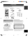 5
5
-
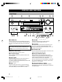 6
6
-
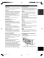 7
7
-
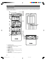 8
8
-
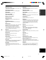 9
9
-
 10
10
-
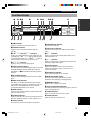 11
11
-
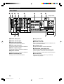 12
12
-
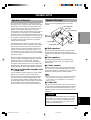 13
13
-
 14
14
-
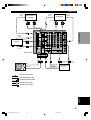 15
15
-
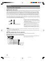 16
16
-
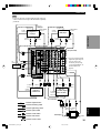 17
17
-
 18
18
-
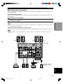 19
19
-
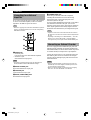 20
20
-
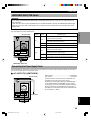 21
21
-
 22
22
-
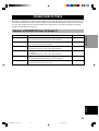 23
23
-
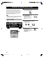 24
24
-
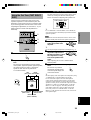 25
25
-
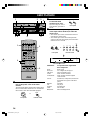 26
26
-
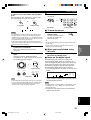 27
27
-
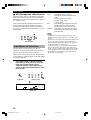 28
28
-
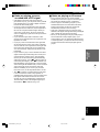 29
29
-
 30
30
-
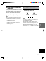 31
31
-
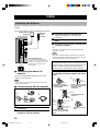 32
32
-
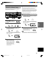 33
33
-
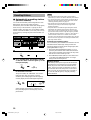 34
34
-
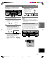 35
35
-
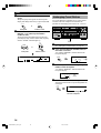 36
36
-
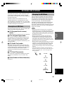 37
37
-
 38
38
-
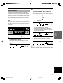 39
39
-
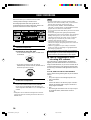 40
40
-
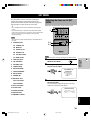 41
41
-
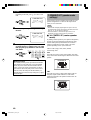 42
42
-
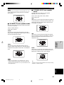 43
43
-
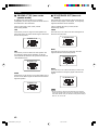 44
44
-
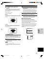 45
45
-
 46
46
-
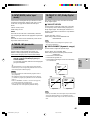 47
47
-
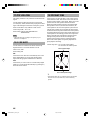 48
48
-
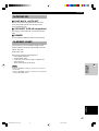 49
49
-
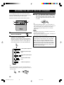 50
50
-
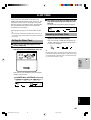 51
51
-
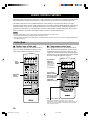 52
52
-
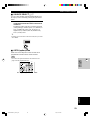 53
53
-
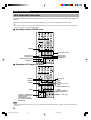 54
54
-
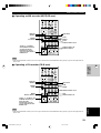 55
55
-
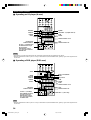 56
56
-
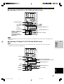 57
57
-
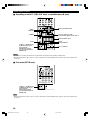 58
58
-
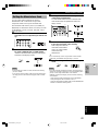 59
59
-
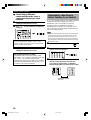 60
60
-
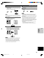 61
61
-
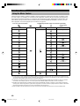 62
62
-
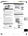 63
63
-
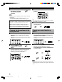 64
64
-
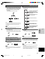 65
65
-
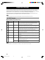 66
66
-
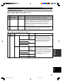 67
67
-
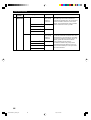 68
68
-
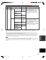 69
69
-
 70
70
-
 71
71
-
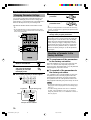 72
72
-
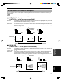 73
73
-
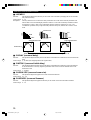 74
74
-
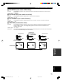 75
75
-
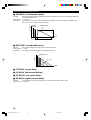 76
76
-
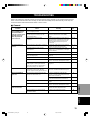 77
77
-
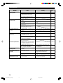 78
78
-
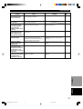 79
79
-
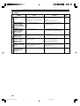 80
80
-
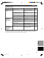 81
81
-
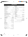 82
82
-
 83
83
-
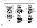 84
84
-
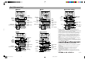 85
85


Yamaha RX-V1000RDS de handleiding
- Categorie
- AV-ontvangers
- Type
- de handleiding
in andere talen
- English: Yamaha RX-V1000RDS Owner's manual
- italiano: Yamaha RX-V1000RDS Manuale del proprietario
- français: Yamaha RX-V1000RDS Le manuel du propriétaire
- Deutsch: Yamaha RX-V1000RDS Bedienungsanleitung
- dansk: Yamaha RX-V1000RDS Brugervejledning
- svenska: Yamaha RX-V1000RDS Bruksanvisning
- Türkçe: Yamaha RX-V1000RDS El kitabı
- română: Yamaha RX-V1000RDS Manualul proprietarului
Gerelateerde papieren
-
Yamaha RX-V357 de handleiding
-
Yamaha RX-497 de handleiding
-
-
-
-
-
-
-
-