
YAMAHA
SY85 Music Synthesizer
Owner’s Manual 2
- Feature Reference -

GENERAL EDITING PROCEDURE
PATTERN EDIT MODE
SONG EDIT MODE
DRUM VOICE EDIT MODE
VOICE EDIT MODE
PERFORMANCE EDIT MODE
UTILITY MODE
WAVE EDIT MODE
APPENDIX

2
CONTENTS
GENERAL EDITING PROCEDURE
■ Mode Selection .............................................8
■ Selecting Specific Edit Functions...............8
■ Selecting & Editing Parameters................10
■ Controller Assignment Display..................11
Performance Edit Mode
■ Edit
1: Layer
1: Voice Number .................................14
2: Volume .............................................15
3: Pan ...................................................16
4: Tune .................................................17
5: Note Limit ........................................18
6: Velocity Limit...................................20
7: CS Enable .......................................22
Layer Data Copy.................................23
2: Performance Total Level .....................24
3: Performance Name ..............................25
4: Layer Voice Edit
1: Oscillator..........................................26
2: Amplitude EG..................................26
3: Filter .................................................26
4: Pitch EG ..........................................26
5: LFO ..................................................26
6: Controller .........................................26
7: Voice Total Level ...........................26
8: Voice Name.....................................26
■ Quick Edit
1: Amplitude EG Offset............................27
2: LFO & Filter Offset ..............................29
3: Controller Conditions ...........................31
4: Other Conditions ..................................33
5: Effect Type............................................35
6: Effect Parameter ..................................36
■ Effect Edit
1: Mode, Type ...........................................37
2: Send Select & Level............................38
3: Layer Dry Output Select .....................40
4: Output Level .........................................41
5: Wet : Dry Balance ...............................42
6: Send & Effect 2 Mix Level .................43
7: Effect 1 Parameters.............................44
8: Effect 2 Parameters.............................44
9: Control Parameters ..............................45
10: Control LFO ........................................47
Effect Data Copy.......................................48
Effect Signal Flow Display.......................49
■ Job
1: Layer Controller Sync..........................50
2: Layer Exchange....................................51
3: Performance Edit Recall .....................52
4: Performance Initialize ..........................53
■ Performance Compare...............................54
■ Performance Store .....................................55
Voice Edit Mode
■ Edit
1: Oscillator................................................58
2: Amplitude EG
1: AEG Level & Rate .........................60
2: Level Scaling ..................................62
3: Sensitivity ........................................63
AEG Data Copy...................................64
3: Filter
1: Type, Cutoff Frequency.................65
2: Cutoff Scaling .................................69
3: FEG Level & Rate..........................70
4: Filter Sensitivity ..............................72
Filter Data Copy..................................73
4: Pitch EG
1: Level & Rate...................................74
2: Range, Sensitivity...........................76
Pitch EG Data Copy...........................77
5: LFO
1: LFO ..................................................78

3
2: LFO Speed Sensitivity...................80
LFO Data Copy ...................................81
6: Controller
1: Pitch Bend Range ..........................82
2: Modulation Wheel Depth ...............83
3: Foot Controller Depth ....................85
4: After Touch Depth..........................87
5: CS3 Parameter Edit.......................89
6: CS4 Parameter Edit.......................91
Controller Data Copy..........................93
7: Voice Total Level ...........................94
8: Voice Name.....................................95
■ Quick Edit
1: Wave......................................................96
2: Amplitude EG........................................98
3: Filter.................................................... 100
4: LFO ..................................................... 102
5: Effect Type......................................... 103
6: Effect Parameter ............................... 104
■ Effect Edit
1: Mode, Type ........................................ 105
2: Send, Mix, Wet : Dry........................ 106
3: Output Level ...................................... 108
4: Effect 1 Parameters.......................... 109
5: Effect 2 Parameters.......................... 109
6: Control Parameters ........................... 110
7: Effect LFO.......................................... 112
Effect Data Copy.................................... 113
Effect Signal Flow Display.................... 114
■ Job
1: Voice Edit Recall............................... 115
2: Voice Initialize ................................... 116
■ Voice Compare ........................................ 117
■ Voice Store............................................... 118
Drum Voice Edit Mode
■ Edit
1: Key Parameters 1 ............................. 120
2: Key Parameters 2 ............................. 122
3: Total Level ......................................... 123
4: Drum Voice Name............................. 124
Drum Key Data Copy ............................ 125
■ Quick Edit
1: Effect Type......................................... 126
2: Effect Send Level.............................. 127
■ Effect Edit
1: Mode, Type ........................................ 128
2: Key Send Select & Level................. 129
3: Key Dry Output Select ..................... 131
4: Output Level ...................................... 132
5: Wet : Dry Balance ............................ 133
6: Send & Effect 2 Mix Level .............. 134
7: Effect 1 Parameter2.......................... 135
8: Effect 2 Parameter2.......................... 135
9: Control Parameters ........................... 136
10: Control LFO ..................................... 138
Effect Data Copy.................................... 139
Effect Signal Flow Display.................... 140
■ Job
1: Key Data Initialize............................. 141
2: Key Data Exchange .......................... 142
3: Drum Voice Edit Recall.................... 143
4: Drum Voice Initialize......................... 144
■ Drum Voice Compare ............................. 145
■ Drum Voice Store.................................... 146

4
Song Edit Mode
■ Multi Edit
1: Voice Select ....................................... 148
2: Volume................................................ 149
3: Pan...................................................... 150
4: Effect Send Level.............................. 151
5: Note Shift ........................................... 152
6: Tune.................................................... 153
7: Effect Type, Out Balance................. 154
8: Song Name ........................................ 155
9: Song Initialize .................................... 156
■ Track Edit ................................................. 157
■ Effect Edit
1: Mode, Type ........................................ 166
2: Send Select & Level......................... 167
3: Inst Dry Output Select...................... 169
4: Output Level ...................................... 170
5: Wet : Dry Balance ............................ 171
6: Send & Effect 2 Mix Level .............. 172
7: Effect 1 Parameters.......................... 173
8: Effect 2 Parameters.......................... 173
9: Control Parameters ........................... 174
10: Control LFO ..................................... 176
Effect Data Copy.................................... 177
Effect Signal Flow Display.................... 178
■ Job
1: Clear Song ......................................... 179
2: Copy Song ......................................... 180
3: Memory Status/Clear Rhythm Track
.................................................... 181,182
4: Track Mixdown................................... 183
5: Delete Track ...................................... 185
6: Quantize ............................................. 186
7: Copy Measure ................................... 188
8: Delete Measure ................................. 190
9: Insert Measure................................... 191
10: Erase Measure ................................ 192
11: Remove Event ................................. 193
12: Clock Move ...................................... 195
13: Transpose......................................... 196
14: Note Shift ......................................... 197
15: Velocity Modify ................................ 198
16: Gate Time Modify ........................... 199
17: Crescendo ........................................ 200
Pattern Edit Mode
■ Job
1: Copy Pattern...................................... 202
2: Clear Pattern...................................... 203
3: Instrument Change............................ 204
4: Velocity Modify .................................. 205
■ Pattern Name........................................... 207
Utility Mode
■ Synth Setup
1: System................................................ 210
2: MIDI 1 (Channel Parameters) ......... 212
3: MIDI 2 (Other Parameters).............. 213
4: Program Change Table .................... 215
5: Velocity ............................................... 216
■ SEQ Setup
1: Click Condition................................... 217
2: Record Condition............................... 219
3: Accent Velocity.................................. 220
4: Song Chain ........................................ 221
■ Bulk Dump
1: all......................................................... 222
2: synth all.............................................. 222
3: sequencer all ..................................... 222
4: pattern all ........................................... 222
5: 1 performance.................................... 222
6: 1 voice ................................................ 222
7: 1 song................................................. 222

5
■ Card
1: Card All Load/Save........................... 223
2: Card Format....................................... 224
■ Disk
1: Disk All Load/Save............................ 225
2: Disk All Load/Save Synth ................ 225
3: Disk All Load/Save Seq ................... 225
4: Disk NSEQ Load/Save ..................... 225
5: Disk Other Load/Save ...................... 225
6: MDR .................................................... 228
7: Rename/Delete .................................. 231
8: Backup Disk....................................... 232
9: Disk Status......................................... 234
10: Disk Format ..................................... 235
Wave Edit Mode
■ Wave Number Select .............................. 239
■ Edit
1: Waveform
1: Wave Assign ................................ 240
2: Wave Name ................................. 240
2: Sample
1: Sample Key Map......................... 243
2: Sample Data ................................ 243
■ Wave Initialize.......................................... 247
■ Sample Dump
1: Sample Dump Recieve..................... 248
2: Sample Dump Transmit.................... 249
■ Wave Card Load ..................................... 250
■ Wave Disk Load/Save 1 Sample .......... 251
■ Wave Memory Status Display................ 252
APPENDIX
■ EFFECTS.................................................. 254
Effect Signal Flow Diagrams — Voice
Mode........................................................ 256
Effect Signal Flow Diagrams — Drum Voice,
Performance, and Song Modes..................
264
The Effects & Their Parameters.......... 274
■ WAVE MEMORY EXPANSION.............. 285
Memory Installation................................ 286
■ INITIAL DATA & BLANK CHART
INITIAL PERFORMANCE “InitPerf” ..... 289
INITIAL NORMAL VOICE “InitVce”...... 290
INITIAL DRUM VOICE “DR PTN”........ 292
INITIAL DRUM VOICE “DR Zones”..... 294
INITIAL DRUM VOICE “DR GMIDI” .... 296
INITIAL DRUM VOICE “DR Efect” ...... 298
INITIAL MULTI “InitSong” ..................... 300
SYSTEM SETUP.................................... 301
INTERNAL PERFORMANCE LIST (1)....
302
INTERNAL PERFORMANCE LIST (2)....
304
INTERNAL VOICE LIST (1).................. 306
INTERNAL VOICE LIST (2).................. 307
INTERNAL VOICE LIST (3).................. 308
INTERNAL VOICE LIST (4).................. 309
INTERNAL WAVE LIST......................... 310
BLANK CHART — PERFORMANCE... 311
BLANK CHART — VOICE.................... 312
BLANK CHART — DRUM VOICE ....... 314
BLANK CHART — MULTI .................... 316
BLANK CHART — SYSTEM SETUP .. 317
■ About the Standard MIDI File Format .. 318
■ SPECIFICATIONS ................................... 319
■ ERROR MESSAGES............................... 320
■ TROUBLE SHOOTING............................ 324
■ INDEX ....................................................... 326


GENERAL EDITING
PROCEDURE
■ Mode Selection ........................................... 8
■ Selecting Specific Edit Functions ............... 8
■ Selecting & Editing Parameters ............... 10
■ Controller Assignment Display ................. 11

8
The SY85 makes editing easy by providing a consistent, logical control
interface via which parameters can be located and edited. Once you’ve learned
the general procedure, you can locate and edit any of the SY85’s many param-
eters quickly and easily.
■ Mode Selection
All SY85 edit modes are selected via the MODE matrix keys. To select the
VOICE EDIT mode, for example, press the VOICE mode key so that its indica-
tor lights, than press the second SUB MODE key in the VOICE column
(EDIT).
■ Selecting Specific Edit Functions
Once you’ve selected an edit mode, one way to select the various edit
screens and functions it contains is to use the PAGE [ ] and [ ] keys. The
[ ] and [ ] keys step backward and forward through the available screens,
respectively. Hold either of these keys for continuous stepping in the specified
direction.
An alternative method is to use the [MENU] key. If you press the [MENU]
key ion the VOICE EDIT mode, for example, you’ll see a display something
like this:
GENERAL EDITING PROCEDURE
The illustrations here are not available.

9
From this display you can use either the data entry dial or the [-1] and [+1]
keys to directly select any of the 8 available functions, then press the [ENTER/
YES] key to actually select the specified function.
In some cases the PAGE [ ] and [ ] or [MENU] keys will take you to
another entry screen. If you select “3: Filter” after pressing the [MENU] key in
the VOICE EDIT mode, and then press [ENTER/YES], you’ll see the following
display:
“Hit [ENTER]” will be flashing. In this case press [ENTER/YES] again to
access the filter functions. Once in the filter “sub-mode” you can use the PAGE
[ ] and [ ] or [MENU] keys to select the various filter functions, as de-
scribed above. When you have finished with the filter functions, press [EXIT/
NO] to return to the normal VOICE EDIT mode.
GENERAL EDITING PROCEDURE
The illustrations here are not available.

10
■ Selecting & Editing Parameters
Most SY85 edit screens contain several parameters that can be selected and
edited. In most cases you can simply operate the continuous slider immediately
below the parameter you want to edit on the display. Operating a slider auto-
matically moves the underline cursor to the corresponding parameter. In the
example below, for example (this is the VOICE EDIT mode Oscillator screen),
the [CS5] slider can be used to adjust the “Fine” parameter.
The parameters can also be edited by first moving the cursor to the required
parameter by pressing the corresponding function key ([F7], for example, would
select the “Rndm” parameter in the above display), and then by using either the
data entry dial or the [-1] and [+1] keys to adjust the parameter’s value.
In some special cases you’ll also use the function keys as parameter
“switches,” and the [SHIFT] key is sometimes called into play to access sec-
ondary functions. Such exceptions are described in the appropriate sections of
the manual.
GENERAL EDITING PROCEDURE
The illustrations here are not available.

11
■ Controller Assignment Display
It is possible to assign a wide range of parameters to be controlled by the
[CS1] through [CS4] sliders when playing in the VOICE or PERFORMANCE
PLAY modes. Since it is easy to forget what parameters have been assigned to
which sliders, the SY85 features a controller assignment display that can be
selected temporarily by pressing the [SHIFT] key in the VOICE or PERFORM-
ANCE PLAY mode.
● PERFORMANCE PLAY mode
● VOICE PLAY mode
● DRUM VOICE PLAY mode
This display shows the names of the parameters assigned to sliders [CS1]
through [CS4] for the current voice or performance combination, so you can
take a quick peek to refresh your memory even while playing.
GENERAL EDITING PROCEDURE


PERFORMANCE EDIT MODE

14
1: VOICE NUMBER
[PERFORMANCE] → [EDIT] → [MENU] → 1:Layer → [ENTER/YES] → [ENTER/YES] →
→ [MENU] → 1:Voice Number → [ENTER/YES]
SY85 performance combinations can have up to four voices assigned to different
“layers” — A, B, C and D. This screen lets you assign voices to the layers.
PERFORMANCE EDIT MODE / 1:Layer
Voice Number A, B, C, D
Range: off, A1 … H7 (internal & card)
Controls: MEMORY, GROUP, PROGRAM, [CS2], [CS4], [CS6], [CS8],
[-1] [+1], Dial
After moving the cursor to the layer you want to edit by pressing the [F2],
[F4], [F6] or [F8] function key, use the [INTERNAL 1], [INTERNAL 2], and
[CARD] keys to select the memory area from which the voice is to be selected,
and then use the GROUP and PROGRAM keys to select the voice. Voices
within the selected memory bank can also be selected directy for each layer by
the [CS2], [CS4], [CS6], and [CS8] keys. Internal and card voices cannot be
mixed.
The voices can individually turned on or off by using the [-] (off) and [+]
(on) keys while holding the [SHIFT] key.
The name of the currently selected voice is shown in the upper right corner
of the display. The characters “ABCD” to the right of the voice name indicate
the status of each voice:
• Capital letter = voice on.
• Lower-case letter = voice muted.
• “-” = voice is off.
For example, “Ab-D” indicates that voices A and D are on, voice B is
muted, and voice C is off.
F1
CS1
F2
CS2
F3
CS3
F4
CS4
F5
CS5
F6
CS6
F7
CS7
F8
CS8

15PERFORMANCE EDIT MODE / 1:Layer
2: VOLUME
For optimum balance between the voices in a performance combination, this
screen allows the volume of each voice to be adjusted individually.
The name of the currently selected voice/layer is shown in the upper right
corner of the display. The characters “ABCD” to the right of the voice name
indicate the status of each voice: a capital letter if the voice is on, a lower-case
letter if the voice is muted, and a dash if the voice is off.
Volume
Range: 0 … 127
Controls: [CS2], [CS4], [CS6], [CS8], [-1] [+1], Dial
Use the [CS2], [CS4], [CS6], and [CS8] sliders to adjust the volume levels
of the A, B, C, and D layer voices, respectively. A setting of “0” produces no
sound, while a setting of “127” produces maximum volume. The vertical bar
graphs next to each parameter provide a visual indication of volume levels —
the longer the bar the higher the volume. Voices that are turned off are indi-
cated by “----” on the display.
[PERFORMANCE] → [EDIT] → [MENU] → 1:Layer → [ENTER/YES] → [ENTER/YES] →
→ [MENU] → 2:Volume → [ENTER/YES]
F1
CS1
F2
CS2
F3
CS3
F4
CS4
F5
CS5
F6
CS6
F7
CS7
F8
CS8

16
3: PAN
[PERFORMANCE] → [EDIT] → [MENU] → 1:Layer → [ENTER/YES] → [ENTER/YES] →
→ [MENU] → 3:Pan → [ENTER/YES]
In multi-layer performance combinations, interesting stereo effects can be pro-
duced by placing the output from different layers at different locations in the stereo
sound field. The parameters in this screen determine the position in the stereo sound
field in which the sound from each active layer will be heard (left to right).
PERFORMANCE EDIT MODE / 1:Layer
The name of the currently selected voice/layer is shown in the upper right
corner of the display. The characters “ABCD” to the right of the voice name
indicate the status of each voice: a capital letter if the voice is on, a lower-case
letter if the voice is muted, and a dash if the voice is off.
Pan
Range: -31 … +31
Controls: [CS2], [CS4], [CS6], [CS8], [-1] [+1], Dial
Use the [CS2], [CS4], [CS6], and [CS8] sliders to adjust the pan positions
of the A, B, C, and D layer voices, respectively. Minus values represent pan-
ning to the left, and positive values represent panning to the right. “0” posi-
tions the sound of the selected layer in the center of the stereo sound field.
Voices that are turned off are indicated by “---” on the display. The upper line
of the display also shows a graphic representation of the stereo sound field
with “L” representing “left” and “R” representing “right.” As you change the
pan value the vertical bar will appear at the corresponding position on the
graphic display.
F1
CS1
F2
CS2
F3
CS3
F4
CS4
F5
CS5
F6
CS6
F7
CS7
F8
CS8

17PERFORMANCE EDIT MODE / 1:Layer
4: TUNE
More than just simple tuning, the note shift and fine tune parameters make it
possible to create harmony and voice-thickening detune effects between layers.
[PERFORMANCE] → [EDIT] → [MENU] → 1:Layer → [ENTER/YES] → [ENTER/YES] →
→ [MENU] → 4:Tune → [ENTER/YES]
The name of the currently selected voice/layer is shown in the upper right
corner of the display. The characters “ABCD” to the right of the voice name
indicate the status of each voice: a capital letter if the voice is on, a lower-case
letter if the voice is muted, and a dash if the voice is off.
NtShft (Note shift)
Range: -63 … +63
Controls: [CS1], [CS3], [CS5], [CS7], [-1] [+1], Dial
Individually shifts the pitch of each active element up or down in semitone
steps.
Use the [CS1], [CS3], [CS5], and [CS7] sliders to shift the pitch of the A,
B, C, and D layer voices, respectively. A setting of “-12,” for example, shifts
the pitch of the selected layer down by one octave; a setting of “+4” shifts the
pitch up by a major third.
The Note Shift parameter can be used to transpose a voice to its most
useful range, or to create harmony (intervals) between different layers in a
performance combination.
Voices that are turned off are indicated by “---” on the display.
Fine (Fine tuning)
Range: -7 … +7
Controls: [CS2], [CS4], [CS6], [CS8], [-1] [+1], Dial
Allows slight upward or downward pitch adjustment of each active element.
Use the [CS2], [CS4], [CS6], and [CS8] sliders to fine tune the A, B, C,
and D layer voices, respectively.
The maximum minus setting of “-7” produces a downward pitch shift of
approximately 2 cents (a “cent” is 1/100th of a semitone), and the maximum
plus setting of “+7” produces an upward pitch shift of approximately 2 cents. A
setting of “0” produces no pitch change.
The Fine parameter allows different layers in a performance combination to
be slightly detuned in relation to each other, thereby “thickening” the overall
sound.
Voices that are turned off are indicated by “--” on the display.
F1
CS1
F2
CS2
F3
CS3
F4
CS4
F5
CS5
F6
CS6
F7
CS7
F8
CS8

18
5: NOTE LIMIT
[PERFORMANCE] → [EDIT] → [MENU] → 1:Layer → [ENTER/YES] → [ENTER/YES] →
→ [MENU] → 5:Note Limit → [ENTER/YES]
The low and high note limit parameters make it possible to create a range of split
keyboard effects using the performance layers. You could have two layers on either
side of a single split point, a four-way split keyboard, or any other possible combina-
tion.
PERFORMANCE EDIT MODE / 1:Layer
The name of the currently selected voice/layer is shown in the upper right
corner of the display. The characters “ABCD” to the right of the voice name
indicate the status of each voice: a capital letter if the voice is on, a lower-case
letter if the voice is muted, and a dash if the voice is off.
Lo (Low note limit)
Range: C-2 … G8
Controls: [CS1], [CS3], [CS5], [CS7], [-1] [+1], Dial,
[SHIFT]+keyboard
Individually sets the low note limit for each active layer (the lowest note
that each layer will produce).
Use the [CS1], [CS3], [CS5], and [CS7] sliders to set the low note limits of
the A, B, C, and D layer voices, respectively. It is also possible to press the
desired note on the keyboard while holding the [SHIFT] key.
The C-2 to G8 range of this parameter covers a full 10-1/2 octaves. “C3”
corresponds to “middle C” on a keyboard.
This parameter, in conjunction with the High Note Limit parameter de-
scribed below, allows the sound from a layer to be limited to a specific region
of the keyboard. If the Low Note Limit is set to C3 and the High Note Limit
for the same layer is set to C4, for example, the sound from that layer will
only be produced between C3 and C4 — the octave immediately above middle
C. This makes it simple to produce split voices.
If the High Note Limit is set to a note that is
lower than the Low Note
Limit for the same layer, the notes between the high and low limits will not
sound.
Voices that are turned off are indicated by “---” on the display.
F1
CS1
F2
CS2
F3
CS3
F4
CS4
F5
CS5
F6
CS6
F7
CS7
F8
CS8
≥ ≥ ≥ ≥

19PERFORMANCE EDIT MODE / 1:Layer
Hi (High note limit)
Range: C-2 … G8
Controls: [CS2], [CS4], [CS6], [CS8], [-1] [+1], Dial,
[SHIFT]+keyboard
Individually sets the high note limit for each active layer (the highest note
that each layer will produce).
Use the [CS2], [CS4], [CS6], and [CS8] sliders to set the high note limits
of the A, B, C, and D layer voices, respectively. It is also possible to press the
desired note on the keyboard while holding the [SHIFT] key.
See the “Lo” parameter, above, for more details.

20
6: VELOCITY LIMIT
[PERFORMANCE] → [EDIT] → [MENU] → 1:Layer → [ENTER/YES] → [ENTER/YES] →
→ [MENU] → 6:VelocityLimit → [ENTER/YES]
The high and low velocity limit parameters make it possible to produce a range of
“velocity switching” effects in which different layers of a performance combination
are set up to produce sound only when the keyboard is played at a certain velocity.
You could, for example, produce a flute sound by playing softly, and a horn sound
by playing harder.
PERFORMANCE EDIT MODE / 1:Layer
F1
CS1
F2
CS2
F3
CS3
F4
CS4
F5
CS5
F6
CS6
F7
CS7
F8
CS8
The name of the currently selected voice/layer is shown in the upper right
corner of the display. The characters “ABCD” to the right of the voice name
indicate the status of each voice: a capital letter if the voice is on, a lower-case
letter if the voice is muted, and a dash if the voice is off.
Lo (Low velocity limit)
Range: 1 … 127
Controls: [CS1], [CS3], [CS5], [CS7], [-1] [+1], Dial,
[SHIFT]+keyboard
Sets the lowest velocity value for a range of velocity values over which
each active layer will produce output.
Use the [CS1], [CS3], [CS5], and [CS7] sliders to set the low velocity
limits of the A, B, C, and D layer voices, respectively. It is also possible to
play any note on the keyboard at the desired velocity while holding the
[SHIFT] key.
Every note played on the keyboard (or external MIDI controller) produces a
“velocity” value that tells the tone generator how hard the note has been
played. The range of MIDI velocity values is from 1 to 127 — thus the 1 ...
127 range of this parameter.
The Low Velocity Limit parameter, in conjunction with the High Velocity
Limit parameter described below, makes it possible to specify a range of veloc-
ity values over which the selected layer will produce sound. You could, for
example, set Low Velocity Limit to “60” and High Velocity Limit to “127.”
This would cause that layer to produce output
only when a velocity value
between 60 and 127 was received — i.e. when a fairly loud note is played. A
second layer could then be set to produce output only when velocity values
below 60 are received, so that completely different sounds are produced on soft
and loud notes.
Voices that are turned off are indicated by “---” on the display.

21PERFORMANCE EDIT MODE / 1:Layer
Hi (High velocity limit)
Range: 1 … 127
Controls: [CS2], [CS4], [CS6], [CS8], [-1] [+1], Dial,
[SHIFT]+keyboard
Sets the highest velocity value for a range of velocity values over which
each active layer will produce output.
Use the [CS2], [CS4], [CS6], and [CS8] sliders to set the high velocity
limits of the A, B, C, and D layer voices, respectively. It is also possible to
play any note on the keyboard at the desired velocity while holding the
[SHIFT] key.
See the “Lo” parameter, above, for more details.

22
7: CS ENABLE
[PERFORMANCE] → [EDIT] → [MENU] → 1:Layer → [ENTER/YES] → [ENTER/YES] →
→ [MENU] → 7:CS Enable → [ENTER/YES]
The CS3 and CS4 sliders can be used to control the level of individual layers or
specified groups of layers in the performance play mode. This screen specifies which
slider controls which layers.
PERFORMANCE EDIT MODE / 1:Layer
The name of the currently selected voice/layer is shown in the upper right
corner of the display. The characters “ABCD” to the right of the voice name
indicate the status of each voice: a capital letter if the voice is on, a lower-case
letter if the voice is muted, and a dash if the voice is off.
CS3 Enable
Range: on, off
Controls: [CS1], [CS3], [CS5], [CS7], [-1] [+1], Dial
The [CS1], [CS3], [CS5], and [CS7] sliders turn CS3 control of layers A,
B, C, and D on or off, respectively.
Voices that are turned off and are not available for editing are indicated by
“---” on the display.
CS4 Enable
Range: on, off
Controls: [CS2], [CS4], [CS6], [CS8], [-1] [+1], Dial
The [CS2], [CS4], [CS6], and [CS8] sliders turn CS4 control of layers A,
B, C, and D on or off, respectively.
Voices that are turned off and are not available for editing are indicated by
“---” on the display.
F1
CS1
F2
CS2
F3
CS3
F4
CS4
F5
CS5
F6
CS6
F7
CS7
F8
CS8

23PERFORMANCE EDIT MODE / 1:Layer
LAYER DATA COPY
[PERFORMANCE] → [EDIT] → [MENU] → 1:Layer → [ENTER/YES] → [COPY]
This function facilitates performance editing by allowing the layer parameters
from any layer in any other performance (the “source” performance) to be copied to
the current layer. You can copy a layer setup that is close to the type you want, then
edit it to produce the required sound.
From Performance
Range: Any INTERNAL or CARD performance
Controls: MEMORY, GROUP, PROGRAM, [CS5], [-1] [+1], Dial
Layer
Range: A, B, C, D
Controls: [CS8], [-1] [+1], Dial
Use the [INTERNAL 1], [INTERNAL 2], and [CARD] MEMORY keys to
select the memory area from which the source performance is to be selected.
Use the GROUP keys to select the source performance bank, then use the
PROGRAM keys to select the source performance number. The [CS5] slider
and other data entry controls can also be used to select the source performance
number. Use the [CS8] slider to select the source layer.
Once the source performance and layer has been selected, press the [EN-
TER/YES] key. “Are you sure?” will appear on the display.
Press the [ENTER/YES] key again to copy the layer data, or press [EXIT/
NO] to cancel the copy operation. Once the copy operation has finished, “Com-
pleted!” will appear on the display briefly, then the display will return to the
layer edit mode.
F1
CS1
F2
CS2
F3
CS3
F4
CS4
F5
CS5
F6
CS6
F7
CS7
F8
CS8

24 PERFORMANCE EDIT MODE / 2:Volume
This parameter sets the overall volume of the current performance combination in
relation to the others, making it possible to match levels for smooth transition when
switching between performance combinations.
PERFORMANCE TOTAL LEVEL
[PERFORMANCE] → [EDIT] → [MENU] → 2:Total Level → [ENTER/YES]
Total Level
Range: 0 … 127
Controls: [CS4], [-1] [+1], Dial
Adjusts the volume of the current performance.
A setting of “0” produces no sound while a setting of “127” produces
maximum volume. A bar graph to the right of the parameter provides a visual
indication of volume level — the longer the bar, the higher the volume.
F1
CS1
F2
CS2
F3
CS3
F4
CS4
F5
CS5
F6
CS6
F7
CS7
F8
CS8

25PERFORMANCE EDIT MODE / 3:Name
Your original performance combinations should naturally have original names.
This function can be used to assign a name of up to 8 characters to the current
performance.
PERFORMANCE NAME
[PERFORMANCE] → [EDIT] → [MENU] → 3:Name → [ENTER/YES]
Name
Range: See character list, below
Controls: GROUP, PROGRAM, [F1] … [F4], [F7], [F8],
[CS1] … [CS8], [-1] [+1], Dial
Assigns a name of up to 8 characters to the current performance.
Use the [F7] function key to move the character cursor to the left, and the
[F8] function key to move the cursor to the right. Use the GROUP and PRO-
GRAM keys to input a character at the cursor position. Each GROUP or PRO-
GRAM key selects the three characters printed above it in sequence. It is also
possible to use the [-1] and [+1] keys or dial to scroll through the available
characters (see list below).
The sliders, [CS1] through [CS8], independently select characters for the
corresponding character position: [CS1] selects the first character, [CS2] selects
the second character, and so on.
The first four function keys also perform important functions: [F1] clears
the entire name, [F2] selects upper-case characters for GROUP and PROGRAM
key entry, [F3] selects lower-case characters for GROUP and PROGRAM key
entry, and [F4] inserts a space at the cursor position.
F1
CS1
F2
CS2
F3
CS3
F4
CS4
F5
CS5
F6
CS6
F7
CS7
F8
CS8
[A]: A → B → C
[B]: D → E → F
[C]: G → H → I
[D]: J → K → L
[E]: M → N → O
[F]: P → Q → R
[G]: S → T → U
[H]: V → W → X
[1]: Y → Z → 0
[2]: 1 → 2 → 3
[3]: 4 → 5 → 6
[4]: 7 → 8 → 9
[5]: * → & → _
[6]: / → . → ,
[7]: ’ → ! → ?
[8]: # → : → ;
PROGRAM key
GROUP key

26
The Layer Voice Edit menu allows you to access any of the voice edit parameters
for the voice assigned to the currently selected performance layer, without having to
leave the performance edit mode.
LAYER VOICE EDIT MENU
[PERFORMANCE] → [EDIT] → [MENU] → 4:Layer Voice → [ENTER/YES]
Press [ENTER/YES] from the entry display (above) to access the layer
voice edit menu.
Use the [CS3] slider, the [-1] and [+1] keys, or the data entry dial to select
the desired voice edit screen, then press [ENTER/YES] to jump to selected
screen. Other voice edit screens can then be selected by using the [ ] and [ ]
keys. The available voice edit screens are listed below:
1: Oscillator
2: Amplitude EG
3: Filter
4: Pitch EG
5: LFO
6: Controller
7: VOICE Total Level
8: VOICE Name
While editing the voice parameters in voice edit screens 2 through 7, above,
the PROGRAM keys [1] through [4] (LAYER SELECT A, B, C, and D) can be
used to select a different layer for editing. PROGRAM keys [5] through [8] can
also be used for layer muting.
Press [EXIT/NO] to return to the performance edit mode when you’re
finished with the voice edit parameters. Refer to pages 58 through 95 in the
“Voice Edit Mode” section for details on the voice edit parameters.
PERFORMANCE EDIT MODE / 4:Layer Voice
F1
CS1
F2
CS2
F3
CS3
F4
CS4
F5
CS5
F6
CS6
F7
CS7
F8
CS8

27PERFORMANCE EDIT MODE / QUICK EDIT
These parameters allow the amplitude envelopes of the voices assigned to each
layer to be modified to some degree. The actual amplitude EG of the voices are not
affected, these “offset” values are only effective in the performance mode.
1: AMPLITUDE EG OFFSET
[PERFORMANCE] → [QUICK EDIT] → [MENU] → 1:AEG Offset → [ENTER/YES]
Use PROGRAM keys [1] through [4] (LAYER SELECT A, B, C, and D) to
select the layer to be edited.
Hold the [F1] function key (“ALL”) while editing any of the following
parameters to change its value by the same amount for all layers simultane-
ously.
R1 (Attack rate)
Range: -63 … +63
Controls: [CS3], [-1] [+1], Dial
Modifies the “R1” parameter of the voice amplitude EG — see page 60.
Plus (+) values produce a faster attack rate while minus (-) values produce a
slower attack rate.
No matter how much offset is applied, the minimum and maximum EG
attack rates cannot be exceeded.
R2,3 (Decay 1 rate)
Range: -63 … +63
Controls: [CS4], [-1] [+1], Dial
Modifies the “R2” and “R3” parameters of the voice amplitude EG — see
page 60. Plus (+) values produce a faster decay rate while minus (-) values
produce a slower decay rate.
No matter how much offset is applied, the minimum and maximum EG
decay rates cannot be exceeded.
R4 (Decay 2 rate)
Range: -63 … +63
Controls: [CS5], [-1] [+1], Dial
Modifies the “R4” parameter of the voice amplitude EG — see page 60.
Plus (+) values produce a faster decay rate while minus (-) values produce a
slower decay rate.
No matter how much offset is applied, the minimum and maximum EG
decay rates cannot be exceeded.
F1
CS1
F2
CS2
F3
CS3
F4
CS4
F5
CS5
F6
CS6
F7
CS7
F8
CS8

28 PERFORMANCE EDIT MODE / QUICK EDIT
RR (Release rate)
Range: -63 … +63
Controls: [CS6], [-1] [+1], Dial
Modifies the “RR” parameter of the voice amplitude EG — see page 60.
Plus (+) values produce a faster release rate while minus (-) values produce a
slower release rate.
No matter how much offset is applied, the minimum and maximum EG
release rates cannot be exceeded.
Vel (Velocity sensitivity)
Range: -14 ... +14
Controls: [CS7], [-1] [+1], Dial
Modifies the amplitude EG velocity sensitivity setting (see page 63). Plus
“+” settings increase sensitivity while minus “-” settings reduce sensitivity.
No matter how much offset is applied, the minimum and maximum velocity
values cannot be exceeded.

29PERFORMANCE EDIT MODE / QUICK EDIT
These parameters allow the main LFO and filter parameters of the voices assigned
to each layer to be modified to some degree. The actual LFO and filter parameters of
the voices are not affected, these “offset” values are only effective in the performance
mode.
2: LFO & FILTER OFFSET
[PERFORMANCE] → [QUICK EDIT] → [MENU] → 2:LFO,Filter Offset → [ENTER/YES]
Use PROGRAM keys [1] through [4] (LAYER SELECT A, B, C, and D) to
select the layer to be edited.
Hold the [F1] function key (“ALL”) while editing any of the following
parameters to change its value by the same amount for all layers simultane-
ously.
Speed (LFO speed)
Range: -99 … +99
Controls: [CS3], [-1] [+1], Dial
Modifies the speed of the LFO (this corresponds to the “Speed” parameter
of the main voice LFO — see page 78). Plus (+) values increase the LFO
speed while minus (-) values reduce the speed.
No matter how much offset is applied, the minimum and maximum LFO
speeds cannot be exceeded.
Depth (LFO depth)
Range: -99 … +99
Controls: [CS4], [-1] [+1], Dial
Modifies the amplitude, pitch, and frequency modulation depth of the LFO
(this corresponds to the “Pmod”, “Amod”, and “Fmod” parameters of the main
voice LFO — see page 78 and 79). Plus (+) values produce greater modulation
depth while minus (-) values reduce the modulation depth.
No matter how much offset is applied, the minimum and maximum LFO
depth values cannot be exceeded.
F1
CS1
F2
CS2
F3
CS3
F4
CS4
F5
CS5
F6
CS6
F7
CS7
F8
CS8

30 PERFORMANCE EDIT MODE / QUICK EDIT
Coff (Filter cutoff frequency)
Range: -127 … +127
Controls: [CS6], [-1] [+1], Dial
Modifies the filter cutoff frequency (this corresponds to the voice filter
“CutOff” parameter — see page 65). Plus (+) values increase the cutoff fre-
quency while minus (-) values lower the cutoff frequency. This parameter
cannot be used if the filter is set to “Thru”. In this case “----” appears in place
of the parameter value.
No matter how much offset is applied, the minimum and maximum cutoff
frequency values cannot be exceeded.
Reso (Filter resonance)
Range: -99 … +99
Controls: [CS7], [-1] [+1], Dial
Modifies the height of the filter’s resonant peak (this corresponds to the
filter “Resonance” parameter — see page 68). Plus (+) values increase reso-
nance while minus (-) values reduce resonance. This parameter cannot be used
if the filter is
not set to “LPF”. In this case “---” appears in place of the pa-
rameter value.
No matter how much offset is applied, the minimum and maximum reso-
nance values cannot be exceeded.
Vel (Velocity sensitivity)
Range: -127 ... +127
Controls: [CS8], [-1] [+1], Dial
Modifies the filter velocity sensitivity setting (see page 72). Plus “+” set-
tings increase sensitivity while minus “-” settings reduce sensitivity.
No matter how much offset is applied, the minimum and maximum velocity
values cannot be exceeded.

31PERFORMANCE EDIT MODE / QUICK EDIT
These parameters determine how the performance layers are affected by keyboard
aftertouch response, the modulation wheel, and the foot controller.
3: CONTROLLER CONDITIONS
[PERFORMANCE] → [QUICK EDIT] → [MENU] → 3:Controller Condition → [ENTER/YES]
Use PROGRAM keys [1] through [4] (LAYER SELECT A, B, C, and D) to
select the layer to be edited.
Hold the [F1] function key (“ALL”) while editing any of the following
parameters to change its value by the same amount for all layers simultane-
ously.
AT (Aftertouch)
Range: off, LyrA, LyrB, LyrC, LyrD
Controls: [CS3], [-1] [+1], Dial
The aftertouch control settings from the voice assigned to the selected layer
(LyrA, LyrB, LyrC, or LyrD) are applied to the layer being edited (i.e. the
layer selected via PROGRAM keys [1] through [4]). Select “off” to turn
aftertouch control off for the layer being edited.
MW (Modulation wheel)
Range: off, LyrA, LyrB, LyrC, LyrD
Controls: [CS4], [-1] [+1], Dial
The modulation wheel control settings from the voice assigned to the se-
lected layer (LyrA, LyrB, LyrC, or LyrD) are applied to the layer being edited
(i.e. the layer selected via PROGRAM keys [1] through [4]). Select “off” to
turn modulation wheel control off for the layer being edited.
FC (Foot controller)
Range: off, LyrA, LyrB, LyrC, LyrD
Controls: [CS6], [-1] [+1], Dial
The foot controller control settings from the voice assigned to the selected
layer (LyrA, LyrB, LyrC, or LyrD) are applied to the layer being edited (i.e.
the layer selected via PROGRAM keys [1] through [4]). Select “off” to turn
foot control off for the layer being edited.
F1
CS1
F2
CS2
F3
CS3
F4
CS4
F5
CS5
F6
CS6
F7
CS7
F8
CS8

32 PERFORMANCE EDIT MODE / QUICK EDIT
AT>MW (Aftertouch ➔ modulation wheel)
Range: off, on
Controls: [CS7], [-1] [+1], Dial
When this parameter is turned “on,” aftertouch can be used to prouce the
same effect as the modulation wheel, in addition to any parameters assigned to
aftertouch.
MW>AT (Modulation wheel ➔ aftertouch)
Range: off, on
Controls: [CS8], [-1] [+1], Dial
When this parameter is turned “on,” the modulation wheel can be used to
produce the same effect as aftertouch, in addition to any parameters assigned to
the modulation wheel.

33PERFORMANCE EDIT MODE / QUICK EDIT
Other parameters that can be individually set for each performance layer are
provided in this screen: sustain enable, pitch envelope generator enable, oscillator
fixed note mode and note number.
4: OTHER CONDITIONS
[PERFORMANCE] → [QUICK EDIT] → [MENU] → 4:Other Condition → [ENTER/YES]
Use PROGRAM keys [1] through [4] (LAYER SELECT A, B, C, and D) to
select the layer to be edited.
Hold the [F1] function key (“ALL”) while editing any of the following
parameters to change its value by the same amount for all layers simultane-
ously.
Sustain
Range: off, on
Controls: [CS4], [-1] [+1], Dial
Turns sustain off or on for the selected layer. Interesting effects can be
produced by setting some layers to respond to the sustain footswitch in the
normal way, while others do not sustain at all.
PEG (Pitch EG enable)
Range: off, on
Controls: [CS5], [-1] [+1], Dial
Turns pitch envelope generator control of the selected layer off or on.
Fix (Oscillator fix)
Range: off, on
Controls: [CS6], [-1] [+1], Dial
Turns the oscillator fixed-pitch mode on or off (see page 58). The FixNote
parameter described below can be used to set the note produced when the “fix”
mode is turned on.
F1
CS1
F2
CS2
F3
CS3
F4
CS4
F5
CS5
F6
CS6
F7
CS7
F8
CS8

34 PERFORMANCE EDIT MODE / QUICK EDIT
FixNote (Oscillator fix note number)
Range: C-2 … G8
Controls: [CS7], [-1] [+1], Dial
Sets the frequency (note) at which the selected layer will be played when
the “fix” mode is turned on (“---” is displayed in place of the note when the
“fix” mode is turned off).
The C-2 to G8 range of this parameter covers a full 10-1/2 octaves. “C3”
corresponds to “middle C” on a keyboard.

35PERFORMANCE EDIT MODE / QUICK EDIT
The SY85 features a complex, high-performance effect system that can be pro-
grammed easily via the parameters presented here and in the following screen.
For a complete list of effect parameters see page 274.
5: EFFECT TYPE
[PERFORMANCE] → [QUICK EDIT] → [MENU] → 5:Effect Type → [ENTER/YES]
Effect Type 1/2
Range: 0 … 90
Controls: [CS1]/[CS4], [-1] [+1], Dial
[CS1] selects any of the SY85’s 90 effect types for the EFFECT 1 proces-
sor, and [CS4] does the same for the EFFECT 2 processor. See page 254 for
more details on the SY85 effect system.
Wet Balance 1/2
Range: 0 … 100
Controls: [CS7]/[CS8], [-1] [+1], Dial
[CS7] controls the balance between the direct no-effect sound and the effect
sound of the EFFECT 1 processor, while [CS8] does the same for the EFFECT
2 processor. The higher the value the deeper the effect. See page 254 for more
details on the SY85 effect system.
F1
CS1
F2
CS2
F3
CS3
F4
CS4
F5
CS5
F6
CS6
F7
CS7
F8
CS8

36 PERFORMANCE EDIT MODE / QUICK EDIT
6: EFFECT PARAMETER
[PERFORMANCE] → [QUICK EDIT] → [MENU] → 6:Effect Param → [ENTER/YES]
This screen provides access to the four main parameters each for the current
selected effect 1 and effect 2. The four effect 1 parameters are edited via [CS1]
through [CS4], while the four effect 2 parameters are edited via [CS5] through [CS8].
The parameters are different for each effect (refer to page 274 for details). The
EFFECT mode PARAMETERS screen described on page 44 provides full access to
all 8 effect parameters.
F1
CS1
F2
CS2
F3
CS3
F4
CS4
F5
CS5
F6
CS6
F7
CS7
F8
CS8

37PERFORMANCE EDIT MODE / EFFECT EDIT
1: MODE, TYPE
[PERFORMANCE] → [EFFECT EDIT] → [MENU] → 1:Mode, Type → [ENTER/YES]
The SY85 features a dual-processor effect system that includes 90 top-quality
digital effects. Two different effects can be connected in series or parallel, providing
an extensive range of possible configurations.
Mode
Range: 0:off, 1:seri, 2:para
Controls: [CS1], [-1] [+1], Dial
Determines whether the SY85’s two effect processors are connected in
series (“1:seri”) or in parallel (“2:para”), or whether the entire effect system is
turned off (“0:off”).
EF1 Type
Range: 0 … 90
Controls: [CS3], [-1] [+1], Dial
Selects any of the SY85’s 90 effect types for the EFFECT 1 processor. See
page 254 for more details on the SY85 effect system, and page 274 for a
complete list of the available effects.
EF2 Type
Range: 0 … 90
Controls: [CS6], [-1] [+1], Dial
Selects any of the SY85’s 90 effect types for the EFFECT 2 processor. See
page 254 for more details on the SY85 effect system, and page 274 for a
complete list of the available effects.
F1
CS1
F2
CS2
F3
CS3
F4
CS4
F5
CS5
F6
CS6
F7
CS7
F8
CS8

38 PERFORMANCE EDIT MODE / EFFECT EDIT
The parameters provided here determine to which of the SY85 effect stages the
output from the voice assigned to each layer is sent, and at what level. It is also
possible to control the effect send level via keyboard dynamics and key scaling.
2: SEND SELECT & LEVEL
[PERFORMANCE] → [EFFECT EDIT] → [MENU] → 2:Send → [ENTER/YES]
Layer
Range: A, B, C, D
Controls: [CS2], PROGRAM [1] … [4], [-1] [+1], Dial
Selects the layer to be edited. The name of the voice assigned to the se-
lected layer is shown between parentheses on the upper line of the display.
Switch 1a, 1b/2a, 2b
Range: See text below.
Controls: [CS4]/[CS5], [-1] [+1], Dial
Determines to which of the EFFECT 1 and EFFECT 2 effect stages the
output from the current layer is sent. The [-1] and [+1] keys can then be used
to turn the stage on (“a” or “b”) or off (“.”). The [CS4] and [CS5] sliders
select the following settings in sequence:
CS4 (EFFECT 1) CS5 (EFFECT 2)
1./. (a and b off) 2./. (a and b off)
1a/. (a on, b off) 2a/. (a on, b off)
1a/b (a and b on) 2a/b (a and b on)
1./b (a off, b on) 2./b (a off, b on)
If a “single” type effect is selected then only stage “a” can be selected. If a
“dual” or “cascade” type effect is selected, then both stages “a” and “b” can be
selected. An effect stage that cannot be selected is represented by “-” on the
display.
F1
CS1
F2
CS2
F3
CS3
F4
CS4
F5
CS5
F6
CS6
F7
CS7
F8
CS8

39PERFORMANCE EDIT MODE / EFFECT EDIT
Send (Send level)
Range: 0 … 127
Controls: [CS6], [-1] [+1], Dial
This parameter adjusts the amount of direct voice signal that is sent to the
effect processors, determining the strength of the final effect sound. A setting
of “0” results in no effect, leaving only the “dry” sound of the voice. The
maximum setting of “127” produces the maximum amount of effect.
VelS (Send velocity sensitivity)
Range: -7 … +7
Controls: [CS7], [-1] [+1], Dial
Determines how the send level from the selected layer is affected by veloc-
ity changes (e.g. keyboard dynamics).
Plus “+” settings produce higher send levels in response to higher velocity
values — i.e. the harder a key is played, the higher the send level, and there-
fore the deeper the effect. The maximum setting of “+7” produces the maxi-
mum level variation in response to velocity changes. Minus “-” settings produce
the opposite effect: lower send level in response to higher velocity. A setting of
“+0” results in no send level variation.
Kscl (Send key scaling)
Range: -7 … +7
Controls: [CS8], [-1] [+1], Dial
Allows the send level for the selected layer to be varied across the entire
pitch range (i.e. keyboard range).
Plus (“+”) settings produce a higher send level for the low notes and a
lower send level for the high notes. The maximum “+7” setting produces the
greatest send level variation across the pitch range. Minus (“-”) settings pro-
duce the opposite effect — a lower low-note send level and higher high-note
send level. A setting of “+0” results in no send level variation.

40
These parameters determine turn the “dry lines” (i.e. the signal paths which by-
passes each effect processor) on or off, determining whether any dry signal output
can occur at OUTPUT 1 and OUTPUT 2.
3: LAYER DRY OUTPUT SELECT
[PERFORMANCE] → [EFFECT EDIT] → [MENU] → 3:Layer Dry Out Select → [ENTER/YES]
Layer
Range: A, B, C, D
Controls: [CS2], PROGRAM [1] … [4], [-1] [+1], Dial
Selects the layer to be edited. The name of the voice assigned to the se-
lected layer is shown between parentheses on the upper line of the display.
Dry1
Range: off, on
Controls: [CS6], [-1] [+1], Dial
Turns the “dry line” bypassing the EFFECT 1 signal processor on or off.
When this parameter is turned “off,” the “WET:DRY BALANCE” parameters
(page 42) have no effect.
Dry2
Range: off, on
Controls: [CS7], [-1] [+1], Dial
Turns the “dry line” bypassing the EFFECT 2 signal processor on or off.
When this parameter is turned “off,” the “WET:DRY BALANCE” parameters
(page 42) have no effect.
PERFORMANCE EDIT MODE / EFFECT EDIT
F1
CS1
F2
CS2
F3
CS3
F4
CS4
F5
CS5
F6
CS6
F7
CS7
F8
CS8

41PERFORMANCE EDIT MODE / EFFECT EDIT
Depending on the selected effects the SY85 effect system can have up to four
separate output levels that are adjusted by the parameters provided in this screen.
4: OUTPUT LEVEL
[PERFORMANCE] → [EFFECT EDIT] → [MENU] → 4:Output Level → [ENTER/YES]
1a, 1b, 2a, and 2b (Effect output levels)
Range: 0 … 100
Controls: [CS3], [CS4], [CS7], [CS8], [-1] [+1], Dial
The [CS3] and [CS4] sliders adjust the output levels of the effect 1 “1a”
and “1b” stages, respectively, while the [CS7] and [CS8] sliders adjust the
output levels of the effect 2 “2a” and “2b” stages. A setting of “0” turns output
from the corresponding effect stage off, while a setting of “100” produces
maximum output level.
If the selected effect is a “single” type, then only the “1a” or “2a” output
level is available. If it is a “cascade” type, then only the “1b” or “2b” output
level is available. Both the “1a” and “1b” or “2a” and “2b” levels are available
only if the selected effect is a “dual” type. The type of the effects currently
selected for the effect 1 and effect 2 processors are shown in parentheses on
the bottom line of the display. See page 254 for details on the effect stages and
the SY85 effect system in general.
If a controller is assigned to any of the output level parameters (page 45),
an inverse “c” will appear to the right of the parameter.
F1
CS1
F2
CS2
F3
CS3
F4
CS4
F5
CS5
F6
CS6
F7
CS7
F8
CS8

42 PERFORMANCE EDIT MODE / EFFECT EDIT
5: WET:DRY BALANCE
[PERFORMANCE] → [EFFECT EDIT] → [MENU] → 5:Wet:Dry Balance → [ENTER/YES]
The balance between the direct sound of the voice and the effect sound is a
delicate thing. Even slight changes can make a big difference to the final sound. The
parameters provided in this screen provide precise balance control.
Out1 Wet/Out2 Wet
Range: 0 … 100
Controls: [CS3]/[CS7], [-1] [+1], Dial
These parameters and the corresponding “Out1 Dry” and “Out2 Dry” pa-
rameters, below, work together to balance the effect (“wet”) and direct (“dry”)
signals delivered via the EFFECT 1 and EFFECT2 processors. Higher “Wet”
values produce more effect sound in relation to the direct, dry sound of the
voice.
Although the “Wet” and “Dry” parameters can be set independently, adjust-
ing one will cause the other to change so that their total is always 100(%).
If a controller is assigned to the “Out1 Wet” or “Out2 Wet” parameter
(page 45), an inverse “c” will appear to the right of the parameter.
Out1 Dry/Out2 Dry
Range: 0 … 100
Controls: [CS4]/[CS8], [-1] [+1], Dial
These parameters and the corresponding “Out1 Wet” and “Out2 Wet” pa-
rameters, above, work together to balance the effect (“wet”) and direct (“dry”)
signals delivered via the EFFECT 1 and EFFECT 2 processors, respectively.
Higher “Dry” values produce more direct, dry sound in relation to the effect
sound.
Although the “Wet” and “Dry” parameters can be set independently, adjust-
ing one will cause the other to change so that their total is always 100(%).
If a controller is assigned to the “Out1 Dry” or “Out2 Dry” parameter (page
45), an inverse “c” will appear to the right of the parameter.
F1
CS1
F2
CS2
F3
CS3
F4
CS4
F5
CS5
F6
CS6
F7
CS7
F8
CS8

43PERFORMANCE EDIT MODE / EFFECT EDIT
These parameters determine the mix level between each effect send and the output
of the preceding effect stage. Refer to the section beginning on page 254 for details
on the overall SY85 effect system.
6: SEND & EFFECT 2 MIX LEVEL
[PERFORMANCE] → [EFFECT EDIT] → [MENU] → 6:Mix Level → [ENTER/YES]
EF2 Mix (Effect 2 mix level)
Range: 0 … 100
Controls: [CS4], [-1] [+1], Dial
Mixes the output of the EFFECT 2 processor with that of the EFFECT 1
processor. This parameter can only be used with the “serial” effect mode is
selected. If any other mode is selected (“off” or “para”), “---” appears on the
display in place of the value.
If a controller is assigned to the EF2 Mix parameter (page 45), an inverse
“c” will appear to the right of the parameter.
Insert 1b, 2a, 2b (Insert level)
Range: 0 … 100
Controls: [CS6], [CS7], [CS8], [-1] [+1], Dial
These parameters mix the dry signal sent to the corresponding effect stage
with the output of the preceding effect stage. The higher the value the greater
mix level. If the current effect configuration does not allow one of these mix
parameters, “--” will appear in place of the mix level parameter.
If a controller is assigned to the one of these parameters (page 45), an
inverse “c” will appear to the right of the parameter.
F1
CS1
F2
CS2
F3
CS3
F4
CS4
F5
CS5
F6
CS6
F7
CS7
F8
CS8

44 PERFORMANCE EDIT MODE / EFFECT EDIT
7: EFFECT 1 PARAMETERS
8: EFFECT 2 PARAMETERS
[PERFORMANCE] → [EFFECT EDIT] → [MENU] → 7:EF1 Parameter → [ENTER/YES]
→ 8:EF2 Parameter → [ENTER/YES]
Each of the SY85’s 90 effects has 8 parameters that can be edited via the param-
eters in this screen to fine-tune the effect.
Each parameter is controlled by the corresponding slider (i.e. the slider
immediately below each parameter). The [-1]/[+1] keys and data entry dial can
also be used to edit the parameter at which the cursor is currently located.
Refer to page 274 for a complete listing of the parameters provided for
each effect.
F1
CS1
F2
CS2
F3
CS3
F4
CS4
F5
CS5
F6
CS6
F7
CS7
F8
CS8

45PERFORMANCE EDIT MODE / EFFECT EDIT
The SY85 [CS1] and [CS2] sliders can be assigned to control different effect
parameters in real time while playing in the voice or performance modes. The param-
eters provided in this screen determine which effect parameters are to be controlled
by the [CS1] and [CS2] sliders, the minimum and maximum parameter values, and
assign MIDI control numbers to the same parameters for MIDI effect control.
9: CONTROL PARAMETERS
[PERFORMANCE] → [EFFECT EDIT] → [MENU] → 9:Control Parameter → [ENTER/YES]
CS1/CS2 (CS1/CS2 switch)
Range: CS1, CS2
Controls: [CS1], [-1] [+1], Dial
Selects [CS1] or [CS2] for assignment.
Parameter (Effect parameter)
Range: Depends on selected effects.
Controls: [CS2], [-1] [+1], Dial
Selects the effect parameter to be controlled by the currently selected slider.
Since each effect has as many as 8 different parameters, the maximum number
of settings available for this parameter will be 8: “Ef1prm1” through “Ef1prm8”
on the display, for example, stands for “effect 1 parameter 1” through “effect 1
parameter 8”. The parameters available for each effect are different, but the
name of the selected parameter will be shown between the parentheses on the
top line of the display. Parameters that can not be assigned to the sliders are
indicated by dashes (“--------”) instead of a parameter name.
Min (Minimum parameter value)
Range: 0 … 100
Controls: [CS4], [-1] [+1], Dial
Sets the lower limit of the [CS1] or [CS2] control range. A setting of “0”,
for example, means that when the slider is set to its lowest position the as-
signed parameter will also be set to its lowest value. A setting of “50” means
that the lowest slider position will set the assigned parameter to about 50% of
its range (a parameter with a range of 0 to 127, for example, would be set to
about 63).
If a controller is assigned to the “Min” parameter, an inverse “c” will
appear to the right of the parameter.
F1
CS1
F2
CS2
F3
CS3
F4
CS4
F5
CS5
F6
CS6
F7
CS7
F8
CS8

46 PERFORMANCE EDIT MODE / EFFECT EDIT
Max (Maximum parameter value)
Range: 0 … 100
Controls: [CS5], [-1] [+1], Dial
Sets the upper limit of the [CS1] or [CS2] control range. A setting of
“100”, for example, means that when the slider is set to its highest position the
assigned parameter will also be set to its highest value. A setting of “80”
means that the highest slider position will set the assigned parameter to about
80% of its range (a parameter with a range of 0 to 127, for example, would be
set to about 102).
If a controller is assigned to the “Max” parameter, an inverse “c” will
appear to the right of the parameter.
Additional (Additional MIDI control)
Range: 000 … 120, AfterTch, Velocity, KeyScale, LFO
Controls: [CS6], [-1] [+1], Dial
This parameter allows MIDI control change numbers to be assigned to the
selected effect parameters, so that they can be controlled from the SY85 con-
trollers (modulation wheel, foot controller, etc) or an external MIDI device that
is capable of transmitting control change messages. Additional settings include
“AfterTch” for keyboard aftertouch control, “Velocity” for keyboard velocity
control, “KeyScale” for key scaling control, and “LFO” for internal LFO con-
trol. This is in addition to control via the [CS1] and [CS2] sliders. MIDI con-
trol change numbers 000 through 120 can be assigned. Some control change
numbers are already defined, while others are not assigned to any specific
controller (see chart below).
MIDI CONTROL CHANGE NUMBER/DEVICE
0: “--------”
1: “Mod.Whl.”
2: “Breath C”
4: “Foot Cnt”
5: “Porta.Tm”
6: “Data Ent”
7: “Main Vol”
8: “Balance ”
10: “Panpot ”
11: “Express.”
64: “Hold 1 ”
65: “Porta.Sw”
66: “Sostenut”
67: “Soft ”
69: “Hold 2 ”
91: “Effect D”
92: “TremoloD”
93: “Chorus D”
94: “CelesteD”
95: “Phaser D”
96: “Inc. ”
97: “Dec. ”
98: “NRPN LSB”
99: “NRPN MSB”
100: “RPN LSB”
101: “RPN MSB”
121: “AfterTch”
122: “Velocity”
123: “KeyScale”
124: “LFO ”

47PERFORMANCE EDIT MODE / EFFECT EDIT
All of the modulation-type effects — chorus, flanging, etc. — require LFO con-
trol. The SY85 has an independent effect LFO that is set up by the following param-
eters.
10: CONTROL LFO
[PERFORMANCE] → [EFFECT EDIT] → [MENU] → 10:Control LFO → [ENTER/YES]
F1
CS1
F2
CS2
F3
CS3
F4
CS4
F5
CS5
F6
CS6
F7
CS7
F8
CS8
∆ ∆
Wave (LFO waveform)
Range: tri, dwn, up, squ, sin, S/H, 1tm
Controls: [CS4], [-1] [+1], Dial
Determines the waveform of the effect LFO.
“tri” = Triangle. “dwn” = Downward sawtooth.
“up” = Upward sawtooth. “squ” = Square.
“sin” = Sine. “S/H” = Sample and hold.
“1tm” = Upward 1-shot.
If a controller is assigned to the “Wave” parameter (page 45), an inverse
“c” will appear to the right of the parameter.
Speed (LFO speed)
Range: 0 … 99
Controls: [CS6], [-1] [+1], Dial
Sets the speed of the effect LFO.
“0” is the slowest speed setting, producing an LFO speed of approximately
0 Hertz. The fastest setting of 99 produces an LFO speed of approximately 25
Hertz.
If a controller is assigned to the “Speed” parameter (page 45), an inverse
“c” will appear to the right of the parameter.
Delay
Range: 0 … 99
Controls: [CS8], [-1] [+1], Dial
Sets the delay time between the beginning of a note and the beginning of
effect LFO operation for the selected element.
The minimum setting “0” results in no delay, while the maximum setting of
“99” produces a delay of approximately 2.66 seconds before the effect LFO
begins operation.
If a controller is assigned to the “Delay” parameter (page 45), an inverse
“c” will appear to the right of the parameter.

48 PERFORMANCE EDIT MODE / EFFECT EDIT
[PERFORMANCE] → [EFFECT EDIT] → [COPY]
This function facilitates performance effect editing by allowing the effect param-
eters from any other song, voice, or performance combination to be copied to the
current performance combination. You can copy an effect setup that is close to the
type you want, then edit it to produce the required sound.
From
Range: Any song, voice or performance combination
Controls: MEMORY, GROUP, PROGRAM, [CS5], [-1] [+1], Dial
Use the [INTERNAL 1], [INTERNAL 2], and [CARD] MEMORY keys to
select the memory area from which the source voice is to be selected. Use the
GROUP keys to select the source voice bank, then use the PROGRAM keys to
select the source voice number. The [CS5] slider and other data entry controls
can also be used to select the source voice number.
Once the source voice has been selected, press the [ENTER/YES] key. “Are
you sure?” will appear on the display.
F1
CS1
F2
CS2
F3
CS3
F4
CS4
F5
CS5
F6
CS6
F7
CS7
F8
CS8
EFFECT DATA COPY
Press the [ENTER/YES] key again to copy the effect data, or press [EXIT/
NO] to cancel the copy operation. Once the copy operation has finished, “Com-
pleted!” will appear on the display briefly, then the display will return to the
effect edit mode.

49PERFORMANCE EDIT MODE / EFFECT EDIT
EFFECT SIGNAL FLOW DISPLAY
[PERFORMANCE] → [EFFECT EDIT] → [SHIFT] + [F1] ~ [F3]
This function provides a graphic indication of the current effect system configura-
tion while in the effect edit mode.
● Overall Effect Flow
● Effect 1 Configuration
Press [SHIFT] + [F1] to see the overall effect system signal flow. Press [SHIFT]
+ [F2] to see the effect 1 section configuration, and [SHIFT] + [F3] for the effect 2
section configuration.
Refer the to section beginning on page 254 for details on the effect system.
● Effect 2 Configuration
F1
CS1
F2
CS2
F3
CS3
F4
CS4
F5
CS5
F6
CS6
F7
CS7
F8
CS8
∏ ∏∏∏∏∏∏
F1
CS1
F2
CS2
F3
CS3
F4
CS4
F5
CS5
F6
CS6
F7
CS7
F8
CS8
◊
F1
CS1
F2
CS2
F3
CS3
F4
CS4
F5
CS5
F6
CS6
F7
CS7
F8
CS8
◊

50 PERFORMANCE EDIT MODE / JOB
1: LAYER CONTROLLER SYNC
[PERFORMANCE] → [JOB] → [MENU] → 1:Layer Controller Sync → [ENTER/YES]
This function changes the controller parameters of all voices in the selected
perfomance combination to match those of the voice assigned to the specified
“source” layer.
Use the [CS8] slider to select the source layer (A, B, C, or D) from which
the controller data is to be copied, then press [ENTER/YES] to begin the layer
controller sync procedure. The following confirmation display will appear:
F1
CS1
F2
CS2
F3
CS3
F4
CS4
F5
CS5
F6
CS6
F7
CS7
F8
CS8
Press [ENTER/YES] again to confirm that you want to go ahead with the
operation (which will overwrite all controller data for the voices assigned to all
layers other than the source layer), or press [EXIT/NO] to cancel.
When the data has been copied, “Completed!” will appear briefly on the
display, then the display will return to the mode that was engaged prior to
calling the layer controller sync function.

51PERFORMANCE EDIT MODE / JOB
2: LAYER EXCHANGE
[PERFORMANCE] → [JOB] → [MENU] → 2:Layer Exchange → [ENTER/YES]
This function can be used to eliminate the audible effects of slight note delays
that can occur in the performance play mode. The notes played by layers A, B, C,
and D are sounded in sequence in the performance play mode. Normally the delay is
so slight that it is not audible. If a voice with a sharp attack is assigned to one of the
later layers (C or D), however, the delay can “soften” the attack of the voice. The
problem can be overcome by using this function to exchange layers A and D, for
example, so that the voice with the strong attack is assigned to layer A instead of
layer D. Since layer A is sounded first, the sharpness of the attack will be retained.
Use the [CS7] and [CS8] sliders to select the layers to be exchanged (A
through D), then press [ENTER/YES] to begin the layer exchange procedure.
The following confirmation display will appear:
F1
CS1
F2
CS2
F3
CS3
F4
CS4
F5
CS5
F6
CS6
F7
CS7
F8
CS8
Press [ENTER/YES] again to confirm that you want to go ahead with the
layer exchange operation, or press [EXIT/NO] to cancel.
When the data has been exchanged, “Completed!” will appear briefly on the
display, then the display will return to the mode that was engaged prior to
calling the layer exchange function.

52 PERFORMANCE EDIT MODE / JOB
3: PERFORMANCE EDIT RECALL
[PERFORMANCE] → [JOB] → [MENU] → 3:Recall → [ENTER/YES]
If you’re dissatisfied with the results of edits you’ve made to a performance
combination, or have accidentally lost track of changes made, use the PERFORM-
ANCE EDIT RECALL function to recall the pre-edit performance data from the
SY85’s backup buffer memory.
Press [ENTER/YES] to begin the recall procedure. The following confirma-
tion display will appear:
Press [ENTER/YES] again to confirm that you want to go ahead with the
recall operation (which will erase all current edited data), or press [EXIT/NO]
to cancel.
When the original voice data has been recalled, “Completed!” will appear
briefly on the display, then the display will return to the mode that was en-
gaged prior to calling the performance edit recall function.
F1
CS1
F2
CS2
F3
CS3
F4
CS4
F5
CS5
F6
CS6
F7
CS7
F8
CS8

53PERFORMANCE EDIT MODE / JOB
4: PERFORMANCE INITIALIZE
[PERFORMANCE] → [JOB] → [MENU] → 4:Initialize → [ENTER/YES]
When you want to program a totally new performance combination “from
scratch,” rather than editing an existing combination, use this function to initialize all
performance parameters.
Press [F6] if you want to initialize the entire performance combination
currently in the edit buffer, or [F7] if you only want to initialize one specific
layer. If you choose [F7], use the [CS8] slider to select the layer you want to
initialize.
Press [ENTER/YES] to begin the initialize procedure. The following confir-
mation display will appear:
Press [ENTER/YES] again to confirm that you want to go ahead with the
initialize operation (which will erase all current edited data), or press [EXIT/
NO] to cancel.
When the performance data has been initialized, “Completed!” will appear
briefly on the display, then the display will return to the mode that was en-
gaged prior to calling the performance initialize function.
F1
CS1
F2
CS2
F3
CS3
F4
CS4
F5
CS5
F6
CS6
F7
CS7
F8
CS8

54 PERFORMANCE EDIT MODE / COMPARE
PERFORMANCE COMPARE
[SHIFT] + [STORE]
The performance compare function makes it possible to compare the sound of a
performance combination being edited with the same performance combination prior
to editing.
To temporarily recall the original performance data while editing, press the
[STORE] key while holding the [SHIFT] key. The [PERFORMANCE] LED will
flash, indicating that the compare mode is engaged. Although you can select different
edit mode display screens, data cannot be edited in the compare mode. Press [EXIT/
NO] to return to the edit mode and the performance combination being edited.
The illustrations here are not available.

55
PERFORMANCE STORE
[STORE]
When you’re satsfied with a new performance combination you’ve created in the
performance edit mode, use the store function described below to store the new
performance combination to an internal or card memory location.
When you’ve finished editing, return to the normal performance play mode
(press the [PERFORMANCE] key), and before selecting a different mode or
performance combination press the [STORE] key. You can now use the
MEMORY, GROUP, and NUMBER keys (or the [CS2] slider) to select the
memory location to which your new performance combination is to be stored.
Since any changes you have made via the LAYER VOICE EDIT MENU
(page 26) will be stored as voice data, it is also possible to specify the voice
memory loactions to which the voice data from each layer will be stored. The
[F5], [F6], [F7], and [F8] function keys select the layer A, B, C, and D layer
voices, respectively. The corresponding layer and voice name appears on the
upper display line. With the cursor in the appropriate position you can use the
MEMORY, GROUP, and NUMBER keys (or the corresponding slider) to select
the memory location to which each voice is to be stored. A “u” appearing next
to one of these voice numbers means that the voice is currently used by an-
other performance combination, and therefore any changes to that voice will
affect the performance combination in which it is used. For more information
press the [SHIFT] key for a list of names of other performance combinations
that use the voices assigned to each layer.
Once the store location has been specified, press [ENTER/YES] to begin
the store procedure. The following confirmation display will appear:
F1
CS1
F2
CS2
F3
CS3
F4
CS4
F5
CS5
F6
CS6
F7
CS7
F8
CS8
Press [ENTER/YES] again to confirm that you want to go ahead with the
store operation (which will erase all previous data in the specified memory
location), or press [EXIT/NO] to cancel.
When the performance data has been stored, “Completed!” will appear
briefly on the display, then the display will return to the mode that was en-
gaged prior to calling the store function.
PERFORMANCE EDIT MODE / STORE


VOICE EDIT MODE

58
F1
CS1
F2
CS2
F3
CS3
F4
CS4
F5
CS5
F6
CS6
F7
CS7
F8
CS8
This screen contains 6 parameters that determine the fundamental sound of the
voice being edited — including the number of the waveform on which the voice will
be based.
OSCILLATOR
[VOICE] → [EDIT] → [MENU] → 1:Oscillator → [ENTER/YES]
VOICE EDIT MODE / 1:Oscillator
Wave
Range: P001 … P244, I00 … I63, C00 … C63
Controls: [CS1], [-1] [+1], Dial
Selects the wave (AWM waveform) to be used in the current voice. Use the
[INTERNAL 1], [INTERNAL 2], and [CARD] keys to select the memory area
from which the wave is to be selected. Please note that when SIMM memory is
wave memory installed, wave data can not be loaded into memory from a
waveform card. A complete listing of the internal waves is given in the Appen-
dix, on page 310.
Mode
Range: fix, norm
Controls: [CS4], [-1] [+1], Dial
Determines whether the selected wave is reproduced in the normal (variable
pitch) or fixed-pitch mode.
Normally you want the pitch of the AWM wave (or waves) used in a voice
to be controllable from a keyboard or other type of controller, in which case
the “norm” mode should be selected. In some cases — sound effects in particu-
lar — you might want the same pitch to be produced no matter what note you
play on the keyboard or other controller. In this case, the “fix” mode is appro-
priate. The Note parameter described below can be used to set the note pro-
duced when the “fix” mode is selected.
Fine
Range: -63 … 0 … +63
Controls: [CS5], [-1] [+1], Dial
Allows fine tuning of the selected AWM wave. Each increment corresponds
to approximately 1.17 cents (a “cent” is 1/100th of a semitone) so the lowest
setting (-63) shifts the pitch down by almost three quarters of a semitone, while
the highest setting (+63) shifts the pitch up by the same amount. A setting of
“+0” produces standard concert pitch (A3 = 440 Hertz).

59VOICE EDIT MODE / 1:Oscillator
Please note that this parameter is used to individually tune the current
voice. Overall tuning control is provided by the MASTER TUNE function
available in the UTILITY mode.
Note
Range: C-2 … G8, -64 … +63
Controls: [CS6], [-1] [+1], Dial
When the “fix” mode is selected this parameters sets the frequency (note) at
which the selected wave will be played. The C-2 to G8 range of this parameter
covers a full 10-1/2 octaves. “C3” corresponds to “middle C” on a keyboard.
When the “norm” mode is selected, this parameter is used to shift the
overall pitch of the entire keyboard up or down in semitone increments (i.e. a
“note shift” function). In this case the range of the parameters is from -64
through 0 to +63. A setting of “-12,” for example, shifts the pitch down by one
octave; a setting of “+4” shifts the pitch up by a major third.
Rndm (Random pitch)
Range: 0 … 7
Controls: [CS7], [-1] [+1], Dial
Sets the amount of random pitch variation produced each time a note is
played.
When this parameter is set to a value other than “0,” the pitch changes
randomly each time a note is played. The random pitch change is applied
independently to each note in a chord. A setting of “7” produces the greatest
amount of random pitch change.
This function is ideal for simulating the sound of instruments like the
clavichord, string sections or other ensembles in which the pitch of each note is
rarely in perfect tune with the others.
Rvs (Reverse)
Range: off, on
Controls: [CS8], [-1] [+1], Dial
When this parameter is turned “on,” the selected wave is played in reverse.
When Rvs is “on,” the pitch EG “Loop” parameter described on page 75 is
automatically turned “off.”

60
1: AEG LEVEL & RATE
[VOICE] → [EDIT] → [MENU] → 2:Amlitude EG → [ENTER/YES] → [ENTER/YES] →
→ [MENU] → 1:Level&Rate → [ENTER/YES]
The SY85’s main AEG (Amplitude Envelope generator) has five individually
programmable rates and two levels for exceptional envelope programming flexibility.
Next to the fundamental waveform used, the amplitude envelope is one of the most
important factors determining the overall sound of a voice.
Atk/Hld (Amplitude EG attack/hold mode)
Range: atk, hold
Controls: [CS1], [-1] [+1], Dial
The “Atk” and “Hld” mode settings affect the initial attack of the sound,
determining how the amplitude envelope begins. In the “Atk” mode, the enve-
lope begins from zero level, reaching the maximum AWM level at a rate deter-
mined by the R1 (Rate 1) parameter. In this mode there will always be a slight
delay between the initiation of a note and maximum level.
R1 … RR, L2 … L3 (Rates & levels)
Range: 0 … 63
Controls: [CS2] … [CS8], [-1] [+1], Dial
The following diagrams illustrate how the AEG rate and level parameters
determine the overall shape of the amplitude envelope.
● “Atk” Mode
VOICE EDIT MODE / 2:Amplitude EG
F1
CS1
F2
CS2
F3
CS3
F4
CS4
F5
CS5
F6
CS6
F7
CS7
F8
CS8
π π π π
The illustrations here are not available.

61
The envelope begins at zero level, reaches maximum level at the rate deter-
mined by the R1 parameter, moves to L2 (Level 2) at R2 (Rate 2), moves on
to L3 (Level 3) at R3 (Rate 3), and finally decays to zero level at R4 (Rate 4)
if the note is held the entire time.
If the note is released before the end of the envelope described above, then
the sound decays to zero level from the point at which the note is released at
the rate determined by the RR (Release Rate) parameter.
● “Hld” Mode
If the “hold” mode is selected, the envelope begins immediately from maxi-
mum AWM level, allowing the fast attack transients of waveforms to pass
unaffected. In this case the R1 parameter is replaced by the HT (Hold Time)
parameter. The HT parameter determines the length of time between the begin-
ning of the envelope and the point at which the envelope begins to move
towards L2 (Level 2) at R2 (Rate 2), as shown below.
For the level parameters, a setting of “0” corresponds to the lowest possible
level (no sound) while a setting of 63 produces the highest output level. A “0”
rate parameter setting produces the slowest rate between levels, while the
maximum setting of “63” produces the fastest (almost instantaneous) change.
VOICE EDIT MOD E / 2:Amplitude EG
The illustrations here are not available.
The illustrations here are not available.

62
2: LEVEL SCALING
[VOICE] → [EDIT] → [MENU] → 2:Amlitude EG → [ENTER/YES] → [ENTER/YES] →
→ [MENU] → 2:Level Scaling → [ENTER/YES]
Point 1 … 4
Range: C-2 ... G8
Controls: [CS1] … [CS4], [-1] [+1], Dial, [SHIFT] + Keyboard
Allows four separate amplitude envelope generator level-scaling breakpoints
to be set at any notes between C-2 and G8 for the selected element.
To use the keyboard for breakpoint entry, simply select a breakpoint param-
eter by pressing the coresponding function key or moving the corresponding
continuous slider, then press the key at which you want to set the breakpoint
while holding the [SHIFT] key.
No breakpoint can be set to a key lower than the breakpoint to its left.
Offset 1 … 4
Range: -127 ... +127
Controls: [CS5] … [CS8], [-1] [+1], Dial
Sets the amount of level offset for each of the four level-scaling break-
points set by the “Point” parameters described above.
Negative values reduce the level, and positive values increase the level at
the corresponding breakpoint. No matter what value is chosen, the EG level
will never exceed its minimum or maximum levels. When different offset
values are applied to adjacent breakpoints, the level varies smoothly between
the breakpoints.
Level scaling produces natural level variations across the range of the keyboard
by allowing different level “offset” values to be applied to each of four “breakpoints”
set at appropriate keys.
VOICE EDIT MODE / 2:Amplitude EG
F1
CS1
F2
CS2
F3
CS3
F4
CS4
F5
CS5
F6
CS6
F7
CS7
F8
CS8

63
3: SENSITIVITY
The parameters provided here determine how the amplitude envelope generator
responds to changes in keyboard velocity and range.
[VOICE] → [EDIT] → [MENU] → 2:Amlitude EG → [ENTER/YES] → [ENTER/YES] →
→ [MENU] → 3:Sensitivity → [ENTER/YES]
VOICE EDIT MOD E / 2:Amplitude EG
F1
CS1
F2
CS2
F3
CS3
F4
CS4
F5
CS5
F6
CS6
F7
CS7
F8
CS8
Vel (Velocity sensitivity)
Range: -7 ... +7
Controls: [CS2], [-1] [+1], Dial
Determines how the output level of the current voice changes in response to
velocity changes (e.g. keyboard dynamics).
Plus “+” settings produce higher output level in response to higher velocity
values — i.e. the harder a key is played, the louder the sound. The maximum
setting of “+7” produces the maximum level variation in response to velocity
changes. Minus “-” settings produce the opposite effect: lower level in response
to higher velocity. A setting of “+0” results in no level variation.
AtkRateVel (Attack rate velocity sensitivity)
Range: -7 … +7
Controls: [CS4], [-1] [+1], Dial
Determines how key velocity (keyboard dynamics) affect the attack time of
the amplitude envelope generator.
Plus (“+”) settings produce an increase in attack time in proportion to key
velocity, while minus (“-”) settings produce a decrease in attack time in propor-
tion to key velocity. The greater the value the greater the change in envelope
length.
RateScaling
Range: -7 ... +7
Controls: [CS7], [-1] [+1], Dial
Allows the overall amplitude envelope generator decay rate for the selected
element to be varied across the entire pitch range.
Plus (“+”) settings produce a longer overall envelope time for the low notes
and a shorter envelope time for the high notes. This is useful for simulating
instruments such as piano, in which the low notes take much longer to decay
than the high notes. The maximum “+7” setting produces the greatest envelope
length variation across the pitch range. Minus (“-”) settings produce the oppo-
site effect — short low notes and long high notes. A setting of “+0” results in
no envelope length variation.

64
AEG DATA COPY
[VOICE] → [EDIT] → [MENU] → 2:Amplitude EG → [ENTER/YES] → [ENTER/YES] → [COPY]
This function facilitates voice editing by allowing the amplitude EG data from
any other voice (the “source” voice) to be copied to the current voice. You can copy
an envelope that is close to the type you want, then edit it to produce the required
sound.
VOICE EDIT MODE / 2:Amplitude EG
From Voice
Range: Any INTERNAL or CARD voice
Controls: MEMORY, GROUP, PROGRAM, [CS5], [-1] [+1], Dial
Use the [INTERNAL 1], [INTERNAL 2], and [CARD] MEMORY keys to
select the memory area from which the source voice is to be selected. Use the
GROUP keys to select the source voice bank, then use the PROGRAM keys to
select the source voice number. The [CS5] slider and other data entry controls
can also be used to select the source voice bank and number.
Once the source voice has been selected, press the [ENTER/YES] key. “Are
you sure?” will appear on the display.
Press the [ENTER/YES] key again to copy the AEG data, or press [EXIT/
NO] to cancel the copy operation. Once the copy operation has finished, “Com-
pleted!” will appear on the display briefly, then the display will return to the
amplitude EG edit mode.
F1
CS1
F2
CS2
F3
CS3
F4
CS4
F5
CS5
F6
CS6
F7
CS7
F8
CS8

65
1:TYPE, CUTOFF FREQUENCY
[VOICE] → [EDIT] → [MENU] → 3:Filter → [ENTER/YES] → [ENTER/YES] →
→ [MENU] → 1:Cutoff Frequency → [ENTER/YES]
The SY85 features a sophisticated digital filter system that can be used to shape
the timbre of the voice being edited in a number of ways. Changes in the response
and cutoff frequency can be used to define the basic timbre of the voice, while EG-
controlled filter sweeps can produce a virtually unlimited range of time-based timbre
variations.
VOICE EDIT MODE / 3:Filter
Cutoff Freq. (Cutoff frequency)
Range: 0 … 127
Controls: [CS4], [-1] [+1], Dial
Sets the cutoff frequency of the selected filter.
Lower cutoff values produce a lower cutoff frequency and higher values
produce a higher cutoff frequency.
With an LPF response (selected by the “Type” parameter, below), a lower
cutoff frequency reduces the range of high frequencies passed, making the
sound “darker” or “rounder.”
With a HPF response, a higher cutoff frequency reduces the range of low
frequencies passed, making the sound “thinner” or “sharper.”
F1
CS1
F2
CS2
F3
CS3
F4
CS4
F5
CS5
F6
CS6
F7
CS7
F8
CS8
The illustrations here are not available.

66
Type (Filter type)
Range: THRU, LPF, LPF12, HPF, BPF, BEF
Controls: [CS5], [-1] [+1], Dial
Determines the type of filter response used.
The “THRU” (THROUGH) setting turns the filter OFF.
● “LPF” and “LPF12” Types
The “LPF” (Low Pass Filter) and “LPF12” settings produces a filter re-
sponse that allows only frequencies
below the cutoff frequency (See “Cutoff”
above) to pass. The “LPF” filter type has a steep 24-dB/octave cutoff slope,
while the “LPF12” type has a gentler 12-dB/octave slope.
● “HPF” Type
The “HPF” (High Pass Filter) setting produces a filter response that allows
only frequencies
above the cutoff frequency (See “Cutoff” above) to pass.
VOICE EDIT MODE / 3:Filter
The illustrations here are not available.
The illustrations here are not available.

67
● “BPF” Type
The “BPF” (Band Pass Filter) setting produces a filter response that allows
only a band of frequencies centered at the cutoff frequency (See “Cutoff”
above) to pass. The “Band” parameter (below) determines the width of the pass
band.
VOICE EDIT MODE / 3:Filter
● “BEF” Type
The “BEF” (Band Elimination Filter) setting produces a filter response that
eliminates a band of frequencies centered at the cutoff frequency (See “Cutoff”
above) to pass. The “Band” parameter (below) determines the width of the
elimination band.
Band (BPF & BEF bandwidth)
Range: 0 … 127
Controls: [CS6], [-1] [+1], Dial
Determeines the width of the frequency pass or elimination band for the
BPF and BEF filter types, respectively. The minimum setting of “0” produces
an extremely narrow pass or elimination band, while the maximum setting of
“127” produces a wide band.
The illustrations here are not available.
The illustrations here are not available.

68
Reso (Resonance)
Range: 0 … 99
Controls: [CS7], [-1] [+1], Dial
Determines the degree of filter resonance when the “LPF” filter type is
selected (“--” appears in place of the resonance parameter when any other filter
type is selected).
This parameter has a similar effect to the “resonance” settings on traditional
analog synthesizer filters — i.e. it determines the height of a peak in the filter
response at the cutoff frequency.
VOICE EDIT MODE / 3:Filter
Higher resonance values produce a higher resonant peak and reduce the
overall bandwidth of the filter, passing a narrow band of frequencies at the
filter’s cutoff.
CTRL (Filter control)
Range: EG, LFO
Controls: [CS8], [-1] [+1], Dial
Determines whether the cutoff frequency of the selected filter will be con-
trolled by the LFO or by the filter envelope generator (EG).
Varying the filter cutoff frequency can create “sweep” or “wah-wah” type
effects. If the cutoff is controlled via the LFO a cyclic variation based on the
“shape” of the selected LFO waveform is produced. If EG control is selected,
the filter envelope generator (see “FILTER EG LEVEL & RATE” below) can
be set up to produce a wide range of time-based variations.
Please note that if “LFO” is selected, the filter cutoff envelope generator
parameters have no effect on the sound.
The illustrations here are not available.

69
2: CUTOFF SCALING
[VOICE] → [EDIT] → [MENU] → 3:Filter → [ENTER/YES] → [ENTER/YES] →
→ [MENU] → 2:Cutoff Scaling → [ENTER/YES]
Cutoff scaling produces natural timbre variations across the range of the keyboard
by allowing different filter cutoff frequency “offset” values to be applied to each of
four “breakpoints” set at appropriate keys.
POINT 1 … 4
Range: C-2 ... G8
Controls: [CS1] … [CS4], [-1] [+1], Dial, [SHIFT] + Keyboard
Allows four separate cutoff envelope generator level-scaling breakpoints to
be set at any notes between C-2 and G8 for the selected filter.
To use the keyboard for breakpoint entry, simply select a breakpoint param-
eter by pressing the coresponding function key or moving the corresponding
continuous slider, then press the key at which you want to set the breakpoint
while holding the [SHIFT] key.
No breakpoint can be set to a key lower than the breakpoint to its left.
OFFSET 1 … 4
Range: -127 ... +127
Controls: [CS5] … [CS8], [-1] [+1], Dial
Sets the amount of level offset for each of the four level-scaling break-
points set by the “Point” parameter described above.
Negative values lower the cutoff frequency, and positive values increase the
cutoff frequency at the corresponding breakpoint. No matter what value is
chosen, the cutoff frequency will never exceed its minimum or maximum value.
When different offset values are applied to adjacent breakpoints, the cutoff
frequency varies smoothly between the breakpoints.
VOICE EDIT MODE / 3:Filter
F1
CS1
F2
CS2
F3
CS3
F4
CS4
F5
CS5
F6
CS6
F7
CS7
F8
CS8

70
3: FEG LEVEL & RATE
[VOICE] → [EDIT] → [MENU] → 3:Filter → [ENTER/YES] → [ENTER/YES] →
→ [MENU] → 3:FEG Level&Rate → [ENTER/YES]
The filter envelope generator is entirely separate from the amplitude EG, and is
used specifically to create time-based timbre variations. It can be used to simulate the
natural timbre variations produced by acoustic instruments, or to create more pro-
nounced electronic effects.
LVL/RATE (Level/Rate switch)
Range: LVL, RATE
Controls: [F1]
This “switch” determines whether the level parameters (L0 … L4, RL1, and
RL2) or the rate parameters (RS, R1 … R4, RR1, and RR2), described below,
are selected for editing.
L0 … L4, RL1, RL2 (Levels 0 … 4, Release levels 1 & 2)
Range: -63 ... +63
Controls: [CS2] … [CS8], [-1] [+1], Dial
These parameters are available when the Level/Rate switch parameter is set
to “LVL”.
The level parameters work in conjunction with the rate parameters described
below to determine the “shape” of the cutoff envelope generator for the se-
lected filter. This function is only available if the “CTRL” parameter (page 68)
is set to “EG.”
The cutoff envelope generator level parameters correspond to cutoff fre-
quency. Plus “+” values produce higher cutoff frequencies while minus “-”
VOICE EDIT MODE / 3:Filter
F1
CS1
F2
CS2
F3
CS3
F4
CS4
F5
CS5
F6
CS6
F7
CS7
F8
CS8
π π π π π π
F1
CS1
F2
CS2
F3
CS3
F4
CS4
F5
CS5
F6
CS6
F7
CS7
F8
CS8
π π π π π π

71
values produce lower cutoff frequencies. “0” level values produce the normal
cutoff frequency as determined by the cutoff parameter (See “Cutoff” on page
65).
RS (Rate scaling)
Range: -7 ... +7
Controls: [CS2], [-1] [+1], Dial
Allows the overall cutoff envelope generator rate for the selected filter to
be varied across the entire pitch range (i.e. keyboard range). This function is
only available if the “CTRL” parameter (page 68) is set to “EG.”
Plus (“+”) settings produce a longer overall envelope time for the low notes
and a shorter envelope time for the high notes. The maximum “+7” setting
produces the greatest envelope length variation across the pitch range. Minus
(“-”) settings produce the opposite effect — a shorter low-note envelope and
longer high-note envelope. A setting of “+0” results in no envelope length
variation.
R1 … R4, RR1, RR2 (Rates 1 … 4, Release rates 1 & 2)
Range: 0 … 63
Controls: [CS3] … [CS8], [-1] [+1], Dial
These parameters work in conjunction with the level parameters described
above to determine the “shape” of the cutoff envelope generator for the se-
lected filter. This function is only available if the “CTRL” parameter (page 68)
is set to “EG.”
The “Rate” parameters work in the same way as the amplitude and pitch
envelope generator rate parameters: a setting of “63” produces the fastest (al-
most instantaneous) rate between levels, while the minimum setting of “0”
produces the slowest change.
The filter envelope begins at L0 (Level 0), moves to L1 (Level 1) at a rate
determined by the setting of R1, then to L2 (Level 2) at R2 (Rate 2), then to
L3 (Level 3) at R3 (Rate 3), and then to L4 (Level 4) at R4 (Rate 4). The
cutoff stays at L4 until the key is released, and then moves to RL1 (Release
Level 1) at the rate determined by RR1 (Release Rate 1), and finally to RL2
(Release Level 2) at RR2 (Release Rate 2).
VOICE EDIT MODE / 3:Filter

72
4: FILTER SENSITIVITY
These parameters determine how the filter envelope generator is affected by
keyboard dynamics.
Type (Velocity sensitivity type)
Range: EG_attack, EG_shift
Controls: [CS4], [-1] [+1], Dial
Determines whether changes in key velocity (keyboard dynamics) affect the
attack level of the filter EG or its cutoff frequency. When set to “EG_attack”,
velocity affects filter EG attack level, and when set to “EG_shift”, velocity
affects the filter cutoff frequency.
Vel (Velocity sensitivity)
Range: -63 ... +63
Controls: [CS5], [-1] [+1], Dial
Determines how the filter cutoff frequency changes in response to velocity
changes (e.g. keyboard dynamics).
Plus “+” settings produce higher cutoff frequencies in response to higher
velocity values — i.e. the harder a key is played, the higher the cutoff fre-
quency. The maximum setting of “+63” produces the maximum level variation
in response to velocity changes. Minus “-” settings produce the opposite effect:
lower cutoff in response to higher velocity. A setting of “+0” results in no
cutoff variation.
AtkRateVel (Attack rate velocity sensitivity)
Range: -63 ... +63
Controls: [CS8], [-1] [+1], Dial
Determines how key velocity (keyboard dynamics) affect the attack portion
of the filter EG envelope.
Plus (“+”) settings produce an increase in attack time in proportion to key
velocity, while minus (“-”) settings produce a decrease in attack time in propor-
tion to key velocity. The greater the value the greater the change in attack
time.
[VOICE] → [EDIT] → [MENU] → 3:Filter → [ENTER/YES] → [ENTER/YES] →
→ [MENU] → 4:Filter Sensitivity → [ENTER/YES]
VOICE EDIT MODE / 3:Filter
F1
CS1
F2
CS2
F3
CS3
F4
CS4
F5
CS5
F6
CS6
F7
CS7
F8
CS8

73
FILTER DATA COPY
[VOICE] → [EDIT] → [MENU] → 3:Filter → [ENTER/YES]→ [ENTER/YES]→ [COPY]
This function facilitates voice editing by allowing the filter parameters from any
other voice (the “source” voice) to be copied to the current voice. You can copy a
filter setup that is close to the type you want, then edit it to produce the required
sound.
VOICE EDIT MODE / 3:Filter
From Voice
Range: Any INTERNAL or CARD voice
Controls: MEMORY, GROUP, PROGRAM, [CS5], [-1] [+1], Dial
Use the [INTERNAL 1], [INTERNAL 2], and [CARD] MEMORY keys to
select the memory area from which the source voice is to be selected. Use the
GROUP keys to select the source voice bank, then use the PROGRAM keys to
select the source voice number. The [CS5] slider and other data entry controls
can also be used to select the source voice number.
Once the source voice has been selected, press the [ENTER/YES] key. “Are
you sure?” will appear on the display.
Press the [ENTER/YES] key again to copy the filter data, or press [EXIT/
NO] to cancel the copy operation. Once the copy operation has finished, “Com-
pleted!” will appear on the display briefly, then the display will return to the
filter edit mode.
F1
CS1
F2
CS2
F3
CS3
F4
CS4
F5
CS5
F6
CS6
F7
CS7
F8
CS8

74
1: LEVEL & RATE
[VOICE] → [EDIT] → [MENU] → 4:Pitch EG → [ENTER/YES] → [ENTER/YES] →
→ [MENU] → 1:Level&Rate → [ENTER/YES]
In addition to the amplitude and filter envelope generators, the SY85 has an
independent pitch EG that can be used to produce subtle or pronounced time-based
pitch variations. The pitch EG has 5 programmable levels and 4 rates for extended
flexibility.
VOICE EDIT MODE / 4:Pitch EG
Level/Rate
Range: LEVEL, RATE
Controls: [F1]
This “switch” determines whether the level parameters (L0 … L3, RL1) or
the rate parameters (Loop, R1 … R3, RR, and RS), described below, are
selected for editing.
L0 … L3, RL1 (Levels 0 … 3, release level 1)
Range: -63 ... +63
Controls: [CS3] … [CS7], [-1] [+1], Dial
These parameters work in conjunction with the rate parameters described
below to determine the “shape” of the pitch envelope generator for the selected
element.
Unlike the amplitude envelope generator, the “Level” parameters of which
actually correspond to volume levels, the pitch envelope generator level param-
eters correspond to pitch. Plus “+” values produce higher pitch while minus “-”
values produce lower pitch. “0” level values produce normal pitch.
F1
CS1
F2
CS2
F3
CS3
F4
CS4
F5
CS5
F6
CS6
F7
CS7
F8
CS8
π π π π
F1
CS1
F2
CS2
F3
CS3
F4
CS4
F5
CS5
F6
CS6
F7
CS7
F8
CS8
π π π π

75
Loop
Range: off, on
Controls: [CS3], [-1] [+1], Dial
When the Loop parameter is set to “on” the pitch EG cycle repeats from
the beginning (L0) to the L3 level until the keys being played are released.
When set to “off,” the L3 level is maintained until the keys being played are
released.
R1 … R3, RR (Rates 1 … 3, release rate)
Range: 0 ... +63
Controls: [CS4] … [CS7], [-1] [+1], Dial
These parameters work in conjunction with the level parameters described
above to determine the “shape” of the pitch envelope generator for the selected
element.
The “Rate” parameters work in the same way as the amplitude envelope
generator rate parameters: a setting of “63” produces the fastest (almost instan-
taneous) rate between levels, while the minimum setting of “0” produces the
slowest change.
The pitch envelope begins at L0 (Level 0), moves to L1 (Level 1) at a rate
determined by the setting of R1, then to L2 (Level 2) at R2 (Rate 2), and then
to L3 (Level 3) at R3 (Rate 3). The pitch stays at L3 until the key is released,
and then moves to RL1 (Release Level 1) at the rate determined by RR (Re-
lease Rate).
VOICE EDIT MODE / 4:Pitch EG
RS (Pitch EG rate scaling)
Range: -7 … +7
Controls: [CS8], [-1] [+1], Dial
Allows the overall pitch envelope generator rate for the selected element to
be varied across the entire pitch range.
Plus (“+”) settings produce a longer overall envelope time for the low notes
and a shorter envelope time for the high notes. The maximum “+7” setting
produces the greatest envelope length variation across the pitch range. Minus
(“-”) settings produce the opposite effect — a shorter low-note envelope and
longer high-note envelope. A setting of “+0” results in no envelope length
variation.
The illustrations here are not available.

76
2: RANGE, SENSITIVITY
These parameters determined the overall range of the pitch EG, and how it is
affected by variations in keyboard velocity.
Range
Range: 1/8oct, 1/2oct, 1oct, 2oct
Controls: [CS3], [-1] [+1], Dial
Sets the maximum range of pitch envelope generator pitch variation.
This parameter determines the
total maximum range of the pitch envelope
generator, so a setting of “2oct” means that the maximum range is ±1 octave.
That is, if a level parameter is set to +63, for example, the pitch at that point
will be one octave above normal pitch.
Vel (Pitch EG velocity sensitivity)
Range: -7 … +7
Controls: [CS5], [-1] [+1], Dial
Determines how the overall envelope depth of the pitch envelope generator
is controlled by velocity information.
Plus (“+”) values produce a deeper pitch envelope in response to higher
velocity, while minus (“-”) values produce a shallower pitch envelope in re-
sponse to higher velocity values. The greater the value the greater the change
in pitch envelope depth.
RateVel (Pitch EG rate velocity sensitivity)
Range: -7 … +7
Controls: [CS6], [-1] [+1], Dial
Determines how the overall envelope length of the pitch envelope generator
is controlled by velocity information.
Plus (“+”) values produce a longer pitch envelope in response to higher
velocity, while minus (“-”) values produce a shorter pitch envelope in response
to higher velocity values. The greater the value the greater the change in pitch
envelope length.
[VOICE] → [EDIT] → [MENU] → 4:Pitch EG → [ENTER/YES] → [ENTER/YES] →
→ [MENU] → 2:Sensitivity → [ENTER/YES]
VOICE EDIT MODE / 4:Pitch EG
F1
CS1
F2
CS2
F3
CS3
F4
CS4
F5
CS5
F6
CS6
F7
CS7
F8
CS8

77
This function facilitates voice editing by allowing the pitch EG parameters from
any other voice (the “source” voice) to be copied to the current voice. You can copy
a pitch EG setup that is close to the type you want, then edit it to produce the re-
quired sound.
PITCH EG DATA COPY
[VOICE] → [EDIT] → [MENU] → 4:Pitch EG → [ENTER/YES] → [ENTER/YES] → [COPY]
VOICE EDIT MODE / 4:Pitch EG
From Voice
Range: Any INTERNAL or CARD voice
Controls: MEMORY, GROUP, PROGRAM, [CS5], [-1] [+1], Dial
Use the [INTERNAL 1], [INTERNAL 2], and [CARD] MEMORY keys to
select the memory area from which the source voice is to be selected. Use the
GROUP keys to select the source voice bank, then use the PROGRAM keys to
select the source voice number. The [CS5] slider and other data entry controls
can also be used to select the source voice number.
Once the source voice has been selected, press the [ENTER/YES] key. “Are
you sure?” will appear on the display.
Press the [ENTER/YES] key again to copy the pitch EG data, or press
[EXIT/NO] to cancel the copy operation. Once the copy operation has finished,
“Completed!” will appear on the display briefly, then the display will return to
the pitch EG edit mode.
F1
CS1
F2
CS2
F3
CS3
F4
CS4
F5
CS5
F6
CS6
F7
CS7
F8
CS8

78
1: LFO
These parameters define the operation of the SY85’s main LFO (Low Frequency
Oscillator). The main LFO controls amplitude, pitch, frequency, and filter cutoff
modulation applied via the modulation wheel, the foot controller, and keyboard
aftertouch response.
[VOICE] → [EDIT] → [MENU] → 5:LFO → [ENTER/YES] → [ENTER/YES] →
→ [MENU] → 1:LFO → [ENTER/YES]
VOICE EDIT MODE / 5:LFO
Wave (LFO waveform)
Range: tri, dwn, up, squ, sin, S/H
Controls: [CS2], [-1] [+1], Dial
Determines the waveform of the LFO.
“tri” = Triangle. “dwn” = Downward sawtooth.
“up” = Upward sawtooth. “squ” = Square.
“sin” = Sine. “S/H” = Sample and hold.
Sped (LFO speed)
Range: 0 … 99
Controls: [CS3], [-1] [+1], Dial
Sets the speed of the LFO.
“0” is the slowest Speed setting, producing an LFO speed of approximately
0 Hertz. The fastest setting of 99 produces an LFO speed of approximately 25
Hertz.
Pmod (Pitch modulation depth)
Range: 0 … 127
Controls: [CS4], [-1] [+1], Dial
Sets the maximum amount of pitch modulation that can be applied to the
current voice.
A “0” setting produces no modulation while a setting of “127” produces
maximum modulation. Pitch modulation produces a periodic pitch variation,
thereby creating a vibrato effect.
Please note that the pitch modulation depth parameter for the controller
which is to be used to apply pitch modulation (see page 83, 85, and 87) must
also be set to an appropriate value before pitch modulation can be applied.
F1
CS1
F2
CS2
F3
CS3
F4
CS4
F5
CS5
F6
CS6
F7
CS7
F8
CS8
∆ ∆ ±

79
Amod (Amplitude modulation depth)
Range: 0 … 127
Controls: [CS5], [-1] [+1], Dial
Sets the maximum amount of amplitude modulation that can be applied to
the current voice.
A “0” setting produces no modulation while a setting of “127” produces
maximum modulation. Amplitude modulation produces a periodic variation in
the volume of the sound, thus creating a tremolo effect.
Please note that the amplitude modulation depth parameter for the controller
which is to be used to apply amplitude modulation (see page 83, 85, and 87)
must also be set to an appropriate value before amplitude modulation can be
applied.
Fmod (Filter cutoff frequency modulation depth)
Range: 0 … 127
Controls: [CS6], [-1] [+1], Dial
Sets the maximum amount of filter cuttoff modulation that can be applied
to the current voice.
A “0” setting produces no modulation while a setting of “127” produces
maximum modulation. Filter cutoff modulation produces wah-wah type effects.
Please note that the filter cutoff modulation depth parameter for the control-
ler which is to be used to apply cutoff modulation (see page 84, 86, and 88)
must also be set to an appropriate value before cutoff frequency modulation can
be applied.
Dely (Delay)
Range: 0 … 99
Controls: [CS7], [-1] [+1], Dial
Sets the delay time between the beginning of a note and the beginning of
LFO operation for the selected element.
The minimum setting “0” results in no delay, while the maximum setting of
“99” produces a delay of approximately 2.66 seconds before the LFO begins
operation (5.3 seconds before it reaches maximum depth).
Phase
Range: 0 … 180
Controls: [CS8], [-1] [+1], Dial
Determines at which point in the LFO waveform the LFO will begin opera-
tion for the selected element. The values 0 through 180 correspond to phase
angles in degrees. The illustration below shows how the various phase angles
correspond to points on the LFO waveform (a sine wave is used for clarity).
VOICE EDIT MODE / 5:LFO

80
2: LFO SPEED SENSITIVITY
The speed of the SY85 LFO can be varied randomly, and according to variations
in keyboard velocity and range. Such variations can produce more natural, musical
effects.
[VOICE] → [EDIT] → [MENU] → 5:LFO → [ENTER/YES] → [ENTER/YES] →
→ [MENU] → 2:LFO Speed Sensitivity → [ENTER/YES]
VOICE EDIT MODE / 5:LFO
Random
Range: 0 … 7
Controls: [CS4], [-1] [+1], Dial
Sets the amount of random LFO speed variation produced each time a note
is played.
When this parameter is set to a value other than “0,” the LFO speed
changes randomly each time a note is played. A setting of “7” produces the
greatest amount of random speed change.
Velocity
Range: -7 … +7
Controls: [CS6], [-1] [+1], Dial
Determines how the LFO speed changes in response to velocity changes
(e.g. keyboard dynamics).
Plus “+” settings produce higher LFO speed in response to higher velocity
values — i.e. the harder a key is played, the higher the LFO speed. The maxi-
mum setting of “+7” produces the maximum speed variation in response to
velocity changes. Minus “-” settings produce the opposite effect: lower speed in
response to higher velocity. A setting of “+0” results in no speed variation.
KeyScale
Range: -7 … +7
Controls: [CS8], [-1] [+1], Dial
Determines how the LFO speed changes in response to the key played.
Plus “+” settings produce higher LFO speed when higher notes on the
keyboard are played. The maximum setting of “+7” produces the maximum
speed variation. Minus “-” settings produce the opposite effect: lower speed
when higher notes are played. A setting of “+0” results in no speed variation.
F1
CS1
F2
CS2
F3
CS3
F4
CS4
F5
CS5
F6
CS6
F7
CS7
F8
CS8

81
This function facilitates voice editing by allowing the LFO parameters from any
other voice (the “source” voice) to be copied to the current voice. You can copy an
LFO setup that is close to the type you want, then edit it to produce the required
sound.
LFO DATA COPY
[VOICE] → [EDIT] → [MENU] → 5:LFO → [ENTER/YES] → [ENTER/YES] → [COPY]
VOICE EDIT MODE / 5:LFO
From Voice
Range: Any INTERNAL or CARD voice
Controls: MEMORY, GROUP, PROGRAM, [CS5], [-1] [+1], Dial
Use the [INTERNAL 1], [INTERNAL 2], and [CARD] MEMORY keys to
select the memory area from which the source voice is to be selected. Use the
GROUP keys to select the source voice bank, then use the PROGRAM keys to
select the source voice number. The [CS5] slider and other data entry controls
can also be used to select the source voice number.
Once the source voice has been selected, press the [ENTER/YES] key. “Are
you sure?” will appear on the display.
Press the [ENTER/YES] key again to copy the LFO data, or press [EXIT/
NO] to cancel the copy operation. Once the copy operation has finished, “Com-
pleted!” will appear on the display briefly, then the display will return to the
LFO edit mode.
F1
CS1
F2
CS2
F3
CS3
F4
CS4
F5
CS5
F6
CS6
F7
CS7
F8
CS8

82
1: PITCH BEND RANGE
[VOICE] → [EDIT] → [MENU] → 6:Controller → [ENTER/YES] → [ENTER/YES] →
→ [MENU] → 1:Pitch Bend Range → [ENTER/YES]
This screen includes parameters that set the SY85’s pitch bend range, the mini-
mum volume attainable with the foot volume controller, and the sustain switch en-
able/disable mode.
VOICE EDIT MODE / 6:Controller
PB Range (Pitch bend range)
Range: 0 … 12
Controls: [CS3], [-1] [+1], Dial
Sets the maximum pitch bend range.
Each increment from “0” to “12” represents a semitone. A setting of “0”
produces no pitch bend. A setting of “12” allows a maximum pitch bend of
plus or minus one octave, while a setting of “4” allows a maximum pitch bend
of plus or minus a major third.
VolLoLimit (Minimum foot volume level)
Range: 0 … 127
Controls: [CS5], [-1] [+1], Dial
Determines the minimum volume level that can be set by the foot volume
control. If this parameter is set to “0,” the minimum foot volume control posi-
tion will produce no sound. A setting of “63” will result in about half volume
when the control is set to its minimum position.
SustainSw (Sustain switch enable)
Range: enable, disable
Controls: [CS7], [-1] [+1], Dial
Enables or disables sustain footswitch operation. The sustain footswitch
operates normally when this parameter is set to “enable,” but has no effect
when set to “disable.”
F1
CS1
F2
CS2
F3
CS3
F4
CS4
F5
CS5
F6
CS6
F7
CS7
F8
CS8

83
2: MODULATION WHEEL DEPTH
[VOICE] → [EDIT] → [MENU] → 6:Controller → [ENTER/YES] → [ENTER/YES] →
→ [MENU] → 2:MW Depth → [ENTER/YES]
The modulation wheel can be used to control a wide range of modulation effects.
The parameters provided in this screen set the depth of each effect type.
Amod (Amplitude modulation depth)
Range: 0 … 127
Controls: [CS4], [-1] [+1], Dial
Sets the maximum depth of amplitude modulation (tremolo effects) applied
via the modulation wheel.
A setting of “0” allows no amplitude modulation, while a setting of 127
results in maximum amplitude modulation depth.
When setting up the low-frequency oscillator to apply amplitude modula-
tion, this parameter must be set to a value
other than “0” if amplitude modula-
tion is to be applied via the modulation wheel.
Pmod (Pitch modulation depth)
Range: 0 … 127
Controls: [CS5], [-1] [+1], Dial
Sets the maximum depth of pitch modulation (vibrato effects) applied via
the modulation wheel.
A setting of “0” allows no pitch modulation, while a setting of 127 results
in maximum amplitude modulation.
When setting up the low-frequency oscillator to apply pitch modulation, this
parameter must be set to a value
other than “0” if pitch modulation is to be
applied via the modulation wheel.
VOICE EDIT MODE / 6:Controller
F1
CS1
F2
CS2
F3
CS3
F4
CS4
F5
CS5
F6
CS6
F7
CS7
F8
CS8

84
Fmod (Frequency modulation depth)
Range: 0 … 127
Controls: [CS6], [-1] [+1], Dial
Sets the maximum depth of filter cutoff frequency modulation (wah-wah
type effects) applied via the modulation wheel.
A setting of “0” allows no frequency modulation, while a setting of 127
results in maximum frequency modulation.
When setting up the LFO (low-frequency oscillator) to apply cutoff modula-
tion, this parameter must be set to a value
other than “0” if cutoff modulation
is to be applied via the modulation wheel. Also, the filter “CTRL” parameter
(page 68) must be set to “LFO” in order to vary the cutoff frequency continu-
ously.
EGBs (EG bias depth)
Range: -127 … +127
Controls: [CS7], [-1] [+1], Dial
Sets the depth and “direction” of EG bias produced by the modulation
wheel. EG bias increases or decreases the amplitude envelope generator levels,
simulating the dynamic variations that can be produced on an acoustic instru-
ment more accurately than simple volume control.
A setting of “0” produces no change in EG levels. Plus (“+”) settings
produce an increase in level when the modulation wheel is rolled upward, and
minus (“-”) settings produce a decrease in level when when the modultion
wheel is rolled upward. The greater the value, the greater the change in level.
Coff (Cutoff frequency depth)
Range: -127 … +127
Controls: [CS8], [-1] [+1], Dial
Sets the maximum depth of filter cutoff frequency variation applied via the
modulation wheel.
Plus “+” settings produce higher cutoff frequencies in response to modula-
tion wheel operation — i.e. the higher the modulation wheel position, the
higher the cutoff frequency. The maximum setting of “+127” produces the
maximum cutoff variation. Minus “-” settings produce the opposite effect: lower
cutoff in response to higher modulation wheel positions. A setting of “+0”
results in no cutoff variation. The filter “CTRL” parameter (page 68) must be
set to “LFO” in order to vary the cutoff frequency continuously.
VOICE EDIT MODE / 6:Controller

85
3: FOOT CONTROLLER DEPTH
The SY85 allows modulation control via a foot controller connected to th rear-
panel FOOT CONTROLLER jack as well as the modulation wheel. This allows
modulation effects to be applied while playing with both hands. The parameters in
this screen set the depth of the foot controller modulation effects.
Amod (Amplitude modulation depth)
Range: 0 … 127
Controls: [CS4], [-1] [+1], Dial
Sets the maximum depth of amplitude modulation (tremolo effects) applied
via the foot controller.
A setting of “0” allows no amplitude modulation, while a setting of 127
results in maximum amplitude modulation depth.
When setting up the low-frequency oscillator to apply amplitude modula-
tion, this parameter must be set to a value
other than “0” if amplitude modula-
tion is to be applied via the foot controller.
Pmod (Pitch modulation depth)
Range: 0 … 127
Controls: [CS5], [-1] [+1], Dial
Sets the maximum depth of pitch modulation (vibrato effects) applied via
the foot controller.
A setting of “0” allows no pitch modulation, while a setting of 127 results
in maximum amplitude modulation.
When setting up the low-frequency oscillator to apply pitch modulation, this
parameter must be set to a value
other than “0” if pitch modulation is to be
applied via the foot controller.
[VOICE] → [EDIT] → [MENU] → 6:Controller → [ENTER/YES] → [ENTER/YES] →
→ [MENU] → 3:FC Depth → [ENTER/YES]
VOICE EDIT MODE / 6:Controller
F1
CS1
F2
CS2
F3
CS3
F4
CS4
F5
CS5
F6
CS6
F7
CS7
F8
CS8

86
Fmod (Frequency modulation depth)
Range: 0 … 127
Controls: [CS6], [-1] [+1], Dial
Sets the maximum depth of filter cutoff frequency modulation (wah-wah
type effects) applied via the foot controller.
A setting of “0” allows no frequency modulation, while a setting of 127
results in maximum frequency modulation.
When setting up the LFO (low-frequency oscillator) to apply cutoff modula-
tion, this parameter must be set to a value
other than “0” if cutoff modulation
is to be applied via the foot controller. Also, the filter “CTRL” parameter (page
68) must be set to “LFO” in order to vary the cutoff frequency continuously.
EGBs (EG bias depth)
Range: -127 … +127
Controls: [CS7], [-1] [+1], Dial
Sets the depth and “direction” of EG bias produced by the foot controller.
EG bias increases or decreases the amplitude envelope generator levels, simu-
lating the dynamic variations that can be produced on an acoustic instrument
more accurately than simple volume control.
A setting of “0” produces no change in EG levels. Plus (“+”) settings
produce an increase in level when the foot controller is applied, and minus (“-
”) settings produce a decrease in level when the foot controller is applied. The
greater the value, the greater the change in level.
Coff (Cutoff frequency depth)
Range: -127 … +127
Controls: [CS8], [-1] [+1], Dial
Sets the maximum depth of filter cutoff frequency variation applied via the
foot controller.
Plus “+” settings produce higher cutoff frequencies in response to foot
controller operation — i.e. the more the foot controller is depressed, the higher
the cutoff frequency. The maximum setting of “+127” produces the maximum
cutoff variation. Minus “-” settings produce the opposite effect: lower cutoff in
response to higher foot controller positions. A setting of “+0” results in no
cutoff variation. The filter “CTRL” parameter (page 68) must be set to “LFO”
in order to vary the cutoff frequency continuously.
VOICE EDIT MODE / 6:Controller

87
4: AFTER TOUCH DEPTH
[VOICE] → [EDIT] → [MENU] → 6:Controller → [ENTER/YES] → [ENTER/YES] →
→ [MENU] → 4:AT Depth → [ENTER/YES]
For truly “intimate” modulation control, the SY85 allows a number of modulation
effects to be controlled via keyboard aftertouch response. The parameters in this
screen set the depth of the aftertouch modulation effects.
Amod (Amplitude modulation depth)
Range: 0 … 127
Controls: [CS3], [-1] [+1], Dial
Sets the maximum depth of amplitude modulation (tremolo effects) applied
via keyboard aftertouch.
A setting of “0” allows no amplitude modulation, while a setting of 127
results in maximum amplitude modulation depth.
When setting up the low-frequency oscillator to apply amplitude modula-
tion, this parameter must be set to a value
other than “0” if amplitude modula-
tion is to be applied via keyboard after touch.
Pmod (Pitch modulation depth)
Range: 0 … 127
Controls: [CS4], [-1] [+1], Dial
Sets the maximum depth of pitch modulation (vibrato effects) applied via
keyboard aftertouch.
A setting of “0” allows no pitch modulation, while a setting of 127 results
in maximum amplitude modulation.
When setting up the low-frequency oscillator to apply pitch modulation, this
parameter must be set to a value
other than “0” if pitch modulation is to be
applied via keyboard aftertouch.
VOICE EDIT MODE / 6:Controller
F1
CS1
F2
CS2
F3
CS3
F4
CS4
F5
CS5
F6
CS6
F7
CS7
F8
CS8

88
Fmod (Frequency modulation depth)
Range: 0 … 127
Controls: [CS5], [-1] [+1], Dial
Sets the maximum depth of filter cutoff frequency modulation (wah-wah
type effects) applied via keyboard aftertouch.
A setting of “0” allows no frequency modulation, while a setting of 127
results in maximum frequency modulation.
When setting up the LFO (low-frequency oscillator) to apply cutoff modula-
tion, this parameter must be set to a value
other than “0” if cutoff modulation
is to be applied via keyboard aftertouch. Also, the filter “CTRL” parameter
(page 68) must be set to “LFO” in order to vary the cutoff frequency continu-
ously.
EGBs (EG bias depth)
Range: -127 … +127
Controls: [CS6], [-1] [+1], Dial
Sets the depth and “direction” of EG bias produced by aftertouch response.
EG bias increases or decreases the amplitude envelope generator levels, simu-
lating the dynamic variations that can be produced on an acoustic instrument
more accurately than simple volume control.
A setting of “0” produces no change in EG levels. Plus (“+”) settings
produce an increase in level when aftertouch is applied, and minus (“-”) set-
tings produce a decrease in level when aftertouch is applied. The greater the
value, the greater the change in level.
Coff (Cutoff frequency depth)
Range: -127 … +127
Controls: [CS7], [-1] [+1], Dial
Sets the maximum depth of filter cutoff frequency variation applied via
keyboard aftertouch.
Plus “+” settings produce higher cutoff frequencies in response to aftertouch
— i.e. the greater the aftertouch pressure, the higher the cutoff frequency. The
maximum setting of “+127” produces the maximum cutoff variation. Minus “-”
settings produce the opposite effect: lower cutoff in response to greater
aftertouch pressure. A setting of “+0” results in no cutoff variation. The filter
“CTRL” parameter (page 68) must be set to “LFO” in order to vary the cutoff
frequency continuously.
PtBs (Pitch bias depth)
Range: -12 … +12
Controls: [CS8], [-1] [+1], Dial
Sets the maximum pitch variation range achievable via after-touch control.
Each increment represents a semitone. A setting of “0” produces no pitch
variation. A setting of “+12” allows a maximum pitch variation of one octave
up, while a setting of “-12” allows a maximum pitch variation of one octave
down corresponding to aftertouch key pressure.
VOICE EDIT MODE / 6:Controller

89
5: CS3 PARAMETER EDIT
The [CS3] and [CS4] sliders can be assigned to control a wide range of voice
parameters in real time while playing the SY85. These parameters assign a voice
parameter to the [CS3] slider, and set the maximum and minimum limits of the
control range.
[VOICE] → [EDIT] → [MENU] → 6:Controller → [ENTER/YES] → [ENTER/YES] →
→ [MENU] → 5:CS3 Parameter → [ENTER/YES]
VOICE EDIT MODE / 6:Controller
CS3 Param (CS3 parameter)
Range: 0 … 75
Controls: [CS1], [-1] [+1], Dial
Assigns any of 75 different voice parameters to be controlled via the [CS3]
slider.
The numbers and abbreviations associated with each voice parameter are
listed below:
F1
CS1
F2
CS2
F3
CS3
F4
CS4
F5
CS5
F6
CS6
F7
CS7
F8
CS8
CS3 PARAMETER LIST (0 … 39)
0: “No_Assign ”
1: “CT_MW_Pmod”
2: “CT_MW_Amod”
3: “CT_MW_Fmod”
4: “CT_MW_Coff”
5: “CT_MW_EGBs”
6: “CT_FC_Pmod”
7: “CT_FC_Amod”
8: “CT_FC_Fmod”
9: “CT_FC_Coff”
10: “CT_FC_EGBs”
11: “CT_AT_Pmod”
12: “CT_AT_Amod”
13: “CT_AT_Fmod”
14: “CT_AT_Coff”
15: “CT_AT_EGBs”
16: “CT_AT_PtBs”
17: “CT_PBRange”
18: “CT_VLLoLim”
19: “TotalLevel”
20: “EF_SendLvl”
21: “OS_FrqFine”
22: “OS_Random ”
23: “PEG_Rate1 ”
24: “PEG_Rate2 ”
25: “PEG_Rate3 ”
26: “PEG_RlsRt ”
27: “PEG_Level0”
28: “PEG_Level1”
29: “PEG_Level2”
30: “PEG_Level3”
31: “PEG_RlsLvl”
32: “PEG_Range ”
33: “PEG_LvlVel”
34: “PEG_RtVel ”
35: “LFO_Speed ”
36: “LFO_Delay ”
37: “LFO_Pmod ”
38: “LFO_Amod ”
39: “LFO_Fmod ”

90 VOICE EDIT MODE / 6:Controller
CS3 PARAMETER LIST (40 … 75)
40: “LFO_Wave ”
41: “LFO_Phase”
42: “LFO_SpdVel”
43: “LFO_SpdRnd”
44: “AEG_Rate1 ”
45: “AEG_Rate2 ”
46: “AEG_Rate3 ”
47: “AEG_Rate4 ”
48: “AEG_RlsRt ”
49: “AEG_Level2”
50: “AEG_Level3”
51: “AEG_LvlVel”
52: “AEG_RtVel ”
53: “FLT_Reso ”
54: “FLT_CofVel”
55: “FLT_ARVel ”
56: “FLT_Band ”
57: “FLT_CofFrq”
58: “FLT_Rate1 ”
59: “FLT_Rate2 ”
60: “FLT_Rate3 ”
61: “FLT_Rate4 ”
62: “FLT_RlsRt1”
63: “FLT_RlsRt2”
64: “FLT_Level0”
65: “FLT_Level1”
66: “FLT_Level2”
67: “FLT_Level3”
68: “FLT_Level4”
69: “FLT_RlsLv1”
70: “FLT_RlsLv2”
71: “OS_NoteSft”
72: “FLT_BPLvl1”
73: “FLT_BPLvl2”
74: “FLT_BPLvl3”
75: “FLT_BPLvl4”
The parameter assigned to [CS3] can also be controlled from an external
MIDI controller via MIDI control number 18. Operation of the [CS3] slider in
the VOICE or PERFORMANCE mode also transmits corresponding MIDI
control change data using control number 18.
Min.
Range: 0 … 100
Controls: [CS6], [-1] [+1], Dial
Sets the lower limit of the [CS3] control range. A setting of “0”, for exam-
ple, means that when the [CS3] slider is set to its lowest position the assigned
parameter will also be set to its lowest value. A setting of “50” means that the
lowest [CS3] position will set the assigned parameter to about 50% of its range
(a parameter with a range of 0 to 127, for example, would be set to about 63).
Max.
Range: 0 … 100
Controls: [CS8], [-1] [+1], Dial
Sets the upper limit of the [CS3] control range. A setting of “100”, for
example, means that when the [CS3] slider is set to its highest position the
assigned parameter will also be set to its highest value. A setting of “80”
means that the highest [CS3] position will set the assigned parameter to about
80% of its range (a parameter with a range of 0 to 127, for example, would be
set to about 102).

91
6: CS4 PARAMETER EDIT
The [CS3] and [CS4] sliders can be assigned to control a wide range of voice
parameters in real time while playing the SY85. These parameters assign a voice
parameter to the [CS4] slider, and set the maximum and minimum limits of the
control range.
[VOICE] → [EDIT] → [MENU] → 6:Controller → [ENTER/YES] → [ENTER/YES] →
→ [MENU] → 6:CS4 Parameter → [ENTER/YES]
VOICE EDIT MODE / 6:Controller
CS4 Param (CS4 parameter)
Range: 0 … 75
Controls: [CS1], [-1] [+1], Dial
Assigns any of 75 different voice parameters to be controlled via the [CS4]
slider.
The numbers and abbreviations associated with each voice parameter are
listed below:
F1
CS1
F2
CS2
F3
CS3
F4
CS4
F5
CS5
F6
CS6
F7
CS7
F8
CS8
CS4 PARAMETER LIST (0 … 39)
0: “No_Assign ”
1: “CT_MW_Pmod”
2: “CT_MW_Amod”
3: “CT_MW_Fmod”
4: “CT_MW_Coff”
5: “CT_MW_EGBs”
6: “CT_FC_Pmod”
7: “CT_FC_Amod”
8: “CT_FC_Fmod”
9: “CT_FC_Coff”
10: “CT_FC_EGBs”
11: “CT_AT_Pmod”
12: “CT_AT_Amod”
13: “CT_AT_Fmod”
14: “CT_AT_Coff”
15: “CT_AT_EGBs”
16: “CT_AT_PtBs”
17: “CT_PBRange”
18: “CT_VLLoLim”
19: “TotalLevel”
20: “EF_SendLvl”
21: “OS_FrqFine”
22: “OS_Random ”
23: “PEG_Rate1 ”
24: “PEG_Rate2 ”
25: “PEG_Rate3 ”
26: “PEG_RlsRt ”
27: “PEG_Level0”
28: “PEG_Level1”
29: “PEG_Level2”
30: “PEG_Level3”
31: “PEG_RlsLvl”
32: “PEG_Range ”
33: “PEG_LvlVel”
34: “PEG_RtVel ”
35: “LFO_Speed ”
36: “LFO_Delay ”
37: “LFO_Pmod ”
38: “LFO_Amod ”
39: “LFO_Fmod ”

92 VOICE EDIT MODE / 6:Controller
CS4 PARAMETER LIST (40 … 75)
40: “LFO_Wave ”
41: “LFO_Phase”
42: “LFO_SpdVel”
43: “LFO_SpdRnd”
44: “AEG_Rate1 ”
45: “AEG_Rate2 ”
46: “AEG_Rate3 ”
47: “AEG_Rate4 ”
48: “AEG_RlsRt ”
49: “AEG_Level2”
50: “AEG_Level3”
51: “AEG_LvlVel”
52: “AEG_RtVel ”
53: “FLT_Reso ”
54: “FLT_CofVel”
55: “FLT_ARVel ”
56: “FLT_Band ”
57: “FLT_CofFrq”
58: “FLT_Rate1 ”
59: “FLT_Rate2 ”
60: “FLT_Rate3 ”
61: “FLT_Rate4 ”
62: “FLT_RlsRt1”
63: “FLT_RlsRt2”
64: “FLT_Level0”
65: “FLT_Level1”
66: “FLT_Level2”
67: “FLT_Level3”
68: “FLT_Level4”
69: “FLT_RlsLv1”
70: “FLT_RlsLv2”
71: “OS_NoteSft”
72: “FLT_BPLvl1”
73: “FLT_BPLvl2”
74: “FLT_BPLvl3”
75: “FLT_BPLvl4”
The parameter assigned to [CS4] can also be controlled from an external
MIDI controller via MIDI control number 19. Operation of the [CS4] slider in
the VOICE or PERFORMANCE mode also transmits corresponding MIDI
control change data using control number 19.
Min (Minimum parameter value)
Range: 0 … 100
Controls: [CS6], [-1] [+1], Dial
Sets the lower limit of the [CS4] control range. A setting of “0”, for exam-
ple, means that when the [CS4] slider is set to its lowest position the assigned
parameter will also be set to its lowest value. A setting of “50” means that the
lowest [CS4] position will set the assigned parameter to about 50% of its range
(a parameter with a range of 0 to 127, for example, would be set to about 63).
Max (Maximum parameter value)
Range: 0 … 100
Controls: [CS8], [-1] [+1], Dial
Sets the upper limit of the [CS4] control range. A setting of “100”, for
example, means that when the [CS4] slider is set to its highest position the
assigned parameter will also be set to its highest value. A setting of “80”
means that the highest [CS4] position will set the assigned parameter to about
80% of its range (a parameter with a range of 0 to 127, for example, would be
set to about 102).

93
This function allows the controller parameters from any other voice (the “source”
voice) to be copied to the current voice. You can copy a controller setup that is close
to the type you want, then edit it to produce the required sound.
CONTROLLER DATA COPY
[VOICE] → [EDIT] → [MENU] → 6:Controller → [ENTER/YES] → [ENTER/YES] → [COPY]
VOICE EDIT MODE / 6:Controller
From Voice
Range: Any INTERNAL or CARD voice
Controls: MEMORY, GROUP, PROGRAM, [CS5], [-1] [+1], Dial
Use the [INTERNAL 1], [INTERNAL 2], and [CARD] MEMORY keys to
select the memory area from which the source voice is to be selected. Use the
GROUP keys to select the source voice bank, then use the PROGRAM keys to
select the source voice number. The [CS5] slider and other data entry controls
can also be used to select the source voice number.
Once the source voice has been selected, press the [ENTER/YES] key. “Are
you sure?” will appear on the display.
Press the [ENTER/YES] key again to copy the controller data, or press
[EXIT/NO] to cancel the copy operation. Once the copy operation has finished,
“Completed!” will appear on the display briefly, then the display will return to
the controller edit mode.
F1
CS1
F2
CS2
F3
CS3
F4
CS4
F5
CS5
F6
CS6
F7
CS7
F8
CS8

94
The ability to independently adjust the volume of each voice makes it possible to
match levels for smooth transition when switching between voices.
Total Level
Range: 0 … 127
Controls: [CS4], [-1] [+1], Dial
Adjusts the volume of the current voice.
A setting of “0” produces no sound while a setting of “127” produces
maximum volume. A bar graph to the right of the parameter provides a visual
indication of volume level — the longer the bar, the higher the volume.
VOICE TOTAL LEVEL
[VOICE] → [EDIT] → [MENU] → 7:Total Level → [ENTER/YES]
VOICE EDIT MODE / 7:Total Level
F1
CS1
F2
CS2
F3
CS3
F4
CS4
F5
CS5
F6
CS6
F7
CS7
F8
CS8

95
Your original voices should naturally have original names. This function can be
used to assign a name of up to 8 characters to the current voice.
VOICE NAME
[VOICE] → [EDIT] → [MENU] → 8:Name → [ENTER/YES]
VOICE EDIT MODE / 8:Name
F1
CS1
F2
CS2
F3
CS3
F4
CS4
F5
CS5
F6
CS6
F7
CS7
F8
CS8
Name
Range: See character list, below
Controls: [F1] … [F4], [F7], [F8], [CS1] … [CS8], [-1] [+1], Dial,
GROUP, PROGRAM
Assigns a name of up to 8 characters to the current voice.
Use the [F7] function key to move the character cursor to the left, and the
[F8] function key to move the cursor to the right. Use the GROUP and PRO-
GRAM keys to input a character at the cursor position. Each GROUP and
PROGRAM key selects the three characters printed above it in sequence. It is
also possible to use the [-1] and [+1] keys or dial to scroll through the avail-
able characters (see list below).
The sliders, [CS1] through [CS8], independently select characters for the
corresponding character position: [CS1] selects the first character, [CS2] selects
the second character, and so on.
The first four function keys also perform important functions: [F1] clears
the entire name, [F2] selects upper-case characters, [F3] selects lower-case
characters, and [F4] inserts a space at the cursor position.
[A]: A → B → C
[B]: D → E → F
[C]: G → H → I
[D]: J → K → L
[E]: M → N → O
[F]: P → Q → R
[G]: S → T → U
[H]: V → W → X
[1]: Y → Z → 0
[2]: 1 → 2 → 3
[3]: 4 → 5 → 6
[4]: 7 → 8 → 9
[5]: * → & → _
[6]: / → . → ,
[7]: ’ → ! → ?
[8]: # → : → ;
PROGRAM key
GROUP key

96
These parameters provide a fast, easy way to select a new wave for the current
voice, and instantly set the main amplitude envelope generator parameters to values
that produce good results with the selected wave.
For full oscillator parameters see page 58.
1: WAVE
[VOICE] → [QUICK EDIT] → [MENU] → 1:Wave → [ENTER/YES]
Group
Range: 1 … 16
Controls: [CS2], [-1] [+1], Dial
For fast, easy selection of the preset SY85 waves this parameter selects 16
different wave categories or “groups”, each containing a number of waves that
can be individually selected by using the “Number” parameter, below.
Quick Edit Wave Groups
1:Piano Acoustic pianos
2:Key Other keyboards
3:Brass Brass instruments
4:Wind Wind instruments
5:Strings Strings
6:A.Guitar Acoustic guitars
7:E.Guitar Electric guitars
8:Bass Acoustic & electric bass
9:Folk Folk & ethnic instruments
10:Synth Synthesizer sounds
11:Choir Choir & human voice
12:TPerc Tuned percussion
13:Drum Drums
14:Perc Percussion instruments
15:SE Sound effects
16:Osc Basic oscillator waveforms
VOICE EDIT MODE / QUICK EDIT
F1
CS1
F2
CS2
F3
CS3
F4
CS4
F5
CS5
F6
CS6
F7
CS7
F8
CS8

97
Number
Range: P001 … P244, I00 … I63, C00 … C63
Controls: MEMORY, [CS5], [-1] [+1], Dial
Selects the wave (AWM waveform) to be used in the current voice. Use the
“Group” parameter, above, to select the group containing the wave that is to be
selected. The [INTERNAL 1], [INTERNAL 2], and [CARD] keys can also be
used to select the memory area from which the wave is to be selected. A
complete listing of the internal waves is given in the Appendix, on page 310.
VOICE EDIT MODE / QUICK EDIT

98
Rather than having to set numerous level and rate values via the full-edit ampli-
tude EG parameters, these parameters let you select from a range of preset envelope
types, and then modify the overall attack, sustain, and release characteristics as re-
quired.
For full amplitude EG parameters see page 60.
2: AMPLITUDE EG
[VOICE] → [QUICK EDIT] → [MENU] → 2:AEG → [ENTER/YES]
VOICE EDIT MODE / QUICK EDIT
Type (Envelope type)
Range: 00 … 21
Controls: [CS1], [-1] [+1], Dial
Selects either the envelope defined by the current amplitude envelope pa-
rameter settings (page 60), or one of 21 preset amplitude envelope types for the
current voice. The envelope types are:
Quick Edit Envelope Types
00:-------- Full-edit envelope
01:Piano Acoustic piano
02:Brass Brass
03:SfzBrass Sforzando brass
04:SynBrass Synthesizer brass
05:StFast Fast-attack strings
06:StSlw/Pd Slow-attack strings (pad)
07:E.Bass Electric bass
08:SynBass1 Synthesizer bass 1
09:SynBass2 Synthesizer bass 2
10:Organ Organ
11:Guitar Guitar
12:Pluck1 Plucked instrument 1
13:Pluck2 Pluched instrument 2
14:SynPad Synthesizer pad
15:SynComp Synthesizer comping (backing)
16:Percusiv Percussive
17:S.Ideal1 Sound envelope 1
18:S.Ideal2 Sound envelope 2
19:S.Ideal3 Sound envelope 3
20:S.Ideal4 Sound envelope 4
21:Init Initialized envelope
F1
CS1
F2
CS2
F3
CS3
F4
CS4
F5
CS5
F6
CS6
F7
CS7
F8
CS8

99
Atk (Attack rate)
Range: 0 … 63
Controls: [CS5], [-1] [+1], Dial
Sets the attack rate for the selected envelope. “63” produces the fastest
attack, while “0” produces the slowest attack.
Sus (Sustain level)
Range: 0 … 63
Controls: [CS6], [-1] [+1], Dial
Sets the sustain level for the selected envelope.
Rel (Release rate)
Range: 0 … 63
Controls: [CS7], [-1] [+1], Dial
Sets the release rate for the selected envelope.
Velo (Velocity sensitivity)
Range: -7 … +7
Controls: [CS8], [-1] [+1], Dial
Determines how the output level of the current voice changes in response to
velocity changes (e.g. keyboard dynamics).
Plus “+” settings produce higher output level in response to higher velocity
values — i.e. the harder a key is played, the louder the sound. The maximum
setting of “+7” produces the maximum level variation in response to velocity
changes. Minus “-” settings produce the opposite effect: lower level in response
to higher velocity. A setting of “+0” results in no level variation.
VOICE EDIT MODE / QUICK EDIT

100
The simplified filter parameters provided here have been specifically created for
fast, efficient filter programming.
For full filter parameters see page 65.
[VOICE] → [QUICK EDIT] → [MENU] → 3:Filter → [ENTER/YES]
Type (Filter type)
Range: 0 … 15
Controls: [CS3], [-1] [+1], Dial
Selects either the filter defined by the current filter parameter settings (page
65), or one of 15 preset filter types for the current voice. The filter types are:
Quick Edit Filter Types
0:-------- Full-edit filter
1:VeloSoft Velocity sensitive, soft response
2:VeloWide Velocity sensitive, wide response
3:VeloHard Velocity sensitive, hard response
4:VeloReso Velocity sensitive, resonant
5:SynBass1 Synthesizer bass 1
6:SynBass2 Synthesizer bass 2
7:SynBras1 Synthesizer brass 1
8:SynBras2 Synthesizer brass 2
9:Sweep Sweep-frequency filter
10:SlowAtak Slow-attack filter
11:LPF_Init Initialized LPF
12:HPF_Init Initialized HPF
13:BPF_Init Initialized BP
14:BEF_Init Initialized BEF
15:Thru No filter
Coff (Cutoff frequency)
Range: 0 … 127
Controls: [CS6], [-1] [+1], Dial
Sets the cutoff frequency of the selected filter.
Lower cutoff values produce a lower cutoff frequency and higher values
produce a higher cutoff frequency. If the “Thru” filter type is selected, no
cutoff frequency can be set and “---” appears on the display in place of the
parameter.
VOICE EDIT MODE / QUICK EDIT
F1
CS1
F2
CS2
F3
CS3
F4
CS4
F5
CS5
F6
CS6
F7
CS7
F8
CS8
3: FILTER

101
Reso (Resonance)
Range: 0 … 99
Controls: [CS7], [-1] [+1], Dial
Determines the degree of filter resonance.
This parameter has a similar effect to the “resonance” settings on traditional
analog synthesizer filters — i.e. it determines the height of a peak in the filter
response at the cutoff frequency. If a filter type other than “LPF” is selected,
no resonance can be produced and “---” appears on the display in place of the
parameter.
VOICE EDIT MODE / QUICK EDIT
Higher resonance values produce a higher resonant peak and reduce the
overall bandwidth of the filter, passing a narrow band of frequencies at the
filter’s cutoff.
Vel (Velocity sensitivity)
Range: -63 … +63
Controls: [CS8], [-1] [+1], Dial
Determines how the filter cutoff frequency changes in response to velocity
changes (e.g. keyboard dynamics).
Plus “+” settings produce higher cutoff frequencies in response to higher
velocity values — i.e. the harder a key is played, the higher the cutoff fre-
quency. The maximum setting of “+63” produces the maximum level variation
in response to velocity changes. Minus “-” settings produce the opposite effect:
lower cutoff in response to higher velocity. A setting of “+0” results in no
cutoff variation.
The illustrations here are not available.

102
Here, the main LFO parameters are simplified and concentrated in a single screen
for quick, easy programming.
For full LFO parameters see page 78.
Type (LFO modulation type)
Range: --------, vibrato, tremolo, wahwah
Controls: [CS3], [-1] [+1], Dial
Determines whether the LFO will produce vibrato (pitch modulation),
tremolo (amplitude modulation), or wahwah (filter cutoff modulation) effects.
The current LFO parameter settings (page 78) are selected when this parameter
is set to “--------”.
Speed
Range: 0 … 99
Controls: [CS5], [-1] [+1], Dial
Sets the speed of the LFO.
“0” is the slowest speed setting, producing an LFO speed of approximately
0 Hertz. The fastest setting of 99 produces an LFO speed of approximately 25
Hertz.
Depth
Range: 0 … 127
Controls: [CS6], [-1] [+1], Dial
Sets the maximum amount of amplitude (tremolo), pitch (vibrato), or filter
cutoff (wahwah) modulation that can be applied to the current voice.
A “0” setting produces no modulation while a setting of “127” produces
maximum modulation.
4: LFO
[VOICE] → [QUICK EDIT] → [MENU] → 4:LFO → [ENTER/YES]
VOICE EDIT MODE / QUICK EDIT
F1
CS1
F2
CS2
F3
CS3
F4
CS4
F5
CS5
F6
CS6
F7
CS7
F8
CS8

103
The SY85 features a complex, high-performance effect system that can be pro-
grammed easily via the parameters presented here and in the following screen.
For a complete list of effect parameters see page 274.
Effect Type 1/2
Range: 0 … 90
Controls: [CS1]/[CS4], [-1] [+1], Dial
[CS1] selects any of the SY85’s 90 effect types for the EFFECT 1 proces-
sor, and [CS4] does the same for the EFFECT 2 processor. See page 254 for
more details on the SY85 effect system.
Wet Balance
Range: 0 … 100
Controls: [CS8], [-1] [+1], Dial
[CS8] controls the balance between the direct no-effect sound and the effect
sound delivered via the OUTPUT 1 jacks. The maximum setting of “100”
produces maximum effect depth.
5: EFFECT TYPE
[VOICE] → [QUICK EDIT] → [MENU] → 5:Effect Type → [ENTER/YES]
VOICE EDIT MODE / QUICK EDIT
F1
CS1
F2
CS2
F3
CS3
F4
CS4
F5
CS5
F6
CS6
F7
CS7
F8
CS8

104
6: EFFECT PARAMETER
[VOICE] → [QUICK EDIT] → [MENU] → 6:Effect Param → [ENTER/YES]
This screen provides access to the four main parameters each for the current
selected effect 1 and effect 2. The four effect 1 parameters are edited via [CS1]
through [CS4], while the four effect 2 parameters are edited via [CS5] through [CS8].
The parameters are different for each effect (refer to page 274 for details). The
EFFECT mode PARAMETERS screen described on page 109 provides full access to
all 8 effect parameters.
VOICE EDIT MODE / QUICK EDIT
F1
CS1
F2
CS2
F3
CS3
F4
CS4
F5
CS5
F6
CS6
F7
CS7
F8
CS8

105
The SY85 features a dual-processor effect system that includes 90 top-quality
digital effects. Two different effects can be connected in series or parallel, providing
an extensive range of possible configurations.
1: MODE, TYPE
[VOICE] → [EFFECT EDIT] → [MENU] → 1:Mode, Type → [ENTER/YES]
Mode
Range: 0:off, 1:seri, 2:para
Controls: [CS1], [-1] [+1], Dial
Determines whether the SY85’s two effect processors are connected in
series (“1:seri”) or in parallel (“2:para”), or whether the entire effect system is
turned off (“0:off”).
EF1 Type
Range: 0 … 90
Controls: [CS3], [-1] [+1], Dial
Selects any of the SY85’s 90 effect types for the EFFECT 1 processor. See
page 254 for more details on the SY85 effect system, and page 274 for a
complete list of the available effects.
EF2 Type
Range: 0 … 90
Controls: [CS6], [-1] [+1], Dial
Selects any of the SY85’s 90 effect types for the EFFECT 2 processor. See
page 254 for more details on the SY85 effect system, and page 274 for a
complete list of the available effects.
VOICE EDIT MODE / EFFECT EDIT
F1
CS1
F2
CS2
F3
CS3
F4
CS4
F5
CS5
F6
CS6
F7
CS7
F8
CS8

106
The balance between the direct sound of the voice and the effect sound is a
delicate thing. Even slight changes can make a big different to the final sound. The
parameters provided in this screen provide precise balance control.
2: SEND, MIX, WET:DRY
[VOICE] → [EFFECT EDIT] → [MENU] → 2:Send, Mix, Wet:Dry → [ENTER/YES]
Send (Send level)
Range: 0 … 127
Controls: [CS3], [-1] [+1], Dial
This parameter adjusts the amount of direct voice signal that is sent to the
effect processors, determining the strength of the final effect sound. A setting
of “0” results in no effect, leaving only the “dry” sound of the voice. The
maximum setting of “127” produces the maximum amount of effect.
EF2 Mix (Effect 2 mix level)
Range: 0 … 100
Controls: [CS5], [-1] [+1], Dial
This parameter can only be used with the “serial” effect mode is selected.
If any other mode is selected (“off” or “para”), “---” appears on the display in
place of the value.
If a controller is assigned to the EF2 Mix parameter (page 110), an inverse
“c” will appear to the right of the parameter.
Out1 Wet
Range: 0 … 100
Controls: [CS7], [-1] [+1], Dial
This parameter and the “Out1 Dry” parameter, below, work together to
balance the effect (“wet”) and direct (“dry”) signals delivered via the OUTPUT
1 jacks. Higher “Out1 Wet” values produce more effect sound in relation to the
direct, dry sound of the voice.
Although the “Wet” and “Dry” parameters can be set independently, adjust-
ing one will cause the other to change so that their total is always 100(%).
If a controller is assigned to the “out1 Wet” parameter (page 110), an
inverse “c” will appear to the right of the parameter.
VOICE EDIT MODE / EFFECT EDIT
F1
CS1
F2
CS2
F3
CS3
F4
CS4
F5
CS5
F6
CS6
F7
CS7
F8
CS8

107
Out1 Dry
Range: 0 … 100
Controls: [CS8], [-1] [+1], Dial
This parameter and the “Out1 Wet” parameter, above, work together to
balance the effect (“wet”) and direct (“dry”) signals delivered via the OUTPUT
1 jacks. Higher “Out1 Dry” values produce more direct, dry sound in relation
to the effect sound.
Although the “Wet” and “Dry” parameters can be set independently, adjust-
ing one will cause the other to change so that their total is always 100(%).
VOICE EDIT MODE / EFFECT EDIT

108
Depending on the selected effects the SY85 effect system can have up to four
separate output levels that are adjusted by the parameters provided in this screen.
3: OUTPUT LEVEL
[VOICE] → [EFFECT EDIT] → [MENU] → 3:Output Level → [ENTER/YES]
1a, 1b, 2a, and 2b (Effect output levels)
Range: 0 … 100
Controls: [CS3], [CS4], [CS7], [CS8], [-1] [+1], Dial
The [CS3] and [CS4] sliders adjust the output levels of the effect 1 “1a”
and “1b” stages, respectively, while the [CS7] and [CS8] sliders adjust the
output levels of the effect 2 “2a” and “2b” stages. A setting of “0” turns output
from the corresponding effect stage off, while a setting of “100” produces
maximum output level.
If the selected effect is a “single” type, then only the “1a” or “2a” output
level is available. If it is a “cascade” type, then only the “1b” or “2b” output
level is available. Both the “1a” and “1b” or “2a” and “2b” levels are available
only if the selected effect is a “dual” type. The type of the effects currently
selected for the effect 1 and effect 2 processors are shown in parentheses on
the bottom line of the display. See page 254 for details on the effect stages and
the SY85 effect system in general.
If a controller is assigned to any of the output level parameters (page 110),
an inverse “c” will appear to the right of the parameter.
VOICE EDIT MODE / EFFECT EDIT
F1
CS1
F2
CS2
F3
CS3
F4
CS4
F5
CS5
F6
CS6
F7
CS7
F8
CS8

109VOICE EDIT MODE / EFFECT EDIT
4: EFFECT 1 PARAMETERS
5: EFFECT 2 PARAMETERS
[VOICE] → [EFFECT EDIT] → [MENU] → 4:EF1 Parameter → [ENTER/YES]
→ 5:EF2 Parameter → [ENTER/YES]
Each of the SY85’s 90 effects has 8 parameters that can be edited via the param-
eters in this screen to fine-tune the effect.
Each parameter is controlled by the corresponding slider (i.e. the slider immedi-
ately below each parameter). The [-1]/[+1] keys and data entry dial can also be used
to edit the parameter at which the cursor is currently located.
Refer to page 274 for a complete listing of the parameters provided for each
effect.
F1
CS1
F2
CS2
F3
CS3
F4
CS4
F5
CS5
F6
CS6
F7
CS7
F8
CS8

110
The SY85 [CS1] and [CS2] sliders can be assigned to control different effect
parameters in real time while playing in the voice or performance modes. The param-
eters provided in this screen determine which effect parameters are to be controlled
by the [CS1] and [CS2] sliders, the minimum and maximum parameter values, and
assign MIDI control numbers to the same parameters for MIDI effect control.
6: CONTROL PARAMETERS
[VOICE] → [EFFECT EDIT] → [MENU] → 6:Control Parameter → [ENTER/YES]
CS1/CS2 (CS1/CS2 switch)
Range: CS1, CS2
Controls: [CS1], [-1] [+1], Dial
Selects [CS1] or [CS2] for assignment.
Parameter (Effect parameter)
Range: Depends on selected effects.
Controls: [CS2], [-1] [+1], Dial
Selects the effect parameter to be controlled by the currently selected slider.
Since each effect has as many as 8 different parameters, the maximum number
of settings available for this parameter will be 8: “Ef1prm1” through “Ef1prm8”
on the display, for example, stands for “effect 1 parameter 1” through “effect 1
parameter 8”. The parameters available for each effect are different, but the
name of the selected parameter will be shown between the parentheses on the
top line of the display. Parameters that can not be assigned to the sliders are
indicated by dashes (“--------”) instead of a parameter name.
Min (Minimum parameter value)
Range: 0 … 100
Controls: [CS4], [-1] [+1], Dial
Sets the lower limit of the [CS1] or [CS2] control range. A setting of “0”,
for example, means that when the slider is set to its lowest position the as-
signed parameter will also be set to its lowest value. A setting of “50” means
that the lowest slider position will set the assigned parameter to about 50% of
its range (a parameter with a range of 0 to 127, for example, would be set to
about 63).
If a controller is assigned to the “Min” parameter, an inverse “c” will
appear to the right of the parameter.
VOICE EDIT MODE / EFFECT EDIT
F1
CS1
F2
CS2
F3
CS3
F4
CS4
F5
CS5
F6
CS6
F7
CS7
F8
CS8

111
Max (Maximum parameter value)
Range: 0 … 100
Controls: [CS5], [-1] [+1], Dial
Sets the upper limit of the [CS1] or [CS2] control range. A setting of
“100”, for example, means that when the slider is set to its highest position the
assigned parameter will also be set to its highest value. A setting of “80”
means that the highest slider position will set the assigned parameter to about
80% of its range (a parameter with a range of 0 to 127, for example, would be
set to about 102).
If a controller is assigned to the “Max” parameter, an inverse “c” will
appear to the right of the parameter.
Additional (Additional MIDI control)
Range: 000 … 120, AfterTch, Velocity, KeyScale, LFO
Controls: [CS6], [-1] [+1], Dial
This parameter allows MIDI control change numbers to be assigned to the
selected effect parameters, so that they can be controlled from the SY85 con-
trollers (modulation wheel, foot controller, etc) or an external MIDI device that
is capable of transmitting control change messages. Additional settings include
“AfterTch” for keyboard aftertouch control, “Velocity” for keyboard velocity
control, “KeyScale” for key scaling control, and “LFO” for internal LFO con-
trol. This is in addition to control via the [CS1] and [CS2] sliders. MIDI con-
trol change numbers 000 through 120 can be assigned. Some control change
numbers are already defined, while others are not assigned to any specific
controller (see chart below).
VOICE EDIT MODE / EFFECT EDIT
MIDI CONTROL CHANGE NUMBER/DEVICE
0: “--------”
1: “Mod.Whl.”
2: “Breath C”
4: “Foot Cnt”
5: “Porta.Tm”
6: “Data Ent”
7: “Main Vol”
8: “Balance ”
10: “Panpot ”
11: “Express.”
64: “Hold 1 ”
65: “Porta.Sw”
66: “Sostenut”
67: “Soft ”
69: “Hold 2 ”
91: “Effect D”
92: “TremoloD”
93: “Chorus D”
94: “CelesteD”
95: “Phaser D”
96: “Inc. ”
97: “Dec. ”
98: “NRPN LSB”
99: “NRPN MSB”
100: “RPN LSB”
101: “RPN MSB”
121: “AfterTch”
122: “Velocity”
123: “KeyScale”
124: “LFO ”

112
7: EFFECT LFO
[VOICE] → [EFFECT EDIT] → [MENU] → 7:Control LFO → [ENTER/YES]
All of the modulation-type effects — chorus, flanging, etc. — require LFO con-
trol. The SY85 has an independent effect LFO that is set up by the following param-
eters.
VOICE EDIT MODE / EFFECT EDIT
Wave (LFO waveform)
Range: tri, dwn, up, squ, sin, S/H, 1tm
Controls: [CS4], [-1] [+1], Dial
Determines the waveform of the effect LFO.
“tri” = Triangle “dwn” = Downward sawtooth
“up” = Upward sawtooth “squ” = Square
“sin” = Sine “S/H” = Sample and hold
“1tm” = Upward 1-shot
If a controller is assigned to the “Wave” parameter (page 110), an inverse
“c” will appear to the right of the parameter.
Speed (LFO speed)
Range: 0 … 99
Controls: [CS6], [-1] [+1], Dial
Sets the speed of the effect LFO.
“0” is the slowest Speed setting, producing an LFO speed of approximately
0 Hertz. The fastest setting of 99 produces an LFO speed of approximately 25
Hertz.
If a controller is assigned to the “Speed” parameter (page 110), an inverse
“c” will appear to the right of the parameter.
Delay
Range: 0 … 99
Controls: [CS8], [-1] [+1], Dial
Sets the delay time between the beginning of a note and the beginning of
effect LFO operation for the selected element.
The minimum setting “0” results in no delay, while the maximum setting of
“99” produces a delay of approximately 2.66 seconds before the LFO begins
operation (5.3 seconds before it reaches maximum depth).
If a controller is assigned to the “Delay” parameter (page 110), an inverse
“c” will appear to the right of the parameter.
F1
CS1
F2
CS2
F3
CS3
F4
CS4
F5
CS5
F6
CS6
F7
CS7
F8
CS8
∆ ∆

113
EFFECT DATA COPY
[VOICE] → [EFFECT EDIT] → [COPY]
This function facilitates voice effect editing by allowing the effect parameters
from any other song, voice, or performance combination to be copied to the current
voice. You can copy an effect setup that is close to the type you want, then edit it to
produce the required sound.
VOICE EDIT MODE / EFFECT EDIT
From Voice
Range: Any song, voice or performance combination
Controls: MEMORY, GROUP, PROGRAM, [CS4], [CS5], [-1] [+1], Dial
Use the [CS4] slider to select the mode containing the desired voice and
effect data (“PFM” = PERFORMANCE, “VCE” = VOICE, and “MLT” =
MULTI). Use the [INTERNAL 1], [INTERNAL 2], and [CARD] MEMORY
keys to select the memory area from which the source voice is to be selected.
Use the GROUP keys to select the source voice bank, then use the PROGRAM
keys to select the source voice number. The [CS5] slider and other data entry
controls can also be used to select the source voice number.
Once the source voice has been selected, press the [ENTER/YES] key. “Are
you sure?” will appear on the display.
Press the [ENTER/YES] key again to copy the effect data, or press [EXIT/
NO] to cancel the copy operation. Once the copy operation has finished, “Com-
pleted!” will appear on the display briefly, then the display will return to the
effect edit mode.
F1
CS1
F2
CS2
F3
CS3
F4
CS4
F5
CS5
F6
CS6
F7
CS7
F8
CS8

114
EFFECT SIGNAL FLOW DISPLAY
[VOICE] → [EFFECT EDIT] → [SHIFT] + [F1] ~ [F3]
VOICE EDIT MODE / EFFECT EDIT
This function provides a graphic indication of the current effect system configura-
tion while in the effect edit mode.
● Overall Effect Flow
● Effect 1 Configuration
Press [SHIFT] + [F1] to see the overall effect system signal flow. Press [SHIFT]
+ [F2] to see the effect 1 section configuration, and [SHIFT] + [F3] for the effect 2
section configuration. Press the [EXIT/NO] key to exit from the effect signal flow
display.
Refer the to section beginning on page 254 for details on the effect system.
● Effect 2 Configuration
F1
CS1
F2
CS2
F3
CS3
F4
CS4
F5
CS5
F6
CS6
F7
CS7
F8
CS8
∏ ∏∏∏∏∏∏
∏∏∏∏∏∏∏
F1
CS1
F2
CS2
F3
CS3
F4
CS4
F5
CS5
F6
CS6
F7
CS7
F8
CS8
F1
CS1
F2
CS2
F3
CS3
F4
CS4
F5
CS5
F6
CS6
F7
CS7
F8
CS8
◊

115
1: VOICE EDIT RECALL
[VOICE] → [JOB] → [MENU] → 1:Recall → [ENTER/YES]
If you’re dissatisfied with the results of edits you’ve made to a voice, or have
accidentally lost track of changes made, use the VOICE EDIT RECALL function to
recall the pre-edit voice data from the SY85’s voice backup buffer memory.
Press [ENTER/YES] to begin the recall procedure. The following confirma-
tion display will appear:
Press [ENTER/YES] again to confirm that you want to go ahead with the
recall operation (which will erase all current edited data), or press [EXIT/NO]
to cancel.
When the original voice data has been recalled, “Completed!” will appear
briefly on the display, then the display will return to the mode that was en-
gaged prior to calling the voice edit recall function.
VOICE EDIT MODE / JOB
F1
CS1
F2
CS2
F3
CS3
F4
CS4
F5
CS5
F6
CS6
F7
CS7
F8
CS8

116
2: VOICE INITIALIZE
[VOICE] → [JOB] → [MENU] → 2:Initialize → [ENTER/YES]
When you want to program a totally new voice “from scratch,” rather than editing
an existing voice, use this function to initialize all voice parameters.
Press [ENTER/YES] to begin the initialize procedure. The following confir-
mation display will appear:
Press [ENTER/YES] again to confirm that you want to go ahead with the
initialize operation (which will erase all current edited data), or press [EXIT/
NO] to cancel.
When the voice data has been initialized, “Completed!” will appear briefly
on the display, then the display will return to the mode that was engaged prior
to calling the voice initialize function.
VOICE EDIT MODE / JOB
F1
CS1
F2
CS2
F3
CS3
F4
CS4
F5
CS5
F6
CS6
F7
CS7
F8
CS8

117
VOICE COMPARE
[SHIFT] + [STORE]
The voice compare function makes it possible to compare the sound of a voice
being edited with the same voice prior to editing.
VOICE EDIT MODE / COMPARE
To temporarily recall the original voice while editing, press the [STORE] key
while holding the [SHIFT] key. The [VOICE] LED will flash, indicating that the
compare mode is engaged. Data cannot be edited in the compare mode. Press [EXIT/
NO] again to return to the edit mode and the voice being edited.
The illustrations here are not available.

118
VOICE STORE
[STORE]
When you’re satsfied with a new voice you’ve created in the voice edit mode, use
the store function described below to store the new voice to an internal or card
memory location.
VOICE EDIT MODE / STORE
When you’ve finished editing, return to the normal voice play mode (press
the [VOICE] key), and
before selecting a different voice press the [STORE]
key. You can now use the MEMORY, GROUP, and NUMBER keys to select
the memory location to which your new voice is to be stored.
Once the store location has been specified, press [ENTER/YES] to begin
the store procedure. The following confirmation display will appear:
Press [ENTER/YES] again to confirm that you want to go ahead with the
store operation (which will erase all previous data in the specified memory
location), or press [EXIT/NO] to cancel.
When the voice data has been stored, “Completed!” will appear briefly on
the display, then the display will return to the mode that was engaged prior to
calling the store function.
F1
CS1
F2
CS2
F3
CS3
F4
CS4
F5
CS5
F6
CS6
F7
CS7
F8
CS8

DRUM VOICE EDIT MODE

120
1: KEY PARAMETERS 1
[VOICE] → [EDIT] → [MENU] → 1:Key Param1 → [ENTER/YES]
DRUM VOICE EDIT MODE / DRUM KEY EDIT
Key Number
Range: C1 … C5
Controls: [CS1], [-1] [+1], Dial, Keyboard
Selects the the drum key to be edited. In addition to using the [CS1] slider,
data entry dial, and [-1] and [+1] keys, the drum key can be selected by simply
pressing the appropriate key on the keyboard.
Wave
Range: P001 … P244, I00 … I63, C00 … C63
Controls: MEMORY, [CS4], [-1] [+1], Dial
Selects the wave (AWM waveform) to be played by the current drum key.
Use the [INTERNAL 1], [INTERNAL 2], and [CARD] keys to select the
memory area from which the wave is to be selected. A complete listing of the
internal waves is given in the Appendix, on page 310.
Vol
Range: 0 … 127
Controls: [CS5], [-1] [+1], Dial
For optimum balance between the instruments in a drum “kit,” this param-
eter allows the volume of the current drum key to be adjusted independently. A
setting of “0” produces no sound, while a setting of “127” produces maximum
volume.
Nsft
Range: -48 … +36
Controls: [CS6], [-1] [+1], Dial
Shifts the pitch of selected drum key up or down in semitone steps.
A setting of “-12,” for example, shifts the pitch of the selected layer down
by one octave; a setting of “+4” shifts the pitch up by a major third.
F1
CS1
F2
CS2
F3
CS3
F4
CS4
F5
CS5
F6
CS6
F7
CS7
F8
CS8

121DRUM VOICE EDIT MODE / DRUM KEY EDIT
Tune
Range: -63 … +63
Controls: [CS7], [-1] [+1], Dial
Allows upward or downward pitch adjustment of the current drum key in
approximately 1.7-cent steps (a “cent” is 1/100th of a semitone).
The maximum minus setting of “-63” produces a downward pitch shift of
approximately three quarters of a semitone, and the maximum plus setting of
“+63” shifts the pitch up by the same amount. A setting of “0” produces no
pitch change.
Pan
Range: -31 … +31
Controls: [CS8], [-1] [+1], Dial
Interesting stereo effects can be produced by placing the sound of different
drum instruments at different locations in the stereo sound field. This parameter
determines the position in the stereo sound field in which the sound from the
current drum key will be heard (left to right).
Minus values represent panning to the left, and positive values represent
panning to the right. “0” positions the sound of the selected layer in the center
of the stereo sound field.

122
2: KEY PARAMETERS 2
[VOICE] → [EDIT] → [MENU] → 2:Key Param2 → [ENTER/YES]
Key Number
Range: C1 … C5
Controls: [CS1], [-1] [+1], Dial, Keyboard
Selects the the drum key to be edited. In addition to using the [CS1] slider,
data entry dial, and [-1] and [+1] keys, the drum key can be selected by simply
pressing the appropriate key on the keyboard.
AltGrp
Range: off, 1 … 5
Controls: [CS5], [-1] [+1], Dial
Assigns the selected drum key to an “alternate group” numbered between 1
and 5. No two drum keys assigned to the same alternate group number can
sound at the same time. This is most commonly used to create a realistic hi-hat
cymbal effect: the closed and open hi-hat keys are assigned to the same alter-
nate group, so that when the closed hi-hat key is played the open hi-hat sound
is immediately cut off. Turn this parameter “off” if you don’t want the current
drum key to be assigned to any alternate group.
GateTime
Range: short, normal, long, very_long
Controls: [CS6], [-1] [+1], Dial
Sets the length of the note played by the selected drum key to short, nor-
mal, long, or very long. Please note that this parameter will not extend the
length of the waveform assigned to the current drum key, so no change may be
heard even if you select the “very long” gate time for a short wave.
Rvs (Reverse)
Range: off, on
Controls: [CS8], [-1] [+1], Dial
When this parameter is turned “on,” the selected wave is played in reverse.
When Rvs is “on,” the pitch EG “Loop” parameter described on page 75 is
automatically turned “off.”
DRUM VOICE EDIT MODE / DRUM KEY EDIT
F1
CS1
F2
CS2
F3
CS3
F4
CS4
F5
CS5
F6
CS6
F7
CS7
F8
CS8

123DRUM VOICE EDIT MODE / DRUM KEY EDIT
3: TOTAL LEVEL
[VOICE] → [EDIT] → [MENU] → 3:Total Level → [ENTER/YES]
This parameter sets the overall volume of the current drum voice in relation to
the others, making it possible to match levels for smooth transition when switching
between voices.
Total Level
Range: 0 … 127
Controls: [CS4], [-1] [+1], Dial
Adjusts the volume of the current drum voice.
A setting of “0” produces no sound while a setting of “127” produces
maximum volume. A bar graph beside the parameter provides a visual indica-
tion of volume level — the longer the bar, the higher the volume.
VolLoLimit (Minimum volume level)
Range: 0 … 127
Controls: [CS6], [-1] [+1], Dial
Determines the minimum volume level that can be set by the foot volume
control MIDI volume control data. If this parameter is set to “0,” the minimum
foot volume control position will produce almost no sound. A setting of “63”
will result in about half volume when the control is set to its minimum posi-
tion. This parameter does not affect keyboard velocity response.
F1
CS1
F2
CS2
F3
CS3
F4
CS4
F5
CS5
F6
CS6
F7
CS7
F8
CS8

124
4: DRUM VOICE NAME
[VOICE] → [EDIT] → [MENU] → 4:Name → [ENTER/YES]
Your original drum voices should naturally have original names. This function can
be used to assign a name of up to 8 characters to the current drum voice.
Name
Range: See character list, below
Controls: GROUP, PROGRAM, [F1] … [F4], [F7], [F8]
[CS1] … [CS8], [-1] [+1], Dial
Assigns a name of up to 8 characters to the current drum voice.
Use the [F7] function key to move the character cursor to the left, and the
[F8] function key to move the cursor to the right. Use the GROUP and PRO-
GRAM keys to input a character at the cursor position. Each GROUP or PRO-
GRAM key selects the three characters printed above it in sequence. It is also
possible to use the [-1] and [+1] keys or dial to scroll through the available
characters (see list below).
The sliders, [CS1] through [CS8], independently select characters for the
corresponding character position: [CS1] selects the first character, [CS2] selects
the second character, and so on.
The first four function keys also perform important functions: [F1] clears
the entire name, [F2] selects upper-case characters for GROUP and PROGRAM
key entry, [F3] selects lower-case characters for GROUP and PROGRAM key
entry, and [F4] inserts a space at the cursor position.
DRUM VOICE EDIT MODE / DRUM KEY EDIT
F1
CS1
F2
CS2
F3
CS3
F4
CS4
F5
CS5
F6
CS6
F7
CS7
F8
CS8
[A]: A → B → C
[B]: D → E → F
[C]: G → H → I
[D]: J → K → L
[E]: M → N → O
[F]: P → Q → R
[G]: S → T → U
[H]: V → W → X
[1]: Y → Z → 0
[2]: 1 → 2 → 3
[3]: 4 → 5 → 6
[4]: 7 → 8 → 9
[5]: * → & → _
[6]: / → . → ,
[7]: ’ → ! → ?
[8]: # → : → ;
PROGRAM key
GROUP key

125
DRUM KEY DATA COPY
[VOICE] → [EDIT] → [COPY]
This function facilitates drum voice editing by allowing the data from one drum
key (the “source” key) to be copied to any other drum key. You can copy the data
from a key that is close to the sound you want, then edit it as required.
From
Range: C1 … C5
Controls: [CS5], [-1] [+1], Dial, Keyboard
To
Range: C1 … C5
Controls: [CS7], [-1] [+1], Dial, Keyboard
Use the [CS5] slider to select the source (“From”) key, and the [CS7] slider
to select the destination (“To”) key. The source and destination keys can also
be selected by simply pressing the appropriate key on the keyboard after plac-
ing the cursor at the “From” or “To” parameter position by pressing the [F5] or
[F7] function key, respectively. The names of the waves currently assigned to
the “From” and “To” keys are displayed above the key numbers.
Once the source and destination keys have been selected, press the [EN-
TER/YES] key. “Are you sure?” will appear on the display.
Press the [ENTER/YES] key again to copy the drum key data, or press
[EXIT/NO] to cancel the copy operation. Once the copy operation has finished,
“Completed!” will appear on the display briefly, then the display will return to
the drum edit mode.
DRUM VOICE EDIT MODE / DRUM KEY EDIT
F1
CS1
F2
CS2
F3
CS3
F4
CS4
F5
CS5
F6
CS6
F7
CS7
F8
CS8

126
1: EFFECT TYPE
[VOICE] → [QUICK EDIT] → [MENU] → 1:Effect Type → [ENTER/YES]
The SY85 features a complex, high-performance effect system that can be pro-
grammed easily via the parameters presented here and in the following screen.
For a complete list of effect parameters see page 274.
Effect Type 1/2
Range: 0 … 90
Controls: [CS1]/[CS4], [-1] [+1], Dial
[CS1] selects any of the SY85’s 90 effect types for the EFFECT 1 proces-
sor, and [CS4] does the same for the EFFECT 2 processor. See page 254 for
more details on the SY85 effect system.
Wet Balance 1/2
Range: 0 … 100
Controls: [CS7]/[CS8], [-1] [+1], Dial
[CS7] controls the balance between the direct no-effect sound and the effect
sound of the EFFECT 1 processor, while [CS8] does the same for the EFFECT
2 processor. The higher the value the deeper the effect. See page 254 for more
details on the SY85 effect system.
DRUM VOICE EDIT MODE / QUICK EDIT
F1
CS1
F2
CS2
F3
CS3
F4
CS4
F5
CS5
F6
CS6
F7
CS7
F8
CS8

127
2: EFFECT SEND LEVEL
[VOICE] → [QUICK EDIT] → [MENU] → 2:Effect Send → [ENTER/YES]
The ability to set different effect send levels for each drum key provides ex-
tremely fine control over the drum effect sound.
DRUM VOICE EDIT MODE / QUICK EDIT
Key
Range: C1 … C5
Controls: [CS2], [-1] [+1], Dial, keyboard
Selects the drum key (C1 … C5) for which the send level is to be adjusted.
Use either the [CS2] slider or the keyboard to enter the key number.
Send Level
Range: 0 … 127
Controls: [CS4], [-1] [+1], Dial
Sets the effect send level for the selected drum key.
F1
CS1
F2
CS2
F3
CS3
F4
CS4
F5
CS5
F6
CS6
F7
CS7
F8
CS8

128
1: MODE, TYPE
[VOICE] → [EFFECT EDIT] → [MENU] → 1:Mode Type → [ENTER/YES]
The SY85 features a dual-processor effect system that includes 90 top-quality
digital effects. Two different effects can be connected in series or parallel, providing
an extensive range of possible configurations.
Mode
Range: 0:off, 1:seri, 2:para
Controls: [CS1], [-1] [+1], Dial
Determines whether the SY85’s two effect processors are connected in
series (“1:seri”) or in parallel (“2:para”), or whether the entire effect system is
turned off (“0:off”).
EF1 Type
Range: 0 … 90
Controls: [CS3], [-1] [+1], Dial
Selects any of the SY85’s 90 effect types for the EFFECT 1 processor. See
page 254 for more details on the SY85 effect system, and page 274 for a
complete list of the available effects.
EF2 Type
Range: 0 … 90
Controls: [CS6], [-1] [+1], Dial
Selects any of the SY85’s 90 effect types for the EFFECT 2 processor. See
page 254 for more details on the SY85 effect system, and page 274 for a
complete list of the available effects.
DRUM VOICE EDIT MODE / EFFECT EDIT
F1
CS1
F2
CS2
F3
CS3
F4
CS4
F5
CS5
F6
CS6
F7
CS7
F8
CS8

129
2: KEY SEND SELECT & LEVEL
[VOICE] → [EFFECT EDIT] → [MENU] → 2:Send → [ENTER/YES]
The parameters provided here determine to which of the SY85 effect stages the
output from each drum key is sent, and at what level. It is also possible to control
the effect send level via keyboard dynamics.
Key
Range: C1 … C5
Controls: [CS2], [-1] [+1], Dial, Keyboard
Selects the drum key (C1 … C5) for which the send select and level param-
eters are to be adjusted. Use either the [CS2] slider or the keyboard to enter
the key number.
Switch 1a, 1b/2a, 2b
Range: See text below
Controls: [CS5]/[CS6], [-1] [+1], Dial
Determines to which of the EFFECT 1 and EFFECT 2 effect stages the
output from the current layer is sent. Each time the [F5] or [F6] function key is
pressed, the cursor alternately moves to the corresponding “a” or “b” parameter.
The [-1] and [+1] keys can then be used to turn the stage on (“a” or “b”) or
off (“.”). The [CS5] and [CS6] sliders select the following settings in sequence:
CS5 (EFFECT 1) CS6 (EFFECT 2)
1./. (a and b off) 2./. (a and b off)
1a/. (a on, b off) 2a/. (a on, b off)
1a/b (a and b on) 2a/b (a and b on)
1./b (a off, b on) 2./b (a off, b on)
If a “single” type effect is selected then only stage “a” can be selected. If a
“cascade” type effect is selected, then only stage “b” can be selected. If a
“dual” type effect is selected, then both stages “a” and “b” can be selected. An
effect stage that cannot be selected is represented by “-” on the display.
DRUM VOICE EDIT MODE / EFFECT EDIT
F1
CS1
F2
CS2
F3
CS3
F4
CS4
F5
CS5
F6
CS6
F7
CS7
F8
CS8

130
Send (Send level)
Range: 0 … 127
Controls: [CS7], [-1] [+1], Dial
This parameter adjusts the amount of direct voice signal that is sent to the
effect processors, determining the strength of the final effect sound. A setting
of “0” results in no effect, leaving only the “dry” sound of the voice. The
maximum setting of “127” produces the maximum amount of effect.
VelS (Send velocity sensitivity)
Range: -7 … +7
Controls: [CS8], [-1] [+1], Dial
Determines how the send level from the selected drum key is affected by
velocity changes (e.g. keyboard dynamics).
Plus “+” settings produce higher send levels in response to higher velocity
values — i.e. the harder a key is played, the higher the send level, and there-
fore the deeper the effect. The maximum setting of “+7” produces the maxi-
mum level variation in response to velocity changes. Minus “-” settings produce
the opposite effect: lower send level in response to higher velocity. A setting of
“+0” results in no send level variation.
DRUM VOICE EDIT MODE / EFFECT EDIT

131DRUM VOICE EDIT MODE / EFFECT EDIT
3: KEY DRY OUTPUT SELECT
[VOICE] → [EFFECT EDIT] → [MENU] → 3:Key Dry Out Select → [ENTER/YES]
These parameters determine turn the “dry lines” (i.e. the signal paths which by-
passes each effect processor) on or off, determining whether any dry signal output
can occur at OUTPUT 1 and OUTPUT 2.
Key
Range: C1 … C5
Controls: [CS2], GROUP [A] … [D], [-1] [+1], Dial
Selects the key to be edited. The name of the voice assigned to the selected
key is shown between parentheses on the upper line of the display.
Dry1
Range: off, on
Controls: [CS6], [-1] [+1], Dial
Turns the “dry line” bypassing the EFFECT 1 signal processor on or off.
When this parameter is turned “off,” the “WET:DRY BALANCE” parameters
(page 133) have no effect.
Dry2
Range: off, on
Controls: [CS7], [-1] [+1], Dial
Turns the “dry line” bypassing the EFFECT 2 signal processor on or off.
When this parameter is turned “off,” the “WET:DRY BALANCE” parameters
(page 133) have no effect.
F1
CS1
F2
CS2
F3
CS3
F4
CS4
F5
CS5
F6
CS6
F7
CS7
F8
CS8

132 DRUM VOICE EDIT MODE / EFFECT EDIT
Depending on the selected effects the SY85 effect system can have up to four
separate output levels that are adjusted by the parameters provided in this screen.
1a, 1b, 2a, and 2b (Effect output levels)
Range: 0 … 100
Controls: [CS3], [CS4], [CS7], [CS8], [-1] [+1], Dial
The [CS3] and [CS4] sliders adjust the output levels of the effect 1 “1a”
and “1b” stages, respectively, while the [CS7] and [CS8] sliders adjust the
output levels of the effect 2 “2a” and “2b” stages. A setting of “0” turns output
from the corresponding effect stage off, while a setting of “100” produces
maximum output level.
If the selected effect is a “single” type, then only the “1a” or “2a” output
level is available. If it is a “cascade” type, then only the “1b” or “2b” output
level is available. Both the “1a” and “1b” or “2a” and “2b” levels are available
only if the selected effect is a “dual” type. The type of the effects currently
selected for the effect 1 and effect 2 processors are shown in parentheses on
the bottom line of the display. See page 254 for details on the effect stages and
the SY85 effect system in general.
If a controller is assigned to any of the output level parameters (page 136),
an inverse “c” will appear to the right of the parameter.
4: OUTPUT LEVEL
[VOICE] → [EFFECT EDIT] → [MENU] → 4:Output Level → [ENTER/YES]
F1
CS1
F2
CS2
F3
CS3
F4
CS4
F5
CS5
F6
CS6
F7
CS7
F8
CS8

133
5: WET:DRY BALANCE
[VOICE] → [EFFECT EDIT] → [MENU] → 5:Wet:Dry Balance → [ENTER/YES]
The balance between the direct sound of the voice and the effect sound is a
delicate thing. Even slight changes can make a big difference to the final sound. The
parameters provided in this screen provide precise balance control.
DRUM VOICE EDIT MODE / EFFECT EDIT
Out1 Wet/Out2 Wet
Range: 0 … 100
Controls: [CS3]/[CS7], [-1] [+1], Dial
These parameters and the corresponding “Out1 Dry” and “Out2 Dry” pa-
rameters, below, work together to balance the effect (“wet”) and direct (“dry”)
signals delivered via the EFFECT 1 and EFFECT2 processors. Higher “Wet”
values produce more effect sound in relation to the direct, dry sound of the
voice.
Although the “Wet” and “Dry” parameters can be set independently, adjust-
ing one will cause the other to change so that their total is always 100(%).
If a controller is assigned to the “Out1 Wet” or “Out2 Wet” parameter
(page 136), an inverse “c” will appear to the right of the parameter.
Out2 Dry/Out2 Dry
Range: 0 … 100
Controls: [CS4]/[CS8], [-1] [+1], Dial
These parameters and the corresponding “Out1 Wet” and “Out2 Wet” pa-
rameters, above, work together to balance the effect (“wet”) and direct (“dry”)
signals delivered via the EFFECT 1 and EFFECT 2 processors, respectively.
Higher “Dry” values produce more direct, dry sound in relation to the effect
sound.
Although the “Wet” and “Dry” parameters can be set independently, adjust-
ing one will cause the other to change so that their total is always 100(%).
If a controller is assigned to the “Out1 Dry” or “Out2 Dry” parameter (page
136), an inverse “c” will appear to the right of the parameter.
F1
CS1
F2
CS2
F3
CS3
F4
CS4
F5
CS5
F6
CS6
F7
CS7
F8
CS8

134
6: SEND & EFFECT 2 MIX LEVEL
[VOICE] → [EFFECT EDIT] → [MENU] → 6:Mix Level → [ENTER/YES]
DRUM VOICE EDIT MODE / EFFECT EDIT
These parameters determine the mix level between each effect send and the output
of the preceding effect stage. Refer to the section beginning on page 254 for details
on the overall SY85 effect system.
EF2 Mix (Effect 2 mix level)
Range: 0 … 100
Controls: [CS4], [-1] [+1], Dial
Mixes the output of the EFFECT 2 processor with that of the EFFECT 1
processor. This parameter can only be used with the “serial” effect mode is
selected. If any other mode is selected (“off” or “para”), “---” appears on the
display in place of the value.
If a controller is assigned to the EF2 Mix parameter (page 136), an inverse
“c” will appear to the right of the parameter.
Send 1b, 2a, 2b (Send level)
Range: 0 … 100
Controls: [CS6], [CS7], [CS8], [-1] [+1], Dial
These parameters mix the dry signal sent to the corresponding effect stage
with the output of the preceding effect stage. The higher the value the greater
mix level. If the current effect configuration does not allow one of these mix
parameters, “--” will appear in place of the mix level parameter.
If a controller is assigned to the one of these parameters (page 136), an
inverse “c” will appear to the right of the parameter.
F1
CS1
F2
CS2
F3
CS3
F4
CS4
F5
CS5
F6
CS6
F7
CS7
F8
CS8

135DRUM VOICE EDIT MODE / EFFECT EDIT
7: EFFECT 1 PARAMETERS
8: EFFECT 2 PARAMETERS
[VOICE] → [EFFECT EDIT] → [MENU] → 7:EF1 Parameter → [ENTER/YES]
→ 8:EF2 Parameter → [ENTER/YES]
Each of the SY85’s 90 effects has 8 parameters that can be edited via the param-
eters in this screen to fine-tune the effect.
Each parameter is controlled by the corresponding slider (i.e. the slider
immediately below each parameter). The [-1]/[+1] keys and data entry dial can
also be used to edit the parameter at which the cursor is currently located.
Refer to page 274 for a complete listing of the parameters provided for
each effect.
F1
CS1
F2
CS2
F3
CS3
F4
CS4
F5
CS5
F6
CS6
F7
CS7
F8
CS8

136
9: CONTROL PARAMETERS
[VOICE] → [EFFECT EDIT] → [MENU] → 2:Key Param2 → [ENTER/YES]
DRUM VOICE EDIT MODE / DRUM KEY EDIT
The SY85 [CS1] and [CS2] sliders can be assigned to control different effect
parameters in real time while playing in the voice or performance modes. The param-
eters provided in this screen determine which effect parameters are to be controlled
by the [CS1] and [CS2] sliders, the minimum and maximum parameter values, and
assign MIDI control numbers to the same parameters for MIDI effect control.
CS1/CS2 (CS1/CS2 switch)
Range: CS1, CS2
Controls: [CS1], [-1] [+1], Dial
Selects [CS1] or [CS2] for assignment.
Parameter (Effect parameter)
Range: Depends on selected effects.
Controls: [CS2], [-1] [+1], Dial
Selects the effect parameter to be controlled by the currently selected slider.
Since each effect has as many as 8 different parameters, the maximum number
of settings available for this parameter will be 8: “Ef1prm1” through “Ef1prm8”
on the display, for example, stands for “effect 1 parameter 1” through “effect 1
parameter 8”. The parameters available for each effect are different, but the
name of the selected parameter will be shown between the parentheses on the
top line of the display. Parameters that can not be assigned to the sliders are
indicated by dashes (“--------”) instead of a parameter name.
Min (Minimum parameter value)
Range: 0 … 100
Controls: [CS4], [-1] [+1], Dial
Sets the lower limit of the [CS1] or [CS2] control range. A setting of “0”,
for example, means that when the slider is set to its lowest position the as-
signed parameter will also be set to its lowest value. A setting of “50” means
that the lowest slider position will set the assigned parameter to about 50% of
its range (a parameter with a range of 0 to 127, for example, would be set to
about 63).
If a controller is assigned to the “Min” parameter, an inverse “c” will
appear to the right of the parameter.
F1
CS1
F2
CS2
F3
CS3
F4
CS4
F5
CS5
F6
CS6
F7
CS7
F8
CS8

137
Max (Maximum parameter value)
Range: 0 … 100
Controls: [CS5], [-1] [+1], Dial
Sets the upper limit of the [CS1] or [CS2] control range. A setting of
“100”, for example, means that when the slider is set to its highest position the
assigned parameter will also be set to its highest value. A setting of “80”
means that the highest slider position will set the assigned parameter to about
80% of its range (a parameter with a range of 0 to 127, for example, would be
set to about 102).
If a controller is assigned to the “Max” parameter, an inverse “c” will
appear to the right of the parameter.
Additional (Additional MIDI control)
Range: 000 … 120, AfterTch, Velocity, KeyScale, LFO
Controls: [CS6], [-1] [+1], Dial
This parameter allows MIDI control change numbers to be assigned to the
selected effect parameters, so that they can be controlled from the SY85 con-
trollers (modulation wheel, foot controller, etc) or an external MIDI device that
is capable of transmitting control change messages. Additional settings include
“AfterTch” for keyboard aftertouch control, “Velocity” for keyboard velocity
control, “KeyScale” for key scaling control, and “LFO” for internal LFO con-
trol. This is in addition to control via the [CS1] and [CS2] sliders. MIDI con-
trol change numbers 000 through 120 can be assigned. Some control change
numbers are already defined, while others are not assigned to any specific
controller (see chart below).
DRUM VOICE EDIT MODE / EFFECT EDIT
MIDI CONTROL CHANGE NUMBER/DEVICE
0: “--------”
1: “Mod.Whl.”
2: “Breath C”
4: “Foot Cnt”
5: “Porta.Tm”
6: “Data Ent”
7: “Main Vol”
8: “Balance ”
10: “Panpot ”
11: “Express.”
64: “Hold 1 ”
65: “Porta.Sw”
66: “Sostenut”
67: “Soft ”
69: “Hold 2 ”
91: “Effect D”
92: “TremoloD”
93: “Chorus D”
94: “CelesteD”
95: “Phaser D”
96: “Inc. ”
97: “Dec. ”
98: “NRPN LSB”
99: “NRPN MSB”
100: “RPN LSB”
101: “RPN MSB”
121: “AfterTch”
122: “Velocity”
123: “KeyScale”
124: “LFO ”

138
10: CONTROL LFO
[VOICE] → [EFFECT EDIT] → [MENU] → 10:Control LFO → [ENTER/YES]
All of the modulation-type effects — chorus, flanging, etc. — require LFO con-
trol. The SY85 has an independent effect LFO that is set up by the following param-
eters.
DRUM VOICE EDIT MODE / EFFECT EDIT
Wave (LFO waveform)
Range: tri, dwn, up, squ, sin, S/H, 1tm
Controls: [CS4], [-1] [+1], Dial
Determines the waveform of the effect LFO.
“tri” = Triangle. “dwn” = Downward sawtooth.
“up” = Upward sawtooth. “squ” = Square.
“sin” = Sine. “S/H” = Sample and hold.
“1tm” = Upward 1-shot.
If a controller is assigned to the “Wave” parameter (page 136), an inverse
“c” will appear to the right of the parameter.
Speed (LFO speed)
Range: 0 … 99
Controls: [CS6], [-1] [+1], Dial
Sets the speed of the effect LFO.
“0” is the slowest speed setting, producing an LFO speed of approximately
0 Hertz. The fastest setting of 99 produces an LFO speed of approximately 25
Hertz.
If a controller is assigned to the “Speed” parameter (page 136), an inverse
“c” will appear to the right of the parameter.
Delay
Range: 0 … 99
Controls: [CS8], [-1] [+1], Dial
Sets the delay time between the beginning of a note and the beginning of
effect LFO operation for the selected element.
The minimum setting “0” results in no delay, while the maximum setting of
“99” produces a delay of approximately 2.66 seconds before the effect LFO
begins operation.
If a controller is assigned to the “Delay” parameter (page 136), an inverse
“c” will appear to the right of the parameter.
F1
CS1
F2
CS2
F3
CS3
F4
CS4
F5
CS5
F6
CS6
F7
CS7
F8
CS8
∆ ∆

139
EFFECT DATA COPY
[VOICE] → [EFFECT EDIT] → [COPY]
This function facilitates drum voice effect editing by allowing the effect param-
eters from any other song, voice, or performance combination to be copied to the
current drum voice. You can copy an effect setup that is close to the type you want,
then edit it to produce the required sound.
DRUM VOICE EDIT MODE / EFFECT EDIT
From
Range: Any song, voice or performance combination
Controls: MEMORY, GROUP, PROGRAM, [CS4], [CS5], [-1] [+1], Dial
Use the [CS4] slider to select the mode containing the desired voice and
effect data (“PFM” = PERFORMANCE, “VCE” = VOICE, and “MLT” =
MULTI). Use the [INTERNAL 1], [INTERNAL 2], and [CARD] MEMORY
keys to select the memory area from which the source voice is to be selected.
Use the GROUP keys to select the source voice bank, then use the PROGRAM
keys to select the source voice number. The [CS5] slider and other data entry
controls can also be used to select the source voice number.
Once the source voice has been selected, press the [ENTER/YES] key. “Are
you sure?” will appear on the display.
Press the [ENTER/YES] key again to copy the effect data, or press [EXIT/
NO] to cancel the copy operation. Once the copy operation has finished, “Com-
pleted!” will appear on the display briefly, then the display will return to the
effect edit mode.
F1
CS1
F2
CS2
F3
CS3
F4
CS4
F5
CS5
F6
CS6
F7
CS7
F8
CS8

140 DRUM VOICE EDIT MODE / EFFECT EDIT
EFFECT SIGNAL FLOW DISPLAY
[VOICE] → [EFFECT EDIT] → [SHIFT] + [F1] ~ [F3]
This function provides a graphic indication of the current effect system configura-
tion while in the effect edit mode.
● Overall Effect Flow
● Effect 1 Configuration
Press [SHIFT] + [F1] to see the overall effect system signal flow. Press [SHIFT]
+ [F2] to see the effect 1 section configuration, and [SHIFT] + [F3] for the effect 2
section configuration.
Refer the to section beginning on page 254 for details on the effect system.
● Effect 2 Configuration
F1
CS1
F2
CS2
F3
CS3
F4
CS4
F5
CS5
F6
CS6
F7
CS7
F8
CS8
∏ ∏∏∏∏∏∏
∏∏∏∏∏∏∏
F1
CS1
F2
CS2
F3
CS3
F4
CS4
F5
CS5
F6
CS6
F7
CS7
F8
CS8
◊
F1
CS1
F2
CS2
F3
CS3
F4
CS4
F5
CS5
F6
CS6
F7
CS7
F8
CS8

141DRUM VOICE EDIT MODE / JOB
1: KEY DATA INITIALIZE
[VOICE] → [JOB] → [MENU] → 1:Key Data Initialize → [ENTER/YES]
When you want to program a single drum key “from scratch,” rather than editing
an existing key, use this function to initialize all data for the specified drum key.
Use the [CS7] slider or the keyboard to enter the drum key you want to
initialize (C1 … C5), then press [ENTER/YES] to begin the initialize proce-
dure. The following confirmation display will appear:
Press [ENTER/YES] again to confirm that you want to go ahead with the
initialize operation (which will erase all current edited data), or press [EXIT/
NO] to cancel.
When the drum key data has been initialized, “Completed!” will appear
briefly on the display, then the display will return to the mode that was en-
gaged prior to calling the key data initialize function.
F1
CS1
F2
CS2
F3
CS3
F4
CS4
F5
CS5
F6
CS6
F7
CS7
F8
CS8

142 DRUM VOICE EDIT MODE / JOB
This function makes it simple to re-arrange you drum key layout by directly
exchanging the data between any two specifed drum keys.
Use the [CS5] and [CS7] sliders to select the drum keys to be exchanged
(C1 … C5), or use the keyboard to enter the keys after pressing the [F5] or
[F7] function key to move the cursor to the appropriate parameter.
Press [ENTER/YES] to begin the layer exchange procedure. The following
confirmation display will appear:
Press [ENTER/YES] again to confirm that you want to go ahead with the
key data exchange operation, or press [EXIT/NO] to cancel.
When the data has been exchanged, “Completed!” will appear briefly on the
display, then the display will return to the mode that was engaged prior to
calling the key data exchange function.
2: KEY DATA EXCHANGE
[VOICE] → [JOB] → [MENU] → 2:Key Data Exchange → [ENTER/YES]
F1
CS1
F2
CS2
F3
CS3
F4
CS4
F5
CS5
F6
CS6
F7
CS7
F8
CS8

143DRUM VOICE EDIT MODE / JOB
3: DRUM VOICE EDIT RECALL
[VOICE] → [JOB] → [MENU] → 3:Recall → [ENTER/YES]
If you’re dissatisfied with the results of edits you’ve made to a drum voice, or
have accidentally lost track of changes made, use the DRUM VOICE EDIT RECALL
function to recall the pre-edit drum voice data from the SY85’s backup buffer
memory.
Press [ENTER/YES] to begin the recall procedure. The following confirma-
tion display will appear:
Press [ENTER/YES] again to confirm that you want to go ahead with the
recall operation (which will erase all current edited data), or press [EXIT/NO]
to cancel.
When the original drum voice data has been recalled, “Completed!” will
appear briefly on the display, then the display will return to the mode that was
engaged prior to calling the performance drum voice edit recall function.
F1
CS1
F2
CS2
F3
CS3
F4
CS4
F5
CS5
F6
CS6
F7
CS7
F8
CS8

144
4: DRUM VOICE INITIALIZE
[VOICE] → [JOB] → [MENU] → 2:Initialize → [ENTER/YES]
When you want to program a totally new drum voice “from scratch,” rather than
editing an existing voice, use this function to initialize all drum voice parameters.
Use [CS6] to select the type of drum voice to be initialized. Press [ENTER/
YES] to begin the initialize procedure. The following confirmation display will
appear:
Press [ENTER/YES] again to confirm that you want to go ahead with the
initialize operation (which will erase all current edited data), or press [EXIT/
NO] to cancel.
When the drum voice data has been initialized, “Completed!” will appear
briefly on the display, then the display will return to the mode that was en-
gaged prior to calling the drum voice initialize function.
DRUM VOICE EDIT MODE / JOB
F1
CS1
F2
CS2
F3
CS3
F4
CS4
F5
CS5
F6
CS6
F7
CS7
F8
CS8

145
DRUM VOICE COMPARE
[SHIFT] + [STORE]
The drum voice compare function makes it possible to compare the sound of a
drum voice being edited with the same drum voice prior to editing.
To temporarily recall the original drum voice data while editing, press the
[STORE] key while holding the [SHIFT] key. The [VOICE] LED will flash, indicat-
ing that the compare mode is engaged. Although you can select different edit mode
display screens, data cannot be edited in the compare mode. Press [EXIT/NO] to
return to the edit mode and the drum voice being edited.
DRUM VOICE EDIT MODE / COMPARE
The illustrations here are not available.

146
DRUM VOICE STORE
[STORE]
When you’re satisfied with a new drum voice you’ve created in the drum voice
edit mode, use the store function described below to store the new voice to an inter-
nal or card memory location.
When you’ve finished editing, return to the normal play mode (press the
[VOICE] key), and before selecting a different voice press the [STORE] key.
You can now use the MEMORY, GROUP, and NUMBER keys to select the
memory location to which your new drum voice is to be stored.
Once the store location has been specified, press [ENTER/YES] to begin
the store procedure. The following confirmation display will appear:
Press [ENTER/YES] again to confirm that you want to go ahead with the
store operation (which will erase all previous data in the specified memory
location), or press [EXIT/NO] to cancel.
When the voice data has been stored, “Completed!” will appear briefly on
the display, then the display will return to the mode that was engaged prior to
calling the store function.
DRUM VOICE EDIT MODE / STORE
F1
CS1
F2
CS2
F3
CS3
F4
CS4
F5
CS5
F6
CS6
F7
CS7
F8
CS8

SONG EDIT MODE

148 SONG EDIT MODE / MULTI EDIT
Each SY85 “song” has an independent “multi setup” that can have up to 16
voices assigned to “instruments” 1 through 16. Each instrument is controlled via the
correspondingly numbered MIDI channel. This screen lets you select the voices that
are to be played via the various multi-setup channels.
1: VOICE SELECT
[SONG] → [MULTI EDIT] → [MENU] → 1:Voice Select → [ENTER/YES]
F1
CS1
F2
CS2
F3
CS3
F4
CS4
F5
CS5
F6
CS6
F7
CS7
F8
CS8
Voice Select 1… 16
Range: off, Any voice or performance combination.
Controls: [SHIFT] + [ ]/[ ], MEMORY, GROUP, PROGRAM, [CS1] …
[CS8], [-1] [+1], Dial
Only eight voice numbers are shown on the display at one time. Use the
PAGE [ ] and [ ] keys while holding the [SHIFT] key to switch between
multi instruments “1 … 8” and “9 … 16”. The currenty selected group of
voices is indicated on the upper display line.
After moving the cursor to the instrument you want to edit by pressing the
appropriate function key, use the same function key to toggle between PER-
FORMANCE or VOICE memory (“P” or “V” at the beginning of the voice
number). Then use the [INTERNAL 1], [INTERNAL 2], and [CARD] keys to
select the memory area from which the voice is to be selected, and finally the
GROUP and PROGRAM keys to select the voice. Voices within the selected
memory bank can also be selected directy for each channel by the appropriate
CS sliders, the data entry dial, and the [-] and [+] keys.
The voices can individually turned on or off by using the [-] (off) and [+]
(on) keys while holding the [SHIFT] key.
The name of the currently selected voice is shown in the upper right corner
of the display.

149
For optimum balance between the instruments in a multi setup, this screen allows
the volume of each voice to be adjusted individually.
2: VOLUME
[SONG] → [MULTI EDIT] → [MENU] → 2:Volume → [ENTER/YES]
Volume
Range: 0 … 127
Controls: [SHIFT] + [ ]/[ ], [CS1] … [CS8], [-1] [+1], Dial
Only eight voice numbers are shown on the display at one time. Use the
PAGE [ ] and [ ] keys while holding the [SHIFT] key to switch between
multi instruments “1 … 8” and “9 … 16”. The currenty selected group of
voices is indicated on the upper display line.
Use the [CS1] through [CS8] sliders to adjust the volume levels of voices 1
through 8 or 9 through 16, respectively. The name of the currently selected
voice is shown in the upper right corner of the display. Voices that are turned
off are indicated by “---” on the display. A setting of “0” produces no sound,
while a setting of “127” produces maximum volume. The vertical bar graphs
next to each parameter provide a visual indication of volume levels — the
longer the bar the higher the volume.
F1
CS1
F2
CS2
F3
CS3
F4
CS4
F5
CS5
F6
CS6
F7
CS7
F8
CS8
SONG EDIT MODE / MULTI EDIT

150 SONG EDIT MODE / MULTI EDIT
In a multi setup, interesting stereo effects can be produced by placing the output
from different voices at different locations in the stereo sound field. The parameters
in this screen determine the position in the stereo sound field in which the sound
from each active voice will be heard (left to right).
3: PAN
[SONG] → [MULTI EDIT] → [MENU] → 3:Pan → [ENTER/YES]
F1
CS1
F2
CS2
F3
CS3
F4
CS4
F5
CS5
F6
CS6
F7
CS7
F8
CS8
Pan
Range: -31 … +31, vce
Controls: [SHIFT] + [ ]/[ ], [CS1] … [CS8], [-1] [+1], Dial
Only eight voice numbers are shown on the display at one time. Use the
PAGE [ ] and [ ] keys while holding the [SHIFT] key to switch between
multi instruments “1 … 8” and “9 … 16”. The currenty selected group of
voices is indicated on the upper display line.
Use the [CS1] through [CS8] sliders to adjust the pan positions of voices 1
through 8 or 9 through 16, respectively. The name of the currently selected
voice is shown in the upper right corner of the display. Voices that are turned
off are indicated by “---” on the display. Minus values represent panning to the
left, and positive values represent panning to the right. “0” positions the sound
of the selected layer in the center of the stereo sound field. The next setting
above “+31” is “vce.” When “vce” is selected the preset pan position for the
selected voice or performance combination is used. The upper line of the dis-
play also shows a graphic representation of the stereo sound field with “L”
representing “left” and “R” representing “right.” As you change the pan value
the vertical bar will appear at the corresponding position on the graphic dis-
play.

151SONG EDIT MODE / MULTI EDIT
The ability to individually adjust the effect send level for each voice in a multi
setup allows the optimum amount of effect to be applied to each voice.
4: EFFECT SEND LEVEL
[SONG] → [MULTI EDIT] → [MENU] → 4:Effect Send Level → [ENTER/YES]
SendLevel
Range: 0 … 127
Controls: [SHIFT] + [ ]/[ ], [CS1] … [CS8], [-1] [+1], Dial
Only eight voice numbers are shown on the display at one time. Use the
PAGE [ ] and [ ] keys while holding the [SHIFT] key to switch between
multi instruments “1 … 8” and “9 … 16”. The currenty selected group of
voices is indicated on the upper display line.
Use the [CS1] through [CS8] sliders to adjust the effect send levels of
voices 1 through 8 or 9 through 16, respectively. The name of the currently
selected voice is shown in the upper right corner of the display. Voices that are
turned off are indicated by “---” on the display. A setting of “0” produces no
effect, while a setting of “127” produces maximum send level and therefore
maximum effect sound. The vertical bar graphs next to each parameter provide
a visual indication of send levels — the longer the bar the higher the send
level.
Please note that if the “Source” parameter in the “2: SEND SELECT &
LEVEL” screen (page 167) is set to “VCE” or “PFM” for any instrument, the
send level of that instrument cannot be changed. In this case “(vce)” will
appear on the display in place of the send level value.
F1
CS1
F2
CS2
F3
CS3
F4
CS4
F5
CS5
F6
CS6
F7
CS7
F8
CS8

152 SONG EDIT MODE / MULTI EDIT
Individually shifts the pitch of each active voice up or down in semitone steps.
5: NOTE SHIFT
[SONG] → [MULTI EDIT] → [MENU] → 5:Note Shift → [ENTER/YES]
F1
CS1
F2
CS2
F3
CS3
F4
CS4
F5
CS5
F6
CS6
F7
CS7
F8
CS8
Note Shift
Range: -63 … +63
Controls: [SHIFT] + [ ]/[ ], [CS1] … [CS8], [-1] [+1], Dial
Only eight voice numbers are shown on the display at one time. Use the
PAGE [ ] and [ ] keys while holding the [SHIFT] key to switch between
multi instruments “1 … 8” and “9 … 16”. The currenty selected group of
voices is indicated on the upper display line.
Use the [CS1] through [CS8] sliders to shift the pitch of voices 1 through 8
or 9 through 16, respectively. The name of the currently selected voice is
shown in the upper right corner of the display. Voices that are turned off are
indicated by “---” on the display. A setting of “-12,” for example, shifts the
pitch of the selected layer down by one octave; a setting of “+4” shifts the
pitch up by a major third. Please note that note shift cannot be applied to
drum/percussion voices (the Note Shift value is fixed at “+0”).
The Note Shift parameter can be used to transpose a voice to its most
useful range, or to create harmony (intervals) between different voices in a
multi setup.

153SONG EDIT MODE / MULTI EDIT
Allows slight upward or downward pitch adjustment of each active voice. More
than just simple tuning, the tune parameters make it possible to create sound-thicken-
ing detune effects between voices.
6: TUNE
[SONG] → [MULTI EDIT] → [MENU] → 6:Tune → [ENTER/YES]
Tune (Fine tuning)
Range: -63 … +63
Controls: [SHIFT] + [ ]/[ ], [CS1] … [CS8], [-1] [+1], Dial
Only eight voice numbers are shown on the display at one time. Use the
PAGE [ ] and [ ] keys while holding the [SHIFT] key to switch between
multi instruments “1 … 8” and “9 … 16”. The currenty selected group of
voices is indicated on the upper display line.
Use the [CS1] through [CS8] sliders to fine tune voices 1 through 8 or 9
through 16, respectively. The name of the currently selected voice is shown in
the upper right corner of the display. Voices that are turned off are indicated
by “---” on the display. Each increment corresponds to approximately 1.17
cents (a “cent” is 1/100th of a semitone). The maximum minus setting of “-63”
produces a downward pitch shift of almost three-quarters of a semitone, and the
maximum plus setting of “+63” produces an upward pitch shift of the same
amount. A setting of “0” produces no pitch change. Please note that tuning
cannot be applied to drum/percussion voices (the Tune value is fixed at “+0”).
F1
CS1
F2
CS2
F3
CS3
F4
CS4
F5
CS5
F6
CS6
F7
CS7
F8
CS8

154 SONG EDIT MODE / MULTI EDIT
The SY85 features a complex, high-performance effect system that can be pro-
grammed easily via the parameters presented here and in the following screen.
For a complete list of effect parameters see page 274.
7: EFFECT TYPE, OUT BALANCE
[SONG] → [MULTI EDIT] → [MENU] → 7:Effect Type → [ENTER/YES]
F1
CS1
F2
CS2
F3
CS3
F4
CS4
F5
CS5
F6
CS6
F7
CS7
F8
CS8
Effect Type 1/2
Range: 0 … 90
Controls: [CS1]/[CS4], [-1] [+1], Dial
[CS1] selects any of the SY85’s 90 effect types for the EFFECT 1 proces-
sor, and [CS4] does the same for the EFFECT 2 processor. See page 254 for
more details on the SY85 effect system.
Wet Balance 1/2
Range: 0 … 100
Controls: [CS7]/[CS8], [-1] [+1], Dial
[CS7] controls the balance between the direct no-effect sound and the effect
sound of the EFFECT 1 processor, while [CS8] does the same for the EFFECT
2 processor. The higher the value the deeper the effect. See page 254 for more
details on the SY85 effect system.

155SONG EDIT MODE / MULTI EDIT
Your original songs should naturally have original names. This function can be
used to assign a name of up to 8 characters to the current song.
8: SONG NAME
[SONG] → [MULTI EDIT] → [MENU] → 8:Name → [ENTER/YES]
Name
Range: See character list, below
Controls: GROUP, PROGRAM, [F1] … [F4], [F7], [F8],
[CS1] … [CS8], [-1] [+1], Dial
Assigns a name of up to 8 characters to the current performance.
Use the [F7] function key to move the character cursor to the left, and the
[F8] function key to move the cursor to the right. Use the GROUP and PRO-
GRAM keys to input a character at the cursor position. Each GROUP or PRO-
GRAM key selects the three characters printed above it in sequence. It is also
possible to use the [-1] and [+1] keys or dial to scroll through the available
characters (see list below).
The sliders, [CS1] through [CS8], independently select characters for the
corresponding character position: [CS1] selects the first character, [CS2] selects
the second character, and so on.
The first four function keys also perform important functions: [F1] clears
the entire name, [F2] selects upper-case characters for GROUP and PROGRAM
key entry, [F3] selects lower-case characters for GROUP and PROGRAM key
entry, and [F4] inserts a space at the cursor position.
F1
CS1
F2
CS2
F3
CS3
F4
CS4
F5
CS5
F6
CS6
F7
CS7
F8
CS8
[A]: A → B → C
[B]: D → E → F
[C]: G → H → I
[D]: J → K → L
[E]: M → N → O
[F]: P → Q → R
[G]: S → T → U
[H]: V → W → X
[1]: Y → Z → 0
[2]: 1 → 2 → 3
[3]: 4 → 5 → 6
[4]: 7 → 8 → 9
[5]: * → & → _
[6]: / → . → ,
[7]: ’ → ! → ?
[8]: # → : → ;
PROGRAM key
GROUP key

156 SONG EDIT MODE / MULTI EDIT
When you want to program a totally new multi setup “from scratch,” rather than
editing an existing setup, use this function to initialize all multi parameters.
9: SONG INITIALIZE
[SONG] → [MULTI EDIT] → [MENU] → 9:Initialize → [ENTER/YES]
F1
CS1
F2
CS2
F3
CS3
F4
CS4
F5
CS5
F6
CS6
F7
CS7
F8
CS8
Press [ENTER/YES] to begin the initialize procedure. The following confir-
mation display will appear:
Press [ENTER/YES] again to confirm that you want to go ahead with the
initialize operation (which will erase all current edited data), or press [EXIT/
NO] to cancel.
When the multi data has been initialized, “Completed!” will appear briefly
on the display, then the display will return to the mode that was engaged prior
to calling the multi initialize function.

157SONG EDIT MODE / TRACK EDIT
TRACK EDIT
[SONG] → [TRACK EDIT] → [A]~[H]
The track edit mode has two sub-modes — change and insert — which will
be described below. Use the [F1] key to toggle between the change (“CHG” on
the display) and insert (“INS” on the display) modes. The change mode is
always selected when the track edit mode is initially engaged.
F1
CS1
F2
CS2
F3
CS3
F4
CS4
F5
CS5
F6
CS6
F7
CS7
F8
CS8
The track edit mode is used to edit material already recorded on the sequencer
tracks. Individual notes and other events can be deleted, changed, or inserted as
required, providing precise musical control.

158 SONG EDIT MODE / TRACK EDIT
■ THE CHANGE MODE (Tracks 1 … 8)
Change edit (“CHG”) allows note, control change, program change, pitch bend,
and aftertouch data to be changed or erased as required.
Use the GROUP [A] through [H] keys to select the track you want to edit (A =
track1, B = track 2, etc.). The LED of the selected track will glow red while the
LEDs of all other tracks containing data glow green.
Use the data entry dial to step through the events on the selected track. The
displays and parameters corresponding to the various event types are described below.
When the event to be changed is located, use the appropriate slider to change it as
required (or move the cursor to the desired parameter by pressing the corresponding
function key and then use the [-] and [+] keys). The selected event can be erased by
pressing the [F8] key (“Top of Track”, “Measure Bar”, and “End of Track” can not
be deleted). After changing a value the [ENTER/YES] key must be pressed to actu-
ally enter the new value.
When done, press the [EXIT/NO] key to return to the song mode menu.
● Top of the Track, Measure Dividers, & End of Track
These displays indicated the beginning of the track, measure lines, and the
end of the track, respectively. Since they are not actually musical events, they
can not be edited.

159SONG EDIT MODE / TRACK EDIT
● Notes
Note events appear with three parameters:
• The note itself, edited by [CS5]. Range: 0 (C-2) … 111 (D#7). The note
name appears on the upper display line while the corresponding MIDI note
number appears on then lower line. In addition to using [CS5] or the [-1]
and [+1] keys, note events can be change by pressing the desired key on
the keyboard while holding the [SHIFT] key.
• The gate time of the note, edited by [CS6]. Range: 0000 (j) … 8190 (j).
The note length is shown graphically on the upper display line while the
corresponding length in clocks is shown on the lower line.
• The velocity of the note, edited by [CS7]. Range: 1 (ppp) … 127 (fff). The
velocity is displayed in approximate musical dynamic markings on the
upper display line, while the corresponding MIDI velocity value is shown
on the lower line.
● Control Change
F1
CS1
F2
CS2
F3
CS3
F4
CS4
F5
CS5
F6
CS6
F7
CS7
F8
CS8
F1
CS1
F2
CS2
F3
CS3
F4
CS4
F5
CS5
F6
CS6
F7
CS7
F8
CS8
Control change events appear with 2 parameters:
• The control number, edited by [CS5]. Range: 0 … 120. This specifies what
controller was used (modulation wheel, foot controller, etc.).
• The control value, edited by [CS6]. Range: 0 … 127. This specifies the
actual controller setting, and therefore how the sound is modified.

160
● Program Change
SONG EDIT MODE / TRACK EDIT
Pitch change events appear with a single parameter: the new pitch bend
value, edited via [CS6]. Range: -64 … +63.
● Aftertouch
Program change events have a single parameter: the program change
number itself, edited via [CS6]. Range: 000 … 127. Program change numbers
normally specify a voice change.
● Pitch Bend
Aftertouch events appear with a single parameter: the new aftertouch value,
edited via [CS6]. Range: 0 … 127. The effect of aftertouch events depends on
how aftertouch control is assigned in the voice edit mode.
F1
CS1
F2
CS2
F3
CS3
F4
CS4
F5
CS5
F6
CS6
F7
CS7
F8
CS8
F1
CS1
F2
CS2
F3
CS3
F4
CS4
F5
CS5
F6
CS6
F7
CS7
F8
CS8
F1
CS1
F2
CS2
F3
CS3
F4
CS4
F5
CS5
F6
CS6
F7
CS7
F8
CS8

161SONG EDIT MODE / TRACK EDIT
● The Meas, Beat, and Clock Parameters
These three parameters are common to all the displays described above. In
addition to indicating the location of the current event, they can be edited to
move the event as required:
• The “Meas” parameter, edited via [CS2], indicates the number of the cur-
rent measure. Range: 001 … 999. The length of each measure depends on
the time signature of the song.
• The “Beat” parameter, edited via [CS3], indicates the current beat within
the current measure. The value of each beat and the number of beats in
each measure depend on the selected time signature. If the time signature is
4/4, for example, each beat will equal one quarter-note, and there will be
four beats per measure. If the time signature is 6/8, however, each beat will
equal an eighth-note, and there will be six beats per measure.
• The “Clock” parameter, edited via [CS4], indicates the current clock within
the current beat within the current measure. There are 48 clocks per quarter
note, 24 per eighth note, 12 per sixteenth note, and so on.
If the “Top of Track”, “Measure Bar”, or “End of Track” display is show-
ing, changing these parameters and pressing the [ENTER/YES] key takes you
directly to the specified location.
■ THE INSERT MODE (Tracks 1 … 8)
Insert edit (INS) allows note, control change, program change, pitch bend, and
aftertouch events to be inserted at any point in the sequencer tracks.
Normally, the insert mode is entered by pressing the [F1] key after locating the
desired insert point in the change mode. The type of event to be inserted can then be
selected by pressing the [F8] key until the desired event appears on the display
(“NOTE” = note; “CTRL” = control change; “PGM” = program change; “PB” = pitch
bend; “AT” = aftertouch). The various event types have the same parameters and
ranges as in the change mode (see above). Set the parameters for the selected event
as required, then press the [ENTER/YES] key to insert the event.
The insert location can be changed while in the insert mode by using the data
entry dial. The [F3] key determines whether the dial changes the measure (“MEAS”),
beat (“BEAT”), or clock (“CLOCK”) value.
Press the [F1] key to return to the change mode, or the [EXIT/NO] key to return
to the song play mode.

162 SONG EDIT MODE / TRACK EDIT
This initial display allows any existing rhythm part to be selected via [CS2]
(001 … 999), the event located at that part to be changed via [CS3], and the
parameter asociated with the event to be changed via [CS4]. The various event
types and their parameters are as follows:
• ptn (Pattern number)
Use [CS4] to select a different pattern number as required (P00 … P99 or
I00 … I99).
• ||: (Begin repeat)
This symbol indicates the beginning of a range of rhythm parts to be re-
peated. The begin repeat event has no other parameter.
• :|| (End repeat)
A “||:” must always be followed at some point by a “:||” symbol signifying
the end of the range of parts to be repeated. Use [CS4] to set the number of
times the specified section is to be repeated (x00 … x99).
• vol (Volume change)
This event produces a volume change at the selected part. The [CS4] slider
sets the new volume level (0 … 127).
F1
CS1
F2
CS2
F3
CS3
F4
CS4
F5
CS5
F6
CS6
F7
CS7
F8
CS8
■ RHYTHM TRACK EDIT
When the track edit mode is engaged while the rhythm track (track 9) is selected,
or when the rhythm track is selected while the track edit mode is engaged, the fol-
lowing display will appear:

163SONG EDIT MODE / TRACK EDIT
• tmp (Tempo change)
This event indicates a tempo change to occur over a specified number of
beats. The numbers above the [CS4] slider define the tempo change: the
number to the left of the slash (-99 … 0 … +99, or atmp for “a tempo”) sets
the number of beats per minute by which the tempo will decrease or increase,
and the number to the right of the slash (0 … 99) sets the number of beats
from the “tmp” mark over which the change will occur. A setting of “+20/8”,
for example, would increase the tempo by 20 beats per minute over 8 beats (2
measures of 4/4 time). The [F4] function key is used to toggle the cursor
between the left and right numbers, and [CS4] is used to change the selected
number.
• mark (Search mark)
This sets one of 16 markers to be used by the rhythm track search function
described on page 165. [CS4] is used to specify the marker (A … P).
The [F5] through [F8] function keys are used to access the rhythm track
edit functions described below:
● [F5]: “INS” = Rhythm Track Insert
F1
CS1
F2
CS2
F3
CS3
F4
CS4
F5
CS5
F6
CS6
F7
CS7
F8
CS8
This function is used to insert a new part at any point in an existing rhythm
track. Press [F5] to engage the rhythm track insert function after locating the
desired insert point via the main rhythm track edit screen, described above.
Then use [CS3] and [CS4] to specify the event to be inserted. The event types
that can be inserted and their parameters are exactly the same as those de-
scribed for the main rhythm track edit screen, above. Once the event to be
inserted has been specified, press [ENTER/YES] to begin the insert procedure.
The following confirmation display will appear:
Press [ENTER/YES] again to confirm that you want to go ahead with the
insert operation, or press [EXIT/NO] to cancel.
When the event has been inserted, “Completed!” will appear briefly on the
display, then the display will return to the main rhythm track edit mode.

164 SONG EDIT MODE / TRACK EDIT
● [F6]: “DEL” = Rhythm Track Delete
F1
CS1
F2
CS2
F3
CS3
F4
CS4
F5
CS5
F6
CS6
F7
CS7
F8
CS8
This function is used to delete a part from an existing rhythm track. Press
[F6] to engage the rhythm track delete function after locating the part to be
deleted via the main rhythm track edit screen, described above. The following
confirmation display will appear:
Press [ENTER/YES] again to confirm that you want to go ahead with the
delete operation, or press [EXIT/NO] to cancel.
When the part has been deleted, “Completed!” will appear briefly on the
display, then the display will return to the main rhythm track edit mode.
● [F7]: “CPY” = Rhythm Track Copy
F1
CS1
F2
CS2
F3
CS3
F4
CS4
F5
CS5
F6
CS6
F7
CS7
F8
CS8
This function is used to copy a part or a range of parts to any other point
in a rhythm track. Press [F7] to engage the rhythm track copy function. Then
use [CS6] to select the number of the first part in the range of parts to be
copied (001 … 999), [CS7] to select the number of the last part in the range of
parts to be copied (001 … 999), and [CS8] to select the part number to which
the source parts will be copied (001 … 999). Press [ENTER/YES] to begin the
copy procedure. The following confirmation display will appear:

165SONG EDIT MODE / TRACK EDIT
Press [ENTER/YES] again to confirm that you want to go ahead with the
copy operation (which will overwite existing parts from the destination part
number), or press [EXIT/NO] to cancel.
When the parts have been copied, “Completed!” will appear briefly on the
display, then the display will return to the main rhythm track edit mode.
● [F8]: “SCH” = Rhythm Track Search
This function makes it possible to directly locate “marks” entered in the
track using the “mark” event in the main rhythm track edit screen. The
[SHIFT] key is used to toggle between marks A through H and I through G.
Square brackets appear around marks that exist within the rhythm track. To go
directly to a marked location, simply press the function key immediately below
the desired mark. The main rhythm track edit screen will appear with the
marked part selected.
If you select a mark that has not been specified, “Mark Not Used!” will
appear on the display. Press [EXIT/No] to return to the Search Mark display.
F1
CS1
F2
CS2
F3
CS3
F4
CS4
F5
CS5
F6
CS6
F7
CS7
F8
CS8

166 SONG EDIT MODE / SONG EFFECT
The SY85 features a dual-processor effect system that includes 90 top-quality
digital effects. Two different effects can be connected in series or parallel, providing
an extensive range of possible configurations.
1: MODE, TYPE
[SONG] → [EFFECT EDIT] → [MENU] → 1:Mode, Type → [ENTER/YES]
F1
CS1
F2
CS2
F3
CS3
F4
CS4
F5
CS5
F6
CS6
F7
CS7
F8
CS8
Mode
Range: 0:off, 1:seri, 2:para
Controls: [CS1], [-1] [+1], Dial
Determines whether the SY85’s two effect processors are connected in
series (“1:seri”) or in parallel (“2:para”), or whether the entire effect system is
turned off (“0:off”).
EF1 Type
Range: 0 … 90
Controls: [CS3], [-1] [+1], Dial
Selects any of the SY85’s 90 effect types for the EFFECT 1 processor. See
page 254 for more details on the SY85 effect system, and page 274 for a
complete list of the available effects.
EF2 Type
Range: 0 … 90
Controls: [CS6], [-1] [+1], Dial
Selects any of the SY85’s 90 effect types for the EFFECT 2 processor. See
page 254 for more details on the SY85 effect system, and page 274 for a
complete list of the available effects.

167SONG EDIT MODE / SONG EFFECT
The parameters provided here determine to which of the SY85 effect stages the
output from the voice assigned to each layer is sent, and at what level. It is also
possible to control the effect send level via keyboard dynamics and key scaling.
2: SEND SELECT & LEVEL
[SONG] → [EFFECT EDIT] → [MENU] → 2:Send → [ENTER/YES]
Inst (Instrument)
Range: 1 … 16
Controls: [CS2], [-1] [+1], Dial
Selects the multi instrument to be edited. The name of the voice assigned to
the selected instrument is shown between parentheses on the upper line of the
display.
Source
Range: MLT, VCE, PFM
Controls: [CS5], [-1] [+1], Dial
When “MLT” is selected the “Switch” and “Levl” parameters, described
below, can be applied to the selected instrument. If a voice is assigned to the
selected instrument, the “Source” parameter can also be set to “VCE”, causing
the switch and send levels of the assigned voice to be used. In the same way,
if a performance combination is assigned to the selected instrument, the
“Source” parameter can be set to “PFM”, causing the switch and send levels of
the assigned performance combination to be used. If “VCE” or “PFM” is se-
lected, the “Switch” and “Levl” parameters cannot be edited (“----” appears in
place of the parameters).
Switch 1a, 1b/2a, 2b
Range: See text below.
Controls: [CS6]/[CS7], [-1] [+1], Dial
Determines to which of the EFFECT 1 and EFFECT 2 effect stages the
output from the current layer is sent. Each time the [F6] or [F7] function key is
pressed, the cursor alternately moves to the corresponding “a” or “b” parameter.
The [-1] and [+1] keys can then be used to turn the stage on (“a” or “b”) or
off (“.”). The [CS6] and [CS7] sliders select the following settings in sequence:
F1
CS1
F2
CS2
F3
CS3
F4
CS4
F5
CS5
F6
CS6
F7
CS7
F8
CS8

168 SONG EDIT MODE / SONG EFFECT
CS6 (EFFECT 1) CS7 (EFFECT 2)
1./. (a and b off) 2./. (a and b off)
1a/. (a on, b off) 2a/. (a on, b off)
1a/b (a and b on) 2a/b (a and b on)
1./b (a off, b on) 2./b (a off, b on)
If a “single” type effect is selected then only stage “a” can be selected. If a
“cascade” type effect is selected, then only stage “b” can be selected. If a
“dual” type effect is selected, then both stages “a” and “b” can be selected. An
effect stage that cannot be selected is represented by “-” on the display.
Levl (Send level)
Range: 0 … 127
Controls: [CS8], [-1] [+1], Dial
This parameter adjusts the amount of direct voice signal that is sent to the
effect processors, determining the strength of the final effect sound. A setting
of “0” results in no effect, leaving only the “dry” sound. The maximum setting
of “127” produces the maximum amount of effect.

169SONG EDIT MODE / SONG EFFECT
3: INST DRY OUTPUT SELECT
[SONG] → [EFFECT EDIT] → [MENU] → 3:Inst Dry Out Select → [ENTER/YES]
Inst (Instrument)
Range: 1 … 16
Controls: [CS2], [-1] [+1], Dial
Selects the multi instrument to be edited. The name of the voice assigned to
the selected instrument is shown between parentheses on the upper line of the
display.
Dry1
Range: off, on
Controls: [CS6], [-1] [+1], Dial
Turns the “dry line” bypassing the EFFECT 1 signal processor on or off.
When this parameter is turned “off,” the “WET:DRY BALANCE” parameters
(page 171) have no effect.
Dry2
Range: off, on
Controls: [CS7], [-1] [+1], Dial
Turns the “dry line” bypassing the EFFECT 2 signal processor on or off.
When this parameter is turned “off,” the “WET:DRY BALANCE” parameters
(page 171) have no effect.
F1
CS1
F2
CS2
F3
CS3
F4
CS4
F5
CS5
F6
CS6
F7
CS7
F8
CS8

170 SONG EDIT MODE / SONG EFFECT
Depending on the selected effects the SY85 effect system can have up to four
separate output levels that are adjusted by the parameters provided in this screen.
4: OUTPUT LEVEL
[SONG] → [EFFECT EDIT] → [MENU] → 4:Output Level → [ENTER/YES]
F1
CS1
F2
CS2
F3
CS3
F4
CS4
F5
CS5
F6
CS6
F7
CS7
F8
CS8
1a, 1b, 2a, and 2b (Effect output levels)
Range: 0 … 100
Controls: [CS3], [CS4], [CS7], [CS8], [-1] [+1], Dial
The [CS3] and [CS4] sliders adjust the output levels of the effect 1 “1a”
and “1b” stages, respectively, while the [CS7] and [CS8] sliders adjust the
output levels of the effect 2 “2a” and “2b” stages. A setting of “0” turns output
from the corresponding effect stage off, while a setting of “100” produces
maximum output level.
If the selected effect is a “single” type, then only the “1a” or “2a” output
level is available. If it is a “cascade” type, then only the “1b” or “2b” output
level is available. Both the “1a” and “1b” or “2a” and “2b” levels are available
only if the selected effect is a “dual” type. The type of the effects currently
selected for the effect 1 and effect 2 processors are shown in parentheses on
the bottom line of the display. See page 254 for details on the effect stages and
the SY85 effect system in general.
If a controller is assigned to any of the output level parameters (page 174),
an inverse “c” will appear to the right of the parameter.

171SONG EDIT MODE / SONG EFFECT
The balance between the direct sound of the voice and the effect sound is a
delicate thing. Even slight changes can make a big difference to the final sound. The
parameters provided in this screen provide precise balance control.
5: WET:DRY BALANCE
[SONG] → [EFFECT EDIT] → [MENU] → 5:Wet:Dry Balance → [ENTER/YES]
Out1 Wet/Out2 Wet
Range: 0 … 100
Controls: [CS3]/[CS7], [-1] [+1], Dial
These parameters and the corresponding “Out1 Dry” and “Out2 Dry” pa-
rameters, below, work together to balance the effect (“wet”) and direct (“dry”)
signals delivered via the EFFECT 1 and EFFECT2 processors. Higher “Wet”
values produce more effect sound in relation to the direct, dry sound of the
voice.
Although the “Wet” and “Dry” parameters can be set independently, adjust-
ing one will cause the other to change so that their total is always 100(%).
If a controller is assigned to the “Out1 Wet” or “Out2 Wet” parameter
(page 174), an inverse “c” will appear to the right of the parameter.
Out1 Dry/Out2 Dry
Range: 0 … 100
Controls: [CS4]/[CS8], [-1] [+1], Dial
These parameters and the corresponding “Out1 Wet” and “Out2 Wet” pa-
rameters, above, work together to balance the effect (“wet”) and direct (“dry”)
signals delivered via the EFFECT 1 and EFFECT 2 processors, respectively.
Higher “Dry” values produce more direct, dry sound in relation to the effect
sound.
Although the “Wet” and “Dry” parameters can be set independently, adjust-
ing one will cause the other to change so that their total is always 100(%).
If a controller is assigned to the “Out1 Dry” or “Out2 Dry” parameter (page
174), an inverse “c” will appear to the right of the parameter.
F1
CS1
F2
CS2
F3
CS3
F4
CS4
F5
CS5
F6
CS6
F7
CS7
F8
CS8

172 SONG EDIT MODE / SONG EFFECT
These parameters determine the mix level between each effect send and the output
of the preceding effect stage. Refer to the section beginning on page 254 for details
on the overall SY85 effect system.
6: SEND & EFFECT 2 MIX LEVEL
[SONG] → [EFFECT EDIT] → [MENU] → 6:Mix Level → [ENTER/YES]
F1
CS1
F2
CS2
F3
CS3
F4
CS4
F5
CS5
F6
CS6
F7
CS7
F8
CS8
EF2 Mix (Effect 2 mix level)
Range: 0 … 100
Controls: [CS4], [-1] [+1], Dial
Mixes the output of the EFFECT 2 processor with that of the EFFECT 1
processor. This parameter can only be used with the “serial” effect mode is
selected. If any other mode is selected (“off” or “para”), “---” appears on the
display in place of the value.
If a controller is assigned to the EF2 Mix parameter (page 174), an inverse
“c” will appear to the right of the parameter.
Send 1b, 2a, 2b (Send level)
Range: 0 … 100
Controls: [CS6], [CS7], [CS8], [-1] [+1], Dial
These parameters mix the dry signal sent to the corresponding effect stage
with the output of the preceding effect stage. The higher the value the greater
mix level. If the current effect configuration does not allow one of these mix
parameters, “--” will appear in place of the mix level parameter.
If a controller is assigned to the one of these parameters (page 174), an
inverse “c” will appear to the right of the parameter. SONG EFFECT

173SONG EDIT MODE / SONG EFFECT
7: EFFECT 1 PARAMETERS
8: EFFECT 2 PARAMETERS
[SONG] → [EFFECT EDIT] → [MENU] → 7:EF1 Parameter → [ENTER/YES]
→ 8:EF2 Parameter → [ENTER/YES]
Each of the SY85’s 90 effects has 8 parameters that can be edited via the param-
eters in this screen to fine-tune the effect.
Each parameter is controlled by the corresponding slider (i.e. the slider
immediately below each parameter). The [-1]/[+1] keys and data entry dial can
also be used to edit the parameter at which the cursor is currently located.
Refer to page 274 for a complete listing of the parameters provided for
each effect.
F1
CS1
F2
CS2
F3
CS3
F4
CS4
F5
CS5
F6
CS6
F7
CS7
F8
CS8

174 SONG EDIT MODE / SONG EFFECT
The parameters provided in this screen determine which effect parameters are to
be controlled by the minimum and maximum parameter values and assign MIDI
control numbers to the same parameters for MIDI effect control.
9: CONTROL PARAMETERS
[SONG] → [EFFECT EDIT] → [MENU] → 9:Control Parameter → [ENTER/YES]
F1
CS1
F2
CS2
F3
CS3
F4
CS4
F5
CS5
F6
CS6
F7
CS7
F8
CS8
CTRL1/CTRL2 (CTRL1/CTRL2 switch)
Range: 1, 2
Controls: [CS1], [-1] [+1], Dial
Selects CTRL1 or CTRL2 for assignment.
Parameter (Effect parameter)
Range: Depends on selected effects.
Controls: [CS2], [-1] [+1], Dial
Selects the effect parameter to be controlled by the currently selected slider.
Since each effect has as many as 8 different parameters, the maximum number
of settings available for this parameter will be 8: “Ef1prm1” through “Ef1prm8”
on the display, for example, stands for “effect 1 parameter 1” through “effect 1
parameter 8”. The parameters available for each effect are different, but the
name of the selected parameter will be shown between the parentheses on the
top line of the display. Parameters that can not be assigned to the sliders are
indicated by dashes (“--------”) instead of a parameter name.
Min (Minimum parameter value)
Range: 0 … 100
Controls: [CS4], [-1] [+1], Dial
Sets the lower limit of the [CS1] or [CS2] control range. A setting of “0”,
for example, means that when the slider is set to its lowest position the as-
signed parameter will also be set to its lowest value. A setting of “50” means
that the lowest slider position will set the assigned parameter to about 50% of
its range (a parameter with a range of 0 to 127, for example, would be set to
about 63).
If a controller is assigned to the “Min” parameter, an inverse “c” will
appear to the right of the parameter.

175SONG EDIT MODE / SONG EFFECT
Max (Maximum parameter value)
Range: 0 … 100
Controls: [CS5], [-1] [+1], Dial
Sets the upper limit of the [CS1] or [CS2] control range. A setting of
“100”, for example, means that when the slider is set to its highest position the
assigned parameter will also be set to its highest value. A setting of “80”
means that the highest slider position will set the assigned parameter to about
80% of its range (a parameter with a range of 0 to 127, for example, would be
set to about 102).
If a controller is assigned to the “Max” parameter, an inverse “c” will
appear to the right of the parameter.
Controller (Control device number)
Range: 000 … 120, AfterTch, Velocity, KeyScale, LFO
Controls: [CS6], [-1] [+1], Dial
This parameter allows MIDI control change numbers to be assigned to the
selected effect parameters, so that they can be controlled from the SY85 con-
trollers (modulation wheel, foot controller, etc) or an external MIDI device that
is capable of transmitting control change messages. Additional settings include
“AfterTch” for keyboard aftertouch control, “Velocity” for keyboard velocity
control, “KeyScale” for key scaling control, and “LFO” for internal LFO con-
trol. This is in addition to control via the [CS1] and [CS2] sliders. MIDI con-
trol change numbers 000 through 120 can be assigned. Some control change
numbers are already defined, while others are not assigned to any specific
controller (see chart below).
MIDI CONTROL CHANGE NUMBER/DEVICE
0: “--------”
1: “Mod.Whl.”
2: “Breath C”
4: “Foot Cnt”
5: “Porta.Tm”
6: “Data Ent”
7: “Main Vol”
8: “Balance ”
10: “Panpot ”
11: “Express.”
64: “Hold 1 ”
65: “Porta.Sw”
66: “Sostenut”
67: “Soft ”
69: “Hold 2 ”
91: “Effect D”
92: “TremoloD”
93: “Chorus D”
94: “CelesteD”
95: “Phaser D”
96: “Inc. ”
97: “Dec. ”
98: “NRPN LSB”
99: “NRPN MSB”
100: “RPN LSB”
101: “RPN MSB”
121: “AfterTch”
122: “Velocity”
123: “KeyScale”
124: “LFO ”

176 SONG EDIT MODE / SONG EFFECT
All of the modulation-type effects — chorus, flanging, etc. — require LFO con-
trol. The SY85 has an independent effect LFO that is set up by the following param-
eters.
10: CONTROL LFO
[SONG] → [EFFECT EDIT] → [MENU] → 10:Control LFO → [ENTER/YES]
F1
CS1
F2
CS2
F3
CS3
F4
CS4
F5
CS5
F6
CS6
F7
CS7
F8
CS8
Ω≈
Wave (LFO waveform)
Range: tri, dwn, up, squ, sin, S/H, 1tm
Controls: [CS4], [-1] [+1], Dial
Determines the waveform of the effect LFO.
“tri” = Triangle. “dwn” = Downward sawtooth.
“up” = Upward sawtooth. “squ” = Square.
“sin” = Sine. “S/H” = Sample and hold.
“1tm” = Upward 1-shot.
If a controller is assigned to the “Wave” parameter (page 174), an inverse
“c” will appear to the right of the parameter.
Speed (LFO speed)
Range: 0 … 99
Controls: [CS6], [-1] [+1], Dial
Sets the speed of the effect LFO.
“0” is the slowest speed setting, producing an LFO speed of approximately
0 Hertz. The fastest setting of 99 produces an LFO speed of approximately 25
Hertz.
If a controller is assigned to the “Speed” parameter (page 174), an inverse
“c” will appear to the right of the parameter.
Delay
Range: 0 … 99
Controls: [CS8], [-1] [+1], Dial
Sets the delay time between the beginning of a note and the beginning of
effect LFO operation for the selected element.
The minimum setting “0” results in no delay, while the maximum setting of
“99” produces a delay of approximately 2.66 seconds before the effect LFO
begins operation.
If a controller is assigned to the “Delay” parameter (page 174), an inverse
“c” will appear to the right of the parameter.

177SONG EDIT MODE / SONG EFFECT
This function facilitates song editing by allowing the effect parameters from any
other song, voice, or performance combination to be copied to the current song. You
can copy an effect setup that is close to the type you want, then edit it to produce
the required sound.
EFFECT DATA COPY
[SONG] → [EFFECT EDIT] → [EFFECT COPY]
From
Range: Any song, voice or performance combination
Controls: MEMORY, GROUP, PROGRAM, [CS4], [CS5], [-1] [+1], Dial
Use the [CS4] slider to select the mode containing the desired voice and
effect data (“PFM” = PERFORMANCE, “VCE” = VOICE, and “MLT” =
MULTI). Use the [INTERNAL 1], [INTERNAL 2], and [CARD] MEMORY
keys to select the memory area from which the source voice is to be selected.
Use the GROUP keys to select the source voice bank, then use the PROGRAM
keys to select the source voice number. The [CS5] slider and other data entry
controls can also be used to select the source voice number.
Once the source voice has been selected, press the [ENTER/YES] key. “Are
you sure?” will appear on the display.
F1
CS1
F2
CS2
F3
CS3
F4
CS4
F5
CS5
F6
CS6
F7
CS7
F8
CS8
Press the [ENTER/YES] key again to copy the effect data, or press [EXIT/
NO] to cancel the copy operation. Once the copy operation has finished, “Com-
pleted!” will appear on the display briefly, then the display will return to the
effect edit mode.

178 SONG EDIT MODE / SONG EFFECT
EFFECT SIGNAL FLOW DISPLAY
[PERFORMANCE] → [EFFECT EDIT] → [SHIFT] + [F1] ~ [F3]
This function provides a graphic indication of the current effect system configura-
tion while in the effect edit mode.
● Overall Effect Flow
F1
CS1
F2
CS2
F3
CS3
F4
CS4
F5
CS5
F6
CS6
F7
CS7
F8
CS8
∏ ∏∏∏∏∏∏
● Effect 1 Configuration
F1
CS1
F2
CS2
F3
CS3
F4
CS4
F5
CS5
F6
CS6
F7
CS7
F8
CS8
◊
● Effect 2 Configuration
F1
CS1
F2
CS2
F3
CS3
F4
CS4
F5
CS5
F6
CS6
F7
CS7
F8
CS8
◊
Press [SHIFT] + [F1] to see the overall effect system signal flow. Press [SHIFT]
+ [F2] to see the effect 1 section configuration, and [SHIFT] + [F3] for the effect 2
section configuration.
Refer the to section beginning on page 254 for details on the effect system.

179SONG EDIT MODE / SONG JOB
ONE, ALL
Range: ONE, ALL
Controls: [F1], [F2]
Press [F1] if you want to clear the currently selected song, or [F2] if you
want to clear all songs in memory. If you select “ONE” song, the current song
name is shown between parentheses on the lower display line.
Press [ENTER/YES] to begin the clear procedure. The following confirma-
tion display will appear:
Press [ENTER/YES] again to confirm that you want to go ahead with the
clear operation, or press [EXIT/NO] to cancel.
When the song data has been cleared, “Completed!” will appear briefly on
the display.
In addition to clearing all sequencer data for the current song, the clear
function initializes the following parameters:
Song name: “InitSong”
Tempo: 120
Time signature: 4/4
Entirely clears all songs or just the currently selected song (one song) from
memory.
F1
CS1
F2
CS2
F3
CS3
F4
CS4
F5
CS5
F6
CS6
F7
CS7
F8
CS8
[SONG] → [A]~[H] → [SONG JOB] → [MENU] → 1:Clear Song → [ENTER/YES]
→ [1] → [SONG JOB] → [MENU] → 1:Clear Song → [ENTER/YES]
1: CLEAR SONG

180 SONG EDIT MODE / SONG JOB
Copies all song data from one song to any other. This can be handy if you want
to make minor changes to an existing song while retaining a copy of the original
song data.
F1
CS1
F2
CS2
F3
CS3
F4
CS4
F5
CS5
F6
CS6
F7
CS7
F8
CS8
From
Range: 01 … 10
Controls: [CS7], [-1] [+1], Dial
To
Range: 01 … 10
Controls: [CS8], [-1] [+1], Dial
Use the [CS7] slider to select the “From” or source song number (1 … 10),
and the [CS8] slider to select the “To” or desination song number. The name of
the currently selected “From” or “To” song is shown between parentheses on
the lower display line, depending on which parameter the cursor is positioned
below.
Press [ENTER/YES] to begin the copy procedure. The following confirma-
tion display will appear:
Press [ENTER/YES] again to confirm that you want to go ahead with the
copy operation (which will overwrite all data in the “To” song number), or
press [EXIT/NO] to cancel.
When the song data has been copied, “Completed!” will appear briefly on
the display.
[SONG] → [A]~[H] → [SONG JOB] → [MENU] → 2:Copy Song → [ENTER/YES]
→ [1] → [SONG JOB] → [MENU] → 2:Copy Song → [ENTER/YES]
2: COPY SONG

181SONG EDIT MODE / SONG JOB
Indicates the amount of memory available for song recording.
This job is not available when the rhythm track (track 9) is selected. The
“CLEAR RHYTHM TRACK” job described on page 182 appears in its place.
3: MEMORY STATUS
[SONG] → [A]~[H] → [SONG JOB] → [MENU] → 3:Memory Status → [ENTER/YES]
A display of “Free=80%”, for example, means that approximately 20% of
the available memory has been used, and approximately 80% is available for
further recording.
A “Memory full” error message may appear during recording even if this
function does not indicate “Free=0%”. This is because a certain amount of free
“work area’ is required by each function, and the memory can never be occu-
pied entirely by song data.
F1
CS1
F2
CS2
F3
CS3
F4
CS4
F5
CS5
F6
CS6
F7
CS7
F8
CS8

182 SONG EDIT MODE / RHYTHM TRACK SONG JOB
Deletes all data from the rhythm track.
This job appears in place of the “MEMORY STATUS” job, described on the
previous page, when the rhtyhm track (track 9) is selected.
3: CLEAR RHYTHM TRACK
[SONG] → [1] → [SONG JOB] → [MENU] → 3:Clear Rhythm Track → [ENTER/YES]
F1
CS1
F2
CS2
F3
CS3
F4
CS4
F5
CS5
F6
CS6
F7
CS7
F8
CS8
Press [ENTER/YES] to begin the delete procedure. The following confirma-
tion display will appear:
Press [ENTER/YES] again to confirm that you want to go ahead with the
delete operation, or press [EXIT/NO] to cancel.
When the rhythm track has been deleted, “Completed!” will appear briefly
on the display.

183SONG EDIT MODE / SONG JOB
Combines the data from two different tracks and copies the result to a third track.
This job is not available when the rhythm track (track 9) is selected.
4: TRACK MIXDOWN
[SONG] → [A]~[H] → [SONG JOB] → [MENU] → 4:Track Mixdown → [ENTER/YES]
From (From track 1 + track 2)
Range: 1 … 8
Controls: [CS6], [CS7], [-1] [+1], Dial
To
Range: 1 … 8
Controls: [CS8], [-1] [+1], Dial
Use the [CS6] slider to select the first “From” (source) track and the [CS7]
slider to select the second source track. The data from the first and second
source tracks will be combined and copied to the “To” (destination) track,
selected by the [CS8] slider.
Press [ENTER/YES] to begin the mixdown procedure. The following confir-
mation display will appear:
F1
CS1
F2
CS2
F3
CS3
F4
CS4
F5
CS5
F6
CS6
F7
CS7
F8
CS8
Press [ENTER/YES] again to confirm that you want to go ahead with the
mixdown operation (which will overwrite all data in the “To” track), or press
[EXIT/NO] to cancel.
When the data has been mixed and copied, “Completed!” will appear briefly
on the display.
The mixdown function is most useful when you want to record more than 8
individual parts. Successfully recorded parts can be combined using this func-
tion, thus opening up more tracks for further recording. The data in the source
tracks is not erased during a mixdown operation.
Please note that if both source tracks are set to the same track number, the
data from that track will simply be copied to the destination track.

184 SONG EDIT MODE / SONG JOB
The illustrations here are not available.

185SONG EDIT MODE / SONG JOB
Deletes all data from the specified track.
This job is not available when the rhythm track (track 9) is selected.
5: DELETE TRACK
[SONG] → [A]~[H] → [SONG JOB] → [MENU] → 5:Delete Track → [ENTER/YES]
Use the GROUP [A] through [H] keys to select the track you want to delete
(A = track1, B = track 2, and so on). The LED of the selected track will glow
red while the LEDs of all other tracks containing data glow green. Press
[ENTER/YES] to begin the delete procedure. The following confirmation dis-
play will appear:
F1
CS1
F2
CS2
F3
CS3
F4
CS4
F5
CS5
F6
CS6
F7
CS7
F8
CS8
Press [ENTER/YES] again to confirm that you want to go ahead with the
delete operation, or press [EXIT/NO] to cancel.
When the track has been deleted, “Completed!” will appear briefly on the
display.

186 SONG EDIT MODE / SONG JOB
Aligns notes in the specified track to the nearest specified beat.
This job is not available when the rhythm track (track 9) is selected.
6: QUANTIZE
[SONG] → [A]~[H] → [SONG JOB] → [MENU] → 6:Quantize → [ENTER/YES]
F1
CS1
F2
CS2
F3
CS3
F4
CS4
F5
CS5
F6
CS6
F7
CS7
F8
CS8
Meas (First & last measure numbers)
Range: 001 … 999
Controls: [CS6], [CS7], [-1] [+1], Dial
Size
Range: 1/48, 1/32, 1/24, 1/16, 1/12, 1/8, 1/6, 1/4
Controls: [CS8], [-1] [+1], Dial
Use the GROUP [A] through [H] keys to select the track you want to
quantize (A = track1, B = track 2, and so on). The LED of the selected track
will glow red while the LEDs of all other tracks containing data glow green.
Use the [CS6] and [CS7] sliders to select the numbers of the first and last
measures in the range of measures you want to quantize, and use the [CS8]
slider to select the quantize size.
Press [ENTER/YES] to begin the quantize procedure. The following confir-
mation display will appear:
Press [ENTER/YES] again to confirm that you want to go ahead with the
quantize operation, or press [EXIT/NO] to cancel.
When the data has been quantized, “Completed!” will appear briefly on the
display.

187SONG EDIT MODE / SONG JOB
Quantization is generally used to tighten up sloppy timing. Use it judi-
ciously, however, because timing that is too perfect can sound cold and me-
chanical — unless, of course, you’re specifically aiming for a cold, mechanical
feel. Always use a quantize value that is at least as “short” as the shortest
notes in the track to be quantized. If you quantize a track containing 16th notes
to 1/8 (8th notes), for example, some of the 16th notes will be aligned with 8th
note beats, thus ruining the track.
The various quantize values correspond to note lengths as follows:

188 SONG EDIT MODE / SONG JOB
Copies a specified measure or range of measures from one track to the specified
measure in another track.
This job is not available when the rhythm track (track 9) is selected.
7: COPY MEASURE
[SONG] → [A]~[H] → [SONG JOB] → [MENU] → 7:Copy Measure → [ENTER/YES]
F1
CS1
F2
CS2
F3
CS3
F4
CS4
F5
CS5
F6
CS6
F7
CS7
F8
CS8
From Meas (Source measure range, track, copy count)
Range: Measures: 001 … 999. Track: TR1 … TR8. Count: 1x … 99x
Controls: [CS3] … [CS6], [-1] [+1], Dial
To Meas (Destination track & measure)
Range: Track: TR1 … TR8. Measure: 001 … 999.
Controls: [CS7], [CS8], [-1] [+1], Dial
Use [CS4] to specify the track from which the data is to be copied, [CS5]
and [CS6] to select the first and last measures of the range to be copied, and
[CS3] to specify the number of times the selected data is to be copied. Use
[CS7] to specify the destination track, and [CS8] to specify the destination
measure.
Press [ENTER/YES] to begin the copy procedure. The following confirma-
tion display will appear:
Press [ENTER/YES] again to confirm that you want to go ahead with the
copy operation (which will overwrite data in the destination track), or press
[EXIT/NO] to cancel.
When the data has been copied, “Completed!” will appear briefly on the
display.
A copy operation overwrites the data from the beginning of the specified
destination measure with the data from the source measure(s). Previous data in
the overwritten measures is therefore lost.

189SONG EDIT MODE / SONG JOB
The illustrations here are not available.

190 SONG EDIT MODE / SONG JOB
Deletes the specified measure or range of measures from all tracks.
This job is not available when the rhythm track (track 9) is selected.
8: DELETE MEASURE
[SONG] → [A]~[H] → [SONG JOB] → [MENU] → 8:Delete Measure → [ENTER/YES]
F1
CS1
F2
CS2
F3
CS3
F4
CS4
F5
CS5
F6
CS6
F7
CS7
F8
CS8
Meas (First & last measure numbers)
Range: 001 … 999
Controls: [CS7], [CS8], [-1] [+1], Dial
Use the [CS7] and [CS8] sliders to select the numbers of the first and last
measures in the range of measures you want to delete.
Press [ENTER/YES] to begin the delete procedure. The following confirma-
tion display will appear:
Press [ENTER/YES] again to confirm that you want to go ahead with the
delete operation, or press [EXIT/NO] to cancel.
When the data has been deleted, “Completed!” will appear briefly on the
display.
It’s important to remember that a delete operation affects
all tracks simulta-
neously, and that measures following the deleted range are moved back to take
the place of the deleted measures.

191SONG EDIT MODE / SONG JOB
Inserts a specified measure or range of measures from all tracks before any other
specified measure.
This job is not available when the rhythm track (track 9) is selected.
9: INSERT MEASURE
[SONG] → [A]~[H] → [SONG JOB] → [MENU] → 9:Insert Measure → [ENTER/YES]
From (Source measure range)
Range: 001 … 999
Controls: [CS6], [CS7], [-1] [+1], Dial
To (Destination measure)
Range: 001 … 999
Controls: [CS8], [-1] [+1], Dial
Use [CS6] and [CS7] to specify the first and last measures in the range to
be copied, and [CS8] to select the destination measure number at which the
source data will be inserted.
Press [ENTER/YES] to begin the insert procedure. The following confirma-
tion display will appear:
F1
CS1
F2
CS2
F3
CS3
F4
CS4
F5
CS5
F6
CS6
F7
CS7
F8
CS8
Press [ENTER/YES] again to confirm that you want to go ahead with the
insert operation, or press [EXIT/NO] to cancel.
When the data has been inserted, “Completed!” will appear briefly on the
display.
Insert affects all tracks simultaneously. The source measure or range of
measures in inserted
before the specified destination measure.

192 SONG EDIT MODE / SONG JOB
Erases all note and event data from the specified measure or range of measures in
the specified track.
This job is not available when the rhythm track (track 9) is selected.
10: ERASE MEASURE
[SONG] → [A]~[H] → [SONG JOB] → [MENU] → 10:Erase Measure → [ENTER/YES]
F1
CS1
F2
CS2
F3
CS3
F4
CS4
F5
CS5
F6
CS6
F7
CS7
F8
CS8
Meas (First & last measure numbers)
Range: 001 … 999
Controls: [CS7], [CS8], [-1] [+1], Dial
Use the GROUP [A] through [H] keys to select the track containing the
measures you want to erase (A = track1, B = track 2, and so on). The LED of
the selected track will glow red while the LEDs of all other tracks containing
data glow green.
Use the [CS7] and [CS8] sliders to select the numbers of the first and last
measures in the range of measures you want to erase.
Press [ENTER/YES] to begin the erase procedure. The following confirma-
tion display will appear:
Press [ENTER/YES] again to confirm that you want to go ahead with the
erase operation, or press [EXIT/NO] to cancel.
When the data has been erased, “Completed!” will appear briefly on the
display.
An erase operation leaves the specified measures intact but blank.

193SONG EDIT MODE / SONG JOB
Allows pitch bend, after touch, program change, or control change events (data) to
be removed from a specified measure or range of measures in a specified track.
This job is not available when the rhythm track (track 9) is selected.
11: REMOVE EVENT
[SONG] → [A]~[H] → [SONG JOB] → [MENU] → 11:Remove Event → [ENTER/YES]
Event (Event type & No. if “ctrl” selected)
Range: PB, AT, crtl, pgm
Controls: [CS5], [CS6], [-1] [+1], Dial
Meas (First & last measure numbers)
Range: 001 … 999
Controls: [CS7], [CS8], [-1] [+1], Dial
Use the GROUP [A] through [H] keys to select the track containing the
measures from which you want to remove events (A = track1, B = track 2, and
so on). The LED of the selected track will glow red while the LEDs of all
other tracks containing data glow green.
Use [CS5] to select the type of event to remove: “ctrl” for control change,
“pgm” for program change, “AT” for aftertouch, and “PB” for pitch bend.
Removing a program change (“pgm”) event also removes control change
number 0 and 32 (bank select). If “ctrl” is selected, [CS6] can be used to
specify a control number to be removed (see below). Use the [CS7] and [CS8]
sliders to select the numbers of the first and last measures in the range of
measures from which the specified event data is to be removed.
Press [ENTER/YES] to begin the remove event procedure. The following
confirmation display will appear:
F1
CS1
F2
CS2
F3
CS3
F4
CS4
F5
CS5
F6
CS6
F7
CS7
F8
CS8
Press [ENTER/YES] again to confirm that you want to go ahead with the
remove event operation, or press [EXIT/NO] to cancel.
When the data has been removed, “Completed!” will appear briefly on the
display.

194 SONG EDIT MODE / SONG JOB
● Control Change Numbers
If you choose to remove control change events — modulation wheel, breath
controller, volume, etc. — you must also specify the control change number corre-
sponding to the specific event you want to remove. For your reference, the following
is a list of assigned controllers:
MIDI CONTROL CHANGE NUMBER
0: “--------”
1: “Mod.Whl.”
2: “Breath C”
4: “Foot Cnt”
5: “Porta.Tm”
6: “Data Ent”
7: “Main Vol”
8: “Balance ”
10: “Panpot ”
11: “Express.”
64: “Hold 1 ”
65: “Porta.Sw”
66: “Sostenut”
67: “Soft ”
69: “Hold 2 ”
91: “Effect D”
92: “TremoloD”
93: “Chorus D”
94: “CelesteD”
95: “Phaser D”
96: “Inc. ”
97: “Dec. ”
98: “NRPN LSB”
99: “NRPN MSB”
100: “RPN LSB”
101: “RPN MSB”

195SONG EDIT MODE / SONG JOB
Moves all notes and events in the specified track and range of measures forward
or backward by the specified number of “clocks.”
This job is not available when the rhythm track (track 9) is selected.
12: CLOCK MOVE
[SONG] → [A]~[H] → [SONG JOB] → [MENU] → 12:Clock Move → [ENTER/YES]
Meas (First & last measure numbers)
Range: 001 … 999
Controls: [CS6], [CS7], [-1] [+1], Dial
Clock
Range: -999 … +999
Controls: [CS8], [-1] [+1], Dial
Use the GROUP [A] through [H] keys to select the track on which the
clock move operation is to be performed (A = track1, B = track 2, and so on).
The LED of the selected track will glow red while the LEDs of all other tracks
containing data glow green.
Use [CS6] and [CS7] to specify the first and last measure numbers in the
range of measures over which you want to shift the timing of note and event
data. Use [CS8] to set the number of clocks by which the data will be moved
forward or backward. Minus (-) values move the data backward (toward the
beginning of the song) while plus (+) values move the data forward (toward the
end of the song). Each “clock” is equal to 1/48th of a quarter note.
Press [ENTER/YES] to begin the clock move procedure. The following
confirmation display will appear:
F1
CS1
F2
CS2
F3
CS3
F4
CS4
F5
CS5
F6
CS6
F7
CS7
F8
CS8
Press [ENTER/YES] again to confirm that you want to go ahead with the
clock move operation, or press [EXIT/NO] to cancel.
When the data has been moved, “Completed!” will appear briefly on the
display.

196 SONG EDIT MODE / SONG JOB
Transposes all notes in the specified track and range of measures up or down by
the specified “offset” in semitones.
This job is not available when the rhythm track (track 9) is selected.
13: TRANSPOSE
[SONG] → [A]~[H] → [SONG JOB] → [MENU] → 13:Transpose → [ENTER/YES]
F1
CS1
F2
CS2
F3
CS3
F4
CS4
F5
CS5
F6
CS6
F7
CS7
F8
CS8
Meas (First & last measure numbers)
Range: 001 … 999
Controls: [CS6], [CS7], [-1] [+1], Dial
Ofst (Offset)
Range: -99 … +99
Controls: [CS8], [-1] [+1], Dial
Use the GROUP [A] through [H] keys to select the track on which the
transpose operation is to be performed (A = track1, B = track 2, and so on).
The LED of the selected track will glow red while the LEDs of all other tracks
containing data glow green.
Use [CS6] and [CS7] to specify the first and last measure numbers in the
range of measures over which you want to transpose note data. Use [CS8] to
set the number of semitones by which the notes will be transposed up or down.
Minus (-) values transpose down while plus (+) values transpose up.
Press [ENTER/YES] to begin the transpose procedure. The following confir-
mation display will appear:
Press [ENTER/YES] again to confirm that you want to go ahead with the
transpose operation, or press [EXIT/NO] to cancel.
When the data has been transposed, “Completed!” will appear briefly on the
display.

197SONG EDIT MODE / SONG JOB
Shifts all occurences of the specified note in the specified track and range of
measures to any other note.
This job is not available when the rhythm track (track 9) is selected.
14: NOTE SHIFT
[SONG] → [A]~[H] → [SONG JOB] → [MENU] → 14:Note Shift → [ENTER/YES]
F1
CS1
F2
CS2
F3
CS3
F4
CS4
F5
CS5
F6
CS6
F7
CS7
F8
CS8
≥ ≥
Meas (First & last measure numbers)
Range: 001 … 999
Controls: [CS5], [CS6], [-1] [+1], Dial
From (Original note)
Range: C-2 … G8
Controls: [CS7], [-1] [+1], Dial, Keyboard
To (New note)
Range: C-2 … G8
Controls: [CS8], [-1] [+1], Dial, Keyboard
Use the GROUP [A] through [H] keys to select the track on which the note
shift operation is to be performed (A = track1, B = track 2, and so on). The
LED of the selected track will glow red while the LEDs of all other tracks
containing data glow green.
Use [CS5] and [CS6] to specify the first and last measure numbers in the
range of measures over which you want to shift note data. Use [CS7] to specify
the note that is to be shifted (or press the appropriate key on the keyboard after
moving the cursor to the “From” parameter by pressing the [F7] key), and use
[CS8] or the keyboard to specify the new note to which all occurrences of the
“From” note are to be shifted.
Press [ENTER/YES] to begin the note shift procedure. The following con-
firmation display will appear:
≥ ≥
Press [ENTER/YES] again to confirm that you want to go ahead with the
note shift operation, or press [EXIT/NO] to cancel.
When the notes have been shifted, “Completed!” will appear briefly on the
display.

198 SONG EDIT MODE / SONG JOB
Increases or decreases the velocity values of all notes in the specified track and
range of measures.
This job is not available when the rhythm track (track 9) is selected.
15: VELOCITY MODIFY
[SONG] → [A]~[H] → [SONG JOB] → [MENU] → 15:Velocity Modify → [ENTER/YES]
F1
CS1
F2
CS2
F3
CS3
F4
CS4
F5
CS5
F6
CS6
F7
CS7
F8
CS8
Meas (First & last measure numbers)
Range: 001 … 999
Controls: [CS5], [CS6], [-1] [+1], Dial
Rate (Velocity ratio)
Range: 000 … 200
Controls: [CS7], [-1] [+1], Dial
Ofst (Offset)
Range: -99 … +99
Controls: [CS8], [-1] [+1], Dial
Use the GROUP [A] through [H] keys to select the track on which the
velocity modify operation is to be performed (A = track1, B = track 2, and so
on). The LED of the selected track will glow red while the LEDs of all other
tracks containing data glow green.
Use [CS5] and [CS6] to specify the first and last measure numbers in the
range of measures over which you want to modify the velocity data. Use [CS7]
to set the “ratio” between the lower and higher velocity values (a setting of
“100%” maintains the original relationship between the notes, lower values
produce a narrower dynamic range, and higher values produce a broader dy-
namic range). Use [CS8] to specify the amount of offset (“-” settings reduce
the velocity while “+” settings increase the velocity).
Press [ENTER/YES] to begin the velocity modify procedure. The following
confirmation display will appear:
Press [ENTER/YES] again to confirm that you want to go ahead with the
velocity modify operation, or press [EXIT/NO] to cancel.
When the velocity data has been modified, “Completed!” will appear briefly
on the display.

199SONG EDIT MODE / SONG JOB
Increases or decreases the gate times (length) of all notes in the specified track
and range of measures.
This job is not available when the rhythm track (track 9) is selected.
16: GATE TIME MODIFY
[SONG] → [A]~[H] → [SONG JOB] → [MENU] → 16:Gate Time Modify → [ENTER/YES]
F1
CS1
F2
CS2
F3
CS3
F4
CS4
F5
CS5
F6
CS6
F7
CS7
F8
CS8
Press [ENTER/YES] again to confirm that you want to go ahead with the
gate time modify operation, or press [EXIT/NO] to cancel.
When the gate time data has been modified, “Completed!” will appear
briefly on the display.
Meas (First & last measure numbers)
Range: 001 … 999
Controls: [CS5], [CS6], [-1] [+1], Dial
Rate (Gate time ratio)
Range: 000 … 200
Controls: [CS7], [-1] [+1], Dial
Ofst (Offset)
Range: -99 … +99
Controls: [CS8], [-1] [+1], Dial
Use the GROUP [A] through [H] keys to select the track on which the gate
time modify operation is to be performed (A = track1, B = track 2, and so on).
The LED of the selected track will glow red while the LEDs of all other tracks
containing data glow green.
Use [CS5] and [CS6] to specify the first and last measure numbers in the
range of measures over which you want to modify the gate time data. Use
[CS7] to set the “ratio” between the shorter and longer gate time values (a
setting of “100%” maintains the original relationship between the notes, lower
values produce a narrower gate time range, and higher values produce a broader
gate time range). Use [CS8] to specify the amount of offset (“-” settings
shorten the gate time while “+” settings increase the gate time).
Press [ENTER/YES] to begin the gate time modify procedure. The follow-
ing confirmation display will appear:

200 SONG EDIT MODE / SONG JOB
Produces a crescendo or decrescendo across the specified range of measures in the
selected track by gradually increasing or decreasing the note velocity values.
This job is not available when the rhythm track (track 9) is selected.
17: CRESCENDO
[SONG] → [A]~[H] → [SONG JOB] → [MENU] → 17:Crescendo → [ENTER/YES]
F1
CS1
F2
CS2
F3
CS3
F4
CS4
F5
CS5
F6
CS6
F7
CS7
F8
CS8
Meas (First & last measure numbers)
Range: 001 … 999
Controls: [CS6], [CS7], [-1] [+1], Dial
Rng (Range)
Range: -99 … +99
Controls: [CS8], [-1] [+1], Dial
Use the GROUP [A] through [H] keys to select the track on which the
crescendo operation is to be performed (A = track1, B = track 2, and so on).
The LED of the selected track will glow red while the LEDs of all other tracks
containing data glow green.
Use [CS6] and [CS7] to specify the first and last measure numbers in the
range of measures over which you want to produce a crescendo or decrescendo.
Use [CS8] to specify the final range of the crescendo or decrescendo: “-”
settings produce a decrescendo while “+” settings produce a crescendo.
Press [ENTER/YES] to begin the crescendo procedure. The following con-
firmation display will appear:
Press [ENTER/YES] again to confirm that you want to go ahead with the
crescendo operation, or press [EXIT/NO] to cancel.
When the crescendo or decrescendo has been created, “Completed!” will
appear briefly on the display.

PATTERN EDIT MODE

202 PATTERN EDIT MODE / PATTERN JOB
Copies all pattern data from one pattern to any other. This can be handy if you
want to make minor changes to an existing pattern while retaining a copy of the
original pattern data. It is also possible to append one pattern to another, and copy
the result to a new pattern number.
1: COPY PATTERN
[PATTERN] → [JOB] → [MENU] → 1:Copy Pattern → [ENTER/YES]
F1
CS1
F2
CS2
F3
CS3
F4
CS4
F5
CS5
F6
CS6
F7
CS7
F8
CS8
From (Source and append patterns)
Range: 00 … 99
Controls: [CS6], [CS7], [-1] [+1], Dial
To
Range: 00 … 99
Controls: [CS8], [-1] [+1], Dial
Use [CS6] to select the “From” or source pattern number (0 … 99), [CS7]
to select a pattern to be appended to the end of the of the first pattern (leave
this parameter set to “***” if you do not want to append a pattern), and [CS8]
to select the “To” or destination pattern number. The name of the currently
selected “From” or “To” pattern is shown between parentheses on the lower
display line, depending on which parameter the cursor is positioned below.
Press [ENTER/YES] to begin the copy procedure. The following confirma-
tion display will appear:
Press [ENTER/YES] again to confirm that you want to go ahead with the
copy operation (which will overwrite all data in the “To” pattern number), or
press [EXIT/NO] to cancel.
When the pattern data has been copied, “Completed!” will appear briefly on
the display.

203PATTERN EDIT MODE / PATTERN JOB
Entirely clears all patterns, a single pattern, or one instrument (key) from a se-
lected pattern.
2: CLEAR PATTERN
[PATTERN] → [JOB] → [MENU] → 2:Clear Pattern → [ENTER/YES]
PTN, ALL, KEY
Range: PTN, ALL, KEY
Controls: [F1], [F2], [F3]
Ptn (Pattern number)
Range: 00 … 99
Controls: [CS6], [-1] [+1], Dial
Key
Range: 36 … 96 (C1 … C6)
Controls: [CS7], [-1] [+1], Dial, Keyboard
Press [F1] if you want to clear one pattern, [F2] if you want to clear all
patterns in memory, or [F3] if you want to clear a specified instrument (key)
from a selected pattern. If you select “PTN”, the current pattern name is shown
between parentheses on the lower display line and [CS6] can be used to select
the pattern to be cleared.
If you select “KEY”, the current pattern name is shown between parenthe-
ses on the lower display line, [CS6] can be used to select the pattern from
which an instrument is to be cleared, and [CS7] is used to select the key to be
cleared. The key to be cleared can also be directly specified by pressing the
appropriate key on the keyboard. The MIDI note number corresponding to the
selected instrument/key is shown on the lower display line while the note name
(C1 … C6) is shown on the upper line.
Press [ENTER/YES] to begin the clear procedure. The following confirma-
tion display will appear:
Press [ENTER/YES] again to confirm that you want to go ahead with the
clear operation, or press [EXIT/NO] to cancel.
When the specified data has been cleared, “Completed!” will appear briefly
on the display.
F1
CS1
F2
CS2
F3
CS3
F4
CS4
F5
CS5
F6
CS6
F7
CS7
F8
CS8

204
Allows a specified instrument (key) in one or all patterns to be changed to any
other. This makes it possible to change all occurences of one instrument to a different
instrument in one easy step.
3: INSTRUMENT CHANGE
[PATTERN] → [JOB] → [MENU] → 3:Inst Change → [ENTER/YES]
PATTERN EDIT MODE / PATTERN JOB
PTN, ALL
Range: PTN, ALL
Controls: [F1], [F2]
Ptn (Pattern number)
Range: 00 … 99
Controls: [CS6], [-1] [+1], Dial
From
Range: C1 … C6
Controls: [CS7], [-1] [+1], Dial, Keyboard
To
Range: C1 … C6
Controls: [CS8], [-1] [+1], Dial, Keyboard
Press [F1] if you want to change an instrument in one pattern, or [F2] if
you want to change an instrument in all patterns. If you select “PTN”, the
current pattern name is shown between parentheses on the lower display line
and [CS6] can be used to select the pattern in which an instrument is to be
changed. Use [CS7] (“From”) to select the key corresponding to the instrument
to be changed, and [CS8] (“To”) to select the key corresponding to the new
instrument. The “From” and “To” keys can also be directly specified via the
keyboard when the cursor is located at the corresponding parameter.
Press [ENTER/YES] to begin the instrument change procedure. The follow-
ing confirmation display will appear:
Press [ENTER/YES] again to confirm that you want to go ahead with the
instrument change operation, or press [EXIT/NO] to cancel.
When the instrument has been changed, “Completed!” will appear briefly on
the display, then the display will return to the pattern play mode.
F1
CS1
F2
CS2
F3
CS3
F4
CS4
F5
CS5
F6
CS6
F7
CS7
F8
CS8

205
4: VELOCITY MODIFY
[PATTERN] → [JOB] → [MENU] → 4:Velocity Modify → [ENTER/YES]
PATTERN EDIT MODE / PATTERN JOB
Inceases or decreases the velocity values of all occurences of the specified instru-
ment (key) in the specified pattern or all patterns.
PTN, ALL
Range: PTN, ALL
Controls: [F1], [F2]
Ptn (Pattern number)
Range: 00 … 99
Controls: [CS5], [-1] [+1], Dial
Key
Range: C1 … C6
Controls: [CS6], [-1] [+1], Dial, Keyboard
Rate (Velocity ratio)
Range: 000 … 200
Controls: [CS7], [-1] [+1], Dial
F1
CS1
F2
CS2
F3
CS3
F4
CS4
F5
CS5
F6
CS6
F7
CS7
F8
CS8

206
Ofst (Offset)
Range: -99 … +99
Controls: [CS8], [-1] [+1], Dial
Press [F1] if you want to modify the velocity values of an instrument in
one pattern, or [F2] if you want to modify the velocity values of an instrument
in all patterns. If you select “PTN”, the current pattern name is shown between
parentheses on the lower display line and [CS5] can be used to select the
pattern in which the velocity values are to be modified. Use [CS6] to select the
instrument (key) for which the velocity values are to be modified. Use [CS7] to
set the “ratio” between the lower and higher velocity values (a setting of
“100%” maintains the original relationship between the notes, lower values
produce a narrower dynamic range, and higher values produce a broader dy-
namic range). Use [CS8] to specify the amount of offset (“-” settings reduce
the velocity while “+” settings increase the velocity).
Press [ENTER/YES] to begin the velocity modify procedure. The following
confirmation display will appear:
PATTERN EDIT MODE / PATTERN JOB
Press [ENTER/YES] again to confirm that you want to go ahead with the
velocity modify operation, or press [EXIT/NO] to cancel.
When the velocity data has been modified, “Completed!” will appear briefly
on the display, then the display will return to the pattern play mode.

207
This function can be used to assign a name of up to 8 characters to the current
pattern.
PATTERN NAME
[PATTERN] → [NAME]
PATTERN EDIT MODE / PATTERN NAME
F1
CS1
F2
CS2
F3
CS3
F4
CS4
F5
CS5
F6
CS6
F7
CS7
F8
CS8
Name
Range: See character list, below
Controls: GROUP, PROGRAM, [CS1] … [CS8], [-1] [+1], Dial
Assigns a name of up to 8 characters to the current pattern.
Use the [F7] function key to move the character cursor to the left, and the
[F8] function key to move the cursor to the right. Use the GROUP and PRO-
GRAM keys to input a character at the cursor position. Each GROUP or PRO-
GRAM key selects the three characters printed above it in sequence. It is also
possible to use the [-1] and [+1] keys or dial to scroll through the available
characters (see list below).
The sliders, [CS1] through [CS8], independently select characters for the
corresponding character position: [CS1] selects the first character, [CS2] selects
the second character, and so on.
The first four function keys also perform important functions: [F1] clears
the entire name, [F2] selects upper-case characters for GROUP and PROGRAM
key entry, [F3] selects lower-case characters for GROUP and PROGRAM key
entry, and [F4] inserts a space at the cursor position.
[A]: A → B → C
[B]: D → E → F
[C]: G → H → I
[D]: J → K → L
[E]: M → N → O
[F]: P → Q → R
[G]: S → T → U
[H]: V → W → X
[1]: Y → Z → 0
[2]: 1 → 2 → 3
[3]: 4 → 5 → 6
[4]: 7 → 8 → 9
[5]: * → & → _
[6]: / → . → ,
[7]: ’ → ! → ?
[8]: # → : → ;
PROGRAM key
GROUP key


UTILITY MODE

210 UTILITY MODE / SYNTH SETUP
This screen includes several parameters that affect overall operation of the SY85.
1: SYSTEM
[UTILITY] → [SYNTH SETUP] → [MENU] → 1:System → [ENTER/YES]
F1
CS1
F2
CS2
F3
CS3
F4
CS4
F5
CS5
F6
CS6
F7
CS7
F8
CS8
NtShft (Note shift)
Range: -63 … +63
Controls: [CS4], [-1] [+1], Dial,
Shifts the overall pitch of the SY85 up or down in semitone steps.
A setting of “-12,” for example, shifts the pitch down by one octave; a
setting of “+4” shifts the pitch up by a major third.
Tune (Master tuning)
Range: -63 … +63
Controls: [CS5], [-1] [+1], Dial,
Fine tunes the overall pitch of the SY85 in approximately 1.17-cent steps (a
“cent” is 1/100th of a semitone).
The maximum minus setting of “-63” produces a downward pitch shift of
almost three-quarters of a semitone, and the maximum plus setting of “+63”
produces an upward pitch shift of the same amount. A setting of “0” produces
no pitch change.
CtrlRst (Control reset)
Range: off, on
Controls: [CS7], [-1] [+1], Dial
Determines whether controller settings (modulation wheel, pitch bend,
breath controller, foot controller, etc.) are held (“off”) or reset (“on”) when
voices or multi-play setups are switched.
If this function is set to “off,” then if, for example, you have applied modu-
lation to a voice via the modulation wheel and switch to a new voice while
maintaining the same modulation wheel position, then the same amount of
modulation will be applied to the new voice. If “on” is selected, than all con-
troller values are reset when a new voice or multi-play setup is selected.

211UTILITY MODE / SYNTH SETUP
Local
Range: off, on
Controls: [CS8], [-1] [+1], Dial,
“Local control” refers to the fact that, normally, the SY85 keyboard con-
trols its internal tone generator, allowing the internal voices to be played di-
rectly from the keyboard. This situation is “Local Control ON” since the inter-
nal tone generator is controlled locally by its own keyboard. Local control can
be turned OFF, however, so that the keyboard does not play the internal voices,
but the appropriate MIDI information is still transmitted via the MIDI OUT
connector when notes are played on the keyboard. At the same time, the inter-
nal tone generator responds to MIDI information received via the MIDI IN
connector.

212 UTILITY MODE / SYNTH SETUP
The MIDI channel parameters provided here are essential to ensure proper com-
munication between the SY85 and other MIDI instruments.
2: MIDI 1 (CHANNEL PARAMETERS)
[UTILITY] → [SYNTH SETUP] → [MENU] → 2:MIDI 1 → [ENTER/YES]
F1
CS1
F2
CS2
F3
CS3
F4
CS4
F5
CS5
F6
CS6
F7
CS7
F8
CS8
Tch (Transmit channel)
Range: 1 … 16
Controls: [CS5], [-1] [+1], Dial
Selects the MIDI channel via which all SY85 data will be transmitted.
Rch (Receive channel)
Range: 1 … 16, omni
Controls: [CS6], [-1] [+1], Dial
Sets the MIDI receive channel to any channel between 1 and 16, or the
“omni” mode for reception on all channels. Make sure that the SY85 MIDI
receive channel is either set to the channel that your external controller is
transmitting on, or the omni mode.
DevNo (Device number)
Range: off, 1 … 16, all
Controls: [CS7], [-1] [+1], Dial
Sets the SY85 MIDI device number — i.e. the MIDI channel on which all
system exclusive data will be received and transmitted.
The device number is important for transfer of voice data and other system
exclusive data between the SY85 and other Yamaha MIDI devices — e.g.
another SY85 or SY-series synthesizer, a Yamaha MIDI sequence recorder such
as the QX3, etc. Bulk voice data, for example, is transmitted and received on
the channel specified by the device number. Make sure that the SY85 device
number is matched to that of other devices in your system with which such
data transfers will take place.

213UTILITY MODE / SYNTH SETUP
More MIDI parameters that determine how the SY85 responds to external MIDI
control.
3: MIDI 2 (OTHER PARAMETERS)
[UTILITY] → [SYNTH SETUP] → [MENU] → 3:MIDI 2 → [ENTER/YES]
VolCtrl (Volume control device)
Range: 000 … 121
Controls: [CS4], [-1] [+1], Dial
Sets a MIDI control number via which the overall volume of the SY85 can
be controlled.
PC (Program change type)
Range: off, norm, drct, tbl
Controls: [CS5], [-1] [+1], Dial
Determines whether the SY85 will respond to MIDI program change mes-
sages for remote voice/performance selection.
The “off” setting turns MIDI program change reception off, so operating the
voice selectors on an external controller will not cause the corresponding SY85
voice or performance setup to be selected.
In the “norm” (normal) mode, program change numbers 0 through 63 select
SY85 voices or performance combinations 1 through 64, depending on the
current mode.
The “drct” (direct) mode allows, in addition to the voice and performance
selection of the “norm” mode, selection of the various SY85 modes by recep-
tion of the MIDI program bank change messages listed below.
F1
CS1
F2
CS2
F3
CS3
F4
CS4
F5
CS5
F6
CS6
F7
CS7
F8
CS8

214 UTILITY MODE / SYNTH SETUP
When “tbl” (table) is selected, transmission conforms to the program change
table (see “4: PROGRAM CHANGE TABLE,” below), while reception is the
same as in the “drct” mode, above.
Bulkprot (Bulk receive protect)
Range: off, on
Controls: [CS6], [-1] [+1], Dial
Enables or disables bulk data reception. When this function is set to “off,”
the SY85 will automatically receive a bulk dump of voice, multi-play or system
data from an external device connected to its MIDI IN terminal when the
appropriate bulk dump data is received (assuming that the SY85 and transmit-
ting device are both set to the same device number).
Turn bulk in protect “on” to disable bulk dump reception (this prevents
accidental disruption of the SY85 during use).
MIDI PROGRAM BANK
CHANGE MESSAGE
Voice
Performance
Voice
(multi)
Performance
(multi)
“00H” “20H”
MEMORY
MODE
00
03
06
09
01
04
07
0A
40
43
41
44
20
23
26
29
21
24
27
2A
50
53
51
54
00
00
00
00
00
00
00
00
00
00
00
00
00
00
00
00
00
00
00
00
00
00
00
00
Internal1
Internal2
Internal3
Internal4
Card1
Card2
Card3
Card4
Internal1
Internal2
Card1
Card2
Internal1
Internal2
Internal3
Internal4
Card1
Card2
Card3
Card4
Internal1
Internal2
Card1
Card2

215UTILITY MODE / SYNTH SETUP
These parameters make it possible to specify what MIDI program change number
is transmitted via the MIDI OUT connector when any of the internal voice or per-
formance memory locations are selected.
4: PROGRAM CHANGE TABLE
[UTILITY] → [SYNTH SETUP] → [MENU] → 4:Program Change Table → [ENTER/YES]
Source
Range: A1 … H8
Controls: [CS5], GROUP, PROGRAM, [-1] [+1], Dial
Specifies the source voice number (GROUP and PROGRAM) which, when
selected on the SY85, will cause the bank and program change numbers speci-
fied by the “MSB”, “LSB”, and “PGM” parameters, described below, to be
transmitted via the MIDI OUT connector.
MSB (Bank select most significant bits)
Range: 000 … 127
Controls: [CS6], [-1] [+1], Dial
Sets the decimal value of the most significant bits of the bank select code
to be transmitted when the source voice number is selected. The specific func-
tions of the bank select codes are determined by individual instrument manufac-
turers, so, if you intend to use these codes, refer to the documentation of the
device you intend to control.
LSB (Bank select least significant bits)
Range: 000 … 127
Controls: [CS7], [-1] [+1], Dial
Sets the decimal value of the least significant bits of the bank select code
to be transmitted when the source voice number is selected. See “MSB”, above,
for more details.
PGM (Program change number)
Range: 00 … 127
Controls: [CS8], [-1] [+1], Dial
Sets the MIDI program change number to be transmitted via the MIDI OUT
connector when the corresponding “Source” voice number is selected.
F1
CS1
F2
CS2
F3
CS3
F4
CS4
F5
CS5
F6
CS6
F7
CS7
F8
CS8

216 UTILITY MODE / SYNTH SETUP
Thge SY85 offers a range of keyboard velocity curves that produce subtly differ-
ent responses to keyboard dynamics. Choose the velocity curve that best suits your
personal style of expression.
5: VELOCITY
[UTILITY] → [SYNTH SETUP] → [MENU] → 5:Velocity → [ENTER/YES]
F1
CS1
F2
CS2
F3
CS3
F4
CS4
F5
CS5
F6
CS6
F7
CS7
F8
CS8
Crv (Velocity curve)
Range: 0 … 7
Controls: [CS4], [-1] [+1], Dial
Selects one of eight different velocity curves.
0: normal
1: soft1
2: soft2
3: easy
4: wide
5: hard
6: cross1
7: cross2
The velocity curves determine how the SY85 responds to different velocity
values (i.e. keyboard dynamics). Different keyboards and controllers have
different velocity sensitivity, and different players have individual preferences.
This function lets you select the velocity curve that best suits your keyboard/
controller and playing style. Try each one out to find the one you like best.
Fix
Range: off, 1 … 127
Controls: [CS5], [-1] [+1], Dial
Sets an absolute velocity value. All notes played, no matter how hard they
are played, are sounded at the specified velocity value. When this parameter is
set to “off” normal keyboard velocity control is enabled.

217UTILITY MODE / SEQUENCER SETUP
The parametrers provided in this screen determine how the sequencer’s metronome
functions, and whether sequencer operation is synchronized to the SY85’s own inter-
nal clock or an external MIDI device.
1: CLICK CONDITION
[UTILITY] → [SEQ SETUP] → [MENU] → 1:Click Condition → [ENTER/YES]
Click
Range: off, on
Controls: [CS3], [-1] [+1], Dial
Enables or disables the sequencer’s metronome click sound.
The “off” setting means that the metronome never sounds. This setting is
useful for recording free-tempo passages. The “on” setting causes the metro-
nome to sound during real-time recording.
The volume of the click metronome sound can be adjusted via the rear-
panel [CLICK VOLUME] control.
Beat
Range: 1/4, 1/6, 1/8, 1/12, 1/16, 1/24, 1/32
Controls: [CS4], [-1] [+1], Dial
Effective only in the pattern mode, this parameter determines how many
metronome beats occur between each accented beat.
Clock
Range: int, MIDI
Controls: [CS5], [-1] [+1], Dial
Determines whether the SY85 sequencer timing is synchronized by its own
internal clock or an external MIDI clock.
“int” (internal) is the normal setting when the SY85 is being used alone. If
you are using the SY85 with an external sequencer, MIDI computer, or other
MIDI device, and you want the SY85 to be synchronized to the external device,
set this function to MIDI. In the latter case, the external device must be con-
nected to the SY85 MIDI IN connector, and must be transmitting an appropri-
ate MIDI clock signal.
F1
CS1
F2
CS2
F3
CS3
F4
CS4
F5
CS5
F6
CS6
F7
CS7
F8
CS8

218 UTILITY MODE / SEQUENCER SETUP
MIDI Ctrl
Range: off, on
Controls: [CS8], [-1] [+1], Dial
Enables or disables reception and transmission of MIDI start, stop, and
continue messages; enables or disables MIDI clock transmission; and enables or
disables MIDI song position pointer reception.

219UTILITY MODE / SEQUENCER SETUP
Since you might want to use the SY85 sequencer to record material from an
external MIDI device rather than the instrument’s own keyboard, the Receive Channel
parameter on this page is provided so you can specify reception on any MIDI chan-
nel. The Aftertouch parameter is used to turn recording of aftertouch data on or off.
2: RECORD CONDITION
[UTILITY] → [SEQ SETUP] → [MENU] → 2:Rec Condition → [ENTER/YES]
Rch (Receive channel)
Range: 1 … 16, omni, kbd
Controls: [CS7], [-1] [+1], Dial
Selects input from the SY85 keyboard, or sets the MIDI receive channel
when data is to be recorded from an external MIDI device.
This function must be set to “kbd” if you will be recording from the SY85
keyboard. If you will be recording from an external MIDI controller such as a
master keyboard or wind controller, however, select the appropriate MIDI
channel or the “omni” mode for reception on all MIDI channels.
AT (Aftertouch)
Range: off, on
Controls: [CS8], [-1] [+1], Dial
Turns recording of after touch data on or off.
After touch data tends to be quite voluminous, and can use up the
sequencer memory capacity quickly, For this reason, the default setting for after
touch data recording is “off.” turn this parameter “on” only if you specifically
want to use an after touch effect.
F1
CS1
F2
CS2
F3
CS3
F4
CS4
F5
CS5
F6
CS6
F7
CS7
F8
CS8

220 UTILITY MODE / SEQUENCER SETUP
Determine the velocity values of three accent types that can be entered in the
song/pattern step record mode and in the pattern real-time record mode, and of the
fixed velocity value for all record modes.
3: ACCENT VELOCITY
[UTILITY] → [SEQ SETUP] → [MENU] → 3:Accent Velocity → [ENTER/YES]
F1
CS1
F2
CS2
F3
CS3
F4
CS4
F5
CS5
F6
CS6
F7
CS7
F8
CS8
ACC1, ACC2, ACC3 (Accents 1 … 3)
Range: 1 … 127
Controls: [CS5], [CS6], [CS7], [-1] [+1], Dial
[CS5], [CS6], and [CS7] set the ACC1, ACC2, and ACC3 velocity values,
respectively. Refer to the step recording instructions beginning on page 52 of
the “Getting Started” manual for more information about the accents.
FIX
Range: 1 … 127, kbd
Controls: [CS8], [-1] [+1], Dial
Set to “kbd” for normal velocity control during recording, or to a specific
fixed velocity value, as required. The specified value will be used for all song
and pattern recording.

221UTILITY MODE / SEQUENCER SETUP
These parameters allow repeat playback of a single song, sequential playback of
several songs, or repeat playback of a sequence of songs.
4: SONG CHAIN
[UTILITY] → [SEQ SETUP] → [MENU] → 4:Song Chain → [ENTER/YES]
Loop
Range: off, on
Controls: [CS5], [-1] [+1], Dial
When this parameter is turned “on”, a song (or chain of songs — see
below) played back in the song play mode will repeat continuously until
stopped manually. When “on” the loop symbol ( ÷ ) will apear on the display
in the song play mode.
Chain
Range: off, on
Controls: [CS7], [-1] [+1], Dial
When this parameter is turned “on”, consecutively-numbered songs that
contain data will be played back in sequence in the song play mode, then
playback will stop when the last song has finished. If the “Loop” parameter is
also “on”, the entire chain will repeat until stopped manually. When “on” the
chain symbol ( ) will apear on the display in the song play mode.
F1
CS1
F2
CS2
F3
CS3
F4
CS4
F5
CS5
F6
CS6
F7
CS7
F8
CS8
÷

222 UTILITY MODE / MIDI
Initiates MIDI bulk transmission of the selected voice, multi-play, and/or system
data.
BULK DUMP
[UTILITY] → [MIDI]
F1
CS1
F2
CS2
F3
CS3
F4
CS4
F5
CS5
F6
CS6
F7
CS7
F8
CS8
Type
Range: all, synth all, sequencer all, pattern all, 1 performance, 1
voice, 1 song
Controls: [CS3], [-1] [+1], Dial
Use [CS3] to select the type of data you want to transmit. The various data
types are as follows:
1: all All internal data.
2: synth all All synthesizer data, including setup, performance
combinations, and voices.
3: sequencer all All sequencer data, including setup, songs,and patterns.
4: pattern all All patterns.
5: 1 performance The currently selected performance combination.
6: 1 voice The currently selected voice.
7: 1 song The currently selected song, including multi data.
Press [ENTER/YES] to begin the bulk dump procedure. The following
confirmation display will appear:
Press [ENTER/YES] again to confirm that you want to go ahead with the
bulk dump operation, or press [EXIT/NO] to cancel.
When the data has been transmitted, “Completed!” will appear briefly on
the display.
This function is useful for transferring synthesizer, sequencer, and/or system
data from one SY85 to another. If the MIDI OUT of the transmitting SY85 is
connected to the MIDI IN of the receiving SY85 via a MIDI cable, the receiv-
ing unit will automatically receive and load the data as long as its BULK
RECEIVE PROTECT (page 214) function is turned “off” and it is set to the
same device number as the transmitting SY85. Another possibility is to transfer
the data to an external MIDI bulk data storage device for long-term storage.

223UTILITY MODE / CARD
1: CARD ALL LOAD/SAVE
[UTILITY] → [CARD] → [MENU] → 1:ALL Load/Save → [ENTER/YES]
Before executing a load or save operation, check the card status as shown
in the upper right corner of the display. If the display shows “Card=<SY85 >”,
a properly formatted MCD64 is installed and the load or save operation can be
executed. If the wrong type of card (wrong format) or no card is installed in
the DATA slot, however, the card status display will show “Card=<------>” and
no load or save operation is possible. You will have to use the card format job,
described next, to format a new memory card or one that has been formatted
for use with a different instrument before the card can be used with the SY85.
Also make sure that the card write protect switch (see MCD64 Memory Card
operation manual) is set to the “OFF” position before attempting to save data to
the card.
Press the [F1] key to highlight “LOAD” on the display if you want to load
the voices and performance combinations from the card into the SY85’s internal
memory, or press the [F2] key to highlight “SAVE” on the display if you want
to save the voice and performance data from the internal memory to the card.
Press [ENTER/YES] to begin the card load or save procedure. The follow-
ing confirmation display will appear:
Press [ENTER/YES] again to confirm that you want to go ahead with the
card load or save operation, or press [EXIT/NO] to cancel.
When the data has been loaded or saved, “Completed!” will appear briefly
on the display.
F1
CS1
F2
CS2
F3
CS3
F4
CS4
F5
CS5
F6
CS6
F7
CS7
F8
CS8
Saves or loads all internal voices and performance combinations to or from a
Yamaha MCD64 memory card plugged into to the DATA card slot.

224 UTILITY MODE / CARD
New memory cards, or cards that have been formatted for use with a different
instrument or device, will have to be formatted specifically for use with the SY85.
Note that this operation will erase any existing data on the card.
2: CARD FORMAT
[UTILITY] → [CARD] → [MENU] → 2:Format → [ENTER/YES]
F1
CS1
F2
CS2
F3
CS3
F4
CS4
F5
CS5
F6
CS6
F7
CS7
F8
CS8
After plugging the card to be formatted into the DATA card slot, press
[ENTER/YES] to begin the card format procedure. The following confirmation
display will appear:
Press [ENTER/YES] again to confirm that you want to go ahead with the
card format operation, or press [EXIT/NO] to cancel.
When the card has been formatted, “Completed!” will appear briefly on the
display.

225UTILITY MODE / DISK
1: DISK ALL LOAD/SAVE
2: DISK ALL LOAD/SAVE SYNTH
3: DISK ALL LOAD/SAVE SEQ
4: DISK NSEQ LOAD/SAVE
5: DISK OTHER LOAD/SAVE
[UTILITY] → [DISK] → [MENU] → 1:All Load/Save → [ENTER/YES]
→ 2:Synth All Load/Save → [ENTER/YES]
→ 3:Seq All Load/Save → [ENTER/YES]
→ 4:NSEQ Load/Save → [ENTER/YES]
→ 5:Other Load/Save → [ENTER/YES]
These 5 disk utilities allow different types of data to be saved to or loaded from
a 3.5" floppy disk inserted in the SY85 disk drive. Since the operation of all five
utilities is almost identical, they will be described here in a single section.
Use only 2DD type disks that have been formatted for use with the SY85 via the
DISK FORMAT function described on page 235.
● 1: Load or Save All Synthesizer & Sequencer Data
F1
CS1
F2
CS2
F3
CS3
F4
CS4
F5
CS5
F6
CS6
F7
CS7
F8
CS8
● 2: Load or Save All Synthesizer Data
F1
CS1
F2
CS2
F3
CS3
F4
CS4
F5
CS5
F6
CS6
F7
CS7
F8
CS8

226 UTILITY MODE / DISK
● 3: Load or Save All Sequencer Data
F1
CS1
F2
CS2
F3
CS3
F4
CS4
F5
CS5
F6
CS6
F7
CS7
F8
CS8
● 4: Load or Save 1 NSEQ File
F1
CS1
F2
CS2
F3
CS3
F4
CS4
F5
CS5
F6
CS6
F7
CS7
F8
CS8
● 5: Load or Save 1 Song in Standard MIDI File Format
F1
CS1
F2
CS2
F3
CS3
F4
CS4
F5
CS5
F6
CS6
F7
CS7
F8
CS8

227UTILITY MODE / DISK
Press the [F1] key to highlight “LOAD” on the display if you want to load
data from the disk into the SY85 internal memory, or press the [F2] key to
highlight “SAVE” on the display if you want to save data from the internal
memory to the disk. Next, use [CS5] to select the number of the disk file (01
through 99) that you want to load from or save to. In the case of utilities
number 4 and 5, you also need to select the number of the song (1 through 10)
to be loaded or saved via [CS8].
Press [ENTER/YES] to begin the disk load or save procedure. If you select
“SAVE”, you have the option of pressing the [F3] key to give the data file a
name before it is saved (the name is displayed above the file number — un-
named files are automatically named “--NEW--*”). If you choose the “NAME”
option, enter the file name in the normal way (see page 95)
◊
, then press [EN-
TER/YES] to begin the disk load or save procedure. The following confirma-
tion display will appear:
Press [ENTER/YES] again to confirm that you want to go ahead with the
disk load or save operation, or press [EXIT/NO] to cancel.
When the data has been loaded or saved, “Completed!” will appear briefly
on the display.
See page 321 for information on disk error messages.
◊ Please note the following points if you will writing or modifying disk
file names using a personal computer.
• The file extension “.Xnn”
must be present (“nn” is the extension
number).
• If two files having the same extension number exist on the same
disk, only one will appear on the display. Please make sure that all
files on the same disk have different extension numbers.
• Unlike voice names, file name can consist only of upper-case char-
acters.

228 UTILITY MODE / DISK
The MDR (MIDI Data Recorder) utilities allow MIDI bulk dump data to be
transferred between different MIDI devices via the SY85, and saved to or loaded
from floppy disk.
Engaging the MDR utilities required an extra confirmation step since all
sequencer data in the SY85 song memory is erased when the MDR functions are
used. This is because the sequencer memory is used as temporary storage for MDR
data handled by the SY85.
6: MDR
[UTILITY] → [DISK] → [MENU] → 6:MDR → [ENTER/YES]
F1
CS1
F2
CS2
F3
CS3
F4
CS4
F5
CS5
F6
CS6
F7
CS7
F8
CS8
From this entry display press [ENTER/YES]. The following confirmation
display will appear:
Press [ENTER/YES] again to access the MDR functions (erasing any song
data in the process), or [EXIT/NO] to quit. Once in the MDR mode, you can
use th PAGE [ ] and [ ] keys to access the two display screens it includes.
Press [EXIT/NO] when you’re ready to exit from the MDR mode.

229UTILITY MODE / DISK
● 1: MDR IN/OUT
This utility allows MIDI bulk data to be received from an external device and
stored in the SY85 internal memory, after which it can be saved to disk by using the
MDR SAVE utility, described next. In the same way, MIDI bulk data that has been
loaded into the SY85 memory from disk using the MDR LOAD utility can be trans-
mitted to an external device.
Up to 16 different MDR files can be retained in internal memory. Use
[CS8] (“DataNo”) to select the number of the file to be initialized, transmitted,
or received.
The “Interval” parameter, adjustable from 01 to 10 via [CS6], sets a delay
interval between transmitted data to conform to the timing requirements of
some MIDI devices. Normally the “Interval” parameter can be set at “01”
unless your receiving device has trouble receiving data from the SY85.
Initializing the MDR Memory
Press [F3] (“INIT”) and then press [ENTER/YES] twice to initialize (clear)
the selected file number. “Completed!” appears briefly when the data has been
initialized.
Receiving MDR Data
Press [F1] (“IN”) and then [ENTER/YES] to receive the data to the current
file number. The number of data blocks received is displayed on the upper
display line during reception.
Transmitting MDR Data
Press [F2] (“OUT”) and then [ENTER/YES] to transmit the data in the
current file number. The number of data blocks transmitted is displayed on the
upper display line during transmission. “Completed!” appears briefly when the
data has been transmitted.
F1
CS1
F2
CS2
F3
CS3
F4
CS4
F5
CS5
F6
CS6
F7
CS7
F8
CS8

230 UTILITY MODE / DISK
● 2: MDR SAVE/LOAD
This utility is used to move MDR data between the internal memory and disk. A
SAVE operation saves MDR data from the internal memory to the specified disk file
number, and a LOAD operation loads MDR data to the internal memory from the
specified disk file number.
Press the [F1] key to highlight “LOAD” on the display if you want to load
MDR data from the disk into the SY85 internal memory, or press the [F2] key
to highlight “SAVE” on the display if you want to save MDR data from the
internal memory to the disk. Next, use [CS5] to select the number of the disk
file (00 through 99) that you want to load from or save to.
Press [ENTER/YES] to begin the MDR disk load or save procedure. If you
select “SAVE”, you have the option of pressing the [F2] key to give the data
file a name before it is saved (the name is displayed above the file number —
unnamed files are automatically named “--NEW--*”). If you choose the
“NAME” option, enter the file name in the normal way (see page 95), then
press [ENTER/YES] to begin the disk load or save procedure. The following
confirmation display will appear:
F1
CS1
F2
CS2
F3
CS3
F4
CS4
F5
CS5
F6
CS6
F7
CS7
F8
CS8
Press [ENTER/YES] again to confirm that you want to go ahead with the
disk load or save operation, or press [EXIT/NO] to cancel.
When the data has been loaded or saved, “Completed!” will appear briefly
on the display.
See page 321 for information on disk error messages.

231UTILITY MODE / DISK
These utilities allow disk files to be renamed or deleted.
7: RENAME/DELETE
[UTILITY] → [DISK] → [MENU] → 7:Rename, Delete → [ENTER/YES]
Press the [F1] key to highlight “REN” on the display if you want to rename
a file, or press the [F2] key to highlight “DEL” on the display if you want to
delete a file. Next, use [CS6] to select the type of data file you want to rename
or delete (“1:All,Sy,Seq” for all synthesizer and sequencer files, “NSEQ” for
NSEQ format files, “Other” for standard MIDI format files, and “MDR” for
MDR files). Use [CS5] to select the number of the disk file (01 through 99)
that you want to load from or save to. Only files that have the selected file
type will show a file name above the file number.
If you selected “REN”, enter the file name with the group and program
keys as in “Voice Name” (see page 95), then press [ENTER/YES] to begin the
rename procedure. If you selected “DEL”, simply press [ENTER/YES] to begin
the delete procedure. The following confirmation display will appear:
Press [ENTER/YES] again to confirm that you want to go ahead with the
file rename or delete operation, or press [EXIT/NO] to cancel.
When the file has been renamed or deleted, “Completed!” will appear
briefly on the display.
See page 321 for information on disk error messages.
F1
CS1
F2
CS2
F3
CS3
F4
CS4
F5
CS5
F6
CS6
F7
CS7
F8
CS8

232 UTILITY MODE / DISK
The disk backup utility makes it simple to create backup disks of important data.
Engaging the disk backup utility required an extra confirmation step since all
sequencer data in the SY85 song memory is erased when the disk backup function is
used. This is because the sequencer memory is used as temporary storage for the data
copied from the source disk to the backup disk.
8: BACKUP DISK
[UTILITY] → [DISK] → [MENU] → 8:Backup Disk → [ENTER/YES] → [ENTER/YES]
F1
CS1
F2
CS2
F3
CS3
F4
CS4
F5
CS5
F6
CS6
F7
CS7
F8
CS8
Press [ENTER/YES] to access the disk backup utility (erasing any song
data in the process), or [EXIT/NO] to quit.
When this display appears, insert the source disk containing the data to be
backed up, then press [ENTER/YES].
“Now loading source” appears on the display while the data from the source
disk is loaded into the SY85 memory.
When this display appears, insert the blank, formatted disk to which the
data is to be copied (i.e. the backup disk), then press [ENTER/YES].

233UTILITY MODE / DISK
This display appears while the data is being saved to the destination disk,
then “Completed!” will appear briefly when the data has been saved.
See page 321 for information on disk error messages.

234 UTILITY MODE / DISK
This display shows the amount of remaining disk space in kilobytes. A newly
formatted disk has a free area of approximately 713 kilobytes.
9: DISK STATUS
[UTILITY] → [DISK] → [MENU] → 9:Disk Status → [ENTER/YES]
F1
CS1
F2
CS2
F3
CS3
F4
CS4
F5
CS5
F6
CS6
F7
CS7
F8
CS8

235UTILITY MODE / DISK
The disk format utility must be used to format new floppy disks, or disks that
have been formatted for use with other equipment, before they can be used with the
SY85.
10: DISK FORMAT
[UTILITY] → [DISK] → [MENU] → 10:Format → [ENTER/YES]
Press [ENTER/YES] to begin the format operation. Note that formatting a
disk that already contains data will erase all data on the disk!
F1
CS1
F2
CS2
F3
CS3
F4
CS4
F5
CS5
F6
CS6
F7
CS7
F8
CS8
“Now formatting” appears on the display while the disk is being formatted,
and the percent of the disk that has been formatted is shown on the lower
display line.
When the disk has been completely formatted, “Completed!” will appear
briefly on the display.
See page 321 for information on disk error messages.


WAVE EDIT MODE

238 WAVE EDIT MODE
Unlike the other SY85 modes, the WAVE mode is not directly accessed via the
mode matrix. To access the WAVE mode, press the [UTILITY] key while holding the
[SHIFT] key. This takes you directly to the WAVEFORM NUMBER SELECT screen,
described on the following page.
[SHIFT] + [UTILITY] → WAVE MODE
F1
CS1
F2
CS2
F3
CS3
F4
CS4
F5
CS5
F6
CS6
F7
CS7
F8
CS8
The other matrix UTILITY SUB MODE keys access the following func-
tions:
[UTILITY] [WAVE]
[SYNTH SETUP] ........[EDIT]
[SEQ SETUP] .............[INITIALIZE]
[MIDI] ...........................[MIDI SAMPLE DUMP]
[CARD].........................[CARD]
[DISK] ..........................[DISK]

239WAVE EDIT MODE / WAVE
Specifies the number of the waveform to be edited using the WAVE EDIT func-
tions, and the number of the waveform to which a sample loaded from disk will be
assigned.
WAVE NUMBER SELECT
[SHIFT]+[UTILITY]
Waveform
Range: 00 … 63
Controls: [CS8], [-1] [+1], Dial
Use [CS8] to select the number of the waveform to be edited. The name of
the selected waveform appears between parentheses on the upper display line.
F1
CS1
F2
CS2
F3
CS3
F4
CS4
F5
CS5
F6
CS6
F7
CS7
F8
CS8

240 WAVE EDIT MODE / EDIT
1: WAVE ASSIGN
2: WAVE NAME
[SHIFT]+[UTILITY] → [SYNTH SETUP] → [MENU] → 1:Waveform → [ENTER/YES] →
→ [ENTER/YES] → [MENU] → 1:Assign → [ENTER/YES]
→ 2:Name → [ENTER/YES]
After pressing the [SYNTH SETUP] SUB MODE key (actually the [EDIT] key in
the WAVE mode), the PAGE [ ] and [ ] keys can be used to select the entry
display for the WAVEFORM EDIT or SAMPLE EDIT functions. Select “WAVE-
FORM EDIT”.
F1
CS1
F2
CS2
F3
CS3
F4
CS4
F5
CS5
F6
CS6
F7
CS7
F8
CS8
From this entry display press [ENTER/YES].
Press [EXIT/NO] when you’re ready to exit from the WAVEFORM EDIT
mode.
● 1: WAVE ASSIGN
If not already selected, press the PAGE [ ] key to select this screen.
This function assigns the selected sample(s) to a “waveform”. A waveform
can consist of anywhere from 0 to 63 samples. The SAMPLE EDIT functions
described below allows each sample assigned to a waveform to be mapped to a
specific range of the keyboard, as well as allowing the volume, pitch, and loop
characteristics of each sample to be set individually.
ON, OFF
Range: ON, OFF
Controls: [F1], [F2]
F1
CS1
F2
CS2
F3
CS3
F4
CS4
F5
CS5
F6
CS6
F7
CS7
F8
CS8

241
From/To
Range: 00 … 63
Controls: [CS4]/[CS5], [-1] [+1], Dial
Press [F1] to turn wave assignment on. If wave assignment is turned off, “-
--” appears in place of the “From” and “To” parameters. Use [CS4] and [CS5]
to specify the range of samples to be assigned to the waveform. [CS4] specifies
the first sample (“From”) and [CS5] specifies the last sample (“To”) in the
range to be assigned. If both the “From” and “To” parameters are set to the
same sample number, then only that sample is assigned to the waveform. If, for
example, “From” is set to “2” and “To” is set to “5”, then sample numbers 2,
3, 4, and 5 are assigned to the waveform.
● 2: WAVE NAME
If not already selected, press the PAGE [ ] key to select this screen.
This function can be used to assign a name of up to 8 characters to the
current sample.
Name
Range: See character list, below
Controls: GROUP, PROGRAM, [F1] … [F4], [F7], [F8],
[CS1] … [CS8], [-1] [+1], Dial
Use the [F7] function key to move the character cursor to the left, and the
[F8] function key to move the cursor to the right. Use the GROUP and PRO-
GRAM keys to input a character at the cursor position. Each GROUP or PRO-
GRAM key selects the three characters printed above it in sequence. It is also
possible to use the [-1] and [+1] keys or dial to scroll through the available
characters (see list below).
The sliders, [CS1] through [CS8], independently select characters for the
corresponding character position: [CS1] selects the first character, [CS2] selects
the second character, and so on.
The first four function keys also perform important functions: [F1] clears
the entire name, [F2] selects upper-case characters for GROUP and PROGRAM
key entry, [F3] selects lower-case characters for GROUP and PROGRAM key
entry, and [F4] inserts a space at the cursor position.
WAVE EDIT MODE / EDIT
F1
CS1
F2
CS2
F3
CS3
F4
CS4
F5
CS5
F6
CS6
F7
CS7
F8
CS8

242 WAVE EDIT MODE / EDIT
[A]: A → B → C
[B]: D → E → F
[C]: G → H → I
[D]: J → K → L
[E]: M → N → O
[F]: P → Q → R
[G]: S → T → U
[H]: V → W → X
[1]: Y → Z → 0
[2]: 1 → 2 → 3
[3]: 4 → 5 → 6
[4]: 7 → 8 → 9
[5]: * → & → _
[6]: / → . → ,
[7]: ’ → ! → ?
[8]: # → : → ;
PROGRAM key
GROUP key

243WAVE EDIT MODE / SAMPLE EDIT
1: SAMPLE KEY MAP
2: SAMPLE DATA
After pressing the [SYNTH SETUP] SUB MODE key (actually the [EDIT] key in
the WAVE mode), the PAGE [ ] and [ ] keys can be used to select the entry
display for the WAVEFORM EDIT or SAMPLE EDIT functions. Select “SAMPLE
EDIT”.
F1
CS1
F2
CS2
F3
CS3
F4
CS4
F5
CS5
F6
CS6
F7
CS7
F8
CS8
From this entry display press [ENTER/YES].
Press [EXIT/NO] when you’re ready to exit from the SAMPLE EDIT mode.
● 1: SAMPLE KEY MAP
If not already selected, press the PAGE [ ] key to select this screen.
This function is used to “map” the samples assigned to the waveform to
specific regions of the keyboard. If more than one sample is assigned, start by
selecting the sample you want to map via the “Sample” parameter, then use the
“Org”, “Low”, and “High” parameters to map the specified sample.
F1
CS1
F2
CS2
F3
CS3
F4
CS4
F5
CS5
F6
CS6
F7
CS7
F8
CS8
[SHIFT]+[UTILITY] → [SYNTH SETUP] → [MENU] → 2:Sample → [ENTER/YES] →
→ [ENTER/YES] → [MENU] → 1:Key Map → [ENTER/YES]
→ 2:Data → [ENTER/YES]

244 WAVE EDIT MODE / SAMPLE EDIT
Org (Original note)
Range: C-2 … C8
Controls: [CS3], [-1] [+1], Dial, Keyboard
This parameter specifies the “original note” to which the pitch of the raw
waveform will be assigned. In addition to the [CS3] slider, the original note
can be specified by pressing the appropriate key on the keyboard if the cursor
is located below the “Org” parameter.
If, for example, the raw sample has a pitch of C3, then setting this param-
eter to “C3” will cause the right note to sound when the C3 key is played. If,
however, the same sample is mapped to C4, then playing the C4 key will
produce a pitch of C3 while playing the C3 will produce a pitch of C2.
Low/High (Low and high limits)
Range: C-2 … C8
Controls: [CS4]/[CS5], [-1] [+1], Dial, Keyboard
These parameters specify the lowest and highest notes on the keyboard on
which the selected sample will sound. In addition to the [CS4] and [CS5]
sliders, the low and high limits can be specified by pressing the appropriate
keys on the keyboard if the cursor is located below the corresponding param-
eter.
If “Low” is set to “C1” and “High” is set to “C3”, for example, then the
current sample will sound only when keys between (and including) C1 and C3
are played.
Sample
Range: 00 … 63
Controls: [CS8], [-1] [+1], Dial
Selects the sample to be mapped using the “Org”, “Low”, and “High”
parameters.
The memory area in which the selected sample resides is shown on the
upper display line (“Volatile” or “Non-vol.”), and an inverted key symbol
appears to the right of sample numbers that correspond to copy-protected sam-
ples.

245WAVE EDIT MODE / SAMPLE EDIT
● 2: SAMPLE DATA
If not already selected, press the PAGE [ ] key to select this screen.
These functions allow the volume, pitch, and loop characteristics of each
sample assigned to the waveform to be set individually. If more than one
sample is assigned, start by selecting the sample you want to edit via the
“Sample” parameter, then use the “Vol”, “Pitch”, “Loop”, and “Typ” param-
eters to edit the specified sample.
F1
CS1
F2
CS2
F3
CS3
F4
CS4
F5
CS5
F6
CS6
F7
CS7
F8
CS8
Vol (Volume)
Range: 0 … 127
Controls: [CS3], [-1] [+1], Dial
Sets the volume of the selected sample. A setting of “0” produces minimum
volume (almost no sound), and a setting of “127” produces maximum volume.
Use this parameter to balance the levels of the different samples used in a
waveform.
Pitch
Range: -4158 … +5376
Controls: [CS4], [-1] [+1], Dial
Fine-tunes the pitch of the selected range over a wide range. Minus (-)
settings decrease the pitch of the sample while plus (+) settings raise the pitch
of the sample. Each increment corresponds to a pitch change of approximately
1.7 cents (a “cent” is one-hundredth of a semitone).

246 WAVE EDIT MODE / SAMPLE EDIT
Loop
Range: FOne, FLp, BOne, BLp
Controls: [CS5], [-1] [+1], Dial
Selects the type of loop to be used for playback of the selected sample. The
settings are:
FOne = Forward one-shot. The sample is played in the normal forward
direction and is not looped (i.e. the sound stops a the end of the
sample).
FLp = Forward loop. The sample is played in the normal forward direction
and is looped (repeated) as long as the key is held.
BOne = Backward one-shot. The sample is played backward and is not
looped (i.e. the sound stops at the beginning of the sample).
BLp = Backward loop. The sample is played backward and is looped
(repeated) as long as the key is held.
Typ (Loop type)
Range: Nrm, Alt
Controls: [CS6], [-1] [+1], Dial
This parameter is only available when either the “FLp” or “BLp” loop type
is selected (see “Loop”, above). When set to “Nrm” (normal), the sample is
repeatedly looped in either the forward or reverse direction, as specified by the
Loop parameter. If “Alt” (alternate) is selected, the sample is alternately played
forward and backward.
Sample
Range: 00 … 63
Controls: [CS8], [-1] [+1], Dial
Selects the sample to be edited using the “Vol”, “Pitch”, “Loop”, and “Typ”
parameters.
The memory area in which the selected sample resides is shown on the
upper display line (“Volatile” or “Non-vol.”), and an inverted key symbol
appears to the right of sample numbers that correspond to copy-protected sam-
ples.

247
This function erases and initializes all wave memory, the specified type of wave
memory, or a single specified sample.
WAVE INITIALIZE
[SHIFT]+[UTILITY] → [SEQ SETUP]
Mem (Memory type)
Range: Volatile, Non-vol., all
Controls: [CS2], [-1] [+1], Dial
Use [CS2] to select either the volatile wave memory (“Volatile Mem.”),
non-volatile wave memory (Non-vol. Mem.”), or all wave memory to be
cleared.
See “Wave Memory Expansion” on page 285 for additional information.
Wave Mem Allocation
Range: 0 … 63, off
Controls: [CS8], [-1] [+1], Dial
All numbers from the number specified here to 63 are allocated for use as
non-volatile waveform and sample numbers.
Press [ENTER/YES] to begin the wave initialize procedure. The following
confirmation display will appear:
F1
CS1
F2
CS2
F3
CS3
F4
CS4
F5
CS5
F6
CS6
F7
CS7
F8
CS8
WAVE EDIT MODE / INITIALIZE
Press [ENTER/YES] again to confirm that you want to go ahead with the
initialize operation, or press [EXIT/NO] to cancel.
When the specified wave memory has been initialized, “Completed!” will
appear briefly on the display.

248 WAVE EDIT MODE / MIDI SAMPLE DUMP
This function initiates reception of MIDI Sample Dump data from an external
MIDI device. Both the MIDI IN and OUT terminals must be connected to the exter-
nal MIDI device, since the SY85 transmits a sample dump request message to initiate
transmission by the external device.
1: SAMPLE DUMP RECEIVE
[SHIFT]+[UTILITY] → [MIDI] → [MENU] → 1:Receive → [ENTER/YES]
F1
CS1
F2
CS2
F3
CS3
F4
CS4
F5
CS5
F6
CS6
F7
CS7
F8
CS8
Sample
Range: 00 … 99
Controls: [CS3], [-1] [+1], Dial
To
Range: Volatile, Non-vol.
Controls: [CS7], [-1] [+1], Dial
Use [CS3] to select the number of the sample to be received from the
transmitting device, and [CS7] to select the type of memory in which the data
is to be stored (see “Wave Memory Expansion” on page 285 for additional
information about the memory types).
When ready to receive the data, press the [ENTER/YES] key. This initiates
transmission of a sample dump request message, then the SY85 waits for the
sample dump data. The received data is appended to the sample data previously
residing in the SY85 memory.
The [EXIT/NO] key can be used to cancel reception at any time.

249WAVE EDIT MODE / MIDI SAMPLE DUMP
This function initiates transmission of MIDI Sample Dump data to an external
MIDI device.
2: SAMPLE DUMP TRANSMIT
[SHIFT]+[UTILITY] → [MIDI] → [MENU] → 2:Transmit → [ENTER/YES]
Sample
Range: 00 … 63
Controls: [CS3], [-1] [+1], Dial
Use [CS3] to select the number of the sample to be transmitted (“--” ap-
pears on the display if no samples are available).
When ready to transmit the data, press the [ENTER/YES] key. The follow-
ing confirmation display will appear:
F1
CS1
F2
CS2
F3
CS3
F4
CS4
F5
CS5
F6
CS6
F7
CS7
F8
CS8
Press [ENTER/YES] again to confirm that you want to go ahead with the
transmission, or press [EXIT/NO] to cancel.
“MIDI Transmitting!” appears while the data is being transmitted, as does a
countdown of the sample packets being sent.
The [EXIT/NO] key can be used to cancel reception at any time.

250 WAVE EDIT MODE / CARD
Loads all samples from a pre-programmed card plugged into the WAVEFORM
card slot.
WAVE CARD LOAD
[SHIFT]+[UTILITY] → [CARD]
F1
CS1
F2
CS2
F3
CS3
F4
CS4
F5
CS5
F6
CS6
F7
CS7
F8
CS8
To
Range: Volatile, Non-vol.
Controls: [CS7], [-1] [+1], Dial
Use [CS7] to select the type of memory to which the data is to be stored
(see “Wave Memory Expansion” on page 285 for additional information about
the memory types).
Press [ENTER/YES] to begin the card load procedure. The following confir-
mation display will appear:
Press [ENTER/YES] again to confirm that you want to go ahead with the
card load operation, or press [EXIT/NO] to cancel.
When the data has been loaded , “Completed!” will appear briefly on the
display.

251WAVE EDIT MODE / DISK
These utilities allow sample data to be saved to or loaded from a 3.5" floppy disk
inserted in the SY85 disk drive.
Use only 2DD type disks that have been formatted for use with the SY85 via the
DISK FORMAT function described on page 235.
WAVE DISK LOAD/SAVE 1 SAMPLE
[SHIFT]+[UTILITY] → [DISK]
Press the [F1] key to highlight “LOAD” on the display if you want to load
data from the disk into the SY85 wave memory, or press the [F2] key to high-
light “SAVE” on the display if you want to save data from the wave memory
to the disk. Next, use [CS5] to select the number of the disk file (01 through
99) that you want to load from or save to. If you select “LOAD”, [CS7] is
used to select the type of wave memory to which to data is to be loaded
(“Volatile” or “Non-vol.”). If you select “SAVE”, [CS7] is used to select the
number of the sample to be saved (00 … 63).
Press [ENTER/YES] to begin the disk load or save procedure. If you select
“SAVE”, you have the option of pressing the [F3] key to give the data file a
name before it is saved (the name is displayed above the file number — un-
named files are automatically named “--NEW--*”). If you choose the “NAME”
option, enter the file name with the group and program keys as in “Voice
Name” (see page 95), then press [ENTER/YES] to begin the disk load or save
procedure. The following confirmation display will appear:
Press [ENTER/YES] again to confirm that you want to go ahead with the
disk load or save operation, or press [EXIT/NO] to cancel.
When the data has been loaded or saved, “Completed!” will appear briefly
on the display.
See page 321 for information on disk error messages
F1
CS1
F2
CS2
F3
CS3
F4
CS4
F5
CS5
F6
CS6
F7
CS7
F8
CS8

252 WAVE EDIT MODE
Press and hold the [SHIFT] key at any time while in the WAVE mode to call the
wave memory status display. This display shows the amount of free volatile and non-
volatile memory in approximate kilobytes.
See “Wave Memory Expansion” on page 285 for information about volatile and
non-volatile wave memory.
WAVE MEMORY STATUS DISPLAY
[SHIFT]+[UTILITY] → [SHIFT]
F1
CS1
F2
CS2
F3
CS3
F4
CS4
F5
CS5
F6
CS6
F7
CS7
F8
CS8

■ Effects ...................................................... 254
■ Wave memory expansion........................ 285
■ Initial data & Blank chart ........................ 289
■ Specifications .......................................... 319
■ Error messages ....................................... 320
■ Trouble shooting ...................................... 324
■ Index ........................................................ 326
APPENDIX

254 APPENDIX / EFFECTS
The SY85 features a sophisticated effect system that affords extraordinary
sound-shaping potential. It includes two separate effect processors — referred
to a EFFECT 1 and EFFECT 2 in this manual — that can be connected either
in series or in parallel via the effect “Mode” parameter (page 105 for voice
effects, page 128 for drum voice effects, page 37 for performance effects, page
166 for song mode effects). In simplified block diagram form the serial and
parallel modes look like this:
The SY85 has 90 different effects including reverb, early reflections, delay,
pitch change, modulation and more. Any of these can be assigned to the
EFFECT 1 and EFFECT 2 processors via the “EF1 Type” and “EF2 Type”
parameters (page 105 for voice effects, page 128 for drum voice effects, page
37 for performance effects, page 166 for song mode effects). Each effect has
up to 8 different parameters that can be edited via the EFFECT 1 PARAM-
ETERS and EFFECT 2 PARAMETERS screens (page 109 for voice effects,
page 135 for drum voice effects, page 44 for performance effects, page 173 for
song mode effects). A complete list of the effects and their parameters is
provided on page 274.
The 90 effects are further divided into three types:
Effects 00 - 30 ...........“Single”
Effects 31 - 60 ...........“Cascade”
Effects 61 - 90 ...........“Dual”
The “Single” effects are, as the name applies, single effects.
EFFECTS
The illustrations here are not available.
The illustrations here are not available.

255APPENDIX / EFFECTS
The “Cascade” effects actually include two effects connected in a cascade
configuration. Effect number 33 (Flg → Rev), for example, includes cascaded
flanger and reverb.
The “Dual” effects include two effects connected in parallel.
Clearly, the possibilities for combining effect modes with effect types
allows a large variety of effect system configurations. Further versatility is
provided by a range of parameters that allow the effect signals to be combined
and mixed in a number of ways. The effect signal flow diagrams provided in
the following section should help you understand the effect signal flow and
how the various effect parameter function. Since the signal flow is somewhat
different in the normal voice mode and the other modes (drum voice,
performance, and song), different sets of flow diagrams are provided.
The illustrations here are not available.
The illustrations here are not available.

256 APPENDIX / EFFECTS
■ Effect Signal Flow Diagrams — Voice Mode
The following diagrams illustrate effect signal flow with different effect
mode and effect type combinations in the normal voice mode. In the diagrams
a diamond (◆) indicates an on/off switch parameter, and a block (■) indicates
a continuously variable level or mix parameter. Although abbreviated in the
diagrams, the direct and effect output signal paths are stereo.
● EFFECT MODE = off.
● EFFECT MODE = serial. EFFECT 1 = single. EFFECT 2 = single.
● EFFECT MODE = serial. EFFECT 1 = single. EFFECT 2 = cascade.
(⊗ = effect parameter number 8)
The illustrations here are not available.
The illustrations here are not available.
The illustrations here are not available.

257APPENDIX / EFFECTS
● EFFECT MODE = serial. EFFECT 1 = single. EFFECT 2 = dual.
● EFFECT MODE = serial. EFFECT 1 = cascade. EFFECT 2 = single.
(⊗ = effect parameter number 8)
● EFFECT MODE = serial. EFFECT 1 = dual. EFFECT 2 = single.
The illustrations here are not available.
The illustrations here are not available.
The illustrations here are not available.

258 APPENDIX / EFFECTS
● EFFECT MODE = serial. EFFECT 1 = cascade. EFFECT 2 = cascade.
(⊗ = effect parameter number 8)
● EFFECT MODE = serial. EFFECT 1 = cascade. EFFECT 2 = dual.
(⊗ = effect parameter number 8)
The illustrations here are not available.
The illustrations here are not available.

259APPENDIX / EFFECTS
● EFFECT MODE = serial. EFFECT 1 = dual. EFFECT 2 = cascade.
(⊗ = effect parameter number 8)
● EFFECT MODE = serial. EFFECT 1 = dual. EFFECT 2 = dual.
The illustrations here are not available.
The illustrations here are not available.

260 APPENDIX / EFFECTS
● EFFECT MODE = parallel. EFFECT 1 = single. EFFECT 2 = single.
● EFFECT MODE = parallel. EFFECT 1 = single. EFFECT 2 = cascade.
(⊗ = effect parameter number 8)
● EFFECT MODE = parallel. EFFECT 1 = single. EFFECT 2 = dual.
The illustrations here are not available.
The illustrations here are not available.
The illustrations here are not available.

261APPENDIX / EFFECTS
● EFFECT MODE = parallel. EFFECT 1 = cascade. EFFECT 2 = single.
(⊗ = effect parameter number 8)
● EFFECT MODE = parallel. EFFECT 1 = dual. EFFECT 2 = single.
● EFFECT MODE = parallel. EFFECT 1 = cascade. EFFECT 2 = cascade.
(⊗ = effect parameter number 8)
The illustrations here are not available.
The illustrations here are not available.
The illustrations here are not available.

262 APPENDIX / EFFECTS
● EFFECT MODE = parallel. EFFECT 1 = cascade. EFFECT 2 = dual.
(⊗ = effect parameter number 8)
● EFFECT MODE = parallel. EFFECT 1 = dual. EFFECT 2 = cascade.
(⊗ = effect parameter number 8)
The illustrations here are not available.
The illustrations here are not available.

263APPENDIX / EFFECTS
● EFFECT MODE = parallel. EFFECT 1 = dual. EFFECT 2 = dual.
The illustrations here are not available.

264 APPENDIX / EFFECTS
■ Effect Signal Flow Diagrams — Drum Voice, Performance,
and Song Modes
The following diagrams illustrate effect signal flow with different effect
mode and effect type combinations in the drum voice, performance, and song
modes. The “Tone Generator” block has slightly different meanings in each of
these modes:
● Drum Voice
“Tone Generator” corresponds to the output from a single drum/
percussion instrument. The other instruments are mixed into the effect
signal path behind the “Dry1” and “Dry2” parameters or the “Switch”
parameters, as indicated by a star (★) in the diagrams.
● Performance
“Tone Generator” corresponds to the output from a single layer. The
other layers are mixed into the effect signal path behind the “Dry1” and
“Dry2” parameters or the “Switch” parameters, as indicated by a star (★)
in the diagrams.
● Song
“Tone Generator” corresponds to the output from a single multi
instrument. The other instruments are mixed into the effect signal path
behind the “Dry1” and “Dry2” parameters or the “Switch” parameters, as
indicated by a star (★) in the diagrams.
In the diagrams a diamond (◆) indicates an on/off switch parameter, and a
block (■) indicates a continuously variable level or mix parameter. Although
abbreviated in the diagrams, the direct and effect signal paths are stereo.
● EFFECT MODE = off.
The illustrations here are not available.

265APPENDIX / EFFECTS
● EFFECT MODE = serial. EFFECT 1 = single. EFFECT 2 = single.
● EFFECT MODE = serial. EFFECT 1 = single. EFFECT 2 = cascade.
(⊗ = effect parameter number 8)
The illustrations here are not available.
The illustrations here are not available.

266 APPENDIX / EFFECTS
● EFFECT MODE = serial. EFFECT 1 = single. EFFECT 2 = dual.
● EFFECT MODE = serial. EFFECT 1 = cascade. EFFECT 2 = single.
(⊗ = effect parameter number 8)
The illustrations here are not available.
The illustrations here are not available.

267APPENDIX / EFFECTS
● EFFECT MODE = serial. EFFECT 1 = dual. EFFECT 2 = single.
● EFFECT MODE = serial. EFFECT 1 = cascade. EFFECT 2 = cascade.
(⊗ = effect parameter number 8)
The illustrations here are not available.
The illustrations here are not available.

268 APPENDIX / EFFECTS
● EFFECT MODE = serial. EFFECT 1 = cascade. EFFECT 2 = dual.
(⊗ = effect parameter number 8)
● EFFECT MODE = serial. EFFECT 1 = dual. EFFECT 2 = cascade.
(⊗ = effect parameter number 8)
The illustrations here are not available.
The illustrations here are not available.

269APPENDIX / EFFECTS
● EFFECT MODE = serial. EFFECT 1 = dual. EFFECT 2 = dual.
● EFFECT MODE = parallel. EFFECT 1 = single. EFFECT 2 = single.
The illustrations here are not available.
The illustrations here are not available.

270 APPENDIX / EFFECTS
● EFFECT MODE = parallel. EFFECT 1 = single. EFFECT 2 = cascade.
(⊗ = effect parameter number 8)
● EFFECT MODE = parallel. EFFECT 1 = single. EFFECT 2 = dual.
The illustrations here are not available.
The illustrations here are not available.

271APPENDIX / EFFECTS
● EFFECT MODE = parallel. EFFECT 1 = cascade. EFFECT 2 = single.
(⊗ = effect parameter number 8)
● EFFECT MODE = parallel. EFFECT 1 = dual. EFFECT 2 = single.
The illustrations here are not available.
The illustrations here are not available.

272 APPENDIX / EFFECTS
● EFFECT MODE = parallel. EFFECT 1 = cascade. EFFECT 2 = cascade.
(⊗ = effect parameter number 8)
● EFFECT MODE = parallel. EFFECT 1 = cascade. EFFECT 2 = dual.
(⊗ = effect parameter number 8)
The illustrations here are not available.
The illustrations here are not available.

273APPENDIX / EFFECTS
● EFFECT MODE = parallel. EFFECT 1 = dual. EFFECT 2 = cascade.
(⊗ = effect parameter number 8)
● EFFECT MODE = parallel. EFFECT 1 = dual. EFFECT 2 = dual.
The illustrations here are not available.
The illustrations here are not available.

274 APPENDIX / EFFECTS
■ The Effects & Their Parameters
* Parameters with “ ” in the QE column are editable in the Quick Edit modes.
“Single” Effects
• 00 : Through
No. PARAMETER RANGE QE
1~8 — —
• 01 : Rev. Hall1
No. PARAMETER RANGE QE
1 Rev.Time [s] 0.3 ~ 30.0s
2 High 0.1 ~ 1.5
3 Diffusion 0 ~ 10
4 Density 0 ~ 4
5 ER/Rev Bal [%] 0 ~ 100%
6 Low Gain [dB] -12 ~ +12dB
7 High Gain [dB] -12 ~ +12dB
8 LPF [kHz] 1.0 ~ 16.0kHz, thru
• 02 : Rev. Hall2
No. PARAMETER RANGE QE
1 Rev.Time [s] 0.3 ~ 30.0s
2 High 0.1 ~ 1.5
3 Diffusion 0 ~ 10
4 Init Dly [ms] 0 ~ 150ms
5 Rev.Dly [ms] 0 ~ 100ms
6 Density 0 ~ 4
7 ER/Rev Bal [%] 0 ~ 100%
8 LPF [kHz] 1.0 ~ 16.0kHz, thru
• 06 : Rev. Stage1, 07 : Rev. Stage2
No. PARAMETER RANGE QE
1 Rev.Time [s] 0.3 ~ 30.0s
2 High 0.1 ~ 1.5
3 Diffusion 0 ~ 10
4 Init Dly [ms] 0 ~ 60ms
5 Rev.Dly [ms] 0 ~ 30ms
6 Density 0 ~ 4
7 ER/Rev Bal [%] 0 ~ 100%
8 LPF [kHz] 1.0 ~ 16.0kHz, thru
• 03 : Rev. Room1, 04 : Rev. Room2, 05 : Rev. Room3
No. PARAMETER RANGE QE
1 Rev.Time [s] 0.3 ~ 30.0s
2 High 0.1 ~ 1.5
3 Diffusion 0 ~ 10
4 Init Dly [ms] 0 ~ 200ms
5 Rev.Dly [ms] 0 ~ 130ms
6 Density 0 ~ 4
7 ER/Rev Bal [%] 0 ~ 100%
8 LPF [kHz] 1.0 ~ 16.0kHz, thru
• 08 : Rev. Plate
No. PARAMETER RANGE QE
1 Rev.Time [s] 0.3 ~ 30.0s
2 High 0.1 ~ 1.5
3 Diffusion 0 ~ 10
4 Init Dly [ms] 0 ~ 200ms
5 Rev.Dly [ms] 0 ~ 200ms
6 Density 0 ~ 4
7 ER/Rev Bal [%] 0 ~ 100%
8 LPF [kHz] 1.0 ~ 16.0kHz, thru
• 09 : Rev. WhRoom, 10 : Rev. Tunnel,
11 : Rev. Canyon, 12 : Rev. Basmnt
No. PARAMETER RANGE QE
1 Rev.Time [s] 0.3 ~ 30.0s
2 High 0.1 ~ 1.5
3 Diffusion 0 ~ 10
4 Width [m] 0.5 ~ 23.6m
5 Height [m] 0.5 ~ 23.6m
6 Depth [m] 0.5 ~ 23.6m
7 Wall Vary 0 ~ 30
8 LPF [kHz] 1.0 ~ 16.0kHz, thru

275APPENDIX / EFFECTS
• 15 : Gate Rev., 16 : Revrs Gate
No. PARAMETER RANGE QE
1 Type A, B
2 Room Size 0.1 ~ 20.0
3 Liveness 0 ~ 10
4 Diffusion 0 ~ 10
5 Init Dly [ms] 0 ~ 150ms
6 FB Dly [ms] 0 ~ 400ms
7 FB Gain [%] -99 ~ +99%
8 LPF [kHz] 1.0 ~ 16.0kHz, thru
• 13 : Early Ref1, 14 : Early Ref2
No. PARAMETER RANGE QE
1 Type Smll, Lrge, Rnd,
Rvrs, Plte, Sprg
2 Room Size 0.1 ~ 20.0
3 Liveness 0 ~ 10
4 Diffusion 0 ~ 10
5 Init Dly [ms] 0 ~ 150ms
6 FB Dly [ms] 0 ~ 400ms
7 FB Gain [%] -99 ~ +99%
8 LPF [kHz] 1.0 ~ 16.0kHz, thru
• 18 : Dly L, C, R
No. PARAMETER RANGE QE
1 Lch Dly [ms] 0 ~ 680ms
2 Rch Dly [ms] 0 ~ 680ms
3 Cntr Dly [ms] 0 ~ 680ms
4 FB Dly Sync. Lch, Rch, Cntr, L, R
5 FB Gain [%] -99 ~ +99%
6 FB High 0.1 ~ 1.0
7 HPF [Hz] thru, 32 ~ 1000Hz
8 LPF [kHz] 1.0 ~ 16.0kHz, thru
• 17 : Dly L, R
No. PARAMETER RANGE QE
1 Lch Dly [ms] 0 ~ 680ms
2 Rch Dly [ms] 0 ~ 680ms
3 FB1 Dly [ms] 0 ~ 680ms
4 FB1 Gain [%] -99 ~ +99%
5 FB2 Dly [ms] 0 ~ 680ms
6 FB2 Gain [%] -99 ~ +99%
7 FB High 0.1 ~ 1.0
8 LPF [kHz] 1.0 ~ 16.0kHz, thru
• 20 : Pit Chnge1
No. PARAMETER RANGE QE
1 1 Pitch -24 ~ +24
2 1 Fine -100 ~ +100
3 1 Dly [ms] 0 ~ 300ms
4 2 Pitch -24 ~ +24
5 2 Fine -100 ~ +100
6 2 Dly [ms] 0 ~ 300ms
7 FB Gain [%] -99 ~ +99%
8 1/2 Bal. [%] 0 ~ 100%
• 19 : St. Echo
No. PARAMETER RANGE QE
1 Lch Dly [ms] 0 ~ 340ms
2 Rch Dly [ms] 0 ~ 340ms
3 L FB Gain [%] -99 ~ +99%
4 R Int Dly [ms] 0 ~ 340ms
5 R FB Dly [ms] 0 ~ 340ms
6 R FB Gain [%] -99 ~ +99%
7 FB High 0.1 ~ 1.0
8 LPF [kHz] 1.0 ~ 16.0kHz, thru
• 22 : Pit Chnge3
No. PARAMETER RANGE QE
1 1 Pitch -24 ~ +24
2 1 Fine -100 ~ +100
3 2 Pitch -24 ~ +24
4 2 Fine -100 ~ +100
5 3 Pitch -24 ~ +24
6 3 Fine -100 ~ +100
7 Dly Time [ms] 0 ~ 600ms
8 FB Gain [%] -99 ~ +99%
• 21 : Pit Chnge2
No. PARAMETER RANGE QE
1 L Pitch -24 ~ +24
2 L Fine -100 ~ +100
3 L Dly [ms] 0 ~ 300ms
4 L FB Gain [%] -99 ~ +99%
5 R Pitch -24 ~ +24
6 R Fine -100 ~ +100
7 R Dly [ms] 0 ~ 300ms
8 R FB Gain [%] -99 ~ +99%

276 APPENDIX / EFFECTS
• 24 : EG Flanger
No. PARAMETER RANGE QE
1 Atck Time [ms] 2.0ms ~ 22.0s
2 Atck Level [%] 0 ~ 100%
3 Rlse Time [ms] 2.0ms ~ 22.0s
4 EG Target Freq, Dpth
5 Mod. Freq [Hz] 0.1 ~ 40.0Hz
6 Mod. Depth [%] 0 ~ 100%
7 Mod. Dly [ms] 0.1 ~ 99.9ms
8 Mod. FB Gain [%] 0 ~ 99%
• 23 : Aural Exc. (Aural Exciter®*)
No. PARAMETER RANGE QE
1 HPF [kHz] 500Hz ~ 16.0kHz
2 Enhance [%] 0 ~ 100%
3 Exc Level [%] 0 ~ 100%
4 Init Dly [ms] 0.0 ~ 99.9ms
5—
6—
7—
8—
* Aural Exciter® is a registered trademark and is manufactured
under license from APHEX Systems Ltd.
• 25: EG Chorus
No. PARAMETER RANGE QE
1 Atck Time [ms] 2.0ms ~ 22.0s
2 Atck Level [%] 0 ~ 100%
3 Rlse Time [ms] 2.0ms ~ 22.0s
4 EG Target Freq, Dpth
5 Mod. Freq [Hz] 0.1 ~ 40.0Hz
6 PM Depth [%] 0 ~ 100%
7 AM Depth [%] 0 ~ 100%
8 High Gain [dB] -12 ~ +12dB
• 26 : EG Sympho
No. PARAMETER RANGE QE
1 Atck Time [ms] 2.0ms ~ 22.0s
2 Atck Level [%] 0 ~ 100%
3 Rlse Time [ms] 2.0ms ~ 22.0s
4 EG Target Freq, Dpth
5 Mod. Freq [Hz] 0.1 ~ 40.0Hz
6 Mod. Depth [%] 0 ~ 100%
7 Init Dly [ms] 0 ~ 300ms
8 High Gain [dB] -12 ~ +12dB
• 28 : Rotary SP.
No. PARAMETER RANGE QE
1 Mid Speed [Hz] 0.1 ~ 40.0Hz
2 Depth [%] 0 ~ 100%
3 TransTime [ms] 2.0ms ~ 22.0s
4 Sped Diff [Hz] 0.05 ~ 5.80Hz
5 L/M/H Switch Low, Mid, High
6 Low Gain [dB] -12 ~ +12dB
7 High Gain [dB] -12 ~ +12dB
8—
• 27 : EG Phaser
No. PARAMETER RANGE QE
1 Atck Time [ms] 2.0ms ~ 22.0s
2 Atck Level [%] 0 ~ 100%
3 Rlse Time [ms] 2.0ms ~ 22.0s
4 EG Target Freq, Dpth
5 Mod. Freq [Hz] 0.1 ~ 40.0Hz
6 Mod. Depth [%] 0 ~ 100%
7 Mod. Dly [ms] 0.1 ~ 5.0ms
8 High Gain [dB] -12 ~ +12dB
• 30 : D.Flt (Wah)
No. PARAMETER RANGE QE
1 Flt Freq [kHz] 315Hz ~ 14.0kHz
2 Flt1 Q 1.0 ~ 5.0
3 Flt1 Gain [dB] 0 ~ +12dB
4 Flt2 Q 0.1 ~ 0.7
5 Wah Dly [ms] 0 ~ 680ms
6 FB Dly [ms] 0 ~ 680ms
7 FB Gain [%] -99 ~ +99%
8 Dly Level [%] 0 ~ 100%
• 29 : Ring Mod.
No. PARAMETER RANGE QE
1 Wave Type tri, dwn, up, squ, sin
2 Wave Freq [Hz] 1 ~ 180Hz
3 PM Freq. [Hz] 0.1 ~ 40.0Hz
4 PM Depth [%] 0 ~ 100%
5 AM Freq. [Hz] 0.1 ~ 40.0Hz
6 AM Depth [%] 0 ~ 100%
7 Low Gain [dB] -12 ~ +12dB
8 High Gain [dB] -12 ~ +12dB

277APPENDIX / EFFECTS
“Cascade” Effects
• 32 : Echo → Rev
No. PARAMETER RANGE QE
1 Lch Dly [ms] 0 ~ 200ms
2 L FB Gain [%] -99 ~ +99%
3 Rch Dly [ms] 0 ~ 200ms
4 R FB Gain [%] -99 ~ +99%
5 Rev. Time [s] 0.3 ~ 30.0s
6 High 0.1 ~ 1.5
7 LPF [kHz] 1.0 ~ 16.0kHz, thru
8 Rev Level [%] 0 ~ 100%
• 31 : Dly → Rev
No. PARAMETER RANGE QE
1 Lch Dly [ms] 0 ~ 400ms
2 Rch Dly [ms] 0 ~ 400ms
3 FB Gain [%] -99 ~ +99%
4 Rev. Time [s] 0.3 ~ 30.0s
5 High 0.1 ~ 1.5
6 ER/Rev Bal [%] 0 ~ 100%
7 LPF [kHz] 1.0 ~ 16.0kHz, thru
8 Rev Level [%] 0 ~ 100%
• 33 : Flg → Rev
No. PARAMETER RANGE QE
1 Mod. Freq [Hz] 0.1 ~ 40.0Hz
2 Mod. Depth [%] 0 ~ 100%
3 Mod. Dly [ms] 0.1 ~ 30.0ms
4 Mod. FB Gain [%] 0 ~ 99%
5 Rev. Time [s] 0.3 ~ 30.0s
6 High 0.1 ~ 1.5
7 LPF [kHz] 1.0 ~ 16.0kHz, thru
8 Rev Level [%] 0 ~ 100%
• 34 : Cho → Rev
No. PARAMETER RANGE QE
1 Mod. Freq [Hz] 0.1 ~ 40.0Hz
2 PM Depth [%] 0 ~ 100%
3 AM Depth [%] 0 ~ 100%
4 Rev. Time [s] 0.3 ~ 30.0s
5 High 0.1 ~ 1.5
6 Init Dly [ms] 0 ~ 200ms
7 LPF [kHz] 1.0 ~ 16.0kHz, thru
8 Rev Level [%] 0 ~ 100%
• 36 : Pha → Rev
No. PARAMETER RANGE QE
1 Mod. Freq [Hz] 0.1 ~ 40.0Hz
2 Mod. Depth [%] 0 ~ 100%
3 Mod. Dly [ms] 0.1 ~ 5.0ms
4 Rev. Time [s] 0.3 ~ 30.0s
5 High 0.1 ~ 1.5
6 Init Dly [ms] 0 ~ 200ms
7 LPF [kHz] 1.0 ~ 16.0kHz, thru
8 Rev Level [%] 0 ~ 100%
• 35 : Sym → Rev
No. PARAMETER RANGE QE
1 Mod. Freq [Hz] 0.1 ~ 40.0Hz
2 Mod. Depth [%] 0 ~ 100%
3 High Gain [dB] -12 ~ +12dB
4 Rev. Time [s] 0.3 ~ 30.0s
5 High 0.1 ~ 1.5
6 Init Dly [ms] 0 ~ 200ms
7 LPF [kHz] 1.0 ~ 16.0kHz, thru
8 Rev Level [%] 0 ~ 100%

278 APPENDIX / EFFECTS
• 37 : Pit → Rev
No. PARAMETER RANGE QE
1 L Pitch -24 ~ +24
2 L Fine -100 ~ +100
3 R Pitch -24 ~ +24
4 R Fine -100 ~ +100
5 Rev. Time [s] 0.3 ~ 30.0s
6 High 0.1~ 1.5
7 LPF [kHz] 1.0 ~ 16.0kHz, thru
8 Rev Level [%] 0 ~ 100%
• 38 : Exc → Rev (Aural Exciter®*)
No. PARAMETER RANGE QE
1 HPF [kHz] 500Hz ~ 16.0kHz
2 Enhance [%] 0 ~ 100%
3 Exc Level [%] 0 ~ 100%
4 Rev. Time [s] 0.3 ~ 30.0s
5 High 0 .1~ 1.5
6 Init Dly [ms] 0 ~ 200ms
7 LPF [kHz] 1.0 ~ 16.0kHz, thru
8 Rev Level [%] 0 ~ 100%
* Aural Exciter® is a registered trademark and is manufactured
under license from APHEX Systems Ltd.
• 39 : Dist → Rev
No. PARAMETER RANGE QE
1 Dist. Level [%] 0 ~ 100%
2 Mid. Freq [kHz] 315Hz ~ 6.3kHz
3 Mid. Gain [dB] -12 ~ +12dB
4 Trbl Gain [dB] -12 ~ +12dB
5 Rev. Time [s] 0 .3~ 30.0s
6 High 0.1 ~ 1.5
7 LPF [kHz] 1.0 ~ 16.0kHz, thru
8 Rev Level [%] 0 ~ 100%
• 40 : Pan → Rev
No. PARAMETER RANGE QE
1 Type L→R, R→L, L<>R
2 Speed 1 ~ 52
3 Fade In [%] -100 ~ +100%
4 L/R Depth [%] 0 ~ 100%
5 Rev. Time [s] 0 .3~ 30.0s
6 High 0.1 ~ 1.5
7 LPF [kHz] 1.0 ~ 16.0kHz, thru
8 Rev Level [%] 0 ~ 100%
• 42 : Cho → Dly
No. PARAMETER RANGE QE
1 Mod. Freq [Hz] 0.1 ~ 40.0Hz
2 PM Depth [%] 0 ~ 100%
3 AM Depth [%] 0 ~ 100%
4 High Gain [dB] -12 ~ +12dB
5 Lch Dly [ms] 0 ~ 600ms
6 Rch Dly [ms] 0 ~ 600ms
7 FB Gain [%] -99 ~ +99%
8 Dly Level [%] 0 ~ 100%
• 41 : Flg → Dly
No. PARAMETER RANGE QE
1 Mod. Freq [Hz] 0.1 ~ 40.0Hz
2 Mod. Depth [%] 0 ~ 100%
3 Mod. Dly [ms] 0.1 ~ 30.0ms
4 Mod. FB Gain [%] 0 ~ 99%
5 Lch Dly [ms] 0 ~ 600ms
6 Rch Dly [ms] 0 ~ 600ms
7 FB Gain [%] -99 ~ +99%
8 Dly Level [%] 0 ~ 100%
• 44 : Pha → Dly
No. PARAMETER RANGE QE
1 Mod. Freq [Hz] 0.1 ~ 40.0Hz
2 Mod. Depth [%] 0 ~ 100%
3 Mod. Dly [ms] 0.1 ~ 5.0ms
4 High Gain [dB] 0.1 ~ +12dB
5 Lch Dly [ms] 0 ~ 600ms
6 Rch Dly [ms] 0 ~ 600ms
7 FB Gain [%] -99 ~ +99%
8 Dly Level [%] 0 ~ 100%
• 43 : Sym → Dly
No. PARAMETER RANGE QE
1 Mod. Freq [Hz] 0.1 ~ 40.0Hz
2 Mod Depth [%] 0 ~ 100%
3— —
4 High Gain [dB] -12 ~ +12dB
5 Lch Dly [ms] 0 ~ 600ms
6 Rch Dly [ms] 0 ~ 600ms
7 FB Gain [%] -99 ~ +99%
8 Dly Level [%] 0 ~ 100%

279APPENDIX / EFFECTS
• 45 : Pit → Dly
No. PARAMETER RANGE QE
1 L Pitch -24 ~ +24
2 L Fine -100 ~ +100
3 R Pitch -24 ~ +24
4 R Fine -100 ~ +100
5 Lch Dly [ms] 0 ~ 600ms
6 Rch Dly [ms] 0 ~ 600ms
7 FB Gain [%] -99 ~ +99%
8 Dly Level [%] 0 ~ 100%
• 46 : Exc → Dly (Aural Exciter®*)
No. PARAMETER RANGE QE
1 HPF [kHz] 500Hz ~ 16kHz
2 Enhance [%] 0 ~ 100%
3 Exc Level [%] 0 ~ 100%
4 Init Dly [ms] 0.0 ~ 80.0ms
5 Lch Dly [ms] 0 ~ 600ms
6 Rch Dly [ms] 0 ~ 600ms
7 FB Gain [%] -99 ~ +99%
8 Dly Level [%] 0 ~ 100%
* Aural Exciter® is a registered trademark and is manufactured
under license from APHEX Systems Ltd.
• 52 : EQ → ER
No. PARAMETER RANGE QE
1 Low Freq [kHz] 32Hz ~ 2.0kHz
2 Low Gain [dB] -12 ~ +12dB
3 High Frq [kHz] 500Hz ~ 16.0kHz
4 High Gain [dB] -12 ~ +12dB
5 Type Smll, Lrge, Rnd,
Rvrs, Plte, Sprg
6 Diffusion 0 ~ 10
7 Init Dly [ms] 0 ~ 200ms
8 ER Level [%] 0 ~ 100%
• 51 : EQ → Rev2
No. PARAMETER RANGE QE
1 Low Freq [kHz] 32Hz ~ 2.0kHz
2 Low Gain [dB] -12 ~ +12dB
3 High Frq [kHz] 500Hz ~ 16.0kHz
4 High Gain [dB] -12 ~ +12dB
5 Rev. Time [s] 0.3 ~ 30.0s
6 High 0.1 ~ 1.5
7 Init Dly [ms] 0 ~ 250ms
8 Rev Level [%] 0 ~ 100%
• 50 : EQ → Rev1
No. PARAMETER RANGE QE
1 Low Freq [kHz] 32Hz ~ 2.0kHz
2 Low Gain [dB] -12 ~ +12dB
3 High Frq. [kHz] 500Hz ~ 16.0kHz
4 High Gain [dB] -12 ~ +12dB
5 Rev. Time [s] 0.3 ~ 30.0s
6 High 0.1 ~ 1.5
7 ER/Rev Bal [%] 0 ~ 100%
8 Rev Level [%] 0 ~ 100%
• 49 : Dist → Echo
No. PARAMETER RANGE QE
1 Dist. Level [%] 0 ~ 100%
2 Mid. Freq [kHz] 315Hz ~ 6.3kHz
3 Mid. Gain [dB] -12 ~ +12dB
4 Trbl Gain [dB] -12 ~ +12dB
5 Lch Dly [ms] 0 ~ 340ms
6 Rch Dly [ms] 0 ~ 340ms
7 FB Gain [%] -99 ~ +99%
8 Echo Level [%] 0 ~ 100%
• 47 : Dist → Dly
No. PARAMETER RANGE QE
1 Dist. Level [%] 0 ~ 100%
2 Mid. Freq [kHz] 315Hz ~ 6.3kHz
3 Mid. Gain [dB] -12 ~ +12dB
4 Trbl Gain [dB] -12 ~ +12dB
5 Lch Dly [ms] 0 ~ 680ms
6 Rch Dly [ms] 0 ~ 680ms
7 FB Gain [%] -99 ~ +99%
8 Dly Level [%] 0 ~ 100%
• 48 : Pan → Dly
No. PARAMETER RANGE QE
1 Type L→R, R→L, L<>R
2 Speed 1 ~ 52
3 Fade In [%] -100 ~ +100%
4 L/R Depth [%] 0 ~ 100%
5 Lch Dly [ms] 0~ 680ms
6 Rch Dly [ms] 0~ 680ms
7 FB Gain [%] -99 ~ +99%
8 Dly Level [%] 0 ~ 100%

280 APPENDIX / EFFECTS
• 53 : EQ → Dly
No. PARAMETER RANGE QE
1 Low Freq [kHz] 32Hz ~ 2.0kHz
2 Low Gain [dB] -12 ~ +12dB
3 High Frq [kHz] 500Hz ~ 16.0kHz
4 High Gain [dB] -12 ~ +12dB
5 Lch Dly [ms] 0 ~ 680ms
6 Rch Dly [ms] 0 ~ 680ms
7 FB Gain [%] -99 ~ +99%
8 Dly Level [%] 0 ~ 100%
• 55 : EQ → Flg
No. PARAMETER RANGE QE
1 Low Freq [kHz] 32Hz ~ 2.0kHz
2 Low Gain [dB] -12 ~ +12dB
3 High Frq [kHz] 500Hz ~ 16.0kHz
4 High Gain [dB] -12 ~ +12dB
5 Mod. Freq [Hz] 0.1 ~ 40.0Hz
6 Mod. Depth [%] 0 ~ 100%
7 Mod. FB Gain [%] 0 ~ 99%
8 Flg Level [%] 0 ~ 100%
• 56 : EQ → Cho
No. PARAMETER RANGE QE
1 Low Freq [kHz] 32Hz ~ 2.0kHz
2 Low Gain [dB] -12 ~ +12dB
3 High Frq [kHz] 500Hz ~ 16.0kHz
4 High Gain [dB] -12 ~ +12dB
5 Mod. Freq [Hz] 0.1 ~ 40.0Hz
6 PM Depth [%] 0 ~ 100%
7 AM Depth [%] 0 ~ 100%
8 Cho Level [%] 0 ~ 100%
• 58 : EQ → Pha
No. PARAMETER RANGE QE
1 Low Freq [kHz] 32Hz ~ 2.0kHz
2 Low Gain [dB] -12 ~ +12dB
3 High Frq [kHz] 500Hz ~ 16.0kHz
4 High Gain [dB] -12 ~ +12dB
5 Mod. Freq [Hz] 0.1 ~ 40.0Hz
6 Mod. Depth [%] 0 ~ 100%
7 Mod. Dly [ms] 0.1 ~ 5.0ms
8 Pha Level [%] 0 ~ 100%
• 57 : EQ → Sym
No. PARAMETER RANGE QE
1 Low Freq [kHz] 32Hz ~ 2.0kHz
2 Low Gain [dB] -12 ~ +12dB
3 High Frq [kHz] 500Hz ~ 16.0kHz
4 High Gain [dB] -12 ~ +12dB
5 Mod. Freq [Hz] 0.1 ~ 40.0Hz
6 Mod. Depth [%] 0 ~ 100%
7 Init Dly [ms] 0 ~ 300ms
8 Sym Level [%] 0 ~ 100%
• 60 : EQ → Pan
No. PARAMETER RANGE QE
1 Low Freq [kHz] 32Hz ~ 2.0kHz
2 Low Gain [dB] -12 ~ +12dB
3 High Frq [kHz] 500Hz ~ 16.0kHz
4 High Gain [dB] -12 ~ +12dB
5 Type L→R, R→L, L<>R
6 Speed 1 ~ 52
7 Fade In [%] -100 ~ +100%
8 L/R Depth [%] 0 ~ 100%
• 59 : EQ → Pit
No. PARAMETER RANGE QE
1 Low Freq [kHz] 32Hz ~ 2.0kHz
2 Low Gain [dB] -12 ~ +12dB
3 High Frq [kHz] 500Hz ~ 16.0kHz
4 High Gain [dB] -12 ~ +12dB
5 L Fine -999 ~ +999
6 R Fine -999 ~ +999
7 Init Dly [ms] 0 ~ 300ms
8 Pit Level [%] 0 ~ 100%
• 54 : EQ → Echo
No. PARAMETER RANGE QE
1 Low Freq [kHz] 32Hz ~ 2.0kHz
2 Low Gain [dB] -12 ~ +12dB
3 High Frq [kHz] 500Hz ~ 16.0kHz
4 High Gain [dB] -12 ~ +12dB
5 Lch Dly [ms] 0 ~ 340ms
6 Rch Dly [ms] 0 ~ 340ms
7 FB Gain [%] -99 ~ +99%
8 Echo Level [%] 0 ~ 100%

281APPENDIX / EFFECTS
“Dual” Effects
• 62 : Echo & Rev
No. PARAMETER RANGE QE
1 Lch Dly [ms] 0 ~ 200ms
2 L FB Gain [%] -99 ~ +99%
3 Rch Dly [ms] 0 ~ 200ms
4 R FB Gain [%] -99 ~ +99%
5 Rev. Time [s] 0.3 ~ 30.0s
6 High 0.1 ~ 1.5
7 ER/Rev Bal [%] 0 ~ 100%
8 LPF [kHz] 1.0 ~ 16.0kHz, thru
• 61 : Hall & Plate
No. PARAMETER RANGE QE
1 Rev. Time [s] 0.3 ~ 30.0s
2 High 0.1 ~ 1.5
3 Diffusion 0 ~ 10
4 LPF [kHz] 1.0 ~ 16.0kHz, thru
5 Rev. Time [s] 0.3 ~ 30.0s
6 High 0.1 ~ 1.5
7 Diffusion 0 ~ 10
8 LPF [kHz] 1.0 ~ 16.0kHz, thru
• 63 : Flg & Rev
No. PARAMETER RANGE QE
1 Mod. Freq [Hz] 0.1 ~ 40.0Hz
2 Mod. Depth [%] 0 ~ 100%
3 Mod Dly [ms] 0.1 ~ 30.0ms
4 Mod. FB Gain [%] 0 ~ 99%
5 Rev. Time [s] 0.3 ~ 30.0s
6 High 0.1 ~ 1.5
7 Init Dly [ms] 0 ~ 200ms
8 LPF [kHz] 1.0 ~ 16.0kHz, thru
• 64 : Cho & Rev
No. PARAMETER RANGE QE
1 Mod. Freq [Hz] 0.1 ~ 40.0Hz
2 PM Depth [%] 0 ~ 100%
3 AM Depth [%] 0 ~ 100%
4 High Gain [dB] -12 ~ +12dB
5 Rev. Time [s] 0.3 ~ 30.0s
6 High 0.1 ~ 1.5
7 Init Dly [ms] 0 ~ 200ms
8 LPF [kHz] 1.0 ~ 16.0kHz, thru
• 66 : Pha & Rev
No. PARAMETER RANGE QE
1 Mod. Freq [Hz] 0.1 ~ 40.0Hz
2 Mod. Depth [%] 0 ~ 100%
3 Mod. Dly [ms] 0.1 ~ 5.0ms
4 High Gain [dB] -12 ~ +12dB
5 Rev. Time [s] 0.3 ~ 30.0s
6 High 0.1 ~ 1.5
7 Init Dly [ms] 0 ~ 200ms
8 LPF [kHz] 1.0 ~ 16.0kHz, thru
• 65 : Sym & Rev
No. PARAMETER RANGE QE
1 Mod. Freq [Hz] 0.1 ~ 40.0Hz
2 Mod. Depth [%] 0 ~ 100%
3—
4 High Gain [dB] -12 ~ +12dB
5 Rev. Time [s] 0.3 ~ 30.0s
6 High 0.1 ~ 1.5
7 Init Dly [ms] 0 ~ 200ms
8 LPF [kHz] 1.0 ~ 16.0kHz, thru

282 APPENDIX / EFFECTS
• 67 : Pit & Rev
No. PARAMETER RANGE QE
1 L Pitch -24 ~ +24
2 L Fine -100 ~ +100
3 R Pitch -24 ~ +24
4 R Fine -100 ~ +100
5 Rev. Time [s] 0.3 ~ 30.0s
6 High 0.1 ~ 1.5
7 Init Dly [ms] 0 ~ 200ms
8 LPF [kHz] 1.0 ~ 16.0kHz, thru
• 68 : Exc & Rev (Aural Exciter®*)
No. PARAMETER RANGE QE
1 HPF [kHz] 500Hz ~ 16.0kHz
2 Enhance [%] 0 ~ 100%
3 Exc Level [%] 0 ~ 100%
4 Init Dly [ms] 0.0 ~ 50.0ms
5 Rev. Time [s] 0.3 ~ 30.0s
6 High 0.1 ~ 1.5
7 Init Dly [ms] 0 ~ 200ms
8 LPF [kHz] 1.0 ~ 16.0kHz, thru
* Aural Exciter® is a registered trademark and is manufactured
under license from APHEX Systems Ltd.
• 69 : Dist & Rev
No. PARAMETER RANGE QE
1 Dist. Level [%] 0 ~ 100%
2 Mid. Freq [kHz] 315Hz ~ 6.3kHz
3 Mid. Gain [dB] -12 ~ +12dB
4 Trbl Gain [dB] -12 ~ +12dB
5 Rev. Time [s] 0.3 ~ 30.0s
6 High 0.1 ~ 1.5
7 Init Dly [ms] 0 ~ 200ms
8 LPF [kHz] 1.0 ~ 16.0kHz, thru
• 70 : Pan & Rev
No. PARAMETER RANGE QE
1 Pan Type L→R, R→L, L<>R
2 Speed 1 ~ 52
3 Fade In [%] -100 ~ +100%
4 L/R Depth [%] 0 ~ 100%
5 Rev. Time [s] 0.3 ~ 30.0s
6 High 0.1 ~ 1.5
7 Init Dly [ms] 0 ~ 150ms
8 LPF [kHz] 1.0 ~ 16.0kHz, thru
• 72 : Dly & Dly
No. PARAMETER RANGE QE
1 Lch Dly [ms] 0 ~ 340ms
2 Rch Dly [ms] 0 ~ 340ms
3 FB Gain [%] -99 ~ +99%
4 High Gain [%] -12 ~ +12dB
5 Lch Dly [ms] 0 ~ 340ms
6 Rch Dly [ms] 0 ~ 340ms
7 FB Gain [%] -99 ~ +99%
8 High Gain [dB] -12 ~ +12dB
• 71 : Dly & Rev
No. PARAMETER RANGE QE
1 Lch Dly [ms] 0 ~ 400ms
2 Rch Dly [ms] 0 ~ 400ms
3 FB Gain [%] -99 ~ +99%
4 Rev. Time [s] 0.3 ~ 30.0s
5 High 0.1 ~ 1.5
6 Diffusion 0 ~ 10
7 ER/Rev Bal [%] 0 ~ 100%
8 LPF [kHz] 1.0 ~ 16.0kHz, thru
• 74 : Cho & Dly
No. PARAMETER RANGE QE
1 Mod. Freq [Hz] 0.1 ~ 40.0Hz
2 PM Depth [%] 0 ~ 100%
3 AM Depth [%] 0 ~ 100%
4 High Gain [dB] -12 ~ +12dB
5 Lch Dly [ms] 0 ~ 600ms
6 Rch Dly [ms] 0 ~ 600ms
7 FB Gain [%] -99 ~ +99%
8 High Gain [dB] -12 ~ +12dB
• 73 : Flg & Dly
No. PARAMETER RANGE QE
1 Mod. Freq [Hz] 0.1 ~ 40.0Hz
2 Mod. Depth [ms] 0 ~ 100%
3 Mod. Dly [ms] 0.1 ~ 30.0ms
4 Mod. FB Gain [%] 0 ~ 99%
5 Lch Dly [ms] 0 ~ 600ms
6 Rch Dly [ms] 0 ~ 600ms
7 FB Gain [%] -99 ~ +99%
8 High Gain [dB] -12 ~ +12dB

283APPENDIX / EFFECTS
• 75 : Sym & Dly
No. PARAMETER RANGE QE
1 Mod. Freq [Hz] 0.1 ~ 40.0Hz
2 Mod. Depth [%] 0 ~ 100%
3— —
4 High Gain [dB] -12 ~ +12dB
5 Lch Dly [ms] 0 ~ 600ms
6 Rch Dly [ms] 0 ~ 600ms
7 FB Gain [%] -99 ~ +99%
8 High Gain [dB] -12 ~ +12dB
• 76 : Pha & Dly
No. PARAMETER RANGE QE
1 Mod. Freq [Hz] 0.1 ~ 40.0Hz
2 Mod Depth [%] 0 ~ 100%
3 Mod Dly [ms] 0.1 ~ 5.0ms
4 High Gain [dB] -12 ~ +12dB
5 Lch Dly [ms] 0 ~ 600ms
6 Rch Dly [ms] 0 ~ 600ms
7 FB Gain [%] -99 ~ +99%
8 High Gain [dB] -12 ~ +12dB
• 77 : Pit & Dly
No. PARAMETER RANGE QE
1 L Pitch -24 ~ +24
2 L Fine -100 ~ +100
3 R Pitch -24 ~ +24
4 R Fine -100 ~ +100
5 Lch Dly [ms] 0 ~ 600ms
6 Rch Dly [ms] 0 ~ 600ms
7 FB Gain [%] -99 ~ +99%
8 High Gain [dB] -12 ~ +12dB
• 78 : Exc & Dly (Aural Exciter®*)
No. PARAMETER RANGE QE
1 HPF [kHz] 500Hz ~ 16.0kHz
2 Enhance [%] 0 ~ 100%
3 Exc Level [%] 0 ~ 100%
4 Init Dly [ms] 0.0 ~ 80.0ms
5 Lch Dly [ms] 0 ~ 600ms
6 Rch Dly [ms] 0 ~ 600ms
7 FB Gain [%] -99 ~ +99%
8 High Gain [dB] -12 ~ +12dB
* Aural Exciter® is a registered trademark and is manufactured
under license from APHEX Systems Ltd.
• 80 : Pan & Dly
No. PARAMETER RANGE QE
1 Type L→R, R→L, L<>R
2 Speed 1 ~ 52
3 Fade In [%] -100 ~ +100%
4 L/R Depth [%] 0 ~ 100%
5 Lch Dly [ms] 0 ~ 680ms
6 Rch Dly [ms] 0 ~ 680ms
7 FB Gain [%] -99 ~ +99%
8 High Gain [dB] -12 ~ +12dB
• 79 : Dist & Dly
No. PARAMETER RANGE QE
1 Dist. Level [%] 0 ~ 100%
2 Mid. Freq [kHz] 315Hz ~ 6.3kHz
3 Mid. Gain [dB] -12 ~ +12dB
4 Trbl Gain [dB] -12 ~ +12dB
5 Lch Dly [ms] 0 ~ 680ms
6 Rch Dly [ms] 0 ~ 680ms
7 FB Gain [%] -99 ~ +99%
8 High Gain [dB] -12 ~ +12dB
• 82 : Flg & Cho
No. PARAMETER RANGE QE
1 Mod. Freq [Hz] 0.1 ~ 40.0Hz
2 Mod. Depth [%] 0 ~ 100%
3 Mod. Dly [ms] 0.1 ~ 99.9ms
4 Mod. FB Gain [%] 0 ~ 99%
5 Mod. Freq [Hz] 0.1 ~40.0Hz
6 PM Depth [%] 0 ~ 100%
7 AM Depth [%] 0 ~ 100%
8 High Gain [dB] -12 ~ +12dB
• 81 : Flg & Flg
No. PARAMETER RANGE QE
1 Mod. Freq [Hz] 0.1 ~ 40.0Hz
2 Mod. Depth [%] 0 ~ 100%
3 Mod. Dly [ms] 0.1 ~ 99.9ms
4 Mod. FB Gain [%] 0 ~ 99%
5 Mod. Freq [Hz] 0.1 ~40.0Hz
6 Mod. Depth [%] 0 ~ 100%
7 Mod. Dly [ms] 0.1 ~ 99.9ms
8 Mod. FB Gain [%] 0 ~ 99%

284 APPENDIX / EFFECTS
• 85 : Cho & Cho
No. PARAMETER RANGE QE
1 Mod. Freq [Hz] 0.1 ~ 40.0Hz
2 PM Depth [%] 0 ~ 100%
3 AM Depth [%] 0 ~ 100%
4 High Gain [dB] -12 ~ +12dB
5 Mod. Freq [Hz] 0.1 ~40.0Hz
6 PM Depth [%] 0 ~ 100%
7 AM Depth [%] 0 ~ 100%
8 High Gain [dB] -12 ~ +12dB
• 86 : Cho & Sym
No. PARAMETER RANGE QE
1 Mod. Freq [Hz] 0.1 ~ 40.0Hz
2 PM Depth [%] 0 ~ 100%
3 AM Depth [%] 0 ~ 100%
4 High Gain [dB] -12 ~ +12dB
5 Mod. Freq [Hz] 0.1 ~40.0Hz
6 Mod. Depth [%] 0 ~ 100%
7 Init Dly [ms] 0 ~ 300ms
8 High Gain [dB] -12 ~ +12dB
• 88 : Sym & Sym
No. PARAMETER RANGE QE
1 Mod. Freq [Hz] 0.1 ~ 40.0Hz
2 Mod.Depth [%] 0 ~ 100%
3 Init Dly [ms] 0 ~ 300ms
4 High Gain [dB] -12 ~ +12dB
5 Mod. Freq [Hz] 0.1 ~40.0Hz
6 Mod. Depth [%] 0 ~ 100%
7 Init Dly [ms] 0 ~ 300ms
8 High Gain [dB] -12 ~ +12dB
• 87 : Cho & Pha
No. PARAMETER RANGE QE
1 Mod. Freq [Hz] 0.1 ~ 40.0Hz
2 PM Depth [%] 0 ~ 100%
3 AM Depth [%] 0 ~ 100%
4 High Gain [dB] -12 ~ +12dB
5 Mod. Freq [Hz] 0.1 ~40.0Hz
6 Mod. Depth [%] 0 ~ 100%
7 Mod. Dly [ms] 0.1 ~ 5.0ms
8 High Gain [dB] -12 ~ +12dB
• 90 : Pha & Pha
No. PARAMETER RANGE QE
1 Mod. Freq [Hz] 0.1 ~ 40.0Hz
2 Mod. Depth [%] 0 ~ 100%
3 Mod. Dly [ms] 0.1 ~ 5.0ms
4 High Gain [dB] -12 ~ +12dB
5 Mod. Freq [Hz] 0.1 ~40.0Hz
6 Mod. Depth [%] 0 ~ 100%
7 Mod. Dly [ms] 0.1 ~ 5.0ms
8 High Gain [dB] -12 ~ +12dB
• 89 : Sym & Pha
No. PARAMETER RANGE QE
1 Mod. Freq [Hz] 0.1 ~ 40.0Hz
2 Mod. Depth [%] 0 ~ 100%
3 Init Dly [ms] 0 ~ 300ms
4 High Gain [dB] -12 ~ +12dB
5 Mod. Freq [Hz] 0.1 ~40.0Hz
6 Mod. Depth [%] 0 ~ 100%
7 Mod. Dly [ms] 0.1 ~ 5.0ms
8 High Gain [dB] -12 ~ +12dB
• 84 : Flg & Pha
No. PARAMETER RANGE QE
1 Mod. Freq [Hz] 0.1 ~ 40.0Hz
2 Mod. Depth [%] 0 ~ 100%
3 Mod. Dly [ms] 0.1 ~ 99.9ms
4 Mod. FB Gain [%] 0 ~ 99%
5 Mod. Freq [Hz] 0.1 ~40.0Hz
6 Mod. Depth [%] 0 ~ 100%
7 Mod. Dly [ms] 0.1 ~ 5.0ms
8 High Gain [dB] -12 ~ +12dB
• 83 : Flg & Sym
No. PARAMETER RANGE QE
1 Mod. Freq [Hz] 0.1 ~ 40.0Hz
2 Mod. Depth [%] 0 ~ 100%
3 Mod. Dly [ms] 0.1 ~ 99.9ms
4 Mod. FB Gain [%] 0 ~ 99%
5 Mod. Freq [Hz] 0.1 ~40.0Hz
6 Mod. Depth [%] 0 ~ 100%
7 Init Dly [ms] 0 ~ 300ms
8 High Gain [dB] -12 ~ +12dB

285APPENDIX / WAVE MEMORY EXPANSION
The SY85 comes with 512 kilobytes of internal wave RAM memory for
storage of wave data loaded from floppy disk or via the MIDI interface (MIDI
sample dump). The internal wave memory is not backed up like the voice,
performance, and song memories, and is therefore “volatile” (i.e. the contents
of the memory are lost when the SY85 power is turned off).
Extra memory modules can be added to the SY85 to expand the wave
memory to a maximum of 3.5 megabytes. Two types of expansion memory are
available:
Yamaha SYEMB06 Memory Expansion Modules
One or two Yamaha SYEMB06 Memory Expansion Modules can be
plugged into expansion slots provided on the SY85 bottom panel. Each
SYEMB06 provides 512 kilobytes. With two SYEMB06 modules installed,
you have a total of 1.5 megabytes of wave memory (512 kilobytes internal
+ 1 megabyte external). Unlike the internal wave memory, SYEMB06
memory is “non-volatile”, so its contents are retained even when the SY85
power is turned off.
SIMM Memory Modules
The SY85 will also accommodate up to 2 megabytes of memory in
standard SIMM memory modules (the type used in popular personal com-
puters: 8-bit, 1-megabyte, 80-nanosecond or faster types only). SIMM
memory is volatile, so its contents will be lost whenever the SY85 power is
turned off.
Please note that when SIMM memory is wave memory installed, wave
data can not be loaded into memory from a waveform card.
WAVE MEMORY EXPANSION

286 APPENDIX / WAVE MEMORY EXPANSION
CAUTION
■ Memory Installation
Memory Installation can erase internal memory!
Be sure to safe all internal data to disk or card before installing
memory.
1
Turn the SY85 power switch OFF, and disconnect the AC power cord
from the mains outlet.
2
Place the SY85 face down on a stable, padded surface.
3
Locate the small cover on the bottom panel, and remove the six screws
that hold it in place (figure 1).
4
Below the cover you will see two recessed panels. The left panel has
slots for two SYEMB06 Memory Expansion Modules, while the right panel
accomodates two SIMM memory modules. While both SIMM modules must
be installed at the same time, you can install either one or two SYEMB06
modules, as required.
The illustrations here are not available.

287APPENDIX / WAVE MEMORY EXPANSION
5
INSTALLING SYEMB06 MODULES: A RAM card adapter (provided)
is required to install SYEMB06 modules. Assemble the SYEMB06 and
adapter as shown in figure 3.
6
When installing a single SYEMB06 use slot number 1 (figure 4). Install
a second SYEMB06 in slot number 2. If you will not be installing SIMM
memory modules skip ahead to step number 8.
The illustrations here are not available.
The illustrations here are not available.

288 APPENDIX / WAVE MEMORY EXPANSION
7
INSTALLING SIMM MODULES: The right panel accomodates compat-
ible SIMM memory modules. Two SIMM modules (1 megabyte each) must
be installed in connector CN13.
8
Replace the expansion slot cover and attach with the six screws removed
in step 3.
Once installed, SYEMB06 memory expansion modules cannot
be removed (the plastic rivets lock the boards in place). Have
your Yamaha dealer remove installed modules to avoid possible
damage.
IMPORTANT
Keyboard
SIMM
The illustrations here are not available.

289APPENDIX / INITIAL DATA & BLANK CHART
A :
C :
B :
D :
Quick Edit
AEG R1
R2, R3
R4
RR
Vel. Sense
LFO Speed
Depth
Filter Cutoff
Resonance
Vel. Sense
Con- AT
trol MW
FC
AT > MW
MW > AT
Sustain
Pitch EG
Fixed Note
A
A
B
B
C
C
Switch
1a
1b
2a
2b
1a
1b
2a
2b
1a
1b
2a
2b
D1
D2
D1
D2
D1
D2
D1
D2
CDAB
Mode off / serial / parallel
EF2 Insert 1b Insert 2a Insert 2b
Parameter Min Max Additional
Parameter Min Max Additional
Waveform Speed Delay
Total Level
Performance Name
Type :
Output Level a Output Level b Wet : Dry :
P1 P2 P3 P4 P5 P6 P7 P8
Type :
Output Level a Output Level b Wet : Dry :
P1 P2 P3 P4 P5 P6 P7 P8
InitPerf 80
127
+0
+0
+0
C-2~G8
1~127
off
off
127
+0
+0
+0
+0
+0
+0
+0
+0
+0
+0
LyrA
LyrA
LyrA
off
off
on
on
06
Rev.Stage1
100
50 50
2.2 0.7 8
80
4 65 Thru
57
EQ
→
Sym
100
50
50
500 +0 3.2
+0
0.8 60
1a
1b
2a
2b
Voice Number
Layer
Volume
Pan
Note Shift
Fine Tune
Note Limit
Vel. Limit
CS3 Enable
CS4 Enable
Effect Send
Level
Vel.Sense
Key.Scale
Effect
Effect 1
Param.
Effect 2
Param.
Mix Level
Control 1
Control 2
Effect LFO
Dry Output
Select
● INITIAL PERFORMANCE “InitPerf”
INITIAL DATA & BLANK CHART
I
I
A1
I
I
A1
I
I
A1
I
I
A1
127
+0
+0
+0
C-2~G8
1~127
off
off
127
+0
+0
127
+0
+0
+0
C-2~G8
1~127
off
off
127
+0
+0
127
+0
+0
+0
C-2~G8
1~127
off
off
127
+0
+0
D
D
+0
+0
+0
+0
+0
+0
+0
+0
LyrA
LyrA
LyrA
off
off
on
on
+0
+0
+0
+0
+0
+0
+0
+0
LyrA
LyrA
LyrA
off
off
on
on
+0
+0
+0
+0
+0
+0
+0
+0
LyrA
LyrA
LyrA
off
off
on
on
0 100
0
off
off
tri
0
0
100
100
0
0

290 APPENDIX / INITIAL DATA & BLANK CHART
● INITIAL NORMAL VOICE “InitVce”
Mode normal / fixed
Phase Delay
Random Vel.
Key Scale
Pmod Amod Fmod
Oscillator
Waveform
Fine Tune
Fixed Note
Random
Reverse
Amplitude EG
Scaling
Note
Offset
Filter
EG
Scaling
Note
Offset
Pitch
EG
Controller
MW
FC
AT
CS3(#=18)
CS4(#=19)
Mode atk / hold
R1 / HT
L3
R3
BP4
BP1
L2
R2
BP3
BP2
LFO
Waveform
Speed
Depth
SpeedSens
RR
R4
Sensitivity Velocity
Atk Rate Vel
Rate Scaling
Sensitivity Type
Velocity
Attack Rate Vel
L0
RS
BP1
L1
R1
BP2
Type
L3
R3
BP4
Band
L4
R4
Reso
RL1
RR1
CTRL
RL2
RR2
L1
R2
BP3
Cutoff freq
Range
L1
R1
Velocity
L2
R2
L3
R3
L0
RS
Rate Velocity
RL1
RR
PB Range
Amod
Amod
Amod
Pmod
Pmod
Pmod
Volume Low Limit
Fmod
Fmod
Fmod
EG Bias
EG Bias
EG Bias
Cutoff
Cutoff
Cutoff
Sustain SW
Pitch Bias
Parameter
Parameter
Min
Min
Max
Max
Voice Name Total Level
InitVce
127
P244 Sin
+0
+0
0
off
0
° 0
tri
64
0
0
0
0
+0
+0
63
C1
+0
G2
+0
63
63
E4
+0
63
63
C6
+0
0
50
+0
+0
+0
+0
+0
C1
+0
+0
+0
G2
+0
+0
+0
E4
+0
THRU
+0
+0
C6
+0
+0
+0
+0
+0
LFO
+0
+0
EGshift
+0
+0
1 oct
+0
63
+0
63
+0
63
+0
63
+0
63
+0
2
0
0
0
0
0
0
0
0
0
0
+0
+0
+0
+0
+0
+0
enable
0
0
100
100
Loop on / off
+0

291APPENDIX / INITIAL DATA & BLANK CHART
Mode off / serial / parallel
Effect
Effect 1
Param.
Effect 2
Param.
Control 1
Control 2
Effect LFO
Type: :
Output Level a Output Level b Wet :Dry :
P1
P2 P3 P4 P5 P6 P7
P8
P1
P2 P3 P4 P5 P6
P8
P7
Parameter Min Max Additional
Parameter Min Max Additional
Waveform Speed Delay
Send EF2 Mix
Type: :
Output Level a Output Level b
127
06
Rev.Stage1
100 50 50
2.2 0.7 8 8 0 4
65 Thru
100
500
+0 3.2 +0 0.8
60
0
100
off
off
tri
0
0
100
100
00
EQ
→
Sym57

292 APPENDIX / INITIAL DATA & BLANK CHART
● INITIAL DRUM VOICE “DR PTN”
Voice Name
Total Level Vol Lo Limit
Effect SendKey Parameters
Waveform Vol. Nsft Tune Pan AltGNote
C1
C#1
D1
D#1
E1
F1
F#1
G1
G#1
A1
A#1
B1
C2
C#2
D2
D#2
E2
F2
F#2
G2
G#2
A2
A#2
B2
C3
C#3
D3
D#3
E3
Gate Rvs EF1
ab
ab
ab
ab
ab
ab
ab
ab
ab
ab
ab
ab
ab
ab
ab
ab
ab
ab
ab
ab
ab
ab
ab
ab
ab
ab
ab
ab
ab
Lvel VelS
DryOut
12
12
12
12
12
12
12
12
12
12
12
12
12
12
12
12
12
12
12
12
12
12
12
12
12
12
12
12
12
DR PTN
127
0
P156 BD6
P155 BD5
P154 BD4
P153 BD3
P170 Tom2
P170 Tom2
P170 Tom2
P170 Tom2
P152 BD2
P151 BD1
P162 SD4
P169 Tom1
P169 Tom1
P160 SD2
P169 Tom1
P168 SDside
P161 SD3
P169 Tom1
P193 Clap
P196 Cowbell
P188 Cabasa
P173
HH light
P174 HH mid
P171 HH Open
P176 Crash
P176 Crash
P177 Ride
P178 RideBell
P189 CongaLo
120
120
121
127
103
105
112
119
115
119
119
127
127
127
127
127
127
127
127
127
127
127
127
127
127
127
127
127
97
EF2
ab
ab
ab
ab
ab
ab
ab
ab
ab
ab
ab
ab
ab
ab
ab
ab
ab
ab
ab
ab
ab
ab
ab
ab
ab
ab
ab
ab
ab
off
off
off
off
off
off
off
off
off
off
off
off
off
off
off
off
off
off
off
off
off
1
1
1
off
off
off
off
off
norm
norm
norm
norm
long
long
norm
norm
norm
norm
norm
verylong
long
norm
long
norm
long
long
short
short
short
short
norm
long
verylong
verylong
verylong
verylong
norm
off
off
off
off
off
off
off
off
off
off
off
off
off
off
off
off
off
off
off
off
off
off
off
off
off
off
off
off
off
+0
+0
+0
+0
+0
+0
+0
+0
+0
+0
+0
+0
+0
+2
+0
+3
+3
+0
+0
+0
+0
+0
+0
+0
+0
+0
+0
+0
+0
+0
+0
+0
+0
-6
-1
+3
+8
-3
-5
+0
-4
+0
-1
+6
+0
-2
+12
+0
+0
-5
+0
+0
+0
+0
+3
+0
+0
+2
+0
+0
+0
+0
+0
+0
+0
+0
+0
+0
+0
+0
+0
-21
+0
+0
+0
+0
+0
+0
+0
+0
+0
+0
+0
+1
+0
+0
+0
+0
+0
+0
+0
-24
-8
+8
+21
+0
+0
+0
-29
-10
+0
+9
+0
+0
+20
+8
+13
-26
+12
+12
+12
-11
-5
+8
+17
-17
127
127
127
127
97
90
95
98
127
127
109
94
98
123
89
124
113
92
99
104
90
111
94
87
102
109
107
107
100

293APPENDIX / INITIAL DATA & BLANK CHART
Type: :
Output Level a Output Level b Wet : Dry :
Waveform Vol. Nsft Tune Pan AltGNote
F3
F#3
G3
G#3
A3
A#3
B3
C4
C#4
D4
D#4
E4
F4
F#4
G4
G#4
A4
A#4
B4
C5
Gate EF1
ab
ab
ab
ab
ab
ab
ab
ab
ab
ab
ab
ab
ab
ab
ab
ab
ab
ab
ab
ab
Mode off / serial / parallel
Effect
Effect 1
Param.
Effect 2
Param.
Mix Level
Control 1
Control 2
Effect LFO
P1
P2 P3 P4 P5 P6 P7
P8
P1
P2 P3 P4 P6
Type: :
Output Level a Output Level b Wet : Dry :
P5
Waveform Speed Delay
Parameter Min Max Additional
Parameter Min Max Additional
EF2 Insert 1b Insert 2a Insert 2b
Effect SendKey Parameters
P190 CongaMt
P191 CongaSlp
P187 Bongo
P187 Bongo
P201 Timbale
P201 Timbale
P198 Tmbrine
P194 Clave
P200 Temp1B1K
P186 AgogoHi
P186 AgogoHi
P204 Whistle
P157 BD7
P195 AnaCwbl
P158 BD8
P181 HHclAnlg
P166 SD8
P180 HHopAnlg
P167 SD9
P116 SynBs6
116
117
127
127
100
108
127
127
127
98
102
127
104
127
104
127
127
127
127
127
EF2
ab
ab
ab
ab
ab
ab
ab
ab
ab
ab
ab
ab
ab
ab
ab
ab
ab
ab
ab
ab
+0
+0
+0
+3
-4
-1
+0
+0
+0
-3
+2
-2
-3
+0
-4
+3
-2
+0
-6
-12
+0
+0
+0
+0
+0
+0
+0
+0
+0
+0
+0
+0
+0
+0
+0
+37
-23
+0
+0
+0
+8
+19
-15
+15
-2
+22
-12
-25
+30
-21
-7
+13
+0
-24
+0
+0
+0
+0
+0
+0
off
off
off
off
off
off
off
off
off
off
off
off
off
off
off
1
off
1
off
off
norm
norm
short
norm
norm
norm
norm
short
short
long
long
norm
long
norm
long
norm
norm
short
norm
short
off
off
off
off
off
off
off
off
off
off
off
off
off
off
off
off
off
off
off
off
100
100
98
99
99
99
101
108
127
102
104
97
127
127
127
113
127
111
127
127
+0
+0
+0
+0
+0
+0
+0
+0
+0
+0
+0
+0
+0
+0
+0
+0
+0
+0
+0
+0
50
100
0
2.0 +12 500 +12 1.4 0.9 86 36
100
500 +12 smll 10
0
100 100
Ef1 prm8
Ef2 prm8
0
0
98
42
tri
00
100
0
2.0
100
Rvs
Lvel VelS
DryOut
12
12
12
12
12
12
12
12
12
12
12
12
12
12
12
12
12
12
12
12
9
P8
P7
+12
52
EQ
→
ER
EQ
→
Rev1

294 APPENDIX / INITIAL DATA & BLANK CHART
● INITIAL DRUM VOICE “DR Zones”
Voice Name
Total Level Vol Lo Limit
Effect SendKey Parameters
Waveform Vol. Nsft Tune Pan AltGNote
C1
C#1
D1
D#1
E1
F1
F#1
G1
G#1
A1
A#1
B1
C2
C#2
D2
D#2
E2
F2
F#2
G2
G#2
A2
A#2
B2
C3
C#3
D3
D#3
E3
Gate Rvs EF1
ab
ab
ab
ab
ab
ab
ab
ab
ab
ab
ab
ab
ab
ab
ab
ab
ab
ab
ab
ab
ab
ab
ab
ab
ab
ab
ab
ab
ab
Lvel VelS
DryOut
12
12
12
12
12
12
12
12
12
12
12
12
12
12
12
12
12
12
12
12
12
12
12
12
12
12
12
12
12
DR Zones
127
0
P151 BD1
P152 BD2
P153 BD3
P154 BD4
P155 BD5
P156 BD6
P157 BD7
P158 BD8
P159 SD1
P160 SD2
P161 SD3
P162 SD4
P163 SD5
P164 SD6
P165 SD7
P166 SD8
P167 SD9
P168 SDside
P169 Tom1
P169 Tom1
P169 Tom1
P169 Tom1
P170 Tom2
P170 Tom2
P170 Tom2
P170 Tom2
P171 HH Open
P172
HH Pedal
P173
HH light
EF2
ab
ab
ab
ab
ab
ab
ab
ab
ab
ab
ab
ab
ab
ab
ab
ab
ab
ab
ab
ab
ab
ab
ab
ab
ab
ab
ab
ab
ab
+0
+0
+0
-1
+0
+0
+0
-2
+0
+0
+0
+2
+0
+0
+0
+0
+0
+0
-5
+0
+3
+6
-6
-3
+0
+4
+0
+0
+0
+3
+0
+0
+0
+0
+0
+0
+0
+0
+0
+0
+0
+0
+0
+0
+0
+0
+0
+0
+0
+0
+0
+0
-14
+0
+0
+0
+0
+0
+0
+0
+0
+0
+0
+0
+0
+0
+0
+0
+0
+0
+0
+0
+0
+0
+0
+0
+20
+10
+0
-10
+20
+10
+0
-10
+0
+0
+0
off
off
off
off
off
off
off
off
off
off
off
off
off
off
off
off
off
off
off
off
off
off
off
off
off
off
1
1
1
verylong
norm
long
norm
long
verylong
verylong
verylong
long
norm
norm
verylong
norm
long
verylong
norm
long
verylong
verylong
verylong
verylong
verylong
norm
verylong
norm
norm
verylong
norm
verylong
off
off
off
off
off
off
off
off
off
off
off
off
off
off
off
off
off
off
off
off
off
off
off
off
off
off
off
off
off
127
127
127
127
127
127
127
127
127
127
127
127
127
127
127
127
127
127
127
127
127
127
127
127
127
127
127
127
127
+0
+0
+0
+0
+0
+0
+0
+0
+0
+0
+0
+0
+0
+0
+0
+0
+0
+0
+0
+0
+0
+0
+0
+0
+0
+0
+0
+0
+0
127
127
127
127
127
127
127
127
127
127
127
127
127
127
127
127
127
127
127
127
127
127
127
127
127
127
127
127
127

295APPENDIX / INITIAL DATA & BLANK CHART
Waveform Vol. Nsft Tune Pan AltGNote
F3
F#3
G3
G#3
A3
A#3
B3
C4
C#4
D4
D#4
E4
F4
F#4
G4
G#4
A4
A#4
B4
C5
Gate Rvs EF1
ab
ab
ab
ab
ab
ab
ab
ab
ab
ab
ab
ab
ab
ab
ab
ab
ab
ab
ab
ab
Lvel VelS
DryOut
12
12
12
12
12
12
12
12
12
12
12
12
12
12
12
12
12
12
12
12
Mode off / serial / parallel
Effect
Effect 1
Param.
Effect 2
Param.
Mix Level
Control 1
Control 2
Effect LFO
Type: :
Output Level a Output Level b Wet : Dry :
P1
P2 P3 P4 P5 P6 P7
P8
P1
P2 P3 P4 P6
P8
Type: :
Output Level a Output Level b Wet : Dry :
P7
P5
Waveform Speed Delay
Parameter Min Max Additional
Parameter Min Max Additional
EF2 Insert 1b Insert 2a Insert 2b
Effect SendKey Parameters
P174 HH mid
P175
HH heavy
P180 HHopAnlg
P181 HHclAnlg
P176 Crash
P177 Ride
P178 RideBell
P179 AnlgTom
P179 AnlgTom
P179 AnlgTom
P179 AnlgTom
P179 AnlgTom
P192 AnaConga
P192 AnaConga
P193 Clap
P195 AnaCwbl
P194 Clave
P183 RezClick
P198 Tmbrine
P122 SynBs9
EF2
ab
ab
ab
ab
ab
ab
ab
ab
ab
ab
ab
ab
ab
ab
ab
ab
ab
ab
ab
ab
+0
+0
+0
+0
+0
+0
+0
-7
-5
-1
+1
+4
+0
-3
+0
+0
-3
+0
+0
-24
+0
+0
+0
+0
+0
+0
+0
+0
+0
+0
+0
+0
+0
+0
+0
+0
+0
+0
+0
+0
+0
+0
+0
+0
+0
+0
+0
-20
-10
+0
+10
+20
-10
+10
+0
+0
+0
-15
+0
+0
1
1
2
2
off
off
off
off
off
off
off
off
off
off
off
off
5
off
off
off
verylong
verylong
verylong
verylong
verylong
verylong
verylong
short
short
short
short
short
norm
verylong
verylong
verylong
verylong
verylong
verylong
short
off
off
off
off
off
off
off
off
off
off
off
off
off
off
off
off
off
off
off
off
+0
+0
+0
+0
+0
+0
+0
+0
+0
+0
+0
+0
+0
+0
+0
+0
+0
+0
+0
+0
47
100% 70 30
25 2.5 +8 +2 500 250 +30 0
100% 40
200 +12 800 +6 1.3 0.8 13 18
100 100
Out2 wet
EF1 prm8
0
0
100
35
tri 0 0
60
50
EQ
→
Rev1
Dist
→
Dly
127
127
127
127
127
127
127
127
127
127
127
127
127
127
127
127
127
127
127
127
127
127
127
127
127
127
127
127
127
127
127
127
127
127
127
127
127
127
127
127

296 APPENDIX / INITIAL DATA & BLANK CHART
● INITIAL DRUM VOICE “DR GMIDI”
Voice Name
Total Level Vol Lo Limit
Effect SendKey Parameters
Waveform Vol. Nsft Tune Pan AltGNote
C1
C#1
D1
D#1
E1
F1
F#1
G1
G#1
A1
A#1
B1
C2
C#2
D2
D#2
E2
F2
F#2
G2
G#2
A2
A#2
B2
C3
C#3
D3
D#3
E3
Gate Rvs EF1
ab
ab
ab
ab
ab
ab
ab
ab
ab
ab
ab
ab
ab
ab
ab
ab
ab
ab
ab
ab
ab
ab
ab
ab
ab
ab
ab
ab
ab
Lvel VelS
DryOut
12
12
12
12
12
12
12
12
12
12
12
12
12
12
12
12
12
12
12
12
12
12
12
12
12
12
12
12
12
DR GMIDI
127
0
P151 BD1
P168 SDside
P160 SD2
P193 Clap
P166 SD8
P169 Tom1
P174 HH mid
P169 Tom1
P172
HH Pedal
P169 Tom1
P171 HH Open
P169 Tom1
P169 Tom1
P176 Crash
P169 Tom1
P177 Ride
P176 Crash
P178 RideBell
P198 Tmbrine
P176 Crash
P196 Cowbell
P176 Crash
P191 CongaSlp
P177 Ride
P187 Bongo
P187 Bongo
P190 CongaMt
P189 CongaLo
P189 CongaLo
127
127
127
127
127
127
127
127
127
127
127
127
127
127
127
127
127
127
127
127
127
127
127
127
127
127
127
127
127
EF2
ab
ab
ab
ab
ab
ab
ab
ab
ab
ab
ab
ab
ab
ab
ab
ab
ab
ab
ab
ab
ab
ab
ab
ab
ab
ab
ab
ab
ab
+0
+2
+0
+1
+1
-8
+1
-6
+0
-3
+2
+2
+7
+0
+12
+0
-4
+0
-2
-8
+0
+0
+0
-2
+3
-2
+0
+5
+0
+3
+0
+0
+0
+0
+0
+0
+0
+0
+0
+0
+0
+0
+0
+0
+0
+0
+0
+0
+0
+0
+0
+0
-14
+0
-2
-14
+0
+0
+0
+0
+0
+0
+0
-18
+0
-16
+0
-12
+0
-6
+3
-10
+10
+0
+15
+0
+0
+15
+15
+0
+0
+0
+0
+0
+0
+0
+0
off
off
off
off
off
off
1
off
1
off
1
off
off
off
off
off
off
off
off
off
off
off
off
off
off
off
off
off
off
verylong
norm
long
norm
long
verylong
long
verylong
long
verylong
verylong
verylong
norm
verylong
verylong
verylong
verylong
verylong
long
verylong
norm
verylong
norm
verylong
norm
norm
norm
norm
norm
off
off
off
off
off
off
off
off
off
off
off
off
off
off
off
off
off
off
off
off
off
on
off
off
off
off
off
off
off
127
127
127
127
127
127
127
127
127
127
127
127
127
127
127
127
127
127
127
127
127
127
127
127
127
127
127
127
127
+0
+0
+0
+0
+0
+0
+0
+0
+0
+0
+0
+0
+0
+0
+0
+0
+0
+0
+0
+0
+0
+0
+0
+0
+0
+0
+0
+0
+0

297APPENDIX / INITIAL DATA & BLANK CHART
P6
30 25 2.5
+30 0
Waveform Vol. Nsft Tune Pan AltGNote
F3
F#3
G3
G#3
A3
A#3
B3
C4
C#4
D4
D#4
E4
F4
F#4
G4
G#4
A4
A#4
B4
C5
Gate Rvs EF1
ab
ab
ab
ab
ab
ab
ab
ab
ab
ab
ab
ab
ab
ab
ab
ab
ab
ab
ab
ab
Lvel VelS
DryOut
12
12
12
12
12
12
12
12
12
12
12
12
12
12
12
12
12
12
12
12
Mode off / serial / parallel
Effect
Effect 1
Param.
Effect 2
Param.
Mix Level
Control 1
Control 2
Effect LFO
Type: :
Output Level a Output Level b Wet : Dry :
P1 P2 P3 P4 P5
P1
P2 P3 P4 P6
P8
Type: :
Output Level a Output Level b Wet : Dry :
P7
P5
Waveform Speed Delay
Parameter Min Max Additional
Parameter Min Max Additional
EF2 Insert 1b Insert 2a Insert 2b
Effect SendKey Parameters
P201 Timbale
P201 Timbale
P186
AgogoHi
P186
AgogoHi
P188 Cabaso
P197 Maracas
P204 Whistle
P204 Whistle
P195 AnaCwbl
P179 AnlgTom
P194 Clave
P192 AnaConga
P194 Clave
P184 VcDrmBD
P185 VcDrmSD
P203 Triangle
P203 Triangle
P183 RezClick
P183
RezClick
P218
OrchHit2
127
127
127
127
127
127
127
127
127
127
127
127
127
127
127
127
EF2
ab
ab
ab
ab
ab
ab
ab
ab
ab
ab
ab
ab
ab
ab
ab
ab
ab
ab
ab
ab
127
127
127
127
+0
-5
+0
-5
+0
+0
-2
-4
+0
+0
-4
+0
-10
+0
+0
+0
+0
+0
4
+0
+0
+0
+0
+0
+0
+0
+0
+0
+0
+0
+0
+0
+0
+0
+0
+0
+0
+0
+0
+0
+0
+0
+25
+19
-20
-18
+0
+0
+0
+0
+0
+0
+25
+0
+0
+0
+0
-15
+15
+0
off
off
off
off
off
off
off
off
off
off
off
off
off
off
off
5
5
off
off
off
verylong
verylong
verylong
verylong
norm
long
norm
long
norm
long
verylong
verylong
verylong
verylong
verylong
short
verylong
verylong
verylong
norm
off
off
off
off
off
off
off
off
off
off
off
off
off
off
off
off
off
off
off
off
127
127
127
127
127
127
127
127
127
127
127
127
127
127
127
127
127
127
127
127
+0
+0
+0
+0
+0
+0
+0
+0
+0
+0
+0
+0
+0
+0
+0
+0
+0
+0 +0
Dist
→
Dly 100% 70
+2
500
250
50 EQ
→
Rev1 100% 36 64 200
+12 800
+6 1.3
0.8
13
18 100 100
Out2 wet
EF1 prm8 0 0
100
35
+0
47
+8
P8P7

298 APPENDIX / INITIAL DATA & BLANK CHART
● INITIAL DRUM VOICE “DR Efect”
Voice Name
Total Level Vol Lo Limit
Effect Send
Waveform Vol. Nsft Tune Pan AltGNote
C1
C#1
D1
D#1
E1
F1
F#1
G1
G#1
A1
A#1
B1
C2
C#2
D2
D#2
E2
F2
F#2
G2
G#2
A2
A#2
B2
C3
C#3
D3
D#3
E3
Gate Rvs EF1
ab
ab
ab
ab
ab
ab
ab
ab
ab
ab
ab
ab
ab
ab
ab
ab
ab
ab
ab
ab
ab
ab
ab
ab
ab
ab
ab
ab
ab
Lvel VelS
DryOut
12
12
12
12
12
12
12
12
12
12
12
12
12
12
12
12
12
12
12
12
12
12
12
12
12
12
12
12
12
DR Efect
127
0
P145 Marimba
P152 BD2
P150
Xylophon
P159 SD1
P160 SD2
P161 SD3
P162 SD4
P163 SD5
P169 Tom1
P169 Tom1
P169 Tom1
P018 PrcOrgl
P170 Tom2
P170 Tom2
P170 Tom2
P164 SD6
P172
HH Pedal
P171 HH Open
P178 RideBell
P177 Ride
P176 Crash
P176 Crash
P176 Crash
P168 SDside
P203 Triangle
P203 Triangle
P199 Timpani
P196 Cowbell
P196 Cowbell
127
127
127
127
127
127
127
127
127
127
127
127
127
127
127
127
127
127
127
127
127
127
127
127
127
127
127
127
127
EF2
ab
ab
ab
ab
ab
ab
ab
ab
ab
ab
ab
ab
ab
ab
ab
ab
ab
ab
ab
ab
ab
ab
ab
ab
ab
ab
ab
ab
ab
Key Parameters
-20
-9
-1
-9
-10
-6
+2
-2
-6
+0
-9
-20
-17
-5
+7
-8
-10
+26
+25
+5
+24
+31
+11
-14
+8
+21
+0
-25
-15
+0
+0
+0
+0
+14
-57
+0
+0
+0
+0
+0
+0
+0
+0
+0
+0
+0
+0
+0
+0
+0
+0
+0
+0
+0
-1
+0
-9
+0
+0
+0
+0
+0
+0
+0
+0
+0
+0
+0
+0
+0
+0
+0
+0
+0
+0
+0
+0
+0
+0
+0
+0
+0
+0
+0
+0
+0
+0
off
off
off
off
off
off
off
off
off
off
off
off
off
off
off
off
1
1
off
off
off
off
off
off
2
2
off
off
off
verylong
norm
norm
long
norm
norm
norm
norm
long
long
norm
verylong
verylong
verylong
norm
norm
verylong
long
verylong
short
verylong
verylong
verylong
norm
verylong
long
verylong
norm
norm
off
off
off
off
off
off
off
off
off
off
off
off
off
off
off
off
off
off
off
off
off
off
off
off
off
off
off
off
off
127
127
127
127
127
127
127
127
127
127
127
127
127
127
127
127
127
127
127
127
127
127
127
127
127
127
127
127
127
+5
+5
+5
+7
+5
+5
+5
+5
+5
+5
+5
+5
+7
+7
+7
+5
+5
+2
+5
+5
+5
+5
+5
+7
+7
+7
+3
+7
+7

299APPENDIX / INITIAL DATA & BLANK CHART
Waveform Vol. Nsft Tune Pan AltGNote
F3
F#3
G3
G#3
A3
A#3
B3
C4
C#4
D4
D#4
E4
F4
F#4
G4
G#4
A4
A#4
B4
C5
Gate Rvs EF1
ab
ab
ab
ab
ab
ab
ab
ab
ab
ab
ab
ab
ab
ab
ab
ab
ab
ab
ab
ab
Lvel VelS
DryOut
12
12
12
12
12
12
12
12
12
12
12
12
12
12
12
12
12
12
12
12
Mode off / serial / parallel
Effect
Effect 1
Param.
Effect 2
Param.
Mix Level
Control 1
Control 2
Effect LFO
Type: :
Output Level a Output Level b Wet : Dry :
P1
P2 P3 P4 P5 P6 P7
P8
P1
P2 P3 P4 P6
P8
Type: :
Output Level a Output Level b Wet : Dry :
P7
P5
Waveform Speed Delay
Parameter Min Max Additional
Parameter Min Max Additional
EF2 Insert 1b Insert 2a Insert 2b
Effect SendKey Parameters
EF2
ab
ab
ab
ab
ab
ab
ab
ab
ab
ab
ab
ab
ab
ab
ab
ab
ab
ab
ab
ab
P197 Maracas
P189 CongaLo
P191 CongaSlp
P190 CongaMt
P213 Mellow
P216 Seq2
P201 Timbale
P206 E.P. Np
P136 DistWvLp
P200 Temp1BIK
P194 Clave
P186 AgogoHi
P184 VcDrmBD
P217 OrchHit1
P178 RideBell
P185 VcDrmSD
P094 Kalimba
P207 Bamboo
P205 Bottle
P208 Temp Ra
127
127
127
127
127
127
127
127
127
127
127
127
127
127
127
127
110
127
127
93
-11
-16
-13
+7
-34
-32
+6
+12
-15
-48
-47
-19
+0
+36
-14
-6
-8
-17
-31
-3
+0
+0
+0
+0
-20
-20
+0
+0
+0
+15
-41
-26
+0
+0
+0
+0
+0
+19
+20
+0
+0
+0
+0
+0
+0
+0
+0
+0
+0
+0
+0
+0
+0
+0
+0
+0
+0
+0
+0
+0
off
off
off
off
off
off
off
off
off
off
off
off
off
off
off
off
off
off
off
off
short
verylong
long
norm
norm
verylong
norm
norm
verylong
norm
norm
verylong
verylong
verylong
verylong
verylong
long
norm
long
verylong
off
off
off
off
off
off
off
off
off
off
off
off
off
off
off
off
off
off
off
off
90
100
127
127
127
127
127
127
127
127
127
127
127
127
127
90
93
127
127
127
+7
+5
+5
+6
+3
+3
+3
+5
+5
+3
+5
+5
+5
+5
+5
+5
+5
+5
+5
+5
Dist
&
Rev
100% 100% 50 50
25 2.0 +6 +12 2.7 1.0 50 12.0
Pit & Rev
100% 100%
100 0
-7 +0 +5 +0 0.8 1.5 50 9.0
100
100
Out1 wet
EF1 prm5
0
0
100
50
tri
0
0
69
67

300 APPENDIX / INITIAL DATA & BLANK CHART
● INITIAL MULTI “InitSong”
1 :
5 :
9 :
13 :
2 :
6 :
10 :
14 :
3 :
7 :
11 :
15 :
4 :
8 :
12 :
16 :
1
1
1a
1b
2a
2b
D1
D2
2
2
1a
1b
2a
2b
D1
D2
3
3
1a
1b
2a
2b
D1
D2
4
4
1a
1b
2a
2b
D1
D2
5
5
1a
1b
2a
2b
D1
D2
6
6
1a
1b
2a
2b
D1
D2
8
8
1a
1b
2a
2b
D1
D2
9
9
1a
1b
2a
2b
D1
D2
10
10
1a
1b
2a
2b
D1
D2
11
11
1a
1b
2a
2b
D1
D2
12
12
1a
1b
2a
2b
D1
D2
13
13
1a
1b
2a
2b
D1
D2
14
14
1a
1b
2a
2b
D1
D2
15
15
1a
1b
2a
2b
D1
D2
7
7
1a
1b
2a
2b
D1
D2
Mode off / serial / parallel
Type :
Output Level a Output Level b Wet : Dry :
P1 P2 P3 P4 P5 P6 P7 P8
Multi Song Name
Parameter Min Max Additional
Parameter Min Max Additional
EF2 Insert 1b Insert 2a Insert 2b
Waveform Speed Delay
Type :
Output Level a Output Level b Wet : Dry :
P1 P2 P3 P4 P5 P6 P7 P8
InitSong
127
+0
+0
+0
127
vce
(+0)
(+0)
VCE
100 0
2.0 +12 500 +12 1.4 0.9 86 36
52
100
0
2.0 Smll 10 9
100
100
Ef1 prm8
Ef2 prm8
tri
0
0
98
42
0
50
+12 500 +12
0
100
EQ
→
Rev1
VI
I
A1
VI
I
A1
VI
I
A1
VI
I
A1
VI
I
A1
VI
I
A1
VI
I
A1
VI
I
A1
VI
I
A1
VI
I
A1
VI
I
A1
VI
I
A1
VI
I
A1
VI
I
A1
VI
I
A1
VI
I
H8
127
+0
+0
+0
MLT
50
127
+0
+0
+0
MLT
50
127
+0
+0
+0
MLT
50
127
+0
+0
+0
MLT
50
127
+0
+0
+0
MLT
50
127
+0
+0
+0
MLT
50
127
+0
+0
+0
MLT
50
127
+0
+0
+0
MLT
50
127
+0
+0
+0
MLT
50
127
+0
+0
+0
MLT
50
127
+0
+0
+0
MLT
50
127
+0
+0
+0
MLT
50
127
+0
+0
+0
MLT
50
127
+0
+0
+0
MLT
50
MLT
50
16
16
Inst Number
Inst
Volume
Pan
Note Shift
Tune
Effect Send
Source
Switch
Level
Dry Output
Select
Effect
Effect 1
Param.
Effect 2
Param.
Mix Level
Control 1
Control 2
Effect LFO
100
EQ
→
ER

301APPENDIX / INITIAL DATA & BLANK CHART
● SYSTEM SETUP
A2
C2
E2
G2
A3
C3
E3
G3
A4
C4
E4
G4
A5
C5
E5
G5
A6
C6
E6
G6
A8
C8
E8
G8
B1
D1
F1
H1
B3
D3
F3
H3
B4
D4
F4
H4
B5
D5
F5
H5
B6
D6
F6
H6
B7
D7
F7
H7
A7
C7
E7
G7
Note shift Tune Ctrl Reset Local
T.Ch
R.Ch Device No.
Volume Ctrl Bulk Protect
Curve Fix
Click Beat
Clock MIDI Control
AT
R.Ch Accent 1
Accent 2
Accent 3 Fix
Loop Chain
off / normal / direct / table
B2
D2
F2
H2
B8
D8
F8
H8
A1
C1
E1
G1
Synth
MIDI
Velocity
Sequencer
Recording
Song
Program Change
Source
Bank(MSB)
Bank(LSB)
Program
Source
Bank(MSB)
Bank(LSB)
Program
Source
Bank(MSB)
Bank(LSB)
Program
Source
Bank(MSB)
Bank(LSB)
Program
+0
+0
off
on
01
007 on
0
off
on
off
1/4
kbd
int
56
off off
on
88
120
kbd
omni
all
000
064
000
000
064
000
000
064
000
000
064
000
000
064
000
000
064
000
000
064
000
000
064
000
000
064
000
000
064
000
000
064
000
000
064
000
000
064
000
000
064
000
000
064
000
000
064
000
000
064
000
000
064
000
000
064
000
000
064
000
000
064
000
000
064
000
000
064
000
000
064
000
000
064
000
000
064
000
000
064
000
000
064
000
000
064
000
000
064
000
000
064
000
000
064
000
000
064
000
000
064
000
000
064
000
000
064
000
000
064
000
000
064
000
000
064
000
000
064
000
000
064
000
000
064
000
000
064
000
000
064
000
000
064
000
000
064
000
000
064
000
000
064
000
000
064
000
000
064
000
000
064
000
000
064
000
000
064
000
000
064
000
000
064
000
000
064
000
000
064
000
000
064
000
000
064
000
000
064
000
000
064
000
000
064
000
000
064
000
000
064
000

302 APPENDIX / INITIAL DATA & BLANK CHART
● INITIAL PERFORMANCE LIST (1)
The illustrations here are not available.

303APPENDIX / INITIAL DATA & BLANK CHART
The illustrations here are not available.

304 APPENDIX / INITIAL DATA & BLANK CHART
● INITIAL PERFORMANCE LIST (2)
The illustrations here are not available.

305APPENDIX / INITIAL DATA & BLANK CHART
The illustrations here are not available.

306 APPENDIX / INITIAL DATA & BLANK CHART
● INITIAL VOICE LIST (1)
The illustrations here are not available.

307APPENDIX / INITIAL DATA & BLANK CHART
● INITIAL VOICE LIST (2)
The illustrations here are not available.

308 APPENDIX / INITIAL DATA & BLANK CHART
● INITIAL VOICE LIST (3)
The illustrations here are not available.

309APPENDIX / INITIAL DATA & BLANK CHART
● INITIAL VOICE LIST (4)
The illustrations here are not available.

310 APPENDIX / INITIAL DATA & BLANK CHART
● WAVE LIST
Wave No. Group Wave Name
1 Piano Piano
2 Keyboard HardEp
3 HardEpLp
4 SoftEp
5 SoftEpLp
6 SynthEp
7 SynthEpLp
8 Clavi 1
9 Clavi 1Lp
10 Clavi 2
11 Clavi 2Lp
12 Harpsi
13 HarpsiLp
14 Acrdion
15 AcrdionLp
16 Organ 1
17 Organ 1Lp
18 PrcOrg1
19 PrcOrg1Lp
20 PrcOrg2
21 PrcOrg2Lp
22 RockOrg
23 Pipe Wv
24 Pipe WvLp
25 Brass Trumpet
26 TrumpetLp
27 MuteTp
28 MuteTpLp
29 Trombone
30 TromBneLp
31 Horn
32 Tuba
33 TpEns
34 TpEnsLp
35 BrsEns
36 BrsEnsLp
37 Wind Baritone
38 BaritneLp
39 Tenor
40 TenorLp
41 AltoSax
42 AltoSaxLp
43 Soprano
44 SopranoLp
45 Clarinet
46 Bassoon
47 Oboe
48 EngHorn
49 Piccolo
50 Recorder
51 Flute
52 Panflute
53 PnFluteLp
54 Strings Strings1
55 Strngs1Lp
56 Strings2
57 Violin
58 Viola
59 Pizz
60 A.Guitar GtrSteel
61 GtrStelLp
Wave No. Group Wave Name
62 GtrNyln
63 GtrNylnLp
64 12String
65 12StrngLp
66 E.Guitar EgSngl1
67 EgSngl1Lp
68 EgSngl2
69 EgSngl2Lp
70 EgMute1
71 EgMute2
72 EgComp
73 EgCompLp
74 EgHarm1
75 EgHarm1Lp
76 EgHarm2
77 EgHarm2Lp
78 Bass WoodBass
79 FingBs
80 FingBsLp
81 PickBs1
82 PickBs1Lp
83 PickBs2
84 PickBs2Lp
85 FretLess
86 FretLs Lp
87 ThumpBs
88 ThumpBsLp
89 SlapBs
90 SlapBsLp
91 Folk Dulcimer
92 DulcimrD
93 DlcmSplt
94 Kalimba
95 Sitar
96 Harp
97 Synth SynBrs1
98 SynBrs1Lp
99 SynBrs2
100 SynBrs2Lp
101 SynBrs3
102 SynBrs3Lp
103 SynBrs4
104 SynBrs4Lp
105 SynBrsWv
106 SynBs1
107 SynBs1Lp
108 SynBs2
109 SynBs2Lp
110 SynBs3
111 SynBs3Lp
112 SynBs4
113 SynBs4Lp
114 SynBs5
115 SynBs5Lp
116 SynBs6
117 SynBs6Lp
118 SynBs7
119 SynBs7Lp
120 SynBs8
121 SynBs8Lp
122 SynBs9
Wave No. Group Wave Name
123 SynBs9Lp
124 SynBs10
125 SynBs10Lp
126 Pad 1
127 Pad 1Lp
128 Pad 2
129 Pad 3
130 Pad 4
131 Pad 5
132 SynLead1
133 SynLead2
134 SynStWv
135 DistWv
136 DistWvLp
137 Choir ChoirAa
138 ChoirAaLp
139 ChoirOo
140 ChoirOoLp
141 Itopia
142 Tuned Glocken
143
Percussion
HandBell
144 HndBellLp
145 Marimba
146 SteelDrm
147 Tubular
148 TubularLp
149 Vibes
150 Xylophon
151 Drum BD1
152 BD2
153 BD3
154 BD4
155 BD5
156 BD6
157 BD7
158 BD8
159 SD1
160 SD2
161 SD3
162 SD4
163 SD5
164 SD6
165 SD7
166 SD8
167 SD9
168 SD side
169 Tom1
170 Tom2
171 HH Open
172 HH Pedal
173 HH light
174 HH mid
175 HH heavy
176 Crash
177 Ride
178 RideBell
179 AnlgTom
180 HHopAnlg
181 HHclAnlg
182 Scratch
183 RezClick
Wave No. Group Wave Name
184 VcDrmBD
185 VcDrmSD
186
Percussion
AgogoHi
187 Bongo
188 Cabasa
189 CongaLo
190 CongaMt
191 CongaSlp
192 AnaConga
193 Clap
194 Clave
195 AnaCwbl
196 Cowbell
197 Maracas
198 Tmbrine
199 Timpani
200 TemplBlk
201 Timbale
202 Timbale2
203 Triangle
204 Whistle
205 SE Bottle
206 E.P. Np
207 Bamboo
208 Temp Ra
209 Typist
210 VoiceAtk
211 ChouCho
212 Vox Bell
213 Mellow
214 Bell Mix
215 Seq1
216 Seq2
217 OrchHit1
218 OrchHit2
219 Noise
220 Osc AnlgSaw1
221 AnlgSaw2
222 Pulse 10
223 Pulse 25
224 Pulse 50
225 Digital1
226 Digital2
227 Digital3
228 Digital4
229 Digital5
230 Digital6
231 Digital7
232 Digital8
233 Digital9
234 Digitl10
235 Digitl11
236 Digitl12
237 DigiVox1
238 DigiVox2
239 DigiVox3
240 DigiVox4
241 DigiVox5
242 DigiWild
243 Tri
244 Sin

311APPENDIX / INITIAL DATA & BLANK CHART
A :
C :
B :
D :
Quick Edit
AEG R1
R2, R3
R4
RR
Vel. Sense
LFO Speed
Depth
Filter Cutoff
Resonance
Vel. Sense
Con- AT
trol MW
FC
AT > MW
MW > AT
Sustain
Pitch EG
Fixed Note
A
A
B
B
C
C
Switch
1a
1b
2a
2b
1a
1b
2a
2b
1a
1b
2a
2b
D1
D2
D1
D2
D1
D2
D1
D2
CDAB
Mode off / serial / parallel
EF2 Insert 1b Insert 2a Insert 2b
Parameter Min Max Additional
Parameter Min Max Additional
Waveform Speed Delay
Total Level
Performance Name
Type :
Output Level a Output Level b Wet : Dry :
P1 P2 P3 P4 P5 P6 P7 P8
Type :
Output Level a Output Level b Wet : Dry :
P1 P2 P3 P4 P5 P6 P7 P8
1a
1b
2a
2b
Voice Number
Layer
Volume
Pan
Note Shift
Fine Tune
Note Limit
Vel. Limit
CS3 Enable
CS4 Enable
Effect Send
Level
Vel.Sense
Key.Scale
Effect
Effect 1
Param.
Effect 2
Param.
Mix Level
Control 1
Control 2
Effect LFO
Dry Output
Select
● BLANK CHART — PERFORMANCE
D
D

312 APPENDIX / INITIAL DATA & BLANK CHART
● BLANK CHART — VOICE
Mode normal / fixed
Phase Delay
Random Vel.
Key Scale
Pmod Amod Fmod
Oscillator
Waveform
Fine Tune
Fixed Note
Random
Reverse
Amplitude EG
Scaling
Note
Offset
Filter
EG
Scaling
Note
Offset
Pitch
EG
Controller
MW
FC
AT
CS3(#=18)
CS4(#=19)
Mode atk / hold
R1 / HT
L3
R3
BP4
BP1
L2
R2
BP3
BP2
LFO
Waveform
Speed
Depth
SpeedSens
RR
R4
Sensitivity Velocity
Atk Rate Vel
Rate Scaling
Sensitivity Type
Velocity
Attack Rate Vel
L0
RS
BP1
L1
R1
BP2
Type
L3
R3
BP4
Band
L4
R4
Reso
RL1
RR1
CTRL
RL2
RR2
L1
R2
BP3
Cutoff freq
Range
L1
R1
Velocity
L2
R2
L3
R3
L0
RS
Rate Velocity
RL1
RR
PB Range
Amod
Amod
Amod
Pmod
Pmod
Pmod
Volume Low Limit
Fmod
Fmod
Fmod
EG Bias
EG Bias
EG Bias
Cutoff
Cutoff
Cutoff
Sustain SW
Pitch Bias
Parameter
Parameter
Min
Min
Max
Max
Voice Name Total Level
Loop on / off

313APPENDIX / INITIAL DATA & BLANK CHART
Mode off / serial / parallel
Effect
Effect 1
Param.
Effect 2
Param.
Control 1
Control 2
Effect LFO
Type: :
Output Level a Output Level b Wet :Dry :
P1
P2 P3 P4 P5 P6 P7
P8
P1
P2 P3 P4 P5 P6
P8
P7
Parameter Min Max Additional
Parameter Min Max Additional
Waveform Speed Delay
Send EF2 Mix
Type: :
Output Level a Output Level b

314 APPENDIX / INITIAL DATA & BLANK CHART
● BLANK CHART — DRUM VOICE
Voice Name
Total Level Vol Lo Limit
Effect SendKey Parameters
Waveform Vol. Nsft Tune Pan AltGNote
C1
C#1
D1
D#1
E1
F1
F#1
G1
G#1
A1
A#1
B1
C2
C#2
D2
D#2
E2
F2
F#2
G2
G#2
A2
A#2
B2
C3
C#3
D3
D#3
E3
Gate Rvs EF1
ab
ab
ab
ab
ab
ab
ab
ab
ab
ab
ab
ab
ab
ab
ab
ab
ab
ab
ab
ab
ab
ab
ab
ab
ab
ab
ab
ab
ab
Lvel VelS
DryOut
12
12
12
12
12
12
12
12
12
12
12
12
12
12
12
12
12
12
12
12
12
12
12
12
12
12
12
12
12
EF2
ab
ab
ab
ab
ab
ab
ab
ab
ab
ab
ab
ab
ab
ab
ab
ab
ab
ab
ab
ab
ab
ab
ab
ab
ab
ab
ab
ab
ab

315APPENDIX / INITIAL DATA & BLANK CHART
Type: :
Output Level a Output Level b Wet : Dry :
Waveform Vol. Nsft Tune Pan AltGNote
F3
F#3
G3
G#3
A3
A#3
B3
C4
C#4
D4
D#4
E4
F4
F#4
G4
G#4
A4
A#4
B4
C5
Gate EF1
ab
ab
ab
ab
ab
ab
ab
ab
ab
ab
ab
ab
ab
ab
ab
ab
ab
ab
ab
ab
Mode off / serial / parallel
Effect
Effect 1
Param.
Effect 2
Param.
Mix Level
Control 1
Control 2
Effect LFO
P1
P2 P3 P4 P5 P6 P7
P8
P1
P2 P3 P4 P6
Type: :
Output Level a Output Level b Wet : Dry :
P5
Waveform Speed Delay
Parameter Min Max Additional
Parameter Min Max Additional
EF2 Insert 1b Insert 2a Insert 2b
Effect SendKey Parameters
EF2
ab
ab
ab
ab
ab
ab
ab
ab
ab
ab
ab
ab
ab
ab
ab
ab
ab
ab
ab
ab
Rvs
Lvel VelS
DryOut
12
12
12
12
12
12
12
12
12
12
12
12
12
12
12
12
12
12
12
12
P8
P7

316 APPENDIX / INITIAL DATA & BLANK CHART
● BLANK CHART — MULTI
1 :
5 :
9 :
13 :
2 :
6 :
10 :
14 :
3 :
7 :
11 :
15 :
4 :
8 :
12 :
16 :
Inst Number
Inst
Volume
Pan
Note Shift
Tune
Effect Send
Source
Switch
Level
Dry Output
Select
Effect
Effect 1
Param.
Effect 2
Param.
Mix Level
Control 1
Control 2
Effect LFO
1
1
1a
1b
2a
2b
D1
D2
2
2
1a
1b
2a
2b
D1
D2
3
3
1a
1b
2a
2b
D1
D2
4
4
1a
1b
2a
2b
D1
D2
5
5
1a
1b
2a
2b
D1
D2
6
6
1a
1b
2a
2b
D1
D2
8
8
1a
1b
2a
2b
D1
D2
9
9
1a
1b
2a
2b
D1
D2
10
10
1a
1b
2a
2b
D1
D2
11
11
1a
1b
2a
2b
D1
D2
12
12
1a
1b
2a
2b
D1
D2
13
13
1a
1b
2a
2b
D1
D2
14
14
1a
1b
2a
2b
D1
D2
15
15
1a
1b
2a
2b
D1
D2
7
7
1a
1b
2a
2b
D1
D2
Mode off / serial / parallel
Type :
Output Level a Output Level b Wet : Dry :
P1 P2 P3 P4 P5 P6 P7 P8
Multi Song Name
Parameter Min Max Additional
Parameter Min Max Additional
EF2 Insert 1b Insert 2a Insert 2b
Waveform Speed Delay
Type :
Output Level a Output Level b Wet : Dry :
P1 P2 P3 P4 P5 P6 P7 P8
16
16

317APPENDIX / INITIAL DATA & BLANK CHART
● BLANK CHART — SYSTEM SETUP
A2
C2
E2
G2
A3
C3
E3
G3
A4
C4
E4
G4
A5
C5
E5
G5
A6
C6
E6
G6
A8
C8
E8
G8
B1
D1
F1
H1
B3
D3
F3
H3
B4
D4
F4
H4
B5
D5
F5
H5
B6
D6
F6
H6
B7
D7
F7
H7
A7
C7
E7
G7
Note shift Tune Ctrl Reset Local
T.Ch
R.Ch Device No.
Volume Ctrl Bulk Protect
Curve Fix
Click Beat
Clock MIDI Control
AT
R.Ch Accent 1
Accent 2
Accent 3 Fix
Loop Chain
off / normal / direct / table
B2
D2
F2
H2
B8
D8
F8
H8
A1
C1
E1
G1
Synth
MIDI
Velocity
Sequencer
Recording
Song
Program Change
Source
Bank(MSB)
Bank(LSB)
Program
Source
Bank(MSB)
Bank(LSB)
Program
Source
Bank(MSB)
Bank(LSB)
Program
Source
Bank(MSB)
Bank(LSB)
Program

318 APPENDIX / About the Standard MIDI File Format
The Standard MIDI File Format is a standard which has recently been implemented by a number of software and
hardware makers. This standardized format allows song data to be transferred easily between different sequencers —
even between sequencers made by different manufacturers.
The SY85 supports two Standard MIDI File types, known as format 0 and format 1. In the former type, all
sequencer data is recorded as a single track, which may include data for more than one MIDI channel. In the latter,
an unlimited number of tracks may be used, each of which may contain data for more than one channel. The SY85
is capable of loading data saved in either of these formats. Data saved by the SY85 using the Standard MIDI File
format will be saved as format 0.
Loading data: To load sequencer data saved in an Standard MIDI File format, select load operation type Other
Load from the disk menu. The file to be loaded must meet the following conditions:
• The File must be loaded from a disk formatted by the SY85, or from a 3.5 inch 2DD floppy disk in
MS-DOS
®
or PC-DOS
®
format. (Refer to the paragraph titled Acceptable disk formats, below.)
• It must have been saved as Standard MIDI File format 0 or format 1. Files saved using Standard MIDI File
format 2 cannot be loaded.
• The MIDI clock must be used as the basic clock.
• The file must have a resolution of 1/96, 192, 288, 384, 480 of a quarter note.
• The file must have an extension .X01 through .X99.
When a format 0 file is loaded, the data for each MIDI channel is loaded to the corresponding track (channel 1
to Track 1, channel 2 to Track 2, and so on). Only data for channels 1 through 8 is loaded, however; any data
for channel 9 through 16 will be ignored.
When a format 1 file is loaded, tracks are loaded in sequence. It will therefore be necessary to reset the
channel assignments for each track when loading is complete.
All data loaded to a single track in this way will be transmitted by the SY85 on a single channel. For this
reason, even if one track of a format 1 file contains data for two or more MIDI channels, all this data will be
played back by the SY85 using a single channel. Since this may mean that sequencer parts may not play back as
desired, we recommend that format 0 be used for the transfer of data whenever possible.
No exclusive data is loaded from Standard MIDI Files of either format type.
Saving data: Data may be saved in Standard MIDI File format to any of the disk types described in Acceptable
disk formats, below. To save sequencer data in Standard MIDI File format, select save operation type Other
Save from the disk menu. The data for each track is saved to the corresponding MIDI channel (Track 1 to
channel 1, Track 2 to channel 2, and so on). No exclusive data is saved when this format is used.
Files saved using the Standard MIDI File format are given a file extension .X01 through .X99, which allows
the SY85 to recognize the file’s format. Other programs, however, may not be able to recognize the file as a
Standard MIDI File unless the .MID extension is used; when transferring data saved by the SY85 to another
device where it will be used by such a program, you should first rename the file using a personal computer or
other means.
Acceptable disk formats: Standard MIDI Files may of course be saved to or loaded from disks formatted by the
SY85. Disks formatted by a personal computer may also be used, as long as they are 2DD disks in
MS-DOS
®
or PC-DOS
®
format. Disks formatted by an Apple Macintosh
®
may used as long as they are format-
ted using a SuperDrive or other disk drive device capable of formatting a disk in MS-DOS
®
format.
To use Standard MIDI Files saved by the SY85 on an Apple Macintosh
®
, use ResEdit or a similar utility to
change the file type attribute to that of a MIDI file.
* MS-DOS
®
is a registered trademark of Microsoft Corporation.
* PC-DOS
®
is a registered trademark of International business Machines Corporation.
* Macintosh
®
is a registered trademark of Apple Computer, Inc.
About the Standard MIDI File Format

319
SPECIFICATIONS
Keyboard 61 keys, initial and after-touch response.
Tone Generator Systems AWM2 (2nd-generation Advanced Wave Memory), 30-note polyphony.
Internal Memory Wave ROM: 6 megabytes (48 Mbits).
Wave RAM: 0.5 megabyte, expandable to 3.5 megabytes.
Internal RAM: 256 voices, 128 performance combinations,
10 multi-play setups.
External Memory 3.5” 2DD floppy disk drive.
MCD64 memory card for voice data (DATA x 1, WAVE x 1).
Sequencer Tracks: 9 (8 normal + 1 rhythm).
Songs: 10 songs.
Simultaneous notes: 30.
Capacity: Approx. 20,000 notes.
Patterns: 100.
Record modes: Real-time, step, and punch-in.
Resolution: 1/48 quarter note (internal clock),
1/24 quarter note (MIDI sync).
Effects 90 types (dual DSP units).
Displays 40-character x 2-line LCD.
27 LEDs.
Controllers Wheels: pitch, modulation.
Sliders: Output x 2, function x 8.
Dial: Data entry dial.
Panel Switches 53: function select matrix x 10, exit, enter, store, memory x 3, group x 8,
program x 8, function x 8, data entry x 2, page x 3, sequencer x 6,
others x 2.
Connectors Headphones, audio output x 4, foot controller, sustain switch, volume
pedal, MIDI in, MIDI out, MIDI thru.
Power Requirements US & Canadian models: 120 VAC, 20 W.
General model: 220 … 240 VAC, 20 W.
Dimensions (W x D x H) 1024 x 367 x 119 mm (3’4-3/8” x 14-1/2” x 4-3/4”)
Weight 14 kg (30 lbs. 13 oz)
* Specifications and appearance subject to change without notice.
APPENDIX / SPECIFICATIONS

320
● MIDI
ERROR MESSAGE
When the SY85 attempted to receive or transmit a large amount
of MIDI data, its handling capacity was exceeded.
An error occurred when receiving MIDI data.
An error occurred when receiving bulk data.
While receiving or transmitting bulk data, [EXIT/NO] was pressed
to abort the operation.
Since the “Bulk Protect” parameter is on, the bulk data was not
received.
Since the device number is off, bulk data cannot be transmintted
or received.
Since the device numbers did not match, the bulk data was not
received.
COMMENTS
DISPLAY
● Data card
DISPLAY COMMENTS
The data card is not correctly inserted into the slot.
Since the memory protect switch of the card is on, data cannot
be saved to the card.
The card is the wrong format.
The data was not correctly saved.
● Wave card
DISPLAY COMMENTS
The wave card is not correctly inserted into the slot.
A multi includes voices which use two or more wave cards.
APPENDIX / ERROR MESSAGES

321
● Disk
The disk is not correctly inserted into the disk drive.
During the backup operation, the original and backup disks were
inserted in the wrong order.
The data in the disk is faulty.
The disk is faulty.
The file was not found, or you attempted to load a file that does
not have a legal MS-DOS file name.
The disk is write protected.
There is no more memory available on the disk.
The disk is the wrong type.
The file is not for the SY85.
COMMENTS
DISPLAY
● Sequencer
The sequencer cannot play during disk or card loading/saving or
during bulk data transmission.
Rhythm track search was performed on a track which contains
no mark.
More sequence data was played back than could be sounded.
You have attempted to perform a song job on a measure that
contains no data.
The sequencer’s internal memory is full. Execution of song jobs,
bulk reception, and loading from disks is not possible.
COMMENTS
● Battery
DISPLAY COMMENTS
The internal backup battery needs to be replaced.
The card backup battery needs to be replaced.
DISPLAY
APPENDIX / ERROR MESSAGES

322
● Sample
Since the sample memory is full, further loading of
sample data is not possible.
Not enough volatile memory.
Wave memory allocation setting cannot be changed.
Not enough non-volatile memory.
Wave memory allocation setting cannot be changed.
Since no sample exists in the specified sample number,
bulk transmission is not possible.
Since the waveform card is write protected, data save
and bulk transmission are not possible.
The maximum allowable number of waves was exceeded.
The maximum allowable number of samples was ex-
ceeded.
COMMENTS
DISPLAY
● MDR
DISPLAY COMMENTS
Since the MDR’s memory is full, loading of data is not
possible.
Since MDR data already exists, input of data is not
possible.
No data exists in the specified MDR file.
APPENDIX / ERROR MESSAGES

323APPENDIX / ERROR MESSAGES

324
TROUBLE SHOOTING
The SY85 is a very versatile instrument with many features and functions that affect operation. In
many cases, what appears to be a fault with the SY85 can actually be traced to an improperly set param-
eter or, at the most fundamental level, to something as simple as a bad connection.
Here’s how to determine if the problem is internal (e.g. parameter settings) or external (e.g. connec-
tions, amplifier, etc.):
● Listen Via Headphones.
Plug a pair of headphones into the SY85 and play. If the headphone sound is OK, then the problem
is most likely in the amplifier or mixer you are using, or the audio connection cables.
● Check the Sound In the Voice, Performance, and Song Modes.
If the problem only occurs in one mode or one voice/performance/song, then the cause is most likely
a parameter setting related to that mode or voice/performance/song. If the problem occurs in all modes,
then the cause may be a utility parameter or other parameter that affects all modes.
The following are some common problems and probable causes:
● Amplifier, Mixer, Connection Problems
Symptom Possible Cause
No Sound
Distorted sound
• Is the amplifier/mixer power turned on?
• Is the amplifier/mixer volume set to an appropriate level?
• Are the SY85 outputs properly connected to the amplifier/mixer inputs?
• Are the connection cables shorted, open, or otherwise faulty?
• Is the SY85 connected to a high-sensitivity microphone or instrument input
on your amplifier or mixer? Try turning the SY85 OUTPUT controls down to
avoid overloading the amplifier/mixer inputs.
● Performance Mode Problems
Symptom Possible Cause
No Sound
Wrong pitch.
• Are voices properly assigned to the performance layers (page 14)?
• Are the voice volume parameters set high enough (page 15)?
• Is the total performance level set high enough (page 24)?
• Are the voice note and velocity parameters set to appropriate values (page
18 through 21)?
• If a foot volume pedal is connected or a controller is assigned to volume
control, is the controller set to produce a high enough volume level (page
31)?
• Are the note shift parameters for each voice set to appropriate values
(page 17)?.
APPENDIX / TROUBLE SHOOTING

325
● Voice Mode Problems
Symptom Possible Cause
No Sound
Wrong pitch.
Unstable/indefinite pitch.
• Is the pitch envelope generator set properly? If the L0 through L3 param-
eters are set too low, the resultant pitch may be below the audible range
(page 74).
• Is the filter set in such a way that most of the sound is filtered out (page
65)?
• Is the total voice level set high enough (page 94)?
• Is the amplitude envelope generator attack time set to an excessively long
value (page 60)?
• Is an appropriate wave assigned to the voice (page 58)?
• Is the tuning set properly (page 58)?.
• Is the note shift parameter set properly (page 59)?.
• Is the random pitch parameter set properly (page 59)?.
• Is the aftertouch pitch bias parameter set properly (page 88)?.
• Is the LFO pitch modulation parameter set to an excessively high value
(page 78)?.
• Is the pitch envelope generator set properly (page 74)?.
● Song Mode Problems
Symptom Possible Cause
No Sound
Wrong pitch.
Some notes not played during
sequencer playback.
• Are voices/performance combinations properly assigned to the multi instru-
ments (page 148).
• Are the volume levels of the multi instruments set high enough (page 149)?
• Are the sequencer track transmit channels properly matched to the multi
instrument channels (Getting Started manual, page 47)?
• Are the note shift parameters for each multi instrument set properly (page
152)?.
• Are the tune parameters for each multi instrument set properly (page 153)?.
• Does the sequence data exceed the maximum polyphony of the SY85
(page 157)?.
● Other Problems
Symptom Possible Cause
No Sound
Wrong pitch.
• Is the local off mode selected (page 211).
• Are the keyboard transmit channel and voice receive channels matched
(page 212)?
• Is the master tune parameter set properly (page 210)?.
APPENDIX / TROUBLE SHOOTING

326
INDEX
A
Accent velocity ..................................................... 220
Additional MIDI control ..................... 46, 111, 137
AEG data copy ....................................................... 64
Aftertouch....................................................... 31, 219
Aftertouch depth..................................................... 87
Aftertouch events ................................................. 160
Alternate group ..................................................... 122
Amplitude EG ......................................................... 98
Amplitude EG offset.............................................. 27
Amplitude envelope generator.............................. 60
Amplitude modulation depth ............79, 83, 85, 87
Attack mode ............................................................ 60
Attack rate.........................................................27, 99
Attack rate velocity sensitivity.......................63, 72
B
Bandwidth................................................................ 67
Bank select ............................................................ 215
Beat ........................................................................ 217
BEF filter response ................................................ 67
Blank chart ............................................................ 311
BPF filter response ................................................ 67
Bulk dump............................................................. 222
C
Card format ........................................................... 224
Card load/save ...................................................... 223
Cascade effect parameters................................... 277
Change mode......................................................... 158
Clear pattern.......................................................... 203
Clear song.............................................................. 179
Click condition ..................................................... 217
Clock ...................................................................... 217
Clock move ........................................................... 195
Continuous sliders .................................................. 10
Control change events ......................................... 159
Control device number ........................................ 175
Control LFO.......................................... 47, 138, 176
Control parameters ...................... 45, 110, 136, 174
Control reset.......................................................... 210
Controller................................................................. 31
Controller assignment display .............................. 11
Controller data copy .............................................. 93
Copy measure........................................................ 188
Copy pattern.......................................................... 202
Copy song.............................................................. 180
Crescendo .............................................................. 200
CS enable ................................................................ 22
CS1/CS2 switch ........................... 45, 110, 136, 174
CS3 parameter edit................................................. 89
CS4 parameter edit................................................. 91
Cutoff frequency............................................ 65, 100
Cutoff frequency depth.............................84, 86, 88
Cutoff scaling.......................................................... 69
D
Data entry dial ....................................................9, 10
Decay rate................................................................ 27
Delay .......................................47, 79, 112, 138, 176
Delete file.............................................................. 231
Delete measure...................................................... 190
Delete rhythm track ............................................. 182
Delete track ........................................................... 185
Device number...................................................... 212
Disk backup........................................................... 232
Disk format ........................................................... 235
Disk load/save....................................................... 225
Disk status............................................................. 234
Drum key data copy ............................................ 125
Drum total level ................................................... 123
Drum voice compare............................................ 145
Drum voice edit recall......................................... 143
Drum voice initialize ........................................... 144
Drum voice name ................................................. 124
Drum voice store.................................................. 146
Dry output ............................................. 40, 131, 169
Dual effect parameters......................................... 281
E
Effect 1 parameters ..................... 44, 109, 135, 173
Effect 2 mix level ....................... 43, 106, 134, 172
Effect 2 parameters ..................... 44, 109, 135, 173
Effect configuration ............................................. 254
Effect data copy .......................... 48, 113, 139, 177
Effect LFO ............................................................ 112
Effect mode.................................. 37, 105, 128, 166
APPENDIX / INDEX

327
Effect parameter ...........36, 45, 104, 110, 136, 174
Effect send level................................................... 151
Effect signal flow diagrams....................... 256, 264
Effect signal flow display.......... 49, 114, 140, 178
Effect source ......................................................... 167
Effect type............................ 35, 37, 103, 105, 126,
.............................................................. 128, 154, 166
EG bias depth ............................................84, 86, 88
EG level & rate ...................................................... 70
End of track .......................................................... 158
Erase measure ....................................................... 192
Error messages...................................................... 320
F
Filter....................................................................... 100
Filter control ........................................................... 68
Filter cutoff frequency........................................... 30
Filter cutoff frequency modulation depth........... 79
Filter data copy....................................................... 73
Filter offset.............................................................. 29
Filter resonance ...................................................... 30
Filter type ....................................................... 65, 100
Fine........................................................................... 58
Fine tuning .............................................................. 17
Foot controller ........................................................ 31
Foot controller depth ............................................. 85
Frequency modulation depth....................84, 86, 88
Function keys.......................................................... 10
G
Gate time ............................................................... 122
Gate time modify ................................................. 199
H
High note limit ....................................................... 19
High velocity limit................................................. 21
Hold mode............................................................... 61
HPF filter response ................................................ 66
I
Initial drum voice data ........................................ 292
Initial multi data................................................... 300
Initial performance data ...................................... 289
Initial voice data................................................... 290
Insert measure....................................................... 191
Insert mode............................................................ 161
Instrument change ................................................ 204
Internal performance list ..................................... 302
Internal voice list ................................................. 306
K
Key data exchange ............................................... 142
Key data initialize ................................................ 141
Key note shift ....................................................... 120
Key number.................................................. 120, 122
Key on velocity curve ......................................... 216
Key pan.................................................................. 121
Key parameters ............................................ 120, 122
Key scaling.............................................................. 80
Key tune ................................................................ 121
Key volume ........................................................... 120
Key-on velocity sensitivity ................................... 72
L
Layer controller sync............................................. 50
Layer data copy ...................................................... 23
Layer exchange....................................................... 51
Layer voice edit menu........................................... 26
Level & rate............................................................ 74
Level scaling ........................................................... 62
Level/rate switch .................................................... 70
LFO .......................................................................... 78
LFO data copy........................................................ 81
LFO depth ...................................................... 29, 102
LFO modulation type........................................... 102
LFO offset ............................................................... 29
LFO speed ...............................29, 47, 78, 102, 112,
....................................................................... 138, 176
LFO waveform.......................47, 78, 112, 138, 176
Local on/off........................................................... 211
Loop ....................................................... 75, 221, 246
APPENDIX / INDEX

328 APPENDIX / INDEX
Low and high limits ............................................ 246
Low note limit ........................................................ 18
Low velocity limit.................................................. 20
LPF filter response................................................. 66
M
Master tuning ........................................................ 210
Max. ...................................................................90, 92
Maximum parameter value......... 46, 111, 137, 175
MDR ....................................................................... 228
Measure dividers .................................................. 158
Memory expansion modules ............................... 285
Memory installation ............................................. 286
Memory status....................................................... 181
Memory type ......................................................... 247
Menu key....................................................................8
MIDI control enable ............................................ 218
Min. ....................................................................90, 92
Minimum foot volume level ................................. 82
Minimum parameter value ......... 45, 110, 136, 174
Minimum volume level ....................................... 123
Mode ........................................................................ 58
Mode matrix...............................................................8
Modulation wheel................................................... 31
Modulation wheel depth........................................ 83
Multi Initialize ...................................................... 156
N
Note .......................................................................... 59
Note events............................................................ 159
Note limit ................................................................ 18
Note shift...................................... 17, 152, 197, 210
O
Original note ......................................................... 244
Oscillator ................................................................. 58
Oscillator fix ........................................................... 33
Oscillator fix note number.................................... 34
Out 1 dry ............................................................... 107
Out 1 wet............................................................... 106
Output level.................................. 41, 108, 132, 170
P
Page keys....................................................................8
Pan ................................................................... 16, 150
Pattern name.......................................................... 207
Pattern number...................................................... 162
Performance compare............................................. 54
Performance edit recall.......................................... 52
Performance initialize ............................................ 53
Performance name .................................................. 25
Performance volume .............................................. 24
Performance store................................................... 55
Phase ........................................................................ 79
Pitch........................................................................ 245
Pitch bend events ................................................. 160
Pitch bend range..................................................... 82
Pitch bias depth ...................................................... 88
Pitch EG enable...................................................... 33
Pitch EG rate scaling............................................. 75
Pitch EG rate velocity sensitivity........................ 76
Pitch EG velocity sensitivity................................ 76
Pitch EG data copy................................................ 77
Pitch modulation depth......................78, 83, 85, 87
Program change events........................................ 160
Program change number...................................... 215
Program change table .......................................... 215
Program change type ........................................... 213
Q
Quantize ................................................................. 186
R
Random ..............................................................59, 80
Range........................................................................ 76
Rate scaling.......................................................63, 71
Rates and levels...................................................... 60
Receive channel........................................... 212, 219
Record condition .................................................. 219
Release rate .......................................................28, 99
Remove event........................................................ 193
Rename file ........................................................... 231
Repeats................................................................... 162
Resonance ....................................................... 68, 101

329APPENDIX / INDEX
Reverse............................................................ 59, 122
Rhythm track copy............................................... 164
Rhythm track delete............................................. 164
Rhythm track edit................................................. 162
Rhythm track search ............................................ 165
Rhythm track insert.............................................. 163
S
Sample........................................................... 244, 246
Sample data........................................................... 245
Sample dump receive........................................... 248
Sample dump transmit ......................................... 249
Sample key map ................................................... 243
Sample load/save .................................................. 251
Search mark........................................................... 163
Send key scaling..................................................... 39
Send level.................... 38, 43, 106, 127, 130, 134,
.............................................................. 167, 168, 172
Send select............................................................... 38
Send velocity sensitivity .............................. 39, 130
Sensitivity ...................................................63, 72, 76
Single effect parameters...................................... 274
Song chain............................................................. 221
Song name............................................................. 155
Specifications ........................................................ 319
Speed sensitivity..................................................... 80
Sustain...................................................................... 33
Sustain level............................................................ 99
Sustain switch enable ............................................ 82
Switch..................................................... 38, 129, 167
System.................................................................... 210
System setup data................................................. 301
T
Tempo change....................................................... 163
Top of track .......................................................... 158
Track edit .............................................................. 157
Track mixdown ..................................................... 183
Transmit channel .................................................. 212
Transpose............................................................... 196
Troubleshooting .................................................... 324
Tune................................................................. 17, 153
V
Velocity.................................................................... 80
Velocity fix ............................................................. 26
Velocity limit .......................................................... 20
Velocity modify........................................... 198, 205
Velocity sensitivity....................28, 30, 63, 99, 101
Velocity sensitivity type........................................ 72
Voice compare ...................................................... 117
Voice edit recall ................................................... 115
Voice initialize...................................................... 116
Voice name.............................................................. 95
Voice number.......................................................... 14
Voice select........................................................... 148
Voice store ............................................................ 118
Voice volume .......................................................... 94
Volume................................................... 15, 149, 245
Volume change ..................................................... 162
Volume control device ........................................ 213
W
Wave..........................................................58, 96, 120
Wave assign .......................................................... 240
Wave card load..................................................... 250
Wave initialize...................................................... 247
Wave list................................................................ 310
Wave memory allocation..................................... 247
Wave memory expansion .................................... 285
Wave memory status display.............................. 252
Wave mode access ............................................... 238
Wave name............................................................ 240
Wave number select............................................. 239
Wet balance.................................. 35, 103, 126, 154
Wet:dry balance.................................... 42, 133, 171
[-1] and [+1] keys..............................................9, 10

SY04
MIDDLE & SOUTH AMERICA
MEXICO
Yamaha De Mexico S.A. De C.V.,
Departamento de ventas
Javier Rojo Gomez No.1149, Col. Gpe Del
Moral, Deleg. Iztapalapa, 09300 Mexico, D.F.
Tel: 686-00-33
BRASIL
Yamaha Musical Do Brasil LTDA.
Ave. Reboucas 2636, São Paulo, Brasil
Tel: 55-11 853-1377
PANAMA
Yamaha De Panama S.A.
Edificio Interseco, Calle Elvira Mendez no.10,
Piso 3, Oficina #105, Ciudad de Panama, Panama
Tel: 507-69-5311
OTHER LATIN AMERICAN COUNTRIES
AND CARIBBEAN COUNTRIES
Yamaha Music Latin America Corp.
6101 Blue Lagoon Drive, Miami, Florida 33126,
U.S.A.
Tel: 305-261-4111
EUROPE
THE UNITED KINGDOM
Yamaha-Kemble Music (U.K.) Ltd.
Sherbourne Drive, Tilbrook, Milton Keynes,
MK7 8BL, England
Tel: 0908-366700
IRELAND
Danfay Limited
61D, Sallynoggin Road, Dun Laoghaire, Co. Dublin
Tel: 01-2859177
GERMANY/SWITZERLAND
Yamaha Europa GmbH.
Siemensstraße 22-34, D-2084 Rellingen, F.R. of
Germany
Tel: 04101-3030
AUSTRIA/HUNGARY/SLOVENIA/
ROMANIA/BULGARIA
Yamaha Music Austria GesmbH.
Schleiergasse 20, A-1100 Wien Austria
Tel: 0222-60203900
THE NETHERLANDS
Yamaha Music Benelux B.V.,
Verkoop Administratie
Kanaalweg 18G, 3526KL, Utrecht, The Netherlands
Tel: 030-828411
BELGIUM/LUXEMBOURG
Yamaha Music Benelux B.V.,
Brussels-office
Keiberg Imperiastraat 8, 1930 Zaventem, Belgium
Tel: 02-7258220
HEAD OFFICE Yamaha Corporation, Electronic Musical Instrument Division
Nakazawa-cho 10-1, Hamamatsu, Japan 430
Tel: 053-460-2445
Die Einzelheiten zu Produkten sind bei Ihrer unten aufgeführten
Niederlassung und bei Yamaha Vertragshändlern in den jeweiligen
Bestimmungsländern erhältlich.
Para detalles sobre productos, contacte su tienda Yamaha más cercana
o el distribuidor autorizado que se lista debajo.
For details of products, please contact your nearest Yamaha or the
authorized distributor listed below.
Pour plus de détails sur les produits, veuillez-vous adresser à Yamaha
ou au distributeur le plus proche de vous figurant dans la liste suivante.
FRANCE
Yamaha Musique France,
Division Instruments Electroniques et de Scène
BP 70-77312 Marne-la-Valée Cedex 2, France
Tel: 01-64-61-4000
ITALY
Yamaha Musica Italia S.P.A.,
Combo Division
Viale Italia 88, 20020 Lainate (Milano), Italy
Tel: 02-935-771
SPAIN
Yamaha-Hazen Electronica Musical, S.A.
Jorge Juan 30, 28001, Madrid, Spain
Tel: 91-577-7270
PORTUGAL
Valentim de Carvalho CI SA
Estrada de Porto Salvo, Paço de Arcos 2780 Oeiras,
Portugal
Tel: 01-443-3398/4030/1823
GREECE
Philippe Nakas S.A.
Navarinou Street 13, P.Code 10680, Athens, Greece
Tel: 01-364-7111
SWEDEN
Yamaha Scandinavia AB
J.A. Wettergrens gata 1, Box 30053, 400 43
Göteborg, Sweden
Tel: 031-496090
DENMARK
YS Copenhagen Liaison Office
Finsensvej 86, DK-2000 Frederiksberg, Denmark
Tel: 31-87 30 88
FINLAND
Fazer Music Inc.
Aleksanterinkatu 11, SF 00100 Helsinki, Finland
Tel: 0435 011
NORWAY
Narud Yamaha AS
Østerndalen 29, 1345 Østerås
Tel: 02-24 47 90
ICELAND
Páll H. Pálsson
P.O. Box 85, 121 Reykjavik, Iceland
Tel: 01-19440
EAST EUROPEAN COUNTRIES
(Except HUNGARY)
Yamaha Europa GmbH.
Siemensstraße 22-34, D-2084 Rellingen, F.R. of
Germany
Tel: 04101-3030
ASIA
HONG KONG
Tom Lee Music Co., Ltd.
11/F., Silvercord Tower 1, 30 Canton Road,
Tsimshatsui, Kowloon, Hong Kong
Tel: 730-1098
INDONESIA
PT. Yamaha Music Indonesia(Distributor)
PT. Nusantik
Gedung Yamaha Music Center, Jalan Jend. Gatot
Subroto Kav. 4, Jakarta 12930, Indonesia
Tel: 21-520-2577
KOREA
Cosmos Corporation
#131-31, Neung-Dong, Sungdong-Ku, Seoul
Korea
Tel: 02-466-0021~5
MALAYSIA
Yamaha Music Malaysia, Sdn., Bhd.
16-28, Jalan SS 2/72, Petaling Jaya, Selangor,
Malaysia
Tel: 3-717-8977
PHILIPPINES
Yupangco Music Corporation
339 Gil J. Puyat Avenue, P.O. BOX 885 MCPO,
Makati, Metro Manila, Philippines
Tel: 819-7551
SINGAPORE
Yamaha Music Asia Pte., Ltd.
Blk 17A Toa Payoh #01-190 Lorong 7
Singapore 1231
Tel: 354-0133
TAIWAN
Kung Hsue She Trading Co., Ltd.
No. 322, Section 1, FuHsing S. Road,
Taipei 106, Taiwan. R.O.C.
Tel: 02-709-1266
THAILAND
Siam Music Yamaha Co., Ltd.
865 Phornprapha Building, Rama I Road,
Patumwan, Bangkok 10330, Thailand
Tel: 2-215-3443
THE PEOPLE’S REPUBLIC OF CHINA
AND OTHER ASIAN COUNTRIES
Yamaha Corporation,
International Marketing Division
Nakazawa-cho 10-1, Hamamatsu, Japan 430
Tel: 053-460-2311
AFRICA
Yamaha Corporation,
International Marketing Division
Nakazawa-cho 10-1, Hamamatsu, Japan 430
Tel: 053-460-2311
MIDDLE EAST
TURKEY/CYPRUS
Yamaha Musique France, Division Export
BP 70-77312 Marne-la-Valée Cedex 2, France
Tel: 01-64-61-4000
OTHER COUNTRIES
Yamaha Corporation,
International Marketing Division
Nakazawa-cho 10-1, Hamamatsu, Japan 430
Tel: 053-460-2311
NORTH AMERICA
CANADA
Yamaha Canada Music Ltd.
135 Milner Avenue, Scarborough, Ontario,
M1S 3R1, Canada
Tel: 416-298-1311
U.S.A.
Yamaha Corporation of America
6600 Orangethorpe Ave., Buena Park, Calif. 90620,
U.S.A.
Tel: 714-522-9011
OCEANIA
AUSTRALIA
Yamaha Music Australia Pty. Ltd.
17-33 Market Street, South Melbourne, Vic. 3205,
Australia
Tel: 3-699-2388
NEW ZEALAND
Music Houses of N.Z. Ltd.
146/148 Captain Springs Road, Te Papapa, Auckland,
New Zealand
Tel: 9-634-0099
COUNTRIES AND TRUST
TERRITORIES IN PACIFIC OCEAN
Yamaha Corporation,
International Marketing Division
Nakazawa-cho 10-1, Hamamatsu, Japan 430
Tel: 053-460-2311
Documenttranscriptie
YAMAHA SY85 Music Synthesizer Owner’s Manual 2 - Feature Reference - GENERAL EDITING PROCEDURE PERFORMANCE EDIT MODE VOICE EDIT MODE DRUM VOICE EDIT MODE SONG EDIT MODE PATTERN EDIT MODE UTILITY MODE WAVE EDIT MODE APPENDIX CONTENTS GENERAL EDITING PROCEDURE ■ ■ ■ ■ Mode Selection ............................................. 8 Selecting Specific Edit Functions ............... 8 Selecting & Editing Parameters................ 10 Controller Assignment Display .................. 11 Performance Edit Mode ■ Edit 1: Layer 1: Voice Number ................................. 14 2: Volume ............................................. 15 3: Pan ................................................... 16 4: Tune ................................................. 17 5: Note Limit ........................................ 18 6: Velocity Limit ................................... 20 7: CS Enable ....................................... 22 Layer Data Copy ................................. 23 2: Performance Total Level ..................... 24 3: Performance Name .............................. 25 4: Layer Voice Edit 1: Oscillator .......................................... 26 2: Amplitude EG .................................. 26 3: Filter ................................................. 26 4: Pitch EG .......................................... 26 5: LFO .................................................. 26 6: Controller ......................................... 26 7: Voice Total Level ........................... 26 8: Voice Name ..................................... 26 ■ Quick Edit 1: Amplitude EG Offset ............................ 27 2: LFO & Filter Offset .............................. 29 3: Controller Conditions ........................... 31 4: Other Conditions .................................. 33 5: Effect Type ............................................ 35 6: Effect Parameter .................................. 36 ■ Effect Edit 1: Mode, Type ........................................... 37 2: Send Select & Level ............................ 38 2 3: Layer Dry Output Select ..................... 40 4: Output Level ......................................... 41 5: Wet : Dry Balance ............................... 42 6: Send & Effect 2 Mix Level ................. 43 7: Effect 1 Parameters ............................. 44 8: Effect 2 Parameters ............................. 44 9: Control Parameters .............................. 45 10: Control LFO ........................................ 47 Effect Data Copy ....................................... 48 Effect Signal Flow Display ....................... 49 ■ Job 1: Layer Controller Sync .......................... 50 2: Layer Exchange .................................... 51 3: Performance Edit Recall ..................... 52 4: Performance Initialize .......................... 53 ■ Performance Compare ............................... 54 ■ Performance Store ..................................... 55 Voice Edit Mode ■ Edit 1: Oscillator ................................................ 58 2: Amplitude EG 1: AEG Level & Rate ......................... 60 2: Level Scaling .................................. 62 3: Sensitivity ........................................ 63 AEG Data Copy ................................... 64 3: Filter 1: Type, Cutoff Frequency ................. 65 2: Cutoff Scaling ................................. 69 3: FEG Level & Rate .......................... 70 4: Filter Sensitivity .............................. 72 Filter Data Copy .................................. 73 4: Pitch EG 1: Level & Rate ................................... 74 2: Range, Sensitivity ........................... 76 Pitch EG Data Copy ........................... 77 5: LFO 1: LFO .................................................. 78 2: LFO Speed Sensitivity ................... 80 LFO Data Copy ................................... 81 6: Controller 1: Pitch Bend Range .......................... 82 2: Modulation Wheel Depth ............... 83 3: Foot Controller Depth .................... 85 4: After Touch Depth .......................... 87 5: CS3 Parameter Edit ....................... 89 6: CS4 Parameter Edit ....................... 91 Controller Data Copy .......................... 93 7: Voice Total Level ........................... 94 8: Voice Name ..................................... 95 ■ Quick Edit 1: Wave ...................................................... 96 2: Amplitude EG ........................................ 98 3: Filter .................................................... 100 4: LFO ..................................................... 102 5: Effect Type ......................................... 103 6: Effect Parameter ............................... 104 ■ Effect Edit 1: Mode, Type ........................................ 2: Send, Mix, Wet : Dry ........................ 3: Output Level ...................................... 4: Effect 1 Parameters .......................... 5: Effect 2 Parameters .......................... 6: Control Parameters ........................... 7: Effect LFO .......................................... Effect Data Copy .................................... Effect Signal Flow Display .................... 105 106 108 109 109 110 112 113 114 ■ Job 1: Voice Edit Recall ............................... 115 2: Voice Initialize ................................... 116 ■ Voice Compare ........................................ 117 Drum Voice Edit Mode ■ Edit 1: Key Parameters 1 ............................. 2: Key Parameters 2 ............................. 3: Total Level ......................................... 4: Drum Voice Name ............................. Drum Key Data Copy ............................ 120 122 123 124 125 ■ Quick Edit 1: Effect Type ......................................... 126 2: Effect Send Level .............................. 127 ■ Effect Edit 1: Mode, Type ........................................ 2: Key Send Select & Level ................. 3: Key Dry Output Select ..................... 4: Output Level ...................................... 5: Wet : Dry Balance ............................ 6: Send & Effect 2 Mix Level .............. 7: Effect 1 Parameter2 .......................... 8: Effect 2 Parameter2 .......................... 9: Control Parameters ........................... 10: Control LFO ..................................... Effect Data Copy .................................... Effect Signal Flow Display .................... 128 129 131 132 133 134 135 135 136 138 139 140 ■ Job 1: Key Data Initialize ............................. 2: Key Data Exchange .......................... 3: Drum Voice Edit Recall .................... 4: Drum Voice Initialize ......................... 141 142 143 144 ■ Drum Voice Compare ............................. 145 ■ Drum Voice Store .................................... 146 ■ Voice Store ............................................... 118 3 15: Velocity Modify ................................ 198 16: Gate Time Modify ........................... 199 17: Crescendo ........................................ 200 Song Edit Mode ■ Multi Edit 1: Voice Select ....................................... 2: Volume ................................................ 3: Pan ...................................................... 4: Effect Send Level .............................. 5: Note Shift ........................................... 6: Tune .................................................... 7: Effect Type, Out Balance ................. 8: Song Name ........................................ 9: Song Initialize .................................... 148 149 150 151 152 153 154 155 156 ■ Track Edit ................................................. 157 ■ Effect Edit 1: Mode, Type ........................................ 2: Send Select & Level ......................... 3: Inst Dry Output Select ...................... 4: Output Level ...................................... 5: Wet : Dry Balance ............................ 6: Send & Effect 2 Mix Level .............. 7: Effect 1 Parameters .......................... 8: Effect 2 Parameters .......................... 9: Control Parameters ........................... 10: Control LFO ..................................... Effect Data Copy .................................... Effect Signal Flow Display .................... ■ Job 1: Copy Pattern ...................................... 2: Clear Pattern ...................................... 3: Instrument Change ............................ 4: Velocity Modify .................................. 202 203 204 205 ■ Pattern Name ........................................... 207 166 167 169 170 171 172 173 173 174 176 177 178 ■ Job 1: Clear Song ......................................... 179 2: Copy Song ......................................... 180 3: Memory Status/Clear Rhythm Track .................................................... 181,182 4: Track Mixdown ................................... 183 5: Delete Track ...................................... 185 6: Quantize ............................................. 186 7: Copy Measure ................................... 188 8: Delete Measure ................................. 190 9: Insert Measure ................................... 191 10: Erase Measure ................................ 192 11: Remove Event ................................. 193 12: Clock Move ...................................... 195 13: Transpose ......................................... 196 14: Note Shift ......................................... 197 4 Pattern Edit Mode Utility Mode ■ Synth Setup 1: System ................................................ 2: MIDI 1 (Channel Parameters) ......... 3: MIDI 2 (Other Parameters) .............. 4: Program Change Table .................... 5: Velocity ............................................... 210 212 213 215 216 ■ SEQ Setup 1: Click Condition ................................... 2: Record Condition ............................... 3: Accent Velocity .................................. 4: Song Chain ........................................ 217 219 220 221 ■ Bulk Dump 1: all ......................................................... 2: synth all .............................................. 3: sequencer all ..................................... 4: pattern all ........................................... 5: 1 performance .................................... 6: 1 voice ................................................ 7: 1 song ................................................. 222 222 222 222 222 222 222 ■ Card 1: Card All Load/Save ........................... 223 2: Card Format ....................................... 224 ■ Disk 1: Disk All Load/Save ............................ 2: Disk All Load/Save Synth ................ 3: Disk All Load/Save Seq ................... 4: Disk NSEQ Load/Save ..................... 5: Disk Other Load/Save ...................... 6: MDR .................................................... 7: Rename/Delete .................................. 8: Backup Disk ....................................... 9: Disk Status ......................................... 10: Disk Format ..................................... 225 225 225 225 225 228 231 232 234 235 Wave Edit Mode ■ Wave Number Select .............................. 239 ■ Edit 1: Waveform 1: Wave Assign ................................ 2: Wave Name ................................. 2: Sample 1: Sample Key Map ......................... 2: Sample Data ................................ 240 240 243 243 ■ Wave Initialize .......................................... 247 ■ Sample Dump 1: Sample Dump Recieve ..................... 248 2: Sample Dump Transmit .................... 249 APPENDIX ■ EFFECTS .................................................. 254 Effect Signal Flow Diagrams — Voice Mode ........................................................ 256 Effect Signal Flow Diagrams — Drum Voice, Performance, and Song Modes .................. 264 The Effects & Their Parameters .......... 274 ■ WAVE MEMORY EXPANSION .............. 285 Memory Installation ................................ 286 ■ INITIAL DATA & BLANK CHART INITIAL PERFORMANCE “InitPerf” ..... INITIAL NORMAL VOICE “InitVce” ...... INITIAL DRUM VOICE “DR PTN” ........ INITIAL DRUM VOICE “DR Zones” ..... INITIAL DRUM VOICE “DR GMIDI” .... INITIAL DRUM VOICE “DR Efect” ...... INITIAL MULTI “InitSong” ..................... SYSTEM SETUP .................................... INTERNAL PERFORMANCE LIST (1) .... INTERNAL PERFORMANCE LIST (2) .... INTERNAL VOICE LIST (1) .................. INTERNAL VOICE LIST (2) .................. INTERNAL VOICE LIST (3) .................. INTERNAL VOICE LIST (4) .................. INTERNAL WAVE LIST ......................... BLANK CHART — PERFORMANCE ... BLANK CHART — VOICE .................... BLANK CHART — DRUM VOICE ....... BLANK CHART — MULTI .................... BLANK CHART — SYSTEM SETUP .. 289 290 292 294 296 298 300 301 302 304 306 307 308 309 310 311 312 314 316 317 ■ About the Standard MIDI File Format .. 318 ■ Wave Card Load ..................................... 250 ■ SPECIFICATIONS ................................... 319 ■ Wave Disk Load/Save 1 Sample .......... 251 ■ ERROR MESSAGES ............................... 320 ■ Wave Memory Status Display ................ 252 ■ TROUBLE SHOOTING............................ 324 ■ INDEX ....................................................... 326 5 GENERAL EDITING PROCEDURE ■ Mode Selection ........................................... 8 ■ Selecting Specific Edit Functions ............... 8 ■ Selecting & Editing Parameters ............... 10 ■ Controller Assignment Display ................. 11 The SY85 makes editing easy by providing a consistent, logical control interface via which parameters can be located and edited. Once you’ve learned the general procedure, you can locate and edit any of the SY85’s many parameters quickly and easily. ■ Mode Selection All SY85 edit modes are selected via the MODE matrix keys. To select the VOICE EDIT mode, for example, press the VOICE mode key so that its indicator lights, than press the second SUB MODE key in the VOICE column (EDIT). The illustrations here are not available. ■ Selecting Specific Edit Functions k l Once you’ve selected an edit mode, one way to select the various edit screens and functions it contains is to use the PAGE [ ] and [ ] keys. The [ ] and [ ] keys step backward and forward through the available screens, respectively. Hold either of these keys for continuous stepping in the specified direction. k l An alternative method is to use the [MENU] key. If you press the [MENU] key ion the VOICE EDIT mode, for example, you’ll see a display something like this: VOICE`EDIT`MENU``1ø8```````````````````` `````````````1:Oscillator``````````````` 8 GENERAL EDITING PROCEDURE From this display you can use either the data entry dial or the [-1] and [+1] keys to directly select any of the 8 available functions, then press the [ENTER/ YES] key to actually select the specified function. The illustrations here are not available. k l In some cases the PAGE [ ] and [ ] or [MENU] keys will take you to another entry screen. If you select “3: Filter” after pressing the [MENU] key in the VOICE EDIT mode, and then press [ENTER/YES], you’ll see the following display: FILTER`````````````````````````````````` `````````````````````````````Hit`[ENTER] “Hit [ENTER]” will be flashing. In this case press [ENTER/YES] again to access the filter functions. Once in the filter “sub-mode” you can use the PAGE [ ] and [ ] or [MENU] keys to select the various filter functions, as described above. When you have finished with the filter functions, press [EXIT/ NO] to return to the normal VOICE EDIT mode. k l GENERAL EDITING PROCEDURE 9 ■ Selecting & Editing Parameters Most SY85 edit screens contain several parameters that can be selected and edited. In most cases you can simply operate the continuous slider immediately below the parameter you want to edit on the display. Operating a slider automatically moves the underline cursor to the corresponding parameter. In the example below, for example (this is the VOICE EDIT mode Oscillator screen), the [CS5] slider can be used to adjust the “Fine” parameter. OSC``Wave``````Mode`Fine`Note`Rndm``Rvs` P001`Piano`````norm```+0```+0````0``off` The parameters can also be edited by first moving the cursor to the required parameter by pressing the corresponding function key ([F7], for example, would select the “Rndm” parameter in the above display), and then by using either the data entry dial or the [-1] and [+1] keys to adjust the parameter’s value. The illustrations here are not available. In some special cases you’ll also use the function keys as parameter “switches,” and the [SHIFT] key is sometimes called into play to access secondary functions. Such exceptions are described in the appropriate sections of the manual. 10 GENERAL EDITING PROCEDURE ■ Controller Assignment Display It is possible to assign a wide range of parameters to be controlled by the [CS1] through [CS4] sliders when playing in the VOICE or PERFORMANCE PLAY modes. Since it is easy to forget what parameters have been assigned to which sliders, the SY85 features a controller assignment display that can be selected temporarily by pressing the [SHIFT] key in the VOICE or PERFORMANCE PLAY mode. ● PERFORMANCE PLAY mode CS`````1(LFO):Ef1`Mix``````````````````` ASSGIN`2(MW`):Ef2»Hi`Gain``````````````` ● VOICE PLAY mode CS`````1(LFO):Ef1`Mix``````3:----------` ASSGIN`2(MW`):Ef2»Hi`Gain``4:----------` ● DRUM VOICE PLAY mode CS`````1(LFO):Ef1`Mix``````````````````` ASSGIN`2(MW`):Ef2»Hi`Gain``````````````` This display shows the names of the parameters assigned to sliders [CS1] through [CS4] for the current voice or performance combination, so you can take a quick peek to refresh your memory even while playing. GENERAL EDITING PROCEDURE 11 PERFORMANCE EDIT MODE 1: VOICE NUMBER [PERFORMANCE] → [EDIT] → [MENU] → 1:Layer → [ENTER/YES] → [ENTER/YES] → → [MENU] → 1:Voice Number → [ENTER/YES] SY85 performance combinations can have up to four voices assigned to different “layers” — A, B, C and D. This screen lets you assign voices to the layers. LAYER`Voice`Number````````<InitVce`>ABCD ````A=¡A1`````B=¡A1`````C=¡A1`````D=¡A1 F1 F2 F3 F4 F5 F6 F7 F8 CS1 CS2 CS3 CS4 CS5 CS6 CS7 CS8 Voice Number A, B, C, D Range: off, A1 … H7 (internal & card) Controls: MEMORY, GROUP, PROGRAM, [CS2], [CS4], [CS6], [CS8], [-1] [+1], Dial After moving the cursor to the layer you want to edit by pressing the [F2], [F4], [F6] or [F8] function key, use the [INTERNAL 1], [INTERNAL 2], and [CARD] keys to select the memory area from which the voice is to be selected, and then use the GROUP and PROGRAM keys to select the voice. Voices within the selected memory bank can also be selected directy for each layer by the [CS2], [CS4], [CS6], and [CS8] keys. Internal and card voices cannot be mixed. The voices can individually turned on or off by using the [-] (off) and [+] (on) keys while holding the [SHIFT] key. The name of the currently selected voice is shown in the upper right corner of the display. The characters “ABCD” to the right of the voice name indicate the status of each voice: • Capital letter = voice on. • Lower-case letter = voice muted. • “-” = voice is off. For example, “Ab-D” indicates that voices A and D are on, voice B is muted, and voice C is off. 14 PERFORMANCE EDIT MODE / 1:Layer 2: VOLUME [PERFORMANCE] → [EDIT] → [MENU] → 1:Layer → [ENTER/YES] → [ENTER/YES] → → [MENU] → 2:Volume → [ENTER/YES] For optimum balance between the voices in a performance combination, this screen allows the volume of each voice to be adjusted individually. LAYER`Volume``````````````<InitVce`>ABCD ``````127ƒ``````127ƒ``````127ƒ``````127ƒ F1 F2 F3 F4 F5 F6 F7 F8 CS1 CS2 CS3 CS4 CS5 CS6 CS7 CS8 The name of the currently selected voice/layer is shown in the upper right corner of the display. The characters “ABCD” to the right of the voice name indicate the status of each voice: a capital letter if the voice is on, a lower-case letter if the voice is muted, and a dash if the voice is off. Volume Range: 0 … 127 Controls: [CS2], [CS4], [CS6], [CS8], [-1] [+1], Dial Use the [CS2], [CS4], [CS6], and [CS8] sliders to adjust the volume levels of the A, B, C, and D layer voices, respectively. A setting of “0” produces no sound, while a setting of “127” produces maximum volume. The vertical bar graphs next to each parameter provide a visual indication of volume levels — the longer the bar the higher the volume. Voices that are turned off are indicated by “----” on the display. PERFORMANCE EDIT MODE / 1:Layer 15 3: PAN [PERFORMANCE] → [EDIT] → [MENU] → 1:Layer → [ENTER/YES] → [ENTER/YES] → → [MENU] → 3:Pan → [ENTER/YES] In multi-layer performance combinations, interesting stereo effects can be produced by placing the output from different layers at different locations in the stereo sound field. The parameters in this screen determine the position in the stereo sound field in which the sound from each active layer will be heard (left to right). LAYER`Pan`L¯¯Æ¯¯R`````````<InitVce`>ABCD ```````+0````````+0````````+0````````+0` F1 F2 F3 F4 F5 F6 F7 F8 CS1 CS2 CS3 CS4 CS5 CS6 CS7 CS8 The name of the currently selected voice/layer is shown in the upper right corner of the display. The characters “ABCD” to the right of the voice name indicate the status of each voice: a capital letter if the voice is on, a lower-case letter if the voice is muted, and a dash if the voice is off. Pan Range: -31 … +31 Controls: [CS2], [CS4], [CS6], [CS8], [-1] [+1], Dial Use the [CS2], [CS4], [CS6], and [CS8] sliders to adjust the pan positions of the A, B, C, and D layer voices, respectively. Minus values represent panning to the left, and positive values represent panning to the right. “0” positions the sound of the selected layer in the center of the stereo sound field. Voices that are turned off are indicated by “---” on the display. The upper line of the display also shows a graphic representation of the stereo sound field with “L” representing “left” and “R” representing “right.” As you change the pan value the vertical bar will appear at the corresponding position on the graphic display. 16 PERFORMANCE EDIT MODE / 1:Layer 4: TUNE [PERFORMANCE] → [EDIT] → [MENU] → 1:Layer → [ENTER/YES] → [ENTER/YES] → → [MENU] → 4:Tune → [ENTER/YES] More than just simple tuning, the note shift and fine tune parameters make it possible to create harmony and voice-thickening detune effects between layers. LAYER`Tune`)NtShft(```````<InitVce`>ABCD ``+0```+0```+0```+0```+0```+0```+0```+0` F1 F2 F3 F4 F5 F6 F7 F8 CS1 CS2 CS3 CS4 CS5 CS6 CS7 CS8 The name of the currently selected voice/layer is shown in the upper right corner of the display. The characters “ABCD” to the right of the voice name indicate the status of each voice: a capital letter if the voice is on, a lower-case letter if the voice is muted, and a dash if the voice is off. NtShft (Note shift) Range: -63 … +63 Controls: [CS1], [CS3], [CS5], [CS7], [-1] [+1], Dial Individually shifts the pitch of each active element up or down in semitone steps. Use the [CS1], [CS3], [CS5], and [CS7] sliders to shift the pitch of the A, B, C, and D layer voices, respectively. A setting of “-12,” for example, shifts the pitch of the selected layer down by one octave; a setting of “+4” shifts the pitch up by a major third. The Note Shift parameter can be used to transpose a voice to its most useful range, or to create harmony (intervals) between different layers in a performance combination. Voices that are turned off are indicated by “---” on the display. Fine (Fine tuning) Range: -7 … +7 Controls: [CS2], [CS4], [CS6], [CS8], [-1] [+1], Dial Allows slight upward or downward pitch adjustment of each active element. Use the [CS2], [CS4], [CS6], and [CS8] sliders to fine tune the A, B, C, and D layer voices, respectively. The maximum minus setting of “-7” produces a downward pitch shift of approximately 2 cents (a “cent” is 1/100th of a semitone), and the maximum plus setting of “+7” produces an upward pitch shift of approximately 2 cents. A setting of “0” produces no pitch change. The Fine parameter allows different layers in a performance combination to be slightly detuned in relation to each other, thereby “thickening” the overall sound. Voices that are turned off are indicated by “--” on the display. PERFORMANCE EDIT MODE / 1:Layer 17 5: NOTE LIMIT [PERFORMANCE] → [EDIT] → [MENU] → 1:Layer → [ENTER/YES] → [ENTER/YES] → → [MENU] → 5:Note Limit → [ENTER/YES] The low and high note limit parameters make it possible to create a range of split keyboard effects using the performance layers. You could have two layers on either side of a single split point, a four-way split keyboard, or any other possible combination. LAYER`NoteLimit`)Lo(``````<InitVce`>ABCD ``C≥ `ø`G8```C≥ `ø`G8```C≥ `ø`G8```C≥ `ø`G8 F1 F2 F3 F4 F5 F6 F7 F8 CS1 CS2 CS3 CS4 CS5 CS6 CS7 CS8 The name of the currently selected voice/layer is shown in the upper right corner of the display. The characters “ABCD” to the right of the voice name indicate the status of each voice: a capital letter if the voice is on, a lower-case letter if the voice is muted, and a dash if the voice is off. Lo (Low note limit) Range: C-2 … G8 Controls: [CS1], [CS3], [CS5], [CS7], [-1] [+1], Dial, [SHIFT]+keyboard Individually sets the low note limit for each active layer (the lowest note that each layer will produce). Use the [CS1], [CS3], [CS5], and [CS7] sliders to set the low note limits of the A, B, C, and D layer voices, respectively. It is also possible to press the desired note on the keyboard while holding the [SHIFT] key. The C-2 to G8 range of this parameter covers a full 10-1/2 octaves. “C3” corresponds to “middle C” on a keyboard. This parameter, in conjunction with the High Note Limit parameter described below, allows the sound from a layer to be limited to a specific region of the keyboard. If the Low Note Limit is set to C3 and the High Note Limit for the same layer is set to C4, for example, the sound from that layer will only be produced between C3 and C4 — the octave immediately above middle C. This makes it simple to produce split voices. If the High Note Limit is set to a note that is lower than the Low Note Limit for the same layer, the notes between the high and low limits will not sound. Voices that are turned off are indicated by “---” on the display. 18 PERFORMANCE EDIT MODE / 1:Layer Hi (High note limit) Range: C-2 … G8 Controls: [CS2], [CS4], [CS6], [CS8], [-1] [+1], Dial, [SHIFT]+keyboard Individually sets the high note limit for each active layer (the highest note that each layer will produce). Use the [CS2], [CS4], [CS6], and [CS8] sliders to set the high note limits of the A, B, C, and D layer voices, respectively. It is also possible to press the desired note on the keyboard while holding the [SHIFT] key. See the “Lo” parameter, above, for more details. PERFORMANCE EDIT MODE / 1:Layer 19 6: VELOCITY LIMIT [PERFORMANCE] → [EDIT] → [MENU] → 1:Layer → [ENTER/YES] → [ENTER/YES] → → [MENU] → 6:VelocityLimit → [ENTER/YES] The high and low velocity limit parameters make it possible to produce a range of “velocity switching” effects in which different layers of a performance combination are set up to produce sound only when the keyboard is played at a certain velocity. You could, for example, produce a flute sound by playing softly, and a horn sound by playing harder. LAYER`VelLimit`)Lo(```````<InitVce`>ABCD ```1`ø127````1`ø127````1`ø127````1`ø127` F1 F2 F3 F4 F5 F6 F7 F8 CS1 CS2 CS3 CS4 CS5 CS6 CS7 CS8 The name of the currently selected voice/layer is shown in the upper right corner of the display. The characters “ABCD” to the right of the voice name indicate the status of each voice: a capital letter if the voice is on, a lower-case letter if the voice is muted, and a dash if the voice is off. Lo (Low velocity limit) Range: 1 … 127 Controls: [CS1], [CS3], [CS5], [CS7], [-1] [+1], Dial, [SHIFT]+keyboard Sets the lowest velocity value for a range of velocity values over which each active layer will produce output. Use the [CS1], [CS3], [CS5], and [CS7] sliders to set the low velocity limits of the A, B, C, and D layer voices, respectively. It is also possible to play any note on the keyboard at the desired velocity while holding the [SHIFT] key. Every note played on the keyboard (or external MIDI controller) produces a “velocity” value that tells the tone generator how hard the note has been played. The range of MIDI velocity values is from 1 to 127 — thus the 1 ... 127 range of this parameter. The Low Velocity Limit parameter, in conjunction with the High Velocity Limit parameter described below, makes it possible to specify a range of velocity values over which the selected layer will produce sound. You could, for example, set Low Velocity Limit to “60” and High Velocity Limit to “127.” This would cause that layer to produce output only when a velocity value between 60 and 127 was received — i.e. when a fairly loud note is played. A second layer could then be set to produce output only when velocity values below 60 are received, so that completely different sounds are produced on soft and loud notes. Voices that are turned off are indicated by “---” on the display. 20 PERFORMANCE EDIT MODE / 1:Layer Hi (High velocity limit) Range: 1 … 127 Controls: [CS2], [CS4], [CS6], [CS8], [-1] [+1], Dial, [SHIFT]+keyboard Sets the highest velocity value for a range of velocity values over which each active layer will produce output. Use the [CS2], [CS4], [CS6], and [CS8] sliders to set the high velocity limits of the A, B, C, and D layer voices, respectively. It is also possible to play any note on the keyboard at the desired velocity while holding the [SHIFT] key. See the “Lo” parameter, above, for more details. PERFORMANCE EDIT MODE / 1:Layer 21 7: CS ENABLE [PERFORMANCE] → [EDIT] → [MENU] → 1:Layer → [ENTER/YES] → [ENTER/YES] → → [MENU] → 7:CS Enable → [ENTER/YES] The CS3 and CS4 sliders can be used to control the level of individual layers or specified groups of layers in the performance play mode. This screen specifies which slider controls which layers. LAYER`CS`Enable`)CS4(`````<InitVce`>ABCD `off``off``off``off``off``off``off``off F1 F2 F3 F4 F5 F6 F7 F8 CS1 CS2 CS3 CS4 CS5 CS6 CS7 CS8 The name of the currently selected voice/layer is shown in the upper right corner of the display. The characters “ABCD” to the right of the voice name indicate the status of each voice: a capital letter if the voice is on, a lower-case letter if the voice is muted, and a dash if the voice is off. CS3 Enable Range: on, off Controls: [CS1], [CS3], [CS5], [CS7], [-1] [+1], Dial The [CS1], [CS3], [CS5], and [CS7] sliders turn CS3 control of layers A, B, C, and D on or off, respectively. Voices that are turned off and are not available for editing are indicated by “---” on the display. CS4 Enable Range: on, off Controls: [CS2], [CS4], [CS6], [CS8], [-1] [+1], Dial The [CS2], [CS4], [CS6], and [CS8] sliders turn CS4 control of layers A, B, C, and D on or off, respectively. Voices that are turned off and are not available for editing are indicated by “---” on the display. 22 PERFORMANCE EDIT MODE / 1:Layer LAYER DATA COPY [PERFORMANCE] → [EDIT] → [MENU] → 1:Layer → [ENTER/YES] → [COPY] This function facilitates performance editing by allowing the layer parameters from any layer in any other performance (the “source” performance) to be copied to the current layer. You can copy a layer setup that is close to the type you want, then edit it to produce the required sound. LAYER`COPY``````From`Performance```Layer `````````````````````¡A1:InitPerf`````B` F1 F2 F3 F4 F5 F6 F7 F8 CS1 CS2 CS3 CS4 CS5 CS6 CS7 CS8 From Performance Range: Any INTERNAL or CARD performance Controls: MEMORY, GROUP, PROGRAM, [CS5], [-1] [+1], Dial Layer Range: A, B, C, D Controls: [CS8], [-1] [+1], Dial Use the [INTERNAL 1], [INTERNAL 2], and [CARD] MEMORY keys to select the memory area from which the source performance is to be selected. Use the GROUP keys to select the source performance bank, then use the PROGRAM keys to select the source performance number. The [CS5] slider and other data entry controls can also be used to select the source performance number. Use the [CS8] slider to select the source layer. Once the source performance and layer has been selected, press the [ENTER/YES] key. “Are you sure?” will appear on the display. LAYER`COPY``````From`Performance```Layer Are`you`sure`?```````¡G1:InitPerf`````A Press the [ENTER/YES] key again to copy the layer data, or press [EXIT/ NO] to cancel the copy operation. Once the copy operation has finished, “Completed!” will appear on the display briefly, then the display will return to the layer edit mode. PERFORMANCE EDIT MODE / 1:Layer 23 PERFORMANCE TOTAL LEVEL [PERFORMANCE] → [EDIT] → [MENU] → 2:Total Level → [ENTER/YES] This parameter sets the overall volume of the current performance combination in relation to the others, making it possible to match levels for smooth transition when switching between performance combinations. PERFORMANCE`Total`Level`` `````````````````80ß F1 F2 F3 F4 F5 F6 F7 F8 CS1 CS2 CS3 CS4 CS5 CS6 CS7 CS8 Total Level Range: 0 … 127 Controls: [CS4], [-1] [+1], Dial Adjusts the volume of the current performance. A setting of “0” produces no sound while a setting of “127” produces maximum volume. A bar graph to the right of the parameter provides a visual indication of volume level — the longer the bar, the higher the volume. 24 PERFORMANCE EDIT MODE / 2:Volume PERFORMANCE NAME [PERFORMANCE] → [EDIT] → [MENU] → 3:Name → [ENTER/YES] Your original performance combinations should naturally have original names. This function can be used to assign a name of up to 8 characters to the current performance. PERFORMANCE`Name``````````````"InitPerf" [CLR][UPR][LWR][SPC]````````````[†]``[¥] F1 F2 F3 F4 F5 F6 F7 F8 CS1 CS2 CS3 CS4 CS5 CS6 CS7 CS8 Name Range: See character list, below Controls: GROUP, PROGRAM, [F1] … [F4], [F7], [F8], [CS1] … [CS8], [-1] [+1], Dial Assigns a name of up to 8 characters to the current performance. Use the [F7] function key to move the character cursor to the left, and the [F8] function key to move the cursor to the right. Use the GROUP and PROGRAM keys to input a character at the cursor position. Each GROUP or PROGRAM key selects the three characters printed above it in sequence. It is also possible to use the [-1] and [+1] keys or dial to scroll through the available characters (see list below). The sliders, [CS1] through [CS8], independently select characters for the corresponding character position: [CS1] selects the first character, [CS2] selects the second character, and so on. The first four function keys also perform important functions: [F1] clears the entire name, [F2] selects upper-case characters for GROUP and PROGRAM key entry, [F3] selects lower-case characters for GROUP and PROGRAM key entry, and [F4] inserts a space at the cursor position. GROUP key [A]: [B]: [C]: [D]: [E]: [F]: [G]: [H]: A → B → C D → E → F G → H → I J → K → L M → N → O P → Q → R S → T → U V → W → X PROGRAM key [1]: [2]: [3]: [4]: [5]: [6]: [7]: [8]: Y → Z → 0 1 → 2 → 3 4 → 5 → 6 7 → 8 → 9 * → & → _ / → . → , ’ → ! → ? # → : → ; PERFORMANCE EDIT MODE / 3:Name 25 LAYER VOICE EDIT MENU [PERFORMANCE] → [EDIT] → [MENU] → 4:Layer Voice → [ENTER/YES] The Layer Voice Edit menu allows you to access any of the voice edit parameters for the voice assigned to the currently selected performance layer, without having to leave the performance edit mode. LAYER`VOICE` `````````````````````````````Hit`[ENTER] F1 F2 F3 F4 F5 F6 F7 F8 CS1 CS2 CS3 CS4 CS5 CS6 CS7 CS8 Press [ENTER/YES] from the entry display (above) to access the layer voice edit menu. LAYER`VOICE`EDIT``MENU``1ø8 `````````````1:Oscillator Use the [CS3] slider, the [-1] and [+1] keys, or the data entry dial to select the desired voice edit screen, then press [ENTER/YES] to jump to selected screen. Other voice edit screens can then be selected by using the [ ] and [ ] keys. The available voice edit screens are listed below: k 1: 2: 3: 4: 5: 6: 7: 8: l Oscillator Amplitude EG Filter Pitch EG LFO Controller VOICE Total Level VOICE Name While editing the voice parameters in voice edit screens 2 through 7, above, the PROGRAM keys [1] through [4] (LAYER SELECT A, B, C, and D) can be used to select a different layer for editing. PROGRAM keys [5] through [8] can also be used for layer muting. Press [EXIT/NO] to return to the performance edit mode when you’re finished with the voice edit parameters. Refer to pages 58 through 95 in the “Voice Edit Mode” section for details on the voice edit parameters. 26 PERFORMANCE EDIT MODE / 4:Layer Voice 1: AMPLITUDE EG OFFSET [PERFORMANCE] → [QUICK EDIT] → [MENU] → 1:AEG Offset → [ENTER/YES] These parameters allow the amplitude envelopes of the voices assigned to each layer to be modified to some degree. The actual amplitude EG of the voices are not affected, these “offset” values are only effective in the performance mode. QED`AEG)````R1``R2,3``R4```RR``Vel `ALL[Lyr:A]`+0```+0```+0```+0```+0 F1 F2 F3 F4 F5 F6 F7 F8 CS1 CS2 CS3 CS4 CS5 CS6 CS7 CS8 Use PROGRAM keys [1] through [4] (LAYER SELECT A, B, C, and D) to select the layer to be edited. Hold the [F1] function key (“ALL”) while editing any of the following parameters to change its value by the same amount for all layers simultaneously. R1 (Attack rate) Range: -63 … +63 Controls: [CS3], [-1] [+1], Dial Modifies the “R1” parameter of the voice amplitude EG — see page 60. Plus (+) values produce a faster attack rate while minus (-) values produce a slower attack rate. No matter how much offset is applied, the minimum and maximum EG attack rates cannot be exceeded. R2,3 (Decay 1 rate) Range: -63 … +63 Controls: [CS4], [-1] [+1], Dial Modifies the “R2” and “R3” parameters of the voice amplitude EG — see page 60. Plus (+) values produce a faster decay rate while minus (-) values produce a slower decay rate. No matter how much offset is applied, the minimum and maximum EG decay rates cannot be exceeded. R4 (Decay 2 rate) Range: -63 … +63 Controls: [CS5], [-1] [+1], Dial Modifies the “R4” parameter of the voice amplitude EG — see page 60. Plus (+) values produce a faster decay rate while minus (-) values produce a slower decay rate. No matter how much offset is applied, the minimum and maximum EG decay rates cannot be exceeded. PERFORMANCE EDIT MODE / QUICK EDIT 27 RR (Release rate) Range: -63 … +63 Controls: [CS6], [-1] [+1], Dial Modifies the “RR” parameter of the voice amplitude EG — see page 60. Plus (+) values produce a faster release rate while minus (-) values produce a slower release rate. No matter how much offset is applied, the minimum and maximum EG release rates cannot be exceeded. Vel (Velocity sensitivity) Range: -14 ... +14 Controls: [CS7], [-1] [+1], Dial Modifies the amplitude EG velocity sensitivity setting (see page 63). Plus “+” settings increase sensitivity while minus “-” settings reduce sensitivity. No matter how much offset is applied, the minimum and maximum velocity values cannot be exceeded. 28 PERFORMANCE EDIT MODE / QUICK EDIT 2: LFO & FILTER OFFSET [PERFORMANCE] → [QUICK EDIT] → [MENU] → 2:LFO,Filter Offset → [ENTER/YES] These parameters allow the main LFO and filter parameters of the voices assigned to each layer to be modified to some degree. The actual LFO and filter parameters of the voices are not affected, these “offset” values are only effective in the performance mode. QED``LFO)Speed`Depth`Fltr)Coff`Reso``Vel `ALL[Lyr:C]`+0```+0``````----``---```+0 F1 F2 F3 F4 F5 F6 F7 F8 CS1 CS2 CS3 CS4 CS5 CS6 CS7 CS8 Use PROGRAM keys [1] through [4] (LAYER SELECT A, B, C, and D) to select the layer to be edited. Hold the [F1] function key (“ALL”) while editing any of the following parameters to change its value by the same amount for all layers simultaneously. Speed (LFO speed) Range: -99 … +99 Controls: [CS3], [-1] [+1], Dial Modifies the speed of the LFO (this corresponds to the “Speed” parameter of the main voice LFO — see page 78). Plus (+) values increase the LFO speed while minus (-) values reduce the speed. No matter how much offset is applied, the minimum and maximum LFO speeds cannot be exceeded. Depth (LFO depth) Range: -99 … +99 Controls: [CS4], [-1] [+1], Dial Modifies the amplitude, pitch, and frequency modulation depth of the LFO (this corresponds to the “Pmod”, “Amod”, and “Fmod” parameters of the main voice LFO — see page 78 and 79). Plus (+) values produce greater modulation depth while minus (-) values reduce the modulation depth. No matter how much offset is applied, the minimum and maximum LFO depth values cannot be exceeded. PERFORMANCE EDIT MODE / QUICK EDIT 29 Coff (Filter cutoff frequency) Range: -127 … +127 Controls: [CS6], [-1] [+1], Dial Modifies the filter cutoff frequency (this corresponds to the voice filter “CutOff” parameter — see page 65). Plus (+) values increase the cutoff frequency while minus (-) values lower the cutoff frequency. This parameter cannot be used if the filter is set to “Thru”. In this case “----” appears in place of the parameter value. No matter how much offset is applied, the minimum and maximum cutoff frequency values cannot be exceeded. Reso (Filter resonance) Range: -99 … +99 Controls: [CS7], [-1] [+1], Dial Modifies the height of the filter’s resonant peak (this corresponds to the filter “Resonance” parameter — see page 68). Plus (+) values increase resonance while minus (-) values reduce resonance. This parameter cannot be used if the filter is not set to “LPF”. In this case “---” appears in place of the parameter value. No matter how much offset is applied, the minimum and maximum resonance values cannot be exceeded. Vel (Velocity sensitivity) Range: -127 ... +127 Controls: [CS8], [-1] [+1], Dial Modifies the filter velocity sensitivity setting (see page 72). Plus “+” settings increase sensitivity while minus “-” settings reduce sensitivity. No matter how much offset is applied, the minimum and maximum velocity values cannot be exceeded. 30 PERFORMANCE EDIT MODE / QUICK EDIT 3: CONTROLLER CONDITIONS [PERFORMANCE] → [QUICK EDIT] → [MENU] → 3:Controller Condition → [ENTER/YES] These parameters determine how the performance layers are affected by keyboard aftertouch response, the modulation wheel, and the foot controller. QED`CTRL)Use`AT``MW```FC`````AT>MW`MW>AT `ALL[Lyr:A]LyrA`LyrA`LyrA``````off``off F1 F2 F3 F4 F5 F6 F7 F8 CS1 CS2 CS3 CS4 CS5 CS6 CS7 CS8 Use PROGRAM keys [1] through [4] (LAYER SELECT A, B, C, and D) to select the layer to be edited. Hold the [F1] function key (“ALL”) while editing any of the following parameters to change its value by the same amount for all layers simultaneously. AT (Aftertouch) Range: off, LyrA, LyrB, LyrC, LyrD Controls: [CS3], [-1] [+1], Dial The aftertouch control settings from the voice assigned to the selected layer (LyrA, LyrB, LyrC, or LyrD) are applied to the layer being edited (i.e. the layer selected via PROGRAM keys [1] through [4]). Select “off” to turn aftertouch control off for the layer being edited. MW (Modulation wheel) Range: off, LyrA, LyrB, LyrC, LyrD Controls: [CS4], [-1] [+1], Dial The modulation wheel control settings from the voice assigned to the selected layer (LyrA, LyrB, LyrC, or LyrD) are applied to the layer being edited (i.e. the layer selected via PROGRAM keys [1] through [4]). Select “off” to turn modulation wheel control off for the layer being edited. FC (Foot controller) Range: off, LyrA, LyrB, LyrC, LyrD Controls: [CS6], [-1] [+1], Dial The foot controller control settings from the voice assigned to the selected layer (LyrA, LyrB, LyrC, or LyrD) are applied to the layer being edited (i.e. the layer selected via PROGRAM keys [1] through [4]). Select “off” to turn foot control off for the layer being edited. PERFORMANCE EDIT MODE / QUICK EDIT 31 AT>MW (Aftertouch ➔ modulation wheel) Range: off, on Controls: [CS7], [-1] [+1], Dial When this parameter is turned “on,” aftertouch can be used to prouce the same effect as the modulation wheel, in addition to any parameters assigned to aftertouch. MW>AT (Modulation wheel ➔ aftertouch) Range: off, on Controls: [CS8], [-1] [+1], Dial When this parameter is turned “on,” the modulation wheel can be used to produce the same effect as aftertouch, in addition to any parameters assigned to the modulation wheel. 32 PERFORMANCE EDIT MODE / QUICK EDIT 4: OTHER CONDITIONS [PERFORMANCE] → [QUICK EDIT] → [MENU] → 4:Other Condition → [ENTER/YES] Other parameters that can be individually set for each performance layer are provided in this screen: sustain enable, pitch envelope generator enable, oscillator fixed note mode and note number. QED`OTHER)``Sustain``PEG``Fix`FixNote `ALL[Lyr:A]``````on```on``off``--F1 F2 F3 F4 F5 F6 F7 F8 CS1 CS2 CS3 CS4 CS5 CS6 CS7 CS8 Use PROGRAM keys [1] through [4] (LAYER SELECT A, B, C, and D) to select the layer to be edited. Hold the [F1] function key (“ALL”) while editing any of the following parameters to change its value by the same amount for all layers simultaneously. Sustain Range: off, on Controls: [CS4], [-1] [+1], Dial Turns sustain off or on for the selected layer. Interesting effects can be produced by setting some layers to respond to the sustain footswitch in the normal way, while others do not sustain at all. PEG (Pitch EG enable) Range: off, on Controls: [CS5], [-1] [+1], Dial Turns pitch envelope generator control of the selected layer off or on. Fix (Oscillator fix) Range: off, on Controls: [CS6], [-1] [+1], Dial Turns the oscillator fixed-pitch mode on or off (see page 58). The FixNote parameter described below can be used to set the note produced when the “fix” mode is turned on. PERFORMANCE EDIT MODE / QUICK EDIT 33 FixNote (Oscillator fix note number) Range: C-2 … G8 Controls: [CS7], [-1] [+1], Dial Sets the frequency (note) at which the selected layer will be played when the “fix” mode is turned on (“---” is displayed in place of the note when the “fix” mode is turned off). The C-2 to G8 range of this parameter covers a full 10-1/2 octaves. “C3” corresponds to “middle C” on a keyboard. 34 PERFORMANCE EDIT MODE / QUICK EDIT 5: EFFECT TYPE [PERFORMANCE] → [QUICK EDIT] → [MENU] → 5:Effect Type → [ENTER/YES] The SY85 features a complex, high-performance effect system that can be programmed easily via the parameters presented here and in the following screen. For a complete list of effect parameters see page 274. QED`EFFECT)```Type```````````Wet`Balance ``06:Rev.Stage1``57:EQ`->`Sym```50%``50% F1 F2 F3 F4 F5 F6 F7 F8 CS1 CS2 CS3 CS4 CS5 CS6 CS7 CS8 Effect Type 1/2 Range: 0 … 90 Controls: [CS1]/[CS4], [-1] [+1], Dial [CS1] selects any of the SY85’s 90 effect types for the EFFECT 1 processor, and [CS4] does the same for the EFFECT 2 processor. See page 254 for more details on the SY85 effect system. Wet Balance 1/2 Range: 0 … 100 Controls: [CS7]/[CS8], [-1] [+1], Dial [CS7] controls the balance between the direct no-effect sound and the effect sound of the EFFECT 1 processor, while [CS8] does the same for the EFFECT 2 processor. The higher the value the deeper the effect. See page 254 for more details on the SY85 effect system. PERFORMANCE EDIT MODE / QUICK EDIT 35 6: EFFECT PARAMETER [PERFORMANCE] → [QUICK EDIT] → [MENU] → 6:Effect Param → [ENTER/YES] QED`EF`PARAM)`<`1:Stge>``)Rev.Time``[s]( `2.5``1.0```45`12.0```+0```+0``0.8``100 F1 F2 F3 F4 F5 F6 F7 F8 CS1 CS2 CS3 CS4 CS5 CS6 CS7 CS8 This screen provides access to the four main parameters each for the current selected effect 1 and effect 2. The four effect 1 parameters are edited via [CS1] through [CS4], while the four effect 2 parameters are edited via [CS5] through [CS8]. The parameters are different for each effect (refer to page 274 for details). The EFFECT mode PARAMETERS screen described on page 44 provides full access to all 8 effect parameters. 36 PERFORMANCE EDIT MODE / QUICK EDIT 1: MODE, TYPE [PERFORMANCE] → [EFFECT EDIT] → [MENU] → 1:Mode, Type → [ENTER/YES] The SY85 features a dual-processor effect system that includes 90 top-quality digital effects. Two different effects can be connected in series or parallel, providing an extensive range of possible configurations. EF`Mode`````EF1`Type```````EF2`Type`` ```2:para```06:Rev.Stage1``57:EQ`->`Sym F1 F2 F3 F4 F5 F6 F7 F8 CS1 CS2 CS3 CS4 CS5 CS6 CS7 CS8 Mode Range: 0:off, 1:seri, 2:para Controls: [CS1], [-1] [+1], Dial Determines whether the SY85’s two effect processors are connected in series (“1:seri”) or in parallel (“2:para”), or whether the entire effect system is turned off (“0:off”). EF1 Type Range: 0 … 90 Controls: [CS3], [-1] [+1], Dial Selects any of the SY85’s 90 effect types for the EFFECT 1 processor. See page 254 for more details on the SY85 effect system, and page 274 for a complete list of the available effects. EF2 Type Range: 0 … 90 Controls: [CS6], [-1] [+1], Dial Selects any of the SY85’s 90 effect types for the EFFECT 2 processor. See page 254 for more details on the SY85 effect system, and page 274 for a complete list of the available effects. PERFORMANCE EDIT MODE / EFFECT EDIT 37 2: SEND SELECT & LEVEL [PERFORMANCE] → [EFFECT EDIT] → [MENU] → 2:Send → [ENTER/YES] The parameters provided here determine to which of the SY85 effect stages the output from the voice assigned to each layer is sent, and at what level. It is also possible to control the effect send level via keyboard dynamics and key scaling. EF`Send`<InitVce`>`Switch`Levl`VelS`Kscl ``Layer=A(¡A1)```1a/-`2a/b`127```+0```+0 F1 F2 F3 F4 F5 F6 F7 F8 CS1 CS2 CS3 CS4 CS5 CS6 CS7 CS8 Layer Range: A, B, C, D Controls: [CS2], PROGRAM [1] … [4], [-1] [+1], Dial Selects the layer to be edited. The name of the voice assigned to the selected layer is shown between parentheses on the upper line of the display. Switch 1a, 1b/2a, 2b Range: See text below. Controls: [CS4]/[CS5], [-1] [+1], Dial Determines to which of the EFFECT 1 and EFFECT 2 effect stages the output from the current layer is sent. The [-1] and [+1] keys can then be used to turn the stage on (“a” or “b”) or off (“.”). The [CS4] and [CS5] sliders select the following settings in sequence: CS4 (EFFECT 1) CS5 (EFFECT 2) 1./. 1a/. 1a/b 1./b 2./. 2a/. 2a/b 2./b (a (a (a (a and b off) on, b off) and b on) off, b on) (a (a (a (a and b off) on, b off) and b on) off, b on) If a “single” type effect is selected then only stage “a” can be selected. If a “dual” or “cascade” type effect is selected, then both stages “a” and “b” can be selected. An effect stage that cannot be selected is represented by “-” on the display. 38 PERFORMANCE EDIT MODE / EFFECT EDIT Send (Send level) Range: 0 … 127 Controls: [CS6], [-1] [+1], Dial This parameter adjusts the amount of direct voice signal that is sent to the effect processors, determining the strength of the final effect sound. A setting of “0” results in no effect, leaving only the “dry” sound of the voice. The maximum setting of “127” produces the maximum amount of effect. VelS (Send velocity sensitivity) Range: -7 … +7 Controls: [CS7], [-1] [+1], Dial Determines how the send level from the selected layer is affected by velocity changes (e.g. keyboard dynamics). Plus “+” settings produce higher send levels in response to higher velocity values — i.e. the harder a key is played, the higher the send level, and therefore the deeper the effect. The maximum setting of “+7” produces the maximum level variation in response to velocity changes. Minus “-” settings produce the opposite effect: lower send level in response to higher velocity. A setting of “+0” results in no send level variation. Kscl (Send key scaling) Range: -7 … +7 Controls: [CS8], [-1] [+1], Dial Allows the send level for the selected layer to be varied across the entire pitch range (i.e. keyboard range). Plus (“+”) settings produce a higher send level for the low notes and a lower send level for the high notes. The maximum “+7” setting produces the greatest send level variation across the pitch range. Minus (“-”) settings produce the opposite effect — a lower low-note send level and higher high-note send level. A setting of “+0” results in no send level variation. PERFORMANCE EDIT MODE / EFFECT EDIT 39 3: LAYER DRY OUTPUT SELECT [PERFORMANCE] → [EFFECT EDIT] → [MENU] → 3:Layer Dry Out Select → [ENTER/YES] These parameters determine turn the “dry lines” (i.e. the signal paths which bypasses each effect processor) on or off, determining whether any dry signal output can occur at OUTPUT 1 and OUTPUT 2. OUTPUT`Select`<InitVce`>`Dry1`Dry2` ``Layer=A(¡A1)`````````````on```on F1 F2 F3 F4 F5 F6 F7 F8 CS1 CS2 CS3 CS4 CS5 CS6 CS7 CS8 Layer Range: A, B, C, D Controls: [CS2], PROGRAM [1] … [4], [-1] [+1], Dial Selects the layer to be edited. The name of the voice assigned to the selected layer is shown between parentheses on the upper line of the display. Dry1 Range: off, on Controls: [CS6], [-1] [+1], Dial Turns the “dry line” bypassing the EFFECT 1 signal processor on or off. When this parameter is turned “off,” the “WET:DRY BALANCE” parameters (page 42) have no effect. Dry2 Range: off, on Controls: [CS7], [-1] [+1], Dial Turns the “dry line” bypassing the EFFECT 2 signal processor on or off. When this parameter is turned “off,” the “WET:DRY BALANCE” parameters (page 42) have no effect. 40 PERFORMANCE EDIT MODE / EFFECT EDIT 4: OUTPUT LEVEL [PERFORMANCE] → [EFFECT EDIT] → [MENU] → 4:Output Level → [ENTER/YES] Depending on the selected effects the SY85 effect system can have up to four separate output levels that are adjusted by the parameters provided in this screen. EF`OutLevel`1a```1b`````````````2a```2b` `EF1(sngl)=100%``--`EF2(casc)=``--``100% F1 F2 F3 F4 F5 F6 F7 F8 CS1 CS2 CS3 CS4 CS5 CS6 CS7 CS8 1a, 1b, 2a, and 2b (Effect output levels) Range: 0 … 100 Controls: [CS3], [CS4], [CS7], [CS8], [-1] [+1], Dial The [CS3] and [CS4] sliders adjust the output levels of the effect 1 “1a” and “1b” stages, respectively, while the [CS7] and [CS8] sliders adjust the output levels of the effect 2 “2a” and “2b” stages. A setting of “0” turns output from the corresponding effect stage off, while a setting of “100” produces maximum output level. If the selected effect is a “single” type, then only the “1a” or “2a” output level is available. If it is a “cascade” type, then only the “1b” or “2b” output level is available. Both the “1a” and “1b” or “2a” and “2b” levels are available only if the selected effect is a “dual” type. The type of the effects currently selected for the effect 1 and effect 2 processors are shown in parentheses on the bottom line of the display. See page 254 for details on the effect stages and the SY85 effect system in general. If a controller is assigned to any of the output level parameters (page 45), an inverse “c” will appear to the right of the parameter. PERFORMANCE EDIT MODE / EFFECT EDIT 41 5: WET:DRY BALANCE [PERFORMANCE] → [EFFECT EDIT] → [MENU] → 5:Wet:Dry Balance → [ENTER/YES] The balance between the direct sound of the voice and the effect sound is a delicate thing. Even slight changes can make a big difference to the final sound. The parameters provided in this screen provide precise balance control. EF`Wet:Dry`Balance````` `````Out1=``50`:`50``````Out2=``50`:`50 F1 F2 F3 F4 F5 F6 F7 F8 CS1 CS2 CS3 CS4 CS5 CS6 CS7 CS8 Out1 Wet/Out2 Wet Range: 0 … 100 Controls: [CS3]/[CS7], [-1] [+1], Dial These parameters and the corresponding “Out1 Dry” and “Out2 Dry” parameters, below, work together to balance the effect (“wet”) and direct (“dry”) signals delivered via the EFFECT 1 and EFFECT2 processors. Higher “Wet” values produce more effect sound in relation to the direct, dry sound of the voice. Although the “Wet” and “Dry” parameters can be set independently, adjusting one will cause the other to change so that their total is always 100(%). If a controller is assigned to the “Out1 Wet” or “Out2 Wet” parameter (page 45), an inverse “c” will appear to the right of the parameter. Out1 Dry/Out2 Dry Range: 0 … 100 Controls: [CS4]/[CS8], [-1] [+1], Dial These parameters and the corresponding “Out1 Wet” and “Out2 Wet” parameters, above, work together to balance the effect (“wet”) and direct (“dry”) signals delivered via the EFFECT 1 and EFFECT 2 processors, respectively. Higher “Dry” values produce more direct, dry sound in relation to the effect sound. Although the “Wet” and “Dry” parameters can be set independently, adjusting one will cause the other to change so that their total is always 100(%). If a controller is assigned to the “Out1 Dry” or “Out2 Dry” parameter (page 45), an inverse “c” will appear to the right of the parameter. 42 PERFORMANCE EDIT MODE / EFFECT EDIT 6: SEND & EFFECT 2 MIX LEVEL [PERFORMANCE] → [EFFECT EDIT] → [MENU] → 6:Mix Level → [ENTER/YES] These parameters determine the mix level between each effect send and the output of the preceding effect stage. Refer to the section beginning on page 254 for details on the overall SY85 effect system. EF`Mix`Level```EF2``Insert`1b```2a```2b` ````````````````--`````````--```--````0% F1 F2 F3 F4 F5 F6 F7 F8 CS1 CS2 CS3 CS4 CS5 CS6 CS7 CS8 EF2 Mix (Effect 2 mix level) Range: 0 … 100 Controls: [CS4], [-1] [+1], Dial Mixes the output of the EFFECT 2 processor with that of the EFFECT 1 processor. This parameter can only be used with the “serial” effect mode is selected. If any other mode is selected (“off” or “para”), “---” appears on the display in place of the value. If a controller is assigned to the EF2 Mix parameter (page 45), an inverse “c” will appear to the right of the parameter. Insert 1b, 2a, 2b (Insert level) Range: 0 … 100 Controls: [CS6], [CS7], [CS8], [-1] [+1], Dial These parameters mix the dry signal sent to the corresponding effect stage with the output of the preceding effect stage. The higher the value the greater mix level. If the current effect configuration does not allow one of these mix parameters, “--” will appear in place of the mix level parameter. If a controller is assigned to the one of these parameters (page 45), an inverse “c” will appear to the right of the parameter. PERFORMANCE EDIT MODE / EFFECT EDIT 43 7: EFFECT 1 PARAMETERS 8: EFFECT 2 PARAMETERS [PERFORMANCE] → [EFFECT EDIT] → [MENU] → 7:EF1 Parameter → [ENTER/YES] → 8:EF2 Parameter → [ENTER/YES] Each of the SY85’s 90 effects has 8 parameters that can be edited via the parameters in this screen to fine-tune the effect. EF1`PARAM`<Rev.Stage1>```)ER/Rev`Bal[%]( `2.5``1.0```10```32```16````4````0`12.0 F1 F2 F3 F4 F5 F6 F7 F8 CS1 CS2 CS3 CS4 CS5 CS6 CS7 CS8 Each parameter is controlled by the corresponding slider (i.e. the slider immediately below each parameter). The [-1]/[+1] keys and data entry dial can also be used to edit the parameter at which the cursor is currently located. Refer to page 274 for a complete listing of the parameters provided for each effect. 44 PERFORMANCE EDIT MODE / EFFECT EDIT 9: CONTROL PARAMETERS [PERFORMANCE] → [EFFECT EDIT] → [MENU] → 9:Control Parameter → [ENTER/YES] The SY85 [CS1] and [CS2] sliders can be assigned to control different effect parameters in real time while playing in the voice or performance modes. The parameters provided in this screen determine which effect parameters are to be controlled by the [CS1] and [CS2] sliders, the minimum and maximum parameter values, and assign MIDI control numbers to the same parameters for MIDI effect control. EF`CTRL)````````(`Min``Max``Additional` ``CS1`:`off````````0%`100%`000:off F1 F2 F3 F4 F5 F6 F7 F8 CS1 CS2 CS3 CS4 CS5 CS6 CS7 CS8 CS1/CS2 (CS1/CS2 switch) Range: CS1, CS2 Controls: [CS1], [-1] [+1], Dial Selects [CS1] or [CS2] for assignment. Parameter (Effect parameter) Range: Depends on selected effects. Controls: [CS2], [-1] [+1], Dial Selects the effect parameter to be controlled by the currently selected slider. Since each effect has as many as 8 different parameters, the maximum number of settings available for this parameter will be 8: “Ef1prm1” through “Ef1prm8” on the display, for example, stands for “effect 1 parameter 1” through “effect 1 parameter 8”. The parameters available for each effect are different, but the name of the selected parameter will be shown between the parentheses on the top line of the display. Parameters that can not be assigned to the sliders are indicated by dashes (“--------”) instead of a parameter name. Min (Minimum parameter value) Range: 0 … 100 Controls: [CS4], [-1] [+1], Dial Sets the lower limit of the [CS1] or [CS2] control range. A setting of “0”, for example, means that when the slider is set to its lowest position the assigned parameter will also be set to its lowest value. A setting of “50” means that the lowest slider position will set the assigned parameter to about 50% of its range (a parameter with a range of 0 to 127, for example, would be set to about 63). If a controller is assigned to the “Min” parameter, an inverse “c” will appear to the right of the parameter. PERFORMANCE EDIT MODE / EFFECT EDIT 45 Max (Maximum parameter value) Range: 0 … 100 Controls: [CS5], [-1] [+1], Dial Sets the upper limit of the [CS1] or [CS2] control range. A setting of “100”, for example, means that when the slider is set to its highest position the assigned parameter will also be set to its highest value. A setting of “80” means that the highest slider position will set the assigned parameter to about 80% of its range (a parameter with a range of 0 to 127, for example, would be set to about 102). If a controller is assigned to the “Max” parameter, an inverse “c” will appear to the right of the parameter. Additional (Additional MIDI control) Range: 000 … 120, AfterTch, Velocity, KeyScale, LFO Controls: [CS6], [-1] [+1], Dial This parameter allows MIDI control change numbers to be assigned to the selected effect parameters, so that they can be controlled from the SY85 controllers (modulation wheel, foot controller, etc) or an external MIDI device that is capable of transmitting control change messages. Additional settings include “AfterTch” for keyboard aftertouch control, “Velocity” for keyboard velocity control, “KeyScale” for key scaling control, and “LFO” for internal LFO control. This is in addition to control via the [CS1] and [CS2] sliders. MIDI control change numbers 000 through 120 can be assigned. Some control change numbers are already defined, while others are not assigned to any specific controller (see chart below). MIDI CONTROL CHANGE NUMBER/DEVICE 0: 1: 2: 4: 5: 6: 7: 8: 10: 11: 64: 65: 66: 67: 69: 46 PERFORMANCE EDIT MODE / “--------” “Mod.Whl.” “Breath C” “Foot Cnt” “Porta.Tm” “Data Ent” “Main Vol” “Balance ” “Panpot ” “Express.” “Hold 1 ” “Porta.Sw” “Sostenut” “Soft ” “Hold 2 ” EFFECT EDIT 91: 92: 93: 94: 95: 96: 97: 98: 99: 100: 101: 121: 122: 123: 124: “Effect D” “TremoloD” “Chorus D” “CelesteD” “Phaser D” “Inc. ” “Dec. ” “NRPN LSB” “NRPN MSB” “RPN LSB” “RPN MSB” “AfterTch” “Velocity” “KeyScale” “LFO ” 10: CONTROL LFO [PERFORMANCE] → [EFFECT EDIT] → [MENU] → 10:Control LFO → [ENTER/YES] All of the modulation-type effects — chorus, flanging, etc. — require LFO control. The SY85 has an independent effect LFO that is set up by the following parameters. EF`CTRL`LFO``Waveform````Speed````Delay` ``````````````∆˚∆`tri````````0````````0 F1 F2 F3 F4 F5 F6 F7 F8 CS1 CS2 CS3 CS4 CS5 CS6 CS7 CS8 Wave (LFO waveform) Range: tri, dwn, up, squ, sin, S/H, 1tm Controls: [CS4], [-1] [+1], Dial Determines the waveform of the effect LFO. “tri” = Triangle. “up” = Upward sawtooth. “sin” = Sine. “dwn” = Downward sawtooth. “squ” = Square. “S/H” = Sample and hold. “1tm” = Upward 1-shot. If a controller is assigned to the “Wave” parameter (page 45), an inverse “c” will appear to the right of the parameter. Speed (LFO speed) Range: 0 … 99 Controls: [CS6], [-1] [+1], Dial Sets the speed of the effect LFO. “0” is the slowest speed setting, producing an LFO speed of approximately 0 Hertz. The fastest setting of 99 produces an LFO speed of approximately 25 Hertz. If a controller is assigned to the “Speed” parameter (page 45), an inverse “c” will appear to the right of the parameter. Delay Range: 0 … 99 Controls: [CS8], [-1] [+1], Dial Sets the delay time between the beginning of a note and the beginning of effect LFO operation for the selected element. The minimum setting “0” results in no delay, while the maximum setting of “99” produces a delay of approximately 2.66 seconds before the effect LFO begins operation. If a controller is assigned to the “Delay” parameter (page 45), an inverse “c” will appear to the right of the parameter. PERFORMANCE EDIT MODE / EFFECT EDIT 47 EFFECT DATA COPY [PERFORMANCE] → [EFFECT EDIT] → [COPY] This function facilitates performance effect editing by allowing the effect parameters from any other song, voice, or performance combination to be copied to the current performance combination. You can copy an effect setup that is close to the type you want, then edit it to produce the required sound. EFFECT`COPY`````From ````````````````PFM``¡A1:InitPerf``````` F1 F2 F3 F4 F5 F6 F7 F8 CS1 CS2 CS3 CS4 CS5 CS6 CS7 CS8 From Range: Any song, voice or performance combination Controls: MEMORY, GROUP, PROGRAM, [CS5], [-1] [+1], Dial Use the [INTERNAL 1], [INTERNAL 2], and [CARD] MEMORY keys to select the memory area from which the source voice is to be selected. Use the GROUP keys to select the source voice bank, then use the PROGRAM keys to select the source voice number. The [CS5] slider and other data entry controls can also be used to select the source voice number. Once the source voice has been selected, press the [ENTER/YES] key. “Are you sure?” will appear on the display. EFFECT`COPY`````From Are`you`sure`?``PFM``¡A1:InitPerf Press the [ENTER/YES] key again to copy the effect data, or press [EXIT/ NO] to cancel the copy operation. Once the copy operation has finished, “Completed!” will appear on the display briefly, then the display will return to the effect edit mode. 48 PERFORMANCE EDIT MODE / EFFECT EDIT EFFECT SIGNAL FLOW DISPLAY [PERFORMANCE] → [EFFECT EDIT] → [SHIFT] + [F1] ~ [F3] This function provides a graphic indication of the current effect system configuration while in the effect edit mode. ● Overall Effect Flow EFFECT`FLOW`Ú`∏Á∏∏∏∏∏∏ Î`Ú`EF1=Rev.Stage1 `Mode=`para`Ú`ØØØØØËÔÁ `Ú`EF2=EQ`->`Sym F1 F2 F3 F4 F5 F6 F7 F8 CS1 CS2 CS3 CS4 CS5 CS6 CS7 CS8 ● Effect 1 Configuration EF1`Send1a>---[Stge˜]------------◊ ->OUT1 `````````````````````````````````’-<DRY1 F1 F2 F3 F4 F5 F6 F7 F8 CS1 CS2 CS3 CS4 CS5 CS6 CS7 CS8 ● Effect 2 Configuration EF2`Send2a>---[EQ```]-Ÿ-[Sym`˜]--◊ ->OUT2 ````Send2b>-----------Û``````````’-<DRY2 F1 F2 F3 F4 F5 F6 F7 F8 CS1 CS2 CS3 CS4 CS5 CS6 CS7 CS8 Press [SHIFT] + [F1] to see the overall effect system signal flow. Press [SHIFT] + [F2] to see the effect 1 section configuration, and [SHIFT] + [F3] for the effect 2 section configuration. Refer the to section beginning on page 254 for details on the effect system. PERFORMANCE EDIT MODE / EFFECT EDIT 49 1: LAYER CONTROLLER SYNC [PERFORMANCE] → [JOB] → [MENU] → 1:Layer Controller Sync → [ENTER/YES] This function changes the controller parameters of all voices in the selected perfomance combination to match those of the voice assigned to the specified “source” layer. PERFORMANCE`JOB`Layer`Controller`Sync``` ``````````````````````````Source`LayerA F1 F2 F3 F4 F5 F6 F7 F8 CS1 CS2 CS3 CS4 CS5 CS6 CS7 CS8 Use the [CS8] slider to select the source layer (A, B, C, or D) from which the controller data is to be copied, then press [ENTER/YES] to begin the layer controller sync procedure. The following confirmation display will appear: PERFORMANCE`JOB`Layer`Controller`Sync Are`you`sure`?````````````Source`LayerA Press [ENTER/YES] again to confirm that you want to go ahead with the operation (which will overwrite all controller data for the voices assigned to all layers other than the source layer), or press [EXIT/NO] to cancel. When the data has been copied, “Completed!” will appear briefly on the display, then the display will return to the mode that was engaged prior to calling the layer controller sync function. 50 PERFORMANCE EDIT MODE / JOB 2: LAYER EXCHANGE [PERFORMANCE] → [JOB] → [MENU] → 2:Layer Exchange → [ENTER/YES] This function can be used to eliminate the audible effects of slight note delays that can occur in the performance play mode. The notes played by layers A, B, C, and D are sounded in sequence in the performance play mode. Normally the delay is so slight that it is not audible. If a voice with a sharp attack is assigned to one of the later layers (C or D), however, the delay can “soften” the attack of the voice. The problem can be overcome by using this function to exchange layers A and D, for example, so that the voice with the strong attack is assigned to layer A instead of layer D. Since layer A is sounded first, the sharpness of the attack will be retained. PERFORMANCE`JOB`Layer`Exchange `````````````````````````````````A`†¥`A F1 F2 F3 F4 F5 F6 F7 F8 CS1 CS2 CS3 CS4 CS5 CS6 CS7 CS8 Use the [CS7] and [CS8] sliders to select the layers to be exchanged (A through D), then press [ENTER/YES] to begin the layer exchange procedure. The following confirmation display will appear: PERFORMANCE`JOB`Layer`Exchange Are`you`sure`?```````````````````A`†¥`A Press [ENTER/YES] again to confirm that you want to go ahead with the layer exchange operation, or press [EXIT/NO] to cancel. When the data has been exchanged, “Completed!” will appear briefly on the display, then the display will return to the mode that was engaged prior to calling the layer exchange function. PERFORMANCE EDIT MODE / JOB 51 3: PERFORMANCE EDIT RECALL [PERFORMANCE] → [JOB] → [MENU] → 3:Recall → [ENTER/YES] If you’re dissatisfied with the results of edits you’ve made to a performance combination, or have accidentally lost track of changes made, use the PERFORMANCE EDIT RECALL function to recall the pre-edit performance data from the SY85’s backup buffer memory. PERFORMANCE`JOB`Recall````````<InitPerf> `` F1 F2 F3 F4 F5 F6 F7 F8 CS1 CS2 CS3 CS4 CS5 CS6 CS7 CS8 Press [ENTER/YES] to begin the recall procedure. The following confirmation display will appear: PERFORMANCE`JOB`Recall````````<InitPerf> Are`you`sure`? Press [ENTER/YES] again to confirm that you want to go ahead with the recall operation (which will erase all current edited data), or press [EXIT/NO] to cancel. When the original voice data has been recalled, “Completed!” will appear briefly on the display, then the display will return to the mode that was engaged prior to calling the performance edit recall function. 52 PERFORMANCE EDIT MODE / JOB 4: PERFORMANCE INITIALIZE [PERFORMANCE] → [JOB] → [MENU] → 4:Initialize → [ENTER/YES] When you want to program a totally new performance combination “from scratch,” rather than editing an existing combination, use this function to initialize all performance parameters. PERFORMANCE`JOB`Initialize`` `````````````````````````[EDIT]`LYR F1 F2 F3 F4 F5 F6 F7 F8 CS1 CS2 CS3 CS4 CS5 CS6 CS7 CS8 Press [F6] if you want to initialize the entire performance combination currently in the edit buffer, or [F7] if you only want to initialize one specific layer. If you choose [F7], use the [CS8] slider to select the layer you want to initialize. Press [ENTER/YES] to begin the initialize procedure. The following confirmation display will appear: PERFORMANCE`JOB`Initialize Are`you`sure`?```````````[EDIT]`LYR Press [ENTER/YES] again to confirm that you want to go ahead with the initialize operation (which will erase all current edited data), or press [EXIT/ NO] to cancel. When the performance data has been initialized, “Completed!” will appear briefly on the display, then the display will return to the mode that was engaged prior to calling the performance initialize function. PERFORMANCE EDIT MODE / JOB 53 PERFORMANCE COMPARE [SHIFT] + [STORE] The performance compare function makes it possible to compare the sound of a performance combination being edited with the same performance combination prior to editing. The illustrations here are not available. To temporarily recall the original performance data while editing, press the [STORE] key while holding the [SHIFT] key. The [PERFORMANCE] LED will flash, indicating that the compare mode is engaged. Although you can select different edit mode display screens, data cannot be edited in the compare mode. Press [EXIT/ NO] to return to the edit mode and the performance combination being edited. 54 PERFORMANCE EDIT MODE / COMPARE PERFORMANCE STORE [STORE] When you’re satsfied with a new performance combination you’ve created in the performance edit mode, use the store function described below to store the new performance combination to an internal or card memory location. PERFORMANCE`STORE`````Layer-:<--------> ``To``¡A1:InitPerf```¡A1u`¡A1u`¡A1u`¡A1u F1 F2 F3 F4 F5 F6 F7 F8 CS1 CS2 CS3 CS4 CS5 CS6 CS7 CS8 When you’ve finished editing, return to the normal performance play mode (press the [PERFORMANCE] key), and before selecting a different mode or performance combination press the [STORE] key. You can now use the MEMORY, GROUP, and NUMBER keys (or the [CS2] slider) to select the memory location to which your new performance combination is to be stored. Since any changes you have made via the LAYER VOICE EDIT MENU (page 26) will be stored as voice data, it is also possible to specify the voice memory loactions to which the voice data from each layer will be stored. The [F5], [F6], [F7], and [F8] function keys select the layer A, B, C, and D layer voices, respectively. The corresponding layer and voice name appears on the upper display line. With the cursor in the appropriate position you can use the MEMORY, GROUP, and NUMBER keys (or the corresponding slider) to select the memory location to which each voice is to be stored. A “u” appearing next to one of these voice numbers means that the voice is currently used by another performance combination, and therefore any changes to that voice will affect the performance combination in which it is used. For more information press the [SHIFT] key for a list of names of other performance combinations that use the voices assigned to each layer. Once the store location has been specified, press [ENTER/YES] to begin the store procedure. The following confirmation display will appear: PERFORMANCE`STORE`````````Are`you`sure`? ``To``¡A1:InitPerf```¡A1u`¡A1u`¡A1u`¡A1u Press [ENTER/YES] again to confirm that you want to go ahead with the store operation (which will erase all previous data in the specified memory location), or press [EXIT/NO] to cancel. When the performance data has been stored, “Completed!” will appear briefly on the display, then the display will return to the mode that was engaged prior to calling the store function. PERFORMANCE EDIT MODE / STORE 55 VOICE EDIT MODE OSCILLATOR [VOICE] → [EDIT] → [MENU] → 1:Oscillator → [ENTER/YES] This screen contains 6 parameters that determine the fundamental sound of the voice being edited — including the number of the waveform on which the voice will be based. OSC``Wave``````Mode`Fine`Note`Rndm``Rvs` P244`Sin```````norm```+0```+0````0``off` F1 F2 F3 F4 F5 F6 F7 F8 CS1 CS2 CS3 CS4 CS5 CS6 CS7 CS8 Wave Range: P001 … P244, I00 … I63, C00 … C63 Controls: [CS1], [-1] [+1], Dial Selects the wave (AWM waveform) to be used in the current voice. Use the [INTERNAL 1], [INTERNAL 2], and [CARD] keys to select the memory area from which the wave is to be selected. Please note that when SIMM memory is wave memory installed, wave data can not be loaded into memory from a waveform card. A complete listing of the internal waves is given in the Appendix, on page 310. Mode Range: fix, norm Controls: [CS4], [-1] [+1], Dial Determines whether the selected wave is reproduced in the normal (variable pitch) or fixed-pitch mode. Normally you want the pitch of the AWM wave (or waves) used in a voice to be controllable from a keyboard or other type of controller, in which case the “norm” mode should be selected. In some cases — sound effects in particular — you might want the same pitch to be produced no matter what note you play on the keyboard or other controller. In this case, the “fix” mode is appropriate. The Note parameter described below can be used to set the note produced when the “fix” mode is selected. Fine Range: -63 … 0 … +63 Controls: [CS5], [-1] [+1], Dial Allows fine tuning of the selected AWM wave. Each increment corresponds to approximately 1.17 cents (a “cent” is 1/100th of a semitone) so the lowest setting (-63) shifts the pitch down by almost three quarters of a semitone, while the highest setting (+63) shifts the pitch up by the same amount. A setting of “+0” produces standard concert pitch (A3 = 440 Hertz). 58 VOICE EDIT MODE / 1:Oscillator Please note that this parameter is used to individually tune the current voice. Overall tuning control is provided by the MASTER TUNE function available in the UTILITY mode. Note Range: C-2 … G8, -64 … +63 Controls: [CS6], [-1] [+1], Dial When the “fix” mode is selected this parameters sets the frequency (note) at which the selected wave will be played. The C-2 to G8 range of this parameter covers a full 10-1/2 octaves. “C3” corresponds to “middle C” on a keyboard. When the “norm” mode is selected, this parameter is used to shift the overall pitch of the entire keyboard up or down in semitone increments (i.e. a “note shift” function). In this case the range of the parameters is from -64 through 0 to +63. A setting of “-12,” for example, shifts the pitch down by one octave; a setting of “+4” shifts the pitch up by a major third. Rndm (Random pitch) Range: 0 … 7 Controls: [CS7], [-1] [+1], Dial Sets the amount of random pitch variation produced each time a note is played. When this parameter is set to a value other than “0,” the pitch changes randomly each time a note is played. The random pitch change is applied independently to each note in a chord. A setting of “7” produces the greatest amount of random pitch change. This function is ideal for simulating the sound of instruments like the clavichord, string sections or other ensembles in which the pitch of each note is rarely in perfect tune with the others. Rvs (Reverse) Range: off, on Controls: [CS8], [-1] [+1], Dial When this parameter is turned “on,” the selected wave is played in reverse. When Rvs is “on,” the pitch EG “Loop” parameter described on page 75 is automatically turned “off.” VOICE EDIT MODE / 1:Oscillator 59 1: AEG LEVEL & RATE [VOICE] → [EDIT] → [MENU] → 2:Amlitude EG → [ENTER/YES] → [ENTER/YES] → → [MENU] → 1:Level&Rate → [ENTER/YES] The SY85’s main AEG (Amplitude Envelope generator) has five individually programmable rates and two levels for exceptional envelope programming flexibility. Next to the fundamental waveform used, the amplitude envelope is one of the most important factors determining the overall sound of a voice. AEG````R1```R2```L2```R3```L3```R4```RR` `atk``π 63`ƒ`63````0`π `63```63`ƒ``0`π `50π F1 F2 F3 F4 F5 F6 F7 F8 CS1 CS2 CS3 CS4 CS5 CS6 CS7 CS8 Atk/Hld (Amplitude EG attack/hold mode) Range: atk, hold Controls: [CS1], [-1] [+1], Dial The “Atk” and “Hld” mode settings affect the initial attack of the sound, determining how the amplitude envelope begins. In the “Atk” mode, the envelope begins from zero level, reaching the maximum AWM level at a rate determined by the R1 (Rate 1) parameter. In this mode there will always be a slight delay between the initiation of a note and maximum level. R1 … RR, L2 … L3 (Rates & levels) Range: 0 … 63 Controls: [CS2] … [CS8], [-1] [+1], Dial The following diagrams illustrate how the AEG rate and level parameters determine the overall shape of the amplitude envelope. ● “Atk” Mode The illustrations here are not available. 60 VOICE EDIT MODE / 2:Amplitude EG The envelope begins at zero level, reaches maximum level at the rate determined by the R1 parameter, moves to L2 (Level 2) at R2 (Rate 2), moves on to L3 (Level 3) at R3 (Rate 3), and finally decays to zero level at R4 (Rate 4) if the note is held the entire time. If the note is released before the end of the envelope described above, then the sound decays to zero level from the point at which the note is released at the rate determined by the RR (Release Rate) parameter. The illustrations here are not available. ● “Hld” Mode If the “hold” mode is selected, the envelope begins immediately from maximum AWM level, allowing the fast attack transients of waveforms to pass unaffected. In this case the R1 parameter is replaced by the HT (Hold Time) parameter. The HT parameter determines the length of time between the beginning of the envelope and the point at which the envelope begins to move towards L2 (Level 2) at R2 (Rate 2), as shown below. The illustrations here are not available. For the level parameters, a setting of “0” corresponds to the lowest possible level (no sound) while a setting of 63 produces the highest output level. A “0” rate parameter setting produces the slowest rate between levels, while the maximum setting of “63” produces the fastest (almost instantaneous) change. VOICE EDIT MOD E / 2:Amplitude EG 61 2: LEVEL SCALING [VOICE] → [EDIT] → [MENU] → 2:Amlitude EG → [ENTER/YES] → [ENTER/YES] → → [MENU] → 2:Level Scaling → [ENTER/YES] Level scaling produces natural level variations across the range of the keyboard by allowing different level “offset” values to be applied to each of four “breakpoints” set at appropriate keys. LEVEL`SCALING`)POINT1`(````````````````` ``C1```G2```E4```F4```+0```+0```+0```+0 F1 F2 F3 F4 F5 F6 F7 F8 CS1 CS2 CS3 CS4 CS5 CS6 CS7 CS8 Point 1 … 4 Range: C-2 ... G8 Controls: [CS1] … [CS4], [-1] [+1], Dial, [SHIFT] + Keyboard Allows four separate amplitude envelope generator level-scaling breakpoints to be set at any notes between C-2 and G8 for the selected element. To use the keyboard for breakpoint entry, simply select a breakpoint parameter by pressing the coresponding function key or moving the corresponding continuous slider, then press the key at which you want to set the breakpoint while holding the [SHIFT] key. No breakpoint can be set to a key lower than the breakpoint to its left. Offset 1 … 4 Range: -127 ... +127 Controls: [CS5] … [CS8], [-1] [+1], Dial Sets the amount of level offset for each of the four level-scaling breakpoints set by the “Point” parameters described above. Negative values reduce the level, and positive values increase the level at the corresponding breakpoint. No matter what value is chosen, the EG level will never exceed its minimum or maximum levels. When different offset values are applied to adjacent breakpoints, the level varies smoothly between the breakpoints. 62 VOICE EDIT MODE / 2:Amplitude EG 3: SENSITIVITY [VOICE] → [EDIT] → [MENU] → 2:Amlitude EG → [ENTER/YES] → [ENTER/YES] → → [MENU] → 3:Sensitivity → [ENTER/YES] The parameters provided here determine how the amplitude envelope generator responds to changes in keyboard velocity and range. AMP```Vel```AtkRateVel`````RateScaling`` Sens.``+0````````-7`````````````+0`````` F1 F2 F3 F4 F5 F6 F7 F8 CS1 CS2 CS3 CS4 CS5 CS6 CS7 CS8 Vel (Velocity sensitivity) Range: -7 ... +7 Controls: [CS2], [-1] [+1], Dial Determines how the output level of the current voice changes in response to velocity changes (e.g. keyboard dynamics). Plus “+” settings produce higher output level in response to higher velocity values — i.e. the harder a key is played, the louder the sound. The maximum setting of “+7” produces the maximum level variation in response to velocity changes. Minus “-” settings produce the opposite effect: lower level in response to higher velocity. A setting of “+0” results in no level variation. AtkRateVel (Attack rate velocity sensitivity) Range: -7 … +7 Controls: [CS4], [-1] [+1], Dial Determines how key velocity (keyboard dynamics) affect the attack time of the amplitude envelope generator. Plus (“+”) settings produce an increase in attack time in proportion to key velocity, while minus (“-”) settings produce a decrease in attack time in proportion to key velocity. The greater the value the greater the change in envelope length. RateScaling Range: -7 ... +7 Controls: [CS7], [-1] [+1], Dial Allows the overall amplitude envelope generator decay rate for the selected element to be varied across the entire pitch range. Plus (“+”) settings produce a longer overall envelope time for the low notes and a shorter envelope time for the high notes. This is useful for simulating instruments such as piano, in which the low notes take much longer to decay than the high notes. The maximum “+7” setting produces the greatest envelope length variation across the pitch range. Minus (“-”) settings produce the opposite effect — short low notes and long high notes. A setting of “+0” results in no envelope length variation. VOICE EDIT MOD E / 2:Amplitude EG 63 AEG DATA COPY [VOICE] → [EDIT] → [MENU] → 2:Amplitude EG → [ENTER/YES] → [ENTER/YES] → [COPY] This function facilitates voice editing by allowing the amplitude EG data from any other voice (the “source” voice) to be copied to the current voice. You can copy an envelope that is close to the type you want, then edit it to produce the required sound. AEG`COPY````````From`Voice`````````````` `````````````````````¡A1:InitVce F1 F2 F3 F4 F5 F6 F7 F8 CS1 CS2 CS3 CS4 CS5 CS6 CS7 CS8 From Voice Range: Any INTERNAL or CARD voice Controls: MEMORY, GROUP, PROGRAM, [CS5], [-1] [+1], Dial Use the [INTERNAL 1], [INTERNAL 2], and [CARD] MEMORY keys to select the memory area from which the source voice is to be selected. Use the GROUP keys to select the source voice bank, then use the PROGRAM keys to select the source voice number. The [CS5] slider and other data entry controls can also be used to select the source voice bank and number. Once the source voice has been selected, press the [ENTER/YES] key. “Are you sure?” will appear on the display. AEG`COPY````````From`Voice`````````````` Are`you`sure`?```````¡A1:InitVce Press the [ENTER/YES] key again to copy the AEG data, or press [EXIT/ NO] to cancel the copy operation. Once the copy operation has finished, “Completed!” will appear on the display briefly, then the display will return to the amplitude EG edit mode. 64 VOICE EDIT MODE / 2:Amplitude EG 1:TYPE, CUTOFF FREQUENCY [VOICE] → [EDIT] → [MENU] → 3:Filter → [ENTER/YES] → [ENTER/YES] → → [MENU] → 1:Cutoff Frequency → [ENTER/YES] The SY85 features a sophisticated digital filter system that can be used to shape the timbre of the voice being edited in a number of ways. Changes in the response and cutoff frequency can be used to define the basic timbre of the voice, while EGcontrolled filter sweeps can produce a virtually unlimited range of time-based timbre variations. FILTER`Cutoff`Freq.`Type`Band`Reso`CTRL` `````(------Hz)`---`THRU``---```--``LFO` F1 F2 F3 F4 F5 F6 F7 F8 CS1 CS2 CS3 CS4 CS5 CS6 CS7 CS8 Cutoff Freq. (Cutoff frequency) Range: 0 … 127 Controls: [CS4], [-1] [+1], Dial Sets the cutoff frequency of the selected filter. Lower cutoff values produce a lower cutoff frequency and higher values produce a higher cutoff frequency. The illustrations here are not available. With an LPF response (selected by the “Type” parameter, below), a lower cutoff frequency reduces the range of high frequencies passed, making the sound “darker” or “rounder.” With a HPF response, a higher cutoff frequency reduces the range of low frequencies passed, making the sound “thinner” or “sharper.” VOICE EDIT MODE / 3:Filter 65 Type (Filter type) Range: THRU, LPF, LPF12, HPF, BPF, BEF Controls: [CS5], [-1] [+1], Dial Determines the type of filter response used. The “THRU” (THROUGH) setting turns the filter OFF. ● “LPF” and “LPF12” Types The “LPF” (Low Pass Filter) and “LPF12” settings produces a filter response that allows only frequencies below the cutoff frequency (See “Cutoff” above) to pass. The “LPF” filter type has a steep 24-dB/octave cutoff slope, while the “LPF12” type has a gentler 12-dB/octave slope. The illustrations here are not available. ● “HPF” Type The “HPF” (High Pass Filter) setting produces a filter response that allows only frequencies above the cutoff frequency (See “Cutoff” above) to pass. The illustrations here are not available. 66 VOICE EDIT MODE / 3:Filter ● “BPF” Type The “BPF” (Band Pass Filter) setting produces a filter response that allows only a band of frequencies centered at the cutoff frequency (See “Cutoff” above) to pass. The “Band” parameter (below) determines the width of the pass band. The illustrations here are not available. ● “BEF” Type The “BEF” (Band Elimination Filter) setting produces a filter response that eliminates a band of frequencies centered at the cutoff frequency (See “Cutoff” above) to pass. The “Band” parameter (below) determines the width of the elimination band. The illustrations here are not available. Band (BPF & BEF bandwidth) Range: 0 … 127 Controls: [CS6], [-1] [+1], Dial Determeines the width of the frequency pass or elimination band for the BPF and BEF filter types, respectively. The minimum setting of “0” produces an extremely narrow pass or elimination band, while the maximum setting of “127” produces a wide band. VOICE EDIT MODE / 3:Filter 67 Reso (Resonance) Range: 0 … 99 Controls: [CS7], [-1] [+1], Dial Determines the degree of filter resonance when the “LPF” filter type is selected (“--” appears in place of the resonance parameter when any other filter type is selected). This parameter has a similar effect to the “resonance” settings on traditional analog synthesizer filters — i.e. it determines the height of a peak in the filter response at the cutoff frequency. The illustrations here are not available. Higher resonance values produce a higher resonant peak and reduce the overall bandwidth of the filter, passing a narrow band of frequencies at the filter’s cutoff. CTRL (Filter control) Range: EG, LFO Controls: [CS8], [-1] [+1], Dial Determines whether the cutoff frequency of the selected filter will be controlled by the LFO or by the filter envelope generator (EG). Varying the filter cutoff frequency can create “sweep” or “wah-wah” type effects. If the cutoff is controlled via the LFO a cyclic variation based on the “shape” of the selected LFO waveform is produced. If EG control is selected, the filter envelope generator (see “FILTER EG LEVEL & RATE” below) can be set up to produce a wide range of time-based variations. Please note that if “LFO” is selected, the filter cutoff envelope generator parameters have no effect on the sound. 68 VOICE EDIT MODE / 3:Filter 2: CUTOFF SCALING [VOICE] → [EDIT] → [MENU] → 3:Filter → [ENTER/YES] → [ENTER/YES] → → [MENU] → 2:Cutoff Scaling → [ENTER/YES] Cutoff scaling produces natural timbre variations across the range of the keyboard by allowing different filter cutoff frequency “offset” values to be applied to each of four “breakpoints” set at appropriate keys. CUTOFF`SCALING``````)POINT1`(``````````` ``C1```G2```E4```F4```+0```+0```+0```+0 F1 F2 F3 F4 F5 F6 F7 F8 CS1 CS2 CS3 CS4 CS5 CS6 CS7 CS8 POINT 1 … 4 Range: C-2 ... G8 Controls: [CS1] … [CS4], [-1] [+1], Dial, [SHIFT] + Keyboard Allows four separate cutoff envelope generator level-scaling breakpoints to be set at any notes between C-2 and G8 for the selected filter. To use the keyboard for breakpoint entry, simply select a breakpoint parameter by pressing the coresponding function key or moving the corresponding continuous slider, then press the key at which you want to set the breakpoint while holding the [SHIFT] key. No breakpoint can be set to a key lower than the breakpoint to its left. OFFSET 1 … 4 Range: -127 ... +127 Controls: [CS5] … [CS8], [-1] [+1], Dial Sets the amount of level offset for each of the four level-scaling breakpoints set by the “Point” parameter described above. Negative values lower the cutoff frequency, and positive values increase the cutoff frequency at the corresponding breakpoint. No matter what value is chosen, the cutoff frequency will never exceed its minimum or maximum value. When different offset values are applied to adjacent breakpoints, the cutoff frequency varies smoothly between the breakpoints. VOICE EDIT MODE / 3:Filter 69 3: FEG LEVEL & RATE [VOICE] → [EDIT] → [MENU] → 3:Filter → [ENTER/YES] → [ENTER/YES] → → [MENU] → 3:FEG Level&Rate → [ENTER/YES] The filter envelope generator is entirely separate from the amplitude EG, and is used specifically to create time-based timbre variations. It can be used to simulate the natural timbre variations produced by acoustic instruments, or to create more pronounced electronic effects. FEG````L0`π `L1`π `L2```L3`π `L4`π RL1`π RL2π [LVL]``+0```+0``-63`ƒ`+0```+0```+0```+0 F1 F2 F3 F4 F5 F6 F7 F8 CS1 CS2 CS3 CS4 CS5 CS6 CS7 CS8 FEG````RS`π `R1`π `R2```R3`π `R4`π RR1`π RR2π [RATE]`+0````0````0`ƒ``0````0````0````0` F1 F2 F3 F4 F5 F6 F7 F8 CS1 CS2 CS3 CS4 CS5 CS6 CS7 CS8 LVL/RATE (Level/Rate switch) Range: LVL, RATE Controls: [F1] This “switch” determines whether the level parameters (L0 … L4, RL1, and RL2) or the rate parameters (RS, R1 … R4, RR1, and RR2), described below, are selected for editing. L0 … L4, RL1, RL2 (Levels 0 … 4, Release levels 1 & 2) Range: -63 ... +63 Controls: [CS2] … [CS8], [-1] [+1], Dial These parameters are available when the Level/Rate switch parameter is set to “LVL”. The level parameters work in conjunction with the rate parameters described below to determine the “shape” of the cutoff envelope generator for the selected filter. This function is only available if the “CTRL” parameter (page 68) is set to “EG.” The cutoff envelope generator level parameters correspond to cutoff frequency. Plus “+” values produce higher cutoff frequencies while minus “-” 70 VOICE EDIT MODE / 3:Filter values produce lower cutoff frequencies. “0” level values produce the normal cutoff frequency as determined by the cutoff parameter (See “Cutoff” on page 65). RS (Rate scaling) Range: -7 ... +7 Controls: [CS2], [-1] [+1], Dial Allows the overall cutoff envelope generator rate for the selected filter to be varied across the entire pitch range (i.e. keyboard range). This function is only available if the “CTRL” parameter (page 68) is set to “EG.” Plus (“+”) settings produce a longer overall envelope time for the low notes and a shorter envelope time for the high notes. The maximum “+7” setting produces the greatest envelope length variation across the pitch range. Minus (“-”) settings produce the opposite effect — a shorter low-note envelope and longer high-note envelope. A setting of “+0” results in no envelope length variation. R1 … R4, RR1, RR2 (Rates 1 … 4, Release rates 1 & 2) Range: 0 … 63 Controls: [CS3] … [CS8], [-1] [+1], Dial These parameters work in conjunction with the level parameters described above to determine the “shape” of the cutoff envelope generator for the selected filter. This function is only available if the “CTRL” parameter (page 68) is set to “EG.” The “Rate” parameters work in the same way as the amplitude and pitch envelope generator rate parameters: a setting of “63” produces the fastest (almost instantaneous) rate between levels, while the minimum setting of “0” produces the slowest change. The filter envelope begins at L0 (Level 0), moves to L1 (Level 1) at a rate determined by the setting of R1, then to L2 (Level 2) at R2 (Rate 2), then to L3 (Level 3) at R3 (Rate 3), and then to L4 (Level 4) at R4 (Rate 4). The cutoff stays at L4 until the key is released, and then moves to RL1 (Release Level 1) at the rate determined by RR1 (Release Rate 1), and finally to RL2 (Release Level 2) at RR2 (Release Rate 2). VOICE EDIT MODE / 3:Filter 71 4: FILTER SENSITIVITY [VOICE] → [EDIT] → [MENU] → 3:Filter → [ENTER/YES] → [ENTER/YES] → → [MENU] → 4:Filter Sensitivity → [ENTER/YES] These parameters determine how the filter envelope generator is affected by keyboard dynamics. FILTER`SENS.```Type``Vel`````AtkRateVel` ```````````EG»attack``+0`````````````+0` F1 F2 F3 F4 F5 F6 F7 F8 CS1 CS2 CS3 CS4 CS5 CS6 CS7 CS8 Type (Velocity sensitivity type) Range: EG_attack, EG_shift Controls: [CS4], [-1] [+1], Dial Determines whether changes in key velocity (keyboard dynamics) affect the attack level of the filter EG or its cutoff frequency. When set to “EG_attack”, velocity affects filter EG attack level, and when set to “EG_shift”, velocity affects the filter cutoff frequency. Vel (Velocity sensitivity) Range: -63 ... +63 Controls: [CS5], [-1] [+1], Dial Determines how the filter cutoff frequency changes in response to velocity changes (e.g. keyboard dynamics). Plus “+” settings produce higher cutoff frequencies in response to higher velocity values — i.e. the harder a key is played, the higher the cutoff frequency. The maximum setting of “+63” produces the maximum level variation in response to velocity changes. Minus “-” settings produce the opposite effect: lower cutoff in response to higher velocity. A setting of “+0” results in no cutoff variation. AtkRateVel (Attack rate velocity sensitivity) Range: -63 ... +63 Controls: [CS8], [-1] [+1], Dial Determines how key velocity (keyboard dynamics) affect the attack portion of the filter EG envelope. Plus (“+”) settings produce an increase in attack time in proportion to key velocity, while minus (“-”) settings produce a decrease in attack time in proportion to key velocity. The greater the value the greater the change in attack time. 72 VOICE EDIT MODE / 3:Filter FILTER DATA COPY [VOICE] → [EDIT] → [MENU] → 3:Filter → [ENTER/YES]→ [ENTER/YES]→ [COPY] This function facilitates voice editing by allowing the filter parameters from any other voice (the “source” voice) to be copied to the current voice. You can copy a filter setup that is close to the type you want, then edit it to produce the required sound. FILTER`COPY`````From`Voice`````````````` `````````````````````¡A1:InitVce F1 F2 F3 F4 F5 F6 F7 F8 CS1 CS2 CS3 CS4 CS5 CS6 CS7 CS8 From Voice Range: Any INTERNAL or CARD voice Controls: MEMORY, GROUP, PROGRAM, [CS5], [-1] [+1], Dial Use the [INTERNAL 1], [INTERNAL 2], and [CARD] MEMORY keys to select the memory area from which the source voice is to be selected. Use the GROUP keys to select the source voice bank, then use the PROGRAM keys to select the source voice number. The [CS5] slider and other data entry controls can also be used to select the source voice number. Once the source voice has been selected, press the [ENTER/YES] key. “Are you sure?” will appear on the display. FILTER`COPY`````From`Voice`````````````` Are`you`sure`?```````¡A1:InitVce Press the [ENTER/YES] key again to copy the filter data, or press [EXIT/ NO] to cancel the copy operation. Once the copy operation has finished, “Completed!” will appear on the display briefly, then the display will return to the filter edit mode. VOICE EDIT MODE / 3:Filter 73 1: LEVEL & RATE [VOICE] → [EDIT] → [MENU] → 4:Pitch EG → [ENTER/YES] → [ENTER/YES] → → [MENU] → 1:Level&Rate → [ENTER/YES] In addition to the amplitude and filter envelope generators, the SY85 has an independent pitch EG that can be used to produce subtle or pronounced time-based pitch variations. The pitch EG has 5 programmable levels and 4 rates for extended flexibility. PEG`````````L0`π `L1```L2`π `L3`π RL1`π ```` [LEVEL]`````+0``-63`ƒ`+0```+0```+0`````` F1 F2 F3 F4 F5 F6 F7 F8 CS1 CS2 CS3 CS4 CS5 CS6 CS7 CS8 PEG```````Loop`π `R1```R2`π `R3`π `RR`π `RS` [RATE`]````off````0`ƒ`63```63```63```+0` F1 F2 F3 F4 F5 F6 F7 F8 CS1 CS2 CS3 CS4 CS5 CS6 CS7 CS8 Level/Rate Range: LEVEL, RATE Controls: [F1] This “switch” determines whether the level parameters (L0 … L3, RL1) or the rate parameters (Loop, R1 … R3, RR, and RS), described below, are selected for editing. L0 … L3, RL1 (Levels 0 … 3, release level 1) Range: -63 ... +63 Controls: [CS3] … [CS7], [-1] [+1], Dial These parameters work in conjunction with the rate parameters described below to determine the “shape” of the pitch envelope generator for the selected element. Unlike the amplitude envelope generator, the “Level” parameters of which actually correspond to volume levels, the pitch envelope generator level parameters correspond to pitch. Plus “+” values produce higher pitch while minus “-” values produce lower pitch. “0” level values produce normal pitch. 74 VOICE EDIT MODE / 4:Pitch EG Loop Range: off, on Controls: [CS3], [-1] [+1], Dial When the Loop parameter is set to “on” the pitch EG cycle repeats from the beginning (L0) to the L3 level until the keys being played are released. When set to “off,” the L3 level is maintained until the keys being played are released. R1 … R3, RR (Rates 1 … 3, release rate) Range: 0 ... +63 Controls: [CS4] … [CS7], [-1] [+1], Dial These parameters work in conjunction with the level parameters described above to determine the “shape” of the pitch envelope generator for the selected element. The “Rate” parameters work in the same way as the amplitude envelope generator rate parameters: a setting of “63” produces the fastest (almost instantaneous) rate between levels, while the minimum setting of “0” produces the slowest change. The pitch envelope begins at L0 (Level 0), moves to L1 (Level 1) at a rate determined by the setting of R1, then to L2 (Level 2) at R2 (Rate 2), and then to L3 (Level 3) at R3 (Rate 3). The pitch stays at L3 until the key is released, and then moves to RL1 (Release Level 1) at the rate determined by RR (Release Rate). The illustrations here are not available. RS (Pitch EG rate scaling) Range: -7 … +7 Controls: [CS8], [-1] [+1], Dial Allows the overall pitch envelope generator rate for the selected element to be varied across the entire pitch range. Plus (“+”) settings produce a longer overall envelope time for the low notes and a shorter envelope time for the high notes. The maximum “+7” setting produces the greatest envelope length variation across the pitch range. Minus (“-”) settings produce the opposite effect — a shorter low-note envelope and longer high-note envelope. A setting of “+0” results in no envelope length variation. VOICE EDIT MODE / 4:Pitch EG 75 2: RANGE, SENSITIVITY [VOICE] → [EDIT] → [MENU] → 4:Pitch EG → [ENTER/YES] → [ENTER/YES] → → [MENU] → 2:Sensitivity → [ENTER/YES] These parameters determined the overall range of the pitch EG, and how it is affected by variations in keyboard velocity. PEG`SENS.``Range`````Vel`RateVel```````` `````````````1oct`````+0```+0`````` F1 F2 F3 F4 F5 F6 F7 F8 CS1 CS2 CS3 CS4 CS5 CS6 CS7 CS8 Range Range: 1/8oct, 1/2oct, 1oct, 2oct Controls: [CS3], [-1] [+1], Dial Sets the maximum range of pitch envelope generator pitch variation. This parameter determines the total maximum range of the pitch envelope generator, so a setting of “2oct” means that the maximum range is ±1 octave. That is, if a level parameter is set to +63, for example, the pitch at that point will be one octave above normal pitch. Vel (Pitch EG velocity sensitivity) Range: -7 … +7 Controls: [CS5], [-1] [+1], Dial Determines how the overall envelope depth of the pitch envelope generator is controlled by velocity information. Plus (“+”) values produce a deeper pitch envelope in response to higher velocity, while minus (“-”) values produce a shallower pitch envelope in response to higher velocity values. The greater the value the greater the change in pitch envelope depth. RateVel (Pitch EG rate velocity sensitivity) Range: -7 … +7 Controls: [CS6], [-1] [+1], Dial Determines how the overall envelope length of the pitch envelope generator is controlled by velocity information. Plus (“+”) values produce a longer pitch envelope in response to higher velocity, while minus (“-”) values produce a shorter pitch envelope in response to higher velocity values. The greater the value the greater the change in pitch envelope length. 76 VOICE EDIT MODE / 4:Pitch EG PITCH EG DATA COPY [VOICE] → [EDIT] → [MENU] → 4:Pitch EG → [ENTER/YES] → [ENTER/YES] → [COPY] This function facilitates voice editing by allowing the pitch EG parameters from any other voice (the “source” voice) to be copied to the current voice. You can copy a pitch EG setup that is close to the type you want, then edit it to produce the required sound. PEG`COPY````````From`Voice`````````````` `````````````````````¡A1:InitVce F1 F2 F3 F4 F5 F6 F7 F8 CS1 CS2 CS3 CS4 CS5 CS6 CS7 CS8 From Voice Range: Any INTERNAL or CARD voice Controls: MEMORY, GROUP, PROGRAM, [CS5], [-1] [+1], Dial Use the [INTERNAL 1], [INTERNAL 2], and [CARD] MEMORY keys to select the memory area from which the source voice is to be selected. Use the GROUP keys to select the source voice bank, then use the PROGRAM keys to select the source voice number. The [CS5] slider and other data entry controls can also be used to select the source voice number. Once the source voice has been selected, press the [ENTER/YES] key. “Are you sure?” will appear on the display. PEG`COPY````````From`Voice`````````````` Are`you`sure`?```````¡A1:InitVce Press the [ENTER/YES] key again to copy the pitch EG data, or press [EXIT/NO] to cancel the copy operation. Once the copy operation has finished, “Completed!” will appear on the display briefly, then the display will return to the pitch EG edit mode. VOICE EDIT MODE / 4:Pitch EG 77 1: LFO [VOICE] → [EDIT] → [MENU] → 5:LFO → [ENTER/YES] → [ENTER/YES] → → [MENU] → 1:LFO → [ENTER/YES] These parameters define the operation of the SY85’s main LFO (Low Frequency Oscillator). The main LFO controls amplitude, pitch, frequency, and filter cutoff modulation applied via the modulation wheel, the foot controller, and keyboard aftertouch response. LFO``Wave`Sped`Pmod`Amod`Fmod`Dely`Phase `∆˚∆``tri```64````0````0````0````0````0± F1 F2 F3 F4 F5 F6 F7 F8 CS1 CS2 CS3 CS4 CS5 CS6 CS7 CS8 Wave (LFO waveform) Range: tri, dwn, up, squ, sin, S/H Controls: [CS2], [-1] [+1], Dial Determines the waveform of the LFO. “tri” = Triangle. “up” = Upward sawtooth. “sin” = Sine. “dwn” = Downward sawtooth. “squ” = Square. “S/H” = Sample and hold. Sped (LFO speed) Range: 0 … 99 Controls: [CS3], [-1] [+1], Dial Sets the speed of the LFO. “0” is the slowest Speed setting, producing an LFO speed of approximately 0 Hertz. The fastest setting of 99 produces an LFO speed of approximately 25 Hertz. Pmod (Pitch modulation depth) Range: 0 … 127 Controls: [CS4], [-1] [+1], Dial Sets the maximum amount of pitch modulation that can be applied to the current voice. A “0” setting produces no modulation while a setting of “127” produces maximum modulation. Pitch modulation produces a periodic pitch variation, thereby creating a vibrato effect. Please note that the pitch modulation depth parameter for the controller which is to be used to apply pitch modulation (see page 83, 85, and 87) must also be set to an appropriate value before pitch modulation can be applied. 78 VOICE EDIT MODE / 5:LFO Amod (Amplitude modulation depth) Range: 0 … 127 Controls: [CS5], [-1] [+1], Dial Sets the maximum amount of amplitude modulation that can be applied to the current voice. A “0” setting produces no modulation while a setting of “127” produces maximum modulation. Amplitude modulation produces a periodic variation in the volume of the sound, thus creating a tremolo effect. Please note that the amplitude modulation depth parameter for the controller which is to be used to apply amplitude modulation (see page 83, 85, and 87) must also be set to an appropriate value before amplitude modulation can be applied. Fmod (Filter cutoff frequency modulation depth) Range: 0 … 127 Controls: [CS6], [-1] [+1], Dial Sets the maximum amount of filter cuttoff modulation that can be applied to the current voice. A “0” setting produces no modulation while a setting of “127” produces maximum modulation. Filter cutoff modulation produces wah-wah type effects. Please note that the filter cutoff modulation depth parameter for the controller which is to be used to apply cutoff modulation (see page 84, 86, and 88) must also be set to an appropriate value before cutoff frequency modulation can be applied. Dely (Delay) Range: 0 … 99 Controls: [CS7], [-1] [+1], Dial Sets the delay time between the beginning of a note and the beginning of LFO operation for the selected element. The minimum setting “0” results in no delay, while the maximum setting of “99” produces a delay of approximately 2.66 seconds before the LFO begins operation (5.3 seconds before it reaches maximum depth). Phase Range: 0 … 180 Controls: [CS8], [-1] [+1], Dial Determines at which point in the LFO waveform the LFO will begin operation for the selected element. The values 0 through 180 correspond to phase angles in degrees. The illustration below shows how the various phase angles correspond to points on the LFO waveform (a sine wave is used for clarity). VOICE EDIT MODE / 5:LFO 79 2: LFO SPEED SENSITIVITY [VOICE] → [EDIT] → [MENU] → 5:LFO → [ENTER/YES] → [ENTER/YES] → → [MENU] → 2:LFO Speed Sensitivity → [ENTER/YES] The speed of the SY85 LFO can be varied randomly, and according to variations in keyboard velocity and range. Such variations can produce more natural, musical effects. LFO`SPEED`SENS.`Random`Velocity`KeyScale ``````````````````0````````+0````````+0` F1 F2 F3 F4 F5 F6 F7 F8 CS1 CS2 CS3 CS4 CS5 CS6 CS7 CS8 Random Range: 0 … 7 Controls: [CS4], [-1] [+1], Dial Sets the amount of random LFO speed variation produced each time a note is played. When this parameter is set to a value other than “0,” the LFO speed changes randomly each time a note is played. A setting of “7” produces the greatest amount of random speed change. Velocity Range: -7 … +7 Controls: [CS6], [-1] [+1], Dial Determines how the LFO speed changes in response to velocity changes (e.g. keyboard dynamics). Plus “+” settings produce higher LFO speed in response to higher velocity values — i.e. the harder a key is played, the higher the LFO speed. The maximum setting of “+7” produces the maximum speed variation in response to velocity changes. Minus “-” settings produce the opposite effect: lower speed in response to higher velocity. A setting of “+0” results in no speed variation. KeyScale Range: -7 … +7 Controls: [CS8], [-1] [+1], Dial Determines how the LFO speed changes in response to the key played. Plus “+” settings produce higher LFO speed when higher notes on the keyboard are played. The maximum setting of “+7” produces the maximum speed variation. Minus “-” settings produce the opposite effect: lower speed when higher notes are played. A setting of “+0” results in no speed variation. 80 VOICE EDIT MODE / 5:LFO LFO DATA COPY [VOICE] → [EDIT] → [MENU] → 5:LFO → [ENTER/YES] → [ENTER/YES] → [COPY] This function facilitates voice editing by allowing the LFO parameters from any other voice (the “source” voice) to be copied to the current voice. You can copy an LFO setup that is close to the type you want, then edit it to produce the required sound. LFO`COPY````````From`Voice`````````````` `````````````````````¡A1:InitVce F1 F2 F3 F4 F5 F6 F7 F8 CS1 CS2 CS3 CS4 CS5 CS6 CS7 CS8 From Voice Range: Any INTERNAL or CARD voice Controls: MEMORY, GROUP, PROGRAM, [CS5], [-1] [+1], Dial Use the [INTERNAL 1], [INTERNAL 2], and [CARD] MEMORY keys to select the memory area from which the source voice is to be selected. Use the GROUP keys to select the source voice bank, then use the PROGRAM keys to select the source voice number. The [CS5] slider and other data entry controls can also be used to select the source voice number. Once the source voice has been selected, press the [ENTER/YES] key. “Are you sure?” will appear on the display. LFO`COPY````````From`Voice`````````````` Are`you`sure`?```````¡A1:InitVce Press the [ENTER/YES] key again to copy the LFO data, or press [EXIT/ NO] to cancel the copy operation. Once the copy operation has finished, “Completed!” will appear on the display briefly, then the display will return to the LFO edit mode. VOICE EDIT MODE / 5:LFO 81 1: PITCH BEND RANGE [VOICE] → [EDIT] → [MENU] → 6:Controller → [ENTER/YES] → [ENTER/YES] → → [MENU] → 1:Pitch Bend Range → [ENTER/YES] This screen includes parameters that set the SY85’s pitch bend range, the minimum volume attainable with the foot volume controller, and the sustain switch enable/disable mode. CTRL`````PB»Range`VolLowLimit``SustainSw `````````````2`````````0````````enable`` F1 F2 F3 F4 F5 F6 F7 F8 CS1 CS2 CS3 CS4 CS5 CS6 CS7 CS8 PB Range (Pitch bend range) Range: 0 … 12 Controls: [CS3], [-1] [+1], Dial Sets the maximum pitch bend range. Each increment from “0” to “12” represents a semitone. A setting of “0” produces no pitch bend. A setting of “12” allows a maximum pitch bend of plus or minus one octave, while a setting of “4” allows a maximum pitch bend of plus or minus a major third. VolLoLimit (Minimum foot volume level) Range: 0 … 127 Controls: [CS5], [-1] [+1], Dial Determines the minimum volume level that can be set by the foot volume control. If this parameter is set to “0,” the minimum foot volume control position will produce no sound. A setting of “63” will result in about half volume when the control is set to its minimum position. SustainSw (Sustain switch enable) Range: enable, disable Controls: [CS7], [-1] [+1], Dial Enables or disables sustain footswitch operation. The sustain footswitch operates normally when this parameter is set to “enable,” but has no effect when set to “disable.” 82 VOICE EDIT MODE / 6:Controller 2: MODULATION WHEEL DEPTH [VOICE] → [EDIT] → [MENU] → 6:Controller → [ENTER/YES] → [ENTER/YES] → → [MENU] → 2:MW Depth → [ENTER/YES] The modulation wheel can be used to control a wide range of modulation effects. The parameters provided in this screen set the depth of each effect type. CTRL`MW````````Amod`Pmod`Fmod`EGBs`Coff` ``````````````````0````0````0```+0```+0` F1 F2 F3 F4 F5 F6 F7 F8 CS1 CS2 CS3 CS4 CS5 CS6 CS7 CS8 Amod (Amplitude modulation depth) Range: 0 … 127 Controls: [CS4], [-1] [+1], Dial Sets the maximum depth of amplitude modulation (tremolo effects) applied via the modulation wheel. A setting of “0” allows no amplitude modulation, while a setting of 127 results in maximum amplitude modulation depth. When setting up the low-frequency oscillator to apply amplitude modulation, this parameter must be set to a value other than “0” if amplitude modulation is to be applied via the modulation wheel. Pmod (Pitch modulation depth) Range: 0 … 127 Controls: [CS5], [-1] [+1], Dial Sets the maximum depth of pitch modulation (vibrato effects) applied via the modulation wheel. A setting of “0” allows no pitch modulation, while a setting of 127 results in maximum amplitude modulation. When setting up the low-frequency oscillator to apply pitch modulation, this parameter must be set to a value other than “0” if pitch modulation is to be applied via the modulation wheel. VOICE EDIT MODE / 6:Controller 83 Fmod (Frequency modulation depth) Range: 0 … 127 Controls: [CS6], [-1] [+1], Dial Sets the maximum depth of filter cutoff frequency modulation (wah-wah type effects) applied via the modulation wheel. A setting of “0” allows no frequency modulation, while a setting of 127 results in maximum frequency modulation. When setting up the LFO (low-frequency oscillator) to apply cutoff modulation, this parameter must be set to a value other than “0” if cutoff modulation is to be applied via the modulation wheel. Also, the filter “CTRL” parameter (page 68) must be set to “LFO” in order to vary the cutoff frequency continuously. EGBs (EG bias depth) Range: -127 … +127 Controls: [CS7], [-1] [+1], Dial Sets the depth and “direction” of EG bias produced by the modulation wheel. EG bias increases or decreases the amplitude envelope generator levels, simulating the dynamic variations that can be produced on an acoustic instrument more accurately than simple volume control. A setting of “0” produces no change in EG levels. Plus (“+”) settings produce an increase in level when the modulation wheel is rolled upward, and minus (“-”) settings produce a decrease in level when when the modultion wheel is rolled upward. The greater the value, the greater the change in level. Coff (Cutoff frequency depth) Range: -127 … +127 Controls: [CS8], [-1] [+1], Dial Sets the maximum depth of filter cutoff frequency variation applied via the modulation wheel. Plus “+” settings produce higher cutoff frequencies in response to modulation wheel operation — i.e. the higher the modulation wheel position, the higher the cutoff frequency. The maximum setting of “+127” produces the maximum cutoff variation. Minus “-” settings produce the opposite effect: lower cutoff in response to higher modulation wheel positions. A setting of “+0” results in no cutoff variation. The filter “CTRL” parameter (page 68) must be set to “LFO” in order to vary the cutoff frequency continuously. 84 VOICE EDIT MODE / 6:Controller 3: FOOT CONTROLLER DEPTH [VOICE] → [EDIT] → [MENU] → 6:Controller → [ENTER/YES] → [ENTER/YES] → → [MENU] → 3:FC Depth → [ENTER/YES] The SY85 allows modulation control via a foot controller connected to th rearpanel FOOT CONTROLLER jack as well as the modulation wheel. This allows modulation effects to be applied while playing with both hands. The parameters in this screen set the depth of the foot controller modulation effects. CTRL`FC````````Amod`Pmod`Fmod`EGBs`Coff` ``````````````````0````0````0```+0```+0` F1 F2 F3 F4 F5 F6 F7 F8 CS1 CS2 CS3 CS4 CS5 CS6 CS7 CS8 Amod (Amplitude modulation depth) Range: 0 … 127 Controls: [CS4], [-1] [+1], Dial Sets the maximum depth of amplitude modulation (tremolo effects) applied via the foot controller. A setting of “0” allows no amplitude modulation, while a setting of 127 results in maximum amplitude modulation depth. When setting up the low-frequency oscillator to apply amplitude modulation, this parameter must be set to a value other than “0” if amplitude modulation is to be applied via the foot controller. Pmod (Pitch modulation depth) Range: 0 … 127 Controls: [CS5], [-1] [+1], Dial Sets the maximum depth of pitch modulation (vibrato effects) applied via the foot controller. A setting of “0” allows no pitch modulation, while a setting of 127 results in maximum amplitude modulation. When setting up the low-frequency oscillator to apply pitch modulation, this parameter must be set to a value other than “0” if pitch modulation is to be applied via the foot controller. VOICE EDIT MODE / 6:Controller 85 Fmod (Frequency modulation depth) Range: 0 … 127 Controls: [CS6], [-1] [+1], Dial Sets the maximum depth of filter cutoff frequency modulation (wah-wah type effects) applied via the foot controller. A setting of “0” allows no frequency modulation, while a setting of 127 results in maximum frequency modulation. When setting up the LFO (low-frequency oscillator) to apply cutoff modulation, this parameter must be set to a value other than “0” if cutoff modulation is to be applied via the foot controller. Also, the filter “CTRL” parameter (page 68) must be set to “LFO” in order to vary the cutoff frequency continuously. EGBs (EG bias depth) Range: -127 … +127 Controls: [CS7], [-1] [+1], Dial Sets the depth and “direction” of EG bias produced by the foot controller. EG bias increases or decreases the amplitude envelope generator levels, simulating the dynamic variations that can be produced on an acoustic instrument more accurately than simple volume control. A setting of “0” produces no change in EG levels. Plus (“+”) settings produce an increase in level when the foot controller is applied, and minus (“”) settings produce a decrease in level when the foot controller is applied. The greater the value, the greater the change in level. Coff (Cutoff frequency depth) Range: -127 … +127 Controls: [CS8], [-1] [+1], Dial Sets the maximum depth of filter cutoff frequency variation applied via the foot controller. Plus “+” settings produce higher cutoff frequencies in response to foot controller operation — i.e. the more the foot controller is depressed, the higher the cutoff frequency. The maximum setting of “+127” produces the maximum cutoff variation. Minus “-” settings produce the opposite effect: lower cutoff in response to higher foot controller positions. A setting of “+0” results in no cutoff variation. The filter “CTRL” parameter (page 68) must be set to “LFO” in order to vary the cutoff frequency continuously. 86 VOICE EDIT MODE / 6:Controller 4: AFTER TOUCH DEPTH [VOICE] → [EDIT] → [MENU] → 6:Controller → [ENTER/YES] → [ENTER/YES] → → [MENU] → 4:AT Depth → [ENTER/YES] For truly “intimate” modulation control, the SY85 allows a number of modulation effects to be controlled via keyboard aftertouch response. The parameters in this screen set the depth of the aftertouch modulation effects. CTRL`AT````Amod`Pmod`Fmod`EGBs`Coff`PtBs ``````````````0````0````0```+0```+0```+0 F1 F2 F3 F4 F5 F6 F7 F8 CS1 CS2 CS3 CS4 CS5 CS6 CS7 CS8 Amod (Amplitude modulation depth) Range: 0 … 127 Controls: [CS3], [-1] [+1], Dial Sets the maximum depth of amplitude modulation (tremolo effects) applied via keyboard aftertouch. A setting of “0” allows no amplitude modulation, while a setting of 127 results in maximum amplitude modulation depth. When setting up the low-frequency oscillator to apply amplitude modulation, this parameter must be set to a value other than “0” if amplitude modulation is to be applied via keyboard after touch. Pmod (Pitch modulation depth) Range: 0 … 127 Controls: [CS4], [-1] [+1], Dial Sets the maximum depth of pitch modulation (vibrato effects) applied via keyboard aftertouch. A setting of “0” allows no pitch modulation, while a setting of 127 results in maximum amplitude modulation. When setting up the low-frequency oscillator to apply pitch modulation, this parameter must be set to a value other than “0” if pitch modulation is to be applied via keyboard aftertouch. VOICE EDIT MODE / 6:Controller 87 Fmod (Frequency modulation depth) Range: 0 … 127 Controls: [CS5], [-1] [+1], Dial Sets the maximum depth of filter cutoff frequency modulation (wah-wah type effects) applied via keyboard aftertouch. A setting of “0” allows no frequency modulation, while a setting of 127 results in maximum frequency modulation. When setting up the LFO (low-frequency oscillator) to apply cutoff modulation, this parameter must be set to a value other than “0” if cutoff modulation is to be applied via keyboard aftertouch. Also, the filter “CTRL” parameter (page 68) must be set to “LFO” in order to vary the cutoff frequency continuously. EGBs (EG bias depth) Range: -127 … +127 Controls: [CS6], [-1] [+1], Dial Sets the depth and “direction” of EG bias produced by aftertouch response. EG bias increases or decreases the amplitude envelope generator levels, simulating the dynamic variations that can be produced on an acoustic instrument more accurately than simple volume control. A setting of “0” produces no change in EG levels. Plus (“+”) settings produce an increase in level when aftertouch is applied, and minus (“-”) settings produce a decrease in level when aftertouch is applied. The greater the value, the greater the change in level. Coff (Cutoff frequency depth) Range: -127 … +127 Controls: [CS7], [-1] [+1], Dial Sets the maximum depth of filter cutoff frequency variation applied via keyboard aftertouch. Plus “+” settings produce higher cutoff frequencies in response to aftertouch — i.e. the greater the aftertouch pressure, the higher the cutoff frequency. The maximum setting of “+127” produces the maximum cutoff variation. Minus “-” settings produce the opposite effect: lower cutoff in response to greater aftertouch pressure. A setting of “+0” results in no cutoff variation. The filter “CTRL” parameter (page 68) must be set to “LFO” in order to vary the cutoff frequency continuously. PtBs (Pitch bias depth) Range: -12 … +12 Controls: [CS8], [-1] [+1], Dial Sets the maximum pitch variation range achievable via after-touch control. Each increment represents a semitone. A setting of “0” produces no pitch variation. A setting of “+12” allows a maximum pitch variation of one octave up, while a setting of “-12” allows a maximum pitch variation of one octave down corresponding to aftertouch key pressure. 88 VOICE EDIT MODE / 6:Controller 5: CS3 PARAMETER EDIT [VOICE] → [EDIT] → [MENU] → 6:Controller → [ENTER/YES] → [ENTER/YES] → → [MENU] → 5:CS3 Parameter → [ENTER/YES] The [CS3] and [CS4] sliders can be assigned to control a wide range of voice parameters in real time while playing the SY85. These parameters assign a voice parameter to the [CS3] slider, and set the maximum and minimum limits of the control range. CTRL`CS3`Param(CTRL#=18)``Min.``````Max. ```0:No»Assign``````````````0%``````100% F1 F2 F3 F4 F5 F6 F7 F8 CS1 CS2 CS3 CS4 CS5 CS6 CS7 CS8 CS3 Param (CS3 parameter) Range: 0 … 75 Controls: [CS1], [-1] [+1], Dial Assigns any of 75 different voice parameters to be controlled via the [CS3] slider. The numbers and abbreviations associated with each voice parameter are listed below: CS3 PARAMETER LIST (0 … 39) 0: 1: 2: 3: 4: 5: 6: 7: 8: 9: 10: 11: 12: 13: 14: 15: 16: 17: 18: 19: “No_Assign ” “CT_MW_Pmod” “CT_MW_Amod” “CT_MW_Fmod” “CT_MW_Coff” “CT_MW_EGBs” “CT_FC_Pmod” “CT_FC_Amod” “CT_FC_Fmod” “CT_FC_Coff” “CT_FC_EGBs” “CT_AT_Pmod” “CT_AT_Amod” “CT_AT_Fmod” “CT_AT_Coff” “CT_AT_EGBs” “CT_AT_PtBs” “CT_PBRange” “CT_VLLoLim” “TotalLevel” 20: 21: 22: 23: 24: 25: 26: 27: 28: 29: 30: 31: 32: 33: 34: 35: 36: 37: 38: 39: “EF_SendLvl” “OS_FrqFine” “OS_Random ” “PEG_Rate1 ” “PEG_Rate2 ” “PEG_Rate3 ” “PEG_RlsRt ” “PEG_Level0” “PEG_Level1” “PEG_Level2” “PEG_Level3” “PEG_RlsLvl” “PEG_Range ” “PEG_LvlVel” “PEG_RtVel ” “LFO_Speed ” “LFO_Delay ” “LFO_Pmod ” “LFO_Amod ” “LFO_Fmod ” VOICE EDIT MODE / 6:Controller 89 CS3 PARAMETER LIST (40 … 75) 40: 41: 42: 43: 44: 45: 46: 47: 48: 49: 50: 51: 52: 53: 54: 55: 56: 57: 58: 59: “LFO_Wave ” “LFO_Phase” “LFO_SpdVel” “LFO_SpdRnd” “AEG_Rate1 ” “AEG_Rate2 ” “AEG_Rate3 ” “AEG_Rate4 ” “AEG_RlsRt ” “AEG_Level2” “AEG_Level3” “AEG_LvlVel” “AEG_RtVel ” “FLT_Reso ” “FLT_CofVel” “FLT_ARVel ” “FLT_Band ” “FLT_CofFrq” “FLT_Rate1 ” “FLT_Rate2 ” 60: 61: 62: 63: 64: 65: 66: 67: 68: 69: 70: 71: 72: 73: 74: 75: “FLT_Rate3 ” “FLT_Rate4 ” “FLT_RlsRt1” “FLT_RlsRt2” “FLT_Level0” “FLT_Level1” “FLT_Level2” “FLT_Level3” “FLT_Level4” “FLT_RlsLv1” “FLT_RlsLv2” “OS_NoteSft” “FLT_BPLvl1” “FLT_BPLvl2” “FLT_BPLvl3” “FLT_BPLvl4” The parameter assigned to [CS3] can also be controlled from an external MIDI controller via MIDI control number 18. Operation of the [CS3] slider in the VOICE or PERFORMANCE mode also transmits corresponding MIDI control change data using control number 18. Min. Range: 0 … 100 Controls: [CS6], [-1] [+1], Dial Sets the lower limit of the [CS3] control range. A setting of “0”, for example, means that when the [CS3] slider is set to its lowest position the assigned parameter will also be set to its lowest value. A setting of “50” means that the lowest [CS3] position will set the assigned parameter to about 50% of its range (a parameter with a range of 0 to 127, for example, would be set to about 63). Max. Range: 0 … 100 Controls: [CS8], [-1] [+1], Dial Sets the upper limit of the [CS3] control range. A setting of “100”, for example, means that when the [CS3] slider is set to its highest position the assigned parameter will also be set to its highest value. A setting of “80” means that the highest [CS3] position will set the assigned parameter to about 80% of its range (a parameter with a range of 0 to 127, for example, would be set to about 102). 90 VOICE EDIT MODE / 6:Controller 6: CS4 PARAMETER EDIT [VOICE] → [EDIT] → [MENU] → 6:Controller → [ENTER/YES] → [ENTER/YES] → → [MENU] → 6:CS4 Parameter → [ENTER/YES] The [CS3] and [CS4] sliders can be assigned to control a wide range of voice parameters in real time while playing the SY85. These parameters assign a voice parameter to the [CS4] slider, and set the maximum and minimum limits of the control range. CTRL`CS4`Param(CTRL#=19)``Min.``````Max. ```0:No»Assign``````````````0%``````100% F1 F2 F3 F4 F5 F6 F7 F8 CS1 CS2 CS3 CS4 CS5 CS6 CS7 CS8 CS4 Param (CS4 parameter) Range: 0 … 75 Controls: [CS1], [-1] [+1], Dial Assigns any of 75 different voice parameters to be controlled via the [CS4] slider. The numbers and abbreviations associated with each voice parameter are listed below: CS4 PARAMETER LIST (0 … 39) 0: 1: 2: 3: 4: 5: 6: 7: 8: 9: 10: 11: 12: 13: 14: 15: 16: 17: 18: 19: “No_Assign ” “CT_MW_Pmod” “CT_MW_Amod” “CT_MW_Fmod” “CT_MW_Coff” “CT_MW_EGBs” “CT_FC_Pmod” “CT_FC_Amod” “CT_FC_Fmod” “CT_FC_Coff” “CT_FC_EGBs” “CT_AT_Pmod” “CT_AT_Amod” “CT_AT_Fmod” “CT_AT_Coff” “CT_AT_EGBs” “CT_AT_PtBs” “CT_PBRange” “CT_VLLoLim” “TotalLevel” 20: 21: 22: 23: 24: 25: 26: 27: 28: 29: 30: 31: 32: 33: 34: 35: 36: 37: 38: 39: “EF_SendLvl” “OS_FrqFine” “OS_Random ” “PEG_Rate1 ” “PEG_Rate2 ” “PEG_Rate3 ” “PEG_RlsRt ” “PEG_Level0” “PEG_Level1” “PEG_Level2” “PEG_Level3” “PEG_RlsLvl” “PEG_Range ” “PEG_LvlVel” “PEG_RtVel ” “LFO_Speed ” “LFO_Delay ” “LFO_Pmod ” “LFO_Amod ” “LFO_Fmod ” VOICE EDIT MODE / 6:Controller 91 CS4 PARAMETER LIST (40 … 75) 40: 41: 42: 43: 44: 45: 46: 47: 48: 49: 50: 51: 52: 53: 54: 55: 56: 57: 58: 59: “LFO_Wave ” “LFO_Phase” “LFO_SpdVel” “LFO_SpdRnd” “AEG_Rate1 ” “AEG_Rate2 ” “AEG_Rate3 ” “AEG_Rate4 ” “AEG_RlsRt ” “AEG_Level2” “AEG_Level3” “AEG_LvlVel” “AEG_RtVel ” “FLT_Reso ” “FLT_CofVel” “FLT_ARVel ” “FLT_Band ” “FLT_CofFrq” “FLT_Rate1 ” “FLT_Rate2 ” 60: 61: 62: 63: 64: 65: 66: 67: 68: 69: 70: 71: 72: 73: 74: 75: “FLT_Rate3 ” “FLT_Rate4 ” “FLT_RlsRt1” “FLT_RlsRt2” “FLT_Level0” “FLT_Level1” “FLT_Level2” “FLT_Level3” “FLT_Level4” “FLT_RlsLv1” “FLT_RlsLv2” “OS_NoteSft” “FLT_BPLvl1” “FLT_BPLvl2” “FLT_BPLvl3” “FLT_BPLvl4” The parameter assigned to [CS4] can also be controlled from an external MIDI controller via MIDI control number 19. Operation of the [CS4] slider in the VOICE or PERFORMANCE mode also transmits corresponding MIDI control change data using control number 19. Min (Minimum parameter value) Range: 0 … 100 Controls: [CS6], [-1] [+1], Dial Sets the lower limit of the [CS4] control range. A setting of “0”, for example, means that when the [CS4] slider is set to its lowest position the assigned parameter will also be set to its lowest value. A setting of “50” means that the lowest [CS4] position will set the assigned parameter to about 50% of its range (a parameter with a range of 0 to 127, for example, would be set to about 63). Max (Maximum parameter value) Range: 0 … 100 Controls: [CS8], [-1] [+1], Dial Sets the upper limit of the [CS4] control range. A setting of “100”, for example, means that when the [CS4] slider is set to its highest position the assigned parameter will also be set to its highest value. A setting of “80” means that the highest [CS4] position will set the assigned parameter to about 80% of its range (a parameter with a range of 0 to 127, for example, would be set to about 102). 92 VOICE EDIT MODE / 6:Controller CONTROLLER DATA COPY [VOICE] → [EDIT] → [MENU] → 6:Controller → [ENTER/YES] → [ENTER/YES] → [COPY] This function allows the controller parameters from any other voice (the “source” voice) to be copied to the current voice. You can copy a controller setup that is close to the type you want, then edit it to produce the required sound. CONTROLLER`COPY`From`Voice`````````````` `````````````````````¡A1:InitVce F1 F2 F3 F4 F5 F6 F7 F8 CS1 CS2 CS3 CS4 CS5 CS6 CS7 CS8 From Voice Range: Any INTERNAL or CARD voice Controls: MEMORY, GROUP, PROGRAM, [CS5], [-1] [+1], Dial Use the [INTERNAL 1], [INTERNAL 2], and [CARD] MEMORY keys to select the memory area from which the source voice is to be selected. Use the GROUP keys to select the source voice bank, then use the PROGRAM keys to select the source voice number. The [CS5] slider and other data entry controls can also be used to select the source voice number. Once the source voice has been selected, press the [ENTER/YES] key. “Are you sure?” will appear on the display. CONTROLLER`COPY`From`Voice`````````````` Are`you`sure`?```````¡A1:InitVce Press the [ENTER/YES] key again to copy the controller data, or press [EXIT/NO] to cancel the copy operation. Once the copy operation has finished, “Completed!” will appear on the display briefly, then the display will return to the controller edit mode. VOICE EDIT MODE / 6:Controller 93 VOICE TOTAL LEVEL [VOICE] → [EDIT] → [MENU] → 7:Total Level → [ENTER/YES] The ability to independently adjust the volume of each voice makes it possible to match levels for smooth transition when switching between voices. VOICE`Total`Level`` ````````````````127ƒ`` F1 F2 F3 F4 F5 F6 F7 F8 CS1 CS2 CS3 CS4 CS5 CS6 CS7 CS8 Total Level Range: 0 … 127 Controls: [CS4], [-1] [+1], Dial Adjusts the volume of the current voice. A setting of “0” produces no sound while a setting of “127” produces maximum volume. A bar graph to the right of the parameter provides a visual indication of volume level — the longer the bar, the higher the volume. 94 VOICE EDIT MODE / 7:Total Level VOICE NAME [VOICE] → [EDIT] → [MENU] → 8:Name → [ENTER/YES] Your original voices should naturally have original names. This function can be used to assign a name of up to 8 characters to the current voice. VOICE`Name````````````````````"InitVce`" [CLR][UPR][LWR][SPC]````````````[†]``[¥] F1 F2 F3 F4 F5 F6 F7 F8 CS1 CS2 CS3 CS4 CS5 CS6 CS7 CS8 Name Range: See character list, below Controls: [F1] … [F4], [F7], [F8], [CS1] … [CS8], [-1] [+1], Dial, GROUP, PROGRAM Assigns a name of up to 8 characters to the current voice. Use the [F7] function key to move the character cursor to the left, and the [F8] function key to move the cursor to the right. Use the GROUP and PROGRAM keys to input a character at the cursor position. Each GROUP and PROGRAM key selects the three characters printed above it in sequence. It is also possible to use the [-1] and [+1] keys or dial to scroll through the available characters (see list below). The sliders, [CS1] through [CS8], independently select characters for the corresponding character position: [CS1] selects the first character, [CS2] selects the second character, and so on. The first four function keys also perform important functions: [F1] clears the entire name, [F2] selects upper-case characters, [F3] selects lower-case characters, and [F4] inserts a space at the cursor position. GROUP key [A]: [B]: [C]: [D]: [E]: [F]: [G]: [H]: A → B → C D → E → F G → H → I J → K → L M → N → O P → Q → R S → T → U V → W → X PROGRAM key [1]: [2]: [3]: [4]: [5]: [6]: [7]: [8]: Y → Z → 0 1 → 2 → 3 4 → 5 → 6 7 → 8 → 9 * → & → _ / → . → , ’ → ! → ? # → : → ; VOICE EDIT MODE / 8:Name 95 1: WAVE [VOICE] → [QUICK EDIT] → [MENU] → 1:Wave → [ENTER/YES] These parameters provide a fast, easy way to select a new wave for the current voice, and instantly set the main amplitude envelope generator parameters to values that produce good results with the selected wave. For full oscillator parameters see page 58. QED`WAVE)Group``````Number`` ```````16:Osc```````P244:Sin F1 F2 F3 F4 F5 F6 F7 F8 CS1 CS2 CS3 CS4 CS5 CS6 CS7 CS8 Group Range: 1 … 16 Controls: [CS2], [-1] [+1], Dial For fast, easy selection of the preset SY85 waves this parameter selects 16 different wave categories or “groups”, each containing a number of waves that can be individually selected by using the “Number” parameter, below. Quick Edit Wave Groups 1:Piano 2:Key 3:Brass 4:Wind 5:Strings 6:A.Guitar 7:E.Guitar 8:Bass 9:Folk 10:Synth 11:Choir 12:TPerc 13:Drum 14:Perc 15:SE 16:Osc 96 VOICE EDIT MODE / QUICK EDIT Acoustic pianos Other keyboards Brass instruments Wind instruments Strings Acoustic guitars Electric guitars Acoustic & electric bass Folk & ethnic instruments Synthesizer sounds Choir & human voice Tuned percussion Drums Percussion instruments Sound effects Basic oscillator waveforms Number Range: P001 … P244, I00 … I63, C00 … C63 Controls: MEMORY, [CS5], [-1] [+1], Dial Selects the wave (AWM waveform) to be used in the current voice. Use the “Group” parameter, above, to select the group containing the wave that is to be selected. The [INTERNAL 1], [INTERNAL 2], and [CARD] keys can also be used to select the memory area from which the wave is to be selected. A complete listing of the internal waves is given in the Appendix, on page 310. VOICE EDIT MODE / QUICK EDIT 97 2: AMPLITUDE EG [VOICE] → [QUICK EDIT] → [MENU] → 2:AEG → [ENTER/YES] Rather than having to set numerous level and rate values via the full-edit amplitude EG parameters, these parameters let you select from a range of preset envelope types, and then modify the overall attack, sustain, and release characteristics as required. For full amplitude EG parameters see page 60. QED`AEG)Type`````````Atk``Sus``Rel``Vel` ``0:--------``````````63```63```50```+0` F1 F2 F3 F4 F5 F6 F7 F8 CS1 CS2 CS3 CS4 CS5 CS6 CS7 CS8 Type (Envelope type) Range: 00 … 21 Controls: [CS1], [-1] [+1], Dial Selects either the envelope defined by the current amplitude envelope parameter settings (page 60), or one of 21 preset amplitude envelope types for the current voice. The envelope types are: Quick Edit Envelope Types 00:-------01:Piano 02:Brass 03:SfzBrass 04:SynBrass 05:StFast 06:StSlw/Pd 07:E.Bass 08:SynBass1 09:SynBass2 10:Organ 11:Guitar 12:Pluck1 13:Pluck2 14:SynPad 15:SynComp 16:Percusiv 17:S.Ideal1 18:S.Ideal2 19:S.Ideal3 20:S.Ideal4 21:Init 98 VOICE EDIT MODE / QUICK EDIT Full-edit envelope Acoustic piano Brass Sforzando brass Synthesizer brass Fast-attack strings Slow-attack strings (pad) Electric bass Synthesizer bass 1 Synthesizer bass 2 Organ Guitar Plucked instrument 1 Pluched instrument 2 Synthesizer pad Synthesizer comping (backing) Percussive Sound envelope 1 Sound envelope 2 Sound envelope 3 Sound envelope 4 Initialized envelope Atk (Attack rate) Range: 0 … 63 Controls: [CS5], [-1] [+1], Dial Sets the attack rate for the selected envelope. “63” produces the fastest attack, while “0” produces the slowest attack. Sus (Sustain level) Range: 0 … 63 Controls: [CS6], [-1] [+1], Dial Sets the sustain level for the selected envelope. Rel (Release rate) Range: 0 … 63 Controls: [CS7], [-1] [+1], Dial Sets the release rate for the selected envelope. Velo (Velocity sensitivity) Range: -7 … +7 Controls: [CS8], [-1] [+1], Dial Determines how the output level of the current voice changes in response to velocity changes (e.g. keyboard dynamics). Plus “+” settings produce higher output level in response to higher velocity values — i.e. the harder a key is played, the louder the sound. The maximum setting of “+7” produces the maximum level variation in response to velocity changes. Minus “-” settings produce the opposite effect: lower level in response to higher velocity. A setting of “+0” results in no level variation. VOICE EDIT MODE / QUICK EDIT 99 3: FILTER [VOICE] → [QUICK EDIT] → [MENU] → 3:Filter → [ENTER/YES] The simplified filter parameters provided here have been specifically created for fast, efficient filter programming. For full filter parameters see page 65. QED`FILTER)Type```````````Coff`Reso``Vel `````````````0:--------```---```--```+0` F1 F2 F3 F4 F5 F6 F7 F8 CS1 CS2 CS3 CS4 CS5 CS6 CS7 CS8 Type (Filter type) Range: 0 … 15 Controls: [CS3], [-1] [+1], Dial Selects either the filter defined by the current filter parameter settings (page 65), or one of 15 preset filter types for the current voice. The filter types are: Quick Edit Filter Types 0:-------1:VeloSoft 2:VeloWide 3:VeloHard 4:VeloReso 5:SynBass1 6:SynBass2 7:SynBras1 8:SynBras2 9:Sweep 10:SlowAtak 11:LPF_Init 12:HPF_Init 13:BPF_Init 14:BEF_Init 15:Thru Full-edit filter Velocity sensitive, soft response Velocity sensitive, wide response Velocity sensitive, hard response Velocity sensitive, resonant Synthesizer bass 1 Synthesizer bass 2 Synthesizer brass 1 Synthesizer brass 2 Sweep-frequency filter Slow-attack filter Initialized LPF Initialized HPF Initialized BP Initialized BEF No filter Coff (Cutoff frequency) Range: 0 … 127 Controls: [CS6], [-1] [+1], Dial Sets the cutoff frequency of the selected filter. Lower cutoff values produce a lower cutoff frequency and higher values produce a higher cutoff frequency. If the “Thru” filter type is selected, no cutoff frequency can be set and “---” appears on the display in place of the parameter. 100 VOICE EDIT MODE / QUICK EDIT Reso (Resonance) Range: 0 … 99 Controls: [CS7], [-1] [+1], Dial Determines the degree of filter resonance. This parameter has a similar effect to the “resonance” settings on traditional analog synthesizer filters — i.e. it determines the height of a peak in the filter response at the cutoff frequency. If a filter type other than “LPF” is selected, no resonance can be produced and “---” appears on the display in place of the parameter. The illustrations here are not available. Higher resonance values produce a higher resonant peak and reduce the overall bandwidth of the filter, passing a narrow band of frequencies at the filter’s cutoff. Vel (Velocity sensitivity) Range: -63 … +63 Controls: [CS8], [-1] [+1], Dial Determines how the filter cutoff frequency changes in response to velocity changes (e.g. keyboard dynamics). Plus “+” settings produce higher cutoff frequencies in response to higher velocity values — i.e. the harder a key is played, the higher the cutoff frequency. The maximum setting of “+63” produces the maximum level variation in response to velocity changes. Minus “-” settings produce the opposite effect: lower cutoff in response to higher velocity. A setting of “+0” results in no cutoff variation. VOICE EDIT MODE / QUICK EDIT 101 4: LFO [VOICE] → [QUICK EDIT] → [MENU] → 4:LFO → [ENTER/YES] Here, the main LFO parameters are simplified and concentrated in a single screen for quick, easy programming. For full LFO parameters see page 78. QED`LFO)```Type`````Speed``Depth`` ```````````--------```64```---`` F1 F2 F3 F4 F5 F6 F7 F8 CS1 CS2 CS3 CS4 CS5 CS6 CS7 CS8 Type (LFO modulation type) Range: --------, vibrato, tremolo, wahwah Controls: [CS3], [-1] [+1], Dial Determines whether the LFO will produce vibrato (pitch modulation), tremolo (amplitude modulation), or wahwah (filter cutoff modulation) effects. The current LFO parameter settings (page 78) are selected when this parameter is set to “--------”. Speed Range: 0 … 99 Controls: [CS5], [-1] [+1], Dial Sets the speed of the LFO. “0” is the slowest speed setting, producing an LFO speed of approximately 0 Hertz. The fastest setting of 99 produces an LFO speed of approximately 25 Hertz. Depth Range: 0 … 127 Controls: [CS6], [-1] [+1], Dial Sets the maximum amount of amplitude (tremolo), pitch (vibrato), or filter cutoff (wahwah) modulation that can be applied to the current voice. A “0” setting produces no modulation while a setting of “127” produces maximum modulation. 102 VOICE EDIT MODE / QUICK EDIT 5: EFFECT TYPE [VOICE] → [QUICK EDIT] → [MENU] → 5:Effect Type → [ENTER/YES] The SY85 features a complex, high-performance effect system that can be programmed easily via the parameters presented here and in the following screen. For a complete list of effect parameters see page 274. QED`EFFECT)```Type```````````Wet`Balance ``06:Rev.Stage1``00:Through``````````50% F1 F2 F3 F4 F5 F6 F7 F8 CS1 CS2 CS3 CS4 CS5 CS6 CS7 CS8 Effect Type 1/2 Range: 0 … 90 Controls: [CS1]/[CS4], [-1] [+1], Dial [CS1] selects any of the SY85’s 90 effect types for the EFFECT 1 processor, and [CS4] does the same for the EFFECT 2 processor. See page 254 for more details on the SY85 effect system. Wet Balance Range: 0 … 100 Controls: [CS8], [-1] [+1], Dial [CS8] controls the balance between the direct no-effect sound and the effect sound delivered via the OUTPUT 1 jacks. The maximum setting of “100” produces maximum effect depth. VOICE EDIT MODE / QUICK EDIT 103 6: EFFECT PARAMETER [VOICE] → [QUICK EDIT] → [MENU] → 6:Effect Param → [ENTER/YES] QED`EF`PARAM)`<```Stge>``)LPF`````[kHz]( `2.5``1.0```45``1.0``---``---``---``--F1 F2 F3 F4 F5 F6 F7 F8 CS1 CS2 CS3 CS4 CS5 CS6 CS7 CS8 This screen provides access to the four main parameters each for the current selected effect 1 and effect 2. The four effect 1 parameters are edited via [CS1] through [CS4], while the four effect 2 parameters are edited via [CS5] through [CS8]. The parameters are different for each effect (refer to page 274 for details). The EFFECT mode PARAMETERS screen described on page 109 provides full access to all 8 effect parameters. 104 VOICE EDIT MODE / QUICK EDIT 1: MODE, TYPE [VOICE] → [EFFECT EDIT] → [MENU] → 1:Mode, Type → [ENTER/YES] The SY85 features a dual-processor effect system that includes 90 top-quality digital effects. Two different effects can be connected in series or parallel, providing an extensive range of possible configurations. EF`Mode`````EF1`Type```````EF2`Type`` ```2:para```06:Rev.Stage1``00:Through F1 F2 F3 F4 F5 F6 F7 F8 CS1 CS2 CS3 CS4 CS5 CS6 CS7 CS8 Mode Range: 0:off, 1:seri, 2:para Controls: [CS1], [-1] [+1], Dial Determines whether the SY85’s two effect processors are connected in series (“1:seri”) or in parallel (“2:para”), or whether the entire effect system is turned off (“0:off”). EF1 Type Range: 0 … 90 Controls: [CS3], [-1] [+1], Dial Selects any of the SY85’s 90 effect types for the EFFECT 1 processor. See page 254 for more details on the SY85 effect system, and page 274 for a complete list of the available effects. EF2 Type Range: 0 … 90 Controls: [CS6], [-1] [+1], Dial Selects any of the SY85’s 90 effect types for the EFFECT 2 processor. See page 254 for more details on the SY85 effect system, and page 274 for a complete list of the available effects. VOICE EDIT MODE / EFFECT EDIT 105 2: SEND, MIX, WET:DRY [VOICE] → [EFFECT EDIT] → [MENU] → 2:Send, Mix, Wet:Dry → [ENTER/YES] The balance between the direct sound of the voice and the effect sound is a delicate thing. Even slight changes can make a big different to the final sound. The parameters provided in this screen provide precise balance control. EF`Level``Send```EF2`Mix```Out1`Wet:Dry` ```````````127```````---````````50`:`50` F1 F2 F3 F4 F5 F6 F7 F8 CS1 CS2 CS3 CS4 CS5 CS6 CS7 CS8 Send (Send level) Range: 0 … 127 Controls: [CS3], [-1] [+1], Dial This parameter adjusts the amount of direct voice signal that is sent to the effect processors, determining the strength of the final effect sound. A setting of “0” results in no effect, leaving only the “dry” sound of the voice. The maximum setting of “127” produces the maximum amount of effect. EF2 Mix (Effect 2 mix level) Range: 0 … 100 Controls: [CS5], [-1] [+1], Dial This parameter can only be used with the “serial” effect mode is selected. If any other mode is selected (“off” or “para”), “---” appears on the display in place of the value. If a controller is assigned to the EF2 Mix parameter (page 110), an inverse “c” will appear to the right of the parameter. Out1 Wet Range: 0 … 100 Controls: [CS7], [-1] [+1], Dial This parameter and the “Out1 Dry” parameter, below, work together to balance the effect (“wet”) and direct (“dry”) signals delivered via the OUTPUT 1 jacks. Higher “Out1 Wet” values produce more effect sound in relation to the direct, dry sound of the voice. Although the “Wet” and “Dry” parameters can be set independently, adjusting one will cause the other to change so that their total is always 100(%). If a controller is assigned to the “out1 Wet” parameter (page 110), an inverse “c” will appear to the right of the parameter. 106 VOICE EDIT MODE / EFFECT EDIT Out1 Dry Range: 0 … 100 Controls: [CS8], [-1] [+1], Dial This parameter and the “Out1 Wet” parameter, above, work together to balance the effect (“wet”) and direct (“dry”) signals delivered via the OUTPUT 1 jacks. Higher “Out1 Dry” values produce more direct, dry sound in relation to the effect sound. Although the “Wet” and “Dry” parameters can be set independently, adjusting one will cause the other to change so that their total is always 100(%). VOICE EDIT MODE / EFFECT EDIT 107 3: OUTPUT LEVEL [VOICE] → [EFFECT EDIT] → [MENU] → 3:Output Level → [ENTER/YES] Depending on the selected effects the SY85 effect system can have up to four separate output levels that are adjusted by the parameters provided in this screen. EF`OutLevel`1a```1b`````````````2a```2b` `EF1(sngl)=100%``--``EF2(sngl)=100%``--` F1 F2 F3 F4 F5 F6 F7 F8 CS1 CS2 CS3 CS4 CS5 CS6 CS7 CS8 1a, 1b, 2a, and 2b (Effect output levels) Range: 0 … 100 Controls: [CS3], [CS4], [CS7], [CS8], [-1] [+1], Dial The [CS3] and [CS4] sliders adjust the output levels of the effect 1 “1a” and “1b” stages, respectively, while the [CS7] and [CS8] sliders adjust the output levels of the effect 2 “2a” and “2b” stages. A setting of “0” turns output from the corresponding effect stage off, while a setting of “100” produces maximum output level. If the selected effect is a “single” type, then only the “1a” or “2a” output level is available. If it is a “cascade” type, then only the “1b” or “2b” output level is available. Both the “1a” and “1b” or “2a” and “2b” levels are available only if the selected effect is a “dual” type. The type of the effects currently selected for the effect 1 and effect 2 processors are shown in parentheses on the bottom line of the display. See page 254 for details on the effect stages and the SY85 effect system in general. If a controller is assigned to any of the output level parameters (page 110), an inverse “c” will appear to the right of the parameter. 108 VOICE EDIT MODE / EFFECT EDIT 4: EFFECT 1 PARAMETERS 5: EFFECT 2 PARAMETERS [VOICE] → [EFFECT EDIT] → [MENU] → 4:EF1 Parameter → [ENTER/YES] → 5:EF2 Parameter → [ENTER/YES] Each of the SY85’s 90 effects has 8 parameters that can be edited via the parameters in this screen to fine-tune the effect. EF1`PARAM`<Rev.Stage1>```)Init`Dly`[ms]( `2.5``1.0```10````0```16````4```45``1.0 F1 F2 F3 F4 F5 F6 F7 F8 CS1 CS2 CS3 CS4 CS5 CS6 CS7 CS8 Each parameter is controlled by the corresponding slider (i.e. the slider immediately below each parameter). The [-1]/[+1] keys and data entry dial can also be used to edit the parameter at which the cursor is currently located. Refer to page 274 for a complete listing of the parameters provided for each effect. VOICE EDIT MODE / EFFECT EDIT 109 6: CONTROL PARAMETERS [VOICE] → [EFFECT EDIT] → [MENU] → 6:Control Parameter → [ENTER/YES] The SY85 [CS1] and [CS2] sliders can be assigned to control different effect parameters in real time while playing in the voice or performance modes. The parameters provided in this screen determine which effect parameters are to be controlled by the [CS1] and [CS2] sliders, the minimum and maximum parameter values, and assign MIDI control numbers to the same parameters for MIDI effect control. EF`CTRL)````````(`Min``Max``Additional` ``CS1`:`0ff````````0%`100%`000:off F1 F2 F3 F4 F5 F6 F7 F8 CS1 CS2 CS3 CS4 CS5 CS6 CS7 CS8 CS1/CS2 (CS1/CS2 switch) Range: CS1, CS2 Controls: [CS1], [-1] [+1], Dial Selects [CS1] or [CS2] for assignment. Parameter (Effect parameter) Range: Depends on selected effects. Controls: [CS2], [-1] [+1], Dial Selects the effect parameter to be controlled by the currently selected slider. Since each effect has as many as 8 different parameters, the maximum number of settings available for this parameter will be 8: “Ef1prm1” through “Ef1prm8” on the display, for example, stands for “effect 1 parameter 1” through “effect 1 parameter 8”. The parameters available for each effect are different, but the name of the selected parameter will be shown between the parentheses on the top line of the display. Parameters that can not be assigned to the sliders are indicated by dashes (“--------”) instead of a parameter name. Min (Minimum parameter value) Range: 0 … 100 Controls: [CS4], [-1] [+1], Dial Sets the lower limit of the [CS1] or [CS2] control range. A setting of “0”, for example, means that when the slider is set to its lowest position the assigned parameter will also be set to its lowest value. A setting of “50” means that the lowest slider position will set the assigned parameter to about 50% of its range (a parameter with a range of 0 to 127, for example, would be set to about 63). If a controller is assigned to the “Min” parameter, an inverse “c” will appear to the right of the parameter. 110 VOICE EDIT MODE / EFFECT EDIT Max (Maximum parameter value) Range: 0 … 100 Controls: [CS5], [-1] [+1], Dial Sets the upper limit of the [CS1] or [CS2] control range. A setting of “100”, for example, means that when the slider is set to its highest position the assigned parameter will also be set to its highest value. A setting of “80” means that the highest slider position will set the assigned parameter to about 80% of its range (a parameter with a range of 0 to 127, for example, would be set to about 102). If a controller is assigned to the “Max” parameter, an inverse “c” will appear to the right of the parameter. Additional (Additional MIDI control) Range: 000 … 120, AfterTch, Velocity, KeyScale, LFO Controls: [CS6], [-1] [+1], Dial This parameter allows MIDI control change numbers to be assigned to the selected effect parameters, so that they can be controlled from the SY85 controllers (modulation wheel, foot controller, etc) or an external MIDI device that is capable of transmitting control change messages. Additional settings include “AfterTch” for keyboard aftertouch control, “Velocity” for keyboard velocity control, “KeyScale” for key scaling control, and “LFO” for internal LFO control. This is in addition to control via the [CS1] and [CS2] sliders. MIDI control change numbers 000 through 120 can be assigned. Some control change numbers are already defined, while others are not assigned to any specific controller (see chart below). MIDI CONTROL CHANGE NUMBER/DEVICE 0: 1: 2: 4: 5: 6: 7: 8: 10: 11: 64: 65: 66: 67: 69: “--------” “Mod.Whl.” “Breath C” “Foot Cnt” “Porta.Tm” “Data Ent” “Main Vol” “Balance ” “Panpot ” “Express.” “Hold 1 ” “Porta.Sw” “Sostenut” “Soft ” “Hold 2 ” 91: 92: 93: 94: 95: 96: 97: 98: 99: 100: 101: 121: 122: 123: 124: “Effect D” “TremoloD” “Chorus D” “CelesteD” “Phaser D” “Inc. ” “Dec. ” “NRPN LSB” “NRPN MSB” “RPN LSB” “RPN MSB” “AfterTch” “Velocity” “KeyScale” “LFO ” VOICE EDIT MODE / EFFECT EDIT 111 7: EFFECT LFO [VOICE] → [EFFECT EDIT] → [MENU] → 7:Control LFO → [ENTER/YES] All of the modulation-type effects — chorus, flanging, etc. — require LFO control. The SY85 has an independent effect LFO that is set up by the following parameters. EF`CTRL`LFO``Waveform````Speed````Delay` ``````````````∆˚∆`tri````````0````````0` F1 F2 F3 F4 F5 F6 F7 F8 CS1 CS2 CS3 CS4 CS5 CS6 CS7 CS8 Wave (LFO waveform) Range: tri, dwn, up, squ, sin, S/H, 1tm Controls: [CS4], [-1] [+1], Dial Determines the waveform of the effect LFO. “tri” = Triangle “up” = Upward sawtooth “sin” = Sine “dwn” = Downward sawtooth “squ” = Square “S/H” = Sample and hold “1tm” = Upward 1-shot If a controller is assigned to the “Wave” parameter (page 110), an inverse “c” will appear to the right of the parameter. Speed (LFO speed) Range: 0 … 99 Controls: [CS6], [-1] [+1], Dial Sets the speed of the effect LFO. “0” is the slowest Speed setting, producing an LFO speed of approximately 0 Hertz. The fastest setting of 99 produces an LFO speed of approximately 25 Hertz. If a controller is assigned to the “Speed” parameter (page 110), an inverse “c” will appear to the right of the parameter. Delay Range: 0 … 99 Controls: [CS8], [-1] [+1], Dial Sets the delay time between the beginning of a note and the beginning of effect LFO operation for the selected element. The minimum setting “0” results in no delay, while the maximum setting of “99” produces a delay of approximately 2.66 seconds before the LFO begins operation (5.3 seconds before it reaches maximum depth). If a controller is assigned to the “Delay” parameter (page 110), an inverse “c” will appear to the right of the parameter. 112 VOICE EDIT MODE / EFFECT EDIT EFFECT DATA COPY [VOICE] → [EFFECT EDIT] → [COPY] This function facilitates voice effect editing by allowing the effect parameters from any other song, voice, or performance combination to be copied to the current voice. You can copy an effect setup that is close to the type you want, then edit it to produce the required sound. EFFECT`COPY`````From```````````````````` ````````````````VCE``¡A1:InitVce F1 F2 F3 F4 F5 F6 F7 F8 CS1 CS2 CS3 CS4 CS5 CS6 CS7 CS8 From Voice Range: Any song, voice or performance combination Controls: MEMORY, GROUP, PROGRAM, [CS4], [CS5], [-1] [+1], Dial Use the [CS4] slider to select the mode containing the desired voice and effect data (“PFM” = PERFORMANCE, “VCE” = VOICE, and “MLT” = MULTI). Use the [INTERNAL 1], [INTERNAL 2], and [CARD] MEMORY keys to select the memory area from which the source voice is to be selected. Use the GROUP keys to select the source voice bank, then use the PROGRAM keys to select the source voice number. The [CS5] slider and other data entry controls can also be used to select the source voice number. Once the source voice has been selected, press the [ENTER/YES] key. “Are you sure?” will appear on the display. EFFECT`COPY`````From```````````````````` Are`you`sure`?``VCE``¡A1:InitVce Press the [ENTER/YES] key again to copy the effect data, or press [EXIT/ NO] to cancel the copy operation. Once the copy operation has finished, “Completed!” will appear on the display briefly, then the display will return to the effect edit mode. VOICE EDIT MODE / EFFECT EDIT 113 EFFECT SIGNAL FLOW DISPLAY [VOICE] → [EFFECT EDIT] → [SHIFT] + [F1] ~ [F3] This function provides a graphic indication of the current effect system configuration while in the effect edit mode. ● Overall Effect Flow EFFECT`FLOW`Ú`∏Á∏∏∏∏∏∏ Î`Ú`EF1=Rotary`SP. `Mode=`para`Ú`∏∏∏∏∏ Á∏∏`Ú`EF2=Dist->`Rev F1 F2 F3 F4 F5 F6 F7 F8 CS1 CS2 CS3 CS4 CS5 CS6 CS7 CS8 ● Effect 1 Configuration EF1`Send1a>---[R.SPÙ]------------Ç->OUT1 `````````````````````````````````’-<DRY1 F1 F2 F3 F4 F5 F6 F7 F8 CS1 CS2 CS3 CS4 CS5 CS6 CS7 CS8 ● Effect 2 Configuration EF2`Send2a>---[Dist`]-Ÿ-[Rev`Ç]--◊ ->OUT2 ````Send2b>-----------Û``````````’-<DRY2 F1 F2 F3 F4 F5 F6 F7 F8 CS1 CS2 CS3 CS4 CS5 CS6 CS7 CS8 Press [SHIFT] + [F1] to see the overall effect system signal flow. Press [SHIFT] + [F2] to see the effect 1 section configuration, and [SHIFT] + [F3] for the effect 2 section configuration. Press the [EXIT/NO] key to exit from the effect signal flow display. Refer the to section beginning on page 254 for details on the effect system. 114 VOICE EDIT MODE / EFFECT EDIT 1: VOICE EDIT RECALL [VOICE] → [JOB] → [MENU] → 1:Recall → [ENTER/YES] If you’re dissatisfied with the results of edits you’ve made to a voice, or have accidentally lost track of changes made, use the VOICE EDIT RECALL function to recall the pre-edit voice data from the SY85’s voice backup buffer memory. VOICE`JOB`Recall``````````````<InitVce`> `` F1 F2 F3 F4 F5 F6 F7 F8 CS1 CS2 CS3 CS4 CS5 CS6 CS7 CS8 Press [ENTER/YES] to begin the recall procedure. The following confirmation display will appear: VOICE`JOB`Recall``````````````<InitVce`> Are`you`sure`? Press [ENTER/YES] again to confirm that you want to go ahead with the recall operation (which will erase all current edited data), or press [EXIT/NO] to cancel. When the original voice data has been recalled, “Completed!” will appear briefly on the display, then the display will return to the mode that was engaged prior to calling the voice edit recall function. VOICE EDIT MODE / JOB 115 2: VOICE INITIALIZE [VOICE] → [JOB] → [MENU] → 2:Initialize → [ENTER/YES] When you want to program a totally new voice “from scratch,” rather than editing an existing voice, use this function to initialize all voice parameters. VOICE`JOB`Initialize` ` F1 F2 F3 F4 F5 F6 F7 F8 CS1 CS2 CS3 CS4 CS5 CS6 CS7 CS8 Press [ENTER/YES] to begin the initialize procedure. The following confirmation display will appear: VOICE`JOB`Initialize` Are`you`sure`? Press [ENTER/YES] again to confirm that you want to go ahead with the initialize operation (which will erase all current edited data), or press [EXIT/ NO] to cancel. When the voice data has been initialized, “Completed!” will appear briefly on the display, then the display will return to the mode that was engaged prior to calling the voice initialize function. 116 VOICE EDIT MODE / JOB VOICE COMPARE [SHIFT] + [STORE] The voice compare function makes it possible to compare the sound of a voice being edited with the same voice prior to editing. The illustrations here are not available. To temporarily recall the original voice while editing, press the [STORE] key while holding the [SHIFT] key. The [VOICE] LED will flash, indicating that the compare mode is engaged. Data cannot be edited in the compare mode. Press [EXIT/ NO] again to return to the edit mode and the voice being edited. VOICE EDIT MODE / COMPARE 117 VOICE STORE [STORE] When you’re satsfied with a new voice you’ve created in the voice edit mode, use the store function described below to store the new voice to an internal or card memory location. VOICE`STORE``````````To `````````````````````¡A1:InitVce F1 F2 F3 F4 F5 F6 F7 F8 CS1 CS2 CS3 CS4 CS5 CS6 CS7 CS8 When you’ve finished editing, return to the normal voice play mode (press the [VOICE] key), and before selecting a different voice press the [STORE] key. You can now use the MEMORY, GROUP, and NUMBER keys to select the memory location to which your new voice is to be stored. Once the store location has been specified, press [ENTER/YES] to begin the store procedure. The following confirmation display will appear: VOICE`STORE``````````To Are`you`sure`?```````¡A1:InitVce Press [ENTER/YES] again to confirm that you want to go ahead with the store operation (which will erase all previous data in the specified memory location), or press [EXIT/NO] to cancel. When the voice data has been stored, “Completed!” will appear briefly on the display, then the display will return to the mode that was engaged prior to calling the store function. 118 VOICE EDIT MODE / STORE DRUM VOICE EDIT MODE 1: KEY PARAMETERS 1 [VOICE] → [EDIT] → [MENU] → 1:Key Param1 → [ENTER/YES] DRUM`KEY`<BD6`````>``Vol``Nsft`Tune`Pan` ``C1``````Wave`P156``120ƒ``+0```+0```+0` F1 F2 F3 F4 F5 F6 F7 F8 CS1 CS2 CS3 CS4 CS5 CS6 CS7 CS8 Key Number Range: C1 … C5 Controls: [CS1], [-1] [+1], Dial, Keyboard Selects the the drum key to be edited. In addition to using the [CS1] slider, data entry dial, and [-1] and [+1] keys, the drum key can be selected by simply pressing the appropriate key on the keyboard. Wave Range: P001 … P244, I00 … I63, C00 … C63 Controls: MEMORY, [CS4], [-1] [+1], Dial Selects the wave (AWM waveform) to be played by the current drum key. Use the [INTERNAL 1], [INTERNAL 2], and [CARD] keys to select the memory area from which the wave is to be selected. A complete listing of the internal waves is given in the Appendix, on page 310. Vol Range: 0 … 127 Controls: [CS5], [-1] [+1], Dial For optimum balance between the instruments in a drum “kit,” this parameter allows the volume of the current drum key to be adjusted independently. A setting of “0” produces no sound, while a setting of “127” produces maximum volume. Nsft Range: -48 … +36 Controls: [CS6], [-1] [+1], Dial Shifts the pitch of selected drum key up or down in semitone steps. A setting of “-12,” for example, shifts the pitch of the selected layer down by one octave; a setting of “+4” shifts the pitch up by a major third. 120 DRUM VOICE EDIT MODE / DRUM KEY EDIT Tune Range: -63 … +63 Controls: [CS7], [-1] [+1], Dial Allows upward or downward pitch adjustment of the current drum key in approximately 1.7-cent steps (a “cent” is 1/100th of a semitone). The maximum minus setting of “-63” produces a downward pitch shift of approximately three quarters of a semitone, and the maximum plus setting of “+63” shifts the pitch up by the same amount. A setting of “0” produces no pitch change. Pan Range: -31 … +31 Controls: [CS8], [-1] [+1], Dial Interesting stereo effects can be produced by placing the sound of different drum instruments at different locations in the stereo sound field. This parameter determines the position in the stereo sound field in which the sound from the current drum key will be heard (left to right). Minus values represent panning to the left, and positive values represent panning to the right. “0” positions the sound of the selected layer in the center of the stereo sound field. DRUM VOICE EDIT MODE / DRUM KEY EDIT 121 2: KEY PARAMETERS 2 [VOICE] → [EDIT] → [MENU] → 2:Key Param2 → [ENTER/YES] DRUM`KEY`<BD6`````>AltGrp`GateTime``Rvs` ``C1`````````````````off``normal````off` F1 F2 F3 F4 F5 F6 F7 F8 CS1 CS2 CS3 CS4 CS5 CS6 CS7 CS8 Key Number Range: C1 … C5 Controls: [CS1], [-1] [+1], Dial, Keyboard Selects the the drum key to be edited. In addition to using the [CS1] slider, data entry dial, and [-1] and [+1] keys, the drum key can be selected by simply pressing the appropriate key on the keyboard. AltGrp Range: off, 1 … 5 Controls: [CS5], [-1] [+1], Dial Assigns the selected drum key to an “alternate group” numbered between 1 and 5. No two drum keys assigned to the same alternate group number can sound at the same time. This is most commonly used to create a realistic hi-hat cymbal effect: the closed and open hi-hat keys are assigned to the same alternate group, so that when the closed hi-hat key is played the open hi-hat sound is immediately cut off. Turn this parameter “off” if you don’t want the current drum key to be assigned to any alternate group. GateTime Range: short, normal, long, very_long Controls: [CS6], [-1] [+1], Dial Sets the length of the note played by the selected drum key to short, normal, long, or very long. Please note that this parameter will not extend the length of the waveform assigned to the current drum key, so no change may be heard even if you select the “very long” gate time for a short wave. Rvs (Reverse) Range: off, on Controls: [CS8], [-1] [+1], Dial When this parameter is turned “on,” the selected wave is played in reverse. When Rvs is “on,” the pitch EG “Loop” parameter described on page 75 is automatically turned “off.” 122 DRUM VOICE EDIT MODE / DRUM KEY EDIT 3: TOTAL LEVEL [VOICE] → [EDIT] → [MENU] → 3:Total Level → [ENTER/YES] This parameter sets the overall volume of the current drum voice in relation to the others, making it possible to match levels for smooth transition when switching between voices. DRUM````````TotalLevel`VolLowLimit` ````````````````127ƒ````````0`` F1 F2 F3 F4 F5 F6 F7 F8 CS1 CS2 CS3 CS4 CS5 CS6 CS7 CS8 Total Level Range: 0 … 127 Controls: [CS4], [-1] [+1], Dial Adjusts the volume of the current drum voice. A setting of “0” produces no sound while a setting of “127” produces maximum volume. A bar graph beside the parameter provides a visual indication of volume level — the longer the bar, the higher the volume. VolLoLimit (Minimum volume level) Range: 0 … 127 Controls: [CS6], [-1] [+1], Dial Determines the minimum volume level that can be set by the foot volume control MIDI volume control data. If this parameter is set to “0,” the minimum foot volume control position will produce almost no sound. A setting of “63” will result in about half volume when the control is set to its minimum position. This parameter does not affect keyboard velocity response. DRUM VOICE EDIT MODE / DRUM KEY EDIT 123 4: DRUM VOICE NAME [VOICE] → [EDIT] → [MENU] → 4:Name → [ENTER/YES] Your original drum voices should naturally have original names. This function can be used to assign a name of up to 8 characters to the current drum voice. DRUM`VOICE`Name```````````````"DR`PTN``" [CLR][UPR][LWR][SPC]````````````[†]``[¥] F1 F2 F3 F4 F5 F6 F7 F8 CS1 CS2 CS3 CS4 CS5 CS6 CS7 CS8 Name Range: See character list, below Controls: GROUP, PROGRAM, [F1] … [F4], [F7], [F8] [CS1] … [CS8], [-1] [+1], Dial Assigns a name of up to 8 characters to the current drum voice. Use the [F7] function key to move the character cursor to the left, and the [F8] function key to move the cursor to the right. Use the GROUP and PROGRAM keys to input a character at the cursor position. Each GROUP or PROGRAM key selects the three characters printed above it in sequence. It is also possible to use the [-1] and [+1] keys or dial to scroll through the available characters (see list below). The sliders, [CS1] through [CS8], independently select characters for the corresponding character position: [CS1] selects the first character, [CS2] selects the second character, and so on. The first four function keys also perform important functions: [F1] clears the entire name, [F2] selects upper-case characters for GROUP and PROGRAM key entry, [F3] selects lower-case characters for GROUP and PROGRAM key entry, and [F4] inserts a space at the cursor position. GROUP key [A]: [B]: [C]: [D]: [E]: [F]: [G]: [H]: 124 DRUM VOICE EDIT MODE / A → B → C D → E → F G → H → I J → K → L M → N → O P → Q → R S → T → U V → W → X DRUM KEY EDIT PROGRAM key [1]: [2]: [3]: [4]: [5]: [6]: [7]: [8]: Y → Z → 0 1 → 2 → 3 4 → 5 → 6 7 → 8 → 9 * → & → _ / → . → , ’ → ! → ? # → : → ; DRUM KEY DATA COPY [VOICE] → [EDIT] → [COPY] This function facilitates drum voice editing by allowing the data from one drum key (the “source” key) to be copied to any other drum key. You can copy the data from a key that is close to the sound you want, then edit it as required. DRUM`KEY`COPY`From<BD6`````>To<BD6`````> ``````````````````````C1````¥```C1 F1 F2 F3 F4 F5 F6 F7 F8 CS1 CS2 CS3 CS4 CS5 CS6 CS7 CS8 From Range: C1 … C5 Controls: [CS5], [-1] [+1], Dial, Keyboard To Range: C1 … C5 Controls: [CS7], [-1] [+1], Dial, Keyboard Use the [CS5] slider to select the source (“From”) key, and the [CS7] slider to select the destination (“To”) key. The source and destination keys can also be selected by simply pressing the appropriate key on the keyboard after placing the cursor at the “From” or “To” parameter position by pressing the [F5] or [F7] function key, respectively. The names of the waves currently assigned to the “From” and “To” keys are displayed above the key numbers. Once the source and destination keys have been selected, press the [ENTER/YES] key. “Are you sure?” will appear on the display. DRUM`KEY`COPY`From<BD6`````>To<BD6`````> Are`you`sure`?````````C1````¥```C1 Press the [ENTER/YES] key again to copy the drum key data, or press [EXIT/NO] to cancel the copy operation. Once the copy operation has finished, “Completed!” will appear on the display briefly, then the display will return to the drum edit mode. DRUM VOICE EDIT MODE / DRUM KEY EDIT 125 1: EFFECT TYPE [VOICE] → [QUICK EDIT] → [MENU] → 1:Effect Type → [ENTER/YES] The SY85 features a complex, high-performance effect system that can be programmed easily via the parameters presented here and in the following screen. For a complete list of effect parameters see page 274. QED`EFFECT)```Type```````````Wet`Balance ``03:Rev.Room1```12:Rev.Basmnt``40%``10% F1 F2 F3 F4 F5 F6 F7 F8 CS1 CS2 CS3 CS4 CS5 CS6 CS7 CS8 Effect Type 1/2 Range: 0 … 90 Controls: [CS1]/[CS4], [-1] [+1], Dial [CS1] selects any of the SY85’s 90 effect types for the EFFECT 1 processor, and [CS4] does the same for the EFFECT 2 processor. See page 254 for more details on the SY85 effect system. Wet Balance 1/2 Range: 0 … 100 Controls: [CS7]/[CS8], [-1] [+1], Dial [CS7] controls the balance between the direct no-effect sound and the effect sound of the EFFECT 1 processor, while [CS8] does the same for the EFFECT 2 processor. The higher the value the deeper the effect. See page 254 for more details on the SY85 effect system. 126 DRUM VOICE EDIT MODE / QUICK EDIT 2: EFFECT SEND LEVEL [VOICE] → [QUICK EDIT] → [MENU] → 2:Effect Send → [ENTER/YES] The ability to set different effect send levels for each drum key provides extremely fine control over the drum effect sound. QED`EFFECT)Send`Level`````````<BD6`````> ````Key=`C1`````127 F1 F2 F3 F4 F5 F6 F7 F8 CS1 CS2 CS3 CS4 CS5 CS6 CS7 CS8 Key Range: C1 … C5 Controls: [CS2], [-1] [+1], Dial, keyboard Selects the drum key (C1 … C5) for which the send level is to be adjusted. Use either the [CS2] slider or the keyboard to enter the key number. Send Level Range: 0 … 127 Controls: [CS4], [-1] [+1], Dial Sets the effect send level for the selected drum key. DRUM VOICE EDIT MODE / QUICK EDIT 127 1: MODE, TYPE [VOICE] → [EFFECT EDIT] → [MENU] → 1:Mode Type → [ENTER/YES] The SY85 features a dual-processor effect system that includes 90 top-quality digital effects. Two different effects can be connected in series or parallel, providing an extensive range of possible configurations. EF`Mode`````EF1`Type```````EF2`Type`` ```2:para```03:Rev.Room1```12:Rev.Basmnt F1 F2 F3 F4 F5 F6 F7 F8 CS1 CS2 CS3 CS4 CS5 CS6 CS7 CS8 Mode Range: 0:off, 1:seri, 2:para Controls: [CS1], [-1] [+1], Dial Determines whether the SY85’s two effect processors are connected in series (“1:seri”) or in parallel (“2:para”), or whether the entire effect system is turned off (“0:off”). EF1 Type Range: 0 … 90 Controls: [CS3], [-1] [+1], Dial Selects any of the SY85’s 90 effect types for the EFFECT 1 processor. See page 254 for more details on the SY85 effect system, and page 274 for a complete list of the available effects. EF2 Type Range: 0 … 90 Controls: [CS6], [-1] [+1], Dial Selects any of the SY85’s 90 effect types for the EFFECT 2 processor. See page 254 for more details on the SY85 effect system, and page 274 for a complete list of the available effects. 128 DRUM VOICE EDIT MODE / EFFECT EDIT 2: KEY SEND SELECT & LEVEL [VOICE] → [EFFECT EDIT] → [MENU] → 2:Send → [ENTER/YES] The parameters provided here determine to which of the SY85 effect stages the output from each drum key is sent, and at what level. It is also possible to control the effect send level via keyboard dynamics. EF`Send`<BD6`````>``Switch`````Levl`VelS ``Key=`C1````````````1./-`2./-``127```+0 F1 F2 F3 F4 F5 F6 F7 F8 CS1 CS2 CS3 CS4 CS5 CS6 CS7 CS8 Key Range: C1 … C5 Controls: [CS2], [-1] [+1], Dial, Keyboard Selects the drum key (C1 … C5) for which the send select and level parameters are to be adjusted. Use either the [CS2] slider or the keyboard to enter the key number. Switch 1a, 1b/2a, 2b Range: See text below Controls: [CS5]/[CS6], [-1] [+1], Dial Determines to which of the EFFECT 1 and EFFECT 2 effect stages the output from the current layer is sent. Each time the [F5] or [F6] function key is pressed, the cursor alternately moves to the corresponding “a” or “b” parameter. The [-1] and [+1] keys can then be used to turn the stage on (“a” or “b”) or off (“.”). The [CS5] and [CS6] sliders select the following settings in sequence: CS5 (EFFECT 1) CS6 (EFFECT 2) 1./. 1a/. 1a/b 1./b 2./. 2a/. 2a/b 2./b (a (a (a (a and b off) on, b off) and b on) off, b on) (a (a (a (a and b off) on, b off) and b on) off, b on) If a “single” type effect is selected then only stage “a” can be selected. If a “cascade” type effect is selected, then only stage “b” can be selected. If a “dual” type effect is selected, then both stages “a” and “b” can be selected. An effect stage that cannot be selected is represented by “-” on the display. DRUM VOICE EDIT MODE / EFFECT EDIT 129 Send (Send level) Range: 0 … 127 Controls: [CS7], [-1] [+1], Dial This parameter adjusts the amount of direct voice signal that is sent to the effect processors, determining the strength of the final effect sound. A setting of “0” results in no effect, leaving only the “dry” sound of the voice. The maximum setting of “127” produces the maximum amount of effect. VelS (Send velocity sensitivity) Range: -7 … +7 Controls: [CS8], [-1] [+1], Dial Determines how the send level from the selected drum key is affected by velocity changes (e.g. keyboard dynamics). Plus “+” settings produce higher send levels in response to higher velocity values — i.e. the harder a key is played, the higher the send level, and therefore the deeper the effect. The maximum setting of “+7” produces the maximum level variation in response to velocity changes. Minus “-” settings produce the opposite effect: lower send level in response to higher velocity. A setting of “+0” results in no send level variation. 130 DRUM VOICE EDIT MODE / EFFECT EDIT 3: KEY DRY OUTPUT SELECT [VOICE] → [EFFECT EDIT] → [MENU] → 3:Key Dry Out Select → [ENTER/YES] These parameters determine turn the “dry lines” (i.e. the signal paths which bypasses each effect processor) on or off, determining whether any dry signal output can occur at OUTPUT 1 and OUTPUT 2. OUTPUT`Select`<BD6`````>`Dry1`Dry2``` ``Key=`C1``````````````````on```on`` F1 F2 F3 F4 F5 F6 F7 F8 CS1 CS2 CS3 CS4 CS5 CS6 CS7 CS8 Key Range: C1 … C5 Controls: [CS2], GROUP [A] … [D], [-1] [+1], Dial Selects the key to be edited. The name of the voice assigned to the selected key is shown between parentheses on the upper line of the display. Dry1 Range: off, on Controls: [CS6], [-1] [+1], Dial Turns the “dry line” bypassing the EFFECT 1 signal processor on or off. When this parameter is turned “off,” the “WET:DRY BALANCE” parameters (page 133) have no effect. Dry2 Range: off, on Controls: [CS7], [-1] [+1], Dial Turns the “dry line” bypassing the EFFECT 2 signal processor on or off. When this parameter is turned “off,” the “WET:DRY BALANCE” parameters (page 133) have no effect. DRUM VOICE EDIT MODE / EFFECT EDIT 131 4: OUTPUT LEVEL [VOICE] → [EFFECT EDIT] → [MENU] → 4:Output Level → [ENTER/YES] Depending on the selected effects the SY85 effect system can have up to four separate output levels that are adjusted by the parameters provided in this screen. EF`OutLevel`1a```1b`````````````2a```2b` `EF1(sngl)=100%``--``EF2(sngl)=`98%``-F1 F2 F3 F4 F5 F6 F7 F8 CS1 CS2 CS3 CS4 CS5 CS6 CS7 CS8 1a, 1b, 2a, and 2b (Effect output levels) Range: 0 … 100 Controls: [CS3], [CS4], [CS7], [CS8], [-1] [+1], Dial The [CS3] and [CS4] sliders adjust the output levels of the effect 1 “1a” and “1b” stages, respectively, while the [CS7] and [CS8] sliders adjust the output levels of the effect 2 “2a” and “2b” stages. A setting of “0” turns output from the corresponding effect stage off, while a setting of “100” produces maximum output level. If the selected effect is a “single” type, then only the “1a” or “2a” output level is available. If it is a “cascade” type, then only the “1b” or “2b” output level is available. Both the “1a” and “1b” or “2a” and “2b” levels are available only if the selected effect is a “dual” type. The type of the effects currently selected for the effect 1 and effect 2 processors are shown in parentheses on the bottom line of the display. See page 254 for details on the effect stages and the SY85 effect system in general. If a controller is assigned to any of the output level parameters (page 136), an inverse “c” will appear to the right of the parameter. 132 DRUM VOICE EDIT MODE / EFFECT EDIT 5: WET:DRY BALANCE [VOICE] → [EFFECT EDIT] → [MENU] → 5:Wet:Dry Balance → [ENTER/YES] The balance between the direct sound of the voice and the effect sound is a delicate thing. Even slight changes can make a big difference to the final sound. The parameters provided in this screen provide precise balance control. EF`Wet:Dry`Balance`````````` `````Out1=``40®:`60``````Out2=``16`:`84` F1 F2 F3 F4 F5 F6 F7 F8 CS1 CS2 CS3 CS4 CS5 CS6 CS7 CS8 Out1 Wet/Out2 Wet Range: 0 … 100 Controls: [CS3]/[CS7], [-1] [+1], Dial These parameters and the corresponding “Out1 Dry” and “Out2 Dry” parameters, below, work together to balance the effect (“wet”) and direct (“dry”) signals delivered via the EFFECT 1 and EFFECT2 processors. Higher “Wet” values produce more effect sound in relation to the direct, dry sound of the voice. Although the “Wet” and “Dry” parameters can be set independently, adjusting one will cause the other to change so that their total is always 100(%). If a controller is assigned to the “Out1 Wet” or “Out2 Wet” parameter (page 136), an inverse “c” will appear to the right of the parameter. Out2 Dry/Out2 Dry Range: 0 … 100 Controls: [CS4]/[CS8], [-1] [+1], Dial These parameters and the corresponding “Out1 Wet” and “Out2 Wet” parameters, above, work together to balance the effect (“wet”) and direct (“dry”) signals delivered via the EFFECT 1 and EFFECT 2 processors, respectively. Higher “Dry” values produce more direct, dry sound in relation to the effect sound. Although the “Wet” and “Dry” parameters can be set independently, adjusting one will cause the other to change so that their total is always 100(%). If a controller is assigned to the “Out1 Dry” or “Out2 Dry” parameter (page 136), an inverse “c” will appear to the right of the parameter. DRUM VOICE EDIT MODE / EFFECT EDIT 133 6: SEND & EFFECT 2 MIX LEVEL [VOICE] → [EFFECT EDIT] → [MENU] → 6:Mix Level → [ENTER/YES] These parameters determine the mix level between each effect send and the output of the preceding effect stage. Refer to the section beginning on page 254 for details on the overall SY85 effect system. EF`Mix`Level```EF2``Insert`1b```2a```2b` ````````````````--`````````--```--```--` F1 F2 F3 F4 F5 F6 F7 F8 CS1 CS2 CS3 CS4 CS5 CS6 CS7 CS8 EF2 Mix (Effect 2 mix level) Range: 0 … 100 Controls: [CS4], [-1] [+1], Dial Mixes the output of the EFFECT 2 processor with that of the EFFECT 1 processor. This parameter can only be used with the “serial” effect mode is selected. If any other mode is selected (“off” or “para”), “---” appears on the display in place of the value. If a controller is assigned to the EF2 Mix parameter (page 136), an inverse “c” will appear to the right of the parameter. Send 1b, 2a, 2b (Send level) Range: 0 … 100 Controls: [CS6], [CS7], [CS8], [-1] [+1], Dial These parameters mix the dry signal sent to the corresponding effect stage with the output of the preceding effect stage. The higher the value the greater mix level. If the current effect configuration does not allow one of these mix parameters, “--” will appear in place of the mix level parameter. If a controller is assigned to the one of these parameters (page 136), an inverse “c” will appear to the right of the parameter. 134 DRUM VOICE EDIT MODE / EFFECT EDIT 7: EFFECT 1 PARAMETERS 8: EFFECT 2 PARAMETERS [VOICE] → [EFFECT EDIT] → [MENU] → 7:EF1 Parameter → [ENTER/YES] → 8:EF2 Parameter → [ENTER/YES] Each of the SY85’s 90 effects has 8 parameters that can be edited via the parameters in this screen to fine-tune the effect. EF1`PARAM`<Rev.Room1`>```)Rev.Time``[s]( `1.2``0.8````8````0```50````4```68``5.6 F1 F2 F3 F4 F5 F6 F7 F8 CS1 CS2 CS3 CS4 CS5 CS6 CS7 CS8 Each parameter is controlled by the corresponding slider (i.e. the slider immediately below each parameter). The [-1]/[+1] keys and data entry dial can also be used to edit the parameter at which the cursor is currently located. Refer to page 274 for a complete listing of the parameters provided for each effect. DRUM VOICE EDIT MODE / EFFECT EDIT 135 9: CONTROL PARAMETERS [VOICE] → [EFFECT EDIT] → [MENU] → 2:Key Param2 → [ENTER/YES] The SY85 [CS1] and [CS2] sliders can be assigned to control different effect parameters in real time while playing in the voice or performance modes. The parameters provided in this screen determine which effect parameters are to be controlled by the [CS1] and [CS2] sliders, the minimum and maximum parameter values, and assign MIDI control numbers to the same parameters for MIDI effect control. EF`CTRL)````````(`Min``Max``Additional` ``CS1`:`Out1`Wet```0%``40%`000:off F1 F2 F3 F4 F5 F6 F7 F8 CS1 CS2 CS3 CS4 CS5 CS6 CS7 CS8 CS1/CS2 (CS1/CS2 switch) Range: CS1, CS2 Controls: [CS1], [-1] [+1], Dial Selects [CS1] or [CS2] for assignment. Parameter (Effect parameter) Range: Depends on selected effects. Controls: [CS2], [-1] [+1], Dial Selects the effect parameter to be controlled by the currently selected slider. Since each effect has as many as 8 different parameters, the maximum number of settings available for this parameter will be 8: “Ef1prm1” through “Ef1prm8” on the display, for example, stands for “effect 1 parameter 1” through “effect 1 parameter 8”. The parameters available for each effect are different, but the name of the selected parameter will be shown between the parentheses on the top line of the display. Parameters that can not be assigned to the sliders are indicated by dashes (“--------”) instead of a parameter name. Min (Minimum parameter value) Range: 0 … 100 Controls: [CS4], [-1] [+1], Dial Sets the lower limit of the [CS1] or [CS2] control range. A setting of “0”, for example, means that when the slider is set to its lowest position the assigned parameter will also be set to its lowest value. A setting of “50” means that the lowest slider position will set the assigned parameter to about 50% of its range (a parameter with a range of 0 to 127, for example, would be set to about 63). If a controller is assigned to the “Min” parameter, an inverse “c” will appear to the right of the parameter. 136 DRUM VOICE EDIT MODE / DRUM KEY EDIT Max (Maximum parameter value) Range: 0 … 100 Controls: [CS5], [-1] [+1], Dial Sets the upper limit of the [CS1] or [CS2] control range. A setting of “100”, for example, means that when the slider is set to its highest position the assigned parameter will also be set to its highest value. A setting of “80” means that the highest slider position will set the assigned parameter to about 80% of its range (a parameter with a range of 0 to 127, for example, would be set to about 102). If a controller is assigned to the “Max” parameter, an inverse “c” will appear to the right of the parameter. Additional (Additional MIDI control) Range: 000 … 120, AfterTch, Velocity, KeyScale, LFO Controls: [CS6], [-1] [+1], Dial This parameter allows MIDI control change numbers to be assigned to the selected effect parameters, so that they can be controlled from the SY85 controllers (modulation wheel, foot controller, etc) or an external MIDI device that is capable of transmitting control change messages. Additional settings include “AfterTch” for keyboard aftertouch control, “Velocity” for keyboard velocity control, “KeyScale” for key scaling control, and “LFO” for internal LFO control. This is in addition to control via the [CS1] and [CS2] sliders. MIDI control change numbers 000 through 120 can be assigned. Some control change numbers are already defined, while others are not assigned to any specific controller (see chart below). MIDI CONTROL CHANGE NUMBER/DEVICE 0: 1: 2: 4: 5: 6: 7: 8: 10: 11: 64: 65: 66: 67: 69: “--------” “Mod.Whl.” “Breath C” “Foot Cnt” “Porta.Tm” “Data Ent” “Main Vol” “Balance ” “Panpot ” “Express.” “Hold 1 ” “Porta.Sw” “Sostenut” “Soft ” “Hold 2 ” 91: 92: 93: 94: 95: 96: 97: 98: 99: 100: 101: 121: 122: 123: 124: “Effect D” “TremoloD” “Chorus D” “CelesteD” “Phaser D” “Inc. ” “Dec. ” “NRPN LSB” “NRPN MSB” “RPN LSB” “RPN MSB” “AfterTch” “Velocity” “KeyScale” “LFO ” DRUM VOICE EDIT MODE / EFFECT EDIT 137 10: CONTROL LFO [VOICE] → [EFFECT EDIT] → [MENU] → 10:Control LFO → [ENTER/YES] All of the modulation-type effects — chorus, flanging, etc. — require LFO control. The SY85 has an independent effect LFO that is set up by the following parameters. EF`CTRL`LFO``Waveform````Speed````Delay` ``````````````∆˚∆`tri````````0````````0 F1 F2 F3 F4 F5 F6 F7 F8 CS1 CS2 CS3 CS4 CS5 CS6 CS7 CS8 Wave (LFO waveform) Range: tri, dwn, up, squ, sin, S/H, 1tm Controls: [CS4], [-1] [+1], Dial Determines the waveform of the effect LFO. “tri” = Triangle. “up” = Upward sawtooth. “sin” = Sine. “dwn” = Downward sawtooth. “squ” = Square. “S/H” = Sample and hold. “1tm” = Upward 1-shot. If a controller is assigned to the “Wave” parameter (page 136), an inverse “c” will appear to the right of the parameter. Speed (LFO speed) Range: 0 … 99 Controls: [CS6], [-1] [+1], Dial Sets the speed of the effect LFO. “0” is the slowest speed setting, producing an LFO speed of approximately 0 Hertz. The fastest setting of 99 produces an LFO speed of approximately 25 Hertz. If a controller is assigned to the “Speed” parameter (page 136), an inverse “c” will appear to the right of the parameter. Delay Range: 0 … 99 Controls: [CS8], [-1] [+1], Dial Sets the delay time between the beginning of a note and the beginning of effect LFO operation for the selected element. The minimum setting “0” results in no delay, while the maximum setting of “99” produces a delay of approximately 2.66 seconds before the effect LFO begins operation. If a controller is assigned to the “Delay” parameter (page 136), an inverse “c” will appear to the right of the parameter. 138 DRUM VOICE EDIT MODE / EFFECT EDIT EFFECT DATA COPY [VOICE] → [EFFECT EDIT] → [COPY] This function facilitates drum voice effect editing by allowing the effect parameters from any other song, voice, or performance combination to be copied to the current drum voice. You can copy an effect setup that is close to the type you want, then edit it to produce the required sound. EFFECT`COPY`````From ````````````````VCE``¡H8:DR`PTN F1 F2 F3 F4 F5 F6 F7 F8 CS1 CS2 CS3 CS4 CS5 CS6 CS7 CS8 From Range: Any song, voice or performance combination Controls: MEMORY, GROUP, PROGRAM, [CS4], [CS5], [-1] [+1], Dial Use the [CS4] slider to select the mode containing the desired voice and effect data (“PFM” = PERFORMANCE, “VCE” = VOICE, and “MLT” = MULTI). Use the [INTERNAL 1], [INTERNAL 2], and [CARD] MEMORY keys to select the memory area from which the source voice is to be selected. Use the GROUP keys to select the source voice bank, then use the PROGRAM keys to select the source voice number. The [CS5] slider and other data entry controls can also be used to select the source voice number. Once the source voice has been selected, press the [ENTER/YES] key. “Are you sure?” will appear on the display. EFFECT`COPY`````From Are`you`sure`?``VCE``¡H8:DR`PTN Press the [ENTER/YES] key again to copy the effect data, or press [EXIT/ NO] to cancel the copy operation. Once the copy operation has finished, “Completed!” will appear on the display briefly, then the display will return to the effect edit mode. DRUM VOICE EDIT MODE / EFFECT EDIT 139 EFFECT SIGNAL FLOW DISPLAY [VOICE] → [EFFECT EDIT] → [SHIFT] + [F1] ~ [F3] This function provides a graphic indication of the current effect system configuration while in the effect edit mode. ● Overall Effect Flow EFFECT`FLOW`Ú`∏Á∏∏∏∏∏∏ Î`Ú`EF1=Rev.Room1 `Mode=`para`Ú`∏∏∏∏∏ Á∏∏`Ú`EF2=Rev.Basmnt F1 F2 F3 F4 F5 F6 F7 F8 CS1 CS2 CS3 CS4 CS5 CS6 CS7 CS8 ● Effect 1 Configuration EF1`Send1a>---[Room˜]------------◊ ->OUT1 `````````````````````````````````’-<DRY1 F1 F2 F3 F4 F5 F6 F7 F8 CS1 CS2 CS3 CS4 CS5 CS6 CS7 CS8 ● Effect 2 Configuration EF2`Send2a>---[Baseˆ]------------Ù->OUT2 `````````````````````````````````’-<DRY2 F1 F2 F3 F4 F5 F6 F7 F8 CS1 CS2 CS3 CS4 CS5 CS6 CS7 CS8 Press [SHIFT] + [F1] to see the overall effect system signal flow. Press [SHIFT] + [F2] to see the effect 1 section configuration, and [SHIFT] + [F3] for the effect 2 section configuration. Refer the to section beginning on page 254 for details on the effect system. 140 DRUM VOICE EDIT MODE / EFFECT EDIT 1: KEY DATA INITIALIZE [VOICE] → [JOB] → [MENU] → 1:Key Data Initialize → [ENTER/YES] When you want to program a single drum key “from scratch,” rather than editing an existing key, use this function to initialize all data for the specified drum key. DRUM`JOB`Key`Initialize````````Key `````````````````````<BD6`````>``C1`` F1 F2 F3 F4 F5 F6 F7 F8 CS1 CS2 CS3 CS4 CS5 CS6 CS7 CS8 Use the [CS7] slider or the keyboard to enter the drum key you want to initialize (C1 … C5), then press [ENTER/YES] to begin the initialize procedure. The following confirmation display will appear: DRUM`JOB`Key`Initialize````````Key Are`you`sure`?```````<BD6`````>``C1 Press [ENTER/YES] again to confirm that you want to go ahead with the initialize operation (which will erase all current edited data), or press [EXIT/ NO] to cancel. When the drum key data has been initialized, “Completed!” will appear briefly on the display, then the display will return to the mode that was engaged prior to calling the key data initialize function. DRUM VOICE EDIT MODE / JOB 141 2: KEY DATA EXCHANGE [VOICE] → [JOB] → [MENU] → 2:Key Data Exchange → [ENTER/YES] This function makes it simple to re-arrange you drum key layout by directly exchanging the data between any two specifed drum keys. DRUM`JOB`Exchange```<BD6`````><BD6`````> ``````````````````````C1```†¥```C1`` F1 F2 F3 F4 F5 F6 F7 F8 CS1 CS2 CS3 CS4 CS5 CS6 CS7 CS8 Use the [CS5] and [CS7] sliders to select the drum keys to be exchanged (C1 … C5), or use the keyboard to enter the keys after pressing the [F5] or [F7] function key to move the cursor to the appropriate parameter. Press [ENTER/YES] to begin the layer exchange procedure. The following confirmation display will appear: DRUM`JOB`Exchange```<BD6`````><BD6`````> Are`you`sure`?````````C1```†¥```C1 Press [ENTER/YES] again to confirm that you want to go ahead with the key data exchange operation, or press [EXIT/NO] to cancel. When the data has been exchanged, “Completed!” will appear briefly on the display, then the display will return to the mode that was engaged prior to calling the key data exchange function. 142 DRUM VOICE EDIT MODE / JOB 3: DRUM VOICE EDIT RECALL [VOICE] → [JOB] → [MENU] → 3:Recall → [ENTER/YES] If you’re dissatisfied with the results of edits you’ve made to a drum voice, or have accidentally lost track of changes made, use the DRUM VOICE EDIT RECALL function to recall the pre-edit drum voice data from the SY85’s backup buffer memory. DRUM`JOB`Recall```````````````<DR`PTN``> `` F1 F2 F3 F4 F5 F6 F7 F8 CS1 CS2 CS3 CS4 CS5 CS6 CS7 CS8 Press [ENTER/YES] to begin the recall procedure. The following confirmation display will appear: DRUM`JOB`Recall```````````````<DR`PTN``> Are`you`sure`? Press [ENTER/YES] again to confirm that you want to go ahead with the recall operation (which will erase all current edited data), or press [EXIT/NO] to cancel. When the original drum voice data has been recalled, “Completed!” will appear briefly on the display, then the display will return to the mode that was engaged prior to calling the performance drum voice edit recall function. DRUM VOICE EDIT MODE / JOB 143 4: DRUM VOICE INITIALIZE [VOICE] → [JOB] → [MENU] → 2:Initialize → [ENTER/YES] When you want to program a totally new drum voice “from scratch,” rather than editing an existing voice, use this function to initialize all drum voice parameters. DRUM`JOB`Initialize```````Type ````````````````````````````1 F1 F2 F3 F4 F5 F6 F7 F8 CS1 CS2 CS3 CS4 CS5 CS6 CS7 CS8 Use [CS6] to select the type of drum voice to be initialized. Press [ENTER/ YES] to begin the initialize procedure. The following confirmation display will appear: DRUM`JOB`Initialize```````Type Are`you`sure`?``````````````1 Press [ENTER/YES] again to confirm that you want to go ahead with the initialize operation (which will erase all current edited data), or press [EXIT/ NO] to cancel. When the drum voice data has been initialized, “Completed!” will appear briefly on the display, then the display will return to the mode that was engaged prior to calling the drum voice initialize function. 144 DRUM VOICE EDIT MODE / JOB DRUM VOICE COMPARE [SHIFT] + [STORE] The drum voice compare function makes it possible to compare the sound of a drum voice being edited with the same drum voice prior to editing. The illustrations here are not available. To temporarily recall the original drum voice data while editing, press the [STORE] key while holding the [SHIFT] key. The [VOICE] LED will flash, indicating that the compare mode is engaged. Although you can select different edit mode display screens, data cannot be edited in the compare mode. Press [EXIT/NO] to return to the edit mode and the drum voice being edited. DRUM VOICE EDIT MODE / COMPARE 145 DRUM VOICE STORE [STORE] When you’re satisfied with a new drum voice you’ve created in the drum voice edit mode, use the store function described below to store the new voice to an internal or card memory location. VOICE`STORE`(DRUM)```To `````````````````````¡H8:DR`PTN F1 F2 F3 F4 F5 F6 F7 F8 CS1 CS2 CS3 CS4 CS5 CS6 CS7 CS8 When you’ve finished editing, return to the normal play mode (press the [VOICE] key), and before selecting a different voice press the [STORE] key. You can now use the MEMORY, GROUP, and NUMBER keys to select the memory location to which your new drum voice is to be stored. Once the store location has been specified, press [ENTER/YES] to begin the store procedure. The following confirmation display will appear: VOICE`STORE`(DRUM)```To Are`you`sure`?```````¡H8:DR`PTN Press [ENTER/YES] again to confirm that you want to go ahead with the store operation (which will erase all previous data in the specified memory location), or press [EXIT/NO] to cancel. When the voice data has been stored, “Completed!” will appear briefly on the display, then the display will return to the mode that was engaged prior to calling the store function. 146 DRUM VOICE EDIT MODE / STORE SONG EDIT MODE 1: VOICE SELECT [SONG] → [MULTI EDIT] → [MENU] → 1:Voice Select → [ENTER/YES] Each SY85 “song” has an independent “multi setup” that can have up to 16 voices assigned to “instruments” 1 through 16. Each instrument is controlled via the correspondingly numbered MIDI channel. This screen lets you select the voices that are to be played via the various multi-setup channels. MULTI`Voice`Select`1-`8```````<InitPerf> P¡A1`P¡A1`P¡A1`P¡A1`P¡A1`P¡A1`P¡A1`P¡A1` F1 F2 F3 F4 F5 F6 F7 F8 CS1 CS2 CS3 CS4 CS5 CS6 CS7 CS8 Voice Select 1… 16 k l Range: off, Any voice or performance combination. Controls: [SHIFT] + [ ]/[ ], MEMORY, GROUP, PROGRAM, [CS1] … [CS8], [-1] [+1], Dial k l Only eight voice numbers are shown on the display at one time. Use the PAGE [ ] and [ ] keys while holding the [SHIFT] key to switch between multi instruments “1 … 8” and “9 … 16”. The currenty selected group of voices is indicated on the upper display line. After moving the cursor to the instrument you want to edit by pressing the appropriate function key, use the same function key to toggle between PERFORMANCE or VOICE memory (“P” or “V” at the beginning of the voice number). Then use the [INTERNAL 1], [INTERNAL 2], and [CARD] keys to select the memory area from which the voice is to be selected, and finally the GROUP and PROGRAM keys to select the voice. Voices within the selected memory bank can also be selected directy for each channel by the appropriate CS sliders, the data entry dial, and the [-] and [+] keys. The voices can individually turned on or off by using the [-] (off) and [+] (on) keys while holding the [SHIFT] key. The name of the currently selected voice is shown in the upper right corner of the display. 148 SONG EDIT MODE / MULTI EDIT 2: VOLUME [SONG] → [MULTI EDIT] → [MENU] → 2:Volume → [ENTER/YES] For optimum balance between the instruments in a multi setup, this screen allows the volume of each voice to be adjusted individually. MULTI`Volume```````1-`8```````<InitPerf> `127ƒ`127ƒ`127ƒ`127ƒ`127ƒ`127ƒ`127ƒ`127ƒ F1 F2 F3 F4 F5 F6 F7 F8 CS1 CS2 CS3 CS4 CS5 CS6 CS7 CS8 Volume Range: 0 … 127 Controls: [SHIFT] + [ k k ]/[l ], [CS1] … [CS8], [-1] [+1], Dial l Only eight voice numbers are shown on the display at one time. Use the PAGE [ ] and [ ] keys while holding the [SHIFT] key to switch between multi instruments “1 … 8” and “9 … 16”. The currenty selected group of voices is indicated on the upper display line. Use the [CS1] through [CS8] sliders to adjust the volume levels of voices 1 through 8 or 9 through 16, respectively. The name of the currently selected voice is shown in the upper right corner of the display. Voices that are turned off are indicated by “---” on the display. A setting of “0” produces no sound, while a setting of “127” produces maximum volume. The vertical bar graphs next to each parameter provide a visual indication of volume levels — the longer the bar the higher the volume. SONG EDIT MODE / MULTI EDIT 149 3: PAN [SONG] → [MULTI EDIT] → [MENU] → 3:Pan → [ENTER/YES] In a multi setup, interesting stereo effects can be produced by placing the output from different voices at different locations in the stereo sound field. The parameters in this screen determine the position in the stereo sound field in which the sound from each active voice will be heard (left to right). MULTI`Pan`L¯¯˘¯¯R`1-`8````````<InitPerf> ``+0```+0```+0```+0```+0```+0```+0```+0` F1 F2 F3 F4 F5 F6 F7 F8 CS1 CS2 CS3 CS4 CS5 CS6 CS7 CS8 Pan k l ], [CS1] … [CS8], [-1] [+1], Dial Range: -31 … +31, vce Controls: [SHIFT] + [ ]/[ k l Only eight voice numbers are shown on the display at one time. Use the PAGE [ ] and [ ] keys while holding the [SHIFT] key to switch between multi instruments “1 … 8” and “9 … 16”. The currenty selected group of voices is indicated on the upper display line. Use the [CS1] through [CS8] sliders to adjust the pan positions of voices 1 through 8 or 9 through 16, respectively. The name of the currently selected voice is shown in the upper right corner of the display. Voices that are turned off are indicated by “---” on the display. Minus values represent panning to the left, and positive values represent panning to the right. “0” positions the sound of the selected layer in the center of the stereo sound field. The next setting above “+31” is “vce.” When “vce” is selected the preset pan position for the selected voice or performance combination is used. The upper line of the display also shows a graphic representation of the stereo sound field with “L” representing “left” and “R” representing “right.” As you change the pan value the vertical bar will appear at the corresponding position on the graphic display. 150 SONG EDIT MODE / MULTI EDIT 4: EFFECT SEND LEVEL [SONG] → [MULTI EDIT] → [MENU] → 4:Effect Send Level → [ENTER/YES] The ability to individually adjust the effect send level for each voice in a multi setup allows the optimum amount of effect to be applied to each voice. MULTI`EF`SendLevel`1-`8```````<InitPerf> `127ƒ`127ƒ`127ƒ`127ƒ`127ƒ`127ƒ`127ƒ`127ƒ F1 F2 F3 F4 F5 F6 F7 F8 CS1 CS2 CS3 CS4 CS5 CS6 CS7 CS8 SendLevel Range: 0 … 127 Controls: [SHIFT] + [ k k ]/[l ], [CS1] … [CS8], [-1] [+1], Dial l Only eight voice numbers are shown on the display at one time. Use the PAGE [ ] and [ ] keys while holding the [SHIFT] key to switch between multi instruments “1 … 8” and “9 … 16”. The currenty selected group of voices is indicated on the upper display line. Use the [CS1] through [CS8] sliders to adjust the effect send levels of voices 1 through 8 or 9 through 16, respectively. The name of the currently selected voice is shown in the upper right corner of the display. Voices that are turned off are indicated by “---” on the display. A setting of “0” produces no effect, while a setting of “127” produces maximum send level and therefore maximum effect sound. The vertical bar graphs next to each parameter provide a visual indication of send levels — the longer the bar the higher the send level. Please note that if the “Source” parameter in the “2: SEND SELECT & LEVEL” screen (page 167) is set to “VCE” or “PFM” for any instrument, the send level of that instrument cannot be changed. In this case “(vce)” will appear on the display in place of the send level value. SONG EDIT MODE / MULTI EDIT 151 5: NOTE SHIFT [SONG] → [MULTI EDIT] → [MENU] → 5:Note Shift → [ENTER/YES] Individually shifts the pitch of each active voice up or down in semitone steps. MULTI`Note`Shift```1-`8```````<InitPerf> ``+0```+0```+0```+0```+0```+0```+0```+0` F1 F2 F3 F4 F5 F6 F7 F8 CS1 CS2 CS3 CS4 CS5 CS6 CS7 CS8 Note Shift Range: -63 … +63 Controls: [SHIFT] + [ k l k ]/[l ], [CS1] … [CS8], [-1] [+1], Dial Only eight voice numbers are shown on the display at one time. Use the PAGE [ ] and [ ] keys while holding the [SHIFT] key to switch between multi instruments “1 … 8” and “9 … 16”. The currenty selected group of voices is indicated on the upper display line. Use the [CS1] through [CS8] sliders to shift the pitch of voices 1 through 8 or 9 through 16, respectively. The name of the currently selected voice is shown in the upper right corner of the display. Voices that are turned off are indicated by “---” on the display. A setting of “-12,” for example, shifts the pitch of the selected layer down by one octave; a setting of “+4” shifts the pitch up by a major third. Please note that note shift cannot be applied to drum/percussion voices (the Note Shift value is fixed at “+0”). The Note Shift parameter can be used to transpose a voice to its most useful range, or to create harmony (intervals) between different voices in a multi setup. 152 SONG EDIT MODE / MULTI EDIT 6: TUNE [SONG] → [MULTI EDIT] → [MENU] → 6:Tune → [ENTER/YES] Allows slight upward or downward pitch adjustment of each active voice. More than just simple tuning, the tune parameters make it possible to create sound-thickening detune effects between voices. MULTI`Tune`````````1-`8```````<InitPerf> ``+0```+0```+0```+0```+0```+0```+0```+0` F1 F2 F3 F4 F5 F6 F7 F8 CS1 CS2 CS3 CS4 CS5 CS6 CS7 CS8 Tune (Fine tuning) Range: -63 … +63 Controls: [SHIFT] + [ k k ]/[l ], [CS1] … [CS8], [-1] [+1], Dial l Only eight voice numbers are shown on the display at one time. Use the PAGE [ ] and [ ] keys while holding the [SHIFT] key to switch between multi instruments “1 … 8” and “9 … 16”. The currenty selected group of voices is indicated on the upper display line. Use the [CS1] through [CS8] sliders to fine tune voices 1 through 8 or 9 through 16, respectively. The name of the currently selected voice is shown in the upper right corner of the display. Voices that are turned off are indicated by “---” on the display. Each increment corresponds to approximately 1.17 cents (a “cent” is 1/100th of a semitone). The maximum minus setting of “-63” produces a downward pitch shift of almost three-quarters of a semitone, and the maximum plus setting of “+63” produces an upward pitch shift of the same amount. A setting of “0” produces no pitch change. Please note that tuning cannot be applied to drum/percussion voices (the Tune value is fixed at “+0”). SONG EDIT MODE / MULTI EDIT 153 7: EFFECT TYPE, OUT BALANCE [SONG] → [MULTI EDIT] → [MENU] → 7:Effect Type → [ENTER/YES] The SY85 features a complex, high-performance effect system that can be programmed easily via the parameters presented here and in the following screen. For a complete list of effect parameters see page 274. MULTI`````Effect`Type````````Wet`Balance ``06:Rev.Stagel``57:EQ`->`Sym```50%``50% F1 F2 F3 F4 F5 F6 F7 F8 CS1 CS2 CS3 CS4 CS5 CS6 CS7 CS8 Effect Type 1/2 Range: 0 … 90 Controls: [CS1]/[CS4], [-1] [+1], Dial [CS1] selects any of the SY85’s 90 effect types for the EFFECT 1 processor, and [CS4] does the same for the EFFECT 2 processor. See page 254 for more details on the SY85 effect system. Wet Balance 1/2 Range: 0 … 100 Controls: [CS7]/[CS8], [-1] [+1], Dial [CS7] controls the balance between the direct no-effect sound and the effect sound of the EFFECT 1 processor, while [CS8] does the same for the EFFECT 2 processor. The higher the value the deeper the effect. See page 254 for more details on the SY85 effect system. 154 SONG EDIT MODE / MULTI EDIT 8: SONG NAME [SONG] → [MULTI EDIT] → [MENU] → 8:Name → [ENTER/YES] Your original songs should naturally have original names. This function can be used to assign a name of up to 8 characters to the current song. MULTI`Song`Name```````````````"InitSong" [CLR][UPR][LWR][SPC]````````````[†]``[¥] F1 F2 F3 F4 F5 F6 F7 F8 CS1 CS2 CS3 CS4 CS5 CS6 CS7 CS8 Name Range: See character list, below Controls: GROUP, PROGRAM, [F1] … [F4], [F7], [F8], [CS1] … [CS8], [-1] [+1], Dial Assigns a name of up to 8 characters to the current performance. Use the [F7] function key to move the character cursor to the left, and the [F8] function key to move the cursor to the right. Use the GROUP and PROGRAM keys to input a character at the cursor position. Each GROUP or PROGRAM key selects the three characters printed above it in sequence. It is also possible to use the [-1] and [+1] keys or dial to scroll through the available characters (see list below). The sliders, [CS1] through [CS8], independently select characters for the corresponding character position: [CS1] selects the first character, [CS2] selects the second character, and so on. The first four function keys also perform important functions: [F1] clears the entire name, [F2] selects upper-case characters for GROUP and PROGRAM key entry, [F3] selects lower-case characters for GROUP and PROGRAM key entry, and [F4] inserts a space at the cursor position. GROUP key [A]: [B]: [C]: [D]: [E]: [F]: [G]: [H]: A → B → C D → E → F G → H → I J → K → L M → N → O P → Q → R S → T → U V → W → X PROGRAM key [1]: [2]: [3]: [4]: [5]: [6]: [7]: [8]: Y → Z → 0 1 → 2 → 3 4 → 5 → 6 7 → 8 → 9 * → & → _ / → . → , ’ → ! → ? # → : → ; SONG EDIT MODE / MULTI EDIT 155 9: SONG INITIALIZE [SONG] → [MULTI EDIT] → [MENU] → 9:Initialize → [ENTER/YES] When you want to program a totally new multi setup “from scratch,” rather than editing an existing setup, use this function to initialize all multi parameters. MULTI`Initialize``````````````"InitSong" ```````````````````````````````````````` F1 F2 F3 F4 F5 F6 F7 F8 CS1 CS2 CS3 CS4 CS5 CS6 CS7 CS8 Press [ENTER/YES] to begin the initialize procedure. The following confirmation display will appear: MULTI`Initialize``````````````"InitSong" Are`you`sure`?`````````````````````````` Press [ENTER/YES] again to confirm that you want to go ahead with the initialize operation (which will erase all current edited data), or press [EXIT/ NO] to cancel. When the multi data has been initialized, “Completed!” will appear briefly on the display, then the display will return to the mode that was engaged prior to calling the multi initialize function. 156 SONG EDIT MODE / MULTI EDIT TRACK EDIT [SONG] → [TRACK EDIT] → [A]~[H] The track edit mode is used to edit material already recorded on the sequencer tracks. Individual notes and other events can be deleted, changed, or inserted as required, providing precise musical control. `````Meas`Beat`Clock`C#3```(›)``mf``````` `CHG``001`-`01`-`24```61`0018```64`ERASE F1 F2 F3 F4 F5 F6 F7 F8 CS1 CS2 CS3 CS4 CS5 CS6 CS7 CS8 The track edit mode has two sub-modes — change and insert — which will be described below. Use the [F1] key to toggle between the change (“CHG” on the display) and insert (“INS” on the display) modes. The change mode is always selected when the track edit mode is initially engaged. SONG EDIT MODE / TRACK EDIT 157 ■ THE CHANGE MODE (Tracks 1 … 8) Change edit (“CHG”) allows note, control change, program change, pitch bend, and aftertouch data to be changed or erased as required. Use the GROUP [A] through [H] keys to select the track you want to edit (A = track1, B = track 2, etc.). The LED of the selected track will glow red while the LEDs of all other tracks containing data glow green. Use the data entry dial to step through the events on the selected track. The displays and parameters corresponding to the various event types are described below. When the event to be changed is located, use the appropriate slider to change it as required (or move the cursor to the desired parameter by pressing the corresponding function key and then use the [-] and [+] keys). The selected event can be erased by pressing the [F8] key (“Top of Track”, “Measure Bar”, and “End of Track” can not be deleted). After changing a value the [ENTER/YES] key must be pressed to actually enter the new value. When done, press the [EXIT/NO] key to return to the song mode menu. ● Top of the Track, Measure Dividers, & End of Track `````Meas`Beat`Clock`==`Top`of`Track`==`` `CHG``001`-`01`-`24````````````````````` `````Meas`Beat`Clock`==`Measure`Bar`==`` `CHG``001`-`01`-`24````````````````````` `````Meas`Beat`Clock`==`End`of`Track`==`` `CHG``001`-`01`-`24````````````````````` These displays indicated the beginning of the track, measure lines, and the end of the track, respectively. Since they are not actually musical events, they can not be edited. 158 SONG EDIT MODE / TRACK EDIT ● Notes `````Meas`Beat`Clock`C#3```(›`)`mf``````` `CHG``001`-`01`-`24```61`0018```64`ERASE F1 F2 F3 F4 F5 F6 F7 F8 CS1 CS2 CS3 CS4 CS5 CS6 CS7 CS8 Note events appear with three parameters: • The note itself, edited by [CS5]. Range: 0 (C-2) … 111 (D#7). The note name appears on the upper display line while the corresponding MIDI note number appears on then lower line. In addition to using [CS5] or the [-1] and [+1] keys, note events can be change by pressing the desired key on the keyboard while holding the [SHIFT] key. • The gate time of the note, edited by [CS6]. Range: 0000 (j) … 8190 (j). The note length is shown graphically on the upper display line while the corresponding length in clocks is shown on the lower line. • The velocity of the note, edited by [CS7]. Range: 1 (ppp) … 127 (fff). The velocity is displayed in approximate musical dynamic markings on the upper display line, while the corresponding MIDI velocity value is shown on the lower line. ● Control Change `````Meas`Beat`Clock``=`Control`Change`= `CHG``001`-`01`-`24````1````2``````ERASE F1 F2 F3 F4 F5 F6 F7 F8 CS1 CS2 CS3 CS4 CS5 CS6 CS7 CS8 Control change events appear with 2 parameters: • The control number, edited by [CS5]. Range: 0 … 120. This specifies what controller was used (modulation wheel, foot controller, etc.). • The control value, edited by [CS6]. Range: 0 … 127. This specifies the actual controller setting, and therefore how the sound is modified. SONG EDIT MODE / TRACK EDIT 159 ● Program Change `````Meas`Beat`Clock``=`Program`Change`= `CHG``001`-`01`-`24```````001``````ERASE F1 F2 F3 F4 F5 F6 F7 F8 CS1 CS2 CS3 CS4 CS5 CS6 CS7 CS8 Program change events have a single parameter: the program change number itself, edited via [CS6]. Range: 000 … 127. Program change numbers normally specify a voice change. ● Pitch Bend `````Meas`Beat`Clock``=`Pitch`Bend`=```` `CHG``001`-`01`-`24```````+07``````ERASE F1 F2 F3 F4 F5 F6 F7 F8 CS1 CS2 CS3 CS4 CS5 CS6 CS7 CS8 Pitch change events appear with a single parameter: the new pitch bend value, edited via [CS6]. Range: -64 … +63. ● Aftertouch `````Meas`Beat`Clock``=`After`Touch`=``` `CHG``001`-`01`-`24`````````7``````ERASE F1 F2 F3 F4 F5 F6 F7 F8 CS1 CS2 CS3 CS4 CS5 CS6 CS7 CS8 Aftertouch events appear with a single parameter: the new aftertouch value, edited via [CS6]. Range: 0 … 127. The effect of aftertouch events depends on how aftertouch control is assigned in the voice edit mode. 160 SONG EDIT MODE / TRACK EDIT ● The Meas, Beat, and Clock Parameters These three parameters are common to all the displays described above. In addition to indicating the location of the current event, they can be edited to move the event as required: • The “Meas” parameter, edited via [CS2], indicates the number of the current measure. Range: 001 … 999. The length of each measure depends on the time signature of the song. • The “Beat” parameter, edited via [CS3], indicates the current beat within the current measure. The value of each beat and the number of beats in each measure depend on the selected time signature. If the time signature is 4/4, for example, each beat will equal one quarter-note, and there will be four beats per measure. If the time signature is 6/8, however, each beat will equal an eighth-note, and there will be six beats per measure. • The “Clock” parameter, edited via [CS4], indicates the current clock within the current beat within the current measure. There are 48 clocks per quarter note, 24 per eighth note, 12 per sixteenth note, and so on. If the “Top of Track”, “Measure Bar”, or “End of Track” display is showing, changing these parameters and pressing the [ENTER/YES] key takes you directly to the specified location. ■ THE INSERT MODE (Tracks 1 … 8) Insert edit (INS) allows note, control change, program change, pitch bend, and aftertouch events to be inserted at any point in the sequencer tracks. Normally, the insert mode is entered by pressing the [F1] key after locating the desired insert point in the change mode. The type of event to be inserted can then be selected by pressing the [F8] key until the desired event appears on the display (“NOTE” = note; “CTRL” = control change; “PGM” = program change; “PB” = pitch bend; “AT” = aftertouch). The various event types have the same parameters and ranges as in the change mode (see above). Set the parameters for the selected event as required, then press the [ENTER/YES] key to insert the event. The insert location can be changed while in the insert mode by using the data entry dial. The [F3] key determines whether the dial changes the measure (“MEAS”), beat (“BEAT”), or clock (“CLOCK”) value. Press the [F1] key to return to the change mode, or the [EXIT/NO] key to return to the song play mode. SONG EDIT MODE / TRACK EDIT 161 ■ RHYTHM TRACK EDIT When the track edit mode is engaged while the rhythm track (track 9) is selected, or when the rhythm track is selected while the track edit mode is engaged, the following display will appear: SONG`EDIT``````````````````````````````` Part:`001=`ptn``***`[INS][DEL][CPY][SCH] F1 F2 F3 F4 F5 F6 F7 F8 CS1 CS2 CS3 CS4 CS5 CS6 CS7 CS8 This initial display allows any existing rhythm part to be selected via [CS2] (001 … 999), the event located at that part to be changed via [CS3], and the parameter asociated with the event to be changed via [CS4]. The various event types and their parameters are as follows: • ptn (Pattern number) Use [CS4] to select a different pattern number as required (P00 … P99 or I00 … I99). • ||: (Begin repeat) This symbol indicates the beginning of a range of rhythm parts to be repeated. The begin repeat event has no other parameter. • :|| (End repeat) A “||:” must always be followed at some point by a “:||” symbol signifying the end of the range of parts to be repeated. Use [CS4] to set the number of times the specified section is to be repeated (x00 … x99). • vol (Volume change) This event produces a volume change at the selected part. The [CS4] slider sets the new volume level (0 … 127). 162 SONG EDIT MODE / TRACK EDIT • tmp (Tempo change) This event indicates a tempo change to occur over a specified number of beats. The numbers above the [CS4] slider define the tempo change: the number to the left of the slash (-99 … 0 … +99, or atmp for “a tempo”) sets the number of beats per minute by which the tempo will decrease or increase, and the number to the right of the slash (0 … 99) sets the number of beats from the “tmp” mark over which the change will occur. A setting of “+20/8”, for example, would increase the tempo by 20 beats per minute over 8 beats (2 measures of 4/4 time). The [F4] function key is used to toggle the cursor between the left and right numbers, and [CS4] is used to change the selected number. • mark (Search mark) This sets one of 16 markers to be used by the rhythm track search function described on page 165. [CS4] is used to specify the marker (A … P). The [F5] through [F8] function keys are used to access the rhythm track edit functions described below: ● [F5]: “INS” = Rhythm Track Insert SONG`EDIT`Insert`Part``````````````````` `Part:001=`ptn``***````````````````````` F1 F2 F3 F4 F5 F6 F7 F8 CS1 CS2 CS3 CS4 CS5 CS6 CS7 CS8 This function is used to insert a new part at any point in an existing rhythm track. Press [F5] to engage the rhythm track insert function after locating the desired insert point via the main rhythm track edit screen, described above. Then use [CS3] and [CS4] to specify the event to be inserted. The event types that can be inserted and their parameters are exactly the same as those described for the main rhythm track edit screen, above. Once the event to be inserted has been specified, press [ENTER/YES] to begin the insert procedure. The following confirmation display will appear: SONG`EDIT`Insert`Part`````Are`you`sure`? `Part:001=`ptn``***````````````````````` Press [ENTER/YES] again to confirm that you want to go ahead with the insert operation, or press [EXIT/NO] to cancel. When the event has been inserted, “Completed!” will appear briefly on the display, then the display will return to the main rhythm track edit mode. SONG EDIT MODE / TRACK EDIT 163 ● [F6]: “DEL” = Rhythm Track Delete SONG`EDIT`Delete`Part``````````````````` `Part:001=`ptn``***````````````````````` F1 F2 F3 F4 F5 F6 F7 F8 CS1 CS2 CS3 CS4 CS5 CS6 CS7 CS8 This function is used to delete a part from an existing rhythm track. Press [F6] to engage the rhythm track delete function after locating the part to be deleted via the main rhythm track edit screen, described above. The following confirmation display will appear: SONG`EDIT`Delete`Part`````Are`you`sure`? `Part:001=`ptn``***````````````````````` Press [ENTER/YES] again to confirm that you want to go ahead with the delete operation, or press [EXIT/NO] to cancel. When the part has been deleted, “Completed!” will appear briefly on the display, then the display will return to the main rhythm track edit mode. ● [F7]: “CPY” = Rhythm Track Copy SONG`EDIT`Copy`Part```````from``````To`` `Part:001=`ptn``***```````001ø`001``001` F1 F2 F3 F4 F5 F6 F7 F8 CS1 CS2 CS3 CS4 CS5 CS6 CS7 CS8 This function is used to copy a part or a range of parts to any other point in a rhythm track. Press [F7] to engage the rhythm track copy function. Then use [CS6] to select the number of the first part in the range of parts to be copied (001 … 999), [CS7] to select the number of the last part in the range of parts to be copied (001 … 999), and [CS8] to select the part number to which the source parts will be copied (001 … 999). Press [ENTER/YES] to begin the copy procedure. The following confirmation display will appear: 164 SONG EDIT MODE / TRACK EDIT SONG`EDIT`Copy`Part```````Are`you`sure`? `Part:001=`ptn``***```````001ø`001``001` Press [ENTER/YES] again to confirm that you want to go ahead with the copy operation (which will overwite existing parts from the destination part number), or press [EXIT/NO] to cancel. When the parts have been copied, “Completed!” will appear briefly on the display, then the display will return to the main rhythm track edit mode. ● [F8]: “SCH” = Rhythm Track Search SONG`EDIT`Search`Mark``````````````````` ```A````B````C````D````E````F````G````H` F1 F2 F3 F4 F5 F6 F7 F8 CS1 CS2 CS3 CS4 CS5 CS6 CS7 CS8 This function makes it possible to directly locate “marks” entered in the track using the “mark” event in the main rhythm track edit screen. The [SHIFT] key is used to toggle between marks A through H and I through G. Square brackets appear around marks that exist within the rhythm track. To go directly to a marked location, simply press the function key immediately below the desired mark. The main rhythm track edit screen will appear with the marked part selected. If you select a mark that has not been specified, “Mark Not Used!” will appear on the display. Press [EXIT/No] to return to the Search Mark display. SONG EDIT MODE / TRACK EDIT 165 1: MODE, TYPE [SONG] → [EFFECT EDIT] → [MENU] → 1:Mode, Type → [ENTER/YES] The SY85 features a dual-processor effect system that includes 90 top-quality digital effects. Two different effects can be connected in series or parallel, providing an extensive range of possible configurations. EF`Mode`````EF1`Type```````EF2`Type````` ```2:para```06:Rev.Stagel``57:EQ`->`Sym` F1 F2 F3 F4 F5 F6 F7 F8 CS1 CS2 CS3 CS4 CS5 CS6 CS7 CS8 Mode Range: 0:off, 1:seri, 2:para Controls: [CS1], [-1] [+1], Dial Determines whether the SY85’s two effect processors are connected in series (“1:seri”) or in parallel (“2:para”), or whether the entire effect system is turned off (“0:off”). EF1 Type Range: 0 … 90 Controls: [CS3], [-1] [+1], Dial Selects any of the SY85’s 90 effect types for the EFFECT 1 processor. See page 254 for more details on the SY85 effect system, and page 274 for a complete list of the available effects. EF2 Type Range: 0 … 90 Controls: [CS6], [-1] [+1], Dial Selects any of the SY85’s 90 effect types for the EFFECT 2 processor. See page 254 for more details on the SY85 effect system, and page 274 for a complete list of the available effects. 166 SONG EDIT MODE / SONG EFFECT 2: SEND SELECT & LEVEL [SONG] → [EFFECT EDIT] → [MENU] → 2:Send → [ENTER/YES] The parameters provided here determine to which of the SY85 effect stages the output from the voice assigned to each layer is sent, and at what level. It is also possible to control the effect send level via keyboard dynamics and key scaling. EF`Send<InitSong>`Source``Switch````Levl ``Inst=`1(P¡A1)``````MLT``1a/-`2a/b``127 F1 F2 F3 F4 F5 F6 F7 F8 CS1 CS2 CS3 CS4 CS5 CS6 CS7 CS8 Inst (Instrument) Range: 1 … 16 Controls: [CS2], [-1] [+1], Dial Selects the multi instrument to be edited. The name of the voice assigned to the selected instrument is shown between parentheses on the upper line of the display. Source Range: MLT, VCE, PFM Controls: [CS5], [-1] [+1], Dial When “MLT” is selected the “Switch” and “Levl” parameters, described below, can be applied to the selected instrument. If a voice is assigned to the selected instrument, the “Source” parameter can also be set to “VCE”, causing the switch and send levels of the assigned voice to be used. In the same way, if a performance combination is assigned to the selected instrument, the “Source” parameter can be set to “PFM”, causing the switch and send levels of the assigned performance combination to be used. If “VCE” or “PFM” is selected, the “Switch” and “Levl” parameters cannot be edited (“----” appears in place of the parameters). Switch 1a, 1b/2a, 2b Range: See text below. Controls: [CS6]/[CS7], [-1] [+1], Dial Determines to which of the EFFECT 1 and EFFECT 2 effect stages the output from the current layer is sent. Each time the [F6] or [F7] function key is pressed, the cursor alternately moves to the corresponding “a” or “b” parameter. The [-1] and [+1] keys can then be used to turn the stage on (“a” or “b”) or off (“.”). The [CS6] and [CS7] sliders select the following settings in sequence: SONG EDIT MODE / SONG EFFECT 167 CS6 (EFFECT 1) 1./. 1a/. 1a/b 1./b (a (a (a (a and b off) on, b off) and b on) off, b on) CS7 (EFFECT 2) 2./. 2a/. 2a/b 2./b (a (a (a (a and b off) on, b off) and b on) off, b on) If a “single” type effect is selected then only stage “a” can be selected. If a “cascade” type effect is selected, then only stage “b” can be selected. If a “dual” type effect is selected, then both stages “a” and “b” can be selected. An effect stage that cannot be selected is represented by “-” on the display. Levl (Send level) Range: 0 … 127 Controls: [CS8], [-1] [+1], Dial This parameter adjusts the amount of direct voice signal that is sent to the effect processors, determining the strength of the final effect sound. A setting of “0” results in no effect, leaving only the “dry” sound. The maximum setting of “127” produces the maximum amount of effect. 168 SONG EDIT MODE / SONG EFFECT 3: INST DRY OUTPUT SELECT [SONG] → [EFFECT EDIT] → [MENU] → 3:Inst Dry Out Select → [ENTER/YES] OUTPUT`Select`<InitSong>`Dry1`Dry2`````` ``Inst=`1(P¡A1)````````````on```on`````` F1 F2 F3 F4 F5 F6 F7 F8 CS1 CS2 CS3 CS4 CS5 CS6 CS7 CS8 Inst (Instrument) Range: 1 … 16 Controls: [CS2], [-1] [+1], Dial Selects the multi instrument to be edited. The name of the voice assigned to the selected instrument is shown between parentheses on the upper line of the display. Dry1 Range: off, on Controls: [CS6], [-1] [+1], Dial Turns the “dry line” bypassing the EFFECT 1 signal processor on or off. When this parameter is turned “off,” the “WET:DRY BALANCE” parameters (page 171) have no effect. Dry2 Range: off, on Controls: [CS7], [-1] [+1], Dial Turns the “dry line” bypassing the EFFECT 2 signal processor on or off. When this parameter is turned “off,” the “WET:DRY BALANCE” parameters (page 171) have no effect. SONG EDIT MODE / SONG EFFECT 169 4: OUTPUT LEVEL [SONG] → [EFFECT EDIT] → [MENU] → 4:Output Level → [ENTER/YES] Depending on the selected effects the SY85 effect system can have up to four separate output levels that are adjusted by the parameters provided in this screen. EF`OutLevel`1a```1b`````````````2a```2b` `EF1(sngl)=100%``--``EF2(casc)=`--``100% F1 F2 F3 F4 F5 F6 F7 F8 CS1 CS2 CS3 CS4 CS5 CS6 CS7 CS8 1a, 1b, 2a, and 2b (Effect output levels) Range: 0 … 100 Controls: [CS3], [CS4], [CS7], [CS8], [-1] [+1], Dial The [CS3] and [CS4] sliders adjust the output levels of the effect 1 “1a” and “1b” stages, respectively, while the [CS7] and [CS8] sliders adjust the output levels of the effect 2 “2a” and “2b” stages. A setting of “0” turns output from the corresponding effect stage off, while a setting of “100” produces maximum output level. If the selected effect is a “single” type, then only the “1a” or “2a” output level is available. If it is a “cascade” type, then only the “1b” or “2b” output level is available. Both the “1a” and “1b” or “2a” and “2b” levels are available only if the selected effect is a “dual” type. The type of the effects currently selected for the effect 1 and effect 2 processors are shown in parentheses on the bottom line of the display. See page 254 for details on the effect stages and the SY85 effect system in general. If a controller is assigned to any of the output level parameters (page 174), an inverse “c” will appear to the right of the parameter. 170 SONG EDIT MODE / SONG EFFECT 5: WET:DRY BALANCE [SONG] → [EFFECT EDIT] → [MENU] → 5:Wet:Dry Balance → [ENTER/YES] The balance between the direct sound of the voice and the effect sound is a delicate thing. Even slight changes can make a big difference to the final sound. The parameters provided in this screen provide precise balance control. EF`Wet:Dry`Balance`````````````````````` `````Out1=``50`:`50``````Out2=``50`:`50` F1 F2 F3 F4 F5 F6 F7 F8 CS1 CS2 CS3 CS4 CS5 CS6 CS7 CS8 Out1 Wet/Out2 Wet Range: 0 … 100 Controls: [CS3]/[CS7], [-1] [+1], Dial These parameters and the corresponding “Out1 Dry” and “Out2 Dry” parameters, below, work together to balance the effect (“wet”) and direct (“dry”) signals delivered via the EFFECT 1 and EFFECT2 processors. Higher “Wet” values produce more effect sound in relation to the direct, dry sound of the voice. Although the “Wet” and “Dry” parameters can be set independently, adjusting one will cause the other to change so that their total is always 100(%). If a controller is assigned to the “Out1 Wet” or “Out2 Wet” parameter (page 174), an inverse “c” will appear to the right of the parameter. Out1 Dry/Out2 Dry Range: 0 … 100 Controls: [CS4]/[CS8], [-1] [+1], Dial These parameters and the corresponding “Out1 Wet” and “Out2 Wet” parameters, above, work together to balance the effect (“wet”) and direct (“dry”) signals delivered via the EFFECT 1 and EFFECT 2 processors, respectively. Higher “Dry” values produce more direct, dry sound in relation to the effect sound. Although the “Wet” and “Dry” parameters can be set independently, adjusting one will cause the other to change so that their total is always 100(%). If a controller is assigned to the “Out1 Dry” or “Out2 Dry” parameter (page 174), an inverse “c” will appear to the right of the parameter. SONG EDIT MODE / SONG EFFECT 171 6: SEND & EFFECT 2 MIX LEVEL [SONG] → [EFFECT EDIT] → [MENU] → 6:Mix Level → [ENTER/YES] These parameters determine the mix level between each effect send and the output of the preceding effect stage. Refer to the section beginning on page 254 for details on the overall SY85 effect system. EF`Mix`Level```EF2``Insert`1b```2a```2b` ````````````````--`````````--```--````0% F1 F2 F3 F4 F5 F6 F7 F8 CS1 CS2 CS3 CS4 CS5 CS6 CS7 CS8 EF2 Mix (Effect 2 mix level) Range: 0 … 100 Controls: [CS4], [-1] [+1], Dial Mixes the output of the EFFECT 2 processor with that of the EFFECT 1 processor. This parameter can only be used with the “serial” effect mode is selected. If any other mode is selected (“off” or “para”), “---” appears on the display in place of the value. If a controller is assigned to the EF2 Mix parameter (page 174), an inverse “c” will appear to the right of the parameter. Send 1b, 2a, 2b (Send level) Range: 0 … 100 Controls: [CS6], [CS7], [CS8], [-1] [+1], Dial These parameters mix the dry signal sent to the corresponding effect stage with the output of the preceding effect stage. The higher the value the greater mix level. If the current effect configuration does not allow one of these mix parameters, “--” will appear in place of the mix level parameter. If a controller is assigned to the one of these parameters (page 174), an inverse “c” will appear to the right of the parameter. SONG EFFECT 172 SONG EDIT MODE / SONG EFFECT 7: EFFECT 1 PARAMETERS 8: EFFECT 2 PARAMETERS [SONG] → [EFFECT EDIT] → [MENU] → 7:EF1 Parameter → [ENTER/YES] → 8:EF2 Parameter → [ENTER/YES] Each of the SY85’s 90 effects has 8 parameters that can be edited via the parameters in this screen to fine-tune the effect. EF1`PARAM`<Rev.Stagel>```)Rev.Time``[S]( `2.5``1.0```10```32```16````4```45`12.0` F1 F2 F3 F4 F5 F6 F7 F8 CS1 CS2 CS3 CS4 CS5 CS6 CS7 CS8 Each parameter is controlled by the corresponding slider (i.e. the slider immediately below each parameter). The [-1]/[+1] keys and data entry dial can also be used to edit the parameter at which the cursor is currently located. Refer to page 274 for a complete listing of the parameters provided for each effect. SONG EDIT MODE / SONG EFFECT 173 9: CONTROL PARAMETERS [SONG] → [EFFECT EDIT] → [MENU] → 9:Control Parameter → [ENTER/YES] The parameters provided in this screen determine which effect parameters are to be controlled by the minimum and maximum parameter values and assign MIDI control numbers to the same parameters for MIDI effect control. EF`CTRL)````````(`Min``Max``Controller`` ````1`:`off````````0%`100%`000:off`````` F1 F2 F3 F4 F5 F6 F7 F8 CS1 CS2 CS3 CS4 CS5 CS6 CS7 CS8 CTRL1/CTRL2 (CTRL1/CTRL2 switch) Range: 1, 2 Controls: [CS1], [-1] [+1], Dial Selects CTRL1 or CTRL2 for assignment. Parameter (Effect parameter) Range: Depends on selected effects. Controls: [CS2], [-1] [+1], Dial Selects the effect parameter to be controlled by the currently selected slider. Since each effect has as many as 8 different parameters, the maximum number of settings available for this parameter will be 8: “Ef1prm1” through “Ef1prm8” on the display, for example, stands for “effect 1 parameter 1” through “effect 1 parameter 8”. The parameters available for each effect are different, but the name of the selected parameter will be shown between the parentheses on the top line of the display. Parameters that can not be assigned to the sliders are indicated by dashes (“--------”) instead of a parameter name. Min (Minimum parameter value) Range: 0 … 100 Controls: [CS4], [-1] [+1], Dial Sets the lower limit of the [CS1] or [CS2] control range. A setting of “0”, for example, means that when the slider is set to its lowest position the assigned parameter will also be set to its lowest value. A setting of “50” means that the lowest slider position will set the assigned parameter to about 50% of its range (a parameter with a range of 0 to 127, for example, would be set to about 63). If a controller is assigned to the “Min” parameter, an inverse “c” will appear to the right of the parameter. 174 SONG EDIT MODE / SONG EFFECT Max (Maximum parameter value) Range: 0 … 100 Controls: [CS5], [-1] [+1], Dial Sets the upper limit of the [CS1] or [CS2] control range. A setting of “100”, for example, means that when the slider is set to its highest position the assigned parameter will also be set to its highest value. A setting of “80” means that the highest slider position will set the assigned parameter to about 80% of its range (a parameter with a range of 0 to 127, for example, would be set to about 102). If a controller is assigned to the “Max” parameter, an inverse “c” will appear to the right of the parameter. Controller (Control device number) Range: 000 … 120, AfterTch, Velocity, KeyScale, LFO Controls: [CS6], [-1] [+1], Dial This parameter allows MIDI control change numbers to be assigned to the selected effect parameters, so that they can be controlled from the SY85 controllers (modulation wheel, foot controller, etc) or an external MIDI device that is capable of transmitting control change messages. Additional settings include “AfterTch” for keyboard aftertouch control, “Velocity” for keyboard velocity control, “KeyScale” for key scaling control, and “LFO” for internal LFO control. This is in addition to control via the [CS1] and [CS2] sliders. MIDI control change numbers 000 through 120 can be assigned. Some control change numbers are already defined, while others are not assigned to any specific controller (see chart below). MIDI CONTROL CHANGE NUMBER/DEVICE 0: 1: 2: 4: 5: 6: 7: 8: 10: 11: 64: 65: 66: 67: 69: “--------” “Mod.Whl.” “Breath C” “Foot Cnt” “Porta.Tm” “Data Ent” “Main Vol” “Balance ” “Panpot ” “Express.” “Hold 1 ” “Porta.Sw” “Sostenut” “Soft ” “Hold 2 ” 91: 92: 93: 94: 95: 96: 97: 98: 99: 100: 101: 121: 122: 123: 124: “Effect D” “TremoloD” “Chorus D” “CelesteD” “Phaser D” “Inc. ” “Dec. ” “NRPN LSB” “NRPN MSB” “RPN LSB” “RPN MSB” “AfterTch” “Velocity” “KeyScale” “LFO ” SONG EDIT MODE / SONG EFFECT 175 10: CONTROL LFO [SONG] → [EFFECT EDIT] → [MENU] → 10:Control LFO → [ENTER/YES] All of the modulation-type effects — chorus, flanging, etc. — require LFO control. The SY85 has an independent effect LFO that is set up by the following parameters. EF`CTRL`LFO``Waveform````Speed````Daley` ``````````````Ω≈ç`sin````````0````````0` F1 F2 F3 F4 F5 F6 F7 F8 CS1 CS2 CS3 CS4 CS5 CS6 CS7 CS8 Wave (LFO waveform) Range: tri, dwn, up, squ, sin, S/H, 1tm Controls: [CS4], [-1] [+1], Dial Determines the waveform of the effect LFO. “tri” = Triangle. “up” = Upward sawtooth. “sin” = Sine. “dwn” = Downward sawtooth. “squ” = Square. “S/H” = Sample and hold. “1tm” = Upward 1-shot. If a controller is assigned to the “Wave” parameter (page 174), an inverse “c” will appear to the right of the parameter. Speed (LFO speed) Range: 0 … 99 Controls: [CS6], [-1] [+1], Dial Sets the speed of the effect LFO. “0” is the slowest speed setting, producing an LFO speed of approximately 0 Hertz. The fastest setting of 99 produces an LFO speed of approximately 25 Hertz. If a controller is assigned to the “Speed” parameter (page 174), an inverse “c” will appear to the right of the parameter. Delay Range: 0 … 99 Controls: [CS8], [-1] [+1], Dial Sets the delay time between the beginning of a note and the beginning of effect LFO operation for the selected element. The minimum setting “0” results in no delay, while the maximum setting of “99” produces a delay of approximately 2.66 seconds before the effect LFO begins operation. If a controller is assigned to the “Delay” parameter (page 174), an inverse “c” will appear to the right of the parameter. 176 SONG EDIT MODE / SONG EFFECT EFFECT DATA COPY [SONG] → [EFFECT EDIT] → [EFFECT COPY] This function facilitates song editing by allowing the effect parameters from any other song, voice, or performance combination to be copied to the current song. You can copy an effect setup that is close to the type you want, then edit it to produce the required sound. EFFECT`COPY`````From```````````````````` ````````````````MLT```01:InitSong``````` F1 F2 F3 F4 F5 F6 F7 F8 CS1 CS2 CS3 CS4 CS5 CS6 CS7 CS8 From Range: Any song, voice or performance combination Controls: MEMORY, GROUP, PROGRAM, [CS4], [CS5], [-1] [+1], Dial Use the [CS4] slider to select the mode containing the desired voice and effect data (“PFM” = PERFORMANCE, “VCE” = VOICE, and “MLT” = MULTI). Use the [INTERNAL 1], [INTERNAL 2], and [CARD] MEMORY keys to select the memory area from which the source voice is to be selected. Use the GROUP keys to select the source voice bank, then use the PROGRAM keys to select the source voice number. The [CS5] slider and other data entry controls can also be used to select the source voice number. Once the source voice has been selected, press the [ENTER/YES] key. “Are you sure?” will appear on the display. EFFECT`COPY`````From```````````````````` Are`you`sure`?``MLT```01:InitSong``````` Press the [ENTER/YES] key again to copy the effect data, or press [EXIT/ NO] to cancel the copy operation. Once the copy operation has finished, “Completed!” will appear on the display briefly, then the display will return to the effect edit mode. SONG EDIT MODE / SONG EFFECT 177 EFFECT SIGNAL FLOW DISPLAY [PERFORMANCE] → [EFFECT EDIT] → [SHIFT] + [F1] ~ [F3] This function provides a graphic indication of the current effect system configuration while in the effect edit mode. ● Overall Effect Flow EFFECT`FLOW`Ú`∏Á∏∏∏∏∏∏ Î`Ú`EF1=Rev.Stage1 `Mode=`para`Ú`ØØØØØËÔÁ `Ú`EF2`EQ`->`Sym F1 F2 F3 F4 F5 F6 F7 F8 CS1 CS2 CS3 CS4 CS5 CS6 CS7 CS8 ● Effect 1 Configuration EF1`Send1a>---[Stge˜]------------◊ ->OUT1 `````````````````````````````````’-<DRY1 F1 F2 F3 F4 F5 F6 F7 F8 CS1 CS2 CS3 CS4 CS5 CS6 CS7 CS8 ● Effect 2 Configuration EF2`Send2a>---[EQ```]-Ÿ-[Sym`˜]--◊ ->OUT2 ````Send2b>-----------Û``````````’-<DRY2 F1 F2 F3 F4 F5 F6 F7 F8 CS1 CS2 CS3 CS4 CS5 CS6 CS7 CS8 Press [SHIFT] + [F1] to see the overall effect system signal flow. Press [SHIFT] + [F2] to see the effect 1 section configuration, and [SHIFT] + [F3] for the effect 2 section configuration. Refer the to section beginning on page 254 for details on the effect system. 178 SONG EDIT MODE / SONG EFFECT 1: CLEAR SONG [SONG] → [A]~[H] → [SONG JOB] → [MENU] → 1:Clear Song → [ENTER/YES] → [1] → [SONG JOB] → [MENU] → 1:Clear Song → [ENTER/YES] Entirely clears all songs or just the currently selected song (one song) from memory. SONG`JOB`Clear`Song````````````````````` [ONE]`ALL````<InitSong>````````````````` F1 F2 F3 F4 F5 F6 F7 F8 CS1 CS2 CS3 CS4 CS5 CS6 CS7 CS8 ONE, ALL Range: ONE, ALL Controls: [F1], [F2] Press [F1] if you want to clear the currently selected song, or [F2] if you want to clear all songs in memory. If you select “ONE” song, the current song name is shown between parentheses on the lower display line. Press [ENTER/YES] to begin the clear procedure. The following confirmation display will appear: SONG`JOB`Clear`Song```````Are`you`sure`? [ONE]`ALL````<InitSong>````````````````` Press [ENTER/YES] again to confirm that you want to go ahead with the clear operation, or press [EXIT/NO] to cancel. When the song data has been cleared, “Completed!” will appear briefly on the display. In addition to clearing all sequencer data for the current song, the clear function initializes the following parameters: Song name: “InitSong” Tempo: 120 Time signature: 4/4 SONG EDIT MODE / SONG JOB 179 2: COPY SONG [SONG] → [A]~[H] → [SONG JOB] → [MENU] → 2:Copy Song → [ENTER/YES] → [1] → [SONG JOB] → [MENU] → 2:Copy Song → [ENTER/YES] Copies all song data from one song to any other. This can be handy if you want to make minor changes to an existing song while retaining a copy of the original song data. SONG`JOB`Copy`Song`````````````From`To`` `````````````<InitSong>````````S01``S01` F1 F2 F3 F4 F5 F6 F7 F8 CS1 CS2 CS3 CS4 CS5 CS6 CS7 CS8 From Range: 01 … 10 Controls: [CS7], [-1] [+1], Dial To Range: 01 … 10 Controls: [CS8], [-1] [+1], Dial Use the [CS7] slider to select the “From” or source song number (1 … 10), and the [CS8] slider to select the “To” or desination song number. The name of the currently selected “From” or “To” song is shown between parentheses on the lower display line, depending on which parameter the cursor is positioned below. Press [ENTER/YES] to begin the copy procedure. The following confirmation display will appear: SONG`JOB`Copy`Song````````Are`you`sure`? `````````````<InitSong>````````S01``S01` Press [ENTER/YES] again to confirm that you want to go ahead with the copy operation (which will overwrite all data in the “To” song number), or press [EXIT/NO] to cancel. When the song data has been copied, “Completed!” will appear briefly on the display. 180 SONG EDIT MODE / SONG JOB 3: MEMORY STATUS [SONG] → [A]~[H] → [SONG JOB] → [MENU] → 3:Memory Status → [ENTER/YES] Indicates the amount of memory available for song recording. This job is not available when the rhythm track (track 9) is selected. The “CLEAR RHYTHM TRACK” job described on page 182 appears in its place. SONG`JOB`Memory`Status`````````Free=100% ```````````````````````````````````````` F1 F2 F3 F4 F5 F6 F7 F8 CS1 CS2 CS3 CS4 CS5 CS6 CS7 CS8 A display of “Free=80%”, for example, means that approximately 20% of the available memory has been used, and approximately 80% is available for further recording. A “Memory full” error message may appear during recording even if this function does not indicate “Free=0%”. This is because a certain amount of free “work area’ is required by each function, and the memory can never be occupied entirely by song data. SONG EDIT MODE / SONG JOB 181 3: CLEAR RHYTHM TRACK [SONG] → [1] → [SONG JOB] → [MENU] → 3:Clear Rhythm Track → [ENTER/YES] Deletes all data from the rhythm track. This job appears in place of the “MEMORY STATUS” job, described on the previous page, when the rhtyhm track (track 9) is selected. SONG`JOB`Clear`Rhythm`Track F1 F2 F3 F4 F5 F6 F7 F8 CS1 CS2 CS3 CS4 CS5 CS6 CS7 CS8 Press [ENTER/YES] to begin the delete procedure. The following confirmation display will appear: SONG`JOB`Clear`Rhythm`Track Are`you`sure`? Press [ENTER/YES] again to confirm that you want to go ahead with the delete operation, or press [EXIT/NO] to cancel. When the rhythm track has been deleted, “Completed!” will appear briefly on the display. 182 SONG EDIT MODE / RHYTHM TRACK SONG JOB 4: TRACK MIXDOWN [SONG] → [A]~[H] → [SONG JOB] → [MENU] → 4:Track Mixdown → [ENTER/YES] Combines the data from two different tracks and copies the result to a third track. This job is not available when the rhythm track (track 9) is selected. SONG`JOB`Track`Mixdown````From``````To`` ``````````````````````````TR1+`TR1¥`TR1` F1 F2 F3 F4 F5 F6 F7 F8 CS1 CS2 CS3 CS4 CS5 CS6 CS7 CS8 From (From track 1 + track 2) Range: 1 … 8 Controls: [CS6], [CS7], [-1] [+1], Dial To Range: 1 … 8 Controls: [CS8], [-1] [+1], Dial Use the [CS6] slider to select the first “From” (source) track and the [CS7] slider to select the second source track. The data from the first and second source tracks will be combined and copied to the “To” (destination) track, selected by the [CS8] slider. Press [ENTER/YES] to begin the mixdown procedure. The following confirmation display will appear: SONG`JOB`Track`Mixdown````From``````To`` Are`you`sure`?````````````TR1+`TR1¥`TR1` Press [ENTER/YES] again to confirm that you want to go ahead with the mixdown operation (which will overwrite all data in the “To” track), or press [EXIT/NO] to cancel. When the data has been mixed and copied, “Completed!” will appear briefly on the display. The mixdown function is most useful when you want to record more than 8 individual parts. Successfully recorded parts can be combined using this function, thus opening up more tracks for further recording. The data in the source tracks is not erased during a mixdown operation. Please note that if both source tracks are set to the same track number, the data from that track will simply be copied to the destination track. SONG EDIT MODE / SONG JOB 183 The illustrations here are not available. 184 SONG EDIT MODE / SONG JOB 5: DELETE TRACK [SONG] → [A]~[H] → [SONG JOB] → [MENU] → 5:Delete Track → [ENTER/YES] Deletes all data from the specified track. This job is not available when the rhythm track (track 9) is selected. SONG`JOB`Delete`Track``````````````````` ```````````````````````````````````````` F1 F2 F3 F4 F5 F6 F7 F8 CS1 CS2 CS3 CS4 CS5 CS6 CS7 CS8 Use the GROUP [A] through [H] keys to select the track you want to delete (A = track1, B = track 2, and so on). The LED of the selected track will glow red while the LEDs of all other tracks containing data glow green. Press [ENTER/YES] to begin the delete procedure. The following confirmation display will appear: SONG`JOB`Delete`Track``````````````````` ``````````````````````````Are`you`sure`? Press [ENTER/YES] again to confirm that you want to go ahead with the delete operation, or press [EXIT/NO] to cancel. When the track has been deleted, “Completed!” will appear briefly on the display. SONG EDIT MODE / SONG JOB 185 6: QUANTIZE [SONG] → [A]~[H] → [SONG JOB] → [MENU] → 6:Quantize → [ENTER/YES] Aligns notes in the specified track to the nearest specified beat. This job is not available when the rhythm track (track 9) is selected. SONG`JOB`Quantize`````````Meas`````Size` ``````````````````````````001ø`001`1/48` F1 F2 F3 F4 F5 F6 F7 F8 CS1 CS2 CS3 CS4 CS5 CS6 CS7 CS8 Meas (First & last measure numbers) Range: 001 … 999 Controls: [CS6], [CS7], [-1] [+1], Dial Size Range: 1/48, 1/32, 1/24, 1/16, 1/12, 1/8, 1/6, 1/4 Controls: [CS8], [-1] [+1], Dial Use the GROUP [A] through [H] keys to select the track you want to quantize (A = track1, B = track 2, and so on). The LED of the selected track will glow red while the LEDs of all other tracks containing data glow green. Use the [CS6] and [CS7] sliders to select the numbers of the first and last measures in the range of measures you want to quantize, and use the [CS8] slider to select the quantize size. Press [ENTER/YES] to begin the quantize procedure. The following confirmation display will appear: SONG`JOB`Quantize`````````Meas`````Size` Are`you`sure`?````````````001ø`001`1/48` Press [ENTER/YES] again to confirm that you want to go ahead with the quantize operation, or press [EXIT/NO] to cancel. When the data has been quantized, “Completed!” will appear briefly on the display. 186 SONG EDIT MODE / SONG JOB Quantization is generally used to tighten up sloppy timing. Use it judiciously, however, because timing that is too perfect can sound cold and mechanical — unless, of course, you’re specifically aiming for a cold, mechanical feel. Always use a quantize value that is at least as “short” as the shortest notes in the track to be quantized. If you quantize a track containing 16th notes to 1/8 (8th notes), for example, some of the 16th notes will be aligned with 8th note beats, thus ruining the track. The various quantize values correspond to note lengths as follows: SONG EDIT MODE / SONG JOB 187 7: COPY MEASURE [SONG] → [A]~[H] → [SONG JOB] → [MENU] → 7:Copy Measure → [ENTER/YES] Copies a specified measure or range of measures from one track to the specified measure in another track. This job is not available when the rhythm track (track 9) is selected. SONG`JOB`Copy```From`Meas``````To`Meas`` `````````````1Ê(TR1``001ø`001)`TR1``001` F1 F2 F3 F4 F5 F6 F7 F8 CS1 CS2 CS3 CS4 CS5 CS6 CS7 CS8 From Meas (Source measure range, track, copy count) Range: Measures: 001 … 999. Track: TR1 … TR8. Count: 1x … 99x Controls: [CS3] … [CS6], [-1] [+1], Dial To Meas (Destination track & measure) Range: Track: TR1 … TR8. Measure: 001 … 999. Controls: [CS7], [CS8], [-1] [+1], Dial Use [CS4] to specify the track from which the data is to be copied, [CS5] and [CS6] to select the first and last measures of the range to be copied, and [CS3] to specify the number of times the selected data is to be copied. Use [CS7] to specify the destination track, and [CS8] to specify the destination measure. Press [ENTER/YES] to begin the copy procedure. The following confirmation display will appear: SONG`JOB`Copy```From`Meas`Are`you`sure`? `````````````1Ê(TR1``001ø`001)`TR1``001` Press [ENTER/YES] again to confirm that you want to go ahead with the copy operation (which will overwrite data in the destination track), or press [EXIT/NO] to cancel. When the data has been copied, “Completed!” will appear briefly on the display. A copy operation overwrites the data from the beginning of the specified destination measure with the data from the source measure(s). Previous data in the overwritten measures is therefore lost. 188 SONG EDIT MODE / SONG JOB The illustrations here are not available. SONG EDIT MODE / SONG JOB 189 8: DELETE MEASURE [SONG] → [A]~[H] → [SONG JOB] → [MENU] → 8:Delete Measure → [ENTER/YES] Deletes the specified measure or range of measures from all tracks. This job is not available when the rhythm track (track 9) is selected. SONG`JOB`Delete`Measure````````Meas````` `````````(`TR1ø8`All`)`````````001ø`001` F1 F2 F3 F4 F5 F6 F7 F8 CS1 CS2 CS3 CS4 CS5 CS6 CS7 CS8 Meas (First & last measure numbers) Range: 001 … 999 Controls: [CS7], [CS8], [-1] [+1], Dial Use the [CS7] and [CS8] sliders to select the numbers of the first and last measures in the range of measures you want to delete. Press [ENTER/YES] to begin the delete procedure. The following confirmation display will appear: SONG`JOB`Delete`Measure```Are`you`sure`? `````````(`TR1ø8`All`)`````````001ø`001` Press [ENTER/YES] again to confirm that you want to go ahead with the delete operation, or press [EXIT/NO] to cancel. When the data has been deleted, “Completed!” will appear briefly on the display. It’s important to remember that a delete operation affects all tracks simultaneously, and that measures following the deleted range are moved back to take the place of the deleted measures. 190 SONG EDIT MODE / SONG JOB 9: INSERT MEASURE [SONG] → [A]~[H] → [SONG JOB] → [MENU] → 9:Insert Measure → [ENTER/YES] Inserts a specified measure or range of measures from all tracks before any other specified measure. This job is not available when the rhythm track (track 9) is selected. SONG`JOB`Insert`Measure```From``````To`` `````````(`TR1ø8`All`)````001`ø001``001` F1 F2 F3 F4 F5 F6 F7 F8 CS1 CS2 CS3 CS4 CS5 CS6 CS7 CS8 From (Source measure range) Range: 001 … 999 Controls: [CS6], [CS7], [-1] [+1], Dial To (Destination measure) Range: 001 … 999 Controls: [CS8], [-1] [+1], Dial Use [CS6] and [CS7] to specify the first and last measures in the range to be copied, and [CS8] to select the destination measure number at which the source data will be inserted. Press [ENTER/YES] to begin the insert procedure. The following confirmation display will appear: SONG`JOB`Insert`Measure```Are`you`sure`? `````````(`TR1ø8`All`)````001`ø001``001` Press [ENTER/YES] again to confirm that you want to go ahead with the insert operation, or press [EXIT/NO] to cancel. When the data has been inserted, “Completed!” will appear briefly on the display. Insert affects all tracks simultaneously. The source measure or range of measures in inserted before the specified destination measure. SONG EDIT MODE / SONG JOB 191 10: ERASE MEASURE [SONG] → [A]~[H] → [SONG JOB] → [MENU] → 10:Erase Measure → [ENTER/YES] Erases all note and event data from the specified measure or range of measures in the specified track. This job is not available when the rhythm track (track 9) is selected. SONG`JOB`Erase`Measure`````````Meas````` ```````````````````````````````001ø`001` F1 F2 F3 F4 F5 F6 F7 F8 CS1 CS2 CS3 CS4 CS5 CS6 CS7 CS8 Meas (First & last measure numbers) Range: 001 … 999 Controls: [CS7], [CS8], [-1] [+1], Dial Use the GROUP [A] through [H] keys to select the track containing the measures you want to erase (A = track1, B = track 2, and so on). The LED of the selected track will glow red while the LEDs of all other tracks containing data glow green. Use the [CS7] and [CS8] sliders to select the numbers of the first and last measures in the range of measures you want to erase. Press [ENTER/YES] to begin the erase procedure. The following confirmation display will appear: SONG`JOB`Erase`Measure`````````Meas````` Are`you`sure`?`````````````````001ø`001` Press [ENTER/YES] again to confirm that you want to go ahead with the erase operation, or press [EXIT/NO] to cancel. When the data has been erased, “Completed!” will appear briefly on the display. An erase operation leaves the specified measures intact but blank. 192 SONG EDIT MODE / SONG JOB 11: REMOVE EVENT [SONG] → [A]~[H] → [SONG JOB] → [MENU] → 11:Remove Event → [ENTER/YES] Allows pitch bend, after touch, program change, or control change events (data) to be removed from a specified measure or range of measures in a specified track. This job is not available when the rhythm track (track 9) is selected. SONG`JOB`Remove`````Event``````Meas````` ``````````````````````PB```````001ø`001` F1 F2 F3 F4 F5 F6 F7 F8 CS1 CS2 CS3 CS4 CS5 CS6 CS7 CS8 Event (Event type & No. if “ctrl” selected) Range: PB, AT, crtl, pgm Controls: [CS5], [CS6], [-1] [+1], Dial Meas (First & last measure numbers) Range: 001 … 999 Controls: [CS7], [CS8], [-1] [+1], Dial Use the GROUP [A] through [H] keys to select the track containing the measures from which you want to remove events (A = track1, B = track 2, and so on). The LED of the selected track will glow red while the LEDs of all other tracks containing data glow green. Use [CS5] to select the type of event to remove: “ctrl” for control change, “pgm” for program change, “AT” for aftertouch, and “PB” for pitch bend. Removing a program change (“pgm”) event also removes control change number 0 and 32 (bank select). If “ctrl” is selected, [CS6] can be used to specify a control number to be removed (see below). Use the [CS7] and [CS8] sliders to select the numbers of the first and last measures in the range of measures from which the specified event data is to be removed. Press [ENTER/YES] to begin the remove event procedure. The following confirmation display will appear: SONG`JOB`Remove`````Event``````Meas````` Are`you`sure`?````````PB```````001ø`001` Press [ENTER/YES] again to confirm that you want to go ahead with the remove event operation, or press [EXIT/NO] to cancel. When the data has been removed, “Completed!” will appear briefly on the display. SONG EDIT MODE / SONG JOB 193 ● Control Change Numbers If you choose to remove control change events — modulation wheel, breath controller, volume, etc. — you must also specify the control change number corresponding to the specific event you want to remove. For your reference, the following is a list of assigned controllers: MIDI CONTROL CHANGE NUMBER 0: 1: 2: 4: 5: 6: 7: 8: 10: 11: 64: 65: 66: 67: 69: 194 SONG EDIT MODE / “--------” “Mod.Whl.” “Breath C” “Foot Cnt” “Porta.Tm” “Data Ent” “Main Vol” “Balance ” “Panpot ” “Express.” “Hold 1 ” “Porta.Sw” “Sostenut” “Soft ” “Hold 2 ” SONG JOB 91: 92: 93: 94: 95: 96: 97: 98: 99: 100: 101: “Effect D” “TremoloD” “Chorus D” “CelesteD” “Phaser D” “Inc. ” “Dec. ” “NRPN LSB” “NRPN MSB” “RPN LSB” “RPN MSB” 12: CLOCK MOVE [SONG] → [A]~[H] → [SONG JOB] → [MENU] → 12:Clock Move → [ENTER/YES] Moves all notes and events in the specified track and range of measures forward or backward by the specified number of “clocks.” This job is not available when the rhythm track (track 9) is selected. SONG`JOB`Clock`Move```````Meas`````Clock ``````````````````````````001ø`001`+000` F1 F2 F3 F4 F5 F6 F7 F8 CS1 CS2 CS3 CS4 CS5 CS6 CS7 CS8 Meas (First & last measure numbers) Range: 001 … 999 Controls: [CS6], [CS7], [-1] [+1], Dial Clock Range: -999 … +999 Controls: [CS8], [-1] [+1], Dial Use the GROUP [A] through [H] keys to select the track on which the clock move operation is to be performed (A = track1, B = track 2, and so on). The LED of the selected track will glow red while the LEDs of all other tracks containing data glow green. Use [CS6] and [CS7] to specify the first and last measure numbers in the range of measures over which you want to shift the timing of note and event data. Use [CS8] to set the number of clocks by which the data will be moved forward or backward. Minus (-) values move the data backward (toward the beginning of the song) while plus (+) values move the data forward (toward the end of the song). Each “clock” is equal to 1/48th of a quarter note. Press [ENTER/YES] to begin the clock move procedure. The following confirmation display will appear: SONG`JOB`Clock`Move```````Meas`````Clock Are`you`sure`?````````````001ø`001`+000` Press [ENTER/YES] again to confirm that you want to go ahead with the clock move operation, or press [EXIT/NO] to cancel. When the data has been moved, “Completed!” will appear briefly on the display. SONG EDIT MODE / SONG JOB 195 13: TRANSPOSE [SONG] → [A]~[H] → [SONG JOB] → [MENU] → 13:Transpose → [ENTER/YES] Transposes all notes in the specified track and range of measures up or down by the specified “offset” in semitones. This job is not available when the rhythm track (track 9) is selected. SONG`JOB`Transpose````````Meas``````Ofst ``````````````````````````001ø`001```+0` F1 F2 F3 F4 F5 F6 F7 F8 CS1 CS2 CS3 CS4 CS5 CS6 CS7 CS8 Meas (First & last measure numbers) Range: 001 … 999 Controls: [CS6], [CS7], [-1] [+1], Dial Ofst (Offset) Range: -99 … +99 Controls: [CS8], [-1] [+1], Dial Use the GROUP [A] through [H] keys to select the track on which the transpose operation is to be performed (A = track1, B = track 2, and so on). The LED of the selected track will glow red while the LEDs of all other tracks containing data glow green. Use [CS6] and [CS7] to specify the first and last measure numbers in the range of measures over which you want to transpose note data. Use [CS8] to set the number of semitones by which the notes will be transposed up or down. Minus (-) values transpose down while plus (+) values transpose up. Press [ENTER/YES] to begin the transpose procedure. The following confirmation display will appear: SONG`JOB`Transpose````````Meas``````Ofst Are`you`sure`?````````````001ø`001```+0` Press [ENTER/YES] again to confirm that you want to go ahead with the transpose operation, or press [EXIT/NO] to cancel. When the data has been transposed, “Completed!” will appear briefly on the display. 196 SONG EDIT MODE / SONG JOB 14: NOTE SHIFT [SONG] → [A]~[H] → [SONG JOB] → [MENU] → 14:Note Shift → [ENTER/YES] Shifts all occurences of the specified note in the specified track and range of measures to any other note. This job is not available when the rhythm track (track 9) is selected. SONG`JOB`Note`Shift``Meas``````From`To`` `````````````````````001ø`001```C≥ ```C≥ F1 F2 F3 F4 F5 F6 F7 F8 CS1 CS2 CS3 CS4 CS5 CS6 CS7 CS8 Meas (First & last measure numbers) Range: 001 … 999 Controls: [CS5], [CS6], [-1] [+1], Dial From (Original note) Range: C-2 … G8 Controls: [CS7], [-1] [+1], Dial, Keyboard To (New note) Range: C-2 … G8 Controls: [CS8], [-1] [+1], Dial, Keyboard Use the GROUP [A] through [H] keys to select the track on which the note shift operation is to be performed (A = track1, B = track 2, and so on). The LED of the selected track will glow red while the LEDs of all other tracks containing data glow green. Use [CS5] and [CS6] to specify the first and last measure numbers in the range of measures over which you want to shift note data. Use [CS7] to specify the note that is to be shifted (or press the appropriate key on the keyboard after moving the cursor to the “From” parameter by pressing the [F7] key), and use [CS8] or the keyboard to specify the new note to which all occurrences of the “From” note are to be shifted. Press [ENTER/YES] to begin the note shift procedure. The following confirmation display will appear: SONG`JOB`Note`Shift``Meas``````From`To`` Are`you`sure`?```````001ø`001```C≥ ```C≥ Press [ENTER/YES] again to confirm that you want to go ahead with the note shift operation, or press [EXIT/NO] to cancel. When the notes have been shifted, “Completed!” will appear briefly on the display. SONG EDIT MODE / SONG JOB 197 15: VELOCITY MODIFY [SONG] → [A]~[H] → [SONG JOB] → [MENU] → 15:Velocity Modify → [ENTER/YES] Increases or decreases the velocity values of all notes in the specified track and range of measures. This job is not available when the rhythm track (track 9) is selected. SONG`JOB`Vel.Modify``Meas``````Rate`Ofst `````````````````````001ø`001``000%``+0` F1 F2 F3 F4 F5 F6 F7 F8 CS1 CS2 CS3 CS4 CS5 CS6 CS7 CS8 Meas (First & last measure numbers) Range: 001 … 999 Controls: [CS5], [CS6], [-1] [+1], Dial Rate (Velocity ratio) Range: 000 … 200 Controls: [CS7], [-1] [+1], Dial Ofst (Offset) Range: -99 … +99 Controls: [CS8], [-1] [+1], Dial Use the GROUP [A] through [H] keys to select the track on which the velocity modify operation is to be performed (A = track1, B = track 2, and so on). The LED of the selected track will glow red while the LEDs of all other tracks containing data glow green. Use [CS5] and [CS6] to specify the first and last measure numbers in the range of measures over which you want to modify the velocity data. Use [CS7] to set the “ratio” between the lower and higher velocity values (a setting of “100%” maintains the original relationship between the notes, lower values produce a narrower dynamic range, and higher values produce a broader dynamic range). Use [CS8] to specify the amount of offset (“-” settings reduce the velocity while “+” settings increase the velocity). Press [ENTER/YES] to begin the velocity modify procedure. The following confirmation display will appear: SONG`JOB`Vel.Modify``Meas``````Rate`Ofst Are`you`sure`?```````001ø`001``000%``+0` Press [ENTER/YES] again to confirm that you want to go ahead with the velocity modify operation, or press [EXIT/NO] to cancel. When the velocity data has been modified, “Completed!” will appear briefly on the display. 198 SONG EDIT MODE / SONG JOB 16: GATE TIME MODIFY [SONG] → [A]~[H] → [SONG JOB] → [MENU] → 16:Gate Time Modify → [ENTER/YES] Increases or decreases the gate times (length) of all notes in the specified track and range of measures. This job is not available when the rhythm track (track 9) is selected. SONG`JOB`Gate`Modify`Meas``````Rate`Ofst `````````````````````001ø`001``000%``+0` F1 F2 F3 F4 F5 F6 F7 F8 CS1 CS2 CS3 CS4 CS5 CS6 CS7 CS8 Meas (First & last measure numbers) Range: 001 … 999 Controls: [CS5], [CS6], [-1] [+1], Dial Rate (Gate time ratio) Range: 000 … 200 Controls: [CS7], [-1] [+1], Dial Ofst (Offset) Range: -99 … +99 Controls: [CS8], [-1] [+1], Dial Use the GROUP [A] through [H] keys to select the track on which the gate time modify operation is to be performed (A = track1, B = track 2, and so on). The LED of the selected track will glow red while the LEDs of all other tracks containing data glow green. Use [CS5] and [CS6] to specify the first and last measure numbers in the range of measures over which you want to modify the gate time data. Use [CS7] to set the “ratio” between the shorter and longer gate time values (a setting of “100%” maintains the original relationship between the notes, lower values produce a narrower gate time range, and higher values produce a broader gate time range). Use [CS8] to specify the amount of offset (“-” settings shorten the gate time while “+” settings increase the gate time). Press [ENTER/YES] to begin the gate time modify procedure. The following confirmation display will appear: SONG`JOB`Gate`Modify`Meas``````Rate`Ofst Are`you`sure`?```````001ø`001``000%``+0` Press [ENTER/YES] again to confirm that you want to go ahead with the gate time modify operation, or press [EXIT/NO] to cancel. When the gate time data has been modified, “Completed!” will appear briefly on the display. SONG EDIT MODE / SONG JOB 199 17: CRESCENDO [SONG] → [A]~[H] → [SONG JOB] → [MENU] → 17:Crescendo → [ENTER/YES] Produces a crescendo or decrescendo across the specified range of measures in the selected track by gradually increasing or decreasing the note velocity values. This job is not available when the rhythm track (track 9) is selected. SONG`JOB`Crescendo````````Meas``````Rng` ``````````````````````````001ø`001```+0` F1 F2 F3 F4 F5 F6 F7 F8 CS1 CS2 CS3 CS4 CS5 CS6 CS7 CS8 Meas (First & last measure numbers) Range: 001 … 999 Controls: [CS6], [CS7], [-1] [+1], Dial Rng (Range) Range: -99 … +99 Controls: [CS8], [-1] [+1], Dial Use the GROUP [A] through [H] keys to select the track on which the crescendo operation is to be performed (A = track1, B = track 2, and so on). The LED of the selected track will glow red while the LEDs of all other tracks containing data glow green. Use [CS6] and [CS7] to specify the first and last measure numbers in the range of measures over which you want to produce a crescendo or decrescendo. Use [CS8] to specify the final range of the crescendo or decrescendo: “-” settings produce a decrescendo while “+” settings produce a crescendo. Press [ENTER/YES] to begin the crescendo procedure. The following confirmation display will appear: SONG`JOB`Crescendo````````Meas``````Rng` Are`you`sure`?````````````001ø`001```+0` Press [ENTER/YES] again to confirm that you want to go ahead with the crescendo operation, or press [EXIT/NO] to cancel. When the crescendo or decrescendo has been created, “Completed!” will appear briefly on the display. 200 SONG EDIT MODE / SONG JOB PATTERN EDIT MODE 1: COPY PATTERN [PATTERN] → [JOB] → [MENU] → 1:Copy Pattern → [ENTER/YES] Copies all pattern data from one pattern to any other. This can be handy if you want to make minor changes to an existing pattern while retaining a copy of the original pattern data. It is also possible to append one pattern to another, and copy the result to a new pattern number. PTN`JOB`Copy`Pattern``````From``````To`` ```````````````<Funk1``V>`I00+`***``I00` F1 F2 F3 F4 F5 F6 F7 F8 CS1 CS2 CS3 CS4 CS5 CS6 CS7 CS8 From (Source and append patterns) Range: 00 … 99 Controls: [CS6], [CS7], [-1] [+1], Dial To Range: 00 … 99 Controls: [CS8], [-1] [+1], Dial Use [CS6] to select the “From” or source pattern number (0 … 99), [CS7] to select a pattern to be appended to the end of the of the first pattern (leave this parameter set to “***” if you do not want to append a pattern), and [CS8] to select the “To” or destination pattern number. The name of the currently selected “From” or “To” pattern is shown between parentheses on the lower display line, depending on which parameter the cursor is positioned below. Press [ENTER/YES] to begin the copy procedure. The following confirmation display will appear: PTN`JOB`Copy`Pattern``````From``````To`` Are`you`sure`?`<Funk1``V>`I00+`***``I00` Press [ENTER/YES] again to confirm that you want to go ahead with the copy operation (which will overwrite all data in the “To” pattern number), or press [EXIT/NO] to cancel. When the pattern data has been copied, “Completed!” will appear briefly on the display. 202 PATTERN EDIT MODE / PATTERN JOB 2: CLEAR PATTERN [PATTERN] → [JOB] → [MENU] → 2:Clear Pattern → [ENTER/YES] Entirely clears all patterns, a single pattern, or one instrument (key) from a selected pattern. PTN`JOB`Clear`Pattern`````Ptn``````````` [PTN]`ALL``KEY`<Funk1``V>`I00w`````````` F1 F2 F3 F4 F5 F6 F7 F8 CS1 CS2 CS3 CS4 CS5 CS6 CS7 CS8 PTN, ALL, KEY Range: PTN, ALL, KEY Controls: [F1], [F2], [F3] Ptn (Pattern number) Range: 00 … 99 Controls: [CS6], [-1] [+1], Dial Key Range: 36 … 96 (C1 … C6) Controls: [CS7], [-1] [+1], Dial, Keyboard Press [F1] if you want to clear one pattern, [F2] if you want to clear all patterns in memory, or [F3] if you want to clear a specified instrument (key) from a selected pattern. If you select “PTN”, the current pattern name is shown between parentheses on the lower display line and [CS6] can be used to select the pattern to be cleared. If you select “KEY”, the current pattern name is shown between parentheses on the lower display line, [CS6] can be used to select the pattern from which an instrument is to be cleared, and [CS7] is used to select the key to be cleared. The key to be cleared can also be directly specified by pressing the appropriate key on the keyboard. The MIDI note number corresponding to the selected instrument/key is shown on the lower display line while the note name (C1 … C6) is shown on the upper line. Press [ENTER/YES] to begin the clear procedure. The following confirmation display will appear: PTN`JOB`Clear`Pattern`````Are`you`sure`? [PTN]`ALL``KEY`<Funk1``V>`I00w`````````` Press [ENTER/YES] again to confirm that you want to go ahead with the clear operation, or press [EXIT/NO] to cancel. When the specified data has been cleared, “Completed!” will appear briefly on the display. PATTERN EDIT MODE / PATTERN JOB 203 3: INSTRUMENT CHANGE [PATTERN] → [JOB] → [MENU] → 3:Inst Change → [ENTER/YES] Allows a specified instrument (key) in one or all patterns to be changed to any other. This makes it possible to change all occurences of one instrument to a different instrument in one easy step. PTN`JOB`Inst`Change```````Ptn``From``To` [PTN]`ALL``````<Funk1``V>`I00```C1```C1` F1 F2 F3 F4 F5 F6 F7 F8 CS1 CS2 CS3 CS4 CS5 CS6 CS7 CS8 PTN, ALL Range: PTN, ALL Controls: [F1], [F2] Ptn (Pattern number) Range: 00 … 99 Controls: [CS6], [-1] [+1], Dial From Range: C1 … C6 Controls: [CS7], [-1] [+1], Dial, Keyboard To Range: C1 … C6 Controls: [CS8], [-1] [+1], Dial, Keyboard Press [F1] if you want to change an instrument in one pattern, or [F2] if you want to change an instrument in all patterns. If you select “PTN”, the current pattern name is shown between parentheses on the lower display line and [CS6] can be used to select the pattern in which an instrument is to be changed. Use [CS7] (“From”) to select the key corresponding to the instrument to be changed, and [CS8] (“To”) to select the key corresponding to the new instrument. The “From” and “To” keys can also be directly specified via the keyboard when the cursor is located at the corresponding parameter. Press [ENTER/YES] to begin the instrument change procedure. The following confirmation display will appear: PTN`JOB`Inst`Change```````Are`you`sure`? [PTN]`ALL``````<Funk1``V>`I00```C1```C1` Press [ENTER/YES] again to confirm that you want to go ahead with the instrument change operation, or press [EXIT/NO] to cancel. When the instrument has been changed, “Completed!” will appear briefly on the display, then the display will return to the pattern play mode. 204 PATTERN EDIT MODE / PATTERN JOB 4: VELOCITY MODIFY [PATTERN] → [JOB] → [MENU] → 4:Velocity Modify → [ENTER/YES] Inceases or decreases the velocity values of all occurences of the specified instrument (key) in the specified pattern or all patterns. PTN`JOB`Velocity`````Ptn``Key``Rate`Ofst [PTN]`ALL`<Funk1``V>`I00```C1``000%``+0` F1 F2 F3 F4 F5 F6 F7 F8 CS1 CS2 CS3 CS4 CS5 CS6 CS7 CS8 PTN, ALL Range: PTN, ALL Controls: [F1], [F2] Ptn (Pattern number) Range: 00 … 99 Controls: [CS5], [-1] [+1], Dial Key Range: C1 … C6 Controls: [CS6], [-1] [+1], Dial, Keyboard Rate (Velocity ratio) Range: 000 … 200 Controls: [CS7], [-1] [+1], Dial PATTERN EDIT MODE / PATTERN JOB 205 Ofst (Offset) Range: -99 … +99 Controls: [CS8], [-1] [+1], Dial Press [F1] if you want to modify the velocity values of an instrument in one pattern, or [F2] if you want to modify the velocity values of an instrument in all patterns. If you select “PTN”, the current pattern name is shown between parentheses on the lower display line and [CS5] can be used to select the pattern in which the velocity values are to be modified. Use [CS6] to select the instrument (key) for which the velocity values are to be modified. Use [CS7] to set the “ratio” between the lower and higher velocity values (a setting of “100%” maintains the original relationship between the notes, lower values produce a narrower dynamic range, and higher values produce a broader dynamic range). Use [CS8] to specify the amount of offset (“-” settings reduce the velocity while “+” settings increase the velocity). Press [ENTER/YES] to begin the velocity modify procedure. The following confirmation display will appear: PTN`JOB`Velocity`````ptn``Are`you`sure`? [PTN]`ALL`<Funk1``V>`I00```C1``000%``+0` Press [ENTER/YES] again to confirm that you want to go ahead with the velocity modify operation, or press [EXIT/NO] to cancel. When the velocity data has been modified, “Completed!” will appear briefly on the display, then the display will return to the pattern play mode. 206 PATTERN EDIT MODE / PATTERN JOB PATTERN NAME [PATTERN] → [NAME] This function can be used to assign a name of up to 8 characters to the current pattern. Pattern`Name`````````````I00`:"Funk1``V" [CLR][UPR][LWR][SPC]````````````[†]``[¥] F1 F2 F3 F4 F5 F6 F7 F8 CS1 CS2 CS3 CS4 CS5 CS6 CS7 CS8 Name Range: See character list, below Controls: GROUP, PROGRAM, [CS1] … [CS8], [-1] [+1], Dial Assigns a name of up to 8 characters to the current pattern. Use the [F7] function key to move the character cursor to the left, and the [F8] function key to move the cursor to the right. Use the GROUP and PROGRAM keys to input a character at the cursor position. Each GROUP or PROGRAM key selects the three characters printed above it in sequence. It is also possible to use the [-1] and [+1] keys or dial to scroll through the available characters (see list below). The sliders, [CS1] through [CS8], independently select characters for the corresponding character position: [CS1] selects the first character, [CS2] selects the second character, and so on. The first four function keys also perform important functions: [F1] clears the entire name, [F2] selects upper-case characters for GROUP and PROGRAM key entry, [F3] selects lower-case characters for GROUP and PROGRAM key entry, and [F4] inserts a space at the cursor position. GROUP key [A]: [B]: [C]: [D]: [E]: [F]: [G]: [H]: A → B → C D → E → F G → H → I J → K → L M → N → O P → Q → R S → T → U V → W → X PROGRAM key [1]: [2]: [3]: [4]: [5]: [6]: [7]: [8]: Y → Z → 0 1 → 2 → 3 4 → 5 → 6 7 → 8 → 9 * → & → _ / → . → , ’ → ! → ? # → : → ; PATTERN EDIT MODE / PATTERN NAME 207 UTILITY MODE 1: SYSTEM [UTILITY] → [SYNTH SETUP] → [MENU] → 1:System → [ENTER/YES] This screen includes several parameters that affect overall operation of the SY85. SYNTH`SYSTEM```NtShft`Tune`CtrlRst`Local `````````````````+0````+0``````off```on F1 F2 F3 F4 F5 F6 F7 F8 CS1 CS2 CS3 CS4 CS5 CS6 CS7 CS8 NtShft (Note shift) Range: -63 … +63 Controls: [CS4], [-1] [+1], Dial, Shifts the overall pitch of the SY85 up or down in semitone steps. A setting of “-12,” for example, shifts the pitch down by one octave; a setting of “+4” shifts the pitch up by a major third. Tune (Master tuning) Range: -63 … +63 Controls: [CS5], [-1] [+1], Dial, Fine tunes the overall pitch of the SY85 in approximately 1.17-cent steps (a “cent” is 1/100th of a semitone). The maximum minus setting of “-63” produces a downward pitch shift of almost three-quarters of a semitone, and the maximum plus setting of “+63” produces an upward pitch shift of the same amount. A setting of “0” produces no pitch change. CtrlRst (Control reset) Range: off, on Controls: [CS7], [-1] [+1], Dial Determines whether controller settings (modulation wheel, pitch bend, breath controller, foot controller, etc.) are held (“off”) or reset (“on”) when voices or multi-play setups are switched. If this function is set to “off,” then if, for example, you have applied modulation to a voice via the modulation wheel and switch to a new voice while maintaining the same modulation wheel position, then the same amount of modulation will be applied to the new voice. If “on” is selected, than all controller values are reset when a new voice or multi-play setup is selected. 210 UTILITY MODE / SYNTH SETUP Local Range: off, on Controls: [CS8], [-1] [+1], Dial, “Local control” refers to the fact that, normally, the SY85 keyboard controls its internal tone generator, allowing the internal voices to be played directly from the keyboard. This situation is “Local Control ON” since the internal tone generator is controlled locally by its own keyboard. Local control can be turned OFF, however, so that the keyboard does not play the internal voices, but the appropriate MIDI information is still transmitted via the MIDI OUT connector when notes are played on the keyboard. At the same time, the internal tone generator responds to MIDI information received via the MIDI IN connector. UTILITY MODE / SYNTH SETUP 211 2: MIDI 1 (CHANNEL PARAMETERS) [UTILITY] → [SYNTH SETUP] → [MENU] → 2:MIDI 1 → [ENTER/YES] The MIDI channel parameters provided here are essential to ensure proper communication between the SY85 and other MIDI instruments. SYNTH`MIDI`1`````````Tch``Rch`DevNo````` ``````````````````````01`omni``all F1 F2 F3 F4 F5 F6 F7 F8 CS1 CS2 CS3 CS4 CS5 CS6 CS7 CS8 Tch (Transmit channel) Range: 1 … 16 Controls: [CS5], [-1] [+1], Dial Selects the MIDI channel via which all SY85 data will be transmitted. Rch (Receive channel) Range: 1 … 16, omni Controls: [CS6], [-1] [+1], Dial Sets the MIDI receive channel to any channel between 1 and 16, or the “omni” mode for reception on all channels. Make sure that the SY85 MIDI receive channel is either set to the channel that your external controller is transmitting on, or the omni mode. DevNo (Device number) Range: off, 1 … 16, all Controls: [CS7], [-1] [+1], Dial Sets the SY85 MIDI device number — i.e. the MIDI channel on which all system exclusive data will be received and transmitted. The device number is important for transfer of voice data and other system exclusive data between the SY85 and other Yamaha MIDI devices — e.g. another SY85 or SY-series synthesizer, a Yamaha MIDI sequence recorder such as the QX3, etc. Bulk voice data, for example, is transmitted and received on the channel specified by the device number. Make sure that the SY85 device number is matched to that of other devices in your system with which such data transfers will take place. 212 UTILITY MODE / SYNTH SETUP 3: MIDI 2 (OTHER PARAMETERS) [UTILITY] → [SYNTH SETUP] → [MENU] → 3:MIDI 2 → [ENTER/YES] More MIDI parameters that determine how the SY85 responds to external MIDI control. SYNTH`MIDI`2`VolCtrl`PC``Bulkprot``````` ``````(Main`Vol)007`drct```on F1 F2 F3 F4 F5 F6 F7 F8 CS1 CS2 CS3 CS4 CS5 CS6 CS7 CS8 VolCtrl (Volume control device) Range: 000 … 121 Controls: [CS4], [-1] [+1], Dial Sets a MIDI control number via which the overall volume of the SY85 can be controlled. PC (Program change type) Range: off, norm, drct, tbl Controls: [CS5], [-1] [+1], Dial Determines whether the SY85 will respond to MIDI program change messages for remote voice/performance selection. The “off” setting turns MIDI program change reception off, so operating the voice selectors on an external controller will not cause the corresponding SY85 voice or performance setup to be selected. In the “norm” (normal) mode, program change numbers 0 through 63 select SY85 voices or performance combinations 1 through 64, depending on the current mode. The “drct” (direct) mode allows, in addition to the voice and performance selection of the “norm” mode, selection of the various SY85 modes by reception of the MIDI program bank change messages listed below. UTILITY MODE / SYNTH SETUP 213 MIDI PROGRAM BANK CHANGE MESSAGE MODE MEMORY Voice Internal1 Internal2 Internal3 Internal4 Card1 Card2 Card3 Card4 Performance Internal1 Internal2 Card1 Card2 20 23 26 29 21 24 27 2A Voice (multi) Internal1 Internal2 Internal3 Internal4 Card1 Card2 Card3 Card4 50 53 51 54 Performance (multi) Internal1 Internal2 Card1 Card2 “00H” “20H” 00 00 00 00 00 00 00 00 00 03 06 09 01 04 07 0A 00 00 00 00 40 43 41 44 00 00 00 00 00 00 00 00 00 00 00 00 When “tbl” (table) is selected, transmission conforms to the program change table (see “4: PROGRAM CHANGE TABLE,” below), while reception is the same as in the “drct” mode, above. Bulkprot (Bulk receive protect) Range: off, on Controls: [CS6], [-1] [+1], Dial Enables or disables bulk data reception. When this function is set to “off,” the SY85 will automatically receive a bulk dump of voice, multi-play or system data from an external device connected to its MIDI IN terminal when the appropriate bulk dump data is received (assuming that the SY85 and transmitting device are both set to the same device number). Turn bulk in protect “on” to disable bulk dump reception (this prevents accidental disruption of the SY85 during use). 214 UTILITY MODE / SYNTH SETUP 4: PROGRAM CHANGE TABLE [UTILITY] → [SYNTH SETUP] → [MENU] → 4:Program Change Table → [ENTER/YES] These parameters make it possible to specify what MIDI program change number is transmitted via the MIDI OUT connector when any of the internal voice or performance memory locations are selected. SYNTH`PC`TABLE````BankSel(MSB)(LSB)`PGM` (Transmit`Only)Source=A1``000``064``000` F1 F2 F3 F4 F5 F6 F7 F8 CS1 CS2 CS3 CS4 CS5 CS6 CS7 CS8 Source Range: A1 … H8 Controls: [CS5], GROUP, PROGRAM, [-1] [+1], Dial Specifies the source voice number (GROUP and PROGRAM) which, when selected on the SY85, will cause the bank and program change numbers specified by the “MSB”, “LSB”, and “PGM” parameters, described below, to be transmitted via the MIDI OUT connector. MSB (Bank select most significant bits) Range: 000 … 127 Controls: [CS6], [-1] [+1], Dial Sets the decimal value of the most significant bits of the bank select code to be transmitted when the source voice number is selected. The specific functions of the bank select codes are determined by individual instrument manufacturers, so, if you intend to use these codes, refer to the documentation of the device you intend to control. LSB (Bank select least significant bits) Range: 000 … 127 Controls: [CS7], [-1] [+1], Dial Sets the decimal value of the least significant bits of the bank select code to be transmitted when the source voice number is selected. See “MSB”, above, for more details. PGM (Program change number) Range: 00 … 127 Controls: [CS8], [-1] [+1], Dial Sets the MIDI program change number to be transmitted via the MIDI OUT connector when the corresponding “Source” voice number is selected. UTILITY MODE / SYNTH SETUP 215 5: VELOCITY [UTILITY] → [SYNTH SETUP] → [MENU] → 5:Velocity → [ENTER/YES] Thge SY85 offers a range of keyboard velocity curves that produce subtly different responses to keyboard dynamics. Choose the velocity curve that best suits your personal style of expression. SYNTH`OTHER`Vel)Crv``Fix```````````````` ``````````(normal)0``off```````````````` F1 F2 F3 F4 F5 F6 F7 F8 CS1 CS2 CS3 CS4 CS5 CS6 CS7 CS8 Crv (Velocity curve) Range: 0 … 7 Controls: [CS4], [-1] [+1], Dial Selects one of eight different velocity curves. 0: 1: 2: 3: 4: 5: 6: 7: normal soft1 soft2 easy wide hard cross1 cross2 The velocity curves determine how the SY85 responds to different velocity values (i.e. keyboard dynamics). Different keyboards and controllers have different velocity sensitivity, and different players have individual preferences. This function lets you select the velocity curve that best suits your keyboard/ controller and playing style. Try each one out to find the one you like best. Fix Range: off, 1 … 127 Controls: [CS5], [-1] [+1], Dial Sets an absolute velocity value. All notes played, no matter how hard they are played, are sounded at the specified velocity value. When this parameter is set to “off” normal keyboard velocity control is enabled. 216 UTILITY MODE / SYNTH SETUP 1: CLICK CONDITION [UTILITY] → [SEQ SETUP] → [MENU] → 1:Click Condition → [ENTER/YES] The parametrers provided in this screen determine how the sequencer’s metronome functions, and whether sequencer operation is synchronized to the SY85’s own internal clock or an external MIDI device. SEQUENCER`Click`Beat`Clock`````MIDI`Ctrl ````````````on```1/4``int````````````on` F1 F2 F3 F4 F5 F6 F7 F8 CS1 CS2 CS3 CS4 CS5 CS6 CS7 CS8 Click Range: off, on Controls: [CS3], [-1] [+1], Dial Enables or disables the sequencer’s metronome click sound. The “off” setting means that the metronome never sounds. This setting is useful for recording free-tempo passages. The “on” setting causes the metronome to sound during real-time recording. The volume of the click metronome sound can be adjusted via the rearpanel [CLICK VOLUME] control. Beat Range: 1/4, 1/6, 1/8, 1/12, 1/16, 1/24, 1/32 Controls: [CS4], [-1] [+1], Dial Effective only in the pattern mode, this parameter determines how many metronome beats occur between each accented beat. Clock Range: int, MIDI Controls: [CS5], [-1] [+1], Dial Determines whether the SY85 sequencer timing is synchronized by its own internal clock or an external MIDI clock. “int” (internal) is the normal setting when the SY85 is being used alone. If you are using the SY85 with an external sequencer, MIDI computer, or other MIDI device, and you want the SY85 to be synchronized to the external device, set this function to MIDI. In the latter case, the external device must be connected to the SY85 MIDI IN connector, and must be transmitting an appropriate MIDI clock signal. UTILITY MODE / SEQUENCER SETUP 217 MIDI Ctrl Range: off, on Controls: [CS8], [-1] [+1], Dial Enables or disables reception and transmission of MIDI start, stop, and continue messages; enables or disables MIDI clock transmission; and enables or disables MIDI song position pointer reception. 218 UTILITY MODE / SEQUENCER SETUP 2: RECORD CONDITION [UTILITY] → [SEQ SETUP] → [MENU] → 2:Rec Condition → [ENTER/YES] Since you might want to use the SY85 sequencer to record material from an external MIDI device rather than the instrument’s own keyboard, the Receive Channel parameter on this page is provided so you can specify reception on any MIDI channel. The Aftertouch parameter is used to turn recording of aftertouch data on or off. SEQUENCER`Rec`Condition````````Rch```AT` ```````````````````````````````kbd``off` F1 F2 F3 F4 F5 F6 F7 F8 CS1 CS2 CS3 CS4 CS5 CS6 CS7 CS8 Rch (Receive channel) Range: 1 … 16, omni, kbd Controls: [CS7], [-1] [+1], Dial Selects input from the SY85 keyboard, or sets the MIDI receive channel when data is to be recorded from an external MIDI device. This function must be set to “kbd” if you will be recording from the SY85 keyboard. If you will be recording from an external MIDI controller such as a master keyboard or wind controller, however, select the appropriate MIDI channel or the “omni” mode for reception on all MIDI channels. AT (Aftertouch) Range: off, on Controls: [CS8], [-1] [+1], Dial Turns recording of after touch data on or off. After touch data tends to be quite voluminous, and can use up the sequencer memory capacity quickly, For this reason, the default setting for after touch data recording is “off.” turn this parameter “on” only if you specifically want to use an after touch effect. UTILITY MODE / SEQUENCER SETUP 219 3: ACCENT VELOCITY [UTILITY] → [SEQ SETUP] → [MENU] → 3:Accent Velocity → [ENTER/YES] Determine the velocity values of three accent types that can be entered in the song/pattern step record mode and in the pattern real-time record mode, and of the fixed velocity value for all record modes. SEQUENCER`Accent`````ACC1`ACC2`ACC3`FIX` ``````````````````````56```88``120``kbd` F1 F2 F3 F4 F5 F6 F7 F8 CS1 CS2 CS3 CS4 CS5 CS6 CS7 CS8 ACC1, ACC2, ACC3 (Accents 1 … 3) Range: 1 … 127 Controls: [CS5], [CS6], [CS7], [-1] [+1], Dial [CS5], [CS6], and [CS7] set the ACC1, ACC2, and ACC3 velocity values, respectively. Refer to the step recording instructions beginning on page 52 of the “Getting Started” manual for more information about the accents. FIX Range: 1 … 127, kbd Controls: [CS8], [-1] [+1], Dial Set to “kbd” for normal velocity control during recording, or to a specific fixed velocity value, as required. The specified value will be used for all song and pattern recording. 220 UTILITY MODE / SEQUENCER SETUP 4: SONG CHAIN [UTILITY] → [SEQ SETUP] → [MENU] → 4:Song Chain → [ENTER/YES] These parameters allow repeat playback of a single song, sequential playback of several songs, or repeat playback of a sequence of songs. SEQUENCER`Song```````Loop:÷ ```Chain:º``` `````````````````````off```````off`````` F1 F2 F3 F4 F5 F6 F7 F8 CS1 CS2 CS3 CS4 CS5 CS6 CS7 CS8 Loop Range: off, on Controls: [CS5], [-1] [+1], Dial When this parameter is turned “on”, a song (or chain of songs — see below) played back in the song play mode will repeat continuously until stopped manually. When “on” the loop symbol ( ÷ ) will apear on the display in the song play mode. Chain Range: off, on Controls: [CS7], [-1] [+1], Dial When this parameter is turned “on”, consecutively-numbered songs that contain data will be played back in sequence in the song play mode, then playback will stop when the last song has finished. If the “Loop” parameter is also “on”, the entire chain will repeat until stopped manually. When “on” the chain symbol ( º ) will apear on the display in the song play mode. UTILITY MODE / SEQUENCER SETUP 221 BULK DUMP [UTILITY] → [MIDI] Initiates MIDI bulk transmission of the selected voice, multi-play, and/or system data. Bulk`Dump````Type``````````````````````` `````````````1`:all F1 F2 F3 F4 F5 F6 F7 F8 CS1 CS2 CS3 CS4 CS5 CS6 CS7 CS8 Type Range: all, synth all, sequencer all, pattern all, 1 performance, 1 voice, 1 song Controls: [CS3], [-1] [+1], Dial Use [CS3] to select the type of data you want to transmit. The various data types are as follows: 1: all 2: synth all All internal data. All synthesizer data, including setup, performance combinations, and voices. 3: sequencer all All sequencer data, including setup, songs,and patterns. 4: pattern all All patterns. 5: 1 performance The currently selected performance combination. 6: 1 voice The currently selected voice. 7: 1 song The currently selected song, including multi data. Press [ENTER/YES] to begin the bulk dump procedure. The following confirmation display will appear: Bulk`Dump````Type`````````Are`you`sure`? `````````````1`:all Press [ENTER/YES] again to confirm that you want to go ahead with the bulk dump operation, or press [EXIT/NO] to cancel. When the data has been transmitted, “Completed!” will appear briefly on the display. This function is useful for transferring synthesizer, sequencer, and/or system data from one SY85 to another. If the MIDI OUT of the transmitting SY85 is connected to the MIDI IN of the receiving SY85 via a MIDI cable, the receiving unit will automatically receive and load the data as long as its BULK RECEIVE PROTECT (page 214) function is turned “off” and it is set to the same device number as the transmitting SY85. Another possibility is to transfer the data to an external MIDI bulk data storage device for long-term storage. 222 UTILITY MODE / MIDI 1: CARD ALL LOAD/SAVE [UTILITY] → [CARD] → [MENU] → 1:ALL Load/Save → [ENTER/YES] Saves or loads all internal voices and performance combinations to or from a Yamaha MCD64 memory card plugged into to the DATA card slot. CARD`All```````````````````Card=<------> [LOAD]SAVE```````Card`````¥`Internal```` F1 F2 F3 F4 F5 F6 F7 F8 CS1 CS2 CS3 CS4 CS5 CS6 CS7 CS8 Before executing a load or save operation, check the card status as shown in the upper right corner of the display. If the display shows “Card=<SY85 >”, a properly formatted MCD64 is installed and the load or save operation can be executed. If the wrong type of card (wrong format) or no card is installed in the DATA slot, however, the card status display will show “Card=<------>” and no load or save operation is possible. You will have to use the card format job, described next, to format a new memory card or one that has been formatted for use with a different instrument before the card can be used with the SY85. Also make sure that the card write protect switch (see MCD64 Memory Card operation manual) is set to the “OFF” position before attempting to save data to the card. Press the [F1] key to highlight “LOAD” on the display if you want to load the voices and performance combinations from the card into the SY85’s internal memory, or press the [F2] key to highlight “SAVE” on the display if you want to save the voice and performance data from the internal memory to the card. Press [ENTER/YES] to begin the card load or save procedure. The following confirmation display will appear: CARD`All```````````````````Card=<------> [LOAD]SAVE```````Card`````Are`you`sure`? Press [ENTER/YES] again to confirm that you want to go ahead with the card load or save operation, or press [EXIT/NO] to cancel. When the data has been loaded or saved, “Completed!” will appear briefly on the display. UTILITY MODE / CARD 223 2: CARD FORMAT [UTILITY] → [CARD] → [MENU] → 2:Format → [ENTER/YES] New memory cards, or cards that have been formatted for use with a different instrument or device, will have to be formatted specifically for use with the SY85. Note that this operation will erase any existing data on the card. CARD`Format````````````````Card=<------> ```````````````````````````````````````` F1 F2 F3 F4 F5 F6 F7 F8 CS1 CS2 CS3 CS4 CS5 CS6 CS7 CS8 After plugging the card to be formatted into the DATA card slot, press [ENTER/YES] to begin the card format procedure. The following confirmation display will appear: CARD`Format````````````````Card=<------> ``````````````````````````Are`you`sure`? Press [ENTER/YES] again to confirm that you want to go ahead with the card format operation, or press [EXIT/NO] to cancel. When the card has been formatted, “Completed!” will appear briefly on the display. 224 UTILITY MODE / CARD 1: DISK ALL LOAD/SAVE 2: DISK ALL LOAD/SAVE SYNTH 3: DISK ALL LOAD/SAVE SEQ 4: DISK NSEQ LOAD/SAVE 5: DISK OTHER LOAD/SAVE [UTILITY] → [DISK] → [MENU] → → → → → 1:All Load/Save → [ENTER/YES] 2:Synth All Load/Save → [ENTER/YES] 3:Seq All Load/Save → [ENTER/YES] 4:NSEQ Load/Save → [ENTER/YES] 5:Other Load/Save → [ENTER/YES] These 5 disk utilities allow different types of data to be saved to or loaded from a 3.5" floppy disk inserted in the SY85 disk drive. Since the operation of all five utilities is almost identical, they will be described here in a single section. Use only 2DD type disks that have been formatted for use with the SY85 via the DISK FORMAT function described on page 235. ● 1: Load or Save All Synthesizer & Sequencer Data DISK`All```````<--NEW--*>``````````````` [LOAD]SAVE```````Disk=01``¥`Internal```` F1 F2 F3 F4 F5 F6 F7 F8 CS1 CS2 CS3 CS4 CS5 CS6 CS7 CS8 ● 2: Load or Save All Synthesizer Data DISK`Synth`All`<--NEW--*>``````````````` [LOAD]SAVE```````Disk=01``¥`Internal```` F1 F2 F3 F4 F5 F6 F7 F8 CS1 CS2 CS3 CS4 CS5 CS6 CS7 CS8 UTILITY MODE / DISK 225 ● 3: Load or Save All Sequencer Data DISK`Seq`All```<--NEW--*>``````````````` [LOAD]SAVE```````Disk=01``¥`Internal```` F1 F2 F3 F4 F5 F6 F7 F8 CS1 CS2 CS3 CS4 CS5 CS6 CS7 CS8 ● 4: Load or Save 1 NSEQ File DISK`NSEQ``````<--NEW--*>```<InitSong>`` [LOAD]SAVE```````Disk=01``¥`Internal:01` F1 F2 F3 F4 F5 F6 F7 F8 CS1 CS2 CS3 CS4 CS5 CS6 CS7 CS8 ● 5: Load or Save 1 Song in Standard MIDI File Format DISK`Other`````<--NEW--*>```<InitSong>`` [LOAD]SAVE```````Disk=01``¥`Internal:01` 226 UTILITY MODE / F1 F2 F3 F4 F5 F6 F7 F8 CS1 CS2 CS3 CS4 CS5 CS6 CS7 CS8 DISK Press the [F1] key to highlight “LOAD” on the display if you want to load data from the disk into the SY85 internal memory, or press the [F2] key to highlight “SAVE” on the display if you want to save data from the internal memory to the disk. Next, use [CS5] to select the number of the disk file (01 through 99) that you want to load from or save to. In the case of utilities number 4 and 5, you also need to select the number of the song (1 through 10) to be loaded or saved via [CS8]. Press [ENTER/YES] to begin the disk load or save procedure. If you select “SAVE”, you have the option of pressing the [F3] key to give the data file a name before it is saved (the name is displayed above the file number — unnamed files are automatically named “--NEW--*”). If you choose the “NAME” option, enter the file name in the normal way (see page 95)◊, then press [ENTER/YES] to begin the disk load or save procedure. The following confirmation display will appear: DISK`All```````<--NEW--*>`Are`you`sure`? [LOAD]SAVE```````Disk=01``¥`Internal```` Press [ENTER/YES] again to confirm that you want to go ahead with the disk load or save operation, or press [EXIT/NO] to cancel. When the data has been loaded or saved, “Completed!” will appear briefly on the display. See page 321 for information on disk error messages. ◊ Please note the following points if you will writing or modifying disk file names using a personal computer. • The file extension “.Xnn” must be present (“nn” is the extension number). • If two files having the same extension number exist on the same disk, only one will appear on the display. Please make sure that all files on the same disk have different extension numbers. • Unlike voice names, file name can consist only of upper-case characters. UTILITY MODE / DISK 227 6: MDR [UTILITY] → [DISK] → [MENU] → 6:MDR → [ENTER/YES] The MDR (MIDI Data Recorder) utilities allow MIDI bulk dump data to be transferred between different MIDI devices via the SY85, and saved to or loaded from floppy disk. Engaging the MDR utilities required an extra confirmation step since all sequencer data in the SY85 song memory is erased when the MDR functions are used. This is because the sequencer memory is used as temporary storage for MDR data handled by the SY85. MDR````````````````````````````````````` `````````````````````````````Hit`[ENTER] F1 F2 F3 F4 F5 F6 F7 F8 CS1 CS2 CS3 CS4 CS5 CS6 CS7 CS8 From this entry display press [ENTER/YES]. The following confirmation display will appear: MDR```````````````````````Are`you`sure`? ****`Sequencer`data`will`be`erased`!`*** Press [ENTER/YES] again to access the MDR functions (erasing any song data in the process), or [EXIT/NO] to quit. Once in the MDR mode, you can use th PAGE [ ] and [ ] keys to access the two display screens it includes. Press [EXIT/NO] when you’re ready to exit from the MDR mode. k 228 UTILITY MODE / DISK l ● 1: MDR IN/OUT This utility allows MIDI bulk data to be received from an external device and stored in the SY85 internal memory, after which it can be saved to disk by using the MDR SAVE utility, described next. In the same way, MIDI bulk data that has been loaded into the SY85 memory from disk using the MDR LOAD utility can be transmitted to an external device. MDR`````````````````````Block`Count=000` `[IN]`OUT``INIT```Interval=01`DataNo=01` F1 F2 F3 F4 F5 F6 F7 F8 CS1 CS2 CS3 CS4 CS5 CS6 CS7 CS8 Up to 16 different MDR files can be retained in internal memory. Use [CS8] (“DataNo”) to select the number of the file to be initialized, transmitted, or received. The “Interval” parameter, adjustable from 01 to 10 via [CS6], sets a delay interval between transmitted data to conform to the timing requirements of some MIDI devices. Normally the “Interval” parameter can be set at “01” unless your receiving device has trouble receiving data from the SY85. Initializing the MDR Memory Press [F3] (“INIT”) and then press [ENTER/YES] twice to initialize (clear) the selected file number. “Completed!” appears briefly when the data has been initialized. Receiving MDR Data Press [F1] (“IN”) and then [ENTER/YES] to receive the data to the current file number. The number of data blocks received is displayed on the upper display line during reception. Transmitting MDR Data Press [F2] (“OUT”) and then [ENTER/YES] to transmit the data in the current file number. The number of data blocks transmitted is displayed on the upper display line during transmission. “Completed!” appears briefly when the data has been transmitted. UTILITY MODE / DISK 229 ● 2: MDR SAVE/LOAD This utility is used to move MDR data between the internal memory and disk. A SAVE operation saves MDR data from the internal memory to the specified disk file number, and a LOAD operation loads MDR data to the internal memory from the specified disk file number. MDR````````````<--NEW--*>``````````````` [LOAD]SAVE```````Disk=01``¥`Internal```` F1 F2 F3 F4 F5 F6 F7 F8 CS1 CS2 CS3 CS4 CS5 CS6 CS7 CS8 Press the [F1] key to highlight “LOAD” on the display if you want to load MDR data from the disk into the SY85 internal memory, or press the [F2] key to highlight “SAVE” on the display if you want to save MDR data from the internal memory to the disk. Next, use [CS5] to select the number of the disk file (00 through 99) that you want to load from or save to. Press [ENTER/YES] to begin the MDR disk load or save procedure. If you select “SAVE”, you have the option of pressing the [F2] key to give the data file a name before it is saved (the name is displayed above the file number — unnamed files are automatically named “--NEW--*”). If you choose the “NAME” option, enter the file name in the normal way (see page 95), then press [ENTER/YES] to begin the disk load or save procedure. The following confirmation display will appear: MDR````````````<--NEW--*>`Are`you`sure`? [LOAD]SAVE```````Disk=01``¥`Internal```` Press [ENTER/YES] again to confirm that you want to go ahead with the disk load or save operation, or press [EXIT/NO] to cancel. When the data has been loaded or saved, “Completed!” will appear briefly on the display. See page 321 for information on disk error messages. 230 UTILITY MODE / DISK 7: RENAME/DELETE [UTILITY] → [DISK] → [MENU] → 7:Rename, Delete → [ENTER/YES] These utilities allow disk files to be renamed or deleted. DISK`Rename/Del<````````>```Type```````` [REN]`DEL````````Disk=01````1:All,Sy,Seq F1 F2 F3 F4 F5 F6 F7 F8 CS1 CS2 CS3 CS4 CS5 CS6 CS7 CS8 Press the [F1] key to highlight “REN” on the display if you want to rename a file, or press the [F2] key to highlight “DEL” on the display if you want to delete a file. Next, use [CS6] to select the type of data file you want to rename or delete (“1:All,Sy,Seq” for all synthesizer and sequencer files, “NSEQ” for NSEQ format files, “Other” for standard MIDI format files, and “MDR” for MDR files). Use [CS5] to select the number of the disk file (01 through 99) that you want to load from or save to. Only files that have the selected file type will show a file name above the file number. If you selected “REN”, enter the file name with the group and program keys as in “Voice Name” (see page 95), then press [ENTER/YES] to begin the rename procedure. If you selected “DEL”, simply press [ENTER/YES] to begin the delete procedure. The following confirmation display will appear: DISK`Rename/Del<````````>`Are`you`sure`? `REN`[DEL]```````Disk=01````1:All,Sy,Seq Press [ENTER/YES] again to confirm that you want to go ahead with the file rename or delete operation, or press [EXIT/NO] to cancel. When the file has been renamed or deleted, “Completed!” will appear briefly on the display. See page 321 for information on disk error messages. UTILITY MODE / DISK 231 8: BACKUP DISK [UTILITY] → [DISK] → [MENU] → 8:Backup Disk → [ENTER/YES] → [ENTER/YES] The disk backup utility makes it simple to create backup disks of important data. Engaging the disk backup utility required an extra confirmation step since all sequencer data in the SY85 song memory is erased when the disk backup function is used. This is because the sequencer memory is used as temporary storage for the data copied from the source disk to the backup disk. DISK`Backup```````````````Are`you`sure`? ****`Sequencer`data`will`be`erased`!`*** F1 F2 F3 F4 F5 F6 F7 F8 CS1 CS2 CS3 CS4 CS5 CS6 CS7 CS8 Press [ENTER/YES] to access the disk backup utility (erasing any song data in the process), or [EXIT/NO] to quit. DISK`Backup````````````````````````````` Input`source`disk`!```````````Hit[ENTER] When this display appears, insert the source disk containing the data to be backed up, then press [ENTER/YES]. DISK`Backup`***`Now`loading`source`***** ```````**`BUSY`**`Now`executing`! “Now loading source” appears on the display while the data from the source disk is loaded into the SY85 memory. DISK`Backup````````````````````````````` Input`destination`disk`!``````Hit[ENTER] When this display appears, insert the blank, formatted disk to which the data is to be copied (i.e. the backup disk), then press [ENTER/YES]. 232 UTILITY MODE / DISK DISK`Backup`***`Now`saving`destination`* ```````**`BUSY`**`Now`executing`! This display appears while the data is being saved to the destination disk, then “Completed!” will appear briefly when the data has been saved. See page 321 for information on disk error messages. UTILITY MODE / DISK 233 9: DISK STATUS [UTILITY] → [DISK] → [MENU] → 9:Disk Status → [ENTER/YES] This display shows the amount of remaining disk space in kilobytes. A newly formatted disk has a free area of approximately 713 kilobytes. DISK`Status````````````````````````````` ```````````````Free`area=``0`Kbyte`````` 234 UTILITY MODE / F1 F2 F3 F4 F5 F6 F7 F8 CS1 CS2 CS3 CS4 CS5 CS6 CS7 CS8 DISK 10: DISK FORMAT [UTILITY] → [DISK] → [MENU] → 10:Format → [ENTER/YES] The disk format utility must be used to format new floppy disks, or disks that have been formatted for use with other equipment, before they can be used with the SY85. DISK`Format````````````````````````````` ```````````````````````````````````````` F1 F2 F3 F4 F5 F6 F7 F8 CS1 CS2 CS3 CS4 CS5 CS6 CS7 CS8 Press [ENTER/YES] to begin the format operation. Note that formatting a disk that already contains data will erase all data on the disk! DISK`Format```````````````Are`you`sure`? ```````````````````````````````````````` “Now formatting” appears on the display while the disk is being formatted, and the percent of the disk that has been formatted is shown on the lower display line. When the disk has been completely formatted, “Completed!” will appear briefly on the display. See page 321 for information on disk error messages. UTILITY MODE / DISK 235 WAVE EDIT MODE Unlike the other SY85 modes, the WAVE mode is not directly accessed via the mode matrix. To access the WAVE mode, press the [UTILITY] key while holding the [SHIFT] key. This takes you directly to the WAVEFORM NUMBER SELECT screen, described on the following page. [SHIFT] + [UTILITY] → WAVE MODE Waveform`Number`Select````````<InitWave> ````````````````````````````Waveform=00` F1 F2 F3 F4 F5 F6 F7 F8 CS1 CS2 CS3 CS4 CS5 CS6 CS7 CS8 The other matrix UTILITY SUB MODE keys access the following functions: [UTILITY] [WAVE] [SYNTH SETUP] ........ [EDIT] [SEQ SETUP] ............. [INITIALIZE] [MIDI] ........................... [MIDI SAMPLE DUMP] [CARD] ......................... [CARD] [DISK] .......................... [DISK] 238 WAVE EDIT MODE WAVE NUMBER SELECT [SHIFT]+[UTILITY] Specifies the number of the waveform to be edited using the WAVE EDIT functions, and the number of the waveform to which a sample loaded from disk will be assigned. Waveform`Number`Select````````<InitWave> ````````````````````````````Waveform=00` F1 F2 F3 F4 F5 F6 F7 F8 CS1 CS2 CS3 CS4 CS5 CS6 CS7 CS8 Waveform Range: 00 … 63 Controls: [CS8], [-1] [+1], Dial Use [CS8] to select the number of the waveform to be edited. The name of the selected waveform appears between parentheses on the upper display line. WAVE EDIT MODE / WAVE 239 1: WAVE ASSIGN 2: WAVE NAME [SHIFT]+[UTILITY] → [SYNTH SETUP] → [MENU] → 1:Waveform → [ENTER/YES] → → [ENTER/YES] → [MENU] → 1:Assign → [ENTER/YES] → 2:Name → [ENTER/YES] k l After pressing the [SYNTH SETUP] SUB MODE key (actually the [EDIT] key in the WAVE mode), the PAGE [ ] and [ ] keys can be used to select the entry display for the WAVEFORM EDIT or SAMPLE EDIT functions. Select “WAVEFORM EDIT”. WAVEFORM`EDIT``````````````````````````` `````````````````````````````Hit`[ENTER] F1 F2 F3 F4 F5 F6 F7 F8 CS1 CS2 CS3 CS4 CS5 CS6 CS7 CS8 From this entry display press [ENTER/YES]. Press [EXIT/NO] when you’re ready to exit from the WAVEFORM EDIT mode. ● 1: WAVE ASSIGN k If not already selected, press the PAGE [ ] key to select this screen. This function assigns the selected sample(s) to a “waveform”. A waveform can consist of anywhere from 0 to 63 samples. The SAMPLE EDIT functions described below allows each sample assigned to a waveform to be mapped to a specific range of the keyboard, as well as allowing the volume, pitch, and loop characteristics of each sample to be set individually. WAVEFORM`Assign``From`To``````<InitWave> [`ON][OFF]```````--```--```````````````` F1 F2 F3 F4 F5 F6 F7 F8 CS1 CS2 CS3 CS4 CS5 CS6 CS7 CS8 ON, OFF Range: ON, OFF Controls: [F1], [F2] 240 WAVE EDIT MODE / EDIT From/To Range: 00 … 63 Controls: [CS4]/[CS5], [-1] [+1], Dial Press [F1] to turn wave assignment on. If wave assignment is turned off, “--” appears in place of the “From” and “To” parameters. Use [CS4] and [CS5] to specify the range of samples to be assigned to the waveform. [CS4] specifies the first sample (“From”) and [CS5] specifies the last sample (“To”) in the range to be assigned. If both the “From” and “To” parameters are set to the same sample number, then only that sample is assigned to the waveform. If, for example, “From” is set to “2” and “To” is set to “5”, then sample numbers 2, 3, 4, and 5 are assigned to the waveform. ● 2: WAVE NAME l If not already selected, press the PAGE [ ] key to select this screen. This function can be used to assign a name of up to 8 characters to the current sample. WAVEFORM`Name`````````````````"InitWave" [CLR][UPR][LWR][SPC]````````````[†]``[¥] F1 F2 F3 F4 F5 F6 F7 F8 CS1 CS2 CS3 CS4 CS5 CS6 CS7 CS8 Name Range: See character list, below Controls: GROUP, PROGRAM, [F1] … [F4], [F7], [F8], [CS1] … [CS8], [-1] [+1], Dial Use the [F7] function key to move the character cursor to the left, and the [F8] function key to move the cursor to the right. Use the GROUP and PROGRAM keys to input a character at the cursor position. Each GROUP or PROGRAM key selects the three characters printed above it in sequence. It is also possible to use the [-1] and [+1] keys or dial to scroll through the available characters (see list below). The sliders, [CS1] through [CS8], independently select characters for the corresponding character position: [CS1] selects the first character, [CS2] selects the second character, and so on. The first four function keys also perform important functions: [F1] clears the entire name, [F2] selects upper-case characters for GROUP and PROGRAM key entry, [F3] selects lower-case characters for GROUP and PROGRAM key entry, and [F4] inserts a space at the cursor position. WAVE EDIT MODE / EDIT 241 GROUP key [A]: [B]: [C]: [D]: [E]: [F]: [G]: [H]: 242 WAVE EDIT MODE / EDIT A → B → C D → E → F G → H → I J → K → L M → N → O P → Q → R S → T → U V → W → X PROGRAM key [1]: [2]: [3]: [4]: [5]: [6]: [7]: [8]: Y → Z → 0 1 → 2 → 3 4 → 5 → 6 7 → 8 → 9 * → & → _ / → . → , ’ → ! → ? # → : → ; 1: SAMPLE KEY MAP 2: SAMPLE DATA [SHIFT]+[UTILITY] → [SYNTH SETUP] → [MENU] → 2:Sample → [ENTER/YES] → → [ENTER/YES] → [MENU] → 1:Key Map → [ENTER/YES] → 2:Data → [ENTER/YES] k l After pressing the [SYNTH SETUP] SUB MODE key (actually the [EDIT] key in the WAVE mode), the PAGE [ ] and [ ] keys can be used to select the entry display for the WAVEFORM EDIT or SAMPLE EDIT functions. Select “SAMPLE EDIT”. ``SAMPLE`EDIT``````````````````````````` `````````````````````````````Hit`[ENTER] F1 F2 F3 F4 F5 F6 F7 F8 CS1 CS2 CS3 CS4 CS5 CS6 CS7 CS8 From this entry display press [ENTER/YES]. Press [EXIT/NO] when you’re ready to exit from the SAMPLE EDIT mode. ● 1: SAMPLE KEY MAP k If not already selected, press the PAGE [ ] key to select this screen. This function is used to “map” the samples assigned to the waveform to specific regions of the keyboard. If more than one sample is assigned, start by selecting the sample you want to map via the “Sample” parameter, then use the “Org”, “Low”, and “High” parameters to map the specified sample. SMPL`Map```Org``Low``High`````---------```````````---``---``---``````Sample=--` F1 F2 F3 F4 F5 F6 F7 F8 CS1 CS2 CS3 CS4 CS5 CS6 CS7 CS8 WAVE EDIT MODE / SAMPLE EDIT 243 Org (Original note) Range: C-2 … C8 Controls: [CS3], [-1] [+1], Dial, Keyboard This parameter specifies the “original note” to which the pitch of the raw waveform will be assigned. In addition to the [CS3] slider, the original note can be specified by pressing the appropriate key on the keyboard if the cursor is located below the “Org” parameter. If, for example, the raw sample has a pitch of C3, then setting this parameter to “C3” will cause the right note to sound when the C3 key is played. If, however, the same sample is mapped to C4, then playing the C4 key will produce a pitch of C3 while playing the C3 will produce a pitch of C2. Low/High (Low and high limits) Range: C-2 … C8 Controls: [CS4]/[CS5], [-1] [+1], Dial, Keyboard These parameters specify the lowest and highest notes on the keyboard on which the selected sample will sound. In addition to the [CS4] and [CS5] sliders, the low and high limits can be specified by pressing the appropriate keys on the keyboard if the cursor is located below the corresponding parameter. If “Low” is set to “C1” and “High” is set to “C3”, for example, then the current sample will sound only when keys between (and including) C1 and C3 are played. Sample Range: 00 … 63 Controls: [CS8], [-1] [+1], Dial Selects the sample to be mapped using the “Org”, “Low”, and “High” parameters. The memory area in which the selected sample resides is shown on the upper display line (“Volatile” or “Non-vol.”), and an inverted key symbol appears to the right of sample numbers that correspond to copy-protected samples. 244 WAVE EDIT MODE / SAMPLE EDIT ● 2: SAMPLE DATA l If not already selected, press the PAGE [ ] key to select this screen. These functions allow the volume, pitch, and loop characteristics of each sample assigned to the waveform to be set individually. If more than one sample is assigned, start by selecting the sample you want to edit via the “Sample” parameter, then use the “Vol”, “Pitch”, “Loop”, and “Typ” parameters to edit the specified sample. SMPL`Data``Vol`Pitch`Loop`Typ`---------```````````---`-----`----`---`Sample=--` F1 F2 F3 F4 F5 F6 F7 F8 CS1 CS2 CS3 CS4 CS5 CS6 CS7 CS8 Vol (Volume) Range: 0 … 127 Controls: [CS3], [-1] [+1], Dial Sets the volume of the selected sample. A setting of “0” produces minimum volume (almost no sound), and a setting of “127” produces maximum volume. Use this parameter to balance the levels of the different samples used in a waveform. Pitch Range: -4158 … +5376 Controls: [CS4], [-1] [+1], Dial Fine-tunes the pitch of the selected range over a wide range. Minus (-) settings decrease the pitch of the sample while plus (+) settings raise the pitch of the sample. Each increment corresponds to a pitch change of approximately 1.7 cents (a “cent” is one-hundredth of a semitone). WAVE EDIT MODE / SAMPLE EDIT 245 Loop Range: FOne, FLp, BOne, BLp Controls: [CS5], [-1] [+1], Dial Selects the type of loop to be used for playback of the selected sample. The settings are: FOne = Forward one-shot. The sample is played in the normal forward direction and is not looped (i.e. the sound stops a the end of the sample). FLp = Forward loop. The sample is played in the normal forward direction and is looped (repeated) as long as the key is held. BOne = Backward one-shot. The sample is played backward and is not looped (i.e. the sound stops at the beginning of the sample). BLp = Backward loop. The sample is played backward and is looped (repeated) as long as the key is held. Typ (Loop type) Range: Nrm, Alt Controls: [CS6], [-1] [+1], Dial This parameter is only available when either the “FLp” or “BLp” loop type is selected (see “Loop”, above). When set to “Nrm” (normal), the sample is repeatedly looped in either the forward or reverse direction, as specified by the Loop parameter. If “Alt” (alternate) is selected, the sample is alternately played forward and backward. Sample Range: 00 … 63 Controls: [CS8], [-1] [+1], Dial Selects the sample to be edited using the “Vol”, “Pitch”, “Loop”, and “Typ” parameters. The memory area in which the selected sample resides is shown on the upper display line (“Volatile” or “Non-vol.”), and an inverted key symbol appears to the right of sample numbers that correspond to copy-protected samples. 246 WAVE EDIT MODE / SAMPLE EDIT WAVE INITIALIZE [SHIFT]+[UTILITY] → [SEQ SETUP] This function erases and initializes all wave memory, the specified type of wave memory, or a single specified sample. WAVE`Initialize`````Wave`Mem`Allocation` `Volatile`Mem.````````NonÒvol.``Mem`=off F1 F2 F3 F4 F5 F6 F7 F8 CS1 CS2 CS3 CS4 CS5 CS6 CS7 CS8 Mem (Memory type) Range: Volatile, Non-vol., all Controls: [CS2], [-1] [+1], Dial Use [CS2] to select either the volatile wave memory (“Volatile Mem.”), non-volatile wave memory (Non-vol. Mem.”), or all wave memory to be cleared. See “Wave Memory Expansion” on page 285 for additional information. Wave Mem Allocation Range: 0 … 63, off Controls: [CS8], [-1] [+1], Dial All numbers from the number specified here to 63 are allocated for use as non-volatile waveform and sample numbers. Press [ENTER/YES] to begin the wave initialize procedure. The following confirmation display will appear: WAVE`Initialize`````Wave``Are`you`sure`? `Volatile`Mem.````````NonÒvol.``Mem`=off Press [ENTER/YES] again to confirm that you want to go ahead with the initialize operation, or press [EXIT/NO] to cancel. When the specified wave memory has been initialized, “Completed!” will appear briefly on the display. WAVE EDIT MODE / INITIALIZE 247 1: SAMPLE DUMP RECEIVE [SHIFT]+[UTILITY] → [MIDI] → [MENU] → 1:Receive → [ENTER/YES] This function initiates reception of MIDI Sample Dump data from an external MIDI device. Both the MIDI IN and OUT terminals must be connected to the external MIDI device, since the SY85 transmits a sample dump request message to initiate transmission by the external device. MIDI`SAMPLE`DUMP`Receive````````To`````` `````Sample=00`````````````Volatile`Mem. F1 F2 F3 F4 F5 F6 F7 F8 CS1 CS2 CS3 CS4 CS5 CS6 CS7 CS8 Sample Range: 00 … 99 Controls: [CS3], [-1] [+1], Dial To Range: Volatile, Non-vol. Controls: [CS7], [-1] [+1], Dial Use [CS3] to select the number of the sample to be received from the transmitting device, and [CS7] to select the type of memory in which the data is to be stored (see “Wave Memory Expansion” on page 285 for additional information about the memory types). When ready to receive the data, press the [ENTER/YES] key. This initiates transmission of a sample dump request message, then the SY85 waits for the sample dump data. The received data is appended to the sample data previously residing in the SY85 memory. The [EXIT/NO] key can be used to cancel reception at any time. 248 WAVE EDIT MODE / MIDI SAMPLE DUMP 2: SAMPLE DUMP TRANSMIT [SHIFT]+[UTILITY] → [MIDI] → [MENU] → 2:Transmit → [ENTER/YES] This function initiates transmission of MIDI Sample Dump data to an external MIDI device. MIDI`SAMPLE`DUMP`Transmit``````````````` `````Sample=--`````````````````````````` F1 F2 F3 F4 F5 F6 F7 F8 CS1 CS2 CS3 CS4 CS5 CS6 CS7 CS8 Sample Range: 00 … 63 Controls: [CS3], [-1] [+1], Dial Use [CS3] to select the number of the sample to be transmitted (“--” appears on the display if no samples are available). When ready to transmit the data, press the [ENTER/YES] key. The following confirmation display will appear: MIDI`SAMPLE`DUMP`Transmit`Are`you`sure`? `````Sample=--`````````````````````````` Press [ENTER/YES] again to confirm that you want to go ahead with the transmission, or press [EXIT/NO] to cancel. “MIDI Transmitting!” appears while the data is being transmitted, as does a countdown of the sample packets being sent. The [EXIT/NO] key can be used to cancel reception at any time. WAVE EDIT MODE / MIDI SAMPLE DUMP 249 WAVE CARD LOAD [SHIFT]+[UTILITY] → [CARD] Loads all samples from a pre-programmed card plugged into the WAVEFORM card slot. WAVE`Card`Load`````````````````````````` `````````````````Card````¥`Volatile`Mem. F1 F2 F3 F4 F5 F6 F7 F8 CS1 CS2 CS3 CS4 CS5 CS6 CS7 CS8 To Range: Volatile, Non-vol. Controls: [CS7], [-1] [+1], Dial Use [CS7] to select the type of memory to which the data is to be stored (see “Wave Memory Expansion” on page 285 for additional information about the memory types). Press [ENTER/YES] to begin the card load procedure. The following confirmation display will appear: WAVE`Card`Load````````````Are`you`sure`? `````````````````Card````¥`Volatile`Mem. Press [ENTER/YES] again to confirm that you want to go ahead with the card load operation, or press [EXIT/NO] to cancel. When the data has been loaded , “Completed!” will appear briefly on the display. 250 WAVE EDIT MODE / CARD WAVE DISK LOAD/SAVE 1 SAMPLE [SHIFT]+[UTILITY] → [DISK] These utilities allow sample data to be saved to or loaded from a 3.5" floppy disk inserted in the SY85 disk drive. Use only 2DD type disks that have been formatted for use with the SY85 via the DISK FORMAT function described on page 235. WAVE`Disk`1Smpl`<--NEW--*>`````````````` [LOAD]SAVE```````Disk=01`¥`Volatile`Mem` F1 F2 F3 F4 F5 F6 F7 F8 CS1 CS2 CS3 CS4 CS5 CS6 CS7 CS8 Press the [F1] key to highlight “LOAD” on the display if you want to load data from the disk into the SY85 wave memory, or press the [F2] key to highlight “SAVE” on the display if you want to save data from the wave memory to the disk. Next, use [CS5] to select the number of the disk file (01 through 99) that you want to load from or save to. If you select “LOAD”, [CS7] is used to select the type of wave memory to which to data is to be loaded (“Volatile” or “Non-vol.”). If you select “SAVE”, [CS7] is used to select the number of the sample to be saved (00 … 63). Press [ENTER/YES] to begin the disk load or save procedure. If you select “SAVE”, you have the option of pressing the [F3] key to give the data file a name before it is saved (the name is displayed above the file number — unnamed files are automatically named “--NEW--*”). If you choose the “NAME” option, enter the file name with the group and program keys as in “Voice Name” (see page 95), then press [ENTER/YES] to begin the disk load or save procedure. The following confirmation display will appear: WAVE`Disk`1Smpl`<--NEW--*>Are`you`sure`? [LOAD]SAVE```````Disk=01`¥`Volatile````` Press [ENTER/YES] again to confirm that you want to go ahead with the disk load or save operation, or press [EXIT/NO] to cancel. When the data has been loaded or saved, “Completed!” will appear briefly on the display. See page 321 for information on disk error messages WAVE EDIT MODE / DISK 251 WAVE MEMORY STATUS DISPLAY [SHIFT]+[UTILITY] → [SHIFT] Press and hold the [SHIFT] key at any time while in the WAVE mode to call the wave memory status display. This display shows the amount of free volatile and nonvolatile memory in approximate kilobytes. See “Wave Memory Expansion” on page 285 for information about volatile and non-volatile wave memory. WAVE`Memory`Status``Volatile:``512kbytes ```````(Free`Area)``Non»vol.:`1024kbytes 252 WAVE EDIT MODE F1 F2 F3 F4 F5 F6 F7 F8 CS1 CS2 CS3 CS4 CS5 CS6 CS7 CS8 APPENDIX ■ Effects ...................................................... 254 ■ Wave memory expansion ........................ 285 ■ Initial data & Blank chart ........................ 289 ■ Specifications .......................................... 319 ■ Error messages ....................................... 320 ■ Trouble shooting ...................................... 324 ■ Index ........................................................ 326 EFFECTS The SY85 features a sophisticated effect system that affords extraordinary sound-shaping potential. It includes two separate effect processors — referred to a EFFECT 1 and EFFECT 2 in this manual — that can be connected either in series or in parallel via the effect “Mode” parameter (page 105 for voice effects, page 128 for drum voice effects, page 37 for performance effects, page 166 for song mode effects). In simplified block diagram form the serial and parallel modes look like this: The illustrations here are not available. The SY85 has 90 different effects including reverb, early reflections, delay, pitch change, modulation and more. Any of these can be assigned to the EFFECT 1 and EFFECT 2 processors via the “EF1 Type” and “EF2 Type” parameters (page 105 for voice effects, page 128 for drum voice effects, page 37 for performance effects, page 166 for song mode effects). Each effect has up to 8 different parameters that can be edited via the EFFECT 1 PARAMETERS and EFFECT 2 PARAMETERS screens (page 109 for voice effects, page 135 for drum voice effects, page 44 for performance effects, page 173 for song mode effects). A complete list of the effects and their parameters is provided on page 274. The 90 effects are further divided into three types: Effects 00 - 30 ........... “Single” Effects 31 - 60 ........... “Cascade” Effects 61 - 90 ........... “Dual” The “Single” effects are, as the name applies, single effects. The illustrations here are not available. 254 APPENDIX / EFFECTS The “Cascade” effects actually include two effects connected in a cascade configuration. Effect number 33 (Flg → Rev), for example, includes cascaded flanger and reverb. The illustrations here are not available. The “Dual” effects include two effects connected in parallel. The illustrations here are not available. Clearly, the possibilities for combining effect modes with effect types allows a large variety of effect system configurations. Further versatility is provided by a range of parameters that allow the effect signals to be combined and mixed in a number of ways. The effect signal flow diagrams provided in the following section should help you understand the effect signal flow and how the various effect parameter function. Since the signal flow is somewhat different in the normal voice mode and the other modes (drum voice, performance, and song), different sets of flow diagrams are provided. APPENDIX / EFFECTS 255 ■ Effect Signal Flow Diagrams — Voice Mode The following diagrams illustrate effect signal flow with different effect mode and effect type combinations in the normal voice mode. In the diagrams a diamond (◆) indicates an on/off switch parameter, and a block (■) indicates a continuously variable level or mix parameter. Although abbreviated in the diagrams, the direct and effect output signal paths are stereo. ● EFFECT MODE = off. The illustrations here are not available. ● EFFECT MODE = serial. EFFECT 1 = single. EFFECT 2 = single. The illustrations here are not available. ● EFFECT MODE = serial. EFFECT 1 = single. EFFECT 2 = cascade. (⊗ = effect parameter number 8) The illustrations here are not available. 256 APPENDIX / EFFECTS ● EFFECT MODE = serial. EFFECT 1 = single. EFFECT 2 = dual. The illustrations here are not available. ● EFFECT MODE = serial. EFFECT 1 = cascade. EFFECT 2 = single. (⊗ = effect parameter number 8) The illustrations here are not available. ● EFFECT MODE = serial. EFFECT 1 = dual. EFFECT 2 = single. The illustrations here are not available. APPENDIX / EFFECTS 257 ● EFFECT MODE = serial. EFFECT 1 = cascade. EFFECT 2 = cascade. (⊗ = effect parameter number 8) The illustrations here are not available. ● EFFECT MODE = serial. EFFECT 1 = cascade. EFFECT 2 = dual. (⊗ = effect parameter number 8) The illustrations here are not available. 258 APPENDIX / EFFECTS ● EFFECT MODE = serial. EFFECT 1 = dual. EFFECT 2 = cascade. (⊗ = effect parameter number 8) The illustrations here are not available. ● EFFECT MODE = serial. EFFECT 1 = dual. EFFECT 2 = dual. The illustrations here are not available. APPENDIX / EFFECTS 259 ● EFFECT MODE = parallel. EFFECT 1 = single. EFFECT 2 = single. The illustrations here are not available. ● EFFECT MODE = parallel. EFFECT 1 = single. EFFECT 2 = cascade. (⊗ = effect parameter number 8) The illustrations here are not available. ● EFFECT MODE = parallel. EFFECT 1 = single. EFFECT 2 = dual. The illustrations here are not available. 260 APPENDIX / EFFECTS ● EFFECT MODE = parallel. EFFECT 1 = cascade. EFFECT 2 = single. (⊗ = effect parameter number 8) The illustrations here are not available. ● EFFECT MODE = parallel. EFFECT 1 = dual. EFFECT 2 = single. The illustrations here are not available. ● EFFECT MODE = parallel. EFFECT 1 = cascade. EFFECT 2 = cascade. (⊗ = effect parameter number 8) The illustrations here are not available. APPENDIX / EFFECTS 261 ● EFFECT MODE = parallel. EFFECT 1 = cascade. EFFECT 2 = dual. (⊗ = effect parameter number 8) The illustrations here are not available. ● EFFECT MODE = parallel. EFFECT 1 = dual. EFFECT 2 = cascade. (⊗ = effect parameter number 8) The illustrations here are not available. 262 APPENDIX / EFFECTS ● EFFECT MODE = parallel. EFFECT 1 = dual. EFFECT 2 = dual. The illustrations here are not available. APPENDIX / EFFECTS 263 ■ Effect Signal Flow Diagrams — Drum Voice, Performance, and Song Modes The following diagrams illustrate effect signal flow with different effect mode and effect type combinations in the drum voice, performance, and song modes. The “Tone Generator” block has slightly different meanings in each of these modes: ● Drum Voice “Tone Generator” corresponds to the output from a single drum/ percussion instrument. The other instruments are mixed into the effect signal path behind the “Dry1” and “Dry2” parameters or the “Switch” parameters, as indicated by a star (★) in the diagrams. ● Performance “Tone Generator” corresponds to the output from a single layer. The other layers are mixed into the effect signal path behind the “Dry1” and “Dry2” parameters or the “Switch” parameters, as indicated by a star (★) in the diagrams. ● Song “Tone Generator” corresponds to the output from a single multi instrument. The other instruments are mixed into the effect signal path behind the “Dry1” and “Dry2” parameters or the “Switch” parameters, as indicated by a star (★) in the diagrams. In the diagrams a diamond (◆) indicates an on/off switch parameter, and a block (■) indicates a continuously variable level or mix parameter. Although abbreviated in the diagrams, the direct and effect signal paths are stereo. ● EFFECT MODE = off. The illustrations here are not available. 264 APPENDIX / EFFECTS ● EFFECT MODE = serial. EFFECT 1 = single. EFFECT 2 = single. The illustrations here are not available. ● EFFECT MODE = serial. EFFECT 1 = single. EFFECT 2 = cascade. (⊗ = effect parameter number 8) The illustrations here are not available. APPENDIX / EFFECTS 265 ● EFFECT MODE = serial. EFFECT 1 = single. EFFECT 2 = dual. The illustrations here are not available. ● EFFECT MODE = serial. EFFECT 1 = cascade. EFFECT 2 = single. (⊗ = effect parameter number 8) The illustrations here are not available. 266 APPENDIX / EFFECTS ● EFFECT MODE = serial. EFFECT 1 = dual. EFFECT 2 = single. The illustrations here are not available. ● EFFECT MODE = serial. EFFECT 1 = cascade. EFFECT 2 = cascade. (⊗ = effect parameter number 8) The illustrations here are not available. APPENDIX / EFFECTS 267 ● EFFECT MODE = serial. EFFECT 1 = cascade. EFFECT 2 = dual. (⊗ = effect parameter number 8) The illustrations here are not available. ● EFFECT MODE = serial. EFFECT 1 = dual. EFFECT 2 = cascade. (⊗ = effect parameter number 8) The illustrations here are not available. 268 APPENDIX / EFFECTS ● EFFECT MODE = serial. EFFECT 1 = dual. EFFECT 2 = dual. The illustrations here are not available. ● EFFECT MODE = parallel. EFFECT 1 = single. EFFECT 2 = single. The illustrations here are not available. APPENDIX / EFFECTS 269 ● EFFECT MODE = parallel. EFFECT 1 = single. EFFECT 2 = cascade. (⊗ = effect parameter number 8) The illustrations here are not available. ● EFFECT MODE = parallel. EFFECT 1 = single. EFFECT 2 = dual. The illustrations here are not available. 270 APPENDIX / EFFECTS ● EFFECT MODE = parallel. EFFECT 1 = cascade. EFFECT 2 = single. (⊗ = effect parameter number 8) The illustrations here are not available. ● EFFECT MODE = parallel. EFFECT 1 = dual. EFFECT 2 = single. The illustrations here are not available. APPENDIX / EFFECTS 271 ● EFFECT MODE = parallel. EFFECT 1 = cascade. EFFECT 2 = cascade. (⊗ = effect parameter number 8) The illustrations here are not available. ● EFFECT MODE = parallel. EFFECT 1 = cascade. EFFECT 2 = dual. (⊗ = effect parameter number 8) The illustrations here are not available. 272 APPENDIX / EFFECTS ● EFFECT MODE = parallel. EFFECT 1 = dual. EFFECT 2 = cascade. (⊗ = effect parameter number 8) The illustrations here are not available. ● EFFECT MODE = parallel. EFFECT 1 = dual. EFFECT 2 = dual. The illustrations here are not available. APPENDIX / EFFECTS 273 ■ The Effects & Their Parameters * Parameters with “ B ” in the QE column are editable in the Quick Edit modes. “Single” Effects • 00 : Through No. 1~8 PARAMETER — RANGE QE — • 01 : Rev. Hall1 No. 1 2 3 4 5 6 7 8 • 02 : Rev. Hall2 PARAMETER Rev.Time [s] High Diffusion Density ER/Rev Bal [%] Low Gain [dB] High Gain [dB] LPF [kHz] RANGE 0.3 0.1 0 ~ 0 ~ 0 ~ -12 -12 1.0 ~ 30.0s ~ 1.5 10 4 100% ~ +12dB ~ +12dB ~ 16.0kHz, thru QE B B B B • 03 : Rev. Room1, 04 : Rev. Room2, 05 : Rev. Room3 No. 1 2 3 4 5 6 7 8 PARAMETER Rev.Time [s] High Diffusion Init Dly [ms] Rev.Dly [ms] Density ER/Rev Bal [%] LPF [kHz] RANGE 0.3 0.1 0 ~ 0 ~ 0 ~ 0 ~ 0 ~ 1.0 ~ 30.0s ~ 1.5 10 200ms 130ms 4 100% ~ 16.0kHz, thru QE B B B B 1 2 3 4 5 6 7 8 274 PARAMETER Rev.Time [s] High Diffusion Init Dly [ms] Rev.Dly [ms] Density ER/Rev Bal [%] LPF [kHz] APPENDIX / 1 2 3 4 5 6 7 8 PARAMETER Rev.Time [s] High Diffusion Init Dly [ms] Rev.Dly [ms] Density ER/Rev Bal [%] LPF [kHz] RANGE 0.3 0.1 0 ~ 0 ~ 0 ~ 0 ~ 0 ~ 1.0 ~ 30.0s ~ 1.5 10 150ms 100ms 4 100% ~ 16.0kHz, thru QE B B B B • 06 : Rev. Stage1, 07 : Rev. Stage2 No. 1 2 3 4 5 6 7 8 PARAMETER Rev.Time [s] High Diffusion Init Dly [ms] Rev.Dly [ms] Density ER/Rev Bal [%] LPF [kHz] RANGE 0.3 0.1 0 ~ 0 ~ 0 ~ 0 ~ 0 ~ 1.0 ~ 30.0s ~ 1.5 10 60ms 30ms 4 100% ~ 16.0kHz, thru QE B B B B • 09 : Rev. WhRoom, 10 : Rev. Tunnel, 11 : Rev. Canyon, 12 : Rev. Basmnt • 08 : Rev. Plate No. No. RANGE 0.3 0.1 0 ~ 0 ~ 0 ~ 0 ~ 0 ~ 1.0 EFFECTS ~ 30.0s ~ 1.5 10 200ms 200ms 4 100% ~ 16.0kHz, thru QE B B B B No. 1 2 3 4 5 6 7 8 PARAMETER Rev.Time [s] High Diffusion Width [m] Height [m] Depth [m] Wall Vary LPF [kHz] RANGE 0.3 0.1 0 ~ 0.5 0.5 0.5 0 ~ 1.0 ~ 30.0s ~ 1.5 10 ~ 23.6m ~ 23.6m ~ 23.6m 30 ~ 16.0kHz, thru QE B B B B • 13 : Early Ref1, 14 : Early Ref2 No. PARAMETER 1 Type 2 3 4 5 6 7 8 Room Size Liveness Diffusion Init Dly [ms] FB Dly [ms] FB Gain [%] LPF [kHz] • 15 : Gate Rev., 16 : Revrs Gate RANGE Smll, Lrge, Rnd, Rvrs, Plte, Sprg 0.1 ~ 20.0 0 ~ 10 0 ~ 10 0 ~ 150ms 0 ~ 400ms -99 ~ +99% 1.0 ~ 16.0kHz, thru QE B B B B • 17 : Dly L, R No. 1 2 3 4 5 6 7 8 RANGE 0 ~ 0 ~ 0 ~ -99 0 ~ -99 0.1 1.0 680ms 680ms 680ms ~ +99% 680ms ~ +99% ~ 1.0 ~ 16.0kHz, thru QE B B B B • 19 : St. Echo No. 1 2 3 4 5 6 7 8 RANGE 0 ~ 0 ~ -99 0 ~ 0 ~ -99 0.1 1.0 340ms 340ms ~ +99% 340ms 340ms ~ +99% ~ 1.0 ~ 16.0kHz, thru QE B B B B • 21 : Pit Chnge2 No. 1 2 3 4 5 6 7 8 PARAMETER L L L L R R R R Pitch Fine Dly [ms] FB Gain [%] Pitch Fine Dly [ms] FB Gain [%] PARAMETER Type Room Size Liveness Diffusion Init Dly [ms] FB Dly [ms] FB Gain [%] LPF [kHz] RANGE A, B 0.1 ~ 20.0 0 ~ 10 0 ~ 10 0 ~ 150ms 0 ~ 400ms -99 ~ +99% 1.0 ~ 16.0kHz, thru QE B B B B No. 1 2 3 4 5 6 7 8 PARAMETER Lch Dly [ms] Rch Dly [ms] Cntr Dly [ms] FB Dly Sync. FB Gain [%] FB High HPF [Hz] LPF [kHz] RANGE 0 ~ 680ms 0 ~ 680ms 0 ~ 680ms Lch, Rch, Cntr, L, R -99 ~ +99% 0.1 ~ 1.0 thru, 32 ~ 1000Hz 1.0 ~ 16.0kHz, thru QE B B B B • 20 : Pit Chnge1 PARAMETER Lch Dly [ms] Rch Dly [ms] L FB Gain [%] R Int Dly [ms] R FB Dly [ms] R FB Gain [%] FB High LPF [kHz] 1 2 3 4 5 6 7 8 • 18 : Dly L, C, R PARAMETER Lch Dly [ms] Rch Dly [ms] FB1 Dly [ms] FB1 Gain [%] FB2 Dly [ms] FB2 Gain [%] FB High LPF [kHz] No. No. 1 2 3 4 5 6 7 8 PARAMETER 1 Pitch 1 Fine 1 Dly [ms] 2 Pitch 2 Fine 2 Dly [ms] FB Gain [%] 1/2 Bal. [%] RANGE -24 ~ +24 -100 ~ +100 0 ~ 300ms -24 ~ +24 -100 ~ +100 0 ~ 300ms -99 ~ +99% 0 ~ 100% QE B B B B • 22 : Pit Chnge3 RANGE -24 ~ +24 -100 ~ +100 0 ~ 300ms -99 ~ +99% -24 ~ +24 -100 ~ +100 0 ~ 300ms -99 ~ +99% QE B B B B No. 1 2 3 4 5 6 7 8 PARAMETER 1 Pitch 1 Fine 2 Pitch 2 Fine 3 Pitch 3 Fine Dly Time [ms] FB Gain [%] RANGE -24 ~ +24 -100 ~ +100 -24 ~ +24 -100 ~ +100 -24 ~ +24 -100 ~ +100 0 ~ 600ms -99 ~ +99% APPENDIX / EFFECTS QE B B B B 275 • 23 : Aural Exc. (Aural Exciter®*) No. 1 2 3 4 5 6 7 8 PARAMETER HPF [kHz] Enhance [%] Exc Level [%] Init Dly [ms] — — — — • 24 : EG Flanger RANGE QE B B B B 500Hz ~ 16.0kHz 0 ~ 100% 0 ~ 100% 0.0 ~ 99.9ms No. 1 2 3 4 5 6 7 8 PARAMETER Atck Time [ms] Atck Level [%] Rlse Time [ms] EG Target Mod. Freq [Hz] Mod. Depth [%] Mod. Dly [ms] Mod. FB Gain [%] RANGE 2.0ms ~ 22.0s 0 ~ 100% 2.0ms ~ 22.0s Freq, Dpth 0.1 ~ 40.0Hz 0 ~ 100% 0.1 ~ 99.9ms 0 ~ 99% QE B B B B * Aural Exciter® is a registered trademark and is manufactured under license from APHEX Systems Ltd. • 25: EG Chorus No. 1 2 3 4 5 6 7 8 • 26 : EG Sympho PARAMETER Atck Time [ms] Atck Level [%] Rlse Time [ms] EG Target Mod. Freq [Hz] PM Depth [%] AM Depth [%] High Gain [dB] RANGE 2.0ms ~ 22.0s 0 ~ 100% 2.0ms ~ 22.0s Freq, Dpth 0.1 ~ 40.0Hz 0 ~ 100% 0 ~ 100% -12 ~ +12dB QE B B B B • 27 : EG Phaser No. 1 2 3 4 5 6 7 8 1 2 3 4 5 6 7 8 276 Atck Time [ms] Atck Level [%] Rlse Time [ms] EG Target Mod. Freq [Hz] Mod. Depth [%] Mod. Dly [ms] High Gain [dB] RANGE 2.0ms ~ 22.0s 0 ~ 100% 2.0ms ~ 22.0s Freq, Dpth 0.1 ~ 40.0Hz 0 ~ 100% 0.1 ~ 5.0ms -12 ~ +12dB PARAMETER Atck Time [ms] Atck Level [%] Rlse Time [ms] EG Target Mod. Freq [Hz] Mod. Depth [%] Init Dly [ms] High Gain [dB] RANGE 2.0ms ~ 22.0s 0 ~ 100% 2.0ms ~ 22.0s Freq, Dpth 0.1 ~ 40.0Hz 0 ~ 100% 0 ~ 300ms -12 ~ +12dB QE B B B B QE B B B B No. 1 2 3 4 5 6 7 8 PARAMETER Mid Speed [Hz] Depth [%] TransTime [ms] Sped Diff [Hz] L/M/H Switch Low Gain [dB] High Gain [dB] — RANGE 0.1 ~ 40.0Hz 0 ~ 100% 2.0ms ~ 22.0s 0.05 ~ 5.80Hz Low, Mid, High -12 ~ +12dB -12 ~ +12dB QE B B B B • 30 : D.Flt (Wah) PARAMETER Wave Type Wave Freq [Hz] PM Freq. [Hz] PM Depth [%] AM Freq. [Hz] AM Depth [%] Low Gain [dB] High Gain [dB] APPENDIX / 1 2 3 4 5 6 7 8 • 28 : Rotary SP. PARAMETER • 29 : Ring Mod. No. No. RANGE tri, dwn, up, squ, sin 1 ~ 180Hz 0.1 ~ 40.0Hz 0 ~ 100% 0.1 ~ 40.0Hz 0 ~ 100% -12 ~ +12dB -12 ~ +12dB EFFECTS QE No. B B B B 1 2 3 4 5 6 7 8 PARAMETER Flt Freq [kHz] Flt1 Q Flt1 Gain [dB] Flt2 Q Wah Dly [ms] FB Dly [ms] FB Gain [%] Dly Level [%] RANGE 315Hz ~ 14.0kHz 1.0 ~ 5.0 0 ~ +12dB 0.1 ~ 0.7 0 ~ 680ms 0 ~ 680ms -99 ~ +99% 0 ~ 100% QE B B B B “Cascade” Effects • 31 : Dly → Rev No. 1 2 3 4 5 6 7 8 • 32 : Echo → Rev PARAMETER Lch Dly [ms] Rch Dly [ms] FB Gain [%] Rev. Time [s] High ER/Rev Bal [%] LPF [kHz] Rev Level [%] RANGE 0 ~ 0 ~ -99 0.3 0.1 0 ~ 1.0 0 ~ 400ms 400ms ~ +99% ~ 30.0s ~ 1.5 100% ~ 16.0kHz, thru 100% QE B B B B • 33 : Flg → Rev No. 1 2 3 4 5 6 7 8 RANGE 0.1 0 ~ 0.1 0 ~ 0.3 0.1 1.0 0 ~ ~ 40.0Hz 100% ~ 30.0ms 99% ~ 30.0s ~ 1.5 ~ 16.0kHz, thru 100% QE B B B B • 35 : Sym → Rev No. 1 2 3 4 5 6 7 8 PARAMETER Lch Dly [ms] L FB Gain [%] Rch Dly [ms] R FB Gain [%] Rev. Time [s] High LPF [kHz] Rev Level [%] RANGE 0 ~ -99 0 ~ -99 0.3 0.1 1.0 0 ~ 200ms ~ +99% 200ms ~ +99% ~ 30.0s ~ 1.5 ~ 16.0kHz, thru 100% 0.1 0 ~ 0 ~ 0.3 0.1 0 ~ 1.0 0 ~ ~ 40.0Hz 100% 100% ~ 30.0s ~ 1.5 200ms ~ 16.0kHz, thru 100% 0.1 0 ~ 0.1 0.3 0.1 0 ~ 1.0 0 ~ ~ 40.0Hz 100% ~ 5.0ms ~ 30.0s ~ 1.5 200ms ~ 16.0kHz, thru 100% QE B B B B No. 1 2 3 4 5 6 7 8 PARAMETER Mod. Freq [Hz] PM Depth [%] AM Depth [%] Rev. Time [s] High Init Dly [ms] LPF [kHz] Rev Level [%] RANGE QE B B B B • 36 : Pha → Rev PARAMETER Mod. Freq [Hz] Mod. Depth [%] High Gain [dB] Rev. Time [s] High Init Dly [ms] LPF [kHz] Rev Level [%] 1 2 3 4 5 6 7 8 • 34 : Cho → Rev PARAMETER Mod. Freq [Hz] Mod. Depth [%] Mod. Dly [ms] Mod. FB Gain [%] Rev. Time [s] High LPF [kHz] Rev Level [%] No. RANGE 0.1 0 ~ -12 0.3 0.1 0 ~ 1.0 0 ~ ~ 40.0Hz 100% ~ +12dB ~ 30.0s ~ 1.5 200ms ~ 16.0kHz, thru 100% QE B B B B No. 1 2 3 4 5 6 7 8 PARAMETER Mod. Freq [Hz] Mod. Depth [%] Mod. Dly [ms] Rev. Time [s] High Init Dly [ms] LPF [kHz] Rev Level [%] RANGE APPENDIX / EFFECTS QE B B B B 277 • 37 : Pit → Rev No. 1 2 3 4 5 6 7 8 • 38 : Exc → Rev (Aural Exciter®*) PARAMETER L Pitch L Fine R Pitch R Fine Rev. Time [s] High LPF [kHz] Rev Level [%] RANGE -24 ~ +24 -100 ~ +100 -24 ~ +24 -100 ~ +100 0.3 ~ 30.0s 0.1~ 1.5 1.0 ~ 16.0kHz, thru 0 ~ 100% QE B B B B No. 1 2 3 4 5 6 7 8 PARAMETER HPF [kHz] Enhance [%] Exc Level [%] Rev. Time [s] High Init Dly [ms] LPF [kHz] Rev Level [%] RANGE QE B B 500Hz ~ 16.0kHz 0 ~ 100% 0 ~ 100% 0.3 ~ 30.0s 0 .1~ 1.5 0 ~ 200ms 1.0 ~ 16.0kHz, thru 0 ~ 100% B B * Aural Exciter® is a registered trademark and is manufactured under license from APHEX Systems Ltd. • 39 : Dist → Rev No. 1 2 3 4 5 6 7 8 • 40 : Pan → Rev PARAMETER Dist. Level [%] Mid. Freq [kHz] Mid. Gain [dB] Trbl Gain [dB] Rev. Time [s] High LPF [kHz] Rev Level [%] RANGE 0 ~ 100% 315Hz ~ 6.3kHz -12 ~ +12dB -12 ~ +12dB 0 .3~ 30.0s 0.1 ~ 1.5 1.0 ~ 16.0kHz, thru 0 ~ 100% QE No. B B 1 2 3 4 5 6 7 8 B B • 41 : Flg → Dly No. 1 2 3 4 5 6 7 8 1 2 3 4 5 6 7 8 278 Mod. Freq [Hz] Mod. Depth [%] Mod. Dly [ms] Mod. FB Gain [%] Lch Dly [ms] Rch Dly [ms] FB Gain [%] Dly Level [%] RANGE 0.1 0 ~ 0.1 0 ~ 0 ~ 0 ~ -99 0 ~ QE B B B B ~ 40.0Hz 100% ~ 30.0ms 99% 600ms 600ms ~ +99% 100% QE B B B B No. 1 2 3 4 5 6 7 8 PARAMETER Mod. Freq [Hz] PM Depth [%] AM Depth [%] High Gain [dB] Lch Dly [ms] Rch Dly [ms] FB Gain [%] Dly Level [%] RANGE 0.1 0 ~ 0 ~ -12 0 ~ 0 ~ -99 0 ~ ~ 40.0Hz 100% 100% ~ +12dB 600ms 600ms ~ +99% 100% 0.1 0 ~ 0.1 0.1 0 ~ 0 ~ -99 0 ~ ~ 40.0Hz 100% ~ 5.0ms ~ +12dB 600ms 600ms ~ +99% 100% QE B B B B • 44 : Pha → Dly PARAMETER Mod. Freq [Hz] Mod Depth [%] — High Gain [dB] Lch Dly [ms] Rch Dly [ms] FB Gain [%] Dly Level [%] APPENDIX / RANGE L→R, R→L, L<>R 1 ~ 52 -100 ~ +100% 0 ~ 100% 0 .3~ 30.0s 0.1 ~ 1.5 1.0 ~ 16.0kHz, thru 0 ~ 100% • 42 : Cho → Dly PARAMETER • 43 : Sym → Dly No. PARAMETER Type Speed Fade In [%] L/R Depth [%] Rev. Time [s] High LPF [kHz] Rev Level [%] RANGE 0.1 0 ~ — -12 0 ~ 0 ~ -99 0 ~ EFFECTS ~ 40.0Hz 100% ~ +12dB 600ms 600ms ~ +99% 100% QE B B B B No. 1 2 3 4 5 6 7 8 PARAMETER Mod. Freq [Hz] Mod. Depth [%] Mod. Dly [ms] High Gain [dB] Lch Dly [ms] Rch Dly [ms] FB Gain [%] Dly Level [%] RANGE QE B B B B • 45 : Pit → Dly No. 1 2 3 4 5 6 7 8 PARAMETER L Pitch L Fine R Pitch R Fine Lch Dly [ms] Rch Dly [ms] FB Gain [%] Dly Level [%] • 46 : Exc → Dly (Aural Exciter®*) RANGE -24 ~ +24 -100 ~ +100 -24 ~ +24 -100 ~ +100 0 ~ 600ms 0 ~ 600ms -99 ~ +99% 0 ~ 100% QE B B B B No. 1 2 3 4 5 6 7 8 PARAMETER HPF [kHz] Enhance [%] Exc Level [%] Init Dly [ms] Lch Dly [ms] Rch Dly [ms] FB Gain [%] Dly Level [%] RANGE QE B B 500Hz ~ 16kHz 0 ~ 100% 0 ~ 100% 0.0 ~ 80.0ms 0 ~ 600ms 0 ~ 600ms -99 ~ +99% 0 ~ 100% B B * Aural Exciter® is a registered trademark and is manufactured under license from APHEX Systems Ltd. • 47 : Dist → Dly No. 1 2 3 4 5 6 7 8 PARAMETER Dist. Level [%] Mid. Freq [kHz] Mid. Gain [dB] Trbl Gain [dB] Lch Dly [ms] Rch Dly [ms] FB Gain [%] Dly Level [%] • 48 : Pan → Dly RANGE 0 ~ 100% 315Hz ~ 6.3kHz -12 ~ +12dB -12 ~ +12dB 0 ~ 680ms 0 ~ 680ms -99 ~ +99% 0 ~ 100% QE B B B B • 49 : Dist → Echo No. 1 2 3 4 5 6 7 8 PARAMETER Dist. Level [%] Mid. Freq [kHz] Mid. Gain [dB] Trbl Gain [dB] Lch Dly [ms] Rch Dly [ms] FB Gain [%] Echo Level [%] 1 2 3 4 5 6 7 8 PARAMETER Low Freq [kHz] Low Gain [dB] High Frq [kHz] High Gain [dB] Rev. Time [s] High Init Dly [ms] Rev Level [%] 1 2 3 4 5 6 7 8 PARAMETER Type Speed Fade In [%] L/R Depth [%] Lch Dly [ms] Rch Dly [ms] FB Gain [%] Dly Level [%] RANGE L→R, R→L, L<>R 1 ~ 52 -100 ~ +100% 0 ~ 100% 0~ 680ms 0~ 680ms -99 ~ +99% 0 ~ 100% QE B B B B • 50 : EQ → Rev1 RANGE 0 ~ 100% 315Hz ~ 6.3kHz -12 ~ +12dB -12 ~ +12dB 0 ~ 340ms 0 ~ 340ms -99 ~ +99% 0 ~ 100% QE B B B B • 51 : EQ → Rev2 No. No. No. 1 2 3 4 5 6 7 8 PARAMETER Low Freq [kHz] Low Gain [dB] High Frq. [kHz] High Gain [dB] Rev. Time [s] High ER/Rev Bal [%] Rev Level [%] RANGE 32Hz ~ 2.0kHz -12 ~ +12dB 500Hz ~ 16.0kHz -12 ~ +12dB 0.3 ~ 30.0s 0.1 ~ 1.5 0 ~ 100% 0 ~ 100% QE B B B B • 52 : EQ → ER RANGE 32Hz ~ 2.0kHz -12 ~ +12dB 500Hz ~ 16.0kHz -12 ~ +12dB 0.3 ~ 30.0s 0.1 ~ 1.5 0 ~ 250ms 0 ~ 100% QE B B B B No. PARAMETER 1 2 3 4 5 Low Freq [kHz] Low Gain [dB] High Frq [kHz] High Gain [dB] Type 6 7 8 Diffusion Init Dly [ms] ER Level [%] RANGE 32Hz ~ 2.0kHz -12 ~ +12dB 500Hz ~ 16.0kHz -12 ~ +12dB Smll, Lrge, Rnd, Rvrs, Plte, Sprg 0 ~ 10 0 ~ 200ms 0 ~ 100% APPENDIX / EFFECTS QE B B B B 279 • 53 : EQ → Dly No. 1 2 3 4 5 6 7 8 • 54 : EQ → Echo PARAMETER Low Freq [kHz] Low Gain [dB] High Frq [kHz] High Gain [dB] Lch Dly [ms] Rch Dly [ms] FB Gain [%] Dly Level [%] RANGE 32Hz ~ 2.0kHz -12 ~ +12dB 500Hz ~ 16.0kHz -12 ~ +12dB 0 ~ 680ms 0 ~ 680ms -99 ~ +99% 0 ~ 100% QE B B B B • 55 : EQ → Flg No. 1 2 3 4 5 6 7 8 1 2 3 4 5 6 7 8 PARAMETER Low Freq [kHz] Low Gain [dB] High Frq [kHz] High Gain [dB] Mod. Freq [Hz] Mod. Depth [%] Mod. FB Gain [%] Flg Level [%] RANGE 32Hz ~ 2.0kHz -12 ~ +12dB 500Hz ~ 16.0kHz -12 ~ +12dB 0.1 ~ 40.0Hz 0 ~ 100% 0 ~ 99% 0 ~ 100% QE B B B B 1 2 3 4 5 6 7 8 280 PARAMETER Low Freq [kHz] Low Gain [dB] High Frq [kHz] High Gain [dB] Mod. Freq [Hz] Mod. Depth [%] Init Dly [ms] Sym Level [%] RANGE 32Hz ~ 2.0kHz -12 ~ +12dB 500Hz ~ 16.0kHz -12 ~ +12dB 0.1 ~ 40.0Hz 0 ~ 100% 0 ~ 300ms 0 ~ 100% RANGE 32Hz ~ 2.0kHz -12 ~ +12dB 500Hz ~ 16.0kHz -12 ~ +12dB 0 ~ 340ms 0 ~ 340ms -99 ~ +99% 0 ~ 100% QE B B B B No. 1 2 3 4 5 6 7 8 PARAMETER Low Freq [kHz] Low Gain [dB] High Frq [kHz] High Gain [dB] Mod. Freq [Hz] PM Depth [%] AM Depth [%] Cho Level [%] RANGE 32Hz ~ 2.0kHz -12 ~ +12dB 500Hz ~ 16.0kHz -12 ~ +12dB 0.1 ~ 40.0Hz 0 ~ 100% 0 ~ 100% 0 ~ 100% QE B B B B QE B B B B No. 1 2 3 4 5 6 7 8 PARAMETER Low Freq [kHz] Low Gain [dB] High Frq [kHz] High Gain [dB] Mod. Freq [Hz] Mod. Depth [%] Mod. Dly [ms] Pha Level [%] RANGE 32Hz ~ 2.0kHz -12 ~ +12dB 500Hz ~ 16.0kHz -12 ~ +12dB 0.1 ~ 40.0Hz 0 ~ 100% 0.1 ~ 5.0ms 0 ~ 100% QE B B B B • 60 : EQ → Pan PARAMETER Low Freq [kHz] Low Gain [dB] High Frq [kHz] High Gain [dB] L Fine R Fine Init Dly [ms] Pit Level [%] APPENDIX / PARAMETER Low Freq [kHz] Low Gain [dB] High Frq [kHz] High Gain [dB] Lch Dly [ms] Rch Dly [ms] FB Gain [%] Echo Level [%] • 58 : EQ → Pha • 59 : EQ → Pit No. 1 2 3 4 5 6 7 8 • 56 : EQ → Cho • 57 : EQ → Sym No. No. RANGE 32Hz ~ 2.0kHz -12 ~ +12dB 500Hz ~ 16.0kHz -12 ~ +12dB -999 ~ +999 -999 ~ +999 0 ~ 300ms 0 ~ 100% EFFECTS QE B B B B No. 1 2 3 4 5 6 7 8 PARAMETER Low Freq [kHz] Low Gain [dB] High Frq [kHz] High Gain [dB] Type Speed Fade In [%] L/R Depth [%] RANGE 32Hz ~ 2.0kHz -12 ~ +12dB 500Hz ~ 16.0kHz -12 ~ +12dB L→R, R→L, L<>R 1 ~ 52 -100 ~ +100% 0 ~ 100% QE B B B B “Dual” Effects • 61 : Hall & Plate No. 1 2 3 4 5 6 7 8 • 62 : Echo & Rev PARAMETER Rev. Time [s] High Diffusion LPF [kHz] Rev. Time [s] High Diffusion LPF [kHz] RANGE 0.3 0.1 0 ~ 1.0 0.3 0.1 0 ~ 1.0 ~ 30.0s ~ 1.5 10 ~ 16.0kHz, thru ~ 30.0s ~ 1.5 10 ~ 16.0kHz, thru QE No. B B 1 2 3 4 5 6 7 8 B B • 63 : Flg & Rev No. 1 2 3 4 5 6 7 8 RANGE 0.1 0 ~ 0.1 0 ~ 0.3 0.1 0 ~ 1.0 ~ 40.0Hz 100% ~ 30.0ms 99% ~ 30.0s ~ 1.5 200ms ~ 16.0kHz, thru QE B B B B • 65 : Sym & Rev No. 1 2 3 4 5 6 7 8 RANGE 0 ~ -99 0 ~ -99 0.3 0.1 0 ~ 1.0 200ms ~ +99% 200ms ~ +99% ~ 30.0s ~ 1.5 100% ~ 16.0kHz, thru 0.1 0 ~ 0 ~ -12 0.3 0.1 0 ~ 1.0 ~ 40.0Hz 100% 100% ~ +12dB ~ 30.0s ~ 1.5 200ms ~ 16.0kHz, thru 0.1 0 ~ 0.1 -12 0.3 0.1 0 ~ 1.0 ~ 40.0Hz 100% ~ 5.0ms ~ +12dB ~ 30.0s ~ 1.5 200ms ~ 16.0kHz, thru QE B B B B • 64 : Cho & Rev PARAMETER Mod. Freq [Hz] Mod. Depth [%] Mod Dly [ms] Mod. FB Gain [%] Rev. Time [s] High Init Dly [ms] LPF [kHz] PARAMETER Lch Dly [ms] L FB Gain [%] Rch Dly [ms] R FB Gain [%] Rev. Time [s] High ER/Rev Bal [%] LPF [kHz] No. 1 2 3 4 5 6 7 8 PARAMETER Mod. Freq [Hz] PM Depth [%] AM Depth [%] High Gain [dB] Rev. Time [s] High Init Dly [ms] LPF [kHz] RANGE QE B B B B • 66 : Pha & Rev PARAMETER RANGE Mod. Freq [Hz] Mod. Depth [%] — High Gain [dB] Rev. Time [s] High Init Dly [ms] LPF [kHz] 0.1 ~ 40.0Hz 0 ~ 100% -12 0.3 0.1 0 ~ 1.0 ~ +12dB ~ 30.0s ~ 1.5 200ms ~ 16.0kHz, thru QE B B B B No. 1 2 3 4 5 6 7 8 PARAMETER Mod. Freq [Hz] Mod. Depth [%] Mod. Dly [ms] High Gain [dB] Rev. Time [s] High Init Dly [ms] LPF [kHz] RANGE APPENDIX / EFFECTS QE B B B B 281 • 67 : Pit & Rev No. 1 2 3 4 5 6 7 8 • 68 : Exc & Rev (Aural Exciter®*) PARAMETER L Pitch L Fine R Pitch R Fine Rev. Time [s] High Init Dly [ms] LPF [kHz] RANGE -24 ~ +24 -100 ~ +100 -24 ~ +24 -100 ~ +100 0.3 ~ 30.0s 0.1 ~ 1.5 0 ~ 200ms 1.0 ~ 16.0kHz, thru QE B B B B No. 1 2 3 4 5 6 7 8 PARAMETER HPF [kHz] Enhance [%] Exc Level [%] Init Dly [ms] Rev. Time [s] High Init Dly [ms] LPF [kHz] RANGE QE B B 500Hz ~ 16.0kHz 0 ~ 100% 0 ~ 100% 0.0 ~ 50.0ms 0.3 ~ 30.0s 0.1 ~ 1.5 0 ~ 200ms 1.0 ~ 16.0kHz, thru B B * Aural Exciter® is a registered trademark and is manufactured under license from APHEX Systems Ltd. • 69 : Dist & Rev No. 1 2 3 4 5 6 7 8 • 70 : Pan & Rev PARAMETER Dist. Level [%] Mid. Freq [kHz] Mid. Gain [dB] Trbl Gain [dB] Rev. Time [s] High Init Dly [ms] LPF [kHz] RANGE 0 ~ 100% 315Hz ~ 6.3kHz -12 ~ +12dB -12 ~ +12dB 0.3 ~ 30.0s 0.1 ~ 1.5 0 ~ 200ms 1.0 ~ 16.0kHz, thru QE No. B B 1 2 3 4 5 6 7 8 B B • 71 : Dly & Rev No. 1 2 3 4 5 6 7 8 1 2 3 4 5 6 7 8 282 Lch Dly [ms] Rch Dly [ms] FB Gain [%] Rev. Time [s] High Diffusion ER/Rev Bal [%] LPF [kHz] RANGE 0 ~ 0 ~ -99 0.3 0.1 0 ~ 0 ~ 1.0 QE B B B B 400ms 400ms ~ +99% ~ 30.0s ~ 1.5 10 100% ~ 16.0kHz, thru QE B B B B No. 1 2 3 4 5 6 7 8 PARAMETER Lch Dly [ms] Rch Dly [ms] FB Gain [%] High Gain [%] Lch Dly [ms] Rch Dly [ms] FB Gain [%] High Gain [dB] RANGE 0 ~ 0 ~ -99 -12 0 ~ 0 ~ -99 -12 340ms 340ms ~ +99% ~ +12dB 340ms 340ms ~ +99% ~ +12dB 0.1 0 ~ 0 ~ -12 0 ~ 0 ~ -99 -12 ~ 40.0Hz 100% 100% ~ +12dB 600ms 600ms ~ +99% ~ +12dB QE B B B B • 74 : Cho & Dly PARAMETER Mod. Freq [Hz] Mod. Depth [ms] Mod. Dly [ms] Mod. FB Gain [%] Lch Dly [ms] Rch Dly [ms] FB Gain [%] High Gain [dB] APPENDIX / RANGE L→R, R→L, L<>R 1 ~ 52 -100 ~ +100% 0 ~ 100% 0.3 ~ 30.0s 0.1 ~ 1.5 0 ~ 150ms 1.0 ~ 16.0kHz, thru • 72 : Dly & Dly PARAMETER • 73 : Flg & Dly No. PARAMETER Pan Type Speed Fade In [%] L/R Depth [%] Rev. Time [s] High Init Dly [ms] LPF [kHz] RANGE 0.1 0 ~ 0.1 0 ~ 0 ~ 0 ~ -99 -12 EFFECTS ~ 40.0Hz 100% ~ 30.0ms 99% 600ms 600ms ~ +99% ~ +12dB QE B B B B No. 1 2 3 4 5 6 7 8 PARAMETER Mod. Freq [Hz] PM Depth [%] AM Depth [%] High Gain [dB] Lch Dly [ms] Rch Dly [ms] FB Gain [%] High Gain [dB] RANGE QE B B B B • 75 : Sym & Dly No. 1 2 3 4 5 6 7 8 • 76 : Pha & Dly PARAMETER Mod. Freq [Hz] Mod. Depth [%] — High Gain [dB] Lch Dly [ms] Rch Dly [ms] FB Gain [%] High Gain [dB] RANGE 0.1 0 ~ — -12 0 ~ 0 ~ -99 -12 ~ 40.0Hz 100% ~ +12dB 600ms 600ms ~ +99% ~ +12dB QE B B B B • 77 : Pit & Dly No. 1 2 3 4 5 6 7 8 1 2 3 4 5 6 7 8 PARAMETER RANGE Mod. Freq [Hz] Mod Depth [%] Mod Dly [ms] High Gain [dB] Lch Dly [ms] Rch Dly [ms] FB Gain [%] High Gain [dB] 0.1 0 ~ 0.1 -12 0 ~ 0 ~ -99 -12 QE B B ~ 40.0Hz 100% ~ 5.0ms ~ +12dB 600ms 600ms ~ +99% ~ +12dB B B • 78 : Exc & Dly (Aural Exciter®*) PARAMETER L Pitch L Fine R Pitch R Fine Lch Dly [ms] Rch Dly [ms] FB Gain [%] High Gain [dB] No. RANGE -24 ~ +24 -100 ~ +100 -24 ~ +24 -100 ~ +100 0 ~ 600ms 0 ~ 600ms -99 ~ +99% -12 ~ +12dB QE B B B B No. 1 2 3 4 5 6 7 8 PARAMETER RANGE HPF [kHz] Enhance [%] Exc Level [%] Init Dly [ms] Lch Dly [ms] Rch Dly [ms] FB Gain [%] High Gain [dB] QE B B 500Hz ~ 16.0kHz 0 ~ 100% 0 ~ 100% 0.0 ~ 80.0ms 0 ~ 600ms 0 ~ 600ms -99 ~ +99% -12 ~ +12dB B B * Aural Exciter® is a registered trademark and is manufactured under license from APHEX Systems Ltd. • 79 : Dist & Dly No. 1 2 3 4 5 6 7 8 • 80 : Pan & Dly PARAMETER Dist. Level [%] Mid. Freq [kHz] Mid. Gain [dB] Trbl Gain [dB] Lch Dly [ms] Rch Dly [ms] FB Gain [%] High Gain [dB] RANGE 0 ~ 100% 315Hz ~ 6.3kHz -12 ~ +12dB -12 ~ +12dB 0 ~ 680ms 0 ~ 680ms -99 ~ +99% -12 ~ +12dB QE B B B B • 81 : Flg & Flg No. 1 2 3 4 5 6 7 8 Freq [Hz] Depth [%] Dly [ms] FB Gain [%] Freq [Hz] Depth [%] Dly [ms] FB Gain [%] 1 2 3 4 5 6 7 8 PARAMETER RANGE Type Speed Fade In [%] L/R Depth [%] Lch Dly [ms] Rch Dly [ms] FB Gain [%] High Gain [dB] L→R, R→L, L<>R 1 ~ 52 -100 ~ +100% 0 ~ 100% 0 ~ 680ms 0 ~ 680ms -99 ~ +99% -12 ~ +12dB QE B B B B • 82 : Flg & Cho PARAMETER Mod. Mod. Mod. Mod. Mod. Mod. Mod. Mod. No. RANGE 0.1 0 ~ 0.1 0 ~ 0.1 0 ~ 0.1 0 ~ ~ 40.0Hz 100% ~ 99.9ms 99% ~40.0Hz 100% ~ 99.9ms 99% QE B B B B No. 1 2 3 4 5 6 7 8 PARAMETER RANGE Mod. Freq [Hz] Mod. Depth [%] Mod. Dly [ms] Mod. FB Gain [%] Mod. Freq [Hz] PM Depth [%] AM Depth [%] High Gain [dB] 0.1 0 ~ 0.1 0 ~ 0.1 0 ~ 0 ~ -12 ~ 40.0Hz 100% ~ 99.9ms 99% ~40.0Hz 100% 100% ~ +12dB APPENDIX / EFFECTS QE B B B B 283 • 83 : Flg & Sym No. 1 2 3 4 5 6 7 8 • 84 : Flg & Pha PARAMETER Mod. Freq [Hz] Mod. Depth [%] Mod. Dly [ms] Mod. FB Gain [%] Mod. Freq [Hz] Mod. Depth [%] Init Dly [ms] High Gain [dB] RANGE 0.1 0 ~ 0.1 0 ~ 0.1 0 ~ 0 ~ -12 ~ 40.0Hz 100% ~ 99.9ms 99% ~40.0Hz 100% 300ms ~ +12dB QE B B B B • 85 : Cho & Cho No. 1 2 3 4 5 6 7 8 [Hz] [%] [%] [dB] [Hz] [%] [%] [dB] RANGE 0.1 0 ~ 0 ~ -12 0.1 0 ~ 0 ~ -12 ~ 40.0Hz 100% 100% ~ +12dB ~40.0Hz 100% 100% ~ +12dB QE B B B B • 87 : Cho & Pha No. 1 2 3 4 5 6 7 8 1 2 3 4 5 6 7 8 284 PARAMETER Mod. Mod. Mod. Mod. Mod. Mod. Mod. High Freq [Hz] Depth [%] Dly [ms] FB Gain [%] Freq [Hz] Depth [%] Dly [ms] Gain [dB] RANGE 0.1 0 ~ 0.1 0 ~ 0.1 0 ~ 0.1 -12 ~ 40.0Hz 100% ~ 99.9ms 99% ~40.0Hz 100% ~ 5.0ms ~ +12dB 0.1 0 ~ 0 ~ -12 0.1 0 ~ 0 ~ -12 ~ 40.0Hz 100% 100% ~ +12dB ~40.0Hz 100% 300ms ~ +12dB 0.1 0 ~ 0 ~ -12 0.1 0 ~ 0 ~ -12 ~ 40.0Hz 100% 300ms ~ +12dB ~40.0Hz 100% 300ms ~ +12dB 0.1 0 ~ 0.1 -12 0.1 0 ~ 0.1 -12 ~ 40.0Hz 100% ~ 5.0ms ~ +12dB ~40.0Hz 100% ~ 5.0ms ~ +12dB QE B B B B PARAMETER Mod. Freq [Hz] PM Depth [%] AM Depth [%] High Gain [dB] Mod. Freq [Hz] Mod. Depth [%] Mod. Dly [ms] High Gain [dB] RANGE 0.1 0 ~ 0 ~ -12 0.1 0 ~ 0.1 -12 1 2 3 4 5 6 7 8 PARAMETER Mod. Freq [Hz] PM Depth [%] AM Depth [%] High Gain [dB] Mod. Freq [Hz] Mod. Depth [%] Init Dly [ms] High Gain [dB] RANGE QE B B B B ~ 40.0Hz 100% 100% ~ +12dB ~40.0Hz 100% ~ 5.0ms ~ +12dB QE B B B B No. 1 2 3 4 5 6 7 8 PARAMETER Mod. Freq [Hz] Mod.Depth [%] Init Dly [ms] High Gain [dB] Mod. Freq [Hz] Mod. Depth [%] Init Dly [ms] High Gain [dB] RANGE QE B B B B • 90 : Pha & Pha PARAMETER Mod. Freq [Hz] Mod. Depth [%] Init Dly [ms] High Gain [dB] Mod. Freq [Hz] Mod. Depth [%] Mod. Dly [ms] High Gain [dB] APPENDIX / No. • 88 : Sym & Sym • 89 : Sym & Pha No. 1 2 3 4 5 6 7 8 • 86 : Cho & Sym PARAMETER Mod. Freq PM Depth AM Depth High Gain Mod. Freq PM Depth AM Depth High Gain No. RANGE 0.1 0 ~ 0 ~ -12 0.1 0 ~ 0.1 -12 EFFECTS ~ 40.0Hz 100% 300ms ~ +12dB ~40.0Hz 100% ~ 5.0ms ~ +12dB QE B B B B No. 1 2 3 4 5 6 7 8 PARAMETER Mod. Mod. Mod. High Mod. Mod. Mod. High Freq [Hz] Depth [%] Dly [ms] Gain [dB] Freq [Hz] Depth [%] Dly [ms] Gain [dB] RANGE QE B B B B WAVE MEMORY EXPANSION The SY85 comes with 512 kilobytes of internal wave RAM memory for storage of wave data loaded from floppy disk or via the MIDI interface (MIDI sample dump). The internal wave memory is not backed up like the voice, performance, and song memories, and is therefore “volatile” (i.e. the contents of the memory are lost when the SY85 power is turned off). Extra memory modules can be added to the SY85 to expand the wave memory to a maximum of 3.5 megabytes. Two types of expansion memory are available: Yamaha SYEMB06 Memory Expansion Modules One or two Yamaha SYEMB06 Memory Expansion Modules can be plugged into expansion slots provided on the SY85 bottom panel. Each SYEMB06 provides 512 kilobytes. With two SYEMB06 modules installed, you have a total of 1.5 megabytes of wave memory (512 kilobytes internal + 1 megabyte external). Unlike the internal wave memory, SYEMB06 memory is “non-volatile”, so its contents are retained even when the SY85 power is turned off. SIMM Memory Modules The SY85 will also accommodate up to 2 megabytes of memory in standard SIMM memory modules (the type used in popular personal computers: 8-bit, 1-megabyte, 80-nanosecond or faster types only). SIMM memory is volatile, so its contents will be lost whenever the SY85 power is turned off. Please note that when SIMM memory is wave memory installed, wave data can not be loaded into memory from a waveform card. APPENDIX / WAVE MEMORY EXPANSION 285 ■ Memory Installation CAUTION Memory Installation can erase internal memory! Be sure to safe all internal data to disk or card before installing memory. 1 Turn the SY85 power switch OFF, and disconnect the AC power cord from the mains outlet. 2 Place the SY85 face down on a stable, padded surface. 3 Locate the small cover on the bottom panel, and remove the six screws that hold it in place (figure 1). The illustrations here are not available. 4 Below the cover you will see two recessed panels. The left panel has slots for two SYEMB06 Memory Expansion Modules, while the right panel accomodates two SIMM memory modules. While both SIMM modules must be installed at the same time, you can install either one or two SYEMB06 modules, as required. 286 APPENDIX / WAVE MEMORY EXPANSION 5 INSTALLING SYEMB06 MODULES: A RAM card adapter (provided) is required to install SYEMB06 modules. Assemble the SYEMB06 and adapter as shown in figure 3. The illustrations here are not available. 6 When installing a single SYEMB06 use slot number 1 (figure 4). Install a second SYEMB06 in slot number 2. If you will not be installing SIMM memory modules skip ahead to step number 8. The illustrations here are not available. APPENDIX / WAVE MEMORY EXPANSION 287 7 INSTALLING SIMM MODULES: The right panel accomodates compatible SIMM memory modules. Two SIMM modules (1 megabyte each) must be installed in connector CN13. Keyboard SIMM The illustrations here are not available. 8 Replace the expansion slot cover and attach with the six screws removed in step 3. IMPORTANT 288 APPENDIX / Once installed, SYEMB06 memory expansion modules cannot be removed (the plastic rivets lock the boards in place). Have your Yamaha dealer remove installed modules to avoid possible damage. WAVE MEMORY EXPANSION INITIAL DATA & BLANK CHART ● INITIAL PERFORMANCE “InitPerf” Performance Name Voice Number Total Level InitPerf A : I IA1 C : I IA1 Layer B : D : 80 A B C D R1 +0 +0 +0 +0 R2, R3 +0 +0 +0 +0 I IA1 Quick Edit I IA1 AEG A B C D Volume 127 127 127 127 R4 +0 +0 +0 +0 Pan +0 +0 +0 +0 RR +0 +0 +0 +0 Note Shift +0 +0 +0 +0 Vel. Sense +0 +0 +0 +0 Fine Tune +0 +0 +0 +0 Speed +0 +0 +0 +0 Note Limit C-2~G8 C-2~G8 C-2~G8 C-2~G8 Depth +0 +0 +0 +0 Vel. Limit 1~127 1~127 1~127 1~127 CS3 Enable off off off off Resonance CS4 Enable off off off off Vel. Sense +0 +0 +0 +0 A 1a 1b 2a 2b B 1a 1b 2a 2b C 1a 1b 2a 2b D Con- AT LyrA LyrA LyrA LyrA 1a 1b 2a 2b trol MW LyrA LyrA LyrA LyrA Level 127 127 127 127 Vel.Sense +0 +0 +0 +0 Key.Scale +0 D1 D2 +0 D1 D2 +0 D1 D2 +0 D1 D2 Effect Send Switch Dry Output Select Effect Effect 1 Mode off / serial Type 06 : Rev.Stage1 Output Level a Param. P1 2.2 Effect 2 Type P2 57 : / P3 P2 Cutoff FC LyrA LyrA LyrA LyrA AT > MW off off off off MW > AT off off off off Sustain on on on on Pitch EG on on on on Fixed Note Output Level b 8 P4 8 P5 Wet : Dry 50 : 50 0 P6 4 P7 65 P8 Thru EQ → Sym Output Level a Param. P1 500 Filter parallel 100 0.7 LFO Output Level b +0 P3 3.2 P4 P5 0.8 +0 Wet : Dry 50 : 50 100 P6 60 Mix Level EF2 Control 1 Parameter off Min 0 Max 100 Additional Control 2 Parameter off Min 0 Max 100 Additional Effect LFO Waveform tri Insert 1b Insert 2a Speed APPENDIX / 0 P7 0 P8 Insert 2b Delay 100 0 0 INITIAL DATA & BLANK CHART 289 ● INITIAL NORMAL VOICE “InitVce” Voice Name InitVce Oscillator Mode normal Waveform P244 Sin Fine Tune / fixed 127 0° Phase LFO Waveform tri +0 Speed 64 Fixed Note +0 Depth Random 0 SpeedSens Random Reverse off Amplitude EG Mode Scaling 63 L2 63 L3 63 R2 63 R3 63 BP1 BP2 BP3 BP4 Note C1 G2 E4 Offset +0 +0 +0 Filter Cutoff freq EG Pmod Delay Amod 0 R4 0 RR Sensitivity 0 0 Fmod Vel. 0 Key Scale atk / hold R1 / HT 0 +0 +0 50 Velocity +0 C6 Atk Rate Vel +0 +0 Rate Scaling +0 Type THRU Band CTRL Reso LFO L0 +0 L1 +0 L1 +0 L3 +0 L4 +0 RL1 +0 RL2 +0 RS +0 R1 +0 R2 +0 R3 +0 R4 +0 RR1 +0 RR2 +0 Scaling BP1 BP2 BP3 BP4 Note C1 G2 E4 C6 Velocity +0 Offset +0 +0 +0 +0 Attack Rate Vel +0 Pitch Range EG Controller 290 Total Level 1 oct Velocity +0 Sensitivity Rate Velocity L0 +0 L1 +0 L2 +0 L3 +0 RL1 +0 RS 63 R1 63 R2 63 R3 63 RR 63 PB Range Volume Low Limit 2 +0 Loop Amod 0 Pmod 0 Fmod 0 EG Bias +0 Cutoff +0 FC Amod 0 Pmod 0 Fmod 0 EG Bias +0 Cutoff +0 AT Amod 0 Pmod 0 Fmod 0 EG Bias +0 Cutoff +0 CS3(#=18) Parameter Min 0 Max 100 CS4(#=19) Parameter Min 0 Max 100 INITIAL DATA & BLANK CHART on Sustain SW 0 MW APPENDIX / EGshift Type / off enable Pitch Bias Effect Mode Effect 1 off Type: 06 : / serial Effect 2 P2 parallel Send EF2 Mix 127 Rev.Stage1 Output Level a Param. P1 2.2 / Output Level b 100 0.7 P3 8 P4 P5 8 P6 0 Wet :Dry 50 : 50 P8 Thru 4 P7 65 60 P7 0 Type: 57 : EQ → Sym Output Level a Param. P1 500 P2 Output Level b +0 P3 3.2 P4 +0 P5 100 0.8 P6 Control 1 Parameter off Min 0 Max 100 Additional Control 2 Parameter off Min 0 Max 100 Additional Effect LFO Waveform tri Speed APPENDIX / 0 Delay P8 100 0 INITIAL DATA & BLANK CHART 291 ● INITIAL DRUM VOICE “DR PTN” Voice Name DR PTN Total Level Vol Lo Limit 127 Key Parameters Note Effect Send Vol. Nsft Tune Pan AltG Gate Rvs EF1 EF2 Lvel VelS DryOut C1 P156 BD6 120 +0 +0 +0 off norm off a b a b 127 +0 1 2 C#1 P155 BD5 120 +0 +0 +0 off norm off a b a b 127 +0 1 2 D1 P154 BD4 121 +0 +0 +0 off norm off a b a b 127 +0 1 2 D#1 P153 BD3 127 +0 +0 +0 off norm off a b a b 127 +0 1 2 E1 P170 Tom2 103 -6 +0 -24 off long off a b a b 97 +0 1 2 F1 P170 Tom2 105 -1 +0 -8 off long off a b a b 90 +0 1 2 F#1 P170 Tom2 112 +3 +0 +8 off norm off a b a b 95 +0 1 2 G1 P170 Tom2 119 +8 +0 +21 off norm off a b a b 98 +0 1 2 G#1 P152 BD2 115 -3 +0 +0 off norm off a b a b 127 +0 1 2 A1 P151 BD1 119 -5 +0 +0 off norm off a b a b 127 +0 1 2 A#1 P162 SD4 119 +0 +0 +0 off norm off a b a b 109 +0 1 2 B1 P169 Tom1 127 -4 +0 -29 off verylong off a b a b 94 +0 1 2 C2 P169 Tom1 127 +0 +0 -10 off long off a b a b 98 +0 1 2 C#2 P160 SD2 127 -1 -21 +0 off norm off a b a b 123 +2 1 2 D2 P169 Tom1 127 +6 +0 +9 off long off a b a b 89 +0 1 2 D#2 P168 SDside 127 +0 +0 +0 off norm off a b a b 124 +3 1 2 E2 P161 SD3 127 -2 +0 +0 off long off a b a b 113 +3 1 2 F2 P169 Tom1 127 +12 +0 +20 off long off a b a b 92 +0 1 2 F#2 P193 Clap 127 +0 +0 +8 off short off a b a b 99 +0 1 2 G2 P196 Cowbell 127 +0 +0 +13 off short off a b a b 104 +0 1 2 G#2 P188 Cabasa 127 -5 +0 -26 off short off a b a b 90 +0 1 2 A2 P173 HH light 127 +0 +0 +12 1 short off a b a b 111 +0 1 2 A#2 P174 HH mid 127 +0 +0 +12 1 norm off a b a b 94 +0 1 2 B2 P171 HH Open 127 +0 +0 +12 1 long off a b a b 87 +0 1 2 C3 P176 Crash 127 +0 +0 -11 off verylong off a b a b 102 +0 1 2 C#3 P176 Crash 127 +3 +1 -5 off verylong off a b a b 109 +0 1 2 D3 P177 Ride 127 +0 +0 +8 off verylong off a b a b 107 +0 1 2 D#3 P178 RideBell 127 +0 +0 +17 off verylong off a b a b 107 +0 1 2 P189 CongaLo +2 +0 -17 off norm off a b a b 100 +0 1 2 E3 292 Waveform 0 APPENDIX / 97 INITIAL DATA & BLANK CHART Key Parameters Effect Send Note Waveform Vol. Nsft Tune Pan AltG F3 P190 CongaMt 116 +0 +0 +8 F#3 P191 CongaSlp 117 +0 +0 G3 P187 Bongo 127 +0 G#3 P187 Bongo 127 A3 P201 Timbale A#3 EF1 EF2 Lvel off norm off a b a b 100 +0 1 2 +19 off norm off a b a b 100 +0 1 2 +0 -15 off short off a b a b 98 +0 1 2 +3 +0 +15 off norm off a b a b 99 +0 1 2 100 -4 +0 -2 off norm off a b a b 99 +0 1 2 P201 Timbale 108 -1 +0 +22 off norm off a b a b 99 +0 1 2 B3 P198 Tmbrine 127 +0 +0 -12 off norm off a b a b 101 +0 1 2 C4 P194 Clave 127 +0 +0 -25 off short off a b a b 108 +0 1 2 C#4 P200 Temp1B1K 127 +0 +0 +30 off short off a b a b 127 +0 1 2 D4 P186 AgogoHi 98 -3 +0 -21 off long off a b a b 102 +0 1 2 D#4 P186 AgogoHi 102 +2 +0 -7 off long off a b a b 104 +0 1 2 E4 P204 Whistle 127 -2 +0 +13 off norm off a b a b 97 +0 1 2 F4 P157 BD7 104 -3 +0 +0 off long off a b a b 127 +0 1 2 F#4 P195 AnaCwbl 127 +0 +0 -24 off norm off a b a b 127 +0 1 2 G4 P158 BD8 104 -4 +0 +0 off long off a b a b 127 +0 1 2 G#4 P181 HHclAnlg 127 +3 +37 +0 norm off a b a b 113 +0 1 2 A4 P166 SD8 127 -2 -23 +0 off norm off a b a b 127 +0 1 2 A#4 P180 HHopAnlg 127 +0 +0 +0 short off a b a b 111 +0 1 2 B4 P167 SD9 127 -6 +0 +0 off norm off a b a b 127 +0 1 2 C5 P116 SynBs6 127 -12 +0 +0 off short off a b a b 127 +0 1 2 Effect Mode Effect 1 Type: 50 off : / serial / Effect 2 P2 Type: 52 : 1 Output Level b +12 P3 500 P4 +12 P5 Wet : Dry 100 : 100 P6 0.9 1.4 P7 P8 86 0 36 EQ→ER Output Level b P2 +12 P3 500 Wet : Dry 100 : 100 P4 +12 P5 smll 100 Insert 2a P6 10 Mix Level EF2 Control 1 Parameter Ef1 prm8 Min 0 Max 98 Additional Control 2 Parameter Ef2 prm8 Min 0 Max 42 Additional Effect LFO Waveform VelS DryOut EQ→Rev1 Output Level a Param. P1 2.0 1 Rvs parallel Output Level a Param. P1 2.0 Gate Insert 1b tri Speed APPENDIX / 0 P7 P8 0 Insert 2b Delay 0 9 100 0 INITIAL DATA & BLANK CHART 293 ● INITIAL DRUM VOICE “DR Zones” Voice Name DR Zones Total Level Vol Lo Limit 127 Key Parameters Note 294 Waveform 0 Effect Send Vol. Nsft Tune Pan AltG Gate Rvs EF1 EF2 Lvel VelS DryOut C1 P151 BD1 127 +0 +3 +0 off verylong off a b a b 127 +0 1 2 C#1 P152 BD2 127 +0 +0 +0 off norm off a b a b 127 +0 1 2 D1 P153 BD3 127 +0 +0 +0 off long off a b a b 127 +0 1 2 D#1 P154 BD4 127 -1 +0 +0 off norm off a b a b 127 +0 1 2 E1 P155 BD5 127 +0 +0 +0 off long off a b a b 127 +0 1 2 F1 P156 BD6 127 +0 +0 +0 off verylong off a b a b 127 +0 1 2 F#1 P157 BD7 127 +0 +0 +0 off verylong off a b a b 127 +0 1 2 G1 P158 BD8 127 -2 +0 +0 off verylong off a b a b 127 +0 1 2 G#1 P159 SD1 127 +0 +0 +0 off long off a b a b 127 +0 1 2 A1 P160 SD2 127 +0 +0 +0 off norm off a b a b 127 +0 1 2 A#1 P161 SD3 127 +0 +0 +0 off norm off a b a b 127 +0 1 2 B1 P162 SD4 127 +2 +0 +0 off verylong off a b a b 127 +0 1 2 C2 P163 SD5 127 +0 +0 +0 off norm off a b a b 127 +0 1 2 C#2 P164 SD6 127 +0 +0 +0 off long off a b a b 127 +0 1 2 D2 P165 SD7 127 +0 +0 +0 off verylong off a b a b 127 +0 1 2 D#2 P166 SD8 127 +0 +0 +0 off norm off a b a b 127 +0 1 2 E2 P167 SD9 127 +0 +0 +0 off long off a b a b 127 +0 1 2 F2 P168 SDside 127 +0 +0 +0 off verylong off a b a b 127 +0 1 2 F#2 P169 Tom1 127 -5 +0 +20 off verylong off a b a b 127 +0 1 2 G2 P169 Tom1 127 +0 +0 +10 off verylong off a b a b 127 +0 1 2 G#2 P169 Tom1 127 +3 +0 +0 off verylong off a b a b 127 +0 1 2 A2 P169 Tom1 127 +6 +0 -10 off verylong off a b a b 127 +0 1 2 A#2 P170 Tom2 127 -6 +0 +20 off norm off a b a b 127 +0 1 2 B2 P170 Tom2 127 -3 -14 +10 off verylong off a b a b 127 +0 1 2 C3 P170 Tom2 127 +0 +0 +0 off norm off a b a b 127 +0 1 2 C#3 P170 Tom2 127 +4 +0 -10 off norm off a b a b 127 +0 1 2 D3 P171 HH Open 127 +0 +0 +0 1 verylong off a b a b 127 +0 1 2 D#3 P172 HH Pedal 127 +0 +0 +0 1 norm off a b a b 127 +0 1 2 E3 P173 HH light 127 +0 +0 +0 1 verylong off a b a b 127 +0 1 2 APPENDIX / INITIAL DATA & BLANK CHART Key Parameters Note Waveform Effect Send Vol. Nsft Tune Pan AltG Gate Rvs EF1 EF2 Lvel VelS DryOut F3 P174 HH mid 127 +0 +0 +0 1 verylong off a b a b 127 +0 1 2 F#3 P175 HH heavy 127 +0 +0 +0 1 verylong off a b a b 127 +0 1 2 G3 P180 HHopAnlg 127 +0 +0 +0 2 verylong off a b a b 127 +0 1 2 G#3 P181 HHclAnlg 127 +0 +0 +0 2 verylong off a b a b 127 +0 1 2 A3 P176 Crash 127 +0 +0 +0 off verylong off a b a b 127 +0 1 2 A#3 P177 Ride 127 +0 +0 +0 off verylong off a b a b 127 +0 1 2 B3 P178 RideBell 127 +0 +0 +0 off verylong off a b a b 127 +0 1 2 C4 P179 AnlgTom 127 -7 +0 -20 off short off a b a b 127 +0 1 2 C#4 P179 AnlgTom 127 -5 +0 -10 off short off a b a b 127 +0 1 2 D4 P179 AnlgTom 127 -1 +0 +0 off short off a b a b 127 +0 1 2 D#4 P179 AnlgTom 127 +1 +0 +10 off short off a b a b 127 +0 1 2 E4 P179 AnlgTom 127 +4 +0 +20 off short off a b a b 127 +0 1 2 F4 P192 AnaConga 127 +0 +0 -10 off norm off a b a b 127 +0 1 2 F#4 P192 AnaConga 127 -3 +0 +10 off verylong off a b a b 127 +0 1 2 G4 P193 Clap 127 +0 +0 +0 off verylong off a b a b 127 +0 1 2 G#4 P195 AnaCwbl 127 +0 +0 +0 off verylong off a b a b 127 +0 1 2 A4 P194 Clave 127 -3 +0 +0 5 verylong off a b a b 127 +0 1 2 A#4 P183 RezClick 127 +0 +0 -15 off verylong off a b a b 127 +0 1 2 B4 P198 Tmbrine 127 +0 +0 +0 off verylong off a b a b 127 +0 1 2 C5 P122 SynBs9 127 -24 +0 +0 off short off a b a b 127 +0 1 2 Effect Mode Effect 1 Type: off 47 : / serial / parallel Dist → Dly Output Level a Param. P1 Effect 2 25 Output Level b P2 2.5 P3 +8 P4 P5 500 +2 Wet : Dry 70 : 30 100% P6 250 P7 +30 P8 0 Type: 50 : EQ → Rev1 Output Level a Param. P1 200 P2 Output Level b +12 P3 800 P4 P5 +6 Wet : Dry 40 : 60 100% 1.3 P6 0.8 Mix Level EF2 Control 1 Parameter Out2 wet Min 0 Max 100 Additional Control 2 Parameter EF1 prm8 Min 0 Max 35 Additional Effect LFO Waveform Insert 1b tri Insert 2a 100 Speed APPENDIX / 0 P7 13 P8 Insert 2b Delay 18 100 0 INITIAL DATA & BLANK CHART 295 ● INITIAL DRUM VOICE “DR GMIDI” Voice Name DR GMIDI Total Level Vol Lo Limit 127 Key Parameters Note 296 Waveform 0 Effect Send VelS DryOut Vol. Nsft Tune Pan AltG Gate Rvs EF1 EF2 Lvel verylong off a b a b 127 +0 1 2 C1 P151 BD1 127 +0 +3 +0 off C#1 P168 SDside 127 +2 +0 +0 off norm off a b a b 127 +0 1 2 D1 P160 SD2 127 +0 +0 +0 off long off a b a b 127 +0 1 2 D#1 P193 Clap 127 +1 +0 +0 off norm off a b a b 127 +0 1 2 E1 P166 SD8 127 +1 +0 +0 off long off a b a b 127 +0 1 2 F1 P169 Tom1 127 -8 +0 -18 off off a b a b 127 +0 1 2 F#1 P174 HH mid 127 +1 +0 +0 1 long off a b a b 127 +0 1 2 G1 P169 Tom1 127 -6 +0 -16 off off a b a b 127 +0 1 2 G#1 P172 HH Pedal 127 +0 +0 +0 1 long off a b a b 127 +0 1 2 A1 P169 Tom1 127 -3 +0 -12 off verylong off a b a b 127 +0 1 2 A#1 P171 HH Open 127 +2 +0 +0 1 verylong off a b a b 127 +0 1 2 B1 P169 Tom1 127 +2 +0 -6 off verylong off a b a b 127 +0 1 2 C2 P169 Tom1 127 +7 +0 +3 off norm off a b a b 127 +0 1 2 C#2 P176 Crash 127 +0 +0 -10 off verylong off a b a b 127 +0 1 2 D2 P169 Tom1 127 +12 +0 +10 off verylong off a b a b 127 +0 1 2 D#2 P177 Ride 127 +0 +0 +0 off verylong off a b a b 127 +0 1 2 E2 P176 Crash 127 -4 +0 +15 off verylong off a b a b 127 +0 1 2 F2 P178 RideBell 127 +0 +0 +0 off verylong off a b a b 127 +0 1 2 F#2 P198 Tmbrine 127 -2 +0 +0 off long off a b a b 127 +0 1 2 G2 P176 Crash 127 -8 +0 +15 off off a b a b 127 +0 1 2 G#2 P196 Cowbell 127 +0 +0 +15 off norm off a b a b 127 +0 1 2 A2 P176 Crash 127 +0 +0 +0 off on a b a b 127 +0 1 2 A#2 P191 CongaSlp 127 +0 +0 +0 off norm off a b a b 127 +0 1 2 B2 P177 Ride 127 -2 -14 +0 off off a b a b 127 +0 1 2 C3 P187 Bongo 127 +3 +0 +0 off norm off a b a b 127 +0 1 2 C#3 P187 Bongo 127 -2 -2 +0 off norm off a b a b 127 +0 1 2 D3 P190 CongaMt 127 +0 -14 +0 off norm off a b a b 127 +0 1 2 D#3 P189 CongaLo 127 +5 +0 +0 off norm off a b a b 127 +0 1 2 E3 P189 CongaLo 127 +0 +0 +0 off norm off a b a b 127 +0 1 2 APPENDIX / INITIAL DATA & BLANK CHART verylong verylong verylong verylong verylong Key Parameters Note Waveform F3 P201 Timbale F#3 G3 G#3 A3 A#3 Vol. Effect Send EF1 EF2 Lvel VelS DryOut verylong a b a b off 127 1 2 off verylong a b a b off 127 1 2 +15 off verylong a b a b off 127 1 2 +0 +0 off norm a b a b off 127 1 2 +0 +0 off verylong off a b a b 127 +0 1 2 -5 +0 +0 off verylong off a b a b 127 +0 1 2 Tune Pan AltG Gate Rvs P183 127 +0 +0 +0 5 P201 Timbale RezClick 127 +0 +0 -15 P186 P218 127 4 +0 OrchHit2 127 +0 127 +0 127 AgogoHi P186 AgogoHi Nsft B3 P188 Cabaso 127 +0 +0 +25 off verylong off a b a b 127 +0 1 2 C4 P197 Maracas 127 -5 +0 +19 off verylong off a b a b 127 +0 1 2 C#4 P204 Whistle 127 +0 +0 -20 off norm off a b a b 127 +0 1 2 D4 P204 Whistle 127 +0 +0 -18 off long off a b a b 127 +0 1 2 D#4 P195 AnaCwbl 127 -2 +0 +0 off norm off a b a b 127 +0 1 2 E4 P179 AnlgTom 127 -4 +0 +0 off long off a b a b 127 +0 1 2 F4 P194 Clave 127 +0 +0 +0 off norm off a b a b 127 +0 1 2 F#4 P192 AnaConga 127 +0 +0 +0 off long off a b a b 127 +0 1 2 G4 P194 Clave 127 -4 +0 +0 off verylong off a b a b 127 +0 1 2 G#4 P184 VcDrmBD 127 +0 +0 +0 off verylong off a b a b 127 +0 1 2 A4 P185 VcDrmSD 127 -10 +0 +25 off verylong off a b a b 127 +0 1 2 A#4 P203 Triangle 127 +0 +0 +0 off verylong off a b a b 127 +0 1 2 B4 P203 Triangle 127 +0 +0 +0 off verylong off a b a b 127 +0 1 2 C5 P183 RezClick 127 +0 +0 +0 5 short off a b a b 127 +0 1 2 Effect Mode Effect 1 off / serial Type: +0 : Effect 2 Type: → P2 +8 : Output Level a Param. P1 50 parallel +0 Output Level a Param. P1 / +0 Output Level b P3 P4 100% P5 500 Output Level b Dly 70 P6 30 P7 25 P8 2.5 +2 P2 EQ → P3 Rev1 P4 Mix Level EF2 Control 1 Parameter 0.8 Min Control 2 Parameter 13 Min Effect LFO Waveform Wet : Dry 47 : Dist +0 Insert 1b +12 EF1 prm8 P5 100% Insert 2a 800 Max 18 100 Max Speed Wet : Dry +30 : 250 0 P6 36 P7 64 P8 200 Insert 2b +6 1.3 Additional 100 Additional Out2 wet Delay 0 0 100 35 APPENDIX / INITIAL DATA & BLANK CHART 297 ● INITIAL DRUM VOICE “DR Efect” Voice Name DR Efect Total Level Vol Lo Limit 127 Effect Send Key Parameters 298 0 Note Waveform Vol. Nsft Tune Pan AltG Gate Rvs EF1 EF2 Lvel VelS DryOut C1 P145 Marimba 127 -20 +0 +0 off verylong off a b a b 127 +5 1 2 C#1 P152 BD2 127 -9 +0 +0 off norm off a b a b 127 +5 1 2 D1 P150 Xylophon 127 -1 +0 +0 off norm off a b a b 127 +5 1 2 D#1 P159 SD1 127 -9 +0 +0 off long off a b a b 127 +7 1 2 E1 P160 SD2 127 -10 +14 +0 off norm off a b a b 127 +5 1 2 F1 P161 SD3 127 -6 -57 +0 off norm off a b a b 127 +5 1 2 F#1 P162 SD4 127 +2 +0 +0 off norm off a b a b 127 +5 1 2 G1 P163 SD5 127 -2 +0 +0 off norm off a b a b 127 +5 1 2 G#1 P169 Tom1 127 -6 +0 +0 off long off a b a b 127 +5 1 2 A1 P169 Tom1 127 +0 +0 +0 off long off a b a b 127 +5 1 2 A#1 P169 Tom1 127 -9 +0 +0 off norm off a b a b 127 +5 1 2 B1 P018 PrcOrgl 127 -20 +0 +0 off verylong off a b a b 127 +5 1 2 C2 P170 Tom2 127 -17 +0 +0 off verylong off a b a b 127 +7 1 2 C#2 P170 Tom2 127 -5 +0 +0 off verylong off a b a b 127 +7 1 2 D2 P170 Tom2 127 +7 +0 +0 off norm off a b a b 127 +7 1 2 D#2 P164 SD6 127 -8 +0 +0 off norm off a b a b 127 +5 1 2 E2 P172 HH Pedal 127 -10 +0 +0 1 off a b a b 127 +5 1 2 F2 P171 HH Open 127 +26 +0 +0 1 long off a b a b 127 +2 1 2 F#2 P178 RideBell 127 +25 +0 +0 off off a b a b 127 +5 1 2 G2 P177 Ride 127 +5 +0 +0 off short off a b a b 127 +5 1 2 G#2 P176 Crash 127 +24 +0 +0 off verylong off a b a b 127 +5 1 2 A2 P176 Crash 127 +31 +0 +0 off verylong off a b a b 127 +5 1 2 A#2 P176 Crash 127 +11 +0 +0 off verylong off a b a b 127 +5 1 2 B2 P168 SDside 127 -14 +0 +0 off norm off a b a b 127 +7 1 2 C3 P203 Triangle 127 +8 +0 +0 2 off a b a b 127 +7 1 2 C#3 P203 Triangle 127 +21 -1 +0 2 long off a b a b 127 +7 1 2 D3 P199 Timpani 127 +0 +0 +0 off off a b a b 127 +3 1 2 D#3 P196 Cowbell 127 -25 -9 +0 off norm off a b a b 127 +7 1 2 E3 P196 Cowbell 127 -15 +0 +0 off norm off a b a b 127 +7 1 2 APPENDIX / INITIAL DATA & BLANK CHART verylong verylong verylong verylong Key Parameters Effect Send Note Waveform Vol. Nsft Tune Pan AltG F3 P197 Maracas 127 -11 +0 +0 F#3 P189 CongaLo 127 -16 +0 G3 P191 CongaSlp 127 -13 G#3 P190 CongaMt 127 A3 P213 Mellow A#3 EF2 Lvel off short off a b a b 90 +7 1 2 +0 off off a b a b 100 +5 1 2 +0 +0 off long off a b a b 127 +5 1 2 +7 +0 +0 off norm off a b a b 127 +6 1 2 127 -34 -20 +0 off norm off a b a b 127 +3 1 2 P216 Seq2 127 -32 -20 +0 off off a b a b 127 +3 1 2 B3 P201 Timbale 127 +6 +0 +0 off norm off a b a b 127 +3 1 2 C4 P206 E.P. Np 127 +12 +0 +0 off norm off a b a b 127 +5 1 2 C#4 P136 DistWvLp 127 -15 +0 +0 off off a b a b 127 +5 1 2 D4 P200 Temp1BIK 127 -48 +15 +0 off norm off a b a b 127 +3 1 2 D#4 P194 Clave 127 -47 -41 +0 off norm off a b a b 127 +5 1 2 E4 P186 AgogoHi 127 -19 -26 +0 off verylong off a b a b 127 +5 1 2 F4 P184 VcDrmBD 127 +0 +0 +0 off verylong off a b a b 127 +5 1 2 F#4 P217 OrchHit1 127 +36 +0 +0 off verylong off a b a b 127 +5 1 2 G4 P178 RideBell 127 -14 +0 +0 off verylong off a b a b 127 +5 1 2 G#4 P185 VcDrmSD 127 -6 +0 +0 off verylong off a b a b 90 +5 1 2 A4 P094 Kalimba 110 -8 +0 +0 off long off a b a b 93 +5 1 2 A#4 P207 Bamboo 127 -17 +19 +0 off norm off a b a b 127 +5 1 2 B4 P205 Bottle 127 -31 +20 +0 off long off a b a b 127 +5 1 2 C5 P208 Temp Ra 93 -3 +0 +0 off off a b a b 127 +5 1 2 Mode Effect 1 off Type: 69 : / serial Effect 2 25 -7 P2 verylong Output Level b P3 +6 P4 +12 Wet : Dry 50 : 50 100% P5 2.7 P6 1.0 Output Level b 100% 50 P8 12.0 +0 P3 +5 P4 P5 +0 Wet : Dry 100 : 0 100% 0.8 P6 1.5 Mix Level EF2 Control 1 Parameter Out1 wet Min 0 Max 100 Additional Control 2 Parameter EF1 prm5 Min 0 Max 50 Additional Effect LFO Waveform P7 Pit & Rev Output Level a Param. P1 verylong parallel 100% P2 2.0 Type: 67 : verylong Dist & Rev Output Level a Param. P1 / verylong Rvs VelS DryOut EF1 Effect Gate Insert 1b 100 tri Insert 2a Speed APPENDIX / 0 P7 50 P8 9.0 Insert 2b 100 Delay 0 INITIAL DATA & BLANK CHART 299 ● INITIAL MULTI “InitSong” Multi Song Name InitSong Inst Number Inst 1 : VI I A1 2 : VI I A1 3 : VI I A1 4 : VI I A1 5 : VI I A1 6 : VI I A1 7 : VI I A1 8 : VI I A1 9 : VI I A1 10 : VI I A1 11 : VI I A1 12 : VI I A1 13 : VI I A1 14 : VI I A1 15 : VI I A1 16 : VI I H8 1 2 3 4 6 5 7 8 9 10 11 12 13 14 15 16 Volume 127 127 127 127 127 127 127 127 127 127 127 127 127 127 127 127 Pan +0 +0 +0 +0 +0 +0 +0 +0 +0 +0 +0 +0 +0 +0 +0 Note Shift +0 +0 +0 +0 +0 +0 +0 +0 +0 +0 +0 +0 +0 +0 +0 (+0) Tune +0 +0 +0 +0 +0 +0 +0 +0 +0 +0 +0 +0 +0 +0 +0 (+0) 1 2 3 4 5 6 7 8 9 10 11 12 13 14 15 Effect Send vce 16 Source MLT MLT MLT MLT MLT MLT MLT MLT MLT MLT MLT MLT MLT MLT MLT VCE Switch 1a 1a 1a 1a 1a 1a 1a 1a 1a 1a 1a 1a 1a 1a 1a 1b 1b 1b 1b 1b 1b 1b 1b 1b 1b 1b 1b 1b 1b 1b 2a 2a 2a 2a 2a 2a 2a 2a 2a 2a 2a 2a 2a 2a 2a 2b 2b 2b 2b 2b 2b 2b 2b 2b 2b 2b 2b 2b 2b 2b 50 50 50 50 50 50 50 50 50 50 50 50 50 50 50 Dry Output D1 D1 D1 D1 D1 D1 D1 D1 D1 D1 D1 D1 D1 D1 D1 Select D2 D2 D2 D2 D2 D2 D2 D2 D2 D2 D2 D2 D2 D2 D2 Effect Mode Level Effect 1 Type off / serial : 50 / parallel EQ→Rev1 Output Level a Param. P1 Effect 2 2.0 Type Output Level b P2 : 52 P3 +12 500 P5 1.4 P6 0.9 P7 Output Level b P2 +12 P3 500 P4 +12 P5 Smll P6 10 EF2 Control 1 Parameter Ef1 prm8 Min 0 Max 98 Additional Control 2 Parameter Ef2 prm8 Min 0 Max 42 Additional APPENDIX / 86 P8 0 36 Wet : Dry 100 : 100 Mix Level Effect LFO Waveform 300 +12 Wet : Dry 100 : EQ→ER Output Level a Param. P1 2.0 P4 100 Insert 1b tri 100 Speed INITIAL DATA & BLANK CHART Insert 2a 0 P7 0 Insert 2b Delay P8 0 9 100 ● SYSTEM SETUP Synth Note shift +0 MIDI T.Ch R.Ch omni Velocity Curve Sequencer 01 Tune Ctrl Reset +0 Device No. all Fix 0 off Volume Ctrl 007 Bulk Protect on Beat 1/4 Clock int MIDI Control Recording AT off R.Ch kbd Accent 1 56 Accent 2 88 Accent 3 Song Loop A8 B1 B2 B3 B4 Program Change off Source A1 / normal A2 A3 direct A4 A5 / on 120 Fix kbd B6 B7 B8 off Chain / on off Click off on Local table A6 A7 B5 Bank(MSB) 000 000 000 000 000 000 000 000 000 000 000 000 000 000 000 000 Bank(LSB) 064 064 064 064 064 064 064 064 064 064 064 064 064 064 064 064 Program 000 000 000 000 000 000 000 000 000 000 000 000 000 000 000 000 Source C1 C2 C3 C4 C5 C6 C7 C8 D1 D2 D3 D4 D5 D6 D7 D8 Bank(MSB) 000 000 000 000 000 000 000 000 000 000 000 000 000 000 000 000 Bank(LSB) 064 064 064 064 064 064 064 064 064 064 064 064 064 064 064 064 Program 000 000 000 000 000 000 000 000 000 000 000 000 000 000 000 000 Source E1 E2 E3 E4 E5 E6 E7 E8 F1 F2 F3 F4 F5 F6 F7 F8 Bank(MSB) 000 000 000 000 000 000 000 000 000 000 000 000 000 000 000 000 Bank(LSB) 064 064 064 064 064 064 064 064 064 064 064 064 064 064 064 064 Program 000 000 000 000 000 000 000 000 000 000 000 000 000 000 000 000 Source G1 G2 G3 G4 G5 G6 G7 G8 H1 H2 H3 H4 H5 H6 H7 H8 Bank(MSB) 000 000 000 000 000 000 000 000 000 000 000 000 000 000 000 000 Bank(LSB) 064 064 064 064 064 064 064 064 064 064 064 064 064 064 064 064 Program 000 000 000 000 000 000 000 000 000 000 000 000 000 000 000 000 APPENDIX / INITIAL DATA & BLANK CHART 301 ● INITIAL PERFORMANCE LIST (1) The illustrations here are not available. 302 APPENDIX / INITIAL DATA & BLANK CHART The illustrations here are not available. APPENDIX / INITIAL DATA & BLANK CHART 303 ● INITIAL PERFORMANCE LIST (2) The illustrations here are not available. 304 APPENDIX / INITIAL DATA & BLANK CHART The illustrations here are not available. APPENDIX / INITIAL DATA & BLANK CHART 305 ● INITIAL VOICE LIST (1) The illustrations here are not available. 306 APPENDIX / INITIAL DATA & BLANK CHART ● INITIAL VOICE LIST (2) The illustrations here are not available. APPENDIX / INITIAL DATA & BLANK CHART 307 ● INITIAL VOICE LIST (3) The illustrations here are not available. 308 APPENDIX / INITIAL DATA & BLANK CHART ● INITIAL VOICE LIST (4) The illustrations here are not available. APPENDIX / INITIAL DATA & BLANK CHART 309 ● WAVE LIST Wave No. 1 2 3 4 5 6 7 8 9 10 11 12 13 14 15 16 17 18 19 20 21 22 23 24 25 26 27 28 29 30 31 32 33 34 35 36 37 38 39 40 41 42 43 44 45 46 47 48 49 50 51 52 53 54 55 56 57 58 59 60 61 310 Group Piano Keyboard Brass Wind Strings A.Guitar Wave Name Piano HardEp HardEpLp SoftEp SoftEpLp SynthEp SynthEpLp Clavi 1 Clavi 1Lp Clavi 2 Clavi 2Lp Harpsi HarpsiLp Acrdion AcrdionLp Organ 1 Organ 1Lp PrcOrg1 PrcOrg1Lp PrcOrg2 PrcOrg2Lp RockOrg Pipe Wv Pipe WvLp Trumpet TrumpetLp MuteTp MuteTpLp Trombone TromBneLp Horn Tuba TpEns TpEnsLp BrsEns BrsEnsLp Baritone BaritneLp Tenor TenorLp AltoSax AltoSaxLp Soprano SopranoLp Clarinet Bassoon Oboe EngHorn Piccolo Recorder Flute Panflute PnFluteLp Strings1 Strngs1Lp Strings2 Violin Viola Pizz GtrSteel GtrStelLp APPENDIX / Wave No. 62 63 64 65 66 67 68 69 70 71 72 73 74 75 76 77 78 79 80 81 82 83 84 85 86 87 88 89 90 91 92 93 94 95 96 97 98 99 100 101 102 103 104 105 106 107 108 109 110 111 112 113 114 115 116 117 118 119 120 121 122 Group E.Guitar Bass Folk Synth Wave Name GtrNyln GtrNylnLp 12String 12StrngLp EgSngl1 EgSngl1Lp EgSngl2 EgSngl2Lp EgMute1 EgMute2 EgComp EgCompLp EgHarm1 EgHarm1Lp EgHarm2 EgHarm2Lp WoodBass FingBs FingBsLp PickBs1 PickBs1Lp PickBs2 PickBs2Lp FretLess FretLs Lp ThumpBs ThumpBsLp SlapBs SlapBsLp Dulcimer DulcimrD DlcmSplt Kalimba Sitar Harp SynBrs1 SynBrs1Lp SynBrs2 SynBrs2Lp SynBrs3 SynBrs3Lp SynBrs4 SynBrs4Lp SynBrsWv SynBs1 SynBs1Lp SynBs2 SynBs2Lp SynBs3 SynBs3Lp SynBs4 SynBs4Lp SynBs5 SynBs5Lp SynBs6 SynBs6Lp SynBs7 SynBs7Lp SynBs8 SynBs8Lp SynBs9 Wave No. 123 124 125 126 127 128 129 130 131 132 133 134 135 136 137 138 139 140 141 142 143 144 145 146 147 148 149 150 151 152 153 154 155 156 157 158 159 160 161 162 163 164 165 166 167 168 169 170 171 172 173 174 175 176 177 178 179 180 181 182 183 INITIAL DATA & BLANK CHART Group Choir Tuned Percussion Drum Wave Name SynBs9Lp SynBs10 SynBs10Lp Pad 1 Pad 1Lp Pad 2 Pad 3 Pad 4 Pad 5 SynLead1 SynLead2 SynStWv DistWv DistWvLp ChoirAa ChoirAaLp ChoirOo ChoirOoLp Itopia Glocken HandBell HndBellLp Marimba SteelDrm Tubular TubularLp Vibes Xylophon BD1 BD2 BD3 BD4 BD5 BD6 BD7 BD8 SD1 SD2 SD3 SD4 SD5 SD6 SD7 SD8 SD9 SD side Tom1 Tom2 HH Open HH Pedal HH light HH mid HH heavy Crash Ride RideBell AnlgTom HHopAnlg HHclAnlg Scratch RezClick Wave No. Group 184 185 Percussion 186 187 188 189 190 191 192 193 194 195 196 197 198 199 200 201 202 203 204 205 SE 206 207 208 209 210 211 212 213 214 215 216 217 218 219 220 Osc 221 222 223 224 225 226 227 228 229 230 231 232 233 234 235 236 237 238 239 240 241 242 243 244 Wave Name VcDrmBD VcDrmSD AgogoHi Bongo Cabasa CongaLo CongaMt CongaSlp AnaConga Clap Clave AnaCwbl Cowbell Maracas Tmbrine Timpani TemplBlk Timbale Timbale2 Triangle Whistle Bottle E.P. Np Bamboo Temp Ra Typist VoiceAtk ChouCho Vox Bell Mellow Bell Mix Seq1 Seq2 OrchHit1 OrchHit2 Noise AnlgSaw1 AnlgSaw2 Pulse 10 Pulse 25 Pulse 50 Digital1 Digital2 Digital3 Digital4 Digital5 Digital6 Digital7 Digital8 Digital9 Digitl10 Digitl11 Digitl12 DigiVox1 DigiVox2 DigiVox3 DigiVox4 DigiVox5 DigiWild Tri Sin ● BLANK CHART — PERFORMANCE Performance Name Voice Number Total Level A : B : C : Layer D : A B A Quick Edit AEG R4 Pan RR Note Shift Vel. Sense Fine Tune LFO Speed Note Limit Depth Vel. Limit Filter Cutoff CS3 Enable Resonance CS4 Enable Vel. Sense Effect Send A 1a 1b 2a 2b Switch B 1a 1b 2a 2b C 1a 1b 2a 2b D Con- AT 1a 1b 2a 2b trol MW FC AT > MW Level MW > AT Vel.Sense Sustain Key.Scale Effect 1 D1 D2 D1 D2 D1 D2 Mode off Type : / serial / Param. P1 Type P2 Fixed Note parallel Output Level b P3 P4 P5 Wet : Dry P6 P7 P2 Output Level b P8 P3 P4 P5 Wet : Dry P6 P7 Mix Level EF2 Control 1 Parameter Min Max Additional Control 2 Parameter Min Max Additional Effect LFO Waveform : : Output Level a Param. P1 Pitch EG D1 D2 Output Level a Effect 2 D R2, R3 Volume Dry Output Select Effect C R1 D C B Insert 1b Insert 2a Speed APPENDIX / : P8 Insert 2b Delay INITIAL DATA & BLANK CHART 311 ● BLANK CHART — VOICE Voice Name Total Level Oscillator Mode normal / fixed Phase LFO Waveform Waveform Fine Tune Speed Fixed Note Depth Random SpeedSens Random Pmod Reverse Amod Fmod Vel. Key Scale Amplitude EG Mode atk / hold R1 / HT Scaling BP1 L2 L3 R2 R3 BP4 BP3 BP2 R4 RR Sensitivity Velocity Note Atk Rate Vel Offset Rate Scaling Filter Cutoff freq EG Type Band Reso CTRL L0 L1 L1 L3 L4 RL1 RL2 RS R1 R2 R3 R4 RR1 RR2 Scaling BP3 BP2 BP1 BP4 Sensitivity Type Note Velocity Offset Attack Rate Vel Pitch Velocity Range EG Controller 312 Delay Rate Velocity L0 L1 L2 L3 RL1 RS R1 R2 R3 RR Loop Volume Low Limit PB Range Amod Pmod Fmod EG Bias Cutoff FC Amod Pmod Fmod EG Bias Cutoff AT Amod Pmod Fmod EG Bias Cutoff CS3(#=18) Parameter Min Max CS4(#=19) Parameter Min Max INITIAL DATA & BLANK CHART / off Sustain SW MW APPENDIX / on Pitch Bias Effect Effect 1 Mode off Type: : / serial Output Level a Param. P1 Effect 2 Type: P2 parallel Send EF2 Mix Output Level b P3 P4 P5 Wet :Dry P6 P7 P8 P2 P6 P7 P8 Output Level b P3 P4 P5 Control 1 Parameter Min Max Additional Control 2 Parameter Min Max Additional Effect LFO Waveform : : Output Level a Param. P1 / Speed APPENDIX / Delay INITIAL DATA & BLANK CHART 313 ● BLANK CHART — DRUM VOICE Voice Name Total Level Vol Lo Limit Key Parameters VelS DryOut EF1 EF2 C1 a b a b 1 2 C#1 a b a b 1 2 D1 a b a b 1 2 D#1 a b a b 1 2 E1 a b a b 1 2 F1 a b a b 1 2 F#1 a b a b 1 2 G1 a b a b 1 2 G#1 a b a b 1 2 A1 a b a b 1 2 A#1 a b a b 1 2 B1 a b a b 1 2 C2 a b a b 1 2 C#2 a b a b 1 2 D2 a b a b 1 2 D#2 a b a b 1 2 E2 a b a b 1 2 F2 a b a b 1 2 F#2 a b a b 1 2 G2 a b a b 1 2 G#2 a b a b 1 2 A2 a b a b 1 2 A#2 a b a b 1 2 B2 a b a b 1 2 C3 a b a b 1 2 C#3 a b a b 1 2 D3 a b a b 1 2 D#3 a b a b 1 2 E3 a b a b 1 2 Note 314 Effect Send Waveform APPENDIX / Vol. Nsft Tune Pan AltG INITIAL DATA & BLANK CHART Gate Rvs Lvel Key Parameters Note Waveform EF1 EF2 F3 a b a b 1 2 F#3 a b a b 1 2 G3 a b a b 1 2 G#3 a b a b 1 2 A3 a b a b 1 2 A#3 a b a b 1 2 B3 a b a b 1 2 C4 a b a b 1 2 C#4 a b a b 1 2 D4 a b a b 1 2 D#4 a b a b 1 2 E4 a b a b 1 2 F4 a b a b 1 2 F#4 a b a b 1 2 G4 a b a b 1 2 G#4 a b a b 1 2 A4 a b a b 1 2 A#4 a b a b 1 2 B4 a b a b 1 2 C5 a b a b 1 2 Effect Effect 1 Vol. Mode off Type: : Nsft / Tune Effect Send serial / Pan Effect 2 Type: P2 Rvs Output Level b P3 P4 VelS DryOut P5 Wet : Dry P6 P7 P2 Output Level b : P8 P3 P4 P5 Wet : Dry P7 P6 Mix Level EF2 Control 1 Parameter Min Max Additional Control 2 Parameter Min Max Additional Effect LFO Waveform Lvel : Output Level a Param. P1 Gate parallel Output Level a Param. P1 AltG Insert 1b Insert 2a Speed APPENDIX / : P8 Insert 2b Delay INITIAL DATA & BLANK CHART 315 ● BLANK CHART — MULTI Multi Song Name Inst Number Inst 1 : 2 : 3 : 4 : 5 : 6 : 7 : 8 : 9 : 10 : 11 : 12 : 13 : 14 : 15 : 16 : 1 2 3 4 5 6 7 8 9 10 11 12 13 14 15 16 1 2 3 4 5 6 7 8 9 10 11 12 13 14 15 16 1a 1a 1a 1a 1a 1a 1a 1a 1a 1a 1a 1a 1a 1a 1a 1b 1b 1b 1b 1b 1b 1b 1b 1b 1b 1b 1b 1b 1b 1b 2a 2a 2a 2a 2a 2a 2a 2a 2a 2a 2a 2a 2a 2a 2a 2b 2b 2b 2b 2b 2b 2b 2b 2b 2b 2b 2b 2b 2b 2b Dry Output D1 D1 D1 D1 D1 D1 D1 D1 D1 D1 D1 D1 D1 D1 D1 Select D2 D2 D2 D2 D2 D2 D2 D2 D2 D2 D2 D2 D2 D2 D2 Effect Mode Volume Pan Note Shift Tune Effect Send Source Switch Level Effect 1 off Type / serial / parallel : Output Level a Param. P1 Effect 2 Output Level b P2 Type P3 P6 P7 P2 Output Level b P3 P4 P5 P6 P7 EF2 Control 1 Parameter Min Max Additional Control 2 Parameter Min Max Additional APPENDIX / P8 Wet : Dry Mix Level Effect LFO Waveform 316 P5 : : Output Level a Param. P1 P4 Wet : Dry Insert 1b Insert 2a Speed INITIAL DATA & BLANK CHART Insert 2b Delay : P8 ● BLANK CHART — SYSTEM SETUP Synth Note shift MIDI T.Ch Velocity Curve Sequencer Tune R.Ch Device No. Ctrl Reset Local Volume Ctrl Bulk Protect Fix Click Beat Clock MIDI Control Recording AT R.Ch Accent 1 Accent 2 Song Loop Program Change off Source / Accent 3 Fix Chain normal / direct / table A1 A2 A3 A4 A5 A6 A7 A8 B1 B2 B3 B4 B5 B6 B7 B8 C1 C2 C3 C4 C5 C6 C7 C8 D1 D2 D3 D4 D5 D6 D7 D8 E1 E2 E3 E4 E5 E6 E7 E8 F1 F2 F3 F4 F5 F6 F7 F8 G1 G2 G3 G4 G5 G6 G7 G8 H1 H2 H3 H4 H5 H6 H7 H8 Bank(MSB) Bank(LSB) Program Source Bank(MSB) Bank(LSB) Program Source Bank(MSB) Bank(LSB) Program Source Bank(MSB) Bank(LSB) Program APPENDIX / INITIAL DATA & BLANK CHART 317 About the Standard MIDI File Format The Standard MIDI File Format is a standard which has recently been implemented by a number of software and hardware makers. This standardized format allows song data to be transferred easily between different sequencers — even between sequencers made by different manufacturers. The SY85 supports two Standard MIDI File types, known as format 0 and format 1. In the former type, all sequencer data is recorded as a single track, which may include data for more than one MIDI channel. In the latter, an unlimited number of tracks may be used, each of which may contain data for more than one channel. The SY85 is capable of loading data saved in either of these formats. Data saved by the SY85 using the Standard MIDI File format will be saved as format 0. Loading data: To load sequencer data saved in an Standard MIDI File format, select load operation type Other Load from the disk menu. The file to be loaded must meet the following conditions: • The File must be loaded from a disk formatted by the SY85, or from a 3.5 inch 2DD floppy disk in MS-DOS® or PC-DOS® format. (Refer to the paragraph titled Acceptable disk formats, below.) • It must have been saved as Standard MIDI File format 0 or format 1. Files saved using Standard MIDI File format 2 cannot be loaded. • The MIDI clock must be used as the basic clock. • The file must have a resolution of 1/96, 192, 288, 384, 480 of a quarter note. • The file must have an extension .X01 through .X99. When a format 0 file is loaded, the data for each MIDI channel is loaded to the corresponding track (channel 1 to Track 1, channel 2 to Track 2, and so on). Only data for channels 1 through 8 is loaded, however; any data for channel 9 through 16 will be ignored. When a format 1 file is loaded, tracks are loaded in sequence. It will therefore be necessary to reset the channel assignments for each track when loading is complete. All data loaded to a single track in this way will be transmitted by the SY85 on a single channel. For this reason, even if one track of a format 1 file contains data for two or more MIDI channels, all this data will be played back by the SY85 using a single channel. Since this may mean that sequencer parts may not play back as desired, we recommend that format 0 be used for the transfer of data whenever possible. No exclusive data is loaded from Standard MIDI Files of either format type. Saving data: Data may be saved in Standard MIDI File format to any of the disk types described in Acceptable disk formats, below. To save sequencer data in Standard MIDI File format, select save operation type Other Save from the disk menu. The data for each track is saved to the corresponding MIDI channel (Track 1 to channel 1, Track 2 to channel 2, and so on). No exclusive data is saved when this format is used. Files saved using the Standard MIDI File format are given a file extension .X01 through .X99, which allows the SY85 to recognize the file’s format. Other programs, however, may not be able to recognize the file as a Standard MIDI File unless the .MID extension is used; when transferring data saved by the SY85 to another device where it will be used by such a program, you should first rename the file using a personal computer or other means. Acceptable disk formats: Standard MIDI Files may of course be saved to or loaded from disks formatted by the SY85. Disks formatted by a personal computer may also be used, as long as they are 2DD disks in MS-DOS® or PC-DOS® format. Disks formatted by an Apple Macintosh® may used as long as they are formatted using a SuperDrive or other disk drive device capable of formatting a disk in MS-DOS® format. To use Standard MIDI Files saved by the SY85 on an Apple Macintosh®, use ResEdit or a similar utility to change the file type attribute to that of a MIDI file. * MS-DOS® is a registered trademark of Microsoft Corporation. * PC-DOS® is a registered trademark of International business Machines Corporation. * Macintosh® is a registered trademark of Apple Computer, Inc. 318 APPENDIX / About the Standard MIDI File Format SPECIFICATIONS Keyboard 61 keys, initial and after-touch response. Tone Generator Systems AWM2 (2nd-generation Advanced Wave Memory), 30-note polyphony. Internal Memory Wave ROM: 6 megabytes (48 Mbits). Wave RAM: 0.5 megabyte, expandable to 3.5 megabytes. Internal RAM: 256 voices, 128 performance combinations, 10 multi-play setups. External Memory 3.5” 2DD floppy disk drive. MCD64 memory card for voice data (DATA x 1, WAVE x 1). Sequencer Tracks: 9 (8 normal + 1 rhythm). Songs: 10 songs. Simultaneous notes: 30. Capacity: Approx. 20,000 notes. Patterns: 100. Record modes: Real-time, step, and punch-in. Resolution: 1/48 quarter note (internal clock), 1/24 quarter note (MIDI sync). Effects 90 types (dual DSP units). Displays 40-character x 2-line LCD. 27 LEDs. Controllers Wheels: pitch, modulation. Sliders: Output x 2, function x 8. Dial: Data entry dial. Panel Switches 53: function select matrix x 10, exit, enter, store, memory x 3, group x 8, program x 8, function x 8, data entry x 2, page x 3, sequencer x 6, others x 2. Connectors Headphones, audio output x 4, foot controller, sustain switch, volume pedal, MIDI in, MIDI out, MIDI thru. Power Requirements US & Canadian models: 120 VAC, 20 W. General model: 220 … 240 VAC, 20 W. Dimensions (W x D x H) 1024 x 367 x 119 mm (3’4-3/8” x 14-1/2” x 4-3/4”) Weight 14 kg (30 lbs. 13 oz) * Specifications and appearance subject to change without notice. APPENDIX / SPECIFICATIONS 319 ERROR MESSAGE ● MIDI DISPLAY COMMENTS MIDI`buffer`full`! When the SY85 attempted to receive or transmit a large amount of MIDI data, its handling capacity was exceeded. MIDI`data`error`! An error occurred when receiving MIDI data. MIDI`checksum`err`! An error occurred when receiving bulk data. MIDI`Bulk`canceled`! While receiving or transmitting bulk data, [EXIT/NO] was pressed to abort the operation. Bulk`protected`! Since the “Bulk Protect” parameter is on, the bulk data was not received. Device`number`is`off`! Since the device number is off, bulk data cannot be transmintted or received. Device`number`mismatch`! Since the device numbers did not match, the bulk data was not received. ● Data card DISPLAY COMMENTS Data`card`not`ready`! The data card is not correctly inserted into the slot. Card`protected`! Since the memory protect switch of the card is on, data cannot be saved to the card. Illegal`format`! The card is the wrong format. Verify`NG`! The data was not correctly saved. ● Wave card DISPLAY COMMENTS Wave`card`not`ready`! The wave card is not correctly inserted into the slot. ID`Number`mismatch`! A multi includes voices which use two or more wave cards. 320 APPENDIX / ERROR MESSAGES ● Disk DISPLAY COMMENTS Disk`not`ready`! The disk is not correctly inserted into the disk drive. Illegal`change`! During the backup operation, the original and backup disks were inserted in the wrong order. Illegal`disk`! The data in the disk is faulty. Bad`disk`! The disk is faulty. File`not`found`! The file was not found, or you attempted to load a file that does not have a legal MS-DOS file name. Write`protected`! The disk is write protected. Disk`full`! There is no more memory available on the disk. Media`type`error`! The disk is the wrong type. Illegal`file`! The file is not for the SY85. ● Sequencer DISPLAY COMMENTS Please`stop`sequencer`! The sequencer cannot play during disk or card loading/saving or during bulk data transmission. Mark`not`used`! Rhythm track search was performed on a track which contains no mark. Internal`buffer`full`! More sequence data was played back than could be sounded. Data`Empty`! You have attempted to perform a song job on a measure that contains no data. Song`Memory`full`! The sequencer’s internal memory is full. Execution of song jobs, bulk reception, and loading from disks is not possible. ● Battery DISPLAY COMMENTS Change`internal`battery`! The internal backup battery needs to be replaced. Change`card`battery`! The card backup battery needs to be replaced. APPENDIX / ERROR MESSAGES 321 ● Sample DISPLAY COMMENTS Sample`memory`full`! Since the sample memory is full, further loading of sample data is not possible. Not`enough`memory`for`Volatie`! Not enough volatile memory. Wave memory allocation setting cannot be changed. Not`enough`memory`for`Non_Vol.`! Not enough non-volatile memory. Wave memory allocation setting cannot be changed. Sample`data`not`exists`! Since no sample exists in the specified sample number, bulk transmission is not possible. Sample`data`protected`! Since the waveform card is write protected, data save and bulk transmission are not possible. Over`internal`waveform`number`! The maximum allowable number of waves was exceeded. Over`Sample`number`! The maximum allowable number of samples was exceeded. ● MDR DISPLAY COMMENTS MDR`memory`full`! Since the MDR’s memory is full, loading of data is not possible. MDR`data`already`exists`! Since MDR data already exists, input of data is not possible. MDR`data`not`found`! No data exists in the specified MDR file. 322 APPENDIX / ERROR MESSAGES APPENDIX / ERROR MESSAGES 323 TROUBLE SHOOTING The SY85 is a very versatile instrument with many features and functions that affect operation. In many cases, what appears to be a fault with the SY85 can actually be traced to an improperly set parameter or, at the most fundamental level, to something as simple as a bad connection. Here’s how to determine if the problem is internal (e.g. parameter settings) or external (e.g. connections, amplifier, etc.): ● Listen Via Headphones. Plug a pair of headphones into the SY85 and play. If the headphone sound is OK, then the problem is most likely in the amplifier or mixer you are using, or the audio connection cables. ● Check the Sound In the Voice, Performance, and Song Modes. If the problem only occurs in one mode or one voice/performance/song, then the cause is most likely a parameter setting related to that mode or voice/performance/song. If the problem occurs in all modes, then the cause may be a utility parameter or other parameter that affects all modes. The following are some common problems and probable causes: ● Amplifier, Mixer, Connection Problems Symptom Possible Cause No Sound • • • • Is the amplifier/mixer power turned on? Is the amplifier/mixer volume set to an appropriate level? Are the SY85 outputs properly connected to the amplifier/mixer inputs? Are the connection cables shorted, open, or otherwise faulty? Distorted sound • Is the SY85 connected to a high-sensitivity microphone or instrument input on your amplifier or mixer? Try turning the SY85 OUTPUT controls down to avoid overloading the amplifier/mixer inputs. ● Performance Mode Problems Symptom Possible Cause No Sound • • • • Wrong pitch. • Are the note shift parameters for each voice set to appropriate values (page 17)?. 324 APPENDIX / Are voices properly assigned to the performance layers (page 14)? Are the voice volume parameters set high enough (page 15)? Is the total performance level set high enough (page 24)? Are the voice note and velocity parameters set to appropriate values (page 18 through 21)? • If a foot volume pedal is connected or a controller is assigned to volume control, is the controller set to produce a high enough volume level (page 31)? TROUBLE SHOOTING ● Voice Mode Problems Symptom Possible Cause No Sound • Is the pitch envelope generator set properly? If the L0 through L3 parameters are set too low, the resultant pitch may be below the audible range (page 74). • Is the filter set in such a way that most of the sound is filtered out (page 65)? • Is the total voice level set high enough (page 94)? • Is the amplitude envelope generator attack time set to an excessively long value (page 60)? • Is an appropriate wave assigned to the voice (page 58)? Wrong pitch. • Is the tuning set properly (page 58)?. • Is the note shift parameter set properly (page 59)?. Unstable/indefinite pitch. • Is the random pitch parameter set properly (page 59)?. • Is the aftertouch pitch bias parameter set properly (page 88)?. • Is the LFO pitch modulation parameter set to an excessively high value (page 78)?. • Is the pitch envelope generator set properly (page 74)?. ● Song Mode Problems Symptom Possible Cause No Sound • Are voices/performance combinations properly assigned to the multi instruments (page 148). • Are the volume levels of the multi instruments set high enough (page 149)? • Are the sequencer track transmit channels properly matched to the multi instrument channels (Getting Started manual, page 47)? Wrong pitch. • Are the note shift parameters for each multi instrument set properly (page 152)?. • Are the tune parameters for each multi instrument set properly (page 153)?. Some notes not played during sequencer playback. • Does the sequence data exceed the maximum polyphony of the SY85 (page 157)?. ● Other Problems Symptom Possible Cause No Sound • Is the local off mode selected (page 211). • Are the keyboard transmit channel and voice receive channels matched (page 212)? Wrong pitch. • Is the master tune parameter set properly (page 210)?. APPENDIX / TROUBLE SHOOTING 325 INDEX A Accent velocity ..................................................... 220 Additional MIDI control ..................... 46, 111, 137 AEG data copy ....................................................... 64 Aftertouch ....................................................... 31, 219 Aftertouch depth ..................................................... 87 Aftertouch events ................................................. 160 Alternate group ..................................................... 122 Amplitude EG ......................................................... 98 Amplitude EG offset .............................................. 27 Amplitude envelope generator .............................. 60 Amplitude modulation depth ............ 79, 83, 85, 87 Attack mode ............................................................ 60 Attack rate .........................................................27, 99 Attack rate velocity sensitivity .......................63, 72 B Bandwidth ................................................................ 67 Bank select ............................................................ 215 Beat ........................................................................ 217 BEF filter response ................................................ 67 Blank chart ............................................................ 311 BPF filter response ................................................ 67 Bulk dump ............................................................. 222 C Card format ........................................................... 224 Card load/save ...................................................... 223 Cascade effect parameters ................................... 277 Change mode......................................................... 158 Clear pattern .......................................................... 203 Clear song .............................................................. 179 Click condition ..................................................... 217 Clock ...................................................................... 217 Clock move ........................................................... 195 Continuous sliders .................................................. 10 Control change events ......................................... 159 Control device number ........................................ 175 Control LFO .......................................... 47, 138, 176 Control parameters ...................... 45, 110, 136, 174 Control reset .......................................................... 210 Controller ................................................................. 31 Controller assignment display .............................. 11 326 APPENDIX / INDEX Controller data copy .............................................. 93 Copy measure ........................................................ 188 Copy pattern .......................................................... 202 Copy song .............................................................. 180 Crescendo .............................................................. 200 CS enable ................................................................ 22 CS1/CS2 switch ........................... 45, 110, 136, 174 CS3 parameter edit ................................................. 89 CS4 parameter edit ................................................. 91 Cutoff frequency ............................................ 65, 100 Cutoff frequency depth ............................. 84, 86, 88 Cutoff scaling .......................................................... 69 D Data entry dial .................................................... 9, 10 Decay rate................................................................ 27 Delay .......................................47, 79, 112, 138, 176 Delete file .............................................................. 231 Delete measure ...................................................... 190 Delete rhythm track ............................................. 182 Delete track ........................................................... 185 Device number ...................................................... 212 Disk backup........................................................... 232 Disk format ........................................................... 235 Disk load/save ....................................................... 225 Disk status ............................................................. 234 Drum key data copy ............................................ 125 Drum total level ................................................... 123 Drum voice compare ............................................ 145 Drum voice edit recall ......................................... 143 Drum voice initialize ........................................... 144 Drum voice name ................................................. 124 Drum voice store .................................................. 146 Dry output ............................................. 40, 131, 169 Dual effect parameters ......................................... 281 E Effect Effect Effect Effect Effect Effect Effect 1 parameters ..................... 44, 109, 135, 173 2 mix level ....................... 43, 106, 134, 172 2 parameters ..................... 44, 109, 135, 173 configuration ............................................. 254 data copy .......................... 48, 113, 139, 177 LFO ............................................................ 112 mode .................................. 37, 105, 128, 166 Effect parameter ...........36, 45, 104, 110, 136, 174 Effect send level ................................................... 151 Effect signal flow diagrams ....................... 256, 264 Effect signal flow display .......... 49, 114, 140, 178 Effect source ......................................................... 167 Effect type ............................ 35, 37, 103, 105, 126, .............................................................. 128, 154, 166 EG bias depth ............................................ 84, 86, 88 EG level & rate ...................................................... 70 End of track .......................................................... 158 Erase measure ....................................................... 192 Error messages ...................................................... 320 Initial drum voice data ........................................ 292 Initial multi data ................................................... 300 Initial performance data ...................................... 289 Initial voice data................................................... 290 Insert measure ....................................................... 191 Insert mode ............................................................ 161 Instrument change ................................................ 204 Internal performance list ..................................... 302 Internal voice list ................................................. 306 K F Filter ....................................................................... 100 Filter control ........................................................... 68 Filter cutoff frequency ........................................... 30 Filter cutoff frequency modulation depth ........... 79 Filter data copy ....................................................... 73 Filter offset .............................................................. 29 Filter resonance ...................................................... 30 Filter type ....................................................... 65, 100 Fine ........................................................................... 58 Fine tuning .............................................................. 17 Foot controller ........................................................ 31 Foot controller depth ............................................. 85 Frequency modulation depth .................... 84, 86, 88 Function keys .......................................................... 10 G Gate time ............................................................... 122 Gate time modify ................................................. 199 H High note limit ....................................................... High velocity limit ................................................. Hold mode ............................................................... HPF filter response ................................................ I 19 21 61 66 Key data exchange ............................................... 142 Key data initialize ................................................ 141 Key note shift ....................................................... 120 Key number .................................................. 120, 122 Key on velocity curve ......................................... 216 Key pan .................................................................. 121 Key parameters ............................................ 120, 122 Key scaling .............................................................. 80 Key tune ................................................................ 121 Key volume ........................................................... 120 Key-on velocity sensitivity ................................... 72 L Layer controller sync ............................................. 50 Layer data copy ...................................................... 23 Layer exchange ....................................................... 51 Layer voice edit menu ........................................... 26 Level & rate ............................................................ 74 Level scaling ........................................................... 62 Level/rate switch .................................................... 70 LFO .......................................................................... 78 LFO data copy ........................................................ 81 LFO depth ...................................................... 29, 102 LFO modulation type ........................................... 102 LFO offset ............................................................... 29 LFO speed ...............................29, 47, 78, 102, 112, ....................................................................... 138, 176 LFO waveform .......................47, 78, 112, 138, 176 Local on/off ........................................................... 211 Loop ....................................................... 75, 221, 246 APPENDIX / INDEX 327 Low Low Low LPF and high limits ............................................ 246 note limit ........................................................ 18 velocity limit .................................................. 20 filter response ................................................. 66 M Master tuning ........................................................ 210 Max. ...................................................................90, 92 Maximum parameter value ......... 46, 111, 137, 175 MDR ....................................................................... 228 Measure dividers .................................................. 158 Memory expansion modules ............................... 285 Memory installation ............................................. 286 Memory status ....................................................... 181 Memory type ......................................................... 247 Menu key ....................................................................8 MIDI control enable ............................................ 218 Min. ....................................................................90, 92 Minimum foot volume level ................................. 82 Minimum parameter value ......... 45, 110, 136, 174 Minimum volume level ....................................... 123 Mode ........................................................................ 58 Mode matrix ...............................................................8 Modulation wheel ................................................... 31 Modulation wheel depth ........................................ 83 Multi Initialize ...................................................... 156 N Note .......................................................................... 59 Note events ............................................................ 159 Note limit ................................................................ 18 Note shift ...................................... 17, 152, 197, 210 O Original note ......................................................... 244 Oscillator ................................................................. 58 Oscillator fix ........................................................... 33 Oscillator fix note number .................................... 34 Out 1 dry ............................................................... 107 Out 1 wet ............................................................... 106 Output level .................................. 41, 108, 132, 170 328 APPENDIX / INDEX P Page keys ....................................................................8 Pan ................................................................... 16, 150 Pattern name.......................................................... 207 Pattern number ...................................................... 162 Performance compare ............................................. 54 Performance edit recall .......................................... 52 Performance initialize ............................................ 53 Performance name .................................................. 25 Performance volume .............................................. 24 Performance store ................................................... 55 Phase ........................................................................ 79 Pitch........................................................................ 245 Pitch bend events ................................................. 160 Pitch bend range ..................................................... 82 Pitch bias depth ...................................................... 88 Pitch EG enable ...................................................... 33 Pitch EG rate scaling ............................................. 75 Pitch EG rate velocity sensitivity ........................ 76 Pitch EG velocity sensitivity ................................ 76 Pitch EG data copy ................................................ 77 Pitch modulation depth ...................... 78, 83, 85, 87 Program change events ........................................ 160 Program change number ...................................... 215 Program change table .......................................... 215 Program change type ........................................... 213 Q Quantize ................................................................. 186 R Random ..............................................................59, 80 Range........................................................................ 76 Rate scaling .......................................................63, 71 Rates and levels ...................................................... 60 Receive channel ........................................... 212, 219 Record condition .................................................. 219 Release rate .......................................................28, 99 Remove event ........................................................ 193 Rename file ........................................................... 231 Repeats ................................................................... 162 Resonance ....................................................... 68, 101 Reverse ............................................................ 59, 122 Rhythm track copy ............................................... 164 Rhythm track delete ............................................. 164 Rhythm track edit ................................................. 162 Rhythm track search ............................................ 165 Rhythm track insert .............................................. 163 S Sample ........................................................... 244, 246 Sample data ........................................................... 245 Sample dump receive ........................................... 248 Sample dump transmit ......................................... 249 Sample key map ................................................... 243 Sample load/save .................................................. 251 Search mark........................................................... 163 Send key scaling..................................................... 39 Send level .................... 38, 43, 106, 127, 130, 134, .............................................................. 167, 168, 172 Send select............................................................... 38 Send velocity sensitivity .............................. 39, 130 Sensitivity ................................................... 63, 72, 76 Single effect parameters ...................................... 274 Song chain ............................................................. 221 Song name ............................................................. 155 Specifications ........................................................ 319 Speed sensitivity ..................................................... 80 Sustain ...................................................................... 33 Sustain level ............................................................ 99 Sustain switch enable ............................................ 82 Switch..................................................... 38, 129, 167 System .................................................................... 210 System setup data ................................................. 301 V Velocity .................................................................... 80 Velocity fix ............................................................. 26 Velocity limit .......................................................... 20 Velocity modify ........................................... 198, 205 Velocity sensitivity.................... 28, 30, 63, 99, 101 Velocity sensitivity type ........................................ 72 Voice compare ...................................................... 117 Voice edit recall ................................................... 115 Voice initialize ...................................................... 116 Voice name.............................................................. 95 Voice number .......................................................... 14 Voice select ........................................................... 148 Voice store ............................................................ 118 Voice volume .......................................................... 94 Volume ................................................... 15, 149, 245 Volume change ..................................................... 162 Volume control device ........................................ 213 W Wave..........................................................58, 96, 120 Wave assign .......................................................... 240 Wave card load ..................................................... 250 Wave initialize ...................................................... 247 Wave list ................................................................ 310 Wave memory allocation ..................................... 247 Wave memory expansion .................................... 285 Wave memory status display .............................. 252 Wave mode access ............................................... 238 Wave name ............................................................ 240 Wave number select ............................................. 239 Wet balance .................................. 35, 103, 126, 154 Wet:dry balance .................................... 42, 133, 171 T Tempo change ....................................................... 163 Top of track .......................................................... 158 Track edit .............................................................. 157 Track mixdown ..................................................... 183 Transmit channel .................................................. 212 Transpose ............................................................... 196 Troubleshooting .................................................... 324 Tune ................................................................. 17, 153 [-1] and [+1] keys .............................................. 9, 10 APPENDIX / INDEX 329 For details of products, please contact your nearest Yamaha or the authorized distributor listed below. Pour plus de détails sur les produits, veuillez-vous adresser à Yamaha ou au distributeur le plus proche de vous figurant dans la liste suivante. NORTH AMERICA CANADA Yamaha Canada Music Ltd. 135 Milner Avenue, Scarborough, Ontario, M1S 3R1, Canada Tel: 416-298-1311 U.S.A. Yamaha Corporation of America 6600 Orangethorpe Ave., Buena Park, Calif. 90620, U.S.A. Tel: 714-522-9011 MIDDLE & SOUTH AMERICA MEXICO Yamaha De Mexico S.A. De C.V., Departamento de ventas Javier Rojo Gomez No.1149, Col. Gpe Del Moral, Deleg. Iztapalapa, 09300 Mexico, D.F. Tel: 686-00-33 Die Einzelheiten zu Produkten sind bei Ihrer unten aufgeführten Niederlassung und bei Yamaha Vertragshändlern in den jeweiligen Bestimmungsländern erhältlich. Para detalles sobre productos, contacte su tienda Yamaha más cercana o el distribuidor autorizado que se lista debajo. FRANCE ASIA Yamaha Musique France, Division Instruments Electroniques et de Scène BP 70-77312 Marne-la-Valée Cedex 2, France Tel: 01-64-61-4000 ITALY Yamaha Musica Italia S.P.A., Combo Division Viale Italia 88, 20020 Lainate (Milano), Italy Tel: 02-935-771 SPAIN Yamaha-Hazen Electronica Musical, S.A. Jorge Juan 30, 28001, Madrid, Spain Tel: 91-577-7270 PORTUGAL Valentim de Carvalho CI SA Estrada de Porto Salvo, Paço de Arcos 2780 Oeiras, Portugal Tel: 01-443-3398/4030/1823 GREECE BRASIL Yamaha Musical Do Brasil LTDA. Ave. Reboucas 2636, São Paulo, Brasil Tel: 55-11 853-1377 Philippe Nakas S.A. Navarinou Street 13, P.Code 10680, Athens, Greece Tel: 01-364-7111 SWEDEN PANAMA Yamaha De Panama S.A. Edificio Interseco, Calle Elvira Mendez no.10, Piso 3, Oficina #105, Ciudad de Panama, Panama Tel: 507-69-5311 OTHER LATIN AMERICAN COUNTRIES AND CARIBBEAN COUNTRIES Yamaha Music Latin America Corp. 6101 Blue Lagoon Drive, Miami, Florida 33126, U.S.A. Tel: 305-261-4111 EUROPE THE UNITED KINGDOM Yamaha-Kemble Music (U.K.) Ltd. Sherbourne Drive, Tilbrook, Milton Keynes, MK7 8BL, England Tel: 0908-366700 IRELAND Danfay Limited 61D, Sallynoggin Road, Dun Laoghaire, Co. Dublin Tel: 01-2859177 GERMANY/SWITZERLAND Yamaha Europa GmbH. Siemensstraße 22-34, D-2084 Rellingen, F.R. of Germany Tel: 04101-3030 AUSTRIA/HUNGARY/SLOVENIA/ ROMANIA/BULGARIA Yamaha Music Austria Ges mbH. Schleiergasse 20, A-1100 Wien Austria Tel: 0222-60203900 THE NETHERLANDS Yamaha Music Benelux B.V., Verkoop Administratie Kanaalweg 18G, 3526KL, Utrecht, The Netherlands Tel: 030-828411 BELGIUM/LUXEMBOURG Yamaha Music Benelux B.V., Brussels-office Keiberg Imperiastraat 8, 1930 Zaventem, Belgium Tel: 02-7258220 Yamaha Scandinavia AB J.A. Wettergrens gata 1, Box 30053, 400 43 Göteborg, Sweden Tel: 031-496090 DENMARK YS Copenhagen Liaison Office Finsensvej 86, DK-2000 Frederiksberg, Denmark Tel: 31-87 30 88 FINLAND HONG KONG Tom Lee Music Co., Ltd. 11/F., Silvercord Tower 1, 30 Canton Road, Tsimshatsui, Kowloon, Hong Kong Tel: 730-1098 INDONESIA PT. Yamaha Music Indonesia(Distributor) PT. Nusantik Gedung Yamaha Music Center, Jalan Jend. Gatot Subroto Kav. 4, Jakarta 12930, Indonesia Tel: 21-520-2577 KOREA Cosmos Corporation #131-31, Neung-Dong, Sungdong-Ku, Seoul Korea Tel: 02-466-0021~5 MALAYSIA Yamaha Music Malaysia, Sdn., Bhd. 16-28, Jalan SS 2/72, Petaling Jaya, Selangor, Malaysia Tel: 3-717-8977 PHILIPPINES Yupangco Music Corporation 339 Gil J. Puyat Avenue, P.O. BOX 885 MCPO, Makati, Metro Manila, Philippines Tel: 819-7551 SINGAPORE Yamaha Music Asia Pte., Ltd. Blk 17A Toa Payoh #01-190 Lorong 7 Singapore 1231 Tel: 354-0133 TAIWAN Fazer Music Inc. Aleksanterinkatu 11, SF 00100 Helsinki, Finland Tel: 0435 011 NORWAY Kung Hsue She Trading Co., Ltd. No. 322, Section 1, FuHsing S. Road, Taipei 106, Taiwan. R.O.C. Tel: 02-709-1266 THAILAND Narud Yamaha AS Østerndalen 29, 1345 Østerås Tel: 02-24 47 90 ICELAND Páll H. Pálsson P.O. Box 85, 121 Reykjavik, Iceland Tel: 01-19440 EAST EUROPEAN COUNTRIES (Except HUNGARY) Yamaha Europa GmbH. Siemensstraße 22-34, D-2084 Rellingen, F.R. of Germany Tel: 04101-3030 Siam Music Yamaha Co., Ltd. 865 Phornprapha Building, Rama I Road, Patumwan, Bangkok 10330, Thailand Tel: 2-215-3443 THE PEOPLE’S REPUBLIC OF CHINA AND OTHER ASIAN COUNTRIES Yamaha Corporation, International Marketing Division Nakazawa-cho 10-1, Hamamatsu, Japan 430 Tel: 053-460-2311 OCEANIA AUSTRALIA AFRICA Yamaha Corporation, International Marketing Division Nakazawa-cho 10-1, Hamamatsu, Japan 430 Tel: 053-460-2311 MIDDLE EAST TURKEY/CYPRUS Yamaha Musique France, Division Export BP 70-77312 Marne-la-Valée Cedex 2, France Tel: 01-64-61-4000 OTHER COUNTRIES Yamaha Corporation, International Marketing Division Nakazawa-cho 10-1, Hamamatsu, Japan 430 Tel: 053-460-2311 Yamaha Music Australia Pty. Ltd. 17-33 Market Street, South Melbourne, Vic. 3205, Australia Tel: 3-699-2388 NEW ZEALAND Music Houses of N.Z. Ltd. 146/148 Captain Springs Road, Te Papapa, Auckland, New Zealand Tel: 9-634-0099 COUNTRIES AND TRUST TERRITORIES IN PACIFIC OCEAN Yamaha Corporation, International Marketing Division Nakazawa-cho 10-1, Hamamatsu, Japan 430 Tel: 053-460-2311 HEAD OFFICE Yamaha Corporation, Electronic Musical Instrument Division SY04 Nakazawa-cho 10-1, Hamamatsu, Japan 430 Tel: 053-460-2445-
 1
1
-
 2
2
-
 3
3
-
 4
4
-
 5
5
-
 6
6
-
 7
7
-
 8
8
-
 9
9
-
 10
10
-
 11
11
-
 12
12
-
 13
13
-
 14
14
-
 15
15
-
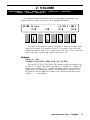 16
16
-
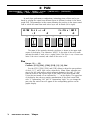 17
17
-
 18
18
-
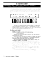 19
19
-
 20
20
-
 21
21
-
 22
22
-
 23
23
-
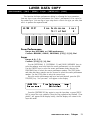 24
24
-
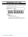 25
25
-
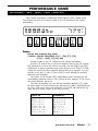 26
26
-
 27
27
-
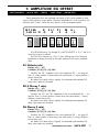 28
28
-
 29
29
-
 30
30
-
 31
31
-
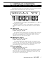 32
32
-
 33
33
-
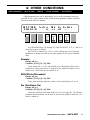 34
34
-
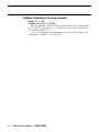 35
35
-
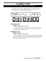 36
36
-
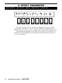 37
37
-
 38
38
-
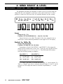 39
39
-
 40
40
-
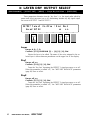 41
41
-
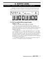 42
42
-
 43
43
-
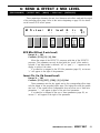 44
44
-
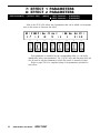 45
45
-
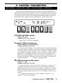 46
46
-
 47
47
-
 48
48
-
 49
49
-
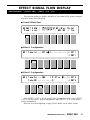 50
50
-
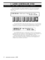 51
51
-
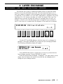 52
52
-
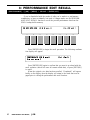 53
53
-
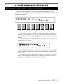 54
54
-
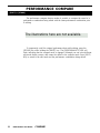 55
55
-
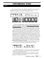 56
56
-
 57
57
-
 58
58
-
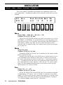 59
59
-
 60
60
-
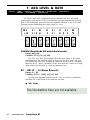 61
61
-
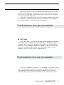 62
62
-
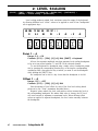 63
63
-
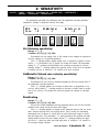 64
64
-
 65
65
-
 66
66
-
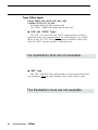 67
67
-
 68
68
-
 69
69
-
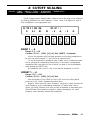 70
70
-
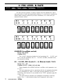 71
71
-
 72
72
-
 73
73
-
 74
74
-
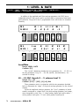 75
75
-
 76
76
-
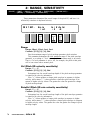 77
77
-
 78
78
-
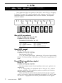 79
79
-
 80
80
-
 81
81
-
 82
82
-
 83
83
-
 84
84
-
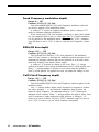 85
85
-
 86
86
-
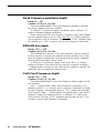 87
87
-
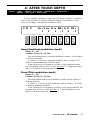 88
88
-
 89
89
-
 90
90
-
 91
91
-
 92
92
-
 93
93
-
 94
94
-
 95
95
-
 96
96
-
 97
97
-
 98
98
-
 99
99
-
 100
100
-
 101
101
-
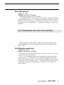 102
102
-
 103
103
-
 104
104
-
 105
105
-
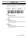 106
106
-
 107
107
-
 108
108
-
 109
109
-
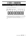 110
110
-
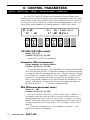 111
111
-
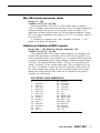 112
112
-
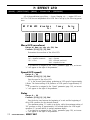 113
113
-
 114
114
-
 115
115
-
 116
116
-
 117
117
-
 118
118
-
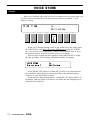 119
119
-
 120
120
-
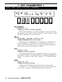 121
121
-
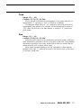 122
122
-
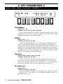 123
123
-
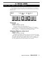 124
124
-
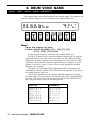 125
125
-
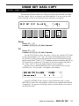 126
126
-
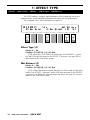 127
127
-
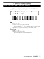 128
128
-
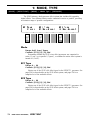 129
129
-
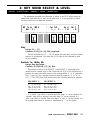 130
130
-
 131
131
-
 132
132
-
 133
133
-
 134
134
-
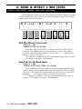 135
135
-
 136
136
-
 137
137
-
 138
138
-
 139
139
-
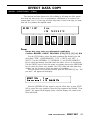 140
140
-
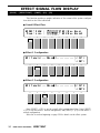 141
141
-
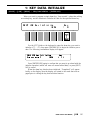 142
142
-
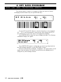 143
143
-
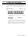 144
144
-
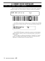 145
145
-
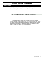 146
146
-
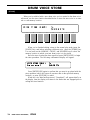 147
147
-
 148
148
-
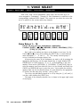 149
149
-
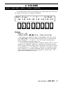 150
150
-
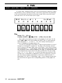 151
151
-
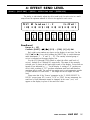 152
152
-
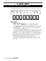 153
153
-
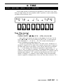 154
154
-
 155
155
-
 156
156
-
 157
157
-
 158
158
-
 159
159
-
 160
160
-
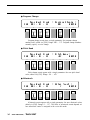 161
161
-
 162
162
-
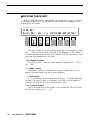 163
163
-
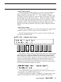 164
164
-
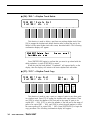 165
165
-
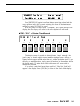 166
166
-
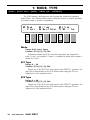 167
167
-
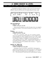 168
168
-
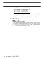 169
169
-
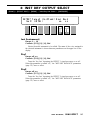 170
170
-
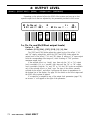 171
171
-
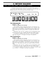 172
172
-
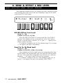 173
173
-
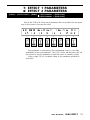 174
174
-
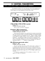 175
175
-
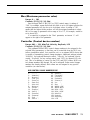 176
176
-
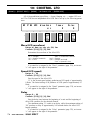 177
177
-
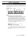 178
178
-
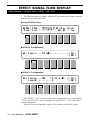 179
179
-
 180
180
-
 181
181
-
 182
182
-
 183
183
-
 184
184
-
 185
185
-
 186
186
-
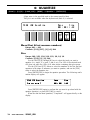 187
187
-
 188
188
-
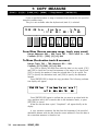 189
189
-
 190
190
-
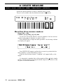 191
191
-
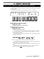 192
192
-
 193
193
-
 194
194
-
 195
195
-
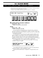 196
196
-
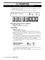 197
197
-
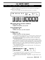 198
198
-
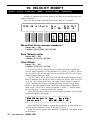 199
199
-
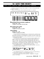 200
200
-
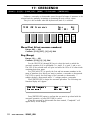 201
201
-
 202
202
-
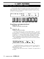 203
203
-
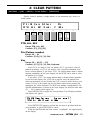 204
204
-
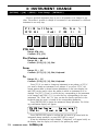 205
205
-
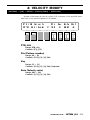 206
206
-
 207
207
-
 208
208
-
 209
209
-
 210
210
-
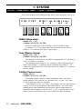 211
211
-
 212
212
-
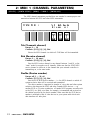 213
213
-
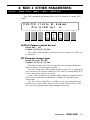 214
214
-
 215
215
-
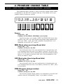 216
216
-
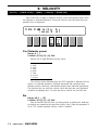 217
217
-
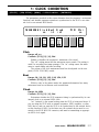 218
218
-
 219
219
-
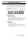 220
220
-
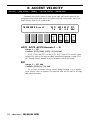 221
221
-
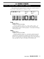 222
222
-
 223
223
-
 224
224
-
 225
225
-
 226
226
-
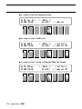 227
227
-
 228
228
-
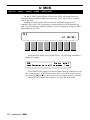 229
229
-
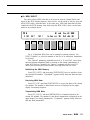 230
230
-
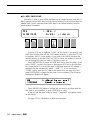 231
231
-
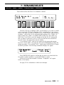 232
232
-
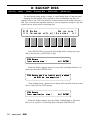 233
233
-
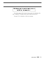 234
234
-
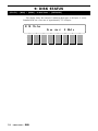 235
235
-
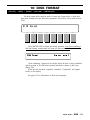 236
236
-
 237
237
-
 238
238
-
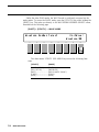 239
239
-
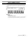 240
240
-
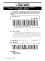 241
241
-
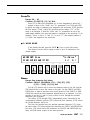 242
242
-
 243
243
-
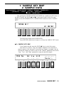 244
244
-
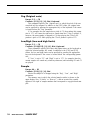 245
245
-
 246
246
-
 247
247
-
 248
248
-
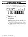 249
249
-
 250
250
-
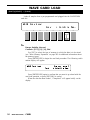 251
251
-
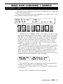 252
252
-
 253
253
-
 254
254
-
 255
255
-
 256
256
-
 257
257
-
 258
258
-
 259
259
-
 260
260
-
 261
261
-
 262
262
-
 263
263
-
 264
264
-
 265
265
-
 266
266
-
 267
267
-
 268
268
-
 269
269
-
 270
270
-
 271
271
-
 272
272
-
 273
273
-
 274
274
-
 275
275
-
 276
276
-
 277
277
-
 278
278
-
 279
279
-
 280
280
-
 281
281
-
 282
282
-
 283
283
-
 284
284
-
 285
285
-
 286
286
-
 287
287
-
 288
288
-
 289
289
-
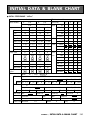 290
290
-
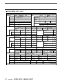 291
291
-
 292
292
-
 293
293
-
 294
294
-
 295
295
-
 296
296
-
 297
297
-
 298
298
-
 299
299
-
 300
300
-
 301
301
-
 302
302
-
 303
303
-
 304
304
-
 305
305
-
 306
306
-
 307
307
-
 308
308
-
 309
309
-
 310
310
-
 311
311
-
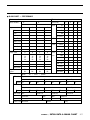 312
312
-
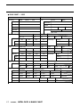 313
313
-
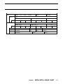 314
314
-
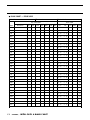 315
315
-
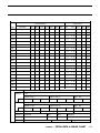 316
316
-
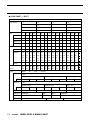 317
317
-
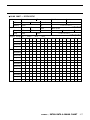 318
318
-
 319
319
-
 320
320
-
 321
321
-
 322
322
-
 323
323
-
 324
324
-
 325
325
-
 326
326
-
 327
327
-
 328
328
-
 329
329
-
 330
330
-
 331
331


in andere talen
- English: Yamaha SY85 User manual
- italiano: Yamaha SY85 Manuale utente
- русский: Yamaha SY85 Руководство пользователя
- français: Yamaha SY85 Manuel utilisateur
- español: Yamaha SY85 Manual de usuario
- Deutsch: Yamaha SY85 Benutzerhandbuch
- português: Yamaha SY85 Manual do usuário
- dansk: Yamaha SY85 Brugermanual
- suomi: Yamaha SY85 Ohjekirja
- čeština: Yamaha SY85 Uživatelský manuál
- svenska: Yamaha SY85 Användarmanual
- Türkçe: Yamaha SY85 Kullanım kılavuzu
- polski: Yamaha SY85 Instrukcja obsługi
- română: Yamaha SY85 Manual de utilizare