flamcogroup.com/manuals
ENG
Flamcomat PU /
Flamcomat MK-U/ MK-C
> 110° C Safety Set
Installation and operating instructions > 110° Safety Set Flamcomat G3 - G4 and Flexcon
M-K/U expansion automats for system over 110° C according EN 12953-6 2011.
Montage- und Bedienungsanleitung >110°C Sicherheitsset für Flamcomat G3-G4 und Flexcon
M-K/U Druckhalteautomaten in Systemen über 110°C nach EN12953-6 2011.
Montage- en gebruikshandleiding > 110° Veiligheid Set Flamcomat G3 - G4 en Flexcon M-K/U
expansie automaat voor systemen boven 110° C volgens EN 12953-6 2011.
Instructions de montage et d’utilisation > 110° Safety Set Flamcomat G3 - G4 and Flexcon
M-K/U expansion automats for system over 110° C according EN 12953-6 2011.
A
B
D
C
E
F
O
G
I
J
K
L
M
N
Flamcomat PU:
L
J
K
I
O
N
M
L
D
AB
D
D D
H
Flamcomat MK-U / MK-C:
CC
FRA
DEU
NLD
Montage- en gebruikshandleiding
waar de toevoerleiding vanaf de warmtebron temperaturen boven 110°C kan bereiken volgens EN 12953-6 2011
en is daarmee geschikt voor toepassing in Europa
Dit document is een aanvulling op de installatie- en bedieningsinstructies: Flamcomat G3/G4 en Flexcon M-K/U
zie DocFinder op www.flamcogroup.com.
Te gebruiken voor de Flamco besturingen
Flextronic:
• De Flextronic besturing is kant en klaar te gebruiken voor >110°C toepassingen.
• Naast de hier beschreven hydraulische opzet en benodigde sensoren is tevens een veiligheidsschakeling nodig
om de warmtebron uit te kunnen schakelen. Deze moet volgens EN 12953-6 2011 aangesloten worden.
• [Art.: 17504] Kant en klare >110°C aansluitkit met voor gemonteerde temperatuurbeveiliging, Minimale druk
schakelaar en aansluitkabels.
• [Art.: 22386] Membraanbreuksensor is door Flamco geadviseerd te gebruiken tezamen met de >110°C kit.
Instellingen en kabelaansluitingen zijn beschreven in de Quick Start Guides die worden meegeleverd met onze
producten.
SPC:
• De SPC besturing kan gebruikt worden met dezelfde sensoren en kit genoemd voor de Flextronic besturing,
mogelijkheden:
- Het uitvoeren van een upgrade met een Flextronic vervangingskit.
- De algemene foutuitgang (NC) van de SPC besturing gebruiken om een veilig schakelend warmtebron
uitschakelsignaal te maken.
Voorbeeld van dit warmtebron uitschakelsignaal:
De algemene foutuitgang (aansluitklemmen 13-14) zal het contact verbreken wanneer er een fout/probleem
is in het verwarmingssysteem en/of de automaat. Dit is een normaal gesloten (NC) contact dat zal openen bij
spanningsuitval of een defecte besturing. Minimaal de volgende fouten moeten geactiveerd worden in [MENU
8-4] van de SPC-besturing:
1. Druk (standard setting)
2. Niveau vat (standard setting)
3. Membraanbreuk (only when this option is installed)
5. Min.druk schakelaar
6. Temperatuur schakelaar
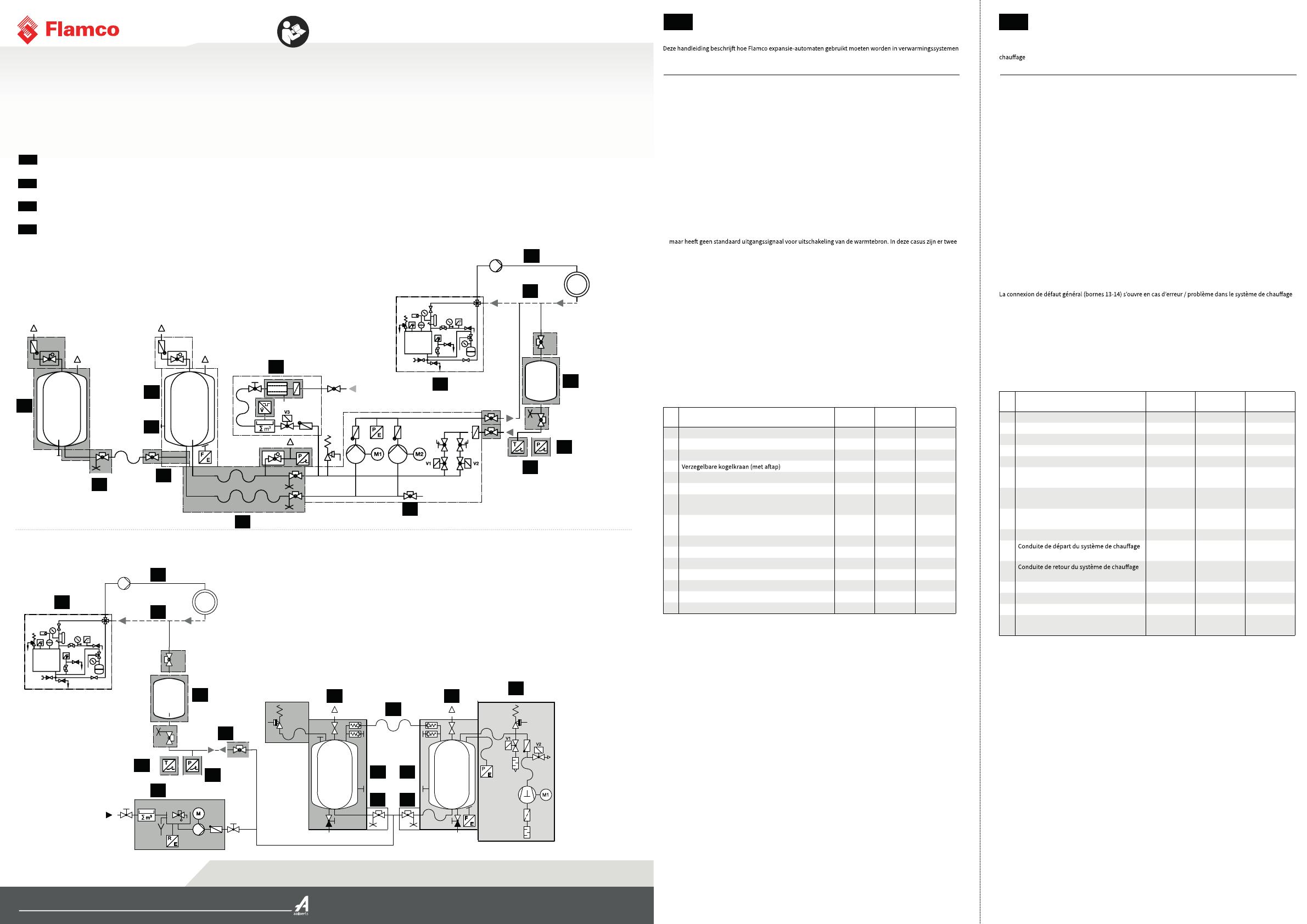
Zie afbeeldingen links voor schematische weergave van de Flamcomat en Flexcon M-K/U.
Legenda Optioneel EN12953
vereist
Flamco
aanbevolen
A Koppelvat x
B Hoofdvat x x
C Membraanbreuksensor x x
Dxxx
E Flexibele aansluiting t.b.v. koppelvat x
F Flamcomat flexibele aansluitset x
G Bijvulleiding (water filter, impulswatermeter is
optioneel verkrijgbaar)
(x) x
H Bijvul pompautomaat (voor suppletie onder
systeemdruk)
x (x)
I Warmtebron x x
J Verwarmingsysteem toevoerleiding (> 105° C) x x
K Verwarmingsysteem retourleiding (< 90° C) x x
L Voorschakelvat Flexcon V-B x x x
M Minimale druk veiligheidschakelaar x x x
N Bimetaal temperatuur schakelaar x x x
O Automatisch geregelde compressor- / pompautomaat x x
Exclusief:
De aansluitkabel voor het potentiaalvrije NC foutcontact van de Flextronic (P29), om de warmtebron mee uit te
schakelen, dient door de gebruiker zelf aangeleverd te worden.
Bewijs van de aanpassingsdiensten en vrijgave voor gebruik.
Dit moet worden gedocumenteerd en voorgelegd aan de eigenaars/exploitanten.
NLD Instructions de montage et d'utilisation
FRA
Ce manuel décrit comment les maintien de pression Flamco peuvent être utilisés dans les systèmes de
où la température de départ de la chaudière dépasse 110 ° C selon EN 12953-6 2011 et est donc
applicable pour l’Europe.
Le présent document est un complément aux instructions d’installation et d’utilisation: Flamcomat G3/G4 et
Flexcon M-K/U, voir DocFinder, sur www.flamcogroup.com.
Convient aux contrôleurs Flamco
Flextronic:
• Le contrôleur Flextronic est prêt à l’emploi (plug-and-play) pour les applications > 110 ° C.
• Outre le schéma hydraulique et les capteurs mentionnés aux pages suivantes, il y a également une sortie de
coupure de chaudière à sécurité intégrée qui doit être connectée conformément à la norme EN 12953-6 2011.
• [Art. : 17504] Kit avec pièce de raccordement plug-and-play avec limiteur de température, limiteur de pression
minimale et câblage.
• [Art. : 22386] Flamco recommande d’utiliser le capteur de rupture de membrane avec le kit > 110 ° C. .
Les paramètres et les connexions des terminaux sont mentionnés dans les guides de démarrage rapide fournis
avec nos produits.
SPC:
• Le contrôleur SPC peut être utilisé avec les mêmes capteurs et kit mentionnés pour le Flextronic, mais n’a pas
de signal de coupure de chaudière. Dans ce cas, le client a deux options :
- Mettre à niveau avec un kit de rénovation Flextronic.
- Fournir une coupure de secours de la chaudière connectée aux bornes de défaut général du SPC.
Exemple de câblage de coupure de chaudière :
ou du maintien de pression. Il s’agit d’un contact normalement fermé (NC : normally closed) qui s’ouvrira
également en cas de coupure de courant ou de panne du contrôleur.
Défauts minimaux qui doivent être activés dans [MENU 8-4] du contrôleur SPC :
1. Pression (réglage standard)
2. Niveau du vase (réglage standard)
3. Rupture de la membrane (uniquement lorsque cette option est installée)
5. Limit. pression minimum
6. Moniteur de temp.
Voir les images sur la gauche pour la disposition schématique du système avec Flamcomat et Flexcon M-K/U.
Légende En option EN12953 requis Recommandé
Flamco
A Ballon auxiliaire x
B Vase principal x x
C Capteur de rupture membrane x x
D Vanne d'arrêt avec vidange x x x
E Connexion flexible du vase auxiliaire x
F Connexion flexible du vase principal
Flamcomat
x
G Ligne de remplissage / d'appoint (disponible
avec compteur d'eau à impulsion, filtre à eau)
(x) x
H Unité de pompe de remplissage / d'appoint
(pour complément sous pression du système)
x (x)
I Générateur de chaleur x x
J
(> 105 ° C)
x x
K
(< 90 ° C)
x x
L Vase intermédiaire Flexcon V-B x x x
MInterrupteur de sécurité de pression minimale x x x
N Interrupteur de température bimétallique x x x
O Unité de compresseur / pompe à commande
automatique
x x
Exclu :
Le fil de câblage du signal de défaut NC sans potentiel de Flextronic (P29), servant à couper et à verrouiller
l’alimentation en chaleur, doit être fourni par l’utilisateur.
Justificatif de la conversion et de la mise en fonctionnement.
Il doit être documenté et présenté au propriétaire/à l’exploitant.

