
OWNER’S MANUAL
MODE D’EMPLOI
Natural Sound AV Receiver
Ampli-tuner audio vidéo
R -V1105
U C A T

1 Read Instructions – All the safety and operating
instructions should be read before the unit is operated.
2 Retain Instructions – The safety and operating instructions
should be retained for future reference.
3 Heed Warnings – All warnings on the unit and in the
operating instructions should be adhered to.
4 Follow Instructions – All operating and other instructions
should be followed.
5 Water and Moisture – The unit should not be used near
water – for example, near a bathtub, washbowl, kitchen
sink, laundry tub, in a wet basement, or near a swimming
pool, etc.
6 Carts and Stands – The unit should be used only with a
cart or stand that is recommended by the manufacturer.
6A A unit and cart combination should be
moved with care. Quick stops, excessive
force, and uneven surfaces may cause
the unit and
cart combination to overturn.
7 Wall or Ceiling Mounting – The unit
should be mounted to a wall or ceiling only as
recommended by the manufacturer.
8 Ventilation – The unit should be situated so that its
location or position does not interfere with its proper
ventilation. For example, the unit should not be situated
on a bed, sofa, rug, or similar surface, that may block the
ventilation openings; or placed in a built-in installation,
such as a bookcase or cabinet that may impede the flow
of air through the ventilation openings.
9 Heat – The unit should be situated away from heat
sources such as radiators, stoves, or other appliances
that produce heat.
10 Power Sources – The unit should be connected to a power
supply only of the type described in the operating
instructions or as marked on the unit.
11 Power-Cord Protection – Power-supply cords should be
routed so that they are not likely to be walked on or
pinched by items placed upon or against them, paying
particular attention to cords at plugs, convenience
receptacles, and the point where they exit from the unit.
12 Cleaning – The unit should be cleaned only as
recommended by the manufacturer.
13 Nonuse Periods – The power cord of the unit should be
unplugged from the outlet when left unused for a long
period of time.
14 Object and Liquid Entry – Care should be taken so that
objects do not fall into and liquids are not spilled into the
inside of the unit.
15 Damage Requiring Service – The unit should be serviced
by qualified service personnel when:
A. The power-supply cord or the plug has been
damaged; or
B. Objects have fallen, or liquid has been spilled into the
unit; or
C. The unit has been exposed to rain; or
D. The unit does not appear to operate normally or
exhibits a marked change in performance; or
E. The unit has been dropped, or the cabinet damaged.
16 Servicing – The user should not attempt to service the unit
beyond those means described in the operating
instructions. All other servicing should be referred to
qualified service personnel.
17 Power Lines – An outdoor antenna should be located away
from power lines.
18 Grounding or Polarization – Precautions should be taken
so that the grounding or polarization is not defeated.
SAFETY INSTRUCTIONS
RISK OF ELECTRIC SHOCK
DO NOT OPEN
CAUTION: TO REDUCE THE RISK OF
ELECTRIC SHOCK, DO NOT REMOVE
COVER (OR BACK). NO USER-SERVICEABLE
PARTS INSIDE. REFER SERVICING TO
QUALIFIED SERVICE PERSONNEL.
The lightning flash with arrowhead
symbol, within an equilateral triangle,
is intended to alert you to the
presence of uninsulated “dangerous
voltage” within the product’s
enclosure that may be of sufficient
magnitude to constitute a risk of
electric shock to persons.
The exclamation point within an
equilateral triangle is intended to alert
you to the presence of important
operating and maintenance
(servicing) instructions in the literature
accompanying the appliance.
•
Explanation of Graphical Symbols
CAUTION
WARNING
TO REDUCE THE RISK OF FIRE OR ELECTRIC
SHOCK, DO NOT EXPOSE THIS UNIT TO RAIN
OR MOISTURE.
IMPORTANT
Please record the serial number of your unit
in the space below.
Model:
Serial No.:
The serial number is located on the rear of
the unit.
Retain this Owner’s Manual in a safe place
for future reference.

English
1. IMPORTANT NOTICE : DO NOT MODIFY THIS UNIT!
This product, when installed as indicated in the
instructions contained in this manual, meets FCC
requirements. Modifications not expressly approved by
Yamaha may void your authority, granted by the FCC, to
use the product.
2. IMPORTANT : When connecting this product to
accessories and/or another product use only high quality
shielded cables. Cable/s supplied with this product
MUST be used. Follow all installation instructions.
Failure to follow instructions could void your FCC
authorization to use this product in the USA.
3. NOTE : This product has been tested and found to
comply with the requirements listed in FCC Regulations,
Part 15 for Class “B” digital devices. Compliance with
these requirements provides a reasonable level of
assurance that your use of this product in a residential
environment will not result in harmful interference with
other electronic devices.
This equipment generates/uses radio frequencies and, if
not installed and used according to the instructions
found in the users manual, may cause interference
harmful to the operation of other electronic devices.
Compliance with FCC regulations does not guarantee that
interference will not occur in all installations. If this product
is found to be the source of interference, which can be
determined by turning the unit “OFF” and “ON”, please try
to eliminate the problem by using one of the following
measures:
Relocate either this product or the device that is being
affected by the interference.
Utilize power outlets that are on different branch (circuit
breaker or fuse) circuits or install AC line filter/s.
In the case of radio or TV interference, relocate/reorient the
antenna. If the antenna lead-in is 300 ohm ribbon lead,
change the lead-in to coaxial type cable.
If these corrective measures do not produce satisfactory
results, please contact the local retailer authorized to
distribute this type of product. If you can not locate the
appropriate retailer, please contact Yamaha Electronics
Corp., U.S.A. 6660 Orangethorpe Ave, Buena Park, CA
90620.
The above statements apply ONLY to those products
distributed by Yamaha Corporation of America or its
subsidiaries.
FCC INFORMATION (for US customers only)
YAMAHA and the Electronic Industries Association’s
Consumer Electronics Group want you to get the most out of
your equipment by playing it at a safe level. One that lets the
sound come through loud and clear without annoying blaring or
distortion – and, most importantly, without affecting your
sensitive hearing.
Since hearing damage from loud sounds is often
undetectable until it is too late, YAMAHA and the
Electronic Industries Association’s Consumer
Electronics Group recommend you to avoid
prolonged exposure from excessive volume levels.
We Want You Listening For A Lifetime
Note to CATV system installer:
This reminder is provided to call the CATV system
installer’s attention to Article 820-40 of the NEC that
provides guidelines for proper grounding and, in
particular, specifies that the cable ground shall be
connected to the grounding system of the building, as
close to the point of cable entry as practical.
19 For US customers only:
Outdoor Antenna Grounding – If an outside antenna is
connected to this unit, be sure the antenna system is
grounded so as to provide some protection against
voltage surges and built-up static charges. Article 810 of
the National Electrical Code, ANSI/NFPA 70, provides
information with regard to proper grounding of the mast
and supporting structure, grounding of the lead-in wire to
an antenna discharge unit, size of grounding conductors,
location of antenna discharge unit, connection to
grounding electrodes, and requirements for the grounding
electrode.
EXAMPLE OF ANTENNA GROUNDING
MAST
GROUND
CLAMP
ANTENNA
LEAD IN
WIRE
ANTENNA
DISCHARGE UNIT
(NEC SECTION 810–20)
GROUNDING CONDUCTORS
(NEC SECTION 810–21)
GROUND CLAMPS
POWER SERVICE GROUNDING
ELECTRODE SYSTEM
(NEC ART 250. PART H)
ELECTRIC
SERVICE
EQUIPMENT
NEC – NATIONAL ELECTRICAL CODE

Congratulations!
You are the proud owner of a Yamaha Digital Sound Field Processing (DSP)
System—an extremely sophisticated audio component. The DSP system takes full
advantage of Yamaha’s undisputed leadership in the field of digital audio processing
to bring you a whole new world of listening experiences. Follow the instructions in this
manual carefully when setting up your system, and the DSP system will sonically
transform your room into a wide range of listening environments—anything from a
famous concert hall to a cozy jazz club. In addition, you get incredible realism from
most of surround-sound encoded video sources available in the market using the built-
in Dolby Pro Logic Surround Decoder, Dolby Digital Decoder and DTS Decoder.
Five built-in channels of amplification on this model mean that no additional
amplifiers are required to enjoy advanced digital sound field processing.
Rather than tell you about the wonders of digital sound field processing, however,
let’s get right down to the business of setting up the system and trying out its many
capabilities. Please read this operation manual carefully and store it in a safe place for
later reference.

1
English
SAFETY INSTRUCTIONS
........................................... Inside of the Front Cover
CAUTION .................................................................. 2
INTRODUCTION ....................................................... 3
Features .................................................................... 3
What’s DSP?............................................................. 4
GETTING STARTED ................................................ 7
Getting started.......................................................... 7
Unpacking.............................................................. 7
Installing batteries in the remote controller ........... 8
Notes about the remote controller.......................... 8
Controls and their functions................................... 9
Front panel............................................................. 9
Display panel........................................................ 11
PREPARATION ...................................................... 12
Speaker setup......................................................... 12
Connections ........................................................... 14
Audio/video source equipment ............................ 14
Speakers ............................................................. 20
Antennas ............................................................. 23
Plugging in this unit ............................................. 25
On screen display.................................................. 26
Selecting the output modes
(“SET MENU” mode) ............................................. 27
Speaker balance adjustment ................................ 30
BASIC OPERATION ............................................... 33
Playing a source .................................................... 33
Recording a source to tape (or MD) or dubbing
from tape (or MD) to tape (or MD)......................... 37
Sound control......................................................... 38
Tuning ..................................................................... 39
Basic operation ................................................... 39
Preset tuning........................................................ 40
Using digital sound field processor (DSP) ......... 43
Playing a source with an effect of the digital
sound field processor (DSP)................................ 43
Adjusting output level of the center, right rear,
left rear speakers and subwoofer......................... 46
Brief overview of digital sound field programs...... 48
ADVANCED FEATURES ....................................... 51
“SET MENU” mode ............................................... 51
Creating your own sound fields .......................... 55
Setting the SLEEP timer ....................................... 60
REMOTE CONTROLLER ....................................... 61
Basic operation ..................................................... 61
Key name and function ......................................... 62
Entering manufacturer codes .............................. 67
Restoring the default codes ................................. 68
TROUBLESHOOTING ............................................ 69
SPECIFICATIONS .................................................. 72
LIST OF MANUFACTURE’S CODE
.............................................. The end of this manual
CONTENTS

2
1. To assure the finest performance, please read this manual
carefully. Keep it in a safe place for future reference.
2. Install this unit in a cool, dry, clean place – away from
windows, heat sources, sources of excessive vibration,
dust, moisture and cold. Avoid sources of humming
(transformers, motors). To prevent fire or electrical shock,
do not expose the unit to rain or water.
3. Never remove the unit cover. Contact your dealer if an
object falls inside the unit.
4. Do not use force on switches, controls or connection wires.
When moving the unit, first disconnect the power plug and
the wires connected to other equipment. Never pull on the
wires themselves.
5. The openings on the unit cover assure proper ventilation of
the unit. If these openings are obstructed, the temperature
inside the unit will rise rapidly. Therefore, avoid placing
objects against these openings, and install the unit in a
well-ventilated area to prevent fire and damage.
<Singapore model only>
Be sure to allow a space of at least 20 cm behind, 20 cm
on the both sides and 30 cm above the top panel of the
unit to prevent fire and damage.
6. The voltage used must be the same as that specified on
this unit. Using this unit with a higher voltage than
specified is dangerous and may result in fire or other
accidents. YAMAHA will not be held responsible for any
damage resulting from use of this unit with a voltage other
than specified.
7. Digital signals generated by this unit may interfere with
other equipment such as tuners, receivers or TVs. Move
this unit farther away from such equipment if interference
is observed.
8. Always set the VOLUME control to “–
∞
” before starting
the audio source play. Increase the volume gradually to an
appropriate level after playback has been started.
9. Do not attempt to clean the unit with chemical solvents;
this might damage the finish. Use a clean, dry cloth.
10.Be sure to read the “TROUBLESHOOTING” section
regarding common operating errors before concluding that
the unit is faulty.
11.When not planning to use this unit for long periods of time,
disconnect the AC power plug from the wall outlet.
12.To prevent lightning damage, disconnect the AC power
plug and antenna cable when there is an electrical storm.
13.Grounding or polarization – Precautions should be taken
so that the grounding or polarization of an appliance is not
defeated.
14.Do not connect an audio unit to the AC outlet on the rear
panel if the equipment requires more power than the outlet
is rated to provide.
15.Voltage Selector (China and General Models only)
The voltage selector on the rear panel of this unit must
be set for your local main voltage BEFORE plugging
into the AC main supply.
Voltages are 110/120/220/240 V AC, 50/60 Hz.
This unit is not disconnected from the AC power source as
long as it is connected to the wall outlet, even if this unit
itself is turned off. This state is called the standby mode.
In this mode, this unit is designed to consume a small
amount of power.
FREQUENCY STEP switch (China and General Models
only)
Because the interstation frequency spacing differs in
different areas, set the FREQUENCY STEP switch (located
at the rear) according to the frequency spacing in your area.
Before setting this switch, disconnect the AC power plug of
this unit from the AC outlet.
For Canadian Customers
To prevent electric shock, match wide blade of plug to wide
slot and fully insert.
This Class B digital apparatus complies with Canadian
ICES–003.
WARNING
Do not change the IMPEDANCE SELECTOR switch
setting while the power to this unit is on, otherwise this
unit may be damaged.
IF THIS UNIT FAILS TO TURN ON WHEN THE
STANDBY/ON SWITCH IS PRESSED;
The IMPEDANCE SELECTOR switch may not be set to
either end. If so, set the switch to either end when this unit
is in the standby mode.
REAR
(SURROUND)
SWITCHED
I20V 60Hz
I00W MAX. TOTAL
AC OUTLETS
IMPEDANCE SELECTOR
: 6
Ω
MIN. /SPEAKER
: 6
Ω
MIN. /SPEAKER
A OR B: 4
Ω
MIN. /SPEAKER
A B: 8
Ω
MIN. /SPEAKER
SET BEFORE POWER ON
REAR
CENTER
MAIN
: 8
Ω
MIN. /SPEAKER
: 8
Ω
MIN. /SPEAKER
A OR B: 8
Ω
MIN. /SPEAKER
A B: I6
Ω
MIN. /SPEAKER
REAR
CENTER
MAIN
IMPEDANCE SELECTOR
(U.S.A. model)
CAUTION : Read this before operating your unit.

3
English
5 Channel Power Amplification
Main: 85W + 85W (8Ω) RMS Output
Power, 0.04% THD, 20–20,000 Hz
Center: 85W (8Ω) RMS Output Power,
0.04% THD, 20–20,000 Hz
Rear: 85W + 85W (8Ω) RMS Output
Power, 0.04% THD, 20–20,000 Hz
Multi-Mode Digital Sound Field
Processing
●
Digital Sound Field Processor (DSP)
●
Dolby Digital Decoder
●
Dolby Pro Logic Surround Decoder
●
DTS Decoder
●
CINEMA DSP:Theater-like Sound
Experience by the Combination of
YAMAHA DSP Technology and Dolby
Digital, Dolby Pro Logic or DTS
●
Automatic Input Balance Control for
Dolby Pro Logic Surround
●
Test Tone Generator for Easier Speaker
Balance Adjustment
●
Speaker Output Mode Selection
Capability for the Most Suitable
Use of Your Speaker System
Sophisticated FM/AM Tuner
● 40-Station Random Access Preset Tuning
● Automatic Preset Tuning
● Preset Station Shifting Capability (Preset
Editing)
● IF Count Direct PLL Synthesizer Tuning
System
Others
●
“SET MENU”Mode which Provides You
with 13 Titles of Setting Changes and
Adjustments for Optimizing This Unit for
Your Audio/Video System
● BASS EXTENSION Button for Reinforcing
Bass Response
● On Screen Display Function Helpful in
Controlling This Unit
● SLEEP Timer
●
OPTICAL and COAXIAL Digital Audio
Signal Terminals
● 6 Channel External Decoder Input for
Other Future Formats
● Video Signal Input/Output Capability
(Including S Video Connections)
● Universal Remote Controller with Preset
Manufacturer Codes
Features
INTRODUCTION

4
Welcome to the exciting world of digital home entertainment.
This unit is one of the most complete and advanced AV
receiver available. Some of the more advanced features may
not be familiar to you, but they are easy to use. State-of-the-art
technologies such as Dolby Digital and Digital Theater
Systems (DTS) may be new to your home, but you have
probably experienced the amazing realism they bring to feature
films in theaters around the world.
To make the listening experience even more enjoyable, this
unit includes a number of exclusive, digitally created listening
environments known as digital sound fields. Choosing a sound
field program is like transporting yourself to such venues as an
outdoor arena, a European church, or a cozy jazz club. Take
some time now to read more about these features and enjoy
the new experiences this unit brings to your home theater.
Digital Sound Field Processing
Technological advances in sound reproduction over the last 30
years have enhanced the listening experience with improved
clarity, precision and power. However, something has still been
missing: The atmosphere and acoustic ambiance of the public
venue. Our Yamaha engineers have extensively researched
the nature of sound acoustics and the way sound reflects
inside a room. We sent these engineers to famous theaters
and concert halls around the world to measure the acoustics of
those venues with sophisticated microphones. The data they
collected is used to recreate these environments in digital
sound fields. Some of these digital sound fields are created
using data measured directly at the original venue; others are
created from combinations of data to form unique
environments for specific purposes.
Of course, that only solves half of the problem. These
engineers have no way of knowing the acoustics of your
listening room, so we’ve made it possible for you to adjust the
various parameters of this data to tailor each virtual venue to
your taste. You can use these sound fields to enhance any
source and in combination with any of the following surround
sound technologies. Some are designed especially for music,
and some especially for movies.
Dolby Pro Logic Surround
Dolby Pro Logic Surround has been used in movie theaters
since the mid-seventies. It has also been available in home
entertainment systems since the late eighties and continues to
be a popular format for home theater systems. It uses four
discrete channels and five speakers to reproduce realistic and
dynamic sound effects: two main channels (left and right), a
center channel for dialog, and a rear channel for special sound
effects. The rear channel reproduces sound within a narrow
frequency range.
Most video tapes and laser discs include Dolby Pro Logic
Surround encoding as do many TV and cable broadcasts. The
Dolby Pro Logic Surround decoder built into this unit employs a
digital signal processing system that stabilizes each channel
for even more accurate sound positioning than is available with
standard analog processors.
Introduction
What’s DSP?
INTRODUCTION

5
English
Dolby Digital is the next level of Dolby Surround sound system
developed for 35 mm film-movies by employing low bit-rate
audio coding.
Dolby Digital is a digital surround sound system that provides
completely independent multi-channel audio to you. Dolby
Digital provides five full range channels in what is sometimes
referred to as a “3/2” configuration: three front channels (left,
center and right), and two surround channels. A sixth bass-only
effect channel is also provided for output of LFE (low frequency
effect), or low bass effects that are independent of other
channels. (This is called the “subwoofer channel” or “LFE
channel”.) This channel is counted as 0.1, thus giving rise to
the term 5.1 channels in total.
Compared to Dolby Pro Logic that is referred to a “3/1” system
(left front, center, right front and just one surround channel),
Dolby Digital features two surround channels, called stereo or
split surrounds, each offering the same full range fidelity as the
three front channels.
By using the built-in Dolby Digital decoder, you can experience
the dramatic realism and impact of Dolby Stereo Digital theater
sound in your home.
Wide dynamic range of sound reproduced by the five full range
channels and precise sound orientation by the digital sound
processing presents listeners much excitement and realism
that has never been experienced before.
Dolby Digital forms 5.1 channels as mentioned left, and
moreover, it can also form fewer channels, for example 2
channel stereo and monaural. You may be able to find some 2
channel stereo and/or monaural sources encoded with Dolby
Digital in the market.
Laserdisc and DVD are home audio formats that could benefit
from Dolby Digital. In the near future, Dolby Digital will also be
applied to DBS, CATV and HDTV. The ongoing release of
Dolby Stereo Digital theatrical films now underway will provide
an immediate source of Dolby Digital encoded video software.
Manufactured under license from Dolby Laboratories Licensing
Corporation. “DOLBY”, “AC-3”, “Pro Logic”, and the double-D
symbol are trademarks of Dolby Laboratories Licensing
Corporation.
Copyright 1992 Dolby Laboratories, Inc. All rights reserved.
DTS (Digital Theater Systems) system was developed to
replace analog soundtracks of movies with six discrete
channels of digital soundtracks, and now, it is installed in many
theaters around the world. The DTS digital playback system
changed the way we experienced movies in theaters with six
discrete channels of superb digital audio.
The DTS technology, through intense research and
development, made it possible to deliver a similar
encode/decode discrete technology to home audio surround-
sound entertainment.
The DTS Digital Surround is an encode/decode system which
delivers six channels of master-quality, 20-bit audio; technically
5.1 channels, which means 5 full-range (left, center, right and
two surround) channels, plus a subwoofer (LFE) channel (as
“0.1”). It is compatible with the 5.1 speaker configurations that
are currently available for home theater systems
The DTS Digital Surround algorithm is designed to encode the
six channels of 20-bit audio onto some laserdiscs, compact
discs and DVDs with considerably less data-compression.
By using the DTS decoder built into this unit, you can
experience the dramatic realism and impact of the DTS
installed theater’s high quality sound in your home.
Laserdisc, compact disc and DVD are home audio format
within which DTS can represent its high quality multi-channel
audio. (In addition to movies on laserdiscs, many exciting new
multi-channel music recordings will also become available in
the form of DTS-encoded compact discs.)
Manufactured under license from Digital Theater Systems, Inc.
US Pat. No. 5,451,942 and other world-wide patents issued
and pending. “DTS”, “DTS Digital Surround”, are trademarks of
Digital Theater Systems, Inc. Copyright 1996 Digital Theater
Systems, Inc. All Rights Reserved.
DTS Digital Surround
Dolby Digital
INTRODUCTION

6
Dolby Pro Logic + 2 Digital Sound Fields
Digital sound fields are created on the presence side and
the rear surround side of the Dolby Pro Logic Surround-
decoded sound field respectively. They create a wide
acoustic environment and emphasize surround-effect in the
room, letting you feel much presence as if you were
watching a movie in a popular Dolby Stereo theater.
This combination is available when the digital sound field
program No. 2, 3 or “PRO LOGIC/Enhanced” of No. 1 is
selected, and the input signal of the source is analog, PCM
audio or encoded with the Dolby Digital in 2-channels.
Dolby Digital or DTS + 3 Digital Sound Fields
Digital sound fields are created on the presence side and
the independent left and right surround sides of the Dolby
Digital-decoded or the DTS-decoded sound field
respectively. They create a wide acoustic environment and
much surround effect in the room without losing high
channel separation. With wide dynamic range of Dolby
Digital or DTS sound, this sound field combination lets you
feel as if you were watching a movie in the newest Dolby
Stereo Digital theater or DTS installed theater. This is the
most ideal home theater sound at the present time.
This combination is available when the digital sound field
program No. 2, 3 or “DOLBY DIGITAL (or DTS DIGITAL
SUR.)/Enhanced” of No. 1 is selected, and the input signal
of the source is encoded with the Dolby Digital (except in 2-
channels) or encoded with the DTS.
CINEMA DSP: Dolby Surround + DSP / DTS + DSP
The Dolby Surround sound and DTS systems show their full
ability in a large movie theater, because movie sounds are
originally designed to be reproduced in a large movie theater
that uses a multitude of speakers. Trying to create a sound
environment similar to that of a movie theater in your home is
difficult because of the room size, material inside the walls, the
number of speakers, and so on. In other words, your listening
room is very different from a movie theater.
However, Yamaha DSP technology allows you to create nearly
the same sound experience as that of a large movie theater in
your home by compensating for the lack of presence and
dynamics in the listening room with original digital sound fields
combined with Dolby Surround or DTS Digital Surround
sounds.
The YAMAHA “CINEMA DSP” logo indicates those programs
that are created by the combination of YAMAHA DSP
technology and Dolby Surround or DTS.
CINEMA DSP
INTRODUCTION

7
English
GETTING STARTED
Getting started
Remote controller
Batteries (size AA, R6, UM-3)
Indoor FM Antenna
AM Loop Antenna
Antenna adapter (U.S.A. and Canada models only)
A/B/C/D/E
+
100
+
10
SET UP
RETURN
LEVEL
SET MENU
POWER
TV
POWER
STANDBY
1
3
CD
TUNER
TAPE/MD
DVD/LD
TV/DBS
VCR
PHONO
V-AUX
EXT. DEC
.
CH
CH
VOLUME
MUTE
MOVIE
THEATER 1
MOVIE
THEATER 2
MONO MOVIE
/DTS
SURROUND
DISCO
TV SPORTS
ROCK
CHURCH
JAZZ CLUB
CLEAR
SLEEP
DIR DIR
ENTER
HALL
TEST
EFCT
DISP
DSP
TV
DISC SKIP
PRESET
ON/OFF
CODE SET
INDEX
A/B
VCR REC TV INPUT
ON SCREEN
SELECT
AB
SUBTITLE ANGLE
AUDIO
ON/OFF
TITLE
MENU
2
5
8
4
7
0
9
6
/
A
M
P
/
T
U
N
Unpacking
Carefully remove this unit and accessories from the box. You should find the unit itself and the following accessories.

8
Installing batteries in the remote
controller
Since the remote controller will be used for many of this unit’s
control operations, you should begin by installing the supplied
batteries.
1. Turn the remote controller over and slide the battery
compartment cover in the direction of the arrow.
2. Insert the batteries (AA, R6, UM-3 type) according to the
polarity markings on the inside of the battery compartment.
3. Close the battery compartment cover.
Notes about the remote controller
Battery replacement
If you find that the remote controller must be used closer to the
main unit, the batteries are weak. Replace both batteries with
new ones.
Notes
●
Use AA, R6, UM-3 batteries.
●
Be sure the polarities are correct. (See the illustration inside
the battery compartment.)
●
Remove the batteries if the remote controller is not used for
an extended period of time.
●
If batteries leak, dispose of them immediately. Avoid
touching the leaked material and contact with clothing, etc.
Clean the battery compartment thoroughly before installing
new batteries.
Be sure to insert the new batteries within 2 minutes after
you remove the old batteries from the remote controller. If
the remote controller is left for more than 2 minutes without
batteries, all of the codes you entered will be cleared and
the remote controller will return to the factory preset
condition.
Remote controller operation range
Notes
●
The area between the remote controller and the main unit
must be clear of large obstacles.
●
Do not expose the remote control sensor to strong lighting,
in particular, an inverter type fluorescent lamp. Otherwise,
the remote controller may not work properly. If necessary,
position the main unit away from direct lighting.
2
1
3
30°
30°
Remote control
sensor
Within approximately
6 m (19.7 feet)
GETTING STARTED

9
English
Controls and their functions
Front panel
NATURAL SOUND AV RECEIVER
SPEAKERSPHONES
A
ON
OFF
ON
OFF
B
BASS TREBLE BALANCE
VIDEO AUX
S VIDEO VIDEO L AUDIO R
VOLUME
INPUT SELECTOR
55
4
3
2
l
0
l
2
3
4
55
4
3
2
l
0
l
2
3
4
LR
l6
20
28
40
60
l2
8
4
2
0
–dB
BASS
EXTENSION
TONE
BYPASS
55
4
3
2
l
0
l
2
3
4
LEVEL EFFECT
SET
MENU
PROGRAM
A
/
B
/
C
/
D
/
E
1
2345678
MEMORY EDIT FM/AM
DOWN
TUNING
UP
INPUT MODE
TUNING
MODE
MAN’L/AUTO FM AUTO/MAN’L MONO
CINEMA DSP
TAPE/MD MON
/EXT. DECODER
STANDBY/ON
1
8AB0CDIG
H
JK
E
F
N
P
L
O
M
23 45 6
79
1 STANDBY/ON switch
Press this switch to turn on the power. Press this switch again
to set this unit in the standby mode.
* A click from the switch and the initial rotation of the built-in
fan will be heard when the power is turned on.
Standby mode
This unit is still using a small amount of power in this mode
in order to be ready to receive infrared-signals from the
remote controller.
2 Remote control sensor
Receives signals from the remote controller.
3 Display panel
Displays a variety of information. (Refer to page 11 for details.)
4 TAPE/MD MON/EXT. DECODER button
Press this button repeatedly until the “TAPE/MD MONITOR
”
indicator is illuminated
on the display. Sound source played or
recorded on the unit connected to the TAPE/MD IN
(PLAY)/OUT (REC) AUDIO SIGNAL terminals on the rear of
this unit is selected as the input source taking priority of the
INPUT SELECTOR’s setting.
Press this button repeatedly until the “EXT. DECODER”
appears
on the display. Sound signals input to the EXTERNAL
DECODER INPUT terminals on the rear of this unit is selected
as the input source taking priority of the INPUT SELECTOR’s
setting.
Press this button repeatedly until the original display mode is
restored to cancel the above input sources.
5 INPUT SELECTOR
Turn this knob to select the input source.
The selected source will be shown on the display.
6 Master VOLUME control
Simultaneously controls volume for all output sounds; main,
rear, center and subwoofer. (The REC OUT level is not
affected.)
* The indicator on the master VOLUME control will flash when
the volume is decreased by pressing the MUTE key on the
remote controller.
7 PHONES jack
Headphones can be plugged into this jack for private listening.
You can listen to the sound to be output from the main
speakers through headphones. When listening with
headphones privately, set both SPEAKERS A and B switches
to the OFF position and turn off the digital sound field
processor by pressing the EFFECT button so that no DSP
program name is illuminated on the display panel.
For the remote controller, refer to pages 61 to 68.
GETTING STARTED
PHONES

10
8
A/B/C/D/E button
Press this button to select a group (A–E) of preset stations.
9 SPEAKERS switches
Press the switch A or B (or both) for the main speakers you will
use inward (ON). Press and release the switch for the main
speakers you do not use outward (OFF).
0 Preset station number selector buttons
Select a preset station number (1 to 8).
A BASS EXTENSION button
Press this button inward (ON) to boost the bass frequency
response at the main left and right channels while maintaining
overall tonal balance. This function is effective for reinforcing
the bass frequencies when a subwoofer is not used.
B TONE BYPASS button
Press this button inward (ON) to bypass the tone (BASS and
TREBLE) control circuitry. This function is used for outputting
pure sound and checking the tone control settings. The tone
control circuitry can be used when this button is released
outward (OFF).
C BASS and TREBLE controls
Rotate these knobs to adjust the low and high frequency
response for the left and right main channels only.
D BALANCE control
This knob controls the sound from the main speakers only.
The balance of the output volume to the left and right main
speakers can be adjusted to compensate for sound imbalances
caused by the speaker location or listening room conditions.
E MEMORY (MAN’L/AUTO FM) button
Use this button to enter a station to memory. Refer to the
section “Manual preset tuning” on page 40 for details.
Hold down this button for more than 3 seconds to start
automatic preset tuning. Refer to page 41 for details.
F EDIT button
This button is used to exchange the places of two preset
stations with each other.
G TUNING MODE (AUTO/MAN’L MONO) button
Press this button to switch the tuning mode between automatic
and manual. To select the automatic tuning mode, press this
button so that the “AUTO” indicator is illuminated on the
display. To select the manual tuning mode, press this button so
that the “AUTO” indicator is not illuminated.
H FM/AM button
Press this button to switch the reception band between FM and
AM.
I LEVEL button
This button is used to adjust the output level of the center and
rear speakers, and subwoofer. First, press this button (several
times) to select the speaker(s). The name appears on the
display. Then press the + or – button (
J
) to change the output
level.
J –/+ button
Adjusts the level of the speaker(s) selected by pressing the
LEVEL button. Moreover, performs setting changes and
adjustments for functions selected by pressing the SET MENU
button (
K).
K SET MENU button
Press this button once or more to select the desired function in
the SET MENU mode.
L TUNING DOWN/UP button
Used for tuning. Press the “UP” side to tune in to a higher
frequency, and press the “DOWN” side to tune in to a lower
frequency.
M PROGRAM selector button
Press this button in the or direction to select a digital
sound field processing program.
N EFFECT button
Press this button to turn on and off the output from the center
and rear speakers. The sound becomes normal 2-channel
when this function is turned off.
However, this does not apply to Dolby Digital or DTS. The
signals at all channels will be distributed to the main channels
and output from the main speakers, even if the output from the
center and rear speakers are turned off, when Dolby Digital or
DTS is decoded.
O VIDEO AUX terminals
Connect an auxiliary video or audio input source unit such as a
camcorder to these terminals. A video unit with a S video
output terminal can be connected to the S VIDEO terminal to
obtain a high resolution picture. The source can be selected
with the INPUT SELECTOR.
P INPUT MODE button
Press this button to select how input signals are received from
sources that output two or more types of signals. The “AUTO”,
“DTS” and “ANALOG” modes are available. Refer to page 36
for details.
GETTING STARTED

11
English
Display panel
DIGITAL
PRO LOGIC
DSP
CD
TUNER
PHONO
TAPE/MD
MONITOR
DVD/LD
TV/DBS
V-AUX
VCR
SLEEP
ENHANCED MOVIE THEATER 12 TV SPORTS
MONO MOVIE DISCO JAZZ CLUB
ROCK CONCERT CHURCH CONCERT HALL
MEMORY
AUTO
0 20 100
STEREO
12 3
45 6 7 89 A B
0
1 indicators
Either “dts” indicators will be illuminated when the built-in DTS
decoder is turned on.
A red “dts” indicator will be illuminated when playing a compact
disc or laserdisc encoded with DTS.
An orange “dts” indicator will be illuminated when playing a
DVD encoded with DTS.
An orange “dts” indicator may be illuminated when playing a
laserdisc encoded with DTS after a video-CD or DVD on a
DVD/LD combi-player.
2 Multi-information display
This display shows the current DSP program and the status of
adjustments and setting changes. Several statuses can be
viewed at one time. The current station frequency and band
(AM or FM) will also appear when the tuner source input mode
is selected.
3 Input source indicators
One of the arrows for these indicators will be illuminated
depending on which source is selected.
4 DIGITAL and PRO LOGIC indicators
The DIGITAL indicator will be illuminated when the built-in
Dolby Digital decoder is on and the signals of the source
encoded with Dolby Digital are not 2-channels.
The PRO LOGIC indicator will be illuminated when the
built-in Dolby Pro Logic Surround decoder is on.
5 DSP indicator
This indicator will be illuminated when the built-in digital sound
field processor is on.
6 MEMORY indicator
A flashing MEMORY indicator means a station can be saved,
as explained in the following:
Press the MEMORY button. The MEMORY indicator will flash
about 5 seconds. While the indicator is flashing, program the
displayed station to memory by using the A/B/C/D/E and the
preset station number selector buttons.
7 DSP program indicators
The name of the selected DSP program will be illuminated in
the following cases.
• When the tuner is selected as the input source
• When a DSP program parameter is selected or adjusted.
• When the DSP program No. 2, 3 or the subprogram
“Enhanced” of No. 1 is selected.
There is no illumination here when no DSP program is
selected
8 AUTO indicator
This indicator will be illuminated during the automatic tuning
mode.
9 STEREO indicator
This indicator will be illuminated when an FM stereo broadcast
with sufficient signal strength is received.
0 Signal-level indicator
This indicator shows the signal level of the received station. If
multipath interference is detected, the indication decreases.
A TAPE/MD MONITOR indicator
This indicator will be illuminated when the tape deck (or MD
recorder etc.) connected to the TAPE/MD IN and OUT
terminals on the rear of this unit is selected as the input source
by pressing the TAPE/MD MON/EXT. DECODER button.
B SLEEP indicator
This indicator will be illuminated when the built-in SLEEP timer
is on.
GETTING STARTED

12
This unit has been designed to provide the best sound field
quality with a full five-speaker system setup, using a pair of
main speakers to output main source sounds, a pair of effect
speakers to generate the sound field plus one center speaker
for dialog. We therefore recommend that you use a five-
speaker setup. A four-speaker system using only one pair of
effect speakers for the sound field will still provide impressive
ambience and effects, however, and may be a good way to
begin with this unit. You can always upgrade to the five-
speaker system later.
Use of the center dialog speaker is
recommended
When playing back a source with Dolby Pro Logic decoded, or
playing back a source which contains center-channel signals
with Dolby Digital or DTS decoded, dialog, vocals etc. are
output from the center channel. Therefore, if you want to
maximize the performance of your Audio/Video home theater
system, it is recommended that you use a center channel
speaker.
If, for some reason, it is not practical to use a center speaker, it
is possible to enjoy the movie without it. Best results, however,
are obtained with the full system.
Use of a subwoofer expands your sound
field
It is also possible to further expand your system with the
addition of a subwoofer and amplifier. The use of a subwoofer
is effective not only for reinforcing bass frequencies from any
or all channels, but also for reproducing signals at the
subwoofer channel with high fidelity during playing back a
source with Dolby Digital or DTS decoded. You may wish to
choose the convenience of a Yamaha Active Servo Processing
Subwoofer System, which has its own built-in power amplifier.
Speaker setup
m Speakers and speaker placement
Your full five-speaker system will require two speaker pairs:
the MAIN SPEAKERS (your normal stereo speakers) and the
REAR SPEAKERS, plus the CENTER SPEAKER. You may
also be using a SUBWOOFER.
The MAIN SPEAKERS should be high performance models
and have enough power handling capacity to accept the
maximum output of your audio system.
Other speakers do not have to be equal to the MAIN
SPEAKERS. For precise sound localization, however, it is
ideal to use high performance models that can reproduce
sounds in full range for the CENTER SPEAKER and REAR
SPEAKERS.
Place the MAIN SPEAKERS in the ordinary position.
Place the REAR SPEAKERS behind your listening position.
They should be nearly 1.8m above the floor.
Place the CENTER SPEAKER precisely between the two
MAIN SPEAKERS. (To avoid interference, keep the speaker
above or below the television monitor, or use a magnetically
shielded speaker.)
If using a SUBWOOFER, such as a Yamaha Active Servo
Processing Subwoofer System, the position of the speaker is
not so critical because low bass tones are not highly
directional.
m Setting up your speaker system
Main speaker Center speaker Rear speaker
Subwoofer
PREPARATION

13
English
5 Speaker System
The recommended system for enjoying Audio/Video
sources.
By the use of a center speaker, center channel sounds (dialog,
vocals etc.) are precisely localized.
1. CENTER SPEAKER—Set to “LRG” or “SML”.
(See page 27.)
4 Speaker System
Basic system.
You can enjoy widely diffused sound by only adding a pair of
rear speakers to a basic stereo speaker system.
However, center channel sounds must be output from the left
and right main speakers.
1. CENTER SPEAKER—Set to “NONE”. (See page 27.)
m Speaker system configurations
PREPARATION

14
Caution: Plug in this unit and other components after all connections are completed.
All connections must be correct, that is to say L (left) to L, R (right) to R, “+” to “+” and “–” to “–”. Also refer to the owner’s manual for
each of your components.
Audio/video source equipment
●
Use RCA type pin plug cables for audio/video units with the exception described later.
●
The output (or input) terminals of YAMAHA audio/video units numbered as 1, 3, 4, etc. on the rear panel must be connected to
the same-numbered terminals of this unit.
PHONO CD
TAPE
/
MD DVD/LD TV/DBS VCR
IN OUT
1 3 4
AUDIO SIGNAL
FM
ANT
AM
ANT
75
Ω
UNBAL.
GND
SUB
WOOFER
ON SCREEN SELECTOR
S VIDEO VIDEO
REMOTE
CONTROL
IN OUT
DVD/LD
COAXIALOPTICAL OPTICAL
DVD/LD TV/DBSCD
DIGITAL SIGNAL
IN (PLAY) OUT (REC)
EXTERNAL DECODER INPUT
MAIN CENTER
SURROUND
GND
MONITOR
OUT
DVD/LD TV/DBS
IN OUT
VCR
MONITOR
OUT
IN OUT
VCR
VIDEO SIGNALS VIDEO SIGNAL
OUTPUT
LINE OUT
LINE IN
VIDEO OUT
AUDIO OUT
AUDIO OUT
AUDIO IN
VIDEO OUT
VIDEO IN
OUTPUT
GND
VIDEO
IN
AUDIO OUT
VIDEO OUT
(U.S.A. model)
Turntable
MD recorder,
Tape deck, etc.
CD player
m Basic connections
(*1): GND terminal (For turntable use)
Connecting the ground wire of the turntable to the GND
terminal will normally minimize hum, but in some cases
better results may be obtained with the ground wire
disconnected.
: Indicates the direction of signals.
Connections
PREPARATION
(*1)
LD player, DVD player, etc.
TV monitor
Video cassette
recorder
TV/Satellite tuner

15
English
PREPARATION
VIDEO AUX
S VIDEO VIDEO L AUDIO R
S VIDEO
L
R
VIDEO
VIDEO OUT
S VIDEO OUT
AUDIO OUT L
AUDIO OUT R
Camcorder
For Custom Installer (
For U.S.A., Canada and Australia models only)
(U.S.A. model)
VIDEO AUX terminals (on the front panel)
These terminals are used to connect a video input source such
as a camcorder.
PAL/NTSC switch (China and General
models only)
This unit is designed for use with the NTSC and PAL television
formats. Set this switch to the position for the format your TV
monitor employs.
PAL: Set to this position if your TV monitor employs the PAL
format.
Outputs signals in the PAL format no matter which
format (PAL or NTSC) of video signal is sent from an
external video unit to this unit.
NTSC: Set to this position if your TV monitor employs the
NTSC format.
Outputs signals in the NTSC format no matter which
format (PAL or NTSC) of video signal is sent from an
external video unit to this unit.
Note
Be sure to input a video signal which employs the same format
that your TV monitor employs, otherwise a picture will not be
played back normally.
Ω
UNBAL.
GND
SUB
WOOFER
S VIDEO VIDEO
PAL NTSC
DVD/LD
COAXIALOPTICAL OPTICAL
DVD/LD TV/DBSCD
DIGITAL SIGNAL
EXTERNAL DECO
MAIN CENTER
ON SCREEN SELECTOR
GND
SUB
WOOFER
ON SCREEN SELECTOR
S VIDEO VIDEO
REMOTE
CONTROL
IN OUT
DVD/LD
COAXIALOPTICAL OPTICAL
DVD/LD TV/DBSCD
DIGITAL SIGNAL
EXTERNAL DECODER INPUT
MAIN CENTER
SURROUND
REMOTE CONTROL (IN, OUT) terminals
These terminals are used for custom installation system.
When this unit is connected to the components for custom
installation system, you can operate this unit with the system
remote control.
Connect the REMOTE CONTROL IN terminal of this unit to
the output terminal of the central controller for custom
installation system.
By connecting the REMOTE CONTROL OUT terminal of this
unit to the REMOTE CONTROL IN terminal of the other
component, you can also operate it with the system remote
control. In this way, up to 6 components can be connected in
series.
: S-video cable
(Refer to page 18 for details about the S
VIDEO terminal.)

16
Notes
●
When you connect an audio/video unit to both of the digital
and analog terminals of this unit, make sure to connect to
both terminals of the same name.
●
Be sure to attach the covers when the OPTICAL terminals
are not being used, in order to protect the terminals from
dust.
●
In order to make this unit perform successful DTS-decoding,
the DTS bitstream must not be altered, manipulated or
corrupted in the process of sending the DTS bitstream from
the DIGITAL OUT terminal of an external unit to a digital
signal input terminal of this unit.
●
All digital audio signal input terminals are applicable to the
sampling frequency of 32 kHz, 44.1 kHz and 48 kHz.
m Connecting to digital (OPTICAL and COAXIAL) terminals
If your CD player, LD player, DVD player, TV/satellite tuner,
etc. are equipped with coaxial or optical digital audio signal
output terminals, they can be connected to this unit’s COAXIAL
or OPTICAL, or both terminals.
Digital audio signals are transmitted with less loss than analog
audio signals. In addition, digital audio signal connections are
necessary, especially for an LD player, a DVD player or a CD
player to send signals encoded with Dolby Digital or DTS to
this unit.
To make an optical digital connection between this unit and an
external unit, remove the cover from each optical terminal, and
then connect them by using a commercially available optical
fiber cable that conforms to EIAJ standards. Other cables
might not function correctly.
Even if you connect an audio/video unit to the OPTICAL (or
COAXIAL) terminal of this unit, you must keep the unit
connected with the same named analog audio signal terminals
of this unit, because digital signal cannot be recorded by a tape
deck or VCR connected to this unit. You can switch the
selection of input signals between “digital” and “analog” easily.
(See page 36 for details.)
FM
ANT
AM
ANT
GND
75
Ω
UNBAL.
GND
ON SCREEN SELECTOR
S VIDEO VIDEO
REMOTE
CONTROL
IN OUT
PHONO CD
TAPE
/
MD DVD/LD TV/DBS VCR
IN OUT
1 3 4
AUDIO SIGNAL
IN (PLAY) OUT (REC)
MONITOR
OUT
DVD/LD TV/DBS
IN OUT
VCR
MONITOR
OUT
IN OUT
VCR
VIDEO SIGNALS VIDEO SIGNAL
SUB
WOOFER
EXTERNAL DECODER INPUT
MAIN CENTER
SURROUND
DVD/LD
COAXIALOPTICAL OPTICAL
DVD/LD TV/DBSCD
DIGITAL SIGNAL
OPTICAL
DIGITAL OUT
COAXIAL
DIGITAL OUT
OPTICAL
DIGITAL
OUT
OPTICAL
DIGITAL
OUT
TV/Satellite tuner
(U.S.A. model)
PREPARATION
: Optical fiber cable
: Coaxial cable
LD player, DVD player, etc.
CD player

17
English
m Connecting to DOLBY DIGITAL RF output of the DVD/LD/CD combi-player
PREPARATION
If your DVD/LD/CD combi-player has a DOLBY DIGITAL RF
signal output terminal, it can be connected to this unit by using
an RF demodulator (separate purchase).
First, connect the DOLBY DIGITAL RF signal output terminal of
the DVD/LD/CD combi-player to the DOLBY DIGITAL RF
signal input terminal of the RF demodulator. Next, connect the
coaxial digital signal output terminal of the RF demodulator to
the COAXIAL digital signal input terminal of this unit.
This connection is necessary for sending audio signals of an
LD source encoded with Dolby Digital to this unit.
It is also necessary to connect the DVD/LD/CD combi-player to
this unit’s analog audio signal input terminals regardless of the
DOLBY DIGITAL RF signal connection. This is for playing back
a source with Dolby Pro Logic Surround decoded or in normal
stereo (or monaural).
You must also connect the optical digital signal output terminal
of the DVD/LD/CD combi-player to the OPTICAL DVD/LD
digital signal input terminal of this unit.
This connection is necessary for playing back a DVD source
with Dolby Digital or DTS decoded, and playing back an LD
source with DTS decoded.
When these connections are completed, set the input mode of
the DVD/LD source to “AUTO”, and you will hear sounds
decoded with Dolby Digital even if signals are input to both
COAXIAL and OPTICAL digital signal input terminals of this
unit. This is because signals input to the COAXIAL terminal
take priority over signals input to the OPTICAL terminal.
Refer to page 36 for details about switching the input mode.
Notes
●
If, for example, you play a CD on the DVD/LD/CD combi-
player, there is no input to the COAXIAL terminal, so the
signals input to the OPTICAL terminal take priority. In this
case, switch off the RF demodulator to listen to CD sound
without interference. However, if your RF demodulator is the
Yamaha model APD-1, you do not have to switch it off.
●
When you want to play an LD source encoded with Dolby
Digital without decoding Dolby Digital, you must switch off
the power of the RF demodulator.
FM
ANT
AM
ANT
GND
75
Ω
UNBAL.
GND
ON SCREEN SELECTOR
S VIDEO VIDEO
REMOTE
CONTROL
IN OUT
PHONO CD
TAPE
/
MD DVD/LD TV/DBS VCR
IN OUT
1 3 4
AUDIO SIGNAL
IN (PLAY) OUT (REC)
SUB
WOOFER
EXTERNAL DECODER INPUT
MAIN CENTER
SURROUND
DVD/LD
COAXIALOPTICAL OPTICAL
DVD/LD TV/DBSCD
DIGITAL SIGNAL
MONITOR
OUT
DVD/LD TV/DBS
IN OUT
VCR
MONITOR
OUT
IN OUT
VCR
S VIDEO SIGNAL VIDEO SIGNAL
COAXIAL
DIGITAL OUT
DOLBY DIGITAL
RF IN
OPTICAL
DIGITAL OUT
ANALOG
OUT
DOLBY DIGITAL
RF OUT
(U.S.A. model)
RF demodulator
DVD/LD/CD combi-
player, etc.

18
GND
FM
ANT
AM
ANT
75
Ω
UNBAL.
GND
PHONO CD
TAPE
/
MD DVD/LD TV/DBS VCR
IN OUT
1 3 4
AUDIO SIGNAL
IN(PLAY) OUT(REC)
DVD/LD
COAXIALOPTICAL OPTICAL
DVD/LD TV/DBSCD
DIGITAL SIGNAL
SUB
WOOFER
EXTERNAL DECODER INPUT
MAIN CENTER
SURROUND
ON SCREEN SELECTOR
S VIDEO VIDEO
REMOTE
CONTROL
IN OUT
MONITOR
OUT
DVD/LD TV/DBS
IN OUT
VCR
MONITOR
OUT
IN OUT
VCR
VIDEO SIGNALS VIDEO SIGNAL
VIDEO
IN
S-VIDEO
IN
VIDEO IN
VIDEO OUT
S-VIDEO IN
S-VIDEO
OUT
m Connecting to S VIDEO terminals
If your video cassette recorder and your monitor are equipped
with “S” video terminals, connect this unit’s S VIDEO SIGNAL
VCR IN and OUT terminals to the “S” video input and output of
your video cassette recorder, and connect this unit’s S VIDEO
SIGNAL MONITOR OUT terminal to the “S” video input of your
monitor. In addition, a video unit equipped with an “S” video
output can be connected to the VIDEO AUX S VIDEO terminal
on the front of this unit.
With these connections, you can play back or record high
quality pictures. Otherwise, connect the “composite” video
terminals from your video cassette recorder, etc. to the VIDEO
SIGNAL terminals of this unit, and connect this unit’s VIDEO
SIGNAL MONITOR OUT terminal to the “composite” video
input of your monitor.
Note
If video signals are sent to both S VIDEO input and VIDEO
input terminals, the signals will be sent to their respective
output terminals.
S VIDEO terminals
This unit provides you with S VIDEO terminals in addition
to standard type VIDEO terminals.
S VIDEO terminals transmit video signals separated into
luminance (Y) signals and color (C) signals. In comparison
with S VIDEO terminals, standard type VIDEO terminals
transmit “composite” video signals.
Video cassette recorderTV monitor
PREPARATION
: S-video cable
(*1): ON SCREEN SELECTOR S VIDEO/VIDEO switch
Set this switch to either position to select the TV monitor on
which you want to display the on-screen information.
S VIDEO: The on-screen information is displayed on the TV
monitor connected to the S VIDEO SIGNAL
MONITOR OUT terminal.
VIDEO: The on-screen information is displayed on the TV
monitor connected to the composite VIDEO
SIGNAL MONITOR OUT terminal.
(*1)
(U.S.A. model)

19
English
This unit is equipped with additional 6-channel audio signal
input terminals (for left main, right main, center, left rear
surround, right rear surround and subwoofer channels) for
inputting signals from an external decoder of a future format to
this unit.
To listen to a sound by reproducing signals input to these
terminals, press the TAPE/MD MON/EXT. DECODER button
on the front panel repeatedly until “EXT. DECODER” appears
on the display. By doing so, the signals input to these terminals
are sent to the corresponding SPEAKERS terminals and
OUTPUT terminals of this unit.
Notes
●
When signals input to these terminals are selected, the
digital sound field processor cannot be used.
●
The settings of “1. CENTER SPEAKER,” “2. REAR
SPEAKER”, “3. MAIN SPEAKER” and “4. LFE/BASS OUT”
in the SET MENU mode have no effect on the signals input
to these terminals. The setting of “5. MAIN LEVEL” is
effective. (Refer to pages 27 to 28 for details.)
●
The adjustments of the output level of the center speakers,
rear speakers and subwoofer are effective when the signals
input to these terminals are selected as the input source.
(Refer to pages 46 to 47 for details.)
m
Connecting an external decoder of a future format to this unit
GND
ON SCREEN SELECTOR
S VIDEO VIDEO
REMOTE
CONTROL
IN OUT
FM
ANT
AM
ANT
75
Ω
UNBAL.
GND
PHONO CD
TAPE
/
MD DVD/LD TV/DBS VCR
IN OUT
1 3 4
AUDIO SIGNAL
IN (PLAY) OUT (REC)
SUB
WOOFER
EXTERNAL DECODER INPUT
MAIN CENTER
SURROUND
OUT
VCR
MONITOR
OUT
DVD/LD TV/DBS
IN
MONITOR
OUT
IN OUT
VCR
VIDEO SIGNALS VIDEO SIGNAL
DVD/LD
COAXIALOPTICAL OPTICAL
DVD/LD TV/DBSCD
DIGITAL SIGNAL
SUBWOOFER OUT
SURROUND OUT
CENTER OUT
MAIN OUT
External decoder
(U.S.A. model)
PREPARATION

20
Speakers
SPEAKERS
MAIN CENTER REAR
(SURROUND)
OUTPUT
SUB
WOOFER
CAUTION
SEE INSTRUCTION MANUAL FOR CORRECT SETTING.
MAIN
A
B
A
B
CENTER REAR
(SURROUND)
Center speaker
LeftRight
Main speakers B
Rear speakers
Subwoofer system
Left
Right
Right
Left
Use speakers with the specified impedance shown on the rear of this unit.
For connecting to the MAIN SPEAKERS terminals
Red: positive (+)
Black: negative (–)
➀
Loosen the knob.
➁
Insert the bare wire.
[Remove approx. 5mm
(1/4”) insulation from
the speaker wires.]
➂
Tighten the knob and
secure the wire.
<U.S.A., Canada, China, Australia and General models
only
>
Banana Plug connections are also possible. Simply insert the
Banana Plug connector into the corresponding terminal.
1
2
3
How to Connect:
Connect the SPEAKERS terminals to your speakers with the wire of the proper gauge (keep as short as possible). If the
connections are faulty, no sound will be heard from the speakers. Make sure that the polarity of the speaker wires is correct. That is
the + and – markings are observed. If these wires are reversed, the sound will be unnatural and lack bass.
Caution
Do not let the bare speaker wires touch each other or any metal part of this unit. This could damage this unit or the
speakers, or both.
PREPARATION
Main speakers A

21
English
WARNING
Do not change the IMPEDANCE SELECTOR switch
setting while the power to this unit is on, otherwise this
unit may be damaged.
IF THIS UNIT FAILS TO TURN ON WHEN THE
STANDBY/ON SWITCH IS PRESSED:
The IMPEDANCE SELECTOR switch may not be set to
either end. If so, set the switch to either end when this unit
is in the standby mode.
Select the position whose requirements your speaker system
meets.
(Upper position)
Rear: The impedance of each speaker must be 6Ω or
higher.
Center: The impedance of the speaker must be 6Ω or higher.
Main: If you use one pair of main speakers, the impedance
of each speaker must be 4Ω or higher.
If you use two pairs of main speakers, the impedance
of each speaker must be 8Ω or higher.
(Lower position)
Rear: The impedance of each speaker must be 8Ω or
higher.
Center: The impedance of the speaker must be 8Ω or higher.
Main:
<Except Canada model>
If you use one pair of main speakers, the impedance
of each speaker must be 8Ω or higher.
If you use two pairs of main speakers, the
impedance of each speaker must be 16Ω or higher.
<For Canada model only>
The impedance of each speaker must be 8Ω or
higher.
m IMPEDANCE SELECTOR switch
REAR
(SURROUND)
SWITCHED
I20V 60Hz
I00W MAX. TOTAL
AC OUTLETS
IMPEDANCE SELECTOR
: 6
Ω
MIN. /SPEAKER
: 6
Ω
MIN. /SPEAKER
A OR B: 4
Ω
MIN. /SPEAKER
A B: 8
Ω
MIN. /SPEAKER
SET BEFORE POWER ON
REAR
CENTER
MAIN
: 8
Ω
MIN. /SPEAKER
: 8
Ω
MIN. /SPEAKER
A OR B: 8
Ω
MIN. /SPEAKER
A B: I6
Ω
MIN. /SPEAKER
REAR
CENTER
MAIN
(U.S.A. model)
IMPEDANCE SELECTOR
For connecting to the REAR and CENTER SPEAKERS
terminals
Red: positive (+)
Black: negative (–)
➀
Press the tab.
➁
Insert the bare wire.
[Remove approx. 5mm
(1/4”) insulation from
the speaker wires.]
➂
Release the tab and
secure the wire.
Note on main speaker connections:
One or two speaker systems can be connected to this unit. If
you use only one speaker system, connect it to either the
SPEAKERS A or B terminals.
Note on a subwoofer connection:
You may wish to add a subwoofer to reinforce low frequencies
or to output low bass sound from the subwoofer channel when
reproducing discrete signals.
When using a subwoofer, connect the SUBWOOFER terminal
of this unit to the INPUT terminal of the subwoofer amplifier,
and connect the speaker terminals of the subwoofer amplifier
to the subwoofer.
With some subwoofers, including the Yamaha Active Servo
Processing Subwoofer System, the amplifier and subwoofer
are in the same unit. Such a subwoofer needs only the
connection between the SUBWOOFER terminal of this unit
and the INPUT terminal of the subwoofer.
(Refer to page 22 for details about the SUBWOOFER
terminal.)
PREPARATION
➁
➂
➀

22
The speaker connections described on page 20 are fine for
most applications. If for some reason, however, you wish to
drive main, center and/or rear speakers with your existing
amplifier, etc., the following terminals are available for
connecting external amplifier(s) to this unit.
1 MAIN terminals
These terminals are for main channel line output.
If you drive main speakers with an external stereo power
amplifier, connect the input terminals of the external
amplifier (MAIN IN or AUX terminals of an amplifier or a
receiver) to these terminals.
There is no connection to these terminals when you use
the built-in amplifier.
* Output signals from the MAIN terminals are affected by
the use of BASS, TREBLE, BALANCE controls, BASS
EXTENSION button and the TONE BYPASS button.
2 SUBWOOFER terminal
When using a subwoofer, connect its amplifier input to
this terminal. Low frequencies distributed from the main,
center and/or rear channels are output from this terminal.
(The cut-off frequency of this terminal is 90 Hz.) Signals
of LFE (low frequency effect) generated when Dolby
Digital or DTS is decoded are also output if they are
assigned to this terminal.
3 CENTER terminal
This terminal is for center channel line output.
If you drive a center speaker with an external power
amplifier, connect the input terminal of the external
amplifier to this terminal.
There is no connection to this terminal when you use the
built-in amplifier.
4 REAR (SURROUND) terminals
These terminals are for rear channel line output.
If you drive rear speakers with an external stereo power
amplifier, connect the input terminals of the external
amplifier (MAIN IN or AUX terminals of an amplifier or a
receiver) to these terminals.
There is no connection to these terminals when you use
the built-in amplifier.
Notes
•
Output level of signals from all of these terminals are
adjusted by the use of VOLUME control on the front panel
or VOLUME keys on the remote controller.
•
If an external power amplifier is connected to the MAIN,
CENTER, or REAR output terminals, do not use the
corresponding SPEAKERS terminals (MAIN, CENTER, or
REAR).
m To drive main, center and/or rear speakers with external amplifiers
MAIN CENTER REAR
(SURROUND)
OUTPUT
SUB
WOOFER
12 34
PREPARATION

23
English
Antennas
●
Each antenna should be connected to the designated terminals correctly, as shown in the following figure.
●
Both AM and FM indoor antennas are included with this unit. In general, these antennas will probably provide sufficient signal
strength. Nevertheless, a properly installed outdoor antenna will give clearer reception than an indoor one. If you experience poor
reception quality only with the indoor antennas, the use of an outdoor antenna may result in improvement.
GND
ON SCREEN SELECTOR
S VIDEO VIDEO
FM
ANT
AM
ANT
75
Ω
UNBAL.
GND
PHONO CD
TAPE
/
MD
1 3
IN (PLAY)
COAXIALOPTICAL
DVD/LDCD
DIGITAL SIGNAL
OUT
MONITOR
OUT
IN
VCR
S VIDEO SIGNAL
Outdoor FM antenna
Outdoor AM antenna
AM loop
antenna
(included)
Ground
75-ohm/300-ohm
antenna adapter
75-ohm coaxial cable
300-ohm flat
ribbon cable
Indoor FM
antenna
(included)
m Connecting the AM loop antenna
1.Press the tab and unlock the terminal hole.
2.Connect the AM loop antenna lead wires to the AM ANT and
GND terminals.
3.Return the tab back to the original position to lock the lead
wires. Lightly pull on the lead wires to confirm a good
connection.
4.Attach the loop antenna to the antenna stand.
5.Orient the AM loop antenna so that the best reception is
obtained.
Notes
●
The AM loop antenna should be placed apart from the main
unit. The antenna may be hung on a wall.
●
The AM loop antenna should be kept connected, even if an
outdoor AM antenna is connected to this unit.
1
2
3
PREPARATION
(U.S.A. model)
75-ohm/300-ohm
antenna adapter
Antenna stand
Loop antenna

24
m Connecting the indoor FM antenna
Connect the included indoor antenna to the 75Ω UNBAL. FM
ANT terminal.
Note
Do not use an outdoor FM antenna and the indoor FM
antenna at the same time.
GND terminal
For maximum safety and minimum interference, connect
the GND terminal to a good ground. A good ground is a
metal stake driven into moist earth.
m Optional outdoor FM antenna
Consult your dealer or authorized service center about the best
method of selecting and erecting an outdoor FM antenna.
The choice of the flat ribbon cable is also important. Flat ribbon
cable performs well electrically, and is cheaper and somewhat
easier to handle when routing it through windows and around
rooms. Coaxial cable is more expensive, does a much better
job of minimizing interference, is less prone to the effects of
weather and close-by metal objects, and is nearly as good a
signal conductor as flat ribbon cable. Coaxial cable is
somewhat more difficult to install at the point where the cable
enters the building. If coaxial cable is selected, make sure the
antenna is designed to be used with this type of cable.
* Use a 75-ohm/300-ohm antenna adapter (not included) or a
75-ohm antenna adapter (not included) for connections.
300-ohm flat ribbon cable 75-ohm coaxial cable
75-ohm/300-ohm antenna adapter
Notes for FM antenna installation
●
To minimize the influence of automobile ignition noise,
locate the antenna as far from heavy traffic as possible.
●
Keep the flat ribbon cable or coaxial cable as short as
possible. Do not bundle or roll up an excess of the cable.
●
The antenna should be at least two meters (6.6 feet) from
reinforced concrete walls or metal structures.
300-ohm flat
ribbon cable
75-ohm coaxial
cable
75-ohm antenna
adapter
75-ohm coaxial
cable
m Optional outdoor AM antenna
If this unit is placed in steel buildings or an area far from
broadcasting stations, it may be necessary to install an outside
long wire antenna.
PREPARATION

25
English
•
After completing all connections, plug the AC power cord
into an AC outlet.
•
Unplug the AC power cord from the AC outlet if this unit is
not to be used for a long period of time.
MAIN CENTER REAR
(SURROUND)
OUTPUT
SUB
WOOFER
SWITCHED
I00W MAX. TOTAL
AC OUTLETS
VOLTAGE SELECTOR
IMPEDANCE SELECTOR
: 6
Ω
MIN. /SPEAKER
: 6
Ω
MIN. /SPEAKER
A OR B: 4
Ω
MIN. /SPEAKER
A B: 8
Ω
MIN. /SPEAKER
SET BEFORE POWER ON
REAR
CENTER
MAIN
: 8
Ω
MIN. /SPEAKER
: 8
Ω
MIN. /SPEAKER
A OR B: 8
Ω
MIN. /SPEAKER
A B: I6
Ω
MIN. /SPEAKER
REAR
CENTER
MAIN
(General model)
Plugging in this unit
AC OUTLET(S)
(U.S.A., Canada, China, Singapore and General models)
.......................................................... 2 SWITCHED OUTLETS
(Australia model).................................. 1 SWITCHED OUTLET
Use these to connect the power cords of your components to
this unit.
The power to the SWITCHED outlets is controlled by this unit’s
STANDBY/ON switch or the remote controller’s POWER and
STANDBY keys. These outlets will supply power to any
connected unit whenever this unit is turned on.
The maximum power (total power consumption of components)
that can be connected to the SWITCHED AC OUTLET(S) is
100W.
Voltage Selector (China and General Models
only)
The voltage selector on the rear panel of this unit must be
set for your local main voltage BEFORE plugging into the
AC main supply.
Voltages are 110/120/220/240 V AC, 50/60 Hz.
PREPARATION
(*1): (*2):
(*1)
(*2)
To AC outlet

26
PREPARATION
If you connect your VCR, LD player, video monitor, etc. to this
unit, you can take advantage of this unit’s capability to display
program titles, parameter data and information for various
setting changes and adjustments on your video monitor
screen. This information will be superimposed over the video
image.
If there is no video source connected or it is turned off, the
information will be displayed over a blue colored background.
Note: The program titles, parameter data and other
information are also displayed on the display panel of this unit.
Selecting a type of display
You can change the type of display showing various
information on the monitor screen by pressing the ON
SCREEN display key on the remote controller.
Press this key to change the screen to a full or simple display,
or no display at all.
(Example)
Full display
Simple display
Goes off after being displayed for
several seconds.
Notes
●
When making a setting change or adjustment in the SET
MENU mode, or adjusting the speaker balance by using the
test tone, information is fully displayed on the monitor
screen even if another type of display is currently selected.
●
Information displayed on the monitor screen in this way
cannot be recorded by a VCR.
DISP
INDEX
ON SCREEN
On screen display

27
English
1. CENTER SPEAKER
Choices: LARGE (LRG)/SMALL (SML)/NONE
Preset position: LRG
LRG: When your center speaker is approximately the same
size as the main speakers.
SML: When you use a center speaker that is smaller than
the main speakers.
In this position, low bass signals (below 90 Hz) at the
center channel are output from the SUBWOOFER
terminals (or the main speakers if the MAIN position
is selected on “4. LFE/BASS OUT”).
NONE: When you do not have a center speaker.
The center channel sound will be output from the left
and right main speakers.
2. REAR SPEAKER
Choices: LARGE/SMALL
Preset position: LARGE
LARGE: If your rear speakers have a high ability for bass
reproduction, or a subwoofer is connected to the rear
speaker in parallel.
In this position, full range signals are output from the
rear speakers.
SMALL: If your rear speakers do not have a high ability for
bass reproduction.
In this position, low bass signals (below 90 Hz) at the
rear channels are output from the SUBWOOFER
terminals (or the main speakers if the MAIN position
is selected on “4. LFE/BASS OUT”).
The following functions control the output signals to the speakers in your audio system. When speaker connections are all
completed, select a proper position on each function to maximize the performance of your speaker system.
* For details about the SET MENU mode, refer to pages 51 to 54.
1. CENTER SPEAKER
2. REAR SPEAKER
3. MAIN SPEAKER
4. LFE/BASS OUT
5. MAIN LEVEL
m Function description
Selecting the output modes (“SET MENU”mode)
PREPARATION

28
3. MAIN SPEAKER
Choices: LARGE/SMALL
Preset position: LARGE
LARGE: If your main speakers have a high ability for bass
reproduction.
In this position, full range signals present at the main
channels are output from the main speakers.
SMALL: If your main speakers do not have a high ability for
bass reproduction. However, if your system does not
include a subwoofer, do not select this position.
In this position, low bass signals (below 90 Hz) at the
main channels are output from the SUBWOOFER
terminals (if the SW or BOTH position is selected on
“4. LFE/BASS OUT”).
4. LFE/BASS OUT
Choices: SW/MAIN/BOTH
Preset position: SW
MAIN: If your system does not include a subwoofer.
In this position, full range signals present at the main
channels, signals from the LFE channel and other
low bass signals that are selected on “1. CENTER
SPEAKER” to “3. MAIN SPEAKER” to be distributed
from other channels are output from the main
speakers.
SW/BOTH:
Select either the SW or BOTH position if your system
includes a subwoofer.
In either position, signals at LFE channel and other
low bass signals that are selected on “1. CENTER
SPEAKER” to “3. MAIN SPEAKER” to be distributed
from other channels are output from the
SUBWOOFER terminals.
When the LARGE position is selected on “3. MAIN
SPEAKER”, in the SW position, no signal is
distributed from the main channels to the
SUBWOOFER terminals, however in the BOTH
position, low bass signals from the main channels
are output to both of the main speakers and the
SUBWOOFER terminals.
5. MAIN LEVEL
Choices: Normal/–10dB
Preset position: Normal
Normal: Normally, select this position.
–10dB: If the volume levels to the center and/or rear
speakers are lower than the level to the main
speakers even though they are adjusted to
maximum.
The volume level to the main speakers are
decreased by 10 dB, so you can adjust the speaker
output level balance properly.
PREPARATION
Note
The settings of “1. CENTER SPEAKER”, “2. REAR
SPEAKER”, “3. MAIN SPEAKER” and “4. LFE/BASS OUT”
have no effect on the signals input to the EXTERNAL
DECODER INPUT terminals on the rear of this unit.

29
English
m Changing selections
Refer to the display panel or the monitor screen when changing the selections.
When using the remote controller, the selector dial must be
set at “AMP/TUN”.
1 Turn on the power of this unit. (If necessary, turn on the
power of the monitor to display information.)
2 Select the function “1. CENTER SPEAKER” by using
one of the following methods.
3 Use one of the buttons figured below to select the
desired position.
4 Follow the same procedure for “2. REAR SPEAKER”,
“3. MAIN SPEAKER”, “4. LFE/BASS OUT” and/or
“5. MAIN LEVEL”.
First select the function by following step 2, and then
select the proper position by following step 3.
Front panel
Remote controlFront panel
Remote control
STANDBY/ON
SELECT
DIR
A
DIR
B
CD
TUNER
PHONO
DVD/LD
TV/DBS
V-AUX
VCR
CD
TUNER
PHONO
DVD/LD
TV/DBS
V-AUX
VCR
NATURAL SOUND AV RECEIVER
SPEAKERSPHONES
A
ON
OFF
ON
OFF
B
BASS TREBLE BALANCE
VIDEO AUX
S VIDEO VIDEO L AUDIO R
VOLUME
INPUT SELECTOR
55
4
3
2
l
0
l
2
3
4
55
4
3
2
l
0
l
2
3
4
LR
l6
20
28
40
60
l2
8
4
2
0
–dB
BASS
EXTENSION
TONE
BYPASS
55
4
3
2
l
0
l
2
3
4
LEVEL EFFECT
SET
MENU
PROGRAM
A
/
B
/
C
/
D
/
E
1
2345678
MEMORY EDIT FM/AM
DOWN
TUNING
UP
INPUT MODE
TUNING
MODE
MAN’L/AUTO FM AUTO/MAN’L MONO
CINEMA DSP
TAPE/MD MON
/EXT. DECODER
STANDBY/ON
A/B/C/D/E
+
100
+
10
POWER
STANDBY
1
3
CD
TUNER
TAPE/MD
DVD/LD
TV/DBS
VCR
PHONO
V-AUX
EXT. DEC
.
MOVIE
THEATER 1
MOVIE
THEATER 2
MONO MOVIE
/DTS
SURROUND
DISCO
TV SPORTS
ROCK
CHURCH
JAZZ CLUB
CLEAR
ENTER
HALL
TEST
EFCT
DSP
2
5
8
4
7
0
9
6
A
M
P
/
T
U
N
1
Remote control
Remote control
or
or
POWER
Changes.
PREPARATION
Front panel
LEVEL
SET
MENU
LEVEL
SET
MENU
SET MENU
AUDIO
MENU
SET MENU
AUDIO
MENU
2
3
SET UP
RETURN
LEVEL
SET MENU
POWER
TV
CH
CH
VOLUME
MUTE
SLEEP
DIR DIR
EFCT
DISP
DSP
TV
DISC SKIP
PRESET
ON/OFF
CODE SET
INDEX
A/B
VCR REC TV INPUT
ON SCREEN
SELECT
AB
SUBTITLE ANGLE
AUDIO
ON/OFF
TITLE
MENU
/
1
3
2
or
POWER
STANDBY
A
M
P
/
T
U
N
2
AMP/TUN
Press once
or more.
Press once or
more.
Press once.
SELECT
DIR
A
DIR
B
Press once or
more.

30
1 Set the selector dial of the remote controller to
“AMP/TUN”.
2
Set to the “
∞
” position.
3 Select main speakers A or B.
* Both speakers A and B can be selected.
4 Turn on the power.
5
Set to the “0” position.
6
Set to the “OFF ( )”.
7 Press the TEST key on the remote controller to enter
the test mode.
This procedure lets you adjust the sound output level balance between the main, center and rear speakers using the built-in test
tone generator. After the adjustments, the sound output level heard at the listening position will be the same from each speaker.
This is important for the best performance of the digital sound field processor, the Dolby Digital decoder, the Dolby Pro Logic
Surround decoder and the DTS decoder.
The adjustment of each speaker output level should be done at your listening position with the remote controller.
VOLUME
l6
20
28
40
60
l2
8
4
2
0
–dB
STANDBY/ON
2
4
NATURAL SOUND AV RECEIVER
SPEAKERSPHONES
A
ON
OFF
ON
OFF
B
BASS TREBLE BALANCE
VIDEO AUX
S VIDEO VIDEO L AUDIO R
VOLUME
INPUT SELECTOR
55
4
3
2
l
0
l
2
3
4
55
4
3
2
l
0
l
2
3
4
LR
l6
20
28
40
60
l2
8
4
2
0
–dB
BASS
EXTENSION
TONE
BYPASS
55
4
3
2
l
0
l
2
3
4
LEVEL EFFECT
SET
MENU
PROGRAM
A
/
B
/
C
/
D
/
E
1
2345678
MEMORY EDIT FM/AM
DOWN
TUNING
UP
INPUT MODE
TUNING
MODE
MAN’L/AUTO FM AUTO/MAN’L MONO
CINEMA DSP
TAPE/MD MON
/EXT. DECODER
STANDBY/ON
63 5
A
/
B
/
C
/
D
/
E
+
100
+
10
POWER
STANDBY
1
3
CD
TUNER
TAPE/MD
DVD/LD
TV/DBS
VCR
PHONO
V-AUX
EXT. DEC
.
MOVIE
THEATER 1
MOVIE
THEATER 2
MONO MOVIE
/DTS
SURROUND
DISCO
TV SPORTS
ROCK
CHURCH
JAZZ CLUB
CLEAR
ENTER
HALL
TEST
2
5
8
4
7
0
9
6
A
M
P
/
T
U
N
7
+
100
CLEAR
TEST
Front panel
Front panel
Front panel
Front panel
4
Remote control
Remote control
POWER
or
CONTINUED
Speaker balance adjustment
PREPARATION
SPEAKERS
A
ON
OFF
B
BASS TREBLE
55
4
3
2
l
0
l
2
3
4
55
4
3
2
l
0
l
2
3
4
BALANCE
55
4
3
2
l
0
l
2
3
4
LR
ON
OFF
BASS
EXTENSION
TONE
BYPASS
1
Front panel
POWER
STANDBY
1
3
CD
TUNER
TAPE/MD
DVD/ D
VCR
MOVIE
THEATER 1
MOVIE
THEATER 2
MONO MOVIE
/DTS
SURROUND
DISCO
2
A
M
P
/
T
U
N
AMP/TUN

31
English
8 Turn up the volume.
You will hear a test tone (like pink noise) from the left main
speaker, then the center speaker, then the right main
speaker, then the right rear speaker, and then the left rear
speaker, for about 2.5 seconds each. The display changes
as shown below.
* The state of the test tone output is also shown on the
monitor screen by an image of the audio listening room.
This is convenient for adjusting each speaker level.
* If the function “1. CENTER SPEAKER” in the SET MENU
mode is set in the “NONE” position, you will hear the
center channel test tone from the left and right main
speakers.
9 Adjust the BALANCE control so that the effect sound
output level of the left main speaker and the right main
speaker are the same.
10 Adjust the sound output levels of the center speaker
and the rear speakers so that they become almost
the same as the main speakers.
How to adjust:
Pressing the or key adjusts the level to the
speaker (except the main speakers) currently
outputting the test tone.
* Pressing the key raises and the key lowers
the level.
* While adjusting, the test tone is fixed on the selected
speaker.
If desired, you can select a speaker to output the test
tone by pressing the or key once or more so
that “CENTER”, “R SUR.” or “L SUR.” appears on the
display.
* While holding the or key pressed, the test
tone is fixed on the selected speaker.
* “CENTER” shows the center speaker is selected,
“R SUR.” shows the right rear speaker, and “L SUR.”
shows the left rear speaker.
* The output level of the selected speaker can be
adjusted by the or key.
TV
VOLUME
MUTE
CODE SET
BALANCE
55
4
3
2
l
0
l
2
3
4
LR
Main (L)
Main (R)
Center
Rear (L)
Rear (R)
SELECT
DIR
A
DIR
B
SELECT
DIR
A
DIR
B
Remote control
Front panel
Remote control
Remote control
TEST DOLBY SUR.
EFFECT LEVEL
CENTER 2dB
+
NATURAL SOUND AV RECEIVER
SPEAKERSPHONES
A
ON
OFF
ON
OFF
B
BASS TREBLE BALANCE
VIDEO AUX
S VIDEO VIDEO L AUDIO R
VOLUME
INPUT SELECTOR
55
4
3
2
l
0
l
2
3
4
55
4
3
2
l
0
l
2
3
4
LR
l6
20
28
40
60
l2
8
4
2
0
–dB
BASS
EXTENSION
TONE
BYPASS
55
4
3
2
l
0
l
2
3
4
LEVEL EFFECT
SET
MENU
PROGRAM
A
/
B
/
C
/
D
/
E
1
2345678
MEMORY EDIT FM/AM
DOWN
TUNING
UP
INPUT MODE
TUNING
MODE
MAN’L/AUTO FM AUTO/MAN’L MONO
CINEMA DSP
TAPE/MD MON
/EXT. DECODER
STANDBY/ON
SET UP
RETURN
POWER
TV
CH
CH
VOLUME
MUTE
SLEEP
DIR DIR
DISP
TV
CODE SET
INDEX
A/B
VCR REC TV INPUT
ON SCREEN
SELECT
AB
SUBT T E ANG E
/
8
10
9
CONTINUED
PREPARATION

32
11 When the adjustment is finished, press the TEST
key once again to cancel the test tone.
Notes
●
Once you have completed these adjustments, you can
adjust the sound level on your audio system by using the
VOLUME control (or the VOLUME keys on the remote
controller) only.
●
If you use external power amplifiers, you may also use
their volume controls to obtain proper balance.
●
If the function “1. CENTER SPEAKER” in the SET MENU
mode is set in the “NONE” position, in step 10, the sound
output level of the center speaker cannot be adjusted.
This is because in this mode, the center sound is
automatically output from the left and right main speakers.
●
If there is insufficient sound output from the center and
rear speakers, you may decrease the main speaker
output level by setting the function “5. MAIN LEVEL” in
the SET MENU mode in the “–10dB” position.
Remote control
Disappears
+
100
CLEAR
TEST
A/B/C/D/E
+
100
+
10
POWER
TV
PHONO
V-AUX
EXT. DEC
.
CH
CH
VOLUME
MUTE
ROCK
CHURCH
JAZZ CLUB
CLEAR
SLEEP
ENTER
HALL
TEST
EFCT
DISP
DSP
TV
DISC SKIP
PRESET
ON/OFF
CODE SET
INDEX
A/B
VCR REC TV INPUT
ON SCREEN
8
7
0
9
/
11
PREPARATION

33
English
NATURAL SOUND AV RECEIVER
SPEAKERSPHONES
A
ON
OFF
ON
OFF
B
BASS TREBLE BALANCE
VIDEO AUX
S VIDEO VIDEO L AUDIO R
VOLUME
INPUT SELECTOR
55
4
3
2
l
0
l
2
3
4
55
4
3
2
l
0
l
2
3
4
LR
l6
20
28
40
60
l2
8
4
2
0
–dB
BASS
EXTENSION
TONE
BYPASS
55
4
3
2
l
0
l
2
3
4
LEVEL EFFECT
SET
MENU
PROGRAM
A
/
B
/
C
/
D
/
E
1
2345678
MEMORY EDIT FM/AM
DOWN
TUNING
UP
INPUT MODE
TUNING
MODE
MAN’L/AUTO FM AUTO/MAN’L MONO
CINEMA DSP
TAPE/MD MON
/EXT. DECODER
STANDBY/ON
When using the remote controller, the selector dial must be
set at “AMP/TUN”.
1
Set to the “
∞
” position.
2 Select main speakers A or B.
Front panel
* Both speakers A and B can be selected.
3 Turn on the power.
4 Select an input source.
(For video sources, turn on the TV/monitor.)
The selected source is shown on the display panel and
the monitor screen.
Name of the selected input source
To select the tape deck connected to this unit’s
TAPE/MD terminals or the source connected to this
unit’s EXTERNAL DECODER INPUT terminals, use one
of the buttons figured below. (Refer to page 35 for
details.)
STANDBY/ON
1
3
4
3
2
Front panel
or
Remote control
Front panel Remote control
CD
TUNER
PHONO
DVD/LD
TV/DBS
V-AUX
VCR
A/B/C/D/E
+
100
+
10
POWER
STANDBY
1
3
CD
TUNER
TAPE/MD
DVD/LD
TV/DBS
VCR
PHONO
V-AUX
EXT. DEC
.
MOVIE
THEATER 1
MOVIE
THEATER 2
MONO MOVIE
/DTS
SURROUND
DISCO
TV SPORTS
ROCK
CHURCH
JAZZ CLUB
CLEAR
ENTER
HALL
TEST
2
5
8
4
7
0
9
6
A
M
P
/
T
U
N
Front panel
Remote control
Remote control
POWER
or
BASIC OPERATION
Playing a source
SPEAKERS
A
ON
OFF
B
CONTINUED
VOLUME
l6
20
28
40
60
l2
8
4
2
0
–dB
Front panel
EXT. DEC
.
HALL
0
3
TAPE/MD
MOVIE
THEATER 2
TAPE/MD MON
/EXT. DECODER
POWER
STANDBY
1
3
CD
TUNER
TAPE/MD
DVD/LD
TV/DBS
VCR
MOVIE
THEATER 1
MOVIE
THEATER 2
MONO MOVIE
/DTS
SURROUND
DISCO
TV SPORTS
2
4
6
A
M
P
/
T
U
N
or
AMP/TUN
4
A/B/C/D/E
+
100
+
10
1
3
CD
TUNER
TAPE/MD
DVD/LD
TV/DBS
VCR
PHONO
V-AUX
EXT. DEC
.
MOVIE
THEATER 1
MOVIE
THEATER 2
MONO MOVIE
/DTS
SURROUND
DISCO
TV SPORTS
ROCK
CHURCH
JAZZ CLUB
CLEAR
ENTER
HALL
TEST
2
5
8
4
7
0
9
6

34
BASIC OPERATION
NATURAL SOUND AV RECEIVER
SPEAKERSPHONES
A
ON
OFF
ON
OFF
B
BASS TREBLE BALANCE
VIDEO AUX
S VIDEO VIDEO L AUDIO R
VOLUME
INPUT SELECTOR
55
4
3
2
l
0
l
2
3
4
55
4
3
2
l
0
l
2
3
4
LR
l6
20
28
40
60
l2
8
4
2
0
–dB
BASS
EXTENSION
TONE
BYPASS
55
4
3
2
l
0
l
2
3
4
LEVEL EFFECT
SET
MENU
PROGRAM
A
/
B
/
C
/
D
/
E
1
2345678
MEMORY EDIT FM/AM
DOWN
TUNING
UP
INPUT MODE
TUNING
MODE
MAN’L/AUTO FM AUTO/MAN’L MONO
CINEMA DSP
TAPE/MD MON
/EXT. DECODER
STANDBY/ON
75
8
A/B/C/D/E
+
100
+
10
POWER
TV
1
3
CD
TUNER
TAPE/MD
DVD/LD
TV/DBS
VCR
PHONO
V-AUX
EXT. DEC
.
CH
CH
VOLUME
MUTE
MOVIE
THEATER 1
MOVIE
THEATER 2
MONO MOVIE
/DTS
SURROUND
DISCO
TV SPORTS
ROCK
CHURCH
JAZZ CLUB
CLEAR
SLEEP
ENTER
HALL
TEST
EFCT
DISP
DSP
TV
DISC SKIP
PRESET
ON/OFF
CODE SET
INDEX
A/B
VCR REC TV INPUT
ON SCREEN
2
5
8
4
7
0
9
6
/
5
8
8
7
5 The current input mode is also shown for a source that
inputs two or more types of signals to this unit.
To change the input mode, press the INPUT MODE button
on the front panel or the input selector key for the currently
selected source on the remote controller. (Refer to page 36
for details on switching the input mode.)
6 Play the source. (Refer to page 39 for details on
tuning.)
7
Adjust the output level.
8 Adjust the BASS, TREBLE, BALANCE controls, etc.
(refer to page 38) and use the digital
sound field processor. (Refer to pages 43 to 45.)
Front panel
or
Remote control
Input mode
INPUT MODE
DVD/LD
MONO MOVIE
4
CD
TUNER
PHONO
DVD/LD
TV/DBS
V-AUX
VCR
Front panel
or
Remote control
VOLUME
l6
20
28
40
60
l2
8
4
2
0
–dB
TV
VOLUME
MUTE
CODE SET
8
When you finish using this unit
Press the STANDBY/ON switch on the front panel or the
STANDBY key on the remote controller to enter the standby
mode.
STANDBY/ON
Front panel
Remote control
STANDBY
or

35
English
To select the tape deck connected to this
unit’s TAPE/MD terminals or the source
connected to this unit’s EXTERNAL
DECODER INPUT terminals as the input
source.
Use one of the buttons figured below to make the
corresponding indicator illuminated on the display.
“TAPE MONITOR”: Lights up for a few seconds just
after you select the tape deck
connected to the TAPE/MD
terminals.
“EXT. DECODER”: Lights up when the source
connected to the EXTERNAL
DECODER INPUT terminals is
selected.
Note
The input source selected in this way has priority over any
other input source already selected. To select another input
source, cancel both of the sources connected to the TAPE/MD
and EXTERNAL DECODER INPUT terminals.
To cancel both of the sources connected to the TAPE/MD
and EXTERNAL DECODER INPUT terminals.
Use one of the buttons figured above to make neither “EXT.
DECODER” nor “TAPE/MD MONITOR” are illuminated on the
display.
Notes on input source selection
●
Note that selecting an input source means that the source
which is connected to the corresponding input terminals on
the rear panel is selected.
* To select the source connected to the VIDEO AUX
terminals on the front panel, select “V-AUX”.
●
If you select a video input source without canceling the
source already selected in the way described on the left,
you will see the picture of the video input source and hear
the sound of the source already selected.
●
If a different audio source is selected with the input selector
keys on the remote controller while enjoying a video source,
the sound from the newly selected audio source is heard,
but the picture from the video source can still be seen.
●
When you select an input source, the DSP program (or the
state of no DSP program is used) which was used when the
same input source was last selected will be automatically
recalled.
●
If a nonstandardized source is played back, or the unit
playing back a source is not operating correctly, “INPUT
DATA ERR” appears on the display.
Front panel
TAPE/MD MON
/EXT. DECODER
Remote control
EXT. DEC
.
HALL
0
3
TAPE/MD
MOVIE
THEATER 2
or
BASIC OPERATION
or
TAPE/MD
MONITOR
Press once or more.
TAPE/MD
MONITOR

This unit allows you to switch the input mode for sources that
send two or more types of signals to this unit.
The following three input modes are provided.
AUTO
This mode is automatically selected when you turn on the
power of this unit.
In this mode, input signal is automatically selected by the
following order of priority.
1. Digital signal encoded with Dolby Digital or DTS, or normal
digital input signals (PCM)
2. Analog input signal (ANALOG)
* For a DVD/LD source, if digital signals are input from both
of the OPTICAL and COAXIAL terminals, the digital signal
from the COAXIAL terminal is selected.
DTS
In this mode, only digital input signals encoded with DTS is
selected even though other signals are input at the same time.
ANALOG
In this mode, only analog input signals are selected even
though digital signals are input at the same time.
Select this mode when you want to use analog input signals
instead of digital input signals.
Notes on input mode selection
●
The input mode for a TV/DBS source is selected with
function “12. TV/DBS INPUT” in the SET MENU mode.
This unit will be automatically set to the selected input mode
when the power is turned on.
●
Set the input mode to the AUTO mode to play a DVD/LD
source encoded with Dolby Digital.
●
Select the ANALOG mode to play a normal 2-channel
source with a Dolby Pro Logic Surround program.
●
The sound output may be interrupted in some LD and DVD
players in the following situation:
The input mode is set to AUTO. A search is made while
playing the disc encoded with Dolby Digital or DTS, then
disc playing is restored. The sound output is interrupted for
a moment because the digital input signal was selected
again.
●
The input mode cannot be changed for PHONO, TUNER,
TAPE/MD, VCR and VIDEO AUX sources because only
analog signals are used.
●
The present input mode appears on the front display and
monitor screen when the input source is changed to
DVD/LD, CD or TV/DBS, or the input mode is changed.
The present input signal is also shown on the monitor
screen when the input mode is changed to AUTO, as shown
below.
* However, the present input signal will not be shown when
the input mode is switched during the speaker test mode.
Only AUTO will be displayed.
Notes on playing a source encoded with DTS
●
Select the DTS mode when playing an LD or CD source
encoded with DTS. (Red “dts” indicator is illuminated on
the display panel.) If the “AUTO” mode is selected, a
noise may be heard just after playback begins.
Do not play these sources in the ANALOG mode
because only background noise will be output from the
speakers.
●
This unit is automatically locked in the DTS decoding
mode when playing a CD or LD source encoded with
DTS in the AUTO mode to prevent background noise in
future operation. The red “dts” indicator will be flashing.
In this mode, no sound will be heard if a disc with normal
digital signals (PCM) is played from a CD or LD source.
To play back the disc normally, press the INPUT MODE
button on the front panel, or, the input selector key for the
current source on the remote controller.
36
BASIC OPERATION
m Switching the input mode for the CD, DVD/LD and TV/DBS sources

37
English
1 Select the source you want to record.
2 Play the source and then turn the VOLUME control up
to confirm the input source. (Refer to page 39 for
details on tuning.)
3 Begin recording to the tape deck (or MD recorder etc.)
or VCR connected to this unit.
4 If the tape deck (or MD recorder etc.) is used for
recording, you can monitor the sound of recording.
To monitor the sound of recording, light up the
“TAPE/MD MONITOR” indicator on the display by
pressing the TAPE/MD MON/EXT. DECODER button
or TAPE/MD key.
Notes on recording
●
The VOLUME, BASS, TREBLE, BALANCE controls, the
BASS EXTENSION button and the settings of DSP have
no effect on the material being recorded.
●
Turn off the “TAPE/MD MONITOR” indicator when the
recording is finished by pressing the TAPE/MD MON/EXT.
DECODER button once or more. Also, do not make “EXT.
DECODER” appear on the display.
●
Composite video and S video signals pass independently
through this unit’s video circuits. Therefore, when recording or
dubbing video signals, if your video source unit is connected
to provide only a S video (or only a composite video) signal,
you can record only a S video (or only a composite video)
signal on your VCR.
●
A source that is connected to this unit between optical or
coaxial digital terminals only cannot be recorded by a tape
deck or VCR connected to this unit.
●
A source of signals input to the EXTERNAL DECODER
INPUT terminals of this unit cannot be recorded.
●
Please check the copyright laws in your country to record
from records, compact discs, radio, etc. Recording of
copyright material may infringe on copyright laws.
If you play back a video source that uses scramble or
encoded signals to prevent it from being dubbed, there may
be a case that display information superimposed on the
picture and/or the picture itself is disturbed due to those
signals.
Front panel
or
Remote control
CD
/DTS
SURROUND
1
Front panel
or
Remote control
VOLUME
l6
20
28
40
60
l2
8
4
2
0
–dB
TV
VOLUME
MUTE
CODE SET
2
NATURAL SOUND AV RECEIVER
SPEAKERSPHONES
A
ON
OFF
ON
OFF
B
BASS TREBLE BALANCE
VIDEO AUX
S VIDEO VIDEO L AUDIO R
VOLUME
INPUT SELECTOR
55
4
3
2
l
0
l
2
3
4
55
4
3
2
l
0
l
2
3
4
LR
l6
20
28
40
60
l2
8
4
2
0
–dB
BASS
EXTENSION
TONE
BYPASS
55
4
3
2
l
0
l
2
3
4
LEVEL EFFECT
SET
MENU
PROGRAM
A
/
B
/
C
/
D
/
E
1
2345678
MEMORY EDIT FM/AM
DOWN
TUNING
UP
INPUT MODE
TUNING
MODE
MAN’L/AUTO FM AUTO/MAN’L MONO
CINEMA DSP
TAPE/MD MON
/EXT. DECODER
STANDBY/ON
1
2
A/B/C/D/E
+
100
+
10
1
3
CD
TUNER
TAPE/MD
DVD/LD
TV/DBS
VCR
PHONO
V-AUX
EXT. DEC
.
CH
CH
VOLUME
MUTE
MOVIE
THEATER 1
MOVIE
THEATER 2
MONO MOVIE
/DTS
SURROUND
DISCO
TV SPORTS
ROCK
CHURCH
JAZZ CLUB
CLEAR
ENTER
HALL
TEST
EFCT
DSP
TV
DISC SKIP
PRESET
ON/OFF
CODE SET
INDEX
2
5
8
4
7
0
9
6
Recording a source to tape (or MD) or dubbing from tape (or MD)
to tape (or MD)
m Recording the playing source to tape (or MD)
BASIC OPERATION
Front panel
TAPE/MD MON
/EXT. DECODER
Remote control
3
TAPE/MD
MOVIE
THEATER 2
4
1
4
TAPE/MD
MONITOR
or

38
BASIC OPERATION
m Adjusting the BALANCE control
Adjust the balance of the output volume to the left and right
speakers to compensate for sound imbalance caused by
speaker location or listening room conditions.
Note
This control is effective only for the sound from the main
speakers.
m Using the BASS EXTENSION
button
Press this button inward (ON) to boost the bass frequency
response at the main left and right channels while maintaining
overall tonal balance. This function is effective for reinforcing
the bass frequencies when a subwoofer is not used.
m Adjusting the BASS and TREBLE
controls
BASS : Turn this knob clockwise to increase (or counter-
clockwise to decrease) the low frequency
response.
TREBLE : Turn this knob clockwise to increase (or counter
clockwise to decrease) the high frequency response.
Note
These controls are effective only for the sound from the main
speakers.
m Using the TONE BYPASS button
Press this button inward (ON) to bypass the tone (BASS and
TREBLE) control circuitry. This function is used for outputting
pure sound and checking the tone control settings. The tone
control circuitry can be used when this button is released
outward (OFF).
BASS TREBLE
55
4
3
2
l
0
l
2
3
4
55
4
3
2
l
0
l
2
3
4
ON
OFF
BASS
EXTENSION
TONE
BYPASS
BALANCE
55
4
3
2
l
0
l
2
3
4
LR
ON
OFF
BASS
EXTENSION
TONE
BYPASS
Sound control

39
English
Tuning
BASIC OPERATION
1 Select “TUNER” as the input source.
2 Select the reception band. “FM” or “AM” will be
illuminated.
3
4 Tune to the desired station manually.
* Hold down the button to continue the tuning search.
1 Select “TUNER” as the input source.
2 Select the reception band. “FM” or “AM” will be
illuminated.
3
4 Press the “UP” side once to tune in to a higher
frequency.
Press the “DOWN” side once to tune in to a lower
frequency.
* Press the button again if the tuning search does not stop at
the correct station.
* Use manual tuning if the tuning search does not stop at the
correct station because the signals are weak.
Quick automatic-search tuning (automatic tuning) is effective when the station signals are strong with no interference. However,
manual tuning can be used during less-than-ideal conditions.
Note
Manually selecting an FM station will automatically change the
reception to monaural to increase the signal quality.
m Automatic tuning m Manual tuning
FM
/
AM
TUNING
MODE
AUTO
/
MAN’L MONO
TUNING
MODE
AUTO
/
MAN’L MONO
DOWN
TUNING
UP
DOWN
TUNING
UP
Turn the “AUTO”
indicator off.
2
1
NATURAL SOUND AV RECEIVER
SPEAKERSPHONES
A
ON
OFF
ON
OFF
B
BASS TREBLE BALANCE
VIDEO AUX
S VIDEO VIDEO L AUDIO R
VOLUME
INPUT SELECTOR
55
4
3
2
l
0
l
2
3
4
55
4
3
2
l
0
l
2
3
4
LR
l6
20
28
40
60
l2
8
4
2
0
–dB
BASS
EXTENSION
TONE
BYPASS
55
4
3
2
l
0
l
2
3
4
LEVEL EFFECT
SET
MENU
PROGRAM
A
/
B
/
C
/
D
/
E
1
2345678
MEMORY EDIT FM/AM
DOWN
TUNING
UP
INPUT MODE
TUNING
MODE
MAN’L/AUTO FM AUTO/MAN’L MONO
CINEMA DSP
TAPE/MD MON
/EXT. DECODER
STANDBY/ON
34
or
FM
/
AM
or
AUTO
Basic operation

40
BASIC OPERATION
1 Tune to a station.
(Refer to the previous page for the tuning procedure.)
2 Select a group (A – E) of preset stations.
3
4 Select a preset station number (1 to 8) where you want
to program the station before the “MEMORY” indicator
goes off from the display.
* In the same way, program other stations to A2, A3 ... A8.
* You can program more stations to the preset station
numbers on other groups in the same way by selecting
other groups in step 2.
11 Select the group of preset stations.
22 Select the preset station number.
Notes
• A new setting can be programmed in place of the former
one.
• For presets, the setting of the reception mode (stereo or
monaural) is stored along with the station frequency.
Memory back-up
The memory back-up circuit prevents the programmed data
from being lost even if this unit is set to the standby mode or
the power plug is disconnected from the AC outlet or the
power is cut due to a temporary power failure. If, however, the
power is cut for more than one week, the memory may be
deleted. If so, it can be re-programmed by simply following
the Preset tuning steps.
m Manual preset tuning
This unit can store station frequencies selected by the tuning operation. With this function, you can recall any desired station only by
selecting the preset station number. Up to 40 stations (8 stations x 5 groups) can be stored.
To store stations
2, 11 3
MAN’L
/
AUTO FM
MEMORY
MEMORY
A
/
B
/
C
/
D
/
E
Flashes on and off
for about 5 seconds.
CD
TUNER
PHONO
DVD/LD
TV/DBS
V-AUX
VCR
AUTO
0 20 100
STEREO
Shows the displayed station has been programmed to A1.
NATURAL SOUND AV RECEIVER
SPEAKERSPHONES
A
ON
OFF
ON
OFF
B
BASS TREBLE BALANCE
VIDEO AUX
S VIDEO VIDEO L AUDIO R
VOLUME
INPUT SELECTOR
55
4
3
2
l
0
l
2
3
4
55
4
3
2
l
0
l
2
3
4
LR
l6
20
28
40
60
l2
8
4
2
0
–dB
BASS
EXTENSION
TONE
BYPASS
55
4
3
2
l
0
l
2
3
4
LEVEL EFFECT
SET
MENU
PROGRAM
A
/
B
/
C
/
D
/
E
1
2345678
MEMORY EDIT FM/AM
DOWN
TUNING
UP
INPUT MODE
TUNING
MODE
MAN’L/AUTO FM AUTO/MAN’L MONO
CINEMA DSP
TAPE/MD MON
/EXT. DECODER
STANDBY/ON
Preset tuning
To recall a preset station
1
2 3 4 5 6 7 8
A
/
B
/
C
/
D
/
E
1
2 3 4
A/B/C/D/E
+
10
ENTER
CH
CH
DISC SKIP
PRESET
Front panel
Remote control
Front panel
Remote control
or
A/B/C/D/E
+
100
+
10
POWER
TV
1
3
DVD/LD
TV/DBS
VCR
PHONO
V-AUX
EXT. DEC
.
CH
CH
VOLUME
MUTE
MONO MOVIE
DISCO
TV SPORTS
ROCK
CHURCH
JAZZ CLUB
CLEAR
SLEEP
ENTER
HALL
TEST
EFCT
DISP
DSP
TV
DISC SKIP
PRESET
ON/OFF
CODE SET
INDEX
ON SCREEN
2
5
8
4
7
0
9
6
4, 22
22
2, 11
or
POWER
STANDBY
1
3
CD
TUNER
TAPE/MD
MOVIE
THEATER 1
MOVIE
THEATER 2
/DTS
SURROUND
A
M
P
/
T
U
N
Select “AMP/TUN”

41
English
1
2 Press and hold for more than 3 seconds
3
To tune to higher frequencies, press the “UP” side once.
To tune to lower frequencies, press the “DOWN” side once.
* If the TUNING button is not pressed, in a while, the
automatic preset tuning begins automatically toward higher
frequencies.
The automatic preset tuning begins from the frequency
currently displayed. Received stations are programmed to
A1, A2 ... A8 sequentially.
* If more than 8 stations are received, they are also
programmed to the preset station numbers on other groups
(B, C, D and E) in that order.
If you want to store the first received station to the
desired preset station number.
If, for example, you want to store the first received station to
C5, select “C5” by using the A/B/C/D/E button and the preset
station number selector buttons after pressing the MEMORY
button in step 2. Then press the TUNING button. The first
received station is stored to C5, and next stations to C6, C7 ...
sequentially.
If stations are stored up to E8, the automatic preset tuning is
finished automatically.
When the automatic preset tuning is finished
The display shows the frequency of the last preset station.
Check the contents and the number of preset stations by
following the procedure of the section “To recall a preset
station” on page 40.
To recall a preset station
Simply follow the procedure of the section “To recall a preset
station” on page 40.
A recalled station is shown by the frequency on the display.
Notes
●
You can replace a preset station by another FM or AM
station manually by simply following the procedure of the
section “To store stations” on page 40.
●
If the number of received stations is not enough to be stored
up to E8, the search will be finished automatically after
searching all frequencies.
●
With this function, only FM stations with sufficient signal
strength are stored automatically. If the station you want to
program is weak in signal strength, tune to it in monaural
manually and program it by following the procedure of the
section “To store stations” on page 40.
m Automatic preset tuning
You can make use of an automatic preset tuning function for FM stations. With this function, this unit performs automatic tuning and
stores FM stations with strong signals sequentially. Up to 40 stations are stored automatically in the same way as in the manual
preset tuning method on page 40.
To store stations
NATURAL SOUND AV RECEIVER
SPEAKERSPHONES
A
ON
OFF
ON
OFF
B
BASS TREBLE BALANCE
VIDEO AUX
S VIDEO VIDEO L AUDIO R
VOLUME
INPUT SELECTOR
55
4
3
2
l
0
l
2
3
4
55
4
3
2
l
0
l
2
3
4
LR
l6
20
28
40
60
l2
8
4
2
0
–dB
BASS
EXTENSION
TONE
BYPASS
55
4
3
2
l
0
l
2
3
4
LEVEL EFFECT
SET
MENU
PROGRAM
A
/
B
/
C
/
D
/
E
1
2345678
MEMORY EDIT FM/AM
DOWN
TUNING
UP
INPUT MODE
TUNING
MODE
MAN’L/AUTO FM AUTO/MAN’L MONO
CINEMA DSP
TAPE/MD MON
/EXT. DECODER
STANDBY/ON
DOWN
TUNING
UP
BASIC OPERATION
Flashes
MAN’L
/
AUTO FM
MEMORY
FM
/
AM
21
3
CD
TUNER
PHONO
DVD/LD
TV/DBS
V-AUX
VCR
MEMORY
AUTO
0 20 100
STEREO

42
BASIC OPERATION
m Exchanging preset stations
You can exchange the places of two preset stations with each other as shown below.
Example)
If you want to exchange the preset stations on E1 and A5 with
each other.
1 Recall the preset station on E1 (by following the
method of “To recall a preset station” on page 40).
2
3 Recall the preset station on A5 by following the same
method with step 1.
4
Shows the exchange of stations is completed.
Flashes.
Flashes.
EDIT
MEMORY
MEMORY
2, 4
NATURAL SOUND AV RECEIVER
SPEAKERSPHONES
A
ON
OFF
ON
OFF
B
BASS TREBLE BALANCE
VIDEO AUX
S VIDEO VIDEO L AUDIO R
VOLUME
INPUT SELECTOR
55
4
3
2
l
0
l
2
3
4
55
4
3
2
l
0
l
2
3
4
LR
l6
20
28
40
60
l2
8
4
2
0
–dB
BASS
EXTENSION
TONE
BYPASS
55
4
3
2
l
0
l
2
3
4
LEVEL EFFECT
SET
MENU
PROGRAM
A
/
B
/
C
/
D
/
E
1
2345678
MEMORY EDIT FM/AM
DOWN
TUNING
UP
INPUT MODE
TUNING
MODE
MAN’L/AUTO FM AUTO/MAN’L MONO
CINEMA DSP
TAPE/MD MON
/EXT. DECODER
STANDBY/ON
CD
TUNER
PHONO
DVD/LD
TV/DBS
V-AUX
VCR
MEMORY
0 20 100
EDIT

When the selector dial is set at a position other
than DSP:
* Do the next operation while the indicator is
illuminated. If the indicator goes off before you
do the next operation, press the DSP key
again.
43
English
Using digital sound field processor (DSP)
Playing a source with an effect of the digital sound field processor (DSP)
A/B/C/D/E
+
100
+
10
POWER
TV
1
3
CD
TUNER
TAPE/MD
DVD/LD
TV/DBS
VCR
PHONO
V-AUX
EXT. DEC
.
CH
CH
VOLUME
MUTE
MOV
I
E
THEATER 1
MONO MOVIE
DISCO
TV SPORTS
ROCK
CHURCH
JAZZ CLUB
CLEAR
SLEEP
ENTER
HALL
TEST
EFCT
DISP
DSP
TV
DISC SKIP
PRESET
ON/OFF
CODE SET
INDEX
ON SCREEN
2
5
8
4
7
0
9
6
This unit incorporates a sophisticated, multi-program digital sound field processor. The processor allows you to electronically expand
and change the shape of the audio sound field from both audio and video sources, creating a theater-like experience in your
listening room. You can create an excellent audio sound field by selecting a suitable sound field program (this will, of course, depend
on what you will be listening to), and adding desired adjustments.
In addition, this unit incorporates a Dolby Digital decoder and a Dolby Pro Logic Surround decoder for multi-channel sound
reproduction of sources encoded with Dolby Surround, and a DTS decoder for multi-channel sound reproduction of sources encoded
with DTS. The operation of these decoders can be controlled by selecting a corresponding DSP program including a combined
operation of YAMAHA DSP and Dolby Digital, Dolby Pro Logic Surround or DTS.
This unit has 10 programs for digital sound field processing; 5 programs for Audio sources and 5 programs for Audio/Video sources.
In addition, some programs have two subprograms. All programs contain parameters that can be adjusted to the listener’s taste.
For details about digital sound field programs, refer to pages 48 to 50.
2 When operating on the front panel:
If no program name is illuminated on
the display panel, press the EFFECT
button to turn on the digital sound field
processor so that a name of a DSP
program appears on the display panel
and the monitor screen.
NATURAL SOUND AV RECEIVER
SPEAKERSPHONES
A
ON
OFF
ON
OFF
B
BASS TREBLE BALANCE
VIDEO AUX
S VIDEO VIDEO L AUDIO R
VOLUME
INPUT SELECTOR
55
4
3
2
l
0
l
2
3
4
55
4
3
2
l
0
l
2
3
4
LR
l6
20
28
40
60
l2
8
4
2
0
–dB
BASS
EXTENSION
TONE
BYPASS
55
4
3
2
l
0
l
2
3
4
LEVEL EFFECT
SET
MENU
PROGRAM
A
/
B
/
C
/
D
/
E
1
2345678
MEMORY EDIT FM/AM
DOWN
TUNING
UP
INPUT MODE
TUNING
MODE
MAN’L/AUTO FM AUTO/MAN’L MONO
CINEMA DSP
TAPE/MD MON
/EXT. DECODER
STANDBY/ON
2
2
DVD/LD
TV/DBS
V-AUX
VCR
CONTINUED
EFFECT
BASIC OPERATION
POWER
STANDBY
CD
TAPE/MD
MOVIE
THEATER 1
MOVIE
THEATER 2
/DTS
SURROUND
A
M
P
/
T
U
N
DSP
The indicator lights up for
about 3 seconds.
When the selector dial is set
at DSP:
Go on to the next step.
When operating on the remote controller:
1 Follow steps 1 to 7 shown in “Playing a source” on pages 33 to 34.
POWER
STANDBY
CD
TAPE/MD
MOVIE
THEATER 1
MOVIE
THEATER 2
/DTS
SURROUND
D
S
P
DSP

44
3 Select a program that is suitable for the source.
The name of the selected program appears on the display panel and the monitor screen.
4
●
A
djust the output level of each speaker. (For details, refer to the corresponding descriptions on pages 46 and 47.)
●
You can create your own sound field taste. (For details, refer to pages 55 to 59.)
Notes
●
Program selection can be made to individual input sources. Once you select a program, it is linked with the input source selected
at this time. So, when you select the same input source the next time, the same program will be automatically recalled.
●
If you prefer to cancel the DSP, press the EFFECT button. The sound will be the normal 2-channel stereo without surround
sound effect.
●
When a monaural sound source is played with the program PRO LOGIC (Normal/Enhanced), a proper effect will not be
obtained. Moreover, sound may become unnatural depending on the settings of the speaker output modes (1. CENTER
SPEAKER to 4. LFE/BASS OUT) in the SET MENU mode.
●
When this unit’s Dolby Pro Logic Surround decoder, Dolby Digital decoder or DTS decoder is used, if the main-source sound is
considerably altered by overadjustment of the BASS or TREBLE control, the relationship between the center and rear channels
may produce an unnatural effect.
●
When a source of signals input to the EXTERNAL DECODER INPUT terminals of this unit is selected, the DSP cannot be used
and the EFFECT button also will not function.
DSP
CD
TUNER
PHONO
DVD/LD
TV/DBS
V-AUX
VCR
MOVIE THEATER 1
A/B/C/D/E
+
100
+
10
1
3
CD
TUNER
TAPE/MD
DVD/LD
TV/DBS
VCR
PHONO
V-AUX
EXT. DEC
.
MOVIE
THEATER 1
MOVIE
THEATER 2
MONO MOVIE
/DTS
SURROUND
DISCO
TV SPORTS
ROCK
CHURCH
JAZZ CLUB
CLEAR
ENTER
HALL
TEST
2
5
8
4
7
0
9
6
Subprogram name Program name
Press once or more.
a)
b) For the programs No. 1, 2 and 3 only, you can select
the desired subprogram by pressing the
corresponding DSP program selector key once or
more.
PROGRAM
A/B/C/D/E
+
100
+
10
1
3
CD
TUNER
TAPE/MD
DVD/LD
TV/DBS
VCR
PHONO
V-AUX
EXT. DEC
.
CH
CH
VOLUME
MUTE
MOVIE
THEATER 1
MOVIE
THEATER 2
MONO MOVIE
/DTS
SURROUND
DISCO
TV SPORTS
ROCK
CHURCH
JAZZ CLUB
CLEAR
ENTER
HALL
TEST
EFCT
DSP
TV
DISC SKIP
PRESET
ON/OFF
CODE SET
2
5
8
4
7
0
9
6
NATURAL SOUND AV RECEIVER
SPEAKERSPHONES
A
ON
OFF
ON
OFF
B
BASS TREBLE BALANCE
VIDEO AUX
S VIDEO VIDEO L AUDIO R
VOLUME
INPUT SELECTOR
55
4
3
2
l
0
l
2
3
4
55
4
3
2
l
0
l
2
3
4
LR
l6
20
28
40
60
l2
8
4
2
0
–dB
BASS
EXTENSION
TONE
BYPASS
55
4
3
2
l
0
l
2
3
4
LEVEL EFFECT
SET
MENU
PROGRAM
A
/
B
/
C
/
D
/
E
1
2345678
MEMORY EDIT FM/AM
DOWN
TUNING
UP
INPUT MODE
TUNING
MODE
MAN’L/AUTO FM AUTO/MAN’L MONO
CINEMA DSP
TAPE/MD MON
/EXT. DECODER
STANDBY/ON
3
3
When operating on the front panel: When operating on the remote controller:
BASIC OPERATION
* Press “0” to select the program No. 10.
DSP
CD
TUNER
PHONO
DVD/LD
TV/DBS
V-AUX
VCR
Program name

45
English
m To enjoy a video source encoded
with Dolby Pro Logic Surround,
Dolby Digital or DTS
When you select the program No. 1, 2 or 3, and the input
signal of the source is 2-channel stereo, Dolby Pro Logic
Surround is decoded. When some program is selected and the
input signal of the source is encoded with Dolby Digital, Dolby
Digital is automatically decoded.
When some program is selected and the input signal of the
source is encoded with DTS, DTS is automatically decoded.
The following indicators on the display panel show you what
sound processing is being made.
1 Lights up when a DVD source encoded with DTS is played
back and DTS is decoded.
2 Lights up when an LD source or a CD source encoded with
DTS is played back and DTS is decoded.
3 Lights up when Dolby Digital is being decoded and the
signals of selected source encoded with Dolby Digital is
not in 2-channels.
4 Lights up when Dolby Pro Logic Surround is being
decoded
5 Lights up when Digital Sound Field Processor is turned
on.
The display panel or the monitor screen will show the selected
subprogram according to the type of the decoding.
Notes
●
Dolby Digital will not be decoded if the source that is not
encoded with Dolby Digital.
DTS will not be decoded if the source that is not encoded
with DTS.
●
If the input signals of source encoded with Dolby Digital
are in 2-channels only, the sound processing for them is
similar to that for analog or PCM audio signals.
Note
If you change the LD (or CD) being played back with DTS
decoded to another disc not encoded with DTS when the red
“dts” indicator is illuminated, playing back the newly selected
disc will output no sound. In this state, the red “dts” indicator
flashes to show that this unit is locked in the DTS-decoding
mode.
To play back the disc normally, change the current DTS-
decoding mode to another mode by pressing an input selector
key on the remote controller or the INPUT MODE button on
the front panel so that the red “dts” indicator turns off.
m To cancel the effect sound
The EFFECT button on the front panel or the EFCT ON/OFF key
on the remote controller make it simple to compare the normal
stereo sound with the fully processed effect sound.
To cancel the effect sound and monitor only the main sound,
press the EFCT ON/OFF key or the EFFECT button. Press the
EFCT ON/OFF key or the EFFECT button a second time to
restore the effect sound.
Notes
●
If the effect sound is canceled when signals encoded with
Dolby Digital or DTS are input to this unit, signals of all
channels are mixed and are output from the main speakers.
●
If the EFFECT button or the EFCT ON/OFF key is pressed to
turn effect sounds off when Dolby Digital or DTS is decoded, it
may happen that sound is output faintly or not output normally
depending on a source. In that case, press the EFFECT
button or the EFCT ON/OFF key to turn effect sounds ON, or
use input signals not encoded with Dolby Digital or DTS.
DIGITAL
PRO LOGIC
DSP
DIGITAL SOURCE
AC 3 DTS PCM
1
3
2
4
5
Front panel
or
Remote control
EFFECT
EFCT
ON/OFF
BASIC OPERATION

46
Speakers
CENTER
RIGHT SURROUND (R SUR.)
LEFT SURROUND (L SUR.)
SUBWOOFER (SWFR)
Preset value
0
0
0
0
Control range (dB)
MIN, –20 to +10
MIN, –20 to +10
MIN, –20 to +10
MIN, –20 to 0
Adjusting output level of the center, right rear, left rear speakers and
subwoofer
You can adjust the sound output level of the each speaker
even if the output level is already set in “Speaker balance
adjustment” on pages 30 to 32.
CENTER
R SUR.
L SUR.
SWFR
(Center speaker output level)
(Right rear speaker output level)
(Left rear speaker output level)
(Subwoofer output level)
BASIC OPERATION

1 Select the speaker(s) whose level you want to adjust by using one of the following methods.
When operating on the front panel: When operating on the Remote controller:
Press a button repeatedly until the name of the desired speaker(s) appears on the display.
2 Adjust the level on the selected speaker(s).
3 Repeat steps 1 and 2 to make adjustments on the other speaker(s).
47
English
Notes
●
If the function “1. CENTER SPEAKER” in the SET MENU
mode is set in the “NONE” position, the sound output level
of the center speaker cannot be adjusted. This is because
in this mode, the center sound is automatically output from
the left and right main speakers.
●
Once the output level is adjusted, the level value will be the
same in all the digital sound field programs.
●
The value of each speaker output level you set the last time
will remain memorized even when this unit is in the standby
mode.
However, if the power cord is disconnected for more than
one week, these values will be automatically changed to the
factory default settings.
BASIC OPERATION
LEVEL
ON/OFF
TITLE
LEVEL
ON/OFF
TITLE
SELECT
DIR
A
DIR
B
m Method of adjustment
SELECT
DIR
A
DIR
B
1
Press once
or more.
Press once
or more.
Press once
or more.
Press once.
POWER
STANDBY
1
3
CD
TUNER
TAPE/MD
DVD/LD
VCR
MOVIE
THEATER 1
MOVIE
THEATER 2
MONO MOVIE
/DTS
SURROUND
DISCO
TV SPORTS
2
A
M
P
/
T
U
N
LEVEL
SET
MENU
LEVEL
SET
MENU
SET UP
RETURN
LEVEL
SET MENU
POWER
TV
DIR DIR
A/B
VCR REC TV INPUT
ON SCREEN
SELECT
AB
SUBTITLE ANGLE
AUDIO
ON/OFF
TITLE
MENU
/
2
1
Select “AMP/TUN.”
NATURAL SOUND AV RECEIVER
SPEAKERSPHONES
A
ON
OFF
ON
OFF
B
BASS TREBLE BALANCE
VIDEO AUX
S VIDEO VIDEO L AUDIO R
VOLUME
INPUT SELECTOR
55
4
3
2
l
0
l
2
3
4
55
4
3
2
l
0
l
2
3
4
LR
l6
20
28
40
60
l2
8
4
2
0
–dB
BASS
EXTENSION
TONE
BYPASS
55
4
3
2
l
0
l
2
3
4
LEVEL EFFECT
SET
MENU
PROGRAM
A
/
B
/
C
/
D
/
E
1
2345678
MEMORY EDIT FM/AM
DOWN
TUNING
UP
INPUT MODE
TUNING
MODE
MAN’L/AUTO FM AUTO/MAN’L MONO
CINEMA DSP
TAPE/MD MON
/EXT. DECODER
STANDBY/ON
21

48
The following list gives you a brief description of the sound fields produced by each of the DSP programs. Keep in mind that most of
these are precise digital recreations of actual acoustic environments. The data for these sound fields were recorded at actual
locations using sophisticated sound field measurement equipment.
Note
The channel level balance between the left and right rear effect speakers may vary depending on the sound field you are
listening in. This is due to the fact that most of these sound field recreations are actual acoustic environments.
m Program No. 1 to 5: CINEMA-DSP programs (for Audio/Video sources)
●
These programs use the Dolby Pro Logic decoder, the Dolby Digital decoder or the DTS decoder.
●
Speaker output: main, center, rear
Note: If the “NONE” position is selected on “1. CENTER SPEAKER” in the SET MENU mode, no sound is output from
the center speaker(s).
●
Program No. 1 is for reproducing video discs, video tapes and similar sources which are encoded with Dolby Surround (bearing
the “DOLBY SURROUND” or “DOLBY DIGITAL” logo) or encoded with DTS (bearing the “dts” logo).
Brief overview of digital sound field programs
BASIC OPERATION
FEATURE
The built-in Dolby Pro Logic Surround decoder, the Dolby
Digital decoder or the DTS decoder precisely reproduces
sounds and sound effects of a source encoded with Dolby
Surround or DTS. The realization of a highly efficient
decoding process improves crosstalk and channel
separation and makes sound positioning smoother and
more precise.
Ideally simulates the multi-surround speaker systems of
the newest film theater. The digital sound field processing
and the Dolby Surround decoding or the DTS decoding
are precisely performed without altering the originally
designed sound orientation. The surround effects
produced by this sound field fold the viewer naturally from
the rear to the left and right and toward the screen.
No. PROGRAM SUBPROGRAM (TYPE)
1 /DTS PRO LOGIC/Normal ()
SURROUND Functions when the input signal is analog
or PCM audio or encoded with Dolby
Digital in 2 channels.
DOLBY DIGITAL/Normal ()
Functions when the input signal is encoded
with Dolby Digital not in 2 channels.
DTS DIGITAL SUR/Normal ()
Functions when the input signal is encoded
with DTS.
PRO LOGIC/Enhanced
()
Functions when the input signal is analog
or PCM audio or encoded with Dolby
Digital in 2 channels.
DOLBY DIGITAL/Enhanced
()
Functions when the input signal is encoded
with Dolby Digital not in 2 channels.
DTS DIGITAL SUR/Enhanced
()
Functions when the input signal is encoded
with DTS.
DSP
DSP
DIGITAL
DSP
PRO LOGIC
DIGITAL
PRO LOGIC

49
English
BASIC OPERATION
FEATURE
Creates the extremely wide sound field of a movie
theater. It precisely reproduces the source sound in
detail, giving both the video and the sound field
incredible reality. Any kind of video sources encoded
with Dolby Surround or DTS (especially large-scale
movie productions) are ideal for use with this program.
Clearly reproduces dialog and sound effects in the latest
sound design of science fiction films, thus creating a
broad and expansive cinematic space amid the silence.
You can enjoy science fiction films in a virtual-space
sound field that includes Dolby Pro Logic, Dolby Digital
and DTS-encoded software employing the most
advanced techniques.
Ideal for precisely reproducing the sound design of the
newest multi-track films. The sound field is made to be
similar to that of the newest movie theaters, so the
reverberations of the sound field itself are restrained as
much as possible. The data of the sound field of an
opera house are used for the front presence side, so the
three dimensional feeling of the sound field is
emphasized, and dialog is precisely oriented on the
screen. By using the data of the sound field of a concert
hall on the rear surround side, powerful reverberations
are generated. You can enjoy watching action, adventure
movies, etc. with much presence.
This program is for reproducing sounds on a multi-track
film, and characterized by a soft and extensive sound
field. The front presence side of the sound field is
relatively narrow. It spatially spreads all around and
toward the screen, restraining echo effect of
conversations without losing clarity. For the surround
side, the harmony of music or chorus sounds beautifully
in a wide space at the rear of the sound field.
No. PROGRAM SUBPROGRAM (TYPE)
2 MOVIE 70 mm Spectacle
THEATER 1 ()
Functions when the input signal is analog
or PCM audio or encoded with Dolby
Digital in 2 channels.
DGTL Spectacle
()
Functions when the input signal is encoded
with Dolby Digital not in 2 channels.
DTS Spectacle
()
Functions when the input signal is encoded
with DTS.
70 mm Sci-Fi
()
Functions when the input signal is analog
or PCM audio or encoded with Dolby
Digital in 2 channels.
DGTL Sci-Fi
()
Functions when the input signal is encoded
with Dolby Digital not in 2 channels.
DTS Sci-Fi
()
Functions when the input signal is encoded
with DTS.
3 MOVIE 70 mm Adventure
THEATER 2 ()
Functions when the input signal is analog
or PCM audio or encoded with Dolby
Digital in 2 channels.
DGTL Adventure
()
Functions when the input signal is encoded
with Dolby Digital not in 2 channels.
DTS Adventure
()
Functions when the input signal is encoded
with DTS.
70 mm General
()
Functions when the input signal is analog
or PCM audio or encoded with Dolby
Digital in 2 channels.
DGTL General
()
Functions when the input signal is encoded
with Dolby Digital not in 2 channels.
DTS General
()
Functions when the input signal is encoded
with DTS.
DSP
DSP
DIGITAL
DSP
PRO LOGIC
DSP
DSP
DIGITAL
DSP
PRO LOGIC
DSP
DSP
DIGITAL
DSP
PRO LOGIC
DSP
DSP
DIGITAL
DSP
PRO LOGIC
●
Program No. 2 to 3 are suitable for reproducing video discs, video tapes and similar sources which are encoded with Dolby
Surround (bearing the “DOLBY SURROUND” or “DOLBY DIGITAL” logo) or encoded with DTS (bearing the “dts” logo).

50
m Program No. 6 to 10: Hi-Fi DSP programs (for audio sources)
●
When the input signal is analog or PCM audio: ( )
Speaker output: main, rear
●
When the input signal is encoded with the Dolby Digital (not in 2 channels): ( )
Speaker output: main, center, rear
●
When the input signal is encoded with the DTS: ( )
Speaker output: main, center, rear
DSP
DSP
DIGITAL
DSP
BASIC OPERATION
FEATURE
This program recreates the acoustic environment of a lively
disco in the heart of a very lively city. The sound is dense and
highly concentrated. It is also characterized by a high-energy,
“immediate” sound.
This program is ideally suited for rock music. You will
experience a very dynamic or lively sound field.
This is a small, cozy jazz club with a low ceiling. The sound is
very close and intimate.
This program recreates the acoustic environment of a big
church with a high pointed dome and columns along the sides.
This interior produces very long reverberations.
In this program, the center will appear to be deep behind the
main speakers, creating an expansive large hall ambience.
Orchestra and opera music are suited for this sound field.
PROGRAM
DISCO
ROCK CONCERT
JAZZ CLUB
CHURCH
CONCERT HALL
No.
6
7
8
9
10
FEATURE
This program is designed specifically to enhance mono
source programs. Compared to a strictly mono setting, the
sound image created in this mode is wider and slightly
forward of the speaker pair, lending an immediacy to the
overall sound. It is particularly effective when used with old
mono movies, news broadcasts and dialog.
This program is furnished with a tight sound field in which the
sound will not spread excessively on the front side, but the rear
surround side produces a dynamic sound expansion. This
program is the most suitable for sports programs.
PROGRAM
MONO MOVIE
TV SPORTS
No.
4
5
●
For program No. 4 and 5 only, indicators light up as follows.
When the input signal is analog or PCM audio: ( )
When the input signal is encoded with the Dolby Digital (not in 2 channels): (
)
When the input signal is encoded with the DTS: ( )
DSP
DSP
DIGITAL
DSP

51
English
ADVANCED FEATURES
1. CENTER SPEAKER
2. REAR SPEAKER
3. MAIN SPEAKER
4. LFE/BASS OUT
5. MAIN LEVEL
6. DOLBY DGTL SET
LFE LEVEL
7. DOLBY DGTL SET
DYNAMIC RANGE
8. DTS SET
LFE LEVEL
19. CENTER DELAY
10. PARAMETER INI
11. MEMORY GUARD
12.TV/DBS INPUT
13. DIMMER
m Changes and adjustments
The following 13 functions maximize the performance of your system and increase the enjoyment of audio listening and video watching.
“SET MENU”mode
● Refer to the information in the display panel or monitor screen during operation. The monitor power must be turned on to display
information on the monitor.
● When using the remote controller, the selector dial must be set at “AMP/TUN” or “DSP”.
NATURAL SOUND AV RECEIVER
SPEAKERSPHONES
A
ON
OFF
ON
OFF
B
BASS TREBLE BALANCE
VIDEO AUX
S VIDEO VIDEO L AUDIO R
VOLUME
INPUT SELECTOR
55
4
3
2
l
0
l
2
3
4
55
4
3
2
l
0
l
2
3
4
LR
l6
20
28
40
60
l2
8
4
2
0
–dB
BASS
EXTENSION
TONE
BYPASS
55
4
3
2
l
0
l
2
3
4
LEVEL EFFECT
SET
MENU
PROGRAM
A
/
B
/
C
/
D
/
E
1
2345678
MEMORY EDIT FM/AM
DOWN
TUNING
UP
INPUT MODE
TUNING
MODE
MAN’L/AUTO FM AUTO/MAN’L MONO
CINEMA DSP
TAPE/MD MON
/EXT. DECODER
STANDBY/ON
21
1 To make changes, select the applicable function by using one of the following methods.
When operating on the front panel: When operating on the Remote controller:
2 Select the desired position or edit parameter for the function by using the following keys.
3 Repeat steps 1 and 2 to change a setting or adjust for another function.
SET MENU
AUDIO
MENU
SET MENU
AUDIO
MENU
SELECT
DIR
A
DIR
B
SELECT
DIR
A
DIR
B
Press once or more.
Press once
or more.
Press once
or more.
Press once.
POWER
STANDBY
1
3
CD
TUNER
TAPE/MD
DVD/LD
VCR
MOVIE
THEATER 1
MOVIE
THEATER 2
MONO MOVIE
/DTS
SURROUND
DISCO
TV SPORTS
2
A
M
P
/
T
U
N
LEVEL
SET
MENU
LEVEL
SET
MENU
SET UP
RETURN
LEVEL
SET MENU
POWER
TV
DIR DIR
A/B
VCR REC TV INPUT
ON SCREEN
SELECT
AB
SUBTITLE ANGLE
AUDIO
ON/OFF
TITLE
MENU
/
2
1
Select “AMP/TUN” or “DSP”.
1

52
1. CENTER SPEAKER 3. MAIN SPEAKER 5. MAIN LEVEL
2. REAR SPEAKER 4. LFE/BASS OUT
(Selecting the output modes suitable for your speaker system)
Refer to pages 27 to 29 for details. (Once you have selected proper modes, you do not have to make a setting change, unless your
speaker system is modified.)
m Function description
6. DOLBY DGTL SET
LFE LEVEL [Adjusting the output level at the LFE (low frequency effect) channel]
●
Control range: –20 dB to 0 dB
Preset value: 0 dB
●
This adjustment is effective only when Dolby Digital is
decoded and the signals of the selected source encoded
with Dolby Digital contain LFE signals.
Adjusts the output level at the LFE (low frequency effect)
channel. If the LFE signals are mixed with signals of other
channels and they are output from the same speakers, the ratio
of LFE signals to other signals can be adjusted. (Refer to page 5
for details about the LFE channel.)
ADVANCED FEATURES
●
Choices: MAX/STD/MIN
Preset position: MAX
●
This adjustment is effective only when Dolby Digital is
decoded.
“Dynamic range” is the difference between the maximum level
and the minimum level of sounds. Sounds on a movie
originally designed for movie theaters feature very wide
dynamic range.
Dolby Digital technology can bring the original sound track into
a home audio format with this wide dynamic range unchanged.
Powerful sounds of extremely wide dynamic range are not
always suitable for home use. Depending upon the condition of
your listening environment, it may not be possible to increase
the sound output level as high as a movie theater. However, in
a level suitable for listening in your room, the low level parts of
source sound cannot be heard well because they will be lost
among noises in your environment.
Dolby Digital technology also made it possible to reduce an
original sound track’s dynamic range for a home audio format
by “compressing” the data of sound.
MAX: In this position, a source encoded with Dolby Digital
is reproduced in the original sound track’s wide
dynamic range providing you with powerful sounds
like a movie theater.
Selecting this position will be more ideal if you can
listen to a source in a high output level in a room
specially soundproofed for audio/video enjoyment.
STD (Standard):
In this position, a source encoded with Dolby Digital
is reproduced in the “compressed” dynamic range of
the source suitable for low level listening.
MIN: In this position, dynamic range is more reduced than
in the STD position. Selecting this position will be
effective when you must listen to a source in an
extremely low level.
* In this position, it may happen that sound is output
faintly or not output normally depending on a
source. In that case, select the MAX or STD
position.
7. DOLBY DGTL SET
DYNAMIC RANGE (Adjusting dynamic range)

53
English
ADVANCED FEATURES
9. CENTER DELAY [Adjusting the delay of center sounds (dialog etc.)]
●
Control range: 0 ms to 5 ms (in 1 ms step)
Preset value: 0 ms
●
This adjustment is effective only when Dolby Digital or
DTS is decoded and the signals of the selected source
encoded with Dolby Digital or DTS contain center
channel signals.
Adjusts the delay between the main sounds (at the main
channels) and dialog etc. (at the center channel).
The larger the value, the later the dialog etc. is generated.
In your audio system, the distance from the center speaker to
your listening position may be shorter than the distance from
the left or right main speaker to your listening position. In that
case, sounds from the left main, center and right main
speakers can reach your listening position at the same time by
delaying the sound from the center speaker.
10. PARAMETER INI (Initializing parameters on a DSP program)
You can initialize all parameter settings on a DSP program.
Note that some DSP programs have two subprograms; all
parameters on both subprograms are initialized by this
operation.
Initializing method
Use the remote controller for the operation.
A program number whose parameters has been changed is
marked with “
*
”. First press the DSP key, and then press a
DSP program selector key which corresponds to the program
number whose parameters you want to initialize. When
initialized, the “
*
” mark will disappear.
Note
When the selector dial of the remote controller is set at “DSP”,
simply press the corresponding DSP program selector key.
8. DTS SET
LFE LEVEL [Adjusting the output level at the LFE (low frequency effect) channel]
●
Control range: –10 dB to 10 dB
Preset value: 0 dB
●
This adjustment is effective only when DTS is decoded and
the signals of the selected source encoded with DTS
contain LFE signals.
Adjusts the output level at the LFE (low frequency effect)
channel. If the LFE signals are mixed with signals of other
channels and they are output from the same speakers, the ratio
of LFE signals to other signals can be adjusted. (Refer to page 5
for details about the LFE channel.)

54
12. TV/DBS INPUT (Selecting the initial input mode of the source connected to the
TV/DBS input terminals)
For the source connected to the TV/DBS input terminals of this
unit, you can designate the input mode that is automatically
selected when the power of this unit is switched on.
AUTO: In this position, the AUTO input mode is always
selected when the power of this unit is switched on.
LAST: In this position, the input mode you have selected the
last time is memorized and will not be changed even if
the power of this unit is switched off.
* Refer to page 36 for details about switching the input mode.
13. DIMMER (Changing brightness of the display panel)
You can adjust the brightness of the display panel in five
degree increments.
11. MEMORY GUARD (Locking DSP parameters and other adjustments)
If you wish to prevent accidental alteration to DSP parameters
and other adjustments on this unit, select “ON”. In this position,
they are locked and cannot be changed. The following
functions on this unit can be locked by this operation.
• DSP parameters
• Other functions in the “SET MENU” mode
• ON SCREEN display key
• LEVEL key
• TEST key
ADVANCED FEATURES

55
English
What is a sound field?
In order to explain the impressive functions of the DSP, we
need to first understand what a sound field really is.
What really creates the rich, full tones of a live instrument are
the multiple reflections from the walls of the room. In addition
to making the sound “live”, these reflections enable us to tell
where the player is situated, and the size and shape of the
room in which we are sitting. We can even tell whether it is
highly reflective with steel and glass surfaces, or more
absorbent with wood panels, carpeting and curtains.
The elements of a sound field
In any environment, in addition to the direct sound coming
straight to our ears from the player’s instrument, there are two
distinct types of sound reflections that combine to make up the
sound field:
(1) Early Reflections.
Reflected sounds reach our ears extremely rapidly
(50 ms — 100 ms after the direct sound), after reflecting
from one surface only—for example, from the ceiling or a
wall. These reflections fall into specific patterns as shown
in the diagram on page 57 for any particular environment,
and provide vital information to our ears. Early reflections
actually add clarity to the direct sound.
(2) Reverberations.
These are caused by reflections from more than one
surface—walls, ceiling, the back of the room—so
numerous that they merge together to form a continuous
sonic “afterglow”. They are non-directional, and lessen the
clarity of the direct sound.
Direct sound, early reflections and subsequent reverberation
taken together help us to determine the subjective size and
shape of the room, and it is this information that the DSP
reproduces in order to create sound fields.
If you could create the appropriate early reflections and
subsequent reverberations in your listening room, you would
be able to create your own listening environment. The
acoustics in your room could be changed to those of a concert
hall, a dance floor, or virtually any size room at all. This ability
to create sound fields at will is exactly what Yamaha has done
with the DSP.
DSP programs consist of some parameters to determine
apparent room size, reverberation time, distance from you to
the performer, etc. In each program, these parameters are
preset with values precisely calculated by Yamaha to create
the sound field unique for the program. It is recommended to
use DSP programs without changing values of parameters,
however, this unit also allows you to create your own sound
fields. Starting with one of the built-in programs, you can adjust
those parameters. Even if the power cord of this unit is
disconnected from the AC outlet, your custom sound fields will
remain in the DSP’s memory for about one week. The
following page details how to make your own sound fields.
Each DSP program has a set of parameters that allow you to
change the characteristics of the acoustic environment to
precisely create the effect you want. For the programs which
have subprograms, each subprogram has a set of parameters.
These parameters correspond to the many natural acoustic
factors that create the sound field you experience in an actual
concert hall or other listening environment. The size of the
room, for example, affects the length of time between the
“early reflections”—that is, the first few widely spaced
reflections you hear after the direct sound. The “ROOM SIZE”
parameter provided in many of the DSP programs alters the
timing between these reflections, thus changing the shape of
the “room” you hear. In addition to room size, the shape of the
room and the characteristics of its surfaces have a significant
effect on the final sound. Surfaces that absorb sound, for
example, cause the reflections and reverberations to die out
quicker, while highly reflective surfaces allow the reflections to
carry on for a longer period of time. The DSP parameters allow
you to control these and many other factors that contribute to
your personal sound field, allowing you to essentially
“redesign” the concert halls, theaters, etc. provided to create
custom-tailored listening environments that ideally match your
mood and music.
Refer to “Descriptions of the digital sound field parameters” on
pages 57 to 59 for a description of what each parameter does,
how it effects the sound, and its control range.
Creating your own sound fields
ADVANCED FEATURES

56
m Selecting and editing program parameters
This adjustment can be made only by using the remote controller
and watching the monitor screen or the display panel.
Note
Information on the monitor screen would be
easier to see than the display panel.
1 Set the selector dial of the remote controller to “DSP” or
“AMP/TUN”.
2 Turn on your monitor. If the currently selected type of
display is not the full display, press the ON SCREEN
display key and select the full display.
3 Select the desired program (or subprogram) by following
the steps 2 and 3 of “Playing a source with an effect
of the digital sound field processor (DSP)” on pages
43 and 44.
The selected program name and its parameters will be
displayed on the monitor screen. The arrow-shaped
cursor points to the first parameter or subprogram name.
4 Select the parameter which you want to edit.
5 Change the value on the selected parameter to create
the effect you want.
“ ” increases the value of the selected parameter, and
“ ” decreases the value of the selected parameter. In both
cases you can hold the key down to quickly move to the
desired value.
The display will pause for a moment at the initial set value of
the parameter as a reminder. (On the monitor screen, the
*
mark at the head of the parameter name will disappear upon
reaching the initial set value of the parameter.)
DISP
INDEX
ON SCREEN
A/B/C/D/E
+
100
+
10
1
3
CD
TUNER
TAPE/MD
DVD/LD
TV/DBS
VCR
PHONO
V-AUX
EXT. DEC
.
MOVIE
THEATER 1
MOVIE
THEATER 2
MONO MOVIE
/DTS
SURROUND
DISCO
TV SPORTS
ROCK
CHURCH
JAZZ CLUB
CLEAR
ENTER
HALL
TEST
2
5
8
4
7
0
9
6
SELECT
DIR
A
DIR
B
SELECT
DIR
A
DIR
B
ADVANCED FEATURES
A/B/C/D/E
+
100
+
10
1
3
CD
TUNER
TAPE/MD
DVD/LD
TV/DBS
VCR
PHONO
V-AUX
EXT. DEC
.
MOVIE
THEATER 1
MOVIE
THEATER 2
MONO MOVIE
/DTS
SURROUND
DISCO
TV SPORTS
ROCK
CHURCH
JAZZ CLUB
CLEAR
ENTER
HALL
TEST
EFCT
DSP
DISC SKIP
PRESET
ON/OFF
2
5
8
4
7
0
9
6
SET UP
RETURN
LEVEL
SET MENU
POWER
TV
SLEEP
DIR DIR
DISP
INDEX
A/B
VCR REC TV INPUT
ON SCREEN
SELECT
AB
SUBTITLE ANGLE
AUDIO
ON/OFF
TITLE
MENU
/
3
2
4, 5
POWER
STANDBY
A
M
P
/
T
U
N
Notes
●
For details about parameters, refer to pages 57 to 59.
●
Parameter edits made in this way will remain in effect even
if power is lost due to a power failure or the power plug is
disconnected from the AC outlet for up to about one week,
after which all parameters, as well as other adjustments or
setting changes on this unit, will return to their initial values
or conditions.
DSP or AMP/TUN
A/B/C/D/E
+
100
+
10
1
3
CD
TUNER
TAPE/MD
DVD/LD
TV/DBS
VCR
PHONO
V-AUX
EXT. DEC
.
MOVIE
THEATER 1
MOVIE
THEATER 2
MONO MOVIE
/DTS
SURROUND
DISCO
TV SPORTS
ROCK
CHURCH
JAZZ CLUB
CLEAR
ENTER
HALL
TEST
2
5
8
4
7
0
9
6
DSP
3
A
M
P
/
T
U
N
D
S
P

57
English
m Descriptions of the digital sound field parameters
Not all of the following parameters are found in every program.
●
ROOM SIZE
How it Affects the Sound:
Changes the apparent size of the music venue. The larger
the value, the larger the simulated room will sound.
What it Does:
Adjusts the timing between the early reflections. Early
reflections are the first group of reflections you hear before
the subsequent, dense reverberation begins.
Control Range:
0.1 – 2.0
Standard setting is 1.0.
Changing this parameter from 1 to 2 increases the apparent
volume of the room eight times (length, width, and height all
doubled).
P. ROOM SIZE (Presence Room Size)
Adjusts the apparent space size of the front presence sound
field. The larger the value, the longer the interval between
reflections becomes, which increases the depth of the sound
source.
S. ROOM SIZE (Surround Room Size)
Adjusts the apparent space size of the rear surround sound field.
The larger the value, the larger the surround sound field
becomes.
●
INIT. DELAY (Initial Delay)
How it Affects the Sound:
Changes the apparent distance from the source sound.
Since the distance between a sound source and a reflective
surface determines the delay between the direct sound and
the first reflection, this parameter changes the location of the
sound source within the acoustic environment.
What it Does:
Adjusts the delay between the direct sound and the first
reflection heard by the listener.
Control Range:
1 – 99 milliseconds
For a small living room this parameter would be set for a small
value. Large values for a big room. Larger values produce an
echo effect.
P. INIT. DLY (Presence Initial Delay)
Adjusts the delay between the direct sound and the first reflection
on the presence side of the sound field. The larger the value, the
later the first reflection begins.
Control Range:
1 – 99 milliseconds
S. INIT. DLY (Surround Initial Delay)
Adjusts the delay between the direct sound and the first reflection
on the rear surround side of the sound field. The larger the value,
the later the first reflection begins.
Control Range:
1 – 49 milliseconds
INIT. DLY INIT. DLY INIT. DLY
Level
Direct sound
Early reflections
Time
Small space
Small
Level
Direct sound
Early reflections
Time
Large
Level
Direct sound
Early reflections
Time
Large space
Level
Time
Small
Level Level
Time
Time
Large
Direct sound
Early reflections
ADVANCED FEATURES

58
●
LIVENESS
How it Affects the Sound:
This parameter changes the apparent reflectivity of the walls
in the hall.
The early reflections from a sound source will lose intensity
(decay) much faster in a room with acoustically absorbent
wall surfaces than in one which has mostly reflective
surfaces. A room with highly reflective surfaces in which the
early reflections decay slowly is termed “live”, while a room
with absorbent characteristics in which the reflections decay
rapidly is termed “dead”. The LIVENESS parameter lets you
adjust the early reflection decay rate, and thus the “liveness”
of the room.
What it Does:
Changes the rate at which the early reflections decay.
Control Range:
0 – 10.
LIVENESS (Presence Liveness)
Adjusts the apparent reflectivity of the walls on the front presence
sound field. The larger the value, the more reflective the front
presence sound field becomes.
S. LIVENESS (Surround Liveness)
Adjusts the apparent reflectivity of the walls on the rear surround
sound field. The larger the value, the more reflective the rear
surround sound field becomes.
●
REV.TIME (Reverberation Time)
How it Affects the Sound:
The natural reverberation time of a room depends primarily
on its size and the characteristics of its inner surfaces. This
parameter, therefore, changes the apparent size of the
acoustic environment over an extremely wide range.
What it Does:
Adjusts the amount of time it takes for the level of the dense,
subsequent reverberation sound to decay by 60 dB (1 kHz).
Control Range:
1.0 – 5.0 seconds.
The reverb time in a small-to-medium size hall would be
between 1 and 2, and in a large hall it is normally between 2
and 3.
REV. TIME
60 dB
REV. TIME
60 dB
REV. TIME
60 dB
Level
Time
Small
Level Level
Time
Time
Large
Direct sound
Dead Live
Level
Reverberations Reverberations Reverberations
Time
Small
Level Level
Time
Time
Large
Direct sound
Early reflections
ADVANCED FEATURES

59
English
●
REV. LEVEL (Reverberation Level)
This parameter adjusts the volume of the reverberation sound.
The larger the value, the stronger the reverberation becomes.
Control Range:
0 – 100%
●
S. DELAY (Surround Delay)
Adjusts the delay between the direct sound and the first reflection
on the rear surround side sound field. The larger the value, the
later the surround sound field is generated.
Control Range:
When Dolby Pro Logic Surround is decoded:
15 – 30 milliseconds
When Dolby Digital or DTS is decoded:
0 – 15 milliseconds
When a program without Dolby Surround or DTS
encoded is used:
15 – 49 milliseconds
REV. LEVEL
Level
Direct sound
Time
ADVANCED FEATURES

60
1 Select the source using the INPUT SELECTOR and
start playback (or select a broadcast station) on the
source unit.
2 Press the SLEEP key repeatedly until the desired
SLEEP time appears on the display.
* “SLEEP time” is the time that elapses before this unit
is automatically turned into the standby mode.
Each time you press the SLEEP key, the SLEEP time
changes as follows.
After a while, the display returns to the original indication.
To cancel the SLEEP timer
Press the SLEEP key repeatedly until “SLEEP OFF” appears
on the display. (After a while, the display returns to the original
indication.)
Note
The SLEEP timer setting can also be canceled by setting this
unit into the standby mode with the STANDBY/ON switch on
the front panel (or the STANDBY key on the remote controller)
or disconnecting the power plug of this unit from the AC outlet.
SLEEP
SLEEP
Use the built-in SLEEP timer to automatically turn this unit into the standby mode after the time you set elapses. The SLEEP timer is
useful when you plan to fall asleep while this unit is playing back or recording a source. The SLEEP timer also automatically turns off
external units connected to the SWITCHED AC OUTLET(S) on the rear of this unit. The SLEEP timer can only be set using the
remote controller.
To set the SLEEP time
120 90 60 30
SLEEP OFF
(The SLEEP timer is off.)
(Minutes)
Indicates the SLEEP time.
Flashes.
CD
TUNER
PHONO
DVD/LD
TV/DBS
V-AUX
VCR
SLEEP
Setting the SLEEP timer
ADVANCED FEATURES

1 Select the position for the component that you want to
control by turning the selector dial.
Note: Turn the selector dial unitl it stops with a click.
2 Press an operation key.
Note: Press a key with the remote controller aimed at the
front panel.
61
English
The remote controller is designed to control the most commonly used functions. If you have other Yamaha audio and video
components with remote control capability, this remote controller will also control various functions of them.
In addition, this remote controller can control other manufacturers’ audio and video components by programming the remote
controller with the codes for other manufacturers.
REMOTE CONTROLLER
Basic operation
POWER
STANDBY
1
3
CD
TUNER
TAPE/MD
DVD/LD
TV/DBS
VCR
MOVIE
THEATER 1
MOVIE
THEATER 2
MONO MOVIE
/DTS
SURROUND
DISCO
TV SPORTS
2
5
4
6
A
M
P
/
T
U
N
A
M
P
/
T
U
N
T
A
P
E
/
M
D
C
D
D
S
P
D
V
D
/
L
D
C
B
L
/
D
B
S
D
V
D
M
E
N
U
V
C
R
T
V
POWER
STANDBY
A
M
P
/
T
U
N
Selected position
is shown.
The indicator will flash
when a key is pressed.
Components which can be controlled
The selector dial can be turned to select nine positions. The components which can be controlled with the remote controller differs
depending on the selected position. Refer to the diagram below to know what components can be controlled for each position.
AMP/TUN
This unit can be controlled. Normally set to this position
TAPE/MD
Tape decks and MD recorders can be controlled.
* Keys are originally preset to control Yamaha tape decks. To control a Yamaha MD
recorder, enter the code for Yamaha MD recorders.
CD
CD players can be controlled.
* Keys are originally preset to control Yamaha CD players.
DSP
This unit can be controlled and DSP programs can be selected directly.
DVD/LD
DVD players and LD players can be controlled.
* To control the Yamaha model DVD-1000 or DVD-S700, enter the code number “4490”.
DVD MENU
DVD players can be controlled.
* A code for a DVD player cannot be entered in this position.
VCR
VCRs can be controlled.
CBL/DBS
Cable TVs or DBS tuners can be controlled.
TV
TVs can be controlled.
Notes
●
You can program the remote controller with the codes for
other manufactures for all positions (except AMP/TUN and
DSP) respectively.
For example, if your CD player is not a Yamaha model,
enter the code for the manufacture of the CD player when
the CD position is selected. You can control your CD player
with the remote controller when the CD position is selected.
You can enter one code for one position.
Refer to page 67 for details about entering codes.
●
Some Yamaha CD players and tape decks cannot be
controlled with the default codes. To control such a model,
enter the code for the model in the corresponding position.
●
For the DVD/LD and DVD MENU positions:
If you enter a code for a DVD player in the DVD/LD position,
the keys in the DVD MENU position become also available
for controlling the DVD player. You cannot enter a code for
a DVD player when the DVD MENU is selected.
●
You can enter the code for your second (or third) VCR in the
CBL/DBS position if you do not use a cable TV, DBS tuner, etc.
You can also enter the code for your second (or third) VCR in
the DVD MENU position if you do not use a DVD player. In this
case, however, you must enter a code for an LD player in the
DVD/LD position even if you do not use an LD player.
Refer to page 67 for details.

62
m AMP/TUN
* The keys drawn in a light tone do not function.
Key name and function
The key functions differ depending on the position selected by the selector dial as shown below.
Note
TV POWER and TV VOLUME function if you have entered the
code for your TV.
1 POWER
Press this key to turn on the power of this unit.
2 Input selector keys
Press a key to select the input source.
3 EXT. DEC.
Press this key to select the input signals from the EXTERNAL
DECODER INPUT terminals as the input source. This function
takes priority over the input selector key setting. “EXT.
DECODER” will be illuminated on the display panel.
The source selected with the input selector keys becomes the
current input source when “EXT. DECODER” is not illuminated
on the display panel.
* If the DSP key (
5) is pressed, you can select the HALL
program by pressing this key while the indicator (
C) is
illuminated.
4 A/B/C/D/E
Press this key to select a group of preset stations.
5 DSP
Press this key. While the indicator (
C) is illuminated for about
three seconds, select a DSP program using the keys
(
2, 3, D). No DSP program can be selected after the
indicator goes off.
6 PRESET +/–
+: Press this key to select the next preset station number.
–: Press this key to select the previous preset station
number.
7 VOLUME (up)/ (down)
Press these keys to increase or decrease the volume.
8 MUTE
Press this key to mute the volume. The volume can be
returned to the original level by pressing any remote controller
key which controls this unit.
The indicator on the VOLUME control flashes during the mute
mode.
9 SLEEP
Press this key to turn the built-in SLEEP timer on and off, and
set the SLEEP time. (Refer to page 60.)
0 / / /
The (up) and (down) keys select the DSP parameters,
or select speaker(s) or functions according to the mode
selected by the LEVEL or SET MENU key. The and
keys adjust or make changes in the selected parameter,
speaker(s) or function.
A/B/C/D/E
+
100
+
10
SET UP
RETURN
LEVEL
SET MENU
POWER
TV
POWER
STANDBY
1
3
CD
TUNER
TAPE/MD
DVD/LD
TV/DBS
VCR
PHONO
V-AUX
EXT. DEC
.
CH
CH
MOVIE
THEATER 1
MOVIE
THEATER 2
MONO MOVIE
/DTS
SURROUND
DISCO
TV SPORTS
ROCK
CHURCH
JAZZ CLUB
CLEAR
SLEEP
ENTER
HALL
TEST
EFCT
DISP
DSP
TV
DISC SKIP
PRESET
ON/OFF
INDEX
A/B
VCR REC TV INPUT
ON SCREEN
SUBTITLE ANGLE
AUDIO
ON/OFF
TITLE
MENU
2
5
8
4
7
0
6
/
VOLUME
MUTE
CODE SET
SELECT
DIR
A
DIR
B
A
M
P
/
T
U
N
9
(TV POWER)
(TV VOLUME)
E
B
D
C
F
G
H
1
2
3
4
5
6
7
8
9
0
A
A
M
P
/
T
U
N
REMOTE CONTROLLER

The functions of all keys are the same with the AMP/TUN
position except the DSP program selector keys figured on
the left.
DSP program selector keys
Press a key corresponding to the DSP program you want to
select. The program is directly selected.
Note: Press “0” to select the program No. 10.
63
English
REMOTE CONTROLLER
A LEVEL
This key is used to adjust the output level of the center
speaker, rear speakers and subwoofer. First, press this key.
Then select the speaker(s) by pressing this key repeatedly or
by using the or key (
0). The name will be illuminated
on the display. Then press the or key (
0) to change
the output level.
B STANDBY
Press this key to set this unit in the standby mode.
C Indicator
This indicator flashes when a key is pressed on the remote
controller. (Transmitting infrared signals.)
D CHURCH
If the DSP key (
5) is pressed, you can select the CHURCH
program by pressing this key while the indicator (
C) is
illuminated.
E TEST
This key is used when adjusting the speaker balance. (Refer to
pages 30 to 32.)
F EFCT ON/OFF
Press this key to turn on/off the digital sound field processor,
which includes the Dolby Pro Logic Surround decoder, Dolby
Digital decoder and DTS decoder.
G ON SCREEN
Press this key to change the type of display on the monitor
screen. Three types of displays are available.
Each time the key is pressed, the information can be changed
to a full, simple and no display.
H SET MENU
Press this key to turn the unit into the SET MENU mode.
Select a function by pressing this key repeatedly or by using
the or key (
0). The function name will be illuminated
on the display. Then press the or key (
0) to adjust or
make settings in the function.
+
100
+
10
POWER
STANDBY
1
3
CD
TUNER
TAPE/MD
DVD/LD
TV/DBS
VCR
PHONO
V-AUX
EXT. DEC
.
MOVIE
THEATER 1
MOVIE
THEATER 2
MONO MOVIE
/DTS
SURROUND
DISCO
TV SPORTS
ROCK
CHURCH
JAZZ CLUB
CLEAR
ENTER
HALL
TEST
2
5
8
4
7
0
9
6
D
S
P
DSP program
selector keys
m DSP
D
S
P

64
The keys drawn in a light tone do not function. For the keys which are not described here, see “AMP/TUN” on page 62. For details,
refer to the instruction manual for each of your components.
m TAPE/MD
Note
TV POWER and TV VOLUME function if you have entered the
code for your TV.
A/B/C/D/E
+
100
+
10
SET UP
RETURN
LEVEL
SET MENU
POWER
TV
POWER
STANDBY
1
3
CD
TUNER
TAPE/MD
DVD/LD
TV/DBS
VCR
PHONO
V-AUX
EXT. DEC
.
CH
CH
MOVIE
THEATER 1
MOVIE
THEATER 2
MONO MOVIE
/DTS
SURROUND
DISCO
TV SPORTS
ROCK
CHURCH
JAZZ CLUB
CLEAR
SLEEP
ENTER
HALL
TEST
EFCT
DISP
DSP
TV
DISC SKIP
PRESET
ON/OFF
INDEX
A/B
VCR REC TV INPUT
ON SCREEN
SUBTITLE ANGLE
AUDIO
ON/OFF
TITLE
MENU
2
5
8
4
7
0
9
6
/
VOLUME
MUTE
CODE SET
SELECT
DIR
A
DIR
B
T
A
P
E
/
M
D
1
4
3
2
5
(TV POWER)
INPUT
(TV VOLUME)
8
7
9
6
0
A
For tape decks
1
POWER
This key turns on this unit when the default code is used.
If another code is entered and your tape deck’s remote
controller has a power key, this key will turn on the tape deck.
2 REC/PAUSE
Press this key to set the tape deck in the recording pause
mode.
3 DIR A
Press this key to select the playing direction of DECK A.
4 PLAY
Press this key to play a tape.
5 REWIND
Press this key to rewind a tape.
7 DECK A/B
Press this key to select A or B on a double cassette tape deck.
9 DIR B
Press this key to select the playing direction of DECK B.
0 STOP
Press this key to stop a tape.
A FAST FORWARD
Press this key to fast forward a tape.
For MD recorders
Enter the proper code for your MD recorder.
1 POWER
This key turns on this unit if a code for a Yamaha MD recorder
is entered. If another manufactuer’s code is entered and your
MD recorder’s remote controller has a power key, this key will
turn on the MD recorder.
2 REC/PAUSE
3 SKIP
4 PLAY
5 BACKWARD
6 DISPLAY
8 PAUSE
9 SKIP
0 STOP
A FAST FORWARD
T
A
P
E
/
M
D
REMOTE CONTROLLER

65
English
The keys drawn in a light tone do not function. For the keys which are not described here, see “AMP/TUN” on page 62. For details,
refer to the instruction manual for each of your components.
m DVD/LD
Note
TV POWER, TV VOLUME and TV INPUT function if
you have entered the code for your TV.
Note
TV POWER, TV VOLUME and TV INPUT function if
you have entered the code for your TV.
m DVD MENU
A/B/C/D/E
+
100
+
10
SET UP
RETURN
LEVEL
SET MENU
POWER
TV
POWER
STANDBY
1
3
CD
TUNER
TAPE/MD
DVD/LD
TV/DBS
VCR
PHONO
V-AUX
EXT. DEC
.
CH
CH
MOVIE
THEATER 1
MOVIE
THEATER 2
MONO MOVIE
/DTS
SURROUND
DISCO
TV SPORTS
ROCK
CHURCH
JAZZ CLUB
CLEAR
SLEEP
ENTER
HALL
TEST
EFCT
DISP
DSP
TV
DISC SKIP
PRESET
ON/OFF
INDEX
A/B
VCR REC TV INPUT
ON SCREEN
SUBTITLE ANGLE
AUDIO
ON/OFF
TITLE
MENU
2
5
8
4
7
0
9
6
/
VOLUME
MUTE
CODE SET
SELECT
DIR
A
DIR
B
D
V
D
/
L
D
(TV POWER)
SKIP/SEARCH
PLAY
SUBTITLE (DVD)/
BACKWARD (LD)
SUBTITLE
ON/OFF (DVD)
DISC SKIP
INPUT
POWER
(TV VOLUME)
DISPLAY
(TV INPUT)
PAUSE
STOP
ANGLE (DVD)
AUDIO (DVD)
A/B/C/D/E
+
100
+
10
SET UP
RETURN
LEVEL
SET MENU
POWER
TV
POWER
STANDBY
1
3
CD
TUNER
TAPE/MD
DVD/LD
TV/DBS
VCR
PHONO
V-AUX
EXT. DEC
.
CH
CH
MOVIE
THEATER 1
MOVIE
THEATER 2
MONO MOVIE
/DTS
SURROUND
DISCO
TV SPORTS
ROCK
CHURCH
JAZZ CLUB
CLEAR
SLEEP
ENTER
HALL
TEST
EFCT
DISP
DSP
TV
DISC SKIP
PRESET
ON/OFF
INDEX
A/B
VCR REC TV INPUT
ON SCREEN
SUBTITLE ANGLE
AUDIO
ON/OFF
TITLE
MENU
2
5
8
4
7
0
9
6
/
VOLUME
MUTE
CODE SET
SELECT
DIR
A
DIR
B
D
V
D
M
E
N
U
(TV POWER)
+10
MENU LEFT
MENU SELECT
SET UP
TITLE
DISC SKIP
Numeric
keys
POWER
(TV VOLUME)
TITLE/INDEX
MENU RIGHT
(TV INPUT)
MENU UP
MENU DOWN
CLEAR
RETURN
MENU
m CD
Note
TV POWER, TV VOLUME and TV INPUT function if you have entered the
code for your TV.
A/B/C/D/E
+
100
+
10
SET UP
RETURN
LEVEL
SET MENU
POWER
TV
POWER
STANDBY
1
3
CD
TUNER
TAPE/MD
DVD/LD
TV/DBS
VCR
PHONO
V-AUX
EXT. DEC
.
CH
CH
MOVIE
THEATER 1
MOVIE
THEATER 2
MONO MOVIE
/DTS
SURROUND
DISCO
TV SPORTS
ROCK
CHURCH
JAZZ CLUB
CLEAR
SLEEP
ENTER
HALL
TEST
EFCT
DISP
DSP
TV
DISC SKIP
PRESET
ON/OFF
INDEX
A/B
VCR REC TV INPUT
ON SCREEN
SUBTITLE ANGLE
AUDIO
ON/OFF
TITLE
MENU
2
5
8
4
7
0
9
6
/
VOLUME
MUTE
CODE SET
SELECT
DIR
A
DIR
B
C
D
1
3
2
5
(TV POWER)
INPUT
(TV VOLUME)
(TV INPUT)
6
7
8
4
1 POWER
This key turns on this unit when the
default code is used. If another code
is entered and your CD player’s
remote controller has a power key,
this key will turn on the CD player.
2 DISC SKIP
Press these keys to skip to the next
or previous CD.
3 , SKIP
Press to skip to the beginning of
the next track.
Press to skip to the beginning of
the current or previous track.
4 PLAY
Press this key to play a CD.
5 BACKWARD
Press this key to reverse playback
rapidly.
6 PAUSE
Press this key to pause playback.
This key functions as PAUSE/STOP
for operating Yamaha CD players
under default settings.
7 STOP
Press this key to stop playback.
This key functions as PAUSE/STOP
for operating Yamaha CD players
under default settings.
8 FAST FORWARD
Press this key to advance playback
rapidly.
C
D
D
V
D
/
L
D
D
V
D
M
E
N
U
(*1)
(*1): For a DVD player:
This key turns on this unit when
the default code is used.
For an CD player:
This key turns on this unit if a
code for a Yamaha LD player is
entered.
REMOTE CONTROLLER

66
The keys drawn in a light tone do not function. For the keys which are not described here, see “AMP/TUN” on page 62. For details,
refer to the instruction manual for each of your components.
m VCR m TV
Note
You can control your VCR if you have entered the code for it.
Note
TV POWER, TV VOLUME and TV INPUT function if you have
entered the code for your TV.
Note
TV POWER, TV VOLUME and TV INPUT function if you
have entered the code for your TV.
m CBL/DBS
A/B/C/D/E
+
100
+
10
SET UP
RETURN
LEVEL
SET MENU
POWER
TV
POWER
STANDBY
1
3
CD
TUNER
TAPE/MD
DVD/LD
TV/DBS
VCR
PHONO
V-AUX
EXT. DEC
.
CH
CH
MOVIE
THEATER 1
MOVIE
THEATER 2
MONO MOVIE
/DTS
SURROUND
DISCO
TV SPORTS
ROCK
CHURCH
JAZZ CLUB
CLEAR
SLEEP
ENTER
HALL
TEST
EFCT
DISP
DSP
TV
DISC SKIP
PRESET
ON/OFF
INDEX
A/B
VCR REC TV INPUT
ON SCREEN
SUBTITLE ANGLE
AUDIO
ON/OFF
TITLE
MENU
2
5
8
4
7
0
9
6
/
VOLUME
MUTE
CODE SET
SELECT
DIR
A
DIR
B
V
C
R
(TV POWER)
CHANNEL
ENTER
VCR REC (*1)
PLAY
REWIND
CHANNEL
+(UP)/–(DOWN)
CHANNEL
POWER
(TV VOLUME)
DISPLAY
(TV INPUT)
PAUSE
STOP
FAST
FORWARD
A/B/C/D/E
+
100
+
10
SET UP
RETURN
LEVEL
SET MENU
POWER
TV
POWER
STANDBY
1
3
CD
TUNER
TAPE/MD
DVD/LD
TV/DBS
VCR
PHONO
V-AUX
EXT. DEC
.
CH
CH
MOVIE
THEATER 1
MOVIE
THEATER 2
MONO MOVIE
/DTS
SURROUND
DISCO
TV SPORTS
ROCK
CHURCH
JAZZ CLUB
CLEAR
SLEEP
ENTER
HALL
TEST
EFCT
DISP
DSP
TV
DISC SKIP
PRESET
ON/OFF
INDEX
A/B
VCR REC TV INPUT
ON SCREEN
SUBTITLE ANGLE
AUDIO
ON/OFF
TITLE
MENU
2
5
8
4
7
0
9
6
/
VOLUME
MUTE
CODE SET
SELECT
DIR
A
DIR
B
T
V
TV POWER
TV MUTE
TV SLEEP
CHANNEL
ENTER
CHANNEL
+(UP)/–(DOWN)
CHANNEL
TV VOLUME
DISPLAY
TV EFFECT
ON/OFF
TV INPUT
(VCR)
A/B/C/D/E
+
100
+
10
SET UP
RETURN
LEVEL
SET MENU
POWER
TV
POWER
STANDBY
1
3
CD
TUNER
TAPE/MD
DVD/LD
TV/DBS
VCR
PHONO
V-AUX
EXT. DEC
.
CH
CH
MOVIE
THEATER 1
MOVIE
THEATER 2
MONO MOVIE
/DTS
SURROUND
DISCO
TV SPORTS
ROCK
CHURCH
JAZZ CLUB
CLEAR
SLEEP
ENTER
HALL
TEST
EFCT
DISP
DSP
TV
DISC SKIP
PRESET
ON/OFF
INDEX
A/B
VCR REC TV INPUT
ON SCREEN
SUBTITLE ANGLE
AUDIO
ON/OFF
TITLE
MENU
2
5
8
4
7
0
9
6
/
VOLUME
MUTE
CODE SET
SELECT
DIR
A
DIR
B
C
B
L
/
D
B
S
(TV POWER)
MENU LEFT
CHANNEL
ENTER
MENU SELECT
CHANNEL
+(UP)/–(DOWN)
CHANNEL
POWER
(TV VOLUME)
DISPLAY
+100
(TV INPUT)
MENU UP
MENU RIGHT
RECALL
MENU DOWN
MENU
V
C
R
T
V
C
B
L
/
D
B
S
REMOTE CONTROLLER
(*1) Press this key twice to start recording.

67
English
Entering manufacturer codes
If you have a component which is not a Yamaha model, you can enter the code for the manufacturer of the component in the
corresponding position of the selector dial. By doing so, you can control the component with the remote controller.
Refer to the code list at the end of this manual for the code numbers you need.
Notes
● Some Yamaha CD players and tape decks cannot be controlled with the default codes. To control such a model, enter the code
for the model in the corresponding position.
● If there is no code applicable for your component in the code list, you must use the remote controller provided for the component.
1 Set the selector dial to the position for controlling the
component. (For example, set to “VCR” for a VCR.)
2 Press both of the VOLUME and keys at the
same time and hold them until the indicator flashes
twice.
3 Use the numeric keys to enter the four-digit
manufacturer code for the component to be used.
Make sure that the indicator flashes twice.
* If the indicator does not flash, repeat step 3 and enter
the code again.
4 Try operating the component with the remote controller
to check the code entering is successful.
Note
If the component cannot be controlled, enter another code for
the same manufacturer.
Entering a code
POWER
STANDBY
CD
TAPE/MD
MOVIE
THEATER 1
MOVIE
THEATER 2
/DTS
SURROUND
V
C
R
POWER
STANDBY
V
C
R
Flashes
twice.
Entering a code for a second (or third) VCR
You can use the CBL/DBS or DVD MENU position, or both of
them to control a second (and/or third) VCR if you do not use a
cable TV, DBS tuner, DVD player etc.
*
If you will use the DVD MENU position for a second (or third)
VCR, you must enter the code for an LD player in the DVD/LD
position.
1 Set the selector dial to the CBL/DBS or DVD MENU
position.
2 Press both of the VOLUME and keys at the
same time and hold them until the indicator flashes
twice.
3 Press the MUTE key.
4 Use the numeric keys to enter the four-digit
manufacturer code for the second (or third) VCR. Make
sure that the indicator flashes twice.
* If the indicator does not flash, repeat step 4 and enter the
code again.
5 Try operating the component with the remote controller
to check the code entering is successful.
Note
If the component cannot be controlled, enter another code for
the same manufacturer.
POWER
STANDBY
CD
TAPE/MD
MOVIE
THEATER 1
MOVIE
THEATER 2
/DTS
SURROUND
D
V
D
M
E
N
U
TV
VOLUME
MUTE
CODE SET
POWER
STANDBY
D
V
D
M
E
N
U
Flashes
twice.
TV
VOLUME
MUTE
CODE SET
A/B/C/D/E
+
100
+
10
1
3
CD
TUNER
TAPE/MD
DVD/LD
TV/DBS
VCR
PHONO
V-AUX
EXT. DEC
.
MOVIE
THEATER 1
MOVIE
THEATER 2
MONO MOVIE
/DTS
SURROUND
DISCO
TV SPORTS
ROCK
CHURCH
JAZZ CLUB
CLEAR
ENTER
HALL
TEST
2
5
8
4
7
0
9
6
POWER
STANDBY
V
C
R
Flashes
twice.
TV
VOLUME
MUTE
CODE SET
A/B/C/D/E
+
100
+
10
1
3
CD
TUNER
TAPE/MD
DVD/LD
TV/DBS
VCR
PHONO
V-AUX
EXT. DEC
.
MOVIE
THEATER 1
MOVIE
THEATER 2
MONO MOVIE
/DTS
SURROUND
DISCO
TV SPORTS
ROCK
CHURCH
JAZZ CLUB
CLEAR
ENTER
HALL
TEST
2
5
8
4
7
0
9
6
POWER
STANDBY
D
V
D
M
E
N
U
Flashes
twice.
REMOTE CONTROLLER

68
Restoring the default codes
1 Press both of the VOLUME and keys at the
same time and hold them until the indicator flashes
twice.
2 Enter the code number “9987”.
* Make sure that the indicator flashes twice.
1 Set the selector dial to the position for which you want to
restore the default code.
2 Press both of the VOLUME and keys at the
same time and hold them until the indicator flashes
twice.
3 Enter the code number “9999”.
* Make sure that the indicator flashes twice.
To restore the default codes for the all
positions.
To restore the default code for each
position
Default codes
The following codes are preset as the default code.
<U.S.A., Canada, China, Singapore and General models><Australia model>
We recommend that you write all code numbers you have entered on the “Quick Reference Card”.
Position Component Code
TV TV 0047
CBL/DBS DBS tuner 2566
VCR VCR 3060
DVD/LD DVD player 4545 YAMAHA
CD CD player 6187 YAMAHA
TAPE/MD Tape deck 8524 YAMAHA
Position Component Code
TV TV 0037
CBL/DBS DBS tuner 2455
VCR VCR 3072
DVD/LD DVD player 4545 YAMAHA
CD CD player 6187 YAMAHA
TAPE/MD Tape deck 8524 YAMAHA
TV
VOLUME
MUTE
CODE SET
POWER
STANDBY
D
V
D
M
E
N
U
Flashes
twice.
POWER
STANDBY
D
V
D
M
E
N
U
Flashes
twice.
A/B/C/D/E
+
100
+
10
1
3
CD
TUNER
TAPE/MD
DVD/LD
TV/DBS
VCR
PHONO
V-AUX
EXT. DEC
.
MOVIE
THEATER 1
MOVIE
THEATER 2
MONO MOVIE
/DTS
SURROUND
DISCO
TV SPORTS
ROCK
CHURCH
JAZZ CLUB
CLEAR
ENTER
HALL
TEST
2
5
8
4
7
0
9
6
POWER
STANDBY
D
V
D
M
E
N
U
Flashes
twice.
A/B/C/D/E
+
100
+
10
1
3
CD
TUNER
TAPE/MD
DVD/LD
TV/DBS
VCR
PHONO
V-AUX
EXT. DEC
.
MOVIE
THEATER 1
MOVIE
THEATER 2
MONO MOVIE
/DTS
SURROUND
DISCO
TV SPORTS
ROCK
CHURCH
JAZZ CLUB
CLEAR
ENTER
HALL
TEST
2
5
8
4
7
0
9
6
TV
VOLUME
MUTE
CODE SET
POWER
STANDBY
D
V
D
M
E
N
U
Flashes
twice.
POWER
STANDBY
CD
TAPE/MD
MOVIE
THEATER 1
MOVIE
THEATER 2
/DTS
SURROUND
D
V
D
M
E
N
U
REMOTE CONTROLLER

69
English
Refer to the chart below when this unit does not function properly. If the problem you are experiencing is not listed below or if the
instruction below does not help, disconnect the power cord and contact your authorized YAMAHA dealer or service center.
Problem
The unit fails to turn on when the
STANDBY/ON switch is pressed, or turns
into the standby mode suddenly soon after
the power is turned on.
This unit does not work normally.
No sound or no picture.
No picture
The sound suddenly goes off.
Only one side speaker outputs the sound.
No sound from the effect speakers.
No sound from the center speaker.
Poor bass reproduction.
Sound “hums”.
The volume level is low while playing a
record.
The volume level cannot be increased, or
sound is distorted.
Cause
Power cord is not plugged in or is not
completely inserted.
The IMPEDANCE SELECTOR switch on the
rear panel is not set to either end.
There is an influence of strong external
noise (lightning, excessive static electricity,
etc.) or a misoperation on this unit while
using this unit.
Incorrect output cord connections.
Appropriate input source is not selected.
Speaker connections are not secure.
Digital signals other than PCM audio and
Dolby Digital (or DTS) encoded signals
which this unit cannot reproduce are input to
this unit by playing a CD-ROM etc.
There is no S video terminal connection
between this unit and the TV, though S
video signals are input to this unit.
The protection circuit has been activated
because of short circuit etc.
The SLEEP timer came on.
Incorrect setting of the BALANCE control.
Incorrect cord connections.
The EFFECT button is set off.
A Dolby Surround (or DTS) decoding
program is being used with material not
encoded with Dolby Surround (or DTS).
The function “1. CENTER SPEAKER” in the
SET MENU mode is set to the “NONE” position.
One of the DSP programs No. 6 to No. 10 is
selected when the input signal of source is
2-channel stereo (analog/PCM).
The input signals of source encoded with
Dolby Digital or DTS do not have center
channel signals.
The function “4. LFE/BASS OUT” in the SET
MENU mode is set in the SW or BOTH
position, though your system does not
include a subwoofer.
Output mode selection for each channel
(MAIN, CENTER or REAR) is improper.
Incorrect cord connections.
No connection from the turntable to the
GND terminal.
The record is being played on a turntable
with an MC cartridge.
The component connected to the TAPE/MD
OUT terminals of this unit is turned off.
What to Do
Firmly plug in the power cord.
Set the switch to either end when this unit is
in the standby mode.
Turn this unit into the standby mode and
disconnect the AC power cord from the AC
outlet. After about 30 seconds have passed,
connect the power and operate this unit
again.
Connect the cords properly. If the problem
persists, the cords may be defective.
Select the appropriate input source with the
INPUT SELECTOR or the TAPE/MD
MON/EXT. DECODER button.
Secure the connections.
Play a source whose signals this unit can
reproduce.
Connect this unit’s S VIDEO MONITOR OUT
terminal to the TV’s S video input terminal.
Turn this unit into the standby mode, and
then turn on to reset the protection circuit.
Cancel the SLEEP timer function.
Adjust it to the appropriate position.
Connect the cords properly. If the problem
persists, the cords may be defective.
Press the EFFECT button to turn it on.
Use a different sound field program.
Select the appropriate position.
Select another program.
Refer to the instructions for the source
currently played.
Select the MAIN position.
Make output mode selections suitable for
your speaker system.
Firmly connect the audio plugs. If the
problem persists, the cords may be defective.
Make the GND connection between the
turntable and this unit.
The player should be connected to the unit
through the MC head amplifier.
Turn on the power to the component.
General
TROUBLESHOOTING

70
TROUBLESHOOTING
Problem
The remote controller does not work.
The remote controller does not function
properly.
This unit or another component cannot be
controlled with the remote controller.
Cause
The batteries of this remote controller are
weak.
Wrong distance or angle.
Direct sunlight or lighting (of an inverter type
of fluorescent lamp etc.) is striking the remote
control sensor of the main unit.
The selector dial of the remote controller is
not set at the proper position.
The code for controlling the component is not
preset to the remote controller.
What to Do
Replace the batteries with new ones.
The remote controller will function from a
maximum range of 6 meters, no more than 30
degrees off-axis from the front panel.
Change position of the main unit.
Set the selector dial to the proper position.
Enter the code for controlling the component
in the corresponding position of the remote
controller.
Remote controller
Problem
DSP parameters and some other settings
on this unit cannot be changed.
“INPUT DATA ERR” appears on the display
and no sound is heard.
The sound field cannot be recorded.
This unit does not operate properly.
A source cannot be recorded by a tape
deck or VCR connected to this unit.
Noise from nearby TV or tuner.
The sound is degraded when listening with
the headphones connected to the compact
disc player or tape deck that is connected
with this unit.
Cause
The function “11. MEMORY GUARD” in the
SET MENU mode is set to the “ON” position.
A nonstandardized source is played back, or
the unit playing back a source is
misoperating.
It is not possible to record the sound field on
a tape deck connected to this unit’s
TAPE/MD OUT terminals.
The internal microcomputer has been frozen
by an external electric shock (lightning,
excessive static electricity, etc.) or power
supply with low voltage.
The source unit is connected to this unit
between digital terminals only.
This unit is too close to the affected
equipment.
This unit is in the standby mode.
What to Do
Set to the “OFF” position.
Check the source, or turn off the unit playing
back the source and then turn on again.
Unplug the AC power cord from the wall AC
outlet, and then plug in again after about one
minute.
Make additional connection between analog
terminals.
Move the unit further away from the affected
equipment.
Turn the power to this unit on.

71
English
TROUBLESHOOTING
Problem
A loud hissing noise is heard when you
play back a source encoded with DTS.
A percussive noise is heard when you
begin playing back a source encoded with
DTS.
No sound is heard when you play back a
source encoded with DTS, even though the
“AUTO” or “DTS” input mode is selected
on this unit.
No sound is heard when you play back an
MD onto which you have recorded a
source encoded with DTS.
No sound is heard when you play back a
DAT onto which you have recorded a
source encoded with DTS.
No sound is heard when you play back a
source (CD etc.) even though the currently
selected input mode is “AUTO”.
Problem
FM stereo reception is noisy.
There is distortion and clear reception
cannot be obtained even with a good
FM antenna.
A desired station cannot be tuned in
with the automatic tuning method.
Previously preset stations can no
longer be tuned in.
A desired station cannot be tuned in
with the automatic tuning method.
There are continuous crackling and
hissing noises.
There are buzzing and whining noises
(especially in the evening).
Cause
The player which plays back the source is
not connected to a digital audio signal input
terminal of this unit.
The “ANALOG” input mode is selected on
this unit.
If the “AUTO” input mode is selected,
depending on some sources, there may be a
case that a noise is heard while this unit is
identifying the format of input signal.
The DTS decoder built into this unit does not
function because the player has a digital
volume control and it is set at a position
other than “maximum”, “neutral” or
“ineffective”.
A source encoded with DTS cannot be
recorded onto an MD.
Depending on a DAT deck, a source
encoded with DTS cannot be recorded onto
a DAT.
In the “AUTO” mode, DTS-decoding mode
cannot be changed to the normal (PCM)
digital signal input mode automatically.
Cause
Because of the characteristics of FM stereo
broadcasts, this is limited to cases where
the transmitter is too far away or the
antenna input is poor.
There is multipath interference.
The station is too weak.
This unit has been unplugged for a long
period.
Weak signal or loose antenna connections.
Noises result from lightning, fluorescent
lamps, motors, thermostats and other
electrical equipment.
A television set is being used nearby.
What to Do
The player must be connected to a digital
audio signal input terminal of this unit besides
analog audio signal terminal connections.
Select a proper input mode on this unit to turn
on the DTS decoder built into this unit.
Set the input mode of the currently selected
input source to “DTS”.
Set the player’s digital volume control at the
maximum, neutral or ineffective position.
Press the INPUT MODE button on the front
panel or the input selector button (for the
currently selected source) on the remote
controller so that “PCM” appears on the
monitor screen.
What to Do
Check the antenna connections.
Try using a high quality directional FM
antenna.
Set the TUNING MODE button to the manual
tuning mode.
Adjust antenna placement to eliminate
multipath interference.
Use the manual tuning method.
Use a high quality directional FM antenna.
Repeat the presetting procedure.
Tighten the AM loop antenna connections
and rotate it for best reception.
Use the manual tuning method.
Use an outdoor antenna and a ground wire.
This will help somewhat but it is difficult to
eliminate all the noises.
Relocate this unit away from the TV.
When playing back a source encoded with DTS:
Tuner
Notes
• It is necessary to use a DTS decoder to play back a source encoded with DTS, so the player which plays back a source must be
connected to a digital audio input terminal of this unit in the way described in this manual. If this connection is not made or only a
D-to-A converter is used without using a DTS decoder, when you play back a source, only a loud hiss noise will be heard.
• If you make a search (or skip etc.) operation while playing back a source encoded with DTS, the “dts” indicator goes out from the
display. This is because this unit automatically changes the DTS-decoding mode to the standard (PCM) digital signal input mode
to prevent a noise from being output.
• A source encoded with DTS cannot be recorded onto analog audio and video tapes, and also, an analog tape recorded with a
source encoded with DTS cannot be played back.
The same result is obtained for MDs and DATs (depending on a DAT deck used for recording and/or playback).
FMAM
Although you make the operation for
recalling a preset station, the station
cannot be tuned in, or a station other than
the preset one is tuned in.
Some memory of the preset stations was
modified because the setting of the
FREQUENCY STEP switch was changed
after storing stations.
Repeat storing stations by following the
preset tuning procedure.
<For China and General models only>

72
SPECIFICATIONS
AUDIO SECTION
Minimum RMS Output Power Per Channel
(Power Amp. Section)
(When both channels are driven)
MAIN L/R
20 Hz to 20 kHz, 0.04% THD, 8 ohms
................................................ 85W+85W
1 kHz, 0.07% THD, 8 ohms
............................................ 100W+100W
CENTER
20 Hz to 20 kHz, 0.04% THD, 8 ohms
.......................................................... 85W
1 kHz, 0.07% THD, 8 ohms............ 100W
REAR L/R
20 Hz to 20 kHz, 0.04% THD, 8 ohms
.................................................85W+85W
1 kHz, 0.07% THD, 8 ohms
.............................................100W+100W
Maximum Power (EIAJ) [China and General
models only]
1 kHz, 10% THD
, 8 ohms
(When both channels are driven)
MAIN L/R................................125W+125W
CENTER.............................................125W
REAR L/R...............................125W+125W
Dynamic Power Per Channel
(by IHF Dynamic Headroom Measuring Method)
MAIN L/R (8 ohms/6 ohms/4 ohms/2 ohms)
(When both channels are driven)
..................................115W/140W/170W/200W
Dynamic Headroom
[U.S.A. and Canada models only]
MAIN L/R (8 ohms) .......................... 1.31 dB
DIN Standard Output Power Per Channel
[Europe, U.K. and Singapore models only]
MAIN L/R (1 kHz, 0.7% THD, 4 ohms)
(When both channels are driven) ..... 130W
IEC Power
[Europe, U.K. and Singapore models only]
MAIN L/R (1 kHz, 0.04% THD, 8 ohms)
(When both channels are driven) ....... 95W
Power Band Width
8 ohms, 40W, 0.09% THD
(When both channels are driven)
MAIN L/R .........................10 Hz to 50 kHz
Damping Factor (SPEAKER A)
MAIN L/R (20 Hz to 20 kHz, 8 ohms)
..................................................... 80 or more
Input Sensitivity/Impedance
CD/TAPEzMD/DVDzLD/TVzDBS/VCR
/VIDEO AUX ................... 150 mV/47 k-ohms
PHONO MM......................2.5 mV/47 k-ohms
Maximum Input Signal
CD/TAPEzMD/DVDzLD/TVzDBS/VCR
/VIDEO AUX (EFFECT ON)
(1 kHz, 0.5% THD) ................... 2.2V or more
PHONO MM (1 kHz, 0.04% THD)
............................................ 110 mV or more
Output Level/Impedance
REC OUT....................... 150 mV/1.0 k-ohms
PRE OUT............................ 2.6V/1.1 k-ohms
SUBWOOFER (MAIN SP: SMALL)
............................................ 4.0V/1.2 k-ohms
Headphone Jack Rated Output/Impedance
Output Level
CD/TAPEzMD/DVDzLD/TVzDBS/VCR
/VIDEO AUX Input: 1 kHz,
150 mV, RL=8 ohms ........................ 0.55V
Impedance .................................... 390 ohms
Frequency Response (20 Hz to 20 kHz)
CD/TAPEzMD/DVDzLD/TVzDBS/VCR
/VIDEO AUX to MAIN L/R SP OUT
........................................................ 0±0.5 dB
RIAA Equalization Deviation
PHONO MM ....................................0±0.5 dB
Total Harmonic Distortion (20 Hz to 20 kHz)
CD/TAPEzMD/DVDzLD/TVzDBS/VCR/VIDEO
AUX to MAIN SP OUT, 40W/8 ohms
.............................................. 0.025% or less
PHONO MM to REC OUT, 1V
................................................ 0.02% or less
Signal-to-Noise Ratio (IHF-A Network)
CD/TAPEzMD/DVDzLD/TVzDBS/VCR/VIDEO
AUX to SP OUT (Input Shorted 150 mV)
(EFFECT OFF) ...................... 96 dB or more
PHONO MM to REC OUT
(Input Shorted 5 mV)
[U.S.A., Canada, China and General
models] .................................86 dB or more
[Europe, U.K., Australia and Singapore
models] .................................82 dB or more
Residual Noise (IHF-A Network)
MAIN L/R SP OUT ................. 170 µV or less
Channel Separation (Vol. –30 dB, EFFECT
OFF)
CD/TAPEzMD/DVDzLD/TVzDBS/VCR/VIDEO
AUX Input 5.1 k-ohms Shorted
1 kHz/10 kHz
........................................ 60/45 dB or more
PHONO MM Input Shorted
1 kHz/10 kHz
.........................................60/55 dB or more
Tone Control Characteristics
Bass
Boost/Cut ........................... ±10 dB (50 Hz)
Turnover frequency ........................ 350 Hz
Treble
Boost/Cut ......................... ±10 dB (20 kHz)
Turnover frequency ....................... 3.5 kHz
Bass Extension (MAIN L/R) .......+6 dB (50 Hz)
Filter Characteristics
MAIN L/R, CENTER, REAR L/R
(MAIN, CENTER, REAR SP: SMALL)
(H.P.F.) .......................fc = 90 Hz, 12 dB/oct.
SUBWOOFER (L.P.F.)
.................................... fc = 90 Hz, 18 dB/oct.
Gain Tracking Error (0 to –60 dB)
MAIN L/R ....................................3 dB or less
VIDEO SECTION
Video Signal Type
[U.S.A. and Canada models]................NTSC
[Europe, U.K., Australia and Singapore
models] .................................................. PAL
[China and General models] ....... NTSC/PAL
Video Signal Level ................. 1 Vp-p/75 ohms
S-Video Signal Level
Y ......................................... 1 Vp-p/75 ohms
C .................................. 0.286 Vp-p/75 ohms
Maximum Input Level ........... 1.5 Vp-p or more
Signal-to-Noise Ratio ............... 50 dB or more
Monitor Out Frequency Response
..................................... 5 Hz to 10 MHz, –3 dB
FM SECTION
Tuning Range
[U.S.A. and Canada models]
..........................................87.5 to 107.9 MHz
[Europe, U.K., Australia, China, Singapore
and General models] ........87.5 to 108.0 MHz
50 dB Quieting Sensitivity (IHF, 75 ohms,
100% mod., 1 kHz)
[U.S.A., Canada, China and General
models only]
Mono.................................1.6 µV (15.3 dBf)
Stereo................................23 µV (38.5 dBf)
Usable Sensitivity (75 ohms)
[Europe, U.K., Australia and Singapore
models only]
DIN, Mono (S/N 26 dB) .....................0.9 µV
DIN, Stereo (S/N 46 dB).....................28 µV
Alternate Channel Selectivity (±400 kHz)
[U.S.A., Canada, China and General
models only]..........................................75 dB
Selectivity (two signals, 40 kHz Dev. ±300
kHz)
[Europe, U.K., Australia and Singapore
models only] .........................................55 dB
Signal-to-Noise Ratio
(IHF) Mono/Stereo
[U.S.A., Canada, China and General
models]..........................................81/75 dB
(DIN-Weighted, 40 kHz Dev.) Mono/Stereo
[Europe, U.K., Australia and Singapore
models]..........................................75/69 dB

73
English
SPECIFICATIONS
Harmonic Distortion (1 kHz) ...............0.1/0.2%
Stereo Separation (1 kHz).......................48 dB
Frequency Response
20 Hz to 15 kHz..................................0±1 dB
Output Level (100% mod., 1 kHz)
[U.S.A., Canada, China and General models]
...........................................................550 mV
[Europe, U.K., Australia and Singapore
models (40 kHz Dev.)] ......................550 mV
AM SECTION
Tuning Range
[U.S.A., Canada, China and General models]
........................................... 530 to 1,710 kHz
[Europe, U.K., Australia and Singapore
models] ...............................531 to 1,611 kHz
Usable Sensitivity..............................300 µV/m
Signal-to-Noise Ratio ..............................52 dB
Output Level (30% mod., 1 kHz) .........150 mV
GENERAL
Power Supply
[U.S.A. and Canada models]
............................................. AC 120V/60 Hz
[Europe, U.K. and Singapore models]
............................................. AC 230V/50 Hz
[Australia model] .................. AC 240V/50 Hz
[China and General models]
.................. AC 110/120/220/240V, 50/60 Hz
Power Consumption
[U.S.A. model] ..................................... 310W
[Europe, U.K., Australia, China, Singapore
and General models] ............................350W
[Canada model]........................350W/440 VA
Maximum Power Consumption
[General model only] ...........................690W
AC Outlets
2 SWITCHED OUTLETS
[U.S.A., Europe, Canada, China, Singapore
and General models] ....... 100W max. total
1 SWITCHED OUTLET
[U.K. and Australia models] ..... 100W max.
Dimensions (W x H x D)
........................................ 435 x 151 x 391 mm
(17-1/8” x 5-15/16” x 15-3/8”)
Weight ......................... 13.0 kg (28 lbs. 10 oz)
Accessories..........................Remote controller
Batteries
AM loop antenna
Indoor FM antenna
Antenna adapter
(U.S.A. and Canada models only)
* Specifications are subject to change without
notice.

SETUP CODES FOR TV
Manufacturer Code
A-Mark 0003
AOC 0030, 0019, 0003, 0052, 0185
Abex 0032
Acura 0009
Admiral 0093
Adventura 0046
Adyson 0032
Aiko 0092
Akai 0030, 0208
Akura 0264
Alaron 0179, 0216
Alba 0009, 0037
Ambassador 0177
Amstrad 0009, 0171, 0177
Anam 0180, 0004, 0009, 0068
Anam National 0161
Anitech 0009, 0068
Arcam 0216
Archer 0003
Audinac 0391
Audiosonic 0037, 0109
Audiovox 0451, 0180, 0003, 0092
BPL 0282
Basic Line 0009
Baur 0037, 0512, 0535, 0554
Baysonic 0180
Belcor 0019
Bell & Howell 0154, 0016
Beon 0037
Blaupunkt 0535, 0554
Blue Star 0282
Bradford 0180
Brandt 0109
Britannia 0216
Brockwood 0019
Broksonic 0236, 0463, 0003, 0426
Bush 0282, 0009, 0037
CCE 0037
CS Electronics 0216
CXC 0180
Candle 0030, 0056, 0046, 0186
Carnivale 0030
Carver 0054, 0170
Cascade 0009
Cathay 0037
Celebrity 0000
Centurion 0037
Cimline 0009
Cineral 0451, 0092
Citizen 0060, 0030, 0056, 0039,
0046, 0092, 0186, 0280
Clairtone 0185
Clarivox 0037
Concerto 0056
Contec 0180, 0009, 0185, 0216
Craig 0180, 0161
Crosley 0054
Crown 0180, 0039, 0009, 0037, 0418
Curtis Mathes 0047, 0054, 0154, 0051,
0451, 0093, 0060, 0030,
0145, 0056, 0016, 0039, 0166
Daewoo 0451, 0019, 0039, 0009,
0037, 0066, 0092
Dansai 0037
Dayton 0009
Daytron 0019
De Graaf 0208
Decca 0037
Denon 0145
Dixi 0004, 0009, 0037
Dumont 0017, 0019
Ectec 0391
Electroband 0000, 0185
Elin 0037
Elta 0009
Emerson 0154, 0236, 0463, 0180,
0282, 0178, 0019, 0179,
0039, 0177, 0185, 0280
Envision 0030
Erres 0037
Ferguson 0037, 0109, 0287, 0560
Fidelity 0216
Finlandia 0208
Finlux 0179, 0037
Firstline 0009, 0216
Fisher 0154, 0159, 0208
Formenti 0037
Frontech 0264
Fujitsu 0179
Funai 0180, 0179, 0171, 0264
Futuretech 0180
GE 0047, 0051, 0451, 0093,
0282, 0178, 0021, 0135
GEC 0037
Geloso 0009
Gibralter 0017, 0030, 0019
GoldStar 0030, 0178, 0019, 0056,
0001, 0002, 0032, 0037, 0109
Goodmans 0179, 0037
Gradiente 0053, 0056, 0170
Granada 0037, 0208, 0339, 0502
Grandin 0282
Grundig 0037, 0535, 0554
Grunpy 0180, 0179
HCM 0282, 0009
Hallmark 0178
Hanseatic 0037
Harley Davidson 0179
Harvard 0180, 0068
Hinari 0179, 0009, 0037, 0283
Hisawa 0282
Hitachi 0145, 0056, 0032,
0109, 0151, 0576
Huanyu 0216
Hypson 0282, 0037, 0264
ICE 0264
ITT 0283
Imperial 0418
Indiana 0037
Infinity 0054
Inteq 0017
Interbuy 0068
Interfunk 0037, 0512
Intervision 0037, 0068, 0264
JBL 0054
JCB 0000
JEC 0502
JVC 0053, 0069, 0160
Janeil 0046
KEC 0180
KTV 0180, 0030, 0039, 0185, 0280
Kaisui 0282, 0009, 0216
Kamp 0216
Kawasho 0216
Kaypani 0052
Kendo 0037
Kenwood 0030, 0019
Kingsley 0216
Kloss 0046
Korpel 0037
Koyoda 0009
LG 0056
LXI 0047, 0054, 0154, 0156, 0178
Leyco 0037, 0264
Liesenk & Tter 0037
Lloytron 0032
Loewe 0512
Logik 0016, 0001
Luxman 0056
M Electronic 0009, 0037, 0068,
0109, 0287
MEI 0185
MGA 0150, 0030, 0178, 0019
MTC 0060, 0030, 0019, 0056,
0185, 0216, 0512
Magnavox 0054, 0030, 0179,
0186, 0187
Majestic 0016
Manesth 0264
Marantz 0054, 0030, 0037
Mark 0037
Matsui 0009, 0035, 0037, 0177, 0208
Matsushita 0250
Mediator 0037
LIST OF MANUFACTURER’S CODES
LISTE DES CODES FABRICANTS
For U.S.A. and Canada models
Modèles pour les Etats-Unis et le Canada

Megatron 0178, 0145, 0003
Memorex 0154, 0250, 0150, 0178,
0056, 0016, 0009
Metz 0535
Midland 0047, 0017, 0051,
0039, 0032, 0135
Minerva 0535, 0554
Minutz 0021
Mitsubishi 0093, 0150, 0178,
0019, 0512, 0535
Mivar 0216
Motorola 0093
Multitech 0180, 0009, 0216
NAD 0156, 0178, 0166
NEC 0030, 0019, 0056, 0170
NEI 0037
NTC 0092
Neckermann 0037, 0554
Nesco 0179
Nikkai 0032, 0035, 0037, 0216, 0264
Nikko 0030, 0178, 0092
Nisato 0391
Nordmende 0109, 0287, 0560
Noshi 0018
Onwa 0180
Optimus 0154, 0250, 0166
Optonica 0093, 0165
Orion 0236, 0463, 0179, 0037, 0177
Osaki 0032, 0264
Osume 0032
Otto Versand 0037, 0512, 0535, 0554
Palladium 0418
Panama 0264
Panasonic 0051, 0250, 0226
Pathe Cinema 0216
Pausa 0009
Penney 0047, 0156, 0051, 0060, 0030,
0178, 0021, 0019, 0018, 0056,
0039, 0002, 0003,
0032, 0135, 0149
Phase 0032
Philco 0054, 0463, 0030, 0145, 0019
Philips 0054, 0037, 0554
Phonola 0037
Pilot 0030, 0019, 0039
Pioneer 0109, 0166, 0287
Portland 0019, 0039, 0092
Prism 0051
Profex 0009
Proscan 0047
Protech 0009, 0037, 0264, 0418
Proton 0178, 0003, 0052
Pulsar 0017, 0019
Quasar 0051, 0250, 0165
Quelle 0037, 0252, 0512, 0535, 0554
R-Line 0037
RCA 0047, 0051, 0093, 0019,
0018, 0090, 0135
Radio Shack 0047, 0154, 0165, 0180,
0030, 0178, 0019, 0056,
0039, 0032
Radiola 0037
Realistic 0154, 0165, 0180, 0030,
0178, 0019, 0056, 0039, 0032
Revox 0037
Rex 0264
Rhapsody 0185, 0216
Roadstar 0009, 0264, 0418
Runco 0017, 0030
SBR 0037
SEG 0264
SEI 0177
SSS 0180, 0019
Saba 0109, 0287
Saisho 0009, 0177, 0264
Sampo 0030, 0039, 0032, 0052
Samsung 0060, 0030, 0178, 0019,
0056, 0039, 0009, 0032,
0037, 0090, 0264, 0427
Samsux 0039
Sandra 0216
Sansei 0451
Sansui 0463
Sanyo 0154, 0159, 0208, 0339
Schneider 0037
Scimitsu 0019
Scotch 0178
Scott 0236, 0180, 0178, 0019, 0179
Sears 0047, 0054, 0154, 0156, 0178,
0179, 0056, 0149, 0159, 0171
Semivox 0180
Semp 0156
Sentra 0035, 0283
Sharp 0093, 0165, 0039
Shogun 0019
Siemens 0037, 0535, 0554
Signature 0016
Simpson 0186, 0187
Sinudyne 0177
Solavox 0032
Sonitron 0208
Sonoko 0009, 0037
Sonolor 0208
Sontec 0037
Sony 0000, 0080
Soundesign 0180, 0178, 0179, 0186
Soundwave 0037, 0418
Spectricon 0003
Squareview 0171
Standard 0009
Starlite 0180
Supra 0056
Supre-Macy 0046
Supreme 0000
Sylvania 0054, 0030
Symphonic 0171
Sysline 0037
TMK 0178, 0056, 0177
Tandy 0093
Tatung 0003, 0037
Technics 0051, 0250
Technol Ace 0179
Techwood 0051, 0056, 0003
Teknika 0054, 0180, 0150, 0060,
0019, 0179, 0056, 0016,
0039, 0092, 0186
Telefunken 0056, 0109, 0252
Teletech 0009
Teleton 0186
Texet 0216
Thomson 0109, 0287
Thorn 0035, 0037, 0512, 0535
Tomashi 0282
Toshiba 0154, 0156, 0060,
0035, 0149, 0502
Tosonic 0185
Totevision 0039
Triumph 0177
Ultra 0391
Universum 0037, 0264, 0535
Vector Research 0030
Vestel 0037
Victor 0053
Vidikron 0054
Vidtech 0178, 0019
Viking 0046
Wards 0054, 0165, 0030, 0178, 0021,
0019, 0179, 0056, 0016, 0080
Watson 0037
White Westinghouse 0037, 0216
Yamaha 0030, 0019
Yoko 0037, 0264
Zenith 0017, 0016, 0092
Zonda 0003
SETUP CODES FOR CABLE
Manufacturer Code
ABC 1003, 1008, 1014, 1011
Allegro 1315
Archer 1797
BBT 1267
Belcor 1056
British Telecom 1003
Cable Star 1056
Citizen 1315
Colour Voice 1031
Comtronics 1040
Contec 1019
Emerson 1797
Everquest 1015, 1040
Focus 1400
GC Electronics 1056
Gemini 1015
General Instrument 1476, 1011
GoldStar 1144, 1040
Goodmind 1797
Hamlin 1020, 1259, 1009, 1034
Hitachi 1011

Jasco 1315
Jerrold 1003, 1012, 1476, 1014,
1015, 1011, 1024
MNet 1019
Magnavox 1027
Memorex 1000
Movie Time 1063
NSC 1063
Novaplex 1618
Oak 1019
Optimus 1021
PVP Stereo Visual Matrix 1003
Panasonic 1000, 1107, 1021
Paragon 1000
Philips 1027, 1031
Pioneer 1144, 1533
Popular Mechanics 1400
Prelude 1770
Pulsar 1000
RCA 1021
Radio Shack 1015, 1315
Recoton 1400
Regal 1020, 1259
Rembrandt 1011
Runco 1000
SL Marx 1040
Samsung 1144, 1040
Scientific Atlanta 1008, 1477
Signal 1015, 1040
Signature 1011
Sprucer 1021
StarSight 1422
Starcom 1003, 1015
Stargate 1015, 1040, 1770, 1797
Starquest 1015
TV86 1063
TeleCaption 1221
Teleview 1040
Timeless 1418
Tocom 1012
Toshiba 1000
Tusa 1015
United Cable 1003
Universal 1056, 1191
Viewstar 1063, 1027
Zenith 1000, 1054, 1525
Zentek 1400
SETUP CODES
FOR DBS TUNER
Manufacturer Code
AST 2321
Audio Ton 2364
Avalon 2396
Chaparral 2053, 2209
Connexions 2396
DNT 2396
Echostar 2396
Elta 2364
Expressvu 2775
Fuba 2396
Galaxis 2364
Galaxisat 2321
General Instrument 2361
Huth 2364
JSR 2364
JVC 2775
Jerrold 2361
Lemon 2692
NEC 2507
Neusat 2692
Next-Wave 2732
Primestar 2361
Radix 2396
SAT 2321
SatPartner 2692
Seemann 2396
Triad 2321
Wisi 2321, 2396
Zehnder 2321
(DSS)
AlphaStar 2772
Echostar 2775
General Instrument 2869
HTS 2775
Hitachi 2819
Hughes Network System 2749
Jerrold 2627
Magnavox 2724
Memorex 2724
Panasonic 2701
Philips 2724
Primestar 2627
RCA 2566
Sony 2639
Star Choice 2869
Toshiba 2790
Uniden 2724
SETUP CODES
FOR VCR
Manufacturer Code
ASA 3037, 3081
Admiral 3048
Adventura 3000
Aiko 3278
Aiwa 3037, 3000
Akai 3041, 3061, 3281, 3288
Akiba 3072
Akura 3271
Alba 3209, 3072, 3278, 3020, 3295
Ambassador 3020
American High 3035
Amstrad 3000, 3278
Anitech 3072
Asha 3240
Asuka 3037
Audiovox 3037
Baird 3000, 3104, 3041
Basic Line 3072, 3278, 3020
Beaumark 3240
Bell & Howell 3104
Blaupunkt 3162, 3034, 3195,
3226, 3227
Brandt 3187, 3320
Brandt Electronic 3041
Broksonic 3184, 3121, 3209, 3002,
3295, 3361, 3479
Bush 3209, 3072, 3278
CCE 3072, 3278
CGE 3000
Calix 3037
Canon 3035
Capehart 3020
Carver 3081
Catron 3020
Cimline 3072
Cineral 3278
Citizen 3037, 3278
Clatronic 3020
Colt 3072
Condor 3020
Craig 3037, 3047, 3240, 3072, 3271
Crown 3072, 3278, 3020
Curtis Mathes 3060, 3035, 3041, 3162
Cybernex 3240
Cyrus 3081
Daewoo 3045, 3278, 3020
Dansai 3072
Daytron 3020
De Graaf 3042, 3166
Decca 3081, 3000
Denon 3042
Dual 3041
Dumont 3081, 3000, 3104
Dynatech 3000
ESC 3240, 3278
Elbe 3038

Elcatech 3072
Electrohome 3037
Electrophonic 3037
Emerex 3032
Emerson 3037, 3184, 3000, 3121,
3043, 3209, 3002, 3278,
3036, 3061, 3068, 3208,
3212, 3295, 3361, 3479
Ferguson 3041, 3320
Fidelity 3000
Finlandia 3081, 3104
Finlux 3081, 3000, 3042, 3104
Firstline 3037, 3045, 3043, 3209, 3072
Fisher 3047, 3104, 3046, 3054, 3066
Frontech 3020
Fuji 3035, 3033
Funai 3000
GE 3060, 3035, 3048, 3240, 3202
GEC 3081
Garrard 3000
General 3020
GoldHand 3072
GoldStar 3037, 3038, 3225, 3471
Goodmans 3037, 3000, 3072, 3278,
3062, 3020
Gradiente 3000, 3008
Graetz 3240, 3104, 3041
Granada 3081, 3104, 3046
Grandin 3037, 3000, 3072
Grundig 3081, 3072, 3195, 3226
HCM 3072
HI-Q 3047
Hanseatic 3037
Harley Davidson 3000
Harman/Kardon 3038
Harwood 3072, 3068
Headquarter 3046
Hinari 3240, 3072, 3208
Hitachi 3240, 3000, 3042,
3041, 3166, 3235
Hypson 3072
ITT 3240, 3104, 3041, 3046, 3384
ITV 3037, 3278
Imperial 3000
Interfunk 3081
JVC 3067, 3041, 3008, 3384
Jensen 3041
KEC 3037, 3278
KLH 3072
Kaisui 3072
Kendo 3209
Kenwood 3067, 3041, 3038, 3384
Kodak 3035, 3037
Korpel 3072
LXI 3037
Lenco 3278
Leyco 3072
LIoyd’s 3000, 3208
Loewe 3037, 3081
Logik 3240, 3072
Luxor 3048, 3104, 3043, 3062, 3046
M Electronic 3000
MEI 3035
MGA 3240, 3043, 3061
MGN Technology 3240
MTC 3240, 3000
Magnasonic 3278
Magnavox 3035, 3039, 3081, 3000
Magnin 3240
Manesth 3045, 3072
Marantz 3035, 3081, 3062, 3295
Marta 3037
Matsui 3209, 3036, 3208, 3295
Matsushita 3035, 3162
Memorex 3035, 3037, 3048, 3039,
3047, 3240, 3000, 3104,
3162, 3046
Memphis 3072
Metz 3162, 3195, 3227
Minerva 3195
Minolta 3042
Mitsubishi 3048, 3081, 3067, 3043,
3061, 3173, 3196
Motorola 3035, 3048
Multitech 3000, 3072
Murphy 3000
NEC 3104, 3067, 3041, 3038, 3040
Neckermann 3081
Nesco 3072
Nikko 3037
Nikon 3034
Noblex 3240
Nokia 3240, 3104, 3041, 3046
Nordmende 3041, 3320, 3384
Oceanic 3000, 3041
Olympus 3035, 3226
Optimus 3037, 3048, 3104, 3162
Optonica 3062
Orion 3184, 3121, 3209, 3002,
3036, 3208, 3295, 3479
Osaki 3037, 3000, 3072
Otto Versand 3081
Palladium 3037, 3041, 3072
Panasonic 3035, 3162, 3225,
3226, 3227
Pathe Cinema 3036
Pathe Marconi 3041
Penney 3035, 3037, 3240, 3042,
3038, 3040, 3054
Pentax 3042
Perdio 3000
Philco 3035, 3209, 3038, 3479
Philips 3035, 3081, 3062, 3384
Phonola 3081
Pilot 3037
Pioneer 3081, 3067, 3162, 3235
Portland 3020
Profitronic 3240
Proline 3000
Proscan 3060, 3202
Protec 3072
Pulsar 3039
Pye 3081
Quarter 3046
Quartz 3046
Quasar 3035, 3162
Quelle 3081
RCA 3060, 3035, 3048,
3240, 3042, 3202
Radio Shack 3037, 3000
Radiola 3081
Radix 3037
Randex 3037
Realistic 3035, 3037, 3048, 3047,
3000, 3104, 3062, 3046, 3066
Rex 3041, 3384
Ricoh 3034
Roadstar 3037, 3240, 3072, 3278
Runco 3039
SBR 3081
SEG 3240
SEI 3081
STS 3042
Saba 3041, 3320, 3384
Saisho 3209, 3036, 3208
Salora 3043, 3046
Samsung 3240, 3045
Sanky 3048, 3039
Sansui 3000, 3067, 3041, 3271, 3479
Sanyo 3047, 3240, 3104, 3046
Schaub Lorenz 3000, 3104, 3041
Schneider 3081, 3000, 3072
Scott 3184, 3045, 3121, 3043, 3212
Sears 3035, 3037, 3047, 3000, 3042,
3104, 3046, 3054, 3066
Seleco 3041
Semp 3045
Sentra 3020
Sharp 3048, 3062
Shintom 3104, 3072
Shogun 3240
Siemens 3037, 3081, 3104, 3054, 3195
Silva 3037
Singer 3045, 3072
Sinudyne 3081
Solavox 3020
Sonolor 3046
Sontec 3037
Sony 3035, 3032, 3000, 3033, 3034
Sunstar 3000
Suntronic 3000
Sylvania 3035, 3081, 3000, 3043
Symphonic 3000
TMK 3240, 3036, 3208
Tashiko 3000
Tatung 3081, 3000, 3041
Teac 3000, 3041
Tec 3020
Technics 3035, 3162, 3226
Teknika 3035, 3037, 3000
Teleavia 3041
Telefunken 3041, 3187, 3320, 3384
Tenosal 3072

Tensai 3000
Thomas 3000
Thomson 3041, 3320, 3384
Thorn 3104, 3041, 3036
Toshiba 3081, 3045, 3043, 3041,
3066, 3212, 3366, 3384
Totevision 3037, 3240
Triumph 3208
Uher 3240
Unitech 3240
Universum 3037, 3081, 3240,
3000, 3195
Vector 3045
Vector Research 3038, 3040
Video Concepts 3045, 3040, 3061
Videosonic 3240
Wards 3060, 3035, 3048, 3047,
3081, 3240, 3000, 3042,
3072, 3062, 3212
White Westinghouse 3278
XR-1000 3035, 3000, 3072
Yamaha 3038
Yamishi 3072
Yokan 3072
Yoko 3240, 3020
Zenith 3039, 3000, 3033, 3034
SETUP CODES
FOR DVD PLAYER
Manufacturer Code
JVC 4558
Kenwood 4534
Magnavox 4503
Mitsubishi 4521
Onkyo 4503
Panasonic 4490
Philips 4503, 4539
Pioneer 4525
Proscan 4522
RCA 4522
Sony 4533
Technics 4490
Toshiba 4503
Yamaha 4490, 4545
Zenith 4503
SETUP CODES
FOR LD PLAYER
Manufacturer Code
Aiwa 5203
Carver 5064, 5194, 5323
Denon 5059, 5172
Disco Vision 5023
Funai 5203
Hitachi 5023
Magnavox 5194, 5217
Marantz 5064, 5194
Mitsubishi 5059
NAD 5059
Panasonic 5204
Philips 5064, 5194
Pioneer 5059, 5023
Quasar 5204
Realistic 5203
Salora 5064
Samsung 5323
Sega 5023
Sony 5193, 5201
Technics 5204
Telefunken 5059
Theta Digital 5194
Yamaha 5217
SETUP CODES
FOR CD PLAYER
Manufacturer Code
ADC 6018
Acoustic Research 6420
Adcom 6155
Aiwa 6157, 6012, 6124
Akai 6156
Arcam 6157
Audio Pro 6437
Audio Research 6157
Audio-Technica 6170
Audio Ton 6157
Audiolab 6157
Audiomeca 6157
BSR 6245
Bestar 6164
Burmester 6420
Bush 6245
California Audio Lab 6029
Carver 6157, 6179, 6437
Condor 6164
Crown 6122
Cyrus 6157
DAK 6245
DKK 6000
Denon 6003, 6034
Elektra 6393, 6437
Emerson 6305, 6155, 6164
Fisher 6179, 6048, 6088, 6342
Garrard 6420, 6393, 6245, 6280, 6425
Genexxa 6032, 6305, 6164, 6426
Goodmans 6305, 6245, 6280
Grundig 6157
Harman/Kardon 6426
Hitachi 6032, 6155
JVC 6072
Kenwood 6028, 6037, 6190, 6048
Kodak 6287
Krell 6157
Kyocera 6018
LXI 6305
Linn 6157
Luxman 6093
MCS 6029, 6043
MTC 6420
Magnavox 6157, 6305
Marantz 6029, 6157, 6180
Matsui 6157
Mclntosh 6287
Memorex 6032, 6305, 6155,
6164, 6180
Meridian 6157
Micromega 6157
Mission 6157
Mitsubishi 6156
NAD 6000
NEC 6043
NSM 6157
Nagaoka 6018
Naim 6157
Nakamichi 6147
Nikko 6164, 6170
Onkyo 6101
Optimus 6000, 6032, 6179, 6305,
6037, 6420, 6048, 6145,
6468, 6087, 6280, 6342,
6426, 6437
Panasonic 6029, 6303
Parasound 6420
Philips 6157, 6287
Pioneer 6032, 6305, 6468, 6244
Poppy 6164
Proton 6157
QED 6157
Quad 6157
Quasar 6029
RCA 6179, 6305, 6053, 6155
Realistic 6179, 6420, 6155, 6164, 6180
Revox 6157
Roadstar 6461
Rotel 6157, 6420
Royal 6420
SAE 6157
STS 6018
Sansui 6157, 6305, 6202
Sanyo 6179, 6048, 6087, 6342
Scott 6305, 6155, 6164

Sears 6305
Sharp 6037, 6180, 6261
Sherwood 6114, 6180, 6426
Shure 6043
Sony 6000, 6185
Soundesign 6145, 6425
Tascam 6420
Teac 6420, 6393, 6180
Technics 6029, 6303
Universum 6157, 6437
Victor 6072
Wards 6157, 6053
Yamaha 6036, 6187, 6261, 6082, 6712
Yorx 6461
SETUP CODES
FOR MD RECORDER
Manufacturer Code
Kenwood 7826
Sony 7490
Yamaha 7888, 7490
SETUP CODES
FOR TAPE DECK
Manufacturer Code
ADC 8171
Aiwa 8029, 8197
Akai 8283
Arcam 8076
Carver 8029
Denon 8076
Fisher 8074
Garrard 8308, 8309, 8375
GoldStar 8375
Grundig 8029, 8375
JVC 8244, 8274, 8303, 8304, 8310
Kenwood 8071, 8092, 8233, 8234
Kyocera 8171
Magnavox 8029
Marantz 8029, 8009
Memorex 8099
Mitsubishi 8283
Onkyo 8136, 8282
Optimus 8027, 8220, 8337
Panasonic 8229
Philips 8029
Phonotrend 8337
Pioneer 8027, 8220, 8099
Revox 8029, 8190
Sansui 8029, 8009
Sanyo 8074
Sharp 8231
Sherwood 8337
Sonic 8375
Sony 8243, 8170, 8291
Teac 8280, 8289, 8308, 8309
Technics 8229
Universum 8375
Victor 8274
Wards 8027
Yamaha 8097, 8094, 8478, 8524

SETUP CODES FOR TV
Manufacturer Code
Abex 0032
Acura 0009
Admiral 0093, 0163, 0213
Adyson 0217, 0032
Akai 0208, 0361
Akura 0218, 0264, 0369
Alaron 0216
Alba 0037, 0218, 0371, 0009,
0036, 0235
Allorgan 0294
Amplivision 0217
Amstrad 0371, 0009, 0362, 0369
Anam 0009, 0068
Anitech 0009, 0068, 0076
Arcam 0216, 0217
Asberg 0076
Asuka 0218
Atlantic 0206
Audiosonic 0037, 0109
Autovox 0206, 0076, 0336
BPL 0282
BSR 0294
BTC 0218
Baird 0343
Basic Line 0218, 0009
Baur 0037, 0010, 0554, 0349, 0361
Beko 0370
Beon 0037
Binatone 0217
Blaupunkt 0554, 0191, 0195, 0200,
0213, 0327, 0328
Blue Sky 0218
Blue Star 0282
Bondstec 0247
Boots 0217
Brandt 0109, 0196, 0198,
0205, 0333, 0335
Brionvega 0362
Britannia 0216
Bush 0037, 0218, 0374, 0371, 0294,
0009, 0282, 0036, 0349
CCE 0037, 0217
CGE 0074, 0076, 0084, 0247, 0306
CS Electronics 0216
CTC 0247
Carrefour 0036
Cascade 0009
Cathay 0037
Centurion 0037
Century 0213
Cimline 0009
Clarivox 0037
Clatronic 0370, 0076, 0247
Condor 0370, 0320
Contec 0216, 0009, 0036, 0157
Continental Edison 0196, 0198,
0205, 0333
Crosley 0074, 0076, 0084, 0213
Crown 0037, 0370, 0418, 0009, 0076
Crystal 0431
Curtis Mathes 0093
Cybertron 0218
Daewoo 0037, 0374, 0009
Dainichi 0218, 0215
Dansai 0037
Dayton 0009
De Graaf 0208
Decca 0037, 0072
Dixi 0037, 0009
Dual 0336, 0352
Dual Tec 0217
Dumont 0070
Elbe 0259
Elin 0037
Elite 0218, 0320
Elta 0009
Emerson 0282, 0213, 0361
Erres 0037, 0012
Expert 0206
Ferguson 0037, 0109, 0005, 0073,
0190, 0238, 0287, 0335, 0343
Fidelity 0216, 0361
Finlandia 0208, 0346, 0359
Finlux 0037, 0072, 0070, 0105, 0346
Firstline 0216, 0217, 0294, 0009,
0321, 0247
Fisher 0370, 0217, 0208, 0303
Flint 0455
Formenti 0037, 0320, 0213
Frontech 0264, 0431, 0163, 0247
Fujitsu 0072, 0206
Funai 0294, 0264, 0303
GE 0282, 0093
GEC 0037, 0217, 0072, 0043, 0205
GPM 0218
Geloso 0009, 0213
Genexxa 0218, 0163
GoldStar 0037, 0217, 0109,
0032, 0290
Goodmans 0037, 0217, 0374, 0371,
0072, 0036, 0235, 0317, 0343
Gorenje 0370
Gradiente 0053
Graetz 0163, 0361
Granada 0037, 0217, 0072, 0146,
0208, 0339, 0359
Grandin 0282
Grundig 0037, 0554, 0070, 0191,
0195, 0205
HCM 0009, 0282
Hanseatic 0037, 0320, 0361
Harley Davidson 0043
Harvard 0068
Hinari 0037, 0218, 0009, 0036
Hisawa 0282, 0455
Hitachi 0217, 0036, 0109, 0032, 0043,
0044, 0105, 0163, 0196,
0198, 0225, 0306, 0349
Huanyu 0216, 0374
Hypson 0037, 0282, 0264
ICE 0217, 0371, 0264
ICeS 0218
ITS 0371
ITT 0163, 0361
Imperial 0370, 0418, 0074, 0076,
0084, 0247
Indiana 0037
Ingelen 0163
Inno Hit 0072
Interbuy 0068
Interfunk 0037, 0163, 0247, 0361
Intervision 0037, 0217, 0264,
0102, 0068
Isukai 0218
JVC 0371, 0036, 0053, 0190, 0192
KTV 0217
Kaisui 0216, 0217, 0218, 0009, 0282
Kamp 0216
Kapsch 0206, 0163
Kawasho 0216
Kendo 0037, 0235, 0362
Kingsley 0216
Kneissel 0259
Korpel 0037
Koyoda 0009
Leyco 0037, 0294, 0072, 0264
Liesenk & Tter 0037
Lloytron 0032
Loewe 0075
Luma 0206
Luxor 0349, 0361
M Electronic 0037, 0217, 0374, 0009,
0109, 0068, 0105, 0163,
0287, 0346
MGA 0150
MTC 0216, 0349
Magnadyne 0102, 0247
Magnafon 0102, 0076, 0213
Magnavox 0036
Manesth 0217, 0320, 0264, 0235
Marantz 0037
Mark 0037
Matsui 0037, 0217, 0371, 0294,
0009, 0072, 0036, 0035,
0011, 0208, 0235
Matsushita 0250
McMichael 0043
Mediator 0037, 0012
Memorex 0009, 0250, 0150
Memphis 0337
Metz 0213, 0367
For Australia model
Modèle pour l’Austrarie

Midland 0032
Minerva 0554, 0070
Minoka 0369
Mitsubishi 0036, 0093, 0108, 0150
Mivar 0216, 0290, 0291, 0292
Motion 0076
Motorola 0093
Multitech 0216, 0217, 0009, 0102, 0076
NEC 0455, 0036
NEI 0037, 0431, 0337
Neckermann 0037, 0554, 0191,
0213, 0349
Nikkai 0037, 0216, 0218, 0072,
0264, 0035, 0032, 0337
Nikko 0317
Nobliko 0102, 0076
Nokia 0361
Nordmende 0109, 0196, 0198,
0213, 0287, 0343
Oceanic 0163, 0215, 0361
Optimus 0250
Optonica 0093
Orion 0037, 0294, 0320, 0321, 0235
Osaki 0217, 0218, 0072, 0264, 0032
Oso 0218
Osume 0072, 0032, 0157
Otake 0317
Otto Versand 0037, 0217, 0320, 0036,
0010, 0554, 0191, 0213,
0343, 0349
Palladium 0370, 0418
Panama 0217, 0264
Panasonic 0250, 0163, 0213, 0214,
0226, 0367
Pathe Cinema 0216, 0320, 0213, 0238
Pathe Marconi 0196, 0198, 0205, 0333
Pausa 0009
Penney 0032
Perdio 0320
Phase 0032
Philco 0074, 0076, 0084, 0213, 0247
Philips 0037, 0374, 0554, 0012,
0043, 0323
Phonola 0037, 0012
Pioneer 0109, 0163, 0287
Profex 0009, 0076, 0361
Proline 0321
Protech 0037, 0217, 0418, 0009,
0264, 0102, 0431, 0247, 0337
Pye 0012
Quasar 0250
Quelle 0037, 0010, 0554, 0011,
0070, 0074, 0084, 0200,
0213, 0306, 0327, 0328, 0361
Questa 0036
R-Line 0037
RBM 0070
RCA 0090, 0093
Radio Shack 0032
Radiola 0037, 0012, 0323
Rank Arena 0036
Realistic 0032
Rediffusion 0361
Revox 0037
Rex 0206, 0264, 0163, 0259
Rhapsody 0216
Roadstar 0218, 0418, 0009, 0264
SBR 0037, 0012, 0043
SEG 0217, 0264, 0036, 0076
SEI 0294, 0102, 0213
Saba 0109, 0075, 0163, 0196, 0198,
0205, 0213, 0287, 0335, 0343
Saccs 0238
Saisho 0009, 0264, 0431, 0011, 0235
Salora 0163, 0349, 0359, 0361
Sambers 0102, 0076, 0213
Sampo 0032
Samsung 0037, 0370, 0217, 0009,
0264, 0032, 0090, 0290
Sandra 0216
Sanyo 0072, 0036, 0011, 0146, 0157,
0208, 0213, 0339
Schaub Lorenz 0361
Schneider 0037, 0218, 0371, 0247,
0303, 0323, 0336, 0352
Sears 0146
Sei-Sinudyne 0010
Seleco 0206, 0163, 0259, 0362
Sentra 0035
Sharp 0036, 0093, 0157
Shorai 0294
Siarem 0102, 0213
Siemens 0037, 0554, 0157, 0191,
0195, 0200, 0213, 0327, 0328
Silver 0036
Sinudyne 0294, 0102, 0213, 0235
Solavox 0032, 0163
Sonitron 0208
Sonoko 0037, 0009
Sonolor 0163, 0208, 0215
Sontec 0037
Sony 0036, 0010, 0011
Soundwave 0037, 0418
Standard 0217, 0218, 0009
Stern 0206, 0163, 0259
Sunkai 0294, 0321
Susumu 0218
Sysline 0037
Tandy 0217, 0218, 0072, 0093, 0163
Tashiko 0217, 0036, 0043, 0359
Tatung 0037, 0217, 0072
Tec 0217, 0247
Technema 0320
Technics 0250
Teknika 0150
Teleavia 0205, 0333, 0343
Telefunken 0109, 0005, 0074, 0084,
0101, 0213, 0262, 0306,
0335, 0343
Telemeister 0320
Teletech 0009
Teleton 0217, 0206, 0349
Tensai 0218, 0294, 0320, 0317
Texet 0216, 0218
Thomson 0109, 0196, 0198, 0205,
0287, 0333, 0343, 0349
Thorn 0037, 0072, 0035, 0074,
0084, 0190, 0192, 0361
Thorn-Ferguson 0343
Tomashi 0282
Toshiba 0036, 0035, 0070, 0243
Trical 0157
Triumph 0243
Uher 0206, 0320, 0303
Ultra 0192
Ultravox 0102
Universum 0037, 0370, 0264,
0105, 0346
Vestel 0037
Victor 0053
Videosat 0247
Videotechnic 0217
Vidtech 0036
Vision 0320
Voxson 0163
Waltham 0217
Watson 0037, 0320
Watt Radio 0102
Wega 0036
White Westinghouse 0037, 0216, 0320
Yoko 0037, 0217, 0264, 0431
Zanussi 0206

SETUP CODES FOR CABLE
Manufacturer Code
ABC 1003, 1008, 1014, 1017
Birgmingham Cable Communications
1276
British Telecom 1003, 1105
Cabletime 1161, 1271, 1377
Clyde 1086
Contec 1019
Decsat 1423
Filmnet 1443
France Telecom 1451
GEC 1086
General Instrument 1276
GoldStar 1144
Jerrold 1003, 1276, 1014
MNet 1443, 1019
Magnavox 1032
Memorex 1000
Movie Time 1156
NSC 1156
Oak 1019
PVP Stereo Visual Matrix 1003
Panasonic 1000
Paragon 1000
Pioneer 1144, 1260
Pulsar 1000
Runco 1000
STS 1156
Salora 1382
Samsung 1144
Satbox 1375
Scientific Atlanta 1008, 1277, 1017
Starcom 1003
Tele+1 1443
Teleservice 1281
Toshiba 1000
Tudi 1286
United Cable 1003
Videoway 1250
Westminster 1105
Zenith 1000
SETUP CODES
FOR DBS TUNER
Manufacturer Code
AST 2321, 2351
Alba 2455, 2421, 2362, 2613
Aldes 2288
Allantide 2333
Amstrad 2080, 2252, 2345, 2461, 2501
Ankaro 2369, 2288, 2220, 2519, 2217
Anttron 2421, 2183
Arcon 2368
Armstrong 2243
Astra 2108, 2539
Astro 2520, 2173, 2358, 2501
Avalon 2396
Axis 2369, 2530
BT 2668
Barcom 2217
Beko 2189
Best 2369, 2217
Blaupunkt 2173
Boca 2243, 2513
Brain Wave 2332
Bush 2067
CNT 2520
Cambridge 2344
Channel Master 2362
Chaparral 2053, 2209
CityCom 2394
Commlink 2288
Connexions 2396
Crown 2243
Cyrus 2200
D-box 2723
DDC 2362
DNT 2396, 2200
Diskxpress 2217
Drake 2268
EIF 2417
Echostar 2396, 2871
Emanon 2421
FTE 2331
Ferguson 2183, 2067, 2189, 2336
Fidelity 2252
Finlux 2455, 2108, 2344, 2397
Fracarro 2871
Freecom 2421, 2335
Fuba 2421, 2369, 2396, 2217,
2297, 2417
G-Sat 2183
Galaxis 2288, 2834, 2863
Galaxisat 2321
GoldStar 2335
Gooding 2571
Goodmans 2189
Grothusen 2335
Grundig 2571, 2173, 2189, 2328
Harting und Helling 2333
Hinari 2183
Hirschmann 2502, 2173, 2573,
2287, 2333, 2397, 2398
Hitachi 2455
Houston 2668
Huth 2243, 2288, 2220, 2346
ITT 2108
InVideo 2871
Intervision 2592
JVC 2571
Johansson 2332
Kathrein 2173, 2200, 2092, 2331,
2358, 2394, 2442, 2480, 2504
Kosmos 2331, 2335
Kreiselmeyer 2173
Kyostar 2421
La Sat 2520, 2513, 2464
Lemon 2692
Lenco 2421, 2335
Lennox 2592
Lupus 2369
Luxor 2573, 2108
Manhattan 2455, 2592, 2520
Marantz 2200
Maspro 2092, 2328, 2336
Matsui 2571, 2344
Mediamarkt 2243
Micro Technology 2333, 2539
Minerva 2571
Morgan’s 2243, 2513
Multistar 2331, 2464
Muratto 2335
Navex 2332
Neuhaus 2501
Neusat 2692, 2834
Newhaus 2220
Nikko 2360
Nokia 2455, 2573, 2108, 2328,
2397, 2873
Nordmende 2362
Orbitech 2501
Oxford 2344
Pace 2455, 2183, 2067, 2328,
2336, 2791
Palcom 2297
Palladium 2571
Palsat 2501
Panda 2455
Philips 2455, 2571, 2200, 2292, 2328
Phonotrend 2288, 2592
Planet 2871
Plasmatic 2442
Polytron 2394
Promax 2455
Prosat 2288
Quadral 2362, 2519
RFT 2288, 2220, 2200
Radiola 2200
Radix 2396, 2882
SAT 2321, 2351, 2461
SEG 2421, 2369, 2539
STVI 2417
Saba 2520, 2336
Sabre 2455
Sagem 2820
Salora 2108

Samsung 2287
SatPartner 2421, 2332, 2520, 2502,
2335, 2692
Satcom 2605, 2346
Satec 2183, 2328
Satmaster 2346
Schwaiger 2183, 2394, 2504
Seemann 2396, 2530
Siemens 2173
Skymaster 2288, 2605, 2519
Star Trak 2421
Strong 2421
Sunstar 2513
TPS 2820
Tantec 2455, 2297, 2336
TechniSat 2262, 2501
Techniland 2346
Telefunken 2421
Teleka 2243, 2613
Telesat 2605
Thomson 2455
Tonna 2668, 2346
Triad 2321, 2333, 2335, 2351
Triasat 2501
Unitor 2332, 2217
Universum 2571, 2173
Vector 2333
Ventana 2200
Vortec 2421
Vtech 2351
Wevasat 2333
Winersat 2332
Wisi 2455, 2396, 2173, 2321,
2351, 2372, 2406, 2407
XSat 2889
Xcom Multimedia 2889
Zehnder 2520, 2321, 2331
SETUP CODES FOR VCR
Manufacturer Code
ASA 3037, 3081
Admiral 3048
Adventura 3000
Aiko 3278
Aiwa 3000, 3037, 3307, 3348, 3352
Akai 3315, 3106, 3041, 3053
Akiba 3072
Alba 3072, 3020, 3278, 3209,
3315, 3352
Ambassador 3020
Amstrad 3000, 3278, 3325, 3332
Anitech 3072
Asha 3240
Asuka 3037
Audiovox 3037
Baird 3000, 3041, 3104, 3107
Basic Line 3072, 3020, 3278
Beaumark 3240
Bell & Howell 3104
Blaupunkt 3034, 3226, 3195,
3003, 3006, 3154,
3162, 3227, 3403
Brandt 3320, 3187, 3321
Brandt Electronic 3041
Broksonic 3209
Bush 3072, 3278, 3209, 3352
CCE 3072, 3278
CGE 3000
Calix 3037
Capehart 3020
Carver 3081
Catron 3020
Cimline 3072
Cineral 3278
Citizen 3037, 3278
Clatronic 3020
Colt 3072
Combitech 3352
Condor 3020
Craig 3072, 3037, 3047, 3240
Crown 3072, 3020, 3278
Curtis Mathes 3041, 3162
Cybernex 3240
Cyrus 3081
Daewoo 3020, 3278, 3045
Dansai 3072
Daytron 3020
De Graaf 3042, 3166
Decca 3000, 3081
Denon 3042
Dual 3041
Dumont 3000, 3081, 3104
Dynatech 3000
ESC 3278, 3240
Elbe 3038
Elcatech 3072
Electrohome 3037
Electrophonic 3037
Emerex 3032
Emerson 3000, 3037, 3278, 3209,
3036, 3043, 3088
Ferguson 3320, 3041, 3107, 3321
Fidelity 3000
Finlandia 3081, 3104
Finlux 3000, 3081, 3042, 3104
Firstline 3072, 3037, 3209,
3045, 3043
Fisher 3046, 3047, 3054, 3104
Frontech 3020
Fuji 3033
Funai 3000
GE 3048, 3240
GEC 3081
Garrard 3000
General 3020
Go Video 3432
GoldHand 3072
GoldStar 3037, 3038, 3225
Goodmans 3072, 3000, 3020,
3037, 3278, 3403
Gradiente 3000, 3008
Graetz 3005, 3041, 3104, 3240
Granada 3081, 3046, 3104
Grandin 3072, 3000, 3037
Grundig 3072, 3081, 3347, 3226,
3195, 3003, 3006, 3007,
3207, 3349, 3403
HCM 3072
HI-Q 3047
Hanseatic 3037
Harley Davidson 3000
Harman/Kardon 3038
Harwood 3072
Headquarter 3046
Hinari 3072, 3004, 3240, 3352
Hitachi 3000, 3004, 3042, 3041,
3166, 3235, 3240
Hypson 3072
ITT 3106, 3046, 3384, 3005,
3041, 3104, 3240
ITV 3037, 3278
Imperial 3000
Ingersol 3004
Interfunk 3081
JVC 3067, 3384, 3008, 3041,
3206, 3207, 3486
Jensen 3041
KEC 3037, 3278
KLH 3072
Kaisui 3072
Kendo 3209, 3106
Kenwood 3067, 3384, 3038, 3041
Kodak 3037
Korpel 3072
LXI 3037
Lenco 3278
Leyco 3072
LIoyd’s 3000
Loewe 3037, 3004, 3081, 3006
Logik 3072, 3004, 3240
Luxor 3106, 3048, 3046, 3043, 3104

M Electronic 3000
MGA 3043, 3240
MGN Technology 3240
MTC 3000, 3240
Magnasonic 3278
Magnavox 3000, 3081
Magnin 3240
Manesth 3072, 3045
Marantz 3081, 3003, 3006
Marta 3037
Matsui 3209, 3004, 3036,
3088, 3348, 3352
Matsushita 3162
Memorex 3000, 3037, 3048,
3046, 3047, 3104,
3162, 3240, 3307
Memphis 3072
Metz 3347, 3195, 3003,
3006, 3162, 3227
Minerva 3195, 3006
Minolta 3042
Mitsubishi 3081, 3067, 3048, 3043
Motorola 3048
Multitech 3072, 3000
Murphy 3000
NEC 3067, 3038, 3041, 3104
Neckermann 3081
Nesco 3072
Nikko 3037
Nikon 3034
Noblex 3240
Nokia 3106, 3046, 3041, 3104, 3240
Nordmende 3320, 3384, 3041,
3297, 3321
Oceanic 3000, 3041
Okano 3315, 3348
Olympus 3226
Optimus 3037, 3432, 3048, 3104, 3162
Orion 3209, 3004, 3036,
3088, 3348, 3352
Osaki 3072, 3000, 3037
Otto Versand 3081
Palladium 3072, 3037, 3006, 3041
Panasonic 3226, 3162, 3225, 3227
Pathe Cinema 3036
Pathe Marconi 3041
Penney 3037, 3042, 3038, 3054, 3240
Pentax 3042
Perdio 3000
Philco 3209, 3038
Philips 3081, 3384, 3403
Phonola 3081
Pilot 3037
Pioneer 3081, 3067, 3162, 3235
Portland 3020
Profex 3322
Profitronic 3240
Proline 3000
Protec 3072
Pye 3081
Quarter 3046
Quartz 3046
Quasar 3162
Quelle 3081
RCA 3106, 3042, 3048, 3240
RFT 3403
Radio Shack 3000, 3037
Radiola 3081
Radix 3037
Randex 3037
Realistic 3000, 3037, 3048,
3046, 3047, 3104
Rex 3384, 3041
Ricoh 3034
Roadstar 3072, 3037, 3278, 3240
SBR 3081
SEG 3322, 3240
SEI 3004, 3081
STS 3042
Saba 3320, 3384, 3041, 3206,
3207, 3297, 3321
Saisho 3209, 3004, 3036, 3088
Salora 3106, 3046, 3043
Samsung 3432, 3045, 3053, 3240
Sanky 3048
Sansui 3000, 3067, 3041
Sanyo 3046, 3047, 3104, 3240
Saville 3352
Schaub Lorenz 3000, 3005,
3041, 3104
Schneider 3072, 3000, 3081
Scott 3045, 3043
Sears 3000, 3037, 3042, 3046,
3047, 3054, 3104
Seleco 3041
Semp 3045
Sentra 3020
Sharp 3048
Shintom 3072, 3104
Shogun 3240
Shorai 3004
Siemens 3037, 3081, 3195, 3003,
3006, 3054, 3104
Silva 3037
Singer 3072, 3045
Sinudyne 3004, 3081
Solavox 3020
Sonolor 3046
Sontec 3037
Sony 3000, 3032, 3033, 3034, 3011
Sunkai 3348
Sunstar 3000
Suntronic 3000
Sylvania 3000, 3081, 3043
Symphonic 3000
TMK 3036, 3240
Tashiko 3000
Tatung 3000, 3081, 3041
Teac 3000, 3041
Tec 3020
Technics 3226, 3162
Teknika 3000, 3037
Teleavia 3041
Telefunken 3320, 3384, 3041,
3187, 3321
Tenosal 3072
Tensai 3322, 3000
Thomas 3000
Thomson 3320, 3384, 3041
Thorn 3036, 3041, 3104
Toshiba 3081, 3045, 3384,
3041, 3043
Totevision 3037, 3240
Towada 3322
Uher 3240
Unitech 3240
Universum 3000, 3037, 3081, 3106,
3195, 3006, 3240, 3325
Vector 3045
Vector Research 3038
Video Concepts 3045
Videosonic 3240
Wards 3072, 3000, 3081, 3042,
3048, 3047, 3240
White Westinghouse 3278
XR-1000 3072, 3000
Yamaha 3038
Yamishi 3072
Yokan 3072
Yoko 3020, 3240
Zenith 3000, 3033, 3034
SETUP CODES
FOR DVD PLAYER
Manufacturer Code
Kenwood 4534
Magnavox 4503
Onkyo 4503
Panasonic 4490
Philips 4539, 4503
Pioneer 4525
Sony 4533
Technics 4490
Thomson 4551
Toshiba 4503
Yamaha 4490, 4545
Zenith 4503

SETUP CODES
FOR LD PLAYER
Manufacturer Code
Aiwa 5203
Carver 5064, 5194
Cyrus 5388
Denon 5059, 5172
Disco Vision 5023
Funai 5203
Hitachi 5023
Magnavox 5194, 5217
Marantz 5064, 5194
Mitsubishi 5059
NAD 5059
Panasonic 5204, 5496
Philips 5064, 5388, 5194
Pioneer 5023, 5059
Quasar 5204
Radiola 5388
Realistic 5203
Salora 5064
Sega 5023
Sharp 5001
Sony 5193, 5201
Technics 5204, 5496
Telefunken 5059
Theta Digital 5194
Thorn 5014
Yamaha 5217
SETUP CODES
FOR CD PLAYER
Manufacturer Code
Aiwa 6124, 6157, 6419
Akai 6108, 6156, 6199
Alba 6536, 6288, 6334
Arcam 6157
Audio Research 6157
Audio Ton 6157
Audiolab 6157
Audiomeca 6157
BSR 6134
Bestar 6164
Binatone 6452
California Audio Lab 6029
Carver 6157, 6179
Condor 6134, 6164
Cyrus 6157
DKK 6000
Denon 6003, 6034
Dual 6196
Emerson 6164
Fisher 6048, 6179, 6342
GE 6334
Genexxa 6032, 6164
GoldStar 6525, 6383
Goodmans 6536
Grundig 6157
Harman/Kardon 6108, 6173
Hitachi 6032, 6291
JVC 6072
Kenwood 6037, 6523, 6028,
6048, 6190
Kodak 6287
Krell 6157
Linn 6157
Luxman 6328
M Electronic 6525
MCS 6029
Magnavox 6157, 6038, 6129
Marantz 6157, 6029, 6038, 6129
Matsui 6157, 6288, 6307
Mclntosh 6287
Memorex 6032, 6164
Meridian 6157
Micromega 6157
Mission 6157
Mitsubishi 6108, 6156
NAD 6000
NSM 6157
Naim 6157
Nikko 6525, 6164
Onkyo 6101, 6102
Optimus 6000, 6032, 6037, 6536,
6048, 6179, 6196, 6342
Panasonic 6303, 6029, 6367
Philips 6157, 6274, 6287
Pioneer 6032
Poppy 6164
Proton 6157
QED 6157
Quad 6157
Quasar 6029
RCA 6179
Realistic 6164, 6179
Revox 6157, 6113
Roadstar 6461, 6525, 6527
Rotel 6157
SAE 6157
Sansui 6157, 6202, 6513
Sanyo 6048, 6179, 6342
Schneider 6134
Scott 6164
Sharp 6037, 6262, 6265
Sherwood 6114, 6196
Siemens 6516
Signature 6108
Sony 6000, 6490
Teac 6378
Technics 6207, 6303, 6029
Toshiba 6481
Universum 6157
Victor 6072
Wards 6157, 6108
Yamaha 6036, 6082, 6187, 6712
Yorx 6461
SETUP CODES
FOR MD RECORDER
Manufacturer Code
Kenwood 7826
Sony 7490
Yamaha 7888, 7490
SETUP CODES
FOR TAPE DECK
Manufacturer Code
Aiwa 8029, 8197, 8200
Akai 8188, 8189
Arcam 8076
Carver 8029
Denon 8076, 8412
Fisher 8074
Grundig 8029
Harman/Kardon 8182
JVC 8244, 8273, 8274
Kenwood 8070, 8071, 8092,
8205, 8233, 8234
Magnavox 8029
Marantz 8029, 8009
Memorex 8099, 8101
Mitsubishi 8189
Onkyo 8136, 8135
Optimus 8027, 8220
Panasonic 8229
Philips 8029
Pioneer 8027, 8099, 8101, 8220
Revox 8029
Sansui 8029, 8009
Sanyo 8074
Sharp 8205
Sony 8170, 8243
Technics 8229
Victor 8273, 8274
Wards 8027
Yamaha 8094, 8097, 8205, 8478, 8524

V293670
YAMAHA ELECTRONICS CORPORATION, USA 6660 ORANGETHORPE AVE., BUENA PARK, CALIF. 90620, U.S.A.
YAMAHA CANADA MUSIC LTD. 135 MILNER AVE., SCARBOROUGH, ONTARIO M1S 3R1, CANADA
YAMAHA ELECTRONIK EUROPA G.m.b.H. SIEMENSSTR. 22-34, 25462 RELLINGEN BEI HAMBURG, F.R. OF GERMANY
YAMAHA ELECTRONIQUE FRANCE S.A. RUE AMBROISE CROIZAT BP70 CROISSY-BEAUBOURG 77312 MARNE-LA-VALLEE CEDEX02, FRANCE
YAMAHA ELECTRONICS (UK) LTD. YAMAHA HOUSE, 200 RICKMANSWORTH ROAD WATFORD, HERTS WD1 7JS, ENGLAND
YAMAHA SCANDINAVIA A.B. J A WETTERGRENS GATA 1, BOX 30053, 400 43 VÄSTRA FRÖLUNDA, SWEDEN
YAMAHA MUSIC AUSTRALIA PTY, LTD. 17-33 MARKET ST., SOUTH MELBOURNE, 3205 VIC., AUSTRALIA
Printed in Malaysia

Quick Reference Card
A/B/C/D/E
+
100
+
10
SET UP
RETURN
LEVEL
SET MENU
POWER
TV
POWER
STANDBY
1
3
CD
TUNER
TAPE/MD
DVD/LD
TV/DBS
VCR
PHONO
V-AUX
EXT. DEC
.
CH
CH
MOVIE
THEATER 1
MOVIE
THEATER 2
MONO MOVIE
/DTS
SURROUND
DISCO
TV SPORTS
ROCK
CHURCH
JAZZ CLUB
CLEAR
SLEEP
ENTER
HALL
TEST
EFCT
DISP
DSP
TV
DISC SKIP
PRESET
ON/OFF
INDEX
A/B
VCR REC TV INPUT
ON SCREEN
SUBTITLE ANGLE
AUDIO
ON/OFF
TITLE
MENU
2
5
8
4
7
0
9
6
/
VOLUME
MUTE
CODE SET
SELECT
DIR
A
DIR
B
A
M
P
/
T
U
N
(TV POWER)
LEVEL
MUTE
SLEEP
A/B/C/D/E
PRESET +/–
INPUT
DSP
EXT. DEC.
POWER
(TV VOLUME)
EFFECT ON/OFF
ON SCREEN
STANDBY
TEST
SET MENU
VOLUME
UP/DOWN
A/B/C/D/E
+
100
+
10
POWER
STANDBY
1
3
CD
TUNER
TAPE/MD
DVD/LD
TV/DBS
VCR
PHONO
V-AUX
EXT. DEC
.
MOVIE
THEATER 1
MOVIE
THEATER 2
MONO MOVIE
/DTS
SURROUND
DISCO
TV SPORTS
ROCK
CHURCH
JAZZ CLUB
CLEAR
ENTER
HALL
TEST
2
5
8
4
7
0
9
6
D
S
P
DSP program
m AMP/TUN
A
M
P
/
T
U
N
m DSP
D
S
P
A/B/C/D/E
+
100
+
10
SET UP
RETURN
LEVEL
SET MENU
POWER
TV
POWER
STANDBY
1
3
CD
TUNER
TAPE/MD
DVD/LD
TV/DBS
VCR
PHONO
V-AUX
EXT. DEC
.
CH
CH
MOVIE
THEATER 1
MOVIE
THEATER 2
MONO MOVIE
/DTS
SURROUND
DISCO
TV SPORTS
ROCK
CHURCH
JAZZ CLUB
CLEAR
SLEEP
ENTER
HALL
TEST
EFCT
DISP
DSP
TV
DISC SKIP
PRESET
ON/OFF
INDEX
A/B
VCR REC TV INPUT
ON SCREEN
SUBTITLE ANGLE
AUDIO
ON/OFF
TITLE
MENU
2
5
8
4
7
0
9
6
/
VOLUME
MUTE
CODE SET
SELECT
DIR
A
DIR
B
T
A
P
E
/
M
D
(TV POWER)
INPUT
REC/PAUSE
DIR A
SKIP (MD)
REWIND
BACKWARD
(MD)
DISPLAY (MD)
DECK A/B
DIR B
SKIP (MD)
PAUSE
STOP
FAST
FORWARD
PLAY
POWER
(TV VOLUME)
m TAPE/MD
T
A
P
E
/
M
D
m CD
C
D
A/B/C/D/E
+
100
+
10
SET UP
RETURN
LEVEL
SET MENU
POWER
TV
POWER
STANDBY
1
3
CD
TUNER
TAPE/MD
DVD/LD
TV/DBS
VCR
PHONO
V-AUX
EXT. DEC
.
CH
CH
MOVIE
THEATER 1
MOVIE
THEATER 2
MONO MOVIE
/DTS
SURROUND
DISCO
TV SPORTS
ROCK
CHURCH
JAZZ CLUB
CLEAR
SLEEP
ENTER
HALL
TEST
EFCT
DISP
DSP
TV
DISC SKIP
PRESET
ON/OFF
INDEX
A/B
VCR REC TV INPUT
ON SCREEN
SUBTITLE ANGLE
AUDIO
ON/OFF
TITLE
MENU
2
5
8
4
7
0
9
6
/
VOLUME
MUTE
CODE SET
SELECT
DIR
A
DIR
B
C
D
(TV POWER)
SKIP
PLAY
BACKWARD
INPUT
DISC SKIP
POWER
(TV VOLUME)
(TV INPUT)
PAUSE
STOP
FAST
FORWARD
DISPLAY
A/B/C/D/E
+
100
+
10
SET UP
RETURN
LEVEL
SET MENU
POWER
TV
POWER
STANDBY
1
3
CD
TUNER
TAPE/MD
DVD/LD
TV/DBS
VCR
PHONO
V-AUX
EXT. DEC
.
CH
CH
MOVIE
THEATER 1
MOVIE
THEATER 2
MONO MOVIE
/DTS
SURROUND
DISCO
TV SPORTS
ROCK
CHURCH
JAZZ CLUB
CLEAR
SLEEP
ENTER
HALL
TEST
EFCT
DISP
DSP
TV
DISC SKIP
PRESET
ON/OFF
INDEX
A/B
VCR REC TV INPUT
ON SCREEN
SUBTITLE ANGLE
AUDIO
ON/OFF
TITLE
MENU
2
5
8
4
7
0
9
6
/
VOLUME
MUTE
CODE SET
SELECT
DIR
A
DIR
B
D
V
D
/
L
D
(TV POWER)
SKIP/SEARCH
PLAY
SUBTITLE (DVD)/
BACKWARD (LD)
SUBTITLE
ON/OFF (DVD)
DISC SKIP
INPUT
POWER
(TV VOLUME)
DISPLAY
(TV INPUT)
PAUSE
STOP
ANGLE (DVD)/
FAST
FORWARD (LD)
AUDIO (DVD)
m DVD/LD
D
V
D
/
L
D
V296050

m VCR m TV
m CBL/DBS
V
C
R
T
V
C
B
L
/
D
B
S
m DVD MENU
D
V
D
M
E
N
U
A/B/C/D/E
+
100
+
10
SET UP
RETURN
LEVEL
SET MENU
POWER
TV
POWER
STANDBY
1
3
CD
TUNER
TAPE/MD
DVD/LD
TV/DBS
VCR
PHONO
V-AUX
EXT. DEC
.
CH
CH
MOVIE
THEATER 1
MOVIE
THEATER 2
MONO MOVIE
/DTS
SURROUND
DISCO
TV SPORTS
ROCK
CHURCH
JAZZ CLUB
CLEAR
SLEEP
ENTER
HALL
TEST
EFCT
DISP
DSP
TV
DISC SKIP
PRESET
ON/OFF
INDEX
A/B
VCR REC TV INPUT
ON SCREEN
SUBTITLE ANGLE
AUDIO
ON/OFF
TITLE
MENU
2
5
8
4
7
0
9
6
/
VOLUME
MUTE
CODE SET
SELECT
DIR
A
DIR
B
D
V
D
M
E
N
U
(TV POWER)
+10
MENU LEFT
MENU SELECT
SET UP
TITLE
DISC SKIP
Numeric
keys
POWER
(TV VOLUME)
TITLE/INDEX
MENU RIGHT
(TV INPUT)
MENU UP
MENU DOWN
CLEAR
RETURN
MENU
A/B/C/D/E
+
100
+
10
SET UP
RETURN
LEVEL
SET MENU
POWER
TV
POWER
STANDBY
1
3
CD
TUNER
TAPE/MD
DVD/LD
TV/DBS
VCR
PHONO
V-AUX
EXT. DEC
.
CH
CH
MOVIE
THEATER 1
MOVIE
THEATER 2
MONO MOVIE
/DTS
SURROUND
DISCO
TV SPORTS
ROCK
CHURCH
JAZZ CLUB
CLEAR
SLEEP
ENTER
HALL
TEST
EFCT
DISP
DSP
TV
DISC SKIP
PRESET
ON/OFF
INDEX
A/B
VCR REC TV INPUT
ON SCREEN
SUBTITLE ANGLE
AUDIO
ON/OFF
TITLE
MENU
2
5
8
4
7
0
9
6
/
VOLUME
MUTE
CODE SET
SELECT
DIR
A
DIR
B
C
B
L
/
D
B
S
(TV POWER)
MENU LEFT
CHANNEL
ENTER
MENU SELECT
CHANNEL
+(UP)/–(DOWN)
CHANNEL
POWER
(TV VOLUME)
DISPLAY
+100
(TV INPUT)
MENU UP
MENU RIGHT
RECALL
MENU DOWN
MENU
A/B/C/D/E
+
100
+
10
SET UP
RETURN
LEVEL
SET MENU
POWER
TV
POWER
STANDBY
1
3
CD
TUNER
TAPE/MD
DVD/LD
TV/DBS
VCR
PHONO
V-AUX
EXT. DEC
.
CH
CH
MOVIE
THEATER 1
MOVIE
THEATER 2
MONO MOVIE
/DTS
SURROUND
DISCO
TV SPORTS
ROCK
CHURCH
JAZZ CLUB
CLEAR
SLEEP
ENTER
HALL
TEST
EFCT
DISP
DSP
TV
DISC SKIP
PRESET
ON/OFF
INDEX
A/B
VCR REC TV INPUT
ON SCREEN
SUBTITLE ANGLE
AUDIO
ON/OFF
TITLE
MENU
2
5
8
4
7
0
9
6
/
VOLUME
MUTE
CODE SET
SELECT
DIR
A
DIR
B
T
V
TV POWER
TV MUTE
TV SLEEP
CHANNEL
ENTER
CHANNEL
+(UP)/–(DOWN)
CHANNEL
TV VOLUME
DISPLAY
TV EFFECT
ON/OFF
TV INPUT
(VCR)
(VCR)
A/B/C/D/E
+
100
+
10
SET UP
RETURN
LEVEL
SET MENU
POWER
TV
POWER
STANDBY
1
3
CD
TUNER
TAPE/MD
DVD/LD
TV/DBS
VCR
PHONO
V-AUX
EXT. DEC
.
CH
CH
MOVIE
THEATER 1
MOVIE
THEATER 2
MONO MOVIE
/DTS
SURROUND
DISCO
TV SPORTS
ROCK
CHURCH
JAZZ CLUB
CLEAR
SLEEP
ENTER
HALL
TEST
EFCT
DISP
DSP
TV
DISC SKIP
PRESET
ON/OFF
INDEX
A/B
VCR REC TV INPUT
ON SCREEN
SUBTITLE ANGLE
AUDIO
ON/OFF
TITLE
MENU
2
5
8
4
7
0
9
6
/
VOLUME
MUTE
CODE SET
SELECT
DIR
A
DIR
B
V
C
R
(TV POWER)
CHANNEL
ENTER
VCR REC (*1)
PLAY
REWIND
CHANNEL
+(UP)/–(DOWN)
CHANNEL
POWER
(TV VOLUME)
DISPLAY
(TV INPUT)
PAUSE
STOP
FAST
FORWARD
Quick Reference Card
*1: Press this key twice to start recording.
Appuyer deux fois sur cette touche pour démarrer l’enregistrement.
Diese Taste zweimal drücken, um die Aufnahme zu starten.
Tryck två gånger på denna knapp för att starta inspelningen.
Premere due volte questo tasto per iniziare la registrazione.
Oprima dos veces esta tecla para empezar a grabar.
Druk tweemaal op deze toets om met opnemen te beginnen.
V296070
Documenttranscriptie
UCAT R-V1105 Natural Sound AV Receiver Ampli-tuner audio vidéo OWNER’S MANUAL MODE D’EMPLOI • Explanation of Graphical Symbols CAUTION RISK OF ELECTRIC SHOCK DO NOT OPEN CAUTION: TO REDUCE THE RISK OF ELECTRIC SHOCK, DO NOT REMOVE COVER (OR BACK). NO USER-SERVICEABLE PARTS INSIDE. REFER SERVICING TO QUALIFIED SERVICE PERSONNEL. IMPORTANT Please record the serial number of your unit in the space below. Model: Serial No.: The serial number is located on the rear of the unit. Retain this Owner’s Manual in a safe place for future reference. The lightning flash with arrowhead symbol, within an equilateral triangle, is intended to alert you to the presence of uninsulated “dangerous voltage” within the product’s enclosure that may be of sufficient magnitude to constitute a risk of electric shock to persons. The exclamation point within an equilateral triangle is intended to alert you to the presence of important operating and maintenance (servicing) instructions in the literature accompanying the appliance. WARNING TO REDUCE THE RISK OF FIRE OR ELECTRIC SHOCK, DO NOT EXPOSE THIS UNIT TO RAIN OR MOISTURE. SAFETY INSTRUCTIONS 1 Read Instructions – All the safety and operating instructions should be read before the unit is operated. 2 Retain Instructions – The safety and operating instructions should be retained for future reference. 3 Heed Warnings – All warnings on the unit and in the operating instructions should be adhered to. 4 Follow Instructions – All operating and other instructions should be followed. 5 6 Water and Moisture – The unit should not be used near water – for example, near a bathtub, washbowl, kitchen sink, laundry tub, in a wet basement, or near a swimming pool, etc. Carts and Stands – The unit should be used only with a cart or stand that is recommended by the manufacturer. 6A A unit and cart combination should be moved with care. Quick stops, excessive force, and uneven surfaces may cause the unit and cart combination to overturn. 7 Wall or Ceiling Mounting – The unit should be mounted to a wall or ceiling only as recommended by the manufacturer. 8 Ventilation – The unit should be situated so that its location or position does not interfere with its proper ventilation. For example, the unit should not be situated on a bed, sofa, rug, or similar surface, that may block the ventilation openings; or placed in a built-in installation, such as a bookcase or cabinet that may impede the flow of air through the ventilation openings. 9 Heat – The unit should be situated away from heat sources such as radiators, stoves, or other appliances that produce heat. 10 Power Sources – The unit should be connected to a power supply only of the type described in the operating instructions or as marked on the unit. 11 Power-Cord Protection – Power-supply cords should be routed so that they are not likely to be walked on or pinched by items placed upon or against them, paying particular attention to cords at plugs, convenience receptacles, and the point where they exit from the unit. 12 Cleaning – The unit should be cleaned only as recommended by the manufacturer. 13 Nonuse Periods – The power cord of the unit should be unplugged from the outlet when left unused for a long period of time. 14 Object and Liquid Entry – Care should be taken so that objects do not fall into and liquids are not spilled into the inside of the unit. 15 Damage Requiring Service – The unit should be serviced by qualified service personnel when: A. The power-supply cord or the plug has been damaged; or B. Objects have fallen, or liquid has been spilled into the unit; or C. The unit has been exposed to rain; or D. The unit does not appear to operate normally or exhibits a marked change in performance; or E. The unit has been dropped, or the cabinet damaged. 16 Servicing – The user should not attempt to service the unit beyond those means described in the operating instructions. All other servicing should be referred to qualified service personnel. 17 Power Lines – An outdoor antenna should be located away from power lines. 18 Grounding or Polarization – Precautions should be taken so that the grounding or polarization is not defeated. Outdoor Antenna Grounding – If an outside antenna is connected to this unit, be sure the antenna system is grounded so as to provide some protection against voltage surges and built-up static charges. Article 810 of the National Electrical Code, ANSI/NFPA 70, provides information with regard to proper grounding of the mast and supporting structure, grounding of the lead-in wire to an antenna discharge unit, size of grounding conductors, location of antenna discharge unit, connection to grounding electrodes, and requirements for the grounding electrode. Note to CATV system installer: This reminder is provided to call the CATV system installer’s attention to Article 820-40 of the NEC that provides guidelines for proper grounding and, in particular, specifies that the cable ground shall be connected to the grounding system of the building, as close to the point of cable entry as practical. English 19 For US customers only: EXAMPLE OF ANTENNA GROUNDING MAST ANTENNA LEAD IN WIRE GROUND CLAMP ANTENNA DISCHARGE UNIT (NEC SECTION 810–20) ELECTRIC SERVICE EQUIPMENT GROUNDING CONDUCTORS (NEC SECTION 810–21) GROUND CLAMPS POWER SERVICE GROUNDING ELECTRODE SYSTEM (NEC ART 250. PART H) NEC – NATIONAL ELECTRICAL CODE FCC INFORMATION (for US customers only) 1. IMPORTANT NOTICE : DO NOT MODIFY THIS UNIT! This product, when installed as indicated in the instructions contained in this manual, meets FCC requirements. Modifications not expressly approved by Yamaha may void your authority, granted by the FCC, to use the product. 2. IMPORTANT : When connecting this product to accessories and/or another product use only high quality shielded cables. Cable/s supplied with this product MUST be used. Follow all installation instructions. Failure to follow instructions could void your FCC authorization to use this product in the USA. 3. NOTE : This product has been tested and found to comply with the requirements listed in FCC Regulations, Part 15 for Class “B” digital devices. Compliance with these requirements provides a reasonable level of assurance that your use of this product in a residential environment will not result in harmful interference with other electronic devices. This equipment generates/uses radio frequencies and, if not installed and used according to the instructions found in the users manual, may cause interference harmful to the operation of other electronic devices. Compliance with FCC regulations does not guarantee that interference will not occur in all installations. If this product is found to be the source of interference, which can be determined by turning the unit “OFF” and “ON”, please try to eliminate the problem by using one of the following measures: Relocate either this product or the device that is being affected by the interference. Utilize power outlets that are on different branch (circuit breaker or fuse) circuits or install AC line filter/s. In the case of radio or TV interference, relocate/reorient the antenna. If the antenna lead-in is 300 ohm ribbon lead, change the lead-in to coaxial type cable. If these corrective measures do not produce satisfactory results, please contact the local retailer authorized to distribute this type of product. If you can not locate the appropriate retailer, please contact Yamaha Electronics Corp., U.S.A. 6660 Orangethorpe Ave, Buena Park, CA 90620. The above statements apply ONLY to those products distributed by Yamaha Corporation of America or its subsidiaries. We Want You Listening For A Lifetime YAMAHA and the Electronic Industries Association’s Consumer Electronics Group want you to get the most out of your equipment by playing it at a safe level. One that lets the sound come through loud and clear without annoying blaring or distortion – and, most importantly, without affecting your sensitive hearing. Since hearing damage from loud sounds is often undetectable until it is too late, YAMAHA and the Electronic Industries Association’s Consumer Electronics Group recommend you to avoid prolonged exposure from excessive volume levels. Congratulations! You are the proud owner of a Yamaha Digital Sound Field Processing (DSP) System—an extremely sophisticated audio component. The DSP system takes full advantage of Yamaha’s undisputed leadership in the field of digital audio processing to bring you a whole new world of listening experiences. Follow the instructions in this manual carefully when setting up your system, and the DSP system will sonically transform your room into a wide range of listening environments—anything from a famous concert hall to a cozy jazz club. In addition, you get incredible realism from most of surround-sound encoded video sources available in the market using the builtin Dolby Pro Logic Surround Decoder, Dolby Digital Decoder and DTS Decoder. Five built-in channels of amplification on this model mean that no additional amplifiers are required to enjoy advanced digital sound field processing. Rather than tell you about the wonders of digital sound field processing, however, let’s get right down to the business of setting up the system and trying out its many capabilities. Please read this operation manual carefully and store it in a safe place for later reference. English CONTENTS SAFETY INSTRUCTIONS ........................................... Inside of the Front Cover BASIC OPERATION ............................................... 33 Playing a source .................................................... 33 CAUTION .................................................................. 2 Recording a source to tape (or MD) or dubbing from tape (or MD) to tape (or MD)......................... 37 Sound control......................................................... 38 INTRODUCTION ....................................................... 3 Tuning ..................................................................... 39 Features .................................................................... 3 Basic operation ................................................... 39 What’s DSP?............................................................. 4 Preset tuning ........................................................ 40 Using digital sound field processor (DSP) ......... 43 GETTING STARTED ................................................ 7 Getting started.......................................................... 7 Playing a source with an effect of the digital sound field processor (DSP) ................................ 43 Unpacking .............................................................. 7 Adjusting output level of the center, right rear, left rear speakers and subwoofer......................... 46 Installing batteries in the remote controller ........... 8 Brief overview of digital sound field programs...... 48 Notes about the remote controller.......................... 8 Controls and their functions ................................... 9 ADVANCED FEATURES ....................................... 51 Front panel ............................................................. 9 Display panel........................................................ 11 “SET MENU” mode ............................................... 51 Creating your own sound fields .......................... 55 PREPARATION ...................................................... 12 Speaker setup......................................................... 12 Setting the SLEEP timer ....................................... 60 REMOTE CONTROLLER ....................................... 61 Connections ........................................................... 14 Audio/video source equipment ............................ 14 Speakers ............................................................. 20 Antennas ............................................................. 23 Plugging in this unit ............................................. 25 Basic operation ..................................................... 61 Key name and function ......................................... 62 Entering manufacturer codes .............................. 67 Restoring the default codes ................................. 68 On screen display .................................................. 26 Selecting the output modes (“SET MENU” mode) ............................................. 27 TROUBLESHOOTING ............................................ 69 Speaker balance adjustment ................................ 30 SPECIFICATIONS .................................................. 72 LIST OF MANUFACTURE’S CODE .............................................. The end of this manual 1 CAUTION : Read this before operating your unit. 1. To assure the finest performance, please read this manual carefully. Keep it in a safe place for future reference. 2. Install this unit in a cool, dry, clean place – away from windows, heat sources, sources of excessive vibration, dust, moisture and cold. Avoid sources of humming (transformers, motors). To prevent fire or electrical shock, do not expose the unit to rain or water. 3. Never remove the unit cover. Contact your dealer if an object falls inside the unit. 4. Do not use force on switches, controls or connection wires. When moving the unit, first disconnect the power plug and the wires connected to other equipment. Never pull on the wires themselves. 5. The openings on the unit cover assure proper ventilation of the unit. If these openings are obstructed, the temperature inside the unit will rise rapidly. Therefore, avoid placing objects against these openings, and install the unit in a well-ventilated area to prevent fire and damage. <Singapore model only> Be sure to allow a space of at least 20 cm behind, 20 cm on the both sides and 30 cm above the top panel of the unit to prevent fire and damage. 6. The voltage used must be the same as that specified on this unit. Using this unit with a higher voltage than specified is dangerous and may result in fire or other accidents. YAMAHA will not be held responsible for any damage resulting from use of this unit with a voltage other than specified. 7. Digital signals generated by this unit may interfere with other equipment such as tuners, receivers or TVs. Move this unit farther away from such equipment if interference is observed. 8. Always set the VOLUME control to “– ∞” before starting the audio source play. Increase the volume gradually to an appropriate level after playback has been started. 9. Do not attempt to clean the unit with chemical solvents; This unit is not disconnected from the AC power source as long as it is connected to the wall outlet, even if this unit itself is turned off. This state is called the standby mode. In this mode, this unit is designed to consume a small amount of power. FREQUENCY STEP switch (China and General Models only) Because the interstation frequency spacing differs in different areas, set the FREQUENCY STEP switch (located at the rear) according to the frequency spacing in your area. Before setting this switch, disconnect the AC power plug of this unit from the AC outlet. For Canadian Customers To prevent electric shock, match wide blade of plug to wide slot and fully insert. This Class B digital apparatus complies with Canadian ICES–003. WARNING Do not change the IMPEDANCE SELECTOR switch setting while the power to this unit is on, otherwise this unit may be damaged. IF THIS UNIT FAILS TO TURN ON WHEN THE STANDBY/ON SWITCH IS PRESSED; The IMPEDANCE SELECTOR switch may not be set to either end. If so, set the switch to either end when this unit is in the standby mode. IMPEDANCE SELECTOR this might damage the finish. Use a clean, dry cloth. 10. Be sure to read the “TROUBLESHOOTING” section regarding common operating errors before concluding that the unit is faulty. 11. When not planning to use this unit for long periods of time, disconnect the AC power plug from the wall outlet. 12. To prevent lightning damage, disconnect the AC power plug and antenna cable when there is an electrical storm. IMPEDANCE SELECTOR SET BEFORE POWER ON REAR (SURROUND) REAR : 6ΩMIN. /SPEAKER CENTER : 6ΩMIN. /SPEAKER MAIN A OR B: 4ΩMIN. /SPEAKER A B: 8ΩMIN. /SPEAKER REAR : 8ΩMIN. /SPEAKER CENTER : 8ΩMIN. /SPEAKER MAIN A OR B: 8ΩMIN. /SPEAKER A B:I6ΩMIN. /SPEAKER AC OUTLETS SWITCHED I20V 60Hz I00W MAX. TOTAL 13. Grounding or polarization – Precautions should be taken so that the grounding or polarization of an appliance is not defeated. 14. Do not connect an audio unit to the AC outlet on the rear panel if the equipment requires more power than the outlet is rated to provide. 15. Voltage Selector (China and General Models only) The voltage selector on the rear panel of this unit must be set for your local main voltage BEFORE plugging into the AC main supply. Voltages are 110/120/220/240 V AC, 50/60 Hz. 2 (U.S.A. model) Features 5 Channel Power Amplification Main: Center: Rear: 85W + 85W (8Ω) RMS Output Power, 0.04% THD, 20–20,000 Hz 85W (8Ω) RMS Output Power, 0.04% THD, 20–20,000 Hz 85W + 85W (8Ω) RMS Output Power, 0.04% THD, 20–20,000 Hz English INTRODUCTION Sophisticated FM/AM Tuner ● 40-Station Random Access Preset Tuning ● Automatic Preset Tuning ● Preset Station Shifting Capability (Preset Editing) ● IF Count Direct PLL Synthesizer Tuning System Multi-Mode Digital Sound Field Processing Others ● Digital Sound Field Processor (DSP) ● Dolby Digital Decoder ● Dolby Pro Logic Surround Decoder ● DTS Decoder ● “SET MENU” Mode which Provides You with 13 Titles of Setting Changes and Adjustments for Optimizing This Unit for Your Audio/Video System ● CINEMA DSP: Theater-like Sound Experience by the Combination of YAMAHA DSP Technology and Dolby Digital, Dolby Pro Logic or DTS ● BASS EXTENSION Button for Reinforcing Bass Response ● Automatic Input Balance Control for Dolby Pro Logic Surround ● SLEEP Timer ● Test Tone Generator for Easier Speaker Balance Adjustment ● Speaker Output Mode Selection Capability for the Most Suitable Use of Your Speaker System ● On Screen Display Function Helpful in Controlling This Unit ● OPTICAL and COAXIAL Digital Audio Signal Terminals ● 6 Channel External Decoder Input for Other Future Formats ● Video Signal Input/Output Capability (Including S Video Connections) ● Universal Remote Controller with Preset Manufacturer Codes 3 INTRODUCTION What’s DSP? Introduction Welcome to the exciting world of digital home entertainment. This unit is one of the most complete and advanced AV receiver available. Some of the more advanced features may not be familiar to you, but they are easy to use. State-of-the-art technologies such as Dolby Digital and Digital Theater Systems (DTS) may be new to your home, but you have probably experienced the amazing realism they bring to feature films in theaters around the world. To make the listening experience even more enjoyable, this unit includes a number of exclusive, digitally created listening environments known as digital sound fields. Choosing a sound field program is like transporting yourself to such venues as an outdoor arena, a European church, or a cozy jazz club. Take some time now to read more about these features and enjoy the new experiences this unit brings to your home theater. Digital Sound Field Processing Technological advances in sound reproduction over the last 30 years have enhanced the listening experience with improved clarity, precision and power. However, something has still been missing: The atmosphere and acoustic ambiance of the public venue. Our Yamaha engineers have extensively researched the nature of sound acoustics and the way sound reflects inside a room. We sent these engineers to famous theaters and concert halls around the world to measure the acoustics of those venues with sophisticated microphones. The data they collected is used to recreate these environments in digital sound fields. Some of these digital sound fields are created using data measured directly at the original venue; others are created from combinations of data to form unique environments for specific purposes. Of course, that only solves half of the problem. These engineers have no way of knowing the acoustics of your listening room, so we’ve made it possible for you to adjust the various parameters of this data to tailor each virtual venue to your taste. You can use these sound fields to enhance any source and in combination with any of the following surround sound technologies. Some are designed especially for music, and some especially for movies. Dolby Pro Logic Surround Dolby Pro Logic Surround has been used in movie theaters since the mid-seventies. It has also been available in home entertainment systems since the late eighties and continues to be a popular format for home theater systems. It uses four discrete channels and five speakers to reproduce realistic and dynamic sound effects: two main channels (left and right), a center channel for dialog, and a rear channel for special sound effects. The rear channel reproduces sound within a narrow frequency range. 4 Most video tapes and laser discs include Dolby Pro Logic Surround encoding as do many TV and cable broadcasts. The Dolby Pro Logic Surround decoder built into this unit employs a digital signal processing system that stabilizes each channel for even more accurate sound positioning than is available with standard analog processors. INTRODUCTION Dolby Digital is the next level of Dolby Surround sound system developed for 35 mm film-movies by employing low bit-rate audio coding. Dolby Digital is a digital surround sound system that provides completely independent multi-channel audio to you. Dolby Digital provides five full range channels in what is sometimes referred to as a “3/2” configuration: three front channels (left, center and right), and two surround channels. A sixth bass-only effect channel is also provided for output of LFE (low frequency effect), or low bass effects that are independent of other channels. (This is called the “subwoofer channel” or “LFE channel”.) This channel is counted as 0.1, thus giving rise to the term 5.1 channels in total. Compared to Dolby Pro Logic that is referred to a “3/1” system (left front, center, right front and just one surround channel), Dolby Digital features two surround channels, called stereo or split surrounds, each offering the same full range fidelity as the three front channels. Dolby Digital forms 5.1 channels as mentioned left, and moreover, it can also form fewer channels, for example 2 channel stereo and monaural. You may be able to find some 2 channel stereo and/or monaural sources encoded with Dolby Digital in the market. English Dolby Digital Laserdisc and DVD are home audio formats that could benefit from Dolby Digital. In the near future, Dolby Digital will also be applied to DBS, CATV and HDTV. The ongoing release of Dolby Stereo Digital theatrical films now underway will provide an immediate source of Dolby Digital encoded video software. Manufactured under license from Dolby Laboratories Licensing Corporation. “DOLBY”, “AC-3”, “Pro Logic”, and the double-D symbol are trademarks of Dolby Laboratories Licensing Corporation. Copyright 1992 Dolby Laboratories, Inc. All rights reserved. By using the built-in Dolby Digital decoder, you can experience the dramatic realism and impact of Dolby Stereo Digital theater sound in your home. Wide dynamic range of sound reproduced by the five full range channels and precise sound orientation by the digital sound processing presents listeners much excitement and realism that has never been experienced before. DTS Digital Surround DTS (Digital Theater Systems) system was developed to replace analog soundtracks of movies with six discrete channels of digital soundtracks, and now, it is installed in many theaters around the world. The DTS digital playback system changed the way we experienced movies in theaters with six discrete channels of superb digital audio. The DTS technology, through intense research and development, made it possible to deliver a similar encode/decode discrete technology to home audio surroundsound entertainment. The DTS Digital Surround is an encode/decode system which delivers six channels of master-quality, 20-bit audio; technically 5.1 channels, which means 5 full-range (left, center, right and two surround) channels, plus a subwoofer (LFE) channel (as “0.1”). It is compatible with the 5.1 speaker configurations that are currently available for home theater systems By using the DTS decoder built into this unit, you can experience the dramatic realism and impact of the DTS installed theater’s high quality sound in your home. Laserdisc, compact disc and DVD are home audio format within which DTS can represent its high quality multi-channel audio. (In addition to movies on laserdiscs, many exciting new multi-channel music recordings will also become available in the form of DTS-encoded compact discs.) Manufactured under license from Digital Theater Systems, Inc. US Pat. No. 5,451,942 and other world-wide patents issued and pending. “DTS”, “DTS Digital Surround”, are trademarks of Digital Theater Systems, Inc. Copyright 1996 Digital Theater Systems, Inc. All Rights Reserved. The DTS Digital Surround algorithm is designed to encode the six channels of 20-bit audio onto some laserdiscs, compact discs and DVDs with considerably less data-compression. 5 INTRODUCTION CINEMA DSP: Dolby Surround + DSP / DTS + DSP The Dolby Surround sound and DTS systems show their full ability in a large movie theater, because movie sounds are originally designed to be reproduced in a large movie theater that uses a multitude of speakers. Trying to create a sound environment similar to that of a movie theater in your home is difficult because of the room size, material inside the walls, the number of speakers, and so on. In other words, your listening room is very different from a movie theater. However, Yamaha DSP technology allows you to create nearly the same sound experience as that of a large movie theater in your home by compensating for the lack of presence and dynamics in the listening room with original digital sound fields combined with Dolby Surround or DTS Digital Surround sounds. CINEMA DSP The YAMAHA “CINEMA DSP” logo indicates those programs that are created by the combination of YAMAHA DSP technology and Dolby Surround or DTS. Dolby Pro Logic + 2 Digital Sound Fields Dolby Digital or DTS + 3 Digital Sound Fields Digital sound fields are created on the presence side and the rear surround side of the Dolby Pro Logic Surrounddecoded sound field respectively. They create a wide acoustic environment and emphasize surround-effect in the room, letting you feel much presence as if you were watching a movie in a popular Dolby Stereo theater. Digital sound fields are created on the presence side and the independent left and right surround sides of the Dolby Digital-decoded or the DTS-decoded sound field respectively. They create a wide acoustic environment and much surround effect in the room without losing high channel separation. With wide dynamic range of Dolby Digital or DTS sound, this sound field combination lets you feel as if you were watching a movie in the newest Dolby Stereo Digital theater or DTS installed theater. This is the most ideal home theater sound at the present time. This combination is available when the digital sound field program No. 2, 3 or “PRO LOGIC/Enhanced” of No. 1 is selected, and the input signal of the source is analog, PCM audio or encoded with the Dolby Digital in 2-channels. This combination is available when the digital sound field program No. 2, 3 or “DOLBY DIGITAL (or DTS DIGITAL SUR.)/Enhanced” of No. 1 is selected, and the input signal of the source is encoded with the Dolby Digital (except in 2channels) or encoded with the DTS. 6 Getting started English GETTING STARTED Unpacking Carefully remove this unit and accessories from the box. You should find the unit itself and the following accessories. Remote controller Indoor FM Antenna POWER STANDBY AMP/TUN /DTS SURROUND CD 1 MONO MOVIE DVD/LD 4 ROCK PHONO 7 HALL EXT. DEC. 0 MOVIE THEATER 1 TUNER MOVIE THEATER 2 TAPE/MD 3 2 DISCO TV SPORTS VCR TV/DBS 6 5 JAZZ CLUB V-AUX 8 +10 CHURCH 9 TEST +100 CLEAR ENTER A/B/C/D/E DSP EFCT DISC SKIP PRESET CH ON/OFF CH TV AM Loop Antenna CODE SET MUTE VOLUME INDEX DISP SLEEP POWER VCR REC TV DIR A SUBTITLE ON/OFF TV INPUT A/B / SET UP ON SCREEN SELECT DIR B RETURN ANGLE AUDIO TITLE MENU LEVEL SET MENU Antenna adapter (U.S.A. and Canada models only) Batteries (size AA, R6, UM-3) 7 GETTING STARTED Installing batteries in the remote controller Notes about the remote controller Battery replacement Since the remote controller will be used for many of this unit’s control operations, you should begin by installing the supplied batteries. 1. Turn the remote controller over and slide the battery compartment cover in the direction of the arrow. 2. Insert the batteries (AA, R6, UM-3 type) according to the polarity markings on the inside of the battery compartment. 3. Close the battery compartment cover. 2 If you find that the remote controller must be used closer to the main unit, the batteries are weak. Replace both batteries with new ones. Notes ● Use AA, R6, UM-3 batteries. ● Be sure the polarities are correct. (See the illustration inside the battery compartment.) ● Remove the batteries if the remote controller is not used for an extended period of time. ● If batteries leak, dispose of them immediately. Avoid touching the leaked material and contact with clothing, etc. Clean the battery compartment thoroughly before installing new batteries. Be sure to insert the new batteries within 2 minutes after you remove the old batteries from the remote controller. If the remote controller is left for more than 2 minutes without batteries, all of the codes you entered will be cleared and the remote controller will return to the factory preset condition. 1 3 Remote controller operation range Remote control sensor Within approximately 6 m (19.7 feet) 30° 30° Notes ● The area between the remote controller and the main unit must be clear of large obstacles. ● Do not expose the remote control sensor to strong lighting, in particular, an inverter type fluorescent lamp. Otherwise, the remote controller may not work properly. If necessary, position the main unit away from direct lighting. 8 GETTING STARTED English Controls and their functions Front panel 2 1 NATURAL SOUND 3 4 5 6 CINEMA DSP AV RECEIVER VOLUME INPUT SELECTOR l6 20 l2 28 8 60 2 4 40 STANDBY/ON TAPE/MD MON /EXT. DECODER 0 A/B/C/D/E 1 2 3 4 5 6 7 8 MEMORY MAN’L/AUTO FM PHONES SPEAKERS BASS 0 l l BASS TONE EXTENSION BYPASS B A 2 2 3 ON OFF ON OFF TREBLE 0 l l 3 4 2 7 8 9 0A B 2 3 4 5 3 4 5 BALANCE 0 l l 4 5 5 2 EDIT TUNING MODE –dB FM/AM DOWN TUNING UP INPUT MODE AUTO/MAN’L MONO LEVEL SET MENU VIDEO AUX EFFECT 2 3 3 4 PROGRAM 4 L5 C 5R S VIDEO D E G IJK M N L F H VIDEO L AUDIO R O P For the remote controller, refer to pages 61 to 68. 1 STANDBY/ON switch Press this switch to turn on the power. Press this switch again to set this unit in the standby mode. * A click from the switch and the initial rotation of the built-in fan will be heard when the power is turned on. Standby mode This unit is still using a small amount of power in this mode in order to be ready to receive infrared-signals from the remote controller. 2 Remote control sensor Receives signals from the remote controller. 3 Display panel Displays a variety of information. (Refer to page 11 for details.) 4 TAPE/MD MON/EXT. DECODER button Press this button repeatedly until the “TAPE/MD MONITOR” indicator is illuminated on the display. Sound source played or recorded on the unit connected to the TAPE/MD IN (PLAY)/OUT (REC) AUDIO SIGNAL terminals on the rear of this unit is selected as the input source taking priority of the INPUT SELECTOR’s setting. Press this button repeatedly until the “EXT. DECODER” appears on the display. Sound signals input to the EXTERNAL DECODER INPUT terminals on the rear of this unit is selected as the input source taking priority of the INPUT SELECTOR’s setting. Press this button repeatedly until the original display mode is restored to cancel the above input sources. 5 INPUT SELECTOR Turn this knob to select the input source. The selected source will be shown on the display. 6 Master VOLUME control Simultaneously controls volume for all output sounds; main, rear, center and subwoofer. (The REC OUT level is not affected.) * The indicator on the master VOLUME control will flash when the volume is decreased by pressing the MUTE key on the remote controller. 7 PHONES jack Headphones can be plugged into this jack for private listening. You can listen to the sound to be output from the main speakers through headphones. When listening with headphones privately, set both SPEAKERS A and B switches to the OFF position and turn off the digital sound field processor by pressing the EFFECT button so that no DSP program name is illuminated on the display panel. PHONES 9 GETTING STARTED 8 A/B/C/D/E button H FM/AM button Press this button to select a group (A–E) of preset stations. Press this button to switch the reception band between FM and AM. 9 SPEAKERS switches Press the switch A or B (or both) for the main speakers you will use inward (ON). Press and release the switch for the main speakers you do not use outward (OFF). 0 Preset station number selector buttons Select a preset station number (1 to 8). I LEVEL button This button is used to adjust the output level of the center and rear speakers, and subwoofer. First, press this button (several times) to select the speaker(s). The name appears on the display. Then press the + or – button (J) to change the output level. A BASS EXTENSION button Press this button inward (ON) to boost the bass frequency response at the main left and right channels while maintaining overall tonal balance. This function is effective for reinforcing the bass frequencies when a subwoofer is not used. J –/+ button B TONE BYPASS button Press this button inward (ON) to bypass the tone (BASS and TREBLE) control circuitry. This function is used for outputting pure sound and checking the tone control settings. The tone control circuitry can be used when this button is released outward (OFF). K SET MENU button C BASS and TREBLE controls Rotate these knobs to adjust the low and high frequency response for the left and right main channels only. D BALANCE control This knob controls the sound from the main speakers only. The balance of the output volume to the left and right main speakers can be adjusted to compensate for sound imbalances caused by the speaker location or listening room conditions. E MEMORY (MAN’L/AUTO FM) button Use this button to enter a station to memory. Refer to the section “Manual preset tuning” on page 40 for details. Hold down this button for more than 3 seconds to start automatic preset tuning. Refer to page 41 for details. F EDIT button This button is used to exchange the places of two preset stations with each other. G TUNING MODE (AUTO/MAN’L MONO) button Press this button to switch the tuning mode between automatic and manual. To select the automatic tuning mode, press this button so that the “AUTO” indicator is illuminated on the display. To select the manual tuning mode, press this button so that the “AUTO” indicator is not illuminated. 10 Adjusts the level of the speaker(s) selected by pressing the LEVEL button. Moreover, performs setting changes and adjustments for functions selected by pressing the SET MENU button (K). Press this button once or more to select the desired function in the SET MENU mode. L TUNING DOWN/UP button Used for tuning. Press the “UP” side to tune in to a higher frequency, and press the “DOWN” side to tune in to a lower frequency. M PROGRAM selector button Press this button in the or direction to select a digital sound field processing program. N EFFECT button Press this button to turn on and off the output from the center and rear speakers. The sound becomes normal 2-channel when this function is turned off. However, this does not apply to Dolby Digital or DTS. The signals at all channels will be distributed to the main channels and output from the main speakers, even if the output from the center and rear speakers are turned off, when Dolby Digital or DTS is decoded. O VIDEO AUX terminals Connect an auxiliary video or audio input source unit such as a camcorder to these terminals. A video unit with a S video output terminal can be connected to the S VIDEO terminal to obtain a high resolution picture. The source can be selected with the INPUT SELECTOR. P INPUT MODE button Press this button to select how input signals are received from sources that output two or more types of signals. The “AUTO”, “DTS” and “ANALOG” modes are available. Refer to page 36 for details. GETTING STARTED English Display panel 1 2 3 DIGITAL PRO LOGIC DSP MEMORY 4 5 ENHANCED MOVIE THEATER 12 TV SPORTS MONO MOVIE DISCO JAZZ CLUB ROCK CONCERT CHURCH CONCERT HALL AUTO 6 7 1 indicators Either “dts” indicators will be illuminated when the built-in DTS decoder is turned on. A red “dts” indicator will be illuminated when playing a compact disc or laserdisc encoded with DTS. An orange “dts” indicator will be illuminated when playing a DVD encoded with DTS. An orange “dts” indicator may be illuminated when playing a laserdisc encoded with DTS after a video-CD or DVD on a DVD/LD combi-player. STEREO 0 20 DVD/LD CD TV/DBS TUNER V-AUX PHONO VCR TAPE/MD MONITOR SLEEP 100 89 0 A B 6 MEMORY indicator A flashing MEMORY indicator means a station can be saved, as explained in the following: Press the MEMORY button. The MEMORY indicator will flash about 5 seconds. While the indicator is flashing, program the displayed station to memory by using the A/B/C/D/E and the preset station number selector buttons. 7 DSP program indicators 2 Multi-information display This display shows the current DSP program and the status of adjustments and setting changes. Several statuses can be viewed at one time. The current station frequency and band (AM or FM) will also appear when the tuner source input mode is selected. The name of the selected DSP program will be illuminated in the following cases. • When the tuner is selected as the input source • When a DSP program parameter is selected or adjusted. • When the DSP program No. 2, 3 or the subprogram “Enhanced” of No. 1 is selected. There is no illumination here when no DSP program is selected 3 Input source indicators 8 AUTO indicator One of the arrows for these indicators will be illuminated depending on which source is selected. This indicator will be illuminated during the automatic tuning mode. 4 9 STEREO indicator DIGITAL and PRO LOGIC indicators The DIGITAL indicator will be illuminated when the built-in Dolby Digital decoder is on and the signals of the source encoded with Dolby Digital are not 2-channels. The PRO LOGIC indicator will be illuminated when the built-in Dolby Pro Logic Surround decoder is on. 5 DSP indicator This indicator will be illuminated when the built-in digital sound field processor is on. This indicator will be illuminated when an FM stereo broadcast with sufficient signal strength is received. 0 Signal-level indicator This indicator shows the signal level of the received station. If multipath interference is detected, the indication decreases. A TAPE/MD MONITOR indicator This indicator will be illuminated when the tape deck (or MD recorder etc.) connected to the TAPE/MD IN and OUT terminals on the rear of this unit is selected as the input source by pressing the TAPE/MD MON/EXT. DECODER button. B SLEEP indicator This indicator will be illuminated when the built-in SLEEP timer is on. 11 PREPARATION Speaker setup m Setting up your speaker system This unit has been designed to provide the best sound field quality with a full five-speaker system setup, using a pair of main speakers to output main source sounds, a pair of effect speakers to generate the sound field plus one center speaker for dialog. We therefore recommend that you use a fivespeaker setup. A four-speaker system using only one pair of effect speakers for the sound field will still provide impressive ambience and effects, however, and may be a good way to begin with this unit. You can always upgrade to the fivespeaker system later. Use of the center dialog speaker is recommended When playing back a source with Dolby Pro Logic decoded, or playing back a source which contains center-channel signals with Dolby Digital or DTS decoded, dialog, vocals etc. are output from the center channel. Therefore, if you want to maximize the performance of your Audio/Video home theater system, it is recommended that you use a center channel speaker. If, for some reason, it is not practical to use a center speaker, it is possible to enjoy the movie without it. Best results, however, are obtained with the full system. Use of a subwoofer expands your sound field It is also possible to further expand your system with the addition of a subwoofer and amplifier. The use of a subwoofer is effective not only for reinforcing bass frequencies from any or all channels, but also for reproducing signals at the subwoofer channel with high fidelity during playing back a source with Dolby Digital or DTS decoded. You may wish to choose the convenience of a Yamaha Active Servo Processing Subwoofer System, which has its own built-in power amplifier. m Speakers and speaker placement Your full five-speaker system will require two speaker pairs: the MAIN SPEAKERS (your normal stereo speakers) and the REAR SPEAKERS, plus the CENTER SPEAKER. You may also be using a SUBWOOFER. The MAIN SPEAKERS should be high performance models and have enough power handling capacity to accept the maximum output of your audio system. Other speakers do not have to be equal to the MAIN SPEAKERS. For precise sound localization, however, it is ideal to use high performance models that can reproduce sounds in full range for the CENTER SPEAKER and REAR SPEAKERS. Place the MAIN SPEAKERS in the ordinary position. Place the REAR SPEAKERS behind your listening position. They should be nearly 1.8m above the floor. Place the CENTER SPEAKER precisely between the two MAIN SPEAKERS. (To avoid interference, keep the speaker above or below the television monitor, or use a magnetically shielded speaker.) If using a SUBWOOFER, such as a Yamaha Active Servo Processing Subwoofer System, the position of the speaker is not so critical because low bass tones are not highly directional. Main speaker Subwoofer 12 Center speaker Rear speaker PREPARATION English m Speaker system configurations 4 Speaker System 5 Speaker System The recommended system for enjoying Audio/Video sources. By the use of a center speaker, center channel sounds (dialog, vocals etc.) are precisely localized. 1. CENTER SPEAKER—Set to “LRG” or “SML”. (See page 27.) Basic system. You can enjoy widely diffused sound by only adding a pair of rear speakers to a basic stereo speaker system. However, center channel sounds must be output from the left and right main speakers. 1. CENTER SPEAKER—Set to “NONE”. (See page 27.) 13 PREPARATION Connections Caution: Plug in this unit and other components after all connections are completed. All connections must be correct, that is to say L (left) to L, R (right) to R, “+” to “+” and “–” to “–”. Also refer to the owner’s manual for each of your components. Audio/video source equipment ● ● Use RCA type pin plug cables for audio/video units with the exception described later. The output (or input) terminals of YAMAHA audio/video units numbered as 1, 3, 4, etc. on the rear panel must be connected to the same-numbered terminals of this unit. m Basic connections TV monitor AUDIO OUT VIDEO IN (*1) VIDEO OUT LD player, DVD player, etc. GND OUTPUT Turntable (U.S.A. model) EXTERNAL DECODER INPUT GND MAIN CENTER SURROUND 75Ω UNBAL. CD DVD/LD OPTICAL COAXIAL DVD/LD TV/DBS OPTICAL DIGITAL SIGNAL FM ANT S VIDEO VIDEO ON SCREEN SELECTOR IN OUT SUB WOOFER REMOTE CONTROL GND AM ANT MONITOR OUT IN OUT VCR MONITOR OUT IN DVD/LD S VIDEO SIGNAL PHONO CD 1 TV/DBS OUT VCR VIDEO SIGNAL IN (PLAY) OUT (REC) 3 TAPE/MD 4 DVD/LD IN TV/DBS OUT VCR CD player MD recorder, Tape deck, etc. (*1): GND terminal (For turntable use) Connecting the ground wire of the turntable to the GND terminal will normally minimize hum, but in some cases better results may be obtained with the ground wire disconnected. 14 TV/Satellite tuner VIDEO IN VIDEO OUT AUDIO IN AUDIO OUT AUDIO OUT VIDEO OUT LINE IN LINE OUT OUTPUT AUDIO SIGNAL Video cassette recorder : Indicates the direction of signals. PREPARATION These terminals are used to connect a video input source such as a camcorder. English VIDEO AUX terminals (on the front panel) PAL/NTSC switch (China and General models only) EXTERNAL DECO GND MAIN CENTER VIDEO AUX Ω UNBAL. CD DVD/LD OPTICAL COAXIAL DVD/LD TV/DBS OPTICAL DIGITAL SIGNAL S VIDEO VIDEO L AUDIO R SUB WOOFER PAL NTSC S VIDEO VIDEO ON SCREEN SELECTOR This unit is designed for use with the NTSC and PAL television formats. Set this switch to the position for the format your TV monitor employs. AUDIO OUT R R AUDIO OUT L L VIDEO OUT VIDEO S VIDEO OUT S VIDEO Camcorder : S-video cable (Refer to page 18 for details about the S VIDEO terminal.) PAL: Set to this position if your TV monitor employs the PAL format. Outputs signals in the PAL format no matter which format (PAL or NTSC) of video signal is sent from an external video unit to this unit. NTSC: Set to this position if your TV monitor employs the NTSC format. Outputs signals in the NTSC format no matter which format (PAL or NTSC) of video signal is sent from an external video unit to this unit. Note Be sure to input a video signal which employs the same format that your TV monitor employs, otherwise a picture will not be played back normally. For Custom Installer (For U.S.A., Canada and Australia models only) REMOTE CONTROL (IN, OUT) terminals (U.S.A. model) These terminals are used for custom installation system. When this unit is connected to the components for custom installation system, you can operate this unit with the system remote control. Connect the REMOTE CONTROL IN terminal of this unit to the output terminal of the central controller for custom installation system. By connecting the REMOTE CONTROL OUT terminal of this unit to the REMOTE CONTROL IN terminal of the other component, you can also operate it with the system remote control. In this way, up to 6 components can be connected in series. EXTERNAL DECODER INPUT GND MAIN CD DVD/LD OPTICAL COAXIAL DVD/LD CENTER SURROUND TV/DBS OPTICAL DIGITAL SIGNAL S VIDEO VIDEO ON SCREEN SELECTOR IN OUT REMOTE CONTROL SUB WOOFER 15 PREPARATION m Connecting to digital (OPTICAL and COAXIAL) terminals To make an optical digital connection between this unit and an external unit, remove the cover from each optical terminal, and then connect them by using a commercially available optical fiber cable that conforms to EIAJ standards. Other cables might not function correctly. If your CD player, LD player, DVD player, TV/satellite tuner, etc. are equipped with coaxial or optical digital audio signal output terminals, they can be connected to this unit’s COAXIAL or OPTICAL, or both terminals. Digital audio signals are transmitted with less loss than analog audio signals. In addition, digital audio signal connections are necessary, especially for an LD player, a DVD player or a CD player to send signals encoded with Dolby Digital or DTS to this unit. Even if you connect an audio/video unit to the OPTICAL (or COAXIAL) terminal of this unit, you must keep the unit connected with the same named analog audio signal terminals of this unit, because digital signal cannot be recorded by a tape deck or VCR connected to this unit. You can switch the selection of input signals between “digital” and “analog” easily. (See page 36 for details.) LD player, DVD player, etc. COAXIAL DIGITAL OUT TV/Satellite tuner OPTICAL DIGITAL OUT OPTICAL DIGITAL OUT EXTERNAL DECODER INPUT GND MAIN CENTER SURROUND 75Ω UNBAL. CD DVD/LD OPTICAL COAXIAL OPTICAL DIGITAL OUT DVD/LD TV/DBS OPTICAL DIGITAL SIGNAL FM ANT S VIDEO VIDEO ON SCREEN SELECTOR IN OUT SUB WOOFER REMOTE CONTROL GND AM ANT MONITOR OUT CD player PHONO CD MONITOR OUT IN DVD/LD 1 TV/DBS OUT VCR VIDEO SIGNAL IN (PLAY) OUT (REC) 3 TAPE/MD 4 DVD/LD IN TV/DBS OUT VCR (U.S.A. model) : Coaxial cable 16 OUT VCR AUDIO SIGNAL : Optical fiber cable Notes ● When you connect an audio/video unit to both of the digital and analog terminals of this unit, make sure to connect to both terminals of the same name. ● Be sure to attach the covers when the OPTICAL terminals are not being used, in order to protect the terminals from dust. IN S VIDEO SIGNAL ● ● In order to make this unit perform successful DTS-decoding, the DTS bitstream must not be altered, manipulated or corrupted in the process of sending the DTS bitstream from the DIGITAL OUT terminal of an external unit to a digital signal input terminal of this unit. All digital audio signal input terminals are applicable to the sampling frequency of 32 kHz, 44.1 kHz and 48 kHz. PREPARATION English m Connecting to DOLBY DIGITAL RF output of the DVD/LD/CD combi-player You must also connect the optical digital signal output terminal of the DVD/LD/CD combi-player to the OPTICAL DVD/LD digital signal input terminal of this unit. This connection is necessary for playing back a DVD source with Dolby Digital or DTS decoded, and playing back an LD source with DTS decoded. If your DVD/LD/CD combi-player has a DOLBY DIGITAL RF signal output terminal, it can be connected to this unit by using an RF demodulator (separate purchase). First, connect the DOLBY DIGITAL RF signal output terminal of the DVD/LD/CD combi-player to the DOLBY DIGITAL RF signal input terminal of the RF demodulator. Next, connect the coaxial digital signal output terminal of the RF demodulator to the COAXIAL digital signal input terminal of this unit. This connection is necessary for sending audio signals of an LD source encoded with Dolby Digital to this unit. When these connections are completed, set the input mode of the DVD/LD source to “AUTO”, and you will hear sounds decoded with Dolby Digital even if signals are input to both COAXIAL and OPTICAL digital signal input terminals of this unit. This is because signals input to the COAXIAL terminal take priority over signals input to the OPTICAL terminal. Refer to page 36 for details about switching the input mode. It is also necessary to connect the DVD/LD/CD combi-player to this unit’s analog audio signal input terminals regardless of the DOLBY DIGITAL RF signal connection. This is for playing back a source with Dolby Pro Logic Surround decoded or in normal stereo (or monaural). Notes ● If, for example, you play a CD on the DVD/LD/CD combiplayer, there is no input to the COAXIAL terminal, so the signals input to the OPTICAL terminal take priority. In this case, switch off the RF demodulator to listen to CD sound without interference. However, if your RF demodulator is the Yamaha model APD-1, you do not have to switch it off. ● When you want to play an LD source encoded with Dolby Digital without decoding Dolby Digital, you must switch off the power of the RF demodulator. RF demodulator COAXIAL DIGITAL OUT (U.S.A. model) DOLBY DIGITAL RF IN EXTERNAL DECODER INPUT GND MAIN CENTER SURROUND 75Ω UNBAL. DVD/LD/CD combiDOLBY DIGITAL player, etc. RF OUT CD DVD/LD OPTICAL COAXIAL DVD/LD TV/DBS OPTICAL DIGITAL SIGNAL FM ANT S VIDEO VIDEO ON SCREEN SELECTOR IN OUT SUB WOOFER REMOTE CONTROL GND AM ANT ANALOG OUT MONITOR OUT OPTICAL DIGITAL OUT IN OUT VCR MONITOR OUT IN DVD/LD S VIDEO SIGNAL PHONO CD 1 TV/DBS OUT VCR VIDEO SIGNAL IN (PLAY) OUT (REC) 3 TAPE/MD 4 DVD/LD IN TV/DBS OUT VCR AUDIO SIGNAL 17 PREPARATION m Connecting to S VIDEO terminals Note If video signals are sent to both S VIDEO input and VIDEO input terminals, the signals will be sent to their respective output terminals. If your video cassette recorder and your monitor are equipped with “S” video terminals, connect this unit’s S VIDEO SIGNAL VCR IN and OUT terminals to the “S” video input and output of your video cassette recorder, and connect this unit’s S VIDEO SIGNAL MONITOR OUT terminal to the “S” video input of your monitor. In addition, a video unit equipped with an “S” video output can be connected to the VIDEO AUX S VIDEO terminal on the front of this unit. With these connections, you can play back or record high quality pictures. Otherwise, connect the “composite” video terminals from your video cassette recorder, etc. to the VIDEO SIGNAL terminals of this unit, and connect this unit’s VIDEO SIGNAL MONITOR OUT terminal to the “composite” video input of your monitor. S VIDEO terminals This unit provides you with S VIDEO terminals in addition to standard type VIDEO terminals. S VIDEO terminals transmit video signals separated into luminance (Y) signals and color (C) signals. In comparison with S VIDEO terminals, standard type VIDEO terminals transmit “composite” video signals. (U.S.A. model) (*1) : S-video cable EXTERNAL DECODER INPUT GND MAIN CENTER SURROUND 75Ω UNBAL. CD DVD/LD OPTICAL COAXIAL DVD/LD TV/DBS OPTICAL DIGITAL SIGNAL FM ANT S VIDEO VIDEO ON SCREEN SELECTOR IN OUT SUB WOOFER REMOTE CONTROL GND AM ANT MONITOR OUT IN DVD/LD S-VIDEO IN IN(PLAY) PHONO CD 1 OUT(REC) 3 TAPE/MD 4 IN DVD/LD AUDIO SIGNAL TV monitor (*1): ON SCREEN SELECTOR S VIDEO/VIDEO switch Set this switch to either position to select the TV monitor on which you want to display the on-screen information. S VIDEO: The on-screen information is displayed on the TV monitor connected to the S VIDEO SIGNAL MONITOR OUT terminal. VIDEO: 18 OUT VCR The on-screen information is displayed on the TV monitor connected to the composite VIDEO SIGNAL MONITOR OUT terminal. TV/DBS OUT VCR VIDEO OUT VIDEO IN TV/DBS VIDEO SIGNAL VIDEO IN OUT VCR S-VIDEO IN IN S VIDEO SIGNAL S-VIDEO OUT MONITOR OUT Video cassette recorder PREPARATION Notes When signals input to these terminals are selected, the digital sound field processor cannot be used. ● The settings of “1. CENTER SPEAKER,” “2. REAR SPEAKER”, “3. MAIN SPEAKER” and “4. LFE/BASS OUT” in the SET MENU mode have no effect on the signals input to these terminals. The setting of “5. MAIN LEVEL” is effective. (Refer to pages 27 to 28 for details.) ● The adjustments of the output level of the center speakers, rear speakers and subwoofer are effective when the signals input to these terminals are selected as the input source. (Refer to pages 46 to 47 for details.) This unit is equipped with additional 6-channel audio signal input terminals (for left main, right main, center, left rear surround, right rear surround and subwoofer channels) for inputting signals from an external decoder of a future format to this unit. To listen to a sound by reproducing signals input to these terminals, press the TAPE/MD MON/EXT. DECODER button on the front panel repeatedly until “EXT. DECODER” appears on the display. By doing so, the signals input to these terminals are sent to the corresponding SPEAKERS terminals and OUTPUT terminals of this unit. English m Connecting an external decoder of a future format to this unit ● (U.S.A. model) EXTERNAL DECODER INPUT GND MAIN CENTER SURROUND 75Ω UNBAL. CD DVD/LD OPTICAL COAXIAL DVD/LD TV/DBS OPTICAL DIGITAL SIGNAL OUT GND AM ANT MONITOR OUT IN OUT VCR MONITOR OUT IN DVD/LD S VIDEO SIGNAL PHONO CD 1 TV/DBS OUT VCR VIDEO SIGNAL IN (PLAY) OUT (REC) 3 TAPE/MD 4 DVD/LD IN TV/DBS MAIN OUT SUB WOOFER REMOTE CONTROL CENTER OUT IN SURROUND OUT S VIDEO VIDEO ON SCREEN SELECTOR SUBWOOFER OUT FM ANT OUT VCR AUDIO SIGNAL External decoder 19 PREPARATION Speakers Use speakers with the specified impedance shown on the rear of this unit. Rear speakers Right Left Center speaker Subwoofer system CENTER REAR (SURROUND) OUTPUT MAIN CENTER REAR (SURROUND) SUB WOOFER CAUTION SEE INSTRUCTION MANUAL FOR CORRECT SETTING. MAIN A A B B SPEAKERS Right Right Left Left Main speakers A Main speakers B How to Connect: Connect the SPEAKERS terminals to your speakers with the wire of the proper gauge (keep as short as possible). If the connections are faulty, no sound will be heard from the speakers. Make sure that the polarity of the speaker wires is correct. That is the + and – markings are observed. If these wires are reversed, the sound will be unnatural and lack bass. Caution Do not let the bare speaker wires touch each other or any metal part of this unit. This could damage this unit or the speakers, or both. For connecting to the MAIN SPEAKERS terminals <U.S.A., Canada, China, Australia and General models only> Banana Plug connections are also possible. Simply insert the Banana Plug connector into the corresponding terminal. Red: positive (+) Black: negative (–) 2 1 3 20 ➀ Loosen the knob. ➁ Insert the bare wire. [Remove approx. 5mm (1/4”) insulation from the speaker wires.] ➂ Tighten the knob and secure the wire. PREPARATION Red: positive (+) Black: negative (–) Note on main speaker connections: One or two speaker systems can be connected to this unit. If you use only one speaker system, connect it to either the SPEAKERS A or B terminals. English For connecting to the REAR and CENTER SPEAKERS terminals Note on a subwoofer connection: ➀ ➀ Press the tab. ➁ Insert the bare wire. ➂ [Remove approx. 5mm (1/4”) insulation from the speaker wires.] ➂ Release the tab and secure the wire. ➁ You may wish to add a subwoofer to reinforce low frequencies or to output low bass sound from the subwoofer channel when reproducing discrete signals. When using a subwoofer, connect the SUBWOOFER terminal of this unit to the INPUT terminal of the subwoofer amplifier, and connect the speaker terminals of the subwoofer amplifier to the subwoofer. With some subwoofers, including the Yamaha Active Servo Processing Subwoofer System, the amplifier and subwoofer are in the same unit. Such a subwoofer needs only the connection between the SUBWOOFER terminal of this unit and the INPUT terminal of the subwoofer. (Refer to page 22 for details about the SUBWOOFER terminal.) m IMPEDANCE SELECTOR switch WARNING Do not change the IMPEDANCE SELECTOR switch setting while the power to this unit is on, otherwise this unit may be damaged. IF THIS UNIT FAILS TO TURN ON WHEN THE STANDBY/ON SWITCH IS PRESSED: The IMPEDANCE SELECTOR switch may not be set to either end. If so, set the switch to either end when this unit is in the standby mode. Select the position whose requirements your speaker system meets. (Upper position) Rear: The impedance of each speaker must be 6Ω or higher. Center: The impedance of the speaker must be 6Ω or higher. Main: IMPEDANCE SELECTOR If you use one pair of main speakers, the impedance of each speaker must be 4Ω or higher. If you use two pairs of main speakers, the impedance of each speaker must be 8Ω or higher. IMPEDANCE SELECTOR SET BEFORE POWER ON REAR (SURROUND) (Lower position) REAR : 6ΩMIN. /SPEAKER CENTER : 6ΩMIN. /SPEAKER MAIN A OR B: 4ΩMIN. /SPEAKER A B: 8ΩMIN. /SPEAKER REAR : 8ΩMIN. /SPEAKER CENTER : 8ΩMIN. /SPEAKER MAIN A OR B: 8ΩMIN. /SPEAKER A B:I6ΩMIN. /SPEAKER Rear: The impedance of each speaker must be 8Ω or higher. AC OUTLETS SWITCHED I20V 60Hz I00W MAX. TOTAL Center: The impedance of the speaker must be 8Ω or higher. Main: (U.S.A. model) <Except Canada model> If you use one pair of main speakers, the impedance of each speaker must be 8Ω or higher. If you use two pairs of main speakers, the impedance of each speaker must be 16Ω or higher. <For Canada model only> The impedance of each speaker must be 8Ω or higher. 21 PREPARATION m To drive main, center and/or rear speakers with external amplifiers The speaker connections described on page 20 are fine for most applications. If for some reason, however, you wish to drive main, center and/or rear speakers with your existing amplifier, etc., the following terminals are available for connecting external amplifier(s) to this unit. 3 This terminal is for center channel line output. If you drive a center speaker with an external power amplifier, connect the input terminal of the external amplifier to this terminal. There is no connection to this terminal when you use the built-in amplifier. OUTPUT MAIN CENTER CENTER terminal REAR (SURROUND) 4 SUB WOOFER 1 2 1 3 4 MAIN terminals These terminals are for main channel line output. If you drive main speakers with an external stereo power amplifier, connect the input terminals of the external amplifier (MAIN IN or AUX terminals of an amplifier or a receiver) to these terminals. There is no connection to these terminals when you use the built-in amplifier. * Output signals from the MAIN terminals are affected by the use of BASS, TREBLE, BALANCE controls, BASS EXTENSION button and the TONE BYPASS button. 2 SUBWOOFER terminal When using a subwoofer, connect its amplifier input to this terminal. Low frequencies distributed from the main, center and/or rear channels are output from this terminal. (The cut-off frequency of this terminal is 90 Hz.) Signals of LFE (low frequency effect) generated when Dolby Digital or DTS is decoded are also output if they are assigned to this terminal. 22 REAR (SURROUND) terminals These terminals are for rear channel line output. If you drive rear speakers with an external stereo power amplifier, connect the input terminals of the external amplifier (MAIN IN or AUX terminals of an amplifier or a receiver) to these terminals. There is no connection to these terminals when you use the built-in amplifier. Notes • Output level of signals from all of these terminals are adjusted by the use of VOLUME control on the front panel or VOLUME keys on the remote controller. • If an external power amplifier is connected to the MAIN, CENTER, or REAR output terminals, do not use the corresponding SPEAKERS terminals (MAIN, CENTER, or REAR). PREPARATION English Antennas ● ● Each antenna should be connected to the designated terminals correctly, as shown in the following figure. Both AM and FM indoor antennas are included with this unit. In general, these antennas will probably provide sufficient signal strength. Nevertheless, a properly installed outdoor antenna will give clearer reception than an indoor one. If you experience poor reception quality only with the indoor antennas, the use of an outdoor antenna may result in improvement. Outdoor AM antenna Indoor FM antenna (included) Outdoor FM antenna AM loop antenna (included) (U.S.A. model) GND 75Ω UNBAL. CD DVD/LD OPTICAL COAXIAL DIGITAL SIGNAL FM ANT S VIDEO VIDEO ON SCREEN SELECTOR 75-ohm/300-ohm antenna adapter GND AM ANT MONITOR OUT 75-ohm coaxial cable IN OUT VCR S VIDEO SIGNAL PHONO CD 1 IN (PLAY) 3 TAPE/MD 75-ohm/300-ohm antenna adapter 300-ohm flat ribbon cable Ground m Connecting the AM loop antenna 1. Press the tab and unlock the terminal hole. 4. Attach the loop antenna to the antenna stand. Loop antenna 2. Connect the AM loop antenna lead wires to the AM ANT and GND terminals. 3. Return the tab back to the original position to lock the lead wires. Lightly pull on the lead wires to confirm a good connection. Antenna stand 1 3 5. Orient the AM loop antenna so that the best reception is obtained. 2 Notes ● The AM loop antenna should be placed apart from the main unit. The antenna may be hung on a wall. ● The AM loop antenna should be kept connected, even if an outdoor AM antenna is connected to this unit. 23 PREPARATION m Connecting the indoor FM antenna Connect the included indoor antenna to the 75Ω UNBAL. FM ANT terminal. GND terminal For maximum safety and minimum interference, connect the GND terminal to a good ground. A good ground is a metal stake driven into moist earth. Note Do not use an outdoor FM antenna and the indoor FM antenna at the same time. m Optional outdoor AM antenna If this unit is placed in steel buildings or an area far from broadcasting stations, it may be necessary to install an outside long wire antenna. m Optional outdoor FM antenna Consult your dealer or authorized service center about the best method of selecting and erecting an outdoor FM antenna. The choice of the flat ribbon cable is also important. Flat ribbon cable performs well electrically, and is cheaper and somewhat easier to handle when routing it through windows and around rooms. Coaxial cable is more expensive, does a much better job of minimizing interference, is less prone to the effects of weather and close-by metal objects, and is nearly as good a signal conductor as flat ribbon cable. Coaxial cable is somewhat more difficult to install at the point where the cable enters the building. If coaxial cable is selected, make sure the antenna is designed to be used with this type of cable. * Use a 75-ohm/300-ohm antenna adapter (not included) or a 75-ohm antenna adapter (not included) for connections. 300-ohm flat ribbon cable 75-ohm/300-ohm antenna adapter 75-ohm coaxial cable 300-ohm flat ribbon cable 24 75-ohm coaxial cable 75-ohm coaxial cable 75-ohm antenna adapter Notes for FM antenna installation ● To minimize the influence of automobile ignition noise, locate the antenna as far from heavy traffic as possible. ● Keep the flat ribbon cable or coaxial cable as short as possible. Do not bundle or roll up an excess of the cable. ● The antenna should be at least two meters (6.6 feet) from reinforced concrete walls or metal structures. PREPARATION English Plugging in this unit • After completing all connections, plug the AC power cord into an AC outlet. • Unplug the AC power cord from the AC outlet if this unit is not to be used for a long period of time. (General model) IMPEDANCE SELECTOR OUTPUT MAIN CENTER VOLTAGE SELECTOR SET BEFORE POWER ON REAR (SURROUND) REAR : 6ΩMIN. /SPEAKER CENTER : 6ΩMIN. /SPEAKER MAIN A OR B: 4ΩMIN. /SPEAKER A B: 8ΩMIN. /SPEAKER REAR : 8ΩMIN. /SPEAKER CENTER : 8ΩMIN. /SPEAKER MAIN A OR B: 8ΩMIN. /SPEAKER A B:I6ΩMIN. /SPEAKER SUB WOOFER (*2) AC OUTLETS SWITCHED I00W MAX. TOTAL (*1) To AC outlet (*1): (*2): AC OUTLET(S) Voltage Selector (China and General Models only) (U.S.A., Canada, China, Singapore and General models) .......................................................... 2 SWITCHED OUTLETS (Australia model).................................. 1 SWITCHED OUTLET Use these to connect the power cords of your components to this unit. The voltage selector on the rear panel of this unit must be set for your local main voltage BEFORE plugging into the AC main supply. Voltages are 110/120/220/240 V AC, 50/60 Hz. The power to the SWITCHED outlets is controlled by this unit’s STANDBY/ON switch or the remote controller’s POWER and STANDBY keys. These outlets will supply power to any connected unit whenever this unit is turned on. The maximum power (total power consumption of components) that can be connected to the SWITCHED AC OUTLET(S) is 100W. 25 PREPARATION On screen display If you connect your VCR, LD player, video monitor, etc. to this unit, you can take advantage of this unit’s capability to display program titles, parameter data and information for various setting changes and adjustments on your video monitor screen. This information will be superimposed over the video image. If there is no video source connected or it is turned off, the information will be displayed over a blue colored background. Selecting a type of display You can change the type of display showing various information on the monitor screen by pressing the ON SCREEN display key on the remote controller. Press this key to change the screen to a full or simple display, or no display at all. INDEX DISP ON SCREEN (Example) Full display Note: The program titles, parameter data and other information are also displayed on the display panel of this unit. Simple display Goes off after being displayed for several seconds. Notes ● When making a setting change or adjustment in the SET MENU mode, or adjusting the speaker balance by using the test tone, information is fully displayed on the monitor screen even if another type of display is currently selected. ● Information displayed on the monitor screen in this way cannot be recorded by a VCR. 26 PREPARATION English Selecting the output modes (“SET MENU” mode) The following functions control the output signals to the speakers in your audio system. When speaker connections are all completed, select a proper position on each function to maximize the performance of your speaker system. * For details about the SET MENU mode, refer to pages 51 to 54. 1. CENTER SPEAKER 2. REAR SPEAKER 3. MAIN SPEAKER 4. LFE/BASS OUT 5. MAIN LEVEL m Function description 1. CENTER SPEAKER 2. REAR SPEAKER Choices: LARGE (LRG)/SMALL (SML)/NONE Preset position: LRG Choices: LARGE/SMALL Preset position: LARGE LRG: When your center speaker is approximately the same size as the main speakers. SML: When you use a center speaker that is smaller than the main speakers. In this position, low bass signals (below 90 Hz) at the center channel are output from the SUBWOOFER terminals (or the main speakers if the MAIN position is selected on “4. LFE/BASS OUT”). NONE: When you do not have a center speaker. The center channel sound will be output from the left and right main speakers. LARGE: If your rear speakers have a high ability for bass reproduction, or a subwoofer is connected to the rear speaker in parallel. In this position, full range signals are output from the rear speakers. SMALL: If your rear speakers do not have a high ability for bass reproduction. In this position, low bass signals (below 90 Hz) at the rear channels are output from the SUBWOOFER terminals (or the main speakers if the MAIN position is selected on “4. LFE/BASS OUT”). 27 PREPARATION 3. MAIN SPEAKER 5. MAIN LEVEL Choices: LARGE/SMALL Preset position: LARGE Choices: Normal/–10dB Preset position: Normal LARGE: If your main speakers have a high ability for bass reproduction. In this position, full range signals present at the main channels are output from the main speakers. SMALL: If your main speakers do not have a high ability for bass reproduction. However, if your system does not include a subwoofer, do not select this position. In this position, low bass signals (below 90 Hz) at the main channels are output from the SUBWOOFER terminals (if the SW or BOTH position is selected on “4. LFE/BASS OUT”). 4. LFE/BASS OUT Choices: SW/MAIN/BOTH Preset position: SW MAIN: If your system does not include a subwoofer. In this position, full range signals present at the main channels, signals from the LFE channel and other low bass signals that are selected on “1. CENTER SPEAKER” to “3. MAIN SPEAKER” to be distributed from other channels are output from the main speakers. SW/BOTH: Select either the SW or BOTH position if your system includes a subwoofer. In either position, signals at LFE channel and other low bass signals that are selected on “1. CENTER SPEAKER” to “3. MAIN SPEAKER” to be distributed from other channels are output from the SUBWOOFER terminals. When the LARGE position is selected on “3. MAIN SPEAKER”, in the SW position, no signal is distributed from the main channels to the SUBWOOFER terminals, however in the BOTH position, low bass signals from the main channels are output to both of the main speakers and the SUBWOOFER terminals. Note The settings of “1. CENTER SPEAKER”, “2. REAR SPEAKER”, “3. MAIN SPEAKER” and “4. LFE/BASS OUT” have no effect on the signals input to the EXTERNAL DECODER INPUT terminals on the rear of this unit. 28 Normal: Normally, select this position. –10dB: If the volume levels to the center and/or rear speakers are lower than the level to the main speakers even though they are adjusted to maximum. The volume level to the main speakers are decreased by 10 dB, so you can adjust the speaker output level balance properly. PREPARATION English m Changing selections Refer to the display panel or the monitor screen when changing the selections. DSP 2 1 EFCT DISC SKIP PRESET 1 POWER CH STANDBY ON/OFF CH TV CODE SET AMP/TUN MUTE VOLUME NATURAL SOUND CINEMA DSP AV RECEIVER INDEX VOLUME INPUT SELECTOR l6 20 l2 28 STANDBY/ON POWER 4 VCR REC TAPE/MD MON /EXT. DECODER DISP SLEEP 8 40 TV A/B / 1 2 3 4 5 6 7 8 MEMORY EDIT MAN’L/AUTO FM PHONES SPEAKERS BASS 0 l BASS TONE EXTENSION BYPASS TREBLE 0 l l l B A 2 2 3 ON OFF ON OFF 3 4 4 5 5 2 /DTS SURROUND 2 3 4 5 UP INPUT MODE CD LEVEL SET MENU 3 4 5 DOWN TUNING 1 VIDEO AUX EFFECT 2 3 4 –dB FM/AM AUTO/MAN’L MONO BALANCE 0 l l 2 3 TUNING MODE MONO MOVIE PROGRAM DVD/LD 4 L5 5R S VIDEO VIDEO L AUDIO R 4 ROCK PHONO 7 3 HALL EXT. DEC. 0 MOVIE THEATER 1 TUNER MOVIE THEATER 2 3 DISCO TV SPORTS TV/DBS VCR DIR A 6 5 JAZZ CLUB V-AUX 8 +10 AMP/TUN SET UP RETURN +100 CLEAR ON/OFF ANGLE AUDIO TITLE MENU LEVEL SET MENU Use one of the buttons figured below to select the desired position. AMP/TUN LEVEL Remote control SET MENU or 1 3 2 EFCT Front panel STANDBY DIR B SUBTITLE 9 TEST A/B/C/D/E 3 SELECT CHURCH ENTER When using the remote controller, the selector dial must be set at “AMP/TUN”. Remote control 2 TAPE/MD 2 DSP POWER TV INPUT 2 60 0 A/B/C/D/E ON SCREEN DIR A SELECT DIR B Turn on the power of this unit. (If necessary, turn on the power of the monitor to display information.) Remote control Front panel POWER STANDBY/ON DVD/LD CD TV/DBS TUNER V-AUX PHONO VCR or Changes. 2 Select the function “1. CENTER SPEAKER” by using one of the following methods. Front panel LEVEL Remote control AUDIO SET MENU 4 Follow the same procedure for “2. REAR SPEAKER”, “3. MAIN SPEAKER”, “4. LFE/BASS OUT” and/or “5. MAIN LEVEL”. First select the function by following step 2, and then select the proper position by following step 3. MENU SET MENU AUDIO MENU Press once or more. SET MENU or Press once. Press once or more. DIR A DIR B SELECT Press once or more. DVD/LD CD TV/DBS TUNER V-AUX PHONO VCR 29 PREPARATION Speaker balance adjustment This procedure lets you adjust the sound output level balance between the main, center and rear speakers using the built-in test tone generator. After the adjustments, the sound output level heard at the listening position will be the same from each speaker. This is important for the best performance of the digital sound field processor, the Dolby Digital decoder, the Dolby Pro Logic Surround decoder and the DTS decoder. The adjustment of each speaker output level should be done at your listening position with the remote controller. 2 4 NATURAL SOUND POWER 4 STANDBY AMP/TUN 1 CINEMA DSP AV RECEIVER VOLUME INPUT SELECTOR l6 20 l2 28 8 4 40 STANDBY/ON TAPE/MD MON /EXT. DECODER 2 60 /DTS SURROUND 0 A/B/C/D/E 1 2 3 4 5 6 7 8 MEMORY MAN’L/AUTO FM PHONES BASS TONE EXTENSION BYPASS SPEAKERS A BASS 0 l l B 2 2 3 ON ON OFF OFF TREBLE 0 l l 3 4 2 5 2 3 4 BALANCE 0 l l 3 4 5 4 5 5 2 EDIT TUNING MODE –dB FM/AM DOWN TUNING UP INPUT MODE LEVEL SET MENU 3 4 5R MONO MOVIE VIDEO TV SPORTS TV/DBS 4 L AUDIO R JAZZ CLUB V-AUX 7 8 HALL 1 EXT. DEC. 5 CD MOVIE THEATER 1 4 Turn on the power. Remote control Front panel POWER MONO MOVIE 5 MOVIE THEATER 2 TAPE/MD 3 2 DISCO DVD/ D or Front panel VCR BASS 0 l l 2 2 Front panel 3 4 4 5 l6 5 BALANCE 0 l l 2 2 3 3 4 4 5 5 2 2 3 3 4 4 L5 5R Set to the “0” position. l2 28 TREBLE 0 l l 2 3 VOLUME 20 7 CLEAR STANDBY TUNER 1 9 TEST +100 ENTER AMP/TUN /DTS SURROUND 6 CHURCH A/B/C/D/E STANDBY/ON AMP/TUN +10 0 Set the selector dial of the remote controller to “AMP/TUN”. POWER VCR 5 ROCK PHONO 3 6 3 DISCO DVD/LD S VIDEO MOVIE THEATER 2 TAPE/MD 2 EFFECT PROGRAM 4 L5 TUNER 1 VIDEO AUX 2 3 MOVIE THEATER 1 CD AUTO/MAN’L MONO 8 4 40 6 Front panel BASS TONE EXTENSION BYPASS 2 60 0 –dB Set to the “∞” position. 3 ON Set to the “OFF ( Select main speakers A or B. Front panel SPEAKERS A OFF 7 )”. Press the TEST key on the remote controller to enter the test mode. B Remote control ON OFF TEST +100 CLEAR * Both speakers A and B can be selected. CONTINUED 30 PREPARATION CH TV CODE SET NATURAL SOUND CINEMA DSP AV RECEIVER 8 MUTE VOLUME INPUT SELECTOR l6 20 VOLUME l2 28 8 TAPE/MD MON /EXT. DECODER INDEX 4 40 STANDBY/ON DISP SLEEP 2 60 POWER 0 A/B/C/D/E 1 2 3 4 5 6 7 8 MEMORY MAN’L/AUTO FM PHONES SPEAKERS A BASS 0 l BASS TONE EXTENSION BYPASS 2 OFF ON OFF TREBLE 0 l l l B 2 3 ON 3 4 4 5 5 2 3 4 4 5 TUNING MODE 5 2 DOWN TUNING UP TV INPUT MODE VCR REC LEVEL SET MENU VIDEO AUX TV INPUT A/B / EFFECT 2 3 3 4 PROGRAM 4 L5 5R S VIDEO VIDEO L AUDIO R DIR A 9 8 ON SCREEN –dB FM/AM AUTO/MAN’L MONO BALANCE 0 l l 2 3 EDIT English CH 9 Turn up the volume. Remote control 10 DIR B SELECT SET UP RETURN SUBT T E ANG E Adjust the BALANCE control so that the effect sound output level of the left main speaker and the right main speaker are the same. TV Front panel CODE SET BALANCE 0 l l MUTE VOLUME 2 2 3 3 4 4 L5 You will hear a test tone (like pink noise) from the left main speaker, then the center speaker, then the right main speaker, then the right rear speaker, and then the left rear speaker, for about 2.5 seconds each. The display changes as shown below. Main (L) Center Main (R) 10 5R Adjust the sound output levels of the center speaker and the rear speakers so that they become almost the same as the main speakers. How to adjust: Pressing the or key adjusts the level to the speaker (except the main speakers) currently outputting the test tone. * Pressing the key raises and the key lowers the level. * While adjusting, the test tone is fixed on the selected speaker. Remote control Rear (R) DIR A SELECT DIR B Rear (L) * The state of the test tone output is also shown on the monitor screen by an image of the audio listening room. This is convenient for adjusting each speaker level. TEST DOLBY SUR. EFFECT LEVEL CENTER + 2dB * If the function “1. CENTER SPEAKER” in the SET MENU mode is set in the “NONE” position, you will hear the center channel test tone from the left and right main speakers. If desired, you can select a speaker to output the test tone by pressing the or key once or more so that “CENTER”, “R SUR.” or “L SUR.” appears on the display. * While holding the or key pressed, the test tone is fixed on the selected speaker. * “CENTER” shows the center speaker is selected, “R SUR.” shows the right rear speaker, and “L SUR.” shows the left rear speaker. * The output level of the selected speaker can be adjusted by the or key. Remote control DIR A SELECT DIR B CONTINUED 31 PREPARATION ROCK PHONO 7 HALL EXT. DEC. 0 JAZZ CLUB V-AUX 8 +10 CHURCH 9 TEST +100 11 CLEAR ENTER A/B/C/D/E DSP EFCT DISC SKIP PRESET CH ON/OFF CH TV CODE SET MUTE VOLUME INDEX DISP SLEEP POWER VCR REC / 11 When the adjustment is finished, press the TEST key once again to cancel the test tone. Remote control TEST +100 CLEAR Disappears 32 TV ON SCREEN TV INPUT A/B Notes Once you have completed these adjustments, you can adjust the sound level on your audio system by using the VOLUME control (or the VOLUME keys on the remote controller) only. ● If you use external power amplifiers, you may also use their volume controls to obtain proper balance. ● If the function “1. CENTER SPEAKER” in the SET MENU mode is set in the “NONE” position, in step 10, the sound output level of the center speaker cannot be adjusted. This is because in this mode, the center sound is automatically output from the left and right main speakers. ● If there is insufficient sound output from the center and rear speakers, you may decrease the main speaker output level by setting the function “5. MAIN LEVEL” in the SET MENU mode in the “–10dB” position. ● English BASIC OPERATION Playing a source 4 3 1 3 POWER STANDBY AMP/TUN NATURAL SOUND CINEMA DSP AV RECEIVER VOLUME INPUT SELECTOR l6 20 l2 28 8 4 40 STANDBY/ON TAPE/MD MON /EXT. DECODER 2 60 0 A/B/C/D/E 1 2 3 4 5 6 7 8 MEMORY SPEAKERS BASS 0 l BASS TONE EXTENSION BYPASS 2 2 3 ON OFF ON TREBLE 0 l l l B A OFF 2 3 4 4 5 2 3 4 5 UP INPUT MODE /DTS SURROUND LEVEL 3 4 5 DOWN TUNING SET MENU CD VIDEO AUX EFFECT 1 2 3 4 5 FM/AM AUTO/MAN’L MONO BALANCE 0 l l 2 3 TUNING MODE EDIT MAN’L/AUTO FM PHONES –dB PROGRAM 4 L5 5R S VIDEO VIDEO MONO MOVIE L AUDIO R DVD/LD 4 ROCK PHONO 7 2 HALL EXT. DEC. 0 MOVIE THEATER 2 MOVIE THEATER 1 TAPE/MD TUNER 3 2 DISCO VCR TV SPORTS TV/DBS 4 6 5 CHURCH JAZZ CLUB V-AUX 9 8 TEST +100 +10 CLEAR ENTER A/B/C/D/E When using the remote controller, the selector dial must be set at “AMP/TUN”. Remote control POWER 3 Turn on the power. Front panel Remote control STANDBY POWER AMP/TUN STANDBY/ON AMP/TUN or /DTS SURROUND CD MOVIE THEATER 1 4 3 2 MONO MOVIE DISCO DVD/LD 4 1 MOVIE THEATER 2 TAPE/MD TUNER 1 TV SPORTS VCR TV/DBS 6 Front panel Select an input source. (For video sources, turn on the TV/monitor.) The selected source is shown on the display panel and the monitor screen. Front panel Remote control /DTS SURROUND VOLUME CD l6 1 20 l2 28 or MONO MOVIE DVD/LD 4 8 ROCK PHONO 7 4 40 HALL EXT. DEC. 0 MOVIE THEATER 1 MOVIE THEATER 2 TAPE/MD TUNER 3 2 DISCO TV SPORTS TV/DBS VCR 6 5 JAZZ CLUB V-AUX 8 CHURCH 9 TEST +100 +10 CLEAR ENTER A/B/C/D/E 2 60 0 –dB Set to the “∞” position. 2 Select main speakers A or B. Front panel SPEAKERS A ON B OFF DVD/LD CD TV/DBS TUNER V-AUX PHONO VCR Name of the selected input source To select the tape deck connected to this unit’s TAPE/MD terminals or the source connected to this unit’s EXTERNAL DECODER INPUT terminals, use one of the buttons figured below. (Refer to page 35 for details.) Front panel Remote control MOVIE THEATER 2 HALL TAPE/MD EXT. DEC. 0 or 3 TAPE/MD MON /EXT. DECODER * Both speakers A and B can be selected. CONTINUED 33 BASIC OPERATION /DTS SURROUND 5 CD 7 1 MONO MOVIE 5 DVD/LD 4 ROCK PHONO 7 HALL NATURAL SOUND CINEMA DSP AV RECEIVER EXT. DEC. VOLUME INPUT SELECTOR 0 l6 20 l2 28 TAPE/MD MON /EXT. DECODER 8 8 4 2 60 0 A/B/C/D/E 1 2 3 4 5 6 7 8 MEMORY MAN’L/AUTO FM PHONES SPEAKERS BASS 0 l BASS TONE EXTENSION BYPASS 2 2 3 ON OFF ON OFF TREBLE 0 l l l B A 3 4 4 5 5 2 2 3 4 DISCO TV/DBS 8 6 5 JAZZ CLUB V-AUX 8 +10 CHURCH 9 TEST +100 CLEAR A/B/C/D/E DSP DOWN TUNING UP EFCT DISC SKIP PRESET ON/OFF INPUT MODE CH AUTO/MAN’L MONO LEVEL CH TV VIDEO AUX SET MENU EFFECT PROGRAM CODE SET 4 L5 5R S VIDEO VIDEO L AUDIO R MUTE 7 8 VOLUME 8 INDEX DISP SLEEP POWER VCR REC TV The current input mode is also shown for a source that inputs two or more types of signals to this unit. To change the input mode, press the INPUT MODE button on the front panel or the input selector key for the currently selected source on the remote controller. (Refer to page 36 for details on switching the input mode.) Front panel 6 ON SCREEN TV INPUT A/B / 5 VCR –dB FM/AM 3 4 5 3 2 TV SPORTS 2 3 4 5 TUNING MODE BALANCE 0 l l 2 3 EDIT MOVIE THEATER 2 TAPE/MD ENTER 40 STANDBY/ON MOVIE THEATER 1 TUNER Play the source. (Refer to page 39 for details on tuning.) 7 Front panel Remote control VOLUME Remote control l6 20 l2 TV MONO MOVIE INPUT MODE DVD/LD or 28 8 CODE SET 4 4 40 or MUTE VOLUME 2 60 0 –dB DVD/LD CD TV/DBS TUNER V-AUX PHONO VCR Input mode When you finish using this unit Press the STANDBY/ON switch on the front panel or the STANDBY key on the remote controller to enter the standby mode. Front panel Remote control STANDBY STANDBY/ON or 34 Adjust the output level. 8 Adjust the BASS, TREBLE, BALANCE controls, etc. (refer to page 38) and use the digital sound field processor. (Refer to pages 43 to 45.) BASIC OPERATION Use one of the buttons figured below to make the corresponding indicator illuminated on the display. Front panel TAPE/MD MON /EXT. DECODER Press once or more. TAPE/MD MONITOR or Notes on input source selection ● Note that selecting an input source means that the source which is connected to the corresponding input terminals on the rear panel is selected. * To select the source connected to the VIDEO AUX terminals on the front panel, select “V-AUX”. ● If you select a video input source without canceling the source already selected in the way described on the left, you will see the picture of the video input source and hear the sound of the source already selected. ● If a different audio source is selected with the input selector keys on the remote controller while enjoying a video source, the sound from the newly selected audio source is heard, but the picture from the video source can still be seen. ● When you select an input source, the DSP program (or the state of no DSP program is used) which was used when the same input source was last selected will be automatically recalled. ● If a nonstandardized source is played back, or the unit playing back a source is not operating correctly, “INPUT DATA ERR” appears on the display. English To select the tape deck connected to this unit’s TAPE/MD terminals or the source connected to this unit’s EXTERNAL DECODER INPUT terminals as the input source. Remote control MOVIE THEATER 2 HALL EXT. DEC. 0 or TAPE/MD 3 TAPE/MD MONITOR “TAPE MONITOR”: “EXT. DECODER”: Lights up for a few seconds just after you select the tape deck connected to the TAPE/MD terminals. Lights up when the source connected to the EXTERNAL DECODER INPUT terminals is selected. Note The input source selected in this way has priority over any other input source already selected. To select another input source, cancel both of the sources connected to the TAPE/MD and EXTERNAL DECODER INPUT terminals. To cancel both of the sources connected to the TAPE/MD and EXTERNAL DECODER INPUT terminals. Use one of the buttons figured above to make neither “EXT. DECODER” nor “TAPE/MD MONITOR” are illuminated on the display. 35 BASIC OPERATION m Switching the input mode for the CD, DVD/LD and TV/DBS sources This unit allows you to switch the input mode for sources that send two or more types of signals to this unit. The following three input modes are provided. AUTO This mode is automatically selected when you turn on the power of this unit. In this mode, input signal is automatically selected by the following order of priority. 1. Digital signal encoded with Dolby Digital or DTS, or normal digital input signals (PCM) 2. Analog input signal (ANALOG) * For a DVD/LD source, if digital signals are input from both of the OPTICAL and COAXIAL terminals, the digital signal from the COAXIAL terminal is selected. DTS In this mode, only digital input signals encoded with DTS is selected even though other signals are input at the same time. ANALOG In this mode, only analog input signals are selected even though digital signals are input at the same time. Select this mode when you want to use analog input signals instead of digital input signals. Notes on input mode selection ● The input mode for a TV/DBS source is selected with function “12. TV/DBS INPUT” in the SET MENU mode. This unit will be automatically set to the selected input mode when the power is turned on. ● Set the input mode to the AUTO mode to play a DVD/LD source encoded with Dolby Digital. ● Select the ANALOG mode to play a normal 2-channel source with a Dolby Pro Logic Surround program. ● The sound output may be interrupted in some LD and DVD players in the following situation: The input mode is set to AUTO. A search is made while playing the disc encoded with Dolby Digital or DTS, then disc playing is restored. The sound output is interrupted for a moment because the digital input signal was selected again. ● The input mode cannot be changed for PHONO, TUNER, TAPE/MD, VCR and VIDEO AUX sources because only analog signals are used. ● The present input mode appears on the front display and monitor screen when the input source is changed to DVD/LD, CD or TV/DBS, or the input mode is changed. The present input signal is also shown on the monitor screen when the input mode is changed to AUTO, as shown below. * However, the present input signal will not be shown when the input mode is switched during the speaker test mode. Only AUTO will be displayed. Notes on playing a source encoded with DTS ● Select the DTS mode when playing an LD or CD source encoded with DTS. (Red “dts” indicator is illuminated on the display panel.) If the “AUTO” mode is selected, a noise may be heard just after playback begins. Do not play these sources in the ANALOG mode because only background noise will be output from the speakers. ● This unit is automatically locked in the DTS decoding mode when playing a CD or LD source encoded with DTS in the AUTO mode to prevent background noise in future operation. The red “dts” indicator will be flashing. In this mode, no sound will be heard if a disc with normal digital signals (PCM) is played from a CD or LD source. To play back the disc normally, press the INPUT MODE button on the front panel, or, the input selector key for the current source on the remote controller. 36 BASIC OPERATION English Recording a source to tape (or MD) or dubbing from tape (or MD) to tape (or MD) m Recording the playing source to tape (or MD) 4 1 /DTS SURROUND 2 1 CD 1 MONO MOVIE DVD/LD 4 ROCK PHONO 7 HALL EXT. DEC. NATURAL SOUND 0 CINEMA DSP AV RECEIVER DISCO VCR TV/DBS 6 5 JAZZ CLUB V-AUX 8 +10 28 8 60 2 DSP TAPE/MD MON /EXT. DECODER 3 4 5 6 7 8 MEMORY MAN’L/AUTO FM PHONES SPEAKERS BASS 0 l l B A 2 2 3 ON ON OFF OFF TREBLE 0 l l 3 4 4 5 5 2 CH 3 4 2 5 DOWN TUNING UP LEVEL SET MENU 3 4 CH TV VIDEO AUX EFFECT CODE SET 2 PROGRAM 4 L5 ON/OFF INPUT MODE 2 3 4 5 –dB FM/AM CLEAR AUTO/MAN’L MONO BALANCE 0 l l 2 3 TUNING MODE EDIT 9 TEST +100 EFCT DISC SKIP PRESET 4 0 2 BASS TONE EXTENSION BYPASS CHURCH A/B/C/D/E l2 40 STANDBY/ON 1 4 3 2 TV SPORTS l6 20 A/B/C/D/E MOVIE THEATER 2 TAPE/MD ENTER VOLUME INPUT SELECTOR MOVIE THEATER 1 TUNER 5R S VIDEO VIDEO MUTE L AUDIO R VOLUME INDEX 1 Select the source you want to record. Front panel Remote control /DTS SURROUND CD or 2 1 Play the source and then turn the VOLUME control up to confirm the input source. (Refer to page 39 for details on tuning.) Front panel Remote control VOLUME l6 20 l2 TV 28 8 CODE SET MUTE or 4 40 VOLUME 2 60 Notes on recording The VOLUME, BASS, TREBLE, BALANCE controls, the BASS EXTENSION button and the settings of DSP have no effect on the material being recorded. ● Turn off the “TAPE/MD MONITOR” indicator when the recording is finished by pressing the TAPE/MD MON/EXT. DECODER button once or more. Also, do not make “EXT. DECODER” appear on the display. ● Composite video and S video signals pass independently through this unit’s video circuits. Therefore, when recording or dubbing video signals, if your video source unit is connected to provide only a S video (or only a composite video) signal, you can record only a S video (or only a composite video) signal on your VCR. ● A source that is connected to this unit between optical or coaxial digital terminals only cannot be recorded by a tape deck or VCR connected to this unit. ● A source of signals input to the EXTERNAL DECODER INPUT terminals of this unit cannot be recorded. ● Please check the copyright laws in your country to record from records, compact discs, radio, etc. Recording of copyright material may infringe on copyright laws. ● 0 –dB 3 4 Begin recording to the tape deck (or MD recorder etc.) or VCR connected to this unit. If the tape deck (or MD recorder etc.) is used for recording, you can monitor the sound of recording. To monitor the sound of recording, light up the “TAPE/MD MONITOR” indicator on the display by pressing the TAPE/MD MON/EXT. DECODER button or TAPE/MD key. Front panel If you play back a video source that uses scramble or encoded signals to prevent it from being dubbed, there may be a case that display information superimposed on the picture and/or the picture itself is disturbed due to those signals. Remote control MOVIE THEATER 2 or TAPE/MD MON /EXT. DECODER TAPE/MD 3 TAPE/MD MONITOR 37 BASIC OPERATION Sound control m Adjusting the BALANCE control Adjust the balance of the output volume to the left and right speakers to compensate for sound imbalance caused by speaker location or listening room conditions. m Adjusting the BASS and TREBLE controls BASS 0 l TREBLE 0 l l l 2 2 3 BALANCE 0 l l 2 3 4 2 4 5 2 3 3 4 5 4 5 3 3 4 4 L5 5R Note This control is effective only for the sound from the main speakers. m Using the BASS EXTENSION button Press this button inward (ON) to boost the bass frequency response at the main left and right channels while maintaining overall tonal balance. This function is effective for reinforcing the bass frequencies when a subwoofer is not used. BASS TONE EXTENSION BYPASS ON BASS : Turn this knob clockwise to increase (or counterclockwise to decrease) the low frequency response. TREBLE : Turn this knob clockwise to increase (or counter clockwise to decrease) the high frequency response. Note These controls are effective only for the sound from the main speakers. m Using the TONE BYPASS button Press this button inward (ON) to bypass the tone (BASS and TREBLE) control circuitry. This function is used for outputting pure sound and checking the tone control settings. The tone control circuitry can be used when this button is released outward (OFF). OFF BASS TONE EXTENSION BYPASS ON 38 5 2 OFF BASIC OPERATION English Tuning Basic operation Quick automatic-search tuning (automatic tuning) is effective when the station signals are strong with no interference. However, manual tuning can be used during less-than-ideal conditions. 1 2 NATURAL SOUND CINEMA DSP AV RECEIVER VOLUME INPUT SELECTOR l6 20 l2 28 8 4 40 STANDBY/ON TAPE/MD MON /EXT. DECODER 2 60 0 A/B/C/D/E 1 2 3 4 5 6 7 8 MEMORY MAN’L/AUTO FM PHONES SPEAKERS BASS 0 l BASS TONE EXTENSION BYPASS 2 2 3 ON OFF ON OFF TREBLE 0 l l l B A 3 4 4 5 5 2 3 4 4 5 TUNING MODE FM/AM 5 2 DOWN TUNING UP INPUT MODE AUTO/MAN’L MONO BALANCE 0 l l 2 3 EDIT –dB LEVEL SET MENU VIDEO AUX EFFECT 2 3 3 4 PROGRAM 4 L5 5R S VIDEO VIDEO L AUDIO R 3 4 m Automatic tuning 1 2 m Manual tuning 1 Select “TUNER” as the input source. Select the reception band. “FM” or “AM” will be illuminated. 2 FM/AM Select “TUNER” as the input source. Select the reception band. “FM” or “AM” will be illuminated. FM/AM or 3 3 TUNING MODE AUTO AUTO/MAN’L MONO 4 or Press the “UP” side once to tune in to a higher frequency. Press the “DOWN” side once to tune in to a lower frequency. DOWN TUNING TUNING MODE Turn the “AUTO” indicator off. AUTO/MAN’L MONO 4 Tune to the desired station manually. DOWN TUNING UP UP * Hold down the button to continue the tuning search. * Press the button again if the tuning search does not stop at the correct station. * Use manual tuning if the tuning search does not stop at the correct station because the signals are weak. Note Manually selecting an FM station will automatically change the reception to monaural to increase the signal quality. 39 BASIC OPERATION Preset tuning m Manual preset tuning This unit can store station frequencies selected by the tuning operation. With this function, you can recall any desired station only by selecting the preset station number. Up to 40 stations (8 stations x 5 groups) can be stored. 1 3 2 MONO MOVIE DVD/LD Select “AMP/TUN” 4 DISCO NATURAL SOUND 7 CINEMA DSP AV RECEIVER VOLUME INPUT SELECTOR EXT. DEC. l2 28 8 60 2 TAPE/MD MON /EXT. DECODER 0 4 40 STANDBY/ON POWER 1 2 3 4 5 6 7 8 MEMORY MAN’L/AUTO FM PHONES SPEAKERS A BASS 0 l BASS TONE EXTENSION BYPASS 2 2 3 ON OFF ON OFF TREBLE 0 l l l B 3 4 4 5 2 3 4 5 4 5 5 TUNING MODE 2 DOWN TUNING UP LEVEL VIDEO AUX SET MENU EFCT DISC SKIP PRESET AMP/TUN AUTO/MAN’L MONO 4 2, 1 CLEAR DSP INPUT MODE CH EFFECT 3 TEST +100 +10 ON/OFF CH TV 2 3 9 8 A/B/C/D/E –dB FM/AM BALANCE 0 l l 2 3 EDIT V-AUX ENTER STANDBY 0 A/B/C/D/E CHURCH JAZZ CLUB HALL l6 20 6 5 ROCK PHONO VCR TV SPORTS TV/DBS PROGRAM 4 L5 5R S VIDEO VIDEO L AUDIO R CODE SET 2 MUTE VOLUME 2, 1 4, 2 3 /DTS SURROUND CD 1 MOVIE THEATER 1 TUNER MOVIE THEATER 2 INDEX TAPE/MD DISP SLEEP POWER 3 ON SCREEN TV To store stations 1 2 To recall a preset station 1 Tune to a station. (Refer to the previous page for the tuning procedure.) Select the group of preset stations. Remote control Front panel Select a group (A – E) of preset stations. +10 A/B/C/D/E ENTER or A/B/C/D/E A/B/C/D/E 2 3 Select the preset station number. Front panel Remote control MEMORY 1 MEMORY 2 3 DISC SKIP PRESET 4 or MAN’L/AUTO FM CH CH Flashes on and off for about 5 seconds. 4 Select a preset station number (1 to 8) where you want to program the station before the “MEMORY” indicator goes off from the display. 1 2 3 4 5 6 STEREO AUTO 0 20 7 8 DVD/LD CD TV/DBS TUNER V-AUX PHONO VCR 100 Shows the displayed station has been programmed to A1. * In the same way, program other stations to A2, A3 ... A8. * You can program more stations to the preset station numbers on other groups in the same way by selecting other groups in step 2. 40 Notes A new setting can be programmed in place of the former one. • For presets, the setting of the reception mode (stereo or monaural) is stored along with the station frequency. • Memory back-up The memory back-up circuit prevents the programmed data from being lost even if this unit is set to the standby mode or the power plug is disconnected from the AC outlet or the power is cut due to a temporary power failure. If, however, the power is cut for more than one week, the memory may be deleted. If so, it can be re-programmed by simply following the Preset tuning steps. BASIC OPERATION You can make use of an automatic preset tuning function for FM stations. With this function, this unit performs automatic tuning and stores FM stations with strong signals sequentially. Up to 40 stations are stored automatically in the same way as in the manual preset tuning method on page 40. NATURAL SOUND English m Automatic preset tuning CINEMA DSP AV RECEIVER VOLUME INPUT SELECTOR l6 20 l2 28 8 4 40 STANDBY/ON TAPE/MD MON /EXT. DECODER 2 60 0 A/B/C/D/E 1 2 3 4 5 6 7 8 MEMORY MAN’L/AUTO FM PHONES SPEAKERS BASS 0 l BASS TONE EXTENSION BYPASS TREBLE 0 l l l B A 2 2 3 ON OFF ON OFF 3 4 2 3 4 5 4 5 5 2 2 FM/AM DOWN TUNING LEVEL UP SET MENU INPUT MODE VIDEO AUX EFFECT 2 3 3 4 PROGRAM 4 L5 5R S VIDEO 2 1 To store stations 1 TUNING MODE AUTO/MAN’L MONO BALANCE 0 l l 2 3 4 5 EDIT –dB VIDEO L AUDIO R 3 If you want to store the first received station to the desired preset station number. FM/AM If, for example, you want to store the first received station to C5, select “C5” by using the A/B/C/D/E button and the preset station number selector buttons after pressing the MEMORY button in step 2. Then press the TUNING button. The first received station is stored to C5, and next stations to C6, C7 ... sequentially. If stations are stored up to E8, the automatic preset tuning is finished automatically. Press and hold for more than 3 seconds MEMORY When the automatic preset tuning is finished The display shows the frequency of the last preset station. Check the contents and the number of preset stations by following the procedure of the section “To recall a preset station” on page 40. MAN’L/AUTO FM To recall a preset station STEREO DVD/LD CD TV/DBS TUNER V-AUX PHONO VCR Simply follow the procedure of the section “To recall a preset station” on page 40. A recalled station is shown by the frequency on the display. MEMORY AUTO 0 20 100 Flashes 3 DOWN TUNING UP To tune to higher frequencies, press the “UP” side once. To tune to lower frequencies, press the “DOWN” side once. * If the TUNING button is not pressed, in a while, the automatic preset tuning begins automatically toward higher frequencies. Notes ● You can replace a preset station by another FM or AM station manually by simply following the procedure of the section “To store stations” on page 40. ● If the number of received stations is not enough to be stored up to E8, the search will be finished automatically after searching all frequencies. ● With this function, only FM stations with sufficient signal strength are stored automatically. If the station you want to program is weak in signal strength, tune to it in monaural manually and program it by following the procedure of the section “To store stations” on page 40. The automatic preset tuning begins from the frequency currently displayed. Received stations are programmed to A1, A2 ... A8 sequentially. * If more than 8 stations are received, they are also programmed to the preset station numbers on other groups (B, C, D and E) in that order. 41 BASIC OPERATION m Exchanging preset stations You can exchange the places of two preset stations with each other as shown below. NATURAL SOUND CINEMA DSP AV RECEIVER VOLUME INPUT SELECTOR l6 20 l2 28 8 4 40 STANDBY/ON TAPE/MD MON /EXT. DECODER 2 60 0 A/B/C/D/E 1 2 3 4 5 6 7 8 MEMORY MAN’L/AUTO FM PHONES SPEAKERS A BASS 0 l BASS TONE EXTENSION BYPASS 2 OFF ON OFF TREBLE 0 l l l B 2 3 ON 3 4 4 5 5 2 3 4 4 5 5 TUNING MODE 2 –dB FM/AM DOWN TUNING UP INPUT MODE AUTO/MAN’L MONO BALANCE 0 l l 2 3 EDIT LEVEL SET MENU VIDEO AUX EFFECT 2 3 3 4 PROGRAM 4 L5 5R S VIDEO VIDEO L AUDIO R 2, 4 Example) If you want to exchange the preset stations on E1 and A5 with each other. 1 Recall the preset station on E1 (by following the method of “To recall a preset station” on page 40). 4 EDIT 2 EDIT MEMORY Flashes. 3 Recall the preset station on A5 by following the same method with step 1. DVD/LD CD TV/DBS TUNER V-AUX PHONO VCR MEMORY 0 20 100 MEMORY Shows the exchange of stations is completed. Flashes. 42 BASIC OPERATION English Using digital sound field processor (DSP) This unit incorporates a sophisticated, multi-program digital sound field processor. The processor allows you to electronically expand and change the shape of the audio sound field from both audio and video sources, creating a theater-like experience in your listening room. You can create an excellent audio sound field by selecting a suitable sound field program (this will, of course, depend on what you will be listening to), and adding desired adjustments. In addition, this unit incorporates a Dolby Digital decoder and a Dolby Pro Logic Surround decoder for multi-channel sound reproduction of sources encoded with Dolby Surround, and a DTS decoder for multi-channel sound reproduction of sources encoded with DTS. The operation of these decoders can be controlled by selecting a corresponding DSP program including a combined operation of YAMAHA DSP and Dolby Digital, Dolby Pro Logic Surround or DTS. This unit has 10 programs for digital sound field processing; 5 programs for Audio sources and 5 programs for Audio/Video sources. In addition, some programs have two subprograms. All programs contain parameters that can be adjusted to the listener’s taste. For details about digital sound field programs, refer to pages 48 to 50. Playing a source with an effect of the digital sound field processor (DSP) MOVIE THEATER 1 CD TUNER 1 MONO MOVIE DVD/LD CINEMA DSP AV RECEIVER HALL l2 EXT. DEC. 8 0 4 40 STANDBY/ON 2 60 2 0 A/B/C/D/E 1 2 3 4 5 6 7 8 MEMORY EDIT MAN’L/AUTO FM SPEAKERS BASS 0 l BASS TONE EXTENSION BYPASS 2 2 3 ON OFF ON OFF TREBLE 0 l l l B A 3 4 4 5 5 2 BALANCE 0 l l 2 3 3 4 4 5 5 2 TUNING MODE –dB FM/AM DOWN TUNING UP INPUT MODE AUTO/MAN’L MONO LEVEL SET MENU 3 4 +10 9 TEST +100 CLEAR VIDEO AUX A/B/C/D/E DSP EFCT DISC SKIP PRESET ON/OFF EFFECT 2 3 6 CHURCH ENTER TAPE/MD MON /EXT. DECODER PHONES 8 l6 20 28 VCR 5 JAZZ CLUB V-AUX 7 VOLUME INPUT SELECTOR 3 DISCO TV SPORTS TV/DBS 4 ROCK PHONO NATURAL SOUND TAPE/MD 2 CH PROGRAM CH TV 4 L5 5R S VIDEO VIDEO L AUDIO R CODE SET MUTE VOLUME 2 INDEX DISP SLEEP POWER ON SCREEN TV 1 Follow steps 1 to 7 shown in “Playing a source” on pages 33 to 34. 2 When operating on the front panel: If no program name is illuminated on the display panel, press the EFFECT button to turn on the digital sound field processor so that a name of a DSP program appears on the display panel and the monitor screen. When operating on the remote controller: When the selector dial is set at a position other than DSP: The indicator lights up for about 3 seconds. POWER DSP STANDBY When the selector dial is set at DSP: Go on to the next step. DSP POWER AMP/TUN STANDBY DSP EFFECT /DTS SURROUND CD DVD/LD TV/DBS V-AUX VCR MOVIE THEATER 1 MOVIE THEATER 2 TAPE/MD /DTS SURROUND CD MOVIE THEATER 1 MOVIE THEATER 2 TAPE/MD * Do the next operation while the indicator is illuminated. If the indicator goes off before you do the next operation, press the DSP key again. CONTINUED 43 BASIC OPERATION /DTS SURROUND CD 1 NATURAL SOUND CINEMA DSP AV RECEIVER MONO MOVIE INPUT SELECTOR l6 20 l2 28 8 4 40 STANDBY/ON TAPE/MD MON /EXT. DECODER DVD/LD 3 VOLUME 4 ROCK PHONO 7 2 60 0 A/B/C/D/E 1 2 3 4 5 6 7 8 MEMORY MAN’L/AUTO FM PHONES SPEAKERS BASS 0 l BASS TONE EXTENSION BYPASS 2 2 3 ON OFF ON OFF TREBLE 0 l l l B A 3 4 4 5 5 2 3 4 4 5 TUNING MODE 5 2 HALL –dB FM/AM DOWN TUNING UP INPUT MODE EXT. DEC. AUTO/MAN’L MONO BALANCE 0 l l 2 3 EDIT LEVEL 0 VIDEO AUX SET MENU MOVIE THEATER 1 TUNER MOVIE THEATER 2 TAPE/MD 3 2 DISCO TV SPORTS TV/DBS VCR 6 5 JAZZ CLUB V-AUX 8 +10 CHURCH 9 TEST +100 CLEAR ENTER EFFECT 2 3 3 4 A/B/C/D/E PROGRAM 4 L5 5R S VIDEO VIDEO DSP L AUDIO R EFCT DISC SKIP PRESET CH ON/OFF TV CH CODE SET 3 3 MUTE VOLUME Select a program that is suitable for the source. When operating on the front panel: When operating on the remote controller: a) /DTS SURROUND CD 1 PROGRAM MONO MOVIE DVD/LD 4 ROCK PHONO 7 HALL EXT. DEC. 0 MOVIE THEATER 1 MOVIE THEATER 2 TAPE/MD TUNER 3 2 DISCO TV SPORTS TV/DBS VCR 6 5 JAZZ CLUB V-AUX 8 +10 CHURCH 9 TEST +100 CLEAR ENTER A/B/C/D/E Press once or more. * Press “0” to select the program No. 10. b) For the programs No. 1, 2 and 3 only, you can select the desired subprogram by pressing the corresponding DSP program selector key once or more. The name of the selected program appears on the display panel and the monitor screen. Program name ● ● CD TV/DBS TUNER V-AUX PHONO VCR DSP 4 DVD/LD DSP MOVIE THEATER 1 Subprogram name DVD/LD CD TV/DBS TUNER V-AUX PHONO VCR Program name Adjust the output level of each speaker. (For details, refer to the corresponding descriptions on pages 46 and 47.) You can create your own sound field taste. (For details, refer to pages 55 to 59.) Notes ● Program selection can be made to individual input sources. Once you select a program, it is linked with the input source selected at this time. So, when you select the same input source the next time, the same program will be automatically recalled. ● If you prefer to cancel the DSP, press the EFFECT button. The sound will be the normal 2-channel stereo without surround sound effect. ● When a monaural sound source is played with the program PRO LOGIC (Normal/Enhanced), a proper effect will not be obtained. Moreover, sound may become unnatural depending on the settings of the speaker output modes (1. CENTER SPEAKER to 4. LFE/BASS OUT) in the SET MENU mode. ● When this unit’s Dolby Pro Logic Surround decoder, Dolby Digital decoder or DTS decoder is used, if the main-source sound is considerably altered by overadjustment of the BASS or TREBLE control, the relationship between the center and rear channels may produce an unnatural effect. ● When a source of signals input to the EXTERNAL DECODER INPUT terminals of this unit is selected, the DSP cannot be used and the EFFECT button also will not function. 44 BASIC OPERATION Note If you change the LD (or CD) being played back with DTS decoded to another disc not encoded with DTS when the red “dts” indicator is illuminated, playing back the newly selected disc will output no sound. In this state, the red “dts” indicator flashes to show that this unit is locked in the DTS-decoding mode. To play back the disc normally, change the current DTSdecoding mode to another mode by pressing an input selector key on the remote controller or the INPUT MODE button on the front panel so that the red “dts” indicator turns off. When you select the program No. 1, 2 or 3, and the input signal of the source is 2-channel stereo, Dolby Pro Logic Surround is decoded. When some program is selected and the input signal of the source is encoded with Dolby Digital, Dolby Digital is automatically decoded. When some program is selected and the input signal of the source is encoded with DTS, DTS is automatically decoded. The following indicators on the display panel show you what sound processing is being made. 1 2 3 DIGITAL 4 5 PRO LOGIC DSP DIGITAL SOURCE AC 3 DTS PCM m To cancel the effect sound The EFFECT button on the front panel or the EFCT ON/OFF key on the remote controller make it simple to compare the normal stereo sound with the fully processed effect sound. To cancel the effect sound and monitor only the main sound, press the EFCT ON/OFF key or the EFFECT button. Press the EFCT ON/OFF key or the EFFECT button a second time to restore the effect sound. Front panel 1 Lights up when a DVD source encoded with DTS is played back and DTS is decoded. 2 Lights up when an LD source or a CD source encoded with DTS is played back and DTS is decoded. 3 Lights up when Dolby Digital is being decoded and the signals of selected source encoded with Dolby Digital is not in 2-channels. 4 Lights up when Dolby Pro Logic Surround is being decoded 5 Lights up when Digital Sound Field Processor is turned on. Notes Dolby Digital will not be decoded if the source that is not encoded with Dolby Digital. DTS will not be decoded if the source that is not encoded with DTS. Remote control EFFECT EFCT or ON/OFF Notes ● If the effect sound is canceled when signals encoded with Dolby Digital or DTS are input to this unit, signals of all channels are mixed and are output from the main speakers. ● The display panel or the monitor screen will show the selected subprogram according to the type of the decoding. English m To enjoy a video source encoded with Dolby Pro Logic Surround, Dolby Digital or DTS If the EFFECT button or the EFCT ON/OFF key is pressed to turn effect sounds off when Dolby Digital or DTS is decoded, it may happen that sound is output faintly or not output normally depending on a source. In that case, press the EFFECT button or the EFCT ON/OFF key to turn effect sounds ON, or use input signals not encoded with Dolby Digital or DTS. ● ● If the input signals of source encoded with Dolby Digital are in 2-channels only, the sound processing for them is similar to that for analog or PCM audio signals. 45 BASIC OPERATION Adjusting output level of the center, right rear, left rear speakers and subwoofer You can adjust the sound output level of the each speaker even if the output level is already set in “Speaker balance adjustment” on pages 30 to 32. CENTER 46 (Center speaker output level) R SUR. (Right rear speaker output level) L SUR. (Left rear speaker output level) SWFR (Subwoofer output level) Speakers Control range (dB) Preset value CENTER RIGHT SURROUND (R SUR.) LEFT SURROUND (L SUR.) SUBWOOFER (SWFR) MIN, –20 to +10 MIN, –20 to +10 MIN, –20 to +10 MIN, –20 to 0 0 0 0 0 BASIC OPERATION English m Method of adjustment Select “AMP/TUN.” POWER NATURAL SOUND CINEMA DSP AV RECEIVER VCR REC VOLUME INPUT SELECTOR POWER l6 20 l2 28 STANDBY ON SCREEN TV INPUT A/B 8 4 40 STANDBY/ON TV / AMP/TUN TAPE/MD MON /EXT. DECODER 2 2 60 0 A/B/C/D/E 1 2 3 4 5 6 7 8 MEMORY MAN’L/AUTO FM PHONES SPEAKERS BASS 0 l BASS TONE EXTENSION BYPASS B A 2 2 3 ON OFF ON OFF TREBLE 0 l l l 3 4 4 5 5 2 2 3 3 4 4 5 5 EDIT TUNING MODE –dB FM/AM 2 DOWN TUNING UP DIR A INPUT MODE AUTO/MAN’L MONO BALANCE 0 l l LEVEL SET MENU DIR B 2 3 3 4 PROGRAM SET UP RETURN SUBTITLE ANGLE AUDIO 4 L5 5R S VIDEO VIDEO L AUDIO R /DTS SURROUND CD 1 MONO MOVIE 1 2 1 SELECT VIDEO AUX EFFECT DVD/LD MOVIE THEATER 1 MOVIE THEATER 2 TAPE/MD TUNER 3 2 DISCO TV SPORTS VCR 1 ON/OFF TITLE MENU LEVEL SET MENU 1 Select the speaker(s) whose level you want to adjust by using one of the following methods. When operating on the front panel: When operating on the Remote controller: ON/OFF TITLE LEVEL SET MENU ON/OFF Press once. LEVEL TITLE LEVEL Press once or more. Press once or more. DIR A SELECT DIR B Press once or more. Press a button repeatedly until the name of the desired speaker(s) appears on the display. 2 Adjust the level on the selected speaker(s). LEVEL SET MENU DIR A 3 DIR B Repeat steps 1 and 2 to make adjustments on the other speaker(s). Notes ● If the function “1. CENTER SPEAKER” in the SET MENU mode is set in the “NONE” position, the sound output level of the center speaker cannot be adjusted. This is because in this mode, the center sound is automatically output from the left and right main speakers. ● SELECT Once the output level is adjusted, the level value will be the same in all the digital sound field programs. ● The value of each speaker output level you set the last time will remain memorized even when this unit is in the standby mode. However, if the power cord is disconnected for more than one week, these values will be automatically changed to the factory default settings. 47 BASIC OPERATION Brief overview of digital sound field programs The following list gives you a brief description of the sound fields produced by each of the DSP programs. Keep in mind that most of these are precise digital recreations of actual acoustic environments. The data for these sound fields were recorded at actual locations using sophisticated sound field measurement equipment. Note The channel level balance between the left and right rear effect speakers may vary depending on the sound field you are listening in. This is due to the fact that most of these sound field recreations are actual acoustic environments. m Program No. 1 to 5: CINEMA-DSP programs (for Audio/Video sources) ● These programs use the Dolby Pro Logic decoder, the Dolby Digital decoder or the DTS decoder. ● Speaker output: main, center, rear Note: If the “NONE” position is selected on “1. CENTER SPEAKER” in the SET MENU mode, no sound is output from the center speaker(s). ● Program No. 1 is for reproducing video discs, video tapes and similar sources which are encoded with Dolby Surround (bearing the “DOLBY SURROUND” or “DOLBY DIGITAL” logo) or encoded with DTS (bearing the “dts” logo). No. 1 PROGRAM /DTS SURROUND SUBPROGRAM (TYPE) FEATURE PRO LOGIC/Normal ( PRO LOGIC ) Functions when the input signal is analog or PCM audio or encoded with Dolby Digital in 2 channels. The built-in Dolby Pro Logic Surround decoder, the Dolby Digital decoder or the DTS decoder precisely reproduces sounds and sound effects of a source encoded with Dolby Surround or DTS. The realization of a highly efficient decoding process improves crosstalk and channel separation and makes sound positioning smoother and more precise. DIGITAL ) DOLBY DIGITAL/Normal ( Functions when the input signal is encoded with Dolby Digital not in 2 channels. DTS DIGITAL SUR/Normal ( ) Functions when the input signal is encoded with DTS. PRO LOGIC/Enhanced DSP ( PRO LOGIC ) Functions when the input signal is analog or PCM audio or encoded with Dolby Digital in 2 channels. DOLBY DIGITAL/Enhanced DSP DIGITAL ( ) Functions when the input signal is encoded with Dolby Digital not in 2 channels. DTS DIGITAL SUR/Enhanced DSP ( ) Functions when the input signal is encoded with DTS. 48 Ideally simulates the multi-surround speaker systems of the newest film theater. The digital sound field processing and the Dolby Surround decoding or the DTS decoding are precisely performed without altering the originally designed sound orientation. The surround effects produced by this sound field fold the viewer naturally from the rear to the left and right and toward the screen. BASIC OPERATION Program No. 2 to 3 are suitable for reproducing video discs, video tapes and similar sources which are encoded with Dolby Surround (bearing the “DOLBY SURROUND” or “DOLBY DIGITAL” logo) or encoded with DTS (bearing the “dts” logo). No. 2 PROGRAM MOVIE THEATER 1 SUBPROGRAM (TYPE) 70 mm Spectacle DSP ( PRO LOGIC ) Functions when the input signal is analog or PCM audio or encoded with Dolby Digital in 2 channels. English ● FEATURE Creates the extremely wide sound field of a movie theater. It precisely reproduces the source sound in detail, giving both the video and the sound field incredible reality. Any kind of video sources encoded with Dolby Surround or DTS (especially large-scale movie productions) are ideal for use with this program. DGTL Spectacle DIGITAL DSP ( ) Functions when the input signal is encoded with Dolby Digital not in 2 channels. DTS Spectacle DSP ( ) Functions when the input signal is encoded with DTS. 70 mm Sci-Fi DSP ( PRO LOGIC ) Functions when the input signal is analog or PCM audio or encoded with Dolby Digital in 2 channels. DGTL Sci-Fi DIGITAL DSP ( ) Functions when the input signal is encoded with Dolby Digital not in 2 channels. Clearly reproduces dialog and sound effects in the latest sound design of science fiction films, thus creating a broad and expansive cinematic space amid the silence. You can enjoy science fiction films in a virtual-space sound field that includes Dolby Pro Logic, Dolby Digital and DTS-encoded software employing the most advanced techniques. DTS Sci-Fi DSP ( ) Functions when the input signal is encoded with DTS. 3 MOVIE THEATER 2 70 mm Adventure DSP ( PRO LOGIC ) Functions when the input signal is analog or PCM audio or encoded with Dolby Digital in 2 channels. DGTL Adventure DIGITAL DSP ( ) Functions when the input signal is encoded with Dolby Digital not in 2 channels. DTS Adventure DSP ( ) Functions when the input signal is encoded with DTS. 70 mm General DSP ( PRO LOGIC ) Functions when the input signal is analog or PCM audio or encoded with Dolby Digital in 2 channels. DGTL General DIGITAL DSP ( ) Functions when the input signal is encoded with Dolby Digital not in 2 channels. Ideal for precisely reproducing the sound design of the newest multi-track films. The sound field is made to be similar to that of the newest movie theaters, so the reverberations of the sound field itself are restrained as much as possible. The data of the sound field of an opera house are used for the front presence side, so the three dimensional feeling of the sound field is emphasized, and dialog is precisely oriented on the screen. By using the data of the sound field of a concert hall on the rear surround side, powerful reverberations are generated. You can enjoy watching action, adventure movies, etc. with much presence. This program is for reproducing sounds on a multi-track film, and characterized by a soft and extensive sound field. The front presence side of the sound field is relatively narrow. It spatially spreads all around and toward the screen, restraining echo effect of conversations without losing clarity. For the surround side, the harmony of music or chorus sounds beautifully in a wide space at the rear of the sound field. DTS General DSP ( ) Functions when the input signal is encoded with DTS. 49 BASIC OPERATION ● For program No. 4 and 5 only, indicators light up as follows. DSP When the input signal is analog or PCM audio: ( ) When the input signal is encoded with the Dolby Digital (not in 2 channels): ( DSP When the input signal is encoded with the DTS: ( ) DIGITAL PROGRAM No. DSP ) FEATURE 4 MONO MOVIE This program is designed specifically to enhance mono source programs. Compared to a strictly mono setting, the sound image created in this mode is wider and slightly forward of the speaker pair, lending an immediacy to the overall sound. It is particularly effective when used with old mono movies, news broadcasts and dialog. 5 TV SPORTS This program is furnished with a tight sound field in which the sound will not spread excessively on the front side, but the rear surround side produces a dynamic sound expansion. This program is the most suitable for sports programs. m Program No. 6 to 10: Hi-Fi DSP programs (for audio sources) ● ● ● DSP When the input signal is analog or PCM audio: ( ) Speaker output: main, rear When the input signal is encoded with the Dolby Digital (not in 2 channels): ( Speaker output: main, center, rear DSP When the input signal is encoded with the DTS: ( ) Speaker output: main, center, rear PROGRAM No. 50 DIGITAL DSP ) FEATURE 6 DISCO This program recreates the acoustic environment of a lively disco in the heart of a very lively city. The sound is dense and highly concentrated. It is also characterized by a high-energy, “immediate” sound. 7 ROCK CONCERT This program is ideally suited for rock music. You will experience a very dynamic or lively sound field. 8 JAZZ CLUB This is a small, cozy jazz club with a low ceiling. The sound is very close and intimate. 9 CHURCH This program recreates the acoustic environment of a big church with a high pointed dome and columns along the sides. This interior produces very long reverberations. 10 CONCERT HALL In this program, the center will appear to be deep behind the main speakers, creating an expansive large hall ambience. Orchestra and opera music are suited for this sound field. “SET MENU” mode The following 13 functions maximize the performance of your system and increase the enjoyment of audio listening and video watching. 6. DOLBY DGTL SET LFE LEVEL 7. DOLBY DGTL SET DYNAMIC RANGE 8. DTS SET LFE LEVEL 1. CENTER SPEAKER 2. REAR SPEAKER 3. MAIN SPEAKER 4. LFE/BASS OUT 5. MAIN LEVEL English ADVANCED FEATURES 19. CENTER DELAY 10. PARAMETER INI 11. MEMORY GUARD 12. TV/DBS INPUT 13. DIMMER m Changes and adjustments Select “AMP/TUN” or “DSP”. POWER NATURAL SOUND CINEMA DSP AV RECEIVER VCR REC VOLUME INPUT SELECTOR l6 20 l2 28 POWER TAPE/MD MON /EXT. DECODER ON SCREEN TV INPUT A/B 8 4 40 STANDBY/ON TV / STANDBY AMP/TUN 2 60 0 A/B/C/D/E 1 2 3 4 5 6 7 8 MEMORY MAN’L/AUTO FM PHONES SPEAKERS BASS 0 l BASS TONE EXTENSION BYPASS 2 2 3 ON OFF ON OFF TREBLE 0 l l l B A 3 4 2 5 3 4 4 5 5 TUNING MODE –dB FM/AM 2 DOWN TUNING UP INPUT MODE 2 AUTO/MAN’L MONO BALANCE 0 l l 2 3 4 5 EDIT LEVEL SET MENU VIDEO AUX EFFECT 2 3 3 4 PROGRAM DIR A 4 L5 5R S VIDEO VIDEO SELECT DIR B SET UP RETURN SUBTITLE ANGLE AUDIO L AUDIO R /DTS SURROUND CD 1 2 1 MONO MOVIE DVD/LD MOVIE THEATER 1 MOVIE THEATER 2 TAPE/MD TUNER ON/OFF 3 TITLE MENU LEVEL SET MENU 2 DISCO TV SPORTS VCR 1 1 ● Refer to the information in the display panel or monitor screen during operation. The monitor power must be turned on to display information on the monitor. ● When using the remote controller, the selector dial must be set at “AMP/TUN” or “DSP”. 1 To make changes, select the applicable function by using one of the following methods. When operating on the front panel: When operating on the Remote controller: AUDIO MENU LEVEL SET MENU AUDIO Press once. SET MENU MENU SET MENU Press once or more. Press once or more. DIR A 2 Press once or more. Select the desired position or edit parameter for the function by using the following keys. LEVEL SET MENU DIR A 3 SELECT DIR B SELECT DIR B Repeat steps 1 and 2 to change a setting or adjust for another function. 51 ADVANCED FEATURES m Function description 1. CENTER SPEAKER 2. REAR SPEAKER 3. MAIN SPEAKER 4. LFE/BASS OUT 5. MAIN LEVEL (Selecting the output modes suitable for your speaker system) Refer to pages 27 to 29 for details. (Once you have selected proper modes, you do not have to make a setting change, unless your speaker system is modified.) 6. DOLBY DGTL SET LFE LEVEL [Adjusting the output level at the LFE (low frequency effect) channel] ● Control range: –20 dB to 0 dB Preset value: 0 dB ● This adjustment is effective only when Dolby Digital is decoded and the signals of the selected source encoded with Dolby Digital contain LFE signals. Adjusts the output level at the LFE (low frequency effect) channel. If the LFE signals are mixed with signals of other channels and they are output from the same speakers, the ratio of LFE signals to other signals can be adjusted. (Refer to page 5 for details about the LFE channel.) 7. DOLBY DGTL SET DYNAMIC RANGE (Adjusting dynamic range) ● Choices: MAX/STD/MIN Preset position: MAX ● This adjustment is effective only when Dolby Digital is decoded. “Dynamic range” is the difference between the maximum level and the minimum level of sounds. Sounds on a movie originally designed for movie theaters feature very wide dynamic range. Dolby Digital technology can bring the original sound track into a home audio format with this wide dynamic range unchanged. Powerful sounds of extremely wide dynamic range are not always suitable for home use. Depending upon the condition of your listening environment, it may not be possible to increase the sound output level as high as a movie theater. However, in a level suitable for listening in your room, the low level parts of source sound cannot be heard well because they will be lost among noises in your environment. Dolby Digital technology also made it possible to reduce an original sound track’s dynamic range for a home audio format by “compressing” the data of sound. 52 MAX: In this position, a source encoded with Dolby Digital is reproduced in the original sound track’s wide dynamic range providing you with powerful sounds like a movie theater. Selecting this position will be more ideal if you can listen to a source in a high output level in a room specially soundproofed for audio/video enjoyment. STD (Standard): In this position, a source encoded with Dolby Digital is reproduced in the “compressed” dynamic range of the source suitable for low level listening. MIN: In this position, dynamic range is more reduced than in the STD position. Selecting this position will be effective when you must listen to a source in an extremely low level. * In this position, it may happen that sound is output faintly or not output normally depending on a source. In that case, select the MAX or STD position. ADVANCED FEATURES ● Control range: –10 dB to 10 dB Preset value: 0 dB ● This adjustment is effective only when DTS is decoded and the signals of the selected source encoded with DTS contain LFE signals. English 8. DTS SET LFE LEVEL [Adjusting the output level at the LFE (low frequency effect) channel] Adjusts the output level at the LFE (low frequency effect) channel. If the LFE signals are mixed with signals of other channels and they are output from the same speakers, the ratio of LFE signals to other signals can be adjusted. (Refer to page 5 for details about the LFE channel.) 9. CENTER DELAY [Adjusting the delay of center sounds (dialog etc.)] ● Control range: 0 ms to 5 ms (in 1 ms step) Preset value: 0 ms ● This adjustment is effective only when Dolby Digital or DTS is decoded and the signals of the selected source encoded with Dolby Digital or DTS contain center channel signals. Adjusts the delay between the main sounds (at the main channels) and dialog etc. (at the center channel). The larger the value, the later the dialog etc. is generated. In your audio system, the distance from the center speaker to your listening position may be shorter than the distance from the left or right main speaker to your listening position. In that case, sounds from the left main, center and right main speakers can reach your listening position at the same time by delaying the sound from the center speaker. 10. PARAMETER INI (Initializing parameters on a DSP program) You can initialize all parameter settings on a DSP program. Note that some DSP programs have two subprograms; all parameters on both subprograms are initialized by this operation. Initializing method Use the remote controller for the operation. A program number whose parameters has been changed is marked with “ ”. First press the DSP key, and then press a DSP program selector key which corresponds to the program number whose parameters you want to initialize. When initialized, the “ ” mark will disappear. * * Note When the selector dial of the remote controller is set at “DSP”, simply press the corresponding DSP program selector key. 53 ADVANCED FEATURES 11. MEMORY GUARD (Locking DSP parameters and other adjustments) If you wish to prevent accidental alteration to DSP parameters and other adjustments on this unit, select “ON”. In this position, they are locked and cannot be changed. The following functions on this unit can be locked by this operation. • • • • • DSP parameters Other functions in the “SET MENU” mode ON SCREEN display key LEVEL key TEST key 12. TV/DBS INPUT (Selecting the initial input mode of the source connected to the TV/DBS input terminals) For the source connected to the TV/DBS input terminals of this unit, you can designate the input mode that is automatically selected when the power of this unit is switched on. AUTO: In this position, the AUTO input mode is always selected when the power of this unit is switched on. LAST: In this position, the input mode you have selected the last time is memorized and will not be changed even if the power of this unit is switched off. * Refer to page 36 for details about switching the input mode. 13. DIMMER (Changing brightness of the display panel) You can adjust the brightness of the display panel in five degree increments. 54 ADVANCED FEATURES English Creating your own sound fields What is a sound field? In order to explain the impressive functions of the DSP, we need to first understand what a sound field really is. What really creates the rich, full tones of a live instrument are the multiple reflections from the walls of the room. In addition to making the sound “live”, these reflections enable us to tell where the player is situated, and the size and shape of the room in which we are sitting. We can even tell whether it is highly reflective with steel and glass surfaces, or more absorbent with wood panels, carpeting and curtains. The elements of a sound field In any environment, in addition to the direct sound coming straight to our ears from the player’s instrument, there are two distinct types of sound reflections that combine to make up the sound field: (1) Early Reflections. Reflected sounds reach our ears extremely rapidly (50 ms — 100 ms after the direct sound), after reflecting from one surface only—for example, from the ceiling or a wall. These reflections fall into specific patterns as shown in the diagram on page 57 for any particular environment, and provide vital information to our ears. Early reflections actually add clarity to the direct sound. (2) Reverberations. These are caused by reflections from more than one surface—walls, ceiling, the back of the room—so numerous that they merge together to form a continuous sonic “afterglow”. They are non-directional, and lessen the clarity of the direct sound. Direct sound, early reflections and subsequent reverberation taken together help us to determine the subjective size and shape of the room, and it is this information that the DSP reproduces in order to create sound fields. DSP programs consist of some parameters to determine apparent room size, reverberation time, distance from you to the performer, etc. In each program, these parameters are preset with values precisely calculated by Yamaha to create the sound field unique for the program. It is recommended to use DSP programs without changing values of parameters, however, this unit also allows you to create your own sound fields. Starting with one of the built-in programs, you can adjust those parameters. Even if the power cord of this unit is disconnected from the AC outlet, your custom sound fields will remain in the DSP’s memory for about one week. The following page details how to make your own sound fields. Each DSP program has a set of parameters that allow you to change the characteristics of the acoustic environment to precisely create the effect you want. For the programs which have subprograms, each subprogram has a set of parameters. These parameters correspond to the many natural acoustic factors that create the sound field you experience in an actual concert hall or other listening environment. The size of the room, for example, affects the length of time between the “early reflections”—that is, the first few widely spaced reflections you hear after the direct sound. The “ROOM SIZE” parameter provided in many of the DSP programs alters the timing between these reflections, thus changing the shape of the “room” you hear. In addition to room size, the shape of the room and the characteristics of its surfaces have a significant effect on the final sound. Surfaces that absorb sound, for example, cause the reflections and reverberations to die out quicker, while highly reflective surfaces allow the reflections to carry on for a longer period of time. The DSP parameters allow you to control these and many other factors that contribute to your personal sound field, allowing you to essentially “redesign” the concert halls, theaters, etc. provided to create custom-tailored listening environments that ideally match your mood and music. Refer to “Descriptions of the digital sound field parameters” on pages 57 to 59 for a description of what each parameter does, how it effects the sound, and its control range. If you could create the appropriate early reflections and subsequent reverberations in your listening room, you would be able to create your own listening environment. The acoustics in your room could be changed to those of a concert hall, a dance floor, or virtually any size room at all. This ability to create sound fields at will is exactly what Yamaha has done with the DSP. 55 ADVANCED FEATURES m Selecting and editing program parameters This adjustment can be made only by using the remote controller and watching the monitor screen or the display panel. INDEX CD MONO MOVIE DVD/LD 4 MOVIE THEATER 2 TAPE/MD 3 2 DISCO TV SPORTS VCR TV/DBS 6 POWER 3 VCR REC TV ON SCREEN JAZZ CLUB V-AUX 7 8 HALL EXT. DEC. A/B / +10 CHURCH DIR A 9 TEST 2 TV INPUT 5 ROCK PHONO 0 MOVIE THEATER 1 TUNER 1 Note Information on the monitor screen would be easier to see than the display panel. DISP SLEEP /DTS SURROUND SELECT DIR B 4, 5 +100 CLEAR SET UP RETURN SUBTITLE ANGLE AUDIO ENTER 3 1 Set the selector dial of the remote controller to “DSP” or “AMP/TUN”. POWER DSP or AMP/TUN A/B/C/D/E DSP DISC SKIP PRESET 4 EFCT ON/OFF ON/OFF TITLE MENU LEVEL SET MENU Select the parameter which you want to edit. STANDBY AMP/TUN DIR A 2 Turn on your monitor. If the currently selected type of display is not the full display, press the ON SCREEN display key and select the full display. 5 SELECT DIR B Change the value on the selected parameter to create the effect you want. INDEX DISP ON SCREEN DIR A 3 Select the desired program (or subprogram) by following the steps 2 and 3 of “Playing a source with an effect of the digital sound field processor (DSP)” on pages 43 and 44. DSP AMP/TUN DSP /DTS SURROUND CD 1 MONO MOVIE DVD/LD 4 ROCK PHONO 7 HALL EXT. DEC. 0 MOVIE THEATER 1 TUNER MOVIE THEATER 2 TAPE/MD 3 2 DISCO TV SPORTS TV/DBS DIR B “ ” increases the value of the selected parameter, and “ ” decreases the value of the selected parameter. In both cases you can hold the key down to quickly move to the desired value. The display will pause for a moment at the initial set value of the parameter as a reminder. (On the monitor screen, the mark at the head of the parameter name will disappear upon reaching the initial set value of the parameter.) * VCR 6 5 JAZZ CLUB V-AUX 8 +10 ENTER A/B/C/D/E CHURCH 9 TEST +100 CLEAR /DTS SURROUND CD 1 MONO MOVIE DVD/LD 4 ROCK PHONO 7 HALL EXT. DEC. 0 MOVIE THEATER 1 TUNER MOVIE THEATER 2 TAPE/MD 3 2 DISCO TV SPORTS TV/DBS VCR 6 5 JAZZ CLUB V-AUX 8 +10 CHURCH 9 TEST +100 CLEAR ENTER A/B/C/D/E The selected program name and its parameters will be displayed on the monitor screen. The arrow-shaped cursor points to the first parameter or subprogram name. 56 SELECT Notes ● For details about parameters, refer to pages 57 to 59. ● Parameter edits made in this way will remain in effect even if power is lost due to a power failure or the power plug is disconnected from the AC outlet for up to about one week, after which all parameters, as well as other adjustments or setting changes on this unit, will return to their initial values or conditions. ADVANCED FEATURES English m Descriptions of the digital sound field parameters Not all of the following parameters are found in every program. ● ROOM SIZE P. ROOM SIZE (Presence Room Size) How it Affects the Sound: Changes the apparent size of the music venue. The larger the value, the larger the simulated room will sound. Adjusts the apparent space size of the front presence sound field. The larger the value, the longer the interval between reflections becomes, which increases the depth of the sound source. What it Does: Adjusts the timing between the early reflections. Early reflections are the first group of reflections you hear before the subsequent, dense reverberation begins. S. ROOM SIZE (Surround Room Size) Adjusts the apparent space size of the rear surround sound field. The larger the value, the larger the surround sound field becomes. Control Range: 0.1 – 2.0 Standard setting is 1.0. Changing this parameter from 1 to 2 increases the apparent volume of the room eight times (length, width, and height all doubled). Level Level Direct sound Early reflections Level Direct sound Direct sound Early reflections Small Early reflections Large Time Small space Time Time Large space ● INIT. DELAY (Initial Delay) P. INIT. DLY (Presence Initial Delay) How it Affects the Sound: Changes the apparent distance from the source sound. Since the distance between a sound source and a reflective surface determines the delay between the direct sound and the first reflection, this parameter changes the location of the sound source within the acoustic environment. Adjusts the delay between the direct sound and the first reflection on the presence side of the sound field. The larger the value, the later the first reflection begins. Control Range: 1 – 99 milliseconds What it Does: Adjusts the delay between the direct sound and the first reflection heard by the listener. S. INIT. DLY (Surround Initial Delay) Adjusts the delay between the direct sound and the first reflection on the rear surround side of the sound field. The larger the value, the later the first reflection begins. Control Range: 1 – 99 milliseconds For a small living room this parameter would be set for a small value. Large values for a big room. Larger values produce an echo effect. Level Level Control Range: 1 – 49 milliseconds Direct sound Early reflections Small INIT. DLY Time Level Large INIT. DLY Time INIT. DLY Time 57 ADVANCED FEATURES ● LIVENESS LIVENESS (Presence Liveness) How it Affects the Sound: This parameter changes the apparent reflectivity of the walls in the hall. Adjusts the apparent reflectivity of the walls on the front presence sound field. The larger the value, the more reflective the front presence sound field becomes. The early reflections from a sound source will lose intensity (decay) much faster in a room with acoustically absorbent wall surfaces than in one which has mostly reflective surfaces. A room with highly reflective surfaces in which the early reflections decay slowly is termed “live”, while a room with absorbent characteristics in which the reflections decay rapidly is termed “dead”. The LIVENESS parameter lets you adjust the early reflection decay rate, and thus the “liveness” of the room. S. LIVENESS (Surround Liveness) Adjusts the apparent reflectivity of the walls on the rear surround sound field. The larger the value, the more reflective the rear surround sound field becomes. What it Does: Changes the rate at which the early reflections decay. Control Range: 0 – 10. Level Level Small Large Time Dead Level Direct sound Time Live Time ● REV. TIME (Reverberation Time) How it Affects the Sound: Control Range: The natural reverberation time of a room depends primarily on its size and the characteristics of its inner surfaces. This parameter, therefore, changes the apparent size of the acoustic environment over an extremely wide range. 1.0 – 5.0 seconds. The reverb time in a small-to-medium size hall would be between 1 and 2, and in a large hall it is normally between 2 and 3. What it Does: Adjusts the amount of time it takes for the level of the dense, subsequent reverberation sound to decay by 60 dB (1 kHz). Level Level 60 dB Direct sound Level Early reflections Small 60 dB Time REV. TIME Reverberations 58 Large 60 dB Time REV. TIME Reverberations REV. TIME Reverberations Time ADVANCED FEATURES This parameter adjusts the volume of the reverberation sound. The larger the value, the stronger the reverberation becomes. English ● REV. LEVEL (Reverberation Level) Control Range: 0 – 100% Level Direct sound REV. LEVEL Time ● S. DELAY (Surround Delay) Adjusts the delay between the direct sound and the first reflection on the rear surround side sound field. The larger the value, the later the surround sound field is generated. Control Range: When Dolby Pro Logic Surround is decoded: 15 – 30 milliseconds When Dolby Digital or DTS is decoded: 0 – 15 milliseconds When a program without Dolby Surround or DTS encoded is used: 15 – 49 milliseconds 59 ADVANCED FEATURES Setting the SLEEP timer Use the built-in SLEEP timer to automatically turn this unit into the standby mode after the time you set elapses. The SLEEP timer is useful when you plan to fall asleep while this unit is playing back or recording a source. The SLEEP timer also automatically turns off external units connected to the SWITCHED AC OUTLET(S) on the rear of this unit. The SLEEP timer can only be set using the remote controller. To set the SLEEP time 1 2 To cancel the SLEEP timer Select the source using the INPUT SELECTOR and start playback (or select a broadcast station) on the source unit. Press the SLEEP key repeatedly until the desired SLEEP time appears on the display. * “SLEEP time” is the time that elapses before this unit is automatically turned into the standby mode. Indicates the SLEEP time. DVD/LD CD TV/DBS TUNER V-AUX PHONO VCR SLEEP Flashes. Each time you press the SLEEP key, the SLEEP time changes as follows. (Minutes) 90 60 30 SLEEP OFF (The SLEEP timer is off.) After a while, the display returns to the original indication. 60 SLEEP Note The SLEEP timer setting can also be canceled by setting this unit into the standby mode with the STANDBY/ON switch on the front panel (or the STANDBY key on the remote controller) or disconnecting the power plug of this unit from the AC outlet. SLEEP 120 Press the SLEEP key repeatedly until “SLEEP OFF” appears on the display. (After a while, the display returns to the original indication.) REMOTE CONTROLLER English The remote controller is designed to control the most commonly used functions. If you have other Yamaha audio and video components with remote control capability, this remote controller will also control various functions of them. In addition, this remote controller can control other manufacturers’ audio and video components by programming the remote controller with the codes for other manufacturers. Basic operation 1 Select the position for the component that you want to control by turning the selector dial. Note: Turn the selector dial unitl it stops with a click. POWER 2 Press an operation key. Note: Press a key with the remote controller aimed at the front panel. STANDBY Selected position is shown. AMP/TUN The indicator will flash when a key is pressed. Components which can be controlled The selector dial can be turned to select nine positions. The components which can be controlled with the remote controller differs depending on the selected position. Refer to the diagram below to know what components can be controlled for each position. AMP/TUN POWER STANDBY AMP/TUN /DTS SURROUND CD 1 MONO MOVIE DVD/LD 4 MOVIE THEATER 1 TUNER TAPE/MD MOVIE THEATER 2 TAPE/MD 3 2 CD DISCO TV SPORTS VCR TV/DBS 6 5 DSP DVD/LD DVDMENU VCR CBL/DBS TV AMP/TUN This unit can be controlled. Normally set to this position TAPE/MD Tape decks and MD recorders can be controlled. * Keys are originally preset to control Yamaha tape decks. To control a Yamaha MD recorder, enter the code for Yamaha MD recorders. CD CD players can be controlled. * Keys are originally preset to control Yamaha CD players. DSP This unit can be controlled and DSP programs can be selected directly. DVD/LD DVD players and LD players can be controlled. * To control the Yamaha model DVD-1000 or DVD-S700, enter the code number “4490”. DVD MENU DVD players can be controlled. * A code for a DVD player cannot be entered in this position. VCR VCRs can be controlled. CBL/DBS Cable TVs or DBS tuners can be controlled. TV TVs can be controlled. Notes ● You can program the remote controller with the codes for other manufactures for all positions (except AMP/TUN and DSP) respectively. For example, if your CD player is not a Yamaha model, enter the code for the manufacture of the CD player when the CD position is selected. You can control your CD player with the remote controller when the CD position is selected. You can enter one code for one position. Refer to page 67 for details about entering codes. ● Some Yamaha CD players and tape decks cannot be controlled with the default codes. To control such a model, enter the code for the model in the corresponding position. ● For the DVD/LD and DVD MENU positions: If you enter a code for a DVD player in the DVD/LD position, the keys in the DVD MENU position become also available for controlling the DVD player. You cannot enter a code for a DVD player when the DVD MENU is selected. ● You can enter the code for your second (or third) VCR in the CBL/DBS position if you do not use a cable TV, DBS tuner, etc. You can also enter the code for your second (or third) VCR in the DVD MENU position if you do not use a DVD player. In this case, however, you must enter a code for an LD player in the DVD/LD position even if you do not use an LD player. Refer to page 67 for details. 61 REMOTE CONTROLLER Key name and function The key functions differ depending on the position selected by the selector dial as shown below. m AMP/TUN AMP/TUN * The keys drawn in a light tone do not function. 1 POWER Press this key to turn on the power of this unit. POWER 1 STANDBY AMP/TUN /DTS SURROUND CD 1 2 MONO MOVIE DVD/LD 4 ROCK PHONO 7 3 HALL EXT. DEC. 0 4 MOVIE THEATER 1 TUNER C MOVIE THEATER 2 TAPE/MD 3 2 DISCO TV SPORTS TV/DBS VCR 6 5 JAZZ CLUB V-AUX 8 +10 CHURCH D E F 9 TEST +100 CLEAR ENTER A/B/C/D/E 5 6 DSP EFCT DISC SKIP PRESET CH B ON/OFF (TV VOLUME) 8 CODE SET MUTE VOLUME 9 INDEX POWER VCR REC (TV POWER) 0 A DISP SLEEP TV DIR A ON SCREEN SELECT 3 EXT. DEC. Press this key to select the input signals from the EXTERNAL DECODER INPUT terminals as the input source. This function takes priority over the input selector key setting. “EXT. DECODER” will be illuminated on the display panel. The source selected with the input selector keys becomes the current input source when “EXT. DECODER” is not illuminated on the display panel. * If the DSP key (5) is pressed, you can select the HALL program by pressing this key while the indicator (C) is illuminated. 4 A/B/C/D/E Press this key to select a group of preset stations. RETURN SUBTITLE ANGLE AUDIO TITLE MENU LEVEL SET MENU 5 DSP Press this key. While the indicator (C) is illuminated for about three seconds, select a DSP program using the keys (2, 3, D). No DSP program can be selected after the indicator goes off. 6 PRESET +/– +: –: DIR B SET UP ON/OFF G TV INPUT A/B / Press a key to select the input source. CH TV 7 2 Input selector keys Press this key to select the next preset station number. Press this key to select the previous preset station number. 7 VOLUME (up)/ (down) Press these keys to increase or decrease the volume. H 8 MUTE Press this key to mute the volume. The volume can be returned to the original level by pressing any remote controller key which controls this unit. The indicator on the VOLUME control flashes during the mute mode. 9 SLEEP Press this key to turn the built-in SLEEP timer on and off, and set the SLEEP time. (Refer to page 60.) 0 Note TV POWER and TV VOLUME function if you have entered the code for your TV. 62 / / / The (up) and (down) keys select the DSP parameters, or select speaker(s) or functions according to the mode selected by the LEVEL or SET MENU key. The and keys adjust or make changes in the selected parameter, speaker(s) or function. REMOTE CONTROLLER B STANDBY Press this key to set this unit in the standby mode. C Indicator This indicator flashes when a key is pressed on the remote controller. (Transmitting infrared signals.) D CHURCH If the DSP key (5) is pressed, you can select the CHURCH program by pressing this key while the indicator (C) is illuminated. F EFCT ON/OFF Press this key to turn on/off the digital sound field processor, which includes the Dolby Pro Logic Surround decoder, Dolby Digital decoder and DTS decoder. English A LEVEL This key is used to adjust the output level of the center speaker, rear speakers and subwoofer. First, press this key. Then select the speaker(s) by pressing this key repeatedly or by using the or key (0). The name will be illuminated on the display. Then press the or key (0) to change the output level. G ON SCREEN Press this key to change the type of display on the monitor screen. Three types of displays are available. Each time the key is pressed, the information can be changed to a full, simple and no display. H SET MENU Press this key to turn the unit into the SET MENU mode. Select a function by pressing this key repeatedly or by using the or key (0). The function name will be illuminated on the display. Then press the or key (0) to adjust or make settings in the function. E TEST This key is used when adjusting the speaker balance. (Refer to pages 30 to 32.) m DSP DSP POWER STANDBY The functions of all keys are the same with the AMP/TUN position except the DSP program selector keys figured on the left. DSP DSP program selector keys Press a key corresponding to the DSP program you want to select. The program is directly selected. Note: Press “0” to select the program No. 10. /DTS SURROUND CD 1 DSP program selector keys MONO MOVIE DVD/LD 4 ROCK PHONO 7 HALL EXT. DEC. 0 MOVIE THEATER 1 TUNER MOVIE THEATER 2 TAPE/MD 3 2 DISCO TV SPORTS TV/DBS VCR 6 5 JAZZ CLUB V-AUX 8 +10 CHURCH 9 TEST +100 CLEAR ENTER 63 REMOTE CONTROLLER The keys drawn in a light tone do not function. For the keys which are not described here, see “AMP/TUN” on page 62. For details, refer to the instruction manual for each of your components. m TAPE/MD TAPE/MD 1 POWER For tape decks 1 POWER STANDBY This key turns on this unit when the default code is used. If another code is entered and your tape deck’s remote controller has a power key, this key will turn on the tape deck. TAPE/MD 2 /DTS SURROUND CD 1 INPUT MONO MOVIE DVD/LD 4 ROCK PHONO 7 HALL EXT. DEC. 0 MOVIE THEATER 1 TUNER REC/PAUSE Press this key to set the tape deck in the recording pause mode. MOVIE THEATER 2 TAPE/MD 3 2 DISCO TV SPORTS TV/DBS VCR 6 5 JAZZ CLUB V-AUX 8 +10 3 DIR A CHURCH 9 TEST Press this key to select the playing direction of DECK A. +100 CLEAR ENTER A/B/C/D/E DSP DISC SKIP PRESET CH 4 EFCT ON/OFF CH TV (TV VOLUME) PLAY Press this key to play a tape. CODE SET 5 MUTE VOLUME (TV POWER) 4 2 3 5 INDEX DISP SLEEP POWER VCR REC TV DIR A ON SCREEN TV INPUT A/B / SELECT DIR B SET UP RETURN SUBTITLE ANGLE AUDIO ON/OFF TITLE MENU LEVEL SET MENU 6 7 8 9 0 A REWIND Press this key to rewind a tape. 7 DECK A/B Press this key to select A or B on a double cassette tape deck. 9 DIR B Press this key to select the playing direction of DECK B. 0 STOP Press this key to stop a tape. A FAST FORWARD Press this key to fast forward a tape. Note TV POWER and TV VOLUME function if you have entered the code for your TV. For MD recorders Enter the proper code for your MD recorder. 1 POWER This key turns on this unit if a code for a Yamaha MD recorder is entered. If another manufactuer’s code is entered and your MD recorder’s remote controller has a power key, this key will turn on the MD recorder. 2 REC/PAUSE 3 SKIP 4 PLAY 5 BACKWARD 6 DISPLAY 8 PAUSE 9 SKIP 0 STOP A FAST FORWARD 64 REMOTE CONTROLLER m CD CD 1 Note TV POWER, TV VOLUME and TV INPUT function if you have entered the code for your TV. POWER STANDBY 1 POWER CD /DTS SURROUND TAPE/MD TUNER 1 This key turns on this unit when the default code is used. If another code is entered and your CD player’s remote controller has a power key, this key will turn on the CD player. MOVIE THEATER 2 MOVIE THEATER 1 CD INPUT 3 2 MONO MOVIE DISCO DVD/LD VCR TV SPORTS TV/DBS 4 6 5 ROCK PHONO V-AUX 9 8 HALL EXT. DEC. TEST +100 +10 0 2 DISC SKIP CHURCH JAZZ CLUB 7 Press these keys to skip to the next or previous CD. CLEAR ENTER A/B/C/D/E DSP 2 EFCT DISC SKIP PRESET CH ON/OFF CH TV (TV VOLUME) CODE SET MUTE VOLUME (TV INPUT) INDEX (TV POWER) DISP SLEEP POWER ON SCREEN TV VCR REC TV INPUT A/B / 3 4 5 DIR A DIR B SELECT SET UP RETURN SUBTITLE ON/OFF ANGLE AUDIO TITLE MENU LEVEL SET MENU m DVD/LD 3 , SKIP Press to skip to the beginning of the next track. Press to skip to the beginning of the current or previous track. 6 4 7 5 7 STOP Press this key to stop playback. This key functions as PAUSE/STOP for operating Yamaha CD players under default settings. 8 FAST FORWARD Press this key to advance playback rapidly. BACKWARD Press this key to reverse playback rapidly. 8 m DVD MENU (*1) POWER 6 PAUSE Press this key to pause playback. This key functions as PAUSE/STOP for operating Yamaha CD players under default settings. PLAY Press this key to play a CD. DVD/LD POWER STANDBY (*1): For a DVD player: This key turns on this unit when the default code is used. /DTS SURROUND CD 1 MONO MOVIE DVD/LD 4 ROCK PHONO 7 HALL EXT. DEC. 0 MOVIE THEATER 1 TUNER MOVIE THEATER 2 TAPE/MD V-AUX 8 +10 CD 1 MONO MOVIE Numeric keys VCR 6 5 JAZZ CLUB /DTS SURROUND 3 DISCO TV SPORTS CHURCH DVD/LD 4 ROCK PHONO 9 7 TEST HALL +100 EXT. DEC. CLEAR 0 ENTER EFCT DISC SKIP PRESET DISC SKIP CH ON/OFF CH TV (TV VOLUME) CODE SET +10 DISC SKIP INDEX (TV POWER) VCR REC TV ON SCREEN TV INPUT SUBTITLE ON/OFF (DVD) 6 5 JAZZ CLUB V-AUX 8 +10 CHURCH 9 TEST +100 EFCT DISC SKIP PRESET CH ON/OFF CH TV (TV VOLUME) (TV INPUT) TITLE/INDEX VOLUME INDEX DISP SLEEP (TV POWER) POWER VCR REC TV ON SCREEN TV INPUT SELECT DIR B SET UP RETURN SUBTITLE ANGLE AUDIO ON/OFF TITLE MENU LEVEL SET MENU STOP ANGLE (DVD) AUDIO (DVD) Note TV POWER, TV VOLUME and TV INPUT function if you have entered the code for your TV. MENU LEFT MENU SELECT SET UP TITLE DIR A SET UP SUBTITLE ON/OFF (TV INPUT) A/B / PAUSE DIR A CLEAR CLEAR A/B/C/D/E DISPLAY A/B SKIP/SEARCH PLAY SUBTITLE (DVD)/ BACKWARD (LD) VCR CODE SET DISP / 3 DISCO TV SPORTS TV/DBS MUTE VOLUME POWER MOVIE THEATER 2 TAPE/MD 2 DSP MUTE SLEEP MOVIE THEATER 1 TUNER ENTER A/B/C/D/E DSP STANDBY DVDMENU For an CD player: This key turns on this unit if a code for a Yamaha LD player is entered. 2 TV/DBS DVDMENU POWER POWER DVD/LD INPUT English The keys drawn in a light tone do not function. For the keys which are not described here, see “AMP/TUN” on page 62. For details, refer to the instruction manual for each of your components. SELECT DIR B RETURN ANGLE AUDIO TITLE MENU LEVEL SET MENU MENU UP MENU RIGHT MENU DOWN RETURN MENU Note TV POWER, TV VOLUME and TV INPUT function if you have entered the code for your TV. 65 REMOTE CONTROLLER The keys drawn in a light tone do not function. For the keys which are not described here, see “AMP/TUN” on page 62. For details, refer to the instruction manual for each of your components. m VCR m TV VCR Note TV POWER, TV VOLUME and TV INPUT function if you have entered the code for your TV. POWER POWER TV Note You can control your VCR if you have entered the code for it. POWER STANDBY STANDBY TV VCR /DTS SURROUND CD 1 MONO MOVIE CHANNEL DVD/LD 4 ROCK PHONO 7 HALL EXT. DEC. CHANNEL ENTER CHANNEL +(UP)/–(DOWN) 0 MOVIE THEATER 1 TUNER MOVIE THEATER 2 /DTS SURROUND TAPE/MD CD 3 1 2 CHANNEL DISCO TV SPORTS TV/DBS VCR V-AUX 6 8 +10 7 TEST ENTER EFCT DISC SKIP PRESET ON/OFF CH TV (TV VOLUME) CODE SET VOLUME VCR REC (*1) PLAY INDEX POWER VCR REC TV ON SCREEN TV INPUT A/B / DISPLAY (TV INPUT) CHURCH 9 8 TEST +100 +10 0 TV EFFECT ON/OFF CLEAR ENTER A/B/C/D/E DSP EFCT DISC SKIP PRESET CH ON/OFF CH TV SUBTITLE ON/OFF MUTE VOLUME INDEX DISP SLEEP POWER VCR REC TV ON SCREEN TV INPUT A/B / SELECT DIR B RETURN ANGLE AUDIO TITLE MENU LEVEL SET MENU DIR A STOP SET UP FAST FORWARD TV INPUT RETURN SUBTITLE ANGLE AUDIO ON/OFF TITLE MENU LEVEL SET MENU CBL/DBS POWER POWER STANDBY CBL/DBS Note TV POWER, TV VOLUME and TV INPUT function if you have entered the code for your TV. /DTS SURROUND CD 1 CHANNEL MONO MOVIE DVD/LD 4 ROCK PHONO 7 HALL EXT. DEC. CHANNEL ENTER CHANNEL +(UP)/–(DOWN) 0 MOVIE THEATER 1 TUNER MOVIE THEATER 2 TAPE/MD 3 2 DISCO TV SPORTS TV/DBS VCR 6 5 JAZZ CLUB V-AUX 8 +10 CHURCH 9 TEST +100 +100 CLEAR ENTER A/B/C/D/E DSP EFCT DISC SKIP PRESET CH ON/OFF CH TV (TV VOLUME) CODE SET MUTE VOLUME INDEX DISP SLEEP (TV POWER) MENU SELECT MENU LEFT POWER VCR REC TV DIR A SUBTITLE ON/OFF SELECT DISPLAY ON SCREEN TV INPUT A/B / SET UP 66 DISPLAY DIR B SELECT (*1) Press this key twice to start recording. m CBL/DBS TV VOLUME CODE SET PAUSE DIR A SET UP REWIND DISP SLEEP 6 5 V-AUX EXT. DEC. CHANNEL ENTER CHANNEL +(UP)/–(DOWN) TV MUTE TV SLEEP TV POWER CLEAR VCR JAZZ CLUB HALL +100 MUTE (TV POWER) 4 3 DISCO TV SPORTS TV/DBS ROCK PHONO 9 A/B/C/D/E DSP CH MONO MOVIE CHURCH MOVIE THEATER 2 TAPE/MD 2 DVD/LD 5 JAZZ CLUB MOVIE THEATER 1 TUNER DIR B RETURN ANGLE AUDIO TITLE MENU LEVEL SET MENU (TV INPUT) MENU UP MENU RIGHT MENU DOWN RECALL MENU (VCR) REMOTE CONTROLLER English Entering manufacturer codes If you have a component which is not a Yamaha model, you can enter the code for the manufacturer of the component in the corresponding position of the selector dial. By doing so, you can control the component with the remote controller. Refer to the code list at the end of this manual for the code numbers you need. Notes ● Some Yamaha CD players and tape decks cannot be controlled with the default codes. To control such a model, enter the code for the model in the corresponding position. ● If there is no code applicable for your component in the code list, you must use the remote controller provided for the component. Entering a code 1 Entering a code for a second (or third) VCR Set the selector dial to the position for controlling the component. (For example, set to “VCR” for a VCR.) POWER STANDBY VCR /DTS SURROUND CD 2 MOVIE THEATER 1 You can use the CBL/DBS or DVD MENU position, or both of them to control a second (and/or third) VCR if you do not use a cable TV, DBS tuner, DVD player etc. * If you will use the DVD MENU position for a second (or third) VCR, you must enter the code for an LD player in the DVD/LD position. 1 MOVIE THEATER 2 TAPE/MD Press both of the VOLUME and keys at the same time and hold them until the indicator flashes twice. Set the selector dial to the CBL/DBS or DVD MENU position. POWER STANDBY DVDMENU TV POWER STANDBY CODE SET VCR MUTE /DTS SURROUND Flashes twice. VOLUME CD 2 3 Use the numeric keys to enter the four-digit manufacturer code for the component to be used. Make sure that the indicator flashes twice. MOVIE THEATER 1 MOVIE THEATER 2 TAPE/MD Press both of the VOLUME and keys at the same time and hold them until the indicator flashes twice. TV POWER STANDBY CODE SET DVDMENU MUTE Flashes twice. VOLUME /DTS SURROUND CD 1 MONO MOVIE DVD/LD 4 ROCK PHONO 7 HALL EXT. DEC. 0 MOVIE THEATER 1 TUNER MOVIE THEATER 2 TAPE/MD POWER STANDBY 3 2 DISCO TV SPORTS TV/DBS VCR 6 5 JAZZ CLUB V-AUX 8 +10 CHURCH 9 TEST +100 VCR Flashes twice. CLEAR ENTER 3 TV Press the MUTE key. CODE SET A/B/C/D/E MUTE VOLUME * If the indicator does not flash, repeat step 3 and enter the code again. 4 Try operating the component with the remote controller to check the code entering is successful. 4 Use the numeric keys to enter the four-digit manufacturer code for the second (or third) VCR. Make sure that the indicator flashes twice. /DTS SURROUND CD Note If the component cannot be controlled, enter another code for the same manufacturer. 1 MONO MOVIE DVD/LD 4 ROCK PHONO 7 HALL EXT. DEC. 0 MOVIE THEATER 1 TUNER MOVIE THEATER 2 TAPE/MD POWER STANDBY 3 2 DISCO TV SPORTS TV/DBS VCR 6 5 JAZZ CLUB V-AUX 8 +10 CHURCH 9 TEST +100 DVDMENU Flashes twice. CLEAR ENTER A/B/C/D/E * If the indicator does not flash, repeat step 4 and enter the code again. 5 Try operating the component with the remote controller to check the code entering is successful. Note If the component cannot be controlled, enter another code for the same manufacturer. 67 REMOTE CONTROLLER Restoring the default codes To restore the default codes for the all positions. 1 Press both of the VOLUME and keys at the same time and hold them until the indicator flashes twice. Flashes twice. To restore the default code for each position 1 Set the selector dial to the position for which you want to restore the default code. TV CODE SET POWER POWER STANDBY DVDMENU STANDBY MUTE DVDMENU VOLUME /DTS SURROUND CD 2 2 MOVIE THEATER 1 MOVIE THEATER 2 TAPE/MD Press both of the VOLUME and keys at the same time and hold them until the indicator flashes twice. Enter the code number “9987”. * Make sure that the indicator flashes twice. TV /DTS SURROUND CD 1 MOVIE THEATER 1 TUNER 4 CODE SET STANDBY VCR 6 DVDMENU CHURCH V-AUX 8 EXT. DEC. +10 0 STANDBY DVDMENU Flashes twice. 5 JAZZ CLUB 7 HALL POWER MUTE DISCO TV SPORTS TV/DBS ROCK PHONO POWER 3 2 MONO MOVIE DVD/LD MOVIE THEATER 2 TAPE/MD 9 TEST +100 Flashes twice. VOLUME CLEAR ENTER A/B/C/D/E 3 Enter the code number “9999”. * Make sure that the indicator flashes twice. /DTS SURROUND CD 1 MOVIE THEATER 1 TUNER DVD/LD 4 7 POWER STANDBY 3 DISCO TV SPORTS TV/DBS VCR DVDMENU 6 5 ROCK PHONO MOVIE THEATER 2 TAPE/MD 2 MONO MOVIE JAZZ CLUB V-AUX 8 HALL EXT. DEC. +10 0 Flashes twice. CHURCH 9 TEST +100 CLEAR ENTER A/B/C/D/E Default codes The following codes are preset as the default code. <U.S.A., Canada, China, Singapore and General models> Position Component <Australia model> Code Position Component TV TV 0047 TV TV 0037 CBL/DBS DBS tuner 2566 CBL/DBS DBS tuner 2455 VCR VCR 3060 VCR VCR 3072 DVD/LD DVD player 4545 YAMAHA DVD/LD DVD player 4545 YAMAHA CD CD player 6187 YAMAHA CD CD player 6187 YAMAHA TAPE/MD Tape deck 8524 YAMAHA TAPE/MD Tape deck 8524 YAMAHA We recommend that you write all code numbers you have entered on the “Quick Reference Card”. 68 Code Refer to the chart below when this unit does not function properly. If the problem you are experiencing is not listed below or if the instruction below does not help, disconnect the power cord and contact your authorized YAMAHA dealer or service center. English TROUBLESHOOTING General Problem Cause What to Do The unit fails to turn on when the STANDBY/ON switch is pressed, or turns into the standby mode suddenly soon after the power is turned on. Power cord is not plugged in or is not completely inserted. Firmly plug in the power cord. The IMPEDANCE SELECTOR switch on the rear panel is not set to either end. Set the switch to either end when this unit is in the standby mode. This unit does not work normally. There is an influence of strong external noise (lightning, excessive static electricity, etc.) or a misoperation on this unit while using this unit. Turn this unit into the standby mode and disconnect the AC power cord from the AC outlet. After about 30 seconds have passed, connect the power and operate this unit again. No sound or no picture. Incorrect output cord connections. Connect the cords properly. If the problem persists, the cords may be defective. Appropriate input source is not selected. Select the appropriate input source with the INPUT SELECTOR or the TAPE/MD MON/EXT. DECODER button. Speaker connections are not secure. Secure the connections. Digital signals other than PCM audio and Dolby Digital (or DTS) encoded signals which this unit cannot reproduce are input to this unit by playing a CD-ROM etc. Play a source whose signals this unit can reproduce. No picture There is no S video terminal connection between this unit and the TV, though S video signals are input to this unit. Connect this unit’s S VIDEO MONITOR OUT terminal to the TV’s S video input terminal. The sound suddenly goes off. The protection circuit has been activated because of short circuit etc. Turn this unit into the standby mode, and then turn on to reset the protection circuit. The SLEEP timer came on. Cancel the SLEEP timer function. Incorrect setting of the BALANCE control. Adjust it to the appropriate position. Incorrect cord connections. Connect the cords properly. If the problem persists, the cords may be defective. The EFFECT button is set off. Press the EFFECT button to turn it on. A Dolby Surround (or DTS) decoding program is being used with material not encoded with Dolby Surround (or DTS). Use a different sound field program. The function “1. CENTER SPEAKER” in the SET MENU mode is set to the “NONE” position. Select the appropriate position. One of the DSP programs No. 6 to No. 10 is selected when the input signal of source is 2-channel stereo (analog/PCM). Select another program. The input signals of source encoded with Dolby Digital or DTS do not have center channel signals. Refer to the instructions for the source currently played. The function “4. LFE/BASS OUT” in the SET MENU mode is set in the SW or BOTH position, though your system does not include a subwoofer. Select the MAIN position. Output mode selection for each channel (MAIN, CENTER or REAR) is improper. Make output mode selections suitable for your speaker system. Incorrect cord connections. Firmly connect the audio plugs. If the problem persists, the cords may be defective. No connection from the turntable to the GND terminal. Make the GND connection between the turntable and this unit. The volume level is low while playing a record. The record is being played on a turntable with an MC cartridge. The player should be connected to the unit through the MC head amplifier. The volume level cannot be increased, or sound is distorted. The component connected to the TAPE/MD OUT terminals of this unit is turned off. Turn on the power to the component. Only one side speaker outputs the sound. No sound from the effect speakers. No sound from the center speaker. Poor bass reproduction. Sound “hums”. 69 TROUBLESHOOTING Problem Cause What to Do DSP parameters and some other settings on this unit cannot be changed. The function “11. MEMORY GUARD” in the SET MENU mode is set to the “ON” position. Set to the “OFF” position. “INPUT DATA ERR” appears on the display and no sound is heard. A nonstandardized source is played back, or the unit playing back a source is misoperating. Check the source, or turn off the unit playing back the source and then turn on again. The sound field cannot be recorded. It is not possible to record the sound field on a tape deck connected to this unit’s TAPE/MD OUT terminals. This unit does not operate properly. The internal microcomputer has been frozen by an external electric shock (lightning, excessive static electricity, etc.) or power supply with low voltage. Unplug the AC power cord from the wall AC outlet, and then plug in again after about one minute. A source cannot be recorded by a tape deck or VCR connected to this unit. The source unit is connected to this unit between digital terminals only. Make additional connection between analog terminals. Noise from nearby TV or tuner. This unit is too close to the affected equipment. Move the unit further away from the affected equipment. The sound is degraded when listening with the headphones connected to the compact disc player or tape deck that is connected with this unit. This unit is in the standby mode. Turn the power to this unit on. Remote controller Problem What to Do The batteries of this remote controller are weak. Replace the batteries with new ones. The remote controller does not function properly. Wrong distance or angle. The remote controller will function from a maximum range of 6 meters, no more than 30 degrees off-axis from the front panel. Direct sunlight or lighting (of an inverter type of fluorescent lamp etc.) is striking the remote control sensor of the main unit. Change position of the main unit. The selector dial of the remote controller is not set at the proper position. Set the selector dial to the proper position. The code for controlling the component is not preset to the remote controller. Enter the code for controlling the component in the corresponding position of the remote controller. This unit or another component cannot be controlled with the remote controller. 70 Cause The remote controller does not work. TROUBLESHOOTING FM Problem Cause What to Do FM stereo reception is noisy. Because of the characteristics of FM stereo broadcasts, this is limited to cases where the transmitter is too far away or the antenna input is poor. Check the antenna connections. Try using a high quality directional FM antenna. Set the TUNING MODE button to the manual tuning mode. There is distortion and clear reception cannot be obtained even with a good FM antenna. There is multipath interference. Adjust antenna placement to eliminate multipath interference. A desired station cannot be tuned in with the automatic tuning method. The station is too weak. Use the manual tuning method. Use a high quality directional FM antenna. Previously preset stations can no longer be tuned in. This unit has been unplugged for a long period. Repeat the presetting procedure. A desired station cannot be tuned in with the automatic tuning method. Weak signal or loose antenna connections. Tighten the AM loop antenna connections and rotate it for best reception. There are continuous crackling and hissing noises. Noises result from lightning, fluorescent lamps, motors, thermostats and other electrical equipment. Use an outdoor antenna and a ground wire. This will help somewhat but it is difficult to eliminate all the noises. There are buzzing and whining noises (especially in the evening). A television set is being used nearby. Relocate this unit away from the TV. English Tuner AM Use the manual tuning method. <For China and General models only> Although you make the operation for recalling a preset station, the station cannot be tuned in, or a station other than the preset one is tuned in. Some memory of the preset stations was modified because the setting of the FREQUENCY STEP switch was changed after storing stations. Repeat storing stations by following the preset tuning procedure. When playing back a source encoded with DTS: Problem Cause What to Do The player which plays back the source is not connected to a digital audio signal input terminal of this unit. The player must be connected to a digital audio signal input terminal of this unit besides analog audio signal terminal connections. The “ANALOG” input mode is selected on this unit. Select a proper input mode on this unit to turn on the DTS decoder built into this unit. A percussive noise is heard when you begin playing back a source encoded with DTS. If the “AUTO” input mode is selected, depending on some sources, there may be a case that a noise is heard while this unit is identifying the format of input signal. Set the input mode of the currently selected input source to “DTS”. No sound is heard when you play back a source encoded with DTS, even though the “AUTO” or “DTS” input mode is selected on this unit. The DTS decoder built into this unit does not function because the player has a digital volume control and it is set at a position other than “maximum”, “neutral” or “ineffective”. Set the player’s digital volume control at the maximum, neutral or ineffective position. No sound is heard when you play back an MD onto which you have recorded a source encoded with DTS. A source encoded with DTS cannot be recorded onto an MD. No sound is heard when you play back a DAT onto which you have recorded a source encoded with DTS. Depending on a DAT deck, a source encoded with DTS cannot be recorded onto a DAT. No sound is heard when you play back a source (CD etc.) even though the currently selected input mode is “AUTO”. In the “AUTO” mode, DTS-decoding mode cannot be changed to the normal (PCM) digital signal input mode automatically. A loud hissing noise is heard when you play back a source encoded with DTS. Press the INPUT MODE button on the front panel or the input selector button (for the currently selected source) on the remote controller so that “PCM” appears on the monitor screen. Notes • It is necessary to use a DTS decoder to play back a source encoded with DTS, so the player which plays back a source must be connected to a digital audio input terminal of this unit in the way described in this manual. If this connection is not made or only a D-to-A converter is used without using a DTS decoder, when you play back a source, only a loud hiss noise will be heard. • If you make a search (or skip etc.) operation while playing back a source encoded with DTS, the “dts” indicator goes out from the display. This is because this unit automatically changes the DTS-decoding mode to the standard (PCM) digital signal input mode to prevent a noise from being output. • A source encoded with DTS cannot be recorded onto analog audio and video tapes, and also, an analog tape recorded with a source encoded with DTS cannot be played back. The same result is obtained for MDs and DATs (depending on a DAT deck used for recording and/or playback). 71 SPECIFICATIONS AUDIO SECTION Minimum RMS Output Power Per Channel (Power Amp. Section) (When both channels are driven) MAIN L/R 20 Hz to 20 kHz, 0.04% THD, 8 ohms ................................................ 85W+85W 1 kHz, 0.07% THD, 8 ohms ............................................ 100W+100W CENTER 20 Hz to 20 kHz, 0.04% THD, 8 ohms .......................................................... 85W 1 kHz, 0.07% THD, 8 ohms ............ 100W REAR L/R 20 Hz to 20 kHz, 0.04% THD, 8 ohms .................................................85W+85W 1 kHz, 0.07% THD, 8 ohms .............................................100W+100W Maximum Power (EIAJ) [China and General models only] 1 kHz, 10% THD, 8 ohms (When both channels are driven) MAIN L/R ................................125W+125W CENTER.............................................125W REAR L/R ...............................125W+125W Dynamic Power Per Channel (by IHF Dynamic Headroom Measuring Method) MAIN L/R (8 ohms/6 ohms/4 ohms/2 ohms) (When both channels are driven) ..................................115W/140W/170W/200W Dynamic Headroom [U.S.A. and Canada models only] MAIN L/R (8 ohms) .......................... 1.31 dB DIN Standard Output Power Per Channel [Europe, U.K. and Singapore models only] MAIN L/R (1 kHz, 0.7% THD, 4 ohms) (When both channels are driven) ..... 130W IEC Power [Europe, U.K. and Singapore models only] MAIN L/R (1 kHz, 0.04% THD, 8 ohms) (When both channels are driven) ....... 95W Power Band Width 8 ohms, 40W, 0.09% THD (When both channels are driven) MAIN L/R .........................10 Hz to 50 kHz Damping Factor (SPEAKER A) MAIN L/R (20 Hz to 20 kHz, 8 ohms) ..................................................... 80 or more Input Sensitivity/Impedance CD/TAPEzMD/DVDzLD/TVzDBS/VCR /VIDEO AUX ................... 150 mV/47 k-ohms PHONO MM ......................2.5 mV/47 k-ohms Maximum Input Signal CD/TAPEzMD/DVDzLD/TVzDBS/VCR /VIDEO AUX (EFFECT ON) (1 kHz, 0.5% THD) ................... 2.2V or more PHONO MM (1 kHz, 0.04% THD) ............................................ 110 mV or more 72 Output Level/Impedance REC OUT ....................... 150 mV/1.0 k-ohms PRE OUT ............................ 2.6V/1.1 k-ohms SUBWOOFER (MAIN SP: SMALL) ............................................ 4.0V/1.2 k-ohms Headphone Jack Rated Output/Impedance Output Level CD/TAPEzMD/DVDzLD/TVzDBS/VCR /VIDEO AUX Input: 1 kHz, 150 mV, RL=8 ohms ........................ 0.55V Impedance .................................... 390 ohms Gain Tracking Error (0 to –60 dB) MAIN L/R ....................................3 dB or less VIDEO SECTION Video Signal Type [U.S.A. and Canada models] ................NTSC [Europe, U.K., Australia and Singapore models] .................................................. PAL [China and General models] ....... NTSC/PAL Video Signal Level ................. 1 Vp-p/75 ohms Frequency Response (20 Hz to 20 kHz) CD/TAPEzMD/DVDzLD/TVzDBS/VCR /VIDEO AUX to MAIN L/R SP OUT ........................................................ 0±0.5 dB RIAA Equalization Deviation PHONO MM ....................................0±0.5 dB S-Video Signal Level Y ......................................... 1 Vp-p/75 ohms C .................................. 0.286 Vp-p/75 ohms Maximum Input Level ........... 1.5 Vp-p or more Signal-to-Noise Ratio ............... 50 dB or more Total Harmonic Distortion (20 Hz to 20 kHz) CD/TAPEzMD/DVDzLD/TVzDBS/VCR/VIDEO AUX to MAIN SP OUT, 40W/8 ohms .............................................. 0.025% or less PHONO MM to REC OUT, 1V ................................................ 0.02% or less Signal-to-Noise Ratio (IHF-A Network) CD/TAPEzMD/DVDzLD/TVzDBS/VCR/VIDEO AUX to SP OUT (Input Shorted 150 mV) (EFFECT OFF) ...................... 96 dB or more PHONO MM to REC OUT (Input Shorted 5 mV) [U.S.A., Canada, China and General models] .................................86 dB or more [Europe, U.K., Australia and Singapore models] .................................82 dB or more Residual Noise (IHF-A Network) MAIN L/R SP OUT ................. 170 µV or less Channel Separation (Vol. –30 dB, EFFECT OFF) CD/TAPEzMD/DVDzLD/TVzDBS/VCR/VIDEO AUX Input 5.1 k-ohms Shorted 1 kHz/10 kHz ........................................ 60/45 dB or more PHONO MM Input Shorted 1 kHz/10 kHz .........................................60/55 dB or more Tone Control Characteristics Bass Boost/Cut ........................... ±10 dB (50 Hz) Turnover frequency ........................ 350 Hz Treble Boost/Cut ......................... ±10 dB (20 kHz) Turnover frequency ....................... 3.5 kHz Bass Extension (MAIN L/R) .......+6 dB (50 Hz) Filter Characteristics MAIN L/R, CENTER, REAR L/R (MAIN, CENTER, REAR SP: SMALL) (H.P.F.) .......................fc = 90 Hz, 12 dB/oct. SUBWOOFER (L.P.F.) .................................... fc = 90 Hz, 18 dB/oct. Monitor Out Frequency Response ..................................... 5 Hz to 10 MHz, –3 dB FM SECTION Tuning Range [U.S.A. and Canada models] ..........................................87.5 to 107.9 MHz [Europe, U.K., Australia, China, Singapore and General models] ........87.5 to 108.0 MHz 50 dB Quieting Sensitivity (IHF, 75 ohms, 100% mod., 1 kHz) [U.S.A., Canada, China and General models only] Mono.................................1.6 µV (15.3 dBf) Stereo ................................23 µV (38.5 dBf) Usable Sensitivity (75 ohms) [Europe, U.K., Australia and Singapore models only] DIN, Mono (S/N 26 dB) .....................0.9 µV DIN, Stereo (S/N 46 dB).....................28 µV Alternate Channel Selectivity (±400 kHz) [U.S.A., Canada, China and General models only]..........................................75 dB Selectivity (two signals, 40 kHz Dev. ±300 kHz) [Europe, U.K., Australia and Singapore models only] .........................................55 dB Signal-to-Noise Ratio (IHF) Mono/Stereo [U.S.A., Canada, China and General models]..........................................81/75 dB (DIN-Weighted, 40 kHz Dev.) Mono/Stereo [Europe, U.K., Australia and Singapore models]..........................................75/69 dB SPECIFICATIONS Usable Sensitivity ..............................300 µV/m Stereo Separation (1 kHz).......................48 dB Signal-to-Noise Ratio ..............................52 dB Frequency Response 20 Hz to 15 kHz ..................................0±1 dB Output Level (30% mod., 1 kHz) .........150 mV Output Level (100% mod., 1 kHz) [U.S.A., Canada, China and General models] ...........................................................550 mV [Europe, U.K., Australia and Singapore models (40 kHz Dev.)] ......................550 mV GENERAL AM SECTION Tuning Range [U.S.A., Canada, China and General models] ........................................... 530 to 1,710 kHz [Europe, U.K., Australia and Singapore models] ...............................531 to 1,611 kHz Power Supply [U.S.A. and Canada models] ............................................. AC 120V/60 Hz [Europe, U.K. and Singapore models] ............................................. AC 230V/50 Hz [Australia model] .................. AC 240V/50 Hz [China and General models] .................. AC 110/120/220/240V, 50/60 Hz Power Consumption [U.S.A. model] ..................................... 310W [Europe, U.K., Australia, China, Singapore and General models] ............................350W [Canada model]........................350W/440 VA Maximum Power Consumption [General model only] ...........................690W AC Outlets 2 SWITCHED OUTLETS [U.S.A., Europe, Canada, China, Singapore and General models] ....... 100W max. total 1 SWITCHED OUTLET [U.K. and Australia models] ..... 100W max. English Harmonic Distortion (1 kHz) ...............0.1/0.2% Dimensions (W x H x D) ........................................ 435 x 151 x 391 mm (17-1/8” x 5-15/16” x 15-3/8”) Weight ......................... 13.0 kg (28 lbs. 10 oz) Accessories ..........................Remote controller Batteries AM loop antenna Indoor FM antenna Antenna adapter (U.S.A. and Canada models only) * Specifications are subject to change without notice. 73 LIST OF MANUFACTURER’S CODES LISTE DES CODES FABRICANTS For U.S.A. and Canada models Modèles pour les Etats-Unis et le Canada SETUP CODES FOR TV Manufacturer Code A-Mark 0003 AOC 0030, 0019, 0003, 0052, 0185 Abex 0032 Acura 0009 Admiral 0093 Adventura 0046 Adyson 0032 Aiko 0092 Akai 0030, 0208 Akura 0264 Alaron 0179, 0216 Alba 0009, 0037 Ambassador 0177 Amstrad 0009, 0171, 0177 Anam 0180, 0004, 0009, 0068 Anam National 0161 Anitech 0009, 0068 Arcam 0216 Archer 0003 Audinac 0391 Audiosonic 0037, 0109 Audiovox 0451, 0180, 0003, 0092 BPL 0282 Basic Line 0009 Baur 0037, 0512, 0535, 0554 Baysonic 0180 Belcor 0019 Bell & Howell 0154, 0016 Beon 0037 Blaupunkt 0535, 0554 Blue Star 0282 Bradford 0180 Brandt 0109 Britannia 0216 Brockwood 0019 Broksonic 0236, 0463, 0003, 0426 Bush 0282, 0009, 0037 CCE 0037 CS Electronics 0216 CXC 0180 Candle 0030, 0056, 0046, 0186 Carnivale 0030 Carver 0054, 0170 Cascade 0009 Cathay 0037 Celebrity 0000 Centurion 0037 Cimline 0009 Cineral 0451, 0092 Citizen 0060, 0030, 0056, 0039, 0046, 0092, 0186, 0280 Clairtone 0185 Clarivox 0037 Concerto 0056 Contec 0180, 0009, 0185, 0216 Craig 0180, 0161 Crosley 0054 Crown 0180, 0039, 0009, 0037, 0418 Curtis Mathes 0047, 0054, 0154, 0051, 0451, 0093, 0060, 0030, 0145, 0056, 0016, 0039, 0166 Daewoo 0451, 0019, 0039, 0009, 0037, 0066, 0092 Dansai 0037 Dayton 0009 Daytron 0019 De Graaf 0208 Decca 0037 Denon 0145 Dixi 0004, 0009, 0037 Dumont 0017, 0019 Ectec 0391 Electroband 0000, 0185 Elin 0037 Elta 0009 Emerson 0154, 0236, 0463, 0180, 0282, 0178, 0019, 0179, 0039, 0177, 0185, 0280 Envision 0030 Erres 0037 Ferguson 0037, 0109, 0287, 0560 Fidelity 0216 Finlandia 0208 Finlux 0179, 0037 Firstline 0009, 0216 Fisher 0154, 0159, 0208 Formenti 0037 Frontech 0264 Fujitsu 0179 Funai 0180, 0179, 0171, 0264 Futuretech 0180 GE 0047, 0051, 0451, 0093, 0282, 0178, 0021, 0135 GEC 0037 Geloso 0009 Gibralter 0017, 0030, 0019 GoldStar 0030, 0178, 0019, 0056, 0001, 0002, 0032, 0037, 0109 Goodmans 0179, 0037 Gradiente 0053, 0056, 0170 Granada 0037, 0208, 0339, 0502 Grandin 0282 Grundig 0037, 0535, 0554 Grunpy 0180, 0179 HCM 0282, 0009 Hallmark 0178 Hanseatic 0037 Harley Davidson 0179 Harvard Hinari Hisawa Hitachi 0180, 0068 0179, 0009, 0037, 0283 0282 0145, 0056, 0032, 0109, 0151, 0576 Huanyu 0216 Hypson 0282, 0037, 0264 ICE 0264 ITT 0283 Imperial 0418 Indiana 0037 Infinity 0054 Inteq 0017 Interbuy 0068 Interfunk 0037, 0512 Intervision 0037, 0068, 0264 JBL 0054 JCB 0000 JEC 0502 JVC 0053, 0069, 0160 Janeil 0046 KEC 0180 KTV 0180, 0030, 0039, 0185, 0280 Kaisui 0282, 0009, 0216 Kamp 0216 Kawasho 0216 Kaypani 0052 Kendo 0037 Kenwood 0030, 0019 Kingsley 0216 Kloss 0046 Korpel 0037 Koyoda 0009 LG 0056 LXI 0047, 0054, 0154, 0156, 0178 Leyco 0037, 0264 Liesenk & Tter 0037 Lloytron 0032 Loewe 0512 Logik 0016, 0001 Luxman 0056 M Electronic 0009, 0037, 0068, 0109, 0287 MEI 0185 MGA 0150, 0030, 0178, 0019 MTC 0060, 0030, 0019, 0056, 0185, 0216, 0512 Magnavox 0054, 0030, 0179, 0186, 0187 Majestic 0016 Manesth 0264 Marantz 0054, 0030, 0037 Mark 0037 Matsui 0009, 0035, 0037, 0177, 0208 Matsushita 0250 Mediator 0037 Megatron Memorex 0178, 0145, 0003 0154, 0250, 0150, 0178, 0056, 0016, 0009 Metz 0535 Midland 0047, 0017, 0051, 0039, 0032, 0135 Minerva 0535, 0554 Minutz 0021 Mitsubishi 0093, 0150, 0178, 0019, 0512, 0535 Mivar 0216 Motorola 0093 Multitech 0180, 0009, 0216 NAD 0156, 0178, 0166 NEC 0030, 0019, 0056, 0170 NEI 0037 NTC 0092 Neckermann 0037, 0554 Nesco 0179 Nikkai 0032, 0035, 0037, 0216, 0264 Nikko 0030, 0178, 0092 Nisato 0391 Nordmende 0109, 0287, 0560 Noshi 0018 Onwa 0180 Optimus 0154, 0250, 0166 Optonica 0093, 0165 Orion 0236, 0463, 0179, 0037, 0177 Osaki 0032, 0264 Osume 0032 Otto Versand 0037, 0512, 0535, 0554 Palladium 0418 Panama 0264 Panasonic 0051, 0250, 0226 Pathe Cinema 0216 Pausa 0009 Penney 0047, 0156, 0051, 0060, 0030, 0178, 0021, 0019, 0018, 0056, 0039, 0002, 0003, 0032, 0135, 0149 Phase 0032 Philco 0054, 0463, 0030, 0145, 0019 Philips 0054, 0037, 0554 Phonola 0037 Pilot 0030, 0019, 0039 Pioneer 0109, 0166, 0287 Portland 0019, 0039, 0092 Prism 0051 Profex 0009 Proscan 0047 Protech 0009, 0037, 0264, 0418 Proton 0178, 0003, 0052 Pulsar 0017, 0019 Quasar 0051, 0250, 0165 Quelle 0037, 0252, 0512, 0535, 0554 R-Line 0037 RCA 0047, 0051, 0093, 0019, 0018, 0090, 0135 Radio Shack 0047, 0154, 0165, 0180, 0030, 0178, 0019, 0056, 0039, 0032 Radiola Realistic 0037 0154, 0165, 0180, 0030, 0178, 0019, 0056, 0039, 0032 Revox 0037 Rex 0264 Rhapsody 0185, 0216 Roadstar 0009, 0264, 0418 Runco 0017, 0030 SBR 0037 SEG 0264 SEI 0177 SSS 0180, 0019 Saba 0109, 0287 Saisho 0009, 0177, 0264 Sampo 0030, 0039, 0032, 0052 Samsung 0060, 0030, 0178, 0019, 0056, 0039, 0009, 0032, 0037, 0090, 0264, 0427 Samsux 0039 Sandra 0216 Sansei 0451 Sansui 0463 Sanyo 0154, 0159, 0208, 0339 Schneider 0037 Scimitsu 0019 Scotch 0178 Scott 0236, 0180, 0178, 0019, 0179 Sears 0047, 0054, 0154, 0156, 0178, 0179, 0056, 0149, 0159, 0171 Semivox 0180 Semp 0156 Sentra 0035, 0283 Sharp 0093, 0165, 0039 Shogun 0019 Siemens 0037, 0535, 0554 Signature 0016 Simpson 0186, 0187 Sinudyne 0177 Solavox 0032 Sonitron 0208 Sonoko 0009, 0037 Sonolor 0208 Sontec 0037 Sony 0000, 0080 Soundesign 0180, 0178, 0179, 0186 Soundwave 0037, 0418 Spectricon 0003 Squareview 0171 Standard 0009 Starlite 0180 Supra 0056 Supre-Macy 0046 Supreme 0000 Sylvania 0054, 0030 Symphonic 0171 Sysline 0037 TMK 0178, 0056, 0177 Tandy 0093 Tatung 0003, 0037 Technics 0051, 0250 Technol Ace 0179 Techwood Teknika 0051, 0056, 0003 0054, 0180, 0150, 0060, 0019, 0179, 0056, 0016, 0039, 0092, 0186 Telefunken 0056, 0109, 0252 Teletech 0009 Teleton 0186 Texet 0216 Thomson 0109, 0287 Thorn 0035, 0037, 0512, 0535 Tomashi 0282 Toshiba 0154, 0156, 0060, 0035, 0149, 0502 Tosonic 0185 Totevision 0039 Triumph 0177 Ultra 0391 Universum 0037, 0264, 0535 Vector Research 0030 Vestel 0037 Victor 0053 Vidikron 0054 Vidtech 0178, 0019 Viking 0046 Wards 0054, 0165, 0030, 0178, 0021, 0019, 0179, 0056, 0016, 0080 Watson 0037 White Westinghouse 0037, 0216 Yamaha 0030, 0019 Yoko 0037, 0264 Zenith 0017, 0016, 0092 Zonda 0003 SETUP CODES FOR CABLE Manufacturer Code ABC 1003, 1008, 1014, 1011 Allegro 1315 Archer 1797 BBT 1267 Belcor 1056 British Telecom 1003 Cable Star 1056 Citizen 1315 Colour Voice 1031 Comtronics 1040 Contec 1019 Emerson 1797 Everquest 1015, 1040 Focus 1400 GC Electronics 1056 Gemini 1015 General Instrument 1476, 1011 GoldStar 1144, 1040 Goodmind 1797 Hamlin 1020, 1259, 1009, 1034 Hitachi 1011 Jasco Jerrold 1315 1003, 1012, 1476, 1014, 1015, 1011, 1024 MNet 1019 Magnavox 1027 Memorex 1000 Movie Time 1063 NSC 1063 Novaplex 1618 Oak 1019 Optimus 1021 PVP Stereo Visual Matrix 1003 Panasonic 1000, 1107, 1021 Paragon 1000 Philips 1027, 1031 Pioneer 1144, 1533 Popular Mechanics 1400 Prelude 1770 Pulsar 1000 RCA 1021 Radio Shack 1015, 1315 Recoton 1400 Regal 1020, 1259 Rembrandt 1011 Runco 1000 SL Marx 1040 Samsung 1144, 1040 Scientific Atlanta 1008, 1477 Signal 1015, 1040 Signature 1011 Sprucer 1021 StarSight 1422 Starcom 1003, 1015 Stargate 1015, 1040, 1770, 1797 Starquest 1015 TV86 1063 TeleCaption 1221 Teleview 1040 Timeless 1418 Tocom 1012 Toshiba 1000 Tusa 1015 United Cable 1003 Universal 1056, 1191 Viewstar 1063, 1027 Zenith 1000, 1054, 1525 Zentek 1400 SETUP CODES FOR DBS TUNER Manufacturer AST Audio Ton Avalon Chaparral Connexions DNT Echostar Elta Expressvu Fuba Galaxis Galaxisat General Instrument Huth JSR JVC Jerrold Lemon NEC Neusat Next-Wave Primestar Radix SAT SatPartner Seemann Triad Wisi Zehnder SETUP CODES FOR VCR Code 2321 2364 2396 2053, 2209 2396 2396 2396 2364 2775 2396 2364 2321 2361 2364 2364 2775 2361 2692 2507 2692 2732 2361 2396 2321 2692 2396 2321 2321, 2396 2321 (DSS) AlphaStar Echostar General Instrument HTS Hitachi Hughes Network System Jerrold Magnavox Memorex Panasonic Philips Primestar RCA Sony Star Choice Toshiba Uniden 2772 2775 2869 2775 2819 2749 2627 2724 2724 2701 2724 2627 2566 2639 2869 2790 2724 Manufacturer Code ASA 3037, 3081 Admiral 3048 Adventura 3000 Aiko 3278 Aiwa 3037, 3000 Akai 3041, 3061, 3281, 3288 Akiba 3072 Akura 3271 Alba 3209, 3072, 3278, 3020, 3295 Ambassador 3020 American High 3035 Amstrad 3000, 3278 Anitech 3072 Asha 3240 Asuka 3037 Audiovox 3037 Baird 3000, 3104, 3041 Basic Line 3072, 3278, 3020 Beaumark 3240 Bell & Howell 3104 Blaupunkt 3162, 3034, 3195, 3226, 3227 Brandt 3187, 3320 Brandt Electronic 3041 Broksonic 3184, 3121, 3209, 3002, 3295, 3361, 3479 Bush 3209, 3072, 3278 CCE 3072, 3278 CGE 3000 Calix 3037 Canon 3035 Capehart 3020 Carver 3081 Catron 3020 Cimline 3072 Cineral 3278 Citizen 3037, 3278 Clatronic 3020 Colt 3072 Condor 3020 Craig 3037, 3047, 3240, 3072, 3271 Crown 3072, 3278, 3020 Curtis Mathes 3060, 3035, 3041, 3162 Cybernex 3240 Cyrus 3081 Daewoo 3045, 3278, 3020 Dansai 3072 Daytron 3020 De Graaf 3042, 3166 Decca 3081, 3000 Denon 3042 Dual 3041 Dumont 3081, 3000, 3104 Dynatech 3000 ESC 3240, 3278 Elbe 3038 Elcatech 3072 Electrohome 3037 Electrophonic 3037 Emerex 3032 Emerson 3037, 3184, 3000, 3121, 3043, 3209, 3002, 3278, 3036, 3061, 3068, 3208, 3212, 3295, 3361, 3479 Ferguson 3041, 3320 Fidelity 3000 Finlandia 3081, 3104 Finlux 3081, 3000, 3042, 3104 Firstline 3037, 3045, 3043, 3209, 3072 Fisher 3047, 3104, 3046, 3054, 3066 Frontech 3020 Fuji 3035, 3033 Funai 3000 GE 3060, 3035, 3048, 3240, 3202 GEC 3081 Garrard 3000 General 3020 GoldHand 3072 GoldStar 3037, 3038, 3225, 3471 Goodmans 3037, 3000, 3072, 3278, 3062, 3020 Gradiente 3000, 3008 Graetz 3240, 3104, 3041 Granada 3081, 3104, 3046 Grandin 3037, 3000, 3072 Grundig 3081, 3072, 3195, 3226 HCM 3072 HI-Q 3047 Hanseatic 3037 Harley Davidson 3000 Harman/Kardon 3038 Harwood 3072, 3068 Headquarter 3046 Hinari 3240, 3072, 3208 Hitachi 3240, 3000, 3042, 3041, 3166, 3235 Hypson 3072 ITT 3240, 3104, 3041, 3046, 3384 ITV 3037, 3278 Imperial 3000 Interfunk 3081 JVC 3067, 3041, 3008, 3384 Jensen 3041 KEC 3037, 3278 KLH 3072 Kaisui 3072 Kendo 3209 Kenwood 3067, 3041, 3038, 3384 Kodak 3035, 3037 Korpel 3072 LXI 3037 Lenco 3278 Leyco 3072 LIoyd’s 3000, 3208 Loewe 3037, 3081 Logik 3240, 3072 Luxor 3048, 3104, 3043, 3062, 3046 M Electronic 3000 MEI 3035 MGA 3240, 3043, 3061 MGN Technology 3240 MTC 3240, 3000 Magnasonic 3278 Magnavox 3035, 3039, 3081, 3000 Magnin 3240 Manesth 3045, 3072 Marantz 3035, 3081, 3062, 3295 Marta 3037 Matsui 3209, 3036, 3208, 3295 Matsushita 3035, 3162 Memorex 3035, 3037, 3048, 3039, 3047, 3240, 3000, 3104, 3162, 3046 Memphis 3072 Metz 3162, 3195, 3227 Minerva 3195 Minolta 3042 Mitsubishi 3048, 3081, 3067, 3043, 3061, 3173, 3196 Motorola 3035, 3048 Multitech 3000, 3072 Murphy 3000 NEC 3104, 3067, 3041, 3038, 3040 Neckermann 3081 Nesco 3072 Nikko 3037 Nikon 3034 Noblex 3240 Nokia 3240, 3104, 3041, 3046 Nordmende 3041, 3320, 3384 Oceanic 3000, 3041 Olympus 3035, 3226 Optimus 3037, 3048, 3104, 3162 Optonica 3062 Orion 3184, 3121, 3209, 3002, 3036, 3208, 3295, 3479 Osaki 3037, 3000, 3072 Otto Versand 3081 Palladium 3037, 3041, 3072 Panasonic 3035, 3162, 3225, 3226, 3227 Pathe Cinema 3036 Pathe Marconi 3041 Penney 3035, 3037, 3240, 3042, 3038, 3040, 3054 Pentax 3042 Perdio 3000 Philco 3035, 3209, 3038, 3479 Philips 3035, 3081, 3062, 3384 Phonola 3081 Pilot 3037 Pioneer 3081, 3067, 3162, 3235 Portland 3020 Profitronic 3240 Proline 3000 Proscan 3060, 3202 Protec 3072 Pulsar 3039 Pye Quarter Quartz Quasar Quelle RCA 3081 3046 3046 3035, 3162 3081 3060, 3035, 3048, 3240, 3042, 3202 Radio Shack 3037, 3000 Radiola 3081 Radix 3037 Randex 3037 Realistic 3035, 3037, 3048, 3047, 3000, 3104, 3062, 3046, 3066 Rex 3041, 3384 Ricoh 3034 Roadstar 3037, 3240, 3072, 3278 Runco 3039 SBR 3081 SEG 3240 SEI 3081 STS 3042 Saba 3041, 3320, 3384 Saisho 3209, 3036, 3208 Salora 3043, 3046 Samsung 3240, 3045 Sanky 3048, 3039 Sansui 3000, 3067, 3041, 3271, 3479 Sanyo 3047, 3240, 3104, 3046 Schaub Lorenz 3000, 3104, 3041 Schneider 3081, 3000, 3072 Scott 3184, 3045, 3121, 3043, 3212 Sears 3035, 3037, 3047, 3000, 3042, 3104, 3046, 3054, 3066 Seleco 3041 Semp 3045 Sentra 3020 Sharp 3048, 3062 Shintom 3104, 3072 Shogun 3240 Siemens 3037, 3081, 3104, 3054, 3195 Silva 3037 Singer 3045, 3072 Sinudyne 3081 Solavox 3020 Sonolor 3046 Sontec 3037 Sony 3035, 3032, 3000, 3033, 3034 Sunstar 3000 Suntronic 3000 Sylvania 3035, 3081, 3000, 3043 Symphonic 3000 TMK 3240, 3036, 3208 Tashiko 3000 Tatung 3081, 3000, 3041 Teac 3000, 3041 Tec 3020 Technics 3035, 3162, 3226 Teknika 3035, 3037, 3000 Teleavia 3041 Telefunken 3041, 3187, 3320, 3384 Tenosal 3072 Tensai Thomas Thomson Thorn Toshiba 3000 3000 3041, 3320, 3384 3104, 3041, 3036 3081, 3045, 3043, 3041, 3066, 3212, 3366, 3384 Totevision 3037, 3240 Triumph 3208 Uher 3240 Unitech 3240 Universum 3037, 3081, 3240, 3000, 3195 Vector 3045 Vector Research 3038, 3040 Video Concepts 3045, 3040, 3061 Videosonic 3240 Wards 3060, 3035, 3048, 3047, 3081, 3240, 3000, 3042, 3072, 3062, 3212 White Westinghouse 3278 XR-1000 3035, 3000, 3072 Yamaha 3038 Yamishi 3072 Yokan 3072 Yoko 3240, 3020 Zenith 3039, 3000, 3033, 3034 SETUP CODES FOR LD PLAYER Manufacturer Aiwa Carver Denon Disco Vision Funai Hitachi Magnavox Marantz Mitsubishi NAD Panasonic Philips Pioneer Quasar Realistic Salora Samsung Sega Sony Technics Telefunken Theta Digital Yamaha Code 5203 5064, 5194, 5323 5059, 5172 5023 5203 5023 5194, 5217 5064, 5194 5059 5059 5204 5064, 5194 5059, 5023 5204 5203 5064 5323 5023 5193, 5201 5204 5059 5194 5217 SETUP CODES FOR DVD PLAYER Manufacturer JVC Kenwood Magnavox Mitsubishi Onkyo Panasonic Philips Pioneer Proscan RCA Sony Technics Toshiba Yamaha Zenith Code 4558 4534 4503 4521 4503 4490 4503, 4539 4525 4522 4522 4533 4490 4503 4490, 4545 4503 SETUP CODES FOR CD PLAYER Manufacturer ADC Acoustic Research Adcom Aiwa Akai Arcam Audio Pro Audio Research Audio-Technica Audio Ton Audiolab Audiomeca BSR Bestar Burmester Bush California Audio Lab Carver Condor Crown Cyrus DAK DKK Denon Code 6018 6420 6155 6157, 6012, 6124 6156 6157 6437 6157 6170 6157 6157 6157 6245 6164 6420 6245 6029 6157, 6179, 6437 6164 6122 6157 6245 6000 6003, 6034 Elektra 6393, 6437 Emerson 6305, 6155, 6164 Fisher 6179, 6048, 6088, 6342 Garrard 6420, 6393, 6245, 6280, 6425 Genexxa 6032, 6305, 6164, 6426 Goodmans 6305, 6245, 6280 Grundig 6157 Harman/Kardon 6426 Hitachi 6032, 6155 JVC 6072 Kenwood 6028, 6037, 6190, 6048 Kodak 6287 Krell 6157 Kyocera 6018 LXI 6305 Linn 6157 Luxman 6093 MCS 6029, 6043 MTC 6420 Magnavox 6157, 6305 Marantz 6029, 6157, 6180 Matsui 6157 Mclntosh 6287 Memorex 6032, 6305, 6155, 6164, 6180 Meridian 6157 Micromega 6157 Mission 6157 Mitsubishi 6156 NAD 6000 NEC 6043 NSM 6157 Nagaoka 6018 Naim 6157 Nakamichi 6147 Nikko 6164, 6170 Onkyo 6101 Optimus 6000, 6032, 6179, 6305, 6037, 6420, 6048, 6145, 6468, 6087, 6280, 6342, 6426, 6437 Panasonic 6029, 6303 Parasound 6420 Philips 6157, 6287 Pioneer 6032, 6305, 6468, 6244 Poppy 6164 Proton 6157 QED 6157 Quad 6157 Quasar 6029 RCA 6179, 6305, 6053, 6155 Realistic 6179, 6420, 6155, 6164, 6180 Revox 6157 Roadstar 6461 Rotel 6157, 6420 Royal 6420 SAE 6157 STS 6018 Sansui 6157, 6305, 6202 Sanyo 6179, 6048, 6087, 6342 Scott 6305, 6155, 6164 Sears 6305 Sharp 6037, 6180, 6261 Sherwood 6114, 6180, 6426 Shure 6043 Sony 6000, 6185 Soundesign 6145, 6425 Tascam 6420 Teac 6420, 6393, 6180 Technics 6029, 6303 Universum 6157, 6437 Victor 6072 Wards 6157, 6053 Yamaha 6036, 6187, 6261, 6082, 6712 Yorx 6461 SETUP CODES FOR MD RECORDER Manufacturer Kenwood Sony Yamaha Code 7826 7490 7888, 7490 SETUP CODES FOR TAPE DECK Manufacturer Code ADC 8171 Aiwa 8029, 8197 Akai 8283 Arcam 8076 Carver 8029 Denon 8076 Fisher 8074 Garrard 8308, 8309, 8375 GoldStar 8375 Grundig 8029, 8375 JVC 8244, 8274, 8303, 8304, 8310 Kenwood 8071, 8092, 8233, 8234 Kyocera 8171 Magnavox 8029 Marantz 8029, 8009 Memorex 8099 Mitsubishi 8283 Onkyo 8136, 8282 Optimus 8027, 8220, 8337 Panasonic 8229 Philips 8029 Phonotrend 8337 Pioneer 8027, 8220, 8099 Revox 8029, 8190 Sansui 8029, 8009 Sanyo 8074 Sharp 8231 Sherwood 8337 Sonic 8375 Sony 8243, 8170, 8291 Teac 8280, 8289, 8308, 8309 Technics 8229 Universum 8375 Victor 8274 Wards 8027 Yamaha 8097, 8094, 8478, 8524 For Australia model Modèle pour l’Austrarie SETUP CODES FOR TV Continental Edison Manufacturer Abex Acura Admiral Adyson Akai Akura Alaron Alba Code 0032 0009 0093, 0163, 0213 0217, 0032 0208, 0361 0218, 0264, 0369 0216 0037, 0218, 0371, 0009, 0036, 0235 Allorgan 0294 Amplivision 0217 Amstrad 0371, 0009, 0362, 0369 Anam 0009, 0068 Anitech 0009, 0068, 0076 Arcam 0216, 0217 Asberg 0076 Asuka 0218 Atlantic 0206 Audiosonic 0037, 0109 Autovox 0206, 0076, 0336 BPL 0282 BSR 0294 BTC 0218 Baird 0343 Basic Line 0218, 0009 Baur 0037, 0010, 0554, 0349, 0361 Beko 0370 Beon 0037 Binatone 0217 Blaupunkt 0554, 0191, 0195, 0200, 0213, 0327, 0328 Blue Sky 0218 Blue Star 0282 Bondstec 0247 Boots 0217 Brandt 0109, 0196, 0198, 0205, 0333, 0335 Brionvega 0362 Britannia 0216 Bush 0037, 0218, 0374, 0371, 0294, 0009, 0282, 0036, 0349 CCE 0037, 0217 CGE 0074, 0076, 0084, 0247, 0306 CS Electronics 0216 CTC 0247 Carrefour 0036 Cascade 0009 Cathay 0037 Centurion 0037 Century 0213 Cimline 0009 Clarivox 0037 Clatronic 0370, 0076, 0247 Condor 0370, 0320 Contec 0216, 0009, 0036, 0157 0196, 0198, 0205, 0333 Crosley 0074, 0076, 0084, 0213 Crown 0037, 0370, 0418, 0009, 0076 Crystal 0431 Curtis Mathes 0093 Cybertron 0218 Daewoo 0037, 0374, 0009 Dainichi 0218, 0215 Dansai 0037 Dayton 0009 De Graaf 0208 Decca 0037, 0072 Dixi 0037, 0009 Dual 0336, 0352 Dual Tec 0217 Dumont 0070 Elbe 0259 Elin 0037 Elite 0218, 0320 Elta 0009 Emerson 0282, 0213, 0361 Erres 0037, 0012 Expert 0206 Ferguson 0037, 0109, 0005, 0073, 0190, 0238, 0287, 0335, 0343 Fidelity 0216, 0361 Finlandia 0208, 0346, 0359 Finlux 0037, 0072, 0070, 0105, 0346 Firstline 0216, 0217, 0294, 0009, 0321, 0247 Fisher 0370, 0217, 0208, 0303 Flint 0455 Formenti 0037, 0320, 0213 Frontech 0264, 0431, 0163, 0247 Fujitsu 0072, 0206 Funai 0294, 0264, 0303 GE 0282, 0093 GEC 0037, 0217, 0072, 0043, 0205 GPM 0218 Geloso 0009, 0213 Genexxa 0218, 0163 GoldStar 0037, 0217, 0109, 0032, 0290 Goodmans 0037, 0217, 0374, 0371, 0072, 0036, 0235, 0317, 0343 Gorenje 0370 Gradiente 0053 Graetz 0163, 0361 Granada 0037, 0217, 0072, 0146, 0208, 0339, 0359 Grandin 0282 Grundig 0037, 0554, 0070, 0191, 0195, 0205 HCM 0009, 0282 Hanseatic 0037, 0320, 0361 Harley Davidson 0043 Harvard 0068 Hinari 0037, 0218, 0009, 0036 Hisawa 0282, 0455 Hitachi 0217, 0036, 0109, 0032, 0043, 0044, 0105, 0163, 0196, 0198, 0225, 0306, 0349 Huanyu 0216, 0374 Hypson 0037, 0282, 0264 ICE 0217, 0371, 0264 ICeS 0218 ITS 0371 ITT 0163, 0361 Imperial 0370, 0418, 0074, 0076, 0084, 0247 Indiana 0037 Ingelen 0163 Inno Hit 0072 Interbuy 0068 Interfunk 0037, 0163, 0247, 0361 Intervision 0037, 0217, 0264, 0102, 0068 Isukai 0218 JVC 0371, 0036, 0053, 0190, 0192 KTV 0217 Kaisui 0216, 0217, 0218, 0009, 0282 Kamp 0216 Kapsch 0206, 0163 Kawasho 0216 Kendo 0037, 0235, 0362 Kingsley 0216 Kneissel 0259 Korpel 0037 Koyoda 0009 Leyco 0037, 0294, 0072, 0264 Liesenk & Tter 0037 Lloytron 0032 Loewe 0075 Luma 0206 Luxor 0349, 0361 M Electronic 0037, 0217, 0374, 0009, 0109, 0068, 0105, 0163, 0287, 0346 MGA 0150 MTC 0216, 0349 Magnadyne 0102, 0247 Magnafon 0102, 0076, 0213 Magnavox 0036 Manesth 0217, 0320, 0264, 0235 Marantz 0037 Mark 0037 Matsui 0037, 0217, 0371, 0294, 0009, 0072, 0036, 0035, 0011, 0208, 0235 Matsushita 0250 McMichael 0043 Mediator 0037, 0012 Memorex 0009, 0250, 0150 Memphis 0337 Metz 0213, 0367 Midland 0032 Minerva 0554, 0070 Minoka 0369 Mitsubishi 0036, 0093, 0108, 0150 Mivar 0216, 0290, 0291, 0292 Motion 0076 Motorola 0093 Multitech 0216, 0217, 0009, 0102, 0076 NEC 0455, 0036 NEI 0037, 0431, 0337 Neckermann 0037, 0554, 0191, 0213, 0349 Nikkai 0037, 0216, 0218, 0072, 0264, 0035, 0032, 0337 Nikko 0317 Nobliko 0102, 0076 Nokia 0361 Nordmende 0109, 0196, 0198, 0213, 0287, 0343 Oceanic 0163, 0215, 0361 Optimus 0250 Optonica 0093 Orion 0037, 0294, 0320, 0321, 0235 Osaki 0217, 0218, 0072, 0264, 0032 Oso 0218 Osume 0072, 0032, 0157 Otake 0317 Otto Versand 0037, 0217, 0320, 0036, 0010, 0554, 0191, 0213, 0343, 0349 Palladium 0370, 0418 Panama 0217, 0264 Panasonic 0250, 0163, 0213, 0214, 0226, 0367 Pathe Cinema 0216, 0320, 0213, 0238 Pathe Marconi 0196, 0198, 0205, 0333 Pausa 0009 Penney 0032 Perdio 0320 Phase 0032 Philco 0074, 0076, 0084, 0213, 0247 Philips 0037, 0374, 0554, 0012, 0043, 0323 Phonola 0037, 0012 Pioneer 0109, 0163, 0287 Profex 0009, 0076, 0361 Proline 0321 Protech 0037, 0217, 0418, 0009, 0264, 0102, 0431, 0247, 0337 Pye 0012 Quasar 0250 Quelle 0037, 0010, 0554, 0011, 0070, 0074, 0084, 0200, 0213, 0306, 0327, 0328, 0361 Questa 0036 R-Line 0037 RBM 0070 RCA 0090, 0093 Radio Shack 0032 Radiola 0037, 0012, 0323 Rank Arena 0036 Realistic 0032 Rediffusion 0361 Revox 0037 Rex 0206, 0264, 0163, 0259 Rhapsody 0216 Roadstar 0218, 0418, 0009, 0264 SBR 0037, 0012, 0043 SEG 0217, 0264, 0036, 0076 SEI 0294, 0102, 0213 Saba 0109, 0075, 0163, 0196, 0198, 0205, 0213, 0287, 0335, 0343 Saccs 0238 Saisho 0009, 0264, 0431, 0011, 0235 Salora 0163, 0349, 0359, 0361 Sambers 0102, 0076, 0213 Sampo 0032 Samsung 0037, 0370, 0217, 0009, 0264, 0032, 0090, 0290 Sandra 0216 Sanyo 0072, 0036, 0011, 0146, 0157, 0208, 0213, 0339 Schaub Lorenz 0361 Schneider 0037, 0218, 0371, 0247, 0303, 0323, 0336, 0352 Sears 0146 Sei-Sinudyne 0010 Seleco 0206, 0163, 0259, 0362 Sentra 0035 Sharp 0036, 0093, 0157 Shorai 0294 Siarem 0102, 0213 Siemens 0037, 0554, 0157, 0191, 0195, 0200, 0213, 0327, 0328 Silver 0036 Sinudyne 0294, 0102, 0213, 0235 Solavox 0032, 0163 Sonitron 0208 Sonoko 0037, 0009 Sonolor 0163, 0208, 0215 Sontec 0037 Sony 0036, 0010, 0011 Soundwave 0037, 0418 Standard 0217, 0218, 0009 Stern 0206, 0163, 0259 Sunkai 0294, 0321 Susumu 0218 Sysline 0037 Tandy 0217, 0218, 0072, 0093, 0163 Tashiko 0217, 0036, 0043, 0359 Tatung 0037, 0217, 0072 Tec 0217, 0247 Technema 0320 Technics 0250 Teknika 0150 Teleavia 0205, 0333, 0343 Telefunken 0109, 0005, 0074, 0084, 0101, 0213, 0262, 0306, 0335, 0343 Telemeister 0320 Teletech 0009 Teleton 0217, 0206, 0349 Tensai 0218, 0294, 0320, 0317 Texet 0216, 0218 Thomson 0109, 0196, 0198, 0205, 0287, 0333, 0343, 0349 Thorn 0037, 0072, 0035, 0074, 0084, 0190, 0192, 0361 Thorn-Ferguson 0343 Tomashi 0282 Toshiba 0036, 0035, 0070, 0243 Trical 0157 Triumph 0243 Uher 0206, 0320, 0303 Ultra 0192 Ultravox 0102 Universum 0037, 0370, 0264, 0105, 0346 Vestel 0037 Victor 0053 Videosat 0247 Videotechnic 0217 Vidtech 0036 Vision 0320 Voxson 0163 Waltham 0217 Watson 0037, 0320 Watt Radio 0102 Wega 0036 White Westinghouse 0037, 0216, 0320 Yoko 0037, 0217, 0264, 0431 Zanussi 0206 SETUP CODES FOR CABLE Manufacturer SETUP CODES FOR DBS TUNER Code Manufacturer ABC 1003, 1008, 1014, 1017 Birgmingham Cable Communications 1276 British Telecom 1003, 1105 Cabletime 1161, 1271, 1377 Clyde 1086 Contec 1019 Decsat 1423 Filmnet 1443 France Telecom 1451 GEC 1086 General Instrument 1276 GoldStar 1144 Jerrold 1003, 1276, 1014 MNet 1443, 1019 Magnavox 1032 Memorex 1000 Movie Time 1156 NSC 1156 Oak 1019 PVP Stereo Visual Matrix 1003 Panasonic 1000 Paragon 1000 Pioneer 1144, 1260 Pulsar 1000 Runco 1000 STS 1156 Salora 1382 Samsung 1144 Satbox 1375 Scientific Atlanta 1008, 1277, 1017 Starcom 1003 Tele+1 1443 Teleservice 1281 Toshiba 1000 Tudi 1286 United Cable 1003 Videoway 1250 Westminster 1105 Zenith 1000 Code AST 2321, 2351 Alba 2455, 2421, 2362, 2613 Aldes 2288 Allantide 2333 Amstrad 2080, 2252, 2345, 2461, 2501 Ankaro 2369, 2288, 2220, 2519, 2217 Anttron 2421, 2183 Arcon 2368 Armstrong 2243 Astra 2108, 2539 Astro 2520, 2173, 2358, 2501 Avalon 2396 Axis 2369, 2530 BT 2668 Barcom 2217 Beko 2189 Best 2369, 2217 Blaupunkt 2173 Boca 2243, 2513 Brain Wave 2332 Bush 2067 CNT 2520 Cambridge 2344 Channel Master 2362 Chaparral 2053, 2209 CityCom 2394 Commlink 2288 Connexions 2396 Crown 2243 Cyrus 2200 D-box 2723 DDC 2362 DNT 2396, 2200 Diskxpress 2217 Drake 2268 EIF 2417 Echostar 2396, 2871 Emanon 2421 FTE 2331 Ferguson 2183, 2067, 2189, 2336 Fidelity 2252 Finlux 2455, 2108, 2344, 2397 Fracarro 2871 Freecom 2421, 2335 Fuba 2421, 2369, 2396, 2217, 2297, 2417 G-Sat 2183 Galaxis 2288, 2834, 2863 Galaxisat 2321 GoldStar 2335 Gooding 2571 Goodmans 2189 Grothusen 2335 Grundig 2571, 2173, 2189, 2328 Harting und Helling 2333 Hinari 2183 Hirschmann 2502, 2173, 2573, 2287, 2333, 2397, 2398 Hitachi 2455 Houston 2668 Huth 2243, 2288, 2220, 2346 ITT 2108 InVideo 2871 Intervision 2592 JVC 2571 Johansson 2332 Kathrein 2173, 2200, 2092, 2331, 2358, 2394, 2442, 2480, 2504 Kosmos 2331, 2335 Kreiselmeyer 2173 Kyostar 2421 La Sat 2520, 2513, 2464 Lemon 2692 Lenco 2421, 2335 Lennox 2592 Lupus 2369 Luxor 2573, 2108 Manhattan 2455, 2592, 2520 Marantz 2200 Maspro 2092, 2328, 2336 Matsui 2571, 2344 Mediamarkt 2243 Micro Technology 2333, 2539 Minerva 2571 Morgan’s 2243, 2513 Multistar 2331, 2464 Muratto 2335 Navex 2332 Neuhaus 2501 Neusat 2692, 2834 Newhaus 2220 Nikko 2360 Nokia 2455, 2573, 2108, 2328, 2397, 2873 Nordmende 2362 Orbitech 2501 Oxford 2344 Pace 2455, 2183, 2067, 2328, 2336, 2791 Palcom 2297 Palladium 2571 Palsat 2501 Panda 2455 Philips 2455, 2571, 2200, 2292, 2328 Phonotrend 2288, 2592 Planet 2871 Plasmatic 2442 Polytron 2394 Promax 2455 Prosat 2288 Quadral 2362, 2519 RFT 2288, 2220, 2200 Radiola 2200 Radix 2396, 2882 SAT 2321, 2351, 2461 SEG 2421, 2369, 2539 STVI 2417 Saba 2520, 2336 Sabre 2455 Sagem 2820 Salora 2108 Samsung SatPartner 2287 2421, 2332, 2520, 2502, 2335, 2692 Satcom 2605, 2346 Satec 2183, 2328 Satmaster 2346 Schwaiger 2183, 2394, 2504 Seemann 2396, 2530 Siemens 2173 Skymaster 2288, 2605, 2519 Star Trak 2421 Strong 2421 Sunstar 2513 TPS 2820 Tantec 2455, 2297, 2336 TechniSat 2262, 2501 Techniland 2346 Telefunken 2421 Teleka 2243, 2613 Telesat 2605 Thomson 2455 Tonna 2668, 2346 Triad 2321, 2333, 2335, 2351 Triasat 2501 Unitor 2332, 2217 Universum 2571, 2173 Vector 2333 Ventana 2200 Vortec 2421 Vtech 2351 Wevasat 2333 Winersat 2332 Wisi 2455, 2396, 2173, 2321, 2351, 2372, 2406, 2407 XSat 2889 Xcom Multimedia 2889 Zehnder 2520, 2321, 2331 SETUP CODES FOR VCR Manufacturer Emerson Code ASA 3037, 3081 Admiral 3048 Adventura 3000 Aiko 3278 Aiwa 3000, 3037, 3307, 3348, 3352 Akai 3315, 3106, 3041, 3053 Akiba 3072 Alba 3072, 3020, 3278, 3209, 3315, 3352 Ambassador 3020 Amstrad 3000, 3278, 3325, 3332 Anitech 3072 Asha 3240 Asuka 3037 Audiovox 3037 Baird 3000, 3041, 3104, 3107 Basic Line 3072, 3020, 3278 Beaumark 3240 Bell & Howell 3104 Blaupunkt 3034, 3226, 3195, 3003, 3006, 3154, 3162, 3227, 3403 Brandt 3320, 3187, 3321 Brandt Electronic 3041 Broksonic 3209 Bush 3072, 3278, 3209, 3352 CCE 3072, 3278 CGE 3000 Calix 3037 Capehart 3020 Carver 3081 Catron 3020 Cimline 3072 Cineral 3278 Citizen 3037, 3278 Clatronic 3020 Colt 3072 Combitech 3352 Condor 3020 Craig 3072, 3037, 3047, 3240 Crown 3072, 3020, 3278 Curtis Mathes 3041, 3162 Cybernex 3240 Cyrus 3081 Daewoo 3020, 3278, 3045 Dansai 3072 Daytron 3020 De Graaf 3042, 3166 Decca 3000, 3081 Denon 3042 Dual 3041 Dumont 3000, 3081, 3104 Dynatech 3000 ESC 3278, 3240 Elbe 3038 Elcatech 3072 Electrohome 3037 Electrophonic 3037 Emerex 3032 Ferguson Fidelity Finlandia Finlux Firstline Fisher Frontech Fuji Funai GE GEC Garrard General Go Video GoldHand GoldStar Goodmans 3000, 3037, 3278, 3209, 3036, 3043, 3088 3320, 3041, 3107, 3321 3000 3081, 3104 3000, 3081, 3042, 3104 3072, 3037, 3209, 3045, 3043 3046, 3047, 3054, 3104 3020 3033 3000 3048, 3240 3081 3000 3020 3432 3072 3037, 3038, 3225 3072, 3000, 3020, 3037, 3278, 3403 Gradiente 3000, 3008 Graetz 3005, 3041, 3104, 3240 Granada 3081, 3046, 3104 Grandin 3072, 3000, 3037 Grundig 3072, 3081, 3347, 3226, 3195, 3003, 3006, 3007, 3207, 3349, 3403 HCM 3072 HI-Q 3047 Hanseatic 3037 Harley Davidson 3000 Harman/Kardon 3038 Harwood 3072 Headquarter 3046 Hinari 3072, 3004, 3240, 3352 Hitachi 3000, 3004, 3042, 3041, 3166, 3235, 3240 Hypson 3072 ITT 3106, 3046, 3384, 3005, 3041, 3104, 3240 ITV 3037, 3278 Imperial 3000 Ingersol 3004 Interfunk 3081 JVC 3067, 3384, 3008, 3041, 3206, 3207, 3486 Jensen 3041 KEC 3037, 3278 KLH 3072 Kaisui 3072 Kendo 3209, 3106 Kenwood 3067, 3384, 3038, 3041 Kodak 3037 Korpel 3072 LXI 3037 Lenco 3278 Leyco 3072 LIoyd’s 3000 Loewe 3037, 3004, 3081, 3006 Logik 3072, 3004, 3240 Luxor 3106, 3048, 3046, 3043, 3104 M Electronic MGA MGN Technology MTC Magnasonic Magnavox Magnin Manesth Marantz Marta Matsui 3000 3043, 3240 3240 3000, 3240 3278 3000, 3081 3240 3072, 3045 3081, 3003, 3006 3037 3209, 3004, 3036, 3088, 3348, 3352 Matsushita 3162 Memorex 3000, 3037, 3048, 3046, 3047, 3104, 3162, 3240, 3307 Memphis 3072 Metz 3347, 3195, 3003, 3006, 3162, 3227 Minerva 3195, 3006 Minolta 3042 Mitsubishi 3081, 3067, 3048, 3043 Motorola 3048 Multitech 3072, 3000 Murphy 3000 NEC 3067, 3038, 3041, 3104 Neckermann 3081 Nesco 3072 Nikko 3037 Nikon 3034 Noblex 3240 Nokia 3106, 3046, 3041, 3104, 3240 Nordmende 3320, 3384, 3041, 3297, 3321 Oceanic 3000, 3041 Okano 3315, 3348 Olympus 3226 Optimus 3037, 3432, 3048, 3104, 3162 Orion 3209, 3004, 3036, 3088, 3348, 3352 Osaki 3072, 3000, 3037 Otto Versand 3081 Palladium 3072, 3037, 3006, 3041 Panasonic 3226, 3162, 3225, 3227 Pathe Cinema 3036 Pathe Marconi 3041 Penney 3037, 3042, 3038, 3054, 3240 Pentax 3042 Perdio 3000 Philco 3209, 3038 Philips 3081, 3384, 3403 Phonola 3081 Pilot 3037 Pioneer 3081, 3067, 3162, 3235 Portland 3020 Profex 3322 Profitronic 3240 Proline 3000 Protec 3072 Pye 3081 Quarter 3046 Quartz 3046 Quasar 3162 Quelle RCA RFT Radio Shack Radiola Radix Randex Realistic 3081 3106, 3042, 3048, 3240 3403 3000, 3037 3081 3037 3037 3000, 3037, 3048, 3046, 3047, 3104 Rex 3384, 3041 Ricoh 3034 Roadstar 3072, 3037, 3278, 3240 SBR 3081 SEG 3322, 3240 SEI 3004, 3081 STS 3042 Saba 3320, 3384, 3041, 3206, 3207, 3297, 3321 Saisho 3209, 3004, 3036, 3088 Salora 3106, 3046, 3043 Samsung 3432, 3045, 3053, 3240 Sanky 3048 Sansui 3000, 3067, 3041 Sanyo 3046, 3047, 3104, 3240 Saville 3352 Schaub Lorenz 3000, 3005, 3041, 3104 Schneider 3072, 3000, 3081 Scott 3045, 3043 Sears 3000, 3037, 3042, 3046, 3047, 3054, 3104 Seleco 3041 Semp 3045 Sentra 3020 Sharp 3048 Shintom 3072, 3104 Shogun 3240 Shorai 3004 Siemens 3037, 3081, 3195, 3003, 3006, 3054, 3104 Silva 3037 Singer 3072, 3045 Sinudyne 3004, 3081 Solavox 3020 Sonolor 3046 Sontec 3037 Sony 3000, 3032, 3033, 3034, 3011 Sunkai 3348 Sunstar 3000 Suntronic 3000 Sylvania 3000, 3081, 3043 Symphonic 3000 TMK 3036, 3240 Tashiko 3000 Tatung 3000, 3081, 3041 Teac 3000, 3041 Tec 3020 Technics 3226, 3162 Teknika 3000, 3037 Teleavia 3041 Telefunken 3320, 3384, 3041, 3187, 3321 Tenosal 3072 Tensai Thomas Thomson Thorn Toshiba 3322, 3000 3000 3320, 3384, 3041 3036, 3041, 3104 3081, 3045, 3384, 3041, 3043 Totevision 3037, 3240 Towada 3322 Uher 3240 Unitech 3240 Universum 3000, 3037, 3081, 3106, 3195, 3006, 3240, 3325 Vector 3045 Vector Research 3038 Video Concepts 3045 Videosonic 3240 Wards 3072, 3000, 3081, 3042, 3048, 3047, 3240 White Westinghouse 3278 XR-1000 3072, 3000 Yamaha 3038 Yamishi 3072 Yokan 3072 Yoko 3020, 3240 Zenith 3000, 3033, 3034 SETUP CODES FOR DVD PLAYER Manufacturer Kenwood Magnavox Onkyo Panasonic Philips Pioneer Sony Technics Thomson Toshiba Yamaha Zenith Code 4534 4503 4503 4490 4539, 4503 4525 4533 4490 4551 4503 4490, 4545 4503 SETUP CODES FOR LD PLAYER Manufacturer Aiwa Carver Cyrus Denon Disco Vision Funai Hitachi Magnavox Marantz Mitsubishi NAD Panasonic Philips Pioneer Quasar Radiola Realistic Salora Sega Sharp Sony Technics Telefunken Theta Digital Thorn Yamaha Code 5203 5064, 5194 5388 5059, 5172 5023 5203 5023 5194, 5217 5064, 5194 5059 5059 5204, 5496 5064, 5388, 5194 5023, 5059 5204 5388 5203 5064 5023 5001 5193, 5201 5204, 5496 5059 5194 5014 5217 SETUP CODES FOR CD PLAYER Manufacturer Aiwa Akai Alba Arcam Audio Research Audio Ton Audiolab Audiomeca BSR Bestar Binatone California Audio Lab Carver Condor Cyrus DKK Denon Dual Emerson Fisher GE Genexxa GoldStar Code 6124, 6157, 6419 6108, 6156, 6199 6536, 6288, 6334 6157 6157 6157 6157 6157 6134 6164 6452 6029 6157, 6179 6134, 6164 6157 6000 6003, 6034 6196 6164 6048, 6179, 6342 6334 6032, 6164 6525, 6383 Goodmans Grundig Harman/Kardon Hitachi JVC Kenwood Kodak Krell Linn Luxman M Electronic MCS Magnavox Marantz Matsui Mclntosh Memorex Meridian Micromega Mission Mitsubishi NAD NSM Naim Nikko Onkyo Optimus Panasonic Philips Pioneer Poppy Proton QED Quad Quasar RCA Realistic Revox Roadstar Rotel SAE Sansui Sanyo Schneider Scott Sharp Sherwood Siemens Signature Sony Teac Technics Toshiba Universum Victor Wards Yamaha Yorx 6536 6157 6108, 6173 6032, 6291 6072 6037, 6523, 6028, 6048, 6190 6287 6157 6157 6328 6525 6029 6157, 6038, 6129 6157, 6029, 6038, 6129 6157, 6288, 6307 6287 6032, 6164 6157 6157 6157 6108, 6156 6000 6157 6157 6525, 6164 6101, 6102 6000, 6032, 6037, 6536, 6048, 6179, 6196, 6342 6303, 6029, 6367 6157, 6274, 6287 6032 6164 6157 6157 6157 6029 6179 6164, 6179 6157, 6113 6461, 6525, 6527 6157 6157 6157, 6202, 6513 6048, 6179, 6342 6134 6164 6037, 6262, 6265 6114, 6196 6516 6108 6000, 6490 6378 6207, 6303, 6029 6481 6157 6072 6157, 6108 6036, 6082, 6187, 6712 6461 SETUP CODES FOR MD RECORDER Manufacturer Kenwood Sony Yamaha Code 7826 7490 7888, 7490 SETUP CODES FOR TAPE DECK Manufacturer Aiwa Akai Arcam Carver Denon Fisher Grundig Harman/Kardon JVC Kenwood Code 8029, 8197, 8200 8188, 8189 8076 8029 8076, 8412 8074 8029 8182 8244, 8273, 8274 8070, 8071, 8092, 8205, 8233, 8234 Magnavox 8029 Marantz 8029, 8009 Memorex 8099, 8101 Mitsubishi 8189 Onkyo 8136, 8135 Optimus 8027, 8220 Panasonic 8229 Philips 8029 Pioneer 8027, 8099, 8101, 8220 Revox 8029 Sansui 8029, 8009 Sanyo 8074 Sharp 8205 Sony 8170, 8243 Technics 8229 Victor 8273, 8274 Wards 8027 Yamaha 8094, 8097, 8205, 8478, 8524 YAMAHA YAMAHA YAMAHA YAMAHA YAMAHA YAMAHA YAMAHA ELECTRONICS CORPORATION, USA 6660 ORANGETHORPE AVE., BUENA PARK, CALIF. 90620, U.S.A. CANADA MUSIC LTD. 135 MILNER AVE., SCARBOROUGH, ONTARIO M1S 3R1, CANADA ELECTRONIK EUROPA G.m.b.H. SIEMENSSTR. 22-34, 25462 RELLINGEN BEI HAMBURG, F.R. OF GERMANY ELECTRONIQUE FRANCE S.A. RUE AMBROISE CROIZAT BP70 CROISSY-BEAUBOURG 77312 MARNE-LA-VALLEE CEDEX02, FRANCE ELECTRONICS (UK) LTD. YAMAHA HOUSE, 200 RICKMANSWORTH ROAD WATFORD, HERTS WD1 7JS, ENGLAND SCANDINAVIA A.B. J A WETTERGRENS GATA 1, BOX 30053, 400 43 VÄSTRA FRÖLUNDA, SWEDEN MUSIC AUSTRALIA PTY, LTD. 17-33 MARKET ST., SOUTH MELBOURNE, 3205 VIC., AUSTRALIA Printed in Malaysia V293670 Quick Reference Card m AMP/TUN POWER m TAPE/MD AMP/TUN STANDBY POWER STANDBY POWER /DTS SURROUND CD INPUT /DTS SURROUND CD 3 1 DISCO 4 TV SPORTS VCR TV/DBS 6 JAZZ CLUB DVD/LD 4 8 HALL EXT. DEC. +10 ROCK CHURCH V-AUX 7 PHONO 9 7 TEST HALL +100 EXT. DEC. TEST CLEAR ENTER A/B/C/D/E MONO MOVIE INPUT 5 ROCK PHONO 0 MOVIE THEATER 2 TAPE/MD 2 DVD/LD EXT. DEC. MOVIE THEATER 1 0 EFCT DSP CH ON/OFF CH TV VOLUME UP/DOWN (TV VOLUME) ON SCREEN VOLUME INDEX DISP SLEEP POWER SLEEP VCR REC TV SELECT RETURN SUBTITLE ANGLE AUDIO TITLE MENU LEVEL SET MENU CD 3 1 DISCO MONO MOVIE VCR 6 INPUT DVD/LD 4 5 V-AUX 8 +10 DISC SKIP PRESET CH ROCK CHURCH PHONO 9 7 HALL TEST +100 EXT. DEC. CLEAR 0 EFCT DSP SET MENU MOVIE THEATER 1 TUNER MOVIE THEATER 2 TV SPORTS VCR TV/DBS 6 1 REWIND BACKWARD (MD) V-AUX 8 +10 ROCK CHURCH PHONO 9 7 TEST HALL +100 EXT. DEC. CLEAR 0 EFCT DSP DISC SKIP CH DSP POWER VCR 6 5 JAZZ CLUB V-AUX 8 +10 ON/OFF CH TV (TV VOLUME) DISC SKIP CH VOLUME TV ON SCREEN TV INPUT A/B / SELECT DIR B SET UP RETURN SUBTITLE ANGLE AUDIO TITLE MENU LEVEL SET MENU INDEX DECK A/B PAUSE DIR B SKIP (MD) STOP FAST FORWARD (TV POWER) VCR REC TV ON SCREEN TV INPUT (TV VOLUME) VCR REC TV ON SCREEN TV INPUT SELECT DIR B SET UP RETURN PAUSE SUBTITLE ANGLE AUDIO ON/OFF TITLE MENU LEVEL SET MENU DIR A STOP FAST FORWARD PLAY SUBTITLE (DVD)/ BACKWARD (LD) (TV INPUT) A/B / SKIP/SEARCH DIR A DISPLAY DISP POWER (TV POWER) PAUSE SKIP BACKWARD CH INDEX SLEEP A/B / PLAY (TV INPUT) ON/OFF VOLUME DISPLAY DISP POWER CLEAR EFCT MUTE SLEEP 9 TEST +100 TV MUTE DISPLAY (MD) CHURCH ENTER DISC SKIP PRESET MUTE DISP 3 DISCO TV SPORTS TV/DBS A/B/C/D/E SUBTITLE ON/OFF (DVD) m DSP 4 MOVIE THEATER 2 TAPE/MD 2 CODE SET INDEX ON/OFF DVD/LD MOVIE THEATER 1 TUNER CODE SET SLEEP DIR A MONO MOVIE INPUT 5 JAZZ CLUB DISC SKIP PRESET ON/OFF CH STANDBY CODE SET POWER REC/PAUSE CD 3 DISCO ENTER TV VCR REC /DTS SURROUND TAPE/MD 2 A/B/C/D/E VOLUME (TV POWER) POWER DVD/LD (TV VOLUME) DIR A SKIP (MD) PLAY DIR B SET UP ON/OFF LEVEL (TV POWER) TV INPUT A/B / DIR A ON SCREEN /DTS SURROUND MOVIE THEATER 2 TV SPORTS DVD/LD POWER TAPE/MD TV/DBS JAZZ CLUB STANDBY CD 2 DSP CODE SET MUTE POWER POWER A/B/C/D/E EFFECT ON/OFF PRESET +/– MUTE MOVIE THEATER 1 TUNER m DVD/LD CD ENTER A/B/C/D/E DSP DISC SKIP PRESET m CD TAPE/MD TUNER 1 STANDBY POWER AMP/TUN MONO MOVIE TAPE/MD SELECT DIR B SET UP RETURN SUBTITLE ANGLE AUDIO ON/OFF TITLE MENU LEVEL SET MENU STOP ANGLE (DVD)/ FAST FORWARD (LD) AUDIO (DVD) STANDBY DSP /DTS SURROUND CD 1 DSP program MONO MOVIE DVD/LD 4 ROCK PHONO 7 HALL EXT. DEC. 0 MOVIE THEATER 1 TUNER MOVIE THEATER 2 TAPE/MD 3 2 DISCO TV SPORTS TV/DBS VCR 6 5 JAZZ CLUB V-AUX 8 +10 CHURCH 9 TEST +100 CLEAR ENTER A/B/C/D/E V296050 Quick Reference Card m DVD MENU DVDMENU m VCR POWER POWER STANDBY m CBL/DBS VCR POWER STANDBY POWER POWER 1 MONO MOVIE Numeric keys DVD/LD 4 ROCK PHONO 7 HALL EXT. DEC. 0 MOVIE THEATER 1 TUNER 1 TV/DBS VCR DVD/LD 4 6 ROCK 5 JAZZ CLUB V-AUX 8 +10 PHONO CHURCH 7 9 HALL TEST +100 CLEAR CLEAR A/B/C/D/E DSP CH MONO MOVIE CHANNEL DISCO EXT. DEC. CHANNEL ENTER 0 CH CODE SET CHANNEL (TV VOLUME) +(UP)/–(DOWN) MOVIE THEATER 2 /DTS SURROUND TAPE/MD CD 3 1 2 DISCO TV SPORTS VCR TV/DBS 6 V-AUX 8 DVD/LD 4 +10 ROCK CHURCH PHONO 9 7 TEST HALL +100 EXT. DEC. CHANNEL ENTER CLEAR ENTER A/B/C/D/E CH MONO MOVIE CHANNEL 5 JAZZ CLUB EFCT DISC SKIP PRESET ON/OFF TV MOVIE THEATER 1 TUNER DSP EFCT DISC SKIP PRESET DISC SKIP CD 3 ENTER +10 /DTS SURROUND MOVIE THEATER 2 TAPE/MD 2 TV SPORTS POWER STANDBY 0 CODE SET CHANNEL (TV VOLUME) +(UP)/–(DOWN) /DTS SURROUND CD 3 1 DISCO TV SPORTS VCR TV/DBS 6 V-AUX 8 +10 ROCK PHONO 7 TEST HALL +100 +100 CLEAR EFCT CH CODE SET INDEX DISP SLEEP POWER (TV POWER) VCR REC TV MENU SELECT SET UP TITLE DIR A TV INPUT (TV INPUT) A/B / MENU LEFT ON SCREEN SELECT DIR B SET UP RETURN SUBTITLE ON/OFF ANGLE AUDIO TITLE MENU LEVEL SET MENU MENU UP MENU RIGHT MENU DOWN RETURN MENU (TV POWER) VCR REC (*1) PLAY POWER VCR REC ON SCREEN TV INPUT A/B / (TV INPUT) PAUSE DIR A SET UP REWIND TV INDEX DISPLAY SUBTITLE ON/OFF SELECT DIR B RETURN ANGLE AUDIO TITLE MENU LEVEL SET MENU STOP FAST FORWARD *1: Press this key twice to start recording. Appuyer deux fois sur cette touche pour démarrer l’enregistrement. Diese Taste zweimal drücken, um die Aufnahme zu starten. Tryck två gånger på denna knapp för att starta inspelningen. DISP SLEEP POWER (TV POWER) MENU SELECT MENU LEFT VCR REC TV DIR A SET UP SUBTITLE ON/OFF SELECT DISPLAY ON SCREEN TV INPUT A/B / 0 DIR B RETURN ANGLE AUDIO TITLE MENU LEVEL SET MENU (TV INPUT) MENU UP MENU RIGHT MOVIE THEATER 1 TUNER MOVIE THEATER 2 TAPE/MD 3 2 DISCO TV SPORTS VCR TV/DBS 6 5 JAZZ CLUB V-AUX 8 +10 CHURCH 9 TEST +100 TV EFFECT ON/OFF CLEAR ENTER A/B/C/D/E DSP EFCT DISC SKIP PRESET CH ON/OFF CH TV TV VOLUME CODE SET TV MUTE VOLUME DISP SLEEP CHANNEL ENTER CHANNEL (TV VOLUME) +(UP)/–(DOWN) MUTE INDEX EXT. DEC. ON/OFF TV VOLUME 4 9 MUTE TITLE/INDEX DVD/LD CHURCH ENTER CH MONO MOVIE CHANNEL 5 JAZZ CLUB DISC SKIP PRESET CH MOVIE THEATER 2 TAPE/MD 2 A/B/C/D/E ON/OFF TV MOVIE THEATER 1 TUNER DSP MUTE VOLUME STANDBY TV CBL/DBS DVDMENU CD TV POWER VCR /DTS SURROUND m TV CBL/DBS MUTE VOLUME INDEX TV SLEEP POWER VCR REC (VCR) DISP SLEEP TV ON SCREEN A/B / DISPLAY TV INPUT TV INPUT TV POWER MENU DOWN RECALL MENU DIR A SET UP SUBTITLE ON/OFF SELECT DIR B RETURN ANGLE AUDIO TITLE MENU LEVEL SET MENU (VCR) Premere due volte questo tasto per iniziare la registrazione. Oprima dos veces esta tecla para empezar a grabar. Druk tweemaal op deze toets om met opnemen te beginnen. V296070-
 1
1
-
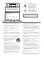 2
2
-
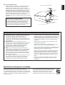 3
3
-
 4
4
-
 5
5
-
 6
6
-
 7
7
-
 8
8
-
 9
9
-
 10
10
-
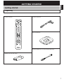 11
11
-
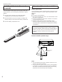 12
12
-
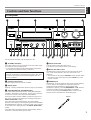 13
13
-
 14
14
-
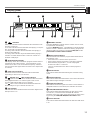 15
15
-
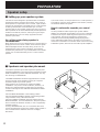 16
16
-
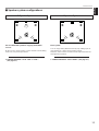 17
17
-
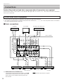 18
18
-
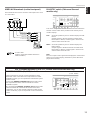 19
19
-
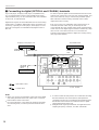 20
20
-
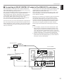 21
21
-
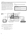 22
22
-
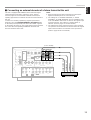 23
23
-
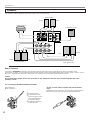 24
24
-
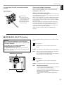 25
25
-
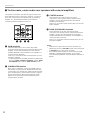 26
26
-
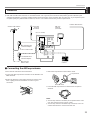 27
27
-
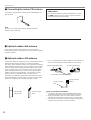 28
28
-
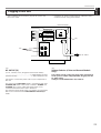 29
29
-
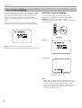 30
30
-
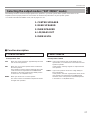 31
31
-
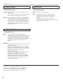 32
32
-
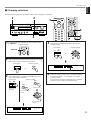 33
33
-
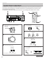 34
34
-
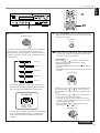 35
35
-
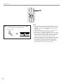 36
36
-
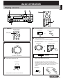 37
37
-
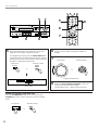 38
38
-
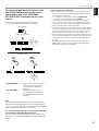 39
39
-
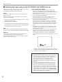 40
40
-
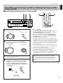 41
41
-
 42
42
-
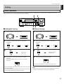 43
43
-
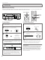 44
44
-
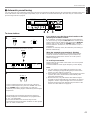 45
45
-
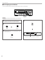 46
46
-
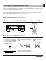 47
47
-
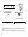 48
48
-
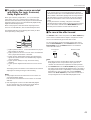 49
49
-
 50
50
-
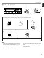 51
51
-
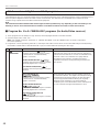 52
52
-
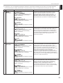 53
53
-
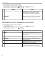 54
54
-
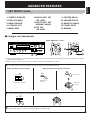 55
55
-
 56
56
-
 57
57
-
 58
58
-
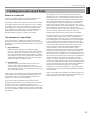 59
59
-
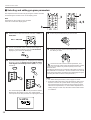 60
60
-
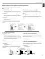 61
61
-
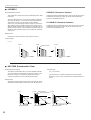 62
62
-
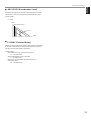 63
63
-
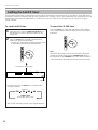 64
64
-
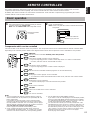 65
65
-
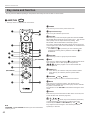 66
66
-
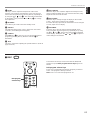 67
67
-
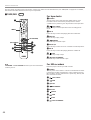 68
68
-
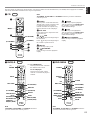 69
69
-
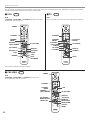 70
70
-
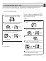 71
71
-
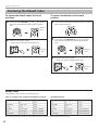 72
72
-
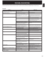 73
73
-
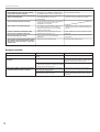 74
74
-
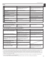 75
75
-
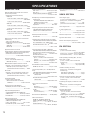 76
76
-
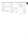 77
77
-
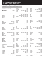 78
78
-
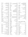 79
79
-
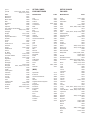 80
80
-
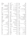 81
81
-
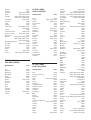 82
82
-
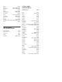 83
83
-
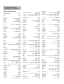 84
84
-
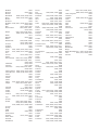 85
85
-
 86
86
-
 87
87
-
 88
88
-
 89
89
-
 90
90
-
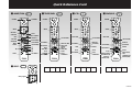 91
91
-
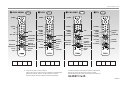 92
92


in andere talen
- English: Yamaha R-V1105 Owner's manual
- italiano: Yamaha R-V1105 Manuale del proprietario
- русский: Yamaha R-V1105 Инструкция по применению
- français: Yamaha R-V1105 Le manuel du propriétaire
- español: Yamaha R-V1105 El manual del propietario
- Deutsch: Yamaha R-V1105 Bedienungsanleitung
- português: Yamaha R-V1105 Manual do proprietário
- dansk: Yamaha R-V1105 Brugervejledning
- suomi: Yamaha R-V1105 Omistajan opas
- čeština: Yamaha R-V1105 Návod k obsluze
- svenska: Yamaha R-V1105 Bruksanvisning
- Türkçe: Yamaha R-V1105 El kitabı
- polski: Yamaha R-V1105 Instrukcja obsługi
- română: Yamaha R-V1105 Manualul proprietarului