Yamaha RX-V563 Handleiding
- Categorie
- AV-ontvangers
- Type
- Handleiding
Deze handleiding is ook geschikt voor

YAMAHA ELECTRONICS CORPORATION, USA
6660 ORANGETHORPE AVE., BUENA PARK, CALIF. 90620, U.S.A.
YAMAHA CANADA MUSIC LTD.
135 MILNER AVE., SCARBOROUGH, ONTARIO M1S 3R1, CANADA
YAMAHA ELECTRONIK EUROPA G.m.b.H.
SIEMENSSTR. 22-34, 25462 RELLINGEN BEI HAMBURG, GERMANY
YAMAHA ELECTRONIQUE FRANCE S.A.
RUE AMBROISE CROIZAT BP70 CROISSY-BEAUBOURG 77312 MARNE-LA-VALLEE CEDEX02, FRANCE
YAMAHA ELECTRONICS (UK) LTD.
YAMAHA HOUSE, 200 RICKMANSWORTH ROAD WATFORD, HERTS WD18 7GQ, ENGLAND
YAMAHA SCANDINAVIA A.B.
J A WETTERGRENS GATA 1, BOX 30053, 400 43 VÄSTRA FRÖLUNDA, SWEDEN
YAMAHA MUSIC AUSTRALIA PTY, LTD.
17-33 MARKET ST., SOUTH MELBOURNE, 3205 VIC., AUSTRALIA
RX-V563
©
2008 All rights reserved.
Printed in China WN25500
RX-V563
AV Receiver
OWNER’S MANUAL
U
Memorex 1001, 1002, 1003,
1004, 1005, 1008,
1013, 1014, 1042,
1045, 1047
Memphis 1050
Metz 1048
MGA 1014
MGN Technology
1002, 1014
Micromaxx 1044, 1048
Microstar 1044, 1048
Migros 1042
Minolta 1010
Mitsubishi 1011, 1042, 1046
Montgomery Ward
1008
Motorola 1004, 1008
MTC 1002, 1014
Multitech 1002, 1005, 1006,
1042, 1046, 1050
Murphy 1042
National 1048
NEC 1000, 1001, 1007,
1011, 1043, 1051
Neckermann 1043, 1046
NEI 1046
Nesco 1050
Nikko 1003
Noblex 1002, 1014
Nokia 1043, 1047
Nordmende 1043
Oceanic 1042, 1043
Okano 1044
Olympus 1004
Optimus 1003, 1008
Orion 1012, 1013, 1044,
1065
Orson 1042
Osaki 1042, 1045, 1050
Otto Versand 1046
Palladium 1043, 1045, 1050
Panasonic 1004, 1020, 1034,
1040, 1048, 1054,
1072
Pathe Marconi 1043
Penney 1010, 1014
Pentax 1010, 1049
Perdio 1042
Philco 1004, 1051
Philips 1004, 1025, 1033,
1046, 1056, 1057,
1059, 1062, 1063
Philips Magnavox
1018
Phonola 1046
Pilot 1003
Pioneer 1011, 1046
Prinz 1042
Profex 1050
Profitronic 1014
Proline 1042
Proscan 1009
Prosonic 1044
Protec 1006
Pye 1046, 1056
Quarter 1001
Quartz 1001, 1047
Quasar 1004, 1035
Quelle 1042, 1046, 1047
Radio Shack 1003
Radio Shack/Realistic
1001, 1002, 1003,
1004, 1005, 1008
Radiola 1046
Radix 1003
Randex 1003
RCA 1002, 1004, 1009,
1010, 1014, 1015,
1022, 1032
Realistic 1001, 1002, 1003,
1004, 1005, 1008
Rex 1043
RFT 1046
Roadstar 1045, 1050, 1066
Saba 1043
Saisho 1044, 1050
Salora 1047
Samsung 1002, 1014, 1021,
1027, 1052, 1068,
1070
Sanky 1008
Sansui 1007, 1011, 1013,
1043
Sanyo 1001, 1002, 1014,
1047
SBR 1046
Schaub Lorenz 1042, 1043, 1047
Schneider 1042, 1044, 1045,
1046, 1050
Scott 1012
Sears 1001, 1003, 1004,
1010
SEG 1050
SEI-Sinudyne 1046
Seleco 1043
Sentron 1050
Sharp 1008, 1023, 1028,
1053, 1073
Shintom 1006, 1047, 1050
Shivaki 1045
Shogun 1002, 1014
Siemens 1045, 1047
Signature 2000 1008
Silva 1045
Singer 1004, 1006
Sinudyne 1046
Sontec 1045
Sony 1016, 1019, 1055,
1060, 1064, 1074
STS 1004, 1010
Sunkai 1044
Sunstar 1042
Suntronic 1042
Sunwood 1050
Sylvania 1004, 1005, 1031,
1041
Symphonic 1005
Taisho 1044
Tandy 1001
Tashiko 1003, 1042
Tatung 1007, 1042, 1043,
1046, 1066
TCM 1044, 1048
Teac 1005, 1007
Technics 1004, 1048
Teknika 1003, 1004, 1005
Teleavia 1043
Telefunken 1043
Tenosal 1050
Tensai 1042, 1045, 1050
Tevion 1044, 1048
Thomson 1043, 1058
Thorn 1043, 1047
TMK 1002, 1014
Tokai 1045, 1050
Tonsai 1050
Toshiba 1013, 1024, 1029,
1043, 1046, 1066,
1075
Totevision 1002, 1003, 1014
Towada 1050
Towika 1050
Uher 1045
Unitech 1002, 1014
Universum 1042, 1045, 1046
Vector Research 1000
Video Concepts 1000
Videon 1044, 1048
Videosonic 1002, 1014
Wards 1002, 1003, 1004,
1005, 1006, 1008,
1010, 1014
Weltblick 1045
White Westinghouse
1013
XR-1000 1004, 1005, 1006
Yamaha 1000, 1001, 1007
Yamishi 10 50
Yokan 1050
Yoko 1045, 1050
Zenith 1013, 1026, 1037
RX-V563_U-cv.fm Page 1 Tuesday, December 4, 2007 5:56 PM
Black process 45.0° 240.0 LPI

IMPORTANT SAFETY INSTRUCTIONS
Caution-i En
• Explanation of Graphical Symbols
The lightning flash with arrowhead symbol, within an
equilateral triangle, is intended to alert you to the
presence of uninsulated “dangerous voltage” within
the product’s enclosure that may be of sufficient
magnitude to constitute a risk of electric shock to
persons.
The exclamation point within an equilateral triangle
is intended to alert you to the presence of important
operating and maintenance (servicing) instructions in
the literature accompanying the appliance.
1 Read Instructions – All the safety and operating instructions
should be read before the product is operated.
2 Retain Instructions – The safety and operating instructions
should be retained for future reference.
3 Heed Warnings – All warnings on the product and in the
operating instructions should be adhered to.
4 Follow Instructions – All operating and use instructions
should be followed.
5 Cleaning – Unplug this product from the wall outlet before
cleaning. Do not use liquid cleaners or aerosol cleaners.
6 Attachments – Do not use attachments not recommended by
the product manufacturer as they may cause hazards.
7 Water and Moisture – Do not use this product near water –
for example, near a bath tub, wash bowl, kitchen sink, or
laundry tub; in a wet basement; or near a swimming pool;
and the like.
8 Accessories – Do not place this product on an unstable cart,
stand, tripod, bracket, or table. The product may fall,
causing serious injury to a child or adult, and serious
damage to the product. Use only with a cart, stand, tripod,
bracket, or table recommended by the manufacturer, or sold
with the product. Any mounting of the product should
follow the manufacturer’s instructions, and should use a
mounting accessory recommended by the manufacturer.
9 A product and cart combination should be moved with care.
Quick stops, excessive force, and uneven surfaces may
cause the product and cart combination to
overturn.
10 Ventilation – Slots and openings in the cabinet are provided
for ventilation and to ensure reliable operation of the
product and to protect it from overheating, and these
openings must not be blocked or covered. The openings
should never be blocked by placing the product on a bed,
sofa, rug, or other similar surface. This product should not
be placed in a built-in installation such as a bookcase or rack
unless proper ventilation is provided or the manufacturer’s
instructions have been adhered to.
11 Power Sources – This product should be operated only from
the type of power source indicated on the marking label. If
you are not sure of the type of power supply to your home,
consult your product dealer or local power company. For
products intended to operate from battery power, or other
sources, refer to the operating instructions.
12 Grounding or Polarization – This product may be equipped
with a polarized alternating current line plug (a plug having
one blade wider than the other). This plug will fit into the
power outlet only one way. This is a safety feature. If you
are unable to insert the plug fully into the outlet, try
reversing the plug. If the plug should still fail to fit, contact
your electrician to replace your obsolete outlet. Do not
defeat the safety purpose of the polarized plug.
13 Power-Cord Protection – Power-supply cords should be
routed so that they are not likely to be walked on or pinched
by items placed upon or against them, paying particular
attention to cords at plugs, convenience receptacles, and the
point where they exit from the product.
14 Lightning – For added protection for this product during a
lightning storm, or when it is left unattended and unused for
long periods of time, unplug it from the wall outlet and
disconnect the antenna or cable system. This will prevent
damage to the product due to lightning and power-line
surges.
15 Power Lines – An outside antenna system should not be
located in the vicinity of overhead power lines or other
electric light or power circuits, or where it can fall into such
power lines or circuits. When installing an outside antenna
system, extreme care should be taken to keep from touching
such power lines or circuits as contact with them might be
fatal.
16 Overloading – Do not overload wall outlets, extension
cords, or integral convenience receptacles as this can result
in a risk of fire or electric shock.
17 Object and Liquid Entry – Never push objects of any kind
into this product through openings as they may touch
dangerous voltage points or short-out parts that could result
in a fire or electric shock. Never spill liquid of any kind on
the product.
18 Servicing – Do not attempt to service this product yourself
as opening or removing covers may expose you to
dangerous voltage or other hazards. Refer all servicing to
qualified service personnel.
19 Damage Requiring Service – Unplug this product from the
wall outlet and refer servicing to qualified service personnel
under the following conditions:
a) When the power-supply cord or plug is damaged,
b) If liquid has been spilled, or objects have fallen into the
product,
c) If the product has been exposed to rain or water,
IMPORTANT SAFETY INSTRUCTIONS
CAUTION
CAUTION: TO REDUCE THE RISK OF
ELECTRIC SHOCK, DO NOT REMOVE
COVER (OR BACK). NO USER-SERVICEABLE
PARTS INSIDE. REFER SERVICING TO
QUALIFIED SERVICE PERSONNEL.
RISK OF ELECTRIC SHOCK
DO NOT OPEN
01EN_RX-V563_U.book Page i Thursday, January 31, 2008 10:28 AM

IMPORTANT SAFETY INSTRUCTIONS
Caution-ii En
EXAMPLE OF ANTENNA GROUNDING
MAST
GROUND
CLAMP
ANTENNA
LEAD IN
WIRE
ANTENNA
DISCHARGE UNIT
(NEC SECTION 810–20)
GROUNDING CONDUCTORS
(NEC SECTION 810–21)
GROUND CLAMPS
POWER SERVICE GROUNDING
ELECTRODE SYSTEM
(NEC ART 250. PART H)
ELECTRIC
SERVICE
EQUIPMENT
NEC – NATIONAL ELECTRICAL CODE
d) If the product does not operate normally by following
the operating instructions. Adjust only those controls
that are covered by the operating instructions as an
improper adjustment of other controls may result in
damage and will often require extensive work by a
qualified technician to restore the product to its normal
operation,
e) If the product has been dropped or damaged in any
way, and
f) When the product exhibits a distinct change in perfor-
mance - this indicates a need for service.
20 Replacement Parts – When replacement parts are required,
be sure the service technician has used replacement parts
specified by the manufacturer or have the same
characteristics as the original part. Unauthorized
substitutions may result in fire, electric shock, or other
hazards.
21 Safety Check – Upon completion of any service or repairs to
this product, ask the service technician to perform safety
checks to determine that the product is in proper operating
condition.
22 Wall or Ceiling Mounting – The unit should be mounted
to a wall or ceiling only as recommended by the
manufacturer.
23 Heat – The product should be situated away from heat
sources such as radiators, heat registers, stoves, or other
products (including amplifiers) that produce heat.
24 Outdoor Antenna Grounding – If an outside antenna or
cable system is connected to the product, be sure the antenna
or cable system is grounded so as to provide some
protection against voltage surges and built-up static charges.
Article 810 of the National Electrical Code, ANSI/NFPA 70,
provides information with regard to proper grounding of the
mast and supporting structure, grounding of the lead-in wire
to an antenna discharge unit, size of grounding conductors,
location of antenna discharge unit, connection to grounding
electrodes, and requirements for the grounding electrode.
Note to CATV system installer:
This reminder is provided to call the CATV system installer’s
attention to Article 820-40 of the NEC that provides
guidelines for proper grounding and, in particular, specifies
that the cable ground shall be connected to the grounding
system of the building, as close to the point of cable entry as
practical.
FCC INFORMATION (for US customers)
1 IMPORTANT NOTICE: DO NOT MODIFY THIS
UNIT!
This product, when installed as indicated in the
instructions contained in this manual, meets FCC
requirements. Modifications not expressly approved by
Yamaha may void your authority, granted by the FCC, to
use the product.
2 IMPORTANT: When connecting this product to
accessories and/or another product use only high quality
shielded cables. Cable/s supplied with this product MUST
be used. Follow all installation instructions. Failure to
follow instructions could void your FCC authorization to
use this product in the USA.
3 NOTE: This product has been tested and found to comply
with the requirements listed in FCC Regulations, Part 15
for Class “B” digital devices. Compliance with these
requirements provides a reasonable level of assurance that
your use of this product in a residential environment will
not result in harmful interference with other electronic
devices.
This equipment generates/uses radio frequencies and, if
not installed and used according to the instructions found
in the users manual, may cause interference harmful to the
operation of other electronic devices.
Compliance with FCC regulations does not guarantee that
interference will not occur in all installations. If this
product is found to be the source of interference, which
can be determined by turning the unit “OFF” and “ON”,
please try to eliminate the problem by using one of the
following measures:
Relocate either this product or the device that is being
affected by the interference.
Utilize power outlets that are on different branch (circuit
breaker or fuse) circuits or install AC line filter/s.
In the case of radio or TV interference, relocate/reorient
the antenna. If the antenna lead-in is 300 ohm ribbon lead,
change the lead-in to coaxial type cable.
If these corrective measures do not produce satisfactory
results, please contact the local retailer authorized to
distribute this type of product. If you can not locate the
appropriate retailer, please contact Yamaha Electronics
Corp., U.S.A. 6660 Orangethorpe Ave., Buena Park, CA
90620.
The above statements apply ONLY to those products
distributed by Yamaha Corporation of America or its
subsidiaries.
01EN_RX-V563_U.book Page ii Thursday, January 31, 2008 10:28 AM

CAUTION: READ THIS BEFORE OPERATING YOUR UNIT.
Caution-iii En
1 To assure the finest performance, please read this manual
carefully. Keep it in a safe place for future reference.
2 Install this sound system in a well ventilated, cool, dry, clean
place – away from direct sunlight, heat sources, vibration,
dust, moisture, and/or cold. Allow ventilation space of at least
30 cm on the top, 20 cm on the left and right, and 20 cm on
the back of this unit.
3 Locate this unit away from other electrical appliances, motors,
or transformers to avoid humming sounds.
4 Do not expose this unit to sudden temperature changes from
cold to hot, and do not locate this unit in a environment with
high humidity (i.e. a room with a humidifier) to prevent
condensation inside this unit, which may cause an electrical
shock, fire, damage to this unit, and/or personal injury.
5 Avoid installing this unit where foreign object may fall onto
this unit and/or this unit may be exposed to liquid dripping or
splashing. On the top of this unit, do not place:
– other components, as they may cause damage and/or
discoloration on the surface of this unit.
– burning objects (i.e. candles), as they may cause fire,
damage to this unit, and/or personal injury.
– containers with liquid in them, as they may fall and liquid
may cause electrical shock to the user and/or damage to
this unit.
6 Do not cover this unit with a newspaper, tablecloth, curtain,
etc. in order not to obstruct heat radiation. If the temperature
inside this unit rises, it may cause fire, damage to this unit,
and/or personal injury.
7 Do not plug in this unit to a wall outlet until all connections
are complete.
8 Do not operate this unit upside-down. It may overheat,
possibly causing damage.
9 Do not use force on switches, knobs and/or cords.
10 When disconnecting the power cable from the wall outlet,
grasp the plug; do not pull the cord.
11 Do not clean this unit with chemical solvents; this might
damage the finish. Use a clean, dry cloth.
12 Only voltage specified on this unit must be used. Using this
unit with a higher voltage than specified is dangerous and may
cause fire, damage to this unit, and/or personal injury. Yamaha
will not be held responsible for any damage resulting from use
of this unit with a voltage other than specified.
13 To prevent damage by lightning, keep the power cord and
outdoor antennas disconnected from a wall outlet or the unit
during a lightning storm.
14 Do not attempt to modify or fix this unit. Contact qualified
Yamaha service personnel when any service is needed. The
cabinet should never be opened for any reasons.
15 When not planning to use this unit for long periods of time
(i.e. vacation), disconnect the AC power plug from the wall
outlet.
16 Install this unit near the AC outlet and where the AC power
plug can be reached easily.
17 Be sure to read the “Troubleshooting” section on common
operating errors before concluding that this unit is faulty.
18 Before moving this unit, press CSYSTEM OFF to set this
unit in the standby mode, and disconnect the AC power plug
from the wall outlet.
19 VOLTAGE SELECTOR (Asia and General models only)
The VOLTAGE SELECTOR on the rear panel of this unit
must be set for your local main voltage BEFORE plugging
into the AC wall outlet.
Voltages are 110–120/220–240 V AC, 50/60 Hz.
20 The batteries shall not be exposed to excessive heat such as
sunshine, fire or like.
21 Excessive sound pressure from earphones and headphones can
cause hearing loss.
Caution: Read this before operating your unit.
WARNING
TO REDUCE THE RISK OF FIRE OR ELECTRIC
SHOCK, DO NOT EXPOSE THIS UNIT TO RAIN
OR MOISTURE.
This unit is not disconnected from the AC power
source as long as it is connected to the wall outlet, even
if this unit itself is turned off by CSYSTEM OFF.
This state is called the standby mode. In this state, this
unit is designed to consume a very small quantity of
power.
FOR CANADIAN CUSTOMERS
To prevent electric shock, match wide blade of plug to
wide slot and fully insert.
This Class B digital apparatus complies with Canadian
ICES-003.
POUR LES CONSOMMATEURS CANADIENS
Pour éviter les chocs électriques, introduire la lame la
plus large de la fiche dans la borne correspondante de
la prise et pousser jusqu’au fond.
Cet appareil numérique de la classe B est conforme à
la norme NMB-003 du Canada.
IMPORTANT
Please record the serial number of this unit in the space
below.
MODEL:
Serial No.:
The serial number is located on the rear of the unit.
Retain this Owner’s Manual in a safe place for future
reference.
01EN_RX-V563_U.book Page iii Thursday, January 31, 2008 10:28 AM

1 En
English
PREPARATIONINTRODUCTION
BASIC
OPERATION
ADVANCED
OPERATION
ADDITIONAL
INFORMATION
APPENDIX
Features ................................................................... 2
Getting started ........................................................ 3
Quick start guide .................................................... 4
Preparation: Check the items ..................................... 4
Step 1: Set up your speakers...................................... 5
Step 2: Connect your DVD player and other
components............................................................ 6
Step 3: Press SCENE 1 button................................... 7
What do you want to do with this unit?..................... 8
Connections ............................................................. 9
Rear panel .................................................................. 9
Placing speakers....................................................... 10
Connecting speakers ................................................ 11
Information on jacks and cable plugs ...................... 13
Information on HDMI™.......................................... 14
Audio and video signal flow.................................... 15
Connecting video components................................. 16
Connecting other components ................................. 17
Connecting audio components................................. 19
Connecting a Yamaha iPod™ universal dock or
Bluetooth™ adapter............................................. 20
Using REMOTE IN/OUT jacks............................... 20
Using the VIDEO AUX jacks on the front panel .... 21
Connecting the FM and AM antennas ..................... 21
Connecting the power cable..................................... 22
Setting the speaker impedance................................. 23
Turning on and off the power .................................. 23
Front panel display .................................................. 24
Optimizing the speaker setting
for your listening room .................................... 26
Using AUTO SETUP .............................................. 26
Selecting the SCENE templates........................... 30
Selecting the desired SCENE template.................... 30
Creating your original SCENE templates................ 33
Using remote control on the SCENE feature........... 34
Playback ................................................................ 35
Basic operations....................................................... 35
Selecting audio input jacks
(AUDIO SELECT).............................................. 36
Selecting the MULTI CH INPUT component......... 36
Displaying the current status of this unit on a video
monitor ................................................................ 37
Using your headphones............................................ 37
Muting the audio output........................................... 37
Playing video sources in the background of an audio
source................................................................... 38
Displaying the input source information ................. 38
Using the sleep timer ............................................... 39
Sound field programs ........................................... 40
Sound field program descriptions............................ 40
Using audio features ............................................. 43
Enjoying high quality sound.................................... 43
Adjusting the tonal quality....................................... 43
Adjusting the speaker level...................................... 43
Selecting the night listening mode........................... 44
FM/AM tuning ...................................................... 45
Automatic tuning ..................................................... 45
Manual tuning.......................................................... 45
Automatic preset tuning........................................... 46
Manual preset tuning ............................................... 46
Selecting preset stations........................................... 47
Exchanging preset station ........................................ 47
XM Satellite Radio tuning ....................................48
Connecting the XM Mini-Tuner Dock .................... 48
Activating XM Satellite Radio ................................ 49
Basic XM Satellite Radio operations....................... 49
Setting XM Satellite Radio preset channels ............ 51
Displaying the XM Satellite Radio information...... 52
SIRIUS Satellite Radio™ tuning .........................53
Connecting the SiriusConnect™ tuner .................... 53
Activating SIRIUS Satellite Radio™ subscription.. 54
Basic SIRIUS Satellite Radio™ operations ............ 54
Setting the SIRIUS Satellite Radio™ preset
channels ............................................................... 56
Setting the Parental Lock......................................... 56
Displaying the SIRIUS Satellite Radio™
information .......................................................... 58
Using iPod™ ..........................................................59
Controlling iPod™................................................... 59
Using Bluetooth™ components ............................61
Pairing the Bluetooth™ adapter and your Bluetooth™
component ........................................................... 61
Playback of the Bluetooth™ component................. 61
Recording ...............................................................62
SET MENU ............................................................63
Using SET MENU................................................... 64
1 SOUND MENU.................................................... 65
2 INPUT MENU...................................................... 71
3 OPTION MENU................................................... 73
Remote control features........................................76
Controlling this unit, a TV, or other components.... 76
Setting remote control codes ................................... 78
Using multi-zone configuration............................79
Connecting Zone 2................................................... 79
Controlling Zone 2................................................... 80
Advanced setup......................................................82
Troubleshooting.....................................................84
Glossary..................................................................94
Specifications .........................................................97
Index .......................................................................98
(at the end of this manual)
Front panel................................................................i
Remote control ....................................................... ii
List of remote control codes ................................. iii
Contents
INTRODUCTION
PREPARATION
BASIC OPERATION
ADVANCED OPERATION
ADDITIONAL INFORMATION
APPENDIX
About this manual
• y indicates a tip for your operation.
• Some operations can be performed by using either the buttons on the
front panel or the ones on the remote control. In case the button
names differ between the front panel and the remote control, the
button name on the remote control is given in parentheses.
• This manual is printed prior to production. Design and specifications
are subject to change in part as a result of improvements, etc. In case
of differences between the manual and product, the product has
priority.
•“MSPEAKERS” or “4DVD” (example) indicates the name of the
parts on the front panel or the remote control. Refer to the attached
sheet or the pages at the end of this manual for the information about
each position of the parts.
• The symbol “☞ ” with page number(s) indicates the corresponding
reference page(s).
01EN_RX-V563_U.book Page 1 Thursday, January 31, 2008 10:28 AM

Features
2 En
Built-in 7-channel power amplifier
◆ Minimum RMS output power
[U.S.A. and Canada models]
(1 kHz, 0.9% THD, 8 Ω)
90 W/ch
[Other models]
(1 kHz, 0.9% THD, 6 Ω)
90 W/ch
SCENE select function
◆ Preset SCENE templates for various situations
◆ SCENE template customizing capability
Decoders and DSP circuits
◆ Proprietary Yamaha technology for the creation of multi-
channel surround sound
◆ Compressed Music Enhancer mode
◆ Dolby Digital/Dolby Digital EX decoder
◆ DTS/DTS-ES Matrix, Discrete, DTS Neo:6,
DTS 96/24 decoder
◆ Dolby Pro Logic/Dolby Pro Logic II/Dolby Pro Logic IIx
decoder
◆ Neural Surround decoder
(U.S.A. and Canada models only)
◆ Virtual CINEMA DSP
◆ SILENT CINEMA
™
Radio tuners
◆ FM/AM tuning capability
◆ XM Satellite Radio tuning capability (using XM Mini-Tuner
and Home Dock, sold separately)
◆ SIRIUS Satellite Radio™ tuning capability (using SIRIUS
Connect tuner, sold separately)
HDMI (High-Definition Multimedia Interface)
◆ HDMI interface for standard, enhanced or high-definition
video (includes 1080p video signal transmission) as well as
multi-channel digital audio
DOCK terminal
◆ DOCK terminal to connect a Yamaha iPod universal dock
(such as YDS-10, sold separately) or Bluetooth adapter (such
as YBA-10, sold separately).
Other features
◆ YPAO (Yamaha Parametric Room Acoustic Optimizer) for
automatic speaker setup
◆ 192-kHz/24-bit D/A converter
◆ DIRECT mode for high quality sound for all sources
◆ 6 additional input jacks for discrete multi-channel input
◆ OSD (on-screen display) menus that allow you to optimize
this unit to suit your individual audiovisual system
◆ Component video input/output capability
(3 COMPONENT VIDEO INs and 1 MONITOR OUT)
◆ S-video signal input/output capability
◆ Optical and coaxial digital audio signal jacks
◆ Sleep timer
◆ Cinema and music night listening modes
◆ iPod controlling capability
◆ Remote control with preset remote control codes
◆ Zone 2 custom installation facility
◆ Bi-amplification connection capability
Manufactured under license from Dolby Laboratories.
“Dolby”, “Pro Logic”, and the double-D symbol are trademarks
of Dolby Laboratories.
“SILENT CINEMA” is a trademark of YAMAHA
CORPORATION.
iPod™
“iPod” is a trademark of Apple, Inc., registered in the U.S. and
other countries.
Bluetooth™
Bluetooth is a registered trademark of the Bluetooth SIG and is
used by Yamaha in accordance with a license agreement.
“HDMI”, the “HDMI” logo and “High-Definition Multimedia
Interface” are trademarks or registered trademarks of HDMI
Licensing LLC.
DTS-ES | NEO:6 | 96/24. Product “DTS” and “DTS-ES | NEO:6”
are registered trademarks of DTS, Inc.
“96/24” is a trademark of DTS, Inc.
The XM name and related logos are registered trademarks of XM
Satellite Radio Inc.
Neural Surround
™
name and related logos are trademarks owned
by Neural Audio Corporation.
©2006 SIRIUS Satellite Radio Inc. “SIRIUS”, “Sirius Connect”,
the SIRIUS dog logo, channel names and logos are trademarks of
SIRIUS Satellite Radio Inc.
Features
01EN_RX-V563_U.book Page 2 Thursday, January 31, 2008 10:28 AM

Getting started
3 En
English
INTRODUCTION
■ Supplied accessories
Check that you received all of the following parts.
❏ Remote control
❏ Batteries (2) (AAA, R03, UM-4)
❏ Optimizer microphone
❏ AM loop antenna
❏ Indoor FM antenna
■ VOLTAGE SELECTOR
(Asia and General models only)
■ Installing batteries in the remote control
1 Take off the battery compartment cover.
2 Insert the two supplied batteries
(AAA, R03, UM-4) according to the polarity
markings (+ and –) on the inside of the
battery compartment.
3 Snap the battery compartment cover back
into place.
• Change all of the batteries if you notice that the operation range
of the remote control decreases.
• Do not use an old battery and a new one together.
• Do not use different types of batteries (such as alkaline and
manganese batteries) together. Read the packaging carefully as
these different types of batteries may have the same shape and
color.
• If the batteries have leaked, dispose of them immediately. Avoid
touching the leaked material or letting it come into contact with
clothing, etc. Clean the battery compartment thoroughly before
installing new batteries.
• Do not throw away batteries with general house waste; dispose
of them correctly in accordance with your local regulations.
• If the remote control is without batteries for more than 2
minutes, or if exhausted batteries remain in the remote control,
the contents of the memory may be cleared. When the memory
is cleared, insert new batteries and set up the remote control
code.
We Want You Listening For A Lifetime
Yamaha and the Electronic Industries Association’s Consumer
Electronics Group want you to get the most out of your
equipment by playing it at a safe level. One that lets the sound
come through loud and clear without annoying blaring or
distortion – and, most importantly, without affecting your
sensitive hearing.
Since hearing damage from loud sounds is often
undetectable until it is too late, Yamaha and the
Electronic Industries Association’s Consumer
Electronics Group recommend you to avoid
prolonged exposure from excessive volume levels.
Getting started
Caution
The VOLTAGE SELECTOR on the rear panel of this
unit must be set for your local voltage BEFORE
plugging the power cable into the AC wall outlet.
Improper setting of the VOLTAGE SELECTOR may
cause damage to this unit and create a potential fire
hazard.
Rotate the VOLTAGE SELECTOR clockwise or
counterclockwise to the correct position using a
straight slot screwdriver.
Voltages are as follows:
Asia model ................... 220/230–240 V AC, 50/60 Hz
General model
...................... 110/120/220/230–240 V AC, 50/60 Hz
230-
240V
VOLTAGE
SELECTOR
Voltage indication
Notes
1
3
2
01EN_RX-V563_U.book Page 3 Thursday, January 31, 2008 10:28 AM

Quick start guide
4 En
The following steps describe the easiest way to enjoy
DVD movie playback in your home theater.
Prepare the following items.
❏ Speakers
❏ Front speaker .....................................x 2
❏ Center speaker ...................................x 1
❏ Surround speaker ..............................x 4
Select magnetically shielded speakers. The
minimum required speakers are two front speakers.
The priority of the requirement of other speakers is
as follows:
1. Two surround speakers
2. Center speaker
3. One (or two) surround back speaker(s)
❏ Active subwoofer ...................................x 1
Select an active subwoofer equipped with an RCA
input jack.
❏ Speaker cable .........................................x 7
❏ Subwoofer cable .....................................x 1
Select a monaural RCA cable.
❏ DVD player ..............................................x 1
Select DVD player equipped with coaxial digital
audio output jack and composite video output
jack.
❏ Video monitor ..........................................x 1
Select a TV monitor, video monitor or projector
equipped with a composite video input jack.
❏ Video cable .............................................x 2
Select an RCA composite video cable.
❏ Digital coaxial audio cable ....................x 1
Quick start guide
Front right
speaker
Subwoofer
Surround left
speaker
Front left
speaker
Surround right
speaker
Center speaker
DVD player
Video monitor
Surround back
right speaker
Surround back left
speaker
Enjoy DVD playback!
Step 1: Set up your speakers
Step 2: Connect your DVD player
and other components
Step 3: Press SCENE 1 button
☞
P. 6
☞
P. 7
☞
P. 5
Preparation: Check the items
01EN_RX-V563_U.book Page 4 Thursday, January 31, 2008 10:28 AM

Quick start guide
5 En
English
INTRODUCTION
Place your speakers in the room and connect them to this
unit.
1 Place your speakers and subwoofer in the
room.
2 Connect speaker cables to each speaker.
Cables are colored or shaped differently, perhaps with
a stripe, groove or ridge. Connect the striped
(grooved, etc.) cable to the “+” (red) terminals of
your speaker. Connect the plain cable to the “–”
(black) terminals.
3 Connect each speaker cable to the
corresponding speaker terminal of this unit.
1 Make sure that this unit and the subwoofer are
unplugged from the AC wall outlets.
2 Twist the exposed wires of the speaker cables
together to prevent short circuits.
3 Do not let the bare speaker wires touch each other.
4 Do not let the bare speaker wires touch any metal
part of this unit.
Be sure to connect the left channel (L), right channel
(R), “+” (red) and “–” (black) properly.
Front and center speakers
Surround and surround back speakers
4 Connect the subwoofer cable to the input
jack of the subwoofer and the SUBWOOFER
OUTPUT jack of this unit.
Step 1: Set up your speakers
LR
SURROUND
LR
FRONT B
LR
FRONT ACENTER
LR
SURROUND BACK/BI-AMP
SINGLE
SWITCHED
MONITOR
OUT
L
R
DTV/CBL DVRDVD
MD/
CD-R
OUT
(REC)
IN
(PLAY)
OUT
IN
DTV/CBL DVRDVD
OUT
OUT
+12V
15mA MAX.
IN
IN
MONITOR
OUT
DTV/CBL DVRDVD
OUT S VIDEOIN
CD
L
R
SUB
WOOFER
SUB
WOOFER
SURROUND
CENTER
MULTI CH INPUTAUDIO
VIDEO
OUTPUT
ZONE 2
OUT
FRONT(6CH)
SB(8CH)
1
2
3
DTV/CBL
DTV/CBL CD
OUT
DTV/CBL
DVR
DVD
DVD
OPTICAL
COAXIAL
DVD
P
R
P
B
YP
R
P
B
Y
MONITOR OUT
AM
GND
FM
75
UNBAL.
COMPONENT VIDEO ANTENNA
SPEAKERS
HDMI
REMOTE
TRIGGER
OUT
DIGITAL INPUT
VIDEO
XM SIRIUS DOCK
A
IN1 IN2
B
C
AC OUTLETS
LR
SURROUND
LR
FRONT B
LR
FRONT ACENTER
LR
SURROUND BACK/BI-AMP
SINGLE
SUB
WOOFER
OUTPUT
SPEAKERS
12 3 4
To the front
right speaker
To the front
left speaker
Loosen Insert Tighten
To the center
speaker
To the surround
back right
speaker
To the surround
back left speaker
To the surround
left speaker
To the surround
right speaker
SUBWOOFER
OUTPUT jack
Subwoofer cable
Input jack
AV receiver
Subwoofer
01EN_RX-V563_U.book Page 5 Thursday, January 31, 2008 10:28 AM

Quick start guide
6 En
1 Connect the digital coaxial audio cable to the
digital coaxial audio output jack of your DVD
player and the DVD DIGITAL INPUT COAXIAL
jack of this unit.
2 Connect the video cable to the composite
video output jack of your DVD player and the
DVD VIDEO jack of this unit.
3 Connect the video cable to the video input
jack of your video monitor and the VIDEO
MONITOR OUT jack of this unit.
4 Connect the power plug of this unit and other
components into the AC wall outlet.
y
This unit is equipped with AC OUTLET(S) for the power supply
of the other components (except Korea model). See page 22 for
details.
Step 2: Connect your DVD player
and other components
LR
SURROUND
LR
FRONT B
LR
FRONT ACENTER
LR
SURROUND BACK/BI-AMP
SINGLE
SWITCHED
MONITOR
OUT
L
R
DTV/CBL DVRDVD
MD/
CD-R
OUT
(REC)
IN
(PLAY)
OUT
IN
DTV/CBL DVRDVD
OUT
OUT
+12V
15mA MAX.
IN
IN
MONITOR
OUT
DTV/CBL DVRDVD
OUT S VIDEOIN
CD
L
R
SUB
WOOFER
SUB
WOOFER
SURROUND
CENTER
MULTI CH INPUTAUDIO
VIDEO
OUTPUT
ZONE 2
OUT
FRONT(6CH)
SB(8CH)
1
2
3
DTV/CBL
DTV/CBL CD
OUT
DTV/CBL
DVR
DVD
DVD
OPTICAL
COAXIAL
DVD
P
R
P
B
YP
R
P
B
Y
MONITOR OUT
AM
GND
FM
75
UNBAL.
COMPONENT VIDEO ANTENNA
SPEAKERS
HDMI
REMOTE
TRIGGER
OUT
DIGITAL INPUT
VIDEO
XM SIRIUS DOCK
A
IN1 IN2
B
C
AC OUTLETS
MONITOR
OUT
DTV/CBL DVRDVD
OUTIN
MONITOR
OUT
DTV/CBL DVRDVD
OUT S VIDEOIN
VIDEO
1
2
3
DTV/CBL CDDVD
OPTICAL
COAXIAL
DIGITAL INPUT
VIDEO
Make sure that this unit and the DVD
player are unplugged from the AC wall
outlets.
Digital coaxial
audio output jack
Digital coaxial audio
cable
DVD DIGITAL INPUT
COAXIAL jack
DVD player
AV receiver
Composite video
output jack
Video cable
DVD VIDEO jack
DVD player
AV receiver
■ For further connections
• Using the other kind of speaker
combinations ☞ P. 11
• Connecting a video components ☞ P. 16
• Connecting a DVD player ☞ P. 17
• Connecting a DVD recorder ☞ P. 18
• Connecting a set-top boxes ☞ P. 18
• Connecting a CD player
and a CD recorder/ MD recorder ☞ P. 19
• Connecting a multi-format player
or an external decoder ☞ P. 19
• Connecting an Yamaha iPod/Bluetooth
dock ☞ P. 20
• Connecting the REMOTE IN/OUT jacks
☞ P. 20
• Using the VIDEO AUX jacks on the front
panel ☞ P. 21
• Connecting an FM/AM antenna ☞ P. 21
• Connecting the XM Mini-Tuner Dock
☞ P. 48
• Connecting the SIRIUS Connect tuner
☞ P. 53
Video monitor
AV receiver
Video input
jack
VIDEO MONITOR OUT
jack
Video cable
01EN_RX-V563_U.book Page 6 Thursday, January 31, 2008 10:28 AM

Quick start guide
7 En
English
INTRODUCTION
1 Turn on the video monitor and then set the
input source selector of the video monitor to
this unit.
2 Press
T
SCENE 1.
This unit is turned on. “DVD Viewing” appears in the
front panel display, and this unit automatically
optimize own status for the DVD playback.
y
The indicator on the selected SCENE button lights up while
this unit is in the SCENE mode.
3 Start playback of the desired DVD on your
player.
4 Rotate
L
VOLUME to adjust the volume.
When you change the input source or sound field program, the
SCENE mode is deactivated, and the indicator on the selected
SCENE button turns off.
■ About SCENE function
Just by pressing one SCENE button, you can turn on this
unit and recall your favorite input source and sound field
program according to the SCENE template that has been
assigned to the SCENE button. The SCENE templates are
built combinations of input sources and sound field
programs.
y
If you connect a Yamaha product that has capability of the
SCENE control signals, this unit can automatically activate the
component and start playback. Refer to the instruction manual of
the DVD player for further information.
■ Using the other SCENE buttons
*1
You must connect a cable TV or a satellite tuner to this unit in
advance. See page 18 for details.
*2
You need to connect the supplied FM and AM antennas to this
unit in advance. See page 21 for details.
*3
You must tune into the desired radio station. See pages 45 to 47
for the tuning information.
*4
To achieve the best possible reception, orient the connected
AM loop antenna, or adjust the position of the end of the
indoor FM antenna.
y
If you cannot find the desired situation, you can select and change
the assigned SCENE template for the SCENE buttons. See
page 30 for details.
Step 3: Press SCENE 1 button
Check the type of the connected speakers.
If the speakers are 6 ohm speakers, set “SP IMP.” to
“6Ω MIN” before using this unit (see page 23).
Note
Default
SCENE
button
The name of the SCENE template
and its description
SCENE
1
DVD Viewing
– input source: DVD
– sound field program: STRAIGHT
For when you want to enjoy a DVD playback.
SCENE
2
Disc Listening
– input source: DVD
– sound field program: 7ch Stereo
For when you want to listen to a music disc from
the connected DVD player as the background
music for this room.
SCENE
3
TV Viewing
*1
– input source: DTV/CBL
– sound field program: STRAIGHT
For when you want to watch a TV program.
SCENE
4
Radio Listening
*2, *3, *4
– input source: TUNER
– sound field program: 7ch Enhancer
For when you want to listen to a music program
from the FM radio station.
Notes
01EN_RX-V563_U.book Page 7 Thursday, January 31, 2008 10:28 AM

Quick start guide
8 En
■ After using this unit...
Press
A
MAIN ZONE ON/OFF on the front
panel to set this unit to the standby mode.
This unit is set to the standby mode. In the standby mode,
this unit consumes a small amount of power in order to
receive infrared signals from the remote control. To turn
on this unit from the standby mode, press
A
MAIN ZONE
ON/OFF (or HPOWER). See page 23 for details.
What do you want to do with this
unit?
■ Customizing the SCENE templates
• Using various SCENE templates ☞ P. 30
• Creating your original SCENE templates
☞ P. 33
■ Using various input sources
• Basic controls of this unit ☞ P. 35
• Enjoying FM/AM radio programs ☞ P. 45
• Enjoying XM Satellite Radio programs
☞ P. 48
• Enjoying SIRIUS Satellite Radio programs
☞ P. 53
• Using your iPod with this unit. ☞ P. 59
• Using your Bluetooth components
with this unit. ☞ P. 61
■ Using various sound features
• Using various sound field programs
☞ P. 40
• Using the direct mode for
the high quality sound ☞ P. 43
• Customizing the sound field programs
☞ P. 42
■ Adjusting the parameters of this unit
• Automatically optimizing the speaker
parameters for your listening room (AUTO
SETUP) ☞ P. 26
• Manually adjusting various parameters of
this unit ☞ P. 63
• Setting the remote control ☞ P. 76
• Adjusting the advanced parameters ☞ P. 82
■ Additional features
Automatically turning off this unit ☞ P. 39
01EN_RX-V563_U.book Page 8 Thursday, January 31, 2008 10:28 AM

Connections
9 En
English
PREPARATION
Connections
Rear panel
LR
SURROUND
LR
FRONT B
LR
FRONT ACENTER
LR
SURROUND BACK/BI-AMP
SINGLE
SWITCHED
MONITOR
OUT
L
R
DTV/CBL DVRDVD
MD/
CD-R
OUT
(REC)
IN
(PLAY)
OUT
IN
DTV/CBL DVRDVD
OUT
OUT
+12V
15mA MAX.
IN
IN
MONITOR
OUT
DTV/CBL DVRDVD
OUT S VIDEOIN
CD
L
R
SUB
WOOFER
SUB
WOOFER
SURROUND
CENTER
MULTI CH INPUTAUDIO
VIDEO
OUTPUT
ZONE 2
OUT
FRONT(6CH)
SB(8CH)
1
2
3
DTV/CBL
DTV/CBL CD
OUT
DTV/CBL
DVR
DVD
DVD
OPTICAL
COAXIAL
DVD
P
R
P
B
YP
R
P
B
Y
MONITOR OUT
AM
GND
FM
75
UNBAL.
COMPONENT VIDEO ANTENNA
SPEAKERS
HDMI
REMOTE
TRIGGER
OUT
DIGITAL INPUT
VIDEO
XM SIRIUS DOCK
A
IN1 IN2
B
C
AC OUTLETS
1
2 43 5 6 7 8
GFB EDCA9 0
(U.S.A. model)
Name Page
1 HDMI jacks 14
2 DIGITAL INPUT jacks 13
3 COMPONENT VIDEO jacks 13
4 XM jack (U.S.A. and Canada models only) 48
5 SIRIUS jack
(U.S.A. and Canada models only)
53
6 DOCK terminal 20
7 Speaker terminals 11
8 VOLTAGE SELECTOR
(Asia and General models only)
3
9 REMOTE IN/OUT jacks 20
0
TRIGGER OUT jack
—
This is a control expansion jack for custom
installation.
A AUDIO jacks 13
B VIDEO jacks 13
C MULTI CH INPUT jacks 19
D ZONE 2 OUT jacks 79
E SUBWOOFER OUTPUT jack 11
F ANTENNA terminals 21
G AC OUTLET(S) 22
01EN_RX-V563_U.book Page 9 Thursday, January 31, 2008 10:28 AM

10 En
Connections
The speaker layout below shows the speaker setting we recommend. You can use it to enjoy CINEMA DSP and multi-
channel audio sources.
Front left and right speakers (FL and FR)
The front speakers are used for the main source sound plus effect sounds. Place these speakers at an equal distance from the
ideal listening position. The distance of each speaker from each side of the video monitor should be the same.
Center speaker (C)
The center speaker is for the center channel sounds (dialog, vocals, etc.). If for some reason it is not practical to use a
center speaker, you can do without it. Best results, however, are obtained with the full system.
Surround left and right speakers (SL and SR)
The surround speakers are used for effect and surround sounds.
Surround back left and right speakers (SBL and SBR)
The surround back speakers supplement the surround speakers and provide more realistic front-to-back transitions.
Subwoofer (SW)
The use of a subwoofer with a built-in amplifier, such as the Yamaha Active Servo Processing Subwoofer System, is
effective not only for reinforcing bass frequencies from any or all channels, but also for high fidelity sound reproduction
of the LFE (low-frequency effect) channel included in Dolby Digital and DTS sources. The position of the subwoofer is
not so critical, because low bass sounds are not highly directional. But it is better to place the subwoofer near the front
speakers. Turn it slightly toward the center of the room to reduce wall reflections.
Placing speakers
FR
FL
SBR
SBL
SL
SR
C
SW
60˚
30˚
SBR
SBL
FL
FR
C
SL
SR
SR
80˚
SL
30 cm (12 in) or more
01EN_RX-V563_U.book Page 10 Thursday, January 31, 2008 10:28 AM

11 En
Connections
English
PREPARATION
Be sure to connect the left channel (L), right channel (R), “+” (red) and “–” (black) properly. If the connections are faulty,
this unit cannot reproduce the input sources accurately.
Connecting speakers
Caution
• Before connecting the speakers, make sure that the AC power plug is disconnected from the AC wall outlet.
• Do not let the bare speaker wires touch each other or let them touch any metal part of this unit. This could damage
this unit and/or the speakers. If the speaker wires are short-circuited, “CHECK SP WIRES” appears in the front
panel display when you turn on this unit.
• Use the magnetically shielded speakers. If this type of speaker still creates interference with the monitor, place the
speakers away from the monitor.
• If you are to use 6 ohm speakers, be sure to set “SP IMP.” to “6Ω MIN” before using this unit. For details about the
speaker impedance setting, see page 23.
LR
SURROUND
LR
FRONT B
LR
FRONT ACENTER
LR
SURROUND BACK/BI-AMP
SINGLE
SWITCHED
MONITOR
OUT
L
R
DTV/CBL DVRDVD
MD/
CD-R
OUT
(REC)
IN
(PLAY)
OUT
IN
DTV/CBL DVRDVD
OUT
OUT
+12V
15mA MAX.
IN
IN
MONITOR
OUT
DTV/CBL DVRDVD
OUT S VIDEOIN
CD
L
R
SUB
WOOFER
SUB
WOOFER
SURROUND
CENTER
MULTI CH INPUTAUDIO
VIDEO
OUTPUT
ZONE 2
OUT
FRONT(6CH)
SB(8CH)
1
2
3
DTV/CBL
DTV/CBL CD
OUT
DTV/CBL
DVR
DVD
DVD
OPTICAL
COAXIAL
DVD
P
R
P
B
YP
R
P
B
Y
MONITOR OUT
AM
GND
FM
75
UNBAL.
COMPONENT VIDEO ANTENNA
SPEAKERS
HDMI
REMOTE
TRIGGER
OUT
DIGITAL INPUT
VIDEO
XM SIRIUS DOCK
A
IN1 IN2
B
C
AC OUTLETS
Front speakers
(FRONT A)
Surround speakers
Subwoofer
Right
Center
speaker
When you use single surround
back speaker, connect the
speaker to the left SURROUND
BACK terminal (SINGLE).
Left
Left
Left
Right
Right
FRONT B terminals
Connect the alternative front speaker system
(FRONT B).
Surround back speakers
01EN_RX-V563_U.book Page 11 Thursday, January 31, 2008 10:28 AM

12 En
Connections
■ Before connecting to the SPEAKERS
terminal
A speaker cord is actually a pair of insulated cables
running side by side. Cables are colored or shaped
differently, perhaps with a stripe, groove or ridges.
Connect the striped (grooved, etc.) cable to the “+” (red)
terminals of this unit and your speaker. Connect the plain
cable to the “–” (black) terminals.
Remove approximately 10 mm (3/8”) of insulation
from the end of each speaker cable and then
twist the bare wires of the cable together to
prevent short circuits.
■ Connecting to the FRONT A terminals
1 Loosen the knob.
2 Insert the bare end of the speaker wire into
the hole on the terminal.
3 Tighten the knob to secure the wire.
Connecting the banana plug
(except Europe, Russia, Korea, and Asia models)
The banana plug is a single-pole electrical connector
widely used to terminate speaker cables. First, tighten the
knob and then insert the banana plug connector into the
end of the corresponding terminal.
■ Using bi-amplification connections
This unit allows you to make bi-amplification connections
to one speaker system. Check if your speakers support bi-
amplification.
To make the bi-amplification connections, use the FRONT
and SURROUND BACK terminals as shown below. To
activate the bi-amplification connections, set “BI-AMP”
to “ON” in “Advanced setup” (see page 82).
• When you make the conventional connection, make sure that
the shorting bars are put into the terminals appropriately. Refer
to the instruction manuals of the speakers for details.
• When you use bi-amplification connections, you can not use
surround back speakers.
10 mm (3/8”)
1
2
3
Red: positive (+)
Black: negative (–)
Banana plug
Caution
Remove the shorting bars or bridges to separate the
LPF (low pass filter) and HPF (high pass filter)
crossovers.
Notes
LR
FRONT A
LR
SURROUND BACK/BI-AMP
SINGLE
This unit
Left
Right
Front speakers
01EN_RX-V563_U.book Page 12 Thursday, January 31, 2008 10:28 AM

13 En
Connections
English
PREPARATION
Connect one of the type of the audio jack(s) and/or video jack(s) that your input components are equipped with.
■ Audio jacks
This unit has three types of audio jacks. Connection
depends on the availability of audio jacks on your other
components.
AUDIO jacks
For conventional analog audio signals transmitted via left
and right analog audio cables. Connect red plugs to the
right jacks and white plugs to the left jacks.
DIGITAL AUDIO COAXIAL jacks
For digital audio signals transmitted via coaxial digital
audio cables.
DIGITAL AUDIO OPTICAL jacks
For digital audio signals transmitted via optical digital
audio cables.
• You can use the digital jacks to input PCM, Dolby Digital and
DTS bitstreams. Optical input jacks are compatible with digital
signals with up to 96 kHz of sampling frequency.
• This unit handles digital and analog signals independently. Thus
audio signals input at the digital jacks are not output at the
analog AUDIO OUT (REC) jacks.
■ Video jacks
This unit has three types of video jacks. Connection
depends on the availability of input jacks on your video
monitor.
VIDEO jacks
For conventional composite video signals transmitted via
composite video cables.
S VIDEO jacks
For S-video signals, separated into the luminance (Y) and
chrominance (C) video signals transmitted on separate
wires of S-video cables.
COMPONENT VIDEO jacks
For component signals, separated into the luminance (Y)
and chrominance (P
B, PR) video signals transmitted on
separate wires of component video cables.
The OSD signal is not output at the DVR OUT (REC) jacks.
Information on jacks and cable plugs
VIDEO S VIDEO
COMPONENT VIDEO
P
R
P
B
Y
PB
PR
Y
S
V
COAXIAL
DIGITAL AUDIO
AUDIO
OPTICAL
DIGITAL AUDIO
R
L
C
O
R
L
Left and right
analog audio
cable plugs
Optical
digital
audio cable
plug
Coaxial
digital audio
cable plug
Composite
video cable
plug
Component
video cable
plugs
Audio jacks and cable plugs Video jacks and cable plugs
(Red)(White) (Orange) (Yellow) (Red) (Blue) (Green)
S-video
cable plug
Notes
Note
PR PB Y PR PB Y
Video signal flow for MONITOR OUT
Output
(MONITOR OUT)
Input
COMPONENT
VIDEO
VIDEO
S VIDEO
Through
Video conversion ON
(see page 73)
01EN_RX-V563_U.book Page 13 Thursday, January 31, 2008 10:28 AM

14 En
Connections
■ HDMI compatibility with this unit
• When CPPM copy-protected DVD audio is played back, video
and audio signals may not be output depending on the type of
the DVD player.
• This unit is not compatible with HDCP-incompatible HDMI or
DVI components.
• You can check the potential problem about the HDMI
connection (see page 38).
■ HDMI jack and cable plug
y
• We recommend using an HDMI cable shorter than 5 meters (16
feet) with the HDMI logo printed on it.
• Use a conversion cable (HDMI jack
↔ DVI-D jack) to connect
this unit to other DVI components.
• Do not disconnect or connect the cable or turn off the power of
the HDMI components connected to the HDMI OUT jack of
this unit while data is being transferred. Doing so may disrupt
playback or cause noise.
• Audio signals input at input jacks other than the HDMI IN DVD
or HDMI IN DTV/CBL jack of this unit cannot be digitally
output at the HDMI OUT jack.
• If you turn off the power of the video monitor connected to the
HDMI OUT jack via a DVI connection, this unit may fail to
establish the connection to the component.
Information on HDMI™
Audio signal
types
Audio signal
formats
Compatible
HDMI
components
2ch Linear PCM 2ch, 32-192 kHz,
16/20/24 bit
CD, DVD-Video,
DVD-Audio, etc.
Multi-ch Linear
PCM
8ch, 32-192 kHz,
16/20/24 bit
DVD-Audio, etc.
Bitstream Dolby Digital, DTS DVD-Video, etc.
This unit’s HDMI interface is based on the following
standards:
• HDMI Version 1.2a (High-Definition Multimedia
Interface Specification Version 1.2a) licensed by
HDMI Licensing, LLC.
• HDCP (High-bandwidth Digital Content Protection
System) licensed by Digital Content Protection,
LLC.
Notes
Notes
HDMI
HDMI cable plug
01EN_RX-V563_U.book Page 14 Thursday, January 31, 2008 10:28 AM

15 En
Connections
English
PREPARATION
■ Audio signal flow
• 2-channel as well as multi-channel PCM, Dolby Digital and
DTS signals input at the HDMI IN DVD or HDMI IN DTV/
CBL jack can be output at the HDMI OUT jack only when
“SUPPORT AUDIO” is set to “Other” (see page 70).
• Audio signals input at the HDMI IN jacks are not output at the
AUDIO output jacks.
■ Video signal flow
• When the all video signals are input at the HDMI,
COMPONENT VIDEO, S VIDEO and VIDEO jacks, the
priority order of the input signals is as follows:
1. HDMI
2. COMPONENT VIDEO
3. S VIDEO
4. VIDEO
When some digital video signals are input at the HDMI IN
DVD or HDMI IN DTV/CBL jack, the video conversion
function does not work.
• Digital video signals input at the HDMI IN DVD or HDMI IN
DTV/CBL jack cannot be output from analog video output
jacks.
Audio and video signal flow
Notes
HDMI
AUDIO
OutputInput
Analog output
Digital output
Notes
S VIDEO
VIDEO
COMPONENT
VIDEO
HDMI
Through
OutputInput
Video conversion ON (see page 73)
01EN_RX-V563_U.book Page 15 Thursday, January 31, 2008 10:28 AM

16 En
Connections
Connect your TV (or projector) to the HDMI OUT jack,
the COMPONENT VIDEO MONITOR OUT jacks, the S
VIDEO MONITOR OUT jack or the VIDEO MONITOR
OUT jack of this unit.
y
You can choose to play back HDMI audio signals on this unit or
on another HDMI component connected to the HDMI OUT jack
of this unit. Use the “SUPPORT AUDIO” parameter in “SOUND
MENU” to select the component to play back HDMI audio
signals (see page 70).
• Some video monitors connected to this unit via a DVI
connection fail to recognize the HDMI audio/video signals
being input if they are in the standby mode. In this case, the
HDMI indicator flashes irregularly.
• When you connect your TV monitor or projector via HDMI
connection, the OSD does not appear. In such cases, connect the
TV monitor or projector via component, S-video or video
connection.
• Connect the input source components to the HDMI IN DVD or
HDMI IN DTV/CBL jack to display the video images on the
video monitor connected to the HDMI OUT jack.
Connecting video components
Make sure that this unit and other
components are unplugged from the
AC wall outlets.
Notes
MONITOR
OUT
DTV/CBL DVRDVD
D
/
-R
OUT
(REC)
OUTIN
DTV/CBL DVRDVD
OUT
M
AX.
IN
MONITOR
OUT
DTV/CBL DVRDVD
OUT S VIDEOIN
CD
L
R
SUB
WOOFER
W
O
SURROUND
CENTER
MULTI CH INPUTAUDIO
VIDEO
OUTPUT
ZONE 2
OUT
FRONT(6CH)
SB(8CH)
1
2
3
DTV/CBL
DTV/CBL CD
OUT
DTV/CBL
DVR
V
D
DVD
OPTICAL
COAXIAL
DVD
P
R
P
B
YP
R
P
B
Y
MONITOR OUT
COMPONENT VIDEO
HDMI
O
TE
G
ER
U
T
DIGITAL INPUT
VIDEO
XM SIRIUS
A
IN1 IN2
B
C
MONITOR
OUT
MONITOR
OUT
S VIDEO
VIDEO
OUT
P
R
P
B
Y
MONITOR OUT
COMPONENT VIDEO
HDMI
VIDEO
PR PB
V
S
Y
TV (or projector)
Video in
Component
video in
S-video in
HDMI in
indicates recommended connections
indicates alternative connections
(One for the video connection,
and one for the audio connection)
01EN_RX-V563_U.book Page 16 Thursday, January 31, 2008 10:28 AM

17 En
Connections
English
PREPARATION
• When “VIDEO CONV.” is set to “OFF” (see page 73), be sure
to make the same type of video connections as those made for
your TV (see page 16). For example, if you connected your TV
to the VIDEO MONITOR OUT jack of this unit, connect your
other components to the VIDEO jacks.
• When “VIDEO CONV.” is set to “ON” (see page 73), the
converted video signals are output only at the MONITOR OUT
jacks. To record a source, make the same type of video
connections between each component.
• To make a digital connection to a component other than the
default component assigned to DIGITAL INPUT jack, select
the corresponding setting for “OPTICAL IN” or “COAXIAL
IN” in “INPUT ASSIGNMENT” (see page 71).
• If you connect your DVD player to both the DIGITAL INPUT
(OPTICAL) and the DIGITAL INPUT (COAXIAL) jacks,
priority is given to the signals input at the DIGITAL INPUT
(COAXIAL) jack.
■ Connecting a DVD player
Connecting other components
Notes
Make sure that this unit and other
components are unplugged from the
AC wall outlets.
MONITOR
OUT
L
R
DTV/CBL DVRDVD
MD/
CD-R
OUT
(REC)
IN
(PLAY)
OUT
IN
DTV/CBL DVRDVD
OUT
OUT
+12V
15mA MAX.
IN
IN
MONITOR
OUT
DTV/CBL DVRDVD
OUT S VIDEOIN
CD
L
R
SUB
WOOFER
W
O
SURROUND
CENTER
MULTI CH INPUTAUDIO
VIDEO
OUTPUT
ZONE 2
OUT
FRONT(6CH)
SB(8CH)
1
2
3
DTV/CBL
DTV/CBL CD
OUT
DTV/CBL
DVR
DVD
DVD
OPTICAL
COAXIAL
DVD
P
R
P
B
YP
R
P
B
Y
MONITOR OUT
COMPONENT VIDEO
HDMI
REMOTE
TRIGGER
OUT
DIGITAL INPUT
VIDEO
XM SIRIUS
A
IN1 IN2
B
C
L
R
DVD
DVD DVD
S VIDEO
AUDIO
VIDEO
1
DVD
DVD
COAXIAL
DVD
P
R
P
B
Y
COMPONENT VIDEO
HDMI DIGITAL INPUT
VIDEO
A
IN1
LR
C
V
S
PR PB Y
DVD player
HDMI out
Component
video out
S-video out
Video out
Audio out
indicates recommended connections
indicates alternative connections
(One for the video connection,
and one for the audio connection)
Coaxial out
01EN_RX-V563_U.book Page 17 Thursday, January 31, 2008 10:28 AM

18 En
Connections
■ Connecting a DVD recorder, PVR or VCR
■ Connecting a set-top box
MONITOR
OUT
L
R
DTV/CBL DVRDVD
MD/
CD-R
OUT
(REC)
IN
(PLAY)
OUT
IN
DTV/CBL DVRDVD
OUT
OUT
+12V
15mA MAX.
IN
IN
MONITOR
OUT
DTV/CBL DVRDVD
OUT S VIDEOIN
CD
L
R
SUB
WOOFER
W
O
SURROUND
CENTER
MULTI CH INPUTAUDIO
VIDEO
OUTPUT
ZONE 2
OUT
FRONT(6CH)
SB(8CH)
1
2
3
DTV/CBL
DTV/CBL CD
OUT
DTV/CBL
DVR
DVD
DVD
DVD
P
R
P
B
YP
R
P
B
Y
MONITOR OUT
COMPONENT VIDEO
HDMI
REMOTE
TRIGGER
OUT
DIGITAL INPUT
VIDEO
XM SIRIUS
A
IN1 IN2
B
C
L
R
DVR
OUT
IN
DVR
OUTIN
DVR
OUT S VIDEOIN
AUDIO
VIDEO
DVR
P
R
P
B
Y
COMPONENT VIDEO
VIDEO
C
V
R
L
R
L
S
S
V
PR PB Y
S-video in
S-video out
Video out
Audio out
Audio in
Video in
Component video out
DVD recorder,
PVR or VCR
MONITOR
OUT
L
R
DTV/CBL DVRDVD
MD/
CD-R
OUT
(REC)
IN
(PLAY)
OUT
IN
DTV/CBL DVRDVD
OUT
OUT
+12V
15mA MAX.
IN
IN
MONITOR
OUT
DTV/CBL DVRDVD
OUT S VIDEOIN
CD
L
R
SUB
WOOFER
W
O
SURROUND
CENTER
MULTI CH INPUTAUDIO
VIDEO
OUTPUT
ZONE 2
OUT
FRONT(6CH)
SB(8CH)
1
2
3
DTV/CBL
DTV/CBL CD
OUT
DTV/CBL
DVR
DVD
DVD
OPTICAL
COAXIAL
DVD
P
R
P
B
YP
R
P
B
Y
MONITOR OUT
COMPONENT VIDEO
HDMI
REMOTE
TRIGGER
OUT
DIGITAL INPUT
VIDEO
XM SIRIUS
A
IN1 IN2
B
C
L
R
DTV/CBL
DTV/CBL DTV/CBL
S VIDEO
AUDIO
VIDEO
DTV/CBL
DTV/CBL
P
R
P
B
Y
COMPONENT VIDEO
HDMI DIGITAL INPUT
VIDEO
IN2
B
2
DTV/CBL
OPTICAL
O
V
L R
S
PR PB Y
Satellite receiver, cable TV
receiver or HDTV decoder
HDMI out Component video out
Audio out
S-video out
Video out
Optical out
indicates recommended
connections
indicates alternative
connections
(One for the video connection,
and one for the audio
connection)
01EN_RX-V563_U.book Page 18 Thursday, January 31, 2008 10:28 AM

19 En
Connections
English
PREPARATION
Connect the audio components as follows.
■ Connecting a CD player and a CD
recorder/MD recorder
• When you connect your CD player via analog and digital
connection, priority is given to the signal input at the DIGITAL
INPUT jack.
• To make a digital connection to a component other than the
default component assigned to each DIGITAL INPUT jack,
select the corresponding setting in “INPUT ASSIGNMENT”
(see page 71).
■ Connecting a multi-format player or an external decoder
This unit is equipped with 6 additional input jacks (left and right FRONT, CENTER, left and right SURROUND and
SUBWOOFER) for discrete multi-channel input from a multi-format player, external decoder, sound processor or pre-
amplifier.
If you set “INPUT CH” to “8ch” in “MULTI CH SET” (see page 72), you can use the input jacks assigned as “FRONT”
in “MULTI CH SET” (see page 72) together with the MULTI CH INPUT jacks to input 8-channel signals.
Connect the output jacks on your multi-format player or external decoder to the MULTI CH INPUT jacks. Be sure to
match the left and right outputs to the left and right input jacks for the front and surround channels.
• When you select the component connected to the MULTI CH INPUT jacks as the input source (see page 36), this unit automatically
turns off the digital sound field processor, and you cannot select sound field programs.
• This unit does not redirect signals input at the MULTI CH INPUT jacks to accommodate for missing speakers. We recommend that
you connect at least a 5.1-channel speaker system before using this feature.
*1
The analog audio input jacks assigned as “FRONT” in “MULTI CH SET” (see page 72).
Connecting audio components
Make sure that this unit and other
components are unplugged from the
AC wall outlets.
Notes
indicates recommended connections
indicates alternative connections
Notes
MONITOR
OUT
L
R
DTV/CBL DVRDVD
MD/
CD-R
OUT
(REC)
IN
(PLAY)
OUT
IN
DTV/CBL DVRDVD
OUT
OUT
+12V
15mA MAX.
IN
IN
DTV/CBL DV
R
DVD
IN
CD
L
R
W
SURROUND
MULTI CH INP
U
AUDIO
VIDEO
FRONT(6CH)
SB(8CH)
1
2
3
DTV/CBL
DTV/CBL CD
OUTDVD
DVD
OPTICAL
COAXIAL
DVD
P
R
P
B
YP
R
MONITOR OUT
COMPONENT VIDEO
HDMI
REMOTE
TRIGGER
OUT
DIGITAL INPUT
VIDEO
A
IN1 IN2
L
R
MD/
CD-R
OUT
(REC)
IN
(PLAY)
CD
AUDIO
3
CD
OPTICAL
DIGITAL INPUT
L
R
O
R
L
L
R
CD playerCD recorder or
MD recorder
Audio out
Optical out
Audio in
Audio out
SB(8CH)
FRONT(6CH)
CENTER
SURROUND
SUB
WOOFER
L
R
L
R
SB(8CH)
FRONT(6CH)
CENTER
SURROUND
SUB
WOOFER
L
R
MULTI CH INPUT
MULTI CH INPUT
L R LR
L R LRL R
*1
Subwoofer out
Multi-format player/External
decoder (5.1-channel output)
Center out
Surround out
Front out
Multi-format player/External
decoder (7.1-channel output)
Front out
Subwoofer out
Center out
Surround back out
Surround out
01EN_RX-V563_U.book Page 19 Thursday, January 31, 2008 10:28 AM

20 En
Connections
This unit is equipped with the DOCK terminal on the rear
panel that allows you to connect a Yamaha iPod universal
dock (such as YDS-10, sold separately) or Bluetooth
adapter (such as YBA-10, sold separately). Connect a
Yamaha iPod universal dock or Bluetooth adapter to the
DOCK terminal on the rear panel of this unit using its
dedicated cable.
When the components are the Yamaha products and have
the capability of the transmission of the remote control
signals, connect the REMOTE IN jack and REMOTE
OUT jack to the remote control input and output jack with
the monaural analog mini cable as follows.
y
• If the components have the capability of the SCENE control
signals, this unit can automatically activate the corresponding
components and start the playback when you use one of the
SCENE buttons. Refer to the owner’s manuals for details about
the capability of the SCENE control signals of the components.
• If the component connected to the REMOTE OUT jack is not
the Yamaha product, set “SCENE IR” in the advanced setup
menu to “OFF” (see page 83).
Connecting a Yamaha iPod
™
universal dock or Bluetooth
™
adapter
Make sure that this unit and other
components are unplugged from the
AC wall outlets.
R
SURROUND BA
C
DTV/CBL
DVR
P
B
Y
AM
GND
ANTENNA
XM SIRIUS DOCK
B
C
DOCK
Yamaha iPod universal dock
or Bluetooth adapter
Using REMOTE IN/OUT jacks
OUT
+12V
15mA MAX.
IN
DVD
REMOTE
IN1
OUT
IN
REMOTE
Yamaha
component
(CD or DVD
player, etc.)
Remote
control in
Remote
control out
Infrared signal
receiver or
Yamaha
component
01EN_RX-V563_U.book Page 20 Thursday, January 31, 2008 10:28 AM

21 En
Connections
English
PREPARATION
Use the VIDEO AUX jacks on the front panel to connect a
game console or a video camera to this unit.
• To reproduce the source signals input at these jacks, select
“V-AUX” as the input source.
• When audio signals are input at the AUDIO jacks, PORTABLE
jack and the DOCK terminal on the rear panel, the priority order
of the input signal is as follows:
1. DOCK
2. PORTABLE
3. AUDIO
Both FM and AM indoor antennas are supplied with this
unit. Connect each antenna correctly to the designated
terminals. In general, these antennas should provide
sufficient signal strength.
y
See page 22 for connection information of the supplied AM loop
antenna.
• The AM loop antenna should be placed away from this unit.
• The AM loop antenna should always be connected, even if an
outdoor AM antenna is connected to this unit.
• A properly installed outdoor antenna provides clearer reception
than an indoor one. If you experience poor reception quality,
install an outdoor antenna. Consult the nearest authorized
Yamaha dealer or service center about outdoor antennas.
Using the VIDEO AUX jacks on the
front panel
Caution
Be sure to turn down the volume of this unit and other
components before making connections.
Notes
SPEAKERS
PHONES
SILENT CINEMA
ON/OFF
A/B/OFF
l
PRESET/TUNING/CH
h
CATEGORY
A/B/C/D/E
BAND
ZONE 2
ON/OFF
EDIT
SEARCH MODE
PRESET/TUNING
MEMORY
ZONE
CONTROL
INFO
TUNING AUTO/MAN'L
OPTIMIZER MIC
AUDIO SELECT
DIRECTSTRAIGHT
EFFECT
TONE CON TROL
l INPUT hl PROGRAM h
VOLUME
SCENE
1234
VIDEO L AUDIO R
VIDEO AUX
MAIN ZONE
PORTABLE
SYSTEM OFF
VIDEO L AUDIO R PORTABLE
VIDEO AUX
V
L
R
Game console or
video camera
Audio
output
Video
output
Audio
output
3.5 mm stereo
mini plug
Portable audio
player
Connecting the FM and AM
antennas
Notes
CENTE
R
O
SUB
WOOFER
T
PUT
L
R
AM
GND
FM
75
UNBAL.
ANTENNA
S
DOCK
AM
GND
FM
75
UNBAL.
ANTENNA
Indoor FM
antenna
(supplied)
Ground (GND terminal)
For maximum safety and minimum interference, connect the
antenna
GND terminal to a good earth ground. A good earth
ground is a metal stake driven into moist earth.
AM loop
antenna
(supplied)
Outdoor AM antenna
Use a 5 to 10 m (16 to 33
ft) vinyl-covered wire
extended outdoors from a
window.
(U.S.A. model)
01EN_RX-V563_U.book Page 21 Thursday, January 31, 2008 10:28 AM

22 En
Connections
Connecting the wire of the AM loop antenna
y
The wire of the AM loop antenna does not have any polarity
and you can connect either end of the wire to AM or GND
terminal.
Assembling the supplied AM loop antenna
The types of the supplied AM loop antenna is different
depending on the models.
Once all connections are complete, plug the power cable
into the AC wall outlet.
■ AC OUTLET(S) (SWITCHED)
Australia model...................................................... 1 outlet
Korea model............................................................... None
Other models......................................................... 2 outlets
Use these outlet(s) to supply power to any connected
components. Connect the power cable of your other
components to these outlet(s). Power to these outlet(s) is
supplied when this unit is turned on. However, power to
these outlet(s) is cut off when this unit is set to the standby
mode. For information on the maximum power or the total
power consumption of the components that can be
connected to these outlet(s), see “Specifications” on
page 97.
Note
Open the lever
Insert
Close the lever
Connecting the power cable
SWITCHED
AC OUTLETS
SWITCHED
AC OUTLETS
(U.S.A. model)
Power cable
01EN_RX-V563_U.book Page 22 Thursday, January 31, 2008 10:28 AM

23 En
Connections
English
PREPARATION
1 Press
C
SYSTEM OFF on the front panel to
set this unit to the standby mode.
Refer to the right column for details.
2 Press and hold
N
TONE CONTROL and
then press
A
MAIN ZONE ON/OFF to turn
on this unit.
This unit turns on, and the advanced setup menu
appears in the front panel display.
3 Press
O
PROGRAM l / h to select “SP
IMP.”.
“SP IMP.” and the current speaker impedance setting
(“8Ω MIN”) appear in the front panel display.
4 Press
P
STRAIGHT repeatedly to select “6Ω
MIN”.
5 Press
A
MAIN ZONE ON/OFF to save the
new setting and turn off this unit.
The setting you made is reflected next time you turn on this unit.
■ Turning on this unit
Press
A
MAIN ZONE ON/OFF (or
H
POWER)
to turn on this unit.
y
When you turn on this unit, there will be a 4 to 5-second delay
before this unit can reproduce sound.
■ Set this unit to the standby mode
Press
A
MAIN ZONE ON/OFF (or
I
STANDBY) to set this unit to the standby
mode.
In the standby mode, this unit consumes a small amount of
power in order to receive infrared signals from the remote
control.
y
You can set the main zone and zone 2 to the standby mode
simultaneously by pressing CSYSTEM OFF.
Setting the speaker impedance
Caution
If you are to use 6 ohm speakers, set “SP IMP.” to
“6Ω MIN” as follows BEFORE using this unit.
Note
TONE CONTROL
ON/OFF
MAIN ZONE
While holding
down
Turning on and off the power
01EN_RX-V563_U.book Page 23 Thursday, January 31, 2008 10:28 AM

24 En
Connections
The XM and SIRIUS indicator is only applicable to the U.S.A. and Canada models and the cursor on the left of the XM indicator or
SIRIUS indicator lights up only when “XM” or “SIRIUS” is selected as the input source.
1 HDMI indicator
Lights up when the signal of the selected input source is
input at the HDMI IN jacks (see page 14).
2 DOCK indicator
• Lights up when you station your iPod in a Yamaha
iPod universal dock (such as the YDS-10, sold
separately) connected to the DOCK terminal of this
unit (see page 20) and V-AUX is selected as the input
source. The DOCK indicator also lights up when this
unit is charging the battery of the stationed iPod in the
standby mode.
• Flashes while the connected Yamaha Bluetooth adaptor
(such as YBA-10, sold separately) and the Bluetooth
component is in the paring (see page 61) or the
Bluetooth adaptor is searching the Bluetooth
component (see page 61).
• Lights up while the connected Yamaha Bluetooth
adaptor is connected to the Bluetooth component (see
page 20).
3 ENHANCER indicator
Lights up when the Compressed Music Enhancer mode is
selected (see page 40).
4 Input source indicators
The corresponding cursor lights up to show the currently
selected input source.
5 YPAO indicator
Lights up when you run “AUTO SETUP” and when the
speaker settings set in “AUTO SETUP” are used without
any modifications (see page 26).
6 Tuner indicators
Lights up when this unit is in the FM, AM, XM Satellite
Radio or SIRIUS Satellite Radio tuning mode (see
pages 45 to 58).
7 96/24 indicator
Lights up when a DTS 96/24 signal is input to this unit.
8 MUTE indicator and VOLUME level indicator
• The MUTE indicator flashes while the MUTE function
is on (see page 37).
• Indicates the current volume level.
9 PCM indicator
Lights up when this unit is reproducing PCM (Pulse Code
Modulation) digital audio signals.
0 Decoder indicators
The respective indicator lights up when any of the
decoders of this unit function.
A Headphone indicator
Lights up when headphones are connected (see page 37).
B SP A B indicators
Light up according to the set of front speakers activated
(see page 35).
SP A: The FRONT A speakers are activated.
SP B: The FRONT B speakers are activated.
C ZONE2 indicator
Lights up when Zone 2 is turned on (see page 80).
Front panel display
Note
MUTE
ms
dB
ft
VOL.
dB
neural
PCM
96/24
VIRTUAL
AUTO
YPAO
MEMORY
TUNED
STEREO
HOLD
SLEEP
MULTI CH
DVR
V-AUX
DTV/CBL
DVD CD
MD/CD-R
TUNER SIRIUS
XM
MATRIX DISCRETE
ES
DOCK ENHANCER
SILENT
CINEMA
ZONE 2
SP
A B
96
24
q
PL x
LFE
LL C R
SL SB SR
SBRSBL
q
EX
q
DIGITAL
GFECB DA09
12345678
01EN_RX-V563_U.book Page 24 Thursday, January 31, 2008 10:28 AM

25 En
Connections
English
PREPARATION
D CINEMA DSP indicator
Lights up when you select a sound field program (see
page 41).
VIRTUAL indicator
Lights up when Virtual CINEMA DSP is active (see
page 41).
SILENT CINEMA indicator
Lights up when headphones are connected and a
sound field program is selected (see page 41).
E Multi-information display
Shows the name of the current sound field program and
other information when adjusting or changing settings.
F SLEEP indicator
Lights up while the sleep timer is on (see page 39).
G Input channel and speaker indicators
Input channel indicators
• Indicate the channel components of the current
digital input signal.
• Light up or flash according to the settings of the
speakers when this unit is in the automatic setup
procedure (see page 26) or the speaker level setting
procedure in the “SP LEVEL” (see page 67).
■ Using the remote control
The remote control transmits a directional infrared ray.
Be sure to aim the remote control directly at the remote
control sensor on this unit during operation.
1Infrared window
Outputs infrared control signals. Aim this window at the
component you want to operate.
y
To set the remote control codes for other components, see
page 78.
• Do not spill water or other liquids on the remote control.
• Do not drop the remote control.
• Do not leave or store the remote control in the following types
of conditions:
– places of high humidity, such as near a bath
– places of high temperature, such as near a heater or stove
– places of extremely low temperatures
– dusty places
Input channel indicators
LFE
LL C R
SL SB SR
SBRSBL
LFE indicator
Notes
30º 30º
Approximately
6 m (20 ft)
01EN_RX-V563_U.book Page 25 Thursday, January 31, 2008 10:28 AM

Optimizing the speaker setting for your listening room
26 En
This unit employs the YPAO (Yamaha Parametric Room Acoustic Optimizer) technology which lets you avoid
troublesome listening-based speaker setup and achieves highly accurate sound adjustments automatically. The supplied
optimizer microphone collects and this unit analyzes the sound your speakers produce in your actual listening
environment.
• Be advised that it is normal for loud test tones to be output
during the “AUTO SETUP” procedure.
• To achieve the best results, make sure the room is as quiet as
possible while the “AUTO SETUP” procedure is in progress. If
there is too much ambient noise, the results may not be
satisfactory.
y
You can run “AUTO SETUP” using the system menu that appears
in the OSD or in the front panel display. This manual uses the
OSD illustrations to explain the “AUTO SETUP” procedure.
1 Make sure of the following check points.
Before starting the automatic setup, check the following
check points.
❏ Speakers are connected appropriately.
❏ Headphones are disconnected from this unit.
❏ This unit and the video monitor are turned on.
❏ This unit is selected as the video input source of
the video monitor.
❏ The connected subwoofer is turned on and the
volume level is set to about half way (or slightly
less).
❏ The crossover frequency controls of the
connected subwoofer is set to the maximum.
❏ FRONT A speakers are selected as the front
speaker system (see page 35).
❏ The room is sufficiently quiet.
2 Connect the supplied optimizer microphone
to the OPTIMIZER MIC jack on the front
panel.
The following display appears in the OSD.
3 Place the optimizer microphone at your
normal listening position on a flat level
surface with the microphone heading
upward.
y
It is recommended that you use a tripod (etc.) to affix the
optimizer microphone at the same height as your ears would be
when you are seated in your listening position. You can use the
attached screw of a tripod (etc.) to fix the optimizer microphone
to the tripod (etc.).
Optimizing the speaker setting for your listening room
Using AUTO SETUP
Notes
Note
VOLUME
MIN
MAX
MIN MAX
CROSSOVER
HIGH CUT
Controls of a subwoofer (example)
O
/MAN'L
ZONE
CONTROL
OPTIMIZER MIC
AUDIO SELECT
VIDEO L AUDIO R PORTABLE
VIDEO AUX
Optimizer
microphone
AUTO SETUP
SETUP;;;;;;;AUTO
. START
Automatic
Processing
of all item
[ ]/[ ]:Up/Down
[ ]/[ ]:Select
p
[
p
p
Optimizer microphone
01EN_RX-V563_U.book Page 26 Thursday, January 31, 2008 10:28 AM

27 En
Optimizing the speaker setting for your listening room
English
PREPARATION
4 Make sure that “SETUP” is set to “AUTO”
and the pointer is pointing at “START”.
y
You can also select the following setup methods. In this
case, press
8
k to select “SETUP”, press
8
l / h to
select the one of the following choises and then select
“START”.
Choices: AUTO, RELOAD, UNDO, DEFAULT
• Select “AUTO” to automatically run the entire
“AUTO SETUP” procedure.
• Select “RELOAD” to reload the last “AUTO
SETUP” settings and override the previous
settings.
• Select “UNDO” to undo the last “AUTO SETUP”
settings and restore the previous settings.
• Select “DEFAULT” to reset the “AUTO SETUP”
parameters to the initial factory settings.
“RELOAD” or “UNDO” is available only when you have
previously run “AUTO SETUP” and confirmed the results.
5 Press
8
n to select “START” and then press
8
ENTER to start the setup procedure.
The following message appears in the OSD.
6 Press
8
ENTER to start the setup
procedure.
This unit starts the auto setup procedure. Loud test
tones are output from each speaker during the auto
setup procedure. Once all items are set, the result
display appears in the OSD.
• During the auto setup procedure, do not perform any
operation on this unit.
• We recommend getting out of the room while this unit is in
the auto setup procedure. It takes approximately 3 minutes
for this unit to complete the auto setup procedure.
This unit performs the following checks:
Speaker wiring/volume level WIRING/LEVEL
Checks which speakers are connected and the
polarity of each speaker. Also checks and adjusts the
volume level of each speaker.
Speaker distance DISTANCE
Checks the distance of each speaker from the
listening position and adjusts the timing of each
channel.
Speaker size SIZE
Checks the frequency response of each speaker and
sets the appropriate low-frequency crossover for each
channel.
Note
Before proceeding next operation
Once you perform the next operation, this unit starts the
automatic setup procedure. For more accurate
measurements, keep quiet and move to the wall where
speakers are not around. We recommend that you leave
the listening room during the automatic setup
procedure.
NOTICE
output.
Loudtesttonesare
Pleasekeepquiet
orleavetheroom.
Press[ENTER]
Notes
01EN_RX-V563_U.book Page 27 Thursday, January 31, 2008 10:28 AM

28 En
Optimizing the speaker setting for your listening room
The display changes as follows.
The results displayed under “RESULT” are as follows.
Number of speakers SP
Displays the number of speakers connected to this unit in
the following order:
Front/Back/Subwoofer
Speaker distance DIST
Displays the speaker distance from the listening position
in the following order:
Closest speaker distance/Farthest speaker distance
Speaker level LVL
Displays the speaker output level in the following order:
Lowest speaker output level/Highest speaker output level
• If “E-9:INTERNAL ERROR” appears during the testing
procedure, restart from step 4.
• If you selected “RELOAD” in step 4, no test tones are output.
• If an error occurs during the “AUTO SETUP” procedure, the
setup procedure is canceled and an error screen appears. For
details, see “If an error screen appears” on page 29.
• When this unit detects potential problems during the “AUTO
SETUP” procedure, “WARNING” and the number of warning
messages appears (see page 29).
7 Press
8
k and
8
ENTER to display the
setup results in detail.
8 Press
8
l / h repeatedly to toggle between
the setup result displays.
y
If you are not satisfied with the results or want to manually
adjust each parameter, run “MANUAL SETUP” (see
page 63).
The distances displayed in the “DISTANCE” results may be
longer than the actual distance depending on the
characteristics of your speakers.
9 Press
8
ENTER to return to the result
display.
Notes
AUTO SETUP
SETUP;;;;;;;AUTO
. START
Automatic
Processing
of all item
[ ]/[ ]:Up/Down
[ENTER]:Start
p
p
AUTO SETUP
RESULT
SP : 3/2/0.1
DIST: 3.2/3.5m
LVL : -2/+2dB
. SET CANCEL
[ ]/[ ]:Up/Down
[ENTER]:Enter
>
INITIALIZING
. WIRING/LEVEL
DISTANCE
SIZE
WAITING;;;
;;;;;;;;;;
[]:Exit
[
AUTO SETUP
Note
Results of the speaker
connection and wiring
Results of the speaker
distance from the
listening position
Results of the speaker
size
Results of the speaker
output level
AUTO:RESULT
. RESULT
SP : 3/2/0.1
DIST: 3.2/3.5m
LVL : -2/+2dB
SET CANCEL
[ ]/[ ]:Up/Down
[ENTER]:Detail
>
01EN_RX-V563_U.book Page 28 Thursday, January 31, 2008 10:28 AM

29 En
Optimizing the speaker setting for your listening room
English
PREPARATION
10 Press
8
n and then press
8
l / h to select
“SET” or “CANCEL”.
Choices: SET, CANCEL
• Select “SET” to confirm the “AUTO SETUP”
results.
• Select “CANCEL” to cancel the “AUTO SETUP”
results.
11 Press
8
ENTER to confirm your selection.
The top “SET MENU” display appears in the OSD.
12 Press
M
MENU to exit from “SET MENU”.
13 Disconnect the optimizer microphone from
this unit.
The optimizer microphone is sensitive to heat. Keep it
away from direct sunlight and do not place it on top
of this unit.
y
If you change speakers, speaker positions, or the layout of your
listening environment, run “AUTO SETUP” again to recalibrate
your system.
■ If an error screen appears
Press
8
k / n / l / h to select “RETRY” or
“EXIT” and then press
8
ENTER.
The following display is an example where “E-8:USER
CANCEL” appears in the OSD.
Choices: RETRY, EXIT
• Select “RETRY” to retry the “AUTO SETUP”
procedure.
• Select “EXIT” to exit from the “AUTO SETUP”
procedure.
■ If “WARNING” appears
When this unit detects potential problems during the
“AUTO SETUP” procedure, “WARNING” appears in the
result display. Check the warning messages to correct your
speaker settings.
Warnings differ from errors in that warnings do not cancel the
“AUTO SETUP” procedure.
1 Make sure the pointer is pointing at
“WARNING” and then press
8
ENTER to
display the detailed information about the
warning.
The number on the right of “WARNING” indicates
the number of warning messages.
2 Press
8
l / h repeatedly to toggle between
the warning displays.
y
• For details about each warning message, see the “AUTO
SETUP” section in “Troubleshooting” on page 90.
• When the corresponding warning message is not
applicable to a speaker, “–
–” is displayed instead.
3 Press
8
ENTER to return to the result
display.
SET MENU
TOP MENU
.;AUTO SETUP
;MANUAL SETUP
.A;SIGNAL INFO
[ ]/[ ]:Up/Down
[ENTER]:Enter
p
p
ERROR
. E-8:USER CANCEL
Can't detect
signal at MIC
RETRY EXIT
[ ]/[ ]:Select
[ENTER]:Enter
>
Note
AUTO SETUP
. WARNING(2)
RESULT
SP : 3/2/0.1
DIST: 3.2/3.5m
LVL : -2/+2dB
SET CANCEL
[ ]/[ ]:Up/Down
[ENTER]:Detail
>
WARNING
W-1:OUT OF PHASE
Reverse channel
AAAAFLAAAAA---
AAACENTER
AAAASLAAAAA---
AAAASBLAAAA---
[ ]/[ ]:Select
[ENTER]:Return
01EN_RX-V563_U.book Page 29 Thursday, January 31, 2008 10:28 AM

SELECTING THE SCENE TEMPLATES
30 En
This unit is equipped with 17 preset SCENE templates for
various situations of using this unit. As the initial factory
setting, the following SCENE templates are assigned to
each SCENE button:
SCENE 1: DVD Viewing
SCENE 2: Disc Listening
SCENE 3: TV Viewing
SCENE 4: Radio Listening
If you want to use other SCENE templates, you can select
the desired SCENE templates from the SCENE template
library and assign the templates to the selected SCENE
buttons on the front panel and the remote control.
1 Press and hold the desired TSCENE (or
6
SCENE) button for 3 seconds.
The indicator on the selected SCENE button on the
front panel starts to flash, and the name of the
currently assigned SCENE template appears in the
front panel display.
2 Press
R
INPUT l / h (or press
5
AMP and
then press 8l / h) to select the desired
template.
3 Press the TSCENE (or
6
SCENE) button
again to confirm the selection.
The selected SCENE template is assigned to the
button.
Once the desired SCENE templates are assigned to the
corresponding SCENE buttons, you may need to set the input
source of the SCENE template on the remote control. See page 34
for details.
Selecting the SCENE templates
Selecting the desired SCENE
template
1
SCENE template library
(Image)
Select the desired SCENE
template
Assign the
SCENE
template to the
SCENE button
1
DVD Viewing
1
1
or
Remote control
Flashes
3 seconds
3 seconds
Front panel
Note
l INPUT h
AMP
ENTER
DVD MovieView
or
Front panel
Remote control
1
1
or
Remote controlFront panel
01EN_RX-V563_U.book Page 30 Thursday, January 31, 2008 10:28 AM

31 En
Selecting the SCENE templates
English
BASIC
OPERATION
■ Which SCENE template would you like to select?
*
When iPod is connected to the Yamaha iPod universal dock or a Bluetooth component is connected to the Bluetooth adapter, this unit
plays back the audio sources input at the DOCK terminal.
y
You can create your original SCENE templates by editing the preset SCENE templates. See page 33 for details.
Note
1
2
3
4
Radio Listening
CD Hi-fi Listening
CD Listening
CD Music Listening
XM Listening
Dock Listening
DVD Live Viewing
DVD Movie Viewing
DVD Viewing
Disc Hi-fi Listening
Music Disc Listening
Disc Listening
DVR Viewing
TV Viewing
Game Playing
DVD
V-AUX
*
DTV/CBL
TUNER (FM/AM)
DOCK
CD
DVD
DVR
Video sources
(DVD video,
Recorded video)
TV programs
Video games
iPod or Bluetooth
component
Radio programs
Music discs (CD, SACD
or DVD-Audio)
SCENE templates
Which component do you
like for playback?
Which source do you like to
play back?
XM
Default
SCENE buttons
TV Sports Viewing
SIRIUS
SIRIUS Listening
01EN_RX-V563_U.book Page 31 Thursday, January 31, 2008 10:28 AM

32 En
Selecting the SCENE templates
■ Preset SCENE templates descriptions
The illustrations of the SCENE button in the following table indicate the assigned SCENE buttons in the default setting.
*
When the connected DVD player or CD player has the capability of the SCENE control signals and is connected to the REMOTE
OUT jack of this unit, this unit operates the DVD player or CD player worked with the SCENE features.
SCENE template Input source Playback mode Features
DVD Viewing
DVD
*
STRAIGHT
Select this SCENE template when you play back general
contents on the DVD player.
DVD Movie Viewing
DVD
*
MOVIE
Movie Dramatic
Select this SCENE template when you play back movies on
your DVD player.
DVD Live Viewing
DVD
*
MUSIC
Pop/Rock
Select this SCENE template when you enjoy the music live
video on your DVD player.
DVR Viewing
DVR MOVIE
Movie Dramatic
Select this SCENE template when you play back movies on
your digital video recorder.
Disc Hi-fi Listening
DVD
*
DIRECT
Select this SCENE template when you enjoy the high fidelity
sound of the music discs on your DVD player.
Music Disc
Listening
DVD
*
STEREO
2ch Stereo
Select this SCENE template when you play back music discs
on your DVD player.
Disc Listening
DVD
*
STEREO
7ch Stereo
Select this SCENE template when you play back music
sources on your DVD player as the background music.
CD Hi-fi Listening
CD
*
DIRECT
Select this SCENE template when you enjoy the high fidelity
sound of the music discs on your CD player.
CD Listening
CD
*
STEREO
7ch Stereo
Select this SCENE template when you play back music discs
on your CD player as the background music.
CD Music Listening
CD
*
STEREO
2ch Stereo
Select this SCENE template when you play back music source
on your CD player.
Radio Listening
TUNER MUSIC ENHANCER
7ch Enhancer
Select this SCENE template when you enjoy FM or AM radio
programs.
XM Listening
XM MUSIC ENHANCER
7ch Enhancer
Select this SCENE template when you enjoy XM Satellite
Radio programs.
SIRIUS Listening
SIRIUS MUSIC ENHANCER
7ch Enhancer
Select this SCENE template when you enjoy SIRIUS Satellite
Radio programs.
Dock Listening
DOCK MUSIC ENHANCER
7ch Enhancer
Select this SCENE template when you play back music on
your iPod stationed in a Yamaha iPod universal dock or
Bluetooth component that is connected to the Bluetooth
adapter.
TV Viewing
DTV/CBL STRAIGHT
Select this SCENE template when you enjoy general
programs on your TV.
TV Sports Viewing
DTV/CBL ENTERTAINMENT
TV Sports
Select this SCENE template when you enjoy sports programs
on your TV.
Game Playing
V-AUX ENTERTAINMENT
Game
Select this SCENE template when you play video games.
11
2
14
13
01EN_RX-V563_U.book Page 32 Thursday, January 31, 2008 10:28 AM

33 En
Selecting the SCENE templates
English
BASIC
OPERATION
You can create your original SCENE templates for each
SCENE button. You can refer to the preset 17 SCENE
templates to create the original SCENE templates.
■ Customizing the preset SCENE
templates
Use this feature to customize the preset SCENE templates.
1 Turn on the video monitor connected to this
unit.
2 Press and hold the desired
6
SCENE button
for 3 seconds.
The SCENE template customizing screen appears on
the video monitor.
When the SCENE template you want to customize is not
assigned to any of the
6
SCENE buttons, press
5
AMP
and then press 8l / h repeatedly to recall the desired
SCENE template on the menu screen.
3 Press
5
AMP and then
8
k / n to select the
desired parameter of the SCENE template
and then
8
l / h to select the desired value
of the selected parameter.
You can adjust the following parameters for a SCENE
template:
• INPUT: The input source component
• MODE: The active sound field programs,
STRAIGHT or DIRECT mode (see
pages 41 and 43)
• NIGHT: The night listening mode setting (see
page 44)
− SYSTEM: Keeps the current night listening
mode.
− CINEMA: Sets the night listening mode to the
CINEMA mode.
− MUSIC: Sets the night listening mode to the
MUSIC mode.
4 Press the
6
SCENE button again to confirm
the edit.
y
An asterisk mark (*) appears by the name of the original SCENE
template.
• Once the desired SCENE templates are assigned to the
corresponding
6
SCENE buttons, you may need to set the
input source of the SCENE template on the remote control. See
page 34 for details.
• You can create a customized SCENE template for each
6
SCENE button, and if you create another customized
SCENE template, this unit overwrites the old customized
SCENE template with the new one.
• The newly created template is only available for the assigned
6
SCENE button.
■ Renaming the SCENE templates
Select the name of the SCENE template at step 3
of “Customizing the preset SCENE templates”
and then press
8
ENTER.
• Press 8k / n to select the desired character.
•Press
8l / h to place “_” (underscore) under the
space or the desired character.
• Press
9
RETURN to cancel the new name.
• Press
8
ENTER to confirm the new name.
Creating your original SCENE
templates
Note
: DVD Viewing
: DVD
SCENE
INPUT
SCENE : DVD Viewing
1
SCENE template library
(Image)
Select a SCENE template
Assign to the SCENE
button
Create the original SCENE
template
AMP
1
3 seconds
Notes
1
01EN_RX-V563_U.book Page 33 Thursday, January 31, 2008 10:28 AM

34 En
Selecting the SCENE templates
■ Controlling the input source
components in the SCENE mode
You can operate both this unit and the input source
component by using the remote control. You must set the
appropriate remote control code for each input source in
advance (see page 78).
1 Press the desired
6
SCENE button on the
remote control.
2 Press the desired buttons in the * area below
to control the input source component of the
selected SCENE template.
*
These buttons control the input source component. See page 77
for details of the function of each button.
■ Setting input source of the customized
SCENE template on the remote control
If you customize the input source of the selected SCENE
template, you must set the input source of the SCENE
template on the remote control to operate the input source
component correctly.
Press and hold the
6
SCENE button and the
desired input selector button (
4
) for 3 seconds.
y
Press the
6
SCENE button again to operate the input source
component.
Using remote control on the SCENE feature
Note
REC
SUR. DECODE
NIGHT
STRAIGHT DIRECT
PARAMETER
MULTI CH IN AUDIO SEL
SLEEP
ENHANCER
l PROG h
TV MUTE
TV INPUT
TV VOL
TV CH
POWER
AMP
STANDBY
POWER
MUTE
POWER
8
10
7
09
65
4321
ENT
DVD
V-AUX/DOCK
BC
DTV/CBL DVR
CD MD/CD-R TUNER
SRCH MODE
MENU
VOLUME
TITLE
ENTER
BAND LEVEL
DISPLAY
RETURN
MEMORY
AVTV
SCENE
4321
AXMSIRIUS
INFO
SCENE buttons
*
01EN_RX-V563_U.book Page 34 Thursday, January 31, 2008 10:28 AM

PLAYBACK
35 En
English
BASIC
OPERATION
1 Turn on the video monitor connected to this
unit.
2 Press
M
SPEAKERS repeatedly to select the
front speakers you want to use.
The respective speaker indicators lights up in the
front panel display.
3 Press
R
INPUT l / h repeatedly (or press
one of the input selector buttons (
4
)) to
select the desired input source.
The name of the currently selected input source
appears in the front panel display for a few seconds.
4 Start playback on the selected component or
select a broadcast station.
• Refer to the operating instructions for the source
component.
• See page 45 for details about FM/AM tuning
instructions.
• See page 48 for details about XM Satellite Radio
tuning instructions.
• See page 53 for details about SIRIUS Satellite
Radio tuning instructions.
5 Rotate
L
VOLUME (or press
N
VOLUME +/–) to adjust the volume to the
desired output level.
6 Press
O
PROGRAM l / h repeatedly (or
press
5
AMP and then
B
PROG l / h
repeatedly) to select the desired sound field
program.
The name of the selected sound field program appears
in the front panel display.
See page 40 for details about sound field programs.
• Choose a sound field program based on your listening
preference, not merely on the name of the program.
• When you select an input source, this unit automatically selects
the last sound field program used with the corresponding input
source.
• Sound field programs cannot be selected when the component
connected to the MULTI CH INPUT jacks is selected as the
input source (see page 36).
• When PCM signals with a sampling frequency higher than 48
kHz are input, this unit is automatically set to the “STRAIGHT”
mode (see page 41).
• To display information about the currently selected input source
in the OSD, see page 38 for details.
■ A quick guide to contents
Playback
Caution
Extreme caution should be exercised when you play
back CDs encoded in DTS. If you play back a CD
encoded in DTS on a DTS-incompatible CD player,
you will only hear some unwanted noise that may
damage your speakers. Check whether your CD player
supports CDs encoded in DTS. Also, check the sound
output level of your CD player before you play back a
CD encoded in DTS.
Basic operations
MULTI CH
DVR
V-AUX
DTV/CBL
DVD CD
MD/CD-R
TUNER SIRIUS
XM
INPUT:DVD
Currently selected input
source
Available input sources
Notes
When you want to...
See
page
Enjoy high-quality sound 43
Adjust the tonal quality of the front speakers 43
Adjust the parameters of sound field programs 42
Enjoy the sources with a wide dynamic range at night 44
Use headphones 37
Select a decoder to play back sources with 41
Automatically set this unit to the standby mode 39
Movie Dramatic
Currently selected
surround field program
01EN_RX-V563_U.book Page 35 Thursday, January 31, 2008 10:28 AM

36 En
Playback
This unit comes with a variety of input jacks. Use this
feature (audio input jack select) to switch between input
jacks when more than one input jack is assigned to as the
same input source.
y
• We recommend setting the audio input jack select to “AUTO”
in most cases.
• You can adjust the default audio input jack select of this unit by
using “AUDIO SELECT” in “OPTION MENU” (see page 74).
Press
S
AUDIO SELECT (or press
5
AMP and
then
F
AUDIO SEL) repeatedly to select the
desired audio input jack select setting.
This feature is not available when no digital input jacks
(OPTICAL, COAXIAL and HDMI) are assigned. In addition,
HDMI is not available as an audio input jack select setting when
the HDMI IN DVD and HDMI IN DTV/CBL jacks are not used.
Use “INPUT ASSIGNMENT” in “INPUT MENU” to reassign
the respective input jack (see page 71).
Use this feature to select the component connected to the
MULTI CH INPUT jacks (see page 19) as the input
source.
Press
R
INPUTl / h repeatedly (or press
5
AMP and then
E
MULTI CH IN) to select
MULTI CH.
“MULTI CH” appears in the front panel display.
y
Use “MULTI CH SET” menu in “INPUT MENU” to set the
parameters for MULTI CH INPUT (see page 72).
The input signals are amplified and output directly without sound
processing. Therefore, you cannot activate sound field programs,
the night listening mode, etc. while MULTI CH is selected as the
input source.
Selecting audio input jacks
(AUDIO SELECT)
AUDIO SELECT Function
AUTO
Automatically selects input signals in the
following order: (1) HDMI (2) Digital
signals (3) Analog signals
HDMI
Selects only HDMI signals. When HDMI
signals are not input, no sound is output.
COAX/OPT
Selects only digital signals. When no
signals are input, no sound is output.
ANALOG
Selects only analog signals. If no analog
signals are input, no sound is output.
Note
MULTI CH
DVR
V-AUX
DTV/CBL
DVD CD
MD/CD-R
TUNER SIRIUS
XM
A.SEL:AUTO
Currently selected audio input jack select setting
Available input sources
Selecting the MULTI CH INPUT
component
Note
01EN_RX-V563_U.book Page 36 Thursday, January 31, 2008 10:28 AM

37 En
Playback
English
BASIC
OPERATION
You can display the operating information of this unit on a
video monitor.
1 Turn on the video monitor connected to this
unit.
2 Press
O
DISPLAY.
The current status screen appears in the OSD.
y
You can select the amount of time that the current status is
displayed in the OSD by using the “OSD-AMP” parameter in
“OPTION MENU” (see page 73).
The OSD signal is not output at the DVR VIDEO OUT jacks and
will not be recorded.
Connect a pair of headphones with a stereo
analog audio cable plug to the PHONES jack on
the front panel.
y
When you select a sound field program, SILENT CINEMA mode
is automatically activated (see page 41).
• When you connect headphones, no signals are output at the
speaker terminals.
• All Dolby Digital and DTS audio signals are mixed down to the
left and right headphone channels.
Press
J
MUTE to mute the audio output. Press
J
MUTE again to resume the audio output.
y
• You can also rotate
L
VOLUME or press
N
VOLUME +/– to
resume the audio output.
• You can adjust the muting level by using the “MUTE TYPE”
parameter in “SOUND MENU” (see page 69).
• The MUTE indicator flashes in the front panel display when the
audio output is muted and disappears from the front panel
display when the audio output is resumed.
Displaying the current status of
this unit on a video monitor
Note
[DISPLAY]:STATUSOFF
NIGHT:CINEMA(MID)
A.SEL:HDMI
INPUT:DVD
MovieSpacious
MOVIE
DVDMovieViewing
STATUSVOL:-40dB
Using your headphones
Notes
Muting the audio output
01EN_RX-V563_U.book Page 37 Thursday, January 31, 2008 10:28 AM

38 En
Playback
You can combine a video image from a video source with
sound from an audio source. For example, you can enjoy
listening to classical music while viewing beautiful
scenery from the video source on the video monitor.
Press the input selector buttons (
4
) control to
select a video source and then an audio source.
y
• You can also select “MULTI CH” as the audio source (see
page 36). Press
5
AMP and then press
E
MULTI CH IN.
• Set the “BGV” parameter in the “MULTI CH SET” menu to the
desired setting to select the default background video input
source of the MULTI CH INPUT sources (see page 72).
You can display the format, sampling frequency, channel,
bit rate and flag data of the current input signal.
1 Press
5
AMP and then
M
MENU.
The top “SET MENU” display appears in the OSD.
2 Press
8
n repeatedly to select “SIGNAL
INFO” and then press
8
ENTER.
The audio information about the input source appears
in the OSD.
3 Press
8
l / h to toggle between the audio
and video information displays.
4 Press
M
MENU again to exit from “SET
MENU”.
■ Audio information
“–––” appears when this unit cannot display the corresponding
information.
■ Video information
“–––” appears when this unit cannot display the corresponding
information.
HDMI error and message
Playing video sources in the
background of an audio source
Displaying the input source
information
Audio sources
Video sources
DVD
V-AU X
DTV/CBL DVR
CD MD/CD-R TUNER
XM SIRIUS
DVD
SET MENU
TOP MENU
.;AUTO SETUP
;MANUAL SETUP
.A;SIGNAL INFO
[ ]/[ ]:Up/Down
[ENTER]:Enter
p
p
Information Descriptions
FORMAT
Signal format. When this unit cannot detect a
digital signal, it automatically switches to
analog input.
SAMPLING
The number of samples per second taken from
a continuous signal to make a discrete signal.
CHANNEL
The number of source channels in the input
signal (front/surround/LFE). For example, a
multi-channel soundtrack with 3 front
channels, 2 surround channels and LFE, is
displayed as “3/2/0.1”.
BITRATE
The number of bits passing a given point per
second.
FLAG
Flag data encoded in DTS, Dolby Digital, or
PCM signals that cue this unit to automatically
switch decoders.
Note
Information Descriptions
HDMI SIGNAL
Type of the source video signals and the
video signals output at the HDMI OUT
jack of this unit.
HDMI RES.
Resolution of the HDMI signals input or
output at the HDMI IN/OUT jacks of this
unit.
HDMI ERROR
(Only when error
is detected)
Error message for HDMI sources or
connected HDMI devices. See “HDMI
error and message” for details.
Note
Message Cause
DEVICE OVER
The number of the connected HDMI
components is over the limit.
HDCP ERROR
HDCP authentication failed.
OUT OF RES.
The connected monitor is not compatible
with the resolution of the input video signal.
01EN_RX-V563_U.book Page 38 Thursday, January 31, 2008 10:28 AM

39 En
Playback
English
BASIC
OPERATION
Use this feature to automatically set the main zone to the
standby mode after a certain amount of time.
Press
5
AMP and then press
T
SLEEP
repeatedly to set the amount of time.
Each time you press
N
SLEEP, the front panel display
changes as shown below.
The SLEEP indicator flashes while you are switching the
amount of time for the sleep timer. Once the sleep timer is
set, the SLEEP indicator lights up in the front panel
display, and the display returns to the selected sound field
program.
y
• To cancel the sleep timer, press
5
AMP and then press
N
SLEEP repeatedly until “SLEEP OFF
” appears in the front
panel display.
• The sleep timer setting can also be canceled by pressing
A
MAIN ZONE ON/OFF (or
I
STANDBY) to set the main
zone to the standby mode.
Using the sleep timer
SLEEP 120min SLEEP 90min
SLEEP 60minSLEEP 30minSLEEP OFF
01EN_RX-V563_U.book Page 39 Thursday, January 31, 2008 10:28 AM

SOUND FIELD PROGRAMS
40 En
This unit is equipped with a variety of precise digital
decoders that allow you to enjoy multi-channel playback
from almost any stereo or multi-channel sound source.
Press
O
PROGRAM l / h (or press
5
AMP and
then press
B
PROG l / h repeatedly).
The name of the selected sound field program appears in
the front panel display.
• When you select an input source, this unit automatically selects
the last sound field program used with the corresponding input
source.
• Sound field programs cannot be selected when the component
connected to the MULTI CH INPUT jacks is selected as the
input source (see page 36).
• When PCM signals with a sampling frequency higher than 48
kHz are input, this unit is automatically set to the “STRAIGHT”
mode (see page 41).
y
Choose a sound field program based on your listening preference,
not merely on the name of the program itself.
The sound field programs of this unit are recreations of real-world acoustic environments made from precise measurements taken in the
actual concert hall, music venue, movie theater, etc. Thus, you may notice variations in the strength of the reflections coming from each
direction.
Sound field programs
Notes
Sound field program descriptions
Category Program Features
MUSIC
Pop/Rock
CINEMA DSP processing. This program presents an image of pop, rock, or jazz live
concert. The sound field reproduces the spaciousness of a massive pavilion with an emphasis
on the vividness of vocals on the stage and solo instruments and the beats of rhythm
instruments.
Hall
CINEMA DSP processing. This sound field is suitable for classic and orchestral music. The
program uses data collected in a large concert hall in Munich. You can enjoy delicate and
beautiful reverberation and a majestic atmosphere.
Jazz
CINEMA DSP processing. The sound field is suitable for jazz and fusion music. It uses data
collected in a famous jazz club in New York. You can enjoy clear reverberation.
ENTERTAINMENT
Game
CINEMA DSP processing. You can enjoy dynamic and thrilling sound effects as you play
games. The program lets you feel the depth and three-dimensional surrounding sounds of the
field where you are playing, and offers cinema-like surrounding sound effects for the scenes
of movies.
TV Sports
CINEMA DSP processing. You can enjoy sports relays broadcast in stereo and variety shows
with a live sound environment. For sports relays, the voices of commentators and
announcers come clearly from the center; the cheers and atmosphere in the stadium spread
around within a comfortable range, and you can feel like as if you are in the stadium.
MOVIE
Movie Spacious
CINEMA DSP processing. The sound field is suitable for movies with an emphasis on
spectacular sound effects, and is a perfect fit with a wide screen. The program reproduces a
wide dynamic range from minimum sound effects to powerful sounds.
Movie Dramatic
CINEMA DSP processing. This sound field is also suitable for movies with an emphasis on
three-dimensional sound effects. It restrains reverberation to an moderate extent, but
reproduces sound effects and background music in a soft, three-dimensional manner with
clarity and center orientation of voices as pivots.
STEREO
2ch Stereo
Downmixes multi-channel sources to 2 channel or plays back 2-channel sources as they are.
7ch Stereo
CINEMA DSP processing. Using this program increases the listening position range. This is
a sound field suitable for background music at parties.
MUSIC
ENHANCER
2ch Enhancer
7ch Enhancer
Select these programs to play back compression artifacts (such as the MP3 format) in
2-channel or 7-channel stereo. This program enhances your listening experience by
regenerating the missing harmonics in a compression artifact.
Note
01EN_RX-V563_U.book Page 40 Thursday, January 31, 2008 10:28 AM

41 En
Sound field programs
English
BASIC
OPERATION
■ Enjoying 2-channel sources using the
standard decoders
Signals input from 2-channel sources can also be played
back on multi-channels.
Press
5
AMP and then press
QSUR. DECODE
repeatedly to select a decoder.
You can select from the following decoders depending on
the type of source you are playing and your personal
preference.
■ Using sound field programs without
surround speakers (Virtual CINEMA
DSP)
Virtual CINEMA DSP allows you to enjoy the CINEMA
DSP programs without surround speakers by creating
virtual speakers.
If you set “SUR. L/R SP” to “NONE” (see page 66),
Virtual CINEMA DSP is automatically activated
whenever you select a CINEMA DSP program (see
page 40).
Virtual CINEMA DSP will not be activated even when “SUR. L/
R SP” is set to “NONE” (see page 66) in the following cases:
– when “7ch Stereo” (see page 40) is selected.
– when headphones are connected to the PHONES jack.
■ Enjoying multi-channel sources and
sound field programs with headphones
(SILENT CINEMA)
SILENT CINEMA allows you to enjoy multi-channel
music or movie sound, including Dolby Digital and DTS
sources, through ordinary headphones. SILENT CINEMA
is automatically activated whenever you connect
headphones to the PHONES jack while listening to
CINEMA DSP sound field programs (except for 7ch) (see
page 40). When activated, the SILENT CINEMA
indicator lights up in the front panel display.
■ Enjoying unprocessed input sources
(Straight decoding mode)
When this unit is in the “STRAIGHT” mode, multi-
channel sources are decoded straight into the appropriate
channels without any additional effect processing. 2-
channel stereo sources are output from only the front left
and right speakers.
Press
P
STRAIGHT (or press
5
AMP and then
press
C
STRAIGHT) to select “STRAIGHT”.
To deactivate the “STRAIGHT” mode, press
P
STRAIGHT (or press
5
AMP and then
C
STRAIGHT) again so that “STRAIGHT” disappears
from the front panel display.
Decoder Functions
Pro Logic
Dolby Pro Logic processing for any
sources
PLII Movie
PLIIx Movie
Dolby Pro Logic II processing for
movie sources
PLII Music
PLIIx Music
Dolby Pro Logic II processing for
music sources
PLII Game
PLIIx Game
Dolby Pro Logic II processing for
game sources
Neo:6 Cinema
DTS processing for movie sources
Neo:6 Music
DTS processing for music sources
Neural Sur.
Neural Surround processing for any
sources
Note
01EN_RX-V563_U.book Page 41 Thursday, January 31, 2008 10:28 AM

42 En
Sound field programs
■ Editing sound fields parameters
You can enjoy good quality sound with the factory default
parameters. Although you do not have to change the initial
settings, you can change some of the parameters to better
suit the input source or your listening room.
1 While listening to a source, press
5
AMP
and then press SPARAMETER.
2 Press 8k / n to select the desired parameter
you want to change.
3 Press 8l / h to change the parameter
value.
You cannot change parameter values when “MEMORY GUARD”
in “OPTION MENU” is set to “ON” (see page 74).
y
Initial settings are indicated in bold under each parameter.
For Pop/Rock, Hall, Jazz, Game, TV Sports,
Movie Spacious and Movie Dramatic:
DSP level DSP LEVEL
Function: Adjusts the effect level.
Choices: MIN, MID, MAX
For 2ch Enhancer and 7ch Enhancer:
Effect level EFFECT LEVEL
Function: Adjusts the effect level.
Choices: LOW, HIGH
For Pro Logic II Music and Pro Logic IIx Music:
Panorama PANORAMA
Function: Sends stereo signals to the surround
speakers as well as the front speakers for
a wraparound effect.
Choices: OFF, ON
Dimension DIMENSION
Function: Gradually adjusts the sound field either
towards the front or towards the rear.
Control range: –3 (towards the rear) to +3 (towards the
front), initial setting is STD (standard).
Center width CT WIDTH
Function: Adjusts the center image from all three
front speakers to varying degrees. A
larger value adjusts the center image
towards the front left and right speakers.
Control range: 0 (center channel sound is output only
from center speaker) to 7 (center channel
sound is output only from front left and
right speakers), initial setting is 3.
For Neo:6 Music
Center image C.IMAGE
Function: Adjusts the front left and right channel
output relative to the center channel
more or less dominant as necessary.
Control range: 0.0 to 1.0, initial setting is 0.3.
Note
01EN_RX-V563_U.book Page 42 Thursday, January 31, 2008 10:28 AM

USING AUDIO FEATURES
43 En
English
BASIC
OPERATION
Use the DIRECT mode to enjoy the high quality sounds of
the selected source. When the DIRECT mode is activated,
this unit plays back the selected source with the least
circuitry.
Press
QDIRECT
(or press
5
AMP and then
D
DIRECT) to select
“DIRECT”.
• “TONE CONTROL” and “SOUND MENU” (see page 65)
settings (except for speaker level settings) are not effective.
• The front panel display automatically dims.
y
While DIRECT mode is activated, the front panel display turns on
momentarily when an operation is performed.
Use this feature to adjust the balance of bass and treble for
the front left and right speaker channels.
y
Speaker and headphone adjustments are stored independently.
1 Press
N
TONE CONTROL repeatedly to
select the high-frequency response
(TREBLE) or the low-frequency response
(BASS).
2 Press
O
PROGRAM l / h repeatedly to
adjust the high-frequency response
(TREBLE) or the low-frequency response
(BASS).
• If you increase or decrease the high-frequency or the low-
frequency sound to an extreme level, the tonal quality of the
surround speakers may not match.
• TONE CONTROL is not effective when this unit is in the
DIRECT mode, or when MULTI CH is selected as the input
source.
You can adjust the output level of each speaker while
listening to a music source. This is also possible when
playing sources input at the MULTI CH INPUT jacks.
This operation will override the level adjustments made in
“AUTO SETUP” (see page 26) and “SP LEVEL” (see page 67).
1 Press
5
AMP and then press
7
LEVEL on
the remote control and then
8
k / n to select
the speaker you want to adjust.
y
• Instead of “SB L” and “SB R”, “SUR.B” is displayed if
“SUR.B L/R SP” is set to either “SMLx1” or “LRGx1”
(see page 66).
• The available speaker channels differ depending on the
setting of the speakers.
• When the video monitor is turned on, the “SP LEVEL”
adjustment menu appears in the video monitor.
2 Press
8
l / h to adjust the speaker output
level.
•Press
8
h to increase the value.
•Press
8
l to decrease the value.
• Control range: –10 dB to +10 dB
3 Press
7
LEVEL to turn off the speaker level
adjustment display.
Using audio features
Enjoying high quality sound
Notes
Adjusting the tonal quality
Notes
Adjusting the speaker level
Note
Display Adjusted speaker
FRONT L
Front left speaker
FRONT R
Front right speaker
CENTER
Center speaker
SWFR
Subwoofer
SUR. L
Surround left speaker
SUR. R
Surround right speaker
SB L
Surround back left speaker
SB R
Surround back right speaker
01EN_RX-V563_U.book Page 43 Thursday, January 31, 2008 10:28 AM

44 En
Using audio features
The night listening modes are designed to improve
listenability at lower volumes or at night.
1 Press
5
AMP and then
R
NIGHT repeatedly
to select “NIGHT:CINEMA” or
“NIGHT:MUSIC”.
Choices: NIGHT:CINEMA, NIGHT:MUSIC, OFF
• Select “NIGHT:CINEMA” when watching films to
reduce the dynamic range of film soundtracks and
make dialog easier to hear at lower volumes.
• Select “NIGHT:MUSIC” when listening to music
sources to preserve ease-of-listening for all sounds.
• Select “OFF” if you do not want to use this feature.
y
When a night listening mode is selected, the NIGHT
indicator lights up in the front panel display.
2 Press
8
l / h to adjust the effect level while
“NIGHT:CINEMA” or “NIGHT:MUSIC” is
displayed in the front panel display.
Choices: MIN, MID, MAX
• Select “MIN” for minimum compression.
• Select “MID” for standard compression.
• Select “MAX” for maximum compression.
y
“NIGHT:CINEMA” and “NIGHT:MUSIC” adjustments are
stored independently.
• You cannot use the night listening modes in the following cases:
– when the DIRECT mode (see page 43) is selected.
– when the component connected to the MULTI CH INPUT
jacks is selected as the input source (see page 36).
– when headphones are connected to the PHONES jack.
• The night listening modes may vary in effectiveness depending
on the input source and surround sound settings you use.
Selecting the night listening mode
Notes
Effect.Lvl:MID
01EN_RX-V563_U.book Page 44 Thursday, January 31, 2008 10:28 AM

FM/AM TUNING
45 En
English
BASIC
OPERATION
There are 2 tuning methods: automatic and manual. Automatic tuning is effective when station signals are strong and
there is no interference. If the signal from the station you want to select is weak, tune into it manually. You can also use
the automatic and manual preset tuning features to store up to 40 stations.
Automatic tuning is effective when station signals are
strong and there is no interference.
1 Press RINPUT l / h repeatedly so that
“TUNER” is displayed in the front panel
display.
2 Press
E
BAND to select the reception band
(FM or AM).
3 Press ITUNING AUTO/MAN’L so that the
AUTO indicator lights up in the front panel
display.
If a colon (:) appears in the front panel display,
automatic tuning is not possible. Press
D
PRESET/
TUNING to turn the colon (:) off.
4 Press
GPRESET/TUNING/CH
l / h once
to begin automatic tuning.
When this unit is tuned into a station, the TUNED
indicator lights up and the frequency of the received
station is shown in the front panel display.
If the signal received from the station you want to select is
weak, tune into it manually.
Manually tuning into an FM station automatically switches the
tuner to monaural reception to increase the signal quality.
1 Press RINPUT l / h repeatedly so that
“TUNER” is displayed in the front panel
display.
2 Press
E
BAND to select the reception band
(FM or AM).
3 Press ITUNING AUTO/MAN’L so that the
AUTO indicator disappears from the front
panel display.
If a colon (:) appears in the front panel display,
manual tuning is not possible. Press
D
PRESET/
TUNING to turn the colon (:) off.
4 Press
GPRESET/TUNING/CH
l / h to
tune into the desired station manually.
y
Hold down the button to continue searching.
FM/AM tuning
Automatic tuning
AUTO
AFM 88.9 MHz
Lights up
No colon (:)
TUNED
AFM 88.9 MHz
Lights up
Manual tuning
Note
AFM 88.9 MHz
No colon (:)
01EN_RX-V563_U.book Page 45 Thursday, January 31, 2008 10:28 AM

46 En
FM/AM tuning
You can use the automatic preset tuning feature to store
FM stations with strong signals up to 40 (A1 to E8: 8
preset station numbers in each of the 5 preset station
groups) of those stations in order. You can then recall any
preset station easily by selecting the preset station number.
1 Press RINPUT l / h repeatedly so that
“TUNER” is displayed in the front panel
display.
2 Press
E
BAND to select “FM” as the
reception band.
3 Press and hold HMEMORY for more than 3
seconds.
The preset station number as well as the MEMORY
and AUTO indicators flashes. After approximately 5
seconds, automatic presetting starts from the current
frequency and proceeds toward the higher
frequencies.
When automatic preset tuning is completed, the front
panel display shows the frequency of the last preset
station.
y
You can select the preset station group and the preset station
number where the first received station will be stored by pressing
F
A/B/C/D/E and then GPRESET/TUNING/CH l / h.
• Any stored station data existing under a preset station number is
cleared when you store a new station under the same preset
station number.
• Only FM stations with sufficient signal strength are stored
automatically by automatic preset tuning. If the station you
want to store is weak in signal strength, tune into it manually
and store it as described in “Manual preset tuning” on this page.
You can also store up to 40 stations (A1 to E8: 8 preset
station numbers in each of the 5 preset station groups)
manually.
1 Tune into a station automatically or manually.
See page 45 for tuning instructions.
2 Press HMEMORY.
The MEMORY indicator flashes in the front panel
display for approximately 30 seconds.
3 Press
F
A/B/C/D/E and GPRESET/
TUNING/CH l / h repeatedly to select a
preset station group (A1 to E8) while the
MEMORY indicator is flashing.
Check that the colon (:) appears in the front panel
display.
4 Press HMEMORY while the MEMORY
indicator is flashing.
The station band and frequency appear in the front
panel display with the preset station group and
number you have selected.
• Any stored station data existing under a preset station number is
cleared when you store a new station under the same preset
station number.
• The reception mode (stereo or monaural) is stored along with
the station frequency.
Automatic preset tuning
Notes
AUTO
MEMORY
A1:FM 88.9 MHz
Flashes
Flashes
Manual preset tuning
Notes
MEMORY
A3:FM 88.9 MHz
Preset station
group and
number
Flashes
Colon (:)
TUNED
A1:FM 88.9 MHz
The displayed station has been stored as A1.
01EN_RX-V563_U.book Page 46 Thursday, January 31, 2008 10:28 AM

47 En
FM/AM tuning
English
BASIC
OPERATION
You can tune into any desired station simply by selecting
the preset station group and number under which it was
stored.
y
When performing this operation with the remote control, press
4
TUNER to select “TUNER” as the input source.
1 Press FA/B/C/D/E (or 8A-E/CAT. l / h)
repeatedly to select the desired preset
station group (A to E).
The preset station group letter appears in the front
panel display and changes each time you press the
button.
2 Press
GPRESET/TUNING/CH
l / h (or
8
PRESET/CH k / n) to select the desired
preset station number (1 to 8).
The preset station group and number appear in the
front panel display along with the station band and
frequency.
y
You can select the desired preset station number (1 to 8) directly
by pressing the numeric buttons on the remote control.
You can exchange the assignments of two preset stations
with each other. The example below describes the
procedure to exchange preset station “E1” with “A5”.
1 Select preset station “E1” using FA/B/C/D/E
and
GPRESET/TUNING/CH
l / h.
See “Selecting preset stations” on this page.
2 Press and hold
D
PRESET/TUNING for
more than 3 seconds.
“E1” and the MEMORY indicator flash in the front
panel display.
3 Select preset station “A5” using FA/B/C/D/
E and
GPRESET/TUNING/CH
l / h.
“A5” and the MEMORY indicator flash in the front
panel display.
4 Press
D
PRESET/TUNING again.
“EXCHANGE E1–A5” appears in the front panel
display and the assignments of the two preset stations
are exchanged.
Selecting preset stations
E1:FM 88.9 MHz
Exchanging preset station
MEMORY
E1:FM 88.9 MHz
Flashes
Flashes
MEMORY
A5:FM 88.9 MHz
Flashes
Flashes
01EN_RX-V563_U.book Page 47 Thursday, January 31, 2008 10:28 AM

XM SATELLITE RADIO TUNING
48 En
XM Radio offers an extraordinary variety of commercial-free music, plus the best in premier sports, news, talk radio,
stand-up comedy, children’s and entertainment programming. XM is broadcast in superior digital audio quality from
coast to coast. From rock to reggae, from classical to hip hop, XM has something for every music fan.
The XM Satellite Radio service is only available in the 48 contiguous United States (not available in Alaska and Hawaii) and Canada.
Connect XM Mini-Tuner and XM Mini-Tuner Dock (sold
separately) to the XM jack on the rear panel of this unit.
For details, see the operating instructions provided with
XM Mini-Tuner Dock.
y
To ensure optimal reception of the XM Satellite Radio signals,
the XM Mini-Tuner Dock must be placed at or near a southerly
facing window with no obstacles in the path to the sky. You can
mount it indoors or outdoors. Use the “XM RADIO SET” screen
in the video monitor (see page 75) to check the antenna reception
level and adjust the orientation of the antenna.
If “CHECK ANTENNA” or “CHECK XM TUNER” appears in
the front panel display, the connection and setting of the antenna,
Home Dock, or XM Mini-Tuner may not correct (see page 88).
XM Satellite Radio tuning
XM Satellite Radio online information
For U.S. customers: http://www.xmradio.com/
For Canadian customers: http://www.xmradio.ca/
Note
XM READY
legal disclaimer
XM monthly service subscription sold separately. XM Mini-Tuner and Home Dock required (each sold separately) to receive XM
service. It is prohibited to copy, decompile, disassemble, reverse engineer, hack, manipulate or otherwise make available any
technology or software incorporated in receivers compatible with the XM Satellite Radio System. Installation costs and other fees
and taxes, including a one-time activation fee may apply. All fees and programming subject to change. Channels with frequent
explicit language are indicated with an XL. Channel blocking is available for XM radio receivers by calling 1-800-XM-RADIO (US
residents) and 1-877-GET-XMSR (Canadian residents). For a full listing of the XM commercial- free channels and advertising-
supported channels, visit lineup.xmradio.com (US residents) or xmradio.ca (Canadian residents). Subscriptions subject to Customer
Agreement available at www.xmradio.com (US residents) and www.xmradio.ca (Canadian residents). Only available in the 48
contiguous United States and Canada. ©2008 XM Satellite Radio Inc. All rights reserved. All other trademarks are the property of
their respective owners.
Connecting the XM Mini-Tuner Dock
CENTE
R
MONITOR
OUT
T
S VIDEO
B
ER
SUB
WOOFER
E
R
OUTPUT
ZONE 2
OUT
DTV/CBL
DVR
P
B
Y
AM
GND
FM
75
UNBAL.
ANTENNA
XM SIRIUS DOCK
B
C
XM
XM Mini-Tuner and XM Mini-Tuner Dock
(sold separately)
Note
01EN_RX-V563_U.book Page 48 Thursday, January 31, 2008 10:28 AM

49 En
XM Satellite Radio tuning
English
BASIC
OPERATION
Once you have installed the XM Mini-Tuner Dock,
inserted the XM Mini-Tuner, connected the XM Mini-
Tuner Dock to your XM Ready
®
home audio system, and
installed the antenna, you are ready to subscribe and begin
receiving XM programming. There are three places to find
your eight character XM Radio ID: on the XM Mini-
Tuner, on the XM Mini-Tuner package, and on XM
Channel 0. Record the Radio ID in the following eight
squares for reference.
The XM Radio ID does not use the letters “I”, “O”, “S” or “F”.
Activate your XM Satellite Radio service in the U.S. online at
http://www.xmradio.com/ or call 1-800-XM-RADIO (1-800-967-
2346). You will need a major credit card. XM will send a signal
from the satellites to activate the full channel lineup. Activation
normally takes 10 to 15 minutes, but during peak busy periods
you may need to keep your XM Ready home audio system on for
up to an hour. When you can access the full channel lineup on
your XM Ready home audio system you are done. For more
information or to subscribe in Canada, visit XM on the Web at
www.xmradio.ca or call XM’s Listener Care at 1-877-GET-
XMSR (1-877-438-9677).
1 Press
R
INPUT l / h repeatedly (or press
3
XM) to select “XM” as the input source.
The cursor on the left of the XM indicator lights up in
the front panel display and the
XM Satellite Radio
information (such as channel number, channel name,
category, artist name, or song title) for the currently
selected channel appears in the front panel display.
y
When you select “XM” as the input source, this unit
automatically recalls the previously selected channel.
• The XM Satellite Radio signals cannot be output at the
AUDIO OUT (REC) jacks.
• If a status message or an error message appears in the front
panel display or in the OSD, see the “XM Satellite Radio”
section in “Troubleshooting” on page 84 for appropriate
remedies.
2 Search for a channel by using one of the XM
Satellite Radio search modes.
• To select a channel from the all channel list, see
“All Channel Search mode” on page 50.
• To select a channel by category, see “Category
Search mode” on page 50.
• To select a channel from the preset channels, see
“Preset Search mode” on page 50.
• To select the desired channel directly by entering
the channel number, see “Direct Number Access
mode” on page 50.
y
• You can use the Neural Surround decoder to enjoy the XM HD
surround sound content of the XM Satellite Radio broadcasts in
multi-channels (see page 41).
• You can set the XM Satellite Radio preset channels (see
page 51).
• You can display the XM Satellite Radio information in the front
panel display or in the OSD (see page 52).
Activating XM Satellite Radio
Note
Basic XM Satellite Radio
operations
Notes
MULTI CH
DVR
V-AUX
DTV/CBL
DVD CD
MD/CD-R
TUNER SIRIUS
XM
001Preview
Lights up
01EN_RX-V563_U.book Page 49 Thursday, January 31, 2008 10:28 AM

50 En
XM Satellite Radio tuning
y
Before performing operations, press
3
XM to select “XM” as the
input source.
■ All Channel Search mode
1 Press
D
SEARCH MODE (or
M
SRCH
MODE) repeatedly to select “ALL CH
SEARCH”.
2 Press
G
PRESET/TUNING/CH l / h (or
8
PRESET/CH k / n) repeatedly to search
for a channel within all channels.
y
• You can search for a channel quickly by pressing and holding
G
PRESET/TUNING/CH l / h (or
8
PRESET/CH k / n).
• To display the XM Radio ID number displayed in the front
panel display, select channel “0”.
■ Category Search mode
1 Press
D
SEARCH MODE (or
M
SRCH
MODE) repeatedly to select “CAT SEARCH”.
2 Press
F
CATEGORY (or
8
A-E/CAT. l / h)
repeatedly to change the channel category.
3 Press
G
PRESET/TUNING/CH l / h (or
8
PRESET/CH k / n) repeatedly to search
for a channel within the selected channel
category.
y
You can search for a channel quickly by pressing and holding
G
PRESET/TUNING/CH l / h (or
8
PRESET/CH
k / n).
■ Preset Search mode
Prior to selecting a preset channel in the Preset Search
mode, you must preset XM Satellite Radio channels. For
details, see “Setting XM Satellite Radio preset channels”
on page 51.
y
All preset channels (A1 to E8) recalls “001 Preview” by the initial
factory setting.
1 Press
D
SEARCH MODE (or
M
SRCH
MODE) repeatedly to select “PRESET
SEARCH”.
2 Press
F
CATEGORY (or
8
A-E/CAT. l / h)
repeatedly to change the preset channel
group (A to E).
3 Press
G
PRESET/TUNING/CH l / h (or
8
PRESET/CH k / n) repeatedly to change
the preset channel number (1 to 8).
y
You can also select the preset channel number directly by
pressing the numeric buttons (1 to 8) on the remote control.
■ Direct Number Access mode
1 Press
M
SRCH MODE repeatedly to select
“ALL CH SEARCH” or “CAT SEARCH”.
2 Press the numeric buttons (G) to enter the
desired three-digit channel number.
For example, to enter the number 123, press the
numeric buttons as shown below.
The display changes as follows.
y
• To enter a one-digit or two-digit channel number, press the
numeric buttons (G) and then press
T
ENT to confirm the
input number. Instead of pressing
T
ENT to tune into the
channel immediately, you can wait a few seconds until this unit
confirms the entered channel number.
• Pressing a button other than the numeric buttons (G) or
T
ENT
cancels the Direct Number Access mode procedure.
1 2 3
<XM> --1
<XM> -12
<XM>123
01EN_RX-V563_U.book Page 50 Thursday, January 31, 2008 10:28 AM

51 En
XM Satellite Radio tuning
English
BASIC
OPERATION
You can use this feature to store up to 40 XM Satellite
Radio channels (A1 to E8: 8 preset channel numbers in
each of the 5 preset channel groups). You can then recall
any preset channel easily by selecting the preset channel
group and number as described in “Preset Search mode”
on page 50.
1 Search for a channel you want to set as a
preset channel by using one of the XM
Satellite Radio search modes.
See “Basic XM Satellite Radio operations” on
page 49 for details.
2 Press
H
MEMORY (or 9MEMORY).
The MEMORY indicator flashes in the front panel
display for approximately 30 seconds.
You must proceed to and carry out steps 3 through 5 while
the MEMORY indicator is flashing in the front panel
display.
3 Press
F
CATEGORY (or 8A-E/CAT. l / h)
repeatedly to select a preset channel group
(A to E) while the MEMORY indicator is
flashing.
The preset channel group letter appears in the front
panel display.
4 Press
G
PRESET/TUNING/CH l / h (or
8
PRESET/CH k / n) repeatedly to select a
preset channel number (1 to 8) while the
MEMORY indicator is flashing.
The preset channel number appears in the front panel
display.
5 Press
H
MEMORY (or 9MEMORY) to set
the selected XM Satellite Radio channel as a
preset channel while the MEMORY indicator
is flashing.
A colon (:) appears next to the preset channel number
for confirmation, and the MEMORY indicator turns
off in the front panel display.
Once you set a new preset channel, the one previously stored in
the same preset channel group and number is cleared.
Setting XM Satellite Radio preset
channels
Note
043XMU
Currently selected channel number
MEMORY
Flashes
Note
MEMORY
C- 043XMU
Selected preset channel group
Flashes
MEMORY
C5 043XMU
Selected preset channel number
Flashes
C5:043XMU
Colon (:)
01EN_RX-V563_U.book Page 51 Thursday, January 31, 2008 10:28 AM

52 En
XM Satellite Radio tuning
You can display the XM Satellite Radio information (such
as channel number, channel name, category, artist name,
or song title) for the currently selected channel in the front
panel display or in the OSD.
If a status message or an error message appears in the front panel
display or in the OSD, see the “XM Satellite Radio” section in
“Troubleshooting” on page 88 for appropriate remedies.
■ Displaying the XM Satellite Radio
information in the front panel display
Press
I
INFO (or
A
INFO) repeatedly to toggle
between the following XM Satellite Radio
information display modes.
When the channel number / name is displayed:
When the channel category is displayed:
When the artist name / song title is displayed:
y
• The front panel display can indicate up to 14 alphanumeric
characters at once. You can set whether to display the XM
Satellite Radio information in the front panel display in a
continuous manner or by 14 alphanumeric characters at once by
using the “FL SCROLL” parameter in “OPTION MENU” (see
page 73).
• If the XM Satellite Radio information contains a character that
cannot be recognized by this unit, the character will be
displayed with a space.
• To hold the current XM Raido information, press
8
ENTER on
the remote control while it is being displayed. Press
8
ENTER
again to release the held information.
• When the antenna of the XM Mini-Tuner Dock cannot receive
the signals, “NO SIGNAL” appears in the front panel display.
■ Displaying the XM Satellite Radio
information in the OSD
Press
O
DISPLAY.
The following screen is displayed in the OSD.
[1] Search mode (see page 50)
[2] Channel category
[3] Song title
[4] Channel number/name
[5] Artist name
y
• To turn off the OSD, press
O
DISPLAY again.
• XM status messages also appear in the OSD.
• You can select the amount of time the XM Satellite Radio
information is displayed in the OSD by using the “OSD-
SOURCE” parameter in “OPTION MENU” (see page 73).
• To hold the XM Satellite Radio information, press
8
ENTER
on the remote control while it is being displayed in the OSD.
The HOLD indicator flashes in the front panel display while
you are holding the XM information. Press
8
ENTER again or
change the XM Satellite Radio channel to release the held
information.
Displaying the XM Satellite Radio
information
Note
Channel number/name
Channel category
Artist name/song title
[043] XMU
<CAT>ROCK
Coldplay / Clo
XM INFORMATION
ALL CH SEARCH
XM : 043
CHAN : XMU
CAT : Rock
NAME : Coldplay
TITLE : Speed of sound
.(Spe / Coldplay)
[ ]/[ ]: CHANNEL
[ ]/[ ]: CATEGORY
[
[
[1]
[2]
[4]
[5]
[3]
01EN_RX-V563_U.book Page 52 Thursday, January 31, 2008 10:28 AM

SIRIUS SATELLITE RADIO™ TUNING
53 En
English
BASIC
OPERATION
SIRIUS Satellite Radio provides over 130 channels of exclusive entertainment and 100% commercial-free music. Only
SIRIUS has more than 65 original music channels, from today's hits to R&B, oldies and classical masterpieces. From
authentic country and real bluegrass to cool jazz, hot latin, reggae, rock and many more. Best of all, it’s all 100%
commercial-free.
SIRIUS also has more than 55 channels of world-class sports, news and entertainment. Included as part of your
subscription, you get up to 16 NFL games a week, up to 40 NBA games a week and up to 40 NHL games a week. (Games
are broadcast during their respective seasons.)
Coupled with great sports news from ESPN, the SIRIUS sports offering is unrivaled. And don’t forget a host of other
great news and entertainment, like NPR, CNBC, Fox News, Radio Disney and E! Entertainment Radio. For more
information, visit http://www.sirius.com/.
Connect the SiriusConnect tuner (sold separately) to the
SIRIUS jack on the rear panel of this unit. For details, see
the operating instructions provided with the SiriusConnect
tuner.
y
• To ensure optimal reception of the SIRIUS Satellite Radio
signals, the antenna of the SiriusConnect tuner must be placed
at or near a window with no obstacles in the path to the sky. The
orientation of the antenna for the best reception differs
depending on the area. Refer to the instruction manuals
supplied with the SiriusConnect tuner for the installation of the
antenna.You can mount it indoors or outdoors.
• Use the “ANTENNA INFO” information in the front panel or
“SIRIUS Information” screen in the video monitor (see
page 58) to check the antenna reception level and adjust the
orientation of the antenna.
• You will need to connect the SiriusConnect tuner to the AC wall
outlet.
• If “CHECK SR TUNER” or “ANTENNA ERROR” appears in
the front panel display, the connection of the SiriusConnect
tuner or antenna is incorrect. In such cases, check the
connection of the SiriusConnect tuner and the antenna (see
page 89).
• If “NOT SUPPORTED” appears in the front panel display, this
unit does not support the connected SiriusConnect tuner.
SIRIUS Satellite Radio™ tuning
SIRIUS Satellite Radio
legal disclaimer
SIRIUS is available in the U.S. for subscribers with addresses in the continental U.S. and is available in Canada for subscribers with
a Canadian address. To get SIRIUS Satellite Radio, a subscription and compatible tuner and antenna are required (sold separately).
Visit sirius.com for the most complete and up-to-date channel lineup and information.
“SIRIUS” and the SIRIUS dog logo and related marks are trademarks of SIRIUS Satellite Radio Inc.
Connecting the SiriusConnect
™
tuner
DTV/CBL
P
B
Y
ANTENNA
XM SIRIUS DOCK
B
SIRIUS
D
C
5
V
A
N
T
SiriusConnect tuner and the antenna
(sold separately)
To the AC wall outlet
Notes
01EN_RX-V563_U.book Page 53 Thursday, January 31, 2008 10:28 AM

54 En
SIRIUS Satellite Radio™ tuning
Before using the SIRIUS Satellite feature, you need to
activate your SIRIUS Satellite Radio subscription. To
activate the subscription, you need the Sirius ID, which is
uniquely assigned to the SiriusConnect tuner. Sirius ID is
12-digit number and it appears on the package of the
SiriusConnect tuner, on the label of the SiriusConnect
tuner and when you tune into the SIRIUS Satellite Radio
Channel “0” (see below).
■ Displaying the Sirius ID of your
SiriusConnect tuner
1 Press
K
SIRIUS.
2 Press
F
0 and then
T
ENT to display the
Sirius ID of your SiriusConnect tuner.
“000 Sirius IDxxxxxxxxxxxx” (“xxxxxxxxxxxx”
indicates the 12-digit Sirius ID of your SiriusConnect
tuner) appears in the front panel display.
y
To scroll the message again, press
I
INFO (or
A
INFO).
Write the Sirius ID below.
1 Press
R
INPUT l / h (or press
K
SIRIUS)
to select “SIRIUS” as the input source.
The cursor on the left of the SIRIUS indicator lights
up in the front panel display and the SIRIUS Satellite
Radio information (such as channel number, channel
name, category, artist name, or song title) for the
currently selected channel appears in the front panel
display.
y
When you select “SIRIUS” as the input source, this unit
automatically recalls the previously selected channel.
• The SIRIUS Satellite Radio signals cannot be output at the
AUDIO OUT (REC) jacks.
• When you have not activated your subscription yet, you
can only select “184” or “000”.
2 Search for a channel by using one of the
SIRIUS Satellite Radio search modes.
• To select a channel from the all channel list, see
“All Channel Search mode” on page 55.
• To select a channel by category, see “Category
Search mode” on page 55.
• To select a channel from the preset channels, see
“Preset Search mode” on page 55.
• To select the desired channel directly by entering
the channel number, see “Direct Number Access
mode” on page 55.
y
• You can set the SIRIUS Satellite Radio preset channels
(see page 56).
• You can display the SIRIUS Satellite Radio information in
the front panel display or in the OSD (see page 58).
Activating SIRIUS Satellite
Radio
™
subscription
SIRIUS Satellite Radio online information
Contact for activation
URL: https//activate.siriusradio.com/
Phone: 1-888-539-SIRIUS (1-888-539-7474)
ID:
Basic SIRIUS Satellite Radio
™
operations
Notes
MULTI CH
DVR
V-AUX
DTV/CBL
DVD CD
MD/CD-R
TUNER SIRIUS
XM
184 SIRIUS Wea
Lights up
01EN_RX-V563_U.book Page 54 Thursday, January 31, 2008 10:28 AM

55 En
SIRIUS Satellite Radio™ tuning
English
BASIC
OPERATION
■ All Channel Search mode
1 Press
D
SEARCH MODE (or
M
SRCH
MODE) repeatedly to select “ALL CH
SEARCH”.
2 Press
G
PRESET/TUNING/CH l / h (or
8
PRESET/CH k / n) repeatedly to search
for a channel within all channels.
y
•
You can search for a channel quickly by pressing and holding
G
PRESET/TUNING/CH l / h
(or
8
PRESET/CH k / n).
• You can skip channels to the previous or next category by
pressing
F
CATEGORY (or
8
A-E/CAT. l / h).
■ Category Search mode
1 Press
D
SEARCH MODE (or
M
SRCH
MODE) repeatedly to select “CAT SEARCH”.
2 Press
F
CATEGORY (or
8
A-E/CAT. l / h)
repeatedly to change the channel category.
3 Press
G
PRESET/TUNING/CH l / h (or
8
PRESET/CH k / n) repeatedly to search
for a channel within the selected channel
category.
y
You can search for a channel quickly by pressing and holding
G
PRESET/TUNING/CH l / h (or
8
PRESET/CH k / n).
This unit skips the channels when this unit is All Channel Search
mode or Category Search mode in the following cases (it is not
malfunction of this unit):
– the channel is locked (see page 56).
– the channel is out of service.
– you do not subscribe to the channel.
■ Preset Search mode
Prior to selecting a preset channel in the Preset Search
mode, you must preset SIRIUS channels. For details, see
“Setting the SIRIUS Satellite Radio™ preset channels” on
page 56.
1 Press
D
SEARCH MODE (or
M
SRCH
MODE) repeatedly to select “PRESET
SEARCH”.
2 Press
F
CATEGORY (or
8
A-E/CAT. l / h)
repeatedly to change the preset channel
group (A to E).
3 Press
G
PRESET/TUNING/CH l / h (or
8
PRESET/CH k / n) repeatedly to change
the preset channel number (1 to 8).
y
You can also select the preset channel number directly by
pressing the numeric buttons (1 to 8) (
G
).
■ Direct Number Access mode
1 Press
M
SRCH MODE on the remote control
repeatedly to select “ALL CH SEARCH” or
“CAT SEARCH”.
2 Press the numeric buttons (
G
) to enter the
desired three-digit channel number.
For example, to enter the number 123, press the
numeric buttons (
G
) as shown below.
y
• To display the SIRIUS Radio ID (SID) number displayed in the
front panel display, select channel “0”.
• To enter a one-digit or two-digit channel number, press the
numeric buttons (
G
) on the remote control and then press
T
ENT to confirm the input number.
• Instead of pressing
T
ENT to tune into the channel
immediately, you can wait a few seconds until this unit confirms
the entered channel number.
• Pressing a button other than the numeric buttons (
G
) or
T
ENT
cancels the Direct Number Access mode procedure.
• If the selected channel is locked, “PIN:____” appears in the
front panel display. Enter the four-digit Parental Lock code
number by using the numeric buttons (
G
) or press
T
ENT to
cancel.
Before performing the following operations, press
K
SIRIUS.
Note
1 2 3
01EN_RX-V563_U.book Page 55 Thursday, January 31, 2008 10:28 AM

56 En
SIRIUS Satellite Radio™ tuning
You can use this feature to store up to 40 SIRIUS Satellite
Radio channels (A1 to E8: 8 preset channel numbers in
each of the 5 preset channel groups). You can then recall
any preset channel easily by selecting the preset channel
group and number as described in “Preset Search mode”
on page 55.
1 Search for a channel you want to set as a
preset channel by using one of the SIRIUS
Satellite Radio search modes.
See “Basic SIRIUS Satellite Radio™ operations” on
page 54 for details.
2 Press
H
MEMORY (or
9
MEMORY).
The MEMORY indicator flashes in the front panel
display for approximately 30 seconds.
You must proceed to and carry out steps 3 through 5 while
the MEMORY indicator is flashing in the front panel
display.
3 Press
F
CATEGORY (or
8
A-E/CAT. l / h)
repeatedly to select a preset channel group
(A to E) while the MEMORY indicator is
flashing.
The preset channel group letter appears in the front
panel display.
4 Press
G
PRESET/TUNING/CH l / h
(or
8
PRESET/CH k / n) repeatedly to select
a preset channel number (1 to 8) while the
MEMORY indicator is flashing.
The preset channel number appears in the front panel
display.
5 Press
H
MEMORY (or
9
MEMORY) to set
the selected SIRIUS Satellite Radio channel
as a preset channel while the MEMORY
indicator is flashing.
A colon (:) appears next to the preset channel number
for confirmation, and the MEMORY indicator turns
off in the front panel display.
Once you set a new preset channel, the one previously stored in
the same preset channel group and number is cleared.
You can use the Parental Lock feature to limit the access
to the desired SIRIUS Satellite channels. This unit
automatically skips the locked channels when this unit is
in the All Channel Search mode or Category Search mode
and you search a channel by pressing
G
PRESET/
TUNING/CH l / h (or
8
PRESET/CH k / n).
■ Setting the code number and the locked
channels
Use this feature to set the Parental Lock code number
(PIN) and select the channels to be locked.
1 Press
5
AMP on the remote control and then
press
M
MENU to display.
2 Press
8
n to select “MANUAL SETUP” and
then press
8
ENTER.
Before performing the following operations, press
K
SIRIUS.
Setting the SIRIUS Satellite
Radio
™
preset channels
Note
001 SIRIUS Hit
Currently selected channel number
MEMORY
Flashes
MEMORY
A-023 Hair N
Currently selected preset channel group
Flashes
Note
Setting the Parental Lock
MEMORY
A1023 Hair Na
Currently selected preset channel number
FlashesFlashes
A1:023 Hair Na
Colon (:)
01EN_RX-V563_U.book Page 56 Thursday, January 31, 2008 10:28 AM

57 En
SIRIUS Satellite Radio™ tuning
English
BASIC
OPERATION
3 Press
8
n repeatedly to select “OPTION
MENU” and then press
8
ENTER.
4 Press
8
k / n repeatedly to select “G)SIRIUS
SET” and then press
8
ENTER.
The following menu screen appears.
5 Press
8
n repeatedly to select “PARENTAL
LOCK” and then press
8
ENTER.
“NEW PIN:0000” appears.
If a SiriusConnect tuner is not connected to this unit, “Not
Available” appears.
y
If the Parental Lock code number is already set, “PIN:___”
appears instead of “NEW PIN:0000”. Refer to step 8 and
then proceed the operations.
6 Enter the desired 4-digit code number by
using the numeric buttons (
G
).
y
Press
9
RETURN to return the previous menu level
without setting the code number.
7 Press
8
ENTER to confirm the code number.
“OK” appears and then “PIN:___” appears.
8 Enter the 4-digit code number you set at step
6 above to unlock the protection.
When the code number is correct, “OK” and then the
SIRIUS Satellite Radio channel list appears.
9 Press
8
l / h repeatedly to select the
desired channel category and then press
8
k
/ n repeatedly to select the channel you want
to lock.
In the SIRIUS Satellite Radio channel list screen, this unit
outputs the sound of the selected channel even if the channel
is locked. Only the first eight characters of each channel
name are displayed in the list.
10 Press
8
ENTER to lock the selected
channel.
Check mark appears before the selected channel.
y
When you select the locked channel and press
8
ENTER,
this unit unlocks the selected channel.
11 Repeat steps 9 and 10 to lock the channels
you want.
12 Press
9
RETURN repeatedly to exit from the
“PARENTAL LOCK” screen.
13 Press
M
MENU to exit from the setup menu.
This unit is tuned into the last channel you select in
the “PARENTAL LOCK” screen. If the channel is
locked, this unit is tuned into “184 SIRIUS Weather
& Emergency” or “000 Sirius IDxxxxxxxxxxxx”
(“xxxxxxxxxxxx” indicates the Sirius ID of your
SiriusConnect tuner).
y
If you forget or want to change the Parental lock code number,
use “SSR PIN” in “ADVANCED SETUP” to reset the Parental
Lock code number.
■ Tuning into the locked channels
You can tune into the locked channels by the Direct
number access mode or preset channel mode. When you
tune into the locked channel, following message appears
in the front panel display. Enter the code number you set
for the Parental Lock feature by using the numeric buttons
(
G
) or press
T
ENT to cancel the tuning.
If the entered code number is incorrect, “Wrong” appears in the
front panel display and this unit is tuned into the previously
selected channel.
Note
3 OPTION MENU
G)SIRIUSSET
. PARENTAL LOCK
[ ]/[ ]:Up/Down
[ ]/[ ]:Select
[
p
p
[
PARENTAL LOCK
NEWPIN:0000
[0] [9]:NUMBER
[ENT]:ENTER
-
Note
Note
PIN:
____
01EN_RX-V563_U.book Page 57 Thursday, January 31, 2008 10:28 AM

58 En
SIRIUS Satellite Radio™ tuning
You can display the SIRIUS Satellite Radio information
(such as channel number, channel name, category, artist
name, composer name, or song title) for the currently
selected channel in the front panel display or in the OSD.
If a status message or an error message appears in the front panel
display or in the OSD, see the “SIRIUS Satellite Radio” section
in “Troubleshooting” on page 89 for appropriate remedies.
■ Displaying the SIRIUS Satellite Radio
information in the front panel display
Press
I
INFO (or
A
INFO) repeatedly to toggle
between the following SIRIUS Satellite Radio
information display modes.
Back to “CHANNEL INFO”
y
• The front panel display can indicate up to 14 alphanumeric
characters at once. You can set whether to display the SIRIUS
Satellite Radio information in the front panel display in a
continuous manner or by 14 alphanumeric characters at once by
using the “FL SCROLL” parameter in “OPTION MENU” (see
page 73).
• If the SIRIUS Satellite Radio information contains a character
that cannot be recognized by this unit, the character will be
displayed with a space.
• To hold the current SIRIUS Satellite Radio information, press
8
ENTER while it is being displayed.
■ Displaying the SIRIUS Satellite Radio
information in the OSD
Press
I
INFO (or
O
DISPLAY).
The following screen is displayed in the OSD.
[1] Search mode (see page 54)
[2] Channel category
[3] Song title
[4] Composer name
[5] Antenna reception level
[6] Channel number/name
[7] Artist name
y
• To turn off the OSD, press
O
DISPLAY again.
• SIRIUS status messages also appear in the OSD.
• You can select the amount of time the SIRIUS Satellite Radio
information is displayed in the OSD by using the “OSD-
SOURCE” parameter in “OPTION MENU” (see page 73).
• To hold the SIRIUS Satellite Radio information, press
8
ENTER while it is being displayed in the OSD. While this
unit is holding the information screen, “HOLD” appears in the
OSD.
• The HOLD indicator flashes in the front panel display while
you are holding the SIRIUS information. Press
8
ENTER
again or change the SIRIUS Satellite Radio channel to release
the held information. When an information is unavailable,
“––––” appears.
Before performing the following operations, press
K
SIRIUS.
Displaying the SIRIUS Satellite
Radio™ information
Note
CHANNEL INFO
e.g.) 008 Big '80s
Channel number/name
CATEGORY INFO
e.g.) Pop
Channel category
SONG INFO
e.g.) Sanumemo / Roa
Artist name / Song title
COMPOSER INFO
e.g.) Frankie Zipper
Composer name
ANTENNA INFO
e.g.) 043 ANT:
Channel number/Antenna reception level
DSP PROG. INFO
e.g.) 7ch Enhancer
Sound field program
-
SIRIUSInformationANT:
ALLCHSEARCH
008:Big'80s
:Pop
:Sanumemo
:RoadtoIndia
C:FrankieZipper
[1]
[2]
[5]
[6]
[7]
[3]
[4]
01EN_RX-V563_U.book Page 58 Thursday, January 31, 2008 10:28 AM

USING IPOD™
59 En
English
BASIC
OPERATION
Once you have stationed your iPod in a Yamaha iPod universal dock (such as YDS-10, sold separately) connected to the
DOCK terminal of this unit (see page 20), you can enjoy playback of your iPod using the supplied remote control. You
can also use the Compressed Music Enhancer mode of this unit to improve the sound quality of the compression artifacts
(such as the MP3 format) stored on your iPod (see page 20).
• Only iPod (Click and Wheel), iPod nano, and iPod mini are supported.
• Some features may not be compatible depending on the model or the software version of your iPod.
y
• For a complete list of status messages that appear in the front panel display and in the OSD, see the “iPod” section in
“Troubleshooting” on page 91.
• Once your iPod is stationed in a Yamaha iPod universal dock, this unit begins signal transmission with your iPod.
• Once the connection between your iPod and this unit is complete, “iPod connected” appears in the front panel display and the DOCK
indicator lights up in the front panel display.
• Only the analog audio and video signals of your iPod are input at the DOCK terminal, and the analog audio signals can be output at the
analog AUDIO OUT (REC) jacks for recording.
• Your iPod battery is automatically charged when your iPod is stationed in a Yamaha iPod universal dock connected to the DOCK
terminal of this unit as long as this unit is turned on.
You can control your iPod when “V-AUX” is selected as the input source. The operations of your iPod can be done with
the aid of the OSD of this unit (menu browse mode) or without it (simple remote mode).
■ Remote control operation ■ Controlling iPod in the simple remote
mode
You can perform the basic operations of your iPod (play,
stop, skip, etc.) using the supplied remote control without
the aid of the OSD of this unit.
y
• You can view the photos or video clips stored on your iPod
(some models only).
• Operations can be also done with the controls on your iPod.
Using iPod™
Notes
Controlling iPod™
Before performing the following operations,
press
4
V-AUX/DOCK.
Button Function
8 ENTER Subsequent menu
k Menu up
n Menu down
l Previous menu
p Subsequent menu
0 ll Search backward (Press and hold)
hh
Search forward
(Press and hold)
b Skip backward
a Skip forward
s Stop
e Pause (Menu browse mode)
Play/Pause (Simple remote mode)
p Play (Menu browse mode)
Play/Pause (Simple remote mode)
M MENU Previous menu
O DISPLAY Display
01EN_RX-V563_U.book Page 59 Thursday, January 31, 2008 10:28 AM

60 En
Using iPod™
■ Controlling iPod in the menu browse
mode
You can perform the advanced operations of your iPod
using the supplied remote control when you connect this
unit and a monitor using the S VIDEO or VIDEO
connection. You can browse the songs stored on your iPod
in the OSD. Further, you can change or adjust settings for
your iPod to suit your personal preferences.
y
• The name of the song being played also appears in the front
panel display according to the “FL SCROLL” parameter in
“OPTION MENU” (see page 73).
• You can select the amount of time the iPod menu and play
information is displayed in the OSD by using the “OSD-
SOURCE” in “OPTION MENU” (see page 73)
• Operations cannot be done with the controls on your iPod.
• The Yamaha logo appears in the display window of your iPod.
• There are some characters that cannot be displayed in the front
panel display or in the OSD of this unit. Those characters are
replaced with underscores “_”.
• The “Settings” parameters can be changed or adjusted only in
the OSD. Press
8
ENTER repeatedly to toggle between the
“Settings” parameter settings.
• You cannot browse the photos or video clips stored on your
iPod in the OSD. Use the simple remote mode to enjoy
watching the photos or video clips stored on your iPod.
1 Press
4
V-AUX/DOCK and then
O
DISPLAY.
The following display appears in the OSD.
2 Press
8
k / n / l / h to navigate the iPod
menu and then press
8
ENTER to begin
playback of the selected song.
Choices: Playlists (playlists), Artists (artists), Albums
(albums), Songs (songs), Genres (genres),
Composers (composers), Settings (settings)
• Playlists > Songs
• Artists > Albums > Songs
• Albums > Songs
• Songs
• Genres > Artists > Albums > Songs
• Composers > Albums > Songs
• Settings > Shuffle, Repeat
Shuffle Shuffle
Use this feature to set this unit to play songs or albums in
random order.
Choices: Off, Songs, Albums
• Select “Off ” to deactivate this feature.
• Select “Songs” to set this unit to play songs in random
order.
• Select “Albums” to set this unit to play albums in
random order.
y
When “Shuffle” is set to a setting other than “Off ”, “ ” appears
in the top right corner while songs or albums are being shuffled.
Repeat Repeat
Use this feature to set this unit to repeat one song or a
sequence of songs.
Choices: Off, One, All
• Select “Off ” to deactivate this feature.
• Select “One” to set this unit to repeat one song.
• Select “All” to set this unit to repeat a sequence of
songs.
y
When “Repeat” is set to a setting other than “Off ”, “ ” or “ ”
appears in the top right corner while one song or a sequence of
songs are being repeated.
■ The function of the play information
display
[1] Playback status
[2] Track number/total tracks
[3] Artist name
[4] Song title
[5] Progress bar
[6] Elapsed time
[7] Shuffle and repeat icons
[8] (playback), (pausing), (search
forward) and (search backward)
[9] Name of the album
[10] Remaining time
Notes
>
>
>
>
>
>
>
Playlists
Artists
Albums
Songs
Genres
Composers
Settings
iPod Top
1 All
iPod[Play]
1/9
FrankieZipper
Made-to-order
RoadtoIndia
||;;;;;;;;;;;;;;;;;;
0:51-7:44
All
[2]
[7]
[8]
[9]
[10]
[3]
[4]
[5]
[6]
[1]
01EN_RX-V563_U.book Page 60 Thursday, January 31, 2008 10:28 AM

USING BLUETOOTH™ COMPONENTS
61 En
English
BASIC
OPERATION
You can connect a Yamaha Bluetooth adapter (such as YBA-10, sold separately) to the DOCK terminal of this unit and
enjoy the music contents stored in your Bluetooth component (such as a portable music player) without wiring between
this unit and the Bluetooth component. You need to perform “pairing” the connected Bluetooth adapter and your
Bluetooth component in advance.
Pairing must be performed when using a Bluetooth
component with the Bluetooth adapter connected to this
unit for the first time or if the pairing data has been
deleted. “Pairing” refers to the operation of registering a
Bluetooth component for Bluetooth communications.
y
• You only need the pairing operation for the first time that you
use the Bluetooth component with the Bluetooth adapter.
• Pairing requires operations on this unit and on the other
component with which Bluetooth communications are to be
established. If necessary, refer to the other component’s
operating instructions.
There are two pairing methods: pairing by using “START
PAIRING” in “SET MENU” and quick pairing.
■ Pairing by using “SET MENU”
Use this feature to perform pairing with the video monitor.
Select “START PAIRING” in “INPUT MENU”. See
page 75 for details.
■ Quick pairing
1 Press
R
INPUT
l / h repeatedly (or press
4
V-AUX/DOCK) to select “V-AUX” as the
input source.
2 Turn on the Bluetooth component you want
to pair with.
3 Press and hold
EBAND
(or
7
BAND) for 3
seconds to start pairing.
Once the Bluetooth adapter starts pairing,
“Searching...” appears for a moment. While the
Bluetooth adapter is in the pairing mode, DOCK
indicator flashes in the front panel display.
y
To cancel the pairing, press
EBAND
(or
7
BAND) again.
If the Bluetooth adapter is not connected to the DOCK
terminal of this unit, “No BT adapter” appears in the front
panel display.
4 Check that the Bluetooth component detects
the Bluetooth adapter.
If the Bluetooth component detects the Bluetooth
adapter, “YBA-10 YAMAHA” (example) appears in
the Bluetooth device list.
5 Select the Bluetooth adapter in the Bluetooth
device list and then enter the pass key
“0000” on the Bluetooth component.
When the pairing procedure is successful,
“Completed” appears in the front panel display.
The Yamaha Bluetooth adapter can be paired with up to eight
Bluetooth components. When pairing is conducted successfully
with a ninth component and the pairing data is registered, the
pairing data for the least recently used other component is
cleared.
1 Press
R
INPUT
l / h repeatedly (or press
4
V-AUX/DOCK) to select “V-AUX” as the
input source.
2 Start playback of your Bluetooth component.
When the connected Bluetooth adapter detects the
Bluetooth component, “BT connected” and the
DOCK indicator appears in the front panel display.
y
• When you press
8
ENTER, the connected Bluetooth adapter
searches and connect to the last connected Bluetooth
component. If the Bluetooth adapter cannot find the Bluetooth
component, “Not found” appears in the front panel display.
• To disconnect the Bluetooth adapter from the Bluetooth
component, press
9
RETURN.
Using Bluetooth™ components
Pairing the Bluetooth™ adapter
and your Bluetooth™ component
To ensure security, a time limit of 8 minutes is set for the
pairing operation. You are recommended to read and fully
understand all the instructions before starting.
Note
Note
Playback of the Bluetooth™
component
01EN_RX-V563_U.book Page 61 Thursday, January 31, 2008 10:28 AM

RECORDING
62 En
Recording adjustments and other operations are performed from the recording components. Refer to the operating
instructions for those components.
• When this unit is set to the standby mode, you cannot record between other components connected to this unit.
• TONE CONTROL (see page 43) and VOLUME settings, speaker levels (see page 43) and the sound field programs (see page 40) do
not affect recorded material.
• The source connected to the MULTI CH INPUT jacks of this unit cannot be recorded.
• The XM Satellite Radio signals cannot be output at the AUDIO OUT (REC) jacks.
• The SIRIUS Satellite Radio signals cannot be output at the AUDIO OUT (REC) jacks.
• Digital signals input at the DIGITAL INPUT jacks are not output at the analog AUDIO OUT (REC) jacks for recording. Therefore, if
your source component is connected to provide only digital signals, you cannot record the source.
• S-video and composite video signals pass independently through the video circuits of this unit. Therefore, when recording or dubbing
video signals input from a video source component that provides only an S-video or a composite video signal, you can record only an
S-video or a composite video signal on your DVD recorder.
• A given input source is not output on the same OUT (REC) channel.
• The analog audio signals input at the DOCK terminal can be output at the analog AUDIO OUT (REC) jacks for recording.
• Once you have connected a recording component to this unit, keep the component turned on while using this unit. If the component is
turned off, this unit may distort the sound from other components.
• Check the copyright laws in your country to record from CDs, radio, etc. Recording of copyrighted material may infringe copyright
laws.
y
Do a test recording before you start an actual recording.
1 Turn on all the connected components.
2 Press
R
INPUT
l / h repeatedly (or press
one of the input selector buttons (4)) to
select the source component you want to
record from.
3 Start playback on the selected source
component or select a broadcast station.
4 Start recording on the recording component.
Recording
Notes
If you play back a video source that uses scrambled or encoded signals to prevent it from being dubbed, the picture
itself may be disturbed due to those signals.
01EN_RX-V563_U.book Page 62 Thursday, January 31, 2008 10:28 AM

SET MENU
63 En
English
ADVANCED
OPERATION
You can use the following parameters in “SET MENU” to adjust a variety of system settings and customize the way this
unit operates. Change the initial settings (indicated in bold under each parameter) to reflect the needs of your listening
environment.
■ Auto setup AUTO SETUP
Use this feature to automatically adjust speaker and system parameters (see page 26).
■ Manual setup MANUAL SETUP
Use this feature to manually adjust speaker and system parameters.
Sound menu 1 SOUND MENU
Input menu 2 INPUT MENU
SET MENU
Parameter Features Page
A)SPEAKER SET
Selects the size of each speaker, the speakers for low-frequency signal output, and the
crossover frequency, and the location of the front speakers connected to the FRONT B
terminals.
65
B)SP LEVEL
Adjusts the output level of each speaker.
67
C)SP DISTANCE
Adjusts the delay time of each speaker.
68
D)CENTER GEQ
Adjusts the tonal quality of the center speaker.
68
E)LFE LEVEL
Adjusts the output level of the LFE channel for Dolby Digital or DTS signals.
68
F)DYNAMIC RANGE
Adjusts the dynamic range of Dolby Digital or DTS signals.
69
G)AUDIO SET
Adjusts the muting level, audio delay, maximum volume level and initial volume level.
69
H)HDMI SET
Selects whether to play back HDMI audio signals on this unit or on another HDMI
component connected to the HDMI OUT jack.
70
I)EXTD SUR.
Use this feature to enjoy 6.1/7.1-channel playback for multi-channel sources using the
Dolby Pro Logic IIx, Dolby Digital EX, or DTS-ES decoders by using the connected
surround back speakers.
70
Parameter Features Page
A)INPUT ASSIGNMENT
Assigns the input jacks of this unit according to the component to be used.
71
B)INPUT RENAME
Changes the name of the input source.
71
C)VOLUME TRIM
Adjusts the output volume of each input source.
72
D)DECODER MODE
Selects the decoder mode for the sources connected to the DIGITAL INPUT jacks on the
rear panel of this unit.
72
E)MULTI CH SET
Selects the video source played in the background of the sources input from the MULTI CH
INPUT jacks.
72
01EN_RX-V563_U.book Page 63 Thursday, January 31, 2008 10:28 AM

64 En
SET MENU
Option menu 3 OPTION MENU
The “XM RADIO SET” and “SIRIUS SET” parameters are only applicable to the U.S.A. and Canada models.
■ Signal information SIGNAL INFO
Use this feature to check audio signal information (see page 38).
Use the remote control to access and adjust each
parameter.
y
You can change the “SET MENU” parameters while this unit is
reproducing sound.
1 Press
5
AMP and then press
M
MENU to
enter “SET MENU”.
The top “SET MENU” display appears in the OSD.
2 Press
8
k / n to select “MANUAL SETUP”.
3 Press
8
ENTER to enter “MANUAL SETUP”.
The “MANUAL SETUP” display appears in the
OSD.
4 Press
8
k / n / l / h and
8
ENTER to select
and change the parameter.
•Press 8k / n to select the desired menu or
parameter.
•Press 8l / h to change the parameter value.
•Press
8
ENTER to enter the selected menu or to
confirm the parameter.
•Press
9
RETURN to return to the previous menu
level.
5 Press
M
MENU to exit from “SET MENU”.
Parameter Features Page
A)DISPLAY SET
Adjusts the brightness of the front panel display and the way in which the XM and iPod
information is displayed.
73
B)MEMORY GUARD
Locks sound field program parameters and other “SET MENU” settings.
74
C)AUDIO SELECT
Designates the default audio input jack select setting for the input sources connected to the
DIGITAL INPUT jacks when you turn on the power of this unit.
74
D)PARAM. INI
Initializes the parameters of a group of sound field programs.
74
E)BLUETOOTH SET
Pair the connected Yamaha Bluetooth adapter (such as YBA-10, sold separately) with a
Bluetooth component (see page 61).
75
F)XM RADIO SET
Displays the current reception level of the XM Satellite Radio signals.
75
G)SIRIUS SET
Sets the SIRIUS Parental Lock code number and the channel lock configuration (see
page 56).
75
Note
Using SET MENU
SET MENU
TOPAMENU
.;AUTO SETUP
.A;MANUAL SETUP
;SIGNAL INFO
[ ]/[ ]:Up/Down
[ENTER]:Enter
p
p
SET MENU
TOPAMENU
;AUTO SETUP
.A;MANUAL SETUP
;SIGNAL INFO
[ ]/[ ]:Up/Down
[ENTER]:Enter
p
p
;MANUAL SETUP
. 1 SOUND MENU
2 INPUT MENU
3 OPTION MENU
[ ]/[ ]:Up/Down
p
p
[ENTER]:Enter
01EN_RX-V563_U.book Page 64 Thursday, January 31, 2008 10:28 AM

65 En
SET MENU
English
ADVANCED
OPERATION
Use this menu to manually adjust any speaker settings or
compensate for video signal processing delays when using
LCD monitors or projectors.
■ Speaker settings A)SPEAKER SET
Use this feature to manually adjust any speaker settings.
FRONT B speaker setting FRONT B
Use this feature to select the location of the front speakers
connected to the FRONT B terminals.
Choices: FRONT, ZONE B
• Select “FRONT” to turn on or off SPEAKERS A and B
when the speakers connected to the FRONT B
terminals are set in the main zone.
• Select “ZONE B” if the speakers connected to the
FRONT B terminals are set in another zone. If
SPEAKERS A is turned off and SPEAKERS B is
turned on, all the speakers including the subwoofer in
the main zone are muted and this unit outputs sound at
the FRONT B terminals only.
• If you connect headphones to the PHONES jack of this unit, the
sound is output from both headphones and the FRONT B
terminals when “FRONT B” is set to “ZONE B”.
• If a DSP program is selected when “FRONT B” is set to
“ZONE B”, this unit automatically enters the Virtual CINEMA
DSP mode (see page 41).
Front speakers FRONT SP
Choices: SMALL, LARGE
When the front speakers are large
Select “LARGE” (large).
When the front speakers are small
Select “SMALL” (small).
When “LFE/BASS OUT” is set to “FRONT” (see page 66), you
can select only “LARGE” in “FRONT SP”. If the value of
“FRONT SP” is set to a setting other than “LARGE” in advance,
this unit automatically changes the value to “LARGE”.
Center speaker CENTER SP
Choices: NONE, SML, LRG
When the center speaker is large
Select “LRG” (large).
When the center speaker is small
Select “SML” (small).
When you do not use the center speaker
Select “NONE” (none). The center channel signals are
directed to the front left and right speakers.
1 SOUND MENU
Notes
;MANUAL SETUP
1 SOUND MENU 1/2
. A)SPEAKER SET
B)SP LEVEL
C)SP DISTANCE
D)CENTER GEQ
E)LFE LEVEL
[ ]/[ ]:Up/Down
p
p
[ENTER]:Enter
;MANUAL SETUP
1 SOUND MENU 2/2
. F)DYNAMIC RANGE
G)AUDIO SET
H)HDMI SET
I)EXTD SUR.
[ ]/[ ]:Up/Down
p
p
[ENTER]:Enter
1 SOUND MENU
A)SPEAKER SET
FRONT B;;;;FRONT
[ ]/[ ]:Up/Down
[ ]/[ ]:Select
p
[
p
p
Woofer section of a speaker is 16 cm (6.5 in) or larger:
large
Woofer section of a speaker is smaller than 16 cm
(6.5 in): small
Note
1 SOUND MENU
A)SPEAKER SET
FRONT SP
SMALL >LARGE
1 SOUND MENU
A)SPEAKER SET
CENTER SP
NONE >SML LRG
01EN_RX-V563_U.book Page 65 Thursday, January 31, 2008 10:28 AM

66 En
SET MENU
Surround left/right speakers SUR. L/R SP
Choices: NONE, SML, LRG
When the surround speakers are large
Select “LRG” (large).
When the surround speakers are small
Select “SML” (small).
When you do not use the surround speakers
Select “NONE” (none). This unit is set to the Virtual
CINEMA DSP mode (see page 41).
Surround back left/right speakers
SUR.B L/R SP
Choices: NONE, SMLx1, SMLx2, LRGx1, LRGx2
When the surround back left and right
speakers are large
Select “LRGx2” (large x 2).
When the single surround back speaker is
large
Select “LRGx1” (large x 1).
When the surround back left and right
speakers are small
Select “SMLx2” (small x 2).
When the single surround back speaker is
small
Select “SMLx1” (small x 1).
When you do not use the surround back
speakers
Select “NONE” (none). The surround back channel
signals are directed to the surround left and right
speakers.
LFE Bass out LFE/BASS OUT
Use this feature to select the speakers that output the LFE
(low-frequency effect) and the low-frequency signals.
Choices: SWFR, FRNT, BOTH
When a subwoofer is connected to this unit
and you want to get natural bass sound
Select “SWFR” (subwoofer). The LFE signals as well
as the low-frequency signals of other speakers set to
“SML” (or “SMALL”) are directed to the subwoofer.
When a subwoofer is connected to this unit
and you want to get rich bass sound
Select “BOTH” (both). The low-frequency signals of
any source are output from the subwoofer. The LFE
signals as well as the low-frequency signals of other
speakers set to “SML” (or “SMALL”) are directed to
the subwoofer. The low-frequency signals of the front
left and right channels are directed to the front left and
right speakers and the subwoofer regardless of the
“FRONT SP” setting (see page 65).
When you do not use a subwoofer
Select “FRNT” (front). The LFE signals, the low-
frequency signals of the front left and right channels,
and the low-frequency signals of other speakers set to
“SML” (or “SMALL”) are all directed to the front left
and right speakers regardless of the “FRONT SP”
setting (see page 65).
1 SOUND MENU
A)SPEAKER SET
SUR. L/R SP
NONE >SML LRG
1 SOUND MENU
A)SPEAKER SET
SUR.B L/R SP
NONE >SMLx1 SMLx2
1 SOUND MENU
A)SPEAKER SET
LFE/BASS OUT
SWFR FRNT>BOTH
01EN_RX-V563_U.book Page 66 Thursday, January 31, 2008 10:28 AM

67 En
SET MENU
English
ADVANCED
OPERATION
Crossover CROSSOVER
Use this feature to select the crossover frequency of all the
speakers set to “SML” (or “SMALL”) in “SPEAKER
SET” (see page 65). All frequencies below the selected
frequency will be sent to the subwoofer or front speakers
depending on the setting of “LFE/BASS OUT” in
“SPEAKER SET” (see page 65).
Choices: 40Hz, 60Hz, 80Hz, 90Hz, 100Hz, 110Hz,
120Hz, 160Hz, 200Hz
Subwoofer phase SUBWOOFER PHASE
Use this feature to switch the phase of your subwoofer if
bass sounds are lacking or unclear.
Choices: NORMAL, REVERSE
• Select “NORMAL” if you do not want to reverse the
phase of your subwoofer.
• Select “REVERSE” to reverse the phase of your
subwoofer.
■ Speaker level B)SP LEVEL
Use this feature to manually adjust the output level of each
speaker.
Control range: –10 to +10 dB
Control step: 1 dB
Initial setting: 0 dB
• The available speaker channels differ depending on the setting
of the speakers.
• Instead of “SBL” and “SBR”, “SUR.B” is displayed if “SUR.B
L/R SP” is set to either “SMLx1” or “LRGx1” (see page 66).
1 SOUND MENU
A)SPEAKER SET
CROSSOVER
FREQ;;;80Hz
1 SOUND MENU
A)SPEAKER SET
SUBWOOFER PHASE
>NORMAL REVERSE
SP LEVEL Adjusted speaker
FR.L
Front left speaker
FR.R
Front right speaker
CNTR
Center speaker
SWFR
Subwoofer
SUR.L
Surround left speaker
SUR.R
Surround right speaker
SBL
Surround back left speaker
SBR
Surround back right speaker
Notes
1 SOUND MENU
B)SP LEVEL 1/2
-
__________
+
. FR.L
FR.R
CNTR
SWFR
1 SOUND MENU
B)SP LEVEL 2/2
-
__________
+
.SUR.L
SUR.R
SBL
SBR
01EN_RX-V563_U.book Page 67 Thursday, January 31, 2008 10:28 AM

68 En
SET MENU
■ Speaker distance C)SP DISTANCE
Use this feature to manually adjust the distance of each
speaker and the delay applied to the respective channel.
Ideally, each speaker should be the same distance from the
main listening position. However, this is not possible in
most home situations. Thus, a certain amount of delay
must be applied to the sound from each speaker so that all
sounds will arrive at the listening position at the same
time.
Unit UNIT
Choices: meters (m), feet (ft)
Initial setting:
[U.S.A. and Canada models]: feet (ft)
[Other models]: meters (m)
• Select “meters” to adjust speaker distances in meters.
• Select “feet” to adjust speaker distances in feet.
Speaker distances
Control range: 0.30 to 24.00 m (1.0 to 80.0 ft)
Control step: 0.10 m (0.5 ft)
Initial setting:
FRONT L/FRONT R/SWFR: 3.00 m (10.0 ft)
CENTER: 2.60 m (8.5 ft)
SUR. L/SUR. R/SB L/SB R: 2.40 m (8.0 ft)
• The available speaker channels differ depending on the setting
of the speakers.
• Instead of “SB L” and “SB R”, “SUR.B” is displayed if
“SUR.B L/R SP” is set to either “SMLx1” or “LRGx1” (see
page 66).
■ Center speaker equalizer D)CENTER GEQ
Use this feature to adjust the built-in 5-frequency band
(100Hz, 300Hz, 1kHz, 3kHz and 10kHz) graphic
equalizer for the center channel so that the tonal quality of
the center speaker matches that of the front speakers. You
can make adjustments while listening to the currently
selected source component or a test tone.
Control range: –6.0 to +6.0 dB
Control step: 0.5 dB
Initial setting: 0 dB
Test tone
TEST
Use this feature to make adjustments for “CENTER GEQ”
while listening to a test tone.
Choices: OFF, ON
• Select “OFF” to stop test tones and output the currently
selected source component.
• Select “ON” to output test tones from the center and
front left speakers.
■ Low-frequency effect level E)LFE LEVEL
Use this feature to adjust the output level of the LFE (low-
frequency effect) channel according to the capacity of
your subwoofer or headphones. The LFE channel carries
low-frequency special effects which are only added to
certain scenes. This setting is effective when the input
signal contains the LFE channel.
Control range: –20 to 0 dB
Control step: 1 dB
Speaker
SPEAKER
Adjusts the speaker LFE level.
Headphone HEADPHONE
Adjusts the headphone LFE level.
Depending on the settings of “LFE/BASS OUT” (see page 66),
some signals may not be output at the SUBWOOFER OUTPUT
jack.
SP DISTANCE Adjusted speaker
FRONT L
Front left speaker
FRONT R
Front right speaker
CENTER
Center speaker
SWFR
Subwoofer
SUR. L
Surround left speaker
SUR. R
Surround right speaker
SB L
Surround back left speaker
SB R
Surround back right speaker
Notes
1 SOUND MENU
C)SP DISTANCE 1/2
. UNIT;;;;;;;;feet
FRONT L;;;10.0ft
FRONT R;;;10.0ft
CENTER;;;;;8.5ft
SWFR;;;;;;10.0ft
[ ]/[ ]:Up/Down
[ ]/[ ]:Adjust
p
p
p
[
1 SOUND MENU
C)SP DISTANCE 2/2
. SUR. L;;;;;8.0ft
SUR. R;;;;;8.0ft
SB L;;;;;;;8.0ft
SB R;;;;;;;8.0ft
[ ]/[ ]:Up/Down
[ ]/[ ]:Adjust
p
p
p
[
Note
1 SOUND MENU
D)CENTER GEQ
TEST >OFF ON
. 100Hz ;;;;;; 0dB
300Hz ;;;;;; 0dB
1kHz ;;;;;; 0dB
3kHz ;;;;;; 0dB
10kHz ;;;;;; 0dB
[ ]/[ ]:Up/Down
p
p
p
[
[ ]/[ ]:Adjust
E)LFE LEVEL
. SPEAKER;;;;;;0dB
HEADPHONE;;;;0dB
[ ]/[ ]:Up/Down
p
p
p
[
[ ]/[ ]:Adjust
1 SOUND MENU
01EN_RX-V563_U.book Page 68 Thursday, January 31, 2008 10:28 AM

69 En
SET MENU
English
ADVANCED
OPERATION
■ Dynamic range F)DYNAMIC RANGE
Use this feature to select the amount of dynamic range
compression to be applied to your speakers or
headphones. This setting is effective only when this unit is
decoding Dolby Digital and DTS signals.
Speaker
SPEAKER
Adjusts the speaker compression.
Headphone HEADPHONE
Adjusts the headphone compression.
Choices: MIN, STD, MAX
• Select “MIN” (minimum) if you regularly listen at low
volume levels.
• Select “STD” (standard) for general use.
• Select “MAX” (maximum) to preserve the greatest
amount of dynamic range.
■ Audio settings G)AUDIO SET
Use this feature to adjust the overall audio settings of this
unit.
Mute type MUTE TYPE
Use this feature to adjust how much the mute function
reduces the output volume (see page 37).
Choices: FULL, –20dB
• Select “FULL” to completely mute all the audio
output.
• Select “–20dB” to reduce the current volume by 20 dB.
Audio delay A.DELAY
Use this feature to delay the sound output and synchronize
it with the video image. This may be necessary when
using certain LCD monitors or projectors.
Control range: 0 to 160 ms
Control step: 1 ms
Maximum volume MAX VOL.
Use this feature to set the maximum volume level. This
feature is useful to avoid the unexpected loud sound by
mistake. For example, the original volume range is +16 dB
to –80 dB. However, when “MAX VOL.” is set to –5 dB,
the volume range becomes –5 dB to –80 dB.
Control range: +16 dB, +10 dB to –30 dB
Control step: 5 dB
The “MAX VOL.” setting takes priority over the “Initial Volume”
setting. For example, if “INIT.VOL.” is set to –20 dB and “MAX
VOL.” is set to –30 dB, the volume level is automatically set to
–30 dB when you turn on the power of this unit next time.
Initial volume INIT.VOL.
Use this feature to set the volume level when the power of
this unit is turned on.
Choices: Off, MUTE, –80 dB to +16 dB
Control step: 1 dB
The “MAX VOL.” setting takes priority over the “INIT.VOL.”
setting.
F)DYNAMIC RANGE
. SPEAKER;;;;;;MAX
HEADPHONE;;;;MAX
[ ]/[ ]:Up/Down
p
p
p
[
[ ]/[ ]:Adjust
1 SOUND MENU
G)AUDIO SET
. MUTE TYPE;;;FULL
A.DELAY;;;;;;0ms
MAX VOL.;;;+16dB
INIT.VOL.;;;;OFF
[ ]/[ ]:Up/Down
p
p
p
[
[ ]/[ ]:Select
1 SOUND MENU
Note
Note
01EN_RX-V563_U.book Page 69 Thursday, January 31, 2008 10:28 AM

70 En
SET MENU
■ HDMI set H)HDMI SET
Use this feature to select the component to play back
HDMI audio signals.
Support audio S.AUDIO
Use this feature to select whether to play back HDMI
audio signals on this unit or on another HDMI component
connected to the HDMI OUT jack on the rear panel of this
unit.
• This unit transmits audio and video signals input at the HDMI
input jacks to the HDMI out jack only when this unit is turned
on even if “SUPPORT AUDIO” is set to “Other”.
• Available audio/video signals depend on the specification of the
connected video monitor. Refer to the instruction manual of
each connected component.
■ Extended surround I)EXTD SUR.
Extended decoder select mode
Use this feature to designate the extended decoder mode
for the input sources connected to the DIGITAL INPUT
jacks when you turn on the power of this unit.
Choices: AUTO, LAST
• Select “AUTO” if you want this unit to automatically
detect the digital audio input signal and activate the
appropriate decoder.
• Select “LAST” if you want this unit to automatically
select the last decoder mode set for “EXTD SUR.”.
Extended decoder specifying
Use this feature to enjoy 6.1/7.1-channel playback for
multi-channel sources using the Dolby Pro Logic IIx,
Dolby Digital EX, or DTS-ES decoders by using the
connected surround back speakers.
Choice Functions
RX-V563
Plays back HDMI audio signals on this unit. The
HDMI audio signals input at the HDMI input
jacks of this unit are not output to the HDMI
component connected to the HDMI OUT jack on
the rear panel of this unit.
Other
Plays back HDMI audio signals on another
HDMI component connected to the HDMI OUT
jack.
Notes
H)HDMI SET
SUPPORT AUDIO:
RX-V563
[ ]/[ ]:Select
p
[
[ENTER]:Return
1 SOUND MENU
Choice Functions
AUTO
Activates the optimum decoder to play back
signals in 6.1/7.1 channels when this unit
recognizes a signal flag being input.
PLIIxMovie
(when 2 surround
speakers are
used.)
Plays back Dolby Digital or DTS signals in
7.1 channels using the Pro Logic IIx movie
decoder.
PLIIxMusic
Plays back Dolby Digital or DTS signals in
6.1/7.1 channels using the Pro Logic IIx
music decoder.
EX/ES
Plays back Dolby Digital or DTS signals in
6.1/7.1 channels using the Dolby Digital EX
or DTS-ES decoder.
OFF
Does not use any decoders to create 6.1/7.1
channels.
I)EXTD SUR.
. >AUTO LAST
EXTD SUR.;;;;;;AUTO
[ ]/[ ]:Select
p
[
[ENTER]:Return
1 SOUND MENU
01EN_RX-V563_U.book Page 70 Thursday, January 31, 2008 10:28 AM

71 En
SET MENU
English
ADVANCED
OPERATION
Use this menu to reassign the input jacks, select the
decoder mode or rename the input source.
■ Input assignment
A)INPUT ASSIGNMENT
Use this feature to assign the input jacks according to the
component to be used if the initial settings of this unit do
not correspond to your needs. Change the following
parameters to reassign the respective jacks and effectively
connect more components.
Once the input jacks are reassigned, you can select the
corresponding component by using RINPUT l / h (or
the input selector buttons (4)).
For COAXIAL INPUT jack 1
COAXIAL IN (1)
Choices: (1) CD, MD/CD-R, DVD, DTV/CBL,
V-AUX, DVR
For OPTICAL INPUT jacks 2 and 3
OPTICAL IN (2)
OPTICAL IN (3)
Choices: (2) CD, MD/CD-R, DVD, DTV/CBL,
V-AUX, DVR
(3) CD, MD/CD-R, DVD, DTV/CBL,
V-AUX, DVR
You cannot select a specific item more than once.
For HDMI jacks 1 and 2
HDMI IN [1]
HDMI IN [2]
Choices: (1) DVD, DTV/CBL, V-AUX, DVR
(2) DVD, DTV/CBL, V-AUX, DVR
■ Input rename B)INPUT RENAME
Use this feature to change the name of the input source
that appears in the OSD and in the front panel display.
1 Press one of the input selector buttons (
4
)
or
E
MULTI CH IN to select the input
source you want to change the name of.
2 Press
5
AMP and then press
8
l / h on the
remote control to place the “_” (underscore)
under the space or the character you want to
edit.
3 Press
8
k / n to select the character you
want to use and then press
8
l / h to move
to the next space.
• You can use up to 8 characters for each input.
•Press
8
n to change the character in the following order,
or press
8
k to go in the reverse order:
A to Z, a space, 0 to 9, a space, a to z, a space, symbols (#,
*, –, +, etc.)
2 INPUT MENU
Note
;MANUAL SETUP
2 INPUT MENU
. A)INPUT ASSIGNMENT
B)INPUT RENAME
C)VOLUME TRIM
D)DECODER MODE
E)MULTI CH SET
[ ]/[ ]:Up/Down
p
p
[ENTER]:Enter
A)INPUT ASSIGNMENT
COAXIAL IN
. (1);;;;; DVD
( DVD )
p
[
[ ]/[ ]:Select
2 INPUT MENU
A)INPUT ASSIGNMENT
OPTICAL IN
. (2);;;;;DTV/CBL
(DTV/CBL )
(3);;;;; CD
(CD)
p
[
[ ]/[ ]:Select
2 INPUT MENU
Notes
A)INPUT ASSIGNMENT
HDMI IN
. [IN1];;; DVD
( DVD )
[IN2];;;DTV/CBL
(DTV/CBL )
p
[
[ ]/[ ]:Select
2 INPUT MENU
B)INPUT RENAME
DVD -> DVD
[ ]/[ ]:Position
p
[
[ ]/[ ]:Chara.
p
p
2 INPUT MENU
MULTI CH IN
DVD
V-AUX/DOCK
DTV/CBL DVR
CD MD/CD-R
TUNER
XM SIRIUS
or
01EN_RX-V563_U.book Page 71 Thursday, January 31, 2008 10:28 AM

72 En
SET MENU
4 Repeat steps 1 through 3 to rename each
input source.
5 Press
8
ENTER to exit from “INPUT
RENAME”.
■ Volume trim C)VOLUME TRIM
Use this feature to adjust the output volume of each
source. This is useful if you want to balance the level of
each input source to avoid sudden changes in volume
when switching between input sources.
Choices: CD, MD/CD-R, TUNER, DVD,
DTV/CBL, V-AUX, DVR, DOCK,
MULTI CH, XM, SIRIUS
Control range: –6.0 to +6.0 dB
Control step: 1.0 dB
Initial setting: 0.0 dB
You can only adjust the value for DOCK when your iPod is
stationed in the Yamaha Universal Dock connected to this unit.
■ Decoder mode D)DECODER MODE
Decoder select mode
Use this feature to designate the default decoder mode for
the input sources connected to the DIGITAL INPUT jacks
when you turn on the power of this unit.
Choices: AUTO, LAST
• Select “AUTO” if you want this unit to automatically
detect the type of input signals and select the
appropriate decoder mode.
• Select “LAST” if you want this unit to automatically
select the last decoder mode used the connected input
source.
DTS decoder prioritize setting
Choices: AUTO, DTS
• Select “AUTO” if you want this unit to automatically
detect input signal types and select the appropriate
input mode.
• Select “DTS” when you play back a DTS-CD.
■ Multi channel input setup
E)MULTI CH SET
Background Video BGV
Use this feature to select the video source played in the
background of the sources input at the MULTI CH INPUT
jacks.
Choices: DVD, DTV/CBL, V-AUX, DVR, LAST
y
Select “LAST” to set this unit to automatically select the last
selected video source as the background video source.
Input channels INPUT CH
Use this setting to select the number of channels input
from an external decoder (see page 19).
Choices: 6CH, 8CH
If the connected component outputs discrete
6-channel audio signals.
Select “6CH”.
If the connected component outputs discrete
8-channel audio signals.
Select “8CH”. Also set “FRONT” (see below) to the
analog audio jacks at which the front left and right
channel signals output from the connected component
are input.
Front left and right channels input jack FRONT
If you selected “8CH” in “INPUT CH”, you can select the
analog audio jacks at which the front left and right channel
signals output from the connected external decoder is
input.
Choices: DVD, DTV/CBL, DVR, V-AUX
“FRONT” parameter appears only when you set “INPUT CH” to
“8CH”.
Note
C)VOLUME TRIM
DVD
DVD ;;;;;0.0dB
[ ]/[ ]:Adjust
p
[
[RETURN]:Exit
2 INPUT MENU
D)DECODER MODE
. >AUTO LAST
CD ;;;;AUTO
DVD ;;;;AUTO
DTV/CBL ;;;;AUTO
[ ]/[ ]:Up/Down
p
p
[ ]/[ ]:Select
p
[
2 INPUT MENU
Note
E)MULTI CH SET
BGV;;;;;;;;;LAST
INPUT CH;;;;;6CH
[ ]/[ ]:Select
p
[
2 INPUT MENU
E)MULTI CH SET
BGV;;;;;;;;;LAST
INPUT CH;;;;;8CH
FRONT;;;;;;;;DVD
[ ]/[ ]:Select
p
[
2 INPUT MENU
01EN_RX-V563_U.book Page 72 Thursday, January 31, 2008 10:28 AM

73 En
SET MENU
English
ADVANCED
OPERATION
Use this menu to adjust the optional system parameters.
■ Display settings A)DISPLAY SET
Dimmer DIMMER
Use this feature to adjust the brightness of the front panel
display.
Control range: –4 to 0
Control step: 1
•Press
8
l to make the front panel display dimmer.
•Press
8
h to make the front panel display brighter.
Video conversion VIDEO CONV.
Use this feature to set whether to convert the video signals
input at the VIDEO and S VIDEO jacks.
Choices: ON, OFF
• Select “ON” to convert composite and S-video signals
interchangeably, or to convert composite and S-video
to component video signals.
• Select “OFF” not to convert any signals.
• This unit does not convert 480 line video signals and 576 line
video signals interchangeably.
• The converted video signals are only output at the MONITOR
OUT jacks. When recording a video source, you must make the
same type of video connections between each component.
• When composite video or S-video signals from a VCR are
converted to component video signals, the picture quality may
suffer depending on your VCR.
• Unconventional signals input at the composite video or S-video
jacks cannot be converted or may be output abnormally. In such
cases, set “VIDEO CONV.” to “OFF”.
• When non-standard video signals (such as video signals from a
game console) are input, this unit may not convert the signals
even if you set “VIDEO CONV.” to “ON”.
Front panel display scroll FL SCROLL
Use this feature to set whether to display the information
(such as a song title or a channel name) in the front panel
display in a continuous manner or by the first 14
alphanumeric characters after scrolling all characters once
when “XM”, “SIRIUS” or “DOCK” is selected as the
input source.
Choices: CONT, ONCE
• Select “CONT” to display the operation status in the
front panel display in a continuous manner.
• Select “ONCE” to display the operation status in the
front panel display by the first 14 alphanumeric
characters after scrolling all characters once.
OSD shift OSD SHIFT
Use this feature to adjust the vertical position of the OSD.
Control range: –5 (downward) to +5 (upward)
Control step: 1
Initial setting: 0
• Press
8
l to lower the position of the OSD.
• Press
8
h to raise the position of the OSD.
Source feature OSD display time
OSD-SOURCE
Use this feature to set the amount of time to display the
XM Satellite Radio information, SIRIUS Satellite Radio
information or iPod menu in the OSD after you perform a
certain operation.
Choices: ON, 10s, 30s
• Select “ON” to display the OSD unceasingly during an
operation.
• Select “10s” to turn off the OSD 10 seconds after you
perform a certain operation.
• Select “30s” to turn off the OSD 30 seconds after you
perform a certain operation.
Amplifier function OSD display time
OSD-AMP
Use this feature to set the amount of time to display the
status after you perform a certain operation.
Choices: ON, 10s, 30s
• Select “ON” to display the OSD constantly during an
operation.
• Select “10s” to turn off the OSD 10 seconds after you
perform a certain operation.
• Select “30s” to turn off the OSD 30 seconds after you
perform a certain operation.
3 OPTION MENU
Notes
;MANUAL SETUP
3 OPTION MENU 1/2
p
p
. A)DISPLAY SET
B)MEMORY GUARD
C)AUDIO SELECT
D)PARAM. INI
[ ]/[ ]:Up/Down
[ENTER]:Enter
;MANUAL SETUP
3 OPTION MENU 2/2
p
p
E)BLUETOOTH SET
. F)XM RADIO SET
G)SIRIUS SET
[ ]/[ ]:Up/Down
[ENTER]:Enter
A)DISPLAY SET 1/2
DIMMER;;;;;;;;;0
VIDEO CONV;;;;ON
FL SCROLL;;;CONT
[ ]/[ ]:Up/Down
p
p
p
[
[ ]/[ ]:Select
3 OPTION MENU
A)DISPLAY SET 2/2
. OSD SHIFT;;;;;;0
OSD-SOURCE;;;30s
OSD-AMP;;;;;;30s
[ ]/[ ]:Up/Down
p
p
p
[
[ ]/[ ]:Select
3 OPTION MENU
01EN_RX-V563_U.book Page 73 Thursday, January 31, 2008 10:28 AM

74 En
SET MENU
■ Memory guard B)MEMORY GUARD
Use this feature to prevent accidental changes to DSP
program parameter values and other system settings.
Choices: OFF, ON
• Select “OFF” to turn off the “MEMORY GUARD”
feature.
• Select “ON” to protect:
– sound field program parameters
– all “SET MENU” items
– all speaker levels
– SCENE template parameters
When “MEMORY GUARD” is set to “ON”, you cannot select
and adjust any other “SET MENU” items.
■ Audio select C)AUDIO SELECT
Use this feature to designate the default audio input jack
select setting for the input sources when you turn on the
power of this unit.
Choices: AUTO, LAST
• Select “AUTO” if you want this unit to automatically
detect the type of input signals and select the
appropriate input mode.
• Select “LAST” if you want this unit to automatically
select the last input mode used for the connected input
source (see page 36).
■ Parameter initialization D)PARAM. INI
Use this feature to set all the parameters of the sound field
programs to the initial factory settings.
Choices: NO, YES
• Select “NO” to cancel the parameter initialization and
return to the previous menu screen.
• Select “YES” and press
8
ENTER to set all the sound
field parameters to the initial factory settings.
• You cannot automatically revert to the previous parameter
settings once you initialize the sound field program parameters.
• You cannot separately initialize individual sound field
programs.
• You cannot initialize any sound field program groups when
“MEMORY GUARD” is set to “ON”.
Note
B)MEMORY GUARD
>OFF ON
[ ]/[ ]:Select
p
[
3 OPTION MENU
C)AUDIO SELECT
>AUTO LAST
[ ]/[ ]:Select
p
[
3 OPTION MENU
Notes
D)PARAM. INI
>NO YES
[ ]/[ ]:Select
[ENTER]:Return
p
[
3 OPTION MENU
01EN_RX-V563_U.book Page 74 Thursday, January 31, 2008 10:28 AM

75 En
SET MENU
English
ADVANCED
OPERATION
■ Bluetooth setting E)BLUETOOTH SET
Use this feature to start pairing the connected Yamaha
Bluetooth adapter (such as YBA-10, sold separately) with
your Bluetooth component. For details about the pairing,
refer to “Pairing the Bluetooth™ adapter and your
Bluetooth™ component” on page 61.
1 Press
8
ENTER to start pairing.
The connected Bluetooth adapter starts searching
Bluetooth components. “Searching...” appears in the
video monitor.
2 Check that the Bluetooth component detects
the Bluetooth adapter.
If the Bluetooth component the Bluetooth adapter,
“YBA-10 YAMAHA” (example) appears in the
Bluetooth device list.
3 Select the Bluetooth adapter in the Bluetooth
device list and then enter the pass key
“0000” on the Bluetooth component.
Once this unit completes the pairing successfully,
“Pairing completed” appears.
y
To cancel the pairing, press
9
RETURN to exit from
“START PAIRING”.
4 Press
9
RETURN to exit from “START
PAIRING”.
• If the connected Bluetooth adapter cannot find any Bluetooth
components, “Not found” appears.
• If a Bluetooth adapter is not connected to this unit, “No
Bluetooth Adapter” appears.
■ XM Radio setting F)XM RADIO SET
(U.S.A. and Canada models only)
XM Radio antenna XM ANTENNA
Use this feature to check the current reception level of the
XM Satellite Radio signals. For the best reception, orient
XM Mini-Tuner so that a value of 60% or more is
displayed here.
Display status: NONE, 0 to 100%
“NONE” is displayed if XM Mini-Tuner Dock is not connected to
this unit. In this case, check the antenna connections (see
page 48).
■ SIRIUS Satellite Radio setting
G)SIRIUS SET
(U.S.A. and Canada models only)
Use this feature to set the code number for locking the
desired SIRIUS Satellite Radio channels. Refer to “Setting
the Parental Lock” on page 56 for details.
SIRIUS Satellite Radio parental lock
PARENTAL LOCK
Use this feature to set the code number for locking the
desired SIRIUS Satellite Radio channels. Refer to “Setting
the Parental Lock” on page 56 for details.
To ensure security, a time limit of 8 minutes is set for
the pairing operation. You are recommended to read
and fully understand all the instructions before starting.
Notes
3 OPTION MENU
E)BLUETOOTH SET
START PAIRING
[ENTER]:Enter
Note
3 OPTION MENU
F)XM RADIO SET
XM ANTENNA;;;95%
[ENTER]:Return
3 OPTION MENU
G)SIRIUS SET
. PARENTAL LOCK
[ ]/[ ]:Up/Down
[ENTER]:Select
p
p
01EN_RX-V563_U.book Page 75 Thursday, January 31, 2008 10:28 AM

Remote control features
76 En
In addition to controlling this unit, the remote control can also operate other audiovisual components made by Yamaha
and other manufacturers. To control your TV or other components, you must set up the appropriate remote control code
for each input source (see page 78).
■ Controlling this unit
Press
5
AMP to control this unit.
*1
These buttons always control this unit.
*2
These buttons control this unit only when
5
AMP is pressed.
■ Controlling a TV
Press
4
DTV/CBL to control your TV. To control your
TV, you must set the appropriate remote control code for
DTV/CBL (see page 78).
*1
These buttons always control your TV regardless of whether
you press
4
DTV/CBL or not.
*2
These buttons control your TV only when
4
DTV/CBL is
pressed. For details, see the “Digital TV/Cable TV” column on
page 77.
y
You can control more than one TV by setting the appropriate
remote control code for any input source selector buttons other
than
4
DTV/CBL. In such a case, you can control the buttons
highlighted above (*1 and *2) when you press the input source
selector button.
Remote control features
Controlling this unit, a TV, or other components
Notes
REC
SUR. DECODE
NIGHT
STRAIGHT
INFO
DIRECT
PARAMETER
MULTI CH IN AUDIO SEL
SLEEP
ENHANCER
l PROG h
TV MUTE
TV INPUT
TV VOL
TV CH
POWER
AMP
STANDBY
POWER
MUTE
POWER
8
10
7
09
65
4321
ENT
DVD
V-AUX/DOCK
BC
DTV/CBL DVR
CD MD/CD-R TUNER
VOLUME
TITLE
ENTER
BAND LEVEL
DISPLAY
AVTV
SCENE
4321
A XM SIRIUS
SRCH MODE
MENU
RETURN
MEMORY
AMP
*2
*1
Notes
Remote control Digital TV/Cable TV
TV POWER
Turns on or off the power.
TV CH +/– Changes the channel number.
TV VOL +/–
Increases or decreases the volume
level.
TV INPUT
Changes the input source.
TV MUTE
Mutes the audio output.
REC
SUR. DECODE
NIGHT
STRAIGHT
MULTI CH IN AUDIO SEL
SLEEP
ENHANCER
l
PROG
h
TV MUTE
TV INPUT
TV VOL
TV CH
POWER
AMP
STANDBY
POWER
MUTE
POWER
8
10
7
09
65
4321
ENT
DVD
V-AUX/DOCK
DTV/CBL DVR
CD MD/CD-R TUNER
VOLUME
TITLE
ENTER
BAND LEVEL
DISPLAY
AVTV
SCENE
4321
A
INFO
DIRECT
PARAMETER
BC
XM SIRIUS
SRCH MODE
MENU
RETURN
MEMORY
DTV/CBL
*2
*1
01EN_RX-V563_U.book Page 76 Thursday, January 31, 2008 10:28 AM

77 En
Remote control features
English
ADVANCED
OPERATION
■ Controlling other components
Press one of the input selector buttons (4) or A to C
buttons to control other components. You must set the
appropriate remote control code for each input source in
advance (see page 78). The following table shows the
function of each control button used to control other
components assigned to each input selector button. Be
advised that some buttons may not correctly operate the
selected component.
y
• The remote control has 13 modes (input areas) to control
components so that the remote control can operate up to 13
different components.
• When you press one of the optional component control area
buttons (A to C), you can control the desired component
without changing the input source of this unit.
*1
This button is operational only when the original remote control supplied with the component has a POWER button.
*2
These buttons operate your DVD recorder only when you set the appropriate remote control code for DVR (see page 78).
TV MUTE
TV INPUT
TV VOL
TV CH
POWER
AMP
STANDBY
POWER
MUTE
POWER
DVD
V-AUX/DOCK
BC
DTV/CBL DVR
CD MD/CD-R TUNER
AVTV
SCENE
4321
A XM SIRIUS
REC
SUR. DECODE
NIGHT
STRAIGHT DIRECT
PARAMETER
MULTI CH IN AUDIO SEL
SLEEP
ENHANCER
l
PROG
h
8
10
7
09
65
4321
ENT
SRCH MODE
MENU
VOLUME
TITLE
ENTER
BAND LEVEL
DISPLAY
INFO
RETURN
MEMORY
[2]
[8]
[9]
[7]
[3]
[4]
[6]
[5]
[1]
Remote control
DVD player/
recorder
VCR
Digital TV/
Cable TV
LD player CD player
MD/CD
recorder
Tuner
[1] AV POWER Power *1 Power *1 Power *2 Power *1 Power *1 Power *1
[2] TITLE Title Band
[3] PRESET/CH k
Up VCR channel up Up
Preset up (1-8)/
Tuning up
PRESET/CH n Down
VCR channel
down
Down
Preset down
(1-8)/Tuning
down
A-E/CAT. l Left Left
Preset down
(A-E)
A-E/CAT. h Right Right
Preset up
(A-E)
ENTER Enter Enter Hold
[4] RETURN Return Return Memory
[5] REC Disc skip
(player)
Rec (recorder)
Rec Rec *2 Disc skip Rec
p Play Play Play *2 Play Play Play
w
Search
backward
Search backward
Search backward
*2
Search backward Search backward Search backward Information
f Search forward Search forward
Search forward
*2
Search forward Search forward Search forward
e Pause Pause Pause *2 Pause Pause Pause
b Skip backward Skip backward
Skip backward
*2
Skip backward Skip backward Skip backward
Audio program
down
a Skip forward Skip forward Skip forward *2 Skip forward Skip forward Skip forward
Audio program
up
s Stop Stop Stop *2 Stop Stop Stop
[6] 1-9, 0, +10
Numeric buttons Numeric buttons Numeric buttons Numeric buttons Numeric buttons Numeric buttons
Preset stations
(1-8)
[7] MENU Menu Menu Search mode
[8] DISPLAY Display Display Display Display Display Display Display
[9] ENT Title/Index Enter Enter Chapter/Time Index Index Enter
Notes
01EN_RX-V563_U.book Page 77 Thursday, January 31, 2008 10:28 AM

78 En
Remote control features
You can control other components by setting the
appropriate remote control codes. For a complete list of
available remote control codes, refer to “List of remote
control codes” at the end of this manual.
Remote control code default settings
You may not be able to operate your Yamaha component even if a
Yamaha remote control code is preset as listed above. In this case,
try setting another Yamaha remote control code.
1 While pressing and holding one of the input
selector buttons (
4
) on the remote control to
select the input area you want to set up,
press
2
AV POWER for more than 3
seconds.
2 Press the numeric buttons (0 to 9) (
G
) to
enter the four-digit remote control code for
the component to be used.
When the setting succeeds, “RemoteSetup OK”
appears; however, when it does not, “RemoteSetup
NG” appears in the front panel display.
• If the manufacturer of your component has more than one code,
try each of them until you find the correct one.
• If you do not press any buttons within 30 seconds in step 2, the
setup process is canceled. If this happens, repeat the setup
procedure.
Setting remote control codes
Input
source
Component
category
Manufacturer
Default
code
CD CD YAMAHA 5013
MD/CD-R CD-R YAMAHA 5001
TUNER TUNER YAMAHA 5007
DVD DVD YAMAHA 2000
DTV/CBL — — —
V-AUX TUNER YAMAHA 5011
DVR DVR YAMAHA 2011
XM TUNER YAMAHA 5009
SIRIUS TUNER YAMAHA 5017
A TUNER YAMAHA 5012
B TUNER YAMAHA 5009
C TUNER YAMAHA 5017
Note
Notes
DVD
V-AUX/DOCK
BC
DTV/CBL DVR
CD MD/CD-R
TUNER
A
XM SIRIUS
POWER
AV
While holding down
Press for 3
seconds
01EN_RX-V563_U.book Page 78 Thursday, January 31, 2008 10:28 AM

Using multi-zone configuration
79 En
English
ADVANCED
OPERATION
This unit allows you to configure a multi-zone audio system. The Zone 2 feature allows you to set this unit to reproduce
separate input sources in the main zone and the second zone (Zone 2). You can control this unit from the second zone
using the supplied remote control.
You need the following additional equipment to use the multi-zone functions of this unit:
• An infrared signal receiver in the second zone.
• An infrared signal emitter in the main zone. This emitter transmits the infrared signals from the remote control via the
infrared signal receiver in the second zone to a CD player or a DVD player, etc. in the main zone.
• An amplifier and speakers in the second zone.
y
• Since there are many possible ways to connect and use this unit in a multi-zone configuration, we recommend that you consult with
your nearest authorized Yamaha dealer or service center about the Zone 2 connections that best meet your requirements.
• Some Yamaha models are able to connect directly to the REMOTE jacks of this unit. If you own these products, you may not need to
use an infrared signal emitter. Up to 6 Yamaha components can be connected as shown below.
■ Using the external amplifier
Connect the amplifier/receiver in the second zone and other components to this unit as follows.
To avoid unexpected noise, DO NOT USE the Zone 2 feature with CDs encoded in DTS.
Using multi-zone configuration
Only analog signals are sent to the second zone. Any source you want to listen to in the second zone must be
connected to the analog AUDIO IN jacks of this unit.
Connecting Zone 2
Note
OUTOUT
IN
REMOTE
IN
REMOTE
OUT
IN
REMOTE
REMOTE
This unit
Yamaha
component
Yamaha
component
Infrared signal
receiver
Infrared signal emitter
DVD player
Amplifier
Remote control
Infrared signal receiver
Second zone
(Zone 2)
Main zone
This unit
From the ZONE 2 OUT jacks
From the REMOTE OUT jacks
From the REMOTE IN jacks
01EN_RX-V563_U.book Page 79 Thursday, January 31, 2008 10:28 AM

80 En
Using multi-zone configuration
You can select and control Zone 2 by using the control
buttons on the front panel or on the remote control. The
available operations are as follows:
• Selecting the input source of Zone 2.
• Tuning into FM or AM when “TUNER” is selected as
the input source of Zone 2 (see page 45).
• Tuning into XM Satellite Radio when “XM” is selected
as the input source of Zone 2 (see page 48) (U.S.A. and
Canada models only).
• Tuning into SIRIUS Satellite Radio when “SIRIUS” is
selected as the input source of Zone 2 (see page 53)
(U.S.A. and Canada models only).
• Enjoying music stored on your iPod stationed in a
Yamaha iPod universal dock (such as YDS-10 sold
separately) connected to the DOCK terminal of this
unit when “V-AUX” is selected as the input source
(see page 59).
• Enjoying music stored on your Bluetooth component
being performed “paring” operation with a Yamaha
Bluetooth adapter (such as YBA-10 sold separately)
connected to the DOCK terminal of this unit when “V-
AUX” is selected as the input source
(see page 61).
You must complete each step while the ZONE2 indicator is
flashing in the front panel display. Otherwise, the Zone 2 mode is
automatically canceled and this unit returns to the normal
operation mode. In this case, repeat the Zone 2 selection
procedure.
■ Controlling Zone 2 with the front panel
Turning on Zone 2
Press
K
ZONE CONTROL to turn on Zone 2.
Activating the Zone 2 operation mode
Press
K
ZONE CONTROL to control Zone 2.
The ZONE2 indicator flashes in the front panel display for
approximately 10 seconds.
Controlling Zone 2
Note
ZONE2
Flashes
01EN_RX-V563_U.book Page 80 Thursday, January 31, 2008 10:28 AM

81 En
Using multi-zone configuration
English
ADVANCED
OPERATION
Operating Zone 2
Press
R
INPUT l / h to select the desired input
source while the ZONE2 indicator is flashing in
the front panel display.
• Select “TUNER” as the input source to use the TUNER
features in Zone 2. For details about the TUNER
operations, see “FM/AM tuning” on page 45.
• Select “XM” as the input source to use the XM
Satellite Radio features in Zone 2. For details about the
XM Satellite Radio operations, see “XM Satellite
Radio tuning” on page 48.
• Select “SIRIUS” as the input source to use the SIRIUS
Satellite Radio features in Zone 2. For details about the
SIRIUS Satellite Radio operations, see “SIRIUS
Satellite Radio™ tuning” on page 53.
• Select “V-AUX” as the input source to use iPod
features in Zone 2. For details about the iPod
operations, see “Using iPod™” on page 59.
• Select “V-AUX” as the input source to use Bluetooth
component features in Zone 2. For details about the
Bluetooth component operations, see “Using
Bluetooth™ components” on page 61.
Set Zone 2 to the standby mode
Press
8
ZONE 2 ON/OFF to set Zone 2 to the
standby mode.
y
Press CSYSTEM OFF to set the main zone and Zone 2 to the
standby mode simultaneously.
■ Controlling Zone 2 with the remote
control
Turning on Zone 2
While pressing and holding
5
AMP, press
H
POWER.
Operating Zone 2
While pressing and holding
5
AMP, press one of
the input selector buttons (
4
) to select the
desired input source of Zone 2.
Setting Zone 2 to the standby mode
While pressing and holding
5
AMP, press
I
STANDBY to set ZONE 2 to the standby
mode.
Operate the following operations after activating the Zone 2
operation mode.
POWER
AMP
While holding
down
01EN_RX-V563_U.book Page 81 Thursday, January 31, 2008 10:28 AM

Advanced setup
82 En
This unit has additional menus that are displayed in the
front panel display. The advanced setup menu offers
additional operations to adjust and customize the way this
unit operates. Change the initial settings (indicated in bold
under each parameter) to reflect the needs of your
listening environment.
•Only
A
MAIN ZONE ON/OFF,
O
PROGRAM
l / h, and
P
STRAIGHT are effective while you are using the advanced
setup menu.
• No other operations can be made while you are using the
advanced setup menu.
• The advanced setup menu is only available in the front panel
display.
1 Press
C
SYSTEM OFF to set this unit to the
standby mode.
2 Press and hold
N
TONE CONTROL and
then press
A
MAIN ZONE ON/OFF to turn
on this unit.
This unit turns on, and the advanced setup menu
appears in the front panel display.
3 Press
O
PROGRAM
l / h to select the
parameter you want to adjust.
The name of the selected parameter appears in the
front panel display.
4 Press
P
STRAIGHT repeatedly to change
the selected parameter setting.
5 Press
A
MAIN ZONE ON/OFF to confirm
your selection and set this unit to the
standby mode.
y
The settings you made are reflected next time you turn on this
unit.
■ Speaker impedance SP IMP.
(U.S.A. and Canada models only)
Use this feature to set the speaker impedance of this unit
so that it matches that of your speakers.
Choices: 8Ω MIN, 6Ω MIN
• Select “8Ω MIN” to set the speaker impedance to 8 Ω .
• Select “6Ω MIN” to set the speaker impedance to 6 Ω .
■ SIRIUS Satellite Radio Parental Lock
code number reset
SSR PIN
Use this feature to set the code number for the SIRIUS
Satellite Radio Parental Lock feature to the initial factory
setting.
Choices: RESET, CANCEL
• Select “RESET” to set the code number to the initial
factory setting.
• Select “CANCEL” to set the code number to the initial
factory setting.
Even if you set “SSR PIN” to “RESET”, this unit does not unlock
the locked channels. The initial factory setting of the Parental
Lock code number is “0000”.
■ Bi-amplifier setting BI-AMP
Use this feature to activate or deactivate the bi-amplifier
function (see page 12).
Choices: ON, OFF
• Select “ON” if you want to activate the bi-amplifier
function. “SUR.B L/R SP” is set to “NONE”
automatically, and this unit outputs the front channel
audio signals at the SURROUND BACK/BI-AMP
speaker terminals.
• Select “OFF” if you want to deactivate the bi-amplifier
function.
Advanced setup
Notes
SP IMP. Speaker Impedance level
8Ω MIN
Front (A or B)
The impedance of each
speaker must be 8 Ω or
higher.
Center
Surround
6Ω MIN
Front (A or B)
The impedance of each
speaker must be 6 Ω or
higher.
Center
Surround
Note
01EN_RX-V563_U.book Page 82 Thursday, January 31, 2008 10:28 AM

83 En
Advanced setup
English
ADVANCED
OPERATION
■ SCENE IR code setting SCENE IR
Use this feature to output the remote control signals at the
REMOTE OUT jack automatically when this unit is in the
SCENE mode.
Choices: ON, OFF
• Select “ON” when the component connected to the
REMOTE OUT jack is the Yamaha component and has
the capability of the SCENE control signals. This unit
automatically sends the remote control signals to the
component.
• Select “OFF” when the component connected to the
REMOTE OUT jack is not the Yamaha component and
does not have the capability of the SCENE control
signals.
If noises are output when you operate the SCENE function, set
“SCENE IR” to “OFF”.
■ Tuner frequency step TU
(Asia and General models only)
Use this feature to set the tuner frequency step according
to the frequency spacing in your area.
Choices: AM10/FM100, AM9/FM50
• Select “AM10/FM100” for North, Central and South
America.
• Select “AM9/FM50” for all other areas.
■ Initializing INIT.
Use this feature to reset all the parameters of this unit to
the initial factory settings (see page 93).
Choices: CANCEL, RESET
• Select “CANCEL” not to reset any parameters of this
unit.
• Select “RESET” to reset the parameters of this unit.
• This setting completely resets all the parameters of this unit
including the “SET MENU” parameters. However, the
advanced setup menu parameters will not be initialized.
• The initial factory settings are activated next time you turn on
this unit.
Note
Notes
01EN_RX-V563_U.book Page 83 Thursday, January 31, 2008 10:28 AM

Troubleshooting
84 En
Refer to the table below when this unit does not function properly. If the problem you are experiencing is not listed below
or if the instruction below does not help, turn off this unit, disconnect the power cable, and contact the nearest authorized
Yamaha dealer or service center.
■ General
Troubleshooting
Problem Cause Remedy
See
page
This unit fails to turn
on or enters the
standby mode soon
after the power is
turned on.
The power cable is not connected or the
plug is not completely inserted.
Connect the power cable firmly.
—
The speaker impedance setting is
incorrect.
Set the speaker impedance to match your speakers.
23
The protection circuitry has been
activated.
Make sure that all speaker wire connections on this
unit and on all speakers are secure and that the wire
for each connection does not touch anything other
than its respective connection.
11
This unit has been exposed to a strong
external electric shock (such as lightning
or strong static electricity).
Set this unit to the standby mode, disconnect the
power cable, plug it back in after 30 seconds and then
use it normally.
—
No sound. Incorrect input or output cable
connections.
Connect the cables properly. If the problem persists,
the cables may be defective.
13-19
No appropriate Audio input jack select has
been set.
Set an appropriate Audio input jack select.
36
Audio input jack select is set to “HDMI”,
“COAX/OPT” or “ANALOG”.
Set Audio input jack select to “AUTO”.
36
Audio input jack select is set to
“ANALOG” while playing a source
encoded in Dolby Digital or DTS.
Set Audio input jack select to “AUTO” or
“COAX/OPT”.
36
No appropriate input source has been
selected.
Select an appropriate input source with RINPUT
l / h (or the input selector buttons(4)).
35
Speaker connections are not secure. Secure the connections.
11
The front speakers to be used have not
been selected properly.
Select the front speakers with MSPEAKERS.
35
The volume is turned down. Turn up the volume.
—
The sound is muted.
Press JMUTE or
N
VOLUME +/– to resume audio
output and then adjust the volume.
37
Signals this unit cannot reproduce are
being input from a source component,
such as a CD-ROM.
Play a source whose signals can be reproduced by this
unit.
—
The HDMI components connected to this
unit do not support the HDCP copy
protection standards.
Connect HDMI components that support the HDCP
copy protection standards.
14
“SUPPORT AUDIO” is set to “Other” and
“HDMI” audio signals are not being
played back on this unit.
Set “SUPPORT AUDIO” to “RX-V563” in
“MANUAL SETUP”.
70
01EN_RX-V563_U.book Page 84 Thursday, January 31, 2008 10:28 AM

85 En
Troubleshooting
English
ADDITIONAL
INFORMATION
Problem Cause Remedy
See
page
The sound suddenly
goes off.
The protection circuitry has been activated
because of a short circuit, etc.
Check that the impedance setting is correct.
23
Check that the speaker wires are not touching each
other and then turn this unit back on.
—
The sleep timer has turned off this unit. Turn on this unit, and play the source again.
—
The sound is muted.
Press JMUTE or
N
VOLUME +/– to resume audio
output.
37
Sound is heard from
the speaker on one
side only.
Incorrect cable connections. Connect the cables properly. If the problem persists,
the cables may be defective.
11-19
Incorrect settings in “SP LEVEL”. Adjust the “SP LEVEL” settings.
43
Only the center
speaker outputs
substantial sound.
When playing a monaural source with a
CINEMA DSP program, the source signal
is directed to the center channel, and the
front and surround speakers output effect
sounds.
This is not malfunction.
—
No sound is heard
from the center
speaker.
“CENTER SP” in “SPEAKER SET” is set
to “NONE”.
Set “CENTER SP” to “SML” or “LRG”.
65
One of the HiFi DSP programs (except for
7ch Stereo) has been selected.
Try another sound field program.
40
No sound is heard
from the surround
speakers.
“SUR. L/R SP” in “SPEAKER SET” is
set to “NONE”.
Set “SUR. L/R SP” to “SML” or “LRG”.
66
This unit is in the “STRAIGHT” mode
and a monaural source is being played
back.
Press
P
STRAIGHT so that “STRAIGHT”
disappears from the front panel display.
41
No sound is heard
from the surround
back speakers.
“SUR. L/R SP” in “SPEAKER SET” is
set to “NONE” and “SUR.B L/R SP” is
automatically set to “NONE”.
Set “SUR. L/R SP” and “SUR. B L/R SP” to a setting
other than “NONE”.
66
“SUR.B L/R SP” in “SPEAKER SET” is
set to “NONE”.
Set “SUR.B L/R SP” to a setting other than “NONE”.
66
No sound from the
center, surround or
surround back
speakers when the
FRONT B speakers
are activated.
“FRONT B” in “SPEAKER SET” is set to
“ZONE B”.
Set “FRONT B” to “FRONT”.
65
No sound is heard
from the subwoofer.
“LFE/BASS OUT” in “SPEAKER SET”
is set to “FRNT” when a Dolby Digital or
DTS signal is being played.
Set “LFE/BASS OUT” to “SWFR” or “BOTH”.
66
“LFE/BASS OUT” in “SPEAKER SET”
is set to “SWFR” or “FRNT” when a 2-
channel source is being played.
Set “LFE/BASS OUT” to “SWFR” or “BOTH”.
66
The source does not contain low-
frequency bass signals.
This is not malfunction.
—
01EN_RX-V563_U.book Page 85 Thursday, January 31, 2008 10:28 AM

86 En
Troubleshooting
Problem Cause Remedy
See
page
Dolby Digital or DTS
sources cannot be
played. (Dolby Digital
or DTS indicator in
the front panel
display does not light
up.)
The connected component is not set to
output Dolby Digital or DTS digital
signals.
Make an appropriate setting following the operating
instructions for your component.
—
Audio input jack select is set to
“ANALOG”.
Set Audio input jack select to “AUTO”.
36
A humming sound is
heard.
Incorrect cable connections. Connect the audio cables firmly. If the problem
persists, the cables may be defective.
—
The volume level
cannot be increased,
or the sound is
distorted.
You are attempting to set the volume level
higher than the maximum volume level.
Adjust “MAX VOL.” setting.
69
The component connected to the AUDIO
OUT (REC) jacks of this unit is turned
off.
Turn on the power of the component.
—
The sound effect
cannot be recorded.
It is not possible to record the sound effect
with a recording component.
This is not malfunction.
—
A source cannot be
recorded by an
analog component
connected to the
AUDIO OUT (REC)
jacks.
The source component is not connected to
the analog AUDIO IN jacks of this unit.
Connect the source component to the analog AUDIO
IN jacks.
15, 19
The sound field
parameters and some
other settings of this
unit cannot be
changed.
“MEMORY GUARD” in “OPTION
MENU” is set to “ON”.
Set “MEMORY GUARD” to “OFF”.
74
This unit does not
operate properly.
The internal microcomputer has been
frozen by an external electric shock (such
as lightning or excessive static electricity)
or by a power supply with low voltage.
Disconnect the power cable from the AC wall outlet
and then plug it in again after about 30 seconds.
—
No sound is heard
from the connected
HDMI component.
The HDMI component does not accept the
multi-channel audio signals.
Convert the multi-channel audio signals to the 2-
channel audio signals at the source component such
as a DVD player.
—
“CHECK SP WIRES”
appears in the front
panel display.
Speaker cables are short-circuited. Make sure all speaker cables are connected correctly.
11
There is noise
interference from
digital or radio
frequency equipment.
This unit is too close to the digital or high-
frequency equipment.
Move this unit further away from such equipment.
—
The picture is
disturbed.
The video source uses scrambled or
encoded signals to prevent dubbing.
This in not malfunction.
—
This unit suddenly
enters the standby
mode.
The internal temperature is too high and
the overheat protection circuitry has been
activated.
Wait about 1 hour for this unit to cool down and then
turn it back on.
—
The video conversion
function does not
work.
Some digital signals are input via HDMI
jack.
Turn off the power of the component connected to
HDMI IN jacks.
15
01EN_RX-V563_U.book Page 86 Thursday, January 31, 2008 10:28 AM

87 En
Troubleshooting
English
ADDITIONAL
INFORMATION
■ Tuner
Problem Cause Remedy
See
page
FM
FM stereo reception is
noisy.
The characteristics of FM stereo
broadcasts may cause this problem
when the transmitter is too far away or
the antenna input is poor.
Check the antenna connections.
21
Try using a high-quality directional FM
antenna.
—
Use the manual tuning method.
45
There is distortion, and
clear reception cannot
be obtained even with a
good FM antenna.
There is multi-path interference. Adjust the antenna position to eliminate
multi-path interference.
—
The desired station
cannot be tuned into
with the automatic
tuning method.
The signal is too weak. Use a high-quality directional FM antenna.
—
Use the manual tuning method.
45
Previously preset
stations can no longer
be tuned into.
This unit has been disconnected for a
long period.
Set preset stations.
46
AM
The desired station
cannot be tuned into
with the automatic
tuning method.
The signal is weak or the antenna
connections are loose.
Tighten the AM loop antenna connections
and orient it for the best reception.
—
Use the manual tuning method.
45
There are continuous
crackling and hissing
noises.
Noise can result from lightning,
fluorescent lamps, motors, thermostats
and other electrical equipment.
Use an outdoor antenna and a ground wire.
This will help somewhat, but it is difficult to
eliminate all noise.
—
There are buzzing and
whining noises.
A TV set is being used nearby. Move this unit away from the TV set.
—
01EN_RX-V563_U.book Page 87 Thursday, January 31, 2008 10:28 AM

88 En
Troubleshooting
■ XM Satellite Radio
If an operation takes longer than usual or an error occurs, one of the following messages may appear in the front panel
display. In this case, read the cause and follow the corresponding remedies.
Status message Cause Remedy
See
page
CHECK XM TUNER
The XM Mini-Tuner is not installed in the
XM Mini-Tuner Dock or the XM Mini-
Tuner Dock is not connected to this unit.
Confirm the XM Mini-Tuner is fully seated in the
dock and check the XM Mini-Tuner Dock cable is
connected to this unit.
48
CHECK ANTENNA
The XM antenna is not connected to the
XM Mini-Tuner Dock or the XM antenna
cable has become damaged.
Check that the XM antenna is securely connected to
the XM Mini-Tuner Dock and check the antenna
cable for damage. Replace the XM antenna if the
cable is damaged.
48
CH UNAUTH
You may be attempting to tune to an XM
channel that is blocked or that you cannot
receive with your XM subscription
package.
Consult the latest channel guide at
http://www.xmradio.com/ (US residents) and http://
www.xmradio.ca/ (Canadian residents) for the current
list of channels. For information on receiving this
channel, visit http://www.xmradio.com/ (US
residents) and http://www.xmradio.ca/ (Canadian
residents) or contact XM Satellite Radio at 1-800-
967-2346 (US residents) and 1-877-GET XMSR
(Canadian residents).
49
NO SIGNAL
The XM Mini-Tuner is not receiving the
XM satellite signal. Something may be
blocking the XM antenna’s view of the
satellites or the antenna is not properly
aimed.
Check for antenna obstructions and reposition the
XM antenna to get better signal reception. Use the
“XM RADIO SET” screen in the video monitor to
check the antenna reception level. See instructions
supplied with the XM Mini-Tuner and Dock for
antenna installation information.
48, 75
LOADING
The XM Mini-Tuner is acquiring audio or
program information from the XM
satellite signal. This message can also
occur in weak XM signal conditions. Note
that this unit may not respond to some
operations while this message is
displayed.
This message should disappear in a few seconds in
good signal conditions. If you see this message often,
reposition the XM antenna to get better signal
reception. Use the “XM RADIO SET” screen in the
video monitor to check the antenna reception level.
75
OFF AIR
The XM channel you selected is not
currently broadcasting.
Check back at a later time; in the mean time, select
another channel.
—
CH UNAVAILABLE
The selected channel is not available. The
channel may have been reassigned to a
different channel number. This message
may occur initially with a new XM Mini-
Tuner or a XM Mini-Tuner that has not
received XM’s signal for an extended
period.
Consult the latest channel guide at
http://www.xmradio.com/ (US residents) and http://
www.xmradio.ca/ (Canadian residents) for the current
list of channels. For cases of a new XM Mini-Tuner
or a XM Mini-Tuner that has not received XM’s
signal for an extended period, allow the XM Mini-
Tuner to receive the XM satellite signal for at least 5
minutes and then try to select the channel again.
—
- - - -
No artist name or song title is available for
this selection.
No action required.
—
01EN_RX-V563_U.book Page 88 Thursday, January 31, 2008 10:28 AM

89 En
Troubleshooting
English
ADDITIONAL
INFORMATION
■ SIRIUS Satellite Radio
If an operation takes longer than usual or an error occurs, one of the following messages may appear in the front panel
display. In this case, read the cause and follow the corresponding remedies.
Status message Cause Remedy
See
page
ANTENNA ERROR
The antenna is not connected to the
SiriusConnect tuner properly.
Check the connection of the antenna and
SiriusConnect tuner.
53
CHECK SR TUNER
The SiriusConnect tuner is not connected
to the SIRIUS jack of this unit correctly.
Check the connection of the SiriusConnect tuner and
this unit.
53
The SiriusConnect tuner is not connected
to the AC wall outlet.
Connect the power cable of the SiriusConnect tuner
to the AC wall outlet.
53
NOT SUPPORTED
This unit does not support the connected
SIRIUS Satellite Radio tuner.
Connect the SiriusConnect tuner that this unit
supports,
53
ACQUIRING
The signal is too weak. Adjust the orientation of the antenna of the
SiriusConnect tuner. Use the “ANTENNA INFO”
information in the front panel display or “SIRIUS
Information” screen in the video monitor to check the
antenna reception level.
53, 58
UPDATING
The SiriusConnect tuner is updating the
channel list.
Wait until the updating is complete.
—
The period of the subscription is end. Contact SIRIUS Satellite Radio to renew the
subscription.
54
F/W UPDATING
The SiriusConnect tuner is updating the
firmware.
Wait until the updating is complete.
—
CALL SIRIUS
(CALL 888-539-
SIRIUS TO
SUBSCRIBE)
The selected channel is not subscribed. Contact SIRIUS Satellite Radio to subscribe the
selected channel.
URL: https://activate.siriusradio.com/
Phone: 1-888-539-SIRIUS (1-888-539-7474)
54
Select another channel.
54
SUB UPDATED
The subscription information is updated.
INVALID
The selected channel is currently out of
service.
Select another channel.
54
Not Available
The operation you made is not available.
01EN_RX-V563_U.book Page 89 Thursday, January 31, 2008 10:28 AM

90 En
Troubleshooting
■ AUTO SETUP
Before AUTO SETUP
During AUTO SETUP
Error message Cause Remedy
See
page
Connect MIC!
Optimizer microphone is not connected. Connect the supplied optimizer microphone
to the OPTIMIZER MIC jack on the front
panel.
26
Unplug HP!
Headphones are connected. Unplug the headphones.
—
Error message Cause Remedy
See
page
E-1:NO FRONT SP
Front L/R channel signals are not detected. Check the front L/R speaker connections.
11
E-2:NO SUR.SP
A surround channel signal is not detected. Check the surround speaker connections.
11
E-3:SBR->SBL
Only a right surround back channel signal is
detected.
Connect the surround back speaker to the
LEFT SURROUND BACK SPEAKERS
terminal if you only have one surround
back speaker.
11
E-4:NOISY
Background noise is too loud. Try running “AUTO SETUP” in a quiet
environment.
—
Turn off noisy electric equipment like air
conditioners or move them away from the
optimizer microphone.
—
E-5:CHECK SUR.
Surround back speakers are connected,
though surround L/R speakers are not.
Connect surround speakers when you use
surround back speakers.
11
E-6:NO MIC
The optimizer microphone was unplugged
during the “AUTO SETUP” procedure.
Connect the supplied optimizer microphone
to OPTIMIZER MIC jack on the front
panel.
26
E-7:NO SIGNAL
The optimizer microphone does not detect
test tones.
Check the microphone setting.
26
Check the speaker connections and
placement.
10, 11,
26
E-8:USER CANCEL
The “AUTO SETUP” procedure was
cancelled due to user activity.
Run “AUTO SETUP” again.
26
E-9:INTERNAL ERROR
An internal error occurred. Run “AUTO SETUP” again.
26
01EN_RX-V563_U.book Page 90 Thursday, January 31, 2008 10:28 AM

91 En
Troubleshooting
English
ADDITIONAL
INFORMATION
After AUTO SETUP
• If the “ERROR” or “WARNING” screens appears, check the cause of the problem, then run “AUTO SETUP” again.
• If a warning message “W-1”, “W-2”, or “W-3” appears, corrections are made, but they may not be optimal.
• If an error message “E-9” occurs repeatedly, please contact a qualified Yamaha service center.
■ iPod
In case of a transmission error without a status message appearing in the front panel and in the OSD, check the connection to your iPod
(see page 20).
Warning message Cause Remedy
See
page
W-1:OUT OF PHASE
Speaker polarity is not correct. This
message may appear depending on the
speakers even when the speakers are
connected correctly.
Check the speaker connections for proper
polarity (+ or –).
12
W-2:OVER 24m (80ft)
The distance between the nearest speaker
and the furthest speaker is out of adjustable
range.
Bring the speaker closer to the listening
position.
—
W-3:LEVEL ERROR
The difference of volume level among
speakers is excessive. (No level correction
is made.)
If “SWFR:TOO LOUD” or “SWFR:TOO
LOW” appears, adjust the output volume of
the subwoofer.
26, 67
Readjust the speaker installation so that all
speakers are set in locations with similar
conditions.
—
Check the speaker connections.
11
Use speakers of similar quality.
—
Notes
Note
Status message Cause Remedy
See
page
Loading...
This unit is in the middle of recognizing
the connection with your iPod.
This unit is in the middle of acquiring
song lists from your iPod.
Connect error
There is a problem with the signal path
from your iPod to this unit.
Turn off this unit and reconnect the Yamaha iPod
universal dock to the DOCK terminal of this unit.
20
Try resetting your iPod.
—
Unknown iPod
The iPod being used is not supported by
this unit.
Only iPod (Click and Wheel), iPod nano, and iPod
mini are supported.
—
iPod connected
Your iPod is properly stationed in a
Yamaha iPod universal dock (YDS-10,
sold separately) connected to the DOCK
terminal of this unit, and the connection
between your iPod and this unit is
complete.
Disconnected
Your iPod was removed from a Yamaha
iPod universal dock (YDS-10, sold
separately) connected to the DOCK
terminal of this unit.
Station your iPod back in a Yamaha iPod universal
dock (YDS-10, sold separately) connected to the
DOCK terminal of this unit.
20
Unable to play
This unit cannot play back the songs
currently stored on your iPod.
Check that the songs currently stored on your iPod
are playable.
—
Store some other playable music files on your iPod.
—
01EN_RX-V563_U.book Page 91 Thursday, January 31, 2008 10:28 AM

92 En
Troubleshooting
■ Bluetooth
Status message Cause Remedy
See
page
Searching...
The Bluetooth adapter and the Bluetooth
component is in the middle of the pairing.
The Bluetooth adapter and the Bluetooth
component is in the middle of establishing
the connection.
Completed
The paring is completed.
Canceled
The paring is canceled.
BT connected
The connection between the Yamaha
Bluetooth adapter (such as YBA-10, sold
separately) and the Bluetooth component
is established.
Disconnected
The Bluetooth component is disconnected
from the Yamaha Bluetooth adapter (such
as YBA-10, sold separately).
No BT Adapter
The Bluetooth adapter is not connected to
the DOCK terminal.
Connect the Yamaha Bluetooth adapter (such as
YBA-10, sold separately) to the DOCK terminal.
20
01EN_RX-V563_U.book Page 92 Thursday, January 31, 2008 10:28 AM

93 En
Troubleshooting
English
ADDITIONAL
INFORMATION
■ Remote control
■ Resetting the system
Use this feature to reset all the parameters of this unit to
the initial factory settings.
1 Press
C
SYSTEM OFF on the front panel to
set this unit to the standby mode.
2 Press and hold
N
TONE CONTROL and
then press
A
MAIN ZONE ON/OFF to turn
on this unit.
The advanced setup menu appears in the front panel
display.
3 Press
O
PROGRAM l / h to select “INIT.”.
4 Press
P
STRAIGHT repeatedly to select
“RESET”.
Select “CANCEL” to cancel the initialization
procedure without making any changes.
5 Press
A
MAIN ZONE ON/OFF to confirm
your selection and set this unit to the
standby mode.
• This procedure completely resets all the parameters of this unit
including the “SET MENU” parameters. However, the
advanced setup menu parameters will not be initialized.
• The initial factory settings are activated next time you turn on
this unit.
y
To cancel the initialization procedure at any time without making
any changes, press
P
STRAIGHT repeatedly to select
“CANCEL” and then press
A
MAIN ZONE ON/OFF.
Problem Cause Remedy
See
page
The remote control
does not work nor
function properly.
Wrong distance or angle. The remote control functions within a maximum
range of 6 m (20 ft) and no more than 30 degrees off-
axis from the front panel.
25
Direct sunlight or lighting (from an
inverter type of fluorescent lamp, etc.) is
striking the remote control sensor of this
unit.
Reposition this unit.
—
The batteries are weak. Replace all batteries.
3
The remote control code is not correctly
set.
Set the remote control code correctly using “List of
remote control codes” at the end of this manual.
78
Try setting another code for the same manufacturer
using “List of remote control codes” at the end of this
manual.
78
Even if the remote control code is
correctly set, there are some models that
do not respond to the remote control.
Notes
01EN_RX-V563_U.book Page 93 Thursday, January 31, 2008 10:28 AM

Glossary
94 En
■ Bi-amplification connection
A bi-amplification connection uses two amplifiers for a
speaker. One amplifier is connected to the woofer section
of a loudspeaker while the other is connected to the
combined mid and tweeter section. With this arrangement
each amplifier operates over a restricted frequency range.
This restricted range presents each amplifier with a much
simpler job and each amplifier is less likely to influence
the sound in some way. The internal crossover of the
speaker consists of a LPF (low pass filter) and a HPF (high
pass filter). As its name implies, the LPF passes
frequencies below a cutoff and rejects frequencies above
the cutoff frequency. Likewise, the HPF passes
frequencies above its cutoff.
■ CINEMA DSP
Since the Dolby Surround and DTS systems were
originally designed for use in movie theaters, their effect
is best felt in a theater having many speakers designed for
acoustic effects. Since home conditions, such as room
size, wall material, number of speakers, and so on, can
differ so widely, it is inevitable that there are differences in
the sound heard. Based on a wealth of actually measured
data, Yamaha CINEMA DSP uses Yamaha original sound
field technology to combine Dolby Pro Logic, Dolby
Digital and DTS systems to provide the audiovisual
experience of a movie theater in the listening room of your
own home.
■ Component video signal
With the component video signal system, the video signal
is separated into the Y signal for the luminance and the P
B
and PR signals for the chrominance. Color can be
reproduced more faithfully with this system because each
of these signals is independent. The component signal is
also called the “color difference signal” because the
luminance signal is subtracted from the color signal. A
monitor with component input jacks is required in order to
output component signals.
■ Composite video signal
With the composite video signal system, the video signal
is composed of three basic elements of a video picture:
color, brightness and synchronization data. A composite
video jack on a video component transmits these three
elements combined.
■ Dolby Digital
Dolby Digital is a digital surround sound system that gives
you completely independent multi-channel audio. With 3
front channels (front L/R and center), and 2 surround
stereo channels, Dolby Digital provides 5 full-range audio
channels. With an additional channel especially for bass
effects, called LFE (Low Frequency Effect), the system
has a total of 5.1-channels (LFE is counted as 0.1
channel). By using 2-channel stereo for the surround
speakers, more accurate moving sound effects and
surround sound environment are possible than with Dolby
Surround. The wide dynamic range from maximum to
minimum volume reproduced by the 5 full-range channels
and the precise sound orientation generated using digital
sound processing provide listeners with unprecedented
excitement and realism. With this unit, any sound
environment from monaural up to a 5.1-channel
configuration can be freely selected for your enjoyment.
■ Dolby Digital EX
Dolby Digital EX creates 6 full-bandwidth output
channels from 5.1-channel sources. This is done using a
matrix decoder that derives 3 surround channels from the
2 in the original recording. For the best results, Dolby
Digital EX should be used with movie sound tracks
recorded with Dolby Digital Surround EX. With this
additional channel, you can experience more dynamic and
realistic moving sound especially with scenes with
“fly-over” and “fly-around” effects.
■ Dolby Pro Logic II
Dolby Pro Logic II is an improved technique used to
decode vast numbers of existing Dolby Surround sources.
This new technology enables a discrete 5-channel
playback with 2 front left and right channels, 1 center
channel, and 2 surround left and right channels instead of
only 1 surround channel for conventional Pro Logic
technology. There are three modes available: “Music
mode” for music sources, “Movie mode” for movie
sources and “Game mode” for game sources.
■ Dolby Pro Logic IIx
Dolby Pro Logic IIx is a new technology enabling discrete
multi-channel playback from 2-channel or multi-channel
sources. There are three modes available: “Music mode”
for music sources, “Movie mode” for movie sources (for
2-channel sources only) and “Game mode” for game
sources.
Glossary
01EN_RX-V563_U.book Page 94 Thursday, January 31, 2008 10:28 AM

95 En
Glossary
English
ADDITIONAL
INFORMATION
■ Dolby Surround
Dolby Surround uses a 4-channel analog recording system
to reproduce realistic and dynamic sound effects: 2 front
left and right channels (stereo), a center channel for dialog
(monaural), and a surround channel for special sound
effects (monaural). The surround channel reproduces
sound within a narrow frequency range. Dolby Surround is
widely used with nearly all video tapes and laser discs,
and in many TV and cable broadcasts as well. The Dolby
Pro Logic decoder built into this unit employs a digital
signal processing system that automatically stabilizes the
volume on each channel to enhance moving sound effects
and directionality.
■ DTS 96/24
DTS 96/24 offers an unprecedented level of audio quality
for multi-channel sound on DVD video, and is fully
backward-compatible with all DTS decoders. “96” refers
to a 96 kHz sampling rate compared to the typical 48 kHz
sampling rate. “24” refers to 24-bit word length. DTS 96/
24 offers sound quality transparent to the original 96/24
master, and 96/24 5.1-channel sound with full-quality full-
motion video for music programs and motion picture
soundtracks on DVD video.
■ DTS Digital Surround
DTS digital surround was developed to replace the analog
soundtracks of movies with a 6.1-channel digital sound
track, and is now rapidly gaining popularity in movie
theaters around the world. DTS, Inc. has developed a
home theater system so that you can enjoy the depth of
sound and natural spatial representation of DTS digital
surround in your home. This system produces practically
distortion-free 6.1-channel sound (technically, front left
and right, center, surround left and right, and LFE 0.1
(subwoofer) channels for a total of 5.1 channels). This unit
incorporates a DTS-ES decoder that enables 6.1-channel
reproduction by adding the surround back channel to the
existing 5.1-channel format.
■ HDMI
HDMI (High-Definition Multimedia Interface) is the first
industry-supported, uncompressed, all-digital audio/video
interface. Providing an interface between any source (such
as a set-top box or AV receiver) and an audio/video
monitor (such as a digital television), HDMI supports
standard, enhanced or high-definition video as well as
multi-channel digital audio using a single cable. HDMI
transmits all ATSC HDTV standards and supports 8-
channel digital audio, with bandwidth to spare to
accommodate future enhancements and requirements.
When used in combination with HDCP (High-bandwidth
Digital Content Protection), HDMI provides a secure
audio/video interface that meets the security requirements
of content providers and system operators. For further
information on HDMI, visit the HDMI website at
“http://www.hdmi.org/”.
■ LFE 0.1 channel
This channel reproduces low-frequency signals. The
frequency range of this channel is from 20 Hz to 120 Hz.
This channel is counted as 0.1 because it only enforces a
low-frequency range compared to the full-range
reproduced by the other 5/6 channels in Dolby Digital or
DTS 5.1/6.1-channel systems.
■ Neo:6
Neo:6 decodes the conventional 2-channel sources for 6-
channel playback by the specific decoder. It enables
playback with the full-range channels with higher
separation just like digital discrete signal playback. There
are two modes available: “Music mode” for music sources
and “Cinema mode” for movie sources.
■ Neural Surround
Neural Surround
™
represents the latest advancement in
surround technology and has been adopted by XM
Satellite Radio for digital radio broadcast of surround
recordings and live events in surround sound. Neural
Surround
™
employs psychoacoustic frequency domain
processing which allows delivery of a more detailed sound
stage with superior channel separation and localization of
audio elements. System playback is scalable from 5.1 to
7.1 multi-channel surround playback.
■ PCM (Linear PCM)
Linear PCM is a signal format under which an analog
audio signal is digitized, recorded and transmitted without
using any compression. This is used as a method of
recording CDs and DVD audio. The PCM system uses a
technique for sampling the size of the analog signal per
very small unit of time. Standing for “Pulse Code
Modulation”, the analog signal is encoded as pulses and
then modulated for recording.
■ Sampling frequency and number of
quantized bits
When digitizing an analog audio signal, the number of
times the signal is sampled per second is called the
sampling frequency, while the degree of fineness when
converting the sound level into a numeric value is called
the number of quantized bits. The range of rates that can
be played back is determined based on the sampling rate,
while the dynamic range representing the sound level
difference is determined by the number of quantized bits.
In principle, the higher the sampling frequency, the wider
the range of frequencies that can be played back, and the
higher the number of quantized bits, the more finely the
sound level can be reproduced.
01EN_RX-V563_U.book Page 95 Thursday, January 31, 2008 10:28 AM

96 En
Glossary
■ SILENT CINEMA
Yamaha has developed a natural, realistic sound effect
DSP algorithm for headphones. Parameters for
headphones have been set for each sound field so that
accurate representations of all the sound field programs
can be enjoyed on headphones.
■ S-video signal
With the S-video signal system, the video signal normally
transmitted using a pin cable is separated and transmitted
as the Y signal for the luminance and the C signal for the
chrominance through the S-video cable. Using the S
VIDEO jack eliminates video signal transmission loss and
allows recording and playback of even more beautiful
images.
■ Virtual CINEMA DSP
Yamaha has developed a Virtual CINEMA DSP algorithm
that allows you to enjoy DSP sound field surround effects
even without any surround speakers by using virtual
surround speakers. It is even possible to enjoy Virtual
CINEMA DSP using a minimal two-speaker system that
does not include a center speaker.
01EN_RX-V563_U.book Page 96 Thursday, January 31, 2008 10:28 AM

Specifications
97 En
English
ADDITIONAL
INFORMATION
AUDIO SECTION
• Minimum RMS Output Power for Front, Center, Surround,
Surround Back
[U.S.A. and Canada models]
1 kHz, 0.9% THD, 8 Ω ...................................................... 90 W
[Other models]
1 kHz, 0.9% THD, 6 Ω ...................................................... 90 W
• Maximum Power for Front, Center, Surround, Surround Back
(JEITA)
[U.S.A. and Canada models]
1 kHz, 10% THD, 8 Ω ..................................................... 115 W
[Other models]
1 kHz, 10% THD, 6 Ω ..................................................... 115 W
• Dynamic Power
[U.S.A. and Canada models]
(IHF, 8/6/4/2 Ω) ............................................ 90/110/130/150 W
[Other models]
(IHF, 6/4/2 Ω) .................................................... 100/110/125 W
• Dynamic Headroom [U.S.A. and Canada models]
8 Ω .................................................................................... 0.18 dB
• Maximum Input Signal
CD, etc. Effect On, 1 kHz, 0.5% THD ................... 2.0 V or more
• Frequency Response
CD, etc. to Front L/R ............................. 10 Hz to 100 kHz, –3 dB
• Total Harmonic Distortion
[U.S.A. and Canada models]
(1 kHz, 50 W, Front L/R, 8 Ω ) ............................. 0.06% or less
[Other models]
(1 kHz, 50 W, Front L/R, 6 Ω ) ............................. 0.06% or less
• Signal to Noise Ratio (IHF-A Network)
CD (200 mV) to Front L/R, Effect Off ................... 98 dB or more
CD (250 mV) to Front L/R, Effect Off ................. 100 dB or more
• Residual Noise (IHF-A Network)
Front L/R ............................................................... 150 µV or less
• Channel Separation (1 kHz/10 kHz)
CD, etc. (5.1 kΩ shorted) to Front L/R
................................................................... 60 dB/45 dB or more
• Tone Control (Front L/R)
BASS Boost/Cut ................................................... ±10 dB/100 Hz
TREBLE Boost/Cut .............................................. ±10 dB/20 kHz
• Headphone Jack Rated Output/Inpedance ............... 400 mV/470 Ω
• Input Sensitivity/Input Impedance
CD, etc. ................................................................. 200 mV/47 kΩ
MULTI CH INPUT ............................................... 200 mV/47 kΩ
• Output Level/Output Impedance
AUDIO OUT (REC) ............................................ 200 mV/1.2 kΩ
SUBWOOFER OUTPUT ............................................ 4 V/1.2 kΩ
• Filter Characteristics (fc=40/60/80/90/100/110/120/160/200 Hz)
H.P.F.
(FRONT SP, CENTER SP, SUR. L/R SP, SUR. B L/R SP:
SMALL/SML) ............................................................ 12 dB/oct.
L.P.F. (Subwoofer) ......................................................... 24 dB/oct.
VIDEO SECTION
• Video Signal Type (Gray back)
[U.S.A., Canada, Korea and General models] .................... NTSC
[Other models] ....................................................................... PAL
• Video Signal Type (Video Conversion) ......................... NTSC/PAL
• Signal Level
Composite ................................................................. 1 Vp-p/75 Ω
S-video ............................ 1 Vp-p/75 Ω (Y), 0.286 Vp-p/75 Ω (C)
Component ................... 1 Vp-p/75 Ω (Y), 0.7 Vp-p/75 Ω (PB/PR)
• Signal to Noise Ratio ................................................ 50 dB or more
• Maximum Input Level........................................... 1.5 Vp-p or more
• Frequency Response (MONITOR OUT)
Component Signal .................................... 5 Hz to 60 MHz, –3 dB
FM SECTION
• Tuning Range
[U.S.A. and Canada models] ........................... 87.5 to 107.9 MHz
[Asia and General models] ........ 87.5/87.50 to 108.0/108.00 MHz
[Other models] ............................................ 87.50 to 108.00 MHz
• 50 dB Quieting Sensitivity (IHF, 100% mod.)
Mono ................................................................. 2.8 µV (20.2 dBf)
• Signal to Noise Ratio (IHF)
Mono/Stereo .............................................................. 73 dB/70 dB
• Harmonic Distortion (1 kHz)
Mono/Stereo ................................................................ 0.5%/0.5%
• Antenna Input (unbalanced) ..................................................... 75 Ω
AM SECTION
• Tuning Range
[U.S.A. and Canada models] .............................. 530 to 1710 kHz
[Asia and General models] ................. 530/531 to 1710/1611 kHz
[Other models] ................................................... 531 to 1611 kHz
GENERAL
• Power Supply
[U.S.A. and Canada models] ............................. 120 V AC, 60 Hz
[Australia model] .............................................. 240 V AC, 50 Hz
[Korea model] ................................................... 220 V AC, 60 Hz
[China model] .................................................... 220 V AC, 50 Hz
[Asia and General models]
.............................................. 110-120/220-240 V AC, 50/60 Hz
• Power Consumption
[U.S.A. and Canada models] ................................. 240 W/320 VA
[General model] ................................................................. 260 W
[Other models] ................................................................... 240 W
• Standby Power Consumption ...................................... 0.8 W or less
• Maximum Power Consumption [Asia and General models only]
5ch, 10% THD ................................................................... 490 W
•AC Outlets
[Australia model] ....................................... 1 (100 W maximum)
[U.S.A., Canada and China models] ...2 (Total 100 W maximum)
[Other model] ........................................2 (Total 50 W maximum)
• Dimensions (W x H x D) ................................. 435 x 151 x 352 mm
(17-1/8” x 5-15/16” x 13-7/8”)
• Weight ............................................................. 9.0 kg (19 lbs 13 oz)
* Specifications are subject to change without notice.
Specifications
01EN_RX-V563_U.book Page 97 Thursday, January 31, 2008 10:28 AM

INDEX
98 En
■ Symbols
<XM> - - -,
XM tuning status message ............... 88
■ Numerics
1 SOUND MENU, Manual setup ........ 63
2 INPUT MENU, Manual setup .......... 63
2ch Stereo, Sound field program ......... 40
3 OPTION MENU ............................... 73
3 OPTION MENU, Manual setup ....... 64
5ch Stereo, Sound field program ......... 40
96/24 indicator ..................................... 24
■ A
A)DISPLAY SET, Option menu ......... 73
A)INPUT ASSIGNMENT,
Input menu ....................................... 71
A)SPEAKER SET, Sound menu ......... 65
A.DELAY, Audio settings ................... 69
AC OUTLET(S) (SWITCHED) .......... 22
ACQUIRING, SIRIUS Satellite Radio
status message ................................. 89
Activating XM Satellite Radio ............ 49
ALL CH SEARCH, XM tuning ........... 55
All Channel Search mode,
XM tuning ................................. 50, 55
AM antenna connection ....................... 21
AM tuning ............................................ 45
Amplifier function OSD display time,
Display settings ............................... 73
ANTENNA ERROR, SIRIUS Satellite
Radio status message ....................... 89
Audio components, Connection ........... 19
Audio delay, Audio settings ................. 69
Audio information ................................ 38
Audio input jacks selection .................. 36
AUDIO jacks ....................................... 13
Audio jacks .......................................... 13
AUDIO SELECT ................................. 36
Audio select, Option menu .................. 74
Audio settings, Sound menu ................ 69
Audio signal flow ................................. 15
AUTO SETUP ..................................... 26
AUTO SETUP, Error message ............ 90
Automatic preset tuning,
FM/AM tuning ................................. 46
Automatic tuning, FM/AM tuning ....... 45
■ B
B)INPUT RENAME,
Input menu ....................................... 71
B)MEMORY GUARD,
Option menu .................................... 74
B)SPEAKER LEVEL,
Sound menu ..................................... 67
Background Video,
Multi channel input setup ................ 72
BGV, Multi channel input setup .......... 72
BI-AMP, Advanced setup .................... 82
Bi-Amplifier, Advanced setup ............. 82
Bluetooth setting, Option menu ...........75
BT connected,
Bluetooth status message .................92
■ C
C)AUDIO SELECT, Option menu ......74
C)SP DISTANCE, Sound menu ..........68
C)VOLUME TRIM, Input menu .........72
CALL SIRIUS, SIRIUS Satellite Radio
status message ..................................89
Canceled, Troubleshooting ..................92
CAT SEARCH, XM tuning .................55
Category Search mode, XM tuning ......50
CD player, Connection .........................19
CD recorder, Connection .....................19
CENTER SP, Speaker settings .............65
Center speaker equalizer,
Sound menu .....................................68
Center speaker, Speaker settings ..........65
Center width, Sound field parameter ...42
CHECK ANTENNA, XM tuning status
message ............................................88
CHECK SR TUNER, SIRIUS Satellite
Radio status message .......................89
CINEMA DSP indicator ......................25
COAXIAL IN (1),
Input assignment ..............................71
COAXIAL INPUT assignment,
Input assignment ..............................71
COAXIAL INPUT jacks ......................71
Completed,
Bluetooth status message .................92
COMPONENT VIDEO jacks ..............13
Connect error, iPod controlling status
message ............................................91
Connect MIC!,
Auto setup error message .................90
Connecting to the FRONT A
terminals ...........................................12
Connection,
AM antenna connection ...................21
Connection, Audio components ...........19
Connection, CD player .........................19
Connection, CD recorder .....................19
Connection, DVD player ......................17
Connection, DVD recorder ..................18
Connection, external decoder ...............19
Connection, FM antenna ......................21
Connection, HDMI ...............................14
Connection, MD recorder ....................19
Connection, Multi-format player .........19
Connection, Power cable ......................22
Connection, PVR .................................18
Connection, set-top boxes ....................18
Connection, VCR .................................18
Connection, Video components ...........16
Connection,
Yamaha iPod universal dock ...........20
Controlling a TV ..................................76
Controlling other components,
Remote control ................................ 77
Controlling this unit,
Remote control ................................ 76
Creating original SCENE
templates ......................................... 33
CROSSOVER, Speaker settings ......... 67
Crossover, Speaker settings ................. 67
CT WIDTH,
Sound field parameter ..................... 42
Current status display .......................... 37
■ D
D)CENTER GEQ, Sound menu .......... 68
D)DECODER MODE, Input menu ..... 72
D)PARAM. INI, Option menu ............ 74
Decoder indicators ............................... 24
Decoder mode, Input menu ................. 72
Decoder select mode,
Decoder mode ................................. 72
DIGITAL AUDIO COAXIAL jacks ... 13
DIGITAL AUDIO OPTICAL jacks .... 13
DIMENSION,
Sound field parameter ..................... 42
Dimension,
Sound field parameter ..................... 42
DIMMER, Display settings ................. 73
Dimmer, Display settings .................... 73
DIRECT ............................................... 43
Direct Number Access mode,
XM tuning ....................................... 50
Direct number access mode,
XM tuning ....................................... 55
Disconnected,
Bluetooth status message ................ 92
Disconnected,
iPod controlling status message ...... 91
Display settings,
Option menu .................................... 73
Displaying the XM Satellite Radio
information ...................................... 52
DIST .................................................... 28
DIST, Auto setup result ....................... 28
DISTANCE ......................................... 27
DISTANCE, Auto setup ...................... 27
DOCK indicator .................................. 24
DSP LEVEL,
Sound field parameter ..................... 42
DSP level,
Sound field parameter ..................... 42
DTS decoder prioritize setting,
Decoder mode ................................. 72
DVD player connection ....................... 17
DVD recorder connection ................... 18
Dynamic range, Sound menu .............. 69
■ E
E)EXTD SUR., Sound menu ............... 70
E)LFE LEVEL, Sound menu .............. 68
E)MULTI CH SET, Input menu .......... 72
Index
01EN_RX-V563_U.book Page 98 Thursday, January 31, 2008 10:28 AM

Index
99 En
ADDITIONAL
INFORMATION
English
E)XM RADIO SET,
Option menu .................................... 75
E-1:NO FRONT SP,
Auto setup error message ................ 90
E-2:NO SURR.SP,
Auto setup error message ................ 90
E-3:SBR->SBL,
Auto setup error message ................ 90
E-4:NOISY,
Auto setup error message ................ 90
E-5:CHECK SUR.,
Auto setup error message ................ 90
E-6:NO MIC,
Auto setup error message ................ 90
E-7:NO SIGNAL,
Auto setup error message ................ 90
E-8:USER CANCEL,
Auto setup error message ................ 90
E-9:INTERNAL ERROR,
Auto setup error message ................ 90
Effect level, Sound field parameter ..... 42
ENHANCER indicator ........................ 24
Exchange, Preset station,
FM/AM tuning ................................. 47
Extended surround, Sound menu ......... 70
External decoder connection ................ 19
■ F
F)DYNAMIC RANGE,
Sound menu ..................................... 69
F/W UPDATING, SIRIUS Satellite Radio
status message .................................. 89
Factory presets,
Advanced setup ................................ 83
FL SCROLL, Display settings ............. 73
FM antenna .......................................... 21
FM antenna connection ........................ 21
FM tuning ............................................ 45
FRONT B speaker setting,
Speaker settings ............................... 65
FRONT B, Speaker settings ................. 65
Front input,
Multi-channel input setup ................ 72
Front panel display ............................... 24
Front panel display scroll,
Display settings ................................ 73
FRONT SP, Speaker settings ............... 65
Front speakers, Speaker settings .......... 65
FRONT,
Multi-channel input setup ................ 72
■ G
G)AUDIO SET, Sound menu .............. 69
G)SIRIUS SET .................................... 75
Games, Sound field program ............... 40
■ H
H) HDMI SET, Sound menu ............... 70
Hall, Sound field program ................... 40
HDMI indicator .................................... 24
HDMI set, Sound menu ....................... 70
HDMI, Connection .............................. 14
HEADPHONE, Dynamic range .......... 69
Headphone, Dynamic range ................. 69
HEADPHONE,
Low-frequency effect level ..............68
Headphone,
Low-frequency effect level ..............68
Headphones ..........................................37
Headphones indicator ...........................24
■ I
I) EXTD SUR., Sound menu ................70
Infrared window, Remote control ........25
INI.VOL., Audio settings .....................69
Initial volume, Audio settings ..............69
Input assignment, Input menu ..............71
INPUT CH,
Multi-channel input setup ................72
Input channel and
speaker indicators .............................25
Input channel indicators .......................25
Input channels,
Multi-channel input setup ................72
Input menu, Manual setup ....................63
Input rename, Input menu ....................71
Input source indicators .........................24
Input source information display .........38
INVALID, SIRIUS Satellite Radio status
message ............................................89
iPod connected, iPod controlling status
message ............................................91
iPod control, Status message ................91
iPod using .............................................59
■ J
Jazz, Sound field program ....................40
■ L
LFE/BASS OUT, Speaker settings ......66
LFE/Bass out, Speaker settings ............66
LOADING,
XM tuning status message ...............88
Loading...,
iPod controlling status message .......91
Low-frequency effect level,
Sound menu .....................................68
LVL ......................................................28
LVL, Auto setup result .........................28
■ M
Manual preset tuning,
FM/AM tuning .................................46
MANUAL SETUP, SET MENU .........63
Manual setup, SET MENU ..................63
Manual tuning, FM/AM tuning ............45
MAX VOL., Audio settings .................69
Maximum volume, Audio settings .......69
MD recorder, Connection .....................19
Memory guard, Option menu ...............74
Menu browse mode,
iPod controlling ................................60
Movie Dramatic,
Sound field program ........................40
Movie Spacious,
Sound field program ........................40
MULTI CH INPUT component
selection ...........................................36
MULTI CH INPUT jacks .................... 19
Multi channel input setup,
Input menu ....................................... 72
Multi-channel source
with headphones .............................. 41
Multi-format player connection ........... 19
Multi-information display ................... 25
MULTI-ZONE Configuration ............. 79
Music Enh. 2ch,
Sound field program ........................ 40
Music Enh. 5ch,
Sound field program ........................ 40
MUTE .................................................. 37
MUTE indicator ................................... 24
MUTE TYPE, Audio settings .............. 69
Muting ................................................. 37
■ N
Neo:6 Music ........................................ 41
Neural Surround .................................. 41
Night listening mode ........................... 44
No BT Adapter,
Bluetooth status message ................ 92
NO SIGNAL,
XM tuning status message ............... 88
Not Available, SIRIUS Satellite Radio
status message ................................. 89
NOT SUPPORTED, SIRIUS Satellite
Radio status message ....................... 89
Number of speakers ............................. 28
Number of speakers,
Auto setup result .............................. 28
■ O
OFF AIR,
XM tuning status message ............... 88
OPTICAL IN (2),
Input assignment ............................. 71
OPTICAL IN (3),
Input assignment ............................. 71
OPTICAL INPUT assignment,
Input assignment ............................. 71
OPTIMIZER MIC jack,
Auto setup ....................................... 26
Optimizer microphone ......................... 26
Optimizer microphone,
Auto setup ....................................... 26
Optimizing speaker setting .................. 26
Option menu, Manual setup ................ 64
OSD SHIFT, Display settings ............. 73
OSD shift, Display settings ................. 73
OSD-AMP, Display settings ............... 73
OSD-SOURCE, Display settings ........ 73
Other components controlling
by remote control ............................ 77
Other components controlling,
Remote control ................................ 77
■ P
PANORAMA,
Sound field parameter ..................... 42
Panorama,
Sound field parameter ..................... 42
01EN_RX-V563_U.book Page 99 Thursday, January 31, 2008 10:28 AM

Index
100 En
Parameter initialization,
Option menu .................................... 74
PARENTAL LOCK, SIRIUS Satellite
Radio setting .................................... 75
PCM indicator ...................................... 24
PHONES jack ...................................... 37
Play information display,
iPod controlling ............................... 60
Playing video sources
in the background ............................ 38
PLII Game ............................................ 41
PLII Movie ........................................... 41
PLII Music ........................................... 41
PLIIx Game .......................................... 41
PLIIx Movie ......................................... 41
PLIIx Music ......................................... 41
Pop/Rock, Sound field program ........... 40
Power cable, Connection ..................... 22
Preset channel setting,
XM tuning ................................. 51, 56
Preset SCENE templates ...................... 32
Preset Search mode,
XM tuning ................................. 50, 55
PRESET SEARCH, XM tuning .......... 55
Preset station exchange,
FM/AM tuning ................................. 47
Preset station selection,
FM/AM tuning ................................. 47
PRESET, Advanced setup ................... 83
Pro Logic .............................................. 41
Pure hi-fi sound .................................... 43
PVR connection ................................... 18
■ R
Remote control codes ............................iii
Remote control, Troubleshooting ........ 93
REMOTE IN/OUT jacks ..................... 20
Rename, SCENE template ................... 33
Repeat .................................................. 60
Repeat, iPod controlling ...................... 60
Resetting the system ............................ 93
■ S
S VIDEO jacks ..................................... 13
SB L/R SP, Speaker settings ................ 66
SCENE ................................................... 7
SCENE IR code setting,
Advanced setup ............................... 83
SCENE IR, Advanced setup ................ 83
SCENE template selection ................... 30
Searching...,
Bluetooth status message ................. 92
Selection, Audio input jacks ................ 36
Selection,
MULTI CH INPUT component ...... 36
Selection, Preset station,
FM/AM tuning ................................. 47
Selection, SCENE template ................. 30
SET MENU .......................................... 63
Setting remote control codes ................ 78
Setting SCENE template input source,
Remote control ................................ 34
Set-top box connection ........................ 18
Shuffle, iPod controlling ...................... 60
SILENT CINEMA ...............................41
SILENT CINEMA indicator ................25
Simple remote mode,
iPod controlling ................................59
SIRIUS Satellite Radio ........................89
SIRIUS Satellite Radio
parental lock .....................................75
SIRIUS Satellite Radio Parental Lock,
Advanced setup ................................82
SIRIUS Satellite Radio setting .............75
SIRIUS Satellite Radio tuning .............53
SiriusConnect tuner ..............................53
SIZE .....................................................27
SIZE, Auto setup ..................................27
SLEEP indicator ...................................25
Sleep timer ...........................................39
Sound field programs
with headphones ..............................41
Sound menu, Manual setup ..................63
Source feature OSD display time,
Display settings ................................73
SP .........................................................28
SP A B indicators .................................24
SP IMP., Advanced setup ....................82
SP, Auto setup result ............................28
Speaker distance .............................27, 28
Speaker distance, Auto setup ...............27
Speaker distance,
Auto setup result ..............................28
Speaker distance, Sound menu .............68
Speaker distances,
Speaker distance ..............................68
Speaker impedance setting ...................23
Speaker impedance,
Advanced setup ................................82
Speaker level ........................................28
Speaker level adjustment .....................43
Speaker level, Auto setup result ...........28
Speaker level, Sound menu ..................67
Speaker settings, Sound menu .............65
Speaker size ..........................................27
Speaker size, Auto setup ......................27
Speaker wiring .....................................27
Speaker wiring, Auto setup ..................27
Speaker wiring/volume level,
Auto setup ........................................27
SPEAKER, Dynamic range .................69
Speaker, Dynamic range ......................69
SPEAKER,
Low-frequency effect level ..............68
Speaker,
Low-frequency effect level ..............68
Specifications .......................................97
SSR PIN, Advanced setup ...................82
Standby mode, Zone 2 .........................81
STRAIGHT ..........................................41
Straight .................................................41
SUB UPDATED, SIRIUS Satellite Radio
status message ..................................89
SUBWOOFER PHASE,
Speaker settings ...............................67
Subwoofer phase, Speaker settings ......67
SUPPORT AUDIO, HDMI set ............70
Support audio, HDMI set .....................70
SUR. L/R SP, Speaker settings ........... 66
Surround back left/right speakers,
Speaker settings ............................... 66
Surround left/right speakers,
Speaker settings ............................... 66
■ T
Test tone,
Center speaker equalizer ................. 68
TEST, Center speaker equalizer .......... 68
Tonal quality adjustment ..................... 43
Troubleshooting ................................... 84
TU, Advanced setup ............................ 83
Tuner (FM/AM),
Troubleshooting .............................. 87
Tuner frequency step,
Advanced setup ............................... 83
Tuner indicators ................................... 24
Turning off the power .......................... 23
Turning on the power .......................... 23
TV Sports, Sound field program ......... 40
■ U
Unable to play, iPod controlling status
message ........................................... 91
UNIT, Speaker distance ...................... 68
Unit, Speaker distance ......................... 68
Unknown iPod, iPod controlling status
message ........................................... 91
Unplug HP!,
Auto setup error message ................ 90
UPDATING, SIRIUS Satellite Radio
status message ................................. 89
UPDATING,
XM tuning status message .............. 88
■ V
VCR connection .................................. 18
VIDEO AUX jacks, Front panel ......... 21
Video components, Connection .......... 16
VIDEO CONV., Display settings ........ 73
Video conversion,
Display settings ............................... 73
Video information ............................... 38
VIDEO jacks ....................................... 13
Video jacks .......................................... 13
Video signal flow ................................ 15
Video sources in the background ........ 38
Virtual CINEMA DSP ......................... 41
VIRTUAL indicator ............................ 25
VOLTAGE SELECTOR ....................... 3
VOLUME level indicator .................... 24
Volume Trim, Input menu ................... 72
■ W
W-1:OUT OF PHASE,
Auto setup error message ................ 91
W-2:DISTANCE ERROR,
Auto setup error message ................ 91
W-3:LEVEL ERROR,
Auto setup error message ................ 91
WIRING/LEVEL ................................ 27
WIRING/LEVEL, Auto setup ............. 27
01EN_RX-V563_U.book Page 100 Thursday, January 31, 2008 10:28 AM

Index
101 En
ADDITIONAL
INFORMATION
English
■ X
XM ANTENNA,
XM Radio setting ............................. 75
XM Mini-Tuner Dock .......................... 48
XM Radio antenna,
XM Radio setting ............................. 75
XM Radio setting,
Option menu .................................... 75
XM Satellite Radio tuning ................... 48
XM Satellite Radio,
Status message ................................. 88
■ Y
Yamaha iPod universal dock,
Connection ....................................... 20
Yamaha Parametric Room Acoustic
Optimizer ......................................... 26
YPAO ................................................... 26
YPAO (Yamaha Parametric Room
Acoustic Optimizer) ........................ 26
YPAO indicator ................................... 24
■ Z
Zone 2 .................................................. 79
ZONE2 indicator .................................. 24
01EN_RX-V563_U.book Page 101 Thursday, January 31, 2008 10:28 AM

i
■ Front panel
SPEAKERS
PHONES
SILENT CINEMA
A/B/OFF
l
PRESET/TUNING/CH
h
CATEGORY
A/B/C/D/E
BAND
ZONE 2
ON/OFF
EDIT
SEARCH MODE
PRESET/TUNING
MEMORY
ZONE
CONTROL
INFO
TUNING AUTO/MAN'L
OPTIMIZER MIC
AUDIO SELECT
DIRECTSTRAIGHT
EFFECT
TONE CONTROL
l INPUT hl PROGRAM h
VOLUME
SCENE
1234
VIDEO L AUDIO R
VIDEO AUX
MAIN ZONE
PORTABLE
SYSTEM OFF
ON/OFF
A DE FG
L
M RO Q S TP
BC
N
KI
H J
01EN_RX-V563_U.book Page i Thursday, January 31, 2008 10:28 AM

ii
APPENDIX
■ Remote control
REC
SUR. DECODE
NIGHT
STRAIGHT DIRECT
PARAMETER
MULTI CH IN AUDIO SEL
SLEEP
ENHANCER
l PROG h
TV MUTE
TV INPUT
TV VOL
TV CH
POWER
AMP
STANDBY
POWER
MUTE
POWER
8
10
7
09
65
4321
ENT
DVD
V-AUX/DOCK
BC
DTV/CBL DVR
CD MD/CD-R TUNER
SRCH MODE
MENU
VOLUME
TITLE
ENTER
BAND LEVEL
DISPLAY
RETURN
MEMORY
AVTV
SCENE
4321
AXMSIRIUS
INFO
1
H
J
I
K
L
M
N
O
P
Q
R
S
t
2
4
5
6
7
8
9
0
B
C
E
A
F
G
D
3
01EN_RX-V563_U.book Page ii Thursday, January 31, 2008 10:28 AM

iii
List of remote control codes
Blu-ray player
Samsung 2137
CD player
Yamaha 5000, 5013
CD Recorder
Yamaha 5001
DVD
Acoustic Solutions
2078
Aiwa 2055, 2100
Akai 2096
Akura 2076
Alba 2078, 2086
Apex 2027, 2049
Awa 2078
Axion 2078
Brainwave 2096
Brandt 2073, 2085
Broksonic 2060
Bush 2075, 2078, 2112
Centrex 2077
Classic 2078
Clatronic 2075
Coby 2078
C-Tech 2074
CyberHome 2025, 2079, 2091
Daewoo 2092, 2098
Dansai 2096
Daytek 2080, 2089
DEC 2075
Denon 2030, 2102, 2103
Denver 2075, 2076
Diamond 2074
DK Digital 2094
Dual 2078
D-Vision 2096
DVX 2074
Elta 2096
Euroline 2096
Funai 2052, 2058
Global Solutions2074
Global Sphere 2074
Goodmans 2075, 2077, 2078
Grundig 2077, 2098
H&B 2075
Haaz 2074
HE 2078
Hitachi 2032, 2072
Home Electronics
2078
Innovation 2072
Irradio 2134
JDB 2078
JVC 2033, 2045, 2053,
2073, 2099
Kenwood 2030, 2097
Kingavon 2075
Koda 2075
Lawson 2074
Lenco 2075
LG 2084, 2087
Lifetec 2072
Limit 2074
LogicLab 2074
Luxor 2077
Magnavox 2037, 2073, 2075
Magnum 2072
MBO 2078
Medion 2072
Micromaxx 2072
Micromedia 2073
Microstar 2072
Mitsubishi 2035
Mizuda 2075
Mustek 2078
Naiko 2077
Onkyo 2073, 2135
Orava 2075
P&B 2075
Pacific 2074
Panasonic 2030, 2040, 2054,
2057, 2105, 2110
Philips 2019, 2026, 2046,
2073, 2081, 2090
Pioneer 2036, 2082
Proline 2077
Provision 2075
RCA 2031, 2042, 2050,
2051
Red Star 2076
Reoc 2074
Roadstar 2075, 2078, 2086
Rowa 2077
Saba 2085
Sabaki 2074
Samsung 2032, 2041, 2104,
2113
Sansui 2074
Sanyo 2095
ScanMagic 2078
Scientific Labs 2074
Scott 2088
SEG 2074, 2086
Sharp 2034, 2043, 2059,
2093, 2106
Silva 2076
Singer 2074
Skymaster 2074, 2078
Skyworth 2076
SM Electronic 2074, 2078
Sony 2028, 2029, 2039,
2083, 2107
Soundmaster 2074
Soundmax 2074
Standard 2074
Star Cluster 2074
Starmedia 2075
Supervision 2074, 2078
Sylvania 2052, 2058
Synn 2074
TCM 2072
Teac 2074
Tec 2076
Technics 2030
Technika 2096
Technosonic 2096
Tevion 2072, 2074
Thomson 2085, 2109
Tokai 2076
Toshiba 2026, 2044, 2048,
2056, 2073, 2108,
2111
United 2078
Voxson 2078
Wharfedale 2074
Xlogic 2074
Yakumo 2077
Yamada 2077
Yamaha 2000, 2001, 2003,
2030, 2101
Yukai 2078
Zenith 2038, 2047, 2073
DVD Recorder
Apex 2024
JVC 2070
LG 2071
Panasonic 2020, 2065, 2066,
2067
Philips 2019, 2061, 2062,
2063
Pioneer 2021
RCA 2018
Sony 2022, 2064
Toshiba 2068
Yamaha 2023
Yukai 2069
DVD/LD
Pioneer 2036
DVD/VCR
JVC 1017, 2045
LG 1071, 2087
Panasonic 1020, 1072, 2040,
2105
Philips 1025
RCA 1022, 2042
Samsung 1021, 2041, 2104
Sharp 1023, 1073, 2043,
2106
Sony 1019, 1074, 2039,
2107
Toshiba 1024, 1075, 2044,
2108
Zenith 1026, 2047
DVD-DVR
Panasonic 2067
Pioneer 2114
Samsung 2115
Toshiba 2068
DVR
ABS 2132
Alienware 2132
CyberPower 2132
Dell 2132
DIRECTV 2123, 2128, 2129,
2133
DISH Network 2126, 2127
Dishpro 2126
Echostar 2126, 2127
Expressvu 2126
Gateway 2132
GOI 2126
Hewlett Packard2132
Hitachi 2008
Howard Computers
2132
HTS 2126
Hughes 2123, 2128
Humax 2123
Hush 2132
iBUYPOWER 2132
JVC 2126, 2127
Linksys 2132
Media Center PC
2132
Microsoft 2132
Mind 2132
Niveus Media 2132
Northgate 2132
Panasonic 2015, 2016, 2017,
2120
Philips 2117, 2121, 2123,
2128
Pioneer 2012, 2013, 2014
Proscan 2129
RCA 2116, 2124, 2129,
2133
ReplayTV 2118, 2119, 2120
Sharp 2009, 2010
Sonic Blue 2119, 2120
Sony 2005, 2006, 2007,
2122, 2130, 2131,
2132
Stack 10 2132
Stack 9 2132
Systemax 2132
Tagar Systems 2132
Tivo 2116, 2121, 2122,
2123, 2130, 2131
Toshiba 2004, 2125, 2132
Touch 2132
UltimateTV 2133
Viewsonic 2132
Voodoo 2132
Yamaha 2011
ZT Group 2132
HD DVD
Toshiba 2136
iPod
Yamaha 5011
LD player
Yamaha 2002
MD
Yamaha 5002, 5003, 5004
TAPE DECK
Yamaha 5005, 5006
TUNER
Yamaha 5007, 5008, 5009,
5010, 5012, 5014,
5015, 5016, 5017,
5018
TV
Acer 0093
Acme 0207
Acura 0208
ADA 0255
ADC 0206
Admiral 0058, 0205, 0206,
0210, 0211
Adyson 0200, 0207
Agashi 0200
Agazi 0206
AGB 0204
Aiko 0127, 0200, 0207,
0208
Aiwa 0028, 0139, 0229,
0237
01EN_RX-V563_U.book Page iii Thursday, January 31, 2008 10:28 AM

iv
APPENDIX
Akai 0059, 0065, 0127,
0129, 0130, 0200,
0204, 0208, 0209,
0213, 0217, 0218,
0255
Akiba 0209, 0218
Akura 0206, 0209, 0218
Alaron 0200
Alba 0200, 0207, 0208,
0209, 0217, 0218
ALBIRAL 0212
Allstar 0213
Amplivision 0207
Amstrad 0204, 0206, 0208,
0209, 0218
Amtron 0062
Anam 0208
Anam National 0062
Anglo 0208
Anitech 0206, 0208
Ansonic 0203, 0208
AOC 0060, 0061
Apex 0118, 0122, 0132
Arc en Ciel 0216
Arcam 0200
Arcam Delta 0207
Aristona 0213, 0217
ASA 0205, 0211
Asberg 0213
Astra 0208
Asuka 0200, 0206, 0207,
0209, 0218
Atlantic 0200, 0207, 0213,
0217
Atori 0208
Audiosonic 0207, 0208, 0209,
0213, 0216, 0217,
0218
AudioTon 0207
Audiovox 0062
Autovox 0205, 0206, 0207
Awa 0200
Baird 0216
Bang & Olufsen 0205
Basic Line 0208, 0209, 0213,
0218
Bastide 0207
Baur 0217
Beko 0228
Belcor 0060
Bell & Howell 0058, 0064
Benq 0081
Beon 0213, 0217
Bestar 0213
Binatone 0207
Black Star 0214
Blaupunkt 0255
Blue Sky 0209, 0218
Bondstec 0214
Boots 0207
Bradford 0062
Brandt 0216, 0226
Brionvega 0205, 0213, 0217
Britannia 0200, 0207
Brockwood 0060
Broksonic 0138
Bruns 0205
BSR 0215
BTC 0209, 0218
Bush 0177, 0208, 0209,
0210, 0213, 0215,
0216, 0217, 0218,
0230, 0237
Candle 0060, 0061
Capsonic 0206
Cascade 0208
Cathay 0213, 0217
CCE 0127
Celebrity 0059
Centurion 0213, 0217
Century 0205
CGE 0214, 0215
Cimline 0208, 0218
Citizen 0060, 0061, 0062,
0064
City 0208
Clarivox 0212, 0217
Clatronic 0206, 0207, 0208,
0209, 0213, 0214,
0218
CMS 0200
Colortyme 0060, 0061
Concerto 0060, 0061
Concorde 0208
Condor 0200, 0207, 0213
Contec 0200, 0207, 0208
Contec/Cony 0062
Continental Edison
0216
Cosmel 0208
Craig 0062
Crosley 0205, 0214, 0215
Crown 0062, 0063, 0128,
0208, 0213, 0217
CS Electronics 0200, 0207, 0209,
0214, 0218
CTC 0214
Curtis Mathes 0057, 0060, 0061,
0064, 0065
CXC 0062
Cybertron 0209, 0218
Daewoo 0060, 0061, 0120,
0127, 0155, 0193,
0200, 0207, 0208,
0213, 0218, 0238
Dainichi 0200, 0209, 0218
Dansai 0200, 0206, 0213,
0217
Dantax 0217
Daytron 0060, 0061, 0208
De Graaf 0210
Decca 0204, 0207, 0213,
0217
Desmet 0213, 0217
Diamond 0200
Dimensia 0057
Dixi 0208, 0213, 0217
DTS 0208
Dual 0207, 0215, 0216
Dual-Tec 0207, 0208, 0215
Dumont 0060, 0127, 0205,
0207
Durabrand 0126
Dux 0217
Dynatron 0213, 0217
Elbe 0203, 0204, 0212,
0218
Elbe-Sharp 0204
Elcit 0204, 0205
ELECTRO TECH
0208
Electroband 0059
Electrohome 0059, 0060, 0061
Elin 0200, 0207, 0213,
0217
Elite 0209, 0213, 0218
Elman 0215
Elta 0200, 0208
Emerson 0060, 0061, 0062,
0064, 0128, 0205
Envision 0060, 0061
Erres 0213, 0217
ESA 0080
Etron 0208
Euro-Feel 0206
Euroline 0217
Euroman 0200
Euromann 0206, 0207, 0213
Europhon 0200, 0204, 0207,
0213, 0215
Fenner 0208
Ferguson 0212, 0217, 0226
Fidelity 0200, 0207, 0210
Finlandia 0210
Finlux 0204, 0205, 0207,
0213, 0215, 0217
Firstline 0200, 0207, 0208,
0213, 0214
Fisher 0064, 0127, 0128,
0205, 0207, 0215
Flint 0213, 0218
Formenti 0200, 0205, 0207,
0215, 0217
Formenti-Phoenix
0200
Fortress 0205
Frontech 0206, 0208, 0210,
0211, 0214
Fujitsu 0023, 0024, 0025,
0088, 0127
Funai 0033, 0034, 0035,
0036, 0037, 0062,
0206
Futuretech 0062
Gateway 0094
GBC 0208, 0215, 0218
GE 0057, 0060, 0061,
0122, 0147
GEC 0204, 0207, 0211,
0213, 0217
Geloso 0208, 0210, 0215
General Technic 0208
Genexxa 0209, 0211, 0213,
0218
Gibralter 0060
GoldHand 0200
GoldStar 0060, 0061, 0127,
0128, 0200, 0201,
0207, 0208, 0210,
0213, 0214, 0215,
0217
Goodmans 0171, 0201, 0204,
0206, 0208, 0213,
0217, 0240
GPM 0209, 0218
Graetz 0211
Granada 0204, 0207, 0210,
0213, 0217
Grandin 0208, 0209, 0217
Grundig 0128, 0130, 0222,
0236, 0255
Grunpy 0062
Halifax 0200, 0206, 0207
Hallmark 0060, 0061
Hampton 0200, 0207
Hanseatic 0203, 0207, 0208,
0213, 0215, 0217
Hantarex 0204, 0208
Harvard 0062
HCM 0206, 0207, 0208,
0218
Hifivox 0216
Higashi 0200
Hinari 0208, 0209, 0213,
0217, 0218
Hisawa 0209, 0218
Hitachi 0006, 0014, 0015,
0016, 0042, 0060,
0061, 0095, 0105,
0127, 0156, 0179,
0180, 0204, 0207,
0210, 0211, 0215,
0216, 0251
Hornyphon 0213
Hoshai 0209, 0218
Huanyu 0200, 0207
Hygashi 0200, 0207
Hyper 0200, 0207, 0208,
0214, 0215
Hypson 0206, 0207, 0213,
0217
ICE 0127, 0200, 0206,
0207, 0208, 0209,
0213, 0218
ICeS 0200, 0218
IMA 0062
Imperial 0211, 0213, 0214,
0215
Indiana 0213, 0217
Infinity 0063
Ingelen 0211
Ingersol 0208
Inno Hit 0201, 0204, 0207,
0208, 0209, 0213,
0217, 0218
Innovation 0206, 0208
Interbuy 0208, 0214
Interfunk 0205, 0211, 0213,
0214, 0216, 0217
International 0200
Intervision 0206, 0207, 0218
Irradio 0201, 0208, 0209,
0213, 0217, 0218
Isukai 0209, 0218
ITC 0207, 0215
ITS 0200, 0209, 0213,
0218
ITT 0129, 0208, 0211
ITV 0208, 0217
JBL 0063
JC Penney 0057, 0060, 0061
JCB 0059
Jensen 0060, 0061
JVC 0017, 0018, 0019,
0108, 0136, 0153,
0178, 0190, 0213,
0218
Kaisui 0200, 0207, 0208,
0209, 0218
Kamosonic 0207
Kamp 0200, 0207
Kapsch 0211
Karcher 0207, 0208, 0212,
0217
Kawasho 0059, 0060, 0061,
0200
Kendo 0128, 0210
Kennedy 0215
Kenwood 0060, 0061
Kingsley 0200, 0207
Kloss Novabeam
0062
Kneissel 0203
Kolster 0213
Konka 0209, 0218
Korpel 0213, 0217
Korting 0205
Koyoda 0208
KTV 0062, 0127, 0207
Kyoto 0200, 0212
01EN_RX-V563_U.book Page iv Thursday, January 31, 2008 10:28 AM

v
Lenco 0208
Lenoir 0207, 0208
Lesa 0214
Leyco 0206, 0213, 0217
LG 0016, 0038, 0039,
0127, 0128, 0157,
0158, 0163, 0164,
0166, 0188, 0189,
0200, 0201, 0207,
0208, 0210, 0213,
0214, 0215, 0217
Liesenk 0217
Life 0206, 0208
Lifetec 0206, 0208, 0218
Loewe 0063, 0128, 0203,
0204, 0223, 0227
Loewe Opta 0205, 0213, 0217
Logik 0058
Luma 0210, 0217
Lumatron 0210, 0213, 0217
Lux May 0213
Luxman 0060, 0061
Luxor 0201, 0207, 0210
LXI 0057, 0061, 0063,
0064
Magnadyne 0204, 0205, 0214,
0215, 0217
Magnafon 0200, 0204, 0207
Magnavox 0060, 0061, 0063,
0102, 0103, 0150
Magnum 0206, 0208
Majestic 0058
Mandor 0206
Manesth 0206, 0207, 0213,
0217
Marantz 0060, 0061, 0063,
0090, 0213, 0217
Marelli 0205
Mark 0200, 0213, 0217
Matsui 0204, 0207, 0208,
0210, 0213, 0217
Mediator 0213, 0217
Medion 0206, 0208
Megatron 0061
Melectronic 0200, 0207, 0208,
0211, 0213, 0216,
0217
Memorex 0058, 0061, 0064,
0208
Memphis 0208
Metz 0205
MGA 0060, 0061
Micromaxx 0206, 0208
Microstar 0206, 0208
Minerva 0204
Minoka 0213
Mitsubishi 0006, 0015, 0016,
0048, 0060, 0061,
0104, 0112, 0113,
0125, 0205, 0213
Mivar 0200, 0201, 0202,
0203, 0204, 0207
Montgomery Ward
0058
MTC 0060, 0061, 0128,
0200
Multi System 0217
Multitech 0062, 0127, 0128,
0200, 0207, 0208,
0210, 0214, 0215,
0217
Murphy 0200, 0207
NAD 0061
Naonis 0210
NEC 0026, 0053, 0060,
0061, 0096, 0127
Neckermann 0205, 0207, 0210,
0213, 0217, 0255
NEI 0213, 0217
Nesco 0214
NET-TV 0082, 0101
New Tech 0208, 0213
New World 0209, 0218
Nicamagic 0200, 0207
Nikkai 0200, 0206, 0207,
0209, 0213, 0217,
0218
Nikko 0061
Nobliko 0200, 0207
Nogamatic 0216
Nokia 0129, 0211
Nordmende 0205, 0211, 0213,
0216
Nordvision 0217
Oceanic 0211
Olevia 0084
ONCEAS 0207
Onwa 0062, 0218
Orbit 0213
Orion 0126, 0204, 0208,
0213, 0217, 0235
Orline 0218
Orsowe 0204
Osaki 0127, 0206, 0207,
0209, 0218
Osio 0201
Oso 0209, 0218
Osume 0218
Otto Versand 0204, 0207, 0213,
0215, 0216, 0217,
0255
Pael 0200, 0207
Palladium 0207
Panama 0200, 0206, 0207,
0208
Panasonic 0006, 0007, 0063,
0073, 0074, 0097,
0110, 0114, 0137,
0141, 0151, 0162,
0165, 0186, 0204,
0211, 0244, 0245,
0246, 0254
Pathe Cinema 0200, 0203, 0207,
0212, 0215
Pathe Marconi 0212, 0216
Pausa 0208
Perdio 0200
Philco 0060, 0061, 0063,
0128, 0205, 0214,
0215
Philharmonic 0207
Philips 0040, 0060, 0063,
0072, 0115, 0116,
0124, 0130, 0150,
0175, 0184, 0187,
0205, 0207, 0213,
0215, 0217, 0220,
0221, 0232, 0233,
0252, 0253
Philips Magnavox
0124
Phoenix 0200, 0205, 0213,
0217
Phonola 0200, 0205, 0213,
0217
Pilot 0060
Pioneer 0012, 0013, 0060,
0061, 0098, 0109,
0117, 0128, 0181,
0182, 0194, 0195,
0211, 0213, 0216,
0217, 0250
Plantron 0206, 0213
Polaroid 0075
Poppy 0208
Portland 0060, 0061
Prandoni-Prince 0204, 0210
Precision 0207
Prima 0208, 0211
Profex 0208
Profi-Tronic 0213
Proline 0213
Proscan 0057
Prosonic 0200, 0207, 0217
Protech 0206, 0207, 0208,
0213, 0214, 0215,
0217
Proton 0060, 0061
Provision 0217
Pulsar 0060
Pye 0213, 0217
Pymi 0208
Quasar 0152, 0214
Quelle 0201, 0206, 0207,
0213, 0214, 0215,
0217
Radialva 0218
Radio Shack 0064
Radio Shack/Realistic
0057, 0060, 0061,
0062, 0064
Radiola 0213, 0217
Radiomarelli 0204, 0205, 0214
Radiotone 0213
RCA 0057, 0060, 0061,
0091, 0133, 0135,
0147, 0149
Realistic 0064
Revox 0213, 0217
Rex 0206, 0210, 0211
RFT 0203, 0205
Rhapsody 0200
R-Line 0213, 0217
Roadstar 0206, 0208, 0209,
0218, 0237
Robotron 0205
Rowa 0200
RTF 0205
Saba 0204, 0205, 0211,
0216
saccs 0212
Saisho 0204, 0206, 0207,
0208
Salora 0201, 0204, 0210,
0211, 0215
Sambers 0204
Sampo 0060, 0061, 0083,
0101
Samsung 0029, 0030, 0031,
0032, 0044, 0045,
0046, 0047, 0060,
0061, 0065, 0068,
0069, 0071, 0079,
0087, 0127, 0128,
0130, 0144, 0160,
0161, 0170, 0176,
0183, 0185, 0200,
0201, 0206, 0207,
0208, 0213, 0217,
0239, 0241, 0242,
0243
Sandra 0200, 0207
Sansui 0123, 0126, 0213
Sanyo 0020, 0021, 0022,
0049, 0060, 0064,
0127, 0128, 0200,
0203, 0207, 0215
SBR 0217
SCHAUB LORENTZ
0211
Schneider 0207, 0209, 0213,
0215, 0216, 0217,
0218
Scotch 0061
Scott 0060, 0061, 0062
Sears 0057, 0060, 0061,
0064
SEG 0200, 0206, 0207,
0214, 0215, 0217
SEI 0204
SEI-Sinudyne 0204, 0205, 0211
Seleco 0210, 0211, 0215
Sencora 0208
Sentra 0218
Serino 0200
Sharp 0009, 0010, 0011,
0060, 0061, 0066,
0070, 0087, 0111,
0143, 0145, 0167,
0168, 0169, 0198,
0204, 0224, 0247,
0248, 0249
Shogun 0060
Siarem 0204, 0205, 0215
Sicatel 0212
Siemens 0255
Sierra 0213
Signature 0058
Silva 0200
Singer 0205, 0214, 0215
Sinudyne 0204, 0205, 0215,
0217
Skantic 0211
Solavox 0211
Sonoko 0206, 0207, 0208,
0213, 0217
Sonolor 0211
Sontec 0213, 0217
Sony 0041, 0059, 0067,
0085, 0086, 0174,
0196, 0199, 0208,
0219, 0234
Sound & Vision 0209, 0218
Soundesign 0060, 0061, 0062
Soundwave 0213, 0217
SSS 0060, 0062
Standard 0207, 0208, 0209,
0213, 0218
Starlight 0217
Starlite 0062
Stenway 0218
Stern 0210, 0211
Sunkai 0208, 0218
Sunwood 0208, 0213
Superla 0200, 0204, 0207
SuperTech 0200
Supra 0208
Supreme 0059
Susumu 0209
Sutron 0208
Sydney 0200, 0207
Sylvania 0060, 0061, 0063,
0080, 0134, 0142,
0148
Symphonic 0062, 0080
Sysline 0217
Sytong 0200
01EN_RX-V563_U.book Page v Thursday, January 31, 2008 10:28 AM

vi
APPENDIX
Tandy 0127, 0207, 0209,
0211, 0218
Tashiko 0200, 0207, 0210
Tatung 0127, 0204, 0207,
0213, 0217, 0237
TCM 0206, 0208
Teac 0127
Tec 0207, 0208, 0214,
0215
Techwood 0060, 0061
Teknika 0058, 0060, 0061,
0062
Teleavia 0216
Telecor 0218
Telefunken 0065, 0213, 0216
Telegazi 0218
Teletech 0208, 0214, 0217
Teleton 0207
Televideon 0200
Tensai 0208, 0209, 0213,
0218
Tesmet 0213
Tevion 0206, 0208
Texet 0200, 0207
Thomson 0191, 0192, 0207,
0213, 0216, 0226
Thorn 0212, 0217
TMK 0060, 0061
Tokai 0213
Tokyo 0200, 0207
Toshiba 0027, 0043, 0053,
0054, 0064, 0078,
0089, 0090, 0106,
0107, 0127, 0131,
0140, 0146, 0159,
0197, 0225, 0231,
0237
Towada 0211, 0215
Transtec 0200
Trident 0204
Tristar 0218
Triumph 0204
Uher 0211, 0213
Ultravox 0200, 0205, 0207,
0214, 0215
United 0217
Universum 0127, 0128, 0129,
0201, 0206, 0213,
0214, 0215, 0217
Univox 0212
Vestel 0210, 0211, 0213,
0214, 0215, 0217
Vexa 0208, 0217
Victor 0213
VIDEOLOGIC 0200
Videologique 0200, 0207, 0209,
0218
Videosat 0214
VideoSystem 0213
Videotechnic 0200
Vidtech 0060, 0061
Viewsonic 0076, 0077, 0092,
0099, 0172, 0173
Visiola 0200, 0207
Vision 0213
Vortec 0213, 0217
Voxson 0205, 0210, 0211,
0213
Waltham 0207, 0212
Wards 0057, 0058, 0060,
0061, 0063
Watson 0213, 0217, 0218
Watt Radio 0200, 0207, 0212,
0215
Wega 0205
Weltblick 0213, 0217
Weston 0215
White Westinghouse
0200, 0207, 0217
Yamaha 0000, 0001, 0002,
0003, 0004, 0005,
0060, 0061
Yamishi 0218
Yoko 0200, 0206, 0207,
0208, 0209, 0213,
0217, 0218
Yorx 0209, 0218
Zanussi 0210
Zenith 0058, 0060, 0100,
0105, 0119, 0121,
0154
TV/DVD
Aiwa 0139, 2055
Apex 0132, 2049
Broksonic 0138, 2060
Bush 0230, 2112
JVC 0136, 2053
Panasonic 0137, 0254, 2054,
2110
RCA 0133, 0135, 2050,
2051
Sylvania 0134, 2052
Thomson 0226, 2109
Toshiba 0131, 0231, 2048,
2111
TV/DVD/VCR
Panasonic 0141, 1040, 2057
Samsung 0241, 1070, 2113
Sharp 0143, 1028, 2059
Sylvania 0142, 1041, 2058
Toshiba 0140, 1029, 2056
TV/VCR
Aiwa 0237, 1066
Bush 0237, 1066
Daewoo 0155, 0238, 1038,
1067
GE 0147, 1030
Goodmans 0240, 1069
Grundig 0236, 1062
Hitachi 0156, 1039
JVC 0153, 1036
Magnavox 0150, 1033
Orion 0235, 1065
Panasonic 0151, 1034
Philips 0150, 0232, 0233,
1033, 1062, 1063
Quasar 0152, 1035
RCA 0149, 1032
Roadstar 0237, 1066
Samsung 0144, 0239, 1027,
1068
Sharp 0145, 1028
Sony 0234, 1064
Sylvania 0148, 1031
Tatung 0237, 1066
Toshiba 0146, 0237, 1029,
1066
Zenith 0154, 1037
VCR
Admiral 1008, 1013
Adventura 1005
Aiwa 1005, 1042, 1043,
1044, 1066
Akai 1007, 1043
Akiba 1050
Akura 1043, 1050
Alba 1044, 1050
American High 1004
Amstrad 1042
Anitech 1050
ASA 1045, 1046
Asha 1002, 1014
Asuka 1042, 1045, 1046,
1050
Audio Dynamics1000
Audiovox 1003
Baird 1042, 1043, 1047
Basic Line 1044, 1050
Baur 1046
Beaumark 1002, 1014
Bell & Howell 1001
Blaupunkt 1046, 1048
Broksonic 1012, 1013
Bush 1044, 1050, 1066
Calix 1003
Candle 1002, 1003
Canon 1004
CCE 1006
CGE 1042, 1043
Cimline 1044, 1050
Citizen 1002, 1003
Colortyme 1000
Colt 1006
Craig 1002, 1003, 1006,
1014
Crown 1050
Curtis Mathes 1000, 1002, 1004,
1009
Cybernex 1002, 1014
Daewoo 1005, 1038, 1061,
1067
Dansai 1050
Dantax 1044
DBX 1000
De Graaf 1046, 1049
Decca 1042, 1043, 1046
Denon 1010
Dimensia 1009
Dual 1043, 1046
Dumont 1042, 1046, 1047,
1049
Dynatech 1005
Electrohome 1003
Electrophonic 1003
Elta 1050
Emerson 1003, 1004, 1005,
1012, 1013
Etzuko 1050
Ferguson 1043
Fidelity 1042
Finlandia 1046, 1047, 1049
Finlux 1042, 1043, 1046,
1047, 1049
FIRST LINE 1044, 1045, 1049,
1050
Fisher 1001, 1047
Flint 1044
Formenti/Phoenix
1046
Fuji 1004
Fujitsu 1042
Funai 1005, 1042
Galaxy 1042
Garrard 1005
GBC 1050
GE 1002, 1004, 1009,
1014, 1030
GEC 1046
Geloso 1050
General Technic 1044, 1048
Go Video 1014
GoldHand 1050
Goldstar 1000, 1003, 1042,
1045
Goodmans 1042, 1045, 1050,
1069
Gradiente 1005
Graetz 1043, 1047
Granada 1046, 1047, 1049
Grandin 1042, 1045, 1050
Grundig 1046, 1050, 1062
Hanseatic 1045, 1046
Harley Davidson1005
Harman/Kardon 1000
Harwood 1006
HCM 1050
Headquarter 1001
Hinari 1044, 1050
Hisawa 1044
Hitachi 1007, 1010, 1039,
1042, 1043, 1046,
1049
Hughes Network Systems
1010
Hypson 1044, 1050
Imperial 1042
Inno Hit 1046, 1050
Innovation 1044, 1048
Instant Replay 1004
Interbuy 1045
Interfunk 1046, 1047
Intervision 1042
Irradio 1045, 1050
ITT 1043, 1047
ITV 1045
JC Penney 1000, 1001, 1002,
1003, 1004, 1006
JCL 1004
Jensen 1007
JVC 1000, 1001, 1007,
1011, 1017, 1036,
1043
Kaisui 1050
Karcher 1046
Kendo 1044
Kenwood 1000, 1001, 1007,
1011, 1043
KLH 1006
Kodak 1003, 1004
Korpel 1050
Leyco 1050
LG 1003, 1042, 1045,
1071
Lifetec 1044, 1048
Lloyd's 1005
Loewe 1048
Loewe Opta 1045, 1046
Logik 1006, 1050
Luxor 1047
LXI 1003
M Electronic 1042
Magnasonic 1047
Magnavox 1004, 1018, 1033
Magnin 1003, 1014
Manesth 1050
Marantz 1000, 1001, 1004,
1046, 1051
Marta 1003
Matsui 1044, 1045
Matsushita 1004
Mediator 1046
Medion 1044, 1048
MEI 1004
01EN_RX-V563_U.book Page vi Thursday, January 31, 2008 10:28 AM

YAMAHA ELECTRONICS CORPORATION, USA
6660 ORANGETHORPE AVE., BUENA PARK, CALIF. 90620, U.S.A.
YAMAHA CANADA MUSIC LTD.
135 MILNER AVE., SCARBOROUGH, ONTARIO M1S 3R1, CANADA
YAMAHA ELECTRONIK EUROPA G.m.b.H.
SIEMENSSTR. 22-34, 25462 RELLINGEN BEI HAMBURG, GERMANY
YAMAHA ELECTRONIQUE FRANCE S.A.
RUE AMBROISE CROIZAT BP70 CROISSY-BEAUBOURG 77312 MARNE-LA-VALLEE CEDEX02, FRANCE
YAMAHA ELECTRONICS (UK) LTD.
YAMAHA HOUSE, 200 RICKMANSWORTH ROAD WATFORD, HERTS WD18 7GQ, ENGLAND
YAMAHA SCANDINAVIA A.B.
J A WETTERGRENS GATA 1, BOX 30053, 400 43 VÄSTRA FRÖLUNDA, SWEDEN
YAMAHA MUSIC AUSTRALIA PTY, LTD.
17-33 MARKET ST., SOUTH MELBOURNE, 3205 VIC., AUSTRALIA
RX-V563
©
2008 All rights reserved.
Printed in China WN25500
RX-V563
AV Receiver
OWNER’S MANUAL
U
Memorex 1001, 1002, 1003,
1004, 1005, 1008,
1013, 1014, 1042,
1045, 1047
Memphis 1050
Metz 1048
MGA 1014
MGN Technology
1002, 1014
Micromaxx 1044, 1048
Microstar 1044, 1048
Migros 1042
Minolta 1010
Mitsubishi 1011, 1042, 1046
Montgomery Ward
1008
Motorola 1004, 1008
MTC 1002, 1014
Multitech 1002, 1005, 1006,
1042, 1046, 1050
Murphy 1042
National 1048
NEC 1000, 1001, 1007,
1011, 1043, 1051
Neckermann 1043, 1046
NEI 1046
Nesco 1050
Nikko 1003
Noblex 1002, 1014
Nokia 1043, 1047
Nordmende 1043
Oceanic 1042, 1043
Okano 1044
Olympus 1004
Optimus 1003, 1008
Orion 1012, 1013, 1044,
1065
Orson 1042
Osaki 1042, 1045, 1050
Otto Versand 1046
Palladium 1043, 1045, 1050
Panasonic 1004, 1020, 1034,
1040, 1048, 1054,
1072
Pathe Marconi 1043
Penney 1010, 1014
Pentax 1010, 1049
Perdio 1042
Philco 1004, 1051
Philips 1004, 1025, 1033,
1046, 1056, 1057,
1059, 1062, 1063
Philips Magnavox
1018
Phonola 1046
Pilot 1003
Pioneer 1011, 1046
Prinz 1042
Profex 1050
Profitronic 1014
Proline 1042
Proscan 1009
Prosonic 1044
Protec 1006
Pye 1046, 1056
Quarter 1001
Quartz 1001, 1047
Quasar 1004, 1035
Quelle 1042, 1046, 1047
Radio Shack 1003
Radio Shack/Realistic
1001, 1002, 1003,
1004, 1005, 1008
Radiola 1046
Radix 1003
Randex 1003
RCA 1002, 1004, 1009,
1010, 1014, 1015,
1022, 1032
Realistic 1001, 1002, 1003,
1004, 1005, 1008
Rex 1043
RFT 1046
Roadstar 1045, 1050, 1066
Saba 1043
Saisho 1044, 1050
Salora 1047
Samsung 1002, 1014, 1021,
1027, 1052, 1068,
1070
Sanky 1008
Sansui 1007, 1011, 1013,
1043
Sanyo 1001, 1002, 1014,
1047
SBR 1046
Schaub Lorenz 1042, 1043, 1047
Schneider 1042, 1044, 1045,
1046, 1050
Scott 1012
Sears 1001, 1003, 1004,
1010
SEG 1050
SEI-Sinudyne 1046
Seleco 1043
Sentron 1050
Sharp 1008, 1023, 1028,
1053, 1073
Shintom 1006, 1047, 1050
Shivaki 1045
Shogun 1002, 1014
Siemens 1045, 1047
Signature 2000 1008
Silva 1045
Singer 1004, 1006
Sinudyne 1046
Sontec 1045
Sony 1016, 1019, 1055,
1060, 1064, 1074
STS 1004, 1010
Sunkai 1044
Sunstar 1042
Suntronic 1042
Sunwood 1050
Sylvania 1004, 1005, 1031,
1041
Symphonic 1005
Taisho 1044
Tandy 1001
Tashiko 1003, 1042
Tatung 1007, 1042, 1043,
1046, 1066
TCM 1044, 1048
Teac 1005, 1007
Technics 1004, 1048
Teknika 1003, 1004, 1005
Teleavia 1043
Telefunken 1043
Tenosal 1050
Tensai 1042, 1045, 1050
Tevion 1044, 1048
Thomson 1043, 1058
Thorn 1043, 1047
TMK 1002, 1014
Tokai 1045, 1050
Tonsai 1050
Toshiba 1013, 1024, 1029,
1043, 1046, 1066,
1075
Totevision 1002, 1003, 1014
Towada 1050
Towika 1050
Uher 1045
Unitech 1002, 1014
Universum 1042, 1045, 1046
Vector Research 1000
Video Concepts 1000
Videon 1044, 1048
Videosonic 1002, 1014
Wards 1002, 1003, 1004,
1005, 1006, 1008,
1010, 1014
Weltblick 1045
White Westinghouse
1013
XR-1000 1004, 1005, 1006
Yamaha 1000, 1001, 1007
Yamishi 10 50
Yokan 1050
Yoko 1045, 1050
Zenith 1013, 1026, 1037
RX-V563_U-cv.fm Page 1 Tuesday, December 4, 2007 5:56 PM
Black process 45.0° 240.0 LPI

The circled numbers and alphabets correspond to those in the Owner’s Manual.
Les nombres et lettres dans un cercle correspondent à ceux du mode d’emploi.
■ Front panel/Face avant
RX-V563
UC
SPEAKERS
PHONES
SILENT CINEMA
A/B/OFF
l
PRESET/TUNING/CH
h
CATEGORY
A/B/C/D/E
BAND
ZONE 2
ON/OFF
EDIT
SEARCH MODE
PRESET/TUNING
MEMORY
ZONE
CONTROL
INFO
TUNING AUTO/MAN'L
OPTIMIZER MIC
AUDIO SELECT
DIRECTSTRAIGHT
EFFECT
TONE CONTROL
l INPUT hl PROGRAM h
VOLUME
SCENE
1234
VIDEO L AUDIO R
VIDEO AUX
MAIN ZONE
PORTABLE
SYSTEM OFF
ON/OFF
A DE FG
L
M RO Q S TP
B C
N
KI
H J
00_sheet_RX-V563_UC.book Page 1 Thursday, January 31, 2008 10:37 AM

■ Remote control/Boîtier de télécommande
REC
SUR. DECODE
NIGHT
STRAIGHT DIRECT
PARAMETER
MULTI CH IN AUDIO SEL
SLEEP
ENHANCER
l PROG h
TV MUTE
TV INPUT
TV VOL
TV CH
POWER
AMP
STANDBY
POWER
MUTE
POWER
8
10
7
09
65
4321
ENT
DVD
V-AUX/DOCK
BC
DTV/CBL DVR
CD MD/CD-R TUNER
SRCH MODE
MENU
VOLUME
TITLE
ENTER
BAND LEVEL
DISPLAY
RETURN
MEMORY
AVTV
SCENE
4321
AXMSIRIUS
INFO
1
H
J
I
K
L
M
N
O
P
Q
R
S
t
2
4
5
6
7
8
9
0
B
C
E
A
F
G
D
3
WN26130
Printed in China
00_sheet_RX-V563_UC.book Page i Thursday, January 31, 2008 10:37 AM
-
 1
1
-
 2
2
-
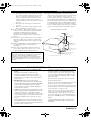 3
3
-
 4
4
-
 5
5
-
 6
6
-
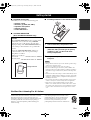 7
7
-
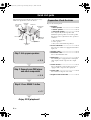 8
8
-
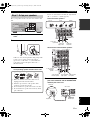 9
9
-
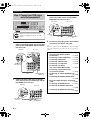 10
10
-
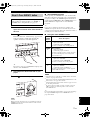 11
11
-
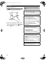 12
12
-
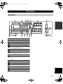 13
13
-
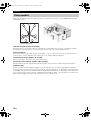 14
14
-
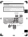 15
15
-
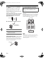 16
16
-
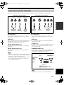 17
17
-
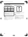 18
18
-
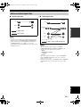 19
19
-
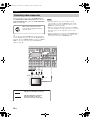 20
20
-
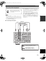 21
21
-
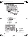 22
22
-
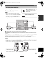 23
23
-
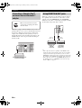 24
24
-
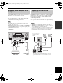 25
25
-
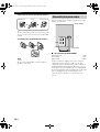 26
26
-
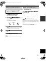 27
27
-
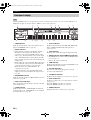 28
28
-
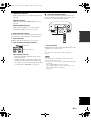 29
29
-
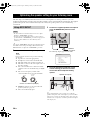 30
30
-
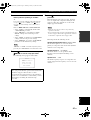 31
31
-
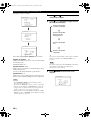 32
32
-
 33
33
-
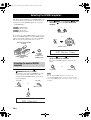 34
34
-
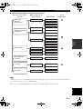 35
35
-
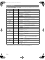 36
36
-
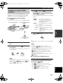 37
37
-
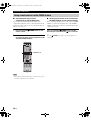 38
38
-
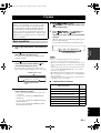 39
39
-
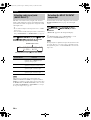 40
40
-
 41
41
-
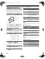 42
42
-
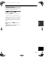 43
43
-
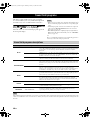 44
44
-
 45
45
-
 46
46
-
 47
47
-
 48
48
-
 49
49
-
 50
50
-
 51
51
-
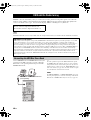 52
52
-
 53
53
-
 54
54
-
 55
55
-
 56
56
-
 57
57
-
 58
58
-
 59
59
-
 60
60
-
 61
61
-
 62
62
-
 63
63
-
 64
64
-
 65
65
-
 66
66
-
 67
67
-
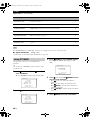 68
68
-
 69
69
-
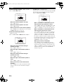 70
70
-
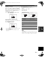 71
71
-
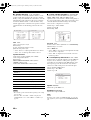 72
72
-
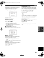 73
73
-
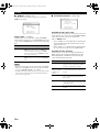 74
74
-
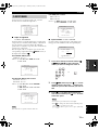 75
75
-
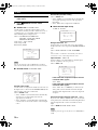 76
76
-
 77
77
-
 78
78
-
 79
79
-
 80
80
-
 81
81
-
 82
82
-
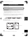 83
83
-
 84
84
-
 85
85
-
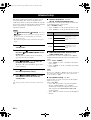 86
86
-
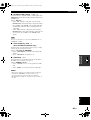 87
87
-
 88
88
-
 89
89
-
 90
90
-
 91
91
-
 92
92
-
 93
93
-
 94
94
-
 95
95
-
 96
96
-
 97
97
-
 98
98
-
 99
99
-
 100
100
-
 101
101
-
 102
102
-
 103
103
-
 104
104
-
 105
105
-
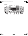 106
106
-
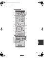 107
107
-
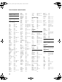 108
108
-
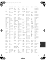 109
109
-
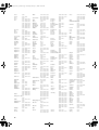 110
110
-
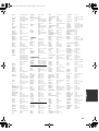 111
111
-
 112
112
-
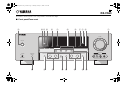 113
113
-
 114
114


Yamaha RX-V563 Handleiding
- Categorie
- AV-ontvangers
- Type
- Handleiding
- Deze handleiding is ook geschikt voor
in andere talen
- English: Yamaha RX-V563 User manual
- italiano: Yamaha RX-V563 Manuale utente
- русский: Yamaha RX-V563 Руководство пользователя
- français: Yamaha RX-V563 Manuel utilisateur
- español: Yamaha RX-V563 Manual de usuario
- Deutsch: Yamaha RX-V563 Benutzerhandbuch
- português: Yamaha RX-V563 Manual do usuário
- dansk: Yamaha RX-V563 Brugermanual
- suomi: Yamaha RX-V563 Ohjekirja
- čeština: Yamaha RX-V563 Uživatelský manuál
- svenska: Yamaha RX-V563 Användarmanual
- Türkçe: Yamaha RX-V563 Kullanım kılavuzu
- polski: Yamaha RX-V563 Instrukcja obsługi
- română: Yamaha RX-V563 Manual de utilizare
Gerelateerde papieren
-
Yamaha RX-V663 de handleiding
-
Yamaha RX-V757 Handleiding
-
Yamaha RX-V863 de handleiding
-
Yamaha RX-V461 - AV Receiver Handleiding
-
Yamaha RX-V657 de handleiding
-
Yamaha RX V661 - AV Receiver Handleiding
-
Sony RX-V559 de handleiding
-
Yamaha RX-V563 de handleiding
-
-