Makita 6903VD de handleiding
- Categorie
- Elektrisch gereedschap
- Type
- de handleiding

GB
Cordless Impact Driver Instruction Manual
F
Tournevis à chocs sans fil Manuel d’instructions
D
Akku-Schlagschrauber Betriebsanleitung
I
Avvitatrice ad impulso a batteria Istruzioni per l’uso
NL
Snoerloze slagschroevedraaier Gebruiksaanwijzing
E
Atornillador de impacto a batería Manual de instrucciones
P
Parafusadora de impacto a bateria Manual de instruções
DK
Akku slagskruetrækker Brugsanvisning
S
Sladdlös slagskruvdragare Bruksanvisning
N
Accu slagboremaskin Bruksanvisning
SF
Iskevä akkuruuvinväännin Käyttöohje
GR Φρητ κρυστικ κατσαίδι δηγίες ρήσεως
6903VD

2
12
34
56
78
12
0
500
400
300
200
100
600
13
12
11
12
M10
M8
M6
0
500
400
300
200
100
M10
M8
M6
8
9
10
10
10
11
12
010.5
M8
M6
M5
200
150
100
50
M8X14
M6X12
M5X12
8
9
10
10
10
11
12
7
6
3
5
4
3
4
1
2

3
ENGLISH
Explanation of general view
1 Battery cartridge
2 Set plate
3Bit
4Sleeve
5 Bit-piece
6 Switch trigger
7 Reversing switch
8 Kg•cm
9 Tightening torque
10 Proper tightening torque for
11 Seconds
12 Tightening time
13 Number of tightenings
SPECIFICATIONS
Model 6903VD
Capacities
Machine screw ........................................4 mm – 10 mm
Bolt .........................................................4 mm – 10 mm
No load speed (min
–1
) .......................................0 – 2,200
Impacts per minute ............................................0 – 2,800
Max. tightening torque ...................................... 68.6 N•m
Overall length ..................................................... 188 mm
Net weight ...............................................................1.3 kg
Rated voltage ...................................................D.C. 9.6 V
• Due to our continuing program of research and devel-
opment, the specifications herein are subject to change
without notice.
• Note: Specifications may differ from country to country.
Intended use
The tool is intended for screw driving in wood, metal and
plastic.
Safety hints
For your own safety, please refer to the enclosed safety
instructions.
IMPORTANT SAFETY INSTRUCTIONS FOR
CHARGER & BATTERY CARTRIDGE
ENC004-1
1. Before using battery cartridge, read all instruc-
tions and cautionary markings on (1) battery
charger, (2) battery, and (3) product using bat-
tery.
2. Do not disassemble battery cartridge.
3. If operating time has become excessively
shorter, stop operating immediately. It may
result in a risk of overheating, possible burns
and even an explosion.
4. If electrolyte gets into your eyes, rinse them out
with clear water and seek medical attention right
away. It may result in loss of your eyesight.
5. Always cover the battery terminals with the bat-
tery cover when the battery cartridge is not
used.
6. Do not short the battery cartridge:
(1) Do not touch the terminals with any conduc-
tive material.
(2) Avoid storing battery cartridge in a container
with other metal objects such as nails, coins,
etc.
(3) Do not expose battery cartridge to water or
rain.
A battery short can cause a large current flow,
overheating, possible burns and even a break-
down.
7. Do not store the tool and battery cartridge in
locations where the temperature may reach or
exceed 50°C (122°F).
8. Do not incinerate the battery cartridge even if it
is severely damaged or is completely worn out.
The battery cartridge can explode in a fire.
9. Be careful not to drop or strike battery.
SAVE THESE INSTRUCTIONS.
Tips for maintaining maximum battery life
1. Charge the battery cartridge before completely
discharged.
Always stop tool operation and charge the bat-
tery cartridge when you notice less tool power.
2. Never recharge a fully charged battery cartridge.
Overcharging shortens the battery service life.
3. Charge the battery cartridge with room tempera-
ture at 10°C – 40°C (50°F – 104°F). Let a hot bat-
tery cartridge cool down before charging it.
4. Charge the Nickel Metal Hydride battery car-
tridge when you do not use it for more than six
months.
ADDITIONAL SAFETY RULES FOR TOOL
1. Be aware that this tool is always in an operating
condition, because it does not have to be
plugged into an electrical outlet.
2. Wear ear protectors.
3. Hold the tool firmly.
4. Always be sure you have a firm footing. Be sure
no one is below when using the tool in high loca-
tions.
5. When driving into walls, floors or wherever
“live” electrical wires may be encountered, DO
NOT TOUCH ANY METAL PARTS OF THE TOOL!
Hold the tool only by the insulated grasping sur-
faces to prevent electric shock if you drive into a
“live” wire.
SAVE THESE INSTRUCTIONS.
OPERATING INSTRUCTIONS
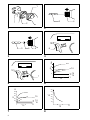
Installing or removing battery cartridge (Fig. 1)
• Always switch off the tool before insertion or removal of
the battery cartridge.
• To remove the battery cartridge, pull out the set plate
on the tool and grasp both sides of the cartridge while
withdrawing it from the tool.
• To insert the battery cartridge, align the tongue on the
battery cartridge with the groove in the housing and slip
it into place. Snap the set plate back into place. Be sure
to close the set plate fully before using the tool.
• Do not use force when inserting the battery cartridge. If
the cartridge does not slide in easily, it is not being
inserted correctly.

4
Installing or removing bit
Important:
Always be sure that the tool is switched off and the battery cartridge is removed before installing or removing the bit.
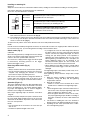
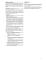
Use only the driver bit or socket bit shown in the table below.
Do not use any other driver bit or socket bit.
(1) To install the bit, pull the sleeve in the direction of the arrow and insert the bit into the sleeve as far as it will go.
Then release the sleeve to secure the bit. (Fig. 2)
(2) To install the bit, pull the sleeve in the direction of the arrow and insert the bit-piece and the bit into the sleeve as
far as it will go. The bit-piece should be inserted into the sleeve with its pointed end facing in. Then release the
sleeve to secure the bit. (Fig. 3)
To remove the bit, pull the sleeve in the direction of the arrow and pull the bit out firmly.
NOTE:
If the bit is not inserted deep enough into the sleeve, the sleeve will not return to its original position and the bit will not
be secured. In this case, try re-inserting the bit according to the instructions above.
Switch action (Fig. 4)
CAUTION:
Before inserting the battery cartridge into the tool, always
check to see that the switch trigger actuates properly and
returns to the “OFF” position when released.
To start the tool, simply pull the trigger. ToolTools speed
is increased by increasing pressure on the trigger.
Release the trigger to stop.
Reversing switch action (Fig. 5)
CAUTION:
• Always check the direction of rotation before operation.
• Use the reversing switch only after the tool comes to a
complete stop. Changing the direction of rotation
before the tool stops may damage the tool.
This tool has a reversing switch to change the direction of
rotation. Move the reversing switch to the left for clock-
wise rotation or to the right for counterclockwise rotation.
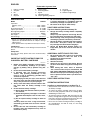
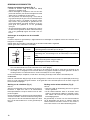
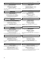
Operation (Fig. 6 & 7)
The proper tightening torque may differ depending upon
the kind or size of the screw, the material of the work-
piece to be tightened, etc. The relation between tighten-
ing torque and tightening time is shown in Fig. 6 for
machine screw or Fig. 7 for standard bolt.
Note: Proper tightening torque for machine screw M4 is
14 kg•cm.
Hold the tool firmly and place the point of the driver bit in
the screw head. Apply forward pressure to the tool to the
extent that the bit will not slip off the screw and turn the
tool on to start operation.
NOTE:
• Use the proper bit for the head of the screw that you
wish to use.
• Hold the tool pointed straight at the screw.
• If you tighten the screw for a time longer than shown in
the figures above, the screw or the point of the driver bit
may be overstressed, stripped, damaged, etc. Before
starting your job, always perform a test operation to
determine the proper tightening time for your screw.
When tightening a standard screw in a steel plate, the
proper tightening torque can be obtained in an
extremely short time (approx. 0.1 – 0.2 seconds). Turn
the tool off as soon as the impact sound is heard.
• When tightening screw M6 or smaller, carefully adjust
pressure on the switch trigger so that the screw is not
damaged.
The tightening torque is affected by a wide variety of fac-
tors including the following.
After tightening, always check the torque with a torque
wrench.
1. When the battery cartridge is discharged almost
completely, voltage will drop and the tightening
torque will be reduced.
2. Driver bit or socket bit
• Failure to use the correct size driver bit or socket
bit will cause a reduction in the tightening torque.
3. Bolt
• Even though the torque coefficient and the class of
bolt are the same, the proper tightening torque will
differ according to the diameter of bolt.
• Even though the diameters of bolts are the same,
the proper tightening torque will differ according to
the torque coefficient, the class of bolt and the bolt
length.
4. The manner of holding the tool or the material of
driving position to be tightened will affect the torque.
5. Operating the tool at low speed will cause a reduc-
tion in the tightening torque.
A= 17mm
B= 14mm
To install these types of bits, follow the procedure (1).
(Note) Makita bits are these types.
A= 11mm
B = 9 mm
To install these types of bits, follow the procedure (2).
(Note) Bit-piece is necessary for installing the bit.
For European and North & South American countries
Use only these types of bits. Follow the procedure (1).
(Note) Bit-piece is not necessary.
A
B

5
MAINTENANCE
CAUTION:
Always be sure that the tool is switched off and the bat-
tery cartridge is removed before carrying out any work on
the tool.
To maintain product safety and reliability, repairs, mainte-
nance or adjustment should be carried out by a Makita
Authorized Service Center.

15
NEDERLANDS
Verklaring van algemene gegevens
1 Batterij
2 Sluitplaat
3 Schroevedraaier bit
4Bus
5 Inzetstuk
6 Trekschakelaar
7 Omkeerschakelaar
8Kg•cm
9 Aandraaikoppel
10 Het juiste aandraaikoppel voor
11 Sekonden
12 Vastdraaitijd
13 Aantal vastdraaiingen
TECHNISCHE GEGEVENS
Model 6903VD
Capaciteit
Machineschroef ......................................4 mm – 10 mm
Bout ........................................................4 mm – 10 mm
Toerental onbelast/min. (min
–1
) ......................... 0 – 2 200
Aantal slagen/min. ............................................. 0 – 2 800
Maximal aandraaikoppel ................................... 68,6 N•m
Totale lengte ....................................................... 188 mm
Netto gewicht ..........................................................1,3 kg
Nominale spanning ............................................ DC 9,6 V
• In verband met ononderbroken research en ontwikke-
ling behouden wij ons het recht voor bovenstaande
technische gegevens te wijzigen zonder voorafgaande
kennisgeving.
• Opmerking: De technische gegevens kunnen van land
tot land verschillen.
Doeleinden van gebruik
Dit gereedschap is bedoeld voor het indraaien van
schroeven in hout, metaal en kunststof.
Veiligheidswenken
Voor uw veiligheid dient u de bijgevoegde Veiligheids-
voorschriften nauwkeurig op te volgen.
BELANGRIJKE
VEILIGHEIDSVOORSCHRIFTEN
VOOR ACCULADER EN ACCU
1. Lees alle voorschriften en waarschuwingen op
(1) de acculader, (2) de accu, en (3) het product
waarvoor de accu wordt gebruikt, aandachtig
door alvorens de acculader in gebruik te nemen.
2. Neem de accu niet uit elkaar.
3. Als de gebruikstijd van een opgeladen accu aan-
zienlijk korter is geworden, moet u het gebruik
ervan onmiddellijk stopzetten. Voortgezet
gebruik kan oververhitting, brandwonden en
zelfs een ontploffing veroorzaken.
4. Als er elektrolyt in uw ogen is terechtgekomen,
spoel dan uw ogen met schoon water en roep
onmiddellijk de hulp van een dokter in. Elektrolyt
in de ogen kan blindheid veroorzaken.
5. Bedek de accuklemmen altijd met de accukap
wanneer u de accu niet gebruikt.
6. Voorkom kortsluiting van de accu:
(1) Raak de accuklemmen nooit aan met een
geleidend materiaal.
(2) Bewaar de accu niet in een bak waarin
andere metalen voorwerpen zoals spijkers,
munten e.d. worden bewaard.
(3) Stel de accu niet bloot aan water of regen.
Kortsluiting van de accu kan oorzaak zijn van
een grote stroomafgifte, oververhitting, brand-
wonden, en zelfs defecten.
7. Bewaar het gereedschap en de accu niet op
plaatsen waar de temperatuur kan oplopen tot
50°C of hoger.
8. Werp de accu nooit in het vuur, ook niet wanneer
hij zwaar beschadigd of volledig versleten is. De
accu kan namelijk ontploffen in het vuur.
9. Wees voorzichtig dat u de accu niet laat vallen
en hem niet blootstelt aan schokken of stoten.
BEWAAR DEZE VOORSCHRIFTEN.
Tips voor een maximale levensduur van de accu
1. Laad de accu op voordat hij volledig ontladen is.
Stop het gebruik van het gereedschap en laad de
accu op telkens wanneer u vaststelt dat het ver-
mogen van het gereedschap is afgenomen.
2. Laad een volledig opgeladen accu nooit opnieuw
op. Als u de accu te veel oplaadt, zal hij minder
lang meegaan.
3. Laad de accu op bij een kamertemperatuur tus-
sen 10°C en 40°C. Laat een warme accu afkoelen
alvorens hem op te laden.
4. Laad de nikkel-metaalhydride accu op telkens
wanneer u hem langer dan zes maanden niet
hebt gebruikt.
BIJGEVOEGDE
VEILIGHEIDSVOORSCHRIFTEN
VOOR DE MACHINE
1. Wees op uw hoede. Dit gereedschap is altijd
gereed voor gebruik, aangezien het niet op een
stopkontakt hoeft te worden aangesloten.
2. Draag oorbeschermers.
3. Houd het gereedschap stevig vast.
4. Zorg ervoor dat u stevig staat op een vast onder-
grond. Bij gebruik van het gereedschap op een
hoge plaats dient u ervoor te zorgen dat nie-
mand beneden u aanwezig is.
5. Bij inschroeven in muren, vloeren en dergelijke
bestaat het gevaar dat u onder spanning staande
elektrische kabels tegenkomt. RAAK DERHALVE
DE METALEN DELEN VAN HET GEREEDSCHAP
NIET AAN! Houd het gereedschap uitsluitend
vast bij de geisoleer- de handgreep ter vermij-
ding van elektrische schok in het geval dat het
gereedschap in aanraking komt met een onder
spanning staande kabel.
BEWAAR DEZE VOORSCHRIFTEN.

16
BEDIENINGSVOORSCHRIFTEN
Plaatsen en uithalen van batterij (Fig.1)
• Schakel de machine altijd uit voordat een batterij
geplaatst of verwijdert wordt.
• Om het batterijpak te verwijderen, trek eerst de sluit-
plaat uit de machine, pak dan het batterijpak aan beide
zijden vast en verwijder het uit de machine.
• Voor het plaatsen van de batterij zorgt u ervoor dat de
rug op de batterij in de groef van het batterijkomparti-
ment komt, waarna u de batterij naar binnen schuift.
Klap alvorens het gereedschap te gebruiken de stel-
plaat oftewel deksel weer dicht, kontroleer of de stel-
plaat goed vast geklemd zit en niet gemakkelijk
opengaat.
• Als het batterijpak moeilijk in de houder komt, probeer
het dan niet met geweld in te duwen. Indien het batterij-
pak er niet gemakkelijk ingaat, dan houdt u het ver-
keerd.
Aanbrengen of verwijderen van de schroefbit
Belangrijk:
Controleer altijd of het gereedschap is uitgeschakeld en het batterijpak is verwijderd, alvorens de schroefbit aan te
brengen of te verwijderen.
Gebruik alleen de schroefbit of schroefdop die in de onderstaande tabel is afgebeeld.
Gebruik geen andere schroefbit of schroefdop.
(1) Om de schroefbit aan te brengen, trek de bus in de richting van de pijl en steek dan de schroefbit zo ver mogelijk
erin. Laat daarna de bus los om de schroefbit vast te zetten. (Fig. 2)
(2) Om de schroefdop aan te brengen, trek de bus in de richting van de pijl en steek dan het inzetstuk en de
schroefdop zo ver mogelijk erin. Het inzetstuk dient met zijn gepunte uiteinde naar binnen gekeerd in de bus te
worden gestoken. Laat daarna de bus los om de schroefdop vast te zetten. (Fig. 3)
Om de schroefbit/dop te verwijderen, trek de bus in de richting van de pijl en trek dan de schroefbit/dop eruit.
OPMERKING:
Indien de schroefbit niet diep genoeg in de bus wordt gestoken, zal de bus niet naar zijn oorspronkelijke positie terug-
keren en zal de schroefbit niet goed vastzitten. In dat geval dient u de schroefbit opnieuw erin te steken volgens de
bovenstaande aanwijzingen.
Werking van de schakelaar (Fig.4)
LET OP:
Alvorens het batterijpak in het gereedschap te plaatsen,
kontroleert u altijd eerst even of de trekschakelaar
behoorlijk funktioneert en bij het loslaten naar de “OFF”
positie terugkeert.
Om het gereedschap te starten hoeft u de trekschakelaar
slechts in te drukken. U kunt de snelheid van het gereed-
schap opvoeren door de trekschakelaar dieper in te druk-
ken. Laat de trekschakelaar los om het gereedschap te
stoppen.
Werking van de omkeerschakelaar (Fig. 5)
LET OP:
• Kontroleer altijd de draairichting alvorens het gereed-
schap te gebruiken.
• Zet de omkeerschakelaar alleen in de andere stand,
nadat het gereedschap volledig tot stilstand is geko-
men. Indien u dit nalaat kan het gereedschap zware
beschadiging oplopen.
Dit gereedschap is voorzien van een omkeerschakelaar
om de draairichting van de boor te wijzigen. Schuif de
omkeerschakelaar naar links wanneer u een rechtse of
naar rechts wanneer u een linkse draairichting wenst.
A= 17mm
B= 14mm
Voor het aanbrengen van dit type schroefbits, volg procedure (1).
(Opmerking) Makita schroefbits zijn van dit type.
A= 11mm
B= 9mm
Voor het aanbrengen van dit soort schroefdoppen, volg procedure (2).
(Opmerking) Voor het aanbrengen van de schroefdop is een inzetstuk
nodig.
Voor Europese en Noord- en Zuid-Amerikaanse landen
Gebruik alleen dit type bits. Volg procedure (1).
(Opmerking) Een inzetstuk is niet nodig.
A
B

17
Bediening (Fig.6 en 7)
Het juiste aandraaikoppel hangt af van het soort of de
maat van de schroef, het materiaal waar de schroef inge-
draaid moet worden, enz. De verhouding tussen de aan-
draaikoppel en de vastdraaitijd wordt in de Fig. 6 voor
machine schroeven of Fig. 7 voor standaardbout aange-
geven.
Opmerking: De juiste aandraaikoppel voor een M4
machineschroef is 14 kg•cm.
Houd het gereedschap stevig vast en plaats de punt van
de schroefbit in de schroefkop. Oefen zoveel kracht op
het gereedschap uit als nodig is om de schroefbit op z’n
plaats te houden. Schakel vervolgens het gereedschap
in om de werkzaamheden te starten.
OPMERKING:
• Gebruik voor het vastdraaien van schroeven altijd de
juiste maat schroefbit.
• Houd het gereedschap altijd haaks.
• Wanneer u de in de bovenstaande figuren aangegeven
vastdraaitijden overschrijdt, kan de schroef doldraaien
of de schroefkop of de punt van de schroefbit bescha-
digd worden. Het verdient daarom aanbeveling eerst
een proefje te nemen voor het vaststellen van de juiste
vastdraaitijd. Bij vastdraaien van een standaardschroef
in een staalplaat, wordt het juiste aandraaikoppel in
zeer korte tijd (ongeveer 0,1 tot 0,2 sek.) bereikt. Scha-
kel het gereedschap uit, zodra u het geluid van de
impact hoort.
• Voor het vastdraaien van M6 of kleinere schroeven
dient u met zorg de druk op de trekschakelaar te rege-
len zodat de schroef niet beschadigd wordt.
Het aandraaikoppel wordt beïnvloed door een groot aan-
tal verschillende faktoren, waaronder de volgende.
Kontroleer na het vastdraaien altijd het aandraaikoppel
met een momentsleutel.
1. Wanneer het batterijpak bijna leeg is, neemt het vol-
tage af en vermindert het aandraaikoppel.
2. Schroefbit of schroefdop
• Gebruikt u niet de juiste maat dan heeft een ver-
mindering van de aandraaikoppel plaats.
3. Bout
• In geval het koppelcoefficient overeenkomt met de
boutklasse, hangt het juiste aandraaikoppel af van
de boutdiameter.
• In geval de boutdiameters gelijk zijn, hangt het
juiste aandraaikoppel af van het koppelcoefficient,
de boutklasse en de boutlengte.
4. De manier van vasthouden van het gereedschap en
de positie waarin de schroef in het materiaal vastge-
draaid wordt, beinvloeden het koppel.
5. Bij lagere toerentallen wordt ook het aandraaikoppel
kleiner. vervangen of opgeladen.
ONDERHOUD
LET OP:
Controleer altijd of het gereedschap is uitgeschakeld en
de accu is losgekoppeld vooraleer onderhoud uit te voe-
ren aan de machine.
Opdat het gereedschap veilig en betrouwbaar blijft, die-
nen alle reparaties, onderhoud of afstellingen te worden
uitgevoerd bij een erkend Makita service centrum.

37
ENH002-1
EC-DECLARATION OF CONFORMITY
We declare under our sole responsibility that this product is in com-
pliance with the following standards of standardized documents,
EN50260, EN55014
in accordance with Council Directives, 89/336/EEC and 98/37/EC.
DÉCLARATION DE CONFORMITÉ CE
Nous déclarons sous notre entière responsabilité que ce produit
est conforme aux normes des documents standardisés suivants,
EN50260, EN55014
conformément aux Directives du Conseil, 89/336/CEE et
98/37/EG.
CE-KONFORMITÄTSERKLÄRUNG
Hiermit erklärt wir unter unserer alleinigen Verantwortung, daß
dieses Produkt gemäß den Ratsdirektiven 89/336/EWG und 98/37/
EG mit den folgenden Normen von Normendokumenten überein-
stimmen:
EN50260, EN55014.
DICHIARAZIONE DI CONFORMITÀ
CON LE NORME DELLA COMUNITÀ EUROPEA
Dichiariamo sotto la nostra sola responsabilità che questo prodotto
è conforme agli standard di documenti standardizzati seguenti:
EN50260, EN55014
secondo le direttive del Consiglio 89/336/CEE e 98/37/CE.
EG-VERKLARING VAN CONFORMITEIT
Wij verklaren hierbij uitsluitend op eigen verantwoordelijkheid dat
dit produkt voldoet aan de volgende normen van genormaliseerde
documenten,
EN50260, EN55014
in overeenstemming met de richtlijnen van de Raad 89/336/EEC
en 98/37/EC.
DECLARACIÓN DE CONFORMIDAD DE LA CE
Declaramos bajo nuestra sola responsabilidad que este producto
cumple con las siguientes normas de documentos normalizados,
EN50260, EN55014
de acuerdo con las directivas comunitarias, 89/336/EEC y
98/37/CE.
DECLARAÇÃO DE CONFORMIDADE DA CE
Declaramos sob inteira responsabilidade que este produto obe-
dece às seguintes normas de documentos normalizados,
EN50260, EN55014
de acordo com as directivas 89/336/CEE e 98/37/CE do Conselho.
EU-DEKLARATION OM KONFORMITET
Vi erklærer hermed på eget ansvar, at dette produkt er i overens-
stemmelse med de følgende standarder i de normsættende doku-
menter,
EN50260, EN55014
i overensstemmelse med Rådets Direktiver 89/336/EEC og
98/37/EC.
EG-DEKLARATION OM ÖVERENSSTÄMMELSE
Under eget ansvar deklarerar vi härmed att denna produkt över-
ensstämmer med följande standardiseringar för standardiserade
dokument,
EN50260, EN55014
i enlighet med EG-direktiven 89/336/EEC och 98/37/EC.
EUs SAMSVARS-ERKLÆRING
Vi erklærer på eget ansvar at dette produktet er i overensstem-
melse med følgende standard i de standardiserte dokumenter:
EN50260, EN55014,
i samsvar med Råds-direktivene, 89/336/EEC og 98/37/EC.
VAKUUTUS EC-VASTAAVUUDESTA
Yksinomaisesti vastuullisina ilmoitamme, että tämä tuote on
seuraavien standardoitujen dokumenttien standardien mukainen,
EN50260, EN55014
neuvoston direktiivien 89/336/EEC ja 98/37/EC mukaisesti.
∆ΗΛΩΣΗ ΣΥΜΜΡΦΩΣΗΣ ΕΚ
∆ηλώνυµε υπ την µναδική µας ευθύνη τι αυτ τ πριν
ρίσκεται σε Συµφωνία µε τα ακλυθα πρτυπα
τυππιηµένων εγγράφων,
EN50260, EN55014
σύµφωνα µε τις δηγίες τυ Συµυλίυ, 89/336/EEC και
98/37/ΚE.
Yasuhiko Kanzaki
CE 2003
Director Director
Directeur Direktør
Direktor Direktör
Amministratore Direktor
Directeur Johtaja
Director ∆ιευθυντής
MAKITA INTERNATIONAL EUROPE LTD.
Michigan Drive, Tongwell, Milton Keynes,
Bucks MK15 8JD, ENGLAND
ENGLISH
FRANÇAISE
DEUTSCH
ITALIANO
NEDERLANDS
ESPAÑOL
PORTUGUÊS
DANSK
SVENSKA
NORSK
SUOMI
ΕΛΛΗΝΙΚΑ

38
ENG006-1
Noise and Vibration
The typical A-weighted noise levels are
sound pressure level: 91 dB (A)
sound power level: 104 dB (A)
– Wear ear protection. –
The typical weighted root mean square acceleration
value is 4 m/s
2
.
Bruit et vibrations
Les niveaux de bruit ponderes types A sont:
niveau de pression sonore: 91 dB (A)
niveau de puissance du son: 104 dB (A)
– Porter des protecteurs anti-bruit. –
L’accélération pondérée est de 4 m/s
2
.
Geräusch- und Vibrationsentwicklung
Die typischen A-bewerteten Geräuschpegel betragen:
Schalldruckpegel: 91 dB (A)
Schalleistungspegel: 104 dB (A)
– Gehörschutz tragen. –
Der gewichtete Effektivwert der Beschleunigung beträgt
4m/s
2
.
Rumore e vibrazione
I livelli del rumore pesati secondo la curva A sono:
Livello pressione sonora: 91 dB (A)
Livello potenza sonora: 104 dB (A)
– Indossare i paraorecchi. –
Il valore quadratico medio di accellerazione è di 4 m/s
2
.
Geluidsniveau en trilling
De typische A-gewogen geluidsniveau’s zijn
geluidsdrukniveau: 91 dB (A)
geluidsenergie-niveau: 104 dB (A)
– Draag oorbeschermers. –
De typische gewogen effectieve versnellingswaarde is
4m/s
2
.
Ruido y vibración
Los niveles típicos de ruido ponderados A son
presión sonora: 91dB (A)
nivel de potencia sonora: 104 dB (A)
– Póngase protectores en los oídos. –
El valor ponderado de la aceleración es de 4 m/s
2
.
Ruído e vibração
Os níveis normais de ruído A são
nível de pressão de som: 91 dB (A)
nível do sum: 104 dB (A)
– Utilize protectores para os ouvidos –
O valor médio da aceleração é 4 m/s
2
.
Lyd og vibration
De typiske A-vægtede lydniveauer er
lydtryksniveau: 91 dB (A)
lydeffektniveau: 104 dB (A)
– Bær høreværn. –
Den vægtede effektive accelerationsværdi er 4 m/s
2
.
Buller och vibration
De typiska A-vägda bullernivåerna är
ljudtrycksnivå: 91 dB (A)
ljudeffektnivå: 104 dB (A)
– Använd hörselskydd –
Det typiskt vägda effektivvärdet för acceleration är
4m/s
2
.
Støy og vibrasjon
De vanlige A-belastede støynivå er
lydtrykksnivå: 91 dB (A)
lydstyrkenivå: 104 dB (A)
– Benytt hørselvern. –
Den vanlig belastede effektiv-verdi for akselerasjon er
4m/s
2
.
Melutaso ja tärinä
Tyypilliset A-painotetut melutasot ovat
äänenpainetaso: 91 dB (A)
äänen tehotaso: 104 dB (A)
– Käytä kuulosuojaimia. –
Tyypillinen kiihtyvyyden painotettu tehollisarvo on
4m/s
2
.
Θρυς και κραδασµς
ι τυπικές A-µετρύµενες εντάσεις ήυ είναι
πίεση ήυ: 91 dB (A)
δύναµη τυ ήυ: 104 dB (A)
– Φράτε ωτασπίδες. –
Η τυπική αία της µετρύµενης ρίας τυ µέσυ
τετραγώνυ της επιτάυνσης είναι 4 m/s
2
.
ENGLISH
FRANÇAISE
DEUTSCH
ITALIANO
NEDERLANDS
ESPAÑOL
PORTUGUÊS
DANSK
SVENSKA
NORSK
SUOMI
ΕΛΛΗΝΙΚΑ

39

Makita Corporation
Anjo, Aichi, Japan
883754G987
-
 1
1
-
 2
2
-
 3
3
-
 4
4
-
 5
5
-
 6
6
-
 7
7
-
 8
8
-
 9
9
-
 10
10
-
 11
11
-
 12
12


Makita 6903VD de handleiding
- Categorie
- Elektrisch gereedschap
- Type
- de handleiding
in andere talen
- English: Makita 6903VD Owner's manual