
Collegamenti elettrici
Banda: 40-860 MHz
Guadagno Max. BI 3 dB / BIII 16 dB / UHF 26 dB
Alimentazione: 230 Vac / 12-24 Vcc
SILICONE
SICAFLEX
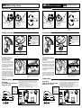
Installazione della base
La base dell’antenna può essere fissata al tetto con 4 viti ( Fig. 1 ) oppure con SYCAFLEX ad alta
tenuta ( Fig. 2 )
FRONTE DEL
VEICOLO
ATTENZIONE
1 2
Posizionare la base in maniera che la freccia
FRONT sia direzionata verso la parte anteriore
del veicolo.
Fissaggio dell’antenna
Inserire il cavo nel passacavo (A) e stringerlo
adeguatamente per renderlo stagno, lasciando
circa 20 cm.
Posizionare l’antenna sulla base ed avvitare le 4
viti di bloccaggio.
Variazione dell’inclinazione
dell’antenna.
Nel caso che il tetto del veicolo non sia piano è
consigliabile variare l’inclinazione dell’antenna
affinchè la stessa, una volta installata, si presenti
parallela al terreno. Infatti per ottenere il massimo
delle prestazioni l’antenna deve essere:
1) Lontana da ostacoli che possono limitare il
passaggio dei segnali televisivi ( ad es. bauliere,
condizionatori ecc. )
2) In posizione orizzontale. E’ inoltre importante
tener presente che sotto agli alberi il segnale
televisivo si riduce notevolmente e quindi la
ricezione può diventare molto scadente o addirittura
nulla.
Svitare leggermente ( un quarto di giro ) il dado (A)
Posare l’antenna sul tetto ed inclinarla fino a
renderla orizzontale. Avvitare nuovamente il dado
(A) e fissare l’antenna sulla base.
Via E. Majorana 49 - 48022 Lugo (RA)
Tel. + 39 0545 25037 - Fax + 39 0545 32064
E.mail: [email protected] - www.telecogroup.com
3
WING 11 Antenna TV omnidirezionale
SILICONE
SICAFLEX
1 2 3
Elektrische aansluitingen
Band: 40-860 MHz
Max. versterking: BI 8 dB / BIII 22 dB / UHF 26 dB
Voeding: 230 Vac / 12-24 Vdc
Installatie van de voet
De voet van de antenne kan met 4 schroeven aan het dak bevestigd worden (fig. 1) of met SICAFLEX
dat een groot afdichtingsvermogen heeft (fig. 2).
Voorkant van
het voertuig
ATTENTIE
Plaats de voet zodanig dat de pijl FRONT naar
de voorkant van het voertuig wijst.
Bevestiging van de antenne
Steek de kabel in de kabeldoorvoer (A), zet hem
goed vast en laat ongeveer 20 cm over.
Plaats de antenne op de voet en draai de 4
borgschroeven aan.
Verstelling van de schuine
stand van de antenne
Als het dak van het voertuig niet vlak is, dan is het
raadzaam om de schuine stand van de antenne
te verstellen om ervoor te zorgen dat de antenne
als deze geïnstalleerd is evenwijdig is aan de
grond. Om de beste prestaties te kunnen leveren
moet de antenne namelijk:
1) verwijderd zijn van obstakels waardoor de
doorkomst van de televisiesignalen beperkt kan
worden (bijv. bagagekoffers, aircondioners enz.);
2) horizontaal zijn; verder is het belangrijk dat er
rekening mee gehouden wordt dat de sterkte van
het televisiesignaal onder bomen aanzienlijk
verminderd wordt en de ontvangst dus erg slecht
kan zijn of het zelfs kan gebeuren dat er helemaal
geen ontvangst is.
Draai de moer (A) iets (een kwartslag) los.
Plaats de antenne op het dak en knik de antenne
zodanig dat hij horizontaal komt te staan. Draai
de moer (A) weer aan en zet de antenne op de
voet vast.
WING 11 Alle richtings TV-antenne 02-02-11
Recycling: gooi, om de
afvalverwerking van elek-
trisch en elektronisch afval
zoveel mogelijk te beperken,
dit apparaat aan het einde
van de levensduur niet bij
ander ongescheiden afval
weg, maar lever het in bij een
recyclingcentrum.
Riciclaggio: con lo scopo di
ridurre il più possibile lo
smaltimento dei rifiuti elettrici
ed elettronici, non gettare
quest'apparecchio a fine vita
con gli altri rifiuti urbani non
separati, ma in un centro di
riciclaggio.
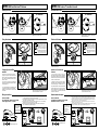
1) Knip de antennekabel op de vereiste lengte af en breng de stekker aan zoals afgebeeld
pas op dat er geen enkele draad van de kous tegen de kern van de kabel aan komt.
2) Steek de stekker van de antenne in de speciale ingang van de versterker en sluit daarna de
TV-toestellen met twee kabel-stukken aan.
3) Sluit de AT 42 aan op een aansluiting van 230 Vac of op een accu van 12 (of 24) Volt en let
daarbij goed op dat u de + en de - klemmen niet verwisselt.
4) Stel terwijl u naar de televisie kijkt de gevoeligheid van de antenne af door net zolang aan
de speciale knop “dB+“ te draaien totdat u het beste beeld krijgt.
230 Vac
dB
ANT
TV
TV
AT42
TV
TV
12 Vcc
OFF ON
12VDC
Indien gevoed door een
accu, is het mogelijk met
deze schakelaar de AT42
uit te zetten.
Indien de ontvanger is
verbonden met 230V, is
deze schakelaar niet aktief.
12 Vdc Voeding
1) Tagliare il cavo dell’antenna alla lunghezza necessaria e applicare il connettore
facendo attenzione che nessun filo della calza vada a toccare l’anima del cavo.
2) Introdurre il connettore dell’antenna nell’apposito ingresso dell’amplificatore e
collegare quindi gli apparecchi TV con due spezzoni di cavo.
3) Collegare l’AT 42 con una presa 230 Vac oppure ad una batteria a 12 (o 24 )
Volt, facendo ben attenzione a non invertire i morsetti + e -.
4) Osservando il televisore regolare la sensibilità dell’antenna ruotando l’apposita
manopola “ dB+ “ fino ad ottenere la migliore immagine.
230 Vac
dB
ANT
TV
TV
AT42
TV
TV
12 Vcc
OFF ON
12VDC
Con alimentazione a
batteria questo interruttore
permette di spegnere
l'AT42.
Se l'amplificatore è
collegato alla presa 230V
l'interruttore non è attivo.
Alimentazione 12 Vcc
5
76
4
5
76
4

SILICONE
SICAFLEX
1 2 3
SILICONE
SICAFLEX
1 2 3
Wiring connections
Band: 40-860 MHz
Max. Gain BI 8 dB / BIII 22 dB / UHF 26 dB
Power supply: 230 Vac / 12-24 Vdc
Installing the base
The base of the antenna may be attached to the roof by means of 4 screws ( Fig. 1 ) or else using
high-seal SYCAFLEX ( Fig. 2 )
Front of
the vehicle
ATTENTION
Position the base so that the FRONT arrow points
towards the front of the vehicle.
Fixing the antenna
Fit the cable into the cable lead (A) and tighten
it so as to make it waterproof, leaving it at about
20 cm.
Position the antenna on the base and tighten the
4 fastening screws.
Changing the slant of the
antenna.
Should the roof of the vehicle not be flat, we
suggest you change the slant of the antenna so
that it is parallel to the ground when installed. In
fact, in order to give its best performance, the la
antenna must be:
1) Far from any obstacles which can hinder the
passage of TV signals (for example trunk holders,
air conditioners, etc. )
2) In a horizontal position. One should also bear
in mind that TV signals diminish considerably
beneath trees, and reception can be poor or even
non existent.
Loosen the nut (A) slightly (by one quarter of a turn).
Lay the antenna on the roof and slant it until it
becomes horizontal. Tighten the screws (A) again
and fasten the antenna to the base.
WING 11 Omni-Directional TV Antenna
Branchements électriques
Bande: 40-860 MHz
Gain Maxi BI 8 dB / BIII 22 dB / UHF 26 dB
Alimentation: 230 Vca / 12-24 Vcc
Installation de la base
La base de l’antenne peut être fixée au toit à l'aide de 4 vis ( Fig. 1 ) ou avec SYCAFLEX à étanchéité
élevée (Fig. 2 )
Devant du
véhicule
ATTENTION
Positionner la base de façon à ce que la flèche
FRONT ("DEVANT") soit dans la direction de la
partie avant du véhicule.
Fixation de l’antenne
Introduire le câble dans le passe-câble (A) et le
serrer de façon appropriée pour le rendre étanche,
en laissant environ 20 cm.
Positionner l’antenne sur la base et visser les 4
vis de blocage.
Variation de l’inclinaison de
l’antenne.
Si le toit du véhicule n'est pas plat, il est
recommandé de changer l’inclinaison de l’antenne
afin qu'elle soit parallèle au terrain lorsqu'elle est
installée. En effet, pour obtenir les performances
maximum, l’antenne doit être:
1) Eloignée des obstacles pouvant limiter le
passage des signaux de télévision (par exemple:
coffre porte-bagages, conditionneurs, etc.)
2) En position horizontale. Il est en outre important
de tenir compte du fait que, sous les arbres, le
signal de télévision est considérablement réduit
et, par conséquent, la réception peut être très
mauvaise ou même nulle.
Dévisser légèrement (un quart de tour) l'écrou (A)
WING 11 Antenne TV omnidirectionnelle
Poser l’antenne sur le toit et l'incliner jusqu'à ce
qu'elle soit horizontale. Visser de nouveau l'écrou
(A) et fixer l’antenne sur la base.
Recycling: with a view to
reducing disposal of waste
electrical and electronic
equipment as much as
possible, do not throw out this
end of life cycle appliance
together with other unsorted
municipal waste, but make
use of a recycling centre.
Recyclage: Dans le but de
réduire le plus possible
l’élimination des déchets
électriques et électroniques,
ne pas jeter cet appareil en
fin de vie avec les autres
déchets municipaux non triés,
mais dans un centre de
recyclage.
1) Cut the antenna cable to the proper length and apply the connector. Make sure
no wire of the braiding touches the core of the cable.
2) Fit the antenna connector into the relevant input of the amplifier and then connect
the TV sets using two pieces of cable.
3) Connect AT 42 to a 230 Vac power source or else to a 12 (or 24 ) Volt battery.
Make sure you do not mix up the + and – clamps.
4) Look at the TV set and adjust the sensitivity of the antenna by turning the
“ dB+ “handle until you get the best image.
230 Vac
dB
ANT
TV
TV
AT42
TV
TV
12 Vcc
With battery power
supply this switch allows
to switch off the AT42.
If the amplifier is
connected to the 230V
the switch is not active.
OFF ON
12VDC
Power supply 12 Vdc
1) Couper le câble de l’antenne selon la longueur nécessaire et appliquer le connecteur comme
représenté en faisant attention à ce qu'aucun fil du guipage textile touche l'âme du câble.
2) Introduire le connecteur de l’antenne dans l'entrée de l’amplificateur prévue à cet effet, puis
brancher les appareils TV avec les deux parties de câble.
3) Brancher l'AT 42 à une prise 230 Vca ou à une batterie à 12 (ou 24 ) Volt, en faisant très
attention à ne pas inverser les bornes + et -.
4) Tout en regardant l'écran de télévision, régler la sensibilité de l’antenne en tournant la poignée
prévue à cet effet “dB+ “ jusqu'à ce que la meilleure image apparaisse.
230 Vac
dB
ANT
TV
TV
AT42
TV
TV
12 Vcc
OFF ON
12VDC
Lorsque l’amplificateur est
alimenté sur batterie, cet
interrupteur permet d’arreter
l’AT42.
Si l’amplificateur est
connecté sur une prise
secteur 230V, cet
interrupteur n’est pas actif.
Alimentation 12 Vcc
5
76
4
5
76
4
-
 1
1
-
 2
2


in andere talen
- English: Teleco WING11 User manual
- italiano: Teleco WING11 Manuale utente
- français: Teleco WING11 Manuel utilisateur