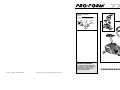
ProForm PFEX7206 de handleiding
- Categorie
- Fitness, gymnastiek
- Type
- de handleiding
Deze handleiding is ook geschikt voor

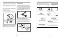
GEBRUIKERSHANDLEIDING
WAARSCHUWING:
Lees alle voorzorgsmaatregelen
en instructies in deze handleiding
zorgvuldig voor gebruik door.
Bewaar deze handleiding voor
toekomstige referentie.
Sticker
met
Serie
Nummer
Part No. 136456 F03389-C R1196A Printed in Taiwan © 1996 ICON Health & Fitness, Inc.
Modelnr. PFEX72060
Serienr
Schrijf het serie nummer van het apparaat
hierboven voor toekomstige referentie.

2
29
25
64
65
26
52
15
1
20
19
22
21
24
17
66
33
34
35
47
38
2
60
35
34
33
49
3
29
66
56
4
6
14
11
53
46
16
5
10
54
73
58
12
12
39
42
46
44
48
29
29
57
57
55
55
2
9
39
72
72
41
5
0
26
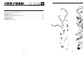
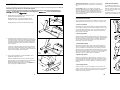
EXPLODED DRAWING—Model No. PFEX72060 R1196A
15
INHOUD
BELANGRIJKE VOORZORGSMAATREGELEN . . . . . . . . . . . . . . . . . . . . . . . . . . . . . . . . . . . . . . . . . . . . . . . .3
VOORDAT U BEGINT . . . . . . . . . . . . . . . . . . . . . . . . . . . . . . . . . . . . . . . . . . . . . . . . . . . . . . . . . . . . . . . . . . .4
ONDERDELEN IDENTIFICATIE KAART . . . . . . . . . . . . . . . . . . . . . . . . . . . . . . . . . . . . . . . . . . . . . . . . . . . . .5
MONTAGE . . . . . . . . . . . . . . . . . . . . . . . . . . . . . . . . . . . . . . . . . . . . . . . . . . . . . . . . . . . . . . . . . . . . . . . . . . . .6
HET IN GEBRUIK NEMEN VAN DE PROFORM 770S . . . . . . . . . . . . . . . . . . . . . . . . . . . . . . . . . . . . . . . . . . .8
CONDITIE RICHTLIJNEN . . . . . . . . . . . . . . . . . . . . . . . . . . . . . . . . . . . . . . . . . . . . . . . . . . . . . . . . . . . . . . .10
ONDERHOUD EN OPSLAG . . . . . . . . . . . . . . . . . . . . . . . . . . . . . . . . . . . . . . . . . . . . . . . . . . . . . . . . . . . . .12
AANMERKINGEN . . . . . . . . . . . . . . . . . . . . . . . . . . . . . . . . . . . . . . . . . . . . . . . . . . . . . . . . . . . . . . . . . . . . .13
ONDERDELEN LIJST . . . . . . . . . . . . . . . . . . . . . . . . . . . . . . . . . . . . . . . . . . . . . . . . . . . . . . . . . . . . . . . . . .14
GEDETAILLEERDE TEKENING . . . . . . . . . . . . . . . . . . . . . . . . . . . . . . . . . . . . . . . . . . . . . . . . . . . . . . . . . . .15

14 3
PART LIST—Model No. PFEX72060 R1196A
Key
No. Qty. Description
1 1 Frame
2 1 Handlebar Frame
3 1 Seat Post
4 1 Handlebar Post
5 1 Left Handlebar
6 1 Right Handlebar
7 1 Idler Bracket
8 1 Idler Wheel
9 1 Stabilizer
10 1 Handlebar Bracket
11 1 Resistance Dial
12 4 Console Screw
13 1 Right Pedal Strap
14 1 M10 Star Washer
15 1 Left Pedal Strap
16 1 3/8” x 6” Carriage Bolt
17 1 Crank
18 1 Pulley
19 2 Bearing
20 2 Bearing Cup
21 1 Keyed Washer
22 1 7/8” Slotted Crank Nut
23 1 15/16” Slotted Crank Nut
24 1 7/8” Crank Nut
25 1 Flywheel Assembly
26 8 5/16” Flat Washer
27 1 Left Side Shield
28 1 Right Side Shield
29 10 Side Shield Screw
30 5 Fastener
31 1 Top Shield
32 1 Belt
33 2 Wheel Hub
34 2 Wheel
35 2 Wheel Bushing
36 1 Seat
37 1 Seat Knob
38 1 Lock Knob
39 2 Friction Pad
Key
No. Qty. Description
40 1 Tension Assembly
41 2 Handlebar Endcap
42 1 M5 Screw
43 1 Rubber Grommet
44 2 Foam Grip
45 2 Stabilizer Endcap
46 7 M8 Nylon Locknut
47 1 Handlebar Frame Bushing
48 1 Frame Bushing
49 1 Seat Post Bushing
50 1 #8 x 1/2” Screw
51 1 Right Pedal
52 1 Left Pedal
53 1 Lock Pin
54 2 1/4” x 1” Screw
55 2 3/8” x 31/2” Screw
56 5 3/8” Nylon Locknut
57 2 M10 Flat Washer
58 1 Console
59 1 Idler Spring
60 1 Reed Switch Wire
61 1 Push Nut
62 1 Flat Crank Washer
63 2 3/8” x 2 3/4” Crg. Bolt
64 1 Flywheel Axle
65 1 Spacer
66 2 Wheel Screw
67 1 Magnet Bracket
68 2 M8 x 60mm Screw
69 2 M8 Nut
70 1 Extension Spring
71 1 Idler Pivot Bolt
72 1 Handlebar Housing
73 2 M12 OD Flat Washer
74 1 Axle Bushing
# 1 User’s Manual
# 1 Socket Tool
# 1 Multi-Tool
# 1 Allen Wrench
Note: “#” indicates a non-illustrated part. Specifications are subject to change without notice. See the back cover
of this manual for information about ordering replacement parts.
BELANGRIJKE VOORZORGSMAATREGELEN
Om het risico van verwonding bij personen te voorkomen, dient U de volgende voorzorgsmaatrege-
len en informatie voor gebruik van de PROFORM 770S door te lezen.
1. Lees alle instructies in deze handleiding
voordat u op de PROFORM 770S oefent.
Gebruik de 770S alleen zoals voorgeschre-
ven in deze handleiding.
2. Het is de verantwoordelijkheid van de eige-
naar van deze 770S om alle gebruikers
ervan te informeren over de voorzorgsmaat-
regelen.
3. Houdt de 770S binnenshuis, weg van vocht
en stof. Plaats de 770S op een vlakke onder-
grond. Bedek de vloer onder de 770S met
een kleed om die van beschadiging te
beschermen.
4. Inspecteer en draai alle onderdelen van het
apparaat elke drie maanden goed vast.
5. Houdt kinderen en huisdieren van de 770S
vandaan.
6 De 770S kan niet gebruikt worden door per-
sonen die meer dan 115 kg wegen.
7. Draag geschikte sportkleding bij gebruik
van de 770S; draag geen losse kleding die
in de loopband bekneld kan raken. Draag
altijd sportschoenen.
8. Om de zitting bij te stellen, steek de knop
van de zitting door een van de gaten in de
buis van de zitting (zie tekening op pagina
4). Zorg ervoor dat u de knop van de zitting
niet onder de buis van de zitting steekt.
9. Zorg ervoor da t u altijd uw rug recht houdt
tijdens het oefenen op de 770 S.
10. Als U zich niet lekker voelt of pijn voelt tij-
dens het oefenen, stopt U dan onmiddellijk
en begin een cooling down oefening.
11. Dit apparaat is ontworpen voor in huis
gebruik. Deze 770S is niet bedoelt voor ver-
huur of enig ander commercieel doeleind.
WAARSCHUWING: Raadpleeg uw arts voordat u met dit of een enig oefenprogramma begint.
Dit is in het bijzonder belangrijk voor personen boven de 35 jaar en/of voor personen die gezond-
heidsproblemen hebben of die ze gehad hebben. Lees alle instructies voor gebruik. ICON is niet
aansprakelijk voor persoonlijk letsel of schade aan eigendom door het gebruik van dit produkt.

134
VOORDAT U BEGINT
Fijn dat U denieuwe PROFORM
®
770S hebt gekozen.
De 770S biedt een lage weerstandsoefening aan die
zowel het bovenlichaam als het onderlichaam traint.
Deze oefening resulteert in een verbeterd uithou-
dingsvermogen en weerstand. En wanneer u niet
oefent, kunt u de 770 S gemakkelijk opbergen door
het op te vouwen.
Lees voor het gebruik van de PROFORM 770S
deze handleiding zorgvuldig door. Het modelnum-
mer van dit prodrukt is PFEX72060. Het serienummer
staat op een sticker die bevestigd is op de 770S (zie
de omslag van deze handleiding voor de plaats).
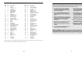
Voordat uw verder gaat met lezen, bekijk a.u.b. de
volgende tekening aandachtig om bekend te raken
met de verschillende onderdelen.
Handvat
Weerstandsknop
Weerstandsknop
VOORKANT
ACHTER
RECHTERKANT
Knop van de Zitting
Zitting
Buis van de Zitting
Pedaal
Knop
Bedieningspaneel
Onderstel
Waterfles Houder/Handdoek
Houder (waterfles niet inbegrepen)
Wiel
Sluitpen
NOTES

512
Inspect and tighten all parts of the PROFORM 770S
regularly. The 770S can be cleaned with a soft, damp
cloth. To prevent damage to the console, keep liquids
away from the console and keep the console out of
direct sunlight.
BATTERY REPLACEMENT
If the console does not function properly, the batteries
should be replaced. To replace the batteries, see
assembly step 4 on page 7.
HANDLEBAR LUBRICATION
If a squeak is heard when the Handlebars (5, 6) are
moved, a small amount of grease should be applied.
Remove the Lock Pin (53). Turn the Resistance Dial
(11) counterclockwise and remove it. Remove the
M10 Star Washer (14). Using pliers, grip the head of
the 3/8” x 6” Carriage Bolt (16) and remove it. Apply a
thin film of grease to both sides of the Handlebar
Housings (72). Reattach all parts, making sure that
they are in the positions shown.
CRANK ADJUSTMENT
If the arms of the Crank (17) become loose, they
should be tightened in order to prevent excessive
wear. Loosen the Crank Nut (24) on the left arm of the
Crank. Place the end of a standard screwdriver in one
of the slots in the Slotted Crank Nut (22). Lightly tap
the screwdriver with a hammer to turn the Slotted
Crank Nut counterclockwise until the arms are no lon-
ger loose. Do not overtighten the Slotted Crank
Nut. When the Slotted Crank Nut is properly tighte-
ned, tighten the Crank Nut.
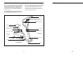
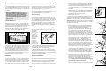
HOW TO STORE THE PROFORM 770S
When the 770S is not in use, it can be folded for com-
pact storage. Refer to the drawing below. Loosen the
Lock Knob (38). Slide the Handlebar Frame (2) into
the Frame (1) as far as it will go. Tighten the Lock
Knob. Store the 770S indoors, away from moisture
and dust.
MAINTENANCE AND STORAGE
38
2
1
ONDERDELEN IDENTIFICATIE KAART
Gebruik de kaart hieronder om u te helpen met de
identificatie van de kleine onderdelen die in montage
worden gebruikt. De nummer tussen haakjes geeft het
ondredeel nummer aan. Het tweede getaal geeft het
aantal gebruikt in montage. Aandacht: Sommige
onderdelen zijn al gemonteerd om het verzenden
te vergemakkelijken. Als u niet een onderdeel in
de zak met onderdelen knut vinden. Bekijk dan
het apparaat om te zien of dat onderdeel al
gemonteerd is.
3/8" x 2 3/4" Carriage Bolt (63)—2
3/8" x 3 1/2" Screw (55)—2
3/8" Nylon Locknut (56)—4
3/8" x 6" Carriage Bolt (16)—1
M8 Nylon Locknut (46)—4
(May be attached to seat)
M10 Star Washer (14)—1
M10 Flat Washer (57)—2
1/4" x 1" Screw (54)—2
M12 OD Flat Washer (73)—2
5/16" Flat Washer (26)—4
(May be attached to seat)
Console Screw (12)—4
(May be attached to console)
10
16
4
5
72
72
6
Lubricate
53
11
14
24
22
17

116
1. Bekijk tekening 1A. Draai de Knop (38) aan de rech-
terkant van het Onderstel (1) los.
Bekijk trekening 1. Schuif het Onderstel van de
Staander (2) naar voren totdat het niet meer kan.
Bekijk tekening 1A. Draai de Knop (38) weer vast.
2. Vindt het Linker Pedaal (52); deze bevat een “L” om
het te herkennen. Draai het Pedaal op het Pedaal Arm
(17) tegen de klok in vast met een verstelbare engles-
esleutel. Bevestig het Rechter Pedaal (niet getoond)
op dezelfde wijze maar draai het Pedaal met de klok
mee op het Arm.
U kunt als u dat wilt de Riem van de Pedaal (15) van
het Linker Pedaal (52) bijstellen. Druk de Riem op en
van de bijstel k nopjes. U kunt het rechter Pedaal (niet
getoond) op hetzelfde manier bijstellen.
3. Zorg ervoor bijde kanten van de Stabilisator (9) en
Stabilisator Kapje (45) bevat.
Maak de Stabilisator (9) aan het Onderstel (1) vast
met twee 3/8” x 2 3/4” Draagbouten (63) en twee 3/8”
Nylon Borgmoeren (56). Zorg ervoor dat de
Stabilisator zodaning gedraaid is dat de dimples zich
in de aangegeven positie bevinden.
MONTAGE
Leg alle onderdelen van de PROFORM 770S op een open plek en verwijder het verpakkingsmateriaal. Gooi de
verpakking pas weg wanneer U de770S hebt opgezet.
U hebt het volgene gereedschap nodig om het apparaat te monteren: Een inbussleutel (inbegrepen)
, een kruiskop schroevendraaier (niet inbegrepen) , en een verstelbare engelse
sleutel (niet inbegrepen) .
3
2
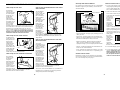
SUGGESTED STRETCHES
The correct form for several basic stretches is shown in the
drawings below. Move slowly as you stretch—never bounce.
1. Toe Touch Stretch
Stand with your knees bent slightly and slowly bend forward
from your hips. Allow your back and shoulders to relax as you
reach down toward your toes as far as possible. Hold for 15
counts, then relax. Repeat 3 times. Stretches: Hamstrings,
back of knees and back.
2. Hamstring Stretch
Sit with one leg extended. Bring the sole of the opposite foot
toward you and rest it against the inner thigh of your extended
leg. Reach toward your toes as far as possible. Hold for 15
counts, then relax. Repeat 3 times for each leg. Stretches:
Hamstrings, lower back and groin.
3. Calf/Achilles Stretch
With one leg in front of the other, reach forward and place
your hands against a wall. Keep your back leg straight and
your back foot flat on the floor. Bend your front leg, lean for-
ward and move your hips toward the wall. Hold for 15 counts,
then relax. Repeat 3 times for each leg. To cause further stret-
ching of the achilles tendons, bend your back leg as well.
Stretches: Calves, achilles tendons and ankles.
4. Quadriceps Stretch
With one hand against a wall for balance, reach back and
grasp one foot with your other hand. Bring your heel as close
to your buttocks as possible. Hold for 15 counts, then relax.
Repeat 3 times for each leg. Stretches: Quadriceps and hip
muscles.
5. Inner Thigh Stretch
Sit with the soles of your feet together and your knees out-
ward. Pull your feet toward your groin area as far as possible.
Hold for 15 counts, then relax. Repeat 3 times. Stretches:
Quadriceps and hip muscles.
1
2
3
4
5
Training zone exercise, consisting of 20 to 30 minu-
tes of exercising with your heart rate in your training
zone.
A cool-down, with 5 to 10 minutes of stretching.
Thorough stretching helps to offset problems caused
when you stop exercising suddenly. Stretching for
increased flexibility is also most effective after exerci-
sing. A proper cool-down should leave you relaxed
and comfortably tired.
EXERCISE FREQUENCY
To maintain or improve your condition, plan three wor-
kouts each week, with at least one day of rest
between workouts. After a few months of regular exer-
cise, you may complete up to five workouts each
week, if desired.
Remember, the key to success is make exercise a
regular and enjoyable part of your everyday life.
1
38
1
2
52
15
45
45
9
1
63
Dimples
56
56
17
1A
Bijstel
Knopje

710
4. Bekijk tekening 4A. Het Bedieiningspaneel (58) werkt
op twee “AA” batterijen (niet inbegrepen). Wij raden
alkaline batterijen aan. Druk twee batterijen in de bat-
terij klem onder het Bedieningspaneel. Zorg ervoor
dat de negatieve polen (–) van de batterijen de veren
aan raken.
Bekijk tekening 4. Steek de draad van het bediening-
spaneel door de Buis van het Handvat (4). Bevestig
het Bedieningspaneel (58) aan de Buid van het
Handvat met vier Schroeven van het
Bedieningspaneel (12).
Bevestig de draad van het bedieningspaneel met de
Magneet Sensor Draad (60) aan de bovenkant van het
Onderstel van de Staander (2). Insert the Handlebar Post
(4) into the Handlebar Frame. Be care-ful to avoid pin-
ching the wires. Attach the Handle-bar Post with two 3/8”
x 3 1/2” Screws (55), two M10 Flat Washers (57), and two
3/8” Nylon Locknuts (56).
5. Refer to drawing 5. Remove the four round stickers
from the Handlebar Bracket (10) and the Handlebar
Post (4). Attach the Handlebar Bracket to the
Handlebar Post with two 1/4” x 1” Screws (54) and
the two M12 OD Flat Washers (73). Make sure that
the square hole is on the left side. Note: This step
shows how to assemble the Resistance Dial (11) on
the right side of the Handlebar Post (4). To assemble
the Resistance Dial on the left side, reverse the orien-
tation of the Resistance Bracket (10), 6” Carriage Bolt
(16), M10 Star Washer (14), and Resistance Dial.
Hold the lower end of the Left Handlebar (5) inside
the Handlebar Bracket (10). Insert the 3/8” x 6”
Carriage Bolt (16) into the Handlebar Bracket and
through the Left Handlebar. Hold the Right Handlebar
(6) inside the Handlebar Bracket. Insert the Carriage
Bolt until the head of the Carriage Bolt is resting in
the square hole in the Handlebar Bracket. Slide the
M10 Star Washer (14) onto the Carriage Bolt. Tighten
the Resistance Dial (11) onto the Carriage Bolt.
Align the holes in the Handlebars (5, 6) with the hole
in the Handlebar Post (4). Insert the Lock Pin (53)
through the Handlebars and the Handlebar Post. Be
careful not to damage the wire inside the Handlebar
Post.
6. Insert the Seat Post (3) into the Frame (1). Align one
of the holes in the Seat Post with the hole in the
Frame. Insert the Seat Knob (37) into the Frame and
the Seat Post, and tighten the Seat Knob into the
Frame. Make sure to insert the Seat Knob through
one of the holes in the Seat Post; do not insert
the Seat Knob under the Seat Post.
Attach the Seat (36) to the Seat Post (3) with four M8
5
6
CONDITIE RICHTLIJNEN
De volgende richtlijnen zullen helpen met het plannen
van een oefenprogramma. Denk er aan dat juiste voe-
ding en adequate rust essentieel zijn voor succesvolle
resultaten.
OEFEN INTENSITEIT
Whether your goal is to burn fat or strengthen your
cardiovascular system, the key to achieving the desi-
red results is to exercise with the proper intensity. The
proper intensity level can be found by using your
heart rate as a guide. The chart below shows recom-
mended heart rates for fat burning, maximum fat bur-
ning, and cardiovascular (aerobic) exercise.
To find the proper heart rate for you, first find your age
near the top of the chart (ages are rounded off to the
nearest ten years). Next, look below your age and
find the three numbers in grey boxes. The three num-
bers are your “training zone.” The lowest number is
the recommended heart rate for fat burning; the mid-
dle number is the recommended heart rate for maxi-
mum fat burning; the highest number is the recom-
mended heart rate for aerobic exercise.
Fat Burning
To burn fat effectively, you must exercise at a relative-
ly low intensity level for a sustained period of time.
During the first few minutes of exercise, your body
uses easily accessible carbohydrate calories for ener-
gy. Only after the first few minutes of exercise does
your body begin to use stored fat calories for energy.
If your goal is to burn fat, adjust the intensity of your
exercise until your heart rate is near the lowest num-
ber in your training zone as you exercise.
For maximum fat burning, adjust the intensity of your
exercise until your heart rate is near the middle num-
ber in your training zone as you exercise.
Aerobic Exercise
If your goal is to strengthen your cardiovascular sys-
tem, your exercise must be “aerobic.” Aerobic exerci-
se is activity that requires large amounts of oxygen for
prolonged periods of time. This increases the demand
on the heart to pump blood to the muscles, and on
the lungs to oxygenate the blood. For aerobic exerci-
se, adjust the intensity of your exercise until your
heart rate is near the highest number in your training
zone.
HOW TO MEASURE YOUR HEART RATE
To measure your heart rate, first exercise for at least
four minutes.
Then, stop
exercising and
place two fin-
gers on your
wrist as
shown. Take a
six-second
heartbeat
count, and
multiply the
result by 10 to
find your heart
rate. For example, if your six-second heartbeat count
is 14, your heart rate is 140 beats per minute. (A six-
second count is used because your heart rate will
drop rapidly when you stop exercising.)
Adjust the intensity of your exercise until your heart
rate is at the desired level. You can adjust the intensi-
ty of your exercise by changing your pedaling speed,
adjusting the pedaling resistance, or using the handle-
bars in the dual-motion position.
WORKOUT GUIDELINES
Each workout should include the following three parts:
A warm-up, lasting 5 to 10 minutes. Begin with slow,
controlled stretches, and progress to more rhythmic
stretches to increase the body temperature, heart
rate, and circulation in preparation for strenuous exer-
WAARSCHUWING: Raadpleeg uw arts voor-
dat U begint met dit of ieder ander oefenpro-
gramma. Dit is in het bijzonder belangrijk
voor personen boven de 35 jaar en of perso-
nen met gezondheidsproblemen of die ze
gehad hebben.
58
12
4
2
10
16
Square Hole
4
5
36
46
26
26
3
1
37
6
53
11
14
54
73
55
57
56
4
58
Batteries
Console Wire
Console
Wire
60
4A

98
BESCHRIJVING VAN DE MONITOR
De monitor op uw bevat vijf modes om u onmiddellijk
feedback te geven op uw oefening. The modes are
described below.
• Speed (Snelheid)—Displays your pedaling speed, in
miles per hour.
• Time (Tijd)—Geeft de lengte van uw oefening aan.
Note: If you stop pedaling for ten seconds or longer,
the time mode will pause until you resume.
• Distance (Afstand)—Displays the total number of
miles you have pedaled, up to 999. De display
springt dan terug op nul en begint opnieuw te tellen .
• Calorie—Geeft bij benadering de hoeveelheid calo-
rieën aan die u hebt verbrand.
• Scan—Displays the speed, time, distance, and calo-
rie modes, for 5 seconds each, in a repeating cycle.
BATTERY INSTALLATION
Before the console can be operated, two “AA” batte-
ries must be installed. If you have not installed batte-
ries, see assembly step 4 on page 7.
HOW TO OPERATE THE CONSOLE
1. To turn on the power, press the on/reset button or
simply begin pedaling. When the power is turned
on, the entire display will appear for two seconds.
The console will then be ready for operation.
2. Select one of the five modes:
Scan mode—When the power is turned on, the
scan mode will automatically be selected. One
mode indica-
tor will show
that the scan
mode is
selected,
and a flas-
hing mode
indicator will
show which
mode is currently displayed. Note: If a different
mode is selected, you can select the scan mode
again by repeatedly pressing the mode button.
Speed, time, distance or calorie mode—To select
one of these modes for continuous display, repe-
atedly press
the mode
button. The
mode indica-
tors will
show which
mode is
selected.
(Make sure
that the scan mode is not selected.)
3. To reset the display, press the on/reset button.
4. To turn off the power, simply wait for about four
minutes. Note: The console has an “auto-off”
feature. If the pedals are not moved and the
console buttons are not pressed for four minu-
tes, the power will turn off automatically in
order to conserve the batteries.
Mode Indicators
Mode Indicators
HOW TO USE THE PROFORM 770S
HOW TO ADJUST THE SEAT
For effective
exercise, the
Seat (36) should
be at the proper
height. As you
pedal, there
should be a
slight bend in
your knees when
the pedals are at
the lowest posi-
tion. To adjust
the Seat, first
hold the Seat and unscrew the Seat Knob (37). Align
one of the holes in the Seat Post (3) with the hole in
the Frame (1). Insert the Seat Knob (37) into the
Frame and the Seat Post, and tighten the Seat Knob
into the Frame. Make sure to insert the Seat Knob
through one of the holes in the Seat Post; do not
insert the Seat Knob under the Seat Post.
HOW TO ADJUST THE PEDAL STRAPS
To adjust each
Pedal Strap (13),
first pull the end
of the Pedal
Strap off the
adjustment tab
on the Pedal
(51). Align a dif-
ferent hole in the
Pedal Strap with
the adjustment
tab. Press the
Pedal Strap onto the adjustment tab.
HOW TO ADJUST THE PEDALING RESISTANCE
The pedaling
resistance can
be adjusted
using the
Resistance Knob
(40) located at
the base of the
seat post. To
increase the resi-
stance, turn the
Resistance Knob
clockwise; to decrease the resistance, turn the
Resistance Knob counterclockwise.
HOW TO USE THE HANDLEBARS IN THE STATIO-
NARY POSITION
The Handlebars
(5, 6) can be
used in either the
stationary posi-
tion or the dual-
motion position.
To use the
Handlebars in the
stationary posi-
tion, align the
holes in the
Handlebars with
the hole in the
Handlebar Post
(4). Insert the
Lock Pin (53)
through the
Handlebars and
the Handlebar
Post. Note: If it is difficult to insert the Lock Pin, twist
the Handlebars slightly in order to align the holes.
Next, tighten the Resistance Dial (11) (see the dra-
wing above).
HOW TO USE THE HANDLEBARS IN THE DUAL-
MOTION POSITION
To use the
Handlebars (5, 6)
in the dual-motion
position, remove
the Lock Pin (53)
from the
Handlebars and
the Handlebar
Post (4). Keep
the Lock Pin in a
safe place. The
resistance of the
Handlebars can
be adjusted with
the Resistance
Dial (11). To
increase the resi-
stance, turn the
Resistance Dial
clockwise; to decrease the resistance, turn the
Resistance Dial counterclockwise.
To exercise, move the Handlebars (5, 6) forward and
backward as you pedal. Be sure to keep your back
straight and your knees bent slightly.
37
36
5
4
53
11
6
3
1
51
40
Adjustment
Tab
13
5
4
53
11
6
Indicator
Mode Indicators
-
 1
1
-
 2
2
-
 3
3
-
 4
4
-
 5
5
-
 6
6
-
 7
7
-
 8
8


ProForm PFEX7206 de handleiding
- Categorie
- Fitness, gymnastiek
- Type
- de handleiding
- Deze handleiding is ook geschikt voor
in andere talen
- English: ProForm PFEX7206 Owner's manual
Andere documenten
-
Matrix CXP de handleiding
-
-
Tunturi Home Gym F20 Handleiding
-
Accell Cardio Comfort Pacer Handleiding
-
Tunturi E30R Handleiding
-
Tunturi Cardio Fit Bike B35 Handleiding
-
-
-
Tunturi FitCycle 30 de handleiding
-
Tunturi E100 de handleiding