Teleco TSP 130W pannello solare Handleiding
- Type
- Handleiding

Pannello Solare
TELECO TSP 130W
Istruzioni di Montaggio

Il kit di montaggio Solar Panel di Teleco è stato costruito per il montaggio su un tetto
piano e orizzontale di camper o caravan.
Istruzioni di Montaggio Pannello Solare TELECO TSP 130W
IT
1
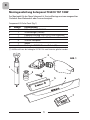
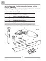
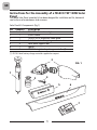
(*) A richiesta viene fornito il regolatore di carica SPC10/2 per due Batterie
N°
1
2
3
4
5
6
7
Quantità
1
1
1
8
4
1
1
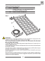
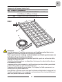
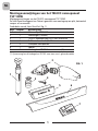
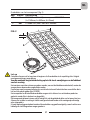
Componenti Kit Solar Panel (Fig.1)
Descrizione
Colla siliconica DEKASYL
Pulitore rapido (Cleaner)
Passacavo TELECO SPCA in alluminio
Vite Autoforante 4.2x25 inox
Piede appoggio pannello solare
Spoiler
Regolatore di carica SPC10/1 per una Batteria (*)
2
3
4
5
6
7
FIG. 1
1

Attenzione
Prima di iniziare il montaggio controllare che tutti i componenti siano presenti nella
confezione. Seguire attentamente le istruzioni di montaggio.
Per il carico massimo consentito sul tetto fare riferimento alle indicazioni
del costruttore del veicolo
Il montaggio deve essere eseguito da personale specializzato, per le sezioni dei cavi
attenersi a quelle prescritte.
Il montaggio deve essere conforme alle disposizioni tecnico e/o amministrative del paese
d’utilizzo (es. EN1648).
Il pannello solare e relativa componentistica non devono essere installati nella vicinanza
di prodotti infiammabili (es. vicino alla bombola del gas).
Il pannello solare genera corrente, anche in presenza di bassa luminosità; non toccare
le parti conduttrici.
Prima di azionare il sistema accertarsi che il lavoro sia stato eseguito a regola d’arte.
Eseguire il controllo periodico del corretto fissaggio dei componenti, specialmente dopo
aver percorso strade accidentate.
2
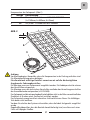
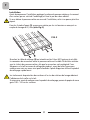
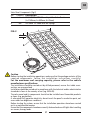
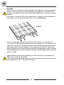
Componenti Pannello Solare (Fig.2)
Quantità
1
6m
Descrizione
Pannello Solare TELECO TSP 130W Monocristallino
(L=1160mm; A=830mm; H=35mm)
Cavo FV 2x2.5mm
2
con spine MC3
N°
8
9
8
9
H
A
L
FIG. 2
IT

IT
3
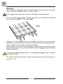
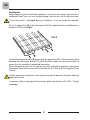
Montaggio
Prima di iniziare il montaggio, coprire la superficie del pannello solare con un cartone
(ad es. quello dell’imballo) e fissarlo con nastro adesivo.
Se danneggiate il pannello solare durante il montaggio, non è più riparabile.
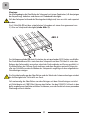
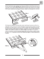
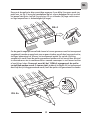
Fissare i 4 piedi di appoggio (5) al pannello solare con le viti in dotazione esercitando
una coppia di serraggio di 2,5 Nm (vedi Fig.3).
FIG. 3
Collegare il cavo di prolunga (9) inserendo le apposite spine MC3. La connessione del
connettore fra il pannello solare ed il cavo FV va prevista sotto il telaio del pannello
solare in modo che il connettore sia protetto dall’acqua.
Contrassegnare sul tetto le aree di incollaggio dei piedi e, prima di incollare il pannello,
pulire accuratamente tali zone, oltre al fondo dei 4 piedi di appoggio tramite il pulitore
rapido in dotazione.
I trattamenti di protezione delle superfici e la cera degli autolavaggi, riducono l’aderenza
della colla sul tetto.
Se necessario prima di pulire con il cleaner levigare le superfici con carta abrasiva a
grana 100 – 120.

4
IT
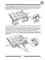
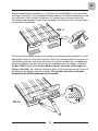
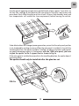
Tramite l’applicatore distribuire tre cordoni paralleli di colla, spessi circa 3mm sui quatto
piedi, vedi Fig.4, posizionare il pannello solare sulla superficie del tetto pulita e pressare
energicamente. Lasciare indurire la colla per almeno 24 ore (umidità e basse temperature
prolungano il tempo indicato) prima di muovere il veicolo.
1
2
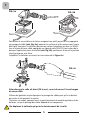
Al fine di poter generare il massimo della corrente, posizionare il pannello solare dove
le sovrastrutture non vi gettino ombra. Quando si monta il pannello solare in linea con
la direzione di marcia va montato lo spoiler, questo per ridurre i rumori dovuti al vento
e per evitare che vi restino impigliati componenti estranei; inoltre, per il pannello
130W, occorre incollare lo spoiler ai due piedi di fissaggio, vedi Fig.5a.
Se il montaggio del pannello solare avviene in senso trasversale al senso di marcia, lo
spoiler non deve essere montato. Lo spoiler va montato solo dopo l’indurimento
della colla.
FIG. 4
FIG. 5a

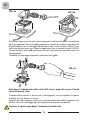
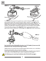
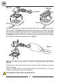
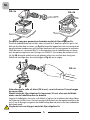
Posizionare Il passacavo sul tetto contrassegnando il profilo, praticare un foro adeguato
per il passaggio del cavo vedi Fig.6a, preparare le superfici da incollare come descritto
precedentemente per il montaggio del pannello solare. Inserire le due viti M4x14 inox
nella base del passacavo, con l’apposito applicatore fare un cordone di colla DEKASYL
intorno alla base vedi Fig.6b, posizionare la base nella posizione prescelta e pressare
energicamente.
Completare il montaggio seguendo le indicazioni di Figg.6c.
IT
5
FIG. 6a
FIG. 6b
Attendere l’indurimento della colla (24h circa), prima di serrare il dado
cieco del pressa cavo.
Prevedere delle canaline in plastica per il passaggio dei cavi per impedire che questi
sbattano sul tetto durante la marcia.
Scegliere un posto adeguato anche per il posizionamento del modulo regolatore e le
batterie, dato che il passaggio dei cavi è determinato da questi componenti.
Spostare il veicolo solo dopo l’ indurimento della colla
FIG. 6c

6
IT

Solarpanel
TELECO TSP 130W
Montageanleitung

Das Montagekit für das Teleco-Solarpanel ist für eine Montage an einem waagerechten
Flachdach eines Wohnmobils oder Caravan konzipiert.
Montageanleitung Solarpanel TELECO TSP 130W
D
1
(*) Auf Wunsch kann der Laderegler SPC10/2 für zwei Batterien geliefert werden
N°
1
2
3
4
5
6
7
Menge
1
1
1
8
4
1
1
Componenti Kit Solar Panel (Fig.1)
Beschreibung
Silikon-Dichtstoff DEKASYL
Schnellreiniger (Cleaner)
Kabeldurchführung TELECO SPCA aus Aluminium
Selbstbohrende Schraube 4.2x25 aus rostfreiem Stahl
Stützfuß Solarpanel
Spoiler
Laderegler SPC10/1 für eine Batterie (*)
2
3
4
5
6
7
ABB. 1
1

Achtung
Vor Montagebeginn überprüfen, dass alle Komponenten in der Packung enthalten sind.
Die Montageanleitung genau befolgen.
Für die maximal zulässige Dachlast verweisen wir auf die diesbezüglichen
Angaben des Fahrzeugherstellers.
Die Montage muss von Fachpersonal ausgeführt werden. Die Kabelquerschnitte müssen
den Vorschriften entsprechen.
Die Montage muss den technischen Vorschriften und/oder den Verwaltungsvorschriften
des Anwenderlandes entsprechen (z.B. EN1648).
Das Solarpanel und die entsprechenden Bauteile dürfen nicht in der Nähe von entzündlichen
Produkten (z.B. neben einer Gasflasche) installiert werden.
Das Solarpanel erzeugt auch bei schwachen Lichtverhältnissen Strom. Die leitfähigen
Teile daher nicht berühren.
Vor dem Einschalten des Systems sicherstellen, dass die Arbeit fachgerecht ausgeführt
wurde.
Regelmäßig überprüfen, dass die Bauteile korrekt befestigt sind, vor allem nach einer
Fahrt auf holprigen Straßen.
2
Komponenten des Solarpanels (Abb. 2)
Menge
1
6m
Beschreibung
Monokristallines Solarmodul TELECO TSP 130W
(L=1160mm; A=830mm; H=35mm)
2x2,5 mm
2
-PV-Kabel mit MC3-Steckern
N°
8
9
8
9
H
A
L
ABB. 2
D

D
3
Montage:
Vor Montagebeginn die Oberfläche des Solarpanels mit einem Pappkarton (z.B. demjenigen
der Verpackung) abdecken und diesen mit Klebeband befestigen.
Falls das Solarpanel während der Montage beschädigt wird, kann es nicht mehr repariert
werden.
Die 4 Stützfüße (5) mit den mitgelieferten Schrauben mit einem Anzugsmoment von
2,5 Nm am Solarpanel befestigen (siehe Abb. 3).
ABB. 3
D
as Verlängerungskabel (9) durch Einstecken der entsprechenden MC3-Stecker anschließen.
Der Steckverbinderanschluss zwischen dem Solarpanel und dem PV-Kabel ist unter dem
Rahmen des Solarmoduls vorzusehen, damit der Steckverbinder vor Wasser geschützt ist.
Die Klebeflächen der Füße am Dach markieren und diese Bereiche sowie die Unterseite
aller vier Stützfüße vor dem Aufkleben des Solarpanels sorgfältig mit dem mitgelieferten
Schnellreiniger reinigen.
Die Schutzbehandlungen der Oberflächen und das Wachs der Autowaschanlagen mindert
die Haftfestigkeit des Dichtstoffs am Dach.
Falls notwendig, die Oberflächen vor dem Reinigen mit dem Schnellreiniger zunächst
mit Schleifpapier mit 100/120er Körnung abschleifen. Um den DEKASYL-Schlauch in den
dafür vorgesehenen Applikator einführen zu können, muss der Deckel mit einem passenden
Werkzeug entfernt werden.

4
D
Mit dem Applikator drei parallele, ca. 3 mm dicke Dichtstoffstreifen an den vier Füßen
auftragen, siehe Abb. 4. Das Solarpanel auf der sauberen Dachfläche positionieren und
fest andrücken. Den Dichtstoff mindestens 24 Stunden lang aushärten lassen (bei
Feuchtigkeit und niedrigen Temperaturen verlängert sich der genannte Zeitraum), bevor
man das Fahrzeug bewegt.
Um die maximale Stromerzeugung zu erreichen, das Solarpanel so positionieren, an die
Überbauten keinen Schatten darauf werfen. Wenn das Solarpanel übereinstimmend zur
Fahrtrichtung montiert wird muss del Spoiler so installiert werden, dass windbedingte
Geräusche reduziert werden und sich keine Fremdkörper darin verfangen; außerdem,
für den 130W Panel, ist es notwendig den Spoiler an beiden Halterungen zu
kleben, siehe Abb. 5a. Wird das Solarpanel quer zur Fahrtrichtung montiert, kann auf
die Montage des Spoilers verzichtet werden. Der Spoiler darf erst nach dem
Aushärten des Dichtstoffes montiert werden.
ABB. 4
1
2
FIG. 5a

Die Kabeldurchführung am Dach positionieren und ihr Außenprofil markieren. Eine
passende Bohrung für den Durchführung des Kabels ausführen, siehe Abb. 6a. Die
Klebeflächen wie zuvor für die Montage des Solarpanels beschreiben vorbereiten. Die
beiden M4x14 Schrauben aus rostfreiem Stahl an der Basis der Kabeldurchführung
einführen. Mit dem dafür vorgesehenen Applikator rund um die Basis einen DEKASYL-
Dichtstoffstreifen auftragen, siehe Abb. 6b. Die Basis an der gewünschten Stelle
positionieren und fest andrücken. Die Montage wie in Abb. 6c ersichtlich abschließen.
D
5
ABB. 6a
ABB. 6b
Das Aushärten des Dichtstoffs abwarten (ca. 24 Stunden), bevor man die
Blindmutter der Kabeldurchführung festzieht.
Kabelkanäle aus Kunststoff für die Durchführung der Kabel vorsehen, um zu verhindern,
dass diese während der Fahrt auf das Dach schlagen.
Für die Positionierung des Reglermoduls und der Batterien ebenfalls einen geeigneten
Platz wählen, da die Kabelführung von diesen Komponenten abhängig ist.
Das Fahrzeug erst nach dem Aushärten des Dichtstoffs bewegen.
ABB. 6c

6
D

Panneau Solaire
TELECO TSP 130W
Instructions pour l’installation

Le kit d’installation Solar Panel de Teleco a été réalisé pour l’installation sur le toit plat
et bien horizontal d’un camping-car ou d’une caravane.
Composants du Kit Solar Panel (Fig.1)
Instructions pour l’installations du Panneau Solaire
TELECO TSP 130W
F
1
(*) Sur demande nous pouvons fournir le régulateur de charge SPC10/2 pour deux Batteries
Rep
1
2
3
4
5
6
7
Quantité
1
1
1
8
4
1
1
Désignation
Colle à base de silicone DEKASYL
Produit de nettoyage rapide (Cleaner)
Serre-câble alu TELECO SPCA
Vis auto-perceuse 4.2x25 inox
Pied d’appui panneau solaire
Spoiler
Régulateur de charge SPC10/1 pour une Batterie (*)
2
3
4
5
6
7
FIG. 1
1

Attention
Avant de commencer l’installation, assurez-vous que l’emballage contient bien tous les
composants. Suivez avec attention les instructions d’installation.
Pour ce qui concerne la charge maximale admise sur le toit, reportez-vous aux
indications du constructeur du véhicule.
L’installation doit être réalisée par du personnel spécialisé ; quant aux sections des câbles,
respectez les valeurs prescrites.
L’installation doit être conforme aux dispositions techniques et/ou administratives du pays
d’utilisation (ex. EN1648).
Le panneau solaire et les composants y relatifs ne doivent pas être installés à proximité de
produits inflammables (ex. près de la bouteille de gaz).
Le panneau solaire génère du courant même s’il ne capte qu’un faible rayonnement ; ne
touchez jamais les parties conductrices.
Avant d’activer le système, assurez-vous que l’installation a été faite dans les règles de l’art.
Contrôlez périodiquement si les composants sont correctement fixés, tout particulièrement
après avoir parcouru des routes accidentées.
2
Composants du Panneau Solaire (Fig.2)
Quantité
1
6m
Désignation
Panneau Solaire TELECO TSP 130W Monocristallin
(L=1160mm; A=830mm; H=35mm)
Câble FV 2x2.5 mm
2
avec fiches MC3
Rep
8
9
8
9
H
A
L
FIG. 2
F

F
3
Installation
Avant de commencer l’installation, protégez la surface du panneau solaire en la couvrant
d’un carton (par ex. celui de l’emballage) et fixez-le par du ruban adhésif.
Si vous abîmez le panneau solaire au cours de l’installation, celui-ci ne pourra plus être
réparé.
Fixez les 4 pieds d’appui (5) au panneau solaire par les vis fournies en exerçant un
couple de serrage de 2,5 Nm (voir Fig.3).
FIG. 3
Branchez le câble de rallonge (9) en introduisant les fiches MC3 prévues à cet effet.
La connexion du connecteur entre le panneau solaire et le câble FV doit être réalisée
sous le châssis du panneau solaire, afin que le connecteur soit protégé de l’eau.
Marquez sur le toit les zones de collage des pieds et, avant de coller le panneau,
nettoyez avec soin ces zones ainsi que le fond des 4 pieds d’appui en utilisant le produit
de nettoyage rapide fourni.
Les traitements de protection des surfaces et la cire des stations de lavage réduisent
l’adhérence de la colle sur le toit.
Si nécessaire, avant de nettoyer avec le produit de nettoyage, passez du papier de verre
grain 100 – 120 sur les surfaces.

4
F
Utilisez l’applicateur pour appliquer trois lignes parallèles de colle d’une épaisseur de
3 mm env. sur les 4 pieds (voir Fig. 4), positionnez le panneau solaire sur la surface
propre du toit et pressez avec force. Laissez durcir la colle au moins 24 heures (l’humidité
et les basses températures prolongent le temps indiqué) avant de déplacer le véhicule.
Afin de pouvoir générer le maximum de courant, positionnez le panneau solaire à un
endroit où aucune structure ne lui fasse de l’ombre. Quand le panneau solaire est monté
parallèle au sens de marche, il faut aussi installer le spoiler afin de réduire le bruit dû
au vent et d’éviter que des éléments étrangers y restent pris; en outre, pour le panneau
130W, il faut coller le spoiler aux 2 pieds d'appui, voir Fig.5a. Si le panneau
solaire est monté en sens transversal par rapport au sens de marche, le spoiler ne doit
pas être installé. Le spoiler ne doit être installé qu’après le durcissement de
la colle.
FIG. 4
1
2
FIG. 5a

Positionnez le serre-câble sur le toit en marquant son profil, percez un trou approprié
au passage du câble (voir Fig. 6a), préparez les surfaces à coller comme nous l’avons
décrit plus haut pour l’installation du panneau solaire. Introduisez les deux vis M4x14
inox à la base du serre-câble, appliquez une ligne de colle DEKASYL tout autour de la
base par l’applicateur prévu à cet effet (voir Fig. 6b), positionnez la base à la position
choisie et pressez avec force.
Complétez l’installation en suivant les instructions de la Figure 6c.
F
5
FIG. 6a
FIG. 6b
Attendez que la colle ait durci (24 h env.), avant de serrer l’écrou borgne
du serre-câble.
Utilisez des goulottes en plastique pour le passage des câbles pour qu’ils ne battent
pas contre le toit pendant la marche.
Choisissez un endroit approprié aussi au positionnement du module régulateur et des
batteries, vu que le passage des câbles dépend de ces composants.
Ne déplacez le véhicule qu’après le durcissement de la colle
FIG. 6c

6
F

TELECO TSP 130W
Solar Panel
Assembly instructions

The Teleco Solar Panel assembly kit has been designed for installation on flat, horizontal
roof surfaces of motorhomes and caravans.
Instructions for the Assembly of a TELECO TSP 130W Solar
Panel
GB
1
(*) SPC10/2 dual battery charge controller supplied on request
No.
1
2
3
4
5
6
7
Quantity
1
1
1
8
4
1
1
Solar Panel Kit Components (Fig.1)
Description
DEKASYL silicone-based glue
Quick Cleaner
TELECO SPCA aluminium cable guide
4.2x25 S. steel self-tapping screw
Solar panel support foot
Spoiler
SPC10/1 single battery charge controller (*)
2
3
4
5
6
7
FIG. 1
1

Caution
Before starting the installation operations, make sure that the package contains all the
required components. Follow the installation instructions carefully!
For the maximum roof carrying capacity, please refer to the vehicle
manufacturer specifications.
The installation should be carried out by skilled personnel; ensure that cable cross-
sections are as prescribed.
Installation should be carried out in compliance with the technical and/or administrative
standards in force in the country of use (e.g. EN1648).
The solar panel and its components should not be installed near flammable products
or items (e.g. gas bottles).
A solar panel will generate electricity: do not touch the panel's conductive parts, not
even under low brightness conditions.
Before starting the system, ensure that the installation operations have been carried
out in a workmanlike manner.
Ensure that the components have been correctly fastened and are still tight after travelling
on uneven, bumpy roads.
2
Solar Panel Components (Fig.2)
Quantity
1
6m
Description
TELECO TSP 130W Mono-Crystalline Solar Panel
(L=1160mm; A=830mm; H=35mm)
2x2.5mm
2
PV cable with MC3 plugs
No.
8
9
8
9
H
A
L
FIG. 2
GB

GB
3
Installation
Before beginning the installation operations, cover the solar panel surface with a
cardboard sheet (you can use the packaging) and secure it with adhesive tape.
If the solar panel is damaged during installation, it can no longer be repaired.
Fix the 4 support feet (5) to the solar panel with the supplied screws, and tighten to a
torque of 2.5 Nm (see Fig.3).
FIG. 3
Connect the extension cable (9) by inserting the special pins MC3. The connection point
between the solar panel and the PV cable should be under the solar panel frame, to
ensure that the connector is protected from water.
Mark the glueing areas for the feet on the roof, and before glueing on the panel,
thoroughly clean those areas and the bottom of all 4 feet with the supplied Quick
Cleaner.
Surface protection treatments and carwash waxing will decrease the glue adhesion
power on the roof.
If necessary, before cleaning with the cleaner, polish the surfaces with 100 – 120 grit
sandpaper.

4
GB
Use the special applicator to apply three parallel beads of glue, approx. 3 mm thick, on
the four feet, see Fig. 4, then position the solar panel on the clean roof surface and
press down firmly. Allow the glue to set for at least 24 hours (high humidity levels and
low temperatures will extend the time requirement) before moving the vehicle.
To be able to obtain the strongest power generation, ensure that the solar panel position
is not shadowed by existing structures. When the solar panel is installed in line with the
travelling direction, the spoiler should be installed, to reduce wind noise and prevent
any objects becoming caught in it; furthermore, with the 130W solar panel, you have
to glue the spoiler to the 2 support feet as shown in Fig.5a.
If the solar panel is installed transversally to the travelling direction, the spoiler doesn't
have to be fitted.
The spoiler should only be installed after the glue has set.
FIG. 4
1
2
FIG. 5a

Place the cable guide on the roof marking the outline, drill a suitable hole to let the
cable throug h (see Fig.6a), prepare the surfaces for glueing as described here above
to install the solar panel. Insert the two M4x14 stainless steel screws in the cable guide
base, and use the special applicator to apply a DEKASYL glue bead around the base,
see Fig.6b, then position the base in the required position and press firmly. Complete
the installation according to the indications in Figs. 6c.
GB
5
FIG. 6a
FIG. 6b
Wait for the glue to set (approx. 24h) before tightening the cable guide
cap nut.
Provide plastic cable conduits for the cables, to prevent them hitting the roof during
vehicle travelling.
Choose a suitable location for the controller module and the batteries, as the cable
routing is influenced by these parts' positioning.
Only move the vehicle after the glue has set.
FIG. 6c

6
GB

Zonnepaneel
TELECO TSP 130W
Montageaanwijzingen

Montageaanwijzingen van het TELECO zonnepaneel TSP 130W
De Solar Panel montageset van Teleco is gemaakt voor montage op een plat, horizontaal
camper- of caravandak.
Onderdelen van de Solar Panel Set (fig. 1)
Montageaanwijzingen van het TELECO zonnepaneel
TSP 130W
NL
1
(*) Op aanvraag kan de laadregelaar SPC10/2 voor twee accu’s geleverd worden
Rep
1
2
3
4
5
6
7
Aantal
1
1
1
8
4
1
1
Beschrijving
Siliconenlijm DEKASYL
Snelreiniger (Cleaner)
TELECO kabeldoorvoer SPCA van aluminium
Zelfborende schroef 4,2x25 rvs
Steunpoot zonnepaneel
Spoiler
Laadregelaar SPC10/1 voor één accu (*)
2
3
4
5
6
7
FIG. 1
1

Let op
Controleer alvorens met het monteren te beginnen of alle onderdelen in de verpakking zitten. Volg de
montageaanwijzingen zorgvuldig op.
Voor de maximaal toegestane belasting op het dak zie de aanwijzingen van de fabrikant
van het voertuig.
Het monteren moet door vakmensen gedaan worden; voor wat de kabeldoorsneden betreft, moeten de
voorgeschreven doorsneden aangehouden worden.
De montage moet in overeenstemming zijn met de technische en/of administratieve voorschriften die in
het land van gebruik gelden (bijv. EN1648).
Het zonnepaneel en de betreffende onderdelen mogen niet in de buurt van ontvlambare producten
geplaatst worden (bijv. in de buurt van de gasfles).
Het zonnepaneel genereert stroom, ook bij weinig licht; raak de geleidende delen van het paneel niet aan.
Alvorens het systeem in werking te stellen moet gecontroleerd worden of de montage op vakkundige
wijze uitgevoerd is.
Er moet regelmatig gecontroleerd worden of de onderdelen nog goed bevestigd zijn, vooral nadat er over
hobbelige en slecht begaanbare wegen gereden is.
2
Onderdelen van het zonnepaneel (fig. 2)
Aantal
1
6m
Beschrijving
TELECO monokristallijn zonnepaneel TSP 130W
(L=1160mm; A=830mm; H=35mm)
FV kabel 2x2,5mm
2
met MC3 stekkers
Rep
8
9
8
9
H
A
L
FIG. 2
NL

NL
3
Montage
Alvorens met het monteren te beginnen bedekt u het oppervlak van het zonnepaneel
met een stuk karton (bijv. dat van de verpakking) en maakt u dit met plakband vast.
Indien het zonnepaneel tijdens het monteren beschadigd wordt, is repareren niet meer
mogelijk.
Bevestig de 4 steunpoten (5) met de meegeleverde schroeven aan het zonnepaneel
en draai deze met een aanhaalmoment van 2,5 Nm aan (zie fig. 3).
FIG. 3
Sluit het verlengsnoer (9) aan door de speciale MC3 stekkers erin te steken. Het
aansluitpunt van de verbindingsstekker tussen het zonnepaneel en de FV kabel moet
onder het frame van het zonnepaneel komen zodat de stekkerverbinding beschermd
wordt tegen water.Teken de lijmpunten van de poten op het dak af en voordat het
paneel vastgelijmd wordt moeten deze punten goed schoongemaakt worden; dit geldt
ook voor de onderkant van de 4 steunpoten. Hiervoor moet de meegeleverde snelreiniger
gebruikt worden.
Oppervlaktebeschermende behandelingen en autowasstraat-wax verminderen de
hechtkracht van de lijm op het dak.
Indien nodig moeten de oppervlakken voor het schoonmaken met de cleaner eerst met
schuurpapier korrel 100 – 120 geschuurd worden.

4
NL
Breng met de applicator drie evenwijdige ongeveer 3 mm dikke lijmrupsen op de vier
poten aan, zie fig. 4, breng het zonnepaneel op het schone dakoppervlak aan en druk
het paneel stevig aan. Laat de lijm minstens 24 uur uitharden (bij hoge vochtniveaus
en lage temperaturen is de benodigde tijd langer).
Om de grootst mogelijke hoeveelheid stroom te kunnen genereren moet het zonnepaneel
aangebracht worden op een plaats waar er geen schaduw op valt door hoge constructies,
stellages, bebouwing e.d. Wanner het zonnepaneel op één lijn met de rijrichting
aangebracht wordt, moet de spoiler gemonteerd worden om het lawaai door de wind
te verminderen en om te voorkomen dat er vreemde voorwerpen in vast komen te zitten
of aan blijven haken. Daarnaast moet bij het 130Watt zonnepaneel de spoiler
vastgelijmd worden aan de 2 steunen zoals te zien is in Fig 5a. Als het zonnepaneel
dwars op de rijrichting gemonteerd wordt, hoeft de spoiler niet gemonteerd te worden.
FIG. 4
1
2
FIG. 5a

De spoiler mag pas gemonteerd worden nadat de lijm uitgehard is.
Plaats de kabeldoorvoer op het dak, teken het profiel af, boor een geschikt gat in het
dak om de kabel door te voeren, zie fig. 6a, bereid het oppervlak waar het zonnepaneel
op gelijmd moet worden voor, zoals hiervoor beschreven om het zonnepaneel te monteren.
Steek de twee rvs schroeven M4x14 in de onderkant van de kabeldoorvoer en breng
met de speciale applicator een lijmrups van DEKASYL lijm rondom de onderkant aan,
zie fig. 6b, breng de onderkant op de gekozen plaats aan en druk deze stevig aan.
Voltooi de montage door de aanwijzingen in fig. 6c op te volgen.
NL
5
FIG. 6a
FIG. 6b
Attendez que la colle ait durci (24 h env.), avant de serrer l’écrou borgne
du serre-câble.
Wacht totdat de lijm uitgehard is (ongeveer 24 uur) alvorens de blinde
moer van de kabelklem aan te draaien.
Leg plastic kabelgoten aan waar u de kabels in legt om te voorkomen dat deze tijdens
het rijden op het dak slaan. Kies ook een geschikte plaats om de regelaarmodule en de
accu’s aan te brengen aangezien het kabelverloop door de plaats van deze onderdelen
beïnvloed wordt.
Verplaats het voertuig pas nadat de lijm uitgehard is.
FIG. 6c

6
NL

GREAT BRITAIN - SCAN TERIEUR LTD
30, The Metro Centre, Tolpits Lane - Watford,
Herts - England - WD18 9XG
Tel. 01923 800353 - Fax 01923 220358
e-mail: [email protected]
www.scan-terieur.com
THE NETHERLANDS/BELGIUM/LUXEMBOURG/DENMARK/SWEDEN
KARMAN TRADING
Tel. +31 ( 0 ) 341 722450 - Fax +31 ( 0 ) 341 722451
e-mail: [email protected]
www.karmantrading.eu
FRANCE - TELECO SAS
3, impasse des ILES - ZA La Maladière
07300 St Jean de Muzols - France
TéL. 04 75 08 49 17 - Fax 09 70 32 83 00
www.telecogroup.fr
SERVICE COMMERCIAL:
Jean-Philippe Bleys
Tél. 02 48 58 03 67 - Fax. 02 48 58 35 85
Service Technique:
Tél. 06 83 31 44 05 ou 04 75 08 28 25
ESPAÑA - ADD SICMAP S.L.
EVA Caravan - Via Sergia 92
Pol. Ind. Pla d’en Boet II
08302 MATARÓ ( Barcelona )
Tel. 93 790 35 26 - Fax. 93 796 21 17
e-mail: [email protected]
Servicio técnico: Fills de Rocha i Lopez, S.L.
C/Goya, 4 - 08903 L'Hospitalet de Llobregat - Barcelona
Tel. 933 333 753 Fax 933 337 236
ÖSTERREICH - TELECO GmbH
82041 Deisenhofen - Deutschland
Tel. 0049 8031 98939 - Fax. 0049 8031 98949
www.telecogroup.com
SERVICE 0900 94 94 70
DEUTSCHLAND - TELECO GmbH
82041 Deisenhofen
Tel. 08031 98939 - Fax 08031 98949
www.telecogroup.com
Vertretung:
Zimmer - Technik für Mobile Freizeit
Raiffeisenstr. 6 - 64347 Griesheim
Tel. 06155 797873 - Fax 06155 797871
SERVICE 08921129995
Kundendienst bei
ausgewählten
Bosch Service!
Foto e disegni non contrattuali - Les photos et les dessins ne sont donnés qu’à titre indicatif. - We reserve the right to make technical
changes without prior notice -
Fotos und Zeichnungen nicht vertraglich - Foto’s en tekeningen niet contractueel - Fotos y planos no indicados en contrato
IN EUROPE:
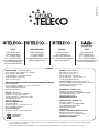
SPA
ITALY
Via E. Majorana 49
48022 LUGO ( RA )
Tel. + 39 0545 25037
Fax. + 39 0545 32064
mail: [email protected]
www.telecogroup.com
Assistenza 899 899 856
DEUTSCHLAND
82041 Deisenhofen
Tel. 08031 98939
Fax 08031 98949
www.telecogroup.com
FRANCE
3, Impasse des Iles
ZA La Maladière
07300 St Jean de Muzols
mail: [email protected]
www.telecogroup.fr
ITALY
Via E. Majorana 49
48022 LUGO ( RA )
Tel. + 39 0545 25037
Fax. + 39 0545 32064
mail: [email protected]
www.telecogroup.com
GmbH
sas
srl
04_06_2016
-
 1
1
-
 2
2
-
 3
3
-
 4
4
-
 5
5
-
 6
6
-
 7
7
-
 8
8
-
 9
9
-
 10
10
-
 11
11
-
 12
12
-
 13
13
-
 14
14
-
 15
15
-
 16
16
-
 17
17
-
 18
18
-
 19
19
-
 20
20
-
 21
21
-
 22
22
-
 23
23
-
 24
24
-
 25
25
-
 26
26
-
 27
27
-
 28
28
-
 29
29
-
 30
30
-
 31
31
-
 32
32
-
 33
33
-
 34
34
-
 35
35
-
 36
36


Teleco TSP 130W pannello solare Handleiding
- Type
- Handleiding
in andere talen
Gerelateerde papieren
Andere documenten
-
STEINEL NEO2 de handleiding
-
-
-
KS VERLICHTING 7411 Handleiding
-
Beurer HL 40 harsapparaat de handleiding
-
BioLite SolarHome 620 Handleiding
-
STEINEL XSolar L-S Handleiding
-
TFA Digital Garden Thermometer with Solar Powered Display Lighting AVENUE Handleiding
-
TFA Digital Window Thermometer with Solar Light VISION SOLAR de handleiding
-
Juwel 20150 Assembly Instruction