
EN
CL/QL series V4.1 Supplementary Manual
This supplementary manual explains mainly the functions that have been added or changed in CL5/CL3/CL1 and QL5/
QL1 firmware V4.1.
Use it in conjunction with the CL5/CL3/CL1 and QL5/QL1 V4 Owner’s Manual and Reference Manual.
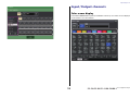
CL/QL Editor V4.1 Supplementary Manual
This supplementary manual explains mainly the functions that have been added or changed in CL/QL Editor V4.1.
NOTE
• The explanations in this supplementary manual will use the CL5.
• In the case of the CL3/CL1 or QL5/QL1, some screens will not show channels and faders that do not exist on those models.

Contents
V4.1 Supplementary Manual
2
Contents
Support for Shure AXT400, QLXD4 and ULXD4........................ 3
Selected Channel section (QL series only) .............................. 11
4-band EQ band selection...................................................................................... 11
Input and output patching..................................................... 12
Added functions to display channel name and effect type in the PATCH/NAME
window, CH SELECT window, and PORT SELECT window........................... 12
Input/Output channels........................................................... 13
Color name display................................................................................................ 13
EQ and Dynamics .................................................................... 14
Simultaneously setting EQ type.............................................................................. 14
HPF/EQ window (1ch) ........................................................................................... 15
Meters ..................................................................................... 16
Added functions in the RTA display window (RTA METER window,
HPF/EQ window, GEQ window, 8BandPEQ window) .................................. 16
I/O devices and external head amps ...................................... 17
Support for the AES67 standard for audio networking interoperability ................... 17
I/O DEVICE window (I/O page).............................................................................. 18
Setup ....................................................................................... 18
Added supported devices ...................................................................................... 18
Dante Device Lock................................................................................................. 20
Added functions in the NETWORK window............................................................ 21
Alert message display............................................................................................. 22
CL/QL Editor V4.1 Supplementary Manual............................. 23
Reading and Writing CSV files ............................................... 23
Added option for writing CSV files ......................................................................... 23
Added specifications for the CSV file read function ................................................ 23
Support for devices that do not feature Dante output ......... 26

Support for Shure AXT400, QLXD4 and ULXD4
V4.1 Supplementary Manual
3
Support for Shure AXT400, QLXD4 and
ULXD4
In addition to support for the Shure ULXD4D and ULXD4Q digital wireless systems with CL/
QL V4.0 and later, the Shure AXT400, QLXD4, and ULXD4 wireless systems, which do not
feature Dante output, can now be controlled. These Shure devices can be connected to the
same physical network as Dante, mounted, and controlled.
However, the actual audio signals are physically connected to an R series I/O rack mounted
on the CL/QL console or to OMNI IN. By associating the port where audio is input with the
mounted Shure device, control and monitoring are possible from the input channel that is
patched to the input port. For details about the explanation of how to control the Shure
wireless systems, which do not feature Dante output, refer to
B “PORT ASSIGN tabs” on “I/
O DEVICE EDIT window”.
Settings before use
Update the firmware for Shure devices to a version that supports this function.
Please refer to the Yamaha Pro Audio website for details on supported versions.
http://www.yamahaproaudio.com/global/en/
Configure the network settings for each device.
Shure devices: Configure the network settings using the Shure “Wireless Workbench 6”
software or in the menu on each device. For details, refer to the manual of your Shure device.
CL/QL: In the SETUP window, press the NETWORK button to open a popup window, and
configure the settings on the FOR DEVICE CONTROL tab.
If you are not using a DHCP server, set both the Shure device and the CL/QL console to
“A U T O . ”
If you are using a DHCP server, set the Shure device to “AUTO” and the CL/QL console to
“DHCP.”
If you are using a fixed IP address, set the CL/QL console to STATIC IP. In this case, set the
IP address for the Shure device and the IP address in “FOR DEVICE CONTROL” for the CL/
QL console to the same subnet.
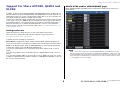
DANTE SETUP window (DEVICE MOUNT page)
Shure AXT400, QLXD4, and ULXD4 can be mounted in this window in the same way as
Dante devices.
NOTE
CL/QL consoles can recognize up to 24 Shure AXT400, QLXD4, and ULXD4 devices on the
same Dante audio network, including Shure ULXD4D and ULXD4Q Dante output devices that
are set to YAMAHA ID mode. Note that if a greater number of devices is connected, some of the
devices will not be recognized by the console based on the order in which their power is turned
on, etc, regardless of the mount setting.

Support for Shure AXT400, QLXD4 and ULXD4
V4.1 Supplementary Manual
4
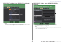
DEVICE SELECT window (when DEVICE LIST is displayed)
NOTE
If a device has the DEVICE IDENTIFY function, the DEVICE IDENTIFY button is enabled.
Otherwise, this button will be grayed out and cannot be pressed.
DEVICE SELECT window (when SUPPORTED DEVICE is
displayed)
1 I/O device indication (for devices that do not feature Dante output)
“NO DANTE PORT” appears on the right side.
NOTE
If a device does not feature Dante output, offline mounting is not possible. Mount it when online
(make sure the DEVICE LIST button is on).
1

Support for Shure AXT400, QLXD4 and ULXD4
V4.1 Supplementary Manual
5
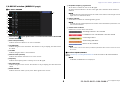
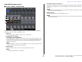
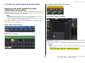
I/O DEVICE window (WIRELESS page)
For Shure AXT400
1
This indicator lights up when there is a connection with a Shure’s ShowLink®
remote control.
2 Device ID (transmitter)
Indicates the device ID that is set on the transmitter.
3 TX.GAIN knob
Indicates the gain for the transmitter. This window is only for display; the value cannot
be edited.
4 TX.GAIN
Indicates the gain value for the transmitter.
5 Channel name (receiver)
Indicates the channel name that is set on the receiver.
6 Frequency
Indicates the frequency that is currently set for the RF signal.
7 RX.LEVEL knob
Indicates the gain for the receiver. This window is only for display; the value cannot be
edited.
8 MUTE indicator
Indicates the mute status (on/off) of the audio signal for the receiver.
9 RF (Radio Frequency) signal meter
Shows bars to indicate the level of the RF signal.
An active antenna indicator is shown on the right side. It indicates which antenna is
enabled.
NOTE
For details about the relationship between the number of bars and the actual strength of the RF
signal, refer to the manual from Shure.
0 Battery indicator
Shows bars to indicate the remaining battery power.
NOTE
For details about the relationship between the number of bars and maximum operation time, refer
to the manual from Shure.
A Control status indicator
Indicates the control status of the device.
NOTE
When control on the receiver side is possible, the parameter values for the receiver are sent to
the console.
For Shure QLXD4/ULXD4
Refer to “Remotely controlling WIRELESS unit” in the CL series or QL series Reference
Manual.
NOTE
For QLXD4, the MUTE button is not displayed.
A
1
2
3
4
5
6
7
8
9
0
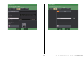
Searching for device to be controlled
Found device to be controlled, but connection refused
Connecting to device
Synchronizing with device
Device can be controlled

Support for Shure AXT400, QLXD4 and ULXD4
V4.1 Supplementary Manual
6
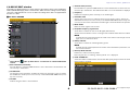
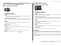
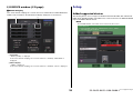
I/O DEVICE EDIT window
This window is displayed when you select and press the wireless device in the I/O DEVICE
window (WIRELESS page). Set the channel name, GAIN, and other settings. These settings
cannot be configured when the console is offline. The settings in the device are applied when
the device is online.
For Shure AXT400
1
This indicator lights up when there is a connection via a ShowLink® remote
control.
2 Device ID button (transmitter)
Press this button to open the NAME window to set the device ID for the transmitter. You
can enter up to 8 characters.
3 TX.GAIN knob
Sets the gain for the transmitter. To adjust the value, press the knob to select it, and use
the multifunction knobs (for CL series consoles) or the TOUCH AND TURN knob (for CL/
QL series consoles).
4 TX.GAIN
Indicates the gain value for the transmitter.
5 Channel name (receiver)
Press this button to open the NAME window to set the channel name for the receiver. You
can enter up to 8 characters. The channel name that is set on the transmitter is displayed.
6 Frequency
Indicates the frequency that is currently set for the RF signal.
7 RX.LEVEL knob
Sets the gain for the receiver. To adjust the value, press the knob to select it, and use the
multifunction knobs (for CL series consoles) or the TOUCH AND TURN knob (for CL/QL series
consoles). The level meter located at the immediate right of the knob indicates the input level.
8 MUTE button
Mutes the audio signal for the receiver.
9 RF (Radio Frequency) signal meter
Shows bars to indicate the level of the RF signal (A/B channel).
An active antenna indicator is shown on the right side. It indicates which antenna is enabled.
NOTE
For details about the relationship between the number of bars and the actual strength of the RF
signal, refer to the manual from Shure.
0 Battery indicator
Shows bars to indicate the remaining battery power.
NOTE
For details about the relationship between the number of bars and maximum operation time, refer
to the manual from Shure.
A Diversity Mode indicator
Indicates the status for Diversity Mode.
If Diversity Mode is not running, “Diversity Mode: off” is displayed.
B PORT ASSIGN tabs
Select these tabs to switch between the windows that specify the ports where the actual
input signals are assigned.
A
1
2
3
4
5
6
7
8
9
0
B

Support for Shure AXT400, QLXD4 and ULXD4
V4.1 Supplementary Manual
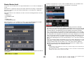
7
This section explains how to control Shure wireless mics that do not output Dante
signals.
Example: Connecting the output of an AXT400 to OMNI 1 on a CL console, and
assigning the signal to input channel 1.
Press the PORT ASSIGN button to open the PORT SELECT window.
Select the port to which the output from the AXT400 is connected (OMNI 1).
Access the GAIN/PATCH window.
Press the INPUT PORT button, and on the PORT SELECT window select the port to which
the output signal from the AXT400 is connected (OMNI 1).

Support for Shure AXT400, QLXD4 and ULXD4
V4.1 Supplementary Manual
8
This assigns the output signal from the AXT400 to the input channel, and at the same
time allows you to control and monitor the level of the AXT400 from the input channel.
For Shure QLXD4/ULXD4
Refer to “Remotely controlling WIRELESS unit” in the CL series or QL series Reference
Manual.
For QLXD4, the PORT ASSIGN tabs have been added. The MUTE button is not displayed.
For ULXD4, the PORT ASSIGN tabs have been added.
GAIN/PATCH window (1ch)
For Shure AXT400 / QLXD4/ULXD4
1
Frequency
Indicates the frequency that is currently set for the RF signal.
2 TX.GAIN knob
Sets the gain for the transmitter. To adjust the value, press the knob to select it, and use
the multifunction knobs (for CL series consoles) or the TOUCH AND TURN knob (for CL/
QL series consoles).
NOTE
• When the AXT400 is connected via a ShowLink® remote control, a gray circle is displayed here
instead of a knob, and the gain cannot be adjusted.
• For QLXD4/ULXD4, a gray circle is displayed instead of the knob, and you cannot adjust the gain.
3 RX.LEVEL knob (for AXT40)
RX.GAIN knob (for QLXD4/ULXD4)
Sets the gain for the receiver. To adjust the value, press the knob to select it, and use the
multifunction knobs (for CL series consoles) or the TOUCH AND TURN knob (for CL/QL
series consoles). The level meter located at the immediate right of the knob indicates
the input level.
4 MUTE indicator
Indicates the mute status (on/off) of the audio signal for the receiver.
NOTE
For QLXD4, the MUTE button is not displayed.
5 RF (Radio Frequency) signal meter
Shows bars to indicate the level of the RF signal (both A and B channels for AXT400).
An active antenna indicator is shown on the right side. It indicates which antenna is
enabled.
NOTE
For details about the relationship between the number of bars and the actual strength of the RF
signal, refer to the manual from Shure.
6 Battery indicator
Shows bars to indicate the remaining battery power.
NOTE
For details about the relationship between the number of bars and maximum operation time, refer
to the manual from Shure.
1 2 3 4 5 6

Support for Shure AXT400, QLXD4 and ULXD4
V4.1 Supplementary Manual
9
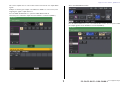
GAIN/PATCH window (8ch)
For Shure AXT400 / QLXD4/ULXD4
If there is a control connection for AXT400 on CH 1-2, a control connection for QLXD4 on
CH3, and a control connection for ULXD4 on CH4.
1 Frequency
Indicates the frequency that is currently set for the RF signal.
2 TX.GAIN knob (for AXT400)
RX.GAIN knob (for QLXD4/ULXD4)
Sets each gain for the transmitter. To adjust the value, press the knob to select it, and
use the multifunction knobs (for CL series consoles) or the TOUCH AND TURN knob (for
CL/QL series consoles). The level meter located at the immediate right of the knob
indicates the input level.
NOTE
When the AXT400 is connected via a ShowLink® remote control, a gray circle is displayed here
instead of a knob, and the gain cannot be adjusted.
3 MUTE indicator
Indicates the mute status (on/off) of the audio signal for the receiver.
NOTE
For QLXD4, the MUTE button is not displayed.
4 RF (Radio Frequency) signal meter
Shows bars to indicate the level of the RF signal (both A and B channels for AXT400).
An active antenna indicator is shown on the right side. It indicates which antenna is
enabled.
NOTE
For details about the relationship between the number of bars and the actual strength of the RF
signal, refer to the manual from Shure.
5 Battery indicator
Shows bars to indicate the remaining battery power.
NOTE
For details about the relationship between the number of bars and maximum operation time, refer
to the manual from Shure.
1
2
3
4
5

Support for Shure AXT400, QLXD4 and ULXD4
V4.1 Supplementary Manual
10
GAIN/PATCH window (1-48, 49-72/ST IN (CL5), 49-64/ST IN
(CL3), ST IN (CL1)) and OVERVIEW window
For Shure AXT400 / QLXD4/ULXD4
1
TX.GAIN knob (for AXT400)
RX.GAIN knob (for QLXD4/ULXD4)
NOTE
When the AXT400 is connected via a ShowLink® remote control, a gray circle is displayed here
instead of a knob, and the gain cannot be adjusted.
2 RF (Radio Frequency) signal meter
Shows bars to indicate the level of the RF signal (both A and B channels for AXT400).
An active antenna indicator is shown on the right side. It indicates which antenna is
enabled.
NOTE
For details about the relationship between the number of bars and the actual strength of the
signal, refer to the manual from Shure.
3 Battery indicator
Shows bars to indicate the remaining battery power.
NOTE
For details about the relationship between the number of bars and maximum operation time, refer
to the manual from Shure.
4 OL indicator
This will light if the audio signal level of the receiver reaches the overload point.
NOTE
If MUTE is on for the receiver, the MUTE indicator is displayed.
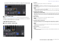
SELECTED CHANNEL window
For Shure AXT400 / QLXD4/ULXD4
1
TX.GAIN knob (for AXT400)
RX.GAIN knob (for QLXD4/ULXD4)
NOTE
When the AXT400 is connected via a ShowLink® remote control, a gray circle is displayed here
instead of a knob, and the gain cannot be adjusted.
2 RF (Radio Frequency) signal meter
Shows bars to indicate the level of the RF signal (both A and B channels for AXT400).
An active antenna indicator is shown on the right side. It indicates which antenna is
enabled.
NOTE
For details about the relationship between the number of bars and the actual strength of the
signal, refer to the manual from Shure.
3 Battery indicator
Shows bars to indicate the remaining battery power.
NOTE
For details about the relationship between the number of bars and maximum operation time, refer
to the manual from Shure.
4 MUTE indicator
Indicates the mute status (on/off) of the audio signal for the receiver.
Precautions
• If the target device is unmounted, the parameters on the console return to their default
values. If a new device is mounted and patched, that device's parameters are applied to the
console.
• All port assignments for a rack are defeated only if the status of the rack is NO ASSIGN.
• Regarding the control of Shure devices, control parameters are not stored in scenes and
saved in console files.
1
2
3
4
1
32
4

Selected Channel section (QL series only)
V4.1 Supplementary Manual
11
Selected Channel section (QL series only)
4-band EQ band selection
Selections of the EQ [LOW] key/EQ [LOW-MID] key/EQ [HIGH-MID] key/EQ [HIGH] key on
the top panel and band selections on the touch screen are now linked.

Input and output patching
V4.1 Supplementary Manual
12
Input and output patching
Added functions to display channel name and
effect type in the PATCH/NAME window, CH
SELECT window, and PORT SELECT window.
The channel name and effect type are now displayed below the channel select buttons and
port select buttons in the PATCH/NAME window, CH SELECT window, and PORT SELECT
window.
NOTE
In categories other than DANTE IN, channel labels cannot be set in Dante Controller for the
following buttons, and therefore they are not displayed.
• MONITOR button
• CUE button
• SURROUND MONITOR button
•SLOT button
• SEL CH button
• SEND MASTER button
•OMNI button
• INPUT button(QL only)

Input/Output channels
V4.1 Supplementary Manual
13
Input/Output channels
Color name display
In the PATCH/NAME window (when the ICON tab is selected), color names are now displayed
on the channel color select buttons.

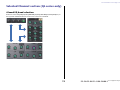
EQ and Dynamics
V4.1 Supplementary Manual
14
EQ and Dynamics
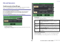
Simultaneously setting EQ type
You can now set the EQ type simultaneously for all channels or all racks in the HPF/EQ
window or the PEQ EDIT window. You can select channels by category.
1 GLOBAL SETUP button
Press this button to open the GLOBAL EQ TYPE popup window, where you can set the
EQ type and channel category.
2 EQ type buttons
Set the EQ type to PRECISE, AGGRESSIVE, SMOOTH, or LEGACY.
The following EQ types can be selected.
3 GLOBAL DESTINATIONS buttons
Set for each category the channels that you set for the selected EQ type. Multiple
selections are possible.
If you select 8BandPEQ, the selected EQ type will be set as the default setting.
STEP
1. Press the EQ type select button in the window.
2. Press the GLOBAL SETUP button on the top right side of the popup window.
3. Select an EQ type and channel category in the GLOBAL EQ TYPE window.
4. Press the APPLY button.
5. When the CONFIRMATION dialog box opens, press the OK button.
1
PRECISE
This EQ type features “precision” and “controllability.”
It can be used to precisely adjust the desired points, to flexibly respond to a
variety of music production needs.
The Low/High shelving filters have “Q” parameters that allow knee
adjustments.
AGGRESSIVE
This EQ type features “effective musical” characteristics.
It allows you to create an aggressive tone, making it a very powerful tool for
artistic expression.
SMOOTH
This EQ type focuses on a “smooth sound quality.”
It allows you to create natural sounds without significant modifications to the
atmosphere of the original sound.
LEGACY
This is the standard EQ type found in classic Yamaha digital mixers, such
as the PM1D and the PM5D.
Use the buttons to switch between TYPE I (an algorithm used in previous
Yamaha digital mixers) and TYPE II (an algorithm that reduces interference
between bands).
2
3

EQ and Dynamics
V4.1 Supplementary Manual
15
HPF/EQ window (1ch)
When the EQ type is set to PRECISE, you can press in and turn the Q knob for the HIGH
band to switch between PEQ, shelving type, and low-pass filter.
In addition, you can press in and turn the Q knob for the LOW band to switch between PEQ
and high-pass filter.
NOTE
• This operation is possible only with the EQ Q knobs in the SELECTED CHANNEL section on the
console
’s top panel.
• For CL series consoles, this operation is not possible with the multifunction knobs in the
Centralogic section. It is also not possible with USER DEFINED knobs that have been assigned
to the TOUCH AND TURN function.
• For QL series consoles, this operation is not possible with the TOUCH AND TURN knob in the
SELECTED CHANNEL section.
HIGH band
• When set to PEQ (Q=0.10), press in and turn the Q knob to the right to switch to shelving
type.
• When set to PEQ (Q=16.0), press in and turn the Q knob to the left to switch to low-pass
filter.
• When set to shelving type (Q=10.0), press in and turn the Q knob to the left to switch to
PEQ.
• When set to low-pass filter, press in and turn the Q knob to the right to switch to PEQ.
LOW band
• When set to PEQ (Q=0.10), press in and turn the Q knob to the right to switch to shelving
type.
• When set to shelving type (Q=10.0), press in and turn the Q knob to the left to switch to
PEQ.

Meters
V4.1 Supplementary Manual
16
Meters
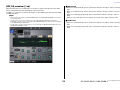
Added functions in the RTA display window (RTA
METER window, HPF/EQ window, GEQ window,
8BandPEQ window)
The visibility of frequency analysis displays has been improved with the addition of a scale
change and offset gain, and the addition of PEAK HOLD.
1 Offset gain (RTA METER window, HPF/EQ window, GEQ window, 8BandPEQ
window)
If a frequency is at a low level, its analysis results might not appear clearly in a graph.
The addition of offset gain allows better visibility in graphs for such results. You can
adjust this gain from 0dB to +30dB.
NOTE
The value for this parameter is applied identically to the RTA METER window, HPF/EQ window,
GEQ window, and 8BandPEQ window.
2 Scale change (RTA METER window)
The RTA scale has been changed to display regular intervals in dB.
3 PEAK HOLD button (RTA METER window)
Turn on this button to hold the peak level indication on graphs of frequency analysis.
Turn off this button to clear the peak hold indication.
NOTE
The settings for the PEAD HOLD button, RTA button, and offset gain are stored even when the
console is turned off.
2
3
1
1
1
1

I/O devices and external head amps
V4.1 Supplementary Manual
17
I/O devices and external head amps
Support for the AES67 standard for audio
networking interoperability
The AES67 standard for interoperability through the use of audio-over-IP technology is now
supported. This allows the CL/QL console and R series to establish an audio connection with
audio networks that support AES67, such as “Ravenna.”
NOTE
• The Audinate “Dante Controller” software is required to use the CL/QL console and R series in
AES67 mode. Routing via AES67 is possible only by using Dante Controller.
• Channels with patches that use AES67 offline will synchronize with the patch settings that are
saved on the target device when connected with the device.
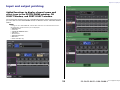
When a patch establishes an audio connection via AES67, “AES67” is displayed on the port
selection buttons, etc. as shown below.
DANTE INPUT PATCH window
PORT SELECT window
I/O DEVICE [OUTPUT PATCH] window
I/O DEVICE window (I/O page)
When the CL/QL console is in AES67 mode, the settings for the following parameters cannot
be changed on the console.
• Master clock select buttons in the MASTER CLOCK SELECT field of the WORD CLOCK/
SLOT window
NOTE
If you try to change any of the above settings, the following message will appear at the bottom of
the LCD screen.

Setup
V4.1 Supplementary Manual
18
I/O DEVICE window (I/O page)
RSio64-D display
If the card’s internal sampling rate converter function is enabled when an MY8-AE96S mini-
YGDAI card is inserted into the RSio64-D, the display will appear as shown below.
1 Card name
“AE96S (w/SRC)” is displayed.
If the card’s internal sampling rate converter function is disabled, “MY8-AE96S” is
displayed.
2 WCLK display
“CARD” is displayed.
If the card’s internal sampling rate converter function is disabled, “SLOT” is displayed.
Setup
Added supported devices
The following devices are now supported: Audinate Dante-MY16-AUD2; d&b audiotechnik
DS10; Shure AXT400, QLXD4, and ULXD4. They can be mounted on the DEVICE MOUNT
page in the DANTE SETUP window.
NOTE
ShureAXT400, QLXD4, and ULXD4 can be mounted only when online.
1 2

Setup
V4.1 Supplementary Manual
19

Setup
V4.1 Supplementary Manual
20
Dante Device Lock
The CL/QL console and R series now support Dante Device Lock. Its status is displayed on
CL/QL.
Dante Device Lock prevents changes to the Dante audio network settings of a Dante device
by another computer on the same network. Dante Device Lock settings are configured in
Dante Controller.
When Dante Device Lock is enabled on a CL/QL console, the following parameters cannot be
changed.
• CONSOLE ID
• SECONDARY PORT
•BIT
•LATENCY (ms)
• PREFERRED MASTER
When Dante Device Lock is enabled on a CL/QL console, the DANTE DEVICE LOCKED
indicator lights up in red on the top left side of the DANTE SETUP window.
If you try to change any of these parameters, the following message will appear at the bottom
of the window.
If a device connected to the console is online, and Dante Device Lock is enabled for that
device, the LOCKED indicator will appear in each window as shown below.
If Dante Device Lock is enabled for the console, the following specifications will apply.
• The master clock select buttons in the WORD CLOCK/SLOT window cannot be changed.
• None of the parameters in the DANTE INPUT PATCH window can be changed. RECALL
and AUTO SETUP in the DANTE INPUT PATCH LIBRARY window will be disabled.
• None of the parameters in the I/O DEVICE [OUTPUT PATCH] window can be changed.
• If a file is being loaded from USB memory to a device that has Dante Device Lock enabled,
the settings will not be changed by the loaded file. A message is displayed on the screen.
• If the console’s internal memory is initialized to the factory settings, Dante Device Lock will
remain enabled and cannot be changed. Locked parameters will also not be initialized.
Refer to the “Initializing the unit to factory default settings” on CL or QL series’s Reference
Manual.
• If the console’s Dante settings are initialized to the factory settings, Dante Device Lock will
be disabled. Locked parameters will also be initialized. Refer to the “Initializing the console
settings and Dante audio network settings” on CL or QL series’s Reference Manual.
• USB memory cannot be used to update the Dante module firmware. In addition, Dante
Firmware Update Manager will not update the firmware.
NOTE
• If Dante Device Lock is enabled for a remote device, all offline settings (such as Dante Patch) for
the device will be disabled.
• Even if Dante Device Lock is enabled for an I/O device, remote control that is unrelated to Dante
settings (such as HA control for R series) is possible.

Setup
V4.1 Supplementary Manual
21
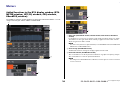
Added functions in the NETWORK window
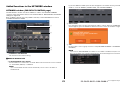
NETWORK window (FOR DEVICE CONTROL page)
Use this window to set the console’s IP address, in order to use the Dante PRIMARY
connector on the rear panel to remote-control external devices. DHCP, AUTO IP, and fixed IP
settings are supported.
Even on DHCP networks, it is now possible to remotely control external devices such as
Tio1608-D and Shure’s ULDX4.
1 CURRENT IP SETTING field
This field shows the current setting.
NEXT IP SETTING field
2
IP SETTING MODE select buttons
Use these buttons to select how to set the IP address the next time the console is turned
on. Select DHCP, AUTO IP, or STATIC IP.
NOTE
If you select AUTO IP, the Dante network automatically sets the console’s IP address to
169.254.xxx.xxx.
If you select DHCP or AUTO IP, the window will appear as shown below and you will be
unable to set the IP ADDRESS, SUBNET MASK, and GATE WAY ADDRESS.
3 APPLY button
Press this button after you have changed the IP address settings. When the ATTENTION
window appears, press the OK button and then turn the console off and back on again.
4 Tabs
Use these tabs to select a group of items to view (FOR MIXER CONTROL or FOR DEVICE
CONTROL).
NOTE
If you use the IP SETTING MODE select buttons to select DHCP or AUTO IP, it may take some
time for the IP address to be configured. During this time, the window will appear as shown below.
2
4
3
1

Setup
V4.1 Supplementary Manual
22
NETWORK window (FOR MIXER CONTROL page)
Use this window to set the console’s IP address, in order to use the NETWORK connector on
the rear panel to remote-control the console from CL Editor/QL Editor, StageMix, or the
MonitorMix application.
Set the UNIT Name and PIN for the MonitorMix application here.
For the IP SETTING MODE select buttons, only STATIC IP button is enabled. The other
buttons cannot be selected.
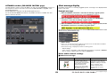
Alert message display
If the Dante network is not connecting at gigabit speeds, a message is now displayed at the
bottom of the LCD.
Example message:
1 When the PRIMARY connection is active but not working at gigabit speeds:
*) However, this message will take priority over the SECONDARY connection.
2 When the PRIMARY connection is not active, and when the SECONDARY
connection is active but not working at gigabit speeds:
3 When the PRIMARY connection is active and working at gigabit speeds, but the
SECONDARY connection is not working at gigabit speeds:
Set whether to turn the alert messages on or off in the ERROR MESSAGE field in the USER
SETUP window (PREFERENCE page).
1 DANTE ALERT
If this is on, an alert message will appear at the bottom of the LCD when the Dante
network is not connecting at gigabit speeds.
If this alert message is displayed, check the following items:
• Switch settings
• Is the console connected to a switch that does not function at a speed of 1000Mbps?
• Are you using a cable that does not support 1000BASE-T?
Dante audio network settings
Added error messages
[SYSTEM] indicators Meaning Possible solution
You changed the positions of
the device setting DIP switches
or rotary switch, or changed the
Dante settings from Dante
Controller. Therefore, the
positions of the device setting
DIP switches do not match the
actual Dante settings.
If the Device Lock setting was
enabled from Dante Controller,
disable the setting, or check the
device setting DIP switch
positions, and set them to
accommodate the current
situation.
1
Lit
Lit

CL/QL Editor V4.1 Supplementary Manual
V4.1 Supplementary Manual
23
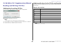
CL/QL Editor V4.1 Supplementary Manual
Reading and Writing CSV files
Added option for writing CSV files
You can now set an output format before selecting a folder for writing CSV files.
Short format: CL/QL Editor V4.0.0 and V4.0.1 file format
Normal format: CL/QL Editor V4.1 file format
NOTE
In V4.1, CSV files can be read in both Short format and Normal format.
If you select the [Export Comments of Detailed Form] check box, data that is not omitted from
the comment line (line 3) is added and output to the CSV file.
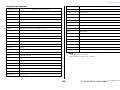
Added specifications for the CSV file read function
The number of synonyms and abbreviations that can be used when creating a CSV file have
been increased.
Channel color notation
NOTE
This notation is not case sensitive.
Original notation Notation when reading a CSV file
Blue BL, B
Orange OR, O
Yellow YE, YL, Y
Purple PU, P
Cyan SkyBlue, CY, C
Magenta Pink, PK, M, MG
Red Brown, RD, BN, R
Green GN, G
Off Black, BK, (Treated as Off if there is no notation.)

Reading and Writing CSV files
V4.1 Supplementary Manual
24
Channel icon notation
NOTE
• This notation is not case sensitive.
• Spaces within the notation are not recognized.
Original notation Notation when reading a CSV file
Kick BassDrum, B.Dr, BD, B.D
Snare Sn, S.Dr, Botm, Botom
Hi-Hat HiHat, HH
Tom RackTom, F.Tom, Ftom, LTom, HTom
Drumkit Drum, Kit, Drums, Top, TopL, TopR, O.HEAD, O.H
Perc. Percussion, Per, Cong, conga, Bong, Bongo
A.Bass AcousticBass, Bass, C.Bass, CB, C.B, AB, A.B, Vc
Strings String, Str, Vl, Vn, Vla
E.Bass ElectricBass, E.B, EB
A.Guitar A.Gt, AcousticGuitar, AcousticGt, A.G, AG
E.Guitar E.Gt, ElectricGuitar, ElectricGt, E.G, EG
BassAmp B.Amp, B.A
GuitarAmp GtAmp, G.Amp, G.A
Trumpet TP, Trp
Trombone Tb, Trb
Saxophone Sax, SSax, ASax, TSax, BSax
Piano Pf, AP, PfL, PfR, PfH
Organ Org, Leslie
Keyboard KB, Key, KeyL, KeyR, EP, E.Pf, Syn, EPL, EPR, SynL, SynR
Male
Female
Choir Chorus, Cho, Chor
Dynamic DynamicMic
Condenser CondenserMic
Wireless WirelessMic, W/L, W.L
Podium Speech, Lecture
Wedge Foot, Flor, Floor
2way
In-Ear InEar, IEM, Ear
Effector Fx, Eff, Effect
Media1 CD, MD, DISC
Media2 PB
Video VTR, DVD, Blu
Mixer Mix
PC DAW
Processor DME, DSP, DLY, DELAY, REV, Reverb
Audience Aud
Star1
Star2
Blank (Treated as Blank if there is no notation.)
Original notation Notation when reading a CSV file

Reading and Writing CSV files
V4.1 Supplementary Manual
25
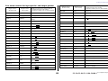
Port name notation for input patches and output patches
Original notation
(Normal format)
Original notation
(Short format)
Additional notation when reading a CSV file
* Underlined words can be omitted.
* [n] indicates a number (such as a channel number).
NONE NONE None
DANTE [n] DNT [n] Dante [n]
OMNI [n] OMNI [n]
Omni [n]
AD [n]
INPUT [n] INPUT [n] Input [n]
PB L PBL Playback Output
Left
PB R PBR Playback Output
Right
SLOT1 [n] SL1 [n] Slot1 [n]
SLOT2 [n] SL2 [n] Slot2 [n]
SLOT3 [n] SL3 [n] Slot3 [n]
FX [n] A FX[n]A Effect Rack
[n] A
FX [n] B FX[n]B Effect Rack
[n] B
PRFX [n] A PR[n]A Premium Rack
[n] A
PRFX [n] B PR[n]B Premium Rack
[n] B
GEQ [n] A GEQ[n]A GEQ Rack
[n] A
GEQ [n] B GEQ[n]B GEQ Rack
[n] B
MIX [n] MX [n] Mix Channel
[n]
MATRIX [n] MT [n] Matrix Channel
[n]
STEREO L STL
Stereo Output
Left
Main L
STEREO R STR
Stereo Output
Right
Main R
MONO (C) MONO Mono (C)
STEREO L+C STLC Stereo Output
L+C
STEREO R+C STRC Stereo Output
R+C
MONITOR L MON L Monitor Left
MONITOR R MON R Monitor Right
MONITOR C MON C Monitor Center
CUE L CUE L
Cue A
Cue Left
CUE R CUE R Cue Right
CUE B L CUE BL Cue B Left
CUE B R CUE BR Cue B Right
INS CH [n] IC [n] Insert1
Input Channel [n]
INS MIX [n] IM [n] Insert1
Mix Channel [n]
INS MATRIX [n] IMT [n] Insert1
Matrix Channel [n]
INS STEREO L ISTL Insert1
Stereo Output Left
INS STEREO R ISTR Insert1
Stereo Output Right
INS MONO (C) IMONO Insert1
Mono (C)
DIR CH [n] DI [n] Direct Input
Channel
CAS MIX [n] CMX [n] Cascade Mix [n]
CAS MARIX [n] CMT [n] Cascade Matrix [n]
CAS STEREO L CSTL Cascade Stereo Left
CAS STEREO R CSTR Cascade Stereo Right
CAS MONO (C) CMONO Cascade Mono (C)
CAS CUE L CCUE L Cascade Cue Left
CAS CUE R CCUE R Cascade Cue Right
CAS CUE B L CCUE BL Cascade Cue B Left
CAS CUE B R CCUE BR Cascade Cue B Right
Original notation
(Normal format)
Original notation
(Short format)
Additional notation when reading a CSV file
* Underlined words can be omitted.
* [n] indicates a number (such as a channel number).

Support for devices that do not feature Dante output
V4.1 Supplementary Manual
26
NOTE
• This notation is not case sensitive.
• This notation is recognized even if spaces are added between each word, or if the word order is
changed. However, the notation will not be recognized if a space is added in the middle of a word.
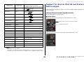
Support for devices that do not feature
Dante output
Devices that do not feature Dante output, such as Shure AXT400, QLXD4, and ULXD4, can
now be controlled.
Selected Channel window (input channels)
The HA display appears as shown below.
AXT400 display
When the receiver is on and connected via a ShowLink® remote control
When the receiver is on and not connected via a ShowLink® remote control
INS2 CH [n] IC2 [n]
Insert2 Input
Channel [n]
Ins2 Input
Channel [n]
INS2 MIX [n] IM2 [n]
Insert2 Mix Channel
[n]
Ins2 Mix Channel
[n]
INS2 MATRIX [n] IMT2 [n]
Insert2 Matrix Channel
[n]
Ins2 Matrix Channel
[n]
INS2 STEREO L ISTL2
Insert2 Stereo Output
Left
Ins2 Stereo Output
Left
INS2 STEREO R ISTR2
Insert2 Stereo Output
Right
Ins2 Stereo Output
Right
INS2 MONO (C) ISTMONO2 Insert2 Mono (C)
SUR MONITOR L SMON L Surround Monitor Left
SUR MONITOR R SMON R Surround Monitor Right
SUR MONITOR C SMON C Surround Monitor Center
SUR MONITOR LFE SMON LFE Surround Monitor LFE
SUR MONITOR LS SMON LS Surround Monitor Ls
SUR MONITOR RS SMON RS Surround Monitor Rs
MONITOR MATRIX L MMT L Monitor Matrix Left
MONITOR MATRIX R MMT R Monitor Matrix Right
MONITOR MATRIX C MMT C Monitor Matrix Center
MONITOR MATRIX LFE MMT LFE Monitor Matrix LFE
MONITOR MATRIX LS MMT LS Monitor Matrix Ls
MONITOR MATRIX RS MMT RS Monitor Matrix Rs
Original notation
(Normal format)
Original notation
(Short format)
Additional notation when reading a CSV file
* Underlined words can be omitted.
* [n] indicates a number (such as a channel number).
The RF level is shown for two channels (A and B).
“TX.GAIN” is displayed.

Support for devices that do not feature Dante output
V4.1 Supplementary Manual
27
When the receiver is off
QLXD4 and ULXD4 display
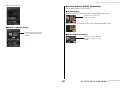
Overview window (INPUT CH window)
The HA display appears as shown below.
AXT400 display
When the receiver is on and connected via a ShowLink® remote control
When the receiver is on and not connected via a ShowLink® remote control
QLXD4 and ULXD4 display
The RF channel (A or B) display
has the same design as for the
AXT400.
The RF level is shown for two
channels (A and B).
The RF channel (A or B) display
has the same design as for the
AXT400.

© 2016 Yamaha Corporation
Published 12/2016 MA-A0
Manual Development Group
Yamaha Downloads
http://download.yamaha.com/
Yamaha Pro Audio global website
http://www.yamahaproaudio.com/
-
 1
1
-
 2
2
-
 3
3
-
 4
4
-
 5
5
-
 6
6
-
 7
7
-
 8
8
-
 9
9
-
 10
10
-
 11
11
-
 12
12
-
 13
13
-
 14
14
-
 15
15
-
 16
16
-
 17
17
-
 18
18
-
 19
19
-
 20
20
-
 21
21
-
 22
22
-
 23
23
-
 24
24
-
 25
25
-
 26
26
-
 27
27
-
 28
28


in andere talen
- English: Yamaha v4 User manual
- italiano: Yamaha v4 Manuale utente
- русский: Yamaha v4 Руководство пользователя
- français: Yamaha v4 Manuel utilisateur
- español: Yamaha v4 Manual de usuario
- Deutsch: Yamaha v4 Benutzerhandbuch
- português: Yamaha v4 Manual do usuário
- dansk: Yamaha v4 Brugermanual
- suomi: Yamaha v4 Ohjekirja
- čeština: Yamaha v4 Uživatelský manuál
- svenska: Yamaha v4 Användarmanual
- Türkçe: Yamaha v4 Kullanım kılavuzu
- polski: Yamaha v4 Instrukcja obsługi
- română: Yamaha v4 Manual de utilizare