Pioneer FH-X700BT de handleiding
- Categorie
- Microfoons
- Type
- de handleiding
Deze handleiding is ook geschikt voor

Installation Manual
Manuel d’installation
Manuale d’installazione
Manual de instalación
Installationsanleitung
Installatiehandleiding
Руководство по установке
CD RDS RECEIVER
AUTORADIO CD RDS
SINTOLETTORE CD RDS
REPRODUCTOR DE CD CON RECEPTOR RDS
CD RDS-EMPFÄNGER
CD RDS-ONTVANGER
CD RDS ПРИЕМНИК
FH-X700BT
English NederlandsDeutschEspañolItalianoFrançais Русский

Important
! Check all connections and systems before
final installation.
! Do not use unauthorized parts as this may
cause malfunctions.
! Consult your dealer if installation requires
drilling of holes or other modifications to the
vehicle.
! Do not install this unit where:
— it may interfere with operation of the vehicle.
— it may cause injury to a passenger as a result
of a sudden stop.
! The semiconductor laser will be damaged if
it overheats. Install this unit away from hot
places such as near the heater outlet.
! Optimum performance is obtained when the
unit is installed at an angle of less than 60°.
60°
! When installing, to ensure proper heat dis-
persal when using this unit, make sure you
leave ample space behind the rear panel and
wrap any loose cables so they are not block-
ing the vents.
5cmcm
Leave ample
space
5 cm
5 cm
! Use commercially available parts when in-
stalling.
How to install
This unit can be installed properly using either
of the methods in the below list.
! Installation with the holder
! Installation using the screw holes on the side
of the unit
Before installing this unit
1 Remove the trim ring.
1
1 Trim ring
2 Insert the supplied extraction keys into
both sides of the unit until they click into
place.
3 Pull the unit out of the holder.
Remove the holder.
1
1 Holder
(factory-supplied part)
Installation with the holder
1 Install the holder into the dashboard.
After inserting the holder into the dashboard, se-
lect and bend the tabs appropriate to the thick-
ness of the dashboard material. (Install this unit
as firmly as possible using the top and bottom
tabs. To secure this unit, bend the tabs 90 de-
grees.)
1
2
1 Dashboard
2 Holder
(factory-supplied part)
2 Install this unit.
1
1 Dashboard
3 Attach the trim ring.
1
1 Trim ring
Removing the holder
The procedure is the same as that for Before in-
stalling this unit. For details, refer to Before in-
stalling this unit on this page.
Installation
2
Section
Installation
En
01

Installation using the screw
holes on the side of the unit
% Fastening the unit to the factory radio-
mounting bracket.
Position the unit so that its screw holes are
aligned with the screw holes of the bracket, and
tighten the screws at 3 locations on each side.
1
2
4
3
1 If the pawl gets in the way, bend it down.
2 Factory radio mounting bracket
3 Truss (5 mm × 8 mm) screws
4 Dashboard or console
Important
! When installing this unit in a vehicle without
an ACC (accessory) position on the ignition
switch, failure to connect the red cable to the
terminal that detects operation of the ignition
key may result in battery drain.
O
N
S
T
A
R
T
O
F
F
ACC position No ACC position
! Use of this unit in conditions other than the
following could result in fire or malfunction.
— Vehicles with a 12-volt battery and negative
grounding.
— Speakers with 50 W (output value) and 4 W to
8 W (impedance value).
! To prevent a short-circuit, overheating or mal-
function, be sure to follow the directions
below.
— Disconnect the negative terminal of the bat-
tery before installation.
— Secure the wiring with cable clamps or adhe-
sive tape. Wrap adhesive tape around wiring
that comes into contact with metal parts to
protect the wiring.
— Place all cables away from moving parts,
such as the shift lever and seat rails.
— Place all cables away from hot places, such
as near the heater outlet.
— Do not connect the yellow cable to the battery
by passing it through the hole to the engine
compartment.
— Cover any disconnected cable connectors
with insulating tape.
— Do not shorten any cables.
— Never cut the insulation of the power cable of
this unit in order to share the power with
other devices. The current capacity of the
cable is limited.
— Use a fuse of the rating prescribed.
— Never wire the negative speaker cable directly
to ground.
— Never band together negative cables of multi-
ple speakers.
! When this unit is on, control signals are sent
through the blue/white cable. Connect this
cable to the system remote control of an ex-
ternal power amp or the vehicle’s auto-anten-
na relay control terminal (max. 300 mA
12 V DC). If the vehicle is equipped with a
glass antenna, connect it to the antenna
booster power supply terminal.
! Never connect the blue/white cable to the
power terminal of an external power amp.
Also, never connect it to the power terminal
of the auto antenna. Doing so may result in
battery drain or a malfunction.
! The black cable is ground. Ground cables for
this unit and other equipment (especially,
high-current products such as power amps)
must be wired separately. If they are not, an
accidental detachment may result in a fire or
malfunction.
This unit
1
3
2
6 78
4
5
1 Power cord input
2 Microphone input
3 Microphone
4m
4 Rear output or subwoofer output
5 Front output
English
Installation
3
Section
Connections
En
01
02

6 Antenna input
7 Fuse (10 A)
8 Wired remote input
Hard-wired remote control adapter can be
connected (sold separately).
Power cord
1
3
3
2
4
4
5
5
6
6
b
8
9
7
a
d
c
1 To power cord input
2 Depending on the kind of vehicle, the func-
tion of 3 and 5 may be different. In this
case, be sure to connect 4 to 5 and 6 to
3.
3 Yellow
Back-up (or accessory)
4 Yellow
Connect to the constant 12 V supply termi-
nal.
5 Red
Accessory (or back-up)
6 Red
Connect to terminal controlled by ignition
switch (12 V DC).
7 Connect leads of the same color to each
other.
8 Black (chassis ground)
9 Blue/white
The pin position of the ISO connector will dif-
fer depending on the type of vehicle. Connect
9 and b when Pin 5 is an antenna control
type. In another type of vehicle, never con-
nect 9 and b.
a Blue/white
Connect to system control terminal of the
power amp (max. 300 mA 12 V DC).
b Blue/white
Connect to auto-antenna relay control termi-
nal (max. 300 mA 12 V DC).
c Speaker leads
White: Front left +
White/black: Front left *
Gray: Front right +
Gray/black: Front right *
Green: Rear left + or subwoofer +
Green/black: Rear left * or subwoofer *
Violet: Rear right + or subwoofer +
Violet/black: Rear right * or subwoofer *
d ISO connector
In some vehicles, the ISO connector may be
divided into two. In this case, be sure to con-
nect to both connectors.
Notes
! Change the initial setting of this unit (refer to
the operation manual). The subwoofer output
of this unit is monaural.
! When using a subwoofer of 70 W (2 W), be
sure to connect the subwoofer to the violet
and violet/black leads of this unit. Do not
connect anything to the green and green/
black leads.
Power amp (sold separately)
Perform these connections when using the op-
tional amplifier.
1
1
3
2
4
55
3
2
6
77
1 System remote control
Connect to Blue/white cable.
2 Power amp (sold separately)
3 Connect with RCA cables (sold separately)
4 To Front output
5 Front speaker
6 To Rear output or subwoofer output
7 Rear speaker or subwoofer
Connections
4
Section
Connections
En
02

CAUTION
It is extremely dangerous to allow the micro-
phone lead to become wound around the steer-
ing column or shift lever. Be sure to install the
unit in such a way that it will not obstruct driv-
ing.
Note
Install the microphone in a position and orienta-
tion that will enable it to pick up the voice of the
person operating the system.
When installing the
microphone on the sun visor
1 Install the microphone on the micro-
phone clip.
1
2
1 Microphone
2 Microphone clip
2 Install the microphone clip on the sun
visor.
With the sun visor up, install the microphone
clip. (Lowering the sun visor reduces the voice
recognition rate.)
1
2
1 Microphone clip
2 Clamp
Use separately sold clamps to secure the
lead where necessary inside the vehicle.
When installing the
microphone on the steering
column
1 Install the microphone on the micro-
phone clip.
2
4
3
1
1 Microphone
2 Microphone base
3 Microphone clip
4 Fit the microphone lead into the groove.
# Microphone can be installed without using mi-
crophone clip. In this case, detach the microphone
base from the microphone clip. To detach the micro-
phone base from the microphone clip, slide the mi-
crophone base.
2 Install the microphone clip on the steer-
ing column.
2
1
3
1 Double-sided tape
2 Install the microphone clip on the rear side of
the steering column.
3 Clamp
Use separately sold clamps to secure the
lead where necessary inside the vehicle.
Adjusting the microphone
angle
The microphone angle can be adjusted.
English
Installing the microphone
5
Section
Installing the microphone
En
03

Important
! Vérifiez toutes les connexions et tous les sys-
tèmes avant l’installation finale.
! N’utilisez pas de pièces non autorisées car il
peut en résulter des dysfonctionnements.
! Consultez votre revendeur si l’installation né-
cessite le perçage de trous ou d’autres modi-
fications du véhicule.
! N’installez pas cet appareil là où :
— il peut interférer avec l’utilisation du véhicule.
— il peut blesser un passager en cas d’arrêt
soudain du véhicule.
! Le laser à semi-conducteur sera endommagé
s’il devient trop chaud. Installez cet appareil
àl’écart de tous les endroits chauds, par
exemple les sorties de chauffage.
! Des performances optimales sont obtenues
quand l’appareil est installé à un angle infé-
rieur à 60°.
60°
! Lors de l’installation, pour assurer une dis-
persion correcte de la chaleur quand cet ap-
pareil est utilisé, assurez-vous de laisser un
espace important derrière la face arrière et
enroulez les câbles volants de façon qu’ils ne
bloquent pas les orifices d’aération.
5cmcm
Laissez suffisamment
d’espace
5 cm
5 cm
! Utilisez des pièces disponibles dans le
commerce lors de l’installation.
Procédure d’installation
Cet appareil peut être installé correctement
selon l’une des méthodes de la liste ci-dessous.
! Installation avec le support
! Installation à l’aide des trous de vis sur les
côtés de l’appareil
Avant l’installation de cet
appareil
1 Retirez l’anneau de garniture.
1
1 Anneau de garniture
2 Insérez les clés d’extraction fournies dans
les deux côtés de l’appareil jusqu’àcequ’el-
les s’enclenchent en place.
3 Tirez l’appareil hors du support.
Retirez le support.
1
1 Support
(pièce fournie)
Installation avec le support
1 Installez le support dans le tableau de
bord.
Une fois le support installé dans le tableau de
bord, sélectionnez et courber les pattes en fonc-
tion de l’épaisseur du tableau de bord. (Fixez cet
appareil aussi fermement que possible à l’aide
des pattes supérieures et inférieures. Afin de
fixer fermement l’appareil, courbez les pattes de
90 degrés.)
1
2
1 Tableau de bord
2 Support
(pièce fournie)
2 Installez cet appareil.
1
1 Tableau de bord
3 Fixez l’anneau de garniture.
1
1 Anneau de garniture
Retrait du support
La procédure est identique à la procédure Avant
l’installation de cet appareil. Pour les détails, re-
portez-vous à cette page, Avant l’installation de
cet appareil.
Installation
6
Section
Installation
Fr
01

Installation à l’aide des trous
de vis sur les côtés de l’appareil
% Fixation de l’appareil sur le support de
montage radio d’usine.
Positionnez l’appareil de sorte que les trous des
vis soient alignés avec les trous des vis sur le
support, puis serrez les vis aux 3 emplacements
de chaque côté de l’appareil.
1
2
4
3
1 Courbez la languette vers le bas si elle gêne.
2 Support de montage radio d’usine
3 Vis à tête bombée (5 mm × 8 mm)
4 Tableau de bord ou console
Important
! Lors de l’installation de cet appareil dans un
véhicule sans position ACC (accessoire) sur
le contact d’allumage, ne pas connecter le
câble rouge à la borne qui détecte l’utilisa-
tion de la clé de contact peut entraîner le dé-
chargement de la batterie.
O
N
S
T
A
R
T
O
F
F
Avec position ACC Sans position ACC
! L’utilisation de cet appareil dans des condi-
tions autres que les conditions suivantes
pourrait provoquer un incendie ou un mau-
vais fonctionnement.
— Véhicules avec une batterie 12 volts et mise à
la masse du négatif.
— Haut-parleurs avec une puissance de sortie
de 50 W et une impédance de 4 W à8W.
! Pour éviter un court-circuit, une surchauffe
ou un dysfonctionnement, assurez-vous de
respecter les instructions suivantes.
— Déconnectez la borne négative de la batterie
avant l’installation.
— Fixez le câblage avec des serre-fils ou de la
bande adhésive. Pour protéger le câblage, en-
roulez dans du ruban adhésif les parties du
câblage en contact avec des pièces en métal.
— Placez les câbles à l’écart de toutes les par-
ties mobiles, telles que le levier de vitesse et
les rails des sièges.
— Placez les câbles à l’écart de tous les endroits
chauds, par exemple les sorties de chauf-
fage.
— Ne reliez pas le câble jaune à la batterie à tra-
vers le trou dans le compartiment moteur.
— Recouvrez tous les connecteurs de câbles qui
ne sont pas connectés avec du ruban adhésif
isolant.
— Ne raccourcissez pas les câbles.
— Ne coupez jamais l’isolation du câble d’ali-
mentation de cet appareil pour partager l’ ali-
mentation avec d’autres appareils. La
capacité en courant du câble est limitée.
— Utilisez un fusible correspondant aux caracté-
ristiques spécifiées.
— Ne câblez jamais le câble négatif du haut-par-
leur directement à la masse.
— Ne réunissez jamais ensemble les câbles né-
gatifs de plusieurs haut-parleurs.
! Lorsque cet appareil est sous tension, les si-
gnaux de commande sont transmis via le
câble bleu/blanc. Connectez ce câble à la té-
lécommande du système d’un amplificateur
de puissance externe ou à la borne de
commande du relais de l’antenne motorisée
du véhicule (max. 300 mA 12 V CC). Si le véhi-
cule est équipé d’une antenne intégrée à la
lunette arrière, connectez-le à la borne d’ali-
mentation de l’amplificateur d’antenne.
! Ne reliez jamais le câble bleu/blanc à la
borne d’alimentation d’un amplificateur de
puissance externe. De même, ne le reliez pas
à la borne d’alimentation de l’antenne moto-
risée. Dans le cas contraire, il peut en résul-
ter un déchargement de la batterie ou un
dysfonctionnement.
! Le câble noir est la masse. Les câbles de
terre de cet appareil et d’autres produits (par-
ticulièrement les produits avec des courants
élevés tels que l’amplificateur de puissance)
doivent être câblés séparément. Dans le cas
contraire, ils peuvent se détacher accidentel-
lement et provoquer un incendie ou un dys-
fonctionnement.
Français
Installation
7
Section
Connexions
Fr
01
02

Cet appareil
1
3
2
6 78
4
5
1 Entrée cordon d’alimentation
2 Entrée microphone
3 Microphone
4m
4 Sortie arrière ou haut-parleur d’extrêmes gra-
ves
5 Sortie avant
6 Entrée antenne
7 Fusible (10 A)
8 Entrée télécommande câblée
Un adaptateur de télécommande câblée
(vendu séparément) peut être connecté.
Cordon d’alimentation
1
3
3
2
4
4
5
5
6
6
b
8
9
7
a
d
c
1 Vers l’entrée cordon d’alimentation
2 Selon le type de véhicule, 3 et 5 peuvent
avoir une fonction différente. Dans ce cas,
assurez-vous de connecter 4 à 5 et 6 à 3.
3 Jaune
Alimentation de secours (ou accessoire)
4 Jaune
Connectez à la borne d’alimentation 12 V per-
manente.
5 Rouge
Accessoire (ou alimentation de secours)
6 Rouge
Connectez à la borne contrôlée par le
contact d’allumage (12 V CC).
7 Connectez les fils de même couleur en-
semble.
8 Noir (masse du châssis)
9 Bleu/blanc
La position des broches du connecteur ISO
est différente selon le type de véhicule.
Connectez 9 et b lorsque la broche 5 est de
type commande de l’antenne. Dans un type
différent de véhicule, ne connectez jamais 9
et b.
a Bleu/blanc
Connectez à la borne de commande du sys-
tème de l’amplificateur de puissance (max.
300 mA 12 V CC).
b Bleu/blanc
Connectez à la borne de commande du relais
de l’antenne motorisée (max. 300 mA 12 V
CC).
c Fils des haut-parleurs
Blanc : Avant gauche +
Blanc/noir : Avant gauche *
Gris : Avant droite +
Gris/noir : Avant droite *
Vert: Arrière gauche + ou haut-parleur d’ex-
trêmes graves +
Vert/noir: Arrière gauche * ou haut-parleur
d’extrêmes graves *
Violet : Arrière droite + ou haut-parleur d’ex-
trêmes graves +
Violet/noir: Arrière droite * ou haut-parleur
d’extrêmes graves *
d Connecteur ISO
Dans certains véhicules, il est possible que
le connecteur ISO soit divisé en deux. Dans
ce cas, assurez-vous de connecter les deux
connecteurs.
Remarques
! Changez les réglages initiaux de cet appareil
(reportez-vous au mode d’emploi). La sortie
haut-parleur d’extrêmes graves de cet appa-
reil est monaurale.
! Lors de l’utilisation d’un haut-parleur d’extrê-
mes graves de 70 W (2 W), assurez-vous de
connecter le haut-parleur d’extrêmes graves
aux fils violet et violet/noir de cet appareil. Ne
connectez aucun périphérique aux fils vert et
vert/noir.
Amplificateur de puissance
(vendu séparément)
Réalisez ces connexions lors de l’utilisation d’un
amplificateur optionnel.
1
1
3
2
4
55
3
2
6
77
1 Télécommande du système
Connectez au câble bleu/blanc.
2 Amplificateur de puissance (vendu séparé-
ment)
3 Connectez avec des câbles RCA (vendus sé-
parément)
4 Vers la sortie avant
5 Haut-parleur avant
6 Vers la sortie arrière ou la sortie du haut-par-
leur d’extrêmes graves
7 Haut-parleur arrière ou haut-parleur d’extrê-
mes graves
Connexions
8
Section
Connexions
Fr
02

PRÉCAUTION
Il est extrêmement dangereux de laisser le fil du
microphone s’enrouler autour de la colonne de
direction ou du levier de vitesse. Assurez-vous
d’installer cet appareil de telle manière qu’il ne
gêne pas la conduite.
Remarque
Installez le microphone dans une position et
une orientation qui lui permette de capter la voix
de la personne qui utilise le système.
Si vous installez le
microphone sur le pare-soleil
1 Installez le microphone sur le clip micro-
phone.
1
2
1 Microphone
2 Clip microphone
2 Installez le clip microphone sur le pare-
soleil.
Avec le pare-soleil relevé, installez le clip micro-
phone. (Abaisser le pare-soleil réduit le taux de
reconnaissance vocale.)
1
2
1 Clip microphone
2 Serre-fils
Utilisez des serre-fils vendus séparément
pour fixer le fil là où c’est nécessaire dans le
véhicule.
Si vous installez le microphone
sur la colonne de direction
1 Installez le microphone sur le clip micro-
phone.
2
4
3
1
1 Microphone
2 Base pour microphone
3 Clip microphone
4 Insérez le fil du microphone dans la fente.
# Le microphone peut être installé sans le clip mi-
crophone. Dans ce cas, détachez la base pour micro-
phone du clip microphone. Pour détacher la base
pour microphone du clip microphone, faites-la glis-
ser.
2 Installez le clip microphone sur la colonne
de direction.
2
1
3
1 Bande double face
2 Installez le clip microphone sur la face arrière
de la colonne de direction.
3 Serre-fils
Utilisez des serre-fils vendus séparément
pour fixer le fil là où c’est nécessaire dans le
véhicule.
Réglage de l’angle du
microphone
L’angle du microphone peut être réglé.
Français
Installation du microphone
9
Section
Installation du microphone
Fr
03

Importante
! Controllare tutti i collegamenti e i sistemi
prima dell’installazione finale.
! Non utilizzare componenti non approvati,
poiché potrebbero provocare malfunziona-
menti.
! Consultare il rivenditore se l’installazione ri-
chiede la trapanatura di fori o altre modifiche
del veicolo.
! Non installare questa unità se:
— potrebbe interferire con il funzionamento del
veicolo.
— potrebbe procurare lesioni al passeggero in
caso di arresto improvviso del veicolo.
! Se si surriscalda il laser a semiconduttore
potrebbe subire danni. Non installare questa
unità in luoghi soggetti a surriscaldamento,
come in prossimità delle bocchette dell’im-
pianto di riscaldamento.
! Le prestazioni ottimali si ottengono quando
l’unità viene installata con un’angolazione in-
feriore a 60°.
60°
! Durante l’installazione, per assicurare la cor-
retta dissipazione del calore quando si utiliz-
za l’unità, accertarsi di lasciare ampio spazio
dietro il pannello posteriore e avvolgere even-
tuali cavi allentati in modo che non ostrui-
scano le aperture.
5cmcm
Lasciare ampio spazio
5 cm
5 cm
! Durante l’installazione utilizzare componenti
disponibili in commercio.
Come installare l’unità
Questa unità può essere installata correttamen-
te utilizzando uno dei due metodi indicati di se-
guito.
! Installazione utilizzando il supporto
! Installazione utilizzando i fori delle viti ai lati
dell’unità
Prima dell’installazione
dell’unità
1 Rimuovere la guarnizione.
1
1 Guarnizione
2 Inserire le chiavi di estrazione fornite su
entrambi i lati dell’unità fino a che non scat-
tano in posizione.
3 Estrarre l’unità dal supporto.
Rimuovere il supporto.
1
1 Supporto
(componente montato in fabbrica)
Installazione utilizzando il
supporto
1 Installare il supporto nel cruscotto.
Dopo aver inserito il supporto nel cruscotto, sce-
gliere e piegare le linguette in modo che corri-
spondano allo spessore del materiale del
cruscotto. (Installare l’unità utilizzando le lin-
guette superiori e inferiori in modo che sia fissa-
ta il più saldamente possibile. Per un montaggio
sicuro, piegare le linguette a 90 gradi).
1
2
1 Cruscotto
2 Supporto
(componente montato in fabbrica)
2 Installare l’unità.
1
1 Cruscotto
3 Collocare la guarnizione.
1
1 Guarnizione
Rimozione del supporto
La procedura è analoga a quella descritta in
Prima dell’installazione dell’unità. Per dettagli,
vedere Prima dell’installazione dell’unità in que-
sta pagina.
Installazione
10
Sezione
Installazione
It
01

Installazione utilizzando i
fori delle viti ai lati dell’unità
% Fissare l’unità alla staffa di montaggio
radio.
Posizionare l’unità in modo che i fori per le viti
sull’unità corrispondano ai fori per le viti sulla
staffa, quindi serrare le viti in 3 posizioni su cia-
scun lato.
1
2
4
3
1 Quando la linguetta si inserisce nel foro, pie-
garla verso il basso.
2 Staffa di montaggio radio
3 Vite a testa tonda (5 mm × 8 mm)
4 Cruscotto o console
Importante
! Quando si installa questa unità in un veicolo
che non dispone della posizione ACC (acces-
soria) per l’interruttore della chiave di avvia-
mento, se non si collega il cavo rosso a un
terminale accoppiato al funzionamento del-
l’interruttore della chiave di avviamento, la
batteria potrebbe scaricarsi.
O
N
S
T
A
R
T
O
F
F
Con posizione ACC Senza posizione ACC
! Se questa unità viene utilizzata in condizione
diverse dalle seguenti, potrebbero verificarsi
incendi o malfunzionamenti.
— Veicoli dotati di batteria da 12 volt e messa a
terra negativa.
— Altoparlanti con uscita nominale da 50 W e
impedenza nominale compresa tra 4 W e8W.
! Per evitare rischi di cortocircuito, surriscalda-
mento o malfunzionamento, accertarsi di se-
guire le indicazioni riportate di seguito.
— Prima dell’installazione, scollegare il morset-
to negativo della batteria.
— Assicurare i cavi con morsetti per cavi o na-
stro adesivo. Per proteggere i cavi, avvolgere
nastro adesivo attorno agli stessi nei punti in
cui entrano in contatto con parti metalliche.
— Posizionare tutti i cavi in modo che non pos-
sano entrare in contatto con componenti mo-
bili, come la leva del cambio e i binari dei
sedili.
— Non posizionare i cavi in luoghi soggetti a
surriscaldamento, come le bocchette dell’im-
pianto di riscaldamento.
— Non collegare il cavo giallo alla batteria fa-
cendolo passare attraverso fori nel vano mo-
tore.
— Rivestire tutti i connettori scollegati con na-
stro isolante.
— Non accorciare i cavi.
— Non condividere mai l’alimentazione con altri
dispositivi tagliando l’isolante del cavo di ali-
mentazione dell’unità. La capacità di carico
di corrente del cavo è limitata.
— Utilizzare esclusivamente un fusibile con la
portata prescritta.
— Non collegare mai direttamente a terra il
cavo negativo dell’altoparlante.
— Non legare mai assieme cavi negativi di più
altoparlanti.
! Quando questa unità è accesa, i segnali di
controllo vengono trasmessi dal cavo blu/
bianco. Collegarlo al telecomando del siste-
ma di amplificazione di potenza o al termina-
le di controllo del relè dell’antenna
automatica del veicolo (max. 300 mA
12 V CC). Se il veicolo è dotato di un’antenna
a vetro, collegarla al terminale di alimentazio-
ne di potenza dell’antenna.
! Non collegare mai il cavo blu/bianco al ter-
minale di alimentazione dell’amplificatore di
potenza esterno. Inoltre, non collegarlo mai
al terminale di alimentazione dell’antenna
automatica. In caso contrario, la batteria po-
trebbe scaricarsi o potrebbero verificarsi mal-
funzionamenti.
! Il cavo nero è la messa a terra. I cavi di
messa a terra di questa unità e di altre appa-
recchiature (soprattutto per i prodotti ad alta
tensione, quali amplificatori di potenza) de-
vono essere collegati separatamente. In caso
contrario, se scollegati accidentalmente, po-
trebbero provocare incendi o malfunziona-
menti.
Italiano
Installazione
11
Sezione
Collegamenti
It
01
02

Questa unità
1
3
2
6 78
4
5
1 Ingresso cavo di alimentazione
2 Ingresso microfono
3 Microfono
4m
4 Uscita posteriore o del subwoofer
5 Uscita anteriore
6 Ingresso antenna
7 Fusibile (10 A)
8 Ingresso telecomando cablato
È possibile collegare un adattatore per tele-
comando cablato (venduto a parte).
Cavo di alimentazione
1
3
3
2
4
4
5
5
6
6
b
8
9
7
a
d
c
1 All’ingresso del cavo di alimentazione
2 A seconda del tipo di veicolo, la funzione di
3 e 5 potrebbe essere diversa. In questo
caso, accertarsi di collegare 4 a 5 e 6 a 3.
3 Giallo
Riserva (o accessorio)
4 Giallo
Collegare al terminale di alimentazione co-
stante 12 V.
5 Rosso
Accessorio (o riserva)
6 Rosso
Collegare al terminale controllato dall’inter-
ruttore di accensione (12 V CC).
7 Collegare insieme i cavi dello stesso colore.
8 Nero (messa a terra telaio)
9 Blu/bianco
La posizione dei pin del connettore ISO sarà
diversa a seconda del tipo di veicolo. Collega-
re 9 e b quando il Pin 5 è del tipo controllo
antenna. In un altro tipo di veicolo, non colle-
gare mai 9 e b.
a Blu/bianco
Collegare al terminale di controllo del siste-
ma dell’amplificatore di potenza (max.
300 mA 12 V CC).
b Blu/bianco
Collegare al terminale di controllo del relè
dell’antenna automatica (max. 300 mA 12 V
CC).
c Cavi altoparlanti
Bianco: Anteriore sinistro +
Bianco/nero: Anteriore sinistro *
Grigio: Anteriore destro +
Grigio/nero: Anteriore destro *
Verde: Posteriore sinistro + o subwoofer +
Verde/nero: Posteriore sinistro * o subwoo-
fer *
Viola: Posteriore destro + o subwoofer +
Viola/nero: Posteriore destro * o subwoofer
*
d Connettore ISO
In alcuni veicoli, il connettore ISO potrebbe
essere diviso in due. In questo caso, accertar-
si di collegare entrambi i connettori.
Note
! Cambiare le impostazioni iniziali dell’unità
(vedere il manuale d’istruzioni). L’uscita sub-
woofer di questa unità è mono.
! Se si usa un subwoofer da 70 W (2 W), assicu-
rarsi di collegarlo ai fili viola e viola/nero di
questa unità. Non collegare niente ai fili
verde e verde/nero.
Amplificatore di potenza
(venduto a parte)
Eseguire questi collegamenti quando si usa
l’amplificatore opzionale.
1
1
3
2
4
55
3
2
6
77
1 Telecomando sistema
Collegare al cavo Blu/bianco.
2 Amplificatore di potenza (venduto a parte)
3 Collegare con cavi RCA (venduti a parte)
4 All’uscita anteriore
5 Altoparlante anteriore
6 All’uscita posteriore o del subwoofer
7 Altoparlanti posteriori o subwoofer
Collegamenti
12
Sezione
Collegamenti
It
02

ATTENZIONE
È estremamente pericoloso se il filo di sostegno
del microfono si avvolge attorno al piantone
dello sterzo o alla leva del cambio. Accertarsi
quindi di installare questa unità in modo tale da
non ostacolare la guida.
Nota
Installare il microfono in una posizione e un
orientamento tale da consentire il rilevamento
della voce della persona che utilizza il sistema.
Installazione del microfono
sull’aletta parasole
1 Installare il microfono sulla clip del micro-
fono.
1
2
1 Microfono
2 Clip del microfono
2 Installare la clip del microfono sull’aletta
parasole.
Con l’aletta parasole piegata verso l’alto, instal-
lare la clip del microfono. (Abbassare l’aletta pa-
rasole riduce la percentuale di riconoscimento
della voce.)
1
2
1 Clip del microfono
2 Morsetto
Utilizzare i morsetti venduti separatamente
per assicurare il cavo, ove necessario, all’in-
terno del veicolo.
Installazione del microfono
sul piantone dello sterzo
1 Installare il microfono sulla clip del micro-
fono.
2
4
3
1
1 Microfono
2 Base del microfono
3 Clip del microfono
4 Inserire il cavo del microfono nella scanalatu-
ra.
# È possibile installare il microfono senza utilizzare
la clip del microfono. In questo caso, scollegare la
base del microfono dalla clip. Per scollegare la base
del microfono dalla clip, far scorrere la base del mi-
crofono.
2 Installare la clip del microfono sul pianto-
ne dello sterzo.
2
1
3
1 Nastro biadesivo
2 Installare la clip del microfono sul lato poste-
riore del piantone dello sterzo.
3 Morsetto
Utilizzare i morsetti venduti separatamente
per assicurare il cavo, ove necessario, all’in-
terno del veicolo.
Regolazione dell’angolazione
del microfono
È possibile regolare l’angolazione del microfono.
Italiano
Installazione del microfono
13
Sezione
Installazione del microfono
It
03

Importante
! Compruebe todas las conexiones y sistemas
antes de la instalación final.
! No utilice piezas no autorizadas, ya que pue-
den causar fallos de funcionamiento.
! Consulte a su distribuidor si para la instala-
ción es necesario taladrar orificios o hacer
otras modificaciones al vehículo.
! No instale esta unidad en un lugar donde:
— Pueda interferir con el manejo del vehículo.
— Pueda lesionar a un pasajero como conse-
cuencia de un frenazo brusco.
! El láser semiconductor se dañará si se sobre-
calienta. Instale esta unidad alejada de
zonas que alcancen altas temperaturas,
como cerca de la salida del calefactor.
! Se logra un rendimiento óptimo si la unidad
se instala en un ángulo inferior a 60°.
60°
! Cuando instale, para asegurar la dispersión
apropiada del calor durante el uso de esta
unidad, asegúrese de dejar un amplio espa-
cio por detrás del panel trasero y enrolle los
cables sueltos de modo que no bloqueen las
aberturas de ventilación.
Deje un amplio espacio
5 cm
5 cm
! En la instalación, emplee piezas disponibles
en el mercado.
Cómo realizar la instalación
Esta unidad se puede instalar utilizando uno de
los siguientes dos métodos:
! Instalación con el soporte
! Instalación usando los agujeros para torni-
llos ubicados en ambos costados de la uni-
dad
Antes de instalar esta unidad
1 Retire el anillo de guarnición.
1
1 Anillo de guarnición
2 Inserte en ambos lados de la unidad las
llaves de extracción provistas hasta que se
escuche un ligero chasquido.
3 Extraiga la unidad del soporte.
Retire el soporte.
1
1 Soporte
(pieza suministrada de fábrica)
Instalación con el soporte
1 Instale el soporte en el panel.
Después de insertar el soporte en el panel, se-
leccione las pestañas que se acoplen al espesor
del material del panel, y dóblelas (instale esta
unidad tan firmemente como sea posible, usan-
do las pestañas superior e inferior; para fijar la
unidad, doble las pestañas 90 grados).
1
2
1 Salpicadero
2 Soporte
(pieza suministrada de fábrica)
2 Instale esta unidad.
1
1 Salpicadero
3 Coloque el anillo de guarnición.
1
1 Anillo de guarnición
Cómo retirar el soporte
El procedimiento es igual al de Antes de instalar
esta unidad. Para más información, consulte
Antes de instalar esta unidad en esta página.
Instalación
14
Sección
Instalación
Es
01

Instalación usando los agujeros
para tornillos ubicados en
ambos costados de la unidad
% Fijar la unidad al soporte de montaje de
radio de fábrica.
Coloque la unidad de forma que los orificios
para los tornillos estén alineados con los orifi-
cios para los tornillos de la carcasa y, a conti-
nuación, apriete los tornillos en 3 lugares en
cada lado.
1
2
4
3
1 Si la lengüeta supone un impedimento, dó-
blela hacia abajo.
2 Soporte de montaje de radio de fábrica
3 Tornillos de cabeza redonda (5 mm × 8 mm)
4 Salpicadero o consola
Importante
! Cuando esta unidad se instale en un ve-
hículo sin posición ACC (accesorio) en la
llave de encendido, el cable rojo se debe co-
nectar al terminal que pueda detectar la ope-
ración de la llave de encendido. De lo
contrario, puede descargarse la batería.
O
N
S
T
A
R
T
O
F
F
Posición ACC Sin posición ACC
! El uso de esta unidad en unas condiciones
distintas de las indicadas a continuación po-
dría causar incendios o fallos de funciona-
miento.
— Vehículos con una batería de 12 voltios y co-
nexión a tierra negativa.
— Altavoces con 50 W (valor de salida) y 4 W a
8 W (valor de impedancia).
! Para evitar cortocircuitos, sobrecalentamien-
to o fallos de funcionamiento, asegúrese de
seguir las siguientes instrucciones.
— Desconecte el terminal negativo de la batería
antes de la instalación.
— Asegure el cableado con pinzas para cables
o cinta adhesiva. Envuelva con cinta adhesiva
las partes en contacto con piezas metálicas
para proteger el cableado.
— Mantenga los cables alejados de las partes
móviles, como la palanca de cambios y los
raíles de los asientos.
— Coloque todos los cables alejados de lugares
calientes, como cerca de la salida del calefac-
tor.
— No conecte el cable amarillo a la batería pa-
sándolo a través del orificio hasta el compar-
timiento del motor.
— Cubra con cinta aislante los conectores de
cables que queden desconectados.
— No acorte ningún cable.
— Nunca corte el aislamiento del cable de ali-
mentación de esta unidad para compartir la
corriente con otros equipos. La capacidad de
corriente del cable es limitada.
— Utilice un fusible con la intensidad nominal
indicada.
— Nunca conecte el cable negativo de los alta-
voces directamente a tierra.
— Nunca empalme los cables negativos de va-
rios altavoces.
! Cuando se enciende esta unidad, se emite
una señal de control a través del cable azul/
blanco. Conecte este cable al mando a dis-
tancia del sistema de un amplificador de po-
tencia externo o al terminal de control del
relé de la antena automática del vehículo
(máx. 300 mA 12 V cc). Si el vehículo posee
una antena integrada en el cristal del para-
brisas, conéctela al terminal de la fuente de
alimentación del amplificador de la antena.
! Nunca conecte el cable azul/blanco al termi-
nal de potencia de un amplificador de poten-
cia externo, ni al terminal de potencia de la
antena automática, de lo contrario, puede
descargarse la batería o producirse un fallo
de funcionamiento.
! El cable negro es el cable a tierra. Los cables
a tierra de esta unidad y de otros productos
(especialmente productos de alta tensión,
como amplificadores de potencia) se deben
conectar por separado, de lo contrario,
puede producirse un incendio o un fallo de
funcionamiento si se desconectan por acci-
dente.
Español
Instalación
15
Sección
Conexiones
Es
01
02

Esta unidad
1
3
2
6 78
4
5
1 Entrada del cable de alimentación
2 Entrada del micrófono
3 Micrófono
4m
4 Salida trasera o salida de subgraves
5 Salida delantera
6 Entrada de la antena
7 Fusible (10 A)
8 Entrada remota conectada
Es posible conectar un adaptador de mando
a distancia físicamente conectado (se vende
por separado).
Cable de alimentación
1
3
3
2
4
4
5
5
6
6
b
8
9
7
a
d
c
1 A la toma del cable de alimentación
2 Según el tipo de vehículo, las funciones de
3 y 5 pueden ser diferentes. En este caso,
conecte 4 a 5 y 6 a 3.
3 Amarillo
Reserva (o accesorio)
4 Amarillo
Conectar al terminal de alimentación cons-
tante de 12 V.
5 Rojo
Accesorio (o reserva)
6 Rojo
Conectar al terminal controlado por la llave
de encendido (12 V CC).
7 Conecte entre sí los cables del mismo color.
8 Negro (Toma de tierra del chasis)
9 Azul/blanco
La posición de las patillas del conector ISO
será diferente según el tipo de vehículo. Co-
necte 9 y b cuando la patilla 5 sea del tipo
control de antena. En otro tipo de vehículo,
no se deben conectar nunca 9 y b.
a Azul/blanco
Conectar al terminal de control del sistema
del amplificador de potencia (máx. 300 mA
12 V CC).
b Azul/blanco
Conectar al terminal de control del relé de la
antena automática (máx. 300 mA 12 V CC).
c Cables de altavoces
Blanco: delantero izquierdo +
Blanco/negro: delantero izquierdo *
Gris: delantero derecho +
Gris/negro: delantero derecho *
Verde: trasero izquierdo + o altavoz de sub-
graves +
Verde/negro: trasero izquierdo * o altavoz de
subgraves *
Violeta: trasero derecho + o altavoz de sub-
graves +
Violeta/negro: trasero derecho * o altavoz
de subgraves *
d Conector ISO
En algunos vehículos, el conector ISO puede
estar dividido en dos. En este caso, asegúre-
se de conectar los dos conectores.
Notas
! Cambie la configuración inicial de esta uni-
dad (consulte el manual de instrucciones).
La salida de graves de esta unidad es mo-
noaural.
! Al usar un altavoz de subgraves de 70 W
(2 W), conecte el mismo a los cables violeta y
violeta/negro de esta unidad. No conecte
nada al cable verde ni al verde/negro.
Amplificador de potencia
(se vende por separado)
Realice estas conexiones cuando utilice el am-
plificador opcional.
1
1
3
2
4
55
3
2
6
77
1 Control remoto del sistema
Conexión a cable azul/blanco.
2 Amplificador de potencia (se vende por sepa-
rado)
3 Conectar con cables RCA (se venden por se-
parado)
4 Salida delantera
5 Altavoz delantero
6 A la salida trasera o salida de subgraves
7 Altavoz trasero o altavoz de subgraves
Conexiones
16
Sección
Conexiones
Es
02

PRECAUCIÓN
Es muy peligroso que el cable del micrófono se
enrolle alrededor de la columna de dirección o
la palanca de cambios. Asegúrese de instalar la
unidad de tal forma que no dificulte la conduc-
ción.
Nota
Instale el micrófono en una posición y orien-
tación que permita detectar la voz de la persona
que utiliza el sistema.
Instalación del micrófono en
el parasol
1 Instale el micrófono en la abrazadera del
micrófono.
1
2
1 Micrófono
2 Pinza
2 Instale la abrazadera del micrófono en el
parasol.
Levante el parasol e instale la pinza del micrófo-
no (si lo baja reduce la capacidad del reconoci-
miento de voz).
1
2
1 Pinza
2 Abrazadera
Use las abrazaderas compradas por separado
para fijar el cable en los lugares del interior
del vehículo donde sea necesario.
Instalación del micrófono en
la columna de dirección
1 Instale el micrófono en la abrazadera del
micrófono.
2
4
3
1
1 Micrófono
2 Base del micrófono
3 Pinza
4 Ajuste el cable del micrófono en la ranura.
# El micrófono puede instalarse sin necesidad de
la pinza, si lo hace así, separe primero la base del
micrófono de la pinza deslizando la base del micró-
fono.
2 Instale la abrazadera del micrófono en la
columna de dirección.
2
1
3
1 Cinta adhesiva de doble cara
2 Instale la abrazadera del micrófono en la
parte trasera de la columna de dirección.
3 Abrazadera
Use las abrazaderas compradas por separado
para fijar el cable en los lugares del interior
del vehículo donde sea necesario.
Ajuste del ángulo del
micrófono
Se puede ajustar el ángulo del micrófono.
Español
Instalación del micrófono
17
Sección
Instalación del micrófono
Es
03

Wichtig
! Überprüfen Sie vor der endgültigen Installa-
tion alle Anschlüsse und Systeme.
! Die Verwendung nicht zugelassener Teile
kann eine Funktionsstörung zur Folge haben.
! Wenden Sie sich an Ihren Fachhändler, wenn
für die Installation Löcher gebohrt oder ande-
re Änderungen am Fahrzeug vorgenommen
werden müssen.
! Installieren Sie dieses Gerät keinesfalls an
folgenden Orten:
— Orte, an denen das Gerät die Steuerung des
Fahrzeugs behindern könnte.
— Orte, an denen das Gerät die Insassen des
Fahrzeugs im Anschluss an eine Schnell-
bremsung verletzen könnte.
! Der Halbleiterlaser kann durch Überhitzung
beschädigt werden. Installieren Sie dieses
Gerät deshalb in sicherer Entfernung von Hit-
zequellen, wie z. B. Heizöffnungen.
! Optimale Leistung kann durch eine Installa-
tion des Geräts in einem Winkel unter 60° er-
zielt werden.
60°
! Um beim Gebrauch des Geräts eine ord-
nungsgemäße Wärmezerstreuung zu ge-
währleisten, ist bei der Installation genügend
Freiraum hinter der Rückseite vorzusehen.
Lose Kabel sind aufzuwickeln, damit sie die
Lüftung nicht behindern.
5cmcm
Reichlich Platz lassen
5 cm
5 cm
! Verwenden Sie für die Montage im Handel
erhältliches Zubehör.
Installationsmethode
Diese Einheit kann anhand einer der Methoden
in der unten stehenden Liste ordnungsgemäß
installiert werden:
! Installation mit Halterung
! Bei Anbringen mithilfe der Schraubenlöcher
auf beiden Seiten der Einheit
Vor dem Anbringen dieser
Einheit
1 Entfernen Sie den Einpassungsring.
1
1 Einpassungsring
2 Führen Sie die mitgelieferten Extrak-
tionsschlüssel an beiden Geräteseiten ein,
bis sie in der richtigen Position einrasten.
3 Ziehen Sie das Gerät aus der Halterung.
Nehmen Sie die Halterung ab.
1
1 Halterung
(werkseitig mitgelieferte Teile)
Installation mit Halterung
1 Bringen Sie die Halterung am Armaturen-
brett an.
Wählen und biegen Sie nach dem Einsetzen der
Halterung im Armaturenbrett die Klammern ent-
sprechend der Dicke des Armaturenbrettmate-
rials. (Setzen Sie diese Einheit so fest wie
möglich mithilfe der oberen und unteren Klam-
mern ein. Biegen Sie die Klammern 90 Grad, um
einen fest Halt zu gewährleisten.)
1
2
1 Armaturenbrett
2 Halterung
(werkseitig mitgelieferte Teile)
Installation
18
Abschnitt
Installation
De
01

2 Installieren Sie dieses Gerät.
1
1 Armaturenbrett
3 Setzen Sie den Einpassungsring ein.
1
1 Einpassungsring
Entfernen der Halterung
Dieser Vorgang ist der gleiche wie unter “Vor
dem Anbringen dieser Einheit”. Für detaillierte
Informationen hierzu siehe Vor dem Anbringen
dieser Einheit auf Seite 18.
Bei Anbringen mithilfe der
Schraubenlöcher auf beiden
Seiten der Einheit
% Befestigen Sie die Einheit an der werksei-
tig-angebrachten Radiomontageklammer.
Richten Sie das Gerät so aus, dass die Schrau-
benlöcher mit den Schraubenlöchern der Klam-
mer übereinstimmen und ziehen Sie 3
Schrauben auf jeder Seite fest.
1
2
4
3
1 Sollte die Sperrklinke im Weg sein, biegen
Sie sie nach unten.
2 Werkseitig bereitgestellte Radio-Montage-
klammer
3 Trägerschrauben (5 mm × 8 mm)
4 Armaturenbrett oder Konsole
Wichtig
! Bei der Installation des Geräts in einem
Kraftfahrzeug, das am Zündschalter keine
Position ACC aufweist, kann es je nach An-
schlusstyp zu einer Entleerung der Fahrzeug-
batterie kommen, wenn das rote Kabel nicht
mit dem Anschluss verbunden wurde, der
für die Erkennung des Zündschlüsselbet-
riebs verantwortlich ist.
O
N
S
T
A
R
T
O
F
F
Zündung mit Position
ACC
Zündung ohne Posi-
tion ACC
! Der Einsatz dieses Geräts in einer anderen
als der nachstehend angegebenen Betriebs-
umgebung kann einen Brand auslösen oder
eine Funktionsstörung zur Folge haben:
— Kraftfahrzeuge mit 12-Volt-Batterie und nega-
tiver Erdung.
— Lautsprecher mit 50 W (Ausgabe) und 4 W bis
8 W (Impedanz).
! Um Kurzschluss, Überhitzung oder Funk-
tionsstörungen zu vermeiden, halten Sie sich
stets an die nachstehend aufgeführten An-
weisungen:
— Trennen Sie die Verbindung zur negativen An-
schlussklemme der Fahrzeugbatterie, bevor
Sie das Gerät installieren.
— Sichern Sie die Kabel mit Kabelklemmen
oder Klebeband. Zum Schutz der Verkabe-
lung sollten die Kabel an allen Stellen, an
denen sie mit Metallteilen in Berührung kom-
men, mit Isolierband umwickelt werden.
— Bringen Sie die Kabel in sicherer Entfernung
von beweglichen Fahrzeugkomponenten, wie
z. B. Schalthebel und Sitzschienen, an.
— Bringen Sie die Kabel in größtmöglicher Ent-
fernung von Stellen an, die sich erhitzen, wie
z. B. die Heizungsöffnung.
— Führen Sie das gelbe Batteriekabel nicht
durch ein Loch in den Motorraum, um die
Verbindung mit der Fahrzeugbatterie herzu-
stellen.
— Kleben Sie freie Kabelanschlüsse mit Isolier-
band ab.
— Kürzen Sie die Kabel nicht.
— Entfernen Sie niemals die Isolierung des
Stromkabels dieses Geräts, um die Stromzu-
fuhr mit einem anderen Gerät zu teilen. Da-
durch wird die Stromversorgungsleistung des
Kabels beeinträchtigt.
— Verwenden Sie eine Sicherung, die den vorge-
gebenen Leistungsmerkmalen entspricht.
— Verdrahten Sie das negative Lautsprecherka-
bel niemals direkt mit der Erde.
— Gruppieren Sie niemals die negativen Kabel
mehrerer Lautsprecher.
! Wenn dieses Gerät eingeschaltet wird, liegen
Steuersignale am blau/weißen Kabel an. Ver-
binden Sie dieses Kabel mit der Systemfern-
bedienung eines externen
Leistungsverstärkers oder der Steuerklemme
des Automatikantennenrelais des Kraftfahr-
zeugs (max. 300 mA, 12 V Gleichspannung).
Wenn das Fahrzeug mit einer in die Heck-
scheibe integrierten Radioantenne ausge-
stattet ist, verbinden Sie das Kabel mit der
Versorgungsklemme des Antennenboosters.
! Verbinden Sie das blau/weiße Kabel niemals
mit der Leistungsklemme des externen Leis-
tungsverstärkers. Darüber hinaus darf das
Kabel keinesfalls mit der Leistungsklemme
der Fahrzeugantenne verbunden werden. An-
dernfalls kann es zu einer Entleerung oder
Funktionsstörung der Fahrzeugbatterie kom-
men.
Deutsch
Installation
19
Abschnitt
Anschlüsse
De
01
02

! Das schwarze Kabel gewährleistet die Er-
dung. Dieses Kabel wie auch die Erdungska-
bel anderer Produkte (insbesondere von
Hochstromprodukten wie Leistungsverstär-
ker) müssen separat verdrahtet werden. An-
derenfalls kann es zu einem Brand oder
einer Funktionsstörung kommen, wenn sich
die Kabel versehentlich lösen.
Dieses Gerät
1
3
2
6 78
4
5
1 Netzkabelzugang
2 Mikrofoneingang
3 Mikrofon
4m
4 Heck- oder Subwooferausgang
5 Frontausgang
6 Antenneneingang
7 Sicherung (10 A)
8 Eingang der festverdrahteten Fernbedienung
Es besteht die Möglichkeit, einen (separat er-
hältlichen) festverdrahteten Fernbedienungs-
adapter anzuschließen.
Netzkabel
1
3
3
2
4
4
5
5
6
6
b
8
9
7
a
d
c
1 Zum Netzzugang
2 Je nach Fahrzeugtyp können die Funktionen
3 und 5 variieren. Stellen Sie in diesem Fall
sicher, dass der Anschluss von 4 nach 5
und 6 nach 3 erfolgt.
3 Gelb
Reserveversorgung (oder Zubehör)
4 Gelb
Verbindung mit der Klemme der konstanten
12-V-Spannungsversorgung.
5 Rot
Zubehör (oder Reserveversorgung)
6 Rot
Verbindung mit der Klemme der zündungs-
gesteuerten Spannungsversorgung (12 V
Gleichspannung).
7 Verbinden Sie jeweils Anschlüsse derselben
Farbe miteinander.
8 Schwarz (Fahrgestell-Erdung)
9 Blau/Weiß
Die Pin-Position des ISO-Anschlusses variiert
je nach Fahrzeugtyp. Wird Pin 5 zur Steue-
rung der Antenne verwendet, verbinden Sie
9 und b. Verbinden Sie in jedem anderen
Fahrzeugtyp niemals 9 und b.
a Blau/Weiß
Verbindung mit der Systemsteuerungsklem-
me des Leistungsverstärkers (max. 300 mA,
12 V Gleichspannung).
b Blau/Weiß
Verbindung mit der Steuerungsklemme des
Automatikantennenrelais (max. 300 mA 12 V
Gleichspannung).
c Lautsprecherkabel
Weiß: Vorn links +
Weiß/Schwarz: Vorn links *
Grau: Vorn rechts +
Grau/Schwarz: Vorn rechts *
Grün: Hinten links + oder Subwoofer +
Grün/Schwarz: Hinten links * oder Subwo-
ofer *
Violett: Hinten rechts + oder Subwoofer +
Violett/Schwarz: Hinten rechts * oder Sub-
woofer *
d ISO-Anschluss
Bei manchen Fahrzeugtypen kann der ISO-
Anschluss zweigeteilt sein. Stellen Sie in die-
sem Fall sicher, dass zu beiden Anschlüssen
Verbindungen hergestellt werden.
Hinweise
! Ändern Sie die Grundeinstellungen dieses
Geräts (Details siehe Bedienungsanleitung).
Die Subwoofer-Ausgabe dieses Geräts erfolgt
in Mono.
! Bei Verwendung eines 70-W-Subwoofers
(2 W) muss sichergestellt werden, dass der
Subwoofer am violetten und violett/schwar-
zen-Anschluss dieses Geräts angeschlossen
wird. Schließen Sie nichts an den grünen
und grün/schwarzen-Anschluss an.
Leistungsverstärker (separat
erhältlich)
Führen Sie diese Verkabelungen beim Gebrauch
eines optionalen Verstärkers durch.
1
1
3
2
4
55
3
2
6
77
1 Systemfernbedienung
Verbindung mit blau/weißem Kabel.
2 Leistungsverstärker (separat erhältlich)
3 Verbindung mit Cinch-Kabeln (separat er-
hältlich)
4 Zum Frontausgang
5 Vorderer Lautsprecher
6 Zum Heck- oder Subwooferausgang
7 Hecklautsprecher oder Subwoofer
Anschlüsse
20
Abschnitt
Anschlüsse
De
02

VORSICHT
Eine Führung des Mikrofonkabels um die Lenk-
säule oder den Schalthebel kann sich als über-
aus gefährlich erweisen. Achten Sie bei der
Installation des Geräts stets darauf, dass die
Lenkung des Fahrzeugs in keiner Weise behin-
dert wird.
Hinweis
Wählen Sie für die Anbringung des Mikrofons
eine Position und Ausrichtung, die eine prob-
lemlose Erfassung der Stimme der das System
bedienenden Person ermöglicht.
Befestigen des Mikrofons an
der Sonnenblende
1 Befestigen Sie das Mikrofon am Mikro-
fonclip.
1
2
1 Mikrofon
2 Mikrofonclip
2 Befestigen Sie den Mikrofonclip an der
Sonnenblende.
Bringen Sie den Mikrofonclip bei hochgeklapp-
ter Sonnenblende an. (Durch das Herunterklap-
pen der Sonnenblende wird die Erfassungsrate
bei der Sprachbedienung reduziert.)
1
2
1 Mikrofonclip
2 Klammer
Verwenden Sie nach Bedarf zusätzliche, se-
parat erhältliche Klammern, um das Kabel
im Fahrzeug zu sichern.
Befestigen des Mikrofons an
der Lenksäule
1 Befestigen Sie das Mikrofon am Mikro-
fonclip.
2
4
3
1
1 Mikrofon
2 Mikrofon-Basisstation
3 Mikrofonclip
4 Führen Sie das Mikrofonkabel durch die
Nute.
# Das Mikrofon kann auch ohne Verwendung des
Mikrofonclips angebracht werden. Lösen Sie in die-
sem Fall die Mikrofon-Basisstation vom Mikrofonclip.
Um die Mikrofon-Basisstation vom Mikrofonclip ab-
zunehmen, verschieben Sie die Basisstation.
2 Bringen Sie den Mikrofonclip an der
Lenksäule an.
2
1
3
1 Doppelseitiges Klebeband
2 Befestigen Sie den Mikrofonclip an der Rück-
seite der Lenksäule.
3 Klammer
Verwenden Sie nach Bedarf zusätzliche, se-
parat erhältliche Klammern, um das Kabel
im Fahrzeug zu sichern.
Anpassen des Mikrofonwinkels
Der Mikrofonwinkel kann angepasst werden.
Deutsch
Installieren des Mikrofons
21
Abschnitt
Installieren des Mikrofons
De
03

Belangrijk
! Controleer alle aansluitingen en systemen
voordat u de installatie voltooit.
! Gebruik geen onderdelen van andere fabri-
kanten; deze kunnen storingen veroorzaken.
! Neem contact op met uw dealer als er voor
de installatie gaten moeten worden geboord
of als er andere aanpassingen aan het voer-
tuig nodig zijn.
! Installeer dit toestel niet op een plaats waar:
— het de besturing van het voertuig kan belem-
meren.
— het de inzittenden kan verwonden bij een
noodstop.
! De halfgeleiderlaser raakt bij oververhitting
beschadigd. Plaats dit apparaat niet op plaat-
sen waar het warm wordt, zoals nabij de uit-
laat van een kachel.
! Dit toestel werkt het beste als het wordt ge-
plaatst onder een hoek van minder dan 60°.
60°
! Laat bij het plaatsen voldoende ruimte vrij
achter het achterpaneel en wikkel losse ka-
bels zo dat ze de ventilatiegaten niet blokke-
ren; zorg altijd dat warmte goed wordt
afgevoerd tijdens gebruik van het toestel.
5cmcm
Laat voldoende
ruimte vrij
5 cm
5 cm
! Gebruik voor installatie in de handel verkrijg-
bare onderdelen.
Installatie
Het toestel kan op een van de volgende wijzen
geïnstalleerd worden.
! Installatie met de houder
! Monteren met de schroefgaten aan de zijkant
van het toestel
Voordat u het toestel monteert
1 Verwijder de sierlijst.
1
1 Sierlijst
2 Steek de meegeleverde uittreksleutels in
de beide kanten van het toestel totdat ze op
hun plaats klikken.
3 Trek het toestel uit de houder.
Verwijder de houder.
1
1 Houder
(meegeleverd onderdeel)
Installatie met de houder
1 Monteer de houder in het dashboard.
Nadat u de houder in het dashboard geplaatst
hebt, kiest en buigt u lipjes die geschikt zijn voor
de dikte van het dashboardmateriaal. (Monteer
dit toestel zo stevig mogelijk met behulp van de
boven- en onderlipjes. Om het toestel vast te zet-
ten, buigt u de lipjes 90 graden.)
1
2
1 Dashboard
2 Houder
(meegeleverd onderdeel)
2 Installeer het toestel.
1
1 Dashboard
3 Bevestig de sierlijst.
1
1 Sierlijst
De houder verwijderen
De procedure is gelijk aan die in Voordat u het
toestel monteert. Raadpleeg voor meer informa-
tie Voordat u het toestel monteert op deze blad-
zijde.
Installatie
22
Hoofdstuk
Installatie
Nl
01

Monteren met de schroefgaten
aan de zijkant van het toestel
% Bevestig het toestel aan de radiomonta-
geklem.
Plaats het toestel zo dat de schroefgaten ervan
samenvallen met de schroefgaten van de beves-
tigingsklem. Bevestig het toestel met drie
schroeven (stevig aandraaien) aan elke zijde.
1
2
4
3
1 Als het uitsteekseltje in de weg zit, buigt u het
omlaag.
2 Radiomontageklem
3 Platbolkopschroeven (5 mm × 8 mm)
4 Dashboard of console
Belangrijk
! Als dit toestel wordt geïnstalleerd in een voer-
tuig met een contactschakelaar zonder ACC-
stand (accessoirestand), kan de accu leeglo-
pen als de rode kabel niet wordt aangesloten
op de aansluiting die de bediening van de
contactschakelaar herkent.
O
N
S
T
A
R
T
O
F
F
ACC-stand Geen ACC-stand
! Gebruik van dit toestel onder andere omstan-
digheden dan de volgende kan leiden tot
brand of storingen.
— Voertuigen met een accu van 12 volt en nega-
tieve aarding.
— Luidsprekers van 50 W (uitgangswaarde) en
4 W tot 8 W (impedantiewaarde).
! Om kortsluiting, oververhitting en storingen
te voorkomen, moet u onderstaande aanwij-
zingen opvolgen.
— Koppel de negatieve aansluiting van de accu
los voordat u het toestel installeert.
— Gebruik kabelklemmen of plakband om de
bekabeling veilig aan te brengen. Bescherm
de kabels met plakband op plaatsen waar
deze tegen metalen onderdelen liggen.
— Plaats geen kabels in de buurt van beweeg-
bare onderdelen zoals de versnellingspook of
de stoelrails.
— Leg kabels niet op plaatsen die heet kunnen
worden, zoals dicht bij de kachel.
— Sluit de gele kabel niet op de accu aan via
een gat in het motorcompartiment.
— Dek alle ongebruikte kabelaansluitingen af
met isolatietape.
— Maak de kabels niet korter.
— Verwijder nooit de isolatie van de voedingska-
bel van dit toestel om andere apparaten van
stroom te voorzien. De stroomcapaciteit van
de voedingskabel is beperkt.
— Gebruik een zekering met het voorgeschreven
vermogen.
— Verbind de negatieve luidsprekerkabel nooit
rechtstreeks met de aarding.
— Voeg de negatieve kabels van verschillende
luidsprekers nooit samen.
! Als dit apparaat aan staat, wordt het bedie-
ningssignaal doorgegeven via de blauw/witte
kabel. Verbind deze kabel met de afstandsbe-
diening van een externe versterker of met de
bedieningsaansluiting van de automatische
antenne van het voertuig (maximaal 300 mA,
12 V gelijkstroom). Als het voertuig is uitge-
rust met een glasantenne, verbindt u deze
met de voedingsaansluiting van de antenne-
booster.
! Verbind de blauw/witte kabel nooit met de
voedingsaansluiting van een externe verster-
ker of automatische antenne. Anders kan de
accu leeglopen of kan er storing optreden.
! De zwarte kabel is de aarding. Dit toestel
moet gescheiden worden geaard van andere
apparaten (met name apparaten die veel
stroom verbruiken zoals een versterker). An-
ders kan er brand of storing ontstaan wan-
neer de aarding per ongeluk losraakt.
Dit toestel
1
3
2
6 78
4
5
1 Ingang stroomkabel
2 Microfooningang
Nederlands
Installatie
23
Hoofdstuk
Verbindingen
Nl
01
02

3 Microfoon
4m
4 Achteruitgang of subwooferuitgang
5 Uitgang voor
6 Antenne-ingang
7 Zekering (10 A)
8 Ingang voor draadafstandsbediening
Een bedrade afstandsbedieningsadapter kan
aangesloten worden (los verkrijgbaar).
Stroomkabel
1
3
3
2
4
4
5
5
6
6
b
8
9
7
a
d
c
1 Naar ingang stroomkabel
2 De functie van 3 en 5 kan verschillen af-
hankelijk van het type voertuig. Verbind in
dat geval 4 met 5 en 6 met 3.
3 Geel
Back-up (of accessoire)
4 Geel
Aansluiten op de constante 12 V-voedings-
aansluiting.
5 Rood
Accessoire (of back-up)
6 Rood
Aansluiten op een aansluiting die door de
contactschakelaar wordt aangestuurd (12 V
gelijkstroom).
7 Verbind kabels van dezelfde kleur met elkaar.
8 Zwart (chassisaarding)
9 Blauw-wit
De pinpositie van de ISO-connector verschilt
naargelang het type voertuig. Als pin 5 de an-
tenne aanstuurt, verbindt u 9 en b. In an-
dere typen voertuigen verbindt u 9 en b
nooit.
a Blauw-wit
Aansluiten op systeembedieningsaansluiting
van de versterker (maximaal 300 mA, 12 V ge-
lijkstroom).
b Blauw-wit
Aansluiten op bedieningsaansluiting van de
gemotoriseerde antenne (maximaal 300 mA,
12 V gelijkstroom).
c Luidsprekerkabels
Wit: Linksvoor +
Wit-zwart: Linksvoor *
Grijs: Rechtsvoor +
Grijs-zwart: Rechtsvoor *
Groen: Linksachter + of subwoofer +
Groen-zwart: Linksachter * of subwoofer *
Violet: Rechtsachter + of subwoofer +
Violet-zwart: Rechtsachter * of subwoofer *
d ISO-connector
Bij sommige voertuigen is de ISO-connector
in twee verdeeld. Verbind in dat geval beide
connectoren.
Opmerkingen
! Wijzig de begininstelling van dit toestel
(raadpleeg de bedieningshandleiding). De
subwooferuitgang van dit toestel is mono.
! Als u een subwoofer van 70 W (2 W) gebruikt,
moet u de subwoofer aansluiten op de vio-
lette en zwart-violette draden van dit toestel.
Sluit niets aan op de groene en groen-zwarte
draden.
Versterker (apart verkrijgbaar)
Maak deze verbindingen als de optionele verster-
ker wordt gebruikt.
1
1
3
2
4
55
3
2
6
77
1 Systeemafstandsbediening
Verbinden met blauw-witte kabel.
2 Versterker (apart verkrijgbaar)
3 Aansluiten op RCA-kabels (apart verkrijg-
baar)
4 Naar vooruitgang
5 Luidsprekers voorin
6 Naar achteruitgang of subwooferuitgang
7 Luidspreker achterin of subwoofer
Verbindingen
24
Hoofdstuk
Verbindingen
Nl
02

LET OP
Het is zeer gevaarlijk om de microfoon zo te in-
stalleren dat het snoer zich om de stuurkolom of
de versnellingspook kan wikkelen. Installeer het
toestel zodanig dat het de besturing op geen en-
kele wijze kan belemmeren.
Opmerking
Installeer de microfoon op een plaats waar de
stem van degene die het toestel bedient, kan
worden opgevangen.
Als u de microfoon op de
zonneklep installeert
1 Plaats de microfoon op de microfoon-
klem.
1
2
1 Microfoon
2 Microfoonklem
2 Plaats de microfoonklem op de zonne-
klep.
Installeer de microfoonklem terwijl de zonneklep
omhoog staat. (Als u de zonneklep lager zet, ver-
mindert de herkenning bij stemopdrachten.)
1
2
1 Microfoonklem
2 Klem
Gebruik waar nodig los verkrijgbare klemmen
om de kabel in het voertuig vast te zetten.
Als u de microfoon op de
stuurkolom installeert
1 Plaats de microfoon op de microfoon-
klem.
2
4
3
1
1 Microfoon
2 Microfoonstatief
3 Microfoonklem
4 Zet de microfoonkabel vast in de groef.
# De microfoon kan ook zonder microfoonklem ge-
monteerd worden. In dat geval schuift u het micro-
foonstatief uit de microfoonklem.
2 Plaats de microfoonklem op de stuurko-
lom.
2
1
3
1 Dubbelzijdige tape
2 Monteer de microfoonklem achter de stuur-
kolom.
3 Klem
Gebruik waar nodig los verkrijgbare klemmen
om de kabel in het voertuig vast te zetten.
De hoek van de microfoon
afstellen
U kun de richting waarin de microfoon staat
aanpassen.
Nederlands
De microfoon installeren
25
Hoofdstuk
De microfoon installeren
Nl
03

Важно
! Перед окончательной установкой про-
верьте все соединения и системы.
! Не используйте детали, не разрешенные
производителем к использованию, по-
скольку это может стать причиной неис-
правностей.
! Уточните у дилера компании, требует ли
установка сверления отверстий или вне-
сения иных изменений в конструкцию ав-
томобиля.
! Не устанавливайте данное устройство в
местах, где оно может:
— помешать управлению автомобилем.
— травмировать пассажира при внезапной
остановке автомобиля.
! Перегрев полупроводникового лазера
приведет к его выходу из строя. Разме-
стите все кабели в удалении от нагреваю-
щихся деталей, таких как решетка
обогревателя.
! Оптимальной является установка устрой-
ства под углом менее 60°.
60°
! При установке необходимо обеспечить
эффективный отвод тепла, оставив до-
статочное пространство за задней пане-
лью и закрепив свободные кабели так,
чтобы они не закрывали вентиляционные
отверстия.
5cmcm
5 см
5 см
Оставить
просторное
место
! При установке используйте детали, имею-
щиеся в продаже.
Порядок установки
Данное устройство можно устанавливать
одним из описанных ниже способов.
! Установка с кронштейном
! Установка с помощью резьбовых отвер-
стий на боковых панелях устройства
Перед установкой данного
устройства
1 Снимите рамку.
1
1 Декоративная рамка
2 Вставьте прилагаемые экстракторы с
обеих сторон устройства до щелчка.
3 Извлеките устройство из кронштейна.
Снимите кронштейн.
1
1 Кронштейн
(входит в комплект поставки)
Установка с кронштейном
1 Установите кронштейн на приборную
панель.
После установки кронштейна на приборную
панель выберите подходящие фиксаторы,
исходя из толщины материала приборной
панели, и подогните их.(С помощью верхних
и нижних фиксаторов закрепите данное ус-
тройство как можно надежнее. Для надеж-
ной фиксации устройства необходимо
подогнуть фиксаторы на 90 градусов.)
1
2
1 Приборная панель
2 Кронштейн
(входит в комплект поставки)
2 Установите устройство.
1
Установка
26
Раздел
Установка
Ru
01

1 Приборная панель
3 Установите рамку.
1
1 Декоративная рамка
Извлечение кронштейна
Порядок действий тот же, что перед установ-
кой устройства. Подробнее см. в разделе
Перед установкой данного устройства
на
стр. 26.
Установка с помощью
резьбовых отверстий на
боковых панелях устройства
% Крепление устройства на заводской
установочный кронштейн.
Расположите устройство таким образом,
чтобы его резьбовые отверстия совпадали с
резьбовыми отверстиями кронштейна, иза-
тяните по 3 винта на каждой стороне.
1
2
4
3
1 Подогните зажим, если он мешает уста-
новке.
2 Заводской установочный кронштейн
3 Крепежные (5 мм ×8мм) винты
4 Приборная панель или консоль
Важно
! При установке данного устройства в авто-
мобиле, в котором отсутствует положение
ключа зажигания АСС, красный кабель
должен быть подключен к клемме, кото-
рая определяет рабочее положение
ключа зажигания; в противном случае
может возникнуть утечка тока аккумуля-
торной батареи.
O
N
S
T
A
R
T
O
F
F
Положение ACC Положение ACC от-
сутствует
! Эксплуатация данного устройства в усло-
виях, отличных от описанных ниже, может
привести к пожару или сбою в работе ус-
тройства.
— Транспортные средства с 12-вольтовым
аккумулятором и заземлением отрица-
тельного полюса.
— Громкоговорители с 50 Вт (выходная мощ-
ность) иот4 W до 8 W (сопротивление).
! Во избежание короткого замыкания, пере-
грева или неисправностей обязательно
соблюдайте следующие указания.
— Перед установкой отсоедините отрица-
тельную клемму аккумулятора.
— Закрепите провода при помощи зажимов
или изоляционной ленты. Для защиты
проводки заизолируйте провода в местах
их соприкосновения с металлическими де-
талями.
— Разместите все кабели в удалении от под-
вижных деталей, таких как рычаг пере-
ключения передач и направляющие
сидений.
— Разместите все кабели в удалении от на-
гревающихся деталей, таких как решетка
обогревателя.
— Запрещается подключать желтый провод
дисплея к аккумуляторной батарее авто-
мобиля через сверленое отверстие в отсе-
ке двигателя.
— Изолируйте концы всех не подсоединен-
ных кабелей изоляционной лентой.
— Не укорачивайте кабели.
— Никогда не срезайте изоляцию со шнура
питания данного устройства с целью пода-
чи питания на другое устройство. Допусти-
мая нагрузка кабеля по току ограничена.
— Используйте предохранитель с указанны-
ми параметрами.
— Запрещается напрямую заземлять отри-
цательный вывод громкоговорителя.
— Запрещается связывать вместе отрица-
тельные кабели нескольких громкоговори-
телей.
! При включении питания устройства упра-
вляющий сигнал подается через сине-
белый провод. Подключите этот провод к
клемме пульта управления внешнего уси-
лителя мощности или клемме реле упра-
вления антенны с электроприводом
(макс. 300 мА 12 В постоянного тока).
Если автомобиль оборудован встроенной
в оконное стекло антенной, подсоедините
провод к клемме питания усилителя ан-
тенны.
! Запрещается подсоединять сине-белый
кабель к клемме питания внешнего усили-
теля мощности. Также запрещается под-
соединять данный провод к клемме
питания антенны с электроприводом. В
противном случае может возникнуть утеч-
ка тока аккумуляторной батареи или иная
неисправность.
Русский
Установка
27
Раздел
Соединения
Ru
01
02

! Черный кабель является заземляющим.
Заземляющие кабели данного устройства
и других устройств (особенно устройств,
предназначенных для эксплуатации при
больших токах, таких как усилитель мощ-
ности) должны монтироваться отдельно.
В противном случае их случайное отсое-
динение может привести к пожару или не-
исправности.
Данное устройство
1
3
2
6 78
4
5
1 Гнездо шнура питания
2 Вход микрофона
3 Микрофон
4 м
4 Выход заднего канала или выход сабву-
фера
5 Передний выход
6 Гнездо антенны
7 Плавкий предохранитель (10 A)
8 Вход проводного пульта дистанционного
управления
Служит для подключения проводного
адаптера пульта дистанционного упра-
вления (приобретается отдельно).
Шнур питания
1
3
3
2
4
4
5
5
6
6
b
8
9
7
a
d
c
1 К гнезду шнура питания
2 В зависимости от типа автомобиля функ-
ции 3 и 5 могут отличаться. В этом слу-
чае следует подключить 4 к 5 и 6 к 3.
3 Желтый
Резервный разъем (или разъем дополни-
тельного оборудования)
4 Желтый
Подключите к клемме источника постоян-
ного тока 12 В.
5 Красный
Разъем дополнительного оборудования
(или резервный разъем)
6 Красный
Подключите к клемме, на которую подает-
ся напряжение (12 В постоянного тока)
при включении зажигания.
7 Подсоедините провода одинакового
цвета друг к другу.
8 Черный (заземление на массу)
9 Синий/белый
Расположение штекера разъема ISO на
различных автомобилях может отличать-
ся. Если штекер 5 предназначен для
управления антенной, подсоедините 9 к
b. На других автомобилях подключать 9
к b запрещается.
a Синий/белый
Подключите к клемме панели управления
усилителя мощности (макс. 300 мА 12 В
постоянного тока).
b Синий/белый
Подключите к клемме реле управления
антенны с электроприводом (макс.
300 мА 12 В постоянного тока).
c Выводы громкоговорителей
Белый: Передний левый +
Белый/черный: Передний левый *
Серый: Передний правый +
Серый/черный: Передний правый *
Зеленый: Задний левый + или сабвуфер
+
Зеленый/черный: Задний левый * или
сабвуфер *
Фиолетовый: Задний правый + или саб-
вуфер +
Фиолетовый/черный: Задний правый *
или сабвуфер *
d Разъем ISO
В некоторых автомобилях разъем ISO
может иметь два вывода. В этом случае
необходимо подсоединить оба разъема.
Примечания
! Требуется изменение начальных на-
строек данного устройства (см. руковод-
ство по эксплуатации). Выход сабвуфера
данного устройства монофонический.
! При использовании сабвуфера мощно-
стью 70 Вт (2 W) обязательно подсоедини-
те к сабвуферу фиолетовый и
фиолетовый/черный провод данного ус-
тройства. Не подсоединяйте зеленый и
зеленый/черный провода.
Усилитель мощности
(приобретается отдельно)
Используйте данную схему подсоединения
при использовании дополнительного усили-
теля мощности.
1
1
3
2
4
55
3
2
6
77
1 Пульт дистанционного управления систе-
мой
Подсоедините синий/белый кабель.
2 Усилитель мощности (приобретается от-
дельно)
3 Подключите с помощью кабелей RCA
(приобретаются отдельно)
4 К переднему выходу
5 Передний громкоговоритель
6 К выходу заднего канала или выходу саб-
вуфера
7 Задний громкоговоритель или сабвуфер
Соединения
28
Раздел
Соединения
Ru
02

ВНИМАНИЕ
Не допускайте наматывания провода микро-
фона вокруг колонки рулевого управления
или рычага переключения передач. Это
очень опасно! Установите это устройство
таким образом, чтобы оно не затрудняло во-
ждение.
Примечание
Установите микрофон в таком положении,
чтобы он мог уловить голос человека, упра-
вляющего системой.
При установке микрофона на
солнцезащитном козырьке
1 Установите микрофон на держателе
микрофона.
1
2
1 Микрофон
2 Держатель микрофона
2 Установите держатель микрофона на
солнцезащитном козырьке.
Установите держатель микрофона при под-
нятом солнцезащитном козырьке.(Опуска-
ние козырька приведет к ухудшению
идентификации голоса при использовании
голосовых команд.)
1
2
1 Держатель микрофона
2 Зажим
При необходимости используйте зажимы
для закрепления кабеля в салоне автомо-
биля (продаются отдельно).
При установке микрофона на
колонке рулевого управления
1 Установите микрофон на держателе
микрофона.
2
4
3
1
1 Микрофон
2 База микрофона
3 Держатель микрофона
4 Уложите провод микрофона в канавку.
# Микрофон можно установить без использова-
ния держателя. В этом случае отсоедините базу
микрофона от держателя. Для этого сдвиньте
базу микрофона.
2 Установите держатель микрофона на
колонке рулевого управления.
2
1
3
1 Двусторонняя клейкая лента
2 Установите держатель микрофона на
внутренней стороне колонки рулевого
управления.
3 Зажим
При необходимости используйте зажимы
для закрепления кабеля в салоне автомо-
биля (продаются отдельно).
Регулировка угла микрофона
Угол микрофона можно регулировать.
Русский
Установка микрофона
29
Раздел
Установка микрофона
Ru
03

30 Ru

Русский
31Ru

PIONEER CORPORATION
1-1, Shin-ogura, Saiwai-ku, Kawasaki-shi,
Kanagawa 212-0031, JAPAN
Корпорация Пайонир
1-1, Син-Огура, Сайвай-ку, г. Кавасаки,
префектура Канагава,
212-0031, Япония
Импортер ООО “ПИОНЕР РУС”
125040, Россия, г. Москва, ул. Правды, д.26
Тел.: +7(495) 956-89-01
PIONEER EUROPE NV
Haven 1087, Keetberglaan 1, B-9120 Melsele, Belgium/Belgique
TEL: (0) 3/570.05.11
PIONEER ELECTRONICS (USA) INC.
P.O. Box 1540, Long Beach, California 90801-1540, U.S.A.
TEL: (800) 421-1404
PIONEER ELECTRONICS OF CANADA, INC.
340 Ferrier Street, Unit 2, Markham, Ontario L3R 2Z5, Canada
TEL: 1-877-283-5901
TEL: 905-479-4411
PIONEER ELECTRONICS ASIACENTRE PTE. LTD.
253 Alexandra Road, #04-01, Singapore 159936
TEL: 65-6472-7555
PIONEER ELECTRONICS AUSTRALIA PTY. LTD.
5 Arco Lane, Heatherton, Victoria, 3202 Australia
TEL: (03) 9586-6300
PIONEER ELECTRONICS DE MEXICO, S.A. de C.V.
Blvd.Manuel Avila Camacho 138 10 piso
Col.Lomas de Chapultepec, Mexico, D.F. 11000
TEL: 55-9178-4270
先鋒股份有限公司
台北市內湖區瑞光路407號8樓
電話: 886-(0)2-2657-3588
先鋒電子(香港)有限公司
香港九龍長沙灣道909號5樓
電話: 852-2848-6488
ã 2012 PIONEER CORPORATION. All rights reserved.
ã 2012 PIONEER CORPORATION.Tous droits de reproduction et de traduction réservés.
Printed in Thailand
Imprimé en Thaïlande
<QRD3147-A/N> EW
<KOKZX> <12F00000>
Documenttranscriptie
Français Español Deutsch Installation Manual Manuel d’installation Manuale d’installazione Manual de instalación Installationsanleitung Installatiehandleiding Руководство по установке Italiano FH-X700BT English CD RDS RECEIVER AUTORADIO CD RDS SINTOLETTORE CD RDS REPRODUCTOR DE CD CON RECEPTOR RDS CD RDS-EMPFÄNGER CD RDS-ONTVANGER CD RDS ПРИЕМНИК Nederlands Русский Section 01 Installation Installation Important ! Check all connections and systems before final installation. ! Do not use unauthorized parts as this may cause malfunctions. ! Consult your dealer if installation requires drilling of holes or other modifications to the vehicle. ! Do not install this unit where: — it may interfere with operation of the vehicle. — it may cause injury to a passenger as a result of a sudden stop. How to install 1 1 1 Holder (factory-supplied part) 1 Dashboard Installation with the holder En Attach the trim ring. 1 1 1 Trim ring 1 1 Trim ring Leave ample 5 cm space 2 3 1 Install the holder into the dashboard. After inserting the holder into the dashboard, select and bend the tabs appropriate to the thickness of the dashboard material. (Install this unit as firmly as possible using the top and bottom tabs. To secure this unit, bend the tabs 90 degrees.) 2 Insert the supplied extraction keys into both sides of the unit until they click into place. 2 5cm cm ! Use commercially available parts when installing. Install this unit. Remove the trim ring. 60° 5 cm 2 Before installing this unit ! The semiconductor laser will be damaged if it overheats. Install this unit away from hot places such as near the heater outlet. ! Optimum performance is obtained when the unit is installed at an angle of less than 60°. ! When installing, to ensure proper heat dispersal when using this unit, make sure you leave ample space behind the rear panel and wrap any loose cables so they are not blocking the vents. 1 This unit can be installed properly using either of the methods in the below list. ! Installation with the holder ! Installation using the screw holes on the side of the unit 1 Dashboard 2 Holder (factory-supplied part) 3 Pull the unit out of the holder. Remove the holder. Removing the holder The procedure is the same as that for Before installing this unit. For details, refer to Before installing this unit on this page. Section Installation 01 Connections 02 F O N OF % Fastening the unit to the factory radiomounting bracket. Position the unit so that its screw holes are aligned with the screw holes of the bracket, and tighten the screws at 3 locations on each side. Important ! When installing this unit in a vehicle without an ACC (accessory) position on the ignition switch, failure to connect the red cable to the terminal that detects operation of the ignition key may result in battery drain. STAR T ACC position No ACC position ! Use of this unit in conditions other than the following could result in fire or malfunction. — Vehicles with a 12-volt battery and negative grounding. — Speakers with 50 W (output value) and 4 W to 8 W (impedance value). 1 2 3 4 1 2 3 4 If the pawl gets in the way, bend it down. Factory radio mounting bracket Truss (5 mm × 8 mm) screws Dashboard or console ! To prevent a short-circuit, overheating or malfunction, be sure to follow the directions below. — Disconnect the negative terminal of the battery before installation. — Secure the wiring with cable clamps or adhesive tape. Wrap adhesive tape around wiring that comes into contact with metal parts to protect the wiring. — Place all cables away from moving parts, such as the shift lever and seat rails. — Place all cables away from hot places, such as near the heater outlet. — Do not connect the yellow cable to the battery by passing it through the hole to the engine compartment. — Cover any disconnected cable connectors with insulating tape. — Do not shorten any cables. — Never cut the insulation of the power cable of this unit in order to share the power with other devices. The current capacity of the cable is limited. — Use a fuse of the rating prescribed. — Never wire the negative speaker cable directly to ground. — Never band together negative cables of multiple speakers. English Installation using the screw holes on the side of the unit ! When this unit is on, control signals are sent through the blue/white cable. Connect this cable to the system remote control of an external power amp or the vehicle’s auto-antenna relay control terminal (max. 300 mA 12 V DC). If the vehicle is equipped with a glass antenna, connect it to the antenna booster power supply terminal. ! Never connect the blue/white cable to the power terminal of an external power amp. Also, never connect it to the power terminal of the auto antenna. Doing so may result in battery drain or a malfunction. ! The black cable is ground. Ground cables for this unit and other equipment (especially, high-current products such as power amps) must be wired separately. If they are not, an accidental detachment may result in a fire or malfunction. This unit 3 1 6 7 2 45 8 1 Power cord input 2 Microphone input 3 Microphone 4m 4 Rear output or subwoofer output 5 Front output En 3 Section 02 Connections Connections 6 Antenna input 7 Fuse (10 A) 8 Wired remote input Hard-wired remote control adapter can be connected (sold separately). Power cord 3 4 5 2 7 6 3 4 5 6 1 8 a 9 b d c 1 To power cord input 2 Depending on the kind of vehicle, the function of 3 and 5 may be different. In this case, be sure to connect 4 to 5 and 6 to 3. 3 Yellow Back-up (or accessory) 4 Yellow Connect to the constant 12 V supply terminal. 5 Red Accessory (or back-up) 6 Red Connect to terminal controlled by ignition switch (12 V DC). 4 En 7 Connect leads of the same color to each other. 8 Black (chassis ground) 9 Blue/white The pin position of the ISO connector will differ depending on the type of vehicle. Connect 9 and b when Pin 5 is an antenna control type. In another type of vehicle, never connect 9 and b. a Blue/white Connect to system control terminal of the power amp (max. 300 mA 12 V DC). b Blue/white Connect to auto-antenna relay control terminal (max. 300 mA 12 V DC). c Speaker leads White: Front left + White/black: Front left * Gray: Front right + Gray/black: Front right * Green: Rear left + or subwoofer + Green/black: Rear left * or subwoofer * Violet: Rear right + or subwoofer + Violet/black: Rear right * or subwoofer * d ISO connector In some vehicles, the ISO connector may be divided into two. In this case, be sure to connect to both connectors. Notes ! Change the initial setting of this unit (refer to the operation manual). The subwoofer output of this unit is monaural. ! When using a subwoofer of 70 W (2 W), be sure to connect the subwoofer to the violet and violet/black leads of this unit. Do not connect anything to the green and green/ black leads. Power amp (sold separately) Perform these connections when using the optional amplifier. 3 1 5 2 3 2 1 7 4 5 6 7 1 System remote control Connect to Blue/white cable. 2 Power amp (sold separately) 3 Connect with RCA cables (sold separately) 4 To Front output 5 Front speaker 6 To Rear output or subwoofer output 7 Rear speaker or subwoofer Section Installing the microphone 03 Installing the microphone English 2 Install the microphone clip on the steering column. 1 CAUTION It is extremely dangerous to allow the microphone lead to become wound around the steering column or shift lever. Be sure to install the unit in such a way that it will not obstruct driving. 1 Note Install the microphone in a position and orientation that will enable it to pick up the voice of the person operating the system. 2 2 When installing the microphone on the sun visor 1 Install the microphone on the microphone clip. 1 2 1 Microphone clip 2 Clamp Use separately sold clamps to secure the lead where necessary inside the vehicle. When installing the microphone on the steering column 1 Install the microphone on the microphone clip. 1 Microphone 2 Microphone clip 2 Install the microphone clip on the sun visor. With the sun visor up, install the microphone clip. (Lowering the sun visor reduces the voice recognition rate.) 1 2 3 4 1 Microphone 2 Microphone base 3 Microphone clip 4 Fit the microphone lead into the groove. # Microphone can be installed without using microphone clip. In this case, detach the microphone base from the microphone clip. To detach the microphone base from the microphone clip, slide the microphone base. 3 1 Double-sided tape 2 Install the microphone clip on the rear side of the steering column. 3 Clamp Use separately sold clamps to secure the lead where necessary inside the vehicle. Adjusting the microphone angle The microphone angle can be adjusted. En 5 Section 01 Installation Installation Important ! Vérifiez toutes les connexions et tous les systèmes avant l’installation finale. ! N’utilisez pas de pièces non autorisées car il peut en résulter des dysfonctionnements. ! Consultez votre revendeur si l’installation nécessite le perçage de trous ou d’autres modifications du véhicule. ! N’installez pas cet appareil là où : — il peut interférer avec l’utilisation du véhicule. — il peut blesser un passager en cas d’arrêt soudain du véhicule. ! Le laser à semi-conducteur sera endommagé s’il devient trop chaud. Installez cet appareil à l’écart de tous les endroits chauds, par exemple les sorties de chauffage. ! Des performances optimales sont obtenues quand l’appareil est installé à un angle inférieur à 60°. Procédure d’installation 2 Avant l’installation de cet appareil 1 Retirez l’anneau de garniture. Installez cet appareil. 1 1 Support (pièce fournie) 1 Tableau de bord Installation avec le support 60° ! Lors de l’installation, pour assurer une dispersion correcte de la chaleur quand cet appareil est utilisé, assurez-vous de laisser un espace important derrière la face arrière et enroulez les câbles volants de façon qu’ils ne bloquent pas les orifices d’aération. 1 Cet appareil peut être installé correctement selon l’une des méthodes de la liste ci-dessous. ! Installation avec le support ! Installation à l’aide des trous de vis sur les côtés de l’appareil 1 1 Anneau de garniture 3 Fixez l’anneau de garniture. 1 Installez le support dans le tableau de bord. Une fois le support installé dans le tableau de bord, sélectionnez et courber les pattes en fonction de l’épaisseur du tableau de bord. (Fixez cet appareil aussi fermement que possible à l’aide des pattes supérieures et inférieures. Afin de fixer fermement l’appareil, courbez les pattes de 90 degrés.) 1 1 2 Insérez les clés d’extraction fournies dans les deux côtés de l’appareil jusqu’à ce qu’elles s’enclenchent en place. 1 Anneau de garniture Retrait du support Laissez suffisamment 5 cm d’espace 5 cm 2 5cm cm ! Utilisez des pièces disponibles dans le commerce lors de l’installation. 6 Fr 3 Tirez l’appareil hors du support. Retirez le support. 1 Tableau de bord 2 Support (pièce fournie) La procédure est identique à la procédure Avant l’installation de cet appareil. Pour les détails, reportez-vous à cette page, Avant l’installation de cet appareil. Section Installation 01 Connexions 02 Installation à l’aide des trous de vis sur les côtés de l’appareil OF O N F STAR T Avec position ACC Sans position ACC ! L’utilisation de cet appareil dans des conditions autres que les conditions suivantes pourrait provoquer un incendie ou un mauvais fonctionnement. 1 2 3 4 1 2 3 4 Courbez la languette vers le bas si elle gêne. Support de montage radio d’usine Vis à tête bombée (5 mm × 8 mm) Tableau de bord ou console — Véhicules avec une batterie 12 volts et mise à la masse du négatif. — Haut-parleurs avec une puissance de sortie de 50 W et une impédance de 4 W à 8 W. ! Pour éviter un court-circuit, une surchauffe ou un dysfonctionnement, assurez-vous de respecter les instructions suivantes. — Déconnectez la borne négative de la batterie avant l’installation. — Fixez le câblage avec des serre-fils ou de la bande adhésive. Pour protéger le câblage, enroulez dans du ruban adhésif les parties du câblage en contact avec des pièces en métal. — Placez les câbles à l’écart de toutes les parties mobiles, telles que le levier de vitesse et les rails des sièges. — Placez les câbles à l’écart de tous les endroits chauds, par exemple les sorties de chauffage. — Ne reliez pas le câble jaune à la batterie à travers le trou dans le compartiment moteur. — Recouvrez tous les connecteurs de câbles qui ne sont pas connectés avec du ruban adhésif isolant. — Ne raccourcissez pas les câbles. — Ne coupez jamais l’isolation du câble d’alimentation de cet appareil pour partager l’alimentation avec d’autres appareils. La capacité en courant du câble est limitée. — Utilisez un fusible correspondant aux caractéristiques spécifiées. — Ne câblez jamais le câble négatif du haut-parleur directement à la masse. — Ne réunissez jamais ensemble les câbles négatifs de plusieurs haut-parleurs. Français % Fixation de l’appareil sur le support de montage radio d’usine. Positionnez l’appareil de sorte que les trous des vis soient alignés avec les trous des vis sur le support, puis serrez les vis aux 3 emplacements de chaque côté de l’appareil. Important ! Lors de l’installation de cet appareil dans un véhicule sans position ACC (accessoire) sur le contact d’allumage, ne pas connecter le câble rouge à la borne qui détecte l’utilisation de la clé de contact peut entraîner le déchargement de la batterie. ! Lorsque cet appareil est sous tension, les signaux de commande sont transmis via le câble bleu/blanc. Connectez ce câble à la télécommande du système d’un amplificateur de puissance externe ou à la borne de commande du relais de l’antenne motorisée du véhicule (max. 300 mA 12 V CC). Si le véhicule est équipé d’une antenne intégrée à la lunette arrière, connectez-le à la borne d’alimentation de l’amplificateur d’antenne. ! Ne reliez jamais le câble bleu/blanc à la borne d’alimentation d’un amplificateur de puissance externe. De même, ne le reliez pas à la borne d’alimentation de l’antenne motorisée. Dans le cas contraire, il peut en résulter un déchargement de la batterie ou un dysfonctionnement. ! Le câble noir est la masse. Les câbles de terre de cet appareil et d’autres produits (particulièrement les produits avec des courants élevés tels que l’amplificateur de puissance) doivent être câblés séparément. Dans le cas contraire, ils peuvent se détacher accidentellement et provoquer un incendie ou un dysfonctionnement. Fr 7 Section 02 Connexions Connexions Cet appareil Cordon d’alimentation 3 1 2 2 6 7 8 1 Entrée cordon d’alimentation 2 Entrée microphone 3 Microphone 4m 4 Sortie arrière ou haut-parleur d’extrêmes graves 5 Sortie avant 6 Entrée antenne 7 Fusible (10 A) 8 Entrée télécommande câblée Un adaptateur de télécommande câblée (vendu séparément) peut être connecté. 8 Fr 3 4 5 6 45 7 3 4 5 6 1 8 a 9 b d c 1 Vers l’entrée cordon d’alimentation 2 Selon le type de véhicule, 3 et 5 peuvent avoir une fonction différente. Dans ce cas, assurez-vous de connecter 4 à 5 et 6 à 3. 3 Jaune Alimentation de secours (ou accessoire) 4 Jaune Connectez à la borne d’alimentation 12 V permanente. 5 Rouge Accessoire (ou alimentation de secours) 6 Rouge Connectez à la borne contrôlée par le contact d’allumage (12 V CC). 7 Connectez les fils de même couleur ensemble. 8 Noir (masse du châssis) 9 Bleu/blanc La position des broches du connecteur ISO est différente selon le type de véhicule. Connectez 9 et b lorsque la broche 5 est de type commande de l’antenne. Dans un type différent de véhicule, ne connectez jamais 9 et b. a Bleu/blanc Connectez à la borne de commande du système de l’amplificateur de puissance (max. 300 mA 12 V CC). b Bleu/blanc Connectez à la borne de commande du relais de l’antenne motorisée (max. 300 mA 12 V CC). c Fils des haut-parleurs Blanc : Avant gauche + Blanc/noir : Avant gauche * Gris : Avant droite + Gris/noir : Avant droite * Vert : Arrière gauche + ou haut-parleur d’extrêmes graves + Vert/noir : Arrière gauche * ou haut-parleur d’extrêmes graves * Violet : Arrière droite + ou haut-parleur d’extrêmes graves + Violet/noir : Arrière droite * ou haut-parleur d’extrêmes graves * d Connecteur ISO Dans certains véhicules, il est possible que le connecteur ISO soit divisé en deux. Dans ce cas, assurez-vous de connecter les deux connecteurs. Remarques ! Changez les réglages initiaux de cet appareil (reportez-vous au mode d’emploi). La sortie haut-parleur d’extrêmes graves de cet appareil est monaurale. ! Lors de l’utilisation d’un haut-parleur d’extrêmes graves de 70 W (2 W), assurez-vous de connecter le haut-parleur d’extrêmes graves aux fils violet et violet/noir de cet appareil. Ne connectez aucun périphérique aux fils vert et vert/noir. Amplificateur de puissance (vendu séparément) Réalisez ces connexions lors de l’utilisation d’un amplificateur optionnel. 3 1 5 2 3 2 1 7 4 5 6 7 1 Télécommande du système Connectez au câble bleu/blanc. 2 Amplificateur de puissance (vendu séparément) 3 Connectez avec des câbles RCA (vendus séparément) 4 Vers la sortie avant 5 Haut-parleur avant 6 Vers la sortie arrière ou la sortie du haut-parleur d’extrêmes graves 7 Haut-parleur arrière ou haut-parleur d’extrêmes graves Section Installation du microphone 03 Installation du microphone 2 Installez le clip microphone sur la colonne de direction. 1 PRÉCAUTION Il est extrêmement dangereux de laisser le fil du microphone s’enrouler autour de la colonne de direction ou du levier de vitesse. Assurez-vous d’installer cet appareil de telle manière qu’il ne gêne pas la conduite. 1 Français Remarque Installez le microphone dans une position et une orientation qui lui permette de capter la voix de la personne qui utilise le système. 2 2 Si vous installez le microphone sur le pare-soleil 1 Installez le microphone sur le clip microphone. 1 2 1 Clip microphone 2 Serre-fils Utilisez des serre-fils vendus séparément pour fixer le fil là où c’est nécessaire dans le véhicule. 3 Si vous installez le microphone sur la colonne de direction 1 Installez le microphone sur le clip microphone. 1 Microphone 2 Clip microphone 2 Installez le clip microphone sur le paresoleil. Avec le pare-soleil relevé, installez le clip microphone. (Abaisser le pare-soleil réduit le taux de reconnaissance vocale.) 1 2 3 1 Bande double face 2 Installez le clip microphone sur la face arrière de la colonne de direction. 3 Serre-fils Utilisez des serre-fils vendus séparément pour fixer le fil là où c’est nécessaire dans le véhicule. 4 1 Microphone 2 Base pour microphone 3 Clip microphone 4 Insérez le fil du microphone dans la fente. # Le microphone peut être installé sans le clip microphone. Dans ce cas, détachez la base pour microphone du clip microphone. Pour détacher la base pour microphone du clip microphone, faites-la glisser. Réglage de l’angle du microphone L’angle du microphone peut être réglé. Fr 9 Sezione 01 Installazione Installazione Importante ! Controllare tutti i collegamenti e i sistemi prima dell’installazione finale. ! Non utilizzare componenti non approvati, poiché potrebbero provocare malfunzionamenti. ! Consultare il rivenditore se l’installazione richiede la trapanatura di fori o altre modifiche del veicolo. ! Non installare questa unità se: — potrebbe interferire con il funzionamento del veicolo. — potrebbe procurare lesioni al passeggero in caso di arresto improvviso del veicolo. ! Se si surriscalda il laser a semiconduttore potrebbe subire danni. Non installare questa unità in luoghi soggetti a surriscaldamento, come in prossimità delle bocchette dell’impianto di riscaldamento. ! Le prestazioni ottimali si ottengono quando l’unità viene installata con un’angolazione inferiore a 60°. ! Durante l’installazione utilizzare componenti disponibili in commercio. Lasciare ampio spazio 5 cm 5 cm Questa unità può essere installata correttamente utilizzando uno dei due metodi indicati di seguito. ! Installazione utilizzando il supporto ! Installazione utilizzando i fori delle viti ai lati dell’unità Prima dell’installazione dell’unità 1 10 It Installare l’unità. 1 1 Supporto (componente montato in fabbrica) 1 Cruscotto 3 Collocare la guarnizione. Rimuovere la guarnizione. Installazione utilizzando il supporto 1 Installare il supporto nel cruscotto. Dopo aver inserito il supporto nel cruscotto, scegliere e piegare le linguette in modo che corrispondano allo spessore del materiale del cruscotto. (Installare l’unità utilizzando le linguette superiori e inferiori in modo che sia fissata il più saldamente possibile. Per un montaggio sicuro, piegare le linguette a 90 gradi). 1 1 1 1 Guarnizione 1 Guarnizione Rimozione del supporto 2 Inserire le chiavi di estrazione fornite su entrambi i lati dell’unità fino a che non scattano in posizione. La procedura è analoga a quella descritta in Prima dell’installazione dell’unità. Per dettagli, vedere Prima dell’installazione dell’unità in questa pagina. 2 5cm cm 2 1 Come installare l’unità 60° ! Durante l’installazione, per assicurare la corretta dissipazione del calore quando si utilizza l’unità, accertarsi di lasciare ampio spazio dietro il pannello posteriore e avvolgere eventuali cavi allentati in modo che non ostruiscano le aperture. 3 Estrarre l’unità dal supporto. Rimuovere il supporto. 1 Cruscotto 2 Supporto (componente montato in fabbrica) Sezione Installazione 01 Collegamenti 02 Installazione utilizzando i fori delle viti ai lati dell’unità F O N OF % Fissare l’unità alla staffa di montaggio radio. Posizionare l’unità in modo che i fori per le viti sull’unità corrispondano ai fori per le viti sulla staffa, quindi serrare le viti in 3 posizioni su ciascun lato. Importante ! Quando si installa questa unità in un veicolo che non dispone della posizione ACC (accessoria) per l’interruttore della chiave di avviamento, se non si collega il cavo rosso a un terminale accoppiato al funzionamento dell’interruttore della chiave di avviamento, la batteria potrebbe scaricarsi. STAR T Con posizione ACC Senza posizione ACC 1 2 3 4 1 Quando la linguetta si inserisce nel foro, piegarla verso il basso. 2 Staffa di montaggio radio 3 Vite a testa tonda (5 mm × 8 mm) 4 Cruscotto o console — Veicoli dotati di batteria da 12 volt e messa a terra negativa. — Altoparlanti con uscita nominale da 50 W e impedenza nominale compresa tra 4 W e 8 W. ! Per evitare rischi di cortocircuito, surriscaldamento o malfunzionamento, accertarsi di seguire le indicazioni riportate di seguito. — Prima dell’installazione, scollegare il morsetto negativo della batteria. — Assicurare i cavi con morsetti per cavi o nastro adesivo. Per proteggere i cavi, avvolgere nastro adesivo attorno agli stessi nei punti in cui entrano in contatto con parti metalliche. — Posizionare tutti i cavi in modo che non possano entrare in contatto con componenti mobili, come la leva del cambio e i binari dei sedili. — Non posizionare i cavi in luoghi soggetti a surriscaldamento, come le bocchette dell’impianto di riscaldamento. — Non collegare il cavo giallo alla batteria facendolo passare attraverso fori nel vano motore. — Rivestire tutti i connettori scollegati con nastro isolante. — Non accorciare i cavi. ! Quando questa unità è accesa, i segnali di controllo vengono trasmessi dal cavo blu/ bianco. Collegarlo al telecomando del sistema di amplificazione di potenza o al terminale di controllo del relè dell’antenna automatica del veicolo (max. 300 mA 12 V CC). Se il veicolo è dotato di un’antenna a vetro, collegarla al terminale di alimentazione di potenza dell’antenna. ! Non collegare mai il cavo blu/bianco al terminale di alimentazione dell’amplificatore di potenza esterno. Inoltre, non collegarlo mai al terminale di alimentazione dell’antenna automatica. In caso contrario, la batteria potrebbe scaricarsi o potrebbero verificarsi malfunzionamenti. ! Il cavo nero è la messa a terra. I cavi di messa a terra di questa unità e di altre apparecchiature (soprattutto per i prodotti ad alta tensione, quali amplificatori di potenza) devono essere collegati separatamente. In caso contrario, se scollegati accidentalmente, potrebbero provocare incendi o malfunzionamenti. It Italiano ! Se questa unità viene utilizzata in condizione diverse dalle seguenti, potrebbero verificarsi incendi o malfunzionamenti. — Non condividere mai l’alimentazione con altri dispositivi tagliando l’isolante del cavo di alimentazione dell’unità. La capacità di carico di corrente del cavo è limitata. — Utilizzare esclusivamente un fusibile con la portata prescritta. — Non collegare mai direttamente a terra il cavo negativo dell’altoparlante. — Non legare mai assieme cavi negativi di più altoparlanti. 11 Sezione 02 Collegamenti Collegamenti Questa unità Cavo di alimentazione 3 1 3 2 5 2 6 7 8 1 Ingresso cavo di alimentazione 2 Ingresso microfono 3 Microfono 4m 4 Uscita posteriore o del subwoofer 5 Uscita anteriore 6 Ingresso antenna 7 Fusibile (10 A) 8 Ingresso telecomando cablato È possibile collegare un adattatore per telecomando cablato (venduto a parte). 12 It 4 45 7 6 3 4 5 6 1 8 a 9 b d c 1 All’ingresso del cavo di alimentazione 2 A seconda del tipo di veicolo, la funzione di 3 e 5 potrebbe essere diversa. In questo caso, accertarsi di collegare 4 a 5 e 6 a 3. 3 Giallo Riserva (o accessorio) 4 Giallo Collegare al terminale di alimentazione costante 12 V. 5 Rosso Accessorio (o riserva) 6 Rosso Collegare al terminale controllato dall’interruttore di accensione (12 V CC). 7 Collegare insieme i cavi dello stesso colore. 8 Nero (messa a terra telaio) 9 Blu/bianco La posizione dei pin del connettore ISO sarà diversa a seconda del tipo di veicolo. Collegare 9 e b quando il Pin 5 è del tipo controllo antenna. In un altro tipo di veicolo, non collegare mai 9 e b. a Blu/bianco Collegare al terminale di controllo del sistema dell’amplificatore di potenza (max. 300 mA 12 V CC). b Blu/bianco Collegare al terminale di controllo del relè dell’antenna automatica (max. 300 mA 12 V CC). c Cavi altoparlanti Bianco: Anteriore sinistro + Bianco/nero: Anteriore sinistro * Grigio: Anteriore destro + Grigio/nero: Anteriore destro * Verde: Posteriore sinistro + o subwoofer + Verde/nero: Posteriore sinistro * o subwoofer * Viola: Posteriore destro + o subwoofer + Viola/nero: Posteriore destro * o subwoofer * d Connettore ISO In alcuni veicoli, il connettore ISO potrebbe essere diviso in due. In questo caso, accertarsi di collegare entrambi i connettori. Note ! Cambiare le impostazioni iniziali dell’unità (vedere il manuale d’istruzioni). L’uscita subwoofer di questa unità è mono. ! Se si usa un subwoofer da 70 W (2 W), assicurarsi di collegarlo ai fili viola e viola/nero di questa unità. Non collegare niente ai fili verde e verde/nero. Amplificatore di potenza (venduto a parte) Eseguire questi collegamenti quando si usa l’amplificatore opzionale. 3 1 5 2 3 2 1 7 4 5 6 7 1 Telecomando sistema Collegare al cavo Blu/bianco. 2 Amplificatore di potenza (venduto a parte) 3 Collegare con cavi RCA (venduti a parte) 4 All’uscita anteriore 5 Altoparlante anteriore 6 All’uscita posteriore o del subwoofer 7 Altoparlanti posteriori o subwoofer Sezione Installazione del microfono 03 Installazione del microfono 2 Installare la clip del microfono sul piantone dello sterzo. 1 ATTENZIONE È estremamente pericoloso se il filo di sostegno del microfono si avvolge attorno al piantone dello sterzo o alla leva del cambio. Accertarsi quindi di installare questa unità in modo tale da non ostacolare la guida. 1 Nota Installare il microfono in una posizione e un orientamento tale da consentire il rilevamento della voce della persona che utilizza il sistema. 2 2 1 Installare il microfono sulla clip del microfono. 1 2 1 Clip del microfono 2 Morsetto Utilizzare i morsetti venduti separatamente per assicurare il cavo, ove necessario, all’interno del veicolo. 3 Installazione del microfono sul piantone dello sterzo 1 Installare il microfono sulla clip del microfono. 1 1 Microfono 2 Clip del microfono 2 Installare la clip del microfono sull’aletta parasole. Con l’aletta parasole piegata verso l’alto, installare la clip del microfono. (Abbassare l’aletta parasole riduce la percentuale di riconoscimento della voce.) Italiano Installazione del microfono sull’aletta parasole 2 3 1 Nastro biadesivo 2 Installare la clip del microfono sul lato posteriore del piantone dello sterzo. 3 Morsetto Utilizzare i morsetti venduti separatamente per assicurare il cavo, ove necessario, all’interno del veicolo. 4 1 2 3 4 Microfono Base del microfono Clip del microfono Inserire il cavo del microfono nella scanalatura. # È possibile installare il microfono senza utilizzare la clip del microfono. In questo caso, scollegare la base del microfono dalla clip. Per scollegare la base del microfono dalla clip, far scorrere la base del microfono. Regolazione dell’angolazione del microfono È possibile regolare l’angolazione del microfono. It 13 Sección 01 Instalación Instalación Importante ! Compruebe todas las conexiones y sistemas antes de la instalación final. ! No utilice piezas no autorizadas, ya que pueden causar fallos de funcionamiento. ! Consulte a su distribuidor si para la instalación es necesario taladrar orificios o hacer otras modificaciones al vehículo. ! No instale esta unidad en un lugar donde: — Pueda interferir con el manejo del vehículo. — Pueda lesionar a un pasajero como consecuencia de un frenazo brusco. Cómo realizar la instalación 1 Retire el anillo de guarnición. Es 3 Coloque el anillo de guarnición. 1 Instale el soporte en el panel. Después de insertar el soporte en el panel, seleccione las pestañas que se acoplen al espesor del material del panel, y dóblelas (instale esta unidad tan firmemente como sea posible, usando las pestañas superior e inferior; para fijar la unidad, doble las pestañas 90 grados). 1 1 1 Anillo de guarnición 1 2 Inserte en ambos lados de la unidad las llaves de extracción provistas hasta que se escuche un ligero chasquido. 1 Anillo de guarnición 2 1 Salpicadero 2 Soporte (pieza suministrada de fábrica) 5 cm 14 1 1 Salpicadero 5 cm ! En la instalación, emplee piezas disponibles en el mercado. Instale esta unidad. 1 Soporte (pieza suministrada de fábrica) Instalación con el soporte 60° Deje un amplio espacio 2 Antes de instalar esta unidad ! El láser semiconductor se dañará si se sobrecalienta. Instale esta unidad alejada de zonas que alcancen altas temperaturas, como cerca de la salida del calefactor. ! Se logra un rendimiento óptimo si la unidad se instala en un ángulo inferior a 60°. ! Cuando instale, para asegurar la dispersión apropiada del calor durante el uso de esta unidad, asegúrese de dejar un amplio espacio por detrás del panel trasero y enrolle los cables sueltos de modo que no bloqueen las aberturas de ventilación. 1 Esta unidad se puede instalar utilizando uno de los siguientes dos métodos: ! Instalación con el soporte ! Instalación usando los agujeros para tornillos ubicados en ambos costados de la unidad 3 Extraiga la unidad del soporte. Retire el soporte. Cómo retirar el soporte El procedimiento es igual al de Antes de instalar esta unidad. Para más información, consulte Antes de instalar esta unidad en esta página. Sección Instalación 01 Conexiones 02 OF F O N Posición ACC STAR % Fijar la unidad al soporte de montaje de radio de fábrica. Coloque la unidad de forma que los orificios para los tornillos estén alineados con los orificios para los tornillos de la carcasa y, a continuación, apriete los tornillos en 3 lugares en cada lado. Importante ! Cuando esta unidad se instale en un vehículo sin posición ACC (accesorio) en la llave de encendido, el cable rojo se debe conectar al terminal que pueda detectar la operación de la llave de encendido. De lo contrario, puede descargarse la batería. T Instalación usando los agujeros para tornillos ubicados en ambos costados de la unidad Sin posición ACC ! El uso de esta unidad en unas condiciones distintas de las indicadas a continuación podría causar incendios o fallos de funcionamiento. 1 2 3 4 1 Si la lengüeta supone un impedimento, dóblela hacia abajo. 2 Soporte de montaje de radio de fábrica 3 Tornillos de cabeza redonda (5 mm × 8 mm) 4 Salpicadero o consola ! Para evitar cortocircuitos, sobrecalentamiento o fallos de funcionamiento, asegúrese de seguir las siguientes instrucciones. — Desconecte el terminal negativo de la batería antes de la instalación. — Asegure el cableado con pinzas para cables o cinta adhesiva. Envuelva con cinta adhesiva las partes en contacto con piezas metálicas para proteger el cableado. — Mantenga los cables alejados de las partes móviles, como la palanca de cambios y los raíles de los asientos. — Coloque todos los cables alejados de lugares calientes, como cerca de la salida del calefactor. — No conecte el cable amarillo a la batería pasándolo a través del orificio hasta el compartimiento del motor. — Cubra con cinta aislante los conectores de cables que queden desconectados. — No acorte ningún cable. ! Cuando se enciende esta unidad, se emite una señal de control a través del cable azul/ blanco. Conecte este cable al mando a distancia del sistema de un amplificador de potencia externo o al terminal de control del relé de la antena automática del vehículo (máx. 300 mA 12 V cc). Si el vehículo posee una antena integrada en el cristal del parabrisas, conéctela al terminal de la fuente de alimentación del amplificador de la antena. ! Nunca conecte el cable azul/blanco al terminal de potencia de un amplificador de potencia externo, ni al terminal de potencia de la antena automática, de lo contrario, puede descargarse la batería o producirse un fallo de funcionamiento. ! El cable negro es el cable a tierra. Los cables a tierra de esta unidad y de otros productos (especialmente productos de alta tensión, como amplificadores de potencia) se deben conectar por separado, de lo contrario, puede producirse un incendio o un fallo de funcionamiento si se desconectan por accidente. Es Español — Vehículos con una batería de 12 voltios y conexión a tierra negativa. — Altavoces con 50 W (valor de salida) y 4 W a 8 W (valor de impedancia). — Nunca corte el aislamiento del cable de alimentación de esta unidad para compartir la corriente con otros equipos. La capacidad de corriente del cable es limitada. — Utilice un fusible con la intensidad nominal indicada. — Nunca conecte el cable negativo de los altavoces directamente a tierra. — Nunca empalme los cables negativos de varios altavoces. 15 Sección 02 Conexiones Conexiones Esta unidad Cable de alimentación 3 1 3 2 5 2 6 7 8 1 Entrada del cable de alimentación 2 Entrada del micrófono 3 Micrófono 4m 4 Salida trasera o salida de subgraves 5 Salida delantera 6 Entrada de la antena 7 Fusible (10 A) 8 Entrada remota conectada Es posible conectar un adaptador de mando a distancia físicamente conectado (se vende por separado). 16 Es 4 45 7 6 3 4 5 6 1 8 a 9 b d c 1 A la toma del cable de alimentación 2 Según el tipo de vehículo, las funciones de 3 y 5 pueden ser diferentes. En este caso, conecte 4 a 5 y 6 a 3. 3 Amarillo Reserva (o accesorio) 4 Amarillo Conectar al terminal de alimentación constante de 12 V. 5 Rojo Accesorio (o reserva) 6 Rojo Conectar al terminal controlado por la llave de encendido (12 V CC). 7 Conecte entre sí los cables del mismo color. 8 Negro (Toma de tierra del chasis) 9 Azul/blanco La posición de las patillas del conector ISO será diferente según el tipo de vehículo. Conecte 9 y b cuando la patilla 5 sea del tipo control de antena. En otro tipo de vehículo, no se deben conectar nunca 9 y b. a Azul/blanco Conectar al terminal de control del sistema del amplificador de potencia (máx. 300 mA 12 V CC). b Azul/blanco Conectar al terminal de control del relé de la antena automática (máx. 300 mA 12 V CC). c Cables de altavoces Blanco: delantero izquierdo + Blanco/negro: delantero izquierdo * Gris: delantero derecho + Gris/negro: delantero derecho * Verde: trasero izquierdo + o altavoz de subgraves + Verde/negro: trasero izquierdo * o altavoz de subgraves * Violeta: trasero derecho + o altavoz de subgraves + Violeta/negro: trasero derecho * o altavoz de subgraves * d Conector ISO En algunos vehículos, el conector ISO puede estar dividido en dos. En este caso, asegúrese de conectar los dos conectores. Notas ! Cambie la configuración inicial de esta unidad (consulte el manual de instrucciones). La salida de graves de esta unidad es monoaural. ! Al usar un altavoz de subgraves de 70 W (2 W), conecte el mismo a los cables violeta y violeta/negro de esta unidad. No conecte nada al cable verde ni al verde/negro. Amplificador de potencia (se vende por separado) Realice estas conexiones cuando utilice el amplificador opcional. 3 1 5 2 3 2 1 7 4 5 6 7 1 Control remoto del sistema Conexión a cable azul/blanco. 2 Amplificador de potencia (se vende por separado) 3 Conectar con cables RCA (se venden por separado) 4 Salida delantera 5 Altavoz delantero 6 A la salida trasera o salida de subgraves 7 Altavoz trasero o altavoz de subgraves Sección Instalación del micrófono 03 Instalación del micrófono 2 Instale la abrazadera del micrófono en la columna de dirección. 1 PRECAUCIÓN Es muy peligroso que el cable del micrófono se enrolle alrededor de la columna de dirección o la palanca de cambios. Asegúrese de instalar la unidad de tal forma que no dificulte la conducción. 1 Nota Instale el micrófono en una posición y orientación que permita detectar la voz de la persona que utiliza el sistema. 2 2 Instalación del micrófono en el parasol 1 Instale el micrófono en la abrazadera del micrófono. 2 3 Instalación del micrófono en la columna de dirección 1 Instale el micrófono en la abrazadera del micrófono. 1 Micrófono 2 Pinza 2 Instale la abrazadera del micrófono en el parasol. Levante el parasol e instale la pinza del micrófono (si lo baja reduce la capacidad del reconocimiento de voz). 1 2 3 Español 1 1 Pinza 2 Abrazadera Use las abrazaderas compradas por separado para fijar el cable en los lugares del interior del vehículo donde sea necesario. 1 Cinta adhesiva de doble cara 2 Instale la abrazadera del micrófono en la parte trasera de la columna de dirección. 3 Abrazadera Use las abrazaderas compradas por separado para fijar el cable en los lugares del interior del vehículo donde sea necesario. 4 1 Micrófono 2 Base del micrófono 3 Pinza 4 Ajuste el cable del micrófono en la ranura. # El micrófono puede instalarse sin necesidad de la pinza, si lo hace así, separe primero la base del micrófono de la pinza deslizando la base del micrófono. Ajuste del ángulo del micrófono Se puede ajustar el ángulo del micrófono. Es 17 Abschnitt 01 Installation Installation Wichtig ! Überprüfen Sie vor der endgültigen Installation alle Anschlüsse und Systeme. ! Die Verwendung nicht zugelassener Teile kann eine Funktionsstörung zur Folge haben. ! Wenden Sie sich an Ihren Fachhändler, wenn für die Installation Löcher gebohrt oder andere Änderungen am Fahrzeug vorgenommen werden müssen. ! Installieren Sie dieses Gerät keinesfalls an folgenden Orten: — Orte, an denen das Gerät die Steuerung des Fahrzeugs behindern könnte. — Orte, an denen das Gerät die Insassen des Fahrzeugs im Anschluss an eine Schnellbremsung verletzen könnte. ! Der Halbleiterlaser kann durch Überhitzung beschädigt werden. Installieren Sie dieses Gerät deshalb in sicherer Entfernung von Hitzequellen, wie z. B. Heizöffnungen. ! Optimale Leistung kann durch eine Installation des Geräts in einem Winkel unter 60° erzielt werden. 60° ! Um beim Gebrauch des Geräts eine ordnungsgemäße Wärmezerstreuung zu gewährleisten, ist bei der Installation genügend Freiraum hinter der Rückseite vorzusehen. Lose Kabel sind aufzuwickeln, damit sie die Lüftung nicht behindern. Reichlich Platz lassen Vor dem Anbringen dieser Einheit 1 Entfernen Sie den Einpassungsring. 5 cm 5 cm 1 1 Halterung (werkseitig mitgelieferte Teile) 5cm cm Installation mit Halterung ! Verwenden Sie für die Montage im Handel erhältliches Zubehör. 1 1 Einpassungsring Installationsmethode Diese Einheit kann anhand einer der Methoden in der unten stehenden Liste ordnungsgemäß installiert werden: ! Installation mit Halterung ! Bei Anbringen mithilfe der Schraubenlöcher auf beiden Seiten der Einheit 2 Führen Sie die mitgelieferten Extraktionsschlüssel an beiden Geräteseiten ein, bis sie in der richtigen Position einrasten. 1 Bringen Sie die Halterung am Armaturenbrett an. Wählen und biegen Sie nach dem Einsetzen der Halterung im Armaturenbrett die Klammern entsprechend der Dicke des Armaturenbrettmaterials. (Setzen Sie diese Einheit so fest wie möglich mithilfe der oberen und unteren Klammern ein. Biegen Sie die Klammern 90 Grad, um einen fest Halt zu gewährleisten.) 1 3 Ziehen Sie das Gerät aus der Halterung. Nehmen Sie die Halterung ab. 2 1 Armaturenbrett 2 Halterung (werkseitig mitgelieferte Teile) 18 De Abschnitt Installation 01 Anschlüsse 02 2 Installieren Sie dieses Gerät. Bei Anbringen mithilfe der Schraubenlöcher auf beiden Seiten der Einheit % Befestigen Sie die Einheit an der werkseitig-angebrachten Radiomontageklammer. Richten Sie das Gerät so aus, dass die Schraubenlöcher mit den Schraubenlöchern der Klammer übereinstimmen und ziehen Sie 3 Schrauben auf jeder Seite fest. F O N OF 1 Wichtig ! Bei der Installation des Geräts in einem Kraftfahrzeug, das am Zündschalter keine Position ACC aufweist, kann es je nach Anschlusstyp zu einer Entleerung der Fahrzeugbatterie kommen, wenn das rote Kabel nicht mit dem Anschluss verbunden wurde, der für die Erkennung des Zündschlüsselbetriebs verantwortlich ist. STAR T 1 Armaturenbrett 3 Zündung mit Position ACC Setzen Sie den Einpassungsring ein. Zündung ohne Position ACC ! Der Einsatz dieses Geräts in einer anderen als der nachstehend angegebenen Betriebsumgebung kann einen Brand auslösen oder eine Funktionsstörung zur Folge haben: 1 2 1 Einpassungsring Dieser Vorgang ist der gleiche wie unter “Vor dem Anbringen dieser Einheit”. Für detaillierte Informationen hierzu siehe Vor dem Anbringen dieser Einheit auf Seite 18. 3 4 1 Sollte die Sperrklinke im Weg sein, biegen Sie sie nach unten. 2 Werkseitig bereitgestellte Radio-Montageklammer 3 Trägerschrauben (5 mm × 8 mm) 4 Armaturenbrett oder Konsole — Trennen Sie die Verbindung zur negativen Anschlussklemme der Fahrzeugbatterie, bevor Sie das Gerät installieren. — Sichern Sie die Kabel mit Kabelklemmen oder Klebeband. Zum Schutz der Verkabelung sollten die Kabel an allen Stellen, an denen sie mit Metallteilen in Berührung kommen, mit Isolierband umwickelt werden. — Bringen Sie die Kabel in sicherer Entfernung von beweglichen Fahrzeugkomponenten, wie z. B. Schalthebel und Sitzschienen, an. — Bringen Sie die Kabel in größtmöglicher Entfernung von Stellen an, die sich erhitzen, wie z. B. die Heizungsöffnung. ! Wenn dieses Gerät eingeschaltet wird, liegen Steuersignale am blau/weißen Kabel an. Verbinden Sie dieses Kabel mit der Systemfernbedienung eines externen Leistungsverstärkers oder der Steuerklemme des Automatikantennenrelais des Kraftfahrzeugs (max. 300 mA, 12 V Gleichspannung). Wenn das Fahrzeug mit einer in die Heckscheibe integrierten Radioantenne ausgestattet ist, verbinden Sie das Kabel mit der Versorgungsklemme des Antennenboosters. ! Verbinden Sie das blau/weiße Kabel niemals mit der Leistungsklemme des externen Leistungsverstärkers. Darüber hinaus darf das Kabel keinesfalls mit der Leistungsklemme der Fahrzeugantenne verbunden werden. Andernfalls kann es zu einer Entleerung oder Funktionsstörung der Fahrzeugbatterie kommen. De Deutsch ! Um Kurzschluss, Überhitzung oder Funktionsstörungen zu vermeiden, halten Sie sich stets an die nachstehend aufgeführten Anweisungen: 1 Entfernen der Halterung — Kraftfahrzeuge mit 12-Volt-Batterie und negativer Erdung. — Lautsprecher mit 50 W (Ausgabe) und 4 W bis 8 W (Impedanz). — Führen Sie das gelbe Batteriekabel nicht durch ein Loch in den Motorraum, um die Verbindung mit der Fahrzeugbatterie herzustellen. — Kleben Sie freie Kabelanschlüsse mit Isolierband ab. — Kürzen Sie die Kabel nicht. — Entfernen Sie niemals die Isolierung des Stromkabels dieses Geräts, um die Stromzufuhr mit einem anderen Gerät zu teilen. Dadurch wird die Stromversorgungsleistung des Kabels beeinträchtigt. — Verwenden Sie eine Sicherung, die den vorgegebenen Leistungsmerkmalen entspricht. — Verdrahten Sie das negative Lautsprecherkabel niemals direkt mit der Erde. — Gruppieren Sie niemals die negativen Kabel mehrerer Lautsprecher. 19 Abschnitt 02 Anschlüsse Anschlüsse ! Das schwarze Kabel gewährleistet die Erdung. Dieses Kabel wie auch die Erdungskabel anderer Produkte (insbesondere von Hochstromprodukten wie Leistungsverstärker) müssen separat verdrahtet werden. Anderenfalls kann es zu einem Brand oder einer Funktionsstörung kommen, wenn sich die Kabel versehentlich lösen. Netzkabel 3 4 5 2 6 3 4 5 6 1 Dieses Gerät 7 3 1 2 8 45 a 9 b d c 6 7 8 1 Netzkabelzugang 2 Mikrofoneingang 3 Mikrofon 4m 4 Heck- oder Subwooferausgang 5 Frontausgang 6 Antenneneingang 7 Sicherung (10 A) 8 Eingang der festverdrahteten Fernbedienung Es besteht die Möglichkeit, einen (separat erhältlichen) festverdrahteten Fernbedienungsadapter anzuschließen. 20 De 1 Zum Netzzugang 2 Je nach Fahrzeugtyp können die Funktionen 3 und 5 variieren. Stellen Sie in diesem Fall sicher, dass der Anschluss von 4 nach 5 und 6 nach 3 erfolgt. 3 Gelb Reserveversorgung (oder Zubehör) 4 Gelb Verbindung mit der Klemme der konstanten 12-V-Spannungsversorgung. 5 Rot Zubehör (oder Reserveversorgung) 6 Rot Verbindung mit der Klemme der zündungsgesteuerten Spannungsversorgung (12 V Gleichspannung). 7 Verbinden Sie jeweils Anschlüsse derselben Farbe miteinander. 8 Schwarz (Fahrgestell-Erdung) 9 Blau/Weiß Die Pin-Position des ISO-Anschlusses variiert je nach Fahrzeugtyp. Wird Pin 5 zur Steuerung der Antenne verwendet, verbinden Sie 9 und b. Verbinden Sie in jedem anderen Fahrzeugtyp niemals 9 und b. a Blau/Weiß Verbindung mit der Systemsteuerungsklemme des Leistungsverstärkers (max. 300 mA, 12 V Gleichspannung). b Blau/Weiß Verbindung mit der Steuerungsklemme des Automatikantennenrelais (max. 300 mA 12 V Gleichspannung). c Lautsprecherkabel Weiß: Vorn links + Weiß/Schwarz: Vorn links * Grau: Vorn rechts + Grau/Schwarz: Vorn rechts * Grün: Hinten links + oder Subwoofer + Grün/Schwarz: Hinten links * oder Subwoofer * Violett: Hinten rechts + oder Subwoofer + Violett/Schwarz: Hinten rechts * oder Subwoofer * d ISO-Anschluss Bei manchen Fahrzeugtypen kann der ISOAnschluss zweigeteilt sein. Stellen Sie in diesem Fall sicher, dass zu beiden Anschlüssen Verbindungen hergestellt werden. Hinweise ! Ändern Sie die Grundeinstellungen dieses Geräts (Details siehe Bedienungsanleitung). Die Subwoofer-Ausgabe dieses Geräts erfolgt in Mono. ! Bei Verwendung eines 70-W-Subwoofers (2 W) muss sichergestellt werden, dass der Subwoofer am violetten und violett/schwarzen-Anschluss dieses Geräts angeschlossen wird. Schließen Sie nichts an den grünen und grün/schwarzen-Anschluss an. Leistungsverstärker (separat erhältlich) Führen Sie diese Verkabelungen beim Gebrauch eines optionalen Verstärkers durch. 3 1 5 2 3 2 1 7 4 5 6 7 1 Systemfernbedienung Verbindung mit blau/weißem Kabel. 2 Leistungsverstärker (separat erhältlich) 3 Verbindung mit Cinch-Kabeln (separat erhältlich) 4 Zum Frontausgang 5 Vorderer Lautsprecher 6 Zum Heck- oder Subwooferausgang 7 Hecklautsprecher oder Subwoofer Abschnitt Installieren des Mikrofons 2 Bringen Sie den Mikrofonclip an der Lenksäule an. 1 VORSICHT Eine Führung des Mikrofonkabels um die Lenksäule oder den Schalthebel kann sich als überaus gefährlich erweisen. Achten Sie bei der Installation des Geräts stets darauf, dass die Lenkung des Fahrzeugs in keiner Weise behindert wird. Hinweis Wählen Sie für die Anbringung des Mikrofons eine Position und Ausrichtung, die eine problemlose Erfassung der Stimme der das System bedienenden Person ermöglicht. Befestigen des Mikrofons an der Sonnenblende 1 Befestigen Sie das Mikrofon am Mikrofonclip. 1 2 2 1 Mikrofonclip 2 Klammer Verwenden Sie nach Bedarf zusätzliche, separat erhältliche Klammern, um das Kabel im Fahrzeug zu sichern. 3 1 Befestigen des Mikrofons an der Lenksäule 2 1 Befestigen Sie das Mikrofon am Mikrofonclip. 2 1 Mikrofon 2 Mikrofonclip 3 1 Doppelseitiges Klebeband 2 Befestigen Sie den Mikrofonclip an der Rückseite der Lenksäule. 3 Klammer Verwenden Sie nach Bedarf zusätzliche, separat erhältliche Klammern, um das Kabel im Fahrzeug zu sichern. Deutsch 1 2 Befestigen Sie den Mikrofonclip an der Sonnenblende. Bringen Sie den Mikrofonclip bei hochgeklappter Sonnenblende an. (Durch das Herunterklappen der Sonnenblende wird die Erfassungsrate bei der Sprachbedienung reduziert.) 03 Installieren des Mikrofons 4 1 2 3 4 Mikrofon Mikrofon-Basisstation Mikrofonclip Führen Sie das Mikrofonkabel durch die Nute. # Das Mikrofon kann auch ohne Verwendung des Mikrofonclips angebracht werden. Lösen Sie in diesem Fall die Mikrofon-Basisstation vom Mikrofonclip. Um die Mikrofon-Basisstation vom Mikrofonclip abzunehmen, verschieben Sie die Basisstation. Anpassen des Mikrofonwinkels Der Mikrofonwinkel kann angepasst werden. De 21 Hoofdstuk 01 Installatie Installatie Belangrijk ! Controleer alle aansluitingen en systemen voordat u de installatie voltooit. ! Gebruik geen onderdelen van andere fabrikanten; deze kunnen storingen veroorzaken. ! Neem contact op met uw dealer als er voor de installatie gaten moeten worden geboord of als er andere aanpassingen aan het voertuig nodig zijn. ! Installeer dit toestel niet op een plaats waar: — het de besturing van het voertuig kan belemmeren. — het de inzittenden kan verwonden bij een noodstop. Installatie 1 Voordat u het toestel monteert 1 1 Dashboard Installatie met de houder 1 2 Steek de meegeleverde uittreksleutels in de beide kanten van het toestel totdat ze op hun plaats klikken. 1 1 Sierlijst 2 1 Dashboard 2 Houder (meegeleverd onderdeel) 5cm cm 3 Trek het toestel uit de houder. Verwijder de houder. Nl Bevestig de sierlijst. 1 Sierlijst Laat voldoende 5 cm ruimte vrij ! Gebruik voor installatie in de handel verkrijgbare onderdelen. 3 1 Monteer de houder in het dashboard. Nadat u de houder in het dashboard geplaatst hebt, kiest en buigt u lipjes die geschikt zijn voor de dikte van het dashboardmateriaal. (Monteer dit toestel zo stevig mogelijk met behulp van de boven- en onderlipjes. Om het toestel vast te zetten, buigt u de lipjes 90 graden.) 1 22 1 1 Houder (meegeleverd onderdeel) 60° 5 cm Installeer het toestel. Verwijder de sierlijst. ! De halfgeleiderlaser raakt bij oververhitting beschadigd. Plaats dit apparaat niet op plaatsen waar het warm wordt, zoals nabij de uitlaat van een kachel. ! Dit toestel werkt het beste als het wordt geplaatst onder een hoek van minder dan 60°. ! Laat bij het plaatsen voldoende ruimte vrij achter het achterpaneel en wikkel losse kabels zo dat ze de ventilatiegaten niet blokkeren; zorg altijd dat warmte goed wordt afgevoerd tijdens gebruik van het toestel. 2 Het toestel kan op een van de volgende wijzen geïnstalleerd worden. ! Installatie met de houder ! Monteren met de schroefgaten aan de zijkant van het toestel De houder verwijderen De procedure is gelijk aan die in Voordat u het toestel monteert. Raadpleeg voor meer informatie Voordat u het toestel monteert op deze bladzijde. Hoofdstuk Installatie 01 Verbindingen 02 Monteren met de schroefgaten aan de zijkant van het toestel F O N OF % Bevestig het toestel aan de radiomontageklem. Plaats het toestel zo dat de schroefgaten ervan samenvallen met de schroefgaten van de bevestigingsklem. Bevestig het toestel met drie schroeven (stevig aandraaien) aan elke zijde. Belangrijk ! Als dit toestel wordt geïnstalleerd in een voertuig met een contactschakelaar zonder ACCstand (accessoirestand), kan de accu leeglopen als de rode kabel niet wordt aangesloten op de aansluiting die de bediening van de contactschakelaar herkent. STAR T ACC-stand Geen ACC-stand ! Gebruik van dit toestel onder andere omstandigheden dan de volgende kan leiden tot brand of storingen. — Voertuigen met een accu van 12 volt en negatieve aarding. — Luidsprekers van 50 W (uitgangswaarde) en 4 W tot 8 W (impedantiewaarde). 1 2 3 — Koppel de negatieve aansluiting van de accu los voordat u het toestel installeert. — Gebruik kabelklemmen of plakband om de bekabeling veilig aan te brengen. Bescherm de kabels met plakband op plaatsen waar deze tegen metalen onderdelen liggen. — Plaats geen kabels in de buurt van beweegbare onderdelen zoals de versnellingspook of de stoelrails. — Leg kabels niet op plaatsen die heet kunnen worden, zoals dicht bij de kachel. — Sluit de gele kabel niet op de accu aan via een gat in het motorcompartiment. — Dek alle ongebruikte kabelaansluitingen af met isolatietape. — Maak de kabels niet korter. — Verwijder nooit de isolatie van de voedingskabel van dit toestel om andere apparaten van stroom te voorzien. De stroomcapaciteit van de voedingskabel is beperkt. ! Als dit apparaat aan staat, wordt het bedieningssignaal doorgegeven via de blauw/witte kabel. Verbind deze kabel met de afstandsbediening van een externe versterker of met de bedieningsaansluiting van de automatische antenne van het voertuig (maximaal 300 mA, 12 V gelijkstroom). Als het voertuig is uitgerust met een glasantenne, verbindt u deze met de voedingsaansluiting van de antennebooster. ! Verbind de blauw/witte kabel nooit met de voedingsaansluiting van een externe versterker of automatische antenne. Anders kan de accu leeglopen of kan er storing optreden. ! De zwarte kabel is de aarding. Dit toestel moet gescheiden worden geaard van andere apparaten (met name apparaten die veel stroom verbruiken zoals een versterker). Anders kan er brand of storing ontstaan wanneer de aarding per ongeluk losraakt. Dit toestel 3 1 6 7 2 45 Nederlands 4 1 Als het uitsteekseltje in de weg zit, buigt u het omlaag. 2 Radiomontageklem 3 Platbolkopschroeven (5 mm × 8 mm) 4 Dashboard of console ! Om kortsluiting, oververhitting en storingen te voorkomen, moet u onderstaande aanwijzingen opvolgen. — Gebruik een zekering met het voorgeschreven vermogen. — Verbind de negatieve luidsprekerkabel nooit rechtstreeks met de aarding. — Voeg de negatieve kabels van verschillende luidsprekers nooit samen. 8 1 Ingang stroomkabel 2 Microfooningang Nl 23 Hoofdstuk 02 Verbindingen Verbindingen 3 Microfoon 4m 4 Achteruitgang of subwooferuitgang 5 Uitgang voor 6 Antenne-ingang 7 Zekering (10 A) 8 Ingang voor draadafstandsbediening Een bedrade afstandsbedieningsadapter kan aangesloten worden (los verkrijgbaar). Stroomkabel 3 4 5 2 7 6 3 4 5 6 1 8 a 9 b d c 1 Naar ingang stroomkabel 2 De functie van 3 en 5 kan verschillen afhankelijk van het type voertuig. Verbind in dat geval 4 met 5 en 6 met 3. 3 Geel Back-up (of accessoire) 4 Geel Aansluiten op de constante 12 V-voedingsaansluiting. 5 Rood Accessoire (of back-up) 24 Nl 6 Rood Aansluiten op een aansluiting die door de contactschakelaar wordt aangestuurd (12 V gelijkstroom). 7 Verbind kabels van dezelfde kleur met elkaar. 8 Zwart (chassisaarding) 9 Blauw-wit De pinpositie van de ISO-connector verschilt naargelang het type voertuig. Als pin 5 de antenne aanstuurt, verbindt u 9 en b. In andere typen voertuigen verbindt u 9 en b nooit. a Blauw-wit Aansluiten op systeembedieningsaansluiting van de versterker (maximaal 300 mA, 12 V gelijkstroom). b Blauw-wit Aansluiten op bedieningsaansluiting van de gemotoriseerde antenne (maximaal 300 mA, 12 V gelijkstroom). c Luidsprekerkabels Wit: Linksvoor + Wit-zwart: Linksvoor * Grijs: Rechtsvoor + Grijs-zwart: Rechtsvoor * Groen: Linksachter + of subwoofer + Groen-zwart: Linksachter * of subwoofer * Violet: Rechtsachter + of subwoofer + Violet-zwart: Rechtsachter * of subwoofer * d ISO-connector Bij sommige voertuigen is de ISO-connector in twee verdeeld. Verbind in dat geval beide connectoren. Opmerkingen ! Wijzig de begininstelling van dit toestel (raadpleeg de bedieningshandleiding). De subwooferuitgang van dit toestel is mono. ! Als u een subwoofer van 70 W (2 W) gebruikt, moet u de subwoofer aansluiten op de violette en zwart-violette draden van dit toestel. Sluit niets aan op de groene en groen-zwarte draden. Versterker (apart verkrijgbaar) Maak deze verbindingen als de optionele versterker wordt gebruikt. 3 1 5 2 3 2 1 7 4 5 6 7 1 Systeemafstandsbediening Verbinden met blauw-witte kabel. 2 Versterker (apart verkrijgbaar) 3 Aansluiten op RCA-kabels (apart verkrijgbaar) 4 Naar vooruitgang 5 Luidsprekers voorin 6 Naar achteruitgang of subwooferuitgang 7 Luidspreker achterin of subwoofer Hoofdstuk De microfoon installeren 03 De microfoon installeren 2 Plaats de microfoonklem op de stuurkolom. 1 LET OP Het is zeer gevaarlijk om de microfoon zo te installeren dat het snoer zich om de stuurkolom of de versnellingspook kan wikkelen. Installeer het toestel zodanig dat het de besturing op geen enkele wijze kan belemmeren. 1 Opmerking Installeer de microfoon op een plaats waar de stem van degene die het toestel bedient, kan worden opgevangen. 2 2 Als u de microfoon op de zonneklep installeert 1 Plaats de microfoon op de microfoonklem. 1 2 1 Microfoonklem 2 Klem Gebruik waar nodig los verkrijgbare klemmen om de kabel in het voertuig vast te zetten. Als u de microfoon op de stuurkolom installeert 1 Plaats de microfoon op de microfoonklem. 1 2 1 Microfoon 2 Microfoonklem 3 1 Dubbelzijdige tape 2 Monteer de microfoonklem achter de stuurkolom. 3 Klem Gebruik waar nodig los verkrijgbare klemmen om de kabel in het voertuig vast te zetten. 4 1 Microfoon 2 Microfoonstatief 3 Microfoonklem 4 Zet de microfoonkabel vast in de groef. # De microfoon kan ook zonder microfoonklem gemonteerd worden. In dat geval schuift u het microfoonstatief uit de microfoonklem. De hoek van de microfoon afstellen Nederlands 2 Plaats de microfoonklem op de zonneklep. Installeer de microfoonklem terwijl de zonneklep omhoog staat. (Als u de zonneklep lager zet, vermindert de herkenning bij stemopdrachten.) 3 U kun de richting waarin de microfoon staat aanpassen. Nl 25 Раздел Установка 01 Установка Важно ! Перед окончательной установкой проверьте все соединения и системы. ! Не используйте детали, не разрешенные производителем к использованию, поскольку это может стать причиной неисправностей. ! Уточните у дилера компании, требует ли установка сверления отверстий или внесения иных изменений в конструкцию автомобиля. ! Не устанавливайте данное устройство в местах, где оно может: — помешать управлению автомобилем. — травмировать пассажира при внезапной остановке автомобиля. ! Перегрев полупроводникового лазера приведет к его выходу из строя. Разместите все кабели в удалении от нагревающихся деталей, таких как решетка обогревателя. ! Оптимальной является установка устройства под углом менее 60°. 60° ! При установке необходимо обеспечить эффективный отвод тепла, оставив достаточное пространство за задней панелью и закрепив свободные кабели так, чтобы они не закрывали вентиляционные отверстия. Оставить просторное место Перед установкой данного устройства 1 Снимите рамку. Установка с кронштейном 1 Установите кронштейн на приборную панель. После установки кронштейна на приборную панель выберите подходящие фиксаторы, исходя из толщины материала приборной панели, и подогните их. (С помощью верхних и нижних фиксаторов закрепите данное устройство как можно надежнее. Для надежной фиксации устройства необходимо подогнуть фиксаторы на 90 градусов.) 5 см 5 см 5cm cm ! При установке используйте детали, имеющиеся в продаже. 1 Кронштейн (входит в комплект поставки) 1 1 1 Декоративная рамка Порядок установки Данное устройство можно устанавливать одним из описанных ниже способов. ! Установка с кронштейном ! Установка с помощью резьбовых отверстий на боковых панелях устройства 2 Вставьте прилагаемые экстракторы с обеих сторон устройства до щелчка. 2 1 Приборная панель 2 Кронштейн (входит в комплект поставки) 3 Извлеките устройство из кронштейна. Снимите кронштейн. 2 Установите устройство. 1 1 26 Ru Раздел Установка Соединения 01 02 1 Приборная панель 3 Важно ! При установке данного устройства в автомобиле, в котором отсутствует положение ключа зажигания АСС, красный кабель должен быть подключен к клемме, которая определяет рабочее положение ключа зажигания; в противном случае может возникнуть утечка тока аккумуляторной батареи. Установите рамку. OF T Положение ACC 1 Порядок действий тот же, что перед установкой устройства. Подробнее см. в разделе Перед установкой данного устройства на стр. 26. Установка с помощью резьбовых отверстий на боковых панелях устройства % Крепление устройства на заводской установочный кронштейн. Расположите устройство таким образом, чтобы его резьбовые отверстия совпадали с резьбовыми отверстиями кронштейна, и затяните по 3 винта на каждой стороне. Положение ACC отсутствует ! Эксплуатация данного устройства в условиях, отличных от описанных ниже, может привести к пожару или сбою в работе устройства. 1 Декоративная рамка Извлечение кронштейна O STAR 2 F N 1 3 4 1 Подогните зажим, если он мешает установке. 2 Заводской установочный кронштейн 3 Крепежные (5 мм × 8 мм) винты 4 Приборная панель или консоль — Транспортные средства с 12-вольтовым аккумулятором и заземлением отрицательного полюса. — Громкоговорители с 50 Вт (выходная мощность) и от 4 W до 8 W (сопротивление). ! Во избежание короткого замыкания, перегрева или неисправностей обязательно соблюдайте следующие указания. ! При включении питания устройства управляющий сигнал подается через синебелый провод. Подключите этот провод к клемме пульта управления внешнего усилителя мощности или клемме реле управления антенны с электроприводом (макс. 300 мА 12 В постоянного тока). Если автомобиль оборудован встроенной в оконное стекло антенной, подсоедините провод к клемме питания усилителя антенны. ! Запрещается подсоединять сине-белый кабель к клемме питания внешнего усилителя мощности. Также запрещается подсоединять данный провод к клемме питания антенны с электроприводом. В противном случае может возникнуть утечка тока аккумуляторной батареи или иная неисправность. Русский — Перед установкой отсоедините отрицательную клемму аккумулятора. — Закрепите провода при помощи зажимов или изоляционной ленты. Для защиты проводки заизолируйте провода в местах их соприкосновения с металлическими деталями. — Разместите все кабели в удалении от подвижных деталей, таких как рычаг переключения передач и направляющие сидений. — Разместите все кабели в удалении от нагревающихся деталей, таких как решетка обогревателя. — Запрещается подключать желтый провод дисплея к аккумуляторной батарее автомобиля через сверленое отверстие в отсеке двигателя. — Изолируйте концы всех не подсоединенных кабелей изоляционной лентой. — Не укорачивайте кабели. — Никогда не срезайте изоляцию со шнура питания данного устройства с целью подачи питания на другое устройство. Допустимая нагрузка кабеля по току ограничена. — Используйте предохранитель с указанными параметрами. — Запрещается напрямую заземлять отрицательный вывод громкоговорителя. — Запрещается связывать вместе отрицательные кабели нескольких громкоговорителей. Ru 27 Раздел Соединения 02 Соединения ! Черный кабель является заземляющим. Заземляющие кабели данного устройства и других устройств (особенно устройств, предназначенных для эксплуатации при больших токах, таких как усилитель мощности) должны монтироваться отдельно. В противном случае их случайное отсоединение может привести к пожару или неисправности. Данное устройство Шнур питания 3 5 2 6 3 5 7 3 1 4 1 4 6 8 2 a 45 9 b d c 6 7 8 1 Гнездо шнура питания 2 Вход микрофона 3 Микрофон 4м 4 Выход заднего канала или выход сабвуфера 5 Передний выход 6 Гнездо антенны 7 Плавкий предохранитель (10 A) 8 Вход проводного пульта дистанционного управления Служит для подключения проводного адаптера пульта дистанционного управления (приобретается отдельно). 28 Ru 1 К гнезду шнура питания 2 В зависимости от типа автомобиля функции 3 и 5 могут отличаться. В этом случае следует подключить 4 к 5 и 6 к 3. 3 Желтый Резервный разъем (или разъем дополнительного оборудования) 4 Желтый Подключите к клемме источника постоянного тока 12 В. 5 Красный Разъем дополнительного оборудования (или резервный разъем) 6 Красный Подключите к клемме, на которую подается напряжение (12 В постоянного тока) при включении зажигания. 7 Подсоедините провода одинакового цвета друг к другу. 8 Черный (заземление на массу) 9 Синий/белый Расположение штекера разъема ISO на различных автомобилях может отличаться. Если штекер 5 предназначен для управления антенной, подсоедините 9 к b. На других автомобилях подключать 9 к b запрещается. a Синий/белый Подключите к клемме панели управления усилителя мощности (макс. 300 мА 12 В постоянного тока). b Синий/белый Подключите к клемме реле управления антенны с электроприводом (макс. 300 мА 12 В постоянного тока). c Выводы громкоговорителей Белый: Передний левый + Белый/черный: Передний левый * Серый: Передний правый + Серый/черный: Передний правый * Зеленый: Задний левый + или сабвуфер + Зеленый/черный: Задний левый * или сабвуфер * Фиолетовый: Задний правый + или сабвуфер + Фиолетовый/черный: Задний правый * или сабвуфер * d Разъем ISO В некоторых автомобилях разъем ISO может иметь два вывода. В этом случае необходимо подсоединить оба разъема. Примечания ! Требуется изменение начальных настроек данного устройства (см. руководство по эксплуатации). Выход сабвуфера данного устройства монофонический. ! При использовании сабвуфера мощностью 70 Вт (2 W) обязательно подсоедините к сабвуферу фиолетовый и фиолетовый/черный провод данного устройства. Не подсоединяйте зеленый и зеленый/черный провода. Усилитель мощности (приобретается отдельно) Используйте данную схему подсоединения при использовании дополнительного усилителя мощности. 3 1 5 2 3 2 1 7 4 5 6 7 1 Пульт дистанционного управления системой Подсоедините синий/белый кабель. 2 Усилитель мощности (приобретается отдельно) 3 Подключите с помощью кабелей RCA (приобретаются отдельно) 4 К переднему выходу 5 Передний громкоговоритель 6 К выходу заднего канала или выходу сабвуфера 7 Задний громкоговоритель или сабвуфер Раздел Установка микрофона Установка микрофона 2 Установите держатель микрофона на колонке рулевого управления. 1 ВНИМАНИЕ Не допускайте наматывания провода микрофона вокруг колонки рулевого управления или рычага переключения передач. Это очень опасно! Установите это устройство таким образом, чтобы оно не затрудняло вождение. 1 2 Примечание Установите микрофон в таком положении, чтобы он мог уловить голос человека, управляющего системой. При установке микрофона на солнцезащитном козырьке 1 Установите микрофон на держателе микрофона. 1 2 1 Держатель микрофона 2 Зажим При необходимости используйте зажимы для закрепления кабеля в салоне автомобиля (продаются отдельно). 2 3 При установке микрофона на колонке рулевого управления 1 Установите микрофон на держателе микрофона. 1 2 1 Микрофон 2 Держатель микрофона 2 Установите держатель микрофона на солнцезащитном козырьке. Установите держатель микрофона при поднятом солнцезащитном козырьке. (Опускание козырька приведет к ухудшению идентификации голоса при использовании голосовых команд.) 03 3 4 Регулировка угла микрофона Русский 1 Микрофон 2 База микрофона 3 Держатель микрофона 4 Уложите провод микрофона в канавку. # Микрофон можно установить без использования держателя. В этом случае отсоедините базу микрофона от держателя. Для этого сдвиньте базу микрофона. 1 Двусторонняя клейкая лента 2 Установите держатель микрофона на внутренней стороне колонки рулевого управления. 3 Зажим При необходимости используйте зажимы для закрепления кабеля в салоне автомобиля (продаются отдельно). Угол микрофона можно регулировать. Ru 29 30 Ru Русский 31 Ru PIONEER CORPORATION 1-1, Shin-ogura, Saiwai-ku, Kawasaki-shi, Kanagawa 212-0031, JAPAN Корпорация Пайонир 1-1, Син-Огура, Сайвай-ку, г. Кавасаки, префектура Канагава, 212-0031, Япония Импортер ООО “ПИОНЕР РУС” 125040, Россия, г. Москва, ул. Правды, д.26 Тел.: +7(495) 956-89-01 PIONEER EUROPE NV Haven 1087, Keetberglaan 1, B-9120 Melsele, Belgium/Belgique TEL: (0) 3/570.05.11 PIONEER ELECTRONICS (USA) INC. P.O. Box 1540, Long Beach, California 90801-1540, U.S.A. TEL: (800) 421-1404 PIONEER ELECTRONICS OF CANADA, INC. 340 Ferrier Street, Unit 2, Markham, Ontario L3R 2Z5, Canada TEL: 1-877-283-5901 TEL: 905-479-4411 PIONEER ELECTRONICS ASIACENTRE PTE. LTD. 253 Alexandra Road, #04-01, Singapore 159936 TEL: 65-6472-7555 PIONEER ELECTRONICS AUSTRALIA PTY. LTD. 5 Arco Lane, Heatherton, Victoria, 3202 Australia TEL: (03) 9586-6300 PIONEER ELECTRONICS DE MEXICO, S.A. de C.V. Blvd.Manuel Avila Camacho 138 10 piso Col.Lomas de Chapultepec, Mexico, D.F. 11000 TEL: 55-9178-4270 先鋒股份有限公司 台北市內湖區瑞光路407號8樓 電話: 886-(0)2-2657-3588 先鋒電子(香港)有限公司 香港九龍長沙灣道909號5樓 電話: 852-2848-6488 ã 2012 PIONEER CORPORATION. All rights reserved. ã 2012 PIONEER CORPORATION.Tous droits de reproduction et de traduction réservés. <KOKZX> <12F00000> Printed in Thailand Imprimé en Thaïlande <QRD3147-A/N> EW-
 1
1
-
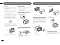 2
2
-
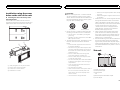 3
3
-
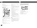 4
4
-
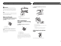 5
5
-
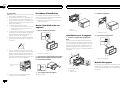 6
6
-
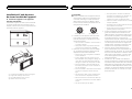 7
7
-
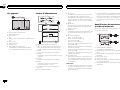 8
8
-
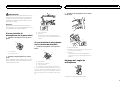 9
9
-
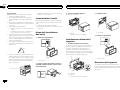 10
10
-
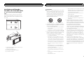 11
11
-
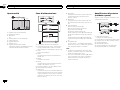 12
12
-
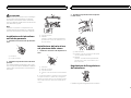 13
13
-
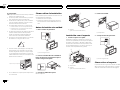 14
14
-
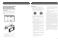 15
15
-
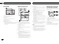 16
16
-
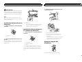 17
17
-
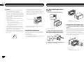 18
18
-
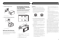 19
19
-
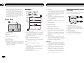 20
20
-
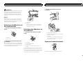 21
21
-
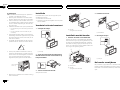 22
22
-
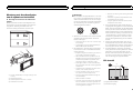 23
23
-
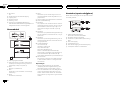 24
24
-
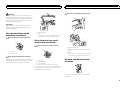 25
25
-
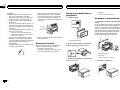 26
26
-
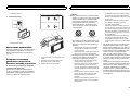 27
27
-
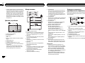 28
28
-
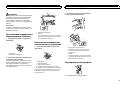 29
29
-
 30
30
-
 31
31
-
 32
32


Pioneer FH-X700BT de handleiding
- Categorie
- Microfoons
- Type
- de handleiding
- Deze handleiding is ook geschikt voor
in andere talen
- English: Pioneer FH-X700BT Owner's manual
- italiano: Pioneer FH-X700BT Manuale del proprietario
- русский: Pioneer FH-X700BT Инструкция по применению
- français: Pioneer FH-X700BT Le manuel du propriétaire
- español: Pioneer FH-X700BT El manual del propietario
- Deutsch: Pioneer FH-X700BT Bedienungsanleitung