Belangrijk
! Als dit toestel wordt geïnstalleerd in een voer-
tuig met een contactschakelaar zonder ACC-
stand (accessoirestand), kan de accu leeglo-
pen als de rode kabel niet wordt aangesloten
op de aansluiting die de bediening van de
contactschakelaar herkent.
O
N
S
T
A
R
T
O
F
F
ACC-stand Geen ACC-stand
! Gebruik van dit toestel onder andere omstan-
digheden dan de volgende kan leiden tot
brand of storingen.
— Voertuigen met een accu van 12 volt en nega-
tieve aarding.
— Luidsprekers van 50 W (uitgangswaarde) en
4 W tot 8 W (impedantiewaarde).
! Om kortsluiting, oververhitting en storingen
te voorkomen, moet u onderstaande aanwij-
zingen opvolgen.
— Koppel de negatieve aansluiting van de accu
los voordat u het toestel installeert.
— Gebruik kabelklemmen of plakband om de
bekabeling veilig aan te brengen. Bescherm
de kabels met plakband op plaatsen waar
deze tegen metalen onderdelen liggen.
— Plaats geen kabels in de buurt van beweeg-
bare onderdelen zoals de versnellingspook of
de stoelrails.
— Leg kabels niet op plaatsen die heet kunnen
worden, zoals dicht bij de kachel.
— Sluit de gele kabel niet op de accu aan via
een gat in het motorcompartiment.
— Dek alle ongebruikte kabelaansluitingen af
met isolatietape.
— Maak de kabels niet korter.
— Verwijder nooit de isolatie van de voedingska-
bel van dit toestel om andere apparaten van
stroom te voorzien. De stroomcapaciteit van
de voedingskabel is beperkt.
— Gebruik een zekering met het voorgeschreven
vermogen.
— Verbind de negatieve luidsprekerkabel nooit
rechtstreeks met de aarding.
— Voeg de negatieve kabels van verschillende
luidsprekers nooit samen.
! Als dit apparaat aan staat, wordt het bedie-
ningssignaal doorgegeven via de blauw/witte
kabel. Verbind deze kabel met de afstandsbe-
diening van een externe versterker of met de
bedieningsaansluiting van de automatische
antenne van het voertuig (maximaal 300 mA,
12 V gelijkstroom). Als het voertuig is uitge-
rust met een glasantenne, verbindt u deze
met de voedingsaansluiting van de antenne-
booster.
! Verbind de blauw/witte kabel nooit met de
voedingsaansluiting van een externe verster-
ker of automatische antenne. Anders kan de
accu leeglopen of kan er storing optreden.
! De zwarte kabel is de aarding. Dit toestel
moet gescheiden worden geaard van andere
apparaten (met name apparaten die veel
stroom verbruiken zoals een versterker). An-
ders kan er brand of storing ontstaan wan-
neer de aarding per ongeluk losraakt.
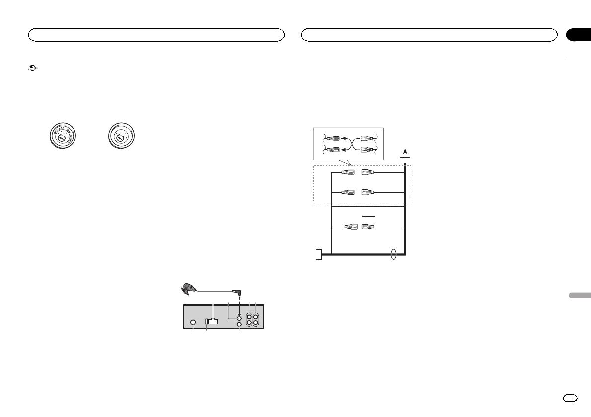
Dit toestel
1
3
2
4
5
1 Ingang stroomkabel
2 Microfooningang
3 Microfoon
4m
4 Achteruitgang of subwooferuitgang
5 Vooruitgang (alleen DEH-X5500BT)
6 Antenne-ingang
7 Zekering (10 A)
8 Ingang voor draadafstandsbediening
Een bedrade afstandsbedieningsadapter kan
aangesloten worden (los verkrijgbaar).
Stroomkabel
1
3
3
2
4
4
5
5
6
6
b
8
9
7
a
d
1 Naar ingang stroomkabel
2 De functie van 3 en 5 kan verschillen af-
hankelijk van het type voertuig. Verbind in
dat geval 4 met 5 en 6 met 3.
3 Geel
Back-up (of accessoire)
4 Geel
Aansluiten op de constante 12 V-voedings-
aansluiting.
5 Rood
Accessoire (of back-up)
6 Rood
Aansluiten op een aansluiting die door de
contactschakelaar wordt aangestuurd (12 V
gelijkstroom).
7 Verbind kabels van dezelfde kleur met elkaar.
8 Zwart (chassisaarding)
9 Blauw-wit
De pinpositie van de ISO-connector verschilt
naargelang het type voertuig. Als pin 5 de an-
tenne aanstuurt, verbindt u 9 en b. In an-
dere typen voertuigen verbindt u 9 en b
nooit.
a Blauw-wit
Aansluiten op systeembedieningsaansluiting
van de versterker (maximaal 300 mA, 12 V ge-
lijkstroom).
b Blauw-wit
Aansluiten op bedieningsaansluiting van de
gemotoriseerde antenne (maximaal 300 mA,
12 V gelijkstroom).
c Luidsprekerkabels
Wit: Linksvoor +
Wit-zwart: Linksvoor *
Grijs: Rechtsvoor +
Grijs-zwart: Rechtsvoor *
Groen: Linksachter + of subwoofer +
Groen-zwart: Linksachter * of subwoofer *
Violet: Rechtsachter + of subwoofer +
Violet-zwart: Rechtsachter * of subwoofer *
d ISO-connector
Bij sommige voertuigen is de ISO-connector
in twee verdeeld. Verbind in dat geval beide
connectoren.
Opmerkingen
! Wijzig de begininstelling van dit toestel
(raadpleeg de bedieningshandleiding). De
subwooferuitgang van dit toestel is mono.
! Als u een subwoofer van 70 W (2 W) gebruikt,
moet u de subwoofer aansluiten op de vio-
lette en zwart-violette draden van dit toestel.
Sluit niets aan op de groene en groen-zwarte
draden.
Versterker (apart verkrijgbaar)
Maak deze verbindingen als de optionele verster-
ker wordt gebruikt.
Nederlands
Verbindingen
23
Hoofdstuk
Verbindingen
Nl
02


