Yamaha VL1 de handleiding
- Categorie
- Digitale piano's
- Type
- de handleiding
Deze handleiding is ook geschikt voor


FCC INFORMATION (U.S.A.)
1. IMPORTANT NOTICE: DO NOT MODIFY THIS UNIT!
This product, when installed as indicated in the instructions contained in this manual, meets FCC requirements. Modifications not expressly approved
by Yamaha may void your authority, granted by the FCC, to use the product.
2. IMPORTANT: When connecting this product to accessories and/or another product use only high quality shielded cables. Cable/s supplied with this
product MUST be used. Follow all installation instructions. Failure to follow instructions could void your FCC authorization to use this product in the
USA.
3. NOTE: This product has been tested and found to comply with the requirements listed in FCC Regulations, Part 15 for Class ”B” digital devices.
Compliance with these requirements provides a reasonable level of assurance that your use of this product in a residential environment will not
result in harmful interference with other electronic devices. This equipment generates/uses radio frequencies and, if not installed and used according
to the instructions found in the users manual, may cause interference harmful to the operation of other electronic devices. Compliance with FCC
regulations does not guarantee that interference will not occur in all installations. If this product is found to be the source of interference, which can
be determined by turning the unit ”OFF” and ”ON”, please try to eliminate the problem by using one of the following measures:
Relocate either this product or the device that is being affected by the interference.
Utilize power outlets that are on different branch (circuit breaker or fuse) circuits or install AC line filter/s.
In the case of radio or TV interference, relocate/reorient the antenna. If the antenna lead-in is 300 ohm ribbon lead, change the lead-in to co-axial type
cable.
If these corrective measures do not produce satisfactory results, please contact the local retailer authorized to distribute this type of product. If you
can not locate the appropriate retailer, please contact Yamaha Corporation of America, Electronic Service Division, 6600 Orangethorpe Ave, Buena
Park, CA 90620
The above statements apply ONLY to those products distributed by Yamaha Corporation of America or its subsidiaries.
* This applies only to products distributed by YAMAHA CORPORATION OF AMERICA.
Dette apparat overholder det gaeldende EF-direktiv
vedrørende radiostøj.
Cet appareil est conforme aux prescriptions de la
directive communautaire 87/308/CEE.
Diese Geräte entsprechen der EG-Richtlinie 82/
499/EWG und/oder 87/308/EWG.
This product complies with the radio frequency
interference requirements of the Council Direc-
tive 82/499/EEC and/or 87/308/EEC.
Questo apparecchio è conforme al D.M.13 aprile
1989 (Direttiva CEE/87/308) sulla soppressione
dei radiodisturbi.
Este producto está de acuerdo con los requisitos
sobre interferencias de radio frequencia fijados
por el Consejo Directivo 87/308/CEE.
YAMAHA CORPORATION
Litiumbatteri!
Bör endast bytas av servicepersonal.
Explosionsfara vid felaktig hantering.
VAROITUS!
Lithiumparisto, Räjähdysvaara.
Pariston saa vaihtaa ainoastaan alan
ammattimies.
ADVARSEL!
Lithiumbatteri!
Eksplosionsfare. Udskiftning må kun foretages
af en sagkyndig, – og som beskrevet i
servicemanualen.
Connecting the Plug and Cord
IMPORTANT: The wires in this mains lead are coloured in accordance with the following code:
GREEN-AND-YELLOW : EARTH
BLUE : NEUTRAL
BROWN : LIVE
As the colours of the wires in the mains lead of this apparatus may not correspond with the coloured
markings identifying the terminals in your plug, proceed as follows:
The wire which is coloured GREEN and YELLOW must be connected to the terminal in the plug
which is marked by the letter E or by the safety earth symbol or coloured GREEN and YELLOW.
The wire which is coloured BLUE must be connected to the terminal which is marked with the letter
N or coloured BLACK.
The wire which is coloured BROWN must be connected to the terminal which is marked with the
letter L or coloured RED.
IMPORTANT NOTICE FOR THE UNITED KINGDOM
* This applies only to products distributed by YAMAHA - KEMBLE MUSIC (U.K.) LTD.
Bescheinigung des Importeurs
Hiermit wird bescheinigt, daß der/die/das
Virtual Acoustic Tone Generator Typ : VL1-m
(Gerät, Typ, Bezeichnung)
in Übereinstimmung mit den Bestimmungen der
VERFÜGUNG 1046/84
(Amtsblattverfügung)
funk-entstört ist.
Der Deutschen Bundespost wurde das Inverkehrbringen dieses
Gerätes angezeigt und die Berechtigung zur Überprüfung der Serie
auf Einhaltung der Bestimmungen eingeräumt.
Yamaha Europa GmbH
Name des Importeurs
* Dies bezieht sich nur auf die von der Yamaha Europa GmbH vertriebenen Produkte.

SPECIAL MESSAGE SECTION
PRODUCT SAFETY MARKINGS: Yamaha electronic prod-
ucts may have either labels similar to the graphics shown
below or molded/stamped facsimiles of these graphics on the
enclosure. The explanation of these graphics appears on this
page. Please observe all cautions indicated on this page and
those indicated in the safety instruction section.
methods used to produce them, meet these goals. In keeping
with both the letter and the spirit of the law, we want you to
be aware of the following:
Battery Notice: This product MAY contain a small non-
rechargeable battery which (if applicable) is soldered in place.
The average life span of this type of battery is approximately
five years. When replacement becomes neccessary, contact a
qualified service representative to perform the replacement.
Warning: Do not attempt to recharge, disassemble, or incin-
erate this type of battery. Keep all batteries away from
children. Dispose of used batteries promptly and as regulated
by applicable laws. Note: In some areas, the servicer is
required by law to return the defective parts. However, you
do have the option of having the servicer dispose of these
parts for you.
Disposal Notice: Should this product become damaged be-
yond repair, or for some reason its useful life is considered
to be at an end, please observe all local, state, and federal
regulations that relate to the disposal of products that contain
lead, batteries, plastics, etc.
NOTICE: Service charges incurred due to lack of knowledge
relating to how a function or effect works (when the unit is
operating as designed) are not covered by the manufacturer’s
warranty, and are therefore the owners responsibility. Please
study this manual carefully and consult your dealer before
requesting service.
NAME PLATE LOCATION: The graphic below indicates
the location of the name plate. The model number, serial
number, power requirements, etc., are located on this plate.
You should record the model number, serial nunber, and the
date of purchase in the spaces provided below and retain this
manual as a permanent record of your purchase.
CAUTION: TO REDUCE THE RISK OF
ELECTRIC SHOCK, DO NOT REMOVE
COVER (OR BACK). NO USER-SERVICEABLE
PARTS INSIDE. REFER SERVICING TO
QUALIFIED SERVICE PERSONNEL
RISK OF ELECTRIC SHOCK
DO NOT OPEN
CAUTION
The exclamation point within the equilateral
triangle is intended to alert the user to the
presence of important operating and mainte-
nance (servicing) instructions in the litera-
ture accompanying the product.
The lightning flash with arrowhead symbol
within the equilateral triangle is intended to
alert the user to the presence of uninsulated
“dangerous voltage” within the product’s
enclosure that may be of sufficient magni-
tude to constitute a risk of electrical shock.
IMPORTANT NOTICE: All Yamaha electronic products are
tested and approvend by an independent safety testing labo-
ratory in order that you may be sure that when it is properly
installed and used in its normal and customary manner, all
foreseeable risks have been eliminated. DO NOT modify this
unit or commission others to do so unless specifically author-
ized by Yamaha. Product performance and/or safety standards
may be diminished. Claims filed under the expressed warranty
may be denied if the unit is/has been modified. Implied
warranties may also be affected.
SPECFICATIONS SUBJECT TO CHANGE: The informa-
tion contained in this manual is believed to be correct at the
time of printing. However, Yamaha reserves the right to
change or modify any of the specifications without notice or
obligation to update existing units.
ENVIRONMENTAL ISSUES: Yamaha strives to produce
products that are both user safe and environmentally friendly.
We sincerely believe that our products and the production
● Explanation of Graphical Symbols
92-469 q
Model
Serial No.
Purchase Date
R
L
OUTPUT
AC INLET
THRU OUT
MIDI
IN

IMPORTANT SAFETY INSTRUCTIONS
INFORMATION RELATING TO PERSONAL INJURY, ELECTRICAL SHOCK,
AND FIER HAZARD POSSIBILITIES HAS BEEN INCLUDED IN THIS LIST.
PLEASE KEEP THIS MANUAL
8. This product was NOT designed for use in wet/damp
locations and should not be used near water or exposed to
rain. Examples of wet/damp locations are; near a swim-
ming pool, spa, tub, sink, or wet basement.
9. This product should be used only with the components
supplied or; a cart, rack, or stand that is recommended by
the manufacturer. If a cart, rack, or stand is used, please
observe all safety markings and instructions that accom-
pany the accessory product.
10.The power supply cord (plug) should be disconnected
from the outlet when electronic products are to be left
unused for extended periods of time. Cords should also be
disconnected when there is a high probability of lightening
and/or electrical storm activity.
11.Care should be taken that objects do not fall and liquids
are not spilled into the enclosure through any openings
that may exist.
12.Electrical/electronic products should be serviced by a
qualified service person when:
a. The power supply cord has been damaged; or
b. Objects have fallen, been inserted, or liquids have been
spilled into the enclosure through openings; or
c. The product has been exposed to rain; or
d. The product does not operate, exhibits a marked change
in performance; or
e. The product has been dropped, or the enclosure of the
product has been damaged.
13.Do not attempt to service this product beyond that de-
scribed in the user-maintenance instructions. All other
servicing should be referred to qualified service personnel.
14.This product, either alone or in combination with an
amplifier and headphones or speaker/s, may be capable of
producing sound levels that could cause permanent hear-
ing loss. DO NOT operate for a long period of time at a
high volume level or at a level that is uncomfortable. If
you experience any hearing loss or ringing in the cars, you
should cousult an audiologist. IMPORTANT: The louder
the sound, the shorter the time period before damage
occurs.
15.Some Yamaha products may have benches and/or acces-
sory mounting fixtures that are either supplied as a part of
the product or as optional accessories. Some of these items
are designed to be dealer assembled or installed. Please
make sure that benches are stable and any optional fixtures
(where applicable) are well secured BEFORE using. Benches
supplied by Yamaha are designed for seating only. No
other uses are recommended.
WARNING — When using any electrical or electronic prod-
uct, basic precautions should always be followed. These
precautions include, but are not limited to, the following:
1. Read all Safety Instructions, Installation Instructions, Spe-
cial Message Section items, and any Assembly Instruc-
tions found in this manual BEFORE making any connec-
tions, including connection to the main supply.
2. Main Power Suplly Verifications: Yamaha products are
manufactured specifically for the supply voltage in the
area where they are to be sold. If you should move, or if
any doubt exists about the supply voltage in your area,
please contact your dealer for supply voltage verification
and (if applicable) instructions. The required supply volt-
age is printed on the name plate. For name plate location,
please refer to the graphic found in the Special Message
Section of this manual.
3. This product may be equipped with a polarized plug (one
blade wider than the other). If you are unable to insert the
plug into the outlet, turn the plug over and try again. If the
problem persists, contact electrician to have the obsolete
outlet replaced. Do NOT defeat the safety purpose of the
plug.
4. Some electronic products utilize external power supplies
or adapters. DO NOT connect this type of product to any
power supply or adapter other than one described in the
owners manual, on the name plate, or specifically recom-
mended by Yamaha.
5. WARNING: Do not place this product or any other objects
on the power cord or place it in a position where anyone
could walk on, trip over, or roll anything over power or
connecting cords of any kind. The use of an extension cord
is not recommended! If you must use an extension cord,
the minimume wire size for a 25' cord (or less) is 18 AWG.
NOTE: The smaller the AWG number, the larger the
current handling capacity. For longer extension cords,
consult a local electrician.
6. Ventilation: Electronic products, unless specifically de-
signed for enclosed installations, should be placed in
locations that do not interfere with proper ventilation. If
instructions for enclosed installations are not provided, it
must be assumed that unobstructed ventilation is required.
7. Temperature considerations: Electronic products should be
installed in locations that do not significantly contribute to
their operating temperature. Placement of this product
close to heat sources such as; radiators, heat registers and
other devices that produce heat should be avoided.
92-469-3

Owner’s Manual 2
Feature Reference
Virtual Acoustic Tone Generator

2
Feature Reference
Contents
■ 3: Feedback Delay . . . . . . . . . . . . . . . . . . . . . . 53
• Mono Delay . . . . . . . . . . . . . . . . . . . . . . . 53
• L,R Delay . . . . . . . . . . . . . . . . . . . . . . . . 55
• L,C,R Delay . . . . . . . . . . . . . . . . . . . . . . 57
■ 4:Reverberation . . . . . . . . . . . . . . . . . . . . . . . . 60
• Hall1, Hall2, Room1, Room2, Studio,
Plate, Space, Reverse . . . . . . . . . . . . . . . 61
Element Controller . . . . . . . . . . . . . . . . . . . . . 64
■ 1: Pressure . . . . . . . . . . . . . . . . . . . . . . . . . . . . 65
■ 2: Embouchure . . . . . . . . . . . . . . . . . . . . . . . . 66
■ 3: Pitch . . . . . . . . . . . . . . . . . . . . . . . . . . . . . . . 67
■ 4: Vibrato . . . . . . . . . . . . . . . . . . . . . . . . . . . . . 69
■ 5: Tonguing . . . . . . . . . . . . . . . . . . . . . . . . . . . 70
■ 6: Amplitude . . . . . . . . . . . . . . . . . . . . . . . . . . 71
■ 7: Scream . . . . . . . . . . . . . . . . . . . . . . . . . . . . . 72
■ 8: Breath Noise . . . . . . . . . . . . . . . . . . . . . . . . 73
■ 9: Growl . . . . . . . . . . . . . . . . . . . . . . . . . . . . . . 74
■ 10: Throat Formant . . . . . . . . . . . . . . . . . . . . . 75
■ 11: Dynamic Filter . . . . . . . . . . . . . . . . . . . . . 77
■ 12; Harmonic Enhancer . . . . . . . . . . . . . . . . . 78
■ 13: Damping . . . . . . . . . . . . . . . . . . . . . . . . . . 80
■ 14: Absorption . . . . . . . . . . . . . . . . . . . . . . . . . 81
■ Controller Search & Replace . . . . . . . . . . . . . 82
Element Miscellaneous . . . . . . . . . . . . . . . . . 84
■ 1: Setting . . . . . . . . . . . . . . . . . . . . . . . . . . . . . 85
■ 2: Breath Noise . . . . . . . . . . . . . . . . . . . . . . . . 86
• 2-1: Breath Noise Level Key Scaling . . 88
• 2-2: Breath Noise HPF Key Scaling . . . 89
• 2-3: Breath Noise LPF Key Scaling . . . . 90
■ 3: Throat Formant . . . . . . . . . . . . . . . . . . . . . . 91
• 3-1: Throat Formant Pitch Key Scaling . 93
• 3-2: Throat Formant Amount Key
Scaling . . . . . . . . . . . . . . . . . . . . . . . 94
• 3-3: Throat Formant Intensity Key
Scaling . . . . . . . . . . . . . . . . . . . . . . . 95
• 3-4: Throat Formant HPF Key Scaling . 96
• 3-5: Throat Formant LPF Key Scaling . 97
■ 4: Mixing . . . . . . . . . . . . . . . . . . . . . . . . . . . . . 98
• 4-1: Mixing Driver Output Key Scaling 100
• 4-2: Mixing Pipe/String Output Key
Scaling . . . . . . . . . . . . . . . . . . . . . . 101
About the Manuals . . . . . . . . . . . . . . . . . . . . . . 4
■ The Getting Started Manual . . . . . . . . . . . . . . . 4
■ The Feature Reference Manual (this manual) . 5
■ Conventions . . . . . . . . . . . . . . . . . . . . . . . . . . . . 5
General Operation
■ The Three Main Modes . . . . . . . . . . . . . . . . . . . 8
■ Finding Functions & Parameters . . . . . . . . . . . 9
■ Other Navigation Aids . . . . . . . . . . . . . . . . . . 11
■ Selecting & Editing Parameters . . . . . . . . . . . 12
Play Mode
■ The Main Play Mode Display . . . . . . . . . . . . . 14
■ Voice Selection . . . . . . . . . . . . . . . . . . . . . . . . 15
■ Controller Views . . . . . . . . . . . . . . . . . . . . . . . 17
■ Quick Editing In the Play Mode . . . . . . . . . . . 19
■ The Monitor Mode . . . . . . . . . . . . . . . . . . . . . 20
Edit Mode
■ Element Selection In the Edit Mode . . . . . . . 22
■ The Edit Compare Function . . . . . . . . . . . . . . 23
■ The Copy Function . . . . . . . . . . . . . . . . . . . . . 24
■ Storing Edited Data . . . . . . . . . . . . . . . . . . . . . 27
Initial Edit Page . . . . . . . . . . . . . . . . . . . . . . . . 30
Common Miscellanous . . . . . . . . . . . . . . . . . 34
■ 1: Setting . . . . . . . . . . . . . . . . . . . . . . . . . . . . . 35
■ 2: Controller . . . . . . . . . . . . . . . . . . . . . . . . . . 36
■ 3: Element Pitch . . . . . . . . . . . . . . . . . . . . . . . 37
■ 4: Element Level & Pan . . . . . . . . . . . . . . . . . 38
■ 5: Portamento . . . . . . . . . . . . . . . . . . . . . . . . . 40
■ 6: Micro Tuning . . . . . . . . . . . . . . . . . . . . . . . 42
■ 7: Quick Edit Assign . . . . . . . . . . . . . . . . . . . . 43
Common Effect . . . . . . . . . . . . . . . . . . . . . . . . 44
■ 1: Setting . . . . . . . . . . . . . . . . . . . . . . . . . . . . . 45
■ 2: Modulation Effect . . . . . . . . . . . . . . . . . . . . 46
• Flanger . . . . . . . . . . . . . . . . . . . . . . . . . . . 47
• Pitch Change . . . . . . . . . . . . . . . . . . . . . . 49
• Distortion . . . . . . . . . . . . . . . . . . . . . . . . . 51

3
Feature Reference
• 4-3: Mixing Tap Output Key Scaling . 102
• 4-4: Mixing Tap Location Key Scaling 103
■ 5: Amplitude . . . . . . . . . . . . . . . . . . . . . . . . . 104
• 5-1: Total Amplitude Level Key Scaling104
Element Modifier . . . . . . . . . . . . . . . . . . . . . 106
■ 1: Harmonic Enhancer . . . . . . . . . . . . . . . . . 107
•1-1: Harmonic Enhancer HPF Key
Scaling . . . . . . . . . . . . . . . . . . . . . . 110
•1-2: Harmonic Enhancer Overdrive Key
Scaling . . . . . . . . . . . . . . . . . . . . . . 111
• 1-3: Harmonic Enhancer Carrier Level
Key Scaling . . . . . . . . . . . . . . . . . . 112
• 1-4: Harmonic Enhancer Modulator
Index Key Scaling . . . . . . . . . . . . . 113
• 1-5: Harmonic Enhancer Balance Key
Scaling . . . . . . . . . . . . . . . . . . . . . . 114
■ 2: Dynamic Filter . . . . . . . . . . . . . . . . . . . . . 115
• 2-1: Dynamic Filter Cutoff Key Scaling 117
• 2-2: Dynamic Filter Resonance Key
Scaling . . . . . . . . . . . . . . . . . . . . . . 118
■ 3: Equalizer Auxiliary . . . . . . . . . . . . . . . . . . 119
• 3-1: Equalizer Auxiliary HPF Key
Scaling . . . . . . . . . . . . . . . . . . . . . . 120
• 3-2: Equalizer Auxiliary LPF Key
Scaling . . . . . . . . . . . . . . . . . . . . . . 121
■ 4: Equalizer Band . . . . . . . . . . . . . . . . . . . . . 122
■ 5: Impulse Expander & Resonator Setting . . 123
■ 6: Impulse Expander . . . . . . . . . . . . . . . . . . . 125
■ 7: Resonator . . . . . . . . . . . . . . . . . . . . . . . . . . 126
Element Envelope . . . . . . . . . . . . . . . . . . . . . 128
■ 1: Pressure . . . . . . . . . . . . . . . . . . . . . . . . . . . 129
■ 2: Embouchure & Pitch . . . . . . . . . . . . . . . . . 130
• 2-1: Embouchure & Pitch Hold Time
Key Scaling . . . . . . . . . . . . . . . . . . 132
• 2-2: Embouchure & Pitch Initial Level
Key Scaling . . . . . . . . . . . . . . . . . . 133
• 2-3: Embouchure & Pitch Decay Rate
Key Scaling . . . . . . . . . . . . . . . . . . 134
■ 3: Vibrato . . . . . . . . . . . . . . . . . . . . . . . . . . . . 135
• 3-1: Vibrato Delay Time Key Scaling . 137
• 3-2: Vibrato Attack Rate Key Scaling . 138
• 3-3: Vibrato Depth Key Scaling . . . . . . 139
• 3-4: Vibrato Speed Key Scaling . . . . . . 140
■ 4: Growl . . . . . . . . . . . . . . . . . . . . . . . . . . . . . 141
• 4-1: Growl Speed Key Scaling . . . . . . . 142
■ 5: Amplitude & Filter . . . . . . . . . . . . . . . . . . 143
• 5-1: Amplitude & Filter Attack Rate
Key Scaling . . . . . . . . . . . . . . . . . . 146
• 5-2: Amplitude & Filter Attack 1 Level
Key Scaling . . . . . . . . . . . . . . . . . . 147
• 5-3: Amplitude & Filter Decay Rate
Key Scaling . . . . . . . . . . . . . . . . . . 148
• 5-4: Amplitude & Filter Sustain Level
Key Scaling . . . . . . . . . . . . . . . . . . 149
• 5-5: Amplitude & Filter Release Rate
Key Scaling . . . . . . . . . . . . . . . . . . 150
Utility Mode
System . . . . . . . . . . . . . . . . . . . . . . . . . . . . . . 152
MIDI Bulk Dump . . . . . . . . . . . . . . . . . . . . . . 160
Disk . . . . . . . . . . . . . . . . . . . . . . . . . . . . . . . . . 162
Edit Recall . . . . . . . . . . . . . . . . . . . . . . . . . . . 172
Demo . . . . . . . . . . . . . . . . . . . . . . . . . . . . . . . 174
Appendix
VL1 & VL1-m Compatibility . . . . . . . . . . . . 178
Troubleshooting . . . . . . . . . . . . . . . . . . . . . . 179
Error Messages . . . . . . . . . . . . . . . . . . . . . . . 182
Specifications . . . . . . . . . . . . . . . . . . . . . . . . 184
Index . . . . . . . . . . . . . . . . . . . . . . . . . . . . . . . . 186

4
Feature Reference
About the Manuals
The VL1-m comes with two manuals — Getting Started and Fea-
ture Reference. If you’re just starting out with the VL1-m we urge you to
begin with the Getting Started manual since it describes basic concepts
and procedures that are essential to proper operation of the VL1-m.
The Getting Started Manual
The Getting Started manual contains seven chapters that take you through
essential information and procedures you will need to know to become familiar
with your VL1-m:
1. VL1-m Basics [≥ Page 8]
Basic concepts you’ll need to understand in order to get the
most out of the VL1-m.
2. The Controls & Connectors [≥ Page 16]
Brief descriptions of the VL1-m controls and connectors, and
their functions.
3. Setting Up [≥ Page 22]
System connections, powering up, playing the demo, calibrating
the Breath Controller, and loading the pre-programmed voices.
4. Voice Selection [≥ Page 34]
Several ways to select and play the VL1-m’s 128 voices.
5. The Controllers [≥ Page 38]
The VL1-m controllers and how they can be assigned and
edited for optimum control.
6. Mixing & The Modifiers [≥ Page 48]
Customizing the sound to suit your own personal needs.
7. Effects [≥ Page 58]
An overview of the built-in digital effects that you can use to
add depth and ambience to the VL1-m sound.
We recommend that you go through the chapters in sequence and actually
try out the various operations described. Once you’ve gone through the entire
Getting Started manual in this way, you should be familiar enough with the
VL1-m to need only the VL1-m Feature Reference manual in future.

5
Feature Reference
The Feature Reference Manual (this manual)
The Feature Reference manual is the “nuts and bolts” reference for
the VL1-m, individually describing its many functions in detail. The
Feature Reference manual is divided into five main sections, each describ-
ing the various functions within a particular VL1-m edit or utility mode.
1. General Operation [≥ Page 7]
2. Play Mode [≥ Page 13]
3. Edit Mode [≥ Page 21]
4. Utility Mode [≥ Page 151]
5. Appendix [≥ Page 177]
Once you have become familiar with the way the VL1-m works by
going through the Getting Started manual, you should only need to refer
to the Feature Reference manual from time to time to get details on func-
tions you’ve never used before, or refresh your memory about functions
that you don’t use very often.
Each section of the Feature Reference manual has its own table of
contents, so you should be able to locate any particular function quickly
and easily. Functions and references can also be located by referring to the
index at the back of the manual.
Conventions
The following conventions are used through the VL1-m manuals to
avoid confusion and make the text easier to read.
Buttons & Controls
Button and control names used on the VL1-m panel appear in the
text in capital letters within a border: “the P button”, for exam-
ple.
Parameter Names
Parameter names and other labels which appear on the VL1-m
display are printed in the courier typeface for easier identifica-
tion: for example, “adjust the “Balance” parameter as required”.
Parameter Ranges
An ellipsis is used to indicate a range of parameter values: e.g. “0
… 127”. This minimizes the confusion sometimes caused by the use
of a hyphen or dash for this purpose.

6
Feature Reference

General Operation
The VL1-m makes operation as easy as possible
by providing a consistent, logical control interface via
which its many functions and parameters can be
accessed and edited. Once you become familiar with
the system, operation should be smooth, efficient, and
easy.
● The Three Main Modes . . . . . . . . . . . . . 8
● Finding Functions & Parameters . . . . . 9
● Other Navigation Aids . . . . . . . . . . . . . 11
● Selecting & Editing Parameters . . . . . 12

8
Feature Reference
●
General Operation
The Three Main Modes
The VL1-m has three main modes: PLAY, EDIT, and UTILITY. Each of these
modes can be directly accessed by pressing the P, E, or U button, respec-
tively.
The PLAY mode is the one you use to select and play the VL1-m
voices. The PLAY mode also includes several “Controller Views” that
allow you to check controller assignments, the status of several
important performance parameters, and the quick edit assignments.
≥
Pages 13 through 20.
All voice editing functions are accessed via the EDIT mode: controller
assignments, mixing, modifiers, effects, and more.
≥
Pages 21 through 150.
The UTILITY mode includes a range of functions that affect overall
operation of the VL1-m rather than individual voices. For example:
master tuning, MIDI settings, disk operations, etc.
≥
Pages 151 through 175.
PLAY
EDIT
UTILITY

9
Feature Reference
●
General Operation
Finding Functions & Parameters
To facilitate access to the many functions provided, the EDIT and UTILITY mode
functions are organized into logical groups arranged in a hierarchical structure (the PLAY
mode is simple enough that it doesn’t require this type of structure). The basic structure
of the EDIT mode, for example, looks like this:
EDIT MODE
ELEMENT
EFFECT
CONTROLLER
MODIFIER
ENVELOPE
COMMON
MISCELLANEOUS
MISCELLANEOUS
Here you can see that the EDIT mode functions are divided into two main groups:
COMMON and ELEMENT, and that these are further sub-divided into related groups of
functions. The COMMON EFFECT group, for example, includes all the effect parameters
(flange, reverb, etc.) that apply to the entire voice. Here’s how you would access the
reverb parameters, starting from the PLAY mode:
●
Example: Locate the Effect Reverb Parameters
1. Press E
Pressing the E button from the PLAY or UTILITY mode will normally take
you to the initial EDIT display page (if the current voice has already been edited but not
stored, you will automatically return to the last EDIT mode page that was selected).
2. Press ¡ (“Com”)
Since you want the effect functions, which are in the common group, press the ¡
function button (immediately below “Com” on the display).

10
Feature Reference
●
General Operation
3. If Necessary, Press ™ (“Efct”)
If the miscellaneous directory is showing (in this case “Misc” above the ¡ button
will be highlighted), press the ™ button below “Efct” on the display to select the
effect directory.
4. Move the Cursor To “4:Reverberation” and Press [
Use the cursor buttons (or the - and = buttons, or the data dial)
to move the cursor to “4:Reverberation” and press the [ button. This will
take you to the first page of reverb parameters.
NOTES ■ Notice that the top line of the display shows the “path” to the current
level or function: “
EDIT/COM/EFFECT/REVERBERATION
”.
This example illustrates the two methods used to move downward through the EDIT
mode levels: 1) press the appropriate function button and 2) move the cursor to the
desired selection and press [.
From any point within the structure you can move upward toward the topmost level
(in this case the initial EDIT mode display) by pressing the ] button. You move up
one level each time the ] button is pressed, until the topmost level is reached.
To exit from the EDIT mode itself you must press either the P or U
button, depending on the mode you want to switch to. You can exit from the EDIT mode
at any level by doing this, and you will be returned automatically to the same display
page the next time you press the E button as long as the voice being edited is not
stored or a new voices is not selected.

11
Feature Reference
●
General Operation
Other Navigation Aids
In addition to the standard procedures described in the previous section, the VL1-m
sometimes provides additional help in moving between related functions via the function
buttons.
In this example display page from the ELEMENT CONTROLLER group, “Bpag”
(back page) and “Fpag” (forward page) appear above the § and ¶ function buttons.
In this case these buttons can be used to move forward and backward through the entire
list of controller functions so you don’t have to move up to the function directory and
then down to the next function every time you want to select a different element control-
ler page.
Also note the “Para” (Parameter) abbreviation above the • button. This enables
you to go directly to the parameters related to the current page: in this case the vibrato
parameters.
From here you can go back to the vibrato controller page by pressing the •
function button again (note that it is now labelled “Ctrl”), or to the vibrato key scaling
parameters by pressing ¶, below “KSC” on the display.
Another variation appears in the COMMON EFFECT parameter displays. In most
cases the number of parameters available for each effect exceeds the capacity of the
display, so the ¡ and ™ function buttons are used to scroll up and down the parameter
list — note the “>” and “<” arrows above the buttons in the display.

12
Feature Reference
●
General Operation
Selecting & Editing Parameters
Once you’ve locate the display page that contains the parameter(s) you want to edit,
simply use the cursor buttons to move the cursor to the parameter, and then use the data
dial or the = and - buttons to set the parameter as required. The data dial is ideal
for quickly covering a large range of settings, while the = and - buttons are best
for small stepwise changes.

Play Mode
The primary function of the PLAY mode is to
allow you to select and play voices. The VL1-m play
mode additionally offers a range of controller views
that let you check controller assignments, and simple
“quick edit” capability. Select the PLAY mode from
either the EDIT or UTILITY mode by pressing the
P button.
● The Main Play Mode Display . . . . . . . 14
● Voice Selection . . . . . . . . . . . . . . . . . . 15
● Controller Views . . . . . . . . . . . . . . . . . 17
● Quick Editing In the Play Mode . . . . . 19
● The Monitor Mode . . . . . . . . . . . . . . . . 20

14
Feature Reference
●
Play Mode
The Main Play Mode Display
When you select the PLAY mode by pressing the P button, the main PLAY
mode display will appear. This display includes a considerable amount of information in
addition to the name of the currently selected voice.
■ The Normal Voice Display
Voice number.
Element E1 and E2 names.
Voice mode.
Voice name.
Play mode.
Reverb on or off.
Stereo output mode.
Effects in use.
Pressure, Amplitude,
or D.Filter Controller *
* If controllers are assigned to both Pressure and Amplitude, the con-
troller with the highest amplitude depth value will be displayed. If
neither is assigned, the Dynamic Filter controller will be displayed (if
assigned).
The abbreviations in the section separated by a line at the bottom of the display
(“Cnt1”, “Cnt2”, etc) indicate the functions of the corresponding function buttons
below the display (described below).

15
Feature Reference
●
Play Mode
Voice Selection
The VL1-m’s 128 voices are organized into 8 banks — “A” through “H” — of 16
voices each (8 x 16 = 128). These can be selected in sequence by using either the data
dial or the = and - buttons. Note that the voice number which appears on the
play mode display includes both the voice bank/number (“A01” through “A16”, “B01”
through “B16”, etc.) and the absolute voice number in parentheses following the bank/
number (“001” through “128”).
DEC INC
● = and - Buttons
These are best for small, step-wise changes —
e.g. selecting adjacent voice numbers, or
numbers that are only a few steps away. Press
the = or - key briefly to decrement or
increment the voice number by one, or hold
either key for continuous decrementing or
incrementing in the corresponding direction.
The = and - buttons also have a
largestep function which allows you to skip
ahead or backward in increments of 16: press
either the = or - button while holding
the other button. The bank will switch auto-
matically if you cross a bank voice-number
boundary.
● Data Dial
The data dial provides a fast, efficient way to
cover a broad range of voice numbers when,
for example, you’re looking for a voice but
don’t know the voice number. Simply rotate
the data dial clockwise for higher voice
numbers or counter-clockwise for lower voice
numbers while watching the display. The
banks are automatically switched when neces-
sary as the voice numbers are changed.

16
Feature Reference
●
Play Mode
●
Using the Voice Directory
The VL1-m also features a voice directory display that can be more convenient than
the normal voice display in some situations. To switch to the voice directory display,
press the • button — located directly below “Dir” on the display. The directory
display shows all 16 voices in the current bank. Voices can be selected using either the
data dial or = and - buttons as described above — the cursor will move to the
selected voice. You can also use the cursor keys to move the cursor to the next voice to
be selected (the voice is not actually selected in this case — the cursor will flash), then
press the [ key to actually select the specified voice. This method lets you switch
directly to the specified voice without having to go through all others in between
To return to the normal voice display press the ] or P button.
●
The Sound Function
You can check the sound of the current voice in the PLAY mode directly from the
VL1-m panel: press the
ENTER/SOUND
key. The pitch played is C4. When a voice is
played in this way all 14 controller parameters (“Pressure” through “Absorption”) are
turned off.

17
Feature Reference
●
Play Mode
Controller Views
In the PLAY mode, function buttons ¡ (“Cnt1”) through § (“QED”) are used
to select “controller view” displays that list all controller assignments for the currently
selected voice. You can press the ] or P button from any controller view to
return to the normal play-mode display.
●
¡
(“Cnt1”) through
¢
(“Cnt4”): Main Controllers
¡ through ¢ display the assignments for the controller parameters.
¡
(“Cnt1”)
£
(“Cnt3”)
™
(“Cnt2”)
Pressure
≥
Page 65.
Embouchure
≥
Page 66.
Pitch
≥
Page 67.
Vibrato
≥
Page 69.
Tounguing
≥
Page 70.
Amplitude
≥
Page 71.
Scream
≥
Page 72.
Breath Noise
≥
Page 73.
Growl
≥
Page 74.
Throat Formant
≥
Page 75.
Dynamic Filter
≥
Page 77.
Harmonic Enhancer
≥
Page 78.

18
Feature Reference
●
Play Mode
The controller parameters are listed in the left column of the controller view dis-
play, and the controllers assigned to them are listed in the center and right columns,
corresponding to elements 1 and 2, respectively.
●
∞
(“Cnt5”): Other Controller Settings
If you press the ∞ function button from the play mode you’ll see the following
controller view:
¢
(“Cnt4”)
The controller parameters listed in this screen are not in the same category as those
discussed in the preceding section, and therefore need to be introduced separately. All of
the related parameters will be discussed in detail in the Feature Reference manual (pages
listed below).
Damping
≥
Page 80.
Absorption
≥
Page 81.
Polyphony
≥
Page 36.
Sustain
≥
Page 35.
Pitch Bend
≥
Page 35.
Portamento
≥
Page 40.
Effect
≥
Page 45.

19
Feature Reference
●
Play Mode
●
§
(“QED”): Quick Edit
The § function button calls the Quick Edit (“QED”) controller view, which will
look something like this:
Two MIDI controllers (control change numbers 16 and 17) can be independently
assigned to several parameters that you can control in real time while playing (also see
“Quick Editing In the Play Mode”, below). The parameters available for editing via the
controllers are individually preset for each voice. You can select from the available range
by using the “Quick Edit Assign” assignment function (≥ Page 43).
The quick edit view shows you which parameters are assigned to which controller
as well as the current positions of the controllers and their corresponding values. When
the positions of the MIDI controllers used do not correspond to the internal parameters,
the values of the internal parameters are displayed.
Quick Editing In the Play Mode
Although detailed voice editing is carried out in the EDIT mode, the MIDI control-
lers assigned to the quick edit parameters can be used to change the assigned parameters
in real time while playing in the PLAY mode. This can be used simply an expressive
tool, or as a way to actually change the sound of the voice to suit your individual musical
requirements. Since the controllers actually edit the parameters to which they are as-
signed, the “new” voice created by using the sliders can be stored to one of the VL1-m’s
voice memory locations and used just as if it had been edited in the EDIT mode (≥ the
STORE operation is described on page 27). The parameters available for editing via the
MIDI controllers are individually preset for each voice. You can select from the available
range by using the “Quick Edit Assign” assignment function (≥ Page 43).

20
Feature Reference
●
Play Mode
The Monitor Mode
In the PLAY mode the ¶ function button (“Moni”) selects a “Monitor” display
which shows the most recently received MIDI values for a range of parameters, plus that
from a breath controller connected to the BREATH jack. Press the ] or P key to
return to the normal play mode display.
The most recently received MIDI control change value for the specified
control change number. This parameter can be set to any control
change number from “001” (Modulation) to “119”, or “off”. To change
the control change number move the cursor to the number and set as
required via the data dial or = and - buttons.
The most recently received modulation value (0 … 127).
The most recently received breath controller value (0 … 127). Data
from both the front-panel BEATH jack and the MIDI IN connector are
displayed (last-received priority).
The most recently received foot controller value (0 … 127).
The most recently received main volume value (0 … 127).
The most recently received pitch bend value (-64 … 63).
The most recently received after touch value (0 … 127).
The most recently received note number and velocity value (note: C-2
… G8. velocity: 1 … 127).
Control Change
Modulation Wheel
(001)
Breath Controller
(002)
Foot Controller
(004)
Main Volume
(007)
Pitch Bend
After Touch
Note

Edit Mode
All voice editing functions are accessed via the
EDIT mode: controller assignments, mixing, modifi-
ers, effects, and more.
● Element Selection
In the Edit Mode . . . . . . . . . . . . . . 22
● The Edit Compare Function . . . . . 23
● The Copy Function . . . . . . . . . . . . 24
● Storing Edited Data . . . . . . . . . . . 27
Initial Edit Page . . . . . . . . . . . . . . . . . . . 30
Common Miscellanous . . . . . . . . . . . . . . 34
Common Effect . . . . . . . . . . . . . . . . . . . . 44
Element Controller . . . . . . . . . . . . . . . . . 64
Element Miscellaneous . . . . . . . . . . . . . 84
Element Modifier . . . . . . . . . . . . . . . . . 106
Element Envelope . . . . . . . . . . . . . . . . . 128

22
Feature Reference
●
Edit Mode
Element Selection In the Edit Mode
In the EDIT mode you’ll need to be able to select the element to be edited, and
independently turn the elements on and off to monitor the sound.
●
Element Select
The ∞ function button and , and < cursor buttons are used to select the ele-
ment to be edited in a 2-element voice when an ELEMENT parameter is selected. Press
, while holding ∞ to select element 1, or press < while holding ∞ to select ele-
ment 2. The currently selected element is shown in the function name at the top of the
display page: “E1” for element 1 and “E2” for element 2.
In the example display below, element 2 is selected for editing (“EDIT/E2/
CTRL/PRESSURE”):
The element cannot be selected when a COMMON parameter is selected. Of course,
“E2” can only be selected in a voice that uses two elements. Single-element voices use
only “E1”.
●
Element On/Off
While editing a 2-element voice it is handy to be able to turn one or the other
element off so you can clearly hear the result of edits to the element you are working on.
The ∞ function button and . and > cursor buttons perform this function. Hold ∞
and press the > button to toggle element 1 on and off, or hold ∞ and press the .
button to toggle element 2 on and off. The on/off status of the elements is indicated by
the element numbers (“12”) at the right end of the second display line: a highlighted
number indicates that the element is on, a plain number that the element is off. In the
following display, for example, element 2 is on while element 1 is off:
The element ON/OFF settings are only effective in the edit mode.

23
Feature Reference
●
Edit Mode
The Edit Compare Function
When editing a voice in the EDIT mode, a copy of the original voice is retained in
the VL1-m “edit buffer”, allowing the edited voice to be compared with the edited
version by using the “Edit Compare” function.
The Edit Compare function is engaged by pressing the E button while in the
EDIT mode (after making at least one change to the voice data). When the Edit Compare
mode is engaged the E indicator will flash, the inverse “E”(´) before the voice
number will disappear, and the sound of the original (pre-edit) voice can be monitored.
Press the E button again to return to the EDIT mode and the edited version of the
voice. You can toggle back and forth between the edited and original voices while editing
to monitor the effect of changes you make to the voices parameters.
NOTES ■ Editing can not be carried out while the Edit Compare function is
engaged.

24
Feature Reference
●
Edit Mode
The Copy Function
The copy function makes it possible to copy common or element data from any
specified voice to the current voice. You can copy all common or element data, or only
the data from a specified group of functions or a single function. It is also possible to
copy the original (pre-edit) data from the voice being edited to restore the specified data
to its original values.
●
Procedure
1. Specify the Data You Want To Copy
In the EDIT mode select the display page and function corresponding to the data
you want to copy:
• To copy all common data, go to the initial EDIT mode display and move the
cursor to the “Voice Name”, “Key Mode”, or “Voice Mode” parameter.
■ Example: Copy all common data.
• To copy all common miscellaneous data select the miscellaneous directory, or
to copy all common effect data select the Effect directory.
■ Example: Copy all common miscellaneous data.
• To copy the data from a single common miscellaneous or common effect
function select the display page for that function.
■ Example: Copy the common miscellaneous element pitch data.

25
Feature Reference
●
Edit Mode
• To copy all element data, go to the initial EDIT mode display and move the
cursor to the “E1 Name” or “E2 Name” parameter.
■ Example: Copy all element data.
• To copy the E1 or E2 controller, miscellaneous, modifier, or envelope data,
select the corresponding directory display page.
■ Example: Copy all E1 element modifier data.
• To copy the data from a single element function select the display page for
that function.
■ Example: Copy the E2 harmonic enhancer data.
2. Press C
Press the C button to call the COPY display.
3. Select the Voice You Want To Copy From
Use the cursor buttons, data dial, or = and - buttons to select the voice you
want to copy the data from (and the element when copying element data).
• At this point you can play the voice to hear how it will sound after the speci-
fied data is copied before actually copying the data.

26
Feature Reference
●
Edit Mode
• The voice/element preceded by an asterisk (*) in the copy window is the
current voice/element. If you select this voice/element as the copy source the
pre-edit data will be copied, thus restoring the specified data to its original
values.
• Press § under “123…” to display the voices in numerical order, or ¶
under “ABC…” to display the voices in alphabetical order. Sometimes it may
take a few seconds to sort the data as specified — the “Now Sorting!”
message will appear during the sort operation.
• When copying element data in a 2-element voice “E1” or “E2” will appear
above £ — this will be the name of the element
not currently being edited.
In this case the £ function button can be pressed to copy the data from the
second element to the element being edited.
4. Press [ and Confirm To Copy
Press the [ button once you’ve selected the copy source (at this point you can
also press the ] button to cancel the copy function).

27
Feature Reference
●
Edit Mode
Storing Edited Data
Once you’ve created a new voice in the edit mode, it’s necessary to store the voice
to one of the VL1-m’s internal memory locations otherwise the edited data will be lost
when a new voice is selected.
NOTES ■ Any previous data in the memory location to which the new voice is
stored will be erased. If you want to keep the previous data, save it to floppy
disk (
≥
Page 166).
■ Edited voice data can only be saved to floppy disk after it has been stored to
an internal memory location.
■ The STORE function can be accessed from the EDIT or PLAY mode.
■ If you have accidentally lost an edited voice by selecting a different voice after
returning to the PLAY mode, the RECALL function can be used to restore the
edited data as long as no other data has been edited in the meantime (
≥
Page
172).
●
Procedure
1. Make Sure Memory Protection Is Off
Make sure that the UTILITY mode Memory Protect function is turned off: press
U to select the UTILITY mode; make sure the “Sys” page is selected; select
“5:Miscellaneous” and press [; move the cursor to “Memory Protect”
and press = to turn it “off”.
2. Press S In the EDIT or PLAY Mode
If you had to go to the UTILITY mode to turn memory protection off, return to
either the EDIT or PLAY mode and press S. At this point you will get a “Memory
Protected” error message if memory protection is turned on — go back and turn
Memory Protect “off”.
3. Select the Destination Memory Location
Use the cursor buttons, data dial, or = and - buttons to select the memory
location you want to store the edited voice to.
NOTES ■ Press
§
under “
123…
” to display the voices in numerical order, or
¶
under “
ABC…
” to display the voices in alphabetical order. Sometimes it may
take a few seconds to sort the data as specified — the “
Now Sorting!
”
message will appear during the sort operation.

28
Feature Reference
●
Edit Mode
4. Press [ and Confirm To Store
Press the [ button once you’ve selected the store destination (at this point you
can also press the ] button to cancel the store function). If you press [ the
confirmation display will appear.
Press the - button to actually store the data (or = to cancel). “Completed”
will appear on the display when the data has been successfully stored.
5. Press ]
Press the ] button to clear the STORE display and return to the previous mode.

29
Feature Reference
●
Edit Mode

30
Feature Reference
●
Edit Mode
Initial Edit Page
Select the EDIT mode from either the PLAY or UTILITY mode by
pressing the E button. The initial EDIT display will appear.
NOTES ■ If you are re-entering the EDIT mode while editing a voice (i.e. you
have edited but not yet stored the current voice), the last selected EDIT display
page will appear.
ELEMENT
EFFECT
CONTROLLER
MODIFIER
ENVELOPE
MISCELLANEOUS
MISCELLANEOUS
EDIT MODE
COMMON

31
Feature Reference
●
Edit Mode
Initial Edit Page
●
Voice Name
≤ A name of up to 10 characters.
To enter a new voice name position the cursor at the “Voice Name” parameter
and press [ or • (“Name” — “Name” only appears above the • button when
the cursor is positioned at the “Voice Name” parameter). The VOICE NAME display
will appear.
• Use the cursor , and . buttons to move the cursor to the character in the
voice name at the top of the display that you want to change.
• Use the = and - buttons or data dial to select a new character by
moving through the character list row by row.
• Press the ™ button (“Spc”) to enter a space at the current cursor position.
• Press the £ button (“Clr”) to clear the entire voice name.
• Press ] or [ when the voice name is complete.
●
E1 Name, E2 Name
≤ A name of up to 10 characters.
These parameters allow independent names to be entered for the E1 and E2 ele-
ments of the current voice (only E1 is available in a single-element voice). To enter a
new element name position the cursor at the “E1 Name” or “E2 Name” parameter and
press [ or • (“Name”). The ELEMENT NAME display will appear. Procedure is
the same as for the Voice Name parameter, above, except for the function of the ¢
button, below.
• Press the ¢ button (“Auto”) to copy the voice name to the element name
(suffixes “_A” and “_B” will be appended to the E1 and E2 names respec-
tively).
●
Key Mode
≤ Mono, Poly, Unison.
In conjunction with the Voice Mode parameter, below, the Key Mode parameter
determines how the VL1-m’s two elements are used to produce sound.
Mono Only a single note can be played at a time.
Poly Two different notes may be played simultaneously.
Unison Playing a single key produces two notes in unison.

32
Feature Reference
●
Edit Mode
SaxBass
SaxBass
SaxBass
SaxBass
SaxSaxSaxSax
SaxSax
Sax
●
Voice Mode
≤ Single, Dual.
In conjunction with the Key Mode parameter, above, the Voice Mode parameter
determines how the VL1-m’s two elements are used to produce sound.
Single Only the sound of one element will be produced at a time.
Dual The sound of two elements may be produced simultaneously.
● Various Key Mode and Voice Mode setting combinations produce the following results:
Key: Mono
Voice: Single
Key: Poly
Voice: Single
Key: Unison
Voice: Single
Key: Mono
Voice: Dual
Key: Poly
Voice: Dual
Key: Unison
Voice: Dual

33
Feature Reference
●
Edit Mode
• When the cursor is positioned at the “E1 Name” or “E2 Name” parameter
in the initial EDIT mode display, “Swap” appears above the ¶ button.
Pressing this button exchanges the E1 and E2 data, including the element
names. This function can be used to swap the elements used for the high and
low notes when Key Mode is set to “Unison” and Voice Mode is set to
“Dual”. Since E2 always contains data, the Swap function can be use to
temporarily switch elements even when Key Mode is set to “Single”.
Initial Edit Page

34
Feature Reference
●
Edit Mode
Common Miscellaneous
ELEMENT
EFFECT
CONTROLLER
MODIFIER
ENVELOPE
MISCELLANEOUS
EDIT MODE
COMMON
MISCELLANEOUS
The COMMON MISCELLANEOUS group includes a miscellaneous
range of functions which affect the entire voice.
■ 1: Setting . . . . . . . . . . . . . . . . . . . . . . . . . . . . . . 35
■ 2: Controller . . . . . . . . . . . . . . . . . . . . . . . . . . . . 36
■ 3: Element Pitch . . . . . . . . . . . . . . . . . . . . . . . . . 37
■ 4: Element Level & Pan . . . . . . . . . . . . . . . . . . . 38
■ 5: Portamento . . . . . . . . . . . . . . . . . . . . . . . . . . . 40
■ 6: Micro Tuning . . . . . . . . . . . . . . . . . . . . . . . . . 42
■ 7: Quick Edit Assign . . . . . . . . . . . . . . . . . . . . . . 43

35
Feature Reference
●
Edit Mode
1: Setting
●
Assign Mode
≤ Bottom Note, Top Note, Last Note.
Determines which note(s) will be played when more than one note is played at a
time. Operation is different in the mono, poly, and unison key modes (≥ Page 31), as
noted below. This parameter also affects how the VL1-m responds to external MIDI
control.
Common Miscellaneous
Bottom Note The lowest note(s) played sounds.
Top Note The highest note(s) played sounds.
Last Note The last note(s) played sounds.
Normal Both notes are effected by pitch bend data.
Bottom The lowest of two notes played will be affected by pitch bend data.
Top The highest of two notes played will be affected by pitch bend data.
Off Sustain can not be applied via MIDI.
On Sustain can be applied via MIDI.
• The above settings apply when the “Mono” key mode is selected.
• When the “Poly” key mode is selected, “Top Note*” will appear in place
of the “Last Note” setting and operation will be the same as when “Top
Note” is selected.
• When the “Unison” key mode is selected, the lowest and highest notes
played will sound regardless of the Assign Mode setting.
●
Pitchbend Mode
≤ Normal, Bottom, Top.
Sets the pitch bend mode. The “Bottom” and “Top” modes are only effective
when the poly or unison key mode (≥ Page 31) is selected.
●
Sustain
≤ off, on.
Turns the VL1-m sustain function on or off. When “off” the sustain function will
not work even if a “sustain on” MIDI message is received.

36
Feature Reference
●
Edit Mode
2: Controller
●
Breath Attack Time
≤ 5.00msec … 1.24 sec.
Determines how quickly the VL1-m responds to changes in breath pressure applied
to the breath controller. A setting of “5.00msec” produces the fastest response; “1.24
sec” produces the slowest response. This parameter should be used with the “Breath
Attack Gain” parameter, below, to determine overall breath controller response.
●
Breath Attack Gain
≤ 0 … 127.
Determines the amount of audible change produced by a changes in breath pressure
applied to the breath controller. A setting of “0” results in no change; “127” produces
maximum change. “127” is the normal setting for this parameter.
●
Touch EG Time
≤ 5.00msec … 1.24 sec.
Sets the response time of the VL1-m Touch Envelope Generator. The Touch Enve-
lope Generator controls the transition from the initial key velocity to aftertouch pressure
when a key is played. A setting of “5.00msec” produces the fastest response; “1.24
sec” produces the slowest response.
●
Polyphony Ctrl
≤ off, Modulation Wheel … 119.
The VL1-m allows any physical MIDI controller to be used to switch between the
mono and poly key modes while playing. This parameter assigns the desired controller to
the key-mode switching function.
The key-mode switching function is off. This setting automatically
selected when Key Mode set to Mono or Unison.
The selected controller will switch between the Mono and Poly key
modes.
off
Modulation
Wheel … 119.
• The key-mode switching function can only be activated (i.e. a controller
assigned) when the Key Mode parameter is set to “Poly”.

37
Feature Reference
●
Edit Mode
3: Element Pitch
●
Element 1 Detune
●
Element 2 Detune
≤ -7 … 7.
Produces a slight upward or downward shift in the pitch of Element 1 or Element 2,
and therefore a detuning effect in relation to the other element. Minus values lower the
pitch while positive values raise the pitch. The change in pitch produced by each incre-
ment is very slight (on the order of a few cents per increment). Both elements can be
independently detuned in relation to each other, and in relation to the VL1-m’s true pitch
as determined by the UTILITY mode “Master Tuning” parameter (≥ Page 153). If
a 1-element voice is being edited the “Element 2 Detune” parameter will not appear —
unless the Voice Mode is set to “Single” and the Key Mode is set to “Unison”. In the
latter case the “Element 2 Detune” parameter appears because the same voice is
being played in the unison mode.
●
Element 1 Note Shift
●
Element 2 Note Shift
≤ -64 … 63.
Shifts the pitch of Element 1 or Element 2 up or down in semitone increments.
Minus values lower the pitch while positive values raise the pitch. The pitches of both
elements can be independently shifted in relation to each other, and in relation to the
VL1-m’s true pitch as determined by the UTILITY mode “Master Tuning” param-
eter (≥ Page 153).
●
Element 1 Random Pitch
●
Element 2 Random Pitch
≤ 0 … 7.
Produces a slight random variation in the pitch of Element 1 or Element 2, simulat-
ing the effect of acoustic instruments in which perfectly stable effect is rarely achieved. A
setting of “0” produces no random pitch variation; “7” produces maximum random pitch
variation.
Common Miscellaneous

38
Feature Reference
●
Edit Mode
063-64
Sound
Left Right
4: Element Level & Pan
●
Element 1 Level
●
Element 2 Level
≤ 0 … 127.
Sets the level (volume) of the output from Element 1 or Element 2. A setting of “0”
produces no output; “127” produces maximum output. Indepedent level parameters are
provided for Element 1 and Element 2, making it easy to create the desired “balance”.
The graphic bar to the right of the numeric parameter provides a visual indication of the
level setting: higher settings move the graphic “slider” to the right.
●
Element 1 Pan L
●
Element 1 Pan R
●
Element 2 Pan L
●
Element 2 Pan R
≤ -64 … 63.
Determines the position of Element 1 or Element 2 in the stereo sound field. Nor-
mally there would be only one pan parameter for each element, placing the sound of the
element anywhere from full left to right in the stereo sound field. The output from the
VL1-m elements and modifier stages is already in stereo, so two pan parameters (L and
R) and provided for each element, offering maximum panning versatility. The “Element
1 Pan L” parameter, for example, determines the position of the left-channel output
signal from Element 1, while the “Element 1 Pan R” parameter determines the
position of the right-channel output from the same element. The graphic bar to the right
of the numeric parameters provides a visual indication of the pan settings: the “L” slider
extends above the bar and the “R” slider extends below the bar. Higher settings move the
corresponding slider to the right.
• To reproduce the original stereo
sound of the element, set the
“Pan L” parameter to “-64”
and the “Pan R” parameter to
“63”.

39
Feature Reference
●
Edit Mode
063-64
Left Right
Sound
063-64
Left Right
Sound
• To limit the sound of Element 1
to the left half of the sound field,
for example, set “Element 1
Pan L” to “-64” and “Ele-
ment 1 Pan R” to “0”.
• If both the “L” and “R” param-
eters are set to the same value,
the sound of the corresponding
element will appear as a mono
source at the appropriate position
in the stereo sound field. If both
parameters are set to “0”, for
example, the sound of the
element will be heard only in the
center of the sound field.
• The Element 2 pan and level parameters will not appear if the Voice Mode
parameter is set to “Single”.
• The pan parameters have no effect if the UTILITY mode “Output” param-
eter is set to “Monaural”.
Common Miscellaneous

40
Feature Reference
●
Edit Mode
5: Portamento
●
Portamento Mode
≤ Full Time, Fingered.
Portamento produces a “slide” effect between subsequently played notes. The
“Portamento Mode” parameter determines how the portamento slide is produced.
The portamento slide will occur between any two subsequent notes
when the portamento switch is on, even if the first note is released
before the second is played.
The portamento slide will only occur if the first note is still held when
the second note is played.
Full Time
Fingered
• If the “Key Mode” parameter (≥ Page 31) is set to “Poly” or “Unison”
the “Portamento Mode” parameter is fixed at “Full Time” and cannot
be changed.
●
Time MIDI Control
≤ off, on.
The portamento time (the length of slide between notes) can be controlled in
realtime via MIDI portamento time messages from an external device. This parameter
turns realtime portamento time control off or on.
●
Time
≤ 0 … 127.
This parameter becomes active only when the “Time MIDI Control” param-
eter, above, is turned “off”. The “Time” parameter sets the portamento time. A setting
of “0” produces the fastest portamento time; “127” produces the longest portamento
slide effect.
●
Element 1
≤ off, on.
Turns portamento off or on for element 1 only.

41
Feature Reference
●
Edit Mode
●
Element 2
≤ off, on.
Turns portamento off or on for element 2 only.
• The “Element 2” parameter will not appear if the “Voice Mode” param-
eter (≥ Page 32) is set to “Single”.
Common Miscellaneous

42
Feature Reference
●
Edit Mode
6: Micro Tuning
●
Element 1
●
Element 2
≤ off, I-1 … I-2, P-1 … P-54.
Selects the micro-tuning for Element 1 or Element 2.
Equal Temperament: The standard modern keyboard tuning with
perfectly even intervals between all 12 notes of the scale. This tuning
allows transposition to any key without modification.
Internal Microtuning: These tunings are included in the system data
on the VL1-m voice disk.
Pure Major C … Pure Major B: A brass-instrument tuning based on
their natural harmonic series. Produces a beautiful beat-free sound in
ensemble, but the tuning must be changed to match the key of the
music.
Pure Minor C … Pure Minor B: Same as the Pure Major scales
above, but for minor keys.
Mean Tone C … Mean Tone B: This tuning was originally devised to
eliminate the conflict caused by the third degree of the Pythagorean
tuning (below). The tuning must be matched to the key of the music.
Pythagorean: A classic tuning from ancient Greece — with a few
rough spots that were fixed in later improvements. The tuning must be
matched to the key of the music.
Werckmeister: This and the following two tunings were created to
allow transposition to any key without the need for re-tuning. They have
the curious chacteristic, however, that the “tension” of the sound
increases in proportion to the number of sharps or flats in the key
being played. Many of the classics were created using these tunings.
Kirnberger: See “Werckmeister”.
Vallotti & Young: See “Werckmeister”.
1/4 Shifted Equal: This is an equal temperament tuning with the
overall pitch raised 1/4 tone. It can be used with other instruments in
standard equal temperament tuning for some unusual and very “tense”
effects.
1/4 Tone: All semitones on the keyboard become 1/4-tone intervals.
1/8 Tone: All semitones on the keyboard become 1/8-tone intervals.
off
I-1, I-2
P-1 … P-12
P-13 … P-24
P-25 … P-36
P-37 … P-48
P-49
P-50
P-51
P-52
P-53
P-54
• The I-1 and I-2 tunings (Internal Microtuning) cannot be edited or modified
using the VL1-m. Microtuning data from the Yamaha SY99 or SY77 synthe-
sizer, however, can be loaded into the VL1-m via a MIDI bulk dump or
parameter change operation.

43
Feature Reference
●
Edit Mode
• The “Element 2” parameter will not appear if the “Voice Mode” param-
eter (≥ Page 32) is set to “Single”.
Common Miscellaneous
7: Quick Edit Assign
●
QED1 (cc16)
●
QED2 (cc17)
≤ off, Com, E1, E2, Both — plus the parameters available for the current voice.
Assigns the available common or element edit parameters to the corresponding
MIDI controller (QED1 = control change number 16; QED2 = control change number
17). The controllers can then be used in the PLAY mode to edit the assigned parameters
in real time while playing (the same applies to the EDIT and UTILITY modes). The
parameter consists of two parts which can be selected independently by moving the
cursor horizontally. The first (leftmost) part determines what type of parameter will be
controlled.
Controller not assigned. Choose this setting if you don’t want the
controller to affect any edit parameters.
Selects the common edit parameters.
Selects the element 1 edit parameters. This setting will appear as “E1*”
if previously set to “E2” or “Both” with the Voice Mode parameter set to
“Dual”, then the Voice Mode parameter is switched to “Single”.
Selects the element 2 edit parameters.
Selects element edit parameters that will affect both element 1 and
element 2.
off
Com
E1
E2
Both
The second (rightmost) part is the actual parameter which will be controlled. The
parameters available for editing via the continuous sliders are individually preset for each
voice.
• Since the controllers actually edit the parameters to which they are assigned,
the “new” voice created by using the controllers can be stored to one of the
VL1-m’s voice memory locations and used just as if it had been edited in the
EDIT mode (≥ the STORE operation is described on page 27).
• The quick edit view function, available in the PLAY mode (≥ Page 13),
shows you which parameters are assigned to which controller as well as the
current positions of the controllers and their corresponding values.

44
Feature Reference
●
Edit Mode
Common Effect
ELEMENT
CONTROLLER
MODIFIER
ENVELOPE
MISCELLANEOUS
MISCELLANEOUS
EDIT MODE
COMMON
EFFECT
The COMMON EFFECT parameters provide access to the VL1-m’s
sophisticated three-stage digital signal processing system.
■ 1: Setting . . . . . . . . . . . . . . . . . . . . . . . . . . . . . . 45
■ 2: Modulation Effect . . . . . . . . . . . . . . . . . . . . . . 46
● Flanger . . . . . . . . . . . . . . . . . . . . . . . . . . . . . . . 47
● Pitch Change . . . . . . . . . . . . . . . . . . . . . . . . . . . 49
● Distortion . . . . . . . . . . . . . . . . . . . . . . . . . . . . . 51
■ 3: Feedback Delay . . . . . . . . . . . . . . . . . . . . . . . 53
● Mono Delay . . . . . . . . . . . . . . . . . . . . . . . . . . . . 53
● L,R Delay . . . . . . . . . . . . . . . . . . . . . . . . . . . . . . 55
● L,C,R Delay . . . . . . . . . . . . . . . . . . . . . . . . . . . . 57
■ 4: Reverberation . . . . . . . . . . . . . . . . . . . . . . . . 60
● Hall1, Hall2, Room1, Room2, Studio, Plate,
Space, Reverse . . . . . . . . . . . . . . . . . . . . . . . . . 61

45
Feature Reference
●
Edit Mode
Common Effect
1: Setting
●
Feedback Delay/Reverb Mode
≤ Serial, Parallel.
Determines whether the Feedback Delay and Reverb effect stages are connected in
series (Serial) or in parallel, as shown in the illustration.
Feedback
Delay
Modulation
Reverb
Serial Mode
From
Element
To
Output
Parallel Mode
Feedback
Delay
From
Element
To
Output
Reverb
Modulation
●
Effect Control — Destination Effect
≤ off, Flanger Freq., Pitch Change Wet/Dry, Distortion Presence, FB Delay Send Level,
Reverb Send Level.
This and the following parameter make it possible to control certain effect param-
eters in real time via any physical MIDI controller. Use this parameter to select the effect
parameter you want to control (only settings corresponding to the currently selected
effects will be available). If the currently selected effect stage is turned off, “isn’t
used” will appear on the display and selection will not be possible.
●
Effect Control — Controller
≤ off, Modulation Wheel … Velocity.
Selects the controller which will be used to control the parameter selected via the
“Destination Effect” parameter. All MIDI control numbers and keyboard veloc-
ity are available. Be sure to turn this parameter “off” if you don’t require realtime effect
control.

46
Feature Reference
●
Edit Mode
2: Modulation Effect
●
Modulation Effect Type
≤ off, Flanger, Pitch Change, Distortion.
Selects the type of effect to be produced by the modulation effect stage. The effect
types and their parameters are individually described on the following pages. No effect
parameters appear when the modulation effect stage is turned “off”.
This type of effect is created by slightly delaying the sound and
periodically varying the delay time. The delayed signal is then added to
the direct signal causing a variable comb-filter effect which results in
the familiar “swishing” flanger sound.
A dual pitch change effect which can be used in the Mono mode, in
which both pitch-shifted notes appear on both channels, or the Stereo
mode in which one pitch-shifted note appears on the left channel and
the other on the right. The pitch of the two pitch-shifted notes can be
set over a two-octave range — from one octave below to one octave
above the input note.
An extremely versatile distortion effect which offers transistor, vintage
tube, fuzz and other distortion types, a variety of speaker types, and a
comprehensive range of other parameters that can be used to refine
the distortion sound.
Flanger
Pitch Change
Distortion

47
Feature Reference
●
Edit Mode
• Use the ¡ (“>”) and ™ (“<”) buttons to switch between the two pages
of effect parameters.
●
Element on/off — E1: & E2:
≤ off, on.
In this parameter the cursor can be positioned at “E1:” or “E2:” to individually turn
the flanger effect on or off for elements 1 and 2, respectively. When “on” the output of
the corresponding element is fed to the input of the modulation stage, and when “off”
the modulation stage is bypassed. The “E2:” parameter will not appear when editing a
single-element voice.
●
Wave
≤ Triangle, Sine, Random.
Selects the waveform which will be used to modulate the flanger effect.
Flanger
Common Effect
●
Freq.
≤ 0.057 … 40.0 Hz when Triangle or Sine Wave selected,
≤ 0.229 … 160.0 Hz when Random Wave selected.
Sets the speed of modulation and therefore the rate of flanger effect variation.
●
Depth
≤ 0 … 100 %.
Sets the depth of modulation. Higher values produce deeper modulation and there-
fore a more pronounced flanger effect.
Triangle
Sine
Random

48
Feature Reference
●
Edit Mode
L In
R In
L Out
R Out
Flanger
Flanger
●
Delay
≤ 0.33 … 32.87 ms.
Sets the flanger delay time (the flanger effect is basically produced by modulating
the delay time of one signal in relation to another). Shorter delay times produce the
greatest effect in the high-frequency range, while longer delay times extend the effect to
the middle and lower frequencies. Delays longer than about 5 milliseconds produce a
more chorus-like effect.
●
Phase
≤ -180.0 … 180.0 deg.
Sets the phase difference between the left and right channel flanger signals. The
larger the value, the greater the “spread” in the sound. A setting of “0” produces a
centered effect.
●
FB Gain
≤ -100 … 100 %.
Determines the amount of effect-sound feedback returned to the input of the flanger
stage. Higher negative or positve values produce a more pronounced effect.
●
High
≤ 0.1 … 1.0.
Determines the amount of high-frequency effect-sound feedback returned to the
input of the flanger stage. Lower values produce more cut in the high-frequency range.
●
Analog Feel
≤ 0 … 10.
This parameters simulates the sound of traditional analog flanger devices. The
higher the value the stronger the “analog feel”.
●
Wet/Dry Balance
≤ 0 … 100 %.
Sets the balance between the direct (“dry”) and effect (“wet”) sound. Higher values
produce a greater proportion of effect sound in relation to direct sound.
■ Flanger Effect Block Diagram
Flanger

49
Feature Reference
●
Edit Mode
Pitch Change
• Use the ¡ (“>”) and ™ (“<”) buttons to switch between the two pages
of effect parameters.
●
Element on/off — E1: & E2:
≤ off, on.
In this parameter the cursor can be positioned at “E1:” or “E2:” to individually
turn the pitch change effect on or off for elements 1 and 2, respectively. When “on” the
output of the corresponding element is fed to the input of the modulation stage, and when
“off” the modulation stage is bypassed. The “E2:” parameter will not appear when
editing a single-element voice.
●
Mode
≤ Monaural, Stereo.
Selects the monaural or stereo pitch change effect mode. In the monaural mode both
pitch-shifted notes appear on both channels. In the stereo mode one pitch-shifted note
appears on the left channel and the other on the right.
■ Stereo Mode Block Diagram
Common Effect
L In
R In
L Out
R Out
Pitch Change L
Pitch Change R
L In
R In
L Out
R Out
Pitch Change 1
Pitch Change 2
■ Monaural Mode Block Diagram

50
Feature Reference
●
Edit Mode
●
1 Pitch (L Pitch)
●
2 Pitch (R Pitch)
≤ -12 … 12.
These two parameters individually set the pitch of the first and second pitch-
changed note between one octave below (“-12”) and one octave above (“+12”) the input
note. When the “Stereo” mode is selected, the “1 Pitch” parameter applies to the
left channel and the “2 Pitch” parameter to the right.
●
1 Fine (L Fine)
●
2 Fine (R Fine)
≤ -100 … 100.
Permit fine tuning of the first and second pitch-changed note in 1-cent steps (1 cent
is 1/100th of a semitone). When the “Stereo” mode is selected, the “L Fine” param-
eter applies to the left channel and the “R Fine” parameter to the right.
●
1 Output (L Output)
●
2 Output (R Output)
≤ 0 … 100 %.
Set the output level of the corresponding pitch-changed note. The higher the value
the higher the output level. When the “Stereo” mode is selected, the “1 Output”
parameter applies to the left channel and the “2 Output” parameter to the right.
●
Wet/Dry Balance
≤ 0 … 100 %.
Sets the balance between the direct (“dry”) and effect (“wet”) sound. Higher values
produce a greater proportion of effect sound in relation to direct sound. When set to “0”
no pitch change effect is produced.
Pitch Change

51
Feature Reference
●
Edit Mode
Distortion
• Use the ¡ (“>”) and ™ (“<”) buttons to switch between the two pages
of effect parameters.
●
Element on/off — E1: & E2:
≤ off, on.
In this parameter the cursor can be positioned at “E1:” or “E2:” to individually
turn the distortion effect on or off for elements 1 and 2, respectively. When “on” the
output of the corresponding element is fed to the input of the modulation stage, and when
“off” the modulation stage is bypassed. The “E2:” parameter will not appear when
editing a single-element voice.
●
Overdrive
≤ 0 … 100 %.
Sets the intensity of the overdrive or distortion effect. Higer values produce more
distortion.
●
Device
≤ Transistor, Vintage Tube, Distortion 1, Distortion 2, Fuzz.
Determines the basic sound of the distortion effect.
Common Effect
The crisp, tight distortion of an overdriven transistor amplifier.
Simulates the warm, relatively “soft” distortion produced by vacuum
tube amplifiers.
A traditional “stomp-box” type distortion unit, type 1.
A traditional “stomp-box” type distortion unit, type 2.
Early “fuzz boxes” produced this type of distortion — rough and
somewhat rude.
Transistor
Vintage Tube
Distortion 1
Distortion 2
Fuzz

52
Feature Reference
●
Edit Mode
L In
R In
L Out
R Out
Distortion
●
Output Level
≤ 0 … 100 %.
Sets the output level of the distortion sound. Higher values produce higher level.
●
Speaker
≤ Flat, Stack, Combo, Twin, Radio, Megaphone.
Simulates a variety of speaker types and configurations via which the distortion
sound might be reproduced.
Distortion
No speaker — the sound of a “direct feed” to a recording or sound
reinforcement console.
The powerful, expansive sound of stacked speaker cabinets.
A single 12" speaker unit in an open-backed enclosure.
Two 12" speaker units in a relatively small open-backed enclosure.
The small, compressed, but pleasant tone of a radio receiver.
Constricted tone with emphasis on the middle frequencies.
Flat
Stack
Combo
Twin
Radio
Megaphone
●
Presence
≤ -10 … 10.
Varies the “presence” or “brilliance” of the sound. Higher values produce more
presence and “punch”.
■ Distortion Effect Block Diagram

53
Feature Reference
●
Edit Mode
3: Feedback Delay
●
Delay Type
≤ off, Mono, L,R, L,C,R.
Selects the type of effect to be produced by the Feedback Delay effect stage. The
effect types and their parameters are individually described on the following pages. No
effect parameters appear when the Feedback Delay effect stage is turned “off”.
Mono Delay
• Use the ¡ (“>”) and ™ (“<”) buttons to switch between the two pages
of effect parameters.
●
Return
≤ 0 … 100 %.
Determines how much of the delayed sound is mixed with the direct sound. Higher
values produce higher delay sound levels.
The Mono delay effect produces a single delay sound which appears in
the center of the stereo sound field.
This variation provides independently programmable delays for the left
and right stereo channels.
Independent delays are provided for the left and right channels, plus a
center delay.
Mono
L,R
L, C, R
Common Effect

54
Feature Reference
●
Edit Mode
●
FB Delay Time
≤ 0 … 1024 ms.
Sets the delay time between repeats. The higher the value the longer the delay.
• Use the VL1-m “Time Calculation” function (≥ Page 59) to enter delay
times based on musical tempo and note lengths.
●
FB Gain
≤ 0 … 100 %.
Determines the amount of effect-sound feedback returned to the input of the delay
stage. Higher values produce a greater number of repeats.
●
High
≤ 0.1 … 1.0.
Produces a natural decay in the high-frequency components of subsequent repeats.
The lower the value the faster and more pronounced the drop-off in high-frequencies.
●
Delay Time
≤ 0 … 1024 ms.
Sets the delay time between the direct sound and the first repeat.
• Use the VL1-m “Time Calculation” function (≥ Page 59) to enter delay
times based on musical tempo and note lengths.
●
Level
≤ 0 … 100 %.
Sets the overall level of the delay sound. Higher values produce higher delay level.
Mono Delay
Time
Volume
Level
Direct Sound
FB Delay TimeDelay Time
FB Gain
■ Mono Delay Effect Block Diagram
L In
R In
L Out
R Out
Delay

55
Feature Reference
●
Edit Mode
L,R Delay
• Use the ¡ (“>”) and ™ (“<”) buttons to switch between the two pages
of effect parameters.
●
Return
≤ 0 … 100 %.
Determines how much of the delayed sound is mixed with the direct sound. Higher
values produce higher delay sound levels.
●
Lch Delay Time
●
Rch Delay Time
≤ 0 … 512 ms.
Set the delay time between repeats. Independent parameters are provided for the left
(“Lch”) and right (“Rch”) channels.
• Use the VL1-m “Time Calculation” function (≥ Page 59) to enter delay
times based on musical tempo and note lengths.
●
Lch Level
●
Rch Level
≤ 0 … 100 %.
Set the overall level of the delay sound. Higher values produce higher delay level.
Independent parameters are provided for the left (“Lch”) and right (“Rch”) channels.
●
Lch FB Gain
●
Rch FB Gain
≤ 0 … 100 %.
Determine the amount of effect-sound feedback returned to the input of the delay
stage. Higher values produce a greater number of repeats. Independent parameters are
provided for the left (“Lch”) and right (“Rch”) channels.
Common Effect

56
Feature Reference
●
Edit Mode
L In
R In
L Out
R Out
Delay
Delay
●
Lch High
●
Rch High
≤ 0.1 … 1.0.
Produces a natural decay in the in the high-frequency components of subsequent
repeats. The lower the value the faster and more pronounced the drop-off in high-frequen-
cies. Independent parameters are provided for the left (“Lch”) and right (“Rch”) chan-
nels.
L,R Delay
■ L,R Delay Effect Block Diagram

57
Feature Reference
●
Edit Mode
L,C,R Delay
• Use the ¡ (“>”) and ™ (“<”) buttons to switch between the two pages
of effect parameters.
●
Return
≤ 0 … 100 %.
Determines how much of the delayed sound is mixed with the direct sound. Higher
values produce higher delay sound levels.
●
FB Delay Time
≤ 0 … 1024 ms.
Sets the delay time between repeats. The higher the value the longer the delay.
• Use the VL1-m “Time Calculation” function (≥ Page 59) to enter delay
times based on musical tempo and note lengths.
●
FB Gain
≤ 0 … 100 %.
Determines the amount of effect-sound feedback returned to the input of the delay
stage. Higher values produce a greater number of repeats.
●
High
≤ 0.1 … 1.0.
Produces a natural decay in the in the high-frequency components of subsequent
repeats. The lower the value the faster and more pronounced the drop-off in high-frequen-
cies.
Common Effect

58
Feature Reference
●
Edit Mode
L In
R In
L Out
R Out
Delay
R
C
L
●
Lch Delay Time
●
Cch Delay Time
●
Rch Delay Time
≤ 0 … 1024 ms.
Set the delay time between the direct sound and the first repeat. Independent param-
eters are provided for the left (“Lch”), center (“Cch”), and right (“Rch”) channels.
• Use the VL1-m “Time Calculation” function (≥ Page 59) to enter delay
times based on musical tempo and note lengths.
●
Lch Level
●
Cch Level
●
Rch Level
≤ 0 … 100 %.
Set the overall level of the delay sound. Higher values produce higher delay level.
Independent parameters are provided for the left (“Lch”), center (“Cch”), and right
(“Rch”) channels.
L,C,R Delay
■ L,C,R Delay Effect Block Diagram

59
Feature Reference
●
Edit Mode
Since the goal in producing a delay effect is often to match the delay time to a
musical time value, the VL1-m includes a “time calculation” function that makes it easy
to convert standard note values to their corresponding delay times in milliseconds.
1. Select a Delay Time Parameter
Position the cursor at the delay time parameter you want to edit — “Calc” will
appear above the • button.
2. Press •
Press the • function button (“calc”). The “TIME CALCULATION” window
will appear.
3. Set the Required Tempo
Use the data dial or = and - buttons to specify the tempo you will be
playing at (quarter-note beats per minute). The delay time corresponding to one quarter
note at the specified tempo will appear, in milliseconds, below the selected tempo.
4. Select the Required Note Length
Use the £ through ¶ buttons to select the note length to which you want to
match the delay time. The corresponding delay time will appear, as in the preceding step.
5. Press [
Press the [ button. The “TIME CALCULATION” window will disappear and
the calculated delay time will automatically be entered for the delay time parameter (you
can also press ] to cancel this operation).
Musical Time Calculation
Common Effect

60
Feature Reference
●
Edit Mode
4: Reverberation
●
Reverb Type
≤ off, Hall1, Hall2, Room1, Room2, Studio, Plate, Space, Reverse.
Selects the type of effect to be produced by the Reverb effect stage. Unlike the
preceding effect stages, the parameters are the same for all Reverb effect types. No effect
parameters appear when the Reverb effect stage is turned “off”.
A simulation of the reverbation characteristics of a fairly standard
concert hall.
This hall simulation produces a richer low-frequency reverb sound than
the Hall 1 program.
The ambience of a small room rather than a large hall. This effect is
ideal when you just want a subtle touch of ambience.
A larger room than the Room 1 simulation, with a correspondingly
“bigger” reverb sound.
In recording studios it is generally desirable to suppress low-frequency
reverberation without entirely losing the “live” sound of the room. The
Studio program simulates this type of environment.
The plate reverb unit is a classic tool of the recording trade — it was
the first mechanical method of creating artificial reverberation that was
capable of producing satisfactory results in the studio. This is a very
realistic simulation.
A diffuse reverberation of the type you might experience in an ex-
tremely large space.
In this effect the reverb sound plays in reverse, building up to
maximum level rather than decaying as normal.
Hall 1
Hall 2
Room 1
Room 2
Studio
Plate
Space
Reverse

61
Feature Reference
●
Edit Mode
Time
Level
Reverb
Boost
Hall1, Hall2, Room1, Room2, Studio, Plate, Space, Reverse
• Use the ¡ (“>”) and ™ (“<”) buttons to switch between the two pages
of effect parameters.
●
Return
≤ 0 … 100 %.
Determines how much of the reverb sound is mixed with the direct sound. Higher
values produce higher reverb sound levels.
●
Reverb Time
≤ 0.05 … 100.0 sec.
Sets the amount of time it takes for the reverb sound to decay by 60 dB (virtually to
silence).
●
Reverb Time Boost
≤ 0 … 10.
This parameter can be used to extend the tail end of the reverb sound. The higher
the value the greater the “boost”.
Common Effect

62
Feature Reference
●
Edit Mode
Time
Level
Reverb
Initial
Delay
Direct Sound
●
High Control
≤ 0.1 … 1.0.
Sets the reverb time of the high frequencies in relation to the overall reverb time.
Higher values produce longer high-frequency reverb times, gradually approaching the
overall reverb time.
●
Diffusion
≤ 0 … 10.
Adjusts the left-right “spread” of the reverb sound. The higher the value the greater
the spread.
●
Initial Delay
≤ 0 … 405 ms.
Sets the delay time before the reverb sound begins.
●
Feel
≤ 0 … 3.
Selects one of four variations in density or overall sound available for each of the
VL1-m’s reverb types.
●
Bass
≤ -21 … 12.
Emphasizes the bass frequencies. The higher the value the greater the bass empha-
sis.
●
Treble
≤ -21 … 12.
Emphasizes the treble frequencies. The higher the value the greater the treble
emphasis.

63
Feature Reference
●
Edit Mode
■ Reverb Effect Block Diagram
Common Effect
L In
R In
L Out
R Out
Reverb

64
Feature Reference
●
Edit Mode
Element Controller
ELEMENT
EFFECT
MODIFIER
ENVELOPE
MISCELLANEOUS
EDIT MODE
COMMON
CONTROLLER
MISCELLANEOUS
■ 1: Pressure . . . . . . . . . . . . . . . . . . . . . . . . . . . . . 65
■ 2: Embouchure . . . . . . . . . . . . . . . . . . . . . . . . . . 66
■ 3: Pitch . . . . . . . . . . . . . . . . . . . . . . . . . . . . . . . . 67
■ 4: Vibrato . . . . . . . . . . . . . . . . . . . . . . . . . . . . . . 69
■ 5: Tonguing . . . . . . . . . . . . . . . . . . . . . . . . . . . . 70
■ 6: Amplitude . . . . . . . . . . . . . . . . . . . . . . . . . . . . 71
■ 7: Scream . . . . . . . . . . . . . . . . . . . . . . . . . . . . . . 72
■ 8: Breath Noise . . . . . . . . . . . . . . . . . . . . . . . . . 73
■ 9: Growl . . . . . . . . . . . . . . . . . . . . . . . . . . . . . . . 74
■ 10: Throat Formant . . . . . . . . . . . . . . . . . . . . . . 75
■ 11: Dynamic Filter . . . . . . . . . . . . . . . . . . . . . . . 77
■ 12; Harmonic Enhancer . . . . . . . . . . . . . . . . . . . 78
■ 13: Damping . . . . . . . . . . . . . . . . . . . . . . . . . . . . 80
■ 14: Absorption . . . . . . . . . . . . . . . . . . . . . . . . . . 81
■ Controller Search & Replace . . . . . . . . . . . . . . 82
Pressing the • button (“S&R”) from this page will take you to the
“CONTROLLER SEARCH & REPLACE” window, allowing you to see
which controllers are assigned to which parameters, and to modify the
assigmments as required (≥ Page 82).

65
Feature Reference
●
Edit Mode
1: Pressure
• The ¶ button (“Fpag”) can be used to go directly the next Element Control-
ler page without having to return to the directory.
●
Controller
≤ off, Modulation Wheel … Touch EG (124 settings).
The “Pressure” parameter corresponds to the amount of breath pressure applied to a
reed or mouthpiece, or the speed of the bow applied to a string. Pressure variations affect
both volume and timbre. The “Controller” parameter specifies the controller to be
used for pressure control. When set to “off” maximum pressure is applied at all times.
• Please note that accurate keyboard pitch is produced only at maximum pres-
sure.
• The actual pressure value applied to the VL1-m tone generator is the product
of the pressure from the controller and that from the pressure envelope (≥
Page 129).
●
Depth
≤ -127 … 127.
Sets the amount of variation produced by the controller assigned to pressure. The
higher the value the greater the variation. Positive values cause an increase in pressure in
response to higher controller values (e.g. increased breath pressure or higher modulation
wheel position), while minus values cause a decrease in pressure in response to higher
controller values. The “Depth” setting is reflected in the graph to the right of the param-
eters — the horizontal axis represents the controller value and the vertical axis represents
pressure.
●
Curve
≤ -16 … 16.
Determines the relationship between the controller value and pressure. When set to
“0” the relationship is linear. That is, a change in the controller value produces a corre-
sponding change in pressure. As the curve value increases the lower end of the controller
range has relatively little effect on the sound while higher controller values produce more
dramatic changes. Negative curve values have the opposite effect: the sound changes
dramatically at low controller values while higher values produce relatively little effect.
The “Curve” setting is reflected in the graph to the right of the parameters — the
horizontal axis represents the controller value and the vertical axis represents pressure.
Element Controller

66
Feature Reference
●
Edit Mode
2: Embouchure
• The § and ¶ buttons (“Bpag” and “Fpag”) can be used to go directly
backward or forward to the next Element Controller page without having to
return to the directory.
●
Controller
≤ off, Modulation Wheel … Touch EG (124 settings).
The “Embouchure” parameter corresponds to the tightness of the lips against the
reed or against each other. In a string instrument voice Embouchure corresponds to how
strongly the bow is pressed against the string. Affects both pitch and timbre. The “Con-
troller” parameter specifies the controller to be used for embouchure control. When
set to “off” medium embouchure is applied at all times.
• Please note that accurate keyboard pitch is produced only at medium embou-
chure.
• The actual embouchure value applied to the VL1-m tone generator is a mix of
the embouchure from the controller and that from the embouchure and pitch
envelopes (≥ Page 130).
●
Upper Depth
≤ -127 … 127.
Sets the amount of variation produced by the controller assigned to embouchure
when the controller is set to its maximum position (e.g. a modulation wheel rolled all the
way up). The higher the value the greater the variation. Positive values cause an increase
in embouchure in response to higher controller values, while minus values cause a
decrease in embouchure in response to higher controller values. The value of the “Lower
Depth” parameter, below, is automatically changed in response to changes in the “Up-
per Depth” value (the “Lower Depth” value is always negative when “Upper
Depth” is positive, and vice versa).
●
Lower Depth
≤ -127 … 127.
Sets the amount of variation produced by the controller assigned to embouchure
when the controller is set to it minimum position (e.g. a modulation wheel rolled all the
way down). The higher the value the greater the variation. Positive values cause an
increase in embouchure in response to lower controller values, while minus values cause
a decrease in embouchure in response to lower controller values. Changing the value of
the “Lower Depth” parameter has no effect on the “Upper Depth” value. The

67
Feature Reference
●
Edit Mode
“Lower Depth” parameter is not available when the “Mode” parameter, below, is set
to “Minimum Base”.
●
Mode
≤ Center Base, Minimum Base.
Selects the controller value (position) which will produce “normal” embouchure.
When set to “Center Base” a central controller position will produce normal embou-
chure, allowing both downward and upward variation. A setting of “Minimum Base”
will produce normal embouchure when the controller is set to its minimum position,
allowing only upward variation.
Element Controller
3: Pitch
• The § and ¶ buttons (“Bpag” and “Fpag”) can be used to go directly
backward or forward to the next Element Controller page without having to
return to the directory.
●
Controller
≤ off, Modulation Wheel … Touch EG (124 settings).
The “Pitch” parameter changes the length of the air column or string, and thereby
the pitch of the sound. The “Controller” parameter specifies the controller to be used
for pitch control. When set to “off” no pitch variation is produced.
• The actual pitch value applied to the VL1-m tone generator is a mix of the
pitch value from the controller and that from the embouchure and pitch
envelopes (≥ Page 130).
• For the same type of simple pitch control available in conventional synthesiz-
ers, assign only the Pitch parameter to controller you intend to use for pitch
control (normally the pitch bend wheel). For more natural, realistic pitch bend
effects, it is sometimes effective to assign both the Pitch and Embouchure
parameters to the same controller.

68
Feature Reference
●
Edit Mode
●
Upper Depth
≤ -12 … 12.
Sets the amount of variation produced by the controller assigned to pitch when the
controller is set to its maximum position (e.g. a pitch wheel rolled all the way up). The
higher the value the greater the variation. Positive values cause an increase in pitch in
response to higher controller values, while minus values cause a decrease in pitch in
response to higher controller values. The value of the “Lower Depth” parameter,
below, is automatically changed in response to changes in the “Upper Depth” value
(the “Lower Depth” value is always negative when “Upper Depth” is positive, and
vice versa).
●
Lower Depth
≤ -12 … 12.
Sets the amount of variation produced by the controller assigned to pitch when the
controller is set to it minimum position (e.g. a pitch wheel rolled all the way down). The
higher the value the greater the variation. Positive values cause an increase in pitch in
response to lower controller values, while minus values cause a decrease in pitch in
response to lower controller values. Changing the value of the “Lower Depth” param-
eter has no effect on the “Upper Depth” value. The “Lower Depth” parameter is
not available when the “Mode” parameter, below, is set to “Minimum Base”.
●
Mode
≤ Center Base, Minimum Base.
Selects the controller value (position) which will produce normal pitch. When set to
“Center Base” a central controller position will produce normal pitch, allowing both
downward and upward variation. A setting of “Minimum Base” will produce normal
pitch when the controller is set to its minimum position, allowing only upward variation.
• Please note that accurate keyboard pitch is produced only when the “Mode”
parameter is set to “Center Base”.

69
Feature Reference
●
Edit Mode
4: Vibrato
• The § and ¶ buttons (“Bpag” and “Fpag”) can be used to go directly
backward or forward to the next Element Controller page without having to
return to the directory.
• The • button (“Para”) can be used to go directly to the Vibrato parameter
page (≥ Page 135), also available from the ELEMENT ENVELOPE direc-
tory. You can then return to the controller vibrato page by pressing •
(“Ctrl”) again.
●
Controller
≤ off, Modulation Wheel … Touch EG (124 settings).
This is essentially a standard vibrato (pitch modulation) effect. An extensive range
of parameters makes it possible to achieve extremely natural vibrato effects. The amounts
of vibrato applied via pitch and embouchure, for example, are independently programma-
ble. The “Controller” parameter specifies the controller to be used for vibrato depth
control. When set to “off” no vibrato can be applied.
●
Depth
≤ -127 … 127.
Sets the amount of variation produced by the controller assigned to vibrato. The
higher the value the greater the variation. Positive values cause an increase in vibrato
depth in response to higher controller values (e.g. increased breath pressure or higher
modulation wheel position), while minus values cause a decrease in vibrato depth in
response to higher controller values.
• No vibrato effect can be applied via any controller if the ELEMENT ENVE-
LOPE “Vibrato Depth”, “Depth to Embouchure”, or “Depth to
Pitch” parameters are set to “0” (≥ Page 135, 136).
Element Controller

70
Feature Reference
●
Edit Mode
5: Tonguing
• The § and ¶ buttons (“Bpag” and “Fpag”) can be used to go directly
backward or forward to the next Element Controller page without having to
return to the directory.
●
Controller
≤ off, Modulation Wheel … Touch EG (124 settings).
The “Tonguing” parameter simulates the half-tonguing technique used by saxo-
phone players by changing the “slit” of the reed. The slit is the space between the tip of
the reed and the mouthpiece. The “Controller” parameter specifies the controller to
be used for tonguing control. When set to “off” no tonguing is applied.
• Please note that accurate keyboard pitch is produced only when maximum
tonguing is applied or the tonguing controller is turned off.
●
Depth
≤ -127 … 127.
Sets the amount of variation produced by the controller assigned to tonguing. The
higher the value the greater the variation. Positive values cause a decrease in tonguing in
response to higher controller values (e.g. increased breath pressure or higher modulation
wheel position), while minus values cause an increase in tonguing in response to higher
controller values. The “Depth” setting is reflected in the graph to the right of the param-
eters — the horizontal axis represents the controller value and the vertical axis represents
tonguing.
●
Curve
≤ -16 … 16.
Determines the relationship between the controller value and tonguing. When set to
“0” the relationship is linear. That is, a change in the controller value produces a corre-
sponding change in tonguing. As the curve value increases the lower end of the controller
range has relatively little effect on the sound while higher controller values produce more
dramatic changes. Negative curve values have the opposite effect: the sound changes
dramatically at low controller values while higher values produce relatively little effect.
The “Curve” setting is reflected in the graph to the right of the parameters — the
horizontal axis represents the controller value and the vertical axis represents tonguing.

71
Feature Reference
●
Edit Mode
6: Amplitude
• The § and ¶ buttons (“Bpag” and “Fpag”) can be used to go directly
backward or forward to the next Element Controller page without having to
return to the directory.
●
Controller
≤ off, Modulation Wheel … Touch EG (124 settings).
Unlike pressure, the “Amplitude” parameter controls the volume of the sound
without varying timbre. The “Controller” parameter specifies the controller to be
used for amplitude control. When set to “off” no amplitude control can be applied.
• Amplitude control via this parameter actually occurs between the modifier
Dynamic Filter and Equalizer stages, the effect of the subsequent impulse
expander and resonator stages is therefore not affected by the amplitude
setting. In contrast, amplitude control applied via MIDI volume control change
number (007) affects the sound level at the instrument’s output, and therefore
the total output from all modifier and effect stages.
• The Amplitude parameter affects the level of the sound prior to the VL1-m
effect stages, so it can be used to vary the amount of overdrive produced by
the distortion effect, for example (≥ Page 51).
●
Depth
≤ -127 … 127.
Sets the amount of variation produced by the controller assigned to amplitude. The
higher the value the greater the variation. Positive values cause an increase in amplitude
in response to higher controller values (e.g. increased breath pressure or higher modula-
tion wheel position), while minus values cause a decrease in amplitude in response to
higher controller values. The “Depth” setting is reflected in the graph to the right of the
parameters — the horizontal axis represents the controller value and the vertical axis
represents amplitude.
●
Curve
≤ -16 … 16.
Determines the relationship between the controller value and amplitude. When set to
“0” the relationship is linear. That is, a change in the controller value produces a corre-
sponding change in amplitude. As the curve value increases the lower end of the control-
ler range has relatively little effect on the sound while higher controller values produce
more dramatic changes. Negative curve values have the opposite effect: the sound
changes dramatically at low controller values while higher values produce relatively little
effect. The “Curve” setting is reflected in the graph to the right of the parameters — the
horizontal axis represents the controller value and the vertical axis represents amplitude.
Element Controller

72
Feature Reference
●
Edit Mode
7: Scream
• The § and ¶ buttons (“Bpag” and “Fpag”) can be used to go directly
backward or forward to the next Element Controller page without having to
return to the directory.
●
Controller
≤ off, Modulation Wheel … Touch EG (124 settings).
The “Scream” parameter drives the entire system into chaotic oscillation, creating
effects that can only be achieved with physical modeling technology. The “Control-
ler” parameter specifies the controller to be used for scream control. When set to “off”
no scream effect variation can be produced, but an absolute scream value can be set via
the “Value” parameter, below.
●
Depth
≤ -127 … 127.
Sets the amount of variation produced by the controller assigned to scream. The
higher the value the greater the variation. Positive values cause an increase in scream
effect in response to higher controller values (e.g. increased breath pressure or higher
modulation wheel position), while minus values cause a decrease in scream effect in
response to higher controller values. The “Depth” setting is reflected in the graph to the
right of the parameters — the horizontal axis represents the controller value and the
vertical axis represents scream.
●
Curve
≤ -16 … 16.
Determines the relationship between the controller value and scream. When set to
“0” the relationship is linear. That is, a change in the controller value produces a corre-
sponding change in scream effect. As the curve value increases the lower end of the
controller range has relatively little effect on the sound while higher controller values
produce more dramatic changes. Negative curve values have the opposite effect: the
sound changes dramatically at low controller values while higher values produce rela-
tively little effect. The “Curve” setting is reflected in the graph to the right of the
parameters — the horizontal axis represents the controller value and the vertical axis
represents scream.
●
Value
≤ 0 … 127.
Determines the amount of scream effect produced when the “Controller”
parameter is set to “off”. The higher the value the greater the effect.

73
Feature Reference
●
Edit Mode
8: Breath Noise
• The § and ¶ buttons (“Bpag” and “Fpag”) can be used to go directly
backward or forward to the next Element Controller page without having to
return to the directory.
• The • button (“Para”) can be used to go directly to the Breath Noise
parameter page (≥ Page 86), also available from the ELEMENT MISCEL-
LANEOUS directory. You can then return to the controller Breath Noise page
by pressing • (“Ctrl”) again.
●
Controller
≤ off, Modulation Wheel … Touch EG (124 settings).
The “Breath Noise” parameter can be used to add the required amount of breath
noise to a voice. The sound of the breath noise itself can be varied over a wide range
using the Breath Noise parameters — accessible from this page by pressing the •
button, or from the ELEMENT MISCELLANEOUS directory. The “Controller”
parameter specifies the controller to be used for breath noise control. When set to “off”
no breath noise variation can be produced, but an absolute breath noise value can be set
via the “Value” parameter, below.
●
Depth
≤ -127 … 127.
Sets the amount of variation produced by the controller assigned to breath noise.
The higher the value the greater the variation. Positive values cause an increase in breath
noise in response to higher controller values (e.g. increased breath pressure or higher
modulation wheel position), while minus values cause a decrease in breath noise in
response to higher controller values. The “Depth” setting is reflected in the graph to the
right of the parameters — the horizontal axis represents the controller value and the
vertical axis represents breath noise.
●
Curve
≤ -16 … 16.
Determines the relationship between the controller value and breath noise. When set
to “0” the relationship is linear. That is, a change in the controller value produces a
corresponding change in breath noise. As the curve value increases the lower end of the
controller range has relatively little effect on the sound while higher controller values
produce more dramatic changes. Negative curve values have the opposite effect: the
sound changes dramatically at low controller values while higher values produce rela-
Element Controller

74
Feature Reference
●
Edit Mode
tively little effect. The “Curve” setting is reflected in the graph to the right of the
parameters — the horizontal axis represents the controller value and the vertical axis
represents breath noise.
●
Value
≤ 0 … 127.
Determines the amount of breath noise produced when the “Controller” param-
eter is set to “off”. The higher the value the greater the effect.
• No breath noise can be applied via any controller if the ELEMENT MISCEL-
LANEOUS Breath Noise page “Level” parameter is set to “0” or the “Con-
trol Balance” parameter is set to “63” (≥ Page 86).
9: Growl
• The § and ¶ buttons (“Bpag” and “Fpag”) can be used to go directly
backward or forward to the next Element Controller page without having to
return to the directory.
• The • button (“Para”) can be used to go directly to the Growl parameter
page (≥ Page 141), also available from the ELEMENT ENVELOPE direc-
tory. You can then return to the controller Growl page by pressing •
(“Ctrl”) again.
●
Controller
≤ off, Modulation Wheel … Touch EG (124 settings).
The “Growl” parameter produces a periodic pressure modulation which produces
the “growl” effect often heard in wind instruments. An extensive range of parameters
allow remarkably realistic effects. The “Controller” parameter specifies the controller
to be used for growl control. When set to “off” no growl variation can be produced, but
an absolute growl value can be set via the “Value” parameter, below.
●
Depth
≤ -127 … 127.
Sets the amount of variation produced by the controller assigned to growl. The
higher the value the greater the variation. Positive values cause an increase in growl

75
Feature Reference
●
Edit Mode
effect in response to higher controller values (e.g. increased breath pressure or higher
modulation wheel position), while minus values cause a decrease in growl effect in
response to higher controller values. The “Depth” setting is reflected in the graph to the
right of the parameters — the horizontal axis represents the controller value and the
vertical axis represents growl.
●
Curve
≤ -16 … 16.
Determines the relationship between the controller value and growl. When set to
“0” the relationship is linear. That is, a change in the controller value produces a corre-
sponding change in growl. As the curve value increases the lower end of the controller
range has relatively little effect on the sound while higher controller values produce more
dramatic changes. Negative curve values have the opposite effect: the sound changes
dramatically at low controller values while higher values produce relatively little effect.
The “Curve” setting is reflected in the graph to the right of the parameters — the
horizontal axis represents the controller value and the vertical axis represents growl.
●
Value
≤ 0 … 127.
Determines the amount of growl effect produced when the “Controller” param-
eter is set to “off”. The higher the value the greater the effect.
• No growl effect can be applied via any controller if the ELEMENT ENVE-
LOPE Growl page “Depth to Pres” and “Depth to BNoise”
parameter are set to “0” or the “Offset” parameter is set to “63” (≥ Page
141).
Element Controller
10: Throat Formant
• The § and ¶ buttons (“Bpag” and “Fpag”) can be used to go directly
backward or forward to the next Element Controller page without having to
return to the directory.
• The • button (“Para”) can be used to go directly to the Throat Formant
parameter page (≥ Page 91), also available from the ELEMENT MISCEL-
LANEOUS directory. You can then return to the controller Throat Formant
page by pressing • (“Ctrl”) again.

76
Feature Reference
●
Edit Mode
●
Controller
≤ off, Modulation Wheel … Touch EG (124 settings).
The “Throat Formant” parameter controls the characteristics of the simulated
player’s lungs, trachea, and oral cavity. Can add a realistic “roughness” to the sound.
The “Controller” parameter specifies the controller to be used for throat formant
control. When set to “off” no throat formant variation can be produced, but an absolute
throat formant value can be set via the “Value” parameter, below.
●
Depth
≤ -127 … 127.
Sets the amount of variation produced by the controller assigned to throat formant.
The higher the value the greater the variation. Positive values cause an increase in throat
formant effect in response to higher controller values (e.g. increased breath pressure or
higher modulation wheel position), while minus values cause a decrease in throat formant
effect in response to higher controller values. The “Depth” setting is reflected in the
graph to the right of the parameters — the horizontal axis represents the controller value
and the vertical axis represents throat formant depth.
●
Curve
≤ -16 … 16.
Determines the relationship between the controller value and throat formant depth.
When set to “0” the relationship is linear. That is, a change in the controller value
produces a corresponding change in throat formant depth. As the curve value increases
the lower end of the controller range has relatively little effect on the sound while higher
controller values produce more dramatic changes. Negative curve values have the oppo-
site effect: the sound changes dramatically at low controller values while higher values
produce relatively little effect. The “Curve” setting is reflected in the graph to the right
of the parameters — the horizontal axis represents the controller value and the vertical
axis represents throat formant depth.
●
Value
≤ 0 … 127.
Determines the amount of throat formant effect produced when the “Control-
ler” parameter is set to “off”. The higher the value the greater the effect.
• No throat formant effect can be applied via any controller if the ELEMENT
MISCELLANEOUS Throat Formant page “Amount” or “Intensity”
parameters are set to “0” (≥ Page 91, 92).

77
Feature Reference
●
Edit Mode
11: Dynamic Filter
• The § and ¶ buttons (“Bpag” and “Fpag”) can be used to go directly
backward or forward to the next Element Controller page without having to
return to the directory.
• The • button (“Para”) can be used to go directly to the Dynamic Filter
parameter page (≥ Page 115), also available from the ELEMENT MODI-
FIER directory. You can then return to the controller Dynamic Filter page by
pressing • (“Ctrl”) again.
●
Controller
≤ off, Modulation Wheel … Touch EG (124 settings).
The VL1-m dynamic filter has selectable high-pass, bandpass, band elimnination,
and low-pass modes. The “Controller” parameter specifies the controller to be used
for filter cutoff frequency control. When set to “off” no filter frequency variation can be
applied via a controller.
• The actual dynamic filter frequency value applied to the VL1-m tone generator
is a mix of the value from the controller, the value from the Dynamic Filter
parameter page, and that from the amplitude & filter envelope (≥ Page
143).
●
Depth
≤ -127 … 127.
Sets the amount of variation produced by the controller assigned to dynamic filter.
The higher the value the greater the variation. Positive values cause an increase in filter
cutoff frequency in response to higher controller values (e.g. increased breath pressure or
higher modulation wheel position), while minus values cause a decrease in filter cutoff
frequency in response to higher controller values. The “Depth” setting is reflected in the
graph to the right of the parameters — the horizontal axis represents the controller value
and the vertical axis represents filter cutoff frequency.
●
Curve
≤ -16 … 16.
Determines the relationship between the controller value and dynamic filter cutoff
frequency. When set to “0” the relationship is linear. That is, a change in the controller
value produces a corresponding change in frequency. As the curve value increases the
lower end of the controller range has relatively little effect on the sound while higher
controller values produce more dramatic changes. Negative curve values have the oppo-
Element Controller

78
Feature Reference
●
Edit Mode
site effect: the sound changes dramatically at low controller values while higher values
produce relatively little effect. The “Curve” setting is reflected in the graph to the right
of the parameters — the horizontal axis represents the controller value and the vertical
axis represents filter cutoff frequency.
• No dynamic filter frequency variation can be applied via any controller if the
ELEMENT MODIFIER Dynamic Filter page “Balance” parameter is set to
“-64” (≥ Page 116).
12: Harmonic Enhancer
• The § and ¶ buttons (“Bpag” and “Fpag”) can be used to go directly
backward or forward to the next Element Controller page without having to
return to the directory.
• The • button (“Para”) can be used to go directly to the Harmonic En-
hancer parameter page (≥ Page 107), also available from the ELEMENT
MODIFIER directory. You can then return to the controller Harmonic En-
hancer page by pressing • (“Ctrl”) again.
●
Controller
≤ off, Modulation Wheel … Touch EG (124 settings).
The Harmonic Enhancer can vary the harmonic structure of the sound over a wide
range. The “Controller” parameter specifies the controller to be used for harmonic
enhancer depth (wet/dry balance) control. When set to “off” no harmonic enhancer
depth variation can be applied via a controller.
●
Depth
≤ -127 … 127.
Sets the amount of variation produced by the controller assigned to the harmonic
enhancer. The higher the value the greater the variation. Positive values cause an increase
in harmonic enhancer depth in response to higher controller values (e.g. increased breath
pressure or higher modulation wheel position), while minus values cause a decrease in
harmonic enhancer depth in response to higher controller values. The “Depth” setting is
reflected in the graph to the right of the parameters — the horizontal axis represents the
controller value and the vertical axis represents harmonic enhancer depth depth.

79
Feature Reference
●
Edit Mode
●
Curve
≤ -16 … 16.
Determines the relationship between the controller value and harmonic enhancer
depth. When set to “0” the relationship is linear. That is, a change in the controller value
produces a corresponding change in harmonic enhancer depth. As the curve value in-
creases the lower end of the controller range has relatively little effect on the sound while
higher controller values produce more dramatic changes. Negative curve values have the
opposite effect: the sound changes dramatically at low controller values while higher
values produce relatively little effect. The “Curve” setting is reflected in the graph to
the right of the parameters — the horizontal axis represents the controller value and the
vertical axis represents harmonic enhancer depth.
• No harmonic enhancer variation can be applied via any controller if the
ELEMENT MODIFIER Harmonic Enhancer page “Balance” parameter is
set to “-64” (≥ Page 108).
Element Controller

80
Feature Reference
●
Edit Mode
13: Damping
• The § and ¶ buttons (“Bpag” and “Fpag”) can be used to go directly
backward or forward to the next Element Controller page without having to
return to the directory.
●
Controller
≤ off, Modulation Wheel … Touch EG (124 settings).
Simulates the effect of damping due to losses within the body of a wind instrument
or in a string due to air friction. Affects both pitch and timbre. The “Controller”
parameter specifies the controller to be used for damping control. When set to “off” no
damping variation can be applied via a controller.
• Please note that accurate keyboard pitch is produced only when damping is
maximum.
●
Depth
≤ -127 … 127.
Sets the amount of variation produced by the controller assigned to damping. The
higher the value the greater the variation. Positive values cause a decrease in damping in
response to higher controller values (e.g. increased breath pressure or higher modulation
wheel position), while minus values cause an increase in damping in response to higher
controller values. The “Depth” setting is reflected in the graph to the right of the param-
eters — the horizontal axis represents the controller value and the vertical axis represents
damping.
●
Curve
≤ -16 … 16.
Determines the relationship between the controller value and damping. When set to
“0” the relationship is linear. That is, a change in the controller value produces a corre-
sponding change in damping. As the curve value increases the lower end of the controller
range has relatively little effect on the sound while higher controller values produce more
dramatic changes. Negative curve values have the opposite effect: the sound changes
dramatically at low controller values while higher values produce relatively little effect.
The “Curve” setting is reflected in the graph to the right of the parameters — the
horizontal axis represents the controller value and the vertical axis represents damping.

81
Feature Reference
●
Edit Mode
14: Absorption
• The § button (“Bpag”) can be used to go directly back to the next Element
Controller page without having to return to the directory.
●
Controller
≤ off, Modulation Wheel … Touch EG (124 settings).
The absorption parameter simulates the effect of high-frequency loss at the end of
the air column or string. The “Controller” parameter specifies the controller to be
used for absorption control. When set to “off” no absorption variation can be applied
via a controller.
• Please note that accurate keyboard pitch is produced only at when absorption
is maximum.
●
Depth
≤ -127 … 127.
Sets the amount of variation produced by the controller assigned to absorption. The
higher the value the greater the variation. Positive values cause a decrease in absorption
in response to higher controller values (e.g. increased breath pressure or higher modula-
tion wheel position), while minus values cause an increase in absorption in response to
higher controller values. The “Depth” setting is reflected in the graph to the right of the
parameters — the horizontal axis represents the controller value and the vertical axis
represents absorption.
●
Curve
≤ -16 … 16.
Determines the relationship between the controller value and absorption. When set
to “0” the relationship is linear. That is, a change in the controller value produces a
corresponding change in absorption. As the curve value increases the lower end of the
controller range has relatively little effect on the sound while higher controller values
produce more dramatic changes. Negative curve values have the opposite effect: the
sound changes dramatically at low controller values while higher values produce rela-
tively little effect. The “Curve” setting is reflected in the graph to the right of the
parameters — the horizontal axis represents the controller value and the vertical axis
represents absorption.
Element Controller

82
Feature Reference
●
Edit Mode
Controller Search & Replace
This function is accessed by pressing the • button (“S&R”) from the element
controller directory page. It provides a fast, convenient way to see which controllers are
assigned to which parameters, and to modify the assignments as required.
1. Select the Controller Search & Replace Window
From the element controller directory page, press •.
2. Select a Controller
When the “CONTROLLER SEARCH & REPLACE” window appears, use the §
and ¶ buttons (“Prev” and “Next”) to search through the assigned controllers (unas-
signed controllers are not displayed). All parameters assigned to the selected controller
are displayed below the controller name (or number).
• In this example, only the Growl parameter is assigned to the Modulation
Wheel:
• In the following example both Pitch and Scream are assigned to the Pitch bend
wheel.
3. Make a New Assignment As Required
You can assign a different controller to the parameters shown by using the data dial
or = and - buttons — without cancelling the original assignments. When a
different controller is selected the controller name will flash and any other parameters
assigned to that controller will appear in non-highlighted text.
• Here, for example, the Pitch Bend controller shown in the previous example
has been replaced with the Velocity controller, which is current is asssigned to
the Amplitude.

83
Feature Reference
●
Edit Mode
Element Controller
4. Press [ to Confirm the new Assignment
When you’re satisfied with the new assignment press the [ button. The
controller name will stop flashing and all assigned parameters will appear in highlighted
text (or you can press the ] button to cancel the operation and return to the element
controller directory).
5. Exit When Done
Press the ] button when you’re ready to return to the element controller direc-
tory.

84
Feature Reference
●
Edit Mode
ELEMENT
CONTROLLER
MODIFIER
ENVELOPE
EDIT MODE
COMMON
EFFECT
MISCELLANEOUS
MISCELLANEOUS
Element Miscellaneous
■ 1: Setting . . . . . . . . . . . . . . . . . . . . . . . . . . . . . . 85
■ 2: Breath Noise . . . . . . . . . . . . . . . . . . . . . . . . . 86
● 2-1: Breath Noise Level Key Scaling . . . . . . . . 88
● 2-2: Breath Noise HPF Key Scaling . . . . . . . . . 89
● 2-3: Breath Noise LPF Key Scaling . . . . . . . . . . 90
■ 3: Throat Formant . . . . . . . . . . . . . . . . . . . . . . . 91
● 3-1: Throat Formant Pitch Key Scaling . . . . . . 93
● 3-2: Throat Formant Amount Key Scaling . . . . 94
● 3-3: Throat Formant Intensity Key Scaling . . . . 95
● 3-4: Throat Formant HPF Key Scaling . . . . . . . 96
● 3-5: Throat Formant LPF Key Scaling . . . . . . . 97
■ 4: Mixing . . . . . . . . . . . . . . . . . . . . . . . . . . . . . . 98
● 4-1: Mixing Driver Output Key Scaling . . . . . . 100
● 4-2: Mixing Pipe/String Output Key Scaling . . 101
● 4-3: Mixing Tap Output Key Scaling . . . . . . . . 102
● 4-4: Mixing Tap Location Key Scaling . . . . . . 103
■ 5: Amplitude . . . . . . . . . . . . . . . . . . . . . . . . . . . 104
● 5-1: Amplitude Level Key Scaling . . . . . . . . . . 104

85
Feature Reference
●
Edit Mode
Element Miscellaneous
1: Setting
●
Trigger Mode
≤ Single, Multi.
Determines how the attack portion of the sound will be triggered.
• The “Single” setting makes it easy to produce the “hammering on” and “pull-
ing off” type effects used by guitar players, for example.
●
Xfade Speed
≤ Fastest, 0.09msec … 390msec.
Simulates the naturally slow note-to-note transitions of acoustic instruments. The
slight “slur” that occurs between notes on wind instruments with tone holes is one exam-
ple. The “Fastest” setting produces the fastest, most synthesizer-like transition be-
tween subsequently-played notes. The higher the value, the longer the transition. Nor-
mally, as setting somewhere between 1 and 2 milliseconds produces the most natural
sound.
●
Interpolate Speed
≤ Fastest, 0.09msec … 6.35msec.
Determines the response time of the VL1-m to control changes — Pressure, Embou-
chure, etc. The higher the value the slower the response (e.g. the slower the attack when
pressure is applied). Normally, as setting somewhere between 1 and 2 milliseconds
produces the most natural sound. Decay-type voices sound best a somewhat shorter value.
If a note is played on the keyboard, then a subsequent note or notes
are played while the first is still held, no attack is produced.
The attack is always reproduced regardless of whether a previous note
is held or not.
Single
Multi

86
Feature Reference
●
Edit Mode
2: Breath Noise
• The • button (“Ctrl”) can be used to go directly to the breath noise
controller page (≥ Page 73), also available from the ELEMENT CON-
TROLLER directory. You can then return to the miscellaneous breath noise
page by pressing • (“Para”) again.
• An inverse “K”(˚) next to a value means that key scaling can be applied to
that parameter. Position the cursor at the appropriate parameter and then press
the ¶ button (“KSC”) to go directly to the key scaling page for that param-
eter. You can return to the breath noise parameter page by pressing the ]
button.
●
Level
≤ 0 … 127.
Sets the level (volume) of the breath noise sound. The higher the value the higher
the level.
• If this parameter is set to “0”, no breath noise can be applied via a controller.
●
Slit Drive
≤ 0 … 32.
Breath noise is produced at the “slit” portion of the VL1-m’s physical model (in a
reed instrument, the space between the reed and the mouthpiece). This parameter deter-
mines the intensity of the breath noise. The smaller the value the more intense and rough
the breath noise.
• If this parameter is set to “63”, no breath noise can be applied via a controller.
●
Ctrl Balance
≤ -64 … 63.
Sets the balance between two factors that determine the overall level of the breath
noise: “Ctrl” is the amount of control applied via the controller assigned to breath noise,
and “Slit” is the amount of breath noise produced by the slit. The graphic slider to the
right of the parameter provides a visual indication of the current balance.

87
Feature Reference
●
Edit Mode
●
HPF Cutoff Frq
≤ 31.1 Hz … 21.6 kHz.
Sets the cutoff frequency of the breath noise high-pass filter. Noise components
below the specified frequency are cut off.
●
LPF Cutoff Frq
≤ 31.1 Hz … 24.0 kHz.
Sets the cutoff frequency of the breath noise low-pass filter. Noise components
above the specified frequency are cut off.
• Virtually no breath noise sound will be produced if the high-pass filter is set
to a higher cutoff frequency than the low-pass filter.
●
Key On Reset
≤ off, on.
Determines the feel of the breath noise attack.
Element Miscellaneous
The noise generator is not reset for each note, result in a different, and
therefore natural, attack feel for each note played.
The noise generator is reset for each note, resulting in the same breath
noise attack feel for each note played.
off
on

88
Feature Reference
●
Edit Mode
2-1: Breath Noise Level Key Scalling
Breath noise level key scaling produces natural breath noise level variations across
the range of the keyboard by allowing different level offset values to be applied to each
of six breakpoints set at appropriate keys.
• The ¶ button (“Fpag”) can be used to go directly the next breath noise key
scaling page without having to return to the main parameter page.
●
Level
≤ 0 … 127.
The “Level” parameter is linked to the main breath noise “Level” parameter, and
sets the level (volume) of the breath noise sound. The higher the value the higher the
level. This value also determines the main level on which all key-scaled variations are
based (indicated by a dotted line on the graph).
●
Breakpoint 1 … 6 Key
≤ C-2 … G8.
Allows six separate key scaling breakpoints to be set at any notes between C-2 and
G8. You can position the cursor at the appropriate breakpoint key parameter and use any
of the normal data entry procedures, or use a keyboard. To use a keyboard for breakpoint
entry, position the cursor at the appropriate breakpoint key parameter, press the •
button (“Kbd”), and then press the key at which you want to set the breakpoint while
“Kbd” appears in inverse characters.
No breakpoint can be set to a key lower than the breakpoint to its left.
●
Breakpoint 1 … 6 Offset
≤ -64 … 63.
Set the amount of level offset for each of the breakpoints defined by the breakpoint
key parameters, above. Negative values reduce the level, and positive values increase the
level at the corresponding breakpoint. No matter what offset value is chosen, the actual
level will never exceed its minimum or maximum absolute value. When different offset
values are applied to adjacent breakpoints, the level varies smoothly between the break-
points.
■ If two breakpoints are
set to the same note, the
lower one functions as the
end of the key scaling
segment connecting to the
next lowest breakpoint
while the higher one
functions as the end of the
segment connecting to the
next highest breakpoint.
Further, the higher
breakpoint applies to the
specified note while the
lower one actually applies
to the next note to its left.
If more than two break-
points are set to the same
note, only the lowest and
highest of these will
function as ends of the
corresponding key scaling
segments while the rest
are ignored.
BP3
BP2
BP4
BP1
BP5
C2 C3 C4
NOTES

89
Feature Reference
●
Edit Mode
2-2: Breath Noise HPF Key Scalling
Element Miscellaneous
Breath noise HPF key scaling produces natural breath noise tone variations across
the range of the keyboard by allowing different cutoff frequency offset values to be
applied to each of two breakpoints set at appropriate keys.
• The § and ¶ buttons (“Bpag” and “Fpag”) can be used to go directly
backward or forward to the next breath noise key scaling page without having
to return to the main parameter page.
●
HPF
≤ 31.1 Hz … 21.6 kHz.
The “HPF” parameter is linked to the main breath noise “HPF Cutoff Frq”
parameter, and sets the cutoff frequency of the breath noise high-pass filter. Noise com-
ponents below the specified frequency are cut off. This value also determines the main
cutoff frequency on which all key-scaled variations are based (indicated by a dotted line
on the graph).
●
Breakpoint 1 & 2 Key
≤ C-2 … G8.
Allows two separate key scaling breakpoints to be set at any notes between C-2 and
G8. You can position the cursor at the appropriate breakpoint key parameter and use any
of the normal data entry procedures, or use a keyboard. To use a keyboard for breakpoint
entry, position the cursor at the appropriate breakpoint key parameter, press the •
button (“Kbd”), and then press the key at which you want to set the breakpoint while
“Kbd” appears in inverse characters.
No breakpoint can be set to a key lower than the breakpoint to its left.
●
Breakpoint 1 & 2 Offset
≤ -64 … 63.
Set the amount of cutoff frequency offset for each of the breakpoints defined by the
breakpoint key parameters, above. Negative values lower the cutoff frequency, and
positive values raise the cutoff frequency at the corresponding breakpoint. No matter
what offset value is chosen, the actual cutoff frequency will never exceed its minimum or
maximum absolute value. When different offset values are applied to adjacent break-
points, the cutoff frequency varies smoothly between the breakpoints.

90
Feature Reference
●
Edit Mode
2-3: Breath Noise LPF Key Scalling
Breath noise LPF key scaling produces natural breath noise tone variations across
the range of the keyboard by allowing different cutoff frequency offset values to be
applied to each of two breakpoints set at appropriate keys.
• The § button (“Bpag”) can be used to go directly back to the next breath
noise key scaling page without having to return to the main parameter page.
●
LPF
≤ 31.1 Hz … 24.0 kHz.
The “LPF” parameter is linked to the main breath noise “LPF Cutoff Frq”
parameter, and sets the cutoff frequency of the breath noise low-pass filter. Noise compo-
nents above the specified frequency are cut off. This value also determines the main
cutoff frequency on which all key-scaled variations are based (indicated by a dotted line
on the graph).
●
Breakpoint 1 & 2 Key
≤ C-2 … G8.
Allows two separate key scaling breakpoints to be set at any notes between C-2 and
G8. You can position the cursor at the appropriate breakpoint key parameter and use any
of the normal data entry procedures, or use a keyboard. To use a keyboard for breakpoint
entry, position the cursor at the appropriate breakpoint key parameter, press the •
button (“Kbd”), and then press the key at which you want to set the breakpoint while
“Kbd” appears in inverse characters.
No breakpoint can be set to a key lower than the breakpoint to its left.
●
Breakpoint 1 & 2 Offset
≤ -64 … 63.
Set the amount of cutoff frequency offset for each of the breakpoints defined by the
breakpoint key parameters, above. Negative values lower the cutoff frequency, and
positive values raise the cutoff frequency at the corresponding breakpoint. No matter
what offset value is chosen, the actual cutoff frequency will never exceed its minimum or
maximum absolute value. When different offset values are applied to adjacent break-
points, the cutoff frequency varies smoothly between the breakpoints.

91
Feature Reference
●
Edit Mode
3: Throat Formant
• The • button (“Ctrl”) can be used to go directly to the throat formant
controller page (≥ Page 75), also available from the ELEMENT CON-
TROLLER directory. You can then return to the miscellaneous throat formant
page by pressing • (“Para”) again.
• An inverse “K”(˚) next to a value means that key scaling can be applied to
that parameter. Position the cursor at the appropriate parameter and then press
the ¶ button (“KSC”) to go directly to the key scaling page for that param-
eter. You can return to the throat formant parameter page by pressing the
] button.
●
Pitch Tracking
≤ Fixed, KeyTrack.
Determines whether the throat formant pitch is fixed or tracks the notes played.
Element Miscellaneous
The throat formant is fixed at the pitch specified by the “Pitch”
parameter, below.
The pitch of the throat formant tracks the note(s) played, offset by the
amount specified by the “Pitch” parameter, below.
Fixed
KeyTrack
●
Pitch
≤ 23.1 Hz … 48.0 kHz (when "Fixed" and "Intens"
≥
0).
≤ 11.4 Hz … 24.0 kHz (when "Fixed" and "Intens" < 0).
≤ -2.00oct … 1.98oct (when "KeyTrack").
When the “Pitch Tracking” parameter is set to “Fixed”, this parameter sets
the throat formant pitch to a specific frequency. When “Pitch Tracking” is set to
“KeyTrack”, however, this parameter determines how much the throat formant pitch is
offset from the pitch of the note played in octave units. In the latter case negative values
offset the throat formant pitch below the pitch of the note played, while positive values
offset the throat formant pitch above that of the note played.
●
Amount
≤ -64 … 63.
Determines the amount of effect the throat formant sound has on the air velocity
within the instrument. Positive values increase the air velocity, thereby increasing the
throat formant effect. Minus values decrease the air velocity, producing a more subtle
throat formant effect.

92
Feature Reference
●
Edit Mode
• If this parameter is set to “0”, no throat formant effect can be applied via a
controller.
●
Intens
≤ -127 … 127.
Sets the intensity of the throat formant effect. Higher values in both the positive and
negative ranges increase the intensity of the throat formant effect.
• If this parameter is set to “0”, no throat formant effect can be applied via a
controller.
●
HPF Cutoff Frq
≤ 31.1 Hz … 21.6 kHz.
Sets the cutoff frequency of the throat formant high-pass filter. Noise components
below the specified frequency are cut off.
●
LPF Cutoff Frq
≤ 31.1 Hz … 24.0 kHz.
Sets the cutoff frequency of the throat formant low-pass filter. Noise components
above the specified frequency are cut off.
• Virtually no throat formant sound will be produced if the high-pass filter is set
to a higher cutoff frequency than the low-pass filter.

93
Feature Reference
●
Edit Mode
Throat formant pitch key scaling produces natural throat formant pitch variations
across the range of the keyboard by allowing different pitch offset values to be applied to
each of four breakpoints set at appropriate keys.
• The ¶ button (“Fpag”) can be used to go directly the next throat formant
key scaling page without having to return to the main parameter page.
●
Pitch
≤ 23.1 Hz … 48.0 kHz (when “Fixed” and “Intens”
≥
0).
≤ 11.4 Hz … 24.0 kHz (when “Fixed” and “Intens” < 0).
≤ -2.00oct … 1.98oct (when “KeyTrack”).
The “Pitch” parameter is linked to the main throat formant “Pitch” parameter,
and has the same effect. When the “Pitch Tracking” parameter is set to “Fixed”,
this parameter sets the throat formant pitch to a specific frequency. When “Pitch
Tracking” is set to “KeyTrack”, however, this parameter determines how much the
throat formant pitch is offset from the pitch of the key played in octave units. In the latter
case negative values offset the throat formant pitch below the pitch of the key played,
while positive values offset the throat formant pitch above that of the key played. This
value also determines the main pitch on which all key-scaled variations are based (indi-
cated by a dotted line on the graph).
●
Breakpoint 1 … 4 Key
≤ C-2 … G8.
Allows four separate key scaling breakpoints to be set at any notes between C-2 and
G8. You can position the cursor at the appropriate breakpoint key parameter and use any
of the normal data entry procedures, or use a keyboard. To use a keyboard for breakpoint
entry, position the cursor at the appropriate breakpoint key parameter, press the •
button (“Kbd”), and then press the key at which you want to set the breakpoint while
“Kbd” appears in inverse characters.
No breakpoint can be set to a key lower than the breakpoint to its left.
●
Breakpoint 1 … 4 Offset
≤ -127 … 127.
Set the amount of pitch offset for each of the breakpoints defined by the breakpoint
key parameters, above. Negative values lower the pitch, and positive values raise the
pitch at the corresponding breakpoint. No matter what offset value is chosen, the actual
pitch will never exceed its minimum or maximum absolute value. When different offset
values are applied to adjacent breakpoints, the pitch varies smoothly between the break-
points.
3-1: Throat Formant Pitch Key Scalling
Element Miscellaneous

94
Feature Reference
●
Edit Mode
3-2: Throat Formant Amount Key Scalling
Throat formant amount key scaling produces natural throat formant variations across
the range of the keyboard by allowing different amount offset values to be applied to
each of four breakpoints set at appropriate keys.
• The § and ¶ buttons (“Bpag” and “Fpag”) can be used to go directly
backward or forward to the next throat formant key scaling page without
having to return to the main parameter page.
●
Amount
≤ -64 … 63.
The “Amount” parameter is linked to the main throat formant “Amount” param-
eter, and determines the amount of effect the throat formant sound has on the air velocity
within the instrument. Positive values increase the air velocity, thereby increasing the
throat formant effect. Minus values decrease the air velocity, producing a more subtle
throat formant effect.
This value also determines the main amount value on which all key-scaled variations are
based (indicated by a dotted line on the graph).
●
Breakpoint 1 … 4 Key
≤ C-2 … G8.
Allows four separate key scaling breakpoints to be set at any notes between C-2 and
G8. You can position the cursor at the appropriate breakpoint key parameter and use any
of the normal data entry procedures, or use a keyboard. To use a keyboard for breakpoint
entry, position the cursor at the appropriate breakpoint key parameter, press the •
button (“Kbd”), and then press the key at which you want to set the breakpoint while
“Kbd” appears in inverse characters.
No breakpoint can be set to a key lower than the breakpoint to its left.
●
Breakpoint 1 … 4 Offset
≤ -64 … 63.
Set the amount offset for each of the breakpoints defined by the breakpoint key
parameters, above. Negative values reduce the amount, and positive values increase the
amount at the corresponding breakpoint. No matter what offset value is chosen, the actual
amount will never exceed its minimum or maximum absolute value. When different
offset values are applied to adjacent breakpoints, the amount varies smoothly between the
breakpoints.

95
Feature Reference
●
Edit Mode
Throat formant intensity key scaling produces natural throat formant intensity
variations across the range of the keyboard by allowing different intensity offset values to
be applied to each of four breakpoints set at appropriate keys.
• The § and ¶ buttons (“Bpag” and “Fpag”) can be used to go directly
backward or forward to the next throat formant key scaling page without
having to return to the main parameter page.
●
Intens
≤ -127 … 127.
The “Intens” parameter is linked to the main throat formant “Intens” param-
eter, and sets the intensity of the throat formant effect. Higher values in both the positive
and negative ranges increase the intensity of the throat formant effect. This value also
determines the main intensity value on which all key-scaled variations are based (indi-
cated by a dotted line on the graph).
●
Breakpoint 1 … 4 Key
≤ C-2 … G8.
Allows four separate key scaling breakpoints to be set at any notes between C-2 and
G8. You can position the cursor at the appropriate breakpoint key parameter and use any
of the normal data entry procedures, or use a keyboard. To use a keyboard for breakpoint
entry, position the cursor at the appropriate breakpoint key parameter, press the •
button (“Kbd”), and then press the key at which you want to set the breakpoint while
“Kbd” appears in inverse characters.
No breakpoint can be set to a key lower than the breakpoint to its left.
●
Breakpoint 1 … 4 Offset
≤ -127 … 127.
Set the amount of intensity offset for each of the breakpoints defined by the break-
point key parameters, above. Negative values reduce the intensity, and positive values
increase the intensity at the corresponding breakpoint. No matter what offset value is
chosen, the actual intensity will never exceed its minimum or maximum absolute value.
When different offset values are applied to adjacent breakpoints, the intensity varies
smoothly between the breakpoints.
3-3: Throat Formant Intensity Key Scalling
Element Miscellaneous

96
Feature Reference
●
Edit Mode
3-4: Throat Formant HPF Key Scalling
Throat formant HPF key scaling produces natural throat formant tone variations
across the range of the keyboard by allowing different cutoff frequency offset values to
be applied to each of three breakpoints set at appropriate keys.
• The § and ¶ buttons (“Bpag” and “Fpag”) can be used to go directly
backward or forward to the next throat formant key scaling page without
having to return to the main parameter page.
●
HPF
≤ 31.1 Hz … 21.6 kHz.
The “HPF” parameter is linked to the main breath noise “HPF Cutoff Frq”
parameter, and sets the cutoff frequency of the throat formant high-pass filter. Compo-
nents above the specified frequency are cut off. This value also determines the main
cutoff frequency on which all key-scaled variations are based (indicated by a dotted line
on the graph).
●
Breakpoint 1 … 3 Key
≤ C-2 … G8.
Allows three separate key scaling breakpoints to be set at any notes between C-2
and G8. You can position the cursor at the appropriate breakpoint key parameter and use
any of the normal data entry procedures, or use a keyboard. To use a keyboard for
breakpoint entry, position the cursor at the appropriate breakpoint key parameter, press
the • button (“Kbd”), and then press the key at which you want to set the breakpoint
while “Kbd” appears in inverse characters.
No breakpoint can be set to a key lower than the breakpoint to its left.
●
Breakpoint 1 … 3 Offset
≤ -64 … 63.
Set the amount of cutoff frequency offset for each of the breakpoints defined by the
breakpoint key parameters, above. Negative values lower the cutoff frequency, and
positive values raise the cutoff frequency at the corresponding breakpoint. No matter
what offset value is chosen, the actual cutoff frequency will never exceed its minimum or
maximum absolute value. When different offset values are applied to adjacent break-
points, the cutoff frequency varies smoothly between the breakpoints.

97
Feature Reference
●
Edit Mode
3-5: Throat Formant LPF Key Scalling
Throat formant LPF key scaling produces natural throat formant tone variations
across the range of the keyboard by allowing different cutoff frequency offset values to
be applied to each of three breakpoints set at appropriate keys.
• The § button (“Bpag”) can be used to go directly back to the next throat
formant key scaling page without having to return to the main parameter page.
●
LPF
≤ 31.1 Hz … 24.0 kHz.
The “LPF” parameter is linked to the main throat formant “LPF Cutoff Frq”
parameter, and sets the cutoff frequency of the throat formant low-pass filter. Compo-
nents above the specified frequency are cut off. This value also determines the main
cutoff frequency on which all key-scaled variations are based (indicated by a dotted line
on the graph).
●
Breakpoint 1 … 3 Key
≤ C-2 … G8.
Allows three separate key scaling breakpoints to be set at any notes between C-2
and G8. You can position the cursor at the appropriate breakpoint key parameter and use
any of the normal data entry procedures, or use a keyboard. To use a keyboard for
breakpoint entry, position the cursor at the appropriate breakpoint key parameter, press
the • button (“Kbd”), and then press the key at which you want to set the breakpoint
while “Kbd” appears in inverse characters.
No breakpoint can be set to a key lower than the breakpoint to its left.
●
Breakpoint 1 … 3 Offset
≤ -64 … 63.
Set the amount of cutoff frequency offset for each of the breakpoints defined by the
breakpoint key parameters, above. Negative values lower the cutoff frequency, and
positive values raise the cutoff frequency at the corresponding breakpoint. No matter
what offset value is chosen, the actual cutoff frequency will never exceed its minimum or
maximum absolute value. When different offset values are applied to adjacent break-
points, the cutoff frequency varies smoothly between the breakpoints.
Element Miscellaneous

98
Feature Reference
●
Edit Mode
4: Mixing
• An inverse “K”(˚) next to a value means that key scaling can be applied to
that parameter. Position the cursor at the appropriate parameter and then press
the ¶ button (“KSC”) to go directly to the key scaling page for that param-
eter. You can return to the mixing parameter page by pressing the ]
button.
●
Driver Output
≤ 0 … 127.
Adjusts the level of the instrument’s “driver” output. The “Driver” signal is the
direct output from the mouthpiece (or bow/string interface) without the resonance of the
instrument’s body. The higher the value the higher the output.
●
Pipe/String Output
≤ 0 … 127.
Adjusts the main output from the instrument’s pipe or string. The higher the value
the higher the output.
●
Tap Output
≤ 0 … 127.
By “tapping” the output from a specific point along the instrument’s pipe or string
and mixing that signal with the Driver and Pipe/String signals, a range of variations can
be produced. This parameter adjusts the tap output. The higher the value the higher the
output.
●
Tap Sign
≤ -, +.
Sets the phase of the tap signal: “+” for positive or normal phase, “-” for negative
or inverse phase.
●
Tap Setting
≤ Variable, Driving Point.
When set to “Driving Point” the tap location is fixed at the instrument’s
driving point (mouthpiece or bow/string interface). When set to “Variable” the tap
location is determined by the “Tap Location” parameter, below.

99
Feature Reference
●
Edit Mode
●
Tap Location
≤ 0 … 99.2 %.
This parameter only appears when the “Tap Setting” parameter is set to
“Variable”, and is used to set the location of the tap at an appropriate point along the
instrument’s pipe or string.
Element Miscellaneous
Modifiers
Mixing
Pipe/String
Driver
Driver Signal
Pipe/Strings Signal
Tap
Signal
Driver signal to
Harmonic Enhancer
Mixed
Output
Output

100
Feature Reference
●
Edit Mode
4-1: Mixing Driver Output Key Scalling
Mixing driver output key scaling produces natural timbre variations across the range
of the keyboard by allowing different driver output offset values to be applied to each of
six breakpoints set at appropriate keys.
• The ¶ button (“Fpag”) can be used to go directly the next throat formant
key scaling page without having to return to the main parameter page.
●
DrivOut
≤ 0 … 127.
The “DrivOut” parameter is linked to the main throat formant “Driver Out-
put” parameter, and has the same effect. This value also determines the main output
level on which all key-scaled variations are based (indicated by a dotted line on the
graph).
●
Breakpoint 1 … 6 Key
≤ C-2 … G8.
Allows six separate key scaling breakpoints to be set at any notes between C-2 and
G8. You can position the cursor at the appropriate breakpoint key parameter and use any
of the normal data entry procedures, or use a keyboard. To use a keyboard for breakpoint
entry, position the cursor at the appropriate breakpoint key parameter, press the •
button (“Kbd”), and then press the key at which you want to set the breakpoint while
“Kbd” appears in inverse characters.
No breakpoint can be set to a key lower than the breakpoint to its left.
●
Breakpoint 1 … 6 Offset
≤ -64 … 63.
Set the amount of output offset for each of the breakpoints defined by the break-
point key parameters, above. Negative values reduce the output, and positive values
increase the output at the corresponding breakpoint. No matter what offset value is
chosen, the actual output level will never exceed its minimum or maximum absolute
value. When different offset values are applied to adjacent breakpoints, the output varies
smoothly between the breakpoints.

101
Feature Reference
●
Edit Mode
4-2: Mixing Pipe/String Output Key Scalling
Mixing pipe/string output key scaling produces natural timbre variations across the
range of the keyboard by allowing different pipe/string output offset values to be applied
to each of six breakpoints set at appropriate keys.
• The § and ¶ buttons (“Bpag” and “Fpag”) can be used to go directly
backward or forward to the next mixing key scaling page without having to
return to the main parameter page.
●
P/S Out
≤ 0 … 127.
The “P/S Out” parameter is linked to the main mixing “Pipe/String Out-
put” parameter, and has the same effect. This value also determines the main output
level on which all key-scaled variations are based (indicated by a dotted line on the
graph).
●
Breakpoint 1 … 6 Key
≤ C-2 … G8.
Allows six separate key scaling breakpoints to be set at any notes between C-2 and
G8. You can position the cursor at the appropriate breakpoint key parameter and use any
of the normal data entry procedures, or use a keyboard. To use a keyboard for breakpoint
entry, position the cursor at the appropriate breakpoint key parameter, press the •
button (“Kbd”), and then press the key at which you want to set the breakpoint while
“Kbd” appears in inverse characters.
No breakpoint can be set to a key lower than the breakpoint to its left.
●
Breakpoint 1 … 6 Offset
≤ -64 … 63.
Set the amount of output offset for each of the breakpoints defined by the break-
point key parameters, above. Negative values reduce the output, and positive values
increase the output at the corresponding breakpoint. No matter what offset value is
chosen, the actual output level will never exceed its minimum or maximum absolute
value. When different offset values are applied to adjacent breakpoints, the output varies
smoothly between the breakpoints.
Element Miscellaneous

102
Feature Reference
●
Edit Mode
4-3: Mixing Tap Output Key Scalling
Mixing tap output key scaling produces natural timbre variations across the range of
the keyboard by allowing different tap output offset values to be applied to each of six
breakpoints set at appropriate keys.
• The § and ¶ buttons (“Bpag” and “Fpag”) can be used to go directly
backward or forward to the next mixing key scaling page without having to
return to the main parameter page.
• Tap Output Key Scaling has no effect when the main Mixing page “Tap
Setting” parameter is set to “Driving Position”.
●
TapOut
≤ 0 … 127.
The “TapOut” parameter is linked to the main mixing “Tap Output” parameter,
and has the same effect. This value also determines the main output level on which all
key-scaled variations are based (indicated by a dotted line on the graph).
●
Breakpoint 1 … 6 Key
≤ C-2 … G8.
Allows six separate key scaling breakpoints to be set at any notes between C-2 and
G8. You can position the cursor at the appropriate breakpoint key parameter and use any
of the normal data entry procedures, or use a keyboard. To use a keyboard for breakpoint
entry, position the cursor at the appropriate breakpoint key parameter, press the •
button (“Kbd”), and then press the key at which you want to set the breakpoint while
“Kbd” appears in inverse characters.
No breakpoint can be set to a key lower than the breakpoint to its left.
●
Breakpoint 1 … 6 Offset
≤ -64 … 63.
Set the amount of output offset for each of the breakpoints defined by the break-
point key parameters, above. Negative values reduce the output, and positive values
increase the output at the corresponding breakpoint. No matter what offset value is
chosen, the actual output level will never exceed its minimum or maximum absolute
value. When different offset values are applied to adjacent breakpoints, the output varies
smoothly between the breakpoints.

103
Feature Reference
●
Edit Mode
4-4: Mixing Tap Location Key Scalling
Mixing tap location key scaling produces natural timbre variations across the range
of the keyboard by allowing different tap location offset values to be applied to each of
six breakpoints set at appropriate keys.
• The § button (“Bpag”) can be used to go directly back to the next mixing
key scaling page without having to return to the main parameter page.
• Tap Location Key Scaling has no effect when the main Mixing page “Tap
Setting” parameter is set to “Driving Position”.
●
TapLoc
≤ 0 … 99.2%.
The “TapLoc” parameter is linked to the main mixing “Tap Location” param-
eter, and has the same effect. This value also determines the main tap location on which
all key-scaled variations are based (indicated by a dotted line on the graph).
●
Breakpoint 1 … 6 Key
≤ C-2 … G8.
Allows six separate key scaling breakpoints to be set at any notes between C-2 and
G8. You can position the cursor at the appropriate breakpoint key parameter and use any
of the normal data entry procedures, or use a keyboard. To use a keyboard for breakpoint
entry, position the cursor at the appropriate breakpoint key parameter, press the •
button (“Kbd”), and then press the key at which you want to set the breakpoint while
“Kbd” appears in inverse characters.
No breakpoint can be set to a key lower than the breakpoint to its left.
●
Breakpoint 1 … 6 Offset
≤ -64 … 63.
Set the amount of tap location offset for each of the breakpoints defined by the
breakpoint key parameters, above. Negative values reduce the tap location value, and
positive values increase the tap location value at the corresponding breakpoint. No matter
what offset value is chosen, the actual tap location will never exceed its minimum or
maximum absolute value. When different offset values are applied to adjacent break-
points, the tap location varies smoothly between the breakpoints.
Element Miscellaneous

104
Feature Reference
●
Edit Mode
5: Amplitude
• Key scaling can be applied to the Amplitude Level parameter. Press the ¶
button (“KSC”) to go directly to the key scaling page. You can return to the
amplitude parameter page by pressing the ] button.
●
Amplitude Level
≤ 0 … 127.
Sets the final output level of the selected Element, after mixing. The higher the
value the higher the level.
5-1: Amplitude Level Key Scaling
Amplitude level key scaling produces natural level variations across the range of the
keyboard by allowing different level offset values to be applied to each of eight break-
points set at appropriate keys.
• The ¶ button (“Xfd”) can be used to invert the curve of the Amplitude Key
Scaling for the other element when a 2-element voice is being edited to
produce a crossfade key scaling effect between elements (“Xfd” will not
appear when a 1-element voice is edited).
●
Level
≤ 0 … 127.
The “Level” parameter is linked to the main amplitude “Amplitude Level”
parameter, and sets the final output level of the selected Element, after mixing. The
higher the value the higher the level. This value also determines the main level on which
all key-scaled variations are based (indicated by a dotted line on the graph).

105
Feature Reference
●
Edit Mode
●
Breakpoint 1 … 8 Key
≤ C-2 … G8.
Allows eight separate key scaling breakpoints to be set at any notes between C-2
and G8. You can position the cursor at the appropriate breakpoint key parameter and use
any of the normal data entry procedures, or use a keyboard. To use a keyboard for
breakpoint entry, position the cursor at the appropriate breakpoint key parameter, press
the • button (“Kbd”), and then press the key at which you want to set the breakpoint
(indicated by a dotted line on the graph).
No breakpoint can be set to a key lower than the breakpoint to its left.
●
Breakpoint 1 … 8 Offset
≤ -64 … 63.
Set the amount of level offset for each of the breakpoints defined by the breakpoint
key parameters, above. Negative values reduce the level, and positive values increase the
level at the corresponding breakpoint. No matter what offset value is chosen, the actual
level will never exceed its minimum or maximum absolute value. When different offset
values are applied to adjacent breakpoints, the level varies smoothly between the break-
points.
Element Miscellaneous

106
Feature Reference
●
Edit Mode
Element Modifier
ELEMENT
EFFECT
ENVELOPE
MISCELLANEOUS
EDIT MODE
COMMON
MISCELLANEOUS
CONTROLLER
MODIFIER
■ 1: Harmonic Enhancer . . . . . . . . . . . . . . . . . . . 107
● 1-1: Harmonic Enhancer HPF Key Scaling . . . 110
● 1-2: Harmonic Enhancer
Overdrive Key Scaling
111
● 1-3: Harmonic Enhancer Carrier Level Key
Scaling . . . . . . . . . . . . . . . . . . . . . . . . . . 112
● 1-4: Harmonic Enhancer Modulator Index Key
Scaling . . . . . . . . . . . . . . . . . . . . . . . . . . 113
● 1-5: Harmonic Enhancer Balance Key Scaling 114
■ 2: Dynamic Filter . . . . . . . . . . . . . . . . . . . . . . . 115
● 2-1: Dynamic Filter Cutoff Key Scaling . . . . . . 117
● 2-2: Dynamic Filter Resonance Key Scaling . . 118
■ 3: Equalizer Auxiliary . . . . . . . . . . . . . . . . . . . 119
● 3-1: Equalizer Auxiliary HPF Key Scaling . . . . 120
● 3-2: Equalizer Auxiliary LPF Key Scaling . . . . 121
■ 4: Equlizer Band . . . . . . . . . . . . . . . . . . . . . . . . 122
■ 5: Impulse Expander & Resonator Setting . . . 123
■ 6: Impulse Expander . . . . . . . . . . . . . . . . . . . . 125
■ 7: Resonator . . . . . . . . . . . . . . . . . . . . . . . . . . . 126

107
Feature Reference
●
Edit Mode
Element Modifier
1: Harmonic Enhancer
• The Harmonic Enhancer has both a “Carrier” and “Modulator” block, as
shown in the block diagram below. Each has its own parameters and therefore
two separate parameter pages are provided. Press the ¡ button (“Crr”) to
select the carrier parameter page or ™ (“Mod”) to select the modulator
parameter page.
• The • button (“Ctrl”) can be used to go directly to the harmonic enhancer
controller page (≥ Page 78), also available from the ELEMENT CON-
TROLLER directory. You can then return to the modifier harmonic enhancer
page by pressing • (“Para”) again.
• An inverse “K”(˚) next to a value means that key scaling can be applied to
that parameter. Position the cursor at the appropriate parameter and then press
the ¶ button (“KSC”) to go directly to the key scaling page for that param-
eter. You can return to the harmonic enhancer parameter page by pressing the
] button.
■ Carrier Parameters
■ Modulator Parameters
Driver,
pipe/string,
and tap sound.
Modulator
Source.
Carrier
Source.
Out
(to Dynamic Filter.)
Wet/Dry
Balance
Modulator
Carrier

108
Feature Reference
●
Edit Mode
●
Signal Select
≤ Normal, Breath Noise Amp., Flow Rate Saturation, Beat, Slit/Friction, Reed.
Selects the signal to be used by the carrier or modulator.
This is the total output of the instrument model: a mix of the driver,
pipe/string, and tap signals.
This signal represents the instantaneous amplitude of the breath noise
produced at the driver. It is basically a highly distorted version of the
Slit/Friction signal described below.
When the pressures on either side of an aperture (e.g. a mouthpiece/
reed assembly) differ, a corresponding flow of air is produced. There is,
however, a limit to the speed of the airflow which can be produced
(saturation). The relationship between the pressure difference and
resulting airflow is derived as the Flow Rate Saturation signal.
The beat signal represents contact between the vibrating reed and the
mouthpiece.
As the reed vibrates, the area of gap (slit) between it and the mouth-
piece varies accordingly. The Slit/Friction signal corresponds to the
varying are of the reed/mouthpiece slit.
This signal is derived directly from the flexing of the reed.
Normal
Breath Noise
Amplitude
Flow Rate Satura-
tion
Beat
Slit/Friction
Reed
●
HPF Cutoff
≤ 17.0 Hz … 11.2 kHz.
Both the modulator and carrier blocks have high-pass filters that can be used to roll
off the low frequencies of the corresponding signal. This parameter sets the cutoff fre-
quency of the carrier or modulator high-pass filter.
●
Over Drive
≤ 0.063 … 15.31.
This parameter boosts the corresponding modulator or carrier signal, forcing it into
distortion and thereby drastically changing its harmonic structure. The higher the value
the greater the distortion. No distortion is produced below a setting of “1.0”.
●
Level (Carrier only)
≤ 0 … 127.
Sets the output level of the carrier. The higher the value the greater the output level.
●
Balance
≤ -64 … 63.
Sets the balance between the “wet” (the output of the harmonic enhancer) and “dry”
(the direct signal) signals. The higher the value the more “wet” the signal, and therefore
the more pronounced the harmonic enhancer effect. The carrier and modulator page
“Balance” parameters are linked.

109
Feature Reference
●
Edit Mode
●
Phase (Modulator only)
≤ 0deg … 360deg.
This parameter is provided for the modulator block only. It allows a degree of
timbral variation by varying the phase of the modulator signal through 360 degrees in 2-
or 3-degree increments.
●
Index (Modulator only)
≤ 0 … 127.
Determines how much modulation is applied to the carrier signal (i.e. the level of
the modulator signal applied to the carrier). The higher the value the greater the modula-
tion.
Notes On Using the Harmonic Enhancer
Although any modulator source signal can be applied to any carrier
source signal, two approaches are recommended when attempting to create
an acoustic instrument simulation.
The first is to set the carrier signal to “Normal” and the modulator
signal to any other than normal, set the dry/wet “Balance” to 63 (all wet),
and set a relatively high “Index” value. In this case the total output of the
instrument model (“Normal” signal) will by modulated by one of the
component signals, so the dry/wet “Balance” can be set to fully wet
(carrier output only) since the carrier source and dry signals are essentially
the same. The Index parameter determines how much modulation is
applied, so a higher value is generally required to create sufficient variation.
The second approach is to set the carrier signal to any other than
normal and the modulator signal to any of the six possibilities, set the dry/
wet “Balance” to a more central value, and set a relatively low “Index”
value. In this situation it is necessary to set the “Balance” more toward
the “Dry” side since the carrier source signal is
not the normal signal and
at least some of the dry signal is necessary to provide the basic sound of
the instrument model. In other words, the sound produced by the Harmonic
Enhancer is simply added to the basic sound of the instrument, in contrast
with the first approach in which the basic sound of the instrument is modu-
lated directly.
Please note that these are only guidelines, and are by no means the
only way to work with the Harmonic Enhancer. Since the Harmonic En-
hancer tends to respond differently with different instrument models,
experimentation and experience are your most valuable tools.
Element Modifier

110
Feature Reference
●
Edit Mode
Harmonic Enhancer HPF key scaling produces natural timbral variations across the
range of the keyboard by allowing different cutoff frequency offset values to be applied
to each of two breakpoints set at appropriate keys. Key scaling can be applied independ-
ently to the carrier and modulator high-pass filters.
• Separate key scaling parameter pages are provided for the carrier and modula-
tor high-pass filters. The appropriate key scaling page will be selected when
you press ¶ (“KSC”) from the main carrier or modulator parameter page.
• The § and ¶ buttons (“Bpag” and “Fpag”) can be used to go directly
backward or forward to the next harmonic enhancer key scaling page without
having to return to the main parameter page.
●
CrrHPF, ModHPF
≤ 17.0 Hz … 11.2 kHz.
The “CrrHPF” and “ModHPF” parameters are linked to the main harmonic en-
hancer “HPF Cutoff” parameters, and set the cutoff frequency of the carrier or modu-
lator high-pass filter. Frequency components below the specified frequency are cut off.
This value also determines the main cutoff frequency on which all key-scaled variations
are based (indicated by a dotted line on the graph).
●
Breakpoint 1 & 2 Key
≤ C-2 … G8.
Allows two separate key scaling breakpoints to be set at any notes between C-2 and
G8. You can position the cursor at the appropriate breakpoint key parameter and use any
of the normal data entry procedures, or use a keyboard. To use a keyboard for breakpoint
entry, position the cursor at the appropriate breakpoint key parameter, press the •
button (“Kbd”), and then press the key at which you want to set the breakpoint while
“Kbd” appears in inverse characters.
No breakpoint can be set to a key lower than the breakpoint to its left.
1-1: Harmonic Enhancer HPF Key Scaling
■ If two breakpoints are
set to the same note, the
lower one functions as the
end of the key scaling
segment connecting to the
next lowest breakpoint
while the higher one
functions as the end of the
segment connecting to the
next highest breakpoint.
BP3
BP2
BP4
BP1
BP5
C2 C3 C4
NOTES
■ Carrier Parameters
■ Modulator Parameters

111
Feature Reference
●
Edit Mode
●
Breakpoint 1 & 2 Offset
≤ -64 … 63.
Set the amount of cutoff frequency offset for each of the breakpoints defined by the
breakpoint key parameters, above. Negative values lower the cutoff frequency, and
positive values raise the cutoff frequency at the corresponding breakpoint. No matter
what offset value is chosen, the actual cutoff frequency will never exceed its minimum or
maximum absolute value. When different offset values are applied to adjacent break-
points, the cutoff frequency varies smoothly between the breakpoints.
1-2: Harmonic Enhancer Overdrive Key Scaling
Harmonic Enhancer overdrive key scaling produces natural timbral variations across
the range of the keyboard by allowing different overdrive offset values to be applied to
each of two breakpoints set at appropriate keys. Key scaling can be applied independently
to the carrier and modulator overdrive parameters.
• Separate key scaling parameter pages are provided for the carrier and modula-
tor overdrive parameters. The appropriate key scaling page will be selected
when you press ¶ (“KSC”) from the main carrier or modulator parameter
page.
• The § and ¶ buttons (“Bpag” and “Fpag”) can be used to go directly
backward or forward to the next harmonic enhancer key scaling page without
having to return to the main parameter page.
●
CrrOvr, ModOvr
≤ 0.063 … 15.31 kHz.
The “CrrOvr” and “ModOvr” parameters are linked to the main harmonic en-
hancer “Over Drive” parameters, and set the amount of distortion produced by the
carrier or modulator. This value also determines the main overdrive level on which all
key-scaled variations are based (indicated by a dotted line on the graph).
Element Modifier
■ Carrier Parameters
■ Modulator Parameters
Further, the higher
breakpoint applies to the
specified note while the
lower one actually applies
to the next note to its left.
If more than two break-
points are set to the same
note, only the lowest and
highest of these will
function as ends of the
corresponding key scaling
segments while the rest
are ignored.

112
Feature Reference
●
Edit Mode
●
Breakpoint 1 & 2 Key
≤ C-2 … G8.
Allows two separate key scaling breakpoints to be set at any notes between C-2 and
G8. You can position the cursor at the appropriate breakpoint key parameter and use any
of the normal data entry procedures, or use a keyboard. To use a keyboard for breakpoint
entry, position the cursor at the appropriate breakpoint key parameter, press the •
button (“Kbd”), and then press the key at which you want to set the breakpoint while
“Kbd” appears in inverse characters.
No breakpoint can be set to a key lower than the breakpoint to its left.
●
Breakpoint 1 & 2 Offset
≤ -64 … 63.
Set the amount of overdrive offset for each of the breakpoints defined by the
breakpoint key parameters, above. Negative values reduce the overdrive level, and
positive values increase the overdrive level at the corresponding breakpoint. No matter
what offset value is chosen, the actual overdrive level will never exceed its minimum or
maximum absolute value. When different offset values are applied to adjacent break-
points, the overdrive level varies smoothly between the breakpoints.
1-3: Harmonic Enhancer Carrier Level Key Scaling
Harmonic Enhancer carrier level key scaling produces natural timbral variations
across the range of the keyboard by allowing different carrier level offset values to be
applied to each of four breakpoints set at appropriate keys.
• The § and ¶ buttons (“Bpag” and “Fpag”) can be used to go directly
backward or forward to the next harmonic enhancer key scaling page without
having to return to the main parameter page.
●
CrrLvl
≤ 0 … 127.
The “CrrLvl” parameter is linked to the main harmonic enhancer carrier “Level”
parameter, and sets the output level of the carrier block. This value also determines the
main carrier level on which all key-scaled variations are based (indicated by a dotted line
on the graph).
●
Breakpoint 1 … 4 Key
≤ C-2 … G8.
Allows four separate key scaling breakpoints to be set at any notes between C-2 and
G8. You can position the cursor at the appropriate breakpoint key parameter and use any

113
Feature Reference
●
Edit Mode
of the normal data entry procedures, or use a keyboard. To use a keyboard for breakpoint
entry, position the cursor at the appropriate breakpoint key parameter, press the •
button (“Kbd”), and then press the key at which you want to set the breakpoint while
“Kbd” appears in inverse characters.
No breakpoint can be set to a key lower than the breakpoint to its left.
●
Breakpoint 1 … 4 Offset
≤ -64 … 63.
Set the amount of level offset for each of the breakpoints defined by the breakpoint
key parameters, above. Negative values reduce the carrier level, and positive values
increase the carie level at the corresponding breakpoint. No matter what offset value is
chosen, the actual carrier level will never exceed its minimum or maximum absolute
value. When different offset values are applied to adjacent breakpoints, the carrier level
varies smoothly between the breakpoints.
Element Modifier
1-4: Harmonic Enhancer Modulator Index Key Scaling
Harmonic Enhancer modulator index key scaling produces natural timbral variations
across the range of the keyboard by allowing different modulator index offset values to
be applied to each of four breakpoints set at appropriate keys.
• The § and ¶ buttons (“Bpag” and “Fpag”) can be used to go directly
backward or forward to the next harmonic enhancer key scaling page without
having to return to the main parameter page.
●
ModIdx
≤ 0 … 127.
The “ModIdx” parameter is linked to the main harmonic enhancer modulator
“Index” parameter, and sets the amount of modulation applied to the carrier. This value
also determines the main modulator index on which all key-scaled variations are based
(indicated by a dotted line on the graph).
●
Breakpoint 1 … 4 Key
≤ C-2 … G8.
Allows four separate key scaling breakpoints to be set at any notes between C-2 and
G8. You can position the cursor at the appropriate breakpoint key parameter and use any
of the normal data entry procedures, or use a keyboard. To use a keyboard for breakpoint
entry, position the cursor at the appropriate breakpoint key parameter, press the •
button (“Kbd”), and then press the key at which you want to set the breakpoint while
“Kbd” appears in inverse characters.
No breakpoint can be set to a key lower than the breakpoint to its left.

114
Feature Reference
●
Edit Mode
●
Breakpoint 1 … 4 Offset
≤ -64 … 63.
Set the amount of modulator index offset for each of the breakpoints defined by the
breakpoint key parameters, above. Negative values reduce the modulator index, and
positive values increase the modulator index at the corresponding breakpoint. No matter
what offset value is chosen, the actual modulator index will never exceed its minimum or
maximum absolute value. When different offset values are applied to adjacent break-
points, the modulator index varies smoothly between the breakpoints.
1-5: Harmonic Enhancer Balance Key Scaling
Harmonic Enhancer balance key scaling produces natural timbral variations across
the range of the keyboard by allowing different balance offset values to be applied to
each of two breakpoints set at appropriate keys.
• The § button (“Bpag”) can be used to go directly backward to the next
harmonic enhancer key scaling page without having to return to the main
parameter page.
●
Balance
≤ -64 … 63.
The “Balance” parameter is linked to the main harmonic enhancer “Balance”
parameter, and sets the balance between the wet and dry sound. This value also deter-
mines the main balance value on which all key-scaled variations are based (indicated by a
dotted line on the graph).
●
Breakpoint 1 & 2 Key
≤ C-2 … G8.
Allows two separate key scaling breakpoints to be set at any notes between C-2 and
G8. You can position the cursor at the appropriate breakpoint key parameter and use any
of the normal data entry procedures, or use a keyboard. To use a keyboard for breakpoint
entry, position the cursor at the appropriate breakpoint key parameter, press the •
button (“Kbd”), and then press the key at which you want to set the breakpoint while
“Kbd” appears in inverse characters.
No breakpoint can be set to a key lower than the breakpoint to its left.
●
Breakpoint 1 & 2 Offset
≤ -64 … 63.
Set the amount of balance offset for each of the breakpoints defined by the break-
point key parameters, above. Negative values reduce the balance value (toward “dry”),

115
Feature Reference
●
Edit Mode
and positive values increase the balance value (toward “wet”) at the corresponding
breakpoint. No matter what offset value is chosen, the actual balance setting will never
exceed its minimum or maximum absolute value. When different offset values are applied
to adjacent breakpoints, the balance varies smoothly between the breakpoints.
2: Dynamic Filter
• The • button (“Ctrl”) can be used to go directly to the dynamic filter
controller page (≥ Page 77), also available from the ELEMENT CON-
TROLLER directory. You can then return to the modifier dynamic filter page
by pressing • (“Para”) again.
• An inverse “K”(˚) next to a value means that key scaling can be applied to
that parameter. Position the cursor at the appropriate parameter and then press
the ¶ button (“KSC”) to go directly to the key scaling page for that param-
eter. You can return to the dynamic filter parameter page by pressing the
] button.
Element Modifier
●
Filter Mode
≤ LPF, BPF, HPF, BEF.
Selects the filter mode.
Low-pass filter. Frequencies below the cutoff frequency are passed
while those above are cut off. The cutoff slope is -12 dB/octave.
Band-pass filter. In this case the “cutoff frequency” is actually the
center frequency of a narrow band of frequencies which will be passed.
The cutoff slope is -6 dB/octave.
High-pass filter. Frequencies above the cutoff frequency are passed
while those below are cut off. The cutoff slope is -12 dB/octave.
Band-eliminaton filter. The cutoff frequency is the center frequency of a
narrow band of frequencies which will be cut off. The cutoff slope is -6
dB/octave.
LPF
BPF
HPF
BEF
In
(from Harmonic
Enhancer)
Out
(to Frequency
Equalizer)
Dynamic
Filter
Wet/Dry
Balance

116
Feature Reference
●
Edit Mode
●
Input Gain
≤ 0 … 127.
Adjusts the level of the input signal to the dynamic filter stage. The higher the value
the higher the input level.
●
Balance
≤ -64 … 63.
Sets the balance between the “wet” (the output of the dynamic filter) and “dry”
(direct) signals. The higher the value the more “wet” the signal, and therefore the more
pronounced the dynamic filter effect.
●
Cutoff Tracking
≤ Fixed, KeyTrack.
Determines whether the dynamic filter cutoff frequency is fixed or tracks the notes
played.
●
Cutoff Freq.
≤ 26.9 Hz … 11.9 kHz (when “Fixed”).
≤ -4.00oct … 3.94oct (when “KeyTrack”).
When the “Cutoff Tracking” parameter is set to “Fixed”, this parameter sets
the dynamic filter cutoff frequency to a specific frequency between 26.9 hertz and 11.9
kilohertz. When “Cutoff Tracking” is set to “KeyTrack”, however, this parameter
determines how much the cutoff frequency is offset from the frequency of the note played
in octave units. In the latter case negative values offset the cutoff frequency below the
frequency of the note played, while positive values offset the cutoff frequency above that
of the note played.
●
Resonance
≤ 1.00 … 15.67.
This parameter produces a “peaking” effect at the filter’s cutoff frequency, further
emphasizing the frequencies at that point. This higher the value the higher the resonant
peak.
The dynamic filter is fixed at the frequency specified by the “Cutoff
Freq.” parameter, below.
The cutoff frequency of the dynamic filter tracks the note(s) played,
offset by the amount specified by the “Cutoff Freq.” parameter,
below.
Fixed
KeyTrack

117
Feature Reference
●
Edit Mode
2-1: Dynamic Filter Cutoff Key Scaling
Dynamic filter cutoff frequency key scaling produces natural timbral variations
across the range of the keyboard by allowing different cutoff frequency offset values to
be applied to each of three breakpoints set at appropriate keys.
• The ¶ button (“Fpag”) can be used to go directly forward to the next dynamic
filter key scaling page without having to return to the main parameter page.
●
Cutoff
≤ 26.9 Hz … 11.9 kHz (when “Fixed”).
≤ -4.0oct … 3.94oct (when “KeyTrack”).
The “Cutoff” parameter is linked to the main dynamic filter “Cutoff Freq.”
parameter, and has the same effect. This value also determines the main cutoff frequency
on which all key-scaled variations are based (indicated by a dotted line on the graph).
●
Breakpoint 1 … 3 Key
≤ C-2 … G8.
Allows three separate key scaling breakpoints to be set at any notes between C-2
and G8. You can position the cursor at the appropriate breakpoint key parameter and use
any of the normal data entry procedures, or use a keyboard. To use a keyboard for
breakpoint entry, position the cursor at the appropriate breakpoint key parameter, press
the • button (“Kbd”), and then press the key at which you want to set the breakpoint
while “Kbd” appears in inverse characters.
No breakpoint can be set to a key lower than the breakpoint to its left.
●
Breakpoint 1 … 3 Offset
≤ -64 … 63.
Set the amount of cutoff frequency offset for each of the breakpoints defined by the
breakpoint key parameters, above. Negative values lower the cutoff frequency, and
positive values raise the cutoff frequency at the corresponding breakpoint. No matter
what offset value is chosen, the actual cutoff frequency will never exceed its minimum or
maximum absolute value. When different offset values are applied to adjacent break-
points, the cutoff frequency varies smoothly between the breakpoints.
Element Modifier

118
Feature Reference
●
Edit Mode
2-2: Dynamic Filter Resonance Key Scaling
Dynamic filter resonance key scaling produces natural timbral variations across the
range of the keyboard by allowing different resonance offset values to be applied to each
of three breakpoints set at appropriate keys.
• The § button (“Bpag”) can be used to go directly backward to the next
dynaic filter key scaling page without having to return to the main parameter
page.
●
Rez
≤ 1.00 … 15.67.
The “Rez” parameter is linked to the main dynamic filter “Resonance” param-
eter, and has the same effect. This value also determines the main resonance value on
which all key-scaled variations are based (indicated by a dotted line on the graph).
●
Breakpoint 1 … 3 Key
≤ C-2 … G8.
Allows three separate key scaling breakpoints to be set at any notes between C-2
and G8. You can position the cursor at the appropriate breakpoint key parameter and use
any of the normal data entry procedures, or use a keyboard. To use a keyboard for
breakpoint entry, position the cursor at the appropriate breakpoint key parameter, press
the • button (“Kbd”), and then press the key at which you want to set the breakpoint
while “Kbd” appears in inverse characters.
No breakpoint can be set to a key lower than the breakpoint to its left.
●
Breakpoint 1 … 3 Offset
≤ -64 … 63.
Set the amount of resonance offset for each of the breakpoints defined by the
breakpoint key parameters, above. Negative values reduce the resonance, and positive
values increase the resonance at the corresponding breakpoint. No matter what offset
value is chosen, the actual resonance setting will never exceed its minimum or maximum
absolute value. When different offset values are applied to adjacent breakpoints, the
resonance varies smoothly between the breakpoints.

119
Feature Reference
●
Edit Mode
3: Equalizer Auxiliary
• An inverse “K”(˚) next to a value means that key scaling can be applied to
that parameter. Position the cursor at the appropriate parameter and then press
the ¶ button (“KSC”) to go directly to the key scaling page for that param-
eter. You can return to the equalizer auxiliary parameter page by pressing the
] button.
●
Input Gain
≤ 0 … 127.
Adjusts the level of the input signal to the equalizer stage. The higher the value the
higher the input level.
●
HPF Cutoff Freq.
≤ 17.0 Hz … 11.2 kHz.
Sets the cutoff frequency of the high-pass filter. Frequency components below the
specified frequency are cut off.
●
LPF Cutoff Freq.
≤ 31.1 Hz … 24.0 kHz.
Sets the cutoff frequency of the low-pass filter. Frequency components above the
specified frequency are cut off. The low-pass filter is completely bypassed when set to
“off”.
Element Modifier

120
Feature Reference
●
Edit Mode
3-1: Equalizer Auxiliary HPF Key Scaling
Equalizer HPF key scaling produces natural tone variations across the range of the
keyboard by allowing different cutoff frequency offset values to be applied to each of
three breakpoints set at appropriate keys.
• The ¶ button (“Fpag”) can be used to go directly forward to the next
equalizer auxiliary key scaling page without having to return to the main
parameter page.
●
HPF
≤ 17.0 Hz … 11.2 kHz.
The “HPF” parameter is linked to the main equalizer auxiliary “HPF Cutoff
Freq.” parameter, and sets the cutoff frequency of the high-pass filter. Frequency
components below the specified frequency are cut off. This value also determines the
main cutoff frequency on which all key-scaled variations are based (indicated by a dotted
line on the graph).
●
Breakpoint 1 … 3 Key
≤ C-2 … G8.
Allows three separate key scaling breakpoints to be set at any notes between C-2
and G8. You can position the cursor at the appropriate breakpoint key parameter and use
any of the normal data entry procedures, or use a keyboard. To use a keyboard for
breakpoint entry, position the cursor at the appropriate breakpoint key parameter, press
the • button (“Kbd”), and then press the key at which you want to set the breakpoint
while “Kbd” appears in inverse characters.
No breakpoint can be set to a key lower than the breakpoint to its left.
●
Breakpoint 1 … 3 Offset
≤ -64 … 63.
Set the amount of cutoff frequency offset for each of the breakpoints defined by the
breakpoint key parameters, above. Negative values lower the cutoff frequency, and
positive values raise the cutoff frequency at the corresponding breakpoint. No matter
what offset value is chosen, the actual cutoff frequency will never exceed its minimum or
maximum absolute value. When different offset values are applied to adjacent break-
points, the cutoff frequency varies smoothly between the breakpoints.

121
Feature Reference
●
Edit Mode
3-2: Equalizer Auxiliary LPF Key Scaling
Equalizer LPF key scaling produces natural tone variations across the range of the
keyboard by allowing different cutoff frequency offset values to be applied to each of
three breakpoints set at appropriate keys.
• The § button (“Bpag”) can be used to go directly backward to the next
equalizer auxiliary key scaling page without having to return to the main
parameter page.
●
LPF
≤ 31.1 Hz … 24.0 kHz.
The “LPF” parameter is linked to the main equalizer auxiliary “LPF Cutoff
Freq.” parameter, and sets the cutoff frequency of the low-pass filter. Frequency
components above the specified frequency are cut off. This value also determines the
main cutoff frequency on which all key-scaled variations are based (indicated by a dotted
line on the graph).
●
Breakpoint 1 … 3 Key
≤ C-2 … G8.
Allows three separate key scaling breakpoints to be set at any notes between C-2
and G8. You can position the cursor at the appropriate breakpoint key parameter and use
any of the normal data entry procedures, or use a keyboard. To use a keyboard for
breakpoint entry, position the cursor at the appropriate breakpoint key parameter, press
the • button (“Kbd”), and then press the key at which you want to set the breakpoint
while “Kbd” appears in inverse characters.
No breakpoint can be set to a key lower than the breakpoint to its left.
●
Breakpoint 1 … 3 Offset
≤ -64 … 63.
Set the amount of cutoff frequency offset for each of the breakpoints defined by the
breakpoint key parameters, above. Negative values lower the cutoff frequency, and
positive values raise the cutoff frequency at the corresponding breakpoint. No matter
what offset value is chosen, the actual cutoff frequency will never exceed its minimum or
maximum absolute value. When different offset values are applied to adjacent break-
points, the cutoff frequency varies smoothly between the breakpoints.
Element Modifier

122
Feature Reference
●
Edit Mode
4: Equalizer Band
• The Equalizer Band block is a 5-band parametric equalizer with frequency, Q
(bandwidth), and level control. The Band block functions in the same way as
any standard parametric equalizer, allowing flexible response control over a
wide range.
●
Bnd1 Freq
≤ 40.0 Hz … 321.0 Hz.
●
Bnd2 Freq
≤ 104.0 Hz … 838.0 Hz.
●
Bnd3 Freq
≤ 284.0 Hz … 2.00 kHz.
●
Bnd4 Freq
≤ 646.0 Hz … 5.21 kHz.
●
Bnd5 Freq
≤ 1.54 kHz … 10.0 kHz.
These parameters individually set the center frequencies of the equalizer stage’s five
bands. Note that the bands overlap somewhat for smooth, seamless control.
●
Bnd1 … Bnd5 Q
≤ 0.5 … 20.0.
Individually set the Q (bandwidth) for each of the equalizer’s five bands. The higher
the value the narrower the bandwidth.
●
Bnd1 … Bnd5 Level
≤ -24.0 … 23.6.
Individually set the level of the equalizer’s five bands. Negative values produce a
cut at the frequency of the corresponding band while positive values produce a boost.

123
Feature Reference
●
Edit Mode
5: Impulse Expander & Resonator Setting
• This page provide access to a range of parameters which affect operation of
the Impulse Expander and Resonator stages (described later) and how they
interact. It contains a number of parameters which are accessed by moving the
cursor to the appropriate block within the diagram. The corresponding
parameter will appear in the upper right area of the display.
Element Modifier
Ipulse
Expander
On/Off
Resonator
Input Gain
Resonator
On/Off
Resonator
Wet Level
Resonator
Level
Balance
Dry
Level
Impulse
Expander
Wet Level
Impulse
Expander
Level
Balance
• When the cursor is positioned at the “IE on/off” or “RSN on/off”
block, “Para” will appear above the • button. Press this button to go
directly to the main Impulse Expander (≥ Page 125) or Resonator (≥
Page 126) parameter page, respectively.
●
IE
≤ off, on.
Turns the Impulse Expander stage off or on. When off (and the Resonator, below, is
on) the display will appear as shown below. Only parameters which appear in the dia-
gram are available for editing.
Impulse
Expander
On/Off

124
Feature Reference
●
Edit Mode
●
RSN
≤ off, on.
Turns the Resonator stage off or on. When off (and the Impulse Expander, above, is
on) the display will appear as shown below. Only parameters which appear in the dia-
gram are available for editing.
●
Dry Level
≤ 0 … 127.
Sets the level of the dry signal (i.e. the direct signal which does not pass through
either the Impulse Expander or the Resonator.
●
IE Wet Level
≤ 0 … 127.
Sets the “wet” output level from the Impulse Expander. The higher the value the
higher the Impulse Expander level.
●
IE Level Bal
≤ -64 … 63.
Adjusts the left-right balance of the wet Impulse Expander signal returned to the
stereo signal path. Positive values route more signal to the right channel while negative
values route more signal to the left channel.
●
RSN Inp Gain
≤ 0 … 127.
Sets the level of the Impulse Expander output signal received at the input of the
Resonator stage. The higher the value the higher the input level.
●
RSN Wet Level
≤ 0 … 127.
Sets the “wet” output level from the Resonator. The higher the value the higher the
Resonator level.
●
RSN Level Bal
≤ -64 … 63.
Adjusts the left-right balance of the wet Resonator signal returned to the stereo
signal path. Positive values route more signal to the right channel while negative values
route more signal to the left channel.

125
Feature Reference
●
Edit Mode
6: Impulse Expander
• This display will not appear — “Impulse Expander is not used”
will appear — if the “IE on/off” block in the “Impulse Expander &
Resonator Setting” page is turned “off” (≥ Page 123). All level and
balance settings relating to the Impulse Expander are also available in that
display page.
• Press the • button (“Set”) to go directly to the “Impulse Expander & Reso-
nator Setting” page.
The Impulse Expander works in conjunction with the Resonator, described below, to
simulate the effect of an instrument’s resonant cavity or sound box. It can also be used to
simulate the acoustic environment in which the instrument is played.
●
Density
≤ 0.146 msec … 20.77 msec.
Adjusts the density of the sound, and therefore its texture. Higher values produce
greater density.
●
Dispersion
≤ 4.028 msec … 4.000 sec.
Determines the resonance time. The higher the value the longer the resonance.
• A high dispersion setting produces an early-reflections type reverberation effect.
●
Roughness
≤ 0 … 16.
This parameter imparts a “roughness” to the overall frequency response in the form
of steep peaks and dips in the response. The higher the value the greater the roughness.
Element Modifier
Mix
Frequency-dependent Delay
In
(from Frequency
Equalizer)
Out
(to Resonator)

126
Feature Reference
●
Edit Mode
7: Resonator
• This display will not appear — “Resonator is not used” will appear
— if the “RES on/off” block in the “Impulse Expander & Resonator
Setting” page is turned “off” (≥ Page 124). All level and balance settings
relating to the Resonator are also available in that display page.
• Press the • button (“Set”) to go directly to the “Impulse Expander & Reso-
nator Setting” page.
While the Impulse Expander tends to give the sound a metallic quality, the Resona-
tor produces a more woody resonance effect. Careful adjustment of the resonator’s
parameters can often bring a not-quite-right voice to life.
●
DL1 … DL5
≤ 0.29 msec … 41.54 msec.
These parameters independently set the delay times for the Resonator’s five delay
lines.
Delay times for “natural” effects can be calculated by dividing the instrument’s
body dimensions by the speed of sound (34 centimeters per millisecond). For example, an
instrument with a body which measures 68 cm x 34 cm would naturally include delay
times of 2 msec (68/34 = 2 msec) and 1 msec (34/34 = 1 msec. These values can then be
fine-adjusted to achieve the desired results.
Right Channel
Left Channel
Out (to Effects)
In
(from Resonator)
Delay
Delay
Delay
Delay
Delay

127
Feature Reference
●
Edit Mode
Element Modifier
●
Decay Time
≤ 4,028 msec … 4.000 sec.
Determines the length of decay of the sound. The higher the value the longer the
decay.
●
LPF Cutoff Freq.
≤ 31.1 Hz … 24.0 kHz.
Sets the cutoff frequency of the low-pass filter. Produces a natural decay in the
high-frequency components of the delay sound.
●
Diffusion
≤ 0 … 16.
Determines how the resonance sound “spreads” in the stereo sound field. The higher
the value the wider the sound.
●
Phase
≤ -16 … 16.
Sets the phase of the resonance signal, changing its position in the stereo sound
field. Positive values move the resonance sound to the left while negative values move it
to the right.

128
Feature Reference
●
Edit Mode
Element Envelope
ELEMENT
EFFECT
MISCELLANEOUS
EDIT MODE
COMMON
MISCELLANEOUS
CONTROLLER
MODIFIER
ENVELOPE
■ 1: Pressure . . . . . . . . . . . . . . . . . . . . . . . . . . . . 129
■ 2: Embouchure & Pitch . . . . . . . . . . . . . . . . . . 130
● 2-1:
Embouchure & Pitch Hold Time Key Scaling
132
● 2-2:
Embouchure & Pitch Initial Level Key Scaling
133
● 2-3:
Embouchure & Pitch Decay Rate Key Scaling
134
■ 3: Vibrato . . . . . . . . . . . . . . . . . . . . . . . . . . . . . 135
● 3-1: Vibrato Delay Time Key Scaling . . . . . . . 137
● 3-2: Vibrato Attack Rate Key Scaling . . . . . . . 138
● 3-3: Vibrato Depth Key Scaling . . . . . . . . . . . 139
● 3-4: Vibrato Speed Key Scaling . . . . . . . . . . . 140
■ 4: Growl . . . . . . . . . . . . . . . . . . . . . . . . . . . . . . . . 141
● 4-1: Growl Speed Key Scaling . . . . . . . . . . . . . . . 142
■ 5: Amplitude & Filter . . . . . . . . . . . . . . . . . . . . . . 143
● 5-1:
Amplitude & Filter Attack Rate Key Scaling
. . 146
● 5-2:
Amplitude & Filter Attack 1 Level Key Scaling
147
● 5-3: Amplitude & Filter Decay Rate Key Scaling . 148
● 5-4: Amplitude & Filter Sustain Level Key Scaling 149
● 5-5: Amplitude & Filter Release Rate Key Scaling 150

129
Feature Reference
●
Edit Mode
Element Envelope
1: Pressure
• Each VL1-m voice has its own pressure envelope which determines how it
responds to pressure changes. The parameters in this display page determine
how the pressure envelope is used and how it will respond to keyboard veloc-
ity.
●
EG Mode
≤ Disable, ADSR, AR.
This parameter determines whether or how the pressure envelope will be used.
●
Attack Rate Offset
≤ -16 … 16.
Adjusts the attack rate of the voice’s pressure evelope. Positive values produce a
faster attack while negative values produce a slower attack.
●
Release Rate Offset
≤ -16 … 16.
Adjusts the release rate of the voice’s pressure evelope. Positive values produce a
faster release while negative values produce a slower release.
●
Velocity Sens To Level
≤ 0 … 16.
Determines the relationship between pressure and keyboard velocity. When set to
“0”, keyboard velocity (i.e. how fast or hard the keyboard is played) has no effect on
pressure. At values higher than “1”, however, high keyboard velocities will increase the
pressure and low keyboard velocities will decrease the pressure. The higher the value the
greater the effect of keyboard velocity on pressure.
The voice’s pressure envelope is not used, and pressure always
corresponds exactly to the position or value of the controller assigned
to pressure. If no controller is assigned the pressure is always maxi-
mum. In this case the “Attack Rate Offset”, “Release Rate
Offset”, “Velocity Sens To Level”, and “Velocity Sens To
Rate” parameters have no effect.
Pressure responds according to the attack, decay, sustain, and release
settings of the voice’s pressure envelope.
Pressure responds according to the attack and release settings of the
voice’s pressure envelope. The decay and sustain settings are ignored.
Disable
ADSR
AR

130
Feature Reference
●
Edit Mode
●
Velocity Sens To Rate
≤ 0 … 16.
Determines the relationship between the voice’s pressure envelope rates (attack,
decay, and release) and keyboard velocity. When set to “0”, keyboard velocity (i.e. how
fast or hard the keyboard is played) has no effect on the envelope rates. At values higher
than “1”, however, high keyboard velocities will increase the rates and low keyboard
velocities will decrease the rates. The higher the value the greater the effect of keyboard
velocity on the pressure envelope rates.
2: Embouchure & Pitch
• Each VL1-m voice has its own embouchure & pitch envelope which deter-
mines how it responds to embouchure and pitch changes. The parameters in
this display page determine how the embouchure & pitch envelope is used and
how it will respond to keyboard velocity.
• An inverse “K”(˚) next to a value means that key scaling can be applied to
that parameter. Position the cursor at the appropriate parameter and then press
the ¶ button (“KSC”) to go directly to the key scaling page for that param-
eter. You can return to the embouchure & pitch envelope parameter page by
pressing the ] button.
●
VlSns To Lvl
≤ 0 … 16.
Determines the relationship between embouchure/pitch and keyboard velocity.
When set to “0”, keyboard velocity (i.e. how fast or hard the keyboard is played) has no
effect on embouchure or pitch. At values higher than “1”, however, high keyboard
velocities produce a higher embouchure and pitch variation while low keyboard velocities
produce a smaller variation. The higher the value the greater the effect of keyboard
velocity on embouchure & pitch.
●
VlSns To Rate
≤ -16 … 16.
Determines the relationship between the voice’s embouchure & pitch envelope
decay rate and keyboard velocity. When set to “0”, keyboard velocity (i.e. how fast or
hard the keyboard is played) has no effect on the decay rate. At values higher than “1”,

131
Feature Reference
●
Edit Mode
however, high keyboard velocities will increase the decay rate and low keyboard veloci-
ties will decrease the decay rate. Negative values have the opposite effect. The higher the
value the greater the effect of keyboard velocity on the embouchure & pitch envelope
decay rate.
●
Dpth To Emb
≤ 0 … 64.
This parameter determines how deeply the settings in this display page affect
embouchure. The higher the value the greater the effect.
●
Dpth To Ptch
≤ 0 … 64.
This parameter determines how deeply the settings in this display page affect pitch.
The higher the value the greater the effect.
●
Hold Time
≤ 0 … 127.
Sets the hold time of the embouchure & pitch envelope. That is, the length of time
the initial envelope level is held before the decay portion of the envelope begins (see
“Initial Lvl”, below). The higher the value the longer the hold time.
Element Envelope
●
Initial Lvl
≤ -64 … 63.
Sets the initial level of the embouchure & pitch envelope. That is, the level of the
envelope (pitch in the case of the pitch parameter) at the instant a key is played. The
higher the value the higher the initial level.
• If the “Initial Lvl” parameter is set to “0” the embouchure & pitch
envelope has no effect.
●
Decay Rate
≤ 0 … 127.
Sets the decay rate of the embouchure & pitch envelope. That is, the rate at which
the envelope level (pitch in the case of the pitch parameter) changes from the initial level
to “0” after the hold time has elapsed. The higher the value the faster the decay rate.
Time
Hold Time
Initial Lvl
Decay Rate
Level
63
0
-64

132
Feature Reference
●
Edit Mode
2-1: Embouchure & Pitch Hold Time Key Scaling
Embouchure & pitch hold time key scaling produces natural hold time variations
across the range of the keyboard by allowing different hold time offset values to be
applied to each of two breakpoints set at appropriate keys.
• The ¶ button (“Fpag”) can be used to go directly forward to the next
Embouchure & Pitch key scaling page without having to return to the main
parameter page.
●
HdTime
≤ 0 … 127.
The “HdTime” parameter is linked to the main Embouchure & Pitch “Hold
Time” parameter, and has the same effect. This value also determines the hold time on
which all key-scaled variations are based (indicated by a dotted line on the graph).
●
Breakpoint 1 & 2 Key
≤ C-2 … G8.
Allows two separate key scaling breakpoints to be set at any notes between C-2 and
G8. You can position the cursor at the appropriate breakpoint key parameter and use any
of the normal data entry procedures, or use a keyboard. To use a keyboard for breakpoint
entry, position the cursor at the appropriate breakpoint key parameter, press the •
button (“Kbd”), and then press the key at which you want to set the breakpoint while
“Kbd” appears in inverse characters.
No breakpoint can be set to a key lower than the breakpoint to its left.
●
Breakpoint 1 & 2 Offset
≤ -64 … 63.
Set the amount of hold time offset for each of the breakpoints defined by the
breakpoint key parameters, above. Negative values reduce the hold time, and positive
values increase the hold time at the corresponding breakpoint. No matter what offset
value is chosen, the actual hold time will never exceed its minimum or maximum abso-
lute value. When different offset values are applied to adjacent breakpoints, the hold time
varies smoothly between the breakpoints.
■ If two breakpoints are
set to the same note, the
lower one functions as the
end of the key scaling
segment connecting to the
next lowest breakpoint
while the higher one
functions as the end of the
segment connecting to the
next highest breakpoint.
Further, the higher
breakpoint applies to the
specified note while the
lower one actually applies
to the next note to its left.
If more than two break-
points are set to the same
note, only the lowest and
highest of these will
function as ends of the
corresponding key scaling
segments while the rest
are ignored.
BP3
BP2
BP4
BP1
BP5
C2 C3 C4
NOTES

133
Feature Reference
●
Edit Mode
2-2: Embouchure & Pitch Initial Level Key Scaling
Embouchure & pitch initial level key scaling produces natural initial level variations
across the range of the keyboard by allowing different level offset values to be applied to
each of two breakpoints set at appropriate keys.
• The § and ¶ buttons (“Bpag” and “Fpag”) can be used to go directly
backward or forward to the next Embouchure & Pitch key scaling page
without having to return to the main parameter page.
●
IntLvl
≤ -64 … 63.
The “IntLvl” parameter is linked to the main Embouchure & Pitch “Initial
Level” parameter, and has the same effect. This value also determines the main initial
level on which all key-scaled variations are based (indicated by a dotted line on the
graph).
●
Breakpoint 1 & 2 Key
≤ C-2 … G8.
Allows two separate key scaling breakpoints to be set at any notes between C-2 and
G8. You can position the cursor at the appropriate breakpoint key parameter and use any
of the normal data entry procedures, or use a keyboard. To use a keyboard for breakpoint
entry, position the cursor at the appropriate breakpoint key parameter, press the •
button (“Kbd”), and then press the key at which you want to set the breakpoint while
“Kbd” appears in inverse characters.
No breakpoint can be set to a key lower than the breakpoint to its left.
●
Breakpoint 1 & 2 Offset
≤ -64 … 63.
Set the amount of initial level offset for each of the breakpoints defined by the
breakpoint key parameters, above. Negative values reduce the initial level, and positive
values increase the initial level at the corresponding breakpoint. No matter what offset
value is chosen, the actual initial level will never exceed its minimum or maximum
absolute value. When different offset values are applied to adjacent breakpoints, the inital
level varies smoothly between the breakpoints.
Element Envelope

134
Feature Reference
●
Edit Mode
Embouchure & pitch decay rate key scaling produces natural decay rate variations
across the range of the keyboard by allowing different rate offset values to be applied to
each of two breakpoints set at appropriate keys.
• The § button (“Bpag”) can be used to go directly backward to the next
Embouchure & Pitch key scaling page without having to return to the main
parameter page.
●
DcRate
≤ 0 … 127.
The “DcRate” parameter is linked to the main Embouchure & Pitch “Decay
Rate” parameter, and has the same effect. This value also determines the main decay
rate on which all key-scaled variations are based (indicated by a dotted line on the graph).
●
Breakpoint 1 & 2 Key
≤ C-2 … G8.
Allows two separate key scaling breakpoints to be set at any notes between C-2 and
G8. You can position the cursor at the appropriate breakpoint key parameter and use any
of the normal data entry procedures, or use a keyboard. To use a keyboard for breakpoint
entry, position the cursor at the appropriate breakpoint key parameter, press the •
button (“Kbd”), and then press the key at which you want to set the breakpoint while
“Kbd” appears in inverse characters.
No breakpoint can be set to a key lower than the breakpoint to its left.
●
Breakpoint 1 & 2 Offset
≤ -64 … 63.
Set the amount of decay rate offset for each of the breakpoints defined by the
breakpoint key parameters, above. Negative values reduce the decay rate, and positive
values increase the decay rate at the corresponding breakpoint. No matter what offset
value is chosen, the actual decay rate will never exceed its minimum or maximum abso-
lute value. When different offset values are applied to adjacent breakpoints, the decay
rate varies smoothly between the breakpoints.
2-3: Embouchure & Pitch Decay Rate Key Scaling

135
Feature Reference
●
Edit Mode
3: Vibrato
• An inverse “K”(˚) next to a value means that key scaling can be applied to
that parameter. Position the cursor at the appropriate parameter and then press
the ¶ button (“KSC”) to go directly to the key scaling page for that param-
eter. You can return to the vibrato parameter page by pressing the ]
button.
• The • button (“Ctrl”) can be used to go directly to the vibrato controller
page (≥ Page 69), also available from the ELEMENT CONTROLLER
directory. You can then return to the vibrato parameter page by pressing •
(“Para”) again.
• The “Delay Time”, “Attack Rate”, and “Sustain Lvl” parameters
define the vibrato effect at all times, and do not affect vibrato as controlled via
a controller.
●
Delay Time
≤ 0 … 127.
Sets the delay time between the instant a note is played and the beginning of the
vibrato effect. The higher the value the longer the delay.
●
Attack Rate
≤ 0 … 127.
This parameter produces a gradual increase in vibrato depth when the vibrato effect
begins. The higher the value the faster the attack rate and therefore the faster the vibrato
“fade in”.
●
Sustain Lvl
≤ 0 … 127.
Sets the final vibrato depth after the delay time and attack have passed. The higher
the value the greater the vibrato depth. This parameter sets the vibrato depth independ-
ently of the depth applied by the controller assigned to vibrato. If you want to apply
vibrato via a controller only, set this parameter to “0”.
●
Vibrato Dpth
≤ 0 … 127.
Sets the vibrato depth as applied by the controller assigned to vibrato (≥ Page
69) and the vibrato envelope generator controlled by the “Delay Time”, “Attack
Rate”, and “Sustain Lvl” parameters. The higher the value the greater the vibrato
depth. When set to “0” no vibrato can be applied via a controller or the vibrato envelope
generator.
Element Envelope

136
Feature Reference
●
Edit Mode
●
Dpth to Emb
≤ 0 … 127.
Determines how deeply the settings in this display page affect embouchure. The
higher the value the greater the effect. When set to “0” no embouchure vibrato can be
applied.
●
Dpth to Ptch
≤ 0 … 127.
Determines how deeply the settings in this display page affect pitch. The higher the
value the greater the effect. When set to “0” no pitch vibrato can be applied.
●
Offset
≤ -127 … 127.
Sets the central value around which the vibrato variation occurs. For example, if the
“Dpth to Ptch” parameter is set to a high value and “Offset” is set to “0”, then
the vibrato will swing equally above and below the actual pitch of the note played.
Higher offset values shift the central vibrato pitch upward while lower values shift the
pitch downward.
●
Randomness
≤ 0 … 10.
The “Randomness” parameter can be used to introduce random variations in the
depth and speed of the vibrato effect. The higher the value the greater the random varia-
tion.
●
Speed
≤ 0 … 127.
Sets the speed of the vibrato effect. The higher the value the faster the vibrato.
●
Speed Shift
≤ 0 … 8.
Determines the amount of speed variation which can be applied via the controller
assigned to vibrato. The higher the value the greater the increase in speed. At the maxi-
mum setting of “8” the speed can be increased to a maximum of 6 times its normal
setting via the controller.

137
Feature Reference
●
Edit Mode
3-1: Vibrato Delay Time Key Scaling
Vibrato delay time key scaling produces natural delay time variations across the
range of the keyboard by allowing different delay time offset values to be applied to each
of two breakpoints set at appropriate keys.
• The ¶ button (“Fpag”) can be used to go directly forward to the next
Vibrato key scaling page without having to return to the main parameter page.
●
DlTime
≤ 0 … 127.
The “DlTime” parameter is linked to the main Vibrato “Delay Time” param-
eter, and has the same effect. This value also determines the main delay time on which all
key-scaled variations are based (indicated by a dotted line on the graph).
●
Breakpoint 1 & 2 Key
≤ C-2 … G8.
Allows two separate key scaling breakpoints to be set at any notes between C-2 and
G8. You can position the cursor at the appropriate breakpoint key parameter and use any
of the normal data entry procedures, or use a keyboard. To use a keyboard for breakpoint
entry, position the cursor at the appropriate breakpoint key parameter, press the •
button (“Kbd”), and then press the key at which you want to set the breakpoint while
“Kbd” appears in inverse characters.
No breakpoint can be set to a key lower than the breakpoint to its left.
●
Breakpoint 1 & 2 Offset
≤ -64 … 63.
Set the amount of delay time offset for each of the breakpoints defined by the
breakpoint key parameters, above. Negative values reduce the delay time, and positive
values increase the delay time at the corresponding breakpoint. No matter what offset
value is chosen, the actual delay time will never exceed its minimum or maximum
absolute value. When different offset values are applied to adjacent breakpoints, the delay
time varies smoothly between the breakpoints.
Element Envelope

138
Feature Reference
●
Edit Mode
3-2: Vibrato Attack Rate Key Scaling
Vibrato attack rate key scaling produces natural attack rate variations across the
range of the keyboard by allowing different rate offset values to be applied to each of two
breakpoints set at appropriate keys.
• The § and ¶ buttons (“Bpag” and “Fpag”) can be used to go directly
backward or forward to the next Vibrato key scaling page without having to
return to the main parameter page.
●
AtRate
≤ 0 … 127.
The “AtRate” parameter is linked to the main Vibrato “Attack Rate” param-
eter, and has the same effect. This value also determines the main attack rate on which all
key-scaled variations are based (indicated by a dotted line on the graph).
●
Breakpoint 1 & 2 Key
≤ C-2 … G8.
Allows two separate key scaling breakpoints to be set at any notes between C-2 and
G8. You can position the cursor at the appropriate breakpoint key parameter and use any
of the normal data entry procedures, or use a keyboard. To use a keyboard for breakpoint
entry, position the cursor at the appropriate breakpoint key parameter, press the •
button (“Kbd”), and then press the key at which you want to set the breakpoint while
“Kbd” appears in inverse characters.
No breakpoint can be set to a key lower than the breakpoint to its left.
●
Breakpoint 1 & 2 Offset
≤ -64 … 63.
Set the amount of attack rate offset for each of the breakpoints defined by the
breakpoint key parameters, above. Negative values reduce the attack rate, and positive
values increase the attack rate at the corresponding breakpoint. No matter what offset
value is chosen, the actual attack rate will never exceed its minimum or maximum
absolute value. When different offset values are applied to adjacent breakpoints, the
attack rate varies smoothly between the breakpoints.

139
Feature Reference
●
Edit Mode
3-3: Vibrato Depth Key Scaling
Vibrato depth key scaling produces natural vibrato depth variations across the range
of the keyboard by allowing different depth offset values to be applied to each of two
breakpoints set at appropriate keys.
• The § and ¶ buttons (“Bpag” and “Fpag”) can be used to go directly
backward or forward to the next Vibrato key scaling page without having to
return to the main parameter page.
●
Depth
≤ 0 … 127.
The “Depth” parameter is linked to the main Vibrato “Vibrato Dpth” param-
eter, and has the same effect. This value also determines the main depth on which all
key-scaled variations are based (indicated by a dotted line on the graph).
●
Breakpoint 1 & 2 Key
≤ C-2 … G8.
Allows two separate key scaling breakpoints to be set at any notes between C-2 and
G8. You can position the cursor at the appropriate breakpoint key parameter and use any
of the normal data entry procedures, or use a keyboard. To use a keyboard for breakpoint
entry, position the cursor at the appropriate breakpoint key parameter, press the •
button (“Kbd”), and then press the key at which you want to set the breakpoint while
“Kbd” appears in inverse characters.
No breakpoint can be set to a key lower than the breakpoint to its left.
●
Breakpoint 1 & 2 Offset
≤ -64 … 63.
Set the amount of depth offset for each of the breakpoints defined by the breakpoint
key parameters, above. Negative values reduce the vibrato depth, and positive values
increase the vibrato depth at the corresponding breakpoint. No matter what offset value is
chosen, the actual depth will never exceed its minimum or maximum absolute value.
When different offset values are applied to adjacent breakpoints, the vibrato depth varies
smoothly between the breakpoints.
Element Envelope

140
Feature Reference
●
Edit Mode
3-4: Vibrato Speed Key Scaling
Vibrato speed key scaling produces natural vibrato speed variations across the range
of the keyboard by allowing different speed offset values to be applied to each of two
breakpoints set at appropriate keys.
• The § button (“Bpag” ) can be used to go directly backward to the next
Vibrato key scaling page without having to return to the main parameter page.
●
Speed
≤ 0 … 127.
The “Speed” parameter is linked to the main Vibrato “Speed” parameter, and has
the same effect. This value also determines the main speed setting on which all key-
scaled variations are based (indicated by a dotted line on the graph).
●
Breakpoint 1 & 2 Key
≤ C-2 … G8.
Allows two separate key scaling breakpoints to be set at any notes between C-2 and
G8. You can position the cursor at the appropriate breakpoint key parameter and use any
of the normal data entry procedures, or use a keyboard. To use a keyboard for breakpoint
entry, position the cursor at the appropriate breakpoint key parameter, press the •
button (“Kbd”), and then press the key at which you want to set the breakpoint while
“Kbd” appears in inverse characters.
No breakpoint can be set to a key lower than the breakpoint to its left.
●
Breakpoint 1 & 2 Offset
≤ -64 … 63.
Set the amount of speed offset for each of the breakpoints defined by the breakpoint
key parameters, above. Negative values reduce the vibrato speed, and positive values
increase the vibrato speed at the corresponding breakpoint. No matter what offset value is
chosen, the actual speed will never exceed its minimum or maximum absolute value.
When different offset values are applied to adjacent breakpoints, the vibrato speed varies
smoothly between the breakpoints.

141
Feature Reference
●
Edit Mode
4: Growl
• An inverse “K”(˚) next to a value means that key scaling can be applied to
that parameter. Position the cursor at the appropriate parameter and then press
the ¶ button (“KSC”) to go directly to the key scaling page for that param-
eter. You can return to the growl parameter page by pressing the ] button.
• The • button (“Ctrl”) can be used to go directly to the growl controller
page (≥ Page 74), also available from the ELEMENT CONTROLLER
directory. You can then return to the growl parameter page by pressing •
(“Para”) again.
●
Dpth to Pres
≤ 0 … 127.
Determines how deeply the settings in this display page affect pressure. The higher
the value the greater the effect. No growl effect will be produced if this and the “Dpth
to BNoise” parameter, below, are set to “0”.
●
Dpth to BNoise
≤ 0 … 127.
Determines how deeply the settings in this display page affect breath noise. The
higher the value the greater the effect. No growl effect will be produced if this and the
“Dpth to Pres” parameter, above, are set to “0”.
●
Offset
≤ -127 … 127.
Sets the central value around which the growl variation occurs. For example, if the
“Dpth to Pres” parameter is set to a high value and “Offset” is set to “0”, then
the growl variation will swing equally above and below the the actual pressure of the
note played. Higher offset values shift the central pressure value upward while lower
values shift the pressure downward. No growl effect will be produced when this param-
eter is set to “127”.
●
Vibrato Sync
≤ off, on.
Allows the growl variation to be synchronized to vibrato.
Element Envelope
The growl variation is independent from the vibrato variation.
Growl speed and randomness are synchronized to the same vibrato
parameters. In this case the speed and randomness parameters, listed
below, will not appear.
off
on

142
Feature Reference
●
Edit Mode
●
Speed
≤ 0 … 127.
Sets the speed of the growl effect. The higher the value the faster the growl.
●
Randomness
≤ 0 … 10.
The “Randomness” parameter can be used to introduce random variations in the
speed of the growl effect. The higher the value the greater the random variation.
4-1: Growl Speed Key Scaling
Growl speed key scaling produces natural growl speed variations across the range of
the keyboard by allowing different speed offset values to be applied to each of two
breakpoints set at appropriate keys.
●
Speed
≤ 0 … 127.
The “Speed” parameter is linked to the main Growl “Speed” parameter, and has
the same effect. This value also determines the main speed setting on which all key-
scaled variations are based (indicated by a dotted line on the graph).
●
Breakpoint 1 & 2 Key
≤ C-2 … G8.
Allows two separate key scaling breakpoints to be set at any notes between C-2 and
G8. You can position the cursor at the appropriate breakpoint key parameter and use any
of the normal data entry procedures, or use a keyboard. To use a keyboard for breakpoint
entry, position the cursor at the appropriate breakpoint key parameter, press the •
button (“Kbd”), and then press the key at which you want to set the breakpoint while
“Kbd” appears in inverse characters.
No breakpoint can be set to a key lower than the breakpoint to its left.
●
Breakpoint 1 & 2 Offset
≤ -64 … 63.
Set the amount of speed offset for each of the breakpoints defined by the breakpoint
key parameters, above. Negative values reduce the growl speed, and positive values
increase the growl speed at the corresponding breakpoint. No matter what offset value is
chosen, the actual speed will never exceed its minimum or maximum absolute value.
When different offset values are applied to adjacent breakpoints, the growl speed varies
smoothly between the breakpoints.

143
Feature Reference
●
Edit Mode
5: Amplitude & Filter
• Two display pages are provided for Amplitude & Filter control. One contains
parameters pertaining to keyboard velocity sensitivity (“Sens”), while the
other contains the envelope generator parameters (“EG”). The ¡ and ™
buttons select these two display pages, respectively.
• An inverse “K”(˚) next to a value in the “EG” page means that key scaling
can be applied to that parameter. Position the cursor at the appropriate param-
eter and then press the ¶ button (“KSC”) to go directly to the key scaling
page for that parameter. You can return to the growl parameter page by
pressing the ] button.
Element Envelope
The parameters in the “Sens” page determine how the envelope settings in the
“Env” are affected by keyboard velocity.
●
Velocity Sens To Level
≤ 0 … 16.
Determines the relationship between the Amplitude & Filter envelope level and
keyboard velocity. When set to “0”, keyboard velocity (i.e. how fast or hard the keyboard
is played) has no effect on the envelope level. At values higher than “1”, however, high
keyboard velocities will increase the envelope level and low keyboard velocities will
decrease the envelope level. The higher the value the greater the effect of keyboard
velocity on the envelope level.
●
Velocity Sens To Rate
≤ 0 … 16.
Determines the relationship between the Amplitude & Filter envelope rates and
keyboard velocity. When set to “0”, keyboard velocity (i.e. how fast or hard the keyboard
is played) has no effect on the envelope rates. At values higher than “1”, however, high
keyboard velocities will increase the envelope rates and low keyboard velocities will
The Sensitivity Parameters

144
Feature Reference
●
Edit Mode
decrease the rates. The higher the value the greater the effect of keyboard velocity on the
envelope rates.
●
Depth To Amplitude
≤ 0 … 127.
Determines how deeply the Amplitude & Filter envelope will affect amplitude. The
higher the value the greater the effect.
●
Depth To Filter
≤ -127 … 127.
Determines how deeply the Amplitude & Filter envelope will affect the cutoff
frequency of the Dynamic Filter. The higher the value the greater the effect. Negative
values invert the effect of the envelope on the filter.
The parameters in this page set the actual “shape” of the envelope used for ampli-
tude and filter control. The parameters correspond to the envelope as shown in the
diagram below.
●
Rate: Attack1
≤ 0 … 127.
Determines the rate at which the envelope level goes from “0” to the level set by
the “Level: Attack1” parameter. The higher the value the faster the attack.
●
Rate: Attack2
≤ 0 … 127.
Determines the rate at which the envelope level goes from the level set by the
“Level: Attack1” parameter to maximum level. The higher the value the faster the
attack.
The Envelope Parameters
Time
Level
Key offKey on
Max.Level
(fixed:127)
Level:
Attack1
Level:
Sustain
Rate:
Attack2
Rate:
Attack1
Rate:
Decay
Rate:
Release

145
Feature Reference
●
Edit Mode
●
Rate: Decay
≤ 0 … 127.
Determines the rate at which the envelope level goes from maximum level to the
sustain level set by the “Level: Sustain” parameter. The higher the value the faster
the decay.
●
Rate: Release
≤ 0 … 127.
Determines the rate at which the envelope level goes from the sustain level to “0”
when the key is released. The higher the value the faster the release.
●
Level: Attack1
≤ 0 … 127.
Sets the envelope level reached by the first portion of the attack, as determined by
the “Rate: Attack1” parameter. The higher the value the higher the level. When set
to “127” the attack 1 level becomes the same as the maximum level, therefore the
second portion of the attack (“Rate: Attack2” parameter) will not be produced.
●
Level: Sustain
≤ 0 … 127.
Sets the envelope sustain level. The higher the value the higher the level. When set
to “127” the sustain level becomes the same as the maximum level, therefore the decay
portion of the envelope (“Rate: Decay” parameter) will not be produced.
Element Envelope

146
Feature Reference
●
Edit Mode
5-1: Amplitude & Filter Attack Rate Key Scaling
Amplitude & Filter attack rate key scaling produces natural attack rate variations
across the range of the keyboard by allowing different rate offset values to be applied to
each of two breakpoints set at appropriate keys.
• The § and ¶ buttons (“Bpag” and “Fpag”) can be used to go directly
backward or forward to the next Amplitude & Filter key scaling page without
having to return to the main parameter page.
●
A1Rate, A2Rate
≤ 0 … 127.
The “A1Rate” and “A2Rate” parameters are linked to the main Amplitude &
Filter “Rate: Attack1” and “Rate: Attack2” parameters, and have the same
effect. These values also determine the main attack rates on which all key-scaled varia-
tions are based (indicated by a dotted line on the graph).
●
Breakpoint 1 & 2 Key
≤ C-2 … G8.
Allows two separate key scaling breakpoints to be set at any notes between C-2 and
G8. You can position the cursor at the appropriate breakpoint key parameter and use any
of the normal data entry procedures, or use a keyboard. To use a keyboard for breakpoint
entry, position the cursor at the appropriate breakpoint key parameter, press the •
button (“Kbd”), and then press the key at which you want to set the breakpoint while
“Kbd” appears in inverse characters.
No breakpoint can be set to a key lower than the breakpoint to its left.
●
Breakpoint 1 & 2 Offset
≤ -64 … 63.
Set the amount of attack rate offset for each of the breakpoints defined by the
breakpoint key parameters, above. Negative values reduce the attack rate, and positive
values increase the attack rate at the corresponding breakpoint. No matter what offset
value is chosen, the actual attack rate will never exceed its minimum or maximum
absolute value. When different offset values are applied to adjacent breakpoints, the
attack rate varies smoothly between the breakpoints.

147
Feature Reference
●
Edit Mode
5-2: Amplitude & Filter Attack 1 Level Key Scaling
Amplitude & Filter attack level key scaling produces natural attack level variations
across the range of the keyboard by allowing different level offset values to be applied to
each of two breakpoints set at appropriate keys.
• The § and ¶ buttons (“Bpag” and “Fpag”) can be used to go directly
backward or forward to the next Amplitude & Filter key scaling page without
having to return to the main parameter page.
●
A1Lvl
≤ 0 … 127.
The “A1Lvl” parameter is linked to the main Amplitude & Filter “Level: At-
tack1” parameter, and has the same effect. This value also determines the main attack 1
level on which all key-scaled variations are based (indicated by a dotted line on the
graph).
●
Breakpoint 1 & 2 Key
≤ C-2 … G8.
Allows two separate key scaling breakpoints to be set at any notes between C-2 and
G8. You can position the cursor at the appropriate breakpoint key parameter and use any
of the normal data entry procedures, or use a keyboard. To use a keyboard for breakpoint
entry, position the cursor at the appropriate breakpoint key parameter, press the •
button (“Kbd”), and then press the key at which you want to set the breakpoint while
“Kbd” appears in inverse characters.
No breakpoint can be set to a key lower than the breakpoint to its left.
●
Breakpoint 1 & 2 Offset
≤ -64 … 63.
Set the amount of attack 1 level offset for each of the breakpoints defined by the
breakpoint key parameters, above. Negative values reduce the attack 1 level, and positive
values increase the attack 1 level at the corresponding breakpoint. No matter what offset
value is chosen, the actual attack 1 level will never exceed its minimum or maximum
absolute value. When different offset values are applied to adjacent breakpoints, the
attack 1 level varies smoothly between the breakpoints.
Element Envelope

148
Feature Reference
●
Edit Mode
5-3: Amplitude & Filter Decay Rate Key Scaling
Amplitude & Filter decay rate key scaling produces natural decay rate variations
across the range of the keyboard by allowing different rate offset values to be applied to
each of two breakpoints set at appropriate keys.
• The § and ¶ buttons (“Bpag” and “Fpag”) can be used to go directly
backward or forward to the next Amplitude & Filter key scaling page without
having to return to the main parameter page.
●
DcRate
≤ 0 … 127.
The “DcRate” parameter is linked to the main Amplitude & Filter “Rate: De-
cay” parameter, and has the same effect. This value also determines the main decay rate
on which all key-scaled variations are based (indicated by a dotted line on the graph).
●
Breakpoint 1 & 2 Key
≤ C-2 … G8.
Allows two separate key scaling breakpoints to be set at any notes between C-2 and
G8. You can position the cursor at the appropriate breakpoint key parameter and use any
of the normal data entry procedures, or use a keyboard. To use a keyboard for breakpoint
entry, position the cursor at the appropriate breakpoint key parameter, press the •
button (“Kbd”), and then press the key at which you want to set the breakpoint while
“Kbd” appears in inverse characters.
No breakpoint can be set to a key lower than the breakpoint to its left.
●
Breakpoint 1 & 2 Offset
≤ -64 … 63.
Set the amount of decay rate offset for each of the breakpoints defined by the
breakpoint key parameters, above. Negative values reduce the decay rate, and positive
values increase the decay rate at the corresponding breakpoint. No matter what offset
value is chosen, the actual decay rate will never exceed its minimum or maximum abso-
lute value. When different offset values are applied to adjacent breakpoints, the decay
rate varies smoothly between the breakpoints.

149
Feature Reference
●
Edit Mode
5-4: Amplitude & Filter Sustain Level Key Scaling
Amplitude & Filter sustain level key scaling produces natural sustain level varia-
tions across the range of the keyboard by allowing different level offset values to be
applied to each of two breakpoints set at appropriate keys.
• The § and ¶ buttons (“Bpag” and “Fpag”) can be used to go directly
backward or forward to the next Amplitude & Filter key scaling page without
having to return to the main parameter page.
●
SusLvl
≤ 0 … 127.
The “SusLvl” parameter is linked to the main Amplitude & Filter “Level:
Sustain” parameter, and has the same effect. This value also determines the main
sustain level on which all key-scaled variations are based (indicated by a dotted line on
the graph).
●
Breakpoint 1 & 2 Key
≤ C-2 … G8.
Allows two separate key scaling breakpoints to be set at any notes between C-2 and
G8. You can position the cursor at the appropriate breakpoint key parameter and use any
of the normal data entry procedures, or use a keyboard. To use a keyboard for breakpoint
entry, position the cursor at the appropriate breakpoint key parameter, press the •
button (“Kbd”), and then press the key at which you want to set the breakpoint while
“Kbd” appears in inverse characters.
No breakpoint can be set to a key lower than the breakpoint to its left.
●
Breakpoint 1 & 2 Offset
≤ -64 … 63.
Set the amount of sustain level offset for each of the breakpoints defined by the
breakpoint key parameters, above. Negative values reduce the sustain level, and positive
values increase the sustain level at the corresponding breakpoint. No matter what offset
value is chosen, the actual sustain level will never exceed its minimum or maximum
absolute value. When different offset values are applied to adjacent breakpoints, the
sustain level varies smoothly between the breakpoints.
Element Envelope

150
Feature Reference
●
Edit Mode
5-5: Amplitude & Filter Release Rate Key Scaling
Amplitude & Filter release rate key scaling produces natural release rate variations
across the range of the keyboard by allowing different rate offset values to be applied to
each of two breakpoints set at appropriate keys.
• The § button (“Bpag” and “Fpag”) can be used to go directly backward to
the next Amplitude & Filter key scaling page without having to return to the
main parameter page.
●
RlRate
≤ 0 … 127.
The “RlRate” parameter is linked to the main Amplitude & Filter “Rate: Re-
lease” parameter, and has the same effect. This value also determines the main release
rate on which all key-scaled variations are based (indicated by a dotted line on the graph).
●
Breakpoint 1 & 2 Key
≤ C-2 … G8.
Allows two separate key scaling breakpoints to be set at any notes between C-2 and
G8. You can position the cursor at the appropriate breakpoint key parameter and use any
of the normal data entry procedures, or use a keyboard. To use a keyboard for breakpoint
entry, position the cursor at the appropriate breakpoint key parameter, press the •
button (“Kbd”), and then press the key at which you want to set the breakpoint while
“Kbd” appears in inverse characters.
No breakpoint can be set to a key lower than the breakpoint to its left.
●
Breakpoint 1 & 2 Offset
≤ -64 … 63.
Set the amount of release rate offset for each of the breakpoints defined by the
breakpoint key parameters, above. Negative values reduce the release rate, and positive
values increase the release rate at the corresponding breakpoint. No matter what offset
value is chosen, the actual release rate will never exceed its minimum or maximum
absolute value. When different offset values are applied to adjacent breakpoints, the
release rate varies smoothly between the breakpoints.

Utility Mode
The UTILITY mode provides access to a range
of functions that do not necessarity affect the instru-
ment’s sound or how it plays. Select the UTILITY
mode from either the EDIT or PLAY mode by press-
ing the U button.
System . . . . . . . . . . . . . . . . . . . . . . . . . . 152
MIDI Bulk Dump . . . . . . . . . . . . . . . . . . 160
Disk . . . . . . . . . . . . . . . . . . . . . . . . . . . . 162
Edit Recall . . . . . . . . . . . . . . . . . . . . . . . 172
Demo . . . . . . . . . . . . . . . . . . . . . . . . . . . 174

152
Feature Reference
●
Utility Mode
System
UTILITY MODE
DEMO
EDIT RECALL
MIDI BULK DUMP
SYSTEM
DISK
■ 1: TG Setting . . . . . . . . . . . . . . . . . . . . . . . . . . 153
■ 2: MIDI Setting . . . . . . . . . . . . . . . . . . . . . . . . . 154
■ 3: PGM Change Table . . . . . . . . . . . . . . . . . . . 155
■ 4: BC Curve . . . . . . . . . . . . . . . . . . . . . . . . . . . 156
■ 5: Miscellaneous . . . . . . . . . . . . . . . . . . . . . . . 157

153
Feature Reference
●
Utility Mode
System
1: TG Setting
●
Master Tuning
≤ -64 … 63.
Fine tunes the overall pitch of the VL1-m in approximately 1.17-cent steps (a “cent”
is 1/100th of a semitone). The maximum minus setting of “-64” produces a downward
pitch shift of almost three-quarters of a semitone, and the maximum plus setting of “63”
produces an upward pitch shift of the same amount. A setting of “0” produces no pitch
change.
●
Reverb
≤ off, on.
Turns the VL1-m’s internal reverb system off or on. This can be handy if you want
to use an external signal processor for rverberation.
●
Output
≤ Monaural, Stereo.
Determines whether the VL1-m output is delivered in mono or stereo. When the
“Monaural” setting is selected the same signal is output via the both the L and R OUT-
PUT jacks. Also, in the mono mode all parameters relating to panning or positioning in
the stereo sound field have no effect.
●
WX Lip
≤ Normal, Expand.
This parameter can be set
to “Expand” when using a
WX11 or WX7 Wind Controller
in the tight-lip mode to expand
the normally limited lip pitch
bend range of these controllers
to the full range available on the
VL1-m.
Set to “Normal” when
using a WX11 or WX7 in the
loose-lip mode, or when using a
keyboard or other non-wind
controller.
tight-lip
63
0
-63
-16
31
Expand
loose-lip
63
0
-63
Normal

154
Feature Reference
●
Utility Mode
2: MIDI Setting
●
Transmit Channel
≤ 1 … 16.
Selects the MIDI channel via which all VL1-m data will be transmitted.
●
Receive Channel
≤ 1 … 16, Omni.
Sets the MIDI receive channel to any channel between 1 and 16, or the “Omni”
mode for reception on all channels. Make sure that the VL1-m MIDI receive channel is
either set to the channel that your external controller is transmitting on, or the omni
mode.
●
Local on/off
≤ off, on.
“Local control” refers to the fact that, normally, a breath controller plugged into the
BREATH jack controls the VL1-m internal tone generator. This situation is “local control
on” since the internal tone generator is controlled locally by the locally-connected breath
controller. Local control can be turned off, however, so that the breath controller does not
affect the internal voices, but the appropriate MIDI information is still transmitted via the
MIDI OUT connector. At the same time, the internal tone generator responds to MIDI
information received via the MIDI IN connector.
●
Device Number
≤ off, 1 … 16, All.
Sets the MIDI device number — i.e. the MIDI channel on which all system exclu-
sive data (included in MIDI bulk dump data) will be received and transmitted. When
“All” is selected reception occurs on all channels and transmission occurs via Device
Number 1.
The device number is important for transfer of voice data and other system exclu-
sive data between the VL1-m and other MIDI devices — e.g. VL1, another VL1-m, a
computer, or a MIDI data recorder. Make sure that the VL1-m device number is matched
to that of other devices in your system with which such data transfers will take place.

155
Feature Reference
●
Utility Mode
System
3: PGM Change Table
Normally, MIDI program change numbers 001 through 128 select the correspond-
ingly-numbered VL1-m voices. The program change table can be used to alter these
assignments as required.
To change a program change assignment, move the cursor to the voice number to be
changed — use the § (“>”) and ¶ (“<”) buttons to scroll up and down through
the table — then use the data dial or = and - buttons to change it as required.
The initial program change assignments can be restored by pressing the • (“Init”)
button, and then the - button in response to the “Are You Sure?” prompt. When the
table has been initialized “Completed!” will appear on the display. Press ] to return
to the utility mode display.

156
Feature Reference
●
Utility Mode
4: BC Curve
●
Curve
≤ Normal, Soft, Wide, Hard.
Determines the relationship between breath controller input and output. Try out the
various settings while using the breath controller in order to find the curve that works
best for you.
• If you play the breath controller while viewing the appropriate curve display,
the instantaneous breath pressure input and output values will appear on the
display both numerically and graphically in the form of markers surrounding
the curve graph.
The relationship between input and output is linear.
This curve makes it easy to cover a wide dynamic range with light
pressure.
Subjectively, this curve produces the widest dynamic range.
Best for players who use relatively heavy pressure.
Normal
Soft
Wide
Hard

157
Feature Reference
●
Utility Mode
System
5: Miscellaneous
●
Display
≤ Reverse, Normal.
Determines whether the VL1-m display appears in the normal way (black characters
on a white background) or reverse (white characters on a black background).
●
Confirm
≤ off, on.
Determines whether the “Are You Sure” confirmation message will appear during
the following operations:
• Voice store.
• Disk save, load, rename, delete, format.
• Bulk data transmit.
• Edit recall.
• Demo data load.
• Program change table initialize.
• Turning the confirmation function off can make operation faster and more
efficient by reducing the number of steps required for some operations, but it
also increases the danger of accidentally erasing important data. Use with
caution.
●
Memory Protect
≤ off, on.
Turns internal RAM memory protection on or off. When “on” no operations that
alter the contents of the internal memory can be performed. Be sure to turn memory
protection “off” before loading data, storing voices, receiving bulk data from external
equipment, etc.

158
Feature Reference
●
Utility Mode
●
Greeting Message
≤ Up to 20 characters.
Allows you to enter an original greeting message which will be displayed by the
VL1-m when the power is initially turned on. Position the cursor at the “Greeting Mes-
sage” parameter and press the • button (“Name”). Then use the name entry procedure
described on page 31.

159
Feature Reference
●
Utility Mode
System

160
Feature Reference
●
Utility Mode
MIDI Bulk Dump
UTILITY MODE
DEMO
EDIT RECALL
MIDI BULK DUMP
SYSTEM
DISK

161
Feature Reference
●
Utility Mode
MIDI Bulk Dump
MIDI “bulk dump” transmission makes it possible to transfer system and voice data
between the VL1-m and other MIDI equipment. The VL1-m is capable transmitting three
types of data:
●
Bulk Data Transmission Procedure
1. Preparation
Make sure the VL1-m is properly connected to a device which is capable of receiv-
ing its bulk data: another VL1-m, a computer, a MIDI data recorder, etc. The VL1-m
MIDI OUT connector should be connected to the MIDI IN connector of the receiving
device via a high-quality MIDI cable. Also make sure that the VL1-m and receiving
device are set to the same MIDI Device Number.
2. Select a Data Type
Position the cursor at the type of bulk data you want to send — “System”, “All
Voice”, or “Current Voice”.
3. Press [
Press the [ button. The “Are You Sure?” confirmation display will
appear.
4. Press - to Transmit
Press the - button to transmit the selected data (or = to cancel the opera-
tion). The progress of the transmission will be indicated in bar-graph form on the display,
and “Completed” will appear when all the data has been transmitted.
•“System” and “All Voice” transmissions can be cancelled between
blocks by pressing the ] button.
5. Press ]
Press the ] button to clear the “Completed” display and return to the main
bulk transmit display.
All VL1-m system Data: the settings in the Utility System page, the 2
internal Micro Tuning, and Program change table data.
All 128 voices in the VL1-m memory.
The currently selected voice only.
1: System
2: All Voice
3: Current Voice
●
Bulk Data Reception
In order for the VL1-m to receive a bulk transmission from another VL1-m or other
device, the MIDI OUT of the transmitting device must be connected to the MIDI IN of
the VL1-m via a MIDI cable. The VL1-m will then automatically receive and load the
data as long as it is set to the same device number as the transmitting device and its
Memory Protect function is turned “off”. Memory Protect does not need to be turned off
in order to receive a single voice (the current voice).

162
Feature Reference
●
Utility Mode
Disk
UTILITY MODE
DEMO
EDIT RECALL
MIDI BULK DUMP
SYSTEM
DISK
■ 1: Disk Status . . . . . . . . . . . . . . . . . . . . . . . . . . 163
■ 2: Load From Disk . . . . . . . . . . . . . . . . . . . . . . 164
■ 3: Save To Disk . . . . . . . . . . . . . . . . . . . . . . . . 166
■ 4: Rename File . . . . . . . . . . . . . . . . . . . . . . . . 168
■ 5: Delete File . . . . . . . . . . . . . . . . . . . . . . . . . . 170
■ 6: Format Disk . . . . . . . . . . . . . . . . . . . . . . . . . 171
CAUTION! ■ Never attempt to remove a disk from the disk drive while the disk
drive indicator is lit. Doing so can damage the data on the disk.
■ The disk write protect tab must be set to the “off” or “write enable” position
in order to save data to the disk, rename a file, delete a file, or format the disk.
CAUTION!

163
Feature Reference
●
Utility Mode
1: Disk Status
This function displays a range of information about the currently loaded floppy
disk.
Disk
The total number of files on the disk.
The amount of disk space currently used, in kilobytes.
The amount of disk space currently free, in kilobytes.
The number of “System” files on the disk.
The number of “All Voice” files on the disk.
The number of “1 Bank” files on the disk.
The number of “1 Voice” files on the disk.
The number of “All” files on the disk.
The number of files on the disk that do not match any of the above
categories.
Total
Used
Free
System
All Voice
1 Bank
1 Voice
All
Others

164
Feature Reference
●
Utility Mode
2: Load From Disk
This function loads a specified data file from a floppy disk inserted in the VL1-m
floppy disk drive. Five types of data files can be selected.
All system and voice data.
All Utility System page settings and internal Microtuning data.
All 128 voices in the VL1-m memory.
16 voices from 1 VL1-m memory bank (A … H).
1 voice.
All
System
All Voice
1 Bank
1 Voice
●
Disk Load Procedure
1. Insert the Floppy Disk
Make sure the floppy disk containing the data you want to load is properly inserted
in the VL1-m floppy disk drive.
• Also make sure that the VL1-m Memory Protect function is turned “off” (≥
Page 157).
2. Select a File Type and press [
Position the cursor at the type of file you want to load, then press the [
button.
3. Select a File and Press [
When the file window appears, select the file you want to load and press [
again.
Depending on the type of data you have selected, an additional selection window
may appear after you have selected the file you want to load. You may have to select an
individual bank or voice, or specify a destination for the data to be loaded (“SRC” in the
selection window title indicates that you are selecting a source file, while “DST” indicates
that you are selecting a destination). Continue making the required selections and presing
[ until the confirmation prompt appears.
• When selecting a voice to load from a long list, you can use the § (“123”)
and ¶ (“ABC”) buttons to display the voices in numeric or alphabetic order,
as required. Sometimes it may take a few seconds to sort the data as specified
— the “Now Sorting!” message will appear during the sort operation.

165
Feature Reference
●
Utility Mode
4. Press - to Load
When the “Are You Sure?” confirmation prompt appears, press the -
button to load the selected data (or = to cancel the operation). The progress of the
load operation will be indicated in bar-graph form on the display, and “Completed”
will appear when all the data has been loaded.
• A load operation in progress cannot be cancelled.
5. Press ]
Press the ] button to clear the “Completed” display.
CAUTION! ■ Whenever a load operation is performed any previous data in the
memory location to which the new data is loaded to will be erased and replaced
by the new data! Be sure to save important data to disk to minimize the possibil-
ity of accidental erasure.
Disk
CAUTION!

166
Feature Reference
●
Utility Mode
3: Save To Disk
This function saves a specified data file from the VL1-m memory to a floppy disk
inserted in the VL1-m floppy disk drive. Five types of data files can be selected.
●
Disk Save Procedure
1. Insert the Floppy Disk
Make sure the floppy disk to which you want to save the data is properly inserted in
the VL1-m floppy disk drive.
• Also make sure that the floppy disk’s write protect tab is set to the “off” or
“write enable” position.
• Only floppy disks which have been formatted using the “Format Disk” func-
tion (≥ Page 171) can be used to save VL1-m data.
2. Select a File Type and press [
Position the cursor at the type of file you want to save, then press the [
button.
If you select “All”, “System” or “All Voice” a list of the files on disk will
appear. In this case skip step 3, below, and go directly to step 4. If you select “1 Bank”
or “1 Voice” continue with step 3.
3. Select a Bank or Voice and Press [
When the source window appears, select the bank or voice you want to save and
press [.
4. Select the Destination File
If you want to save the selected data to a new file, position the cursor at a file name
with the “NewFile” extension. To save the data to an existing file, position the cursor at
the appropriate file name. In the latter case there is no need to enter a new file name, so
you can skip ahead to step 7.
All system and voice data.
All Utility System page settings and internal Microtuning data.
All 128 voices in the VL1-m memory.
16 voices from 1 VL1-m memory bank (A … H).
1 voice.
All
System
All Voice
1 Bank
1 Voice

167
Feature Reference
●
Utility Mode
5. Enter a File Name
Press ∞ (“Name”) and enter a name (maximum 8 characters) for the file to be
saved (≥ Page 31).
• File names which begin with or contain a space are not allowed.
6. Press ] or [
Press the ] or [ button to close the name window.
7. Press [ and Confirm
Press the [ button. When the “Are You Sure?” confirmation prompt
appears, press the - button to save the selected data (or = to cancel the opera-
tion). The progress of the save operation will be indicated in bar-graph form on the
display, and “Completed” will appear when all the data has been saved.
• A save operation in progress cannot be cancelled.
• Files are automatically saved with an extension (a period followed by three
characters) which indicates the file type: .ALL = All Data; .SYS = System;
.AVC = All Voice; .1BK = 1 Bank; .1VC = 1 Voice.
8. Press ]
Press the ] button to clear the “Completed” display.
Disk

168
Feature Reference
●
Utility Mode
4: Rename File
This function can be used to rename a specified data file on a floppy disk inserted
in the VL1-m floppy disk drive. Five types of data files can be selected.
All system and voice data.
All Utility System page settings and internal Microtuning data.
All 128 voices in the VL1-m memory.
16 voices from 1 VL1-m memory bank (A … H).
1 voice.
All
System
All Voice
1 Bank
1 Voice
●
File Rename Procedure
1. Insert the Floppy Disk
Make sure the floppy disk containing the file you want to rename is properly
inserted in the VL1-m floppy disk drive.
• Also make sure that the floppy disk’s write protect tab is set to the “off” or
“write enable” position.
2. Select a File Type and press [
Position the cursor at the type of file you want to rename, then press the [
button.
3. Select a File and Press ∞
When the file window appears, select the file you want to rename and press the ∞
button (“Rnam”).
4. Enter a File Name
Enter a new name (maximum 8 characters) for the selected file (≥ Page 31).
• File names which begin with or contain a space are not allowed.
5. Press ] or [
Press the ] or [ button to close the name window.

169
Feature Reference
●
Utility Mode
6. Press [ and Confirm
Press the [ button. When the “Are You Sure?” confirmation prompt
appears, press the - button to rename the file (or = to cancel the operation). “Now
Executing” will appear while the file name is being rewritten, and “Completed”
will appear when the rename operation is finished.
7. Press ]
Press the ] button to clear the “Completed” display.
Disk

170
Feature Reference
●
Utility Mode
5: Delete File
This function can be used to delete a specified data file on a floppy disk inserted in
the VL1-m floppy disk drive. Six types of data files can be selected.
●
File Delete Procedure
1. Insert the Floppy Disk
Make sure the floppy disk containing the file you want to delete is properly inserted
in the VL1-m floppy disk drive.
• Also make sure that the floppy disk’s write protect tab is set to the “off” or
“write enable” position.
2. Select a File Type and press [
Position the cursor at the type of file you want to delete, then press the [
button.
3. Select a File and Press [
When the file window appears, select the file you want to delete and press [.
4. Press - To Delete
When the “Are You Sure?” confirmation prompt appears, press the -
button to delete the file (or = to cancel the operation). “Now Executing” will
appear while the file is being deleted, and “Completed” will appear when the delete
operation is finished.
5. Press ]
Press the ] button to clear the “Completed” display.
All system and voice data.
All Utility System page settings and internal Microtuning data.
All 128 voices in the VL1-m memory.
16 voices from 1 VL1-m memory bank (A … H).
1 voice.
Any files not included in the above categories.
All
System
All Voice
1 Bank
1 Voice
Others

171
Feature Reference
●
Utility Mode
6: Format Disk
This function formats new 2DD or 2HD type floppy disks for use with the VL1-m.
• 2DD type disks provide 720 kilobytes of storage capacity when formatted
(MS-DOS 9-sector format), and 2HD disks have 1.44 megabytes of storage
capacity when formatted (MS-DOS 18-sector format).
●
Disk Format Procedure
1. Insert the Floppy Disk
Make sure the floppy disk you want to format is properly inserted in the VL1-m
floppy disk drive.
• Also make sure that the floppy disk’s write protect tab is set to the “off” or
“write enable” position.
2. Press [ and Confirm
Press the [ button. When the “Are You Sure?” confirmation prompt
appears, press the - button to begin formatting the disk (or = to cancel the
operation). The progress of the format operation will be indicated on the display in bar
graph form, and “Completed” will appear when the format operation is finished.
3. Press ]
Press the ] button to clear the “Completed” display.
CAUTION! ■ Formatting a disk that contains data will erase all data on the
disk!
Disk
CAUTION!

172
Feature Reference
●
Utility Mode
Edit Recall
UTILITY MODE
DEMO
EDIT RECALL
MIDI BULK DUMP
SYSTEM
DISK

173
Feature Reference
●
Utility Mode
Edit Recall
If you’ve accidentally “lost” an edited voice by selecting a different voice in the
PLAY mode before storing your edited data, the Edit Recall function can be used to
recall the edited data.
• If you’ve made no further edits to any other voice since losing the data, only
the name of the last voice edited (the “Recall Memory Voice”) will
appear on the display. If you’ve already made at least one edit to the newly
selected voice both the name of the recall memory voice and the current voice
will appear on the display — with the warning that the current voice will be
overwritten by the recall memory voice if you proceed with the recall opera-
tion!
●
Edit Recall Procedure
1. Press [ and Confirm
Press the [ button. When the “Are You Sure?” confirmation prompt
appears, press the - button to recall the edit data (or = to cancel the operation).
“Completed” will appear when the recall operation is finished.
2. Press P
Press the P button to return to the PLAY mode. “E”(´) will appear to the left
of the voice name.

174
Feature Reference
●
Utility Mode
Demo
UTILITY MODE
DEMO
EDIT RECALL
MIDI BULK DUMP
SYSTEM
DISK

175
Feature Reference
●
Utility Mode
Demo
The VL1-m includes a built-in demonstration which can be played as follows.
●
Demo Playback Procedure
1. Press [
Press the [ button. The demo selection, start, and stop control display should
appear.
2. Select a Demo
Select the demo you want to play (“Top Song” parameter).
3. Press • To Run
Press the • button to run the demo. The various demo songs will play in sequence
until stopped.
4. Press ¶ To Stop
Press the ¶ button to stop demo playback.
NOTES ■ If you run the demo while editing a voice, the edited data will be lost.
Be sure to store the edited voice before running the demo.

176
Feature Reference
●
Utility Mode

Appendix
VL1 & VL1-m Compatibility
. . . . . . . 178
Troubleshooting . . . . . . . . . . . . . . . . . . . 179
Error Messages . . . . . . . . . . . . . . . . . . . 182
Specifications . . . . . . . . . . . . . . . . . . . . 184
Index . . . . . . . . . . . . . . . . . . . . . . . . . . . 186

178
Feature Reference
●
Appendix
VL1 & VL1-m Compatibility
Although the VL1 Virtual Acoustic Synthesizer and VL1-m Virtual Acoustic Tone
generator are basically data-compatible, there are a few small differences which should be
noted by the user who will be dealing with both instruments.
Differences Between the VL1 and VL1-m
●
VL1-m Features Not Available On the VL1
• Program Change Table (page 155).
• Sound Function (Getting Started manual, page 36).
• WX Lip Parameter (page 153).
• Monitor Display (page 20).
● Functional Differences
The VL1 Continuous Sliders are not provided on the VL1-m, but control change numbers
16 and 17 can be used for the same purpose via the Quick Edit function (page 43).
While bank selection is carried out on the VL1 via the BANK SELECT buttons, bank
selection on the VL1-m is carried out via the = and - buttons (Getting Started
manual, page 35).
●
VL1 Features Not Available On the VL1-m
• Keyboard Transpose.
• Octave Buttons.
• Assignable Controllers.
• Velocity/Aftertouch Curve.
VL1-m/VL1 Data Compatibility
●
Sytem Exclusive Message Compatibility
• VL1 and VL1-m system exclusive data are compatible except for differences
in the physical configurations of the two instruments (i.e. keyboard vs. tone
generator module).
• The VL1-m Quick Edit function will accept control change numbers 16 and 17
as well as parameter change data from the VL1 CS1 and CS2 continuous
sliders.
●
Supplied Disk Compatibility
• Except for the VL1-m “NOBREATH.ALL”, “EXAMPLE.ALL” and
“WXSELECT.ALL” files and some system data, the VL1
“CUSTOMER.ALL” and “FACTORY.ALL” files are the same as the
“FULLCTRL.ALL” and “STANDARD.ALL” files provided with the VL1-m.

179
Feature Reference
●
Appendix
Troubleshooting
The VL1-m is a very versatile instrument with many features and functions that
affect operation. In many cases, what appears to be a fault with the VL1-m can actually
be traced to an improperly set parameter or, at the most fundamental level, to something
as simple as a bad connection.
Here’s how to determine if the problem is internal (e.g. parameter settings) or
external (e.g. connections, amplifier, etc.):
● Listen via Headphones. Plug a pair of headphones into the VL1-m and
play. If the headphone sound is OK, then the problem is most likely in the
amplifier or mixer you are using, or the audio connection cables.
● Try moving all controllers — modulation wheels, foot controlers, etc. In
some cases extreme controller settings can cause unexpected sound or
pitch … or even no sound at all.
● Try selecting diferent voices. If the problem occurs only on one voice then
the voice parameters are most likely at fault. If the problem occurs on all
voices then a utility parameter should be suspected.
The following are some common problems and probable causes:
Troubleshooting

180
Feature Reference
●
Appendix
●
Amplifier, Mixer, Connection Problems
Symptom
Possible Cause
• Is the amplifier/mixer power turned on?
• Is the amplifier/mixer volume set to an appropriate level?
• Are the VL1-m outputs properly connected to the amplifier/mixer
inputs?
• Are the connection cables shorted, open, or otherwise faulty?
• Is the VL1-m connected to a high-sensitivity microphone or
instrument input on your amplifier or mixer? Try turning the VL1-
m DOWN controls down to avoid overloading the amplifier/mixer
inputs.
• Check the level and pan controls on the sound system/mixing
console being used with the VL1-m.
No sound.
Distorted sound.
Improper stereo positioning.
●
Utility Setting Problems
Symptom
Possible Cause
• Is the local off mode selected (page 154)?
• Are the MIDI transmit channel and receive channels matched to
those of the external MIDI device used (page 154)?
• Is the master tune parameter set properly (page 153)?.
• Is the TG Setting Reverb parameter turned “on” (page 153)?.
• Are the controllers on your MIDI keyboard or other instrument
assigned to the appropriate control change numbers?
No Sound
Wrong pitch.
No reverb.
Improper controller operation.

181
Feature Reference
●
Appendix
Troubleshooting
●
Voice Setting Problems
Symptom
Possible Cause
• Is the appropriate element selected (page 25)?.
• Make sure that the element level is not set to “0” (page 38)?.
• Make sure that the amplitude level is not set to “0” (page 104)?.
• Make sure that the driver, pipe/strings, and tap output mixing
parameters are not all set to “0” (page 98)?.
• Make sure that the amplitude & filter sustain level is not set to
“0” (page 145).
• Check the pressure controller (page 65)?.
• Check the amplitude controller (page 71)?.
• Check the embouchure controller (page 66)?.
• Check the damping controller (page 80)?.
• Check the absorption controller (page 81)?.
• Some voices will not produce sound when played at extremely
high or low pitches.
• Make sure that the pressure EG mode parameters is not set to
“Disable” (page 129)?.
• Check the element detune, note shift, and random pitch param-
eters (page 37)?.
• Microtuning may be set to a tuning other than equal tempera-
ment (page 42)?.
• Check the effect pitch change parameters (page 50)?.
• Check the pitch controller (page 67)?.
• Some voices will change pitch when pressure or embouchure
control is applied.
• Check the effect distortion settings (page 51)?.
• Check the scream controller (page 72)?.
• Check the growl controller (page 74)?.
• Check the throat formant controller (page 75)?.
• Are the element pan L and R parameters set to values other
than “-64” and “63”, respectively (page 38)?.
• Check the effect feedback delay settings (page 53)?.
• Make sure that the key mode and voice mode parameters are
set properly (page 31,32)?.
• Check the controller assigned to polyphony control.
No sound.
Sound won’t stop.
Wrong pitch.
Distorted sound.
Improper stereo positioning.
Can’t play two notes
simultaneously.

182
Feature Reference
●
Appendix
Error Messages
When an operational error or other problem occurs, the VL1-m will display one of
the following error messages to inform you of the problem.
Display
Comments
The loaded floppy disk is damaged. Try a different disk.
The voice backup battery needs to be replaced. Have the battery
replaced by qualified Yamaha service personnel.
The specified data cannot be found on the currently selected file.
Make sure the appropriate disk is loaded.
MIDI bulk data could not be transmitted or received because the
device number parameter is turned off. Check the device number
setting.
MIDI bulk data could not be transmitted or received because the
device number of the VL1-m is not matched to that of the second
device. Check the device number settings.
Data cannot be saved to floppy disk because the currently
loaded disk is full. Delete unwanted files to make more space on
the disk, or use a different disk.
The currently loaded floppy disk has not been formatted for use
with the VL1-m. Format the disk before performing any disk opera-
tions.
You have attempted to perform a disk operation while no floppy
disk is loaded. Insert an appropriate floppy disk in the disk drive.
The specified file cannot be found on the currently loaded floppy
disk. Check the file name or use the appropriate disk.
Bad disk!
Change battery!
Data not found!
Device number is off!
Device number mismatch!
Disk full!
Disk not formatted!
Disk not ready!
File not found!

183
Feature Reference
●
Appendix
Error Messages
Display
Comments
Illegal disk!
Illegal file!
Memory protected!
MIDI buffer full!
MIDI checksum error!
MIDI data error!
Same file name exists!
Write protected!
The currently loaded disk has a non-VL1-m format. Either use a
different disk or, if the data on the disk is not needed, re-format the
disk.
The specified file is not a VL1-m file. Check the disk and files.
You have attempted to perform a function which will change the
contents of the internal memory, but the memory protect function is
“on”. Turn memory protect “off” and try again.
The MIDI receive buffer is full. Reduce the amount of data being
transmitted to the VL1-m.
An error has been detected in the received MIDI data. Check the
transmitting device and MIDI cables, and try again.
An error has been detected in the received MIDI data. Check the
transmitting device and MIDI cables, and try again.
You have attempted to save a file with the same name as a file
that already exists on the disk. Change the file name and try again.
You have attempted a save, rename, or delete operation to a
disk which is write protected. Set the disk’s write protect tab to the
“off” or “enable” position and try again.

184
Feature Reference
●
Appendix
Specifications
●
Tone Generator
S/VA (Self-oscillating Virtual Acoustic Synthesis).
Harmonic Enhancer.
Dynamic Filter (LPF, HPF, BPF, BEF, with resonance).
Equalizer (5 bands with frequency, resonace, and boost/cut
control).
Impulse Expander.
Resonator.
32-bit digital signal processor, stereo in/stereo out.
Modulation effects (flanger, pitch change, distorion).
Feed back delay.
Reverberation.
Voice mode only.
Smallest tone generator units: elements. Voices use 1 or 2
elements.
Voices are composed on “common data” and “element data”.
2 notes max.
Mono, Poly, Unison
Type
Modifiers
Effects
Play Mode
Polyphony
Assign Modes
●
Memory
128 voices.
3.5" 2DD or 2HD floppy disk.
Internal
Disk
●
Controls
Master volume. LCD contrast control.
Data entry dial.

185
Feature Reference
●
Appendix
Specifications
●
Panel Switches
Play (with LED). Edit (with LED).
Utility (with LED).
Copy. Store.
Data entry x 2. Cursor x 4.
Function x 8.
Exit. Enter/Sound.
●
Display
240 x 64 dot backlit liquid crystal display.
●
Connectors
Stereo headphones. Breath controller.
Output x 2 (L and R). MIDI IN.
MIDI OUT. MIDI THRU.
Front Panel
Rear Panel
●
Output Level
2.5 ±2 dBm into 10 kΩ.
2.0 ±2 dBm into 33 Ω.
Line
Headphones
●
Power Requirements
UL/CSA: 120V, 16W
Europe: 220-240V, 16W
●
General
480 (W) x 361 (D) x 132 (H) mm.
7.5 kg
Dimensions
Weight
●
Accessories
Power cable. Floppy disk.
Owners manuals x 2. MIDI cable

186
Feature Reference
●
Appendix
Index
This index covers both the VL1-m Getting Started and Feature Reference manuals
for easy cross-referencing. Page numbers in the Getting Started manual are preceded by
“
©”, and page numbers in the Feature Reference manual are preceded by “ƒ”.
A
Absorption . . . . . . . . . . . . . . . . . . . . . . . . . . . . . . . ƒ81
Amplitude & filter envelope . . . . . . . . . . . . . . .
ƒ143
Amplitude & filter key scaling . . . . . . . . .
ƒ146-150
Amplitude . . . . . . . . . . . . . . . . . . . . . . . . . . . . . . .
ƒ71
Assign mode . . . . . . . . . . . . . . . . . . . . . . . . . . . . .
ƒ35
B
Backup battery . . . . . . . . . . . . . . . . . . . . . . . . . . . . ©4
BC Curve . . . . . . . . . . . . . . . . . . . . . . . . . . . . . . . ƒ156
Breath attack gain . . . . . . . . . . . . . . . . . . . . . . . . .
ƒ36
Breath attack time . . . . . . . . . . . . . . . . . . . . . . . . .
ƒ36
Breath controller calibration . . . . . . . . . . . . . . . . .
©28
Breath controller . . . . . . . . . . . . . . . . . . . . . . . . . .
©23
Breath controller jack . . . . . . . . . . . . . . . . . . . . . .
©19
Breath noise . . . . . . . . . . . . . . . . . . . . . . . . . . ƒ73, 86
Breath noise key scaling . . . . . . . . . . . . . . . . .
ƒ88-90
Bulk dump, MIDI . . . . . . . . . . . . . . . . . . . . . . . .
ƒ161
C
Common miscellaneous . . . . . . . . . . . . . . . . . . . . ƒ34
Confirm mode . . . . . . . . . . . . . . . . . . . . . . . . . . .
ƒ157
Controller envelopes . . . . . . . . . . . . . . . . . . . . . . .
©46
Controller search & replace . . . . . . . . . . . . . . . . . ƒ82
Controller parameters . . . . . . . . . . . . . . . . . . . . . .
©40
Controller views . . . . . . . . . . . . . . . .
©41, 47. ƒ17
Controllers . . . . . . . . . . . . . . . . . . . . . . . . . . . .
©12, 38
Conventions . . . . . . . . . . . . . . . . . . . . . . . . . . . . . . .
©7
Copy button . . . . . . . . . . . . . . . . . . . . . . . . . . . . . .
©17
Copy function . . . . . . . . . . . . . . . . . . . . . . . . . . . . ƒ24
Crossfade speed . . . . . . . . . . . . . . . . . . . . . . . . . .
ƒ85
Cursor buttons . . . . . . . . . . . . . . . . . . . . . . . . . . . .
©18
D
Damping . . . . . . . . . . . . . . . . . . . . . . . . . . . . . . . . ƒ80
Data dial . . . . . . . . . . . . . . . . . . . . . .
©18, 35. ƒ15
Decrement & increment buttons . . . ©18, 35. ƒ15
Demo playback . . . . . . . . . . . . . . . . . . .
©26. ƒ175
Device number . . . . . . . . . . . . . . . . . . . . . . . . . .
ƒ154
Disk format . . . . . . . . . . . . . . . . . . . . . . . . . . . . .
ƒ171
Disk status . . . . . . . . . . . . . . . . . . . . . . . . . . . . . .
ƒ163
Disk, delete file . . . . . . . . . . . . . . . . . . . . . . . . . .
ƒ170
Disk, load from . . . . . . . . . . . . . . . . . . . . . . . . . .
ƒ164
Disk, rename file . . . . . . . . . . . . . . . . . . . . . . . . . ƒ168
Disk, save to . . . . . . . . . . . . . . . . . . . . . . . . . . . .
ƒ166
Display mode . . . . . . . . . . . . . . . . . . . . . . . . . . .
ƒ157
Distortion . . . . . . . . . . . . . . . . . . . . . . . . . . . . . . . .
ƒ51
Dynamic filter . . . . . . . . . . . . . . . . .
©54. ƒ77, 115
Dynamic filter key scaling . . . . . . . . . . . . .
ƒ117-118
E
Edit compare function . . . . . . . . . . . . . . . . . . . . . ƒ23
Edit recall . . . . . . . . . . . . . . . . . . . . . . . . . . . . . .
ƒ173
Effect control . . . . . . . . . . . . . . . . . . . . . . . . . . . .
ƒ45
Effects . . . . . . . . . . . . . . . . . . . . . . . . . . . . . . . . . .
©58
Element detune . . . . . . . . . . . . . . . . . . . . . . . . . . .
ƒ37
Element level . . . . . . . . . . . . . . . . . . . . . . . . . . . .
ƒ38
Element names . . . . . . . . . . . . . . . . . . . . . . . . . . . ƒ31
Element note shift . . . . . . . . . . . . . . . . . . . . . . . . .
ƒ37
Element on/off . . . . . . . . . . . . . . . . . . . . . . . . . . .
ƒ22
Element pan . . . . . . . . . . . . . . . . . . . . . . . . . . . . .
ƒ38
Element random pitch . . . . . . . . . . . . . . . . . . . . . .
ƒ37
Element select . . . . . . . . . . . . . . . . . . . . . . . . . . . .
ƒ22
Embouchure & pitch envelope . . . . . . . . . . . . . . ƒ130
Embouchure & pitch envelope key scaling
ƒ132-134
Embouchure . . . . . . . . . . . . . . . . . . . . . . . . . . . . .
ƒ66

187
Feature Reference
●
Appendix
Index
Enter/Sound button . . . . . . . . . . . . . . . . . . . . . . . . ©18
Equalizer auxiliary . . . . . . . . . . . . . . . . . . . . . . .
ƒ119
Equalizer band . . . . . . . . . . . . . . . . . . . . . . . . . .
ƒ122
Equalizer . . . . . . . . . . . . . . . . . . . . . . . . . . . . . . . .
©55
Equalizer key scaling . . . . . . . . . . . . . . . . .
ƒ120-121
Error messages . . . . . . . . . . . . . . . . . . . . . . . . . .
ƒ182
Exit button . . . . . . . . . . . . . . . . . . . . . . . . . . . . . . .
©18
F
Feedback delay effects . . . . . . . . . . . . . . . . . . . . . ©59
Feedback delay . . . . . . . . . . . . . . . . . . . . . . . . . . .
ƒ53
Feedback delay/reverb mode . . . . . . . . . . . . . . . .
ƒ45
Flanger . . . . . . . . . . . . . . . . . . . . . . . . . . . . . . . . . .
ƒ47
Floppy disk drive . . . . . . . . . . . . . . . . . . . . . . . . .
©19
Floppy disks & drive, handling . . . . . . . . . . . . . . . ©5
Function buttons . . . . . . . . . . . . . . . . . . . . . . . . . .
©18
Functions & parameters, finding . . . . . . . . . . . . . .
ƒ9
G
Greeting message . . . . . . . . . . . . . . . . . . . . . . . . ƒ158
Growl envelope . . . . . . . . . . . . . . . . . . . . . . . . . .
ƒ141
Growl . . . . . . . . . . . . . . . . . . . . . . . . . . . . . . . . . . .
ƒ74
Growl speed key scaling . . . . . . . . . . . . . . . . . . ƒ142
H
Harmonic enhancer . . . . . . . . . . . . . ©51. ƒ78, 107
Harmonic enhancer key scaling . . . . . . . . .
ƒ110-115
Headphones . . . . . . . . . . . . . . . . . . . . . . . . . . . . . .
©24
I
Impulse expander & resonator setting . . . . . . . . ƒ123
Impulse expander . . . . . . . . . . . . . . . . .
©56. ƒ125
Initial edit page . . . . . . . . . . . . . . . . . . . . . . . . . . . ƒ30
Interpolate speed . . . . . . . . . . . . . . . . . . . . . . . . . .
ƒ85
K
Key mode . . . . . . . . . . . . . . . . . . . . . . . . . . . . . . . ƒ31
L
L,C,R delay . . . . . . . . . . . . . . . . . . . . . . . . . . . . . . ƒ57
L,R delay . . . . . . . . . . . . . . . . . . . . . . . . . . . . . . . .
ƒ55
LCD display . . . . . . . . . . . . . . . . . . . . . . . . . . . . .
©18
Local on/off . . . . . . . . . . . . . . . . . . . . . . . . . . . . . ƒ154
M
Manuals, about the . . . . . . . . . . . . . . . . . . . ©6. ƒ4
Master tuning . . . . . . . . . . . . . . . . . . . . . . . . . . .
ƒ153
Memory protect . . . . . . . . . . . . . . . . . . . . . . . . . .
ƒ157
Micro tuning . . . . . . . . . . . . . . . . . . . . . . . . . . . . . ƒ42
MIDI connections . . . . . . . . . . . . . . . . . . . . . . . . .
©23
MIDI connectors . . . . . . . . . . . . . . . . . . . . . . . . . .
©20
MIDI Indicator . . . . . . . . . . . . . . . . . . . . . . . . . . .
©17
MIDI settings . . . . . . . . . . . . . . . . . . . . . . . . . . .
ƒ154
Mixing . . . . . . . . . . . . . . . . . . . . . . . . . . .
©48. ƒ98
Mixing key scaling . . . . . . . . . . . . . . . . . . . ƒ100-105
Mode buttons . . . . . . . . . . . . . . . . . . . . . . . . . . . .
©17
Modes, the 3 main . . . . . . . . . . . . . . . . . . . . . . . . .
ƒ8
Modifiers . . . . . . . . . . . . . . . . . . . . . . . . . . . . . . . .
©51
Modulation effect type . . . . . . . . . . . . . . . . . . . .
ƒ46
Modulation effects . . . . . . . . . . . . . . . . . . . . . . . .
©59
Monitor . . . . . . . . . . . . . . . . . . . . . . . . . . . . . . . . . ƒ20
Mono delay . . . . . . . . . . . . . . . . . . . . . . . . . . . . . .
ƒ53
N
Navigation aids . . . . . . . . . . . . . . . . . . . . . . . . . . . ƒ11
O
Output jacks . . . . . . . . . . . . . . . . . . . . . . . . . . . . . ©20
P
Program Change Table . . . . . . . . . . . . . . . . . . . . ƒ155
Phones jack . . . . . . . . . . . . . . . . . . . . . . . . . . . . . .
©19
Pitch bend mode . . . . . . . . . . . . . . . . . . . . . . . . . . ƒ35
Pitch change . . . . . . . . . . . . . . . . . . . . . . . . . . . . .
ƒ49
Pitch . . . . . . . . . . . . . . . . . . . . . . . . . . . . . . . . . . . .
ƒ67
Play-mode display . . . . . . . . . . . . . . . . . .
©34. ƒ14
Polyphony control . . . . . . . . . . . . . . . . . . . . . . . . .
ƒ36
Portamento . . . . . . . . . . . . . . . . . . . . . . . . . . . . . .
ƒ40
Power cord socket . . . . . . . . . . . . . . . . . . . . . . . . . ©20
Power supply . . . . . . . . . . . . . . . . . . . . . . . . . . . . .
©22
Power switch . . . . . . . . . . . . . . . . . . . . . . . . . . . . .
©17
Power-on procedure . . . . . . . . . . . . . . . . . . . . . . .
©25
Pre-programmed voices, loading . . . . . . . . . . . . .
©30
Pressure envelope . . . . . . . . . . . . . . . . . . . . . . . .
ƒ129
Pressure . . . . . . . . . . . . . . . . . . . . . . . . . . . . . . . . . ƒ65
Q
QED1, 2 . . . . . . . . . . . . . . . . . . . . . . . . . . . . . . . . ƒ43
Quick editing . . . . . . . . . . . . . . . . . . . . . . . . . . . . .
ƒ19

188
Feature Reference
●
Appendix
R
Receive channel . . . . . . . . . . . . . . . . . . . . . . . . . ƒ154
Resonator . . . . . . . . . . . . . . . . . . . . . . . .
©57. ƒ126
Reverb effects . . . . . . . . . . . . . . . . . . . . . . . . . . . .
©60
Reverberation . . . . . . . . . . . . . . . . . . . . . . . . . . . . ƒ60
S
Scream . . . . . . . . . . . . . . . . . . . . . . . . . . . . . . . . . . ƒ72
Selecting & editing parameters . . . . . . . . . . . . . .
ƒ12
Sound Function . . . . . . . . . . . . . . . . . . . . . . . . . . .
©36
Sound system . . . . . . . . . . . . . . . . . . . . . . . . . . . .
©24
Specifications . . . . . . . . . . . . . . . . . . . . . . . . . . .
ƒ184
Store button . . . . . . . . . . . . . . . . . . . . . . . . . . . . . . ©18
Store function . . . . . . . . . . . . . . . . . . . . . . . . . . . .
ƒ27
Sustain . . . . . . . . . . . . . . . . . . . . . . . . . . . . . . . . . .
ƒ35
T
Throat formant . . . . . . . . . . . . . . . . . . . . . . . . ƒ75, 91
Throat formant key scaling . . . . . . . . . . . . . .
ƒ93-97
Time calculation, musical . . . . . . . . . . . . . . . . . . .
ƒ59
Tonguing . . . . . . . . . . . . . . . . . . . . . . . . . . . . . . . . ƒ70
Touch EG time . . . . . . . . . . . . . . . . . . . . . . . . . . .
ƒ36
Transmit channel . . . . . . . . . . . . . . . . . . . . . . . . .
ƒ154
Trigger mode . . . . . . . . . . . . . . . . . . . . . . . . . . . . .
ƒ85
Troubleshooting . . . . . . . . . . . . . . . . . . . . . . . . .
ƒ179
V
Vibrato envelope . . . . . . . . . . . . . . . . . . . . . . . . . ƒ135
Vibrato envelope key scaling . . . . . . . . . . . ƒ137-140
Vibrato . . . . . . . . . . . . . . . . . . . . . . . . . . . . . . . . . .
ƒ69
VL1 & VLI-m Compatibility . . . . . . . . . . . . . . .
ƒ178
Voice directory . . . . . . . . . . . . . . . . . . . . . . . . . . .
©36
Voice list, abbreviated . . . . . . . . . . . . . . . . . . . . .
©37
Voice mode . . . . . . . . . . . . . . . . . . . . . . . . . . . . . .
ƒ32
Voice name . . . . . . . . . . . . . . . . . . . . . . . . . . . . . . ƒ31
Voice selection . . . . . . . . . . . . . . . . . . . .
©34. ƒ15
Volume control . . . . . . . . . . . . . . . . . . . . . . . . . . .
©18
W
WX Lip . . . . . . . . . . . . . . . . . . . . . . . . . . . . . . . . ƒ153

189
Feature Reference
●
Appendix
Index

SY05
MIDDLE & SOUTH AMERICA
MEXICO
Yamaha De Mexico S.A. De C.V.,
Departamento de ventas
Javier Rojo Gomez No.1149, Col. Gpe Del
Moral, Deleg. Iztapalapa, 09300 Mexico, D.F.
Tel: 686-00-33
BRASIL
Yamaha Musical Do Brasil LTDA.
Ave. Reboucas 2636, São Paulo, Brasil
Tel: 55-11 853-1377
PANAMA
Yamaha De Panama S.A.
Edificio Interseco, Calle Elvira Mendez no.10,
Piso 3, Oficina #105, Ciudad de Panama, Panama
Tel: 507-69-5311
OTHER LATIN AMERICAN COUNTRIES
AND CARIBBEAN COUNTRIES
Yamaha Music Latin America Corp.
6101 Blue Lagoon Drive, Miami, Florida 33126,
U.S.A.
Tel: 305-261-4111
EUROPE
THE UNITED KINGDOM
Yamaha-Kemble Music (U.K.) Ltd.
Sherbourne Drive, Tilbrook, Milton Keynes,
MK7 8BL, England
Tel: 0908-366700
IRELAND
Danfay Limited
61D, Sallynoggin Road, Dun Laoghaire, Co. Dublin
Tel: 01-2859177
GERMANY/SWITZERLAND
Yamaha Europa GmbH.
Siemensstraße 22-34, D-2084 Rellingen, F.R. of
Germany
Tel: 04101-3030
AUSTRIA/HUNGARY/SLOVENIA/
ROMANIA/BULGARIA
Yamaha Music Austria GesmbH.
Schleiergasse 20, A-1100 Wien Austria
Tel: 0222-60203900
THE NETHERLANDS
Yamaha Music Benelux B.V.,
Verkoop Administratie
Kanaalweg 18G, 3526KL, Utrecht, The Netherlands
Tel: 030-828411
BELGIUM/LUXEMBOURG
Yamaha Music Benelux B.V.,
Brussels-office
Keiberg Imperiastraat 8, 1930 Zaventem, Belgium
Tel: 02-7258220
HEAD OFFICE Yamaha Corporation, Electronic Musical Instrument Division
Nakazawa-cho 10-1, Hamamatsu, Japan 430
Tel: 053-460-2445
Die Einzelheiten zu Produkten sind bei Ihrer unten aufgeführten
Niederlassung und bei Yamaha Vertragshändlern in den jeweiligen
Bestimmungsländern erhältlich.
Para detalles sobre productos, contacte su tienda Yamaha más cercana
o el distribuidor autorizado que se lista debajo.
For details of products, please contact your nearest Yamaha or the
authorized distributor listed below.
Pour plus de détails sur les produits, veuillez-vous adresser à Yamaha
ou au distributeur le plus proche de vous figurant dans la liste suivante.
FRANCE
Yamaha Musique France,
Division Instruments Electroniques et de Scène
BP 70-77312 Marne-la-Valée Cedex 2, France
Tel: 01-64-61-4000
ITALY
Yamaha Musica Italia S.P.A.,
Combo Division
Viale Italia 88, 20020 Lainate (Milano), Italy
Tel: 02-935-771
SPAIN
Yamaha-Hazen Electronica Musical, S.A.
Jorge Juan 30, 28001, Madrid, Spain
Tel: 91-577-7270
PORTUGAL
Valentim de Carvalho CI SA
Estrada de Porto Salvo, Paço de Arcos 2780 Oeiras,
Portugal
Tel: 01-443-3398/4030/1823
GREECE
Philippe Nakas S.A.
Navarinou Street 13, P.Code 10680, Athens, Greece
Tel: 01-364-7111
SWEDEN
Yamaha Scandinavia AB
J.A. Wettergrens gata 1, Box 30053, 400 43
Göteborg, Sweden
Tel: 031-496090
DENMARK
Yamaha Scandinavia Filial Denmark
Generatorvej 8B 2730 Herlev, Denmark
Tel: 44 92 49 00
FINLAND
Fazer Music Inc.
Aleksanterinkatu 11, SF 00100 Helsinki, Finland
Tel: 0435 011
NORWAY
Narud Yamaha AS
Østerndalen 29, 1345 Østerås
Tel: 02-24 47 90
ICELAND
Páll H. Pálsson
P.O. Box 85, 121 Reykjavik, Iceland
Tel: 01-19440
EAST EUROPEAN COUNTRIES
(Except HUNGARY)
Yamaha Europa GmbH.
Siemensstraße 22-34, D-2084 Rellingen, F.R. of
Germany
Tel: 04101-3030
ASIA
HONG KONG
Tom Lee Music Co., Ltd.
11/F., Silvercord Tower 1, 30 Canton Road,
Tsimshatsui, Kowloon, Hong Kong
Tel: 730-1098
INDONESIA
PT. Yamaha Music Indonesia(Distributor)
PT. Nusantik
Gedung Yamaha Music Center, Jalan Jend. Gatot
Subroto Kav. 4, Jakarta 12930, Indonesia
Tel: 21-520-2577
KOREA
Cosmos Corporation
#131-31, Neung-Dong, Sungdong-Ku, Seoul
Korea
Tel: 02-466-0021~5
MALAYSIA
Yamaha Music Malaysia, Sdn., Bhd.
16-28, Jalan SS 2/72, Petaling Jaya, Selangor,
Malaysia
Tel: 3-717-8977
PHILIPPINES
Yupangco Music Corporation
339 Gil J. Puyat Avenue, P.O. BOX 885 MCPO,
Makati, Metro Manila, Philippines
Tel: 819-7551
SINGAPORE
Yamaha Music Asia Pte., Ltd.
Blk 17A Toa Payoh #01-190 Lorong 7
Singapore 1231
Tel: 354-0133
TAIWAN
Kung Hsue She Trading Co., Ltd.
No. 322, Section 1, FuHsing S. Road,
Taipei 106, Taiwan. R.O.C.
Tel: 02-709-1266
THAILAND
Siam Music Yamaha Co., Ltd.
865 Phornprapha Building, Rama I Road,
Patumwan, Bangkok 10330, Thailand
Tel: 2-215-3443
THE PEOPLE’S REPUBLIC OF CHINA
AND OTHER ASIAN COUNTRIES
Yamaha Corporation,
International Marketing Division
Nakazawa-cho 10-1, Hamamatsu, Japan 430
Tel: 053-460-2311
AFRICA
Yamaha Corporation,
International Marketing Division
Nakazawa-cho 10-1, Hamamatsu, Japan 430
Tel: 053-460-2311
MIDDLE EAST
TURKEY/CYPRUS
Yamaha Musique France, Division Export
BP 70-77312 Marne-la-Valée Cedex 2, France
Tel: 01-64-61-4000
OTHER COUNTRIES
Yamaha Corporation,
International Marketing Division
Nakazawa-cho 10-1, Hamamatsu, Japan 430
Tel: 053-460-2311
NORTH AMERICA
CANADA
Yamaha Canada Music Ltd.
135 Milner Avenue, Scarborough, Ontario,
M1S 3R1, Canada
Tel: 416-298-1311
U.S.A.
Yamaha Corporation of America
6600 Orangethorpe Ave., Buena Park, Calif. 90620,
U.S.A.
Tel: 714-522-9011
OCEANIA
AUSTRALIA
Yamaha Music Australia Pty. Ltd.
17-33 Market Street, South Melbourne, Vic. 3205,
Australia
Tel: 3-699-2388
NEW ZEALAND
Music Houses of N.Z. Ltd.
146/148 Captain Springs Road, Te Papapa, Auckland,
New Zealand
Tel: 9-634-0099
COUNTRIES AND TRUST
TERRITORIES IN PACIFIC OCEAN
Yamaha Corporation,
International Marketing Division
Nakazawa-cho 10-1, Hamamatsu, Japan 430
Tel: 053-460-2311

Documenttranscriptie
FCC INFORMATION (U.S.A.) 1. IMPORTANT NOTICE: DO NOT MODIFY THIS UNIT! This product, when installed as indicated in the instructions contained in this manual, meets FCC requirements. Modifications not expressly approved by Yamaha may void your authority, granted by the FCC, to use the product. 2. IMPORTANT: When connecting this product to accessories and/or another product use only high quality shielded cables. Cable/s supplied with this product MUST be used. Follow all installation instructions. Failure to follow instructions could void your FCC authorization to use this product in the USA. 3. NOTE: This product has been tested and found to comply with the requirements listed in FCC Regulations, Part 15 for Class ”B” digital devices. Compliance with these requirements provides a reasonable level of assurance that your use of this product in a residential environment will not result in harmful interference with other electronic devices. This equipment generates/uses radio frequencies and, if not installed and used according to the instructions found in the users manual, may cause interference harmful to the operation of other electronic devices. Compliance with FCC regulations does not guarantee that interference will not occur in all installations. If this product is found to be the source of interference, which can be determined by turning the unit ”OFF” and ”ON”, please try to eliminate the problem by using one of the following measures: Relocate either this product or the device that is being affected by the interference. Utilize power outlets that are on different branch (circuit breaker or fuse) circuits or install AC line filter/s. In the case of radio or TV interference, relocate/reorient the antenna. If the antenna lead-in is 300 ohm ribbon lead, change the lead-in to co-axial type cable. If these corrective measures do not produce satisfactory results, please contact the local retailer authorized to distribute this type of product. If you can not locate the appropriate retailer, please contact Yamaha Corporation of America, Electronic Service Division, 6600 Orangethorpe Ave, Buena Park, CA 90620 The above statements apply ONLY to those products distributed by Yamaha Corporation of America or its subsidiaries. * This applies only to products distributed by YAMAHA CORPORATION OF AMERICA. Dette apparat overholder det gaeldende EF-direktiv vedrørende radiostøj. Cet appareil est conforme aux prescriptions de la directive communautaire 87/308/CEE. Diese Geräte entsprechen der EG-Richtlinie 82/ 499/EWG und/oder 87/308/EWG. This product complies with the radio frequency interference requirements of the Council Directive 82/499/EEC and/or 87/308/EEC. Questo apparecchio è conforme al D.M.13 aprile 1989 (Direttiva CEE/87/308) sulla soppressione dei radiodisturbi. Este producto está de acuerdo con los requisitos sobre interferencias de radio frequencia fijados por el Consejo Directivo 87/308/CEE. YAMAHA CORPORATION IMPORTANT NOTICE FOR THE UNITED KINGDOM Connecting the Plug and Cord IMPORTANT: The wires in this mains lead are coloured in accordance with the following code: GREEN-AND-YELLOW BLUE BROWN : : : EARTH NEUTRAL LIVE As the colours of the wires in the mains lead of this apparatus may not correspond with the coloured markings identifying the terminals in your plug, proceed as follows: The wire which is coloured GREEN and YELLOW must be connected to the terminal in the plug which is marked by the letter E or by the safety earth symbol or coloured GREEN and YELLOW. The wire which is coloured BLUE must be connected to the terminal which is marked with the letter N or coloured BLACK. The wire which is coloured BROWN must be connected to the terminal which is marked with the letter L or coloured RED. * This applies only to products distributed by YAMAHA - KEMBLE MUSIC (U.K.) LTD. Bescheinigung des Importeurs Litiumbatteri! Bör endast bytas av servicepersonal. Explosionsfara vid felaktig hantering. Hiermit wird bescheinigt, daß der/die/das Virtual Acoustic Tone Generator Typ : VL1-m (Gerät, Typ, Bezeichnung) VAROITUS! Lithiumparisto, Räjähdysvaara. Pariston saa vaihtaa ainoastaan alan ammattimies. in Übereinstimmung mit den Bestimmungen der VERFÜGUNG 1046/84 (Amtsblattverfügung) funk-entstört ist. ADVARSEL! Lithiumbatteri! Eksplosionsfare. Udskiftning må kun foretages af en sagkyndig, – og som beskrevet i servicemanualen. Der Deutschen Bundespost wurde das Inverkehrbringen dieses Gerätes angezeigt und die Berechtigung zur Überprüfung der Serie auf Einhaltung der Bestimmungen eingeräumt. Yamaha Europa GmbH Name des Importeurs * Dies bezieht sich nur auf die von der Yamaha Europa GmbH vertriebenen Produkte. SPECIAL MESSAGE SECTION PRODUCT SAFETY MARKINGS: Yamaha electronic products may have either labels similar to the graphics shown below or molded/stamped facsimiles of these graphics on the enclosure. The explanation of these graphics appears on this page. Please observe all cautions indicated on this page and those indicated in the safety instruction section. CAUTION RISK OF ELECTRIC SHOCK DO NOT OPEN CAUTION: TO REDUCE THE RISK OF ELECTRIC SHOCK, DO NOT REMOVE COVER (OR BACK). NO USER-SERVICEABLE PARTS INSIDE. REFER SERVICING TO QUALIFIED SERVICE PERSONNEL ● Explanation of Graphical Symbols The exclamation point within the equilateral triangle is intended to alert the user to the presence of important operating and maintenance (servicing) instructions in the literature accompanying the product. The lightning flash with arrowhead symbol within the equilateral triangle is intended to alert the user to the presence of uninsulated “dangerous voltage” within the product’s enclosure that may be of sufficient magnitude to constitute a risk of electrical shock. methods used to produce them, meet these goals. In keeping with both the letter and the spirit of the law, we want you to be aware of the following: Battery Notice: This product MAY contain a small nonrechargeable battery which (if applicable) is soldered in place. The average life span of this type of battery is approximately five years. When replacement becomes neccessary, contact a qualified service representative to perform the replacement. Warning: Do not attempt to recharge, disassemble, or incinerate this type of battery. Keep all batteries away from children. Dispose of used batteries promptly and as regulated by applicable laws. Note: In some areas, the servicer is required by law to return the defective parts. However, you do have the option of having the servicer dispose of these parts for you. Disposal Notice: Should this product become damaged beyond repair, or for some reason its useful life is considered to be at an end, please observe all local, state, and federal regulations that relate to the disposal of products that contain lead, batteries, plastics, etc. NOTICE: Service charges incurred due to lack of knowledge relating to how a function or effect works (when the unit is operating as designed) are not covered by the manufacturer’s warranty, and are therefore the owners responsibility. Please study this manual carefully and consult your dealer before requesting service. NAME PLATE LOCATION: The graphic below indicates the location of the name plate. The model number, serial number, power requirements, etc., are located on this plate. You should record the model number, serial nunber, and the date of purchase in the spaces provided below and retain this manual as a permanent record of your purchase. IMPORTANT NOTICE: All Yamaha electronic products are tested and approvend by an independent safety testing laboratory in order that you may be sure that when it is properly installed and used in its normal and customary manner, all foreseeable risks have been eliminated. DO NOT modify this unit or commission others to do so unless specifically authorized by Yamaha. Product performance and/or safety standards may be diminished. Claims filed under the expressed warranty may be denied if the unit is/has been modified. Implied warranties may also be affected. SPECFICATIONS SUBJECT TO CHANGE: The information contained in this manual is believed to be correct at the time of printing. However, Yamaha reserves the right to change or modify any of the specifications without notice or obligation to update existing units. OUTPUT MIDI THRU OUT IN 92-469 q L AC INLET Model Serial No. ENVIRONMENTAL ISSUES: Yamaha strives to produce products that are both user safe and environmentally friendly. We sincerely believe that our products and the production R Purchase Date IMPORTANT SAFETY INSTRUCTIONS INFORMATION RELATING TO PERSONAL INJURY, ELECTRICAL SHOCK, AND FIER HAZARD POSSIBILITIES HAS BEEN INCLUDED IN THIS LIST. WARNING — When using any electrical or electronic product, basic precautions should always be followed. These precautions include, but are not limited to, the following: 1. 2. 3. Read all Safety Instructions, Installation Instructions, Special Message Section items, and any Assembly Instructions found in this manual BEFORE making any connections, including connection to the main supply. Main Power Suplly Verifications: Yamaha products are manufactured specifically for the supply voltage in the area where they are to be sold. If you should move, or if any doubt exists about the supply voltage in your area, please contact your dealer for supply voltage verification and (if applicable) instructions. The required supply voltage is printed on the name plate. For name plate location, please refer to the graphic found in the Special Message Section of this manual. This product may be equipped with a polarized plug (one blade wider than the other). If you are unable to insert the plug into the outlet, turn the plug over and try again. If the problem persists, contact electrician to have the obsolete outlet replaced. Do NOT defeat the safety purpose of the plug. 4. Some electronic products utilize external power supplies or adapters. DO NOT connect this type of product to any power supply or adapter other than one described in the owners manual, on the name plate, or specifically recommended by Yamaha. 5. WARNING: Do not place this product or any other objects on the power cord or place it in a position where anyone could walk on, trip over, or roll anything over power or connecting cords of any kind. The use of an extension cord is not recommended! If you must use an extension cord, the minimume wire size for a 25' cord (or less) is 18 AWG. NOTE: The smaller the AWG number, the larger the current handling capacity. For longer extension cords, consult a local electrician. 6. 7. Ventilation: Electronic products, unless specifically designed for enclosed installations, should be placed in locations that do not interfere with proper ventilation. If instructions for enclosed installations are not provided, it must be assumed that unobstructed ventilation is required. Temperature considerations: Electronic products should be installed in locations that do not significantly contribute to their operating temperature. Placement of this product close to heat sources such as; radiators, heat registers and other devices that produce heat should be avoided. 8. This product was NOT designed for use in wet/damp locations and should not be used near water or exposed to rain. Examples of wet/damp locations are; near a swimming pool, spa, tub, sink, or wet basement. 9. This product should be used only with the components supplied or; a cart, rack, or stand that is recommended by the manufacturer. If a cart, rack, or stand is used, please observe all safety markings and instructions that accompany the accessory product. 10.The power supply cord (plug) should be disconnected from the outlet when electronic products are to be left unused for extended periods of time. Cords should also be disconnected when there is a high probability of lightening and/or electrical storm activity. 11.Care should be taken that objects do not fall and liquids are not spilled into the enclosure through any openings that may exist. 12.Electrical/electronic products should be serviced by a qualified service person when: a. The power supply cord has been damaged; or b. Objects have fallen, been inserted, or liquids have been spilled into the enclosure through openings; or c. The product has been exposed to rain; or d. The product does not operate, exhibits a marked change in performance; or e. The product has been dropped, or the enclosure of the product has been damaged. 13.Do not attempt to service this product beyond that described in the user-maintenance instructions. All other servicing should be referred to qualified service personnel. 14.This product, either alone or in combination with an amplifier and headphones or speaker/s, may be capable of producing sound levels that could cause permanent hearing loss. DO NOT operate for a long period of time at a high volume level or at a level that is uncomfortable. If you experience any hearing loss or ringing in the cars, you should cousult an audiologist. IMPORTANT: The louder the sound, the shorter the time period before damage occurs. 15.Some Yamaha products may have benches and/or accessory mounting fixtures that are either supplied as a part of the product or as optional accessories. Some of these items are designed to be dealer assembled or installed. Please make sure that benches are stable and any optional fixtures (where applicable) are well secured BEFORE using. Benches supplied by Yamaha are designed for seating only. No other uses are recommended. PLEASE KEEP THIS MANUAL 92-469-3 Virtual Acoustic Tone Generator Feature Reference Owner’s Manual 2 Feature Reference Contents About the Manuals . . . . . . . . . . . . . . . . . . . . . . ■ The Getting Started Manual . . . . . . . . . . . . . . . ■ The Feature Reference Manual (this manual) . ■ Conventions . . . . . . . . . . . . . . . . . . . . . . . . . . . . 4 4 5 5 3: Feedback Delay . . . . . . . . . . . . . . . . . . . . . . 53 • Mono Delay . . . . . . . . . . . . . . . . . . . . . . . 53 • L,R Delay . . . . . . . . . . . . . . . . . . . . . . . . 55 • L,C,R Delay . . . . . . . . . . . . . . . . . . . . . . 57 ■ 4:Reverberation . . . . . . . . . . . . . . . . . . . . . . . . 60 • Hall1, Hall2, Room1, Room2, Studio, Plate, Space, Reverse . . . . . . . . . . . . . . . 61 Element Controller . . . . . . . . . . . . . . . . . . . . . 64 ■ 1: Pressure . . . . . . . . . . . . . . . . . . . . . . . . . . . . 65 ■ 2: Embouchure . . . . . . . . . . . . . . . . . . . . . . . . 66 ■ 3: Pitch . . . . . . . . . . . . . . . . . . . . . . . . . . . . . . . 67 ■ 4: Vibrato . . . . . . . . . . . . . . . . . . . . . . . . . . . . . 69 ■ 5: Tonguing . . . . . . . . . . . . . . . . . . . . . . . . . . . 70 ■ 6: Amplitude . . . . . . . . . . . . . . . . . . . . . . . . . . 71 ■ 7: Scream . . . . . . . . . . . . . . . . . . . . . . . . . . . . . 72 ■ 8: Breath Noise . . . . . . . . . . . . . . . . . . . . . . . . 73 ■ 9: Growl . . . . . . . . . . . . . . . . . . . . . . . . . . . . . . 74 ■ 10: Throat Formant . . . . . . . . . . . . . . . . . . . . . 75 ■ 11: Dynamic Filter . . . . . . . . . . . . . . . . . . . . . 77 ■ 12; Harmonic Enhancer . . . . . . . . . . . . . . . . . 78 ■ 13: Damping . . . . . . . . . . . . . . . . . . . . . . . . . . 80 ■ 14: Absorption . . . . . . . . . . . . . . . . . . . . . . . . . 81 ■ Controller Search & Replace . . . . . . . . . . . . . 82 Element Miscellaneous . . . . . . . . . . . . . . . . . 84 ■ 1: Setting . . . . . . . . . . . . . . . . . . . . . . . . . . . . . 85 ■ 2: Breath Noise . . . . . . . . . . . . . . . . . . . . . . . . 86 • 2-1: Breath Noise Level Key Scaling . . 88 • 2-2: Breath Noise HPF Key Scaling . . . 89 • 2-3: Breath Noise LPF Key Scaling . . . . 90 ■ 3: Throat Formant . . . . . . . . . . . . . . . . . . . . . . 91 • 3-1: Throat Formant Pitch Key Scaling . 93 • 3-2: Throat Formant Amount Key Scaling . . . . . . . . . . . . . . . . . . . . . . . 94 • 3-3: Throat Formant Intensity Key Scaling . . . . . . . . . . . . . . . . . . . . . . . 95 • 3-4: Throat Formant HPF Key Scaling . 96 • 3-5: Throat Formant LPF Key Scaling . 97 ■ 4: Mixing . . . . . . . . . . . . . . . . . . . . . . . . . . . . . 98 • 4-1: Mixing Driver Output Key Scaling 100 • 4-2: Mixing Pipe/String Output Key Scaling . . . . . . . . . . . . . . . . . . . . . . 101 ■ General Operation ■ ■ ■ ■ The Three Main Modes . . . . . . . . . . . . . . . . . . . 8 Finding Functions & Parameters . . . . . . . . . . . 9 Other Navigation Aids . . . . . . . . . . . . . . . . . . 11 Selecting & Editing Parameters . . . . . . . . . . . 12 Play Mode ■ ■ ■ ■ ■ The Main Play Mode Display . . . . . . . . . . . . . Voice Selection . . . . . . . . . . . . . . . . . . . . . . . . Controller Views . . . . . . . . . . . . . . . . . . . . . . . Quick Editing In the Play Mode . . . . . . . . . . . The Monitor Mode . . . . . . . . . . . . . . . . . . . . . 14 15 17 19 20 Edit Mode Element Selection In the Edit Mode . . . . . . . The Edit Compare Function . . . . . . . . . . . . . . ■ The Copy Function . . . . . . . . . . . . . . . . . . . . . ■ Storing Edited Data . . . . . . . . . . . . . . . . . . . . . Initial Edit Page . . . . . . . . . . . . . . . . . . . . . . . . Common Miscellanous . . . . . . . . . . . . . . . . . ■ 1: Setting . . . . . . . . . . . . . . . . . . . . . . . . . . . . . ■ 2: Controller . . . . . . . . . . . . . . . . . . . . . . . . . . ■ 3: Element Pitch . . . . . . . . . . . . . . . . . . . . . . . ■ 4: Element Level & Pan . . . . . . . . . . . . . . . . . ■ 5: Portamento . . . . . . . . . . . . . . . . . . . . . . . . . ■ 6: Micro Tuning . . . . . . . . . . . . . . . . . . . . . . . ■ 7: Quick Edit Assign . . . . . . . . . . . . . . . . . . . . Common Effect . . . . . . . . . . . . . . . . . . . . . . . . ■ 1: Setting . . . . . . . . . . . . . . . . . . . . . . . . . . . . . ■ 2: Modulation Effect . . . . . . . . . . . . . . . . . . . . • Flanger . . . . . . . . . . . . . . . . . . . . . . . . . . . • Pitch Change . . . . . . . . . . . . . . . . . . . . . . • Distortion . . . . . . . . . . . . . . . . . . . . . . . . . ■ ■ 22 23 24 27 30 34 35 36 37 38 40 42 43 44 45 46 47 49 51 2 Feature Reference • 4-3: Mixing Tap Output Key Scaling . 102 • 4-4: Mixing Tap Location Key Scaling 103 ■ 5: Amplitude . . . . . . . . . . . . . . . . . . . . . . . . . 104 • 5-1: Total Amplitude Level Key Scaling104 Element Modifier . . . . . . . . . . . . . . . . . . . . . 106 ■ 1: Harmonic Enhancer . . . . . . . . . . . . . . . . . 107 •1-1: Harmonic Enhancer HPF Key Scaling . . . . . . . . . . . . . . . . . . . . . . 110 •1-2: Harmonic Enhancer Overdrive Key Scaling . . . . . . . . . . . . . . . . . . . . . . 111 • 1-3: Harmonic Enhancer Carrier Level Key Scaling . . . . . . . . . . . . . . . . . . 112 • 1-4: Harmonic Enhancer Modulator Index Key Scaling . . . . . . . . . . . . . 113 • 1-5: Harmonic Enhancer Balance Key Scaling . . . . . . . . . . . . . . . . . . . . . . 114 ■ 2: Dynamic Filter . . . . . . . . . . . . . . . . . . . . . 115 • 2-1: Dynamic Filter Cutoff Key Scaling 117 • 2-2: Dynamic Filter Resonance Key Scaling . . . . . . . . . . . . . . . . . . . . . . 118 ■ 3: Equalizer Auxiliary . . . . . . . . . . . . . . . . . . 119 • 3-1: Equalizer Auxiliary HPF Key Scaling . . . . . . . . . . . . . . . . . . . . . . 120 • 3-2: Equalizer Auxiliary LPF Key Scaling . . . . . . . . . . . . . . . . . . . . . . 121 ■ 4: Equalizer Band . . . . . . . . . . . . . . . . . . . . . 122 ■ 5: Impulse Expander & Resonator Setting . . 123 ■ 6: Impulse Expander . . . . . . . . . . . . . . . . . . . 125 ■ 7: Resonator . . . . . . . . . . . . . . . . . . . . . . . . . . 126 Element Envelope . . . . . . . . . . . . . . . . . . . . . 128 ■ 1: Pressure . . . . . . . . . . . . . . . . . . . . . . . . . . . 129 ■ 2: Embouchure & Pitch . . . . . . . . . . . . . . . . . 130 • 2-1: Embouchure & Pitch Hold Time Key Scaling . . . . . . . . . . . . . . . . . . 132 • 2-2: Embouchure & Pitch Initial Level Key Scaling . . . . . . . . . . . . . . . . . . 133 • 2-3: Embouchure & Pitch Decay Rate Key Scaling . . . . . . . . . . . . . . . . . . 134 ■ ■ ■ 3: Vibrato . . . . . . . . . . . . . . . . . . . . . . . . . . . . • 3-1: Vibrato Delay Time Key Scaling . • 3-2: Vibrato Attack Rate Key Scaling . • 3-3: Vibrato Depth Key Scaling . . . . . . • 3-4: Vibrato Speed Key Scaling . . . . . . 4: Growl . . . . . . . . . . . . . . . . . . . . . . . . . . . . . • 4-1: Growl Speed Key Scaling . . . . . . . 5: Amplitude & Filter . . . . . . . . . . . . . . . . . . • 5-1: Amplitude & Filter Attack Rate Key Scaling . . . . . . . . . . . . . . . . . . • 5-2: Amplitude & Filter Attack 1 Level Key Scaling . . . . . . . . . . . . . . . . . . • 5-3: Amplitude & Filter Decay Rate Key Scaling . . . . . . . . . . . . . . . . . . • 5-4: Amplitude & Filter Sustain Level Key Scaling . . . . . . . . . . . . . . . . . . • 5-5: Amplitude & Filter Release Rate Key Scaling . . . . . . . . . . . . . . . . . . 135 137 138 139 140 141 142 143 146 147 148 149 150 Utility Mode System . . . . . . . . . . . . . . . . . . . . . . . . . . . . . . MIDI Bulk Dump . . . . . . . . . . . . . . . . . . . . . . Disk . . . . . . . . . . . . . . . . . . . . . . . . . . . . . . . . . Edit Recall . . . . . . . . . . . . . . . . . . . . . . . . . . . Demo . . . . . . . . . . . . . . . . . . . . . . . . . . . . . . . 152 160 162 172 174 Appendix VL1 & VL1-m Compatibility . . . . . . . . . . . . Troubleshooting . . . . . . . . . . . . . . . . . . . . . . Error Messages . . . . . . . . . . . . . . . . . . . . . . . Specifications . . . . . . . . . . . . . . . . . . . . . . . . Index . . . . . . . . . . . . . . . . . . . . . . . . . . . . . . . . 3 178 179 182 184 186 Feature Reference About the Manuals The VL1-m comes with two manuals — Getting Started and Feature Reference. If you’re just starting out with the VL1-m we urge you to begin with the Getting Started manual since it describes basic concepts and procedures that are essential to proper operation of the VL1-m. The Getting Started Manual The Getting Started manual contains seven chapters that take you through essential information and procedures you will need to know to become familiar with your VL1-m: 1. VL1-m Basics [≥ Page 8] Basic concepts you’ll need to understand in order to get the most out of the VL1-m. 2. The Controls & Connectors [≥ Page 16] Brief descriptions of the VL1-m controls and connectors, and their functions. 3. Setting Up [≥ Page 22] System connections, powering up, playing the demo, calibrating the Breath Controller, and loading the pre-programmed voices. 4. Voice Selection [≥ Page 34] Several ways to select and play the VL1-m’s 128 voices. 5. The Controllers [≥ Page 38] The VL1-m controllers and how they can be assigned and edited for optimum control. 6. Mixing & The Modifiers [≥ Page 48] Customizing the sound to suit your own personal needs. 7. Effects [≥ Page 58] An overview of the built-in digital effects that you can use to add depth and ambience to the VL1-m sound. We recommend that you go through the chapters in sequence and actually try out the various operations described. Once you’ve gone through the entire Getting Started manual in this way, you should be familiar enough with the VL1-m to need only the VL1-m Feature Reference manual in future. 4 Feature Reference The Feature Reference Manual (this manual) The Feature Reference manual is the “nuts and bolts” reference for the VL1-m, individually describing its many functions in detail. The Feature Reference manual is divided into five main sections, each describing the various functions within a particular VL1-m edit or utility mode. 1. 2. 3. 4. 5. General Operation [≥ Page 7] Play Mode [≥ Page 13] Edit Mode [≥ Page 21] Utility Mode [≥ Page 151] Appendix [≥ Page 177] Once you have become familiar with the way the VL1-m works by going through the Getting Started manual, you should only need to refer to the Feature Reference manual from time to time to get details on functions you’ve never used before, or refresh your memory about functions that you don’t use very often. Each section of the Feature Reference manual has its own table of contents, so you should be able to locate any particular function quickly and easily. Functions and references can also be located by referring to the index at the back of the manual. Conventions The following conventions are used through the VL1-m manuals to avoid confusion and make the text easier to read. Buttons & Controls Button and control names used on the VL1-m panel appear in the text in capital letters within a border: “the P button”, for example. Parameter Names Parameter names and other labels which appear on the VL1-m display are printed in the courier typeface for easier identification: for example, “adjust the “Balance” parameter as required”. Parameter Ranges An ellipsis is used to indicate a range of parameter values: e.g. “0 … 127”. This minimizes the confusion sometimes caused by the use of a hyphen or dash for this purpose. 5 Feature Reference 6 General Operation The VL1-m makes operation as easy as possible by providing a consistent, logical control interface via which its many functions and parameters can be accessed and edited. Once you become familiar with the system, operation should be smooth, efficient, and easy. ● ● ● ● The Three Main Modes . . . . . . . . . . . . . 8 Finding Functions & Parameters . . . . . 9 Other Navigation Aids . . . . . . . . . . . . . 11 Selecting & Editing Parameters . . . . . 12 Feature Reference ● General Operation The Three Main Modes The VL1-m has three main modes: PLAY, EDIT, and UTILITY. Each of these modes can be directly accessed by pressing the P, E, or U button, respectively. PLAY The PLAY mode is the one you use to select and play the VL1-m voices. The PLAY mode also includes several “Controller Views” that allow you to check controller assignments, the status of several important performance parameters, and the quick edit assignments. ≥ Pages 13 through 20. EDIT All voice editing functions are accessed via the EDIT mode: controller assignments, mixing, modifiers, effects, and more. ≥ Pages 21 through 150. UTILITY The UTILITY mode includes a range of functions that affect overall operation of the VL1-m rather than individual voices. For example: master tuning, MIDI settings, disk operations, etc. ≥ Pages 151 through 175. 8 Feature Reference ● General Operation Finding Functions & Parameters To facilitate access to the many functions provided, the EDIT and UTILITY mode functions are organized into logical groups arranged in a hierarchical structure (the PLAY mode is simple enough that it doesn’t require this type of structure). The basic structure of the EDIT mode, for example, looks like this: EDIT MODE COMMON MISCELLANEOUS EFFECT ELEMENT CONTROLLER MISCELLANEOUS MODIFIER ENVELOPE Here you can see that the EDIT mode functions are divided into two main groups: COMMON and ELEMENT, and that these are further sub-divided into related groups of functions. The COMMON EFFECT group, for example, includes all the effect parameters (flange, reverb, etc.) that apply to the entire voice. Here’s how you would access the reverb parameters, starting from the PLAY mode: ● Example: Locate the Effect Reverb Parameters 1. Press E Pressing the E button from the PLAY or UTILITY mode will normally take you to the initial EDIT display page (if the current voice has already been edited but not stored, you will automatically return to the last EDIT mode page that was selected). 2. Press ¡ (“Com”) Since you want the effect functions, which are in the common group, press the ¡ function button (immediately below “Com” on the display). 9 Feature Reference ● General Operation 3. If Necessary, Press ™ (“Efct”) If the miscellaneous directory is showing (in this case “Misc” above the ¡ button will be highlighted), press the ™ button below “Efct” on the display to select the effect directory. 4. Move the Cursor To “4:Reverberation” and Press [ Use the cursor buttons (or the - and = buttons, or the data dial) to move the cursor to “4:Reverberation” and press the [ button. This will take you to the first page of reverb parameters. NOTES ■ Notice that the top line of the display shows the “path” to the current level or function: “EDIT/COM/EFFECT/REVERBERATION”. This example illustrates the two methods used to move downward through the EDIT mode levels: 1) press the appropriate function button and 2) move the cursor to the desired selection and press [. From any point within the structure you can move upward toward the topmost level (in this case the initial EDIT mode display) by pressing the ] button. You move up one level each time the ] button is pressed, until the topmost level is reached. To exit from the EDIT mode itself you must press either the P or U button, depending on the mode you want to switch to. You can exit from the EDIT mode at any level by doing this, and you will be returned automatically to the same display page the next time you press the E button as long as the voice being edited is not stored or a new voices is not selected. 10 Feature Reference ● General Operation Other Navigation Aids In addition to the standard procedures described in the previous section, the VL1-m sometimes provides additional help in moving between related functions via the function buttons. In this example display page from the ELEMENT CONTROLLER group, “Bpag” (back page) and “Fpag” (forward page) appear above the § and ¶ function buttons. In this case these buttons can be used to move forward and backward through the entire list of controller functions so you don’t have to move up to the function directory and then down to the next function every time you want to select a different element controller page. Also note the “Para” (Parameter) abbreviation above the • button. This enables you to go directly to the parameters related to the current page: in this case the vibrato parameters. From here you can go back to the vibrato controller page by pressing the • function button again (note that it is now labelled “Ctrl”), or to the vibrato key scaling parameters by pressing ¶, below “KSC” on the display. Another variation appears in the COMMON EFFECT parameter displays. In most cases the number of parameters available for each effect exceeds the capacity of the display, so the ¡ and ™ function buttons are used to scroll up and down the parameter list — note the “>” and “<” arrows above the buttons in the display. 11 Feature Reference ● General Operation Selecting & Editing Parameters Once you’ve locate the display page that contains the parameter(s) you want to edit, simply use the cursor buttons to move the cursor to the parameter, and then use the data dial or the = and - buttons to set the parameter as required. The data dial is ideal for quickly covering a large range of settings, while the = and - buttons are best for small stepwise changes. 12 Play Mode The primary function of the PLAY mode is to allow you to select and play voices. The VL1-m play mode additionally offers a range of controller views that let you check controller assignments, and simple “quick edit” capability. Select the PLAY mode from either the EDIT or UTILITY mode by pressing the P button. ● ● ● ● ● The Main Play Mode Display . . . . . . . 14 Voice Selection . . . . . . . . . . . . . . . . . . 15 Controller Views . . . . . . . . . . . . . . . . . 17 Quick Editing In the Play Mode . . . . . 19 The Monitor Mode . . . . . . . . . . . . . . . . 20 Feature Reference ● Play Mode The Main Play Mode Display When you select the PLAY mode by pressing the P button, the main PLAY mode display will appear. This display includes a considerable amount of information in addition to the name of the currently selected voice. ■ The Normal Voice Display Voice name. Voice number. Play mode. Pressure, Amplitude, or D.Filter Controller * Reverb on or off. Stereo output mode. Element E1 and E2 names. Effects in use. Voice mode. * If controllers are assigned to both Pressure and Amplitude, the controller with the highest amplitude depth value will be displayed. If neither is assigned, the Dynamic Filter controller will be displayed (if assigned). The abbreviations in the section separated by a line at the bottom of the display (“Cnt1”, “Cnt2”, etc) indicate the functions of the corresponding function buttons below the display (described below). 14 Feature Reference ● Play Mode Voice Selection The VL1-m’s 128 voices are organized into 8 banks — “A” through “H” — of 16 voices each (8 x 16 = 128). These can be selected in sequence by using either the data dial or the = and - buttons. Note that the voice number which appears on the play mode display includes both the voice bank/number (“A01” through “A16”, “B01” through “B16”, etc.) and the absolute voice number in parentheses following the bank/ number (“001” through “128”). ● = and - Buttons DEC These are best for small, step-wise changes — e.g. selecting adjacent voice numbers, or numbers that are only a few steps away. Press the = or - key briefly to decrement or increment the voice number by one, or hold either key for continuous decrementing or incrementing in the corresponding direction. The = and - buttons also have a largestep function which allows you to skip ahead or backward in increments of 16: press either the = or - button while holding the other button. The bank will switch automatically if you cross a bank voice-number boundary. INC ● Data Dial The data dial provides a fast, efficient way to cover a broad range of voice numbers when, for example, you’re looking for a voice but don’t know the voice number. Simply rotate the data dial clockwise for higher voice numbers or counter-clockwise for lower voice numbers while watching the display. The banks are automatically switched when necessary as the voice numbers are changed. 15 Feature Reference ● Play Mode ● Using the Voice Directory The VL1-m also features a voice directory display that can be more convenient than the normal voice display in some situations. To switch to the voice directory display, press the • button — located directly below “Dir” on the display. The directory display shows all 16 voices in the current bank. Voices can be selected using either the data dial or = and - buttons as described above — the cursor will move to the selected voice. You can also use the cursor keys to move the cursor to the next voice to be selected (the voice is not actually selected in this case — the cursor will flash), then press the [ key to actually select the specified voice. This method lets you switch directly to the specified voice without having to go through all others in between To return to the normal voice display press the ] or P button. ● The Sound Function You can check the sound of the current voice in the PLAY mode directly from the VL1-m panel: press the ENTER/SOUND key. The pitch played is C4. When a voice is played in this way all 14 controller parameters (“Pressure” through “Absorption”) are turned off. 16 Feature Reference ● Play Mode Controller Views In the PLAY mode, function buttons ¡ (“Cnt1”) through § (“QED”) are used to select “controller view” displays that list all controller assignments for the currently selected voice. You can press the ] or P button from any controller view to return to the normal play-mode display. ● ¡ (“Cnt1”) through ¢ (“Cnt4”): Main Controllers ¡ through ¢ display the assignments for the controller parameters. ¡ (“Cnt1”) Pressure ≥ Page 65. Embouchure ≥ Page 66. Pitch ≥ Page 67. Vibrato ≥ Page 69. Tounguing ≥ Page 70. Amplitude ≥ Page 71. Scream ≥ Page 72. Breath Noise ≥ Page 73. Growl ≥ Page 74. Throat Formant ≥ Page 75. Dynamic Filter ≥ Page 77. Harmonic Enhancer ≥ Page 78. ™ (“Cnt2”) £ (“Cnt3”) 17 Feature Reference ● Play Mode ¢ (“Cnt4”) Damping ≥ Page 80. Absorption ≥ Page 81. The controller parameters are listed in the left column of the controller view display, and the controllers assigned to them are listed in the center and right columns, corresponding to elements 1 and 2, respectively. ●∞ (“Cnt5”): Other Controller Settings If you press the ∞ controller view: function button from the play mode you’ll see the following Polyphony ≥ Page 36. Sustain ≥ Page 35. Pitch Bend ≥ Page 35. Portamento ≥ Page 40. Effect ≥ Page 45. The controller parameters listed in this screen are not in the same category as those discussed in the preceding section, and therefore need to be introduced separately. All of the related parameters will be discussed in detail in the Feature Reference manual (pages listed below). 18 Feature Reference ● Play Mode ● § (“QED”): Quick Edit The § function button calls the Quick Edit (“QED”) controller view, which will look something like this: Two MIDI controllers (control change numbers 16 and 17) can be independently assigned to several parameters that you can control in real time while playing (also see “Quick Editing In the Play Mode”, below). The parameters available for editing via the controllers are individually preset for each voice. You can select from the available range by using the “Quick Edit Assign” assignment function (≥ Page 43). The quick edit view shows you which parameters are assigned to which controller as well as the current positions of the controllers and their corresponding values. When the positions of the MIDI controllers used do not correspond to the internal parameters, the values of the internal parameters are displayed. Quick Editing In the Play Mode Although detailed voice editing is carried out in the EDIT mode, the MIDI controllers assigned to the quick edit parameters can be used to change the assigned parameters in real time while playing in the PLAY mode. This can be used simply an expressive tool, or as a way to actually change the sound of the voice to suit your individual musical requirements. Since the controllers actually edit the parameters to which they are assigned, the “new” voice created by using the sliders can be stored to one of the VL1-m’s voice memory locations and used just as if it had been edited in the EDIT mode (≥ the STORE operation is described on page 27). The parameters available for editing via the MIDI controllers are individually preset for each voice. You can select from the available range by using the “Quick Edit Assign” assignment function (≥ Page 43). 19 Feature Reference ● Play Mode The Monitor Mode In the PLAY mode the ¶ function button (“Moni”) selects a “Monitor” display which shows the most recently received MIDI values for a range of parameters, plus that from a breath controller connected to the BREATH jack. Press the ] or P key to return to the normal play mode display. Control Change The most recently received MIDI control change value for the specified control change number. This parameter can be set to any control change number from “001” (Modulation) to “119”, or “off”. To change the control change number move the cursor to the number and set as required via the data dial or = and - buttons. Modulation Wheel (001) Breath Controller (002) The most recently received modulation value (0 … 127). The most recently received breath controller value (0 … 127). Data from both the front-panel BEATH jack and the MIDI IN connector are displayed (last-received priority). Foot Controller (004) The most recently received foot controller value (0 … 127). Main Volume (007) The most recently received main volume value (0 … 127). Pitch Bend The most recently received pitch bend value (-64 … 63). After Touch The most recently received after touch value (0 … 127). Note The most recently received note number and velocity value (note: C-2 … G8. velocity: 1 … 127). 20 Edit Mode All voice editing functions are accessed via the EDIT mode: controller assignments, mixing, modifiers, effects, and more. Element Selection In the Edit Mode . . . . . . . . . . . . . . 22 ● The Edit Compare Function . . . . . 23 ● The Copy Function . . . . . . . . . . . . 24 ● Storing Edited Data . . . . . . . . . . . 27 Initial Edit Page . . . . . . . . . . . . . . . . . . . 30 Common Miscellanous . . . . . . . . . . . . . . 34 Common Effect . . . . . . . . . . . . . . . . . . . . 44 Element Controller . . . . . . . . . . . . . . . . . 64 Element Miscellaneous . . . . . . . . . . . . . 84 Element Modifier . . . . . . . . . . . . . . . . . 106 Element Envelope . . . . . . . . . . . . . . . . . 128 ● Feature Reference ● Edit Mode Element Selection In the Edit Mode In the EDIT mode you’ll need to be able to select the element to be edited, and independently turn the elements on and off to monitor the sound. ● Element Select The ∞ function button and , and < cursor buttons are used to select the element to be edited in a 2-element voice when an ELEMENT parameter is selected. Press , while holding ∞ to select element 1, or press < while holding ∞ to select element 2. The currently selected element is shown in the function name at the top of the display page: “E1” for element 1 and “E2” for element 2. In the example display below, element 2 is selected for editing (“EDIT/E2/ CTRL/PRESSURE”): The element cannot be selected when a COMMON parameter is selected. Of course, “E2” can only be selected in a voice that uses two elements. Single-element voices use only “E1”. ● Element On/Off While editing a 2-element voice it is handy to be able to turn one or the other element off so you can clearly hear the result of edits to the element you are working on. The ∞ function button and . and > cursor buttons perform this function. Hold ∞ and press the > button to toggle element 1 on and off, or hold ∞ and press the . button to toggle element 2 on and off. The on/off status of the elements is indicated by the element numbers (“12”) at the right end of the second display line: a highlighted number indicates that the element is on, a plain number that the element is off. In the following display, for example, element 2 is on while element 1 is off: The element ON/OFF settings are only effective in the edit mode. 22 Feature Reference ● Edit Mode The Edit Compare Function When editing a voice in the EDIT mode, a copy of the original voice is retained in the VL1-m “edit buffer”, allowing the edited voice to be compared with the edited version by using the “Edit Compare” function. The Edit Compare function is engaged by pressing the E button while in the EDIT mode (after making at least one change to the voice data). When the Edit Compare mode is engaged the E indicator will flash, the inverse “E”(´) before the voice number will disappear, and the sound of the original (pre-edit) voice can be monitored. Press the E button again to return to the EDIT mode and the edited version of the voice. You can toggle back and forth between the edited and original voices while editing to monitor the effect of changes you make to the voices parameters. NOTES ■ Editing can not be carried out while the Edit Compare function is engaged. 23 Feature Reference ● Edit Mode The Copy Function The copy function makes it possible to copy common or element data from any specified voice to the current voice. You can copy all common or element data, or only the data from a specified group of functions or a single function. It is also possible to copy the original (pre-edit) data from the voice being edited to restore the specified data to its original values. ● Procedure 1. Specify the Data You Want To Copy In the EDIT mode select the display page and function corresponding to the data you want to copy: • To copy all common data, go to the initial EDIT mode display and move the cursor to the “Voice Name”, “Key Mode”, or “Voice Mode” parameter. ■ • Example: Copy all common data. To copy all common miscellaneous data select the miscellaneous directory, or to copy all common effect data select the Effect directory. ■ • Example: Copy all common miscellaneous data. To copy the data from a single common miscellaneous or common effect function select the display page for that function. ■ Example: Copy the common miscellaneous element pitch data. 24 Feature Reference • ● Edit Mode To copy all element data, go to the initial EDIT mode display and move the cursor to the “E1 Name” or “E2 Name” parameter. ■ • Example: Copy all element data. To copy the E1 or E2 controller, miscellaneous, modifier, or envelope data, select the corresponding directory display page. ■ • Example: Copy all E1 element modifier data. To copy the data from a single element function select the display page for that function. ■ Example: Copy the E2 harmonic enhancer data. 2. Press C Press the C button to call the COPY display. 3. Select the Voice You Want To Copy From Use the cursor buttons, data dial, or = and - buttons to select the voice you want to copy the data from (and the element when copying element data). • At this point you can play the voice to hear how it will sound after the specified data is copied before actually copying the data. 25 Feature Reference ● Edit Mode • The voice/element preceded by an asterisk (*) in the copy window is the current voice/element. If you select this voice/element as the copy source the pre-edit data will be copied, thus restoring the specified data to its original values. • Press § under “123…” to display the voices in numerical order, or ¶ under “ABC…” to display the voices in alphabetical order. Sometimes it may take a few seconds to sort the data as specified — the “Now Sorting!” message will appear during the sort operation. • When copying element data in a 2-element voice “E1” or “E2” will appear above £ — this will be the name of the element not currently being edited. In this case the £ function button can be pressed to copy the data from the second element to the element being edited. 4. Press [ and Confirm To Copy Press the [ button once you’ve selected the copy source (at this point you can also press the ] button to cancel the copy function). 26 Feature Reference ● Edit Mode Storing Edited Data Once you’ve created a new voice in the edit mode, it’s necessary to store the voice to one of the VL1-m’s internal memory locations otherwise the edited data will be lost when a new voice is selected. NOTES ■ Any previous data in the memory location to which the new voice is stored will be erased. If you want to keep the previous data, save it to floppy Page 166). disk (≥ ■ Edited voice data can only be saved to floppy disk after it has been stored to an internal memory location. ■ The STORE function can be accessed from the EDIT or PLAY mode. ■ If you have accidentally lost an edited voice by selecting a different voice after returning to the PLAY mode, the RECALL function can be used to restore the Page edited data as long as no other data has been edited in the meantime (≥ 172). ● Procedure 1. Make Sure Memory Protection Is Off Make sure that the UTILITY mode Memory Protect function is turned off: press U to select the UTILITY mode; make sure the “Sys” page is selected; select “5:Miscellaneous” and press [; move the cursor to “Memory Protect” and press = to turn it “off”. 2. Press S In the EDIT or PLAY Mode If you had to go to the UTILITY mode to turn memory protection off, return to either the EDIT or PLAY mode and press S. At this point you will get a “Memory Protected” error message if memory protection is turned on — go back and turn Memory Protect “off”. 3. Select the Destination Memory Location Use the cursor buttons, data dial, or = and - buttons to select the memory location you want to store the edited voice to. NOTES ■ Press § under “123…” to display the voices in numerical order, or ¶ under “ABC…” to display the voices in alphabetical order. Sometimes it may take a few seconds to sort the data as specified — the “Now Sorting!” message will appear during the sort operation. 27 Feature Reference ● Edit Mode 4. Press [ and Confirm To Store Press the [ button once you’ve selected the store destination (at this point you can also press the ] button to cancel the store function). If you press [ the confirmation display will appear. Press the - button to actually store the data (or = to cancel). “Completed” will appear on the display when the data has been successfully stored. 5. Press ] Press the ] button to clear the STORE display and return to the previous mode. 28 Feature Reference 29 ● Edit Mode Feature Reference ● Edit Mode Initial Edit Page EDIT MODE COMMON MISCELLANEOUS EFFECT ELEMENT CONTROLLER MISCELLANEOUS MODIFIER ENVELOPE Select the EDIT mode from either the PLAY or UTILITY mode by pressing the E button. The initial EDIT display will appear. NOTES ■ If you are re-entering the EDIT mode while editing a voice (i.e. you have edited but not yet stored the current voice), the last selected EDIT display page will appear. 30 Feature Reference ● Edit Mode ≤ A name of up to 10 characters. To enter a new voice name position the cursor at the “Voice Name” parameter and press [ or • (“Name” — “Name” only appears above the • button when the cursor is positioned at the “Voice Name” parameter). The VOICE NAME display will appear. • • • • • Use the cursor , and . buttons to move the cursor to the character in the voice name at the top of the display that you want to change. Use the = and - buttons or data dial to select a new character by moving through the character list row by row. Press the ™ button (“Spc”) to enter a space at the current cursor position. Press the £ button (“Clr”) to clear the entire voice name. Press ] or [ when the voice name is complete. ● E1 Name, E2 Name ≤ A name of up to 10 characters. These parameters allow independent names to be entered for the E1 and E2 elements of the current voice (only E1 is available in a single-element voice). To enter a new element name position the cursor at the “E1 Name” or “E2 Name” parameter and press [ or • (“Name”). The ELEMENT NAME display will appear. Procedure is the same as for the Voice Name parameter, above, except for the function of the ¢ button, below. • Press the ¢ button (“Auto”) to copy the voice name to the element name (suffixes “_A” and “_B” will be appended to the E1 and E2 names respectively). ● Key Mode ≤ Mono, Poly, Unison. In conjunction with the Voice Mode parameter, below, the Key Mode parameter determines how the VL1-m’s two elements are used to produce sound. Mono Only a single note can be played at a time. Poly Two different notes may be played simultaneously. Unison Playing a single key produces two notes in unison. 31 Initial Edit Page ● Voice Name Feature Reference ● Edit Mode ● Voice Mode ≤ Single, Dual. In conjunction with the Key Mode parameter, above, the Voice Mode parameter determines how the VL1-m’s two elements are used to produce sound. Single Only the sound of one element will be produced at a time. Dual The sound of two elements may be produced simultaneously. ● Various Key Mode and Voice Mode setting combinations produce the following results: Sax Key: Mono Voice: Single Sax Sax Key: Poly Voice: Single Sax Sax Sax Sax Bass Sax Key: Unison Voice: Single Bass Sax Bass Sax Key: Mono Voice: Dual Key: Poly Voice: Dual Bass Key: Unison Voice: Dual 32 Sax Feature Reference Edit Mode When the cursor is positioned at the “E1 Name” or “E2 Name” parameter in the initial EDIT mode display, “Swap” appears above the ¶ button. Pressing this button exchanges the E1 and E2 data, including the element names. This function can be used to swap the elements used for the high and low notes when Key Mode is set to “Unison” and Voice Mode is set to “Dual”. Since E2 always contains data, the Swap function can be use to temporarily switch elements even when Key Mode is set to “Single”. 33 Initial Edit Page • ● Feature Reference ● Edit Mode Common Miscellaneous EDIT MODE COMMON MISCELLANEOUS EFFECT ELEMENT CONTROLLER MISCELLANEOUS MODIFIER ENVELOPE The COMMON MISCELLANEOUS group includes a miscellaneous range of functions which affect the entire voice. ■ ■ ■ ■ ■ ■ ■ 1: Setting . . . . . . . . . . . . . . . . . . . . . . . . . . . . . . 2: Controller . . . . . . . . . . . . . . . . . . . . . . . . . . . . 3: Element Pitch . . . . . . . . . . . . . . . . . . . . . . . . . 4: Element Level & Pan . . . . . . . . . . . . . . . . . . . 5: Portamento . . . . . . . . . . . . . . . . . . . . . . . . . . . 6: Micro Tuning . . . . . . . . . . . . . . . . . . . . . . . . . 7: Quick Edit Assign . . . . . . . . . . . . . . . . . . . . . . 34 35 36 37 38 40 42 43 Feature Reference ● Edit Mode 1: Setting Common Miscellaneous ● Assign Mode ≤ Bottom Note, Top Note, Last Note. Determines which note(s) will be played when more than one note is played at a time. Operation is different in the mono, poly, and unison key modes (≥ Page 31), as noted below. This parameter also affects how the VL1-m responds to external MIDI control. Bottom Note The lowest note(s) played sounds. Top Note The highest note(s) played sounds. Last Note The last note(s) played sounds. • The above settings apply when the “Mono” key mode is selected. • When the “Poly” key mode is selected, “Top Note*” will appear in place of the “Last Note” setting and operation will be the same as when “Top Note” is selected. • When the “Unison” key mode is selected, the lowest and highest notes played will sound regardless of the Assign Mode setting. ● Pitchbend Mode ≤ Normal, Bottom, Top. Sets the pitch bend mode. The “Bottom” and “Top” modes are only effective when the poly or unison key mode (≥ Page 31) is selected. Normal Both notes are effected by pitch bend data. Bottom The lowest of two notes played will be affected by pitch bend data. Top The highest of two notes played will be affected by pitch bend data. ● Sustain ≤ off, on. Turns the VL1-m sustain function on or off. When “off” the sustain function will not work even if a “sustain on” MIDI message is received. Off Sustain can not be applied via MIDI. On Sustain can be applied via MIDI. 35 Feature Reference ● Edit Mode 2: Controller ● Breath Attack Time ≤ 5.00msec … 1.24 sec. Determines how quickly the VL1-m responds to changes in breath pressure applied to the breath controller. A setting of “5.00msec” produces the fastest response; “1.24 sec” produces the slowest response. This parameter should be used with the “Breath Attack Gain” parameter, below, to determine overall breath controller response. ● Breath Attack Gain ≤ 0 … 127. Determines the amount of audible change produced by a changes in breath pressure applied to the breath controller. A setting of “0” results in no change; “127” produces maximum change. “127” is the normal setting for this parameter. ● Touch EG Time ≤ 5.00msec … 1.24 sec. Sets the response time of the VL1-m Touch Envelope Generator. The Touch Envelope Generator controls the transition from the initial key velocity to aftertouch pressure when a key is played. A setting of “5.00msec” produces the fastest response; “1.24 sec” produces the slowest response. ● Polyphony Ctrl ≤ off, Modulation Wheel … 119. The VL1-m allows any physical MIDI controller to be used to switch between the mono and poly key modes while playing. This parameter assigns the desired controller to the key-mode switching function. off The key-mode switching function is off. This setting automatically selected when Key Mode set to Mono or Unison. Modulation Wheel … 119. The selected controller will switch between the Mono and Poly key modes. • The key-mode switching function can only be activated (i.e. a controller assigned) when the Key Mode parameter is set to “Poly”. 36 Feature Reference ● Edit Mode 3: Element Pitch Common Miscellaneous ● Element 1 Detune ● Element 2 Detune ≤ -7 … 7. Produces a slight upward or downward shift in the pitch of Element 1 or Element 2, and therefore a detuning effect in relation to the other element. Minus values lower the pitch while positive values raise the pitch. The change in pitch produced by each increment is very slight (on the order of a few cents per increment). Both elements can be independently detuned in relation to each other, and in relation to the VL1-m’s true pitch as determined by the UTILITY mode “Master Tuning” parameter (≥ Page 153). If a 1-element voice is being edited the “Element 2 Detune” parameter will not appear — unless the Voice Mode is set to “Single” and the Key Mode is set to “Unison”. In the latter case the “Element 2 Detune” parameter appears because the same voice is being played in the unison mode. ● Element 1 Note Shift ● Element 2 Note Shift ≤ -64 … 63. Shifts the pitch of Element 1 or Element 2 up or down in semitone increments. Minus values lower the pitch while positive values raise the pitch. The pitches of both elements can be independently shifted in relation to each other, and in relation to the VL1-m’s true pitch as determined by the UTILITY mode “Master Tuning” parameter (≥ Page 153). ● Element 1 Random Pitch ● Element 2 Random Pitch ≤ 0 … 7. Produces a slight random variation in the pitch of Element 1 or Element 2, simulating the effect of acoustic instruments in which perfectly stable effect is rarely achieved. A setting of “0” produces no random pitch variation; “7” produces maximum random pitch variation. 37 Feature Reference ● Edit Mode 4: Element Level & Pan ● Element 1 Level ● Element 2 Level ≤ 0 … 127. Sets the level (volume) of the output from Element 1 or Element 2. A setting of “0” produces no output; “127” produces maximum output. Indepedent level parameters are provided for Element 1 and Element 2, making it easy to create the desired “balance”. The graphic bar to the right of the numeric parameter provides a visual indication of the level setting: higher settings move the graphic “slider” to the right. ● Element 1 Pan L ● Element 1 Pan R ● Element 2 Pan L ● Element 2 Pan R ≤ -64 … 63. Determines the position of Element 1 or Element 2 in the stereo sound field. Normally there would be only one pan parameter for each element, placing the sound of the element anywhere from full left to right in the stereo sound field. The output from the VL1-m elements and modifier stages is already in stereo, so two pan parameters (L and R) and provided for each element, offering maximum panning versatility. The “Element 1 Pan L” parameter, for example, determines the position of the left-channel output signal from Element 1, while the “Element 1 Pan R” parameter determines the position of the right-channel output from the same element. The graphic bar to the right of the numeric parameters provides a visual indication of the pan settings: the “L” slider extends above the bar and the “R” slider extends below the bar. Higher settings move the corresponding slider to the right. • To reproduce the original stereo sound of the element, set the “Pan L” parameter to “-64” and the “Pan R” parameter to “63”. -64 0 Left Right Sound 38 63 Feature Reference • ● Edit Mode -64 0 Left 63 Right Sound • If both the “L” and “R” parameters are set to the same value, the sound of the corresponding element will appear as a mono source at the appropriate position in the stereo sound field. If both parameters are set to “0”, for example, the sound of the element will be heard only in the center of the sound field. -64 0 Left 63 Right Sound • The Element 2 pan and level parameters will not appear if the Voice Mode parameter is set to “Single”. • The pan parameters have no effect if the UTILITY mode “Output” parameter is set to “Monaural”. 39 Common Miscellaneous To limit the sound of Element 1 to the left half of the sound field, for example, set “Element 1 Pan L” to “-64” and “Element 1 Pan R” to “0”. Feature Reference ● Edit Mode 5: Portamento ● Portamento Mode ≤ Full Time, Fingered. Portamento produces a “slide” effect between subsequently played notes. The “Portamento Mode” parameter determines how the portamento slide is produced. Full Time The portamento slide will occur between any two subsequent notes when the portamento switch is on, even if the first note is released before the second is played. Fingered The portamento slide will only occur if the first note is still held when the second note is played. • If the “Key Mode” parameter (≥ Page 31) is set to “Poly” or “Unison” the “Portamento Mode” parameter is fixed at “Full Time” and cannot be changed. ● Time MIDI Control ≤ off, on. The portamento time (the length of slide between notes) can be controlled in realtime via MIDI portamento time messages from an external device. This parameter turns realtime portamento time control off or on. ● Time ≤ 0 … 127. This parameter becomes active only when the “Time MIDI Control” parameter, above, is turned “off”. The “Time” parameter sets the portamento time. A setting of “0” produces the fastest portamento time; “127” produces the longest portamento slide effect. ● Element 1 ≤ off, on. Turns portamento off or on for element 1 only. 40 Feature Reference ● Edit Mode ● Element 2 ≤ off, on. • The “Element 2” parameter will not appear if the “Voice Mode” parameter (≥ Page 32) is set to “Single”. 41 Common Miscellaneous Turns portamento off or on for element 2 only. Feature Reference ● Edit Mode 6: Micro Tuning ● Element 1 ● Element 2 ≤ off, I-1 … I-2, P-1 … P-54. Selects the micro-tuning for Element 1 or Element 2. off Equal Temperament: The standard modern keyboard tuning with perfectly even intervals between all 12 notes of the scale. This tuning allows transposition to any key without modification. I-1, I-2 Internal Microtuning: These tunings are included in the system data on the VL1-m voice disk. P-1 … P-12 Pure Major C … Pure Major B: A brass-instrument tuning based on their natural harmonic series. Produces a beautiful beat-free sound in ensemble, but the tuning must be changed to match the key of the music. P-13 … P-24 Pure Minor C … Pure Minor B: Same as the Pure Major scales above, but for minor keys. P-25 … P-36 Mean Tone C … Mean Tone B: This tuning was originally devised to eliminate the conflict caused by the third degree of the Pythagorean tuning (below). The tuning must be matched to the key of the music. P-37 … P-48 Pythagorean: A classic tuning from ancient Greece — with a few rough spots that were fixed in later improvements. The tuning must be matched to the key of the music. P-49 Werckmeister: This and the following two tunings were created to allow transposition to any key without the need for re-tuning. They have the curious chacteristic, however, that the “tension” of the sound increases in proportion to the number of sharps or flats in the key being played. Many of the classics were created using these tunings. P-50 Kirnberger: See “Werckmeister”. P-51 Vallotti & Young: See “Werckmeister”. P-52 1/4 Shifted Equal: This is an equal temperament tuning with the overall pitch raised 1/4 tone. It can be used with other instruments in standard equal temperament tuning for some unusual and very “tense” effects. P-53 1/4 Tone: All semitones on the keyboard become 1/4-tone intervals. P-54 1/8 Tone: All semitones on the keyboard become 1/8-tone intervals. • The I-1 and I-2 tunings (Internal Microtuning) cannot be edited or modified using the VL1-m. Microtuning data from the Yamaha SY99 or SY77 synthesizer, however, can be loaded into the VL1-m via a MIDI bulk dump or parameter change operation. 42 Feature Reference • ● Edit Mode The “Element 2” parameter will not appear if the “Voice Mode” parameter (≥ Page 32) is set to “Single”. ● QED1 (cc16) ● QED2 (cc17) ≤ off, Com, E1, E2, Both — plus the parameters available for the current voice. Assigns the available common or element edit parameters to the corresponding MIDI controller (QED1 = control change number 16; QED2 = control change number 17). The controllers can then be used in the PLAY mode to edit the assigned parameters in real time while playing (the same applies to the EDIT and UTILITY modes). The parameter consists of two parts which can be selected independently by moving the cursor horizontally. The first (leftmost) part determines what type of parameter will be controlled. off Controller not assigned. Choose this setting if you don’t want the controller to affect any edit parameters. Com Selects the common edit parameters. E1 Selects the element 1 edit parameters. This setting will appear as “E1*” if previously set to “E2” or “Both” with the Voice Mode parameter set to “Dual”, then the Voice Mode parameter is switched to “Single”. E2 Selects the element 2 edit parameters. Both Selects element edit parameters that will affect both element 1 and element 2. The second (rightmost) part is the actual parameter which will be controlled. The parameters available for editing via the continuous sliders are individually preset for each voice. • Since the controllers actually edit the parameters to which they are assigned, the “new” voice created by using the controllers can be stored to one of the VL1-m’s voice memory locations and used just as if it had been edited in the EDIT mode (≥ the STORE operation is described on page 27). • The quick edit view function, available in the PLAY mode (≥ Page 13), shows you which parameters are assigned to which controller as well as the current positions of the controllers and their corresponding values. 43 Common Miscellaneous 7: Quick Edit Assign Feature Reference ● Edit Mode Common Effect EDIT MODE COMMON MISCELLANEOUS EFFECT ELEMENT CONTROLLER MISCELLANEOUS MODIFIER ENVELOPE The COMMON EFFECT parameters provide access to the VL1-m’s sophisticated three-stage digital signal processing system. ■ 1: Setting . . . . . . . . . . . . . . . . . . . . . . . . . . . . . . ■ 2: Modulation Effect . . . . . . . . . . . . . . . . . . . . . . ● Flanger . . . . . . . . . . . . . . . . . . . . . . . . . . . . . . . ● Pitch Change . . . . . . . . . . . . . . . . . . . . . . . . . . . ● Distortion . . . . . . . . . . . . . . . . . . . . . . . . . . . . . 45 46 47 49 51 ■ 3: Feedback Delay . . . . . . . . . . . . . . . . . . . . . . . ● Mono Delay . . . . . . . . . . . . . . . . . . . . . . . . . . . . ● L,R Delay . . . . . . . . . . . . . . . . . . . . . . . . . . . . . . ● L,C,R Delay . . . . . . . . . . . . . . . . . . . . . . . . . . . . ■ 4: Reverberation . . . . . . . . . . . . . . . . . . . . . . . . ● Hall1, Hall2, Room1, Room2, Studio, Plate, Space, Reverse . . . . . . . . . . . . . . . . . . . . . . . . . 44 53 53 55 57 60 61 Feature Reference ● Edit Mode 1: Setting Common Effect ● Feedback Delay/Reverb Mode ≤ Serial, Parallel. Determines whether the Feedback Delay and Reverb effect stages are connected in series (Serial) or in parallel, as shown in the illustration. Serial Mode From Element Modulation Feedback Delay Reverb To Output Parallel Mode From Element Modulation Feedback Delay To Output Reverb ● Effect Control — Destination Effect ≤ off, Flanger Freq., Pitch Change Wet/Dry, Distortion Presence, FB Delay Send Level, Reverb Send Level. This and the following parameter make it possible to control certain effect parameters in real time via any physical MIDI controller. Use this parameter to select the effect parameter you want to control (only settings corresponding to the currently selected effects will be available). If the currently selected effect stage is turned off, “isn’t used” will appear on the display and selection will not be possible. ● Effect Control — Controller ≤ off, Modulation Wheel … Velocity. Selects the controller which will be used to control the parameter selected via the “Destination Effect” parameter. All MIDI control numbers and keyboard velocity are available. Be sure to turn this parameter “off” if you don’t require realtime effect control. 45 Feature Reference ● Edit Mode 2: Modulation Effect ● Modulation Effect Type ≤ off, Flanger, Pitch Change, Distortion. Selects the type of effect to be produced by the modulation effect stage. The effect types and their parameters are individually described on the following pages. No effect parameters appear when the modulation effect stage is turned “off”. Flanger This type of effect is created by slightly delaying the sound and periodically varying the delay time. The delayed signal is then added to the direct signal causing a variable comb-filter effect which results in the familiar “swishing” flanger sound. Pitch Change A dual pitch change effect which can be used in the Mono mode, in which both pitch-shifted notes appear on both channels, or the Stereo mode in which one pitch-shifted note appears on the left channel and the other on the right. The pitch of the two pitch-shifted notes can be set over a two-octave range — from one octave below to one octave above the input note. Distortion An extremely versatile distortion effect which offers transistor, vintage tube, fuzz and other distortion types, a variety of speaker types, and a comprehensive range of other parameters that can be used to refine the distortion sound. 46 Feature Reference ● Edit Mode Flanger Common Effect • Use the ¡ (“>”) and ™ (“<”) buttons to switch between the two pages of effect parameters. ● Element on/off — E1: & E2: ≤ off, on. In this parameter the cursor can be positioned at “E1:” or “E2:” to individually turn the flanger effect on or off for elements 1 and 2, respectively. When “on” the output of the corresponding element is fed to the input of the modulation stage, and when “off” the modulation stage is bypassed. The “E2:” parameter will not appear when editing a single-element voice. ● Wave ≤ Triangle, Sine, Random. Selects the waveform which will be used to modulate the flanger effect. Triangle Sine Random ● Freq. ≤ 0.057 … 40.0 Hz when Triangle or Sine Wave selected, ≤ 0.229 … 160.0 Hz when Random Wave selected. Sets the speed of modulation and therefore the rate of flanger effect variation. ● Depth ≤ 0 … 100 %. Sets the depth of modulation. Higher values produce deeper modulation and therefore a more pronounced flanger effect. 47 Feature Reference Flanger ● Edit Mode ● Delay ≤ 0.33 … 32.87 ms. Sets the flanger delay time (the flanger effect is basically produced by modulating the delay time of one signal in relation to another). Shorter delay times produce the greatest effect in the high-frequency range, while longer delay times extend the effect to the middle and lower frequencies. Delays longer than about 5 milliseconds produce a more chorus-like effect. ● Phase ≤ -180.0 … 180.0 deg. Sets the phase difference between the left and right channel flanger signals. The larger the value, the greater the “spread” in the sound. A setting of “0” produces a centered effect. ● FB Gain ≤ -100 … 100 %. Determines the amount of effect-sound feedback returned to the input of the flanger stage. Higher negative or positve values produce a more pronounced effect. ● High ≤ 0.1 … 1.0. Determines the amount of high-frequency effect-sound feedback returned to the input of the flanger stage. Lower values produce more cut in the high-frequency range. ● Analog Feel ≤ 0 … 10. This parameters simulates the sound of traditional analog flanger devices. The higher the value the stronger the “analog feel”. ● Wet/Dry Balance ≤ 0 … 100 %. Sets the balance between the direct (“dry”) and effect (“wet”) sound. Higher values produce a greater proportion of effect sound in relation to direct sound. ■ Flanger Effect Block Diagram L In L Out Flanger Flanger R In R Out 48 Feature Reference ● Edit Mode Pitch Change Common Effect Use the ¡ (“>”) and ™ (“<”) buttons to switch between the two pages of effect parameters. • ● Element on/off — E1: & E2: ≤ off, on. In this parameter the cursor can be positioned at “E1:” or “E2:” to individually turn the pitch change effect on or off for elements 1 and 2, respectively. When “on” the output of the corresponding element is fed to the input of the modulation stage, and when “off” the modulation stage is bypassed. The “E2:” parameter will not appear when editing a single-element voice. ● Mode ≤ Monaural, Stereo. Selects the monaural or stereo pitch change effect mode. In the monaural mode both pitch-shifted notes appear on both channels. In the stereo mode one pitch-shifted note appears on the left channel and the other on the right. ■ Monaural Mode Block Diagram L In L Out Pitch Change 1 Pitch Change 2 R In ■ R Out Stereo Mode Block Diagram L In L Out Pitch Change L Pitch Change R R In R Out 49 Feature Reference Pitch Change ● Edit Mode ● 1 Pitch (L Pitch) ● 2 Pitch (R Pitch) ≤ -12 … 12. These two parameters individually set the pitch of the first and second pitchchanged note between one octave below (“-12”) and one octave above (“+12”) the input note. When the “Stereo” mode is selected, the “1 Pitch” parameter applies to the left channel and the “2 Pitch” parameter to the right. ● 1 Fine (L Fine) ● 2 Fine (R Fine) ≤ -100 … 100. Permit fine tuning of the first and second pitch-changed note in 1-cent steps (1 cent is 1/100th of a semitone). When the “Stereo” mode is selected, the “L Fine” parameter applies to the left channel and the “R Fine” parameter to the right. ● 1 Output (L Output) ● 2 Output (R Output) ≤ 0 … 100 %. Set the output level of the corresponding pitch-changed note. The higher the value the higher the output level. When the “Stereo” mode is selected, the “1 Output” parameter applies to the left channel and the “2 Output” parameter to the right. ● Wet/Dry Balance ≤ 0 … 100 %. Sets the balance between the direct (“dry”) and effect (“wet”) sound. Higher values produce a greater proportion of effect sound in relation to direct sound. When set to “0” no pitch change effect is produced. 50 Feature Reference ● Edit Mode Distortion Common Effect • Use the ¡ (“>”) and ™ (“<”) buttons to switch between the two pages of effect parameters. ● Element on/off — E1: & E2: ≤ off, on. In this parameter the cursor can be positioned at “E1:” or “E2:” to individually turn the distortion effect on or off for elements 1 and 2, respectively. When “on” the output of the corresponding element is fed to the input of the modulation stage, and when “off” the modulation stage is bypassed. The “E2:” parameter will not appear when editing a single-element voice. ● Overdrive ≤ 0 … 100 %. Sets the intensity of the overdrive or distortion effect. Higer values produce more distortion. ● Device ≤ Transistor, Vintage Tube, Distortion 1, Distortion 2, Fuzz. Determines the basic sound of the distortion effect. Transistor The crisp, tight distortion of an overdriven transistor amplifier. Vintage Tube Simulates the warm, relatively “soft” distortion produced by vacuum tube amplifiers. Distortion 1 A traditional “stomp-box” type distortion unit, type 1. Distortion 2 A traditional “stomp-box” type distortion unit, type 2. Fuzz Early “fuzz boxes” produced this type of distortion — rough and somewhat rude. 51 Feature Reference Distortion ● Edit Mode ● Output Level ≤ 0 … 100 %. Sets the output level of the distortion sound. Higher values produce higher level. ● Speaker ≤ Flat, Stack, Combo, Twin, Radio, Megaphone. Simulates a variety of speaker types and configurations via which the distortion sound might be reproduced. Flat No speaker — the sound of a “direct feed” to a recording or sound reinforcement console. Stack The powerful, expansive sound of stacked speaker cabinets. Combo A single 12" speaker unit in an open-backed enclosure. Twin Two 12" speaker units in a relatively small open-backed enclosure. Radio The small, compressed, but pleasant tone of a radio receiver. Megaphone Constricted tone with emphasis on the middle frequencies. ● Presence ≤ -10 … 10. Varies the “presence” or “brilliance” of the sound. Higher values produce more presence and “punch”. ■ Distortion Effect Block Diagram L In L Out Distortion R In R Out 52 Feature Reference ● Edit Mode 3: Feedback Delay Common Effect ● Delay Type ≤ off, Mono, L,R, L,C,R. Selects the type of effect to be produced by the Feedback Delay effect stage. The effect types and their parameters are individually described on the following pages. No effect parameters appear when the Feedback Delay effect stage is turned “off”. Mono The Mono delay effect produces a single delay sound which appears in the center of the stereo sound field. L,R This variation provides independently programmable delays for the left and right stereo channels. L, C, R Independent delays are provided for the left and right channels, plus a center delay. Mono Delay • Use the ¡ (“>”) and ™ (“<”) buttons to switch between the two pages of effect parameters. ● Return ≤ 0 … 100 %. Determines how much of the delayed sound is mixed with the direct sound. Higher values produce higher delay sound levels. 53 Feature Reference Edit Mode ● FB Delay Time ≤ 0 … 1024 ms. Sets the delay time between repeats. The higher the value the longer the delay. • Use the VL1-m “Time Calculation” function (≥ times based on musical tempo and note lengths. Page 59) to enter delay ● FB Gain ≤ 0 … 100 %. Determines the amount of effect-sound feedback returned to the input of the delay stage. Higher values produce a greater number of repeats. ● High ≤ 0.1 … 1.0. Produces a natural decay in the high-frequency components of subsequent repeats. The lower the value the faster and more pronounced the drop-off in high-frequencies. ● Delay Time ≤ 0 … 1024 ms. Sets the delay time between the direct sound and the first repeat. • Use the VL1-m “Time Calculation” function (≥ times based on musical tempo and note lengths. Page 59) to enter delay ● Level ≤ 0 … 100 %. Sets the overall level of the delay sound. Higher values produce higher delay level. Direct Sound Volume Mono Delay ● FB Gain Level Delay Time ■ Time FB Delay Time Mono Delay Effect Block Diagram L In L Out Delay R In R Out 54 Feature Reference ● Edit Mode L,R Delay Common Effect • Use the ¡ (“>”) and ™ (“<”) buttons to switch between the two pages of effect parameters. ● Return ≤ 0 … 100 %. Determines how much of the delayed sound is mixed with the direct sound. Higher values produce higher delay sound levels. ● Lch Delay Time ● Rch Delay Time ≤ 0 … 512 ms. Set the delay time between repeats. Independent parameters are provided for the left (“Lch”) and right (“Rch”) channels. • Use the VL1-m “Time Calculation” function (≥ times based on musical tempo and note lengths. Page 59) to enter delay ● Lch Level ● Rch Level ≤ 0 … 100 %. Set the overall level of the delay sound. Higher values produce higher delay level. Independent parameters are provided for the left (“Lch”) and right (“Rch”) channels. ● Lch FB Gain ● Rch FB Gain ≤ 0 … 100 %. Determine the amount of effect-sound feedback returned to the input of the delay stage. Higher values produce a greater number of repeats. Independent parameters are provided for the left (“Lch”) and right (“Rch”) channels. 55 Feature Reference L,R Delay ● Edit Mode ● Lch High ● Rch High ≤ 0.1 … 1.0. Produces a natural decay in the in the high-frequency components of subsequent repeats. The lower the value the faster and more pronounced the drop-off in high-frequencies. Independent parameters are provided for the left (“Lch”) and right (“Rch”) channels. ■ L,R Delay Effect Block Diagram L In L Out Delay Delay R In R Out 56 Feature Reference ● Edit Mode L,C,R Delay Common Effect • Use the ¡ (“>”) and ™ (“<”) buttons to switch between the two pages of effect parameters. ● Return ≤ 0 … 100 %. Determines how much of the delayed sound is mixed with the direct sound. Higher values produce higher delay sound levels. ● FB Delay Time ≤ 0 … 1024 ms. Sets the delay time between repeats. The higher the value the longer the delay. • Use the VL1-m “Time Calculation” function (≥ times based on musical tempo and note lengths. Page 59) to enter delay ● FB Gain ≤ 0 … 100 %. Determines the amount of effect-sound feedback returned to the input of the delay stage. Higher values produce a greater number of repeats. ● High ≤ 0.1 … 1.0. Produces a natural decay in the in the high-frequency components of subsequent repeats. The lower the value the faster and more pronounced the drop-off in high-frequencies. 57 Feature Reference L,C,R Delay ● Edit Mode ● Lch Delay Time ● Cch Delay Time ● Rch Delay Time ≤ 0 … 1024 ms. Set the delay time between the direct sound and the first repeat. Independent parameters are provided for the left (“Lch”), center (“Cch”), and right (“Rch”) channels. • Use the VL1-m “Time Calculation” function (≥ times based on musical tempo and note lengths. Page 59) to enter delay ● Lch Level ● Cch Level ● Rch Level ≤ 0 … 100 %. Set the overall level of the delay sound. Higher values produce higher delay level. Independent parameters are provided for the left (“Lch”), center (“Cch”), and right (“Rch”) channels. ■ L,C,R Delay Effect Block Diagram L In L Out L C Delay R R In R Out 58 Feature Reference ● Edit Mode Musical Time Calculation 1. Select a Delay Time Parameter Position the cursor at the delay time parameter you want to edit — “Calc” will appear above the • button. 2. Press • Press the • function button (“calc”). The “TIME CALCULATION” window will appear. 3. Set the Required Tempo Use the data dial or = and - buttons to specify the tempo you will be playing at (quarter-note beats per minute). The delay time corresponding to one quarter note at the specified tempo will appear, in milliseconds, below the selected tempo. 4. Select the Required Note Length Use the £ through ¶ buttons to select the note length to which you want to match the delay time. The corresponding delay time will appear, as in the preceding step. 5. Press [ Press the [ button. The “TIME CALCULATION” window will disappear and the calculated delay time will automatically be entered for the delay time parameter (you can also press ] to cancel this operation). 59 Common Effect Since the goal in producing a delay effect is often to match the delay time to a musical time value, the VL1-m includes a “time calculation” function that makes it easy to convert standard note values to their corresponding delay times in milliseconds. Feature Reference ● Edit Mode 4: Reverberation ● Reverb Type ≤ off, Hall1, Hall2, Room1, Room2, Studio, Plate, Space, Reverse. Selects the type of effect to be produced by the Reverb effect stage. Unlike the preceding effect stages, the parameters are the same for all Reverb effect types. No effect parameters appear when the Reverb effect stage is turned “off”. Hall 1 A simulation of the reverbation characteristics of a fairly standard concert hall. Hall 2 This hall simulation produces a richer low-frequency reverb sound than the Hall 1 program. Room 1 The ambience of a small room rather than a large hall. This effect is ideal when you just want a subtle touch of ambience. Room 2 A larger room than the Room 1 simulation, with a correspondingly “bigger” reverb sound. Studio In recording studios it is generally desirable to suppress low-frequency reverberation without entirely losing the “live” sound of the room. The Studio program simulates this type of environment. Plate The plate reverb unit is a classic tool of the recording trade — it was the first mechanical method of creating artificial reverberation that was capable of producing satisfactory results in the studio. This is a very realistic simulation. Space A diffuse reverberation of the type you might experience in an extremely large space. Reverse In this effect the reverb sound plays in reverse, building up to maximum level rather than decaying as normal. 60 Feature Reference ● Edit Mode Hall1, Hall2, Room1, Room2, Studio, Plate, Space, Reverse Common Effect • Use the ¡ (“>”) and ™ (“<”) buttons to switch between the two pages of effect parameters. ● Return ≤ 0 … 100 %. Determines how much of the reverb sound is mixed with the direct sound. Higher values produce higher reverb sound levels. ● Reverb Time ≤ 0.05 … 100.0 sec. Sets the amount of time it takes for the reverb sound to decay by 60 dB (virtually to silence). ● Reverb Time Boost ≤ 0 … 10. Level This parameter can be used to extend the tail end of the reverb sound. The higher the value the greater the “boost”. Boost Reverb Time 61 Feature Reference ● Edit Mode ● High Control ≤ 0.1 … 1.0. Sets the reverb time of the high frequencies in relation to the overall reverb time. Higher values produce longer high-frequency reverb times, gradually approaching the overall reverb time. ● Diffusion ≤ 0 … 10. Adjusts the left-right “spread” of the reverb sound. The higher the value the greater the spread. ● Initial Delay ≤ 0 … 405 ms. Sets the delay time before the reverb sound begins. Direct Sound Level Initial Delay Reverb Time ● Feel ≤ 0 … 3. Selects one of four variations in density or overall sound available for each of the VL1-m’s reverb types. ● Bass ≤ -21 … 12. Emphasizes the bass frequencies. The higher the value the greater the bass emphasis. ● Treble ≤ -21 … 12. Emphasizes the treble frequencies. The higher the value the greater the treble emphasis. 62 Feature Reference ■ ● Edit Mode Reverb Effect Block Diagram L In L Out R In R Out 63 Common Effect Reverb Feature Reference ● Edit Mode Element Controller EDIT MODE COMMON MISCELLANEOUS EFFECT ELEMENT CONTROLLER MISCELLANEOUS MODIFIER ENVELOPE ■ ■ ■ ■ ■ ■ ■ ■ 1: 2: 3: 4: 5: 6: 7: 8: Pressure . . . . . . . . . . . . . . . . . . . . . . . . . . . . . Embouchure . . . . . . . . . . . . . . . . . . . . . . . . . . Pitch . . . . . . . . . . . . . . . . . . . . . . . . . . . . . . . . Vibrato . . . . . . . . . . . . . . . . . . . . . . . . . . . . . . Tonguing . . . . . . . . . . . . . . . . . . . . . . . . . . . . Amplitude . . . . . . . . . . . . . . . . . . . . . . . . . . . . Scream . . . . . . . . . . . . . . . . . . . . . . . . . . . . . . Breath Noise . . . . . . . . . . . . . . . . . . . . . . . . . 65 66 67 69 70 71 72 73 ■ ■ ■ ■ ■ ■ ■ 9: Growl . . . . . . . . . . . . . . . . . . . . . . . . . . . . . . . 10: Throat Formant . . . . . . . . . . . . . . . . . . . . . . 11: Dynamic Filter . . . . . . . . . . . . . . . . . . . . . . . 12; Harmonic Enhancer . . . . . . . . . . . . . . . . . . . 13: Damping . . . . . . . . . . . . . . . . . . . . . . . . . . . . 14: Absorption . . . . . . . . . . . . . . . . . . . . . . . . . . Controller Search & Replace . . . . . . . . . . . . . . Pressing the • button (“S&R”) from this page will take you to the “CONTROLLER SEARCH & REPLACE” window, allowing you to see which controllers are assigned to which parameters, and to modify the assigmments as required (≥ Page 82). 64 74 75 77 78 80 81 82 Feature Reference ● Edit Mode 1: Pressure The ¶ button (“Fpag”) can be used to go directly the next Element Controller page without having to return to the directory. ● Controller ≤ off, Modulation Wheel … Touch EG (124 settings). The “Pressure” parameter corresponds to the amount of breath pressure applied to a reed or mouthpiece, or the speed of the bow applied to a string. Pressure variations affect both volume and timbre. The “Controller” parameter specifies the controller to be used for pressure control. When set to “off” maximum pressure is applied at all times. • Please note that accurate keyboard pitch is produced only at maximum pressure. • The actual pressure value applied to the VL1-m tone generator is the product of the pressure from the controller and that from the pressure envelope (≥ Page 129). ● Depth ≤ -127 … 127. Sets the amount of variation produced by the controller assigned to pressure. The higher the value the greater the variation. Positive values cause an increase in pressure in response to higher controller values (e.g. increased breath pressure or higher modulation wheel position), while minus values cause a decrease in pressure in response to higher controller values. The “Depth” setting is reflected in the graph to the right of the parameters — the horizontal axis represents the controller value and the vertical axis represents pressure. ● Curve ≤ -16 … 16. Determines the relationship between the controller value and pressure. When set to “0” the relationship is linear. That is, a change in the controller value produces a corresponding change in pressure. As the curve value increases the lower end of the controller range has relatively little effect on the sound while higher controller values produce more dramatic changes. Negative curve values have the opposite effect: the sound changes dramatically at low controller values while higher values produce relatively little effect. The “Curve” setting is reflected in the graph to the right of the parameters — the horizontal axis represents the controller value and the vertical axis represents pressure. 65 Element Controller • Feature Reference ● Edit Mode 2: Embouchure • The § and ¶ buttons (“Bpag” and “Fpag”) can be used to go directly backward or forward to the next Element Controller page without having to return to the directory. ● Controller ≤ off, Modulation Wheel … Touch EG (124 settings). The “Embouchure” parameter corresponds to the tightness of the lips against the reed or against each other. In a string instrument voice Embouchure corresponds to how strongly the bow is pressed against the string. Affects both pitch and timbre. The “Controller” parameter specifies the controller to be used for embouchure control. When set to “off” medium embouchure is applied at all times. • Please note that accurate keyboard pitch is produced only at medium embouchure. • The actual embouchure value applied to the VL1-m tone generator is a mix of the embouchure from the controller and that from the embouchure and pitch envelopes (≥ Page 130). ● Upper Depth ≤ -127 … 127. Sets the amount of variation produced by the controller assigned to embouchure when the controller is set to its maximum position (e.g. a modulation wheel rolled all the way up). The higher the value the greater the variation. Positive values cause an increase in embouchure in response to higher controller values, while minus values cause a decrease in embouchure in response to higher controller values. The value of the “Lower Depth” parameter, below, is automatically changed in response to changes in the “Upper Depth” value (the “Lower Depth” value is always negative when “Upper Depth” is positive, and vice versa). ● Lower Depth ≤ -127 … 127. Sets the amount of variation produced by the controller assigned to embouchure when the controller is set to it minimum position (e.g. a modulation wheel rolled all the way down). The higher the value the greater the variation. Positive values cause an increase in embouchure in response to lower controller values, while minus values cause a decrease in embouchure in response to lower controller values. Changing the value of the “Lower Depth” parameter has no effect on the “Upper Depth” value. The 66 Feature Reference ● Edit Mode “Lower Depth” parameter is not available when the “Mode” parameter, below, is set to “Minimum Base”. ● Mode ≤ Center Base, Minimum Base. 3: Pitch • The § and ¶ buttons (“Bpag” and “Fpag”) can be used to go directly backward or forward to the next Element Controller page without having to return to the directory. ● Controller ≤ off, Modulation Wheel … Touch EG (124 settings). The “Pitch” parameter changes the length of the air column or string, and thereby the pitch of the sound. The “Controller” parameter specifies the controller to be used for pitch control. When set to “off” no pitch variation is produced. • The actual pitch value applied to the VL1-m tone generator is a mix of the pitch value from the controller and that from the embouchure and pitch envelopes (≥ Page 130). • For the same type of simple pitch control available in conventional synthesizers, assign only the Pitch parameter to controller you intend to use for pitch control (normally the pitch bend wheel). For more natural, realistic pitch bend effects, it is sometimes effective to assign both the Pitch and Embouchure parameters to the same controller. 67 Element Controller Selects the controller value (position) which will produce “normal” embouchure. When set to “Center Base” a central controller position will produce normal embouchure, allowing both downward and upward variation. A setting of “Minimum Base” will produce normal embouchure when the controller is set to its minimum position, allowing only upward variation. Feature Reference ● Edit Mode ● Upper Depth ≤ -12 … 12. Sets the amount of variation produced by the controller assigned to pitch when the controller is set to its maximum position (e.g. a pitch wheel rolled all the way up). The higher the value the greater the variation. Positive values cause an increase in pitch in response to higher controller values, while minus values cause a decrease in pitch in response to higher controller values. The value of the “Lower Depth” parameter, below, is automatically changed in response to changes in the “Upper Depth” value (the “Lower Depth” value is always negative when “Upper Depth” is positive, and vice versa). ● Lower Depth ≤ -12 … 12. Sets the amount of variation produced by the controller assigned to pitch when the controller is set to it minimum position (e.g. a pitch wheel rolled all the way down). The higher the value the greater the variation. Positive values cause an increase in pitch in response to lower controller values, while minus values cause a decrease in pitch in response to lower controller values. Changing the value of the “Lower Depth” parameter has no effect on the “Upper Depth” value. The “Lower Depth” parameter is not available when the “Mode” parameter, below, is set to “Minimum Base”. ● Mode ≤ Center Base, Minimum Base. Selects the controller value (position) which will produce normal pitch. When set to “Center Base” a central controller position will produce normal pitch, allowing both downward and upward variation. A setting of “Minimum Base” will produce normal pitch when the controller is set to its minimum position, allowing only upward variation. • Please note that accurate keyboard pitch is produced only when the “Mode” parameter is set to “Center Base”. 68 Feature Reference ● Edit Mode 4: Vibrato The § and ¶ buttons (“Bpag” and “Fpag”) can be used to go directly backward or forward to the next Element Controller page without having to return to the directory. • The • button (“Para”) can be used to go directly to the Vibrato parameter page (≥ Page 135), also available from the ELEMENT ENVELOPE directory. You can then return to the controller vibrato page by pressing • (“Ctrl”) again. ● Controller ≤ off, Modulation Wheel … Touch EG (124 settings). This is essentially a standard vibrato (pitch modulation) effect. An extensive range of parameters makes it possible to achieve extremely natural vibrato effects. The amounts of vibrato applied via pitch and embouchure, for example, are independently programmable. The “Controller” parameter specifies the controller to be used for vibrato depth control. When set to “off” no vibrato can be applied. ● Depth ≤ -127 … 127. Sets the amount of variation produced by the controller assigned to vibrato. The higher the value the greater the variation. Positive values cause an increase in vibrato depth in response to higher controller values (e.g. increased breath pressure or higher modulation wheel position), while minus values cause a decrease in vibrato depth in response to higher controller values. • No vibrato effect can be applied via any controller if the ELEMENT ENVELOPE “Vibrato Depth”, “Depth to Embouchure”, or “Depth to Pitch” parameters are set to “0” (≥ Page 135, 136). 69 Element Controller • Feature Reference ● Edit Mode 5: Tonguing • The § and ¶ buttons (“Bpag” and “Fpag”) can be used to go directly backward or forward to the next Element Controller page without having to return to the directory. ● Controller ≤ off, Modulation Wheel … Touch EG (124 settings). The “Tonguing” parameter simulates the half-tonguing technique used by saxophone players by changing the “slit” of the reed. The slit is the space between the tip of the reed and the mouthpiece. The “Controller” parameter specifies the controller to be used for tonguing control. When set to “off” no tonguing is applied. • Please note that accurate keyboard pitch is produced only when maximum tonguing is applied or the tonguing controller is turned off. ● Depth ≤ -127 … 127. Sets the amount of variation produced by the controller assigned to tonguing. The higher the value the greater the variation. Positive values cause a decrease in tonguing in response to higher controller values (e.g. increased breath pressure or higher modulation wheel position), while minus values cause an increase in tonguing in response to higher controller values. The “Depth” setting is reflected in the graph to the right of the parameters — the horizontal axis represents the controller value and the vertical axis represents tonguing. ● Curve ≤ -16 … 16. Determines the relationship between the controller value and tonguing. When set to “0” the relationship is linear. That is, a change in the controller value produces a corresponding change in tonguing. As the curve value increases the lower end of the controller range has relatively little effect on the sound while higher controller values produce more dramatic changes. Negative curve values have the opposite effect: the sound changes dramatically at low controller values while higher values produce relatively little effect. The “Curve” setting is reflected in the graph to the right of the parameters — the horizontal axis represents the controller value and the vertical axis represents tonguing. 70 Feature Reference ● Edit Mode 6: Amplitude The § and ¶ buttons (“Bpag” and “Fpag”) can be used to go directly backward or forward to the next Element Controller page without having to return to the directory. ● Controller ≤ off, Modulation Wheel … Touch EG (124 settings). Unlike pressure, the “Amplitude” parameter controls the volume of the sound without varying timbre. The “Controller” parameter specifies the controller to be used for amplitude control. When set to “off” no amplitude control can be applied. • Amplitude control via this parameter actually occurs between the modifier Dynamic Filter and Equalizer stages, the effect of the subsequent impulse expander and resonator stages is therefore not affected by the amplitude setting. In contrast, amplitude control applied via MIDI volume control change number (007) affects the sound level at the instrument’s output, and therefore the total output from all modifier and effect stages. • The Amplitude parameter affects the level of the sound prior to the VL1-m effect stages, so it can be used to vary the amount of overdrive produced by the distortion effect, for example (≥ Page 51). ● Depth ≤ -127 … 127. Sets the amount of variation produced by the controller assigned to amplitude. The higher the value the greater the variation. Positive values cause an increase in amplitude in response to higher controller values (e.g. increased breath pressure or higher modulation wheel position), while minus values cause a decrease in amplitude in response to higher controller values. The “Depth” setting is reflected in the graph to the right of the parameters — the horizontal axis represents the controller value and the vertical axis represents amplitude. ● Curve ≤ -16 … 16. Determines the relationship between the controller value and amplitude. When set to “0” the relationship is linear. That is, a change in the controller value produces a corresponding change in amplitude. As the curve value increases the lower end of the controller range has relatively little effect on the sound while higher controller values produce more dramatic changes. Negative curve values have the opposite effect: the sound changes dramatically at low controller values while higher values produce relatively little effect. The “Curve” setting is reflected in the graph to the right of the parameters — the horizontal axis represents the controller value and the vertical axis represents amplitude. 71 Element Controller • Feature Reference ● Edit Mode 7: Scream • The § and ¶ buttons (“Bpag” and “Fpag”) can be used to go directly backward or forward to the next Element Controller page without having to return to the directory. ● Controller ≤ off, Modulation Wheel … Touch EG (124 settings). The “Scream” parameter drives the entire system into chaotic oscillation, creating effects that can only be achieved with physical modeling technology. The “Controller” parameter specifies the controller to be used for scream control. When set to “off” no scream effect variation can be produced, but an absolute scream value can be set via the “Value” parameter, below. ● Depth ≤ -127 … 127. Sets the amount of variation produced by the controller assigned to scream. The higher the value the greater the variation. Positive values cause an increase in scream effect in response to higher controller values (e.g. increased breath pressure or higher modulation wheel position), while minus values cause a decrease in scream effect in response to higher controller values. The “Depth” setting is reflected in the graph to the right of the parameters — the horizontal axis represents the controller value and the vertical axis represents scream. ● Curve ≤ -16 … 16. Determines the relationship between the controller value and scream. When set to “0” the relationship is linear. That is, a change in the controller value produces a corresponding change in scream effect. As the curve value increases the lower end of the controller range has relatively little effect on the sound while higher controller values produce more dramatic changes. Negative curve values have the opposite effect: the sound changes dramatically at low controller values while higher values produce relatively little effect. The “Curve” setting is reflected in the graph to the right of the parameters — the horizontal axis represents the controller value and the vertical axis represents scream. ● Value ≤ 0 … 127. Determines the amount of scream effect produced when the “Controller” parameter is set to “off”. The higher the value the greater the effect. 72 Feature Reference ● Edit Mode 8: Breath Noise The § and ¶ buttons (“Bpag” and “Fpag”) can be used to go directly backward or forward to the next Element Controller page without having to return to the directory. • The • button (“Para”) can be used to go directly to the Breath Noise parameter page (≥ Page 86), also available from the ELEMENT MISCELLANEOUS directory. You can then return to the controller Breath Noise page by pressing • (“Ctrl”) again. ● Controller ≤ off, Modulation Wheel … Touch EG (124 settings). The “Breath Noise” parameter can be used to add the required amount of breath noise to a voice. The sound of the breath noise itself can be varied over a wide range using the Breath Noise parameters — accessible from this page by pressing the • button, or from the ELEMENT MISCELLANEOUS directory. The “Controller” parameter specifies the controller to be used for breath noise control. When set to “off” no breath noise variation can be produced, but an absolute breath noise value can be set via the “Value” parameter, below. ● Depth ≤ -127 … 127. Sets the amount of variation produced by the controller assigned to breath noise. The higher the value the greater the variation. Positive values cause an increase in breath noise in response to higher controller values (e.g. increased breath pressure or higher modulation wheel position), while minus values cause a decrease in breath noise in response to higher controller values. The “Depth” setting is reflected in the graph to the right of the parameters — the horizontal axis represents the controller value and the vertical axis represents breath noise. ● Curve ≤ -16 … 16. Determines the relationship between the controller value and breath noise. When set to “0” the relationship is linear. That is, a change in the controller value produces a corresponding change in breath noise. As the curve value increases the lower end of the controller range has relatively little effect on the sound while higher controller values produce more dramatic changes. Negative curve values have the opposite effect: the sound changes dramatically at low controller values while higher values produce rela- 73 Element Controller • Feature Reference ● Edit Mode tively little effect. The “Curve” setting is reflected in the graph to the right of the parameters — the horizontal axis represents the controller value and the vertical axis represents breath noise. ● Value ≤ 0 … 127. Determines the amount of breath noise produced when the “Controller” parameter is set to “off”. The higher the value the greater the effect. • No breath noise can be applied via any controller if the ELEMENT MISCELLANEOUS Breath Noise page “Level” parameter is set to “0” or the “Control Balance” parameter is set to “63” (≥ Page 86). 9: Growl • The § and ¶ buttons (“Bpag” and “Fpag”) can be used to go directly backward or forward to the next Element Controller page without having to return to the directory. • The • button (“Para”) can be used to go directly to the Growl parameter page (≥ Page 141), also available from the ELEMENT ENVELOPE directory. You can then return to the controller Growl page by pressing • (“Ctrl”) again. ● Controller ≤ off, Modulation Wheel … Touch EG (124 settings). The “Growl” parameter produces a periodic pressure modulation which produces the “growl” effect often heard in wind instruments. An extensive range of parameters allow remarkably realistic effects. The “Controller” parameter specifies the controller to be used for growl control. When set to “off” no growl variation can be produced, but an absolute growl value can be set via the “Value” parameter, below. ● Depth ≤ -127 … 127. Sets the amount of variation produced by the controller assigned to growl. The higher the value the greater the variation. Positive values cause an increase in growl 74 Feature Reference ● Edit Mode effect in response to higher controller values (e.g. increased breath pressure or higher modulation wheel position), while minus values cause a decrease in growl effect in response to higher controller values. The “Depth” setting is reflected in the graph to the right of the parameters — the horizontal axis represents the controller value and the vertical axis represents growl. ● Curve -16 … 16. Determines the relationship between the controller value and growl. When set to “0” the relationship is linear. That is, a change in the controller value produces a corresponding change in growl. As the curve value increases the lower end of the controller range has relatively little effect on the sound while higher controller values produce more dramatic changes. Negative curve values have the opposite effect: the sound changes dramatically at low controller values while higher values produce relatively little effect. The “Curve” setting is reflected in the graph to the right of the parameters — the horizontal axis represents the controller value and the vertical axis represents growl. ● Value ≤ 0 … 127. Determines the amount of growl effect produced when the “Controller” parameter is set to “off”. The higher the value the greater the effect. • No growl effect can be applied via any controller if the ELEMENT ENVELOPE Growl page “Depth to Pres” and “Depth to BNoise” parameter are set to “0” or the “Offset” parameter is set to “63” (≥ Page 141). 10: Throat Formant • The § and ¶ buttons (“Bpag” and “Fpag”) can be used to go directly backward or forward to the next Element Controller page without having to return to the directory. • The • button (“Para”) can be used to go directly to the Throat Formant parameter page (≥ Page 91), also available from the ELEMENT MISCELLANEOUS directory. You can then return to the controller Throat Formant page by pressing • (“Ctrl”) again. 75 Element Controller ≤ Feature Reference ● Edit Mode ● Controller ≤ off, Modulation Wheel … Touch EG (124 settings). The “Throat Formant” parameter controls the characteristics of the simulated player’s lungs, trachea, and oral cavity. Can add a realistic “roughness” to the sound. The “Controller” parameter specifies the controller to be used for throat formant control. When set to “off” no throat formant variation can be produced, but an absolute throat formant value can be set via the “Value” parameter, below. ● Depth ≤ -127 … 127. Sets the amount of variation produced by the controller assigned to throat formant. The higher the value the greater the variation. Positive values cause an increase in throat formant effect in response to higher controller values (e.g. increased breath pressure or higher modulation wheel position), while minus values cause a decrease in throat formant effect in response to higher controller values. The “Depth” setting is reflected in the graph to the right of the parameters — the horizontal axis represents the controller value and the vertical axis represents throat formant depth. ● Curve ≤ -16 … 16. Determines the relationship between the controller value and throat formant depth. When set to “0” the relationship is linear. That is, a change in the controller value produces a corresponding change in throat formant depth. As the curve value increases the lower end of the controller range has relatively little effect on the sound while higher controller values produce more dramatic changes. Negative curve values have the opposite effect: the sound changes dramatically at low controller values while higher values produce relatively little effect. The “Curve” setting is reflected in the graph to the right of the parameters — the horizontal axis represents the controller value and the vertical axis represents throat formant depth. ● Value ≤ 0 … 127. Determines the amount of throat formant effect produced when the “Controller” parameter is set to “off”. The higher the value the greater the effect. • No throat formant effect can be applied via any controller if the ELEMENT MISCELLANEOUS Throat Formant page “Amount” or “Intensity” parameters are set to “0” (≥ Page 91, 92). 76 Feature Reference ● Edit Mode 11: Dynamic Filter The § and ¶ buttons (“Bpag” and “Fpag”) can be used to go directly backward or forward to the next Element Controller page without having to return to the directory. • The • button (“Para”) can be used to go directly to the Dynamic Filter parameter page (≥ Page 115), also available from the ELEMENT MODIFIER directory. You can then return to the controller Dynamic Filter page by pressing • (“Ctrl”) again. ● Controller ≤ off, Modulation Wheel … Touch EG (124 settings). The VL1-m dynamic filter has selectable high-pass, bandpass, band elimnination, and low-pass modes. The “Controller” parameter specifies the controller to be used for filter cutoff frequency control. When set to “off” no filter frequency variation can be applied via a controller. • The actual dynamic filter frequency value applied to the VL1-m tone generator is a mix of the value from the controller, the value from the Dynamic Filter parameter page, and that from the amplitude & filter envelope (≥ Page 143). ● Depth ≤ -127 … 127. Sets the amount of variation produced by the controller assigned to dynamic filter. The higher the value the greater the variation. Positive values cause an increase in filter cutoff frequency in response to higher controller values (e.g. increased breath pressure or higher modulation wheel position), while minus values cause a decrease in filter cutoff frequency in response to higher controller values. The “Depth” setting is reflected in the graph to the right of the parameters — the horizontal axis represents the controller value and the vertical axis represents filter cutoff frequency. ● Curve ≤ -16 … 16. Determines the relationship between the controller value and dynamic filter cutoff frequency. When set to “0” the relationship is linear. That is, a change in the controller value produces a corresponding change in frequency. As the curve value increases the lower end of the controller range has relatively little effect on the sound while higher controller values produce more dramatic changes. Negative curve values have the oppo- 77 Element Controller • Feature Reference ● Edit Mode site effect: the sound changes dramatically at low controller values while higher values produce relatively little effect. The “Curve” setting is reflected in the graph to the right of the parameters — the horizontal axis represents the controller value and the vertical axis represents filter cutoff frequency. • No dynamic filter frequency variation can be applied via any controller if the ELEMENT MODIFIER Dynamic Filter page “Balance” parameter is set to “-64” (≥ Page 116). 12: Harmonic Enhancer • The § and ¶ buttons (“Bpag” and “Fpag”) can be used to go directly backward or forward to the next Element Controller page without having to return to the directory. • The • button (“Para”) can be used to go directly to the Harmonic Enhancer parameter page (≥ Page 107), also available from the ELEMENT MODIFIER directory. You can then return to the controller Harmonic Enhancer page by pressing • (“Ctrl”) again. ● Controller ≤ off, Modulation Wheel … Touch EG (124 settings). The Harmonic Enhancer can vary the harmonic structure of the sound over a wide range. The “Controller” parameter specifies the controller to be used for harmonic enhancer depth (wet/dry balance) control. When set to “off” no harmonic enhancer depth variation can be applied via a controller. ● Depth ≤ -127 … 127. Sets the amount of variation produced by the controller assigned to the harmonic enhancer. The higher the value the greater the variation. Positive values cause an increase in harmonic enhancer depth in response to higher controller values (e.g. increased breath pressure or higher modulation wheel position), while minus values cause a decrease in harmonic enhancer depth in response to higher controller values. The “Depth” setting is reflected in the graph to the right of the parameters — the horizontal axis represents the controller value and the vertical axis represents harmonic enhancer depth depth. 78 Feature Reference ● Edit Mode ● Curve ≤ -16 … 16. • No harmonic enhancer variation can be applied via any controller if the ELEMENT MODIFIER Harmonic Enhancer page “Balance” parameter is set to “-64” (≥ Page 108). 79 Element Controller Determines the relationship between the controller value and harmonic enhancer depth. When set to “0” the relationship is linear. That is, a change in the controller value produces a corresponding change in harmonic enhancer depth. As the curve value increases the lower end of the controller range has relatively little effect on the sound while higher controller values produce more dramatic changes. Negative curve values have the opposite effect: the sound changes dramatically at low controller values while higher values produce relatively little effect. The “Curve” setting is reflected in the graph to the right of the parameters — the horizontal axis represents the controller value and the vertical axis represents harmonic enhancer depth. Feature Reference ● Edit Mode 13: Damping • The § and ¶ buttons (“Bpag” and “Fpag”) can be used to go directly backward or forward to the next Element Controller page without having to return to the directory. ● Controller ≤ off, Modulation Wheel … Touch EG (124 settings). Simulates the effect of damping due to losses within the body of a wind instrument or in a string due to air friction. Affects both pitch and timbre. The “Controller” parameter specifies the controller to be used for damping control. When set to “off” no damping variation can be applied via a controller. • Please note that accurate keyboard pitch is produced only when damping is maximum. ● Depth ≤ -127 … 127. Sets the amount of variation produced by the controller assigned to damping. The higher the value the greater the variation. Positive values cause a decrease in damping in response to higher controller values (e.g. increased breath pressure or higher modulation wheel position), while minus values cause an increase in damping in response to higher controller values. The “Depth” setting is reflected in the graph to the right of the parameters — the horizontal axis represents the controller value and the vertical axis represents damping. ● Curve ≤ -16 … 16. Determines the relationship between the controller value and damping. When set to “0” the relationship is linear. That is, a change in the controller value produces a corresponding change in damping. As the curve value increases the lower end of the controller range has relatively little effect on the sound while higher controller values produce more dramatic changes. Negative curve values have the opposite effect: the sound changes dramatically at low controller values while higher values produce relatively little effect. The “Curve” setting is reflected in the graph to the right of the parameters — the horizontal axis represents the controller value and the vertical axis represents damping. 80 Feature Reference ● Edit Mode 14: Absorption The § button (“Bpag”) can be used to go directly back to the next Element Controller page without having to return to the directory. ● Controller ≤ off, Modulation Wheel … Touch EG (124 settings). The absorption parameter simulates the effect of high-frequency loss at the end of the air column or string. The “Controller” parameter specifies the controller to be used for absorption control. When set to “off” no absorption variation can be applied via a controller. • Please note that accurate keyboard pitch is produced only at when absorption is maximum. ● Depth ≤ -127 … 127. Sets the amount of variation produced by the controller assigned to absorption. The higher the value the greater the variation. Positive values cause a decrease in absorption in response to higher controller values (e.g. increased breath pressure or higher modulation wheel position), while minus values cause an increase in absorption in response to higher controller values. The “Depth” setting is reflected in the graph to the right of the parameters — the horizontal axis represents the controller value and the vertical axis represents absorption. ● Curve ≤ -16 … 16. Determines the relationship between the controller value and absorption. When set to “0” the relationship is linear. That is, a change in the controller value produces a corresponding change in absorption. As the curve value increases the lower end of the controller range has relatively little effect on the sound while higher controller values produce more dramatic changes. Negative curve values have the opposite effect: the sound changes dramatically at low controller values while higher values produce relatively little effect. The “Curve” setting is reflected in the graph to the right of the parameters — the horizontal axis represents the controller value and the vertical axis represents absorption. 81 Element Controller • Feature Reference ● Edit Mode Controller Search & Replace This function is accessed by pressing the • button (“S&R”) from the element controller directory page. It provides a fast, convenient way to see which controllers are assigned to which parameters, and to modify the assignments as required. 1. Select the Controller Search & Replace Window From the element controller directory page, press •. 2. Select a Controller When the “CONTROLLER SEARCH & REPLACE” window appears, use the § and ¶ buttons (“Prev” and “Next”) to search through the assigned controllers (unassigned controllers are not displayed). All parameters assigned to the selected controller are displayed below the controller name (or number). • In this example, only the Growl parameter is assigned to the Modulation Wheel: • In the following example both Pitch and Scream are assigned to the Pitch bend wheel. 3. Make a New Assignment As Required You can assign a different controller to the parameters shown by using the data dial or = and - buttons — without cancelling the original assignments. When a different controller is selected the controller name will flash and any other parameters assigned to that controller will appear in non-highlighted text. • Here, for example, the Pitch Bend controller shown in the previous example has been replaced with the Velocity controller, which is current is asssigned to the Amplitude. 82 Feature Reference ● Edit Mode When you’re satisfied with the new assignment press the [ button. The controller name will stop flashing and all assigned parameters will appear in highlighted text (or you can press the ] button to cancel the operation and return to the element controller directory). 5. Exit When Done Press the ] button when you’re ready to return to the element controller directory. 83 Element Controller 4. Press [ to Confirm the new Assignment Feature Reference ● Edit Mode Element Miscellaneous EDIT MODE COMMON MISCELLANEOUS EFFECT ELEMENT CONTROLLER MISCELLANEOUS MODIFIER ENVELOPE ■ 1: Setting . . . . . . . . . . . . . . . . . . . . . . . . . . . . . . ■ 2: Breath Noise . . . . . . . . . . . . . . . . . . . . . . . . . ● 2-1: Breath Noise Level Key Scaling . . . . . . . . ● 2-2: Breath Noise HPF Key Scaling . . . . . . . . . ● 2-3: Breath Noise LPF Key Scaling . . . . . . . . . . ■ 3: Throat Formant . . . . . . . . . . . . . . . . . . . . . . . ● 3-1: Throat Formant Pitch Key Scaling . . . . . . ● 3-2: Throat Formant Amount Key Scaling . . . . ● 3-3: Throat Formant Intensity Key Scaling . . . . ● 3-4: Throat Formant HPF Key Scaling . . . . . . . ● 3-5: Throat Formant LPF Key Scaling . . . . . . . 85 86 88 89 90 91 93 94 95 96 97 ■ 4: Mixing . . . . . . . . . . . . . . . . . . . . . . . . . . . . . . 98 ● 4-1: Mixing Driver Output Key Scaling . . . . . . 100 ● 4-2: Mixing Pipe/String Output Key Scaling . . 101 ● 4-3: Mixing Tap Output Key Scaling . . . . . . . . 102 ● 4-4: Mixing Tap Location Key Scaling . . . . . . 103 ■ 5: Amplitude . . . . . . . . . . . . . . . . . . . . . . . . . . . 104 ● 5-1: Amplitude Level Key Scaling . . . . . . . . . . 104 84 Feature Reference ● Edit Mode 1: Setting ≤ Single, Multi. Determines how the attack portion of the sound will be triggered. Single If a note is played on the keyboard, then a subsequent note or notes are played while the first is still held, no attack is produced. Multi The attack is always reproduced regardless of whether a previous note is held or not. • The “Single” setting makes it easy to produce the “hammering on” and “pulling off” type effects used by guitar players, for example. ● Xfade Speed ≤ Fastest, 0.09msec … 390msec. Simulates the naturally slow note-to-note transitions of acoustic instruments. The slight “slur” that occurs between notes on wind instruments with tone holes is one example. The “Fastest” setting produces the fastest, most synthesizer-like transition between subsequently-played notes. The higher the value, the longer the transition. Normally, as setting somewhere between 1 and 2 milliseconds produces the most natural sound. ● Interpolate Speed ≤ Fastest, 0.09msec … 6.35msec. Determines the response time of the VL1-m to control changes — Pressure, Embouchure, etc. The higher the value the slower the response (e.g. the slower the attack when pressure is applied). Normally, as setting somewhere between 1 and 2 milliseconds produces the most natural sound. Decay-type voices sound best a somewhat shorter value. 85 Element Miscellaneous ● Trigger Mode Feature Reference ● Edit Mode 2: Breath Noise • The • button (“Ctrl”) can be used to go directly to the breath noise controller page (≥ Page 73), also available from the ELEMENT CONTROLLER directory. You can then return to the miscellaneous breath noise page by pressing • (“Para”) again. • An inverse “K”(˚) next to a value means that key scaling can be applied to that parameter. Position the cursor at the appropriate parameter and then press the ¶ button (“KSC”) to go directly to the key scaling page for that parameter. You can return to the breath noise parameter page by pressing the ] button. ● Level ≤ 0 … 127. Sets the level (volume) of the breath noise sound. The higher the value the higher the level. • If this parameter is set to “0”, no breath noise can be applied via a controller. ● Slit Drive ≤ 0 … 32. Breath noise is produced at the “slit” portion of the VL1-m’s physical model (in a reed instrument, the space between the reed and the mouthpiece). This parameter determines the intensity of the breath noise. The smaller the value the more intense and rough the breath noise. • If this parameter is set to “63”, no breath noise can be applied via a controller. ● Ctrl Balance ≤ -64 … 63. Sets the balance between two factors that determine the overall level of the breath noise: “Ctrl” is the amount of control applied via the controller assigned to breath noise, and “Slit” is the amount of breath noise produced by the slit. The graphic slider to the right of the parameter provides a visual indication of the current balance. 86 Feature Reference ● Edit Mode ● HPF Cutoff Frq ≤ 31.1 Hz … 21.6 kHz. Sets the cutoff frequency of the breath noise high-pass filter. Noise components below the specified frequency are cut off. ● LPF Cutoff Frq ≤ 31.1 Hz … 24.0 kHz. • Virtually no breath noise sound will be produced if the high-pass filter is set to a higher cutoff frequency than the low-pass filter. ● Key On Reset ≤ off, on. Determines the feel of the breath noise attack. off The noise generator is not reset for each note, result in a different, and therefore natural, attack feel for each note played. on The noise generator is reset for each note, resulting in the same breath noise attack feel for each note played. 87 Element Miscellaneous Sets the cutoff frequency of the breath noise low-pass filter. Noise components above the specified frequency are cut off. Feature Reference ● Edit Mode 2-1: Breath Noise Level Key Scalling Breath noise level key scaling produces natural breath noise level variations across the range of the keyboard by allowing different level offset values to be applied to each of six breakpoints set at appropriate keys. • The ¶ button (“Fpag”) can be used to go directly the next breath noise key scaling page without having to return to the main parameter page. ● Level ≤ 0 … 127. The “Level” parameter is linked to the main breath noise “Level” parameter, and sets the level (volume) of the breath noise sound. The higher the value the higher the level. This value also determines the main level on which all key-scaled variations are based (indicated by a dotted line on the graph). ● Breakpoint 1 … 6 Key NOTES ≤ BP4 BP2 BP5 BP1 BP3 C2 C3 C4 ■ If two breakpoints are set to the same note, the lower one functions as the end of the key scaling segment connecting to the next lowest breakpoint while the higher one functions as the end of the segment connecting to the next highest breakpoint. Further, the higher breakpoint applies to the specified note while the lower one actually applies to the next note to its left. If more than two breakpoints are set to the same note, only the lowest and highest of these will function as ends of the corresponding key scaling segments while the rest are ignored. C-2 … G8. Allows six separate key scaling breakpoints to be set at any notes between C-2 and G8. You can position the cursor at the appropriate breakpoint key parameter and use any of the normal data entry procedures, or use a keyboard. To use a keyboard for breakpoint entry, position the cursor at the appropriate breakpoint key parameter, press the • button (“Kbd”), and then press the key at which you want to set the breakpoint while “Kbd” appears in inverse characters. No breakpoint can be set to a key lower than the breakpoint to its left. ● Breakpoint 1 … 6 Offset ≤ -64 … 63. Set the amount of level offset for each of the breakpoints defined by the breakpoint key parameters, above. Negative values reduce the level, and positive values increase the level at the corresponding breakpoint. No matter what offset value is chosen, the actual level will never exceed its minimum or maximum absolute value. When different offset values are applied to adjacent breakpoints, the level varies smoothly between the breakpoints. 88 Feature Reference ● Edit Mode 2-2: Breath Noise HPF Key Scalling Breath noise HPF key scaling produces natural breath noise tone variations across the range of the keyboard by allowing different cutoff frequency offset values to be applied to each of two breakpoints set at appropriate keys. The § and ¶ buttons (“Bpag” and “Fpag”) can be used to go directly backward or forward to the next breath noise key scaling page without having to return to the main parameter page. ● HPF ≤ 31.1 Hz … 21.6 kHz. The “HPF” parameter is linked to the main breath noise “HPF Cutoff Frq” parameter, and sets the cutoff frequency of the breath noise high-pass filter. Noise components below the specified frequency are cut off. This value also determines the main cutoff frequency on which all key-scaled variations are based (indicated by a dotted line on the graph). ● Breakpoint 1 & 2 Key ≤ C-2 … G8. Allows two separate key scaling breakpoints to be set at any notes between C-2 and G8. You can position the cursor at the appropriate breakpoint key parameter and use any of the normal data entry procedures, or use a keyboard. To use a keyboard for breakpoint entry, position the cursor at the appropriate breakpoint key parameter, press the • button (“Kbd”), and then press the key at which you want to set the breakpoint while “Kbd” appears in inverse characters. No breakpoint can be set to a key lower than the breakpoint to its left. ● Breakpoint 1 & 2 Offset ≤ -64 … 63. Set the amount of cutoff frequency offset for each of the breakpoints defined by the breakpoint key parameters, above. Negative values lower the cutoff frequency, and positive values raise the cutoff frequency at the corresponding breakpoint. No matter what offset value is chosen, the actual cutoff frequency will never exceed its minimum or maximum absolute value. When different offset values are applied to adjacent breakpoints, the cutoff frequency varies smoothly between the breakpoints. 89 Element Miscellaneous • Feature Reference ● Edit Mode 2-3: Breath Noise LPF Key Scalling Breath noise LPF key scaling produces natural breath noise tone variations across the range of the keyboard by allowing different cutoff frequency offset values to be applied to each of two breakpoints set at appropriate keys. • The § button (“Bpag”) can be used to go directly back to the next breath noise key scaling page without having to return to the main parameter page. ● LPF ≤ 31.1 Hz … 24.0 kHz. The “LPF” parameter is linked to the main breath noise “LPF Cutoff Frq” parameter, and sets the cutoff frequency of the breath noise low-pass filter. Noise components above the specified frequency are cut off. This value also determines the main cutoff frequency on which all key-scaled variations are based (indicated by a dotted line on the graph). ● Breakpoint 1 & 2 Key ≤ C-2 … G8. Allows two separate key scaling breakpoints to be set at any notes between C-2 and G8. You can position the cursor at the appropriate breakpoint key parameter and use any of the normal data entry procedures, or use a keyboard. To use a keyboard for breakpoint entry, position the cursor at the appropriate breakpoint key parameter, press the • button (“Kbd”), and then press the key at which you want to set the breakpoint while “Kbd” appears in inverse characters. No breakpoint can be set to a key lower than the breakpoint to its left. ● Breakpoint 1 & 2 Offset ≤ -64 … 63. Set the amount of cutoff frequency offset for each of the breakpoints defined by the breakpoint key parameters, above. Negative values lower the cutoff frequency, and positive values raise the cutoff frequency at the corresponding breakpoint. No matter what offset value is chosen, the actual cutoff frequency will never exceed its minimum or maximum absolute value. When different offset values are applied to adjacent breakpoints, the cutoff frequency varies smoothly between the breakpoints. 90 Feature Reference ● Edit Mode 3: Throat Formant The • button (“Ctrl”) can be used to go directly to the throat formant controller page (≥ Page 75), also available from the ELEMENT CONTROLLER directory. You can then return to the miscellaneous throat formant page by pressing • (“Para”) again. • An inverse “K”(˚) next to a value means that key scaling can be applied to that parameter. Position the cursor at the appropriate parameter and then press the ¶ button (“KSC”) to go directly to the key scaling page for that parameter. You can return to the throat formant parameter page by pressing the ] button. ● Pitch Tracking ≤ Fixed, KeyTrack. Determines whether the throat formant pitch is fixed or tracks the notes played. Fixed The throat formant is fixed at the pitch specified by the “Pitch” parameter, below. KeyTrack The pitch of the throat formant tracks the note(s) played, offset by the amount specified by the “Pitch” parameter, below. ● Pitch ≤ 23.1 Hz … 48.0 kHz (when "Fixed" and "Intens" ≥ 0). ≤ 11.4 Hz … 24.0 kHz (when "Fixed" and "Intens" < 0). ≤ -2.00oct … 1.98oct (when "KeyTrack"). When the “Pitch Tracking” parameter is set to “Fixed”, this parameter sets the throat formant pitch to a specific frequency. When “Pitch Tracking” is set to “KeyTrack”, however, this parameter determines how much the throat formant pitch is offset from the pitch of the note played in octave units. In the latter case negative values offset the throat formant pitch below the pitch of the note played, while positive values offset the throat formant pitch above that of the note played. ● Amount ≤ -64 … 63. Determines the amount of effect the throat formant sound has on the air velocity within the instrument. Positive values increase the air velocity, thereby increasing the throat formant effect. Minus values decrease the air velocity, producing a more subtle throat formant effect. 91 Element Miscellaneous • Feature Reference • ● Edit Mode If this parameter is set to “0”, no throat formant effect can be applied via a controller. ● Intens ≤ -127 … 127. Sets the intensity of the throat formant effect. Higher values in both the positive and negative ranges increase the intensity of the throat formant effect. • If this parameter is set to “0”, no throat formant effect can be applied via a controller. ● HPF Cutoff Frq ≤ 31.1 Hz … 21.6 kHz. Sets the cutoff frequency of the throat formant high-pass filter. Noise components below the specified frequency are cut off. ● LPF Cutoff Frq ≤ 31.1 Hz … 24.0 kHz. Sets the cutoff frequency of the throat formant low-pass filter. Noise components above the specified frequency are cut off. • Virtually no throat formant sound will be produced if the high-pass filter is set to a higher cutoff frequency than the low-pass filter. 92 Feature Reference ● Edit Mode 3-1: Throat Formant Pitch Key Scalling Throat formant pitch key scaling produces natural throat formant pitch variations across the range of the keyboard by allowing different pitch offset values to be applied to each of four breakpoints set at appropriate keys. The ¶ button (“Fpag”) can be used to go directly the next throat formant key scaling page without having to return to the main parameter page. ● Pitch ≤ 23.1 Hz … 48.0 kHz (when “Fixed” and “Intens” ≥ 0). ≤ 11.4 Hz … 24.0 kHz (when “Fixed” and “Intens” < 0). ≤ -2.00oct … 1.98oct (when “KeyTrack”). The “Pitch” parameter is linked to the main throat formant “Pitch” parameter, and has the same effect. When the “Pitch Tracking” parameter is set to “Fixed”, this parameter sets the throat formant pitch to a specific frequency. When “Pitch Tracking” is set to “KeyTrack”, however, this parameter determines how much the throat formant pitch is offset from the pitch of the key played in octave units. In the latter case negative values offset the throat formant pitch below the pitch of the key played, while positive values offset the throat formant pitch above that of the key played. This value also determines the main pitch on which all key-scaled variations are based (indicated by a dotted line on the graph). ● Breakpoint 1 … 4 Key ≤ C-2 … G8. Allows four separate key scaling breakpoints to be set at any notes between C-2 and G8. You can position the cursor at the appropriate breakpoint key parameter and use any of the normal data entry procedures, or use a keyboard. To use a keyboard for breakpoint entry, position the cursor at the appropriate breakpoint key parameter, press the • button (“Kbd”), and then press the key at which you want to set the breakpoint while “Kbd” appears in inverse characters. No breakpoint can be set to a key lower than the breakpoint to its left. ● Breakpoint 1 … 4 Offset ≤ -127 … 127. Set the amount of pitch offset for each of the breakpoints defined by the breakpoint key parameters, above. Negative values lower the pitch, and positive values raise the pitch at the corresponding breakpoint. No matter what offset value is chosen, the actual pitch will never exceed its minimum or maximum absolute value. When different offset values are applied to adjacent breakpoints, the pitch varies smoothly between the breakpoints. 93 Element Miscellaneous • Feature Reference ● Edit Mode 3-2: Throat Formant Amount Key Scalling Throat formant amount key scaling produces natural throat formant variations across the range of the keyboard by allowing different amount offset values to be applied to each of four breakpoints set at appropriate keys. • The § and ¶ buttons (“Bpag” and “Fpag”) can be used to go directly backward or forward to the next throat formant key scaling page without having to return to the main parameter page. ● Amount ≤ -64 … 63. The “Amount” parameter is linked to the main throat formant “Amount” parameter, and determines the amount of effect the throat formant sound has on the air velocity within the instrument. Positive values increase the air velocity, thereby increasing the throat formant effect. Minus values decrease the air velocity, producing a more subtle throat formant effect. This value also determines the main amount value on which all key-scaled variations are based (indicated by a dotted line on the graph). ● Breakpoint 1 … 4 Key ≤ C-2 … G8. Allows four separate key scaling breakpoints to be set at any notes between C-2 and G8. You can position the cursor at the appropriate breakpoint key parameter and use any of the normal data entry procedures, or use a keyboard. To use a keyboard for breakpoint entry, position the cursor at the appropriate breakpoint key parameter, press the • button (“Kbd”), and then press the key at which you want to set the breakpoint while “Kbd” appears in inverse characters. No breakpoint can be set to a key lower than the breakpoint to its left. ● Breakpoint 1 … 4 Offset ≤ -64 … 63. Set the amount offset for each of the breakpoints defined by the breakpoint key parameters, above. Negative values reduce the amount, and positive values increase the amount at the corresponding breakpoint. No matter what offset value is chosen, the actual amount will never exceed its minimum or maximum absolute value. When different offset values are applied to adjacent breakpoints, the amount varies smoothly between the breakpoints. 94 Feature Reference ● Edit Mode 3-3: Throat Formant Intensity Key Scalling Throat formant intensity key scaling produces natural throat formant intensity variations across the range of the keyboard by allowing different intensity offset values to be applied to each of four breakpoints set at appropriate keys. The § and ¶ buttons (“Bpag” and “Fpag”) can be used to go directly backward or forward to the next throat formant key scaling page without having to return to the main parameter page. ● Intens ≤ -127 … 127. The “Intens” parameter is linked to the main throat formant “Intens” parameter, and sets the intensity of the throat formant effect. Higher values in both the positive and negative ranges increase the intensity of the throat formant effect. This value also determines the main intensity value on which all key-scaled variations are based (indicated by a dotted line on the graph). ● Breakpoint 1 … 4 Key ≤ C-2 … G8. Allows four separate key scaling breakpoints to be set at any notes between C-2 and G8. You can position the cursor at the appropriate breakpoint key parameter and use any of the normal data entry procedures, or use a keyboard. To use a keyboard for breakpoint entry, position the cursor at the appropriate breakpoint key parameter, press the • button (“Kbd”), and then press the key at which you want to set the breakpoint while “Kbd” appears in inverse characters. No breakpoint can be set to a key lower than the breakpoint to its left. ● Breakpoint 1 … 4 Offset ≤ -127 … 127. Set the amount of intensity offset for each of the breakpoints defined by the breakpoint key parameters, above. Negative values reduce the intensity, and positive values increase the intensity at the corresponding breakpoint. No matter what offset value is chosen, the actual intensity will never exceed its minimum or maximum absolute value. When different offset values are applied to adjacent breakpoints, the intensity varies smoothly between the breakpoints. 95 Element Miscellaneous • Feature Reference ● Edit Mode 3-4: Throat Formant HPF Key Scalling Throat formant HPF key scaling produces natural throat formant tone variations across the range of the keyboard by allowing different cutoff frequency offset values to be applied to each of three breakpoints set at appropriate keys. • The § and ¶ buttons (“Bpag” and “Fpag”) can be used to go directly backward or forward to the next throat formant key scaling page without having to return to the main parameter page. ● HPF ≤ 31.1 Hz … 21.6 kHz. The “HPF” parameter is linked to the main breath noise “HPF Cutoff Frq” parameter, and sets the cutoff frequency of the throat formant high-pass filter. Components above the specified frequency are cut off. This value also determines the main cutoff frequency on which all key-scaled variations are based (indicated by a dotted line on the graph). ● Breakpoint 1 … 3 Key ≤ C-2 … G8. Allows three separate key scaling breakpoints to be set at any notes between C-2 and G8. You can position the cursor at the appropriate breakpoint key parameter and use any of the normal data entry procedures, or use a keyboard. To use a keyboard for breakpoint entry, position the cursor at the appropriate breakpoint key parameter, press the • button (“Kbd”), and then press the key at which you want to set the breakpoint while “Kbd” appears in inverse characters. No breakpoint can be set to a key lower than the breakpoint to its left. ● Breakpoint 1 … 3 Offset ≤ -64 … 63. Set the amount of cutoff frequency offset for each of the breakpoints defined by the breakpoint key parameters, above. Negative values lower the cutoff frequency, and positive values raise the cutoff frequency at the corresponding breakpoint. No matter what offset value is chosen, the actual cutoff frequency will never exceed its minimum or maximum absolute value. When different offset values are applied to adjacent breakpoints, the cutoff frequency varies smoothly between the breakpoints. 96 Feature Reference ● Edit Mode 3-5: Throat Formant LPF Key Scalling Throat formant LPF key scaling produces natural throat formant tone variations across the range of the keyboard by allowing different cutoff frequency offset values to be applied to each of three breakpoints set at appropriate keys. The § button (“Bpag”) can be used to go directly back to the next throat formant key scaling page without having to return to the main parameter page. ● LPF ≤ 31.1 Hz … 24.0 kHz. The “LPF” parameter is linked to the main throat formant “LPF Cutoff Frq” parameter, and sets the cutoff frequency of the throat formant low-pass filter. Components above the specified frequency are cut off. This value also determines the main cutoff frequency on which all key-scaled variations are based (indicated by a dotted line on the graph). ● Breakpoint 1 … 3 Key ≤ C-2 … G8. Allows three separate key scaling breakpoints to be set at any notes between C-2 and G8. You can position the cursor at the appropriate breakpoint key parameter and use any of the normal data entry procedures, or use a keyboard. To use a keyboard for breakpoint entry, position the cursor at the appropriate breakpoint key parameter, press the • button (“Kbd”), and then press the key at which you want to set the breakpoint while “Kbd” appears in inverse characters. No breakpoint can be set to a key lower than the breakpoint to its left. ● Breakpoint 1 … 3 Offset ≤ -64 … 63. Set the amount of cutoff frequency offset for each of the breakpoints defined by the breakpoint key parameters, above. Negative values lower the cutoff frequency, and positive values raise the cutoff frequency at the corresponding breakpoint. No matter what offset value is chosen, the actual cutoff frequency will never exceed its minimum or maximum absolute value. When different offset values are applied to adjacent breakpoints, the cutoff frequency varies smoothly between the breakpoints. 97 Element Miscellaneous • Feature Reference ● Edit Mode 4: Mixing • An inverse “K”(˚) next to a value means that key scaling can be applied to that parameter. Position the cursor at the appropriate parameter and then press the ¶ button (“KSC”) to go directly to the key scaling page for that parameter. You can return to the mixing parameter page by pressing the ] button. ● Driver Output ≤ 0 … 127. Adjusts the level of the instrument’s “driver” output. The “Driver” signal is the direct output from the mouthpiece (or bow/string interface) without the resonance of the instrument’s body. The higher the value the higher the output. ● Pipe/String Output ≤ 0 … 127. Adjusts the main output from the instrument’s pipe or string. The higher the value the higher the output. ● Tap Output ≤ 0 … 127. By “tapping” the output from a specific point along the instrument’s pipe or string and mixing that signal with the Driver and Pipe/String signals, a range of variations can be produced. This parameter adjusts the tap output. The higher the value the higher the output. ● Tap Sign ≤ -, +. Sets the phase of the tap signal: “+” for positive or normal phase, “-” for negative or inverse phase. ● Tap Setting ≤ Variable, Driving Point. When set to “Driving Point” the tap location is fixed at the instrument’s driving point (mouthpiece or bow/string interface). When set to “Variable” the tap location is determined by the “Tap Location” parameter, below. 98 Feature Reference ● Edit Mode ● Tap Location ≤ 0 … 99.2 %. This parameter only appears when the “Tap Setting” parameter is set to “Variable”, and is used to set the location of the tap at an appropriate point along the instrument’s pipe or string. Driver Signal Pipe/String Tap Signal Pipe/Strings Signal Modifiers Driver signal to Harmonic Enhancer Mixed Output Output 99 Mixing Element Miscellaneous Driver Feature Reference ● Edit Mode 4-1: Mixing Driver Output Key Scalling Mixing driver output key scaling produces natural timbre variations across the range of the keyboard by allowing different driver output offset values to be applied to each of six breakpoints set at appropriate keys. • The ¶ button (“Fpag”) can be used to go directly the next throat formant key scaling page without having to return to the main parameter page. ● DrivOut ≤ 0 … 127. The “DrivOut” parameter is linked to the main throat formant “Driver Output” parameter, and has the same effect. This value also determines the main output level on which all key-scaled variations are based (indicated by a dotted line on the graph). ● Breakpoint 1 … 6 Key ≤ C-2 … G8. Allows six separate key scaling breakpoints to be set at any notes between C-2 and G8. You can position the cursor at the appropriate breakpoint key parameter and use any of the normal data entry procedures, or use a keyboard. To use a keyboard for breakpoint entry, position the cursor at the appropriate breakpoint key parameter, press the • button (“Kbd”), and then press the key at which you want to set the breakpoint while “Kbd” appears in inverse characters. No breakpoint can be set to a key lower than the breakpoint to its left. ● Breakpoint 1 … 6 Offset ≤ -64 … 63. Set the amount of output offset for each of the breakpoints defined by the breakpoint key parameters, above. Negative values reduce the output, and positive values increase the output at the corresponding breakpoint. No matter what offset value is chosen, the actual output level will never exceed its minimum or maximum absolute value. When different offset values are applied to adjacent breakpoints, the output varies smoothly between the breakpoints. 100 Feature Reference ● Edit Mode 4-2: Mixing Pipe/String Output Key Scalling Mixing pipe/string output key scaling produces natural timbre variations across the range of the keyboard by allowing different pipe/string output offset values to be applied to each of six breakpoints set at appropriate keys. The § and ¶ buttons (“Bpag” and “Fpag”) can be used to go directly backward or forward to the next mixing key scaling page without having to return to the main parameter page. ● P/S Out ≤ 0 … 127. The “P/S Out” parameter is linked to the main mixing “Pipe/String Output” parameter, and has the same effect. This value also determines the main output level on which all key-scaled variations are based (indicated by a dotted line on the graph). ● Breakpoint 1 … 6 Key ≤ C-2 … G8. Allows six separate key scaling breakpoints to be set at any notes between C-2 and G8. You can position the cursor at the appropriate breakpoint key parameter and use any of the normal data entry procedures, or use a keyboard. To use a keyboard for breakpoint entry, position the cursor at the appropriate breakpoint key parameter, press the • button (“Kbd”), and then press the key at which you want to set the breakpoint while “Kbd” appears in inverse characters. No breakpoint can be set to a key lower than the breakpoint to its left. ● Breakpoint 1 … 6 Offset ≤ -64 … 63. Set the amount of output offset for each of the breakpoints defined by the breakpoint key parameters, above. Negative values reduce the output, and positive values increase the output at the corresponding breakpoint. No matter what offset value is chosen, the actual output level will never exceed its minimum or maximum absolute value. When different offset values are applied to adjacent breakpoints, the output varies smoothly between the breakpoints. 101 Element Miscellaneous • Feature Reference ● Edit Mode 4-3: Mixing Tap Output Key Scalling Mixing tap output key scaling produces natural timbre variations across the range of the keyboard by allowing different tap output offset values to be applied to each of six breakpoints set at appropriate keys. • The § and ¶ buttons (“Bpag” and “Fpag”) can be used to go directly backward or forward to the next mixing key scaling page without having to return to the main parameter page. • Tap Output Key Scaling has no effect when the main Mixing page “Tap Setting” parameter is set to “Driving Position”. ● TapOut ≤ 0 … 127. The “TapOut” parameter is linked to the main mixing “Tap Output” parameter, and has the same effect. This value also determines the main output level on which all key-scaled variations are based (indicated by a dotted line on the graph). ● Breakpoint 1 … 6 Key ≤ C-2 … G8. Allows six separate key scaling breakpoints to be set at any notes between C-2 and G8. You can position the cursor at the appropriate breakpoint key parameter and use any of the normal data entry procedures, or use a keyboard. To use a keyboard for breakpoint entry, position the cursor at the appropriate breakpoint key parameter, press the • button (“Kbd”), and then press the key at which you want to set the breakpoint while “Kbd” appears in inverse characters. No breakpoint can be set to a key lower than the breakpoint to its left. ● Breakpoint 1 … 6 Offset ≤ -64 … 63. Set the amount of output offset for each of the breakpoints defined by the breakpoint key parameters, above. Negative values reduce the output, and positive values increase the output at the corresponding breakpoint. No matter what offset value is chosen, the actual output level will never exceed its minimum or maximum absolute value. When different offset values are applied to adjacent breakpoints, the output varies smoothly between the breakpoints. 102 Feature Reference ● Edit Mode 4-4: Mixing Tap Location Key Scalling Mixing tap location key scaling produces natural timbre variations across the range of the keyboard by allowing different tap location offset values to be applied to each of six breakpoints set at appropriate keys. The § button (“Bpag”) can be used to go directly back to the next mixing key scaling page without having to return to the main parameter page. • Tap Location Key Scaling has no effect when the main Mixing page “Tap Setting” parameter is set to “Driving Position”. ● TapLoc ≤ 0 … 99.2%. The “TapLoc” parameter is linked to the main mixing “Tap Location” parameter, and has the same effect. This value also determines the main tap location on which all key-scaled variations are based (indicated by a dotted line on the graph). ● Breakpoint 1 … 6 Key ≤ C-2 … G8. Allows six separate key scaling breakpoints to be set at any notes between C-2 and G8. You can position the cursor at the appropriate breakpoint key parameter and use any of the normal data entry procedures, or use a keyboard. To use a keyboard for breakpoint entry, position the cursor at the appropriate breakpoint key parameter, press the • button (“Kbd”), and then press the key at which you want to set the breakpoint while “Kbd” appears in inverse characters. No breakpoint can be set to a key lower than the breakpoint to its left. ● Breakpoint 1 … 6 Offset ≤ -64 … 63. Set the amount of tap location offset for each of the breakpoints defined by the breakpoint key parameters, above. Negative values reduce the tap location value, and positive values increase the tap location value at the corresponding breakpoint. No matter what offset value is chosen, the actual tap location will never exceed its minimum or maximum absolute value. When different offset values are applied to adjacent breakpoints, the tap location varies smoothly between the breakpoints. 103 Element Miscellaneous • Feature Reference ● Edit Mode 5: Amplitude • Key scaling can be applied to the Amplitude Level parameter. Press the ¶ button (“KSC”) to go directly to the key scaling page. You can return to the amplitude parameter page by pressing the ] button. ● Amplitude Level ≤ 0 … 127. Sets the final output level of the selected Element, after mixing. The higher the value the higher the level. 5-1: Amplitude Level Key Scaling Amplitude level key scaling produces natural level variations across the range of the keyboard by allowing different level offset values to be applied to each of eight breakpoints set at appropriate keys. • The ¶ button (“Xfd”) can be used to invert the curve of the Amplitude Key Scaling for the other element when a 2-element voice is being edited to produce a crossfade key scaling effect between elements (“Xfd” will not appear when a 1-element voice is edited). ● Level ≤ 0 … 127. The “Level” parameter is linked to the main amplitude “Amplitude Level” parameter, and sets the final output level of the selected Element, after mixing. The higher the value the higher the level. This value also determines the main level on which all key-scaled variations are based (indicated by a dotted line on the graph). 104 Feature Reference ● Edit Mode ● Breakpoint 1 … 8 Key ≤ C-2 … G8. Allows eight separate key scaling breakpoints to be set at any notes between C-2 and G8. You can position the cursor at the appropriate breakpoint key parameter and use any of the normal data entry procedures, or use a keyboard. To use a keyboard for breakpoint entry, position the cursor at the appropriate breakpoint key parameter, press the • button (“Kbd”), and then press the key at which you want to set the breakpoint (indicated by a dotted line on the graph). No breakpoint can be set to a key lower than the breakpoint to its left. ≤ -64 … 63. Set the amount of level offset for each of the breakpoints defined by the breakpoint key parameters, above. Negative values reduce the level, and positive values increase the level at the corresponding breakpoint. No matter what offset value is chosen, the actual level will never exceed its minimum or maximum absolute value. When different offset values are applied to adjacent breakpoints, the level varies smoothly between the breakpoints. 105 Element Miscellaneous ● Breakpoint 1 … 8 Offset Feature Reference ● Edit Mode Element Modifier EDIT MODE COMMON MISCELLANEOUS EFFECT ELEMENT CONTROLLER MISCELLANEOUS MODIFIER ENVELOPE ■ 1: Harmonic Enhancer . . . . . . . . . . . . . . . . . . . ● 1-1: Harmonic Enhancer HPF Key Scaling . . . ● 1-2: Harmonic Enhancer Overdrive Key Scaling ● 1-3: Harmonic Enhancer Carrier Level Key Scaling . . . . . . . . . . . . . . . . . . . . . . . . . . ● 1-4: Harmonic Enhancer Modulator Index Key Scaling . . . . . . . . . . . . . . . . . . . . . . . . . . ● 1-5: Harmonic Enhancer Balance Key Scaling ■ 2: Dynamic Filter . . . . . . . . . . . . . . . . . . . . . . . ● 2-1: Dynamic Filter Cutoff Key Scaling . . . . . . ● 2-2: Dynamic Filter Resonance Key Scaling . . 107 110 111 112 113 114 ■ 3: Equalizer Auxiliary . . . . . . . . . . . . . . . . . . . ● 3-1: Equalizer Auxiliary HPF Key Scaling . . . . ● 3-2: Equalizer Auxiliary LPF Key Scaling . . . . ■ 4: Equlizer Band . . . . . . . . . . . . . . . . . . . . . . . . ■ 5: Impulse Expander & Resonator Setting . . . ■ 6: Impulse Expander . . . . . . . . . . . . . . . . . . . . ■ 7: Resonator . . . . . . . . . . . . . . . . . . . . . . . . . . . 115 117 118 106 119 120 121 122 123 125 126 Feature Reference ● Edit Mode 1: Harmonic Enhancer ■ Carrier Parameters ■ Modulator Parameters Element Modifier • The Harmonic Enhancer has both a “Carrier” and “Modulator” block, as shown in the block diagram below. Each has its own parameters and therefore two separate parameter pages are provided. Press the ¡ button (“Crr”) to select the carrier parameter page or ™ (“Mod”) to select the modulator parameter page. Modulator Source. Modulator Carrier Source. Carrier Driver, pipe/string, and tap sound. Wet/Dry Balance Out (to Dynamic Filter.) • The • button (“Ctrl”) can be used to go directly to the harmonic enhancer controller page (≥ Page 78), also available from the ELEMENT CONTROLLER directory. You can then return to the modifier harmonic enhancer page by pressing • (“Para”) again. • An inverse “K”(˚) next to a value means that key scaling can be applied to that parameter. Position the cursor at the appropriate parameter and then press the ¶ button (“KSC”) to go directly to the key scaling page for that parameter. You can return to the harmonic enhancer parameter page by pressing the ] button. 107 Feature Reference ● Edit Mode ● Signal Select ≤ Normal, Breath Noise Amp., Flow Rate Saturation, Beat, Slit/Friction, Reed. Selects the signal to be used by the carrier or modulator. Normal This is the total output of the instrument model: a mix of the driver, pipe/string, and tap signals. Breath Noise Amplitude This signal represents the instantaneous amplitude of the breath noise produced at the driver. It is basically a highly distorted version of the Slit/Friction signal described below. Flow Rate Saturation When the pressures on either side of an aperture (e.g. a mouthpiece/ reed assembly) differ, a corresponding flow of air is produced. There is, however, a limit to the speed of the airflow which can be produced (saturation). The relationship between the pressure difference and resulting airflow is derived as the Flow Rate Saturation signal. Beat The beat signal represents contact between the vibrating reed and the mouthpiece. Slit/Friction As the reed vibrates, the area of gap (slit) between it and the mouthpiece varies accordingly. The Slit/Friction signal corresponds to the varying are of the reed/mouthpiece slit. Reed This signal is derived directly from the flexing of the reed. ● HPF Cutoff ≤ 17.0 Hz … 11.2 kHz. Both the modulator and carrier blocks have high-pass filters that can be used to roll off the low frequencies of the corresponding signal. This parameter sets the cutoff frequency of the carrier or modulator high-pass filter. ● Over Drive ≤ 0.063 … 15.31. This parameter boosts the corresponding modulator or carrier signal, forcing it into distortion and thereby drastically changing its harmonic structure. The higher the value the greater the distortion. No distortion is produced below a setting of “1.0”. ● Level (Carrier only) ≤ 0 … 127. Sets the output level of the carrier. The higher the value the greater the output level. ● Balance ≤ -64 … 63. Sets the balance between the “wet” (the output of the harmonic enhancer) and “dry” (the direct signal) signals. The higher the value the more “wet” the signal, and therefore the more pronounced the harmonic enhancer effect. The carrier and modulator page “Balance” parameters are linked. 108 Feature Reference ● Edit Mode ● Phase (Modulator only) ≤ 0deg … 360deg. This parameter is provided for the modulator block only. It allows a degree of timbral variation by varying the phase of the modulator signal through 360 degrees in 2or 3-degree increments. ● Index (Modulator only) ≤ 0 … 127. Notes On Using the Harmonic Enhancer Although any modulator source signal can be applied to any carrier source signal, two approaches are recommended when attempting to create an acoustic instrument simulation. The first is to set the carrier signal to “Normal” and the modulator signal to any other than normal, set the dry/wet “Balance” to 63 (all wet), and set a relatively high “Index” value. In this case the total output of the instrument model (“Normal” signal) will by modulated by one of the component signals, so the dry/wet “Balance” can be set to fully wet (carrier output only) since the carrier source and dry signals are essentially the same. The Index parameter determines how much modulation is applied, so a higher value is generally required to create sufficient variation. The second approach is to set the carrier signal to any other than normal and the modulator signal to any of the six possibilities, set the dry/ wet “Balance” to a more central value, and set a relatively low “Index” value. In this situation it is necessary to set the “Balance” more toward the “Dry” side since the carrier source signal is not the normal signal and at least some of the dry signal is necessary to provide the basic sound of the instrument model. In other words, the sound produced by the Harmonic Enhancer is simply added to the basic sound of the instrument, in contrast with the first approach in which the basic sound of the instrument is modulated directly. Please note that these are only guidelines, and are by no means the only way to work with the Harmonic Enhancer. Since the Harmonic Enhancer tends to respond differently with different instrument models, experimentation and experience are your most valuable tools. 109 Element Modifier Determines how much modulation is applied to the carrier signal (i.e. the level of the modulator signal applied to the carrier). The higher the value the greater the modulation. Feature Reference ● Edit Mode 1-1: Harmonic Enhancer HPF Key Scaling Harmonic Enhancer HPF key scaling produces natural timbral variations across the range of the keyboard by allowing different cutoff frequency offset values to be applied to each of two breakpoints set at appropriate keys. Key scaling can be applied independently to the carrier and modulator high-pass filters. ■ Carrier Parameters ■ Modulator Parameters • Separate key scaling parameter pages are provided for the carrier and modulator high-pass filters. The appropriate key scaling page will be selected when you press ¶ (“KSC”) from the main carrier or modulator parameter page. • The § and ¶ buttons (“Bpag” and “Fpag”) can be used to go directly backward or forward to the next harmonic enhancer key scaling page without having to return to the main parameter page. ● CrrHPF, ModHPF ≤ 17.0 Hz … 11.2 kHz. The “CrrHPF” and “ModHPF” parameters are linked to the main harmonic enhancer “HPF Cutoff” parameters, and set the cutoff frequency of the carrier or modulator high-pass filter. Frequency components below the specified frequency are cut off. This value also determines the main cutoff frequency on which all key-scaled variations are based (indicated by a dotted line on the graph). NOTES ● Breakpoint 1 & 2 Key ≤ BP4 BP2 BP5 BP1 BP3 C2 C3 C4 ■ If two breakpoints are set to the same note, the lower one functions as the end of the key scaling segment connecting to the next lowest breakpoint while the higher one functions as the end of the segment connecting to the next highest breakpoint. C-2 … G8. Allows two separate key scaling breakpoints to be set at any notes between C-2 and G8. You can position the cursor at the appropriate breakpoint key parameter and use any of the normal data entry procedures, or use a keyboard. To use a keyboard for breakpoint entry, position the cursor at the appropriate breakpoint key parameter, press the • button (“Kbd”), and then press the key at which you want to set the breakpoint while “Kbd” appears in inverse characters. No breakpoint can be set to a key lower than the breakpoint to its left. 110 Feature Reference Further, the higher breakpoint applies to the specified note while the lower one actually applies to the next note to its left. If more than two breakpoints are set to the same note, only the lowest and highest of these will function as ends of the corresponding key scaling segments while the rest are ignored. ● Edit Mode ● Breakpoint 1 & 2 Offset ≤ -64 … 63. Set the amount of cutoff frequency offset for each of the breakpoints defined by the breakpoint key parameters, above. Negative values lower the cutoff frequency, and positive values raise the cutoff frequency at the corresponding breakpoint. No matter what offset value is chosen, the actual cutoff frequency will never exceed its minimum or maximum absolute value. When different offset values are applied to adjacent breakpoints, the cutoff frequency varies smoothly between the breakpoints. 1-2: Harmonic Enhancer Overdrive Key Scaling ■ Carrier Parameters ■ Modulator Parameters • Separate key scaling parameter pages are provided for the carrier and modulator overdrive parameters. The appropriate key scaling page will be selected when you press ¶ (“KSC”) from the main carrier or modulator parameter page. • The § and ¶ buttons (“Bpag” and “Fpag”) can be used to go directly backward or forward to the next harmonic enhancer key scaling page without having to return to the main parameter page. ● CrrOvr, ModOvr ≤ 0.063 … 15.31 kHz. The “CrrOvr” and “ModOvr” parameters are linked to the main harmonic enhancer “Over Drive” parameters, and set the amount of distortion produced by the carrier or modulator. This value also determines the main overdrive level on which all key-scaled variations are based (indicated by a dotted line on the graph). 111 Element Modifier Harmonic Enhancer overdrive key scaling produces natural timbral variations across the range of the keyboard by allowing different overdrive offset values to be applied to each of two breakpoints set at appropriate keys. Key scaling can be applied independently to the carrier and modulator overdrive parameters. Feature Reference ● Edit Mode ● Breakpoint 1 & 2 Key ≤ C-2 … G8. Allows two separate key scaling breakpoints to be set at any notes between C-2 and G8. You can position the cursor at the appropriate breakpoint key parameter and use any of the normal data entry procedures, or use a keyboard. To use a keyboard for breakpoint entry, position the cursor at the appropriate breakpoint key parameter, press the • button (“Kbd”), and then press the key at which you want to set the breakpoint while “Kbd” appears in inverse characters. No breakpoint can be set to a key lower than the breakpoint to its left. ● Breakpoint 1 & 2 Offset ≤ -64 … 63. Set the amount of overdrive offset for each of the breakpoints defined by the breakpoint key parameters, above. Negative values reduce the overdrive level, and positive values increase the overdrive level at the corresponding breakpoint. No matter what offset value is chosen, the actual overdrive level will never exceed its minimum or maximum absolute value. When different offset values are applied to adjacent breakpoints, the overdrive level varies smoothly between the breakpoints. 1-3: Harmonic Enhancer Carrier Level Key Scaling Harmonic Enhancer carrier level key scaling produces natural timbral variations across the range of the keyboard by allowing different carrier level offset values to be applied to each of four breakpoints set at appropriate keys. • The § and ¶ buttons (“Bpag” and “Fpag”) can be used to go directly backward or forward to the next harmonic enhancer key scaling page without having to return to the main parameter page. ● CrrLvl ≤ 0 … 127. The “CrrLvl” parameter is linked to the main harmonic enhancer carrier “Level” parameter, and sets the output level of the carrier block. This value also determines the main carrier level on which all key-scaled variations are based (indicated by a dotted line on the graph). ● Breakpoint 1 … 4 Key ≤ C-2 … G8. Allows four separate key scaling breakpoints to be set at any notes between C-2 and G8. You can position the cursor at the appropriate breakpoint key parameter and use any 112 Feature Reference ● Edit Mode of the normal data entry procedures, or use a keyboard. To use a keyboard for breakpoint entry, position the cursor at the appropriate breakpoint key parameter, press the • button (“Kbd”), and then press the key at which you want to set the breakpoint while “Kbd” appears in inverse characters. No breakpoint can be set to a key lower than the breakpoint to its left. ● Breakpoint 1 … 4 Offset ≤ -64 … 63. 1-4: Harmonic Enhancer Modulator Index Key Scaling Harmonic Enhancer modulator index key scaling produces natural timbral variations across the range of the keyboard by allowing different modulator index offset values to be applied to each of four breakpoints set at appropriate keys. • The § and ¶ buttons (“Bpag” and “Fpag”) can be used to go directly backward or forward to the next harmonic enhancer key scaling page without having to return to the main parameter page. ● ModIdx ≤ 0 … 127. The “ModIdx” parameter is linked to the main harmonic enhancer modulator “Index” parameter, and sets the amount of modulation applied to the carrier. This value also determines the main modulator index on which all key-scaled variations are based (indicated by a dotted line on the graph). ● Breakpoint 1 … 4 Key ≤ C-2 … G8. Allows four separate key scaling breakpoints to be set at any notes between C-2 and G8. You can position the cursor at the appropriate breakpoint key parameter and use any of the normal data entry procedures, or use a keyboard. To use a keyboard for breakpoint entry, position the cursor at the appropriate breakpoint key parameter, press the • button (“Kbd”), and then press the key at which you want to set the breakpoint while “Kbd” appears in inverse characters. No breakpoint can be set to a key lower than the breakpoint to its left. 113 Element Modifier Set the amount of level offset for each of the breakpoints defined by the breakpoint key parameters, above. Negative values reduce the carrier level, and positive values increase the carie level at the corresponding breakpoint. No matter what offset value is chosen, the actual carrier level will never exceed its minimum or maximum absolute value. When different offset values are applied to adjacent breakpoints, the carrier level varies smoothly between the breakpoints. Feature Reference ● Edit Mode ● Breakpoint 1 … 4 Offset ≤ -64 … 63. Set the amount of modulator index offset for each of the breakpoints defined by the breakpoint key parameters, above. Negative values reduce the modulator index, and positive values increase the modulator index at the corresponding breakpoint. No matter what offset value is chosen, the actual modulator index will never exceed its minimum or maximum absolute value. When different offset values are applied to adjacent breakpoints, the modulator index varies smoothly between the breakpoints. 1-5: Harmonic Enhancer Balance Key Scaling Harmonic Enhancer balance key scaling produces natural timbral variations across the range of the keyboard by allowing different balance offset values to be applied to each of two breakpoints set at appropriate keys. • The § button (“Bpag”) can be used to go directly backward to the next harmonic enhancer key scaling page without having to return to the main parameter page. ● Balance ≤ -64 … 63. The “Balance” parameter is linked to the main harmonic enhancer “Balance” parameter, and sets the balance between the wet and dry sound. This value also determines the main balance value on which all key-scaled variations are based (indicated by a dotted line on the graph). ● Breakpoint 1 & 2 Key ≤ C-2 … G8. Allows two separate key scaling breakpoints to be set at any notes between C-2 and G8. You can position the cursor at the appropriate breakpoint key parameter and use any of the normal data entry procedures, or use a keyboard. To use a keyboard for breakpoint entry, position the cursor at the appropriate breakpoint key parameter, press the • button (“Kbd”), and then press the key at which you want to set the breakpoint while “Kbd” appears in inverse characters. No breakpoint can be set to a key lower than the breakpoint to its left. ● Breakpoint 1 & 2 Offset ≤ -64 … 63. Set the amount of balance offset for each of the breakpoints defined by the breakpoint key parameters, above. Negative values reduce the balance value (toward “dry”), 114 Feature Reference ● Edit Mode and positive values increase the balance value (toward “wet”) at the corresponding breakpoint. No matter what offset value is chosen, the actual balance setting will never exceed its minimum or maximum absolute value. When different offset values are applied to adjacent breakpoints, the balance varies smoothly between the breakpoints. 2: Dynamic Filter Element Modifier • The • button (“Ctrl”) can be used to go directly to the dynamic filter controller page (≥ Page 77), also available from the ELEMENT CONTROLLER directory. You can then return to the modifier dynamic filter page by pressing • (“Para”) again. • An inverse “K”(˚) next to a value means that key scaling can be applied to that parameter. Position the cursor at the appropriate parameter and then press the ¶ button (“KSC”) to go directly to the key scaling page for that parameter. You can return to the dynamic filter parameter page by pressing the ] button. Dynamic Filter In (from Harmonic Enhancer) Wet/Dry Balance Out (to Frequency Equalizer) ● Filter Mode ≤ LPF, BPF, HPF, BEF. Selects the filter mode. LPF Low-pass filter. Frequencies below the cutoff frequency are passed while those above are cut off. The cutoff slope is -12 dB/octave. BPF Band-pass filter. In this case the “cutoff frequency” is actually the center frequency of a narrow band of frequencies which will be passed. The cutoff slope is -6 dB/octave. HPF High-pass filter. Frequencies above the cutoff frequency are passed while those below are cut off. The cutoff slope is -12 dB/octave. BEF Band-eliminaton filter. The cutoff frequency is the center frequency of a narrow band of frequencies which will be cut off. The cutoff slope is -6 dB/octave. 115 Feature Reference ● Edit Mode ● Input Gain ≤ 0 … 127. Adjusts the level of the input signal to the dynamic filter stage. The higher the value the higher the input level. ● Balance ≤ -64 … 63. Sets the balance between the “wet” (the output of the dynamic filter) and “dry” (direct) signals. The higher the value the more “wet” the signal, and therefore the more pronounced the dynamic filter effect. ● Cutoff Tracking ≤ Fixed, KeyTrack. Determines whether the dynamic filter cutoff frequency is fixed or tracks the notes played. Fixed The dynamic filter is fixed at the frequency specified by the “Cutoff Freq.” parameter, below. KeyTrack The cutoff frequency of the dynamic filter tracks the note(s) played, offset by the amount specified by the “Cutoff Freq.” parameter, below. ● Cutoff Freq. ≤ 26.9 Hz … 11.9 kHz (when “Fixed”). ≤ -4.00oct … 3.94oct (when “KeyTrack”). When the “Cutoff Tracking” parameter is set to “Fixed”, this parameter sets the dynamic filter cutoff frequency to a specific frequency between 26.9 hertz and 11.9 kilohertz. When “Cutoff Tracking” is set to “KeyTrack”, however, this parameter determines how much the cutoff frequency is offset from the frequency of the note played in octave units. In the latter case negative values offset the cutoff frequency below the frequency of the note played, while positive values offset the cutoff frequency above that of the note played. ● Resonance ≤ 1.00 … 15.67. This parameter produces a “peaking” effect at the filter’s cutoff frequency, further emphasizing the frequencies at that point. This higher the value the higher the resonant peak. 116 Feature Reference ● Edit Mode 2-1: Dynamic Filter Cutoff Key Scaling Dynamic filter cutoff frequency key scaling produces natural timbral variations across the range of the keyboard by allowing different cutoff frequency offset values to be applied to each of three breakpoints set at appropriate keys. ● Cutoff ≤ 26.9 Hz … 11.9 kHz (when “Fixed”). ≤ -4.0oct … 3.94oct (when “KeyTrack”). The “Cutoff” parameter is linked to the main dynamic filter “Cutoff Freq.” parameter, and has the same effect. This value also determines the main cutoff frequency on which all key-scaled variations are based (indicated by a dotted line on the graph). ● Breakpoint 1 … 3 Key ≤ C-2 … G8. Allows three separate key scaling breakpoints to be set at any notes between C-2 and G8. You can position the cursor at the appropriate breakpoint key parameter and use any of the normal data entry procedures, or use a keyboard. To use a keyboard for breakpoint entry, position the cursor at the appropriate breakpoint key parameter, press the • button (“Kbd”), and then press the key at which you want to set the breakpoint while “Kbd” appears in inverse characters. No breakpoint can be set to a key lower than the breakpoint to its left. ● Breakpoint 1 … 3 Offset ≤ -64 … 63. Set the amount of cutoff frequency offset for each of the breakpoints defined by the breakpoint key parameters, above. Negative values lower the cutoff frequency, and positive values raise the cutoff frequency at the corresponding breakpoint. No matter what offset value is chosen, the actual cutoff frequency will never exceed its minimum or maximum absolute value. When different offset values are applied to adjacent breakpoints, the cutoff frequency varies smoothly between the breakpoints. 117 Element Modifier • The ¶ button (“Fpag”) can be used to go directly forward to the next dynamic filter key scaling page without having to return to the main parameter page. Feature Reference ● Edit Mode 2-2: Dynamic Filter Resonance Key Scaling Dynamic filter resonance key scaling produces natural timbral variations across the range of the keyboard by allowing different resonance offset values to be applied to each of three breakpoints set at appropriate keys. • The § button (“Bpag”) can be used to go directly backward to the next dynaic filter key scaling page without having to return to the main parameter page. ● Rez ≤ 1.00 … 15.67. The “Rez” parameter is linked to the main dynamic filter “Resonance” parameter, and has the same effect. This value also determines the main resonance value on which all key-scaled variations are based (indicated by a dotted line on the graph). ● Breakpoint 1 … 3 Key ≤ C-2 … G8. Allows three separate key scaling breakpoints to be set at any notes between C-2 and G8. You can position the cursor at the appropriate breakpoint key parameter and use any of the normal data entry procedures, or use a keyboard. To use a keyboard for breakpoint entry, position the cursor at the appropriate breakpoint key parameter, press the • button (“Kbd”), and then press the key at which you want to set the breakpoint while “Kbd” appears in inverse characters. No breakpoint can be set to a key lower than the breakpoint to its left. ● Breakpoint 1 … 3 Offset ≤ -64 … 63. Set the amount of resonance offset for each of the breakpoints defined by the breakpoint key parameters, above. Negative values reduce the resonance, and positive values increase the resonance at the corresponding breakpoint. No matter what offset value is chosen, the actual resonance setting will never exceed its minimum or maximum absolute value. When different offset values are applied to adjacent breakpoints, the resonance varies smoothly between the breakpoints. 118 Feature Reference ● Edit Mode 3: Equalizer Auxiliary • ● Input Gain ≤ 0 … 127. Adjusts the level of the input signal to the equalizer stage. The higher the value the higher the input level. ● HPF Cutoff Freq. ≤ 17.0 Hz … 11.2 kHz. Sets the cutoff frequency of the high-pass filter. Frequency components below the specified frequency are cut off. ● LPF Cutoff Freq. ≤ 31.1 Hz … 24.0 kHz. Sets the cutoff frequency of the low-pass filter. Frequency components above the specified frequency are cut off. The low-pass filter is completely bypassed when set to “off”. 119 Element Modifier An inverse “K”(˚) next to a value means that key scaling can be applied to that parameter. Position the cursor at the appropriate parameter and then press the ¶ button (“KSC”) to go directly to the key scaling page for that parameter. You can return to the equalizer auxiliary parameter page by pressing the ] button. Feature Reference ● Edit Mode 3-1: Equalizer Auxiliary HPF Key Scaling Equalizer HPF key scaling produces natural tone variations across the range of the keyboard by allowing different cutoff frequency offset values to be applied to each of three breakpoints set at appropriate keys. • The ¶ button (“Fpag”) can be used to go directly forward to the next equalizer auxiliary key scaling page without having to return to the main parameter page. ● HPF ≤ 17.0 Hz … 11.2 kHz. The “HPF” parameter is linked to the main equalizer auxiliary “HPF Cutoff Freq.” parameter, and sets the cutoff frequency of the high-pass filter. Frequency components below the specified frequency are cut off. This value also determines the main cutoff frequency on which all key-scaled variations are based (indicated by a dotted line on the graph). ● Breakpoint 1 … 3 Key ≤ C-2 … G8. Allows three separate key scaling breakpoints to be set at any notes between C-2 and G8. You can position the cursor at the appropriate breakpoint key parameter and use any of the normal data entry procedures, or use a keyboard. To use a keyboard for breakpoint entry, position the cursor at the appropriate breakpoint key parameter, press the • button (“Kbd”), and then press the key at which you want to set the breakpoint while “Kbd” appears in inverse characters. No breakpoint can be set to a key lower than the breakpoint to its left. ● Breakpoint 1 … 3 Offset ≤ -64 … 63. Set the amount of cutoff frequency offset for each of the breakpoints defined by the breakpoint key parameters, above. Negative values lower the cutoff frequency, and positive values raise the cutoff frequency at the corresponding breakpoint. No matter what offset value is chosen, the actual cutoff frequency will never exceed its minimum or maximum absolute value. When different offset values are applied to adjacent breakpoints, the cutoff frequency varies smoothly between the breakpoints. 120 Feature Reference ● Edit Mode 3-2: Equalizer Auxiliary LPF Key Scaling Equalizer LPF key scaling produces natural tone variations across the range of the keyboard by allowing different cutoff frequency offset values to be applied to each of three breakpoints set at appropriate keys. The § button (“Bpag”) can be used to go directly backward to the next equalizer auxiliary key scaling page without having to return to the main parameter page. ● LPF ≤ 31.1 Hz … 24.0 kHz. The “LPF” parameter is linked to the main equalizer auxiliary “LPF Cutoff Freq.” parameter, and sets the cutoff frequency of the low-pass filter. Frequency components above the specified frequency are cut off. This value also determines the main cutoff frequency on which all key-scaled variations are based (indicated by a dotted line on the graph). ● Breakpoint 1 … 3 Key ≤ C-2 … G8. Allows three separate key scaling breakpoints to be set at any notes between C-2 and G8. You can position the cursor at the appropriate breakpoint key parameter and use any of the normal data entry procedures, or use a keyboard. To use a keyboard for breakpoint entry, position the cursor at the appropriate breakpoint key parameter, press the • button (“Kbd”), and then press the key at which you want to set the breakpoint while “Kbd” appears in inverse characters. No breakpoint can be set to a key lower than the breakpoint to its left. ● Breakpoint 1 … 3 Offset ≤ -64 … 63. Set the amount of cutoff frequency offset for each of the breakpoints defined by the breakpoint key parameters, above. Negative values lower the cutoff frequency, and positive values raise the cutoff frequency at the corresponding breakpoint. No matter what offset value is chosen, the actual cutoff frequency will never exceed its minimum or maximum absolute value. When different offset values are applied to adjacent breakpoints, the cutoff frequency varies smoothly between the breakpoints. 121 Element Modifier • Feature Reference ● Edit Mode 4: Equalizer Band • The Equalizer Band block is a 5-band parametric equalizer with frequency, Q (bandwidth), and level control. The Band block functions in the same way as any standard parametric equalizer, allowing flexible response control over a wide range. ● Bnd1 Freq ≤ 40.0 Hz … 321.0 Hz. ● Bnd2 Freq ≤ 104.0 Hz … 838.0 Hz. ● Bnd3 Freq ≤ 284.0 Hz … 2.00 kHz. ● Bnd4 Freq ≤ 646.0 Hz … 5.21 kHz. ● Bnd5 Freq ≤ 1.54 kHz … 10.0 kHz. These parameters individually set the center frequencies of the equalizer stage’s five bands. Note that the bands overlap somewhat for smooth, seamless control. ● Bnd1 … Bnd5 Q ≤ 0.5 … 20.0. Individually set the Q (bandwidth) for each of the equalizer’s five bands. The higher the value the narrower the bandwidth. ● Bnd1 … Bnd5 Level ≤ -24.0 … 23.6. Individually set the level of the equalizer’s five bands. Negative values produce a cut at the frequency of the corresponding band while positive values produce a boost. 122 Feature Reference ● Edit Mode 5: Impulse Expander & Resonator Setting • Ipulse Impulse Expander On/Off Dry Level • Resonator Input Gain Impulse Expander Wet Level Resonator On/Off Resonator Wet Level Resonator Level Balance Impulse Expander Level Balance When the cursor is positioned at the “IE on/off” or “RSN on/off” block, “Para” will appear above the • button. Press this button to go directly to the main Impulse Expander (≥ Page 125) or Resonator (≥ Page 126) parameter page, respectively. ● IE ≤ off, on. Turns the Impulse Expander stage off or on. When off (and the Resonator, below, is on) the display will appear as shown below. Only parameters which appear in the diagram are available for editing. 123 Element Modifier This page provide access to a range of parameters which affect operation of the Impulse Expander and Resonator stages (described later) and how they interact. It contains a number of parameters which are accessed by moving the cursor to the appropriate block within the diagram. The corresponding parameter will appear in the upper right area of the display. Feature Reference ● Edit Mode ● RSN ≤ off, on. Turns the Resonator stage off or on. When off (and the Impulse Expander, above, is on) the display will appear as shown below. Only parameters which appear in the diagram are available for editing. ● Dry Level ≤ 0 … 127. Sets the level of the dry signal (i.e. the direct signal which does not pass through either the Impulse Expander or the Resonator. ● IE Wet Level ≤ 0 … 127. Sets the “wet” output level from the Impulse Expander. The higher the value the higher the Impulse Expander level. ● IE Level Bal ≤ -64 … 63. Adjusts the left-right balance of the wet Impulse Expander signal returned to the stereo signal path. Positive values route more signal to the right channel while negative values route more signal to the left channel. ● RSN Inp Gain ≤ 0 … 127. Sets the level of the Impulse Expander output signal received at the input of the Resonator stage. The higher the value the higher the input level. ● RSN Wet Level ≤ 0 … 127. Sets the “wet” output level from the Resonator. The higher the value the higher the Resonator level. ● RSN Level Bal ≤ -64 … 63. Adjusts the left-right balance of the wet Resonator signal returned to the stereo signal path. Positive values route more signal to the right channel while negative values route more signal to the left channel. 124 Feature Reference ● Edit Mode 6: Impulse Expander This display will not appear — “Impulse Expander is not used” will appear — if the “IE on/off” block in the “Impulse Expander & Resonator Setting” page is turned “off” (≥ Page 123). All level and balance settings relating to the Impulse Expander are also available in that display page. • Press the • button (“Set”) to go directly to the “Impulse Expander & Resonator Setting” page. The Impulse Expander works in conjunction with the Resonator, described below, to simulate the effect of an instrument’s resonant cavity or sound box. It can also be used to simulate the acoustic environment in which the instrument is played. In (from Frequency Equalizer) Frequency-dependent Delay Mix Out (to Resonator) ● Density ≤ 0.146 msec … 20.77 msec. Adjusts the density of the sound, and therefore its texture. Higher values produce greater density. ● Dispersion ≤ 4.028 msec … 4.000 sec. Determines the resonance time. The higher the value the longer the resonance. • A high dispersion setting produces an early-reflections type reverberation effect. ● Roughness ≤ 0 … 16. This parameter imparts a “roughness” to the overall frequency response in the form of steep peaks and dips in the response. The higher the value the greater the roughness. 125 Element Modifier • Feature Reference ● Edit Mode 7: Resonator • This display will not appear — “Resonator is not used” will appear — if the “RES on/off” block in the “Impulse Expander & Resonator Setting” page is turned “off” (≥ Page 124). All level and balance settings relating to the Resonator are also available in that display page. • Press the • button (“Set”) to go directly to the “Impulse Expander & Resonator Setting” page. While the Impulse Expander tends to give the sound a metallic quality, the Resonator produces a more woody resonance effect. Careful adjustment of the resonator’s parameters can often bring a not-quite-right voice to life. Delay Delay Delay In (from Resonator) Delay Right Channel Out (to Effects) Left Channel Delay ● DL1 … DL5 ≤ 0.29 msec … 41.54 msec. These parameters independently set the delay times for the Resonator’s five delay lines. Delay times for “natural” effects can be calculated by dividing the instrument’s body dimensions by the speed of sound (34 centimeters per millisecond). For example, an instrument with a body which measures 68 cm x 34 cm would naturally include delay times of 2 msec (68/34 = 2 msec) and 1 msec (34/34 = 1 msec. These values can then be fine-adjusted to achieve the desired results. 126 Feature Reference ● Edit Mode ● Decay Time ≤ 4,028 msec … 4.000 sec. Determines the length of decay of the sound. The higher the value the longer the decay. ● LPF Cutoff Freq. ≤ 31.1 Hz … 24.0 kHz. Sets the cutoff frequency of the low-pass filter. Produces a natural decay in the high-frequency components of the delay sound. ≤ 0 … 16. Determines how the resonance sound “spreads” in the stereo sound field. The higher the value the wider the sound. ● Phase ≤ -16 … 16. Sets the phase of the resonance signal, changing its position in the stereo sound field. Positive values move the resonance sound to the left while negative values move it to the right. 127 Element Modifier ● Diffusion Feature Reference ● Edit Mode Element Envelope EDIT MODE COMMON MISCELLANEOUS EFFECT ELEMENT CONTROLLER MISCELLANEOUS MODIFIER ENVELOPE ■ 1: Pressure . . . . . . . . . . . . . . . . . . . . . . . . . . . . 129 ■ 2: Embouchure & Pitch . . . . . . . . . . . . . . . . . . 130 ● 2-1: Embouchure & Pitch Hold Time Key Scaling 132 ● 2-2: Embouchure & Pitch Initial Level Key Scaling 133 ● 2-3: Embouchure & Pitch Decay Rate Key Scaling 134 ■ 3: Vibrato . . . . . . . . . . . . . . . . . . . . . . . . . . . . . 135 ● 3-1: Vibrato Delay Time Key Scaling . . . . . . . 137 ● 3-2: Vibrato Attack Rate Key Scaling . . . . . . . 138 ● 3-3: Vibrato Depth Key Scaling . . . . . . . . . . . 139 ● 3-4: Vibrato Speed Key Scaling . . . . . . . . . . . 140 ■ 4: Growl . . . . . . . . . . . . . . . . . . . . . . . . . . . . . . . . 141 ● 4-1: Growl Speed Key Scaling . . . . . . . . . . . . . . . 142 ■ 5: Amplitude & Filter . . . . . . . . . . . . . . . . . . . . . . 143 ● 5-1: Amplitude & Filter Attack Rate Key Scaling . . 146 ● 5-2: Amplitude & Filter Attack 1 Level Key Scaling 147 ● 5-3: Amplitude & Filter Decay Rate Key Scaling . 148 ● 5-4: Amplitude & Filter Sustain Level Key Scaling 149 ● 5-5: Amplitude & Filter Release Rate Key Scaling 150 128 Feature Reference ● Edit Mode 1: Pressure • Each VL1-m voice has its own pressure envelope which determines how it responds to pressure changes. The parameters in this display page determine how the pressure envelope is used and how it will respond to keyboard velocity. ≤ Disable, ADSR, AR. This parameter determines whether or how the pressure envelope will be used. Disable The voice’s pressure envelope is not used, and pressure always corresponds exactly to the position or value of the controller assigned to pressure. If no controller is assigned the pressure is always maximum. In this case the “Attack Rate Offset”, “Release Rate Offset”, “Velocity Sens To Level”, and “Velocity Sens To Rate” parameters have no effect. ADSR Pressure responds according to the attack, decay, sustain, and release settings of the voice’s pressure envelope. AR Pressure responds according to the attack and release settings of the voice’s pressure envelope. The decay and sustain settings are ignored. ● Attack Rate Offset ≤ -16 … 16. Adjusts the attack rate of the voice’s pressure evelope. Positive values produce a faster attack while negative values produce a slower attack. ● Release Rate Offset ≤ -16 … 16. Adjusts the release rate of the voice’s pressure evelope. Positive values produce a faster release while negative values produce a slower release. ● Velocity Sens To Level ≤ 0 … 16. Determines the relationship between pressure and keyboard velocity. When set to “0”, keyboard velocity (i.e. how fast or hard the keyboard is played) has no effect on pressure. At values higher than “1”, however, high keyboard velocities will increase the pressure and low keyboard velocities will decrease the pressure. The higher the value the greater the effect of keyboard velocity on pressure. 129 Element Envelope ● EG Mode Feature Reference ● Edit Mode ● Velocity Sens To Rate ≤ 0 … 16. Determines the relationship between the voice’s pressure envelope rates (attack, decay, and release) and keyboard velocity. When set to “0”, keyboard velocity (i.e. how fast or hard the keyboard is played) has no effect on the envelope rates. At values higher than “1”, however, high keyboard velocities will increase the rates and low keyboard velocities will decrease the rates. The higher the value the greater the effect of keyboard velocity on the pressure envelope rates. 2: Embouchure & Pitch • Each VL1-m voice has its own embouchure & pitch envelope which determines how it responds to embouchure and pitch changes. The parameters in this display page determine how the embouchure & pitch envelope is used and how it will respond to keyboard velocity. • An inverse “K”(˚) next to a value means that key scaling can be applied to that parameter. Position the cursor at the appropriate parameter and then press the ¶ button (“KSC”) to go directly to the key scaling page for that parameter. You can return to the embouchure & pitch envelope parameter page by pressing the ] button. ● VlSns To Lvl ≤ 0 … 16. Determines the relationship between embouchure/pitch and keyboard velocity. When set to “0”, keyboard velocity (i.e. how fast or hard the keyboard is played) has no effect on embouchure or pitch. At values higher than “1”, however, high keyboard velocities produce a higher embouchure and pitch variation while low keyboard velocities produce a smaller variation. The higher the value the greater the effect of keyboard velocity on embouchure & pitch. ● VlSns To Rate ≤ -16 … 16. Determines the relationship between the voice’s embouchure & pitch envelope decay rate and keyboard velocity. When set to “0”, keyboard velocity (i.e. how fast or hard the keyboard is played) has no effect on the decay rate. At values higher than “1”, 130 Feature Reference ● Edit Mode however, high keyboard velocities will increase the decay rate and low keyboard velocities will decrease the decay rate. Negative values have the opposite effect. The higher the value the greater the effect of keyboard velocity on the embouchure & pitch envelope decay rate. ● Dpth To Emb ≤ 0 … 64. This parameter determines how deeply the settings in this display page affect embouchure. The higher the value the greater the effect. ● Dpth To Ptch ≤ 0 … 64. ● Hold Time ≤ 0 … 127. Sets the hold time of the embouchure & pitch envelope. That is, the length of time the initial envelope level is held before the decay portion of the envelope begins (see “Initial Lvl”, below). The higher the value the longer the hold time. Level 63 Time 0 Initial Lvl Decay Rate Hold Time -64 ● Initial Lvl ≤ -64 … 63. Sets the initial level of the embouchure & pitch envelope. That is, the level of the envelope (pitch in the case of the pitch parameter) at the instant a key is played. The higher the value the higher the initial level. • If the “Initial Lvl” parameter is set to “0” the embouchure & pitch envelope has no effect. ● Decay Rate ≤ 0 … 127. Sets the decay rate of the embouchure & pitch envelope. That is, the rate at which the envelope level (pitch in the case of the pitch parameter) changes from the initial level to “0” after the hold time has elapsed. The higher the value the faster the decay rate. 131 Element Envelope This parameter determines how deeply the settings in this display page affect pitch. The higher the value the greater the effect. Feature Reference ● Edit Mode 2-1: Embouchure & Pitch Hold Time Key Scaling Embouchure & pitch hold time key scaling produces natural hold time variations across the range of the keyboard by allowing different hold time offset values to be applied to each of two breakpoints set at appropriate keys. • The ¶ button (“Fpag”) can be used to go directly forward to the next Embouchure & Pitch key scaling page without having to return to the main parameter page. ● HdTime ≤ 0 … 127. The “HdTime” parameter is linked to the main Embouchure & Pitch “Hold Time” parameter, and has the same effect. This value also determines the hold time on which all key-scaled variations are based (indicated by a dotted line on the graph). ● Breakpoint 1 & 2 Key NOTES ≤ BP4 BP2 BP5 BP1 BP3 C2 C3 C4 ■ If two breakpoints are set to the same note, the lower one functions as the end of the key scaling segment connecting to the next lowest breakpoint while the higher one functions as the end of the segment connecting to the next highest breakpoint. Further, the higher breakpoint applies to the specified note while the lower one actually applies to the next note to its left. If more than two breakpoints are set to the same note, only the lowest and highest of these will function as ends of the corresponding key scaling segments while the rest are ignored. C-2 … G8. Allows two separate key scaling breakpoints to be set at any notes between C-2 and G8. You can position the cursor at the appropriate breakpoint key parameter and use any of the normal data entry procedures, or use a keyboard. To use a keyboard for breakpoint entry, position the cursor at the appropriate breakpoint key parameter, press the • button (“Kbd”), and then press the key at which you want to set the breakpoint while “Kbd” appears in inverse characters. No breakpoint can be set to a key lower than the breakpoint to its left. ● Breakpoint 1 & 2 Offset ≤ -64 … 63. Set the amount of hold time offset for each of the breakpoints defined by the breakpoint key parameters, above. Negative values reduce the hold time, and positive values increase the hold time at the corresponding breakpoint. No matter what offset value is chosen, the actual hold time will never exceed its minimum or maximum absolute value. When different offset values are applied to adjacent breakpoints, the hold time varies smoothly between the breakpoints. 132 Feature Reference ● Edit Mode 2-2: Embouchure & Pitch Initial Level Key Scaling Embouchure & pitch initial level key scaling produces natural initial level variations across the range of the keyboard by allowing different level offset values to be applied to each of two breakpoints set at appropriate keys. • ● IntLvl ≤ -64 … 63. The “IntLvl” parameter is linked to the main Embouchure & Pitch “Initial Level” parameter, and has the same effect. This value also determines the main initial level on which all key-scaled variations are based (indicated by a dotted line on the graph). ● Breakpoint 1 & 2 Key ≤ C-2 … G8. Allows two separate key scaling breakpoints to be set at any notes between C-2 and G8. You can position the cursor at the appropriate breakpoint key parameter and use any of the normal data entry procedures, or use a keyboard. To use a keyboard for breakpoint entry, position the cursor at the appropriate breakpoint key parameter, press the • button (“Kbd”), and then press the key at which you want to set the breakpoint while “Kbd” appears in inverse characters. No breakpoint can be set to a key lower than the breakpoint to its left. ● Breakpoint 1 & 2 Offset ≤ -64 … 63. Set the amount of initial level offset for each of the breakpoints defined by the breakpoint key parameters, above. Negative values reduce the initial level, and positive values increase the initial level at the corresponding breakpoint. No matter what offset value is chosen, the actual initial level will never exceed its minimum or maximum absolute value. When different offset values are applied to adjacent breakpoints, the inital level varies smoothly between the breakpoints. 133 Element Envelope The § and ¶ buttons (“Bpag” and “Fpag”) can be used to go directly backward or forward to the next Embouchure & Pitch key scaling page without having to return to the main parameter page. Feature Reference ● Edit Mode 2-3: Embouchure & Pitch Decay Rate Key Scaling Embouchure & pitch decay rate key scaling produces natural decay rate variations across the range of the keyboard by allowing different rate offset values to be applied to each of two breakpoints set at appropriate keys. • The § button (“Bpag”) can be used to go directly backward to the next Embouchure & Pitch key scaling page without having to return to the main parameter page. ● DcRate ≤ 0 … 127. The “DcRate” parameter is linked to the main Embouchure & Pitch “Decay Rate” parameter, and has the same effect. This value also determines the main decay rate on which all key-scaled variations are based (indicated by a dotted line on the graph). ● Breakpoint 1 & 2 Key ≤ C-2 … G8. Allows two separate key scaling breakpoints to be set at any notes between C-2 and G8. You can position the cursor at the appropriate breakpoint key parameter and use any of the normal data entry procedures, or use a keyboard. To use a keyboard for breakpoint entry, position the cursor at the appropriate breakpoint key parameter, press the • button (“Kbd”), and then press the key at which you want to set the breakpoint while “Kbd” appears in inverse characters. No breakpoint can be set to a key lower than the breakpoint to its left. ● Breakpoint 1 & 2 Offset ≤ -64 … 63. Set the amount of decay rate offset for each of the breakpoints defined by the breakpoint key parameters, above. Negative values reduce the decay rate, and positive values increase the decay rate at the corresponding breakpoint. No matter what offset value is chosen, the actual decay rate will never exceed its minimum or maximum absolute value. When different offset values are applied to adjacent breakpoints, the decay rate varies smoothly between the breakpoints. 134 Feature Reference ● Edit Mode 3: Vibrato An inverse “K”(˚) next to a value means that key scaling can be applied to that parameter. Position the cursor at the appropriate parameter and then press the ¶ button (“KSC”) to go directly to the key scaling page for that parameter. You can return to the vibrato parameter page by pressing the ] button. • The • button (“Ctrl”) can be used to go directly to the vibrato controller page (≥ Page 69), also available from the ELEMENT CONTROLLER directory. You can then return to the vibrato parameter page by pressing • (“Para”) again. • The “Delay Time”, “Attack Rate”, and “Sustain Lvl” parameters define the vibrato effect at all times, and do not affect vibrato as controlled via a controller. ● Delay Time ≤ 0 … 127. Sets the delay time between the instant a note is played and the beginning of the vibrato effect. The higher the value the longer the delay. ● Attack Rate ≤ 0 … 127. This parameter produces a gradual increase in vibrato depth when the vibrato effect begins. The higher the value the faster the attack rate and therefore the faster the vibrato “fade in”. ● Sustain Lvl ≤ 0 … 127. Sets the final vibrato depth after the delay time and attack have passed. The higher the value the greater the vibrato depth. This parameter sets the vibrato depth independently of the depth applied by the controller assigned to vibrato. If you want to apply vibrato via a controller only, set this parameter to “0”. ● Vibrato Dpth ≤ 0 … 127. Sets the vibrato depth as applied by the controller assigned to vibrato (≥ Page 69) and the vibrato envelope generator controlled by the “Delay Time”, “Attack Rate”, and “Sustain Lvl” parameters. The higher the value the greater the vibrato depth. When set to “0” no vibrato can be applied via a controller or the vibrato envelope generator. 135 Element Envelope • Feature Reference ● Edit Mode ● Dpth to Emb ≤ 0 … 127. Determines how deeply the settings in this display page affect embouchure. The higher the value the greater the effect. When set to “0” no embouchure vibrato can be applied. ● Dpth to Ptch ≤ 0 … 127. Determines how deeply the settings in this display page affect pitch. The higher the value the greater the effect. When set to “0” no pitch vibrato can be applied. ● Offset ≤ -127 … 127. Sets the central value around which the vibrato variation occurs. For example, if the “Dpth to Ptch” parameter is set to a high value and “Offset” is set to “0”, then the vibrato will swing equally above and below the actual pitch of the note played. Higher offset values shift the central vibrato pitch upward while lower values shift the pitch downward. ● Randomness ≤ 0 … 10. The “Randomness” parameter can be used to introduce random variations in the depth and speed of the vibrato effect. The higher the value the greater the random variation. ● Speed ≤ 0 … 127. Sets the speed of the vibrato effect. The higher the value the faster the vibrato. ● Speed Shift ≤ 0 … 8. Determines the amount of speed variation which can be applied via the controller assigned to vibrato. The higher the value the greater the increase in speed. At the maximum setting of “8” the speed can be increased to a maximum of 6 times its normal setting via the controller. 136 Feature Reference ● Edit Mode 3-1: Vibrato Delay Time Key Scaling Vibrato delay time key scaling produces natural delay time variations across the range of the keyboard by allowing different delay time offset values to be applied to each of two breakpoints set at appropriate keys. • The ¶ button (“Fpag”) can be used to go directly forward to the next Vibrato key scaling page without having to return to the main parameter page. ≤ 0 … 127. The “DlTime” parameter is linked to the main Vibrato “Delay Time” parameter, and has the same effect. This value also determines the main delay time on which all key-scaled variations are based (indicated by a dotted line on the graph). ● Breakpoint 1 & 2 Key ≤ C-2 … G8. Allows two separate key scaling breakpoints to be set at any notes between C-2 and G8. You can position the cursor at the appropriate breakpoint key parameter and use any of the normal data entry procedures, or use a keyboard. To use a keyboard for breakpoint entry, position the cursor at the appropriate breakpoint key parameter, press the • button (“Kbd”), and then press the key at which you want to set the breakpoint while “Kbd” appears in inverse characters. No breakpoint can be set to a key lower than the breakpoint to its left. ● Breakpoint 1 & 2 Offset ≤ -64 … 63. Set the amount of delay time offset for each of the breakpoints defined by the breakpoint key parameters, above. Negative values reduce the delay time, and positive values increase the delay time at the corresponding breakpoint. No matter what offset value is chosen, the actual delay time will never exceed its minimum or maximum absolute value. When different offset values are applied to adjacent breakpoints, the delay time varies smoothly between the breakpoints. 137 Element Envelope ● DlTime Feature Reference ● Edit Mode 3-2: Vibrato Attack Rate Key Scaling Vibrato attack rate key scaling produces natural attack rate variations across the range of the keyboard by allowing different rate offset values to be applied to each of two breakpoints set at appropriate keys. • The § and ¶ buttons (“Bpag” and “Fpag”) can be used to go directly backward or forward to the next Vibrato key scaling page without having to return to the main parameter page. ● AtRate ≤ 0 … 127. The “AtRate” parameter is linked to the main Vibrato “Attack Rate” parameter, and has the same effect. This value also determines the main attack rate on which all key-scaled variations are based (indicated by a dotted line on the graph). ● Breakpoint 1 & 2 Key ≤ C-2 … G8. Allows two separate key scaling breakpoints to be set at any notes between C-2 and G8. You can position the cursor at the appropriate breakpoint key parameter and use any of the normal data entry procedures, or use a keyboard. To use a keyboard for breakpoint entry, position the cursor at the appropriate breakpoint key parameter, press the • button (“Kbd”), and then press the key at which you want to set the breakpoint while “Kbd” appears in inverse characters. No breakpoint can be set to a key lower than the breakpoint to its left. ● Breakpoint 1 & 2 Offset ≤ -64 … 63. Set the amount of attack rate offset for each of the breakpoints defined by the breakpoint key parameters, above. Negative values reduce the attack rate, and positive values increase the attack rate at the corresponding breakpoint. No matter what offset value is chosen, the actual attack rate will never exceed its minimum or maximum absolute value. When different offset values are applied to adjacent breakpoints, the attack rate varies smoothly between the breakpoints. 138 Feature Reference ● Edit Mode 3-3: Vibrato Depth Key Scaling Vibrato depth key scaling produces natural vibrato depth variations across the range of the keyboard by allowing different depth offset values to be applied to each of two breakpoints set at appropriate keys. • ● Depth ≤ 0 … 127. The “Depth” parameter is linked to the main Vibrato “Vibrato Dpth” parameter, and has the same effect. This value also determines the main depth on which all key-scaled variations are based (indicated by a dotted line on the graph). ● Breakpoint 1 & 2 Key ≤ C-2 … G8. Allows two separate key scaling breakpoints to be set at any notes between C-2 and G8. You can position the cursor at the appropriate breakpoint key parameter and use any of the normal data entry procedures, or use a keyboard. To use a keyboard for breakpoint entry, position the cursor at the appropriate breakpoint key parameter, press the • button (“Kbd”), and then press the key at which you want to set the breakpoint while “Kbd” appears in inverse characters. No breakpoint can be set to a key lower than the breakpoint to its left. ● Breakpoint 1 & 2 Offset ≤ -64 … 63. Set the amount of depth offset for each of the breakpoints defined by the breakpoint key parameters, above. Negative values reduce the vibrato depth, and positive values increase the vibrato depth at the corresponding breakpoint. No matter what offset value is chosen, the actual depth will never exceed its minimum or maximum absolute value. When different offset values are applied to adjacent breakpoints, the vibrato depth varies smoothly between the breakpoints. 139 Element Envelope The § and ¶ buttons (“Bpag” and “Fpag”) can be used to go directly backward or forward to the next Vibrato key scaling page without having to return to the main parameter page. Feature Reference ● Edit Mode 3-4: Vibrato Speed Key Scaling Vibrato speed key scaling produces natural vibrato speed variations across the range of the keyboard by allowing different speed offset values to be applied to each of two breakpoints set at appropriate keys. • The § button (“Bpag” ) can be used to go directly backward to the next Vibrato key scaling page without having to return to the main parameter page. ● Speed ≤ 0 … 127. The “Speed” parameter is linked to the main Vibrato “Speed” parameter, and has the same effect. This value also determines the main speed setting on which all keyscaled variations are based (indicated by a dotted line on the graph). ● Breakpoint 1 & 2 Key ≤ C-2 … G8. Allows two separate key scaling breakpoints to be set at any notes between C-2 and G8. You can position the cursor at the appropriate breakpoint key parameter and use any of the normal data entry procedures, or use a keyboard. To use a keyboard for breakpoint entry, position the cursor at the appropriate breakpoint key parameter, press the • button (“Kbd”), and then press the key at which you want to set the breakpoint while “Kbd” appears in inverse characters. No breakpoint can be set to a key lower than the breakpoint to its left. ● Breakpoint 1 & 2 Offset ≤ -64 … 63. Set the amount of speed offset for each of the breakpoints defined by the breakpoint key parameters, above. Negative values reduce the vibrato speed, and positive values increase the vibrato speed at the corresponding breakpoint. No matter what offset value is chosen, the actual speed will never exceed its minimum or maximum absolute value. When different offset values are applied to adjacent breakpoints, the vibrato speed varies smoothly between the breakpoints. 140 Feature Reference ● Edit Mode 4: Growl An inverse “K”(˚) next to a value means that key scaling can be applied to that parameter. Position the cursor at the appropriate parameter and then press the ¶ button (“KSC”) to go directly to the key scaling page for that parameter. You can return to the growl parameter page by pressing the ] button. • The • button (“Ctrl”) can be used to go directly to the growl controller page (≥ Page 74), also available from the ELEMENT CONTROLLER directory. You can then return to the growl parameter page by pressing • (“Para”) again. ● Dpth to Pres ≤ 0 … 127. Determines how deeply the settings in this display page affect pressure. The higher the value the greater the effect. No growl effect will be produced if this and the “Dpth to BNoise” parameter, below, are set to “0”. ● Dpth to BNoise ≤ 0 … 127. Determines how deeply the settings in this display page affect breath noise. The higher the value the greater the effect. No growl effect will be produced if this and the “Dpth to Pres” parameter, above, are set to “0”. ● Offset ≤ -127 … 127. Sets the central value around which the growl variation occurs. For example, if the “Dpth to Pres” parameter is set to a high value and “Offset” is set to “0”, then the growl variation will swing equally above and below the the actual pressure of the note played. Higher offset values shift the central pressure value upward while lower values shift the pressure downward. No growl effect will be produced when this parameter is set to “127”. ● Vibrato Sync ≤ off, on. Allows the growl variation to be synchronized to vibrato. off The growl variation is independent from the vibrato variation. on Growl speed and randomness are synchronized to the same vibrato parameters. In this case the speed and randomness parameters, listed below, will not appear. 141 Element Envelope • Feature Reference ● Edit Mode ● Speed ≤ 0 … 127. Sets the speed of the growl effect. The higher the value the faster the growl. ● Randomness ≤ 0 … 10. The “Randomness” parameter can be used to introduce random variations in the speed of the growl effect. The higher the value the greater the random variation. 4-1: Growl Speed Key Scaling Growl speed key scaling produces natural growl speed variations across the range of the keyboard by allowing different speed offset values to be applied to each of two breakpoints set at appropriate keys. ● Speed ≤ 0 … 127. The “Speed” parameter is linked to the main Growl “Speed” parameter, and has the same effect. This value also determines the main speed setting on which all keyscaled variations are based (indicated by a dotted line on the graph). ● Breakpoint 1 & 2 Key ≤ C-2 … G8. Allows two separate key scaling breakpoints to be set at any notes between C-2 and G8. You can position the cursor at the appropriate breakpoint key parameter and use any of the normal data entry procedures, or use a keyboard. To use a keyboard for breakpoint entry, position the cursor at the appropriate breakpoint key parameter, press the • button (“Kbd”), and then press the key at which you want to set the breakpoint while “Kbd” appears in inverse characters. No breakpoint can be set to a key lower than the breakpoint to its left. ● Breakpoint 1 & 2 Offset ≤ -64 … 63. Set the amount of speed offset for each of the breakpoints defined by the breakpoint key parameters, above. Negative values reduce the growl speed, and positive values increase the growl speed at the corresponding breakpoint. No matter what offset value is chosen, the actual speed will never exceed its minimum or maximum absolute value. When different offset values are applied to adjacent breakpoints, the growl speed varies smoothly between the breakpoints. 142 Feature Reference ● Edit Mode 5: Amplitude & Filter Two display pages are provided for Amplitude & Filter control. One contains parameters pertaining to keyboard velocity sensitivity (“Sens”), while the other contains the envelope generator parameters (“EG”). The ¡ and ™ buttons select these two display pages, respectively. • An inverse “K”(˚) next to a value in the “EG” page means that key scaling can be applied to that parameter. Position the cursor at the appropriate parameter and then press the ¶ button (“KSC”) to go directly to the key scaling page for that parameter. You can return to the growl parameter page by pressing the ] button. The Sensitivity Parameters The parameters in the “Sens” page determine how the envelope settings in the “Env” are affected by keyboard velocity. ● Velocity Sens To Level ≤ 0 … 16. Determines the relationship between the Amplitude & Filter envelope level and keyboard velocity. When set to “0”, keyboard velocity (i.e. how fast or hard the keyboard is played) has no effect on the envelope level. At values higher than “1”, however, high keyboard velocities will increase the envelope level and low keyboard velocities will decrease the envelope level. The higher the value the greater the effect of keyboard velocity on the envelope level. ● Velocity Sens To Rate ≤ 0 … 16. Determines the relationship between the Amplitude & Filter envelope rates and keyboard velocity. When set to “0”, keyboard velocity (i.e. how fast or hard the keyboard is played) has no effect on the envelope rates. At values higher than “1”, however, high keyboard velocities will increase the envelope rates and low keyboard velocities will 143 Element Envelope • Feature Reference ● Edit Mode decrease the rates. The higher the value the greater the effect of keyboard velocity on the envelope rates. ● Depth To Amplitude ≤ 0 … 127. Determines how deeply the Amplitude & Filter envelope will affect amplitude. The higher the value the greater the effect. ● Depth To Filter ≤ -127 … 127. Determines how deeply the Amplitude & Filter envelope will affect the cutoff frequency of the Dynamic Filter. The higher the value the greater the effect. Negative values invert the effect of the envelope on the filter. The Envelope Parameters The parameters in this page set the actual “shape” of the envelope used for amplitude and filter control. The parameters correspond to the envelope as shown in the diagram below. Max.Level (fixed:127) Level Rate: Decay Rate: Attack2 Level: Attack1 Rate: Release Level: Sustain Rate: Attack1 Time Key on Key off ● Rate: Attack1 ≤ 0 … 127. Determines the rate at which the envelope level goes from “0” to the level set by the “Level: Attack1” parameter. The higher the value the faster the attack. ● Rate: Attack2 ≤ 0 … 127. Determines the rate at which the envelope level goes from the level set by the “Level: Attack1” parameter to maximum level. The higher the value the faster the attack. 144 Feature Reference ● Edit Mode ● Rate: Decay ≤ 0 … 127. Determines the rate at which the envelope level goes from maximum level to the sustain level set by the “Level: Sustain” parameter. The higher the value the faster the decay. ● Rate: Release ≤ 0 … 127. Determines the rate at which the envelope level goes from the sustain level to “0” when the key is released. The higher the value the faster the release. ● Level: Attack1 0 … 127. Sets the envelope level reached by the first portion of the attack, as determined by the “Rate: Attack1” parameter. The higher the value the higher the level. When set to “127” the attack 1 level becomes the same as the maximum level, therefore the second portion of the attack (“Rate: Attack2” parameter) will not be produced. ● Level: Sustain ≤ 0 … 127. Sets the envelope sustain level. The higher the value the higher the level. When set to “127” the sustain level becomes the same as the maximum level, therefore the decay portion of the envelope (“Rate: Decay” parameter) will not be produced. 145 Element Envelope ≤ Feature Reference ● Edit Mode 5-1: Amplitude & Filter Attack Rate Key Scaling Amplitude & Filter attack rate key scaling produces natural attack rate variations across the range of the keyboard by allowing different rate offset values to be applied to each of two breakpoints set at appropriate keys. • The § and ¶ buttons (“Bpag” and “Fpag”) can be used to go directly backward or forward to the next Amplitude & Filter key scaling page without having to return to the main parameter page. ● A1Rate, A2Rate ≤ 0 … 127. The “A1Rate” and “A2Rate” parameters are linked to the main Amplitude & Filter “Rate: Attack1” and “Rate: Attack2” parameters, and have the same effect. These values also determine the main attack rates on which all key-scaled variations are based (indicated by a dotted line on the graph). ● Breakpoint 1 & 2 Key ≤ C-2 … G8. Allows two separate key scaling breakpoints to be set at any notes between C-2 and G8. You can position the cursor at the appropriate breakpoint key parameter and use any of the normal data entry procedures, or use a keyboard. To use a keyboard for breakpoint entry, position the cursor at the appropriate breakpoint key parameter, press the • button (“Kbd”), and then press the key at which you want to set the breakpoint while “Kbd” appears in inverse characters. No breakpoint can be set to a key lower than the breakpoint to its left. ● Breakpoint 1 & 2 Offset ≤ -64 … 63. Set the amount of attack rate offset for each of the breakpoints defined by the breakpoint key parameters, above. Negative values reduce the attack rate, and positive values increase the attack rate at the corresponding breakpoint. No matter what offset value is chosen, the actual attack rate will never exceed its minimum or maximum absolute value. When different offset values are applied to adjacent breakpoints, the attack rate varies smoothly between the breakpoints. 146 Feature Reference ● Edit Mode 5-2: Amplitude & Filter Attack 1 Level Key Scaling Amplitude & Filter attack level key scaling produces natural attack level variations across the range of the keyboard by allowing different level offset values to be applied to each of two breakpoints set at appropriate keys. • ● A1Lvl ≤ 0 … 127. The “A1Lvl” parameter is linked to the main Amplitude & Filter “Level: Attack1” parameter, and has the same effect. This value also determines the main attack 1 level on which all key-scaled variations are based (indicated by a dotted line on the graph). ● Breakpoint 1 & 2 Key ≤ C-2 … G8. Allows two separate key scaling breakpoints to be set at any notes between C-2 and G8. You can position the cursor at the appropriate breakpoint key parameter and use any of the normal data entry procedures, or use a keyboard. To use a keyboard for breakpoint entry, position the cursor at the appropriate breakpoint key parameter, press the • button (“Kbd”), and then press the key at which you want to set the breakpoint while “Kbd” appears in inverse characters. No breakpoint can be set to a key lower than the breakpoint to its left. ● Breakpoint 1 & 2 Offset ≤ -64 … 63. Set the amount of attack 1 level offset for each of the breakpoints defined by the breakpoint key parameters, above. Negative values reduce the attack 1 level, and positive values increase the attack 1 level at the corresponding breakpoint. No matter what offset value is chosen, the actual attack 1 level will never exceed its minimum or maximum absolute value. When different offset values are applied to adjacent breakpoints, the attack 1 level varies smoothly between the breakpoints. 147 Element Envelope The § and ¶ buttons (“Bpag” and “Fpag”) can be used to go directly backward or forward to the next Amplitude & Filter key scaling page without having to return to the main parameter page. Feature Reference ● Edit Mode 5-3: Amplitude & Filter Decay Rate Key Scaling Amplitude & Filter decay rate key scaling produces natural decay rate variations across the range of the keyboard by allowing different rate offset values to be applied to each of two breakpoints set at appropriate keys. • The § and ¶ buttons (“Bpag” and “Fpag”) can be used to go directly backward or forward to the next Amplitude & Filter key scaling page without having to return to the main parameter page. ● DcRate ≤ 0 … 127. The “DcRate” parameter is linked to the main Amplitude & Filter “Rate: Decay” parameter, and has the same effect. This value also determines the main decay rate on which all key-scaled variations are based (indicated by a dotted line on the graph). ● Breakpoint 1 & 2 Key ≤ C-2 … G8. Allows two separate key scaling breakpoints to be set at any notes between C-2 and G8. You can position the cursor at the appropriate breakpoint key parameter and use any of the normal data entry procedures, or use a keyboard. To use a keyboard for breakpoint entry, position the cursor at the appropriate breakpoint key parameter, press the • button (“Kbd”), and then press the key at which you want to set the breakpoint while “Kbd” appears in inverse characters. No breakpoint can be set to a key lower than the breakpoint to its left. ● Breakpoint 1 & 2 Offset ≤ -64 … 63. Set the amount of decay rate offset for each of the breakpoints defined by the breakpoint key parameters, above. Negative values reduce the decay rate, and positive values increase the decay rate at the corresponding breakpoint. No matter what offset value is chosen, the actual decay rate will never exceed its minimum or maximum absolute value. When different offset values are applied to adjacent breakpoints, the decay rate varies smoothly between the breakpoints. 148 Feature Reference ● Edit Mode 5-4: Amplitude & Filter Sustain Level Key Scaling Amplitude & Filter sustain level key scaling produces natural sustain level variations across the range of the keyboard by allowing different level offset values to be applied to each of two breakpoints set at appropriate keys. • ● SusLvl ≤ 0 … 127. The “SusLvl” parameter is linked to the main Amplitude & Filter “Level: Sustain” parameter, and has the same effect. This value also determines the main sustain level on which all key-scaled variations are based (indicated by a dotted line on the graph). ● Breakpoint 1 & 2 Key ≤ C-2 … G8. Allows two separate key scaling breakpoints to be set at any notes between C-2 and G8. You can position the cursor at the appropriate breakpoint key parameter and use any of the normal data entry procedures, or use a keyboard. To use a keyboard for breakpoint entry, position the cursor at the appropriate breakpoint key parameter, press the • button (“Kbd”), and then press the key at which you want to set the breakpoint while “Kbd” appears in inverse characters. No breakpoint can be set to a key lower than the breakpoint to its left. ● Breakpoint 1 & 2 Offset ≤ -64 … 63. Set the amount of sustain level offset for each of the breakpoints defined by the breakpoint key parameters, above. Negative values reduce the sustain level, and positive values increase the sustain level at the corresponding breakpoint. No matter what offset value is chosen, the actual sustain level will never exceed its minimum or maximum absolute value. When different offset values are applied to adjacent breakpoints, the sustain level varies smoothly between the breakpoints. 149 Element Envelope The § and ¶ buttons (“Bpag” and “Fpag”) can be used to go directly backward or forward to the next Amplitude & Filter key scaling page without having to return to the main parameter page. Feature Reference ● Edit Mode 5-5: Amplitude & Filter Release Rate Key Scaling Amplitude & Filter release rate key scaling produces natural release rate variations across the range of the keyboard by allowing different rate offset values to be applied to each of two breakpoints set at appropriate keys. • The § button (“Bpag” and “Fpag”) can be used to go directly backward to the next Amplitude & Filter key scaling page without having to return to the main parameter page. ● RlRate ≤ 0 … 127. The “RlRate” parameter is linked to the main Amplitude & Filter “Rate: Release” parameter, and has the same effect. This value also determines the main release rate on which all key-scaled variations are based (indicated by a dotted line on the graph). ● Breakpoint 1 & 2 Key ≤ C-2 … G8. Allows two separate key scaling breakpoints to be set at any notes between C-2 and G8. You can position the cursor at the appropriate breakpoint key parameter and use any of the normal data entry procedures, or use a keyboard. To use a keyboard for breakpoint entry, position the cursor at the appropriate breakpoint key parameter, press the • button (“Kbd”), and then press the key at which you want to set the breakpoint while “Kbd” appears in inverse characters. No breakpoint can be set to a key lower than the breakpoint to its left. ● Breakpoint 1 & 2 Offset ≤ -64 … 63. Set the amount of release rate offset for each of the breakpoints defined by the breakpoint key parameters, above. Negative values reduce the release rate, and positive values increase the release rate at the corresponding breakpoint. No matter what offset value is chosen, the actual release rate will never exceed its minimum or maximum absolute value. When different offset values are applied to adjacent breakpoints, the release rate varies smoothly between the breakpoints. 150 Utility Mode The UTILITY mode provides access to a range of functions that do not necessarity affect the instrument’s sound or how it plays. Select the UTILITY mode from either the EDIT or PLAY mode by pressing the U button. System . . . . . . . . . . . . . . . . . . . . . . . . . . 152 MIDI Bulk Dump . . . . . . . . . . . . . . . . . . 160 Disk . . . . . . . . . . . . . . . . . . . . . . . . . . . . 162 Edit Recall . . . . . . . . . . . . . . . . . . . . . . . 172 Demo . . . . . . . . . . . . . . . . . . . . . . . . . . . 174 Feature Reference ● Utility Mode System SYSTEM UTILITY MODE MIDI BULK DUMP DISK EDIT RECALL DEMO ■ ■ ■ ■ ■ 1: 2: 3: 4: 5: TG Setting . . . . . . . . . . . . . . . . . . . . . . . . . . MIDI Setting . . . . . . . . . . . . . . . . . . . . . . . . . PGM Change Table . . . . . . . . . . . . . . . . . . . BC Curve . . . . . . . . . . . . . . . . . . . . . . . . . . . Miscellaneous . . . . . . . . . . . . . . . . . . . . . . . 152 153 154 155 156 157 Feature Reference ● Utility Mode System 1: TG Setting ● Master Tuning ≤ -64 … 63. Fine tunes the overall pitch of the VL1-m in approximately 1.17-cent steps (a “cent” is 1/100th of a semitone). The maximum minus setting of “-64” produces a downward pitch shift of almost three-quarters of a semitone, and the maximum plus setting of “63” produces an upward pitch shift of the same amount. A setting of “0” produces no pitch change. ● Reverb ≤ off, on. Turns the VL1-m’s internal reverb system off or on. This can be handy if you want to use an external signal processor for rverberation. ● Output ≤ Monaural, Stereo. Determines whether the VL1-m output is delivered in mono or stereo. When the “Monaural” setting is selected the same signal is output via the both the L and R OUTPUT jacks. Also, in the mono mode all parameters relating to panning or positioning in the stereo sound field have no effect. ● WX Lip ≤ Normal, Expand. This parameter can be set to “Expand” when using a WX11 or WX7 Wind Controller in the tight-lip mode to expand the normally limited lip pitch bend range of these controllers to the full range available on the VL1-m. Set to “Normal” when using a WX11 or WX7 in the loose-lip mode, or when using a keyboard or other non-wind controller. 153 tight-lip 63 loose-lip 63 31 0 -16 -63 0 Expand -63 Normal Feature Reference ● Utility Mode 2: MIDI Setting ● Transmit Channel ≤ 1 … 16. Selects the MIDI channel via which all VL1-m data will be transmitted. ● Receive Channel ≤ 1 … 16, Omni. Sets the MIDI receive channel to any channel between 1 and 16, or the “Omni” mode for reception on all channels. Make sure that the VL1-m MIDI receive channel is either set to the channel that your external controller is transmitting on, or the omni mode. ● Local on/off ≤ off, on. “Local control” refers to the fact that, normally, a breath controller plugged into the BREATH jack controls the VL1-m internal tone generator. This situation is “local control on” since the internal tone generator is controlled locally by the locally-connected breath controller. Local control can be turned off, however, so that the breath controller does not affect the internal voices, but the appropriate MIDI information is still transmitted via the MIDI OUT connector. At the same time, the internal tone generator responds to MIDI information received via the MIDI IN connector. ● Device Number ≤ off, 1 … 16, All. Sets the MIDI device number — i.e. the MIDI channel on which all system exclusive data (included in MIDI bulk dump data) will be received and transmitted. When “All” is selected reception occurs on all channels and transmission occurs via Device Number 1. The device number is important for transfer of voice data and other system exclusive data between the VL1-m and other MIDI devices — e.g. VL1, another VL1-m, a computer, or a MIDI data recorder. Make sure that the VL1-m device number is matched to that of other devices in your system with which such data transfers will take place. 154 Feature Reference ● Utility Mode Normally, MIDI program change numbers 001 through 128 select the correspondingly-numbered VL1-m voices. The program change table can be used to alter these assignments as required. To change a program change assignment, move the cursor to the voice number to be changed — use the § (“>”) and ¶ (“<”) buttons to scroll up and down through the table — then use the data dial or = and - buttons to change it as required. The initial program change assignments can be restored by pressing the • (“Init”) button, and then the - button in response to the “Are You Sure?” prompt. When the table has been initialized “Completed!” will appear on the display. Press ] to return to the utility mode display. 155 System 3: PGM Change Table Feature Reference ● Utility Mode 4: BC Curve ● Curve ≤ Normal, Soft, Wide, Hard. Determines the relationship between breath controller input and output. Try out the various settings while using the breath controller in order to find the curve that works best for you. Normal The relationship between input and output is linear. Soft This curve makes it easy to cover a wide dynamic range with light pressure. Wide Subjectively, this curve produces the widest dynamic range. Hard Best for players who use relatively heavy pressure. • If you play the breath controller while viewing the appropriate curve display, the instantaneous breath pressure input and output values will appear on the display both numerically and graphically in the form of markers surrounding the curve graph. 156 Feature Reference ● Utility Mode System 5: Miscellaneous ● Display ≤ Reverse, Normal. Determines whether the VL1-m display appears in the normal way (black characters on a white background) or reverse (white characters on a black background). ● Confirm ≤ off, on. Determines whether the “Are You Sure” confirmation message will appear during the following operations: • • • • • • • Voice store. Disk save, load, rename, delete, format. Bulk data transmit. Edit recall. Demo data load. Program change table initialize. Turning the confirmation function off can make operation faster and more efficient by reducing the number of steps required for some operations, but it also increases the danger of accidentally erasing important data. Use with caution. ● Memory Protect ≤ off, on. Turns internal RAM memory protection on or off. When “on” no operations that alter the contents of the internal memory can be performed. Be sure to turn memory protection “off” before loading data, storing voices, receiving bulk data from external equipment, etc. 157 Feature Reference ● Utility Mode ● Greeting Message ≤ Up to 20 characters. Allows you to enter an original greeting message which will be displayed by the VL1-m when the power is initially turned on. Position the cursor at the “Greeting Message” parameter and press the • button (“Name”). Then use the name entry procedure described on page 31. 158 Feature Reference ● Utility Mode System 159 Feature Reference ● Utility Mode MIDI Bulk Dump SYSTEM UTILITY MODE MIDI BULK DUMP DISK EDIT RECALL DEMO 160 Feature Reference ● Utility Mode MIDI “bulk dump” transmission makes it possible to transfer system and voice data between the VL1-m and other MIDI equipment. The VL1-m is capable transmitting three types of data: All VL1-m system Data: the settings in the Utility System page, the 2 internal Micro Tuning, and Program change table data. 2: All Voice All 128 voices in the VL1-m memory. 3: Current Voice The currently selected voice only. ● Bulk Data Transmission Procedure 1. Preparation Make sure the VL1-m is properly connected to a device which is capable of receiving its bulk data: another VL1-m, a computer, a MIDI data recorder, etc. The VL1-m MIDI OUT connector should be connected to the MIDI IN connector of the receiving device via a high-quality MIDI cable. Also make sure that the VL1-m and receiving device are set to the same MIDI Device Number. 2. Select a Data Type Position the cursor at the type of bulk data you want to send — “System”, “All Voice”, or “Current Voice”. 3. Press [ Press the [ button. The “Are You Sure?” confirmation display will appear. 4. Press - to Transmit Press the - button to transmit the selected data (or = to cancel the operation). The progress of the transmission will be indicated in bar-graph form on the display, and “Completed” will appear when all the data has been transmitted. • “System” and “All Voice” transmissions can be cancelled between blocks by pressing the ] button. 5. Press ] Press the ] button to clear the “Completed” display and return to the main bulk transmit display. ● Bulk Data Reception In order for the VL1-m to receive a bulk transmission from another VL1-m or other device, the MIDI OUT of the transmitting device must be connected to the MIDI IN of the VL1-m via a MIDI cable. The VL1-m will then automatically receive and load the data as long as it is set to the same device number as the transmitting device and its Memory Protect function is turned “off”. Memory Protect does not need to be turned off in order to receive a single voice (the current voice). 161 MIDI Bulk Dump 1: System Feature Reference ● Utility Mode Disk SYSTEM UTILITY MODE MIDI BULK DUMP DISK EDIT RECALL DEMO ■ ■ ■ ■ ■ ■ 1: Disk Status . . . . . . . . . . . . . . . . . . . . . . . . . . 2: Load From Disk . . . . . . . . . . . . . . . . . . . . . . 3: Save To Disk . . . . . . . . . . . . . . . . . . . . . . . . 4: Rename File . . . . . . . . . . . . . . . . . . . . . . . . 5: Delete File . . . . . . . . . . . . . . . . . . . . . . . . . . 6: Format Disk . . . . . . . . . . . . . . . . . . . . . . . . . 163 164 166 168 170 171 CAUTION! ■ Never attempt to remove a disk from the disk drive while the disk drive indicator is lit. Doing so can damage the data on the disk. CAUTION! ■ The disk write protect tab must be set to the “off” or “write enable” position in order to save data to the disk, rename a file, delete a file, or format the disk. 162 Feature Reference ● Utility Mode 1: Disk Status Disk This function displays a range of information about the currently loaded floppy disk. Total The total number of files on the disk. Used The amount of disk space currently used, in kilobytes. Free The amount of disk space currently free, in kilobytes. System The number of “System” files on the disk. All Voice The number of “All Voice” files on the disk. 1 Bank The number of “1 Bank” files on the disk. 1 Voice The number of “1 Voice” files on the disk. All The number of “All” files on the disk. Others The number of files on the disk that do not match any of the above categories. 163 Feature Reference ● Utility Mode 2: Load From Disk This function loads a specified data file from a floppy disk inserted in the VL1-m floppy disk drive. Five types of data files can be selected. All All system and voice data. System All Utility System page settings and internal Microtuning data. All Voice All 128 voices in the VL1-m memory. 1 Bank 16 voices from 1 VL1-m memory bank (A … H). 1 Voice 1 voice. ● Disk Load Procedure 1. Insert the Floppy Disk Make sure the floppy disk containing the data you want to load is properly inserted in the VL1-m floppy disk drive. • Also make sure that the VL1-m Memory Protect function is turned “off” (≥ Page 157). 2. Select a File Type and press [ Position the cursor at the type of file you want to load, then press the [ button. 3. Select a File and Press [ When the file window appears, select the file you want to load and press [ again. Depending on the type of data you have selected, an additional selection window may appear after you have selected the file you want to load. You may have to select an individual bank or voice, or specify a destination for the data to be loaded (“SRC” in the selection window title indicates that you are selecting a source file, while “DST” indicates that you are selecting a destination). Continue making the required selections and presing [ until the confirmation prompt appears. • When selecting a voice to load from a long list, you can use the § (“123”) and ¶ (“ABC”) buttons to display the voices in numeric or alphabetic order, as required. Sometimes it may take a few seconds to sort the data as specified — the “Now Sorting!” message will appear during the sort operation. 164 Feature Reference ● Utility Mode 4. Press - to Load When the “Are You Sure?” confirmation prompt appears, press the button to load the selected data (or = to cancel the operation). The progress of the load operation will be indicated in bar-graph form on the display, and “Completed” will appear when all the data has been loaded. A load operation in progress cannot be cancelled. 5. Press ] Press the ] button to clear the “Completed” display. CAUTION! CAUTION! ■ Whenever a load operation is performed any previous data in the memory location to which the new data is loaded to will be erased and replaced by the new data! Be sure to save important data to disk to minimize the possibility of accidental erasure. 165 Disk • Feature Reference ● Utility Mode 3: Save To Disk This function saves a specified data file from the VL1-m memory to a floppy disk inserted in the VL1-m floppy disk drive. Five types of data files can be selected. All All system and voice data. System All Utility System page settings and internal Microtuning data. All Voice All 128 voices in the VL1-m memory. 1 Bank 16 voices from 1 VL1-m memory bank (A … H). 1 Voice 1 voice. ● Disk Save Procedure 1. Insert the Floppy Disk Make sure the floppy disk to which you want to save the data is properly inserted in the VL1-m floppy disk drive. • Also make sure that the floppy disk’s write protect tab is set to the “off” or “write enable” position. • Only floppy disks which have been formatted using the “Format Disk” function (≥ Page 171) can be used to save VL1-m data. 2. Select a File Type and press [ Position the cursor at the type of file you want to save, then press the [ button. If you select “All”, “System” or “All Voice” a list of the files on disk will appear. In this case skip step 3, below, and go directly to step 4. If you select “1 Bank” or “1 Voice” continue with step 3. 3. Select a Bank or Voice and Press [ When the source window appears, select the bank or voice you want to save and press [. 4. Select the Destination File If you want to save the selected data to a new file, position the cursor at a file name with the “NewFile” extension. To save the data to an existing file, position the cursor at the appropriate file name. In the latter case there is no need to enter a new file name, so you can skip ahead to step 7. 166 Feature Reference ● Utility Mode 5. Enter a File Name Press ∞ (“Name”) and enter a name (maximum 8 characters) for the file to be saved (≥ Page 31). • File names which begin with or contain a space are not allowed. Press the ] or [ button to close the name window. 7. Press [ and Confirm Press the [ button. When the “Are You Sure?” confirmation prompt appears, press the - button to save the selected data (or = to cancel the operation). The progress of the save operation will be indicated in bar-graph form on the display, and “Completed” will appear when all the data has been saved. • A save operation in progress cannot be cancelled. • Files are automatically saved with an extension (a period followed by three characters) which indicates the file type: .ALL = All Data; .SYS = System; .AVC = All Voice; .1BK = 1 Bank; .1VC = 1 Voice. 8. Press ] Press the ] button to clear the “Completed” display. 167 Disk 6. Press ] or [ Feature Reference ● Utility Mode 4: Rename File This function can be used to rename a specified data file on a floppy disk inserted in the VL1-m floppy disk drive. Five types of data files can be selected. All All system and voice data. System All Utility System page settings and internal Microtuning data. All Voice All 128 voices in the VL1-m memory. 1 Bank 16 voices from 1 VL1-m memory bank (A … H). 1 Voice 1 voice. ● File Rename Procedure 1. Insert the Floppy Disk Make sure the floppy disk containing the file you want to rename is properly inserted in the VL1-m floppy disk drive. • Also make sure that the floppy disk’s write protect tab is set to the “off” or “write enable” position. 2. Select a File Type and press [ Position the cursor at the type of file you want to rename, then press the [ button. 3. Select a File and Press ∞ When the file window appears, select the file you want to rename and press the ∞ button (“Rnam”). 4. Enter a File Name Enter a new name (maximum 8 characters) for the selected file (≥ • Page 31). File names which begin with or contain a space are not allowed. 5. Press ] or [ Press the ] or [ button to close the name window. 168 Feature Reference ● Utility Mode 6. Press [ and Confirm Press the [ button. When the “Are You Sure?” confirmation prompt appears, press the - button to rename the file (or = to cancel the operation). “Now Executing” will appear while the file name is being rewritten, and “Completed” will appear when the rename operation is finished. Disk 7. Press ] Press the ] button to clear the “Completed” display. 169 Feature Reference ● Utility Mode 5: Delete File This function can be used to delete a specified data file on a floppy disk inserted in the VL1-m floppy disk drive. Six types of data files can be selected. All All system and voice data. System All Utility System page settings and internal Microtuning data. All Voice All 128 voices in the VL1-m memory. 1 Bank 16 voices from 1 VL1-m memory bank (A … H). 1 Voice 1 voice. Others Any files not included in the above categories. ● File Delete Procedure 1. Insert the Floppy Disk Make sure the floppy disk containing the file you want to delete is properly inserted in the VL1-m floppy disk drive. • Also make sure that the floppy disk’s write protect tab is set to the “off” or “write enable” position. 2. Select a File Type and press [ Position the cursor at the type of file you want to delete, then press the [ button. 3. Select a File and Press [ When the file window appears, select the file you want to delete and press [. 4. Press - To Delete When the “Are You Sure?” confirmation prompt appears, press the button to delete the file (or = to cancel the operation). “Now Executing” will appear while the file is being deleted, and “Completed” will appear when the delete operation is finished. 5. Press ] Press the ] button to clear the “Completed” display. 170 Feature Reference ● Utility Mode 6: Format Disk Disk This function formats new 2DD or 2HD type floppy disks for use with the VL1-m. • 2DD type disks provide 720 kilobytes of storage capacity when formatted (MS-DOS 9-sector format), and 2HD disks have 1.44 megabytes of storage capacity when formatted (MS-DOS 18-sector format). ● Disk Format Procedure 1. Insert the Floppy Disk Make sure the floppy disk you want to format is properly inserted in the VL1-m floppy disk drive. • Also make sure that the floppy disk’s write protect tab is set to the “off” or “write enable” position. 2. Press [ and Confirm Press the [ button. When the “Are You Sure?” confirmation prompt appears, press the - button to begin formatting the disk (or = to cancel the operation). The progress of the format operation will be indicated on the display in bar graph form, and “Completed” will appear when the format operation is finished. 3. Press ] Press the ] button to clear the “Completed” display. CAUTION! ■ Formatting a disk that contains data will erase all data on the disk! CAUTION! 171 Feature Reference ● Utility Mode Edit Recall SYSTEM UTILITY MODE MIDI BULK DUMP DISK EDIT RECALL DEMO 172 Feature Reference ● Utility Mode If you’ve accidentally “lost” an edited voice by selecting a different voice in the PLAY mode before storing your edited data, the Edit Recall function can be used to recall the edited data. • ● Edit Recall Procedure 1. Press [ and Confirm Press the [ button. When the “Are You Sure?” confirmation prompt appears, press the - button to recall the edit data (or = to cancel the operation). “Completed” will appear when the recall operation is finished. 2. Press P Press the P button to return to the PLAY mode. “E”(´) will appear to the left of the voice name. 173 Edit Recall If you’ve made no further edits to any other voice since losing the data, only the name of the last voice edited (the “Recall Memory Voice”) will appear on the display. If you’ve already made at least one edit to the newly selected voice both the name of the recall memory voice and the current voice will appear on the display — with the warning that the current voice will be overwritten by the recall memory voice if you proceed with the recall operation! Feature Reference ● Utility Mode Demo SYSTEM UTILITY MODE MIDI BULK DUMP DISK EDIT RECALL DEMO 174 Feature Reference ● Utility Mode The VL1-m includes a built-in demonstration which can be played as follows. ● Demo Playback Procedure 1. Press [ Press the [ button. The demo selection, start, and stop control display should appear. Select the demo you want to play (“Top Song” parameter). 3. Press • To Run Press the • button to run the demo. The various demo songs will play in sequence until stopped. 4. Press ¶ To Stop Press the ¶ button to stop demo playback. NOTES ■ If you run the demo while editing a voice, the edited data will be lost. Be sure to store the edited voice before running the demo. 175 Demo 2. Select a Demo Feature Reference 176 ● Utility Mode Appendix VL1 & VL1-m Compatibility . . . . . . . 178 Troubleshooting . . . . . . . . . . . . . . . . . . . 179 Error Messages . . . . . . . . . . . . . . . . . . . 182 Specifications . . . . . . . . . . . . . . . . . . . . 184 Index . . . . . . . . . . . . . . . . . . . . . . . . . . . 186 Feature Reference ● Appendix VL1 & VL1-m Compatibility Although the VL1 Virtual Acoustic Synthesizer and VL1-m Virtual Acoustic Tone generator are basically data-compatible, there are a few small differences which should be noted by the user who will be dealing with both instruments. Differences Between the VL1 and VL1-m ● VL1-m Features Not Available On the VL1 • • • • Program Change Table (page 155). Sound Function (Getting Started manual, page 36). WX Lip Parameter (page 153). Monitor Display (page 20). ● Functional Differences The VL1 Continuous Sliders are not provided on the VL1-m, but control change numbers 16 and 17 can be used for the same purpose via the Quick Edit function (page 43). While bank selection is carried out on the VL1 via the BANK SELECT buttons, bank selection on the VL1-m is carried out via the = and - buttons (Getting Started manual, page 35). ● VL1 Features Not Available On the VL1-m • • • • Keyboard Transpose. Octave Buttons. Assignable Controllers. Velocity/Aftertouch Curve. VL1-m/VL1 Data Compatibility ● Sytem Exclusive Message Compatibility • • VL1 and VL1-m system exclusive data are compatible except for differences in the physical configurations of the two instruments (i.e. keyboard vs. tone generator module). The VL1-m Quick Edit function will accept control change numbers 16 and 17 as well as parameter change data from the VL1 CS1 and CS2 continuous sliders. ● Supplied Disk Compatibility • Except for the VL1-m “NOBREATH.ALL”, “EXAMPLE.ALL” and “WXSELECT.ALL” files and some system data, the VL1 “CUSTOMER.ALL” and “FACTORY.ALL” files are the same as the “FULLCTRL.ALL” and “STANDARD.ALL” files provided with the VL1-m. 178 Feature Reference ● Appendix The VL1-m is a very versatile instrument with many features and functions that affect operation. In many cases, what appears to be a fault with the VL1-m can actually be traced to an improperly set parameter or, at the most fundamental level, to something as simple as a bad connection. Here’s how to determine if the problem is internal (e.g. parameter settings) or external (e.g. connections, amplifier, etc.): ● Listen via Headphones. Plug a pair of headphones into the VL1-m and play. If the headphone sound is OK, then the problem is most likely in the amplifier or mixer you are using, or the audio connection cables. ● Try moving all controllers — modulation wheels, foot controlers, etc. In some cases extreme controller settings can cause unexpected sound or pitch … or even no sound at all. ● Try selecting diferent voices. If the problem occurs only on one voice then the voice parameters are most likely at fault. If the problem occurs on all voices then a utility parameter should be suspected. The following are some common problems and probable causes: 179 Troubleshooting Troubleshooting Feature Reference ● Appendix ● Amplifier, Mixer, Connection Problems Possible Cause Symptom No sound. • Is the amplifier/mixer power turned on? • Is the amplifier/mixer volume set to an appropriate level? • Are the VL1-m outputs properly connected to the amplifier/mixer inputs? • Are the connection cables shorted, open, or otherwise faulty? Distorted sound. • Is the VL1-m connected to a high-sensitivity microphone or instrument input on your amplifier or mixer? Try turning the VL1m DOWN controls down to avoid overloading the amplifier/mixer inputs. Improper stereo positioning. • Check the level and pan controls on the sound system/mixing console being used with the VL1-m. ● Utility Setting Problems Possible Cause Symptom No Sound • Is the local off mode selected (page 154)? • Are the MIDI transmit channel and receive channels matched to those of the external MIDI device used (page 154)? Wrong pitch. • Is the master tune parameter set properly (page 153)?. No reverb. • Is the TG Setting Reverb parameter turned “on” (page 153)?. Improper controller operation. • Are the controllers on your MIDI keyboard or other instrument assigned to the appropriate control change numbers? 180 Feature Reference ● Appendix Possible Cause Symptom No sound. • Is the appropriate element selected (page 25)?. • Make sure that the element level is not set to “0” (page 38)?. • Make sure that the amplitude level is not set to “0” (page 104)?. • Make sure that the driver, pipe/strings, and tap output mixing parameters are not all set to “0” (page 98)?. • Make sure that the amplitude & filter sustain level is not set to “0” (page 145). • Check the pressure controller (page 65)?. • Check the amplitude controller (page 71)?. • Check the embouchure controller (page 66)?. • Check the damping controller (page 80)?. • Check the absorption controller (page 81)?. • Some voices will not produce sound when played at extremely high or low pitches. Sound won’t stop. • Make sure that the pressure EG mode parameters is not set to “Disable” (page 129)?. Wrong pitch. • Check the element detune, note shift, and random pitch parameters (page 37)?. • Microtuning may be set to a tuning other than equal temperament (page 42)?. • Check the effect pitch change parameters (page 50)?. • Check the pitch controller (page 67)?. • Some voices will change pitch when pressure or embouchure control is applied. Distorted sound. • Check the effect distortion settings (page 51)?. • Check the scream controller (page 72)?. • Check the growl controller (page 74)?. • Check the throat formant controller (page 75)?. Improper stereo positioning. • Are the element pan L and R parameters set to values other than “-64” and “63”, respectively (page 38)?. • Check the effect feedback delay settings (page 53)?. Can’t play two notes simultaneously. • Make sure that the key mode and voice mode parameters are set properly (page 31,32)?. • Check the controller assigned to polyphony control. 181 Troubleshooting ● Voice Setting Problems Feature Reference ● Appendix Error Messages When an operational error or other problem occurs, the VL1-m will display one of the following error messages to inform you of the problem. Comments Display Bad disk! The loaded floppy disk is damaged. Try a different disk. Change battery! The voice backup battery needs to be replaced. Have the battery replaced by qualified Yamaha service personnel. Data not found! The specified data cannot be found on the currently selected file. Make sure the appropriate disk is loaded. Device number is off! MIDI bulk data could not be transmitted or received because the device number parameter is turned off. Check the device number setting. Device number mismatch! MIDI bulk data could not be transmitted or received because the device number of the VL1-m is not matched to that of the second device. Check the device number settings. Disk full! Data cannot be saved to floppy disk because the currently loaded disk is full. Delete unwanted files to make more space on the disk, or use a different disk. Disk not formatted! The currently loaded floppy disk has not been formatted for use with the VL1-m. Format the disk before performing any disk operations. Disk not ready! You have attempted to perform a disk operation while no floppy disk is loaded. Insert an appropriate floppy disk in the disk drive. File not found! The specified file cannot be found on the currently loaded floppy disk. Check the file name or use the appropriate disk. 182 Feature Reference ● Appendix Comments Display The currently loaded disk has a non-VL1-m format. Either use a different disk or, if the data on the disk is not needed, re-format the disk. Illegal file! The specified file is not a VL1-m file. Check the disk and files. Memory protected! You have attempted to perform a function which will change the contents of the internal memory, but the memory protect function is “on”. Turn memory protect “off” and try again. MIDI buffer full! The MIDI receive buffer is full. Reduce the amount of data being transmitted to the VL1-m. MIDI checksum error! An error has been detected in the received MIDI data. Check the transmitting device and MIDI cables, and try again. MIDI data error! An error has been detected in the received MIDI data. Check the transmitting device and MIDI cables, and try again. Same file name exists! You have attempted to save a file with the same name as a file that already exists on the disk. Change the file name and try again. Write protected! You have attempted a save, rename, or delete operation to a disk which is write protected. Set the disk’s write protect tab to the “off” or “enable” position and try again. 183 Error Messages Illegal disk! Feature Reference ● Appendix Specifications ● Tone Generator Type S/VA (Self-oscillating Virtual Acoustic Synthesis). Modifiers Harmonic Enhancer. Dynamic Filter (LPF, HPF, BPF, BEF, with resonance). Equalizer (5 bands with frequency, resonace, and boost/cut control). Impulse Expander. Resonator. Effects 32-bit digital signal processor, stereo in/stereo out. Modulation effects (flanger, pitch change, distorion). Feed back delay. Reverberation. Play Mode Voice mode only. Smallest tone generator units: elements. Voices use 1 or 2 elements. Voices are composed on “common data” and “element data”. Polyphony 2 notes max. Assign Modes Mono, Poly, Unison ● Memory Internal 128 voices. Disk 3.5" 2DD or 2HD floppy disk. ● Controls Master volume. Data entry dial. 184 LCD contrast control. Feature Reference ● Appendix ● Panel Switches Edit (with LED). Store. Cursor x 4. Enter/Sound. ● Display 240 x 64 dot backlit liquid crystal display. ● Connectors Front Panel Stereo headphones. Breath controller. Rear Panel Output x 2 (L and R). MIDI OUT. MIDI IN. MIDI THRU. ● Output Level Line 2.5 ±2 dBm into 10 kΩ. Headphones 2.0 ±2 dBm into 33 Ω. ● Power Requirements UL/CSA: 120V, 16W Europe: 220-240V, 16W ● General Dimensions 480 (W) x 361 (D) x 132 (H) mm. Weight 7.5 kg ● Accessories Power cable. Owners manuals x 2. 185 Floppy disk. MIDI cable Specifications Play (with LED). Utility (with LED). Copy. Data entry x 2. Function x 8. Exit. Feature Reference ● Appendix Index This index covers both the VL1-m Getting Started and Feature Reference manuals for easy cross-referencing. Page numbers in the Getting Started manual are preceded by “©”, and page numbers in the Feature Reference manual are preceded by “ƒ”. A D Absorption . . . . . . . . . . . . . . . . . . . . . . . . . . . . . . . ƒ81 Amplitude & filter envelope . . . . . . . . . . . . . . . ƒ143 Amplitude & filter key scaling . . . . . . . . . ƒ146-150 Amplitude . . . . . . . . . . . . . . . . . . . . . . . . . . . . . . . ƒ71 Assign mode . . . . . . . . . . . . . . . . . . . . . . . . . . . . . ƒ35 Damping . . . . . . . . . . . . . . . . . . . . . . . . . . . . . . . . ƒ80 Data dial . . . . . . . . . . . . . . . . . . . . . . ©18, 35. ƒ15 Decrement & increment buttons . . . ©18, 35. ƒ15 Demo playback . . . . . . . . . . . . . . . . . . . ©26. ƒ175 Device number . . . . . . . . . . . . . . . . . . . . . . . . . . ƒ154 Disk format . . . . . . . . . . . . . . . . . . . . . . . . . . . . . ƒ171 Disk status . . . . . . . . . . . . . . . . . . . . . . . . . . . . . . ƒ163 Disk, delete file . . . . . . . . . . . . . . . . . . . . . . . . . . ƒ170 Disk, load from . . . . . . . . . . . . . . . . . . . . . . . . . . ƒ164 Disk, rename file . . . . . . . . . . . . . . . . . . . . . . . . . ƒ168 Disk, save to . . . . . . . . . . . . . . . . . . . . . . . . . . . . ƒ166 Display mode . . . . . . . . . . . . . . . . . . . . . . . . . . . ƒ157 Distortion . . . . . . . . . . . . . . . . . . . . . . . . . . . . . . . . ƒ51 Dynamic filter . . . . . . . . . . . . . . . . . ©54. ƒ77, 115 Dynamic filter key scaling . . . . . . . . . . . . . ƒ117-118 B Backup battery . . . . . . . . . . . . . . . . . . . . . . . . . . . . ©4 BC Curve . . . . . . . . . . . . . . . . . . . . . . . . . . . . . . . ƒ156 Breath attack gain . . . . . . . . . . . . . . . . . . . . . . . . . ƒ36 Breath attack time . . . . . . . . . . . . . . . . . . . . . . . . . ƒ36 Breath controller calibration . . . . . . . . . . . . . . . . . ©28 Breath controller . . . . . . . . . . . . . . . . . . . . . . . . . . ©23 Breath controller jack . . . . . . . . . . . . . . . . . . . . . . ©19 Breath noise . . . . . . . . . . . . . . . . . . . . . . . . . . ƒ73, 86 Breath noise key scaling . . . . . . . . . . . . . . . . . ƒ88-90 Bulk dump, MIDI . . . . . . . . . . . . . . . . . . . . . . . . ƒ161 E Edit compare function . . . . . . . . . . . . . . . . . . . . . ƒ23 Edit recall . . . . . . . . . . . . . . . . . . . . . . . . . . . . . . ƒ173 Effect control . . . . . . . . . . . . . . . . . . . . . . . . . . . . ƒ45 Effects . . . . . . . . . . . . . . . . . . . . . . . . . . . . . . . . . . ©58 Element detune . . . . . . . . . . . . . . . . . . . . . . . . . . . ƒ37 Element level . . . . . . . . . . . . . . . . . . . . . . . . . . . . ƒ38 Element names . . . . . . . . . . . . . . . . . . . . . . . . . . . ƒ31 Element note shift . . . . . . . . . . . . . . . . . . . . . . . . . ƒ37 Element on/off . . . . . . . . . . . . . . . . . . . . . . . . . . . ƒ22 Element pan . . . . . . . . . . . . . . . . . . . . . . . . . . . . . ƒ38 Element random pitch . . . . . . . . . . . . . . . . . . . . . . ƒ37 Element select . . . . . . . . . . . . . . . . . . . . . . . . . . . . ƒ22 Embouchure & pitch envelope . . . . . . . . . . . . . . ƒ130 Embouchure & pitch envelope key scaling ƒ132-134 Embouchure . . . . . . . . . . . . . . . . . . . . . . . . . . . . . ƒ66 C Common miscellaneous . . . . . . . . . . . . . . . . . . . . ƒ34 Confirm mode . . . . . . . . . . . . . . . . . . . . . . . . . . . ƒ157 Controller envelopes . . . . . . . . . . . . . . . . . . . . . . . ©46 Controller search & replace . . . . . . . . . . . . . . . . . ƒ82 Controller parameters . . . . . . . . . . . . . . . . . . . . . . ©40 Controller views . . . . . . . . . . . . . . . . ©41, 47. ƒ17 Controllers . . . . . . . . . . . . . . . . . . . . . . . . . . . . ©12, 38 Conventions . . . . . . . . . . . . . . . . . . . . . . . . . . . . . . . ©7 Copy button . . . . . . . . . . . . . . . . . . . . . . . . . . . . . . ©17 Copy function . . . . . . . . . . . . . . . . . . . . . . . . . . . . ƒ24 Crossfade speed . . . . . . . . . . . . . . . . . . . . . . . . . . ƒ85 Cursor buttons . . . . . . . . . . . . . . . . . . . . . . . . . . . . ©18 186 Feature Reference Enter/Sound button . . . . . . . . . . . . . . . . . . . . . . . . ©18 Equalizer auxiliary . . . . . . . . . . . . . . . . . . . . . . . ƒ119 Equalizer band . . . . . . . . . . . . . . . . . . . . . . . . . . ƒ122 Equalizer . . . . . . . . . . . . . . . . . . . . . . . . . . . . . . . . ©55 Equalizer key scaling . . . . . . . . . . . . . . . . . ƒ120-121 Error messages . . . . . . . . . . . . . . . . . . . . . . . . . . ƒ182 Exit button . . . . . . . . . . . . . . . . . . . . . . . . . . . . . . . ©18 ● Appendix M F Feedback delay effects . . . . . . . . . . . . . . . . . . . . . ©59 Feedback delay . . . . . . . . . . . . . . . . . . . . . . . . . . . ƒ53 Feedback delay/reverb mode . . . . . . . . . . . . . . . . ƒ45 Flanger . . . . . . . . . . . . . . . . . . . . . . . . . . . . . . . . . . ƒ47 Floppy disk drive . . . . . . . . . . . . . . . . . . . . . . . . . ©19 Floppy disks & drive, handling . . . . . . . . . . . . . . . ©5 Function buttons . . . . . . . . . . . . . . . . . . . . . . . . . . ©18 Functions & parameters, finding . . . . . . . . . . . . . . ƒ9 G N Greeting message . . . . . . . . . . . . . . . . . . . . . . . . ƒ158 Growl envelope . . . . . . . . . . . . . . . . . . . . . . . . . . ƒ141 Growl . . . . . . . . . . . . . . . . . . . . . . . . . . . . . . . . . . . ƒ74 Growl speed key scaling . . . . . . . . . . . . . . . . . . ƒ142 Navigation aids . . . . . . . . . . . . . . . . . . . . . . . . . . . ƒ11 O Output jacks . . . . . . . . . . . . . . . . . . . . . . . . . . . . . ©20 H Harmonic enhancer . . . . . . . . . . . . . ©51. ƒ78, 107 Harmonic enhancer key scaling . . . . . . . . . ƒ110-115 Headphones . . . . . . . . . . . . . . . . . . . . . . . . . . . . . . ©24 P Program Change Table . . . . . . . . . . . . . . . . . . . . ƒ155 Phones jack . . . . . . . . . . . . . . . . . . . . . . . . . . . . . . ©19 Pitch bend mode . . . . . . . . . . . . . . . . . . . . . . . . . . ƒ35 Pitch change . . . . . . . . . . . . . . . . . . . . . . . . . . . . . ƒ49 Pitch . . . . . . . . . . . . . . . . . . . . . . . . . . . . . . . . . . . . ƒ67 Play-mode display . . . . . . . . . . . . . . . . . . ©34. ƒ14 Polyphony control . . . . . . . . . . . . . . . . . . . . . . . . . ƒ36 Portamento . . . . . . . . . . . . . . . . . . . . . . . . . . . . . . ƒ40 Power cord socket . . . . . . . . . . . . . . . . . . . . . . . . . ©20 Power supply . . . . . . . . . . . . . . . . . . . . . . . . . . . . . ©22 Power switch . . . . . . . . . . . . . . . . . . . . . . . . . . . . . ©17 Power-on procedure . . . . . . . . . . . . . . . . . . . . . . . ©25 Pre-programmed voices, loading . . . . . . . . . . . . . ©30 Pressure envelope . . . . . . . . . . . . . . . . . . . . . . . . ƒ129 Pressure . . . . . . . . . . . . . . . . . . . . . . . . . . . . . . . . . ƒ65 I Impulse expander & resonator setting . . . . . . . . ƒ123 Impulse expander . . . . . . . . . . . . . . . . . ©56. ƒ125 Initial edit page . . . . . . . . . . . . . . . . . . . . . . . . . . . ƒ30 Interpolate speed . . . . . . . . . . . . . . . . . . . . . . . . . . ƒ85 K Key mode . . . . . . . . . . . . . . . . . . . . . . . . . . . . . . . ƒ31 L L,C,R delay . . . . . . . . . . . . . . . . . . . . . . . . . . . . . . ƒ57 L,R delay . . . . . . . . . . . . . . . . . . . . . . . . . . . . . . . . ƒ55 LCD display . . . . . . . . . . . . . . . . . . . . . . . . . . . . . ©18 Local on/off . . . . . . . . . . . . . . . . . . . . . . . . . . . . . ƒ154 Q QED1, 2 . . . . . . . . . . . . . . . . . . . . . . . . . . . . . . . . ƒ43 Quick editing . . . . . . . . . . . . . . . . . . . . . . . . . . . . . ƒ19 187 Index Manuals, about the . . . . . . . . . . . . . . . . . . . ©6. ƒ4 Master tuning . . . . . . . . . . . . . . . . . . . . . . . . . . . ƒ153 Memory protect . . . . . . . . . . . . . . . . . . . . . . . . . . ƒ157 Micro tuning . . . . . . . . . . . . . . . . . . . . . . . . . . . . . ƒ42 MIDI connections . . . . . . . . . . . . . . . . . . . . . . . . . ©23 MIDI connectors . . . . . . . . . . . . . . . . . . . . . . . . . . ©20 MIDI Indicator . . . . . . . . . . . . . . . . . . . . . . . . . . . ©17 MIDI settings . . . . . . . . . . . . . . . . . . . . . . . . . . . ƒ154 Mixing . . . . . . . . . . . . . . . . . . . . . . . . . . . ©48. ƒ98 Mixing key scaling . . . . . . . . . . . . . . . . . . . ƒ100-105 Mode buttons . . . . . . . . . . . . . . . . . . . . . . . . . . . . ©17 Modes, the 3 main . . . . . . . . . . . . . . . . . . . . . . . . . ƒ8 Modifiers . . . . . . . . . . . . . . . . . . . . . . . . . . . . . . . . ©51 Modulation effect type . . . . . . . . . . . . . . . . . . . . ƒ46 Modulation effects . . . . . . . . . . . . . . . . . . . . . . . . ©59 Monitor . . . . . . . . . . . . . . . . . . . . . . . . . . . . . . . . . ƒ20 Mono delay . . . . . . . . . . . . . . . . . . . . . . . . . . . . . . ƒ53 Feature Reference R Receive channel . . . . . . . . . . . . . . . . . . . . . . . . . ƒ154 Resonator . . . . . . . . . . . . . . . . . . . . . . . . ©57. ƒ126 Reverb effects . . . . . . . . . . . . . . . . . . . . . . . . . . . . ©60 Reverberation . . . . . . . . . . . . . . . . . . . . . . . . . . . . ƒ60 S Scream . . . . . . . . . . . . . . . . . . . . . . . . . . . . . . . . . . ƒ72 Selecting & editing parameters . . . . . . . . . . . . . . ƒ12 Sound Function . . . . . . . . . . . . . . . . . . . . . . . . . . . ©36 Sound system . . . . . . . . . . . . . . . . . . . . . . . . . . . . ©24 Specifications . . . . . . . . . . . . . . . . . . . . . . . . . . . ƒ184 Store button . . . . . . . . . . . . . . . . . . . . . . . . . . . . . . ©18 Store function . . . . . . . . . . . . . . . . . . . . . . . . . . . . ƒ27 Sustain . . . . . . . . . . . . . . . . . . . . . . . . . . . . . . . . . . ƒ35 T Throat formant . . . . . . . . . . . . . . . . . . . . . . . . ƒ75, 91 Throat formant key scaling . . . . . . . . . . . . . . ƒ93-97 Time calculation, musical . . . . . . . . . . . . . . . . . . . ƒ59 Tonguing . . . . . . . . . . . . . . . . . . . . . . . . . . . . . . . . ƒ70 Touch EG time . . . . . . . . . . . . . . . . . . . . . . . . . . . ƒ36 Transmit channel . . . . . . . . . . . . . . . . . . . . . . . . . ƒ154 Trigger mode . . . . . . . . . . . . . . . . . . . . . . . . . . . . . ƒ85 Troubleshooting . . . . . . . . . . . . . . . . . . . . . . . . . ƒ179 V Vibrato envelope . . . . . . . . . . . . . . . . . . . . . . . . . ƒ135 Vibrato envelope key scaling . . . . . . . . . . . ƒ137-140 Vibrato . . . . . . . . . . . . . . . . . . . . . . . . . . . . . . . . . . ƒ69 VL1 & VLI-m Compatibility . . . . . . . . . . . . . . . ƒ178 Voice directory . . . . . . . . . . . . . . . . . . . . . . . . . . . ©36 Voice list, abbreviated . . . . . . . . . . . . . . . . . . . . . ©37 Voice mode . . . . . . . . . . . . . . . . . . . . . . . . . . . . . . ƒ32 Voice name . . . . . . . . . . . . . . . . . . . . . . . . . . . . . . ƒ31 Voice selection . . . . . . . . . . . . . . . . . . . . ©34. ƒ15 Volume control . . . . . . . . . . . . . . . . . . . . . . . . . . . ©18 W WX Lip . . . . . . . . . . . . . . . . . . . . . . . . . . . . . . . . ƒ153 188 ● Appendix Feature Reference ● Appendix Index 189 For details of products, please contact your nearest Yamaha or the authorized distributor listed below. Pour plus de détails sur les produits, veuillez-vous adresser à Yamaha ou au distributeur le plus proche de vous figurant dans la liste suivante. NORTH AMERICA CANADA Yamaha Canada Music Ltd. 135 Milner Avenue, Scarborough, Ontario, M1S 3R1, Canada Tel: 416-298-1311 U.S.A. Yamaha Corporation of America 6600 Orangethorpe Ave., Buena Park, Calif. 90620, U.S.A. Tel: 714-522-9011 MIDDLE & SOUTH AMERICA MEXICO Yamaha De Mexico S.A. De C.V., Departamento de ventas Javier Rojo Gomez No.1149, Col. Gpe Del Moral, Deleg. Iztapalapa, 09300 Mexico, D.F. Tel: 686-00-33 Die Einzelheiten zu Produkten sind bei Ihrer unten aufgeführten Niederlassung und bei Yamaha Vertragshändlern in den jeweiligen Bestimmungsländern erhältlich. Para detalles sobre productos, contacte su tienda Yamaha más cercana o el distribuidor autorizado que se lista debajo. FRANCE ASIA Yamaha Musique France, Division Instruments Electroniques et de Scène BP 70-77312 Marne-la-Valée Cedex 2, France Tel: 01-64-61-4000 ITALY Yamaha Musica Italia S.P.A., Combo Division Viale Italia 88, 20020 Lainate (Milano), Italy Tel: 02-935-771 SPAIN Yamaha-Hazen Electronica Musical, S.A. Jorge Juan 30, 28001, Madrid, Spain Tel: 91-577-7270 PORTUGAL Valentim de Carvalho CI SA Estrada de Porto Salvo, Paço de Arcos 2780 Oeiras, Portugal Tel: 01-443-3398/4030/1823 GREECE BRASIL Yamaha Musical Do Brasil LTDA. Ave. Reboucas 2636, São Paulo, Brasil Tel: 55-11 853-1377 Philippe Nakas S.A. Navarinou Street 13, P.Code 10680, Athens, Greece Tel: 01-364-7111 SWEDEN PANAMA Yamaha De Panama S.A. Edificio Interseco, Calle Elvira Mendez no.10, Piso 3, Oficina #105, Ciudad de Panama, Panama Tel: 507-69-5311 OTHER LATIN AMERICAN COUNTRIES AND CARIBBEAN COUNTRIES Yamaha Music Latin America Corp. 6101 Blue Lagoon Drive, Miami, Florida 33126, U.S.A. Tel: 305-261-4111 EUROPE THE UNITED KINGDOM Yamaha-Kemble Music (U.K.) Ltd. Sherbourne Drive, Tilbrook, Milton Keynes, MK7 8BL, England Tel: 0908-366700 IRELAND Danfay Limited 61D, Sallynoggin Road, Dun Laoghaire, Co. Dublin Tel: 01-2859177 GERMANY/SWITZERLAND Yamaha Europa GmbH. Siemensstraße 22-34, D-2084 Rellingen, F.R. of Germany Tel: 04101-3030 AUSTRIA/HUNGARY/SLOVENIA/ ROMANIA/BULGARIA Yamaha Music Austria Ges mbH. Schleiergasse 20, A-1100 Wien Austria Tel: 0222-60203900 THE NETHERLANDS Yamaha Music Benelux B.V., Verkoop Administratie Kanaalweg 18G, 3526KL, Utrecht, The Netherlands Tel: 030-828411 BELGIUM/LUXEMBOURG Yamaha Music Benelux B.V., Brussels-office Keiberg Imperiastraat 8, 1930 Zaventem, Belgium Tel: 02-7258220 Yamaha Scandinavia AB J.A. Wettergrens gata 1, Box 30053, 400 43 Göteborg, Sweden Tel: 031-496090 DENMARK Yamaha Scandinavia Filial Denmark Generatorvej 8B 2730 Herlev, Denmark Tel: 44 92 49 00 FINLAND HONG KONG Tom Lee Music Co., Ltd. 11/F., Silvercord Tower 1, 30 Canton Road, Tsimshatsui, Kowloon, Hong Kong Tel: 730-1098 INDONESIA PT. Yamaha Music Indonesia(Distributor) PT. Nusantik Gedung Yamaha Music Center, Jalan Jend. Gatot Subroto Kav. 4, Jakarta 12930, Indonesia Tel: 21-520-2577 KOREA Cosmos Corporation #131-31, Neung-Dong, Sungdong-Ku, Seoul Korea Tel: 02-466-0021~5 MALAYSIA Yamaha Music Malaysia, Sdn., Bhd. 16-28, Jalan SS 2/72, Petaling Jaya, Selangor, Malaysia Tel: 3-717-8977 PHILIPPINES Yupangco Music Corporation 339 Gil J. Puyat Avenue, P.O. BOX 885 MCPO, Makati, Metro Manila, Philippines Tel: 819-7551 SINGAPORE Yamaha Music Asia Pte., Ltd. Blk 17A Toa Payoh #01-190 Lorong 7 Singapore 1231 Tel: 354-0133 TAIWAN Fazer Music Inc. Aleksanterinkatu 11, SF 00100 Helsinki, Finland Tel: 0435 011 NORWAY Kung Hsue She Trading Co., Ltd. No. 322, Section 1, FuHsing S. Road, Taipei 106, Taiwan. R.O.C. Tel: 02-709-1266 THAILAND Narud Yamaha AS Østerndalen 29, 1345 Østerås Tel: 02-24 47 90 ICELAND Páll H. Pálsson P.O. Box 85, 121 Reykjavik, Iceland Tel: 01-19440 EAST EUROPEAN COUNTRIES (Except HUNGARY) Yamaha Europa GmbH. Siemensstraße 22-34, D-2084 Rellingen, F.R. of Germany Tel: 04101-3030 Siam Music Yamaha Co., Ltd. 865 Phornprapha Building, Rama I Road, Patumwan, Bangkok 10330, Thailand Tel: 2-215-3443 THE PEOPLE’S REPUBLIC OF CHINA AND OTHER ASIAN COUNTRIES Yamaha Corporation, International Marketing Division Nakazawa-cho 10-1, Hamamatsu, Japan 430 Tel: 053-460-2311 OCEANIA AUSTRALIA AFRICA Yamaha Corporation, International Marketing Division Nakazawa-cho 10-1, Hamamatsu, Japan 430 Tel: 053-460-2311 MIDDLE EAST TURKEY/CYPRUS Yamaha Musique France, Division Export BP 70-77312 Marne-la-Valée Cedex 2, France Tel: 01-64-61-4000 OTHER COUNTRIES Yamaha Corporation, International Marketing Division Nakazawa-cho 10-1, Hamamatsu, Japan 430 Tel: 053-460-2311 Yamaha Music Australia Pty. Ltd. 17-33 Market Street, South Melbourne, Vic. 3205, Australia Tel: 3-699-2388 NEW ZEALAND Music Houses of N.Z. Ltd. 146/148 Captain Springs Road, Te Papapa, Auckland, New Zealand Tel: 9-634-0099 COUNTRIES AND TRUST TERRITORIES IN PACIFIC OCEAN Yamaha Corporation, International Marketing Division Nakazawa-cho 10-1, Hamamatsu, Japan 430 Tel: 053-460-2311 HEAD OFFICE Yamaha Corporation, Electronic Musical Instrument Division SY05 Nakazawa-cho 10-1, Hamamatsu, Japan 430 Tel: 053-460-2445-
 1
1
-
 2
2
-
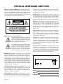 3
3
-
 4
4
-
 5
5
-
 6
6
-
 7
7
-
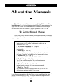 8
8
-
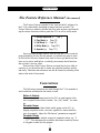 9
9
-
 10
10
-
 11
11
-
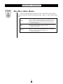 12
12
-
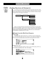 13
13
-
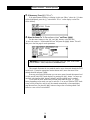 14
14
-
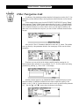 15
15
-
 16
16
-
 17
17
-
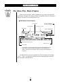 18
18
-
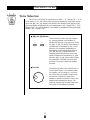 19
19
-
 20
20
-
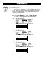 21
21
-
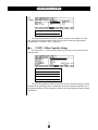 22
22
-
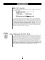 23
23
-
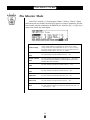 24
24
-
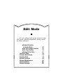 25
25
-
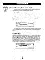 26
26
-
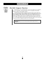 27
27
-
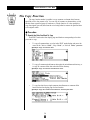 28
28
-
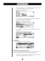 29
29
-
 30
30
-
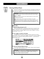 31
31
-
 32
32
-
 33
33
-
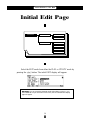 34
34
-
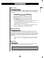 35
35
-
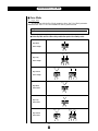 36
36
-
 37
37
-
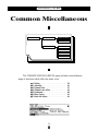 38
38
-
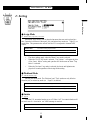 39
39
-
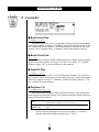 40
40
-
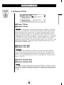 41
41
-
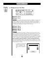 42
42
-
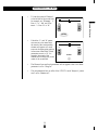 43
43
-
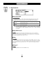 44
44
-
 45
45
-
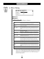 46
46
-
 47
47
-
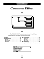 48
48
-
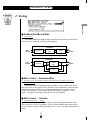 49
49
-
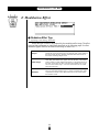 50
50
-
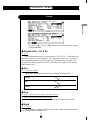 51
51
-
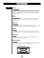 52
52
-
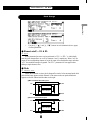 53
53
-
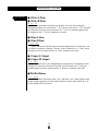 54
54
-
 55
55
-
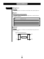 56
56
-
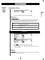 57
57
-
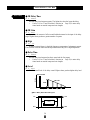 58
58
-
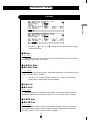 59
59
-
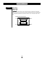 60
60
-
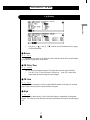 61
61
-
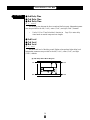 62
62
-
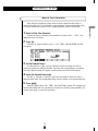 63
63
-
 64
64
-
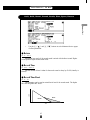 65
65
-
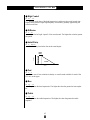 66
66
-
 67
67
-
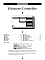 68
68
-
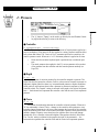 69
69
-
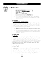 70
70
-
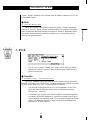 71
71
-
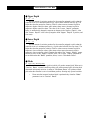 72
72
-
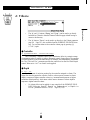 73
73
-
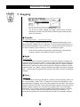 74
74
-
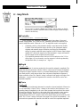 75
75
-
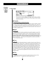 76
76
-
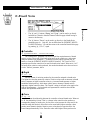 77
77
-
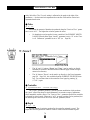 78
78
-
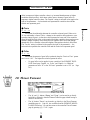 79
79
-
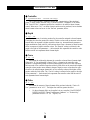 80
80
-
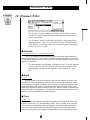 81
81
-
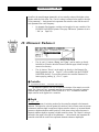 82
82
-
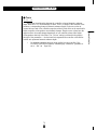 83
83
-
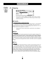 84
84
-
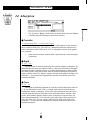 85
85
-
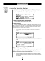 86
86
-
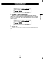 87
87
-
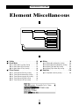 88
88
-
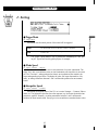 89
89
-
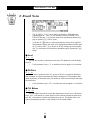 90
90
-
 91
91
-
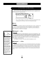 92
92
-
 93
93
-
 94
94
-
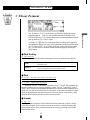 95
95
-
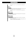 96
96
-
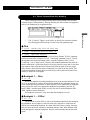 97
97
-
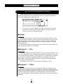 98
98
-
 99
99
-
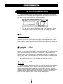 100
100
-
 101
101
-
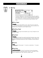 102
102
-
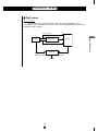 103
103
-
 104
104
-
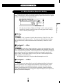 105
105
-
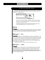 106
106
-
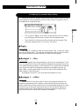 107
107
-
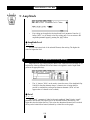 108
108
-
 109
109
-
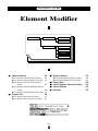 110
110
-
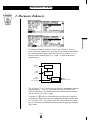 111
111
-
 112
112
-
 113
113
-
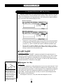 114
114
-
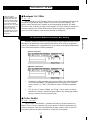 115
115
-
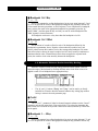 116
116
-
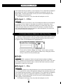 117
117
-
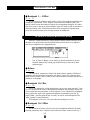 118
118
-
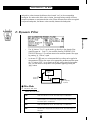 119
119
-
 120
120
-
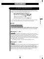 121
121
-
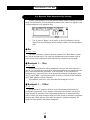 122
122
-
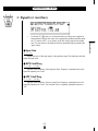 123
123
-
 124
124
-
 125
125
-
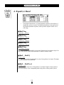 126
126
-
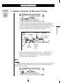 127
127
-
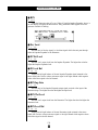 128
128
-
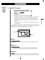 129
129
-
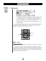 130
130
-
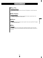 131
131
-
 132
132
-
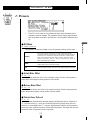 133
133
-
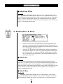 134
134
-
 135
135
-
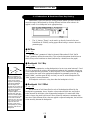 136
136
-
 137
137
-
 138
138
-
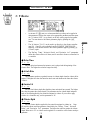 139
139
-
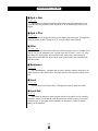 140
140
-
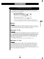 141
141
-
 142
142
-
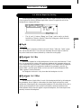 143
143
-
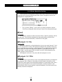 144
144
-
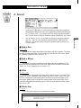 145
145
-
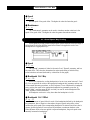 146
146
-
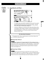 147
147
-
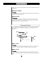 148
148
-
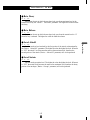 149
149
-
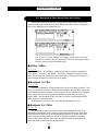 150
150
-
 151
151
-
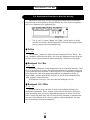 152
152
-
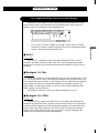 153
153
-
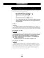 154
154
-
 155
155
-
 156
156
-
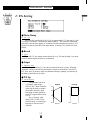 157
157
-
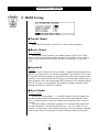 158
158
-
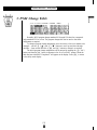 159
159
-
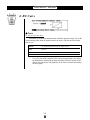 160
160
-
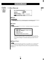 161
161
-
 162
162
-
 163
163
-
 164
164
-
 165
165
-
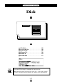 166
166
-
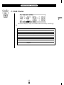 167
167
-
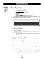 168
168
-
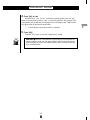 169
169
-
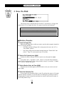 170
170
-
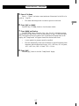 171
171
-
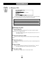 172
172
-
 173
173
-
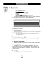 174
174
-
 175
175
-
 176
176
-
 177
177
-
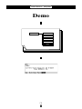 178
178
-
 179
179
-
 180
180
-
 181
181
-
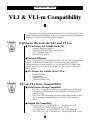 182
182
-
 183
183
-
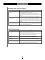 184
184
-
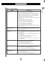 185
185
-
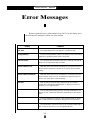 186
186
-
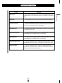 187
187
-
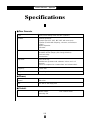 188
188
-
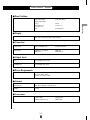 189
189
-
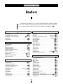 190
190
-
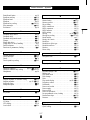 191
191
-
 192
192
-
 193
193
-
 194
194
-
 195
195


Yamaha VL1 de handleiding
- Categorie
- Digitale piano's
- Type
- de handleiding
- Deze handleiding is ook geschikt voor
in andere talen
- English: Yamaha VL1 Owner's manual
- italiano: Yamaha VL1 Manuale del proprietario
- русский: Yamaha VL1 Инструкция по применению
- français: Yamaha VL1 Le manuel du propriétaire
- español: Yamaha VL1 El manual del propietario
- Deutsch: Yamaha VL1 Bedienungsanleitung
- português: Yamaha VL1 Manual do proprietário
- dansk: Yamaha VL1 Brugervejledning
- suomi: Yamaha VL1 Omistajan opas
- čeština: Yamaha VL1 Návod k obsluze
- svenska: Yamaha VL1 Bruksanvisning
- Türkçe: Yamaha VL1 El kitabı
- polski: Yamaha VL1 Instrukcja obsługi
- română: Yamaha VL1 Manualul proprietarului