
OWNER'S MANUAL
VT10160 504CRIT15.2-01A0 M.D.G., EMI Division, © Yamaha Corporation 1995, Printed in Japan

For details of products, please contact your nearest Yamaha or the
authorized distributor listed below.
Pour plus de détails sur les produits, veuillez-vous adresser à Yamaha
ou au distributeur le plus proche de vous figurant dans la liste
suivante.
MIDDLE & SOUTH AMERICA
MEXICO
Yamaha De Mexico S.A. De C.V.,
Departamento de ventas
Javier Rojo Gomez No.1149, Col. Gpe Del Moral,
Deleg. Iztapalapa, 09300 Mexico, D.F.
Tel: 686-00-33
BRASIL
Yamaha Musical Do Brasil LTDA.
Ave. Reboucas 2636, São Paulo, Brasil
Tel: 011-53-1377
PANAMA
Yamaha De Panama S.A.
Edificio Interseco, Calle Elvira Mendez no.10, Piso 3,
Oficina #105, Ciudad de Panama, Panama
Tel: 507-69-5311
OTHER LATIN AMERICAN COUNTRIES
AND CARIBBEAN COUNTRIES
Yamaha Music Latin America Corp.
6101 Blue Lagoon Drive, Miami, Florida 33126,
U.S.A.
Tel: 305-261-4111
EUROPE
THE UNITED KINGDOM
Yamaha-Kemble Music (U.K.) Ltd.
Sherbourne Drive, Tilbrook, Milton Keynes, MK7
8BL, England
Tel: 0908-366700
IRELAND
Danfay Limited
61D, Sallynoggin Road, Dun Laoghaire, Co. Dublin
Tel: 01-2859177
GERMANY/SWITZERLAND
Yamaha Europa GmbH.
Siemensstraße 22-34, D-2084 Rellingen, F.R. of
Germany
Tel: 04101-3030
AUSTRIA/HUNGARY/SLOVENIA/
ROMANIA/BULGARIA
Yamaha Music Austria GesmbH.
Schleiergasse 20, A-1100 Wien Austria
Tel: 0222-60203900
THE NETHERLANDS
Yamaha Music Benelux B.V.,
Verkoop Administratie
Kanaalweg 18G, 3526KL, Utrecht, The Netherlands
Tel: 030-828411
BELGIUM/LUXEMBOURG
Yamaha Music Benelux B.V.,
Brussels-office
Keiberg Imperiastraat 8, 1930 Zaventem, Belgium
Tel: 02-7258220
NORTH AMERICA
CANADA
Yamaha Canada Music Ltd.
135 Milner Avenue, Scarborough, Ontario, M1S 3R1,
Canada
Tel: 416-298-1311
U.S.A.
Yamaha Corporation of America
6600 Orangethorpe Ave., Buena Park, Calif. 90620,
U.S.A.
Tel: 714-522-9011
Die Einzelheiten zu Produkten sind bei Ihrer unten aufgeführten
Niederlassung und bei Yamaha Vertragshändlern in den jeweiligen
Bestimmungsländern erhältlich.
Para detalles sobre productos, contacte su tienda Yamaha más cercana
o el distribuidor autorizado que se lista debajo.
FRANCE
Yamaha Musique France,
Division Instruments Electroniques et de
Scène
BP 70-77312 Marne-la-Valée Cedex 2, France
Tel: 01-64-61-4000
ITALY
Yamaha Musica Italia S.P.A.,
Combo Division
Viale Italia 88, 20020 Lainate (Milano), Italy
Tel: 02-935-771
SPAIN
Yamaha-Hazen Electronica Musical, S.A.
Jorge Juan 30, 28001, Madrid, Spain
Tel: 91-577-7270
PORTUGAL
Valentim de Carvalho CI SA
Estrada de Porto Salvo, Paço de Arcos 2780 Oeiras,
Portugal
Tel: 01-443-3398/4030/1823
GREECE
Philippe Nakas S.A.
Navarinou Street 13, P.Code 10680, Athens, Greece
Tel: 01-364-7111
SWEDEN
Yamaha Scandinavia AB
J.A. Wettergrens gata 1, Box 30053, 400 43 Göteborg,
Sweden
Tel: 031-496090
DENMARK
Yamaha Scandinavia Filial Denmark
Generatorvej 8B, 2730 Herlev, Denmark
Tel: 44 92 49 00
FINLAND
Fazer Music Inc.
Aleksanterinkatu 11, SF 00100 Helsinki, Finland
Tel: 0435 011
NORWAY
Narud Yamaha AS
Østerndalen 29, 1345 Østerås
Tel: 02-24 47 90
ICELAND
Páll H. Pálsson
P.O. Box 85, 121 Reykjavik, Iceland
Tel: 01-19440
EAST EUROPEAN COUNTRIES
(Except HUNGARY)
Yamaha Europa GmbH.
Siemensstraße 22-34, D-2084 Rellingen, F.R. of
Germany
Tel: 04101-3030
AFRICA
Yamaha Corporation,
International Marketing Division
Nakazawa-cho 10-1, Hamamatsu, Japan 430
Tel: 053-460-2312
MIDDLE EAST
TURKEY/CYPRUS
Yamaha Musique France, Division Export
BP 70-77312 Marne-la-Valée Cedex 2, France
Tel: 01-64-61-4000
OTHER COUNTRIES
Yamaha Corporation,
International Marketing Division
Nakazawa-cho 10-1, Hamamatsu, Japan 430
Tel: 053-460-2312
ASIA
HONG KONG
Tom Lee Music Co., Ltd.
11/F., Silvercord Tower 1, 30 Canton Road,
Tsimshatsui, Kowloon, Hong Kong
Tel: 730-1098
INDONESIA
PT. Yamaha Music Indonesia (Distributor)
PT. Nusantik
Gedung Yamaha Music Center, Jalan Jend. Gatot
Subroto Kav. 4, Jakarta 12930, Indonesia
Tel: 21-520-2577
KOREA
Cosmos Corporation
#131-31, Neung-Dong, Sungdong-Ku, Seoul, Korea
Tel: 02-466-0021~5
MALAYSIA
Yamaha Music Malaysia, Sdn., Bhd.
16-28, Jalan SS 2/72, Petaling Jaya, Selangor,
Malaysia
Tel: 3-717-8977
PHILIPPINES
Yupangco Music Corporation
339 Gil J. Puyat Avenue, P.O. BOX 885 MCPO,
Makati, Metro Manila, Philippines
Tel: 819-7551
SINGAPORE
Yamaha Music Asia Pte., Ltd.
Blk 17A Toa Payoh #01-190 Lorong 7
Singapore 1231
Tel: 354-0133
TAIWAN
Kung Hsue She Trading Co., Ltd.
No. 322, Section 1, FuHsing S. Road, Taipei 106,
Taiwan. R.O.C.
Tel: 02-709-1266
THAILAND
Siam Music Yamaha Co., Ltd.
865 Phornprapha Building, Rama I Road,
Patumwan, Bangkok 10330, Thailand
Tel: 2-215-3443
THE PEOPLE’S REPUBLIC OF CHINA
AND OTHER ASIAN COUNTRIES
Yamaha Corporation,
International Marketing Division
Nakazawa-cho 10-1, Hamamatsu, Japan 430
Tel: 053-460-2317
OCEANIA
AUSTRALIA
Yamaha Music Australia Pty. Ltd.
17-33 Market Street, South Melbourne, Vic. 3205,
Australia
Tel: 3-699-2388
NEW ZEALAND
Music Houses of N.Z. Ltd.
146/148 Captain Springs Road, Te Papapa, Auckland,
New Zealand
Tel: 9-634-0099
COUNTRIES AND TRUST
TERRITORIES IN PACIFIC OCEAN
Yamaha Corporation,
International Marketing Division
Nakazawa-cho 10-1, Hamamatsu, Japan 430
Tel: 053-460-2317
HEAD OFFICE Yamaha Corporation, Electronic Musical Instrument Division
Nakazawa-cho 10-1, Hamamatsu, Japan 430
Tel: 053-460-2445
SY06
FCC INFORMATION (U.S.A)
1. IMPORTANT NOTICE : DO NOT MODIFY THIS UNIT!
This product, when installed as indicated in the instructions contained in this manual, meets FCC requirements. Modifications not expressly
approved by Yamaha may void your authority, granted by the FCC, to use the product.
2. IMPORTANT: When connecting this product to accessories and/or another product use only high quality shielded cables. Cable/s
supplied with this product MUST be used. Follow all installation instructions. Failure to follow instructions could void your FCC
authorization to use this product in the USA.
3. NOTE: This product has been tested and found to comply with the requirements listed in FCC Regulations, Part 15 for Class “B” digital
devices. Compliance with these requirements provides a reasonable level of assurance that your use of this product in a residential
environment will not result in harmful interference with other electronic devices. This equipment generates/uses radio frequencies and, if
not installed and used according to the instructions found in the user’s manual, may cause interference harmful to the operation of other
electronic devices. Compliance with FCC regulations does not guarantee that interference will not occur in all installations. If this product
is found to be the source of interference, which can be determined by turning the unit “OFF” and “ON”, please try to eliminate the problem
by using one of the following measures:
Relocate either this product or the device that is being affected by the interference.
Utilize power outlets that are on different branch (circuit breaker or fuse) circuits or install AC line filter/s.
In the case of radio or TV interference, relocate/reorient the antenna. If the antenna lead-in is 300 ohm ribbon lead, change the lead-in to
co-axial type cable.
If these corrective measures do not produce satisfactory results, please contact the your local retailer authorized to distribute this type of
product. If you can not locate the appropriate retailer, please contact Yamaha Corporation of America, Electronic Service Division, 6600
Orangethorpe Ave, Buena Park, CA 90620
*
The above statements apply ONLY to those products distributed by Yamaha Corporation of America or its subsidiaries.
CANADA
THIS DIGITAL APPARATUS DOES NOT EXCEED THE
“CLASS B” LIMITS FOR RADIO NOISE EMISSIONS FROM
DIGITAL APPARATUS SET OUT IN THE RADIO INTERFER-
ENCE REGULATION OF THE CANADIAN DEPARTMENT OF
COMMUNICATIONS.
LE PRESENT APPAREIL NUMERIQUE N’EMET PAS DE
BRUITS RADIOELECTRIQUES DEPASSANT LES LIMITES
APPLICABLES AUX APPAREILS NUMERIQUES DE LA
“CLASSE B” PRESCRITES DANS LE REGLEMENT SUR LE
BROUILLAGE RADIOELECTRIQUE EDICTE PAR LE
MINISTERE DES COMMUNICATIONS DU CANADA.
*
This applies only to products distributed by Yamaha
Canada Music LTD.
ADVARSEL!
Lithiumbatteri—Eksplosionsfare ved fejlagtig håndtering.
Udskiftning må kun ske med batteri af samme fabrikat og type.
Levér det brugte batteri tilbage til leverandoren.
VARNING
Explosionsfara vid felaktigt batteribyte. Använd samma
batterityp eller en ekvivalent typ som rekommenderas av
apparattillverkaren. Kassera använt batteri enligt fabrikantens
instruktion.
VAROITUS
Paristo voi räjähtää, jos se on virheellisesti asennettu. Vaihda
paristo ainoastaan laitevalmistajan suosittelemaan tyyppiin.
Hävitä käytetty paristo valmistajan ohjeiden mukaisesti.

ii
WELCOME TO THE MU50
Welcome to the MU50
Congratulations and thank you for purchasing the Yamaha MU50 Tone
Generator!
The MU50 is an advanced tone generator providing 737 high-quality
Voices, full General MIDI compatibility — including Yamaha’s new XG-
MIDI — plus flexible computer interfacing in a highly compact and
portable package.
With the convenient built-in host computer interface and MIDI ter-
minals, the MU50 is ideal for any computer music system — from connec-
tion to a simple laptop to integration in a complete MIDI studio. With its
large LCD and the intuitive graphic controls on the display, the MU50 is
remarkably easy to use.
The MU50 also features 16 Part multi-timbral capacity and full 32-
note polyphony for playback of even the most sophisticated song data. A
special Performance mode gives you flexible four-Voice operation, for
live performance applications. Built-in digital multi-effects give you enor-
mous versatility in “sweetening” the sound. Plus, the convenient INPUT
jack allows you to connect an external audio source, and mix that source’s
signals with the MU50’s Voices. What’s more, the MU50 provides a host
of comprehensive, yet easy-to-use editing tools for getting just the sound
you need.

UNPACKING
iii
MU50 Serial No.:
PA-1207 AC Power Adaptor*
Owner’s Manual
Unpacking
Your MU50 package should include the items listed below. Make sure that
you have them all. Also, write down the serial number of your MU50 in the
box below, for future reference.
* Power supply recommendation may vary from country to country.
Please check with your nearest Yamaha dealer for further details.

iv
TABLE OF CONTENTS
Table of Contents
Welcome to the MU50 ............................................................................................................ ii
Unpacking ..............................................................................................................................iii
Table of Contents................................................................................................................... iv
How to Use This Manual ...................................................................................................... vi
Precautions............................................................................................................................ vii
The Controls of the MU50 ..................................................................................................... 1
The MU50 — What It Is and What It Can Do .................................................................... 4
What It Is…....................................................................................................................... 4
About General MIDI..................................................................................................... 4
What It Can Do…............................................................................................................. 5
Using With a MIDI Keyboard....................................................................................... 5
Using With a Computer or Sequencer .......................................................................... 5
About the Modes of the MU50 ........................................................................................ 6
Play Modes and the Part Controls................................................................................. 7
Utility Mode................................................................................................................ 10
Part Edit Mode ............................................................................................................ 10
GUIDED TOUR
Setting Up Your MU50 ................................................................................................... 12
What You’ll Need .................................................................................................. 12
Making the Connections ....................................................................................... 12
Powering Up and Playing the Demo Song.................................................................... 14
Playing the Demo Song .............................................................................................. 15
Selecting Voices ............................................................................................................... 17
Changing the Voice Bank............................................................................................ 18
Selecting Voices From Your MIDI Keyboard ............................................................. 19
Changing Some of the Settings — Part Controls......................................................... 20
Selecting another Part and changing its MIDI channel .............................................. 20
Changing the Volume and Pan settings of a Part ........................................................ 22
Using Mute/Solo.............................................................................................................. 23
Using the INPUT Jack.................................................................................................... 24
Setting Up the MU50 in Your Music System................................................................ 25
Connecting With a Computer ..................................................................................... 25
Macintosh .............................................................................................................. 25
IBM PC and Clones .............................................................................................. 26
Connecting to Other MIDI Devices ............................................................................ 27
Using the MU50 with a MIDI Data Storage Device .................................................... 29
Data Flow Block Diagram.............................................................................................. 30
MIDI/Computer Connecting Cables............................................................................. 31
REFERENCE
Multi Mode...................................................................................................................... 34
Multi Play Mode ......................................................................................................... 35
Part Controls ............................................................................................................... 35
Single Part Control...................................................................................................... 36

TABLE OF CONTENTS
v
GUIDED TOUR
REFERENCE
APPENDIX
Selecting Single Part Control ................................................................................ 36
Editing in Single Part ............................................................................................ 36
All Part Control........................................................................................................... 40
Editing in All Part.................................................................................................. 40
Multi Edit Mode.......................................................................................................... 43
Filter ...................................................................................................................... 43
EG (Envelope Generator) ...................................................................................... 45
Vibrato ................................................................................................................... 50
Others .................................................................................................................... 52
Drum Setup Controls............................................................................................. 61
Calling Up the Drum Setup Menu................................................................... 61
Drum Setup Parameters ................................................................................... 62
Performance Mode ......................................................................................................... 66
Performance Play Mode.............................................................................................. 66
Selecting a Performance and its Individual Parts .................................................. 67
Performance Part Control ........................................................................................... 69
Single Part ............................................................................................................. 69
All Part .................................................................................................................. 72
Performance Edit Mode .............................................................................................. 75
Common ................................................................................................................ 75
Part ........................................................................................................................ 78
Filter ...................................................................................................................... 79
EG ......................................................................................................................... 79
Vibrato ................................................................................................................... 80
Others .................................................................................................................... 80
Copy and Store Operations ......................................................................................... 83
Copy ...................................................................................................................... 83
Store ...................................................................................................................... 84
Effect Edit Mode............................................................................................................. 86
Reverb (REV) ............................................................................................................. 86
Chorus (CHO)............................................................................................................. 88
Variation (VAR) .......................................................................................................... 89
About the Effect Connections — System and Insertion ............................................. 92
Utility Mode .................................................................................................................... 95
System Functions ........................................................................................................ 95
Dump Out Functions................................................................................................... 98
Saving and Restoring Data via MIDI .................................................................... 98
Saving and Restoring Data via TO HOST ............................................................ 98
Initialize Functions ................................................................................................... 101
Demo Song Play (DEMO) ........................................................................................ 104
Sound Module Mode (MODE) ................................................................................. 105
APPENDIX
XG .................................................................................................................................. 108
Troubleshooting ............................................................................................................ 123
Error Messages ............................................................................................................. 124
Specifications................................................................................................................. 125
Glossary ......................................................................................................................... 127
Index .............................................................................................................................. 129

vi
HOW TO USE THIS MANUAL
How to Use This Manual
You are probably eager to try out your new MU50 Tone Generator right
away and hear what it can do, rather than have to read through a lot of in-
structions before you can even get a sound out of it.
However, to get the most out of your MU50, we strongly suggest that
you read the following sections in the order given:
1) Precautions
This gives you important information on how to care for your new
MU50, how to avoid damaging, and how to ensure long-term, reliable
operation.
2) The Controls of the MU50
This section introduces you to the panel controls and connectors.
3) The MU50 — What It Is and What It Can Do
This briefly provides an overview of the functions and features of the
MU50 and offers some important hints on how you can use it effectively.
4) Guided Tour
This very important section gets you started using your new MU50. It
helps you set up the instrument, play it, and use some of the more im-
portant functions and features. The hands-on experience you gain in
this section will help you navigate through the other sections of the
manual.
5) Setting Up the MU50 in Your Music System;
Using the MU50 with a Computer
These sections (within the Guided Tour) provide all you need to know
to effectively integrate the MU50 into your present computer music
system.
6) Reference
Once you’re familiar with everything above, lightly go over this com-
prehensive guide to all editing functions. You won’t need (or want) to
read everything at once, but it is there for you to refer to when you need
information about a certain feature or function.
7) Appendix
Finally, use the sections in the Appendix as necessary. For example, the
Index will come in handy when you need to quickly find information
on a specific topic. Other sections, such as the Glossary, Trouble-
shooting and Error Messages provide additional useful information.

PRECAUTIONS
vii
Precautions
Your MU50 will give you years of reliable service if you follow the simple
precautions below:
䡵 LOCATION
Keep the instrument away from locations where it is likely to be exposed to
high temperatures (such as direct sunlight) or humidity. Also avoid loca-
tions which are subject to excessive dust accumulation or vibration which
could cause mechanical damage.
䡵 USE THE CORRECT POWER ADAPTOR
Use only the recommended PA-1207 Power Adaptor for supplying power
to the instrument. Use of another adaptor may cause serious damage to the
instrument or the adaptor itself.
䡵
MAKE SURE POWER IS OFF WHEN MAKING OR REMOVING
CONNECTIONS
To prevent damage to the instrument and other connected equipment, al-
ways turn off the power prior to connecting or disconnecting cables. Also,
turn the power off when the instrument is not in use, and disconnect the
power adaptor during electric storms.
䡵 HANDLE THE INSTRUMENT WITH CARE
Although the instrument has been constructed to withstand the rigors of
normal use for optimum sturdiness and reliability, avoid subjecting it to
strong physical shocks (such as dropping or hitting it). Since the MU50 is a
precision-made electronic device, also avoid applying excessive force to the
various controls. When moving the instrument, first unplug the power adap-
tor and all other cables to prevent damage to cords and jacks. Always un-
plug cables by gripping the plug firmly, not by pulling on the cable.
䡵 CLEAN WITH A SOFT, DRY CLOTH
Never use solvents such as benzine or thinner to clean the instrument, since
these will damage the cabinet finish or dull the keys. Wipe clean with a
soft, dry cloth. If necessary, use a soft, clean, slightly moistened cloth —
making sure to wipe the case off again with a dry cloth.

viii
PRECAUTIONS
䡵 ELECTROMAGNETIC INTERFERENCE
Avoid using the unit near televisions, radios or other equipment generating
electromagnetic fields. Proximity to such equipment may cause the unit to
malfunction, and may generate interference noise in the other appliance as
well.
䡵 DO NOT OPEN THE CASE OR TRY REPAIRING THE INSTRUMENT
YOURSELF
The instrument contains no user-serviceable parts. Never open the case or
tamper with the internal circuitry in any way, since doing so may result in
damage to the instrument. Refer all servicing to qualified Yamaha service
personnel.
䡵 MIDI CABLES
When connecting the instrument to other MIDI equipment, be sure to use
only high-quality cables made especially for MIDI data transmission. Also,
avoid using cables longer than 15 meters, since long cables can result in
data errors.
Yamaha is not responsible for damage caused by improper han-
dling or operation.

THE CONTROLS OF THE MU50
1
The Controls of the MU50
Front Panel
1 INPUT jack
For connection of an external audio source. (Accepts either stereo or mono 1/4"
plugs.)
2 INPUT level control
For control of the INPUT audio level.
3 PHONES jack
For connection to a set of stereo headphones (mini-pin).
4 POWER/VOL control
Pressing this turns the power on and off. Turning it adjusts the overall volume
of the MU50.
5 PLAY button
For entering the Play mode. (See page 34.)
6 UTIL (UTILITY) button
For entering the Utility mode. (See page 95.)
7 MODE button
For entering the Sound Module mode. (See page 34.)
8 EDIT button
For entering the Edit mode. (See pages 43, 75.)
^
1
2
3
4
58
6
7
9
10
11
13
14
15
12

2
THE CONTROLS OF THE MU50
9 EFFECT button
For entering the Effect Edit mode. (See page 86.)
10 MUTE/SOLO button
Pressing this alternately mutes or solos the selected Part. (See page 23.)
11 ENTER button
For calling up menu items in the display and for executing certain functions
and operations. Double-clicking this (pressing it twice quickly) calls up the
System Exclusive or Control Change hexadecimal message for the current
function and parameter value.
12 EXIT button
For leaving various display pages and returning to previous displays. Also for
canceling certain functions and operations.
13 PART q buttons
For selecting different Parts. In the Effect Edit mode, these can be used to
switch among the different effects. Pressing these together enters and exits
from All Part control. (See page 40.)
14 SELECT w buttons
For selecting the various menu items, parameters and controls on the display.
15 VALUE q buttons
For changing the value of a selected parameter or control.
9
12
8
10
11
1
2
3
4
5
6
13
14
15
7

THE CONTROLS OF THE MU50
3
Rear Panel
1 MIDI THRU, MIDI OUT and MIDI IN terminals
For connection to other MIDI devices, such as a MIDI keyboard, tone genera-
tor, sequencer, or to a computer that has a MIDI interface. MIDI IN is for in-
put of MIDI data. MIDI OUT is for data dumps to another MIDI device, while
MIDI THRU is for “daisy-chain” connection of additional MU50s or other
MIDI instruments. (See page 12 for more information on MIDI connections.)
2 HOST SELECT switch
For selecting the type of host computer. (See page 12.)
3 TO HOST terminal
For connection to a host computer that does not have a MIDI interface. (See
page 26.)
4 DC IN jack
For connection to the PA-1207 AC power adaptor.
5 OUTPUT R, L/MONO jacks (Right, Left/Mono)
For connection to a stereo amplifier/speaker system. When using a mono sys-
tem, connect it to the L/MONO jack.
1
2
34 5

4
THE MU50 — WHAT IT IS AND WHAT IT CAN DO
The MU50 — What It Is and What It Can Do
What It Is…
The MU50 is a compact, highly portable and easy-to-use tone generator. It
features full General MIDI Level 1 compatibility with 128 General MIDI
Voices and 1 drum kit. It also provides new XG-MIDI compatibility, with a
total of 480 Voices and 11 drum kits. The MU50 has 32-note polyphony
and is 16-Part multi-timbral. In other words, the MU50 features 16 differ-
ent Parts, each with its own Voice, so that up to 16 different Voices can be
sounded simultaneously.
The MU50 also has a TO HOST terminal for easy interfacing with a
computer, allowing you to play the Voices using your favorite music soft-
ware. This is where the advanced multi-timbral capabilities come in, letting
you playing sophisticated arrangements using up to 16 different Voices at
the same time.
The MU50 also features a special Performance mode, in which four Parts
are played simultaneously over a single MIDI channel. Connected to a MIDI
keyboard, this effectively gives you four tone generators in one. The MU50
gives you four sets of 32 factory-programmed Preset Performances plus 128
Internal Performance locations for your own original Performances.
About General MIDI
General MIDI is a new addition to the worldwide MIDI standard. MIDI, as
you know, stands for Musical Instrument Digital Interface, and makes it
possible for various electronic musical instruments and other devices to
“communicate” with each other. For example, by connecting a sequencer
to the MU50’s MIDI IN terminal, you could play back a song on the
sequencer using the Voices of the MU50.
So, where does General MIDI fit in all of this? One of the most impor-
tant features of General MIDI is in the standardization of Voices. This
means that a song recorded in the General MIDI format can be played back
on any General MIDI compatible tone generator and sound just as the com-
poser intended. For example, if there is an alto sax solo in the song, it will
be played by an alto sax Voice on the General MIDI tone generator (and
not by a tuba or harpsichord!). Since the MU50 is fully compatible with
General MIDI, you can take advantage of the vast wealth of musical mate-
rial recorded in that format.

THE MU50 — WHAT IT IS AND WHAT IT CAN DO
5
What It Can Do…
Here are a few ideas on how you can use the MU50. The list below is not
comprehensive, but is meant to be a general guide to the possibilities and
provide a starting point or springboard for your own creative ideas and ex-
plorations.
Using With a MIDI Keyboard
Use the MU50 as supplementary tone generator with your MIDI keyboard
and play the Voices of both instruments in a layer together. Or, use the con-
venient Performance mode, and play four Voices on the MU50 at once. You
can split the four Voices across the keyboard, playing each from a different
register. Or you can create sophisticated velocity splits, in which a different
Voice is heard depending on how strongly you play the keyboard. Or use
keyboard and velocity splits together for even greater flexibility.
Using With a Computer or Sequencer
Home Studio Setup
The MU50 integrates instantly and easily into any existing setup. If you
have a MIDI keyboard, computer and sequencing software, the MU50 with
its high-quality Voices and multi-timbral capabilities can expand your home
studio system.
Carry It With You
If you have a laptop computer (and sequencing software), simply connect
the MU50, plug in some headphones and you’ve got a complete, high-pow-
ered music making system that’s ready to go wherever you go. Use it for
composing, arranging, practicing or making/playing demos for your band.
Multimedia
Since it’s portable and compatible with General MIDI, the MU50 is a natu-
ral for multimedia applications. Bring it with you to a presentation — since
the computer interface is built-in to the MU50, it hooks up instantly and
easily to the computer’s serial port or printer port, without the need for any
other equipment.

6
THE MU50 — WHAT IT IS AND WHAT IT CAN DO
Sound Module Mode
XG
TG300B
C/M
DOC
Performance
About the Modes of the MU50
The MU50 has two main operating modes: Multi and Performance. In
Multi mode, the MU50 is a 16-Part multi-timbral tone generator; in Per-
formance mode, the MU50 effectively functions as four tone generators
controlled over a single MIDI channel.
Which mode the MU50 is in depends on the selected Sound Module
mode. If XG, TG300B, C/M or DOC are selected, the MU50 automatically
sets itself to the Multi mode. When PERFORM is selected, the MU50 is in
the Performance mode.
The various modes and the software compatibility each provides are de-
scribed below:
XG: Provides compatibility with the XG format.
TG300B: Provides semi-compatibility with the GM Level 1 standard.
C/M: Provides semi-compatibility with computer music software.
DOC: Provides compatibility with DOC music software for the Yamaha
Clavinova.
PERFORMANCE: Allows playing of four separate Parts simultaneously
over a single MIDI channel.
The bottom right of the display indicates the currently selected Sound Mod-
ule mode.
Selected Sound Module mode.
When Performance is selected, both C/M
and DOC are indicated as shown below:
C/M
DOC

THE MU50 — WHAT IT IS AND WHAT IT CAN DO
7
Play Modes and the Part Controls
Once the operating mode of the MU50 is set (Multi or Performance), there
are two main ways you can use the MU50: playing and editing. In the Play
modes, you play the Voices; in the various Edit modes, you change their
settings.
Within the Play modes are the Part controls. These let you make basic
settings for the Parts. The Single Part controls allow you to make independ-
ent settings for each Part, while the All Part controls allow you to change
the overall settings of all Parts. (See page 35 for more information.)
The MU50 has several different Edit modes, each with various menus and
operations:
Part Edit Mode
FilterFilter
FilterFilter
Filter
Cutoff Frequency
Resonance
Play Mode
Part 1 — 16Part 1 — 16
Part 1 — 16Part 1 — 16
Part 1 — 16
AllAll
AllAll
All
Receive Channel Device Number
Bank Number
Program Number
Volume Master Volume
Expression
Pan
Reverb Send Reverb Return
Chorus Send Chorus Return
Variation Send Variation Return
Note Shift Transpose
䊲

8
THE MU50 — WHAT IT IS AND WHAT IT CAN DO
EGEG
EGEG
EG
EG Attack Time
EG Decay Time
EG Release Time
Pitch EG Initial Level
Pitch EG Attack Time
Pitch EG Release Level
Pitch EG Release Time
VibratoVibrato
VibratoVibrato
Vibrato
Vibrato Rate
Vibrato Depth
Vibrato Delay
OthersOthers
OthersOthers
Others
Detune
Part Mode
Mono/Poly Mode
Element Reserve
Velocity Sensitivity Depth
Velocity Sensitivity Offset
Note Limit Low
Note Limit High
Portamento Switch
Portamento Time
Velocity Limit Low
Velocity Limit High
Dry Level (VarConnect=SYS)
Pitch Bend Control
MW LFO Pitch Modulation Depth
䊲

THE MU50 — WHAT IT IS AND WHAT IT CAN DO
9
Performance Edit Mode
PartPart
PartPart
Part
FilterFilter
FilterFilter
Filter
Cutoff Frequency
Resonance
EGEG
EGEG
EG
EG Attack Time
EG Decay Time
EG Release Time
Pitch EG Initial Level
Pitch EG Attack Time
Pitch EG Release Level
Pitch EG Release Time
VibratoVibrato
VibratoVibrato
Vibrato
Vibrato Rate
Vibrato Depth
Vibrato Delay
䊲
Performance Mode
AllAll
AllAll
All
Part 1 — 4Part 1 — 4
Part 1 — 4Part 1 — 4
Part 1 — 4
System MIDI Channel
Performance Bank Bank Number
Performance Number
Program(Voice) Number
Performance Volume Volume
Performance Pan Pan
Reverb Return Reverb Send
Chorus Return Chorus Send
Variation Return Variation Send
System Transpose Note Shift

10
THE MU50 — WHAT IT IS AND WHAT IT CAN DO
For more information on each of these modes and their menus, see the re-
spective sections in the Reference section.
Utility Mode
The Utility mode lets you set functions related to the overall operation of
the MU50, such as Master Tune, display Contrast and reception of certain
MIDI messages that affect the entire instrument. Included also are miscel-
laneous operations, such as sending bulk data to a data storage device, ini-
tializing of the MU50 settings, and playing the special Demo song.
Part Edit Mode
The Part Edit mode allows you to change certain settings for each indi-
vidual Part, such as those of the Filter, EG (Envelope Generator), and many
other settings. The internal Voices can be sounded during editing, allowing
you to hear the effects of your edits.
OthersOthers
OthersOthers
Others
Detune
Mono/Poly Mode
Velocity Sensitivity Depth
Velocity Sensitivity Offset
Note Limit Low
Note Limit High
Portamento Switch
Portamento Time
Velocity Limit Low
Velocity Limit High
Dry Level (VarConnect=SYS)
MW LFO Pitch Modulation Depth
MW LFO Filter Modulation Depth
Pitch Bend Control
Assignable Control 1 Filter Control
Assignable Control 1 Amplitude Control
䊲

G
UIDED
T
OUR
When using your MU50 for the first time, read through this
short section of the manual. It guides you step-by-step in us-
ing many of the basic operations: setting the instrument up,
connecting it properly to other equipment, and — most im-
portantly — playing it.

12
GUIDED TOUR
Setting Up Your MU50
In this introductory section, you’ll learn how to set up the MU50 for use
with a MIDI keyboard. (Setting up for use with a computer is covered on
page 25.)
What You’ll Need
☛ The MU50 and the included power adaptor.
☛ A MIDI keyboard, electronic piano, or any instrument that can output
MIDI data.
☛ An amplifier/speaker system, preferably stereo. Alternately, you can use
a set of stereo headphones.
☛ Audio connecting cables.
☛ A MIDI cable.
Making the Connections
CAUTION!
Before making any connections, make sure that all equipment to be connected is turned off,
and that the MU50 power adaptor is not connected to an electrical outlet.
Operation
1 Connect one end of the MIDI cable to the MIDI OUT terminal of
the MIDI keyboard and the other to the MIDI IN terminal of the
MU50 (as shown in the illustration below).
2 Connect the audio cables from the R and L/MONO OUTPUT
jacks of the MU50 to the appropriate inputs on the amplifier
speaker system (as shown in the illustration below).
If the amplifier has only one input, use the L/MONO jack on
the MU50. If you are using stereo headphones, connect them to
the front panel PHONES jack.
3 Set the HOST SELECT switch on the MU50 to MIDI.
4 Connect the power adaptor to the DC IN terminal on the MU50
and plug the adaptor into an appropriate electrical outlet.

GUIDED TOUR
13
CAUTION!
● Do not attempt to use an AC adaptor other than the PA-1207. The use of an incompatible
adaptor may result in irreparable damage to the MU50, and even pose a serious shock
hazard.
● Be sure to disconnect the power adaptor from the outlet when the MU50 is not in use.
MIDI Keyboard
MIDI OUT
MIDI IN
MIDI CABLE
R
Amplifier
Speaker System
PHONES
DC INL/MONO
Power
Adaptor

14
GUIDED TOUR
Powering Up and Playing the Demo Song
Once you’ve connected everything properly, you’re ready to turn the MU50
on and start playing it. However, a small word of caution before you begin:
Follow the instructions given below to avoid possible damage to your
equipment and speakers.
Powering Up
Operation
1 If you haven’t done so already, press the
POWER/VOLPOWER/VOL
POWER/VOLPOWER/VOL
POWER/VOL control
on the MU50.
After the greeting display, the following display will appear:
2 Turn on the power of your MIDI keyboard.
3 Make sure that all volume controls (on the MU50 and the con-
nected amplifier) are turned down. Then, turn on the power of
your amplifier speaker system.
4 Finally, set the volume control on the MU50 to about the mid-
way position and set the volume on the amplifier to a suitable
level.

GUIDED TOUR
15
Playing the Demo Song
Now that you’ve set everything up properly, try playing the built-in Demo
Song. This showcases the high-quality Voices and the AWM2 tone genera-
tion system of the MU50.
Operation
1 Press the
UTIL UTIL
UTIL UTIL
UTIL button.
2 Select “DEMO” with the
SELECTSELECT
SELECTSELECT
SELECT w buttons and press the
ENTERENTER
ENTERENTER
ENTER button.
3 Press the
ENTER ENTER
ENTER ENTER
ENTER button to start the Demo Song.
The Demo Song starts playing immediately and repeats indefinitely
until stopped (in step 4 below). As the song plays back, the display
also shows in succession the bank number, program number and
voice name for each of the 16 Parts.
NOTE
During Demo Song playback, all panel controls (except the
EXITEXIT
EXITEXIT
EX IT button and the
VOLUMEVOLUME
VOLUMEVOLUME
VOLUME
control) cannot be used.
4 To stop playback of the song, press the
EXITEXIT
EXITEXIT
EXIT button.
5 To exit from the Demo Song function, press the
EXITEXIT
EXITEXIT
EXIT button
again.

16
GUIDED TOUR
Playing Your MU50 With a MIDI Keyboard
Operation
Play some notes on your MIDI keyboard.
If you’ve carefully followed all instructions up to now, one of
the “level meter” bars in the display should move — and you
should be able to hear the sound of the MU50 as you play.
NOTE
If your MIDI keyboard is transmitting on channel 1, the Voice of Part 1 should sound. If it is
transmitting on another channel, another Part’s Voice will sound. For the sake of these intro-
ductory instructions, set your keyboard so that it transmits on channel 1. (Refer to the own-
er’s manual of that instrument if necessary.)
The “level meter” bar indicates the “level” (velocity) of the
incoming MIDI data.
The number under the moving “level meter” indicates the Part number.

GUIDED TOUR
17
Selecting Voices
In this brief section, you’ll learn how to select other Voices. You can do this
directly from the panel of the MU50 or remotely, from your MIDI key-
board.
Operation
1 First, select a Part. Use the
PARTPART
PARTPART
PART q buttons to select Part 1.
Press the appropriate button until “01” appears in the PART sec-
tion of the display.
2 Use the
SELECT SELECT
SELECT SELECT
SELECT w buttons to move the arrow cursor to the
right side of the instrument icon, as shown below.
3 Use the
VALUEVALUE
VALUEVALUE
VALUE q buttons to change the Voice number. In
the display below, Voice number 26 has been selected.
Voice name.
Voice number (program number).
Instrument icon of current Voice.
MIDI receive channel for current Part.
Part number. (This is selectable only with the
PARTPART
PARTPART
PART q buttons.)
Solid arrow at Voice number (currently selected).
Arrow cursor (indicates currently selected control).
The arrow is directly above “PGM#” on the panel,
indicating that Program Number is currently selected.
Use these to move arrow cursor.

18
GUIDED TOUR
Play this new Voice from the keyboard. Try selecting other Voices and play
them as well. (For a list of all the available Voices, refer to the SOUND
LIST & MIDI DATA booklet.
HINT
You can rapidly move through the values by holding down one of the
VALUEVALUE
VALUEVALUE
VALUE q buttons.
You can move even more rapidly by holding down one button and then pressing and hold-
ing down the other. For example, to rapidly advance (increase) the value, hold down the
VALUEVALUE
VALUEVALUE
VALUE + button and simultaneously press and hold down the
VALUEVALUE
VALUEVALUE
VALUE – button.
Changing the Voice Bank
In the current Sound Module mode (XG), several banks of Voices are available.
Each bank can contain up to 128 different Voices.
Operation
1 Use the
SELECT SELECT
SELECT SELECT
SELECT w buttons to move the arrow cursor to the left side of
the instrument icon, as shown below.
Solid arrow at Bank number (currently selected).
Bank number.
Arrow cursor (indicates currently selected control).
The arrow is directly above “BANK” on the panel,
indicating that Bank number is currently selected.
Use these to move arrow cursor.

GUIDED TOUR
19
2 Use the
VALUEVALUE
VALUEVALUE
VALUE q buttons to change the Bank number.
3 Finally, use the
SELECTSELECT
SELECTSELECT
SELECT w buttons again to move the arrow cursor back
to the right side of the instrument icon — for Voice selection.
Selecting Voices From Your MIDI Keyboard
You can also select Voices remotely from the connected MIDI key-
board. Though the actual operation may differ depending on the
keyboard used, the general procedure is the same. (Refer to the
owner’s manual of your instrument for specific instructions.)
Operation
1 Make sure that your keyboard is set up to send Program Change
messages.
2 Use the panel controls to select a program on your keyboard.
Generally, if everything has been set up properly, the Voice number
and name on the MU50 will change, and will be the same number
as the program number you selected on your keyboard.

20
GUIDED TOUR
Changing Some of the Settings — Part Controls
You can make changes to each individual Part by using the Part controls.
These are always displayed in the Play mode, giving you at-a-glance con-
firmation of the various basic settings of the MU50. Let’s take a look at the
Play display again:
Each of these settings can be made independently for each of the Parts. For
example, each Part could have a different Volume setting, or a different Pan
setting. Try going through the brief sections below and making some
changes in the Part controls yourself.
Selecting another Part and changing its MIDI channel
Here we’ll select Part 2 and change its MIDI channel to 1, so that it
matches the MIDI channel of Part 1. This allows you to play the Voices of
both Part 1 and Part 2 over MIDI channel 1.
Voice name, bank number and program number
for the selected Part.
Note Shift setting
for the selected Part.
Chorus Send setting for the
selected Part.
Reverb Send setting for the
selected Part.
Variation Send setting
for the selected Part.
Pan setting for the selected Part.
Expression setting for the selected Part.
MIDI receive channel for the selected Part.
Volume setting for the selected Part.
Part number.

GUIDED TOUR
21
Operation
1 Use the
PARTPART
PARTPART
PART q buttons to select Part 2.
Part 2.
2 Use the
SELECTSELECT
SELECTSELECT
SELECT w buttons to call up the “Rcv CH” display
below.
Current MIDI Receive Channel.
3 Use the
VALUEVALUE
VALUEVALUE
VALUE q buttons to change the MIDI Receive Chan-
nel to “01.”
4 Finally, use the
SELECTSELECT
SELECTSELECT
SELECT w buttons to move the arrow cursor
back to the instrument icon (so that the Voice name is displayed),
and play the MIDI keyboard again.
Both “level meter” move together.
If both Parts 1 and 2 have been set to MIDI channel 1, both of their “level
meters” should move together as you play. And, if the two Parts are set to
different Voices, you should hear two different Voices sound at the same
time. (To change the Voice for a Part, refer back to Selecting Voices above.)

22
GUIDED TOUR
Changing the Volume and Pan settings of a Part
Now that you’re playing two Voices at the same time, you may want to ad-
just their settings. Here, we’ll change the Volume and Pan settings of one
Part’s Voice.
Operation
1
Use the
PARTPART
PARTPART
PART q buttons to select the desired Part (Part 1 or 2).
2 Use the
SELECTSELECT
SELECTSELECT
SELECT w buttons to call up the “Volume” display
below.
Current Volume setting.
3 Use the
VALUEVALUE
VALUEVALUE
VALUE q buttons to change the setting, and play the
keyboard as you make changes.
4 Now that you’ve adjusted the Volume balance of the two Voices,
change one of the Part’s Pan setting. Use the
SELECTSELECT
SELECTSELECT
SELECT w but-
tons to call up the “Pan” display below.
Current Pan setting.
5 Use the
VALUEVALUE
VALUEVALUE
VALUE q buttons to change the setting, and play the
keyboard again as you make changes.
If you want, try making changes to some of the other Part controls. The
procedure is the same: 1) Use the PART q buttons to select a Part, 2)
use the SELECT w buttons to choose the desired control, and 3) use
the VALUE q buttons to change the setting. For more information on
the Part controls, see page 36.

GUIDED TOUR
23
Using Mute/Solo
The MU50 has convenient Mute and Solo functions for selectively muting
or soloing any of the 16 Parts. This is especially useful when playing back
several Parts from a connected computer or sequencer. Mute lets you si-
lence one Part to hear how all of the other Parts sound without it. Solo lets
you isolate a single Part, to hear how that Part sounds by itself.
Mute and Solo are effective tools that help you as you edit the Parts,
since they allow you to better hear how the changes you make affect spe-
cific Voices as well as the overall sound.
Operation
While playing the keyboard (or during playback of a song from a
sequencer), press the MUTE button. Each press cycles through the
three functions: Mute, Solo and Normal operation.
The selected Part is muted, while all other Parts sound normally.
The selected Part is soloed, while all other Parts are muted.
All Parts sound normally.

24
GUIDED TOUR
Using the INPUT Jack
The MU50 also features an INPUT function that allows you to connect an
external audio source (such as an electric guitar, keyboard or CD player)
and mix in those signals with the MU50’s Voices — without the need for
an external mixer. For example, this allows you to play a guitar or keyboard
over backing tracks played with the MU50’s Voices from a MIDI
sequencer. The INPUT jack is a stereo input, and the left and right chan-
nels are indicated on the display as A1 and A2, with corresponding level
meter bars for indicating the signal levels.
Operation
1 Turn down the INPUT control on the front panel.
2 Connect the cable from the external sound source to the INPUT
jack.
NOTE
The INPUT jack accepts stereo signals. The left channel corresponds to the tip of the 1/4"
plug and the right corresponds to the ring.
3
Slowly bring up the INPUT control on the front panel and play the
external instrument or sound source until the level is appropriate.
NOTE
When the MU50 receives a mono signal, only the A1 (left) level meter bar is indicated.

GUIDED TOUR
25
Setting Up the MU50 in Your Music System
As you learned in the section The MU50 — What It Is and What It Can
Do on page 4, the MU50 can be integrated into a variety of setups. It would
be impossible to cover all connection possibilities in a short manual as this;
however, the section below will help in quickly setting up the MU50 and
using it in your system.
Connecting With a Computer
The MU50 features a built-in host computer interface, allowing you to di-
rectly connect it to your computer — eliminating the need of installing a
special MIDI interface to your computer. The MU50 can be used with the
following computers: Apple Macintosh, IBM PC and the NEC PC-9800
Series.
If your computer has a MIDI interface you may want to connect the
MU50 to it, rather than using the host computer interface on the MU50.
(See the section “Connecting to Other MIDI Devices” on page 27.)
Depending on the computer or interface used, set the HOST SELECT
switch to the appropriate setting: MIDI, PC-1 (NEC PC-9800 Series), PC-
2 (IBM and clones), or Mac (Macintosh). For information on the types of
cables that can be used for connection, see the section “MIDI/Computer
Connecting Cables” on page 31.
Macintosh
Follow these instructions if you have an Apple Macintosh not equipped
with an external MIDI interface. Connect the TO HOST terminal on the
MU50 to the Modem or Printer port on the Macintosh.
Modem or
Printer Port
Macintosh

26
GUIDED TOUR
Operation
1 Set the
HOST SELECTHOST SELECT
HOST SELECTHOST SELECT
HOST SELECT switch to
MacMac
MacMac
Mac.
2 Connect the MU50 to the host computer, as shown in the illus-
tration above. Use a standard Macintosh cable (8-pin Mini DIN
on both ends; see page 31).
3 Turn on the the host computer, then the MU50.
4 Start up your music software, and set up the appropriate options
on the software for operation with the MU50.
The options you may have to set include:
MIDI Interface Type
佡
Standard MIDI Interface
Clock
佡
1 MHz
Other options and settings may have to be made as well. Refer to the own-
er’s manual of your particular music software for more information.
IBM PC and Clones
Follow these instructions if you have an IBM PC/AT or compatible computer
not equipped with an external MIDI interface. Connect the TO HOST termi-
nal on the MU50 to one of the computer’s serial ports, COM 1 or COM 2.
Serial Port
IBM PC/AT or Compatible Computer
NOTE
Your music software must be able to recognize the
TO HOSTTO HOST
TO HOSTTO HOST
TO H OS T connection. Consult your
Yamaha dealer for more details. If your software is not compatible, you can still use the
MU50 by installing a MIDI interface (internal card or external) to the computer.

GUIDED TOUR
27
Operation
1 Set the
HOST SELECTHOST SELECT
HOST SELECTHOST SELECT
HOST SELECT switch to
PC-2PC-2
PC-2PC-2
PC-2.
2 Connect the MU50 to the host computer, as shown in the illus-
tration above. Use a standard computer cable (8-pin Mini DIN
to 9-pin D-SUB; see page 31).
3 Turn on the the host computer, then the MU50.
4 Start up your music software, and set up the appropriate options
on the software for operation with the MU50.
Refer to the owner’s manual of your particular music software for more in-
formation.
Connecting to Other MIDI Devices
The MU50 is equipped with MIDI IN and OUT terminals, allowing you to use
it in any MIDI system. Example uses for the built-in MIDI interface include:
☛ Connecting to a MIDI keyboard (for playing the sounds of the MU50
from that keyboard).
☛ Connecting to a computer equipped with a MIDI interface (either in-
ternal or external).
☛ Connecting to a hardware sequencer (such as the Yamaha QY300).
☛ Connecting to a MIDI data storage device (such as the Yamaha MDF2
MIDI Data Filer).
Sequencer
MIDI OUT MIDI IN
MIDI CABLE

28
GUIDED TOUR
MDF2
MIDI IN MIDI INMIDI OUT MIDI OUT
MIDI CABLE
MIDI Keyboard
MIDI IN MIDI INMIDI OUT MIDI OUT
MIDI CABLE
Operation
1 Set the
HOST SELECTHOST SELECT
HOST SELECTHOST SELECT
HOST SELECT switch to MIDI.
2 Connect the MU50 to the appropriate MIDI device, as shown in
the illustrations above. Use a standard MIDI cable (see page 31).
3 Turn on the the connected device, then the MU50.
4 If you are using a computer, start up your music software, and
set up the appropriate options on the software for operation with
the MU50.

GUIDED TOUR
29
Using the MU50 with a MIDI Data Storage Device
You can also use the MU50 with a MIDI data storage device, such as the
Yamaha MDF2 MIDI Data Filer. This lets you save or back up whatever
changes you’ve made in the settings of the Utility and Part Edit modes, as
well as changes to the built-in effects and Performances. Then, when you
want to recall those settings, you can transfer the appropriate data from the
storage device.
The MDF2 also allows you to play compatible song data on the MU50
directly from the MDF2 itself, without the need of a sequencer.
Make sure that the MU50 is properly connected to the data storage de-
vice (via MIDI). (Refer to page 28 for the connection example.) Use the
Dump Out function (page 98) to send data to the device. Also refer to the
owner’s manual of your data storage device for specific operating instruc-
tions in receiving or sending data.

30
GUIDED TOUR
Data Flow Block Diagram
When HOST SELECT switch is set to MIDI (31,250 bps):
TO HOST
IN
OUT
THRU
Sound Module
1~16CH
When HOST SELECT switch is set to PC-1/
PC-2/
Mac:
TO HOST
IN
OUT THRU
Sound Module
1~16CH
HOST SELECT = PC-1 (31,250bps)
PC-2 (38,400bps)
Mac (31,250bps)

GUIDED TOUR
31
MIDI/Computer Connecting Cables
MIDI
Standard MIDI cable. Maximum length 15 meters.
DIN 5-PIN DIN 5-PIN
4
2
5
4
2 (GND)
5
Mac
Apple Macintosh Peripheral cable (M0197). Maximum length 2 meters.
MINI DIN
8-PIN
MINI DIN
8-PIN
1
2
3
2 (HSK i)
1 (HSK o)
5 (RxD –)
4 4 (GND)
5 3 (TxD –)
6 8 (RxD +)
7 7 (GP i)
8 6 (TxD +)
PC-1
8-pin MINI DIN to D-SUB 25-pin cable. If your PC-1 type computer has a
9-pin serial port, use the PC-2 type cable. Maximum length 1.8 meters.
MINI DIN
8-PIN
D-SUB
25-PIN
1
2
3
5 (CTS)
4 (RTS)
3 (RxD)
4 7 (GND)
8
5 2 (TxD)
PC-2
8-pin MINI DIN to D-SUB 9-pin cable. Maximum length 1.8 meters.
MINI DIN
8-PIN
D-SUB
9-PIN
1
2
3
8 (CTS)
7 (RTS)
2 (RxD)
4 5 (GND)
8
5 3 (TxD)
This concludes your basic tour of the important functions of the MU50. To find out
more about how to best use your MU50, look through the Reference section that fol-
lows and try out some of the functions and operations that interest you.

32
GUIDED TOUR

R
EFERENCE
The Reference section of this manual covers in detail all of
the functions of the MU50. Refer to it when you need infor-
mation about a specific function, feature or operation.

34
MULTI MODE
To set the Multi mode:
1 Press the
MODEMODE
MODEMODE
MODE button.
2 Use theg
VALUEVALUE
VALUEVALUE
VALUE w buttons to select the desired Multi mode:
XG, TG300B, C/M or DOC.
3
Press the
EXITEXIT
EXITEXIT
EXIT button or the
PLAYPLAY
PLAYPLAY
PLAY button to return to the Play display.
The currently selected mode setting is shown by the arrow at the bottom
right of the display.
Indicates currently selected mode.
Multi Mode
In the Multi mode, the MU50 performs as a multi-timbral tone generator capable
of playing up to 16 Parts simultaneously, over 16 MIDI channels. Normally, the
MU50 should be set to Multi mode when using it with a sequencer and General
MIDI song data. There are four Multi modes: XG, TG300B, C/M and DOC. Each
mode provides compatibility with different music software and hardware as de-
scribed below:
XG: Provides compatibility with the XG format.
TG300B: Provides semi-compatibility with the GM Level 1 standard.
C/M: Provides semi-compatibility with computer music software.
DOC: Provides compatibility with DOC music software for the Yamaha
Clavinova.
NOTE
When set to the
TG300BTG300B
TG300BTG300B
TG300B mode, the MU50 may not be able to play TG300-specific song data with complete
accuracy. However, MIDI data designed for other computer music tone generators is compatible with the MU50.

MULTI MODE
35
Multi Play Mode
The Play mode (with the main Play display shown below) is the normal op-
erating mode of the MU50. To select the Play mode from any other mode,
press the PLAY button. (The Play mode is also automatically selected
when you turn on the MU50.)
Part Controls
The Part controls in the Play mode give you tools for adjusting the basic
sound and settings for each Part. The MU50 lets you adjust the various set-
tings for each Part individually (Single Part control) or together (All Part
control). Each of these types is explained in greater detail below.
NOTE
In the Multi mode, no settings can be permanently saved to the internal memory of the
MU50. However, you can use the Dump Out function to save Multi settings to a MIDI data
storage device. (See page 98.)
Voice number and name for
currently selected Part.
MIDI channel number for currently selected Part.
Current Part number.
Velocity “level meters” for each Part.
Level meters for
INPUT jack signals.
(A1: left, A2: right)

36
MULTI MODE
Single Part Control
The Single Part controls include: MIDI Receive Channel, Bank Number,
Program Number, Volume, Expression, Pan, Reverb Send, Chorus Send,
Variation Send and Note Shift.
Selecting Single Part Control
Single Part control is automatically called up when the MU50 is turned on.
If All Part is selected, simply press both PART q buttons simultane-
ously (or press the EXIT button) to return to Single Part.
Editing in Single Part
Operation
1 Select the Part to be edited by using the
PART PART
PART PART
PART q
buttons.
2 Select the desired control for the selected Part by using the
SELECT SELECT
SELECT SELECT
SELECT w
buttons.
3 Change the value of the selected control by using the
VALUE VALUE
VALUE VALUE
VALUE
q
buttons.
MIDI Receive Channel
Settings: 1 — 16
This determines the MIDI receive channel (1 — 16) for the selected
Part.

MULTI MODE
37
Bank Number
Settings:
XG: 000, 001, 003, 006, 008, 012, 014, 016 — 020, 024, 025,
027, 028, 032 — 043, 045, 064 — 072, 096 — 101, SFX
TG300B:000 — 011, 016 — 019, 024 — 026, 032, 033, 040, 126,
127
C/M: Fixed (only one bank)
DOC: Fixed (only one bank)
This determines the bank number of the selected Part’s Voice. Each
bank contains 128 Voices. (Refer to the SOUND LIST & MIDI
DATA booklet.
Program (Voice) Number
Range: 1 — 128
This determines the Voice for the selected Part. (Refer to the
SOUND LIST & MIDI DATA booklet.
Volume
Graphically indicates current Volume setting.
Range: 0 — 127
This determines the Volume setting for the selected Part’s Voice.

38
MULTI MODE
Expression (Expresn)
Graphically indicates current Expression setting.
Range: 0 — 127
This determines the Expression setting for the selected Part’s Voice.
Pan
Graphically indicates current Pan setting.
Settings: Rnd (Random), L63 — C — R63
This determines the stereo position of the selected Part’s Voice. A
setting of “Rnd” (Random) randomly assigns the Voice to a pan po-
sition. This is useful when you want to have different Voices sound
from different random parts of the stereo image.
Reverb Send (RevSend)
Graphically indicates current Reverb Send setting.
Range: 0 — 127
This determines the level of the selected Part’s Voice that is sent to the
Reverb effect. A value of 0 results in a completely “dry” Voice sound.
NOTE
Keep in mind that the Reverb effect must be properly enabled and set for this parameter to
work as intended. (See page 86.)

MULTI MODE
39
Chorus Send (ChoSend)
Graphically indicates current Chorus Send setting.
Range: 0 — 127
This determines the level of the selected Part’s Voice that is sent to
the Chorus effect. A value of 0 results in a completely “dry” Voice
sound (no Chorus effect).
NOTE
Keep in mind that the Chorus effect must be properly enabled and set for this parameter to
work as intended. (See page 88.)
Variation Send (VarSend)
Graphically indicates current Variation Send setting.
Settings: off, on (when Variation Connection is set to INS);
0 — 127 (when Variation Connection is set to SYS)
This determines whether the selected Part’s Voice is sent to the Vari-
ation effect or not. A setting of “off” results in no Variation effect
being applied to the Voice.
Note Shift (NoteSft)
Graphically indicates current Note Shift setting.
Range: –24 — +24 semitones
This determines the key transposition setting for the Part’s Voice.

40
MULTI MODE
All Part Control
The All Part controls include: Device Number, Master Volume, Reverb Re-
turn, Chorus Return, Variation Return and Transpose.
Keep in mind that these controls affect all Parts equally, and either add
to or subtract from their individual values. For example, if Note Shift on
one Part is set to –12, and Transpose (in All Part) is set to +12, that Part’s
pitch value will actually be 0 or normal.
Selecting All Part Control
To select All Part control, press both PART q buttons simultaneously. (or
press the EXIT button). (“All” appears in the PART section of the display.)
Editing in All Part
Operation
1 Select the desired control for all Parts by using the
SELECTSELECT
SELECTSELECT
SELECT
w
buttons.
2 Change the value of the selected control by using the
VALUEVALUE
VALUEVALUE
VALUE
q
buttons.
Device Number (DevNo.)
Graphically indicates current Device Number setting.
Settings: 1 — 16, all
This determines the Device Number for the MU50, a kind of MIDI
“identification” number to distinguish between multiple units. For

MULTI MODE
41
example, if you are using more than one MU50, set a different De-
vice Number for each. This is especially important when using the
data dump features. (See page 98.) If you have only one MU50, set
this to “all.”
Master Volume (M.Volum)
Graphically indicates current Master Volume setting.
Range: 0 — 127
This determines the overall Volume of the Parts.
Reverb Return (RevRtn)
Graphically indicates current Reverb Return setting.
Range: 0 — 127
This determines the amount of Reverb return in the overall mix.
Chorus Return (ChoRtn)
Graphically indicates current Chorus Return setting.
Range: 0 — 127
This determines the amount of Chorus return in the overall mix.

42
MULTI MODE
Variation Return (VarRtn)
Graphically indicates current Variation Return setting.
Range: 0 — 127
This determines the amount of Variation return in the overall mix.
Variation Return is only available when the Variation Connection
parameter is set to SYS. (See page 92.)
Transpose (Trans)
Graphically indicates current Transpose setting.
Range: –24 — +24 semitones
This determines the overall Transpose setting of the Parts.

MULTI MODE
43
Multi Edit Mode
The Multi Edit mode features various parameters for controlling the Filter,
the EG (Envelope Generator) and Vibrato. It also features a variety of other
miscellaneous controls grouped in the Others parameters. When a Drum
Part is selected, Drum-related parameters are also available.
To enter the Multi Edit mode, press the EDIT button. When a normal
Part is selected, the following menu appears:
When a Drum Part is selected, the following menu appears:
Filter
The MU50 features a digital filter that can be used to change the timbre of
the Voices. The filter is affected (together with the level) by the EG (Enve-
lope Generator), which allows you to change the timbre over time as well.
(See EG, page 45.)
Part Edit Mode
FilterFilter
FilterFilter
Filter
Cutoff Frequency
Resonance

44
MULTI MODE
Cutoff Frequency (CutoffFreq)
Graphically shows Cutoff Frequency setting for each Part.
Selected Part and MIDI channel
Range: –64 — +63
Default: 0
This determines the cutoff frequency of the filter, or the frequency
point above which other frequencies are filtered out. Lower cutoff
values create a deeper, more rounded tone, while higher values cre-
ate a thinner, brighter tone.
Cutoff
Frequency
Low (–64) High (+63)
Level
Resonance
Graphically shows Resonance setting for each Part.
Selected Part and MIDI channel

MULTI MODE
45
Range: –64 — +63
Default: 0
This determines the amount of filter resonance or emphasis of the
Cutoff Frequency parameter above. Higher values increase the em-
phasis of the Cutoff Frequency, producing a higher resonant peak,
while lower values produce a relatively flat response.
Lower
Resonance
Higher
Resonance
Level
Resonant Peak
Cutoff Frequency
EG (Envelope Generator)
The EG parameters allow you to shape the sound of a Part’s Voice — or, in
other words, set how the level and timbre of the Voice changes over time.
This section also includes independent Pitch Envelope Generator (PEG) pa-
rameters for controlling how the pitch of a Part’s Voice changes over time.
The relationship of the main EG parameters — Attack, Decay and Re-
lease — are shown in the illustration below. These parameters not only affect
the sound level, but also the timbre (with the Filter parameters; see page 43).
Part Edit Mode
EGEG
EGEG
EG
EG Attack Time
EG Decay Time
EG Release Time
Pitch EG Initial Level
Pitch EG Attack Time
Pitch EG Release Level
Pitch EG Release Time

46
MULTI MODE
EG Parameters
1) Short Attack, Decay, Release times:
Level
Attack Decay Release
Time
Key is releasedKey is pressed
Min.
Max.
2) Long Attack, Decay, Release times:
Level
Attack Decay Release
Time
Key is releasedKey is pressed
Min.
Max.
Keep in mind that the EG parameters affect each other, and are af-
fected by how long a note is held. For example, if Decay is set to a
low value and the note is held for a long time, you may not be able
to hear changes made to the Release parameter.
EG Attack Time
Graphically shows EG Attack Time setting for each Part.
Selected Part and MIDI channel
Even though the key is held for the same length of time in both examples,
the sound of the second example slowly reaches full volume and decays
over a longer time. It also sustains longer after the key is released.

MULTI MODE
47
Range: –64 — +63
Default: 0
This determines the Attack Time of the EG, or how long it takes for
the sound to reach full volume when a note is played. For the Filter,
this determines how long it takes for the sound to be affected by the
maximum Filter values.
EG Decay Time
Graphically shows EG Decay Time setting for each Part.
Selected Part and MIDI channel
Range: –64 — +63
Default: 0
This determines the Decay Time of the EG, or how rapidly the
sound dies out as a note is held. For the Filter, this determines how
long it takes for the Filter effect to die out.
EG Release Time
Graphically shows EG Release Time setting for each Part.
Selected Part and MIDI channel
Range: –64 — +63
Default: 0
This determines the Release Time of the EG, or how long the sound
sustains after a note is released. For the Filter, this determines how
long the Filter effect continues after a note is released.

48
MULTI MODE
Pitch EG Parameters
The Pitch EG parameters determine how the pitch of a Part’s Voice
changes over time. This lets you produce subtle or pronounced pitch
changes as a note is played.
In the example Pitch EG settings below, a played note is gradu-
ally bent up to its normal pitch, and kept there as the note is held.
When the note is released, the pitch rapidly climbs up.
Normal
Pitch
Time
Key is released
PEGAtakTime
PEGInitLvl
PEGReleLvl
NOTE
The Pitch EG parameters may have little or no effect, depending on the particular Voice used
and the settings made to the main EG parameters.
Pitch EG Initial Level (PEGInitLvl)
Graphically shows Pitch EG Initial Level setting for each Part.
Selected Part and MIDI channel
Range: –64 — +63
Default: 0
This determines the initial pitch of the Part’s Voice, when the note is
first played. A setting of 0 corresponds to normal pitch.

MULTI MODE
49
Pitch EG Attack Time (PEGAtakTime)
Graphically shows Pitch EG Attack Time setting for each Part.
Selected Part and MIDI channel
Range: –64 — +63
Default: 0
This determines the Attack Time of the Pitch EG, or how long it
takes for the pitch to return to normal (from the pitch value set in
Initial Level above).
Pitch EG Release Level (PEGReleLvl)
Graphically shows Pitch EG Release Level setting for each Part.
Selected Part and MIDI channel
Range: –64 — +63
Default: 0
This determines the final pitch of the Part’s Voice, or the pitch that
is reached after the note is released. A setting of 0 corresponds to
normal pitch.
NOTE
The Pitch EG Release Level and Time parameters may have no effect if the Voice itself does
not sustain after the note is released. (Short percussive Voices may fall into this category.)
Also make sure that the main EG Release Time is set to an appropriate value so that the sound
sustains.

50
MULTI MODE
Pitch EG Release Time (PEGReleTime)
Graphically shows Pitch EG Release Time setting for each Part.
Selected Part and MIDI channel
Range: –64 — +63
Default: 0
This determines the Release Time of the Pitch EG, or how long it
takes for the pitch to change to the pitch value set in Release Level
above.
Vibrato
Vibrato produces a quavering, vibrating sound in the Part’s Voice, by regu-
larly modulating the pitch. You can control the speed and depth of the Vi-
brato, as well as the time it takes before the Vibrato effect is applied.
Vibrato Rate
Graphically shows Vibrato Rate setting for each Part.
Selected Part and MIDI channel
Part Edit Mode
VibratoVibrato
VibratoVibrato
Vibrato
Vibrato Rate
Vibrato Depth
Vibrato Delay

MULTI MODE
51
Range: –64 — +63
Default: 0
This determines the speed of the Vibrato effect. Higher values result
in a faster Vibrato sound.
Vibrato Depth
Graphically shows Vibrato Depth setting for each Part.
Selected Part and MIDI channel
Range: –64 — +63
Default: 0
This determines the depth of the Vibrato effect. Higher values result
in a stronger, more pronounced Vibrato sound.
Vibrato Delay
Graphically shows Vibrato Delay setting for each Part.
Selected Part and MIDI channel
Range: –64 — +63
Default: 0
This determines the delay in the onset of the Vibrato effect. Delay is
effective especially on stringed instrument Voices. For example, vio-
lin players often use delayed vibrato, especially while playing long
notes. The Delay parameter is useful in recreating this effect, pro-
ducing a more natural, lifelike sound. Higher values result in a
longer Delay time.

52
MULTI MODE
Others
The Others section of parameters contains miscellaneous controls, includ-
ing those related to tuning, Part Mode, velocity, portamento, note range, etc.
Detune
Graphically shows Detune setting for each Part.
Selected Part and MIDI channel
Part Edit Mode
OthersOthers
OthersOthers
Others
Detune
Part Mode
Mono/Poly Mode
Element Reserve
Velocity Sensitivity Depth
Velocity Sensitivity Offset
Note Limit Low
Note Limit High
Portamento Switch
Portamento Time
Velocity Limit Low
Velocity Limit High
Dry Level (VarConnect=SYS)
Pitch Bend Control
MW LFO Pitch Moduration Depth

MULTI MODE
53
Range: –12.8 — +12.7
Default: 0.0
This determines the fine tuning of the Part’s Voice.
HINT
Detune could be used to slightly detune a Voice compared to the tuning of the rest of the
Voices for a richer sound. It could also be used to detune two different Voices being played
in unison. For example if two different Parts are set to the same MIDI channel (see page 36)
and same Voice, a naturally thick chorusing effect can be obtained by slightly detuning each
Voice in opposite directions here.
Part Mode
Selected Part and MIDI channel
Height of bars indicates selected Part Mode setting for each Part. (A
single bar indicates “normal” setting.)
Settings: normal, drum, drumS1, drumS2
Default: normal (Parts 1 — 9, 11 — 16)
drumS1 (Part 10)
(When Sound Module mode is set to C/M or DOC, Part 10 is set to
drumS1.)
This determines the mode for the Part. A setting of normal allows selec-
tion of the normal instrument Voices. (See the SOUND LIST & MIDI
DATA booklet.) The drum setting allows selection of the drum kits. (See
the SOUND LIST & MIDI DATA booklet.) The drumS1, drumS2 set-
tings are locations for storing specially programmed drum setups. These
setups can be edited by using the Drum Setup controls in the Multi Edit
mode. (See page 61.) The drum and drumS1, drumS2 settings are not
available in the Performance mode.
The Part Mode settings differ depending on the Sound Module mode
selected, as described below.
For
XGXG
XGXG
XG mode:
All settings described above are available. When normal is selected,
any of the basic or the extended set of Voices can be used for the Part.

54
MULTI MODE
For
TG300BTG300B
TG300BTG300B
TG300B mode:
The settings normal and drumS1, drumS2 are available; drum can-
not be selected. When normal is selected, either the basic or the ex-
tended set of Voices (for the TG300B mode) can be used for the Part.
For
C/MC/M
C/MC/M
C/M mode:
The Part Mode settings are fixed in this mode and cannot be changed:
Part 10 is set to drumS1, and all other Parts are set to normal. The
MIDI Receive Channel setting for Part 1 is set to off. The 128 Voices
of C/M Type 1 can be used for Parts 1 — 9; the 64 Voices of C/M Type
2 can be used for Parts 11 — 16.
For
DOCDOC
DOCDOC
DOC mode:
The Part Mode settings are fixed in this mode and cannot be changed:
Parts 1 through 10 are set to normal and Part 15 is set to drumS1.
For
PERFORMPERFORM
PERFORMPERFORM
PERFORM (Performance) mode:
All four Parts are set to normal; none of the drum settings are avail-
able. Any of the basic or the extended set of Voices can be used for each
Part.
NOTE
When two or more different Parts are set to the same editable drum setup (
drumS1 drumS1
drumS1 drumS1
drumS1 or
drumS2drumS2
drumS2drumS2
drumS2), any edits made to that drum setup automatically affect all those Parts. For example,
when two Parts are set to
drumS1drumS1
drumS1drumS1
drumS1, any changes made to
drumS1drumS1
drumS1drumS1
drumS1 affect both Parts.
Mono/Poly Mode
Height of bars indicates selected Mono/Poly Mode setting for each
Part. (A single bar indicates “mono” setting, while full height indicates
“poly.”)
Selected Part and MIDI channel
Settings: mono, poly
Default: poly
This determines whether the Part’s Voice is played monophonically
(only one note at a time) or polyphonically (up to 32 notes at a
time). This parameter is not available when the Part Mode is set to
Drum.

MULTI MODE
55
Element Reserve (ElemReserv)
Height of bars indicates selected Element Reserve setting for each Part.
Selected Part and MIDI channel
Range: 0 — 32
Default: 2 (Parts 1 — 9, 11 — 16)
Default: 0 (Part 10)
This determines the amount of elements (or notes) that are reserved
for the selected Part, effectively letting you keep notes of certain
Parts from being “stolen” by other Parts.
Normally, elements are dynamically allocated to Parts. However,
you may want to use this parameter to avoid the problem of note
“stealing” and reserve a certain number of elements for particularly
important Parts in a complex composition. The total range of this
parameter is 0 — 32; however, this will be less if the Element Re-
serve for other Parts has been set to 1 or more.
Velocity Sensitivity Depth (VelSensDpt)
Graphically shows Velocity Sensitivity Depth setting for each Part.
Selected Part and MIDI channel
Range: 0 — 127
Default: 64
This determines the degree to which velocity affects the Part’s Voice.
Higher values make the Voice more sensitive to changes in velocity.

56
MULTI MODE
Velocity Sensitivity Offset (VelSensOfs)
Graphically shows Velocity Sensitivity Offset setting for each Part.
Selected Part and MIDI channel
Range: 0 — 127
Default: 64
This determines the volume range over which velocity affects. For
lower values, the velocity affects a volume range from minimum to
medium-loud. For higher values, velocity affects a range from me-
dium-soft to maximum.
Level
127
127
0
at 127
at 64
at 0
Velocity
NOTE
Depending on the Voice used, if Velocity Sensitivity Offset is set to too low of a value, the
Voice may not sound, no matter how strong the velocity.

MULTI MODE
57
Note Limit Parameters
The Note Limit Low and High parameters allow you to set the range
of notes for a Part’s Voice. Notes outside the range will not be
played.
HINT
Note Limit can be used to set up keyboard splits. Set two Parts to the same MIDI channel
(see page 36), but give them Note Limit settings so that one Part is played from the left side of
the keyboard and the other is played from the right.
Note Limit Low (NoteLimitL)
Graphically shows Note Limit Low setting for each Part.
Selected Part and MIDI channel
Range: C-2 — G8
Default: C-2
This determines the lowest responding note for the Part. Notes be-
low this value will not be played.
Note Limit High (NoteLimitH)
Graphically shows Note Limit High setting for each Part.
Selected Part and MIDI channel
Range: C-2 — G8
Default: G8
This determines the highest responding note for the Part. Notes
above this value will not be played.

58
MULTI MODE
Portamento Parameters
Portamento is a function that creates a smooth pitch glide from one
note to another.
Portamento Switch (PortamntSw)
Height of bars indicates selected Portamento Switch setting for each Part.
(A single bar indicates “off” setting, while full height indicates “on.”)
Selected Part and MIDI channel
Settings: off, on
Default: off
This determines whether Portamento is on or off for the Part. (This
parameter is not available for Drum Parts.)
Portamento Time (PortamntTm)
Graphically shows Portamento Time setting for each Part.
Selected Part and MIDI channel
Range: 0 — 127
Default: 0
This determines the time of the Portamento effect, or how long it
takes to glide the pitch from one note to the next. Higher values re-
sult in a longer pitch glide time. (This parameter is not available for
Drum Parts.)
Velocity Limit Parameters
The Velocity Limit Low and High parameters allow you to set the
effective velocity range for a Part’s Voice. Velocity values outside
the range will not be played. (Velocity is generally the strength at
which notes are played from a MIDI keyboard.)

MULTI MODE
59
HINT
Velocity Limit can be used to set up velocity splits. A velocity split allows you to have one Part’s
Voice sound when you play the connected keyboard strongly, and a different Voice sound when
you play softly. Set two Parts to the same MIDI channel (see page 36), but give them different Veloc-
ity Limit settings so that one or the other sounds depending on how strongly you play the keyboard.
Velocity Limit Low (VelLimitLo)
Graphically shows Velocity Limit Low setting for each Part.
Selected Part and MIDI channel
Range: 1 — 127
Default: 1
This determines the lowest velocity value at which the Part’s Voice
will play. The higher the value, the harder the keyboard must be
played for the Voice to sound.
Velocity Limit High (VelLimitHi)
Graphically shows Velocity Limit High setting for each Part.
Selected Part and MIDI channel
Range: 1 — 127
Default: 127
This determines the highest velocity value at which the Part’s Voice
will play. The lower the value, the less strength needed (in playing
the keyboard) to get maximum volume.
no
sound
no
sound
1 127
VelLimitLo VelLimitHi

60
MULTI MODE
Dry Level
Range: 0 — 127
Default: 127
This determines the level of the unprocessed sound of the Voice
(sound with no effect processing). This parameter is only available
when the Variation Connection parameter is set to SYS. (See page
92.)
Pitch Bend Control (PitBndCtrl)
Graphically shows Pitch Bend Control setting for each Part.
Selected Part and MIDI channel
Range: –24 — +24 semitones (+/– 2 octaves)
Default: +2
This determines the Pitch Bend range for the Part’s Voice. (Pitch Bend
is usually controlled by a pitch bend wheel on a MIDI keyboard.)
Modulation Wheel — LFO Pitch Modulation Depth
(MW LFOPMod)
Graphically shows LFO Pitch Modulation Depth setting for each Part.
Selected Part and MIDI channel
Range: 0 — 127
Default: 10
This determines how widely the pitch is modulated by the LFO (low
frequency oscillator). This is generally controlled from a modulation
wheel on a MIDI keyboard and produces a vibrato effect. The higher
the value, the deeper the pitch modulation, and hence, the more pro-
nounced the vibrato effect.

MULTI MODE
61
Drum Setup Controls
The Drum Setup controls allow you to make a wide variety of settings for
the drum sounds in a Drum Part. These settings include Pitch controls,
Level, Pan, effect send, filter controls and EG (Envelope Generator), among
others. Moreover, these parameters can be set to completely independent
values for each of the drum sounds in a Part.
Calling Up the Drum Setup Menu
To call up the Drum Setup menu, select a Part for which a Drum Part has
been assigned. The Drum Setup controls automatically come up in the Edit
mode. For example, if Part 10 is assigned a Drum Part, the Drum Setup
menu will appear in the main Edit menu:
Use the SELECT w buttons to select “DRUM” in the display, and
press the ENTER button.
Currently selected parameter name and value.
Currently selected note and assigned drum sound.
Use these to select the note number.
(Can also be selected by pressing appropriate
key on connected MIDI keyboard.)
Use these to change the parameter value.
Use these to select the parameter.

62
MULTI MODE
Operation
1 Select the desired note number and its assigned drum sound with
the
PART PART
PART PART
PART q buttons.
For a list of the available sounds and their note assignments, see
the
SOUND LIST & MIDI DATASOUND LIST & MIDI DATA
SOUND LIST & MIDI DATASOUND LIST & MIDI DATA
SOUND LIST & MIDI DATA booklet.
HINT
You can also select the desired note number by simply pressing the appropriate key on a
connected MIDI keyboard.
2 Select the desired parameter with the
SELECTSELECT
SELECTSELECT
SELECT w buttons.
Refer to the descriptions below for details on the individual pa-
rameters.
3 Change the parameter value with the
VALUEVALUE
VALUEVALUE
VALUE q buttons.
Drum Setup Parameters
Pitch Coarse
Range: –64 — +63
This determines the coarse pitch setting of the selected drum sound.
This parameter is only available when the Part Mode has been set to
drumS1 or drumS2. (See page 53.)
Pitch Fine
Range: –64 — +63
This determines the fine pitch setting of the selected drum sound.
Level
Range: 0 — 127
This determines the volume of the selected drum sound.
Pan
Settings: Rnd (Random), L63 — C — R63
This determines the stereo position of the selected drum sound. A
setting of “Rnd” (Random) randomly assigns the drum to a pan po-
sition. This is useful when you want to have different drums sound
from different random parts of the stereo image.
Reverb Send (Rev Send)
Range: 0 — 127
This determines the level of the selected drum sound that is sent to
the Reverb effect. A value of 0 results in a completely “dry” drum
sound, no matter how much Reverb is applied to the Drum Part.

MULTI MODE
63
NOTE
Keep in mind that the Reverb effect must be properly enabled and set for this parameter to
work as intended. (See page 86.) Also, the parameters Reverb Send in Single Part control
(page 38) and Reverb Return in All Part control (page 41) must be set to appropriate values.
Chorus Send (Cho Send)
Range: 0 — 127
This determines the level of the selected drum sound that is sent to
the Chorus effect. A value of 0 results in a completely “dry” drum
sound, no matter how much Chorus is applied to the Drum Part.
NOTE
Keep in mind that the Chorus effect must be properly enabled and set for this parameter to
work as intended. (See page 88.) Also, the parameters Chorus Send in Single Part control
(page 39) and Chorus Return in All Part control (page 41) must be set to appropriate values.
Variation Send (Var Send)
Settings: off, on (when Variation Connection is set to INS);
0 — 127 (when Variation Connection is set to SYS)
This determines the level of the selected drum sound that is sent to the
Variation effect. A setting of off results in a completely “dry” drum
sound, no matter how much Variation is applied to the Drum Part.
NOTE
Keep in mind that the Variation effect must be properly enabled and set for this parameter to
work as intended. (See page 89.) Also, the Variation Send parameter in the Part controls must
be set to on. (See page 39.)
Cutoff Frequency (CutoffFreq)
Range: –64 — +63
This determines the cutoff frequency of the filter applied to the se-
lected drum sound, or the frequency point around which other fre-
quencies are filtered out. Lower cutoff values create a deeper, more
rounded tone, while higher values create a thinner, brighter tone.
Cutoff
Frequency
Low (–64) High (+63)
Level

64
MULTI MODE
Resonance
Range: –64 — +63
This determines the amount of filter resonance or emphasis of the
Cutoff Frequency parameter above. Higher values increase the em-
phasis of the Cutoff Frequency, producing a higher resonant peak,
while lower values produce a relatively flat response.
Lower
Resonance
Higher
Resonance
Level
Resonant Peak
Cutoff Frequency
Alternate Group (AlterGroup)
Settings: off, 1 — 127
This determines the group assignment of the selected drum sound.
Drums assigned to the same group cannot be sounded simultane-
ously. In other words, if one drum in a group is sounding while a
second in the same group is played, the first drum sound will be cut
off and the second will sound.
HINT
The main use for this parameter is in creating realistic hi-hat sounds. By assigning an open
hi-hat and a closed hi-hat to the same group, you can “choke” or stop the open hi-hat sound
by simply playing the closed hi-hat — just like pressing the pedal on an actual hi-hat set.
Receive Note On (RcvNoteOn)
Settings: on, off
Default: on
This determines how the selected drum sound responds to MIDI
Note On messages. Normally, this should be set to on so that the
corresponding drum sound plays when a MIDI Note On message is
received. Set this to off when you want to keep the selected drum
sound from playing.

MULTI MODE
65
Receive Note Off
Settings: on, off
This determines how the selected drum sound responds to MIDI
Note Off messages. When this is set to on, the selected sound will
stop in response to the corresponding MIDI Note Off message. An
on setting is good for some sustained sounds (like a whistle), or for
key-controlled cymbal “chokes.” For most drum sounds, however,
this should be set to off so that the drum sound plays back in its en-
tirety (is not cut off).
EG Attack Rate
Range: –64 — +63
This determines the Attack Rate of the EG (Envelope Generator), or
how long it takes for the sound of the selected drum sound to reach
full volume when a note is played. (See illustration below.)
EG Decay 1 Rate
Range: –64 — +63
This determines the Decay 1 rate of the EG, or how rapidly the
sound dies down to the Decay 2 level. (See illustration below.)
Higher values result in a shorter Decay time.
EG Decay 2 Rate
Range: –64 — +63
This determines the Decay 2 rate of the EG, or how rapidly the
sound dies out completely. (See illustration below.) Higher values
result in a shorter Decay time.
Level
EG Attack
EG Decay 1
EG Decay 2
Time

66
PERFORMANCE MODE
Performance Play Mode
To set the Performance mode and call up Performance Play:
1 Press the
MODEMODE
MODEMODE
MODE button.
2 Use the
VALUEVALUE
VALUEVALUE
VALUE q button to select “PERFORM” (PERFORM-
ANCE).
3 Press the
EXITEXIT
EXITEXIT
EXIT button or the
PLAYPLAY
PLAYPLAY
PLAY button to return to the Play
display.
Indicates Performance mode.
Performance Mode
In the Performance mode, the MU50 performs as a four-Part tone generator,
with all Parts controlled over a single MIDI channel. The Performance mode is
so named because it’s ideally suited to live performance situations. It allows
you to play four different Voices at the same time from your MIDI keyboard —
either in a layer, or in sophisticated keyboard and velocity splits. It also gives
you comprehensive control over each of the four Parts for maximum perform-
ance flexibility. A total of 256 Performances are available: 32 × 4 Preset and
128 Internal.
NOTE
Drum Parts are not available in the Performance mode.

PERFORMANCE MODE
67
Selecting a Performance and its Individual Parts
To call up a Preset or Internal Performance and select individual
Parts of that Performance:
1
From the Performance Play mode (see section above), press the
PARTPART
PARTPART
PART
q
buttons simultaneously, so that the All Part display is shown.
Indicates All Part display.
NOTE
The display is automatically set to All Part when the Performance Play mode is selected.
2 Use the
SELECT SELECT
SELECT SELECT
SELECT w buttons to select the Bank parameter, then
use the
VALUEVALUE
VALUEVALUE
VALUE q buttons to select the desired bank, Preset
(Pre) or Internal (Int).
Preset bank:
Internal bank:
Bottom half of keyboard player icon is shown in reverse
display to indicate Preset Performance bank.
Top half of keyboard player icon is shown in reverse
display to indicate Internal Performance bank.

68
PERFORMANCE MODE
3 Use the
SELECTSELECT
SELECTSELECT
SELECT w buttons to select the Program Number pa-
rameter, then use the
VALUEVALUE
VALUEVALUE
VALUE q buttons to select the desired
Performance number.
Performance number
4 From the All Part display, press the
PARTPART
PARTPART
PART q buttons simulta-
neously, so that the Single Part display is shown.
Indicates currently selected Part.
5 Select the desired Part by using the
PARTPART
PARTPART
PART q buttons.
6 Select the desired Voice bank for the Part by using the
SELECTSELECT
SELECTSELECT
SELECT
w buttons to select the Bank parameter, and using the
VALUEVALUE
VALUEVALUE
VALUE
q buttons to change the bank number.
7 Select the desired Voice for the Part by using the
SELECTSELECT
SELECTSELECT
SELECT w
buttons to select the Program Number parameter, and using the
VALUEVALUE
VALUEVALUE
VALUE q buttons to change the Voice number.
To return to the All Part display from the Single Part display, either
press the
PARTPART
PARTPART
PART
q
buttons simultaneously, or press the
EXITEXIT
EXITEXIT
EXIT
button.

PERFORMANCE MODE
69
Performance Part Control
Single Part
Bank Number
Settings:
XG: 000, 001, 003, 006, 008, 012, 014, 016 — 020, 024, 025,
027, 028, 032 — 043, 045, 064 — 072, 096 — 101, SFX
This determines the bank number of the selected Part’s Voice. Each
bank contains 128 Voices. (Refer to the SOUND LIST & MIDI
DATA booklet.
Program (Voice) Number
Range: 1 — 128
This determines the Voice for the selected Part. (Refer to the
SOUND LIST & MIDI DATA booklet.

70
PERFORMANCE MODE
Volume
Graphically indicates current Volume setting.
Range: 0 — 127
This determines the Volume setting for the selected Part’s Voice.
Pan
Graphically indicates current Pan setting.
Settings: Rnd (Random), L63 — C — R63
This determines the stereo position of the selected Part’s Voice. A
setting of “Rnd” (Random) randomly assigns the Voice to a pan po-
sition. This is useful when you want to have different Voices sound
from different random parts of the stereo image.
Reverb Send (Rev Send)
Graphically indicates current Reverb Send setting.
Range: 0 — 127
This determines the level of the selected Part’s Voice that is sent to the
Reverb effect. A value of 0 results in a completely “dry” Voice sound.
NOTE
Keep in mind that the Reverb effect must be properly enabled and set for this parameter to
work as intended. (See page 86.)

PERFORMANCE MODE
71
Chorus Send (Cho Send)
Graphically indicates current Chorus Send setting.
Range: 0 — 127
This determines the level of the selected Part’s Voice that is sent to
the Chorus effect. A value of 0 results in a completely “dry” Voice
sound (no Chorus effect).
NOTE
Keep in mind that the Chorus effect must be properly enabled and set for this parameter to
work as intended. (See page 88.)
Variation Send (Var Send)
Graphically indicates current Variation Send setting.
Settings: off, on (when Variation Connection is set to INS);
0 — 127 (when Variation Connection is set to SYS)
This determines whether the selected Part’s Voice is sent to the Vari-
ation effect or not. A setting of off or 0 results in no Variation effect
being applied to the Voice.
Note Shift (NoteSft)
Graphically indicates current Note Shift setting.
Range: –24 — +24 semitones
This determines the key transposition setting for the Part’s Voice.

72
PERFORMANCE MODE
All Part
System MIDI Channel (Sys CH)
Graphically indicates current System MIDI Channel setting.
Settings: 1 — 16, all
This determines the MIDI receive channel for all Parts of the Per-
formance. When this is set to “all,” the Performance responds over
any incoming MIDI channel.
Performance Bank
Settings: Pre (Preset), Int (Internal)
This determines the bank of Performance programs: Preset or Inter-
nal. Preset Performances are those that have been created and loaded
at the factory; the Internal bank is reserved for user-created Perform-
ances.
Performance Number
Range: 1 — 128
This determines the Performance number.

PERFORMANCE MODE
73
Performance Volume (Pfm Vol)
Graphically indicates current Performance Volume setting.
Range: 0 — 127
This determines the overall Volume of the Performance.
Performance Pan (Pfm Pan)
Graphically indicates current Performance Pan setting.
Range: L63 — C — R63
This determines the overall Pan position of the Performance.
Reverb Return (RevRtn)
Graphically indicates current Reverb Return setting.
Range: 0 — 127
This determines the amount of Reverb return for the Performance in
the overall mix.

74
PERFORMANCE MODE
Chorus Return (ChoRtn)
Graphically indicates current Chorus Return setting.
Range: 0 — 127
This determines the amount of Chorus return for the Performance in
the overall mix.
Variation Return (VarRtn)
Graphically indicates current Variation Return setting.
Range: 0 — 127
This determines the amount of Variation return in the overall mix of
the Performance. Variation Return is only available when the Varia-
tion Connection parameter is set to SYS. (See page 92.)
System Transpose (SysTran)
Graphically indicates current Transpose setting.
Range: –24 — +24 semitones
This determines the overall Transpose setting of the Performance.

PERFORMANCE MODE
75
Performance Edit Mode
The Performance Edit mode features various functions and parameters,
grouped in the following sections: Common (related to the Performance as
a whole), Part (related to each of the four Parts), and the Copy and Store
operations.
To enter the Performance Edit mode, press the EDIT button (from the
Performance Play mode). The following menu appears:
Common
The Common parameters allow you to name a Performance, and set the
control change number for realtime parameter control.
Performance Name (Perform Name)
This allows you to give a name to your edited Performance.

76
PERFORMANCE MODE
Operation
1 From the Performance Name display, press the
ENTERENTER
ENTERENTER
ENTER button.
2 Use the
SELECTSELECT
SELECTSELECT
SELECT w buttons to select the character position
(flashing character) in the name and use the
VALUEVALUE
VALUEVALUE
VALUE q but-
tons to change the character at that position.
Up to 12 characters can be used for the Performance name.
Available characters include all letters of the alphabet, in both
upper and lower case, numbers from 0 to 9, and a variety of mis-
cellaneous characters.
3 Press the
EXIT EXIT
EXIT EXIT
EXIT button to return to the previous display (or press
the
PLAY PLAY
PLAY PLAY
PLAY button to return to the Play display).
After creating and naming a Performance, you’ll probably want to
save that Performance for future recall. For instructions on saving a
Performance, refer to the Store operation on page 84.
Flashes to indicate character position.
Performance name
Use these to move among character positions.
Use these to change character at selected position.

PERFORMANCE MODE
77
Assignable Controller1 Control Change Number (AC1 CC No.)
Graphically indicates Control Change Number setting.
Range: 0 — 95
This determines which Control Change number will be used for As-
signable Controller 1 in the Performance. Assignable Controller 1
can be used to affect the Filter (page 43), the Amplitude or the Vari-
ation effect (page 90).
HINT
Though this parameter allows you to assign any control change number from 0 to 95, only a
few of these are in common use. The controllers most likely to be encountered include:
01 — Modulation wheel or lever
02 — Breath controller
04 — Foot controller
07 — Volume controller
Some or all of these may be available on your MIDI instrument, and can be used to control
certain functions on the MU50 in real time. Some MIDI instruments allow you to change the
control change number for a particular controller: for example, setting the modulation wheel
(normally 01) to control Volume (07). Refer to the owner’s manual of your particular instru-
ment for more information.

78
PERFORMANCE MODE
Part
Performance Edit Mode
PartPart
PartPart
Part
FilterFilter
FilterFilter
Filter
Cutoff Frequency
Resonance
EGEG
EGEG
EG
EG Attack Time
EG Decay Time
EG Release Time
Pitch EG Initial Level
Pitch EG Attack Time
Pitch EG Release Level
Pitch EG Release Time
VibratoVibrato
VibratoVibrato
Vibrato
Vibrato Rate
Vibrato Depth
Vibrato Delay
䊲

PERFORMANCE MODE
79
OthersOthers
OthersOthers
Others
Detune
Mono/Poly Mode
Velocity Sensitivity Depth
Velocity Sensitivity Offset
Note Limit Low
Note Limit High
Portamento Switch
Portamento Time
Velocity Limit Low
Velocity Limit High
Dry Level (VarConnect=SYS)
MW LFO Pitch Moduration Depth
MW LFO Filter Moduration Depth
Pitch Bend Control
Assignable Control 1 Filter Control
Assignable Control 1 Amplitude Control
䊲
The Part menu contains the Filter, EG, Vibrato and Others parameters for
the Performance.
Filter
The Filter section of Performance Edit parameters are the same as the cor-
responding parameters in the Multi Edit mode. (See page 43.)
EG
The EG section of Performance Edit parameters are the same as the corre-
sponding parameters in the Multi Edit mode. (See page 45.)

80
PERFORMANCE MODE
Vibrato
The Vibrato section of Performance Edit parameters are the same as the
corresponding parameters in the Multi Edit mode. (See page 52.)
Others
The Others section of Performance Edit parameters contains miscellaneous
controls, including those related to tuning, velocity, portamento, note range,
etc. With a few additional parameters, these are the same as the parameters
in the Multi Edit mode.
NOTE
The Part Edit parameter (available in Multi Edit) is not available in Performance Edit mode.
No Drum Parts can be selected for a Performance.
Detune
Same as the corresponding parameter in the Multi Edit mode. (See
page 52.)
Mono/Poly Mode
Same as the corresponding parameter in the Multi Edit mode. (See
page 54.)
Velocity Sensitivity Depth (VelSensDpt)
Same as the corresponding parameter in the Multi Edit mode. (See
page 55.)
Velocity Sensitivity Offset (VelSensOfs)
Same as the corresponding parameter in the Multi Edit mode. (See
page 56.)
Note Limit Low (NoteLimitL)
Same as the corresponding parameter in the Multi Edit mode. (See
page 57.)
Note Limit High (NoteLimitH)
Same as the corresponding parameter in the Multi Edit mode. (See
page 57.)
Portamento Switch (PortametSw)
Same as the corresponding parameter in the Multi Edit mode. (See
page 58.)

PERFORMANCE MODE
81
Portamento Time (PortametTm)
Same as the corresponding parameter in the Multi Edit mode. (See
page 58.)
Velocity Limit Low (VelLimitLo)
Same as the corresponding parameter in the Multi Edit mode. (See
page 59.)
Velocity Limit High (VelLimitHi)
Same as the corresponding parameter in the Multi Edit mode. (See
page 59.)
Dry Level
Same as the corresponding parameter in the Multi Edit mode. (See
page 60.) This parameter is only available when the Variation Con-
nection parameter is set to SYS. (See page 92.)
Modulation Wheel — LFO Pitch Modulation Depth
(MWLFO PMod)
Same as the corresponding parameter in the Multi Edit mode. (See
page 60.)
Modulation Wheel — LFO Filter Modulation Depth
(MWLFO FMod)
Graphically shows LFO Filter Modulation Depth setting for each Part.
Range: 0 — 127
This determines how widely the filter is modulated by the LFO (low
frequency oscillator). This is generally controlled from a modulation
wheel on a MIDI keyboard and, depending on the character of the
sound, produces a “swoosh” filter sweep effect. The higher the
value, the deeper the filter modulation, and hence, the more pro-
nounced the filter sweep effect.
Pitch Bend Control (PitBndCtrl)
Same as the corresponding parameter in the Multi Edit mode. (See
page 60.)

82
PERFORMANCE MODE
Assignable Control 1 Filter Control (AC1FilCtrl)
Graphically shows AC1 Filter Control setting for each Part.
Range: –64 — +63
This determines the degree to which Assignable Controller 1 affects
the Filter. A setting of 0 results in no control over the Filter. Negative
settings affect the Filter negatively; in other words, when the control-
ler is at the minimum position, control over the filter is greatest.
In the illustration below, a foot controller is used
as Assignable Controller 1.
For positive values: For negative values:
Minimum
effect
Maximum
effect
Maximum
effect
Minimum
effect
Assignable Control 1 Amplitude Control (AC1AmpCtrl)
Graphically shows AC1 Amplitude Control setting for each Part.
Range: –64 — +63
This determines the degree to which Assignable Controller 1 affects
the Amplitude (level or volume). A setting of 0 results in no control
over the Amplitude. Negative settings affect the Amplitude nega-
tively; in other words, when the controller is at the minimum posi-
tion, control over the Amplitude is greatest.

PERFORMANCE MODE
83
Copy and Store Operations
The Copy and Store operations allow you to save and organize the Perform-
ances you’ve created.
Copy
The Copy operation allows you to copy the settings of one Performance
program (Preset or Internal) to another Performance number (Internal
only).
Operation
1 From the Performance Edit menu, use the
SELECT SELECT
SELECT SELECT
SELECT w buttons
to select “COPY.” Then, press the
ENTER ENTER
ENTER ENTER
ENTER button to call up the
Copy operation.
2 Use the
SELECT SELECT
SELECT SELECT
SELECT w buttons to select the desired parameter:
memory location, source number or destination number. (The se-
lected parameter flashes.) Then use the
VALUEVALUE
VALUEVALUE
VALUE q buttons to
change the value.

84
PERFORMANCE MODE
3 Press the
ENTER ENTER
ENTER ENTER
ENTER button to actually execute the Copy operation.
An “Executing…” message flashes in the display during the op-
eration. When the data has been copied, the MU50 returns to
the Performance Edit menu.
To cancel the operation without copying, press the
EXITEXIT
EXITEXIT
EXIT button
(before pressing
ENTERENTER
ENTERENTER
ENTER).
Store
Once you’ve edited or created a Performance, you can save that new Per-
formance for future recall by using the Store operation. Performances can
be saved to any one of the 128 Internal memory locations. With the excep-
tion of the Receive Channel and Transpose (Note Shift) settings made from
the Play screen, all parameter settings in the Play screen and in the Edit
and Effect modes are saved to the selected Performance number.
Operation
1 From the Performance Edit menu, use the
SELECT SELECT
SELECT SELECT
SELECT w buttons
to select “STORE.” Then, press the
ENTER ENTER
ENTER ENTER
ENTER button to call up the
Store operation.
Memory location (P = Preset, I = Internal)
Source Performance number
Destination Performance number
Use these to select desired parameter.
Use these to change value.

PERFORMANCE MODE
85
2 Use the
VALUEVALUE
VALUEVALUE
VALUE q buttons to change the destination Perform-
ance number.
3 Press the
ENTER ENTER
ENTER ENTER
ENTER button to actually execute the Store operation.
An “Executing...” message flashes in the display during the op-
eration. When the data has been stored, the MU50 returns to the
Performance Edit menu.
To cancel the operation without saving, press the
EXIT EXIT
EXIT EXIT
EXIT button
(before pressing
ENTER ENTER
ENTER ENTER
ENTER).
Performance number
Use these to change Performance number.

86
EFFECT EDIT MODE
Effect Edit Mode
The MU50 features a built-in multi-effect processor with three independent dig-
ital effects: Reverb, Chorus and Variation. These are controlled in the Effect Edit
mode.
In this section, only the effect Types and the global parameters common to
all Types are covered. For descriptions and details on the parameters for each
effect Type, refer to the separate
SOUND LIST & MIDI DATASOUND LIST & MIDI DATA
SOUND LIST & MIDI DATASOUND LIST & MIDI DATA
SOUND LIST & MIDI DATA booklet.
To enter the Effect Edit mode, press the
EFFECTEFFECT
EFFECTEFFECT
EFFECT button. The following menu
appears:
Reverb (REV)
Reverb recreates the sounds of various performance environments by add-
ing an ambient wash of delays or reflections. Several different types of
Reverb effects are available to simulate the ambience of different sized
rooms.
Explanations of the Reverb Type and Reverb Pan parameters are given
below. For descriptions and explanations for all other Reverb parameters,
refer to the separate SOUND LIST & MIDI DATA booklet.
Type

EFFECT EDIT MODE
87
Settings: NO EFFECT, HALL 1, HALL 2, ROOM 1, ROOM 2,
ROOM 3, STAGE 1, STAGE 2, PLATE, WHITE ROOM,
TUNNEL, BASEMENT
This determines the Reverb Type. Each Reverb Type has different
values for the rest of the Reverb parameters.
NOTE
When “
NO EFFECTNO EFFECT
NO EFFECTNO EFFECT
NO EFFECT” is selected, Reverb is off and none of the other Reverb parameters are
available (with the exception of the Reverb Pan parameter).
HINT
Generally when using Reverb, you can simply select the particular Type needed, and use it
without bothering to adjust the other parameters. If fine tuning of the Reverb sound is neces-
sary, delve into the other parameters as needed.
Reverb Pan (RevPan)
Range: L63 — C — R63
This determines the Pan position of the Reverb sound, or where it
appears in the stereo image.
For details on the parameters for each Reverb Type, refer to the
separate SOUND LIST & MIDI DATA booklet.

88
EFFECT EDIT MODE
Chorus (CHO)
The Chorus section uses pitch modulation to create a variety of rich, spa-
cious-sounding effects, including Chorus, Celeste and Flanger.
Explanations of the Chorus Type and Chorus Pan parameters are given
below. For descriptions and explanations for all other Chorus parameters,
refer to the separate SOUND LIST & MIDI DATA booklet.
Type
Settings: NO EFFECT, CHORUS 1 — 4, CELESTE 1 — 4,
FLANGER 1 — 3
Default: CHORUS 1
This determines the Chorus Type. Depending on the Type selected,
the specific parameters and values may differ.
Chorus and Celeste are used to subtly enhance the sound, and generally
make it richer, fatter and warmer. Flanger uses modulation to create an ani-
mated, swirling motion effect, and produces a characteristic metallic sound.
NOTE
When
NO EFFECTNO EFFECT
NO EFFECTNO EFFECT
NO EFFECT is selected, Chorus is off and none of the other Chorus parameters are
available (with the exception of the Chorus Pan and Send Chorus to Reverb parameters).
Chorus Pan (ChoPan)

EFFECT EDIT MODE
89
Range: L63 — C — R63
This determines the Pan position of the Chorus sound, or where it
appears in the stereo image.
Send Chorus to Reverb (SendCho → Rev)
Range: 0 — 127
This determines the level of the Chorus signal sent to and processed
by the Reverb effect. A setting of 0 results in none of the Chorus-
processed signal going to the Reverb.
HINT
Setting this to a relatively high level gives you a more natural sound, since the Chorus-proc-
essed sound is also being processed by the reverb. More unusual effects can be created by
having a long Reverb and setting this to 0, so that the Chorus sound is dry (no Reverb) and
the original sound is “drenched” in Reverb.
For details on the parameters for each Chorus Type, refer to the separate
SOUND LIST & MIDI DATA booklet.
Variation (VAR)
The Variation section provides a wealth of additional effects for processing
the Voices of the MU50. It features some of the same effects found in the
Reverb and Chorus sections. This is not mere redundancy; it allows you to
use two types of Reverb or Chorus on different Voices. For example, you may
want to have the Flanger effect on one Voice and Phaser on another. Variation
also gives you many special effects not found in the other sections, such as
Delay, Gate Reverb, Distortion, and Wah.
The Variation section of effects can be applied either to a single se-
lected Part or to all Parts, depending on the connection setting: Insertion or
System. (See About the Effect Connections — System and Insertion on
page 92 for more information.)
Explanations of the Variation Type and other common parameters are
given below. For specific descriptions of Variation Types and explanations
for all other Variation parameters, refer to the separate SOUND LIST &
MIDI DATA booklet.

90
EFFECT EDIT MODE
Type
Settings:
NO EFFECT; HALL 1 & 2; ROOM 1 — 3; STAGE 1
& 2; PLATE; DELAY LCR; DELAY L,R; ECHO;
CROSS DELAY; EARLY REFLECTION 1 & 2; GATE
REVERB; REVERSE GATE; KARAOKE 1 — 3;
CHORUS 1
—
4; CELESTE 1
—
4; FLANGER 1
—
3;
SYMPHONIC; ROTARY SPEAKER; TREMOLO;
AUTO PAN; PHASER 1
—
2; DISTORTION; OVER-
DRIVE; AMP SIMULATOR; 3-BAND EQ; 2-BAND
EQ; THRU
NOTE
When
NO EFFECTNO EFFECT
NO EFFECTNO EFFECT
NO EFFECT or
THRUTHRU
THRUTHRU
THRU is selected for the Type, no Variation effect is applied, and only
the common parameters shown below are available (with the exception of
Dry/WetDry/Wet
Dry/WetDry/Wet
Dry/Wet).
The
NO EFFECTNO EFFECT
NO EFFECTNO EFFECT
NO EFFECT setting cancels the Variation effect. When the Variation Connection is set
to
SYSSYS
SYSSYS
SYS (System), the sound can be heard with no effect. When the Variation Connection is set
to
INSINS
INSINS
INS (Insertion), no sound is output for the Part.
When set to
THRUTHRU
THRUTHRU
THRU, the sound of the Part (or Parts) is output without any Variation effect.
Generally, when Variation Connection is set to
INSINS
INSINS
I NS (Insertion), you should set the Type to
ThruThru
ThruThru
Thru. When Variation Connection is set to
SYSSYS
SYSSYS
S YS (System), you should set the Type to
NONO
NONO
NO
EFFECTEFFECT
EFFECTEFFECT
EFFECT.

EFFECT EDIT MODE
91
Common Parameters (Insertion connection):
Dry/Wet
Range: D63>W — (D=W) — D<W63
Adjusts the level balance of original sound (dry, or D) and processed
sound (wet, or W). A setting of (D=W) results in an equal balance
of dry and wet sound.
Assignable Controller 1 Variation Control (AC1VarCtrl)
Range: 0 — 127
Determines the amount of effect the Assignable Controller has on
the Variation effect.
Common Parameters (System connection):
Variation Pan (VarPan)
Range: L63 — C — R63
Determines the pan position of the Variation effect.
Send Variation to Chorus (SendVar→Cho)
Range: 0 — 127
Determines the amount of Variation effect sound that is sent to the
Chorus effect.
Send Variation to Reverb (SendVar→Rev)
Range: 0 — 127
Determines the amount of Variation effect sound that is sent to the
Reverb effect.
Variation Connection (VarConnect)
Settings: INS (Insertion), SYS (System)
Determines how the Variation effect is connected in the effect chain
of the MU50. When set to SYS (System), Variation is applied to all
Parts, according to the amount of Variation Send set for each Part.
When set to INS (Insertion), Variation is applied to only the selected
Part, set in Variation Send. (See page 92.)
NOTE
The common parameters above are common to nearly all the Variation effect types. (Excep-
tions are described in the separate
SOUND LIST & MIDI DATASOUND LIST & MIDI DATA
SOUND LIST & MIDI DATASOUND LIST & MIDI DATA
SOUND LIST & MIDI DATA booklet.

92
EFFECT EDIT MODE
About the Effect Connections —
System and Insertion
The multi-effects of the MU50 provide not only a wide range of
sound processing controls, but also a flexible system for connecting
them. Unlike simple effect routing schemes on conventional sound
modules that process all voices with the same effects, the MU50
allows you to put independent, special effects on one Part, as well
as use overall effects for processing all 16 Parts together. For exam-
ple, you can have a Wah effect on a guitar Part, yet still use ambient
effects such as Reverb and Chorus for processing the overall mix.
All the effect sections are connected or routed in one of two ways: System
or Insertion. System applies the selected effect to all 16 Parts, while Inser-
tion applies the selected effect to one specific Part. Reverb and Chorus, are
System effects. The Variation effect section, on the other hand, can be
configured for either System or Insertion routing. (This is done from the
Variation Connection parameter; see page 91.) Since System and Inser-
tion are part of the XG MIDI format, you can create and play back song
data using the same flexible effect routings on any tone generator or sound
module having the XG mark.
NOTE
The
Variation ConnectionVariation Connection
Variation ConnectionVariation Connection
Variation Connection default setting is Insertion.
The illustrations and explanations below cover the System and Insertion
connections in greater detail.

EFFECT EDIT MODE
93
NOTES
●
Even though the System routing applies the selected effect to all Parts, you can control how much the Reverb, Chorus and Variat
ion effects are applied to any indi-
vidual Part (with the
Reverb Send, Chorus SendReverb Send, Chorus Send
Reverb Send, Chorus SendReverb Send, Chorus Send
Reverb Send, Chorus Send and
Variation SendVariation Send
Variation SendVariation Send
Variation Send parameters in the Single Part controls; see pages 38, 39). For the effects to be properly heard, the
Reverb Return, Chorus ReturnReverb Return, Chorus Return
Reverb Return, Chorus ReturnReverb Return, Chorus Return
Reverb Return, Chorus Return and
Variation ReturnVariation Return
Variation ReturnVariation Return
Variation Return parameters in the All Parts controls must also be set to appropriate values (see pages 41, 42).
●
The stereo position of the effects is controlled by the
Reverb Pan, Chorus PanReverb Pan, Chorus Pan
Reverb Pan, Chorus PanReverb Pan, Chorus Pan
Reverb Pan, Chorus Pan and
Variation Pan Variation Pan
Variation Pan Variation Pan
Variation Pan parameters; see pages 87, 88, 91.
●
You can set Reverb, Chorus and Variation to be routed in parallel or in serial, and you can determine the amount of Variation e
ffect that is sent to Chorus and Reverb,
as well as the amount of Chorus that is sent to Reverb. This is done with the
Send Variation to ChorusSend Variation to Chorus
Send Variation to ChorusSend Variation to Chorus
Send Variation to Chorus (page 91),
Send Variation to ReverbSend Variation to Reverb
Send Variation to ReverbSend Variation to Reverb
Send Variation to Reverb (page 91), and
Send ChorusSend Chorus
Send ChorusSend Chorus
Send Chorus
to Reverbto Reverb
to Reverbto Reverb
to Reverb (page 89) parameters. When these are all set to
00
00
0, all three effects are in parallel routing. Higher values for each provide varying degrees of serial routing.
When Variation is set to System:
Variation
Return
Variation
Pan
Volume Expression
Volume Expression
Volume Expression
Rev Send
Cho Send
Var Send
Dry Level
Volume Expression
Pan
Part 1
REVERB
Reverb Return
Chorus Return
Send Chorus to Reverb
Send Variation to Chorus
Send Variation to Reverb
DRY LINE
PAN
PAN
PAN
Reverb Pan
Chorus Pan
OUTPUT
Thick line indicates stereo signal.
VARIATION CONNECTION = SYSTEM
CHORUS
VARIATION
SYSTEM EFFECT
Rev Send
Cho Send
Var Send
Dry Level
Pan
Part 2
Rev Send
Cho Send
Var Send
Dry Level
Pan
Part 3
Rev Send
Cho Send
Var Send
Dry Level
Pan
Part 16

94
EFFECT EDIT MODE
When Variation is set to Insertion:
NOTES
●
The Part to which Variation is applied is determined by the
Variation SendVariation Send
Variation SendVariation Send
Variation Send control in the Single Part controls (page 39).
●
As with System above, the effects cannot be properly heard unless the
Reverb Send, Chorus SendReverb Send, Chorus Send
Reverb Send, Chorus SendReverb Send, Chorus Send
Reverb Send, Chorus Send and
Variation SendVariation Send
Variation SendVariation Send
Variation Send parameters in the Single Part controls (pages 38,
39) and the
Reverb ReturnReverb Return
Reverb ReturnReverb Return
Reverb Return and
Chorus ReturnChorus Return
Chorus ReturnChorus Return
Chorus Return parameters in the All Parts controls are set to appropriate values.
●
The stereo position of the effects is controlled by the
Reverb PanReverb Pan
Reverb PanReverb Pan
Reverb Pan and
Chorus PanChorus Pan
Chorus PanChorus Pan
Chorus Pan parameters. (See pages 87, 88.)
●
You can set Reverb and Chorus to be routed in parallel or in serial, and you can determine the amount of Chorus that is sent to
Reverb. This is done with the
SendSend
SendSend
Send
Chorus to ReverbChorus to Reverb
Chorus to ReverbChorus to Reverb
Chorus to Reverb parameter (see page 89). When this is set to
00
00
0, Reverb and Chorus are in parallel routing. Higher values for each provide varying degrees of serial
routing.
VAR
Variation on/off
Pan
Volume Expression
Cho Send
Rev Send
Dry
Variation Part
Part1
Reverb Return
Chorus Return
Send Chorus to Reverb
Part16
DRY LINE
PAN
Reverb Pan
Chorus Pan
OUTPUT
Thick line indicates stereo signal.
CHORUS
The variation effect can be applied to only one Part at a time.
VARIATION CONNECTION = INSERTION
REVERB
Part2
Part3
SYSTEM EFFECT
Variation on/off
Volume Expression
Cho Send
Rev Send
Dry
Variation on/off
Volume Expression
Cho Send
Rev Send
Dry
Variation on/off
Volume Expression
Cho Send
Rev Send
Dry
VAR
VAR
VAR
Pan
Pan
Pan
PAN

UTILITY MODE
95
System Functions
The System functions provide various controls of the overall operation of
the MU50, such as Master Tune, Mute, some MIDI receive filters and a dis-
play Contrast control.
Master Tune (M.Tune)
Range: –102.4 — +102.3 cents (approx. +/– 1 semitone)
Default: 0
This determines the overall fine tuning of the MU50’s Voices. It also
affects the pitch of the individual drum/percussion sounds of the
drum kits. Master Tune is especially useful for adjusting the pitch of
the MU50 when playing with other instruments. The actual pitch of
each Voice depends also on the other pitch related parameters: Key
(in Play mode) and Detune (in Edit mode).
NOTE
At around 440 Hz, 1 Hz is approximately equal to 4 cents.
Utility Mode
The Utility mode lets you set functions related to the overall operation of the
MU50, such as Master Tune, display contrast and playing of the Demo Song.
Included also are utility operations, such as various kinds of data transfer with
an external data storage device, and initializing of the MU50 settings.
To enter the Utility mode, press the
UTIL UTIL
UTIL UTIL
UTIL button. The following menu appears:

96
UTILITY MODE
Mute Lock
Settings: off, on
Default: off
This determines whether or not the Part Mute status of the MU50 is re-
set when receiving a GM System On, XG System On or Disk Orches-
tra On message. Generally, this message is automatically transmitted
to the MU50 as part of General MIDI song data. When Mute Lock is
set to off, this resets the Mute status of the Parts on the MU50. If you
want to keep the current Mute settings and disable this reset, set Mute
Lock to on. (For more information on the Mute function, see page 23.)
Receive General MIDI Exclusive (RcvGMExcl)
Settings: off, on
Default: on
This determines whether GM System On, XG System On or Disk Or-
chestra On messages are received or not. The on setting allows these
messages to be received.
Receive System Exclusive (RcvSysExcl)
Settings: off, on
Default: on
This determines whether System Exclusive messages are received or
not. System Exclusive messages are data specifically (or “exclusively”)
related to the MU50. The On setting allows these messages to be re-

UTILITY MODE
97
ceived. This should be to On when receiving bulk data from a MIDI
data storage device. (See page 102.)
Receive Bank Select (RcvBankSel)
Settings: off, on
Default: on
This determines whether Bank Select messages are received or not.
Bank Select messages can be sent from another MIDI device to
change the banks of Voices on the MU50. The On setting allows
Bank Select messages to be received.
Contrast
Range: 1 — 8
Default: 2
This determines the contrast of the display. Adjust this as necessary for
optimum visibility. (At extreme settings, the display may not be readable.)
Dump Interval (DumpIntrval)
Settings: 50, 100, 150, 200, 300
Default: 150
This determines the length of time the MU50 pauses when sending
blocks of data in the Dump Out functions. If the receiving device
fails to process the data or displays a “buffer full” type message, try
setting this parameter to a higher value and send the data again.

98
UTILITY MODE
Thru Port
Range: 1 — 8
Default: 1
Some MIDI devices and sequencers are capable of transmitting data
over several MIDI “ports,” effectively breaking the 16-channel barrier.
When this data is received via the TO HOST terminal on the MU50,
this parameter determines which MIDI port’s data will be routed
through the MIDI OUT terminal. This allows you to connect another
multi-timbral tone generator to the MU50 and play back data over 32
independent MIDI channels — 16 on the MU50 and another 16 on the
connected tone generator. This parameter should be set to a value of 2
— 8 when using another multi-timbral tone generator.
Dump Out Functions
The Dump Out functions allow you to save the various settings of the
MU50 (such as settings for Parts, Performances, system, etc.) to a MIDI
sequencer, computer or a MIDI data recorder (such as the Yamaha MDF2
MIDI Data Filer).
The following illustrations show example connections for the Dump
Out functions.
Saving and Restoring Data via MIDI
Bulk Dump data can be sent and received using the MIDI IN and MIDI OUT connections.
MU50
MIDI Data
Recorder
MIDI IN
MIDI OUT
MIDI IN
MIDI OUT
Saving and Restoring Data via TO HOST
Bulk Dump data can be sent and received using the TO HOST connection.
MU50
Computer
(with sequencer or
MIDI librarian
software)
TO HOST SERIAL PORT

UTILITY MODE
99
Operation
1 Make sure that the MU50 is properly connected to the device
and that the
HOST SELECT HOST SELECT
HOST SELECT HOST SELECT
HOST SELECT switch is properly set.
When using the MIDI terminals, connect the
MIDI OUT MIDI OUT
MIDI OUT MIDI OUT
MIDI OUT of the
MU50 to the
MIDI INMIDI IN
MIDI INMIDI IN
MIDI IN of the data recorder. (See the illustrations
above.) Also, set the
HOST SELECTHOST SELECT
HOST SELECTHOST SELECT
HOST SELECT switch to
MIDIMIDI
MIDIMIDI
MIDI.
When using the TO HOST terminal, make sure that the HOST
SELECT switch is set corresponding to the device to be used. (Re-
fer to page 25 for more on host computer connections.)
2 Press the
UTIL UTIL
UTIL UTIL
UTIL button and select “DUMPOUT,” then press the
ENTER ENTER
ENTER ENTER
ENTER button.
3 From the Dump Out menu, select the type of data to be sent:
All, Multi or Performance. Then, press the
ENTER ENTER
ENTER ENTER
ENTER button to call
up the selected data dump.

100
UTILITY MODE
All
This transmits all MU50 data (including Part, Performance, sys-
tem, and all parameter values) to the connected device.
Multi Part
This transmits the MU50 Multi Part data (including System and
Effect data) to the connected device. (Use the VALUE
q
but-
tons to select the type/amount of data to be transmitted.)
Performance (PERFORM)
Settings: ALL, I 001 — I 128 (Internal Performance numbers)
This transmits the selected MU50 Performance data to the con-
nected device. (Use the VALUE q buttons to select the type/
amount of data to be transmitted.)
4 From the “Are you sure?” prompt, press the
ENTER ENTER
ENTER ENTER
ENTER button to ex-
ecute the operation, or press the
EXIT EXIT
EXIT EXIT
EXIT button to cancel it and re-
turn to the Dump Out menu.

UTILITY MODE
101
A “Transmitting…” message appears in the display during the op-
eration. When the transmission is completed, the MU50 returns
to the Dump Out menu.
NOTE
If you have more than one MU50 connected in your MIDI system and wish to send different
sets of data to each, you can specify a different Device Number for each. (See page 40.) You
should set the Device Number on each MU50 you use,
before before
before before
before dumping the data to a data
storage device. Then, when you reload the data to the connected MU50s, each unit will au-
tomatically receive only the data that has the corresponding Device Number.
To reload the data from the data recorder back to the MU50:
Make sure that the devices are properly connected (see the Restoring Data
illustrations above), and execute the appropriate data transfer operation
from the data recorder. (Refer to the owner’s manual of that device for in-
structions.) The MU50 automatically receives incoming bulk data.
Initialize Functions
The Initialize functions allow you to restore the factory settings of the
MU50.
NOTE
Since the Initialize functions replace existing data, you should save any and all important
settings to a MIDI data storage device before using these functions. (See page 98.)
Operation
1 Press the
UTIL UTIL
UTIL UTIL
UTIL button and select “
INITIALINITIAL
INITIALINITIAL
INITIAL,” then press the
ENTER ENTER
ENTER ENTER
ENTER button.

102
UTILITY MODE
2 From the Initialize menu, select the type of data to be initialized:
Factory Settings (FactSet), selected Sound Module mode (XG Init,
GM Init, C/MInit, DOCInit, PFMInit) or Drum (DrumInit) Then,
press the
ENTER ENTER
ENTER ENTER
ENTER button to call up the selected data dump.
Factory Settings (FactSet)
This restores the original factory settings of the MU50.
Selected Sound Module Mode:
Extended General MIDI (XG Init)

UTILITY MODE
103
General MIDI (GM Init)
Computer Music (C/MInit)
Disk Orchestra (DOCInit)
Performance (PFMInit)
One of the four parameters above will be available, depending on the currently
selected Sound Module mode: XG, TG300B, C/M, DOC or PERFORM.
Initializing this parameter restores the original settings for the selected mode.
NOTES
● For the
PFMInitPFMInit
PFMInitPFMInit
PFMInit setting, only the currently selected Performance will be initialized.
● For
XG InitXG Init
XG InitXG Init
XG Init,
GMGM
GMGM
GM
Init Init
Init Init
Init and
DOCInitDOCInit
DOCInitDOCInit
DOCInit, the initialized settings are the same as when the MU50
is reset upon receiving an
XG System OnXG System On
XG System OnXG System On
XG System On,
GM System OnGM System On
GM System OnGM System On
GM System On or
Disk Orchestra OnDisk Orchestra On
Disk Orchestra OnDisk Orchestra On
Disk Orchestra On message.

104
UTILITY MODE
Drum (DrumInit)
Setting: DrumS1, DrumS2
This restores the original drum settings for the selected Drum
SetupS1, SetupS2. (Use the VALUE q buttons to select the
desired Drum Setup.)
When C/M or DOC is selected, only DrumS1 can be selected.
NOTE
This parameter is not available when the MU50 is set to Performance mode.
3 From the “Are you sure?” prompt, press the
ENTER ENTER
ENTER ENTER
ENTER button to ex-
ecute the operation, or press the
EXIT EXIT
EXIT EXIT
EXIT button to cancel it and re-
turn to the previous display.
An “Executing…” message appears in the display during the op-
eration. When the operation is completed, the MU50 returns to
the Initialize menu.
Demo Song Play (DEMO)
The Demo Song function in the Utility menu allows you to play the built-
in Demo Song.
Operation
1
Press the
UTILUTIL
UTILUTIL
UTIL button and select “DEMO” using the
SELECTSELECT
SELECTSELECT
SELECT
w
buttons, then press the
ENTERENTER
ENTERENTER
ENTER button.
2 Press the
ENTERENTER
ENTERENTER
ENTER button to start the Demo Song.

UTILITY MODE
105
The Demo Song starts playing immediately and repeats indefinitely
until stopped (in step 4 below). Playback of the individual Parts of the
song is shown graphically by the “level meter” bars in the display.
NOTE
During Demo Song playback, no panel controls (with the exception of the
EXITEXIT
EXITEXIT
EX IT button and
the
VOLUMEVOLUME
VOLUMEVOLUME
VOLUME control) can be used.
3 To stop playback of the song, press the
EXITEXIT
EXITEXIT
EXIT button.
4
To exit from the Demo Song function, press the
EXITEXIT
EXITEXIT
EXIT button again.
Sound Module Mode (MODE)
This lets you select the operating mode of the MU50. Press the MODE but-
ton, then use the VALUE w buttons to select the desired Sound Mod-
ule mode: XG (XG MIDI), TG300B (General MIDI), C/M (Computer Mu-
sic), DOC (Disk Orchestra) or PERFORM (Performance). If XG,
TG300B, C/M or DOC are selected, the MU50 automatically sets itself to
the Multi mode. When PERFORM is selected, the MU50 is in the Per-
formance mode. (See page 66.)
The bottom right of the display indicates the currently selected Sound
Module mode.
Press the EXIT button (or any one of the other mode select buttons: PLAY,
EDIT, UTIL or EFFECT) to use the MU50 in the current mode.
NOTE
When the MU50 is
not not
not not
not set to the XG mode and an
XG System OnXG System On
XG System OnXG System On
XG System On message is received, the
MU50 changes to the XG mode after a slight pause of 0.5 seconds.
Arrow indicates selected Sound Module mode.

106
UTILITY MODE
About Cable Messages
The MU50 can receive Cable messages (F5) when the TO HOST terminal
is connected to the serial terminal of a computer. On the MU50, MIDI
receive channels 1 — 16 are controlled from Port 1. By connecting another
multi-timbral tone generator to the MIDI OUT terminal of the MU50 and
setting the Thru Port function (page 98) to a value other than 1, you can
play back data over a total of 32 MIDI channels — 16 on the MU50 and
another 16 on the connected tone generator.
Tone Generator
Computer and
Software with
multiple-port
capability
MIDI
OUT
MIDI IN
Port 1: Channels 1 — 16
Thru Port setting:
2 — 8

A
PPENDIX
The Reference section of this manual covers in detail all of
the functions of the MU50. Refer to it when you need infor-
mation about a specific function, feature or operation.

108
APPENDIX
XG
Chapter 0: Format Overview
Yamaha introduces a new tone-generator control format designed to meet the requirements of
the coming multimedia environment. The new XG format — an extension of the existing GM
format — provides broader capabilities suited to the demands of an increasingly sophisticated
and diversified computerized environment. The new format enables a significantly higher
level of musical expressiveness while at the same time ensuring the continued compatibility
of existing sound data.
Yamaha shall use the XG format as the basis for forthcoming electronic instruments,
acoustic software, and tone-generating LSI circuitry, while working to maintain compatibility
and scalability among Yamaha models.
Development Background
Tone generators are utilized in a wide range of devices, from musical instruments to commu-
nications devices and computer games.
The first international MIDI standard arose from the need to enable consistent external con-
trol of tone generators on all device types, regardless of manufacturer or model. Because tone
generator voice arrangements tended to vary considerably among manufacturers and models,
however, different MIDI devices often produced different types of sound in response to iden-
tical MIDI instructions.
In 1991 the MIDI standard committee enacted additional specifications, referred to as the
GM (General MIDI) standard, for the purpose of standardizing voice arrangements and im-
proving MIDI uniformity. The GM standard significantly enhanced acoustics compatibility
among complying devices, leading in turn to an expanding base of GM software applications.
But the GM standard also has its limitations. It provides support for only 128 voices, whereas
many users now perceive the need for a greater number of voices suited to a wider range of
musical genres. Users have also indicated a desire for greater control over voice modifica-
tions and effects so as to enable a higher level of expressiveness.
The advent of the computer-based multimedia age has added yet a different perspective,
bringing increased attention to both image and sound technologies. Developments in multi-
media-related sound and music processing parallel recent advances in the area of image com-
pression, and are pointing the way to the future of multimedia.
At present there are two fundamentally different approaches to the handling of sound and
control data. One method is to digitally store sound data at the software side together with the
control data, then send all of the data together to generate the playback. The second method
is to have the software supply just control data to a tone generator on a computer or other
such device. The tone generator processes the incoming data and generates the sound locally.
The first method offers highly realistic sound, but requires immense quantities of data and
locks in a specific set of performance characteristics and voices. The second method requires
far less data while allowing for entirely free variations in voices, tempos, and virtually all
other performance characteristics. The second method is therefore ideal for interactive multi-
media applications such as karaoke and repetitive computer-game sounds.
MIDI-based applications are typical of this second type of approach. As multimedia tech-
nology advances, we face a pressing need to expand this approach to accomodate a larger
number of voices and greater degree of expressive control. This is why Yamaha is pleased to
propose the new XG format — the tone generator format for the 21st century.

APPENDIX
109
Basic Concepts
The XG format maintains the universality and compatibility of the MIDI and GM standards
while significantly increasing the range of expressiveness. It is designed to ensure data conti-
nuity, and to provide equipment manufacturers with considerable flexibility in designing ma-
chines that satisfy its requirements.
Specifically, the XG format does the following.
●
Enables production of extremely expressive sound data
●
Significantly expands available voice types and variations
●
Supports future compatibility of sound data among musical instruments, computers, and
other devices
●
Ensures that data will remain fully usable well into the future
●
Supports standardized handling of new types of effects-inclusive data (such as karaoke
data)
The XG format is founded on the following three principles:
●
Compatibility
●
Scalability
●
Expandability
1 Compatibility
Any XG machine, regardless of model or manufacturer, will provide faithful reproduction of
any XG sound data. Because the XG format maintains downward compatibility with the GM
format, XG machines will also provide correct reproduction of GM sound data.
2 Scalability
Although the XG format provides detailed and extensive specification of voice sets and
voice changes, it does not require XG machines to support the full range of functions.
Designers are free to develop a wide range of products to meet various cost and perform-
ance objectives. Each XG machine will replay XG data in accordance with the machine’s
level of sophistication. If a model does not support a variation voice, it will automatically
play the corresponding basic voice instead. If a model includes a graphic equalizer, it can
take full advantage of graphic equalizer functions so as to control frequency characteris-
tics to best suit the musical genre being played — from lively rock to soothing classical.
3 Expandability
The XG format remains open to enhancements and extensions that will allow it to remain
in step with future product developments.
Additions to the GM format
The XG offers the following extensions to the GM format.
●
Voices: The GM format supports 128 voices. The XG format provides for Bank Select
messages that significantly expand the number of voices supported.
1) Voice Extension by Bank-Select LSB
Variations of basic GM voices are stored in banks. To select a variation, specify the de-
sired bank by sending the appropriate Bank-Select LSB value. Each bank is associated
with a specific type of variation, so that voices are easy to locate.

110
APPENDIX
2) Bank-Select MSB adds an SFX bank
The Bank-Select LSB method is not useful for extension of distinctive SFX voices that
have no meaningful variation. For this reason the XG format supports a full SFX bank
of extension effects, which you can select by sending a Bank-Select MSB value of 40H.
Bank-Select MSB 7EH or 7FH, in contrast, can be used to set any channel to rhythm-
part play.
●
Voice Modification: The XG format allows creation of extremely expressive control data
that can darken or lighten voices, delay or accelerate sound start-up, or implement many
other types of control. Most controls are issued by Control Change commands, although
System Exclusive messages are also used.
●
Effects: The XG format offers high-level effects support, enabling control of effects types,
circuit operation, and internal parameter settings for both basic and elaborate effects. De-
vices equipped with graphic equalizers will be able to modify ambience and sound to suit
the specific type of music being played.
●
External Input: Whereas existing tone generators create sound in response to internal data
only, the XG format provides for real-time participation by adding support for input of exter-
nal audio signals. External signals can be processed by the mixer in the same way as internal
tone-generator data. A model that supports this function would allow you, for example, to cre-
ate karaoke data that can automatically set the microphone echo used for playback.
New MIDI messages not available under GM format
1. Control Change
Bank Select
Portamento Time
Portamento
Sostenuto
Soft Pedal
Harmonic Content
Release Time
Attack Time
Brightness
Portamento Control
Effects Send Level 1 (Reverb)
Effects Send Level 2 (Chorus)
Effects Send Level 3 (Variation)
NRPN Part Parameter Control
All Sound Off
2. Channel Mode Messages
3. Polyphonic Aftertouch

APPENDIX
111
4. System Exclusive Messages
Parameter Change
System Parameters
Effects Parameters
Three categories of system effects are supported. One of these categories can
be switched with insertion effects.
Graphic EQ and multiple insertion effects are supported as options.
Part Parameters
Filter cutoff and AEG value can be controlled by offset.
Display Parameters
External-Input Control Parameters
Enable control of external signals input into internal mixer.
Drum Setup Parameters
Bulk Dump
Parameter Request
Dump Request
Chapter 1: MIDI Specifications
1. Key On/Key Off
Status: 9nH/8nH
If multipart parameter “Rcv NOTE MESSAGE” is OFF, the part ignores these messages.
2. Program Change
Status: CnH
Default: 00H
If multipart parameter “Rcv PROGRAM CHANGE” is OFF, the part ignores this message.
Melody Voice
As indicated in MU50 Sound List & MIDI Data booklet. Voices can be added through use of Bank Select LSB.
(Refer to description of Bank Select, below.)
Rhythm Voices
As indicated in MU50 Sound List & MIDI Data booklet. Program Change message can be used to change the
voice (drum kit). If the tone generator does not have a drum kit corresponding to the specified program number,
it will ignore the message and continue to use the current drum kit.
3. Pitchbend
Status: EnH
Default: 40H 00H
If multipart parameter “Rcv PITCH BEND” is OFF, the part ignores this message.

112
APPENDIX
4. Control Change
Status: BnH
If multipart parameter “Rcv CONTROL CHANGE” is OFF, the part will continue to accept
Channel Mode messages but will ignore all other Control Change messages.
Bank Select MSB/LSB: 00H/20H
Cntrl# Parameter Data Range
0 Bank Select MSB 0:Normal 64:SFX voice 126:SFX kit 127:Drum
32 Bank Select LSB 0 to 127
Default: 00 00H
If multipart parameter “Rcv BANK SELECT” is OFF, the part ignores this message.
The new bank selection does not become effective until receipt of the next Program
Change message.
The Bank-Select MSB selects melody voice, SFX voice, or rhythm kit. It allows any channel
as opposed to just channel 10 to be designated for rhythm play.
Bank-Select MSB values are as follows.
00H: Melody voice
01H to 3FH: not used
40H: SFX voice
41H to 7DH: not used
7EH: SFX kit (SFX voices arranged over keyboard)
7FH: Rhythm kit (Rhythm voices arranged over keyboard)
The Bank-Select LSB selects from the extended melody-voice set. (SFX-kit and rhythm-kit
voices do not currently support Bank-Select LSB extension sets.) Each bank is set for a spe-
cific type of variation, simplifying retrieval of the desired voice. Extension voices, like basic
voices, are associated with voice names (see MU50 Sound List & MIDI Data booklet). Other
banks and voices may be added in the future.
An XG machine need not support all LSB-selectable extension voices listed in the MU50 Sound List & MIDI Data
booklet. If support is included for one or more voices in an extension bank, however, all the other Program Change
Numbers in that bank are filled with the corresponding Bank #0 voice (basic voice).
Note 1: Under default selection, Channel 10 plays rhythm voices, while other channels take Bank 1 melody voices.
(Same as GM-system Level 1)
Note 2: Receipt of Bank-Select LSB/MSB does not immediately change the voice. The channel stores the received
Bank-Select LSB/MSB setting, but does not apply it until receipt of the next Program Change message.
Note 3: If the new Bank-Select MSB is 00H (melody voice) but the tone generator does not support the melody
voice corresponding to the last received Bank-Select LSB, the channel reverts to the Bank-Select LSB cor-
responding to its most recently played melody voice.
Note 4: If the new Bank Select MSB is 7FH (GM rhythm voice), the tone generator unconditionally uses LSB 00H.
If the tone generator does not support a drum kit corresponding to the channel’s most recently received Pro-
gram Change, the channel will revert to the Program Change corresponding to its most recently played
rhythm kit.

APPENDIX
113
Note 5: If a Bank Select MSB value of 01H~7EH (SFX voice, or unused MSB) is received and the tone generator
does not have a voice corresponding to the last received LSB and Program Change, the tone generator will
produce no sound for that channel regardless of subsequent Key On messages.
(Commentary) Users employing the XG format to generate music data should note the following general
points.
●
The discussion and examples provided above are intended to clarify operating specifications relevant to tone-gen-
erator manufacture. During general operation the MSB, LSB, and Program Change information should always be
sent together (as under the MIDI standard).
●
For melody-voice play: If the channel cannot play from the bank selected by the last LSB specification, it will
revert to the most recent playable LSB specifications.
●
For rhythm-voice play: If the channel cannot play the kit selected by the last received Program Number, it will
revert to the most recent playable Program Number.
Modulation: 01H
Cntrl# Parameter Data Range
1 Modulation 0 to 127
Default: 00H
If multipart parameter “Rcv MODULATION” is OFF, the part ignores this message.
Upon initialization this message applies to vibrato depth, but content can be changed by
use of System Exclusive message.
Portamento Time: 05H
Cntrl# Parameter Data Range
5 Portamento Time 0 to 127
Default: 00H
Sets the pitch-change speed used when Portamento is ON. Has no affect on portamento con-
trol. A value of 0 produces the shortest portamento time; value 127 selects the longest time.
Data Entry MSB/LSB: 06H/26H
Cntrl# Parameter Data Range
6 Data Entry MSB 0 to 127
38 Data Entry LSB 0 to 127
Sets the value for the parameter specified by RPN/NRPN.
Master Volume: 07H
Cntrl# Parameter Data Range
7 Volume 0 to 127
Default: 64H
If multipart parameter “Rcv VOLUME” is OFF, the part ignores this message.
Use this message to balance the volume among the different parts.

114
APPENDIX
Panpot: 0AH
Cntrl# Parameter Data Range
10 Panpot 0 to 127
Default: 40H
If multipart parameter “Rcv PAN” is OFF, the part ignores this message.
Produces relative variations in pan among different installments of the rhythm part.
Expression: 0BH
Cntrl# Parameter Data Range
11 Expression 0 to 127
Default: 7FH
If multipart parameter “Rcv EXPRESSION” is OFF, the part ignores this message.
This message is used to control intonation expression (diminuendo and crescendo) during
play.
Sustain: 40H
Cntrl# Parameter Data Range
64 Sustain 0 to 127 (0-63:Off 64-127:On)
Default: 00H
If multipart parameter “Rcv SUSTAIN” is OFF, the part ignores this message.
Portamento: 41H
Cntrl# Parameter Data Range
65 Portamento 0 to 127 (0-63:Off 64-127:On)
Default: 00H
If multipart parameter “Rcv PORTAMENTO” is OFF, the part ignores this message.
Sostenuto: 42H
Cntrl# Parameter Data Range
66 Sostenuto 0 to 127 (0-63:Off 64-127:On)
Default: 00H
If multipart parameter “Rcv SOSTENUTO” is OFF, the part ignores this message.
Soft Pedal: 43H
Cntrl# Parameter Data Range
67 Soft Pedal 0 to 127 (0-63:Off 64-127:On)
Default: 00H
If multipart parameter “Rcv SOFT PEDAL” is OFF, the part ignores this message.

APPENDIX
115
Harmonic Content: 47H
Cntrl# Parameter Data Range
71 Harmonic Content 0 to 127 (0:-64 64:+0 127:+63)
Default: 40H
Applies adjustment to the resonance value set by the voice. This parameter specifies relative
change, with value 64 producing zero adjustment. As values get higher the sound becomes
increasingly eccentric. Note that for some voices the effective parameter range is narrower
than the legal parameter range.
Release Time: 48H
Cntrl# Parameter Data Range
72 Release Time 0 to 127 (0:-64 64:+0 127:+63)
Default: 40H
Applies adjustment to the envelope release time set by the voice. This parameter specifies
relative change, with value 64 producing zero adjustment. For some voices the effective pa-
rameter range is narrower than the legal parameter range.
Attack Time: 49H
Cntrl# Parameter Data Range
73 Attack Time 0 to 127 (0:-64 64:+0 127:+63)
Default: 40H
Applies adjustment to the envelope attack time set by the voice. This parameter specifies rela-
tive change, with value 64 producing zero adjustment. For some voices the effective param-
eter range is narrower than the legal parameter range.
Brightness: 4AH
Cntrl# Parameter Data Range
74 Brightness 0 to 127 (0:-64 64:+0 127:+63)
Default: 40H
Applies adjustment to the filter cutoff frequency set by the voice. This parameter specifies
relative change, with value 64 producing zero adjustment. For some voices the effective pa-
rameter range is narrower than the legal parameter range.
Portamento Control: 54H
Cntrl# Parameter Data Range
84 Portamento Control 0 to 127
Portamento time is always 0.

116
APPENDIX
Effects Send Level 1 (reverb): 5BH
Cntrl# Parameter Data Range
91 Effect-1 Depth 0 to 127
Default: 28H
Adjusts the reverb send level.
Effects Send Level 3 (chorus): 5DH
Cntrl# Parameter Data Range
93 Effect-3 Depth 0 to 127
Default: 00H
Adjusts the chorus send level.
Effects Send Level 4 (variation): 5EH
Cntrl# Parameter Data Range
94 Effect-4 Depth 0 to 127
Default: 00H
Adjusts the variation effect send level. Effective only if “Variation Connection = System”.
Data Increment/Decrement (RPN): 60H/61H
Cntrl# Parameter Data Range
96 RPN Increment 0 to 127
97 RPN Decrement 0 to 127
The data byte has no meaning.
This message adds or subtracts 1 to/from the Pitchbend Sensitivity, Fine Tune, and Coarse
Tune MSBs. Note that the Increment (Decrement) message will not change a setting that has
already reached its maximum (minimum) value. (Incrementation or decrementation of the
Fine Tune value never carries over to the Coarse Tune value.)
NRPN (Non-registered parameter number) LSB/MSB: 62H/63H
Cntrl# Parameter Data Range
98 NRPN LSB 0 to 127
99 NRPN MSB 0 to 127
If multipart parameter “Rcv NRPN” is OFF, the part ignores this message.
First send the NPRN MSB and LSB to select the control parameter, then set the value by
Data Entry.
Once you have selected an NRPN on a given channel, the channel will apply subsequent
Data Entry to the selected parameter. After making the necessary settings you should set RPN
to Null to reduce the risk of operational errors.

APPENDIX
117
The following NRPN values are supported.
NRPN Data-entry
MSB LSB MSB Parameter Data Range
01H 08H mmH Vibrato Rate mm:00H-40H-7FH(-64-0-+63)
01H 09H mmH Vibrato Depth mm:00H-40H-7FH(-64-0-+63)
01H 0AH mmH Vibrato Delay mm:00H-40H-7FH(-64-0-+63)
01H 20H mmH Filter Cutoff Frequency mm:00H-40H-7FH(-64-0-+63)
01H 21H mmH Filter Resonance mm:00H-40H-7FH(-64-0-+63)
01H 63H mmH EG Attack Time mm:00H-40H-7FH(-64-0-+63)
01H 64H mmH EG Decay Time mm:00H-40H-7FH(-64-0-+63)
01H 66H mmH EG Release mm:00H-40H-7FH(-64-0-+63)
14H rrH mmH Drum Filter Cutoff Frequency mm:00H-40H-7FH(-64-0-+63)
rr:drum instrument note number
15H rrH mmH Drum Filter Resonance mm:00H-40H-7FH(-64-0-+63)
rr:drum instrument note number
16H rrH mmH Drum EG Attack Rate mm:00H-40H-7FH(-64-0-+63)
rr:drum instrument note number
17H rrH mmH Drum EG Decay Rate mm:00H-40H-7FH(-64-0-+63)
rr:drum instrument note number
18H rrH mmH Drum Pitch Coarse mm:00H-40H-7FH(-64-0-+63)
rr:drum instrument note number
19H rrH mmH Drum Pitch Fine mm:00H-40H-7FH(-64-0-+63)
rr:drum instrument note number
1AH rrH mmH Drum Level mm:00H-7FH(0-Max)
rr:drum instrument note number
1CH rrH mmH Drum Pan mm:00H-40H-7FH(Random,L-Center-R)
rr:drum instrument note number
1DH rrH mmH Drum Reverb Send Level mm:00H-7FH(0-Max)
rr:drum instrument note number
1EH rrH mmH Drum Chorus Send Level mm:00H-7FH(0-Max)
rr:drum instrument note number
1FH rrH mmH Drum Variation Send Level mm:00H-7FH(0-Max)
rr:drum instrument note number
If multipart parameter “Rcv NRPN” is OFF, the part ignores these messages.
Note that LSB values 14H through 1FH (drum parameters) are effective only for rhythm
parts.
RPN (Registered parameter number) LSB/MSB: 64H/65H
Cntrl# Parameter Data Range
100 RPN LSB 0 to 127
101 RPN MSB 0 to 127
Default: 7F 7FH
If multipart parameter “Rcv RPN” is OFF, the part ignores this message.
The following parameters are supported.
NRPN Data-entry
LSB MSB MSB Parameter Data Range
00H 00H mmH Pitchbend Sensitivity mm: 00H-40H-7FH (-64-0-+63)
Default: 02H
LSB value is ignored.

118
APPENDIX
Minimum operational range is 00H00H-0CH00H (± octave).
01H 00H mmH Fine Tune mm: 00H-40H-7FH (-64-0-+63)
Default: 40 00H
02H 00H mmH Coarse Tune mm: 00H-40H-7FH (-64-0-+63)
Default: 40 00H
7FH 7FH Null —
5. Channel Mode Messages
All Sound Off: 78H
Cntrl# Parameter Data Range
120 — 0
Switches off sound from all parts.
Does not reset the settings established by Channel Messages.
Reset All Controllers: 79H
Cntrl# Parameter Data Range
121 — 0
Resets the following values: Pitchbend, Modulation, Expression, Sustain, Registered Param-
eter Number, parameter settings.
Resets portamento control. Specifically, clears condition in which source (Portamento
Control Message) has been received but target (new Key On) has not.
Leaves the following values unchanged: Program Change, Bank Select MSB/LSB, Vol-
ume, Pan, Dry Send Level, Effects Send Levels 1 ~ 5, Pitchbend Sensitivity, Fine Tuning,
Coarse Tuning.
All Notes Off: 7BH
Cntrl# Parameter Data Range
123 — 0
Switches off all currently “on” notes in all parts. Any notes being held by sustain or sostenuto
continue to sound until sustain/sostenuto goes off.
OMNI Off: 7CH
Cntrl# Parameter Data Range
124 — 0
Same processing as for All Notes Off.

APPENDIX
119
OMNI On: 7DH
Cntrl# Parameter Data Range
125 — 0
Same processing as for All Notes Off. (“OMNI ON” operation not supported.)
MONO: 7EH
Cntrl# Parameter Data Range
126 Mono 0 to 16
Generates “All Sound Off” operation. If the value of the third byte (mono number) is 0~16,
the channel changes to Mode 4 (m=1).
POLY: 7FH
Cntrl# Parameter Data Range
127 — 0
Generates “All Sound Off” operation, and sets the channel to Mode 3.
6. Channel Aftertouch
Status: DnH
The message is not effective under initial settings.
If multi part parameter “Rcv CHANNEL AFTERTOUCH” is Off, the part ignores this
message.
7. Polyphonic Aftertouch
Status: AnH
The message is not effective under initial settings.
If multi part parameter “Rcv POLYPHONIC AFTERTOUCH” is Off, the part ignores this
message. It is not necessary for the effect to apply to all note numbers (0~127).

120
APPENDIX
8. Exclusive Messages
XG System On
F0H,43H,1nH,4CH,00H,00H,7EH,00H,F7H
11110000 F0 Exclusive status
01000011 43 YAMAHA ID
0001nnnn 1n Device Number
01001100 4C Model ID
00000000 00 Address High
00000000 00 Address Mid
01111110 7E Address Low
00000000 00 Data
11110111 F7 End of Exclusive
The message switches SOUND MODULE MODE to XG and initializes the XG settings.
The message requires approximately 50ms to execute, so sufficient time should be allowed
before the next message is sent.
GM System On
F0H,7EH,7FH,09H,01H,F7H
11110000 F0 Exclusive status
01111110 7E Universal Non-realtime ID
01111111 7F Device ID
00001001 09 Sub ID1
00000001 01 Sub ID2
11110111 F7 End of Exclusive
Resets all data values to their defaults, with the exception of the MIDI Master Tuning value.
MIDI Master Volume
F0H,7FH,7FH,04H,01H,llH,mmH,F7H
11110000 F0 Exclusive status
01111111 7F Universal Realtime ID
01111111 7F Device ID
00000100 04 Sub ID1
00000001 01 Sub ID2
0lllllll l l Master Volume LSB
0mmmmmmm mm Master Volume MSB
11110111 F7 End of Exclusive
Changes volume of all channels. (“Universal System Exclusive”)
MIDI Master Tuning
F0H,43H,1nH,27H,30H,00H,00H,mmH,llH,ccH,F7H
11110000 F0 Exclusive status
01000011 43 YAMAHA ID
0001nnnn 1n Device Number
00100111 27 Model ID
00110000 30 Sub ID2
00000000 00
00000000 00
0mmmmmmm mm Master Tune MSB
0lllllll l l Master Tune LSB
0ccccccc cc Don’t Care
11110111 F7 End of Exclusive
Changes tuning of all channels.

APPENDIX
121
Parameter Change
11110000 F0 Exclusive status
01000011 43 YAMAHA ID
0001nnnn 1n Device Number
01001100 4C Model ID
0aaaaaaa aa Address High
0aaaaaaa aa Address Mid
0aaaaaaa aa Address Low
0ddddddd dd Data
| |
0ddddddd dd Data
11110111 F7 End of Exclusive
Includes 2 or 4 bytes of data, depending on parameter size.
The following eight types of parameter change are provided.
1) System Data parameter change
2) Multi Effect Data parameter change
3) Multi EQ Data parameter change
4) Multi Part Data parameter change
5) Drums Setup Data parameter change
6) System Information
7) Display Data parameter change
8) AD Part Data parameter change
*6) System Information is sent in response to dump requests. Received parameter changes are
ignored.
System Exclusive messages are not accepted if “Rcv System Exclusive” is OFF.
Bulk Dump
11110000 F0 Exclusive status
01000011 43 YAMAHA ID
0000nnnn 0n Device Number
01001100 4C Model ID
0bbbbbbb bb Byte Count MSB
0bbbbbbb bb Byte Count LSB
0aaaaaaa aa Address High
0aaaaaaa aa Address Mid
0aaaaaaa aa Address Low
0ddddddd dd Data
| |
0ddddddd dd Data
0ccccccc cc Checksum
11110111 F7 End of Exclusive
For information about “Address” and “Byte Count” fields, refer to Table 2 on the SOUND
LIST & MIDI DATA booklet.
Checksum value is set such that the sum of Address, Byte Count, and Checksum has value
zero in its seven least significant bits.
No more than 512 bytes should be sent in a single transmission. If the Dump Request asks
for more than 512 bytes, data should be sent in packets of 512 bytes or less, with at least
120msec between transmission of consecutive packets.

122
APPENDIX
Parameter Request
11110000 F0 Exclusive status
01000011 43 YAMAHA ID
0011nnnn 3n Device Number
01001100 4C Model ID
0aaaaaaa aa Address High
0aaaaaaa aa Address Mid
0aaaaaaa aa Address Low
11110111 F7 End of Exclusive
Dump Request
11110000 F0 Exclusive status
01000011 43 YAMAHA ID
0010nnnn 2n Device Number
01001100 4C Model ID
0aaaaaaa aa Address High
0aaaaaaa aa Address Mid
0aaaaaaa aa Address Low
11110111 F7 End of Exclusive
Sending or receiving of dump request cannot be switched off except by setting “Exclusive” to
OFF.

APPENDIX
123
Troubleshooting
Even though the MU50 is exceptionally easy to use, it may occasionally
not function as you expect it to. If that happens, check the possible prob-
lems and solutions below before assuming that the instrument is faulty.
Possible Cause and Solution
If you are using an AC adaptor, check that the adaptor is properly plugged into both
the AC outlet and the MU50 (See page 12.)
Check that:
● The panel volume control is set to an appropriate level.
● Other volume-related parameters are set to appropriate levels. (See Volume and
Expression in the Single Part controls, pages 37—38, and Master Volume and
Master Attenuator in the All Part controls, page 41.)
● Mute or Solo are not active. (See page 23.) If a Part is being muted, or an empty
Part is being soloed, you may not get any sound.
● The Variation effect settings are appropriate. No sound will be output at all if
Variation Connection is set to INS (page 92), Variation Send is turned on for the
Part (page 39), and NO EFFECT is selected for the Variation Type (page 90).
The easiest solution in such a case is to turn off Variation Send for the Part.
● The EG Attack Time (page 46) is appropriately short, for short percussive
sounds.
● The Velocity Sensitivity Offset (page 56) is appropriate.
● The Note Limit Low and Note Limit High (page 57) settings are appropriate. If
the former is set higher than the latter, no sound will be output.
● The Velocity Limit Low and Velocity Limit High (page 59) settings are appropri-
ate. If the former is set too high and the latter too low, no sound may be output.
Check all MIDI connections, making sure that the MIDI OUT of the external device
is connected to the MIDI IN of the MU50, and that the MIDI IN of the external device
is connected to the MIDI OUT of the MU50. (See pages 28—29.) Or, if you are using
the TO HOST terminal with a computer, make sure that the terminal is properly con-
nected to the computer and that the HOST SELECT switch is properly set for your
particular computer. (See pages 25—28.) Also, make sure that you have turned on the
connected MIDI instrument or computer before turning on the MU50. If you haven’t,
simply turning the MU50 off and back on again may solve the problem.
The maximum polyphony of the MU50 may be exceeded. The MU50 can play no
more than 32 notes at once. (Though 32 notes may seem to be more than enough,
you may run short when playing a connected keyboard along with some densely
arranged song data.)
Check all Reverb-, Chorus- and Variation-related controls: Reverb Send, Chorus Send
and Variation Send in Single Part controls (pages 39); Reverb Return, Chorus Return
and Variation Return (when Variation Connection is set to SYS) in All Part controls
(pages 41—42). Also check the individual effect settings; if no Type has been selected,
or if the parameter settings are too low, there may be no effect sound.
Make sure that the INPUT control is set to an appropriate level. Also for best re-
sults, make sure that the input type (guitar, keyboard, audio) is set to match the
input you are using.
Problem
No power.
No sound.
No sound when playing the MU50
from a computer, sequencer or
external keyboard.
Notes are cut off or omitted.
Reverb, Chorus and/or Variation
effects cannot be heard.
The input sound (keyboard, gui-
tar, etc.) cannot be heard.

124
APPENDIX
Error Messages
Battery Low!
The battery voltage (for internal memory backup) may be too low. Bring the unit
to your local Yamaha dealer or any other authorized Yamaha service personnel.
Illegal Data!
A data error resulted during reception of MIDI messages. Try transmitting the data
again, or turn the MU50 off and back on again.
MIDI Buffer Full!
Too much MIDI data is being received by the MU50 at one time. Reduce the
amount of data being sent to the MU50.
HOST is OffLine!
This message appears when the host computer is not turned on, the connecting ca-
ble is not properly connected, or the sequencing software is not active.
SysEx Adrs ERROR!
The data of the received System Exclusive message is incorrect. Check the address
of the message and try transmitting again.
SysEx Data ERROR!
The data of the received System Exclusive message is incorrect. Check the data of
the message (as to whether it requires an MSB or LSB header) and try transmitting
again.
SysEx Size ERROR!
The data of the received System Exclusive message is incorrect. Check the size of
the message and try transmitting again.
Check Sum ERROR!
The checksum of the received System Exclusive message is incorrect. Check the
checksum of the message and try transmitting again.
This Parameter isn’t Excl Data
The selected parameter has no System Exclusive value and cannot be displayed
with the Show Exclusive function.
No Parameter
The selected parameter for use with the Show Exclusive function does not exist as
a valid parameter.
Rcv CH is OFF!
The selected parameter for use with the Show Exclusive function cannot be con-
verted to a MIDI message value since the Receive Channel for the Part is off. Set
the Receive Channel to an appropriate value.

APPENDIX
125
Specifications
Tone Generation Method
AWM2 (Advanced Wave Memory 2)
Maximum Simultaneous Polyphony
32-note
Sound Module Modes
XG (Extended General MIDI), TG300B, C/M, DOC, and Performance
Multi-timbral Capacity
16-Part (on 16 MIDI channels; with element reserve priority for later notes
and dynamic Voice allocation)
Internal Voice/Program Structure
Normal Programs
Total Voices......................... 737
XG mode............................. 480
TG300B mode .................... 579
C/M mode ........................... 128 (Parts 1 — 9), 64 (Parts 11 — 16)
DOC mode .......................... 61
Drum Programs
Total Programs .................... 22
XG mode............................. 11
TG300B mode .................... 10
C/M mode ........................... 1
DOC mode .......................... 1
Performance Programs
Up to four Voices plus all effect settings can be memorized to a Performance.
Preset Programs .................. 32 × 4
User Programs .................... 128
Effects
Five sections of multi-effects: Reverb (12 Types), Chorus (11 Types),
Variation (42 Types)
Demo Song
1 (not editable, stored in ROM)

126
APPENDIX
Display
Custom back-lit LCD
Controls
INPUT level control; POWER/VOL control; Mode select buttons: PLAY,
UTIL (UTILITY), MODE, EDIT, EFFECT; other buttons: MUTE/SOLO,
ENTER, EXIT, PART q, SELECT w, VALUE q
Jacks and Terminals
Front panel: INPUT jack (stereo 1/4"), PHONES jack (stereo mini-pin)
Rear panel: OUTPUT R, L/MONO jacks (Right, Left/Mono); DC IN jack;
TO HOST terminal; HOST SELECT switch; MIDI IN, MIDI OUT, and
MIDI THRU terminals
Computer/MIDI Interface
Direct connection to host computer port (RS-232C, RS-422) with optional
cables; MIDI terminals allow connection to MIDI sequencer or MIDI
controller
Data Transfer (Baud) Rate
MIDI— 31,250 bps (bits per second)
Mac — 31,250 bps
PC-1 — 31,250 bps
PC-2 — 38,400 bps
Power Supply
Yamaha PA-1207 AC Adaptor (included)
Dimensions (W × D × H)
220 × 210 × 44 mm (8-5/8" × 8-1/4" × 1-3/4")
Weight
1.3 kg (2 lbs., 14 oz.)
Included Accessories
Owner’s Manual, Yamaha PA-1207 AC Adaptor
* Specifications subject to change without notice.

APPENDIX
127
Glossary
Assignable Controller 1 Certain functions on the
MU50 (such as the Filter, Volume or Variation ef-
fect) can be changed in real time by controllers on
a connected MIDI instrument. Assignable Control-
ler 1 lets you determine which controller (for ex-
ample: modulation wheel, breath controller, foot
controller, etc.) is used for that purpose.
AWM2 Abbreviation for Advanced Wave Memory 2,
an enhanced version of Yamaha’s original tone
generation system, featuring digital filters for su-
perior sound.
bank A set of Voices or programs. The MIDI stand-
ard supports up to 128 banks, each of which can
contain up to 128 Voices or programs.
edit Editing is the process of changing or adjusting
the settings of the MU50.
EG Abbreviation for Envelope Generator, a common
control on electronic instruments that affects the
“shape” (or envelope) of the sound in time. The
MU50 provides two types of EGs: one for level
and the other for pitch.
Filter A control for affecting the frequency content
of a sound. Filters are used to selectively cut or
boost certain frequency ranges in the sound —
subtly enhancing the sound, or dramatically
changing its character. On the MU50, the Filter
can be controlled in real time with the Assignable
Controller 1.
General MIDI (GM) An addition to the MIDI stand-
ard which effectively ensures that any General
MIDI-compatible song data can be properly
played back on any General MIDI-compatible tone
generator. The standard specifies that a GM-com-
patible tone generator must have at least 24-note
polyphony, 16-part multi-timbral capacity and 128
standard voices.
host computer The controlling computer in a com-
puter music system. The host computer is con-
nected to the MU50 (via the TO HOST or MIDI
terminals) and runs the software necessary for re-
cording and playing back song data, which is re-
produced by the internal sound sources and effects
of the MU50.
LFO Abbreviation for low frequency oscillator,
which generates a low frequency signal that is
used to modulate certain aspects of the sound,
such as pitch or level. Chorus, Flanger, Tremolo,
Vibrato and other modulation effects use LFOs.
MIDI Acronym for Musical Instrument Digital Inter-
face, a worldwide standard that allows MIDI-com-
patible instruments and devices to communicate
with each other. For the instruments to communi-
cate, they normally must be set to the same MIDI
channel.
modulation wheel A controller found on most
MIDI keyboards which is normally used to control
pitch and other types of modulation. It can be used
to control various aspects of the MU50 sound by
proper setting of the Assignable Controller 1. (See
pages 77.)
multi-timbral This refers to the capacity of a tone
generator to produce several different sounds at
once. The MU50 is a 16-Part multi-timbral tone
generator, capable of playing 16 different instru-
ment Voices at once, each over an independent
MIDI channel.
Mute The Mute function of the MU50 allows you to
silence one Part to hear how all of the other Parts
sound without it.
parameter The word “parameter” refers to any ad-
justable setting of an electronic musical instru-
ment. For example, the Filter function of the
MU50 has two parameters: Cutoff Frequency and
Resonance.
Part The Voices of the MU50 are assigned to sepa-
rate Parts, and up to 16 of these Parts can sound
simultaneously. Parts are analogous to the various
instrumental parts in music: e.g., piano part, guitar
part, etc.
Performance In the MU50, “Performance” refers to
an operation mode and the programs that are used
in that mode. A Performance can contain up to
four different Parts, all controllable over the same
MIDI channel. The preset Performances of the
MU50 are special multi-Part sound programs de-
signed particularly for live performance and studio
recording purposes.

128
APPENDIX
Pitch Bend A function found on virtually all MIDI
keyboards (usually controlled with a pitch bend
wheel) that allows the pitch to be raised or lowered
continously. The Pitch Bend Control parameter on
the MU50 allows you to set the range over which
the pitch can be changed.
polyphony The number of notes that can be sounded
simultaneously by an electronic instrument. The
MU50 has 32-note polyphony, ensuring that even
the most complex song data will play back com-
pletely and accurately, with no “note robbing.”
Portamento A function found on early synthesizers
that creates a continuous pitch glide between suc-
cessively played notes. On the MU50, the time of
the pitch glide can be adjusted.
return Related to effect operation, “return” refers to
the effect-processed signal that is returned to the
overall sound mix. For example, the parameter
Reverb Return determines the amount of Reverb-
processed signal that is blended with the overall
sound mix of the MU50. (“Return” is the compan-
ion function of “send” below.)
send Related to effect operation, “send” refers to the
signal that is sent to an effect for processing. For
example, the parameter Reverb Send determines
the degree to which an individual Part is processed
with the Reverb effect. (“Send” is the companion
function of “return” above.)
sequencer A device used for recording, editing and
playing back of MIDI data. Sequencers are gener-
ally of two types: “dedicated” sequencer units, and
computer-based sequencing software. The MU50
can be used with either type.
Solo The Solo function of the MU50 allows you to
isolate a single Part, to hear how that Part sounds
by itself.
Sound Module mode The MU50 has five Sound
Module modes, and these determine the basic op-
eration of the unit as a tone generator. Three Multi
modes (XG, TG300B, C/M and DOC) and one
Performance mode (PFM) are available.
tone generator An electronic instrument that func-
tions as a MIDI-controllable sound source. For the
most part, the term “tone generator” refers to those
devices that have no keyboard or other controller,
but are meant to be connected to and played from
a separate keyboard or computer.
Variation In the MU50, “Variation” refers to the spe-
cial section of various effects, including Reverb,
Delay, Chorus, and many others. The Variation ef-
fects total 44, and can be used simultaneously with
the other effect sections of the MU50: Reverb, and
Chorus.
velocity The speed at which a note is played (for ex-
ample, on a keyboard). Normally, the faster (or
harder) a key is struck, the higher the correspond-
ing note’s velocity — and, hence, the louder the
sound produced. The MU50 features a variety of
velocity-related parameters that provide extensive
control over the velocity response of the Voices,
and even allow you to set up sophisticated velocity
splits, in which the Voices change in response to
playing velocity.
Vibrato Vibrato is a quavering, vibrating sound, and
is produced in the MU50 by regularly modulating
the pitch of a Voice. The speed and depth of the Vi-
brato can be adjusted, as well as the time it takes
before the Vibrato effect is applied.
Voice The basic sound unit (or sound program) of
the MU50. There are a total of 737 Voices avail-
able on the MU50.
XG-MIDI A new standard created by Yamaha which
significantly improves on the General MIDI stand-
ard by providing a greater variety of high-quality
Voices and enhanced effect operation.

APPENDIX
129
Index
A
All Part control ..................................... 40–42, 72–74
All Part control, selecting ....................................... 40
Alternate Group (Drum Setup) ............................... 64
Assignable Controller 1 .................................... 77, 82
Assignable Controller 1 Amplitude Control ........... 82
Assignable Controller 1 Control Change
Number............................................................. 77
Assignable Controller 1 Filter Control ................... 82
Assignable Controller 1 Variation Control ............. 90
B
Bank (Performance mode)................................ 67–68
Bank Number (Multi mode) ................................... 37
Bank Number (Performance mode)........................ 69
banks, changing .......................................... 18, 67–68
C
C/M mode ......................................... 34, 54, 103, 105
Cable messages.................................................... 106
Chorus .............................................................. 88–89
Chorus Pan........................................................ 88–89
Chorus Return (Multi mode) .................................. 41
Chorus Return (Performance mode)....................... 74
Chorus Send (Drum Setup) .................................... 63
Chorus Send (Multi mode) ..................................... 39
Chorus Send (Performance mode).......................... 71
Chorus Send (to Reverb) ........................................ 89
Chorus Type............................................................ 88
Common parameters......................................... 75–77
computer, connecting cables................................... 31
computer, connecting MU50 with .......................... 25
computer, IBM PC and clones.......................... 26–27
computer, Macintosh ........................................ 25–26
connections, audio ............................................ 12–13
connections, MIDI ................................ 12–13, 27–28
Contrast .................................................................. 97
Copy ................................................................. 83–84
Cutoff Frequency (Drum Setup)............................. 63
Cutoff Frequency (Multi mode) ............................. 44
D
Demo song.............................................. 15, 104–105
Detune .............................................................. 52, 80
Device number........................................................ 40
DOC mode....................................... 34, 54, 103, 105
Drum Setup controls......................................... 61–65
Drum Setup menu, selecting and editing.......... 61–62
Dry Level .......................................................... 60, 81
Dry/Wet (Variation) ................................................ 90
Dump Interval......................................................... 97
Dump Out functions ....................................... 98–101
E
editing, in All Part................................................... 40
editing, in Single Part ............................................. 36
Effect Edit mode............................................... 86–94
effect connections (System and Insertion)........ 92–94
EG (Envelope Generator) ........................... 45–50, 79
EG Attack (Drum Setup) ........................................ 65
EG Attack Time ...................................................... 46
EG Decay 1 (Drum Setup) ..................................... 65
EG Decay 2 (Drum Setup) ..................................... 65
EG Decay Time ...................................................... 47
EG Release Time .................................................... 47
Element Reserve .................................................... 55
Expression .............................................................. 38
F
Filter ........................................................... 43–45, 79
I
Initialize functions ........................................ 101–104
INPUT jack/control ............................................... 24
Insertion connection ......................................... 92–94
L
Level (Drum Setup) ................................................ 62
M
Master Tune ............................................................ 95
Master Volume........................................................ 41
MIDI channel, changing ......................................... 72
MIDI data flow (diagram) ...................................... 30
MIDI data storage device ................................. 29, 98
MIDI devices, connecting to .......... 12–13, 27–28, 98
MIDI keyboard, playing the MU50 with................ 16
MIDI keyboard, selecting Voices with ................... 19
MIDI, Receive Channel .......................................... 36
MIDI, Receive Port................................................. 36
Modulation Wheel —
LFO Filter Modulation Depth .......................... 81
Modulation Wheel —
LFO Pitch Modulation Depth..................... 60, 81
Mono/Poly Mode.............................................. 54, 80
Multi Edit mode...................................................... 43
Multi mode ....................................................... 34–65
Multi mode, selecting ............................................. 34
Multi Play mode ..................................................... 35
Mute........................................................................ 23
Mute Lock .............................................................. 96
N
Note Limit High ............................................... 57, 80
Note Limit Low ................................................ 57, 80

130
APPENDIX
Note Shift (Multi mode) ......................................... 39
Note Shift (Performance mode).............................. 71
O
Others parameters ............................................. 52, 80
P
Pan (Drum Setup) ................................................... 62
Pan (Multi mode).................................................... 38
Pan (Performance mode) ........................................ 70
Part controls ................................ 6, 20, 35–42, 69–74
Part Edit mode .................................................... 7, 10
Part Mode ............................................................... 53
Part parameters ................................................. 78–82
Part settings, changing ............................................ 22
Parts, selecting .................................................. 20–21
Performance Bank ............................................ 67, 72
Performance Edit mode ................................ 9, 75–82
Performance mode...................... 54, 66–85, 103, 105
Performance Name ........................................... 75–76
Performance Number.............................................. 72
Performance Pan..................................................... 73
Performance Part control .................................. 69–74
Performance Play mode.................................... 66–68
Performance Volume .............................................. 73
Performances, selecting Preset or Internal ... 67–68, 72
Pitch Bend Control ........................................... 60, 81
Pitch Coarse (Drum Setup)..................................... 62
Pitch EG ........................................................... 48–50
Pitch EG Attack Time ............................................. 49
Pitch EG Initial Level ............................................. 48
Pitch EG Release Level .......................................... 49
Pitch EG Release Time ........................................... 50
Pitch Fine (Drum Setup)......................................... 62
Play mode ........................................................... 7, 35
playing the MU80............................................. 14–16
Portamento Switch ........................................... 58, 80
Portamento Time .............................................. 58, 81
Program (Voice) Number (Multi mode) ................. 37
Program (Voice) Number (Performance mode) ..... 69
R
Receive Bank Select ............................................... 97
Receive General MIDI Exclusive ........................... 96
Receive Note Off (Drum Setup) ............................. 65
Receive Note On (Drum Setup).............................. 64
Receive System Exclusive ...................................... 96
Resonance (Drum Setup)........................................ 64
Resonance (Multi mode) ........................................ 44
Reverb............................................................... 86–87
Reverb Pan.............................................................. 87
Reverb Return (Multi mode) .................................. 41
Reverb Return (Performance mode) ....................... 73
Reverb Send (Drum Setup)..................................... 62
Reverb Send (Multi mode) ..................................... 38
Reverb Send (Performance mode).......................... 70
Reverb Type ...................................................... 86–87
S
Send Chorus to Reverb ........................................... 89
Send Variation to Chorus ........................................ 91
Send Variation to Reverb ........................................ 91
Single Part control (Multi mode)...................... 36–39
Single Part control (Performance mode) .......... 69–71
Single Part control, selecting .................................. 36
Solo......................................................................... 23
Sound Module mode ................................................ 6
Sound Module mode, selecting ...................... 34, 105
Store.................................................................. 84–85
System connection............................................ 92–94
System functions .............................................. 95–98
System MIDI Channel ............................................ 72
System Transpose ................................................... 74
T
TG300B mode .................................. 34, 54, 103, 105
Thru Port................................................................. 98
Transpose .......................................................... 42, 74
U
Utility mode.............................................. 10, 95–105
V
Variation ........................................................... 89–91
Variation Connection .............................................. 91
Variation Pan .......................................................... 91
Variation Return (Multi mode) ............................... 42
Variation Return (Performance mode).................... 74
Variation Send (Drum Setup) ................................. 63
Variation Send (Multi mode) .................................. 39
Variation Send (Performance mode) ...................... 71
Variation Send (to Chorus) ..................................... 91
Variation Send (to Reverb) ..................................... 91
Variation Type......................................................... 90
Velocity Limit High .......................................... 59, 81
Velocity Limit Low........................................... 59, 81
Velocity Sensitivity Depth ................................ 55, 80
Velocity Sensitivity Offset ................................ 56, 80
Vibrato ........................................................ 50–51, 80
Vibrato Delay.......................................................... 51
Vibrato Depth ......................................................... 51
Vibrato Rate ............................................................ 50
Voices, selecting ............................................... 17–19
Volume (Multi mode) ............................................. 37
Volume (Performance mode).................................. 70
X
XG mode .......................................... 34, 53, 103, 105

SOUND LIST & MIDI DATA
M.D.G., EMI Division, © Yamaha Corporation 1995, Printed in Japan
Documenttranscriptie
OWNER'S MANUAL VT10160 504CRIT15.2-01A0 M.D.G., EMI Division, © Yamaha Corporation 1995, Printed in Japan FCC INFORMATION (U.S.A) 1. IMPORTANT NOTICE : DO NOT MODIFY THIS UNIT! This product, when installed as indicated in the instructions contained in this manual, meets FCC requirements. Modifications not expressly approved by Yamaha may void your authority, granted by the FCC, to use the product. For details of products, please contact your nearest Yamaha or the authorized distributor listed below. Die Einzelheiten zu Produkten sind bei Ihrer unten aufgeführten Niederlassung und bei Yamaha Vertragshändlern in den jeweiligen Bestimmungsländern erhältlich. Pour plus de détails sur les produits, veuillez-vous adresser à Yamaha ou au distributeur le plus proche de vous figurant dans la liste suivante. Para detalles sobre productos, contacte su tienda Yamaha más cercana o el distribuidor autorizado que se lista debajo. 2. IMPORTANT: When connecting this product to accessories and/or another product use only high quality shielded cables. Cable/s supplied with this product MUST be used. Follow all installation instructions. Failure to follow instructions could void your FCC authorization to use this product in the USA. 3. NOTE: This product has been tested and found to comply with the requirements listed in FCC Regulations, Part 15 for Class “B” digital devices. Compliance with these requirements provides a reasonable level of assurance that your use of this product in a residential environment will not result in harmful interference with other electronic devices. This equipment generates/uses radio frequencies and, if not installed and used according to the instructions found in the user’s manual, may cause interference harmful to the operation of other electronic devices. Compliance with FCC regulations does not guarantee that interference will not occur in all installations. If this product is found to be the source of interference, which can be determined by turning the unit “OFF” and “ON”, please try to eliminate the problem by using one of the following measures: Relocate either this product or the device that is being affected by the interference. Utilize power outlets that are on different branch (circuit breaker or fuse) circuits or install AC line filter/s. In the case of radio or TV interference, relocate/reorient the antenna. If the antenna lead-in is 300 ohm ribbon lead, change the lead-in to co-axial type cable. If these corrective measures do not produce satisfactory results, please contact the your local retailer authorized to distribute this type of product. If you can not locate the appropriate retailer, please contact Yamaha Corporation of America, Electronic Service Division, 6600 Orangethorpe Ave, Buena Park, CA 90620 * The above statements apply ONLY to those products distributed by Yamaha Corporation of America or its subsidiaries. NORTH AMERICA CANADA Yamaha Canada Music Ltd. 135 Milner Avenue, Scarborough, Ontario, M1S 3R1, Canada Tel: 416-298-1311 ADVARSEL! THIS DIGITAL APPARATUS DOES NOT EXCEED THE “CLASS B” LIMITS FOR RADIO NOISE EMISSIONS FROM DIGITAL APPARATUS SET OUT IN THE RADIO INTERFERENCE REGULATION OF THE CANADIAN DEPARTMENT OF COMMUNICATIONS. Lithiumbatteri—Eksplosionsfare ved fejlagtig håndtering. Udskiftning må kun ske med batteri af samme fabrikat og type. Levér det brugte batteri tilbage til leverandoren. LE PRESENT APPAREIL NUMERIQUE N’EMET PAS DE BRUITS RADIOELECTRIQUES DEPASSANT LES LIMITES APPLICABLES AUX APPAREILS NUMERIQUES DE LA “CLASSE B” PRESCRITES DANS LE REGLEMENT SUR LE BROUILLAGE RADIOELECTRIQUE EDICTE PAR LE MINISTERE DES COMMUNICATIONS DU CANADA. * This applies only to products distributed by Yamaha Canada Music LTD. VARNING Explosionsfara vid felaktigt batteribyte. Använd samma batterityp eller en ekvivalent typ som rekommenderas av apparattillverkaren. Kassera använt batteri enligt fabrikantens instruktion. VAROITUS Paristo voi räjähtää, jos se on virheellisesti asennettu. Vaihda paristo ainoastaan laitevalmistajan suosittelemaan tyyppiin. Hävitä käytetty paristo valmistajan ohjeiden mukaisesti. Yamaha Musique France, Division Instruments Electroniques et de Scène BP 70-77312 Marne-la-Valée Cedex 2, France Tel: 01-64-61-4000 ITALY U.S.A. Yamaha Corporation of America 6600 Orangethorpe Ave., Buena Park, Calif. 90620, U.S.A. Tel: 714-522-9011 Yamaha Musica Italia S.P.A., Combo Division Viale Italia 88, 20020 Lainate (Milano), Italy Tel: 02-935-771 SPAIN MIDDLE & SOUTH AMERICA MEXICO Yamaha De Mexico S.A. De C.V., Departamento de ventas Javier Rojo Gomez No.1149, Col. Gpe Del Moral, Deleg. Iztapalapa, 09300 Mexico, D.F. Tel: 686-00-33 BRASIL Yamaha Musical Do Brasil LTDA. CANADA FRANCE Ave. Reboucas 2636, São Paulo, Brasil Tel: 011-53-1377 PANAMA Yamaha De Panama S.A. Edificio Interseco, Calle Elvira Mendez no.10, Piso 3, Oficina #105, Ciudad de Panama, Panama Tel: 507-69-5311 OTHER LATIN AMERICAN COUNTRIES AND CARIBBEAN COUNTRIES Yamaha Music Latin America Corp. 6101 Blue Lagoon Drive, Miami, Florida 33126, U.S.A. Tel: 305-261-4111 EUROPE THE UNITED KINGDOM Yamaha-Hazen Electronica Musical, S.A. Jorge Juan 30, 28001, Madrid, Spain Tel: 91-577-7270 Valentim de Carvalho CI SA Estrada de Porto Salvo, Paço de Arcos 2780 Oeiras, Portugal Tel: 01-443-3398/4030/1823 GREECE Philippe Nakas S.A. Navarinou Street 13, P.Code 10680, Athens, Greece Tel: 01-364-7111 SWEDEN Yamaha Scandinavia AB J.A. Wettergrens gata 1, Box 30053, 400 43 Göteborg, Sweden Tel: 031-496090 DENMARK Yamaha Scandinavia Filial Denmark Generatorvej 8B, 2730 Herlev, Denmark Tel: 44 92 49 00 FINLAND Fazer Music Inc. Aleksanterinkatu 11, SF 00100 Helsinki, Finland Tel: 0435 011 NORWAY Narud Yamaha AS Sherbourne Drive, Tilbrook, Milton Keynes, MK7 8BL, England Tel: 0908-366700 Østerndalen 29, 1345 Østerås Tel: 02-24 47 90 Danfay Limited 61D, Sallynoggin Road, Dun Laoghaire, Co. Dublin Tel: 01-2859177 GERMANY/SWITZERLAND Páll H. Pálsson P.O. Box 85, 121 Reykjavik, Iceland Tel: 01-19440 EAST EUROPEAN COUNTRIES (Except HUNGARY) Siemensstraße 22-34, D-2084 Rellingen, F.R. of Germany Tel: 04101-3030 AUSTRIA/HUNGARY/SLOVENIA/ ROMANIA/BULGARIA Yamaha Music Benelux B.V., Verkoop Administratie Kanaalweg 18G, 3526KL, Utrecht, The Netherlands Tel: 030-828411 BELGIUM/LUXEMBOURG Yamaha Music Benelux B.V., Brussels-office Keiberg Imperiastraat 8, 1930 Zaventem, Belgium Tel: 02-7258220 PT. Yamaha Music Indonesia (Distributor) PT. Nusantik Gedung Yamaha Music Center, Jalan Jend. Gatot Subroto Kav. 4, Jakarta 12930, Indonesia Tel: 21-520-2577 KOREA Cosmos Corporation MALAYSIA Yamaha Music Malaysia, Sdn., Bhd. 16-28, Jalan SS 2/72, Petaling Jaya, Selangor, Malaysia Tel: 3-717-8977 PHILIPPINES Yupangco Music Corporation 339 Gil J. Puyat Avenue, P.O. BOX 885 MCPO, Makati, Metro Manila, Philippines Tel: 819-7551 SINGAPORE Yamaha Music Asia Pte., Ltd. Blk 17A Toa Payoh #01-190 Lorong 7 Singapore 1231 Tel: 354-0133 TAIWAN Kung Hsue She Trading Co., Ltd. No. 322, Section 1, FuHsing S. Road, Taipei 106, Taiwan. R.O.C. Tel: 02-709-1266 THAILAND THE PEOPLE’S REPUBLIC OF CHINA AND OTHER ASIAN COUNTRIES ICELAND Yamaha Europa GmbH. THE NETHERLANDS INDONESIA 865 Phornprapha Building, Rama I Road, Patumwan, Bangkok 10330, Thailand Tel: 2-215-3443 Siemensstraße 22-34, D-2084 Rellingen, F.R. of Germany Tel: 04101-3030 Schleiergasse 20, A-1100 Wien Austria Tel: 0222-60203900 11/F., Silvercord Tower 1, 30 Canton Road, Tsimshatsui, Kowloon, Hong Kong Tel: 730-1098 Siam Music Yamaha Co., Ltd. Yamaha Europa GmbH. Yamaha Music Austria GesmbH. Tom Lee Music Co., Ltd. #131-31, Neung-Dong, Sungdong-Ku, Seoul, Korea Tel: 02-466-0021~5 PORTUGAL Yamaha-Kemble Music (U.K.) Ltd. IRELAND ASIA HONG KONG AFRICA Yamaha Corporation, International Marketing Division Nakazawa-cho 10-1, Hamamatsu, Japan 430 Tel: 053-460-2312 MIDDLE EAST TURKEY/CYPRUS Yamaha Musique France, Division Export BP 70-77312 Marne-la-Valée Cedex 2, France Tel: 01-64-61-4000 OTHER COUNTRIES Yamaha Corporation, International Marketing Division Nakazawa-cho 10-1, Hamamatsu, Japan 430 Tel: 053-460-2317 OCEANIA AUSTRALIA Yamaha Music Australia Pty. Ltd. 17-33 Market Street, South Melbourne, Vic. 3205, Australia Tel: 3-699-2388 NEW ZEALAND Music Houses of N.Z. Ltd. 146/148 Captain Springs Road, Te Papapa, Auckland, New Zealand Tel: 9-634-0099 COUNTRIES AND TRUST TERRITORIES IN PACIFIC OCEAN Yamaha Corporation, International Marketing Division Nakazawa-cho 10-1, Hamamatsu, Japan 430 Tel: 053-460-2317 Yamaha Corporation, International Marketing Division Nakazawa-cho 10-1, Hamamatsu, Japan 430 Tel: 053-460-2312 HEAD OFFICE SY06 Yamaha Corporation, Electronic Musical Instrument Division Nakazawa-cho 10-1, Hamamatsu, Japan 430 Tel: 053-460-2445 WELCOME TO THE MU50 Welcome to the MU50 Congratulations and thank you for purchasing the Yamaha MU50 Tone Generator! The MU50 is an advanced tone generator providing 737 high-quality Voices, full General MIDI compatibility — including Yamaha’s new XGMIDI — plus flexible computer interfacing in a highly compact and portable package. With the convenient built-in host computer interface and MIDI terminals, the MU50 is ideal for any computer music system — from connection to a simple laptop to integration in a complete MIDI studio. With its large LCD and the intuitive graphic controls on the display, the MU50 is remarkably easy to use. The MU50 also features 16 Part multi-timbral capacity and full 32note polyphony for playback of even the most sophisticated song data. A special Performance mode gives you flexible four-Voice operation, for live performance applications. Built-in digital multi-effects give you enormous versatility in “sweetening” the sound. Plus, the convenient INPUT jack allows you to connect an external audio source, and mix that source’s signals with the MU50’s Voices. What’s more, the MU50 provides a host of comprehensive, yet easy-to-use editing tools for getting just the sound you need. ii UNPACKING Unpacking Your MU50 package should include the items listed below. Make sure that you have them all. Also, write down the serial number of your MU50 in the box below, for future reference. MU50 Serial No.: PA-1207 AC Power Adaptor* Owner’s Manual * Power supply recommendation may vary from country to country. Please check with your nearest Yamaha dealer for further details. iii TABLE OF CONTENTS Table of Contents Welcome to the MU50 ............................................................................................................ ii Unpacking .............................................................................................................................. iii Table of Contents ................................................................................................................... iv How to Use This Manual ...................................................................................................... vi Precautions ............................................................................................................................ vii The Controls of the MU50 ..................................................................................................... 1 The MU50 — What It Is and What It Can Do .................................................................... 4 What It Is… ....................................................................................................................... 4 About General MIDI ..................................................................................................... 4 What It Can Do… ............................................................................................................. 5 Using With a MIDI Keyboard ....................................................................................... 5 Using With a Computer or Sequencer .......................................................................... 5 About the Modes of the MU50 ........................................................................................ 6 Play Modes and the Part Controls ................................................................................. 7 Utility Mode ................................................................................................................ 10 Part Edit Mode ............................................................................................................ 10 GUIDED TOUR Setting Up Your MU50 ................................................................................................... 12 What You’ll Need .................................................................................................. 12 Making the Connections ....................................................................................... 12 Powering Up and Playing the Demo Song .................................................................... 14 Playing the Demo Song .............................................................................................. 15 Selecting Voices ............................................................................................................... 17 Changing the Voice Bank ............................................................................................ 18 Selecting Voices From Your MIDI Keyboard ............................................................. 19 Changing Some of the Settings — Part Controls ......................................................... 20 Selecting another Part and changing its MIDI channel .............................................. 20 Changing the Volume and Pan settings of a Part ........................................................ 22 Using Mute/Solo .............................................................................................................. 23 Using the INPUT Jack .................................................................................................... 24 Setting Up the MU50 in Your Music System ................................................................ 25 Connecting With a Computer ..................................................................................... 25 Macintosh .............................................................................................................. 25 IBM PC and Clones .............................................................................................. 26 Connecting to Other MIDI Devices ............................................................................ 27 Using the MU50 with a MIDI Data Storage Device .................................................... 29 Data Flow Block Diagram .............................................................................................. 30 MIDI/Computer Connecting Cables ............................................................................. 31 REFERENCE Multi Mode ...................................................................................................................... 34 Multi Play Mode ......................................................................................................... 35 Part Controls ............................................................................................................... 35 Single Part Control ...................................................................................................... 36 iv APPENDIX XG .................................................................................................................................. 108 Troubleshooting ............................................................................................................ 123 Error Messages ............................................................................................................. 124 Specifications ................................................................................................................. 125 Glossary ......................................................................................................................... 127 Index .............................................................................................................................. 129 v REFERENCE APPENDIX Selecting Single Part Control ................................................................................ 36 Editing in Single Part ............................................................................................ 36 All Part Control ........................................................................................................... 40 Editing in All Part .................................................................................................. 40 Multi Edit Mode .......................................................................................................... 43 Filter ...................................................................................................................... 43 EG (Envelope Generator) ...................................................................................... 45 Vibrato ................................................................................................................... 50 Others .................................................................................................................... 52 Drum Setup Controls ............................................................................................. 61 Calling Up the Drum Setup Menu ................................................................... 61 Drum Setup Parameters ................................................................................... 62 Performance Mode ......................................................................................................... 66 Performance Play Mode .............................................................................................. 66 Selecting a Performance and its Individual Parts .................................................. 67 Performance Part Control ........................................................................................... 69 Single Part ............................................................................................................. 69 All Part .................................................................................................................. 72 Performance Edit Mode .............................................................................................. 75 Common ................................................................................................................ 75 Part ........................................................................................................................ 78 Filter ...................................................................................................................... 79 EG ......................................................................................................................... 79 Vibrato ................................................................................................................... 80 Others .................................................................................................................... 80 Copy and Store Operations ......................................................................................... 83 Copy ...................................................................................................................... 83 Store ...................................................................................................................... 84 Effect Edit Mode ............................................................................................................. 86 Reverb (REV) ............................................................................................................. 86 Chorus (CHO) ............................................................................................................. 88 Variation (VAR) .......................................................................................................... 89 About the Effect Connections — System and Insertion ............................................. 92 Utility Mode .................................................................................................................... 95 System Functions ........................................................................................................ 95 Dump Out Functions ................................................................................................... 98 Saving and Restoring Data via MIDI .................................................................... 98 Saving and Restoring Data via TO HOST ............................................................ 98 Initialize Functions ................................................................................................... 101 Demo Song Play (DEMO) ........................................................................................ 104 Sound Module Mode (MODE) ................................................................................. 105 GUIDED TOUR TABLE OF CONTENTS HOW TO USE THIS MANUAL How to Use This Manual You are probably eager to try out your new MU50 Tone Generator right away and hear what it can do, rather than have to read through a lot of instructions before you can even get a sound out of it. However, to get the most out of your MU50, we strongly suggest that you read the following sections in the order given: 1) Precautions This gives you important information on how to care for your new MU50, how to avoid damaging, and how to ensure long-term, reliable operation. 2) The Controls of the MU50 This section introduces you to the panel controls and connectors. 3) The MU50 — What It Is and What It Can Do This briefly provides an overview of the functions and features of the MU50 and offers some important hints on how you can use it effectively. 4) Guided Tour This very important section gets you started using your new MU50. It helps you set up the instrument, play it, and use some of the more important functions and features. The hands-on experience you gain in this section will help you navigate through the other sections of the manual. 5) Setting Up the MU50 in Your Music System; Using the MU50 with a Computer These sections (within the Guided Tour) provide all you need to know to effectively integrate the MU50 into your present computer music system. 6) Reference Once you’re familiar with everything above, lightly go over this comprehensive guide to all editing functions. You won’t need (or want) to read everything at once, but it is there for you to refer to when you need information about a certain feature or function. 7) Appendix Finally, use the sections in the Appendix as necessary. For example, the Index will come in handy when you need to quickly find information on a specific topic. Other sections, such as the Glossary, Troubleshooting and Error Messages provide additional useful information. vi PRECAUTIONS Precautions Your MU50 will give you years of reliable service if you follow the simple precautions below: 䡵 LOCATION Keep the instrument away from locations where it is likely to be exposed to high temperatures (such as direct sunlight) or humidity. Also avoid locations which are subject to excessive dust accumulation or vibration which could cause mechanical damage. 䡵 USE THE CORRECT POWER ADAPTOR Use only the recommended PA-1207 Power Adaptor for supplying power to the instrument. Use of another adaptor may cause serious damage to the instrument or the adaptor itself. 䡵 MAKE SURE POWER IS OFF WHEN MAKING OR REMOVING CONNECTIONS To prevent damage to the instrument and other connected equipment, always turn off the power prior to connecting or disconnecting cables. Also, turn the power off when the instrument is not in use, and disconnect the power adaptor during electric storms. 䡵 HANDLE THE INSTRUMENT WITH CARE Although the instrument has been constructed to withstand the rigors of normal use for optimum sturdiness and reliability, avoid subjecting it to strong physical shocks (such as dropping or hitting it). Since the MU50 is a precision-made electronic device, also avoid applying excessive force to the various controls. When moving the instrument, first unplug the power adaptor and all other cables to prevent damage to cords and jacks. Always unplug cables by gripping the plug firmly, not by pulling on the cable. 䡵 CLEAN WITH A SOFT, DRY CLOTH Never use solvents such as benzine or thinner to clean the instrument, since these will damage the cabinet finish or dull the keys. Wipe clean with a soft, dry cloth. If necessary, use a soft, clean, slightly moistened cloth — making sure to wipe the case off again with a dry cloth. vii PRECAUTIONS 䡵 ELECTROMAGNETIC INTERFERENCE Avoid using the unit near televisions, radios or other equipment generating electromagnetic fields. Proximity to such equipment may cause the unit to malfunction, and may generate interference noise in the other appliance as well. 䡵 DO NOT OPEN THE CASE OR TRY REPAIRING THE INSTRUMENT YOURSELF The instrument contains no user-serviceable parts. Never open the case or tamper with the internal circuitry in any way, since doing so may result in damage to the instrument. Refer all servicing to qualified Yamaha service personnel. 䡵 MIDI CABLES When connecting the instrument to other MIDI equipment, be sure to use only high-quality cables made especially for MIDI data transmission. Also, avoid using cables longer than 15 meters, since long cables can result in data errors. Yamaha is not responsible for damage caused by improper handling or operation. viii THE CONTROLS OF THE MU50 The Controls of the MU50 Front Panel 1 2 5 8 10 11 13 14 15 3 4 6 7 9 ^ 12 1 INPUT jack For connection of an external audio source. (Accepts either stereo or mono 1/4" plugs.) 2 INPUT level control For control of the INPUT audio level. 3 PHONES jack For connection to a set of stereo headphones (mini-pin). 4 POWER/VOL control Pressing this turns the power on and off. Turning it adjusts the overall volume of the MU50. 5 PLAY button For entering the Play mode. (See page 34.) 6 UTIL (UTILITY) button For entering the Utility mode. (See page 95.) 7 MODE button For entering the Sound Module mode. (See page 34.) 8 EDIT button For entering the Edit mode. (See pages 43, 75.) 1 THE CONTROLS OF THE MU50 1 5 2 8 10 11 13 14 15 3 4 6 7 9 12 9 EFFECT button For entering the Effect Edit mode. (See page 86.) 10 MUTE/SOLO button Pressing this alternately mutes or solos the selected Part. (See page 23.) 11 ENTER button For calling up menu items in the display and for executing certain functions and operations. Double-clicking this (pressing it twice quickly) calls up the System Exclusive or Control Change hexadecimal message for the current function and parameter value. 12 EXIT button For leaving various display pages and returning to previous displays. Also for canceling certain functions and operations. 13 PART q buttons For selecting different Parts. In the Effect Edit mode, these can be used to switch among the different effects. Pressing these together enters and exits from All Part control. (See page 40.) 14 SELECT w buttons For selecting the various menu items, parameters and controls on the display. 15 VALUE q buttons For changing the value of a selected parameter or control. 2 THE CONTROLS OF THE MU50 Rear Panel 1 2 3 4 5 1 MIDI THRU, MIDI OUT and MIDI IN terminals For connection to other MIDI devices, such as a MIDI keyboard, tone generator, sequencer, or to a computer that has a MIDI interface. MIDI IN is for input of MIDI data. MIDI OUT is for data dumps to another MIDI device, while MIDI THRU is for “daisy-chain” connection of additional MU50s or other MIDI instruments. (See page 12 for more information on MIDI connections.) 2 HOST SELECT switch For selecting the type of host computer. (See page 12.) 3 TO HOST terminal For connection to a host computer that does not have a MIDI interface. (See page 26.) 4 DC IN jack For connection to the PA-1207 AC power adaptor. 5 OUTPUT R, L/MONO jacks (Right, Left/Mono) For connection to a stereo amplifier/speaker system. When using a mono system, connect it to the L/MONO jack. 3 THE MU50 — WHAT IT IS AND WHAT IT CAN DO The MU50 — What It Is and What It Can Do What It Is… The MU50 is a compact, highly portable and easy-to-use tone generator. It features full General MIDI Level 1 compatibility with 128 General MIDI Voices and 1 drum kit. It also provides new XG-MIDI compatibility, with a total of 480 Voices and 11 drum kits. The MU50 has 32-note polyphony and is 16-Part multi-timbral. In other words, the MU50 features 16 different Parts, each with its own Voice, so that up to 16 different Voices can be sounded simultaneously. The MU50 also has a TO HOST terminal for easy interfacing with a computer, allowing you to play the Voices using your favorite music software. This is where the advanced multi-timbral capabilities come in, letting you playing sophisticated arrangements using up to 16 different Voices at the same time. The MU50 also features a special Performance mode, in which four Parts are played simultaneously over a single MIDI channel. Connected to a MIDI keyboard, this effectively gives you four tone generators in one. The MU50 gives you four sets of 32 factory-programmed Preset Performances plus 128 Internal Performance locations for your own original Performances. About General MIDI General MIDI is a new addition to the worldwide MIDI standard. MIDI, as you know, stands for Musical Instrument Digital Interface, and makes it possible for various electronic musical instruments and other devices to “communicate” with each other. For example, by connecting a sequencer to the MU50’s MIDI IN terminal, you could play back a song on the sequencer using the Voices of the MU50. So, where does General MIDI fit in all of this? One of the most important features of General MIDI is in the standardization of Voices. This means that a song recorded in the General MIDI format can be played back on any General MIDI compatible tone generator and sound just as the composer intended. For example, if there is an alto sax solo in the song, it will be played by an alto sax Voice on the General MIDI tone generator (and not by a tuba or harpsichord!). Since the MU50 is fully compatible with General MIDI, you can take advantage of the vast wealth of musical material recorded in that format. 4 THE MU50 — WHAT IT IS AND WHAT IT CAN DO What It Can Do… Here are a few ideas on how you can use the MU50. The list below is not comprehensive, but is meant to be a general guide to the possibilities and provide a starting point or springboard for your own creative ideas and explorations. Using With a MIDI Keyboard Use the MU50 as supplementary tone generator with your MIDI keyboard and play the Voices of both instruments in a layer together. Or, use the convenient Performance mode, and play four Voices on the MU50 at once. You can split the four Voices across the keyboard, playing each from a different register. Or you can create sophisticated velocity splits, in which a different Voice is heard depending on how strongly you play the keyboard. Or use keyboard and velocity splits together for even greater flexibility. Using With a Computer or Sequencer Home Studio Setup The MU50 integrates instantly and easily into any existing setup. If you have a MIDI keyboard, computer and sequencing software, the MU50 with its high-quality Voices and multi-timbral capabilities can expand your home studio system. Carry It With You If you have a laptop computer (and sequencing software), simply connect the MU50, plug in some headphones and you’ve got a complete, high-powered music making system that’s ready to go wherever you go. Use it for composing, arranging, practicing or making/playing demos for your band. Multimedia Since it’s portable and compatible with General MIDI, the MU50 is a natural for multimedia applications. Bring it with you to a presentation — since the computer interface is built-in to the MU50, it hooks up instantly and easily to the computer’s serial port or printer port, without the need for any other equipment. 5 THE MU50 — WHAT IT IS AND WHAT IT CAN DO About the Modes of the MU50 The MU50 has two main operating modes: Multi and Performance. In Multi mode, the MU50 is a 16-Part multi-timbral tone generator; in Performance mode, the MU50 effectively functions as four tone generators controlled over a single MIDI channel. Which mode the MU50 is in depends on the selected Sound Module mode. If XG, TG300B, C/M or DOC are selected, the MU50 automatically sets itself to the Multi mode. When PERFORM is selected, the MU50 is in the Performance mode. The various modes and the software compatibility each provides are described below: XG: Provides compatibility with the XG format. TG300B: Provides semi-compatibility with the GM Level 1 standard. C/M: Provides semi-compatibility with computer music software. DOC: Provides compatibility with DOC music software for the Yamaha Clavinova. PERFORMANCE: Allows playing of four separate Parts simultaneously over a single MIDI channel. Sound Module Mode XG TG300B C/M DOC Performance The bottom right of the display indicates the currently selected Sound Module mode. Selected Sound Module mode. When Performance is selected, both C/M and DOC are indicated as shown below: C/M DOC 6 THE MU50 — WHAT IT IS AND WHAT IT CAN DO Play Modes and the Part Controls Once the operating mode of the MU50 is set (Multi or Performance), there are two main ways you can use the MU50: playing and editing. In the Play modes, you play the Voices; in the various Edit modes, you change their settings. Within the Play modes are the Part controls. These let you make basic settings for the Parts. The Single Part controls allow you to make independent settings for each Part, while the All Part controls allow you to change the overall settings of all Parts. (See page 35 for more information.) Play Mode Part 1 — 16 All Receive Channel Device Number Bank Number Program Number Volume Master Volume Expression Pan Reverb Send Reverb Return Chorus Send Chorus Return Variation Send Variation Return Note Shift Transpose The MU50 has several different Edit modes, each with various menus and operations: Part Edit Mode Filter Cutoff Frequency Resonance 䊲 7 THE MU50 — WHAT IT IS AND WHAT IT CAN DO 䊲 EG EG Attack Time EG Decay Time EG Release Time Pitch EG Initial Level Pitch EG Attack Time Pitch EG Release Level Pitch EG Release Time Vibrato Vibrato Rate Vibrato Depth Vibrato Delay Others Detune Part Mode Mono/Poly Mode Element Reserve Velocity Sensitivity Depth Velocity Sensitivity Offset Note Limit Low Note Limit High Portamento Switch Portamento Time Velocity Limit Low Velocity Limit High Dry Level (VarConnect=SYS) Pitch Bend Control MW LFO Pitch Modulation Depth 8 THE MU50 — WHAT IT IS AND WHAT IT CAN DO Performance Mode All Part 1 — 4 System MIDI Channel Performance Bank Bank Number Performance Number Program(Voice) Number Performance Volume Volume Performance Pan Pan Reverb Return Reverb Send Chorus Return Chorus Send Variation Return Variation Send System Transpose Note Shift Performance Edit Mode Part Filter Cutoff Frequency Resonance EG EG Attack Time EG Decay Time EG Release Time Pitch EG Initial Level Pitch EG Attack Time Pitch EG Release Level Pitch EG Release Time Vibrato Vibrato Rate Vibrato Depth 䊲 Vibrato Delay 9 THE MU50 — WHAT IT IS AND WHAT IT CAN DO 䊲 Others Detune Mono/Poly Mode Velocity Sensitivity Depth Velocity Sensitivity Offset Note Limit Low Note Limit High Portamento Switch Portamento Time Velocity Limit Low Velocity Limit High Dry Level (VarConnect=SYS) MW LFO Pitch Modulation Depth MW LFO Filter Modulation Depth Pitch Bend Control Assignable Control 1 Filter Control Assignable Control 1 Amplitude Control For more information on each of these modes and their menus, see the respective sections in the Reference section. Utility Mode The Utility mode lets you set functions related to the overall operation of the MU50, such as Master Tune, display Contrast and reception of certain MIDI messages that affect the entire instrument. Included also are miscellaneous operations, such as sending bulk data to a data storage device, initializing of the MU50 settings, and playing the special Demo song. Part Edit Mode The Part Edit mode allows you to change certain settings for each individual Part, such as those of the Filter, EG (Envelope Generator), and many other settings. The internal Voices can be sounded during editing, allowing you to hear the effects of your edits. 10 G UIDED T OUR When using your MU50 for the first time, read through this short section of the manual. It guides you step-by-step in using many of the basic operations: setting the instrument up, connecting it properly to other equipment, and — most importantly — playing it. GUIDED TOUR Setting Up Your MU50 In this introductory section, you’ll learn how to set up the MU50 for use with a MIDI keyboard. (Setting up for use with a computer is covered on page 25.) What You’ll Need ☛ The MU50 and the included power adaptor. ☛ A MIDI keyboard, electronic piano, or any instrument that can output MIDI data. ☛ An amplifier/speaker system, preferably stereo. Alternately, you can use a set of stereo headphones. ☛ Audio connecting cables. ☛ A MIDI cable. Making the Connections CAUTION! Before making any connections, make sure that all equipment to be connected is turned off, and that the MU50 power adaptor is not connected to an electrical outlet. Operation 1 Connect one end of the MIDI cable to the MIDI OUT terminal of the MIDI keyboard and the other to the MIDI IN terminal of the MU50 (as shown in the illustration below). 2 Connect the audio cables from the R and L/MONO OUTPUT jacks of the MU50 to the appropriate inputs on the amplifier speaker system (as shown in the illustration below). If the amplifier has only one input, use the L/MONO jack on the MU50. If you are using stereo headphones, connect them to the front panel PHONES jack. 3 Set the HOST SELECT switch on the MU50 to MIDI. 4 Connect the power adaptor to the DC IN terminal on the MU50 and plug the adaptor into an appropriate electrical outlet. 12 GUIDED TOUR CAUTION! ● Do not attempt to use an AC adaptor other than the PA-1207. The use of an incompatible adaptor may result in irreparable damage to the MU50, and even pose a serious shock hazard. ● Be sure to disconnect the power adaptor from the outlet when the MU50 is not in use. Power Adaptor Amplifier Speaker System L/MONO R DC IN MIDI IN MIDI CABLE PHONES MIDI OUT MIDI Keyboard 13 GUIDED TOUR Powering Up and Playing the Demo Song Once you’ve connected everything properly, you’re ready to turn the MU50 on and start playing it. However, a small word of caution before you begin: Follow the instructions given below to avoid possible damage to your equipment and speakers. Powering Up Operation 1 If you haven’t done so already, press the POWER/VOL control on the MU50. After the greeting display, the following display will appear: 2 Turn on the power of your MIDI keyboard. 3 Make sure that all volume controls (on the MU50 and the connected amplifier) are turned down. Then, turn on the power of your amplifier speaker system. 4 Finally, set the volume control on the MU50 to about the midway position and set the volume on the amplifier to a suitable level. 14 GUIDED TOUR Playing the Demo Song Now that you’ve set everything up properly, try playing the built-in Demo Song. This showcases the high-quality Voices and the AWM2 tone generation system of the MU50. Operation 1 Press the UTIL button. 2 Select “DEMO” with the S E L E C T w buttons and press the ENTER button. 3 Press the ENTER button to start the Demo Song. The Demo Song starts playing immediately and repeats indefinitely until stopped (in step 4 below). As the song plays back, the display also shows in succession the bank number, program number and voice name for each of the 16 Parts. NOTE During Demo Song playback, all panel controls (except the EXIT button and the VOLUME control) cannot be used. 4 To stop playback of the song, press the EXIT button. 5 To exit from the Demo Song function, press the EXIT button again. 15 GUIDED TOUR Playing Your MU50 With a MIDI Keyboard Operation Play some notes on your MIDI keyboard. If you’ve carefully followed all instructions up to now, one of the “level meter” bars in the display should move — and you should be able to hear the sound of the MU50 as you play. The “level meter” bar indicates the “level” (velocity) of the incoming MIDI data. The number under the moving “level meter” indicates the Part number. NOTE If your MIDI keyboard is transmitting on channel 1, the Voice of Part 1 should sound. If it is transmitting on another channel, another Part’s Voice will sound. For the sake of these introductory instructions, set your keyboard so that it transmits on channel 1. (Refer to the owner’s manual of that instrument if necessary.) 16 GUIDED TOUR Selecting Voices In this brief section, you’ll learn how to select other Voices. You can do this directly from the panel of the MU50 or remotely, from your MIDI keyboard. Operation 1 First, select a Part. Use the PART q buttons to select Part 1. Press the appropriate button until “01” appears in the PART section of the display. 2 Use the SELECT w buttons to move the arrow cursor to the right side of the instrument icon, as shown below. Solid arrow at Voice number (currently selected). Arrow cursor (indicates currently selected control). The arrow is directly above “PGM#” on the panel, indicating that Program Number is currently selected. Voice name. Voice number (program number). Instrument icon of current Voice. MIDI receive channel for current Part. Use these to move arrow cursor. Part number. (This is selectable only with the PART q buttons.) 3 Use the V A L U E q buttons to change the Voice number. In the display below, Voice number 26 has been selected. 17 GUIDED TOUR Play this new Voice from the keyboard. Try selecting other Voices and play them as well. (For a list of all the available Voices, refer to the SOUND LIST & MIDI DATA booklet. HINT You can rapidly move through the values by holding down one of the V A L U E q buttons. You can move even more rapidly by holding down one button and then pressing and holding down the other. For example, to rapidly advance (increase) the value, hold down the VALUE + button and simultaneously press and hold down the VALUE – button. Changing the Voice Bank In the current Sound Module mode (XG), several banks of Voices are available. Each bank can contain up to 128 different Voices. Operation 1 Use the SELECT w buttons to move the arrow cursor to the left side of the instrument icon, as shown below. Solid arrow at Bank number (currently selected). Bank number. Use these to move arrow cursor. Arrow cursor (indicates currently selected control). The arrow is directly above “BANK” on the panel, indicating that Bank number is currently selected. 18 GUIDED TOUR 2 Use the VALUE q buttons to change the Bank number. 3 Finally, use the SELECT w buttons again to move the arrow cursor back to the right side of the instrument icon — for Voice selection. Selecting Voices From Your MIDI Keyboard You can also select Voices remotely from the connected MIDI keyboard. Though the actual operation may differ depending on the keyboard used, the general procedure is the same. (Refer to the owner’s manual of your instrument for specific instructions.) Operation 1 Make sure that your keyboard is set up to send Program Change messages. 2 Use the panel controls to select a program on your keyboard. Generally, if everything has been set up properly, the Voice number and name on the MU50 will change, and will be the same number as the program number you selected on your keyboard. 19 GUIDED TOUR Changing Some of the Settings — Part Controls You can make changes to each individual Part by using the Part controls. These are always displayed in the Play mode, giving you at-a-glance confirmation of the various basic settings of the MU50. Let’s take a look at the Play display again: Voice name, bank number and program number for the selected Part. Note Shift setting for the selected Part. Variation Send setting for the selected Part. Chorus Send setting for the selected Part. Reverb Send setting for the selected Part. Pan setting for the selected Part. Expression setting for the selected Part. Volume setting for the selected Part. MIDI receive channel for the selected Part. Part number. Each of these settings can be made independently for each of the Parts. For example, each Part could have a different Volume setting, or a different Pan setting. Try going through the brief sections below and making some changes in the Part controls yourself. Selecting another Part and changing its MIDI channel Here we’ll select Part 2 and change its MIDI channel to 1, so that it matches the MIDI channel of Part 1. This allows you to play the Voices of both Part 1 and Part 2 over MIDI channel 1. 20 GUIDED TOUR Operation 1 Use the PART q buttons to select Part 2. Part 2. 2 Use the SELECT w buttons to call up the “Rcv CH” display below. Current MIDI Receive Channel. 3 Use the VALUE q buttons to change the MIDI Receive Channel to “01.” 4 Finally, use the SELECT w buttons to move the arrow cursor back to the instrument icon (so that the Voice name is displayed), and play the MIDI keyboard again. Both “level meter” move together. If both Parts 1 and 2 have been set to MIDI channel 1, both of their “level meters” should move together as you play. And, if the two Parts are set to different Voices, you should hear two different Voices sound at the same time. (To change the Voice for a Part, refer back to Selecting Voices above.) 21 GUIDED TOUR Changing the Volume and Pan settings of a Part Now that you’re playing two Voices at the same time, you may want to adjust their settings. Here, we’ll change the Volume and Pan settings of one Part’s Voice. Operation 1 Use the PART q buttons to select the desired Part (Part 1 or 2). 2 Use the SELECT w buttons to call up the “Volume” display below. Current Volume setting. 3 Use the VALUE q buttons to change the setting, and play the keyboard as you make changes. 4 Now that you’ve adjusted the Volume balance of the two Voices, change one of the Part’s Pan setting. Use the SELECT w buttons to call up the “Pan” display below. Current Pan setting. 5 Use the VALUE q buttons to change the setting, and play the keyboard again as you make changes. If you want, try making changes to some of the other Part controls. The procedure is the same: 1) Use the PART q buttons to select a Part, 2) use the SELECT w buttons to choose the desired control, and 3) use the VALUE q buttons to change the setting. For more information on the Part controls, see page 36. 22 GUIDED TOUR Using Mute/Solo The MU50 has convenient Mute and Solo functions for selectively muting or soloing any of the 16 Parts. This is especially useful when playing back several Parts from a connected computer or sequencer. Mute lets you silence one Part to hear how all of the other Parts sound without it. Solo lets you isolate a single Part, to hear how that Part sounds by itself. Mute and Solo are effective tools that help you as you edit the Parts, since they allow you to better hear how the changes you make affect specific Voices as well as the overall sound. Operation While playing the keyboard (or during playback of a song from a sequencer), press the MUTE button. Each press cycles through the three functions: Mute, Solo and Normal operation. The selected Part is muted, while all other Parts sound normally. The selected Part is soloed, while all other Parts are muted. All Parts sound normally. 23 GUIDED TOUR Using the INPUT Jack The MU50 also features an INPUT function that allows you to connect an external audio source (such as an electric guitar, keyboard or CD player) and mix in those signals with the MU50’s Voices — without the need for an external mixer. For example, this allows you to play a guitar or keyboard over backing tracks played with the MU50’s Voices from a MIDI sequencer. The INPUT jack is a stereo input, and the left and right channels are indicated on the display as A1 and A2, with corresponding level meter bars for indicating the signal levels. Operation 1 Turn down the INPUT control on the front panel. 2 Connect the cable from the external sound source to the INPUT jack. NOTE The INPUT jack accepts stereo signals. The left channel corresponds to the tip of the 1/4" plug and the right corresponds to the ring. 3 Slowly bring up the INPUT control on the front panel and play the external instrument or sound source until the level is appropriate. NOTE When the MU50 receives a mono signal, only the A1 (left) level meter bar is indicated. 24 GUIDED TOUR Setting Up the MU50 in Your Music System As you learned in the section The MU50 — What It Is and What It Can Do on page 4, the MU50 can be integrated into a variety of setups. It would be impossible to cover all connection possibilities in a short manual as this; however, the section below will help in quickly setting up the MU50 and using it in your system. Connecting With a Computer The MU50 features a built-in host computer interface, allowing you to directly connect it to your computer — eliminating the need of installing a special MIDI interface to your computer. The MU50 can be used with the following computers: Apple Macintosh, IBM PC and the NEC PC-9800 Series. If your computer has a MIDI interface you may want to connect the MU50 to it, rather than using the host computer interface on the MU50. (See the section “Connecting to Other MIDI Devices” on page 27.) Depending on the computer or interface used, set the HOST SELECT switch to the appropriate setting: MIDI, PC-1 (NEC PC-9800 Series), PC2 (IBM and clones), or Mac (Macintosh). For information on the types of cables that can be used for connection, see the section “MIDI/Computer Connecting Cables” on page 31. Macintosh Follow these instructions if you have an Apple Macintosh not equipped with an external MIDI interface. Connect the TO HOST terminal on the MU50 to the Modem or Printer port on the Macintosh. Modem or Printer Port Macintosh 25 GUIDED TOUR Operation 1 Set the HOST SELECT switch to Mac Mac. 2 Connect the MU50 to the host computer, as shown in the illustration above. Use a standard Macintosh cable (8-pin Mini DIN on both ends; see page 31). 3 Turn on the the host computer, then the MU50. 4 Start up your music software, and set up the appropriate options on the software for operation with the MU50. The options you may have to set include: MIDI Interface Type 佡 Standard MIDI Interface 佡 1 MHz Clock Other options and settings may have to be made as well. Refer to the owner’s manual of your particular music software for more information. IBM PC and Clones Follow these instructions if you have an IBM PC/AT or compatible computer not equipped with an external MIDI interface. Connect the TO HOST terminal on the MU50 to one of the computer’s serial ports, COM 1 or COM 2. Serial Port IBM PC/AT or Compatible Computer NOTE Your music software must be able to recognize the TO HOST connection. Consult your Yamaha dealer for more details. If your software is not compatible, you can still use the MU50 by installing a MIDI interface (internal card or external) to the computer. 26 GUIDED TOUR Operation 1 Set the HOST SELECT switch to PC-2 PC-2. 2 Connect the MU50 to the host computer, as shown in the illustration above. Use a standard computer cable (8-pin Mini DIN to 9-pin D-SUB; see page 31). 3 Turn on the the host computer, then the MU50. 4 Start up your music software, and set up the appropriate options on the software for operation with the MU50. Refer to the owner’s manual of your particular music software for more information. Connecting to Other MIDI Devices The MU50 is equipped with MIDI IN and OUT terminals, allowing you to use it in any MIDI system. Example uses for the built-in MIDI interface include: ☛ Connecting to a MIDI keyboard (for playing the sounds of the MU50 from that keyboard). ☛ Connecting to a computer equipped with a MIDI interface (either internal or external). ☛ Connecting to a hardware sequencer (such as the Yamaha QY300). ☛ Connecting to a MIDI data storage device (such as the Yamaha MDF2 MIDI Data Filer). MIDI CABLE MIDI OUT MIDI IN Sequencer 27 GUIDED TOUR MIDI CABLE MIDI OUT MIDI IN MIDI OUT MIDI IN MDF2 MIDI CABLE MIDI OUT MIDI IN MIDI OUT MIDI IN MIDI Keyboard Operation 1 Set the HOST SELECT switch to MIDI. 2 Connect the MU50 to the appropriate MIDI device, as shown in the illustrations above. Use a standard MIDI cable (see page 31). 3 Turn on the the connected device, then the MU50. 4 If you are using a computer, start up your music software, and set up the appropriate options on the software for operation with the MU50. 28 GUIDED TOUR Using the MU50 with a MIDI Data Storage Device You can also use the MU50 with a MIDI data storage device, such as the Yamaha MDF2 MIDI Data Filer. This lets you save or back up whatever changes you’ve made in the settings of the Utility and Part Edit modes, as well as changes to the built-in effects and Performances. Then, when you want to recall those settings, you can transfer the appropriate data from the storage device. The MDF2 also allows you to play compatible song data on the MU50 directly from the MDF2 itself, without the need of a sequencer. Make sure that the MU50 is properly connected to the data storage device (via MIDI). (Refer to page 28 for the connection example.) Use the Dump Out function (page 98) to send data to the device. Also refer to the owner’s manual of your data storage device for specific operating instructions in receiving or sending data. 29 GUIDED TOUR Data Flow Block Diagram When HOST SELECT switch is set to MIDI (31,250 bps): TO HOST IN OUT THRU Sound Module 1~16CH When HOST SELECT switch is set to PC-1/PC-2/Mac: HOST SELECT = PC-1 (31,250bps) PC-2 (38,400bps) Mac (31,250bps) TO HOST IN Sound Module 1~16CH 30 OUT THRU GUIDED TOUR MIDI/Computer Connecting Cables MIDI Standard MIDI cable. Maximum length 15 meters. 4 2 5 DIN 5-PIN 4 2 (GND) 5 DIN 5-PIN Mac Apple Macintosh Peripheral cable (M0197). Maximum length 2 meters. MINI DIN 8-PIN 1 2 3 4 5 6 7 8 2 (HSK i) 1 (HSK o) 5 (RxD –) 4 (GND) 3 (TxD –) 8 (RxD +) 7 (GP i) 6 (TxD +) MINI DIN 8-PIN PC-1 8-pin MINI DIN to D-SUB 25-pin cable. If your PC-1 type computer has a 9-pin serial port, use the PC-2 type cable. Maximum length 1.8 meters. MINI DIN 8-PIN 1 2 3 4 8 5 5 (CTS) 4 (RTS) 3 (RxD) 7 (GND) D-SUB 25-PIN 2 (TxD) PC-2 8-pin MINI DIN to D-SUB 9-pin cable. Maximum length 1.8 meters. MINI DIN 8-PIN 1 2 3 4 8 5 8 (CTS) 7 (RTS) 2 (RxD) 5 (GND) D-SUB 9-PIN 3 (TxD) This concludes your basic tour of the important functions of the MU50. To find out more about how to best use your MU50, look through the Reference section that follows and try out some of the functions and operations that interest you. 31 GUIDED TOUR 32 R EFERENCE The Reference section of this manual covers in detail all of the functions of the MU50. Refer to it when you need information about a specific function, feature or operation. MULTI MODE Multi Mode In the Multi mode, the MU50 performs as a multi-timbral tone generator capable of playing up to 16 Parts simultaneously, over 16 MIDI channels. Normally, the MU50 should be set to Multi mode when using it with a sequencer and General MIDI song data. There are four Multi modes: XG, TG300B, C/M and DOC. Each mode provides compatibility with different music software and hardware as described below: XG: Provides compatibility with the XG format. TG300B: Provides semi-compatibility with the GM Level 1 standard. C/M: Provides semi-compatibility with computer music software. DOC: Provides compatibility with DOC music software for the Yamaha Clavinova. NOTE When set to the TG300B mode, the MU50 may not be able to play TG300-specific song data with complete accuracy. However, MIDI data designed for other computer music tone generators is compatible with the MU50. To set the Multi mode: 1 Press the MODE button. 2 Use theg VALUE w buttons to select the desired Multi mode: XG, TG300B, C/M or DOC. 3 Press the EXIT button or the PLAY button to return to the Play display. Indicates currently selected mode. The currently selected mode setting is shown by the arrow at the bottom right of the display. 34 MULTI MODE Multi Play Mode The Play mode (with the main Play display shown below) is the normal operating mode of the MU50. To select the Play mode from any other mode, press the PLAY button. (The Play mode is also automatically selected when you turn on the MU50.) Velocity “level meters” for each Part. Voice number and name for currently selected Part. Level meters for INPUT jack signals. (A1: left, A2: right) Current Part number. MIDI channel number for currently selected Part. Part Controls The Part controls in the Play mode give you tools for adjusting the basic sound and settings for each Part. The MU50 lets you adjust the various settings for each Part individually (Single Part control) or together (All Part control). Each of these types is explained in greater detail below. NOTE In the Multi mode, no settings can be permanently saved to the internal memory of the MU50. However, you can use the Dump Out function to save Multi settings to a MIDI data storage device. (See page 98.) 35 MULTI MODE Single Part Control The Single Part controls include: MIDI Receive Channel, Bank Number, Program Number, Volume, Expression, Pan, Reverb Send, Chorus Send, Variation Send and Note Shift. Selecting Single Part Control Single Part control is automatically called up when the MU50 is turned on. If All Part is selected, simply press both PART q buttons simultaneously (or press the EXIT button) to return to Single Part. Editing in Single Part Operation 1 Select the Part to be edited by using the PART q buttons. 2 Select the desired control for the selected Part by using the S E L E C T w buttons. 3 Change the value of the selected control by using the VALUE q buttons. MIDI Receive Channel Settings: 1 — 16 This determines the MIDI receive channel (1 — 16) for the selected Part. 36 MULTI MODE Bank Number Settings: XG: 000, 001, 003, 006, 008, 012, 014, 016 — 020, 024, 025, 027, 028, 032 — 043, 045, 064 — 072, 096 — 101, SFX TG300B: 000 — 011, 016 — 019, 024 — 026, 032, 033, 040, 126, 127 C/M: Fixed (only one bank) DOC: Fixed (only one bank) This determines the bank number of the selected Part’s Voice. Each bank contains 128 Voices. (Refer to the SOUND LIST & MIDI DATA booklet. Program (Voice) Number Range: 1 — 128 This determines the Voice for the selected Part. (Refer to the SOUND LIST & MIDI DATA booklet. Volume Graphically indicates current Volume setting. Range: 0 — 127 This determines the Volume setting for the selected Part’s Voice. 37 MULTI MODE Expression (Expresn) Graphically indicates current Expression setting. Range: 0 — 127 This determines the Expression setting for the selected Part’s Voice. Pan Graphically indicates current Pan setting. Settings: Rnd (Random), L63 — C — R63 This determines the stereo position of the selected Part’s Voice. A setting of “Rnd” (Random) randomly assigns the Voice to a pan position. This is useful when you want to have different Voices sound from different random parts of the stereo image. Reverb Send (RevSend) Graphically indicates current Reverb Send setting. Range: 0 — 127 This determines the level of the selected Part’s Voice that is sent to the Reverb effect. A value of 0 results in a completely “dry” Voice sound. NOTE Keep in mind that the Reverb effect must be properly enabled and set for this parameter to work as intended. (See page 86.) 38 MULTI MODE Chorus Send (ChoSend) Graphically indicates current Chorus Send setting. Range: 0 — 127 This determines the level of the selected Part’s Voice that is sent to the Chorus effect. A value of 0 results in a completely “dry” Voice sound (no Chorus effect). NOTE Keep in mind that the Chorus effect must be properly enabled and set for this parameter to work as intended. (See page 88.) Variation Send (VarSend) Graphically indicates current Variation Send setting. Settings: off, on (when Variation Connection is set to INS); 0 — 127 (when Variation Connection is set to SYS) This determines whether the selected Part’s Voice is sent to the Variation effect or not. A setting of “off” results in no Variation effect being applied to the Voice. Note Shift (NoteSft) Graphically indicates current Note Shift setting. Range: –24 — +24 semitones This determines the key transposition setting for the Part’s Voice. 39 MULTI MODE All Part Control The All Part controls include: Device Number, Master Volume, Reverb Return, Chorus Return, Variation Return and Transpose. Keep in mind that these controls affect all Parts equally, and either add to or subtract from their individual values. For example, if Note Shift on one Part is set to –12, and Transpose (in All Part) is set to +12, that Part’s pitch value will actually be 0 or normal. Selecting All Part Control To select All Part control, press both PART q buttons simultaneously. (or press the EXIT button). (“All” appears in the PART section of the display.) Editing in All Part Operation 1 Select the desired control for all Parts by using the SELECT w buttons. 2 Change the value of the selected control by using the VALUE q buttons. Device Number (DevNo.) Graphically indicates current Device Number setting. Settings: 1 — 16, all This determines the Device Number for the MU50, a kind of MIDI “identification” number to distinguish between multiple units. For 40 MULTI MODE example, if you are using more than one MU50, set a different Device Number for each. This is especially important when using the data dump features. (See page 98.) If you have only one MU50, set this to “all.” Master Volume (M.Volum) Graphically indicates current Master Volume setting. Range: 0 — 127 This determines the overall Volume of the Parts. Reverb Return (RevRtn) Graphically indicates current Reverb Return setting. Range: 0 — 127 This determines the amount of Reverb return in the overall mix. Chorus Return (ChoRtn) Graphically indicates current Chorus Return setting. Range: 0 — 127 This determines the amount of Chorus return in the overall mix. 41 MULTI MODE Variation Return (VarRtn) Graphically indicates current Variation Return setting. Range: 0 — 127 This determines the amount of Variation return in the overall mix. Variation Return is only available when the Variation Connection parameter is set to SYS. (See page 92.) Transpose (Trans) Graphically indicates current Transpose setting. Range: –24 — +24 semitones This determines the overall Transpose setting of the Parts. 42 MULTI MODE Multi Edit Mode The Multi Edit mode features various parameters for controlling the Filter, the EG (Envelope Generator) and Vibrato. It also features a variety of other miscellaneous controls grouped in the Others parameters. When a Drum Part is selected, Drum-related parameters are also available. To enter the Multi Edit mode, press the EDIT button. When a normal Part is selected, the following menu appears: When a Drum Part is selected, the following menu appears: Filter Part Edit Mode Filter Cutoff Frequency Resonance The MU50 features a digital filter that can be used to change the timbre of the Voices. The filter is affected (together with the level) by the EG (Envelope Generator), which allows you to change the timbre over time as well. (See EG, page 45.) 43 MULTI MODE Cutoff Frequency (CutoffFreq) Graphically shows Cutoff Frequency setting for each Part. Selected Part and MIDI channel Level Range: –64 — +63 Default: 0 This determines the cutoff frequency of the filter, or the frequency point above which other frequencies are filtered out. Lower cutoff values create a deeper, more rounded tone, while higher values create a thinner, brighter tone. Low (–64) Cutoff Frequency Resonance Graphically shows Resonance setting for each Part. Selected Part and MIDI channel 44 High (+63) MULTI MODE Range: –64 — +63 Default: 0 This determines the amount of filter resonance or emphasis of the Cutoff Frequency parameter above. Higher values increase the emphasis of the Cutoff Frequency, producing a higher resonant peak, while lower values produce a relatively flat response. Level Resonant Peak Lower Resonance Higher Resonance Cutoff Frequency EG (Envelope Generator) Part Edit Mode EG EG Attack Time EG Decay Time EG Release Time Pitch EG Initial Level Pitch EG Attack Time Pitch EG Release Level Pitch EG Release Time The EG parameters allow you to shape the sound of a Part’s Voice — or, in other words, set how the level and timbre of the Voice changes over time. This section also includes independent Pitch Envelope Generator (PEG) parameters for controlling how the pitch of a Part’s Voice changes over time. The relationship of the main EG parameters — Attack, Decay and Release — are shown in the illustration below. These parameters not only affect the sound level, but also the timbre (with the Filter parameters; see page 43). 45 MULTI MODE EG Parameters 1) Short Attack, Decay, Release times: Level Attack Decay Release Max. Min. Time Key is pressed Key is released 2) Long Attack, Decay, Release times: Level Attack Decay Release Max. Min. Time Key is pressed Key is released Even though the key is held for the same length of time in both examples, the sound of the second example slowly reaches full volume and decays over a longer time. It also sustains longer after the key is released. Keep in mind that the EG parameters affect each other, and are affected by how long a note is held. For example, if Decay is set to a low value and the note is held for a long time, you may not be able to hear changes made to the Release parameter. EG Attack Time Graphically shows EG Attack Time setting for each Part. Selected Part and MIDI channel 46 MULTI MODE Range: –64 — +63 Default: 0 This determines the Attack Time of the EG, or how long it takes for the sound to reach full volume when a note is played. For the Filter, this determines how long it takes for the sound to be affected by the maximum Filter values. EG Decay Time Graphically shows EG Decay Time setting for each Part. Selected Part and MIDI channel Range: –64 — +63 Default: 0 This determines the Decay Time of the EG, or how rapidly the sound dies out as a note is held. For the Filter, this determines how long it takes for the Filter effect to die out. EG Release Time Graphically shows EG Release Time setting for each Part. Selected Part and MIDI channel Range: –64 — +63 Default: 0 This determines the Release Time of the EG, or how long the sound sustains after a note is released. For the Filter, this determines how long the Filter effect continues after a note is released. 47 MULTI MODE Pitch EG Parameters The Pitch EG parameters determine how the pitch of a Part’s Voice changes over time. This lets you produce subtle or pronounced pitch changes as a note is played. In the example Pitch EG settings below, a played note is gradually bent up to its normal pitch, and kept there as the note is held. When the note is released, the pitch rapidly climbs up. Pitch PEGReleLvl Normal PEGInitLvl Time PEGAtakTime Key is released NOTE The Pitch EG parameters may have little or no effect, depending on the particular Voice used and the settings made to the main EG parameters. Pitch EG Initial Level (PEGInitLvl) Graphically shows Pitch EG Initial Level setting for each Part. Selected Part and MIDI channel Range: –64 — +63 Default: 0 This determines the initial pitch of the Part’s Voice, when the note is first played. A setting of 0 corresponds to normal pitch. 48 MULTI MODE Pitch EG Attack Time (PEGAtakTime) Graphically shows Pitch EG Attack Time setting for each Part. Selected Part and MIDI channel Range: –64 — +63 Default: 0 This determines the Attack Time of the Pitch EG, or how long it takes for the pitch to return to normal (from the pitch value set in Initial Level above). Pitch EG Release Level (PEGReleLvl) Graphically shows Pitch EG Release Level setting for each Part. Selected Part and MIDI channel Range: –64 — +63 Default: 0 This determines the final pitch of the Part’s Voice, or the pitch that is reached after the note is released. A setting of 0 corresponds to normal pitch. NOTE The Pitch EG Release Level and Time parameters may have no effect if the Voice itself does not sustain after the note is released. (Short percussive Voices may fall into this category.) Also make sure that the main EG Release Time is set to an appropriate value so that the sound sustains. 49 MULTI MODE Pitch EG Release Time (PEGReleTime) Graphically shows Pitch EG Release Time setting for each Part. Selected Part and MIDI channel Range: –64 — +63 Default: 0 This determines the Release Time of the Pitch EG, or how long it takes for the pitch to change to the pitch value set in Release Level above. Vibrato Part Edit Mode Vibrato Vibrato Rate Vibrato Depth Vibrato Delay Vibrato produces a quavering, vibrating sound in the Part’s Voice, by regularly modulating the pitch. You can control the speed and depth of the Vibrato, as well as the time it takes before the Vibrato effect is applied. Vibrato Rate Graphically shows Vibrato Rate setting for each Part. Selected Part and MIDI channel 50 MULTI MODE Range: –64 — +63 Default: 0 This determines the speed of the Vibrato effect. Higher values result in a faster Vibrato sound. Vibrato Depth Graphically shows Vibrato Depth setting for each Part. Selected Part and MIDI channel Range: –64 — +63 Default: 0 This determines the depth of the Vibrato effect. Higher values result in a stronger, more pronounced Vibrato sound. Vibrato Delay Graphically shows Vibrato Delay setting for each Part. Selected Part and MIDI channel Range: –64 — +63 Default: 0 This determines the delay in the onset of the Vibrato effect. Delay is effective especially on stringed instrument Voices. For example, violin players often use delayed vibrato, especially while playing long notes. The Delay parameter is useful in recreating this effect, producing a more natural, lifelike sound. Higher values result in a longer Delay time. 51 MULTI MODE Others Part Edit Mode Others Detune Part Mode Mono/Poly Mode Element Reserve Velocity Sensitivity Depth Velocity Sensitivity Offset Note Limit Low Note Limit High Portamento Switch Portamento Time Velocity Limit Low Velocity Limit High Dry Level (VarConnect=SYS) Pitch Bend Control MW LFO Pitch Moduration Depth The Others section of parameters contains miscellaneous controls, including those related to tuning, Part Mode, velocity, portamento, note range, etc. Detune Graphically shows Detune setting for each Part. Selected Part and MIDI channel 52 MULTI MODE Range: –12.8 — +12.7 Default: 0.0 This determines the fine tuning of the Part’s Voice. HINT Detune could be used to slightly detune a Voice compared to the tuning of the rest of the Voices for a richer sound. It could also be used to detune two different Voices being played in unison. For example if two different Parts are set to the same MIDI channel (see page 36) and same Voice, a naturally thick chorusing effect can be obtained by slightly detuning each Voice in opposite directions here. Part Mode Selected Part and MIDI channel Height of bars indicates selected Part Mode setting for each Part. (A single bar indicates “normal” setting.) Settings: normal, drum, drumS1, drumS2 Default: normal (Parts 1 — 9, 11 — 16) drumS1 (Part 10) (When Sound Module mode is set to C/M or DOC, Part 10 is set to drumS1.) This determines the mode for the Part. A setting of normal allows selection of the normal instrument Voices. (See the SOUND LIST & MIDI DATA booklet.) The drum setting allows selection of the drum kits. (See the SOUND LIST & MIDI DATA booklet.) The drumS1, drumS2 settings are locations for storing specially programmed drum setups. These setups can be edited by using the Drum Setup controls in the Multi Edit mode. (See page 61.) The drum and drumS1, drumS2 settings are not available in the Performance mode. The Part Mode settings differ depending on the Sound Module mode selected, as described below. For XG mode: All settings described above are available. When normal is selected, any of the basic or the extended set of Voices can be used for the Part. 53 MULTI MODE For TG300B mode: The settings normal and drumS1, drumS2 are available; drum cannot be selected. When normal is selected, either the basic or the extended set of Voices (for the TG300B mode) can be used for the Part. For C/M mode: The Part Mode settings are fixed in this mode and cannot be changed: Part 10 is set to drumS1, and all other Parts are set to normal. The MIDI Receive Channel setting for Part 1 is set to off. The 128 Voices of C/M Type 1 can be used for Parts 1 — 9; the 64 Voices of C/M Type 2 can be used for Parts 11 — 16. For DOC mode: The Part Mode settings are fixed in this mode and cannot be changed: Parts 1 through 10 are set to normal and Part 15 is set to drumS1. For PERFORM (Performance) mode: All four Parts are set to normal; none of the drum settings are available. Any of the basic or the extended set of Voices can be used for each Part. NOTE drumS1 or When two or more different Parts are set to the same editable drum setup (drumS1 drumS2 drumS2), any edits made to that drum setup automatically affect all those Parts. For example, when two Parts are set to drumS1 drumS1, any changes made to drumS1 affect both Parts. Mono/Poly Mode Height of bars indicates selected Mono/Poly Mode setting for each Part. (A single bar indicates “mono” setting, while full height indicates “poly.”) Selected Part and MIDI channel Settings: mono, poly Default: poly This determines whether the Part’s Voice is played monophonically (only one note at a time) or polyphonically (up to 32 notes at a time). This parameter is not available when the Part Mode is set to Drum. 54 MULTI MODE Element Reserve (ElemReserv) Height of bars indicates selected Element Reserve setting for each Part. Selected Part and MIDI channel Range: 0 — 32 Default: 2 (Parts 1 — 9, 11 — 16) Default: 0 (Part 10) This determines the amount of elements (or notes) that are reserved for the selected Part, effectively letting you keep notes of certain Parts from being “stolen” by other Parts. Normally, elements are dynamically allocated to Parts. However, you may want to use this parameter to avoid the problem of note “stealing” and reserve a certain number of elements for particularly important Parts in a complex composition. The total range of this parameter is 0 — 32; however, this will be less if the Element Reserve for other Parts has been set to 1 or more. Velocity Sensitivity Depth (VelSensDpt) Graphically shows Velocity Sensitivity Depth setting for each Part. Selected Part and MIDI channel Range: 0 — 127 Default: 64 This determines the degree to which velocity affects the Part’s Voice. Higher values make the Voice more sensitive to changes in velocity. 55 MULTI MODE Velocity Sensitivity Offset (VelSensOfs) Graphically shows Velocity Sensitivity Offset setting for each Part. Selected Part and MIDI channel Range: 0 — 127 Default: 64 This determines the volume range over which velocity affects. For lower values, the velocity affects a volume range from minimum to medium-loud. For higher values, velocity affects a range from medium-soft to maximum. 127 Level at 7 12 at 64 at 0 0 Velocity 127 NOTE Depending on the Voice used, if Velocity Sensitivity Offset is set to too low of a value, the Voice may not sound, no matter how strong the velocity. 56 MULTI MODE Note Limit Parameters The Note Limit Low and High parameters allow you to set the range of notes for a Part’s Voice. Notes outside the range will not be played. HINT Note Limit can be used to set up keyboard splits. Set two Parts to the same MIDI channel (see page 36), but give them Note Limit settings so that one Part is played from the left side of the keyboard and the other is played from the right. Note Limit Low (NoteLimitL) Graphically shows Note Limit Low setting for each Part. Selected Part and MIDI channel Range: C-2 — G8 Default: C-2 This determines the lowest responding note for the Part. Notes below this value will not be played. Note Limit High (NoteLimitH) Graphically shows Note Limit High setting for each Part. Selected Part and MIDI channel Range: C-2 — G8 Default: G8 This determines the highest responding note for the Part. Notes above this value will not be played. 57 MULTI MODE Portamento Parameters Portamento is a function that creates a smooth pitch glide from one note to another. Portamento Switch (PortamntSw) Height of bars indicates selected Portamento Switch setting for each Part. (A single bar indicates “off” setting, while full height indicates “on.”) Selected Part and MIDI channel Settings: off, on Default: off This determines whether Portamento is on or off for the Part. (This parameter is not available for Drum Parts.) Portamento Time (PortamntTm) Graphically shows Portamento Time setting for each Part. Selected Part and MIDI channel Range: 0 — 127 Default: 0 This determines the time of the Portamento effect, or how long it takes to glide the pitch from one note to the next. Higher values result in a longer pitch glide time. (This parameter is not available for Drum Parts.) Velocity Limit Parameters The Velocity Limit Low and High parameters allow you to set the effective velocity range for a Part’s Voice. Velocity values outside the range will not be played. (Velocity is generally the strength at which notes are played from a MIDI keyboard.) 58 MULTI MODE HINT Velocity Limit can be used to set up velocity splits. A velocity split allows you to have one Part’s Voice sound when you play the connected keyboard strongly, and a different Voice sound when you play softly. Set two Parts to the same MIDI channel (see page 36), but give them different Velocity Limit settings so that one or the other sounds depending on how strongly you play the keyboard. Velocity Limit Low (VelLimitLo) Graphically shows Velocity Limit Low setting for each Part. Selected Part and MIDI channel Range: 1 — 127 Default: 1 This determines the lowest velocity value at which the Part’s Voice will play. The higher the value, the harder the keyboard must be played for the Voice to sound. Velocity Limit High (VelLimitHi) Graphically shows Velocity Limit High setting for each Part. Selected Part and MIDI channel Range: 1 — 127 Default: 127 This determines the highest velocity value at which the Part’s Voice will play. The lower the value, the less strength needed (in playing the keyboard) to get maximum volume. 1 no sound VelLimitLo no 127 sound VelLimitHi 59 MULTI MODE Dry Level Range: 0 — 127 Default: 127 This determines the level of the unprocessed sound of the Voice (sound with no effect processing). This parameter is only available when the Variation Connection parameter is set to SYS. (See page 92.) Pitch Bend Control (PitBndCtrl) Graphically shows Pitch Bend Control setting for each Part. Selected Part and MIDI channel Range: –24 — +24 semitones (+/– 2 octaves) Default: +2 This determines the Pitch Bend range for the Part’s Voice. (Pitch Bend is usually controlled by a pitch bend wheel on a MIDI keyboard.) Modulation Wheel — LFO Pitch Modulation Depth (MW LFOPMod) Graphically shows LFO Pitch Modulation Depth setting for each Part. Selected Part and MIDI channel Range: 0 — 127 Default: 10 This determines how widely the pitch is modulated by the LFO (low frequency oscillator). This is generally controlled from a modulation wheel on a MIDI keyboard and produces a vibrato effect. The higher the value, the deeper the pitch modulation, and hence, the more pronounced the vibrato effect. 60 MULTI MODE Drum Setup Controls The Drum Setup controls allow you to make a wide variety of settings for the drum sounds in a Drum Part. These settings include Pitch controls, Level, Pan, effect send, filter controls and EG (Envelope Generator), among others. Moreover, these parameters can be set to completely independent values for each of the drum sounds in a Part. Calling Up the Drum Setup Menu To call up the Drum Setup menu, select a Part for which a Drum Part has been assigned. The Drum Setup controls automatically come up in the Edit mode. For example, if Part 10 is assigned a Drum Part, the Drum Setup menu will appear in the main Edit menu: Use the SELECT w buttons to select “DRUM” in the display, and press the ENTER button. Use these to select the note number. (Can also be selected by pressing appropriate key on connected MIDI keyboard.) Currently selected parameter name and value. Currently selected note and assigned drum sound. Use these to select the parameter. Use these to change the parameter value. 61 MULTI MODE Operation 1 Select the desired note number and its assigned drum sound with the P A R T q buttons. For a list of the available sounds and their note assignments, see the SOUND LIST & MIDI DATA booklet. HINT You can also select the desired note number by simply pressing the appropriate key on a connected MIDI keyboard. 2 Select the desired parameter with the SELECT w buttons. Refer to the descriptions below for details on the individual parameters. 3 Change the parameter value with the VALUE q buttons. Drum Setup Parameters Pitch Coarse Range: –64 — +63 This determines the coarse pitch setting of the selected drum sound. This parameter is only available when the Part Mode has been set to drumS1 or drumS2. (See page 53.) Pitch Fine Range: –64 — +63 This determines the fine pitch setting of the selected drum sound. Level Range: 0 — 127 This determines the volume of the selected drum sound. Pan Settings: Rnd (Random), L63 — C — R63 This determines the stereo position of the selected drum sound. A setting of “Rnd” (Random) randomly assigns the drum to a pan position. This is useful when you want to have different drums sound from different random parts of the stereo image. Reverb Send (Rev Send) Range: 0 — 127 This determines the level of the selected drum sound that is sent to the Reverb effect. A value of 0 results in a completely “dry” drum sound, no matter how much Reverb is applied to the Drum Part. 62 MULTI MODE NOTE Keep in mind that the Reverb effect must be properly enabled and set for this parameter to work as intended. (See page 86.) Also, the parameters Reverb Send in Single Part control (page 38) and Reverb Return in All Part control (page 41) must be set to appropriate values. Chorus Send (Cho Send) Range: 0 — 127 This determines the level of the selected drum sound that is sent to the Chorus effect. A value of 0 results in a completely “dry” drum sound, no matter how much Chorus is applied to the Drum Part. NOTE Keep in mind that the Chorus effect must be properly enabled and set for this parameter to work as intended. (See page 88.) Also, the parameters Chorus Send in Single Part control (page 39) and Chorus Return in All Part control (page 41) must be set to appropriate values. Variation Send (Var Send) Settings: off, on (when Variation Connection is set to INS); 0 — 127 (when Variation Connection is set to SYS) This determines the level of the selected drum sound that is sent to the Variation effect. A setting of off results in a completely “dry” drum sound, no matter how much Variation is applied to the Drum Part. NOTE Keep in mind that the Variation effect must be properly enabled and set for this parameter to work as intended. (See page 89.) Also, the Variation Send parameter in the Part controls must be set to on. (See page 39.) Cutoff Frequency (CutoffFreq) Level Range: –64 — +63 This determines the cutoff frequency of the filter applied to the selected drum sound, or the frequency point around which other frequencies are filtered out. Lower cutoff values create a deeper, more rounded tone, while higher values create a thinner, brighter tone. Low (–64) Cutoff Frequency High (+63) 63 MULTI MODE Resonance Range: –64 — +63 This determines the amount of filter resonance or emphasis of the Cutoff Frequency parameter above. Higher values increase the emphasis of the Cutoff Frequency, producing a higher resonant peak, while lower values produce a relatively flat response. Level Resonant Peak Lower Resonance Higher Resonance Cutoff Frequency Alternate Group (AlterGroup) Settings: off, 1 — 127 This determines the group assignment of the selected drum sound. Drums assigned to the same group cannot be sounded simultaneously. In other words, if one drum in a group is sounding while a second in the same group is played, the first drum sound will be cut off and the second will sound. HINT The main use for this parameter is in creating realistic hi-hat sounds. By assigning an open hi-hat and a closed hi-hat to the same group, you can “choke” or stop the open hi-hat sound by simply playing the closed hi-hat — just like pressing the pedal on an actual hi-hat set. Receive Note On (RcvNoteOn) Settings: on, off Default: on This determines how the selected drum sound responds to MIDI Note On messages. Normally, this should be set to on so that the corresponding drum sound plays when a MIDI Note On message is received. Set this to off when you want to keep the selected drum sound from playing. 64 MULTI MODE Receive Note Off Settings: on, off This determines how the selected drum sound responds to MIDI Note Off messages. When this is set to on, the selected sound will stop in response to the corresponding MIDI Note Off message. An on setting is good for some sustained sounds (like a whistle), or for key-controlled cymbal “chokes.” For most drum sounds, however, this should be set to off so that the drum sound plays back in its entirety (is not cut off). EG Attack Rate Range: –64 — +63 This determines the Attack Rate of the EG (Envelope Generator), or how long it takes for the sound of the selected drum sound to reach full volume when a note is played. (See illustration below.) EG Decay 1 Rate Range: –64 — +63 This determines the Decay 1 rate of the EG, or how rapidly the sound dies down to the Decay 2 level. (See illustration below.) Higher values result in a shorter Decay time. EG Decay 2 Rate Range: –64 — +63 This determines the Decay 2 rate of the EG, or how rapidly the sound dies out completely. (See illustration below.) Higher values result in a shorter Decay time. Level EG Attack EG Decay 1 EG Decay 2 Time 65 PERFORMANCE MODE Performance Mode In the Performance mode, the MU50 performs as a four-Part tone generator, with all Parts controlled over a single MIDI channel. The Performance mode is so named because it’s ideally suited to live performance situations. It allows you to play four different Voices at the same time from your MIDI keyboard — either in a layer, or in sophisticated keyboard and velocity splits. It also gives you comprehensive control over each of the four Parts for maximum performance flexibility. A total of 256 Performances are available: 32 × 4 Preset and 128 Internal. NOTE Drum Parts are not available in the Performance mode. Performance Play Mode To set the Performance mode and call up Performance Play: 1 Press the MODE button. 2 Use the V A L U E q button to select “PERFORM” (PERFORMANCE). 3 Press the EXIT button or the PLAY button to return to the Play display. Indicates Performance mode. 66 PERFORMANCE MODE Selecting a Performance and its Individual Parts To call up a Preset or Internal Performance and select individual Parts of that Performance: 1 From the Performance Play mode (see section above), press the PART q buttons simultaneously, so that the All Part display is shown. Indicates All Part display. NOTE The display is automatically set to All Part when the Performance Play mode is selected. 2 Use the SELECT w buttons to select the Bank parameter, then use the VALUE q buttons to select the desired bank, Preset (Pre) or Internal (Int). Preset bank: Bottom half of keyboard player icon is shown in reverse display to indicate Preset Performance bank. Internal bank: Top half of keyboard player icon is shown in reverse display to indicate Internal Performance bank. 67 PERFORMANCE MODE 3 Use the SELECT w buttons to select the Program Number parameter, then use the VALUE q buttons to select the desired Performance number. Performance number 4 From the All Part display, press the PART q buttons simultaneously, so that the Single Part display is shown. Indicates currently selected Part. 5 Select the desired Part by using the PART q buttons. 6 Select the desired Voice bank for the Part by using the SELECT w buttons to select the Bank parameter, and using the VALUE q buttons to change the bank number. 7 Select the desired Voice for the Part by using the SELECT w buttons to select the Program Number parameter, and using the VALUE q buttons to change the Voice number. To return to the All Part display from the Single Part display, either press the PART q buttons simultaneously, or press the E X I T button. 68 PERFORMANCE MODE Performance Part Control Single Part Bank Number Settings: XG: 000, 001, 003, 006, 008, 012, 014, 016 — 020, 024, 025, 027, 028, 032 — 043, 045, 064 — 072, 096 — 101, SFX This determines the bank number of the selected Part’s Voice. Each bank contains 128 Voices. (Refer to the SOUND LIST & MIDI DATA booklet. Program (Voice) Number Range: 1 — 128 This determines the Voice for the selected Part. (Refer to the SOUND LIST & MIDI DATA booklet. 69 PERFORMANCE MODE Volume Graphically indicates current Volume setting. Range: 0 — 127 This determines the Volume setting for the selected Part’s Voice. Pan Graphically indicates current Pan setting. Settings: Rnd (Random), L63 — C — R63 This determines the stereo position of the selected Part’s Voice. A setting of “Rnd” (Random) randomly assigns the Voice to a pan position. This is useful when you want to have different Voices sound from different random parts of the stereo image. Reverb Send (Rev Send) Graphically indicates current Reverb Send setting. Range: 0 — 127 This determines the level of the selected Part’s Voice that is sent to the Reverb effect. A value of 0 results in a completely “dry” Voice sound. NOTE Keep in mind that the Reverb effect must be properly enabled and set for this parameter to work as intended. (See page 86.) 70 PERFORMANCE MODE Chorus Send (Cho Send) Graphically indicates current Chorus Send setting. Range: 0 — 127 This determines the level of the selected Part’s Voice that is sent to the Chorus effect. A value of 0 results in a completely “dry” Voice sound (no Chorus effect). NOTE Keep in mind that the Chorus effect must be properly enabled and set for this parameter to work as intended. (See page 88.) Variation Send (Var Send) Graphically indicates current Variation Send setting. Settings: off, on (when Variation Connection is set to INS); 0 — 127 (when Variation Connection is set to SYS) This determines whether the selected Part’s Voice is sent to the Variation effect or not. A setting of off or 0 results in no Variation effect being applied to the Voice. Note Shift (NoteSft) Graphically indicates current Note Shift setting. Range: –24 — +24 semitones This determines the key transposition setting for the Part’s Voice. 71 PERFORMANCE MODE All Part System MIDI Channel (Sys CH) Graphically indicates current System MIDI Channel setting. Settings: 1 — 16, all This determines the MIDI receive channel for all Parts of the Performance. When this is set to “all,” the Performance responds over any incoming MIDI channel. Performance Bank Settings: Pre (Preset), Int (Internal) This determines the bank of Performance programs: Preset or Internal. Preset Performances are those that have been created and loaded at the factory; the Internal bank is reserved for user-created Performances. Performance Number Range: 1 — 128 This determines the Performance number. 72 PERFORMANCE MODE Performance Volume (Pfm Vol) Graphically indicates current Performance Volume setting. Range: 0 — 127 This determines the overall Volume of the Performance. Performance Pan (Pfm Pan) Graphically indicates current Performance Pan setting. Range: L63 — C — R63 This determines the overall Pan position of the Performance. Reverb Return (RevRtn) Graphically indicates current Reverb Return setting. Range: 0 — 127 This determines the amount of Reverb return for the Performance in the overall mix. 73 PERFORMANCE MODE Chorus Return (ChoRtn) Graphically indicates current Chorus Return setting. Range: 0 — 127 This determines the amount of Chorus return for the Performance in the overall mix. Variation Return (VarRtn) Graphically indicates current Variation Return setting. Range: 0 — 127 This determines the amount of Variation return in the overall mix of the Performance. Variation Return is only available when the Variation Connection parameter is set to SYS. (See page 92.) System Transpose (SysTran) Graphically indicates current Transpose setting. Range: –24 — +24 semitones This determines the overall Transpose setting of the Performance. 74 PERFORMANCE MODE Performance Edit Mode The Performance Edit mode features various functions and parameters, grouped in the following sections: Common (related to the Performance as a whole), Part (related to each of the four Parts), and the Copy and Store operations. To enter the Performance Edit mode, press the EDIT button (from the Performance Play mode). The following menu appears: Common The Common parameters allow you to name a Performance, and set the control change number for realtime parameter control. Performance Name (Perform Name) This allows you to give a name to your edited Performance. 75 PERFORMANCE MODE Operation 1 From the Performance Name display, press the ENTER button. Performance name 2 Use the SELECT w buttons to select the character position (flashing character) in the name and use the VALUE q buttons to change the character at that position. Flashes to indicate character position. Use these to move among character positions. Use these to change character at selected position. Up to 12 characters can be used for the Performance name. Available characters include all letters of the alphabet, in both upper and lower case, numbers from 0 to 9, and a variety of miscellaneous characters. 3 Press the EXIT button to return to the previous display (or press the PLAY button to return to the Play display). After creating and naming a Performance, you’ll probably want to save that Performance for future recall. For instructions on saving a Performance, refer to the Store operation on page 84. 76 PERFORMANCE MODE Assignable Controller1 Control Change Number (AC1 CC No.) Graphically indicates Control Change Number setting. Range: 0 — 95 This determines which Control Change number will be used for Assignable Controller 1 in the Performance. Assignable Controller 1 can be used to affect the Filter (page 43), the Amplitude or the Variation effect (page 90). HINT Though this parameter allows you to assign any control change number from 0 to 95, only a few of these are in common use. The controllers most likely to be encountered include: 01 — 02 — 04 — 07 — Modulation wheel or lever Breath controller Foot controller Volume controller Some or all of these may be available on your MIDI instrument, and can be used to control certain functions on the MU50 in real time. Some MIDI instruments allow you to change the control change number for a particular controller: for example, setting the modulation wheel (normally 01) to control Volume (07). Refer to the owner’s manual of your particular instrument for more information. 77 PERFORMANCE MODE Part Performance Edit Mode Part Filter Cutoff Frequency Resonance EG EG Attack Time EG Decay Time EG Release Time Pitch EG Initial Level Pitch EG Attack Time Pitch EG Release Level Pitch EG Release Time Vibrato Vibrato Rate Vibrato Depth Vibrato Delay 䊲 78 PERFORMANCE MODE 䊲 Others Detune Mono/Poly Mode Velocity Sensitivity Depth Velocity Sensitivity Offset Note Limit Low Note Limit High Portamento Switch Portamento Time Velocity Limit Low Velocity Limit High Dry Level (VarConnect=SYS) MW LFO Pitch Moduration Depth MW LFO Filter Moduration Depth Pitch Bend Control Assignable Control 1 Filter Control Assignable Control 1 Amplitude Control The Part menu contains the Filter, EG, Vibrato and Others parameters for the Performance. Filter The Filter section of Performance Edit parameters are the same as the corresponding parameters in the Multi Edit mode. (See page 43.) EG The EG section of Performance Edit parameters are the same as the corresponding parameters in the Multi Edit mode. (See page 45.) 79 PERFORMANCE MODE Vibrato The Vibrato section of Performance Edit parameters are the same as the corresponding parameters in the Multi Edit mode. (See page 52.) Others The Others section of Performance Edit parameters contains miscellaneous controls, including those related to tuning, velocity, portamento, note range, etc. With a few additional parameters, these are the same as the parameters in the Multi Edit mode. NOTE The Part Edit parameter (available in Multi Edit) is not available in Performance Edit mode. No Drum Parts can be selected for a Performance. Detune Same as the corresponding parameter in the Multi Edit mode. (See page 52.) Mono/Poly Mode Same as the corresponding parameter in the Multi Edit mode. (See page 54.) Velocity Sensitivity Depth (VelSensDpt) Same as the corresponding parameter in the Multi Edit mode. (See page 55.) Velocity Sensitivity Offset (VelSensOfs) Same as the corresponding parameter in the Multi Edit mode. (See page 56.) Note Limit Low (NoteLimitL) Same as the corresponding parameter in the Multi Edit mode. (See page 57.) Note Limit High (NoteLimitH) Same as the corresponding parameter in the Multi Edit mode. (See page 57.) Portamento Switch (PortametSw) Same as the corresponding parameter in the Multi Edit mode. (See page 58.) 80 PERFORMANCE MODE Portamento Time (PortametTm) Same as the corresponding parameter in the Multi Edit mode. (See page 58.) Velocity Limit Low (VelLimitLo) Same as the corresponding parameter in the Multi Edit mode. (See page 59.) Velocity Limit High (VelLimitHi) Same as the corresponding parameter in the Multi Edit mode. (See page 59.) Dry Level Same as the corresponding parameter in the Multi Edit mode. (See page 60.) This parameter is only available when the Variation Connection parameter is set to SYS. (See page 92.) Modulation Wheel — LFO Pitch Modulation Depth (MWLFO PMod) Same as the corresponding parameter in the Multi Edit mode. (See page 60.) Modulation Wheel — LFO Filter Modulation Depth (MWLFO FMod) Graphically shows LFO Filter Modulation Depth setting for each Part. Range: 0 — 127 This determines how widely the filter is modulated by the LFO (low frequency oscillator). This is generally controlled from a modulation wheel on a MIDI keyboard and, depending on the character of the sound, produces a “swoosh” filter sweep effect. The higher the value, the deeper the filter modulation, and hence, the more pronounced the filter sweep effect. Pitch Bend Control (PitBndCtrl) Same as the corresponding parameter in the Multi Edit mode. (See page 60.) 81 PERFORMANCE MODE Assignable Control 1 Filter Control (AC1FilCtrl) Graphically shows AC1 Filter Control setting for each Part. Range: –64 — +63 This determines the degree to which Assignable Controller 1 affects the Filter. A setting of 0 results in no control over the Filter. Negative settings affect the Filter negatively; in other words, when the controller is at the minimum position, control over the filter is greatest. In the illustration below, a foot controller is used as Assignable Controller 1. For positive values: Minimum effect Maximum effect For negative values: Maximum effect Minimum effect Assignable Control 1 Amplitude Control (AC1AmpCtrl) Graphically shows AC1 Amplitude Control setting for each Part. Range: –64 — +63 This determines the degree to which Assignable Controller 1 affects the Amplitude (level or volume). A setting of 0 results in no control over the Amplitude. Negative settings affect the Amplitude negatively; in other words, when the controller is at the minimum position, control over the Amplitude is greatest. 82 PERFORMANCE MODE Copy and Store Operations The Copy and Store operations allow you to save and organize the Performances you’ve created. Copy The Copy operation allows you to copy the settings of one Performance program (Preset or Internal) to another Performance number (Internal only). Operation 1 From the Performance Edit menu, use the SELECT w buttons to select “COPY.” Then, press the ENTER button to call up the Copy operation. 2 Use the SELECT w buttons to select the desired parameter: memory location, source number or destination number. (The selected parameter flashes.) Then use the VALUE q buttons to change the value. 83 PERFORMANCE MODE Memory location (P = Preset, I = Internal) Source Performance number Use these to select desired parameter. Destination Performance number Use these to change value. 3 Press the ENTER button to actually execute the Copy operation. An “Executing…” message flashes in the display during the operation. When the data has been copied, the MU50 returns to the Performance Edit menu. To cancel the operation without copying, press the EXIT button (before pressing ENTER ENTER). Store Once you’ve edited or created a Performance, you can save that new Performance for future recall by using the Store operation. Performances can be saved to any one of the 128 Internal memory locations. With the exception of the Receive Channel and Transpose (Note Shift) settings made from the Play screen, all parameter settings in the Play screen and in the Edit and Effect modes are saved to the selected Performance number. Operation 1 From the Performance Edit menu, use the SELECT w buttons to select “STORE.” Then, press the ENTER button to call up the Store operation. 84 PERFORMANCE MODE 2 Use the VALUE q buttons to change the destination Performance number. Performance number Use these to change Performance number. 3 Press the ENTER button to actually execute the Store operation. An “Executing...” message flashes in the display during the operation. When the data has been stored, the MU50 returns to the Performance Edit menu. To cancel the operation without saving, press the EXIT button (before pressing ENTER ENTER). 85 EFFECT EDIT MODE Effect Edit Mode The MU50 features a built-in multi-effect processor with three independent digital effects: Reverb, Chorus and Variation. These are controlled in the Effect Edit mode. In this section, only the effect Types and the global parameters common to all Types are covered. For descriptions and details on the parameters for each effect Type, refer to the separate SOUND LIST & MIDI DATA booklet. To enter the Effect Edit mode, press the EFFECT button. The following menu appears: Reverb (REV) Reverb recreates the sounds of various performance environments by adding an ambient wash of delays or reflections. Several different types of Reverb effects are available to simulate the ambience of different sized rooms. Explanations of the Reverb Type and Reverb Pan parameters are given below. For descriptions and explanations for all other Reverb parameters, refer to the separate SOUND LIST & MIDI DATA booklet. Type 86 EFFECT EDIT MODE Settings: NO EFFECT, HALL 1, HALL 2, ROOM 1, ROOM 2, ROOM 3, STAGE 1, STAGE 2, PLATE, WHITE ROOM, TUNNEL, BASEMENT This determines the Reverb Type. Each Reverb Type has different values for the rest of the Reverb parameters. NOTE NO EFFECT When “NO EFFECT” is selected, Reverb is off and none of the other Reverb parameters are available (with the exception of the Reverb Pan parameter). HINT Generally when using Reverb, you can simply select the particular Type needed, and use it without bothering to adjust the other parameters. If fine tuning of the Reverb sound is necessary, delve into the other parameters as needed. Reverb Pan (RevPan) Range: L63 — C — R63 This determines the Pan position of the Reverb sound, or where it appears in the stereo image. For details on the parameters for each Reverb Type, refer to the separate SOUND LIST & MIDI DATA booklet. 87 EFFECT EDIT MODE Chorus (CHO) The Chorus section uses pitch modulation to create a variety of rich, spacious-sounding effects, including Chorus, Celeste and Flanger. Explanations of the Chorus Type and Chorus Pan parameters are given below. For descriptions and explanations for all other Chorus parameters, refer to the separate SOUND LIST & MIDI DATA booklet. Type Settings: NO EFFECT, CHORUS 1 — 4, CELESTE 1 — 4, FLANGER 1 — 3 Default: CHORUS 1 This determines the Chorus Type. Depending on the Type selected, the specific parameters and values may differ. Chorus and Celeste are used to subtly enhance the sound, and generally make it richer, fatter and warmer. Flanger uses modulation to create an animated, swirling motion effect, and produces a characteristic metallic sound. NOTE When NO EFFECT is selected, Chorus is off and none of the other Chorus parameters are available (with the exception of the Chorus Pan and Send Chorus to Reverb parameters). Chorus Pan (ChoPan) 88 EFFECT EDIT MODE Range: L63 — C — R63 This determines the Pan position of the Chorus sound, or where it appears in the stereo image. Send Chorus to Reverb (SendCho → Rev) Range: 0 — 127 This determines the level of the Chorus signal sent to and processed by the Reverb effect. A setting of 0 results in none of the Chorusprocessed signal going to the Reverb. HINT Setting this to a relatively high level gives you a more natural sound, since the Chorus-processed sound is also being processed by the reverb. More unusual effects can be created by having a long Reverb and setting this to 0, so that the Chorus sound is dry (no Reverb) and the original sound is “drenched” in Reverb. For details on the parameters for each Chorus Type, refer to the separate SOUND LIST & MIDI DATA booklet. Variation (VAR) The Variation section provides a wealth of additional effects for processing the Voices of the MU50. It features some of the same effects found in the Reverb and Chorus sections. This is not mere redundancy; it allows you to use two types of Reverb or Chorus on different Voices. For example, you may want to have the Flanger effect on one Voice and Phaser on another. Variation also gives you many special effects not found in the other sections, such as Delay, Gate Reverb, Distortion, and Wah. The Variation section of effects can be applied either to a single selected Part or to all Parts, depending on the connection setting: Insertion or System. (See About the Effect Connections — System and Insertion on page 92 for more information.) Explanations of the Variation Type and other common parameters are given below. For specific descriptions of Variation Types and explanations for all other Variation parameters, refer to the separate SOUND LIST & MIDI DATA booklet. 89 EFFECT EDIT MODE Type Settings: NO EFFECT; HALL 1 & 2; ROOM 1 — 3; STAGE 1 & 2; PLATE; DELAY LCR; DELAY L,R; ECHO; CROSS DELAY; EARLY REFLECTION 1 & 2; GATE REVERB; REVERSE GATE; KARAOKE 1 — 3; CHORUS 1 — 4; CELESTE 1 — 4; FLANGER 1 — 3; SYMPHONIC; ROTARY SPEAKER; TREMOLO; AUTO PAN; PHASER 1 — 2; DISTORTION; OVERDRIVE; AMP SIMULATOR; 3-BAND EQ; 2-BAND EQ; THRU NOTE When NO EFFECT or THRU is selected for the Type, no Variation effect is applied, and only the common parameters shown below are available (with the exception of Dry/Wet Dry/Wet). The NO EFFECT setting cancels the Variation effect. When the Variation Connection is set to SYS (System), the sound can be heard with no effect. When the Variation Connection is set to INS (Insertion), no sound is output for the Part. When set to THRU THRU, the sound of the Part (or Parts) is output without any Variation effect. Generally, when Variation Connection is set to I N S (Insertion), you should set the Type to Thru Thru. When Variation Connection is set to S Y S (System), you should set the Type to N O EFFECT EFFECT. 90 EFFECT EDIT MODE Common Parameters (Insertion connection): Dry/Wet Range: D63>W — (D=W) — D<W63 Adjusts the level balance of original sound (dry, or D) and processed sound (wet, or W). A setting of (D=W) results in an equal balance of dry and wet sound. Assignable Controller 1 Variation Control (AC1VarCtrl) Range: 0 — 127 Determines the amount of effect the Assignable Controller has on the Variation effect. Common Parameters (System connection): Variation Pan (VarPan) Range: L63 — C — R63 Determines the pan position of the Variation effect. Send Variation to Chorus (SendVar→Cho) Range: 0 — 127 Determines the amount of Variation effect sound that is sent to the Chorus effect. Send Variation to Reverb (SendVar→Rev) Range: 0 — 127 Determines the amount of Variation effect sound that is sent to the Reverb effect. Variation Connection (VarConnect) Settings: INS (Insertion), SYS (System) Determines how the Variation effect is connected in the effect chain of the MU50. When set to SYS (System), Variation is applied to all Parts, according to the amount of Variation Send set for each Part. When set to INS (Insertion), Variation is applied to only the selected Part, set in Variation Send. (See page 92.) NOTE The common parameters above are common to nearly all the Variation effect types. (Exceptions are described in the separate SOUND LIST & MIDI DATA booklet. 91 EFFECT EDIT MODE About the Effect Connections — System and Insertion The multi-effects of the MU50 provide not only a wide range of sound processing controls, but also a flexible system for connecting them. Unlike simple effect routing schemes on conventional sound modules that process all voices with the same effects, the MU50 allows you to put independent, special effects on one Part, as well as use overall effects for processing all 16 Parts together. For example, you can have a Wah effect on a guitar Part, yet still use ambient effects such as Reverb and Chorus for processing the overall mix. All the effect sections are connected or routed in one of two ways: System or Insertion. System applies the selected effect to all 16 Parts, while Insertion applies the selected effect to one specific Part. Reverb and Chorus, are System effects. The Variation effect section, on the other hand, can be configured for either System or Insertion routing. (This is done from the Variation Connection parameter; see page 91.) Since System and Insertion are part of the XG MIDI format, you can create and play back song data using the same flexible effect routings on any tone generator or sound module having the XG mark. NOTE The Variation Connection default setting is Insertion. The illustrations and explanations below cover the System and Insertion connections in greater detail. 92 When Variation is set to System: VARIATION CONNECTION = SYSTEM Thick line indicates stereo signal. SYSTEM EFFECT Dry Level Volume Rev Send Expression Part 1 Pan REVERB Cho Send Var Send PAN Reverb Pan Reverb Return Dry Level Volume Part 2 Send Chorus to Reverb Rev Send Expression Pan Cho Send Var Send Dry Level Volume Part 3 CHORUS Rev Send Expression PAN Chorus Pan Chorus Return Pan Cho Send Send Variation to Chorus Var Send Send Variation to Reverb Dry Level Volume Part 16 VARIATION Rev Send Expression Pan PAN Variation Pan Cho Send Variation Return Var Send DRY LINE OUTPUT 93 EFFECT EDIT MODE NOTES Even though the System routing applies the selected effect to all Parts, you can control how much the Reverb, Chorus and Variation effects are applied to any individual Part (with the Reverb Send, Chorus Send and Variation Send parameters in the Single Part controls; see pages 38, 39). For the effects to be properly heard, the Reverb Return, Chorus Return and Variation Return parameters in the All Parts controls must also be set to appropriate values (see pages 41, 42). ● The stereo position of the effects is controlled by the Reverb Pan, Chorus Pan and Variation Pan parameters; see pages 87, 88, 91. ● You can set Reverb, Chorus and Variation to be routed in parallel or in serial, and you can determine the amount of Variation effect that is sent to Chorus and Reverb, as well as the amount of Chorus that is sent to Reverb. This is done with the Send Variation to Chorus (page 91), Send Variation to Reverb (page 91), and Send Chorus to Reverb (page 89) parameters. When these are all set to 0 , all three effects are in parallel routing. Higher values for each provide varying degrees of serial routing. ● Thick line indicates stereo signal. The variation effect can be applied to only one Part at a time. SYSTEM EFFECT Variation Part Dry VAR Volume Expression Part1 Rev Send REVERB Pan Cho Send Variation on/off PAN Reverb Pan Reverb Return Dry VAR Volume Expression Part2 Rev Send Pan Send Chorus to Reverb Cho Send Variation on/off Dry VAR Volume Expression Part3 Rev Send CHORUS Pan Cho Send Variation on/off Dry VAR Part16 Volume Expression PAN Chorus Pan Chorus Return OUTPUT Rev Send Pan Variation on/off Cho Send DRY LINE NOTES The Part to which Variation is applied is determined by the Variation Send control in the Single Part controls (page 39). ● As with System above, the effects cannot be properly heard unless the Reverb Send, Chorus Send and Variation Send parameters in the Single Part controls (pages 38, 39) and the Reverb Return and Chorus Return parameters in the All Parts controls are set to appropriate values. ● The stereo position of the effects is controlled by the Reverb Pan and Chorus Pan parameters. (See pages 87, 88.) ● You can set Reverb and Chorus to be routed in parallel or in serial, and you can determine the amount of Chorus that is sent to Reverb. This is done with the S e n d Chorus to Reverb parameter (see page 89). When this is set to 0 , Reverb and Chorus are in parallel routing. Higher values for each provide varying degrees of serial routing. ● EFFECT EDIT MODE When Variation is set to Insertion: 94 VARIATION CONNECTION = INSERTION UTILITY MODE Utility Mode The Utility mode lets you set functions related to the overall operation of the MU50, such as Master Tune, display contrast and playing of the Demo Song. Included also are utility operations, such as various kinds of data transfer with an external data storage device, and initializing of the MU50 settings. To enter the Utility mode, press the UTIL button. The following menu appears: System Functions The System functions provide various controls of the overall operation of the MU50, such as Master Tune, Mute, some MIDI receive filters and a display Contrast control. Master Tune (M.Tune) Range: –102.4 — +102.3 cents (approx. +/– 1 semitone) Default: 0 This determines the overall fine tuning of the MU50’s Voices. It also affects the pitch of the individual drum/percussion sounds of the drum kits. Master Tune is especially useful for adjusting the pitch of the MU50 when playing with other instruments. The actual pitch of each Voice depends also on the other pitch related parameters: Key (in Play mode) and Detune (in Edit mode). NOTE At around 440 Hz, 1 Hz is approximately equal to 4 cents. 95 UTILITY MODE Mute Lock Settings: off, on Default: off This determines whether or not the Part Mute status of the MU50 is reset when receiving a GM System On, XG System On or Disk Orchestra On message. Generally, this message is automatically transmitted to the MU50 as part of General MIDI song data. When Mute Lock is set to off, this resets the Mute status of the Parts on the MU50. If you want to keep the current Mute settings and disable this reset, set Mute Lock to on. (For more information on the Mute function, see page 23.) Receive General MIDI Exclusive (RcvGMExcl) Settings: off, on Default: on This determines whether GM System On, XG System On or Disk Orchestra On messages are received or not. The on setting allows these messages to be received. Receive System Exclusive (RcvSysExcl) Settings: off, on Default: on This determines whether System Exclusive messages are received or not. System Exclusive messages are data specifically (or “exclusively”) related to the MU50. The On setting allows these messages to be re- 96 UTILITY MODE ceived. This should be to On when receiving bulk data from a MIDI data storage device. (See page 102.) Receive Bank Select (RcvBankSel) Settings: off, on Default: on This determines whether Bank Select messages are received or not. Bank Select messages can be sent from another MIDI device to change the banks of Voices on the MU50. The On setting allows Bank Select messages to be received. Contrast Range: 1 — 8 Default: 2 This determines the contrast of the display. Adjust this as necessary for optimum visibility. (At extreme settings, the display may not be readable.) Dump Interval (DumpIntrval) Settings: 50, 100, 150, 200, 300 Default: 150 This determines the length of time the MU50 pauses when sending blocks of data in the Dump Out functions. If the receiving device fails to process the data or displays a “buffer full” type message, try setting this parameter to a higher value and send the data again. 97 UTILITY MODE Thru Port Range: 1 — 8 Default: 1 Some MIDI devices and sequencers are capable of transmitting data over several MIDI “ports,” effectively breaking the 16-channel barrier. When this data is received via the TO HOST terminal on the MU50, this parameter determines which MIDI port’s data will be routed through the MIDI OUT terminal. This allows you to connect another multi-timbral tone generator to the MU50 and play back data over 32 independent MIDI channels — 16 on the MU50 and another 16 on the connected tone generator. This parameter should be set to a value of 2 — 8 when using another multi-timbral tone generator. Dump Out Functions The Dump Out functions allow you to save the various settings of the MU50 (such as settings for Parts, Performances, system, etc.) to a MIDI sequencer, computer or a MIDI data recorder (such as the Yamaha MDF2 MIDI Data Filer). The following illustrations show example connections for the Dump Out functions. Saving and Restoring Data via MIDI MU50 MIDI OUT MIDI IN MIDI Data Recorder MIDI IN MIDI OUT Bulk Dump data can be sent and received using the MIDI IN and MIDI OUT connections. Saving and Restoring Data via TO HOST MU50 TO HOST Computer SERIAL PORT (with sequencer or MIDI librarian software) Bulk Dump data can be sent and received using the TO HOST connection. 98 UTILITY MODE Operation 1 Make sure that the MU50 is properly connected to the device and that the HOST SELECT switch is properly set. When using the MIDI terminals, connect the MIDI OUT of the MU50 to the MIDI IN of the data recorder. (See the illustrations above.) Also, set the HOST SELECT switch to MIDI MIDI. When using the TO HOST terminal, make sure that the HOST SELECT switch is set corresponding to the device to be used. (Refer to page 25 for more on host computer connections.) 2 Press the UTIL button and select “DUMPOUT,” then press the ENTER button. 3 From the Dump Out menu, select the type of data to be sent: All, Multi or Performance. Then, press the ENTER button to call up the selected data dump. 99 UTILITY MODE All This transmits all MU50 data (including Part, Performance, system, and all parameter values) to the connected device. Multi Part This transmits the MU50 Multi Part data (including System and Effect data) to the connected device. (Use the VALUE q buttons to select the type/amount of data to be transmitted.) Performance (PERFORM) Settings: ALL, I 001 — I 128 (Internal Performance numbers) This transmits the selected MU50 Performance data to the connected device. (Use the VALUE q buttons to select the type/ amount of data to be transmitted.) 4 From the “Are you sure?” prompt, press the ENTER button to execute the operation, or press the EXIT button to cancel it and return to the Dump Out menu. 100 UTILITY MODE A “Transmitting…” message appears in the display during the operation. When the transmission is completed, the MU50 returns to the Dump Out menu. NOTE If you have more than one MU50 connected in your MIDI system and wish to send different sets of data to each, you can specify a different Device Number for each. (See page 40.) You should set the Device Number on each MU50 you use, before dumping the data to a data storage device. Then, when you reload the data to the connected MU50s, each unit will automatically receive only the data that has the corresponding Device Number. To reload the data from the data recorder back to the MU50: Make sure that the devices are properly connected (see the Restoring Data illustrations above), and execute the appropriate data transfer operation from the data recorder. (Refer to the owner’s manual of that device for instructions.) The MU50 automatically receives incoming bulk data. Initialize Functions The Initialize functions allow you to restore the factory settings of the MU50. NOTE Since the Initialize functions replace existing data, you should save any and all important settings to a MIDI data storage device before using these functions. (See page 98.) Operation INITIAL 1 Press the UTIL button and select “INITIAL INITIAL,” then press the ENTER button. 101 UTILITY MODE 2 From the Initialize menu, select the type of data to be initialized: Factory Settings (FactSet), selected Sound Module mode (XG Init, GM Init, C/MInit, DOCInit, PFMInit) or Drum (DrumInit) Then, press the ENTER button to call up the selected data dump. Factory Settings (FactSet) This restores the original factory settings of the MU50. Selected Sound Module Mode: Extended General MIDI (XG Init) 102 UTILITY MODE General MIDI (GM Init) Computer Music (C/MInit) Disk Orchestra (DOCInit) Performance (PFMInit) One of the four parameters above will be available, depending on the currently selected Sound Module mode: XG, TG300B, C/M, DOC or PERFORM. Initializing this parameter restores the original settings for the selected mode. NOTES ● For the PFMInit setting, only the currently selected Performance will be initialized. ● For XG Init Init, GM Init and DOCInit DOCInit, the initialized settings are the same as when the MU50 is reset upon receiving an XG System On On, GM System On or Disk Orchestra On message. 103 UTILITY MODE Drum (DrumInit) Setting: DrumS1, DrumS2 This restores the original drum settings for the selected Drum SetupS1, SetupS2. (Use the VALUE q buttons to select the desired Drum Setup.) When C/M or DOC is selected, only DrumS1 can be selected. NOTE This parameter is not available when the MU50 is set to Performance mode. 3 From the “Are you sure?” prompt, press the ENTER button to execute the operation, or press the EXIT button to cancel it and return to the previous display. An “Executing…” message appears in the display during the operation. When the operation is completed, the MU50 returns to the Initialize menu. Demo Song Play (DEMO) The Demo Song function in the Utility menu allows you to play the builtin Demo Song. Operation 1 Press the UTIL button and select “DEMO” using the SELECT w buttons, then press the ENTER button. 2 Press the ENTER button to start the Demo Song. 104 UTILITY MODE The Demo Song starts playing immediately and repeats indefinitely until stopped (in step 4 below). Playback of the individual Parts of the song is shown graphically by the “level meter” bars in the display. NOTE During Demo Song playback, no panel controls (with the exception of the EXIT button and the VOLUME control) can be used. 3 To stop playback of the song, press the EXIT button. 4 To exit from the Demo Song function, press the EXIT button again. Sound Module Mode (MODE) This lets you select the operating mode of the MU50. Press the MODE button, then use the VALUE w buttons to select the desired Sound Module mode: XG (XG MIDI), TG300B (General MIDI), C/M (Computer Music), DOC (Disk Orchestra) or PERFORM (Performance). If XG, TG300B, C/M or DOC are selected, the MU50 automatically sets itself to the Multi mode. When PERFORM is selected, the MU50 is in the Performance mode. (See page 66.) The bottom right of the display indicates the currently selected Sound Module mode. Arrow indicates selected Sound Module mode. Press the EXIT button (or any one of the other mode select buttons: PLAY, EDIT, UTIL or EFFECT) to use the MU50 in the current mode. NOTE When the MU50 is not set to the XG mode and an XG System On message is received, the MU50 changes to the XG mode after a slight pause of 0.5 seconds. 105 UTILITY MODE About Cable Messages The MU50 can receive Cable messages (F5) when the TO HOST terminal is connected to the serial terminal of a computer. On the MU50, MIDI receive channels 1 — 16 are controlled from Port 1. By connecting another multi-timbral tone generator to the MIDI OUT terminal of the MU50 and setting the Thru Port function (page 98) to a value other than 1, you can play back data over a total of 32 MIDI channels — 16 on the MU50 and another 16 on the connected tone generator. Thru Port setting: 2—8 MIDI OUT MIDI IN Port 1: Channels 1 — 16 Tone Generator 106 Computer and Software with multiple-port capability APPENDIX The Reference section of this manual covers in detail all of the functions of the MU50. Refer to it when you need information about a specific function, feature or operation. APPENDIX XG Chapter 0: Format Overview Yamaha introduces a new tone-generator control format designed to meet the requirements of the coming multimedia environment. The new XG format — an extension of the existing GM format — provides broader capabilities suited to the demands of an increasingly sophisticated and diversified computerized environment. The new format enables a significantly higher level of musical expressiveness while at the same time ensuring the continued compatibility of existing sound data. Yamaha shall use the XG format as the basis for forthcoming electronic instruments, acoustic software, and tone-generating LSI circuitry, while working to maintain compatibility and scalability among Yamaha models. Development Background Tone generators are utilized in a wide range of devices, from musical instruments to communications devices and computer games. The first international MIDI standard arose from the need to enable consistent external control of tone generators on all device types, regardless of manufacturer or model. Because tone generator voice arrangements tended to vary considerably among manufacturers and models, however, different MIDI devices often produced different types of sound in response to identical MIDI instructions. In 1991 the MIDI standard committee enacted additional specifications, referred to as the GM (General MIDI) standard, for the purpose of standardizing voice arrangements and improving MIDI uniformity. The GM standard significantly enhanced acoustics compatibility among complying devices, leading in turn to an expanding base of GM software applications. But the GM standard also has its limitations. It provides support for only 128 voices, whereas many users now perceive the need for a greater number of voices suited to a wider range of musical genres. Users have also indicated a desire for greater control over voice modifications and effects so as to enable a higher level of expressiveness. The advent of the computer-based multimedia age has added yet a different perspective, bringing increased attention to both image and sound technologies. Developments in multimedia-related sound and music processing parallel recent advances in the area of image compression, and are pointing the way to the future of multimedia. At present there are two fundamentally different approaches to the handling of sound and control data. One method is to digitally store sound data at the software side together with the control data, then send all of the data together to generate the playback. The second method is to have the software supply just control data to a tone generator on a computer or other such device. The tone generator processes the incoming data and generates the sound locally. The first method offers highly realistic sound, but requires immense quantities of data and locks in a specific set of performance characteristics and voices. The second method requires far less data while allowing for entirely free variations in voices, tempos, and virtually all other performance characteristics. The second method is therefore ideal for interactive multimedia applications such as karaoke and repetitive computer-game sounds. MIDI-based applications are typical of this second type of approach. As multimedia technology advances, we face a pressing need to expand this approach to accomodate a larger number of voices and greater degree of expressive control. This is why Yamaha is pleased to propose the new XG format — the tone generator format for the 21st century. 108 APPENDIX Basic Concepts The XG format maintains the universality and compatibility of the MIDI and GM standards while significantly increasing the range of expressiveness. It is designed to ensure data continuity, and to provide equipment manufacturers with considerable flexibility in designing machines that satisfy its requirements. Specifically, the XG format does the following. ● ● ● ● ● Enables production of extremely expressive sound data Significantly expands available voice types and variations Supports future compatibility of sound data among musical instruments, computers, and other devices Ensures that data will remain fully usable well into the future Supports standardized handling of new types of effects-inclusive data (such as karaoke data) The XG format is founded on the following three principles: ● ● ● Compatibility Scalability Expandability 1 Compatibility Any XG machine, regardless of model or manufacturer, will provide faithful reproduction of any XG sound data. Because the XG format maintains downward compatibility with the GM format, XG machines will also provide correct reproduction of GM sound data. 2 Scalability Although the XG format provides detailed and extensive specification of voice sets and voice changes, it does not require XG machines to support the full range of functions. Designers are free to develop a wide range of products to meet various cost and performance objectives. Each XG machine will replay XG data in accordance with the machine’s level of sophistication. If a model does not support a variation voice, it will automatically play the corresponding basic voice instead. If a model includes a graphic equalizer, it can take full advantage of graphic equalizer functions so as to control frequency characteristics to best suit the musical genre being played — from lively rock to soothing classical. 3 Expandability The XG format remains open to enhancements and extensions that will allow it to remain in step with future product developments. Additions to the GM format The XG offers the following extensions to the GM format. ● Voices: The GM format supports 128 voices. The XG format provides for Bank Select messages that significantly expand the number of voices supported. 1) Voice Extension by Bank-Select LSB Variations of basic GM voices are stored in banks. To select a variation, specify the desired bank by sending the appropriate Bank-Select LSB value. Each bank is associated with a specific type of variation, so that voices are easy to locate. 109 APPENDIX 2) Bank-Select MSB adds an SFX bank The Bank-Select LSB method is not useful for extension of distinctive SFX voices that have no meaningful variation. For this reason the XG format supports a full SFX bank of extension effects, which you can select by sending a Bank-Select MSB value of 40H. Bank-Select MSB 7EH or 7FH, in contrast, can be used to set any channel to rhythmpart play. ● Voice Modification: The XG format allows creation of extremely expressive control data that can darken or lighten voices, delay or accelerate sound start-up, or implement many other types of control. Most controls are issued by Control Change commands, although System Exclusive messages are also used. ● Effects: The XG format offers high-level effects support, enabling control of effects types, circuit operation, and internal parameter settings for both basic and elaborate effects. Devices equipped with graphic equalizers will be able to modify ambience and sound to suit the specific type of music being played. ● External Input: Whereas existing tone generators create sound in response to internal data only, the XG format provides for real-time participation by adding support for input of external audio signals. External signals can be processed by the mixer in the same way as internal tone-generator data. A model that supports this function would allow you, for example, to create karaoke data that can automatically set the microphone echo used for playback. New MIDI messages not available under GM format 1. Control Change Bank Select Portamento Time Portamento Sostenuto Soft Pedal Harmonic Content Release Time Attack Time Brightness Portamento Control Effects Send Level 1 (Reverb) Effects Send Level 2 (Chorus) Effects Send Level 3 (Variation) NRPN Part Parameter Control All Sound Off 2. Channel Mode Messages 3. Polyphonic Aftertouch 110 APPENDIX 4. System Exclusive Messages Parameter Change System Parameters Effects Parameters Three categories of system effects are supported. One of these categories can be switched with insertion effects. Graphic EQ and multiple insertion effects are supported as options. Part Parameters Filter cutoff and AEG value can be controlled by offset. Display Parameters External-Input Control Parameters Enable control of external signals input into internal mixer. Drum Setup Parameters Bulk Dump Parameter Request Dump Request Chapter 1: MIDI Specifications 1. Key On/Key Off Status: 9nH/8nH If multipart parameter “Rcv NOTE MESSAGE” is OFF, the part ignores these messages. 2. Program Change Status: CnH Default: 00H If multipart parameter “Rcv PROGRAM CHANGE” is OFF, the part ignores this message. Melody Voice As indicated in MU50 Sound List & MIDI Data booklet. Voices can be added through use of Bank Select LSB. (Refer to description of Bank Select, below.) Rhythm Voices As indicated in MU50 Sound List & MIDI Data booklet. Program Change message can be used to change the voice (drum kit). If the tone generator does not have a drum kit corresponding to the specified program number, it will ignore the message and continue to use the current drum kit. 3. Pitchbend Status: EnH Default: 40H 00H If multipart parameter “Rcv PITCH BEND” is OFF, the part ignores this message. 111 APPENDIX 4. Control Change Status: BnH If multipart parameter “Rcv CONTROL CHANGE” is OFF, the part will continue to accept Channel Mode messages but will ignore all other Control Change messages. Bank Select MSB/LSB: 00H/20H Cntrl# 0 32 Parameter Data Range Bank Select MSB Bank Select LSB 0:Normal 64:SFX voice 126:SFX kit 127:Drum 0 to 127 Default: 00 00H If multipart parameter “Rcv BANK SELECT” is OFF, the part ignores this message. The new bank selection does not become effective until receipt of the next Program Change message. The Bank-Select MSB selects melody voice, SFX voice, or rhythm kit. It allows any channel as opposed to just channel 10 to be designated for rhythm play. Bank-Select MSB values are as follows. 00H: 01H to 3FH: 40H: 41H to 7DH: 7EH: 7FH: Melody voice not used SFX voice not used SFX kit (SFX voices arranged over keyboard) Rhythm kit (Rhythm voices arranged over keyboard) The Bank-Select LSB selects from the extended melody-voice set. (SFX-kit and rhythm-kit voices do not currently support Bank-Select LSB extension sets.) Each bank is set for a specific type of variation, simplifying retrieval of the desired voice. Extension voices, like basic voices, are associated with voice names (see MU50 Sound List & MIDI Data booklet). Other banks and voices may be added in the future. An XG machine need not support all LSB-selectable extension voices listed in the MU50 Sound List & MIDI Data booklet. If support is included for one or more voices in an extension bank, however, all the other Program Change Numbers in that bank are filled with the corresponding Bank #0 voice (basic voice). Note 1: Under default selection, Channel 10 plays rhythm voices, while other channels take Bank 1 melody voices. (Same as GM-system Level 1) Note 2: Receipt of Bank-Select LSB/MSB does not immediately change the voice. The channel stores the received Bank-Select LSB/MSB setting, but does not apply it until receipt of the next Program Change message. Note 3: If the new Bank-Select MSB is 00H (melody voice) but the tone generator does not support the melody voice corresponding to the last received Bank-Select LSB, the channel reverts to the Bank-Select LSB corresponding to its most recently played melody voice. Note 4: If the new Bank Select MSB is 7FH (GM rhythm voice), the tone generator unconditionally uses LSB 00H. If the tone generator does not support a drum kit corresponding to the channel’s most recently received Program Change, the channel will revert to the Program Change corresponding to its most recently played rhythm kit. 112 APPENDIX Note 5: If a Bank Select MSB value of 01H~7EH (SFX voice, or unused MSB) is received and the tone generator does not have a voice corresponding to the last received LSB and Program Change, the tone generator will produce no sound for that channel regardless of subsequent Key On messages. (Commentary) Users employing the XG format to generate music data should note the following general points. ● ● ● The discussion and examples provided above are intended to clarify operating specifications relevant to tone-generator manufacture. During general operation the MSB, LSB, and Program Change information should always be sent together (as under the MIDI standard). For melody-voice play: If the channel cannot play from the bank selected by the last LSB specification, it will revert to the most recent playable LSB specifications. For rhythm-voice play: If the channel cannot play the kit selected by the last received Program Number, it will revert to the most recent playable Program Number. Modulation: 01H Cntrl# 1 Parameter Data Range Modulation 0 to 127 Default: 00H If multipart parameter “Rcv MODULATION” is OFF, the part ignores this message. Upon initialization this message applies to vibrato depth, but content can be changed by use of System Exclusive message. Portamento Time: 05H Cntrl# 5 Parameter Data Range Portamento Time 0 to 127 Default: 00H Sets the pitch-change speed used when Portamento is ON. Has no affect on portamento control. A value of 0 produces the shortest portamento time; value 127 selects the longest time. Data Entry MSB/LSB: 06H/26H Cntrl# 6 38 Parameter Data Range Data Entry MSB Data Entry LSB 0 to 127 0 to 127 Sets the value for the parameter specified by RPN/NRPN. Master Volume: 07H Cntrl# 7 Parameter Data Range Volume 0 to 127 Default: 64H If multipart parameter “Rcv VOLUME” is OFF, the part ignores this message. Use this message to balance the volume among the different parts. 113 APPENDIX Panpot: 0AH Cntrl# 10 Parameter Data Range Panpot 0 to 127 Default: 40H If multipart parameter “Rcv PAN” is OFF, the part ignores this message. Produces relative variations in pan among different installments of the rhythm part. Expression: 0BH Cntrl# Parameter Data Range 11 Expression 0 to 127 Default: 7FH If multipart parameter “Rcv EXPRESSION” is OFF, the part ignores this message. This message is used to control intonation expression (diminuendo and crescendo) during play. Sustain: 40H Cntrl# 64 Parameter Data Range Sustain 0 to 127 (0-63:Off 64-127:On) Default: 00H If multipart parameter “Rcv SUSTAIN” is OFF, the part ignores this message. Portamento: 41H Cntrl# 65 Parameter Data Range Portamento Default: 00H 0 to 127 (0-63:Off 64-127:On) If multipart parameter “Rcv PORTAMENTO” is OFF, the part ignores this message. Sostenuto: 42H Cntrl# 66 Parameter Data Range Sostenuto Default: 00H 0 to 127 (0-63:Off 64-127:On) If multipart parameter “Rcv SOSTENUTO” is OFF, the part ignores this message. Soft Pedal: 43H Cntrl# Parameter Data Range 67 Soft Pedal 0 to 127 (0-63:Off 64-127:On) Default: 00H If multipart parameter “Rcv SOFT PEDAL” is OFF, the part ignores this message. 114 APPENDIX Harmonic Content: 47H Cntrl# 71 Parameter Data Range Harmonic Content 0 to 127 (0:-64 64:+0 127:+63) Default: 40H Applies adjustment to the resonance value set by the voice. This parameter specifies relative change, with value 64 producing zero adjustment. As values get higher the sound becomes increasingly eccentric. Note that for some voices the effective parameter range is narrower than the legal parameter range. Release Time: 48H Cntrl# 72 Parameter Data Range Release Time 0 to 127 (0:-64 64:+0 127:+63) Default: 40H Applies adjustment to the envelope release time set by the voice. This parameter specifies relative change, with value 64 producing zero adjustment. For some voices the effective parameter range is narrower than the legal parameter range. Attack Time: 49H Cntrl# 73 Parameter Data Range Attack Time 0 to 127 (0:-64 64:+0 127:+63) Default: 40H Applies adjustment to the envelope attack time set by the voice. This parameter specifies relative change, with value 64 producing zero adjustment. For some voices the effective parameter range is narrower than the legal parameter range. Brightness: 4AH Cntrl# Parameter Data Range 74 Brightness 0 to 127 (0:-64 64:+0 127:+63) Default: 40H Applies adjustment to the filter cutoff frequency set by the voice. This parameter specifies relative change, with value 64 producing zero adjustment. For some voices the effective parameter range is narrower than the legal parameter range. Portamento Control: 54H Cntrl# 84 Parameter Data Range Portamento Control 0 to 127 Portamento time is always 0. 115 APPENDIX Effects Send Level 1 (reverb): 5BH Cntrl# 91 Parameter Data Range Effect-1 Depth 0 to 127 Default: 28H Adjusts the reverb send level. Effects Send Level 3 (chorus): 5DH Cntrl# 93 Parameter Data Range Effect-3 Depth 0 to 127 Default: 00H Adjusts the chorus send level. Effects Send Level 4 (variation): 5EH Cntrl# 94 Parameter Data Range Effect-4 Depth 0 to 127 Default: 00H Adjusts the variation effect send level. Effective only if “Variation Connection = System”. Data Increment/Decrement (RPN): 60H/61H Cntrl# 96 97 Parameter Data Range RPN Increment RPN Decrement 0 to 127 0 to 127 The data byte has no meaning. This message adds or subtracts 1 to/from the Pitchbend Sensitivity, Fine Tune, and Coarse Tune MSBs. Note that the Increment (Decrement) message will not change a setting that has already reached its maximum (minimum) value. (Incrementation or decrementation of the Fine Tune value never carries over to the Coarse Tune value.) NRPN (Non-registered parameter number) LSB/MSB: 62H/63H Cntrl# 98 99 Parameter Data Range NRPN LSB NRPN MSB 0 to 127 0 to 127 If multipart parameter “Rcv NRPN” is OFF, the part ignores this message. First send the NPRN MSB and LSB to select the control parameter, then set the value by Data Entry. Once you have selected an NRPN on a given channel, the channel will apply subsequent Data Entry to the selected parameter. After making the necessary settings you should set RPN to Null to reduce the risk of operational errors. 116 APPENDIX The following NRPN values are supported. NRPN MSB 01H 01H 01H 01H 01H 01H 01H 01H 14H LSB 08H 09H 0AH 20H 21H 63H 64H 66H rrH Data-entry MSB mmH mmH mmH mmH mmH mmH mmH mmH mmH Parameter Vibrato Rate Vibrato Depth Vibrato Delay Filter Cutoff Frequency Filter Resonance EG Attack Time EG Decay Time EG Release Drum Filter Cutoff Frequency 15H rrH mmH Drum Filter Resonance 16H rrH mmH Drum EG Attack Rate 17H rrH mmH Drum EG Decay Rate 18H rrH mmH Drum Pitch Coarse 19H rrH mmH Drum Pitch Fine 1AH rrH mmH Drum Level 1CH rrH mmH Drum Pan 1DH rrH mmH Drum Reverb Send Level 1EH rrH mmH Drum Chorus Send Level 1FH rrH mmH Drum Variation Send Level Data Range mm:00H-40H-7FH(-64-0-+63) mm:00H-40H-7FH(-64-0-+63) mm:00H-40H-7FH(-64-0-+63) mm:00H-40H-7FH(-64-0-+63) mm:00H-40H-7FH(-64-0-+63) mm:00H-40H-7FH(-64-0-+63) mm:00H-40H-7FH(-64-0-+63) mm:00H-40H-7FH(-64-0-+63) mm:00H-40H-7FH(-64-0-+63) rr:drum instrument note number mm:00H-40H-7FH(-64-0-+63) rr:drum instrument note number mm:00H-40H-7FH(-64-0-+63) rr:drum instrument note number mm:00H-40H-7FH(-64-0-+63) rr:drum instrument note number mm:00H-40H-7FH(-64-0-+63) rr:drum instrument note number mm:00H-40H-7FH(-64-0-+63) rr:drum instrument note number mm:00H-7FH(0-Max) rr:drum instrument note number mm:00H-40H-7FH(Random,L-Center-R) rr:drum instrument note number mm:00H-7FH(0-Max) rr:drum instrument note number mm:00H-7FH(0-Max) rr:drum instrument note number mm:00H-7FH(0-Max) rr:drum instrument note number If multipart parameter “Rcv NRPN” is OFF, the part ignores these messages. Note that LSB values 14H through 1FH (drum parameters) are effective only for rhythm parts. RPN (Registered parameter number) LSB/MSB: 64H/65H Cntrl# Parameter Data Range 100 101 RPN LSB RPN MSB 0 to 127 0 to 127 Default: 7F 7FH If multipart parameter “Rcv RPN” is OFF, the part ignores this message. The following parameters are supported. NRPN LSB MSB Data-entry MSB Parameter Data Range 00H 00H mmH Pitchbend Sensitivity mm: 00H-40H-7FH (-64-0-+63) Default: 02H LSB value is ignored. 117 APPENDIX Minimum operational range is 00H00H-0CH00H (± octave). 01H 00H mmH Fine Tune 02H 00H mmH Coarse Tune 7FH 7FH Null mm: 00H-40H-7FH (-64-0-+63) Default: 40 00H mm: 00H-40H-7FH (-64-0-+63) Default: 40 00H — 5. Channel Mode Messages All Sound Off: 78H Cntrl# 120 Parameter Data Range — 0 Switches off sound from all parts. Does not reset the settings established by Channel Messages. Reset All Controllers: 79H Cntrl# 121 Parameter Data Range — 0 Resets the following values: Pitchbend, Modulation, Expression, Sustain, Registered Parameter Number, parameter settings. Resets portamento control. Specifically, clears condition in which source (Portamento Control Message) has been received but target (new Key On) has not. Leaves the following values unchanged: Program Change, Bank Select MSB/LSB, Volume, Pan, Dry Send Level, Effects Send Levels 1 ~ 5, Pitchbend Sensitivity, Fine Tuning, Coarse Tuning. All Notes Off: 7BH Cntrl# 123 Parameter Data Range — 0 Switches off all currently “on” notes in all parts. Any notes being held by sustain or sostenuto continue to sound until sustain/sostenuto goes off. OMNI Off: 7CH Cntrl# 124 Parameter Data Range — 0 Same processing as for All Notes Off. 118 APPENDIX OMNI On: 7DH Cntrl# 125 Parameter Data Range — 0 Same processing as for All Notes Off. (“OMNI ON” operation not supported.) MONO: 7EH Cntrl# 126 Parameter Data Range Mono 0 to 16 Generates “All Sound Off” operation. If the value of the third byte (mono number) is 0~16, the channel changes to Mode 4 (m=1). POLY: 7FH Cntrl# 127 Parameter Data Range — 0 Generates “All Sound Off” operation, and sets the channel to Mode 3. 6. Channel Aftertouch Status: DnH The message is not effective under initial settings. If multi part parameter “Rcv CHANNEL AFTERTOUCH” is Off, the part ignores this message. 7. Polyphonic Aftertouch Status: AnH The message is not effective under initial settings. If multi part parameter “Rcv POLYPHONIC AFTERTOUCH” is Off, the part ignores this message. It is not necessary for the effect to apply to all note numbers (0~127). 119 APPENDIX 8. Exclusive Messages XG System On F0H,43H,1nH,4CH,00H,00H,7EH,00H,F7H 11110000 01000011 0001nnnn 01001100 00000000 00000000 01111110 00000000 11110111 F0 43 1n 4C 00 00 7E 00 F7 Exclusive status YAMAHA ID Device Number Model ID Address High Address Mid Address Low Data End of Exclusive The message switches SOUND MODULE MODE to XG and initializes the XG settings. The message requires approximately 50ms to execute, so sufficient time should be allowed before the next message is sent. GM System On F0H,7EH,7FH,09H,01H,F7H 11110000 01111110 01111111 00001001 00000001 11110111 F0 7E 7F 09 01 F7 Exclusive status Universal Non-realtime ID Device ID Sub ID1 Sub ID2 End of Exclusive Resets all data values to their defaults, with the exception of the MIDI Master Tuning value. MIDI Master Volume F0H,7FH,7FH,04H,01H,llH,mmH,F7H 11110000 01111111 01111111 00000100 00000001 0lllllll 0mmmmmmm 11110111 F0 7F 7F 04 01 ll mm F7 Exclusive status Universal Realtime ID Device ID Sub ID1 Sub ID2 Master Volume LSB Master Volume MSB End of Exclusive Changes volume of all channels. (“Universal System Exclusive”) MIDI Master Tuning F0H,43H,1nH,27H,30H,00H,00H,mmH,llH,ccH,F7H 11110000 01000011 0001nnnn 00100111 00110000 00000000 00000000 0mmmmmmm 0lllllll 0ccccccc 11110111 F0 43 1n 27 30 00 00 mm ll cc F7 Exclusive status YAMAHA ID Device Number Model ID Sub ID2 Master Tune MSB Master Tune LSB Don’t Care End of Exclusive Changes tuning of all channels. 120 APPENDIX Parameter Change 11110000 01000011 0001nnnn 01001100 0aaaaaaa 0aaaaaaa 0aaaaaaa 0ddddddd | 0ddddddd 11110111 F0 43 1n 4C aa aa aa dd | dd F7 Exclusive status YAMAHA ID Device Number Model ID Address High Address Mid Address Low Data Data End of Exclusive Includes 2 or 4 bytes of data, depending on parameter size. The following eight types of parameter change are provided. 1) 2) 3) 4) 5) 6) 7) 8) System Data parameter change Multi Effect Data parameter change Multi EQ Data parameter change Multi Part Data parameter change Drums Setup Data parameter change System Information Display Data parameter change AD Part Data parameter change *6) System Information is sent in response to dump requests. Received parameter changes are ignored. System Exclusive messages are not accepted if “Rcv System Exclusive” is OFF. Bulk Dump 11110000 01000011 0000nnnn 01001100 0bbbbbbb 0bbbbbbb 0aaaaaaa 0aaaaaaa 0aaaaaaa 0ddddddd | 0ddddddd 0ccccccc 11110111 F0 43 0n 4C bb bb aa aa aa dd | dd cc F7 Exclusive status YAMAHA ID Device Number Model ID Byte Count MSB Byte Count LSB Address High Address Mid Address Low Data Data Checksum End of Exclusive For information about “Address” and “Byte Count” fields, refer to Table 2 on the SOUND LIST & MIDI DATA booklet. Checksum value is set such that the sum of Address, Byte Count, and Checksum has value zero in its seven least significant bits. No more than 512 bytes should be sent in a single transmission. If the Dump Request asks for more than 512 bytes, data should be sent in packets of 512 bytes or less, with at least 120msec between transmission of consecutive packets. 121 APPENDIX Parameter Request 11110000 01000011 0011nnnn 01001100 0aaaaaaa 0aaaaaaa 0aaaaaaa 11110111 F0 43 3n 4C aa aa aa F7 Exclusive status YAMAHA ID Device Number Model ID Address High Address Mid Address Low End of Exclusive F0 43 2n 4C aa aa aa F7 Exclusive status YAMAHA ID Device Number Model ID Address High Address Mid Address Low End of Exclusive Dump Request 11110000 01000011 0010nnnn 01001100 0aaaaaaa 0aaaaaaa 0aaaaaaa 11110111 Sending or receiving of dump request cannot be switched off except by setting “Exclusive” to OFF. 122 APPENDIX Troubleshooting Even though the MU50 is exceptionally easy to use, it may occasionally not function as you expect it to. If that happens, check the possible problems and solutions below before assuming that the instrument is faulty. Problem Possible Cause and Solution No power. If you are using an AC adaptor, check that the adaptor is properly plugged into both the AC outlet and the MU50 (See page 12.) No sound. Check that: ● The panel volume control is set to an appropriate level. ● Other volume-related parameters are set to appropriate levels. (See Volume and Expression in the Single Part controls, pages 37—38, and Master Volume and Master Attenuator in the All Part controls, page 41.) ● Mute or Solo are not active. (See page 23.) If a Part is being muted, or an empty Part is being soloed, you may not get any sound. ● The Variation effect settings are appropriate. No sound will be output at all if Variation Connection is set to INS (page 92), Variation Send is turned on for the Part (page 39), and NO EFFECT is selected for the Variation Type (page 90). The easiest solution in such a case is to turn off Variation Send for the Part. ● The EG Attack Time (page 46) is appropriately short, for short percussive sounds. ● The Velocity Sensitivity Offset (page 56) is appropriate. ● The Note Limit Low and Note Limit High (page 57) settings are appropriate. If the former is set higher than the latter, no sound will be output. ● The Velocity Limit Low and Velocity Limit High (page 59) settings are appropriate. If the former is set too high and the latter too low, no sound may be output. No sound when playing the MU50 from a computer, sequencer or external keyboard. Check all MIDI connections, making sure that the MIDI OUT of the external device is connected to the MIDI IN of the MU50, and that the MIDI IN of the external device is connected to the MIDI OUT of the MU50. (See pages 28—29.) Or, if you are using the TO HOST terminal with a computer, make sure that the terminal is properly connected to the computer and that the HOST SELECT switch is properly set for your particular computer. (See pages 25—28.) Also, make sure that you have turned on the connected MIDI instrument or computer before turning on the MU50. If you haven’t, simply turning the MU50 off and back on again may solve the problem. Notes are cut off or omitted. The maximum polyphony of the MU50 may be exceeded. The MU50 can play no more than 32 notes at once. (Though 32 notes may seem to be more than enough, you may run short when playing a connected keyboard along with some densely arranged song data.) Reverb, Chorus and/or Variation effects cannot be heard. Check all Reverb-, Chorus- and Variation-related controls: Reverb Send, Chorus Send and Variation Send in Single Part controls (pages 39); Reverb Return, Chorus Return and Variation Return (when Variation Connection is set to SYS) in All Part controls (pages 41—42). Also check the individual effect settings; if no Type has been selected, or if the parameter settings are too low, there may be no effect sound. The input sound (keyboard, guitar, etc.) cannot be heard. Make sure that the INPUT control is set to an appropriate level. Also for best results, make sure that the input type (guitar, keyboard, audio) is set to match the input you are using. 123 APPENDIX Error Messages Battery Low! The battery voltage (for internal memory backup) may be too low. Bring the unit to your local Yamaha dealer or any other authorized Yamaha service personnel. Illegal Data! A data error resulted during reception of MIDI messages. Try transmitting the data again, or turn the MU50 off and back on again. MIDI Buffer Full! Too much MIDI data is being received by the MU50 at one time. Reduce the amount of data being sent to the MU50. HOST is OffLine! This message appears when the host computer is not turned on, the connecting cable is not properly connected, or the sequencing software is not active. SysEx Adrs ERROR! The data of the received System Exclusive message is incorrect. Check the address of the message and try transmitting again. SysEx Data ERROR! The data of the received System Exclusive message is incorrect. Check the data of the message (as to whether it requires an MSB or LSB header) and try transmitting again. SysEx Size ERROR! The data of the received System Exclusive message is incorrect. Check the size of the message and try transmitting again. Check Sum ERROR! The checksum of the received System Exclusive message is incorrect. Check the checksum of the message and try transmitting again. This Parameter isn’t Excl Data The selected parameter has no System Exclusive value and cannot be displayed with the Show Exclusive function. No Parameter The selected parameter for use with the Show Exclusive function does not exist as a valid parameter. Rcv CH is OFF! The selected parameter for use with the Show Exclusive function cannot be converted to a MIDI message value since the Receive Channel for the Part is off. Set the Receive Channel to an appropriate value. 124 APPENDIX Specifications Tone Generation Method AWM2 (Advanced Wave Memory 2) Maximum Simultaneous Polyphony 32-note Sound Module Modes XG (Extended General MIDI), TG300B, C/M, DOC, and Performance Multi-timbral Capacity 16-Part (on 16 MIDI channels; with element reserve priority for later notes and dynamic Voice allocation) Internal Voice/Program Structure Normal Programs Total Voices ......................... XG mode ............................. TG300B mode .................... C/M mode ........................... DOC mode .......................... 737 480 579 128 (Parts 1 — 9), 64 (Parts 11 — 16) 61 Drum Programs Total Programs .................... 22 XG mode ............................. 11 TG300B mode .................... 10 C/M mode ........................... 1 DOC mode .......................... 1 Performance Programs Up to four Voices plus all effect settings can be memorized to a Performance. Preset Programs .................. 32 × 4 User Programs .................... 128 Effects Five sections of multi-effects: Reverb (12 Types), Chorus (11 Types), Variation (42 Types) Demo Song 1 (not editable, stored in ROM) 125 APPENDIX Display Custom back-lit LCD Controls INPUT level control; POWER/VOL control; Mode select buttons: PLAY, UTIL (UTILITY), MODE, EDIT, EFFECT; other buttons: MUTE/SOLO, ENTER, EXIT, PART q , SELECT w , VALUE q Jacks and Terminals Front panel: INPUT jack (stereo 1/4"), PHONES jack (stereo mini-pin) Rear panel: OUTPUT R, L/MONO jacks (Right, Left/Mono); DC IN jack; TO HOST terminal; HOST SELECT switch; MIDI IN, MIDI OUT, and MIDI THRU terminals Computer/MIDI Interface Direct connection to host computer port (RS-232C, RS-422) with optional cables; MIDI terminals allow connection to MIDI sequencer or MIDI controller Data Transfer (Baud) Rate MIDI — 31,250 bps (bits per second) Mac — 31,250 bps PC-1 — 31,250 bps PC-2 — 38,400 bps Power Supply Yamaha PA-1207 AC Adaptor (included) Dimensions (W × D × H) 220 × 210 × 44 mm (8-5/8" × 8-1/4" × 1-3/4") Weight 1.3 kg (2 lbs., 14 oz.) Included Accessories Owner’s Manual, Yamaha PA-1207 AC Adaptor * Specifications subject to change without notice. 126 APPENDIX Glossary Assignable Controller 1 Certain functions on the MU50 (such as the Filter, Volume or Variation effect) can be changed in real time by controllers on a connected MIDI instrument. Assignable Controller 1 lets you determine which controller (for example: modulation wheel, breath controller, foot controller, etc.) is used for that purpose. AWM2 Abbreviation for Advanced Wave Memory 2, an enhanced version of Yamaha’s original tone generation system, featuring digital filters for superior sound. bank A set of Voices or programs. The MIDI standard supports up to 128 banks, each of which can contain up to 128 Voices or programs. edit Editing is the process of changing or adjusting the settings of the MU50. EG Abbreviation for Envelope Generator, a common control on electronic instruments that affects the “shape” (or envelope) of the sound in time. The MU50 provides two types of EGs: one for level and the other for pitch. Filter A control for affecting the frequency content of a sound. Filters are used to selectively cut or boost certain frequency ranges in the sound — subtly enhancing the sound, or dramatically changing its character. On the MU50, the Filter can be controlled in real time with the Assignable Controller 1. General MIDI (GM) An addition to the MIDI standard which effectively ensures that any General MIDI-compatible song data can be properly played back on any General MIDI-compatible tone generator. The standard specifies that a GM-compatible tone generator must have at least 24-note polyphony, 16-part multi-timbral capacity and 128 standard voices. host computer The controlling computer in a computer music system. The host computer is connected to the MU50 (via the TO HOST or MIDI terminals) and runs the software necessary for recording and playing back song data, which is reproduced by the internal sound sources and effects of the MU50. LFO Abbreviation for low frequency oscillator, which generates a low frequency signal that is used to modulate certain aspects of the sound, such as pitch or level. Chorus, Flanger, Tremolo, Vibrato and other modulation effects use LFOs. MIDI Acronym for Musical Instrument Digital Interface, a worldwide standard that allows MIDI-compatible instruments and devices to communicate with each other. For the instruments to communicate, they normally must be set to the same MIDI channel. modulation wheel A controller found on most MIDI keyboards which is normally used to control pitch and other types of modulation. It can be used to control various aspects of the MU50 sound by proper setting of the Assignable Controller 1. (See pages 77.) multi-timbral This refers to the capacity of a tone generator to produce several different sounds at once. The MU50 is a 16-Part multi-timbral tone generator, capable of playing 16 different instrument Voices at once, each over an independent MIDI channel. Mute The Mute function of the MU50 allows you to silence one Part to hear how all of the other Parts sound without it. parameter The word “parameter” refers to any adjustable setting of an electronic musical instrument. For example, the Filter function of the MU50 has two parameters: Cutoff Frequency and Resonance. Part The Voices of the MU50 are assigned to separate Parts, and up to 16 of these Parts can sound simultaneously. Parts are analogous to the various instrumental parts in music: e.g., piano part, guitar part, etc. Performance In the MU50, “Performance” refers to an operation mode and the programs that are used in that mode. A Performance can contain up to four different Parts, all controllable over the same MIDI channel. The preset Performances of the MU50 are special multi-Part sound programs designed particularly for live performance and studio recording purposes. 127 APPENDIX Pitch Bend A function found on virtually all MIDI keyboards (usually controlled with a pitch bend wheel) that allows the pitch to be raised or lowered continously. The Pitch Bend Control parameter on the MU50 allows you to set the range over which the pitch can be changed. tone generator An electronic instrument that functions as a MIDI-controllable sound source. For the most part, the term “tone generator” refers to those devices that have no keyboard or other controller, but are meant to be connected to and played from a separate keyboard or computer. polyphony The number of notes that can be sounded simultaneously by an electronic instrument. The MU50 has 32-note polyphony, ensuring that even the most complex song data will play back completely and accurately, with no “note robbing.” Variation In the MU50, “Variation” refers to the special section of various effects, including Reverb, Delay, Chorus, and many others. The Variation effects total 44, and can be used simultaneously with the other effect sections of the MU50: Reverb, and Chorus. Portamento A function found on early synthesizers that creates a continuous pitch glide between successively played notes. On the MU50, the time of the pitch glide can be adjusted. return Related to effect operation, “return” refers to the effect-processed signal that is returned to the overall sound mix. For example, the parameter Reverb Return determines the amount of Reverbprocessed signal that is blended with the overall sound mix of the MU50. (“Return” is the companion function of “send” below.) send Related to effect operation, “send” refers to the signal that is sent to an effect for processing. For example, the parameter Reverb Send determines the degree to which an individual Part is processed with the Reverb effect. (“Send” is the companion function of “return” above.) sequencer A device used for recording, editing and playing back of MIDI data. Sequencers are generally of two types: “dedicated” sequencer units, and computer-based sequencing software. The MU50 can be used with either type. Solo The Solo function of the MU50 allows you to isolate a single Part, to hear how that Part sounds by itself. Sound Module mode The MU50 has five Sound Module modes, and these determine the basic operation of the unit as a tone generator. Three Multi modes (XG, TG300B, C/M and DOC) and one Performance mode (PFM) are available. 128 velocity The speed at which a note is played (for example, on a keyboard). Normally, the faster (or harder) a key is struck, the higher the corresponding note’s velocity — and, hence, the louder the sound produced. The MU50 features a variety of velocity-related parameters that provide extensive control over the velocity response of the Voices, and even allow you to set up sophisticated velocity splits, in which the Voices change in response to playing velocity. Vibrato Vibrato is a quavering, vibrating sound, and is produced in the MU50 by regularly modulating the pitch of a Voice. The speed and depth of the Vibrato can be adjusted, as well as the time it takes before the Vibrato effect is applied. Voice The basic sound unit (or sound program) of the MU50. There are a total of 737 Voices available on the MU50. XG-MIDI A new standard created by Yamaha which significantly improves on the General MIDI standard by providing a greater variety of high-quality Voices and enhanced effect operation. APPENDIX Index A All Part control ..................................... 40–42, 72–74 All Part control, selecting ....................................... 40 Alternate Group (Drum Setup) ............................... 64 Assignable Controller 1 .................................... 77, 82 Assignable Controller 1 Amplitude Control ........... 82 Assignable Controller 1 Control Change Number ............................................................. 77 Assignable Controller 1 Filter Control ................... 82 Assignable Controller 1 Variation Control ............. 90 B Bank (Performance mode) ................................ 67–68 Bank Number (Multi mode) ................................... 37 Bank Number (Performance mode) ........................ 69 banks, changing .......................................... 18, 67–68 C C/M mode ......................................... 34, 54, 103, 105 Cable messages .................................................... 106 Chorus .............................................................. 88–89 Chorus Pan ........................................................ 88–89 Chorus Return (Multi mode) .................................. 41 Chorus Return (Performance mode) ....................... 74 Chorus Send (Drum Setup) .................................... 63 Chorus Send (Multi mode) ..................................... 39 Chorus Send (Performance mode) .......................... 71 Chorus Send (to Reverb) ........................................ 89 Chorus Type ............................................................ 88 Common parameters ......................................... 75–77 computer, connecting cables ................................... 31 computer, connecting MU50 with .......................... 25 computer, IBM PC and clones .......................... 26–27 computer, Macintosh ........................................ 25–26 connections, audio ............................................ 12–13 connections, MIDI ................................ 12–13, 27–28 Contrast .................................................................. 97 Copy ................................................................. 83–84 Cutoff Frequency (Drum Setup) ............................. 63 Cutoff Frequency (Multi mode) ............................. 44 D Demo song .............................................. 15, 104–105 Detune .............................................................. 52, 80 Device number ........................................................ 40 DOC mode ....................................... 34, 54, 103, 105 Drum Setup controls ......................................... 61–65 Drum Setup menu, selecting and editing .......... 61–62 Dry Level .......................................................... 60, 81 Dry/Wet (Variation) ................................................ 90 Dump Interval ......................................................... 97 Dump Out functions ....................................... 98–101 E editing, in All Part ................................................... 40 editing, in Single Part ............................................. 36 Effect Edit mode ............................................... 86–94 effect connections (System and Insertion) ........ 92–94 EG (Envelope Generator) ........................... 45–50, 79 EG Attack (Drum Setup) ........................................ 65 EG Attack Time ...................................................... 46 EG Decay 1 (Drum Setup) ..................................... 65 EG Decay 2 (Drum Setup) ..................................... 65 EG Decay Time ...................................................... 47 EG Release Time .................................................... 47 Element Reserve .................................................... 55 Expression .............................................................. 38 F Filter ........................................................... 43–45, 79 I Initialize functions ........................................ 101–104 INPUT jack/control ............................................... 24 Insertion connection ......................................... 92–94 L Level (Drum Setup) ................................................ 62 M Master Tune ............................................................ 95 Master Volume ........................................................ 41 MIDI channel, changing ......................................... 72 MIDI data flow (diagram) ...................................... 30 MIDI data storage device ................................. 29, 98 MIDI devices, connecting to .......... 12–13, 27–28, 98 MIDI keyboard, playing the MU50 with ................ 16 MIDI keyboard, selecting Voices with ................... 19 MIDI, Receive Channel .......................................... 36 MIDI, Receive Port ................................................. 36 Modulation Wheel — LFO Filter Modulation Depth .......................... 81 Modulation Wheel — LFO Pitch Modulation Depth ..................... 60, 81 Mono/Poly Mode .............................................. 54, 80 Multi Edit mode ...................................................... 43 Multi mode ....................................................... 34–65 Multi mode, selecting ............................................. 34 Multi Play mode ..................................................... 35 Mute ........................................................................ 23 Mute Lock .............................................................. 96 N Note Limit High ............................................... 57, 80 Note Limit Low ................................................ 57, 80 129 APPENDIX Note Shift (Multi mode) ......................................... 39 Note Shift (Performance mode) .............................. 71 O Others parameters ............................................. 52, 80 P Pan (Drum Setup) ................................................... 62 Pan (Multi mode) .................................................... 38 Pan (Performance mode) ........................................ 70 Part controls ................................ 6, 20, 35–42, 69–74 Part Edit mode .................................................... 7, 10 Part Mode ............................................................... 53 Part parameters ................................................. 78–82 Part settings, changing ............................................ 22 Parts, selecting .................................................. 20–21 Performance Bank ............................................ 67, 72 Performance Edit mode ................................ 9, 75–82 Performance mode ...................... 54, 66–85, 103, 105 Performance Name ........................................... 75–76 Performance Number .............................................. 72 Performance Pan ..................................................... 73 Performance Part control .................................. 69–74 Performance Play mode .................................... 66–68 Performance Volume .............................................. 73 Performances, selecting Preset or Internal ... 67–68, 72 Pitch Bend Control ........................................... 60, 81 Pitch Coarse (Drum Setup) ..................................... 62 Pitch EG ........................................................... 48–50 Pitch EG Attack Time ............................................. 49 Pitch EG Initial Level ............................................. 48 Pitch EG Release Level .......................................... 49 Pitch EG Release Time ........................................... 50 Pitch Fine (Drum Setup) ......................................... 62 Play mode ........................................................... 7, 35 playing the MU80 ............................................. 14–16 Portamento Switch ........................................... 58, 80 Portamento Time .............................................. 58, 81 Program (Voice) Number (Multi mode) ................. 37 Program (Voice) Number (Performance mode) ..... 69 R Receive Bank Select ............................................... 97 Receive General MIDI Exclusive ........................... 96 Receive Note Off (Drum Setup) ............................. 65 Receive Note On (Drum Setup) .............................. 64 Receive System Exclusive ...................................... 96 Resonance (Drum Setup) ........................................ 64 Resonance (Multi mode) ........................................ 44 Reverb ............................................................... 86–87 Reverb Pan .............................................................. 87 Reverb Return (Multi mode) .................................. 41 Reverb Return (Performance mode) ....................... 73 Reverb Send (Drum Setup) ..................................... 62 Reverb Send (Multi mode) ..................................... 38 130 Reverb Send (Performance mode) .......................... 70 Reverb Type ...................................................... 86–87 S Send Chorus to Reverb ........................................... 89 Send Variation to Chorus ........................................ 91 Send Variation to Reverb ........................................ 91 Single Part control (Multi mode) ...................... 36–39 Single Part control (Performance mode) .......... 69–71 Single Part control, selecting .................................. 36 Solo ......................................................................... 23 Sound Module mode ................................................ 6 Sound Module mode, selecting ...................... 34, 105 Store .................................................................. 84–85 System connection ............................................ 92–94 System functions .............................................. 95–98 System MIDI Channel ............................................ 72 System Transpose ................................................... 74 T TG300B mode .................................. 34, 54, 103, 105 Thru Port ................................................................. 98 Transpose .......................................................... 42, 74 U Utility mode .............................................. 10, 95–105 V Variation ........................................................... 89–91 Variation Connection .............................................. 91 Variation Pan .......................................................... 91 Variation Return (Multi mode) ............................... 42 Variation Return (Performance mode) .................... 74 Variation Send (Drum Setup) ................................. 63 Variation Send (Multi mode) .................................. 39 Variation Send (Performance mode) ...................... 71 Variation Send (to Chorus) ..................................... 91 Variation Send (to Reverb) ..................................... 91 Variation Type ......................................................... 90 Velocity Limit High .......................................... 59, 81 Velocity Limit Low ........................................... 59, 81 Velocity Sensitivity Depth ................................ 55, 80 Velocity Sensitivity Offset ................................ 56, 80 Vibrato ........................................................ 50–51, 80 Vibrato Delay .......................................................... 51 Vibrato Depth ......................................................... 51 Vibrato Rate ............................................................ 50 Voices, selecting ............................................... 17–19 Volume (Multi mode) ............................................. 37 Volume (Performance mode) .................................. 70 X XG mode .......................................... 34, 53, 103, 105 SOUND LIST & MIDI DATA M.D.G., EMI Division, © Yamaha Corporation 1995, Printed in Japan-
 1
1
-
 2
2
-
 3
3
-
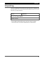 4
4
-
 5
5
-
 6
6
-
 7
7
-
 8
8
-
 9
9
-
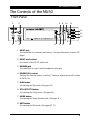 10
10
-
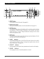 11
11
-
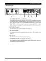 12
12
-
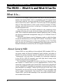 13
13
-
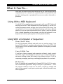 14
14
-
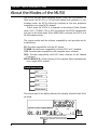 15
15
-
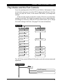 16
16
-
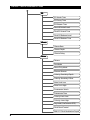 17
17
-
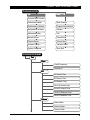 18
18
-
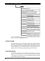 19
19
-
 20
20
-
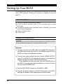 21
21
-
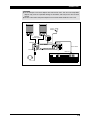 22
22
-
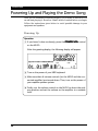 23
23
-
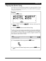 24
24
-
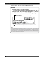 25
25
-
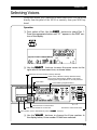 26
26
-
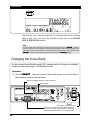 27
27
-
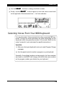 28
28
-
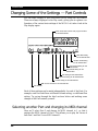 29
29
-
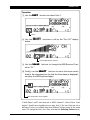 30
30
-
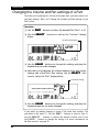 31
31
-
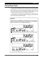 32
32
-
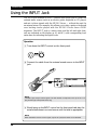 33
33
-
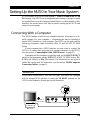 34
34
-
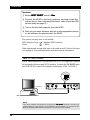 35
35
-
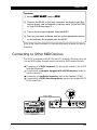 36
36
-
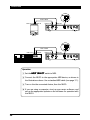 37
37
-
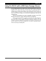 38
38
-
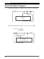 39
39
-
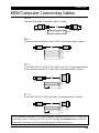 40
40
-
 41
41
-
 42
42
-
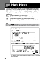 43
43
-
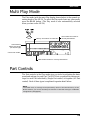 44
44
-
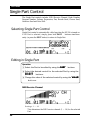 45
45
-
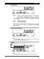 46
46
-
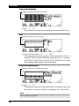 47
47
-
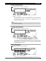 48
48
-
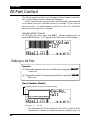 49
49
-
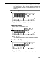 50
50
-
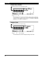 51
51
-
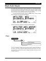 52
52
-
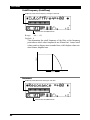 53
53
-
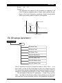 54
54
-
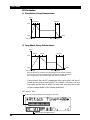 55
55
-
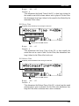 56
56
-
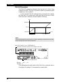 57
57
-
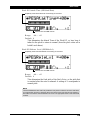 58
58
-
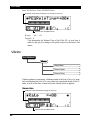 59
59
-
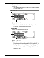 60
60
-
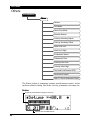 61
61
-
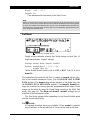 62
62
-
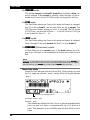 63
63
-
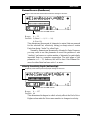 64
64
-
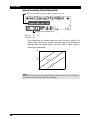 65
65
-
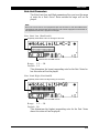 66
66
-
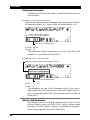 67
67
-
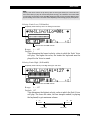 68
68
-
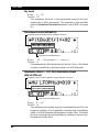 69
69
-
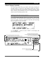 70
70
-
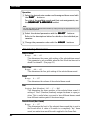 71
71
-
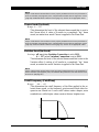 72
72
-
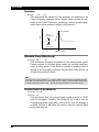 73
73
-
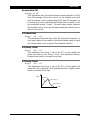 74
74
-
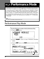 75
75
-
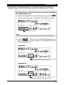 76
76
-
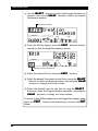 77
77
-
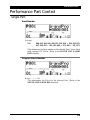 78
78
-
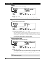 79
79
-
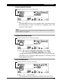 80
80
-
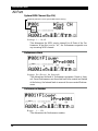 81
81
-
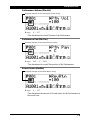 82
82
-
 83
83
-
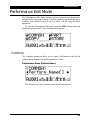 84
84
-
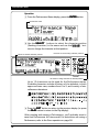 85
85
-
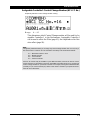 86
86
-
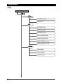 87
87
-
 88
88
-
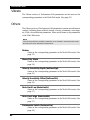 89
89
-
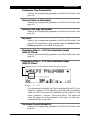 90
90
-
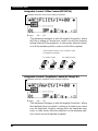 91
91
-
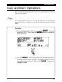 92
92
-
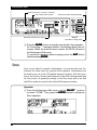 93
93
-
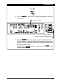 94
94
-
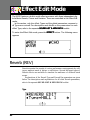 95
95
-
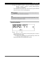 96
96
-
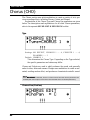 97
97
-
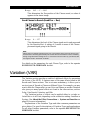 98
98
-
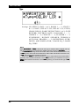 99
99
-
 100
100
-
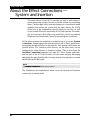 101
101
-
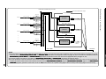 102
102
-
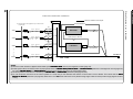 103
103
-
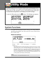 104
104
-
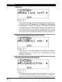 105
105
-
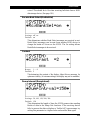 106
106
-
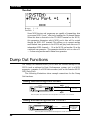 107
107
-
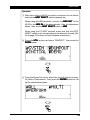 108
108
-
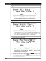 109
109
-
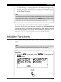 110
110
-
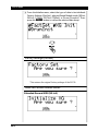 111
111
-
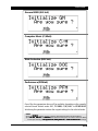 112
112
-
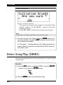 113
113
-
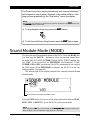 114
114
-
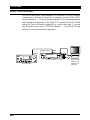 115
115
-
 116
116
-
 117
117
-
 118
118
-
 119
119
-
 120
120
-
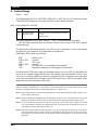 121
121
-
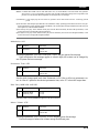 122
122
-
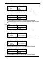 123
123
-
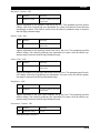 124
124
-
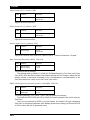 125
125
-
 126
126
-
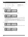 127
127
-
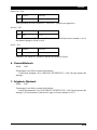 128
128
-
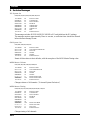 129
129
-
 130
130
-
 131
131
-
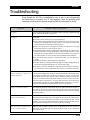 132
132
-
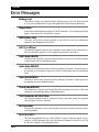 133
133
-
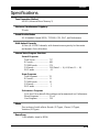 134
134
-
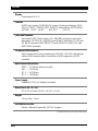 135
135
-
 136
136
-
 137
137
-
 138
138
-
 139
139
-
 140
140


in andere talen
- English: Yamaha MU50 User manual
- italiano: Yamaha MU50 Manuale utente
- русский: Yamaha MU50 Руководство пользователя
- français: Yamaha MU50 Manuel utilisateur
- español: Yamaha MU50 Manual de usuario
- Deutsch: Yamaha MU50 Benutzerhandbuch
- português: Yamaha MU50 Manual do usuário
- dansk: Yamaha MU50 Brugermanual
- suomi: Yamaha MU50 Ohjekirja
- čeština: Yamaha MU50 Uživatelský manuál
- svenska: Yamaha MU50 Användarmanual
- Türkçe: Yamaha MU50 Kullanım kılavuzu
- polski: Yamaha MU50 Instrukcja obsługi
- română: Yamaha MU50 Manual de utilizare