Schwaiger HG1000 532 Instructions Manual
- Categorie
- Afstandsbedieningen
- Type
- Instructions Manual
Deze handleiding is ook geschikt voor

HG1000
GEBRAUCHSANWEISUNG
FUNK-ALARM-SYSTEM „GREEN GUARD“, ERWEITERBAR
INSTRUCTIONS
RADIO ALARM SYSTEM “GREEN GUARD”, EXPANDABLE
INSTRUCTIONS DE SERVICE
SYSTÈME D‘ALARME PAR RADIO « GREEN GUARD », EXTENSIBLE
ISTRUZIONI PER L‘USO
SISTEMA DI ALLARME VIA RADIO „GREEN GUARD“, ESPANDIBILE
INSTRUCCIONES
SISTEMA DE ALARMA POR RADIO „GREEN GUARD“, AMPLIABLE
INSTRUCTIES
DRAADLOOS ALARMSYSTEEM „GREEN GUARD“, UITBREIDBAAR

2
BEDIENUNGSANLEITUNG HG1000 532
INHALTSVERZEICHNIS
1. Einführung .................................................................................................................................... 3
2. Verpackungsinhalt ......................................................................................................................... 3
3. Bestimmungsgemäßer Gebrauch ................................................................................................... 3
4. Zentraleinheit ................................................................................................................................4
4.1. Zentraleinheit im Detail ..............................................................................................................4
4.2. Hintergrundbeleuchtung als Statusanzeige ....................................................................................4
5. Erste Inbetriebnahme.................................................................................................................... 5
5.1. Entfernen des Demoschalters ......................................................................................................5
5.2. Displayanzeige nach Inbetriebnahme der Zentraleinheit ..................................................................5
5.3. Inbetriebnahme des Fenstersensors mit Magnetkontakt ..................................................................6
5.4. Inbetriebnahme des Bewegungssensors ........................................................................................6
5.5. Inbetriebnahme der Fernbedienung ..............................................................................................6
6. Montage & Montageort .................................................................................................................. 6
6.1. Montagehinweise zur Zentraleinheit ..............................................................................................7
6.2. Montagehinweise zum Bewegungssensor.......................................................................................7
6.3. Montagehinweise zum Tür- & Fenstersensor mit Magnetkontakt .......................................................7
7. Betrieb & Individualisierung .......................................................................................................... 7
7.1. Programmierung des 4-stelligen PINs ...........................................................................................7
7.2. Anlernen der Fernbedienung ........................................................................................................8
7.3. Bedientasten der Fernbedienung ..................................................................................................9
7.4. Abmelden von Fernbedienungen ..................................................................................................9
7.5. Abfragen der ID-Nummer einer Fernbedienung ............................................................................ 10
7.6. Einstellen des Haus-Sicherheits-Codes .......................................................................................10
7.7. Einstellen des Zonen-Codes (bei Sensoren) .................................................................................11
7.8. Panikfunktion ..........................................................................................................................11
8. Betriebsarten ...............................................................................................................................11
8.1. ARM (Alarm) Modus .................................................................................................................11
8.1.1. Einstellen der Einschaltverzögerung ..................................................................................11
8.1.2. Einstellen der Alarmverzögerung ......................................................................................12
8.1.3. Einstellen der Alarmdauer ...............................................................................................12
8.1.4. Stummschalten des Countdowns ......................................................................................12
8.1.5. Deaktivieren des Systems ...............................................................................................12
8.1.6. Zoneneinstellung ...........................................................................................................13
8.1.7. Beispiel einer Alarmauslösung .........................................................................................13
8.2. ALERT (Signal) Modus ..............................................................................................................13
8.2.1. Programmierung des ALERT Modus ................................................................................... 14
8.3.1. Programmierung des HOME Modus ...................................................................................14
9. Technische Daten .........................................................................................................................15
Haftungsausschluss..........................................................................................................................16
Entsorgung ...................................................................................................................................16
EG Konformitätserklärung ................................................................................................................16

3
BEDIENUNGSANLEITUNG HG1000 532
1. EINFÜHRUNG
Herzlichen Glückwunsch und vielen Dank für den Kauf eines Produkts aus der SECURE-4-YOU Serie. Im Folgenden
erhalten Sie nützliche Hinweise zur Handhabung dieses Produkts.
Bitte lesen Sie sich daher die Bedienungsanleitung vollständig und sorgfältig durch.
Allgemeine Sicherheits- & Wartungshinweise
• Dieses Produkt ist für den privaten, nicht gewerblichen Haushaltsgebrauch vorgesehen.
• Bei diesem Produkt handelt es sich um ein elektronisches Produkt, welches nicht in Kinderhände gehört!
Bewahren Sie es deshalb außerhalb der Reichweite von Kindern auf.
• Schützen Sie das Produkt vor Feuchtigkeit, Wasser, Regen, Schnee oder Sprühregen und verwenden Sie das
Produkt nur in trockenen Umgebungen, wenn nicht speziell hierauf hingewiesen wird.
• Lassen Sie das Produkt nicht fallen und setzen Sie es keinen starken Erschütterungen aus.
• Führen Sie keine Objekte in die Anschlüsse oder Öffnungen des Produkts ein.
• Zerlegen Sie das Produkt nicht in seine Einzelteile. Das Gerät enthält keine vom Benutzer zu wartenden Teile.
Der unsachgemäße Zusammenbau kann zu elektrischen Schlägen oder Fehlfunktionen führen.
• Reinigen Sie dieses Produkt nur mit einem fusselfreien, maximal leicht feuchten Tuch und verwenden Sie kei-
ne aggressiven Reiniger. Achten Sie hierbei besonders darauf, dass kein Wasser (keine Flüssig-/ Feuchtigkeit)
in das Produkt gelangt.
Vorsicht! Gefahr von Hörschädigungen
Lauter Alarmton! Setzen Sie Ihr Gehör diesem Ton nicht über einen längeren Zeitraum aus, da sonst schwere
Gehörschäden die Folge sein können! Aktivieren Sie den Alarm nicht in direkter Nähe Ihrer Ohren!
2. VERPACKUNGSINHALT
• Zentrale mit integriertem Tastenfeld & 230V Netzteil
• Funkfernbedienung + 12V Batterie (A27)
• PIR Bewegungsmelder mit Halterung (für Innen & Außen geeignet)
• 2x Tür & Fenstersensor mit Magnetkontakt
• Warnaufkleber „Protected by Secure4You Security System”
• Montagematerial (Klebepads, Dübel & Schrauben)
• Bedienungsanleitung & Sicherheitshinweise
Zusätzlich benötigte Batterien:
• 1x 9V Block (6LR61)
• 4x 1,5V LR03 (AAA)
• 1x 3V CR123A
3. BESTIMMUNGSGEMÄSSER GEBRAUCH
Das Schwaiger „Green Guard” System dient der Absicherung und Überwachung Ihres Grundstücks/Zuhauses.
Mithilfe von unterschiedlichen Sensoren können einzelne Bereiche des Gebäudes wie z.B. der Eingangsbereich
überwacht oder abgesichert werden. Das komplette System wird über die Zentraleinheit gesteuert, welche per
Funk mit den unterschiedlichen Sensoren kommuniziert. Sobald die Zentraleinheit einen Verstoß über die Senso-
ren erkennt löst diese einen Alarm aus.
Wichtig!
Die Verwendung von Alarmanlagen, bietet Ihnen einen großen, aber keinen hundert prozentigen Schutz oder
Sicherheit vor Einbrüchen oder Angriffen. Das Auslösen des Alarms dient der Abschreckung von Eindringlingen
oder Angreifern und soll Personen in unmittelbarer Umgebung alarmieren.

4
BEDIENUNGSANLEITUNG HG1000 532
4. ZENTRALEINHEIT
4.1. Zentraleinheit im Detail
RESET-Taste
Diese befindet sich im Batteriefach auf der Rückseite der Zentraleinheit. Mithilfe dieser Taste kann die Werksein-
stellung wiederhergestellt werden. Drücken Sie hierfür zuerst die
RESET-Taste und geben sie anschließend den
Standard-PIN
„1-2-3-4” gefolgt von der Taste ein.
4.2. Hintergrundbeleuchtung als Statusanzeige
Das Aufleuchten des Displays dient als zusätzliche Statusanzeige. Hierdurch kann auch aus größeren Entfernun-
gen schnell geprüft werden, in welchem Modus sich das System befindet.
Übersicht der einzelnen Modi
ARM
Situation 1 Situation 2
Eine Zone löst den Alarm im
ARM-Modus aus Einstellen des Alarms im ARM-Modus
Merkmale
• Der Alarm ertönt für 1 Minute (Standardeinstellung
- einstellbar von 1-6 Minuten)
• Die Alarmzentrale
blinkt alle 2 Sekunden rot auf
• Die ausgelöste Zone wird durch blinken im Display
angezeigt
• Das Beenden des Alarms erfolgt über Eingabe eines
4-stelligen PINs sowie anschließender Bestätigung
mit
Merkmale
• Die Sirene wird nicht ausgelöst
• Die Alarmzentrale blinkt alle 5 Sekunden rot
(Anzeige der Bereitschaft)
HOME
Situation 1 Situation 2
Eine Zone löst den Alarm im
HOME-Modus aus Eine Zone löst den Alarm im ALERT-Modus aus
Merkmale
• Der Alarm ertönt für 1 Minute (Standardeinstellung
- einstellbar von 1 - 6 Minuten)
• Die Alarmzentrale
blinkt alle 2 Sekunden rot auf
• Die ausgelöste Zone wird durch Blinken im Display
angezeigt
• Das Beenden des Alarms erfolgt über Eingabe eines
4-stelligen PINs sowie anschließender Bestätigung
mit
Merkmale
• Ein Türklingelton wird ausgelöst
• Die Alarmzentrale blinkt alle 2 Sekunden grün.
• Die ausgelöste Zone wird durch Blinken im Display
angezeigt
• Für das Beenden des Türklingeltons drücken Sie
einfach
LCD-Anzeige Tastenfeld

5
BEDIENUNGSANLEITUNG HG1000 532
ALERT STANDBY
Situation 1
Eine Zone löst den Alarm im
ALERT-Modus aus
Merkmale
• Ein Türklingelton wird ausgelöst
• Die Alarmzentrale
blinkt alle 2 Sekunden grün.
• Die ausgelöste Zone wird durch blinken im Display
angezeigt
• Für das Beenden des Türklingeltons drücken Sie
einfach
Situation 1
Standby (Ruhe)-Modus
Merkmale
Nach dem Umschalten in den Standby-Modus
leuchtet die Hintergrundbeleuchtung 10 Sekunden
gelb auf.
5. ERSTE INBETRIEBNAHME
Dieses Starterset beinhaltet neben der Funkfernbedienung insgesamt 3 Alarmsensoren, welche in ihrer Standard
Einstellung vorprogrammiert sind. Nach dem Einlegen der jeweiligen Batterien in diese, können Sie sofort ver-
wendet werden. Die Funkfernbedienung muss wie im Punkt 7.2. (Anlernen der Fernbedienung) beschrieben
manuell angelernt werden.
Hinweis!
Es wird geraten, vorab die Anlage im Auslieferzustand zu installieren und auf dessen Funktion zu überprüfen.
Nehmen Sie erst nach einer erfolgreichen Prüfung eine individuelle Einstellung vor (z.B. Änderung des PIN-Codes
oder das hinzufügen weiterer Komponenten zum System).
Alarmzentrale
Die Schwaiger „Green Guard” Zentrale besitzt keinen Ein-/Ausschalter. Sie ist nach dem Anschluss an eine
230 V Steckdose automatisch aktiviert sowie im Standby-Modus.
Bei der 9 V Batterie handelt es sich nur um eine Backup Batterie, welche im Notfall eine Funktion bei Stromaus-
fall gewährleistet. Verwenden Sie daher die Anlage ausschließlich über den 230 V Anschluss und nicht über eine
längere Zeit über die Backup Batterie.
5.1. Entfernen des Demoschalters
Diese Alarmanlage verfügt im Auslieferzustand über einen Demoschalter. Dieser dient nur zur Demonstration der
Funktionen des Displays in der Verkaufsverpackung. Er wird für alle weiteren Funktionen des Produkts nicht mehr
benötigt und muss deshalb entfernt werden.
Gehen Sie hierfür wie folgt vor:
1. Öffnen Sie das Batteriefach mithilfe eines Kreuzschlitzschraubenziehers.
2. Entfernen Sie den Stecker an der linken Oberseite des Batteriefachs, indem Sie diesen vorsichtig herausziehen.
3. Nun können Sie eine Backup Batterie einlegen und den Batteriedeckel wieder schließen.
4. Verbinden Sie nun die Zentraleinheit mit einer 230 V Steckdose.
5.2. Displayanzeige nach Inbetriebnahme der Zentraleinheit
Nachdem Sie die Backup Batterie angeschlossen haben ertönt ein Signalton und das Display leuchtet in unter-
schiedlichen Farben auf. (Orange ➜ Rot ➜ Grün ➜ Orange)
Nach Abschluss der automatischen Selbstprüfung schaltet die Anlage in den Standby Modus.
Nun wird ein
Symbol angezeigt und das Display zeigt folgendes Bild:
Um die Anlage zu entsperren geben Sie den Standard PIN „1-2-3-4” ein und bestätigen Sie diesen mit .

6
BEDIENUNGSANLEITUNG HG1000 532
Batterie- & Netzteil-Symbol
Das Netzteil-Symbol wird immer dann angezeigt, wenn die Alarmeinheit direkt an eine 230V Steckdose ange-
schlossen ist. Sobald die Zentrale vom Stromanschluss getrennt wird, wechselt die Symbolanzeige automatisch
auf ein Batterie-Symbol (ebenfalls rechts oben im Display).
Die Anzeige besitzt die folgenden 4 Unterteilungen:
Voll
Hoch
Mittel
Niedrig
Hinweis!
Bei einem niedrigen Batteriestatus blinkt die LCD Anzeige für 30 Sekunden orange auf und das Symbol fängt
an zu Blinken. Dieses Symbol blinkt nun solange, bis die Backup Batterie ausgetauscht wurde.
5.3. Inbetriebnahme des Fenstersensors mit Magnetkontakt
Um die Fenstersensoren in Betrieb zu nehmen, öffnen Sie die untere Abdeckung des Produkts und legen Sie hier
2x AAA Batterien (polrichtig) entsprechend der Prägung im Batteriefach ein.
Dieses Produkt verfügt über eine Batterie-Statusanzeige. Sobald die Batterien des Produkts ersetzt werden müs-
sen, blinkt die LED auf der Vorderseite des Produkts im Ruhezustand langsam rot auf.
5.4. Inbetriebnahme des Bewegungssensors
Um den Bewegungssensor in Betrieb zu nehmen, entfernen Sie zuerst die
Schraube auf der Unterseite des Produkts. Nun können Sie das komplette
Vorderteil vorsichtig entfernen.
Legen Sie
1x CR123A Batterie (polrichtig) entsprechend der Prägung im
Batteriefach ein.
Dieser Bewegungssensor kann zusätzlich in seiner Empfindlichkeit einge-
stellt werden.
Hierzu besitzt er im Inneren (recht oberhalb der Batterie) Kontaktstifte.
Diese sind mit
H (Hoch ≤ 13 m), M (Mittel ≤ 8 m) oder N (Niedrig ≤ 5 m)
gekennzeichnet. Stecken Sie für die gewünschte Einstellung den sogenann-
ten Jumper (kleiner schwarzer Block) auf das jeweilige Stiftpaar (horizontal).
Hinweis!
Der Bewegungssensor verfügt zur Schonung der Batterie über einen Energiesparmodus. Dies bedeutet, dass der
Bewegungsmelder nach der Alarmierung für 3 Minuten in den Energiesparmodus schaltet und während dieser Zeit
keine weiteren Signale sendet.
5.5. Inbetriebnahme der Fernbedienung
Öffnen Sie hierzu vorsichtig den Batteriedeckel auf der Rückseite der Fernbedienung und entfernen Sie anschlie-
ßend den transparenten Kontaktunterbrecher. Nun ist die Fernbedienung bereit um anschließend in das System
(wie unter dem Punkt 7.2. Anlernen der Fernbedienung beschrieben) integriert zu werden.
6. MONTAGE & MONTAGEORT
Alarmeinheit: Befestigung mithilfe von Schrauben
Fenstersensor mit Magnetkontakt: Befestigung via Klebepad oder Schrauben
Bewegungssensor: Befestigung mithilfe von Schrauben

7
BEDIENUNGSANLEITUNG HG1000 532
6.1. Montagehinweise zur Zentraleinheit
• Die Zentraleinheit ist ausschließlich für die Nutzung im Innenbereich geeignet. Durch die Montage im Außen-
bereich kann bei anschließenden Defekten keine Haftung übernommen werden.
• Die Zentraleinheit besitzt einen integrierten Sabotageschalter. Dieser soll ein Deaktivieren durch Entfernen
des Systems verhindern.
• Stellen Sie sicher, dass sich eine Steckdose am Montageort der Zentraleinheit vorhanden sowie leicht zugäng-
lich ist.
• Der Montageort sollte nicht in unmittelbarer Nähe von Heizungen, Öfen oder anderen großen Metallobjekten
liegen. Diese können möglicherweise zu einer Beeinträchtigung der Funkübertragung führen.
• Prüfen Sie vor der Installation die Eignung des Montageorts und überprüfen Sie das Montagematerial. Ver-
gewissern Sie sich, dass keine elektrischen, Wasser-, Gas- oder sonstigen Leitungen an der Montagestelle
vorhanden sind.
• Verwenden Sie für die Montage der Zentraleinheit die mitgelieferte Bohrschablone.
• Abhängig von Ihrem Montageort kann für die Montage zusätzliches/anderes Montagezubehör benötigt werden.
6.2. Montagehinweise zum Bewegungssensor
• Dieses Produkt kann sowohl im Innen- als auch im Außenbereich montiert werden.
• Es wird empfohlen das Produkt in gefährdeten Räumen oder direkt in der Nähe von möglichen Einstiegspunk-
ten zu montieren.
• Montieren Sie die Alarmeinheit nicht in der direkten Nähe von Öfen, Klimageräten oder anderen Systemen
dieser Art.
• Wählen Sie die Montagestelle so aus, dass im späteren Erfassungsbereich sehr wenige bis keine Hindernisse
stehen (z.B. Möbel oder Schränke).
• Prüfen Sie vor der Installation die Eignung des Montageorts und überprüfen Sie das Montagematerial. Ver-
gewissern Sie sich, dass keine elektrischen, Wasser-, Gas- oder sonstigen Leitungen an der Montagestelle
vorhanden sind.
• Abhängig von Ihrem Montageort kann für die Montage zusätzliches/anderes Montagezubehör benötigt werden.
6.3. Montagehinweise zum Tür- & Fenstersensor mit Magnetkontakt
• Es wird empfohlen, die Sensoreinheit direkt am Fenster- oder Türrahmen und den Magnetkontakt direkt an
dem Fenster bzw. der Tür zu befestigen (beweglicher Teil).
• Dieses Produkt ist ausschließlich für die Nutzung im Innenbereich geeignet. Durch die Montage im Außenbe-
reich kann bei anschließenden Defekten keine Haftung übernommen werden.
• Beachten Sie, dass sich die Markierungen vom Gerät und dem Kontakt auf einer Linie befinden müssen und
maximal 5 mm voneinander entfernt sein sollten, um eine reibungslose Funktion zu gewährleisten.
• Der Sensor kann sowohl auf der linken als auch auf der rechten Seite montiert werden.
7. BETRIEB & INDIVIDUALISIERUNG
7.1. Programmierung des 4-stelligen PINs
Das Schwaiger „Green Guard” System besitzt im Auslieferungszustand einen Standard PIN-Code
„1-2-3-4”. Dieser PIN-Code dient als Schutz der Alarmanlage und dem Aktiveren/Deaktivieren des Systems.
Dieser PIN-Code kann individuell angepasst werden.
Den idealen
Erfassungs-
winkel erreicht
das Produkt
auf einer
Montagehöhe
von 1,8 – 2,4 m.
Reduzierung
des Bereichs
Vergrößerung
des Bereichs

8
BEDIENUNGSANLEITUNG HG1000 532
Für eine Änderung des PIN Codes gehen Sie bitte wie folgt vor:
Schritt 1 Schritt 2 Schritt 3
Sie müssen sich im Standby-Modus
befinden.
Geben Sie nun
„1-2-3-4” ein und
bestätigen Sie dies mit
.
Bei richtiger Eingabe des PINs zeigt
das Display nun folgende Anzeige
an:
(Ein zusätzlicher Signalton gibt
ein akustisches Feedback, ob der
gewählte Code richtig ist. - Drei
Pieptöne bedeuten, dass eine
ungültige Eingabe vorgenommen
wurde.)
Schritt 4 Schritt 5 Schritt 6
Drücken Sie nun
gefolgt von
der Taste
„1”. Das Display zeigt
folgende Anzeige an:
Im Display blinken nun und „1”.
Geben Sie Ihren neuen gewünsch-
ten 4-stelligen PIN ein und bestäti-
gen Sie diesen mit
.
Im Display blinken nun und „2”.
Geben Sie Ihren neuen 4-stelligen
PIN ein zweites Mal ein und bestä-
tigen Sie diesen nochmals mit
.
(Ein zusätzlicher Signalton gibt ein akustisches Feedback, ob der PIN-Code erfolgreich geändert wurde - Zwei-
Pieptöne bedeuten, dass eine ungültige Operation vorgenommen wurde.)
7.2. Anlernen der Fernbedienung
Bevor Sie eine oder mehrere Fernbedienungen in Verbindung mit dem Schwaiger „Green Guard” System ver-
wenden können, müssen sie diese anlernen. Gehen Sie herzu wie folgt vor:
Schritt 1 Schritt 2 Schritt 3
Sie müssen sich im Standby-Modus
befinden.
Geben Sie nun
„1-2-3-4” oder
Ihren
neu erstellten PIN ein und
bestätigen Sie dies mit
.
Bei richtiger Eingabe des PINs zeigt
das Display nun folgende Anzeige
an:
(Ein zusätzlicher Signalton gibt
ein akustisches Feedback, ob der
gewählte Code richtig ist. - Drei
Pieptöne bedeuten, dass eine
ungültige Eingabe vorgenommen
wurde.)
Schritt 4 Schritt 5 Schritt 6
Drücken Sie nun
gefolgt von der
Taste
„2” + drücken Sie eine
beliebige Taste auf der Fernbedie-
nung.
In der Anzeige blinkt nun die
ID-Nummer der Fernbedienung,
welche hinzugefügt werden soll.
(z.B. bei Anmeldung der ersten
Fernbedienung erscheint eine
„01”,
wenn schon eine Fernbedienung
vorhanden ist und eine weitere an-
gelernt wird die
„02”)
Es wird empfohlen immer die vor-
geschlagene ID-Nummer zu ver-
wenden.
(Ein zusätzlicher Signalton gibt ein
akustisches Feedback für eine er-
folgreiche Registrierung an der Zen-
trale)
Bestätigen Sie die Einstellung mit
.
Die Zentrale schaltet sich nun au-
tomatisch wieder in den Standby
Modus.

9
BEDIENUNGSANLEITUNG HG1000 532
7.3. Bedientasten der Fernbedienung
ALERT
DISARM
ARM
HOME
ALERT Durch Drücken der ALERT Taste schaltet sich die Zentrale in den Türklingel-Modus.
Hierbei ertönt bei Auslösung durch einen Sensor ein Türklingelton (Ding-Dong).
HOME Durch Drücken der HOME Taste schaltet sich die Zentrale in den Home Modus.
PANIC
Durch gleichzeitiges Drücken der Taste HOME sowie ALERT, wird ein sofortiger Alarm ausgelöst.
ARM/DISARM
Mithilfe dieser Tasten können Sie die Anlage scharf (ARM) bzw. unscharf (DISARM) schalten.
7.4. Abmelden von Fernbedienungen
Falls eine Fernbedienung beschädigt oder verloren gegangen ist, kann diese wie folgt vom System abgemeldet
werden.
Schritt 1 Schritt 2 Schritt 3
Sie müssen sich im Standby-Modus
befinden.
Geben Sie nun
„1-2-3-4” oder
Ihren
neu erstellten PIN ein und
bestätigen Sie dies mit
.
Bei richtiger Eingabe des PINs zeigt
das Display nun folgende Anzeige
an:
(Ein zusätzlicher Signalton gibt
ein akustisches Feedback, ob der
gewählte Code richtig ist. - Drei
Pieptöne bedeuten, dass eine
ungültige Eingabe vorgenommen
wurde.)
Schritt 4 Schritt 5 Schritt 6
Drücken Sie nun
gefolgt von der
Taste
„5” um in den Löschmodus
zu gelangen.
In der Anzeige blinkt nun die
Gesamtanzahl der im System ein-
geschriebenen Fernbedienungen.
(z.B. bei 3 registrierten Fernbedie-
nungen die „03”)
Geben Sie nun die ID-Nummer
der Fernbedienung, die gelöscht
werden soll über die Bedientasten
ein z.B. „02”.
➜ bei Eingabe von 00 werden alle
registrierten Fern-bedienungen
gelöscht.
Schritt 7 Schritt 8
Im LCD Display blinkt nun die Ge-
samtzahl der restlichen im System
verbliebenen Fernbedienungen.
(Ein zusätzlicher Signalton gibt
ein akustisches Feedback über die
erfolgreiche Löschung der Fernbe-
dienung)
Bestätigen Sie die Einstellung mit
.
Die Zentrale schaltet sich nun
automatisch wieder in den Standby
Modus.

10
BEDIENUNGSANLEITUNG HG1000 532
7.5. Abfragen der ID-Nummer einer Fernbedienung
Falls Sie sich nicht sicher sind, welche ID-Nummer welche Fernbedienung besitzt, kann dies wie folgt ermittelt
werden:
Schritt 1 Schritt 2 Schritt 3
Sie müssen sich im Standby-Modus
befinden.
Geben Sie nun
„1-2-3-4” oder
Ihren
neu erstellten PIN ein und
bestätigen Sie dies mit
.
Bei richtiger Eingabe des PINs zeigt
das Display nun folgende Anzeige
an:
(Ein zusätzlicher Signalton gibt
ein akustisches Feedback, ob der
gewählte Code richtig ist. - Drei
Pieptöne bedeuten, dass eine
ungültige Eingabe vorgenommen
wurde.)
Schritt 4 Schritt 5 Schritt 6
Drücken Sie nun
gefolgt von der
Taste
„8” um in den Anfragemodus
zu gelangen.
Nun blinkt in der Anzeige die aktuel-
le Anzahl der im System registrier-
ten Fernbedienungen.
(wenn in der Anlage z.B. 3 Fernbe-
dienungen angemeldet sind, wird
hier eine „03” angezeigt)
Drücken Sie nun eine beliebige Tas-
te auf der Fernbedienung, für wel-
che Sie die ID-Nummer ermitteln
wollen.
Schritt 7 Schritt 8
Nun blinkt in der Anzeige die je-
weilige Nummer der Fernbedienung
auf.
Zum Verlassen dieses Modus drü-
cken Sie
. Die Zentrale schaltet
sich nun automatisch wieder in den
Standby Modus.
7.6. Einstellen des Haus-Sicherheits-Codes
In den meisten Anwendungsfällen muss dieser Code nicht geändert werden.
Wenn Sie jedoch z.B. durch häufige Fehlalarme vermuten, dass in ihrer Umgebung Nachbarn eine Alarmanlage
des gleichen Typs nutzen, wird empfohlen den Haus-Sicherheits-Code zu ändern.
Wichtig!
Falls Sie Änderungen am Haus-Sicherheits-Code vornehmen möchten, muss dies an allen Komponenten vor-
genommen werden
(Zentrale, Fernbedienung, einzelne Komponenten).
Alle Geräte verfügen über einen 4-poligen Jumper/DIP Schalter (meist im Batteriefach oder unter einer zu-
sätzlichen Abdeckung). Stellen Sie sicher, dass später alle Geräte exakt die gleiche Einstellung dieses Jumpers
besitzen. Hierbei gilt:
Gesteckt =
ON / Entfernt = OFF
Jumper für den
Haus-Code
• Zentraleinheit
• Sensoren
Standard-Code
1: ON, 2: ON, 3: ON, 4: ON
DIP Schalter für den
Haus-Code
• Fernbedienung
Standard-Code
1: ON, 2: ON, 3: ON, 4: ON

11
BEDIENUNGSANLEITUNG HG1000 532
7.7. Einstellen des Zonen-Codes (bei Sensoren)
Die Sensoren werden mit einer vorprogrammierten Zoneneinstellung ausgeliefert.
Die Tür/Fenstersensoren sind auf Zone 1 & 2, der Bewegungsmelder auf Zone 8 eingestellt.
Diese Zonen können mithilfe der Jumper beliebig eingestellt werden.
Öffnen Sie hierzu die Abdeckung des jeweiligen Produkts und stellen Sie dieses auf die gewünschte Zone ein.
Entfernen Sie hierzu durch vorsichtiges Ziehen den Jumper von dem bisherigen Kontakt und stecken Sie diesen
anschließend auf das gewünschte Kontaktpaar der neuen Zone.
Jumper für Zonen-Code
Standardeinstellung
Tür/Fenstersensor = Zone 1
Tür/Fenstersensor = Zone 2
Bewegungsmelder = Zone 8
7.8. Panikfunktion
Durch gleichzeitiges Drücken der Tasten HOME & ALERT wird ein sogenannter Panikalarm ausgelöst. Hierbei
löst die Sirene der Zentraleinheit sofort aus und schlägt Alarm. Falls eine weitere Außensirene mit dem System
verbunden ist, schlägt diese ebenfalls mit an. Um diesen Alarm zu deaktivieren drücken Sie entweder
DISARM
auf der Fernbedienung oder geben Sie den
4-stelligen PIN über die Zentraleinheit ein.
8. BETRIEBSARTEN
Das System verfügt über insgesamt 3 Modi (ARM, ALERT sowie HOME).
Diese können individuell den benötigten Anforderungen angepasst werden.
8.1. ARM (Alarm) Modus
Ist dieser Modus aktiviert, ertönt bei anschließender Erkennung über die Sensoren die Sirene und die Zentralein-
heit blinkt alle 2 Sekunden auf.
Grundeinstellung im ARM Modus:
Sensor Zone Mode/Status
Tür/Fenster Sensor 1 ARM
Tür/Fenster Sensor 2 ARM
Bewegungsmelder 8 ARM
8.1.1. Einstellen der Einschaltverzögerung
Die Einschaltverzögerung ist wichtig, um den überwachten Bereich nach Scharfschaltung verlassen zu können,
ohne den Alarm direkt auszulösen. Die Standardeinstellung hier beträgt 20 Sekunden.
Falls Sie diese Zeitspanne ändern möchten, gehen Sie bitte wie folgt vor:
Schritt 1 Schritt 2 Schritt 3
Sie müssen sich im Standby-Modus
befinden.
Geben Sie nun
„1-2-3-4” oder
Ihren
neu erstellten PIN ein und
bestätigen Sie dies mit
.
Bei richtiger Eingabe des PINs zeigt
das Display nun folgende Anzeige
an:
(Ein zusätzlicher Signalton gibt ein
akustisches Feedback, ob der ge-
wählte Code richtig ist. - Drei Pieptö-
ne bedeuten, dass eine ungültige
Eingabe vorgenommen wurde.)
Schritt 4 Schritt 5 Schritt 6
Drücken Sie nun
gefolgt von der
Taste
„4” um in die Einstellung der
Einschaltverzögerung zu gelangen.
Nun wird Ihnen die eingestellte
Verzögerungszeit angezeigt.
(Werkseinstellung: 20 Sekunden)
Drücken Sie die Taste „4” so oft bis
die gewünschte Dauer angezeigt wird.
(möglicher Bereich: 10 Sekunden –
60 Sekunden)
Bestätigen Sie anschließend die
eingestellte Zeit mit
. Die Zent-
rale schaltet sich nun automatisch
wieder in den Standby Modus.

12
BEDIENUNGSANLEITUNG HG1000 532
8.1.2. Einstellen der Alarmverzögerung
Die Standardeinstellung der Alarmverzögerung beträgt 30 Sekunden. Innerhalb dieser Zeit können Sie sich im
überwachten Bereich aufhalten/bewegen ohne einen Alarm auszulösen.
Dies dient beispielsweise dazu, um in Ruhe das Haus betreten zu können, ohne direkt einen Alarm auszulösen.
Diese Alarmverzögerung lässt sich wie folgt einstellen:
Schritt 1 Schritt 2 Schritt 3
Sie müssen sich im Standby-Modus
befinden.
Geben Sie nun
„1-2-3-4” oder
Ihren
neu erstellten PIN ein und
bestätigen Sie dies mit
.
Bei richtiger Eingabe des PINs zeigt
das Display nun folgende Anzeige
an:
(Ein zusätzlicher Signalton gibt ein
akustisches Feedback, ob der ge-
wählte Code richtig ist. - Drei Pieptö-
ne bedeuten, dass eine ungültige
Eingabe vorgenommen wurde.)
Schritt 4 Schritt 5 Schritt 6
Drücken Sie nun
gefolgt von der
Taste
„7” um in die Einstellung der
Alarmverzögerung zu gelangen.
Nun wird Ihnen die eingestellte
Verzögerungszeit angezeigt.
(Werkseinstellung: 30 Sekunden)
Drücken Sie die Taste „7” so oft bis
die gewünschte Dauer angezeigt wird.
(möglicher Bereich: 10 Sekunden –
60 Sekunden)
Bestätigen Sie anschließend die ein-
gestellte Zeit mit
. Die Zentrale
schaltet sich nun automatisch wie-
der in den Standby Modus.
8.1.3. Einstellen der Alarmdauer
Die Standardeinstellung der Alarmdauer beträgt 1 Minute. Dies bedeutet, dass bei Alarmauslösung der Alarm in
der Zentraleinheit für diese Zeit anschlägt und mögliche Eindringlinge durch einen lauten Alarmton abschreckt.
Schritt 1 Schritt 2 Schritt 3
Sie müssen sich im Standby-Modus
befinden.
Geben Sie nun
„1-2-3-4” oder
Ihren
neu erstellten PIN ein und
bestätigen Sie dies mit
.
Bei richtiger Eingabe des PINs zeigt
das Display nun folgende Anzeige
an:
(Ein zusätzlicher Signalton gibt ein
akustisches Feedback, ob der ge-
wählte Code richtig ist. - Drei Pieptö-
ne bedeuten, dass eine ungültige
Eingabe vorgenommen wurde.)
Schritt 4 Schritt 5 Schritt 6
Drücken Sie nun
gefolgt von der
Taste
„0” um in die Einstellung der
Alarmverzögerung zu gelangen.
Nun wird Ihnen die eingestellte
Alarmdauer angezeigt.
(Werkseinstellung: 1 Minute)
Drücken Sie die Taste
„0” so oft
bis die gewünschte Dauer ange-
zeigt wird.
(möglicher Bereich: 1 Minute –
6 Minuten)
Bestätigen Sie anschließend die ein-
gestellte Zeit mit
. Die Zentrale
schaltet sich nun automatisch wie-
der in den Standby Modus.
8.1.4. Stummschalten des Countdowns
Wenn das Alarmsystem scharf geschalten wird, ertönt ein Countdownzähler (Standardmäßig von 20 Sekunden
abwärtszählend). Dieser kann durch das Drücken der
MUTE Taste stumm geschalten werden. Durch erneutes
Drücken der
MUTE Taste kann hier der Ton wieder aktiviert werden.
Wenn die Alarmanlage im Modus
ARM scharf geschaltet ist, blinkt das Display alle 5 Sekunden rot auf.
8.1.5. Deaktivieren des Systems
Um das System zu Deaktivieren, drücken Sie entweder die Taste DISARM auf der Fernbedienung oder deaktivie-
ren Sie das System mithilfe des 4-stelligen PIN Codes, gefolgt von der
Taste, an der Zentraleinheit.

13
BEDIENUNGSANLEITUNG HG1000 532
8.1.6. Zoneneinstellung
Für die Programmierung der Zonen im ARM-Modus gehen Sie wie folgt vor:
Schritt 1 Schritt 2 Schritt 3
Sie müssen sich im Standby-Modus
befinden.
Geben Sie nun
„1-2-3-4” oder
Ihren
neu erstellten PIN ein und
bestätigen Sie dies mit .
Bei richtiger Eingabe des PINs zeigt
das Display nun folgende Anzeige
an:
(Ein zusätzlicher Signalton gibt ein
akustisches Feedback, ob der ge-
wählte Code richtig ist. - Drei Pieptö-
ne bedeuten, dass eine ungültige
Eingabe vorgenommen wurde.)
Schritt 4 Schritt 5 Schritt 6
Drücken Sie nun
gefolgt von der
Taste
um in den ARM Modus zu
gelangen.
Nun können Sie mit den Tasten 1-8
die jeweiligen Zonen hinzuschalten
oder entfernen.
(Wenn keine Zone angezeigt wird,
ist diese deaktiviert)
Bestätigen Sie anschließend die ein-
gestellte Zeit mit
. Die Zentrale
schaltet sich nun automatisch wie-
der in den Standby Modus.
8.1.7. Beispiel einer Alarmauslösung
Ein Alarm wird in Zone 1 ausgelöst.
Beschreibung Anmerkung & Beschreibung
1 Aktivierter ARM Modus
2
Alarm wird ausgelöst
3 Eingangsverzögerung
(30 Sekunden)
Nun läuft der Countdownzähler für 30 Sekunden, in dieser Zeit kann
das System ohne Auslösen des Alarms deaktiviert werden (über die
Fernbedienung oder den 4-stelligen PIN). Falls das System in dieser Zeit
nicht deaktiviert wird, ertönt für 1 Minute ein Alarm und die Zentrale
blinkt alle 1,5 Sekunden rot auf.
4 Zurück in den ARM-Modus
nach ausgelöstem Alarm
Nach dem ersten Auslösen, wird ein Alarm sofort wieder ausgelöst,
wenn weitere Sensoren anschlagen.
8.2. ALERT (Signal) Modus
Wenn das System ausgelöst wird, ertönt in diesem Modus ein Signalton und die Alarmzentrale blinkt alle
2 Sekunden grün auf und zeigt die ausgelöste Zone an.
Grundeinstellung im ALERT Modus
Sensor Zone Mode/Status
Tür/Fenster Sensor 1 ALERT
Tür/Fenster Sensor 2 ALERT
Bewegungsmelder 8 ALERT

14
BEDIENUNGSANLEITUNG HG1000 532
8.2.1. Programmierung des ALERT Modus
Über die Zentraleinheit:
Schritt 1 Schritt 2 Schritt 3
Sie müssen sich im Standby-Modus
befinden.
Geben Sie nun
„1-2-3-4” oder
Ihren
neu erstellten PIN ein und
bestätigen Sie dies mit .
Bei richtiger Eingabe des PINs zeigt
das Display nun folgende Anzeige
an:
(Ein zusätzlicher Signalton gibt ein
akustisches Feedback, ob der ge-
wählte Code richtig ist. - Drei Pieptö-
ne bedeuten, dass eine ungültige
Eingabe vorgenommen wurde.)
Schritt 4 Schritt 5 Schritt 6
Drücken Sie nun
gefolgt von der
Taste
um in den ALERT Modus
zu gelangen.
Nun können Sie mit den Tasten 1-8
die jeweiligen Zonen hinzuschalten
oder entfernen.
(Wenn keine Zone angezeigt wird,
ist diese deaktiviert)
Bestätigen Sie anschließend die ein-
gestellte Zeit mit
. Die Zentrale
schaltet sich nun automatisch wie-
der in den Standby Modus.
8.3. HOME (Zuhause) Modus
Grundeinstellung im HOME Modus
Sensor Zone Mode/Status
Tür/Fenster Sensor 1 ALERT
Tür/Fenster Sensor 2 ALARM
Bewegungsmelder 8 ALARM
8.3.1. Programmierung des HOME Modus
Über die Zentraleinheit:
Schritt 1 Schritt 2 Schritt 3
Sie müssen sich im Standby-Modus
befinden.
Geben Sie nun
„1-2-3-4” oder
Ihren
neu erstellten PIN ein und
bestätigen Sie dies mit
.
Bei richtiger Eingabe des PINs zeigt
das Display nun folgende Anzeige
an:
(Ein zusätzlicher Signalton gibt ein
akustisches Feedback, ob der ge-
wählte Code richtig ist. - Drei Pieptö-
ne bedeuten, dass eine ungültige
Eingabe vorgenommen wurde.)
Schritt 4 Schritt 5 Schritt 6
Drücken Sie nun
gefolgt von der
Taste
um in den HOME Modus zu
gelangen.
Nun können Sie mit den Tasten 1-8
die jeweiligen Zonen hinzuschalten
oder entfernen.
ZONE ist im ALERT Modus
ZONE ist im ARM-Modus
ZONE ist ausgeschaltet
Bestätigen Sie anschließend die ein-
gestellte Zeit mit
. Die Zentrale
schaltet sich nun automatisch wie-
der in den Standby Modus.

15
BEDIENUNGSANLEITUNG HG1000 532
9. TECHNISCHE DATEN
Alarmzentrale
Stromversorgung 230V Netzteil
Backup Batterie 9V Batterie (6L61)
Maximale Sensoren Anzahl 250 Stück
Betriebsfrequenz 868,35 MHz (+/- 0,5 MHz)
Sendeleistung 25 mW
Haus-Sicherheits-Code Über 4 poligen Jumper
Anzahl Sicherheitszonen 8
dB Sirene 120 dB (max.)
Alarmdauer 1-6 Minuten (einstellbar)
Alarmverzögerung 10-60 Sekunden (einstellbar)
Einschaltverzögerung 10-60 Sekunden (einstellbar)
Fernbedienung
Stromversorgung 1x 12V Batterien (A27)
Betriebsfrequenz 868,35 MHz (+/- 0,5 MHz)
Sendeleistung 0,03 mW
Funkreichweite Max. 60 m (Freifläche)
Haus-Sicherheits-Code Über 4 poligen Jumper
Fenstersensor mit Magnetkontakt
Stromversorgung 2x AAA Batterien (LR03)
Betriebsfrequenz 868,35 MHz (+/- 0,5 MHz)
Sendeleistung 1,31 mW
Funkreichweite Max. 250 m (Freifläche)
Haus-Sicherheits-Code Über 4 poligen Jumper
Zonen-Code Über 8 poligen Jumper
Bewegungsmelder
Stromversorgung 1x 3V Batterien (CR123A)
Betriebsfrequenz 868,35 MHz (+/- 0,5 MHz)
Sendeleistung 1,38 mW
Funkreichweite Max. 250 m (Freifläche)
Haus-Sicherheits-Code Über 4 poligen Jumper
Zonen-Code Über 8 poligen Jumper
Erfassungswinkel < 110°
Empfindlichkeit (Sensor) Einstellbar
H (hoch) ≤ 13 m Reichweite
M (mittel) ≤ 6 m Reichweite
L (schwach) ≤ 4 m Reichweite

16
BEDIENUNGSANLEITUNG HG1000 532
Haftungsausschluss
Die Schwaiger GmbH übernimmt keinerlei Haftung und Gewährleistung für Schäden die aus unsachgemäßer
Installation oder Montage sowie unsachgemäßem Gebrauch des Produkts oder einer Nichtbeachtung der Sicher-
heitshinweise resultieren.
Entsorgung
Elektrische und elektronische Geräte sowie Batterien dürfen nicht mit dem Hausmüll entsorgt werden. Der Ver-
braucher ist gesetzlich verpflichtet, elektrische und elektronische Geräte sowie Batterien am Ende ihrer Le-
bensdauer an den dafür eingerichteten, öffentlichen Sammelstellen oder an die Verkaufsstelle zurückzugeben.
Einzelheiten dazu regelt das jeweilige Landesrecht. Das Symbol auf dem Produkt, der Bedienungsanleitung bzw.
der Verpackung weist auf diese Bestimmung hin.
Konformitätserklärung
Hiermit erklärt die Fa. Schwaiger GmbH, dass der beschriebene Funkanlagentyp der Richtlinie 2014/53/EU und
den weiteren für das Produkt zutreffenden Richtlinien entspricht. Der vollständige Text der EU-Konformitätserklä-
rung ist unter der folgenden Internetadresse verfügbar: http://konform.schwaiger.de

17
USER MANUAL HG1000 532
CONTENTS
1. Introduction and general safety instructions ................................................................................18
2. Contents of packaging ..................................................................................................................18
3. Proper use ...................................................................................................................................18
4. Central unit ..................................................................................................................................19
4.1. Central unit in detail .................................................................................................................19
4.2. Background lighting as a status display .......................................................................................19
5. First commissioning .....................................................................................................................20
5.1. Removing the demo switch........................................................................................................20
5.2. Display after commissioning the central unit ................................................................................20
5.3. Commissioning the window sensor with magnetic contact ..............................................................21
5.4. Commissioning the movement sensor .........................................................................................21
5.5. Commissioning the remote control .............................................................................................21
6. Assembly and place of assembly ..................................................................................................21
6.1. Assembly instructions for the outdoor siren ................................................................................. 22
6.2. Assembly instructions for the movement sensor ...........................................................................22
6.3. Assembly instructions for the door and window sensor with magnetic contact .................................. 22
7. Device settings .............................................................................................................................22
7.1. Programming the 4-digit PINs ....................................................................................................22
7.2. addition of the remote control ...................................................................................................23
7.3. Operating buttons of the remote control......................................................................................24
7.4. Deleting the remote control .......................................................................................................24
7.5. Querying the ID number of a remote control ...............................................................................25
7.6. Setting the house security code .................................................................................................25
7.7. Setting the zone codes (for sensors)........................................................................................... 25
7.8. Panic function ..........................................................................................................................26
8. Operating modes ..........................................................................................................................26
8.1. ARM (Alarm) mode................................................................................................................... 26
8.1.1. Setting the switch-on delay .............................................................................................26
8.1.2. Setting the alarm display ................................................................................................ 27
8.1.3. Setting the alarm duration ..............................................................................................27
8.1.4. Muting the countdown ....................................................................................................27
8.1.5. Deactivating the system .................................................................................................27
8.1.6. Setting zones ................................................................................................................28
8.1.7. Example of setting off an alarm .......................................................................................28
8.2. ALERT (signal) mode ................................................................................................................28
8.2.1. Programming the ALERT mode .........................................................................................29
8.3. HOME mode ............................................................................................................................29
8.3.1. Programming the HOME mode .........................................................................................29
9. Technical data ..............................................................................................................................29
Disclaimer ...................................................................................................................................30
Disposal ...................................................................................................................................30
EC Declaration of Conformity ............................................................................................................30

18
USER MANUAL HG1000 532
1. INTRODUCTION
Congratulations and thank you for purchasing a product from the SECURE-4-YOU series. In the following, you will
receive helpful tips on handling this product.
Therefore, please read the operating instructions carefully and in full.
General safety and maintenance instructions
• This product is intended for private, non-commercial household use.
• This product is an electronic product that must be kept away from children. Therefore, keep it out of reach of
children.
• Protect the product from moisture, water, rain, snow or drizzle and use the product only in dry environments,
if nothing is specifically pointed out to the contrary.
• Do not allow the product to fall and do not expose it to strong shaking.
• Do not introduce any objects into the product’s connections or openings.
• Do not disassemble the product into its individual parts. The device does not contain any parts that require
maintenance by the user. Incorrect assembly can lead to electric shocks or improper functioning.
• Clean this product only using a lint-free, damp cloth that is as light as possible and do not use any aggressive
cleaning agents. In doing this, especially ensure that no water (no fluid or moisture) gets into the product.
Caution! Risk of hearing loss
Loud alarm tone! Do not expose your hearing to this tone over a longer period of time, because otherwise,
severe hearing loss could be the consequence. Do not activate the alarm when it is very near to your ears.
2. Contents of packaging
• Centre with integrated keypad and 230 V network component
• Radio remote control system + 12V battery (A27)
• PIR movement sensor with mount (suitable for indoors and outdoors)
• 2 x door and window sensors with magnetic contact
• Warning sticker ”Protected by Secure4You Security System”
• Mounting material (glue pads, dowels & screws)
• Operating instructions and safety instructions
Batteries that are additionally required:
1 x 9V Block (6LR61)
4 x 1.5V LR03 (AAA)
1 x 3V CR123A
3. Proper use
The Schwaiger ”Green Guard” system is used for the securing and monitoring of your property / home. With
the help of different sensors, individual areas of the building, such as, for example, the entrance zone, can be
monitored or secured. The entire system is controlled via the central unit, which communicates with the various
sensors by radio. As soon as the central unit recognises a breach through the sensors, this triggers an alarm.
Important:
The use of alarm systems offers you extensive, but not 100 percent protection from or security against break-
ins or attacks. Setting off the alarm serves to scare away intruders or attackers and should alert people in the
immediate environment.

19
USER MANUAL HG1000 532
4. CENTRAL UNIT
4.1. Central unit in detail
RESET button
This is located in the battery compartment on the rear side of the central unit. With this button, the factory set-
tings can be reset. To do this, firstly press the
RESET button and then enter the standard PIN “1-2-3-4” followed
by the
button.
4.2. Background lighting as a status display
The display lighting also serves as an additional status display. From here, the mode that the system is currently
in can be checked from larger distances.
Overview of the individual modes
ARM
Situation 1 Situation 2
One zone sets off the alarm in
ARM mode Setting the alarm in ARM mode
Characteristics
• The alarm sounds for 1 minute
(Standard settings – can be set from 1-6 minutes)
• The alarm centre
flashes red every 2 seconds
• The zone that is set off is shown in the display
through flashes
• The alarm is ended by the entry of a 4-digit PIN as
well as by additional confirmation with
Characteristics
• The siren is not set off
• The alarm centre
flashes red every 5 seconds
(Display of the standby)
HOME
Situation 1 Situation 2
One zone sets off the alarm in
HOME mode One zone sets off the alarm in ALERT mode
Characteristics
• The alarm sounds for 1 minute
(Standard settings – can be set from 1-6 minutes)
• The alarm centre
flashes red every 2 seconds
• The zone that is set off is shown in the display
through flashes
• The alarm is ended by the entry of a 4-digit PIN as
well as by subsequent confirmation with
Characteristics
• A doorbell noise is set off
• The alarm centre
flashes green every 2 seconds
• The zone that is set off is shown in the display
through flashes
• To end the doorbell noise, simply press
LCD display Keypad

20
USER MANUAL HG1000 532
ALERT STANDBY
Situation 1
One zone sets off the alarm in
ALERT mode
Characteristics
• A doorbell noise is set off
• The alarm centre
flashes green every 2 seconds
• The zone that is set off is shown in the display
through flashes
• To end the doorbell noise, simply press
Situation 1
Standby (rest) mode
Characteristics
After switching into standby mode, the
background lighting flashes yellow for
10 seconds.
5. FIRST COMMISSIONING
Alongside the remote control, this starter set also contains a total of 3 alarm sensors, which are pre-programmed
in your standard settings. After inserting the relevant batteries in these, they can be used immediately. The radio
remote control system must be manually added as described in Item 7.2. (Deletion of the remote control).
Note
It is advisable to firstly install the system in the condition in which it was delivered and check its functioning.
Only set individual settings (e.g. changing the PIN code or adding further components to the system) after a
successful test.
Alarm centre
The Schwaiger “Green Guard” centre does not have an on/off switch. After connection to a 230 V plug, it is
automatically activated as well as in standby mode.
The 9 V battery is only a backup battery that guarantees functioning in the event of a power failure. Therefore,
use the system only via the 230 V connection and not for a longer time via the backup battery.
5.1. Removing the demo switch
This alarm system has a demo switch when delivered. This is used only for the demonstration of the display func-
tions in the sales packaging. For all further functions of the product, it is no longer required and must therefore
be removed.
For this, proceed as follows:
1. Open the battery compartment using a Phillips screwdriver.
2. Remove the plug on the upper left side of the battery compartment by carefully removing this.
3. Now you can insert a back-up battery and close the battery lid again.
4. Now connect the central unit to a 230 V plug.
5.2. Display after commissioning the central unit
After you have connected the backup battery, a beep sounds and the display lights up in different colours.
(Orange ➜ Red ➜ Green ➜ Orange)
After completing the automatic check the display switches into standby mode.
Now a
symbol is displayed and the display shows the following image:
In order to unlock the system, enter the standard PIN “1-2-3-4” and confirm this with .
Battery and network component symbol
The network component symbol is always displayed when the alarm unit is directly connected to a 230V plug.
As soon as the centre is removed from the power connection, the symbol display changes automatically to a
battery symbol (also at the top right of the display).

21
USER MANUAL HG1000 532
The display has the following 4 divisions:
Full
High
Medium
Low
Note
In the case of low battery status the LCD display now flashes orange for 30 seconds and the symbol begins
to flash. This symbol now flashes until the backup battery is replaced.
5.3. Commissioning the window sensor with magnetic contact
In order to commission the window sensors, open the lower cover of the product and place 2x AAA batteries
(with the correct polarity) accordingly into the battery compartment here.
This product has a battery status display. As soon as a product’s batteries must be replaced, the LED on the front
side of the product now slowly flashed red in resting condition.
5.4. Commissioning the movement sensor
In order to commission the movement sensor, firstly remove the screw on
the lower side of the product. Now you can carefully remove the entire front
part.
Insert
1 x CR123A battery (with the correct polarity) accordingly in the
battery compartment.
The sensitivity of this movement sensor can additionally be set.
For this, it has contact pins in the interior (on the right above the battery).
These are marked with
H (High ≤ 13 m), M (Medium ≤ 8 m) or N (Low ≤ 5
m). Place what is known as the jumper (small black block) on the relevant
pair of pins (horizontal) for the setting you require.
Note
The movement sensor has an energy-saving mode for conserving the battery.
This means that the movement sensor switches into energy-saving mode for three minutes after the alarm and
does not send any further signals during this time.
5.5. Commissioning the remote control
To do this, carefully open the battery lid on the rear side of the remote control and then remove the transparent
contact breaker. Now the remote control is ready to then be integrated into the system (as described under Item
7.2. Adding the remote control).
6. ASSEMBLY AND PLACE OF ASSEMBLY
Alarm unit: Fastening with the help of screws
Window sensor with magnetic contact: Fastening via glue pad or screws
Movement sensor: Fastening with the help of screws

22
USER MANUAL HG1000 532
6.1. Mounting instructions for the central unit
• The central unit is solely suitable for use indoors. No liability for subsequent defects can be undertaken in the
case of mounting in outdoor areas.
• The central unit has an integrated sabotage switch. This should prevent deactivation through removal of the
system.
• Ensure that, in the place of mounting the central unit, a plug is available and easily accessible.
• The place of mounting should not be directly next to heating, ovens or other large metal objects. These can
possibly lead to an impairment of the radio transmission.
• Before installation, check the suitability of the place of assembly and also check the mounting material. En-
sure that no electrical, water, gas or other connections are present at the mounting location.
• For the mounting of the central unit, use the drilling template which is supplied.
• Depending on your mounting location, additional/other mounting accessories may be required for mounting.
6.2. Assembly instructions for the movement sensor
• This product can be installed both in indoor and outdoor areas.
• It is recommended to mount the product in vulnerable spaces or directly next to possible break-in points.
• Do not mount the alarm unit directly next to ovens, air-conditioning units or other similar systems.
• Select the place of mounting so that there are very few or no hindrances (e.g. furniture or cupboards) in
what will later be the coverage area.
• Before installation, check the suitability of the place of assembly and also check the mounting material. En-
sure that no electrical, water, gas or other connections are present at the mounting location.
• Depending on your mounting location, additional/other mounting accessories may be required for mounting.
6.3. Mounting instructions for the door and window sensor with magnetic
contact
• It is recommended to affix the sensor unit directly on window or door frames and the magnetic contact
directly on the window or the door (moving part).
• This product is suited exclusively for use indoors. No liability for subsequent defects can be undertaken in the
case of mounting in outdoor areas.
• Please note that the markings on the device and the contact must be in a line and should be a
maximum of
5 mm
apart from each other, in order to ensure smooth functioning.
• The sensor can be mounted both on the left and on the right side.
7. OPERATION & INDIVIDUALISATION
7.1. Programming the 4-digit PINs
The Schwaiger ”Green Guard” system has a standard PIN code, “1-2-3-4” when delivered. This PIN code is
used to protect the alarm system and to activate/deactivate the system. This PIN code can be adapted individ-
ually.
The ideal coverage
angle reaches
the product at an
assembly height of
1.8 – 2.4 m.
Reduction
of the area
Enlargement
of the area

23
USER MANUAL HG1000 532
To change the PIN code, please proceed as follows:
Step 1 Step 2 Step 3
You must be in Standby Mode. Now enter
“1-2-3-4” and confirm
this with
.
If you enter the PIN correctly, the
display now shows the following
image:
(An additional beep gives acoustic
feedback as to whether the code
that was selected is right. - Three
beeps mean that the input was not
valid.)
Step 4 Step 5 Step 6
Now press
followed by the “1”
button. The display shows the
following image:
In the display, now,
and “1”
flash.
Now enter the new 4-digit PIN of
your choice and confirm this with
.
In the display, now,
and “2”
flash.
Enter your new 4-digit PIN for a
second time and confirm this again
with
.
(An additional beep gives acoustic feedback about whether the PIN code was successfully changed – two beeps
mean that an invalid operation has taken place).
7.2. Addition of the remote control
Before you can use one or more remote controls in connection with the Schwaiger “Green Guard” system, you
must addition this. For this, proceed as follows:
Step 1 Step 2 Step 3
You must be in Standby Mode. Now enter
“1-2-3-4” or your
newly set PIN and confirm this
with
.
If you enter the PIN correctly, the
display now shows the following
image:
(An additional beep gives acoustic
feedback as to whether the code
that was selected is right. - Three
beeps mean that the input was not
valid.)
Step 4 Step 5 Step 6
Now press
followed
by the
“2” button + press any
button on the remote control.
In the display, now, the ID number
of the remote control that should be
added, flashes.
(e.g. in the event of registration of
the first remote control, a
“01” ap-
pears; if a remote control is already
present and another one is added,
it is
“02”)
It is recommended to always use
the suggested ID number.
(An additional beep gives acoustic
feedback for the successful regist-
ration at the centre)
Confirm the setting using
.
The centre now automatically
switches into the Standby Mode
again.

24
USER MANUAL HG1000 532
7.3. Bedientasten der Fernbedienung
ALERT
DISARM
ARM
HOME
ALERT By pressing the ALERT button, the centre switches into doorbell mode. In this case, upon
being set off by a sensor, a doorbell noise (“ding dong”) sounds.
HOME By pressing the HOME button, the centre switches into home mode.
PANIC Pressing the HOME and ALERT buttons at the same time sets off an alarm immediately.
ARM/DISARM Using these buttons, you can activate (ARM) or deactivate (DISARM) the system.
7.4. Deletion of remote controls
If a remote control has become damaged or lost, this can be deleted from the system as follows.
Step 1 Step 2 Step 3
You must be in Standby Mode. Now enter
“1-2-3-4” or your
newly set PIN and confirm this
with
.
If you enter the PIN correctly, the
display now shows the following
image:
(An additional beep gives acoustic
feedback as to whether the code
that was selected is right. - Three
beeps mean that the input was not
valid.)
Step 4 Step 5 Step 6
Now press
followed by the “5”
button, in order to get into the
delete mode.
In the display, now, the total
number of remote controls that are
integrated into the system, flashes.
(e.g. in the case of 3 registered
remote controls, “03”)
Now enter the ID number of the
remote control that should be
deleted via the operating buttons,
e.g. “02”.
➜ If 00 is entered, all registered
remote controls are deleted.
Step 7 Step 8
In the LCD display, now, the
total number of the other remote
controls that remain in the system
flashes.
(An additional beep gives acoustic
feedback about the successful
deletion remote control)
Confirm the setting using
.
The centre now automatically
switches into the Standby Mode
again.

25
USER MANUAL HG1000 532
7.5. Querying the ID number of a remote control
If you are not sure which ID number each remote control has, this can be determined as follows:
Step 1 Step 2 Step 3
You must be in Standby Mode. Now enter
“1-2-3-4” or your
newly set PIN and confirm this
with
.
If you enter the PIN correctly, the
display now shows the following
image:
(An additional beep gives acoustic
feedback as to whether the code
that was selected is right. - Three
beeps mean that the input was not
valid.)
Step 4 Step 5 Step 6
Now press
followed by the
button
“8” in order to get into the
query mode.
Now, the current number of remote
controls that are registered in the
system, flashes.
(If, for example, there are 3 remo-
te controls that are registered, “03”
is displayed here)
Now press any button on the re-
mote control for which you wish to
determine an ID number.
Step 7 Step 8
Now the relevant number of the
remote control flashes in the
display.
To leave this mode, press
. The
centre now automatically switches
into the Standby Mode again.
7.6. Setting the house security code
In most cases of use this code does not need to be changed.
If, however, for example, due to frequent false alarms, you suspect that neighbours in your area use alarm
systems of the same type, you are recommended to change the house security code.
Important:
If you wish to make changes to the house security code, this must be completed for all components
(centre, remote control, individual components).
All devices have a 4-polar jumper / DIP switch (usually in the battery compartment or under an additional
cover). Ensure that, later, all devices have exactly the same setting of this jumper. In this, the following applies:
Inserted =
ON / removed = OFF
Jumper for the house
code
• Central unit
• Sensors
Standard Code
1: ON, 2: ON, 3: ON, 4: ON
DIP switch for the house
code
• Remote control
Standard Code
1: ON, 2: ON, 3: ON, 4: ON
7.7. Setting the zone codes (for sensors)
The sensors are supplied with a pre-programmed allocation of zones. The door/window sensors are set for zones
1 and 2; the movement sensor for zone 8. These zones can be set according to your choice with the help of the
jumper.
To do this, open the cover of the relevant product and set this to the required zone. To do this, remove the jumper
of the previous contact by pulling it carefully and then plug this on the required contact pair for the new zone.
Jumper for zone code
Standard settings
Door/window sensor = zone 1
Door/window sensor = zone 2
Movement sensor = Zone 8

26
USER MANUAL HG1000 532
7.8. Panic function
By pressing the HOME and ALERT buttons at the same time, what is known as a panic alarm is set off.
In this case, the siren of the central unit is immediately triggered and sets off an alarm. If a further outer siren
is linked to the system, this is also set off.
In order to deactivate this alarm press either
DISARM on the remote control or enter the 4-digit PIN in the
central unit.
8. OPERATING MODES
The system has a total of 3 modes: (ARM, ALERT and HOME).
These can be adapted individually, in line with requirements.
8.1. ARM (Alarm) mode
If this mode is activated, then by subsequent recognition through the sensors, the sirens sound and the central
unit flashes every 2 seconds.
Basic setting in ARM mode:
Sensor Zone Mode/Status
Door/window sensor 1 ARM
Door/window sensor 2 ARM
Movement sensor 8 ARM
8.1.1. Setting the switch-on delay
The switch-on delay is important, so that you are able to leave the monitored area without setting off the alarm
directly. The standard setting here is 20 seconds.
If you wish to enter this timespan, please proceed as follows:
Step 1 Step 2 Step 3
You must be in Standby Mode. Now enter
“1-2-3-4” or your
newly set PIN and confirm this
with
.
If you enter the PIN correctly, the
display now shows the following
image:
(An additional beep gives acoustic
feedback as to whether the code
that was selected is right. - Three
beeps mean that the input was not
valid.)
Step 4 Step 5 Step 6
Now press
followed by the “4”
button, in order to get into the
switch-on delay setting.
Now the set time delay is displayed.
(Factory settings: 20 seconds)
Press the
„4“ button as often as
you need to, until the duration you
desire is displayed.
(possible range: 10 seconds –
60 seconds)
Then confirm the set time using
. The centre now automatically
switches into the Standby Mode
again.

27
USER MANUAL HG1000 532
8.1.2. Setting the alarm display
The standard setting for the alarm delay is 30 seconds. Within this time you can stay/move in the monitored
area without setting off an alarm.
This can be used, for example, to enter the house in quiet, without directly setting off an alarm. This alarm
delay can be set as follows:
Step 1 Step 2 Step 3
You must be in Standby Mode. Now enter
“1-2-3-4” or your
newly set PIN and confirm this
with
.
If you enter the PIN correctly, the
display now shows the following
image:
(An additional beep gives acoustic
feedback as to whether the code
that was selected is right. - Three
beeps mean that the input was not
valid.)
Step 4 Step 5 Step 6
Now press
followed by the “7”
button, in order to get into the
settings for the alarm delay.
Now the set time delay is displayed.
(Factory settings: 30 seconds)
Press the
“7” button as often as
you need to, until the duration you
desire is displayed.
(possible range: 10 seconds –
60 seconds)
Then confirm the set time using
. The centre now automatically
switches into the Standby Mode
again.
8.1.3. Setting the alarm duration
The standard setting for the alarm duration is 1 minute. This means that in the event that the alarm is set off,
the alarm is set off for this time and scares off any intruders through a loud alarm noise.
Step 1 Step 2 Step 3
You must be in Standby Mode. Now enter
“1-2-3-4” or your
newly set PIN and confirm this
with
.
If you enter the PIN correctly, the
display now shows the following
image:
(An additional beep gives acoustic
feedback as to whether the code
that was selected is right. - Three
beeps mean that the input was not
valid.)
Step 4 Step 5 Step 6
Now press
followed by the “0”
button, in order to get into the
settings for the alarm delay.
Now the alarm duration that you
have set is displayed.
(Factory set-
tings: 1 minute)
Press the
“0” button as often as
you need to, until the duration you
desire is displayed.
(possible range: 1 minute –
6 minutes)
Then confirm the set time using
.
The centre now automatically
switches into the Standby Mode
again.
8.1.4. Muting the countdown
If the alarm system is activated, a countdown timer sounds (as standard, this is 20 seconds, counting down-
ward). This can be muted by pressing the
MUTE button. By pressing the MUTE button again the tone can be
activated again.
If the alarm system is activated in
ARM mode, the display flashes red every 5 seconds.
8.1.5. Deactivating the system
In order to deactivate the system, either press the DISARM button on the remote control or deactivate the
system using the 4-digit code, followed by the
button on the central unit.

28
USER MANUAL HG1000 532
8.1.6. Setting zones
To programme the zones in ARM mode, proceed as follows:
Step 1 Step 2 Step 3
You must be in Standby Mode. Now enter
“1-2-3-4” or your
newly set PIN and confirm this
with
.
If you enter the PIN correctly, the
display now shows the following
image:
(An additional beep gives acoustic
feedback as to whether the code
that was selected is right. - Three
beeps mean that the input was not
valid.)
Step 4 Step 5 Step 6
Now press
followed by the
button, in order to get into ARM
mode.
Now you can use the 1-8 buttons
to add or remove the relevant
zones.
(If no zone is shown, this is deac-
tivated)
Then confirm the selection using
. The centre now automatically
switches into the
8.1.7. Example of setting off an alarm
An alarm is set off in Zone 1.
Description Note & description
1 Activate ARM mode
2 Alarm is set off
3 Switch-on delay (30 seconds) Now the countdown timer runs for 30 seconds; in this time the system
can be deactivated without the alarm being set off (via the remote
control or the 4-digit PIN). If the system is not deactivated in this
time, an alarm sounds for one minute and the centre flashes red every
1.5 seconds.
4 Back to ARM mode after the
alarm has been set off
After it is set off the first time, an alarm is set off again immediately
when further sensors are triggered.
8.2. ALERT (signal) mode
When the system is set off, in this mode a beep sounds and the alarm centre flashes green every 2 seconds and
displays the zone that was triggered.
Basic setting in ALERT mode
Sensor Zone Mode/Status
Door/window sensor 1 ALERT
Door/window sensor 2 ALERT
Movement sensor 8 ALERT

29
USER MANUAL HG1000 532
8.2.1. Programming the ALERT mode
About the central unit:
Step 1 Step 2 Step 3
You must be in Standby Mode. Now enter
“1-2-3-4” or your
newly set PIN and confirm this
with
.
If you enter the PIN correctly, the
display now shows the following
image:
(An additional beep gives acoustic
feedback as to whether the code
that was selected is right. - Three
beeps mean that the input was not
valid.)
Step 4 Step 5 Step 6
Now press
followed by the
button, in order to get into ALERT
mode.
Now you can use the 1-8 buttons
to add or remove the relevant
zones.
(If no zone is shown, this is deac-
tivated)
Then confirm the selection using
. The centre now automatically
switches into the Standby Mode
again.
8.3. HOME MODE
Basic setting in HOME mode
Sensor Zone Mode/Status
Door/window sensor 1 ALERT
Door/window sensor 2 ALARM
Movement sensor 8 ALARM
8.3.1. Programming the HOME mode
About the central unit:
Step 1 Step 2 Step 3
You must be in Standby Mode. Now enter
“1-2-3-4” or your
newly set PIN and confirm this
with
.
If you enter the PIN correctly, the
display now shows the following
image:
(An additional beep gives acoustic
feedback as to whether the code
that was selected is right. - Three
beeps mean that the input was not
valid.)
Step 4 Step 5 Step 6
Now press
followed by the
button, in order to get into the
HOME mode.
Now you can use the 1-8 buttons
to add or remove the relevant
zones.
ZONE is in ALERT mode
ZONE is in ARM mode
ZONE is switched off
Then confirm the selection using
. The centre now automatically
switches into the Standby Mode
again.
9. TECHNICAL DATA
Remote control
Power supply 1 x 12V batteries (A27)
Operating frequency 868.35 MHz (+/- 0.5 MHz)
Transmission Power 0.03 mW
Radio range Max. 60 m (open space)
House security code Via 4-polar jumper

30
USER MANUAL HG1000 532
Alarm centre
Power supply 230V network component
Backup battery 9V battery (6L61)
Maximum number of sensors 250
Operating frequency 868.35 MHz (+/- 0.5 MHz)
Transmission Power 25 mW
House security code Via 4-polar jumper
Number of safety zones 8
Siren dB 120 dB
Alarm duration 1-6 minutes (can be set)
Alarm delay 10-60 seconds (can be set)
Switch-on delay 10-60 seconds (can be set)
Window sensor with magnetic contact
Power supply 2 x AAA batteries (LR03)
Operating frequency 868.35 MHz (+/- 0.5 MHz)
Transmission Power 1.31 mW
Radio range Max. 250 m (open space)
House security code Via 4-polar jumper
Zone codes Via 8-polar jumper
Movement sensor
Power supply 1 x 3V battery (CR123A)
Operating frequency 868.35 MHz (+/- 0.5 MHz)
Transmission Power 1.38 mW
Radio range Max. 250 m (open space)
House security code Via 4-polar jumper
Zone codes Via 8-polar jumper
Coverage angle < 110°
Sensitivity (Sensor) Can be set
H (high) ≤ 13m range
M (medium) ≤ 6m range
L (low) ≤ 4m range
Disclaimer
Schwaiger GmbH gives no guarantees and assumes no liability whatsover for damages arising from improper instal-
lation or assembly as well as from the improper use of the product or a failure to comply with the safety instructions.
Disposal
Electrical and electronic devices including batteries must not be disposed of with household waste. The user is legally
obliged to return electric and electronic devices including batteries at the end of their service life to the designated pub-
lic collection points or to return them to the original point of sale. Particulars relating to this are regulated by the respec-
tive national law. The symbol on the product, the operating instructions, or the packaging refers to these provisions.
Declaration of Conformity
Hereby, Schwaiger declares that the described type of radio equipment complies with Directive 2014/53 / EU and
the other applicable directives for the product. The full text of the EU Declaration of Conformity is available at the
following Internet address: http://konform.schwaiger.de

31
MODE D’EMPLOI HG1000 532
TABLE DES MATIÈRES
1. Introduction et mesures générales de sécurité ............................................................................32
2. Contenu de l‘emballage ................................................................................................................32
3. Utilisation prévue .........................................................................................................................32
4. Unité centrale ...............................................................................................................................33
4.1. Détails de l‘unité centrale ..........................................................................................................33
4.2. Rétroéclairage comme affichage d‘état ........................................................................................ 33
5. Première mise en service .............................................................................................................34
5.1. Retrait du commutateur démo ...................................................................................................34
5.2. Affichage après mise en service de l‘unité centrale .......................................................................34
5.3. Mise en service du capteur fenêtre avec contact magnétique .........................................................35
5.4. Mise en service du détecteur de mouvement ...............................................................................35
5.5. Mise en service de la télécommande ........................................................................................... 35
6. Montage et lieu d‘installation .......................................................................................................35
6.1. Instructions de montage pour l‘alarme extérieure .........................................................................36
6.2. Instructions de montage pour le détecteur de mouvement.............................................................36
6.3. Instructions de montage pour le capteur porte/fenêtre avec contact magnétique ..............................36
7. Réglages de l‘appareil ..................................................................................................................36
7.1. Programmation du code PIN à 4 chiffres ......................................................................................36
7.2. Configuration de la télécommande ............................................................................................. 37
7.3. Boutons de commande de la télécommande ................................................................................38
7.4. Déconnexion de la télécommande ..............................................................................................38
7.5. Demande du numéro d‘identification d‘une télécommande .............................................................39
7.6. Paramétrage du code sécurité maison ......................................................................................... 39
7.7. Paramétrage des codes de zone (aux capteurs) ............................................................................39
7.8. Fonction panique .....................................................................................................................39
8. Modes de fonctionnement ............................................................................................................40
8.1. Mode ARM (alarme) .................................................................................................................40
8.1.1. Réglage du retard à l‘enclenchement ................................................................................40
8.1.2. Réglage du retard d‘alarme ............................................................................................. 41
8.1.3. Réglage de la durée d‘alarme ..........................................................................................41
8.1.4. Couper le son du compte à rebours ................................................................................. 41
8.1.5. Désactivation du système ...............................................................................................41
8.1.6. Paramétrage des zones ...................................................................................................42
8.1.7. Exemple de déclenchement d‘alarme ................................................................................ 42
8.2. Mode ALERT (signal) ................................................................................................................42
8.2.1. Programmation du mode ALERT ....................................................................................... 43
8.3. Mode HOME (maison) ...............................................................................................................43
8.3.1. Programmation du mode HOME .......................................................................................43
9. Données techniques .....................................................................................................................43
Exclusion de responsabilité ..............................................................................................................44
Recyclage ...................................................................................................................................44
Déclaration de conformité CE ...........................................................................................................44

32
MODE D’EMPLOI HG1000 532
1. Introduction
Toutes nos félicitations et tous nos remerciements pour l‘achat d‘un produit de la série SECURE-4-YOU. Vous
trouverez ci-dessous des renseignements utiles pour la manipulation de ce produit. Pour cette raison, veuillez lire
attentivement le présent mode d‘emploi dans son intégralité.
Instructions générales de sécurité et d‘entretien
• Ce produit est conçu pour une utilisation privée, non industrielle.
• Il s‘agit d‘un produit électronique, qui n‘est pas destiné aux enfants. Pour cette raison, conservez-le hors de
la portée de ceux-ci.
• Gardez le produit à l‘abri de toute humidité, eau, pluie, neige ou pluie, et utilisez-le uniquement dans des
environnements secs, à moins qu‘il ne soit précisé autrement dans le présent mode d‘emploi.
• Ne faites pas tomber le produit et ne l‘exposez pas à des chocs violents.
• N‘introduisez aucun objet dans les ports ou les ouvertures du produit.
• Ne démontez pas le produit. L‘appareil ne contient aucune pièce réparable par l‘utilisateur. Un montage incor-
rect peut provoquer un choc électrique ou un dysfonctionnement.
• Nettoyez ce produit uniquement avec un chiffon non pelucheux très légèrement humide et n‘utilisez aucun
nettoyant abrasif. Faites particulièrement attention à ce qu‘aucun liquide (humidité, eau) ne pénètre dans le
produit.
Attention ! Risque de lésions auditives
Alarme sonore forte ! N‘exposez pas votre ouïe à ce son pendant un temps prolongé, sinon vous encourez le
risque de dommages auditifs graves ! N‘activez pas l‘alarme à proximité immédiate de vos oreilles !
2. CONTENU DE L‘EMBALLAGE
• Unité centrale avec clavier intégré et alimentation électrique de 230V
• Télécommande radio + 12V pile (A27)
• Détecteur de mouvement passif à infrarouge (PIR) avec fixation (convient pour l‘intérieur et l‘extérieur)
• 2 capteurs porte/fenêtre avec contact magnétique
• Autocollant d‘avertissement „Protected by Secure4You Security System“
• Matériel d‘installation (plaquettes adhésifs, chevilles et vis)
• Mode d‘emploi et instructions de sécurité
Piles additionnelles nécessaires :
1x Pile carrée 9V (6LR61)
4x 1,5V LR03 (AAA)
1x 3V CR123A
3. UTILISATION PRÉVUE
Le système „Green Guard“ de Schwaiger sert à protéger et à surveiller votre propriété/habitation. À l‘aide de
divers capteurs, des zones individuelles du bâtiment, par exemple la zone d‘entrée, peuvent être surveillées ou
protégées. Le système complet est commandé par l‘unité centrale, qui communique avec les différents capteurs
par radio. Dès que l‘unité centrale détecte une infraction à l‘aide des capteurs, elle déclenche une alarme.
Important !
Les systèmes d‘alarme vous offrent une sécurité et une protection importante, mais pas à cent pour cent contre
les effractions et les attaques. Le déclenchement de l‘alarme sert à dissuader les intrus ou les attaquants et à
alerter les personnes aux alentours.

33
MODE D’EMPLOI HG1000 532
4. UNITÉ CENTRALE
4.1. Détails de l‘unité centrale
Bouton RESET
Ce bouton se trouve dans le compartiment à pile à l‘arrière de l‘unité centrale. Il sert à restaurer les réglages
d‘usine. Pour cela, appuyez d‘abord sur le bouton
RESET, puis entrez le code PIN par défaut « 1-2-3-4 » suivi
de la touche
.
4.2. Rétroéclairage comme affichage d‘état
L‘éclairage de l‘écran est une indication supplémentaire de l‘état du système. Il permet d‘identifier rapidement et
même de loin le mode dans lequel le système se trouve.
Vue d‘ensemble des différents modes
ARM
Situation 1 Situation 2
Une zone déclenche l‘alarme en
mode ARM Réglage de l‘alarme en mode ARM
Caractéristiques
• L‘alarme retentit pendant 1 minute (réglage par
défaut - réglable entre 1 et 6 minutes)
• La centrale d‘alarme
clignote toutes les
2 secondes en rouge
• La zone ayant déclenché l‘alarme est indiquée à
l‘écran par un clignotement
• L‘alarme s‘arrête après saisie d‘un code PIN de 4
chiffres confirmé par la touche
.
Caractéristiques
• La sirène ne se déclenche pas
• La centrale d‘alarme clignote toutes les
5 secondes en rouge
(indique l‘état prêt)
HOME
Situation 1 Situation 2
Une zone déclenche l‘alarme en
mode HOME Une zone déclenche l‘alarme en mode ALERT
Caractéristiques
• L‘alarme retentit pendant 1 minute (réglage par
défaut - réglable entre 1 et 6 minutes)
• La centrale d‘alarme
clignote toutes les
2 secondes en rouge
• La zone ayant déclenché l‘alarme est indiquée à
l‘écran par un clignotement
• L‘alarme s‘arrête après saisie d‘un code PIN de 4
chiffres confirmé par la touche
.
Caractéristiques
• Une sonnerie de porte se déclenche
• La centrale d‘alarme clignote toutes les
2 secondes en vert
• La zone ayant déclenché la sonnerie est indiquée
à l‘écran par un clignotement
• Pour arrêter la sonnerie, appuyez simplement
sur
.
Écran LCD Clavier

34
MODE D’EMPLOI HG1000 532
ALERT STANDBY
Situation 1
Une zone déclenche l‘alarme en mode
ALERT
Caractéristiques
• Une sonnerie de porte se déclenche
• La centrale d‘alarme
clignote toutes les
2 secondes en vert
• La zone ayant déclenché la sonnerie est
indiquée à l‘écran par un clignotement
• Pour arrêter la sonnerie, appuyez
simplement sur
.
Situation 1
Mode
Standby (veille)
Caractéristiques
Le passage en mode veille est suivi d‘un rétroéc-
lairage jaune de 10 secondes.
5. PREMIÈRE MISE EN SERVICE
Ce kit de démarrage contient, outre la télécommande, 3 capteurs d‘alarme, qui sont paramétrés par défaut. Après
l‘insertion des piles dans chacun de ces capteurs, ils peuvent être utilisés immédiatement. La télécommande doit
être configurée selon les instructions données au point 7.2. (Configuration de la télécommande).
Conseil !
Il est recommandé d‘installer le matériel d‘abord dans son état à la livraison et de vérifier ainsi son fonctionne-
ment. N‘effectuez un réglage personnalisé (par ex. modification du code PIN ou ajout de composants supplémen-
taires au système) qu‘après avoir testé le système avec succès.
Centrale d‘alarme
La centrale „Green Guard“ de Schwaiger ne possède aucun interrupteur. Elle s‘active automatiquement après
son branchement sur une prise de courant de 230V ainsi qu‘en mode Standby.
La pile de 9V n‘est qu‘une pile de secours, qui assure le fonctionnement en cas d‘urgence, en cas de panne de
courant. Par conséquent, utilisez le système exclusivement branché sur l‘alimentation de 230V, et évitez de le
faire fonctionner sur la pile de secours pendant une période prolongée.
5.1. Retrait du commutateur démo
Cette installation d‘alarme est livrée avec un commutateur démo. Celui-ci ne sert qu‘à présenter les différentes
fonctions de l‘affichage dans l‘emballage de vente. Il n‘est plus nécessaire pour le fonctionnement ultérieur du
produit et doit par conséquent être retiré.
Pour cela, procédez comme suit :
1. Ouvrez le compartiment à pile à l‘aide d‘un tournevis cruciforme.
2. Retirez le commutateur situé dans la partie supérieure gauche du compartiment en tirant doucement.
3. Vous pouvez maintenant installer une pile de secours et refermer le couvercle.
4. Branchez maintenant l‘unité centrale sur une prise de courant de 230V.
5.2. Affichage après mise en service de l‘unité centrale
Après avoir connecté la pile de secours, vous entendez un bip sonore et l‘écran s‘éclaire en différentes couleurs.
(Orange ➜ Rouge ➜ Vert ➜ Orange)
Après l‘auto-test automatique, le système passe en mode Standby.
Le symbole
s‘affiche alors et l‘écran présente les éléments suivants :
Pour déverrouiller le système, entrez le code PIN par défaut „1-2-3-4“ et confirmez avec .

35
MODE D’EMPLOI HG1000 532
Symboles pile et alimentation électrique
Le symbole d‘alimentation électriquel est toujours affiché quand l‘unité d‘alarme est branchée directement sur
une prise de courant de 230V. Dès que la centrale n‘est plus connectée à l‘alimentation électrique, le symbole de
pile remplace automatiquement celui d‘alimentation électrique (également en haut à droite de l‘écran).
L‘affichage présente les 4 états suivants :
Pleine
Haute
Moyenne
Faible
Conseil !
En cas d‘état de pile faible, l‘écran LCD clignote orange pendant 30 secondes et le symbole se met à clignoter.
Ce symbole continue de clignoter tant que la pile de secours n‘est pas remplacée.
5.3. Mise en service du capteur fenêtre avec contact magnétique
Pour la mise en service des capteurs fenêtre, ouvrez le couvercle inférieur du produit et insérez ici 2 piles AAA
(en respectant les polarités) en suivant le dessin en relief fourni dans le compartiment des piles.
Ce produit dispose d‘un indicateur d‘état des piles. Lorsque les piles de l‘appareil doivent être remplacées, le
voyant LED en état de veille sur la face avant du produit se met à clignoter lentement.
5.4. Mise en service du détecteur de mouvement
Pour la mise en service du détecteur de mouvement, retirez d‘abord la vis
sur la face inférieure du produit. Vous pouvez ensuite enlever toute la partie
avant avec précaution.
Insérez
1 pile CR123A (en respectant les polarités) en suivant le dessin en
relief fourni dans le compartiment à pile.
La sensibilité de ce détecteur de mouvement peut également être réglée.
Pour cela, vous avez des broches à l‘intérieur (juste au-dessus de la pile).
Ces broches sont marquées
H (Haute ≤ 13 m), M (Moyenne ≤ 8 m) et F
(Faible ≤ 5 m). Pour obtenir le réglage désiré, positionnez le cavalier (un
petit bloc noir) sur la paire de broches concernée (horizontalement).
Conseil !
Le détecteur de mouvement économise l‘énergie de la pile grâce à un mode d‘économie d‘énergie. Cela signifie
qu‘après 3 minutes d‘alarme, il passe en mode d‘économie d‘énergie et n‘envoie plus de signaux.
5.5. Mise en service de la télécommande
Ouvrez avec précaution le couvercle du compartiment à pile sur le dos de la télécommande et retirez la languette
de protection transparente. La télécommande est alors prête à être intégrée dans le système (voir le point
7.2. Configuration de la télécommande).
6. Montage et lieu d‘installation
Unité d‘alarme : Fixation à l‘aide de vis
Capteur fenêtre avec contact magnétique : Fixation par plaquette d’adhésif ou vis
Détecteur de mouvement : Fixation à l‘aide de vis

36
MODE D’EMPLOI HG1000 532
6.1. Instructions de montage pour l‘unité centrale
• L‘unité centrale ne convient que pour une utilisation en intérieur. Toute responsabilité pour tout dommage dû
à un montage à l‘extérieur sera à la charge de l‘utilisateur.
• L‘unité centrale dispose d‘un interrupteur de sécurité intégré. Celui-ci empêche la désactivation du système
par enlèvement.
• Assurez-vous qu‘il y a une prise de courant facilement accessible au lieu choisi pour l‘installation de l‘unité
centrale.
• •N‘installez pas l‘unité à proximité de radiateurs, fours ou autres gros objets métalliques. Un tel emplace-
ment pourrait nuire à la qualité de la transmission radio.
• Assurez-vous avant l‘installation que le lieu de montage est adéquat et vérifiez le matériel de montage. Assu-
rez-vous qu‘il n‘y a aucun conduit électrique, d‘eau, de gaz ou autre à l‘emplacement du montage.
• Utilisez pour le montage de l‘unité centrale le gabarit de perçage compris dans la livraison.
• Selon votre lieu de montage il est possible que des accessoires de montage différents ou supplémentaires
s‘avèrent nécessaires.
6.2. Instructions de montage pour le détecteur de mouvement
• Ce produit peut aussi bien être monté à l‘intérieur qu‘en extérieur.
• Il est conseillé de monter le produit dans un endroit abrité ou directement à proximité d‘un point d‘entrée
possible.
• Ne montez pas l‘unité d‘alarme directement à proximité de fours, climatiseurs ou autres systèmes de ce type.
• Sélectionnez l‘emplacement de montage de manière à ce qu‘il n‘y ait aucun ou très peu d‘obstacles dans la
zone de captage (par ex meuble ou placard).
• Assurez-vous avant l‘installation que le lieu de montage est adéquat et vérifiez le matériel de montage. Assu-
rez-vous qu‘il n‘y a aucun conduit électrique, d‘eau, de gaz ou autre à l‘emplacement du montage.
• Selon votre lieu de montage il est possible que des accessoires de montage différents ou supplémentaires
s‘avèrent nécessaires.
6.3. Instruction de montage pour le capteur de prote et de fenêtre avec
contact magnétique
• Il est conseillé de fixer l‘unité de détection directement sur le cadre de la fenêtre ou de la porte et le contact
magnétique directement sur la fenêtre ou sur la porte (Partie mobile).
• Ce produit ne convient que pour une utilisation en intérieur. Aucune responsabilité d‘aucun type ne saurait
être reconnue pour les accidents provoqués par une installation à l‘extérieur.
• N‘oubliez pas que les marquages de l‘appareil et du contact doivent être alignés et ne doivent pas être
séparés de plus de
5 mm pour pouvoir garantir un fonctionnement adéquat.
• Il est possible de monter le capteur aussi bien du côté gauche que du côté droit.
7. FONCTIONNEMENT ET PERSONNALISATION
7.1. Programmation du code PIN à 4 chiffres
Le système « Green Guard » de Schwaiger est livré avec un code PIN standard „1-2-3-4“. Ce code PIN sert à
protéger le système d‘alarme et l‘activation/désactivation du système. Il est possible de le personnaliser.
L‘angle de détection
idéal s‘obtient quand
le produit est monté à
une hauteur comprise
entre 1,8 et 2,4 m.
Réduction
de la zone
Agrandissement
de la zone

37
MODE D’EMPLOI HG1000 532
Pour le modifier, procédez comme suit :
Étape 1 Étape 2 Étape 3
Vous devez vous trouver en mode
Standby.
Saisissez alors
„1-2-3-4“ et
confirmez avec
.
Si le code PIN a été saisi
correctement, l‘écran présente
alors le message suivant :
(Une tonalité supplémentaire
indique acoustiquement que le
code sélectionné est correct. -
Trois bips indiquent que le code
saisi n‘est pas valide.)
Étape 4 Étape 5 Étape 6
Appuyez maintenant sur
le
bouton
„1“. L‘écran affiche le
message suivant :
On voit maintenant clignoter à
l‘écran
et „1“.
Saisissez de nouveau le code PIN à
quatre chiffres et confirmez-le de
nouveau avec
.
On voit maintenant clignoter à
l‘écran
et „2“.
Saisissez de nouveau le code PIN
à 4 chiffres puis confirmez-le de
nouveau avec
.
(Une tonalité supplémentaire indique acoustiquement que le code sélectionné a bien été changé - deux bips in-
diquent que l‘opération effectuée n‘est pas valable.
7.2. Configuration de la télécommande
Avant de pouvoir utiliser une ou plusieurs commandes à distance en connexion avec le système „Green Guard“
de Schwaiger, il faut les intégrer. Procédez comme suit :
Étape 1 Étape 2 Étape 3
Vous devez vous trouver en mode
Standby.
Saisissez alors
„1-2-3-4“ ou
votre nouveau code PIN et
confirmez-le avec
.
Si le code PIN a été saisi
correctement, l‘écran présente
alors le message suivant :
(Une tonalité supplémentaire
indique acoustiquement que le
code sélectionné est correct. -
Trois bips indiquent que le code
saisi n‘est pas valide.)
Étape 4 Étape 5 Étape 6
Appuyez maintenant sur
le
bouton
„2“ + appuyez sur un
bouton de la télécommande.
Vous voyez alors clignoter le
numéro de l‘identifiant de la télé-
commande à ajouter.
(Par exemple en enregistrant une
première commande à distance,
l‘on voit apparaître un
„01“, et
quand une commande a déjà été
intégrée, on voit apparaître
„02“)
Il est conseillé de toujours utiliser
le numéro d‘identifiant proposé.
(Une tonalité supplémentaire
indique acoustiquement que la
commande a bien été enregistrée
dans la centrale)
Confirmez la configuration avec
.
La centrale repasse alors automa-
tiquement en mode Standby.

38
MODE D’EMPLOI HG1000 532
7.3. Boutons de commande de la télécommande
ALERT
DISARM
ARM
HOME
ALERT En appuyant sur le bouton ALERT la centrale passe mode Carillon. Dans ce cas, quand un
capteur est déclenché, l‘on entend un carillon (Ding-Dong).
HOME En appuyant sur le bouton HOME la centrale passe en mode Home.
PANIC En appuyant simultanément sur les boutons HOME et ALERT, l‘on déclenche une alarme
immédiate.
ARM/DISARM Ces boutons permettent d‘activer (ARM) ou de désactiver (DISARM) le système.
7.4. Déconnexion de la télécommande
Lorsqu‘une télécommande est endommagée ou perdue, il est possible de la déconnecter du système.
Étape 1 Étape 2 Étape 3
Vous devez vous trouver en mode
Standby.
Saisissez alors
„1-2-3-4“ ou
votre nouveau code PIN et
confirmez-le avec
.
Si le code PIN a été saisi
correctement, l‘écran présente
alors le message suivant :
(Une tonalité supplémentaire
indique acoustiquement que le
code sélectionné est correct. -
Trois bips indiquent que le code
saisi n‘est pas valide.)
Étape 4 Étape 5 Étape 6
Appuyez maintenant ensuite
sur
le bouton
„5“ pour passer en mode
suppression.
On voit alors clignoter à l‘écran le
nombre total de télécommandes
intégrées dans le système.
(par ex. dans le cas de 3 télécom-
mandes enregistrées, „03“)
Saisissez alors le numéro de
l‘identifiant de la télécommande à
supprimer, par ex. „02“.
➜ si vous saisissez 00, vous
supprimez toutes les télécomman-
des enregistrées.
Étape 7 Étape 8
On voit alors clignoter à l‘écran
uniquement le nombre total de
télécommandes à distance restan-
tes.
(Une tonalité supplémentaire
indique acoustiquement que
la télécommande a bien été
supprimée)
Confirmez la configuration avec
.
La centrale repasse alors automa-
tiquement en mode Standby.

39
MODE D’EMPLOI HG1000 532
7.5. Demande du numéro d‘identification d‘une télécommande
Si vous n‘êtes pas sûr du numéro d‘identifiant qui correspond à une télécommande, vous pouvez le déterminer
en procédant comme suit :
Étape 1 Étape 2 Étape 3
Vous devez vous trouver en mode
Standby.
Saisissez alors
„1-2-3-4“ ou
votre nouveau code PIN et
confirmez-le avec
.
Si le code PIN a été saisi
correctement, l‘écran présente
alors le message suivant :
(Une tonalité supplémentaire
indique acoustiquement que le
code sélectionné est correct. -
Trois bips indiquent que le code
saisi n‘est pas valide.)
Étape 4 Étape 5 Étape 6
Appuyez maintenant sur
puis
sur le bouton
„8“ pour passer en
mode consultation.
On voit alors clignoter à l‘écran le
nombre actuel des télécommandes
enregistrées dans le système.
(s‘il y a par exemple 3 télé-
commandes intégrées dans le
système, on voit ici „03“)
Appuyez maintenant sur bouton de
la télécommande pour déterminer
son numéro d‘identifiant.
Étape 7 Étape 8
On voit alors clignoter à l‘écran le
numéro correspondant à la
télécommande.
Pour sortir de ce mode, appuyez sur
. La centrale repasse alors auto-
matiquement en mode Standby.
7.6. Paramétrage du code sécurité maison
Dans la plupart des cas d‘utilisation, ce code ne doit pas être modifié. Si toutefois vous soupçonnez qu‘un de vos
voisins utilise un système d‘alarme du même type, par exemple parce que vous avez fréquemment de fausses
alarmes, nous vous recommandons de modifier le code de sécurité maison.
Important !
Dans le cas où vous désireriez modifier le code sécurité maison, vous devez le faire dans tous les composants (cen-
trale, télécommande, chaque composant). Tous les appareils disposent d‘un cavalier/interrupteur à 4 broches (situé
normalement dans le compartiment des piles ou en dessous d‘un couvercle supplémentaire). Assurez-vous par la suite
que ce cavalier est configuré exactement de la même façon dans tous les appareils. Vous avez :
En position = ON / Retiré = OFF
Cavalier pour le code
maison
• Unité centrale
• Capteurs
Code standard
1: ON, 2 : ON, 3 : ON, 4 : ON
Interrupteur DIP pour
le code maison
• Télécommande
Code standard
1: ON, 2 : ON, 3 : ON, 4 : ON
7.7. Configuration du code de zones (dans le cas de capteurs)
Les capteurs sont livrés dans une configuration de zones préprogrammée.
Les capteurs de portes/fenêtres sont configurés dans la zone 1 et 2, et le détecteur de mouvement dans la zone 8.
Ces zones peuvent être configurées de manière aléatoire avec le cavalier.
Pour ce faire, ouvrez le couvercle du produit correspondant et configurez-le dans la zone désirée. Retirez le cavalier
avec précaution de son contact actuel et placez-le ensuite sur la paire de contacts désirée pour la nouvelle zone.
Cavalier pour code de zones
Configuration prédéterminée
Capteur de portes/fenêtres
= Zone 1
Capteur de portes/fenêtres
= Zone 2
Détecteur de mouvement
= Zone 8

40
MODE D’EMPLOI HG1000 532
7.8. Fonction panique
En appuyant simultanément sur le bouton HOME & ALERT on déclenche une alarme de panique.
On déclenche en même temps la sirène de l‘unité centrale et on active l‘alarme. Dans le cas où une autre
alarme est connectée au système, celle-ci est elle aussi activée.
Pour désactiver cette alarme, appuyez sur
DISARM sur la télécommande ou saisissez le code PIN à quatre
chiffres
en passant par l‘unité centrale.
8. MODES DE FONCTIONNEMENT
Le système dispose en tout de 3 modes (ARM, ALERT et HOME).
Ces modes peuvent s‘adapter individuellement aux exigences nécessaires.
8.1. Mode ARM (alarme)
Si ce mode est activé, lors d‘une détection subséquente par les capteurs la sirène retentit et l‘unité centrale cli-
gnote toutes les 2 secondes.
Configuration de base en mode ARM :
Capteur Zone Mode/Status
Capteur porte/fenêtre 1 ARM
Capteur porte/fenêtre 2 ARM
Détecteur de mouvement 8 ARM
8.1.1. Réglage du retard à l‘enclenchement
Le retard à l‘enclenchement permet de sortir de la zone surveillée sans déclencher directement l‘alarme. Le pa-
ramétrage par défaut est ici de 20 secondes.Si vous voulez modifier cette durée, veuillez procéder comme suit :
Étape 1 Étape 2 Étape 3
Vous devez vous trouver en mode
Standby.
Saisissez alors
„1-2-3-4“ ou
votre nouveau code PIN et
confirmez-le avec
.
Si le code PIN a été saisi
correctement, l‘écran présente
alors le message suivant :
(Une tonalité supplémentaire
indique acoustiquement que le
code sélectionné est correct. -
Trois bips indiquent que le code
saisi n‘est pas valide.)
Étape 4 Étape 5 Étape 6
Appuyez maintenant sur
puis sur
le bouton
„4“ pour aller dans le pa-
ramétrage du retard à l‘enclenche-
ment.
Le retard à l‘enclenchement confi-
guré apparaît maintenant. (Réglage
usine : 20 secondes)
Appuyez sur le bouton
„4“ autant
de fois que nécessaire pour afficher
la durée que vous désirez.
(intervalle possible : 10 secondes -
60 secondes)
Puis confirmez la durée sélecti-
onnée avec
. La centrale repasse
alors automatiquement en mode
Standby.

41
MODE D’EMPLOI HG1000 532
8.1.2. Réglage du retard d‘alarme
Le réglage standard du retard d‘alarme est de 30 secondes. Durant cette durée vous pouvez rester/vous déplacer
dans la zone surveillée sans déclencher d‘alarme. Ceci peut servir par exemple à entrer dans la maison sans faire
de bruit, sans déclencher directement une alarme. Ce retard d‘alarme peut être régler comme suit :
Étape 1 Étape 2 Étape 3
Vous devez vous trouver en mode
Standby.
Saisissez alors
„1-2-3-4“ ou
votre nouveau code PIN et
confirmez-le avec
.
Si le code PIN a été saisi
correctement, l‘écran présente
alors le message suivant :
(Une tonalité supplémentaire
indique acoustiquement que le
code sélectionné est correct. -
Trois bips indiquent que le code
saisi n‘est pas valide.)
Étape 4 Étape 5 Étape 6
Appuyez maintenant sur
puis
sur le bouton
„7“ pour aller dans le
paramétrage du retard d‘alarme.
Le retard à l‘enclenchement confi-
guré apparaît maintenant.
(Réglage usine : 30 secondes)
Appuyez sur le bouton
„7“ autant
de fois que nécessaire pour afficher
la durée que vous désirez.
(valeur possible : 10 secondes -
60 secondes)
Puis confirmez la durée sélecti-
onnée avec
. La centrale repasse
alors automatiquement en mode
Standby.
8.1.3. Réglage de la durée d‘alarme
Le réglage standard de la durée de l‘alarme est de 1 minute. Ceci signifie que si l‘alarme est déclenchée, elle l‘est
pendant cette durée et elle intimide tout intrus par l‘intensité du son de son alarme.
Étape 1 Étape 2 Étape 3
Vous devez vous trouver en mode
Standby.
Saisissez alors
„1-2-3-4“ ou
votre nouveau code PIN et
confirmez-le avec
.
Si le code PIN a été saisi
correctement, l‘écran présente
alors le message suivant :
(Une tonalité supplémentaire
indique acoustiquement que le
code sélectionné est correct. -
Trois bips indiquent que le code
saisi n‘est pas valide.)
Étape 4 Étape 5 Étape 6
Appuyez maintenant sur
puis
sur le bouton
„0“ pour aller dans le
paramétrage du retard d‘alarme.
La durée d‘alarme spécifiée est
maintenant affichée. (Réglage
usine : 1 minute)
Appuyez sur le bouton
„0“ autant
de fois que nécessaire pour afficher
la durée que vous désirez.
(valeur possible : 1 minute –
6 minutes)
Puis confirmez la durée sélecti-
onnée avec
. La centrale repasse
alors automatiquement en mode
Standby.
8.1.4. Couper le son du compte à rebours
Si le système d‘alarme est activé, on entend un compte à rebours (par défaut, à partir de 20 secondes). Le son
de ce compte à rebours peut être coupé en appuyant sur le bouton
MUTE. En appuyant sur le bouton MUTE de
nouveau il est possible de réactiver le son.
Si le système d‘alarme est activé en mode
ARM, l‘écran clignote en rouge toutes les 5 secondes.
8.1.5. Désactivation du système
Pour désactiver le système, appuyez sur le bouton DISARM sur la télécommande ou bien désactivez le système
avec le code PIN à 4 chiffres, en appuyant ensuite sur le bouton
sur l‘unité centrale.

42
MODE D’EMPLOI HG1000 532
8.1.6. Paramétrage des zones
Pour programmer les zones en mode ARM procédez comme suit :
Étape 1 Étape 2 Étape 3
Vous devez vous trouver en mode
Standby.
Saisissez alors
„1-2-3-4“ ou
votre nouveau code PIN et
confirmez-le avec
.
Si le code PIN a été saisi
correctement, l‘écran présente
alors le message suivant :
(Une tonalité supplémentaire
indique acoustiquement que le
code sélectionné est correct. -
Trois bips indiquent que le code
saisi n‘est pas valide.)
Étape 4 Étape 5 Étape 6
Appuyez maintenant sur
puis
sur le bouton
pour passer en
mode ARM.
Vous pouvez maintenant utiliser les
boutons de 1 à 8 pour ajouter ou
retirer les zones concernées.
(Si aucune zone n‘est affichée,
cette fonction est désactivée)
Puis confirmez la sélection avec
.
La centrale repasse alors automa-
tiquement en mode Standby.
8.1.7. Exemple de déclenchement d‘alarme
Une alarme est déclenchée en Zone 1.
Description Note et description
1 Activer le mode ARM
2 L‘alarme est déclenchée
3 Délais d‘enclenchement (30
secondes)
Le compte à rebours démarre alors à 30 secondes ; durant ce délai
il est possible de désactiver le système sans déclencher d‘alarme (en
passant par la télécommande ou le code PIN à 4 chiffres). Si le systè-
me n‘est pas désactivé pendant ce délai, une alarme retentit pendant
1 minute et la centrale clignote en route toutes les 1,5 secondes.
4 Retour en mode ARL après le
déclenchement d‘une alarme
Après avoir été fois déclenchée une première fois, une alarme se
déclenche immédiatement dès que d‘autres capteurs sont déclenchés.
8.2. Mode ALERT (signal)
Quand le système est déclenché, dans ce mode un bip retentit et la centrale d‘alarme clignote en vert toutes les
2 secondes en affichant la zone déclenchée.
Réglage de base en mode ALERT
Capteur Zone Mode/Status
Capteur porte/fenêtre 1 ALERT
Capteur porte/fenêtre 2 ALERT
Détecteur de mouvement 8 ALERT

43
MODE D’EMPLOI HG1000 532
8.2.1. Programmation du mode ALERT
Sur l‘unité centrale :
Étape 1 Étape 2 Étape 3
Vous devez vous trouver en mode
Standby.
Saisissez alors
„1-2-3-4“ ou
votre nouveau code PIN et
confirmez-le avec .
Si le code PIN a été saisi
correctement, l‘écran présente
alors le message suivant :
(Une tonalité supplémentaire
indique acoustiquement que le
code sélectionné est correct. -
Trois bips indiquent que le code
saisi n‘est pas valide.)
Étape 4 Étape 5 Étape 6
Appuyez maintenant sur
puis
sur le bouton
pour passer en
mode ALERT.
Vous pouvez maintenant utiliser les
boutons de 1 à 8 pour ajouter ou
retirer les zones concernées.
(Si aucune zone n‘est affichée,
cette fonction est désactivée)
Puis confirmez la sélection avec
.La centrale repasse alors automa-
tiquement en mode Standby.
8.3. Mode HOME (maison)
Réglage de base en mode HOME
Capteur Zone Mode/Status
Capteur porte/fenêtre 1 ALERT
Capteur porte/fenêtre 2 ALARM
Détecteur de mouvement 8 ALARM
8.3.1. Programmation du mode HOME
Sur l‘unité centrale :
Étape 1 Étape 2 Étape 3
Vous devez vous trouver en mode
Standby.
Saisissez alors
„1-2-3-4“ ou
votre nouveau code PIN et
confirmez-le avec
.
Si le code PIN a été saisi
correctement, l‘écran présente
alors le message suivant :
(Une tonalité supplémentaire
indique acoustiquement que le
code sélectionné est correct. -
Trois bips indiquent que le code
saisi n‘est pas valide.)
Étape 4 Étape 5 Étape 6
Appuyez maintenant sur
puis
sur le bouton
pour passer en
mode HOME.
Vous pouvez maintenant utiliser les
boutons de 1 à 8 pour ajouter ou
retirer les zones concernées.
ZONE est en mode ALERT
ZONE est en mode ARM
ZONE est désactivée
Puis confirmez la sélection avec
.
La centrale repasse alors automa-
tiquement en mode Standby.
9. DONNÉES TECHNIQUES
Télécommande
Alimentation électrique 1x 12V pile (A27)
Fréquence de fonctionnement 868,35 MHz (+/- 0,5 MHz)
Puissance d’émission 0,03 mW
Portée signal radio Max. 60 m (sans obstacles)
Code sécurité maison sur cavalier à 4 broches

44
MODE D’EMPLOI HG1000 532
Centrale d‘alarme
Alimentation électrique Alimentation 230V
Pile de secours Pile 9 V (6L61)
Nombre maximum de capteurs 250
Fréquence de fonctionnement 868,35 MHz (+/- 0,5 MHz)
Puissance d’émission 25 mW
Code sécurité maison sur cavalier à 4 broches
Nombre de zones de sécurité 8
dB sirène 120 dB (max.)
Durée de l'alarme 1-6 minutes (paramétrable)
Retard d'alarme 10-60 secondes (paramétrable)
Retard à l'enclenchement 10-60 secondes (paramétrable)
Capteur fenêtre avec contact magnétique
Alimentation électrique 2 piles AAA (LR03)
Fréquence de fonctionnement 868,35 MHz (+/- 0,5 MHz)
Puissance d’émission 1,31 mW
Portée signal radio Max. 250 m (sans obstacles)
Code sécurité maison sur cavalier à 4 broches
Code zones sur cavalier à 8 broches
Détecteur de mouvement
Alimentation électrique 1 pile 3V (CR123A)
Fréquence de fonctionnement 868,35 MHz (+/- 0,5 MHz)
Puissance d’émission 1,38 mW
Portée signal radio Max. 250 m (sans obstacles)
Code sécurité maison sur cavalier à 4 broches
Code zones sur cavalier à 8 broches
Angle de détection < 110°
Sensibilité
(Capteur)
Paramétrable
H (Haute) ≤ 13 m de portée
M (moyenne) ≤ 6 m de portée
L (basse) ≤ 4 m de portée
Exclusion de responsabilité
Schwaiger GmbH décline toute responsabilité et garantie pour les dommages résultants d’une mauvaise installa-
tion ou assemblage tout comme une mauvaise utilisation du produit ou du non-respect des consignes de sécurité.
Recyclage
Les équipements et batteries électriques et électroniques ne doivent pas être jetés avec les ordures ménagères.
Le consommateur est légalement tenu de rapporter aux points de collecte publics prévus à cet effet ou au ma-
gasin les équipements électriques et électroniques ainsi que les batteries en fin de vie. La législation du pays
réglemente les pièces. Le symbole sur le produit, le manuel d’utilisation ou l’emballage indique les dispositions
prévues.
Déclaration de conformité
Par la présente, Schwaiger déclare que le type d’équipement radio décrit est conforme à la Directive 2014/53 /
UE et aux autres directives applicables pour le produit. Le texte intégral de la déclaration de conformité de l’UE
est disponible à l’adresse Internet suivante: http://konform.schwaiger.de

45
ISTRUZIONI PER L‘USO HG1000 532
INDICE
1. Introduzione e avvertenze generali in materia di sicurezza ..........................................................46
2. Contenuto della confezione ..........................................................................................................46
3. Uso consentito ..............................................................................................................................46
4. Unità centrale ...............................................................................................................................47
4.1. Unità centrale in dettaglio .........................................................................................................47
4.2. Retroilluminazione come visualizzazione dello stato ......................................................................47
5. Prima messa in funzione ..............................................................................................................48
5.1. Rimozione dell‘interruttore demo ...............................................................................................48
5.2. Visualizzazione del display dopo avviamento dell‘unità centrale ......................................................48
5.3. Messa in funzione del sensore della finestra con contatto magnetico ...............................................49
5.4. Messa in funzione del rilevatore di movimento .............................................................................49
5.5. Messa in funzione del telecomando ............................................................................................. 49
6. Montaggio e sede di montaggio ....................................................................................................49
6.1. Avvertenze per il montaggio della sirena esterna ..........................................................................50
6.2. Avvertenze per il montaggio del sensore di movimento .................................................................50
6.3. Avvertenze per il montaggio del sensore di porte e finestre con contatto magnetico .......................... 50
7. Impostazioni del dispositivo .........................................................................................................51
7.1. Programmazione del PIN a 4 cifre ..............................................................................................51
7.2. Addestramento del telecomando ................................................................................................51
7.3. Pulsanti di controllo sul telecomando ..........................................................................................52
7.4. Eliminazione della registrazione del telecomando ..........................................................................52
7.5. Interrogazione del numero ID di un telecomando .........................................................................53
7.6. Impostazione del codice di sicurezza casa ................................................................................... 53
7.7. Impostazione del codice di zona (con sensori) ..............................................................................53
7.8. Funzione antipanico .................................................................................................................54
8. Modalità operative ........................................................................................................................54
8.1. Modalità ARM (allarme) ............................................................................................................54
8.1.1. Impostazione del ritardo di attivazione ..............................................................................54
8.1.2. Impostazione del ritardo di allarme ..................................................................................54
8.1.3. Impostazione della durata dell‘allarme ..............................................................................55
8.1.4. Silenziamento del conto alla rovescia ................................................................................55
8.1.5. Disattivazione del sistema ...............................................................................................55
8.1.6. Impostazione della zona .................................................................................................56
8.1.7. Esempio di un avvio dell‘allarme ......................................................................................56
8.2. Modalità ALERT (segnale) ..........................................................................................................56
8.2.1. Programmazione della modalità ALERT ..............................................................................57
8.3. Modalità HOME (Casa) ..............................................................................................................57
8.3.1. Programmazione della modalità HOME ..............................................................................57
9. Dati tecnici ...................................................................................................................................57
Esclusione di responsabilità .............................................................................................................58
Smaltimento ...................................................................................................................................58
Dichiarazione di conformità CE .........................................................................................................58

46
ISTRUZIONI PER L‘USO HG1000 532
1. INTRODUZIONE
Complimenti e grazie per aver acquistato un prodotto della serie SECURE-4-YOU. Qui di seguito troverete avver-
tenze utili per la gestione di questo prodotto.
Si prega di leggere per intero e con attenzione le istruzioni per l‘uso.
Avvertenze generali sulla sicurezza e sulla manutenzione
• Questo prodotto è destinato all‘uso domestico privato, non commerciale.
• Questo prodotto è un prodotto elettronico che non può essere utilizzato dai bambini! Conservarlo fuori dalla
portata dei bambini.
• Proteggere il prodotto da umidità, acqua, pioggia o neve e usare il prodotto solo in ambienti asciutti, se non
espressamente indicato nelle presenti.
• Non far cadere il prodotto e non esporlo ad urti violenti.
• Non inserire oggetti nei collegamenti o nelle aperture del prodotto.
• Non smontare il prodotto nelle sue singole parti. Il dispositivo non contiene parti che richiedono manutenzio-
ne da parte dell‘utente. Il montaggio improprio può causare scosse elettriche o malfunzionamenti.
• Pulire il prodotto solo con un panno leggermente umido e privo di lanugine e non utilizzare detergenti abrasi-
vi. Prestare particolare attenzione a evitare che l‘acqua (o un prodotto liquido/umidità) penetri nel prodotto.
Attenzione! Rischio di perdita dell‘udito
Suono dell‘allarme molto intenso! Non esporre l‘udito a tale suono per un periodo prolungato, dal momento
che può provocare seri danni all‘udito! Non attivare l‘allarme nelle immediate vicinanze delle orecchie!
2. CONTENUTO DELLA CONFEZIONE
• Centrale con tastiera integrata e alimentazione 230V
• Telecomando wireless + 12V batteria (A27)
• Sensore di movimento PIR con staffa (adatto per interno ed esterno)
• 2 sensori per porta e finestra con contatto magnetico
• Adesivo di avvertimento „Protected by Secure4You Security System“
• Materiale per il montaggio (cuscinetti adesivi, tasselli e viti)
• Istruzioni per l‘uso e avvertenze in materia di sicurezza
Batterie aggiuntive richieste:
• 1 da 9V (6LR61)
• 4 da 1,5V LR03 (AAA)
• 1x 3V CR123A
3. USO CONSENTITO
Il sistema Schwaiger „Green Guard“ consente di mettere in sicurezza e di monitorare la proprietà/la casa. Utiliz-
zando diversi sensori, le singole aree dell‘edificio, come ad esempio la zona di ingresso, potranno essere protette
o messe in sicurezza. Il sistema completo è controllato dall‘unità centrale che comunica via radio con i vari sen-
sori. Una volta che l‘unità centrale rileva una violazione sui sensori, ciò innescherà un allarme.
Importante!
L‘utilizzo di impianti di allarme offre una protezione e una sicurezza significativa, ma non totale, nei confronti di
effrazioni e attacchi. L‘attivazione dell‘allarme serve per scoraggiare intrusi o aggressori e segnalare lo stato di
allarme alle persone che si trovano nelle immediate vicinanze.

47
ISTRUZIONI PER L‘USO HG1000 532
4. UNITÀ CENTRALE
4.1. Unità centrale in dettaglio
Tasto RESET
Questo si trova nel vano batterie sul retro della centrale. Tramite questo tasto sarà possibile ripristinare le im-
postazioni di fabbrica. Premere dapprima il tasto
RESET e quindi inserire lo standard PIN „1-2-3-4“ seguito dal
tasto
.
4.2. Retroilluminazione come visualizzazione dello stato
L‘illuminazione del display funge da stato supplementare. In questo modo è possibile controllare rapidamente
anche a distanza la modalità in cui si trova il sistema.
Panoramica delle diverse modalità
ARM
Situazione 1 Situazione 2
Una zona attiva l‘allarme in
modalità ARM Impostazione dell‘allarme in modalità ARM
Caratteristiche
• L‘allarme suona per 1 minuto (Impostazione
predefinita - regolabile da 1-6 minuti)
• La centrale di allarme
lampeggia di colore
rosso ogni 2 secondi
• La zona innescata sarà indicata dalla luce
lampeggiante sul display
• Per terminare l‘allarme sarà necessario inserire
il PIN a 4 cifre e quindi confermare con
Caratteristiche
• La sirena non si attiverà
• La centrale di allarme lampeggia ogni 5 secondi
(display di pronto)
HOME
Situazione 1 Situazione 2
Una zona attiva l‘allarme in
modalità HOME Una zona attiva l‘allarme in modalità ALERT
Caratteristiche
• L‘allarme suona per 1 minuto (Impostazione
predefinita - regolabile da 1 a 6 minuti)
• La centrale di allarme
lampeggia di colore
rosso ogni 2 secondi
• La zona innescata sarà indicata dalla luce
lampeggiate sul display
• Per terminare l‘allarme sarà necessario inserire
il PIN a 4 cifre e quindi confermare con
Caratteristiche
• Sarà avviata una suoneria
• La centrale di allarme lampeggia ogni 2 secondi
di colore verde
• La zona innescata sarà indicata dalla luce
lampeggiate sul display
• Per terminare la suoneria campanello,
basta premere
Display LCD Tastiera

48
ISTRUZIONI PER L‘USO HG1000 532
ALERT STANDBY
Situazione 1
Una zona attiva l‘allarme in modalità
ALERT
Caratteristiche
• Sarà avviata una suoneria
• La centrale di allarme lampeggia ogni
2 secondi di colore verde
• La zona innescata sarà indicata dalla luce
lampeggiante sul display
• Per terminare la suoneria campanello,
basta premere
Situazione 1
Modalità
Stand-by (a riposo)
Caratteristiche
Dopo il passaggio alla modalità standby, le luci di
retroilluminazione si accenderanno di colore giallo
per 10 secondi.
5. PRIMA MESSA IN FUNZIONE
Questo Starter Set comprende, oltre al telecomando wireless, 3 sensori di allarme, che sono pre-programmati
nella loro impostazione standard. Dopo avere inserito le batterie negli alloggiamenti, il dispositivo potrà essere
utilizzato immediatamente. Il telecomando wireless deve essere addestrato manualmente come descritto al pun-
to 7.2. (Addestramento del telecomando).
Avvertenza!
Si consiglia di installare dapprima l‘impianto come fornito e poi di verificarne il funzionamento. Dopo una veri-
fica riuscita effettuare un‘impostazione singola (ad es. modifica del codice PIN o aggiunta di altri componenti al
sistema).
Centrale di allarme
La centrale Schwaiger „Green Guard“ non è dotata di interruttori di accensione/spegnimento. Si attiva automa-
ticamente dopo il collegamento con una presa da 230 V e in modalità stand-by.
La batteria da 9 V è solo una batteria di backup che in caso di emergenza, in presenza di una caduta della cor-
rente, garantirà comunque il loro funzionamento. Pertanto utilizzare il sistema esclusivamente con la connessione
230 V e non per un periodo prolungato tramite la batteria di backup.
5.1. Rimozione dell‘interruttore demo
Così come fornito, questo impianto di allarme è dotato di un interruttore dimostrativo. Questo serve solo a di-
mostrare le funzioni del display nella confezione. Per tutte le altre funzioni del prodotto non sarà più necessario
e dovrà quindi essere rimosso.
Procedere come segue:
1. Aprire il vano batterie con un cacciavite a stella.
2. Eliminare lo spinotto sul lato superiore sinistro dello scomparto batterie, procedendo con cautela.
3. Ora è possibile inserire una batteria di backup e chiudere nuovamente il coperchio della batteria.
4. Collegare ora l‘unità centrale a una presa da 230 V.
5.2. Visualizzazione del display dopo avviamento dell‘unità centrale
Dopo avere collegato la batteria di backup sarà emesso un segnale acustico e il display si illuminerà di diversi
colori. (Arancione ➜ Rosso ➜ Verde ➜ Arancione)
Dopo avere concluso l‘autodiagnostica automatica, l‘impianto passerà in modalità stand-by.
Ora sarà visualizzato un simbolo
e sul display comparirà la seguente immagine:
Per sbloccare l‘impianto, inserire il PIN standard „1-2-3-4“ e confermare con .

49
ISTRUZIONI PER L‘USO HG1000 532
simbolo batteria e alimentazione
Il simbolo dell‘alimentazione sarà visualizzato ogni qualvolta l‘allarme è collegato direttamente ad una presa
da 230V. Se l‘alimentazione è scollegata dall‘alimentazione, sarà immediatamente visualizzato il simbolo della
batteria (anch‘essa in alto a destra sul display).
Questo display ha le seguenti 4 suddivisioni:
Completamente carico
Alto
Medio
Basso
Avvertenza!
Se lo stato di carica della batteria è basso, il display lampeggia per 30 secondi di colore arancione e il simbolo
inizierà a lampeggiare. Questo simbolo lampeggia finché la batteria di backup sarà stata sostituita.
5.3. Messa in funzione del sensore della finestra con contatto magnetico
Per mettere in funzione i sensori delle finestre, aprire il coperchio inferiore del prodotto e inserire qui 2 batterie
AAA
(polarità corretta) secondo l‘immagine impressa nel vano batteria.
Questo prodotto dispone di un display che mostra lo stato della batteria. Una volta che le batterie del dispositivo
vengono sostituite, il LED sul frontale del prodotto a riposo sul rosso lampeggia lentamente di colore rosso.
5.4. Messa in funzione del rilevatore di movimento
Per mettere in funzione il sensore di movimento, rimuovere la vite sul lato
inferiore del prodotto. Ora è possibile rimuovere l‘intera parte anteriore con
attenzione.
Inserire
una batteria CR123A (con polarità corretta) secondo l‘impronta
presente nel vano batteria.
Questo sensore di movimento può essere impostato anche nella sua sen-
sibilità.
A questo scopo sono presenti dei perni di contatto interno (a destra sopra
la batteria).
Questi sono contrassegnati con
H (Alto ≤ 13 m), M (Medio ≤ 8 m) o N
(Basso ≤ 5 m). Per ottenere l‘impostazione desiderata, inserire il c.d.
jumper (blocco piccolo di colore nero) sulla coppia di perni corrispondente
(orizzontale).
Avvertenza!
Il sensore di movimento dispone di una modalità di risparmio energetico, al fine di risparmiare la carica della
batteria.
Questo significa che il rilevatore di movimento, dopo l‘allarme per 3 minuti si collocherà in modalità di risparmio
energetico e in questo intervallo interromperà l‘invio di segnali.
5.5. Messa in funzione del telecomando
Aprire con cautela il coperchio della batteria sul retro del telecomando e quindi rimuovere l‘interruttore contatto
trasparente. Ora il telecomando è pronto per essere addestrato nel sistema (come descritto nel punto 7.2. Ad-
destramento del telecomando).
6. MONTAGGIO E SEDE DI MONTAGGIO
Unità di allarme: Fissaggio con l‘ausilio di viti
Sensore per finestra con contatto magnetico: Fissaggio tramite cuscinetto adesivo o viti
Sensore di movimento: Fissaggio con l‘ausilio di viti

50
ISTRUZIONI PER L‘USO HG1000 532
6.1. Avvertenze per il montaggio sull‘unità centrale
• L‘unità centrale è adatta solo per l‘uso in ambienti chiusi. Con il montaggio all‘esterno non ci si assume alcu-
na responsabilità in caso di difetti successivi.
• L‘unità centrale dispone di un interruttore antimanomissione integrato. Ciò serve a impedire la disattivazione
mediante rimozione del sistema.
• Assicurarsi che presso la sede di montaggio dell‘unità centrale sia presente e facilmente accessibile una presa.
• La sede del montaggio non dovrebbe essere in prossimità di stufe, forni o altri oggetti metallici di grandi
dimensioni. Ciò può potenzialmente portare alla compromissione della trasmissione radio.
• Prima dell‘installazione verificare l‘adeguatezza della sede di montaggio e controllare il materiale per il mon-
taggio. Assicurarsi che non siano presenti linee elettriche, dell‘acqua o del gas né altre linee presso il luogo
del montaggio.
• Per il montaggio dell‘unità centrale utilizzate la dima per foratura.
• In funzione della sede dell‘installazione, potrebbe essere necessario utilizzare altri/diversi accessori per il
montaggio.
6.2. Avvertenze per il montaggio del sensore di movimento
• Questo prodotto può essere montato tanto all‘interno quanto all‘esterno.
• Si consiglia di montare il prodotto nei locali in pericolo oppure direttamente nelle vicinanze di possibili punti
di ingresso.
• Non montare l‘unità di allarme nelle immediate vicinanze di forni, condizionatori o altri sistemi di questo tipo.
• Selezionare la posizione di montaggio in modo che nell‘area di rilevamento successiva non siano presenti
ostacoli o ne siano presenti pochissimi (ad esempio mobili o ripiani).
• Prima dell‘installazione verificare l‘adeguatezza della sede di montaggio e controllare il materiale per il mon-
taggio. Assicurarsi che non siano presenti linee elettriche, dell‘acqua o del gas né altre linee presso il luogo
del montaggio.
• In funzione della sede dell‘installazione, potrebbe essere necessario utilizzare altri/diversi accessori per il
montaggio.
6.3. Avvertenze per il montaggio del sensore per porte e finestre
con contatto magnetico
• Si raccomanda di fissare l‘unità sensore direttamente sul telaio della finestra o della porta e il contatto
magnetico direttamente sulla finestra o sulla porta (parte mobile).
• Questo prodotto è adatto solo per l‘uso in ambienti chiusi. Con il montaggio all‘esterno non ci si assume
alcuna responsabilità in caso di difetti successivi.
• Si noti che le marcature del dispositivo e del contatto devono trovarsi sulla medesima linea e dovrebbero
essere non più
di 5 mm l‘una dall‘altra al fine di garantire un funzionamento regolare.
• Il sensore può essere montato indifferentemente sul lato sinistro o sul lato destro.
Il prodotto raggiunge
un angolo di
rilevazione ideale
se montato a
un‘altezza compresa
tra 1,8 e 2,4 mt.
Riduzione
dell‘intervallo
Aumento
dell‘intervallo

51
ISTRUZIONI PER L‘USO HG1000 532
7. FUNZIONAMENTO E PERSONALIZZAZIONE
7.1. Programmazione del PIN a 4 cifre
Il sistema Schwaiger „Green Guard“ così come fornito dispone di un codice PIN standard „1-2-3-4“. Questo
codice PIN serve come protezione del sistema di allarme e per l‘abilitazione / disabilitazione del sistema. Questo
codice PIN può essere personalizzato.
Per modificare il codice PIN procedere come segue:
Fase 1 Fase 2 Fase 3
Devono trovarsi in
modalità stand-by.
Inserire
„1-2-3-4“ e confermare
con
.
Quando si inserisce correttamente
il codice PIN, il display visualizza
ora quanto segue:
(Se il codice selezionato è corretto,
un nuovo segnale acustico ne darà
la conferma - Tre segnali acustici
indicano che è stato inserito un
dato non valido.)
Fase 4 Fase 5 Fase 6
Ora premere
seguito dal tasto
„1“. Il display mostra quanto
segue:
Sul display ora lampeggeranno
e „1“.
Inserire il PIN a 4 cifre desiderato e
confermarlo con
.
Sul display ora lampeggeranno
e „2“.
Inserire una seconda volta il
nuovo PIN
a 4 cifre desiderato e confermarlo
di nuovo con
.
(Se il PIN è stato modificato correttamente, un nuovo segnale acustico ne darà la conferma - Due segnali acustici
indicano che è stata eseguita un‘operazione non valida.)
7.2. Addestramento del telecomando
Prima di poter utilizzare uno o più telecomandi associati al Schwaiger „Green Guard”, questi dovranno essere
addestrati. Procedere come segue:
Fase 1 Fase 2 Fase 3
Devono trovarsi in
modalità stand-by.
Inserire
„1-2-3-4“ o il nuovo PIN
e confermare con .
Quando si inserisce correttamente
il codice PIN, il display visualizza
ora quanto segue:
(Se il codice selezionato è corretto,
un nuovo segnale acustico ne darà
la conferma - Tre segnali acustici
indicano che è stato inserito un
dato non valido.)
Fase 4 Fase 5 Fase 6
Ora premere
seguito dal tasto
„2“ + Premere ora un tasto a
scelta sul telecomando.
Nel display visualizzerà
lampeggiando il numero ID del
telecomando da aggiungere.
(ad es. per il primo telecomando
apparirà un
„01“, se è già
presente un telecomando e un
secondo viene addestrato
„02“)
Si consiglia sempre di utilizzare il
numero ID proposto.
(Se la registrazione alla centrale è
stata eseguita correttamente, un
nuovo segnale acustico ne darà la
conferma)
Confermare l‘impostazione con
.
La centrale ora passa
automaticamente alla modalità
standby.

52
ISTRUZIONI PER L‘USO HG1000 532
7.3. Pulsanti di controllo sul telecomando
ALERT
DISARM
ARM
HOME
ALERT Premendo il tasto ALERT la centrale si accenderà in modalità campanello. All‘innesco un
sensore darà il via a un suono analogo a quello di un campanello (ding dong).
HOME Premendo il tasto HOME la centrale si accenderà in modalità Home.
PANIC
Premendo contemporaneamente il tasto HOME e ALERT, sarà attivato un allarme immediato.
ARM/DISARM Con l‘ausilio di questi tasti sarà possibile attivare (ARM) o disattivare (DISARM) l‘impianto.
7.4. Disconnessione dei telecomandi
Se un telecomando è stato danneggiato o perso, può essere disconnesso dal sistema come segue.
Fase 1 Fase 2 Fase 3
Devono trovarsi in
modalità stand-by.
Inserire
„1-2-3-4“ o il nuovo PIN
e confermare con .
Quando si inserisce correttamente
il codice PIN, il display visualizza
ora quanto segue:
(Se il codice selezionato è corretto,
un nuovo segnale acustico ne darà
la conferma - Tre segnali acustici
indicano che è stato inserito un
dato non valido.)
Fase 4 Fase 5 Fase 6
Ora premere
seguito dal tasto
„5“
per andare in modalità elimi-
nazione.
Il display visualizzerà lampeggian-
do il numero totale di telecomandi
registrati nel sistema.
(ad es. se sono stati registrati 3
telecomandi, comparirà lo „03“)
Ora inserire il numero ID del tele-
comando che deve essere eliminato
tramite i tasti funzione, ad esempio
„02“.
➜ se è stato inserito 00 tutti i
telecomandi registrati saranno
eliminati.
Fase 7 Fase 8
Il display visualizzerà lampeggian-
do il numero totale di telecomandi
residui nel sistema.
(Se l‘eliminazione è stata eseguita
correttamente, un nuovo segnale
acustico ne darà la conferma)
Confermare l‘impostazione con
.
La centrale ora passa automatica-
mente alla modalità standby.

53
ISTRUZIONI PER L‘USO HG1000 532
7.5. Interrogazione del numero ID di un telecomando
Se non si è sicuri di quale numero ID possiede un determinato telecomando, questo può essere accertato come segue:
Fase 1 Fase 2 Fase 3
Devono trovarsi in
modalità stand-by.
Inserire
„1-2-3-4“ o il nuovo PIN
e confermare con .
Quando si inserisce correttamente
il codice PIN, il display visualizza
ora quanto segue:
(Se il codice selezionato è corretto,
un nuovo segnale acustico ne darà
la conferma - Tre segnali acustici
indicano che è stato inserito un
dato non valido.)
Fase 4 Fase 5 Fase 6
Ora premere
seguito dal tasto
„8“ per andare in modalità elimi-
nazione.
A questo punto sul display
lampeggerà il numero effettivo di
telecomandi registrati nel sistema.
(quando nel sistema sono registrati
ad esempio 3 telecomandi, sarà
visualizzato un „03“)
Premere ora un tasto a piacere sul
telecomando del quale si desidera
rilevare il numero ID.
Fase 7 Fase 8
A questo punto sul display lampeg-
gerà il numero del telecomando.
Per uscire da questa modalità,
premere
.. La centrale ora passa
automaticamente alla modalità
standby.
7.6. Impostazione del codice di sicurezza casa
Nella maggior parte delle applicazioni, questo codice non dovrà essere modificato.
Se si presuppone ad es. che si verificheranno frequenti allarmi di errore, che i residenti nelle vicinanze utilizzino
un impianto di allarme dello stesso tipo, si consiglia di modificare il codice di sicurezza della casa.
Importante!
Nel caso in cui si desideri effettuare modifiche al codice di sicurezza della casa, sarà necessario intervenire su
tutti i componenti
(centrale, telecomando, singoli componenti).
Tutti i dispositivi sono dotati di un interruttore a jumper/DIP a 4 poli (di solito all‘interno del vano batteria o sotto
una copertura aggiuntiva). Assicurarsi che dopo tutti i dispositivi abbiano esattamente la stessa impostazione di
questo jumper. A riguardo: Inserito =
ON / Staccato = OFF
Jumper per il codice
della casa
• Unità centrale
• Sensori
codice standard
1: ON, 2: ON, 3: ON, 4: ON
Interruttore DIP
per il codice della casa
• Telecomando
codice standard
1: ON, 2: ON, 3: ON, 4: ON
7.7. Impostazione del codice di zona (con sensori)
I sensori sono dotati di una impostazione di zona pre-programmata.
I sensori porta / finestra sono impostati sulla zona 1 e 2, il sensore di movimento sulla zona 8.
Queste zone possono essere impostate come desiderato utilizzando il Jumper.
Per farlo aprire la copertura del rispettivo prodotto e impostare la zona desiderata. Rimuoverlo tirando con cautela
il jumper dal contatto e inserire quindi la coppia di contatto desiderata della nuova zona.
Jumper per i codici della zona
Impostazione standard
Sensore porta/finestra
= Zona 1
Sensore porta/finestra
= Zona 2
Rilevatore di movimento
= Zona 8

54
ISTRUZIONI PER L‘USO HG1000 532
7.8. Funzione antipanico
Premendo contemporaneamente il tasto HOME e ALERT, sarà attivato il c.d. allarme antipanico.
Qui, la sirena della centrale attiva immediatamente un allarme. Nel caso in cui un‘ulteriore sirena esterna sarà
collegata al sistema, anche questa sarà attivata.
Questo allarme potrà essere disattivato con i tasti
DISARM sul telecomando oppure inserendo il PIN a 4 cifre
tramite l‘unità centrale.
8. MODALITÀ OPERATIVE
Complessivamente il sistema dispone di 3 modalità (ARM, ALERT e HOME). Queste possono essere adattati
individualmente alle esigenze.
8.1. Modalità ARM (allarme)
Se questa modalità è attivata, la sirena si attivà al successivo riconoscimento tramite i sensori e l‘unità centrale
lampeggerà ogni 2 secondi.
Impostazione di base in modalità ARM:
Sensore Zona Modalità/Stato
Sensore porta/finestra 1 ARM
Sensore porta/finestra 2 ARM
Rilevatore di movimento 8 ARM
8.1.1. Impostazione del ritardo di attivazione
Il ritardo di attivazione è importante per consentire di uscire dall‘area controllata dopo l‘attivazione senza fare
scattare direttamente l‘allarme. L‘impostazione predefinita in questo caso è di 20 secondi.
Per modificare questo intervallo, procedere come segue:
Fase 1 Fase 2 Fase 3
Devono trovarsi in
modalità stand-by.
Inserire
„1-2-3-4“ o il nuovo PIN
e confermare con .
Quando si inserisce correttamente
il codice PIN, il display visualizza
ora quanto segue:
(Se il codice selezionato è corretto,
un nuovo segnale acustico ne darà
la conferma - Tre segnali acustici
indicano che è stato inserito un
dato non valido.)
Fase 4 Fase 5 Fase 6
Premere ora il tasto
seguito da
„4“ per accedere all‘impostazione
del ritardo di attivazione.
A questo punto sarà visualizzato il
tempo di ritardo impostato. (im-
postazione predefinita: 20 secondi)
Premere il pulsante
„4“ fino a vi-
sualizzare la lunghezza desiderata.
(intervallo possibile: 10 secondi -
60 secondi)
Quindi confermare il tempo impost-
ato con
. La centrale ora passa
automaticamente alla modalità
standby.

55
ISTRUZIONI PER L‘USO HG1000 532
8.1.2. Impostazione del ritardo di allarme
L‘impostazione predefinita del ritardo dell‘allarme è di 30 secondi. In tale intervallo sarà possibile sostare/muo-
versi nell‘area sottoposta a controllo senza fare scattare l‘allarme.
Ciò consente ad esempio di entrare in casa senza problemi e senza fare scattare l‘allarme direttamente. Questo
ritardo può essere impostato come segue:
Fase 1 Fase 2 Fase 3
Devono trovarsi in
modalità stand-by.
Inserire
„1-2-3-4“ o il nuovo PIN
e confermare con .
Quando si inserisce correttamente
il codice PIN, il display visualizza
ora quanto segue:
(Se il codice selezionato è corretto,
un nuovo segnale acustico ne darà
la conferma - Tre segnali acustici
indicano che è stato inserito un
dato non valido.)
Fase 4 Fase 5 Fase 6
Premere ora il tasto
seguito da
„7“
per accedere all‘impostazione
del ritardo dell‘allarme.
A questo punto sarà visualizzato il
tempo di ritardo impostato. (im-
postazione predefinita: 30 secondi)
Premere il pulsante
„7“ fino a vi-
sualizzare la lunghezza desiderata.
(intervallo possibile: 10 secondi -
60 secondi)
Quindi confermare il tempo impost-
ato con
. La centrale ora passa
automaticamente alla modalità
standby.
8.1.3. Impostazione della durata dell‘allarme
L‘impostazione predefinita della durata dell‘allarme è di 1 minuto. Ciò significa che quando si attiva un allarme
l‘allarme nell‘unità centrale continuerà a suonare per questo periodo e scoraggia eventuali intrusi grazie al segnale
acustico molto intenso.
Fase 1 Fase 2 Fase 3
Devono trovarsi in
modalità stand-by.
Inserire
„1-2-3-4“ o il nuovo PIN
e confermare con .
Quando si inserisce correttamente
il codice PIN, il display visualizza
ora quanto segue:
(Se il codice selezionato è corretto,
un nuovo segnale acustico ne darà
la conferma - Tre segnali acustici
indicano che è stato inserito un
dato non valido.)
Fase 4 Fase 5 Fase 6
Ora premere
seguito dal tasto
„0“, per accedere all‘impostazione
del ritardo dell‘allarme.
A questo punto sarà visualizzato il
tempo di durata dell‘allarme
impostato. (impostazione
predefinita: 1 minuto)
Premere il pulsante
„0“ fino a vi-
sualizzare la lunghezza desiderata.
(intervallo possibile: 1 minuto -
6 minuti)
Quindi confermare il tempo impost-
ato con
. La centrale ora passa
automaticamente alla modalità
standby.
8.1.4. Silenziamento del conto alla rovescia
Una volta attivato il sistema di allarme, sarà emesso un countdown (di norma un conto alla rovescia partendo da
20). Il conto alla rovescia potrà essere silenziato premendo il tasto
MUTE . Premendo nuovamente MUTE potrà
essere attivato il segnale acustico.
Se la modalità di allarme è attivata in modalità
ARM , il display lampeggia di colore rosso ogni 5 secondi
8.1.5. Disattivazione del sistema
Per disattivare il sistema, premere il tasto DISARM sul telecomando oppure disattivare il sistema con l‘ausilio del
PIN a 4 cifre, seguito dal tasto
sull‘unità centrale.

56
ISTRUZIONI PER L‘USO HG1000 532
8.1.6. Impostazione della zona
Per la programmazione delle zone in modalità ARM, procedere come segue:
Fase 1 Fase 2 Fase 3
Devono trovarsi in
modalità stand-by.
Inserire
„1-2-3-4“ o il nuovo PIN
e confermare con .
Quando si inserisce correttamente
il codice PIN, il display visualizza
ora quanto segue:
(Se il codice selezionato è corretto,
un nuovo segnale acustico ne darà
la conferma - Tre segnali acustici
indicano che è stato inserito un
dato non valido.)
Fase 4 Fase 5 Fase 6
Ora premere
seguito dal tasto
per andare in modalità ARM.
Ora ti permette di aggiungere o
rimuovere le rispettive aree con i
tasti 1-8.
(Se non viene visualizzata alcuna
zona, questa sarà disabilitata)
Confermare l‘impostazione con
.
La centrale ora passa automatica-
mente alla modalità standby.
8.1.7. Esempio di un avvio dell‘allarme
Viene attivato un allarme nella zona 1.
Descrizione Commento e descrizione
1 Attiva modalità ARM
2
Viene attivato un allarme.
3 Ritardo di ingresso
(30 secondi)
Ora il conteggio alla rovescia è in funzione per 30 secondi; durante
questo periodo, il sistema può essere disattivato senza far scattare l'al-
larme (tramite il telecomando o con il PIN a 4 cifre). Se il sistema non
viene disattivato in questo periodo, un allarme suonerà per 1 minuto e
la centrale lampeggerà di colore rosso ogni 1,5 secondi.
4 Tornare in modalità ARM
dopo l‘allarme attivato
Dopo la prima attivazione, viene attivato un allarme immediatamente
quando più sensori si avviano.
8.2. Modalità ALERT (segnale)
Se il sistema è attivato, in questa modalità sarà avviato un segnale acustico e la centrale di allarme lampeggia
ogni 2 secondi di colore verde, visualizzando la zona attivata.
Impostazione di base in modalità ALERT:
Sensore Zona Modalità/Stato
Sensore porta/finestra 1 ALERT
Sensore porta/finestra 2 ALERT
Rilevatore di movimento 8 ALERT

57
ISTRUZIONI PER L‘USO HG1000 532
8.2.1. Programmazione della modalità ALERT
Tramite l‘unità centrale:
Fase 1 Fase 2 Fase 3
Devono trovarsi in
modalità stand-by.
Inserire
„1-2-3-4“ o il nuovo PIN
e confermare con .
Quando si inserisce correttamente
il codice PIN, il display visualizza
ora quanto segue:
(Se il codice selezionato è corretto,
un nuovo segnale acustico ne darà
la conferma - Tre segnali acustici
indicano che è stato inserito un
dato non valido.)
Fase 4 Fase 5 Fase 6
Ora premere
seguito dal tasto
per andare in modalità ALERT.
Ora ti permette di aggiungere o
rimuovere le rispettive aree con i
tasti 1-8.
(Se non viene visualizzata alcuna
zona, questa sarà disabilitata)
Confermare l‘impostazione con
.
La centrale ora passa automatica-
mente alla modalità standby.
8.3. Modalità HOME (Casa)
Impostazione di base in modalità HOME
Sensore Zona Modalità/Stato
Sensore porta/finestra 1 ALERT
Sensore porta/finestra 2 ALARM
Rilevatore di movimento 8 ALARM
8.3.1. Programmazione della modalità HOME
Tramite l‘unità centrale:
Fase 1 Fase 2 Fase 3
Devono trovarsi in
modalità stand-by.
Inserire
„1-2-3-4“ o il nuovo PIN
e confermare con .
Quando si inserisce correttamente
il codice PIN, il display visualizza
ora quanto segue:
(Se il codice selezionato è corretto,
un nuovo segnale acustico ne darà
la conferma - Tre segnali acustici
indicano che è stato inserito un
dato non valido.)
Fase 4 Fase 5 Fase 6
Ora premere
seguito dal tasto
per andare in modalità HOME.
Ora ti permette di aggiungere o
rimuovere le rispettive aree con i
tasti 1-8.
ZONA in modalità ALERT
ZONA in modalità ARM
La ZONA è disattivata
Confermare l‘impostazione con
.
La centrale ora passa automatica-
mente alla modalità standby.
9. DATI TECNICI
Telecomando
Alimentazione elettrica Batteria 1x 12V (A27)
Frequenza d'esercizio 868,35 MHz (+/- 0,5 MHz)
Potenza di trasmissione 0,03 mW
Portata wireless Max. 60 m (spazio aperto)
codice di sicurezza della casa Tramite jumper a 4 poli

58
ISTRUZIONI PER L‘USO HG1000 532
Centrale di allarme
Alimentazione elettrica Alimentazione 230V.
Batteria di backup Batteria da 9V (6L61)
Numero massimo di sensori 250 pezzi
Frequenza d'esercizio 868,35 MHz (+/- 0,5 MHz)
Potenza di trasmissione 25 mW
codice di sicurezza della casa Tramite jumper a 4 poli
Numero zone di sicurezza 8
dB sirena 120 dB (max.)
Durata dell'allarme 1-6 minuti (regolabile)
Ritardo dell'allarme 10-60 secondi (regolabile)
Ritardo 10-60 secondi (regolabile)
Sensore per finestra con contatto magnetico
Alimentazione elettrica 2 batterie AAA (LR03)
Frequenza d'esercizio 868,35 MHz (+/- 0,5 MHz)
Potenza di trasmissione 1,31 mW
Portata wireless Max. 250 m (spazio aperto)
codice di sicurezza della casa Tramite jumper a 4 poli
Codice Zona Tramite jumper a 8 poli
Rilevatore di movimento
Alimentazione elettrica 1 batteria da 3V (CR123A)
Frequenza d'esercizio 868,35 MHz (+/- 0,5 MHz)
Potenza di trasmissione 1,38 mW
Portata wireless Max. 250 m (spazio aperto)
codice di sicurezza della casa Tramite jumper a 4 poli
Codice Zona Tramite jumper a 8 poli
Angolo di rilevazione < 110°
Sensibilità
(Sensore)
Regolabile
H (alto) ≤ 13 m portata
M (medio) ≤ 6 m portata
L (debole) ≤ 4 m portata
Esclusione di responsabilità
Schwaiger GmbH non si assume alcuna responsabilità e non fornisce alcuna garanzia per eventuali danni derivanti
da operazioni d’installazione o montaggio non eseguite correttamente, da un uso improprio del prodotto o dalla
mancata osservanza delle disposizioni di sicurezza.
Smaltimento
Gli apparecchi elettrici ed elettronici e le batterie non devono essere gettati nei rifiuti domestici. In base alla nor-
mativa vigente, il consumatore è tenuto a consegnare gli apparecchi elettrici ed elettronici e le batterie giunti al
termine del loro ciclo di vita agli appositi centri di raccolta pubblici oppure a restituirli al punto vendita. Le moda-
lità secondo cui si svolgono le suddette operazioni vengono stabilite dalle singole normative nazionali. Il simbolo
presente sul prodotto, sul manuale d’uso e sull’imballaggio fa riferimento a queste disposizioni.
Dichiarazione di conformità CE
In questo modo, Schwaiger dichiara che il tipo di apparecchiatura radio descritto è conforme alla Direttiva 2014/53 / UE
e alle altre direttive applicabili per il prodotto. Il testo integrale della dichiarazione di conformità dell’UE è disponibile sul
seguente indirizzo Internet: http://konform.schwaiger.de

59
INSTRUCCIONES HG1000 532
ÍNDICE
1. Introducción e indicaciones generales de seguridad ....................................................................60
2. Contenido del paquete ..................................................................................................................60
3. Uso previsto .................................................................................................................................60
4. Unidad central ..............................................................................................................................61
4.1. Unidad central en detalle ..........................................................................................................61
4.2. Retroiluminación como indicador de estado .................................................................................61
5. Primera puesta en marcha ............................................................................................................62
5.1. Retirada del interruptor de demostración .....................................................................................62
5.2. Indicación del display tras la puesta en marcha de la unidad central ...............................................62
5.3. Puesta en marcha del sensor de ventanas con contacto magnético .................................................63
5.4. Puesta en marcha del sensor de movimiento ...............................................................................63
5.5. Puesta en marcha del mando a distancia ..................................................................................... 63
6. Montaje y lugar de montaje ..........................................................................................................63
6.1. Instrucciones de montaje de la sirena exterior .............................................................................64
6.2. Instrucciones de montaje del sensor de movimiento .....................................................................64
6.3. Instrucciones de montaje del sensor de puertas y ventanas con contacto magnético ......................... 64
7. Configuración del dispositivo ........................................................................................................64
7.1. Programación del PIN de 4 caracteres .........................................................................................64
7.2. Integración del mando a distancia ..............................................................................................65
7.3. Botones de manejo del mando a distancia ...................................................................................66
7.4. Baja del mando a distancia .......................................................................................................66
7.5. Consulta del número de ID de un mando a distancia .....................................................................67
7.6. Configuración del código de seguridad de la casa .........................................................................67
7.7. Configuración del código de zonas (en caso de sensores) ..............................................................67
7.8. Función pánico ........................................................................................................................68
8. Modos operativos .........................................................................................................................68
8.1. Modo ARM (alarma) .................................................................................................................68
8.1.1. Configuración del retardo de conexión ..............................................................................68
8.1.2. Configuración del retardo de alarma ................................................................................. 69
8.1.3. Configuración de la duración de la alarma ......................................................................... 69
8.1.4. Silenciado de la cuenta atrás ...........................................................................................69
8.1.5. Desactivación del sistema ...............................................................................................69
8.1.6. Configuración de zonas ...................................................................................................70
8.1.7. Ejemplo de un disparo de alarma .....................................................................................70
8.2. Modo ALERT (señal) .................................................................................................................70
8.2.1. Programación del modo ALERT ......................................................................................... 71
8.3. Modo HOME (hogar) .................................................................................................................71
8.3.1. Programación del modo HOME .........................................................................................71
9. Datos técnicos ..............................................................................................................................71
Exención de responsabilidad ............................................................................................................72
Eliminación ...................................................................................................................................72
Declaración de conformidad CE ........................................................................................................72

60
INSTRUCCIONES HG1000 532
1. INTRODUCCIÓN
Enhorabuena y muchas gracias por la compra de un producto de la serie SECURE-4-YOU. A continuación le
facilitaremos indicaciones útiles para el manejo de este producto.
Para ello, le rogamos que lea completa y detenidamente el manual de instrucciones.
Indicaciones generales de seguridad y mantenimiento
• Este producto está previsto para uso doméstico, privado, no profesional.
• •¡Es un producto electrónico que no debe dejarse en manos infantiles! Por tanto, manténgalo fuera del alcan-
ce de los niños.
• Proteja el producto de la humedad, el agua, la lluvia, la nieve o la llovizna, y utilícelo solo en entornos secos
si no se indica nada especial a este respecto.
• No deje caer el producto ni lo someta a fuertes sacudidas.
• No introduzca ningún objeto en las conexiones o aberturas del producto.
• No desmonte el producto. El dispositivo no contiene piezas que el usuario deba someter a mantenimiento. El
ensamblaje incorrecto puede provocar descargas eléctricas o fallos de funcionamiento.
• Para limpiar este producto, utilice exclusivamente un paño ligeramente humedecido que no suelte pelusas y
absténgase de utilizar limpiadores agresivos. A este respecto, procure especialmente que no penetre agua
(fluido/humedad) en el producto.
¡Cuidado! Peligro de lesiones auditivas
¡Sonido de alarma muy fuerte! ¡No someta sus oídos a este sonido durante un largo período de tiempo ya
que, de lo contrario, podría sufrir graves lesiones auditivas! ¡No active la alarma cerca de sus oídos!
2. CONTENIDO DEL PAQUETE
• Central con teclado integrado y fuente de alimentación de 230 V
• Mando a distancia inalámbrico + 12V pila (A27)
• Detector de movimiento PIR con soporte (apto para interior y exterior)
• 2 sensores de puertas y ventanas con contacto magnético
• Pegatina de advertencia «Protected by Secure4You Security System»
• Material de montaje (almohadillas adhesivas, tacos y tornillos)
• Manual de instrucciones e indicaciones de seguridad
Pilas adicionales necesarias:
• 1 de 9 V (6LR61)
• 4 de 1,5 V LR03 (AAA)
• 1 de 3 V CR123A
3. USO PREVISTO
El sistema «Green Guard» de Schwaiger sirve para proteger y vigilar su terreno/hogar. Con ayuda de dife-
rentes sensores, se pueden vigilar o proteger zonas individuales del edificio como p. ej. la zona de entrada. El
sistema completo se controla mediante la unidad central que se comunica con los diferentes sensores de modo
inalámbrico. La unidad central dispara una alarma tan pronto como detecta una infracción con los sensores.
¡Importante!
Aunque el uso de sistemas de alarma le proporciona una gran protección o seguridad frente a allanamientos o
asaltos, nunca es cien por ciento efectiva. La activación de la alarma sirve para intimidar a los intrusos o asal-
tantes y advertir a las personas del entorno inmediato.

61
INSTRUCCIONES HG1000 532
4. UNIDAD CENTRAL
4.1. Unidad central en detalle
Botón RESET
Se encuentra en el compartimento de pilas de la parte posterior de la unidad central. Utilizando este botón,
se puede restaurar la configuración de fábrica. Para ello, pulse en primer lugar el botón
RESET e introduzca a
continuación el PIN por defecto
«1-2-3-4» seguido del botón .
4.2. Retroiluminación como indicador de estado
El encendido del display sirve de indicador adicional de estado. Así, también se puede verificar a grandes dis-
tancias en qué modo se encuentra el sistema.
Sinopsis de cada uno de los módulos
ARM
Situación 1 Situación 2
Una zona dispara la alarma en el
modo ARM Configuración de la alarma en modo ARM
Características
• La alarma suena durante 1 minuto (Configuración
predeterminada: regulable entre 1 y 6 minutos)
• La central de alarmas
parpadea 2 segundos
en rojo
• La zona disparada se muestra por el parpadeo en el
display La detención de la alarma se realiza intro-
duciendo un PIN de 4 caracteres y confirmando a
continuación con
Características
• La sirena no se dispara
• La central de alarmas parpadea 5 segundos
en rojo
(Indicación de disponibilidad)
HOME
Situación 1 Situación 2
Una zona dispara la alarma en el
modo HOME Una zona dispara la alarma en el modo ALERT
Características
• La alarma suena durante 1 minuto (Configuración
predeterminada: regulable entre 1 y 6 minutos)
• La central de alarmas
parpadea 2 segundos
en rojo
• La zona disparada se muestra por el parpadeo en
el display
• La detención de la alarma se realiza introduciendo
un PIN de 4 caracteres y confirmando a continua-
ción con
Características
• Se dispara un sonido de timbre
• La central de alarmas parpadea 2 segundos en
verde.
• La zona disparada se muestra por el parpadeo en
el display
• Para detener el sonido de timbre, simplemente
pulse
Pantalla LCD Teclado

62
INSTRUCCIONES HG1000 532
ALERT STANDBY
Situación 1
Una zona dispara la alarma en el modo
ALERT
Características
• Se dispara un sonido de timbre
• La central de alarmas parpadea 2 segundos en verde.
• La zona disparada se muestra por el parpadeo en
el display
• Para detener el sonido de timbre, simplemente
pulse
Situación 1
Modo
standby (reposo)
Características
Después de conmutar al modo standby, se enci-
ende la retroiluminación durante 10 segundos en
amarillo.
5. PRIMERA PUESTA EN MARCHA
Además del mando a distancia inalámbrico, este set inicial incluye un total de 3 sensores de alarma que vienen
preprogramados en su configuración predeterminada. Una vez colocadas las pilas correspondientes, pueden
empezar a utilizarlos de inmediato. El mando a distancia inalámbrico se debe integrar manualmente como se
describe en el punto 7.2. (Integración del mando a distancia).
¡Advertencia!
Se recomienda instalar el sistema con la configuración de fábrica y comprobar su funcionamiento. Una vez
superada la prueba, proceda a realizar una configuración individual (p. ej. cambiar el código PIN o añadir otros
componentes al sistema).
Central de alarmas
La central «Green Guard» de Schwaiger no dispone de interruptor de encendido/apagado. Se activa automá-
ticamente al conectarla a un enchufe de 230 V y en modo standby.
La pila de 9 V es una pila de reserva que, en caso de emergencia, garantiza el funcionamiento en caso de apa-
gón. Por consiguiente, utilice el equipo exclusivamente mediante la conexión a 230 V y no use mucho tiempo la
pila de reserva.
5.1. Retirada del interruptor de demostración
En su configuración de fábrica, este sistema de alarma dispone de un interruptor de demostración. Sirve
únicamente para demostrar las funciones del display en el embalaje de venta. Como ya no se necesita para las
demás funciones del producto, por tanto, se debe quitar.
Para ello, proceda de la siguiente manera:
1. Abra el compartimento de pilas con ayuda de un destornillador de estrella.
2. Quite el enchufe de la parte superior izquierda del compartimento de pilas tirando cuidadosamente de él.
3. Ahora puede introducir una pila de reserva y volver a cerrar la tapa de la pila.
4. Conecte ahora la unidad central a un enchufe de 230 V.
5.2. Indicación del display tras la puesta en marcha de la unidad central
Una vez conectada la pila de reserva, suena una señal acústica y el display se enciende en diferentes colores.
(Naranja ➜ Rojo ➜ Verde ➜ Naranja)
Una vez finalizada la autocomprobación automática, el sistema conmuta al modo standby.
Ahora se muestra un símbolo
y en el display aparece la siguiente imagen:
Para desbloquear el sistema, introduzca el PIN por defecto «1-2-3-4» y confírmelo con .

63
INSTRUCCIONES HG1000 532
Símbolo de pila y unidad de alimentación
El símbolo de unidad de alimentación se muestra siempre que la unidad de alarma esté directamente conecta-
da a un enchufe de 230 V. En cuanto se desenchufa la central de la toma de corriente, la indicación del símbolo
cambia automáticamente a un símbolo de pila (igualmente en la parte superior derecha del display).
La indicación se subdivide en estas 4 partes:
Completo
Alto
Medio
Bajo
¡Advertencia!
En caso de un nivel de carga bajo de la pila, la pantalla LCD parpadea durante 30 segundos en color naranja y
el símbolo
comienza a parpadear. Este símbolo solo parpadea hasta que se cambia la pila de reserva.
5.3. Puesta en marcha del sensor de ventanas con contacto magnético
Para poner en marcha los sensores de ventanas, abra la cubierta inferior del producto y coloque allí 2 pilas
AAA
(con la polaridad correcta) conforme a las marcas impresas en el compartimento para pilas.
Este producto dispone de un indicador de nivel de carga de las pilas. Tan pronto como se cambian las pilas del
producto, el tío doblez de la parte delantera del producto parpadea lentamente en rojo en estado de reposo.
5.4. Puesta en marcha del sensor de movimiento
Para poner en marcha el sensor de movimiento, quite primero el tornillo de
la parte inferior del producto. Ahora ya puede quitar cuidadosamente toda
la parte delantera.
Coloque
1 pila CR123A (con la polaridad correcta) conforme a las marcas
impresas en el compartimento para pilas.
Este sensor de movimiento permite ajustar adicionalmente su sensibilidad.
Para ello, dispone en su interior de unas patillas de contacto (justo encima
de la pila).
Están marcadas con
H (alta ≤ 13 m), M (media ≤ 8 m) o N (baja ≤ 5 m).
Para conseguir la configuración deseada, enchufe el llamado puente
(pequeño bloque negro) en el correspondiente par de clavijas (horizontal).
¡Advertencia!
El sensor de movimiento dispone de un modo de ahorro de energía para proteger la pila.
Esto significa que el detector de movimiento conmuta a modo de ahorro de energía durante los 3 minutos pos-
teriores a la alarma y no envía más señales durante ese tiempo.
5.5. Puesta en marcha del mando a distancia
Abra cuidadosamente la tapa de la pila que se encuentra en la parte posterior del mando a distancia y retire a
continuación el protector transparente de contacto. Ahora el mando a distancia está operativo y ya se puede
integrar en el sistema (como se describe en el punto 7.2. Integración del mando a distancia).
6. MONTAJE Y LUGAR DE MONTAJE
Unidad de alarma: Fijación mediante tornillos
Sensor de ventanas con contacto magnético: Fijación con almohadilla adhesiva o tornillos
Sensor de movimiento: Fijación mediante tornillos

64
INSTRUCCIONES HG1000 532
6.1. Indicaciones de montaje de la unidad central
• La unidad central solo es apta para uso en interiores. No se puede asumir ningún tipo de responsabilidad por
los fallos derivados de un montaje en una zona de exterior.
• La unidad central dispone de un interruptor integrado antisabotaje. Sirve para impedir la desactivación por
retirada del sistema.
• Asegúrese de que en el lugar de montaje de la unidad central se disponga de un enchufe fácilmente accesible.
• En lugar de montaje no de estar cerca de calefacciones, estufas u otros grandes objetos de metal. Estos
pueden interferir la transmisión inalámbrica.
• Antes de proceder a la instalación, compruebe la idoneidad del lugar de montaje y verifique el material de
montaje. Asegúrese de que no haya conductos eléctricos, de agua, de gas o de cualquier otro tipo en el lugar
de montaje.
• Para el montaje de la unidad central, utilice las plantillas de perforación incluidas.
• Dependiendo de su lugar de montaje, pueden ser necesarios accesorios de montaje adicionales o diferentes.
6.2. Instrucciones de montaje del sensor de movimiento
• Este producto se puede montar tanto en interiores como en exteriores.
• Se recomienda montar el producto dentro de los recintos en riesgo o en las inmediaciones de los posibles
puntos de entrada.
• No monte la unidad de alarma cerca de estufas, aparatos de climatización u otros sistemas similares.
• Elija el lugar de montaje de tal modo que en la futura zona de detección haya muy pocos obstáculos o ningu-
no (p. ej. muebles o armarios).
• Antes de proceder a la instalación, compruebe la idoneidad del lugar de montaje y verifique el material de
montaje. Asegúrese de que no haya conductos eléctricos, de agua, de gas o de cualquier otro tipo en el lugar
de montaje.
• Dependiendo de su lugar de montaje, pueden ser necesarios accesorios de montaje adicionales o diferentes.
6.3. Instrucciones de montaje del sensor de puertas y ventanas con
contacto magnético
• Se recomienda fijar la unidad de sensor directamente en el marco de la ventana o de la puerta y el contacto
magnético directamente en la ventana o en la puerta (parte móvil).
• Este producto solo es apto para uso en interiores. No se puede asumir ningún tipo de responsabilidad por los
fallos derivados de un montaje en una zona de exterior.
• Tenga en cuenta que las marcas del dispositivo y del contacto deben encontrarse en línea y no estar separa-
das entre sí
más de 5 mm para poder garantizar un funcionamiento correcto.
• El sensor se puede montar tanto al lado izquierdo como al lado derecho.
7. FUNCIONAMIENTO Y PERSONALIZACIÓN
7.1. Programación del PIN de 4 caracteres
El sistema «Green Guard» de Schwaiger se entrega de fábrica con un código PIN por defecto «1-2-3-4». Este
código PIN Sirve para proteger el sistema de alarma y la activación/desactivación del sistema. Este código PIN
se puede personalizar.
El producto
alcanza el ángulo de
detección ideal a
una altura de
montaje de entre
1,8 y 2,4 m.
Reducción
del área
Ampliación
del área

65
INSTRUCCIONES HG1000 532
Para modificar el código PIN, proceda del siguiente modo:
Paso 1 Paso 2 Paso 3
Debe encontrarse en
modo standby.
Introduzca ahora
«1-2-3-4» y
confírmelo con
.
En caso de una correcta introducción
del PIN, el display muestra ahora la
siguiente indicación:
(Un sonido adicional indica
acústicamente si el código elegido es
correcto. Tres pitidos significan que
se ha introducido uno no válido.)
Paso 4 Paso 5 Paso 6
Pulse ahora
seguido del botón
«1». El display muestra la siguien-
te indicación:
Introduzca el nuevo PIN de 4
caracteres que desee y confírmelo
con
.
En el display parpadean
ahora
y „2“.
Introduzca otra vez su nuevo PIN
de 4 caracteres y confírmelo
nuevamente con
.
(Un sonido adicional indica acústicamente si el código PIN se ha modificado correctamente. Dos pitidos significan
que se ha realizado una operación no válida.)
7.2. Integración del mando a distancia
Antes de que pueda utilizar uno o varios mandos a distancia en conexión con el sistema «Green Guard» de
Schwaiger, debe integrarlos. Para ello, proceda de la siguiente manera:
Paso 1 Paso 2 Paso 3
Debe encontrarse en
modo standby.
Introduzca ahora
«1-2-3-4» o su
nuevo PIN
y confírmelo con .
En caso de una correcta introducción
del PIN, el display muestra ahora la
siguiente indicación:
(Un sonido adicional indica
acústicamente si el código elegido es
correcto. Tres pitidos significan que
se ha introducido uno no válido.)
Paso 4 Paso 5 Paso 6
Pulse ahora
seguido del botón
„2“ + pulse ahora un botón
cualquiera del mando a distancia.
En la pantalla parpadea ahora el
número de ID del mando a
distancia que se debe añadir.
(p. ej. en caso de registro de un
primer mando a distancia, aparece
un
«01» y cuando ya hay
disponible un mando a distancia y
se integra otro, aparece
«02»)
Se recomienda utilizar siempre el
número de ID propuesto.
(Un sonido adicional indica
acústicamente si el registro
en la central es correcto)
Confirme la configuración con
.
Ahora, la central se conmuta
automáticamente de nuevo al
modo standby.

66
INSTRUCCIONES HG1000 532
7.3. Botones de manejo del mando a distancia
ALERT
DISARM
ARM
HOME
ALERT Pulsando el botón ALERT, la central conmuta al modo timbre. En este caso, al dispararse por
un sensor, suena un sonido de timbre (ding dong).
HOME Pulsando el botón HOME, la central conmuta al modo home.
PANIC Pulsando simultáneamente los botones HOME y ALERT, se dispara una alarma inmediata.
ARM/DISARM Con ayuda de estos botones, podrá activar (ARM) o desactivar (DISARM) el sistema.
7.4. Baja de mandos a distancia
En caso de que un mando a distancia se estropee o se pierda, se puede dar de baja del sistema del siguiente
modo.
Paso 1 Paso 2 Paso 3
Debe encontrarse en
modo standby.
Introduzca ahora
«1-2-3-4» o su
nuevo PIN
y confírmelo con .
En caso de una correcta introducción
del PIN, el display muestra ahora la
siguiente indicación:
(Un sonido adicional indica
acústicamente si el código elegido es
correcto. Tres pitidos significan que
se ha introducido uno no válido.)
Paso 4 Paso 5 Paso 6
Pulse ahora
seguido del botón
«5»
para acceder al modo
supresión.
En la pantalla parpadea ahora el
número total de los mandos a
distancia integrados en el sistema.
(p. ej. en caso de 3 mandos a
distancia registrados, el «03»)
Introduzca ahora el número de ID
del mando a distancia que se debe
suprimir mediante los botones de
manejo, p. ej. «02».
➜ si se introduce 00, se
suprimen todos los mandos a
distancia registrados.
Paso 7 Paso 8
En el display LCD parpadea ahora
el número total de los restantes
mandos a distancia que quedan en
el sistema.
(Un sonido adicional indica acústi-
camente si el mando a distancia se
ha suprimido correctamente)
Confirme la configuración con
.
Ahora, la central se conmuta au-
tomáticamente de nuevo al modo
standby.

67
INSTRUCCIONES HG1000 532
7.5. Consulta del número de ID de un mando a distancia
Si no está seguro del número de ID que corresponde a un mando a distancia, lo puede determinar del siguiente modo:
Paso 1 Paso 2 Paso 3
Debe encontrarse en
modo standby.
Introduzca ahora
«1-2-3-4» o su
nuevo PIN y confírmelo con .
En caso de una correcta introducción
del PIN, el display muestra ahora la
siguiente indicación:
(Un sonido adicional indica
acústicamente si el código elegido es
correcto. Tres pitidos significan que
se ha introducido uno no válido.)
Paso 4 Paso 5 Paso 6
Pulse ahora
seguido del botón
«8» para acceder al modo de
consulta.
Ahora parpadea en la pantalla el
número actual de los mandos a
distancia registrados en el sistema.
(si en el sistema están integrados,
p. ej., 3 mandos a distancia, aquí
se muestra un «03»)
Pulse ahora cualquier botón del
mando a distancia para el que
quiere determinar el número de ID.
Paso 7 Paso 8
Ahora parpadea en la pantalla el
número correspondiente del mando
a distancia.
Para salir de este modo, pulse .
Ahora, la central se conmuta automáti-
camente de nuevo al modo standby.
7.6. Configuración del código de seguridad de la casa
En la mayoría de los casos de uso, este código no se debe modificar.
No obstante, si sospecha que algún vecino de su entorno utiliza un sistema de alarma del mismo tipo, p. ej. por
falsas alarmas frecuentes, recomendamos que se modifique el código de seguridad de la casa.
¡Importante!
En caso de que desee hacer modificaciones en el código de seguridad de la casa, deberá hacerlas en todos los
componentes
(central, mando a distancia, componentes individuales).
Todos los dispositivos disponen de un puente/interruptor DIP de 4 polos (normalmente en el compartimento de
pilas o debajo de una tapa adicional). Asegúrese de que este puente tenga después exactamente la misma con-
figuración en todos los dispositivos. Donde:
Metido =
ON / Sacado = OFF
Puente para el código
de la casa
• Unidad central
• Sensores
Código predeterminado
1: ON, 2: ON, 3: ON, 4: ON
Interruptor DIP para el
código de la casa
• Mando a distancia
Código predeterminado
1: ON, 2: ON, 3: ON, 4: ON
7.7. Configuración del código de zonas (en caso de sensores)
Los sensores se entregan con una configuración de zonas preprogramada. Los sensores de puertas/ventanas
están configurados en la zona 1 y 2, y el detector de movimiento, en la zona 8. Estas zonas se pueden configurar
aleatoriamente con ayuda del puente. Para ello, abra la tapa del producto correspondiente y configúrelo en la
zona deseada. Quite cuidadosamente el puente del contacto actual tirando de él y métalo a continuación en el par
de contactos deseado de la nueva zona.
Puente para código de zonas
Configuración predeterminada
Sensor de puertas/ventanas
= Zona 1
Sensor de puertas/ventanas
= Zona 2
Detector de movimiento
= Zona 8

68
INSTRUCCIONES HG1000 532
7.8. Función pánico
Pulsando simultáneamente los botones HOME y ALERT se dispara una alarma de pánico.
Al mismo tiempo, se dispara inmediatamente la sirena de la unidad central y activa la alarma. En caso de que
haya otra sirena exterior conectada con el sistema, también se activará.
Para desactivar esta alarma, pulse
DISARM en el mando a distancia o introduzca el PIN de 4 caracteres a
través de la unidad central.
8. MODOS OPERATIVOS
El sistema dispone de un total de 3 modos (ARM, ALERT y HOME).
Estos se pueden adaptar individualmente a los requisitos necesarios.
8.1. Modo ARM (alarma)
Si este modo está activado, suena la sirena tras la subsiguiente detección mediante los sensores y la unidad
central parpadea cada 2 segundos.
Configuración básica en modo ARM:
Sensor Zona Modo/Estado
Sensor puertas/ventanas 1 ARM
Sensor puertas/ventanas 2 ARM
Detector de movimiento 8 ARM
8.1.1. Configuración del retardo de conexión
El retardo de conexión es importante para poder abandonar la zona vigilada tras la activación sin disparar direc-
tamente la alarma. En este caso, la configuración predeterminada asciende a 20 segundos.
En caso de que desee modificar este lapso, proceda del siguiente modo:
Paso 1 Paso 2 Paso 3
Debe encontrarse en
modo standby.
Introduzca ahora
«1-2-3-4» o su
nuevo PIN
y confírmelo con .
En caso de una correcta introducción
del PIN, el display muestra ahora la
siguiente indicación:
(Un sonido adicional indica
acústicamente si el código elegido es
correcto. Tres pitidos significan que
se ha introducido uno no válido.)
Paso 4 Paso 5 Paso 6
Pulse ahora
seguido del botón
«4» para acceder a la configura-
ción del retardo de conexión.
Ahora se le muestra el tiempo de
retardo configurado.
(Ajuste de fábrica: 20 segundos)
Pulse el botón
«4» cuanto sea
necesario hasta que aparezca la
duración deseada.
(Margen posible: 10 segundos –
60 segundos)
Confirme a continuación el tiempo
configurado con
. Ahora, la cen-
tral se conmuta automáticamente
de nuevo al modo standby.

69
INSTRUCCIONES HG1000 532
8.1.2. Configuración del retardo de alarma
La configuración predeterminada del retardo de alarma asciende a 30 segundos. Dentro de ese plazo de tiempo,
podrá permanecer/moverse en la zona vigilada sin disparar una alarma.
Esto sirve, por ejemplo, para entrar tranquilamente en casa sin disparar inmediatamente una alarma. Este retar-
do de alarma se puede configurar de la siguiente manera:
Paso 1 Paso 2 Paso 3
Debe encontrarse en
modo standby.
Introduzca ahora
«1-2-3-4» o su
nuevo PIN
y confírmelo con .
En caso de una correcta introducción
del PIN, el display muestra ahora la
siguiente indicación:
(Un sonido adicional indica
acústicamente si el código elegido es
correcto. Tres pitidos significan que
se ha introducido uno no válido.)
Paso 4 Paso 5 Paso 6
Pulse ahora
seguido del botón
«7» para acceder a la
configuración del retardo
de alarma.
Ahora se le muestra el tiempo de
retardo configurado.
(Ajuste de fábrica: 30 segundos)
Pulse el botón
«7» cuanto sea
necesario hasta que aparezca la
duración deseada.
(Margen posible: 10 segundos –
60 segundos)
Confirme a continuación el tiempo
configurado con
.
Ahora, la central se conmuta
automáticamente de nuevo al
modo standby.
8.1.3. Configuración de la duración de la alarma
La configuración predeterminada de la duración de la alarma asciende a 1 minuto. Esto significa que, al dispa-
rarse la alarma, la alarma suena durante este tiempo en la unidad central e intimida a los posibles intrusos con
un fuerte sonido de alarma.
Paso 1 Paso 2 Paso 3
Debe encontrarse en
modo standby.
Introduzca ahora
«1-2-3-4» o su
nuevo PIN
y confírmelo con .
En caso de una correcta introducción
del PIN, el display muestra ahora la
siguiente indicación:
(Un sonido adicional indica
acústicamente si el código elegido es
correcto. Tres pitidos significan que
se ha introducido uno no válido.)
Paso 4 Paso 5 Paso 6
Pulse ahora
seguido del botón
«0» para acceder a la
configuración del retardo de
alarma.
Ahora se le muestra la duración de
alarma configurada.
(Ajuste de fábrica: 1 minuto)
Pulse el botón
«0» cuanto sea
necesario hasta que aparezca la
duración deseada.
(Margen posible: 1 minuto –
6 minutos)
Confirme a continuación el tiempo
configurado con
.
Ahora, la central se conmuta au-
tomáticamente de nuevo al modo
standby.
8.1.4. Silenciado de la cuenta atrás
Cuando el sistema de alarma se activa, suena un contador de cuenta atrás (por defecto de 20 segundos contando
hacia atrás). Se puede silenciar pulsando el botón
MUTE. El sonido se puede volver a activar pulsando nueva-
mente el botón
MUTE.
Cuando el sistema de alarma está activado en el modo
ARM, el display parpadea en rojo cada 5 segundos.
8.1.5. Desactivación del sistema
Para desactivar el sistema, pulse el botón DISARM en el mando a distancia o desactive el sistema utilizando el
código PIN de 4 caracteres seguido del botón
en la unidad central.

70
INSTRUCCIONES HG1000 532
8.1.6. Configuración de zonas
Para la programación de las zonas en el modo ARM, proceda del siguiente modo:
Paso 1 Paso 2 Paso 3
Debe encontrarse en
modo standby.
Introduzca ahora
«1-2-3-4» o su
nuevo PIN
y confírmelo con .
En caso de una correcta introducción
del PIN, el display muestra ahora la
siguiente indicación:
(Un sonido adicional indica
acústicamente si el código elegido es
correcto. Tres pitidos significan que
se ha introducido uno no válido.)
Paso 4 Paso 5 Paso 6
Pulse ahora
seguido del botón
para acceder al modo ARM.
Ahora puede conectar o quitar las
zonas correspondientes con los
botones 1-8.
(Si no se muestra ninguna zona,
está desactivado)
Confirme a continuación la configu-
ración con
.
Ahora, la central se conmuta au-
tomáticamente de nuevo al modo
standby.
8.1.7. Ejemplo de un disparo de alarma
Se dispara una alarma en la zona 1.
Descripción Observación y descripción
1 Modo ARM activado
2 Se dispara la alarma
3 Retardo de entrada
(30 segundos)
Ahora, el contador de cuenta atrás corre durante 30 segundos, tiempo
durante el que se puede desactivar el sistema sin disparar la alarma
(mediante el mando a distancia o el PIN de 4 caracteres). Si no se
desactiva el sistema durante ese tiempo, la alarma suena durante 1
minuto y la central parpadea cada 1,5 segundos en rojo.
4 Volver al modo ARM tras
disparo de alarma
Tras un primer disparo, la alarma se vuelve a disparar si se tocan
otros sensores.
8.2. Modo ALERT (señal)
Cuando se dispara el sistema, en este modo suena una señal acústica y la central de alarmas parpadea cada 2
segundos en verde e indica la zona del disparo.
Configuración básica en modo ALERT
Sensor Zona Modo/Estado
Sensor puertas/ventanas 1 ALERT
Sensor puertas/ventanas 2 ALERT
Detector de movimiento 8 ALERT

71
INSTRUCCIONES HG1000 532
8.2.1. Programación del modo ALERT
Mediante la unidad central:
Paso 1 Paso 2 Paso 3
Debe encontrarse en
modo standby.
Introduzca ahora
«1-2-3-4» o su
nuevo PIN
y confírmelo con .
En caso de una correcta introducción
del PIN, el display muestra ahora la
siguiente indicación:
(Un sonido adicional indica
acústicamente si el código elegido es
correcto. Tres pitidos significan que
se ha introducido uno no válido.)
Paso 4 Paso 5 Paso 6
Pulse ahora
seguido del botón
para acceder al modo ALERT.
Ahora puede conectar o quitar las
zonas correspondientes con los
botones 1-8.
(Si no se muestra ninguna zona,
está desactivado)
Confirme a continuación la configu-
ración con
.
Ahora, la central se conmuta au-
tomáticamente de nuevo al modo
standby.
8.3. Modo HOME (hogar)
Configuración básica en modo HOME
Sensor Zona Modo/Estado
Sensor puertas/ventanas 1 ALERT
Sensor puertas/ventanas 2 ALARMA
Detector de movimiento 8 ALARMA
8.3.1. Programación del modo HOME
Mediante la unidad central:
Paso 1 Paso 2 Paso 3
Debe encontrarse en
modo standby.
Introduzca ahora
«1-2-3-4» o su
nuevo PIN
y confírmelo con .
En caso de una correcta introducción
del PIN, el display muestra ahora la
siguiente indicación:
(Un sonido adicional indica
acústicamente si el código elegido es
correcto. Tres pitidos significan que
se ha introducido uno no válido.)
Paso 4 Paso 5 Paso 6
Pulse ahora
seguido del botón
para acceder al modo HOME.
Ahora puede conectar o quitar las
zonas correspondientes con los
botones 1-8.
ZONA en modo ALERT
ZONA en modo ARM
ZONA desactivada
Confirme a continuación la configu-
ración con
.
Ahora, la central se conmuta au-
tomáticamente de nuevo al modo
standby.
9. DATOS TÉCNICOS
Mando a distancia
Alimentación de corriente 1 pila de 12 V (A27)
Frecuencia de funcionamiento 868,35 MHz (+/- 0,5 MHz)
Poder de transmision 0,03 mW
Alcance inalámbrico Máx. 60 m (espacio abierto)
Código de seguridad de la casa Mediante puentes de 4 polos

72
INSTRUCCIONES HG1000 532
Central de alarmas
Alimentación de corriente Unidad de alimentación 230 V
Pila de reserva Pila de 9 V (6L61)
Número máximo de sensores 250 unidades
Frecuencia de funcionamiento 868,35 MHz (+/- 0,5 MHz)
Poder de transmision 25 mW
Código de seguridad de la casa Mediante puentes de 4 polos
Número de zonas de seguridad 8
dB sirena 120 dB (máx.)
Duración de la alarma 1-6 minutos (regulable)
Retardo de alarma 10-60 segundos (regulable)
Retardo de conexión 10-60 segundos (regulable)
Sensor de ventanas con contacto magnético
Alimentación de corriente 2 pilas AAA (LR03)
Frecuencia de funcionamiento 868,35 MHz (+/- 0,5 MHz)
Poder de transmision 1,31 mW
Alcance inalámbrico Máx. 250 m (espacio abierto)
Código de seguridad de la casa Mediante puentes de 4 polos
Código zonas Mediante puentes de 8 polos
Detector de movimiento
Alimentación de corriente 1 pila de 3 V (CR123A)
Frecuencia de funcionamiento 868,35 MHz (+/- 0,5 MHz)
Poder de transmision 1,38 mW
Alcance inalámbrico Máx. 250 m (espacio abierto)
Código de seguridad de la casa Mediante puentes de 4 polos
Código zonas Mediante puentes de 8 polos
Ángulo de detección < 110°
Sensibilidad
(Sensor)
Regulable
H (alta) ≤ 13 m alcance
M (media) ≤ 6 m alcance
L (baja) ≤ 4 m alcance
Exención de responsabilidad
Schwaiger GmbH no asume ningún tipo de responsabilidad ni garantía por los daños producidos por una instala-
ción, montaje o uso indebido del producto, así como por la inobservancia de las indicaciones de seguridad.
Eliminación
Los aparatos eléctricos y electrónicos no deben eliminarse en la basura doméstica. El usuario tiene la obligación
legal de llevar los aparatos eléctricos y electrónicos, así como las pilas que hayan alcanzado su tiempo de vida útil
a los lugares de recogida públicos previstos para ello o devolverlos al comercio donde los adquirió. La legislación
vigente de cada país regula el procedimiento posterior. El símbolo situado en el producto, las instrucciones de
manejo y el embalaje hace referencia a esta legislación.
Declaración de conformidad
Por la presente, Schwaiger declara que el tipo descrito de equipo de radio cumple con la Directiva 2014/53 / EU y
las otras directivas aplicables para el producto. El texto completo de la Declaración de conformidad de la UE está
disponible en la siguiente dirección de Internet: http://konform.schwaiger.de

73
GEBRUIKSAANWIJZING HG1000 532
INHOUDSOPGAVE
1. Invoer & algemene veiligheidsinstructies .....................................................................................74
2. Verpakkingsinhoud .......................................................................................................................74
3. Doelgericht gebruik ......................................................................................................................74
4. Centrale eenheid ..........................................................................................................................75
4.1. Centrale eenheid in detail .........................................................................................................75
4.2. Achtergrondverlichting als statusaanduiding ................................................................................75
5. Eerste inbedrijfname ....................................................................................................................76
5.1. Verwijder de demoschakelaars ...................................................................................................76
5.2. Displayaanduiding na inbedrijfname van de centrale eenheid .........................................................76
5.3. Inbedrijfname van de venstersensor met magneetcontact .............................................................77
5.4. Inbedrijfname van de bewegingssensor ......................................................................................77
5.5. Inbedrijfname van de afstandsbediening ..................................................................................... 77
6. Montage & montageplaats ............................................................................................................77
6.1. Montage-instructies voor buitensirene .............................................................................................78
6.2. Montage-instructies voor de bewegingssensor..............................................................................78
6.3. Montage-instructies voor de deur- & venstersensor met magneetcontact .........................................78
7. Toestelinstellingen .......................................................................................................................78
7.1. Programmering van de 4-cijferige PIN’s ........................................................................................... 78
7.2. Eigen maken van de afstandsbediening ...........................................................................................79
7.3. Bedieningstoetsen van de afstandsbediening ...............................................................................80
7.4. Afmelden van de afstandsbediening ............................................................................................80
7.5. Opvragen van het ID-nummer van een afstandsbediening .............................................................81
7.6. Instellen van de woning-veiligheidscode ...................................................................................... 81
7.7. Instellen van de zonecodes (bij sensoren) ...................................................................................81
7.8. Paniekfunctie...........................................................................................................................81
8. Bedrijfsmodi .................................................................................................................................82
8.1. ARM (Alarm) modus .................................................................................................................82
8.1.1. Instellen van de inschakelvertraging .................................................................................82
8.1.2. Instellen van de alarmvertraging ......................................................................................83
8.1.3. Instellen van de alarmduur.............................................................................................. 83
8.1.4. Dempen van de countdowns ............................................................................................ 83
8.1.5. Desactiveren van het systeem .........................................................................................83
8.1.6. Zone-instelling ..............................................................................................................84
8.1.7. Voorbeeld van een alarmvrijgave .....................................................................................84
8.2. ALERT (Signaal) modus ............................................................................................................84
8.2.1. Programmering van de ALERT modus................................................................................85
8.3. HOME (thuis) modus ................................................................................................................85
8.3.1. Programmering van de HOME modus ................................................................................85
9. Technische gegevens ....................................................................................................................86
Disclaimer ...................................................................................................................................87
Afvoer ...................................................................................................................................87
EG-conformiteitsverklaring ..............................................................................................................87

74
GEBRUIKSAANWIJZING HG1000 532
1. INVOERING
Hartelijk gefeliciteerd en hartelijk bedankt voor de aankoop van een product uit de SECURE-4-YOU-serie. Hierna
krijgt u nuttige aanwijzingen voor het handhaven van dit product.
Lees hiervoor de bedieningshandleiding volledig en zorgvuldig door.
Algemene veiligheids- & onderhoudsinstructies
• Dit product is voorzien voor privégebruik, niet voor commercieel huishoudelijk gebruik.
• Bij dit product gaat het om een elektronisch product, wat niet in de handen van kinderen thuishoort! Bewaar
het daarom buiten het bereik van kinderen.
• Bescherm het product tegen vocht, water, regen, sneeuw of motregen en gebruik het product uitsluitend in
droge omgevingen, wanneer hier niet speciaal op gewezen wordt.
• Laat het product niet vallen en stel het niet bloot aan sterke trillingen.
• Breng geen objecten in de aansluitingen of openingen van het product.
• Demonteer het product niet in zijn afzonderlijke onderdelen. Het toestel bevat geen door de gebruiker te
onderhouden onderdelen. De ondeskundige montage kan tot elektrische slagen of foute werking leiden.
• Reinig dit product uitsluitend met een pluisvrij, hoogstens licht bevochtigd doek en gebruik geen aggressieve
reinigingsmiddelen. Let er hierbij in het bijzonder op, dat geen water (geen vloeistoffen) in het product komt.
Voorzichtig! Gevaar voor gehoorbeschadiging
Luide alarmtoon! Stel uw gehoor niet gedurende langere tijd bloot aan deze toon, omdat anders ernstige ge-
hoorschade het gevolg kan zijn! Activeer het alarm niet in de directe nabijheid van uw oren!
2. VERPAKKINGSINHOUD
• Centrale met geïntegreerd toetsenveld & 230V netonderdeel
• Radiografische afstandsbediening + 12V accu (A27)
• PIR bewegingssensor met houder (voor binnen & buiten geschikt)
• 2x deur- & venstersensor met magneetcontact
• Waarschuwingssticker „Protected by Secure4You Security systeem“
• Montagemateriaal (kleefpads, pluggen & schroeven)
• Bedieningshandleiding & veiligheidsinstructies
Extra benodigde accu’s:
• 1x 9V blok (6LR61)
• 4x 1,5V LR03 (AAA)
• 1x 3V CR123A
3. DOELGERICHT GEBRUIK
Het Schwaiger „Green Guard“ systeem dient voor de beveiliging en bewaking van uw perceel/ woning. Met behulp
van verschillende sensoren kunnen afzonderlijke bereiken van het gebouw zoals bv. het ingangsbereik bewaakt
of beveiligd worden. Het volledige systeem wordt via de centrale eenheid gestuurd, hetwelk per radio met de
verschillende sensoren communiceert. Zodra de centrale eenheid een inbreuk herkent via de sensoren, geeft
deze een alarm vrij.
Belangrijk!
Het gebruik van alarminstallaties biedt u een hoge, doch niet 100 % bescherming of veiligheid tegen inbraak of
agressie. Het vrijgeven van het alarm dient ter afschrikking van inbrekers en dient om personen in de onmiddel-
lijke omgeving te alarmeren.

75
GEBRUIKSAANWIJZING HG1000 532
4. CENTRALE EENHEID
4.1. Centrale eenheid in detail
RESET-toets
Deze bevindt zich in het accuvak aan de achterzijde van de centrale eenheid. Met behulp van deze toets kan de
fabrieksinstelling opnieuw opgemaakt worden. Druk hiervoor eerst de
RESET-toets in en voer aansluitend de
standaard PIN
„1-2-3-4“ in, gevolgd door de toets.
4.2. Achtergrondverlichting als statusaanduiding
Het oplichten van het display dient als bijkomende statusaanduiding. Hierdoor kan ook uit grotere verwijderingen
snel gecontroleerd worden, in welke modus het systeem zich bevindt.
Overzicht van de afzonderlijke modi
ARM
Situatie 1 Situatie 2
Eén zone geeft het alarm in de
ARM-modus vrij Instellen van het alarm in de ARM-modus
Merktekens
• Het alarm klinkt gedurende 1 minuut (Standaard
instelling - instelbaar van 1-6 minuten)
• De alarmcentrale
knippert elke 2 seconden rood
• De vrijgegeven zone wordt door knipperen in het
display aangeduid
• Het beëindigen van het alarm gebeurt via het in-
voeren van een 4-cijferige PIN alsook aansluitende
bevestiging met
Merktekens
• De sirene wordt niet vrijgegeven
• De alarmcentrale
knippert elke 5 seconden rood
(Aanduiding van het klaar zijn)
HOME
Situatie 1 Situatie 2
Eén zone geeft het alarm vrij in de
HOME-modus Eén zone geeft het alarm vrij in de ALERT-modus
Merktekens
• Het alarm klinkt gedurende 1 minuut (Standaard
instelling - instelbaar van 1 - 6 minuten)
• De alarmcentrale
knippert elke 2 seconden rood
• De vrijgegeven zone wordt door knipperen in het
display aangeduid
• Het beëindigen van het alarm gebeurt via het
invoeren van een 4-cijferige PIN alsook aansluitend
bevestigen met
•
Merktekens
• Een deurbeltoon wordt vrijgegeven
• De alarmcentrale knippert elke 2 seconden
groen
• De vrijgegeven zone wordt door knipperen in het
display aangeduid
• Voor het beëindigen van de deurbeltoon drukt u
eenvoudig
LCD-aanduiding Toetsenveld

76
GEBRUIKSAANWIJZING HG1000 532
ALERT STANDBY
Situatie 1
Eén zone geeft het alarm vrij in de
ALERT-modus
Merktekens
• Een deurbeltoon wordt vrijgegeven
• De alarmcentrale knippert elke 2 seconden groen.
• De vrijgegeven zone wordt door knipperen in het
display aangeduid
• Voor het beëindigen van de deurbeltoon drukt u
eenvoudig
Situatie 1
Standby (rust)-modus
Merktekens
Na het omschakelen naar de standby-modus licht
de achtergrondverlichting gedurende 10 seconden
geel op.
5. EERSTE INBEDRIJFNAME
Deze starterset bevat naast de radiografische afstandsbediening in totaal 3 alarmsensoren, dewelke in hun
standaard instelling voorgeprogrammeerd zijn. Na het plaatsen van de overeenkomstige accu’s hierin, kunnen
zij direct gebruikt worden. De radiografische afstandsbediening dient zoals in punt 7.2. (Eigen maken van de
afstandsbediening) beschreven manueel eigen gemaakt te worden.
Aanwijzing!
Er wordt aangeraden vooraf de installatie in de uitlevertoestand te installeren en hierop haar werking te controle-
ren. Doe pas na een succesvolle controle een individuele instelling (bv. wijziging van de PIN-code of het toevoe-
gen van verdere componenten aan het systeem).
Alarmcentrale
De Schwaiger „Green Guard“ centrale bezit geen in-/uitschakelaar. Zij is na het aansluiten aan een 230 V stop-
contact automatisch geactiveerd alsook in standby-modus.
Bij de 9 V accu gaat het enkel om een backup-accu, dewelke in geval van nood een werking bij stroomuitval
waarborgt. Gebruik daarom de installatie uitsluitend via de 230 V-aansluiting en niet gedurende langere tijd via
de backup-accu.
5.1. Verwijder de demoschakelaars
Deze alarminstallatie beschikt in de uitlevertoestand over een demoschakelaar. Deze dient enkel ter demonstratie
van de functies van het display in de verkoopsverpakking. Deze is voor alle verdere functies van het product niet
meer nodig en dient daarom verwijderd te worden.
Ga hiervoor als volgt te werk:
1. Open het accuvak met behulp van een kruiskopschroevendraaier.
2. Verwijder de stekker aan de linker bovenzijde van het accuvak, waarbij u deze voorzichtig uittrekt.
3. Nu kan u een backup-accu plaatsen en het accudeksel opnieuw sluiten.
4. Verbind nu de centrale eenheid met een 230 V stopcontact.
5.2. Displayaanduiding na inbedrijfname van de centrale eenheid
Nadat u de backup-accu aangesloten heeft klinkt een signaaltoon en het display licht in verschillende kleuren op.
(Oranje ➜ Rood ➜ Groen ➜ Oranje)
Na afsluiten van de automatische zelfcontrole schakelt de installatie naar de standby-modus.
Nu wordt een
symbool aangeduid en het display toont volgende afbeelding:
Om de installatie te deblokkeren voert u de standaard PIN „1-2-3-4“ code in en bevestigt deze met .

77
GEBRUIKSAANWIJZING HG1000 532
Accu- & netonderdeel-symbool
Het netonderdeel-symbool wordt steeds dan aangeduid, wanneer de alarmeenheid direct aan een 230V
stopcontact aangesloten is. Zodra de centrale van de stroomaansluiting gescheiden wordt, wisselt de symboola-
anduiding automatisch op een accu-symbool (eveneens rechts bovenaan in het display).
De aanduiding heeft de volgende 4 onderverdelingen:
Vol
Hoog
Middel
Laag
Aanwijzing!
Bij een lage accustatus knippert de LCD-aanduiding gedurende 30 seconden oranje en het symbool begint
te knipperen. Dit symbool knippert nu zo lang tot de backup-accu vervangen wordt.
5.3. Inbedrijfname van de venstersensor met magneetcontact
Om de venstersensoren in bedrijf te nemen, open de onderste afdekking van het product en plaats hier 2x AAA
accu’s
(juiste richting van de polen) overeenkomstig de klemming in het accuvak.
Dit product beschikt over een accustatusaanduiding. Zodra de accu’s van het product vervangen dienen te wor-
den, knippert de LED aan de voorzijde van het product in de rusttoestand langzaam rood.
5.4. Inbedrijfname van de bewegingssensor
Om de bewegingssensor in bedrijf te nemen, verwijder eerst de schroef op
de onderzijde van het product. Nu kan u het volledige voorste gedeelte voor-
zichtig verwijderen.
Plaats
1x CR123A accu (in de juiste richting van de polen) overeenkomstig
de klemming in het accuvak.
Deze bewegingssensor kan bijkomend in zijn gevoeligheid ingesteld worden.
Hiervoor bezit het in het binnengedeelte (recht boven de accu) contactstif-
ten.
Deze zijn met
H (hoog ≤ 13 m), M (middel ≤ 8 m) of N (laag ≤ 5 m) ge-
kenmerkt. Steek voor de gewenste instelling de zogenaamde jumper (klein
zwart blok) op het overeenkomstige stiftpaar (horizontaal).
Aanwijzing!
De bewegingssensor beschikt voor het schonen van de accu over een energiebesparingsmodus.
Dit betekent dat de bewegingsmelder na de alarmering gedurende 3 minuten in de energiebesparingsmodus
schakelt en gedurende deze tijdsperiode geen verdere signalen zendt.
5.5. Inbedrijfname van de afstandsbediening
Open hiervoor voorzichtig het accudeksel aan de achterzijde van de afstandsbediening en verwijder aansluitend
de transparante contactonderbreker. Nu is de afstandsbediening klaar om aansluitend in het systeem (zoals onder
het punt 7.2. Eigen maken van de afstandsbediening beschreven) geïntegreerd te worden.
6. MONTAGE & MONTAGEPLAATS
Alarmeenheid: Bevestiging met behulp van schroeven
Venstersensor met magneetcontact: Bevestiging via kleefpad of schroeven
Bewegingssensor: Bevestiging met behulp van schroeven

78
GEBRUIKSAANWIJZING HG1000 532
6.1. Montage-instructies voor de centrale eenheid
• De centrale eenheid is uitsluitend geschikt voor gebruik in het binnenbereik. Door de montage buiten kan bij
hieruit volgende defecten geen aansprakelijkheid aanvaard worden.
• De centrale eenheid bezit een geïntegreerde sabotageschakelaar. Deze verhindert een desactiveren door
verwijdering van het systeem.
• Verzeker u ervan dat een stopcontact aan de montageplaats van de centrale eenheid voorhanden en ook
gemakkelijk toegankelijk is.
• •De montageplaats mag zich niet in de onmiddelijke nabijheid van verwarmingen, ovens of andere grote me-
talen objecten bevinden. Deze kunnen mogelijk tot een beïnvloeding van de radiografische overdracht leiden.
• Controleer voor de installatie de geschiktheid van de montageplaats en controleer het montagemateriaal.
Vergewis u ervan dat geen elektrische, water-, gas- of andere leidingen aan de montageplaatsen voorhanden
zijn.
• Gebruik voor de montage van de centrale eenheid de meegeleverde boorsjabloon.
• Afhankelijk van uw montageplaats kunnen voor de montage bijkomende/andere montageaccessoires nodig
zijn.
6.2. Montage-instructies voor de bewegingssensor
• Dit product kan zowel in het binnen- alsook in het buitenbereik gemonteerd worden.
• Er wordt aanbevolen het product in bedreigde ruimten of direct in de nabijheid van mogelijke ingangspunten
te monteren.
• Monteer de alarmeenheid niet in de directe nabijheid van ovens, aircotoestellen of andere systemen van deze
aard.
• Kies de montageplaatsen zodanig, dat zich in het latere detectiebereik zeer weinig tot geen hindernissen
bevinden (bv. meubelen of kasten).
• Controleer voor de installatie de geschiktheid van de montageplaats en controleer het montagemateriaal. Ver-
gewis u ervan dat geen elektrische, water-, gas- of andere leidingen aan de montageplaatsen voorhanden zijn.
• Afhankelijk van uw montageplaats kunnen voor de montage bijkomende/andere montageaccessoires nodig zijn.
6.3. Montage-instructies voor deur- & venstersensor met magneetcontact
• Er wordt aanbevolen, de sensoreenheid direct aan het venster- of deurframe en het magneetcontact direct
aan het venster resp. de deur te bevestigen (beweegbaar onderdeel).
• Dit product is uitsluitend geschikt voor gebruik binnen. Door de montage buiten kan bij hieruit volgende
defecten geen aansprakelijkheid aanvaard worden.
• Let er op, de markeringen van het toestel en het contact dienen zich op één lijn te bevinden en ze mogen
maximaal 5 mm van elkaar verwijderd zijn, om een rimpelloze werking te waarborgen.
• De sensor kan zowel op de linker- alsook op de rechterzijde gemonteerd worden.
7. BEDRIJF & INDIVIDUALISERING
7.1. Programmering van de 4-cijferige PIN’s
Het Schwaiger „Green Guard“ systeem bezit in de uitlevertoestand een standaard PIN-code „1-2-3-4“. Deze
PIN-code dient als bescherming van de alarminstallatie en het activeren/desactiveren van het systeem. Deze
PIN-code kan individueel aangepast worden.
De ideale detectiehoek
bereikt het product op
een montagehooogte
van 1,8 – 2,4 m.
Vermindering
van het bereik
Vergroting
van het bereik

79
GEBRUIKSAANWIJZING HG1000 532
Voor een wijzigen van de PIN-code gaat u als volgt te werk:
Stap 1 Stap 2 Stap 3
U dient zich in de standby-modus
te bevinden.
Voer nu
„1-2-3-4“ in en bevestig
dit met
.
Bij correcte invoer van de PIN
toont het display nu volgende
aanduiding:
(Een bijkomende signaaltoon geeft
een akoestische feedback, of de
gekozen code correct is. - Drie
bieptonen betekenen dat een on-
geldige invoer gebeurde.)
Stap 4 Stap 5 Stap 6
Druk nu
in gevolgd door de to-
ets
„1“. Het display toont volgende
aanduiding:
In het display knipperen nu
en „1“.
Voer nu uw nieuwe gewenste
4-cijferige PIN in en bevestig deze
met
.
In het display knipperen nu
en
„2“.
Voer uw nieuwe 4-cijferige PIN een
tweede maal in en bevestig deze
nogmaals met
.
(Een bijkomende signaaltoon geeft een akoestische feedback, of de PIN-code succesvol gewijzigd werd – Twee
bieptonen betekenen dat een ongeldige handeling uitgevoerd werd.)
7.2. Eigen maken van de afstandsbediening
Vooraleer u één of meerdere afstandsbedieningen in verbinding met het Schwaiger „Green Guard“ systeem kan
gebruiken, dient u deze eigen te maken. Ga hiervoor als volgt te werk:
Stap 1 Stap 2 Stap 3
U dient zich in de standby-modus
te bevinden.
Voer nu
„1-2-3-4“ of uw nieuwe
opgemaakte PIN
in en bevestig
deze met
.
Bij correcte invoer van de PIN
toont het display nu volgende
aanduiding:
(Een bijkomende signaaltoon geeft
een akoestische feedback, of de
gekozen code correct is. - Drie
bieptonen betekenen dat een on-
geldige invoer gebeurde.)
Stap 4 Stap 5 Stap 6
Druk nu
in gevolgd door de
toets
„2“ + druk een willekeurige
toets in op de afstandsbediening.
In de aangifte knippert nu het
ID-nummer van de afstandsbe-
diening, dewelke toegevoegd dient
te worden.
(bv. bij aanmelding van de eerste
afstandsbediening verschijnt een
„01“, wanneer reeds een afstands-
bediening voorhanden is en een ver-
dere eigen gemaakt wordt die
„02“)
Er wordt aanbevolen steeds het
voorgestelde ID-nummer te ge-
bruiken.
(Een bijkomende signaaltoon geeft
een akoestische feedback voor een
succesvolle registratie aan
de centrale)
Bevestig de instelling met
.
De centrale schakelt zich nu
automatisch opnieuw in de stand-
by-modus.

80
GEBRUIKSAANWIJZING HG1000 532
7.3. Bedieningstoetsen van de afstandsbediening
ALERT
DISARM
ARM
HOME
ALERT Door indrukken van de ALERT toets schakelt de centrale zich in de deurbel-modus. Hierbij
hoort men bij het vrijgeven via een sensor een deurbeltoon (ding-dong).
HOME Door indrukken van de HOME toets schakelt de centrale zich in de Home-modus.
PANIC
Door gelijktijdig indrukken van de toets HOME alsook ALERT, wordt direct een alarm vrijgegeven.
ARM/DISARM Met behulp van deze toetsen kan u de installatie scherp (ARM) resp. onscherp (DISARM)
schakelen.
7.4. Afmelden van afstandsbedieningen
Ingeval een afstandsbediening beschadigd of verloren gegaan is, kan deze als volgt van het systeem afgemeld
worden.
Stap 1 Stap 2 Stap 3
U dient zich in de standby-modus
te bevinden.
Voer nu
„1-2-3-4“ of uw nieuwe
opgemaakte PIN
in en bevestig
deze met
.
Bij correcte invoer van de PIN
toont het display nu volgende
aanduiding:
(Een bijkomende signaaltoon geeft
een akoestische feedback, of de
gekozen code correct is. - Drie
bieptonen betekenen dat een on-
geldige invoer gebeurde.)
Stap 4 Stap 5 Stap 6
Druk nu
in gevolgd door de
toets
„5“ om in de wismodus te
komen.
In de aangifte knippert nu het
totale aantal in het systeem
ingeschreven afstandsbedieningen.
(bv. bij 3 geregistreerde
afstandsbedieningen de „03“)
Voer nu het ID-nummer van
de afstandsbediening in, die
gewist dient te worden via de
bedieningstoetsen bv. „02“.
➜ bij invoer van 00 worden alle
geregistreerde afstandsbedieningen
gewist.
Stap 7 Stap 8
In het LCD display knippert nu het
totale aantal van de in het systeem
overblijvende afstandsbedieningen.
(Een bijkomende signaaltoon geeft
een akoestische feedback over
het succesvolle wissen van de
afstandsbediening)
Bevestig de instelling met
.
De centrale schakelt zich nu
automatisch opnieuw in de stand-
by-modus.

81
GEBRUIKSAANWIJZING HG1000 532
7.5. Opvragen van het ID-nummer van een afstandsbediening
Ingeval u niet zeker bent, welk ID-nummer welke afstandsbediening bezit, kan dit als volgt bepaald worden:
Stap 1 Stap 2 Stap 3
U dient zich in de standby-modus
te bevinden.
Voer nu
„1-2-3-4“ of uw nieuwe
opgemaakte PIN
in en bevestig
deze met
.
Bij correcte invoer van de PIN
toont het display nu volgende
aanduiding:
(Een bijkomende signaaltoon geeft
een akoestische feedback, of de
gekozen code correct is. - Drie
bieptonen betekenen dat een on-
geldige invoer gebeurde.)
Stap 4 Stap 5 Stap 6
Druk nu op
gevolgd door de
toets
„8“ om in de opvragings-
modus te komen.
Nu knippert in de aangifte het
huidige aantal van de in het systeem
geregistreerde afstandsbedieningen.
(wanneer in de installatie bv. 3 af-
standsbedieningen aangemeld zijn,
wordt hier een „03“ aangeduid)
Druk nu een willekeurige toets
op de afstandsbediening in, voor
dewelke u het ID-nummer wil
bepalen.
Stap 7 Stap 8
Nu knippert in de aangifte het
overeenkomstige nummer van de
afstandsbediening.
Om deze modus te verlaten drukt
u
. De centrale schakelt zich nu
automatisch opnieuw in de stand-
by-modus.
7.6. Instellen van de woning-veiligheidscode
In de meeste toepassingsgevallen dient deze code niet gewijzigd te worden.
Wanneer u echter bv. door veelvuldige foute alarmen vermoedt dat in uw omgeving buren een alarminstallatie
van hetzelfde type gebruiken, wordt aanbevolen de woning-veiligheidscode te wijzigen.
Belangrijk!
Ingeval u wijzigingen aan de woning-veilighedscode wil uitvoeren, dient dit aan alle componenten te
gebeuren
(centrale, afstandsbediening, afzonderlijke componenten).
Alle toestellen beschikken over een 4-polige jumper/DIP-schakelaar (meestal in het accuvak of onder een bijko-
mende afdekking). Verzeker u ervan dat later alle toestellen exact dezelfde instelling van deze jumper hebben.
Hierbij geldt:
Ingestoken =
ON / Verwijderd = OFF
Jumper voor de
woningcode
• Centrale eenheid
• Sensoren
standaardcode
1: ON, 2: ON, 3: ON, 4: ON
DIP-schakelaar
voor de woningcode
• Afstandsbediening
standaardcode
1: ON, 2: ON, 3: ON, 4: ON
7.7. Instellen van de zonecodes (bij sensoren)
De sensoren worden met een voorgeprogrammeerde zone-instelling geleverd. De deur-/venstersensoren zijn op
zone 1 & 2, de bewegingsmelders op zone 8 ingesteld. Deze zones kunnen met behulp van de jumper willekeurig
ingesteld worden. Open hiervoor de afdekking van het overeenkomstige product en stel deze op de gewenste
zone in. Verwijder hiervoor door voorzichtig trekken de jumper van het toenmalige contact en steek deze aans-
luitend op het gewenste contactpaar van de nieuwe zone.
Jumper für Zonen-Code
Standardeinstellung
Tür/Fenstersensor = Zone 1
Tür/Fenstersensor = Zone 2
Bewegungsmelder = Zone 8

82
GEBRUIKSAANWIJZING HG1000 532
7.8. Paniekfunctie
Door gelijktijdig indrukken van de toetsen HOME & ALERT wordt een zognaamd paniekalarm vrijgegeven.
Hierbij wordt de sirene van de centrale eenheid direct vrijgegeven en slaat deze alarm. Ingeval een andere bui-
tensirene met het systeem verbonden is, slaat deze eveneens mee alarm.
Om dit alarm te desactiveren drukt u ofwel
DISARM in op de afstandsbediening of voert u de 4-cijferige PIN
via de centrale eenheid in.
8. BEDRIJFSMODI
Het systeem beschikt over in totaal 3 modi (ARM, ALERT alsook HOME).
Deze kunnen individueel aan de nodige vereisten aangepast worden.
8.1. ARM (Alarm) modus
Is deze modus geactiveerd, klinkt bij aansluitende herkenning via de sensoren de sirene en de centrale eenheid
knippert elke 2 seconden.
Basisinstelling in de ARM modus:
Sensor Zone Modus/status
Deur-/venstersensor 1 ARM
Deur-/venstersensor 2 ARM
Bewegingsmelder 8 ARM
8.1.1. Instellen van de inschakelvertraging
De inschakelvertraging is belangrijk om het bewaakte bereik na het scherpstellen te kunnen verlaten, zonder het
alarm direct vrij te geven. De standaard instelling bedraagt hier 20 seconden.
Ingeval u deze tijdspanne wil wijzigen, ga dan als volgt te werk:
Stap 1 Stap 2 Stap 3
U dient zich in de standby-modus
te bevinden.
Voer nu
„1-2-3-4“ of uw nieuwe
opgemaakte PIN
in en bevestig
deze met
.
Bij correcte invoer van de PIN
toont het display nu volgende
aanduiding:
(Een bijkomende signaaltoon geeft
een akoestische feedback, of de
gekozen code correct is. - Drie
bieptonen betekenen dat een
ongeldige invoer gebeurde.)
Stap 4 Stap 5 Stap 6
Druk nu
in gevolgd door de toets
„4“
, om in de instelling van de in-
schakelvertraging te komen.
Nu wordt u de ingestelde vertra-
gingstijd getoond. (Fabrieksinstel-
ling: 20 seconden)
Druk de toets
„4“ zo vaak in,
tot de gewenste duur aangeduid
wordt.
(mogelijk bereik: 10 seconden –
60 seconden)
Bevestig aansluitend de ingestelde
tijd met
.
De centrale schakelt zich nu auto-
matisch opnieuw in de standby-mo-
dus.

83
GEBRUIKSAANWIJZING HG1000 532
8.1.2. Instellen van de alarmvertraging
De standaard instelling van de alarmvertraging bedraagt 30 seconden. Binnen deze tijdspanne kan u zich in het
bewaakte bereik ophouden/bewegen zonder een alarm vrij te geven.
Dit dient er bijvoorbeeld toe om in alle rust de woning te kunnen betreden, zonder direct een alarm vrij te geven.
Deze alarmvertraging kan als volgt ingesteld worden:
Stap 1 Stap 2 Stap 3
U dient zich in de standby-modus
te bevinden.
Voer nu
„1-2-3-4“ of uw nieuwe
opgemaakte PIN
in en bevestig
deze met
.
Bij correcte invoer van de PIN
toont het display nu volgende
aanduiding:
(Een bijkomende signaaltoon geeft
een akoestische feedback, of de
gekozen code correct is. - Drie
bieptonen betekenen dat een on-
geldige invoer gebeurde.)
Stap 4 Stap 5 Stap 6
Druk nu
in gevolgd door de
toets
„7“, om in de Instelling van
de alarmvertraging te komen.
Nu wordt u de ingestelde vertra-
gingstijd getoond.
(Fabrieksinstelling: 30 seconden)
Druk de toets
„7“ zo vaak in,
tot de gewenste duur aangeduid
wordt.
(mogelijk bereik: 10 seconden –
60 seconden)
Bevestig aansluitend de ingestelde
tijd met
.
De centrale schakelt zich nu
automatisch opnieuw in de
standby-modus.
8.1.3. Instellen van de alarmduur
De standaardinstelling van de alarmduur bedraagt 1 minuut. Dit betekent dat bij alarmvrijgave het alarm in de
centrale eenheid gedurende deze tijdsperiode aanslaat en mogelijke indringers door een luide alarmtoon afsch-
rikt.
Stap 1 Stap 2 Stap 3
U dient zich in de standby-modus
te bevinden.
Voer nu
„1-2-3-4“ of uw nieuwe
opgemaakte PIN
in en bevestig
deze met
.
Bij correcte invoer van de PIN
toont het display nu volgende
aanduiding:
(Een bijkomende signaaltoon geeft
een akoestische feedback, of de
gekozen code correct is. - Drie
bieptonen betekenen dat een on-
geldige invoer gebeurde.)
Stap 4 Stap 5 Stap 6
Druk nu
in gevolgd door de
toets
„0“, om in de Instelling van
de alarmvertraging te komen.
Nu wordt u de ingestelde alarmdu-
ur getoond.
(Fabrieksinstelling: 1 minuut)
Druk de toets
„0“ zo vaak in,
tot de gewenste duur aangeduid
wordt.
(mogelijk bereik: 1 minuut –
6 minuten)
Bevestig aansluitend de ingestelde
tijd met
.
De centrale schakelt zich nu
automatisch opnieuw in de
standby-modus.
8.1.4. Dempen van de countdowns
Wanneer het alarmsysteem scherp geschakeld wordt, klinkt een countdownteller (standaardmatig vanaf 20 se-
conden aftellend). Deze kan door het indrukken van de
MUTE toets geluidloos geschakeld worden. Door opnieuw
indrukken van de
MUTE toets kan hier de toon opnieuw geactiveerd worden.
Wanneer de alarminstallatie in de modus ARM scherp geschakeld is, knippert het display elke 5 seconden rood.
8.1.5. Desactiveren van het systeem
Om het systeem te desactiveren drukt u ofwel de toets DISARM op de afstandsbediening in of desactiveert u het
systeem met behulp van de 4-cijferige PIN-code, gevolgd door de
toets aan de centrale eenheid.

84
GEBRUIKSAANWIJZING HG1000 532
8.1.6. Zone-instelling
Voor de programmering van de zones in de ARM-modus gaat u als volgt te werk:
Stap 1 Stap 2 Stap 3
U dient zich in de standby-modus
te bevinden.
Voer nu
„1-2-3-4“ of uw nieuwe
opgemaakte PIN
in en bevestig
deze met
.
Bij correcte invoer van de PIN
toont het display nu volgende
aanduiding:
(Een bijkomende signaaltoon geeft
een akoestische feedback, of de
gekozen code correct is. - Drie
bieptonen betekenen dat een on-
geldige invoer gebeurde.)
Stap 4 Stap 5 Stap 6
Druk nu
in gevolgd door de
toets
, om in de ARM modus te
komen.
Nu kan u met de toetsen 1-8 de
overeenkomstige zones bijscha-
kelen of verwijderen.
(Wanneer geen zone aangeduid
wordt, is deze gedesactiveerd)
Bevestig aansluitend de instelling
met
.
De centrale schakelt zich nu au-
tomatisch opnieuw in de stand-
by-modus.
8.1.7. Voorbeeld van een alarmvrijgave
Een alarm wordt in zone 1 vrijgegeven.
Beschrijving Aanmerking & beschrijving
1 Geactiveerde ARM modus
2 Alarm wordt vrijgegeven
3 Ingangsvertraging
(30 seconden)
Nu loopt de countdownteller gedurende 30 seconden, in deze tijdspe-
riode kan het systeem zonder vrijgave van het alarm gedesactiveerd
worden (via de afstandsbediening of de 4-cijferige PIN). Ingeval het
systeem in deze tijdsperiode niet gedesactiveerd wordt, klinkt geduren-
de 1 minuut een alarm en de centrale knippert elke 1,5 seconden rood.
4 Terug in de ARM-modus na
vrijgegeven alarm
Na het eerste vrijgeven wordt een alarm direct opnieuw vrijgegeven
wanneer andere sensoren aanslaan.
8.2. ALERT (Signaal) modus
Wanneer het systeem vrijgegeven wordt, klinkt in deze modus een signaaltoon en de alarmcentrale knippert elke
2 seconden groen en toont de vrijgegeven zone.
Basisinstelling in de ALERT modus
Sensor Zone Modus/status
Deur-/venstersensor 1 ALERT
Deur-/venstersensor 2 ALERT
Bewegingsmelder 8 ALERT

85
GEBRUIKSAANWIJZING HG1000 532
8.2.1. Programmering van de ALERT modus
Via de centrale eenheid:
Stap 1 Stap 2 Stap 3
U dient zich in de standby-modus
te bevinden.
Voer nu
„1-2-3-4“ of uw nieuwe
opgemaakte PIN
in en bevestig
deze met .
Bij correcte invoer van de PIN
toont het display nu volgende
aanduiding:
(Een bijkomende signaaltoon geeft
een akoestische feedback, of de
gekozen code correct is. - Drie
bieptonen betekenen dat een on-
geldige invoer gebeurde.)
Stap 4 Stap 5 Stap 6
Druk nu
in gevolgd door de
toets
, om in de ALERT modus
te komen.
Nu kan u met de toetsen 1-8 de
overeenkomstige zones bijscha-
kelen of verwijderen.
(Wanneer geen zone aangeduid
wordt, is deze gedesactiveerd)
Bevestig aansluitend de instelling
met
. De centrale schakelt zich
nu automatisch opnieuw in de
standby-modus.
8.3. HOME (thuis) modus
Basisinstelling in de HOME modus
Sensor Zone Modus/status
Deur-/venstersensor 1 ALERT
Deur-/venstersensor 2 ALARM
Bewegingsmelder 8 ALARM
8.3.1. Programmering van de HOME modus
Via de centrale eenheid:
Stap 1 Stap 2 Stap 3
U dient zich in de standby-modus
te bevinden.
Voer nu
„1-2-3-4“ of uw nieuwe
opgemaakte PIN
in en bevestig
deze met
.
Bij correcte invoer van de PIN
toont het display nu volgende
aanduiding:
(Een bijkomende signaaltoon geeft
een akoestische feedback, of de
gekozen code correct is. - Drie
bieptonen betekenen dat een on-
geldige invoer gebeurde.)
Stap 4 Stap 5 Stap 6
Druk nu
in gevolgd door de
toets
, om in de HOME modus te
komen.
Nu kan u met de toetsen 1-8 de
overeenkomstige zones bijscha-
kelen of verwijderen.
ZONE is in de ALERT modus
ZONE is in de ARM-modus
ZONE is uitgeschakeld
Bevestig aansluitend de instelling
met
.
De centrale schakelt zich nu
automatisch opnieuw in de
standby-modus.

86
GEBRUIKSAANWIJZING HG1000 532
9. TECHNISCHE GEGEVENS
Alarmcentrale
Stroomvoorziening 230V netonderdeel
Backup-accu 9V accu (6L61)
Maximaal aantal sensoren 250 stuks
Bedrijfsfrequentie 868,35 MHz (+/- 0,5 MHz)
Zendevermogen 25 mW
Woning-veiligheidscode Via 4-polige jumper
Aantal veiligheidszones 8
dB sirene 120 dB (max.)
Alarmduur 1-6 minuten (instelbaar)
Alarmvertraging 10-60 seconden (instelbaar)
Inschakelvertraging 10-60 seconden (instelbaar)
Afstandsbediening
Stroomvoorziening 1x 12V accu’s (A27)
Bedrijfsfrequentie 868,35 MHz (+/- 0,5 MHz)
Zendevermogen 0,03 mW
Zendbereik Max. 60 m (openlucht)
Woning-veiligheidscode Via 4-polige jumper
Venstersensor met magneetcontact
Stroomvoorziening 2x AAA accu’s (LR03)
Bedrijfsfrequentie 868,35 MHz (+/- 0,5 MHz)
Zendevermogen 1,31 mW
Zendbereik Max. 250 m (openlucht)
Woning-veiligheidscode Via 4-polige jumper
Zonecode Via 8-polige jumper
Bewegingsmelder
Stroomvoorziening 1x 3V accu’s (CR123A)
Bedrijfsfrequentie 868,35 MHz (+/- 0,5 MHz)
Zendevermogen 1,38 mW
Zendbereik Max. 250 m (openlucht)
Woning-veiligheidscode Via 4-polige jumper
Zonecode Via 8-polige jumper
Detectiehoek < 110°
Gevoeligheid
(sensor)
Instelbaar
H (hoog) ≤ 13 m bereik
M (middel) ≤ 6 m bereik
L (zwak) ≤ 4 m bereik

87
GEBRUIKSAANWIJZING HG1000 532
Disclaimer
Schwaiger GmbH aanvaardt geen enkele aansprakelijkheid en garantie voor schade als gevolg van onjuiste instal-
latie of montage en oneigenlijk gebruik van het product of niet-naleving van de veiligheidsinstructies.
Afvoer
Elektrische en elektronische apparatuur en batterijen mogen niet worden weggegooid met het huishoudelijk afval.
De consument is wettelijk verplicht om elektrische en elektronische apparatuur en batterijen aan het einde van
hun levensduur in te leveren bij het verkooppunt of bij speciaal daarvoor gecreëerde openbare inzamelpunten.
De details van deze regelingen kunnen per land en regio verschillen. Het symbool op het product, de gebruiks-
aanwijzing of de verpakking duidt op deze regeling.
Conformiteitsverklaring
Hierbij verklaart Schwaiger dat het beschreven type radioapparatuur voldoet aan Richtlijn 2014/53 / EU en de
andere toepasselijke richtlijnen voor het product. De volledige tekst van de EU-conformiteitsverklaring is beschik-
baar op het volgende internetadres: http://konform.schwaiger.de

HERSTELLERINFORMATION
Sehr geehrter Kunde,
sollten Sie technischen Rat benötigen und Ihr Fachhändler Ihnen nicht weiterhelfen können,
kontaktieren Sie bitte unseren technischen Support.
MANUFACUTRER’S INFORMATION
Dear customer
Should you require any technical support and not be able to get it at your specialist dealer’s,
please contact our technical support team.
Schwaiger GmbH
Würzburger Straße 17
90579 Langenzenn
Hotline: +49 (0) 9101 702-199
www.schwaiger.de
info@schwaiger.de
Geschäftszeiten:
Montag bis Freitag: 08:00 - 17:00 Uhr
Office hours:
Monday to Friday 8 am – 5 pm BDA_HG1000_a
All technical data and illustrations are subject to errors,
deviations & modifications.
Irrtümer, Abweichungen und Änderungen bei den
technischen Angaben und Abbildungen vorbehalten.
Documenttranscriptie
HG1000 GEBRAUCHSANWEISUNG FUNK-ALARM-SYSTEM „GREEN GUARD“, ERWEITERBAR INSTRUCTIONS RADIO ALARM SYSTEM “GREEN GUARD”, EXPANDABLE INSTRUCTIONS DE SERVICE SYSTÈME D‘ALARME PAR RADIO « GREEN GUARD », EXTENSIBLE ISTRUZIONI PER L‘USO SISTEMA DI ALLARME VIA RADIO „GREEN GUARD“, ESPANDIBILE INSTRUCCIONES SISTEMA DE ALARMA POR RADIO „GREEN GUARD“, AMPLIABLE INSTRUCTIES DRAADLOOS ALARMSYSTEEM „GREEN GUARD“, UITBREIDBAAR BEDIENUNGSANLEITUNG HG1000 532 INHALTSVERZEICHNIS 1. Einführung .................................................................................................................................... 3 2. Verpackungsinhalt......................................................................................................................... 3 3. Bestimmungsgemäßer Gebrauch ................................................................................................... 3 4. Zentraleinheit ................................................................................................................................ 4 4.1. Zentraleinheit im Detail ..............................................................................................................4 4.2. Hintergrundbeleuchtung als Statusanzeige ....................................................................................4 5. Erste Inbetriebnahme.................................................................................................................... 5 5.1. Entfernen des Demoschalters ......................................................................................................5 5.2. Displayanzeige nach Inbetriebnahme der Zentraleinheit ..................................................................5 5.3. Inbetriebnahme des Fenstersensors mit Magnetkontakt ..................................................................6 5.4. Inbetriebnahme des Bewegungssensors ........................................................................................6 5.5. Inbetriebnahme der Fernbedienung ..............................................................................................6 6. Montage & Montageort .................................................................................................................. 6 6.1. Montagehinweise zur Zentraleinheit ..............................................................................................7 6.2. Montagehinweise zum Bewegungssensor.......................................................................................7 6.3. Montagehinweise zum Tür- & Fenstersensor mit Magnetkontakt .......................................................7 7. Betrieb & Individualisierung.......................................................................................................... 7 7.1. Programmierung des 4-stelligen PINs ...........................................................................................7 7.2. Anlernen der Fernbedienung ........................................................................................................8 7.3. Bedientasten der Fernbedienung ..................................................................................................9 7.4. Abmelden von Fernbedienungen ..................................................................................................9 7.5. Abfragen der ID-Nummer einer Fernbedienung ............................................................................ 10 7.6. Einstellen des Haus-Sicherheits-Codes ....................................................................................... 10 7.7. Einstellen des Zonen-Codes (bei Sensoren) ................................................................................. 11 7.8. Panikfunktion .......................................................................................................................... 11 8. Betriebsarten ...............................................................................................................................11 8.1. ARM (Alarm) Modus ................................................................................................................. 11 8.1.1. Einstellen der Einschaltverzögerung .................................................................................. 11 8.1.2. Einstellen der Alarmverzögerung ...................................................................................... 12 8.1.3. Einstellen der Alarmdauer ............................................................................................... 12 8.1.4. Stummschalten des Countdowns ...................................................................................... 12 8.1.5. Deaktivieren des Systems ............................................................................................... 12 8.1.6. Zoneneinstellung ........................................................................................................... 13 8.1.7. Beispiel einer Alarmauslösung ......................................................................................... 13 8.2. ALERT (Signal) Modus .............................................................................................................. 13 8.2.1. Programmierung des ALERT Modus................................................................................... 14 8.3.1. Programmierung des HOME Modus ................................................................................... 14 9. Technische Daten .........................................................................................................................15 Haftungsausschluss..........................................................................................................................16 Entsorgung ...................................................................................................................................16 EG Konformitätserklärung ................................................................................................................16 2 BEDIENUNGSANLEITUNG HG1000 532 1. EINFÜHRUNG Herzlichen Glückwunsch und vielen Dank für den Kauf eines Produkts aus der SECURE-4-YOU Serie. Im Folgenden erhalten Sie nützliche Hinweise zur Handhabung dieses Produkts. Bitte lesen Sie sich daher die Bedienungsanleitung vollständig und sorgfältig durch. Allgemeine Sicherheits- & Wartungshinweise • Dieses Produkt ist für den privaten, nicht gewerblichen Haushaltsgebrauch vorgesehen. • Bei diesem Produkt handelt es sich um ein elektronisches Produkt, welches nicht in Kinderhände gehört! Bewahren Sie es deshalb außerhalb der Reichweite von Kindern auf. • Schützen Sie das Produkt vor Feuchtigkeit, Wasser, Regen, Schnee oder Sprühregen und verwenden Sie das Produkt nur in trockenen Umgebungen, wenn nicht speziell hierauf hingewiesen wird. • Lassen Sie das Produkt nicht fallen und setzen Sie es keinen starken Erschütterungen aus. • Führen Sie keine Objekte in die Anschlüsse oder Öffnungen des Produkts ein. • Zerlegen Sie das Produkt nicht in seine Einzelteile. Das Gerät enthält keine vom Benutzer zu wartenden Teile. Der unsachgemäße Zusammenbau kann zu elektrischen Schlägen oder Fehlfunktionen führen. • Reinigen Sie dieses Produkt nur mit einem fusselfreien, maximal leicht feuchten Tuch und verwenden Sie keine aggressiven Reiniger. Achten Sie hierbei besonders darauf, dass kein Wasser (keine Flüssig-/ Feuchtigkeit) in das Produkt gelangt. Vorsicht! Gefahr von Hörschädigungen Lauter Alarmton! Setzen Sie Ihr Gehör diesem Ton nicht über einen längeren Zeitraum aus, da sonst schwere Gehörschäden die Folge sein können! Aktivieren Sie den Alarm nicht in direkter Nähe Ihrer Ohren! 2. VERPACKUNGSINHALT • Zentrale mit integriertem Tastenfeld & 230V Netzteil • Funkfernbedienung + 12V Batterie (A27) • PIR Bewegungsmelder mit Halterung (für Innen & Außen geeignet) • 2x Tür & Fenstersensor mit Magnetkontakt • Warnaufkleber „Protected by Secure4You Security System” • Montagematerial (Klebepads, Dübel & Schrauben) • Bedienungsanleitung & Sicherheitshinweise Zusätzlich benötigte Batterien: • 1x 9V Block (6LR61) • 4x 1,5V LR03 (AAA) • 1x 3V CR123A 3. BESTIMMUNGSGEMÄSSER GEBRAUCH Das Schwaiger „Green Guard” System dient der Absicherung und Überwachung Ihres Grundstücks/Zuhauses. Mithilfe von unterschiedlichen Sensoren können einzelne Bereiche des Gebäudes wie z.B. der Eingangsbereich überwacht oder abgesichert werden. Das komplette System wird über die Zentraleinheit gesteuert, welche per Funk mit den unterschiedlichen Sensoren kommuniziert. Sobald die Zentraleinheit einen Verstoß über die Sensoren erkennt löst diese einen Alarm aus. Wichtig! Die Verwendung von Alarmanlagen, bietet Ihnen einen großen, aber keinen hundert prozentigen Schutz oder Sicherheit vor Einbrüchen oder Angriffen. Das Auslösen des Alarms dient der Abschreckung von Eindringlingen oder Angreifern und soll Personen in unmittelbarer Umgebung alarmieren. 3 BEDIENUNGSANLEITUNG HG1000 532 4. ZENTRALEINHEIT 4.1. Zentraleinheit im Detail LCD-Anzeige Tastenfeld RESET-Taste Diese befindet sich im Batteriefach auf der Rückseite der Zentraleinheit. Mithilfe dieser Taste kann die Werkseinstellung wiederhergestellt werden. Drücken Sie hierfür zuerst die RESET-Taste und geben sie anschließend den Standard-PIN „1-2-3-4” gefolgt von der Taste ein. 4.2. Hintergrundbeleuchtung als Statusanzeige Das Aufleuchten des Displays dient als zusätzliche Statusanzeige. Hierdurch kann auch aus größeren Entfernungen schnell geprüft werden, in welchem Modus sich das System befindet. Übersicht der einzelnen Modi ARM Situation 1 Situation 2 Eine Zone löst den Alarm im ARM-Modus aus Einstellen des Alarms im ARM-Modus Merkmale Merkmale • Der Alarm ertönt für 1 Minute (Standardeinstellung - einstellbar von 1-6 Minuten) • Die Sirene wird nicht ausgelöst • Die Alarmzentrale blinkt alle 2 Sekunden rot auf • Die Alarmzentrale blinkt alle 5 Sekunden rot (Anzeige der Bereitschaft) • Die ausgelöste Zone wird durch blinken im Display angezeigt • Das Beenden des Alarms erfolgt über Eingabe eines 4-stelligen PINs sowie anschließender Bestätigung mit HOME Situation 1 Eine Zone löst den Alarm im ALERT-Modus aus Merkmale Merkmale • Der Alarm ertönt für 1 Minute (Standardeinstellung - einstellbar von 1 - 6 Minuten) • Ein Türklingelton wird ausgelöst • Die Alarmzentrale blinkt alle 2 Sekunden rot auf • Die ausgelöste Zone wird durch Blinken im Display angezeigt • Die ausgelöste Zone wird durch Blinken im Display angezeigt • Das Beenden des Alarms erfolgt über Eingabe eines 4-stelligen PINs sowie anschließender Bestätigung mit 4 Situation 2 Eine Zone löst den Alarm im HOME-Modus aus • Die Alarmzentrale blinkt alle 2 Sekunden grün. • Für das Beenden des Türklingeltons drücken Sie einfach BEDIENUNGSANLEITUNG HG1000 532 ALERT STANDBY Situation 1 Situation 1 Eine Zone löst den Alarm im ALERT-Modus aus Standby (Ruhe)-Modus Merkmale Merkmale • Ein Türklingelton wird ausgelöst Nach dem Umschalten in den Standby-Modus leuchtet die Hintergrundbeleuchtung 10 Sekunden gelb auf. • Die Alarmzentrale blinkt alle 2 Sekunden grün. • Die ausgelöste Zone wird durch blinken im Display angezeigt • Für das Beenden des Türklingeltons drücken Sie einfach 5. ERSTE INBETRIEBNAHME Dieses Starterset beinhaltet neben der Funkfernbedienung insgesamt 3 Alarmsensoren, welche in ihrer Standard Einstellung vorprogrammiert sind. Nach dem Einlegen der jeweiligen Batterien in diese, können Sie sofort verwendet werden. Die Funkfernbedienung muss wie im Punkt 7.2. (Anlernen der Fernbedienung) beschrieben manuell angelernt werden. Hinweis! Es wird geraten, vorab die Anlage im Auslieferzustand zu installieren und auf dessen Funktion zu überprüfen. Nehmen Sie erst nach einer erfolgreichen Prüfung eine individuelle Einstellung vor (z.B. Änderung des PIN-Codes oder das hinzufügen weiterer Komponenten zum System). Alarmzentrale Die Schwaiger „Green Guard” Zentrale besitzt keinen Ein-/Ausschalter. Sie ist nach dem Anschluss an eine 230 V Steckdose automatisch aktiviert sowie im Standby-Modus. Bei der 9 V Batterie handelt es sich nur um eine Backup Batterie, welche im Notfall eine Funktion bei Stromausfall gewährleistet. Verwenden Sie daher die Anlage ausschließlich über den 230 V Anschluss und nicht über eine längere Zeit über die Backup Batterie. 5.1. Entfernen des Demoschalters Diese Alarmanlage verfügt im Auslieferzustand über einen Demoschalter. Dieser dient nur zur Demonstration der Funktionen des Displays in der Verkaufsverpackung. Er wird für alle weiteren Funktionen des Produkts nicht mehr benötigt und muss deshalb entfernt werden. Gehen Sie hierfür wie folgt vor: 1. Öffnen Sie das Batteriefach mithilfe eines Kreuzschlitzschraubenziehers. 2. Entfernen Sie den Stecker an der linken Oberseite des Batteriefachs, indem Sie diesen vorsichtig herausziehen. 3. Nun können Sie eine Backup Batterie einlegen und den Batteriedeckel wieder schließen. 4. Verbinden Sie nun die Zentraleinheit mit einer 230 V Steckdose. 5.2. Displayanzeige nach Inbetriebnahme der Zentraleinheit Nachdem Sie die Backup Batterie angeschlossen haben ertönt ein Signalton und das Display leuchtet in unterschiedlichen Farben auf. (Orange ➜ Rot ➜ Grün ➜ Orange) Nach Abschluss der automatischen Selbstprüfung schaltet die Anlage in den Standby Modus. Nun wird ein Symbol angezeigt und das Display zeigt folgendes Bild: Um die Anlage zu entsperren geben Sie den Standard PIN „1-2-3-4” ein und bestätigen Sie diesen mit . 5 BEDIENUNGSANLEITUNG HG1000 532 Batterie- & Netzteil-Symbol Das Netzteil-Symbol wird immer dann angezeigt, wenn die Alarmeinheit direkt an eine 230V Steckdose angeschlossen ist. Sobald die Zentrale vom Stromanschluss getrennt wird, wechselt die Symbolanzeige automatisch auf ein Batterie-Symbol (ebenfalls rechts oben im Display). Die Anzeige besitzt die folgenden 4 Unterteilungen: Voll Hoch Mittel Niedrig Hinweis! Bei einem niedrigen Batteriestatus blinkt die LCD Anzeige für 30 Sekunden orange auf und das an zu Blinken. Dieses Symbol blinkt nun solange, bis die Backup Batterie ausgetauscht wurde. Symbol fängt 5.3. Inbetriebnahme des Fenstersensors mit Magnetkontakt Um die Fenstersensoren in Betrieb zu nehmen, öffnen Sie die untere Abdeckung des Produkts und legen Sie hier 2x AAA Batterien (polrichtig) entsprechend der Prägung im Batteriefach ein. Dieses Produkt verfügt über eine Batterie-Statusanzeige. Sobald die Batterien des Produkts ersetzt werden müssen, blinkt die LED auf der Vorderseite des Produkts im Ruhezustand langsam rot auf. 5.4. Inbetriebnahme des Bewegungssensors Um den Bewegungssensor in Betrieb zu nehmen, entfernen Sie zuerst die Schraube auf der Unterseite des Produkts. Nun können Sie das komplette Vorderteil vorsichtig entfernen. Legen Sie 1x CR123A Batterie (polrichtig) entsprechend der Prägung im Batteriefach ein. Dieser Bewegungssensor kann zusätzlich in seiner Empfindlichkeit eingestellt werden. Hierzu besitzt er im Inneren (recht oberhalb der Batterie) Kontaktstifte. Diese sind mit H (Hoch ≤ 13 m), M (Mittel ≤ 8 m) oder N (Niedrig ≤ 5 m) gekennzeichnet. Stecken Sie für die gewünschte Einstellung den sogenannten Jumper (kleiner schwarzer Block) auf das jeweilige Stiftpaar (horizontal). Hinweis! Der Bewegungssensor verfügt zur Schonung der Batterie über einen Energiesparmodus. Dies bedeutet, dass der Bewegungsmelder nach der Alarmierung für 3 Minuten in den Energiesparmodus schaltet und während dieser Zeit keine weiteren Signale sendet. 5.5. Inbetriebnahme der Fernbedienung Öffnen Sie hierzu vorsichtig den Batteriedeckel auf der Rückseite der Fernbedienung und entfernen Sie anschließend den transparenten Kontaktunterbrecher. Nun ist die Fernbedienung bereit um anschließend in das System (wie unter dem Punkt 7.2. Anlernen der Fernbedienung beschrieben) integriert zu werden. 6. MONTAGE & MONTAGEORT Alarmeinheit: Befestigung mithilfe von Schrauben Fenstersensor mit Magnetkontakt: Befestigung via Klebepad oder Schrauben Bewegungssensor: 6 Befestigung mithilfe von Schrauben BEDIENUNGSANLEITUNG HG1000 532 6.1. Montagehinweise zur Zentraleinheit • Die Zentraleinheit ist ausschließlich für die Nutzung im Innenbereich geeignet. Durch die Montage im Außenbereich kann bei anschließenden Defekten keine Haftung übernommen werden. • Die Zentraleinheit besitzt einen integrierten Sabotageschalter. Dieser soll ein Deaktivieren durch Entfernen des Systems verhindern. • Stellen Sie sicher, dass sich eine Steckdose am Montageort der Zentraleinheit vorhanden sowie leicht zugänglich ist. • Der Montageort sollte nicht in unmittelbarer Nähe von Heizungen, Öfen oder anderen großen Metallobjekten liegen. Diese können möglicherweise zu einer Beeinträchtigung der Funkübertragung führen. • Prüfen Sie vor der Installation die Eignung des Montageorts und überprüfen Sie das Montagematerial. Vergewissern Sie sich, dass keine elektrischen, Wasser-, Gas- oder sonstigen Leitungen an der Montagestelle vorhanden sind. • Verwenden Sie für die Montage der Zentraleinheit die mitgelieferte Bohrschablone. • Abhängig von Ihrem Montageort kann für die Montage zusätzliches/anderes Montagezubehör benötigt werden. 6.2. Montagehinweise zum Bewegungssensor • Dieses Produkt kann sowohl im Innen- als auch im Außenbereich montiert werden. • Es wird empfohlen das Produkt in gefährdeten Räumen oder direkt in der Nähe von möglichen Einstiegspunkten zu montieren. • Montieren Sie die Alarmeinheit nicht in der direkten Nähe von Öfen, Klimageräten oder anderen Systemen dieser Art. • Wählen Sie die Montagestelle so aus, dass im späteren Erfassungsbereich sehr wenige bis keine Hindernisse stehen (z.B. Möbel oder Schränke). • Prüfen Sie vor der Installation die Eignung des Montageorts und überprüfen Sie das Montagematerial. Vergewissern Sie sich, dass keine elektrischen, Wasser-, Gas- oder sonstigen Leitungen an der Montagestelle vorhanden sind. • Abhängig von Ihrem Montageort kann für die Montage zusätzliches/anderes Montagezubehör benötigt werden. Reduzierung des Bereichs Vergrößerung des Bereichs Den idealen Erfassungswinkel erreicht das Produkt auf einer Montagehöhe von 1,8 – 2,4 m. 6.3. Montagehinweise zum Tür- & Fenstersensor mit Magnetkontakt • Es wird empfohlen, die Sensoreinheit direkt am Fenster- oder Türrahmen und den Magnetkontakt direkt an dem Fenster bzw. der Tür zu befestigen (beweglicher Teil). • Dieses Produkt ist ausschließlich für die Nutzung im Innenbereich geeignet. Durch die Montage im Außenbereich kann bei anschließenden Defekten keine Haftung übernommen werden. • Beachten Sie, dass sich die Markierungen vom Gerät und dem Kontakt auf einer Linie befinden müssen und maximal 5 mm voneinander entfernt sein sollten, um eine reibungslose Funktion zu gewährleisten. • Der Sensor kann sowohl auf der linken als auch auf der rechten Seite montiert werden. 7. BETRIEB & INDIVIDUALISIERUNG 7.1. Programmierung des 4-stelligen PINs Das Schwaiger „Green Guard” System besitzt im Auslieferungszustand einen Standard PIN-Code „1-2-3-4”. Dieser PIN-Code dient als Schutz der Alarmanlage und dem Aktiveren/Deaktivieren des Systems. Dieser PIN-Code kann individuell angepasst werden. 7 BEDIENUNGSANLEITUNG HG1000 532 Für eine Änderung des PIN Codes gehen Sie bitte wie folgt vor: Schritt 1 Schritt 2 Schritt 3 Sie müssen sich im Standby-Modus befinden. Geben Sie nun „1-2-3-4” ein und bestätigen Sie dies mit . Bei richtiger Eingabe des PINs zeigt das Display nun folgende Anzeige an: (Ein zusätzlicher Signalton gibt ein akustisches Feedback, ob der gewählte Code richtig ist. - Drei Pieptöne bedeuten, dass eine ungültige Eingabe vorgenommen wurde.) Schritt 4 Schritt 5 Schritt 6 gefolgt von Drücken Sie nun der Taste „1”. Das Display zeigt folgende Anzeige an: Im Display blinken nun und „1”. Geben Sie Ihren neuen gewünschten 4-stelligen PIN ein und bestätigen Sie diesen mit . Im Display blinken nun und „2”. Geben Sie Ihren neuen 4-stelligen PIN ein zweites Mal ein und bestätigen Sie diesen nochmals mit . (Ein zusätzlicher Signalton gibt ein akustisches Feedback, ob der PIN-Code erfolgreich geändert wurde - ZweiPieptöne bedeuten, dass eine ungültige Operation vorgenommen wurde.) 7.2. Anlernen der Fernbedienung Bevor Sie eine oder mehrere Fernbedienungen in Verbindung mit dem Schwaiger „Green Guard” System verwenden können, müssen sie diese anlernen. Gehen Sie herzu wie folgt vor: Schritt 1 Schritt 2 Schritt 3 Sie müssen sich im Standby-Modus befinden. Geben Sie nun „1-2-3-4” oder Ihren neu erstellten PIN ein und bestätigen Sie dies mit . Bei richtiger Eingabe des PINs zeigt das Display nun folgende Anzeige an: (Ein zusätzlicher Signalton gibt ein akustisches Feedback, ob der gewählte Code richtig ist. - Drei Pieptöne bedeuten, dass eine ungültige Eingabe vorgenommen wurde.) Schritt 4 Schritt 5 Drücken Sie nun gefolgt von der Taste „2” + drücken Sie eine beliebige Taste auf der Fernbedienung. In der Anzeige blinkt nun die Bestätigen Sie die Einstellung mit . ID-Nummer der Fernbedienung, welche hinzugefügt werden soll. Die Zentrale schaltet sich nun au(z.B. bei Anmeldung der ersten tomatisch wieder in den Standby Fernbedienung erscheint eine „01”, Modus. wenn schon eine Fernbedienung vorhanden ist und eine weitere angelernt wird die „02”) Es wird empfohlen immer die vorgeschlagene ID-Nummer zu verwenden. (Ein zusätzlicher Signalton gibt ein akustisches Feedback für eine erfolgreiche Registrierung an der Zentrale) 8 Schritt 6 BEDIENUNGSANLEITUNG HG1000 532 7.3. Bedientasten der Fernbedienung ARM HOME ALERT DISARM ALERT Durch Drücken der ALERT Taste schaltet sich die Zentrale in den Türklingel-Modus. Hierbei ertönt bei Auslösung durch einen Sensor ein Türklingelton (Ding-Dong). HOME Durch Drücken der HOME Taste schaltet sich die Zentrale in den Home Modus. PANIC Durch gleichzeitiges Drücken der Taste HOME sowie ALERT, wird ein sofortiger Alarm ausgelöst. ARM/DISARM Mithilfe dieser Tasten können Sie die Anlage scharf (ARM) bzw. unscharf (DISARM) schalten. 7.4. Abmelden von Fernbedienungen Falls eine Fernbedienung beschädigt oder verloren gegangen ist, kann diese wie folgt vom System abgemeldet werden. Schritt 1 Schritt 2 Schritt 3 Sie müssen sich im Standby-Modus befinden. Geben Sie nun „1-2-3-4” oder Ihren neu erstellten PIN ein und . bestätigen Sie dies mit Bei richtiger Eingabe des PINs zeigt das Display nun folgende Anzeige an: (Ein zusätzlicher Signalton gibt ein akustisches Feedback, ob der gewählte Code richtig ist. - Drei Pieptöne bedeuten, dass eine ungültige Eingabe vorgenommen wurde.) Schritt 4 Schritt 5 gefolgt von der In der Anzeige blinkt nun die Drücken Sie nun Gesamtanzahl der im System einTaste „5” um in den Löschmodus geschriebenen Fernbedienungen. zu gelangen. (z.B. bei 3 registrierten Fernbedienungen die „03”) Schritt 7 Schritt 8 Im LCD Display blinkt nun die Gesamtzahl der restlichen im System verbliebenen Fernbedienungen. (Ein zusätzlicher Signalton gibt ein akustisches Feedback über die erfolgreiche Löschung der Fernbedienung) Bestätigen Sie die Einstellung mit . Die Zentrale schaltet sich nun automatisch wieder in den Standby Modus. Schritt 6 Geben Sie nun die ID-Nummer der Fernbedienung, die gelöscht werden soll über die Bedientasten ein z.B. „02”. ➜ bei Eingabe von 00 werden alle registrierten Fern-bedienungen gelöscht. 9 BEDIENUNGSANLEITUNG HG1000 532 7.5. Abfragen der ID-Nummer einer Fernbedienung Falls Sie sich nicht sicher sind, welche ID-Nummer welche Fernbedienung besitzt, kann dies wie folgt ermittelt werden: Schritt 1 Schritt 2 Schritt 3 Sie müssen sich im Standby-Modus befinden. Geben Sie nun „1-2-3-4” oder Ihren neu erstellten PIN ein und bestätigen Sie dies mit . Bei richtiger Eingabe des PINs zeigt das Display nun folgende Anzeige an: (Ein zusätzlicher Signalton gibt ein akustisches Feedback, ob der gewählte Code richtig ist. - Drei Pieptöne bedeuten, dass eine ungültige Eingabe vorgenommen wurde.) Schritt 4 Schritt 5 gefolgt von der Nun blinkt in der Anzeige die aktuelDrücken Sie nun Taste „8” um in den Anfragemodus le Anzahl der im System registrierten Fernbedienungen. zu gelangen. (wenn in der Anlage z.B. 3 Fernbedienungen angemeldet sind, wird hier eine „03” angezeigt) Schritt 7 Schritt 6 Drücken Sie nun eine beliebige Taste auf der Fernbedienung, für welche Sie die ID-Nummer ermitteln wollen. Schritt 8 Nun blinkt in der Anzeige die je- Zum Verlassen dieses Modus drüweilige Nummer der Fernbedienung cken Sie . Die Zentrale schaltet auf. sich nun automatisch wieder in den Standby Modus. 7.6. Einstellen des Haus-Sicherheits-Codes In den meisten Anwendungsfällen muss dieser Code nicht geändert werden. Wenn Sie jedoch z.B. durch häufige Fehlalarme vermuten, dass in ihrer Umgebung Nachbarn eine Alarmanlage des gleichen Typs nutzen, wird empfohlen den Haus-Sicherheits-Code zu ändern. Wichtig! Falls Sie Änderungen am Haus-Sicherheits-Code vornehmen möchten, muss dies an allen Komponenten vorgenommen werden (Zentrale, Fernbedienung, einzelne Komponenten). Alle Geräte verfügen über einen 4-poligen Jumper/DIP Schalter (meist im Batteriefach oder unter einer zusätzlichen Abdeckung). Stellen Sie sicher, dass später alle Geräte exakt die gleiche Einstellung dieses Jumpers besitzen. Hierbei gilt: Gesteckt = ON / Entfernt = OFF 10 Jumper für den Haus-Code • Zentraleinheit • Sensoren Standard-Code 1: ON, 2: ON, 3: ON, 4: ON DIP Schalter für den Haus-Code • Fernbedienung Standard-Code 1: ON, 2: ON, 3: ON, 4: ON BEDIENUNGSANLEITUNG HG1000 532 7.7. Einstellen des Zonen-Codes (bei Sensoren) Die Sensoren werden mit einer vorprogrammierten Zoneneinstellung ausgeliefert. Die Tür/Fenstersensoren sind auf Zone 1 & 2, der Bewegungsmelder auf Zone 8 eingestellt. Diese Zonen können mithilfe der Jumper beliebig eingestellt werden. Öffnen Sie hierzu die Abdeckung des jeweiligen Produkts und stellen Sie dieses auf die gewünschte Zone ein. Entfernen Sie hierzu durch vorsichtiges Ziehen den Jumper von dem bisherigen Kontakt und stecken Sie diesen anschließend auf das gewünschte Kontaktpaar der neuen Zone. Jumper für Zonen-Code Standardeinstellung Tür/Fenstersensor = Zone 1 Tür/Fenstersensor = Zone 2 Bewegungsmelder = Zone 8 7.8. Panikfunktion Durch gleichzeitiges Drücken der Tasten HOME & ALERT wird ein sogenannter Panikalarm ausgelöst. Hierbei löst die Sirene der Zentraleinheit sofort aus und schlägt Alarm. Falls eine weitere Außensirene mit dem System verbunden ist, schlägt diese ebenfalls mit an. Um diesen Alarm zu deaktivieren drücken Sie entweder DISARM auf der Fernbedienung oder geben Sie den 4-stelligen PIN über die Zentraleinheit ein. 8. BETRIEBSARTEN Das System verfügt über insgesamt 3 Modi (ARM, ALERT sowie HOME). Diese können individuell den benötigten Anforderungen angepasst werden. 8.1. ARM (Alarm) Modus Ist dieser Modus aktiviert, ertönt bei anschließender Erkennung über die Sensoren die Sirene und die Zentraleinheit blinkt alle 2 Sekunden auf. Grundeinstellung im ARM Modus: Sensor Zone Mode/Status Tür/Fenster Sensor 1 ARM Tür/Fenster Sensor 2 ARM Bewegungsmelder 8 ARM 8.1.1. Einstellen der Einschaltverzögerung Die Einschaltverzögerung ist wichtig, um den überwachten Bereich nach Scharfschaltung verlassen zu können, ohne den Alarm direkt auszulösen. Die Standardeinstellung hier beträgt 20 Sekunden. Falls Sie diese Zeitspanne ändern möchten, gehen Sie bitte wie folgt vor: Schritt 1 Schritt 2 Schritt 3 Sie müssen sich im Standby-Modus befinden. Geben Sie nun „1-2-3-4” oder Ihren neu erstellten PIN ein und bestätigen Sie dies mit . Bei richtiger Eingabe des PINs zeigt das Display nun folgende Anzeige an: (Ein zusätzlicher Signalton gibt ein akustisches Feedback, ob der gewählte Code richtig ist. - Drei Pieptöne bedeuten, dass eine ungültige Eingabe vorgenommen wurde.) Schritt 4 Schritt 5 Drücken Sie nun gefolgt von der Nun wird Ihnen die eingestellte Taste „4” um in die Einstellung der Verzögerungszeit angezeigt. Einschaltverzögerung zu gelangen. (Werkseinstellung: 20 Sekunden) Drücken Sie die Taste „4” so oft bis die gewünschte Dauer angezeigt wird. (möglicher Bereich: 10 Sekunden – 60 Sekunden) Schritt 6 Bestätigen Sie anschließend die eingestellte Zeit mit . Die Zentrale schaltet sich nun automatisch wieder in den Standby Modus. 11 BEDIENUNGSANLEITUNG HG1000 532 8.1.2. Einstellen der Alarmverzögerung Die Standardeinstellung der Alarmverzögerung beträgt 30 Sekunden. Innerhalb dieser Zeit können Sie sich im überwachten Bereich aufhalten/bewegen ohne einen Alarm auszulösen. Dies dient beispielsweise dazu, um in Ruhe das Haus betreten zu können, ohne direkt einen Alarm auszulösen. Diese Alarmverzögerung lässt sich wie folgt einstellen: Schritt 1 Schritt 2 Schritt 3 Sie müssen sich im Standby-Modus befinden. Geben Sie nun „1-2-3-4” oder Ihren neu erstellten PIN ein und bestätigen Sie dies mit . Bei richtiger Eingabe des PINs zeigt das Display nun folgende Anzeige an: (Ein zusätzlicher Signalton gibt ein akustisches Feedback, ob der gewählte Code richtig ist. - Drei Pieptöne bedeuten, dass eine ungültige Eingabe vorgenommen wurde.) Schritt 4 Schritt 5 Drücken Sie nun gefolgt von der Nun wird Ihnen die eingestellte Taste „7” um in die Einstellung der Verzögerungszeit angezeigt. (Werkseinstellung: 30 Sekunden) Alarmverzögerung zu gelangen. Drücken Sie die Taste „7” so oft bis die gewünschte Dauer angezeigt wird. Schritt 6 Bestätigen Sie anschließend die eingestellte Zeit mit . Die Zentrale schaltet sich nun automatisch wieder in den Standby Modus. (möglicher Bereich: 10 Sekunden – 60 Sekunden) 8.1.3. Einstellen der Alarmdauer Die Standardeinstellung der Alarmdauer beträgt 1 Minute. Dies bedeutet, dass bei Alarmauslösung der Alarm in der Zentraleinheit für diese Zeit anschlägt und mögliche Eindringlinge durch einen lauten Alarmton abschreckt. Schritt 1 Schritt 2 Schritt 3 Sie müssen sich im Standby-Modus befinden. Geben Sie nun „1-2-3-4” oder Ihren neu erstellten PIN ein und . bestätigen Sie dies mit Bei richtiger Eingabe des PINs zeigt das Display nun folgende Anzeige an: (Ein zusätzlicher Signalton gibt ein akustisches Feedback, ob der gewählte Code richtig ist. - Drei Pieptöne bedeuten, dass eine ungültige Eingabe vorgenommen wurde.) Schritt 4 Schritt 5 gefolgt von der Nun wird Ihnen die eingestellte Drücken Sie nun Taste „0” um in die Einstellung der Alarmdauer angezeigt. (Werkseinstellung: 1 Minute) Alarmverzögerung zu gelangen. Drücken Sie die Taste „0” so oft bis die gewünschte Dauer angezeigt wird. Schritt 6 Bestätigen Sie anschließend die eingestellte Zeit mit . Die Zentrale schaltet sich nun automatisch wieder in den Standby Modus. (möglicher Bereich: 1 Minute – 6 Minuten) 8.1.4. Stummschalten des Countdowns Wenn das Alarmsystem scharf geschalten wird, ertönt ein Countdownzähler (Standardmäßig von 20 Sekunden abwärtszählend). Dieser kann durch das Drücken der MUTE Taste stumm geschalten werden. Durch erneutes Drücken der MUTE Taste kann hier der Ton wieder aktiviert werden. Wenn die Alarmanlage im Modus ARM scharf geschaltet ist, blinkt das Display alle 5 Sekunden rot auf. 8.1.5. Deaktivieren des Systems Um das System zu Deaktivieren, drücken Sie entweder die Taste DISARM auf der Fernbedienung oder deaktivieren Sie das System mithilfe des 4-stelligen PIN Codes, gefolgt von der Taste, an der Zentraleinheit. 12 BEDIENUNGSANLEITUNG HG1000 532 8.1.6. Zoneneinstellung Für die Programmierung der Zonen im ARM-Modus gehen Sie wie folgt vor: Schritt 1 Schritt 2 Schritt 3 Sie müssen sich im Standby-Modus befinden. Geben Sie nun „1-2-3-4” oder Ihren neu erstellten PIN ein und . bestätigen Sie dies mit Bei richtiger Eingabe des PINs zeigt das Display nun folgende Anzeige an: (Ein zusätzlicher Signalton gibt ein akustisches Feedback, ob der gewählte Code richtig ist. - Drei Pieptöne bedeuten, dass eine ungültige Eingabe vorgenommen wurde.) Schritt 4 Schritt 5 Schritt 6 gefolgt von der Nun können Sie mit den Tasten 1-8 Drücken Sie nun die jeweiligen Zonen hinzuschalten Taste um in den ARM Modus zu oder entfernen. gelangen. (Wenn keine Zone angezeigt wird, ist diese deaktiviert) Bestätigen Sie anschließend die eingestellte Zeit mit . Die Zentrale schaltet sich nun automatisch wieder in den Standby Modus. 8.1.7. Beispiel einer Alarmauslösung Ein Alarm wird in Zone 1 ausgelöst. Beschreibung Anmerkung & Beschreibung 1 Aktivierter ARM Modus 2 Alarm wird ausgelöst 3 Eingangsverzögerung (30 Sekunden) Nun läuft der Countdownzähler für 30 Sekunden, in dieser Zeit kann das System ohne Auslösen des Alarms deaktiviert werden (über die Fernbedienung oder den 4-stelligen PIN). Falls das System in dieser Zeit nicht deaktiviert wird, ertönt für 1 Minute ein Alarm und die Zentrale blinkt alle 1,5 Sekunden rot auf. 4 Zurück in den ARM-Modus nach ausgelöstem Alarm Nach dem ersten Auslösen, wird ein Alarm sofort wieder ausgelöst, wenn weitere Sensoren anschlagen. 8.2. ALERT (Signal) Modus Wenn das System ausgelöst wird, ertönt in diesem Modus ein Signalton und die Alarmzentrale blinkt alle 2 Sekunden grün auf und zeigt die ausgelöste Zone an. Grundeinstellung im ALERT Modus Sensor Zone Mode/Status Tür/Fenster Sensor 1 ALERT Tür/Fenster Sensor 2 ALERT Bewegungsmelder 8 ALERT 13 BEDIENUNGSANLEITUNG HG1000 532 8.2.1. Programmierung des ALERT Modus Über die Zentraleinheit: Schritt 1 Schritt 2 Schritt 3 Sie müssen sich im Standby-Modus befinden. Geben Sie nun „1-2-3-4” oder Ihren neu erstellten PIN ein und . bestätigen Sie dies mit Bei richtiger Eingabe des PINs zeigt das Display nun folgende Anzeige an: (Ein zusätzlicher Signalton gibt ein akustisches Feedback, ob der gewählte Code richtig ist. - Drei Pieptöne bedeuten, dass eine ungültige Eingabe vorgenommen wurde.) Schritt 4 Schritt 5 Schritt 6 gefolgt von der Nun können Sie mit den Tasten 1-8 Drücken Sie nun die jeweiligen Zonen hinzuschalten Taste um in den ALERT Modus oder entfernen. zu gelangen. (Wenn keine Zone angezeigt wird, ist diese deaktiviert) Bestätigen Sie anschließend die eingestellte Zeit mit . Die Zentrale schaltet sich nun automatisch wieder in den Standby Modus. 8.3. HOME (Zuhause) Modus Grundeinstellung im HOME Modus Sensor Zone Mode/Status Tür/Fenster Sensor 1 ALERT Tür/Fenster Sensor 2 ALARM Bewegungsmelder 8 ALARM 8.3.1. Programmierung des HOME Modus Über die Zentraleinheit: Schritt 1 Schritt 2 Schritt 3 Sie müssen sich im Standby-Modus befinden. Geben Sie nun „1-2-3-4” oder Ihren neu erstellten PIN ein und bestätigen Sie dies mit . Bei richtiger Eingabe des PINs zeigt das Display nun folgende Anzeige an: (Ein zusätzlicher Signalton gibt ein akustisches Feedback, ob der gewählte Code richtig ist. - Drei Pieptöne bedeuten, dass eine ungültige Eingabe vorgenommen wurde.) Schritt 4 Schritt 5 gefolgt von der Nun können Sie mit den Tasten 1-8 Drücken Sie nun Taste um in den HOME Modus zu die jeweiligen Zonen hinzuschalten oder entfernen. gelangen. ZONE ist im ALERT Modus ZONE ist im ARM-Modus ZONE ist ausgeschaltet 14 Schritt 6 Bestätigen Sie anschließend die eingestellte Zeit mit . Die Zentrale schaltet sich nun automatisch wieder in den Standby Modus. BEDIENUNGSANLEITUNG HG1000 532 9. TECHNISCHE DATEN Alarmzentrale Stromversorgung 230V Netzteil Backup Batterie 9V Batterie (6L61) Maximale Sensoren Anzahl 250 Stück Betriebsfrequenz 868,35 MHz (+/- 0,5 MHz) Sendeleistung 25 mW Haus-Sicherheits-Code Über 4 poligen Jumper Anzahl Sicherheitszonen 8 dB Sirene 120 dB (max.) Alarmdauer 1-6 Minuten (einstellbar) Alarmverzögerung 10-60 Sekunden (einstellbar) Einschaltverzögerung 10-60 Sekunden (einstellbar) Fernbedienung Stromversorgung 1x 12V Batterien (A27) Betriebsfrequenz 868,35 MHz (+/- 0,5 MHz) Sendeleistung 0,03 mW Funkreichweite Max. 60 m (Freifläche) Haus-Sicherheits-Code Über 4 poligen Jumper Fenstersensor mit Magnetkontakt Stromversorgung 2x AAA Batterien (LR03) Betriebsfrequenz 868,35 MHz (+/- 0,5 MHz) Sendeleistung 1,31 mW Funkreichweite Max. 250 m (Freifläche) Haus-Sicherheits-Code Über 4 poligen Jumper Zonen-Code Über 8 poligen Jumper Bewegungsmelder Stromversorgung 1x 3V Batterien (CR123A) Betriebsfrequenz 868,35 MHz (+/- 0,5 MHz) Sendeleistung 1,38 mW Funkreichweite Max. 250 m (Freifläche) Haus-Sicherheits-Code Über 4 poligen Jumper Zonen-Code Über 8 poligen Jumper Erfassungswinkel < 110° Empfindlichkeit (Sensor) Einstellbar H (hoch) ≤ 13 m Reichweite M (mittel) ≤ 6 m Reichweite L (schwach) ≤ 4 m Reichweite 15 BEDIENUNGSANLEITUNG HG1000 532 Haftungsausschluss Die Schwaiger GmbH übernimmt keinerlei Haftung und Gewährleistung für Schäden die aus unsachgemäßer Installation oder Montage sowie unsachgemäßem Gebrauch des Produkts oder einer Nichtbeachtung der Sicherheitshinweise resultieren. Entsorgung Elektrische und elektronische Geräte sowie Batterien dürfen nicht mit dem Hausmüll entsorgt werden. Der Verbraucher ist gesetzlich verpflichtet, elektrische und elektronische Geräte sowie Batterien am Ende ihrer Lebensdauer an den dafür eingerichteten, öffentlichen Sammelstellen oder an die Verkaufsstelle zurückzugeben. Einzelheiten dazu regelt das jeweilige Landesrecht. Das Symbol auf dem Produkt, der Bedienungsanleitung bzw. der Verpackung weist auf diese Bestimmung hin. Konformitätserklärung Hiermit erklärt die Fa. Schwaiger GmbH, dass der beschriebene Funkanlagentyp der Richtlinie 2014/53/EU und den weiteren für das Produkt zutreffenden Richtlinien entspricht. Der vollständige Text der EU-Konformitätserklärung ist unter der folgenden Internetadresse verfügbar: http://konform.schwaiger.de 16 USER MANUAL HG1000 532 CONTENTS 1. Introduction and general safety instructions ................................................................................18 2. Contents of packaging ..................................................................................................................18 3. Proper use ...................................................................................................................................18 4. Central unit ..................................................................................................................................19 4.1. Central unit in detail ................................................................................................................. 19 4.2. Background lighting as a status display ....................................................................................... 19 5. First commissioning .....................................................................................................................20 5.1. Removing the demo switch........................................................................................................ 20 5.2. Display after commissioning the central unit ................................................................................ 20 5.3. Commissioning the window sensor with magnetic contact .............................................................. 21 5.4. Commissioning the movement sensor ......................................................................................... 21 5.5. Commissioning the remote control ............................................................................................. 21 6. Assembly and place of assembly ..................................................................................................21 6.1. Assembly instructions for the outdoor siren ................................................................................. 22 6.2. Assembly instructions for the movement sensor ........................................................................... 22 6.3. Assembly instructions for the door and window sensor with magnetic contact .................................. 22 7. Device settings .............................................................................................................................22 7.1. Programming the 4-digit PINs .................................................................................................... 22 7.2. addition of the remote control ................................................................................................... 23 7.3. Operating buttons of the remote control...................................................................................... 24 7.4. Deleting the remote control ....................................................................................................... 24 7.5. Querying the ID number of a remote control ............................................................................... 25 7.6. Setting the house security code ................................................................................................. 25 7.7. Setting the zone codes (for sensors)........................................................................................... 25 7.8. Panic function.......................................................................................................................... 26 8. Operating modes ..........................................................................................................................26 8.1. ARM (Alarm) mode................................................................................................................... 26 8.1.1. Setting the switch-on delay ............................................................................................. 26 8.1.2. Setting the alarm display ................................................................................................ 27 8.1.3. Setting the alarm duration .............................................................................................. 27 8.1.4. Muting the countdown .................................................................................................... 27 8.1.5. Deactivating the system ................................................................................................. 27 8.1.6. Setting zones ................................................................................................................ 28 8.1.7. Example of setting off an alarm ....................................................................................... 28 8.2. ALERT (signal) mode ................................................................................................................ 28 8.2.1. Programming the ALERT mode ......................................................................................... 29 8.3. HOME mode ............................................................................................................................ 29 8.3.1. Programming the HOME mode ......................................................................................... 29 9. Technical data ..............................................................................................................................29 Disclaimer ...................................................................................................................................30 Disposal ...................................................................................................................................30 EC Declaration of Conformity............................................................................................................30 17 USER MANUAL HG1000 532 1. INTRODUCTION Congratulations and thank you for purchasing a product from the SECURE-4-YOU series. In the following, you will receive helpful tips on handling this product. Therefore, please read the operating instructions carefully and in full. General safety and maintenance instructions • This product is intended for private, non-commercial household use. • This product is an electronic product that must be kept away from children. Therefore, keep it out of reach of children. • Protect the product from moisture, water, rain, snow or drizzle and use the product only in dry environments, if nothing is specifically pointed out to the contrary. • Do not allow the product to fall and do not expose it to strong shaking. • Do not introduce any objects into the product’s connections or openings. • Do not disassemble the product into its individual parts. The device does not contain any parts that require maintenance by the user. Incorrect assembly can lead to electric shocks or improper functioning. • Clean this product only using a lint-free, damp cloth that is as light as possible and do not use any aggressive cleaning agents. In doing this, especially ensure that no water (no fluid or moisture) gets into the product. Caution! Risk of hearing loss Loud alarm tone! Do not expose your hearing to this tone over a longer period of time, because otherwise, severe hearing loss could be the consequence. Do not activate the alarm when it is very near to your ears. 2. Contents of packaging • Centre with integrated keypad and 230 V network component • Radio remote control system + 12V battery (A27) • PIR movement sensor with mount (suitable for indoors and outdoors) • 2 x door and window sensors with magnetic contact • Warning sticker ”Protected by Secure4You Security System” • Mounting material (glue pads, dowels & screws) • Operating instructions and safety instructions Batteries that are additionally required: 1 x 9V Block (6LR61) 4 x 1.5V LR03 (AAA) 1 x 3V CR123A 3. Proper use The Schwaiger ”Green Guard” system is used for the securing and monitoring of your property / home. With the help of different sensors, individual areas of the building, such as, for example, the entrance zone, can be monitored or secured. The entire system is controlled via the central unit, which communicates with the various sensors by radio. As soon as the central unit recognises a breach through the sensors, this triggers an alarm. Important: The use of alarm systems offers you extensive, but not 100 percent protection from or security against breakins or attacks. Setting off the alarm serves to scare away intruders or attackers and should alert people in the immediate environment. 18 USER MANUAL HG1000 532 4. CENTRAL UNIT 4.1. Central unit in detail LCD display Keypad RESET button This is located in the battery compartment on the rear side of the central unit. With this button, the factory settings can be reset. To do this, firstly press the RESET button and then enter the standard PIN “1-2-3-4” followed by the button. 4.2. Background lighting as a status display The display lighting also serves as an additional status display. From here, the mode that the system is currently in can be checked from larger distances. Overview of the individual modes ARM Situation 1 Situation 2 One zone sets off the alarm in ARM mode Setting the alarm in ARM mode Characteristics Characteristics • The alarm sounds for 1 minute (Standard settings – can be set from 1-6 minutes) • The siren is not set off • The alarm centre flashes red every 2 seconds • The alarm centre flashes red every 5 seconds (Display of the standby) • The zone that is set off is shown in the display through flashes • The alarm is ended by the entry of a 4-digit PIN as well as by additional confirmation with HOME Situation 1 Situation 2 One zone sets off the alarm in HOME mode One zone sets off the alarm in ALERT mode Characteristics Characteristics • The alarm sounds for 1 minute (Standard settings – can be set from 1-6 minutes) • A doorbell noise is set off • The alarm centre flashes red every 2 seconds • The zone that is set off is shown in the display through flashes • The zone that is set off is shown in the display through flashes • The alarm is ended by the entry of a 4-digit PIN as well as by subsequent confirmation with • The alarm centre flashes green every 2 seconds • To end the doorbell noise, simply press 19 USER MANUAL HG1000 532 ALERT STANDBY Situation 1 Situation 1 One zone sets off the alarm in ALERT mode Standby (rest) mode Characteristics Characteristics • A doorbell noise is set off After switching into standby mode, the background lighting flashes yellow for 10 seconds. • The alarm centre flashes green every 2 seconds • The zone that is set off is shown in the display through flashes • To end the doorbell noise, simply press 5. FIRST COMMISSIONING Alongside the remote control, this starter set also contains a total of 3 alarm sensors, which are pre-programmed in your standard settings. After inserting the relevant batteries in these, they can be used immediately. The radio remote control system must be manually added as described in Item 7.2. (Deletion of the remote control). Note It is advisable to firstly install the system in the condition in which it was delivered and check its functioning. Only set individual settings (e.g. changing the PIN code or adding further components to the system) after a successful test. Alarm centre The Schwaiger “Green Guard” centre does not have an on/off switch. After connection to a 230 V plug, it is automatically activated as well as in standby mode. The 9 V battery is only a backup battery that guarantees functioning in the event of a power failure. Therefore, use the system only via the 230 V connection and not for a longer time via the backup battery. 5.1. Removing the demo switch This alarm system has a demo switch when delivered. This is used only for the demonstration of the display functions in the sales packaging. For all further functions of the product, it is no longer required and must therefore be removed. For this, proceed as follows: 1. Open the battery compartment using a Phillips screwdriver. 2. Remove the plug on the upper left side of the battery compartment by carefully removing this. 3. Now you can insert a back-up battery and close the battery lid again. 4. Now connect the central unit to a 230 V plug. 5.2. Display after commissioning the central unit After you have connected the backup battery, a beep sounds and the display lights up in different colours. (Orange ➜ Red ➜ Green ➜ Orange) After completing the automatic check the display switches into standby mode. Now a symbol is displayed and the display shows the following image: In order to unlock the system, enter the standard PIN “1-2-3-4” and confirm this with . Battery and network component symbol The network component symbol is always displayed when the alarm unit is directly connected to a 230V plug. As soon as the centre is removed from the power connection, the symbol display changes automatically to a battery symbol (also at the top right of the display). 20 USER MANUAL HG1000 532 The display has the following 4 divisions: Full High Medium Low Note In the case of low battery status the LCD display now flashes orange for 30 seconds and the to flash. This symbol now flashes until the backup battery is replaced. symbol begins 5.3. Commissioning the window sensor with magnetic contact In order to commission the window sensors, open the lower cover of the product and place 2x AAA batteries (with the correct polarity) accordingly into the battery compartment here. This product has a battery status display. As soon as a product’s batteries must be replaced, the LED on the front side of the product now slowly flashed red in resting condition. 5.4. Commissioning the movement sensor In order to commission the movement sensor, firstly remove the screw on the lower side of the product. Now you can carefully remove the entire front part. Insert 1 x CR123A battery (with the correct polarity) accordingly in the battery compartment. The sensitivity of this movement sensor can additionally be set. For this, it has contact pins in the interior (on the right above the battery). These are marked with H (High ≤ 13 m), M (Medium ≤ 8 m) or N (Low ≤ 5 m). Place what is known as the jumper (small black block) on the relevant pair of pins (horizontal) for the setting you require. Note The movement sensor has an energy-saving mode for conserving the battery. This means that the movement sensor switches into energy-saving mode for three minutes after the alarm and does not send any further signals during this time. 5.5. Commissioning the remote control To do this, carefully open the battery lid on the rear side of the remote control and then remove the transparent contact breaker. Now the remote control is ready to then be integrated into the system (as described under Item 7.2. Adding the remote control). 6. ASSEMBLY AND PLACE OF ASSEMBLY Alarm unit: Fastening with the help of screws Window sensor with magnetic contact: Fastening via glue pad or screws Movement sensor: Fastening with the help of screws 21 USER MANUAL HG1000 532 6.1. Mounting instructions for the central unit • The central unit is solely suitable for use indoors. No liability for subsequent defects can be undertaken in the case of mounting in outdoor areas. • The central unit has an integrated sabotage switch. This should prevent deactivation through removal of the system. • Ensure that, in the place of mounting the central unit, a plug is available and easily accessible. • The place of mounting should not be directly next to heating, ovens or other large metal objects. These can possibly lead to an impairment of the radio transmission. • Before installation, check the suitability of the place of assembly and also check the mounting material. Ensure that no electrical, water, gas or other connections are present at the mounting location. • For the mounting of the central unit, use the drilling template which is supplied. • Depending on your mounting location, additional/other mounting accessories may be required for mounting. 6.2. Assembly instructions for the movement sensor • This product can be installed both in indoor and outdoor areas. • It is recommended to mount the product in vulnerable spaces or directly next to possible break-in points. • Do not mount the alarm unit directly next to ovens, air-conditioning units or other similar systems. • Select the place of mounting so that there are very few or no hindrances (e.g. furniture or cupboards) in what will later be the coverage area. • Before installation, check the suitability of the place of assembly and also check the mounting material. Ensure that no electrical, water, gas or other connections are present at the mounting location. • Depending on your mounting location, additional/other mounting accessories may be required for mounting. Reduction of the area Enlargement of the area The ideal coverage angle reaches the product at an assembly height of 1.8 – 2.4 m. 6.3. Mounting instructions for the door and window sensor with magnetic contact • It is recommended to affix the sensor unit directly on window or door frames and the magnetic contact directly on the window or the door (moving part). • This product is suited exclusively for use indoors. No liability for subsequent defects can be undertaken in the case of mounting in outdoor areas. • Please note that the markings on the device and the contact must be in a line and should be a maximum of 5 mm apart from each other, in order to ensure smooth functioning. • The sensor can be mounted both on the left and on the right side. 7. OPERATION & INDIVIDUALISATION 7.1. Programming the 4-digit PINs The Schwaiger ”Green Guard” system has a standard PIN code, “1-2-3-4” when delivered. This PIN code is used to protect the alarm system and to activate/deactivate the system. This PIN code can be adapted individually. 22 USER MANUAL HG1000 532 To change the PIN code, please proceed as follows: Step 1 Step 2 Step 3 You must be in Standby Mode. Now enter “1-2-3-4” and confirm this with . If you enter the PIN correctly, the display now shows the following image: (An additional beep gives acoustic feedback as to whether the code that was selected is right. - Three beeps mean that the input was not valid.) Step 4 Step 5 Step 6 followed by the “1” Now press button. The display shows the following image: and “1” In the display, now, flash. Now enter the new 4-digit PIN of your choice and confirm this with . In the display, now, flash. and “2” Enter your new 4-digit PIN for a second time and confirm this again with . (An additional beep gives acoustic feedback about whether the PIN code was successfully changed – two beeps mean that an invalid operation has taken place). 7.2. Addition of the remote control Before you can use one or more remote controls in connection with the Schwaiger “Green Guard” system, you must addition this. For this, proceed as follows: Step 1 Step 2 Step 3 You must be in Standby Mode. Now enter “1-2-3-4” or your newly set PIN and confirm this with . If you enter the PIN correctly, the display now shows the following image: (An additional beep gives acoustic feedback as to whether the code that was selected is right. - Three beeps mean that the input was not valid.) Step 4 Step 5 followed Now press by the “2” button + press any button on the remote control. In the display, now, the ID number Confirm the setting using . of the remote control that should be The centre now automatically added, flashes. switches into the Standby Mode (e.g. in the event of registration of again. the first remote control, a “01” appears; if a remote control is already present and another one is added, it is “02”) Step 6 It is recommended to always use the suggested ID number. (An additional beep gives acoustic feedback for the successful registration at the centre) 23 USER MANUAL HG1000 532 7.3. Bedientasten der Fernbedienung ARM HOME ALERT DISARM ALERT By pressing the ALERT button, the centre switches into doorbell mode. In this case, upon being set off by a sensor, a doorbell noise (“ding dong”) sounds. HOME By pressing the HOME button, the centre switches into home mode. PANIC Pressing the HOME and ALERT buttons at the same time sets off an alarm immediately. ARM/DISARM Using these buttons, you can activate (ARM) or deactivate (DISARM) the system. 7.4. Deletion of remote controls If a remote control has become damaged or lost, this can be deleted from the system as follows. Step 1 Step 2 Step 3 You must be in Standby Mode. Now enter “1-2-3-4” or your newly set PIN and confirm this with . If you enter the PIN correctly, the display now shows the following image: (An additional beep gives acoustic feedback as to whether the code that was selected is right. - Three beeps mean that the input was not valid.) Step 4 Step 5 Step 6 followed by the “5” Now press button, in order to get into the delete mode. In the display, now, the total number of remote controls that are integrated into the system, flashes. (e.g. in the case of 3 registered remote controls, “03”) Now enter the ID number of the remote control that should be deleted via the operating buttons, e.g. “02”. ➜ If 00 is entered, all registered remote controls are deleted. 24 Step 7 Step 8 In the LCD display, now, the total number of the other remote controls that remain in the system flashes. (An additional beep gives acoustic feedback about the successful deletion remote control) Confirm the setting using . The centre now automatically switches into the Standby Mode again. USER MANUAL HG1000 532 7.5. Querying the ID number of a remote control If you are not sure which ID number each remote control has, this can be determined as follows: Step 1 Step 2 Step 3 You must be in Standby Mode. Now enter “1-2-3-4” or your newly set PIN and confirm this with . If you enter the PIN correctly, the display now shows the following image: (An additional beep gives acoustic feedback as to whether the code that was selected is right. - Three beeps mean that the input was not valid.) Step 4 Step 5 followed by the Now press button “8” in order to get into the query mode. Now, the current number of remote Now press any button on the recontrols that are registered in the mote control for which you wish to system, flashes. determine an ID number. (If, for example, there are 3 remote controls that are registered, “03” is displayed here) Step 7 Step 8 Now the relevant number of the remote control flashes in the display. . The To leave this mode, press centre now automatically switches into the Standby Mode again. Step 6 7.6. Setting the house security code In most cases of use this code does not need to be changed. If, however, for example, due to frequent false alarms, you suspect that neighbours in your area use alarm systems of the same type, you are recommended to change the house security code. Important: If you wish to make changes to the house security code, this must be completed for all components (centre, remote control, individual components). All devices have a 4-polar jumper / DIP switch (usually in the battery compartment or under an additional cover). Ensure that, later, all devices have exactly the same setting of this jumper. In this, the following applies: Inserted = ON / removed = OFF Jumper for the house code • Central unit • Sensors Standard Code 1: ON, 2: ON, 3: ON, 4: ON DIP switch for the house code • Remote control Standard Code 1: ON, 2: ON, 3: ON, 4: ON 7.7. Setting the zone codes (for sensors) The sensors are supplied with a pre-programmed allocation of zones. The door/window sensors are set for zones 1 and 2; the movement sensor for zone 8. These zones can be set according to your choice with the help of the jumper. To do this, open the cover of the relevant product and set this to the required zone. To do this, remove the jumper of the previous contact by pulling it carefully and then plug this on the required contact pair for the new zone. Jumper for zone code Standard settings Door/window sensor = zone 1 Door/window sensor = zone 2 Movement sensor = Zone 8 25 USER MANUAL HG1000 532 7.8. Panic function By pressing the HOME and ALERT buttons at the same time, what is known as a panic alarm is set off. In this case, the siren of the central unit is immediately triggered and sets off an alarm. If a further outer siren is linked to the system, this is also set off. In order to deactivate this alarm press either DISARM on the remote control or enter the 4-digit PIN in the central unit. 8. OPERATING MODES The system has a total of 3 modes: (ARM, ALERT and HOME). These can be adapted individually, in line with requirements. 8.1. ARM (Alarm) mode If this mode is activated, then by subsequent recognition through the sensors, the sirens sound and the central unit flashes every 2 seconds. Basic setting in ARM mode: Sensor Zone Mode/Status Door/window sensor 1 ARM Door/window sensor 2 ARM Movement sensor 8 ARM 8.1.1. Setting the switch-on delay The switch-on delay is important, so that you are able to leave the monitored area without setting off the alarm directly. The standard setting here is 20 seconds. If you wish to enter this timespan, please proceed as follows: Step 1 Step 2 Step 3 You must be in Standby Mode. Now enter “1-2-3-4” or your newly set PIN and confirm this with . If you enter the PIN correctly, the display now shows the following image: (An additional beep gives acoustic feedback as to whether the code that was selected is right. - Three beeps mean that the input was not valid.) 26 Step 4 Step 5 Step 6 followed by the “4” Now press button, in order to get into the switch-on delay setting. Now the set time delay is displayed. (Factory settings: 20 seconds) Press the „4“ button as often as you need to, until the duration you desire is displayed. (possible range: 10 seconds – 60 seconds) Then confirm the set time using . The centre now automatically switches into the Standby Mode again. USER MANUAL HG1000 532 8.1.2. Setting the alarm display The standard setting for the alarm delay is 30 seconds. Within this time you can stay/move in the monitored area without setting off an alarm. This can be used, for example, to enter the house in quiet, without directly setting off an alarm. This alarm delay can be set as follows: Step 1 Step 2 Step 3 You must be in Standby Mode. Now enter “1-2-3-4” or your newly set PIN and confirm this with . If you enter the PIN correctly, the display now shows the following image: (An additional beep gives acoustic feedback as to whether the code that was selected is right. - Three beeps mean that the input was not valid.) Step 4 Step 5 Step 6 Now press followed by the “7” button, in order to get into the settings for the alarm delay. Now the set time delay is displayed. (Factory settings: 30 seconds) Press the “7” button as often as you need to, until the duration you desire is displayed. (possible range: 10 seconds – 60 seconds) Then confirm the set time using . The centre now automatically switches into the Standby Mode again. 8.1.3. Setting the alarm duration The standard setting for the alarm duration is 1 minute. This means that in the event that the alarm is set off, the alarm is set off for this time and scares off any intruders through a loud alarm noise. Step 1 Step 2 Step 3 You must be in Standby Mode. Now enter “1-2-3-4” or your newly set PIN and confirm this with . If you enter the PIN correctly, the display now shows the following image: (An additional beep gives acoustic feedback as to whether the code that was selected is right. - Three beeps mean that the input was not valid.) Step 4 Step 5 Step 6 followed by the “0” Now press button, in order to get into the settings for the alarm delay. Now the alarm duration that you have set is displayed. (Factory settings: 1 minute) Press the “0” button as often as you need to, until the duration you desire is displayed. (possible range: 1 minute – 6 minutes) Then confirm the set time using . The centre now automatically switches into the Standby Mode again. 8.1.4. Muting the countdown If the alarm system is activated, a countdown timer sounds (as standard, this is 20 seconds, counting downward). This can be muted by pressing the MUTE button. By pressing the MUTE button again the tone can be activated again. If the alarm system is activated in ARM mode, the display flashes red every 5 seconds. 8.1.5. Deactivating the system In order to deactivate the system, either press the DISARM button on the remote control or deactivate the system using the 4-digit code, followed by the button on the central unit. 27 USER MANUAL HG1000 532 8.1.6. Setting zones To programme the zones in ARM mode, proceed as follows: Step 1 Step 2 Step 3 You must be in Standby Mode. Now enter “1-2-3-4” or your newly set PIN and confirm this with . If you enter the PIN correctly, the display now shows the following image: (An additional beep gives acoustic feedback as to whether the code that was selected is right. - Three beeps mean that the input was not valid.) Step 4 Step 5 Step 6 Now press followed by the button, in order to get into ARM mode. Now you can use the 1-8 buttons to add or remove the relevant zones. (If no zone is shown, this is deactivated) Then confirm the selection using . The centre now automatically switches into the 8.1.7. Example of setting off an alarm An alarm is set off in Zone 1. Description Note & description 1 Activate ARM mode 2 Alarm is set off 3 Switch-on delay (30 seconds) Now the countdown timer runs for 30 seconds; in this time the system can be deactivated without the alarm being set off (via the remote control or the 4-digit PIN). If the system is not deactivated in this time, an alarm sounds for one minute and the centre flashes red every 1.5 seconds. 4 Back to ARM mode after the alarm has been set off After it is set off the first time, an alarm is set off again immediately when further sensors are triggered. 8.2. ALERT (signal) mode When the system is set off, in this mode a beep sounds and the alarm centre flashes green every 2 seconds and displays the zone that was triggered. Basic setting in ALERT mode 28 Sensor Zone Mode/Status Door/window sensor 1 ALERT Door/window sensor 2 ALERT Movement sensor 8 ALERT USER MANUAL HG1000 532 8.2.1. Programming the ALERT mode About the central unit: Step 1 Step 2 Step 3 You must be in Standby Mode. Now enter “1-2-3-4” or your newly set PIN and confirm this with . If you enter the PIN correctly, the display now shows the following image: (An additional beep gives acoustic feedback as to whether the code that was selected is right. - Three beeps mean that the input was not valid.) Step 4 Step 5 Step 6 Now press followed by the button, in order to get into ALERT mode. Now you can use the 1-8 buttons to add or remove the relevant zones. (If no zone is shown, this is deactivated) Then confirm the selection using . The centre now automatically switches into the Standby Mode again. 8.3. HOME MODE Basic setting in HOME mode Sensor Zone Mode/Status Door/window sensor 1 ALERT Door/window sensor 2 ALARM Movement sensor 8 ALARM 8.3.1. Programming the HOME mode About the central unit: Step 1 Step 2 Step 3 You must be in Standby Mode. Now enter “1-2-3-4” or your newly set PIN and confirm this . with If you enter the PIN correctly, the display now shows the following image: (An additional beep gives acoustic feedback as to whether the code that was selected is right. - Three beeps mean that the input was not valid.) Step 4 Step 5 Step 6 followed by the Now press button, in order to get into the HOME mode. Now you can use the 1-8 buttons to add or remove the relevant zones. ZONE is in ALERT mode ZONE is in ARM mode ZONE is switched off Then confirm the selection using . The centre now automatically switches into the Standby Mode again. 9. TECHNICAL DATA Remote control Power supply 1 x 12V batteries (A27) Operating frequency 868.35 MHz (+/- 0.5 MHz) Transmission Power 0.03 mW Radio range Max. 60 m (open space) House security code Via 4-polar jumper 29 USER MANUAL HG1000 532 Alarm centre Power supply 230V network component Backup battery 9V battery (6L61) Maximum number of sensors 250 Operating frequency 868.35 MHz (+/- 0.5 MHz) Transmission Power 25 mW House security code Via 4-polar jumper Number of safety zones 8 Siren dB 120 dB Alarm duration 1-6 minutes (can be set) Alarm delay 10-60 seconds (can be set) Switch-on delay 10-60 seconds (can be set) Window sensor with magnetic contact Power supply 2 x AAA batteries (LR03) Operating frequency 868.35 MHz (+/- 0.5 MHz) Transmission Power 1.31 mW Radio range Max. 250 m (open space) House security code Via 4-polar jumper Zone codes Via 8-polar jumper Movement sensor Power supply 1 x 3V battery (CR123A) Operating frequency 868.35 MHz (+/- 0.5 MHz) Transmission Power 1.38 mW Radio range Max. 250 m (open space) House security code Via 4-polar jumper Zone codes Via 8-polar jumper Coverage angle < 110° Sensitivity (Sensor) Can be set H (high) ≤ 13m range M (medium) ≤ 6m range L (low) ≤ 4m range Disclaimer Schwaiger GmbH gives no guarantees and assumes no liability whatsover for damages arising from improper installation or assembly as well as from the improper use of the product or a failure to comply with the safety instructions. Disposal Electrical and electronic devices including batteries must not be disposed of with household waste. The user is legally obliged to return electric and electronic devices including batteries at the end of their service life to the designated public collection points or to return them to the original point of sale. Particulars relating to this are regulated by the respective national law. The symbol on the product, the operating instructions, or the packaging refers to these provisions. Declaration of Conformity Hereby, Schwaiger declares that the described type of radio equipment complies with Directive 2014/53 / EU and the other applicable directives for the product. The full text of the EU Declaration of Conformity is available at the following Internet address: http://konform.schwaiger.de 30 MODE D’EMPLOI HG1000 532 TABLE DES MATIÈRES 1. Introduction et mesures générales de sécurité ............................................................................32 2. Contenu de l‘emballage ................................................................................................................32 3. Utilisation prévue .........................................................................................................................32 4. Unité centrale ...............................................................................................................................33 4.1. Détails de l‘unité centrale .......................................................................................................... 33 4.2. Rétroéclairage comme affichage d‘état ........................................................................................ 33 5. Première mise en service .............................................................................................................34 5.1. Retrait du commutateur démo ................................................................................................... 34 5.2. Affichage après mise en service de l‘unité centrale ....................................................................... 34 5.3. Mise en service du capteur fenêtre avec contact magnétique ......................................................... 35 5.4. Mise en service du détecteur de mouvement ............................................................................... 35 5.5. Mise en service de la télécommande ........................................................................................... 35 6. Montage et lieu d‘installation .......................................................................................................35 6.1. Instructions de montage pour l‘alarme extérieure ......................................................................... 36 6.2. Instructions de montage pour le détecteur de mouvement............................................................. 36 6.3. Instructions de montage pour le capteur porte/fenêtre avec contact magnétique .............................. 36 7. Réglages de l‘appareil ..................................................................................................................36 7.1. Programmation du code PIN à 4 chiffres...................................................................................... 36 7.2. Configuration de la télécommande ............................................................................................. 37 7.3. Boutons de commande de la télécommande ................................................................................ 38 7.4. Déconnexion de la télécommande .............................................................................................. 38 7.5. Demande du numéro d‘identification d‘une télécommande ............................................................. 39 7.6. Paramétrage du code sécurité maison ......................................................................................... 39 7.7. Paramétrage des codes de zone (aux capteurs) ............................................................................ 39 7.8. Fonction panique ..................................................................................................................... 39 8. Modes de fonctionnement ............................................................................................................40 8.1. Mode ARM (alarme) ................................................................................................................. 40 8.1.1. Réglage du retard à l‘enclenchement ................................................................................ 40 8.1.2. Réglage du retard d‘alarme ............................................................................................. 41 8.1.3. Réglage de la durée d‘alarme .......................................................................................... 41 8.1.4. Couper le son du compte à rebours ................................................................................. 41 8.1.5. Désactivation du système ............................................................................................... 41 8.1.6. Paramétrage des zones ................................................................................................... 42 8.1.7. Exemple de déclenchement d‘alarme ................................................................................ 42 8.2. Mode ALERT (signal) ................................................................................................................ 42 8.2.1. Programmation du mode ALERT ....................................................................................... 43 8.3. Mode HOME (maison) ............................................................................................................... 43 8.3.1. Programmation du mode HOME ....................................................................................... 43 9. Données techniques .....................................................................................................................43 Exclusion de responsabilité ..............................................................................................................44 Recyclage ...................................................................................................................................44 Déclaration de conformité CE ...........................................................................................................44 31 MODE D’EMPLOI HG1000 532 1. Introduction Toutes nos félicitations et tous nos remerciements pour l‘achat d‘un produit de la série SECURE-4-YOU. Vous trouverez ci-dessous des renseignements utiles pour la manipulation de ce produit. Pour cette raison, veuillez lire attentivement le présent mode d‘emploi dans son intégralité. Instructions générales de sécurité et d‘entretien • Ce produit est conçu pour une utilisation privée, non industrielle. • Il s‘agit d‘un produit électronique, qui n‘est pas destiné aux enfants. Pour cette raison, conservez-le hors de la portée de ceux-ci. • Gardez le produit à l‘abri de toute humidité, eau, pluie, neige ou pluie, et utilisez-le uniquement dans des environnements secs, à moins qu‘il ne soit précisé autrement dans le présent mode d‘emploi. • Ne faites pas tomber le produit et ne l‘exposez pas à des chocs violents. • N‘introduisez aucun objet dans les ports ou les ouvertures du produit. • Ne démontez pas le produit. L‘appareil ne contient aucune pièce réparable par l‘utilisateur. Un montage incorrect peut provoquer un choc électrique ou un dysfonctionnement. • Nettoyez ce produit uniquement avec un chiffon non pelucheux très légèrement humide et n‘utilisez aucun nettoyant abrasif. Faites particulièrement attention à ce qu‘aucun liquide (humidité, eau) ne pénètre dans le produit. Attention ! Risque de lésions auditives Alarme sonore forte ! N‘exposez pas votre ouïe à ce son pendant un temps prolongé, sinon vous encourez le risque de dommages auditifs graves ! N‘activez pas l‘alarme à proximité immédiate de vos oreilles ! 2. CONTENU DE L‘EMBALLAGE • Unité centrale avec clavier intégré et alimentation électrique de 230V • Télécommande radio + 12V pile (A27) • Détecteur de mouvement passif à infrarouge (PIR) avec fixation (convient pour l‘intérieur et l‘extérieur) • 2 capteurs porte/fenêtre avec contact magnétique • Autocollant d‘avertissement „Protected by Secure4You Security System“ • Matériel d‘installation (plaquettes adhésifs, chevilles et vis) • Mode d‘emploi et instructions de sécurité Piles additionnelles nécessaires : 1x Pile carrée 9V (6LR61) 4x 1,5V LR03 (AAA) 1x 3V CR123A 3. UTILISATION PRÉVUE Le système „Green Guard“ de Schwaiger sert à protéger et à surveiller votre propriété/habitation. À l‘aide de divers capteurs, des zones individuelles du bâtiment, par exemple la zone d‘entrée, peuvent être surveillées ou protégées. Le système complet est commandé par l‘unité centrale, qui communique avec les différents capteurs par radio. Dès que l‘unité centrale détecte une infraction à l‘aide des capteurs, elle déclenche une alarme. Important ! Les systèmes d‘alarme vous offrent une sécurité et une protection importante, mais pas à cent pour cent contre les effractions et les attaques. Le déclenchement de l‘alarme sert à dissuader les intrus ou les attaquants et à alerter les personnes aux alentours. 32 MODE D’EMPLOI HG1000 532 4. UNITÉ CENTRALE 4.1. Détails de l‘unité centrale Écran LCD Clavier Bouton RESET Ce bouton se trouve dans le compartiment à pile à l‘arrière de l‘unité centrale. Il sert à restaurer les réglages d‘usine. Pour cela, appuyez d‘abord sur le bouton RESET, puis entrez le code PIN par défaut « 1-2-3-4 » suivi de la touche . 4.2. Rétroéclairage comme affichage d‘état L‘éclairage de l‘écran est une indication supplémentaire de l‘état du système. Il permet d‘identifier rapidement et même de loin le mode dans lequel le système se trouve. Vue d‘ensemble des différents modes ARM Situation 1 Situation 2 Une zone déclenche l‘alarme en mode ARM Réglage de l‘alarme en mode ARM Caractéristiques Caractéristiques • L‘alarme retentit pendant 1 minute (réglage par défaut - réglable entre 1 et 6 minutes) • La sirène ne se déclenche pas • La centrale d‘alarme clignote toutes les 2 secondes en rouge • La centrale d‘alarme clignote toutes les 5 secondes en rouge (indique l‘état prêt) • La zone ayant déclenché l‘alarme est indiquée à l‘écran par un clignotement • L‘alarme s‘arrête après saisie d‘un code PIN de 4 . chiffres confirmé par la touche HOME Situation 1 Situation 2 Une zone déclenche l‘alarme en mode HOME Une zone déclenche l‘alarme en mode ALERT Caractéristiques Caractéristiques • L‘alarme retentit pendant 1 minute (réglage par défaut - réglable entre 1 et 6 minutes) • Une sonnerie de porte se déclenche • La centrale d‘alarme clignote toutes les 2 secondes en rouge • La zone ayant déclenché l‘alarme est indiquée à l‘écran par un clignotement • L‘alarme s‘arrête après saisie d‘un code PIN de 4 chiffres confirmé par la touche . • La centrale d‘alarme clignote toutes les 2 secondes en vert • La zone ayant déclenché la sonnerie est indiquée à l‘écran par un clignotement • Pour arrêter la sonnerie, appuyez simplement sur . 33 MODE D’EMPLOI HG1000 532 ALERT STANDBY Situation 1 Situation 1 Une zone déclenche l‘alarme en mode ALERT Mode Standby (veille) Caractéristiques Caractéristiques • Une sonnerie de porte se déclenche Le passage en mode veille est suivi d‘un rétroéclairage jaune de 10 secondes. • La centrale d‘alarme clignote toutes les 2 secondes en vert • La zone ayant déclenché la sonnerie est indiquée à l‘écran par un clignotement • Pour arrêter la sonnerie, appuyez simplement sur . 5. PREMIÈRE MISE EN SERVICE Ce kit de démarrage contient, outre la télécommande, 3 capteurs d‘alarme, qui sont paramétrés par défaut. Après l‘insertion des piles dans chacun de ces capteurs, ils peuvent être utilisés immédiatement. La télécommande doit être configurée selon les instructions données au point 7.2. (Configuration de la télécommande). Conseil ! Il est recommandé d‘installer le matériel d‘abord dans son état à la livraison et de vérifier ainsi son fonctionnement. N‘effectuez un réglage personnalisé (par ex. modification du code PIN ou ajout de composants supplémentaires au système) qu‘après avoir testé le système avec succès. Centrale d‘alarme La centrale „Green Guard“ de Schwaiger ne possède aucun interrupteur. Elle s‘active automatiquement après son branchement sur une prise de courant de 230V ainsi qu‘en mode Standby. La pile de 9V n‘est qu‘une pile de secours, qui assure le fonctionnement en cas d‘urgence, en cas de panne de courant. Par conséquent, utilisez le système exclusivement branché sur l‘alimentation de 230V, et évitez de le faire fonctionner sur la pile de secours pendant une période prolongée. 5.1. Retrait du commutateur démo Cette installation d‘alarme est livrée avec un commutateur démo. Celui-ci ne sert qu‘à présenter les différentes fonctions de l‘affichage dans l‘emballage de vente. Il n‘est plus nécessaire pour le fonctionnement ultérieur du produit et doit par conséquent être retiré. Pour cela, procédez comme suit : 1. Ouvrez le compartiment à pile à l‘aide d‘un tournevis cruciforme. 2. Retirez le commutateur situé dans la partie supérieure gauche du compartiment en tirant doucement. 3. Vous pouvez maintenant installer une pile de secours et refermer le couvercle. 4. Branchez maintenant l‘unité centrale sur une prise de courant de 230V. 5.2. Affichage après mise en service de l‘unité centrale Après avoir connecté la pile de secours, vous entendez un bip sonore et l‘écran s‘éclaire en différentes couleurs. (Orange ➜ Rouge ➜ Vert ➜ Orange) Après l‘auto-test automatique, le système passe en mode Standby. Le symbole s‘affiche alors et l‘écran présente les éléments suivants : Pour déverrouiller le système, entrez le code PIN par défaut „1-2-3-4“ et confirmez avec 34 . MODE D’EMPLOI HG1000 532 Symboles pile et alimentation électrique Le symbole d‘alimentation électriquel est toujours affiché quand l‘unité d‘alarme est branchée directement sur une prise de courant de 230V. Dès que la centrale n‘est plus connectée à l‘alimentation électrique, le symbole de pile remplace automatiquement celui d‘alimentation électrique (également en haut à droite de l‘écran). L‘affichage présente les 4 états suivants : Pleine Haute Moyenne Faible Conseil ! En cas d‘état de pile faible, l‘écran LCD clignote orange pendant 30 secondes et le symbole Ce symbole continue de clignoter tant que la pile de secours n‘est pas remplacée. se met à clignoter. 5.3. Mise en service du capteur fenêtre avec contact magnétique Pour la mise en service des capteurs fenêtre, ouvrez le couvercle inférieur du produit et insérez ici 2 piles AAA (en respectant les polarités) en suivant le dessin en relief fourni dans le compartiment des piles. Ce produit dispose d‘un indicateur d‘état des piles. Lorsque les piles de l‘appareil doivent être remplacées, le voyant LED en état de veille sur la face avant du produit se met à clignoter lentement. 5.4. Mise en service du détecteur de mouvement Pour la mise en service du détecteur de mouvement, retirez d‘abord la vis sur la face inférieure du produit. Vous pouvez ensuite enlever toute la partie avant avec précaution. Insérez 1 pile CR123A (en respectant les polarités) en suivant le dessin en relief fourni dans le compartiment à pile. La sensibilité de ce détecteur de mouvement peut également être réglée. Pour cela, vous avez des broches à l‘intérieur (juste au-dessus de la pile). Ces broches sont marquées H (Haute ≤ 13 m), M (Moyenne ≤ 8 m) et F (Faible ≤ 5 m). Pour obtenir le réglage désiré, positionnez le cavalier (un petit bloc noir) sur la paire de broches concernée (horizontalement). Conseil ! Le détecteur de mouvement économise l‘énergie de la pile grâce à un mode d‘économie d‘énergie. Cela signifie qu‘après 3 minutes d‘alarme, il passe en mode d‘économie d‘énergie et n‘envoie plus de signaux. 5.5. Mise en service de la télécommande Ouvrez avec précaution le couvercle du compartiment à pile sur le dos de la télécommande et retirez la languette de protection transparente. La télécommande est alors prête à être intégrée dans le système (voir le point 7.2. Configuration de la télécommande). 6. Montage et lieu d‘installation Unité d‘alarme : Fixation à l‘aide de vis Capteur fenêtre avec contact magnétique : Fixation par plaquette d’adhésif ou vis Détecteur de mouvement : Fixation à l‘aide de vis 35 MODE D’EMPLOI HG1000 532 6.1. Instructions de montage pour l‘unité centrale • L‘unité centrale ne convient que pour une utilisation en intérieur. Toute responsabilité pour tout dommage dû à un montage à l‘extérieur sera à la charge de l‘utilisateur. • L‘unité centrale dispose d‘un interrupteur de sécurité intégré. Celui-ci empêche la désactivation du système par enlèvement. • Assurez-vous qu‘il y a une prise de courant facilement accessible au lieu choisi pour l‘installation de l‘unité centrale. • •N‘installez pas l‘unité à proximité de radiateurs, fours ou autres gros objets métalliques. Un tel emplacement pourrait nuire à la qualité de la transmission radio. • Assurez-vous avant l‘installation que le lieu de montage est adéquat et vérifiez le matériel de montage. Assurez-vous qu‘il n‘y a aucun conduit électrique, d‘eau, de gaz ou autre à l‘emplacement du montage. • Utilisez pour le montage de l‘unité centrale le gabarit de perçage compris dans la livraison. • Selon votre lieu de montage il est possible que des accessoires de montage différents ou supplémentaires s‘avèrent nécessaires. 6.2. Instructions de montage pour le détecteur de mouvement • Ce produit peut aussi bien être monté à l‘intérieur qu‘en extérieur. • Il est conseillé de monter le produit dans un endroit abrité ou directement à proximité d‘un point d‘entrée possible. • Ne montez pas l‘unité d‘alarme directement à proximité de fours, climatiseurs ou autres systèmes de ce type. • Sélectionnez l‘emplacement de montage de manière à ce qu‘il n‘y ait aucun ou très peu d‘obstacles dans la zone de captage (par ex meuble ou placard). • Assurez-vous avant l‘installation que le lieu de montage est adéquat et vérifiez le matériel de montage. Assurez-vous qu‘il n‘y a aucun conduit électrique, d‘eau, de gaz ou autre à l‘emplacement du montage. • Selon votre lieu de montage il est possible que des accessoires de montage différents ou supplémentaires s‘avèrent nécessaires. Réduction de la zone Agrandissement de la zone L‘angle de détection idéal s‘obtient quand le produit est monté à une hauteur comprise entre 1,8 et 2,4 m. 6.3. Instruction de montage pour le capteur de prote et de fenêtre avec contact magnétique • Il est conseillé de fixer l‘unité de détection directement sur le cadre de la fenêtre ou de la porte et le contact magnétique directement sur la fenêtre ou sur la porte (Partie mobile). • Ce produit ne convient que pour une utilisation en intérieur. Aucune responsabilité d‘aucun type ne saurait être reconnue pour les accidents provoqués par une installation à l‘extérieur. • N‘oubliez pas que les marquages de l‘appareil et du contact doivent être alignés et ne doivent pas être séparés de plus de 5 mm pour pouvoir garantir un fonctionnement adéquat. • Il est possible de monter le capteur aussi bien du côté gauche que du côté droit. 7. FONCTIONNEMENT ET PERSONNALISATION 7.1. Programmation du code PIN à 4 chiffres Le système « Green Guard » de Schwaiger est livré avec un code PIN standard „1-2-3-4“. Ce code PIN sert à protéger le système d‘alarme et l‘activation/désactivation du système. Il est possible de le personnaliser. 36 MODE D’EMPLOI HG1000 532 Pour le modifier, procédez comme suit : Étape 1 Étape 2 Étape 3 Vous devez vous trouver en mode Standby. Saisissez alors „1-2-3-4“ et confirmez avec . Si le code PIN a été saisi correctement, l‘écran présente alors le message suivant : (Une tonalité supplémentaire indique acoustiquement que le code sélectionné est correct. Trois bips indiquent que le code saisi n‘est pas valide.) Étape 4 Étape 5 Étape 6 Appuyez maintenant sur le bouton „1“. L‘écran affiche le message suivant : On voit maintenant clignoter à l‘écran et „1“. Saisissez de nouveau le code PIN à quatre chiffres et confirmez-le de nouveau avec . On voit maintenant clignoter à l‘écran et „2“. Saisissez de nouveau le code PIN à 4 chiffres puis confirmez-le de nouveau avec . (Une tonalité supplémentaire indique acoustiquement que le code sélectionné a bien été changé - deux bips indiquent que l‘opération effectuée n‘est pas valable. 7.2. Configuration de la télécommande Avant de pouvoir utiliser une ou plusieurs commandes à distance en connexion avec le système „Green Guard“ de Schwaiger, il faut les intégrer. Procédez comme suit : Étape 1 Étape 2 Étape 3 Vous devez vous trouver en mode Standby. Saisissez alors „1-2-3-4“ ou votre nouveau code PIN et confirmez-le avec . Si le code PIN a été saisi correctement, l‘écran présente alors le message suivant : (Une tonalité supplémentaire indique acoustiquement que le code sélectionné est correct. Trois bips indiquent que le code saisi n‘est pas valide.) Étape 4 Étape 5 Étape 6 le Appuyez maintenant sur bouton „2“ + appuyez sur un bouton de la télécommande. Vous voyez alors clignoter le numéro de l‘identifiant de la télécommande à ajouter. (Par exemple en enregistrant une première commande à distance, l‘on voit apparaître un „01“, et quand une commande a déjà été intégrée, on voit apparaître „02“) Il est conseillé de toujours utiliser le numéro d‘identifiant proposé. (Une tonalité supplémentaire indique acoustiquement que la commande a bien été enregistrée dans la centrale) Confirmez la configuration avec . La centrale repasse alors automatiquement en mode Standby. 37 MODE D’EMPLOI HG1000 532 7.3. Boutons de commande de la télécommande ARM HOME ALERT DISARM ALERT En appuyant sur le bouton ALERT la centrale passe mode Carillon. Dans ce cas, quand un capteur est déclenché, l‘on entend un carillon (Ding-Dong). HOME En appuyant sur le bouton HOME la centrale passe en mode Home. PANIC En appuyant simultanément sur les boutons HOME et ALERT, l‘on déclenche une alarme immédiate. ARM/DISARM Ces boutons permettent d‘activer (ARM) ou de désactiver (DISARM) le système. 7.4. Déconnexion de la télécommande Lorsqu‘une télécommande est endommagée ou perdue, il est possible de la déconnecter du système. Étape 1 Étape 2 Étape 3 Vous devez vous trouver en mode Standby. Saisissez alors „1-2-3-4“ ou votre nouveau code PIN et confirmez-le avec . Si le code PIN a été saisi correctement, l‘écran présente alors le message suivant : (Une tonalité supplémentaire indique acoustiquement que le code sélectionné est correct. Trois bips indiquent que le code saisi n‘est pas valide.) Étape 4 Étape 5 sur On voit alors clignoter à l‘écran le Appuyez maintenant ensuite le bouton „5“ pour passer en mode nombre total de télécommandes intégrées dans le système. suppression. (par ex. dans le cas de 3 télécommandes enregistrées, „03“) 38 Étape 7 Étape 8 On voit alors clignoter à l‘écran uniquement le nombre total de télécommandes à distance restantes. (Une tonalité supplémentaire indique acoustiquement que la télécommande a bien été supprimée) Confirmez la configuration avec . La centrale repasse alors automatiquement en mode Standby. Étape 6 Saisissez alors le numéro de l‘identifiant de la télécommande à supprimer, par ex. „02“. ➜ si vous saisissez 00, vous supprimez toutes les télécommandes enregistrées. MODE D’EMPLOI HG1000 532 7.5. Demande du numéro d‘identification d‘une télécommande Si vous n‘êtes pas sûr du numéro d‘identifiant qui correspond à une télécommande, vous pouvez le déterminer en procédant comme suit : Étape 1 Étape 2 Étape 3 Vous devez vous trouver en mode Standby. Saisissez alors „1-2-3-4“ ou votre nouveau code PIN et confirmez-le avec . Si le code PIN a été saisi correctement, l‘écran présente alors le message suivant : (Une tonalité supplémentaire indique acoustiquement que le code sélectionné est correct. Trois bips indiquent que le code saisi n‘est pas valide.) Étape 4 Étape 5 Étape 6 Appuyez maintenant sur puis sur le bouton „8“ pour passer en mode consultation. On voit alors clignoter à l‘écran le nombre actuel des télécommandes enregistrées dans le système. (s‘il y a par exemple 3 télécommandes intégrées dans le système, on voit ici „03“) Appuyez maintenant sur bouton de la télécommande pour déterminer son numéro d‘identifiant. Étape 7 Étape 8 On voit alors clignoter à l‘écran le numéro correspondant à la télécommande. Pour sortir de ce mode, appuyez sur . La centrale repasse alors automatiquement en mode Standby. 7.6. Paramétrage du code sécurité maison Dans la plupart des cas d‘utilisation, ce code ne doit pas être modifié. Si toutefois vous soupçonnez qu‘un de vos voisins utilise un système d‘alarme du même type, par exemple parce que vous avez fréquemment de fausses alarmes, nous vous recommandons de modifier le code de sécurité maison. Important ! Dans le cas où vous désireriez modifier le code sécurité maison, vous devez le faire dans tous les composants (centrale, télécommande, chaque composant). Tous les appareils disposent d‘un cavalier/interrupteur à 4 broches (situé normalement dans le compartiment des piles ou en dessous d‘un couvercle supplémentaire). Assurez-vous par la suite que ce cavalier est configuré exactement de la même façon dans tous les appareils. Vous avez : En position = ON / Retiré = OFF Cavalier pour le code maison • Unité centrale • Capteurs Code standard 1: ON, 2 : ON, 3 : ON, 4 : ON Interrupteur DIP pour le code maison • Télécommande Code standard 1: ON, 2 : ON, 3 : ON, 4 : ON 7.7. Configuration du code de zones (dans le cas de capteurs) Les capteurs sont livrés dans une configuration de zones préprogrammée. Les capteurs de portes/fenêtres sont configurés dans la zone 1 et 2, et le détecteur de mouvement dans la zone 8. Ces zones peuvent être configurées de manière aléatoire avec le cavalier. Pour ce faire, ouvrez le couvercle du produit correspondant et configurez-le dans la zone désirée. Retirez le cavalier avec précaution de son contact actuel et placez-le ensuite sur la paire de contacts désirée pour la nouvelle zone. Cavalier pour code de zones Configuration prédéterminée Capteur de portes/fenêtres = Zone 1 Capteur de portes/fenêtres = Zone 2 Détecteur de mouvement = Zone 8 39 MODE D’EMPLOI HG1000 532 7.8. Fonction panique En appuyant simultanément sur le bouton HOME & ALERT on déclenche une alarme de panique. On déclenche en même temps la sirène de l‘unité centrale et on active l‘alarme. Dans le cas où une autre alarme est connectée au système, celle-ci est elle aussi activée. Pour désactiver cette alarme, appuyez sur DISARM sur la télécommande ou saisissez le code PIN à quatre chiffres en passant par l‘unité centrale. 8. MODES DE FONCTIONNEMENT Le système dispose en tout de 3 modes (ARM, ALERT et HOME). Ces modes peuvent s‘adapter individuellement aux exigences nécessaires. 8.1. Mode ARM (alarme) Si ce mode est activé, lors d‘une détection subséquente par les capteurs la sirène retentit et l‘unité centrale clignote toutes les 2 secondes. Configuration de base en mode ARM : Capteur Zone Mode/Status Capteur porte/fenêtre 1 ARM Capteur porte/fenêtre 2 ARM Détecteur de mouvement 8 ARM 8.1.1. Réglage du retard à l‘enclenchement Le retard à l‘enclenchement permet de sortir de la zone surveillée sans déclencher directement l‘alarme. Le paramétrage par défaut est ici de 20 secondes.Si vous voulez modifier cette durée, veuillez procéder comme suit : Étape 1 Étape 2 Étape 3 Vous devez vous trouver en mode Standby. Saisissez alors „1-2-3-4“ ou votre nouveau code PIN et . confirmez-le avec Si le code PIN a été saisi correctement, l‘écran présente alors le message suivant : (Une tonalité supplémentaire indique acoustiquement que le code sélectionné est correct. Trois bips indiquent que le code saisi n‘est pas valide.) 40 Étape 4 Étape 5 Étape 6 puis sur Appuyez maintenant sur le bouton „4“ pour aller dans le paramétrage du retard à l‘enclenchement. Le retard à l‘enclenchement configuré apparaît maintenant. (Réglage usine : 20 secondes) Appuyez sur le bouton „4“ autant de fois que nécessaire pour afficher la durée que vous désirez. (intervalle possible : 10 secondes 60 secondes) Puis confirmez la durée sélectionnée avec . La centrale repasse alors automatiquement en mode Standby. MODE D’EMPLOI HG1000 532 8.1.2. Réglage du retard d‘alarme Le réglage standard du retard d‘alarme est de 30 secondes. Durant cette durée vous pouvez rester/vous déplacer dans la zone surveillée sans déclencher d‘alarme. Ceci peut servir par exemple à entrer dans la maison sans faire de bruit, sans déclencher directement une alarme. Ce retard d‘alarme peut être régler comme suit : Étape 1 Étape 2 Étape 3 Vous devez vous trouver en mode Standby. Saisissez alors „1-2-3-4“ ou votre nouveau code PIN et . confirmez-le avec Si le code PIN a été saisi correctement, l‘écran présente alors le message suivant : (Une tonalité supplémentaire indique acoustiquement que le code sélectionné est correct. Trois bips indiquent que le code saisi n‘est pas valide.) Étape 4 Étape 5 Le retard à l‘enclenchement confiAppuyez maintenant sur puis sur le bouton „7“ pour aller dans le guré apparaît maintenant. (Réglage usine : 30 secondes) paramétrage du retard d‘alarme. Appuyez sur le bouton „7“ autant de fois que nécessaire pour afficher la durée que vous désirez. (valeur possible : 10 secondes 60 secondes) Étape 6 Puis confirmez la durée sélectionnée avec . La centrale repasse alors automatiquement en mode Standby. 8.1.3. Réglage de la durée d‘alarme Le réglage standard de la durée de l‘alarme est de 1 minute. Ceci signifie que si l‘alarme est déclenchée, elle l‘est pendant cette durée et elle intimide tout intrus par l‘intensité du son de son alarme. Étape 1 Étape 2 Étape 3 Vous devez vous trouver en mode Standby. Saisissez alors „1-2-3-4“ ou votre nouveau code PIN et . confirmez-le avec Si le code PIN a été saisi correctement, l‘écran présente alors le message suivant : (Une tonalité supplémentaire indique acoustiquement que le code sélectionné est correct. Trois bips indiquent que le code saisi n‘est pas valide.) Étape 4 Étape 5 La durée d‘alarme spécifiée est puis Appuyez maintenant sur sur le bouton „0“ pour aller dans le maintenant affichée. (Réglage usine : 1 minute) paramétrage du retard d‘alarme. Appuyez sur le bouton „0“ autant de fois que nécessaire pour afficher la durée que vous désirez. (valeur possible : 1 minute – 6 minutes) Étape 6 Puis confirmez la durée sélecti. La centrale repasse onnée avec alors automatiquement en mode Standby. 8.1.4. Couper le son du compte à rebours Si le système d‘alarme est activé, on entend un compte à rebours (par défaut, à partir de 20 secondes). Le son de ce compte à rebours peut être coupé en appuyant sur le bouton MUTE. En appuyant sur le bouton MUTE de nouveau il est possible de réactiver le son. Si le système d‘alarme est activé en mode ARM, l‘écran clignote en rouge toutes les 5 secondes. 8.1.5. Désactivation du système Pour désactiver le système, appuyez sur le bouton DISARM sur la télécommande ou bien désactivez le système avec le code PIN à 4 chiffres, en appuyant ensuite sur le bouton sur l‘unité centrale. 41 MODE D’EMPLOI HG1000 532 8.1.6. Paramétrage des zones Pour programmer les zones en mode ARM procédez comme suit : Étape 1 Étape 2 Étape 3 Vous devez vous trouver en mode Standby. Saisissez alors „1-2-3-4“ ou votre nouveau code PIN et confirmez-le avec . Si le code PIN a été saisi correctement, l‘écran présente alors le message suivant : (Une tonalité supplémentaire indique acoustiquement que le code sélectionné est correct. Trois bips indiquent que le code saisi n‘est pas valide.) Étape 4 Étape 5 Étape 6 Appuyez maintenant sur puis pour passer en sur le bouton mode ARM. Vous pouvez maintenant utiliser les boutons de 1 à 8 pour ajouter ou retirer les zones concernées. (Si aucune zone n‘est affichée, cette fonction est désactivée) Puis confirmez la sélection avec . La centrale repasse alors automatiquement en mode Standby. 8.1.7. Exemple de déclenchement d‘alarme Une alarme est déclenchée en Zone 1. Description Note et description 1 Activer le mode ARM 2 L‘alarme est déclenchée 3 Délais d‘enclenchement (30 secondes) Le compte à rebours démarre alors à 30 secondes ; durant ce délai il est possible de désactiver le système sans déclencher d‘alarme (en passant par la télécommande ou le code PIN à 4 chiffres). Si le système n‘est pas désactivé pendant ce délai, une alarme retentit pendant 1 minute et la centrale clignote en route toutes les 1,5 secondes. 4 Retour en mode ARL après le déclenchement d‘une alarme Après avoir été fois déclenchée une première fois, une alarme se déclenche immédiatement dès que d‘autres capteurs sont déclenchés. 8.2. Mode ALERT (signal) Quand le système est déclenché, dans ce mode un bip retentit et la centrale d‘alarme clignote en vert toutes les 2 secondes en affichant la zone déclenchée. Réglage de base en mode ALERT 42 Capteur Zone Mode/Status Capteur porte/fenêtre 1 ALERT Capteur porte/fenêtre 2 ALERT Détecteur de mouvement 8 ALERT MODE D’EMPLOI HG1000 532 8.2.1. Programmation du mode ALERT Sur l‘unité centrale : Étape 1 Étape 2 Étape 3 Vous devez vous trouver en mode Standby. Saisissez alors „1-2-3-4“ ou votre nouveau code PIN et . confirmez-le avec Si le code PIN a été saisi correctement, l‘écran présente alors le message suivant : (Une tonalité supplémentaire indique acoustiquement que le code sélectionné est correct. Trois bips indiquent que le code saisi n‘est pas valide.) Étape 4 Étape 5 Étape 6 puis Appuyez maintenant sur sur le bouton pour passer en mode ALERT. Vous pouvez maintenant utiliser les boutons de 1 à 8 pour ajouter ou retirer les zones concernées. (Si aucune zone n‘est affichée, cette fonction est désactivée) Puis confirmez la sélection avec .La centrale repasse alors automatiquement en mode Standby. 8.3. Mode HOME (maison) Réglage de base en mode HOME Capteur Zone Mode/Status Capteur porte/fenêtre 1 ALERT Capteur porte/fenêtre 2 ALARM Détecteur de mouvement 8 ALARM 8.3.1. Programmation du mode HOME Sur l‘unité centrale : Étape 1 Étape 2 Étape 3 Vous devez vous trouver en mode Standby. Saisissez alors „1-2-3-4“ ou votre nouveau code PIN et confirmez-le avec . Si le code PIN a été saisi correctement, l‘écran présente alors le message suivant : (Une tonalité supplémentaire indique acoustiquement que le code sélectionné est correct. Trois bips indiquent que le code saisi n‘est pas valide.) Étape 4 Étape 5 Étape 6 Appuyez maintenant sur puis sur le bouton pour passer en mode HOME. Vous pouvez maintenant utiliser les boutons de 1 à 8 pour ajouter ou retirer les zones concernées. ZONE est en mode ALERT ZONE est en mode ARM ZONE est désactivée Puis confirmez la sélection avec . La centrale repasse alors automatiquement en mode Standby. 9. DONNÉES TECHNIQUES Télécommande Alimentation électrique 1x 12V pile (A27) Fréquence de fonctionnement 868,35 MHz (+/- 0,5 MHz) Puissance d’émission 0,03 mW Portée signal radio Max. 60 m (sans obstacles) Code sécurité maison sur cavalier à 4 broches 43 MODE D’EMPLOI HG1000 532 Centrale d‘alarme Alimentation électrique Alimentation 230V Pile de secours Pile 9 V (6L61) Nombre maximum de capteurs 250 Fréquence de fonctionnement 868,35 MHz (+/- 0,5 MHz) Puissance d’émission 25 mW Code sécurité maison sur cavalier à 4 broches Nombre de zones de sécurité 8 dB sirène 120 dB (max.) Durée de l'alarme 1-6 minutes (paramétrable) Retard d'alarme 10-60 secondes (paramétrable) Retard à l'enclenchement 10-60 secondes (paramétrable) Capteur fenêtre avec contact magnétique Alimentation électrique 2 piles AAA (LR03) Fréquence de fonctionnement 868,35 MHz (+/- 0,5 MHz) Puissance d’émission 1,31 mW Portée signal radio Max. 250 m (sans obstacles) Code sécurité maison sur cavalier à 4 broches Code zones sur cavalier à 8 broches Détecteur de mouvement Alimentation électrique 1 pile 3V (CR123A) Fréquence de fonctionnement 868,35 MHz (+/- 0,5 MHz) Puissance d’émission 1,38 mW Portée signal radio Max. 250 m (sans obstacles) Code sécurité maison sur cavalier à 4 broches Code zones sur cavalier à 8 broches Angle de détection < 110° Sensibilité (Capteur) Paramétrable H (Haute) ≤ 13 m de portée M (moyenne) ≤ 6 m de portée L (basse) ≤ 4 m de portée Exclusion de responsabilité Schwaiger GmbH décline toute responsabilité et garantie pour les dommages résultants d’une mauvaise installation ou assemblage tout comme une mauvaise utilisation du produit ou du non-respect des consignes de sécurité. Recyclage Les équipements et batteries électriques et électroniques ne doivent pas être jetés avec les ordures ménagères. Le consommateur est légalement tenu de rapporter aux points de collecte publics prévus à cet effet ou au magasin les équipements électriques et électroniques ainsi que les batteries en fin de vie. La législation du pays réglemente les pièces. Le symbole sur le produit, le manuel d’utilisation ou l’emballage indique les dispositions prévues. Déclaration de conformité Par la présente, Schwaiger déclare que le type d’équipement radio décrit est conforme à la Directive 2014/53 / UE et aux autres directives applicables pour le produit. Le texte intégral de la déclaration de conformité de l’UE est disponible à l’adresse Internet suivante: http://konform.schwaiger.de 44 ISTRUZIONI PER L‘USO HG1000 532 INDICE 1. Introduzione e avvertenze generali in materia di sicurezza..........................................................46 2. Contenuto della confezione ..........................................................................................................46 3. Uso consentito..............................................................................................................................46 4. Unità centrale ...............................................................................................................................47 4.1. Unità centrale in dettaglio ......................................................................................................... 47 4.2. Retroilluminazione come visualizzazione dello stato ...................................................................... 47 5. Prima messa in funzione ..............................................................................................................48 5.1. Rimozione dell‘interruttore demo ............................................................................................... 48 5.2. Visualizzazione del display dopo avviamento dell‘unità centrale ...................................................... 48 5.3. Messa in funzione del sensore della finestra con contatto magnetico ............................................... 49 5.4. Messa in funzione del rilevatore di movimento ............................................................................. 49 5.5. Messa in funzione del telecomando............................................................................................. 49 6. Montaggio e sede di montaggio ....................................................................................................49 6.1. Avvertenze per il montaggio della sirena esterna .......................................................................... 50 6.2. Avvertenze per il montaggio del sensore di movimento ................................................................. 50 6.3. Avvertenze per il montaggio del sensore di porte e finestre con contatto magnetico .......................... 50 7. Impostazioni del dispositivo .........................................................................................................51 7.1. Programmazione del PIN a 4 cifre .............................................................................................. 51 7.2. Addestramento del telecomando ................................................................................................ 51 7.3. Pulsanti di controllo sul telecomando .......................................................................................... 52 7.4. Eliminazione della registrazione del telecomando.......................................................................... 52 7.5. Interrogazione del numero ID di un telecomando ......................................................................... 53 7.6. Impostazione del codice di sicurezza casa ................................................................................... 53 7.7. Impostazione del codice di zona (con sensori).............................................................................. 53 7.8. Funzione antipanico ................................................................................................................. 54 8. Modalità operative ........................................................................................................................54 8.1. Modalità ARM (allarme) ............................................................................................................ 54 8.1.1. Impostazione del ritardo di attivazione.............................................................................. 54 8.1.2. Impostazione del ritardo di allarme .................................................................................. 54 8.1.3. Impostazione della durata dell‘allarme .............................................................................. 55 8.1.4. Silenziamento del conto alla rovescia ................................................................................ 55 8.1.5. Disattivazione del sistema ............................................................................................... 55 8.1.6. Impostazione della zona ................................................................................................. 56 8.1.7. Esempio di un avvio dell‘allarme ...................................................................................... 56 8.2. Modalità ALERT (segnale).......................................................................................................... 56 8.2.1. Programmazione della modalità ALERT .............................................................................. 57 8.3. Modalità HOME (Casa) .............................................................................................................. 57 8.3.1. Programmazione della modalità HOME .............................................................................. 57 9. Dati tecnici ...................................................................................................................................57 Esclusione di responsabilità .............................................................................................................58 Smaltimento ...................................................................................................................................58 Dichiarazione di conformità CE .........................................................................................................58 45 ISTRUZIONI PER L‘USO HG1000 532 1. INTRODUZIONE Complimenti e grazie per aver acquistato un prodotto della serie SECURE-4-YOU. Qui di seguito troverete avvertenze utili per la gestione di questo prodotto. Si prega di leggere per intero e con attenzione le istruzioni per l‘uso. Avvertenze generali sulla sicurezza e sulla manutenzione • Questo prodotto è destinato all‘uso domestico privato, non commerciale. • Questo prodotto è un prodotto elettronico che non può essere utilizzato dai bambini! Conservarlo fuori dalla portata dei bambini. • Proteggere il prodotto da umidità, acqua, pioggia o neve e usare il prodotto solo in ambienti asciutti, se non espressamente indicato nelle presenti. • Non far cadere il prodotto e non esporlo ad urti violenti. • Non inserire oggetti nei collegamenti o nelle aperture del prodotto. • Non smontare il prodotto nelle sue singole parti. Il dispositivo non contiene parti che richiedono manutenzione da parte dell‘utente. Il montaggio improprio può causare scosse elettriche o malfunzionamenti. • Pulire il prodotto solo con un panno leggermente umido e privo di lanugine e non utilizzare detergenti abrasivi. Prestare particolare attenzione a evitare che l‘acqua (o un prodotto liquido/umidità) penetri nel prodotto. Attenzione! Rischio di perdita dell‘udito Suono dell‘allarme molto intenso! Non esporre l‘udito a tale suono per un periodo prolungato, dal momento che può provocare seri danni all‘udito! Non attivare l‘allarme nelle immediate vicinanze delle orecchie! 2. CONTENUTO DELLA CONFEZIONE • Centrale con tastiera integrata e alimentazione 230V • Telecomando wireless + 12V batteria (A27) • Sensore di movimento PIR con staffa (adatto per interno ed esterno) • 2 sensori per porta e finestra con contatto magnetico • Adesivo di avvertimento „Protected by Secure4You Security System“ • Materiale per il montaggio (cuscinetti adesivi, tasselli e viti) • Istruzioni per l‘uso e avvertenze in materia di sicurezza Batterie aggiuntive richieste: • 1 da 9V (6LR61) • 4 da 1,5V LR03 (AAA) • 1x 3V CR123A 3. USO CONSENTITO Il sistema Schwaiger „Green Guard“ consente di mettere in sicurezza e di monitorare la proprietà/la casa. Utilizzando diversi sensori, le singole aree dell‘edificio, come ad esempio la zona di ingresso, potranno essere protette o messe in sicurezza. Il sistema completo è controllato dall‘unità centrale che comunica via radio con i vari sensori. Una volta che l‘unità centrale rileva una violazione sui sensori, ciò innescherà un allarme. Importante! L‘utilizzo di impianti di allarme offre una protezione e una sicurezza significativa, ma non totale, nei confronti di effrazioni e attacchi. L‘attivazione dell‘allarme serve per scoraggiare intrusi o aggressori e segnalare lo stato di allarme alle persone che si trovano nelle immediate vicinanze. 46 ISTRUZIONI PER L‘USO HG1000 532 4. UNITÀ CENTRALE 4.1. Unità centrale in dettaglio Display LCD Tastiera Tasto RESET Questo si trova nel vano batterie sul retro della centrale. Tramite questo tasto sarà possibile ripristinare le impostazioni di fabbrica. Premere dapprima il tasto RESET e quindi inserire lo standard PIN „1-2-3-4“ seguito dal tasto . 4.2. Retroilluminazione come visualizzazione dello stato L‘illuminazione del display funge da stato supplementare. In questo modo è possibile controllare rapidamente anche a distanza la modalità in cui si trova il sistema. Panoramica delle diverse modalità ARM Situazione 1 Situazione 2 Una zona attiva l‘allarme in modalità ARM Impostazione dell‘allarme in modalità ARM Caratteristiche Caratteristiche • L‘allarme suona per 1 minuto (Impostazione predefinita - regolabile da 1-6 minuti) • La sirena non si attiverà • La centrale di allarme lampeggia di colore rosso ogni 2 secondi • La centrale di allarme lampeggia ogni 5 secondi (display di pronto) • La zona innescata sarà indicata dalla luce lampeggiante sul display • Per terminare l‘allarme sarà necessario inserire il PIN a 4 cifre e quindi confermare con HOME Situazione 1 Situazione 2 Una zona attiva l‘allarme in modalità HOME Una zona attiva l‘allarme in modalità ALERT Caratteristiche Caratteristiche • L‘allarme suona per 1 minuto (Impostazione predefinita - regolabile da 1 a 6 minuti) • Sarà avviata una suoneria • La centrale di allarme lampeggia di colore rosso ogni 2 secondi • La zona innescata sarà indicata dalla luce lampeggiate sul display • Per terminare l‘allarme sarà necessario inserire il PIN a 4 cifre e quindi confermare con • La centrale di allarme lampeggia ogni 2 secondi di colore verde • La zona innescata sarà indicata dalla luce lampeggiate sul display • Per terminare la suoneria campanello, basta premere 47 ISTRUZIONI PER L‘USO HG1000 532 ALERT STANDBY Situazione 1 Situazione 1 Una zona attiva l‘allarme in modalità ALERT Modalità Stand-by (a riposo) Caratteristiche Caratteristiche • Sarà avviata una suoneria Dopo il passaggio alla modalità standby, le luci di retroilluminazione si accenderanno di colore giallo per 10 secondi. • La centrale di allarme lampeggia ogni 2 secondi di colore verde • La zona innescata sarà indicata dalla luce lampeggiante sul display • Per terminare la suoneria campanello, basta premere 5. PRIMA MESSA IN FUNZIONE Questo Starter Set comprende, oltre al telecomando wireless, 3 sensori di allarme, che sono pre-programmati nella loro impostazione standard. Dopo avere inserito le batterie negli alloggiamenti, il dispositivo potrà essere utilizzato immediatamente. Il telecomando wireless deve essere addestrato manualmente come descritto al punto 7.2. (Addestramento del telecomando). Avvertenza! Si consiglia di installare dapprima l‘impianto come fornito e poi di verificarne il funzionamento. Dopo una verifica riuscita effettuare un‘impostazione singola (ad es. modifica del codice PIN o aggiunta di altri componenti al sistema). Centrale di allarme La centrale Schwaiger „Green Guard“ non è dotata di interruttori di accensione/spegnimento. Si attiva automaticamente dopo il collegamento con una presa da 230 V e in modalità stand-by. La batteria da 9 V è solo una batteria di backup che in caso di emergenza, in presenza di una caduta della corrente, garantirà comunque il loro funzionamento. Pertanto utilizzare il sistema esclusivamente con la connessione 230 V e non per un periodo prolungato tramite la batteria di backup. 5.1. Rimozione dell‘interruttore demo Così come fornito, questo impianto di allarme è dotato di un interruttore dimostrativo. Questo serve solo a dimostrare le funzioni del display nella confezione. Per tutte le altre funzioni del prodotto non sarà più necessario e dovrà quindi essere rimosso. Procedere come segue: 1. Aprire il vano batterie con un cacciavite a stella. 2. Eliminare lo spinotto sul lato superiore sinistro dello scomparto batterie, procedendo con cautela. 3. Ora è possibile inserire una batteria di backup e chiudere nuovamente il coperchio della batteria. 4. Collegare ora l‘unità centrale a una presa da 230 V. 5.2. Visualizzazione del display dopo avviamento dell‘unità centrale Dopo avere collegato la batteria di backup sarà emesso un segnale acustico e il display si illuminerà di diversi colori. (Arancione ➜ Rosso ➜ Verde ➜ Arancione) Dopo avere concluso l‘autodiagnostica automatica, l‘impianto passerà in modalità stand-by. Ora sarà visualizzato un simbolo e sul display comparirà la seguente immagine: Per sbloccare l‘impianto, inserire il PIN standard „1-2-3-4“ e confermare con 48 . ISTRUZIONI PER L‘USO HG1000 532 simbolo batteria e alimentazione Il simbolo dell‘alimentazione sarà visualizzato ogni qualvolta l‘allarme è collegato direttamente ad una presa da 230V. Se l‘alimentazione è scollegata dall‘alimentazione, sarà immediatamente visualizzato il simbolo della batteria (anch‘essa in alto a destra sul display). Questo display ha le seguenti 4 suddivisioni: Completamente carico Alto Medio Basso Avvertenza! Se lo stato di carica della batteria è basso, il display lampeggia per 30 secondi di colore arancione e il simbolo inizierà a lampeggiare. Questo simbolo lampeggia finché la batteria di backup sarà stata sostituita. 5.3. Messa in funzione del sensore della finestra con contatto magnetico Per mettere in funzione i sensori delle finestre, aprire il coperchio inferiore del prodotto e inserire qui 2 batterie AAA (polarità corretta) secondo l‘immagine impressa nel vano batteria. Questo prodotto dispone di un display che mostra lo stato della batteria. Una volta che le batterie del dispositivo vengono sostituite, il LED sul frontale del prodotto a riposo sul rosso lampeggia lentamente di colore rosso. 5.4. Messa in funzione del rilevatore di movimento Per mettere in funzione il sensore di movimento, rimuovere la vite sul lato inferiore del prodotto. Ora è possibile rimuovere l‘intera parte anteriore con attenzione. Inserire una batteria CR123A (con polarità corretta) secondo l‘impronta presente nel vano batteria. Questo sensore di movimento può essere impostato anche nella sua sensibilità. A questo scopo sono presenti dei perni di contatto interno (a destra sopra la batteria). Questi sono contrassegnati con H (Alto ≤ 13 m), M (Medio ≤ 8 m) o N (Basso ≤ 5 m). Per ottenere l‘impostazione desiderata, inserire il c.d. jumper (blocco piccolo di colore nero) sulla coppia di perni corrispondente (orizzontale). Avvertenza! Il sensore di movimento dispone di una modalità di risparmio energetico, al fine di risparmiare la carica della batteria. Questo significa che il rilevatore di movimento, dopo l‘allarme per 3 minuti si collocherà in modalità di risparmio energetico e in questo intervallo interromperà l‘invio di segnali. 5.5. Messa in funzione del telecomando Aprire con cautela il coperchio della batteria sul retro del telecomando e quindi rimuovere l‘interruttore contatto trasparente. Ora il telecomando è pronto per essere addestrato nel sistema (come descritto nel punto 7.2. Addestramento del telecomando). 6. MONTAGGIO E SEDE DI MONTAGGIO Unità di allarme: Fissaggio con l‘ausilio di viti Sensore per finestra con contatto magnetico: Fissaggio tramite cuscinetto adesivo o viti Sensore di movimento: Fissaggio con l‘ausilio di viti 49 ISTRUZIONI PER L‘USO HG1000 532 6.1. Avvertenze per il montaggio sull‘unità centrale • L‘unità centrale è adatta solo per l‘uso in ambienti chiusi. Con il montaggio all‘esterno non ci si assume alcuna responsabilità in caso di difetti successivi. • L‘unità centrale dispone di un interruttore antimanomissione integrato. Ciò serve a impedire la disattivazione mediante rimozione del sistema. • Assicurarsi che presso la sede di montaggio dell‘unità centrale sia presente e facilmente accessibile una presa. • La sede del montaggio non dovrebbe essere in prossimità di stufe, forni o altri oggetti metallici di grandi dimensioni. Ciò può potenzialmente portare alla compromissione della trasmissione radio. • Prima dell‘installazione verificare l‘adeguatezza della sede di montaggio e controllare il materiale per il montaggio. Assicurarsi che non siano presenti linee elettriche, dell‘acqua o del gas né altre linee presso il luogo del montaggio. • Per il montaggio dell‘unità centrale utilizzate la dima per foratura. • In funzione della sede dell‘installazione, potrebbe essere necessario utilizzare altri/diversi accessori per il montaggio. 6.2. Avvertenze per il montaggio del sensore di movimento • Questo prodotto può essere montato tanto all‘interno quanto all‘esterno. • Si consiglia di montare il prodotto nei locali in pericolo oppure direttamente nelle vicinanze di possibili punti di ingresso. • Non montare l‘unità di allarme nelle immediate vicinanze di forni, condizionatori o altri sistemi di questo tipo. • Selezionare la posizione di montaggio in modo che nell‘area di rilevamento successiva non siano presenti ostacoli o ne siano presenti pochissimi (ad esempio mobili o ripiani). • Prima dell‘installazione verificare l‘adeguatezza della sede di montaggio e controllare il materiale per il montaggio. Assicurarsi che non siano presenti linee elettriche, dell‘acqua o del gas né altre linee presso il luogo del montaggio. • In funzione della sede dell‘installazione, potrebbe essere necessario utilizzare altri/diversi accessori per il montaggio. Riduzione dell‘intervallo Aumento dell‘intervallo Il prodotto raggiunge un angolo di rilevazione ideale se montato a un‘altezza compresa tra 1,8 e 2,4 mt. 6.3. Avvertenze per il montaggio del sensore per porte e finestre con contatto magnetico • Si raccomanda di fissare l‘unità sensore direttamente sul telaio della finestra o della porta e il contatto magnetico direttamente sulla finestra o sulla porta (parte mobile). • Questo prodotto è adatto solo per l‘uso in ambienti chiusi. Con il montaggio all‘esterno non ci si assume alcuna responsabilità in caso di difetti successivi. • Si noti che le marcature del dispositivo e del contatto devono trovarsi sulla medesima linea e dovrebbero essere non più di 5 mm l‘una dall‘altra al fine di garantire un funzionamento regolare. • Il sensore può essere montato indifferentemente sul lato sinistro o sul lato destro. 50 ISTRUZIONI PER L‘USO HG1000 532 7. FUNZIONAMENTO E PERSONALIZZAZIONE 7.1. Programmazione del PIN a 4 cifre Il sistema Schwaiger „Green Guard“ così come fornito dispone di un codice PIN standard „1-2-3-4“. Questo codice PIN serve come protezione del sistema di allarme e per l‘abilitazione / disabilitazione del sistema. Questo codice PIN può essere personalizzato. Per modificare il codice PIN procedere come segue: Fase 1 Fase 2 Fase 3 Devono trovarsi in modalità stand-by. Inserire „1-2-3-4“ e confermare con . Quando si inserisce correttamente il codice PIN, il display visualizza ora quanto segue: (Se il codice selezionato è corretto, un nuovo segnale acustico ne darà la conferma - Tre segnali acustici indicano che è stato inserito un dato non valido.) Fase 4 Fase 5 Ora premere seguito dal tasto „1“. Il display mostra quanto segue: Sul display ora lampeggeranno Sul display ora lampeggeranno e „1“. e „2“. Inserire il PIN a 4 cifre desiderato e Inserire una seconda volta il confermarlo con nuovo PIN . a 4 cifre desiderato e confermarlo di nuovo con . Fase 6 (Se il PIN è stato modificato correttamente, un nuovo segnale acustico ne darà la conferma - Due segnali acustici indicano che è stata eseguita un‘operazione non valida.) 7.2. Addestramento del telecomando Prima di poter utilizzare uno o più telecomandi associati al Schwaiger „Green Guard”, questi dovranno essere addestrati. Procedere come segue: Fase 1 Fase 2 Devono trovarsi in modalità stand-by. Inserire „1-2-3-4“ o il nuovo PIN Quando si inserisce correttamente e confermare con . il codice PIN, il display visualizza ora quanto segue: Fase 3 (Se il codice selezionato è corretto, un nuovo segnale acustico ne darà la conferma - Tre segnali acustici indicano che è stato inserito un dato non valido.) Fase 4 Fase 5 Fase 6 Ora premere seguito dal tasto „2“ + Premere ora un tasto a scelta sul telecomando. Nel display visualizzerà lampeggiando il numero ID del telecomando da aggiungere. (ad es. per il primo telecomando apparirà un „01“, se è già presente un telecomando e un secondo viene addestrato „02“) Si consiglia sempre di utilizzare il numero ID proposto. (Se la registrazione alla centrale è stata eseguita correttamente, un nuovo segnale acustico ne darà la conferma) Confermare l‘impostazione con La centrale ora passa automaticamente alla modalità standby. . 51 ISTRUZIONI PER L‘USO HG1000 532 7.3. Pulsanti di controllo sul telecomando ARM HOME ALERT DISARM ALERT Premendo il tasto ALERT la centrale si accenderà in modalità campanello. All‘innesco un sensore darà il via a un suono analogo a quello di un campanello (ding dong). HOME Premendo il tasto HOME la centrale si accenderà in modalità Home. PANIC Premendo contemporaneamente il tasto HOME e ALERT, sarà attivato un allarme immediato. ARM/DISARM Con l‘ausilio di questi tasti sarà possibile attivare (ARM) o disattivare (DISARM) l‘impianto. 7.4. Disconnessione dei telecomandi Se un telecomando è stato danneggiato o perso, può essere disconnesso dal sistema come segue. Fase 1 Fase 2 Devono trovarsi in modalità stand-by. Inserire „1-2-3-4“ o il nuovo PIN Quando si inserisce correttamente e confermare con . il codice PIN, il display visualizza ora quanto segue: Fase 3 (Se il codice selezionato è corretto, un nuovo segnale acustico ne darà la conferma - Tre segnali acustici indicano che è stato inserito un dato non valido.) 52 Fase 4 Fase 5 Fase 6 seguito dal tasto Ora premere „5“ per andare in modalità eliminazione. Il display visualizzerà lampeggiando il numero totale di telecomandi registrati nel sistema. (ad es. se sono stati registrati 3 telecomandi, comparirà lo „03“) Ora inserire il numero ID del telecomando che deve essere eliminato tramite i tasti funzione, ad esempio „02“. ➜ se è stato inserito 00 tutti i telecomandi registrati saranno eliminati. Fase 7 Fase 8 Il display visualizzerà lampeggiando il numero totale di telecomandi residui nel sistema. (Se l‘eliminazione è stata eseguita correttamente, un nuovo segnale acustico ne darà la conferma) Confermare l‘impostazione con . La centrale ora passa automaticamente alla modalità standby. ISTRUZIONI PER L‘USO HG1000 532 7.5. Interrogazione del numero ID di un telecomando Se non si è sicuri di quale numero ID possiede un determinato telecomando, questo può essere accertato come segue: Fase 1 Fase 2 Devono trovarsi in modalità stand-by. Inserire „1-2-3-4“ o il nuovo PIN Quando si inserisce correttamente e confermare con . il codice PIN, il display visualizza ora quanto segue: Fase 3 (Se il codice selezionato è corretto, un nuovo segnale acustico ne darà la conferma - Tre segnali acustici indicano che è stato inserito un dato non valido.) Fase 4 Fase 5 Fase 6 seguito dal tasto Ora premere „8“ per andare in modalità eliminazione. A questo punto sul display lampeggerà il numero effettivo di telecomandi registrati nel sistema. (quando nel sistema sono registrati ad esempio 3 telecomandi, sarà visualizzato un „03“) Premere ora un tasto a piacere sul telecomando del quale si desidera rilevare il numero ID. Fase 7 Fase 8 A questo punto sul display lampeggerà il numero del telecomando. Per uscire da questa modalità, premere .. La centrale ora passa automaticamente alla modalità standby. 7.6. Impostazione del codice di sicurezza casa Nella maggior parte delle applicazioni, questo codice non dovrà essere modificato. Se si presuppone ad es. che si verificheranno frequenti allarmi di errore, che i residenti nelle vicinanze utilizzino un impianto di allarme dello stesso tipo, si consiglia di modificare il codice di sicurezza della casa. Importante! Nel caso in cui si desideri effettuare modifiche al codice di sicurezza della casa, sarà necessario intervenire su tutti i componenti (centrale, telecomando, singoli componenti). Tutti i dispositivi sono dotati di un interruttore a jumper/DIP a 4 poli (di solito all‘interno del vano batteria o sotto una copertura aggiuntiva). Assicurarsi che dopo tutti i dispositivi abbiano esattamente la stessa impostazione di questo jumper. A riguardo: Inserito = ON / Staccato = OFF Jumper per il codice della casa Interruttore DIP per il codice della casa • Unità centrale • Sensori codice standard 1: ON, 2: ON, 3: ON, 4: ON • Telecomando codice standard 1: ON, 2: ON, 3: ON, 4: ON 7.7. Impostazione del codice di zona (con sensori) I sensori sono dotati di una impostazione di zona pre-programmata. I sensori porta / finestra sono impostati sulla zona 1 e 2, il sensore di movimento sulla zona 8. Queste zone possono essere impostate come desiderato utilizzando il Jumper. Per farlo aprire la copertura del rispettivo prodotto e impostare la zona desiderata. Rimuoverlo tirando con cautela il jumper dal contatto e inserire quindi la coppia di contatto desiderata della nuova zona. Jumper per i codici della zona Impostazione standard Sensore porta/finestra = Zona 1 Sensore porta/finestra = Zona 2 Rilevatore di movimento = Zona 8 53 ISTRUZIONI PER L‘USO HG1000 532 7.8. Funzione antipanico Premendo contemporaneamente il tasto HOME e ALERT, sarà attivato il c.d. allarme antipanico. Qui, la sirena della centrale attiva immediatamente un allarme. Nel caso in cui un‘ulteriore sirena esterna sarà collegata al sistema, anche questa sarà attivata. Questo allarme potrà essere disattivato con i tasti DISARM sul telecomando oppure inserendo il PIN a 4 cifre tramite l‘unità centrale. 8. MODALITÀ OPERATIVE Complessivamente il sistema dispone di 3 modalità (ARM, ALERT e HOME). Queste possono essere adattati individualmente alle esigenze. 8.1. Modalità ARM (allarme) Se questa modalità è attivata, la sirena si attivà al successivo riconoscimento tramite i sensori e l‘unità centrale lampeggerà ogni 2 secondi. Impostazione di base in modalità ARM: Sensore Zona Modalità/Stato Sensore porta/finestra 1 ARM Sensore porta/finestra 2 ARM Rilevatore di movimento 8 ARM 8.1.1. Impostazione del ritardo di attivazione Il ritardo di attivazione è importante per consentire di uscire dall‘area controllata dopo l‘attivazione senza fare scattare direttamente l‘allarme. L‘impostazione predefinita in questo caso è di 20 secondi. Per modificare questo intervallo, procedere come segue: Fase 1 Fase 2 Devono trovarsi in modalità stand-by. Inserire „1-2-3-4“ o il nuovo PIN Quando si inserisce correttamente e confermare con . il codice PIN, il display visualizza ora quanto segue: Fase 3 (Se il codice selezionato è corretto, un nuovo segnale acustico ne darà la conferma - Tre segnali acustici indicano che è stato inserito un dato non valido.) 54 Fase 4 Fase 5 Fase 6 Premere ora il tasto seguito da „4“ per accedere all‘impostazione del ritardo di attivazione. A questo punto sarà visualizzato il tempo di ritardo impostato. (impostazione predefinita: 20 secondi) Premere il pulsante „4“ fino a visualizzare la lunghezza desiderata. (intervallo possibile: 10 secondi 60 secondi) Quindi confermare il tempo impostato con . La centrale ora passa automaticamente alla modalità standby. ISTRUZIONI PER L‘USO HG1000 532 8.1.2. Impostazione del ritardo di allarme L‘impostazione predefinita del ritardo dell‘allarme è di 30 secondi. In tale intervallo sarà possibile sostare/muoversi nell‘area sottoposta a controllo senza fare scattare l‘allarme. Ciò consente ad esempio di entrare in casa senza problemi e senza fare scattare l‘allarme direttamente. Questo ritardo può essere impostato come segue: Fase 1 Fase 2 Devono trovarsi in modalità stand-by. Inserire „1-2-3-4“ o il nuovo PIN Quando si inserisce correttamente e confermare con . il codice PIN, il display visualizza ora quanto segue: Fase 3 (Se il codice selezionato è corretto, un nuovo segnale acustico ne darà la conferma - Tre segnali acustici indicano che è stato inserito un dato non valido.) Fase 4 Fase 5 Fase 6 Premere ora il tasto seguito da „7“ per accedere all‘impostazione del ritardo dell‘allarme. A questo punto sarà visualizzato il tempo di ritardo impostato. (impostazione predefinita: 30 secondi) Premere il pulsante „7“ fino a visualizzare la lunghezza desiderata. (intervallo possibile: 10 secondi 60 secondi) Quindi confermare il tempo impost. La centrale ora passa ato con automaticamente alla modalità standby. 8.1.3. Impostazione della durata dell‘allarme L‘impostazione predefinita della durata dell‘allarme è di 1 minuto. Ciò significa che quando si attiva un allarme l‘allarme nell‘unità centrale continuerà a suonare per questo periodo e scoraggia eventuali intrusi grazie al segnale acustico molto intenso. Fase 1 Fase 2 Devono trovarsi in modalità stand-by. Inserire „1-2-3-4“ o il nuovo PIN Quando si inserisce correttamente e confermare con . il codice PIN, il display visualizza ora quanto segue: Fase 3 (Se il codice selezionato è corretto, un nuovo segnale acustico ne darà la conferma - Tre segnali acustici indicano che è stato inserito un dato non valido.) Fase 4 Fase 5 Fase 6 seguito dal tasto Ora premere „0“, per accedere all‘impostazione del ritardo dell‘allarme. A questo punto sarà visualizzato il tempo di durata dell‘allarme impostato. (impostazione predefinita: 1 minuto) Premere il pulsante „0“ fino a visualizzare la lunghezza desiderata. (intervallo possibile: 1 minuto 6 minuti) Quindi confermare il tempo impostato con . La centrale ora passa automaticamente alla modalità standby. 8.1.4. Silenziamento del conto alla rovescia Una volta attivato il sistema di allarme, sarà emesso un countdown (di norma un conto alla rovescia partendo da 20). Il conto alla rovescia potrà essere silenziato premendo il tasto MUTE . Premendo nuovamente MUTE potrà essere attivato il segnale acustico. Se la modalità di allarme è attivata in modalità ARM , il display lampeggia di colore rosso ogni 5 secondi 8.1.5. Disattivazione del sistema Per disattivare il sistema, premere il tasto DISARM sul telecomando oppure disattivare il sistema con l‘ausilio del PIN a 4 cifre, seguito dal tasto sull‘unità centrale. 55 ISTRUZIONI PER L‘USO HG1000 532 8.1.6. Impostazione della zona Per la programmazione delle zone in modalità ARM, procedere come segue: Fase 1 Fase 2 Devono trovarsi in modalità stand-by. Inserire „1-2-3-4“ o il nuovo PIN Quando si inserisce correttamente e confermare con . il codice PIN, il display visualizza ora quanto segue: Fase 3 (Se il codice selezionato è corretto, un nuovo segnale acustico ne darà la conferma - Tre segnali acustici indicano che è stato inserito un dato non valido.) Fase 4 Fase 5 seguito dal tasto Ora premere per andare in modalità ARM. Ora ti permette di aggiungere o Confermare l‘impostazione con . rimuovere le rispettive aree con i La centrale ora passa automaticatasti 1-8. mente alla modalità standby. (Se non viene visualizzata alcuna zona, questa sarà disabilitata) Fase 6 8.1.7. Esempio di un avvio dell‘allarme Viene attivato un allarme nella zona 1. Descrizione Commento e descrizione 1 Attiva modalità ARM 2 Viene attivato un allarme. 3 Ritardo di ingresso (30 secondi) Ora il conteggio alla rovescia è in funzione per 30 secondi; durante questo periodo, il sistema può essere disattivato senza far scattare l'allarme (tramite il telecomando o con il PIN a 4 cifre). Se il sistema non viene disattivato in questo periodo, un allarme suonerà per 1 minuto e la centrale lampeggerà di colore rosso ogni 1,5 secondi. 4 Tornare in modalità ARM dopo l‘allarme attivato Dopo la prima attivazione, viene attivato un allarme immediatamente quando più sensori si avviano. 8.2. Modalità ALERT (segnale) Se il sistema è attivato, in questa modalità sarà avviato un segnale acustico e la centrale di allarme lampeggia ogni 2 secondi di colore verde, visualizzando la zona attivata. Impostazione di base in modalità ALERT: 56 Sensore Zona Modalità/Stato Sensore porta/finestra 1 ALERT Sensore porta/finestra 2 ALERT Rilevatore di movimento 8 ALERT ISTRUZIONI PER L‘USO HG1000 532 8.2.1. Programmazione della modalità ALERT Tramite l‘unità centrale: Fase 1 Fase 2 Devono trovarsi in modalità stand-by. Inserire „1-2-3-4“ o il nuovo PIN Quando si inserisce correttamente e confermare con . il codice PIN, il display visualizza ora quanto segue: Fase 3 (Se il codice selezionato è corretto, un nuovo segnale acustico ne darà la conferma - Tre segnali acustici indicano che è stato inserito un dato non valido.) Fase 4 Fase 5 Fase 6 Ora premere seguito dal tasto per andare in modalità ALERT. Ora ti permette di aggiungere o rimuovere le rispettive aree con i tasti 1-8. (Se non viene visualizzata alcuna zona, questa sarà disabilitata) Confermare l‘impostazione con . La centrale ora passa automaticamente alla modalità standby. 8.3. Modalità HOME (Casa) Impostazione di base in modalità HOME Sensore Zona Modalità/Stato Sensore porta/finestra 1 ALERT Sensore porta/finestra 2 ALARM Rilevatore di movimento 8 ALARM 8.3.1. Programmazione della modalità HOME Tramite l‘unità centrale: Fase 1 Fase 2 Devono trovarsi in modalità stand-by. Inserire „1-2-3-4“ o il nuovo PIN Quando si inserisce correttamente e confermare con . il codice PIN, il display visualizza ora quanto segue: Fase 3 (Se il codice selezionato è corretto, un nuovo segnale acustico ne darà la conferma - Tre segnali acustici indicano che è stato inserito un dato non valido.) Fase 4 Fase 5 Fase 6 seguito dal tasto Ora premere per andare in modalità HOME. Ora ti permette di aggiungere o rimuovere le rispettive aree con i tasti 1-8. ZONA in modalità ALERT ZONA in modalità ARM La ZONA è disattivata . Confermare l‘impostazione con La centrale ora passa automaticamente alla modalità standby. 9. DATI TECNICI Telecomando Alimentazione elettrica Batteria 1x 12V (A27) Frequenza d'esercizio 868,35 MHz (+/- 0,5 MHz) Potenza di trasmissione 0,03 mW Portata wireless Max. 60 m (spazio aperto) codice di sicurezza della casa Tramite jumper a 4 poli 57 ISTRUZIONI PER L‘USO HG1000 532 Centrale di allarme Alimentazione elettrica Alimentazione 230V. Batteria di backup Batteria da 9V (6L61) Numero massimo di sensori 250 pezzi Frequenza d'esercizio 868,35 MHz (+/- 0,5 MHz) Potenza di trasmissione 25 mW codice di sicurezza della casa Tramite jumper a 4 poli Numero zone di sicurezza 8 dB sirena 120 dB (max.) Durata dell'allarme 1-6 minuti (regolabile) Ritardo dell'allarme 10-60 secondi (regolabile) Ritardo 10-60 secondi (regolabile) Sensore per finestra con contatto magnetico Alimentazione elettrica 2 batterie AAA (LR03) Frequenza d'esercizio 868,35 MHz (+/- 0,5 MHz) Potenza di trasmissione 1,31 mW Portata wireless Max. 250 m (spazio aperto) codice di sicurezza della casa Tramite jumper a 4 poli Codice Zona Tramite jumper a 8 poli Rilevatore di movimento Alimentazione elettrica 1 batteria da 3V (CR123A) Frequenza d'esercizio 868,35 MHz (+/- 0,5 MHz) Potenza di trasmissione 1,38 mW Portata wireless Max. 250 m (spazio aperto) codice di sicurezza della casa Tramite jumper a 4 poli Codice Zona Tramite jumper a 8 poli Angolo di rilevazione < 110° Sensibilità (Sensore) Regolabile H (alto) ≤ 13 m portata M (medio) ≤ 6 m portata L (debole) ≤ 4 m portata Esclusione di responsabilità Schwaiger GmbH non si assume alcuna responsabilità e non fornisce alcuna garanzia per eventuali danni derivanti da operazioni d’installazione o montaggio non eseguite correttamente, da un uso improprio del prodotto o dalla mancata osservanza delle disposizioni di sicurezza. Smaltimento Gli apparecchi elettrici ed elettronici e le batterie non devono essere gettati nei rifiuti domestici. In base alla normativa vigente, il consumatore è tenuto a consegnare gli apparecchi elettrici ed elettronici e le batterie giunti al termine del loro ciclo di vita agli appositi centri di raccolta pubblici oppure a restituirli al punto vendita. Le modalità secondo cui si svolgono le suddette operazioni vengono stabilite dalle singole normative nazionali. Il simbolo presente sul prodotto, sul manuale d’uso e sull’imballaggio fa riferimento a queste disposizioni. Dichiarazione di conformità CE In questo modo, Schwaiger dichiara che il tipo di apparecchiatura radio descritto è conforme alla Direttiva 2014/53 / UE e alle altre direttive applicabili per il prodotto. Il testo integrale della dichiarazione di conformità dell’UE è disponibile sul seguente indirizzo Internet: http://konform.schwaiger.de 58 INSTRUCCIONES HG1000 532 ÍNDICE 1. Introducción e indicaciones generales de seguridad ....................................................................60 2. Contenido del paquete ..................................................................................................................60 3. Uso previsto .................................................................................................................................60 4. Unidad central ..............................................................................................................................61 4.1. Unidad central en detalle .......................................................................................................... 61 4.2. Retroiluminación como indicador de estado ................................................................................. 61 5. Primera puesta en marcha............................................................................................................62 5.1. Retirada del interruptor de demostración..................................................................................... 62 5.2. Indicación del display tras la puesta en marcha de la unidad central ............................................... 62 5.3. Puesta en marcha del sensor de ventanas con contacto magnético ................................................. 63 5.4. Puesta en marcha del sensor de movimiento ............................................................................... 63 5.5. Puesta en marcha del mando a distancia ..................................................................................... 63 6. Montaje y lugar de montaje ..........................................................................................................63 6.1. Instrucciones de montaje de la sirena exterior ............................................................................. 64 6.2. Instrucciones de montaje del sensor de movimiento ..................................................................... 64 6.3. Instrucciones de montaje del sensor de puertas y ventanas con contacto magnético ......................... 64 7. Configuración del dispositivo........................................................................................................64 7.1. Programación del PIN de 4 caracteres ......................................................................................... 64 7.2. Integración del mando a distancia .............................................................................................. 65 7.3. Botones de manejo del mando a distancia ................................................................................... 66 7.4. Baja del mando a distancia ....................................................................................................... 66 7.5. Consulta del número de ID de un mando a distancia ..................................................................... 67 7.6. Configuración del código de seguridad de la casa ......................................................................... 67 7.7. Configuración del código de zonas (en caso de sensores) .............................................................. 67 7.8. Función pánico ........................................................................................................................ 68 8. Modos operativos .........................................................................................................................68 8.1. Modo ARM (alarma) ................................................................................................................. 68 8.1.1. Configuración del retardo de conexión .............................................................................. 68 8.1.2. Configuración del retardo de alarma ................................................................................. 69 8.1.3. Configuración de la duración de la alarma ......................................................................... 69 8.1.4. Silenciado de la cuenta atrás ........................................................................................... 69 8.1.5. Desactivación del sistema ............................................................................................... 69 8.1.6. Configuración de zonas ................................................................................................... 70 8.1.7. Ejemplo de un disparo de alarma ..................................................................................... 70 8.2. Modo ALERT (señal) ................................................................................................................. 70 8.2.1. Programación del modo ALERT......................................................................................... 71 8.3. Modo HOME (hogar) ................................................................................................................. 71 8.3.1. Programación del modo HOME ......................................................................................... 71 9. Datos técnicos ..............................................................................................................................71 Exención de responsabilidad ............................................................................................................72 Eliminación ...................................................................................................................................72 Declaración de conformidad CE ........................................................................................................72 59 INSTRUCCIONES HG1000 532 1. INTRODUCCIÓN Enhorabuena y muchas gracias por la compra de un producto de la serie SECURE-4-YOU. A continuación le facilitaremos indicaciones útiles para el manejo de este producto. Para ello, le rogamos que lea completa y detenidamente el manual de instrucciones. Indicaciones generales de seguridad y mantenimiento • Este producto está previsto para uso doméstico, privado, no profesional. • •¡Es un producto electrónico que no debe dejarse en manos infantiles! Por tanto, manténgalo fuera del alcance de los niños. • Proteja el producto de la humedad, el agua, la lluvia, la nieve o la llovizna, y utilícelo solo en entornos secos si no se indica nada especial a este respecto. • No deje caer el producto ni lo someta a fuertes sacudidas. • No introduzca ningún objeto en las conexiones o aberturas del producto. • No desmonte el producto. El dispositivo no contiene piezas que el usuario deba someter a mantenimiento. El ensamblaje incorrecto puede provocar descargas eléctricas o fallos de funcionamiento. • Para limpiar este producto, utilice exclusivamente un paño ligeramente humedecido que no suelte pelusas y absténgase de utilizar limpiadores agresivos. A este respecto, procure especialmente que no penetre agua (fluido/humedad) en el producto. ¡Cuidado! Peligro de lesiones auditivas ¡Sonido de alarma muy fuerte! ¡No someta sus oídos a este sonido durante un largo período de tiempo ya que, de lo contrario, podría sufrir graves lesiones auditivas! ¡No active la alarma cerca de sus oídos! 2. CONTENIDO DEL PAQUETE • Central con teclado integrado y fuente de alimentación de 230 V • Mando a distancia inalámbrico + 12V pila (A27) • Detector de movimiento PIR con soporte (apto para interior y exterior) • 2 sensores de puertas y ventanas con contacto magnético • Pegatina de advertencia «Protected by Secure4You Security System» • Material de montaje (almohadillas adhesivas, tacos y tornillos) • Manual de instrucciones e indicaciones de seguridad Pilas adicionales necesarias: • 1 de 9 V (6LR61) • 4 de 1,5 V LR03 (AAA) • 1 de 3 V CR123A 3. USO PREVISTO El sistema «Green Guard» de Schwaiger sirve para proteger y vigilar su terreno/hogar. Con ayuda de diferentes sensores, se pueden vigilar o proteger zonas individuales del edificio como p. ej. la zona de entrada. El sistema completo se controla mediante la unidad central que se comunica con los diferentes sensores de modo inalámbrico. La unidad central dispara una alarma tan pronto como detecta una infracción con los sensores. ¡Importante! Aunque el uso de sistemas de alarma le proporciona una gran protección o seguridad frente a allanamientos o asaltos, nunca es cien por ciento efectiva. La activación de la alarma sirve para intimidar a los intrusos o asaltantes y advertir a las personas del entorno inmediato. 60 INSTRUCCIONES HG1000 532 4. UNIDAD CENTRAL 4.1. Unidad central en detalle Pantalla LCD Teclado Botón RESET Se encuentra en el compartimento de pilas de la parte posterior de la unidad central. Utilizando este botón, se puede restaurar la configuración de fábrica. Para ello, pulse en primer lugar el botón RESET e introduzca a continuación el PIN por defecto «1-2-3-4» seguido del botón . 4.2. Retroiluminación como indicador de estado El encendido del display sirve de indicador adicional de estado. Así, también se puede verificar a grandes distancias en qué modo se encuentra el sistema. Sinopsis de cada uno de los módulos ARM Situación 1 Situación 2 Una zona dispara la alarma en el modo ARM Configuración de la alarma en modo ARM Características Características • La alarma suena durante 1 minuto (Configuración predeterminada: regulable entre 1 y 6 minutos) • La sirena no se dispara • La central de alarmas parpadea 2 segundos en rojo • La central de alarmas parpadea 5 segundos en rojo (Indicación de disponibilidad) • La zona disparada se muestra por el parpadeo en el display La detención de la alarma se realiza introduciendo un PIN de 4 caracteres y confirmando a continuación con HOME Situación 1 Situación 2 Una zona dispara la alarma en el modo HOME Una zona dispara la alarma en el modo ALERT Características Características • La alarma suena durante 1 minuto (Configuración predeterminada: regulable entre 1 y 6 minutos) • Se dispara un sonido de timbre • La central de alarmas parpadea 2 segundos en rojo • La zona disparada se muestra por el parpadeo en el display • La detención de la alarma se realiza introduciendo un PIN de 4 caracteres y confirmando a continuación con • La central de alarmas parpadea 2 segundos en verde. • La zona disparada se muestra por el parpadeo en el display • Para detener el sonido de timbre, simplemente pulse 61 INSTRUCCIONES HG1000 532 ALERT STANDBY Situación 1 Situación 1 Una zona dispara la alarma en el modo ALERT Modo standby (reposo) Características Características Después de conmutar al modo standby, se enciende la retroiluminación durante 10 segundos en amarillo. • Se dispara un sonido de timbre • La central de alarmas parpadea 2 segundos en verde. • La zona disparada se muestra por el parpadeo en el display • Para detener el sonido de timbre, simplemente pulse 5. PRIMERA PUESTA EN MARCHA Además del mando a distancia inalámbrico, este set inicial incluye un total de 3 sensores de alarma que vienen preprogramados en su configuración predeterminada. Una vez colocadas las pilas correspondientes, pueden empezar a utilizarlos de inmediato. El mando a distancia inalámbrico se debe integrar manualmente como se describe en el punto 7.2. (Integración del mando a distancia). ¡Advertencia! Se recomienda instalar el sistema con la configuración de fábrica y comprobar su funcionamiento. Una vez superada la prueba, proceda a realizar una configuración individual (p. ej. cambiar el código PIN o añadir otros componentes al sistema). Central de alarmas La central «Green Guard» de Schwaiger no dispone de interruptor de encendido/apagado. Se activa automáticamente al conectarla a un enchufe de 230 V y en modo standby. La pila de 9 V es una pila de reserva que, en caso de emergencia, garantiza el funcionamiento en caso de apagón. Por consiguiente, utilice el equipo exclusivamente mediante la conexión a 230 V y no use mucho tiempo la pila de reserva. 5.1. Retirada del interruptor de demostración En su configuración de fábrica, este sistema de alarma dispone de un interruptor de demostración. Sirve únicamente para demostrar las funciones del display en el embalaje de venta. Como ya no se necesita para las demás funciones del producto, por tanto, se debe quitar. Para ello, proceda de la siguiente manera: 1. Abra el compartimento de pilas con ayuda de un destornillador de estrella. 2. Quite el enchufe de la parte superior izquierda del compartimento de pilas tirando cuidadosamente de él. 3. Ahora puede introducir una pila de reserva y volver a cerrar la tapa de la pila. 4. Conecte ahora la unidad central a un enchufe de 230 V. 5.2. Indicación del display tras la puesta en marcha de la unidad central Una vez conectada la pila de reserva, suena una señal acústica y el display se enciende en diferentes colores. (Naranja ➜ Rojo ➜ Verde ➜ Naranja) Una vez finalizada la autocomprobación automática, el sistema conmuta al modo standby. Ahora se muestra un símbolo y en el display aparece la siguiente imagen: Para desbloquear el sistema, introduzca el PIN por defecto «1-2-3-4» y confírmelo con 62 . INSTRUCCIONES HG1000 532 Símbolo de pila y unidad de alimentación El símbolo de unidad de alimentación se muestra siempre que la unidad de alarma esté directamente conectada a un enchufe de 230 V. En cuanto se desenchufa la central de la toma de corriente, la indicación del símbolo cambia automáticamente a un símbolo de pila (igualmente en la parte superior derecha del display). La indicación se subdivide en estas 4 partes: Completo Alto Medio Bajo ¡Advertencia! En caso de un nivel de carga bajo de la pila, la pantalla LCD parpadea durante 30 segundos en color naranja y el símbolo comienza a parpadear. Este símbolo solo parpadea hasta que se cambia la pila de reserva. 5.3. Puesta en marcha del sensor de ventanas con contacto magnético Para poner en marcha los sensores de ventanas, abra la cubierta inferior del producto y coloque allí 2 pilas AAA (con la polaridad correcta) conforme a las marcas impresas en el compartimento para pilas. Este producto dispone de un indicador de nivel de carga de las pilas. Tan pronto como se cambian las pilas del producto, el tío doblez de la parte delantera del producto parpadea lentamente en rojo en estado de reposo. 5.4. Puesta en marcha del sensor de movimiento Para poner en marcha el sensor de movimiento, quite primero el tornillo de la parte inferior del producto. Ahora ya puede quitar cuidadosamente toda la parte delantera. Coloque 1 pila CR123A (con la polaridad correcta) conforme a las marcas impresas en el compartimento para pilas. Este sensor de movimiento permite ajustar adicionalmente su sensibilidad. Para ello, dispone en su interior de unas patillas de contacto (justo encima de la pila). Están marcadas con H (alta ≤ 13 m), M (media ≤ 8 m) o N (baja ≤ 5 m). Para conseguir la configuración deseada, enchufe el llamado puente (pequeño bloque negro) en el correspondiente par de clavijas (horizontal). ¡Advertencia! El sensor de movimiento dispone de un modo de ahorro de energía para proteger la pila. Esto significa que el detector de movimiento conmuta a modo de ahorro de energía durante los 3 minutos posteriores a la alarma y no envía más señales durante ese tiempo. 5.5. Puesta en marcha del mando a distancia Abra cuidadosamente la tapa de la pila que se encuentra en la parte posterior del mando a distancia y retire a continuación el protector transparente de contacto. Ahora el mando a distancia está operativo y ya se puede integrar en el sistema (como se describe en el punto 7.2. Integración del mando a distancia). 6. MONTAJE Y LUGAR DE MONTAJE Unidad de alarma: Fijación mediante tornillos Sensor de ventanas con contacto magnético: Fijación con almohadilla adhesiva o tornillos Sensor de movimiento: Fijación mediante tornillos 63 INSTRUCCIONES HG1000 532 6.1. Indicaciones de montaje de la unidad central • La unidad central solo es apta para uso en interiores. No se puede asumir ningún tipo de responsabilidad por los fallos derivados de un montaje en una zona de exterior. • La unidad central dispone de un interruptor integrado antisabotaje. Sirve para impedir la desactivación por retirada del sistema. • Asegúrese de que en el lugar de montaje de la unidad central se disponga de un enchufe fácilmente accesible. • En lugar de montaje no de estar cerca de calefacciones, estufas u otros grandes objetos de metal. Estos pueden interferir la transmisión inalámbrica. • Antes de proceder a la instalación, compruebe la idoneidad del lugar de montaje y verifique el material de montaje. Asegúrese de que no haya conductos eléctricos, de agua, de gas o de cualquier otro tipo en el lugar de montaje. • Para el montaje de la unidad central, utilice las plantillas de perforación incluidas. • Dependiendo de su lugar de montaje, pueden ser necesarios accesorios de montaje adicionales o diferentes. 6.2. Instrucciones de montaje del sensor de movimiento • Este producto se puede montar tanto en interiores como en exteriores. • Se recomienda montar el producto dentro de los recintos en riesgo o en las inmediaciones de los posibles puntos de entrada. • No monte la unidad de alarma cerca de estufas, aparatos de climatización u otros sistemas similares. • Elija el lugar de montaje de tal modo que en la futura zona de detección haya muy pocos obstáculos o ninguno (p. ej. muebles o armarios). • Antes de proceder a la instalación, compruebe la idoneidad del lugar de montaje y verifique el material de montaje. Asegúrese de que no haya conductos eléctricos, de agua, de gas o de cualquier otro tipo en el lugar de montaje. • Dependiendo de su lugar de montaje, pueden ser necesarios accesorios de montaje adicionales o diferentes. Reducción del área Ampliación del área El producto alcanza el ángulo de detección ideal a una altura de montaje de entre 1,8 y 2,4 m. 6.3. Instrucciones de montaje del sensor de puertas y ventanas con contacto magnético • Se recomienda fijar la unidad de sensor directamente en el marco de la ventana o de la puerta y el contacto magnético directamente en la ventana o en la puerta (parte móvil). • Este producto solo es apto para uso en interiores. No se puede asumir ningún tipo de responsabilidad por los fallos derivados de un montaje en una zona de exterior. • Tenga en cuenta que las marcas del dispositivo y del contacto deben encontrarse en línea y no estar separadas entre sí más de 5 mm para poder garantizar un funcionamiento correcto. • El sensor se puede montar tanto al lado izquierdo como al lado derecho. 7. FUNCIONAMIENTO Y PERSONALIZACIÓN 7.1. Programación del PIN de 4 caracteres El sistema «Green Guard» de Schwaiger se entrega de fábrica con un código PIN por defecto «1-2-3-4». Este código PIN Sirve para proteger el sistema de alarma y la activación/desactivación del sistema. Este código PIN se puede personalizar. 64 INSTRUCCIONES HG1000 532 Para modificar el código PIN, proceda del siguiente modo: Paso 1 Paso 2 Paso 3 Debe encontrarse en modo standby. Introduzca ahora «1-2-3-4» y confírmelo con . En caso de una correcta introducción del PIN, el display muestra ahora la siguiente indicación: (Un sonido adicional indica acústicamente si el código elegido es correcto. Tres pitidos significan que se ha introducido uno no válido.) Paso 4 Paso 5 Introduzca el nuevo PIN de 4 Pulse ahora seguido del botón «1». El display muestra la siguien- caracteres que desee y confírmelo . con te indicación: Paso 6 En el display parpadean y „2“. ahora Introduzca otra vez su nuevo PIN de 4 caracteres y confírmelo nuevamente con . (Un sonido adicional indica acústicamente si el código PIN se ha modificado correctamente. Dos pitidos significan que se ha realizado una operación no válida.) 7.2. Integración del mando a distancia Antes de que pueda utilizar uno o varios mandos a distancia en conexión con el sistema «Green Guard» de Schwaiger, debe integrarlos. Para ello, proceda de la siguiente manera: Paso 1 Paso 2 Paso 3 Debe encontrarse en modo standby. Introduzca ahora «1-2-3-4» o su nuevo PIN y confírmelo con . En caso de una correcta introducción del PIN, el display muestra ahora la siguiente indicación: (Un sonido adicional indica acústicamente si el código elegido es correcto. Tres pitidos significan que se ha introducido uno no válido.) Paso 4 Paso 5 Paso 6 Pulse ahora seguido del botón „2“ + pulse ahora un botón cualquiera del mando a distancia. En la pantalla parpadea ahora el número de ID del mando a distancia que se debe añadir. (p. ej. en caso de registro de un primer mando a distancia, aparece un «01» y cuando ya hay disponible un mando a distancia y se integra otro, aparece «02») Se recomienda utilizar siempre el número de ID propuesto. (Un sonido adicional indica acústicamente si el registro en la central es correcto) Confirme la configuración con Ahora, la central se conmuta automáticamente de nuevo al modo standby. . 65 INSTRUCCIONES HG1000 532 7.3. Botones de manejo del mando a distancia ARM HOME ALERT DISARM ALERT Pulsando el botón ALERT, la central conmuta al modo timbre. En este caso, al dispararse por un sensor, suena un sonido de timbre (ding dong). HOME Pulsando el botón HOME, la central conmuta al modo home. PANIC Pulsando simultáneamente los botones HOME y ALERT, se dispara una alarma inmediata. ARM/DISARM Con ayuda de estos botones, podrá activar (ARM) o desactivar (DISARM) el sistema. 7.4. Baja de mandos a distancia En caso de que un mando a distancia se estropee o se pierda, se puede dar de baja del sistema del siguiente modo. Paso 1 Paso 2 Paso 3 Debe encontrarse en modo standby. Introduzca ahora «1-2-3-4» o su nuevo PIN y confírmelo con . En caso de una correcta introducción del PIN, el display muestra ahora la siguiente indicación: (Un sonido adicional indica acústicamente si el código elegido es correcto. Tres pitidos significan que se ha introducido uno no válido.) 66 Paso 4 Paso 5 Paso 6 seguido del botón Pulse ahora «5» para acceder al modo supresión. En la pantalla parpadea ahora el número total de los mandos a distancia integrados en el sistema. (p. ej. en caso de 3 mandos a distancia registrados, el «03») Introduzca ahora el número de ID del mando a distancia que se debe suprimir mediante los botones de manejo, p. ej. «02». ➜ si se introduce 00, se suprimen todos los mandos a distancia registrados. Paso 7 Paso 8 En el display LCD parpadea ahora el número total de los restantes mandos a distancia que quedan en el sistema. (Un sonido adicional indica acústicamente si el mando a distancia se ha suprimido correctamente) Confirme la configuración con . Ahora, la central se conmuta automáticamente de nuevo al modo standby. INSTRUCCIONES HG1000 532 7.5. Consulta del número de ID de un mando a distancia Si no está seguro del número de ID que corresponde a un mando a distancia, lo puede determinar del siguiente modo: Paso 1 Paso 2 Paso 3 Debe encontrarse en modo standby. Introduzca ahora «1-2-3-4» o su nuevo PIN y confírmelo con . En caso de una correcta introducción del PIN, el display muestra ahora la siguiente indicación: (Un sonido adicional indica acústicamente si el código elegido es correcto. Tres pitidos significan que se ha introducido uno no válido.) Paso 4 Paso 5 Paso 6 Pulse ahora seguido del botón «8» para acceder al modo de consulta. Ahora parpadea en la pantalla el número actual de los mandos a distancia registrados en el sistema. (si en el sistema están integrados, p. ej., 3 mandos a distancia, aquí se muestra un «03») Pulse ahora cualquier botón del mando a distancia para el que quiere determinar el número de ID. Paso 7 Paso 8 Ahora parpadea en la pantalla el Para salir de este modo, pulse . número correspondiente del mando Ahora, la central se conmuta automátia distancia. camente de nuevo al modo standby. 7.6. Configuración del código de seguridad de la casa En la mayoría de los casos de uso, este código no se debe modificar. No obstante, si sospecha que algún vecino de su entorno utiliza un sistema de alarma del mismo tipo, p. ej. por falsas alarmas frecuentes, recomendamos que se modifique el código de seguridad de la casa. ¡Importante! En caso de que desee hacer modificaciones en el código de seguridad de la casa, deberá hacerlas en todos los componentes (central, mando a distancia, componentes individuales). Todos los dispositivos disponen de un puente/interruptor DIP de 4 polos (normalmente en el compartimento de pilas o debajo de una tapa adicional). Asegúrese de que este puente tenga después exactamente la misma configuración en todos los dispositivos. Donde: Metido = ON / Sacado = OFF Puente para el código de la casa • Unidad central • Sensores Código predeterminado 1: ON, 2: ON, 3: ON, 4: ON Interruptor DIP para el código de la casa • Mando a distancia Código predeterminado 1: ON, 2: ON, 3: ON, 4: ON 7.7. Configuración del código de zonas (en caso de sensores) Los sensores se entregan con una configuración de zonas preprogramada. Los sensores de puertas/ventanas están configurados en la zona 1 y 2, y el detector de movimiento, en la zona 8. Estas zonas se pueden configurar aleatoriamente con ayuda del puente. Para ello, abra la tapa del producto correspondiente y configúrelo en la zona deseada. Quite cuidadosamente el puente del contacto actual tirando de él y métalo a continuación en el par de contactos deseado de la nueva zona. Puente para código de zonas Configuración predeterminada Sensor de puertas/ventanas = Zona 1 Sensor de puertas/ventanas = Zona 2 Detector de movimiento = Zona 8 67 INSTRUCCIONES HG1000 532 7.8. Función pánico Pulsando simultáneamente los botones HOME y ALERT se dispara una alarma de pánico. Al mismo tiempo, se dispara inmediatamente la sirena de la unidad central y activa la alarma. En caso de que haya otra sirena exterior conectada con el sistema, también se activará. Para desactivar esta alarma, pulse DISARM en el mando a distancia o introduzca el PIN de 4 caracteres a través de la unidad central. 8. MODOS OPERATIVOS El sistema dispone de un total de 3 modos (ARM, ALERT y HOME). Estos se pueden adaptar individualmente a los requisitos necesarios. 8.1. Modo ARM (alarma) Si este modo está activado, suena la sirena tras la subsiguiente detección mediante los sensores y la unidad central parpadea cada 2 segundos. Configuración básica en modo ARM: Sensor Zona Modo/Estado Sensor puertas/ventanas 1 ARM Sensor puertas/ventanas 2 ARM Detector de movimiento 8 ARM 8.1.1. Configuración del retardo de conexión El retardo de conexión es importante para poder abandonar la zona vigilada tras la activación sin disparar directamente la alarma. En este caso, la configuración predeterminada asciende a 20 segundos. En caso de que desee modificar este lapso, proceda del siguiente modo: Paso 1 Paso 2 Paso 3 Debe encontrarse en modo standby. Introduzca ahora «1-2-3-4» o su nuevo PIN y confírmelo con . En caso de una correcta introducción del PIN, el display muestra ahora la siguiente indicación: (Un sonido adicional indica acústicamente si el código elegido es correcto. Tres pitidos significan que se ha introducido uno no válido.) 68 Paso 4 Paso 5 Paso 6 seguido del botón Pulse ahora «4» para acceder a la configuración del retardo de conexión. Ahora se le muestra el tiempo de retardo configurado. (Ajuste de fábrica: 20 segundos) Pulse el botón «4» cuanto sea necesario hasta que aparezca la duración deseada. (Margen posible: 10 segundos – 60 segundos) Confirme a continuación el tiempo configurado con . Ahora, la central se conmuta automáticamente de nuevo al modo standby. INSTRUCCIONES HG1000 532 8.1.2. Configuración del retardo de alarma La configuración predeterminada del retardo de alarma asciende a 30 segundos. Dentro de ese plazo de tiempo, podrá permanecer/moverse en la zona vigilada sin disparar una alarma. Esto sirve, por ejemplo, para entrar tranquilamente en casa sin disparar inmediatamente una alarma. Este retardo de alarma se puede configurar de la siguiente manera: Paso 1 Paso 2 Paso 3 Debe encontrarse en modo standby. Introduzca ahora «1-2-3-4» o su nuevo PIN y confírmelo con . En caso de una correcta introducción del PIN, el display muestra ahora la siguiente indicación: (Un sonido adicional indica acústicamente si el código elegido es correcto. Tres pitidos significan que se ha introducido uno no válido.) Paso 4 Paso 5 Paso 6 Pulse ahora seguido del botón «7» para acceder a la configuración del retardo de alarma. Ahora se le muestra el tiempo de retardo configurado. (Ajuste de fábrica: 30 segundos) Pulse el botón «7» cuanto sea necesario hasta que aparezca la duración deseada. (Margen posible: 10 segundos – 60 segundos) Confirme a continuación el tiempo configurado con . Ahora, la central se conmuta automáticamente de nuevo al modo standby. 8.1.3. Configuración de la duración de la alarma La configuración predeterminada de la duración de la alarma asciende a 1 minuto. Esto significa que, al dispararse la alarma, la alarma suena durante este tiempo en la unidad central e intimida a los posibles intrusos con un fuerte sonido de alarma. Paso 1 Paso 2 Paso 3 Debe encontrarse en modo standby. Introduzca ahora «1-2-3-4» o su . nuevo PIN y confírmelo con En caso de una correcta introducción del PIN, el display muestra ahora la siguiente indicación: (Un sonido adicional indica acústicamente si el código elegido es correcto. Tres pitidos significan que se ha introducido uno no válido.) Paso 4 Paso 5 Paso 6 seguido del botón Pulse ahora «0» para acceder a la configuración del retardo de alarma. Ahora se le muestra la duración de alarma configurada. (Ajuste de fábrica: 1 minuto) Pulse el botón «0» cuanto sea necesario hasta que aparezca la duración deseada. (Margen posible: 1 minuto – 6 minutos) Confirme a continuación el tiempo configurado con . Ahora, la central se conmuta automáticamente de nuevo al modo standby. 8.1.4. Silenciado de la cuenta atrás Cuando el sistema de alarma se activa, suena un contador de cuenta atrás (por defecto de 20 segundos contando hacia atrás). Se puede silenciar pulsando el botón MUTE. El sonido se puede volver a activar pulsando nuevamente el botón MUTE. Cuando el sistema de alarma está activado en el modo ARM, el display parpadea en rojo cada 5 segundos. 8.1.5. Desactivación del sistema Para desactivar el sistema, pulse el botón DISARM en el mando a distancia o desactive el sistema utilizando el código PIN de 4 caracteres seguido del botón en la unidad central. 69 INSTRUCCIONES HG1000 532 8.1.6. Configuración de zonas Para la programación de las zonas en el modo ARM, proceda del siguiente modo: Paso 1 Paso 2 Paso 3 Debe encontrarse en modo standby. Introduzca ahora «1-2-3-4» o su . nuevo PIN y confírmelo con En caso de una correcta introducción del PIN, el display muestra ahora la siguiente indicación: (Un sonido adicional indica acústicamente si el código elegido es correcto. Tres pitidos significan que se ha introducido uno no válido.) Paso 4 Paso 5 Paso 6 seguido del botón Pulse ahora para acceder al modo ARM. Ahora puede conectar o quitar las zonas correspondientes con los botones 1-8. (Si no se muestra ninguna zona, está desactivado) Confirme a continuación la configuración con . Ahora, la central se conmuta automáticamente de nuevo al modo standby. 8.1.7. Ejemplo de un disparo de alarma Se dispara una alarma en la zona 1. Descripción Observación y descripción 1 Modo ARM activado 2 Se dispara la alarma 3 Retardo de entrada (30 segundos) Ahora, el contador de cuenta atrás corre durante 30 segundos, tiempo durante el que se puede desactivar el sistema sin disparar la alarma (mediante el mando a distancia o el PIN de 4 caracteres). Si no se desactiva el sistema durante ese tiempo, la alarma suena durante 1 minuto y la central parpadea cada 1,5 segundos en rojo. 4 Volver al modo ARM tras disparo de alarma Tras un primer disparo, la alarma se vuelve a disparar si se tocan otros sensores. 8.2. Modo ALERT (señal) Cuando se dispara el sistema, en este modo suena una señal acústica y la central de alarmas parpadea cada 2 segundos en verde e indica la zona del disparo. Configuración básica en modo ALERT 70 Sensor Zona Modo/Estado Sensor puertas/ventanas 1 ALERT Sensor puertas/ventanas 2 ALERT Detector de movimiento 8 ALERT INSTRUCCIONES HG1000 532 8.2.1. Programación del modo ALERT Mediante la unidad central: Paso 1 Paso 2 Paso 3 Debe encontrarse en modo standby. Introduzca ahora «1-2-3-4» o su . nuevo PIN y confírmelo con En caso de una correcta introducción del PIN, el display muestra ahora la siguiente indicación: (Un sonido adicional indica acústicamente si el código elegido es correcto. Tres pitidos significan que se ha introducido uno no válido.) Paso 4 Paso 5 Paso 6 seguido del botón Pulse ahora para acceder al modo ALERT. Ahora puede conectar o quitar las zonas correspondientes con los botones 1-8. (Si no se muestra ninguna zona, está desactivado) Confirme a continuación la configuración con . Ahora, la central se conmuta automáticamente de nuevo al modo standby. 8.3. Modo HOME (hogar) Configuración básica en modo HOME Sensor Zona Modo/Estado Sensor puertas/ventanas 1 ALERT Sensor puertas/ventanas 2 ALARMA Detector de movimiento 8 ALARMA 8.3.1. Programación del modo HOME Mediante la unidad central: Paso 1 Paso 2 Paso 3 Debe encontrarse en modo standby. Introduzca ahora «1-2-3-4» o su nuevo PIN y confírmelo con . En caso de una correcta introducción del PIN, el display muestra ahora la siguiente indicación: (Un sonido adicional indica acústicamente si el código elegido es correcto. Tres pitidos significan que se ha introducido uno no válido.) Paso 4 Paso 5 Paso 6 Pulse ahora seguido del botón para acceder al modo HOME. Ahora puede conectar o quitar las zonas correspondientes con los botones 1-8. ZONA en modo ALERT ZONA en modo ARM ZONA desactivada Confirme a continuación la configu. ración con Ahora, la central se conmuta automáticamente de nuevo al modo standby. 9. DATOS TÉCNICOS Mando a distancia Alimentación de corriente 1 pila de 12 V (A27) Frecuencia de funcionamiento 868,35 MHz (+/- 0,5 MHz) Poder de transmision 0,03 mW Alcance inalámbrico Máx. 60 m (espacio abierto) Código de seguridad de la casa Mediante puentes de 4 polos 71 INSTRUCCIONES HG1000 532 Central de alarmas Alimentación de corriente Unidad de alimentación 230 V Pila de reserva Pila de 9 V (6L61) Número máximo de sensores 250 unidades Frecuencia de funcionamiento 868,35 MHz (+/- 0,5 MHz) Poder de transmision 25 mW Código de seguridad de la casa Mediante puentes de 4 polos Número de zonas de seguridad 8 dB sirena 120 dB (máx.) Duración de la alarma 1-6 minutos (regulable) Retardo de alarma 10-60 segundos (regulable) Retardo de conexión 10-60 segundos (regulable) Sensor de ventanas con contacto magnético Alimentación de corriente 2 pilas AAA (LR03) Frecuencia de funcionamiento 868,35 MHz (+/- 0,5 MHz) Poder de transmision 1,31 mW Alcance inalámbrico Máx. 250 m (espacio abierto) Código de seguridad de la casa Mediante puentes de 4 polos Código zonas Mediante puentes de 8 polos Detector de movimiento Alimentación de corriente 1 pila de 3 V (CR123A) Frecuencia de funcionamiento 868,35 MHz (+/- 0,5 MHz) Poder de transmision 1,38 mW Alcance inalámbrico Máx. 250 m (espacio abierto) Código de seguridad de la casa Mediante puentes de 4 polos Código zonas Mediante puentes de 8 polos Ángulo de detección < 110° Sensibilidad (Sensor) Regulable H (alta) ≤ 13 m alcance M (media) ≤ 6 m alcance L (baja) ≤ 4 m alcance Exención de responsabilidad Schwaiger GmbH no asume ningún tipo de responsabilidad ni garantía por los daños producidos por una instalación, montaje o uso indebido del producto, así como por la inobservancia de las indicaciones de seguridad. Eliminación Los aparatos eléctricos y electrónicos no deben eliminarse en la basura doméstica. El usuario tiene la obligación legal de llevar los aparatos eléctricos y electrónicos, así como las pilas que hayan alcanzado su tiempo de vida útil a los lugares de recogida públicos previstos para ello o devolverlos al comercio donde los adquirió. La legislación vigente de cada país regula el procedimiento posterior. El símbolo situado en el producto, las instrucciones de manejo y el embalaje hace referencia a esta legislación. Declaración de conformidad Por la presente, Schwaiger declara que el tipo descrito de equipo de radio cumple con la Directiva 2014/53 / EU y las otras directivas aplicables para el producto. El texto completo de la Declaración de conformidad de la UE está disponible en la siguiente dirección de Internet: http://konform.schwaiger.de 72 GEBRUIKSAANWIJZING HG1000 532 INHOUDSOPGAVE 1. Invoer & algemene veiligheidsinstructies .....................................................................................74 2. Verpakkingsinhoud.......................................................................................................................74 3. Doelgericht gebruik ......................................................................................................................74 4. Centrale eenheid ..........................................................................................................................75 4.1. Centrale eenheid in detail ......................................................................................................... 75 4.2. Achtergrondverlichting als statusaanduiding ................................................................................ 75 5. Eerste inbedrijfname ....................................................................................................................76 5.1. Verwijder de demoschakelaars ................................................................................................... 76 5.2. Displayaanduiding na inbedrijfname van de centrale eenheid ......................................................... 76 5.3. Inbedrijfname van de venstersensor met magneetcontact ............................................................. 77 5.4. Inbedrijfname van de bewegingssensor ...................................................................................... 77 5.5. Inbedrijfname van de afstandsbediening ..................................................................................... 77 6. Montage & montageplaats ............................................................................................................77 6.1. Montage-instructies voor buitensirene ............................................................................................. 78 6.2. Montage-instructies voor de bewegingssensor.............................................................................. 78 6.3. Montage-instructies voor de deur- & venstersensor met magneetcontact ......................................... 78 7. Toestelinstellingen .......................................................................................................................78 7.1. Programmering van de 4-cijferige PIN’s........................................................................................... 78 7.2. Eigen maken van de afstandsbediening ........................................................................................... 79 7.3. Bedieningstoetsen van de afstandsbediening ............................................................................... 80 7.4. Afmelden van de afstandsbediening............................................................................................ 80 7.5. Opvragen van het ID-nummer van een afstandsbediening ............................................................. 81 7.6. Instellen van de woning-veiligheidscode ...................................................................................... 81 7.7. Instellen van de zonecodes (bij sensoren) ................................................................................... 81 7.8. Paniekfunctie........................................................................................................................... 81 8. Bedrijfsmodi .................................................................................................................................82 8.1. ARM (Alarm) modus ................................................................................................................. 82 8.1.1. Instellen van de inschakelvertraging ................................................................................. 82 8.1.2. Instellen van de alarmvertraging ...................................................................................... 83 8.1.3. Instellen van de alarmduur.............................................................................................. 83 8.1.4. Dempen van de countdowns ............................................................................................ 83 8.1.5. Desactiveren van het systeem .........................................................................................83 8.1.6. Zone-instelling .............................................................................................................. 84 8.1.7. Voorbeeld van een alarmvrijgave ..................................................................................... 84 8.2. ALERT (Signaal) modus ............................................................................................................ 84 8.2.1. Programmering van de ALERT modus................................................................................ 85 8.3. HOME (thuis) modus ................................................................................................................ 85 8.3.1. Programmering van de HOME modus ................................................................................ 85 9. Technische gegevens....................................................................................................................86 Disclaimer ...................................................................................................................................87 Afvoer ...................................................................................................................................87 EG-conformiteitsverklaring ..............................................................................................................87 73 GEBRUIKSAANWIJZING HG1000 532 1. INVOERING Hartelijk gefeliciteerd en hartelijk bedankt voor de aankoop van een product uit de SECURE-4-YOU-serie. Hierna krijgt u nuttige aanwijzingen voor het handhaven van dit product. Lees hiervoor de bedieningshandleiding volledig en zorgvuldig door. Algemene veiligheids- & onderhoudsinstructies • Dit product is voorzien voor privégebruik, niet voor commercieel huishoudelijk gebruik. • Bij dit product gaat het om een elektronisch product, wat niet in de handen van kinderen thuishoort! Bewaar het daarom buiten het bereik van kinderen. • Bescherm het product tegen vocht, water, regen, sneeuw of motregen en gebruik het product uitsluitend in droge omgevingen, wanneer hier niet speciaal op gewezen wordt. • Laat het product niet vallen en stel het niet bloot aan sterke trillingen. • Breng geen objecten in de aansluitingen of openingen van het product. • Demonteer het product niet in zijn afzonderlijke onderdelen. Het toestel bevat geen door de gebruiker te onderhouden onderdelen. De ondeskundige montage kan tot elektrische slagen of foute werking leiden. • Reinig dit product uitsluitend met een pluisvrij, hoogstens licht bevochtigd doek en gebruik geen aggressieve reinigingsmiddelen. Let er hierbij in het bijzonder op, dat geen water (geen vloeistoffen) in het product komt. Voorzichtig! Gevaar voor gehoorbeschadiging Luide alarmtoon! Stel uw gehoor niet gedurende langere tijd bloot aan deze toon, omdat anders ernstige gehoorschade het gevolg kan zijn! Activeer het alarm niet in de directe nabijheid van uw oren! 2. VERPAKKINGSINHOUD • Centrale met geïntegreerd toetsenveld & 230V netonderdeel • Radiografische afstandsbediening + 12V accu (A27) • PIR bewegingssensor met houder (voor binnen & buiten geschikt) • 2x deur- & venstersensor met magneetcontact • Waarschuwingssticker „Protected by Secure4You Security systeem“ • Montagemateriaal (kleefpads, pluggen & schroeven) • Bedieningshandleiding & veiligheidsinstructies Extra benodigde accu’s: • 1x 9V blok (6LR61) • 4x 1,5V LR03 (AAA) • 1x 3V CR123A 3. DOELGERICHT GEBRUIK Het Schwaiger „Green Guard“ systeem dient voor de beveiliging en bewaking van uw perceel/ woning. Met behulp van verschillende sensoren kunnen afzonderlijke bereiken van het gebouw zoals bv. het ingangsbereik bewaakt of beveiligd worden. Het volledige systeem wordt via de centrale eenheid gestuurd, hetwelk per radio met de verschillende sensoren communiceert. Zodra de centrale eenheid een inbreuk herkent via de sensoren, geeft deze een alarm vrij. Belangrijk! Het gebruik van alarminstallaties biedt u een hoge, doch niet 100 % bescherming of veiligheid tegen inbraak of agressie. Het vrijgeven van het alarm dient ter afschrikking van inbrekers en dient om personen in de onmiddellijke omgeving te alarmeren. 74 GEBRUIKSAANWIJZING HG1000 532 4. CENTRALE EENHEID 4.1. Centrale eenheid in detail LCD-aanduiding Toetsenveld RESET-toets Deze bevindt zich in het accuvak aan de achterzijde van de centrale eenheid. Met behulp van deze toets kan de fabrieksinstelling opnieuw opgemaakt worden. Druk hiervoor eerst de RESET-toets in en voer aansluitend de standaard PIN „1-2-3-4“ in, gevolgd door de toets. 4.2. Achtergrondverlichting als statusaanduiding Het oplichten van het display dient als bijkomende statusaanduiding. Hierdoor kan ook uit grotere verwijderingen snel gecontroleerd worden, in welke modus het systeem zich bevindt. Overzicht van de afzonderlijke modi ARM Situatie 1 Situatie 2 Eén zone geeft het alarm in de ARM-modus vrij Instellen van het alarm in de ARM-modus Merktekens Merktekens • Het alarm klinkt gedurende 1 minuut (Standaard instelling - instelbaar van 1-6 minuten) • De sirene wordt niet vrijgegeven • De alarmcentrale knippert elke 2 seconden rood • De alarmcentrale knippert elke 5 seconden rood (Aanduiding van het klaar zijn) • De vrijgegeven zone wordt door knipperen in het display aangeduid • Het beëindigen van het alarm gebeurt via het invoeren van een 4-cijferige PIN alsook aansluitende bevestiging met HOME Situatie 1 Situatie 2 Eén zone geeft het alarm vrij in de HOME-modus Eén zone geeft het alarm vrij in de ALERT-modus Merktekens • Merktekens • Het alarm klinkt gedurende 1 minuut (Standaard instelling - instelbaar van 1 - 6 minuten) • Een deurbeltoon wordt vrijgegeven • De alarmcentrale knippert elke 2 seconden rood • De alarmcentrale knippert elke 2 seconden groen • De vrijgegeven zone wordt door knipperen in het display aangeduid • De vrijgegeven zone wordt door knipperen in het display aangeduid • Het beëindigen van het alarm gebeurt via het invoeren van een 4-cijferige PIN alsook aansluitend bevestigen met • Voor het beëindigen van de deurbeltoon drukt u eenvoudig 75 GEBRUIKSAANWIJZING HG1000 532 ALERT STANDBY Situatie 1 Situatie 1 Eén zone geeft het alarm vrij in de ALERT-modus Standby (rust)-modus Merktekens Merktekens • Een deurbeltoon wordt vrijgegeven Na het omschakelen naar de standby-modus licht de achtergrondverlichting gedurende 10 seconden geel op. • De alarmcentrale knippert elke 2 seconden groen. • De vrijgegeven zone wordt door knipperen in het display aangeduid • Voor het beëindigen van de deurbeltoon drukt u eenvoudig 5. EERSTE INBEDRIJFNAME Deze starterset bevat naast de radiografische afstandsbediening in totaal 3 alarmsensoren, dewelke in hun standaard instelling voorgeprogrammeerd zijn. Na het plaatsen van de overeenkomstige accu’s hierin, kunnen zij direct gebruikt worden. De radiografische afstandsbediening dient zoals in punt 7.2. (Eigen maken van de afstandsbediening) beschreven manueel eigen gemaakt te worden. Aanwijzing! Er wordt aangeraden vooraf de installatie in de uitlevertoestand te installeren en hierop haar werking te controleren. Doe pas na een succesvolle controle een individuele instelling (bv. wijziging van de PIN-code of het toevoegen van verdere componenten aan het systeem). Alarmcentrale De Schwaiger „Green Guard“ centrale bezit geen in-/uitschakelaar. Zij is na het aansluiten aan een 230 V stopcontact automatisch geactiveerd alsook in standby-modus. Bij de 9 V accu gaat het enkel om een backup-accu, dewelke in geval van nood een werking bij stroomuitval waarborgt. Gebruik daarom de installatie uitsluitend via de 230 V-aansluiting en niet gedurende langere tijd via de backup-accu. 5.1. Verwijder de demoschakelaars Deze alarminstallatie beschikt in de uitlevertoestand over een demoschakelaar. Deze dient enkel ter demonstratie van de functies van het display in de verkoopsverpakking. Deze is voor alle verdere functies van het product niet meer nodig en dient daarom verwijderd te worden. Ga hiervoor als volgt te werk: 1. Open het accuvak met behulp van een kruiskopschroevendraaier. 2. Verwijder de stekker aan de linker bovenzijde van het accuvak, waarbij u deze voorzichtig uittrekt. 3. Nu kan u een backup-accu plaatsen en het accudeksel opnieuw sluiten. 4. Verbind nu de centrale eenheid met een 230 V stopcontact. 5.2. Displayaanduiding na inbedrijfname van de centrale eenheid Nadat u de backup-accu aangesloten heeft klinkt een signaaltoon en het display licht in verschillende kleuren op. (Oranje ➜ Rood ➜ Groen ➜ Oranje) Na afsluiten van de automatische zelfcontrole schakelt de installatie naar de standby-modus. Nu wordt een symbool aangeduid en het display toont volgende afbeelding: Om de installatie te deblokkeren voert u de standaard PIN „1-2-3-4“ code in en bevestigt deze met 76 . GEBRUIKSAANWIJZING HG1000 532 Accu- & netonderdeel-symbool Het netonderdeel-symbool wordt steeds dan aangeduid, wanneer de alarmeenheid direct aan een 230V stopcontact aangesloten is. Zodra de centrale van de stroomaansluiting gescheiden wordt, wisselt de symboolaanduiding automatisch op een accu-symbool (eveneens rechts bovenaan in het display). De aanduiding heeft de volgende 4 onderverdelingen: Vol Hoog Middel Laag Aanwijzing! Bij een lage accustatus knippert de LCD-aanduiding gedurende 30 seconden oranje en het te knipperen. Dit symbool knippert nu zo lang tot de backup-accu vervangen wordt. symbool begint 5.3. Inbedrijfname van de venstersensor met magneetcontact Om de venstersensoren in bedrijf te nemen, open de onderste afdekking van het product en plaats hier 2x AAA accu’s (juiste richting van de polen) overeenkomstig de klemming in het accuvak. Dit product beschikt over een accustatusaanduiding. Zodra de accu’s van het product vervangen dienen te worden, knippert de LED aan de voorzijde van het product in de rusttoestand langzaam rood. 5.4. Inbedrijfname van de bewegingssensor Om de bewegingssensor in bedrijf te nemen, verwijder eerst de schroef op de onderzijde van het product. Nu kan u het volledige voorste gedeelte voorzichtig verwijderen. Plaats 1x CR123A accu (in de juiste richting van de polen) overeenkomstig de klemming in het accuvak. Deze bewegingssensor kan bijkomend in zijn gevoeligheid ingesteld worden. Hiervoor bezit het in het binnengedeelte (recht boven de accu) contactstiften. Deze zijn met H (hoog ≤ 13 m), M (middel ≤ 8 m) of N (laag ≤ 5 m) gekenmerkt. Steek voor de gewenste instelling de zogenaamde jumper (klein zwart blok) op het overeenkomstige stiftpaar (horizontaal). Aanwijzing! De bewegingssensor beschikt voor het schonen van de accu over een energiebesparingsmodus. Dit betekent dat de bewegingsmelder na de alarmering gedurende 3 minuten in de energiebesparingsmodus schakelt en gedurende deze tijdsperiode geen verdere signalen zendt. 5.5. Inbedrijfname van de afstandsbediening Open hiervoor voorzichtig het accudeksel aan de achterzijde van de afstandsbediening en verwijder aansluitend de transparante contactonderbreker. Nu is de afstandsbediening klaar om aansluitend in het systeem (zoals onder het punt 7.2. Eigen maken van de afstandsbediening beschreven) geïntegreerd te worden. 6. MONTAGE & MONTAGEPLAATS Alarmeenheid: Bevestiging met behulp van schroeven Venstersensor met magneetcontact: Bevestiging via kleefpad of schroeven Bewegingssensor: Bevestiging met behulp van schroeven 77 GEBRUIKSAANWIJZING HG1000 532 6.1. Montage-instructies voor de centrale eenheid • De centrale eenheid is uitsluitend geschikt voor gebruik in het binnenbereik. Door de montage buiten kan bij hieruit volgende defecten geen aansprakelijkheid aanvaard worden. • De centrale eenheid bezit een geïntegreerde sabotageschakelaar. Deze verhindert een desactiveren door verwijdering van het systeem. • Verzeker u ervan dat een stopcontact aan de montageplaats van de centrale eenheid voorhanden en ook gemakkelijk toegankelijk is. • •De montageplaats mag zich niet in de onmiddelijke nabijheid van verwarmingen, ovens of andere grote metalen objecten bevinden. Deze kunnen mogelijk tot een beïnvloeding van de radiografische overdracht leiden. • Controleer voor de installatie de geschiktheid van de montageplaats en controleer het montagemateriaal. Vergewis u ervan dat geen elektrische, water-, gas- of andere leidingen aan de montageplaatsen voorhanden zijn. • Gebruik voor de montage van de centrale eenheid de meegeleverde boorsjabloon. • Afhankelijk van uw montageplaats kunnen voor de montage bijkomende/andere montageaccessoires nodig zijn. 6.2. Montage-instructies voor de bewegingssensor • Dit product kan zowel in het binnen- alsook in het buitenbereik gemonteerd worden. • Er wordt aanbevolen het product in bedreigde ruimten of direct in de nabijheid van mogelijke ingangspunten te monteren. • Monteer de alarmeenheid niet in de directe nabijheid van ovens, aircotoestellen of andere systemen van deze aard. • Kies de montageplaatsen zodanig, dat zich in het latere detectiebereik zeer weinig tot geen hindernissen bevinden (bv. meubelen of kasten). • Controleer voor de installatie de geschiktheid van de montageplaats en controleer het montagemateriaal. Vergewis u ervan dat geen elektrische, water-, gas- of andere leidingen aan de montageplaatsen voorhanden zijn. • Afhankelijk van uw montageplaats kunnen voor de montage bijkomende/andere montageaccessoires nodig zijn. Vermindering van het bereik Vergroting van het bereik De ideale detectiehoek bereikt het product op een montagehooogte van 1,8 – 2,4 m. 6.3. Montage-instructies voor deur- & venstersensor met magneetcontact • Er wordt aanbevolen, de sensoreenheid direct aan het venster- of deurframe en het magneetcontact direct aan het venster resp. de deur te bevestigen (beweegbaar onderdeel). • Dit product is uitsluitend geschikt voor gebruik binnen. Door de montage buiten kan bij hieruit volgende defecten geen aansprakelijkheid aanvaard worden. • Let er op, de markeringen van het toestel en het contact dienen zich op één lijn te bevinden en ze mogen maximaal 5 mm van elkaar verwijderd zijn, om een rimpelloze werking te waarborgen. • De sensor kan zowel op de linker- alsook op de rechterzijde gemonteerd worden. 7. BEDRIJF & INDIVIDUALISERING 7.1. Programmering van de 4-cijferige PIN’s Het Schwaiger „Green Guard“ systeem bezit in de uitlevertoestand een standaard PIN-code „1-2-3-4“. Deze PIN-code dient als bescherming van de alarminstallatie en het activeren/desactiveren van het systeem. Deze PIN-code kan individueel aangepast worden. 78 GEBRUIKSAANWIJZING HG1000 532 Voor een wijzigen van de PIN-code gaat u als volgt te werk: Stap 1 Stap 2 Stap 3 U dient zich in de standby-modus te bevinden. Voer nu „1-2-3-4“ in en bevestig dit met . Bij correcte invoer van de PIN toont het display nu volgende aanduiding: (Een bijkomende signaaltoon geeft een akoestische feedback, of de gekozen code correct is. - Drie bieptonen betekenen dat een ongeldige invoer gebeurde.) Stap 4 Stap 5 In het display knipperen nu in gevolgd door de toDruk nu ets „1“. Het display toont volgende en „1“. aanduiding: Voer nu uw nieuwe gewenste 4-cijferige PIN in en bevestig deze met . Stap 6 In het display knipperen nu en „2“. Voer uw nieuwe 4-cijferige PIN een tweede maal in en bevestig deze nogmaals met . (Een bijkomende signaaltoon geeft een akoestische feedback, of de PIN-code succesvol gewijzigd werd – Twee bieptonen betekenen dat een ongeldige handeling uitgevoerd werd.) 7.2. Eigen maken van de afstandsbediening Vooraleer u één of meerdere afstandsbedieningen in verbinding met het Schwaiger „Green Guard“ systeem kan gebruiken, dient u deze eigen te maken. Ga hiervoor als volgt te werk: Stap 1 Stap 2 Stap 3 U dient zich in de standby-modus te bevinden. Voer nu „1-2-3-4“ of uw nieuwe opgemaakte PIN in en bevestig deze met . Bij correcte invoer van de PIN toont het display nu volgende aanduiding: (Een bijkomende signaaltoon geeft een akoestische feedback, of de gekozen code correct is. - Drie bieptonen betekenen dat een ongeldige invoer gebeurde.) Stap 4 Stap 5 Stap 6 in gevolgd door de Druk nu toets „2“ + druk een willekeurige toets in op de afstandsbediening. In de aangifte knippert nu het ID-nummer van de afstandsbediening, dewelke toegevoegd dient te worden. (bv. bij aanmelding van de eerste afstandsbediening verschijnt een „01“, wanneer reeds een afstandsbediening voorhanden is en een verdere eigen gemaakt wordt die „02“) Er wordt aanbevolen steeds het voorgestelde ID-nummer te gebruiken. (Een bijkomende signaaltoon geeft een akoestische feedback voor een succesvolle registratie aan de centrale) Bevestig de instelling met . De centrale schakelt zich nu automatisch opnieuw in de standby-modus. 79 GEBRUIKSAANWIJZING HG1000 532 7.3. Bedieningstoetsen van de afstandsbediening ARM HOME ALERT DISARM ALERT Door indrukken van de ALERT toets schakelt de centrale zich in de deurbel-modus. Hierbij hoort men bij het vrijgeven via een sensor een deurbeltoon (ding-dong). HOME Door indrukken van de HOME toets schakelt de centrale zich in de Home-modus. PANIC Door gelijktijdig indrukken van de toets HOME alsook ALERT, wordt direct een alarm vrijgegeven. ARM/DISARM Met behulp van deze toetsen kan u de installatie scherp (ARM) resp. onscherp (DISARM) schakelen. 7.4. Afmelden van afstandsbedieningen Ingeval een afstandsbediening beschadigd of verloren gegaan is, kan deze als volgt van het systeem afgemeld worden. Stap 1 Stap 2 Stap 3 U dient zich in de standby-modus te bevinden. Voer nu „1-2-3-4“ of uw nieuwe opgemaakte PIN in en bevestig . deze met Bij correcte invoer van de PIN toont het display nu volgende aanduiding: (Een bijkomende signaaltoon geeft een akoestische feedback, of de gekozen code correct is. - Drie bieptonen betekenen dat een ongeldige invoer gebeurde.) 80 Stap 4 Stap 5 Stap 6 in gevolgd door de Druk nu toets „5“ om in de wismodus te komen. In de aangifte knippert nu het totale aantal in het systeem ingeschreven afstandsbedieningen. (bv. bij 3 geregistreerde afstandsbedieningen de „03“) Voer nu het ID-nummer van de afstandsbediening in, die gewist dient te worden via de bedieningstoetsen bv. „02“. ➜ bij invoer van 00 worden alle geregistreerde afstandsbedieningen gewist. Stap 7 Stap 8 In het LCD display knippert nu het totale aantal van de in het systeem overblijvende afstandsbedieningen. (Een bijkomende signaaltoon geeft een akoestische feedback over het succesvolle wissen van de afstandsbediening) Bevestig de instelling met . De centrale schakelt zich nu automatisch opnieuw in de standby-modus. GEBRUIKSAANWIJZING HG1000 532 7.5. Opvragen van het ID-nummer van een afstandsbediening Ingeval u niet zeker bent, welk ID-nummer welke afstandsbediening bezit, kan dit als volgt bepaald worden: Stap 1 Stap 2 Stap 3 U dient zich in de standby-modus te bevinden. Voer nu „1-2-3-4“ of uw nieuwe opgemaakte PIN in en bevestig deze met . Bij correcte invoer van de PIN toont het display nu volgende aanduiding: (Een bijkomende signaaltoon geeft een akoestische feedback, of de gekozen code correct is. - Drie bieptonen betekenen dat een ongeldige invoer gebeurde.) Stap 4 Stap 5 Stap 6 gevolgd door de Druk nu op toets „8“ om in de opvragingsmodus te komen. Nu knippert in de aangifte het huidige aantal van de in het systeem geregistreerde afstandsbedieningen. (wanneer in de installatie bv. 3 afstandsbedieningen aangemeld zijn, wordt hier een „03“ aangeduid) Druk nu een willekeurige toets op de afstandsbediening in, voor dewelke u het ID-nummer wil bepalen. Stap 7 Stap 8 Nu knippert in de aangifte het overeenkomstige nummer van de afstandsbediening. Om deze modus te verlaten drukt u . De centrale schakelt zich nu automatisch opnieuw in de standby-modus. 7.6. Instellen van de woning-veiligheidscode In de meeste toepassingsgevallen dient deze code niet gewijzigd te worden. Wanneer u echter bv. door veelvuldige foute alarmen vermoedt dat in uw omgeving buren een alarminstallatie van hetzelfde type gebruiken, wordt aanbevolen de woning-veiligheidscode te wijzigen. Belangrijk! Ingeval u wijzigingen aan de woning-veilighedscode wil uitvoeren, dient dit aan alle componenten te gebeuren (centrale, afstandsbediening, afzonderlijke componenten). Alle toestellen beschikken over een 4-polige jumper/DIP-schakelaar (meestal in het accuvak of onder een bijkomende afdekking). Verzeker u ervan dat later alle toestellen exact dezelfde instelling van deze jumper hebben. Hierbij geldt: Ingestoken = ON / Verwijderd = OFF Jumper voor de woningcode • Centrale eenheid • Sensoren standaardcode 1: ON, 2: ON, 3: ON, 4: ON DIP-schakelaar voor de woningcode • Afstandsbediening standaardcode 1: ON, 2: ON, 3: ON, 4: ON 7.7. Instellen van de zonecodes (bij sensoren) De sensoren worden met een voorgeprogrammeerde zone-instelling geleverd. De deur-/venstersensoren zijn op zone 1 & 2, de bewegingsmelders op zone 8 ingesteld. Deze zones kunnen met behulp van de jumper willekeurig ingesteld worden. Open hiervoor de afdekking van het overeenkomstige product en stel deze op de gewenste zone in. Verwijder hiervoor door voorzichtig trekken de jumper van het toenmalige contact en steek deze aansluitend op het gewenste contactpaar van de nieuwe zone. Jumper für Zonen-Code Standardeinstellung Tür/Fenstersensor = Zone 1 Tür/Fenstersensor = Zone 2 Bewegungsmelder = Zone 8 81 GEBRUIKSAANWIJZING HG1000 532 7.8. Paniekfunctie Door gelijktijdig indrukken van de toetsen HOME & ALERT wordt een zognaamd paniekalarm vrijgegeven. Hierbij wordt de sirene van de centrale eenheid direct vrijgegeven en slaat deze alarm. Ingeval een andere buitensirene met het systeem verbonden is, slaat deze eveneens mee alarm. Om dit alarm te desactiveren drukt u ofwel DISARM in op de afstandsbediening of voert u de 4-cijferige PIN via de centrale eenheid in. 8. BEDRIJFSMODI Het systeem beschikt over in totaal 3 modi (ARM, ALERT alsook HOME). Deze kunnen individueel aan de nodige vereisten aangepast worden. 8.1. ARM (Alarm) modus Is deze modus geactiveerd, klinkt bij aansluitende herkenning via de sensoren de sirene en de centrale eenheid knippert elke 2 seconden. Basisinstelling in de ARM modus: Sensor Zone Modus/status Deur-/venstersensor 1 ARM Deur-/venstersensor 2 ARM Bewegingsmelder 8 ARM 8.1.1. Instellen van de inschakelvertraging De inschakelvertraging is belangrijk om het bewaakte bereik na het scherpstellen te kunnen verlaten, zonder het alarm direct vrij te geven. De standaard instelling bedraagt hier 20 seconden. Ingeval u deze tijdspanne wil wijzigen, ga dan als volgt te werk: Stap 1 Stap 2 Stap 3 U dient zich in de standby-modus te bevinden. Voer nu „1-2-3-4“ of uw nieuwe opgemaakte PIN in en bevestig deze met . Bij correcte invoer van de PIN toont het display nu volgende aanduiding: (Een bijkomende signaaltoon geeft een akoestische feedback, of de gekozen code correct is. - Drie bieptonen betekenen dat een ongeldige invoer gebeurde.) Stap 4 Stap 5 in gevolgd door de toets Nu wordt u de ingestelde vertraDruk nu „4“, om in de instelling van de in- gingstijd getoond. (Fabrieksinstelling: 20 seconden) schakelvertraging te komen. Druk de toets „4“ zo vaak in, tot de gewenste duur aangeduid wordt. (mogelijk bereik: 10 seconden – 60 seconden) 82 Stap 6 Bevestig aansluitend de ingestelde tijd met . De centrale schakelt zich nu automatisch opnieuw in de standby-modus. GEBRUIKSAANWIJZING HG1000 532 8.1.2. Instellen van de alarmvertraging De standaard instelling van de alarmvertraging bedraagt 30 seconden. Binnen deze tijdspanne kan u zich in het bewaakte bereik ophouden/bewegen zonder een alarm vrij te geven. Dit dient er bijvoorbeeld toe om in alle rust de woning te kunnen betreden, zonder direct een alarm vrij te geven. Deze alarmvertraging kan als volgt ingesteld worden: Stap 1 Stap 2 Stap 3 U dient zich in de standby-modus te bevinden. Voer nu „1-2-3-4“ of uw nieuwe opgemaakte PIN in en bevestig deze met . Bij correcte invoer van de PIN toont het display nu volgende aanduiding: (Een bijkomende signaaltoon geeft een akoestische feedback, of de gekozen code correct is. - Drie bieptonen betekenen dat een ongeldige invoer gebeurde.) Stap 4 Stap 5 Stap 6 Druk nu in gevolgd door de toets „7“, om in de Instelling van de alarmvertraging te komen. Nu wordt u de ingestelde vertragingstijd getoond. (Fabrieksinstelling: 30 seconden) Druk de toets „7“ zo vaak in, tot de gewenste duur aangeduid wordt. (mogelijk bereik: 10 seconden – 60 seconden) Bevestig aansluitend de ingestelde tijd met . De centrale schakelt zich nu automatisch opnieuw in de standby-modus. 8.1.3. Instellen van de alarmduur De standaardinstelling van de alarmduur bedraagt 1 minuut. Dit betekent dat bij alarmvrijgave het alarm in de centrale eenheid gedurende deze tijdsperiode aanslaat en mogelijke indringers door een luide alarmtoon afschrikt. Stap 1 Stap 2 Stap 3 U dient zich in de standby-modus te bevinden. Voer nu „1-2-3-4“ of uw nieuwe opgemaakte PIN in en bevestig deze met . Bij correcte invoer van de PIN toont het display nu volgende aanduiding: (Een bijkomende signaaltoon geeft een akoestische feedback, of de gekozen code correct is. - Drie bieptonen betekenen dat een ongeldige invoer gebeurde.) Stap 4 Stap 5 Stap 6 in gevolgd door de Druk nu toets „0“, om in de Instelling van de alarmvertraging te komen. Nu wordt u de ingestelde alarmduur getoond. (Fabrieksinstelling: 1 minuut) Druk de toets „0“ zo vaak in, tot de gewenste duur aangeduid wordt. (mogelijk bereik: 1 minuut – 6 minuten) Bevestig aansluitend de ingestelde tijd met . De centrale schakelt zich nu automatisch opnieuw in de standby-modus. 8.1.4. Dempen van de countdowns Wanneer het alarmsysteem scherp geschakeld wordt, klinkt een countdownteller (standaardmatig vanaf 20 seconden aftellend). Deze kan door het indrukken van de MUTE toets geluidloos geschakeld worden. Door opnieuw indrukken van de MUTE toets kan hier de toon opnieuw geactiveerd worden. Wanneer de alarminstallatie in de modus ARM scherp geschakeld is, knippert het display elke 5 seconden rood. 8.1.5. Desactiveren van het systeem Om het systeem te desactiveren drukt u ofwel de toets DISARM op de afstandsbediening in of desactiveert u het systeem met behulp van de 4-cijferige PIN-code, gevolgd door de toets aan de centrale eenheid. 83 GEBRUIKSAANWIJZING HG1000 532 8.1.6. Zone-instelling Voor de ARM-modus gaat u als volgt te werk: Stapde1programmering van de zones in Stap 2 Stap 3 U dient zich in de standby-modus te bevinden. Voer nu „1-2-3-4“ of uw nieuwe opgemaakte PIN in en bevestig deze met . Bij correcte invoer van de PIN toont het display nu volgende aanduiding: (Een bijkomende signaaltoon geeft een akoestische feedback, of de gekozen code correct is. - Drie bieptonen betekenen dat een ongeldige invoer gebeurde.) Stap 4 Stap 5 Stap 6 Druk nu in gevolgd door de toets , om in de ARM modus te komen. Nu kan u met de toetsen 1-8 de overeenkomstige zones bijschakelen of verwijderen. (Wanneer geen zone aangeduid wordt, is deze gedesactiveerd) Bevestig aansluitend de instelling met . De centrale schakelt zich nu automatisch opnieuw in de standby-modus. 8.1.7. Voorbeeld van een alarmvrijgave Een alarm wordt in zone 1 vrijgegeven. Beschrijving Aanmerking & beschrijving 1 Geactiveerde ARM modus 2 Alarm wordt vrijgegeven 3 Ingangsvertraging Nu loopt de countdownteller gedurende 30 seconden, in deze tijdsperiode kan het systeem zonder vrijgave van het alarm gedesactiveerd worden (via de afstandsbediening of de 4-cijferige PIN). Ingeval het systeem in deze tijdsperiode niet gedesactiveerd wordt, klinkt gedurende 1 minuut een alarm en de centrale knippert elke 1,5 seconden rood. (30 seconden) 4 Terug in de ARM-modus na Na het eerste vrijgeven wordt een alarm direct opnieuw vrijgegeven vrijgegeven alarm wanneer andere sensoren aanslaan. 8.2. ALERT (Signaal) modus Wanneer het systeem vrijgegeven wordt, klinkt in deze modus een signaaltoon en de alarmcentrale knippert elke 2 seconden groen en toont de vrijgegeven zone. Basisinstelling in de ALERT modus 84 Sensor Zone Modus/status Deur-/venstersensor 1 ALERT Deur-/venstersensor 2 ALERT Bewegingsmelder 8 ALERT GEBRUIKSAANWIJZING HG1000 532 8.2.1. Programmering van de ALERT modus Via de centrale eenheid: Stap 1 Stap 2 Stap 3 U dient zich in de standby-modus te bevinden. Voer nu „1-2-3-4“ of uw nieuwe opgemaakte PIN in en bevestig . deze met Bij correcte invoer van de PIN toont het display nu volgende aanduiding: (Een bijkomende signaaltoon geeft een akoestische feedback, of de gekozen code correct is. - Drie bieptonen betekenen dat een ongeldige invoer gebeurde.) Stap 4 Stap 5 Stap 6 in gevolgd door de Druk nu toets , om in de ALERT modus te komen. Nu kan u met de toetsen 1-8 de overeenkomstige zones bijschakelen of verwijderen. (Wanneer geen zone aangeduid wordt, is deze gedesactiveerd) Bevestig aansluitend de instelling met . De centrale schakelt zich nu automatisch opnieuw in de standby-modus. 8.3. HOME (thuis) modus Basisinstelling in de HOME modus Sensor Zone Modus/status Deur-/venstersensor 1 ALERT Deur-/venstersensor 2 ALARM Bewegingsmelder 8 ALARM 8.3.1. Programmering van de HOME modus Via de centrale eenheid: Stap 1 Stap 2 Stap 3 U dient zich in de standby-modus te bevinden. Voer nu „1-2-3-4“ of uw nieuwe opgemaakte PIN in en bevestig deze met . Bij correcte invoer van de PIN toont het display nu volgende aanduiding: (Een bijkomende signaaltoon geeft een akoestische feedback, of de gekozen code correct is. - Drie bieptonen betekenen dat een ongeldige invoer gebeurde.) Stap 4 Stap 5 Stap 6 in gevolgd door de Druk nu toets , om in de HOME modus te komen. Nu kan u met de toetsen 1-8 de overeenkomstige zones bijschakelen of verwijderen. ZONE is in de ALERT modus ZONE is in de ARM-modus ZONE is uitgeschakeld Bevestig aansluitend de instelling met . De centrale schakelt zich nu automatisch opnieuw in de standby-modus. 85 GEBRUIKSAANWIJZING HG1000 532 9. TECHNISCHE GEGEVENS Alarmcentrale Stroomvoorziening 230V netonderdeel Backup-accu 9V accu (6L61) Maximaal aantal sensoren 250 stuks Bedrijfsfrequentie 868,35 MHz (+/- 0,5 MHz) Zendevermogen 25 mW Woning-veiligheidscode Via 4-polige jumper Aantal veiligheidszones 8 dB sirene 120 dB (max.) Alarmduur 1-6 minuten (instelbaar) Alarmvertraging 10-60 seconden (instelbaar) Inschakelvertraging 10-60 seconden (instelbaar) Afstandsbediening Stroomvoorziening 1x 12V accu’s (A27) Bedrijfsfrequentie 868,35 MHz (+/- 0,5 MHz) Zendevermogen 0,03 mW Zendbereik Max. 60 m (openlucht) Woning-veiligheidscode Via 4-polige jumper Venstersensor met magneetcontact Stroomvoorziening 2x AAA accu’s (LR03) Bedrijfsfrequentie 868,35 MHz (+/- 0,5 MHz) Zendevermogen 1,31 mW Zendbereik Max. 250 m (openlucht) Woning-veiligheidscode Via 4-polige jumper Zonecode Via 8-polige jumper Bewegingsmelder 86 Stroomvoorziening 1x 3V accu’s (CR123A) Bedrijfsfrequentie 868,35 MHz (+/- 0,5 MHz) Zendevermogen 1,38 mW Zendbereik Max. 250 m (openlucht) Woning-veiligheidscode Via 4-polige jumper Zonecode Via 8-polige jumper Detectiehoek < 110° Gevoeligheid (sensor) Instelbaar H (hoog) ≤ 13 m bereik M (middel) ≤ 6 m bereik L (zwak) ≤ 4 m bereik GEBRUIKSAANWIJZING HG1000 532 Disclaimer Schwaiger GmbH aanvaardt geen enkele aansprakelijkheid en garantie voor schade als gevolg van onjuiste installatie of montage en oneigenlijk gebruik van het product of niet-naleving van de veiligheidsinstructies. Afvoer Elektrische en elektronische apparatuur en batterijen mogen niet worden weggegooid met het huishoudelijk afval. De consument is wettelijk verplicht om elektrische en elektronische apparatuur en batterijen aan het einde van hun levensduur in te leveren bij het verkooppunt of bij speciaal daarvoor gecreëerde openbare inzamelpunten. De details van deze regelingen kunnen per land en regio verschillen. Het symbool op het product, de gebruiksaanwijzing of de verpakking duidt op deze regeling. Conformiteitsverklaring Hierbij verklaart Schwaiger dat het beschreven type radioapparatuur voldoet aan Richtlijn 2014/53 / EU en de andere toepasselijke richtlijnen voor het product. De volledige tekst van de EU-conformiteitsverklaring is beschikbaar op het volgende internetadres: http://konform.schwaiger.de 87 HERSTELLERINFORMATION Sehr geehrter Kunde, sollten Sie technischen Rat benötigen und Ihr Fachhändler Ihnen nicht weiterhelfen können, kontaktieren Sie bitte unseren technischen Support. MANUFACUTRER’S INFORMATION Dear customer Should you require any technical support and not be able to get it at your specialist dealer’s, please contact our technical support team. Schwaiger GmbH Würzburger Straße 17 90579 Langenzenn Hotline: +49 (0) 9101 702-199 www.schwaiger.de [email protected] Geschäftszeiten: Montag bis Freitag: 08:00 - 17:00 Uhr Irrtümer, Abweichungen und Änderungen bei den technischen Angaben und Abbildungen vorbehalten. Office hours: Monday to Friday 8 am – 5 pm All technical data and illustrations are subject to errors, deviations & modifications. BDA_HG1000_a-
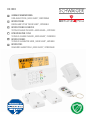 1
1
-
 2
2
-
 3
3
-
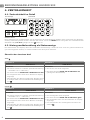 4
4
-
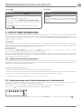 5
5
-
 6
6
-
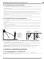 7
7
-
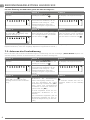 8
8
-
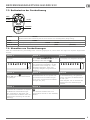 9
9
-
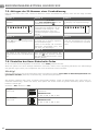 10
10
-
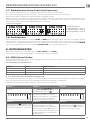 11
11
-
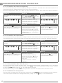 12
12
-
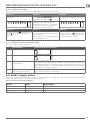 13
13
-
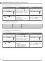 14
14
-
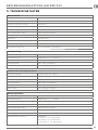 15
15
-
 16
16
-
 17
17
-
 18
18
-
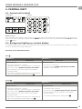 19
19
-
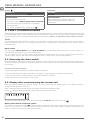 20
20
-
 21
21
-
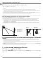 22
22
-
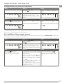 23
23
-
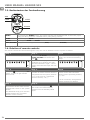 24
24
-
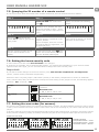 25
25
-
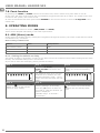 26
26
-
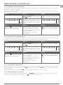 27
27
-
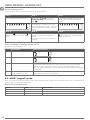 28
28
-
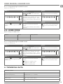 29
29
-
 30
30
-
 31
31
-
 32
32
-
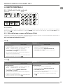 33
33
-
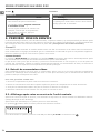 34
34
-
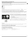 35
35
-
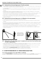 36
36
-
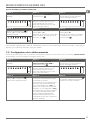 37
37
-
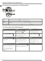 38
38
-
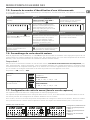 39
39
-
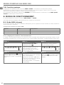 40
40
-
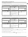 41
41
-
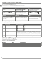 42
42
-
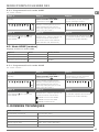 43
43
-
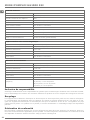 44
44
-
 45
45
-
 46
46
-
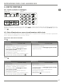 47
47
-
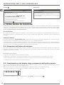 48
48
-
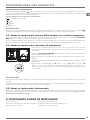 49
49
-
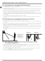 50
50
-
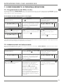 51
51
-
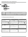 52
52
-
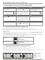 53
53
-
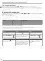 54
54
-
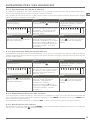 55
55
-
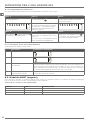 56
56
-
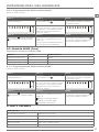 57
57
-
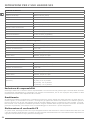 58
58
-
 59
59
-
 60
60
-
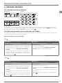 61
61
-
 62
62
-
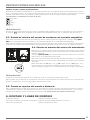 63
63
-
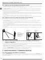 64
64
-
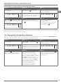 65
65
-
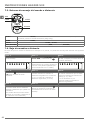 66
66
-
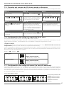 67
67
-
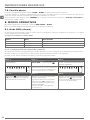 68
68
-
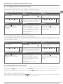 69
69
-
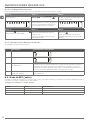 70
70
-
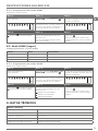 71
71
-
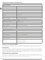 72
72
-
 73
73
-
 74
74
-
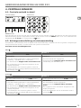 75
75
-
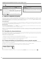 76
76
-
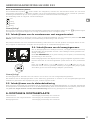 77
77
-
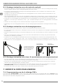 78
78
-
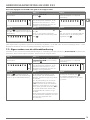 79
79
-
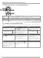 80
80
-
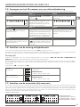 81
81
-
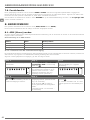 82
82
-
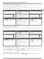 83
83
-
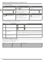 84
84
-
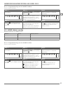 85
85
-
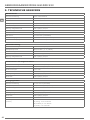 86
86
-
 87
87
-
 88
88


Schwaiger HG1000 532 Instructions Manual
- Categorie
- Afstandsbedieningen
- Type
- Instructions Manual
- Deze handleiding is ook geschikt voor
in andere talen
- English: Schwaiger HG1000 532
- italiano: Schwaiger HG1000 532
- français: Schwaiger HG1000 532
- español: Schwaiger HG1000 532
- Deutsch: Schwaiger HG1000 532
Gerelateerde papieren
-
Schwaiger Secure4You HGA300 532 Handleiding
-
-
-
-
-
-
Schwaiger HGA500 532 Handleiding
-
-
-
Andere documenten
-
König SEC-ALARM100 Specificatie
-
Hama 00176590 Short-Manual
-
Velleman HAM06WS Handleiding
-
Tiiwee A2 Instructions For Use Manual
-
Chuango WI-210 Handleiding
-
Samsara ACC-CPB Installatie gids
-
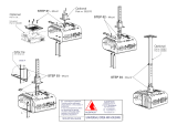 Audipack 390409 Handleiding
-
Xavax Feel Safe - 111982 de handleiding
-
König SEC-APC10 Specificatie
-
 LightPro 165A 12V Motion Sensor Handleiding

