Asco Series 442 449 Short Stroke Cylinder Type PEC KN de handleiding
- Type
- de handleiding

Sachets de pièces de rechange
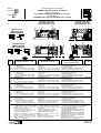
VERINS TYPE PEC ET KN Ø 32 à 100 mm
Spare parts kits for
CYLINDERS TYPES PEC AND KN Ø 32 to 100 mm
Ersatzteilliste
ZYLINDER DES TYPS PEC UND KN Ø 32 bis 100 mm
Series
Baureihe
449
442
Type: PEC
KN
(383 45 58)
PR-P227-1b
Rep.
DESIGNATION du sachet DESIGNATION of kit
BEZEICHNUNG
der Ersatzteilpackung
CODE
FR
GB
DE
978 02 337
1
2
3
4
VERIN Ø 32 mm . . . . . . . . . . . . . . . . . . .
- 2 Joints de tige
- 2 Joints à lèvres
- 2
Joints tube/fond Ø int. 31,2x1 (PEC)
- 2
Joints corps/fond Ø int. 28,3x1,8 (KN)
CYLINDER Ø 32 mm. . . . . . . . . . . . . . . .
- 2 Rod seals
- 2 Lip seals
-
2 O-rings tube/cover Ø int. 31,2x1 (PEC)
-
2 O-rings body/cover Ø int. 28,3x1,8 (KN)
ZYLINDER
Ø 32 mm. . . . . . . . . . . . . . . .
- 2 Kolbenstangendichtungen
- 2 Lippendichtungen
-
2 Dichtungen Rohr/Endstück Ø int. 31,2x1
-
2 Dichtungen Gehaüse/Endstück Ø int. 28,3x1,8
VERIN Ø 40 mm. . . . . . . . . . . . . . . . . . .
- 2 Joints de tige
- 2 Joints à lèvres
- 2
Joints tube/fond Ø int. 39,2x1 (PEC)
- 2
Joints corps/fond Ø int. 37,8x1,8 (KN)
CYLINDER Ø 40 mm. . . . . . . . . . . . . . . .
- 2 Rod seals
- 2 Lip seals
- 2 O-rings
tube/cover
Ø int. 39,2x1 (PEC)
-
2 O-rings body/cover Ø int. 37,8x1,8 (KN)
ZYLINDER
Ø 40 mm. . . . . . . . . . . . . . . .
- 2 Kolbenstangendichtungen
- 2 Lippendichtungen
-
2 Dichtungen Rohr/Endstück Ø int. 39,2x1
-
2 Dichtungen Gehaüse/Endstück Ø int.37,8x1,8
1
2
3
4
VERIN Ø 50 mm. . . . . . . . . . . . . . . . . . .
- 2 Joints de tige
- 2 Joints à lèvres
- 2
Joints tube/fond Ø int. 49x1 (PEC)
- 2
Joints corps/fond Ø int. 47,4x1,8 (KN)
CYLINDER Ø 50 mm. . . . . . . . . . . . . . . .
- 2 Rod seals
- 2 Lip seals
- 2 O-rings
tube/cover
Ø int. 49x1 (PEC)
-
2 O-rings body/cover Ø int. 47,4x1,8 (KN)
ZYLINDER
Ø 50 mm. . . . . . . . . . . . . . . .
- 2 Kolbenstangendichtungen
- 2 Lippendichtungen
-
2 Dichtungen Rohr/Endstück Ø int. 49x1
-
2 Dichtungen Gehaüse/Endstück Ø int. 47,4x1,8
1
2
3
4
978 02 338
978 02 339
VERIN Ø 63 mm. . . . . . . . . . . . . . . . . . .
- 2 Joints de tige
- 2 Joints à lèvres
- 2
Joints tube/fond Ø int. 62x1 (PEC)
- 2
Joints corps/fond Ø int. 60x1,8 (KN)
CYLINDER Ø 63 mm. . . . . . . . . . . . . . . .
- 2 Rod seals
- 2 Lip seals
- 2 O-rings
tube/cover
Ø int. 62x1 (PEC)
- 2 O-rings
body/cover
Ø int. 60x1,8 (KN)
ZYLINDER
Ø 63 mm. . . . . . . . . . . . . . . .
- 2 Kolbenstangendichtungen
- 2 Lippendichtungen
-
2 Dichtungen Rohr/Endstück Ø int. 62x1
-
2 Dichtungen Gehaüse/Endstück Ø int. 60x1,8
1
2
3
4
VERIN Ø 80 mm. . . . . . . . . . . . . . . . . . .
- 2 Joints de tige
- 2 Joints à lèvres
- 2
Joints tube/fond Ø int. 77x1,5 (PEC)
- 2
Joints corps/fond Ø int. 80x2 (KN)
CYLINDER Ø 80 mm. . . . . . . . . . . . . . . .
- 2 Rod seals
- 2 Lip seals
- 2 O-rings
tube/cover
Ø int. 77x1,5 (PEC)
- 2 O-rings
body/cover
Ø int. 80x2 (KN)
ZYLINDER
Ø 80 mm. . . . . . . . . . . . . . . .
- 2 Kolbenstangendichtungen
- 2 Lippendichtungen
-
2 Dichtungen Rohr/Endstück Ø int. 77x1,5
-
2 Dichtungen Gehaüse/Endstück Ø int. 80x2
1
2
3
4
978 02 340
978 02 341
VERIN Ø 100 mm. . . . . . . . . . . . . . . . . . .
- 2 Joints de tige
- 2 Joints à lèvres
- 2
Joints tube/fond Ø int. 95x1,8 (PEC)
-
2 Joints corps/fond Ø int. 99x2 (KN)
- 1 Segment (sur Ø100 mm uniquement)
CYLINDER Ø 100 mm. . . . . . . . . . . . . . .
- 2 Rod seals
- 2 Lip seals
- 2 O-rings
tube/cover
Ø int. 95x1,8 (PEC)
- 2 O-rings
body/cover
Ø int. 99x2 (KN)
- 1 Wear ring (only on Ø 100 mm)
ZYLINDER
Ø 100 mm. . . . . . . . . . . . . . .
- 2 Kolbenstangendichtungen
- 2 Lippendichtungen
-
2 Dichtungen Rohr/Endstück Ø int. 95x1,8
-
2 Dichtungen Gehaüse/Endstück Ø int. 99x2
- 1 Führungsring (nur für Ø100 mm geeignet)
1
2
3
4
5
978 02 342
SIMPLE EFFET
SINGLE ACTING
EINFACHWIRKEND
DOUBLE EFFET
DOUBLE ACTING
DOPPELWIRKEND
NOTA- Pour obtenir un fonctionnement
optimal il est recommandé d'utiliser la
graisse fournie dans chaque sachet.
Tube supplémentaire (11 cm
3
) sur
demande code: 978 02 100.
NOTE: For best results, use grease
supplied in each kit.
Supplementary tube available (11 cm
3
)
on request, code: 978 02 100.
ANMERKUNG: Ein optimales Funktionieren
wird durch Verwendung des beigefügten
Schmiermittels erreicht.
Zusätzliche Tube (11 cm3) auf Anfrage
erhätlich-Bestell-Code: 978 02 100.
4
1
2
2
22
4
13 3
2
13
3
2
4
1
5
5
5
5
Type PEC (série 449)
Type PEC (series 449)
Typ PEC (Baureihe 449)
Type KN (série 442)
Type KN (series 442)
Typ KN (Baureihe 442)
(❉)
Mount the O-rings rep. 3 on PEC cylinders
Mount the O-rings rep.
4
on KN cylinders
The spare parts for the following cylinders
are included:
- Single and double acting versions
- Single rod and through rod versions
- Anti-rotation PEC-KN cylinder
Die Ersatzteilpackung enthält alle Ersatztei-
le für die folgenden Zylinder:
- einfache und doppeltwirkende Ausführung
- Ausführung mit einfacher oder durchgehen
der Kolbenstange.
- Verdrehsichere Zylinder des Typs PEC-KN
(❉)
Monter les joints repère 3 sur les vérins PEC
Monter les joints repère 4 sur les vérins KN
Chaque sachet contient les pièces de
rechange pour les vérins:
- Versions simple et double effet
- Versions simple tige et tige traversante
- Vérins PEC-KN antirotation
NS
(❉)
(❉)
(❉)
(❉)
(❉)
(❉)
NS
NS
(❉)
(❉)
(❉)
(❉)
(❉)
(❉)
(❉)
Montieren Sie die Dichtungen Nr. 3 auf PEC-Zylinder
Montieren Sie die Dichtungen Nr.
4
auf KN-Zylinder
SR
NS
NS
NS

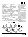
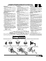
PROCEDURE DE DEMONTAGE-REMONTAGE VERINS PEC-KN
PROCEDURE FOR STRIPPING PEC - KN CYLINDER
WARTUNGS- UND MONTAGEANLEITUNG FÜR PEC-KN ZYLINDER
DEMONTAGE
DEMONTAGE
DISASSEMBLY
1- Démonter les fonds en desserrant les 8
écrous (PEC) ou le circlip avant (KN).
2- Sortir l'ensemble tige/piston du tube de vérin
3- Bloquer l'ensemble tige/piston à l'aide des plats
existant en tête de tige.
4- Retirer les joints à lèvres (2) avec précaution
5- Nettoyer la tige, le piston et l'intérieur du tube
(ne pas utiliser de produits corrosifs ni solvants)
6- Ne pas démonter le piston
REASSEMBLY
Pour obtenir un fonctionnement optimal, il est re-
commandé d'utiliser la graisse fournie.
1- Retirer de la pochette de rechange les joints à
lèvres (2).
2- Enduire légèrement de graisse les joints à lèvres
et les gorges du piston.
3-
Placer le joint à lèvre dans la gorge d'un côté
du piston (fig. A). Respecter le sens de montage
4- Terminer la mise en place du joint dans sa
gorge (fig. B)
5-
Controler le positionnement correct du joint (fig. C)
6-
Retourner l'ensemble tige/piston et monter le
2eme joint en répétant les phases 3,4,5. Respec-
ter les sens de montage des lévres (voir fig. D)
7-
Remonter le segment (5) uniquement sur Ø 100mm
8- Enduire légèrement de graisse l'intérieur et l'en-
trée du tube et les joints à lévres.
9- Placer le piston en biais dans la partie inférieure
du cylindre (fig. E)
10
-Introduire progressivement le joint à lévre, à
l'aide d'un outil plat, sans aspérité et en effec-
tuant un mouvement circulaire de la tige (fig. F).
Ne pas utiliser de tournevis
11
-
Enduire de graisse le pourtour central du piston (❉)
12
-
Pousser le piston dans le cylindre (fig. G)
13
-Aprés avoir remplacé les joints de tige (1) et
joints toriques (3) ou (4), remonter les fonds.
14
-Vérifier que les fonds sont bien mis dans le tube
pour assurer l'alignement et serrer en croix les 8
écrous ou remonter le circlip avant (KN), couple
de serrage recommandé (PEC):
- Ø 32-40 : 7 N.m
- Ø 50-63 : 13,5 N.m
- Ø 80-100 : 27,5 N.m
NOTA: nombre maximum de démontages = 3
Fig. C
Abb. C
Fig. B
Abb. B
Fig. A
Abb. A
1- Entfernen Sie die Endstücke, indem Sie die
8 Muttern (PEC) bzw. den vorderen
Sicherungsring (KN) losen.
2- Nehmen Sie die Einheit bestehend aus Kolben-
stange und Kolben aus dem Zylinderrohr heraus.
3- Blockieren Sie die Einheit aus Kolbenstange und
Kolben an den Schlüsselflächen am Kopf der
Kolbenstange.
4-
Entfernen Sie vorsichtig die Lippendichtungen (2).
5- Reinigen Sie die Kolbenstange, den Kolben und
das Rohr (ätzende Mittel oder Lösemittel sind
nicht zu verwenden).
6- Demontieren Sie nicht den Kolben.
Ein optimales Funktionieren wird durch Verwen-
dung des beigefügten Schmiermittels erreicht.
1- Nehmen Sie die Lippendichtungen (2) aus der
Ersatzteilpackung.
2- Schmieren Sie die Lippendichtungen und die
Kolbenringnuten leicht ein.
3- Legen Sie die Lippendichtung auf einer Seite
des Kolbens (Abb.A) in die Nut ein. Beachten
Sie die Montagerichtung.
4- Schließen Sie die Montage der Dichtung gemäß
(Abb. B) ab.
5-
Überprüfen Sie die richtige Lage der Dichtung (Abb. C)
6- Drehen Sie die Einheit aus Kolbenstange und
Kolben um und legen Sie die 2. Dichtung unter
Wiederholung der Punkte 3,4,5 ein. Beachten
Sie die Montagerichtung der Lippen (Abb.D).
7- Setzen Sie den Führungsring (5) ein nur für
Ø100 mm geeignet
8- Schmieren Sie das Innere und den Eingang des
Rohres sowie die Lippendichtungen leicht ein.
9- Setzen Sie den Kolben schräg in den unteren
Teil des Zylinders (Abb. E) ein.
10
- Schieben Sie die Lippendichtung unter Zuhilfe-
nahme eines glatten Werkzeuges mit einer
drehenden Bewegung in den Zylinder (Abb. F).
Verwenden Sie keinen Schraubendreher.
11-Schmieren Sie den Umfang des Mittelteils des
Kolbens ein (❉).
12-
Schieben Sie den Kolben in den Zylinder (Abb. G)
13-Nachdem Sie die Kolbenstangen- (1) und O-
Ringe (3) oder (4) wieder eingesetzt haben,
schrauben Sie die Endstücke wieder an.
14-Überprüfen Sie die richtige Lage der Endstücke.
Befestigen Sie die 8 Muttern über Kreuz bzw.
denvorderen Sicherungsring (KN). Empfohle-
nen drehmomenten für PEC-Zylinder:
- Ø 32-40 : 7 N.m
- Ø 50-63 : 13,5 N.m
- Ø 80-100 : 27,5 N.m
ANMERKUNG:Max. Anzahl der Demontagen = 3
MONTAGE
REMONTAGE
1- Disassemble the covers by loosening the 8
nuts (PEC) or front circlip (KN).
2-
Remove the rod/piston unit from the cylinder tube.
3- Block the rod/piston unit using the flats on the
rod head.
4- Remove the lip seals (2) carefully.
5- Clean the rod, piston and inside of the tube (do
not use corrosives or solvents).
6- Do not disassemble the piston.
Fig. E
Abb. E
MONTAGE DU PISTON / PISTON ASSEMBLY / MONTAGE DES KOLBENS
Fig. G
Abb. G
MONTAGE DES JOINTS A LEVRES / ASSEMBLY OF THE LIP SEALS / MONTAGE DER LIPPENDICHTUNGEN
❉
Dépôt de graisse
Grease store
Fettkammer
Fig. D
Abb. D
For best results, use grease supplied.
1-
Remove the lip seals from the spare parts bag (3).
2- Coat the lip seals and the piston ring grooves
lightly with grease.
3- Place the lip seal on one side of the piston into
the groove (fig. A). Observe the mounting
direction.
4- Complete fitting of seal into groove (fig. B).
5- Check the correct position of the seal (fig. C).
6- Turn the rod/piston unit around and assemble
the 2nd seal by repeating steps 3,4,5. Observe
the mounting direction of the lips (see fig. D).
7- Install the wear ring (5) only on Ø 100 mm
8- Coat the inside of the tube and its entry as well
as the lip seals lightly with grease.
9- Place the piston diagonally into the bottom part
of the cylinder (fig. E).
10
- Push the lip seal with a circular movement into
the rod using a flat tool (fig. F). Do not use a
screwdriver.
11-Grease the circumference of the middle part of
the piston (❉)
12-Place the piston back into the cylinder (fig. G).
13-After having replaced the rod seals (1) and the
O-rings (3) or (4), reassemble the covers.
14-Check that the ends are properly positioned in
the tube to ensure alignment then tighten the 8
nuts crosswise or assembly the front circlip (KN)
with the following torques (PEC):
- Ø 32-40 : 7 N.m
- Ø 50-63 : 13,5 N.m
- Ø 80-100 : 27,5 N.m
N.B. Max. number of disassemblies = 3
Procédure valable pour version simple tige et tige traversante.
Same procedure for single rod and through rod versions.
Gilt sowohl für die Ausführung mit einfacher als auch mit durchgehender Kolbenstange
.
Lors de l'assemblage des attaches normalisées
sur les vérins PEC, serrer les vis de fixation en
croix suivant couple maxi de serrage ci dessous.
When fixing the standard mountings on the PEC
cylinders tighten the screws crosswise with the
max. torques given below.
Bei der Montage der Standardbefestigungsteile
auf den PEC-Zylindern sind die Schrauben über
Kreuz mit dem nachstehend angegebenen Dreh-
moment anzuziehen.
Ø
Couple maxi
Max. torque
Max. Drehmoment
32-40 50-63 80-100
7 13,5 27,5
(N.m)
Fig. F
Abb. F

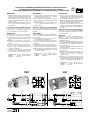
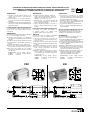
PROCEDURE DE DEMONTAGE-REMONTAGE VERINS PEC-KN ANTIROTATION
PROCEDURE FOR STRIPPING ANTI-ROTATION PEC-KN-CYLINDERS
WARTUNGS- UND MONTAGEANLEITUNG FÜR VERDREHSICHERE PEC-KN-ZYLINDER
DEMONTAGE
1- Démonter la plaque avant en desserrant la vis
centrale (A) tout en immobilisant la tige à l'aide
des deux plats (D) existant en tête de celle-ci.
2- Retirer la plaque + les colonnettes (B) (il n'est
pas nécessaire de démonter les colonnettes de
la plaque avant)
3- Suite du démontage: identique aux phases 1
à 6 des vérins PEC-KN standard (voir page
précédente).
Pièces de rechange / PEC-KN antirotation
Les pochettes de rechange présentées en
première page sont également valables pour
les vérins PEC-KN en version antirotation
REMONTAGE
Procéder au remontage du vérin en commençant
par les phases 1 à 14 (voir page précédente)
15
-
Introduire, avec précaution, les colonnettes (B)
dans les bagues de guidages (C) prévues à cet
effet.
16
- Enduire la vis centrale (A) de Loctite 262
17
- Rentrer la tige du vérin en poussant sur la
plaque.
18
- Visser manuellement la vis centrale (A).
19
- Sortir et rentrer manuellement l'ensemble
plaque et tige (s'assurer de l'absence de
résistance mécanique)
20
- Serrer la vis centrale (A) au couple préconisé
ci-dessous tout en immobilisant la tige à l'aide
des deux plats existant en tête de celle-ci.
Ø 20-25 (KN)= 8 N.m Ø 80 = 67 N.m
Ø 32-40 = 19,5 N.m Ø 100 = 84 N.m
Ø 50-63 = 38,5 N.m
PEC
KN
DISASSEMBLY
1- Block the piston rod using the flats (D) on the
rod head and disassemble the front plate by
loosening the middle screw (A).
2- Draw off the plate and the guide bars (B) (you
do not need to disassemble the guide bars from
the front cover).
3- Disassemble the rest as described in steps 1
to 6 for standard PEC-KN cylinders (see
previous page).
Spar parts / Anti-rotation PEC-KN cylinder
The spare parts kits described on the first page
can also be used for the anti-rotation cylinders type
PEC-KN.
REASSEMBLY
Begin to reassemble the cylinder by following steps
1 to 14 described under "Reassembly" on the
previous page).
15
-
Carefully push the guide bars (B) into the
corresponding guiding rings (C).
16
- Coat the middle screw (A) with Loctite 262.
17
- Insert the rod into the cylinder by pushing on
the plate.
18
- Tighten the middle screw (A) by hand.
19
- Move the plate and rod unit in and out by hand
(make sure there is no mechanical resistance).
20
- Block the piston rod using the flats (D) on the
rod head and tighten the middle screw (A) with
the following torques:
Ø 20-25 (KN)= 8 N.m Ø 80 = 67 N.m
Ø 32-40 = 19,5 N.m Ø 100 = 84 N.m
Ø 50-63 = 38,5 N.m
DEMONTAGE
1- Blockieren Sie die Kolbenstange an den
Schlüsselflächen (D) am Kopf der Kolbenstange
und entfernen sie die vordere Platte, indem Sie
die Schraube in der Mitte (A) lösen.
2- Ziehen Sie die Platte und die Führungsstangen
(B) ab (die Führungsstangen müssen nicht von
der vorderen Platte abmontiert werden).
3- Demontieren Sie die übrigen Teile wie in den
Schritten 1 bis 6 für die Standardzylinder des
Typs PEC-KN beschrieben (siehe vorangehen-
de Seite).
Ersatzteile / Verdrehsichere PEC-KN-Zylinder
Die auf der ersten Seite aufgeführten Ersatzteil-
beutel gelten auch für die verdrehsicheren Zylinder
des Typs PEC-KN.
MONTAGE
Beginnen Sie mit dem Zusammenbau des
Zylinders, indem Sie die unter "Montage"
beschriebenen Schritte 1 bis 14 durchführen (siehe
vorhergehende Seite).
15
-
Führen Sie die Führungsstangen (B) vorsichtig
in die dafür bestimmten Führungsringe (C) ein.
16
- Schmieren Sie die Schraube in der Mitte (A)
mit Loctite 262 ein.
17
- Führen Sie die Kolbenstange ein, indem Sie auf
die Platte drücken.
18
- Schrauben Sie die Schraube in der Mitte (A)
von Hand ein.
19
- Bewegen Sie die Einheit aus Platte und
Kolbenstange hinein und heraus (stellen Sie
sicher, dass es keinen mechanischen
Widerstand gibt).
20
- Blockieren Sie die Kolbenstange an den
Schlüsselflächen am Kopf der Kolbenstange
und ziehen Sie die Schraube in der Mitte (A)
mit den nachstehenden Drehmomenten fest:
Ø 20-25 (KN)= 8 N.m Ø 80 = 67 N.m
Ø 32-40 = 19,5 N.m Ø 100 = 84 N.m
Ø 50-63 = 38,5 N.m
PEC KN
(A)
(B)
(B)
(C)
(D)
(A)
(B)
(B)
(C)
(D)

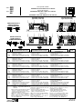
Serie parti di ricambio
CILINDRI TIPO PEC E KN Ø 32 a 100 mm
Piezas de repuesto
CILINDROS TIPO PEC Y KN Ø 32 a 100 mm
Revisie-sets
CILINDERS TYPE PEC EN KN Ø 32 tot 100 mm
Rep.
COMPOSIZIONE della serie DESIGNACION del conjunto
BESCHRIJVING
onderdelen set
COD.
IT
ES
NL
1
2
3
4
CILINDRO
Ø 32 mm . . . . . . . . . . . . . . . .
- 2 Guarnizioni dello stelo
- 2 Guarnizioni a labbro
- 2
Guarnizioni OR canna/testata Ø int. 31,2x1 (PEC)
- 2
Guarnizioni OR corpo/testata Ø int. 28,3x1,8 (KN)
CILINDRO
Ø 32 mm. . . . . . . . . . . . . . . .
- 2 Juntas de vástago
- 2 Juntas de labios
-
2 Juntas tubo/fondo Ø int. 31,2x1 (PEC)
-
2 Juntas cuerpo/fondo Ø int. 28,3x1,8 (KN)
CILINDER
Ø 32 mm. . . . . . . . . . . . . . . .
- 2 Zuigerstangafdichtingen
- 2 Lipafdichtingen
- 2
Afdichtingen buis/deksel Ø int. 31,2x1 (PEC)
-
2
Afdichtingen huis/deksel Ø int. 28,3x1,8 (KN)
CILINDRO
Ø 40 mm. . . . . . . . . . . . . . . .
- 2 Guarnizioni dello stelo
- 2 Guarnizioni a labbro
- 2
Guarnizioni OR canna/testata
Ø int. 39,2x1 (PEC)
- 2
Guarnizioni OR corpo/testata
Ø int. 37,8x1,8 (KN)
CILINDRO
Ø 40 mm. . . . . . . . . . . . . . . .
- 2 Juntas de vástago
- 2 Juntas de labios
- 2 Juntas tubo
/fondo
Ø int. 39,2x1 (PEC)
-
2 Juntas cuerpo/fondo Ø int. 37,8x1,8 (KN)
CILINDER
Ø 40 mm. . . . . . . . . . . . . . . .
- 2 Zuigerstangafdichtingen
- 2 Lipafdichtingen
- 2
Afdichtingen buis/deksel Ø int. 39,2x1 (PEC)
-
2
Afdichtingen huis/deksel Ø int.37,8x1,8 (KN)
1
2
3
4
CILINDRO
Ø 50 mm. . . . . . . . . . . . . . . .
- 2 Guarnizioni dello stelo
- 2 Guarnizioni a labbro
- 2
Guarnizioni OR canna/testata
Ø int. 49x1 (PEC)
- 2
Guarnizioni OR corpo/testata
Ø int. 47,4x1,8 (KN)
CILINDRO
Ø 50 mm. . . . . . . . . . . . . . . .
- 2 Juntas de vástago
- 2 Juntas de labios
- 2 Juntas tubo
/fondo
Ø int. 49x1 (PEC)
-
2 Juntas cuerpo/fondo Ø int. 47,4x1,8 (KN)
CILINDER
Ø 50 mm. . . . . . . . . . . . . . . .
- 2 Zuigerstangafdichtingen
- 2 Lipafdichtingen
- 2
Afdichtingen buis/deksel Ø int.
49x1 (PEC)
-
2
Afdichtingen huis/deksel Ø int. 47,4x1,8 (KN)
1
2
3
4
CILINDRO
Ø 63 mm. . . . . . . . . . . . . . . .
- 2 Guarnizioni dello stelo
- 2 Guarnizioni a labbro
- 2
Guarnizioni OR canna/testata
Ø int. 62x1 (PEC)
- 2
Guarnizioni OR corpo/testata
Ø int. 60x1,8 (KN)
CILINDRO
Ø 63 mm. . . . . . . . . . . . . . . .
- 2 Juntas de vástago
- 2 Juntas de labios
- 2 Juntas tubo
/fondo
Ø int. 62x1 (PEC)
-
2 Juntas cuerpo/fondo Ø int. 60x1,8 (KN)
CILINDER
Ø 63 mm. . . . . . . . . . . . . . . .
- 2 Zuigerstangafdichtingen
- 2 Lipafdichtingen
- 2
Afdichtingen buis/deksel Ø int.
62x1 (PEC)
-
2
Afdichtingen huis/deksel Ø int. 60x1,8 (KN)
1
2
3
4
CILINDRO
Ø 80 mm. . . . . . . . . . . . . . . .
- 2 Guarnizioni dello stelo
- 2 Guarnizioni a labbro
- 2
Guarnizioni OR canna/testata
Ø int. 77x1,5 (PEC)
- 2
Guarnizioni OR corpo/testata
Ø int. 80x2 (KN)
CILINDRO
Ø 80 mm. . . . . . . . . . . . . . . .
- 2 Juntas de vástago
- 2 Juntas de labios
- 2 Juntas tubo
/fondo
Ø int. 77x1,5 (PEC)
- 2 Juntas cuerpo
/fondo
Ø int. 80x2 (KN)
CILINDER
Ø 80 mm. . . . . . . . . . . . . . . .
- 2 Zuigerstangafdichtingen
- 2 Lipafdichtingen
- 2
Afdichtingen buis/deksel Ø int. 77x1,5 (PEC)
-
2
Afdichtingen huis/deksel Ø int. 80x2 (KN)
1
2
3
4
CILINDRO
Ø 100 mm. . . . . . . . . . . . . . .
- 2 Guarnizioni dello stelo
- 2 Guarnizioni a labbro
- 2
Guarnizioni OR canna/testata
Ø int. 95x1,8 (PEC)
-
2
Guarnizioni OR corpo/testata
Ø int. 99x2 (KN)
-
1 Segmento (solo su Ø 100 mm)
CILINDRO
Ø 100 mm. . . . . . . . . . . . . . .
- 2 Juntas de vástago
- 2 Juntas de labios
- 2 Juntas tubo
/fondo
Ø int. 95x1,8 (PEC)
- 2 Juntas cuerpo
/fondo
Ø int. 99x2 (KN)
- 1 Segmento (en Ø 100 mm únicamente)
CILINDER
Ø 100 mm. . . . . . . . . . . . . . .
- 2 Zuigerstangafdichtingen
- 2 Lipafdichtingen
-
2 Afdichtingen
buis/deksel Ø int. 95x1,8 (PEC)
-
2 Afdichtingen huis/deksel Ø int. 99x2 (KN)
- 1 Geleidingsring (only on Ø 100 mm)
1
2
3
4
5
SEMPLICE EFFETTO
SIMPLE EFECTO
ENKELWERKENDE
DOPPIO EFFETTO
DOBLE EFECTO
DUBBELWERKENDE
NOTA- Per ottenere un funzionamento
ottimale, si raccomanda di utilizzare il
grasso fornito in ogni sacchetto.
Tubetto supplementare (11cm3) su richie-
sta codice: 978 02 100.
NOTA- Para obtener un funcionamiento
óptimo, se recomienda utilizar la grasa
provista en casa bolsa.
Tubo suplementario (11 cm3) bajo de-
manda, código : 978 02 100
N.B.:
Voor een optimaal resultaat, wordt
aanbeloven het smeermiddel, zoals in elke
revisieset is bijgevoegd, te gebruiken.
Een aanvullende tube (11 cm3) is beschik-
baar op aanvraag, code: 978 02 100
4
1
2
2
22
4
13 3
2
13
3
2
4
1
5
5
5
5
Tipo PEC (serie 449)
Type PEC (serie 449)
Tipo KN (serie 442)
Type KN (serie 442)
(❉)
Montar las juntas ref. 3 en los cilindros PEC
Montar las juntas ref. 4 en los cilindros KN
Cada bolsa contiene las piezas de recam-
bio para los cilindros:
- Versiones simple y doble efecto
-
Versiones simple vástago y vástago pasante
- Cilindros PEC-KN antirrotaciòn
(❉)
Monteer de afdichting 3 op de PEC cilinders
Monteer de afdichting 4 op de KN cilinders
Iedere revisie-set bevat de reserve-
onderdelen voor de cilinders:
- Enkel- en dubbelwerkende versies
- Enkele en doorlopende stang versies
- PEC-KN cilinders antirotatie
(❉)
Montare le guarnizioni OR rif.3 sui
cilindri PEC
Montar e le guarnizioni OR rif.4 sui
cilindri KN
Ogni kit contiene le parti di ricambio per i cilindri:
- Versione a semplice e doppio effetto
- Versione a stelo singolo e stelo passante
- Cilindri PEC-KN antirotazione
(❉)
(❉)
(❉)
(❉)
(❉)
(❉)
(❉)
(❉)
(❉)
(❉)
(❉)
(❉)
Serie 449
442
Type: PEC
KN
978 02 337
978 02 338
978 02 339
978 02 340
978 02 341
978 02 342
NS
SR
NS
NS
(383 45 58)
PR-P227-1b
NS
NS
NS

SMONTAGGIO
DESMONTAJE
1- Desmontar los fondos soltando las 8 tuercas (PEC) o
el circlip delantero (KN).
2- Sacar el conjunto vástago pistón del tubo del cilindro.
3- Bloquear el conjunto vástago/pistón apoyándose en las
caras planas de la cabeza del vástago.
4- Retirar las juntas de labios (2) con precaución
5- Limpiar el vástago, el pistón y el interior del tubo (no
utilizar productos corrosivos ni disolventes)
6- No desmontar el pistón
1- Smontare le testate svitando gli 8 dadi (PEC) o
l'anello Seeger anteriore (KN).
2- Estrarre l'insieme stelo/pistone dalla canna del
cilindro.
3- Bloccare l'insieme stelo/pistone servendosi delle
fresature che si trovano sull'estremita'
anteriore dello stelo.
4- Togliere i giunti a labbro (2) con precauzione
5- Pulire lo stelo, il pistone e l'interno della canna (non
utilizzare prodotti corrosivi né solventi)
6- Non smontare il pistone.
DEMONTAGE
1- Verwijder de voor- en achtereindstukken door
de 8 schroeven los te draaien (PEC) of de
voorste clip (KN) .
2-
Verwijder de zuigerstang en de zuiger uit de cilinder.
3- Blokkeer de zuigerstang met de juiste steek-
sleutel. Maak gebruik van de pasvlakken aan
het zuigerstangeinde.
4- Verwijder voorzichtig de (2) lipafdichtingen.
5- Reinig de zuigerstang, de zuiger en het
binnenste van de cilinderbuis. (Geen corro-
sieve en/of oplosmiddelen gebruiken).
6- De zuiger niet demonteren.
Voor een optimaal resultaat, wordt aanbeloven het
bijgevoegd smeermiddel te gebruiken.
1- Neem de lipafdichtingen (2) uit de reserve-
onderdelenset.
2- Vet de lipafdichtingen en de groeven in de zuiger
licht in.
3-
Plaats de lipafdichting in een groef aan één zijde
van de zuiger (fig.A). Let op de montagerichting.
4- Monteer de lipafdichting, zonder druk uit te
oefenen en met een draaiende beweging in de
groef (fig. B).
5-
Controleer de juiste positie van de afdichting (fig. C)
6- Plaats de eenheid bestaande uit de zuigerstang
en zuiger weer in de cilinder en monteer de 2e
afdichting volgens de stappen 3,4,5. Let op de
montagerichting van de afdichting (zie fig. D)
7- Monteer de geleidingsring (5) only on Ø 100 mm
8- Vet de binnenzijde en de ingang van de cilinder-
buis alsmede de lipafdichtingen licht in.
9- Plaats de zuiger schuin in het onderste gedeelte
van de cilinder (fig. E)
10
-
B
reng langzaam de lipafdichting met behulp van een
plat gereedschap in, zonder druk uit te oefenen en met
een draaiende beweging van de zuigerstang (fig. F).
Geen schroevendraaier hiervoor gebruiken.
11
-Vet de omtrek van de zuiger in (❉)
12
-Duw de zuiger in de cilinder (fig. G)
13
-Nadat de zuigerstang- (1) en de dempings-
afdichtingen (3) of (4) wederom gemonteerd zijn,
schroeft u de eindstukken vast.
14
-Controleer of de eindstukken goed in de cilinder
zijn ingebracht om een juiste uitlijning te krijgen
en bevestig de 8 schroeven kruislings of
monteer de voorste clip(KN) conform de
aanbevolen aandraaikoppels (PEC):
- Ø 32-40 : 7 N.m
- Ø 50-63 : 13,5 N.m
- Ø 80-100 : 27,5 N.m
N.B.: Deze cilinder met profielbuis mag max.
3x gedemonteerd worden.
MONTAGE
PROCEDURA DI SMONTAGGIO E RIMONTAGGIO DEI CILINDRI PEC-KN
PROCEDIMIENTO DE DESMONTAJE-MONTAJE DE LOS CILINDROS PEC-KN
PROCEDURE VOOR DE MONTAGE EN DEMONTAGE VAN PEC-KN CILINDERS
MONTAJE
Para obtener un funcionamiento óptimo, se reco-
mienda utilizar la grasa provista.
1- Retirar de la bolsa de recambio las juntas de
labios (3).
2- Untar ligeramente de grasa las juntas de labios
y las gargantas del pistón.
3-
Colocar la junta de labios en la garganta de un
lado del pistón (fig.A). Respetar el sentido de
montaje
4- Terminar la colocación de la junta en su gar-
ganta. (fig. B)
5-
Controlar la colocación correcta de la junta (fig. C)
6- Girar el conjunto vástago/pistón y montar la 2ª
junta repitiendo los pasos 3,4,5. Respetar el
sentido de montaje de los labios (ver fig. D)
7- Volver a montar el segmento (5) únicamente
en Ø 100 mm
8- Untar ligeramente de grasa el interior y la entra-
da del tubo y las juntas de labios.
9- Colocar el pistón oblicuamente en la parte infe-
rior del cilindro (fig. E)
10
-Introducir progresivamente la junta de labios,
con ayuda de una herramienta plana, sin aspe-
rezas realizando un movimiento circular del vás-
tago (fig. F). No utilizar destornillador
11
-Untar de grasa la parte central del pistón (i)
12
-Empujar el pistón en el cilindro (fig. G)
13-Después
de haber reemplazado las juntas del
vástago (1) y juntas tóricas (3) o (4), volver a
montar los fondos.
14
-Comprobar que los fondos están bien colocados
en el tubo para asegurar la alineación y apretar en
cruz las 8 tuercas o montar el circlip delantero
(KN) par de apriete recomendado (PEC):
- Ø 32-40 : 7 N.m
- Ø 50-63 : 13,5 N.m
- Ø 80-100 : 27,5 N.m
NOTA:número máximo de desmontajes = 3
Procedura valida per versione semplice e doppio stelo.
Procedimento válido para la versión de vástago simple y vástago pasante.
Procedure van toepassing op cilinder met enkele stang en dwarsdrijfstang.
RIMONTAGGIO
Per ottenere un funzionamento ottimale, si racco-
manda di utilizzare il grasso fornito.
1- Prendere dal kit dei ricambi i giunti a labbro (2).
2- Lubrificare leggermente i giunti a labbro e le
sedi del pistone.
3- Inserire il giunto a labbro dal lato del pistone
(fig.A). Rispettare il senso di montaggio
4- Portare a termine il montaggio del giunto
mediante un movimento circolare (fig. B)
5-
Verificare che la posizione del giunto sia corretta
(fig. C)
6- Rimontare l'insieme stelo/pistone e montare il
2
do
giunto ripetendo le fasi 3,4,5. Rispettare il
senso di montaggio del labbro (vedere fig. D)
7- Rimontare il segmento (5) solo su Ø 100 mm
8- Lubrificare leggermente l'interno e l'ingresso
della canna ed i giunti a labbro.
9- Inserire il pistone in obliquo nella parte inferiore
del cilindro (fig. E)
10
- Introdurre progressivamente il giunto a labbro,
servendosi di un utensile piatto, senza asperita' ,
mediante movimento circolare dello stelo (fig. F).
Non utilizzare cacciaviti
11
-Ingrassare la parte intermedia del pistone (
❉
)
12
-Spingere il pistone nel cilindro (fig. G)
13
-Dopo aver sostituito il giunto raschiaolio (1) e le
guarnizioni OR (3) o (4), rimontare le testate .
14
-Controllare che le testate siano posizionate
correttamente nella canna per assicurare il
corretto allineamento e tringere a croce gli 8 dadi
o rimontare l'anello Seeger anteriore (KN),
coppia di serraggio raccomandata (PEC):
- Ø 32-40 : 7 N.m
- Ø 50-63 : 13,5 N.m
- Ø 80-100 : 27,5 N.m
NOTA: numero max smontaggi = 3
Fig. C
Fig. B
Fig. A
Fig. E
Fig. F Fig. G
Fig. D
Ø
Coppia massima
Par máximo
Max. koppel
32-40 50-63 80-100
7 13,5 27,5
(N.m)
Durante l'assemblaggio dei fissaggi normalizzati
sui cilindrii PEC, serrare le viti a croce secondo la
massima coppia di serraggio sotto riportata.
Durante el montaje de las fijaciones normalizadas en
los cilindros (PEC), apretar los tornillos de fijación en
cruz según el par de apriete máximo de abajo
Tijdens de assemblage van de standaard bevesti-
gingen op de PEC cilinders, dienen de bevestigings-
schroeven kruislings te worden aangedraaid vol-
gens het max. hieronder genoemde koppelmoment.
MONTAGGIO DEL PISTONE / MONTAJE DEL PISTON / MONTAGE VAN DE ZUIGER
MONTAGGIO DEI GIUNTI A LABBRO / MONTAJE DE LAS JUNTAS DE LABIOS / MONTAGE VAN DE LIPAFDICHTINGEN
❉
Parte da ingrassare
Deposito de grasa
Opslag van smering

PROCEDURA DI SMONTAGGIO-MONTAGGIO DEI CILINDRI ANTIROTAZIONE PEC-KN
PROCEDIMIENTO DE DESMONTAJE-MONTAJE CILINDROS PEC-KN ANTIRROTACIÓN
DEMONTAGE - HERMONTAGE PEC-KN-CILINDERS MET ANTIROTATIE
SMONTAGGIO
1- Smontare la piastra anteriore svitando la vite
centrale (A) bloccando lo stelo dalle due
fresature (D).
2- Sfilare la piastra + le colonnette (B) (non è
necessario smontare le colonnette dalla piastra
anteriore).
3- Seguito delle operazioni di smontaggio: identico
alle fasi da 1 a 6 dei cilindri standard KN (vedi
pagina precedente).
Parti di ricambio / PEC-KN antirotazione
Le parti di ricambio elencate in prima pagina sono
valide anche per i cilindri KN in versione
antirotazione.
RIMONTAGGIO
Procedere al rimontaggio del cilindro partendo dalle
fasi 1 a 14 (vedi pagina precedente)
15- Introdurre, con precauzione, le colonnette (B)
nei supporti lisci di guida (C) previsti per questa
funzione.
16- Applicare alla vite centrale (A) della Loctite 262
17- Fare rientrare lo stelo del cilindro spingendo la
piastra.
18- Avvitare manualmente la vite centrale (A).
19- Fare uscire e rientrare manualmente l'insieme
piastra e stelo (assicurarsi che non ci sia attrito).
20-Bloccare la vite centrale (A) con coppia di
serraggio sotto riportata bloccando lo stelo dalle
due fresature.
PEC
KN
Ø 20-25 (KN)= 8 N.m Ø 80 = 67 N.m
Ø 32-40 = 19,5 N.m Ø 100 = 84 N.m
Ø 50-63 = 38,5 N.m
Ø 20-25 (KN)= 8 N.m Ø 80 = 67 N.m
Ø 32-40 = 19,5 N.m Ø 100 = 84 N.m
Ø 50-63 = 38,5 N.m
Ø 20-25 (KN)= 8 N.m Ø 80 = 67 N.m
Ø 32-40 = 19,5 N.m Ø 100 = 84 N.m
Ø 50-63 = 38,5 N.m
PEC KN
(A)
(B)
(B)
(C)
(D)
(A)
(B)
(B)
(C)
(D)
1- Desmontar la placa delantera soltando el
tornillo central (A) inmovilizando siempre el
vástago con la ayuda de los 2 planos (D)
existentes en la cabeza de este.
2- Retirar la placa + los elementos de unión (B)
(no es necesario desmontar los elementos de
unión de la placa delantera)
3- Sigue el desmontaje: idéntico a las fases 1 a
6 de los cilindros KN standard (ver página
anterior).
Piezas de recambio / PEC-KN antirrotación
Las bolsas de recambio presentadas en
la primera página son válidas para
los cilindros KN en versión antirrotación
Proceder al montaje del cilindro comenzando
por las fases 1 a 14 (ver página anterior)
15
-
Introducir, con precaución, los elementos de
unión (B) en los anillos de guiado (C) previstos
para este efecto.
16
- Impregnar el tornillo central (A) de Loctite 262
17
- Meter el vástago del cilindro empujando sobre
la placa.
18
- Atornillar manualmente el tornillo central (A).
19
-Sacar y meter manualmente el conjunto
placa y vástago (comprobar la ausencia de
resistencia mecánica)
20
- Apretar el tornillo central (A) al par recomen-
dado a continuación, inmovilizando el vástago
con la ayuda de los dos planos existentes en
la cabeza de este.
1- Demonteer de voorplaat door de centrale
schroef (A) geheel los te draaien en maak de
stang vast met behulp van de twee platte zijden
(D) aan het uiteinde van de stang.
2- Verwijder de plaat + de geleidingspennen (B)
(het is niet nodig om de geleidingspennen van
de voorplaat te demonteren)
3- Vervolg van de demontage: identiek aan de
fasen 1 - 6 van de standaard KN-cilinders (zie
vorige bladzijde).
Reserveonderdelen / PEC-KN met antirotatie
De zakjes met reserveonderdelen die op de
eerste bladzijde worden getoond, zijn eveneens
geschikt voor de KN-cilinders met antirotatie.
Voor de hermontage van de cilinder voert u de
stappen 1 - 14 uit (zie vorige bladzijde)
15-Steek de geleidingspennen (B) voorzichtig in de
daarvoor bestemde geleidingsringen (C).
16-Smeer de centrale schroef (A) in met Loctite 262
17- Voer de stang van de cilinder opnieuw in door op
de plaat te drukken.
18-Draai de centrale schroef met de hand aan (A).
19-Verwijder het geheel van plaat en stang en
plaats dit met de hand terug (verzeker u ervan
dat er geen mechanische weerstand is)
20-Draai de centrale schroef aan (A) volgens het
hieronder aanbevolen koppel en maak de
stang vast met behulp van de twee platte
zijden aan het uiteinde van de stang.
DESMONTAJE
MONTAJE
HERMONTAGE
DEMONTAGE
-
 1
1
-
 2
2
-
 3
3
-
 4
4
-
 5
5
-
 6
6


Asco Series 442 449 Short Stroke Cylinder Type PEC KN de handleiding
- Type
- de handleiding
in andere talen
- italiano: Asco Series 442 449 Short Stroke Cylinder Type PEC KN Manuale del proprietario
- français: Asco Series 442 449 Short Stroke Cylinder Type PEC KN Le manuel du propriétaire
- español: Asco Series 442 449 Short Stroke Cylinder Type PEC KN El manual del propietario
- Deutsch: Asco Series 442 449 Short Stroke Cylinder Type PEC KN Bedienungsanleitung
