Asco Series 435 Cylinders CIX-DM de handleiding
- Type
- de handleiding

Sachets de pièces de rechange
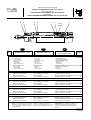
VERINS ANTICORROSION "CIX" Ø 32 à 80 mm
Spare parts kits for
ANTI-CORROSIVE CYLINDERS "CIX" Ø 32 to 80 mm
Ersatzteilliste
KORROSIONSBESTÄNDIGE ZYLINDER "CIX" Ø 32 bis 80 mm
Series
Baureihe
435
Type: CIX-DM
(383 45 11)
PR-P258a
Rep.
DESIGNATION du sachet DESIGNATION of kit
BEZEICHNUNG
der Ersatzteilpackung
CODE
FR
GB
DE
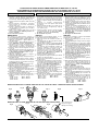
SET OF WEARING PARTS . . . . . . . . .
- 2 Lip seals
- 1 Rod seal
- 2 Cushioning seals
- 1 Wear ring
- 1 O-ring
- 1 Rod seal clip
VERSCHLEISSTEILE . . . . . . . . . . . . . .
- 2 Lippendichtungen
- 1 Kolbenstangendichtung
- 2 Dämpfungsdichtungen
- 1 Führungsring
- 1 O-Ring
- 1 Seegerring
1-6
978 02 130
978 02 131
978 02 132
978 02 133
1
2
3
4
5
6
ENSEMBLE D'USURE . . . . . . . . . . . . .
- 2 Joints à lèvres
- 1 Joint de tige
- 2 Joints d'amortis
- 1 Segment
- 1 Joint torique
- 1 Clip de joint de tige
3
5
3
1
246
Aimant
Magnet
2-5-6
NOTA: Pour obtenir un fonctionnement
optimal en environnement alimentaire, il
est recommandé d'utiliser la graisse
Polylub GA 352P.
NOTE: For optimal operation in a
food processing environment we recom-
mend using Polylub GA 352P grease.
ANMERKUNG: Ein optimales
Funktionieren
im Naherungsmittelbereich wird durch die Ver-
wendung des Schmiermittels Polylub GA 352P
erreicht
NS
ROD SEAL ONLY . . . . . . . . . . . . . . . . .
- 1 Rod seal
- 1 O-ring
- 1 Rod seal clip
KOLBENSTANGENDICHTUNG ALLEIN
- 1 Kolbenstangendichtung
- 1 O-Ring
- 1 Seegerring
2-5-6
2-5-6
2-5-6
978 02 184
978 02 185
978 02 186
978 02 187
2
5
6
ENSEMBLE D'USURE . . . . . . . . . . . . .
Nomenclature dito Ø 32 mm
JOINT DE TIGE SEUL . . . . . . . . . . . . .
Nomenclature dito Ø 32 mm
978 02 188
VERIN Ø 32 mm
CYLINDER Ø 32 mm
VERIN Ø 32 mm
JOINT DE TIGE SEUL . . . . . . . . . . . . .
- 1 Joint de tige
- 1 Joint torique
- 1 Clip de joint de tige
VERIN Ø 40 mm
SET OF WEARING PARTS . . . . . . . . .
Same description as Ø 32 mm
ROD SEAL ONLY . . . . . . . . . . . . . . . . .
Same description as Ø 32 mm
VERIN Ø 50 mm
VERSCHLEISSTEILE . . . . . . . . . . . . . .
Teilebezeichnung wie Ø 32 mm
KOLBENSTANGENDICHTUNG ALLEIN
Teilebezeichnung wie Ø 32 mm
CYLINDER Ø 40 mm
ZYLINDER
Ø 40 mm
CYLINDER Ø 50 mm
ZYLINDER
Ø 50 mm
ENSEMBLE D'USURE . . . . . . . . . . . . .
Nomenclature dito Ø 32 mm
JOINT DE TIGE SEUL . . . . . . . . . . . . .
Nomenclature dito Ø 32 mm
SET OF WEARING PARTS . . . . . . . . .
Same description as Ø 32 mm
ROD SEAL ONLY . . . . . . . . . . . . . . . . .
Same description as Ø 32 mm
VERSCHLEISSTEILE . . . . . . . . . . . . . .
Teilebezeichnung wie Ø 32 mm
KOLBENSTANGENDICHTUNG ALLEIN
Teilebezeichnung wie Ø 32 mm
VERIN Ø 63 mm
CYLINDER Ø 63 mm
ZYLINDER
Ø 63 mm
978 02 134
ENSEMBLE D'USURE . . . . . . . . . . . . .
Nomenclature dito Ø 32 mm
JOINT DE TIGE SEUL . . . . . . . . . . . . .
Nomenclature dito Ø 32 mm
SET OF WEARING PARTS . . . . . . . . .
Same description as Ø 32 mm
ROD SEAL ONLY . . . . . . . . . . . . . . . . .
Same description as Ø 32 mm
VERSCHLEISSTEILE . . . . . . . . . . . . . .
Teilebezeichnung wie Ø 32 mm
KOLBENSTANGENDICHTUNG ALLEIN
Teilebezeichnung wie Ø 32 mm
VERIN Ø 80 mm
CYLINDER Ø 80 mm
ZYLINDER
Ø 80 mm
ENSEMBLE D'USURE . . . . . . . . . . . . .
Nomenclature dito Ø 32 mm
JOINT DE TIGE SEUL . . . . . . . . . . . . .
Nomenclature dito Ø 32 mm
SET OF WEARING PARTS . . . . . . . . .
Same description as Ø 32 mm
ROD SEAL ONLY . . . . . . . . . . . . . . . . .
Same description as Ø 32 mm
VERSCHLEISSTEILE . . . . . . . . . . . . . .
Teilebezeichnung wie Ø 32 mm
KOLBENSTANGENDICHTUNG ALLEIN
Teilebezeichnung wie Ø 32 mm
1-6
1-6
1-6

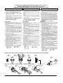
PROCEDURE DE DEMONTAGE-REMONTAGE VERINS CIX Ø 32 à 80 mm
ASSEMBLY/DISASSEMBLY OF CIX CYLINDER Ø 32 to 80 mm
WARTUNGS- UND MONTAGEANLEITUNG FÜR CIX-ZYLINDER Ø 32 bis 80 mm
DEMONTAGE
DEMONTAGE
DISASSEMBLY
1- Dévisser le fond avant en exercant un couple
de rotation à l'aide de deux raccords banjo serrés
dans les orifices d'alimentation (fig. H).
2- Sortir l'ensemble tige/piston du tube de vérin
3- Bloquer l'ensemble tige/piston à l'aide des plats
existant en tête de tige.
4- Retirer les joints à lèvres (1), le joint (5) avec
précaution, ainsi que le segment (4), le clip (6)
et les joints (2) (3)
5- Nettoyer la tige, le piston, l'intérieur du tube et
les emplacements des joints (ne pas utiliser de
produits corrosifs ni solvants)
6- Ne pas démonter le piston
REASSEMBLY
Pour obtenir un fonctionnement optimal, il est re-
commandé d'utiliser la graisse Polylub GA 352 P
1- Retirer de la pochette de rechange les joints à
lèvres (1).
2- Enduire légèrement de graisse les joints à lèvres
et les gorges du piston.
3-
Placer le joint à lèvre dans la gorge d'un côté
du piston (fig.A). Respecter le sens de montage
4- A l'aide d'un outil rond, sans aspérité, terminer
la mise en place du joint en effectuant un
mouvement circulaire. (fig. B)
5-
Controler le positionnement correct du joint (fig. C)
6-
Retourner l'ensemble tige/piston et monter le
2eme joint en répétant les phases 3,4,5. Respec-
ter les sens de montage des lèvres (voir fig. D)
7- Remonter le segment (4)
8- Enduire légèrement de graisse l'intérieur et l'en-
trée du tube et les joints à lévres.
9- Placer le piston en biais dans la partie inférieure
du cylindre (fig. E)
10
-Introduire progressivement le joint à lèvre, à
l'aide d'un outil plat, sans aspérité et en effec-
tuant un mouvement circulaire de la tige (fig. F).
Ne pas utiliser de tournevis
11
-
Enduire de graisse le pourtour central du piston (❉)
12
-
Pousser le piston dans le cylindre (fig. G)
13-
Enduire légèrement de graisse les gorges du
fond avant et les joints (2) (3) (5)
14
-Remonter le joint de tige (2), le joint (5), le joint
d'amorti (3) ainsi que le clip (6)
15-
Protéger l'embout fileté de la tige pour éviter de
détériorer le joint (2)
16
-Visser le fond avant dans le tube (jusqu'à la butée
mécanique), couple de serrage recommandé:
- Ø 32 : 15 N.m - Ø 63 : 160 N.m
- Ø 40 : 25 N.m - Ø 80 : 240 N.m
- Ø 50 : 50 N.m
1-Drehen Sie das vordere Endstück ab unter
Zuhilfenahme der beiden Banjo-Verschraubun-
gen, die sich in den Versorgungsanschlüssen
befinden (Abb. H).
2- Nehmen Sie die Einheit bestehend aus Kolben-
stange und Kolben aus dem Zylinderrohr heraus.
3-
Blockieren Sie die Einheit aus Kolbenstange und Kolben
an den Schlüsselflächen am Kopf der Kolbenstange.
4- Entfernen Sie vorsichtig die Lippendichtungen
(1), den O-Ring (5) den Führungsring (4), den
Seegerring (6) sowie die Dichtungen (2) und (3)
5- Reinigen Sie die Kolbenstange, den Kolben, das
Innere des Zylinderrohrs und die Dichtungsnuten
(ätzende Mittel oder Lösemittel sind nicht zu
verwenden).
6- Demontieren Sie nicht den Kolben.
Ein optimales Funktionieren wird durch Verwendung
des Schmiermittels Polylub GA 352P erreicht
1- Nehmen Sie die Lippendichtungen (3) aus der
Ersatzteilpackung.
2- Schmieren Sie die Lippendichtungen und die
Kolbenringnuten leicht ein.
3- Legen Sie die Lippendichtung auf einer Seite
des Kolbens (Abb.A) in die Nut ein. Beachten
Sie die Montagerichtung.
4- Setzen Sie die Lippendichtung unter Zuhilfenah-
me eines glatten Werkzeugs mit einer drehenden
Bewegung ein (Abb.B).
5-
Überprüfen Sie die richtige Lage der Dichtung (Abb.C).
6- Drehen Sie die Einheit aus Kolbenstange und
Kolben um und legen Sie die 2. Dichtung unter
Wiederholung der Punkte 3,4,5 ein. Beachten
Sie die Montagerichtung der Lippen ( Abb.D).
7- Setzen Sie den Führungsring (4) ein
8.- Schmieren Sie das Innere und den Eingang des
Rohres sowie die Lippendichtungen leicht ein.
9- Setzen Sie den Kolben schräg in den unteren Teil
des Zylinders (Abb. E) ein.
10
-Schieben Sie die Lippendichtung unter Zuhilfe-
nahme eines glatten Werkzeuges mit einer
drehenden Bewegung in den Zylinder (Abb. F).
Verwenden Sie keinen Schraubendreher.
11-Schmieren Sie den Umfang des Mittelteils des
Kolbens ein (❉).
12-
Schieben Sie den Kolben in den Zylinder (Abb. G).
13-
Schmieren Sie die Nuten am vorderen Endstück
und die Dichtungen (2), (3) und (5)
14
-Setzen Sie die Kolbenstangendichtung (2), den
O-Ring (5), und die Dämpfungsdichtung (3) ein
und befestigen Sie den Seegerring (6)
15-
Schützen Sie das Gewinde am Kolbenstangen-
ende, um eine Beschädigung der Dichtung (2) zu
vermeiden
16
-Schrauben Sie das vordere Endstück wieder in
das Rohr ein (bis zum mechanischen Anschlag)
unter Verwendung der folgenden Drehmomente:
- Ø 32 : 15 N.m - Ø 63 : 160 N.m
- Ø 40 : 25 N.m - Ø 80 : 240 N.m
- Ø 50 : 50 N.m
MONTAGE
REMONTAGE
1- Twist off the front cover with the help of the two
banjo-type connections tightened into the supply
ports (fig. H).
2- Remove the rod/piston unit from the cylinder
tube.
3- Block the rod/piston unit at the flats on the rod
head.
4- Carefully remove the lip seals (1), the O-ring (5)
the wear ring (4), the rod seal clip (6) and the
seals (2) and (3)
5- Clean the rod, the piston, the inside of the tube
and the grooves of the seals (do not use
corrosives agents or solvents).
6- Do not disassemble the piston.
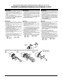
Fig. E
Abb. E
MONTAGE DU PISTON / PISTON ASSEMBLY / MONTAGE DES KOLBENS
MONTAGE DES JOINTS A LEVRES / ASSEMBLY OF THE LIP SEALS / MONTAGE DER LIPPENDICHTUNGEN
❉
For best results, we recommend using
Polylub GA 352 P grease
1-
Remove the lip seals from the spare parts bag (3).
2- Coat the lip seals and the piston ring grooves
lightly with grease.
3-
Place the lip seal on one side of the piston into the
groove (fig. A). Observe the mounting direc-
tion.
4- Insert the lip seal with a circular movement using
a flat tool (fig B).
5- Check the correct position of the seal (fig. C).
6- Turn the rod/piston unit around and assemble the
2nd seal by repeating points 3,4,5. Observe the
mounting direction of the lips (see fig.D).
7- Install the wear ring (4)
8- Coat the inside of the tube and its entry as well as
the lip seals lightly with grease.
9- Place the piston diagonally into the bottom part of
the cylinder (fig. E).
10
-Push the lip seal with a circular movement into
the rod using a flat tool (fig. F). Do not use a
screwdriver.
11-Grease the circumference of the middle part of
the piston (❉)
12
-Place the piston back into the cylinder (fig. G).
13-
Coat the grooves on the front cover and the seals
(2), (3) and (5) lightly with grease
14
-Insert the rod seal (2), the O-ring (5), the cushion-
ing seal (3) and install the rod seal clip (6)
15-
Protect the threaded and of the rod to avoid
damaging the seal (2)
16
-Screw the front cover into the tube (up to the
mechanical stop), with the following tightening
torques:
- Ø 32 : 15 N.m - Ø 63 : 160 N.m
- Ø 40 : 25 N.m - Ø 80 : 240 N.m
- Ø 50 : 50 N.m
Fig. H
Abb. H
ENSEMBLE D'USURE SET OF WEARING PARTS
VERSCHLEISSTEILE
Fig. F
Abb. F
Fig. G
Abb. G
Fig. C
Abb. C
Fig. B
Abb. B
Fig. A
Abb. A
Fig. D
Abb. D
Dépôt de graisse
Grease store
Fettkammer

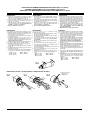
PROCEDURE DE DEMONTAGE-REMONTAGE VERINS CIX Ø 32 à 80 mm
ASSEMBLY/DISASSEMBLY OF CIX CYLINDER Ø 32 to 80 mm
WARTUNGS- UND MONTAGEANLEITUNG FÜR CIX-ZYLINDER Ø 32 bis 80 mm
DEMONTAGE
DEMONTAGE
DISASSEMBLY
1- Dévisser le fond avant en exerçant un couple
de rotation à l'aide de deux raccords banjo serrés
dans les orifices d'alimentation (fig. H).
2- Sortir l'ensemble tige/piston du tube de vérin
3- Retirer le joint (5) avec précaution, ainsi que le
clip (6) et le joint (2)
4- Nettoyer la tige, le piston, l'intérieur du tube et
les emplacements des joints (ne pas utiliser de
produits corrosifs ni solvants)
5- Ne pas démonter le piston
REASSEMBLY
Pour obtenir un fonctionnement optimal, il est re-
commandé d'utiliser la graisse Polylub GA 352 P
1- Enduire légèrement de graisse l'intérieur et l'en-
trée du tube et les joints à lèvres.
2- Placer le piston en biais dans la partie inférieure
du cylindre (fig. E)
3
- Introduire progressivement le joint à lèvre, à
l'aide d'un outil plat, sans aspérité et en effec-
tuant un mouvement circulaire de la tige (fig. F).
Ne pas utiliser de tournevis
4
-
Enduire de graisse le pourtour central du piston (❉)
5
-
Pousser le piston dans le cylindre (fig. G)
6-
Enduire légèrement de graisse les gorges du
fond avant et les joints (2) (5)
7
- Remonter le joint de tige (2), le joint (5), ainsi que
le clip (6).
8-
Protéger l'embout fileté de la tige pour éviter de
détériorer le joint (2)
9
- Visser le fond avant dans le tube (jusqu'à la butée
mécanique), couple de serrage recommandé:
- Ø 32 : 15 N.m - Ø 63 : 160 N.m
- Ø 40 : 25 N.m - Ø 80 : 240 N.m
- Ø 50 : 50 N.m
1-
Drehen Sie das vordere Endstück ab unter Zuhilfe-
nahme der beiden Banjo-Verschraubungen, die sich
in den Versorgungsanschlüssen befinden (Abb. H).
2- Nehmen Sie die Einheit bestehend aus Kolben-
stange und Kolben aus dem Zylinderrohr heraus.
3- Entfernen Sie vorsichtig die O-Ring (5), den
Seegerring (6) sowie die Dichtung (2)
4- Reinigen Sie die Kolbenstange, den Kolben, das
Innere des Zylinderrohrs und die Dichtungs-
nuten (ätzende Mittel oder Lösemittel sind
nicht zu verwenden).
5- Demontieren Sie nicht den Kolben.
Ein optimales Funktionieren wird durch Verwendung
des Schmiermittels Polylub GA 352P erreicht
1.- Schmieren Sie das Innere und den Eingang des
Rohres sowie die Lippendichtungen leicht ein.
2- Setzen Sie den Kolben schräg in den unteren
Teil des Zylinders (Abb. E) ein.
3- Schieben Sie die Lippendichtung unter Zuhilfe-
nahme eines glatten Werkzeuges mit einer
drehenden Bewegung in den Zylinder (Abb. F).
Verwenden Sie keinen Schraubendreher.
4- Schmieren Sie den Umfang des Mittelteils des
Kolbens ein (❉).
5-
Schieben Sie den Kolben in den Zylinder (Abb. G).
6-
Schmieren Sie die Nuten am vorderen Endstück
und die Dichtungen (2) und (5) leicht ein
7
- Setzen Sie die Kolbenstangendichtung (2), und
den O-Ring (5)ein und befestigen Sie den See-
gerring (6).
8-
Schützen Sie das Gewinde am Kolbenstangen-
ende, um eine Beschädigung der Dichtung (2) zu
vermeiden
9
- Schrauben Sie das vordere Endstück wieder in
das Rohr ein (bis zum mechanischen Anschlag)
unter Verwendung der folgenden Dreh-
momente:
- Ø 32 : 15 N.m - Ø 63 : 160 N.m
- Ø 40 : 25 N.m - Ø 80 : 240 N.m
- Ø 50 : 50 N.m
MONTAGEREMONTAGE
1- Twist off the front cover with the help of the two
banjo-type connections tightened into the supply
ports (fig. H).
2-
Remove the rod/piston unit from the cylinder tube.
3- Carefully remove the O-ring (5), the rod seal clip
(6) and the rod seal (2)
4- Clean the rod, the piston, the inside of the tube
and the grooves of the seals
(
do not use cor-
rosives agents or solvents
).
5- Do not disassemble the piston.
Fig. E
Abb. E
Fig. F
Abb. F
MONTAGE DU PISTON / PISTON ASSEMBLY / MONTAGE DES KOLBENS
Fig. G
Abb. G
Dépôt de graisse
Grease store
Fettkammer
For best results, we recommend using
Polylub GA 352 P grease
1- Coat the inside of the tube and its entry as well as
the lip seals lightly with grease.
2- Place the piston diagonally into the bottom part of
the cylinder (fig. E).
3- Push the lip seal with a circular movement into
the rod using a flat tool (fig. F). Do not use a
screwdriver.
4- Grease the circumference of the middle part of
the piston (❉)
5- Place the piston back into the cylinder (fig. G).
6-
Coat the grooves on the front cover and the seals
(2) and (5) lightly with grease
7
- Insert the rod seal (2), the O-ring (5), and install
the rod seal clip (6).
8-
Protect the threaded end of the rod to avoid
damaging the seal (2)
9
- Screw the front cover into the tube (up to me-
chanical stop) with the following tightening tor-
ques:
- Ø 32 : 15 N.m - Ø 63 : 160 N.m
- Ø 40 : 25 N.m - Ø 80 : 240 N.m
- Ø 50 : 50 N.m
Fig. H
Abb. H
❉
JOINT DE TIGE SEUL
ROD SEAL ONLY KOLBENSTANGENDICHTUNG ALLEIN

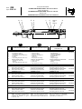
Serie parti di ricambio
CILINDRI ANTICORROSIONE "CIX" Ø 32 a 80 mm
Piezas de repuesto
CILINDROS ANTICORROSIÓN "CIX" Ø 32 a 80 mm
Revisie-sets
CORROSIEVASTE CILINDERS "CIX" Ø 32 tot 80 mm
Serie 435
Type: CIX-DM
PR-P258a
Rep.
COMPOSIZIONE della serie DESIGNACION del conjunto
BESCHRIJVING
onderdelen set
COD.
IT
ES
NL
CONJUNTO DE DESGASTE . . . . . . . .
- 2 Juntas de labios
- 1 Junta de vástago
- 2 Juntas de amortiguación
- 1 Segmento
- 1 Junta tórica
- 1 Clip de junta de vástago
AAN SLIJTAGE ONDERHEVIGE DELEN
- 2 Lipafdichtingen
- 1 Zuigerstangafdichting
- 2 Dempingsdichtingen
- 1 Geleidingsring
- 1 O-ring
- 1 Zuigerstangclip
1-6
978 02 130
978 02 131
978 02 132
978 02 133
1
2
3
4
5
6
KIT DI USURA. . . . . . . . . . . . . . . . . . . .
- 2 Guarnizioni a labbro
- 1 Guarnizione dello stelo
- 2 Guarnizioni di ammortizzamento
- 1 Segmento
- 1 O-ring
- 1 Clip della guarnizione dello stelo
3
5
3
1
246
Magnete
Imán
Magneet
2-5-6
NOTA: Per ottenere un funzionamento
ottimale nell'ambiente alimentare, si rac-
comanda di utilizzare il grasso
Polylub GA 352P.
NOTE: Para obtener un funcionamiento
óptimo en el entorno alimentario, se reco-
mienda utilizar la grasa Polylub GA 352 P
N.B.: Voor gebruik in de voedingsmidde-
lenindustrie wordt het smeermiddel
Polylub GA 352 P aanbevolen
NS
JUNTO DE VÁSTAGO SOLO . . . . . . . .
- 1 Junta de vástago
- 1 Junta tórica
- 1 Clip de junta de vástago
ZUIGERSTANGAFDICHTING ENKEL . .
- 1 Zuigerstangafdichting
- 1 O-ring
- 1 Zuigerstangclip
2-5-6
2-5-6
2-5-6
978 02 184
978 02 185
978 02 186
978 02 187
2
5
6
KIT DI USURA. . . . . . . . . . . . . . . . . . .
Nomenclatura idem Ø 32 mm
TENUTE DELLO DTELO . . . . . . . . . . .
Nomenclatura idem Ø 32 mm
978 02 188
CILINDRO Ø 32 mm
CILINDRO Ø 32 mm
CILINDER Ø 32 mm
TENUTE DELLO DTELO . . . . . . . . . . .
- 1 Guarnizione dello stelo
- 1 O-ring
- 1 Clip della guarnizione dello stelo
CILINDRO Ø 40 mm
CONJUNTO DE DESGASTE . . . . . . . .
Nomenclatura igual a Ø 32 mm
JUNTO DE VÁSTAGO SOLO . . . . . . . .
Nomenclatura igual a Ø 32 mm
CILINDRO Ø 50 mm
AAN SLIJTAGE ONDERHEVIGE DELEN
Beschrijving gelijk aan Ø 32 mm
ZUIGERSTANGAFDICHTING ENKEL . .
Beschrijving gelijk aan Ø 32 mm
CILINDRO Ø 40 mm CILINDER Ø 40 mm
CILINDRO Ø 50 mm CILINDER Ø 50 mm
KIT DI USURA. . . . . . . . . . . . . . . . . . .
Nomenclatura idem Ø 32 mm
TENUTE DELLO DTELO . . . . . . . . . . .
Nomenclatura idem Ø 32 mm
CONJUNTO DE DESGASTE . . . . . . . .
Nomenclatura igual a Ø 32 mm
JUNTO DE VÁSTAGO SOLO . . . . . . . .
Nomenclatura igual a Ø 32 mm
AAN SLIJTAGE ONDERHEVIGE DELEN
Beschrijving gelijk aan Ø 32 mm
ZUIGERSTANGAFDICHTING ENKEL . .
Beschrijving gelijk aan Ø 32 mm
CILINDRO Ø 63 mm
CILINDRO Ø 63 mm CILINDER Ø 63 mm
978 02 134
KIT DI USURA. . . . . . . . . . . . . . . . . . .
Nomenclatura idem Ø 32 mm
TENUTE DELLO DTELO . . . . . . . . . . .
Nomenclatura idem Ø 32 mm
CONJUNTO DE DESGASTE . . . . . . . .
Nomenclatura igual a Ø 32 mm
JUNTO DE VÁSTAGO SOLO . . . . . . . .
Nomenclatura igual a Ø 32 mm
AAN SLIJTAGE ONDERHEVIGE DELEN
Beschrijving gelijk aan Ø 32 mm
ZUIGERSTANGAFDICHTING ENKEL . .
Beschrijving gelijk aan Ø 32 mm
CILINDRO Ø 80 mm
CILINDRO Ø 80 mm CILINDER Ø 80 mm
KIT DI USURA . . . . . . . . . . . . . . . . . . .
Nomenclatura idem Ø 32 mm
TENUTE DELLO DTELO . . . . . . . . . . .
Nomenclatura idem Ø 32 mm
CONJUNTO DE DESGASTE . . . . . . . .
Nomenclatura igual a Ø 32 mm
JUNTO DE VÁSTAGO SOLO . . . . . . . .
Nomenclatura igual a Ø 32 mm
AAN SLIJTAGE ONDERHEVIGE DELEN
Beschrijving gelijk aan Ø 32 mm
ZUIGERSTANGAFDICHTING ENKEL . .
Beschrijving gelijk aan Ø 32 mm
1-6
1-6
1-6

PROCEDURA DI SMONTAGGIO E RIMONTAGGIO DEI CILINDRI CIX Ø 32 a 80 mm
PROCEDIMIENTO DE DESMONTANTAJE-MONTAJE DE LOS CILINDROS CIX Ø 32 a 80 mm
PROCEDURE VOOR DE MONTAGE EN DEMONTAGE VAN CIX CILINDERS Ø 32 tot 80 mm
DEMONTAGE
DESMONTAJE
MONTAJE
Fig. C
Fig. B
Fig. A
1- Draai het deksel aan de voorzijde los door met
behulp van twee banjo-type aanluitingen, die op
de toevoerpoorten zijn geplaatst, een rotatie uit
te voeren (fig. H).
2-
Verwijder de zuigerstang en de zuiger uit de cilinder.
3- Blokkeer de zuigerstang met de juiste steek-
sleutel. Maak gebruik van de pasvlakken aan het
zuigerstangeinde.
4- Verwijder voorzichtig de lipafdichtingen (1), de
O-ring (5), de geleidingsring (4), de
zuigerstangclip (6) en de afdichtingen (2) en (3)
5- Reinig de zuigerstang, de zuiger, de binnenzijde
van de buis en de groeven van de afdichtingen
(gebruik geen corrosieve stoffen of
oplosmiddelen).
6- De zuiger niet demonteren.
Voor de beste resultaten, wordt het smeermiddel
Polylub GA 352 P aanbevolen
1- Neem de lipafdichtingen (1) uit de reserve-
onderdelenset.
2- Vet de lipafdichtingen en de groeven in de zuiger
licht in.
3-
Plaats de lipafdichting in een groef aan de zijkant
van de zuiger (fig.A). Let op de montagerich-ting.
4- Monteer met behulp van een rond gereedschap,
de lipafdichting, zonder druk uit te oefenen en
met een draaiende beweging (fig. B)
5-
Controleer de juiste positie van de afdichting (fig. C)
6- Plaats de eenheid bestaande uit de zuigerstang
en zuiger weer in de cilinder en monteer de 2e
afdichting volgens de stappen 3,4,5. Let op de
montagerichting van de afdichting (zie fig. D)
7- Monteer de geleidingsring (4)
8- Vet de binnenzijde en de ingang van de cilinder-
buis alsmede de lipafdichtingen licht in.
9- Plaats de zuiger schuin in het onderste gedeelte
van de cilinder (fig. E)
10
-Breng langzaam de lipafdichting met behulp een
een plat gereedschap in, zonder druk uit te
oefenen en met een draaiende beweging van de
zuigerstang (fig. F). Geen schroevendraaier
hiervoor gebruiken.
11-Vet de omtrek van de zuiger in (i)
12-Duw de zuiger in de cilinder (fig. G)
13-
Breng het smeermiddel licht aan in de groeven
van het deksel aan de voorzijde en de afdictingen
(2) (3) en (5)
14
-Breng de zuigerstangafdichting in (2), de O-ring
(5), de dempingsafdichting (3) en monteer de
zuigerstangclip (6)
15-
Bescherm het draadeinde van de zuigerstang
om schade aan de afdichting (2) te voorkomen
16
-Schroef het deksel van de voorzijde op de
cilinderbuis (tot aan de mechanische stop), de
volgende koppels worden aanbevolen:
- Ø 32 : 15 N.m - Ø 63 : 160 N.m
- Ø 40 : 25 N.m - Ø 80 : 240 N.m
- Ø 50 : 50 N.m
MONTAGE
1-
Desatornillar el fondo delantero ejerciendo un par
de rotación con la ayuda de dos racores banjo
apretados en los orificios de alimentación (fig. H).
2- Sacar el conjunto vástago pistón del tubo del
cilindro.
3- Bloquear el conjunto vástago/pistón
apoyandose en las caras planas de la cabeza
del vástago.
4- Retirar las juntas de labios (1), le junta (5) con
precaución, asi como el segmento (4), el clip (6)
y las juntas (2) (3)
5- Limpiar el vástago, el pistón, el interior del tubo
y los alojamientos de las juntas (no utilizar
productos corrosivos ni disolventes)
6- No desmontar el pistón
Fig. E
Fig. F
MONTAGGIO DEL PISTONE / MONTAJE DEL PISTON / MONTAGE VAN DE ZUIGER
Fig. G
MONTAGGIO DEI GIUNTI A LABBRO / MONTAJE DE LAS JUNTAS DE LABIOS / MONTAGE VAN DE LIPAFDICHTINGEN
❉
Parte da ingrassare
Deposito de grasa
Opslag van smering
Fig. D
Para obtener un funcionamiento óptimo, se reco-
mienda utilizar la grasa Polylub GA 352 P
1- Retirar de la bolsa de recambio las juntas de
labios (1).
2- Untar ligeramente de grasa las juntas de labios
y las gargantas del pistón.
3- Situar la junta de labios en la garganta de un
lado del pistón (fig.A). Respetar el sentido de
montaje
4- Con ayuda de una herramienta redonda, sin
asperezas, terminar la colocación de la junta
realizando un movimiento circular. (fig. B)
5-
Controlar la colocación correcta de la junta (fig. C)
6- Repetir la operación con la 2ª junta respetando
los pasos 3,4,5. Respetar los sentidos de
montaje de los labios (ver fig. D)
7- Volver a montar el segmento (4)
8- Untar ligeramente de grasa el interior y la entrada
del tubo y las juntas de labios.
9- Situar el pistón oblicuamente en la parte inferior
del tubo (fig. E)
10-Introducir progresivamente la junta de labios,
con ayuda de una herramienta plana, sin aspe-
rezas realizando un movimiento circular del vás-
tago (fig. F). No utilizar destornilladores
11-Untar de grasa la parte central del pistón (❉)
12-Empujar el pistón en el tubo (fig. G)
13
-Untar ligeramente de grasa las gargantas del
fondo delantero y las juntas (2) (3) (5)
14
-Montar la junta de vástago (2), la junta (5), la
junta de amortiguación (3) y el clip (6)
15-
Proteger el extremo roscado del vástago para
evitar dañar la junta (2)
16
-Atornillar el fondo delantero en el tubo (hasta el
tope mecánico), para de apriete recomendado:
- Ø 32 : 15 N.m - Ø 63 : 160 N.m
- Ø 40 : 25 N.m - Ø 80 : 240 N.m
- Ø 50 : 50 N.m
Fig. H
KIT DI USURA CONJUNTO DE DESGASTE
AAN SLIJTAGE ONDERHEVIGE DELEN
SMONTAGGIO
1- Smontare la testata anteriore esercitando una
coppia di rotazione mediante l'utilizzo di due
raccordi banjo applicati agli utilizzi (fig. H).
2- Estrarre l'insieme stelo/pistone dalla canna del
cilindro.
3- Bloccare l'insieme stelo/pistone servendosi
delle fresature che si trovano sull'estremità
anteriore dello stelo.
4- Togliere le guarnizioni a labbro (1), l'O-ring (5)
con precauzione, il segmento (4), la clip (6) e
le guarnizioni (2) (3)
5- Pulire lo stelo, il pistone della canna e le sedi
delle guarnizioni (non utilizzare prodotti cor-
rosivi o solventi)
6- Non smontare il pistone.
Per ottenere un funzionamento ottimale, si
raccomanda di utilizzare il grasso Polylub GA 352P
1- Prendere dal kit dei ricambi i giunti a labbro (1).
2- Lubrificare leggermente i giunti a labbro e le
sedi del pistone.
3- Inserire il giunto a labbro dal lato del pistone
(fig.A). Rispettare il senso di montaggio
4- Servendosi di un utensile arrotondato, senza
asperità, portare a termine il montaggio del
giunto mediante un movimento circolare (fig. B)
5- Verificare che la posizione del giunto sia corret-
ta (fig. C)
6- Rimontare l'insieme stelo/pistone e montare il 2
do
giunto ripetendo le fasi 3,4,5. Rispettare il sen-
so di montaggio del labbro (vedere fig. D)
7- Rimontare il segmento (4)
8- Lubrificare leggermente l'interno e l'ingresso
della canna ed i giunti a labbro.
9- Inserire il pistone in obliquo nella parte inferiore
del cilindro (fig. E)
10
-
Introdurre progressivamente il giunto a labbro,
servendosi di un utensile piatto, senza asperità,
mediante movimento circolare dello stelo (fig. F).
Non utilizzare cacciaviti
11-Ingrassare la parte intermedia del pistone (❉)
12-Spingere il pistone nel cilindro (fig. G)
13-
Lubrificare leggermente le sedi della testata an-
teriore e delle guarnizioni (2) (3) (5)
14
-Rimontare la guarnizioni dello stelo (2), la guar-
nizione (5), le guarnizioni di ammortizzamento
(3) ed anche la clip (6)
15-
Proteggere l'estremità filettata dello stelo per
evitare di deteriorare la guarnizione (2)
16
-Avvitare la testata anteriore sulla canna (fino a
battuta meccanica), coppia di serraggio racco-
mandata:
- Ø 32 : 15 N.m - Ø 63 : 160 N.m
- Ø 40 : 25 N.m - Ø 80 : 240 N.m
- Ø 50 : 50 N.m
RIMONTAGGIO

PROCEDURA DI SMONTAGGIO E RIMONTAGGIO DEI CILINDRI CIX Ø 32 a 80 mm
PROCEDIMIENTO DE DESMONTANTAJE-MONTAJE DE LOS CILINDROS CIX Ø 32 a 80 mm
PROCEDURE VOOR DE MONTAGE EN DEMONTAGE VAN CIX CILINDERSØ 32 tot 80 mm
SMONTAGGIO
DEMONTAGE
DESMONTAJE
1- Smontare la testata anteriore esercitando una
coppia di rotazione mediante l'utilizzo di due
raccordi banjo applicati agli utilizzi (fig. H).
2- Estrarre l'insieme stelo/pistone dalla canna del
cilindro.
3- Togliere la guarnizione (5) con precauzione, la
clip (6) e la guarnizione (2)
4- Pulire lo stelo, il pistone, l'interno della canna
e le sedi delle guarnizioni (non utilizzare pro-
dotti corrosivi o solventi)
5- Non smontare il pistone.
MONTAJE
Per ottenere un funzionamento ottimale, si
raccomanda di utilizzare il grasso Polylub GA 352P
1- Lubrificare leggermente i giunti a labbro e le sedi
del pistone.
2- Inserire il pistone in obliquo nella parte inferiore
del cilindro (fig. E)
3
-
Introdurre progressivamente il giunto a labbro,
servendosi di un utensile piatto, senza asperità,
mediante movimento circolare dello stelo (fig. F).
Non utilizzare cacciaviti
4
- Ingrassare la parte intermedia del pistone (❉)
5
-
Spingere il pistone nel cilindro (fig. G)
6-
Lubrificare leggermente le sedi della testata an-
teriore e delle guarnizioni (2) (5)
7
- Rimontare la guarnizione dello stelo (2), la guar-
nizione (5), e le clip (6).
8-
Proteggere l'estremià filettata dello stelo per
evitare di deteriorare la guarnizione (2)
9
- Avvitare la testata anteriore sulla canna (fino a
battuta meccanica), coppia di serraggio racco-
mandata:
- Ø 32 : 15 N.m - Ø 63 : 160 N.m
- Ø 40 : 25 N.m - Ø 80 : 240 N.m
- Ø 50 : 50 N.m
1- Draai het deksel aan de voorzijde los door met
behulp van twee banjo-type aanluitingen, die op
de toevoerpoorten zijn geplaatst, een rotatie uit
te voeren (fig. H).
2-
Verwijder de zuigerstang en de zuiger uit de cilinder.
3-
Verwijder voorzichtig de O-ring (5), de
zuigerstangclip (6) en de zuigerstangafdichting (2)
4- Reinig de zuigerstang, de zuiger, de binnenzijde
van de cilinderbuis en de groeven van de
afdichtingen ( gebruik geen corrosieve stoffen
of oplosmiddelen).
5- De zuiger niet demonteren.
Voor de beste resultaten, wordt het smeermiddel
Polylub GA 352 P aanbevolen
1- Vet de binnenzijde en de ingang van de cilinder-
buis alsmede de lipafdichtingen licht in.
2- Plaats de zuiger schuin in het onderste gedeelte
van de cilinder (fig. E)
3
- Breng langzaam de lipafdichting met behulp een
een plat gereedschap in, zonder druk uit te
oefenen en met een draaiende beweging van de
zuigerstang (fig. F). Geen schroevendraaier
hiervoor gebruiken.
4
- Vet de omtrek van de zuiger in
(❉)
5
-
Duw de zuiger in de cilinder (fig. G)
6-
Breng het smeermiddel licht aan in de groeven
van het deksel aan de voorzijde en de
afdichtingen (2) en (5)
7
- Breng de zuigerstangafdichting (2) en de O-ring
(5) in, en monteer de zuigerstangclip (6).
8-
Bescherm het draadeinde van de zuigerstang
om schade aan de afdichting (2) te voorkomen
9
- Schroef het deksel van de voorzijde op de
cilinderbuis (tot aan de mechanische stop), de
volgende koppels worden aanbevolen:
- Ø 32 : 15 N.m - Ø 63 : 160 N.m
- Ø 40 : 25 N.m - Ø 80 : 240 N.m
- Ø 50 : 50 N.m
MONTAGEREMONTAGE
1-
Desatornillar el fondo delantero ejerciendo un par
de rotación con la ayuda de dos racores banjo
apretados en los orificios de alimentación (fig. H).
2-
Sacar el conjunto vástago pistón del tubo del cilindro.
3- Retirar la junta (5) con precaución, asi como el
clip (6) y la junta (2)
4- Limpiar el vástago, el pistón, el interior del tubo
y los alojamientos de las juntas (no utilizar
productos corrosivos ni disolventes)
5- No desmontar el pistón
Fig. E
Abb. E
Fig. F
Abb. F
MONTAGGIO DEL PISTONE / MONTAJE DEL PISTON / MONTAGE VAN DE ZUIGER
Fig. G
Abb. G
Parte da ingrassare
Deposito de grasa
Opslag van smering
Para obtener un funcionamiento óptimo, se reco-
mienda utilizar la grasa Polylub GA 352 P
1- Untar ligeramente de grasa el interior y la entrada
del tubo y las juntas de labios.
2- Situar el pistón oblicuamente en la parte inferior
del tubo (fig. E)
3
- Introducir progresivamente la junta de labios,
con ayuda de una herramienta plana, sin aspere-
zas realizando un movimiento circular del vásta-
go (fig. F). No utilizar destornilladores
4
- Untar de grasa la parte central del pistón (❉)
5
-
Empujar el pistón en el tubo (fig. G)
6-
Untar ligeramente de grasa las gargantas del
fondo delantero y las juntas (2) (5)
7
-
Montar la junta de vástago (2), la junta (5), y el clip (6).
8-
Proteger el extremo roscado del vástago para
evitar dañar la junta (2)
9
- Atornillar el fondo delantero en el tubo (hasta el
tope mecánico), para de apriete recomendado:
- Ø 32 : 15 N.m - Ø 63 : 160 N.m
- Ø 40 : 25 N.m - Ø 80 : 240 N.m
- Ø 50 : 50 N.m
Fig. H
Abb. H
❉
TENUTE DELLO STELO
JUNTA DE VÁSTAGO SOLO ZUIGERSTANGAFDICHTING ENKEL
-
 1
1
-
 2
2
-
 3
3
-
 4
4
-
 5
5
-
 6
6


Asco Series 435 Cylinders CIX-DM de handleiding
- Type
- de handleiding
in andere talen
Gerelateerde papieren
-
Asco Series 436 437 Trinorm Cylinder PIS PCN 100-200 mm de handleiding
-
-
Asco series-435-cylinders-iso de handleiding
-
-
-
-
-
-
-