
M
ENGLISH
SUBWOOFER
SW500
Owner’s Manual
Mode d’emploi
Bedienungsanleitung
Manual del Usuario
Thank you for purchasing a Yamaha SW500 subwoofer. The SW500 features a
reflex cabinet, with a 38 cm (15 inch) cone speaker. This powered subwoofer
reproduces a high-quality and powerful low-range sound. Please read this
Owner’s Manual thoroughly to make the best use of the SW500’s quality
functions for a long period of time, and keep the manual in a safe place.
Contents
Precautions .............................................. 3
Rear panel................................................ 4
Connection Examples............................... 5
Specifications ........................................... 6
General specifications ..............................................6
Speaker unit ..............................................................6
Amp. unit .................................................................6
Dimensions.............................................. 6
Block Diagram......................................... 7
Performance graph................................... 7

• Explanation of Graphical Symbols
The lightning flash with arrowhead symbol
within an equilateral triangle is intended to
alert the user to the presence of uninsulated
“dangerous voltage” within the product’s
enclosure that may be of sufficient magni-
tude to constitute a risk of electric shock to
persons.
The exclamation point within an equilat-
eral triangle is intended to alert the user to
the presence of important operating and
maintenance (servicing) instructions in the
literature accompanying the product.
CAUTION: TO REDUCE THE RISK OF
ELECTRIC SHOCK, DO NOT REMOVE
COVER (OR BACK). NO USER-SERVICEABLE
PARTS INSIDE. REFER SERVICING TO
QUALIFIED SERVICE PERSONNEL.
CAUTION
RISK OF ELECTRIC SHOCK
DO NOT OPEN
The above warning is located on the
rear of the unit.
WARNING: THIS APPARATUS MUST BE EARTHED
IMPORTANT
THE WIRES IN THIS MAINS LEAD ARE COLOURED IN
ACCORDANCE WITH THE FOLLOWING CODE:
GREEN-AND-YELLOW : EARTH
BLUE : NEUTRAL
BROWN : LIVE
As the colours of the wires in the mains lead of this apparatus may
not correspond with the coloured markings identifying the terminals in
your plug, proceed as follows:
The wire which is coloured GREEN and YELLOW must be
connected to the terminal in the plug which is marked by the letter E
or by the safety earth symbol or coloured GREEN and YELLOW.
The wire which is coloured BLUE must be connected to the terminal
which is marked with the letter N or coloured BLACK.
The wire which is coloured BROWN must be connected to the
terminal which is marked with the letter L or coloured RED.
* This applies only to products distributed by YAMAHA KEMBLE
MUSIC (U.K.) LTD.

3
Precautions
• Use only the included power cord for this unit. Using
other types may be a fire and electrical shock hazard.
• Do not allow water to enter this unit or allow the unit
to become wet. Fire or electrical shock may result.
• Do not place a container with liquid or small metal
objects on top of this unit. Liquid or metal objects
inside this unit are a fire and electrical shock hazard.
• Connect the included power cord only to an AC out-
let of the type stated in this Owner’s Manual or as
marked on the unit. Failure to do so is a fire and elec-
trical shock hazard.
• Do not scratch, bend, twist, pull, or heat the power
cord. A damaged power cord is a fire and electrical
shock hazard.
• Do not place heavy objects, including this unit, on
top of the power cord. A damaged power cord is a
fire and electrical shock hazard. In particular, be
careful not to place heavy objects on a power cord
covered by a carpet.
• Place the device near a power outlet so you can eas-
ily plug it in.
• If you notice any abnormality, such as smoke, odor,
or noise, or if a foreign object or liquid gets inside the
unit, turn it off immediately. Remove the power cord
from the AC outlet. Consult your dealer for repair.
Using the unit in this condition is a fire and electrical
shock hazard.
• Should this unit be dropped or the cabinet be dam-
aged, turn the power switch off, remove the power
plug from the AC outlet, and contact your dealer. If
you continue using the unit without heeding this
instruction, fire or electrical shock may result.
• If the power cord is damaged (i.e., cut or a bare wire
is exposed), ask your dealer for a replacement. Using
the unit with a damaged power cord is a fire and
electrical shock hazard.
• Do not remove the unit’s cover. You could receive an
electrical shock. If you think internal inspection, main-
tenance, or repair is necessary, contact your dealer.
• Do not modify the unit. Doing so is a fire and electri-
cal shock hazard.
• If lightning begins to occur, turn off the power switch
of the unit as soon as possible, and unplug the power
cable plug from the electrical outlet.
• If there is a possibility of lightning, do not touch the
power cable plug if it is still connected. Doing so may
be an electrical shock hazard.
• Turn off all audio equipment, and speakers when
connecting to this unit. Use the correct connecting
cables and connect as specified.
• Do not subject the speaker to excessive levels, or dis-
torted sounds (indicated by the clip indicator lighting
up often) as this leads to overheating and a possible
fire hazard.
• Always lower the volume control to minimum before
turning on the power to this unit. A sudden blast of
sound may damage your hearing.
• When rack-mounting the unit, allow enough free
space around the unit for normal ventilation. This
should be: 20 cm at the sides, 25 cm behind, and 30
cm above.
For normal ventilation during use, remove the rear of
the rack or open a ventilation hole.
If the airflow is not adequate, the unit will heat up
inside and may cause a fire.
• Do not use the handles to suspend the speaker. Oth-
erwise, it may fall, causing injury.
• Hold the power cord plug when disconnecting it
from an AC outlet. Never pull the cord. A damaged
power cord is a potential fire and electrical shock
hazard.
• This unit is heavy. Use two or more people to carry it.
• Do not touch the power plug with wet hands. Doing
so is a potential electrical shock hazard.
• XLR-type connectors are wired as follows: pin 1:
ground, pin 2: hot (+), and pin 3: cold (–).
• Using a mobile telephone near this unit may induce
noise. If noise occurs, use the telephone away from
the unit.
• Do not use the speakers at uncomfortably loud level.
Otherwise, you may damage your hearing.
• Subwoofer SW500 comes with a metal socket for
installing the speaker stand. Use a speaker stand pole
that is one meter or shorter.
Troubleshooting
—If the unit shuts down during use—
If the CLIP indicator lights up often and you use this
unit for a long period of time, the thermostat inside
the power transformer will turn the power off. In
this case, turn the POWER switch off, wait for a
while (about one hour) until the the power trans-
former cools down, then resume using the unit at a
lower input level.
Be sure to lower the input level so that the CLIP
indicator lights up only momentarily.

4
Rear panel
A
POWER switch
This switch turns the power to the SW500 on and
off. When this switch is turned on, the green power
indicator (
9
) lights up.
B
AC IN connector
Connect the included power cable here.
C
CUTOFF FREQ. control
This control enables you to adjust the cutoff
frequency in the range of 80 through 100 Hz
depending on the speakers you are using with the
SW500 and your personal preferences.
D
LEVEL control
This control enables you to adjust the sound
volume level. The maximum level is at the scale
setting of 10, and the minimum level is at the scale
setting of 0. If the level is too high, the CLIP
indicator (
J
) lights up red. In this case, lower the
level.
E
PHASE switch
This switch enables you to select a phase. You will
usually set this switch to ”NORM”. However, the
”REV” setting may improve low-range sounds,
depending on the type and location of the entire
speaker system. Try both settings and select the one
with a better-sounding low-range output.
F
INPUT jacks A and B
These are XLR-type balanced input jacks. Two
different signals can be input at these INPUT jacks
and routed to OUTPUT THRU jacks A and B and
OUTPUT HIGH PASS A and B jacks respectively. If
two signals are input at the same time, they are
mixed inside the subwoofer.
G
OUTPUT THRU jacks A and B
These are XLR-type balanced output jacks. Connect
these jacks to another subwoofer to route signals
input from INPUT jacks A and B to the subwoofer.
H
OUTPUT HIGH PASS jacks A and B
These are XLR-type balanced output jacks. Connect
these jacks to the main speakers to cut the range
below 100 Hz of signals input from INPUT jacks A
and B and route them to the main speakers.
I
POWER indicator
This indicator lights up green when you turn the
POWER switch ON.
J
CLIP indicator
This indicator lights up red if the output level is too
high. In this case, lower the level using the LEVEL
control or lower the input level.
SUBWOOFER
MODEL SW500
POWER
ON /
OFF
SUBWOOFER CONTROL
100
CUTOFF
FREQ.
80
AC IN
LEVEL
NORM
REV
PHASE
POWER
CLIP
OUTPUT
THRU
OU TPUT
HIGH PASS
100Hz
PARALLEL
A
B
(+4dB)
INPUT
(+4dB)
A
B
C
H
D
PARALLEL
F
E
9
0
G
0
10

5
Connection Examples
●
Using two SW500s
●
Using a single SW500s
OUTPUT
THRU
PARALLEL
(+4dB)
INPUT
PARALLEL
OU TPUT
HIGH PASS
100Hz
(+4dB)
OUTPUT
THRU
PARALLEL
(+4dB)
INPUT
PARALLEL
OU TPUT
HIGH PASS
100Hz
(+4dB)
OUTPUT
THRU
PARALLEL
(+4dB)
INPUT
PARALLEL
OU TPUT
HIGH PASS
100Hz
(+4dB)
OUTPUT
THRU
PARALLEL
(+4dB)
INPUT
PARALLEL
OU TPUT
HIGH PASS
100Hz
(+4dB)
0
2
4
6
8
10
12
1416
18
20
25
30
35
50
00
0
2
4
6
8
10
12
1416
18
20
25
30
35
50
00
5
0
4
0
3
0
2
0
1
0
5
2
0
2
4
5
0
.
0
1
0
.
1
1
.
0
5
1
0
5
0
1
0
0
2
0
0
3
0
0
0
.
0
1
0
.
1
1
.
0
5
1
0
5
0
1
0
0
2
0
0
3
0
0
5
0
4
0
3
0
2
0
1
0
5
2
0
2
4
5
PEAKPEAK
CHANNEL B
CHANNEL A CHANNEL B
CHANNEL A
POWER AMPLIFIER
PROFESSIONAL SERIES
CLIP/LIMITINPUTCLIP/LIMITINPUT
WATTS/8Ω WATTS/8Ω
+dB +dB
ON/ OFF
POWER
PROTECTION B
PROTECTION A
TEMP
Mixer
Mixer
Powered
speaker L
Main
speaker L
Main
speaker R
SW500
SW500
SW500
SW500
Amp
L
R
L
R
Powered
speaker R
OUTPUT
THRU
PARALLEL
(+4dB)
INPUT
PARALLEL
OU TPUT
HIGH PASS
100Hz
(+4dB)
Mixer
SW500
L
R
Powered
speaker L
Powered
speaker R

6
Specifications
General specifications
Type
Bass Reflex powered subwoofer
Frequency Range
40–120 Hz (–10 dB)
Maximum Output Level
122 dB (1 m on Axis)
Dimensiones (W
×
H
×
D)
480
×
619
×
590 mm
Weight
37 kg
Installation pole diameter
35 mm (1.375”)
Accessories
Power cable 2.5 m (AC inlet type)
Speaker unit
Speaker Unit
38 cm cone (8
Ω
)
Enclosure
Type: Bass Reflex
Amp. unit
Maximum Output Power
500 W at 100 Hz, THD=1%, RL=8
Ω
650 W at 100 Hz, 20 ms nonclip RL=8
Ω
Input Sensitivity/Impedance
+4 dB/30 k
Ω
(channels A and B)
Controls
LEVEL Control
CUTOFF FREQ. Control: 80–100 Hz (Variable)
PHASE Switch: (REV/NORM)
POWER Switch: ON/OFF
Connectors
INPUT A ,B (XLR-3-31), OUTPUT THRU A, B (XLR-3-32)
OUTPUT HIGH PASS A ,B (XLR-3-32)
Power Indicator
Green LED
Clip Indicator
Red LED
Power Requirement
USA and Canada: AC 120 V, 60 Hz
Europe: AC 230 V, 50 Hz
Others: AC 240 V, 50 Hz
Power Consumption
200 W
★
0 db=0.775 V
For European Model
Purchaser/User Information specified in EN55103-1
and EN55103-2.
Inrush Current: 70 A
Conformed Environment: E1, E2, E3 and E4
Specifications and appearance are subject to change
without notice.
Dimensions
619
Unit: mm
250
480
590

7
Block Diagram
Performance graph
Standard frequency response
HPF
HPF
BOOST
LOW
CUT
LOW
LPF LPF
SUM
(HIGH PASS)
OUTPUT
(THRU)
OUTPUT
(+4dB)
INPUT
(+4dB)
INPUT
(THRU)
OUTPUT
(HIGH PASS)
OUTPUT
100Hz
100Hz
PHASE
NORMAL
REVERSE
(80Hz to 100Hz)
CUTOFF FREQ
ch A
ch B
SPEAKER
P.AMP
LEVEL
BTL
1k100
20
FREQUENCY (Hz)
RESPONSE (dB)
-40
-30
-20
-10
0
+10
100Hz
90Hz
80Hz
Cutoff Frequency

FRANÇAIS
SUBWOOFER
SW500
Mode d’emploi
Nous vous remercions d’avoir opté pour un subwoofer SW500 de Yamaha. Le
SW500 est pourvu d’un coffret reflex avec un haut-parleur en cône de 38 cm.
Ce subwoofer actif produit des graves puissantes et de grande qualité.
Veuillez lire ce Mode d’emploi avec attention afin de tirer le meilleur parti
des fonctions offertes par le SW500 durant de longues années. Conservez
ensuite ce mode d’emploi dans un endroit sûr.
Sommaire
Précautions ...............................................9
Face arrière .............................................10
Exemples de connexion...........................11
Fiche technique.......................................12
Caractéristiques générales.......................................12
Section haut-parleur ...............................................12
Section d’amplification...........................................12
Dimensions............................................. 12
Schéma................................................... 13
Graphique de performance..................... 13

9
Précautions
• Utilisez uniquement le câble d’alimentation fourni.
Le recours à tout autre type risque de provoquer une
électrocution.
• Evitez de mouiller l’appareil ou de laisser pénétrer de
l’eau dans son boîtier. Il y a risque d’incendie ou
d’électrocution.
• Ne posez pas de récipient contenant des liquides ou
de petits objets métalliques sur l’appareil. Si un liq-
uide ou des objets métalliques pénètrent dans l’appa-
reil, il y a risque d’incendie ou d’électrocution.
• Ne branchez le cordon d’alimentation fourni qu’à
une prise secteur qui répond aux caractéristiques
données dans ce manuel ou sur l’appareil, faute de
quoi, il y a risque d’incendie.
• Evitez de griffer, tordre, plier, tirer ou chauffer le cordon
d’alimentation. Un cordon d’alimentation endommagé
constitue un risque d’incendie ou d’électrocution.
• Ne posez pas d’objets pesants (à commencer par
l’appareil lui-même) sur le cordon d’alimentation.
Un cordon d’alimentation endommagé peut provo-
quer un incendie ou une électrocution. Cette précau-
tion est notamment valable lorsque le cordon
d’alimentation passe sous un tapis.
• Veillez à placer l’unité en proximité d’une prise
murale afin de pouvoir la connecter sans problème.
• Si vous remarquez un phénomène anormal tel que de
la fumée, une odeur bizarre ou un bourdonnement ou,
encore, si vous avez renversé du liquide ou des petits
objets à l’intérieur, mettez l’appareil immédiatement
hors tension et débranchez le cordon d’alimentation.
Consultez votre revendeur pour faire examiner l’appa-
reil. L’utilisation de l’appareil dans ces conditions con-
stitue un risque d’incendie ou d’électrocution.
• Si cet appareil tombe ou si le boîtier est endommagé,
coupez l’alimentation, débranchez le cordon de la
prise secteur et contactez votre revendeur. L’utilisa-
tion de cet appareil dans ces conditions constitue un
risque d’incendie ou d’électrocution.
• Si le cordon d’alimentation est endommagé (s’il est
coupé ou si un fil est à nu), veuillez en demander un
nouveau à votre revendeur. L’utilisation de l’appareil
avec un cordon d’alimentation endommagé con-
stitue un risque d’incendie ou d’électrocution.
• N’ouvrez jamais le boîtier de cet appareil. Il y a ris-
que d’électrocution. Si vous pensez que l’appareil
doit subir une révision, un entretien ou une répara-
tion, veuillez contacter votre revendeur.
• Cet appareil ne peut pas être modifié par l’utilisateur.
Il y a risque d’incendie ou d’électrocution.
• En cas d’orage, veillez à mettre l’unité hors tension
dès que possible et à débrancher le cordon d’alimen-
tation de la prise murale.
• En cas d’orage avec des risques de foudre, évitez tout
contact avec le cordon d’alimentation si ce dernier
est toujours connecté à une prise murale. Vous évit-
erez ainsi une électrocution.
• Coupez tous les appareils audio et les enceintes
avant de les brancher à cet appareil. Utilisez les
câbles de connexion adéquats et branchez-les selon
les consignes données.
• Ne soumettez pas l’enceinte à des niveaux fort élevés
et évitez la saturation (indiquée par le fait que le
témoin CLIP s’allume souvent). L’utilisation dans ces
conditions constitue un risque d’incendie.
• Réglez le volume en position minimum avant de
mettre cet appareil sous tension. Une explosion
sonore brutale risque d’endommager votre ouïe.
• Lors d’un montage en rack, laissez un espace libre
autour de l’appareil pour une bonne aération. Cet
espace doit être de 20 cm sur les côtés, 25 cm der-
rière et de 30 cm sur le dessus.
Pour garantir une bonne aération durant l’utilisation,
ouvrez l’arrière du rack ou les orifices de ventilation.
Si la circulation d’air est insuffisante, il y a accumu-
lation de chaleur ce qui peut provoquer un incendie.
• Ne vous servez pas des poignées pour suspendre
l’enceinte. Elle risque de tomber et de blesser
quelqu’un.
• Débranchez toujours le cordon d’alimentation en
tirant sur la prise et non sur le câble. Un cordon d’ali-
mentation endommagé constitue un risque
d’incendie ou d’électrocution.
• Cet appareil est particulièrement lourd. Il doit être
porté par deux personnes au moins.
• Ne touchez pas la prise d’alimentation avec des
mains mouillées. Il y a risque d’électrocution.
• Le câblage des connexions XLR est le suivant: broche
1= masse, broche 2= chaud (+), broche 3= froid (–).
• L’usage d’un téléphone mobile à proximité de l’appa-
reil peut provoquer des interférences. Dans ce cas,
éloignez le téléphone mobile.
• N’utilisez pas les enceintes à un volume trop élevé.
Vous risquez de vous endommager l’ouïe.
• Le subwoofer SW500 est doté d’une douille en métal
pour le montage d’un pied d’enceinte. Utilisez un
pied d’enceinte d’une longueur maximum d’un
mètre.
Dépannage
–
Lorsque l’unité s’éteint lors de l’utilisation
–
Si l’indicateur CLIP s’allume souvent et que vous
utilisez le subwoofer pendant une période
prolongée dans cet état, le thermostat à l’intérieur
du transformateur de puissance coupera
l’alimentation. Dans ce cas, mettez le subwoofer
hors tension avec le commutateur POWER et
attendez (environ une heure) que le transformateur
refroidisse. Remettez ensuite le subwoofer sous
tension en diminuant le niveau du signal d’entrée.
Veillez à diminuer le niveau d’entrée de sorte que
l’indicateur CLIP ne s’allume que par intermittence.

10
Face arrière
1
Commutateur POWER
Ce commutateur met le SW500 sous et hors
tension. Lorsqu’il est sous tension, l’indicateur
POWER vert (
9
) s’allume.
B
Connecteur AC IN
Branchez ici le cordon d’alimentation fourni.
C
Commande CUTOFF FREQ.
Cette commande vous permet de régler la
fréquence de coupure sur une plage de 80 à
100Hz en fonction des enceintes utilisées avec le
SW500 et de vos préférences personnelles.
D
Commande LEVEL
Cette commande permet de régler le volume. Le
volume maximum est atteint lorsque la commande
est réglée sur 10 tandis que 0 produit le volume
minimum. Si le volume est trop élevé, l’indicateur
CLIP (
J
) s’allume en rouge. Dans ce cas,
diminuez le volume.
E
Commutateur PHASE
Ce commutateur vous permet de sélectionner la
phase. En général, ce commutateur est réglé sur
”NORM”. Cependant, le réglage ”REV” peut
parfois améliorer des sons graves en fonction du
type et de l’installation des enceintes. Essayez les
deux réglages et sélectionnez celui qui produit les
meilleures graves.
F
Connecteurs INPUT A et B
Ces entrées ont des connecteurs XLR symétriques.
Vous pouvez envoyer deux signaux différents à ces
entrées et les acheminer vers les sorties OUTPUT
THRU A et B ainsi que OUTPUT HIGH PASS A et B
respectivement. Si vous envoyez deux signaux
simultanément, ils sont mixés au sein du
subwoofer.
G
Connecteurs OUTPUT THRU A et B
Ces sorties ont des connecteurs XLR symétriques.
Branchez ces connecteurs à un autre subwoofer
afin d’acheminer les signaux présents aux entrées
INPUT A et B vers le subwoofer.
H
Connecteurs OUTPUT HIGH PASS A et B
Ces sorties ont des connecteurs XLR symétriques.
Branchez ces connecteurs aux enceintes
principales afin d’appliquer un filtre passe-haut aux
signaux présents aux entrées INPUT A et B et de
couper les fréquences inférieures à 100Hz avant
d’envoyer les signaux aux enceintes principales.
I
Indicateur POWER
Cet indicateur s’allume en vert lorsque vous mettez
l’appareil sous tension avec le commutateur
POWER.
J
Indicateur CLIP
Cet indicateur s’allume en rouge lorsque le niveau
de sortie est trop élevé. Dans ce cas, diminuez le
volume avec la commande LEVEL ou diminuez le
niveau d’entrée.
SUBWOOFER
MODEL SW500
POWER
ON /
OFF
SUBWOOFER CONTROL
100
CUTOFF
FREQ.
80
AC IN
LEVEL
NORM
REV
PHASE
POWER
CLIP
OUTPUT
THRU
OU TPUT
HIGH PASS
100Hz
PARALLEL
A
B
(+4dB)
INPUT
(+4dB)
A
B
C
H
D
PARALLEL
F
E
9
0
G
0
10

11
Exemples de connexion
●
Utilisation de deux SW500
●
Utilisation d’un seul SW500
OUTPUT
THRU
PARALLEL
(+4dB)
INPUT
PARALLEL
OU TPUT
HIGH PASS
100Hz
(+4dB)
OUTPUT
THRU
PARALLEL
(+4dB)
INPUT
PARALLEL
OU TPUT
HIGH PASS
100Hz
(+4dB)
OUTPUT
THRU
PARALLEL
(+4dB)
INPUT
PARALLEL
OU TPUT
HIGH PASS
100Hz
(+4dB)
OUTPUT
THRU
PARALLEL
(+4dB)
INPUT
PARALLEL
OU TPUT
HIGH PASS
100Hz
(+4dB)
0
2
4
6
8
10
12
1416
18
20
25
30
35
50
00
0
2
4
6
8
10
12
1416
18
20
25
30
35
50
00
5
0
4
0
3
0
2
0
1
0
5
2
0
2
4
5
0
.
0
1
0
.
1
1
.
0
5
1
0
5
0
1
0
0
2
0
0
3
0
0
0
.
0
1
0
.
1
1
.
0
5
1
0
5
0
1
0
0
2
0
0
3
0
0
5
0
4
0
3
0
2
0
1
0
5
2
0
2
4
5
PEAKPEAK
CHANNEL B
CHANNEL A CHANNEL B
CHANNEL A
POWER AMPLIFIER
PROFESSIONAL SERIES
CLIP/LIMITINPUTCLIP/LIMITINPUT
WATTS/8Ω WATTS/8Ω
+dB +dB
ON/ OFF
POWER
PROTECTION B
PROTECTION A
TEMP
Console de mixage
Console de mixage
Enceinte
active L
Enceinte
principale L
Enceinte
principale R
SW500
SW500
SW500
SW500
Amplificateur
L
R
L
R
Enceinte
active R
OUTPUT
THRU
PARALLEL
(+4dB)
INPUT
PARALLEL
OU TPUT
HIGH PASS
100Hz
(+4dB)
SW500
L
R
Enceinte
active L
Enceinte
active R
Console de mixage

12
Fiche technique
Caractéristiques générales
Type
Subwoofer actif Bass Reflex
Bande passante
40~120Hz (–10dB)
Niveau de sortie maximum
122dB (1m dans l’axe)
Dimensions (L
×
H
×
P)
480
×
619
×
590mm
Poids
37kg
Diamètre de l’orifice de montage pour pied
35mm
Accessoires
Cordon d’alimentation de 2,5m (pour connecteur AC)
Section haut-parleur
Haut-parleur
38cm, conique (8
Ω
)
Coffret
Type: Bass Reflex
Section d’amplification
Puissance de sortie maximum
500W à 100Hz, DHT=1%, charge de 8
Ω
650 W à 100Hz, 20ms sans saturation, charge de 8
Ω
Sensibilité d’entrée/Impédance
+4dB/30k
Ω
(canaux A et B)
Commandes
Commande LEVEL
Commande CUTOFF FREQ.: 80~100Hz (variable)
Commutateur PHASE: REV/NORM
Commutateur POWER: ON/OFF
Connecteurs
INPUT A,B (XLR-3-31), OUTPUT THRU A, B (XLR-3-32)
OUTPUT HIGH PASS A, B (XLR-3-32)
Indicateur de mise sous tension
Diode verte
Indicateur de saturation (Clip)
Diode rouge
Alimentation
USA et Canada: AC 120V, 60Hz
Europe: AC 230V, 50Hz
Autres: AC 240V, 50Hz
Consommation
200W
★
0db=0,775V
Pour le modèle européen
Informations pour l’acheteur/usager spécifiées dans
EN55103-1 et EN55103-2.
Courant de démarrage: 70A
Environnement adapté: E1, E2, E3 et E4
Les caractéristiques et l’aspect extérieur peuvent être
modifiés sans avis préalable.
Dimensions
619
250
480
590
Unit : mm

13
Schéma
Graphique de performance
Bande passante standard
HPF
HPF
BOOST
LOW
CUT
LOW
LPF LPF
SUM
(HIGH PASS)
OUTPUT
(THRU)
OUTPUT
(+4dB)
INPUT
(+4dB)
INPUT
(THRU)
OUTPUT
(HIGH PASS)
OUTPUT
100Hz
100Hz
PHASE
NORMAL
REVERSE
(80Hz to 100Hz)
CUTOFF FREQ
ch A
ch B
SPEAKER
P.AMP
LEVEL
BTL
Fr quence de coupure
FREQUENCE (Hz)
REPONSE (dB)
1k100
20
-40
-30
-20
-10
0
+10
100Hz
90Hz
80Hz

DEUTSCH
SUBWOOFER
SW500
Bedienungsanleitung
Vielen Dank, daß Sie sich für einen Tieftöner SW500 von Yamaha entschie-
den haben. Der SW500 enthält einen 38 cm-Konus, der sich in einem
Reflex-Gehäuse befindet. Dank seiner hervorragenden Eigenschaften gibt der
SW500 in hochwertiges und zugleich druckvolles Signal aus. Bitte lesen Sie
sich diese Bedienungsanleitung vollständig durch, um alle Funktionen ken-
nenzulernen und über Jahre hinaus Freude an Ihrem Tieftöner zu haben.
Bewahren Sie die Bedienungsanleitung an einem sicheren Ort auf.
Inhalt
Vorsichtsmaßnahmen .............................15
Rückseite ................................................16
Anschlussbeispiele .................................17
Spezifikationen .......................................18
Allgemeine technische Daten ................................ 18
Box .......................................................................... 18
Verstärkersektion................................................... 18
Abmessungen ........................................ 18
Blockschaltbild ...................................... 19
Frequenzgrafik ....................................... 19

15
Vorsichtsmaßnahmen
• Verwenden Sie ausschließlich das beiliegende Netz-
kabel. Bei Verwendung eines anderen Typs besteht
Schlaggefahr.
• Vermeiden Sie, daß Wasser oder andere Flüssigkeiten
in das Geräteinnere gelangen. Dann besteht nämlich
Schlag- oder Brandgefahr.
• Stellen Sie keine Behälter mit Flüssigkeiten bzw.
legen Sie keine kleinen Metallgegenstände auf das
Gerät. Wenn diese nämlich in das Geräteinnere
gelangen, besteht Brand- oder Schlaggefahr.
• Verbinden Sie das beiliegende Netzkabel dieses
Gerätes ausschließlich mit einer Netzsteckdose, die
den Angaben in dieser Bedienungsanleitung ent-
spricht. Tun Sie das nicht, so besteht Brandgefahr.
• Achten Sie darauf, daß das Netzkabel weder beschä-
digt, noch verdreht, gedehnt, erhitzt oder anderweitig
beschädigt wird. Bei Verwendung eines beschädigten
Netzkabels besteht nämlich Brand- oder Schlaggefahr.
• Stellen Sie keine schweren Gegenstände (also auch
nicht dieses Gerät) auf das Netzkabel. Ein beschädig-
tes Netzkabel kann nämlich einen Stromschlag oder
einen Brand verursachen. Auch wenn das Netzkabel
unter dem Teppich verlegt wird, dürfen Sie keine
schweren Gegenstände darauf stellen.
• Stellen Sie das Gerät in die Nähe einer Steckdose, um
es problemlos ans Netz anschließen zu können.
• Wenn Ihnen etwas Abnormales auffällt, z.B. Rauch,
starker Geruch oder Brummen bzw. wenn ein Fremd-
körper oder eine Flüssigkeit in das Geräteinnere
gelangt, müssen Sie es sofort ausschalten und den Netz-
anschluß lösen. Reichen Sie das Gerät anschließend zur
Reparatur ein. Verwenden Sie es auf keinen Fall weiter,
weil dann Brand- und Schlaggefahr bestehen.
• Wenn das Gerät hinfällt bzw. wenn das Gehäuse
sichtbare Schäden aufweist, müssen Sie es sofort aus-
schalten, den Netzanschluß lösen und sich an Ihren
Händler wenden. Bei Nichtbeachtung dieses Hin-
weises bestehen Brand- und Schlaggefahr.
• Wenn das Netzkabel beschädigt ist (d.h. wenn eine
Ader blank liegt), bitten Sie ihren Händler um ein neues.
Bei Verwendung dieses Gerätes mit einem beschädigten
Netzkabel bestehen Brand- und Schlaggefahr.
• Öffnen Sie niemals die Haube dieses Gerätes, um
sich nicht unnötig einem Stromschlag auszusetzen.
Wenn Sie vermuten, daß das Gerät nachgesehen,
gewartet oder repariert werden muß, wenden Sie sich
bitte an Ihren Händler.
• Dieses Gerät darf vom Anwender nicht modifiziert
werden. Dabei bestehen nämlich Brand- und Schlag-
gefahr.
• Im Falle eines Gewitters sollten Sie das Gerät so schnell
wie möglich ausschalten und den Netzanschluss lösen.
• Wenn Sie die Möglichkeit eines Blitzeinschlages
besteht, dürfen Sie auf keinen Fall das Netzkabel
berühren, solange es noch an die Steckdose ange-
schlossen ist. Sonst besteht Stromschlaggefahr.
• Schalten Sie alle Audiogeräte und Boxen aus, bevor
Sie sie an dieses Gerät anschließen. Verwenden Sie
ausschließlich geeignete Anschlußkabel und befol-
gen Sie die Anschlußhinweise.
• Setzen Sie die Box niemals extrem hohen Pegeln aus
und vermeiden Sie Verzerrung (die man daran
erkennt, dass die CLIP-Diode leuchtet). Sonst besteht
nämlich Brandgefahr.
• Stellen Sie die Lautstärke vor Einschalten dieses
Gerätes auf den Mindestwert. Bei plötzlichem Einset-
zen sehr lauter Signale könnte nämlich Ihr Gehör
beschädigt werden.
• Um auch im Rack eine ausreichende Lüftung zu
garantieren, lassen Sie um das Gerät herum einen
Freiraum von mindestens 20 cm an den Seiten, 25 cm
an der Rückseite und 30 cm über dem Gerät.
Sie sollten vor dem Betrieb die Rückwand entfernen
bzw. die Lüftungsschlitze öffnen.
Bei ungenügender Lüftung kommt es zu einem Wär-
mestau, bei dem Brandgefahr besteht.
• Fliegen Sie die Box niemals, indem Sie ein Seil o.ä.
an den Griffen befestigen. Sonst kann die Box näm-
lich fallen, was zu Verletzungen führen kann.
• Ziehen Sie beim Lösen des Netzanschlusses immer
am Stecker und niemals am Netzkabel. Sonst können
nämlich die Adern reißen, so daß Brand- oder
Schlaggefahr besteht.
• Dieses Gerät ist besonders schwer. Am besten bitten
Sie jemanden, Ihnen beim Transport zu helfen.
• Berühren Sie das Netzkabel niemals mit feuchten
Händen. Sonst besteht nämlich Schlaggefahr.
• Die Bedrahtung der XLR-Anschlüsse lautet folgenderma-
ßen: Stift 1= Masse, Stift 2= heiß (+), Stift 3= kalt (–).
• Bei Verwendung eines Handys in der Nähe dieses Gerätes
kann es zu Störungen kommen. Am besten verwenden Sie
ein Handy niemals in der Nähe dieses Gerätes.
• Betreiben Sie die Box niemals mit einem übertrieben
hohen Pegel, weil das zu Hörschäden führen kann.
• Der Tieftöner SW500 ist mit einem Metallflansch für
die Stativmontage ausgestattet und kann auf ein Stativ
von einem Meter oder kürzer montiert werden.
Fehlersuche
–Wenn das Gerät während des Betriebs
ausgeht–
Wenn die CLIP-Diode oft und längere Zeite leuch-
tet, während dieses Gerät längere Zeit verwendet
wird, schaltet der Thermostat das Gerät irgendwann
aus. Stellen Sie den POWER-Schalter dann in die
“Aus”-Position und warten Sie eine Weile (ungefähr
eine Stunde, um dem Leistungstrafo genügend Zeit
zum Abkühlen zu lassen. Betreiben Sie das Gerät
danach mit einer etwas geringeren Leistung.
Stellen Sie den Eingangspegel immer so ein, dass die
CLIP nur bei Pegelspitzen kurz leuchtet.

16
Rückseite
A
POWER-Schalter
Hiermit kann der SW500 ein- und ausgeschaltet
werden. Wenn dieser Schalter an ist, leuchtet die
grüne Diode (
9
).
B
AC IN-Anschluss
Schließen Sie hier das beiliegende Netzkabel an.
C
CUTOFF FREQ.-Regler
Hiermit kann die Eckfrequenz des Hochpassfilters
im Bereich 80~100Hz eingestellt werden. Welchen
Wert Sie wählen, richtet sich vor allem nach den
anderen Boxen, die Sie an den SW500 anschließen
und natürlich nach Ihrer Vorliebe.
D
LEVEL-Regler
Hiermit kann die Wiedergabelautstärke eingestellt
werden. Bei Einstellung auf “10” erzielen Sie den
Höchstpegel. Stellen Sie den Regler auf “0”, um die
Lautstärke auf den Mindestwert zu stellen. Wenn
der Pegel zu hoch ist, leuchtet die CLIP-Diode (
J
).
Verringern Sie dann die Lautstärke.
E
PHASE-Schalter
Hiermit können Sie das Phasenverhalten der
Ausgabe einstellen. In der Regel werden Sie wohl
”NORM” wählen. Die ”REV”-Einstellung könnte
jedoch an bestimmten Orten und bei bestimmten
Boxensystemen für eine verbesserte
Basswiedergabe sorgen. Am besten probieren Sie
beide Einstellungen aus und entscheiden sich dann
für diejenige, bei der Sie das beste Ergebnis
erzielen.
F
INPUT-Buchsen A und B
Hierbei handelt es sich um symmetrische XLR-
Eingangsbuchsen, an die man zwei unterschiedliche
Signalquellen anlegen kann. Die Signale liegen
dann an den Buchsen OUTPUT THRU A & B sowie
OUTPUT HIGH PASS A & B an. Bei gleichzeitiger
Verwendung dieser Buchsen werden die beiden
Signalquellen im SW500 gemischt.
G
OUTPUT THRU-Buchsen A und B
Hierbei handelt es sich um symmetrische XLR-
Ausgangsbuchsen. Diese Buchsen können Sie mit
einem anderen Tieftöner verbinden. Die an den
Buchsen INPUT A und B anliegenden Signale
werden dann zu jenem durchgeschleift.
H
OUTPUT HIGH PASS-Buchsen A und B
Hierbei handelt es sich um symmetrische XLR-
Ausgangsbuchsen, an welche die
Hauptlautsprecher angeschlossen werden können.
Diese Buchsen geben die über INPUT A und B
empfangenen Signale aus, die jedoch unterhalb
100Hz keine Frequenzen mehr enthalten.
I
POWER-Diode
Wenn Sie den POWER-Schalter auf ON gestellt
haben, leuchtet diese Diode grün.
J
CLIP-Diode
Diese Diode leuchtet rot, wenn der Ausgangspegel
zu hoch ist. In dem Fall müssen Sie die LEVEL-
Einstellung etwas verringern bzw. den
Ausgangspegel der Signalquelle reduzieren.
SUBWOOFER
MODEL SW500
POWER
ON /
OFF
SUBWOOFER CONTROL
100
CUTOFF
FREQ.
80
AC IN
LEVEL
NORM
REV
PHASE
POWER
CLIP
OUTPUT
THRU
OU TPUT
HIGH PASS
100Hz
PARALLEL
A
B
(+4dB)
INPUT
(+4dB)
A
B
C
H
D
PARALLEL
F
E
9
0
G
0
10

17
Anschlussbeispiele
●
Bei Verwendung zweier SW500
●
Bei Verwendung eines SW500
OUTPUT
THRU
PARALLEL
(+4dB)
INPUT
PARALLEL
OU TPUT
HIGH PASS
100Hz
(+4dB)
OUTPUT
THRU
PARALLEL
(+4dB)
INPUT
PARALLEL
OU TPUT
HIGH PASS
100Hz
(+4dB)
OUTPUT
THRU
PARALLEL
(+4dB)
INPUT
PARALLEL
OU TPUT
HIGH PASS
100Hz
(+4dB)
OUTPUT
THRU
PARALLEL
(+4dB)
INPUT
PARALLEL
OU TPUT
HIGH PASS
100Hz
(+4dB)
0
2
4
6
8
10
12
1416
18
20
25
30
35
50
00
0
2
4
6
8
10
12
1416
18
20
25
30
35
50
00
5
0
4
0
3
0
2
0
1
0
5
2
0
2
4
5
0
.
0
1
0
.
1
1
.
0
5
1
0
5
0
1
0
0
2
0
0
3
0
0
0
.
0
1
0
.
1
1
.
0
5
1
0
5
0
1
0
0
2
0
0
3
0
0
5
0
4
0
3
0
2
0
1
0
5
2
0
2
4
5
PEAKPEAK
CHANNEL B
CHANNEL A CHANNEL B
CHANNEL A
POWER AMPLIFIER
PROFESSIONAL SERIES
CLIP/LIMITINPUTCLIP/LIMITINPUT
WATTS/8Ω WATTS/8Ω
+dB +dB
ON/ OFF
POWER
PROTECTION B
PROTECTION A
TEMP
Mischpult
Mischpult
Aktivbox L
Haupt-
lautsprecher L
Haupt-
lautsprecher R
SW500
SW500
SW500
SW500
Endstufe
L
R
L
R
Aktivbox R
L
R
OUTPUT
THRU
PARALLEL
(+4dB)
INPUT
PARALLEL
OU TPUT
HIGH PASS
100Hz
(+4dB)
SW500
Mischpult
Aktivbox L
Aktivbox R

18
Spezifikationen
Allgemeine technische Daten
Typ
Aktiver Bass Reflex-Tieftöner
Frequenzgang
40~120Hz (–10 dB)
Maximaler Ausgangspegel
122dB (1 m in Strahlungsachse)
Abmessungen (B
×
H
×
T)
480
×
619
×
590mm
Gewicht
37kg
Stativflanschdurchmesser
35mm
Lieferumfang
Stromkabel 2,5m (Netzstromtyp)
Box
Lautsprecher
38 cm Konus (8
Ω
)
Gehäuse
Typ: Bass Reflex
Verstärkersektion
Maximale Ausgangsleistung
500 W bei 100Hz, THD=1%, RL=8
Ω
650 W bei 100Hz, 20ms, ohne Verzerrung,RL=8
Ω
Eingangsempfindlichkeit/Impedanz
+4 dB/30 k
Ω
(A- und B-Kanal)
Bedienelemente
LEVEL-Regler
CUTOFF FREQ.-Regler: 80~100Hz (einstellbar)
PHASE-Schalter: (REV/NORM)
POWER-Schalter: ON/OFF
Anschlüsse
INPUT A , B (XLR-3-31), OUTPUT THRU A, B (XLR-3-32)
OUTPUT HIGH PASS A,B (XLR-3-32)
Netzanzeige
Grüne LED
Verzerrungsanzeige (Clip)
Rote LED
Stromversorgung
USA und Kanada: AC 120V, 60Hz
Europa: AC 230V, 50Hz
Andere: AC 240V, 50Hz
Leistungsaufnahme
200W
★
0db=0,775V
Für das europäische Modell
Kunden-/Benutzerinformation nach EN55103-1 und
EN55103-2.
Einschaltstrom: 70A
Entspricht den Umweltschutzbestimmungen: E1, E2,
E3 und E4
Änderungen der technischen Daten und der Ausfüh-
rung ohne Vorankündigung jederzeit vorbehalten.
Abmessungen
619
250
480
590
Einheit: mm

19
Blockschaltbild
Frequenzgrafik
Normaler Frequenzgang
HPF
HPF
BOOST
LOW
CUT
LOW
LPF LPF
SUM
(HIGH PASS)
OUTPUT
(THRU)
OUTPUT
(+4dB)
INPUT
(+4dB)
INPUT
(THRU)
OUTPUT
(HIGH PASS)
OUTPUT
100Hz
100Hz
PHASE
NORMAL
REVERSE
(80Hz to 100Hz)
CUTOFF FREQ
ch A
ch B
SPEAKER
P.AMP
LEVEL
BTL
Eckfrequenz
FREQUENZ (Hz)
PEGEL (dB)
1k100
20
-40
-30
-20
-10
0
+10
100Hz
90Hz
80Hz

ESPAÑOL
SUBWOOFER
SW500
Manual del Usuario
Muchas gracias por la adquisición del altavoz de subgraves SW500 Yamaha.
El SW500 se caracteriza por una caja acústica reflectora de graves, con un
altavoz cónico de 38 cm. Este potente altavoz reproduce un sonido de alta
calidad y potente en la gama de graves. Lea detenidamente esta manual de
instrucciones del usuario a fin de sacar el máximo partido de las funciones
de calidad del SW500 durante mucho tiempo, y guarde esta manual en un
lugar seguro.
Contenido
Precauciones.......................................... 21
Panel posterior ....................................... 22
Ejemplos de Conexión............................ 23
Especificaciones ..................................... 24
Especificaciones generales .....................................24
Bafle ........................................................................24
Unidad de amplificación .......................................24
Dimensiones.......................................... 24
Diagrama en bloques............................. 25
Gráfico de operación............................. 25

21
Precauciones
• Utilice solamente el cable de alimentación incluido
para esta unidad. La utilización de otros tipos
podría provocar el riesgo de descargas eléctricas.
• No permita que entre agua dentro de la unidad, ni
que ésta se humedezca. Esto podría resultar en
descargas eléctricas.
• No coloque recipientes con líquidos no objetos
metálicos pequeños sobre la unidad. Si dentro de la
unidad entrasen líquidos u objetos metálicos, se
podrían producir descargas eléctricas o un incendio.
• Conecte el cable de alimentación incluido sólo a
una toma de corriente CA del tipo que aparece en
este Manual del Usuario o como se marca en la
unidad. Si no lo hace correctamente podría provocar
un riesgo de incendio y de descargas eléctricas.
• No raye, doble, retuerza, tire, ni caliente el cable de
alimentación. Un cable de alimentación dañado
podría causar descargas eléctricas o un incendio.
• No coloque objetos pesados, incluyendo esta unidad,
sobre ningún cable de alimentación. Un cable de
alimentación dañado podría provocar el riesgo de
descargas eléctricas o de un incendio. En especial,
tenga cuidado de no colocar objetos pesados sobre
un cable de alimentación cubierto por una alfombra.
• Coloque esta unidad cerca de una toma de corriente
per poder conectar la unidad sin problema.
• Si nota cualquier anormalidad, como humo, olores,
o ruido, o si algún objeto extraño ha caído dentro
de la unidad, desconecte inmediatamente su
alimentación. Desenchufe el cable de alimentación
del tomacorriente de CA. Solicite la reparación de
la unidad a su proveedor. La utilización de la
unidad en estas condiciones podría suponer el
riesgo de descargas eléctricas o de un incendio.
• Si la unidad cae o si se daña la carcasa, apague el
equipo, desconecte el enchufe de la toma de
corriente CA y póngase en contacto con su
distribuidor. Si continua utilizando esta unidad sin
tener en cuenta esta instrucción, podría provocar
fuego y descargas eléctricas.
• Si el cable de alimentación está dañado (es decir,
cortado o con conductores al descubierto), solicite
a su proveedor que se lo reemplace. La utilización
de la unidad con el cable de alimentación dañado
podría suponer el riesgo de descargas eléctricas o
de un incendio.
• No extraiga la cubierta de la unidad. Podría sufrir una
descarga eléctrica. Si cree que su unidad necesita
repararse, póngase en contacto con su proveedor.
• No modifique la unidad. Si lo hiciese, supondría el
riesgo de descargas eléctricas o de un incendio.
• En caso de que vaya a producirse una tormenta
eléctrica, desconecte la alimentación de la unidad
y desenchufe el cable de alimentación del
tomacorriente lo antes posible.
• Si existe la posibilidad de que caiga un rayo, no
toque el cable de alimentación si está conectado.
Si lo hiciese podría recibir una descarga eléctrica.
• Antes de conectar la unidad, desconecte todos los
equipos de audio, y altavoces. Utilice los cables
conectores correctos y conéctelos como está
especificado.
• No someta el altavoz a niveles excesivos, ni a
sonidos distorsionados (indicados por la iluminación
frecuente del indicador del clip) ya que se podría
sobrecalentar e incurrir en riesgo de incendio.
• Antes de desconectar la alimentación de la unidad,
ponga el control de volumen al mínimo. La salida
repentina del sonido podría dañar sus oídos.
• Para montar la unidad en un bastidor, deje espacio
suficiente alrededor de la unidad para que se ventile.
Este espacio deberá ser de 20 cm a ambos lados, 25
cm en la parte posterior, y 30 cm en la superior.
Para que la unidad se ventile adecuadamente durante
la utilización, extraiga la parte posterior del bastidor
o abra un orificio de ventilación.
Si el flujo de aire no es adecuado, la unidad se podría
recalentar internamente y provocar un incendio.
• No utilice el mango para colgar el altavoz. De lo
contrario, podría caer, provocando daños.
• Para desconectar el cable de alimentación del
tomacorriente de CA, tire del enchufe. No tire
nunca del propio cable. Un cable de alimentación
dañado podría ser la causa de descargas eléctricas
o de un incendio.
• Esta unidad es pesada. Para transporta, pida ayuda a
otra persona o más.
• No toque nunca el enchufe con las manos desnudas.
Si lo hiciese, podría recibir una descarga eléctrica.
• Los conectores de tipo XLR están cableados de la
forma siguiente: contacto 1: masa, contacto 2:
activo (+), y contacto 3: pasivo (–).
• La utilización de un teléfono móvil cerca de esta
unidad puede inducir ruido. Si se produce ruido,
utilice el teléfono alejado de la unidad.
• No utilice los altavoces a niveles inapropiados. De
lo contrario, podría provocar daños en el oído.
• El Subwoofer SW500 viene equipado con un
zócalo metálico para la instalación del soporte del
altavoz. Utilice una vara para el soporte del altavoz
de un metro o menos.
Solucionar problemas
–Cuando la unidad está desactivada
durante su uso–
Si el indicador CLIP se ilumina a menudo y utiliza
esta unidad durante un período largo de tiempo, el
termostato dentro del transformador de potencia
desactivará la unidad. En este caso, desactive el
conmutador POWER, espere un momento
(aproximadamente una hora) hasta que el
transformador de potencia se enfríe, a
continuación continúe utilizando la unidad en un
nivel de entrada más bajo.

22
Panel posterior
1
Interruptor POWER (alimentación)
Este interruptor enciende y apaga la alimentación
del SW500. Cuando está encendido, se ilumina el
piloto de alimentación verde (
9
).
2
Base de conexión AC IN (entrada de corriente
alterna)
Conecte aquí el cable de alimentación que se
incluye.
3
Control CUTOFF FREQ.
Este mando le permite ajustar la frecuencia de
corte en un rango de 80 a 100Hz, que dependerá
de los altavoces que esté usando con el SW500 y
de su gusto personal.
D
Control LEVEL
Este mando le permite ajustar el volumen. El valor
máximo está en el 10 de la escala y el valor
mínimo en el cero. Si el volumen es demasiado
alto, el piloto rojo de clip (saturación) (
J
) se
iluminará. Si se da el caso, baje el volumen.
E
Conmutador PHASE
Este conmutador le permite cambiar la fase. Por lo
general, este conmutador estará en la posición
"NORM". Aun así, la posición "REV" puede mejorar
el resultado en los sonidos graves, dependiendo
del tipo y la configuración y posición de los
altavoces. Pruébe ambas posiciones y selecione el
que le dé mejor rendimiento en graves.
F
Terminales de entrada INPUT A y B
Estos son conectores de entrada XLR balanceados.
Cada uno puede recibir una señal diferente para
luego dirigir éstas a las las terminales OUTPUT
THRU A y B y OUTPUT HIGH PASS A y B
respectivamente. Si se reciben dos señales
diferentes simultáneamente, éstas serán mezcladas
en el altavoz de frecuencias ultrabajas (subwoofer).
G
Terminales de salida OUTPUT THRU A y B
Se trata de dos terminales XLR de salida
balanceados. Conecte estos terminales a otro
subwoofer para llevar la señal de las entradas
INPUT A y B a ese segundo subwoofer.
H
Terminales de salida OUTPUT HIGH PASS A y B
Estos terminales de salida son de tipo XLR
balanceados. Conecte estos terminales a los
altavoces principales para eliminar las frecuencias
por debajo de los 100Hz de la señal provenientes
de los terminales INPUT A y B, cuya señal se
encauzará hacia estos altavoces.
I
Indicador de alimentación POWER
Este indicador verde se encenderá cunado ponga el
interruptor de red en ON.
J
Indicador CLIP
Este indicador rojo se encenderá cuando el nivel
de vlumen de salida sea demasiado alto. En ese
caso baje el volumen con el control LEVEL o
disminuya el nivel de señal de entrada.
SUBWOOFER
MODEL SW500
POWER
ON /
OFF
SUBWOOFER CONTROL
100
CUTOFF
FREQ.
80
AC IN
LEVEL
NORM
REV
PHASE
POWER
CLIP
OUTPUT
THRU
OU TPUT
HIGH PASS
100Hz
PARALLEL
A
B
(+4dB)
INPUT
(+4dB)
A
B
C
H
D
PARALLEL
F
E
9
0
G
0
10

23
Ejemplos de Conexión
●
Usando dos SW500
●
Usando sólo un SW500
OUTPUT
THRU
PARALLEL
(+4dB)
INPUT
PARALLEL
OU TPUT
HIGH PASS
100Hz
(+4dB)
OUTPUT
THRU
PARALLEL
(+4dB)
INPUT
PARALLEL
OU TPUT
HIGH PASS
100Hz
(+4dB)
OUTPUT
THRU
PARALLEL
(+4dB)
INPUT
PARALLEL
OU TPUT
HIGH PASS
100Hz
(+4dB)
OUTPUT
THRU
PARALLEL
(+4dB)
INPUT
PARALLEL
OU TPUT
HIGH PASS
100Hz
(+4dB)
0
2
4
6
8
10
12
1416
18
20
25
30
35
50
00
0
2
4
6
8
10
12
1416
18
20
25
30
35
50
00
5
0
4
0
3
0
2
0
1
0
5
2
0
2
4
5
0
.
0
1
0
.
1
1
.
0
5
1
0
5
0
1
0
0
2
0
0
3
0
0
0
.
0
1
0
.
1
1
.
0
5
1
0
5
0
1
0
0
2
0
0
3
0
0
5
0
4
0
3
0
2
0
1
0
5
2
0
2
4
5
PEAKPEAK
CHANNEL B
CHANNEL A CHANNEL B
CHANNEL A
POWER AMPLIFIER
PROFESSIONAL SERIES
CLIP/LIMITINPUTCLIP/LIMITINPUT
WATTS/8Ω WATTS/8Ω
+dB +dB
ON/ OFF
POWER
PROTECTION B
PROTECTION A
TEMP
Mezclador
Mezclador
Altavoz autoamplificado
L (izquierdo)
Altavoz
principal L
Altavoz
principal R
SW500
SW500
SW500
SW500
Ampli
L
R
L
R
Altavoz autoamplificado
R (derecho)
L
R
OUTPUT
THRU
PARALLEL
(+4dB)
INPUT
PARALLEL
OU TPUT
HIGH PASS
100Hz
(+4dB)
SW500
Mezclador
Altavoz auto-
amplificado L
Altavoz auto-
amplificado R

24
Especificaciones
Especificaciones generales
Tipo
Altavoz de frecuencias ultrabajas (subwoofer) Bass Reflex
Respuesta en frecuencia
40~120Hz (–10dB)
Rendimiento máximo
122dB (a 1m sobre el eje)
Medidas (An
×
al
×
p)
480
×
619
×
590mm
Peso
37kg
Diámetro de la vara de instalación
35mm
Accesorios
Cable de red de 2,5m (para alimentación CA)
Bafle
Altavoz
Cono de 38cm (8
Ω
)
Recinto
Tipo Bass Reflex
Unidad de amplificación
Potencia máxima de salida
500W a 100Hz, THD=1%, RL=8
Ω
650W a 100Hz, 20ms, sin clip, RL=8
Ω
Sensibilidad de entrada/impedancia
+4dB/30k
Ω
(canales A y B)
Controles
Control LEVEL (de nivel)
Control CUTOFF FREQ: Variable de 80~100Hz
Conmutador de fase: (REV/NORM)
Interruptor de red POWER: ON/OFF
Terminales
INPUT A , B (XLR-3-31), OUTPUT THRU A, B (XLR-3-32)
OUTPUT HIGH PASS A,B (XLR-3-32)
Indicador de alimentación
LED verde
Indicador de clip
LED rojo
Alimentación
EE UU y Canadá: AC 120V, 60Hz
Europa: AC 230V, 50Hz
Otros: AC 240V, 50Hz
Consumo
200W
★
0db=0,775V
Modelo para Europa
Información sobre el comprador/usuario
especificada en EN55103-1 y EN55103-2.
Corriente de irrupción: 70A
Entorno de acuerdo con: E1, E2, E3 y E4
Las especificaciones y el aspecto están sujetos a
cambio sin previo aviso.
Dimensiones
619
Unidad: mm
250
480
590

25
Diagrama en bloques
Gráfico de operación
Respuesta en frecuencia estándar
HPF
HPF
BOOST
LOW
CUT
LOW
LPF LPF
SUM
(HIGH PASS)
OUTPUT
(THRU)
OUTPUT
(+4dB)
INPUT
(+4dB)
INPUT
(THRU)
OUTPUT
(HIGH PASS)
OUTPUT
100Hz
100Hz
PHASE
NORMAL
REVERSE
(80Hz to 100Hz)
CUTOFF FREQ
ch A
ch B
SPEAKER
P.AMP
LEVEL
BTL
Frecuencia de corte
FREQUENCY (Hz)
RESPONSE (dB)
1k100
20
-40
-30
-20
-10
0
+10
100Hz
90Hz
80Hz

YAMAHA CORPORATION
V792790 R0 1 IP 32 Pro Audio & Digital Musical Instrument Division
P.O. Box 3, Hamamatsu, 430-8651, Japan
Printed in Taiwan
Documenttranscriptie
ENGLISH SUBWOOFER SW500 Owner’s Manual Mode d’emploi Bedienungsanleitung Manual del Usuario Thank you for purchasing a Yamaha SW500 subwoofer. The SW500 features a reflex cabinet, with a 38 cm (15 inch) cone speaker. This powered subwoofer reproduces a high-quality and powerful low-range sound. Please read this Owner’s Manual thoroughly to make the best use of the SW500’s quality functions for a long period of time, and keep the manual in a safe place. Contents Precautions .............................................. 3 Rear panel ................................................ 4 Connection Examples ............................... 5 Specifications ........................................... 6 Dimensions.............................................. 6 Block Diagram......................................... 7 Performance graph................................... 7 General specifications ..............................................6 Speaker unit ..............................................................6 Amp. unit .................................................................6 M • Explanation of Graphical Symbols CAUTION RISK OF ELECTRIC SHOCK DO NOT OPEN CAUTION: TO REDUCE THE RISK OF ELECTRIC SHOCK, DO NOT REMOVE COVER (OR BACK). NO USER-SERVICEABLE PARTS INSIDE. REFER SERVICING TO QUALIFIED SERVICE PERSONNEL. The above warning is located on the rear of the unit. WARNING: THIS APPARATUS MUST BE EARTHED IMPORTANT THE WIRES IN THIS MAINS LEAD ARE COLOURED IN ACCORDANCE WITH THE FOLLOWING CODE: GREEN-AND-YELLOW : EARTH BLUE : NEUTRAL BROWN : LIVE As the colours of the wires in the mains lead of this apparatus may not correspond with the coloured markings identifying the terminals in your plug, proceed as follows: The wire which is coloured GREEN and YELLOW must be connected to the terminal in the plug which is marked by the letter E or by the safety earth symbol or coloured GREEN and YELLOW. The wire which is coloured BLUE must be connected to the terminal which is marked with the letter N or coloured BLACK. The wire which is coloured BROWN must be connected to the terminal which is marked with the letter L or coloured RED. * This applies only to products distributed by YAMAHA KEMBLE MUSIC (U.K.) LTD. The lightning flash with arrowhead symbol within an equilateral triangle is intended to alert the user to the presence of uninsulated “dangerous voltage” within the product’s enclosure that may be of sufficient magnitude to constitute a risk of electric shock to persons. The exclamation point within an equilateral triangle is intended to alert the user to the presence of important operating and maintenance (servicing) instructions in the literature accompanying the product. Precautions • Use only the included power cord for this unit. Using other types may be a fire and electrical shock hazard. • Do not allow water to enter this unit or allow the unit to become wet. Fire or electrical shock may result. • Do not place a container with liquid or small metal objects on top of this unit. Liquid or metal objects inside this unit are a fire and electrical shock hazard. • Connect the included power cord only to an AC outlet of the type stated in this Owner’s Manual or as marked on the unit. Failure to do so is a fire and electrical shock hazard. • Do not scratch, bend, twist, pull, or heat the power cord. A damaged power cord is a fire and electrical shock hazard. • Do not place heavy objects, including this unit, on top of the power cord. A damaged power cord is a fire and electrical shock hazard. In particular, be careful not to place heavy objects on a power cord covered by a carpet. • Place the device near a power outlet so you can easily plug it in. • If you notice any abnormality, such as smoke, odor, or noise, or if a foreign object or liquid gets inside the unit, turn it off immediately. Remove the power cord from the AC outlet. Consult your dealer for repair. Using the unit in this condition is a fire and electrical shock hazard. • Should this unit be dropped or the cabinet be damaged, turn the power switch off, remove the power plug from the AC outlet, and contact your dealer. If you continue using the unit without heeding this instruction, fire or electrical shock may result. • If the power cord is damaged (i.e., cut or a bare wire is exposed), ask your dealer for a replacement. Using the unit with a damaged power cord is a fire and electrical shock hazard. • Do not remove the unit’s cover. You could receive an electrical shock. If you think internal inspection, maintenance, or repair is necessary, contact your dealer. • Do not modify the unit. Doing so is a fire and electrical shock hazard. • If lightning begins to occur, turn off the power switch of the unit as soon as possible, and unplug the power cable plug from the electrical outlet. • If there is a possibility of lightning, do not touch the power cable plug if it is still connected. Doing so may be an electrical shock hazard. • Turn off all audio equipment, and speakers when connecting to this unit. Use the correct connecting cables and connect as specified. • Do not subject the speaker to excessive levels, or distorted sounds (indicated by the clip indicator lighting up often) as this leads to overheating and a possible fire hazard. • Always lower the volume control to minimum before turning on the power to this unit. A sudden blast of sound may damage your hearing. • When rack-mounting the unit, allow enough free space around the unit for normal ventilation. This should be: 20 cm at the sides, 25 cm behind, and 30 cm above. For normal ventilation during use, remove the rear of the rack or open a ventilation hole. If the airflow is not adequate, the unit will heat up inside and may cause a fire. • Do not use the handles to suspend the speaker. Otherwise, it may fall, causing injury. • Hold the power cord plug when disconnecting it from an AC outlet. Never pull the cord. A damaged power cord is a potential fire and electrical shock hazard. • This unit is heavy. Use two or more people to carry it. • Do not touch the power plug with wet hands. Doing so is a potential electrical shock hazard. • XLR-type connectors are wired as follows: pin 1: ground, pin 2: hot (+), and pin 3: cold (–). • Using a mobile telephone near this unit may induce noise. If noise occurs, use the telephone away from the unit. • Do not use the speakers at uncomfortably loud level. Otherwise, you may damage your hearing. • Subwoofer SW500 comes with a metal socket for installing the speaker stand. Use a speaker stand pole that is one meter or shorter. Troubleshooting —If the unit shuts down during use— If the CLIP indicator lights up often and you use this unit for a long period of time, the thermostat inside the power transformer will turn the power off. In this case, turn the POWER switch off, wait for a while (about one hour) until the the power transformer cools down, then resume using the unit at a lower input level. Be sure to lower the input level so that the CLIP indicator lights up only momentarily. 3 Rear panel D C SUBWOOFER CONTROL POWER SUBWOOFER MODEL SW500 100 80 0 CUTOFF FREQ. 9 10 LEVEL CLIP 0 E NORM REV PHASE INPUT OUTPUT THRU (+4dB) OU TPUT HIGH PASS 100Hz (+4dB) PARALLEL POWER ON / OFF A A H B B PARALLEL AC IN F A POWER switch This switch turns the power to the SW500 on and off. When this switch is turned on, the green power indicator (9) lights up. B AC IN connector Connect the included power cable here. C CUTOFF FREQ. control This control enables you to adjust the cutoff frequency in the range of 80 through 100 Hz depending on the speakers you are using with the SW500 and your personal preferences. D LEVEL control This control enables you to adjust the sound volume level. The maximum level is at the scale setting of 10, and the minimum level is at the scale setting of 0. If the level is too high, the CLIP indicator (J) lights up red. In this case, lower the level. E PHASE switch This switch enables you to select a phase. You will usually set this switch to ”NORM”. However, the ”REV” setting may improve low-range sounds, depending on the type and location of the entire speaker system. Try both settings and select the one with a better-sounding low-range output. 4 G F INPUT jacks A and B These are XLR-type balanced input jacks. Two different signals can be input at these INPUT jacks and routed to OUTPUT THRU jacks A and B and OUTPUT HIGH PASS A and B jacks respectively. If two signals are input at the same time, they are mixed inside the subwoofer. G OUTPUT THRU jacks A and B These are XLR-type balanced output jacks. Connect these jacks to another subwoofer to route signals input from INPUT jacks A and B to the subwoofer. H OUTPUT HIGH PASS jacks A and B These are XLR-type balanced output jacks. Connect these jacks to the main speakers to cut the range below 100 Hz of signals input from INPUT jacks A and B and route them to the main speakers. I POWER indicator This indicator lights up green when you turn the POWER switch ON. J CLIP indicator This indicator lights up red if the output level is too high. In this case, lower the level using the LEVEL control or lower the input level. Connection Examples ● Using two SW500s Powered speaker L Main speaker L Powered speaker R Main speaker R Amp TEMP PROTECTION A PROTECTION B POWER WATTS/8Ω INPUT 1 0.1 1.0 0.0 5 10 CHANNEL A WATTS/8Ω CLIP/LIMIT 50 100 200 300 INPUT 1 0.1 1.0 0.0 5 10 CLIP/LIMIT 50 100 200 300 18 16 14 20 10 5 2 0 2 4 5 PEAK 30 50 40 +dB 20 10 5 2 0 2 4 5 PEAK +dB CHANNEL B 12 18 25 8 INPUT OUTPUT THRU (+4dB) OU TPUT HIGH PASS 100Hz INPUT OU TPUT HIGH PASS 100Hz OUTPUT THRU (+4dB) (+4dB) INPUT 4 35 2 50 00 0 14 12 10 8 6 4 35 2 50 00 0 OFF OU TPUT HIGH PASS 100Hz OUTPUT THRU (+4dB) (+4dB) 16 25 6 30 30 CHANNEL B POWER AMPLIFIER PROFESSIONAL SERIES 20 10 20 30 50 40 CHANNEL A ON/ INPUT OUTPUT THRU (+4dB) (+4dB) PARALLEL (+4dB) PARALLEL PARALLEL PARALLEL PARALLEL PARALLEL SW500 SW500 L OU TPUT HIGH PASS 100Hz PARALLEL PARALLEL SW500 SW500 R L Mixer R Mixer ● Using a single SW500s Powered speaker L Powered speaker R INPUT OUTPUT THRU (+4dB) OU TPUT HIGH PASS 100Hz (+4dB) PARALLEL PARALLEL SW500 L R Mixer 5 Specifications General specifications Type Bass Reflex powered subwoofer Frequency Range 40–120 Hz (–10 dB) Maximum Output Level 122 dB (1 m on Axis) Dimensiones (W × H × D) 480 × 619 × 590 mm Weight 37 kg Installation pole diameter 35 mm (1.375”) Accessories Power cable 2.5 m (AC inlet type) Controls LEVEL Control CUTOFF FREQ. Control: 80–100 Hz (Variable) PHASE Switch: (REV/NORM) POWER Switch: ON/OFF Connectors INPUT A ,B (XLR-3-31), OUTPUT THRU A, B (XLR-3-32) OUTPUT HIGH PASS A ,B (XLR-3-32) Power Indicator Green LED Clip Indicator Red LED Power Requirement USA and Canada: AC 120 V, 60 Hz Europe: AC 230 V, 50 Hz Others: AC 240 V, 50 Hz Power Consumption 200 W ★ 0 db=0.775 V For European Model Purchaser/User Information specified in EN55103-1 and EN55103-2. Inrush Current: 70 A Conformed Environment: E1, E2, E3 and E4 Speaker unit Speaker Unit 38 cm cone (8Ω) Enclosure Type: Bass Reflex Amp. unit Maximum Output Power 500 W at 100 Hz, THD=1%, RL=8Ω 650 W at 100 Hz, 20 ms nonclip RL=8Ω Input Sensitivity/Impedance +4 dB/30 kΩ (channels A and B) Specifications and appearance are subject to change without notice. 250 Dimensions 590 619 480 Unit: mm 6 Block Diagram 100Hz ch A OUTPUT (HIGH PASS) HPF OUTPUT (THRU) LOW BOOST INPUT (+4dB) LOW CUT LPF LPF PHASE SUM INPUT (+4dB) ch B NORMAL REVERSE OUTPUT (THRU) CUTOFF FREQ (80Hz to 100Hz) 100Hz OUTPUT (HIGH PASS) HPF P.AMP LEVEL BTL SPEAKER Performance graph Standard frequency response +10 Cutoff Frequency 100Hz RESPONSE (dB) 0 90Hz -10 80Hz -20 -30 -40 20 100 1k FREQUENCY (Hz) 7 FRANÇAIS SUBWOOFER SW500 Mode d’emploi Nous vous remercions d’avoir opté pour un subwoofer SW500 de Yamaha. Le SW500 est pourvu d’un coffret reflex avec un haut-parleur en cône de 38 cm. Ce subwoofer actif produit des graves puissantes et de grande qualité. Veuillez lire ce Mode d’emploi avec attention afin de tirer le meilleur parti des fonctions offertes par le SW500 durant de longues années. Conservez ensuite ce mode d’emploi dans un endroit sûr. Sommaire Précautions ...............................................9 Face arrière .............................................10 Exemples de connexion...........................11 Fiche technique.......................................12 Caractéristiques générales.......................................12 Section haut-parleur ...............................................12 Section d’amplification...........................................12 Dimensions............................................. 12 Schéma................................................... 13 Graphique de performance ..................... 13 Précautions • Utilisez uniquement le câble d’alimentation fourni. Le recours à tout autre type risque de provoquer une électrocution. • Evitez de mouiller l’appareil ou de laisser pénétrer de l’eau dans son boîtier. Il y a risque d’incendie ou d’électrocution. • Ne posez pas de récipient contenant des liquides ou de petits objets métalliques sur l’appareil. Si un liquide ou des objets métalliques pénètrent dans l’appareil, il y a risque d’incendie ou d’électrocution. • Ne branchez le cordon d’alimentation fourni qu’à une prise secteur qui répond aux caractéristiques données dans ce manuel ou sur l’appareil, faute de quoi, il y a risque d’incendie. • Evitez de griffer, tordre, plier, tirer ou chauffer le cordon d’alimentation. Un cordon d’alimentation endommagé constitue un risque d’incendie ou d’électrocution. • Ne posez pas d’objets pesants (à commencer par l’appareil lui-même) sur le cordon d’alimentation. Un cordon d’alimentation endommagé peut provoquer un incendie ou une électrocution. Cette précaution est notamment valable lorsque le cordon d’alimentation passe sous un tapis. • Veillez à placer l’unité en proximité d’une prise murale afin de pouvoir la connecter sans problème. • Si vous remarquez un phénomène anormal tel que de la fumée, une odeur bizarre ou un bourdonnement ou, encore, si vous avez renversé du liquide ou des petits objets à l’intérieur, mettez l’appareil immédiatement hors tension et débranchez le cordon d’alimentation. Consultez votre revendeur pour faire examiner l’appareil. L’utilisation de l’appareil dans ces conditions constitue un risque d’incendie ou d’électrocution. • Si cet appareil tombe ou si le boîtier est endommagé, coupez l’alimentation, débranchez le cordon de la prise secteur et contactez votre revendeur. L’utilisation de cet appareil dans ces conditions constitue un risque d’incendie ou d’électrocution. • Si le cordon d’alimentation est endommagé (s’il est coupé ou si un fil est à nu), veuillez en demander un nouveau à votre revendeur. L’utilisation de l’appareil avec un cordon d’alimentation endommagé constitue un risque d’incendie ou d’électrocution. • N’ouvrez jamais le boîtier de cet appareil. Il y a risque d’électrocution. Si vous pensez que l’appareil doit subir une révision, un entretien ou une réparation, veuillez contacter votre revendeur. • Cet appareil ne peut pas être modifié par l’utilisateur. Il y a risque d’incendie ou d’électrocution. • En cas d’orage, veillez à mettre l’unité hors tension dès que possible et à débrancher le cordon d’alimentation de la prise murale. • En cas d’orage avec des risques de foudre, évitez tout contact avec le cordon d’alimentation si ce dernier est toujours connecté à une prise murale. Vous éviterez ainsi une électrocution. • Coupez tous les appareils audio et les enceintes avant de les brancher à cet appareil. Utilisez les câbles de connexion adéquats et branchez-les selon les consignes données. • Ne soumettez pas l’enceinte à des niveaux fort élevés et évitez la saturation (indiquée par le fait que le témoin CLIP s’allume souvent). L’utilisation dans ces conditions constitue un risque d’incendie. • Réglez le volume en position minimum avant de mettre cet appareil sous tension. Une explosion sonore brutale risque d’endommager votre ouïe. • Lors d’un montage en rack, laissez un espace libre autour de l’appareil pour une bonne aération. Cet espace doit être de 20 cm sur les côtés, 25 cm derrière et de 30 cm sur le dessus. Pour garantir une bonne aération durant l’utilisation, ouvrez l’arrière du rack ou les orifices de ventilation. Si la circulation d’air est insuffisante, il y a accumulation de chaleur ce qui peut provoquer un incendie. • Ne vous servez pas des poignées pour suspendre l’enceinte. Elle risque de tomber et de blesser quelqu’un. • Débranchez toujours le cordon d’alimentation en tirant sur la prise et non sur le câble. Un cordon d’alimentation endommagé constitue un risque d’incendie ou d’électrocution. • Cet appareil est particulièrement lourd. Il doit être porté par deux personnes au moins. • Ne touchez pas la prise d’alimentation avec des mains mouillées. Il y a risque d’électrocution. • Le câblage des connexions XLR est le suivant: broche 1= masse, broche 2= chaud (+), broche 3= froid (–). • L’usage d’un téléphone mobile à proximité de l’appareil peut provoquer des interférences. Dans ce cas, éloignez le téléphone mobile. • N’utilisez pas les enceintes à un volume trop élevé. Vous risquez de vous endommager l’ouïe. • Le subwoofer SW500 est doté d’une douille en métal pour le montage d’un pied d’enceinte. Utilisez un pied d’enceinte d’une longueur maximum d’un mètre. Dépannage –Lorsque l’unité s’éteint lors de l’utilisation– Si l’indicateur CLIP s’allume souvent et que vous utilisez le subwoofer pendant une période prolongée dans cet état, le thermostat à l’intérieur du transformateur de puissance coupera l’alimentation. Dans ce cas, mettez le subwoofer hors tension avec le commutateur POWER et attendez (environ une heure) que le transformateur refroidisse. Remettez ensuite le subwoofer sous tension en diminuant le niveau du signal d’entrée. Veillez à diminuer le niveau d’entrée de sorte que l’indicateur CLIP ne s’allume que par intermittence. 9 Face arrière D C SUBWOOFER CONTROL POWER SUBWOOFER MODEL SW500 100 80 0 CUTOFF FREQ. 9 10 LEVEL CLIP 0 E NORM REV PHASE INPUT OUTPUT THRU (+4dB) OU TPUT HIGH PASS 100Hz (+4dB) PARALLEL POWER ON / OFF A A H B B PARALLEL AC IN F 1 Commutateur POWER Ce commutateur met le SW500 sous et hors tension. Lorsqu’il est sous tension, l’indicateur POWER vert (9) s’allume. B Connecteur AC IN Branchez ici le cordon d’alimentation fourni. C Commande CUTOFF FREQ. Cette commande vous permet de régler la fréquence de coupure sur une plage de 80 à 100Hz en fonction des enceintes utilisées avec le SW500 et de vos préférences personnelles. D Commande LEVEL Cette commande permet de régler le volume. Le volume maximum est atteint lorsque la commande est réglée sur 10 tandis que 0 produit le volume minimum. Si le volume est trop élevé, l’indicateur CLIP (J) s’allume en rouge. Dans ce cas, diminuez le volume. E Commutateur PHASE Ce commutateur vous permet de sélectionner la phase. En général, ce commutateur est réglé sur ”NORM”. Cependant, le réglage ”REV” peut parfois améliorer des sons graves en fonction du type et de l’installation des enceintes. Essayez les deux réglages et sélectionnez celui qui produit les meilleures graves. 10 G F Connecteurs INPUT A et B Ces entrées ont des connecteurs XLR symétriques. Vous pouvez envoyer deux signaux différents à ces entrées et les acheminer vers les sorties OUTPUT THRU A et B ainsi que OUTPUT HIGH PASS A et B respectivement. Si vous envoyez deux signaux simultanément, ils sont mixés au sein du subwoofer. G Connecteurs OUTPUT THRU A et B Ces sorties ont des connecteurs XLR symétriques. Branchez ces connecteurs à un autre subwoofer afin d’acheminer les signaux présents aux entrées INPUT A et B vers le subwoofer. H Connecteurs OUTPUT HIGH PASS A et B Ces sorties ont des connecteurs XLR symétriques. Branchez ces connecteurs aux enceintes principales afin d’appliquer un filtre passe-haut aux signaux présents aux entrées INPUT A et B et de couper les fréquences inférieures à 100Hz avant d’envoyer les signaux aux enceintes principales. I Indicateur POWER Cet indicateur s’allume en vert lorsque vous mettez l’appareil sous tension avec le commutateur POWER. J Indicateur CLIP Cet indicateur s’allume en rouge lorsque le niveau de sortie est trop élevé. Dans ce cas, diminuez le volume avec la commande LEVEL ou diminuez le niveau d’entrée. Exemples de connexion ● Utilisation de deux SW500 Enceinte active L Enceinte principale L Enceinte active R Enceinte principale R Amplificateur TEMP PROTECTION A PROTECTION B POWER WATTS/8Ω INPUT 1 0.1 1.0 0.0 5 10 CHANNEL A WATTS/8Ω CLIP/LIMIT 50 100 200 300 INPUT 1 0.1 1.0 0.0 5 10 CLIP/LIMIT 50 100 200 300 18 16 14 20 10 5 2 0 2 4 5 PEAK 30 50 40 +dB 20 10 5 2 0 2 4 5 PEAK +dB CHANNEL B 12 18 25 8 INPUT OUTPUT THRU (+4dB) OU TPUT HIGH PASS 100Hz INPUT OUTPUT THRU (+4dB) (+4dB) OU TPUT HIGH PASS 100Hz INPUT OUTPUT THRU (+4dB) (+4dB) 16 14 12 10 25 8 6 30 30 CHANNEL B POWER AMPLIFIER PROFESSIONAL SERIES 20 10 20 30 50 40 CHANNEL A ON/ 4 35 2 50 00 0 6 4 35 2 50 00 0 OFF OU TPUT HIGH PASS 100Hz INPUT OUTPUT THRU (+4dB) (+4dB) PARALLEL (+4dB) PARALLEL PARALLEL PARALLEL PARALLEL PARALLEL SW500 SW500 L OU TPUT HIGH PASS 100Hz PARALLEL PARALLEL SW500 R SW500 L Console de mixage R Console de mixage ● Utilisation d’un seul SW500 Enceinte active L Enceinte active R INPUT OUTPUT THRU (+4dB) OU TPUT HIGH PASS 100Hz (+4dB) PARALLEL PARALLEL SW500 L R Console de mixage 11 Fiche technique Caractéristiques générales Type Subwoofer actif Bass Reflex Bande passante 40~120Hz (–10dB) Niveau de sortie maximum 122dB (1m dans l’axe) Dimensions (L × H × P) 480 × 619 × 590mm Poids 37kg Diamètre de l’orifice de montage pour pied 35mm Accessoires Cordon d’alimentation de 2,5m (pour connecteur AC) Section haut-parleur Haut-parleur 38cm, conique (8Ω) Coffret Type: Bass Reflex Section d’amplification Puissance de sortie maximum 500W à 100Hz, DHT=1%, charge de 8Ω 650 W à 100Hz, 20ms sans saturation, charge de 8Ω Sensibilité d’entrée/Impédance +4dB/30kΩ (canaux A et B) Commandes Commande LEVEL Commande CUTOFF FREQ.: 80~100Hz (variable) Commutateur PHASE: REV/NORM Commutateur POWER: ON/OFF Connecteurs INPUT A,B (XLR-3-31), OUTPUT THRU A, B (XLR-3-32) OUTPUT HIGH PASS A, B (XLR-3-32) Indicateur de mise sous tension Diode verte Indicateur de saturation (Clip) Diode rouge Alimentation USA et Canada: AC 120V, 60Hz Europe: AC 230V, 50Hz Autres: AC 240V, 50Hz Consommation 200W ★ 0db=0,775V Pour le modèle européen Informations pour l’acheteur/usager spécifiées dans EN55103-1 et EN55103-2. Courant de démarrage: 70A Environnement adapté: E1, E2, E3 et E4 Les caractéristiques et l’aspect extérieur peuvent être modifiés sans avis préalable. 250 Dimensions 590 619 480 Unit : mm 12 Schéma 100Hz ch A OUTPUT (HIGH PASS) HPF OUTPUT (THRU) LOW BOOST INPUT (+4dB) LOW CUT LPF LPF PHASE SUM INPUT (+4dB) ch B NORMAL REVERSE OUTPUT (THRU) CUTOFF FREQ (80Hz to 100Hz) 100Hz OUTPUT (HIGH PASS) HPF P.AMP LEVEL BTL SPEAKER Graphique de performance Bande passante standard +10 Fr quence de coupure 100Hz REPONSE (dB) 0 90Hz -10 80Hz -20 -30 -40 20 100 1k FREQUENCE (Hz) 13 DEUTSCH SUBWOOFER SW500 Bedienungsanleitung Vielen Dank, daß Sie sich für einen Tieftöner SW500 von Yamaha entschieden haben. Der SW500 enthält einen 38 cm-Konus, der sich in einem Reflex-Gehäuse befindet. Dank seiner hervorragenden Eigenschaften gibt der SW500 in hochwertiges und zugleich druckvolles Signal aus. Bitte lesen Sie sich diese Bedienungsanleitung vollständig durch, um alle Funktionen kennenzulernen und über Jahre hinaus Freude an Ihrem Tieftöner zu haben. Bewahren Sie die Bedienungsanleitung an einem sicheren Ort auf. Inhalt Vorsichtsmaßnahmen .............................15 Rückseite ................................................16 Anschlussbeispiele .................................17 Spezifikationen .......................................18 Allgemeine technische Daten ................................ 18 Box .......................................................................... 18 Verstärkersektion ................................................... 18 Abmessungen ........................................ 18 Blockschaltbild ...................................... 19 Frequenzgrafik ....................................... 19 Vorsichtsmaßnahmen • Verwenden Sie ausschließlich das beiliegende Netzkabel. Bei Verwendung eines anderen Typs besteht Schlaggefahr. • Vermeiden Sie, daß Wasser oder andere Flüssigkeiten in das Geräteinnere gelangen. Dann besteht nämlich Schlag- oder Brandgefahr. • Stellen Sie keine Behälter mit Flüssigkeiten bzw. legen Sie keine kleinen Metallgegenstände auf das Gerät. Wenn diese nämlich in das Geräteinnere gelangen, besteht Brand- oder Schlaggefahr. • Verbinden Sie das beiliegende Netzkabel dieses Gerätes ausschließlich mit einer Netzsteckdose, die den Angaben in dieser Bedienungsanleitung entspricht. Tun Sie das nicht, so besteht Brandgefahr. • Achten Sie darauf, daß das Netzkabel weder beschädigt, noch verdreht, gedehnt, erhitzt oder anderweitig beschädigt wird. Bei Verwendung eines beschädigten Netzkabels besteht nämlich Brand- oder Schlaggefahr. • Stellen Sie keine schweren Gegenstände (also auch nicht dieses Gerät) auf das Netzkabel. Ein beschädigtes Netzkabel kann nämlich einen Stromschlag oder einen Brand verursachen. Auch wenn das Netzkabel unter dem Teppich verlegt wird, dürfen Sie keine schweren Gegenstände darauf stellen. • Stellen Sie das Gerät in die Nähe einer Steckdose, um es problemlos ans Netz anschließen zu können. • Wenn Ihnen etwas Abnormales auffällt, z.B. Rauch, starker Geruch oder Brummen bzw. wenn ein Fremdkörper oder eine Flüssigkeit in das Geräteinnere gelangt, müssen Sie es sofort ausschalten und den Netzanschluß lösen. Reichen Sie das Gerät anschließend zur Reparatur ein. Verwenden Sie es auf keinen Fall weiter, weil dann Brand- und Schlaggefahr bestehen. • Wenn das Gerät hinfällt bzw. wenn das Gehäuse sichtbare Schäden aufweist, müssen Sie es sofort ausschalten, den Netzanschluß lösen und sich an Ihren Händler wenden. Bei Nichtbeachtung dieses Hinweises bestehen Brand- und Schlaggefahr. • Wenn das Netzkabel beschädigt ist (d.h. wenn eine Ader blank liegt), bitten Sie ihren Händler um ein neues. Bei Verwendung dieses Gerätes mit einem beschädigten Netzkabel bestehen Brand- und Schlaggefahr. • Öffnen Sie niemals die Haube dieses Gerätes, um sich nicht unnötig einem Stromschlag auszusetzen. Wenn Sie vermuten, daß das Gerät nachgesehen, gewartet oder repariert werden muß, wenden Sie sich bitte an Ihren Händler. • Dieses Gerät darf vom Anwender nicht modifiziert werden. Dabei bestehen nämlich Brand- und Schlaggefahr. • Im Falle eines Gewitters sollten Sie das Gerät so schnell wie möglich ausschalten und den Netzanschluss lösen. • Wenn Sie die Möglichkeit eines Blitzeinschlages besteht, dürfen Sie auf keinen Fall das Netzkabel berühren, solange es noch an die Steckdose angeschlossen ist. Sonst besteht Stromschlaggefahr. • Schalten Sie alle Audiogeräte und Boxen aus, bevor Sie sie an dieses Gerät anschließen. Verwenden Sie ausschließlich geeignete Anschlußkabel und befolgen Sie die Anschlußhinweise. • Setzen Sie die Box niemals extrem hohen Pegeln aus und vermeiden Sie Verzerrung (die man daran erkennt, dass die CLIP-Diode leuchtet). Sonst besteht nämlich Brandgefahr. • Stellen Sie die Lautstärke vor Einschalten dieses Gerätes auf den Mindestwert. Bei plötzlichem Einsetzen sehr lauter Signale könnte nämlich Ihr Gehör beschädigt werden. • Um auch im Rack eine ausreichende Lüftung zu garantieren, lassen Sie um das Gerät herum einen Freiraum von mindestens 20 cm an den Seiten, 25 cm an der Rückseite und 30 cm über dem Gerät. Sie sollten vor dem Betrieb die Rückwand entfernen bzw. die Lüftungsschlitze öffnen. Bei ungenügender Lüftung kommt es zu einem Wärmestau, bei dem Brandgefahr besteht. • Fliegen Sie die Box niemals, indem Sie ein Seil o.ä. an den Griffen befestigen. Sonst kann die Box nämlich fallen, was zu Verletzungen führen kann. • Ziehen Sie beim Lösen des Netzanschlusses immer am Stecker und niemals am Netzkabel. Sonst können nämlich die Adern reißen, so daß Brand- oder Schlaggefahr besteht. • Dieses Gerät ist besonders schwer. Am besten bitten Sie jemanden, Ihnen beim Transport zu helfen. • Berühren Sie das Netzkabel niemals mit feuchten Händen. Sonst besteht nämlich Schlaggefahr. • Die Bedrahtung der XLR-Anschlüsse lautet folgendermaßen: Stift 1= Masse, Stift 2= heiß (+), Stift 3= kalt (–). • Bei Verwendung eines Handys in der Nähe dieses Gerätes kann es zu Störungen kommen. Am besten verwenden Sie ein Handy niemals in der Nähe dieses Gerätes. • Betreiben Sie die Box niemals mit einem übertrieben hohen Pegel, weil das zu Hörschäden führen kann. • Der Tieftöner SW500 ist mit einem Metallflansch für die Stativmontage ausgestattet und kann auf ein Stativ von einem Meter oder kürzer montiert werden. Fehlersuche –Wenn das Gerät während des Betriebs ausgeht– Wenn die CLIP-Diode oft und längere Zeite leuchtet, während dieses Gerät längere Zeit verwendet wird, schaltet der Thermostat das Gerät irgendwann aus. Stellen Sie den POWER-Schalter dann in die “Aus”-Position und warten Sie eine Weile (ungefähr eine Stunde, um dem Leistungstrafo genügend Zeit zum Abkühlen zu lassen. Betreiben Sie das Gerät danach mit einer etwas geringeren Leistung. Stellen Sie den Eingangspegel immer so ein, dass die CLIP nur bei Pegelspitzen kurz leuchtet. 15 Rückseite D C SUBWOOFER CONTROL POWER SUBWOOFER MODEL SW500 100 80 0 CUTOFF FREQ. 9 10 LEVEL CLIP 0 E NORM REV PHASE INPUT OUTPUT THRU (+4dB) OU TPUT HIGH PASS 100Hz (+4dB) PARALLEL POWER ON / OFF A A H B B PARALLEL AC IN F A POWER-Schalter Hiermit kann der SW500 ein- und ausgeschaltet werden. Wenn dieser Schalter an ist, leuchtet die grüne Diode (9). B AC IN-Anschluss Schließen Sie hier das beiliegende Netzkabel an. C CUTOFF FREQ.-Regler Hiermit kann die Eckfrequenz des Hochpassfilters im Bereich 80~100Hz eingestellt werden. Welchen Wert Sie wählen, richtet sich vor allem nach den anderen Boxen, die Sie an den SW500 anschließen und natürlich nach Ihrer Vorliebe. D LEVEL-Regler Hiermit kann die Wiedergabelautstärke eingestellt werden. Bei Einstellung auf “10” erzielen Sie den Höchstpegel. Stellen Sie den Regler auf “0”, um die Lautstärke auf den Mindestwert zu stellen. Wenn der Pegel zu hoch ist, leuchtet die CLIP-Diode (J). Verringern Sie dann die Lautstärke. E PHASE-Schalter Hiermit können Sie das Phasenverhalten der Ausgabe einstellen. In der Regel werden Sie wohl ”NORM” wählen. Die ”REV”-Einstellung könnte jedoch an bestimmten Orten und bei bestimmten Boxensystemen für eine verbesserte Basswiedergabe sorgen. Am besten probieren Sie beide Einstellungen aus und entscheiden sich dann für diejenige, bei der Sie das beste Ergebnis erzielen. 16 G F INPUT-Buchsen A und B Hierbei handelt es sich um symmetrische XLREingangsbuchsen, an die man zwei unterschiedliche Signalquellen anlegen kann. Die Signale liegen dann an den Buchsen OUTPUT THRU A & B sowie OUTPUT HIGH PASS A & B an. Bei gleichzeitiger Verwendung dieser Buchsen werden die beiden Signalquellen im SW500 gemischt. G OUTPUT THRU-Buchsen A und B Hierbei handelt es sich um symmetrische XLRAusgangsbuchsen. Diese Buchsen können Sie mit einem anderen Tieftöner verbinden. Die an den Buchsen INPUT A und B anliegenden Signale werden dann zu jenem durchgeschleift. H OUTPUT HIGH PASS-Buchsen A und B Hierbei handelt es sich um symmetrische XLRAusgangsbuchsen, an welche die Hauptlautsprecher angeschlossen werden können. Diese Buchsen geben die über INPUT A und B empfangenen Signale aus, die jedoch unterhalb 100Hz keine Frequenzen mehr enthalten. I POWER-Diode Wenn Sie den POWER-Schalter auf ON gestellt haben, leuchtet diese Diode grün. J CLIP-Diode Diese Diode leuchtet rot, wenn der Ausgangspegel zu hoch ist. In dem Fall müssen Sie die LEVELEinstellung etwas verringern bzw. den Ausgangspegel der Signalquelle reduzieren. Anschlussbeispiele ● Bei Verwendung zweier SW500 Hauptlautsprecher L Aktivbox R Aktivbox L Hauptlautsprecher R Endstufe TEMP PROTECTION A PROTECTION B POWER WATTS/8Ω INPUT 1 0.1 1.0 0.0 5 10 CHANNEL A WATTS/8Ω CLIP/LIMIT 50 100 200 300 INPUT 1 0.1 1.0 0.0 5 10 CLIP/LIMIT 50 100 200 300 18 16 14 20 10 5 2 0 2 4 5 PEAK 30 50 40 +dB 20 10 5 2 0 2 4 5 PEAK +dB CHANNEL B 12 18 25 8 INPUT OUTPUT THRU (+4dB) OU TPUT HIGH PASS 100Hz INPUT OUTPUT THRU (+4dB) (+4dB) OU TPUT HIGH PASS 100Hz INPUT OUTPUT THRU (+4dB) (+4dB) 16 14 12 10 25 8 6 30 30 CHANNEL B POWER AMPLIFIER PROFESSIONAL SERIES 20 10 20 30 50 40 CHANNEL A ON/ 4 35 2 50 00 0 6 4 35 2 50 00 0 OFF OU TPUT HIGH PASS 100Hz INPUT OUTPUT THRU (+4dB) (+4dB) PARALLEL (+4dB) PARALLEL PARALLEL PARALLEL PARALLEL PARALLEL SW500 SW500 L OU TPUT HIGH PASS 100Hz PARALLEL PARALLEL SW500 R SW500 L Mischpult R Mischpult ● Bei Verwendung eines SW500 Aktivbox R Aktivbox L INPUT OUTPUT THRU (+4dB) OU TPUT HIGH PASS 100Hz (+4dB) PARALLEL PARALLEL SW500 L R Mischpult 17 Spezifikationen Allgemeine technische Daten Typ Aktiver Bass Reflex-Tieftöner Frequenzgang 40~120Hz (–10 dB) Maximaler Ausgangspegel 122dB (1 m in Strahlungsachse) Abmessungen (B × H × T) 480 × 619 × 590mm Gewicht 37kg Stativflanschdurchmesser 35mm Lieferumfang Stromkabel 2,5m (Netzstromtyp) Box Lautsprecher 38 cm Konus (8Ω) Gehäuse Typ: Bass Reflex Verstärkersektion Maximale Ausgangsleistung 500 W bei 100Hz, THD=1%, RL=8Ω 650 W bei 100Hz, 20ms, ohne Verzerrung,RL=8Ω Eingangsempfindlichkeit/Impedanz +4 dB/30 kΩ (A- und B-Kanal) Bedienelemente LEVEL-Regler CUTOFF FREQ.-Regler: 80~100Hz (einstellbar) PHASE-Schalter: (REV/NORM) POWER-Schalter: ON/OFF Anschlüsse INPUT A , B (XLR-3-31), OUTPUT THRU A, B (XLR-3-32) OUTPUT HIGH PASS A,B (XLR-3-32) Netzanzeige Grüne LED Verzerrungsanzeige (Clip) Rote LED Stromversorgung USA und Kanada: AC 120V, 60Hz Europa: AC 230V, 50Hz Andere: AC 240V, 50Hz Leistungsaufnahme 200W ★ 0db=0,775V Für das europäische Modell Kunden-/Benutzerinformation nach EN55103-1 und EN55103-2. Einschaltstrom: 70A Entspricht den Umweltschutzbestimmungen: E1, E2, E3 und E4 Änderungen der technischen Daten und der Ausführung ohne Vorankündigung jederzeit vorbehalten. 250 Abmessungen 590 619 480 Einheit: mm 18 Blockschaltbild 100Hz ch A OUTPUT (HIGH PASS) HPF OUTPUT (THRU) LOW BOOST INPUT (+4dB) LOW CUT LPF LPF PHASE SUM INPUT (+4dB) ch B NORMAL REVERSE OUTPUT (THRU) CUTOFF FREQ (80Hz to 100Hz) 100Hz OUTPUT (HIGH PASS) HPF P.AMP LEVEL BTL SPEAKER Frequenzgrafik Normaler Frequenzgang +10 Eckfrequenz 100Hz PEGEL (dB) 0 90Hz -10 80Hz -20 -30 -40 20 100 1k FREQUENZ (Hz) 19 ESPAÑOL SUBWOOFER SW500 Manual del Usuario Muchas gracias por la adquisición del altavoz de subgraves SW500 Yamaha. El SW500 se caracteriza por una caja acústica reflectora de graves, con un altavoz cónico de 38 cm. Este potente altavoz reproduce un sonido de alta calidad y potente en la gama de graves. Lea detenidamente esta manual de instrucciones del usuario a fin de sacar el máximo partido de las funciones de calidad del SW500 durante mucho tiempo, y guarde esta manual en un lugar seguro. Contenido Precauciones .......................................... 21 Panel posterior ....................................... 22 Ejemplos de Conexión............................ 23 Especificaciones ..................................... 24 Especificaciones generales .....................................24 Bafle ........................................................................24 Unidad de amplificación .......................................24 Dimensiones.......................................... 24 Diagrama en bloques............................. 25 Gráfico de operación ............................. 25 Precauciones • Utilice solamente el cable de alimentación incluido para esta unidad. La utilización de otros tipos podría provocar el riesgo de descargas eléctricas. • No permita que entre agua dentro de la unidad, ni que ésta se humedezca. Esto podría resultar en descargas eléctricas. • No coloque recipientes con líquidos no objetos metálicos pequeños sobre la unidad. Si dentro de la unidad entrasen líquidos u objetos metálicos, se podrían producir descargas eléctricas o un incendio. • Conecte el cable de alimentación incluido sólo a una toma de corriente CA del tipo que aparece en este Manual del Usuario o como se marca en la unidad. Si no lo hace correctamente podría provocar un riesgo de incendio y de descargas eléctricas. • No raye, doble, retuerza, tire, ni caliente el cable de alimentación. Un cable de alimentación dañado podría causar descargas eléctricas o un incendio. • No coloque objetos pesados, incluyendo esta unidad, sobre ningún cable de alimentación. Un cable de alimentación dañado podría provocar el riesgo de descargas eléctricas o de un incendio. En especial, tenga cuidado de no colocar objetos pesados sobre un cable de alimentación cubierto por una alfombra. • Coloque esta unidad cerca de una toma de corriente per poder conectar la unidad sin problema. • Si nota cualquier anormalidad, como humo, olores, o ruido, o si algún objeto extraño ha caído dentro de la unidad, desconecte inmediatamente su alimentación. Desenchufe el cable de alimentación del tomacorriente de CA. Solicite la reparación de la unidad a su proveedor. La utilización de la unidad en estas condiciones podría suponer el riesgo de descargas eléctricas o de un incendio. • Si la unidad cae o si se daña la carcasa, apague el equipo, desconecte el enchufe de la toma de corriente CA y póngase en contacto con su distribuidor. Si continua utilizando esta unidad sin tener en cuenta esta instrucción, podría provocar fuego y descargas eléctricas. • Si el cable de alimentación está dañado (es decir, cortado o con conductores al descubierto), solicite a su proveedor que se lo reemplace. La utilización de la unidad con el cable de alimentación dañado podría suponer el riesgo de descargas eléctricas o de un incendio. • No extraiga la cubierta de la unidad. Podría sufrir una descarga eléctrica. Si cree que su unidad necesita repararse, póngase en contacto con su proveedor. • No modifique la unidad. Si lo hiciese, supondría el riesgo de descargas eléctricas o de un incendio. • En caso de que vaya a producirse una tormenta eléctrica, desconecte la alimentación de la unidad y desenchufe el cable de alimentación del tomacorriente lo antes posible. • Si existe la posibilidad de que caiga un rayo, no toque el cable de alimentación si está conectado. Si lo hiciese podría recibir una descarga eléctrica. • Antes de conectar la unidad, desconecte todos los equipos de audio, y altavoces. Utilice los cables conectores correctos y conéctelos como está especificado. • No someta el altavoz a niveles excesivos, ni a sonidos distorsionados (indicados por la iluminación frecuente del indicador del clip) ya que se podría sobrecalentar e incurrir en riesgo de incendio. • Antes de desconectar la alimentación de la unidad, ponga el control de volumen al mínimo. La salida repentina del sonido podría dañar sus oídos. • Para montar la unidad en un bastidor, deje espacio suficiente alrededor de la unidad para que se ventile. Este espacio deberá ser de 20 cm a ambos lados, 25 cm en la parte posterior, y 30 cm en la superior. Para que la unidad se ventile adecuadamente durante la utilización, extraiga la parte posterior del bastidor o abra un orificio de ventilación. Si el flujo de aire no es adecuado, la unidad se podría recalentar internamente y provocar un incendio. • No utilice el mango para colgar el altavoz. De lo contrario, podría caer, provocando daños. • Para desconectar el cable de alimentación del tomacorriente de CA, tire del enchufe. No tire nunca del propio cable. Un cable de alimentación dañado podría ser la causa de descargas eléctricas o de un incendio. • Esta unidad es pesada. Para transporta, pida ayuda a otra persona o más. • No toque nunca el enchufe con las manos desnudas. Si lo hiciese, podría recibir una descarga eléctrica. • Los conectores de tipo XLR están cableados de la forma siguiente: contacto 1: masa, contacto 2: activo (+), y contacto 3: pasivo (–). • La utilización de un teléfono móvil cerca de esta unidad puede inducir ruido. Si se produce ruido, utilice el teléfono alejado de la unidad. • No utilice los altavoces a niveles inapropiados. De lo contrario, podría provocar daños en el oído. • El Subwoofer SW500 viene equipado con un zócalo metálico para la instalación del soporte del altavoz. Utilice una vara para el soporte del altavoz de un metro o menos. Solucionar problemas –Cuando la unidad está desactivada durante su uso– Si el indicador CLIP se ilumina a menudo y utiliza esta unidad durante un período largo de tiempo, el termostato dentro del transformador de potencia desactivará la unidad. En este caso, desactive el conmutador POWER, espere un momento (aproximadamente una hora) hasta que el transformador de potencia se enfríe, a continuación continúe utilizando la unidad en un nivel de entrada más bajo. 21 Panel posterior D C SUBWOOFER CONTROL POWER SUBWOOFER MODEL SW500 100 80 0 CUTOFF FREQ. 9 10 LEVEL CLIP 0 E NORM REV PHASE INPUT OUTPUT THRU (+4dB) OU TPUT HIGH PASS 100Hz (+4dB) PARALLEL POWER ON / OFF A A H B B PARALLEL AC IN F 1 Interruptor POWER (alimentación) Este interruptor enciende y apaga la alimentación del SW500. Cuando está encendido, se ilumina el piloto de alimentación verde (9). 2 Base de conexión AC IN (entrada de corriente alterna) Conecte aquí el cable de alimentación que se incluye. 3 Control CUTOFF FREQ. Este mando le permite ajustar la frecuencia de corte en un rango de 80 a 100Hz, que dependerá de los altavoces que esté usando con el SW500 y de su gusto personal. D Control LEVEL Este mando le permite ajustar el volumen. El valor máximo está en el 10 de la escala y el valor mínimo en el cero. Si el volumen es demasiado alto, el piloto rojo de clip (saturación) (J) se iluminará. Si se da el caso, baje el volumen. E Conmutador PHASE Este conmutador le permite cambiar la fase. Por lo general, este conmutador estará en la posición "NORM". Aun así, la posición "REV" puede mejorar el resultado en los sonidos graves, dependiendo del tipo y la configuración y posición de los altavoces. Pruébe ambas posiciones y selecione el que le dé mejor rendimiento en graves. 22 G F Terminales de entrada INPUT A y B Estos son conectores de entrada XLR balanceados. Cada uno puede recibir una señal diferente para luego dirigir éstas a las las terminales OUTPUT THRU A y B y OUTPUT HIGH PASS A y B respectivamente. Si se reciben dos señales diferentes simultáneamente, éstas serán mezcladas en el altavoz de frecuencias ultrabajas (subwoofer). G Terminales de salida OUTPUT THRU A y B Se trata de dos terminales XLR de salida balanceados. Conecte estos terminales a otro subwoofer para llevar la señal de las entradas INPUT A y B a ese segundo subwoofer. H Terminales de salida OUTPUT HIGH PASS A y B Estos terminales de salida son de tipo XLR balanceados. Conecte estos terminales a los altavoces principales para eliminar las frecuencias por debajo de los 100Hz de la señal provenientes de los terminales INPUT A y B, cuya señal se encauzará hacia estos altavoces. I Indicador de alimentación POWER Este indicador verde se encenderá cunado ponga el interruptor de red en ON. J Indicador CLIP Este indicador rojo se encenderá cuando el nivel de vlumen de salida sea demasiado alto. En ese caso baje el volumen con el control LEVEL o disminuya el nivel de señal de entrada. Ejemplos de Conexión ● Usando dos SW500 Altavoz autoamplificado L (izquierdo) Altavoz principal L Altavoz autoamplificado R (derecho) Altavoz principal R Ampli TEMP PROTECTION A PROTECTION B POWER WATTS/8Ω INPUT 1 0.1 1.0 0.0 5 10 CHANNEL A WATTS/8Ω CLIP/LIMIT 50 100 200 300 INPUT 1 0.1 1.0 0.0 5 10 CLIP/LIMIT 50 100 200 300 18 16 14 20 10 5 2 0 2 4 5 PEAK 30 50 40 +dB 20 10 5 2 0 2 4 5 PEAK +dB CHANNEL B 12 18 25 8 INPUT OUTPUT THRU OU TPUT HIGH PASS 100Hz INPUT OUTPUT THRU (+4dB) (+4dB) OU TPUT HIGH PASS 100Hz INPUT OUTPUT THRU (+4dB) (+4dB) 4 35 2 50 PROFESSIONAL SERIES (+4dB) 16 14 12 10 25 8 6 30 30 CHANNEL B POWER AMPLIFIER 20 10 20 30 50 40 CHANNEL A ON/ 00 0 6 4 35 2 50 00 0 OFF OU TPUT HIGH PASS 100Hz INPUT OUTPUT THRU (+4dB) (+4dB) PARALLEL (+4dB) PARALLEL PARALLEL PARALLEL PARALLEL PARALLEL SW500 SW500 L OU TPUT HIGH PASS 100Hz PARALLEL PARALLEL SW500 R SW500 L Mezclador R Mezclador ● Usando sólo un SW500 Altavoz autoamplificado L Altavoz autoamplificado R INPUT OUTPUT THRU (+4dB) OU TPUT HIGH PASS 100Hz (+4dB) PARALLEL PARALLEL SW500 L R Mezclador 23 Especificaciones Especificaciones generales Tipo Altavoz de frecuencias ultrabajas (subwoofer) Bass Reflex Respuesta en frecuencia 40~120Hz (–10dB) Rendimiento máximo 122dB (a 1m sobre el eje) Medidas (An × al × p) 480 × 619 × 590mm Peso 37kg Diámetro de la vara de instalación 35mm Accesorios Cable de red de 2,5m (para alimentación CA) Bafle Altavoz Cono de 38cm (8Ω) Recinto Tipo Bass Reflex Unidad de amplificación Potencia máxima de salida 500W a 100Hz, THD=1%, RL=8Ω 650W a 100Hz, 20ms, sin clip, RL=8Ω Sensibilidad de entrada/impedancia +4dB/30kΩ (canales A y B) Controles Control LEVEL (de nivel) Control CUTOFF FREQ: Variable de 80~100Hz Conmutador de fase: (REV/NORM) Interruptor de red POWER: ON/OFF Terminales INPUT A , B (XLR-3-31), OUTPUT THRU A, B (XLR-3-32) OUTPUT HIGH PASS A,B (XLR-3-32) Indicador de alimentación LED verde Indicador de clip LED rojo Alimentación EE UU y Canadá: AC 120V, 60Hz Europa: AC 230V, 50Hz Otros: AC 240V, 50Hz Consumo 200W ★ 0db=0,775V Modelo para Europa Información sobre el comprador/usuario especificada en EN55103-1 y EN55103-2. Corriente de irrupción: 70A Entorno de acuerdo con: E1, E2, E3 y E4 Las especificaciones y el aspecto están sujetos a cambio sin previo aviso. 250 Dimensiones 590 619 480 Unidad: mm 24 Diagrama en bloques 100Hz ch A OUTPUT (HIGH PASS) HPF OUTPUT (THRU) LOW BOOST INPUT (+4dB) LOW CUT LPF LPF PHASE SUM INPUT (+4dB) ch B NORMAL REVERSE OUTPUT (THRU) CUTOFF FREQ (80Hz to 100Hz) 100Hz OUTPUT (HIGH PASS) HPF P.AMP LEVEL BTL SPEAKER Gráfico de operación Respuesta en frecuencia estándar +10 Frecuencia de corte 100Hz RESPONSE (dB) 0 90Hz -10 80Hz -20 -30 -40 20 100 1k FREQUENCY (Hz) 25 YAMAHA CORPORATION V792790 R0 1 IP 32 Printed in Taiwan Pro Audio & Digital Musical Instrument Division P.O. Box 3, Hamamatsu, 430-8651, Japan-
 1
1
-
 2
2
-
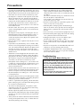 3
3
-
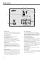 4
4
-
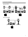 5
5
-
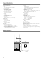 6
6
-
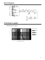 7
7
-
 8
8
-
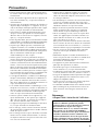 9
9
-
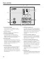 10
10
-
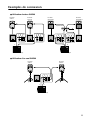 11
11
-
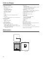 12
12
-
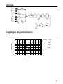 13
13
-
 14
14
-
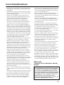 15
15
-
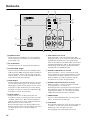 16
16
-
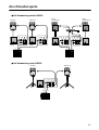 17
17
-
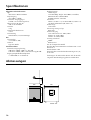 18
18
-
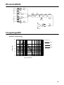 19
19
-
 20
20
-
 21
21
-
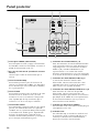 22
22
-
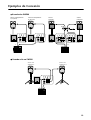 23
23
-
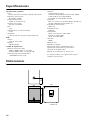 24
24
-
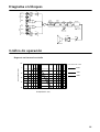 25
25
-
 26
26


in andere talen
- English: Yamaha SW500 User manual
- italiano: Yamaha SW500 Manuale utente
- русский: Yamaha SW500 Руководство пользователя
- français: Yamaha SW500 Manuel utilisateur
- español: Yamaha SW500 Manual de usuario
- Deutsch: Yamaha SW500 Benutzerhandbuch
- português: Yamaha SW500 Manual do usuário
- dansk: Yamaha SW500 Brugermanual
- čeština: Yamaha SW500 Uživatelský manuál
- svenska: Yamaha SW500 Användarmanual
- Türkçe: Yamaha SW500 Kullanım kılavuzu
- polski: Yamaha SW500 Instrukcja obsługi
- română: Yamaha SW500 Manual de utilizare