
Inleiding
Introduction
Einleitung Technical Information
Charactéristique technique
Technische Spezikationen
Technische specicatie
Manual
Pump logic module for KL06 wiring centre
Model: PL06
Issue Date: Mar 2020
V001
Maintaining a policy of continuous product development SALUS Controls
plc reserve the right to change specification, design and materials
of products listed in this brochure without prior notice.
SALUS Controls is a member of the Computime Group
www.salus-controls.com
Head Office:
SALUS Controls Plc
Units 8-10 Northfield
Business Park
Forge Way, Parkgate, Rotherham
S60 1SD, United Kingdom
T: +44 (0) 1226 323961
tel: +44 (0) 1226 323961
DE / NL: support@salus-controls.de
tel: +49 6108 8258515
tel: +33 (0) 134 724 039
Introduction
The PL06 module extends the functionality of the KL06 wiring centre. The
Module is used to control the pump (or boiler) using volt-free NC/COM/
NO contacts. When any of the thermostats connected to the KL06 230V
call for heat, COM/NO contacts are closed. COM/NO contacts are open
when thermostats connected the wiring centre stop calling for heat.
Product Compliance
This product complies with the essential requirements and other relevant
provisions of the following EU Directives: EMC 2014/30/EU, Low Voltage
Directive LVD 2014/35/EU, RoHS directive 2011/65/EU. The full text of
the EU Declaration of Conformity is available at the following internet
address: www.saluslegal.com
Safety Information
Use in accordance with national and EU regulations. The device should
be used for the purpose intended and kept in dry conditions. The product
is for indoor use only. Installation must be carried out by a qualied
person in accordance with national and EU regulations.
Before carrying out any installation or connecting wires, make sure that
the device is not connected to any power source. Installation must be
carried out by a qualied person. Incorrect connection of the wires may
cause damage to the wiring centre. The module must not be used in
damp conditions or exposed to water.
Das PL06 Modul erweitert die Funktionalität der Klemmleiste KL06.
Das Modul regelt die Laufzeit der Pumpe (oder des Brenners), dazu
werden die potentialfreien Anschlüsse NC/COM/NO genutzt. Gibt es bei
einem oder mehreren Thermostaten eine Heizanforderung, dann wird
das Relais COM/NO geschlossen und die Pumpe läuft. Gibt es keinerlei
Heizanforderung, dann wir das Relais COM/NO geönet und die Pumpe
stoppt – es wird aktiv Energie gespart.
Le module PL06 étend les fonctionnalités du centre de câblage KL06. Le
module permet de contrôler la pompe (ou la chaudière) via de contacts
libres de potentiel, NF/COM/NO. Lorsqu’un des thermostats connectés au
KL06 230V demande de chauage, les contacts COM/NO sont fermés.
Les contacts COM/NO sont ouverts lorsque les thermostats connectés au
centre de câblage cessent de demander de chauage.
Produktkonformität
Conformité du produit
Dieses Produkt erfüllt die wesentlichen Anforderungen der EMC
2014/30/EU, LVD 2014/35/EU und RoHS 2011/65/EU. Den vollständigen
Text der EU Komformitätserklärung können Sie auf www.saluslegal.com
einsehen.
Ce produit est conforme aux exigences essentielles et aux autres
dispositions pertinentes dénies dans les directives de l’UE suivantes: EMC
2014/30/EU, LVD 2014/35/EU et RoHS 2011/65/EU. Le texte complet de la
déclaration de conformité UE est disponible sur www.saluslegal.com
Sicherheitsinformationen
Das Produkt muss gemäß der EU- und der nationalen Richtlinien
verwendet werden. Nur für eine Verwendung in Innenräumen. Halten
Sie Ihr Gerät vollständig trocken. Dieses Produkt muss von einer fachlich
geeigneten Person gemäß sämtlicher EU- und nationalen Richtlinien
installiert werden.
Vor Installation, bitte unbedingt darauf achten, dass alle Komponenten
stromlos sind! Installation und elektrischen Anschluss müssen von
qualiziertem Fachpersonal durchgeführt werden. Inkorrekte Anschlüsse
können zu Schäden der Klemmleiste bzw. des Pumpenlogikmoduls
führen. Das Modul darf weder Feuchtigkeit, Dampf noch Wasser
ausgesetzt werden!
De PL06 module verlengt de functie van het KL06 bedradingscentrum.
De module wordt gebruikt om de pomp (of boiler) te bedienen door
voltvrije NC/COM/NO contacten. Wanneer één van de thermostaten
verbonden met de KL06 230V om verwarming verzoekt, worden de
COM/NO contacten gesloten. COM/NO contacten zijn open wanneer
thermostaten verbonden met het bedradingscentrum niet langer om
warmte verzoeken.
Productconformiteit
Dit product voldoet aan de essentiële vereisten en andere
relevante bepalingen van de volgende EU-richtlijnen: 2014/30/EU
(elektromagnetische compatibiliteit), 2014/35/EU (laagspanning) en
2011/65/EU (beperking van gevaarlijke stoen). De volledige tekst van de
EU-verklaring van overeenstemming is te vinden op www.saluslegal.com
Veiligheidsinformatie
Informations de sécurité
Gebruik in overeenstemming met nationale en Europese regelgeving.
Gebruik het apparaat zoals bedoeld en houd het droog. Uitsluitend
binnenshuis gebruiken. Installatie dient te worden uitgevoerd door
een gekwaliceerd persoon overeenkomstig nationale en Europese
regelgeving.
Voordat een installatie wordt uitgevoerd of draden worden verbonden,
bevestig dat het toestel niet verbonden is met een stroombron. De
installatie moet worden uitgevoerd door een bevoegd persoon. Verkeerd
verbonden draden kunnen het bedradingscentrum beschadigen. De
module mag niet worden gebruikt in vochtige omstandigheden en mag
niet worden blootgesteld aan water.
Utilisez le produit dans le respect des réglementations nationales et
européennes. Utilisez le dispositif conformément à sa destination et
maintenez-le au sec. Produit conçu pour un usage intérieur uniquement.
Seule une personne qualiée est autorisée à installer ce produit
conformément aux réglementations nationales et européennes.
Avant toute installation, assurez-vous que l’appareil n’est connecté à
aucune source d’alimentation. L’installation doit être eectuée par une
personne qualiée. Une mauvaise connexion des ls peut endommager
le centre de câblage. Le module ne doit pas être utilisé dans des
conditions humides ou exposé à l’eau.
Power Supply from the KL06 wiring centre
Max load 5 (2) A
Output NO/COM/NC relay
Dimensions [mm] 60 x 80 x 20
Alimentation par le centre de câblage KL06
Pouvoir de coupure 5 (2) A
Sorties relais NC/COM/NO
Dimensions [mm] 60 x 80 x 20
Stromversorgung Über die Klemmleiste KL06
Max. Schaltstrom 5 (2) A
Anschlüsse Stromlos Oen (NO)/COM/
Stromlos Geschlossen (NC)
Abmessungen [mm] 60 x 80 x 20
Voeding van het KL06 bedradingscentrum
Maximale belasting 5 (2) A
Output NO/COM/NC relais
Afmetingen [mm] 60 x 80 x 20

Connecteur série pour les modules PL06 et PL07
FR: Ceci assure la communication entre le centre de câblage KL06 et le
module PL06. Le centre de câblage KL06 + le module PL07 augmentent
la fonctionnalité, permettent également de contrôler une pompe ou
une chaudière. Les modules PL06/PL07 sont alimenté par le centre de
câblage.
DE: Dieser Anschluss ermöglicht die Kommunikation zwischen
Klemmleiste KL06 und Pumpenlogikmodul PL06. Die Kombination KL06
und PL06 erhöht die Funktionalität der Einheit und ermöglicht es eine
Pumpe oder den Brenner zu schalten. Die Stromversorgung des PL06
Moduls erfolgt über die Klemmleiste.
EN: This provides communication between the KL06 wiring centre and
the PL06 module. The KL06 wiring centre + the PL07 module increases
the functionality and also makes it possible to control a pump or boiler.
The PL06 module is powered from the wiring centre.
NL: Verzorgt de communicatie tussen het KL06 bedradingscentrum
en de PL06 module. Het KL06 bedradingscentrum + de PL07
module verbetertde functie en maakt het mogelijk om een pomp
of boiler te bedienen. De PL06 module wordt aangedreven van het
bedradingscentrum.
ON OFF
34
DelayOverrun
ON OFF
12
123456
fuse
(T2A)
LN LN LN LN LN LN
LN
CON1
Serial Connector for PL06 and PL07 Modules
Serieller Anschluss für Module PL06 und PL07
Seriële connector voor PL06 en PL07 Modules
EN: Jumpers 0-15
These are used to set in minutes the delay (over-
run) time. Default setting is “0”. 0-15 values specify
the time in minutes, e.g. when a jumper is set to
“0” COM/NO output will turn o as soon as the
thermostats stop calling for heat. If the jumper is
set to the value “10”, the module will turn o 10
minutes after the thermostats stop calling for heat.
DE: Jumper 0-15
Die Jumper-Positionen dienen dazu die Laufzeit NACH Beendigung der
Heizanforderung zu regeln. Werkseinstellung ist „0“. 0-15 geben die
Nachlaufzeit in Minuten an. Bsp.: Wenn „0“ gesetzt ist, dann wird das
Relais COM/NO sofort nach Beendigung der Heizanforderung geönet.
Wenn „10“ gesetzt wird, önet sich das Relais mit einem Nachlauf von
10 Minuten.
FR: Cavaliers 0-15
Ceux-ci sont utilisés pour dénir en minutes le délai (dépassement) pour
éteindre la pompe/chaudière. Par défaut le réglage est “0”. Les valeurs
0-15 spécient le temps en minutes, par ex. quand un cavalier est
réglé sur “0” La sortie COM/NO s’éteint dès que les thermostats cessent
de demander de chauage. Si le cavalier est réglé sur la valeur “10”, le
module tournera la pompe/chaudière encore 10 minutes après que les
thermostats cessent de demander de chauage.
NL: Jumpers 0-15
Deze worden gebruikt om de vertraging (over-run) tijd in te stellen in
minuten. De standaard instelling is “0”. 0-15 waarden speciceren de tijd
in minuten, bv. wanneer een jumper is ingesteld op “0”, zal de COM/NO
output uitschakelen zodra dat de thermostaten niet langer om warmte
verzoeken. Als de jumper is ingesteld op waarde “10”, zal de module
uitschakelen 10 minuten nadat de thermostaten niet langer om warmte
verzoeken.
EN: Jumpers P, 1, 2, 3, 4, 5, 6
These are used to select the zone which turns on the
module. Default setting is “P”.
P – all zones start the module.
1, 2, 3, 4, 5, 6 – select the specic zone which
turns on the module.
DE: Jumper P, 1, 2, 3, 4, 5, 6
Es kann eine ganz spezielle Zone zur Schaltung des Relais ausgewählt
werden. Werkseinstellung ist P.
P – alle 6 Heizzonen schalten das Relais.
1, 2, 3, 4, 5, 6 – nur die ausgewählte Zone schaltet das Relais.
FR: Cavaliers P, 1, 2, 3, 4, 5, 6
Ceux-ci sont utilisés pour sélectionner la zone qui pilote le module. Par
défaut le réglage est “P”.
P – toutes les zones démarrent le module.
1, 2, 3, 4, 5, 6 – sélectionnez la zone spécique qui pilote le module.
NL:
Jumpers P, 1, 2, 3, 4, 5, 6
Worden gebruikt om de zone te selecteren die de module aanschakelt.
Standaard instelling is “P”.
P – alle zones starten de module.
1, 2, 3, 4, 5, 6 – selecteer de specieke zone die de module aanschakelt.
ON OFF
34
DelayOverrun
ON OFF
12
123456
fuse (T2A)
LN LN LN LN LN LN
LN
CON1
ON OFF
34
DelayOverrun
ON OFF
12
123456
fuse (T2A)
LN LN LN LN LN LN
LN
CON1
ON OFF
34
DelayOverrun
ON OFF
12
123456
fuse (T2A)
LN LN LN LN LN LN
LN
CON1
ON OFF
34
DelayOverrun
ON OFF
12
123456
fuse (T2A)
LN LN LN LN LN LN
LN
CON1
ON OFF
34
DelayOverrun
ON OFF
12
123456
fuse (T2A)
LN LN LN LN LN LN
LN
CON1
ON OFF
34
DelayOverrun
ON OFF
12
123456
fuse (T2A)
LN LN LN LN LN LN
LN
CON1
Jumpers Description
Description des cavaliers
Jumper-Beschreibung
Jumpers beschrijving
EN: PUMP CONTROL
DE: STEUERUNG DER PUMPE
FR: CONTRÔLE DE LA POMPE
NL: POMPBEDIENING
EN: BOILER CONTROL
DE: STEUERUNG DES BRENNERS
FR: CONTRÔLE DE LA CHAUDIÈRE
NL: BOILERBEDIENING
ON OFF
34
DelayOverrun
ON OFF
12
123456
fuse
(T2A)
LN LN LN LN LN LN
LN
CON1
ON OFF
34
DelayOverrun
ON OFF
12
123456
fuse
(T2A)
LN LN LN LN LN LN
LN
CON1
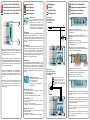
230 V AC
L
L
N
NPE
max 5 (2) A
ON OFF
34
DelayOverrun
ON OFF
12
123456
fuse
(T2A)
LN LN LN LN LN LN
LN
CON1
ON OFF
34
DelayOverrun
ON OFF
12
123456
fuse
(T2A)
LN LN LN LN LN LN
LN
CON1
Boiler ON/OFF contacts (according to the boiler’s manual)
Bitte entnehmen Sie die Anschlüsse des Wärmeerzeugers für die
Regelung des Brenners aus deren Bedienungsanleitung
Contacts ON/OFF de la chaudière (selon le manuel de la chaudière)
Boiler AAN/UIT contacten (in overeenstemming met de handleiding
van de boiler)
Wiring Diagrams
Schémas de câblage
Schaltplan
Bedradingsschema’s
3
1
2
EN: Make sure that all the wires are properly connected, mount top cover
and power up the wiring centre - the green „Power” indicator LED will
illuminate.
FR: Assurez-vous que tous les ls sont correctement connectés,
montez le couvercle et allumez le centre de câblage - le voyant LED vert
«Alimentation» s’allume.
DE: Vergewissern Sie sich, dass alle Kabel korrekt angeschlossen sind.
Setzen Sie den transparenten Deckel wieder auf die Klemmleiste und
befestigen Sie diesen. Setzen Sie die Einheit unter Strom – die grüne
„Power“ LED wird aueuchten.
NL: Alle draden moeten correct verbonden zijn, bevestig de bovenste
cover en schakel het bedradingscentrum aan - het groene „Power”
indicator LED zal oplichten.
EN: Remove the top cover of the wiring centre.
Note: Before connecting module, disconnect the main power from the
KL06 wiring centre.
FR: Retirez le couvercle du centre de câblage.
Remarque: Avant de connecter le module, débranchez l’alimentation
du Centre de câblage KL06.
DE: Entfernen Sie den transparenten Deckel der Klemmleiste.
ACHTUNG: Ganz Einheit stromlos setzen bevor Sie das Modul
installieren.
NL: Verwijder de bovenste cover van het bedradingscentrum.
Let op: Voordat u de module verbindt, moet het KL06 bedradingscentrum
losgekoppeld worden van het elektriciteitsnet.
EN: Connect the module to the serial connector.
DE: Entfernen Sie die beiden „rechten“ Schrauben der Platine. Setzen Sie
jetzt das Modul ein und xieren die Einheit mit 4 Schrauben.
FR: Connectez le module au connecteur série.
NL: Verbind de module met de seriële connector.
Installation of the Additional Module
Installation du module additionnel
Installation des Pumpenlogikmoduls PL06
Installatie van de extra module
-
 1
1
-
 2
2


in andere talen
- English: Salus PL06 User manual
- français: Salus PL06 Manuel utilisateur
- español: Salus PL06 Manual de usuario
- Deutsch: Salus PL06 Benutzerhandbuch
