
Owner’s Manual
Bedienungsanleitung
Mode d’emploi
Manual de instrucciones
JA
ZH
ES
FR
DE
EN

2
T5n/T4n/T3n Owner’s Manual
The above warning is located on the top of the unit.
Explanation of Graphical Symbols
The lightning flash with arrowhead symbol
within an equilateral triangle is intended to alert
the user to the presence of uninsulated
“dangerous voltage” within the product’s
enclosure that may be of sufficient magnitude to
constitute a risk of electric shock to persons.
The exclamation point within an equilateral
triangle is intended to alert the user to the
presence of important operating and
maintenance (servicing) instructions in the
literature accompanying the product.
IMPORTANT SAFETY INSTRUCTIONS
1 Read these instructions.
2Keep these instructions.
3 Heed all warnings.
4 Follow all instructions.
5 Do not use this apparatus near water.
6 Clean only with dry cloth.
7 Do not block any ventilation openings. Install in
accordance with the manufacturer’s instructions.
8 Do not install near any heat sources such as radiators,
heat registers, stoves, or other apparatus (including
amplifiers) that produce heat.
9 Do not defeat the safety purpose of the polarized or
grounding-type plug. A polarized plug has two blades
with one wider than the other. A grounding type plug
has two blades and a third grounding prong. The wide
blade or the third prong are provided for your safety. If
the provided plug does not fit into your outlet, consult
an electrician for replacement of the obsolete outlet.
10 Protect the power cord from being walked on or pinched
particularly at plugs, convenience receptacles, and the
point where they exit from the apparatus.
11 Only use attachments/accessories specified by the
manufacturer.
12 Use only with the cart, stand,
tripod, bracket, or table specified
by the manufacturer, or sold with
the apparatus. When a cart is
used, use caution when moving
the cart/apparatus combination
to avoid injury from tip-over.
13 Unplug this apparatus during
lightning storms or when unused for long periods of
time.
14 Refer all servicing to qualified service personnel.
Servicing is required when the apparatus has been
damaged in any way, such as power-supply cord or plug
is damaged, liquid has been spilled or objects have
fallen into the apparatus, the apparatus has been
exposed to rain or moisture, does not operate normally,
or has been dropped.
(98-6500)
CAUTION: TO REDUCE THE RISK OF
ELECTRIC SHOCK, DO NOT REMOVE
COVER (OR BACK). NO USER-SERVICEABLE
PARTS INSIDE. REFER SERVICING TO
QUALIFIED SERVICE PERSONNEL.
CAUTION
RISK OF ELECTRIC SHOCK
DO NOT OPEN
WARNING
TO REDUCE THE RISK OF FIRE OR ELECTRIC SHOCK, DO NOT EXPOSE THIS APPARATUS TO RAIN OR MOISTURE.
1. IMPORTANT NOTICE: DO NOT MODIFY THIS UNIT!
This product, when installed as indicated in the instructions con-
tained in this manual, meets FCC requirements. Modifications
not expressly approved by Yamaha may void your authority,
granted by the FCC, to use the product.
2. IMPORTANT:
When connecting this product to accessories
and/or another product use only high quality shielded cables.
Cable/s supplied with this product MUST be used. Follow all
installation instructions. Failure to follow instructions could void
your FCC authorization to use this product in the USA.
3. NOTE:
This product has been tested and found to comply with
the requirements listed in FCC Regulations, Part 15 for Class
“B” digital devices. Compliance with these requirements pro-
vides a reasonable level of assurance that your use of this prod-
uct in a residential environment will not result in harmful
interference with other electronic devices. This equipment gen-
erates/uses radio frequencies and, if not installed and used
according to the instructions found in the users manual, may
cause interference harmful to the operation of other electronic
devices. Compliance with FCC regulations does not guarantee
that interference will not occur in all installations. If this product
is found to be the source of interference, which can be deter-
mined by turning the unit “OFF” and “ON”, please try to eliminate
the problem by using one of the following measures:
Relocate either this product or the device that is being affected
by the interference.
Utilize power outlets that are on different branch (circuit breaker
or fuse) circuits or install AC line filter/s.
In the case of radio or TV interference, relocate/reorient the
antenna. If the antenna lead-in is 300 ohm ribbon lead, change
the lead-in to co-axial type cable.
If these corrective measures do not produce satisfactory results,
please contact the local retailer authorized to distribute this type
of product. If you can not locate the appropriate retailer, please
contact Yamaha Corporation of America, Electronic Service Divi-
sion, 6600 Orangethorpe Ave, Buena Park, CA90620
The above statements apply ONLY to those products distributed
by Yamaha Corporation of America or its subsidiaries.
* This applies only to products distributed by YAMAHA CORPORATION OF AMERICA. (class B)
FCC INFORMATION (U.S.A.)

(5)-4
T5n/T4n/T3n Owner’s Manual
3
PRECAUTIONS
PLEASE READ CAREFULLY BEFORE PROCEEDING
* Please keep this manual in a safe place for future reference.
WARNING
Always follow the basic precautions listed below to avoid the possibility of serious injury or even death from electrical
shock, short-circuiting, damages, fire or other hazards. These precautions include, but are not limited to, the following:
• Only use the voltage specified as correct for the device. The required voltage is
printed on the name plate of the device.
• Do not place the power cord near heat sources such as heaters or radiators, and
do not excessively bend or otherwise damage the cord, place heavy objects on
it, or place it in a position where anyone could walk on, trip over, or roll anything
over it.
• Be sure to connect to an appropriate outlet with a protective grounding
connection. Improper grounding can result in electrical shock.
• Do not open the device or attempt to disassemble the internal parts or modify
them in any way. The device contains no user-serviceable parts. If it should
appear to be malfunctioning, discontinue use immediately and have it inspected
by qualified Yamaha service personnel.
• Do not expose the device to rain, use it near water or in damp or wet conditions,
or place containers on it containing liquids which might spill into any openings.
• Never insert or remove an electric plug with wet hands.
• If the power cord or plug becomes frayed or damaged, or if there is a sudden
loss of sound during use of the device, or if any unusual smells or smoke
should appear to be caused by it, immediately turn off the power switch,
disconnect the electric plug from the outlet, and have the device inspected by
qualified Yamaha service personnel.
• If this device should be dropped or damaged, immediately turn off the power
switch, disconnect the electric plug from the outlet, and have the device
inspected by qualified Yamaha service personnel.
CAUTION
Always follow the basic precautions listed below to avoid the possibility of physical injury to you or others, or damage
to the device or other property. These precautions include, but are not limited to, the following:
• Remove the electric plug from the outlet when the device is not to be used for
extended periods of time, or during electrical storms.
• When removing the electric plug from the device or an outlet, always hold the
plug itself and not the cord. Pulling by the cord can damage it.
• Before moving the device, remove all connected cables.
• When setting up the device, make sure that the AC outlet you are using is easily
accessible. If some trouble or malfunction occurs, immediately turn off the
power switch and disconnect the plug from the outlet. Even when the power
switch is turned off, electricity is still flowing to the product all the minimum
level. When you are not using the product for a long time, make sure to unplug
the power cord from the wall AC outlet.
• If this device is to be mounted in an EIA-standard rack, leave the back of the rack
open and make sure that it is at least 10 cm away from walls or surfaces to
provide better airflow. In such a situation, these devices can be stacked on top of
each other if necessary. Also, if this device is to be mounted with devices that
tend to generate heat, such as power amplifiers made by another manufacturer,
be sure to keep an adequate gap between this device and the heat-generating
devices, or install ventilation panels or forced ventilation fans to prevent high
temperatures from developing inside this device.
Inadequate ventilation can result in overheating, possibly causing damage to the
device(s), or even fire.
• Do not use the device in a confined, poorly-ventilated location. If this device is
to be used in a small space other than an EIA-standard rack, make sure that
there is adequate space between the device and surrounding walls or other
devices: at least 10cm at the sides, 30cm behind and 40cm above. Inadequate
ventilation can result in overheating, possibly causing damage to the device(s),
or even fire.
• Do not expose the device to excessive dust or vibrations, or extreme cold or heat
(such as in direct sunlight, near a heater, or in a car during the day) to prevent
the possibility of panel disfiguration or damage to the internal components.
• Do not place the device in an unstable position where it might accidentally fall
over.
• Do not block the vents. This device has ventilation holes at the front/rear to
prevent the internal temperature from becoming too high. In particular, do not
place the device on its side or upside down. Inadequate ventilation can result in
overheating, possibly causing damage to the device(s), or even fire.
• Do not use the device in the vicinity of a TV, radio, stereo equipment, mobile
phone, or other electric devices. Doing so may result in noise, both in the device
itself and in the TV or radio next to it.
• Do not place the device in a location where it may come into contact with
corrosive gases or salt air. Doing so may result in malfunction.
Power supply/Power cord
Do not open
Water warning
If you notice any abnormality
Power supply/Power cord
Location

4
T5n/T4n/T3n Owner’s Manual
(5)-4
• Before connecting the device to other devices, turn off the power for all devices.
Before turning the power on or off for all devices, set all volume levels to
minimum.
• Use only speaker cables for connecting speakers to the speaker jacks. Use of
other types of cables may result in fire.
• Inspect the cooling fan air filter and clean it periodically (see page 11). Dust and
dirt can seriously degrade the effectiveness of the cooling fan and result in
malfunction or fire.
• Remove the power plug from the AC outlet when cleaning the device.
• When turning on the AC power in your audio system, always turn on the device
LAST, to avoid speaker damage. When turning the power off, the device should
be turned off FIRST for the same reason.
• Do not insert your fingers or hands in any gaps or openings on the device
(vents).
•Avoid inserting or dropping foreign objects (paper, plastic, metal, etc.) into any
gaps or openings on the device (vents) If this happens, turn off the power
immediately and unplug the power cord from the AC outlet. Then have the
device inspected by qualified Yamaha service personnel.
• Do not use the device for a long period of time at a high or uncomfortable
volume level, since this can cause permanent hearing loss. If you experience
any hearing loss or ringing in the ears, consult a physician.
• Do not rest your weight on the device or place heavy objects on it, and avoid use
excessive force on the buttons, switches or connectors.
• Do not use this device for any purpose other than driving loudspeakers.
Always turn the power off when the device is not in use.
The performance of components with moving contacts, such as switches, volume controls, and connectors, deteriorates over time. Consult qualified Yamaha service
personnel about replacing defective components.
Illustrations in this manual are for explanatory purposes only, and may not match the actual appearance of the product during operation.
The company names and product names in this Owner’s Manual are the trademarks or registered trademarks of their respective companies.
Connections
Maintenance
Handling caution
XLR-type connectors are wired as follows (IEC60268 standard): pin 1: ground, pin 2: hot (+), and pin 3: cold (-).
Use only Neutrik NL4 plugs for connecting Speakon connectors.
Yamaha cannot be held responsible for damage caused by improper use or modifications to the device, or data that is lost or destroyed.
IMPORTANT NOTICE FOR THE UNITED KINGDOM
Connecting the Plug and Cord
WARNING: THIS APPARATUS MUST BE EARTHED
IMPORTANT. The wires in this mains lead are coloured in accordance with the following code:
GREEN-AND-YELLOW : EARTH
BLUE : NEUTRAL
BROWN : LIVE
As the colours of the wires in the mains lead of this apparatus may not correspond with the
coloured markings identifying the terminals in your plug proceed as follows:
The wire which is coloured GREEN-and-YELLOW must be connected to the terminal in the plug
which is marked by the letter E or by the safety earth symbol or colored GREEN or GREEN-
and-YELLOW.
The wire which is coloured BLUE must be connected to the terminal which is marked with the
letter N or coloured BLACK.
The wire which is coloured BROWN must be connected to the terminal which is marked with the
letter L or coloured RED.
• This applies only to products distributed by Yamaha-Kemble Music (U.K.) Ltd. (3 wires)
This mark indicates a dangerous electrically live terminal. When connecting an external wire to this terminal, it is necessary
either to have “a person who have received appropriate guidance on handling” make the connection or to use leads or a cord that
have been manufactured in such a way that the connection can be made simply and without problem.

T5n/T4n/T3n Owner’s Manual
5
Controls and Functions............................ 6
Front Panel .......................................................... 6
Rear Panel .......................................................... 7
Speaker Connections ............................... 8
STEREO Mode ................................................... 8
PARALLEL Mode ................................................ 8
BRIDGE Mode .................................................... 9
Wiring......................................................... 9
Using a Euroblock connector .............................. 9
Speaker Connection .......................................... 10
Filter Element Cleaning .......................... 11
Troubleshooting...................................... 11
Specifications.......................................... 12
Block Diagram......................................... 71
Dimensions.............................................. 72
Performance Graph ................................ 73
Current Draw ........................................... 73
Introduction
Thank you for your purchase of the YAMAHA T5n, T4n, T3n Series Power Amplifier.
This series of power amplifiers was developed from Yamaha’s wealth of experience in building PA
equipment and its tradition of careful attention to every detail of circuit design. These power amplifiers
feature high power — thanks to EEEngine (Energy Efficient Engine) technology — and superb quality
together with superior reliability and stability, guaranteeing the highest possible audio performance.
Features:
• Three modes are provided to support a broad range of applications: STEREO mode which can be driven by two
independent sources, PARALLEL mode in which a monaural source drives both channels, and BRIDGE mode
in which the two internal amps function as a single high-power mono amp.
• Balanced XLR connector and Euroblock connector inputs, and Speakon connector and five-way binding post
outputs are provided.
• SIGNAL indicator, CLIP indicator and MUTE indicator and sophisticated dB step Volume control are provided
for each channel.
•PROTECTION indicator that shows the state of various protection systems (power On/Off detection, output
protection, DC detection), a TEMP indicator that indicates heat sink overheating, and a POWER/STANBY indi-
cator that indicates the power status are provided.
•Variable-speed low-noise fans ensure high reliability.
• The
T5n
enables parallel connection of multiple high-impedance speakers that support 100 V line output.
• The
T3n
enables parallel connection of multiple high-impedance speakers that support 70 V line output.
• An optional external amp control device, such as the ACD1 or ACU16-C, enables you to monitor or control the
amplifier via a network. For the latest information about amp control units, please visit our website:
http://www.yamahaproaudio.com/
This Owner’s Manual applies to the three models: T5n, T4n and T3n power amplifiers.
Please read through this manual carefully before beginning use, so that you will be able to take full
advantage of your power amp’s superlative features and enjoy trouble-free operation for years to come.
Accessories
Owner’s Manual
Two handles
Four flat-head screws
Two Euroblock connectors
Index

6
T5n/T4n/T3n Owner’s Manual
Controls and Functions
■
Front Panel
1
POWER switch and indicator
Press to toggle the power on or off. The POWER indicator
lights up green when the power is ON.
If the amplifier is connected to an amp control device such
as the ACD1 or ACU16-C and the amplifier has been com-
manded to enter STANDBY mode, this indicator will light
orange.
2
TEMP indicator
Lights up red if the heat sink temperature exceeds 85°C
(185°F).
3
PROTECTION indicator
When the protection system is active, the indicator lights in
red. No sound will be output from the speakers, since the
speakers are automatically disconnected from the ampli-
fier’s outputs.
The protection system actives in the following situations:
•When the amplifier is turned on
The protection system actives for approximately 10
seconds when the amplifier is turned on. After 10 sec-
onds, the protection system deactivates automatically
and the amplifier is ready for normal operation.
• If the amplifier overheats
The protection system activates if the heat sink tem-
perature exceeds 85°C (185°F). The amplifier is
muted if the heat sink temperature exceeds 90°C (194
°F). The amplifier operates normally after the ampli-
fier cools down.
4
REMOTE indicator
This indicator will light green if the amplifier is being con-
trolled by an amp control device such as the ACD1 or
ACU16-C.
5
CLIP indicator
Lights up red when the output signal distortion on the corre-
sponding channel rises above 1% — indicating that “clip-
ping” has occurred because the signal level is too high.
6
SIGNAL indicator
Lights up green when the corresponding channel’s output
level exceeds 1 Vrms (equivalent to 0.2 W into an 8 ohms
load, 0.4 W into a 4 ohms load or 0.8 W into a 2 ohms
load).
7
MUTE indicator
This indicator will light red if the amplifier is muted by an
amp control device such as the ACD1 or ACU16-C. This
indicator will also light red while the PROTECTION indi-
cator is ON.
8
Volume control knobs
Each control knob adjusts the volume of the corresponding
channel, in 31 steps from -
∞
dB to 0 dB.
9
Air intakes
The amplifier uses forced-air cooling. The variable speed
cooling fan draws air in from the front and exhausts it
through the rear. The cooling fan speed varies depending
on the heat sink temperature: It operates at low speed when
it is below 40 °C (104 °F), increases in speed according to
increases in temperature, and operates at high speed when
temperature exceeds 60 °C (140 °F). Please be sure that
you do not block the air intakes or exhaust vents. Also,
clean the filter elements regularly. If the air intakes are
clogged with dust or debris, the amplifier will overheat,
which may result in the amplifier to shutting down.
0
Screw holes for handles
These four screw holes are for the included handles. Fix
the handles to the amplifier, using the included flat-head
screws.
8130 074
2
56
99
6
T5n
Note: Screw holes for security cover
These four screw holes are for attaching a security
cover to protect the volume setting. Since a secu-
rity cover and screws are not included in the ampli-
fier, please prepare a security cover the same size
as indicated below and four M3 screws.
108 mm
30 mm
Front Rear
Air
exhaust
Air
intake

T5n/T4n/T3n Owner’s Manual
7
Controls and Functions
■
Rear Panel
1
Input connectors
• XLR3-31 type input connectors
The pins are wired as shown below (IEC 60268).
• Euroblock input connectors
These are balanced input connectors. The included
Euroblock connectors can be used to make connec-
tions here.
2
Mode switch
• STEREO mode
In STEREO mode, channels A and B are completely
independent.
•PARALLEL mode
In PARALLEL mode, the channel A input signal is sent
both to the channel A power amp and the channel B amp.
The Channel B input connector does not function.
• BRIDGE mode
In BRIDGE mode, channels A and B operates simul-
taneously, functioning as a single mono amplifier.
3
GAIN switch
This switch is used when changing the Gain of the A and B
channels simultaneously.
32 dB: Setting of 32 dB
26 dB: Setting of 26 dB
When monitoring or controlling from an amplifier control
device such as the ACD1 or ACU16-C, set the GAIN
switch to [26 dB] to avoid clipping if you plan to input sig-
nals with a maximum input level of +24 dBu.
When the power amplifier is connected to the ACD1 or
ACU16-C, the electronic volume control inside the ampli-
fier will become effective, and the maximum input level
will become +18 dBu if the GAIN switch has been set to
[32 dB].
4
DATA PORT jacks
An amp control device, such as the ACD1 or ACU16-C,
can be connected to the DATA PORT jack for monitoring
or controlling the amplifier from the external device.
5
AMP ID switch
When an amp control device, such as the ACD1 or ACU16-
C, is connected to the DATA PORT jack
4
, the AMP ID
can be used to set the amplifier’s ID.
6
SPEAKERS jacks
• 5-way binding post output jacks
• Speakon type output jacks
Speakon type cable plugs (Neutrik NL4) can be con-
nected here.
7
Ground screw
If you are having a problem with hum or noise, use this ter-
minal to connect to ground or connect to the chassis of the
mixer, preamp, or other device in your system.
8
AC IN connector
This amplifier uses a NEMA L5-30 outlet.
Connect the 30 A twist-lock connectors by orienting the
locking L-shaped prong with the corresponding connector
entry, then fully insert the three prongs. Twist the plug
about 1/8 of a turn clockwise to lock the connector and
plug.
The amplifier requires very high-power so that it
can demand high current from the AC service.
Connections must be properly rated for reliable
operation.
If this device is to be rack mounted and trans-
ported frequently, be sure to support the rear end
of the unit with mounting hardware that matches
the size of the rack used.
4 5
32
178
6
Note: In PARALLEL and BRIDGE mode, only the
channel A connector is active. Make sure
not to input an audio signal to an inactive
input terminal (channel B).
Ground
Cold
Hot
Amplifiers purchased in the United States of America
and Canada.

8
T5n/T4n/T3n Owner’s Manual
Speaker Connections
Speakers can be connected to the amplifier as shown below. Note that actual speaker impedance varies according to the con-
nection method and the number of speakers. Please be sure that your speakers’ impedance is not less than the relevant mini-
mum value indicated below.
■
STEREO Mode
Set the MODE switch on the rear panel to “STEREO” to use the unit as a stereo amplifier. The volume controls on the front
panel (A and B) let you control the volume of each channel independently.
■
PARALLEL Mode
Set the MODE switch on the rear panel to “PARALLEL” to use the unit as a two-channel mono amplifier. The volume con-
trols on the front panel (A and B) let you control the volume of each channel independently.
+
–
+
–
● 5-way binding post ● Speakon connector
Total speaker
impedance:
2 Ω (minimum)
Total speaker
impedance:
2 Ω (minimum)
Total speaker
impedance:
2 Ω (minimum)
Total speaker
impedance:
2 Ω (minimum)
+
–
+
–
● 5-way binding post ● Speakon connector
Total speaker
impedance:
2 Ω (minimum)
Total speaker
impedance:
2 Ω (minimum)
Total speaker
impedance:
2 Ω (minimum)
Total speaker
impedance:
2 Ω (minimum)

T5n/T4n/T3n Owner’s Manual
9
Speaker Connections
■
BRIDGE Mode (use as high-power mono amplifier)
Set the MODE switch on the rear panel to “BRIDGE” to use the unit as a high-power mono amplifier. The volume control A
on the front panel lets you control the volume.
Wiring
■
Using a Euroblock connector
Turn off the POWER switch before connecting external devices to the amplifier.
–
+
● 5-way binding post ● Speakon connector
Total speaker
impedance:
4 Ω (minimum)
Total speaker
impedance:
4 Ω (minimum)
● Cable preparation
•To prepare the cable for attachment to a Euroblock connector, strip the wire as shown in the illustration, and use stranded wire to
make connections. With a Euroblock connection, the stranded wire may be prone to breakage because of metal fatigue due to the
weight of the cable or due to vibration. When rack-mounting your equipment, use a lacing bar when possible to bundle and fasten
the cables.
• If cables will be frequently connected and disconnected, as in the case of a portable installation, we recommend that you use ferrules
with insulation sleeves. Use a ferrule whose conductor portion has an external diameter of 1.6 mm or less, and a length of approxi-
mately 7 mm (such as the AI0, 5-6WH made by the Phoenix Contact corporation).
If you use stranded wire, do not tin (plate with solder) the exposed end.
approx.
7 mm
approx.
7 mm
1.6 mm
or less
Speaker Connections

10 T5n/T4n/T3n Owner’s Manual
Wiring
1. If the wire insertion ports are closed, turn the screws on
top of the connector counterclockwise to open the ports.
2. Insert the wires into the appropriate ports, following the
indication of the pole on the input terminal, and turn the
screws on top of the connector clockwise to fix the
wires.
3. Attach the Euroblock connector to the input terminal on
the amplifier.
■ Speaker Connection
● 5-way binding post
1. Remove the cover attachment screws and remove the
protective cover from the speaker terminals.
2. Remove about 15mm of insulation from the end of each
speaker cable, and pass the bare wire through the holes
in the appropriate speaker terminals. Tighten the termi-
nals to securely clamp the wires.
Refer to page 8 for speaker polarities.
Be sure that the bare wire ends do not jut out from the ter-
minals and touch the chassis. The illustration on the right
shows how the cable should look when correctly attached.
3. Reattach the protective cover over the speaker termi-
nals.
● Speakon connector
Insert the Neutrik NL4 plugs into the Speakon connector
on the rear of the amplifier, and turn clockwise to lock.
+
–
G
Use a screwdriver
to fix the wires.
Screw
Bare wire
Chassis
* Actual size
Speaker
cable
15mm*
CHANNEL Å
STEREO or PARALLEL BRIDGE
Neutrik Amplifier Neutrik Amplifier
1+ A+ 1+ +
1– A– 1–
2+ B+ 2+ –
2– B– 2–
Neutrik NL4 plugs
CHANNEL ı
Neutrik Amplifier
1+ B+
1– B–

T5n/T4n/T3n Owner’s Manual 11
Filter Element Cleaning
To ensure adequate cooling air intake, the filter elements must be cleaned when they have become clogged. Follow the
description below to clean the filter elements.
1. Make sure that the power to the amplifier is turned off.
2. Disconnect the power plug from the AC outlet.
3. Remove the two screws that secure the front filter grilles
to the amplifier.
4. Remove the filter elements, and wash them in plain
water. If the filter elements are exceptionally dirty, mild
detergent may be used.
5. Dry the filter elements completely.
Never replace the filter elements while they are
still wet.
6. Replace the filter elements on the air intakes, hook the
front filter grilles on the amplifier, and secure them
using the screws. (The replacement part number of the
filter element is WH66270.)
Troubleshooting
The following table lists the main causes of abnormal operation and the corrective measures required, as well as the protec-
tive circuit operation in each case.
Filter element
Front filter grille
Indicator(s) Possible Cause Remedy Protection Circuit
CLIP indicator
lights.
There is a short at a speaker ter-
minal, amplifier terminal, or
wire.
Locate and correct the cause of
the short.
The PC limiter circuit operates to
protect the power transistors.
The amplifier load is excessive.
Use a speaker system with an
impedance of at least 2 ohms
(STEREO/PARALLEL mode) or
4 ohms (BRIDGE mode).
TEMP indica-
tor lights.
The heat sink temperature has
exceeded 85˚C.
Check the ventilation slots and
clean the filter elements to pro-
vide better airflow around the
amplifier.
The TEMP indicator lights up to
indicate temperature warning.
PROTEC-
TION indica-
tor lights.
The heat sink temperature has
exceeded 85˚C.
Check the amplifier ventilation
conditions and take appropriate
measures to improve the airflow
around the amplifier.
Also, clean the filter elements to
ensure proper airflow.
The thermal protection circuit
operates to protect the power
transistors.
A DC voltage is detected at the
amplifier’s output.
Consult your dealer or the near-
est Yamaha service center.
The power supply shuts down to
protect the speaker system.
MUTE indica-
tor lights.
There is a short at a speaker ter-
minal.
Locate and correct the cause of
the short.
The MUTE circuit operates to
protect the power transistors.

12 T5n/T4n/T3n Owner’s Manual
Specifications
T5n
120V 230V 240V
Output Power 1 kHz
THD + N = 1%
8 Ω per channel
MIN
1350 W 1350 W 1400 W
4 Ω per channel 2200 W 2350 W 2500 W
2 Ω per channel 2500 W 2500 W 2500 W
8 Ω bridge 4400 W 4700 W 5000 W
4 Ω bridge 5000 W 5000 W 5000 W
20 ms burst 2 Ω per channel 3400 W 3400 W 3600 W
4 Ω bridge 6800 W 6800 W 7200 W
Constant voltage line
STEREO mode: 100 V line, 1250 W/8 Ω
BRIDGE mode: 200 V line, 2500 W/16 Ω
Input Sensitivity RL=8 Ω 26 dB position +16.6 dBu +16.6 dBu +16.7 dBu
32 dB position +10.6 dBu +10.6 dBu +10.7 dBu
SN Ratio 20 Hz-20 kHz (DIN AUDIO) MIN 107 dB
Power Consumption Standby 5 W
Idle 70 W
1/8 power, 2 Ω/pink noise 1600 W
T4n
120V 230V 240V
Output Power 1 kHz
THD + N = 1%
8 Ω per channel
MIN
1150 W 1150 W 1250 W
4 Ω per channel 1950 W 2050 W 2150 W
2 Ω per channel 2200 W 2200 W 2200 W
8 Ω bridge 3900 W 4100 W 4300 W
4 Ω bridge 4400 W 4400 W 4400 W
20 ms burst 2 Ω per channel 2900 W 3100 W 3300 W
4 Ω bridge 5800 W 6200 W 6600 W
Constant voltage line —
Input Sensitivity RL=8 Ω 26 dB position +15.9 dBu +15.9 dBu +16.2 dBu
32 dB position +9.9 dBu + 9.9 dBu +10.2 dBu
SN Ratio 20 Hz-20 kHz (DIN AUDIO) MIN 106 dB
Power Consumption Standby 5 W
Idle 70 W
1/8 power, 2 Ω/pink noise 1400 W
T3n
120V 230V 240V
Output Power 1 kHz
THD + N = 1%
8 Ω per channel
MIN
790 W 750 W 850 W
4 Ω per channel 1400 W 1400 W 1500 W
2 Ω per channel 1900 W 1900 W 1900 W
8 Ω bridge 2800 W 2800 W 3000 W
4 Ω bridge 3800 W 3800 W 3800 W
20 ms burst 2 Ω per channel 2200 W 2150 W 2350 W
4 Ω bridge 4400 W 4300 W 4700 W
Constant voltage line TYP
STEREO mode: 70.7 V line, 625 W/8 Ω
BRIDGE mode: 141.4 V line, 1250 W/16 Ω
Input Sensitivity RL=8 Ω 26 dB position +14.2 dBu +14.0 dBu +14.5 dBu
32 dB position +8.2 dBu +8.0 dBu +8.5 dBu
SN Ratio 20 Hz-20 kHz (DIN AUDIO) MIN 105 dB
Power Consumption Standby 5 W
Idle 70 W
1/8 power, 2 Ω/pink noise 1200 W

T5n/T4n/T3n Owner’s Manual 13
Specifications
These specifications apply to rated power supplies of 120 V, 230 V and 240 V.
Half Power = 3 dB below rated power
1/8 Power = 9 dB below rated power
0 dBu = 0.775 Vrms
Specifications and descriptions in this owner’s manual are for information purposes only.
Yamaha Corp. reserves the right to change or modify products of specifications at any time without prior notice. Since specifications, equipment or options
may not be the same in every locale, please check with your Yamaha dealer.
European models
Purchaser/User Information specified in EN55103-1 and EN55103-2.
Inrush Current: 14A
Conforms to Environments: E1, E2, E3, E4
All Models
THD + N 20 Hz-20 kHz, Half power, RL = 4 Ω, 8 Ω MAX 0.1 %
Intermodulation Distortion 60 Hz:7 kHz, 4:1, Half power MAX 0.1 %
Frequency Response RL = 8 Ω, Po = 1 W
20 Hz-20 kHz
MAX 0 dB
TYP 0 dB
MIN -0.5 dB
Channel Separation Half power, RL = 8 Ω, 1 kHz
Att. Max, input 600 Ω shunt
MIN 67 dB
Damping Factor RL = 8 Ω, 1 kHz MIN 800
Voltage Gain Att. Max TYP 32 dB/26 dB
Maximum Input Voltage MIN +24 dBu
Input Impedance TYP 20 kΩ (balanced) 10 kΩ (unbalanced)
Controls Front Panel POWER switch (ON/OFF)
Attenuator (31position) x 2
Rear Panel MODE switch (STEREO/BRIDGE/PARALLEL) x 1
GAIN switch (32 dB/26 dB) x 1
AMP ID switch (6P DIP) x 1
Connectors Input XLR-3-31 type x 2
Euroblock connector (balanced) x 2
Output Speakon x 2, 5-way binding post x 2 pairs
DATA PORT RJ45 x 2
Indicators POWER/STANDBY x 1 (Green/Orange)
REMOTE x 1 (Green)
PROTECTION x 1 (Red)
TEMP x 1 (Red) heatsink temp ≥ 85 °C
SIGNAL x 2 (Green)
MUTE x 2 (Red)
CLIP x 2 (Red)
Load Protection POWER switch ON/OFF mute
DC-fault: Amplifier shuts down automatically.
Clip limiting: THD ≥ 0.5 %
Amplifier Protection Thermal: Mute the output (heatsink temp ≥ 90 °C)
(return automatically.)
VI limiter (RL ≤ 1 Ω): Limit the output.
Power Supply Protection Thermal: Amplifier shuts down automatically.
(heatsink temp ≥ 100 °C)
Cooling Continuously variable-speed fan x 2
Power Requirements 120V, 220V–240V; 50Hz/60Hz
(120V models use 30A twist lock connector)
Power Cord Length 1.5 m
Dimensions (W x H x D) 480 x 88 x 447 mm (18-7/8" x 3-7/16" x 17-9/16")
Weight 14.0 kg (30.9 lbs)
Included Accessories Handle x 2 (with flat-head screw x 4),
Euroblock connector x 2, Owner’s Manual

T5n/T4n/T3n Owner’s Manual 71
Block Diagram
+
+
–
–
+
–
G
+
–
G
3
12
3
12
BA
BA
BA
POWER
BA
INV
INVINV
INV
INV
BA
BA
BA
INV
INV
1+
2+
1–
2–
1+
2+
1–
2–
CH A
CH B
FG
+5V
–6dB
–6dB
MODEL ID
OVER CURRENT
SHUTDOWN
(LATCH)
SHUTDOWN
(LATCH)
TEMPERATURE
OVER CURRENT
SWITCHING
CONTROL
VOLTAGE
LIMITER
TEMPERATURE
SENSOR
VI
LIMITER
PHASE
SHIFT
SWITCHING
DRIVER
TEMPERATURE
CALCULATOR
SWITCHING
DRIVER
VOLTAGE
DETECT
+15V
–15V
+15V
AC INPUT
HIGH VOLTAGE
+15V
EMI
FILTER
RELAY
DRIVE
FAN CONTROL
PROTECTION
POWER ON/OFF
∑ 1
+B(A)
FAN (L)
TEMP
FAN (R)
+27V
EEEngine(–B)
EEEngine(+B)
CLIP
HIGH FREQUENCY
MAX CURRENT
+B
10mV/˚C
–B
AMP HEAT SINK
+14V(B)
GAIN
35.5dB
POWER
VOLTAGE
LIMITER
TEMPERATURE
SENSOR
VI
LIMITER
EEEngine(–B)
EEEngine(+B)
CLIP
LIMITER MUTE
LIMITER MUTE
+B
10mV/˚C
–B
AMP HEAT SINK
MUTE
(CH A)
MUTE
(CH B)
+14V(A)
GAIN
35.5dB
DRIVER
DRIVER
+5V (POWER ON)
POWER/STANDBY
GR/OR (GR+RE)
OUTPUT
(SPEAKERS)
FG
OUTPUT I
MONITOR (CH B)
OUTPUT V
MONITOR (CH B)
OUTPUT I
MONITOR (CH A)
OUTPUT V
MONITOR (CH A)
REMOTE
GR
TEMP
RE
PROTECTION
RE
CLIP/LIMIT
RE
OUTPUT SIGNAL
GR
MUTE
RE
CH B
CH A
CH B
CH A
CH B
CH A
+5V
STANDBY (REMOTE)
REMOTE
TEMP
MUTE
OUTPUT V
CLIP
PROTECTION
DRIVER
+5V
GND(A)
–B(A)
+14V(A)
0V(A)
+15V
+15V
PS HEAT
SINK
+5V
0V
+15V
0V
GND
–15V
+B(B)
GND(B)
–B(B)
+14V(B)
0V(B)
+27V
BD
MAIN TRANSFORMER
MAIN TRANSFORMER
SUB TRANSFORMER
SUB TRANSFORMER
Thermal cutoff
Thermal cutoff
POWER
RELAY
+27V
J : 100V 50Hz/60Hz
U: 120V 60Hz
H: 230V 50Hz
A: 240V 50Hz
PROTECTION
>
150 Apeak
>
150 Apeak
>
80˚C
>
80˚C
>
100˚C
>
50Apeak (2.5kW @ 2Ω)
>
130%
TEMPERATURE
PS HEAT
SINK
>
100˚C
ELECTRIC VARIABLE RESISTANCE
GAIN
–3.4dB
STEREO
BRIDGE
PARALLEL
STEREO
BRIDGE
PARALLEL
STEREO
BRIDGE
PARALLEL
BA
GAIN
–3.4dB
FG
GAIN
26dB
32dB
MODE
MODEL ID
INPUT V MONITOR
MODE
PHASE CONTROL
LEVEL CONTROL
REMOTE
+6V
–6V
ID
SWITCHES
RS-485
DRIVER/
RECEIVER
CPU
DATA PORT 1
(RJ-45)
DATA PORT 2
(RJ-45)
OVER HEAT
MUTE
DC FAULT
LOAD
SHORT
LED
LOGIC
+100˚C
OUTPUT I
OUTPUT I
TEMP
OUTPUT V
TEMP
+15V
+5V
BD
CLIP
INPUT V
MONITOR (CH B)
INPUT V
MONITOR (CH A)
MODE
GAIN
0dB
GAIN
0dB
GAIN
–10dB
GAIN
10dB
REMOTE
GAIN
0dB
GAIN
–10dB
GAIN
10dB
PHASE
(CH B)
PHASE
(CH A)
+15V
–15V
CH B ATT
31 position
CH A ATT
31 position
LEVEL CONTROL
OUTPUT V MONITOR
OUTPUT I MONITOR
MUTE (REMOTE)
TEMP
PROTECTION STATUS
STANDBY (REMOTE)
6.4512MHz
+5V
–15V
OUTPUT V
CH A
INPUT
[+24dBu] MAX
CH B

72 T5n/T4n/T3n Owner’s Manual
Dimensions
88
426.9
480
3535 9393 224
4.4
16.5
380 26
Unit: mm

T5n/T4n/T3n Owner’s Manual 73
Performance Graph
FREQUENCY RESPONSE
INPUT: Ch A/B (XLR 150 ohm)
OUTPUT: Ch A/B (8 ohm) 0 dBr = 1 W
AT T: MAX
Current Draw
T5n
T4n
T3n
1/8 power is typical of program material with occasional clipping. Refer to these figures for most applications.
1/3 power represents program material with extremely heavy clipping.
Test signal: Pink Noise, bandwidth limited from 22Hz to 22kHz
1W = 0.860kcal/h, 1BTU = 0.252kcal
Note that Line Voltage [V] x Line Current [A] = [VA], not equals to [W].
Inrush current: 6A (100V), 7A (120V), 14A (240V)
-8
+2
-6
-4
-2
10 100k20 50 100 200 500 1k 2k 5k 10k 20k
Hz
dBr
+0
Line Current (A) Power (W) Thermal Dissipation
100 V/120 V 230 V/240 V In Out Dissipated Btu/h kcal/h
standby 0.08 0.04 5 0 5 17 4
idle 1.0 0.5 70 0 70 239 60
1/8 power
8 Ω/ch 10.4 5.7 637 325 312 1070 269
4 Ω/ch 14.7 8.1 955 525 430 1470 369
2 Ω/ch 20.0 11.0 1302 625 677 2310 582
1/3 power
8 Ω/ch 20.6 11.3 1398 867 531 1810 457
4 Ω/ch 30.9 17.0 2222 1400 822 2810 707
2 Ω/ch 40.6 22.3 2924 1667 1257 4290 1080
Line Current (A) Power (W) Thermal Dissipation
100 V/120 V 230 V/240 V In Out Dissipated Btu/h kcal/h
standby 0.08 0.04 5 0 5 17 4
idle 1.0 0.5 70 0 70 239 60
1/8 power
8 Ω/ch 8.4 4.6 515 263 252 861 217
4 Ω/ch 12.2 6.7 795 438 358 1220 308
2 Ω/ch 17.6 9.7 1146 550 596 2030 512
1/3 power
8 Ω/ch 16.6 9.1 1129 700 429 1460 369
4 Ω/ch 25.7 14.1 1852 1167 685 2340 589
2 Ω/ch 35.7 19.6 2573 1467 1106 3780 952
Line Current (A) Power (W) Thermal Dissipation
100 V/120 V 230 V/240 V In Out Dissipated Btu/h kcal/h
standby 0.08 0.04 5 0 5 17 4
idle 1.0 0.5 70 0 70 239 60
1/8 power
8 Ω/ch 6.0 3.3 368 188 180 615 155
4 Ω/ch 9.1 5.0 591 325 266 907 229
2 Ω/ch 15.2 8.4 990 475 515 1760 443
1/3 power
8 Ω/ch 11.9 6.5 806 500 306 1050 264
4 Ω/ch 19.1 10.5 1376 867 509 1740 438
2 Ω/ch 30.9 17.0 2222 1267 956 3260 822


WH65390
Yamaha Pro Audio global web site:
http://www.yamahaproaudio.com/
Yamaha Manual Library:
http://www.yamaha.co.jp/manual/
C.S.G., Pro Audio Division
© 2006 Yamaha Corporation
305POTO-D0
Printed in Japan
Documenttranscriptie
Owner’s Manual Bedienungsanleitung Mode d’emploi Manual de instrucciones EN DE FR ES ZH JA FCC INFORMATION (U.S.A.) 1. IMPORTANT NOTICE: DO NOT MODIFY THIS UNIT! This product, when installed as indicated in the instructions contained in this manual, meets FCC requirements. Modifications not expressly approved by Yamaha may void your authority, granted by the FCC, to use the product. 2. IMPORTANT: When connecting this product to accessories and/or another product use only high quality shielded cables. Cable/s supplied with this product MUST be used. Follow all installation instructions. Failure to follow instructions could void your FCC authorization to use this product in the USA. 3. NOTE: This product has been tested and found to comply with the requirements listed in FCC Regulations, Part 15 for Class “B” digital devices. Compliance with these requirements provides a reasonable level of assurance that your use of this product in a residential environment will not result in harmful interference with other electronic devices. This equipment generates/uses radio frequencies and, if not installed and used according to the instructions found in the users manual, may cause interference harmful to the operation of other electronic devices. Compliance with FCC regulations does not guarantee that interference will not occur in all installations. If this product is found to be the source of interference, which can be determined by turning the unit “OFF” and “ON”, please try to eliminate the problem by using one of the following measures: Relocate either this product or the device that is being affected by the interference. Utilize power outlets that are on different branch (circuit breaker or fuse) circuits or install AC line filter/s. In the case of radio or TV interference, relocate/reorient the antenna. If the antenna lead-in is 300 ohm ribbon lead, change the lead-in to co-axial type cable. If these corrective measures do not produce satisfactory results, please contact the local retailer authorized to distribute this type of product. If you can not locate the appropriate retailer, please contact Yamaha Corporation of America, Electronic Service Division, 6600 Orangethorpe Ave, Buena Park, CA90620 The above statements apply ONLY to those products distributed by Yamaha Corporation of America or its subsidiaries. * This applies only to products distributed by YAMAHA CORPORATION OF AMERICA. (class B) Explanation of Graphical Symbols The lightning flash with arrowhead symbol within an equilateral triangle is intended to alert the user to the presence of uninsulated “dangerous voltage” within the product’s enclosure that may be of sufficient magnitude to constitute a risk of electric shock to persons. CAUTION RISK OF ELECTRIC SHOCK DO NOT OPEN The exclamation point within an equilateral triangle is intended to alert the user to the presence of important operating and maintenance (servicing) instructions in the literature accompanying the product. CAUTION: TO REDUCE THE RISK OF ELECTRIC SHOCK, DO NOT REMOVE COVER (OR BACK). NO USER-SERVICEABLE PARTS INSIDE. REFER SERVICING TO QUALIFIED SERVICE PERSONNEL. The above warning is located on the top of the unit. IMPORTANT SAFETY INSTRUCTIONS 1 2 3 4 5 6 7 8 9 10 Read these instructions. Keep these instructions. Heed all warnings. Follow all instructions. Do not use this apparatus near water. Clean only with dry cloth. Do not block any ventilation openings. Install in accordance with the manufacturer’s instructions. Do not install near any heat sources such as radiators, heat registers, stoves, or other apparatus (including amplifiers) that produce heat. Do not defeat the safety purpose of the polarized or grounding-type plug. A polarized plug has two blades with one wider than the other. A grounding type plug has two blades and a third grounding prong. The wide blade or the third prong are provided for your safety. If the provided plug does not fit into your outlet, consult an electrician for replacement of the obsolete outlet. Protect the power cord from being walked on or pinched particularly at plugs, convenience receptacles, and the 11 12 13 14 point where they exit from the apparatus. Only use attachments/accessories specified by the manufacturer. Use only with the cart, stand, tripod, bracket, or table specified by the manufacturer, or sold with the apparatus. When a cart is used, use caution when moving the cart/apparatus combination to avoid injury from tip-over. Unplug this apparatus during lightning storms or when unused for long periods of time. Refer all servicing to qualified service personnel. Servicing is required when the apparatus has been damaged in any way, such as power-supply cord or plug is damaged, liquid has been spilled or objects have fallen into the apparatus, the apparatus has been exposed to rain or moisture, does not operate normally, or has been dropped. WARNING TO REDUCE THE RISK OF FIRE OR ELECTRIC SHOCK, DO NOT EXPOSE THIS APPARATUS TO RAIN OR MOISTURE. (98-6500) 2 T5n/T4n/T3n Owner’s Manual PRECAUTIONS PLEASE READ CAREFULLY BEFORE PROCEEDING * Please keep this manual in a safe place for future reference. WARNING Always follow the basic precautions listed below to avoid the possibility of serious injury or even death from electrical shock, short-circuiting, damages, fire or other hazards. These precautions include, but are not limited to, the following: Power supply/Power cord Water warning • Only use the voltage specified as correct for the device. The required voltage is printed on the name plate of the device. • Do not expose the device to rain, use it near water or in damp or wet conditions, or place containers on it containing liquids which might spill into any openings. • Do not place the power cord near heat sources such as heaters or radiators, and do not excessively bend or otherwise damage the cord, place heavy objects on it, or place it in a position where anyone could walk on, trip over, or roll anything over it. • Never insert or remove an electric plug with wet hands. • Be sure to connect to an appropriate outlet with a protective grounding connection. Improper grounding can result in electrical shock. • If the power cord or plug becomes frayed or damaged, or if there is a sudden loss of sound during use of the device, or if any unusual smells or smoke should appear to be caused by it, immediately turn off the power switch, disconnect the electric plug from the outlet, and have the device inspected by qualified Yamaha service personnel. If you notice any abnormality Do not open • Do not open the device or attempt to disassemble the internal parts or modify them in any way. The device contains no user-serviceable parts. If it should appear to be malfunctioning, discontinue use immediately and have it inspected by qualified Yamaha service personnel. • If this device should be dropped or damaged, immediately turn off the power switch, disconnect the electric plug from the outlet, and have the device inspected by qualified Yamaha service personnel. CAUTION Always follow the basic precautions listed below to avoid the possibility of physical injury to you or others, or damage to the device or other property. These precautions include, but are not limited to, the following: • Do not use the device in a confined, poorly-ventilated location. If this device is to be used in a small space other than an EIA-standard rack, make sure that there is adequate space between the device and surrounding walls or other devices: at least 10cm at the sides, 30cm behind and 40cm above. Inadequate ventilation can result in overheating, possibly causing damage to the device(s), or even fire. Power supply/Power cord • Remove the electric plug from the outlet when the device is not to be used for extended periods of time, or during electrical storms. • When removing the electric plug from the device or an outlet, always hold the plug itself and not the cord. Pulling by the cord can damage it. • Do not expose the device to excessive dust or vibrations, or extreme cold or heat (such as in direct sunlight, near a heater, or in a car during the day) to prevent the possibility of panel disfiguration or damage to the internal components. Location • Before moving the device, remove all connected cables. • Do not place the device in an unstable position where it might accidentally fall over. • When setting up the device, make sure that the AC outlet you are using is easily accessible. If some trouble or malfunction occurs, immediately turn off the power switch and disconnect the plug from the outlet. Even when the power switch is turned off, electricity is still flowing to the product all the minimum level. When you are not using the product for a long time, make sure to unplug the power cord from the wall AC outlet. • Do not block the vents. This device has ventilation holes at the front/rear to prevent the internal temperature from becoming too high. In particular, do not place the device on its side or upside down. Inadequate ventilation can result in overheating, possibly causing damage to the device(s), or even fire. • Do not use the device in the vicinity of a TV, radio, stereo equipment, mobile phone, or other electric devices. Doing so may result in noise, both in the device itself and in the TV or radio next to it. • If this device is to be mounted in an EIA-standard rack, leave the back of the rack open and make sure that it is at least 10 cm away from walls or surfaces to provide better airflow. In such a situation, these devices can be stacked on top of each other if necessary. Also, if this device is to be mounted with devices that tend to generate heat, such as power amplifiers made by another manufacturer, be sure to keep an adequate gap between this device and the heat-generating devices, or install ventilation panels or forced ventilation fans to prevent high temperatures from developing inside this device. Inadequate ventilation can result in overheating, possibly causing damage to the device(s), or even fire. • Do not place the device in a location where it may come into contact with corrosive gases or salt air. Doing so may result in malfunction. (5)-4 T5n/T4n/T3n Owner’s Manual 3 Connections Handling caution • Before connecting the device to other devices, turn off the power for all devices. Before turning the power on or off for all devices, set all volume levels to minimum. • When turning on the AC power in your audio system, always turn on the device LAST, to avoid speaker damage. When turning the power off, the device should be turned off FIRST for the same reason. • Use only speaker cables for connecting speakers to the speaker jacks. Use of other types of cables may result in fire. • Do not insert your fingers or hands in any gaps or openings on the device (vents). • Avoid inserting or dropping foreign objects (paper, plastic, metal, etc.) into any gaps or openings on the device (vents) If this happens, turn off the power immediately and unplug the power cord from the AC outlet. Then have the device inspected by qualified Yamaha service personnel. Maintenance • Inspect the cooling fan air filter and clean it periodically (see page 11). Dust and dirt can seriously degrade the effectiveness of the cooling fan and result in malfunction or fire. • Do not use the device for a long period of time at a high or uncomfortable volume level, since this can cause permanent hearing loss. If you experience any hearing loss or ringing in the ears, consult a physician. • Remove the power plug from the AC outlet when cleaning the device. • Do not rest your weight on the device or place heavy objects on it, and avoid use excessive force on the buttons, switches or connectors. • Do not use this device for any purpose other than driving loudspeakers. XLR-type connectors are wired as follows (IEC60268 standard): pin 1: ground, pin 2: hot (+), and pin 3: cold (-). Use only Neutrik NL4 plugs for connecting Speakon connectors. Yamaha cannot be held responsible for damage caused by improper use or modifications to the device, or data that is lost or destroyed. Always turn the power off when the device is not in use. The performance of components with moving contacts, such as switches, volume controls, and connectors, deteriorates over time. Consult qualifi ed Yamaha service personnel about replacing defective components. Illustrations in this manual are for explanatory purposes only, and may not match the actual appearance of the product during operation. The company names and product names in this Owner’s Manual are the trademarks or registered trademarks of their respective companies. IMPORTANT NOTICE FOR THE UNITED KINGDOM Connecting the Plug and Cord WARNING: THIS APPARATUS MUST BE EARTHED IMPORTANT. The wires in this mains lead are coloured in accordance with the following code: GREEN-AND-YELLOW : EARTH BLUE : NEUTRAL BROWN : LIVE As the colours of the wires in the mains lead of this apparatus may not correspond with the coloured markings identifying the terminals in your plug proceed as follows: The wire which is coloured GREEN-and-YELLOW must be connected to the terminal in the plug which is marked by the letter E or by the safety earth symbol or colored GREEN or GREENand-YELLOW. The wire which is coloured BLUE must be connected to the terminal which is marked with the letter N or coloured BLACK. The wire which is coloured BROWN must be connected to the terminal which is marked with the letter L or coloured RED. • This applies only to products distributed by Yamaha-Kemble Music (U.K.) Ltd. (3 wires) This mark indicates a dangerous electrically live terminal. When connecting an external wire to this terminal, it is necessary either to have “a person who have received appropriate guidance on handling” make the connection or to use leads or a cord that have been manufactured in such a way that the connection can be made simply and without problem. (5)-4 4 T5n/T4n/T3n Owner’s Manual Introduction Thank you for your purchase of the YAMAHA T5n, T4n, T3n Series Power Amplifier. This series of power amplifiers was developed from Yamaha’s wealth of experience in building PA equipment and its tradition of careful attention to every detail of circuit design. These power amplifiers feature high power — thanks to EEEngine (Energy Efficient Engine) technology — and superb quality together with superior reliability and stability, guaranteeing the highest possible audio performance. Features: • Three modes are provided to support a broad range of applications: STEREO mode which can be driven by two independent sources, PARALLEL mode in which a monaural source drives both channels, and BRIDGE mode in which the two internal amps function as a single high-power mono amp. • Balanced XLR connector and Euroblock connector inputs, and Speakon connector and five-way binding post outputs are provided. • SIGNAL indicator, CLIP indicator and MUTE indicator and sophisticated dB step Volume control are provided for each channel. • PROTECTION indicator that shows the state of various protection systems (power On/Off detection, output protection, DC detection), a TEMP indicator that indicates heat sink overheating, and a POWER/STANBY indicator that indicates the power status are provided. • Variable-speed low-noise fans ensure high reliability. • The T5n enables parallel connection of multiple high-impedance speakers that support 100 V line output. • The T3n enables parallel connection of multiple high-impedance speakers that support 70 V line output. • An optional external amp control device, such as the ACD1 or ACU16-C, enables you to monitor or control the amplifier via a network. For the latest information about amp control units, please visit our website: http://www.yamahaproaudio.com/ This Owner’s Manual applies to the three models: T5n, T4n and T3n power amplifiers. Please read through this manual carefully before beginning use, so that you will be able to take full advantage of your power amp’s superlative features and enjoy trouble-free operation for years to come. Accessories Owner’s Manual Two handles Four flat-head screws Two Euroblock connectors Index Controls and Functions............................ 6 Front Panel .......................................................... 6 Rear Panel .......................................................... 7 Speaker Connections ............................... 8 STEREO Mode ................................................... 8 PARALLEL Mode ................................................ 8 BRIDGE Mode .................................................... 9 Wiring......................................................... 9 Using a Euroblock connector .............................. 9 Speaker Connection .......................................... 10 Filter Element Cleaning .......................... 11 Troubleshooting...................................... 11 Specifications.......................................... 12 Block Diagram......................................... 71 Dimensions.............................................. 72 Performance Graph ................................ 73 Current Draw ........................................... 73 T5n/T4n/T3n Owner’s Manual 5 Controls and Functions ■ Front Panel 2 6 5 6 T5n 9 1 43 1 POWER switch and indicator Press to toggle the power on or off. The POWER indicator lights up green when the power is ON. If the amplifier is connected to an amp control device such as the ACD1 or ACU16-C and the amplifier has been commanded to enter STANDBY mode, this indicator will light orange. 2 TEMP indicator Lights up red if the heat sink temperature exceeds 85°C (185°F). 3 PROTECTION indicator When the protection system is active, the indicator lights in red. No sound will be output from the speakers, since the speakers are automatically disconnected from the amplifier’s outputs. The protection system actives in the following situations: • When the amplifier is turned on The protection system actives for approximately 10 seconds when the amplifier is turned on. After 10 seconds, the protection system deactivates automatically and the amplifier is ready for normal operation. • If the amplifier overheats The protection system activates if the heat sink temperature exceeds 85°C (185°F). The amplifier is muted if the heat sink temperature exceeds 90°C (194 °F). The amplifier operates normally after the amplifier cools down. 4 REMOTE indicator This indicator will light green if the amplifier is being controlled by an amp control device such as the ACD1 or ACU16-C. 5 CLIP indicator Lights up red when the output signal distortion on the corresponding channel rises above 1% — indicating that “clipping” has occurred because the signal level is too high. 7 8 9 0 7 MUTE indicator This indicator will light red if the amplifier is muted by an amp control device such as the ACD1 or ACU16-C. This indicator will also light red while the PROTECTION indicator is ON. 8 Volume control knobs Each control knob adjusts the volume of the corresponding channel, in 31 steps from -∞ dB to 0 dB. Note: Screw holes for security cover These four screw holes are for attaching a security cover to protect the volume setting. Since a security cover and screws are not included in the amplifier, please prepare a security cover the same size as indicated below and four M3 screws. 30 mm 0 108 mm 9 Air intakes The amplifier uses forced-air cooling. The variable speed cooling fan draws air in from the front and exhausts it through the rear. The cooling fan speed varies depending on the heat sink temperature: It operates at low speed when it is below 40 °C (104 °F), increases in speed according to increases in temperature, and operates at high speed when temperature exceeds 60 °C (140 °F). Please be sure that you do not block the air intakes or exhaust vents. Also, clean the filter elements regularly. If the air intakes are clogged with dust or debris, the amplifier will overheat, which may result in the amplifier to shutting down. Front Rear 6 SIGNAL indicator Lights up green when the corresponding channel’s output level exceeds 1 Vrms (equivalent to 0.2 W into an 8 ohms load, 0.4 W into a 4 ohms load or 0.8 W into a 2 ohms load). Air intake Air exhaust 0 Screw holes for handles These four screw holes are for the included handles. Fix the handles to the amplifier, using the included flat-head screws. 6 T5n/T4n/T3n Owner’s Manual Controls and Functions ■ Rear Panel 2 4 3 51 1 Input connectors 6 8 7 4 DATA PORT jacks • XLR3-31 type input connectors The pins are wired as shown below (IEC 60268). An amp control device, such as the ACD1 or ACU16-C, can be connected to the DATA PORT jack for monitoring or controlling the amplifier from the external device. 5 AMP ID switch Hot Ground Cold • Euroblock input connectors These are balanced input connectors. The included Euroblock connectors can be used to make connections here. Note: In PARALLEL and BRIDGE mode, only the channel A connector is active. Make sure not to input an audio signal to an inactive input terminal (channel B). 2 Mode switch • STEREO mode In STEREO mode, channels A and B are completely independent. • PARALLEL mode In PARALLEL mode, the channel A input signal is sent both to the channel A power amp and the channel B amp. The Channel B input connector does not function. • BRIDGE mode In BRIDGE mode, channels A and B operates simultaneously, functioning as a single mono amplifier. 3 GAIN switch This switch is used when changing the Gain of the A and B channels simultaneously. 32 dB: Setting of 32 dB 26 dB: Setting of 26 dB When monitoring or controlling from an amplifier control device such as the ACD1 or ACU16-C, set the GAIN switch to [26 dB] to avoid clipping if you plan to input signals with a maximum input level of +24 dBu. When the power amplifier is connected to the ACD1 or ACU16-C, the electronic volume control inside the amplifier will become effective, and the maximum input level will become +18 dBu if the GAIN switch has been set to [32 dB]. When an amp control device, such as the ACD1 or ACU16C, is connected to the DATA PORT jack 4, the AMP ID can be used to set the amplifier’s ID. 6 SPEAKERS jacks • 5-way binding post output jacks • Speakon type output jacks Speakon type cable plugs (Neutrik NL4) can be connected here. 7 Ground screw If you are having a problem with hum or noise, use this terminal to connect to ground or connect to the chassis of the mixer, preamp, or other device in your system. 8 AC IN connector Amplifiers purchased in the United States of America and Canada. This amplifier uses a NEMA L5-30 outlet. Connect the 30 A twist-lock connectors by orienting the locking L-shaped prong with the corresponding connector entry, then fully insert the three prongs. Twist the plug about 1/8 of a turn clockwise to lock the connector and plug. The amplifier requires very high-power so that it can demand high current from the AC service. Connections must be properly rated for reliable operation. If this device is to be rack mounted and transported frequently, be sure to support the rear end of the unit with mounting hardware that matches the size of the rack used. T5n/T4n/T3n Owner’s Manual 7 Speaker Connections Speakers can be connected to the amplifier as shown below. Note that actual speaker impedance varies according to the connection method and the number of speakers. Please be sure that your speakers’ impedance is not less than the relevant minimum value indicated below. ■ STEREO Mode Set the MODE switch on the rear panel to “STEREO” to use the unit as a stereo amplifier. The volume controls on the front panel (A and B) let you control the volume of each channel independently. ● 5-way binding post ● Speakon connector – + Total speaker impedance: 2 Ω (minimum) + – Total speaker impedance: 2 Ω (minimum) Total speaker impedance: 2 Ω (minimum) Total speaker impedance: 2 Ω (minimum) ■ PARALLEL Mode Set the MODE switch on the rear panel to “PARALLEL” to use the unit as a two-channel mono amplifier. The volume controls on the front panel (A and B) let you control the volume of each channel independently. ● 5-way binding post ● Speakon connector – + Total speaker impedance: 2 Ω (minimum) 8 T5n/T4n/T3n Owner’s Manual + – Total speaker impedance: 2 Ω (minimum) Total speaker impedance: 2 Ω (minimum) Total speaker impedance: 2 Ω (minimum) Speaker Connections Speaker Connections ■ BRIDGE Mode (use as high-power mono amplifier) Set the MODE switch on the rear panel to “BRIDGE” to use the unit as a high-power mono amplifier. The volume control A on the front panel lets you control the volume. ● 5-way binding post ● Speakon connector – + Total speaker impedance: 4 Ω (minimum) Total speaker impedance: 4 Ω (minimum) Wiring Turn off the POWER switch before connecting external devices to the amplifier. ■ Using a Euroblock connector ● Cable preparation • To prepare the cable for attachment to a Euroblock connector, strip the wire as shown in the illustration, and use stranded wire to make connections. With a Euroblock connection, the stranded wire may be prone to breakage because of metal fatigue due to the weight of the cable or due to vibration. When rack-mounting your equipment, use a lacing bar when possible to bundle and fasten the cables. approx. 7 mm • If cables will be frequently connected and disconnected, as in the case of a portable installation, we recommend that you use ferrules with insulation sleeves. Use a ferrule whose conductor portion has an external diameter of 1.6 mm or less, and a length of approximately 7 mm (such as the AI0, 5-6WH made by the Phoenix Contact corporation). 1.6 mm or less approx. 7 mm If you use stranded wire, do not tin (plate with solder) the exposed end. T5n/T4n/T3n Owner’s Manual 9 Wiring 1. If the wire insertion ports are closed, turn the screws on top of the connector counterclockwise to open the ports. 2. Insert the wires into the appropriate ports, following the indication of the pole on the input terminal, and turn the screws on top of the connector clockwise to fix the wires. 3. Attach the Euroblock connector to the input terminal on the amplifier. Use a screwdriver to fix the wires. + – G ■ Speaker Connection ● 5-way binding post 1. Remove the cover attachment screws and remove the protective cover from the speaker terminals. Screw 15mm* 2. Remove about 15mm of insulation from the end of each speaker cable, and pass the bare wire through the holes in the appropriate speaker terminals. Tighten the terminals to securely clamp the wires. Refer to page 8 for speaker polarities. Be sure that the bare wire ends do not jut out from the terminals and touch the chassis. The illustration on the right shows how the cable should look when correctly attached. Speaker cable * Actual size 3. Reattach the protective cover over the speaker terminals. Chassis Bare wire ● Speakon connector Neutrik NL4 plugs Insert the Neutrik NL4 plugs into the Speakon connector on the rear of the amplifier, and turn clockwise to lock. CHANNEL Å STEREO or PARALLEL 10 BRIDGE Neutrik Amplifier Neutrik Amplifier 1+ 1– 2+ 2– A+ A– B+ B– 1+ 1– 2+ 2– + T5n/T4n/T3n Owner’s Manual – CHANNEL ı Neutrik Amplifier 1+ 1– B+ B– Filter Element Cleaning To ensure adequate cooling air intake, the filter elements must be cleaned when they have become clogged. Follow the description below to clean the filter elements. 1. Make sure that the power to the amplifier is turned off. 2. Disconnect the power plug from the AC outlet. 3. Remove the two screws that secure the front filter grilles to the amplifier. 4. Remove the filter elements, and wash them in plain water. If the filter elements are exceptionally dirty, mild detergent may be used. 5. Dry the filter elements completely. Never replace the filter elements while they are still wet. 6. Replace the filter elements on the air intakes, hook the front filter grilles on the amplifier, and secure them using the screws. (The replacement part number of the filter element is WH66270.) Front filter grille Filter element Troubleshooting The following table lists the main causes of abnormal operation and the corrective measures required, as well as the protective circuit operation in each case. Indicator(s) Possible Cause PROTECTION indicator lights. MUTE indicator lights. Protection Circuit There is a short at a speaker terminal, amplifier terminal, or wire. Locate and correct the cause of the short. The amplifier load is excessive. The PC limiter circuit operates to Use a speaker system with an protect the power transistors. impedance of at least 2 ohms (STEREO/PARALLEL mode) or 4 ohms (BRIDGE mode). The heat sink temperature has exceeded 85˚C. Check the ventilation slots and clean the filter elements to provide better airflow around the amplifier. The TEMP indicator lights up to indicate temperature warning. The heat sink temperature has exceeded 85˚C. Check the amplifier ventilation conditions and take appropriate measures to improve the airflow around the amplifier. Also, clean the filter elements to ensure proper airflow. The thermal protection circuit operates to protect the power transistors. A DC voltage is detected at the amplifier’s output. Consult your dealer or the nearest Yamaha service center. The power supply shuts down to protect the speaker system. There is a short at a speaker terminal. Locate and correct the cause of the short. The MUTE circuit operates to protect the power transistors. CLIP indicator lights. TEMP indicator lights. Remedy T5n/T4n/T3n Owner’s Manual 11 Specifications T5n Output Power 1 kHz THD + N = 1% 120V 230V 240V 8 Ω per channel 1350 W 1350 W 1400 W 4 Ω per channel 2200 W 2350 W 2500 W 2 Ω per channel 2500 W 2500 W 2500 W 8 Ω bridge 4400 W 4700 W 5000 W 5000 W 4 Ω bridge 20 ms burst MIN 5000 W 5000 W 2 Ω per channel 3400 W 3400 W 3600 W 4 Ω bridge 6800 W 6800 W 7200 W STEREO mode: 100 V line, 1250 W/8 Ω BRIDGE mode: 200 V line, 2500 W/16 Ω Constant voltage line Input Sensitivity RL=8 Ω 26 dB position +16.6 dBu +16.6 dBu +16.7 dBu 32 dB position +10.6 dBu +10.6 dBu +10.7 dBu SN Ratio 20 Hz-20 kHz (DIN AUDIO) MIN 107 dB Power Consumption Standby 5W Idle 70 W 1/8 power, 2 Ω/pink noise 1600 W T4n Output Power 1 kHz THD + N = 1% 120V 230V 240V 8 Ω per channel 1150 W 1150 W 1250 W 4 Ω per channel 1950 W 2050 W 2150 W 2 Ω per channel 2200 W 2200 W 2200 W 8 Ω bridge 3900 W 4100 W 4300 W 4400 W 4 Ω bridge 20 ms burst MIN 4400 W 4400 W 2 Ω per channel 2900 W 3100 W 3300 W 4 Ω bridge 5800 W 6200 W 6600 W Constant voltage line Input Sensitivity RL=8 Ω — 26 dB position +15.9 dBu +15.9 dBu +16.2 dBu 32 dB position +9.9 dBu + 9.9 dBu +10.2 dBu SN Ratio 20 Hz-20 kHz Power Consumption Standby (DIN AUDIO) MIN 106 dB 5W Idle 70 W 1/8 power, 2 Ω/pink noise 1400 W T3n Output Power 1 kHz THD + N = 1% 120V 230V 240V 8 Ω per channel 790 W 750 W 850 W 4 Ω per channel 1400 W 1400 W 1500 W 2 Ω per channel 1900 W 1900 W 1900 W 2800 W 2800 W 3000 W 4 Ω bridge 3800 W 3800 W 3800 W 2 Ω per channel 2200 W 2150 W 2350 W 4 Ω bridge 4400 W 4300 W 4700 W 8 Ω bridge 20 ms burst Constant voltage line Input Sensitivity RL=8 Ω TYP STEREO mode: 70.7 V line, 625 W/8 Ω BRIDGE mode: 141.4 V line, 1250 W/16 Ω 26 dB position +14.2 dBu +14.0 dBu +14.5 dBu 32 dB position +8.2 dBu +8.0 dBu +8.5 dBu SN Ratio 20 Hz-20 kHz (DIN AUDIO) Power Consumption Standby 5W Idle 70 W 1/8 power, 2 Ω/pink noise 12 MIN T5n/T4n/T3n Owner’s Manual MIN 105 dB 1200 W Specifications All Models THD + N 20 Hz-20 kHz, Half power, RL = 4 Ω, 8 Ω MAX Intermodulation Distortion 60 Hz:7 kHz, 4:1, Half power MAX 0.1 % Frequency Response RL = 8 Ω, Po = 1 W 20 Hz-20 kHz MAX 0 dB TYP 0 dB MIN -0.5 dB MIN 67 dB 800 0.1 % Channel Separation Half power, RL = 8 Ω, 1 kHz Att. Max, input 600 Ω shunt Damping Factor RL = 8 Ω, 1 kHz MIN Voltage Gain Att. Max TYP 32 dB/26 dB MIN +24 dBu TYP 20 kΩ (balanced) 10 kΩ (unbalanced) Maximum Input Voltage Input Impedance Controls Front Panel POWER switch (ON/OFF) Attenuator (31position) x 2 Rear Panel MODE switch (STEREO/BRIDGE/PARALLEL) x 1 GAIN switch (32 dB/26 dB) x 1 AMP ID switch (6P DIP) x 1 Connectors Indicators Input XLR-3-31 type x 2 Euroblock connector (balanced) x 2 Output Speakon x 2, 5-way binding post x 2 pairs DATA PORT RJ45 x 2 POWER/STANDBY x 1 (Green/Orange) REMOTE x 1 (Green) PROTECTION x 1 (Red) TEMP x 1 (Red) heatsink temp ≥ 85 °C SIGNAL x 2 (Green) MUTE x 2 (Red) CLIP Load Protection x 2 (Red) POWER switch ON/OFF mute DC-fault: Amplifier shuts down automatically. Clip limiting: THD ≥ 0.5 % Amplifier Protection Thermal: Mute the output (heatsink temp ≥ 90 °C) (return automatically.) VI limiter (RL ≤ 1 Ω): Limit the output. Power Supply Protection Thermal: Amplifier shuts down automatically. (heatsink temp ≥ 100 °C) Cooling Continuously variable-speed fan x 2 Power Requirements 120V, 220V–240V; 50Hz/60Hz (120V models use 30A twist lock connector) Power Cord Length 1.5 m Dimensions (W x H x D) 480 x 88 x 447 mm (18-7/8" x 3-7/16" x 17-9/16") Weight 14.0 kg (30.9 lbs) Included Accessories Handle x 2 (with flat-head screw x 4), Euroblock connector x 2, Owner’s Manual These specifications apply to rated power supplies of 120 V, 230 V and 240 V. Half Power = 3 dB below rated power 1/8 Power = 9 dB below rated power 0 dBu = 0.775 Vrms Specifications and descriptions in this owner’s manual are for information purposes only. Yamaha Corp. reserves the right to change or modify products of specifications at any time without prior notice. Since specifications, equipment or options may not be the same in every locale, please check with your Yamaha dealer. European models Purchaser/User Information specified in EN55103-1 and EN55103-2. Inrush Current: 14A Conforms to Environments: E1, E2, E3, E4 T5n/T4n/T3n Owner’s Manual 13 1 FG FG J : 100V 50Hz/60Hz U: 120V 60Hz H: 230V 50Hz A: 240V 50Hz CH B – + G – + G 2 EMI FILTER 3 +5V BA GAIN –3.4dB BA BRIDGE STEREO RELAY DRIVE +27V RELAY POWER DATA PORT 2 (RJ-45) DATA PORT 1 (RJ-45) ID SWITCHES STEREO BRIDGE PARALLEL PARALLEL INPUT V MONITOR (CH A) MODE Thermal cutoff SUB TRANSFORMER Thermal cutoff SUB TRANSFORMER RS-485 DRIVER/ RECEIVER 26dB 32dB INPUT V MONITOR (CH B) MODEL ID BA BA –6dB –6dB MODEL ID 2 INPUT V MONITOR 3 GAIN +5V CPU MODE 1 PHASE CONTROL CH A MODE LEVEL CONTROL +15V +15V +5V PHASE (CH B) PHASE (CH A) CH B ATT 31 position +6V –6V GAIN –10dB INV +15V 0V >80˚C TEMPERATURE > 100˚C PS HEAT SINK OVER CURRENT >150 Apeak >80˚C +15V 0V >130% PS HEAT SINK TEMPERATURE > 100˚C OVER CURRENT >150 Apeak STANDBY (REMOTE) PROTECTION STATUS TEMP MUTE (REMOTE) OUTPUT I MONITOR OUTPUT V MONITOR CLIP +15V –15V GAIN –10dB INV LEVEL CONTROL CH A ATT 31 position AC INPUT HIGH VOLTAGE PROTECTION 6.4512MHz GAIN 0dB INV GAIN 0dB INV REMOTE GAIN –3.4dB ELECTRIC VARIABLE RESISTANCE SHUTDOWN (LATCH) REMOTE OUTPUT I SWITCHING DRIVER TEMP OUTPUT V 0V(B) +14V(B) +B(B) GND(B) –B(B) +15V GND –15V +27V VOLTAGE BD DETECT –15V 0V(A) +14V(A) +B(A) GND(A) –B(A) FAN CONTROL DC FAULT LOAD SHORT OVER HEAT +100˚C +15V TEMP OUTPUT V MAIN TRANSFORMER SWITCHING DRIVER SWITCHING CONTROL ∑1 TEMP OUTPUT I PARALLEL BRIDGE STEREO GAIN 0dB INV MAIN TRANSFORMER PROTECTION POWER ON/OFF SHUTDOWN (LATCH) BD +5V +15V –15V GAIN 10dB INV GAIN 10dB INV PHASE SHIFT INPUT [+24dBu] MAX +27V FAN (R) FAN (L) LIMITER LIMITER TEMPERATURE CALCULATOR MUTE MUTE (CH B) MUTE MUTE (CH A) MUTE OUTPUT V CLIP MUTE LED LOGIC 10mV/˚C TEMPERATURE SENSOR AMP HEAT SINK VI LIMITER VOLTAGE LIMITER CLIP 10mV/˚C TEMPERATURE SENSOR AMP HEAT SINK VI LIMITER VOLTAGE LIMITER CLIP +B +14V(A) GAIN 35.5dB +14V(B) GAIN 35.5dB –B EEEngine(–B) POWER EEEngine(+B) +B –B EEEngine(–B) POWER EEEngine(+B) OUTPUT V MONITOR (CH B) OUTPUT I MONITOR (CH B) OUTPUT V MONITOR (CH A) OUTPUT I MONITOR (CH A) PROTECTION TEMP REMOTE STANDBY (REMOTE) DRIVER DRIVER DRIVER CH B +5V CH A CH B CH A CH B +5V CH A +5V (POWER ON) MAX CURRENT >50Apeak (2.5kW @ 2Ω) HIGH FREQUENCY BA BA BA BA 2+ 1+ – + + – 2+ 2– 2– CH B CH A OUTPUT (SPEAKERS) MUTE RE OUTPUT SIGNAL GR CLIP/LIMIT RE PROTECTION RE TEMP RE REMOTE GR POWER/STANDBY GR/OR (GR+RE) FG 1– 1– 1+ Block Diagram T5n/T4n/T3n Owner’s Manual 71 Dimensions 16.5 4.4 380 426.9 26 Unit: mm 35 93 224 93 35 88 480 72 T5n/T4n/T3n Owner’s Manual Performance Graph +2 FREQUENCY RESPONSE INPUT: Ch A/B (XLR 150 ohm) OUTPUT: Ch A/B (8 ohm) 0 dBr = 1 W ATT: MAX +0 dBr -2 -4 -6 -8 10 20 50 100 200 500 1k 2k 5k 10k 20k 100k Hz Current Draw T5n 8 Ω/ch 4 Ω/ch 2 Ω/ch 8 Ω/ch 4 Ω/ch 2 Ω/ch Line Current (A) 100 V/120 V 230 V/240 V 0.08 0.04 1.0 0.5 10.4 5.7 14.7 8.1 20.0 11.0 20.6 11.3 30.9 17.0 40.6 22.3 In 5 70 637 955 1302 1398 2222 2924 Power (W) Out 0 0 325 525 625 867 1400 1667 Dissipated 5 70 312 430 677 531 822 1257 Thermal Dissipation Btu/h kcal/h 17 4 239 60 1070 269 1470 369 2310 582 1810 457 2810 707 4290 1080 8 Ω/ch 4 Ω/ch 2 Ω/ch 8 Ω/ch 4 Ω/ch 2 Ω/ch Line Current (A) 100 V/120 V 230 V/240 V 0.08 0.04 1.0 0.5 8.4 4.6 12.2 6.7 17.6 9.7 16.6 9.1 25.7 14.1 35.7 19.6 In 5 70 515 795 1146 1129 1852 2573 Power (W) Out 0 0 263 438 550 700 1167 1467 Dissipated 5 70 252 358 596 429 685 1106 Thermal Dissipation Btu/h kcal/h 17 4 239 60 861 217 1220 308 2030 512 1460 369 2340 589 3780 952 8 Ω/ch 4 Ω/ch 2 Ω/ch 8 Ω/ch 4 Ω/ch 2 Ω/ch Line Current (A) 100 V/120 V 230 V/240 V 0.08 0.04 1.0 0.5 6.0 3.3 9.1 5.0 15.2 8.4 11.9 6.5 19.1 10.5 30.9 17.0 In 5 70 368 591 990 806 1376 2222 Power (W) Out 0 0 188 325 475 500 867 1267 Dissipated 5 70 180 266 515 306 509 956 Thermal Dissipation Btu/h kcal/h 17 4 239 60 615 155 907 229 1760 443 1050 264 1740 438 3260 822 standby idle 1/8 power 1/3 power T4n standby idle 1/8 power 1/3 power T3n standby idle 1/8 power 1/3 power 1/8 power is typical of program material with occasional clipping. Refer to these figures for most applications. 1/3 power represents program material with extremely heavy clipping. Test signal: Pink Noise, bandwidth limited from 22Hz to 22kHz 1W = 0.860kcal/h, 1BTU = 0.252kcal Note that Line Voltage [V] x Line Current [A] = [VA], not equals to [W]. Inrush current: 6A (100V), 7A (120V), 14A (240V) T5n/T4n/T3n Owner’s Manual 73 Yamaha Pro Audio global web site: http://www.yamahaproaudio.com/ Yamaha Manual Library: http://www.yamaha.co.jp/manual/ C.S.G., Pro Audio Division © 2006 Yamaha Corporation 305POTO-D0 Printed in Japan WH65390-
 1
1
-
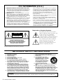 2
2
-
 3
3
-
 4
4
-
 5
5
-
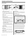 6
6
-
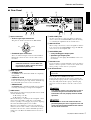 7
7
-
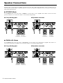 8
8
-
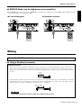 9
9
-
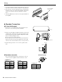 10
10
-
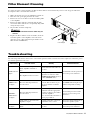 11
11
-
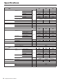 12
12
-
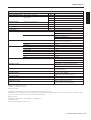 13
13
-
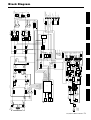 14
14
-
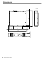 15
15
-
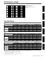 16
16
-
 17
17
-
 18
18


Yamaha T3n de handleiding
- Categorie
- Audio versterkers
- Type
- de handleiding
in andere talen
- English: Yamaha T3n Owner's manual
- italiano: Yamaha T3n Manuale del proprietario
- русский: Yamaha T3n Инструкция по применению
- français: Yamaha T3n Le manuel du propriétaire
- español: Yamaha T3n El manual del propietario
- Deutsch: Yamaha T3n Bedienungsanleitung
- português: Yamaha T3n Manual do proprietário
- dansk: Yamaha T3n Brugervejledning
- suomi: Yamaha T3n Omistajan opas
- čeština: Yamaha T3n Návod k obsluze
- svenska: Yamaha T3n Bruksanvisning
- Türkçe: Yamaha T3n El kitabı
- polski: Yamaha T3n Instrukcja obsługi
- română: Yamaha T3n Manualul proprietarului
